BLUE BOOK REVISION MASTER 12-28-16 - El Paso Electric
260
-
Upload
khangminh22 -
Category
Documents
-
view
1 -
download
0
Transcript of BLUE BOOK REVISION MASTER 12-28-16 - El Paso Electric
Mary E. Kipp Chief Executive Officer To: Our Engineering and Construction Industry Partners "ELECTRIC SERVICE REQUIREMENTS" BOOK - 2015 EDITION As we continue to work together to provide customers with the highest quality of electric service, El Paso Electric Company's (EPE) "Electric Service Requirements" book, commonly referred to as "The Blue Book," has been revised to keep up to date with the most current codes, standards and trends. Your continuing efforts to inform EPE of your plans, in a timely manner, is an important step in helping us both meet our customers' electric service needs. This "Electric Service Requirements" book has a two-fold purpose: (1) to provide you with EPE's operating procedures, rules, regulations and policies and; (2) to provide you with the most current EPE distribution standards and specifications for both overhead and underground electric service. Please review this revised edition as it contains several important changes. It is our belief that we are partners in the development and growth of our communities, and we must continue to work closely together to provide our customers with excellent and reliable electric service. This is especially true in the construction industry for both commercial and residential customers. Since good communication is essential to the success of any partnership, we know this updated "Electric Service Requirements" book will give you guidance as we work together to provide electric service to our customers in a timely fashion. We encourage you to share with us any comments or suggestions on ways we can further improve this book. Our employees are available to answer your questions and to assist you in obtaining additional service information. We are pleased to be able to serve your needs, and with your help, we can meet your new electric service requirements quickly, efficiently and effectively. Sincerely, Mary E. Kipp Chief Executive Officer

Introduction-1 November 2015
ELECTRIC SERVICE REQUIREMENTS
INFORMATION AND REQUIREMENTS FOR ELECTRIC SERVICE INSTALLATIONS
INTRODUCTION This 2015 Edition of the ELECTRIC SERVICE REQUIREMENTS book replaces the Company's "Electric Service Requirements" book last published in January 2013. All information, specifications, and requirements contained in this edition supersede all previous "Electric Service Requirements" books. This book has been prepared as a guide to assist customers, contractors, electricians, builders, architects and engineers in planning and completing electrical installations. Its purpose is to present the Company's procedures and policies applicable to such installations in an easy-to-use format. Requirements that apply to nearly all types of service and situations appear in the General Information Section. Additional requirements and policies that are special to different types of service are covered in other sections and can be readily referred to for specifics on a certain type of project. Please refer to the Table of Contents for a complete listing. The information in this book is intended to comply with the latest editions of the National Electric Safety Code, the National Electric Code and any other Codes and Regulations in effect in the area served. Any deviation from code or local inspection authority requirements should be brought to the Company's attention before beginning the electrical installation. Policies, procedures, or requirements are subject to change without advance notice to customers. The Company will make every effort to keep you informed of any changes. If there are specific conditions not covered in this book, please contact our Distribution Design and Delivery Business Unit and we will be glad to assist you in any way possible. Compliance with the information and requirements contained in this book is essential. This will help assure that The Electric Company can provide the most prompt, economical and reliable electric service.


TABLE OF CONTENTS SECTION PAGE
Contents–1
I. COMPANY SERVICE AREA MAP AND DIRECTORIES ..................................... 1 Service Area Map .................................................................................................. 2 Texas Service Area Directory................................................................................ 3 New Mexico Service Area Directory ...................................................................... 5 Application for Essential Facility Status ......................................................... 7 Required City Releases/Certificate of Compliance........................................ 9 New Mexico Permits ................................................................................... 15 II. DEFINITIONS ..................................................................................................... 16 III. GENERAL INFORMATION AND REQUIREMENTS .......................................... 20 Line Extension Process ....................................................................................... 20 Designer is Contact for Electric Service Extensions............................................ 21 Company Policies and Rules .............................................................................. 22 Customer Service Request Sheet ....................................................................... 22 Maintaining Proper Safety Clearances from Existing Company Facilities ........... 22 Determine Type of Electric Service Available...................................................... 23 Availability of Overhead or Underground Service................................................ 23 Motors ............................................................................................................... 24 Voltage Variations/Clean Power.......................................................................... 24 Meters and Metering Requirements .................................................................... 25 Connectors (Lugs, Spades) Provided by Company ............................................ 25 Maximum Number of Customer Conductors Allowed for Padmounted Transformers or Secondary Service Enclosure Connection ........................ 26 One Type of Service Per Building ....................................................................... 26 Overtime Work by Company at Customer's Request .......................................... 26 Service Point Location Confirmation ................................................................... 27 Changes in Plans ................................................................................................ 27 Inspection and Approval of Customer's Wiring .................................................... 27 Application for Meter Installation and Service Connection .................................. 28 Energizing Customer's Service ........................................................................... 29 Customer Changing or Increasing Existing Electrical Requirements .................. 29 Access to Customer's Premises .......................................................................... 31 Attachment to Company's Property ..................................................................... 31 Easements or Rights-of-Way .............................................................................. 31 Protection of Company's Property ....................................................................... 32 Responsibility for Customer's Installations .......................................................... 32 Rates and Billings ............................................................................................... 32 Meter Pulses Output for Energy Management Equipment .................................. 32 Future Changes in Policies in this Book .............................................................. 33 Customer Backup Generators ............................................................................. 33 Agreement for Pulse Metering Equipment Installation ................................ 34 Residential Request for Service Form ......................................................... 38 EPE Company Checklist ............................................................................. 39 Service Point Confirmation by El Paso Electric Company (EPE) ................ 40

TABLE OF CONTENTS SECTION PAGE
Contents–2
Commercial Request for Service Form ....................................................... 42 Residential Subdivision Request for Service Form ..................................... 48 Administration of Certificate of Plat Compliance ......................................... 50 Electrical Safety Decals/Tips ....................................................................... 53 IV. TYPES OF SERVICE VOTAGES AVAILABLE .................................................. 60 General ............................................................................................................... 60 Types of Electric Services Generally Available ................................................... 60 Transmission or Primary Voltage Service ........................................................... 62 Chart on Available Service for Customer's Electrical Loads................................ 63 V. MOTORS ............................................................................................................ 64 Single-Phase or Three Phase ............................................................................. 64 Motor Protection .................................................................................................. 64 Motor Starting Current Requirements ................................................................. 64 Motors for Wells .................................................................................................. 64 VI. METERING ......................................................................................................... 66 General Information ............................................................................................ 66 Meter Location .................................................................................................... 69 Meter Sealing Program and Energy Diversion (Theft) ......................................... 70 Furnishing and Installation of Meter Sockets or Enclosures ................................ 71 Company Policy for Overhead Service to Multiple Residential and Commercial Customers with Grouped Electrical Meters and Gutter ........... 72 Company Policy for Underground Service to Multiple Residential and Commercial Customers with Grouped Electrical Meters and Gutter ........... 73 Service Entrance Requirements for Instrument Transformers and Heavy-Duty Meters Served from an Overhead System .............................. 74 Current Transformer (CT) Metering ..................................................................... 74 In-Line Metering .................................................................................................. 75 Primary Voltage Metering on Overhead System ................................................. 76 Service Entrance Requirements for Instrument Transformers (CT's) and Heavy-Duty Meters Served from an Underground System ......................... 76 In-Line Metering (One Conductor per Phase Limit) ............................................. 77 CT Metering ........................................................................................................ 78 Primary Voltage Meters on Underground System ............................................... 79 EPE Approved Residential Meter Enclosure and Sockets .................................. 79 EPE Approved Meter Can Listing................................................................ 80 Checklist for New or Upgraded Electric Service .......................................... 84 VII. ELECTRIC SERVICE TO RESIDENTIAL SINGLE-FAMILY DETACHED HOMES AND MOBILE HOMES .................................................... 85 Request for Service ............................................................................................. 85 For Overhead Service ......................................................................................... 85 For Underground Service .................................................................................... 86
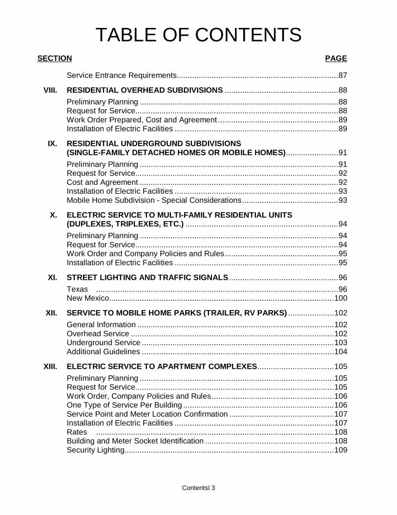
TABLE OF CONTENTS SECTION PAGE
Contents–3
Service Entrance Requirements.......................................................................... 87 VIII. RESIDENTIAL OVERHEAD SUBDIVISIONS .................................................... 88 Preliminary Planning ........................................................................................... 88 Request for Service ............................................................................................. 88 Work Order Prepared, Cost and Agreement ....................................................... 89 Installation of Electric Facilities ........................................................................... 89 IX. RESIDENTIAL UNDERGROUND SUBDIVISIONS (SINGLE-FAMILY DETACHED HOMES OR MOBILE HOMES) ........................ 91 Preliminary Planning ........................................................................................... 91 Request for Service ............................................................................................. 92 Cost and Agreement ........................................................................................... 92 Installation of Electric Facilities ........................................................................... 93 Mobile Home Subdivision - Special Considerations ............................................ 93 X. ELECTRIC SERVICE TO MULTI-FAMILY RESIDENTIAL UNITS (DUPLEXES, TRIPLEXES, ETC.) ...................................................................... 94 Preliminary Planning ........................................................................................... 94 Request for Service ............................................................................................. 94 Work Order and Company Policies and Rules .................................................... 95 Installation of Electric Facilities ........................................................................... 95 XI. STREET LIGHTING AND TRAFFIC SIGNALS .................................................. 96 Texas ............................................................................................................... 96 New Mexico....................................................................................................... 100 XII. SERVICE TO MOBILE HOME PARKS (TRAILER, RV PARKS) ..................... 102 General Information .......................................................................................... 102 Overhead Service ............................................................................................. 102 Underground Service ........................................................................................ 103 Additional Guidelines ........................................................................................ 104 XIII. ELECTRIC SERVICE TO APARTMENT COMPLEXES ................................... 105 Preliminary Planning ......................................................................................... 105 Request for Service ........................................................................................... 105 Work Order, Company Policies and Rules ........................................................ 106 One Type of Service Per Building ..................................................................... 106 Service Point and Meter Location Confirmation ................................................ 107 Installation of Electric Facilities ......................................................................... 107 Rates ............................................................................................................. 108 Building and Meter Socket Identification ........................................................... 108 Security Lighting................................................................................................ 109

TABLE OF CONTENTS SECTION PAGE
Contents–4
XIV. COMMERCIAL, MANUFACTURING OR INDUSTRIAL SERVICE .................. 110 General Information .......................................................................................... 110 Overhead Electric Services ............................................................................... 111 Underground Electric Services .......................................................................... 111 Design of Company Facilities ...................................................................... 111 Padmount Transformer Installation/Service Connection .............................. 112 Transformer Installed in a Vault ................................................................... 113 XV. TEMPORARY SERVICE .................................................................................. 114 Request for Temporary Service ........................................................................ 114 Temporary Service Connection Charge ............................................................ 114 Temporary Line Extension ................................................................................ 114 Temporary Service Point Location .................................................................... 115 XVI. ELECTRIC SERVICE IN THE DOWNTOWN EL PASO AREA AND THE DOWNTOWN LAS CRUCES AREA ........................................................ 116 Downtown El Paso Area ................................................................................... 116 Downtown Las Cruces Area .............................................................................. 117 XVII. REMOVAL AND RELOCATION OF EXISTING COMPANY FACILITIES........ 118 Removal and/or Relocation Requested by Customer ....................................... 118 Conversion of Overhead Facilities to Underground Facilities ............................ 119 Impaired Clearance ........................................................................................... 119 Service and Meter Location Changed ............................................................... 120 No Underground "Dips" ..................................................................................... 120 XVIII. PRIVATE AREA AND SECURITY LIGHTING.................................................. 121 Area Light/Flood Light Program ........................................................................ 121 Request for an Area Light/Flood Light ............................................................... 121 Lighting Agreement ........................................................................................... 121 General Information .......................................................................................... 121 Facilities Provided ............................................................................................. 122 Repair and Maintenance ................................................................................... 123 Light Relocation ................................................................................................ 123 Rates ............................................................................................................. 123 Floodlight Option ............................................................................................... 123 XIX. RENEWABLE ENERGY AND COGENERATION ............................................ 124 Renewable Interconnection Process Flow-TX Customers ................................ 124 Renewable Interconnection Process Flow-NM Customers ............................... 124 XX. GENERATION UTILIZED FOR BACKUP SUPPORT ...................................... 128 XXI. COMPANY STANDARDS FOR SERVICE INSTALLATIONS.......................... 132

TABLE OF CONTENTS SECTION PAGE
Contents–5
STANDARDS FOR OVERHEAD CONSTRUCTION ................................................... DSO Residential Service Entrance Wall Support ....................................................... 415 Residential Service Entrance Riser Support ..................................................... 417 3 Phase Commercial Service Entrances .......................................................... 420 Customer Service Pole for Permanent Mobile Home, Residential or Temporary Service ................................................................ 430 Multiple Services For Residential ...................................................................... 432 Typical Self-Contained Meter For Commercial Installation ............................... 440 Pole Setting ....................................................................................................... 615 Clearances From Building ............................................................................... 1215 Minimum Clearances From Signs and Objects ............................................... 1220 Minimum Clearances From Other Supporting Structures ................................ 1225 Clearances From Wells ................................................................................... 1235 Swimming Pool Approval Guidelines .............................................................. 1240 Typical Multiple Commercial Metering Installation .......................................... 1810 Typical Multiple Residential Metering Installation ............................................ 1815 Typical Multiple Metering Installation With Single Phase and Three Phase Service .................................................... 1820 Typical In-Line Meter Installation..................................................................... 1827 Typical 3 Phase, 4 Wire, 120/208, 120/240 or 277/480 Volt, Instrument Transformer Metering Mounted on Building Wall…………………………...1836 Typical 3 Phase, 4 Wire, 120/208, 120/240 or 277/480 Volt, Instrument Transformer Metering Mounted on Service Pole ...................................... 1839 Parallel Riser Installation For Commercial Metering ....................................... 1845 14 KV Primary Metering Crossarm Tangent Construction Pole ...................... 1860 4 KV – 24 KV Primary Metering for Customers With Bypass .......................... 1865 Governmental Illumination and Traffic Management Service Pole and Supporting Structures Installation ....................................................... 1870

TABLE OF CONTENTS SECTION PAGE
Contents–6
STANDARDS FOR UNDERGROUND CONSTRUCTION ........................................... DSU Service Enclosure Selection Chart .................................................................... 405 Residential and Commercial Secondary Riser 3", 4" and 5" Single Duct .................................................................................................. 410 Underground Residential Service Customer Installed ....................................... 420 Temporary Service From Underground Distribution .......................................... 425 Typical Customer Secondary Cable Length for Padmount Transformers - ....... 440 Commercial Secondary Bus Enclosure ............................................................. 445 Maximum Number of Customer Secondary Conductors Per Phase in Padmount Transformers ......................................................... 510 Clearances and Right-of-Way Requirements For Three-Phase Padmount Transformers 500 - 2500 KVA .............................. 515 Clearances and Right-of-Way Requirements For Three-Phase Padmount Transformers 300 KVA and Below ........................ 520 Clearances and Right-of-Way Requirements For Single-Phase Padmount Transformers 25-250 KVA .................................... 525 Clearances and Right-of-Way Requirements For Single-Phase Padmount Transformers 25-250 KVA Assembly "E" ................... 528 Clearances and Right-of-Way Requirements For Commercial Secondary Service Enclosure .................................................. 530 Clearances and Right-of-Way Requirements For Single-Phase PVI Switch ............................................................................. 545 Clearances and Right-o-Way Requirements For Three-Phase PVI Switch .............................................................................. 550 Meter Frame for Metering. ............................................................................. 1015 Requirements for Pre-manufactured Metering Pedestals for Mobile Homes ....................................................................................... 1020 Meter and Switch Frame Mounting For Mobile Homes ................................... 1025 Typical Multiple Commercial Metering Installation .......................................... 1040 Typical Multiple Underground Three-Phase and Single-Phase Metering Installation ................................................................................... 1045 Pullboxes ........................................................................................................ 1207 Pullboxes Assemblies ..................................................................................... 1210 Equipment Pad Details .................................................................................... 1235

1
SECTION I
COMPANY SERVICE AREA MAP AND DIRECTORIES

2
3
TEXAS
SERVICE AREA DIRECTORY

4
DIRECTORY OF IMPORTANT TELEPHONE NUMBERS
TEXAS COMPANY MAIN SWITCHBOARD ............................................................. (915) 543-5711 TROUBLE - "NO LIGHTS - POWER LOSS" ............................................... (915) 877-3400
............................................................................................................... or 1-800-351-1621
REQUEST NEW SERVICE THAT REQUIRES A LINE EXTENSION ........ (915) 351-4224
CALL BEFORE YOU DIG (To Request Underground Cable Locates)
DIG TESS (Texas Excavation Safety System) .......................................... 1-800-344-8377
TO APPLY FOR A NEW METER INSTALLATION ...................................... (915) 521-4646
TO APPLY FOR A NEW METER INSTALLATION
FOR RENEWABLE ENERGY INTERCONNECTION ............... (800) 351-1621, EXT. 4418
TO APPLY FOR SERVICE THAT HAS AN EXISTING METER .................. (915) 543-5970
OUTLYING OFFICES – TEXAS
FABENS OFFICE (8 a.m. to 4:30 p.m., Monday through Friday) 200 East Main Street
Full service office for WALK-IN AND DRIVE-THROUGH CUSTOMERS ONLY.
VAN HORN OFFICE (8 a.m. to 12:00 p.m. and 1:00 p.m. to 4:30 p.m., Monday through Friday – Central Time Zone) 207 West Second Street, Van Horn, Texas Full service office for WALK-IN CUSTOMERS ONLY.
ANTHONY OFFICE (8 a.m. to 4:30 p.m., Monday through Friday) 400 Anthony Drive
Full service office for WALK-IN AND DRIVE-THROUGH CUSTOMERS for the Anthony and Chaparral, New Mexico service territory.
* IF ANY NEW OR EXISTING SERVICE WILL BE USED FOR THE PROTECTION OR
MAINTENANCE OF PUBLIC HEALTH, SAFETY AND SECURITY DURING AN EMERGENCY, PLEASE SEE PAGE 7 TO COMPLETE AN "APPLICATION FOR ESSENTIAL FACILITY STATUS."

5
NEW MEXICO
SERVICE AREA DIRECTORY
6
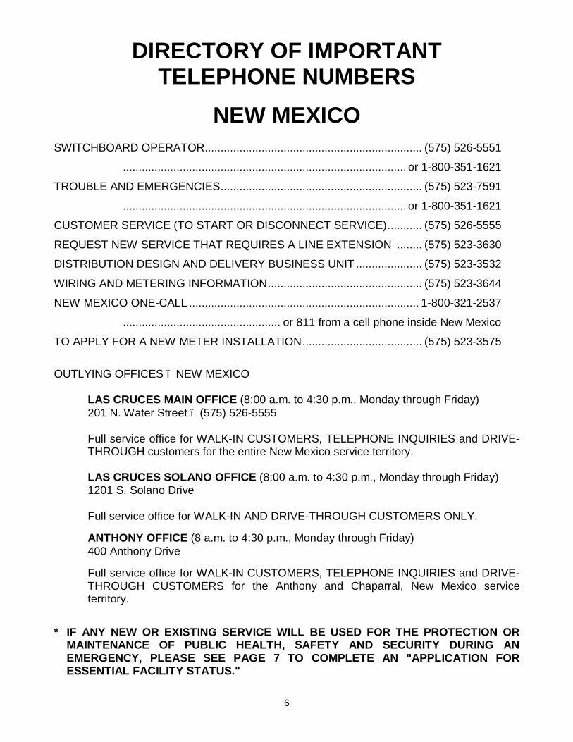
DIRECTORY OF IMPORTANT TELEPHONE NUMBERS
NEW MEXICO SWITCHBOARD OPERATOR ..................................................................... (575) 526-5551
.......................................................................................... or 1-800-351-1621
TROUBLE AND EMERGENCIES ................................................................ (575) 523-7591
.......................................................................................... or 1-800-351-1621
CUSTOMER SERVICE (TO START OR DISCONNECT SERVICE) ........... (575) 526-5555
REQUEST NEW SERVICE THAT REQUIRES A LINE EXTENSION ........ (575) 523-3630
DISTRIBUTION DESIGN AND DELIVERY BUSINESS UNIT ..................... (575) 523-3532
WIRING AND METERING INFORMATION ................................................. (575) 523-3644
NEW MEXICO ONE-CALL ......................................................................... 1-800-321-2537
.................................................. or 811 from a cell phone inside New Mexico
TO APPLY FOR A NEW METER INSTALLATION ...................................... (575) 523-3575
OUTLYING OFFICES – NEW MEXICO LAS CRUCES MAIN OFFICE (8:00 a.m. to 4:30 p.m., Monday through Friday) 201 N. Water Street – (575) 526-5555
Full service office for WALK-IN CUSTOMERS, TELEPHONE INQUIRIES and DRIVE-THROUGH customers for the entire New Mexico service territory. LAS CRUCES SOLANO OFFICE (8:00 a.m. to 4:30 p.m., Monday through Friday) 1201 S. Solano Drive Full service office for WALK-IN AND DRIVE-THROUGH CUSTOMERS ONLY.
ANTHONY OFFICE (8 a.m. to 4:30 p.m., Monday through Friday) 400 Anthony Drive
Full service office for WALK-IN CUSTOMERS, TELEPHONE INQUIRIES and DRIVE-THROUGH CUSTOMERS for the Anthony and Chaparral, New Mexico service territory.
* IF ANY NEW OR EXISTING SERVICE WILL BE USED FOR THE PROTECTION OR
MAINTENANCE OF PUBLIC HEALTH, SAFETY AND SECURITY DURING AN EMERGENCY, PLEASE SEE PAGE 7 TO COMPLETE AN "APPLICATION FOR ESSENTIAL FACILITY STATUS."

7

8

9
REQUIRED CITY RELEASES/CERTIFICATE OF COMPLIANCE IN ADDITION TO THE FOLLOWING REQUIREMENTS THAT ARE SUBJECT TO APPROVAL BY THE AUTHORITY HAVING JURISDICTION, ALL NEW RESIDENTIAL AND COMMERICAL SERVICES, INCLUDING CHANGES TO EXISTING RESIDENTIAL AND COMMERCIAL SERVICES, ARE ALSO SUBJECT TO INSPECTION AND APPROVAL BY El PASO ELECTRIC COMPANY. CITY OF EL PASO
i Residential NSER / Commercial NSER and Meter Relocations
o Require a CITY RELEASE: CITY OF EL PASO Building Permits & Inspection 212-0104 811 Texas Avenue El Paso TX 79901
NOTE: If the meter is disconnected because of a FIRE or ELECTRICAL HAZARD, the customer will
need to apply for a City Release to reconnect service. IF THERE ARE ANY QUESTIONS PLEASE CALL THE FABENS OFFICE FOR ASSISTANCE, AT 765-2061. Do not call the Governing Entities. EL PASO COUNTY (includes El Paso outside limits, San Elizario, Fabens, Tornillo, Canutillo & Westway) The customer will need to provide the legal description of the property, proof of water service and proof of sewer service/septic system to the county for application of Certificate of Compliance. The following customers who have Certificate of Compliance older than 2005 will need to renew their Certificates:
i Customers moving into an existing mobile home park i Customers requesting a second service for same property and if one of the services is residential then a
Certificate of Compliance indicating two meters, specifying type (res/commercial). All accounts will be remarked "Certificate of Compliance issued 00/00/00 #99999 by CC&B on file//RAL". And on the instruction line of service order type 'Certificate of Compliance on file' first and then continue with customer name and your initials.
i Residential NSER o Will need a Certificate of Compliance from the County of El Paso before order will be taken. A non-
refundable fee of $25 will be charged for each Certificate of Compliance. Customer must contact:
* County Road & Bridges 800 E Overland, 4th Floor, Room 407 El Paso TX 79901 915 546-2015
EL PASO COUNTY Exemptions from the Certificate of Compliance
o Commercial Accounts (form TEMP Official Street Address & Assumed Name Records) needed o Lighting (street lights, traffic signal lights, railroad crossings, sports field lighting) o Irrigation Wells o Tigua Reservation o Government Entities o Any business already registered with the Federal or State is Exempt
10
EL PASO COUNTY (continued)
i Temporary Certificate of Plat Compliance
o The County of El Paso will issue temporary Certificate of Plat Compliance to allow for construction of residence, testing of water wells, or for other temporary needs as determined by the County.
o It is a 90 day temporary utility service. o After 90 days the temporary Certificate expires and service will be disconnected. Customer will
need to reapply for an additional 90 days.
i Existing Residential Service
o If there are no remarks on the account showing that a Certificate of Compliance was issued or the address isn't found in the master file – the customer will need a Certificate of Compliance before an order for new service can be taken by the New Service Group.
o Customers requesting a second service for a property; will need a Certificate of Compliance indicating how many meters, before the additional service is connected.
o System updates to correct records due to changes caused by marriage, divorce, death or roommate changes; will not require a Certificate of Compliance.
NOTE: Existing mobile homes should be removed from property, when a customer is adding another
service, unless Certificate of Compliance specifies 2 or more meters. If customer refuses to remove mobile home, advise them they are in violation of Certificate of Compliance. EPE cannot enforce removal of mobile home.
i Meter Relocation for Residential & Commercial
o No Certificate of Compliance required for same structure relocation/upgrades
NOTE: If meter is disconnected because of a fire or electrical hazard, the residential customer will
need to apply for a Certificate of Compliance, if a current one is not on file based on rulings.
i Non pay reconnect for existing Residential Service (NPRC)
o If the NPRC is requested within 90 days of the disconnection date of nonpayment (SONP) no Certificate of Compliance is required.
o If any service is off for more than 90 days and if there is no Certificate of Compliance filed, then a Certificate of Compliance will be required before the services will be turned on for the same customer.
o If the service is off for more than 90 days, the Certificate of Compliance on file is older than 2005 and the customer has more than one residential service per property, a Certificate of Compliance is required
i Commercial NSER'S
o Needs an OFFICIAL STREET ADDRESS FORM
* County Road & Bridges
800 Overland 4th Floor Room 407 El Paso TX 79901 915 546-2015
11
EL PASO COUNTY (continued)
i Any commercial customers will need an OFFICIAL BUSINESS REGISTRATION (Assumed Name Certificate), and the Official Street Address Forms, service addresses must match on both forms.
* County Clerk
500 E San Antonio St Room 105 El Paso TX 79901
i Existing Commercial Service o Exempted from Certificate of Compliance. o Commercial Service (accounts) in our system, will only need an Assumed Name Certificate, the
addressed on the certificate must match our system address. o Established commercial customers requesting additional commercial service under the same name
or type of business for a different address, will be required official documentation same as a new customer (Assumed name registration to match service address).
CITY OF HORIZON New Service Residential & Commercial
i Residential NSER's will require an inspection from the City of Horizon. i Commercial NSER'S will require an issuance of Business Registration from and a City inspection from
the City of Horizon. i Temporary Service needs inspection.
Existing Residential & Commercial Services
i Existing residential will require an inspection by City of Horizon. i Commercial accounts inside the City Limits of Horizon will need a business registration form. i Meter – relocation/upgrades (any type of electrical repairs) for Residential & Commercial will require an
inspection
* City of Horizon 14999 Darrington El Paso TX 79928
(915) 852-1046 NOTE: If meter is disconnected because of a fire or electrical hazard, the customer will need an
inspection from City of Horizon. CITY OF SOCORRO
i Residential/Commercial NSER's
o Need a RELEASE from City of Socorro o Release # begins with:
y E-MMYY### y TE-MMYY### (Temporary Electrical Service) y 3PE- MMYY### (Third Party Electrical Inspection)
* Rio Vista
860 Rio Vista Socorro TX 79927 (915) 872-8531

12
CITY OF SOCORRO (continued)
i Existing Residential/Commercial Service
o No release or certificate is needed
i Meter Relocations/Upgrades for Residential or Commercial
o Needs RELEASE from City of Socorro NOTE: If meter is disconnected because of a fire or electrical hazard, the customer will need an
inspection from City of Socorro to reconnect services. CITY OF CLINT
i Residential/Commercial NSER
o Need a Certificate of Compliance from the City of Clint, if one is not on file.
* (915) 851-3146
i Meter Relocations/Upgrades for Residential or Commercial
o Needs RELEASE from City of Clint NOTE: If meter is disconnected because of a fire or electrical hazard, the customer will need an
inspection from City of Clint to reconnect service. HUDSPETH COUNTY (Includes Ft Hancock, Esperanza & Sierra Blanca)
i Residential/Commercial NSER
o Needs Certificate of Compliance from Sierra Blanca
* County Court House of Sierra Blanca 501 W Galveston Sierra Blanca TX (915) 369-2321
i Existing Residential/Commercial Service
o Will require a Certificate of Compliance if one is not on file for residential service o All services must have a valid address, numeric & street name o Commercial service will require a Certificate of Address Form
* County Court House of Sierra Blanca
501 W Galveston Sierra Blanca TX (915) 369-2321
Only Hudspeth County can fax Certificate of Compliance directly to Fabens Office. Fax # 915 764 2250
13
HUDSPETH COUNTY (Includes Ft Hancock, Esperanza & Sierra Blanca) [continued]
i Meter Relocations/Upgrades for Residential or Commercial
o No Certificate of Compliance is required for same structure relocation or upgrades NOTE: If meter is disconnected because of a fire or electrical hazard, the customer will need a
Certificate of Compliance, if a current one is not on file based on the rulings. CULBERSON COUNTY (Outside City limits of Van Horn)
i Residential NSER
o Needs Certificate of Compliance if one is not on file
* Culberson County Judges Office 300 La Caverna Van Horn TX (432) 283-2059
Exemptions
o Lighting o Irrigation Wells o Government Entities
i Commercial NSER
o No Certificate of Compliance required o Assumed name with Official Street Address Certificate (if address is not in our system)
i Existing Residential Service
o Needs a Certificate of Compliance if one not on file
i Meter Relocations Residential/Commercial
o No Certificate of Compliance required for relocation or upgrades NOTE: If meter is disconnected because of a fire or electrical hazard, the customer will need a
Certificate of Compliance, if a current one is not on file based on the rulings. INSIDE VAN HORN CITY LIMITS
i Residential NSER
o Certificate of Compliance form City of Van Horn required
* City Hall 1801 W Broadway Van Horn TX (432) 283-2050
i Commercial NSER
o Assumed name and Official Street Address Certificate from CITY HALL. Certificate of Compliance is not needed
INSIDE VAN HORN CITY LIMITS (continued)
14
i Existing Commercial Service
o Certificate of Address
i Existing Residential Service
o Mobile homes will need a Certificate of Compliance if one not on file
i Meter Relocations Residential/Commercial
o No Certificate of Compliance required for relocation or upgrades NOTE: If meter is disconnected because of a fire or electrical hazard, the customer will need a
Certificate of Compliance, if a current one is not on file based on the rulings. VILLAGE OF VINTON
i Residential/Commercial NSER
o Will need an inspection by Village of Vinton Electrical Inspector
* 436 Vinton Rd (436) 886-5104
i Existing Residential Service
o Do not need any kind of release o Meter relocation/upgrades will require an inspection by the Village of Vinton Electrical inspector
NOTE: If meter is disconnected because of a fire or electrical hazard, the customer will need an
inspection from the Village of Vinton Electrical Inspector. IF THERE ARE ANY QUESTIONS, PLEASE CALL THE FABENS OFFICE FOR HELP AT 765-2061. Do not call the Governing Entities.
The release card that the electrical inspector provides to the customer must be turned over to EPE (customer is usually referred to our Anthony office).
15
New Mexico Permits
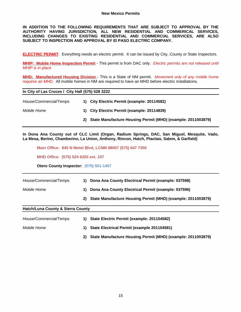
IN ADDITION TO THE FOLLOWING REQUIREMENTS THAT ARE SUBJECT TO APPROVAL BY THE AUTHORITY HAVING JURISDICTION, ALL NEW RESIDENTIAL AND COMMERICAL SERVICES, INCLUDING CHANGES TO EXISTING RESIDENTIAL AND COMMERCIAL SERVICES, ARE ALSO SUBJECT TO INSPECTION AND APPROVAL BY El PASO ELECTRIC COMPANY.
ELECTRIC PERMIT: Everything needs an electric permit. It can be issued by City, County or State Inspectors. MHIP: Mobile Home Inspection Permit - This permit is from DAC only. Electric permits are not released until MHIP is in place MHD: Manufactured Housing Division - This is a State of NM permit. Movement only of any mobile home requires an MHD. All mobile homes in NM are required to have an MHD before electric installations. In City of Las Cruces – City Hall (575) 528 3222 House/Commercial/Temps 1) City Electric Permit (example: 20114582) Mobile Home 1) City Electric Permit (example: 20114839) 2) State Manufacture Housing Permit (MHD) (example: 2011003879) In Dona Ana County out of CLC Limit (Organ, Radium Springs, DAC, San Miguel, Mesquite, Vado, La Mesa, Berino, Chamberino, La Union, Anthony, Rincon, Hatch, Placitas, Salem, & Garfield) Main Office: 845 N Motel Blvd, LCNM 88007 (575) 647 7350 MHD Office: (575) 524 6320 ext. 107
Otero County Inspector: (575) 551-1457 House/Commercial/Temps 1) Dona Ana County Electrical Permit (example: 037598) Mobile Home 1) Dona Ana County Electrical Permit (example: 037596) 2) State Manufacture Housing Permit (MHD) (example: 2011003879) Hatch/Luna County & Sierra County House/Commercial/Temps 1) State Electric Permit (example: 201104582)
Mobile Home 1) State Electrical Permit (example 201104581) 2) State Manufacture Housing Permit (MHD) (example: 2011003879)


16
SECTION II
DEFINITIONS Terms frequently used in this book are herein defined: APPLICATION FOR METER INSTALLATION AND SERVICE CONNECTION: By mail, phone or personal request of the customer at one of the Company offices stating desire for meter. Deposits guaranteeing payment of bills are normally required of commercial, industrial, and certain residential customers. A service charge included in the first bill will be required of all customers. AREA LIGHT: An outdoor light installed and maintained by the Company for use by customers for area and security lighting purposes. CERTIFICATE OF COMPLIANCE: A legal document required by Texas State Government in order to obtain electric service for residential use on property that is located in an Extra Territorial Jurisdiction. This document is issued by the appropriate governing entity before electric service can be provided. COMPANY: The El Paso Electric Company (also called The Electric Company). CT'S AND PT'S (INSTRUMENT TRANSFORMERS): Transformers used to change electric current or voltage to values suitable for use in metering the consumption of electric energy. These are owned, furnished, and installed by the Company. CT CAN (INSTRUMENT TRANSFORMER ENCLOSURE): In general, a metal cabinet owned and furnished by the customer, installed by the customer's electrical contractor, for use by the Company to enclose the Company's metering transformers. Only CT cans approved by the Company and meeting Company specifications may be installed. CUSTOMER: Any corporation, business establishment, institution, association or individual being served or using electric energy supplied by the Company or requesting electric service. RESIDENTIAL CUSTOMER: Each separate house, apartment, or other living quarters occupied by a person or persons constituting a distinct household and using electric service for lighting, appliances, heating, cooking, refrigeration, and incidental single phase power solely in conjunction with domestic home use. COMMERCIAL CUSTOMER: Each separate business establishment, institution or association occupying for its exclusive use any unit or units of space as an entire building, entire floor, suite of rooms or a single room and using electric service for lighting, appliances, heating or power.

17
The term customer as used in this book may also apply to those agents for the customer - i.e., electricians, contractors, engineers, etc. CUSTOMER'S INSTALLATION: All wires, cut-outs, switches, appliances, and apparatus of every kind and nature used in connection with or forming a part of any installation for utilizing electricity for any purpose. Customer's installation is ordinarily located in the customer's side of the point-of-delivery and includes service leads whether such installation is owned outright or otherwise. In general, the customer's installation consists of all equipment beyond the point of delivery except meters and instrument transformers. CUSTOMER REQUEST FOR SERVICE: When a customer needs electric service to a new facility or is making changes in the present electrical use that will require The Electric Company to increase or modify its existing electrical system, the customer shall notify the Company and "request" that the Company perform the needed work stating the amount and type of electric service required at a certain location. For commercial and industrial customers, a "Customer Service Request Sheet" must be completed before the Company can design the electric service. CUSTOMER SERVICE REPRESENTATIVE: Company personnel in the Transmission and Distribution Department who coordinates and analyzes all aspects of voltage problems, determines whether existing or proposed customer equipment will overload Company facilities or cause problems to Company facilities or other customers and checks Company equipment to insure it is functioning properly. CUSTOMER SERVICE REQUEST SHEET: A Company form that must be completed by a customer requesting new or changed electric service. The information on this sheet, plus applicable plans, provides the Company with the information necessary to provide the requested service. DESIGNER: Company personnel in the Distribution Design and Delivery Business Unit who coordinate all aspects of the new or increased service request with the customer and other departments of the Company. DISTRIBUTION LINES: The Company's lines located along streets, alleys, highways, easements or elsewhere, intended for general distribution of electric service to customers at one of the Company's standard primary voltages. DSO (Distribution Standards Overhead): Materials, construction and installation standards and specifications established by the Company for facilities, which are a part of an overhead distribution system. DSU (Distribution Standards Underground): Materials, construction and installation standards and specifications established by the Company for facilities which are a part of an underground distribution system. FAULT CURRENT: The short circuit amperage current produced during the unintentional contact of two parts of an electrical circuit that offers an alternate path for current to flow.

18
FLOOD LIGHT: A directional outdoor light installed and maintained by the Company for use by customers for area and security lighting purposes. IMPAIRED CLEARANCE: The condition where a customer's structure(s), including, but not limited to, buildings, signs, towers, poles, fencing and swimming pools, is in a position or manner in which insufficient clearance, as specified by any applicable local code(s) and the National Electric Safety Code, as such codes now exist or as such codes may be amended, exists between the structure and the Company's existing transmission, substation, express feeder, street light or distribution line facilities, or any combination thereof. LINE EXTENSION: Any addition (other than services wires and meters) to the Company's existing transmission or distribution system or other existing facilities which must be made to provide new or increased electric service to customers. LINE EXTENSION AGREEMENTS: A contract entered into between the customer and the Company which states the terms and conditions of certain types of line extensions, especially those requiring a revenue guarantee or cash advance. LINE EXTENSION POLICY: The Company's major policies which have been approved by the state regulatory commissions regarding extensions of or additions to existing lines or facilities and also regarding other procedures and policies. METER AND WIRING INSPECTOR: Company personnel in the Transmission and Distribution Department who (1) assist customers, electrical consultants and contractors in design of service entrance facilities, (2) inspect meter sockets and wiring conditions of new or existing customer facilities and (3) designate the point of electrical service on residential and commercial buildings not requiring a line extension. METER ENCLOSURE: A Company-approved metal cabinet owned and furnished by the customer and installed by the customer's electrical contractor to enclose the Company's metering equipment. Meter enclosures will be sealed by the Company with Company's seal or lock. METER SOCKET: A Company-approved receptacle of square or rectangular design and of weatherproof construction used for mounting socket-type meters. The meter socket will be provided by the customer and installed by the customer's electrical contractor. OVERHEAD DISTRIBUTION AREA: An area which is served by existing Company overhead electric facilities or which has been designated by the Company as an overhead distribution area. POINT OF ATTACHMENT: The first point of contact on customer's premises, building structure, or service pole to which the Company's service wires are attached. PRIMARY VOLTAGE: One of the Company's standard voltages between 4,000 volts and 24,000 volts, inclusive, phase to phase. Different primary voltages are available in various parts of the Company's service area. All voltages are not available in all areas.

19
RIGHTS-OF-WAY OR EASEMENTS: Areas or property where the Company has the right to install, operate and maintain its facilities and equipment by virtue of ownership, deed, filed plat or grant by property owner. Company facilities will only be installed where firm rights-of-way or easements have been obtained. SECONDARY SERVICE ENCLOSURE: A small junction box used or required by the Company in underground served areas as a pullbox and connection point for low voltage secondary conductors. Also referred to as a service pedestal. SECONDARY VOLTAGE: One of the Company's standard service voltages below 600 volts, phase to phase. SERVICE ENTRANCE EQUIPMENT: Customer-owned wire, conduit, switches and fittings which are installed on customer's premises to connect to Company's wiring or facilities at point of delivery. SERVICE POINT: The point where the Company's wires or facilities are connected with those of the customer. SERVICE WIRES: The wires of the Company which are connected to the service entrance wires of the customer or to the line side of the meter enclosure. TRANSMISSION VOLTAGE: One of the Company's standard voltages greater than or equal to 69,000 volts. TYPE OF SERVICE: The characteristics of electric service described in terms of voltage, phase, frequency, and number of wires. UNDERGROUND DISTRIBUTION AREA: An area in which the customer's premises abut on existing Company underground service facilities or which has been designated or dedicated to underground service by the Company or by covenants or filed easements stipulated by a and developer or regulatory authority.

20
SECTION III
GENERAL INFORMATION AND REQUIREMENTS
THE FOLLOWING INFORMATION WILL APPLY TO ALL TYPES OF SERVICE: 1. LINE EXTENSION PROCESS
Because of various factors involved with each line extension and the Company’s workload at any given time, it can take up to 12 weeks to complete everything necessary to provide customers with electric service. It can take longer than 12 weeks if special materials or special easements or permits are required. Therefore, it is very important to give the Company as much advance notice as possible, including the information needed by the Company, in order to provide electric service in a timely manner and by the date the customer needs electric service. Below is a brief step by step process of the Company’s line extension process: Step 1: Customer contacts the Company to request electric service. Step 2: Customer’s request for electric service is assigned to a Designer who
will usually contact the customer within 1 day after receiving the customer’s request for electric service.
Step 3: Designer will arrange to meet with the customer to get all the
information necessary in order to start the engineering design of the line extension. Customer’s electrical plans must be approved by the Company during this step and before the customer orders electrical equipment or starts the electrical work.
Step 4: Designer conducts a site visit of customer’s property to determine
what will be required to provide electric service. Step 5: Designer prepares engineering design of the proposed line
extension, which includes the estimated cost of the line extension. Step 6: Designer confirms service point location with the customer and
explains the Company’s Line Extension Policy to the customer. Step 7: Customer reviews and approves the Company’s service point
location and engineering design and wants to move the process forward.

21
Step 8: If necessary, the Designer sends job to Land Management to secure
all necessary easements and permits. Step 9: After all easements and permits are obtained and the final estimated
cost of the line extension is known, the Designer will perform a cost-revenue analysis to determine whether or not the line extension is revenue justified. The Designer discusses this with the customer.
Step 10: After the customer signs the line extension agreement and makes
payment to the Company for the line extension, if necessary, the Designer releases the job to construction. Step 11: Once the line extension is constructed and the customer’s electrical
installation is completed and has passed inspection, the customer shall apply for service and meter by calling (915) 521-4646 in El Paso or (575) 523-2575 in Las Cruces.
Step 12: After customer makes application for service, the service and meter
will be installed by the Company. 1. DESIGNER IS CONTACT FOR ELECTRIC SERVICE EXTENSIONS The Designer in the Distribution Design and Delivery Business Unit has the
responsibility of being the one point of contact for customers, electrical contractors, builders, consulting engineers, architects, etc., to work with in obtaining electric service to new facilities or in making changes in existing facilities. The Designer serves as the liaison between other departments in the Company and the customer (or his agents) to coordinate all aspects of any given project. By working with and through the Designer, the customer is ensured that all requirements regarding Company policies, procedures, contracts and financial arrangements, for example, are being met. The Designer coordinates all the various aspects of a project within the Company and with the customer to be sure that all steps are taken in their proper sequence so that electric service is provided when needed. It is therefore extremely important that the Designer be informed immediately of any changes in electric load requirements, specifications, or location. If the customer has any questions or problems, please contact the Designer to resolve the problem.
Company employees in many different departments continually strive to meet
customers' needs on time. It is not unusual to have several projects in varying degrees of progress at the same time, so communication and coordination become very important. It is the Designer's job to tie it all together, and the customer's cooperation is needed to do this effectively. If the customer delays in providing needed information in a timely manner, other projects may have achieved a higher priority. Thus, there will not be time to schedule work on a project where needed information was not provided earlier.
22
2. COMPANY POLICIES AND RULES A. Each request for service will be considered in accordance with the terms and
conditions of the Company's filed Line Extension Policy, Rules and Regulations Regarding Electric Service and in accordance with other standard operating procedures and policies.
B. Several drawings and written comments explaining Company policies and
standards are included in this book. The standards are referred to as DSO's (Distribution Standards Overhead) and DSU's (Distribution Standards Underground). The current standards are shown. However, since they are updated or revised periodically, contractors and consulting engineers should check with the Company if they have any questions, especially on major projects.
3. CUSTOMER SERVICE REQUEST SHEET On commercial or industrial projects, the Customer Service Request Sheet (Sheet)
must be completed and signed before the Company will begin final engineering design or construction. The Sheet is to be given to the appropriate Designer and should contain firm information and be accompanied by final plans. It is important that the appropriate copies of plans are provided. Generally, the following plans will be needed or are required: site plan, legal description, elevation of building, grading, parking and drive layouts, floor plans and all electrical plans (including riser, main and panels). The Sheets are available from the Designer, and a sample is shown at the end of this Section. It may require 6 to 12 weeks to complete engineering, obtain right-of-way, prepare and execute any needed agreements and complete construction. Some larger projects or those with special requirements may take even longer. Therefore, the Sheet must be completed and the project discussed with the Company as early as possible. It is important that the electrical load information, including motor load information asked for on the Sheet, is furnished accurately and completely.
4. MAINTAINING PROPER SAFETY CLEARANCES FROM EXISTING COMPANY
FACILITIES A. The owner, architect, consulting engineer or electrical contractor shall
show the location, to scale, of all existing Company poles, anchors, wires, underground facilities, etc. on the electrical site plan. (This is a requirement of the building ordinance in the City of El Paso.) Any conflicts with these existing Company facilities and the proposed use of the land – i.e., clearances from buildings or interference with traffic flow – should be identified as early as possible in the design stages of a project. The Designer should be notified of the potential problems so that customer design changes can be made if the Company cannot relocate or adjust its facilities. This allows for the inclusion in the customer's design of any costs for changes before the job goes to bid and can help prevent costly delays in construction or in obtaining electric service.
23
B. IF AN IMPAIRED CLEARANCE (A SITUATION WHERE THE DISTANCE
BETWEEN LIVE ELECTRICAL FACILITIES AND STRUCTURES, WORKERS OR EQUIPMENT IS LESS THAN THE ELECTRICAL CODE REQUIREMENTS) IS CREATED DURING CONSTRUCTION, THE COMPANY WILL USE ALL REGULATORY AND POLICE POWERS AVAILABLE TO HALT CONSTRUCTION IMMEDIATELY TO PREVENT INJURY, DEATH OR DAMAGE AND TO KEEP CONSTRUCTION STOPPED UNTIL THE HAZARDOUS SITUATION IS CORRECTED.
5. DETERMINE TYPE OF ELECTRIC SERVICE AVAILABLE The owner, architect, consulting engineer or electrical contractor shall meet with the
Designer to determine the exact type and location of service which will be supplied at the premises to be served before specifying or purchasing any equipment or proceeding with the wiring of the project. Attention to this detail may avoid the purchase of equipment for which service is not available or the added cost of installing additional electrical facilities. The Company is ready to assist in the design stages of a project in any way.
EXISTING EQUIPMENT MOVED TO OTHER PREMISES WITH A DIFFERENT
TYPE OF SERVICE MUST COMPLY WITH THE PREVAILING REQUIREMENTS OF THE COMPANY BEFORE BEING CONNECTED IN A NEW LOCATION.
6. AVAILABILITY OF OVERHEAD OR UNDERGROUND SERVICE A. Overhead service will normally be provided to serve customers in areas where
it is existing, in rural areas and to large manufacturing or industrial tracts. If a customer requests underground service in one of these situations, each request will be considered on its own merits. The Company will not make an extension that would be economically detrimental to other customers. If a customer can be easily served overhead with minimum Company investment and desires underground service for aesthetic reasons only, the customer may be required to pay the additional cost of the underground facilities.
For overhead services, parallel risers are allowed only under the following
conditions: 1. Multiple meters over 400 amps total. 2. For services greater than 600 amps, up to a maximum of four (4) risers total
will be allowed, and only conductor sizes of 350 MCM and larger will be allowed.
3. For 320 amp meter cans with a single meter, a maximum of two (2) risers total are allowed and can be paralleled, and only conductor sizes 4/0 and larger will be allowed.
B. Underground service will be provided in areas dedicated or committed to
underground facilities through easements, covenants, filed plats, etc. by the

24
developer or in areas committed to underground by Company policy or in areas designated by ordinance for underground utilities by governmental authority. The Company will not extend overhead service facilities into such areas or come from underground facilities to overhead facilities. (The Company's express feeders may extend overhead through or into such areas by necessity.)
C. Primary single-phase or three-phase underground risers will not be
installed on an existing Company pole which has other facilities on it (i.e., transformers, capacitors, etc.). There shall only be one riser installed on a pole except when a double riser base is used.
D. High-Leg Marking on a 4-wire, delta-connected system where the midpoint of
one phase winding is grounded to supply lighting and similar loads, the conductor or busbar having the higher phase voltage to ground shall be durably and permanently marked by an outer finish that is orange in color or by other effective means. This is in accordance with the NEC, Article 110.15.
E. For all new overhead services, customer is responsible for all costs associated
with trimming all trees necessary in order to have a clear line of sight to install the overhead service drop. The overhead service drop will not be installed until all tree trimming has been completed.
7. MOTORS The availability of three-phase service and/or certain voltages to serve a customer's
motors will vary in different locations of the Company's service area. Contact the Designer about proposed plans before purchasing new or used motors to ensure that motors can be served at the desired location. See Section V for additional information on electric service to motors.
8. VOLTAGE VARIATIONS/CLEAN POWER The Company is responsible for maintaining steady-state voltage levels of power
provided to customers within the ranges stipulated by appropriate regulatory agencies. The Company cannot guarantee that the steady-state voltage will not vary within these ranges. The Company provides "utility-grade" voltage and cannot guarantee "clean" power that is free from outages or voltages transients, also known as spikes, dips, sags or swells. Normal operation of the Company's electrical system may result in voltage transients and outages in addition to problems caused by storms, accidents, collisions, wildlife or equipment failure. It is the customer's responsibility to install and maintain protective equipment such as power conditioners, Uninterrupted Power Supply (UPS) systems, surge suppressors (MOV's), single phasing protection for three phase motors, etc.
Customers shall adhere to IEEE Standard 519, Section 10, for current distortion
(harmonics) limits at the point of common coupling (PCC) unless a written variance is obtained from the Company. If a customer has a question about voltage levels or current distortion, call (915) 877-3400 in El Paso or (575) 523-7591 in Las Cruces or
25
you can call toll free at (800) 351-1621. The Company will determine if a problem exists with the Company's service or is being caused by another source or the customer's equipment.
9. METERS AND METERING REQUIREMENTS Refer to Section VI for complete information on metering. Special comments on
metering also appear in various sections as applicable. IMPORTANT NOTE: Even though the electrical contractor furnishes the meter
socket or enclosure, the Company will specify what type of socket or enclosure is to be used on each service and where the meter will be located. For commercial installations, please contact the appropriate Designer, or the Company's Meter Test Section.
10. CONNECTORS (LUGS, SPADES) A. On all new or upgraded commercial overhead services, including parallel and
multiple service risers, the customer's electrical contractor shall provide and install the connector for all wire sizes above 4/0.
These connectors shall be a compression lug straight two-hole NEMA that
meets EEI-NEMA Standard TDJ-162, or a compression lug stacking two-hole NEMA that meets EI-NEMA Standard TJC-162. The customer's electrical contractor shall be responsible for shaping, identifying, and crimping the connectors.
B. On all new or upgraded commercial underground services, the Company will
continue to connect the customer's secondary service wire to the Company's service wire or transformer, and the Company will provide and install the connectors for all wire (conductor) sizes.
If the customer's electrical contractor installs a different size conductor than the ones listed above, the contractor will provide and install the connectors on the service wires and the Company will then make the connection.
26
11. MAXIMUM NUMBER OF CUSTOMER CONDUCTORS ALLOWED FOR PADMOUNT TRANSFORMER OR SECONDARY SERVICE ENCLOSURE CONNECTION
Depending upon the size, voltage and type of padmount transformer the Company
will specify for a job, only a certain number of customer secondary conductors can be accommodated within the transformer housing and on the bushings. Please refer to DSU 510 for the limits in effect for each transformer. If the customers' number of conductors per phase exceeds the limits, the customer must provide, install, own and maintain a secondary bus enclosure (or a submersible set screw–type bar connector and enclosure approved by the Company – the Company will specify which is to be used) for the point of connection. The consulting engineer or the electrical contractor shall verify with the Company as to whether a separate secondary termination will be required before customer's plans are finalized and the job goes out for bid.
If the point of service is in a Company-provided secondary service enclosure, please
refer to DSU 405 for the maximum number of conductors allowed. If the customer's number of conductors per phase exceeds these limits, a separate enclosure shall be provided by the customer as stated in the preceding paragraph.
12. ONE TYPE OF SERVICE PER BUILDING
The Company will normally provide only one type of service and one set of service conductors to a building, and all electric energy is to be measured by a meter(s) at each point of delivery.
If more than one electrical service entrance to a building is desired, all applicable
building, fire and electrical codes must be met and must be approved in advance by the Company. The Customer shall pay, as a nonrefundable Contribution in aid of Construction (CIAC), for all costs associated with an additional service point. The Company reserves the right to refuse to provide multiple points of service if the multiple points of service causes problems for the Company or is not equitable for the Company.
As per Article 230.2(E) of the National Electrical Code, where a building or
structure is supplied by more than one service, a permanent plaque or directory shall be installed at each service disconnect location denoting all other services supplying that building or structure and the area served by each.
13. OVERTIME WORK BY COMPANY AT CUSTOMER'S REQUEST If a customer requests the Company to perform work at a time other than normal
business hours for the particular employees involved, the customer shall pay the total labor and supervisory costs (with applicable overheads) incurred by the Company directly related to the overtime work. For example, the customer would be charged the full time and a half or double time rate of pay for employees, and not just the amount above regular time.
27
14. SERVICE POINT LOCATION CONFIRMATION
Customer or the customer’s authorized agent shall provide their electrical requirements, including the customer’s electrical power riser diagram, to EPE before any work is started on the customer’s wiring. The Company will provide to the customer written confirmation that the Company agrees to provide electric service to the location mutually agreed upon by the customer and the Company.
The point of attachment or delivery and location of all new Company facilities
will be designated by the Company. The customer should mark the desired point of service on the plans. Due to individual situations, every building may not be served as desired. The location for the point of attachment and meter shall be secured from the Designer in writing. This information shall be obtained before any work is started on the customer's wiring. Since the desired voltage may not be available or the distance for an overhead drop may be too far, the customer should not assume that a building will be served from the nearest pole or transformers. The Company will also specify the height of the point of attachment for an overhead drop to meet all codes.
Architects and owners must be aware of the planned location of Company poles,
anchors, padmounted transformers, etc., to ensure that potential problems with landscaping, vehicle and pedestrian traffic flow, aesthetics, trash receptacles, possible future expansions, etc., will be minimized and resolved in the early stages of design or construction.
15. CHANGES IN PLANS If a change in the electric service specifications, building design or site plan is
contemplated after the customer has requested service verbally or the Customer Service Request Sheet has been submitted, the customer must notify the Designer immediately. Changes in electrical service specifications may result in additional charges to the customer if such changes require revision or construction already completed by the Company or extensive engineering design changes.
16. INSPECTION AND APPROVAL OF CUSTOMER'S WIRING A. The customer's wiring and equipment shall be installed in conformity with the
latest edition of the National Electric Code and any other codes or regulations in effect in the area served. It is important that customers and contractors make proper arrangements with the City Inspectors where applicable and State Inspectors in the State of New Mexico in order to avoid delaying the Company from providing service. THE COMPANY IS PROHIBITED BY LAW FROM CONNECTING ANY SERVICE UNTIL THE AUTHORIZED INSPECTOR HAS APPROVED THE WIRING INSTALLATION IN WRITING. The Company inspects the customer's installation only for the purpose of insuring that the
28
installation meets the Company's own requirements at the meter and point of connection.
B. In Texas and New Mexico, all new residential and commercial services must be
approved by the authorizing agent having jurisdiction. In Texas and New Mexico, this inspection and approval must be made by the authorized City, County or State Inspector. In the unincorporated areas of the Company’s Texas service territory, the Company is responsible for the inspection and approval of the customer’s wiring. All new residential and commercial services, including changes to existing residential and commercial services, are also subject to inspection approval by the Company.
C. The customer's wiring must be confined to customer's own premises, and
cannot cross public alleys, or streets, or other public or private property used by others.
D. The Electrical Ordinances of the City of El Paso and the state of New Mexico
require that all electrical work performed within those jurisdictions must be installed by a licensed electrical contractor. In areas outside of these jurisdictions, the El Paso Electric Company will inspect the customer's wiring at the meter and point of attachment and will not connect any service that does not meet the National Electric Safety Code requirements. If the Company is aware of a hazardous wiring condition on the customer's premises, a connection will not be made until the hazardous condition is corrected.
17. APPLICATION FOR METER INSTALLATION AND SERVICE CONNECTION The customer must apply for permanent service in the following manner: A. In the Texas area, application is to be made as follows: 1. Residential customers: Apply by phone or in person at any of the
Company offices listed in Section I. 2. Commercial customers: Apply by phone or in person to the New Service
Group (915) 521-4646. 3. Customers in Fabens, Anthony, Sierra Blanca or Van Horn, Texas, may
apply at Company offices in those communities. See Section I for locations and phone numbers.
B. In the New Mexico area, the customer must apply for permanent service either
by phone at (575) 523-3575 or in person at one of the Company's offices located in Las Cruces or Anthony, New Mexico. The phone numbers and addresses for each of these locations are listed in Section I.
C. There are different requirements depending on the area and state where
electric service is being requested. Some of these requirements include, but
29
are not limited to the following: Social Security Number, proper identification, Certificate of Compliance for residential service in the county areas of Texas, building permits in all areas of New Mexico, and deposits for some customers. Deposits must be paid when applying for electric service and a meter. The required deposit shall not exceed an amount equal to one-sixth of the estimated annual billings. Application for electric service should be made as early as possible in case additional electrical facilities are required, which could delay electric service.
18. ENERGIZING CUSTOMER'S SERVICE The Company will make the service connection during normal working hours,
excluding holidays, Saturdays or Sundays, upon receiving notice that the customer's installation is ready for service and has passed all inspections where required. It is necessary for the customer to have his permanent address attached to the front of the building or to have the permanent address displayed between the street and building. The address must be visible from the street. Service will not be connected until the address is posted. In multiple-tenant buildings that are individually metered, all meter sockets and switches must be properly and permanently identified. Metal numbers or painting of numbers or letters is a requirement of the Company and local fire protection authorities. The numbers or letters must be a minimum of 4 inches in height. If numbers are placed on wood, only solid boards can be used (no plywood allowed).
Only Company authorized employees are permitted to make and energize the
connection between the Company's service wires and the customer's service entrance conductors. Such employees carry identification badges which will be shown upon request.
19. CUSTOMER CHANGING OR INCREASING EXISTING ELECTRICAL
REQUIREMENTS Customers shall not increase or decrease the connected load except upon notice to
the Company, and in the event of any such increase or decrease, the customer shall pay for such increased or altered service at the Company's approved rates with applicable minimum or guaranteed charges. The customer, if requested by the Company, will sign a new agreement based on the Company's regular approved rates covering the total new connected load. When there is to be a change in existing electrical requirements (a different voltage required, for example), the customer should notify the Company as soon as possible to allow enough time for the Company to meet these changes. The owner, architect, consulting engineer or electrical contractor should contact the appropriate Designer to determine the exact type and location of existing service and facilities available at the premises before specifying or purchasing any equipment or proceeding with the wiring of the project. Attention to this detail may avoid the purchase of equipment for which service is not available or the added cost of installing additional electrical facilities. The Company is ready to assist in the preliminary design stages of a project to coordinate the
30
Company's installation with the customer's plans. Fault current information can be obtained by calling the appropriate area Designer.
EXISTING EQUIPMENT MOVED TO OTHER PREMISES MUST COMPLY WITH
THE PREVAILING REQUIREMENTS OF THE COMPANY BEFORE BEING CONNECTED IN A NEW LOCATION.
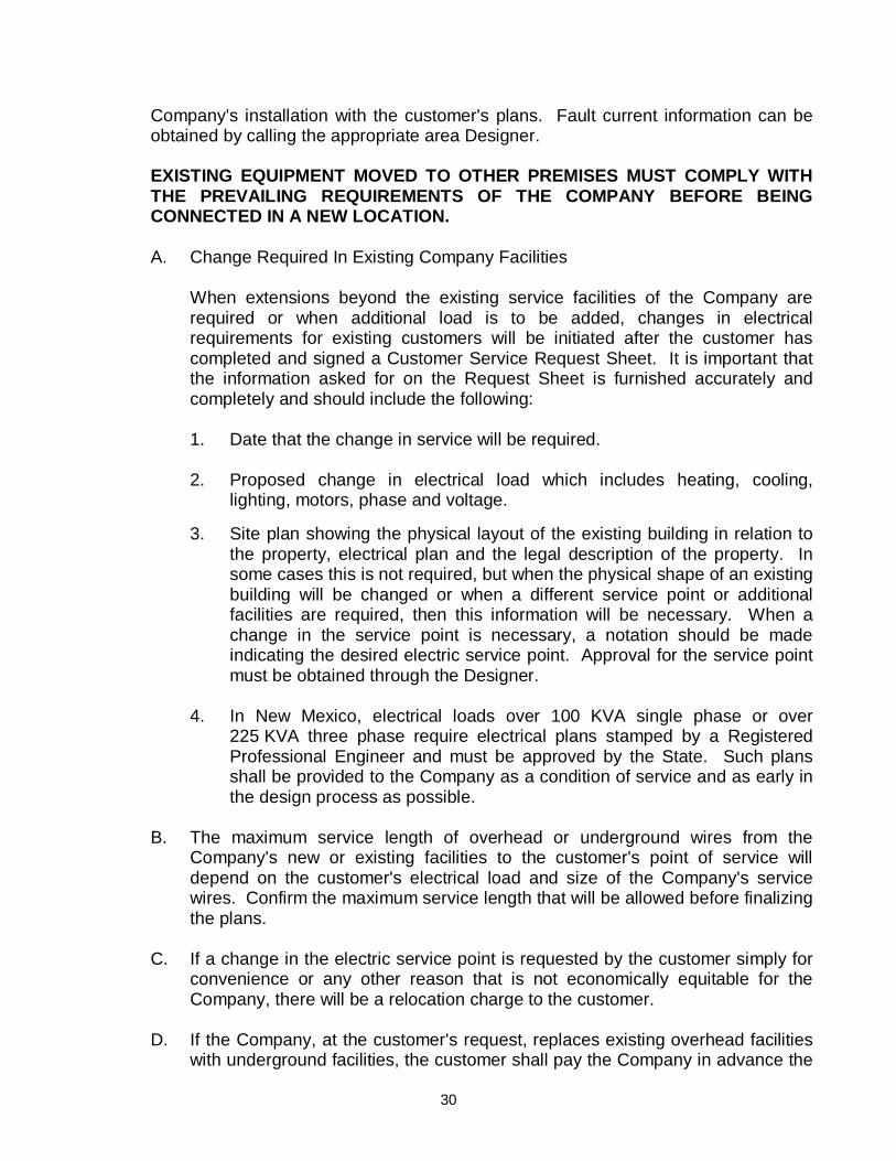
A. Change Required In Existing Company Facilities When extensions beyond the existing service facilities of the Company are
required or when additional load is to be added, changes in electrical requirements for existing customers will be initiated after the customer has completed and signed a Customer Service Request Sheet. It is important that the information asked for on the Request Sheet is furnished accurately and completely and should include the following:
1. Date that the change in service will be required. 2. Proposed change in electrical load which includes heating, cooling,
lighting, motors, phase and voltage. 3. Site plan showing the physical layout of the existing building in relation to
the property, electrical plan and the legal description of the property. In some cases this is not required, but when the physical shape of an existing building will be changed or when a different service point or additional facilities are required, then this information will be necessary. When a change in the service point is necessary, a notation should be made indicating the desired electric service point. Approval for the service point must be obtained through the Designer.
4. In New Mexico, electrical loads over 100 KVA single phase or over
225 KVA three phase require electrical plans stamped by a Registered Professional Engineer and must be approved by the State. Such plans shall be provided to the Company as a condition of service and as early in the design process as possible.
B. The maximum service length of overhead or underground wires from the
Company's new or existing facilities to the customer's point of service will depend on the customer's electrical load and size of the Company's service wires. Confirm the maximum service length that will be allowed before finalizing the plans.
C. If a change in the electric service point is requested by the customer simply for
convenience or any other reason that is not economically equitable for the Company, there will be a relocation charge to the customer.
D. If the Company, at the customer's request, replaces existing overhead facilities
with underground facilities, the customer shall pay the Company in advance the
31
estimated installed cost of the new underground facilities plus the estimated cost to remove the existing overhead facilities, less the estimated salvage value of the removed overhead facilities.
The Company will not make an underground "dip" in an overhead feeder line. If
a customer requests that the Company convert an overhead line to underground, the entire overhead line must be converted from the point it goes underground to the end of the line. This connection would be done at the customer's expense.
E. When changes or additions in a structure or building are made which
impair the clearance of service wires or make the Company's facilities and metering equipment inaccessible, the customer shall change the service entrance so that the Company can move the service to obtain proper clearance and/or maintain access to Company's facilities and metering equipment. If this change is necessary, the customer shall bear all costs incurred.
20. ACCESS TO CUSTOMER'S PREMISES The Company's representatives shall have free and easy access at any time to its
equipment on the premises of the customer and may remove its meters and equipment for proper cause.
21. ATTACHMENT TO COMPANY'S PROPERTY The use of Company poles, wires, towers, structures or other facilities for the
purpose of fastening or supporting any radio equipment, or any lights, wires, ropes, signs, banners or anything of any nature, not necessary to the supplying by the Company of electric service to the community, or the locating of same in such proximity to the Company's aforesaid property of facilities as to cause, or be likely to cause interference with the supply of electric service, or a dangerous condition in connection therewith, is prohibited and the Company shall have the right forthwith to remove same without notice, unless the Company's consent is given in writing.
22. EASEMENTS OR RIGHTS-OF-WAY The Company will not install any electrical facilities until all required easements or
rights-of-way have been obtained in writing from the owner or legally authorized agent representing the owner of the property. In extreme cases, it may require several months to obtain easements, so it is advantageous to the customer to notify the Company of his plans as early as possible.

32
23. PROTECTION OF COMPANY'S PROPERTY The customer shall properly protect the Company's property on the customer's
premises, and shall not permit anyone other than the Company's agents and persons authorized by law, to inspect or maintain the Company's wiring and apparatus. In the event of any loss or damage to Company's property caused by or arising out of carelessness, neglect, or misuse by the customer or other unauthorized parties, the cost of making good such loss or repairing such damage shall be paid by the customer.
24. RESPONSIBILITY FOR CUSTOMER'S INSTALLATIONS The Company will not be responsible for any accidents, fires, or failures which the
customer may sustain due to the condition or use of the customer's wiring installation or equipment. The Company reserves the right to refuse to connect its electric service to any new installations, and to disconnect any existing installations, should it come to the attention of and be determined by the Company that any such installation is unsafe. The customer has the sole responsibility of providing and installing the appropriate equipment to adequately protect 3 phase motors, etc., from damage in the event a single phasing condition might occur. The customer will also provide the proper protection against fault currents, low voltage, interruption of electrical service, etc.
25. RATES AND BILLINGS A. The customer must notify the Company at (575) 526-5555 in the New Mexico
area or at (915) 543-5970 in the Texas service area to ensure that the customer will be billed under the proper rate schedule when there has been a change in electrical requirements.
The Company will assist the temporary and permanent customer in the
selection of the rate schedule under which the customer is eligible to be billed. However, the Company will not be held responsible to refund any overcharge caused by failure on the part of the customer to select the appropriate rate schedule, or for failure on the part of the customer to promptly notify the Company of a change in customer's operations. The rate schedules and rules and regulations, which are approved and filed with the appropriate regulatory agencies, are available for customer's review upon request.
B. The Company will not be obligated to change any past consumption
history or make any billing adjustments due to a change in existing electrical requirements or usage.
26. METER PULSE OUTPUT FOR ENERGY MANAGEMENT EQUIPMENT The Company will provide electric kilowatt-hour (KWH) pulses to the customer for
use with energy management equipment. Time pulses will not be provided. These KWH pulses will be provided by pulse metering equipment installed by the Company. The customer pays the full cost of the installation. The customer must contact the appropriate area Designer for additional information and cost. Please see page 32
33
or a sample copy of the "Agreement and Terms and Conditions for Pulse Metering Equipment Installation."
27. FUTURE CHANGES IN POLICIES IN THIS BOOK The Company reserves the right to make changes in any policies, procedures,
methods, rules, etc., without advance notice to recipients of this book or to the general public. Where needed, the appropriate regulatory approval will be obtained before any changes are made. Other changes may be made at the Company's discretion due to technological or economic conditions.
28. CUSTOMER BACKUP GENERATORS Customers with backup generators shall install a transition or transfer switch. The
customer shall inform the Company of any transition or transfer switch installations or changes. The customer shall allow the Company to inspect and verify correct operation of any transition or transfer switch at any time. The Company prefers "open-transition" or "break-before-make" transfer switches for backup generators. Customers that install "close-transition" or "make-before-break" transfer switches must meet the Company's interconnection requirements for a co-generator.

34
AGREEMENT AND TERMS AND CONDITIONS FOR PULSE METERING EQUIPMENT INSTALLATION
El Paso Electric Company ("Company") and, __________ [an Electric Power and Energy end-user; or the written authorized representative of __________, an Electric Power and Energy end-user ("Customer") hereby agree that the provision of Pulse Metering Equipment will be governed by the Company's Tariff for Retail Delivery Service and this Agreement and Terms and Conditions for Pulse Metering Equipment Installation ("Agreement"). Upon the request of Customer, Company shall install, maintain, repair, replace, or remove Pulse Metering Equipment located at Company's Meter used for billing Delivery System Services in accordance with the following terms and conditions: 1. Company shall install Pulse Metering Equipment, including: pulse initiator, as needed;
external protective devices, as needed; junction box as needed; and necessary wiring and related materials and supplies up to a point for Customer's interconnection.
2. Customer shall be responsible for the installation and maintenance of all wiring and
equipment on Customer's side of the point of interconnection with Company's Pulse Metering Equipment.
3. Customer agrees that Company is not obligated to alter or adjust any meter reading
based on the equipment that Customer installs to receive the Electrical Pulses provided for herein and that Company in no way guarantees that Customer's equipment will operate satisfactorily.
4. Company shall charge and Customer shall pay (i) the installation charge as set forth in
Company's Tariff for Retail Delivery Service, or if there is no such charge, (ii) the difference in costs, if any, between the existing meter (or the standard meter if no meter is currently installed) and the cost of an advanced meter that meets Customer's requirements, or (iii) the actual cost of the installation requirements, which includes the actual cost of equipment, labor, and overheads necessary to provide pulse access, or (iv) an engineering estimate thereof. Customer shall remit payment to Company for the costs incurred under this paragraph by the due date shown on Company's invoice.
5. Only Company or Company's authorized representatives shall install, maintain, repair,
replace, or remove Pulse Metering Equipment. Company shall normally complete installation or removal of such equipment within thirty (30) days from the date request is made in accordance with Section 10. Normal installation times may be impacted by equipment availability or other factors beyond the reasonable control of Company. If Company determines that the installation time may exceed thirty (30) days, Company shall provide notice to customer pursuant to Section 11 of this agreement. Company shall provide notice to Customer's contact person as set forth in Section 11 of this Agreement when Pulse Metering Equipment installation is complete, including pulse multipliers for the meter, so that pulse data can be interpreted.

35
6. Company shall maintain, repair, or replace Pulse Metering Equipment installed hereunder, if and to the extent that such work is necessary to maintain the pulse access desired by Customer. If applicable, a charge for maintenance shall be optional, with Customer having the option whether to pay a monthly maintenance fee, rather than the cost of repair or replacement should such become necessary to maintain the pulse access desired by Customer. Company shall charge and Customer shall pay (i) the replacement charge, (ii) the actual cost of all required repairs/replacement, or (iii) an engineering estimate thereof. Company shall repair or replace only such Company equipment as requires repair or replacement.
7. If an isolation relay is used, under no circumstances shall Customer modify or interrupt
the operation of Company's relay and associated wiring. 8. Company shall have the right to interrupt the pulse circuit in accordance with the
provisions of the Company's tariff for Retail Delivery Service. 9. This Agreement may be amended, revised, or otherwise changed only by an appropriate
order of an Applicable Legal Authority. 10. All requests for Pulse Metering Equipment shall be in writing and must include the
following information: (a) Customer name; (b) Letter of authorization if Customer is other than an Electric Power and Energy end-
user; (c) Customer's authorized representative contact name, if applicable; (d) Customer's authorized representative contact phone number, if applicable; (e) ESI ID (if available); (f) Service address (including City and zip code); (g) Pulse data requested e.g. watt-hour, time, var-hour; (h) Billing/Invoice Information, including: Responsible Party; Billing Address; and (i) If Customer is not the owner of the premises upon which Pulse Metering
Equipment will be located, Customer shall represent that Company is fully authorized to enter the premises and to perform any reasonable effort necessary to install, maintain, repair, replace, or remove Pulse Metering Equipment.

36
11. All communications necessary in the administration and execution of this Agreement may be effectuated by contacting Company and Customer at the addresses and telephone numbers set forth below:
FOR COMPANY: EL PASO ELECTRIC COMPANY P. O. BOX 982 EL PASO, TEXAS 79901 Contact: Address: E-mail: Phone Number: Fax Number: FOR CUSTOMER: SERVICE ADDRESS: Contact: Address: E-mail: Phone Number: Fax Number: Either party may change the preceding designation by providing the other party with no
less than thirty (30) days advanced notification of such change. 12. Except as expressly provided by this Agreement, no provisions of this Agreement shall
revise, alter, modify, or amend Company's Tariff for Retail Delivery Service.

37
13. This Agreement shall commence upon the date of execution by both Parties (the "Effective Date") and shall terminate (a) upon mutual agreement of the Parties, or (b) written notification by Customer to Company that it request to terminate this Agreement; or (c) upon the effective date of a new agreement between the Parties.
14. Termination of this Agreement, for any reason, shall not relieve Company or Customer of
any obligation accrued or accruing prior to such termination. 15. This Agreement may be executed in two or more counterparts, each of which is deemed
an original but all constitute one and the same instrument. Company (insert name) El Paso Electric Company (legal signature) (date) Customer (insert name) (legal signature) (date)
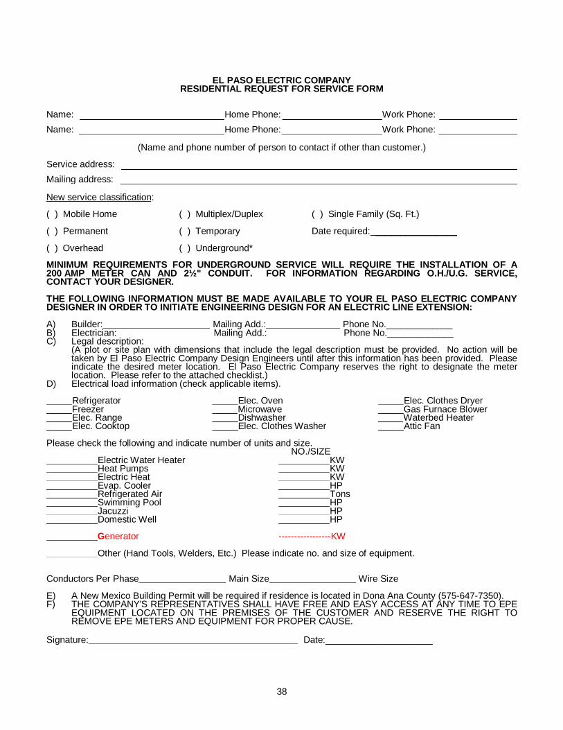
38
EL PASO ELECTRIC COMPANY RESIDENTIAL REQUEST FOR SERVICE FORM
Name: Home Phone: Work Phone: Name: Home Phone: Work Phone:
(Name and phone number of person to contact if other than customer.) Service address: Mailing address: New service classification: ( ) Mobile Home ( ) Multiplex/Duplex ( ) Single Family (Sq. Ft.) ( ) Permanent ( ) Temporary Date required: ________________ ( ) Overhead ( ) Underground* MINIMUM REQUIREMENTS FOR UNDERGROUND SERVICE WILL REQUIRE THE INSTALLATION OF A 200 AMP METER CAN AND 2½" CONDUIT. FOR INFORMATION REGARDING O.H./U.G. SERVICE, CONTACT YOUR DESIGNER. THE FOLLOWING INFORMATION MUST BE MADE AVAILABLE TO YOUR EL PASO ELECTRIC COMPANY DESIGNER IN ORDER TO INITIATE ENGINEERING DESIGN FOR AN ELECTRIC LINE EXTENSION: A) Builder: Mailing Add.: Phone No._____________ B) Electrician: Mailing Add.: Phone No._____________ C) Legal description:
(A plot or site plan with dimensions that include the legal description must be provided. No action will be taken by El Paso Electric Company Design Engineers until after this information has been provided. Please indicate the desired meter location. El Paso Electric Company reserves the right to designate the meter location. Please refer to the attached checklist.)
D) Electrical load information (check applicable items). Refrigerator Elec. Oven Elec. Clothes Dryer Freezer Microwave Gas Furnace Blower Elec. Range Dishwasher Waterbed Heater Elec. Cooktop Elec. Clothes Washer Attic Fan Please check the following and indicate number of units and size. NO./SIZE Electric Water Heater KW Heat Pumps KW Electric Heat KW Evap. Cooler HP Refrigerated Air Tons Swimming Pool HP Jacuzzi HP Domestic Well HP __________Generator -----------------KW Other (Hand Tools, Welders, Etc.) Please indicate no. and size of equipment. Conductors Per Phase Main Size Wire Size E) A New Mexico Building Permit will be required if residence is located in Dona Ana County (575-647-7350). F) THE COMPANY'S REPRESENTATIVES SHALL HAVE FREE AND EASY ACCESS AT ANY TIME TO EPE
EQUIPMENT LOCATED ON THE PREMISES OF THE CUSTOMER AND RESERVE THE RIGHT TO REMOVE EPE METERS AND EQUIPMENT FOR PROPER CAUSE.
Signature: Date:_____________________

39
EL PASO ELECTRIC COMPANY CHECKLIST A) Contact Designer or Engineer prior to construction.
Designer or Engineer:____________________________ Phone Number: ________________________________
B) Provide Designer or Engineer with Residential Request for Service Form. C) Provide Designer or Engineer with plot plan/site plan. An example is shown below.
YOUR PROPERTY&
LEGAL DESCRIPTIONPROPERTY PIN
NAME OF ROAD
NOTES1. PROPERTY PINSSHOULD BE VISIBLEIN THE FIELD.2. A COPY OF THELAND SURVEYWHEN AVAILABLE.
-N-
FT.
FT.
FT.
FT.
D) Confirmation of service location by EPE. Do not install any electrical facilities without approval
from EPE Designer or Engineer. EPE will designate the meter and service location. E) Process agreements and provide revenue guaranty if required.
* The customer may be required to secure construction charges in the form of cash, Letter of Credit, Certificate of Deposit or Withdrawal Restricted Savings Account. if the construction charges exceed customer’s projected revenue for four (4) years. The EPE Designer or Engineer will explain the details.
F) Install property pins which may be required prior to construction. G) Apply for service by calling (915) 521-4646 in Texas or (575) 523-3575 in New Mexico. This is
the property owner's responsibility. EPE requires that house numbers be attached to your house, meter pole or mobile home. The numbers must be 4" or larger. EPE will not accept cardboard posters or "stick on" numbers. EPE will also require the electrical permit number (New Mexico) or Texas release number at the time you place your application for service.
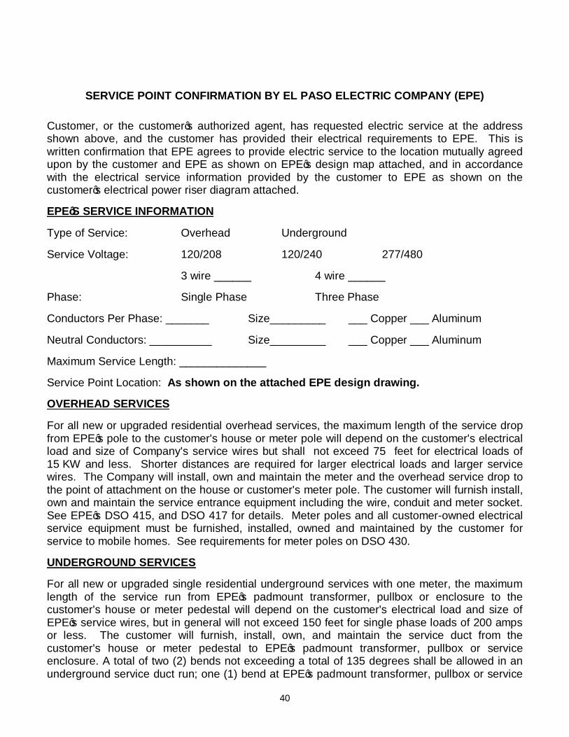
40
SERVICE POINT CONFIRMATION BY EL PASO ELECTRIC COMPANY (EPE)
Customer, or the customer’s authorized agent, has requested electric service at the address shown above, and the customer has provided their electrical requirements to EPE. This is written confirmation that EPE agrees to provide electric service to the location mutually agreed upon by the customer and EPE as shown on EPE’s design map attached, and in accordance with the electrical service information provided by the customer to EPE as shown on the customer’s electrical power riser diagram attached. EPE’S SERVICE INFORMATION Type of Service: Overhead Underground
Service Voltage: 120/208 120/240 277/480 3 wire ______ 4 wire ______ Phase: Single Phase Three Phase Conductors Per Phase: _______ Size_________ ___ Copper ___ Aluminum Neutral Conductors: __________ Size_________ ___ Copper ___ Aluminum Maximum Service Length: ______________ Service Point Location: As shown on the attached EPE design drawing. OVERHEAD SERVICES For all new or upgraded residential overhead services, the maximum length of the service drop from EPE’s pole to the customer's house or meter pole will depend on the customer's electrical load and size of Company's service wires but shall not exceed 75 feet for electrical loads of 15 KW and less. Shorter distances are required for larger electrical loads and larger service wires. The Company will install, own and maintain the meter and the overhead service drop to the point of attachment on the house or customer's meter pole. The customer will furnish install, own and maintain the service entrance equipment including the wire, conduit and meter socket. See EPE’s DSO 415, and DSO 417 for details. Meter poles and all customer-owned electrical service equipment must be furnished, installed, owned and maintained by the customer for service to mobile homes. See requirements for meter poles on DSO 430. UNDERGROUND SERVICES For all new or upgraded single residential underground services with one meter, the maximum length of the service run from EPE’s padmount transformer, pullbox or enclosure to the customer's house or meter pedestal will depend on the customer's electrical load and size of EPE’s service wires, but in general will not exceed 150 feet for single phase loads of 200 amps or less. The customer will furnish, install, own, and maintain the service duct from the customer's house or meter pedestal to EPE’s padmount transformer, pullbox or service enclosure. A total of two (2) bends not exceeding a total of 135 degrees shall be allowed in an underground service duct run; one (1) bend at EPE’s padmount transformer, pullbox or service

41
enclosure, and one (1) bend at the customer’s house or meter pedestal, and the underground service duct run must be a straight line from EPE’s padmount transformer, pullbox or service enclosure to the customer’s house or meter pedestal. EPE will own and maintain all structural facilities for secondary conductors up to and including the first service enclosure. EPE will furnish, install, own and maintain the meter and the service cable from the Company's padmount transformer, pullbox or service enclosure to the customer's service entrance at the house or meter pedestal. The location of the meter must be approved by EPE and shall be located at the nearest point on the house from EPE’s padmount transformer, pullbox or service enclosure. See DSU 420 for underground residential services to houses and manufactured homes set in place on a foundation. See DSU 1020 and DSU 1025 for underground residential services for mobile homes. Please note that a meter pole or meter pedestal must be installed for underground service to mobile homes. For all new or upgraded underground services to multiple residential customers where the residential units have their meters grouped and connected into a common gutter, the Point of Delivery shall be at EPE’s padmount transformer, pullbox or service enclosure as designated by EPE. The customer shall furnish, install, own and maintain the underground service duct and cable from the customer’s building to EPE’s padmount transformer, pullbox or service enclosure, which is the Point of Delivery. EPE will make the service connection between EPE-owned wires and customer-owned wires at this point. This policy applies to duplexes, multiplexes, apartments, condominiums, townhouses or other similar construction. The electrical contractor shall obtain approval from EPE for stack metering prior to customer purchasing and installing this type of metering. No more than four (4) meters stacked vertically shall be allowed for Company-approved stack metering. See DSU 1040 and DSU 1045 for the requirements and the separation between meters for this type of installation. Agreed to and Accepted by Customer: Signature:______________________________________ Print Name:_____________________________________ Title of Person Signing:____________________________ Date:__________________________________________ Agreed to and Accepted by EPE:
Signature:______________________________________ Print Name:_____________________________________ Title of Person Signing:____________________________ Date:__________________________________________
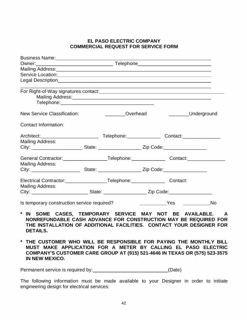
42
EL PASO ELECTRIC COMPANY
COMMERCIAL REQUEST FOR SERVICE FORM Business Name: Owner: Telephone Mailing Address: Service Location: Legal Description For Right-of-Way signatures contact:
Mailing Address: Telephone:
New Service Classification: Overhead Underground Contact Information: Architect: Telephone: Contact:______________ Mailing Address: City: ___________________ State: ________________ Zip Code:________________ General Contractor: Telephone: Contact:______________ Mailing Address: City: __________________ State: ________________ Zip Code:________________ Electrical Contractor: Telephone: Contact: Mailing Address: City: _____________________ State: ________________ Zip Code:________________ Is temporary construction service required? Yes No * IN SOME CASES, TEMPORARY SERVICE MAY NOT BE AVAILABLE. A
NONREFUNDABLE CASH ADVANCE FOR CONSTRUCTION MAY BE REQUIRED FOR THE INSTALLATION OF ADDITIONAL FACILITIES. CONTACT YOUR DESIGNER FOR DETAILS.
* THE CUSTOMER WHO WILL BE RESPONSIBLE FOR PAYING THE MONTHLY BILL
MUST MAKE APPLICATION FOR A METER BY CALLING EL PASO ELECTRIC COMPANY'S CUSTOMER CARE GROUP AT (915) 521-4646 IN TEXAS OR (575) 523-3575 IN NEW MEXICO.
Permanent service is required by: (Date) The following information must be made available to your Designer in order to initiate engineering design for electrical services:
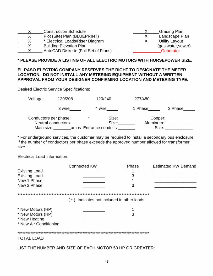
43
X Construction Schedule X Grading Plan X Plot (Site) Plan (BLUEPRINT) X Landscape Plan X * Electrical Loads/Riser Diagram X Utility Layout X Building Elevation Plan (gas,water,sewer) X AutoCAD Diskette (Full Set of Plans) __________ ___ Generator * PLEASE PROVIDE A LISTING OF ALL ELECTRIC MOTORS WITH HORSEPOWER SIZE. EL PASO ELECTRIC COMPANY RESERVES THE RIGHT TO DESIGNATE THE METER LOCATION. DO NOT INSTALL ANY METERING EQUIPMENT WITHOUT A WRITTEN APPROVAL FROM YOUR DESIGNER CONFIRMING LOCATION AND METERING TYPE. Desired Electric Service Specifications:
Voltage: 120/208 120/240_____ 277/480_____ 3 wire 4 wire 1 Phase 3 Phase_____
Conductors per phase: * Size: Copper:____________
Neutral conductors: Size: Aluminum: ____________ Main size: amps Entrance conduits: Size: ____________
* For underground services, the customer may be required to install a secondary bus enclosure if the number of conductors per phase exceeds the approved number allowed for transformer size. Electrical Load Information: Connected KW Phase Estimated KW Demand Existing Load 1 __________________ Existing Load 3 __________________ New 1 Phase 1 __________________ New 3 Phase 3 __________________ *********************************************************************************
( * ) Indicates not included in other loads. * New Motors (HP) 1 * New Motors (HP) 3 * New Heating * New Air Conditioning ********************************************************************************* TOTAL LOAD LIST THE NUMBER AND SIZE OF EACH MOTOR 50 HP OR GREATER:

44
____________________________________________________________________________ ____________________________________________________________________________ ____________________________________________________________________________ Special Request or Comments: ____________________________________________________________________________ ____________________________________________________________________________ * The Company's Representatives shall have free and easy access at any time to EPE
equipment located on the premises of the customer and reserve the right to remove EPE meters and equipment for just cause.
Signature:__________________________________ Date:__________________________
SERVICE POINT CONFIRMATION BY EL PASO ELECTRIC COMPANY (EPE) Customer, or the customer’s authorized agent, has requested electric service at the address shown above, and the customer has provided their electrical requirements to EPE. This is written confirmation that EPE agrees to provide electric service to the location mutually agreed upon by the customer and EPE as shown on EPE’s design map attached, and in accordance with the electrical service information provided by the customer to EPE as shown on the customer’s electrical power riser diagram attached. EPE’S SERVICE INFORMATION Type of Service: Overhead Underground Service Voltage: 120/208 120/240 277/480 3 wire ______ 4 wire ______ Phase: Single Phase Three Phase Conductors Per Phase: _______ Size_________ ___ Copper ___ Aluminum Neutral Conductors: __________ Size_________ ___ Copper ___ Aluminum Maximum Service Length: ______________ Service Point Location: As shown on the attached EPE design drawing.
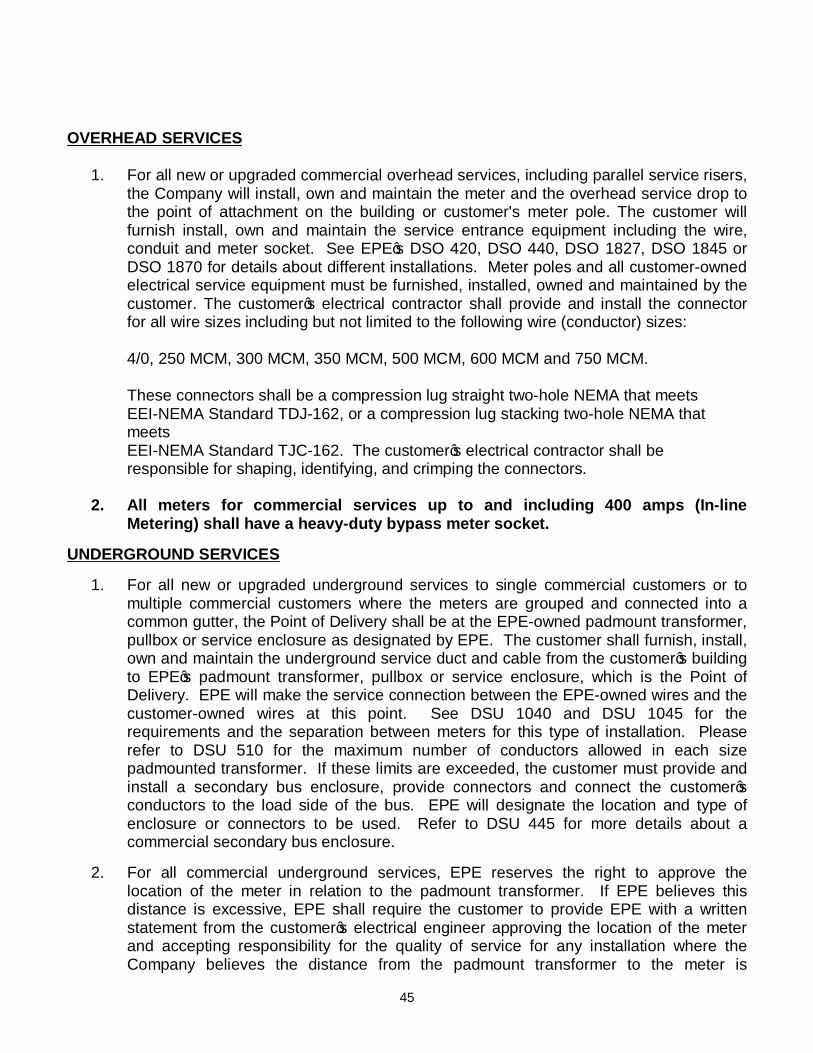
45
OVERHEAD SERVICES
1. For all new or upgraded commercial overhead services, including parallel service risers, the Company will install, own and maintain the meter and the overhead service drop to the point of attachment on the building or customer's meter pole. The customer will furnish install, own and maintain the service entrance equipment including the wire, conduit and meter socket. See EPE’s DSO 420, DSO 440, DSO 1827, DSO 1845 or DSO 1870 for details about different installations. Meter poles and all customer-owned electrical service equipment must be furnished, installed, owned and maintained by the customer. The customer’s electrical contractor shall provide and install the connector for all wire sizes including but not limited to the following wire (conductor) sizes:
4/0, 250 MCM, 300 MCM, 350 MCM, 500 MCM, 600 MCM and 750 MCM.
These connectors shall be a compression lug straight two-hole NEMA that meets EEI-NEMA Standard TDJ-162, or a compression lug stacking two-hole NEMA that meets
EEI-NEMA Standard TJC-162. The customer’s electrical contractor shall be responsible for shaping, identifying, and crimping the connectors.
2. All meters for commercial services up to and including 400 amps (In-line
Metering) shall have a heavy-duty bypass meter socket. UNDERGROUND SERVICES
1. For all new or upgraded underground services to single commercial customers or to multiple commercial customers where the meters are grouped and connected into a common gutter, the Point of Delivery shall be at the EPE-owned padmount transformer, pullbox or service enclosure as designated by EPE. The customer shall furnish, install, own and maintain the underground service duct and cable from the customer’s building to EPE’s padmount transformer, pullbox or service enclosure, which is the Point of Delivery. EPE will make the service connection between the EPE-owned wires and the customer-owned wires at this point. See DSU 1040 and DSU 1045 for the requirements and the separation between meters for this type of installation. Please refer to DSU 510 for the maximum number of conductors allowed in each size padmounted transformer. If these limits are exceeded, the customer must provide and install a secondary bus enclosure, provide connectors and connect the customer’s conductors to the load side of the bus. EPE will designate the location and type of enclosure or connectors to be used. Refer to DSU 445 for more details about a commercial secondary bus enclosure.
2. For all commercial underground services, EPE reserves the right to approve the
location of the meter in relation to the padmount transformer. If EPE believes this distance is excessive, EPE shall require the customer to provide EPE with a written statement from the customer’s electrical engineer approving the location of the meter and accepting responsibility for the quality of service for any installation where the Company believes the distance from the padmount transformer to the meter is
46
excessive. 3. All meters for commercial services up to and including 400 amps (In-line
Metering) shall have a heavy-duty bypass meter socket. 4. For all new or upgraded underground services to multiple residential customers where
the residential units have their meters grouped and connected into a common gutter, the Point of Delivery shall be at EPE’s padmount transformer, pullbox or service enclosure as designated by EPE. The customer shall furnish, install, own and maintain the underground service duct and cable from the customer’s building to EPE’s padmount transformer, pullbox or service enclosure, which is the Point of Delivery. EPE will make the service connection between EPE-owned wires and customer-owned wires at this point. This policy applies to duplexes, multiplexes, apartments, condominiums, townhouses or other similar construction. The electrical contractor shall obtain approval from EPE for stack metering prior to customer purchasing and installing this type of metering. No more than four (4) meters stacked vertically shall be allowed for Company-approved stack metering. See DSU 1040 and DSU 1045 for the requirements and the separation between meters for this type of installation.
5. Separate meters for services up to and including 400 amps that will be used for commercial or non-residential purposes services such as house meters for various uses for the property, parking lot lighting or lighting for other purposes, security systems, sprinkler systems, barns, sheds, storage buildings, domestic or irrigation water well, other types of buildings, etc., shall have a heavy-duty bypass meter socket and will be billed under the applicable commercial service rate tariff.
The customer, or the customer’s authorized agent, agrees to the preceding service point confirmation. Should the customer, or the customer’s authorized agent, make changes that have not been agreed to in writing by EPE, the customer understands additional costs may be billed to customer and must be paid by the customer before EPE continues with the work to provide electric service to the customer. Agreed to and Accepted by Customer:
Signature:______________________________________ Print Name:_____________________________________ Title of Person Signing:____________________________ Date:__________________________________________ Agreed to and Accepted by EPE:

47
Signature:______________________________________ Print Name:_____________________________________ Title of Person Signing:____________________________ Date:__________________________________________

48
EL PASO ELECTRIC COMPANY RESIDENTIAL SUBDIVISION REQUEST FOR SERVICE FORM
Business Name: Owner: Telephone Mailing Address: Service Location: Legal Description
For Right-of-Way signatures contact: Mailing Address: Telephone:
A) Subdivision Name: B) Block and Lot Numbers: Total Residential Lots: Total Commercial Lots: (Complete Commercial Request)
Total Street Lamps: Residential Homes sq. ft.:
All Electric? Yes No Refrigerated Air? Yes No (If Yes then) Number of units Size in tons: NEW SERVICE CLASSIFICATION:
Overhead Underground CONTRACTOR INFORMATION: Architect: Telephone: Contact: Mailing Address:
General Contractor: Telephone: Contact: Mailing Address:
Electrician: Telephone: Contact: Mailing Address: Is temporary construction service required? YES NO NOTE: IN SOME CASES, TEMPORARY SERVICE MAY NOT BE AVAILABLE. A NONREFUNDABLE CASH ADVANCE FOR CONSTRUCTION MAY BE REQUIRED FOR THE INSTALLATION OF ADDITIONAL FACILITIES. PLEASE CONTACT THE AREA DESIGNER FOR DETAILS. THE CONTRACTOR MUST MAKE APPLICATION FOR A METER BY CALLING EL PASO ELECTRIC COMPANY'S NEW SERVICE DESK AT 915 521-4646 IN TEXAS OR 575 523-3575 IN NEW MEXICO. Permanent service is required by: / / MO. DAY YR. The following information must be made available to the Designer who you are working with in order to initiate engineering design for electrical services: Construction Schedule Plot (Site) Plan (Blueprint) Grading Plan Building Elevation Plan *Electrical Loads/Riser Diagram Utility Layout Landscape Plan Auto Cad File

49
EL PASO ELECTRIC COMPANY RESERVES THE RIGHT TO DESIGNATE THE METER LOCATION. DO NOT INSTALL ANY METERING EQUIPMENT WITHOUT A WRITTEN APPROVAL FROM YOUR DESIGNER CONFIRMING LOCATION AND METERING TYPE. Residential electric service: Single Phase 120/240 Volt 3 Wire Residential main sizes: amps If other voltages are required please complete a separate Commercial Line Extension Request for Service Form. Special Request or Comments: *The Company's Representatives shall have free and easy access at any time to EPE equipment located on the premises of the customer and reserve the right to remove EPE meters and equipment for just cause. Signature Date

50
COUNTY OF EL PASO
ADMINISTRATION OF
CERTIFICATE OF PLAT COMPLIANCE
Headings
1. Authority 2. Who Can Request A Certificate of Plat Compliance 3. How to Request a Certificate of Plat Compliance 4. Issuance a Certificate of Plat Compliance 5. Issuance of a Blanket Certificate of Plat Compliance 1. Authority
The Texas Local Government Code, Section 232.028 requires that
CERTIFICATES OF PLAT COMPLIANCE be issued to the person(s) applying only after:
(A) The subdivider, owner or resident of a lot in a subdivision, has made the
request in writing, and (B) The County Commissioner's Court has approved a Plat. The Texas Local Government Code, Section 232.029 requires
(C) A utility may not serve or connect any subdivided land with water or sewer
services unless the utility receives a certificate issued by the County Commissioners Court or receive a determination from the Commissioners Court that a plat has been reviewed and approved by the County Commissioners Court.
(D) A utility may not serve or connect any subdivided land with electricity or gas
unless the entity receives a determination from the County Commissioners Court that adequate water and sewer services have been installed to service the subdivision.
2. Who Can Request A Certificate of Plat Compliance (A) Subdivider
(B) Owner of a lot in a subdivision

51
(C) Resident of lot in a subdivision (D) Entity that provides Utility Service 3. How to Request a Certificate of Plat Compliance (A) Submit a "REQUEST FOR CERTIFICATE OF PLAT COMPLIANCE"
(B) At a minimum, include a copy of the following:
1. Legal Description: Recorded Warranty Deed, Contract of Sale, or Recorded Executory
Contract of the property for which the certificate is being requested. 2. Water Service a. Public Water System: Proof of potable water, such as a copy of a current water utility bill, or
a certified letter from the utility company indicating water is available and will be provided of sufficient quality and quantity to meet the minimum Texas state standards.
b. Private Water Well: Certified letter from a certified laboratory indicating the water is of
sufficient quality and quantity to meet the minimum Texas state standards, along with the laboratory analysis and results.
3. Sewer Service: a. Public Sewer Service: Proof of sewer service, such as a copy of a current sewer utility bill, or
copy of contract for sewer services with utility company b. Septic System: Certified Registration Form or License to Operate for the Satisfaction
Installation of the On-site Sewage Disposal System from the El Paso City-County Health and Environmental District, indicating the septic system has been registered or inspected by the El Paso City-County Health and Environmental District.
C) Under special circumstances, the County of El Paso may request an affidavit
from the person applying and may issue a Certificate of Plat Compliance if the special circumstances comply with Texas State Statutes.
4. Issuance of a Certificate of Plat Compliance
The County of El Paso will review each request and shall make a determination whether the plat is in compliance with Texas state law and the County of El Paso Subdivision Requirements, within 20 days after the date it receives the request and shall issue the Certificate of Plat Compliance, if appropriate, within 10 days after the date the determinations are made.

52
The County of El Paso will return all plats that are not in compliance and request revisions. The 20-day duration for determination of compliance with Texas state laws and County of El Paso Subdivision Requirements and the 10-day duration for issuance of Certificate of Plat Compliance will begin again after receipt of the revised plat.
Temporary Certificate of Plat Compliance The County of El Paso will begin the issuance of temporary Certificate of Plat Compliance to allow for construction of residence, testing of water wells, or for other temporary needs as determined by the County. 90-day Temporary Certificate of Plat Compliance The request for a Temporary Certificate of Plat Compliance for temporary utility service for non-subdivided or non-platted properties will be for 90-days. An extension may be requested to extend the Temporary Certificate of Plat Compliance for an additional 90-days not to exceed a total of 180 days. The customer will be charged a processing fee for each request for Temporary Certificate of Plat Compliance and extension of Temporary Certificate of Plat Compliance, and Permanent Certificate of Plat Compliance. 180-day Temporary Certificate of Plat Compliance The request for a Temporary Certificate of Plat Compliance for temporary utility service for approved platted subdivisions will be for 180-days. An extension may be requested not to exceed 270 days. The customer will be charged a processing fee for each request for Temporary Certificate of Plat Compliance and extension of Temporary Certificate of Plat Compliance, and Permanent Certificate of Plat Compliance.
5. Issuance of a Blanket Certificate of Plat Compliance
A Blanket Certificate for Plat Compliance will be provided to a developer for subdivisions or plats that have been approved by the Commissioner's Court. The plat must be signed by the County Judge and must indicate compliance with Local Government Code § 232.028(a). Also, the final plat for this subdivision must have been recorded in the County Clerk's Office. Individual certificates of compliance are NOT required but may be issued if requested by the respective property owners. A copy of the recorded final plat will be provided along with the Blanket Certificate of Plat Compliance.

53
ELECTRICAL SAFETY DECALS/TIPS Dear Customer: El Paso Electric Company (EPE) is concerned about EPE employee safety, safety for you, your employees and the general public. EPE and contractors in the area may avoid needless accidents, injuries and expenses through a concerted effort. This letter identifies laws and regulations, which address safety around power lines. Federal law prohibits operation of equipment or machines closer than 20 feet to an overhead power line unless the power line has been deenergized and visibly grounded at the worksite. Specifically, it is a violation of the Occupational Health and Safety Act (OSHA), 29 C.F.R. 1926.1408 to operate equipment in a manner that persons or equipment could get closer than 20 feet to an energized power line. OSHA enforces these regulations, and violators may be subject to criminal and civil penalties. In Texas, Chapter 752 of the Texas Health and Safety Code requires that a contractor contact an electric utility company at least 48 hours before working near energized high voltage overhead lines. Once contacted, the electric utility company and contractor shall make a satisfactory mutual arrangement to prevent contact between the line and the material or equipment or the person performing the work, activity, or function. The contractor shall pay the electric utility company for all expenses incurred by the electric utility company to guard against danger by contact with the overhead power line. Before doing any work near overhead power lines, please contact EPE at (915) 877-3400 in El Paso or (575) 523-7591 in Las Cruces. If your company needs additional information or would like a presentation on electrical safety, please call (915) 543-4349 for assistance. Sincerely, Joel Hernandez Supervisor-Safety

54
BEFORE DIGGING OR TRENCHING CALL 1-800-344-8377 IN TEXAS
OR 1-800-321-ALERT (25378) IN NEW MEXICO
EL PASO ELECTRIC
ANTES DE EXCAVAR O ZANJAR LLAME 1-800-344-8377 EN TEXAS
O 1-800-321-ALERT (25378) EN NEW MEXICO
EL PASO ELECTRIC

55

56

57
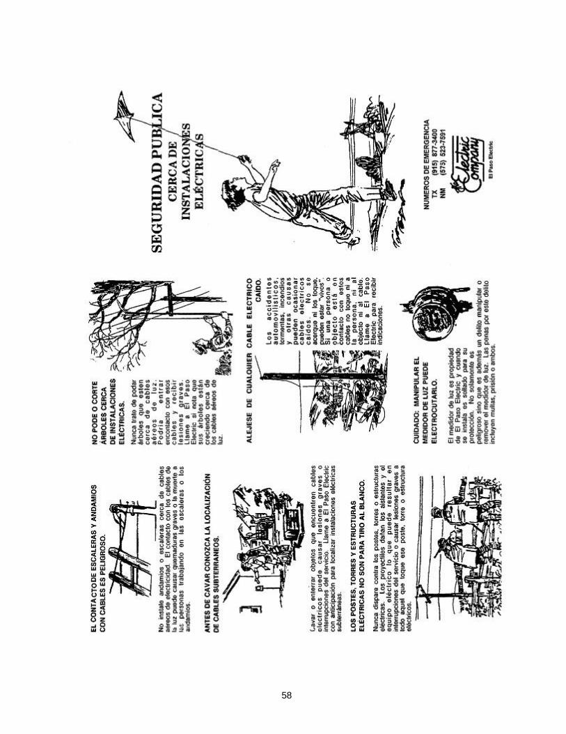
58

59


60
SECTION IV
TYPES OF SERVICE VOLTAGES AVAILABLE
1. GENERAL
The customer should contact the Company to determine the exact type of service which will be supplied at the premises to be served before purchasing any equipment or proceeding with the wiring of the project. Attention to this detail may avoid the purchase of equipment for which service is not available.
EXISTING EQUIPMENT MOVED TO OTHER PREMISES WITH A DIFFERENT TYPE OF SERVICE MUST COMPLY WITH THE PREVAILING REQUIREMENTS OF THE COMPANY BEFORE BEING CONNECTED IN A NEW LOCATION.
The Alternating Current Service supplied by the Company has a normal frequency of 60 hertz. The Company requires two (2) grounding conductors for every service.
Where an AC system at less than 1000 volts is grounded at any point, the grounded conductor(s) shall be run to each service disconnecting means and shall be connected to each disconnecting means grounded conductor(s) terminal or bus. A main bonding jumper shall connect the grounded conductor to each service disconnecting means enclosure. The grounded conductor(s) shall be installed in accordance with 250.24(C)(1) through 250.24 (C)(3) of the NEC.
2. TYPES OF ELECTRIC SERVICES GENERALLY AVAILABLE
The following types of service are generally available in the Company's service territory to customers served under the Company's standard rate schedules. All service will be taken at one point of delivery designated by the Company and at one of the Company's standard types of service. The Company will normally supply only one type of service and one set of conductors to a building. All electric energy will be measured by a single meter for each customer served. The Company is responsible for maintaining nominal voltage levels up to the point of delivery.
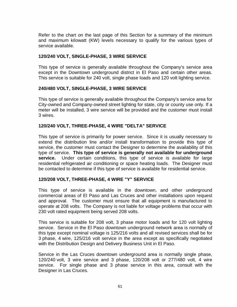
61
Refer to the chart on the last page of this Section for a summary of the minimum and maximum kilowatt (KW) levels necessary to qualify for the various types of service available.
120/240 VOLT, SINGLE-PHASE, 3 WIRE SERVICE
This type of service is generally available throughout the Company's service area except in the Downtown underground district in El Paso and certain other areas. This service is suitable for 240 volt, single phase loads and 120 volt lighting service.
240/480 VOLT, SINGLE-PHASE, 3 WIRE SERVICE
This type of service is generally available throughout the Company's service area for City-owned and Company-owned street lighting for state, city or county use only. If a meter will be installed, 3 wire service will be provided and the customer must install 3 wires. 120/240 VOLT, THREE-PHASE, 4 WIRE "DELTA" SERVICE
This type of service is primarily for power service. Since it is usually necessary to extend the distribution line and/or install transformation to provide this type of service, the customer must contact the Designer to determine the availability of this type of service. This type of service is generally not available for underground service. Under certain conditions, this type of service is available for large residential refrigerated air conditioning or space heating loads. The Designer must be contacted to determine if this type of service is available for residential service.
120/208 VOLT, THREE-PHASE, 4 WIRE "Y" SERVICE
This type of service is available in the downtown, and other underground commercial areas of El Paso and Las Cruces and other installations upon request and approval. The customer must ensure that all equipment is manufactured to operate at 208 volts. The Company is not liable for voltage problems that occur with 230 volt rated equipment being served 208 volts.
This service is suitable for 208 volt, 3 phase motor loads and for 120 volt lighting service. Service in the El Paso downtown underground network area is normally of this type except nominal voltage is 125/216 volts and all revised services shall be for 3 phase, 4 wire, 125/216 volt service in the area except as specifically negotiated with the Distribution Design and Delivery Business Unit in El Paso.
Service in the Las Cruces downtown underground area is normally single phase, 120/240 volt, 3 wire service and 3 phase, 120/208 volt or 277/480 volt, 4 wire service. For single phase and 3 phase service in this area, consult with the Designer in Las Cruces.

62
This type of service will necessitate the selection of motors or equipment which is specifically designed for operation at this specified voltage.
277/480 VOLT TRANSFORMER CONNECTIONS TO A CUSTOMER REQUIRING 480 VOLT, THREE-PHASE SERVICE FOR THREE-PHASE LOADS ONLY
This service is for three-phase loads only (i.e., irrigation pumps, water wells, etc.), where customer requires 480 volt, three-phase service for three-phase loads only. The Company will run 4 wires to the service delivery point. The customer shall run 4 wires, including the neutral, to the first service disconnecting means. The Company will not allow the customer to ground "one corner" of 480 volt service because of our transformer secondary connections. Customer must bring out an equipment ground to the point of service, which will be tied to the Company's system neutral, as per current National Electric Code. For equipment grounding conductor size, refer to current National Electric Code. All 120 and 240 volt equipment and lighting must be supplied by means of two winding transformers installed, owned and maintained by the customer.
277/480 VOLT, THREE-PHASE, 4 WIRE "Y" SERVICE
This type of service is available to serve approved loads upon special application to the Company. It is suitable for large nonresidential loads. 120 and 240 volt equipment and lighting must be supplied by means of two winding transformers installed, owned and maintained by the customer.
Single-phase 277/480 volt is not available.
NOTE: Whatever voltage is required by a customer regardless of the electrical
load on single-phase and 3 phase meter loops, the minimum rating on the service entrance equipment will be 100 amps. The Company is not liable for damage to customer's equipment due to installation of wrong circuit paneling.
TRANSMISSION OR PRIMARY VOLTAGE SERVICE
A. Primary voltage service can be made available for approved loads upon
special application to the Company. Nominal voltages available, as rated phase to phase, are: 4,160 volts, 13,800 volts, or 24,000 volts. Some voltages are not available in all areas of the Company's service territory. The supply of such service usually requires the customer to construct or install special facilities for connection and metering purposes on the customer's premises. The details of such construction and type of service are subject to special negotiations between the Company and the customer. Such details shall be secured by the customer in writing from the Designer.

63
B. Transmission voltage service (69,000 volts or 115,000 volts) availability is contingent upon many factors and will be negotiated with the Company. Six (6) months to two (2) years may be required to provide transmission voltage service, so adequate lead time should be given to the Company.
TYPES OF SERVICE AVAILABLE FOR CUSTOMER'S ELECTRICAL LOAD
(DEMAND) 1. Secondary Voltage Service
Voltage Service Type Demand Range (KVA)* 120/240, Single-Phase, 3 Wire Overhead 1 – 75 120/240, Three-Phase, 4 Wire, Delta Overhead 7½ – 112½ 120/208, Three-Phase, 4 Wire, Wye Overhead 20 – 112½ 277/480, Three-Phase, 4 Wire, Wye Overhead 30 – 225
120/240, Single-Phase, 3 Wire Underground 1 – 167 (up to 250 KVA in New Mexico)
120/208, Three-Phase, 4 Wire, Wye Underground 50 – 300 277/480, Three-Phase, 4 Wire, Wye Underground 150 – 2500
2. Primary Voltage Service (Overhead or Underground)
Voltage Demand Minimum (KVA)* 7,970 Single-Phase Line to Ground 200 13,800 Grd/7,970 Three-Phase 600 13,800 Single-Phase Line to Ground 300 23,900 Grd/13,800 Three-Phase 750 and above
*Demand range subject to modification by EPE.

64
SECTION V
MOTORS 1. SINGLE-PHASE OR THREE-PHASE
Motors of 5 horsepower or less shall normally be served single-phase. Motors of 7.5 horsepower or larger shall normally be served three-phase. When there are several fractional horsepower motors that will be operating simultaneously, they may be served three-phase if they meet the total KW demand requirements for three-phase in the desired voltage. However, the customer should discuss the specific installation and obtain written approval from the Company before purchasing and installing equipment.
2. MOTOR PROTECTION
Motors must be protected by the customer from all variations of circuit conditions both from customer load and utility source. The use of proper protective devices with suitable time delay in motor control switches is highly recommended. The Company is not responsible for protection of customer equipment. The Company assumes no responsibility for single-phasing damage to three-phase motors or any other equipment, which are unprotected or only partially protected against single- phase operation; or for any damage to single-phase or three-phase motors or any other equipment from any cause where proper protective equipment is not installed; or from failure of such protective equipment to function properly or in any case where switches, circuits, motors, etc., have been over fused.
3. MOTOR STARTING CURRENT REQUIREMENTS
In general, motor starting current shall not exceed four and one-half times the full load running current of the motor. No motor starting or any other individual load shall sag or dip primary voltage over 2.0% without written variance from the Company. The Company should be consulted for primary impedance information before large motors and related equipment is purchased or installed. The Company may request motor and motor starting information such as starting power factor. The Company assumes no responsibility for damage to single or 3 phase motors due to overload caused by not starting motors in sequence.
4. MOTORS FOR WELLS
A. Customers who desire electric service to a new well motor should contact the appropriate Designer before the pump motor is purchased. Motor name plate information must be provided (including starting currents and power factor), the

65
location of the well and planned riser (wiring), diagrams and main disconnect information. Please indicate if a pump motor is submersible or if vertical shaft.
B. If a line extension is required to serve the new well, the customer shall enter into
a written agreement covering the cost of the extension as set forth in the Company's Line Extension Policy. Wells and pumps should be located at least 35 feet away from Company lines.
C. If more than one well will be on the Company's line and depending upon the motor sizes, sequential starting of the motors may be required.
D. The following table details the service and voltage characteristics recommended
for electric service to water pumping motors when no other loads are involved:
Motor Size
Phase
Voltage
Secondary Connection
5 HP Single 120/240 7½ HP Single 120/240
*7½ HP Three 120/240 Delta *10 HP Three 120/240 Delta *20 HP Three 120/240 Delta
*25 HP and above Three 120/240 Delta 20 HP and above Three 277/480 Wye
* Available only in areas with overhead service.
Requests for any other voltage will be negotiated with the Company. 4,160 volts service is not available in all parts of the Company service area.
NOTES: 1. All three-phase services will be 4 wire with a grounded neutral and
a grounded conductor at the first service disconnecting means.
2. Some manufacturers of submersible pumps insist on and will guarantee three phase motors only served from a closed delta transformer bank. Notify the Company in these instances. The Company will not serve submersible or vertical shaft pumps from an open delta transformer bank.
3. Proposed voltage and metering requirements are to be designated
on the service inquiries by the Designer before work orders are prepared. Any changes in the voltage characteristics will be coordinated at the earliest possible date between the Company and the customer.
4. The Company recommends that all three-phase motors be
protected from single-phase conditions.

66
SECTION VI
METERING A. General Information
1. EL PASO ELECTRIC COMPANY RESERVES THE RIGHT TO DESIGNATE THE METER LOCATION. DO NOT INSTALL ANY METERING EQUIPMENT WITHOUT A WRITTEN APPROVAL FROM THE COMPANY CONFIRMING LOCATION AND METERING TYPE.
2. The Company will normally supply only one type of service and one set of
conductors to a building. All electric energy will be measured by a single meter for each customer served.
If more than one electrical service entrance to a building is desired, all
applicable building, fire and electrical codes must be met and must be approved in advance by the Company. The Customer shall pay, as a nonrefundable Contribution in aid of Construction (CIAC), for all costs associated with an additional service point. The Company reserves the right to refuse to provide multiple points of service if the multiple points of service causes problems for the Company or is not equitable for the Company.
As per Article 230.2(E) of the National Electrical Code, where a building or
structure is supplied by more than one service, a permanent plaque or directory shall be installed at each service disconnect location denoting all other services supplying that building or structure and the area served by each.
3. The service disconnecting means shall be a loadbreak rated meter
disconnect for all commercial services and a fusible meter disconnect for all residential services, and shall be installed on the exterior of the building or structure adjacent to and not more than 5 feet from the meter. The CT cabinet must also be installed on the exterior of the building or structure adjacent to and not more than 5 feet from the meter. Exceptions to this rule will be considered on a case by case basis. Exceptions to this rule may include, but not limited to, schools, jails, Federal Government facilities and buildings and other similar sites.
4. The Company requires two (2) grounding conductors for every service. 5. All meters for commercial services up to and including 400 amps (In-line
Metering) shall have a heavy-duty bypass meter socket. A heavy-duty
67
bypass meter socket is also required for all house meters and non-residential meters in apartment and multiple tenant complexes, shopping centers and other similar types of facilities. The customer’s service main size must match with the meter can rating. A larger main size shall not be used on a smaller meter can rating.
6. Locations with more than one meter are required to have the space
number on the meter can before the meter is installed. Meter cans need to be marked with stenciled or metal numbers or letters.
7. All meter enclosures (CT or in-line) are required to be grounded before
the meter is installed. 8. All meter enclosures shall be installed in such a manner that the top of
the meter opening is 5 feet from finished grade. Please refer to applicable DSO or DSU in Section XX.
9. Underground Mobile Home Park Pedestals: The minimum height is 3 feet and the maximum is 5 feet. 10. Locations with multiple meters served with one transformer: NO CT METERING WILL BE INSTALLED IN THE TRANSFORMERS,
including house meters. CT metering will be installed in a CT enclosure. 11. For all services between 401 amps and 1200 amps, the CT metering must
be installed in a Company-approved CT enclosure. 12. Contractors shall not utilize any Current Transformer (CT) metering
cabinet or metering equipment unless it has been depicted on the power riser diagram and pre-approved by the Company.
13. Power riser diagrams shall include the main size, fuse size, wire size,
model of CT cabinet, if applicable, and the location and distance of metering equipment in relation to the Company transformer.
14. All Company metering equipment shall be mounted on the exterior wall of
the building, per local inspection authorities. 15. The customer's electrical contractor shall contact the Company's
Designer before any construction (new or rebuild) is started to determine the type of service required, location of service, service connections, type and location of the meter and meter enclosure. All connectors and point of attachment devices furnished by the contractor for connection to Company equipment or wires shall be approved by the Company's Service Section. Riser conduit installed through a roof overhang must be high enough for the Company's service conductors to meet local safety

68
code clearance requirements. Refer to DSO's 417 and 1827. 16. Customer-owned service entrance equipment and Company-owned
meters shall not be installed on Company-owned poles or other Company-owned facilities.
17. All meters and services must have a system neutral at the first point of
disconnecting means in accordance with the NEC. The Company requires two (2) grounding conductors for every service.
18. All meter cans that are group-metered must be permanently marked with
the same address as the Company's CC&B system and in accordance with local government authorities.
19. For all new and upgraded commercial services, including apartment and
other multiple tenant complexes, power riser diagrams must be submitted with plans and the Request for Electric Service form for approval by the Company before the customer or electrician orders any electrical equipment or starts any electric work. The power riser diagram must be reviewed and approved by the Company’s Service and Meter Test Section management before customer applies for electric service.
20. The Company may disconnect Customer's service without prior notice for any
of the following reasons: (1) where a known dangerous condition exists for as long as the condition exists, (2) where service is connected without authority by a person who has not made application for service, (3) where service was reconnected without authority following termination of service for nonpayment, or (4) where there has been meter tampering with the Company's equipment or evidence of theft of service. Where reasonable, given the nature of the hazardous condition, the Company will post a notice of disconnection and the reason for the disconnection at the place of common entry or upon the front door of each affected residential or commercial unit as soon as possible after service has been disconnected. The Company reserves the right to disconnect, pull or remove power from any site it feels poses a safety hazard to the Company’s employees or the general public. Such services and meters will not be reconnected until the safety hazard has been corrected and/or the appropriate authority having jurisdiction has authorized the Company to reconnect the service. Any time the Company disconnects Customer’s service for any reason and prior to the Company’s installation of a new service and meter, the Customer’s new or upgraded service must meet the Company’s current electric service requirements in effect.
21. For all commercial underground services, the meter location and the
Customer’s main disconnect shall not exceed 20 feet from the Company's padmount transformer for services over 1200 amps and the meter location and the Customer’s main disconnect shall not exceed 75 feet from the Company's padmount transformer for services up to 1200 amps. If a meter stand is installed by the Customer, it should comply with DSU 1015 and not interfere
69
with the Company's operational clearance area. 22. In Texas and New Mexico, all new residential and commercial services must be
approved by the authorizing agent having jurisdiction. In Texas and New Mexico, this inspection and approval must be made by the authorized City, County or State Inspector. In the unincorporated areas of the Company’s Texas service territory, the Company is responsible for the inspection and approval of the customer’s wiring. All new residential and commercial services, including changes to existing residential and commercial services, are also subject to inspection approval by the Company.
23. All new residential and commercial services, including changes to existing
residential and commercial services, are also subject to inspection and approval by the Company in Texas and New Mexico.
24. High-Leg Marking on a 4-wire, delta-connected system where the midpoint of
one phase winding is grounded to supply lighting and similar loads, the conductor or busbar having the higher phase voltage to ground shall be durably and permanently marked by an outer finish that is orange in color or by other effective means. This is in accordance with the NEC, Article 110.15.
B. Meter Location
1. EL PASO ELECTRIC COMPANY RESERVES THE RIGHT TO DESIGNATE THE METER LOCATION. DO NOT INSTALL ANY METERING EQUIPMENT WITHOUT A WRITTEN APPROVAL FROM THE COMPANY CONFIRMING LOCATION AND METERING TYPE.
2. The location of meters is an important consideration to both the customer and
the Company and shall be designated by the Company. In all cases meters shall be located in a readily accessible place for convenience in reading, testing and servicing. Meters shall be located on a substantial wall or pole, free from vibration and safe from physical damage. For the mutual convenience of our customers and the Company, meters shall be installed outdoors and shall not be installed in enclosed backyards. THE METER ENCLOSURE SHALL BE INSTALLED IN SUCH A MANNER THAT THE TOP OF THE ENCLOSURE IS 5 FEET FROM THE FINISHED GRADE. For all meters installed in a frame or pedestal in underground-served mobile home parks or subdivisions, the minimum height is 3 feet and the maximum height is 5 feet. See DSU 1025 in Section XX for this type of installation.
Meters shall be accessible at all times to the Company. Meters shall not
be installed on Company-owned poles or other Company-owned facilities. Larger commercial and industrial services usually require extensive metering equipment with corresponding increased space requirements. These installations often require detailed consultation between the customer and Company representatives. Company representatives are readily available to assist customers or their consultants, contractors,
70
etc., in the location of their service entrance facilities and metering installation. Customers are encouraged to request assistance from the Company through the Designer.
3. When structure changes or additions are made which make the meter
inaccessible as indicated above, the customer shall move the service entrance, including metering devices and disconnects and at the customer's expense, to a suitable new location approved by the Company. When the customer has to repair or make changes in the service entrance facilities, the meter enclosure installation shall also be changed by the customer at his expense in order to meet the Company's prevailing specifications, prevailing National Electric Code, and other applicable electrical ordinances and codes in effect in the area served.
4. Meters and necessary instrument transformers (current transformers - "CT's"
and potential transformers - "PT's") and testing devices are furnished, installed and maintained by the Company. Meters and metering devices remain the property of the Company and must not be moved or the connection changed by any person other than the authorized employees of the Company.
5. All separately metered fire pumps must have corresponding size
disconnects and wire sizing adjacent to the main service metering. Meter and disconnect shall be installed on the exterior of the building or structure adjacent to and within 5 feet of each other. The power riser diagram for this installation must be approved in advance by the Company and included in the Service Point Confirmation (see paragraph A16. on page 61).
6. The main disconnect and meter shall be installed on the exterior of the building
or structure adjacent to and within 5 feet of one another. The ATS can be service rated.
7. Please see Section XIX for renewable energy and cogeneration projects and
see Section XX for generation utilized for backup support for customer loads. C. Meter Sealing Program and Energy Diversion (Theft) 1. Meters are sealed for the customer's and Company's protection and seals must
not be disturbed. The Company has an intensive electric meter seal check program as the result of tampering and meter socket jumpering, including those associated with new service at construction sites. These unsafe practices endanger people on the job as well as the general public. All electrical contractors and builders are requested to assist in eliminating meter jumpering and help in controlling losses caused by damaged meters and meter tampering.
THEFT OF ENERGY IS A CRIMINAL OFFENSE AND OFFENDERS WILL BE
PROSECUTED.
71
Energy theft is a serious issue that is not only against the law, it is also very dangerous. While honest customers are working hard to conserve energy and cut energy costs, energy thieves are tampering with service lines and meters and helping themselves to "free service".
Energy theft, also called energy diversion, occurs when individuals tamper with
meters or electric power lines including unauthorized connection of a Company meter, inverting meters, moving a meter from one location to another location, bypass wiring in meter cans and line taps to service conductors. These practices can create unsafe conditions that can result in electrical shock, explosions, fires, injury or death.
The Company takes theft of service very seriously, prosecuting cases of theft of
service to the fullest extent of the law. Cost recovery in the case of energy theft includes the cost of the electric energy used, an Energy Diversion Charge covering the cost of the investigation, the expense of damaged Electric Company property, and the expense of crews needed to replace or repair equipment damaged in the course of energy theft.
We all have a stake in this issue. If you have questions, please call the
Company at 915-543-2071 or 915-543-4152. If you would like to report suspected energy theft, please call the Company in Texas at 915-543-5979, in New Mexico at 575-523-3551, or send an e-mail to: [email protected]. All calls, or e-mails, are kept confidential.
TOGETHER WE CAN MAKE A DIFFERENCE.
2. If the contractor finds it necessary to remove a meter, he must notify the
Company before breaking the seal by calling the service number listed above and providing his name, the meter address and the meter number. The meter number must have a manufacturer's prefix letter in front of the number (I for Itron, G for General Electric, W for Westinghouse and ABB, S for Sangamo and Schlumberger, and L for Landis/Gyr and Duncan - for example, S-1372640). Failure to provide this prior notice may result in legal action against the customer by the Company. Meter sockets found with broken seals or jumpers may be considered evidence of intentional theft of electrical energy and will be dealt with accordingly.
D. Furnishing and Installation of Meter Sockets or Enclosures 1. The customer (or his builder, electrical contractor, etc.) must furnish the meter
sockets and meter enclosures (also known as meter cans) approved by the Company to be installed by the customer's electrical contractor. The meter socket or enclosure is owned by the customer, who is responsible for all repair and maintenance needed to ensure a safe and reliable installation. The permanent meter enclosure shall be securely fastened to the wall, pole, etc., and shall not rely on conduits or risers for the sole support. Electrical contractors are responsible for marking meter enclosures accurately with

72
permanent numbers or letters to correspond to the correct unit, apartments or commercial suites. The customer's electrical contractor in all cases furnishes and installs all service entrance equipment and metering conduit for suitable and complete installations in a manner approved by the Company. The Company has the right at any time to install locks, locking devices, protective covers, etc., on the meter enclosures or sockets to protect and secure the Company's meters and metering equipment. The customer shall not tamper with these locks, etc., in any way. Evidence of tampering may result in an immediate disconnection of service and appropriate charges.
2. The meter or instrument transformer enclosures must not be used as a terminal
point for more than one load circuit. All self-contained metering is designed to receive only one conductor per phase and one ground conductor. The Company reserves the right to require no more than one conductor per phase, as long as applicable electric codes can be met.
3. The Company will not permit the connection of any customer's equipment to
the Company's metering equipment or circuits. If a customer needs kilowatt-hour (KWH) pulses for use with an energy management system, the Company will provide and install pulse metering equipment at the customer's expense. See page 34 for additional information.
4. All services will be reviewed by the Company to determine the type of metering
and meter enclosures to be installed in each situation. The electrical contractor shall purchase and install only meter sockets or enclosures that the Company has approved. The electrical contractor shall contact a Designer or the Meter Testing Department to verify the type or meter enclosure to be used on a job before purchasing or installing the enclosure. A list of approved meter enclosures may be obtained from the Designer. Service requiring instrument transformers of multiple conductors per phase must be approved by the Company and approval obtained in writing for the Designer before proceeding with any work.
5. For all commercial underground services, the Company reserves the right
to approve the location of the meter in relation to the padmount transformer. This approval by the Company should be obtained by the Customer before any work is done by the electrical contractor.
6. Refer to Section XXI for Company standard drawings of typical meter
installations.
7. Meters shall not be installed in vaults, enclosed or confined spaces, locked cabinets or any place that is not accessible to authorized Company employees on a 24/7 hour basis.
E. Company Policy For Overhead Service to Multiple Residential and
Commercial Customers With Grouped Electrical Meters and Gutter
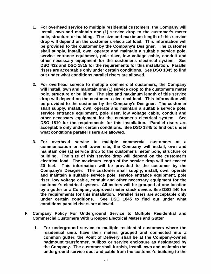
73
1. For overhead service to multiple residential customers, the Company will install, own and maintain one (1) service drop to the customer's meter pole, structure or building. The size and maximum length of this service drop will depend on the customer's electrical load. This information will be provided to the customer by the Company's Designer. The customer shall supply, install, own, operate and maintain a suitable service pole, service entrance equipment, pole riser, low voltage cable, conduit and other necessary equipment for the customer's electrical system. See DSO 432 and DSO 1815 for the requirements for this installation. Parallel risers are acceptable only under certain conditions. See DSO 1845 to find out under what conditions parallel risers are allowed.
2. For overhead service to multiple commercial customers, the Company
will install, own and maintain one (1) service drop to the customer's meter pole, structure or building. The size and maximum length of this service drop will depend on the customer's electrical load. This information will be provided to the customer by the Company's Designer. The customer shall supply, install, own, operate and maintain a suitable service pole, service entrance equipment, pole riser, low voltage cable, conduit and other necessary equipment for the customer's electrical system. See DSO 1810 for the requirements for this installation. Parallel risers are acceptable only under certain conditions. See DSO 1845 to find out under what conditions parallel risers are allowed.
3. For overhead service to multiple commercial customers at a
communication or cell tower site, the Company will install, own and maintain one (1) service drop to the customer's meter pole, structure or building. The size of this service drop will depend on the customer's electrical load. The maximum length of the service drop will not exceed 20 feet. This information will be provided to the customer by the Company's Designer. The customer shall supply, install, own, operate and maintain a suitable service pole, service entrance equipment, pole riser, low voltage cable, conduit and other necessary equipment for the customer's electrical system. All meters will be grouped at one location by a gutter or a Company-approved meter stack device. See DSO 440 for the requirements for this installation. Parallel risers are acceptable only under certain conditions. See DSO 1845 to find out under what conditions parallel risers are allowed.
F. Company Policy For Underground Service to Multiple Residential and
Commercial Customers With Grouped Electrical Meters and Gutter
1. For underground service to multiple residential customers where the residential units have their meters grouped and connected into a common gutter, the Point of Delivery shall be at the Company-owned padmount transformer, pullbox or service enclosure as designated by the Company. The customer shall furnish, install, own and maintain the underground service duct and cable from the customer's building to the
74
Company's padmount transformer, pullbox or service enclosure, which is the Point of Delivery. The Company will make the service connection between the Company-owned wires and customer-owned wires at this point. This policy applies to duplexes, multiplexes, apartments, condominiums, townhouses or other similar construction. The electrical contractor shall obtain approval from the Company for stack metering prior to purchase and installation. No more than four (4) meters stacked vertically shall be allowed for Company-approved stack metering. See DSU 1040 and DSU 1045 for the requirements and the separation between meters for this type of installation.
2. For underground service to multiple commercial customers where the
meters are grouped and connected into a common gutter, the Point of Delivery shall be at the Company-owned padmount transformer, pullbox or service enclosure as designated by the Company. The customer shall furnish, install, own and maintain the underground service duct and cable from the customer's building to the Company's padmount transformer, pullbox or service enclosure, which is the Point of Delivery. The Company will make the service connection between the Company-owned wires and customer-owned wires at this point. This policy also applies to communication and cell tower sites or other similar types of customers. At communication and cell tower sites and other similar types of customers, the meters must be grouped and connected into a common gutter for multiple customers. No more than four (4) meters stacked vertically shall be allowed for Company-approved stack metering. See DSU 1040 and DSU 1045 for the requirements and the separation between meters for this type of installation. Please refer to DSU 510 for the maximum number of conductors allowed in each size padmounted transformer. If these limits are exceeded, the customer must provide and install a secondary bus enclosure, provide connectors and connect the customer's conductors to the load side of the bus. The Company will designate the location and type of enclosure or connector to be used. Refer to DSU 445 for more details about a commercial secondary bus enclosure.
G. SERVICE ENTRANCE REQUIREMENTS FOR INSTRUMENT TRANSFORMERS
AND HEAVY-DUTY METERS SERVED FROM AN OVERHEAD SYSTEM 1. Current Transformer (CT) Metering The Company will determine when CT's will be installed based upon the
customer's service main size. The Company can require the electrical contractor or consultant to install one larger conductor per phase instead of multiple smaller conductors per phase if it would allow the use of self-contained metering and still meet all applicable codes. IT IS EXTREMELY IMPORTANT TO VERIFY WITH THE COMPANY IN ADVANCE WHETHER METERING WILL BE IN-LINE OR CT.
a. The service disconnecting means for services rated 800 amps or less

75
shall be a loadbreak rated meter disconnect and shall be installed on the exterior of the building or structure adjacent to and not more than 5 feet from the meter.
b. CT metering is required for all services over 400 amps. A Company-
approved CT enclosure, in addition to the regular meter enclosure, is required and must be installed by the electrical contractor. The meter enclosure must be within 5 feet of the CT enclosure.
c. If there is more than one meter at a service, a gutter must be used. If
one of the meters requires CT's, the electrical contractor will provide, install and maintain a CT enclosure in addition to the regular meter enclosure. The Company will provide and install CT's in the can and the electrician will run the conductors from the gutter to the CT enclosure. The electrician makes the connections at both ends. The Company will inspect the gutter, CT's and meter to ensure proper installation and then seal the CT can.
d. Meter cans and other metering equipment shall not be used as a raceway
for any type of sub feed or for any other device. 2. In-line Metering
a. In-line metering will accommodate a maximum of two (2) parallel risers under certain conditions and shall be installed by the electrical contractor. In-line metering enclosures approved by the Company can accommodate a maximum of one 500 MCM conductor (copper or aluminum) per phase, or as allowed by the approved UL rating, for a demand load ampacity not greater than 400 amps. All class 320 amp meter cans shall have a Company-approved heavy duty lever bypass.
b. For class 200 amp meter cans, only one conductor per phase is allowed and the maximum size conductor shall comply with the manufacturers' specifications. All class 200 meter cans shall have a Company-approved heavy-duty bypass meter socket. Bypass meter sockets not approved by the Company are not allowed. The minimum size wire on a class 200 meter can is #4 copper or #2 aluminum. When using a meter can for a three phase, 120/240 volt service with a high leg, the high leg must be positioned so that the high leg is in the far right position located on the meter socket.
c. For class 320 amp meter cans that will accept dual conductors per phase, the Company will allow a minimum wire size of 4/0 copper to be paralleled. The meter can shall be suitable to accept multiple conductors, as per the approved UL rating of the meter can. A maximum of two conductors per phase will be allowed on both the line side and the load side of the meter can. Parallel risers shall be allowed for either overhead or underground services, except for single residential underground services. All class 320 meter cans shall have a Company-approved
76
heavy-duty bypass meter socket. Bypass meter sockets not approved by the Company are not allowed. When using a meter can for a three phase with a high leg, the high leg must be positioned so that the high leg is in the far right position located on the meter socket.
d. All grouped meter cans must be connected by a gutter. If a new customer
is added to the existing service, the new meter can shall be connected through the existing gutter or modified to accept the service off the existing guttered service. Multiple isolated runs of conduit shall not be permitted.
3. Primary Voltage Meter on Overhead System
a. Refer to Primary Voltage Service Chart in Section IV, Page 64, for primary voltage service demand load requirements. Normally primary service is not available off the 4 KV system. The Company will install the metering equipment on a Company-installed pole. The customer will install a dead-end pole with the height and guy wires as specified by the Company. The customer's pole location will be designated by the Company. The customer must provide and install an appropriate gang-operated load interrupter switch and over current protection on the pole and the Company will run and connect its conductors to the switch. Company approval for primary service, associated switch and over current protection must be obtained in advance. The Company will designate the size and type of overcurrent protection installed by the customer. The customer provides the meter enclosure and the conduit and the Company installs it on the Company pole. Please refer to DSO for primary voltage meter installations on overhead systems.
b. In order to prevent interruption to the daily operations of a customer and for
the Company to maintain easy access to its facilities at all times, the Company may require the customer to take primary metered service at a
location that is mutually agreeable to the customer and the Company. This applies to high security areas such as, but not limited to, local, state and federal jails, prisons or detention centers, medical facilities, Homeland Security facilities and all other types of high security facilities.
c. The Company has added a single-phase primary metering sequential by-
pass switch for single-phase primary metering. Please see the Company’s Distribution Standards for the requirements for this type of service.
H. SERVICE ENTRANCE REQUIREMENTS FOR INSTRUMENT TRANSFORMERS
(CT'S) AND HEAVY-DUTY METERS SERVED FROM AN UNDERGROUND SYSTEM
1. When a customer is served underground, the following requirements must be
considered. The service point where the customer's secondary conductors are connected to

77
the Company's conductors or facilities will be at one of the following:
• Secondary bushings of the Company's transformer
• Secondary service enclosure installed by the Company
• Secondary bus enclosure installed by the customer
• Secondary submersible bus bar set screw connector terminator and junction box installed by the customer.
The Company will designate the type and location of the service point. Refer to
DSU 510 for the maximum number of conductors allowed in each size padmounted transformer and DSU 405 for the limits on secondary service enclosures. If these limits are exceeded, the customer must provide and install a secondary bus enclosure or submersible bus bar set screw connector and enclosure or pedestal, provide his own connectors and connect his conductors to the load side of the bus. The Company will designate the location and type of enclosure or connector to be used. The location of the secondary bus enclosure shall normally not be more than ten (10) feet from the padmount transformer. The Company provides and installs connectors for the customer's conductors at the Company furnished service point only for the Company's standard conductor sizes:
No. 2, 1/0, 4/0 250 MCM and 350 MCM, 500 MCM, 750 MCM, aluminum or copper On nonstandard size conductors, the connectors will be furnished and installed
by the electrical contractor. Wire terminations will be with compression connectors that have two 9/16" holes with NEMA drilling on 1-3/4" centers.
2. In-line Metering a. In-line metering will accommodate parallel risers under certain conditions
and shall be installed by the electrical contractor. In-line metering enclosures approved by the Company can accommodate a maximum of one 500 MCM conductor (copper or aluminum) per phase, or as allowed by the approved UL rating, for a demand load ampacity not greater than 400 amps.
b. For class 200 amp meter cans, only one conductor per phase is allowed
and the maximum size conductor shall comply with the manufacturers' specifications. All class 200 meter cans shall have a Company-approved heavy-duty bypass meter socket. Bypass meter sockets not approved by the Company are not allowed. The minimum size wire on a class 200 meter can is #4 copper or #2 aluminum. When using a meter can for a three phase, 120/240 volt service with a high leg, the high leg must be positioned so that the high leg is in the far right position located on the meter socket.

78
c. For class 320 amp meter cans that will accept dual conductors per phase,
the Company will allow a minimum wire size of 4/0 (copper or aluminum) to be paralleled. The meter can shall be suitable to accept multiple conductors, as per the approved UL rating of the meter can. A maximum of two conductors per phase will be allowed on both the line side and the load side of the meter can. Parallel risers shall be allowed for either overhead or underground services, except for single residential underground services. All class 320 meter cans shall have a Company-approved heavy-duty bypass meter socket. Bypass meter sockets not approved by the Company are not allowed. When using a meter can for a three phase with a high leg, the high leg must be positioned so that the high leg is in the far right position located on the meter socket.
d. All grouped meter cans must be connected by a gutter. If a new customer
is added to the existing service, the new meter can shall be connected through the existing gutter or modified to accept the service off the existing guttered service. Multiple isolated runs of conduit shall not be permitted.
3. CT Metering a. When a transformer serves just one customer, the CT's will be installed
within the transformer housing for services greater than 1200 amps. For services greater than 1200 amps, the meter enclosure must be within 20 feet of the CT's. The meter stand is not to be bolted or connected to the transformer or transformer pad. See DSU 1015 for specifications. When CT's are used, the customer's cable must be long enough to pass through the CT's and still reach the transformer bushing in compliance with DSU 440.
For services between 401 amps and 1200 amps or if more than one
customer is being served from the transformer, the electrical contractor shall provide and install a Company approved enclosure for the CT's (in addition to the meter enclosure) on the building wall or on a meter stand. The meter stand is not to be bolted or connected to the transformer or the transformer pad. See DSU 1015 for specifications. The meter enclosure must be within 5 feet of the CT enclosure.
b. For all commercial underground services, the Company reserves the
right to approve the location of the meter in relation to the padmount transformer. If the Company believes this distance is excessive, prior to the Company's approval and before any work is done by the electrical contractor, the customer shall provide the Company a written statement from the customer's electrical engineer approving the location of the meter and accepting responsibility for the quality of service for any installation where the Company believes the distance from the padmount transformer to the meter is excessive.
c. Customers requiring an underground vault or ground-level vault shall
furnish drawings in advance for written approval by the Company. For

79
customers who terminate inside a vault with a bus duct, refer to Paragraph II-B in this section for bus duct termination. If customer brings flexible conductors into the vault, the conductors shall be long enough to pass through the current transformers and to reach the transformer terminals or overhead bus. Connectors will be furnished by the Company if standard Company size.
4. Primary Voltage Meters on Underground System a. Refer to Primary Voltage Service Chart in Section IV, Page 63, for primary
voltage service demand load requirements. Normally primary service is not available off the 4 KV system. The Company will install the primary metering equipment in a padmounted meter transclosure furnished and installed by the Company at a location designated by the Company. The customer shall provide and install a meter enclosure within 20 feet of the instrument transformers as specified by the Company. The customer must provide and install an appropriate gang-operated load interrupter switch and over current protection on the load side of the Company's meter enclosure. All primary voltage service requests and associated switch and over current protection must be approved in advance for each situation. The Company will designate the size and type of overcurrent protection installed by the customer.
b. In order to prevent interruption to the daily operations of a customer and for
the Company to maintain easy access to its facilities at all times, the Company may require the customer to take primary metered service at a
location that is mutually agreeable to the customer and the Company. This applies to high security areas such as, but not limited to, local, state and federal jails, prisons or detention centers, medical facilities, Homeland Security facilities and all other types of high security facilities.
I. EL PASO ELECTRIC COMPANY APPROVED RESIDENTIAL METER
ENCLOSURE AND SOCKETS 1. Approved meter sockets are shown on the following pages. 2 Any meter sockets not shown must be approved by a representative of the
Company and must meet the meter socket specification. 3. Electricians shall not use meter cans as a raceway for their copper
grounding wire. As per Article 250.24(A)(1) of the National Electrical Code:
"…connection shall be made at any accessible point from the load end of
the service drop or service lateral to and including the terminal or bus to which the grounded service conductor is connected at the service disconnect means."
Meter cans are not to be accessible to anyone but Company personnel.
The only grounding location is at the nipple of the conduit used to carry the load service wires. Grounding wire shall not be pulled through the

80
meter can or attached to system neutral.

81
EPE APPROVED METER CAN LISTING (REVISED JANUARY 18, 2016)
MANUFACTURER MODEL NUMBER CHARACTERISTICS
SINGLE PHASE MILBANK U5934 XLBL6 ***OH ONLY*** SINGLE PHASE CLASS 100
RESIDENTIAL MILBANK U 7487 RL TG ***OH ONLY*** SINGLE PHASE CLASS 100 SOCKET
RESIDENTIAL (COVER TYPE) MILBANK U 7490 RL ***OH ONLY***SINGLE PHASE CLASS 100 SOCKET
RESIDENTIAL (RING TYPE) EATON UTRS 101 BCH ***FOR UG USE ONLY***SINGLE PHASE RESIDENTIAL
METER CAN 125 AMP MILBANK U 7040 XL TG CLASS 200 SINGLE PHASE SOCKET (COVER TYPE) MILBANK U 8032 XL 100 AMP DUAL METER CAN FOR DUPLEX USE (METER
ONLY) EATON UTRS 213 CE CLASS 200 SINGLE PHASE SOCKET (COVER TYPE) MILBANK U 1980 O CLASS 200 RESIDENTIAL METER CAN EATON MBE 4040 B200 BTS CLASS 200 WITH LOAD CENTER COMBINATION UNIT
FOR RESIDENTAIL USE ONLY EATON MBE 2040 B150 BTS SINGLE PHASE COMBINATION UNIT RESIDENTIAL
150 AMP EATON UTE7213UCH OH/UG with 3 inch hub on top residential only combo unit MILBANK CP3B5111A42SP2 SINGLE PHASE PEDISTAL COMBINATION UNIT
200 AMP MILBANK U-5890-X-2/200-BL SINGLE PHASE WITH TWO 200 AMP MAINS COMBO
UNIT WITH LEVER BY PASS 320 MILBANK U-5890-X-2-150-BL SINGLE PHASE WITH TWO 150 AMP MAINS COMBO
UNTI WITH LEVER BY PASS 320 SQUARE D SC42M200PS SINGLE PHASE ALL IN ONE WITH ARC FLASH
BREAKERS ACCEPTABLE 200 AMP 42 CIRCUIT-OH/UG SQUARE D SC2040M200PS SINGLE PHASE ALL IN ONE WITH ARC FLASH
BREAKERS ACCEPTABLE 200 AMP 40 CIRCUIT-OH/UG SQUARE D SC2040M200PS150 SINGLE PHASE ALL IN ONE WITH ARC FLASH
BREAKERS ACCEPTABLE 150 AMP 40 CIRCUIT-OH/UG SQUARE D SC2040M200PS100 SINGLE PHASE ALL IN ONE WITH ARC FLASH
BREAKERS ACCEPTABLE 100 AMP 24 CIRCUIT-OH/UG EATON MBE SERIES *** OH ONLY***THIS SERIES 100 AMP SERIES
MULTIPLE SPACE BREAKERS EATON MBE SERIES OH/UG IF CORRECTLY RATED CLASS 200 SERIES
MULTIPLE SPACE BREAKERS
HOMELINE SC 1624 M 125S ***OH ONLY***SURFACE MOUNT COMBINATION UNTIL

82
EPE APPROVED METER CAN LISTING (REVISED JANUARY 18, 2016)
MANUFACTURER MODEL NUMBER CHARACTERISTICS
125 AMP RESIDENTIAL HOMELINE SC 1623 M 100S ***OH ONLY*** SURFACE MOUNT COMBINATION UNTIL
100 AMP RESIDENTIAL SIEMENS MC 4040B1200 SECM RESIDENTIAL CLASS 200 OH/UG COMBINATION
SINGLE PHASE SIEMENS MC 0816B 1200TH RESIDENTIAL SINGLE PHASE 200 AMP COMBINATION
OH/UG SIEMENS MC2040 B1200 RESIDENTIAL 200 AMP COMBINATION OH/UG SIEMENS MC 3040 B1200 SECW CLASS 200 SINGLE PHASE COMBINATION OH/UG SIEMENS MC1224 B1100 SEC ***OH ONLY*** RESIDENTIAL 100 AMP COMBINATION
SINGLE PHASE SIEMENS MC0816 B 1200 T ***OH ONLY*** RESIDENTIAL COMBINATION SINGLE
PHASE MILBANK U U 3491 XL 200 ***OH ONLY*** SINGLE PHASE CLASS 200 WITH MAIN
COMBINATION HOMELINE S02040 M200 S ***OH ONLY*** 200 AMP COMBINATION RESIDENTIAL HOMELINE RC186 F 200C ***OH ONLY*** 200 AMP COMBINATION RESIDENTIAL HOMELINE S0120 M100S ***OH ONLY*** 100 AMP COMBINATION RESIDENTIAL HOMELINE SC2040M200 S100 ***OH ONLY***RESIDENTIAL 100 AMP COMBINATION HOMELINE SC 2040 M 200 S150 150 AMP COMBINATION RESIDENTIAL OH/UG HOMELINE SC1040M200S 200 AMP RESIDENTIAL COMBINATION OH/UG
MILBANK MPAP 20020 GR78 RESIDENTIAL 200 AMP SINGLE PHASE WITH GFI AND MAIN PEDISTAL UG
MILBANK CP3B51119A42SP2 UG only 200 amp pedestal for Walls Fargo and ATT sites, with Lever by pass.
EATON UTH 4300 TCH CLASS 320 SINGLE PHASE WITH LEVER BY PASS EATON UTH 4300 UCH CLASS 320 SINGLE PHASE WITH LEVER BY PASS SIEMENS MM 0404L1400 RLS CLASS 320 SINGLE PHASE WITH LEVER BY PASS SIEMENS MC 0816 B1400 RTLM SINGLE PHASE CLASS 320 WITH LEVER BY PASS
COMBINATION UNIT MILBANK U 2448 X CLASS 320 LEVER BY PASS SINGLE PHASE SIEMENS MC2442B1200ESV CLASS 200 WITH 16/32 CIRCUIT PANEL COMBO UNIT
TOP OR BOTTOM FEED (REVERSIBLE LUGS) MILBANK U5891-x-2/200 CLASS 320 WITH LBP AND 200 AMP LOAD CENTER
AND 200 AMP SUB FEED BREAKER.

83
EPE APPROVED METER CAN LISTING (REVISED JANUARY 18, 2016)
MANUFACTURER MODEL NUMBER CHARACTERISTICS
5 TERMINAL NETWORK MILBANK U 9551 RXL 200 AMP 5 TERMINAL NETWORK WITH LEVER BY
PASS EATON UT 5213 CCH 200 AMP 5 TERMINAL NETWORK WITH LEVER BY
PASS EATON UT 5213 UCH 200 AMP 5 TERMINAL NETWORK WITH LEVER BY
PASS THREE PHASE EATON UTH 7213 CCH CLASS 200 THREE PHASE METER CAN WITH LEVER
BY PASS EATON UTH 7213 UCH CLASS 200 THREE PHASE METER CAN WITH LEVER
BY PASS EATON UTH 7330 UCH CLASS 200 THREE PHASE METER CAN WITH LEVER
BY PASS MURRAY RH 173 GRF CLASS 200 THREE PHASE METER CAN WITH LEVER
BY PASS MILBANK U 9701 RXL CLASS 200 THREE PHASE METER CAN WITH LEVER
BY PASS MILBANK U 2594 X 320 AMP THREE PHASE WITH LEVER BY PASS ALL CURRENT
TRANSFORMER METERING
MILBANK UC 7445 RL CLASS 20 C T METER CAN 13 TERMINAL FOR ALL C T METERING
EATON USTS 131 BCH CLASS 20 C T METER CAN 13 TERMINAL FOR ALL C T METERING
CURRENT
TRANSFORMER METERING CABINETS
MILBANK U 4468 XT C T CABINET 1200 AMP ERICKSON CT 81 EPES CT CABINET 600-800 AMP SINGLE PHASE ERICKSON CT 84 EPEA C T CABINET 600-800 AMP SINGLE PHASE ERICKSON CT 81 EPEA CT CABINET 600-800 AMP SINGLE PHASE ERICKSON CT 84 EPES CT CABINET 600-800 AMP THREE PHASE ERICKSON CT 124 EPEA C T CABINET 1200 AMP THREE PHASE ERICKSON CT 121 EPEA CT CABINET 1200 AMP SINGLE PHASE
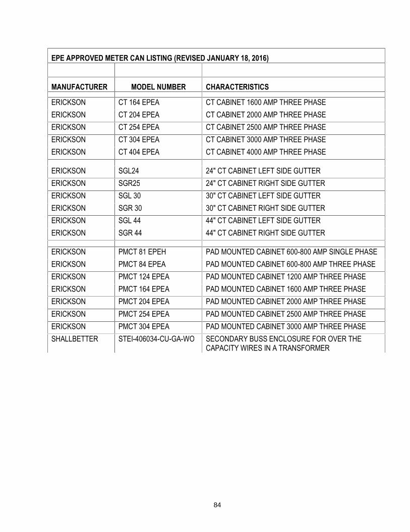
84
EPE APPROVED METER CAN LISTING (REVISED JANUARY 18, 2016)
MANUFACTURER MODEL NUMBER CHARACTERISTICS
ERICKSON CT 164 EPEA CT CABINET 1600 AMP THREE PHASE ERICKSON CT 204 EPEA CT CABINET 2000 AMP THREE PHASE ERICKSON CT 254 EPEA CT CABINET 2500 AMP THREE PHASE ERICKSON CT 304 EPEA CT CABINET 3000 AMP THREE PHASE ERICKSON CT 404 EPEA CT CABINET 4000 AMP THREE PHASE
ERICKSON SGL24 24" CT CABINET LEFT SIDE GUTTER ERICKSON SGR25 24" CT CABINET RIGHT SIDE GUTTER ERICKSON SGL 30 30" CT CABINET LEFT SIDE GUTTER ERICKSON SGR 30 30" CT CABINET RIGHT SIDE GUTTER ERICKSON SGL 44 44" CT CABINET LEFT SIDE GUTTER ERICKSON SGR 44 44" CT CABINET RIGHT SIDE GUTTER
ERICKSON PMCT 81 EPEH PAD MOUNTED CABINET 600-800 AMP SINGLE PHASE ERICKSON PMCT 84 EPEA PAD MOUNTED CABINET 600-800 AMP THREE PHASE ERICKSON PMCT 124 EPEA PAD MOUNTED CABINET 1200 AMP THREE PHASE ERICKSON PMCT 164 EPEA PAD MOUNTED CABINET 1600 AMP THREE PHASE ERICKSON PMCT 204 EPEA PAD MOUNTED CABINET 2000 AMP THREE PHASE ERICKSON PMCT 254 EPEA PAD MOUNTED CABINET 2500 AMP THREE PHASE ERICKSON PMCT 304 EPEA PAD MOUNTED CABINET 3000 AMP THREE PHASE SHALLBETTER STEI-406034-CU-GA-WO SECONDARY BUSS ENCLOSURE FOR OVER THE
CAPACITY WIRES IN A TRANSFORMER
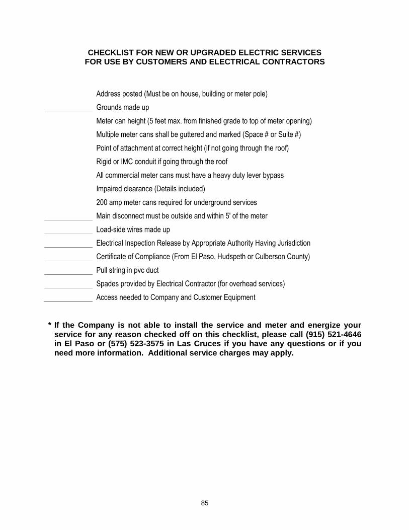
85
CHECKLIST FOR NEW OR UPGRADED ELECTRIC SERVICES FOR USE BY CUSTOMERS AND ELECTRICAL CONTRACTORS
Address posted (Must be on house, building or meter pole) Grounds made up Meter can height (5 feet max. from finished grade to top of meter opening) Multiple meter cans shall be guttered and marked (Space # or Suite #) Point of attachment at correct height (if not going through the roof) Rigid or IMC conduit if going through the roof All commercial meter cans must have a heavy duty lever bypass Impaired clearance (Details included) 200 amp meter cans required for underground services Main disconnect must be outside and within 5' of the meter Load-side wires made up Electrical Inspection Release by Appropriate Authority Having Jurisdiction Certificate of Compliance (From El Paso, Hudspeth or Culberson County) Pull string in pvc duct Spades provided by Electrical Contractor (for overhead services) Access needed to Company and Customer Equipment * If the Company is not able to install the service and meter and energize your
service for any reason checked off on this checklist, please call (915) 521-4646 in El Paso or (575) 523-3575 in Las Cruces if you have any questions or if you need more information. Additional service charges may apply.


85
SECTION VII
ELECTRIC SERVICE TO RESIDENTIAL SINGLE-FAMILY DETACHED HOMES
AND MOBILE HOMES 1. REQUEST FOR SERVICE
A. Residential service will normally be 120/240 volt, single phase, 3 wire service except that 3 phase, 120/240 volt or 120/208 volt service may be provided for motors over 5 horsepower if 3 phase service is available. Three phase is not available in underground served subdivisions. Single or 3 phase motors shall not exceed 10 horsepower individual capacity without written approval of the Company.
B. If the Company only needs to install the service wire and/or install a meter, then
up to 7 working days should be allowed to connect the service.
C. If the Company needs to install additional facilities such as transformers, poles, boxes, lines, etc. (considered a line extension), then 6 to 12 weeks may normally be required to provide service. Please contact the Designer well in advance of the date that service is required when extension beyond the existing facilities is required.
D. It is the policy of EPE not to install service wire over any type of building or
structure. 2. FOR OVERHEAD SERVICE
Normally, the Company will not install overhead electric service drops over public roads, homes, mobile homes, buildings or other permanent structures.
The maximum length of the service drop from the Company's pole to the customer's house or meter pole will depend on the customer's electrical load and size of Company's service wires but shall not exceed 75 feet for electrical loads of 15 KW and less. Shorter distances are required for larger electrical loads and larger service wires. The Company will install, own and maintain the meter and the overhead service drop to the point of attachment on the house or customer's meter pole. The customer will furnish install, own and maintain the service entrance equipment including the wire, conduit and meter socket. See DSO 415, and DSO 417 for details. Meter poles must be furnished, installed, owned and
86
maintained by the customer for service to mobile homes. See requirements for meter poles on DSO 430.
3. FOR UNDERGROUND SERVICE
The maximum length of the service run from the Company's padmount transformer, pullbox or enclosure to the customer's house or meter pedestal will depend on the customer's electrical load and size of Company's service wires but in general will not exceed 150 feet for single phase loads under 25 KVA (approximately 100 amps). The customer will furnish, install, own, and maintain the service duct from the customer's house or meter pedestal to the Company's padmount transformer, pullbox or service enclosure. A total of two (2) bends not exceeding a total of 135 degrees shall be allowed in an underground service duct run; one (1) bend at the Company's padmount transformer, pullbox or service enclosure, and one (1) bend at the customer's house or meter pedestal, and the underground service duct run must be a straight line from the Company's padmount transformer, pullbox or service enclosure to the customer's house or meter pedestal. The Company will own and maintain all structural facilities for secondary conductors up to and including the first service enclosure. The Company will furnish, install, own and maintain the meter and the service cable from the Company's padmount transformer, pullbox or service enclosure to the customer's service entrance at the house or meter pedestal. The location of the meter must be approved by the Company and shall be located at the nearest point on the house from the Company's padmount transformer, pullbox or service enclosure. See DSU 420 for underground residential services to houses and manufactured homes set in place on a foundation. See DSU 1020 and DSU 1025 for underground residential services for mobile homes. Please note that a meter pole or meter pedestal must be installed for underground service to mobile homes. Please contact the Designer for information on this installation.
If a residential customer requests conversion of his existing overhead service drop
to underground service, or if the conversion is required as the result of a situation created by the customer; the Company will, at its expense, install underground service conductors a maximum run of 150 feet if:
(1) The customer pays the Company in advance the estimated installed cost of the
new underground facilities plus the estimated cost to remove the existing overhead facilities less the salvage value of the removed overhead facilities. The customer must also grant to the Company any needed firm easements for this installation and for future underground extensions to adjacent lots as required. See DSU 410 for this installation.
(2) The customer shall supply, install, own and maintain the conduit system from
the Company service enclosure to the customer's meter enclosure. The conduit system must meet Company and applicable code requirements. See DSU 420 for this installation.
(3) The customer must make any changes to his service entrance equipment
necessary to accommodate the new underground service.

87
Installation of all Company underground structural facilities shall be done by either Company crews or Company approved contractors, which have contracted with the Company for these installations.
When the electrician is ready for the Company to run the service wire and install the meter, the electrician shall run a minimum 200 lb. test pull string in the duct and leave it for the Company. Do not stick a fish tape into the transformer housing.
The customer-installed underground service duct shall be a minimum of 18 inches deep in Texas and New Mexico.
The builder should check Company facilities (pedestals, service enclosures) for damage prior to beginning construction. If damaged, notify the Company at once. Otherwise, the builder may be charged for damages.
4. SERVICE ENTRANCE REQUIREMENTS
Service entrance equipment should be rated at not less than 100 amperes for overhead and 200 amperes for underground. The service disconnecting means for services rated 800 amps or less must be installed on the exterior of the building or structure adjacent to and within 5 feet of the meter.


88
SECTION VIII
RESIDENTIAL OVERHEAD SUBDIVISIONS
1. PRELIMINARY PLANNING
The developer should contact the Designer in the early stages of planning to discuss the proposed project and the procedures for obtaining electric service. This is important because the developer should consider the following:
• Whether pole lines will be located along the streets or at the rear of lots.
• How will lot or tract configuration affect the number of poles and anchors
needed and where should utility easements be granted?
• Where will the future lot owners most likely want service and what may be their costs?
• Typically, a single phase, primary voltage line will be installed, will 3 phase
service be needed for wells or sewage treatment plants? What will the loads be, and where are they located?
• Will the Company have difficulty in obtaining easements to get to the project
and will there be delays in obtaining materials or other factors that could prevent the Company from meeting the developer's time frame?
• What will be the costs to the developer and how will they be handled?
• A single phase, primary voltage line will be installed. Transformers will be
installed to provide 120/240 volt service to each lot. 2. REQUEST FOR SERVICE
Once these above items have been considered and the subdivision plat finalized, the developer should submit a completed Customer Service Request Sheet, 5 copies of the final plat, a mylar or AutoCad Disk, if available, and a development schedule to the Designer. Also, clearly identify the name of the person, corporation, joint venture, etc., that is developing the project and in whose name agreements or contracts would be prepared.
If street lights are to be installed as a requirement of a regulatory body, the proposed light locations need to be determined at this time. See Section XI for additional details.
89
3. WORK ORDER PREPARED, COST AND AGREEMENT
The Company will prepare a work order on providing service to the subdivision. The Designer will then give the developers a copy of the electrical layout to review and the estimated cost (cash advance or revenue guarantee amount). Any easements required that are not shown on the filed plat will be requested from the developer. If the developer has any questions about the proposed service, it should be brought to the attention of the Designer at once. The developer then determines which of the revenue guarantee options he will use (these options are subject to change). The Designer will then prepare the agreement which details the requirements for this construction. The agreement is valid for 60 days. The developer obtains the revenue guarantee, signs the agreement (the Surety signs the acknowledgment portion) and returns it to the Company.
The rules governing these installations are found in the Company's filed Line Extension Policy.
The work order will not be released for construction until the agreement is signed and the revenue guarantee approved. Depending upon the Company's work load and materials inventory, it may require up to 60 days to complete construction.
4. INSTALLATION OF ELECTRIC FACILITIES
The areas where the Company's facilities will be located are to be to final grade, and all necessary property irons are to be installed by the developer prior to the Company beginning construction.
The developer may be required to have platted roads/streets improved or to assist the Company in grading temporary roads through inaccessible or rough terrain. The Company will schedule the construction as normal work, but if there are no customers who require electricity living on or preparing to move into the subdivision, other jobs may be given priority at the Company's discretion. The Designer will provide the developer with a letter he can show to prospective buyers that states electricity will be installed when needed and that all arrangements with the Company have been made.
After the electrical installation has been completed, the developer shall install permanent street signs to facilitate the setting of meters and service for future customers. If transformers are not installed in the subdivision, the developer shall notify each lot purchaser to contact the Designer for service and that there may be an additional cost to the lot owner.
The developer is required to pay the cost of (1) relocation and/or extension of any installed electric facilities due to grade changes or other requirements of the developer or subsequent lot owner, and (2) repair and/or replacement of any Company facilities covered in the original agreement should such facilities be damaged during subsequent development and/or building construction.

90
Should a change in the original plat, or development schedule occur, please notify the Designer immediately. Changes in the plat may result in additional customer charges if such changes require revision of construction already completed by the Company. Plat changes also require a revision of the work order which may take from 1 to 4 weeks.


91
SECTION IX
RESIDENTIAL UNDERGROUND SUBDIVISIONS
(SINGLE-FAMILY DETACHED HOMES OR MOBILE HOMES)
1. PRELIMINARY PLANNING
The developer or his engineering consultants shall provide the Company with a preliminary plat and master plan of the area when available. The Company will review the plat, designate the width and location of all required utility easements and identify any potential problems that need to be resolved. This can normally be done through the activities of City or County Planning Departments or Subdivision Coordinating Committees during the preliminary plat approval process. For subdivisions outside of this jurisdiction, plans must be given to the Company and required utility easements shown on the filed plats. Within the city limits and extra territorial zones in New Mexico, all subdivision developers are required to submit a master utility plan to the Company for the design of its underground distribution facilities.
The following additional information must be detailed on the plat:
• Illumination Plan as required in the Texas Jurisdiction.
• Street width, property line to property line.
• Paved width of streets, curb to curb.
• Type of curbs (curb and gutter, header curb, other).
• Sidewalk width and location with respect to curb.
• Width of parkway from curb to sidewalk.
• Elevation of streets and adjacent lots when subdivision is in rough terrain.
• Final grading plans.
It is helpful for future follow-up with builders and to check on any applicable refunds if the addresses of each lot are shown.

92
2. REQUEST FOR SERVICE
A. ONCE THE DEVELOPER FINALIZES THE SUBDIVISION PLAN, he completes a Customer Service Request Sheet and returns it and 5 copies of the final plat, a mylar, or AutoCad Disk, if available to the Designer. The Company will not complete a work order using preliminary plans. A development schedule should be included. This will aid the Designer in coordinating the work order. It is especially important that the information for subdivisions include the date when all property irons will be in place. The Company cannot begin construction until all irons are in place.
B. If any of the lots within the subdivision are to be dedicated or set aside for any
use other than single family, the use must be identified when possible. For example, school sites, parks, commercial areas, apartment sites, etc., should be shown. The developer must identify blocks and lots where duplex or multiplex units are to be built, indicate of separate or grouped meter locations are desired, and provide a plan showing "typical" unit, drive and sidewalk layouts. See Section X for additional information.
C. If any of these above types of uses could require three (3) phase electrical
service, the Company shall incorporate the applicable requirements in to the subdivision electrical design, and the costs for the 3 phase will be a part of the agreement for the subdivision. (Future revenues from these 3 phase users will also apply to fulfilling any revenue guarantees under the agreement terms.) If 3 phase service is required by the water or sewer utility, these locations must be identified prior to the start of the electrical design. Any financial considerations required in providing service to such facilities will be handled with the developer or the water/sewer utility as determined by the parties.
D. If street lights are to be installed as a requirement of a regulatory body, the
proposed light locations need to be determined at this time. See Section XI for additional information.
3. COST AND AGREEMENT
The Company will prepare a work order on providing service to the subdivision. The Designer will then give the developers a copy of the electrical layout to review and the estimated cost (revenue guarantee or cash advance amount). If the developer has any questions about the proposed service, it should be brought to the attention of the Designer. The developer then determines which of the revenue guarantee options he will use. (The options are subject to change.) The Designer will then prepare the agreement. The agreement is valid for 60 days. The developer obtains the revenue guarantee, signs the agreement (the Surety signs the acknowledgement portion) and returns it to the Company.
The job will not be put out for bids and/or the work order released for construction until the agreement is signed and the Surety's guarantee approved. Depending
93
upon the size of the subdivision, it may require three weeks for the bidding and selection of a contractor and preparation to start construction.
4. INSTALLATION OF ELECTRIC FACILITIES
The areas where the Company's facilities will be located are to be to final grade; curb and gutter, water and sewer main lines and taps are to be installed prior to the Company beginning construction. Any exceptions to this requirement must be approved by the Company in advance. The Company will coordinate its installation of structural facilities with the other utilities involved. After the structural facilities are installed, the Company will not install cables, transformers, etc., until they are needed to serve homes.
Should a change in the original plat or development schedule occur, please notify the Designer immediately. Changes in the plat may result in additional customer charges if such changes require revision of construction already completed by the Company. Plat changes also require a revision of the electrical design which may take from 1 to 4 weeks.
After the structural installation is complete and accepted and the Company's Inspector and the Developer's representative have reviewed the subdivision for damage to curbs, etc., the Company's Underground Construction Inspector will provide the Developer with a written paving release.
If a subdivision is replatted after Company facilities have been installed, either through a filing action or by the sale of lots by metes and bounds, or if the intended use of the lots changes from single family to multiplex units, the customer shall notify the Company as soon as the changes are known and provide a layout of the changes showing both old and new property lines.
If additional service/meter points are required because of the changes, the developer or builder shall enter into a new revenue guarantee agreement for the amount of the additional investment in facilities made by the Company. The developer or builder will pay the entire cost to remove or relocate existing Company facilities.
5. MOBILE HOME SUBDIVISION - SPECIAL CONSIDERATION
In a mobile home subdivision, meters are not allowed to be placed on the side of the mobile home per the national Electric Code. The meter must be located on an approved meter stand at a point designated by the Company. An example of such a stand is shown on the enclosed Company Standards DSU 1020, page 1 of 1, and DSU 1025, page 1 and 2 of 2. Self-contained metering pedestals are also available from electrical suppliers. The developer may install the meter stands to insure uniformity and reliability or it may be done on an individual basis by the future lot owners.

94
SECTION X
ELECTRIC SERVICE TO MULTI-FAMILY RESIDENTIAL UNITS
(DUPLEXES, TRIPLEXES, ETC.) 1. PRELIMINARY PLANNING
The owner, architect, consulting engineer or electrical contractor (referred to as "customer") should contact the Designer in the early stages of planning to discuss to proposed multi-family subdivision or projects and the procedures for obtaining electric service. They should provide the Company with a preliminary plat when available. The Company will review the plat, designate the location and width of all required utility easements and identify any potential problems that may need to be resolved, such as the location of the Company's existing electrical facilities in relation to the location of the proposed development.
The Designer will confirm the exact type and location of service which will be supplied to each unit(s) before proceeding with the electrical wiring of a project. If the units are to be separately sold, the Company can advise the customer on the best service method. Attention to this detail may avoid the added cost of installing additional electrical facilities later. The Company is ready to assist in the preliminary design stages of a project in any way.
2. REQUEST FOR SERVICE
The Customer must complete and sign a Customer Service Request Sheet and provide final plans before the Company begins the engineering design. It is important that the information asked for on the Request Sheet be furnished accurately and completely and include the following:
A. Name, street, address and exact location of the proposed multiplex project to
be served, including a legal description of the property.
B. Final plans showing the physical layout of the proposed building(s) in relation to the property in including building elevation plans, electrical plans, floor plans, grading plans (existing and final), landscaping plans, location of proposed curbs, sidewalks, parking areas, driveways and location of other utility lines (water, gas, sewer, telephone, cablevision), etc.
C. Number of buildings in the proposed project along with the number of units
per building and the approximate square footage of each.

95
D. Type of electric service (overhead or underground) and the desired service
point for each building and whether meters will be grouped or served individually. If more than one service per building is requested, fire walls will be required and appropriate inspection approval obtained.
E. Date that electric service will be required and the approximate time table for
construction. 3. WORK ORDER AND COMPANY POLICIES AND RULES
The customer must execute any necessary agreements before construction can begin. Any easements that are required will be requested from the property owner. The work order will not be released for construction until all necessary agreements are signed and approved by the Company and all easements are obtained.
4. INSTALLATION OF ELECTRIC FACILITIES
The areas where the Company's facilities will be located are to be at final grade, clear of all objects. Sidewalks and curbs, etc., should be existing or properly marked, and all necessary property irons as specified by the Company are to be installed by the customer prior to the Company beginning construction.
When meters are to be grouped, the gutter and all of the sockets are to be installed by the customer. The customer shall furnish, install, own and maintain the service duct and service wire from the grouped meters to the service enclosure or transformer box as designated by the Company. For stack metering for multi-family residential units, no more than four (4) meters stacked vertically shall be allowed.
For overhead services, parallel risers are allowed only under the following conditions:
1. Multiple meters over 400 amps total. 2. For services greater than 600 amps, up to a maximum of four (4) risers
total will be allowed, and only conductor sizes of 350 MCM and larger will be allowed.
3. For 320 amp meter cans with a single meter, a maximum of two (2) risers total are allowed and can be paralleled, and only conductor sizes 4/0 and larger will be allowed.
96
SECTION XI
STREET LIGHTING AND TRAFFIC SIGNALS
TEXAS
STREET LIGHTING 1. GENERAL INFORMATION
A. There are five types of governmental street or highway lighting that are installed in the Company's service area. The Customer must obtain approval from the Company for all installations, and these installations must comply with the clearance requirements specified in DSO 1870. All types have to be installed or requested to be installed by a governmental unit and the monthly electric bills are paid by the governmental entity. These five types are:
1. Municipal street lighting.
2. New subdivision street lighting under the jurisdiction of the City of El Paso.
3. County road and highway lighting in El Paso County and the portions of
Culberson and Hudspeth Counties in the Company service area.
4. Interstate freeway lighting involving a cooperative agreement between the Texas Department of Transportation and a municipal or county government.
5. State and interstate highway and intersection lighting by the Texas
Department of Transportation.
B. The Electric Company maintains all street, highway and freeway lighting except for ornamental standards and systems owned by municipalities and those lights outside of cities or towns which are maintained by the Texas Department of Transportation. Report damaged or burned out lights to the Electric Company by calling 877-3400.
C. Information relative to requesting or obtaining lighting in each of these
categories follows. 2. MUNICIPAL STREET LIGHTING ON EXISTING STREETS

97
A. A municipality decides when and where to install street lighting based upon
traffic conditions, needs and location of Company facilities.
B. If a resident or residents of a street want to have a street light installed on their street, they should contact their local governmental body with their request. Depending upon each situation, the local government may install the light without cost to the residents or the government may require the residents to pay the installation cost. Do not contact The Electric Company to request a street light. The Company cannot install any lighting without governmental approval and authorization. Within the Limits of the City of El Paso, contact the Traffic & Transportation Department at 541-4044.
3. STREET LIGHTING IN NEW SUBDIVISIONS UNDER THE JURISDICTION OF
THE CITY OF EL PASO
A. All new subdivisions are to have provisions for street lighting provided by the subdivision developer. The developer is to submit his subdivision plat to the Traffic and Transportation Department of the City before final plat approval is given. The Traffic and Transportation Department will designate the number and location of street lights required for that subdivision on the plat.
B. A copy of the plat showing these locations is given to the Company so the
Company can design the electrical system to include service to the lights. If there are any problems with the proposed light location, the Company will resolve these problems with the Traffic and Transportation Department in a mutually agreeable manner.
C. The developer shall pay either the City or the Company (as determined by
governing ordinances) the installation cost for each light in advance. The lights will be installed and energized within a time frame set forth by governing ordinances in effect.
D. The developer shall contact the Traffic and Transportation Department in the
planning stages of each subdivision to verity the lighting requirements for the subdivision and what governing ordinances and policies will apply.
4. COUNTY ROAD AND HIGHWAY LIGHTING
County government decides when and where to install street lighting based upon traffic conditions and needs. Contact your county government officials 546-2015 to make requests for lighting. Depending upon each situation, the county may install the light without cost or the county may require the citizen(s) to pay the installation costs. Outside the Limits of the City of El Paso, the County of El Paso may be contacted at 546-2015.
5. INTERSTATE AND FREEWAY LIGHTING WITHIN MUNICIPALITIES

98
These systems are designed and installed by the state and cities normally when new highways are constructed or changes are made. Contact the city governments if there are questions about adding lights to these lighting systems.
6. STATE AND INTERSTATE HIGHWAY AND INTERSECTION LIGHTING
Outside of municipalities, the Texas Department of Transportation installs and maintains this lighting. Contact them with questions or requests about lighting.
7. COMPANY POLICIES AND RULES The Company's Rules and Regulations, Line Extension Policy, applicable tariffs
and established operating procedures and policies apply to all lighting service and installation in addition to any specific agreements between the Company and any governmental units.
8. CONVERTING FROM OVERHEAD TO UNDERGROUND SERVICE The total cost of converting existing overhead service to underground service shall
be paid by the customer. The Company reserves the right to refuse to convert any existing overhead service to underground service if the conversion causes problems for the Company or is not equitable for the Company.
9. MUNICIPAL COLLECTIVE ROAD LIGHTING/ARTERIAL LIGHTING All new installations of collective and arterial roads are to have provisions for street
lighting by the City of El Paso. These special projects are projected based upon traffic conditions, needs, locations, and street renovations throughout the City. The City should contact the Company's Street Lighting Department in the planning stages of a project to discuss the project and the procedures. The Company will provide a cost estimate for a standard installation. Upon agreement of the cost, the City shall submit a Purchase Order for the total cost of the job. The Company will not release a work order for construction until the City has submitted a Purchase Order to the Company. The Street Light Representative is the liaison between the City and the Company to will coordinate all aspects of any given project. The Street Light Representative ensures that all policies, procedures and Company standards are being met.
10. STATE AND CITY LIGHTING POWER SOURCES A request for service for State and City lighting power sources should be made
through the Company's Street Lighting Department. This type of lighting normally requires 240/480 volt, single phase service. The Company will meet with the State's or City's representative at the proposed service location to determine if the service for the required voltage is readily available. If a new transformer and/or additional facilities is required to provide service, the City or State shall pay for the total cost of the additional facilities required. The service address and service

99
voltage must be displayed on the main disconnect box and should be visible from the street.
11. RELOCATION OF STREET LIGHTS If the City requests to have a City-owned street light relocated, the City shall pay
the total cost of relocation. The City shall provide the Company with a Purchase Order for the total cost, and then the Company will initiate a new work order and start the process for the relocation.
TRAFFIC AND SCHOOL SIGNAL INSTALLATIONS 1. A request for service for traffic signals should be made through the
Company's Street Lighting Department. The Company will designate the service point location. Traffic signal service is normally 120/240 volt, single phase service. If the Company only needs to install a service drop, then up to seven (7) days should be allowed to connect the service. If the Company needs to install additional facilities such as transformers or poles, then up to six (6) weeks may be required to provide service. If the Company needs to install additional facilities, the customer shall pay the Company the total cost of these facilities. The customer shall provide the Company with a Purchase Order before the Company prepares a work order and starts the process of installing the necessary facilities.
2. If an overhead service drop is required, the customer's service pole shall be
installed a maximum of 75 feet from the Company's pole. The customer shall provide, install and maintain the customer-owned service pole up to the point of attachment.
3. For underground service, the customer shall install their service enclosure
within 3 feet of the Company's service enclosure. 4. Before the Company energizes the power source, all main disconnect
cabinets shall be labeled with the service address and the service voltage. 5. To ensure billing accuracy, the customer shall provide the Company proper
documentation with the accurate count of all installed or upgraded devices.
100
NEW MEXICO 1. GENERAL INFORMATION Street lighting provides safety, security and convenience. The Company presently
offers three (3) types of street lighting: (1) municipal street lighting; (2) private residential subdivision street lighting; and (3) interstate highway street lighting. For private area lighting see Section XVIII.
2. MUNICIPAL STREET LIGHTING Municipal street lighting is available to any village, town, city or county
governmental agency for street lighting purposes only and customers must submit their request for this type of street lighting to these governing bodies for approval. Inside the city limits of Las Cruces, this request must be submitted in writing to the Traffic Engineering Department, City of Las Cruces, New Mexico. Once this street light request is approved, the governing body will submit in writing to the Company a letter of authorization for the installation of the street light(s). The Company will then prepare all the necessary paper work to have the street light installed. All street lights installed inside the City of Las Cruces will be installed in accordance with the Street Lighting Policy adopted by the City Commission on November 19, 1984. The Company will install all other municipal street lighting in accordance with the street lighting policy in effect in the area where the street light is to be installed.
3. PRIVATE RESIDENTIAL SUBDIVISION STREET LIGHTING Private residential subdivision street lighting is available to any individual
corporation outside the incorporated limits of the municipalities in the territory served by the Company and is installed only after a contract has been entered into by the customer and the Company. Contact the Street Lighting Department for more information and details on this type of street lighting.
4. INTERSTATE HIGHWAY LIGHTING Interstate highway lighting is a service contracted for by a village, town, city, county
or state governmental agency and under conditions where the governmental agency owns and installs the street lighting system, including fixtures, standards, appurtenances, cable and duct. Contact the Distribution Design and Delivery Business Unit for more information and details on this type of street lighting.
5. COMPANY POLICIES AND RULES The Company's Rules and Regulations, Line Extension Policy, applicable tariffs
and established operating procedures and policies apply to all lighting service and installation in addition to any specific agreements between the Company and any governmental units.
6. CONVERTING FROM OVERHEAD TO UNDERGROUND SERVICE

101
The total cost of converting existing overhead service to underground service shall be paid by the customer. The Company reserves the right to refuse to convert any existing overhead service to underground service if the conversion causes problems for the Company or is not equitable for the Company.

102
SECTION XII
SERVICE TO MOBILE HOME PARKS (TRAILER, RV PARKS)
1. GENERAL INFORMATION
A mobile home park is defined as a location where the lots are rented or leased, as compared to selling them to mobile home owners. Each lot will receive a separate electric service with meters being placed separately on each lot or several lots grouped together on a common pole or stand. The developer of a park shall contact the appropriate Designer, complete a Customer Service Request Sheet and provide a set of plans showing the following:
• Lot spaces layout.
• Driveways and entrances/exits.
• Location of laundry buildings, swimming pool, playground areas, lighting,
water, sewer and gas lines, etc.
• The electrical loads expected, wiring diagrams and layouts.
No meters are to be installed directly on the side of a mobile home. Meters can be installed on manufactured homes that are set in place on a foundation. This must be approved by the Company prior to any electrical work being done by the customer or the customer's electrical contractor. Locations of the meters shall be such that they are protected from possible vehicular damage. The meter installation shall conform to the latest National, State or applicable municipal electrical codes. The customer provides and installs the meter socket. No parallel risers shall be allowed on customer-owned meter poles.
2. OVERHEAD SERVICE
If the park is served electricity from an overhead Company system, the following specifications and conditions will apply:
The maximum distance the Company will install an overhead service drop is 75 feet in serving an estimated demand load of 15 KVA or less. If meters for multiple mobile homes having a demand load greater than this are grouped on one pole, the length of the service drop will be shortened. If multiple meter poles are installed by the customer for multiple mobile homes, there shall be adequate distance or spacing between these meter poles to prevent an unsafe or improper

103
clearance between service wires that could create a safety hazard. This must be approved by the Company prior any electrical work being done by the customer or the customer's electrical contractor.
All customer service and meter poles will be installed according to specifications stated in DSO's 430 and 431. Electric Company service wires will not cross over mobile home locations. If mobile homes are installed that create an impaired clearance, the Company reserves the right to disconnect service wires until clearance is corrected. The customer shall have the location of all meter poles confirmed by the Company before any installations are made. No parallel risers shall be allowed on customer-owned meter poles.
3. UNDERGROUND SERVICE
A. If the mobile home park is to be served underground, special consideration must be given to the placement of Company facilities and the protection of these facilities from vehicle damage. The Company will supply, install, own and maintain an underground electrical distribution system to serve each lot. The Company will prepare a work order for the mobile home park and give the developer a copy of the electrical layout to review and the estimate cost (cash advance or revenue guarantee amount). If the developer has any questions about the proposed service, it should be brought to the attention of the Designer. The developer notifies the Designer which of the revenue guarantee options he will use. (These options are subject to change.) The Designer will then prepare the agreement, which is valid for 60 days. The developer obtains the revenue guarantee, signs the agreement (the Surety signs the acknowledgement portion) and returns it to the Company.
B. The job will not be put out for bids or the work order released for construction
until the agreement is signed and the Surety's guarantee approved. Depending upon the size of the mobile home park, it may require three weeks for the bidding and selection of a contractor and preparation to start construction.
C. The areas where the Company's facilities will be located are to be to final
grade prior to the start of construction by the Company. Curb and gutter, water and sewer main lines and taps are to be installed prior to the Company beginning construction, if applicable. Coordination between the Company and others installing underground utilities is important to avoid damage to Company facilities, which the customer must pay for.
D. The meters must be located in an approved meter stand or pedestal at a point
designated by the Company. Examples of two such stands are shown on the enclosed Company Standards, DSU 1020 and DSU 1025. Meter heights must be a minimum of 3 feet and a maximum of 5 feet above ground level.
E. Security lighting provided by the Company is available to be installed along
private streets within the park. The customer pays a one-time installation cost

104
for the underground facilities to serve the light pole and the Company will maintain the light(s). The customer then pays a monthly rate for the electricity, pole and light assembly.
4. ADDITIONAL GUIDELINES
A. Each mobile home space shall be prominently numbered and this number shall be legibly and permanently marked on the mobile home main switch box and meter socket. Service will not be connected until the address is permanently displayed and visible from the street.
B. See the detailed instructions for meter service poles and their installation on
DSO's 430 and 431.

105
SECTION XIII
ELECTRIC SERVICE TO APARTMENT COMPLEXES
1. PRELIMINARY PLANNING
The owner, architect, consulting engineer or electrical contractor should contact the Designer in the early stages of planning to discuss the proposed apartment project and the procedures for obtaining electric service. The customer should provide the Company with a preliminary plat when available. The Company will review the plat, designate the location and width of all required utility easements and identify any potential problems that may need to be resolved, such as the location of the Company's existing electrical facilities in relation to the location of the proposed apartment project. The exact type and location of service which will be supplied to the apartment complex should be determined before specifying or purchasing any equipment or proceeding with the electrical wiring or a project. Attention to this detail may avoid the purchase of equipment for which service is not available or the added cost of installing additional electrical facilities. The Company is ready to assist in the preliminary design stages of a project.
2. REQUEST FOR SERVICE
A. The customer must complete and sign a Customer Service Request Sheet and provide final plans before the Company begins the engineering design. It is important that the information asked for on the Request Sheet be furnished accurately and completely and include the following:
1. Name, street address and exact location of the proposed apartment
complex to be served including a legal description of the property.
2. Final plans showing the physical layout of the proposed apartment building in relation to the property including building elevation plans, electrical plans, floor plans, grading plans (existing and final), landscaping plans, location of proposed curbs, sidewalks, parking areas, driveways, location of other utility lines (water, gas, sewer, telephone, cablevision, on site ponding areas, etc.).
3. Number of buildings in the proposed apartment complex along with the
number of apartments per building and the approximate square footage of each.
106
4. Itemized commercial load requirements – i.e., office, laundry room, recreation room, pool, exterior lighting, etc.
5. Type of electric service (overhead or underground) and the desired
service point for each building.
6. Date that electric service will be required and the approximate timetable for construction.
7. Temporary construction service requirements. Please contact the
Designer as early as possible for temporary service requirements. The customer shall pay the Company the estimated cost to install and remove any additional facilities that are needed for temporary construction service. In some cases, temporary service may not be readily available, practical or economically feasible.
3. WORK ORDER, COMPANY POLICIES AND RULES
The Company will prepare a work order to provide service to the proposed apartment complex. The Designer will then give the customer a copy of the Company's proposed electrical layout to review and the estimated cost to provide the electric service. Each request for service will be considered in accordance with the terms and conditions of the Company's filed Line Extension Policy and Rules and Regulations Regarding Electric Service. The customer must execute any necessary agreements before construction can begin. Any easements that are required will be requested from the property owner.
The work order will not be released from construction until all necessary agreements are signed, and the revenue guaranty account or cash advance (if required) is approved by the Company and all easements are obtained.
4. ONE TYPE OF SERVICE PER BUILDING
The Company will normally provide only one type of service and one set of service conductors to a building, and all electric energy is to be measured by a single meter at each point of delivery. If more than one electrical service entrance to a building is desired, all applicable building, fire and electrical codes must be met and must be approved in advance by the Company. The Customer shall pay, as a nonrefundable Contribution in aid of Construction (CIAC), for all costs associated with an additional service point. The Company reserves the right to refuse to provide multiple points of service if the multiple points of service causes problems for the Company or is not equitable for the Company.
As per Article 230.2(E) of the National Electrical Code, where a building or structure is supplied by more than one service, a permanent plaque or directory shall be installed at each service disconnect location denoting all
107
other services supplying that building or structure and the area served by each.
5. SERVICE POINT AND METER LOCATION CONFIRMATION
The service point location (point of attachment or point of delivery) and the metering locations will be designated by the Company. The location for the service point and meters shall be secured from the Designer. This information shall be obtained before any work is started on the customer's wiring.
6. INSTALLATION OF ELECTRIC FACILITIES
The areas where the Company's facilities will be located are to be to final grade and clear of all objects. Sidewalks, curbs, etc., should be existing or properly marked, and all necessary property irons as specified by the Company are to be installed by the customer prior to the Company beginning construction.
A. Overhead Service: The maximum length of the service drops from the
Company's service pole to the customer's apartment building will depend on the customer's electrical load and size of Company's service wires. Shorter distances are required for larger electrical loads and larger service wires. The Company will install, own and maintain the overhead service drop to the point of attachment on the building, including the meter. The customer will furnish, install, own and maintain the service entrance equipment including the wire, conduit and meter socket. Stack metering may be used, but must conform to Company requirements on spacing between the meter sockets, and must be approved by the Company in advance. The minimum distance between meter sockets is 3 inches. For stack metering for apartment complexes, no more than four (4) meters stacked vertically shall be allowed. The point of attachment of the Company's service wires to the customer's building shall be high enough so that minimum service wire clearance, above finished grade, shall not be less than the applicable code requirements.
On overhead single phase services, multiple risers, parallel risers and
paralleled conductor shall not be allowed. B. Underground Service: For all underground services in an apartment
complex, including the clubhouse, laundry room, swimming pool and any and all other types of buildings or structures requiring electric service in the apartment complex, the customer will furnish, install, own and maintain the service duct and cable from the customer's building to the Company's padmount transformer, pullbox or service enclosure. The Company's padmount transformer, pullbox or service enclosure will be the point of delivery, and the Company will make the service connection between Company-owned wires and customer-owned wires at this point. If the number of customer's cables coming to the designated service point exceed the number allowed for the transformer or Company connector (see DSU 405

108
and DSU 510), the customer shall provide, own, install and maintain a secondary bus enclosure or submersible set screw bar type connector and enclosure approved by the Company. The Company will specify which type may be used. The location of this enclosure will be designated by the Company. The Company's transformer(s) shall be protected from vehicular traffic by the customer as shown in DSU 515, 1 of 2 and 2 of 2 or DSU 525 when applicable. See DSU 1045 for typical multiple underground residential metering installations. Stack metering may be used, but must conform to Company requirements on spacing between the meter sockets, and must be approved by the Company in advance. The minimum distance between meter sockets is 3 inches. For stack metering for apartment complexes, no more than four (4) meters stacked vertically shall be allowed.
1. Padmount Transformer Installation/Service Connection
The Company's transformer must be located in an area that provides
accessibility to vehicles, trucks and/or cranes with applicable operating clearances around and above the transformer. Adequate protection for the transformer must also be provided and installed by the customer or his contractor before service to the customer will be connected. Refer to DSU 515, 520, 525, 528 and 530 for complete specifications on the required clearances and protection.
7. RATES
The Residential Service Rate is available only for domestic purpose individually metered apartments. If more than one unit or apartment is served on one meter, then the applicable commercial rate will apply.
All electric service to loads such as the apartment office, laundry room, recreation room, pool or exterior lighting, etc., will be separately metered (one or more meters) and billed under the applicable commercial service rate.
In accordance with the Federal Public Utility Regulatory Policy Act and state
and local laws, all newly constructed or occupied apartments or condominiums must provide for individual metering of each dwelling unit by the Company or submetering by the owner. The Designer can furnish additional information on this subject.
8. BUILDING AND METER SOCKET IDENTIFICATION The electrical contractor shall place permanent markings on the meter
sockets to correctly identify them with the corresponding apartment number. Each apartment building shall be clearly marked and identified with a large number or letter permanently attached to the building. METERS WILL NOT BE SET UNTIL THE METER SOCKETS AND THE BUILDINGS ARE MARKED.

109
9. SECURITY LIGHTING
Private Area Lighting installed, owned and maintained by the Company is available. See Section XVIII for additional details.


110
SECTION XIV
COMMERCIAL MANUFACTURING OR INDUSTRIAL SERVICE
1. GENERAL INFORMATION
A. A complete set of plans including site, floor, elevations, grading, electrical, mechanical and landscaping should be provided to the Designer as early as possible. The location of existing or proposed Company facilities needs to be reviewed to avoid conflicts that could later create additional costs or delays. An owner requesting service to a speculative development without written commitments from future tenants may require that a revenue guarantee or cash advance agreement be signed before the Company begins the installation of its facilities.
B. The service disconnecting means for a service rated at 800 amps or less
service must be installed on the exterior of the building or structure adjacent to and within 5 feet of the meter.
All meters for commercial services up to 400 amps shall have a heavy-
duty bypass meter socket. When using the bypass meter socket for three phase 120/240 volt service, the power leg must be on the right side of the meter socket as you face the meter can.
C. Please review Section III, IV, V and VI of this book. They contain important
information related to Commercial/Industrial services.
D. Service Point Location Confirmation
The customer should show the desired location for the transformer/service point on his drawings. The point of attachment or delivery will be designated by the Company. The location for the point of attachment and meter shall be secured from the Designer. This information shall be obtained before any work is started on the customer's wiring. Do not assume that a building will be served from the nearest pole or transformers. For example, the desired voltage may not be available or the distance for an overhead drop may be too far.
Architects and owners should also be aware of the planned location of Company poles, anchors, padmounted transformers, etc., to ensure that

111
potential problems with landscaping, vehicle and pedestrian traffic flow, aesthetics, trash receptacles, possible future expansions, etc., will be minimized and resolved in the early stages of design or construction.
If underground service is desired, but space limitations prohibit the installation of a padmounted transformer, a customer meter pole next to the Company transformer pole should be considered.
E. Fault current information can be obtained by calling the appropriate Designer.
2. OVERHEAD ELECTRIC SERVICES
A. The Point of Attachment provided by the electrical contractor for the Company to attach its service wires needs to be 18" - 24" higher than the ground to wire code clearance requirements to allow for wire sag and the drip loop.
B. The length of the Company's service drop is determined by the size of the
Company transformer and thus the size of the service wires. This is important to consider in determining the service point in relation to the Company's existing pole line or new pole installation. Contact the Company to verify these distances. Do not assume that secondary can always be run from a nearby pole line. Normally, the Company will not install overhead electric service drops over public roads, homes, mobile homes, buildings or other permanent structures.
3. UNDERGROUND ELECTRIC SERVICES
A. Design of Company Facilities
The design and installation of Company underground facilities will be done by the Company. The customer is to show the desired point of service or transformer location on his electrical site plan. The Company will confirm the desired service point or specify a different one in writing depending upon the underground design. If a customer requests an underground service in areas where there are overhead lines, the Company has the right to designate the location of the riser pole for the underground service, which may include an overhead line extension as part of the design.
No permanent buildings or structures can be constructed on top of the Company's underground facilities, so it is important for the customer to show future additions or buildings planned for the property. It is also very important to show the location of other utilities' lines and to assist the Company in coordinating the layout and installation of all underground facilities for the benefit of all utilities. The Company's primary voltage lines shall be installed a minimum of 36" below final grade. Secondary voltage lines shall be a minimum of 24" below final grade. The area must be to final grade before
112
installation will begin and the required property irons shall be installed. Primary voltage lines will be concrete encased for protection when deemed necessary by the Company's Distribution Design & Delivery Department.
The development of a commercial subdivision requires careful planning between the developer and the Company. Usually lot lines are not absolutely final and future driveway locations unknown. If a developer has two or three possibilities of lot layouts, but needs to install the underground electric facilities in advance, it is wise to install extra street crossings to provide duct for future use without extensive street cuts. The developer would pay the cost up front of these extra crossings. If installed Company facilities have to be relocated or removed, the developer pays these costs. Curbs and gutters are to be installed prior to the installation of Company facilities. The underground electrical system will be installed along the streets in the subdivision.
B. Padmount Transformer Installation/Service Connection
The Company's transformer must be located in an area that provides accessibility to vehicles, trucks and/or cranes with applicable operating clearances around and above the transformer. Adequate protection for the transformer must also be provided and installed by the customer or his contractor before the Company’s padmount transformer is installed and service to the customer is connected. Refer to DSU 515, 520, 525, 528 and 530 for complete specifications on the required clearances and protection. The Customer has the option of requesting that the Company install adequate protection for the transformer and the Customer shall pay the Company, in advance, a nonrefundable contribution in aid of construction for the Company to install adequate protection for the transformer.
For all commercial underground services, the Customer will provide, install,
own and maintain all ducts and low voltage cables from the secondary terminals of the transformer to and within the building. The meter location shall not exceed 20 feet from the Company’s padmount transformer or secondary service enclosure, shall not be located within the Company’s operational clearance space requirements, and should be a straight run. If a meter stand is installed, it should comply with DSU 1015.
The point of connection for the customer's secondary service cables will be at the secondary bushings of the transformer if the number of customer cables does not exceed the capacity of the transformer. Refer to DSU 510 for a listing of these limits for various sizes of transformers. The Company will determine the size of transformer to install based upon the customer's connected load and diversity of operation. If more than 4 conductors per phase are installed, the electrical contractor shall bundle all the cables in each phase together in the transformer pullbox.

113
If the customer's number of cables per phase exceeds the number allowed for the transformer, the customer shall provide and install either a secondary bus enclosure or a submersible bus bar set screw-type connector and enclosure approved by the Company for the point of connection. The Company will determine which type is to be used. The Company will designate the location of the enclosure close to the transformer and install duct and cables from the transformer to the line side of the bus or connector. The electrical contractor will terminate his secondary cables on the load side of the bus or connector. The consulting engineer or electrical contractor shall verify with the Company whether a separate secondary termination point will be required before plans are finalized and the job goes out for bid. Refer to DSU 530 for Right of Way Requirements.
When the point of connection is the transformer secondary bushings, the duct and cable installation into the transformer pullbox and housing must follow the specifications shown on DSU 510 and DSU 440.
When a meter stand is installed next to the transformer, the meter stand must be constructed as per the specifications in DSU 1015. The meter enclosure shall be installed in such a manner that the top of the meter opening must be 5 feet from finished grade. The stand shall not be attached to the transformer housing or to the concrete pullbox or lid. The meter stand shall not be located more than 20 feet away from the transformer. This is for padmount transformers only with pre-approved current transformers located in the transformer. Current transformers will be in an approved CT cabinet for services from 401 to 1200 amp ratings. If multiple services larger than 1200 amperes are served from the same transformer, all metering will be guttered and CT's will NOT be installed in the transformer.
Customers with multiple transformers shall not have any internal ties in
their electrical system to allow transformers to operate in parallel.
C. Transformer Installed in a Vault
1. Underground Vault: The customer will design and construct the vault following Company specifications. The vault design must be approved by the Company in advance of construction. Contact the Company for the specifications and requirements, which will vary depending upon the size and location of each vault.
2. Connections in a Vault: If the customer's service entrance into the vault is with cable, the point of connection will be at the secondary bushings of the transformer. The customer's cable shall be long enough to rest in all cable trays, pass through CT's and reach the transformer bushings easily.
If the customer's service entrance is a bus duct, the Company shall approve the bus duct design and entrance location in advance. The Company will specify the number and size of the termination lugs required on the bus. The Company will run its cables from the transformer to the bus duct.
114
SECTION XV
TEMPORARY SERVICE 1. REQUEST FOR TEMPORARY SERVICE A request for temporary service should be made well in advance of the date
that temporary service is required. If the Company only needs to install secondary wire and set a meter, then up to 7 days should be allowed to connect the temporary service. If the Company needs to install additional facilities such as transformers, poles, overhead or underground lines, etc. (considered a line extension), then 4 to 12 weeks may be required to provide temporary service. Therefore, it is very important that the Company be notified well in advance of the date that temporary service is required when a line extension beyond the existing service facilities of the Company is required. In some cases, temporary service may not be readily available, practical or economically feasible. Contact the New Service Group at (915) 521-4646 in Texas (El Paso) or (575) 523-3575 in New Mexico (Las Cruces) to apply for temporary service.
2. TEMPORARY SERVICE CONNECTION CHARGE
A temporary service connection charge shall be made for temporary overhead and underground services based on the current charge in effect in the area served and approved by the appropriate regulatory agency. This is an additional charge for temporary service and does not include the costs of additional facilities installed by the Company. This is a one-time charge, is nonrefundable and will normally be included in the customer's first monthly bill.
3. TEMPORARY LINE EXTENSION
If a line extension is required to provide temporary overhead or underground service, the customer shall pay the Company in advance the estimated cost of required Company facilities plus installation and removal costs, less the estimated salvage value of the facilities when they are removed. This cost will be obtained from the Designer of the Company. When a line extension is required, the customer or customer's contractor shall provide the Company with the following information before planning for the temporary service can begin:
• Name of responsible party and street address and/or location where
temporary service is required.
• A map or site plan indicating the customer's desired temporary service point.

115
• Electrical load requirements (load in amps or KW, single phase or three phase and secondary voltage).
• Type of service required (overhead or underground). • Date that temporary service will be required.
4. TEMPORARY SERVICE POINT LOCATION
The temporary service point location (point of attachment or point of delivery) will be designated by the Company. The location for the temporary service point and meter shall be secured from the Designer. This information shall be obtained before any work is started on the customer's temporary wiring installation.
A. For temporary overhead service, the customer will furnish, install, own and
maintain the temporary service entrance equipment including the temporary meter pole, wire, conduit and meter socket. See DSO 430 and 431 for specific details on this installation. The maximum length of the service drop shall not exceed 75 feet for single phase loads of 15 KW or less. Shorter distances are required for larger electrical loads and larger service wires. The Company will install, own and maintain the overhead service drop to the point of attachment on the temporary meter pole, including the meter. The point of attachment of Company's service wires to the temporary meter pole shall be high enough so that minimum service wire clearance, above finished grade, shall not be less than the applicable code requirements.
B. For temporary underground service, the customer will furnish, install, own
and maintain the temporary service entrance equipment including the temporary meter pole, wire, conduit and meter socket. See DSU 425 for specific details on this installation. The customer will furnish, install, own and maintain the service duct and cable from the temporary meter pole to the Company's padmounted transformer, pullbox or service enclosure. The distance shall not exceed 4 feet. The Company's padmounted transformer, pullbox or service enclosure will be the point of delivery and the Company will make the service connection between Company-owned wires and customer-owned wires at this point. UNDER NO CIRCUMSTANCES WILL THE CUSTOMER OR THE CUSTOMER'S ELECTRICAL CONTRACTOR BE AUTHORIZED TO MAKE THIS CONNECTION.

116
SECTION XVI
ELECTRIC SERVICE IN THE DOWNTOWN EL PASO AREA
AND THE DOWNTOWN LAS CRUCES AREA
1. DOWNTOWN EL PASO AREA
El Paso Electric Company maintains an underground electrical network system in a specified geographical area of downtown. The main type of service available from the network has a nominal voltage of 125/216 volts, 3 phase,4 wire, "wye" connected. This service is suitable to serve motor loads rated at 208 volts, 3 phase and for 120 volt lighting service. The customer must ensure that all equipment is manufactured to operate at 208 volts. The Company is not liable for voltage problems that occur with 240 volt rated equipment being served 216 volts. 277/480 volts, 3 phase, 4 wire service is available in some locations. The primary voltage serving the network is 13,800 volts and is available in certain situations and applications.
A new customer requesting service shall contact the Designer to determine if the
desired voltage is available. More than one type of voltage is normally not available in a building. All meters will be located near the point of service. The Company will not run service or primary voltage conductors as interior building circuits, set dry-type transformers within the building, or install meters on different floors. Customer’s low voltage cable connected to the Company’s downtown underground network system must be either 350 MCM or 500 MCM copper cable only.
If a customer is adding new electrical loads, he shall contact the Network Engineering Group before purchasing or installing the equipment to verify that existing services to the building have adequate capacity.
A new customer constructing a new building within the network area will be served from a vault. The customer will construct the vault to Company-approved specifications and standards at the customer's expense. The design of the vault including bus duct entrance location and specifications must be approved by the Company in advance of any construction.

117
2. DOWNTOWN LAS CRUCES AREA
The Company shall make every effort to encourage and promote the design and use of underground facilities in the downtown Las Cruces area, also referred to as the urban renewal area or downtown redevelopment area. The Company has a 3 phase underground electric distribution system in this area. The type of service normally available in this area is single phase, 120/240 volt, 3 wire service or 3 phase, 120/208 volt or 277/480 volt, 4 wire service. For single phase or 3 phase service in this area, the Company may require the customer to take service at the Company's existing secondary voltage. Therefore, it is important that the owner, architect, consulting engineer or electrical contractor contact the Company to determine the exact type and location of service which will be supplied and approved by the Company before specifying or purchasing any equipment or proceeding with the electrical wiring of any project.
All other Company policies and rules will be applicable to the type of service that will be provided, and this information can be found in the appropriate section of this book.

118
SECTION XVII
REMOVAL AND RELOCATION OF EXISTING COMPANY
FACILITIES 1. REMOVAL AND/OR RELOCATION REQUESTED BY CUSTOMER
A. A customer requesting removal and/or relocation of Company facilities shall pay all costs incurred by the Company in completing the removal and/or relocation. If removal and/or relocation causes technical problems for the Company or is objectionable to other parties, the Company may refuse to remove and/or relocate the facilities. Relocation of Company facilities is contingent upon the Company securing all necessary rights-of-way.
B. Customers needing assistance in locating existing Company underground
lines should call (915) 877-3400 in El Paso or (575) 526-0400 in Las Cruces. To locate existing underground lines anywhere in New Mexico, customers should call toll-free 1-800-321-ALERT (25378). To locate underground lines anywhere in Texas, customers should call toll-free 1-800-344-8377.
C. When a customer requests removal and/or relocation of Company facilities
that are in the way of proposed construction and/or which involves providing electric service to a new customer, then the customer should contact the appropriate Designer at the earliest possible time. This will allow the Company time to review the request and if possible coordinate the removal and/or relocation of Company facilities in conjunction with providing electric service to a new customer. This could save time and money for both the Company and the customer. General information requirements for the type of new service to be provided – i.e., residential or commercial – can be found in the appropriate section of this book. The Company is always ready to assist the customer in the design stages of a project.
D. If other utilities (telephone or cable television) have their facilities attached to
poles that a customer has requested be removed or relocated, the Company will provide a cost only for the work involved with Company-owned facilities. The customer must contact the other utilities, make all necessary financial arrangements with them, and provide written verification from the other utilities to the Company that everything is resolved before Company will proceed with its work.
119
2. CONVERSION OF OVERHEAD FACILITIES TO UNDERGROUND FACILITIES
A. If the Company, in response to a customer request, agrees to replace the Company's existing overhead facilities with underground facilities, the customer shall pay the Company in advance the estimated installed cost of the Company's new underground facilities plus the estimated cost to remove the existing overhead facilities less the estimated salvage value of the removed overhead facilities. Only one secondary riser will be installed on a Company pole.
B. For residential customers (excluding multiple-metered installations), the
customer will furnish, install, own and maintain the underground service duct from the customer's house or meter pedestal (for mobile homes) to the Company's padmount transformer, pullbox or service enclosure. The Company will furnish, install, own and maintain the service conductors in the duct. The Company will own and maintain all structural facilities for secondary conductors up to and including the service enclosure.
C. For commercial and industrial customers (including multiple-metered
residential installations), the customer will furnish, install, own and maintain all facilities (service duct and service conductors) beyond the point of delivery (Company's padmount transformer, pullbox or service enclosure) to the customer's building.
3. IMPAIRED CLEARANCE
Any customer (person, company, corporation, partnership, contractor, land developer, property owner or property lease) who installs or constructs any permanent or temporary structure(s) that impairs the clearance of the Company's existing facilities shall pay all costs incurred by the Company in the reconstruction or relocation, or both, necessary to remove any and all impaired clearances. The customer shall notify the Company as soon as possible of any existing or anticipated impaired clearances. An impaired clearance is defined as a condition where structures(s), including, but not limited to, buildings, signs, towers, poles, fencing, swimming pools, etc. is located in a position or manner in which insufficient clearance, as specified by any applicable local code(s) and the National Electric Safety Code, as such codes now exist or as such codes may be amended, exists between the structure and the Company's existing facilities.
THE COMPANY WILL TAKE ANY AND ALL LEGAL ACTION NECESSARY TO CORRECT A HAZARDOUS SITUATION OR TO HALT CONSTRUCTION IMMEDIATELY TO PREVENT INJURY, DEATH OR DAMAGE AND TO KEEP CONSTRUCTION STOPPED UNTIL THE HAZARDOUS SITUATION IS CORRECTED.
If a customer is asked by the Company to change his service entrance location, to grant an easement to the Company, or to pay the Company the cost of labor and materials to correct an impaired clearance and the customer refuses to comply

120
with the Company's request after a reasonable period or time, the Company will take any and all legal action necessary to correct a hazard until the situation is corrected by the customer.
4. SERVICE AND METER LOCATION CHANGED
A. The Company shall have free and easy access at any time to its equipment on the premises of the customer and may remove its meters and equipment for proper cause.
B. When changes or repair are necessary to a meter enclosure installation, the
meter enclosure installation shall be changed to meet the Company's prevailing specifications, prevailing National Electric Codes and any other electrical ordinances and codes in effect in the area served.
C. When a structure changes or additions are made which make the Company's
facilities inaccessible, the customer shall, at his own expense, move the meter enclosure to a suitable location approved by the Company or pay all costs incurred by the Company for relocation of existing Company facilities. The customer shall not disconnect the service or the meter but shall request the Company to make the disconnection.
D. In an effort to improve service response time for electrical outage requests, the customer may arrange for a service outage by calling (915) 521-4646 in Texas (El Paso) or (575) 523-3575 in New Mexico (Las Cruces). A 24-hour advance notice is preferred, and the customer shall pay all costs incurred by the Company in completing this type of request.
5. NO UNDERGROUND "DIPS"
The Company will not make an underground "dip" in an overhead feeder line. If a customer requests that the Company convert an overhead line to underground, the entire overhead line must be converted from the point it goes underground to the end of the line. This conversion would be done at the customer's expense.


121
SECTION XVIII
PRIVATE AREA LIGHTING 1. AREA LIGHT/FLOOD LIGHT PROGRAM
The El Paso Electric Company, from either its overhead or underground systems, offers outdoor area and flood lighting to its customers for several reasons: protection of property, safety, outdoor work at night, outdoor recreation at night and simply for convenience. The Company currently offers high pressure sodium vapor and metal halide area lights and flood lights in various sizes and at different costs.
2. REQUEST FOR AN AREA LIGHT/FLOOD LIGHT
Please contact the Lighting Representative at (915) 543-2041 in Texas or (575) 523-3532 in New Mexico to request a light. The Lighting Representative will initiate the necessary paper work to have the light installed and assist the customer in the selection and location of the light for the maximum benefit to the customer. Depending on the Company's work load, it can take up to six (6) weeks to install a light. The Company reserves the right not to install lights in areas that are inaccessible to Company trucks. Lights are not available in residential subdivisions served with underground electric installation. Persons requesting lights must obtain written agreement from any neighbors that would be affected by the light that they do not object to it.
3. LIGHTING AGREEMENT
Upon requesting a light, the customer shall enter into an agreement with the Company for an initial period of two (2) years. (This contract period is subject to change without notice.) During this initial term, the customer will be billed monthly for twenty-four (24) consecutive months. If the customer moves or no longer wants the light before the initial two (2) year term has expired, then the Company may remove the light and bill the customer for the remainder of the agreement in one sum. After the initial term has expired, the agreement will remain in effect on a month-to-month basis. The Company's Rules and Regulations and applicable tariffs apply to service for the light.
4. GENERAL INFORMATION
The Company will own, operate and maintain the installation. All facilities will remain the property of the Company. The Company will install the light on the private property of the customer requesting the light. The customer shall give the Company permission to build the necessary facilities on the customer's property.

122
The Company's representatives shall have free and easy access at any time to its equipment on the customer's property. If the light circuit crosses another owner's property, the Company shall acquire the necessary right-of-way.
The customer shall also give the Company permission to trim trees when necessary for installation of the light and at any other time that the Company deems necessary to maintain clearances. The Company will normally not install an overhead light circuit over or near buildings. Wires will not be installed over mobile homes or metal buildings. If the light must be installed over or near a building, the Company will install the light circuit and maintain proper clearance from the building in conformity with the latest edition of the National Electric Safety Code and any other codes or regulations in effect in the area covered. The customer will pay in advance the cost of additional or taller poles, wire, etc., to provide this clearance.
5. FACILITIES PROVIDED
A. Lights Served From OVERHEAD Facilities
The Company will install the appropriate wood pole, if necessary, luminaire and necessary equipment, and extend overhead wiring up to 160 feet. Facilities necessary in addition to the above will be paid for by the customer prior to the installation of the light and will be a nonrefundable contribution in-aid-of construction.
B. Lights Served From UNDERGROUND Facilities
The Company will not normally install security lights in residential subdivisions that are being served from underground facilities. However, in areas such as mobile home parks and subdivisions with private streets, private subdivisions, apartment complexes, commercial and/or industrial facilities, etc., the Company will install overhead lights and serve them from existing underground facilities in accordance with the following. Underground service for area lighting is available at a cost equal to the differential between supplied overhead facilities and the actual cost of the underground facilities. The Company will install the appropriate wood pole, luminaire and necessary equipment. The Company will do the necessary trenching and backfilling and install the necessary underground facilities including the service enclosure, conduit and wire. The customer shall pay the total cost of installing the underground facilities prior to the installation of the light, and this will be a nonrefundable contribution in-aid-of construction. There will be no additional charge for the cost to install the appropriate wood pole, luminaire and necessary equipment. The Company will then extend overhead wiring up to 160 feet if the customer requested more than one light. There will be no additional charge to extend overhead wiring, but there will be an additional charge to install the underground secondary as stated above.

123
6. REPAIR AND MAINTENANCE
The Company will perform necessary repairs and maintenance during normal working hours, excluding holidays, Saturdays or Sundays, upon receiving notice from the customer that repairs are necessary. However, if repairs become excessive due to vandalism or other causes, the Company has the right to cancel the Lighting Agreement and remove its facilities.
7. LIGHT RELOCATION A customer requesting that a light be relocated shall pay all costs incurred
by the Company in completing the relocation. If the relocation causes problems for the Company or is objectionable to other parties, the Company may refuse to relocate the light. If an impaired clearance (a situation where the distance between live electrical wires and structures, workers, or equipment is less than the electrical code requirements) is created by the customer or if the customer creates a situation that makes it necessary for the Company to relocate a light, then the customer shall pay all costs incurred by the Company for correcting the impaired clearance and/or relocating the light.
8. RATES
Lights will be billed under the Private Area Lighting Rate filed with and approved by the appropriate regulatory agency for the area served. The Company will normally bill the customer for the light as a separate item under the main service account number. A customer that has a light installed will receive a copy of the Private Area Lighting Rate Schedule, and this rate schedule and the rules and regulations pertaining to this type of service are available for customer's review upon request.
9. FLOODLIGHT OPTION
The Company offers directional all-night illumination as part of the Area Light Program. Floodlights offer customers the option of aimed illumination that concentrates light to a specific area, versus a general lighting pattern produced by area Lights. Floodlights are available in various wattages in high pressure sodium and metal halide and are leased to the customer under a flat monthly charge that appears in a customer's monthly electric bill. For information on the current monthly charges, please refer to the current Company's Schedule No. 28 - Private Area Lighting Rate. Since Floodlights are a part of the Area Light Program, their installation will be under the guidelines of this program.

124
SECTION XIX
RENEWABLE ENERGY AND COGENERATION
1. RENEWABLE ENERGY PROJECTS There is a great deal of public interest today in renewable energy sources such as
wind, solar, geothermal, hydro power and combustible waste. Interest also exists in utilizing electricity generation in conjunction with meeting heat requirements of using excess waste heat. A growing number of people are considering the purchase and installation of systems that will make them more energy self-sufficient or that will allow them to sell electric power to their utility company.
The El Paso Electric Company supports this concept in the interest of reducing our
nation's dependence on nonrenewable and imported fuel resources. The Company's philosophy and support to develop new and renewable energy sources has been demonstrated by its various projects, studies, and ongoing support of research to investigate new energy alternatives.
Customers interested in renewable energy sources and that want more information
about the Company's requirements for these installations should contact the Company's Corporate Development Department at 1-800-351-1621, extension 4418 or you can send an email to [email protected]. For more information about renewable energy projects, please see the following pages for the "Renewable Interconnection Process Flow" for Texas and New Mexico customers.
2. COGENERATION PROJECTS Customers considering the development of either a cogeneration or small power
production facility should contact the Company at the earliest opportunity. Upon request from a cogenerator or small power producer, the Company will interconnect with and purchase electric energy from a cogenerator or small power production facility or provide backup or supplementary power to a facility that qualifies under the Federal Energy Regulatory Commission Regulations Subpart B, 18CFR Part 292, promulgated pursuant to Section 201 of the Public Utility Regulatory Act of 1978. Before the Company will interconnect with a qualifying cogeneration or small power production facility, an Interconnection Agreement must be signed and executed by the facility owner, the facility operator or both, and the Company.
125
An application for interconnection of a qualifying cogeneration or small power production facility to the Company's electrical system is available upon request. A customer's proposed plan must be discussed in detail with the Company before any purchase orders are issued for the qualifying generation facility including the necessary interconnection and safety equipment. For the safe operation of a Qualifying Facility and the Company's electrical system, the interconnection and safety equipment provided and installed by the customer must meet local, National Electric Code, National Electric Safety Code and the Company requirements. For more information regarding cogeneration or small power production, contact the Company's Corporate Development Department at 1-800-351-1621, extension 4418.

126

127

128
SECTION XX
GENERATION UTILIZED FOR BACKUP SUPPORT
1. INTRODUCTION This section addresses the growing implementation of customer installed backup
generation utilized to support customer loads during supply system disturbances, coordinated disconnection from the utility, and re-connection to the utility. Generation used for backup support is not considered a supply source for the utility and will at no time be allowed to supply power to the utility.
Customers utilizing Company approved backup generation installed prior to
07/24/2013 can continue to utilize the legacy systems but may be required to follow the requirements listed in this section if any system changes are made and shall contact the Company prior to implementation.
Customers interested in backup generation that want more information about the
Company's requirements for these installations should contact Distribution Systems at (915) 521-4745.
2. INTERCONNECTION TYPES Customers installing backup generation will be classified through the type of
switching connection utilized. The two switching classifications defined by the Company are Open Transition and Closed Transition. Open Transition switching requires the customer to disconnect local loads from the utility supply prior to connecting backup generation and disconnect the generator before re-connection to the utility supply, ensuring the generator is never electrically paralleled to the Company. Closed Transition switching includes all transfers performed where the generator is momentarily paralleled with the utility supply during disconnection from and/or re-connection to the Company.
3. OPEN TRANSITION REQUIREMENTS Customers implementing Open Transition switching shall provide the Company the
generator and transfer switch specifications, protection method and settings, and a One-Line diagram of the circuit connection to the utility. The Company shall review and approve all Open Transition connections dependent upon the Customers clear illustration of the Open Transition method utilized, as well as, the installation of a visible, manual, lockable disconnect, located on the exterior of the building, that is

129
accessible by Company employees. This disconnect will serve as a visual open and ensure electrical isolation of the utility from the customer. It shall be installed in accordance with the service entrance requirements and shall not be integrated with any other electrical equipment. It will be located after the Company meter and before the transfer switch and/or main, to avoid any back feed into the Distribution System. Site testing and evaluation must also be performed with a Company representative present.
4. CLOSED TRANSITION REQUIREMENTS All Closed Transition connections are required to be reviewed and approved by the
Company. An aggregate total of the generation connected to the supply feeder, as well as, the customers system will be utilized to determine the generator category. Closed Transition connections must be 10 seconds or less in duration to qualify as backup generation. Customers installing Closed Transition connections greater than 10 seconds will be considered Distributed Generation and shall contact the Company’s Corporate Development Department for more information.
A. Closed Transition with a generator less than 1MW
The customer shall provide the Company the generator and transfer switch specifications, protection methods and settings, one line diagrams of the electrical circuit including protective devices, interconnection equipment specifications, and short circuit and fault studies. The customer may also need to perform feasibility and impact studies which will be determined on a case by case basis. The Company requirements include the following: 1. Interconnection disconnect device, located on the exterior of the building,
that is manual, lockable, visible, and accessible by Company employees. 2. Interrupting device of appropriate rating with the following protection
implemented:
Over/Under-voltage Over/Under-frequency Ground Fault Over-voltage Parallel Time Limiter Phase/Ground Over-current Reverse Power Flow Synchronism Check Unbalanced Voltage
3. Redundant protection for primary interrupting device and protection failure. 4. Site testing and evaluation with a Company representative present.
B. Closed Transition with a generator 1MW or greater
130
The customer shall provide the Company the generator specifications, protection methods and settings, one-line diagrams of the electrical circuit including protective devices, interconnection equipment specifications, and short circuit and fault studies. The customer will also need to perform feasibility and impact studies which include unbalanced load flow, dynamic load flow, transient stability, and harmonic analysis. The Company requirements include the following:
1. Interconnection disconnect device, located on the exterior of the building, that is manual, lockable, visible, and accessible by Company employees at the PCC.
2. Interrupting device of appropriate rating with the following protection implemented:
Over/Under-voltage Over/Under-frequency Ground Fault Over-voltage Parallel Time Limiter Phase/Ground Over-current Reverse Power Flow Synchronism Check Unbalanced Voltage
3. Redundant protection for primary interrupting device and protection failure. 4. Customer will consume the cost of installing and configuring a utility side
recloser 5. Customer will provide a Company compatible communication link for
Supervisory Control and Data Acquisition (SCADA) 6. SCADA will be required to monitor status of the utility recloser, generator
interrupting device, customer interrupting device at the PCC, and generator control mode.
7. A Power Quality meter capable of bi-directional metering, recording harmonics to the 32nd harmonic, sub-cycle event capture, and data storage will be installed at the PCC.
8. Voltage regulation 9. VAR support 10. Direct Transfer Trip 11. Site testing and evaluation with a Company representative present. 12. Customer will be required to contact the Company when transferring to
backup generation during nominal system operation.

131
C. Closed Transition transfers of 1 second or less Customers that implement Closed Transition connections that are 1 second or less may qualify for a reduced requirements variance pending review and approval by the Company.

THIS PAGE LEFT BLANK INTENTIONALLY

132
SECTION XXI
COMPANY STANDARDS FOR SERVICE INSTALLATIONS
1. The Company and the customer interconnect with one another as the
Company provides service. To ensure that all connections and related facilities are installed correctly, the Company has developed and adopted various standards and specifications in compliance with the National Electric Safety Code and other applicable codes. The following pages include those Company standards that apply to service and installations covered in this Electric Service Requirements book. Review them completely for the details of these installations.
2. The standards for installations located in areas presently served by overhead
electrical systems are listed first. Those standards are called "DSO's." 3. The standards for installations located in an underground served area are listed
next. These standards are called "DSU's." 4. These standards are subject to change without notice. Customer should
contact the Distribution Design and Delivery Business Unit in Texas at (915) 351-4255 or in New Mexico at (575) 523-3537 to obtain information and copies of the current standards.
5. If there are any questions, contact the Company prior to finalizing plans or
beginning construction. THE INFORMATION CONTAINED IN THE FOLLOWING COMPANY STANDARDS IS CONFIDENTIAL AND/OR PRIVILEGED. THESE STANDARDS ARE INTENDED FOR INFORMATION PURPOSES ONLY AND SHOULD NOT BE COPIED, MODIFIED, DISTRIBUTED OR USED IN ANY MANNER OTHER THAN WHAT THEY ARE INTENDED FOR WITHOUT WRITTEN PERMISSION FROM THE COMPANY.

TOP OF METER OPENING
DETAIL "A"
5' - 0"
FINAL GRADE LEVEL
NOTE 5.
SEE
SEE NOTE 6.
GROUND
CUSTOMER'S
METER SOCKET
DETAIL "A"
NOTE 2
NOTE 3
WALL
SEE
SEE NOTE 1
16'-0" MAX
SEE
SEE
SIDE VIEW
FRONT VIEW
&
SERVICE DISCONNECT
SEE NOTE 7.
METER SOCKET
MAIN SERVICE DISCONNECT
NOTE: SEE NEXT PAGES FOR SPANISH VERSION.
WALL SUPPORT
RESIDENTIAL SERVICE ENTRANCE
EL PASO ELECTRIC CO. DISTRIBUTION STANDARD
ORIG. DATE: _______
REV. DATE: ________
06/29/15
12/22/82DSO 415
PAGE 1 OF 2
MAIN
16'-6" MAX.
SEE NOTE 8.
6" MAX.
SEE NOTE 8.
NOTE:
SEE NOTE 4.
Street Name and address shall
be in 4" company approved numbers
and letters and shall be in front of the
house, mobile home or building and
ABOVE GRADE
LEVEL
DRAWING NOT TO SCALE
shall be visible from the street.
STREET NAME
ADDRESS

NOTES:1 16' MAX. CLEARANCE IS REQUIRED FOR SERVICE DROPS CROSSING RESIDENTIAL DRIVEWAYS, PARKING
LOTS AND OTHER AREAS SUBJECT TO VEHICULAR TRAFFIC. THE CLEARANCE IS MEASURED FROMTHE LOWEST PART OF THE SERVICE DROP TO FINAL GRADE. ALL CLEARANCES MUST BE MAINTAINED DURING ALL PHASES OF CONSTRUCTION. A. ADDITIONAL CLEARANCE IS REQUIRED OVER STREET CROSSINGS, RAILWAYS AND CERTAIN BODIES OF WATER AS OUTLINED IN N.E.S.C. 232. B. THIS CLEARANCE MAY BE REDUCED TO 12' IF THE SERVICE DROP IS ACCESSIBLE ONLY TO PEDESTRIANS. THIS CLEARANCE IS MEASURED FROM THE LOWEST PART OF THE SERVICE DROP TO FINAL GRADE OR ANY PROJECTION OR PLATFORM FROM WHICH IT MIGHT BE REACHED.
2 FOR SERVICES UP TO 100 AMPS, THE RISER MUST BE 1" MINIMUM (IMC, EMT OR RMC) FOR CONDUCTORS, # 4 COPPER (MINIMUM).FOR SERVICES OVER 100 AMPS, THE RISER MUST BE 1 1/4" (MINIMUM).
3 RISER MUST BE SECURELY ATTACHED TO THE WALL OF THE BUILDING. USE TOGGLE BOLTS FOR CINDER BLOCK OR PLASTIC SHIELDS WITH THE APPROPRIATE SCREWS FOR WOOD OR BRICK.
4 STREET NAME AND ADDRESS SHALL BE IN 4" COMPANY APPROVED NUMBERS AND LETTERS AND SHALL BE ON THE FRONT OF THE HOUSE, MOBILE HOME OR BUILDING AND SHALL BE VISIBLE FROM THESTREET. ADHESIVE DECALS ARE NOT ALLOWED. THE STREET NAME IS NOT REQUIRED IF THE STREETIS ADEQUATELY MARKED. OTHER METHODS MAY BE ALLOWED IF PRIOR APPROVAL FROM E.P.E.C. ISOBTAINED.
5 CUSTOMER MUST PROVIDE A POINT OF ATTACHMENT ON THE WALL. THE CUSTOMER SHOULD USE ASECONDARY CLEVIS WITH INSULATOR (E.P.E.C. GROUP & ITEM # 007-550 & # 006-150). DO NOT USE RISER AS POINT OF ATTACHMENT.
6 A GROUND MEETING THE NATIONAL ELECTRICAL CODE REQUIREMENTS SHALL BE PROVIDED BY THECUSTOMER. A MINIMUM OF TWO GROUND ELECTRODES SHALL BE INSTALLED ACCORDING TO N.E.C.
7 FOR A SERVICE OF 800 AMPS OR LESS,THE MAIN SERVICE DISCONNECT SHALL BE INSTALLED ON THE EXTERIOR OF THE BUILDING OR STRUCTURE, WITHIN 5 FEET OF THE METER.
8 THE MAXIMUM HEIGHT OF THE WEATHER HEAD ON THE WALL SHALL BE 16'-6". IF THE RISER IS PERMANENTLY TRUCK ACCESSIBLE.
9 INSTALLATION MUST COMPLY WITH ALL LOCAL CODE REQUIREMENTS, NATIONAL ELECTRIC CODEAND THE NATIONAL ELECTRIC SAFETY CODE.
10 FOR ANY CLARIFICATION OR QUESTIONS REGARDING THIS STANDARD CONTACT THE E.P.E.C. DISTRIBUTION DESIGN & DELIVERY DEPARTMENT.
11 METER CAN, CAN NOT BE USED AS A JUNCTION BOX.
ORIG. DATE: 12/22/82REV. DATE: 06/29/15 EL PASO ELECTRIC CO. DISTRIBUTION STANDARD
DSO 415PAGE 2 OF 2

PARTE SUPERIOR DEL MEDIDOR
DETALLE "A"
NOTA 5.
VER
CAJA PARA MEDIDOR
DETALLE "A"
NOTA 2.
NOTA 3.
PARED
VER
VER NOTA 1
16'-0" MAX.
VER
VER
VISTA LATERALVISTA FRONTAL
1" MIN. HASTA
#4 COBRE
E
CAJA PARA MEDIDOR
DETALLE "B"
VER
DETALLE "B"
SOPORTE EN LA PARED
ENTRADA DE SERVICIO RESIDENCIAL
EL PASO ELECTRIC CO. DISTRIBUTION STANDARD
ORIG. DATE: _______
REV. DATE: ________
06/29/15
12/22/82DSO 415
PAGE 1 OF 2
VER NOTA 8.
VER NOTA 6.
16' - 6" MAX.
VER
NOTA 8.
NOMBRE DE
DIRECCIONVER NOTA 4.
LA CALLE
INTERRUPTOR
PRINCIPAL
DE SERVICIO
NIVEL DE PISO TERMINADO
INTERRUPTOR
PRINCIPAL
DE SERVICIO
VER NOTA 7.
SOBRE EL
NIVEL DE PISO
TERMINADO
NOTA:
La dirección debe
incluír número y nombre
de la calle con letras
de 4" aprovadas por la
compañía y deben ser
instaladas en frente del
edificio ó casa móvil. La
dirección debe ser visible
5' - 0"
DIBUJO SIN ESCALA
desde la calle.
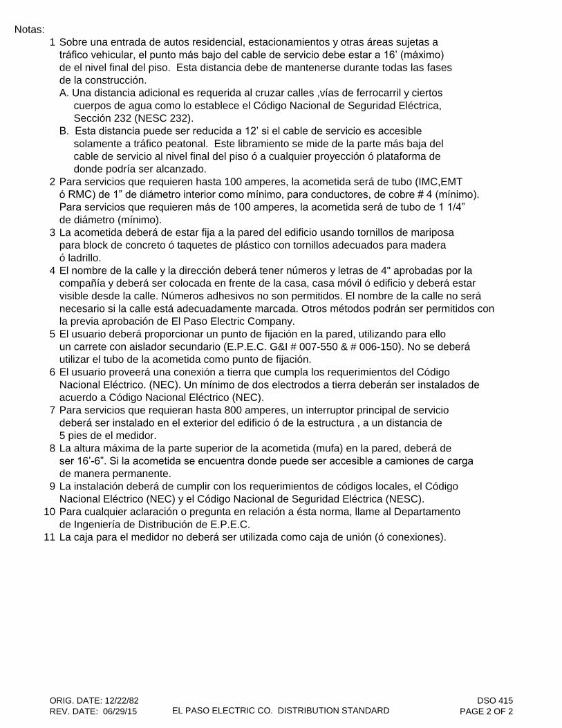
Notas:1 Sobre una entrada de autos residencial, estacionamientos y otras áreas sujetas a
tráfico vehicular, el punto más bajo del cable de servicio debe estar a 16’ (máximo)
de el nivel final del piso. Esta distancia debe de mantenerse durante todas las fasesde la construcción.A. Una distancia adicional es requerida al cruzar calles ,vías de ferrocarril y ciertos cuerpos de agua como lo establece el Código Nacional de Seguridad Eléctrica, Sección 232 (NESC 232).B. Esta distancia puede ser reducida a 12’ si el cable de servicio es accesible
solamente a tráfico peatonal. Este libramiento se mide de la parte más baja del cable de servicio al nivel final del piso ó a cualquier proyección ó plataforma de donde podría ser alcanzado.
2 Para servicios que requieren hasta 100 amperes, la acometida será de tubo (IMC,EMTó RMC) de 1” de diámetro interior como mínimo, para conductores, de cobre # 4 (mínimo).
Para servicios que requieren más de 100 amperes, la acometida será de tubo de 1 1/4”
de diámetro (mínimo).3 La acometida deberá de estar fija a la pared del edificio usando tornillos de mariposa
para block de concreto ó taquetes de plástico con tornillos adecuados para maderaó ladrillo.
4 El nombre de la calle y la dirección deberá tener números y letras de 4" aprobadas por la compañía y deberá ser colocada en frente de la casa, casa móvil ó edificio y deberá estarvisible desde la calle. Números adhesivos no son permitidos. El nombre de la calle no será necesario si la calle está adecuadamente marcada. Otros métodos podrán ser permitidos con la previa aprobación de El Paso Electric Company.
5 El usuario deberá proporcionar un punto de fijación en la pared, utilizando para elloun carrete con aislador secundario (E.P.E.C. G&I # 007-550 & # 006-150). No se deberáutilizar el tubo de la acometida como punto de fijación.
6 El usuario proveerá una conexión a tierra que cumpla los requerimientos del CódigoNacional Eléctrico. (NEC). Un mínimo de dos electrodos a tierra deberán ser instalados deacuerdo a Código Nacional Eléctrico (NEC).
7 Para servicios que requieran hasta 800 amperes, un interruptor principal de serviciodeberá ser instalado en el exterior del edificio ó de la estructura , a un distancia de5 pies de el medidor.
8 La altura máxima de la parte superior de la acometida (mufa) en la pared, deberá deser 16’-6”. Si la acometida se encuentra donde puede ser accesible a camiones de carga
de manera permanente.9 La instalación deberá de cumplir con los requerimientos de códigos locales, el Código
Nacional Eléctrico (NEC) y el Código Nacional de Seguridad Eléctrica (NESC).10 Para cualquier aclaración o pregunta en relación a ésta norma, llame al Departamento
de Ingeniería de Distribución de E.P.E.C.11 La caja para el medidor no deberá ser utilizada como caja de unión (ó conexiones).
ORIG. DATE: 12/22/82REV. DATE: 06/29/15 EL PASO ELECTRIC CO. DISTRIBUTION STANDARD
DSO 415PAGE 2 OF 2
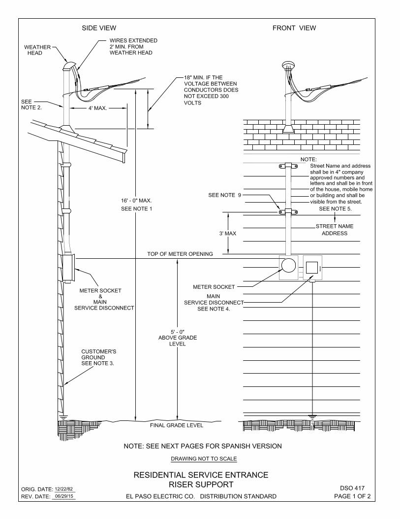

NOTES:1 16' MAX. CLEARANCE IS REQUIRED FOR SERVICE DROPS CROSSING RESIDENTIAL DRIVEWAYS, PARKING
LOTS AND OTHER AREAS SUBJECT TO VEHICULAR TRAFFIC. THE CLEARANCE IS MEASURED FROMTHE LOWEST PART OF THE SERVICE DROP TO FINAL GRADE. ALL CLEARANCES MUST BE MAINTAINED DURING ALL PHASES OF CONSTRUCTION. A. ADDITIONAL CLEARANCE IS REQUIRED OVER STREET CROSSINGS, RAILWAYS AND CERTAIN BODIES OF WATER AS OUTLINED IN NESC 232. B. THIS CLEARANCE MAY BE REDUCED TO 12' IF THE SERVICE DROP IS ACCESSIBLE ONLY TO PEDESTRIANS. THIS CLEARANCE IS MEASURED FROM THE LOWEST PART OF THE SERVICE DROP TO FINAL GRADE OR ANY PROJECTION OR PLATFORM FROM WHICH IT MIGHT BE REACHED.
2 FOR SERVICES UP TO 100 AMPS, THE RISER MUST BE 1 1/4" MINIMUM (IMC OR RMC). FOR CONDUCTORS, # 4 COPPER ( MINIMUM ).FOR SERVICES OVER 100 AMPS, THE RISER MUST BE 2" MINIMUM (IMC OR RMC).RISER SHALL NOT EXTEND MORE THAN 3' ABOVE THE ROOF EXCEPT BY SPECIALPERMISSION BY THE ELECTRICAL INSPECTOR. RISER CONDUIT MUST BE INTERMEDIATE METALLICCONDUIT OR RIGID METALLIC CONDUIT.
3 A GROUND MEETING THE NATIONAL ELECTRICAL CODE REQUIREMENTS SHALL BE PROVIDED BY THECUSTOMER. A MINIMUM OF TWO GROUND ELECTRODES SHALL BE INSTALLED ACCORDING TO N.E.C..
4 FOR A SERVICE OF 800 AMPS OR LESS,THE MAIN SERVICE DISCONNECT SHALL BE INSTALLED ON THE EXTERIOR OF THE BUILDING OR STRUCTURE, WITHIN 5 FEET OF THE METER.
5 STREET NAME AND ADDRESS SHALL BE IN 4" COMPANY APPROVED NUMBERS AND LETTERS AND SHALL BE ON THE FRONT OF THE HOUSE, MOBILE HOME OR BUILDING AND SHALL BE VISIBLE FROM THESTREET. ADHESIVE DECALS ARE NOT ALLOWED. THE STREET NAME IS NOT REQUIRED IF THE STREETIS ADEQUATELY MARKED. OTHER METHODS MAY BE ALLOWED IF PRIOR APPROVAL FROM E.P.E.C. ISOBTAINED.
6 INSTALLATION MUST COMPLY WITH ALL LOCAL CODE REQUIREMENTS, NATIONAL ELECTRIC CODEAND THE NATIONAL ELECTRIC SAFETY CODE.
7 FOR ANY CLARIFICATION OR QUESTIONS REGARDING THIS STANDARD CONTACT THE E.P.E.C. DISTRIBUTION DESIGN & DELIVERY DEPARTMENT.
8 METER CAN, CAN NOT BE USED AS A JUNCTION BOX.9 RISER MUST BE SECURELY ATTACHED TO THE WALL OF THE BUILDING. USE TOGGLE BOLTS FOR
CINDER BLOCK OR PLASTIC SHIELDS WITH THE APPROPRIATE SCREWS FOR WOOD OR BRICK.FIRST SUPPORTING STRAP FOR THE RISER CONDUIT SHALL BE INSTALLED NO MORE THAN THREE ( 3 ) FEET FROM THE TOP OF THE METER ENCLOSURE.
ORIG. DATE: 12/22/82REV. DATE: 06/29/15 EL PASO ELECTRIC CO. DISTRIBUTION STANDARD
DSO 417PAGE 2 OF 2
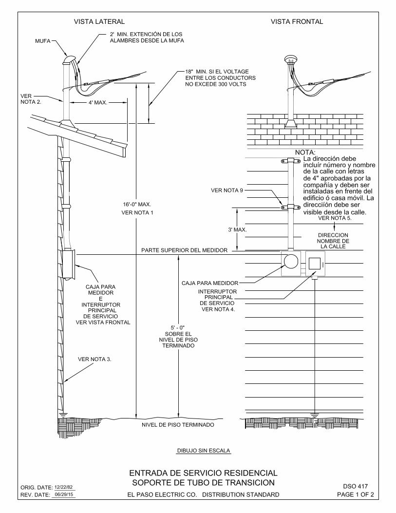

Notas:1 Sobre una entrada de autos residencial, estacionamientos y otras áreas sujetas a
tráfico vehicular, el punto mas bajo del cable de servicio debe estar por lo menos a 16’ (máximo)de el nivel final del piso. Esta distancia debe de mantenerse durante todas las fases de la construcción.A. Una distancia adicional es requerida al cruzar calles, vías de ferrocarril y ciertos cuerpos de agua como lo establece el Código Nacional de Seguridad Eléctrica, sección 232 (NESC 232).B. Esta distancia puede ser reducida a 12’ si el cable de servicio es accesible solamente a tráfico peatonal. Este libramiento se mide de la parte más baja del cable de servicio al nivel final del piso ó a cualquier proyección ó plataforma de donde podría ser alcanzado.
2 Para servicios que requieren hasta 100 amperes, la acometida será de tubo (IMC ó RMC) de 1 ¼” diámetro interior como mínimo, para conductores de cobre # 4 (mínimo).para servicios que requieren más de 100 amperes, la acometida será de tubo (IMC ó RMC) de 2” de diámetro. La acometida no deberá de extenderse más de 3’ por encima del techo, excepto por permiso especial del inspector eléctrico. El tubo de la acometida debe ser de tubo metálico intermedio (IMC) o tubo metálico rígido (RUC).
3 El usuario proveerá una conexión a tierra que cumpla los requerimientos del Código Nacional Eléctrico (NEC). Un mínimo de dos electrodos a tierra deberán ser instalados deacuerdo a Código Nacional Eléctrico (NEC).
4 Para servicios que requieran hasta 800 amperes, un interruptor principal de servicio deberá ser instalado en el exterior del edificio ó de la estructura , a una distancia de 5 pies de el medidor.
5 El nombre de la calle y la dirección deberán tener números y letras de 4" aprobadas por la compañía y deberá ser colocada en frente de la casa, casa móvil ó edificio y deberá estarvisible desde la calle. Números adhesivos no son permitidos. El nombre de la calle no será necesario si la calle está adecuadamente marcada. Otros métodos podrán ser permitidos con la previa aprobación de El Paso Electric Company.
6 La instalación deberá de cumplir con los requerimientos de códigos locales, el CódigoNacional Eléctrico (NEC), y el Código Nacional de Seguridad Eléctrica (NESC).
7 Para cualquier aclaración ó pregunta en relación a ésta norma, llame al Departamento de Ingeniería de Distribución de (El Paso Electric Company).
8 La caja para el medidor no deberá ser utilizada como caja de unión (ó conexiones).9 La acometida deberá de estar fija a la pared del edificio usando tornillos de mariposa
para block de concreto ó taquetes de plástico con tornillos adecuados para maderaó ladrillo. La primera atadura que sostiene el tubo de la acometida deberá ser instalada a no más de (3) tres pies arriba de la caja para el medidor.
ORIG. DATE: 12/22/82REV. DATE: 06/29/15 EL PASO ELECTRIC CO. DISTRIBUTION STANDARD
DSO 417PAGE 2 OF 2
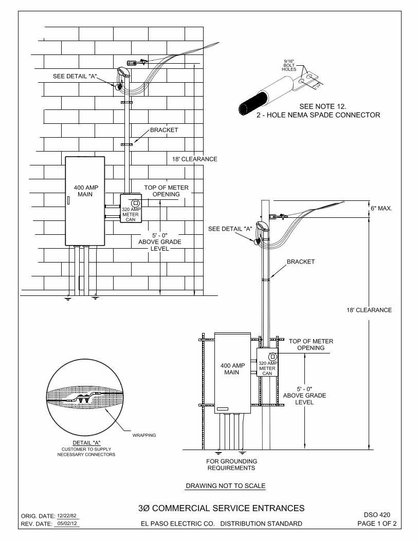
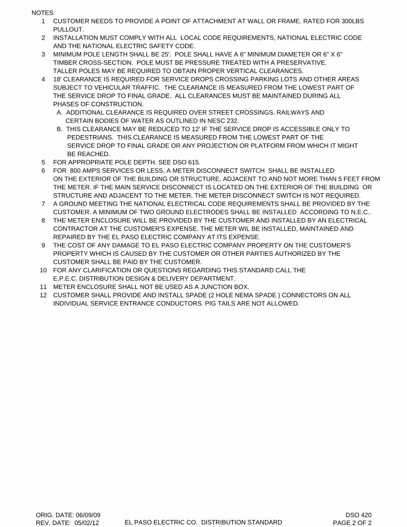
NOTES:1 CUSTOMER NEEDS TO PROVIDE A POINT OF ATTACHMENT AT WALL OR FRAME. RATED FOR 300LBS
PULLOUT.2 INSTALLATION MUST COMPLY WITH ALL LOCAL CODE REQUIREMENTS, NATIONAL ELECTRIC CODE
AND THE NATIONAL ELECTRIC SAFETY CODE.3 MINIMUM POLE LENGTH SHALL BE 25'. POLE SHALL HAVE A 6" MINIMUM DIAMETER OR 6" X 6"
TIMBER CROSS-SECTION. POLE MUST BE PRESSURE TREATED WITH A PRESERVATIVE.TALLER POLES MAY BE REQUIRED TO OBTAIN PROPER VERTICAL CLEARANCES.
4 18' CLEARANCE IS REQUIRED FOR SERVICE DROPS CROSSING PARKING LOTS AND OTHER AREASSUBJECT TO VEHICULAR TRAFFIC. THE CLEARANCE IS MEASURED FROM THE LOWEST PART OF THE SERVICE DROP TO FINAL GRADE. ALL CLEARANCES MUST BE MAINTAINED DURING ALL PHASES OF CONSTRUCTION. A. ADDITIONAL CLEARANCE IS REQUIRED OVER STREET CROSSINGS, RAILWAYS AND CERTAIN BODIES OF WATER AS OUTLINED IN NESC 232. B. THIS CLEARANCE MAY BE REDUCED TO 12' IF THE SERVICE DROP IS ACCESSIBLE ONLY TO PEDESTRIANS. THIS CLEARANCE IS MEASURED FROM THE LOWEST PART OF THE SERVICE DROP TO FINAL GRADE OR ANY PROJECTION OR PLATFORM FROM WHICH IT MIGHT BE REACHED.
5 FOR APPROPRIATE POLE DEPTH. SEE DSO 615.6 FOR 800 AMPS SERVICES OR LESS, A METER DISCONNECT SWITCH SHALL BE INSTALLED
ON THE EXTERIOR OF THE BUILDING OR STRUCTURE, ADJACENT TO AND NOT MORE THAN 5 FEET FROM THE METER. IF THE MAIN SERVICE DISCONNECT IS LOCATED ON THE EXTERIOR OF THE BUILDING OR STRUCTURE AND ADJACENT TO THE METER, THE METER DISCONNECT SWITCH IS NOT REQUIRED.
7 A GROUND MEETING THE NATIONAL ELECTRICAL CODE REQUIREMENTS SHALL BE PROVIDED BY THECUSTOMER. A MINIMUM OF TWO GROUND ELECTRODES SHALL BE INSTALLED ACCORDING TO N.E.C..
8 THE METER ENCLOSURE WILL BE PROVIDED BY THE CUSTOMER AND INSTALLED BY AN ELECTRICALCONTRACTOR AT THE CUSTOMER'S EXPENSE. THE METER WIL BE INSTALLED, MAINTAINED AND REPAIRED BY THE EL PASO ELECTRIC COMPANY AT ITS EXPENSE.
9 THE COST OF ANY DAMAGE TO EL PASO ELECTRIC COMPANY PROPERTY ON THE CUSTOMER'SPROPERTY WHICH IS CAUSED BY THE CUSTOMER OR OTHER PARTIES AUTHORIZED BY THECUSTOMER SHALL BE PAID BY THE CUSTOMER.
10 FOR ANY CLARIFICATION OR QUESTIONS REGARDING THIS STANDARD CALL THE E.P.E.C. DISTRIBUTION DESIGN & DELIVERY DEPARTMENT.
11 METER ENCLOSURE SHALL NOT BE USED AS A JUNCTION BOX.12 CUSTOMER SHALL PROVIDE AND INSTALL SPADE (2 HOLE NEMA SPADE ) CONNECTORS ON ALL
INDIVIDUAL SERVICE ENTRANCE CONDUCTORS. PIG TAILS ARE NOT ALLOWED.
ORIG. DATE: 06/09/09REV. DATE: 05/02/12 EL PASO ELECTRIC CO. DISTRIBUTION STANDARD
DSO 420PAGE 2 OF 2

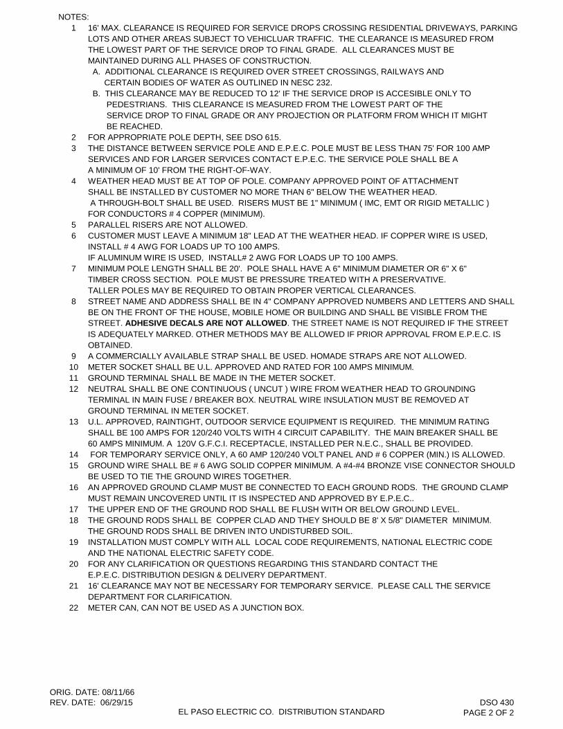
NOTES:1 16' MAX. CLEARANCE IS REQUIRED FOR SERVICE DROPS CROSSING RESIDENTIAL DRIVEWAYS, PARKING
LOTS AND OTHER AREAS SUBJECT TO VEHICLUAR TRAFFIC. THE CLEARANCE IS MEASURED FROMTHE LOWEST PART OF THE SERVICE DROP TO FINAL GRADE. ALL CLEARANCES MUST BE MAINTAINED DURING ALL PHASES OF CONSTRUCTION. A. ADDITIONAL CLEARANCE IS REQUIRED OVER STREET CROSSINGS, RAILWAYS AND CERTAIN BODIES OF WATER AS OUTLINED IN NESC 232. B. THIS CLEARANCE MAY BE REDUCED TO 12' IF THE SERVICE DROP IS ACCESIBLE ONLY TO PEDESTRIANS. THIS CLEARANCE IS MEASURED FROM THE LOWEST PART OF THE SERVICE DROP TO FINAL GRADE OR ANY PROJECTION OR PLATFORM FROM WHICH IT MIGHT BE REACHED.
2 FOR APPROPRIATE POLE DEPTH, SEE DSO 615.3 THE DISTANCE BETWEEN SERVICE POLE AND E.P.E.C. POLE MUST BE LESS THAN 75' FOR 100 AMP
SERVICES AND FOR LARGER SERVICES CONTACT E.P.E.C. THE SERVICE POLE SHALL BE AA MINIMUM OF 10' FROM THE RIGHT-OF-WAY.
4 WEATHER HEAD MUST BE AT TOP OF POLE. COMPANY APPROVED POINT OF ATTACHMENT SHALL BE INSTALLED BY CUSTOMER NO MORE THAN 6" BELOW THE WEATHER HEAD. A THROUGH-BOLT SHALL BE USED. RISERS MUST BE 1" MINIMUM ( IMC, EMT OR RIGID METALLIC )FOR CONDUCTORS # 4 COPPER (MINIMUM).
5 PARALLEL RISERS ARE NOT ALLOWED.6 CUSTOMER MUST LEAVE A MINIMUM 18" LEAD AT THE WEATHER HEAD. IF COPPER WIRE IS USED,
INSTALL # 4 AWG FOR LOADS UP TO 100 AMPS. IF ALUMINUM WIRE IS USED, INSTALL# 2 AWG FOR LOADS UP TO 100 AMPS.
7 MINIMUM POLE LENGTH SHALL BE 20'. POLE SHALL HAVE A 6" MINIMUM DIAMETER OR 6" X 6"TIMBER CROSS SECTION. POLE MUST BE PRESSURE TREATED WITH A PRESERVATIVE.TALLER POLES MAY BE REQUIRED TO OBTAIN PROPER VERTICAL CLEARANCES.
8 STREET NAME AND ADDRESS SHALL BE IN 4" COMPANY APPROVED NUMBERS AND LETTERS AND SHALL BE ON THE FRONT OF THE HOUSE, MOBILE HOME OR BUILDING AND SHALL BE VISIBLE FROM THESTREET. ADHESIVE DECALS ARE NOT ALLOWED. THE STREET NAME IS NOT REQUIRED IF THE STREETIS ADEQUATELY MARKED. OTHER METHODS MAY BE ALLOWED IF PRIOR APPROVAL FROM E.P.E.C. ISOBTAINED.
9 A COMMERCIALLY AVAILABLE STRAP SHALL BE USED. HOMADE STRAPS ARE NOT ALLOWED.10 METER SOCKET SHALL BE U.L. APPROVED AND RATED FOR 100 AMPS MINIMUM.11 GROUND TERMINAL SHALL BE MADE IN THE METER SOCKET.12 NEUTRAL SHALL BE ONE CONTINUOUS ( UNCUT ) WIRE FROM WEATHER HEAD TO GROUNDING
TERMINAL IN MAIN FUSE / BREAKER BOX. NEUTRAL WIRE INSULATION MUST BE REMOVED ATGROUND TERMINAL IN METER SOCKET.
13 U.L. APPROVED, RAINTIGHT, OUTDOOR SERVICE EQUIPMENT IS REQUIRED. THE MINIMUM RATINGSHALL BE 100 AMPS FOR 120/240 VOLTS WITH 4 CIRCUIT CAPABILITY. THE MAIN BREAKER SHALL BE60 AMPS MINIMUM. A 120V G.F.C.I. RECEPTACLE, INSTALLED PER N.E.C., SHALL BE PROVIDED.
14 FOR TEMPORARY SERVICE ONLY, A 60 AMP 120/240 VOLT PANEL AND # 6 COPPER (MIN.) IS ALLOWED.15 GROUND WIRE SHALL BE # 6 AWG SOLID COPPER MINIMUM. A #4-#4 BRONZE VISE CONNECTOR SHOULD
BE USED TO TIE THE GROUND WIRES TOGETHER.16 AN APPROVED GROUND CLAMP MUST BE CONNECTED TO EACH GROUND RODS. THE GROUND CLAMP
MUST REMAIN UNCOVERED UNTIL IT IS INSPECTED AND APPROVED BY E.P.E.C.. 17 THE UPPER END OF THE GROUND ROD SHALL BE FLUSH WITH OR BELOW GROUND LEVEL.18 THE GROUND RODS SHALL BE COPPER CLAD AND THEY SHOULD BE 8' X 5/8" DIAMETER MINIMUM.
THE GROUND RODS SHALL BE DRIVEN INTO UNDISTURBED SOIL.19 INSTALLATION MUST COMPLY WITH ALL LOCAL CODE REQUIREMENTS, NATIONAL ELECTRIC CODE
AND THE NATIONAL ELECTRIC SAFETY CODE.20 FOR ANY CLARIFICATION OR QUESTIONS REGARDING THIS STANDARD CONTACT THE
E.P.E.C. DISTRIBUTION DESIGN & DELIVERY DEPARTMENT.21 16' CLEARANCE MAY NOT BE NECESSARY FOR TEMPORARY SERVICE. PLEASE CALL THE SERVICE
DEPARTMENT FOR CLARIFICATION.22 METER CAN, CAN NOT BE USED AS A JUNCTION BOX.
ORIG. DATE: 08/11/66REV. DATE: 06/29/15
EL PASO ELECTRIC CO. DISTRIBUTION STANDARDDSO 430
PAGE 2 OF 2


Notas:1 Sobre una entrada de autos residencial, estacionamientos y otras áreas sujetas a tráfico vehicular, el
punto más bajo del cable de servicio debe estar por lo menos a 16’ (máximo) del nivel final del piso. Esta
distancia debe de mantenerse durante todas las fases de la construcción.A. Una distancia adicional es requerida al cruzar calles, vías de ferrocarril y ciertos cuerpos de agua como lo establece el Código Nacional de Seguridad Eléctrica, Sección 232 (NESC 232).B. Esta distancia puede ser reducida a 12’ si el cable de servicio es accesible solamente a tráfico
peatonal. Este libramiento se mide de la parte más baja del cable de servicio al nivel final del piso ó a cualquier proyección ó plataforma de donde podría ser alcanzado.
2 Para el empotramiento adecuado de postes, ver DSO 615.3 La distancia entre el poste de servicio y el poste de E.P.E.C. deberá ser de 75’ ó menos para servicios
de 100 amperes. Para servicios más grandes favor de llamar a E.P.E.C. El poste de servicio debe de instalarse a una distancia mínima de 10’ del derecho de vía.
4 La acometida (mufa) deberá ser instalada en la parte superior del poste. El punto de sujeción del cable aprobado por E.P.E.C. debe de ser instalado por el usuario a una distancia no mayor de 6" debajo de la acometida, usando un tornillo de rosca continua. La acometida será de tubo de 1" de diámetro interior como mínimo (IMC, EMT ó tubo metálico rígido) para conductores de cobre #4 (mínimo).
5 No se permiten acometidas paralelas.6 El usuario deberá dejar un mínimo de 18” de cable saliendo de la acometida. Si se usa alambre de cobre,
alambre # 4 awg para cargas eléctricas hasta 100 amperes deberá ser utilizado. Si se usa alambre dealuminio, alambre # 2 awg para cargas eléctricas hasta 100 amperes deberá ser utilizado.
7 El poste debe medir 20’ de largo como mínimo. El poste debe ser redondo con un diámetro mínimo
de 6” ó poste cuadrado de 6” x 6” de madera sólida. El poste deberá de ser tratado a presión con un
conservante. Postes más largos pueden ser requeridos para obtener los libramientos verticalesadecuados. Ver Nota 1.
8 El nombre de la calle y la dirección deberá tener números y letras de 4" aprobadas por la compañía y deberá ser colocada en frente de la casa, casa móvil ó edificio y deberá estarvisible desde la calle. Números adhesivos no son permitidos. El nombre de la calle no será necesariosi la calle está adecuadamente marcada. Otros métodos podrán ser permitidos con la previa aprobaciónde El Paso Electric Company.
9 Solamente utilice abrazaderas de tipo comercial. No se permiten abrazaderas hechas a mano ó improvisadas.
10 El receptáculo para el medidor deberá tener el sello U.L. y aprobado para 100 amperesmínimo.
11 La terminal (conexión) a tierra deberá de hacerse en la base del medidor.12 El cable neutro deberá ser continuo (sin uniones) desde la acometida hasta la terminal de tierra en la
caja principal de fusibles ó interruptores. El aislante del alambre neutro será removido de la terminal atierra en la base del medidor.
13 Se requiere la utilización de equipo para servicio exterior, a prueba de agua, con el sello de aprobaciónU.L. El equipo deberá de estar aprobado para 100 amperes con voltajes de 120/240 con capacidad para 4 circuitos. El interruptor principal deberá de estar aprobado para 60 amperes como mínimo.Un tomacorriente de 120 v, con protección de fallas a tierra (G.F.C.I.), instalado de acuerdo con elel Código Nacional Eléctrico (NEC) deberá de ser proveído.
14 Unicamente para servicios temporales, se permite el uso de equipo aprobado para 60 amperes concon voltajes de 120/240.
15 El alambre de tierra deberá de ser #6 awg (mínimo) de cobre sólido. Un conector de tornillo de bronce de tamaño #4-#4 deberá ser utilizado para unir los alambres de tierra.
16 Una abrazadera aprobada deberá de usarse para conectar el alambre a cada una de las varillas de tierra. Esta conexión deberá permanecer descubierta hasta ser inspeccionada y aprobada por E.P.E.C.
17 La parte superior de la varilla de tierra deberá estar al nivel del terreno ó por debajo de éste.18 Los electrodos (varillas) de tierra deberán de tener una superficie de cobre y deberán medir como mínimo
8’ de largo y 5/8” de diámetro. Las varillas deberán de enterrarse completamente en suelo firme.
19 La instalación deberá de cumplir con los requerimientos de códigos locales, el Código NacionalEléctrico (NEC) y el Código Nacional de Seguridad Eléctrica (NESC).
20 Para cualquier clarificación ó pregunta en relación a ésta norma, llame al Departamento de Ingenieríade Distribución de E.P.E.C.
21 Para servicios temporales, un libramiento de 16’ podría no ser necesario. Por favor llame al Departamento
de Servicio para aclaraciones.22 El medidor no deberá ser utilizado como caja de unión.
ORIG. DATE: 08/11/66REV. DATE: 06/29/15 EL PASO ELECTRIC CO. DISTRIBUTION STANDARD
DSO 430PAGE 2 OF 2


NOTES:1 THE CUSTOMER SHALL INSTALL, OPERATE AND MAINTAIN A SUITABLE SERVICE POLE, SERVICE
ENTRANCE EQUIPMENT, POLE RISER, LOW VOLTAGE CABLE, CONDUIT AND OTHER NECESSARYEQUIPMENT MAKING UP ITS ELECTRICAL SYSTEM.
2 INSTALLATION MUST COMPLY WITH ALL LOCAL CODE REQUIREMENTS, NATIONAL ELECTRIC CODEAND THE NATIONAL ELECTRIC SAFETY CODE.
3 WEATHER HEAD MUST BE AT TOP OF POLE. COMPANY APPROVED POINT OF ATTACHMENT SHALL BE INSTALLED BY CUSTOMER NO MORE THAN 6" BELOW THE WEATHER HEAD. A THROUGH-BOLT SHALL BE USED. RISERS MUST BE 1" MINIMUM ( IMC, EMT OR RIGID METALLIC )FOR CONDUCTORS # 4 COPPER (MINIMUM).SEE N.E.C. FOR SIZE OF CONDUIT FOR CONDUCTORS LARGER THAN # 4 COPPER.
4 MINIMUM POLE LENGTH SHALL BE 25'. POLE SHALL HAVE A 6" MINIMUM DIAMETER OR 6" X 6"TIMBER CROSS-SECTION. POLE MUST BE PRESSURE TREATED WITH A PRESERVATIVE.TALLER POLES MAY BE REQUIRED TO OBTAIN PROPER VERTICAL CLEARANCES.
5 18' CLEARANCE IS REQUIRED FOR SERVICE DROPS CROSSING PARKING LOTS AND OTHER AREASSUBJECT TO VEHICULAR TRAFFIC. THE CLEARANCE IS MEASURED FROM THE LOWEST PART OF THE SERVICE DROP TO FINAL GRADE. ALL CLEARANCES MUST BE MAINTAINED DURING ALL PHASES OF CONSTRUCTION. A. ADDITIONAL CLEARANCE IS REQUIRED OVER STREET CROSSINGS, RAILWAYS AND CERTAIN BODIES OF WATER AS OUTLINED IN NESC 232. B. THIS CLEARANCE MAY BE REDUCED TO 12' IF THE SERVICE DROP IS ACCESSIBLE ONLY TO PEDESTRIANS. THIS CLEARANCE IS MEASURED FROM THE LOWEST PART OF THE SERVICE DROP TO FINAL GRADE OR ANY PROJECTION OR PLATFORM FROM WHICH IT MIGHT BE REACHED.
6 FOR APPROPRIATE POLE DEPTH, SEE DSO 615.7 A GROUND MEETING THE NATIONAL ELECTRICAL CODE REQUIREMENTS SHALL BE PROVIDED BY THE
CUSTOMER. A MINIMUM OF TWO GROUND ELECTRODES SHALL BE INSTALLED ACCORDING TO N.E.C..8 THE LOCATION OF THE POLE AND METER, WILL BE DESIGNATED BY E.P.E.C.. 9 THE METER ENCLOSURE WILL BE PROVIDED BY THE CUSTOMER AND INSTALLED BY AN ELECTRICAL
CONTRACTOR AT THE CUSTOMER'S EXPENSE. THE METER WILL BE INSTALLED, MAINTAINED AND REPAIRED BY THE EL PASO ELECTRIC COMPANY AT ITS EXPENSE.
10 THE SERVICE DISCONNECTING MEANS FOR SERVICES OF 800 AMPS OR LESS SHALL BE ALOADBREAK-RATED METER DISCONNECT AND SHALL BE INSTALLED ON THE EXTERIOR OF THE BUILDING OR STRUCTURE ADJACENT TO AND NOT MORE THAN FIVE (5 ) FEET FROM THE METER.
11 THE COST OF ANY DAMAGE TO EL PASO ELECTRIC COMPANY PROPERTY ON THE CUSTOMER'S PROPERTY WHICH IS CAUSED BY THE CUSTOMER OR OTHER PARTIES AUTHORIZED BY THE CUSTOMER SHALL BE PAID BY THE CUSTOMER.
12 FOR ANY CLARIFICATION OR QUESTIONS REGARDING THIS STANDARD, CALL THE E.P.E.C. DISTRIBUTION DESIGN AND DELIVERY DEPARTMENT.
ORIG. DATE: 03/08/05REV. DATE: 05/02/12 EL PASO ELECTRIC CO. DISTRIBUTION STANDARD
DSO 432PAGE 2 OF 2
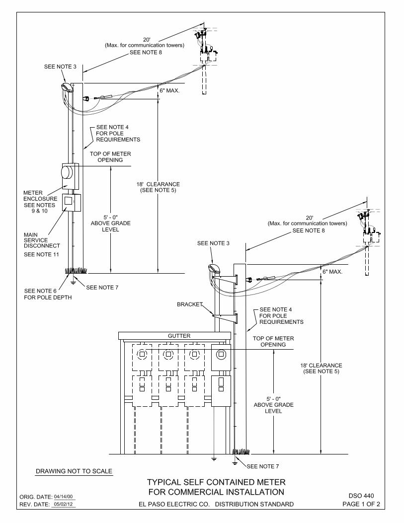
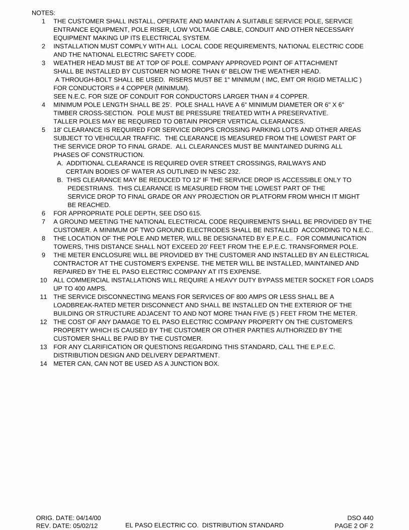
NOTES:1 THE CUSTOMER SHALL INSTALL, OPERATE AND MAINTAIN A SUITABLE SERVICE POLE, SERVICE
ENTRANCE EQUIPMENT, POLE RISER, LOW VOLTAGE CABLE, CONDUIT AND OTHER NECESSARYEQUIPMENT MAKING UP ITS ELECTRICAL SYSTEM.
2 INSTALLATION MUST COMPLY WITH ALL LOCAL CODE REQUIREMENTS, NATIONAL ELECTRIC CODEAND THE NATIONAL ELECTRIC SAFETY CODE.
3 WEATHER HEAD MUST BE AT TOP OF POLE. COMPANY APPROVED POINT OF ATTACHMENT SHALL BE INSTALLED BY CUSTOMER NO MORE THAN 6" BELOW THE WEATHER HEAD. A THROUGH-BOLT SHALL BE USED. RISERS MUST BE 1" MINIMUM ( IMC, EMT OR RIGID METALLIC )FOR CONDUCTORS # 4 COPPER (MINIMUM).SEE N.E.C. FOR SIZE OF CONDUIT FOR CONDUCTORS LARGER THAN # 4 COPPER.
4 MINIMUM POLE LENGTH SHALL BE 25'. POLE SHALL HAVE A 6" MINIMUM DIAMETER OR 6" X 6"TIMBER CROSS-SECTION. POLE MUST BE PRESSURE TREATED WITH A PRESERVATIVE.TALLER POLES MAY BE REQUIRED TO OBTAIN PROPER VERTICAL CLEARANCES.
5 18' CLEARANCE IS REQUIRED FOR SERVICE DROPS CROSSING PARKING LOTS AND OTHER AREASSUBJECT TO VEHICULAR TRAFFIC. THE CLEARANCE IS MEASURED FROM THE LOWEST PART OF THE SERVICE DROP TO FINAL GRADE. ALL CLEARANCES MUST BE MAINTAINED DURING ALL PHASES OF CONSTRUCTION. A. ADDITIONAL CLEARANCE IS REQUIRED OVER STREET CROSSINGS, RAILWAYS AND CERTAIN BODIES OF WATER AS OUTLINED IN NESC 232. B. THIS CLEARANCE MAY BE REDUCED TO 12' IF THE SERVICE DROP IS ACCESSIBLE ONLY TO PEDESTRIANS. THIS CLEARANCE IS MEASURED FROM THE LOWEST PART OF THE SERVICE DROP TO FINAL GRADE OR ANY PROJECTION OR PLATFORM FROM WHICH IT MIGHT BE REACHED.
6 FOR APPROPRIATE POLE DEPTH, SEE DSO 615.7 A GROUND MEETING THE NATIONAL ELECTRICAL CODE REQUIREMENTS SHALL BE PROVIDED BY THE
CUSTOMER. A MINIMUM OF TWO GROUND ELECTRODES SHALL BE INSTALLED ACCORDING TO N.E.C..8 THE LOCATION OF THE POLE AND METER, WILL BE DESIGNATED BY E.P.E.C.. FOR COMMUNICATION
TOWERS, THIS DISTANCE SHALL NOT EXCEED 20' FEET FROM THE E.P.E.C. TRANSFORMER POLE. 9 THE METER ENCLOSURE WILL BE PROVIDED BY THE CUSTOMER AND INSTALLED BY AN ELECTRICAL
CONTRACTOR AT THE CUSTOMER'S EXPENSE. THE METER WILL BE INSTALLED, MAINTAINED AND REPAIRED BY THE EL PASO ELECTRIC COMPANY AT ITS EXPENSE.
10 ALL COMMERCIAL INSTALLATIONS WILL REQUIRE A HEAVY DUTY BYPASS METER SOCKET FOR LOADS UP TO 400 AMPS.
11 THE SERVICE DISCONNECTING MEANS FOR SERVICES OF 800 AMPS OR LESS SHALL BE ALOADBREAK-RATED METER DISCONNECT AND SHALL BE INSTALLED ON THE EXTERIOR OF THE BUILDING OR STRUCTURE ADJACENT TO AND NOT MORE THAN FIVE (5 ) FEET FROM THE METER.
12 THE COST OF ANY DAMAGE TO EL PASO ELECTRIC COMPANY PROPERTY ON THE CUSTOMER'S PROPERTY WHICH IS CAUSED BY THE CUSTOMER OR OTHER PARTIES AUTHORIZED BY THE CUSTOMER SHALL BE PAID BY THE CUSTOMER.
13 FOR ANY CLARIFICATION OR QUESTIONS REGARDING THIS STANDARD, CALL THE E.P.E.C. DISTRIBUTION DESIGN AND DELIVERY DEPARTMENT.
14 METER CAN, CAN NOT BE USED AS A JUNCTION BOX.
ORIG. DATE: 04/14/00REV. DATE: 05/02/12 EL PASO ELECTRIC CO. DISTRIBUTION STANDARD
DSO 440PAGE 2 OF 2

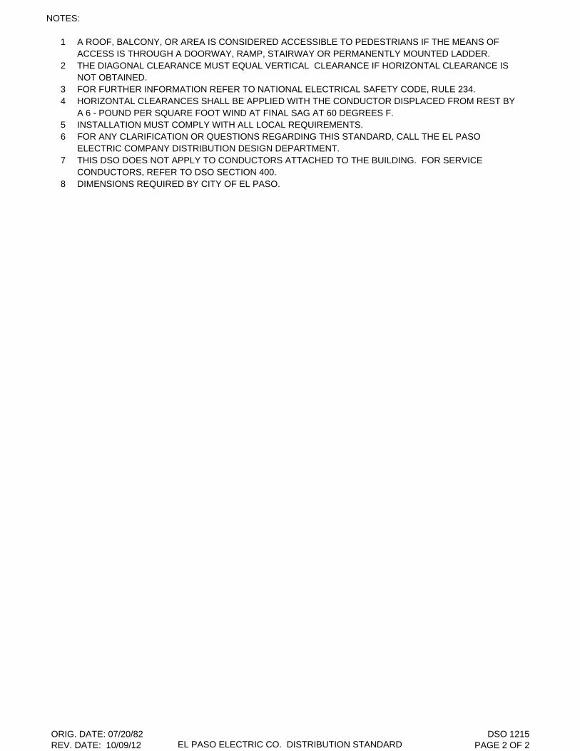
NOTES:
1 A ROOF, BALCONY, OR AREA IS CONSIDERED ACCESSIBLE TO PEDESTRIANS IF THE MEANS OFACCESS IS THROUGH A DOORWAY, RAMP, STAIRWAY OR PERMANENTLY MOUNTED LADDER.
2 THE DIAGONAL CLEARANCE MUST EQUAL VERTICAL CLEARANCE IF HORIZONTAL CLEARANCE ISNOT OBTAINED.
3 FOR FURTHER INFORMATION REFER TO NATIONAL ELECTRICAL SAFETY CODE, RULE 234.4 HORIZONTAL CLEARANCES SHALL BE APPLIED WITH THE CONDUCTOR DISPLACED FROM REST BY
A 6 - POUND PER SQUARE FOOT WIND AT FINAL SAG AT 60 DEGREES F.5 INSTALLATION MUST COMPLY WITH ALL LOCAL REQUIREMENTS.6 FOR ANY CLARIFICATION OR QUESTIONS REGARDING THIS STANDARD, CALL THE EL PASO
ELECTRIC COMPANY DISTRIBUTION DESIGN DEPARTMENT.7 THIS DSO DOES NOT APPLY TO CONDUCTORS ATTACHED TO THE BUILDING. FOR SERVICE
CONDUCTORS, REFER TO DSO SECTION 400.8 DIMENSIONS REQUIRED BY CITY OF EL PASO.
ORIG. DATE: 07/20/82REV. DATE: 10/09/12 EL PASO ELECTRIC CO. DISTRIBUTION STANDARD
DSO 1215PAGE 2 OF 2


NOTES:
1 THE RECOMMENDED MINIMUM CLEARANCES SHOWN ABOVE SHOULD BE INCREASED AS MUCH ASPRACTICABLE.
2 SIGNS SHOULD NEVER HANG OVER ANY ADJACENT POWER CIRCUITS.3 CLEARANCES BASED ON SECTION 234 OF N.E.S.C. 2007 EDITION.4 VOLTAGES ARE LINE TO GROUND.5 THE PREFERED DISTANCE IS 60" BUT SHALL NOT BE LESS THAN 12", FROM BACK OF CURB TO
FACE OF POLE (REFER TO N.E.S.C. RULE 231B).6 E.P.E.C. AND CITY OF EL PASO PREFERENCE IS 60" FOR ALL POLES. N.E.S.C. 231A RECOMMENDS
A MINIMUM OF 48" BUT ALLOWS 36" WHEN CONDITIONS DO NOT ALLOW 48".7 INSTALLATION MUST COMPLY WITH ALL LOCAL REQUIREMENTS.8 FOR ANY CLARIFICATION OR QUESTIONS REGARDING THIS STANDARD, CALL THE EL PASO
ELECTRIC COMPANY DISTRIBUTION DESIGN DEPARTMENT.
ORIG. DATE: 05/02/78REV DATE: 08/17/10 EL PASO ELECTRIC CO. DISTRIBUTION STANDARD
DSO 1220PAGE 2 OF 2


NOTES:
1 THE CENTERLINE OF ANY PRIMARY OR SECONDARY DISTRIBUTION LINE SHALL BE NO CLOSER THAN35 FEET TO A WATER WELL. THE DISTRIBUTION POLE LINE SHALL HAVE A MINIMUM VERTICALCLEARANCE TO THE LOWEST PHASE CONDUCTOR OF 33 FEET ABOVE THE FINISHED GRADE OF THE WELL SITE.
2 CARE SHOULD BE TAKEN, IF UNUSUAL CIRCUMSTANCES EXIST, TO INCREASE THIS CLEARANCE.THESE CIRCUMSTANCES COULD INCLUDE UNUSUALLY LARGE OR DEEP WELLS REQUIRING TALL SERVICE RIGS, GEOTHERMAL WELLS, OIL WELLS, ETC.
3 THIS CLEARANCE APPLIES TO ALL CONSTRUCTION AFTER THE DATE OF THIS STANDARD, AS WELLAS ANY PRESENT INSTALLATION CONSIDERED BY E.P.E.C. TO BE HAZARDOUS.
SHALL POLE LINE BE CLOSER THAN 20'THE CIRCUIT. BUT UNDER NO CIRCUMSTANCES PLACEMENT OF DRILLING EQUIPMENT UNDER PERPENDICULAR TO THE WELL TO DISCOURAGEA TANGENT POLE SHOULD BE INSTALLED* IF 35' CLEARANCE CAN NOT BE ATTAINED,
35'*
WELL
DIS
TR
IBU
TIO
N P
OLE
CE
NTE
R L
INE
CUSTOMER OWNED SERVICE POLE SHALLNOT BE CLOSER THAN 10' TO THE WELL. THE SERVICE DROP SHALL NOT CROSS AN ENTRANCE ROAD OR THE WELL.
ENTRANCE TO WELL
EN
TR
AN
CE
TO
WE
LL
ORIG. DATE: 05/08/85REV. DATE: 07/01/03
CLEARANCES FROM WELLSEL PASO ELECTRIC CO. DISTRIBUTION STANDARD
DSO 1235PAGE 1 OF 1


NOTES A - G :
A POOL EDGE WILL NOT BE ALLOWED WITHIN THE PLATTED OR PRIVATE UTILITY EASEMENT,USUALLY 5 FEET OR GREATER ON BOTH SIDES OF THE PROPERTY LINE.
B SECONDARY / SERVICE OR NEUTRAL: 22.5' MINIMUM DIAGONAL CLEARANCE FOR INSULATED SECONDARY / SERVICE. FOR BARE UNINSULATED SECONDARY, THE MINIMUM DIAGONAL CLEARANCE IS 23'. FOR NEUTRAL WIRES THE MINIMUM DIAGONAL CLEARANCE IS 22'.
C,D&E PRIMARY CONDUCTOR: 25' MINIMUM DIAGONAL CLEARANCE.SERVICE ENCLOSURE, RISER BASE AND SERVICE DUCT ( PVC ) TO BE PROVIDED AND INSTALLED BY ELECTRICAL SUBCONTRACTOR. EL PASO ELECTRIC COMPANY WILL INSTALL SERVICE CONDUCTORS AT CUSTOMER EXPENSE.
F RELOCATED OVERHEAD SERVICE POINT (WEATHERHEAD ) BY ELECTRICAL SUBCONTRACTOR. SERVICE CONDUCTORS TO BE RELOCATED BY E.P.E.C. PERSONNEL AT CUSTOMER EXPENSE.
G UNDERGROUND WIRING SHALL NOT BE PERMITTED UNDER THE POOL OR WITHIN THE AREAEXTENDING 5 FEET HORIZONTALLY FROM THE INSIDE WALL OF THE POOL.
NOTES 1 -6 :
1 ALL SWIMMING POOL PLANS SUBMITTED TO THE E.P.E.C. DISTRIBUTION DESIGN DEPARTMENT FOR APPROVAL MUST HAVE A WRITTEN STATEMENT ASSURING THE DIMENSIONS IN NOTES A, B & CWILL BE MAINTAINED.
2 THIS STANDARD COMPLIES WITH REQUIREMENTS FOR CLEARANCES OF OVERHEAD LINES TOSWIMMING POOLS AS STATED IN THE NATIONAL ELECTRICAL SAFETY CODE, 2012 LATEST REVISIONRULE 234E AND THE CURRENT CITY OF EL PASO ELECTRICAL CODE.
3 EL PASO ELECTRIC COMPANY WILL NOT DETERMINE THE ADEQUACY OF LOT SIZE OR AVAILABILITYFOR A VARIANCE FROM THE CITY OF EL PASO REGARDING INSTALLATION OF A SWIMMING POOL.
4 ALL CLEARANCES SHALL BE MEASURED FROM THE WATER LEVEL, EDGE OF POOL, OR BASE OFDIVING PLATFORM TO THE OUTERMOST EDGE OF THE INVOLVED EQUIPMENT, WIRE OR CABLE.
5 INSTALLATION MUST COMPLY WITH ALL LOCAL REQUIREMENTS.6 FOR ANY CLARIFICATION OR QUESTIONS REGARDING THIS STANDARD, CALL THE EL PASO
ELECTRIC COMPANY DISTRIBUTION DESIGN DEPARTMENT.
ORIG. DATE: 04/02/91REV. DATE: 10/27/13 EL PASO ELECTRIC CO. DISTRIBUTION STANDARD
DSO 1240PAGE 2 OF 2


NOTES:1 JOSLYN WIRE HOLDER TO BE USE FOR UP TO 4/0 CABLE. FOR LARGER CABLE USE ALUMINUM
STRAP, EYELET AND ALUMINUM STRAIN CLAMP.2 FOR PARALLEL RISERS, SEE DSO 1845 FOR DETAILS.3 3" MINIMUM IS REQUIRED BETWEEN A METER ENCLOSURE AND ANY ADJACENT EQUIPMENT.4 18' CLEARANCE IS REQUIRED FOR SERVICE DROPS CROSSING PARKING LOTS AND OTHER AREAS
SUBJECT TO VEHICULAR TRAFFIC. THE CLEARANCE IS MEASURED FROM THE LOWEST PART OF THE SERVICE DROP TO FINAL GRADE. ALL CLEARANCES MUST BE MAINTAINED DURING ALL PHASES OF CONSTRUCTION. A. ADDITIONAL CLEARANCE IS REQUIRED OVER STREET CROSSINGS, RAILWAYS AND CERTAIN BODIES OF WATER AS OUTLINED IN NESC 232. B. THIS CLEARANCE MAY BE REDUCED TO 12' IF THE SERVICE DROP IS ACCESSIBLE ONLY TO PEDESTRIANS. THIS CLEARANCE IS MEASURED FROM THE LOWEST PART OF THE SERVICE DROP TO FINAL GRADE OR ANY PROJECTION OR PLATFORM FROM WHICH IT MIGHT BE REACHED.
5 THERE SHALL BE NO MORE THAN SIX DISCONNECTS PER SERVICE GROUPED IN ANY ONELOCATION AS PER NATIONAL ELECTRICAL CODE, SECTION 230 - 71, PARAGRAPH "A".
6 SERVICE DISCONNECT NEEDED WHEN MORE THAN 6 METERS ARE USED.7 THE SERVICE DISCONNECTING MEANS FOR SERVICES OF 800 AMPS OR LESS SHALL BE A
LOADBREAK-RATED METER DISCONNECT AND SHALL BE INSTALLED ON THE EXTERIOR OF THE BUILDING OR STRUCTURE ADJACENT TO AND NOT MORE THAN FIVE (5 ) FEET FROM THE METER.
8 ALL COMMERCIAL INSTALLATIONS UP TO 400 AMPS WILL REQUIRE A HEAVY DUTY BYPASS METER SOCKET.
9 RIGID CONDUIT MUST BE USED IF SERVICE DROP IS ANCHORED TO MAST.10 ELECTRICAL CONTRACTORS ARE RESPONSIBLE FOR MARKING EACH METER ENCLOSURE
ACCURATELY WITH PERMANENT NUMBERS OR LETTERS TO CORRESPOND TO THE CORRECTUNIT, APARTMENT OR COMMERCIAL SUITES.
11 INSTALLATION MUST COMPLY WITH LOCAL CODE REQUIREMENTS, NATIONAL ELECTRIC CODEAND THE NATIONAL ELECTRIC SAFETY CODE.
12 A GROUND MEETING THE NATIONAL ELECTRICAL CODE REQUIREMENTS SHALL BE PROVIDED BY THECUSTOMER. A MINIMUM OF TWO GROUND ELECTRODES SHALL BE INSTALLED ACCORDING TO N.E.C..
13 FOR ANY CLARIFICATION OR QUESTIONS REGARDING THIS STANDARD, CALL THE EL PASO ELECTRIC COMPANY DISTRIBUTION DESIGN AND DELIVERY DEPARTMENT.
14 METER ENCLOSURE SHALL NOT BE USED AS A JUNCTION BOX.15 RISER MUST BE SECURELY ATTACHED TO THE WALL OF THE BUILDING. USE TOGGLE BOLTS FOR
CINDER BLOCK OR PLASTIC SHIELDS WITH THE APPROPRIATE SCREWS FOR WOOD OR BRICK.
ORIG. DATE: 03/05/84REV. DATE: 05/02/12 EL PASO ELECTRIC CO. DISTRIBUTION STANDARD
DSO 1810PAGE 2 OF 2
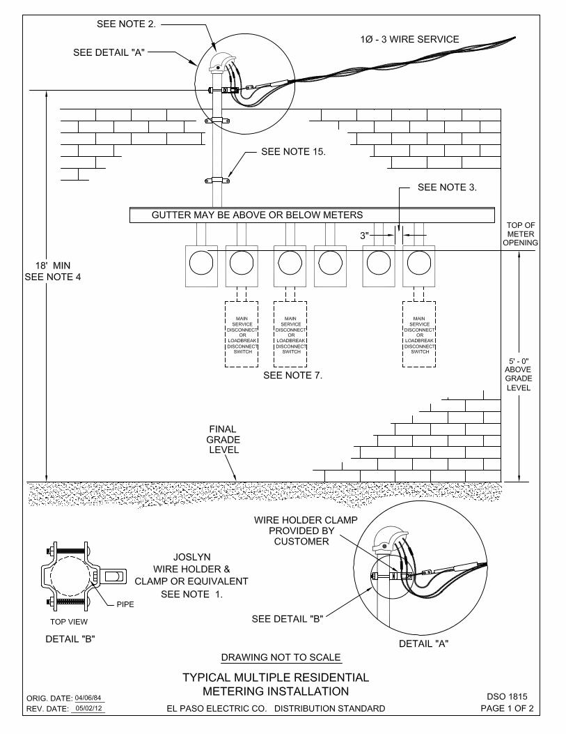

NOTES:1 JOSLYN WIRE HOLDER TO BE USE FOR UP TO 4/0 CABLE. FOR LARGER CABLE USE ALUMINUM
STRAP, EYELET AND ALUMINUM STRAIN CLAMP.2 FOR PARALLEL RISERS, SEE DSO 1845 FOR DETAILS.3 3" MINIMUM IS REQUIRED BETWEEN A METER ENCLOSURE AND ANY ADJACENT EQUIPMENT.4 18' CLEARANCE IS REQUIRED FOR SERVICE DROPS CROSSING PARKING LOTS AND OTHER AREAS
SUBJECT TO VEHICULAR TRAFFIC. THE CLEARANCE IS MEASURED FROM THE LOWEST PART OF THE SERVICE DROP TO FINAL GRADE. ALL CLEARANCES MUST BE MAINTAINED DURING ALL PHASES OF CONSTRUCTION. A. ADDITIONAL CLEARANCE IS REQUIRED OVER STREET CROSSINGS, RAILWAYS AND CERTAIN BODIES OF WATER AS OUTLINED IN NESC 232. B. THIS CLEARANCE MAY BE REDUCED TO 12' IF THE SERVICE DROP IS ACCESSIBLE ONLY TO PEDESTRIANS. THIS CLEARANCE IS MEASURED FROM THE LOWEST PART OF THE SERVICE DROP TO FINAL GRADE OR ANY PROJECTION OR PLATFORM FROM WHICH IT MIGHT BE REACHED.
5 THERE SHALL BE NO MORE THAN SIX DISCONNECTS PER SERVICE GROUPED IN ANY ONELOCATION AS PER NATIONAL ELECTRICAL CODE, SECTION 230 - 71, PARAGRAPH "A".
6 SERVICE DISCONNECT NEEDED WHEN MORE THAN 6 METERS ARE USED.7 THE SERVICE DISCONNECTING MEANS FOR SERVICES OF 800 AMPS OR LESS SHALL BE A
LOADBREAK-RATED METER DISCONNECT AND SHALL BE INSTALLED ON THE EXTERIOR OF THE BUILDING OR STRUCTURE ADJACENT TO AND NOT MORE THAN FIVE (5 ) FEET FROM THE METER.
8 ALL COMMERCIAL INSTALLATIONS UP TO 400 AMPS WILL REQUIRE A HEAVY DUTY BYPASS METER SOCKET.
9 RIGID CONDUIT MUST BE USED IF SERVICE DROP IS ANCHORED TO MAST.10 ELECTRICAL CONTRACTORS ARE RESPONSIBLE FOR MARKING EACH METER ENCLOSURE.
( INCLUDING WATER HEATER ) ACCURATELY WITH PERMANENT NUMBERS OR LETTERS TOCORRESPOND TO THE CORRECT UNIT, APARTMENT OR COMMERCIAL SUITES.
11 INSTALLATION MUST COMPLY WITH LOCAL CODE REQUIREMENTS, NATIONAL ELECTRIC CODEAND THE NATIONAL ELECTRIC SAFETY CODE.
12 A GROUND MEETING THE NATIONAL ELECTRICAL CODE REQUIREMENTS SHALL BE PROVIDED BY THECUSTOMER. A MINIMUM OF TWO GROUND ELECTRODES SHALL BE INSTALLED ACCORDING TO N.E.C..
13 FOR ANY CLARIFICATION OR QUESTIONS REGARDING THIS STANDARD, CALL THE EL PASO ELECTRIC COMPANY DISTRIBUTION DESIGN AND DELIVERY DEPARTMENT.
14 METER CAN, CAN NOT BE USED AS A JUNCTION BOX.15 RISER MUST BE SECURELY ATTACHED TO THE WALL OF THE BUILDING. USE TOGGLE BOLTS FOR
CINDER BLOCK OR PLASTIC SHIELDS WITH THE APPROPRIATE SCREWS FOR WOOD OR BRICK.
ORIG. DATE: 04/06/84REV. DATE: 05/02/12 EL PASO ELECTRIC CO. DISTRIBUTION STANDARD
DSO 1815PAGE 2 OF 2


NOTES:1 JOSLYN WIRE HOLDER TO BE USE FOR UP TO 4/0 CABLE. FOR LARGER CABLE USE ALUMINUM
STRAP, EYELET AND ALUMINUM STRAIN CLAMP.2 FOR PARALLEL RISERS, SEE DSO 1845 FOR DETAILS.3 3" MINIMUM IS REQUIRED BETWEEN A METER ENCLOSURE AND ANY ADJACENT EQUIPMENT.4 18' CLEARANCE IS REQUIRED FOR SERVICE DROPS CROSSING PARKING LOTS AND OTHER AREAS
SUBJECT TO VEHICULAR TRAFFIC. THE CLEARANCE IS MEASURED FROM THE LOWEST PART OF THE SERVICE DROP TO FINAL GRADE. ALL CLEARANCES MUST BE MAINTAINED DURING ALL PHASES OF CONSTRUCTION. A. ADDITIONAL CLEARANCE IS REQUIRED OVER STREET CROSSINGS, RAILWAYS AND CERTAIN BODIES OF WATER AS OUTLINED IN NESC 232. B. THIS CLEARANCE MAY BE REDUCED TO 12' IF THE SERVICE DROP IS ACCESSIBLE ONLY TO PEDESTRIANS. THIS CLEARANCE IS MEASURED FROM THE LOWEST PART OF THE SERVICE DROP TO FINAL GRADE OR ANY PROJECTION OR PLATFORM FROM WHICH IT MIGHT BE REACHED.
5 THIS SERVICE SHALL NOT PASS THROUGH ANY OTHER BUILDING OR ENCLOSED STRUCTURE PERTHE NATIONAL ELECTRICAL CODE.
6 THERE SHALL BE NO MORE THAN SIX DISCONNECTS PER SERVICE GROUPED IN ANY ONELOCATION AS PER NATIONAL ELECTRICAL CODE, SECTION 230 - 71, PARAGRAPH "A".
7 SERVICE DISCONNECT NEEDED WHEN MORE THAN 6 METERS ARE USED.8 THE SERVICE DISCONNECTING MEANS FOR SERVICES OF 800 AMPS OR LESS SHALL BE A
LOADBREAK-RATED METER DISCONNECT AND SHALL BE INSTALLED ON THE EXTERIOR OF THE BUILDING OR STRUCTURE ADJACENT TO AND NOT MORE THAN FIVE (5 ) FEET FROM THE METER.
9 ALL COMMERCIAL INSTALLATIONS UP TO 400 AMPS WILL REQUIRE A HEAVY DUTY BYPASS METER SOCKET.
10 RIGID CONDUIT MUST BE USED IF SERVICE DROP IS ANCHORED TO MAST.11 ELECTRICAL CONTRACTORS ARE RESPONSIBLE FOR MARKING EACH METER ENCLOSURE
ACCURATELY WITH PERMANENT NUMBERS OR LETTERS TO CORRESPOND TO THE CORRECTUNIT, APARTMENT OR COMMERCIAL SUITES.
12 INSTALLATION MUST COMPLY WITH ALL LOCAL CODE REQUIREMENTS, NATIONAL ELECTRIC CODE AND THE NATIONAL ELECTRIC SAFETY CODE.
13 A GROUND MEETING THE NATIONAL ELECTRICAL CODE REQUIREMENTS SHALL BE PROVIDED BY THECUSTOMER. A MINIMUM OF TWO GROUND ELECTRODES SHALL BE INSTALLED ACCORDING TO N.E.C..
14 FOR ANY CLARIFICATION OR QUESTIONS REGARDING THIS STANDARD, CALL THE EL PASO ELECTRIC COMPANY DISTRIBUTION DESIGN AND DELIVERY DEPARTMENT.
15 METER CAN, CAN NOT BE USED AS A JUNCTION BOX.16 RISER MUST BE SECURELY ATTACHED TO THE WALL OF THE BUILDING. USE TOGGLE BOLTS FOR
CINDER BLOCK OR PLASTIC SHIELDS WITH THE APPROPRIATE SCREWS FOR WOOD OR BRICK.
ORIG. DATE: 04/06/84REV. DATE: 05/02/12 EL PASO ELECTRIC CO. DISTRIBUTION STANDARD
DS0 1820PAGE 2 OF 2

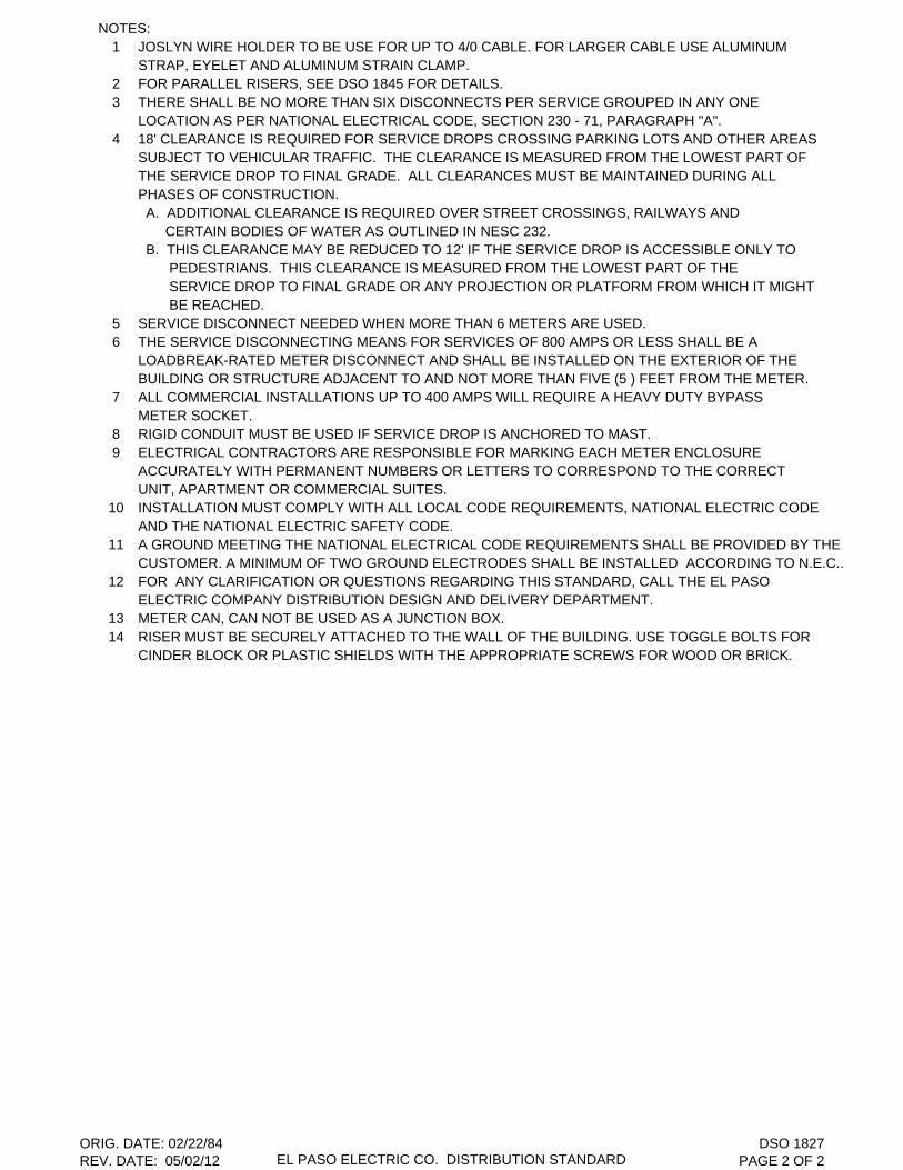
NOTES:1 JOSLYN WIRE HOLDER TO BE USE FOR UP TO 4/0 CABLE. FOR LARGER CABLE USE ALUMINUM
STRAP, EYELET AND ALUMINUM STRAIN CLAMP.2 FOR PARALLEL RISERS, SEE DSO 1845 FOR DETAILS.3 THERE SHALL BE NO MORE THAN SIX DISCONNECTS PER SERVICE GROUPED IN ANY ONE
LOCATION AS PER NATIONAL ELECTRICAL CODE, SECTION 230 - 71, PARAGRAPH "A".4 18' CLEARANCE IS REQUIRED FOR SERVICE DROPS CROSSING PARKING LOTS AND OTHER AREAS
SUBJECT TO VEHICULAR TRAFFIC. THE CLEARANCE IS MEASURED FROM THE LOWEST PART OF THE SERVICE DROP TO FINAL GRADE. ALL CLEARANCES MUST BE MAINTAINED DURING ALL PHASES OF CONSTRUCTION. A. ADDITIONAL CLEARANCE IS REQUIRED OVER STREET CROSSINGS, RAILWAYS AND CERTAIN BODIES OF WATER AS OUTLINED IN NESC 232. B. THIS CLEARANCE MAY BE REDUCED TO 12' IF THE SERVICE DROP IS ACCESSIBLE ONLY TO PEDESTRIANS. THIS CLEARANCE IS MEASURED FROM THE LOWEST PART OF THE SERVICE DROP TO FINAL GRADE OR ANY PROJECTION OR PLATFORM FROM WHICH IT MIGHT BE REACHED.
5 SERVICE DISCONNECT NEEDED WHEN MORE THAN 6 METERS ARE USED.6 THE SERVICE DISCONNECTING MEANS FOR SERVICES OF 800 AMPS OR LESS SHALL BE A
LOADBREAK-RATED METER DISCONNECT AND SHALL BE INSTALLED ON THE EXTERIOR OF THE BUILDING OR STRUCTURE ADJACENT TO AND NOT MORE THAN FIVE (5 ) FEET FROM THE METER.
7 ALL COMMERCIAL INSTALLATIONS UP TO 400 AMPS WILL REQUIRE A HEAVY DUTY BYPASS METER SOCKET.
8 RIGID CONDUIT MUST BE USED IF SERVICE DROP IS ANCHORED TO MAST.9 ELECTRICAL CONTRACTORS ARE RESPONSIBLE FOR MARKING EACH METER ENCLOSURE
ACCURATELY WITH PERMANENT NUMBERS OR LETTERS TO CORRESPOND TO THE CORRECTUNIT, APARTMENT OR COMMERCIAL SUITES.
10 INSTALLATION MUST COMPLY WITH ALL LOCAL CODE REQUIREMENTS, NATIONAL ELECTRIC CODE AND THE NATIONAL ELECTRIC SAFETY CODE.
11 A GROUND MEETING THE NATIONAL ELECTRICAL CODE REQUIREMENTS SHALL BE PROVIDED BY THECUSTOMER. A MINIMUM OF TWO GROUND ELECTRODES SHALL BE INSTALLED ACCORDING TO N.E.C..
12 FOR ANY CLARIFICATION OR QUESTIONS REGARDING THIS STANDARD, CALL THE EL PASO ELECTRIC COMPANY DISTRIBUTION DESIGN AND DELIVERY DEPARTMENT.
13 METER CAN, CAN NOT BE USED AS A JUNCTION BOX.14 RISER MUST BE SECURELY ATTACHED TO THE WALL OF THE BUILDING. USE TOGGLE BOLTS FOR
CINDER BLOCK OR PLASTIC SHIELDS WITH THE APPROPRIATE SCREWS FOR WOOD OR BRICK.
ORIG. DATE: 02/22/84REV. DATE: 05/02/12 EL PASO ELECTRIC CO. DISTRIBUTION STANDARD
DSO 1827PAGE 2 OF 2
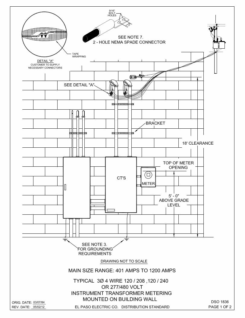
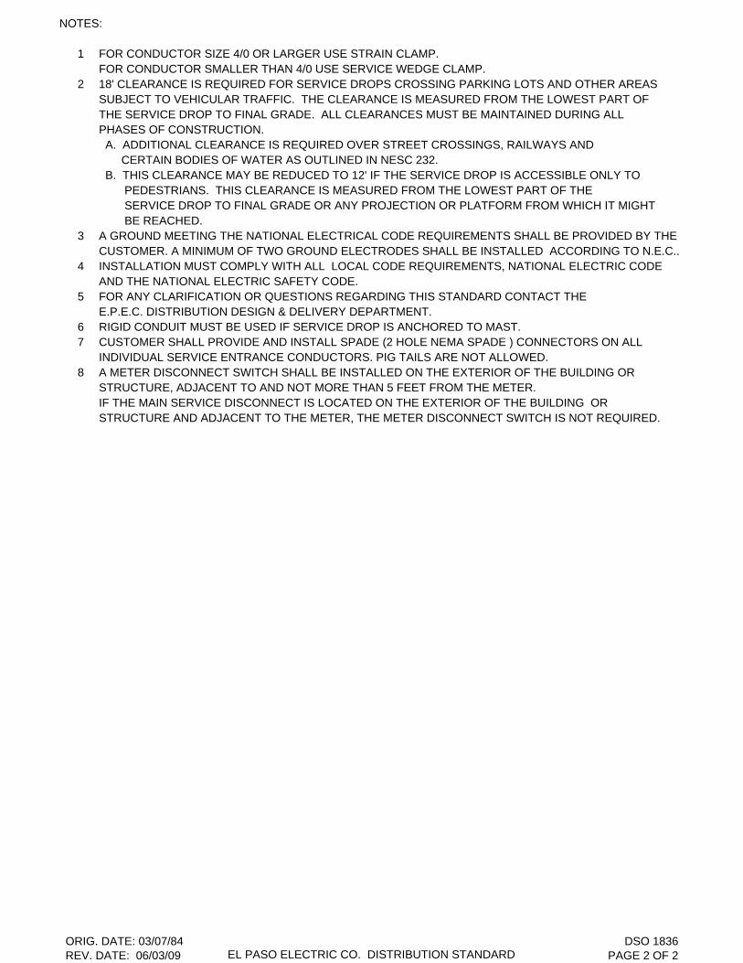
NOTES:
1 FOR CONDUCTOR SIZE 4/0 OR LARGER USE STRAIN CLAMP.FOR CONDUCTOR SMALLER THAN 4/0 USE SERVICE WEDGE CLAMP.
2 18' CLEARANCE IS REQUIRED FOR SERVICE DROPS CROSSING PARKING LOTS AND OTHER AREASSUBJECT TO VEHICULAR TRAFFIC. THE CLEARANCE IS MEASURED FROM THE LOWEST PART OF THE SERVICE DROP TO FINAL GRADE. ALL CLEARANCES MUST BE MAINTAINED DURING ALL PHASES OF CONSTRUCTION. A. ADDITIONAL CLEARANCE IS REQUIRED OVER STREET CROSSINGS, RAILWAYS AND CERTAIN BODIES OF WATER AS OUTLINED IN NESC 232. B. THIS CLEARANCE MAY BE REDUCED TO 12' IF THE SERVICE DROP IS ACCESSIBLE ONLY TO PEDESTRIANS. THIS CLEARANCE IS MEASURED FROM THE LOWEST PART OF THE SERVICE DROP TO FINAL GRADE OR ANY PROJECTION OR PLATFORM FROM WHICH IT MIGHT BE REACHED.
3 A GROUND MEETING THE NATIONAL ELECTRICAL CODE REQUIREMENTS SHALL BE PROVIDED BY THECUSTOMER. A MINIMUM OF TWO GROUND ELECTRODES SHALL BE INSTALLED ACCORDING TO N.E.C..
4 INSTALLATION MUST COMPLY WITH ALL LOCAL CODE REQUIREMENTS, NATIONAL ELECTRIC CODEAND THE NATIONAL ELECTRIC SAFETY CODE.
5 FOR ANY CLARIFICATION OR QUESTIONS REGARDING THIS STANDARD CONTACT THE E.P.E.C. DISTRIBUTION DESIGN & DELIVERY DEPARTMENT.
6 RIGID CONDUIT MUST BE USED IF SERVICE DROP IS ANCHORED TO MAST.7 CUSTOMER SHALL PROVIDE AND INSTALL SPADE (2 HOLE NEMA SPADE ) CONNECTORS ON ALL
INDIVIDUAL SERVICE ENTRANCE CONDUCTORS. PIG TAILS ARE NOT ALLOWED.8 A METER DISCONNECT SWITCH SHALL BE INSTALLED ON THE EXTERIOR OF THE BUILDING OR
STRUCTURE, ADJACENT TO AND NOT MORE THAN 5 FEET FROM THE METER.IF THE MAIN SERVICE DISCONNECT IS LOCATED ON THE EXTERIOR OF THE BUILDING OR STRUCTURE AND ADJACENT TO THE METER, THE METER DISCONNECT SWITCH IS NOT REQUIRED.
ORIG. DATE: 03/07/84REV. DATE: 06/03/09 EL PASO ELECTRIC CO. DISTRIBUTION STANDARD
DSO 1836PAGE 2 OF 2

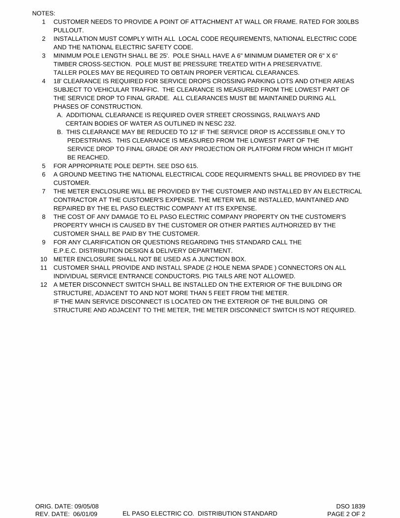
NOTES:1 CUSTOMER NEEDS TO PROVIDE A POINT OF ATTACHMENT AT WALL OR FRAME. RATED FOR 300LBS
PULLOUT.2 INSTALLATION MUST COMPLY WITH ALL LOCAL CODE REQUIREMENTS, NATIONAL ELECTRIC CODE
AND THE NATIONAL ELECTRIC SAFETY CODE.3 MINIMUM POLE LENGTH SHALL BE 25'. POLE SHALL HAVE A 6" MINIMUM DIAMETER OR 6" X 6"
TIMBER CROSS-SECTION. POLE MUST BE PRESSURE TREATED WITH A PRESERVATIVE.TALLER POLES MAY BE REQUIRED TO OBTAIN PROPER VERTICAL CLEARANCES.
4 18' CLEARANCE IS REQUIRED FOR SERVICE DROPS CROSSING PARKING LOTS AND OTHER AREASSUBJECT TO VEHICULAR TRAFFIC. THE CLEARANCE IS MEASURED FROM THE LOWEST PART OF THE SERVICE DROP TO FINAL GRADE. ALL CLEARANCES MUST BE MAINTAINED DURING ALL PHASES OF CONSTRUCTION. A. ADDITIONAL CLEARANCE IS REQUIRED OVER STREET CROSSINGS, RAILWAYS AND CERTAIN BODIES OF WATER AS OUTLINED IN NESC 232. B. THIS CLEARANCE MAY BE REDUCED TO 12' IF THE SERVICE DROP IS ACCESSIBLE ONLY TO PEDESTRIANS. THIS CLEARANCE IS MEASURED FROM THE LOWEST PART OF THE SERVICE DROP TO FINAL GRADE OR ANY PROJECTION OR PLATFORM FROM WHICH IT MIGHT BE REACHED.
5 FOR APPROPRIATE POLE DEPTH. SEE DSO 615.6 A GROUND MEETING THE NATIONAL ELECTRICAL CODE REQUIRMENTS SHALL BE PROVIDED BY THE
CUSTOMER.7 THE METER ENCLOSURE WILL BE PROVIDED BY THE CUSTOMER AND INSTALLED BY AN ELECTRICAL
CONTRACTOR AT THE CUSTOMER'S EXPENSE. THE METER WIL BE INSTALLED, MAINTAINED AND REPAIRED BY THE EL PASO ELECTRIC COMPANY AT ITS EXPENSE.
8 THE COST OF ANY DAMAGE TO EL PASO ELECTRIC COMPANY PROPERTY ON THE CUSTOMER'SPROPERTY WHICH IS CAUSED BY THE CUSTOMER OR OTHER PARTIES AUTHORIZED BY THECUSTOMER SHALL BE PAID BY THE CUSTOMER.
9 FOR ANY CLARIFICATION OR QUESTIONS REGARDING THIS STANDARD CALL THE E.P.E.C. DISTRIBUTION DESIGN & DELIVERY DEPARTMENT.
10 METER ENCLOSURE SHALL NOT BE USED AS A JUNCTION BOX.11 CUSTOMER SHALL PROVIDE AND INSTALL SPADE (2 HOLE NEMA SPADE ) CONNECTORS ON ALL
INDIVIDUAL SERVICE ENTRANCE CONDUCTORS. PIG TAILS ARE NOT ALLOWED.12 A METER DISCONNECT SWITCH SHALL BE INSTALLED ON THE EXTERIOR OF THE BUILDING OR
STRUCTURE, ADJACENT TO AND NOT MORE THAN 5 FEET FROM THE METER.IF THE MAIN SERVICE DISCONNECT IS LOCATED ON THE EXTERIOR OF THE BUILDING OR STRUCTURE AND ADJACENT TO THE METER, THE METER DISCONNECT SWITCH IS NOT REQUIRED.
ORIG. DATE: 09/05/08REV. DATE: 06/01/09 EL PASO ELECTRIC CO. DISTRIBUTION STANDARD
DSO 1839PAGE 2 OF 2

THIS PAGE LEFT BLANK INTENTIONALLY


ITEM STOCK/DSO C/UNo. No. Code1 ARRESTER 01-140 6 CLAD12C2 CURRENT TRANSFORMER ------- 33 POTENTIAL TRANSFORMER 19-666 24 SATELLITE MOUNTING BRACKET 19-310 15 1" STEEL CONDUIT ( PROVIDED BY CUSTOMER) 25'6 # 4 SOLID COVERED CU WIRE 12-111 AS REQ. C4INSCU7 POLYMER INSULATOR ASSEMBLY DSO 1705 6 CPOLY15
WEDGE CONNECTOR8 OR DSO 1758 6
COMPRESSION CONNECTOR9 INSULATOR ADAPTER 07-010 1 PINSADPT
10 5/8" X 12" MACHINE BOLT 02-470 1 PMB5/81211 15KV PIN INSULATOR DSO 1705 1 CINS1312 NEUTRAL ASSEMBLY "B" DSO 1708 213 NEUTRAL CONNECTOR DSO1758 1
NOTES:1 THIS PARTICULAR C.T. AND P.T. ARRANGEMENT IS FOR A 3 PHASE 4 - WIRE 2 1/2 ELEMENT
METER.2 CUSTOMER MUST INSTALL A GANG-OPERATED LOAD INTERRUPTER SWITCH, PER N.E.S.C. 216,
ON CUSTOMER'S POLE, WITH OVER CURRENT PROTECTION . REFER TO E.P.E.C.'S ELECTRICREQUIREMENTS BOOK SECTION VI, SUBSECTION G, PARAGRAPH 3.
3 LAST SPAN TO CUSTOMER OWNED WOOD POLE TO BE PROVIDED AND INSTALLED BY E.P.E.C.4 SEE DSO 321 (MAINT. SECTION ) FOR DEADEND ASSEMBLY.
IF CUT-OUTS ARE LOCATED ON THIS POLE ORDER ITEMS BELOWCUTOUT 15KV 100AMP 01-340 LINECO10015OR OR 3 ORCUTOUT 15KV 200AMP 01-341 LINECO20015HOT LINE CLAMP 1/0 - 336 03-730 CHTLN336OR OR 3 ORHOT LINE CLAMP 1/0 - 795 03-795 CHTLN795
DESCRIPTION Qty.
ORIG. DATE: 06/13/64REV. DATE: 10/09/12 EL PASO ELECTRIC CO. DISTRIBUTION STANDARD
DSO 1860PAGE 2 OF 2
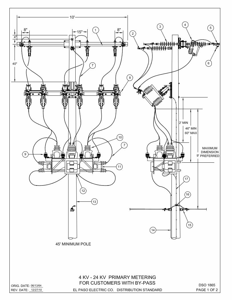
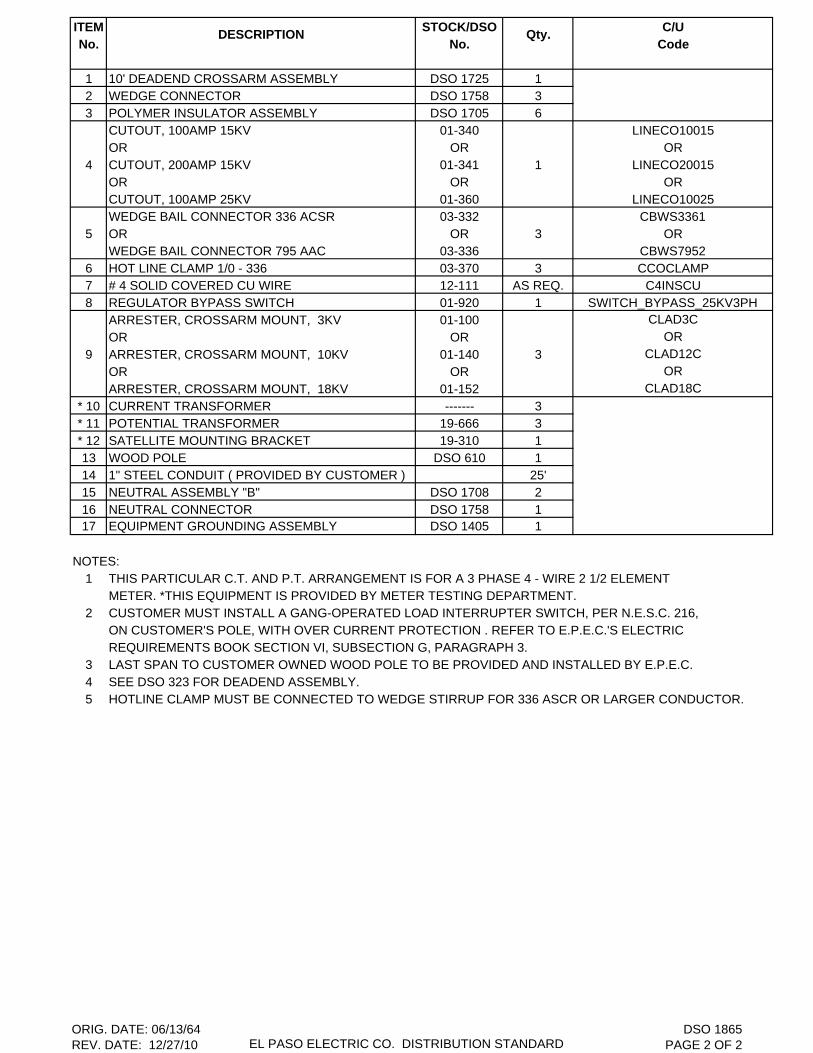
ITEM STOCK/DSO C/UNo. No. Code
1 10' DEADEND CROSSARM ASSEMBLY DSO 1725 12 WEDGE CONNECTOR DSO 1758 33 POLYMER INSULATOR ASSEMBLY DSO 1705 6
CUTOUT, 100AMP 15KV 01-340 LINECO10015OR OR OR
4 CUTOUT, 200AMP 15KV 01-341 1 LINECO20015OR OR ORCUTOUT, 100AMP 25KV 01-360 LINECO10025WEDGE BAIL CONNECTOR 336 ACSR 03-332 CBWS3361
5 OR OR 3 ORWEDGE BAIL CONNECTOR 795 AAC 03-336 CBWS7952
6 HOT LINE CLAMP 1/0 - 336 03-370 3 CCOCLAMP7 # 4 SOLID COVERED CU WIRE 12-111 AS REQ. C4INSCU8 REGULATOR BYPASS SWITCH 01-920 1 SWITCH_BYPASS_25KV3PH
ARRESTER, CROSSARM MOUNT, 3KV 01-100 CLAD3C
OR OR OR
9 ARRESTER, CROSSARM MOUNT, 10KV 01-140 3 CLAD12C
OR OR OR
ARRESTER, CROSSARM MOUNT, 18KV 01-152 CLAD18C
* 10 CURRENT TRANSFORMER ------- 3* 11 POTENTIAL TRANSFORMER 19-666 3* 12 SATELLITE MOUNTING BRACKET 19-310 113 WOOD POLE DSO 610 114 1" STEEL CONDUIT ( PROVIDED BY CUSTOMER ) 25'15 NEUTRAL ASSEMBLY "B" DSO 1708 216 NEUTRAL CONNECTOR DSO 1758 117 EQUIPMENT GROUNDING ASSEMBLY DSO 1405 1
NOTES:1 THIS PARTICULAR C.T. AND P.T. ARRANGEMENT IS FOR A 3 PHASE 4 - WIRE 2 1/2 ELEMENT
METER. *THIS EQUIPMENT IS PROVIDED BY METER TESTING DEPARTMENT.2 CUSTOMER MUST INSTALL A GANG-OPERATED LOAD INTERRUPTER SWITCH, PER N.E.S.C. 216,
ON CUSTOMER'S POLE, WITH OVER CURRENT PROTECTION . REFER TO E.P.E.C.'S ELECTRICREQUIREMENTS BOOK SECTION VI, SUBSECTION G, PARAGRAPH 3.
3 LAST SPAN TO CUSTOMER OWNED WOOD POLE TO BE PROVIDED AND INSTALLED BY E.P.E.C.4 SEE DSO 323 FOR DEADEND ASSEMBLY.5 HOTLINE CLAMP MUST BE CONNECTED TO WEDGE STIRRUP FOR 336 ASCR OR LARGER CONDUCTOR.
DESCRIPTION Qty.
ORIG. DATE: 06/13/64REV. DATE: 12/27/10 EL PASO ELECTRIC CO. DISTRIBUTION STANDARD
DSO 1865PAGE 2 OF 2


THIS PAGE LEFT BLANK INTENTIONALLY
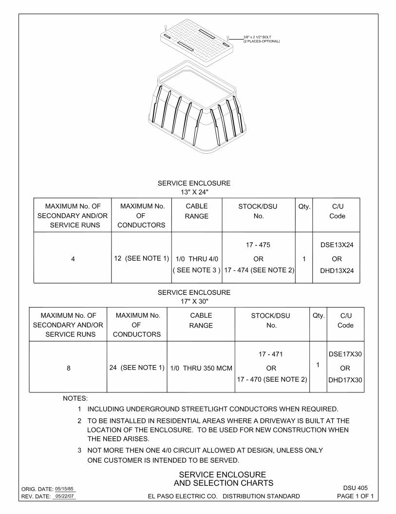


ITEM DESCRIPTION STOCK/DSU Qty. C/UNo. No. Code1 SERVICE ENCLOSURE DSU 405 12 45° DB-60 PVC DUCT SWEEP WITH BELL END 17-32__ 1 DEL4536_3 90° SCH. 80 PVC DUCT SWEEP WITHOUT BELL 15-32__ 1 DEL80_4 DB- 60 PVC DUCT 17-30__ 1 DPVC_
NOTES:1 THIS IS AN E.P.E.C. INSTALLATION. REFER TO E.P.E.C. LINE EXTENSION POLICY FOR MATERIAL AND
CONSTRUCTION RESPONSIBILITIES.2 SIZE OF SCHEDULE 80 CONDUIT ( UV RESISTANT ) TO BE SPECIFIED FOR EACH JOB.3 ANY EXCEPTION OR MODIFICATIONS MUST BE APPROVED BY AN E.P.E.C. REPRESENTATIVE.4 ENCLOSURE AND DUCT RUNS WILL BE INSTALLED PARALLEL TO E.P.E.C. OVERHEAD FACILITIES
TO FACILITATE THE USE OF DEDICATED EASEMENTS WHEN POSSIBLE.5 WHEN A SECONDARY RISER USING 2-500 MCM CABLES PLUS NEUTRAL IS NECESSARY,
A PADMOUNT INSTALLLATION IS PREFERRED. IF A PADMOUNT INSTALLATION IS NOT POSSIBLE, A 60" PULLBOX OR TRAFFIC BEARING BOX SHOULD BE INSTALLED AND A 6" OR 5" DIA. DUCT SIZE WILL BE REQUIRED. BOX TYPE AND DUCT SIZE WILL BE DEPENDENT ON THE CONDITIONS OF THE JOB.
ORIG. DATE: 02/10/70REV. DATE: 06/22/10 EL PASO ELECTRIC CO. DISTRIBUTION STANDARD
DSU 410PAGE 2 OF 2
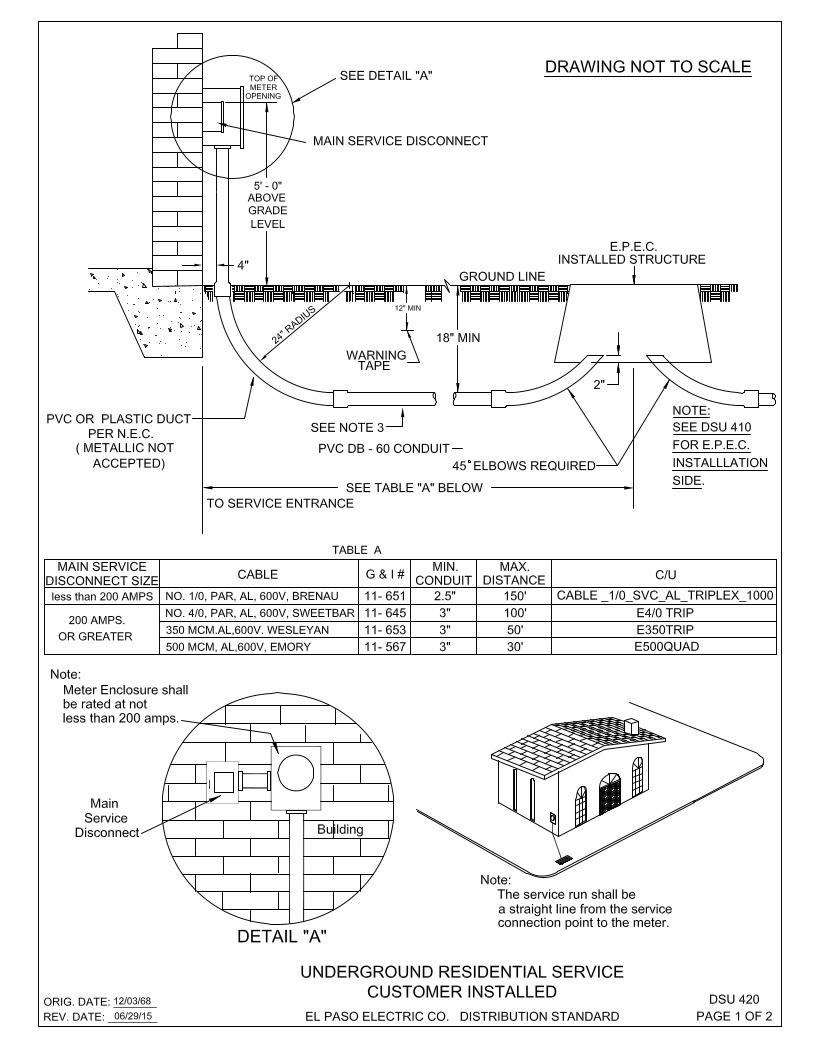
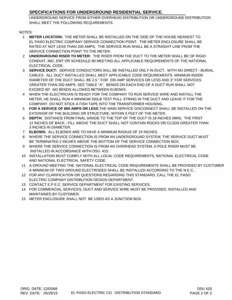
SPECIFICATIONS FOR UNDERGROUND RESIDENTIAL SERVICE.UNDERGROUND SERVICE FROM EITHER OVERHEAD DISTRIBUTION OR UNDERGROUND DISTRIBUTION SHALL MEET THE FOLLOWING REQUIREMENTS.
NOTES:1 METER LOCATION: THE METER SHALL BE INSTALLED ON THE SIDE OF THE HOUSE NEAREST TO
EL PASO ELECTRIC COMPANY SERVICE CONNECTION POINT. THE METER ENCLOSURE SHALL BERATED AT NOT LESS THAN 200 AMPS. THE SERVICE RUN SHALL BE A STRAIGHT LINE FROM THE SERVICE CONNECTION POINT TO THE METER.
2 UNDERGROUND RISER TO METER: THE RISER FROM THE DUCT TO THE METER SHALL BE OF RIGIDCONDUIT, IMC, EMT OR SCHEDULE 80 MEETING ALL APPLICABLE REQUIREMENTS OF THE NATIONALELECTRICAL CODE.
3 SERVICE DUCT: SERVICE CONDUCTORS WILL BE INSTALLED ONLY IN DUCT, WITH NO DIRECT - BURIALCABLES. ALL DUCT INSTALLED SHALL MEET APPLICABLE CODE REQUIREMENTS. MINIMUM INSIDEDIAMETER OF THE DUCT SHALL BE 2.5 " FOR 200 AMP SERVICES OR LESS AND 3" FOR SERVICES GREATER THAN 200 AMPS. SEE TABLE "A". BENDS ON EACH END OF A DUCT RUN SHALL NOTEXCEED 90°. NO BENDS ALLOWED BETWEEN ELBOWS.
4 WHEN THE ELECTRICIAN IS READY FOR THE COMPANY TO RUN SERVICE WIRE AND INSTALL THEMETER, HE SHALL RUN A MINIMUM 200LB TEST PULL STRING IN THE DUCT AND LEAVE IT FOR THECOMPANY. DO NOT STICK A FISH TAPE INTO THE TRANSFORMER HOUSING.
5 FOR A SERVICE OF 800 AMPS OR LESS,THE MAIN SERVICE DISCONNECT SHALL BE INSTALLED ON THE EXTERIOR OF THE BUILDING OR STRUCTURE, WITHIN 5 FEET OF THE METER.
6 DEPTH: DISTANCE FROM FINAL GRADE TO THE TOP OF THE DUCT IS 18 INCHES (MIN). THE FIRST12 INCHES OF BACK - FILL ABOVE THE DUCT SHALL NOT CONTAIN ROCKS OR CLODS GREATER THAN 3 INCHES IN DIAMETER.
7 ELBOWS: ALL ELBOWS ARE TO HAVE A MINIMUM RADIUS OF 24 INCHES.8 WHERE THE SERVICE CONNECTION IS FROM AN UNDERGROUND SYSTEM, THE SERVICE DUCT MUST
BE TERMINATED 2 INCHES ABOVE THE BOTTOM OF THE SERVICE CONNECTION BOX.9 WHERE THE SERVICE CONNECTION IS FROM AN OVERHEAD SYSTEM, A POLE RISER MUST BE
INSTALLED IN ACCORDANCE WITH DSU 410.10 INSTALLATION MUST COMPLY WITH ALL LOCAL CODE REQUIREMENTS, NATIONAL ELECTRICAL CODE
AND NATIONAL ELECTRICAL SAFETY CODE.11 A GROUND MEETING THE NATIONAL ELECTRICAL CODE REQUIREMENTS SHALL BE PROVIDED BY CUSTOMER.
A MINIMUM OF TWO GROUND ELECTRODES SHALL BE INSTALLED ACCORDING TO THE N.E.C..12 FOR ANY CLARIFICATION OR QUESTIONS REGARDING THIS STANDARD, CALL THE EL PASO
ELECTRIC COMPANY DISTRIBUTION DESIGN DEPARTMENT.13 CONTACT E.P.E.C. SERVICE DEPARTMENT FOR EXISTING SERVICES.14 FOR COMMERCIAL SERVICES, DUCT AND SERVICE WIRE MUST BE PROVIDED, INSTALLED AND
MAINTAINED BY CUSTOMER.15 METER ENCLOSURE SHALL NOT BE USED AS A JUNCTION BOX.
ORIG. DATE: 12/03/68REV. DATE: 05/29/15 EL PASO ELECTRIC CO. DISTRIBUTION STANDARD
DSU 420PAGE 2 OF 2

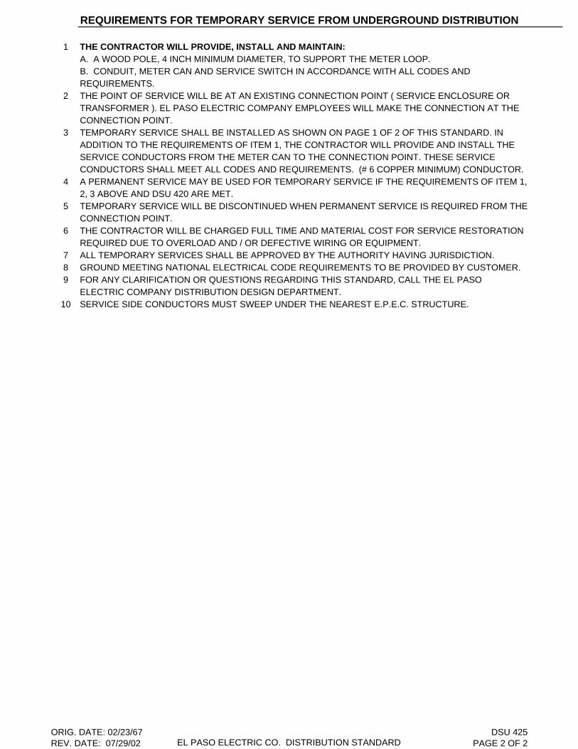
REQUIREMENTS FOR TEMPORARY SERVICE FROM UNDERGROUND DISTRIBUTION
1 THE CONTRACTOR WILL PROVIDE, INSTALL AND MAINTAIN:A. A WOOD POLE, 4 INCH MINIMUM DIAMETER, TO SUPPORT THE METER LOOP.B. CONDUIT, METER CAN AND SERVICE SWITCH IN ACCORDANCE WITH ALL CODES ANDREQUIREMENTS.
2 THE POINT OF SERVICE WILL BE AT AN EXISTING CONNECTION POINT ( SERVICE ENCLOSURE ORTRANSFORMER ). EL PASO ELECTRIC COMPANY EMPLOYEES WILL MAKE THE CONNECTION AT THECONNECTION POINT.
3 TEMPORARY SERVICE SHALL BE INSTALLED AS SHOWN ON PAGE 1 OF 2 OF THIS STANDARD. INADDITION TO THE REQUIREMENTS OF ITEM 1, THE CONTRACTOR WILL PROVIDE AND INSTALL THE SERVICE CONDUCTORS FROM THE METER CAN TO THE CONNECTION POINT. THESE SERVICECONDUCTORS SHALL MEET ALL CODES AND REQUIREMENTS. (# 6 COPPER MINIMUM) CONDUCTOR.
4 A PERMANENT SERVICE MAY BE USED FOR TEMPORARY SERVICE IF THE REQUIREMENTS OF ITEM 1,2, 3 ABOVE AND DSU 420 ARE MET.
5 TEMPORARY SERVICE WILL BE DISCONTINUED WHEN PERMANENT SERVICE IS REQUIRED FROM THECONNECTION POINT.
6 THE CONTRACTOR WILL BE CHARGED FULL TIME AND MATERIAL COST FOR SERVICE RESTORATIONREQUIRED DUE TO OVERLOAD AND / OR DEFECTIVE WIRING OR EQUIPMENT.
7 ALL TEMPORARY SERVICES SHALL BE APPROVED BY THE AUTHORITY HAVING JURISDICTION.8 GROUND MEETING NATIONAL ELECTRICAL CODE REQUIREMENTS TO BE PROVIDED BY CUSTOMER.9 FOR ANY CLARIFICATION OR QUESTIONS REGARDING THIS STANDARD, CALL THE EL PASO
ELECTRIC COMPANY DISTRIBUTION DESIGN DEPARTMENT.10 SERVICE SIDE CONDUCTORS MUST SWEEP UNDER THE NEAREST E.P.E.C. STRUCTURE.
ORIG. DATE: 02/23/67REV. DATE: 07/29/02 EL PASO ELECTRIC CO. DISTRIBUTION STANDARD
DSU 425PAGE 2 OF 2


NOTES:1 DUCT OR ELBOW SHOULD TERMINATE 3" - 4" ABOVE SURFACE INSIDE PULLBOX.2 SECONDARY CABLE SHALL REST ON BOTTOM OF PULLBOX AS SHOWN.3 DUE TO POSITIONING OF LEVELING BLOCKS, DUCT MUST NOT ENTER PULLBOX WITH 12" OF ANY CORNER.4 METERING CONDUITS MUST ENTER PULLBOX ON LV SIDE FROM BELOW.5 THE SECONDARY DUCT ENTRANCE SHALL NOT ENTER THE FRONT OF PULLBOX / TRANSFORMER. 6 NO SPLICES ALLOWED 1N CUSTOMER SECONDARY, E.P.E.C. TRANSFORMERS OR PULLBOX.7 FOR ANY CLARIFICATION OR QUESTIONS REGARDING THIS STANDARD, CALL THE EL PASO
ELECTRIC COMPANY DISTRIBUTION DESIGN DEPARTMENT.
ORIG. DATE: 01/15/76REV. DATE: 10/27/09 EL PASO ELECTRIC CO. DISTRIBUTION STANDARD
DSU 440PAGE 2 OF 2
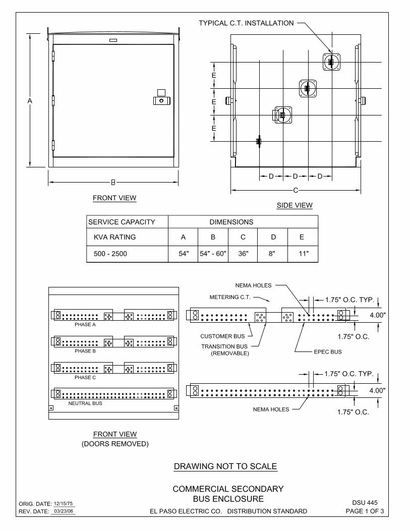

NOTES:1 DEVIATIONS FROM THIS STANDARD MUST BE CLEARED WITH E.P.E.C. DISTRIBUTION DESIGN
DEPARTMENT BEFORE EQUIPMENT IS ORDERED.2 DIMENSIONS FOR C.T.'S WILL BE PROVIDED BY E.P.E.C. METER TESTING DEPARTMENT.3 MINIMUM EIGHT SETS OF NEMA HOLES ( 2 - 9/16" Ø HOLES 1.75" APART ) WILL BE PROVIDED ON ALL
THREE PHASES AND NEUTRAL FOR SERVICE CONNECTION ON E.P.E.C. BUS.4 CUSTOMER'S SIDE OF THE BUS WILL BE PUNCHED AS REQUIRED BY THE CUSTOMER OR APPROPRIATE
CODES.5 C.T.'S SHALL BE INSTALLED IN SECONDARY BUS ENCLOSURE.6 PULLBOX UNDER BUS ENCLOSURE WILL BE ASSEMBLY "S" SEE DSU 1210 (PAGE 2 OF 3)
ASSEMBLY AND INSTALLATION WILL BE PROVIDE BY E.P.E.C.7 THE BUS ENCLOSURE SHALL HAVE PROVISIONS FOR INSTALLING PADLOCKS ON BOTH DOORS AS
SPECIFIED IN ANSI C57.12.28 LATEST REVISION. E.P.E.C. WILL PROVIDE AND INSTALL PADLOCKS ON BOTH DO8 SECONDARY CABLE FROM THE TRANSFORMER TO BUS ENCLOSURE WILL BE SUPPLIED AND
TERMINATED BY E.P.E.C.9 SECONDARY BUS ENCLOSURE SHALL COMPLY WITH THE DIMENSIONS SPECIFIED IN THIS STANDARD.
SHOP DRAWINGS OF THE PROPOSED ENCLOSURE SHALL BE SUBMITTED TO THE METER TESTING DEPARTMENT AND DISTRIBUTION DESIGN DEPARTMENT FOR APPROVAL BEFORE PURCHASE.
10 WHEN ENCLOSURE IS INSTALLED THE USE OF A CABLE PROTECTOR IS REQUIRED. USE G & I # 17-680 FOR 350 MCM AND G & I # 17-681 FOR 500 MCM.
11 WHEN A BUS ENCLOSURE IS REQUIRED, ONLY SIX 5" PVC CONDUITS IN A 2 BY 3 ARRAY ARE ALLOWED BETWEEN TRANSFORMER AND COMMERCIAL SECONDARY BUS ENCLOSURE.
12 USE COPPER BAR WITH THE TRANSFORMER. (ECUBUS)13 FOR BUS ENCLOSURE CABLE REQUIREMENTS SEE DSU 510.14 SECONDARY BUS ENCLOSURE SHALL BE PROVIDED, INSTALLED, MAINTAINED AND OWNED BY THE
CUSTOMER. PULLBOX ASSEMBLY CONDUIT AND CABLE FROM TRANSFORMER SHALL BE OWNED, INSTALLED AND MAINTAINED BY E.P.E.C. BUS ENCLOSURE SHALL BE SECURED WITH E.P.E.C. LOCKS.
ORIG. DATE: 12/15/75REV. DATE: 10/25/13 EL PASO ELECTRIC CO. DISTRIBUTION STANDARD
DSU 445PAGE 2 OF 3

THIS PAGE LEFT BLANK INTENTIONALLY


THIS PAGE LEFT BLANK INTENTIONALLY
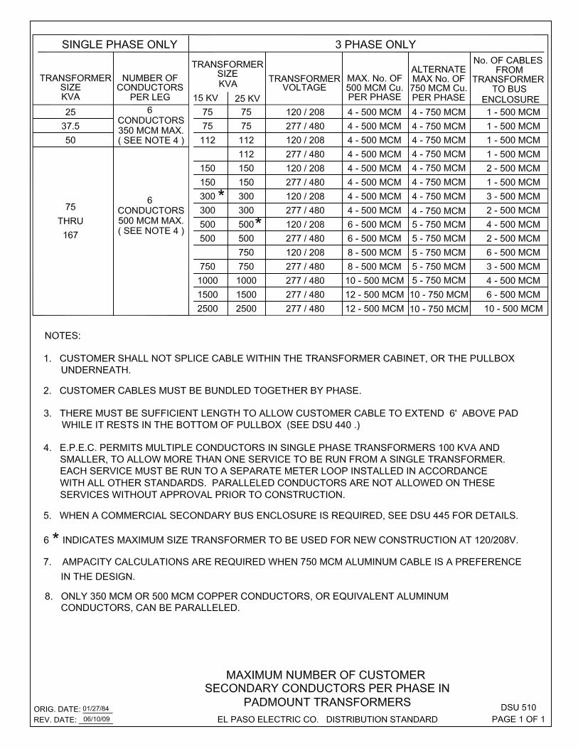

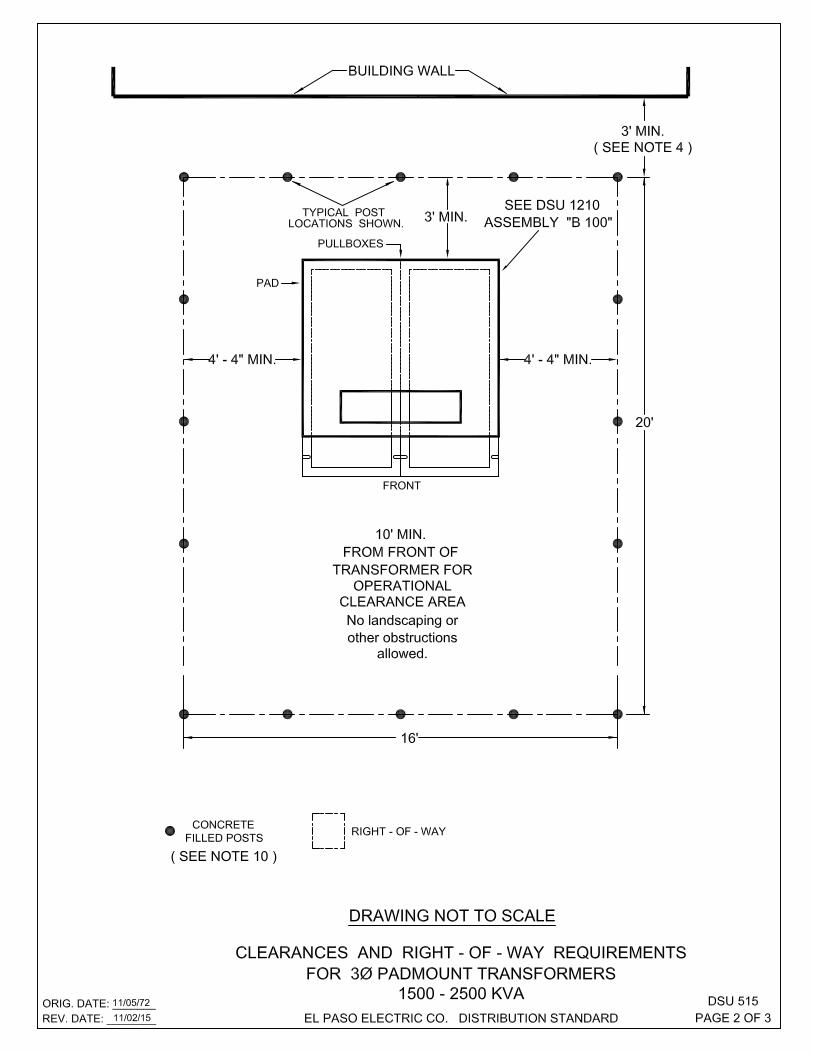

THIS PAGE LEFT BLANK INTENTIONALLY

NOTES:1 WHERE THIS AREA IS SUBJECT TO VEHICULAR TRAFFIC, THE CUSTOMER WILL INSTALL PROTECTION
AS DESCRIBED BELOW BEFORE ELECTRICAL SERVICE IS PROVIDED.A. CONCRETE FILLED METAL PIPES WITH A 4 INCH MINIMUM DIAMETER USED AS POSTS, 3 FEET MINIMUM SECURELY EMBEDDED IN CONCRETE AND EXTENDING AT LEAST 4 FEET OUT OF THE GROUND. B. THE POSTS SHOULD BE EQUALLY SPACED BUT NOT MORE THAN 5 FEET APART AND LOCATED ON THE PERIMETER OF THE EASEMENT ON THOSE SIDES REQUIRING PROTECTION.
2 THERE SHALL BE NO BUILDING OVERHANG OR OTHER OBSTRUCTION THAT WILL PREVENT ACCESSWITH A BOOM TRUCK OR CRANE.
3 ASSEMBLY "B" FOR 3Ø 500-1000 KVA AND ASSEMBLY "B 100" FOR 3Ø 1500-2500 KVA PADMOUNTTRANSFORMERS INSTALLATION IS SHOWN.
4 EASEMENT SHALL BE LOCATED A MINIMUM OF 3' FROM THE CLOSEST BUILDING WALL.5 FOR PULL BOXES AND PAD SIZES SEE DSU 1210.6 A MINIMUM STANDARD EASEMENT OF 16' X 20' IS REQUIRED. 7 THE SECONDARY DUCT ENTRANCE SHALL NOT ENTER THE FRONT OF PULLBOX / TRANSFORMER.
SEE DSU 440.8 FOR ANY CLARIFICATION OR QUESTIONS REGARDING THIS STANDARD, CALL THE EL PASO
ELECTRIC COMPANY DISTRIBUTION DESIGN DEPARTMENT.9 THE METER FRAME FOR METERING SHALL BE INSTALLED 3 FEET MIN. FROM THE LOW VOLTAGE SIDE
OF THE TRANSFORMER PAD TO ALLOW ROOM FOR TRANSFORMER MAINTENANCE. FRAME MAY BE INSTALLED ON HIGH VOLTAGE SIDE OF THE TRANSFORMER WITH E.P.E.C. PERMISSION ONLY.
10 THE CUSTOMER HAS THE OPTION OF REQUESTING THAT THE COMPANY INSTALL ADEQUATEPROTECTION FOR THE TRANSFORMER AND THE CUSTOMER SHALL PAY THE COMPANY, IN ADVANCE, A NONREFUNABLE CONTRIBUTION IN AID OF CONSTRUCTION FOR THE COMPANY TO INSTALL ADEQUATE PROTECTION FOR THE TRANSFORMER.
ORIG. DATE: 11/05/72REV. DATE: 11/02/15 EL PASO ELECTRIC CO. DISTRIBUTION STANDARD
DSU 515PAGE 3 OF 3

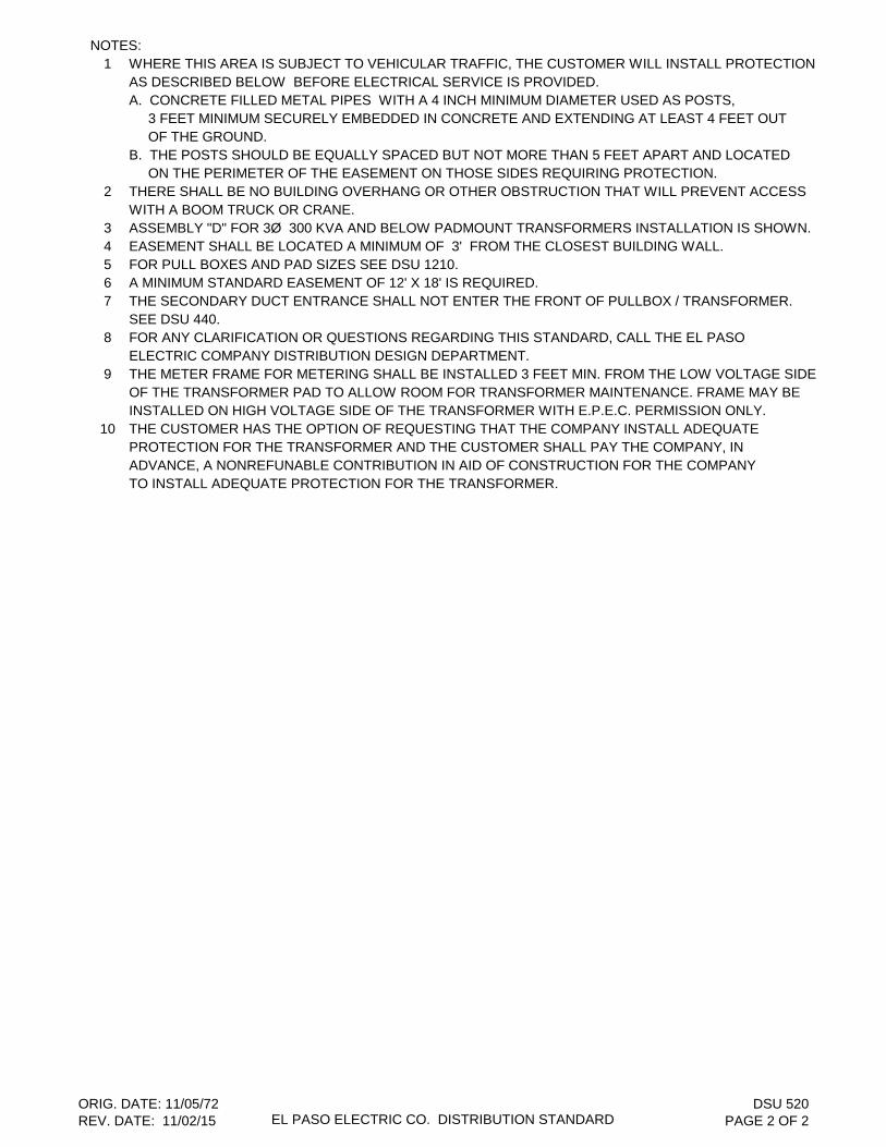
NOTES:1 WHERE THIS AREA IS SUBJECT TO VEHICULAR TRAFFIC, THE CUSTOMER WILL INSTALL PROTECTION
AS DESCRIBED BELOW BEFORE ELECTRICAL SERVICE IS PROVIDED.A. CONCRETE FILLED METAL PIPES WITH A 4 INCH MINIMUM DIAMETER USED AS POSTS, 3 FEET MINIMUM SECURELY EMBEDDED IN CONCRETE AND EXTENDING AT LEAST 4 FEET OUT OF THE GROUND. B. THE POSTS SHOULD BE EQUALLY SPACED BUT NOT MORE THAN 5 FEET APART AND LOCATED ON THE PERIMETER OF THE EASEMENT ON THOSE SIDES REQUIRING PROTECTION.
2 THERE SHALL BE NO BUILDING OVERHANG OR OTHER OBSTRUCTION THAT WILL PREVENT ACCESSWITH A BOOM TRUCK OR CRANE.
3 ASSEMBLY "D" FOR 3Ø 300 KVA AND BELOW PADMOUNT TRANSFORMERS INSTALLATION IS SHOWN. 4 EASEMENT SHALL BE LOCATED A MINIMUM OF 3' FROM THE CLOSEST BUILDING WALL.5 FOR PULL BOXES AND PAD SIZES SEE DSU 1210.6 A MINIMUM STANDARD EASEMENT OF 12' X 18' IS REQUIRED. 7 THE SECONDARY DUCT ENTRANCE SHALL NOT ENTER THE FRONT OF PULLBOX / TRANSFORMER.
SEE DSU 440.8 FOR ANY CLARIFICATION OR QUESTIONS REGARDING THIS STANDARD, CALL THE EL PASO
ELECTRIC COMPANY DISTRIBUTION DESIGN DEPARTMENT.9 THE METER FRAME FOR METERING SHALL BE INSTALLED 3 FEET MIN. FROM THE LOW VOLTAGE SIDE
OF THE TRANSFORMER PAD TO ALLOW ROOM FOR TRANSFORMER MAINTENANCE. FRAME MAY BE INSTALLED ON HIGH VOLTAGE SIDE OF THE TRANSFORMER WITH E.P.E.C. PERMISSION ONLY.
10 THE CUSTOMER HAS THE OPTION OF REQUESTING THAT THE COMPANY INSTALL ADEQUATEPROTECTION FOR THE TRANSFORMER AND THE CUSTOMER SHALL PAY THE COMPANY, IN ADVANCE, A NONREFUNABLE CONTRIBUTION IN AID OF CONSTRUCTION FOR THE COMPANY TO INSTALL ADEQUATE PROTECTION FOR THE TRANSFORMER.
ORIG. DATE: 11/05/72REV. DATE: 11/02/15 EL PASO ELECTRIC CO. DISTRIBUTION STANDARD
DSU 520PAGE 2 OF 2
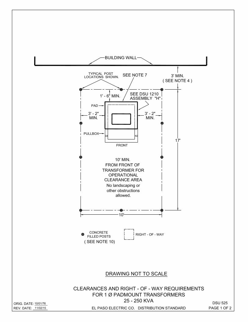
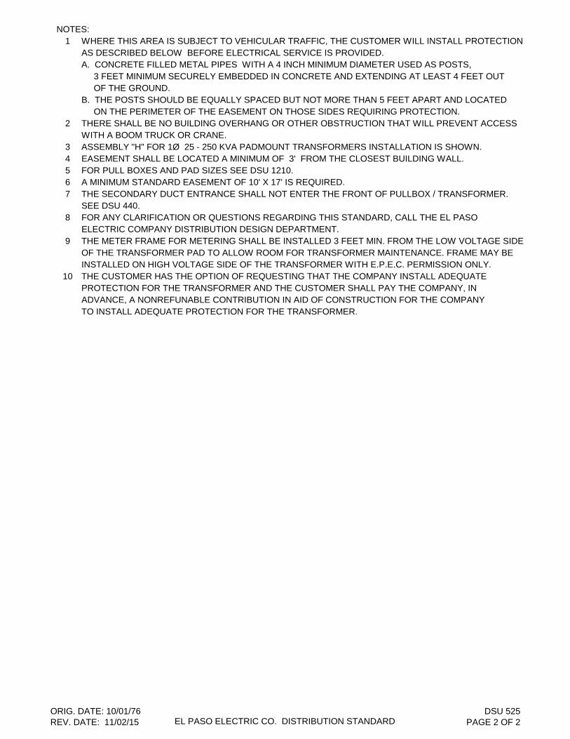
NOTES:1 WHERE THIS AREA IS SUBJECT TO VEHICULAR TRAFFIC, THE CUSTOMER WILL INSTALL PROTECTION
AS DESCRIBED BELOW BEFORE ELECTRICAL SERVICE IS PROVIDED.A. CONCRETE FILLED METAL PIPES WITH A 4 INCH MINIMUM DIAMETER USED AS POSTS, 3 FEET MINIMUM SECURELY EMBEDDED IN CONCRETE AND EXTENDING AT LEAST 4 FEET OUT OF THE GROUND. B. THE POSTS SHOULD BE EQUALLY SPACED BUT NOT MORE THAN 5 FEET APART AND LOCATED ON THE PERIMETER OF THE EASEMENT ON THOSE SIDES REQUIRING PROTECTION.
2 THERE SHALL BE NO BUILDING OVERHANG OR OTHER OBSTRUCTION THAT WILL PREVENT ACCESSWITH A BOOM TRUCK OR CRANE.
3 ASSEMBLY "H" FOR 1Ø 25 - 250 KVA PADMOUNT TRANSFORMERS INSTALLATION IS SHOWN. 4 EASEMENT SHALL BE LOCATED A MINIMUM OF 3' FROM THE CLOSEST BUILDING WALL.5 FOR PULL BOXES AND PAD SIZES SEE DSU 1210.6 A MINIMUM STANDARD EASEMENT OF 10' X 17' IS REQUIRED. 7 THE SECONDARY DUCT ENTRANCE SHALL NOT ENTER THE FRONT OF PULLBOX / TRANSFORMER.
SEE DSU 440.8 FOR ANY CLARIFICATION OR QUESTIONS REGARDING THIS STANDARD, CALL THE EL PASO
ELECTRIC COMPANY DISTRIBUTION DESIGN DEPARTMENT.9 THE METER FRAME FOR METERING SHALL BE INSTALLED 3 FEET MIN. FROM THE LOW VOLTAGE SIDE
OF THE TRANSFORMER PAD TO ALLOW ROOM FOR TRANSFORMER MAINTENANCE. FRAME MAY BE INSTALLED ON HIGH VOLTAGE SIDE OF THE TRANSFORMER WITH E.P.E.C. PERMISSION ONLY.
10 THE CUSTOMER HAS THE OPTION OF REQUESTING THAT THE COMPANY INSTALL ADEQUATEPROTECTION FOR THE TRANSFORMER AND THE CUSTOMER SHALL PAY THE COMPANY, IN ADVANCE, A NONREFUNABLE CONTRIBUTION IN AID OF CONSTRUCTION FOR THE COMPANY TO INSTALL ADEQUATE PROTECTION FOR THE TRANSFORMER.
ORIG. DATE: 10/01/76REV. DATE: 11/02/15 EL PASO ELECTRIC CO. DISTRIBUTION STANDARD
DSU 525PAGE 2 OF 2


NOTES:1 WHERE THIS AREA IS SUBJECT TO VEHICULAR TRAFFIC, THE CUSTOMER WILL INSTALL PROTECTION
AS DESCRIBED BELOW BEFORE ELECTRICAL SERVICE IS PROVIDED.A. CONCRETE FILLED METAL PIPES WITH A 4 INCH MINIMUM DIAMETER USED AS POSTS, 3 FEET MINIMUM SECURELY EMBEDDED IN CONCRETE AND EXTENDING AT LEAST 4 FEET OUT OF THE GROUND. B. THE POSTS SHOULD BE EQUALLY SPACED BUT NOT MORE THAN 5 FEET APART AND LOCATED ON THE PERIMETER OF THE EASEMENT ON THOSE SIDES REQUIRING PROTECTION.
2 THERE SHALL BE NO BUILDING OVERHANG OR OTHER OBSTRUCTION THAT WILL PREVENT ACCESSWITH A BOOM TRUCK OR CRANE.
3 ASSEMBLY "E" FOR 1Ø 25 - 250 KVA PADMOUNT TRANSFORMERS INSTALLATION IS SHOWN. 4 EASEMENT SHALL BE LOCATED A MINIMUM OF 3' FROM THE CLOSEST BUILDING WALL.5 FOR PULL BOXES AND PAD SIZES SEE DSU 1210.6 A MINIMUM STANDARD EASEMENT OF 10' X 17' IS REQUIRED. 7 THE SECONDARY DUCT ENTRANCE SHALL NOT ENTER THE FRONT OF PULLBOX / TRANSFORMER.
SEE DSU 440.8 FOR ANY CLARIFICATION OR QUESTIONS REGARDING THIS STANDARD, CALL THE EL PASO
ELECTRIC COMPANY DISTRIBUTION DESIGN DEPARTMENT.9 THE METER FRAME FOR METERING SHALL BE INSTALLED 3 FEET MIN. FROM THE LOW VOLTAGE SIDE
OF THE TRANSFORMER PAD TO ALLOW ROOM FOR TRANSFORMER MAINTENANCE. FRAME MAY BE INSTALLED ON HIGH VOLTAGE SIDE OF THE TRANSFORMER WITH E.P.E.C. PERMISSION ONLY.
10 THE CUSTOMER HAS THE OPTION OF REQUESTING THAT THE COMPANY INSTALL ADEQUATEPROTECTION FOR THE TRANSFORMER AND THE CUSTOMER SHALL PAY THE COMPANY, IN ADVANCE, A NONREFUNABLE CONTRIBUTION IN AID OF CONSTRUCTION FOR THE COMPANY TO INSTALL ADEQUATE PROTECTION FOR THE TRANSFORMER.
ORIG. DATE: 10/01/76REV. DATE: 11/02/15 EL PASO ELECTRIC CO. DISTRIBUTION STANDARD
DSU 528PAGE 2 OF 2
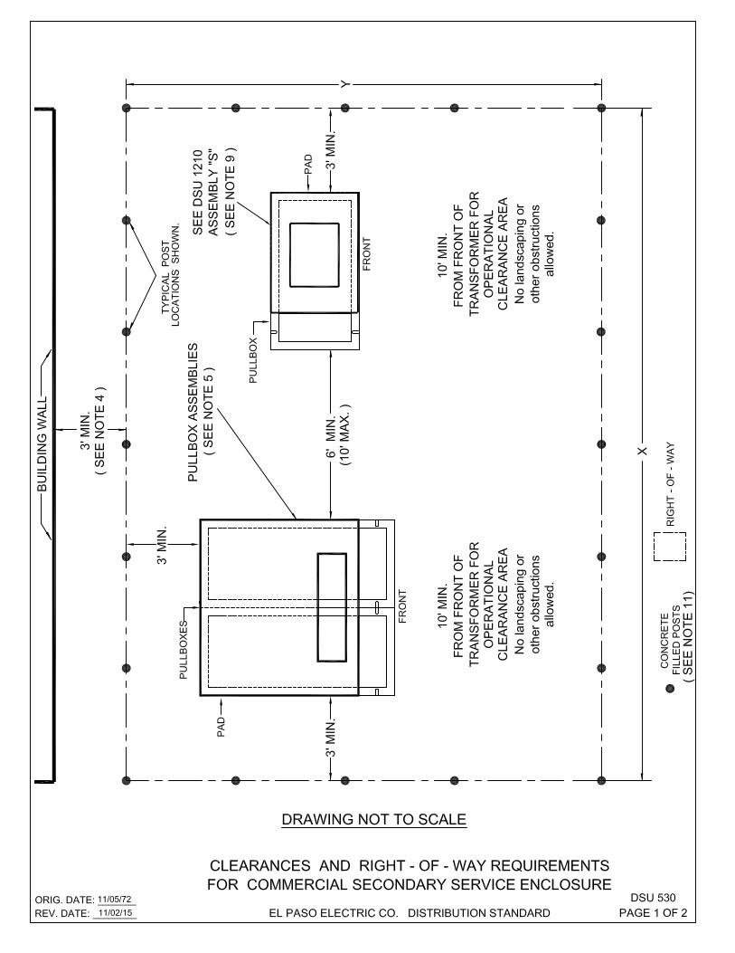
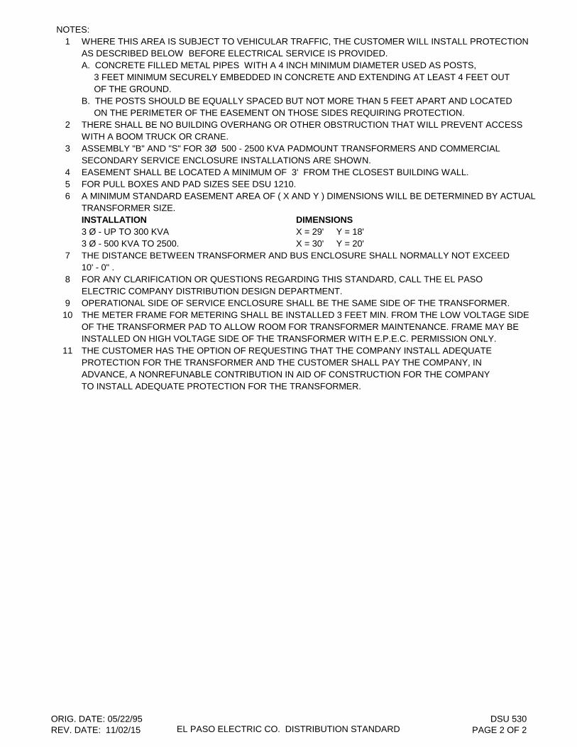
NOTES:1 WHERE THIS AREA IS SUBJECT TO VEHICULAR TRAFFIC, THE CUSTOMER WILL INSTALL PROTECTION
AS DESCRIBED BELOW BEFORE ELECTRICAL SERVICE IS PROVIDED.A. CONCRETE FILLED METAL PIPES WITH A 4 INCH MINIMUM DIAMETER USED AS POSTS, 3 FEET MINIMUM SECURELY EMBEDDED IN CONCRETE AND EXTENDING AT LEAST 4 FEET OUT OF THE GROUND. B. THE POSTS SHOULD BE EQUALLY SPACED BUT NOT MORE THAN 5 FEET APART AND LOCATED ON THE PERIMETER OF THE EASEMENT ON THOSE SIDES REQUIRING PROTECTION.
2 THERE SHALL BE NO BUILDING OVERHANG OR OTHER OBSTRUCTION THAT WILL PREVENT ACCESSWITH A BOOM TRUCK OR CRANE.
3 ASSEMBLY "B" AND "S" FOR 3Ø 500 - 2500 KVA PADMOUNT TRANSFORMERS AND COMMERCIALSECONDARY SERVICE ENCLOSURE INSTALLATIONS ARE SHOWN.
4 EASEMENT SHALL BE LOCATED A MINIMUM OF 3' FROM THE CLOSEST BUILDING WALL.5 FOR PULL BOXES AND PAD SIZES SEE DSU 1210.6 A MINIMUM STANDARD EASEMENT AREA OF ( X AND Y ) DIMENSIONS WILL BE DETERMINED BY ACTUAL
TRANSFORMER SIZE.INSTALLATION DIMENSIONS3 Ø - UP TO 300 KVA X = 29' Y = 18'3 Ø - 500 KVA TO 2500. X = 30' Y = 20'
7 THE DISTANCE BETWEEN TRANSFORMER AND BUS ENCLOSURE SHALL NORMALLY NOT EXCEED 10' - 0" .
8 FOR ANY CLARIFICATION OR QUESTIONS REGARDING THIS STANDARD, CALL THE EL PASO ELECTRIC COMPANY DISTRIBUTION DESIGN DEPARTMENT.
9 OPERATIONAL SIDE OF SERVICE ENCLOSURE SHALL BE THE SAME SIDE OF THE TRANSFORMER.10 THE METER FRAME FOR METERING SHALL BE INSTALLED 3 FEET MIN. FROM THE LOW VOLTAGE SIDE
OF THE TRANSFORMER PAD TO ALLOW ROOM FOR TRANSFORMER MAINTENANCE. FRAME MAY BE INSTALLED ON HIGH VOLTAGE SIDE OF THE TRANSFORMER WITH E.P.E.C. PERMISSION ONLY.
11 THE CUSTOMER HAS THE OPTION OF REQUESTING THAT THE COMPANY INSTALL ADEQUATEPROTECTION FOR THE TRANSFORMER AND THE CUSTOMER SHALL PAY THE COMPANY, IN ADVANCE, A NONREFUNABLE CONTRIBUTION IN AID OF CONSTRUCTION FOR THE COMPANY TO INSTALL ADEQUATE PROTECTION FOR THE TRANSFORMER.
ORIG. DATE: 05/22/95REV. DATE: 11/02/15 EL PASO ELECTRIC CO. DISTRIBUTION STANDARD
DSU 530PAGE 2 OF 2
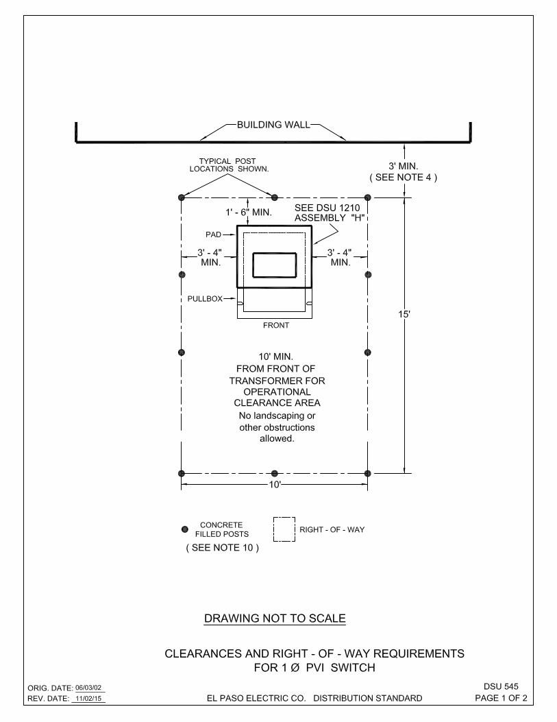
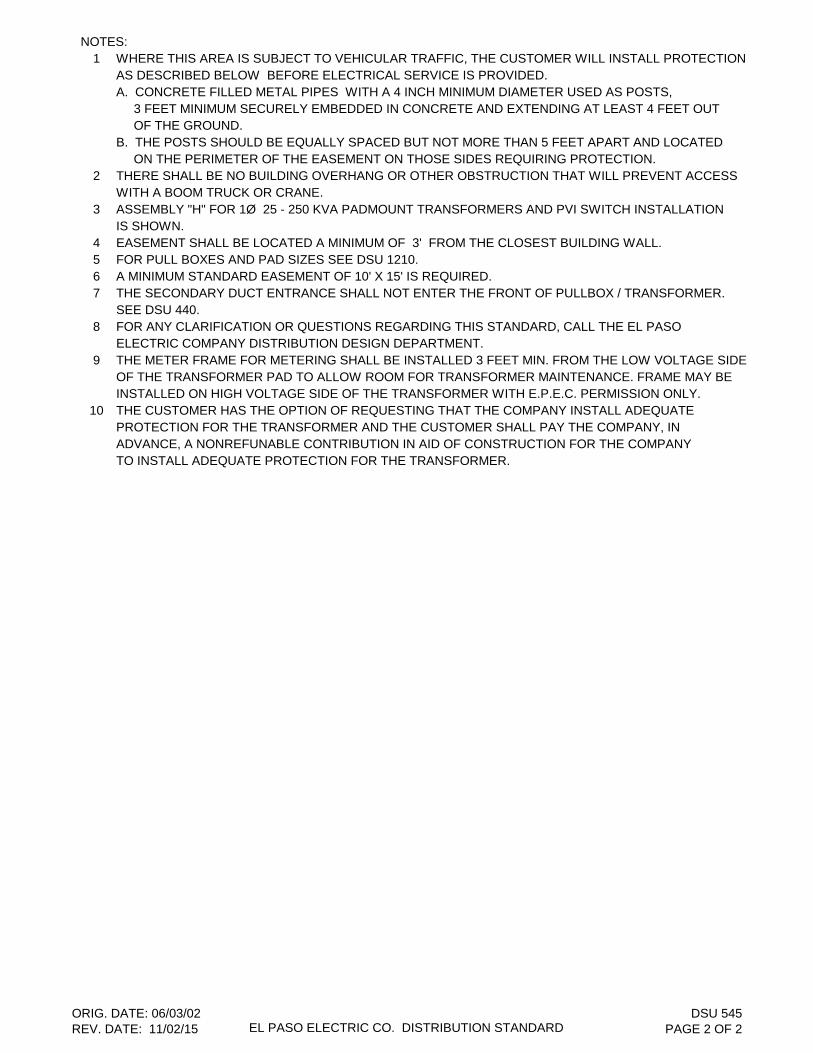
NOTES:1 WHERE THIS AREA IS SUBJECT TO VEHICULAR TRAFFIC, THE CUSTOMER WILL INSTALL PROTECTION
AS DESCRIBED BELOW BEFORE ELECTRICAL SERVICE IS PROVIDED.A. CONCRETE FILLED METAL PIPES WITH A 4 INCH MINIMUM DIAMETER USED AS POSTS, 3 FEET MINIMUM SECURELY EMBEDDED IN CONCRETE AND EXTENDING AT LEAST 4 FEET OUT OF THE GROUND. B. THE POSTS SHOULD BE EQUALLY SPACED BUT NOT MORE THAN 5 FEET APART AND LOCATED ON THE PERIMETER OF THE EASEMENT ON THOSE SIDES REQUIRING PROTECTION.
2 THERE SHALL BE NO BUILDING OVERHANG OR OTHER OBSTRUCTION THAT WILL PREVENT ACCESSWITH A BOOM TRUCK OR CRANE.
3 ASSEMBLY "H" FOR 1Ø 25 - 250 KVA PADMOUNT TRANSFORMERS AND PVI SWITCH INSTALLATION IS SHOWN.
4 EASEMENT SHALL BE LOCATED A MINIMUM OF 3' FROM THE CLOSEST BUILDING WALL.5 FOR PULL BOXES AND PAD SIZES SEE DSU 1210.6 A MINIMUM STANDARD EASEMENT OF 10' X 15' IS REQUIRED. 7 THE SECONDARY DUCT ENTRANCE SHALL NOT ENTER THE FRONT OF PULLBOX / TRANSFORMER.
SEE DSU 440.8 FOR ANY CLARIFICATION OR QUESTIONS REGARDING THIS STANDARD, CALL THE EL PASO
ELECTRIC COMPANY DISTRIBUTION DESIGN DEPARTMENT.9 THE METER FRAME FOR METERING SHALL BE INSTALLED 3 FEET MIN. FROM THE LOW VOLTAGE SIDE
OF THE TRANSFORMER PAD TO ALLOW ROOM FOR TRANSFORMER MAINTENANCE. FRAME MAY BE INSTALLED ON HIGH VOLTAGE SIDE OF THE TRANSFORMER WITH E.P.E.C. PERMISSION ONLY.
10 THE CUSTOMER HAS THE OPTION OF REQUESTING THAT THE COMPANY INSTALL ADEQUATEPROTECTION FOR THE TRANSFORMER AND THE CUSTOMER SHALL PAY THE COMPANY, IN ADVANCE, A NONREFUNABLE CONTRIBUTION IN AID OF CONSTRUCTION FOR THE COMPANY TO INSTALL ADEQUATE PROTECTION FOR THE TRANSFORMER.
ORIG. DATE: 06/03/02REV. DATE: 11/02/15 EL PASO ELECTRIC CO. DISTRIBUTION STANDARD
DSU 545PAGE 2 OF 2
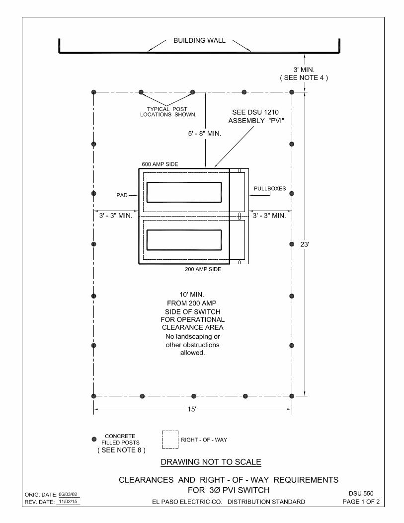
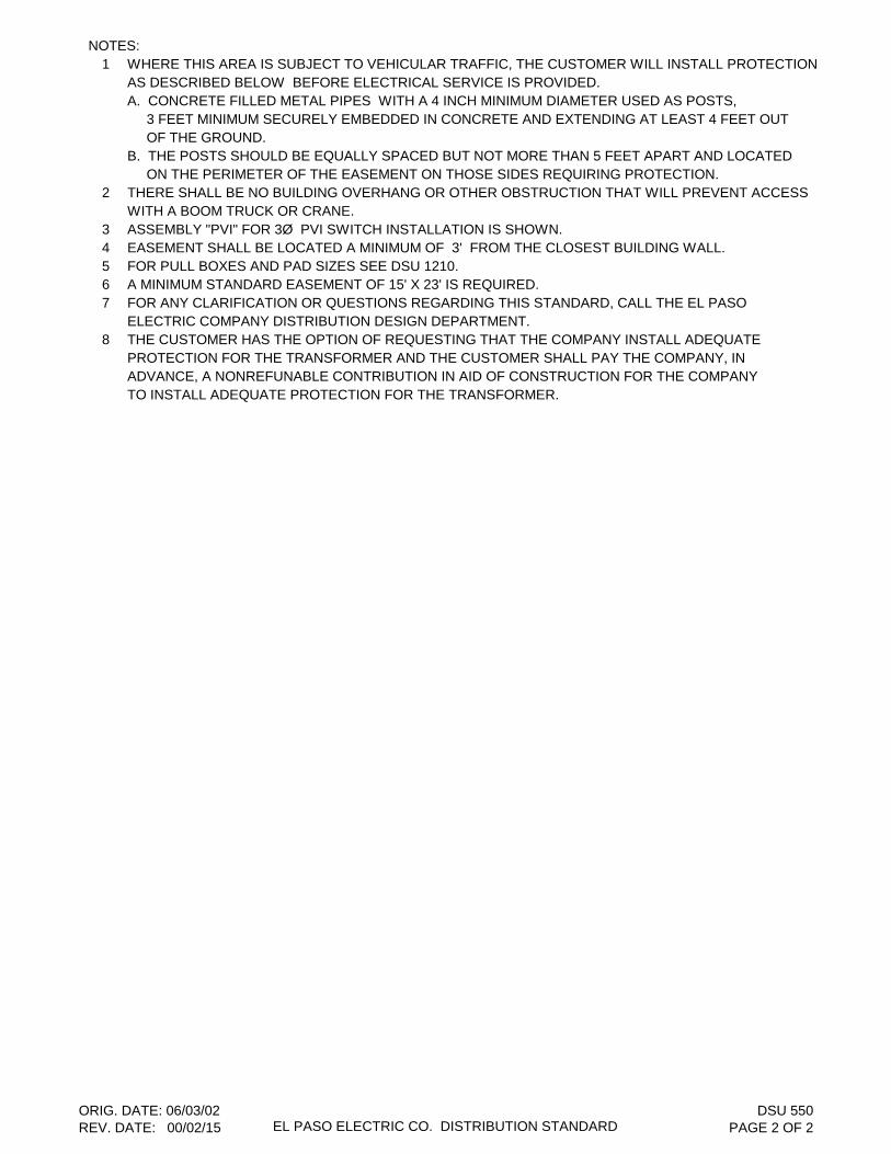
NOTES:1 WHERE THIS AREA IS SUBJECT TO VEHICULAR TRAFFIC, THE CUSTOMER WILL INSTALL PROTECTION
AS DESCRIBED BELOW BEFORE ELECTRICAL SERVICE IS PROVIDED.A. CONCRETE FILLED METAL PIPES WITH A 4 INCH MINIMUM DIAMETER USED AS POSTS, 3 FEET MINIMUM SECURELY EMBEDDED IN CONCRETE AND EXTENDING AT LEAST 4 FEET OUT OF THE GROUND. B. THE POSTS SHOULD BE EQUALLY SPACED BUT NOT MORE THAN 5 FEET APART AND LOCATED ON THE PERIMETER OF THE EASEMENT ON THOSE SIDES REQUIRING PROTECTION.
2 THERE SHALL BE NO BUILDING OVERHANG OR OTHER OBSTRUCTION THAT WILL PREVENT ACCESSWITH A BOOM TRUCK OR CRANE.
3 ASSEMBLY "PVI" FOR 3Ø PVI SWITCH INSTALLATION IS SHOWN.4 EASEMENT SHALL BE LOCATED A MINIMUM OF 3' FROM THE CLOSEST BUILDING WALL.5 FOR PULL BOXES AND PAD SIZES SEE DSU 1210.6 A MINIMUM STANDARD EASEMENT OF 15' X 23' IS REQUIRED.7 FOR ANY CLARIFICATION OR QUESTIONS REGARDING THIS STANDARD, CALL THE EL PASO
ELECTRIC COMPANY DISTRIBUTION DESIGN DEPARTMENT.8 THE CUSTOMER HAS THE OPTION OF REQUESTING THAT THE COMPANY INSTALL ADEQUATE
PROTECTION FOR THE TRANSFORMER AND THE CUSTOMER SHALL PAY THE COMPANY, IN ADVANCE, A NONREFUNABLE CONTRIBUTION IN AID OF CONSTRUCTION FOR THE COMPANY TO INSTALL ADEQUATE PROTECTION FOR THE TRANSFORMER.
ORIG. DATE: 06/03/02REV. DATE: 00/02/15 EL PASO ELECTRIC CO. DISTRIBUTION STANDARD
DSU 550PAGE 2 OF 2


NOTES:1 USE 1" MIN. RIGID OR PVC CONDUIT BETWEEN TRANSFORMER AND METER ENCLOSURE.2 METER CAN MUST BE GROUNDED.3 SPECIFICATION FOR METER FRAME INSTALLATION:
L 2" X 2" X 1/8" STEEL OR UNISTRUT CHANNEL 1 5/8" X 1 5/8" 12 GAUGE4 FRAME SHALL BE INSTALLED 3 FEET MIN. FROM THE LOW VOLTAGE SIDE OF THE TRANSFORMER
PAD TO ALLOW ROOM FOR TRANSFORMER MAINTENANCE. FRAME MAY BE INSTALLED ON HIGHVOLTAGE SIDE OF THE TRANSFORMER WITH E.P.E.C. PERMISSION ONLY.
ORIG. DATE: 12/13/85REV. DATE: 05/25/05 EL PASO ELECTRIC CO. DISTRIBUTION STANDARD
DSU 1015PAGE 2 OF 2
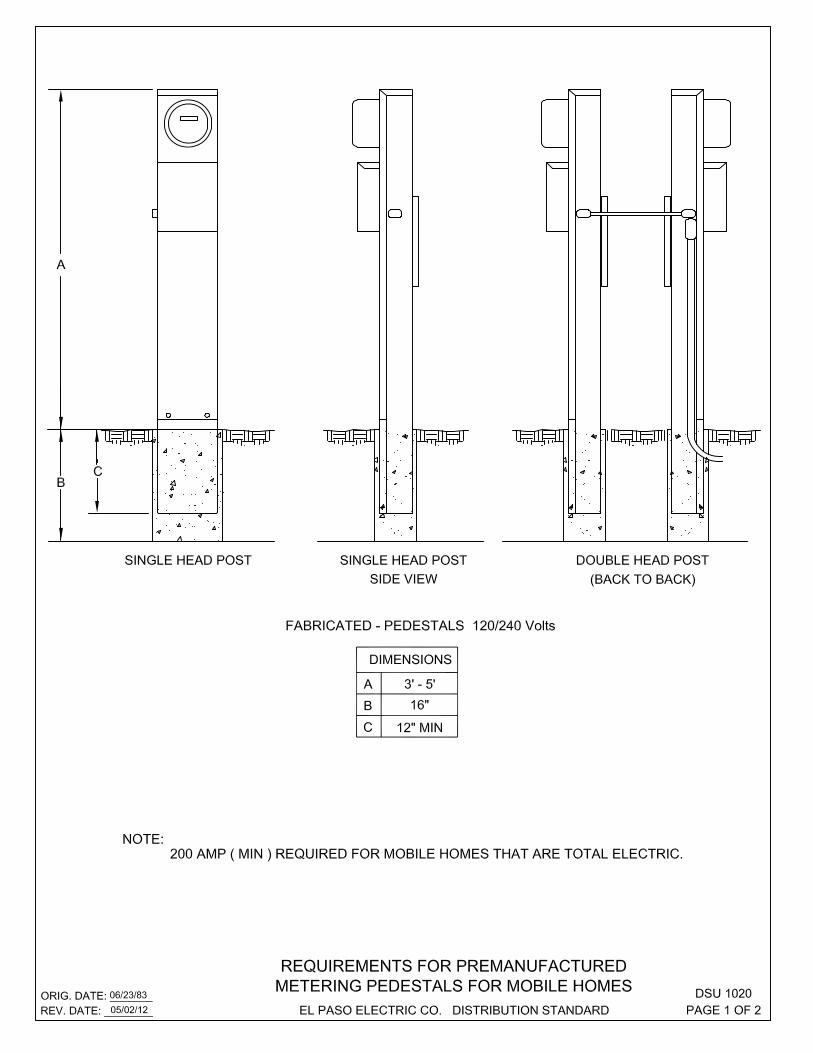
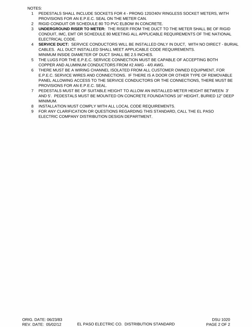
NOTES:1 PEDESTALS SHALL INCLUDE SOCKETS FOR 4 - PRONG 120/240V RINGLESS SOCKET METERS, WITH
PROVISIONS FOR AN E.P.E.C. SEAL ON THE METER CAN.2 RIGID CONDUIT OR SCHEDULE 80 TO PVC ELBOW IN CONCRETE.3 UNDERGROUND RISER TO METER: THE RISER FROM THE DUCT TO THE METER SHALL BE OF RIGID
CONDUIT, IMC, EMT OR SCHEDULE 80 MEETING ALL APPLICABLE REQUIREMENTS OF THE NATIONALELECTRICAL CODE.
4 SERVICE DUCT: SERVICE CONDUCTORS WILL BE INSTALLED ONLY IN DUCT, WITH NO DIRECT - BURIALCABLES. ALL DUCT INSTALLED SHALL MEET APPLICABLE CODE REQUIREMENTS. MINIMUM INSIDE DIAMETER OF DUCT SHALL BE 2.5 INCHES.
5 THE LUGS FOR THE E.P.E.C. SERVICE CONNECTION MUST BE CAPABLE OF ACCEPTING BOTHCOPPER AND ALUMINUM CONDUCTORS FROM #2 AWG - 4/0 AWG.
6 THERE MUST BE A WIRING CHANNEL ISOLATED FROM ALL CUSTOMER OWNED EQUIPMENT, FORE.P.E.C. SERVICE WIRES AND CONNECTIONS. IF THERE IS A DOOR OR OTHER TYPE OF REMOVABLEPANEL ALLOWING ACCESS TO THE SERVICE CONDUCTORS OR THE CONNECTIONS, THERE MUST BE PROVISIONS FOR AN E.P.E.C. SEAL.
7 PEDESTALS MUST BE OF SUITABLE HEIGHT TO ALLOW AN INSTALLED METER HEIGHT BETWEEN 3'AND 5'. PEDESTALS MUST BE MOUNTED ON CONCRETE FOUNDATIONS 16" HEIGHT, BURIED 12" DEEPMINIMUM.
8 INSTALLATION MUST COMPLY WITH ALL LOCAL CODE REQUIREMENTS.9 FOR ANY CLARIFICATION OR QUESTIONS REGARDING THIS STANDARD, CALL THE EL PASO
ELECTRIC COMPANY DISTRIBUTION DESIGN DEPARTMENT.
ORIG. DATE: 06/23/83REV. DATE: 05/02/12 EL PASO ELECTRIC CO. DISTRIBUTION STANDARD
DSU 1020PAGE 2 OF 2
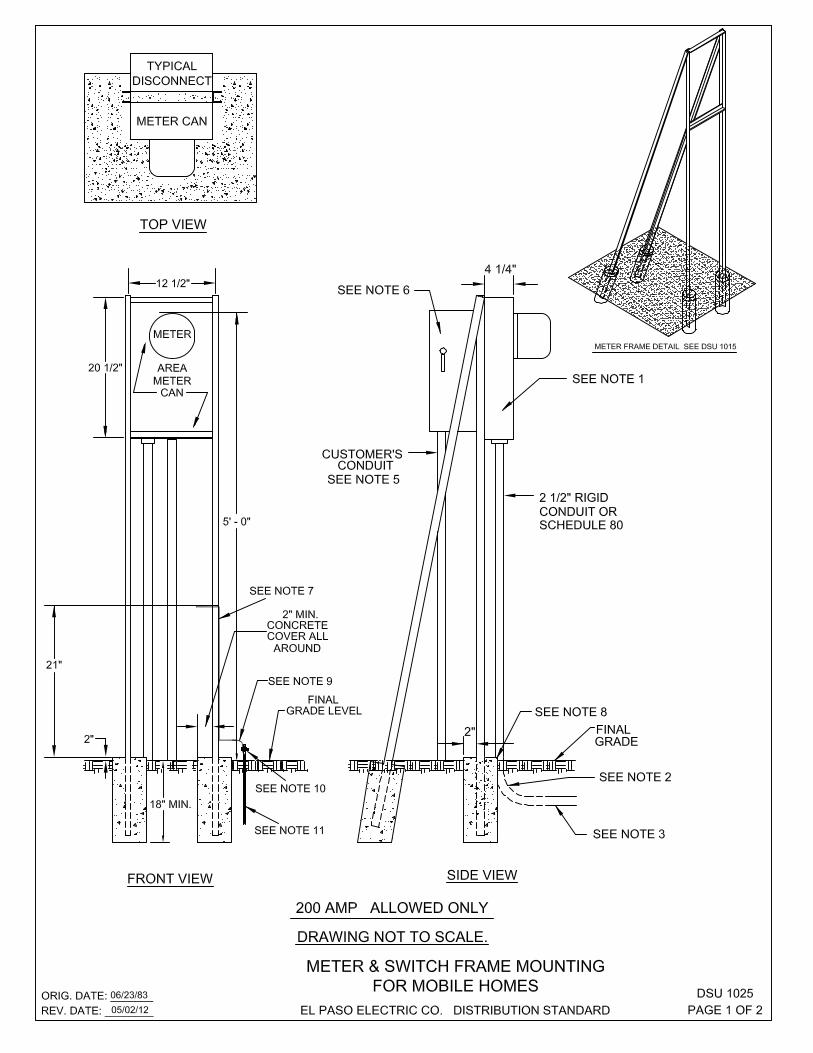

NOTES:1 200 AMP METER - CAN SHALL BE PROVIDED BY CUSTOMER.2 RIGID CONDUIT OR SCHEDULE 80 TO PVC ELBOW IN CONCRETE.3 PVC CONDUIT UNDERGROUND.4 UNDERGROUND RISER TO METER: THE RISER FROM THE DUCT TO THE METER SHALL BE OF RIGID
CONDUIT, IMC, EMT OR SCHEDULE 80 MEETING ALL APPLICABLE REQUIREMENTS OF THE NATIONALELECTRICAL CODE.
5 SERVICE DUCT: SERVICE CONDUCTORS WILL BE INSTALLED ONLY IN DUCT, WITH NO DIRECT -BURIAL CABLES. ALL DUCT INSTALLED SHALL MEET APPLICABLE CODE REQUIREMENTS. MINIMUM INSIDE DIAMETER OF DUCT SHALL BE 2.5 INCHES.
6 ATTACH DISCONNECT TO METER CAN USING REAR KNOCKOUT. CUSTOMER DISCONNECT MUSTPROVIDE OVER CURRENT PROTECTION. CUSTOMER MUST PROVIDE A 120V , GFCI RECEPTACLEINSTALLED PER N.E.C..
7 UNISTRUT CHANNEL P-1000SL OR EQUIVALENT.8 CONCRETE FOOTER REQUIRED.9 GROUND WIRE # 6 AWG COPPER.
10 APPROVED GROUND CLAMP MUST BE CONNECTED TO GROUND ROD 6" ABOVE GROUND LEVEL.11 GROUND RODS MUST BE DRIVEN A MINIMUM OF 8' IN THE GROUND, AND MUST BE A MINIMUM OF 5/8"
COPPERWELD ROD. A MINIMUM OF TWO GROUND ELECTRODES SHALL BE INSTALLED ACCORDINGTO N.E.C..
12 INSTALLATION MUST COMPLY WITH ALL LOCAL CODE REQUIREMENTS AND NATIONAL ELECTRIC CODE.13 FOR ANY CLARIFICATION OR QUESTIONS REGARDING THIS STANDARD, CALL THE EL PASO
ELECTRIC COMPANY DISTRIBUTION DESIGN DEPARTMENT.
ORIG. DATE: 06/23/83REV. DATE: 05/02/12 EL PASO ELECTRIC CO. DISTRIBUTION STANDARD
DSU 1025PAGE 2 OF 2

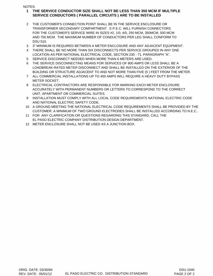
NOTES:1 THE SERVICE CONDUCTOR SIZE SHALL NOT BE LESS THAN 350 MCM IF MULTIPLE
SERVICE CONDUCTORS ( PARALLEL CIRCUITS ) ARE TO BE INSTALLED
2 THE CUSTOMER'S CONNECTION POINT SHALL BE IN THE SERVICE ENCLOSURE ORTRANSFORMER SECONDARY COMPARTMENT. E.P.E.C. WILL FURNISH CONNECTORSFOR THE CUSTOMER'S SERVICE WIRE IN SIZES #2, 1/0, 4/0, 250 MCM, 350MCM, 500 MCMAND 750 MCM. THE MAXIMUM NUMBER OF CONDUCTORS PER LEG SHALL CONFORM TODSU 510.
3 3" MINIMUM IS REQUIRED BETWEEN A METER ENCLOSURE AND ANY ADJACENT EQUIPMENT.4 THERE SHALL BE NO MORE THAN SIX DISCONNECTS PER SERVICE GROUPED IN ANY ONE
LOCATION AS PER NATIONAL ELECTRICAL CODE, SECTION 230 - 71, PARAGRAPH "A".5 SERVICE DISCONNECT NEEDED WHEN MORE THAN 6 METERS ARE USED.6 THE SERVICE DISCONNECTING MEANS FOR SERVICES OF 800 AMPS OR LESS SHALL BE A
LOADBREAK-RATED METER DISCONNECT AND SHALL BE INSTALLED ON THE EXTERIOR OF THE BUILDING OR STRUCTURE ADJACENT TO AND NOT MORE THAN FIVE (5 ) FEET FROM THE METER.
7 ALL COMMERCIAL INSTALLATIONS UP TO 400 AMPS WILL REQUIRE A HEAVY DUTY BYPASS METER SOCKET.
8 ELECTRICAL CONTRACTORS ARE RESPONSIBLE FOR MARKING EACH METER ENCLOSUREACCURATELY WITH PERMANENT NUMBERS OR LETTERS TO CORRESPOND TO THE CORRECTUNIT, APARTMENT OR COMMERCIAL SUITES.
9 INSTALLATION MUST COMPLY WITH ALL LOCAL CODE REQUIREMENTS NATIONAL ELECTRIC CODEAND NATIONAL ELECTRIC SAFETY CODE.
10 A GROUND MEETING THE NATIONAL ELECTRICAL CODE REQUIREMENTS SHALL BE PROVIDED BY THECUSTOMER. A MINIMUM OF TWO GROUND ELECTRODES SHALL BE INSTALLED ACCORDING TO N.E.C..
11 FOR ANY CLARIFICATION OR QUESTIONS REGARDING THIS STANDARD, CALL THE EL PASO ELECTRIC COMPANY DISTRIBUTION DESIGN DEPARTMENT.
12 METER ENCLOSURE SHALL NOT BE USED AS A JUNCTION BOX.
ORIG. DATE: 03/30/84REV. DATE: 05/01/12 EL PASO ELECTRIC CO. DISTRIBUTION STANDARD
DSU 1040PAGE 2 OF 2
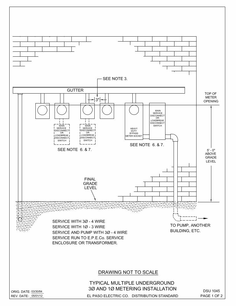
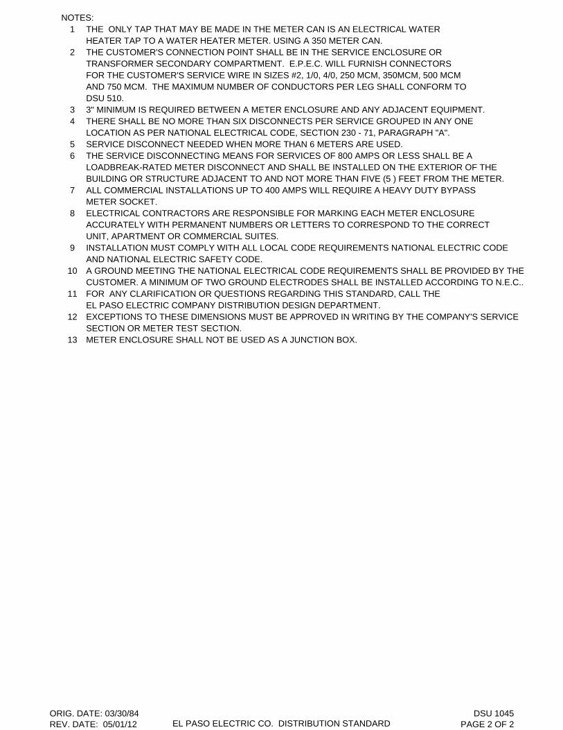
NOTES:1 THE ONLY TAP THAT MAY BE MADE IN THE METER CAN IS AN ELECTRICAL WATER
HEATER TAP TO A WATER HEATER METER. USING A 350 METER CAN.2 THE CUSTOMER'S CONNECTION POINT SHALL BE IN THE SERVICE ENCLOSURE OR
TRANSFORMER SECONDARY COMPARTMENT. E.P.E.C. WILL FURNISH CONNECTORSFOR THE CUSTOMER'S SERVICE WIRE IN SIZES #2, 1/0, 4/0, 250 MCM, 350MCM, 500 MCMAND 750 MCM. THE MAXIMUM NUMBER OF CONDUCTORS PER LEG SHALL CONFORM TODSU 510.
3 3" MINIMUM IS REQUIRED BETWEEN A METER ENCLOSURE AND ANY ADJACENT EQUIPMENT.4 THERE SHALL BE NO MORE THAN SIX DISCONNECTS PER SERVICE GROUPED IN ANY ONE
LOCATION AS PER NATIONAL ELECTRICAL CODE, SECTION 230 - 71, PARAGRAPH "A".5 SERVICE DISCONNECT NEEDED WHEN MORE THAN 6 METERS ARE USED.6 THE SERVICE DISCONNECTING MEANS FOR SERVICES OF 800 AMPS OR LESS SHALL BE A
LOADBREAK-RATED METER DISCONNECT AND SHALL BE INSTALLED ON THE EXTERIOR OF THE BUILDING OR STRUCTURE ADJACENT TO AND NOT MORE THAN FIVE (5 ) FEET FROM THE METER.
7 ALL COMMERCIAL INSTALLATIONS UP TO 400 AMPS WILL REQUIRE A HEAVY DUTY BYPASS METER SOCKET.
8 ELECTRICAL CONTRACTORS ARE RESPONSIBLE FOR MARKING EACH METER ENCLOSUREACCURATELY WITH PERMANENT NUMBERS OR LETTERS TO CORRESPOND TO THE CORRECTUNIT, APARTMENT OR COMMERCIAL SUITES.
9 INSTALLATION MUST COMPLY WITH ALL LOCAL CODE REQUIREMENTS NATIONAL ELECTRIC CODE AND NATIONAL ELECTRIC SAFETY CODE.
10 A GROUND MEETING THE NATIONAL ELECTRICAL CODE REQUIREMENTS SHALL BE PROVIDED BY THECUSTOMER. A MINIMUM OF TWO GROUND ELECTRODES SHALL BE INSTALLED ACCORDING TO N.E.C..
11 FOR ANY CLARIFICATION OR QUESTIONS REGARDING THIS STANDARD, CALL THE EL PASO ELECTRIC COMPANY DISTRIBUTION DESIGN DEPARTMENT.
12 EXCEPTIONS TO THESE DIMENSIONS MUST BE APPROVED IN WRITING BY THE COMPANY'S SERVICESECTION OR METER TEST SECTION.
13 METER ENCLOSURE SHALL NOT BE USED AS A JUNCTION BOX.
ORIG. DATE: 03/30/84REV. DATE: 05/01/12 EL PASO ELECTRIC CO. DISTRIBUTION STANDARD
DSU 1045PAGE 2 OF 2


DRAWING NOT TO SCALE
9" 9"
60"
30"
(1) C" Channels 1 5/8" X 1 3/8" X 5'-2" LONG
(1 ea. side)
w w-j i----- 82"----i 1-
36"
.____ ___ J 100" x 44"
( 1) C" Channels 1 5/8" X 1 3/8" X 6'-1 O" LONG
(1 ea. side)
9" 9"
�z PULLBOX
18" 80" X44"
_J_
(1) C" Channels 1 5/8" X 1 3/8" X 2'-2" LONG
(1 ea. side)
9" 9"
1--1------1--,r
i' 24"
'----------1-----... _l
PULLBOX
100" X44"
(1) C" Channels 1 5/8" X 1 3/8" X 2'-2" LONG
(1 ea. side)
PULLBOXES
ORIG. DATE: 04/30/07
REV. DATE: 11/02/15 EL PASO ELECTRIC CO. DISTRIBUTION STANDARD
DSU 1207
PAGE 2 OF 3

THIS PAGE LEFT BLANK INTENTIONALLY

Stock C/UDescription Number Qty. Code
PULLBOX 60" X 44" N/A 1 DPBF1LEVELING BLOCKS N/A 4PULLBOX 80" X 36" N/A 1 DPB8036LEVELING BLOCKS N/A 4PULLBOX 80" X 44" N/A 1 DPBFLEVELING BLOCKS N/A 4PULLBOX 88" X 80" N/A 1 DPB8880LEVELING BLOCKS N/A 4PULLBOX 100" X 44" N/A 1 DPB100LEVELING BLOCKS N/A 4
NOTES:1 LEVELING BLOCKS SHOWN ARE 4" X 8" X 16" CINDER BLOCKS.2 EACH PULLBOX SHALL BE INSTALLED WITH A 3" LAYER OF 3/4" GRAVEL BASE INSIDE.
ORIG. DATE:12/15/00REV. DATE: 05/07/07 EL PASO ELECTRIC CO. DISTRIBUTION STANDARD
DSU 1207PAGE 3 OF 3

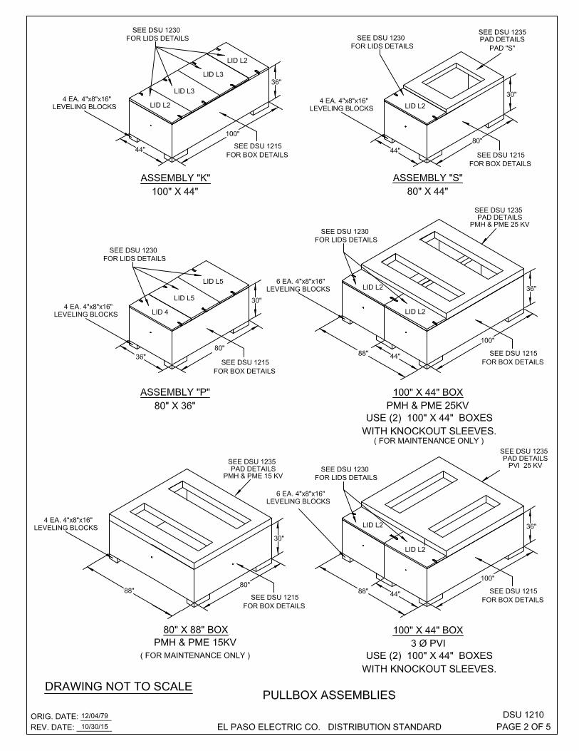

Stock C/U
Assembly Description Number Qty. Code Feature
PULLBOX 80" X 44" 1 DPBF
5/8" X 10' CU BONDED GROUND ROD 08-626
5/8" GROUND ROD CLAMP 07-461 1 GROUNDROD
VISE CONNECTOR # 4 - # 2 04-030 _UG
WIRE # 2 BARE 7 STRD. 12-115 80 IN PULLBOX
"A" LIGHT WEIGHT LID L2 17-995 1 ASSEMBLY "A"
WASHER ROUND GALV. 1 3/8" O.D. 9/16" HOLE 02-755 2 DLID20
BOLT PENTA HEAD. 1/2" X 2 1/2" 17-987 2
LIGHT WEIGHT LID L3 17-996 1
WASHER ROUND GALV. 1 3/8" O.D. 9/16" HOLE 02-755 2 DLID30
BOLT PENTA HED. 1/2" X 2 1/2" 17-987 2
PULLBOX 80" X 44" 2 DPBF
5/8" X 10' CU BONDED GROUND ROD 08-626 80 IN X 44 IN
5/8" GROUND ROD CLAMP 07-461 1 GROUNDROD PULLBOX
VISE CONNECTOR # 4 - # 2 04-030 _UG
"B" WIRE # 2 BARE 7 STRD. 12-115
LIGHT WEIGHT LID L2 17-995 2
WASHER ROUND GALV. 1 3/8" O.D. 9/16" HOLE 02-755 4 DLID20
BOLT PENTA HEAD. 1/2" X 2 1/2" 17-987 4
CONCRETE PAD "B" 1 DBPAD
PULLBOX 100" X 44" 2 DPB100
5/8" X 10' CU BONDED GROUND ROD 08-626 100 IN X 44 IN
5/8" GROUND ROD CLAMP 07-461 1 GROUNDROD PULLBOX
VISE CONNECTOR # 4 - # 2 04-030 _UG
"B100" WIRE # 2 BARE 7 STRD. 12-115
LIGHT WEIGHT LID L2 17-995 2
WASHER ROUND GALV. 1 3/8" O.D. 9/16" HOLE 02-755 4 DLID20
BOLT PENTA HEAD. 1/2" X 2 1/2" 17-987 4
CONCRETE PAD "B" 1 DBPAD
PULLBOX 80" X 44" 1 DPDF
5/8" X 10' CU BONDED GROUND ROD 08-626 80 IN X 44 IN
5/8" GROUND ROD CLAMP 07-461 1 GROUNDROD PULLBOX
VISE CONNECTOR # 4 - # 2 04-030 _UG
"D" WIRE # 2 BARE 7 STRD. 12-115
LIGHT WEIGHT LID L2 17-995 1
WASHER ROUND GALV. 1 3/8" O.D. 9/16" HOLE 02-755 2 DLID20
BOLT PENTA HEAD. 1/2" X 2 1/2" 17-987 2
CONCRETE PAD "D" 1 DDPAD
NOTES:
1 LEVELING BLOCKS SHOWN ARE 4" X 8" X 16" CINDER BLOCKS.
2 EACH PULLBOX SHALL BE INSTALLED WITH A 3" LAYER OF 3/4" GRAVEL BASE INSIDE.
3 SEE DSU 1215 FOR PULLBOX DETAILS.
4 SEE DSU 1230 FOR BOLT DOWN LID DETAILS.
5 SEE DSU 1235 FOR EQUIPMENT PAD DETAIL.
6 ASSEMBLY " D " CAN BE USED FOR A CAPACITOR BANK WITH SOME MODIFICATIONS.
ORIG. DATE: 12/04/79REV. DATE: 01/22/13 EL PASO ELECTRIC CO. DISTRIBUTION STANDARD
DSU 1210PAGE 3 OF 5
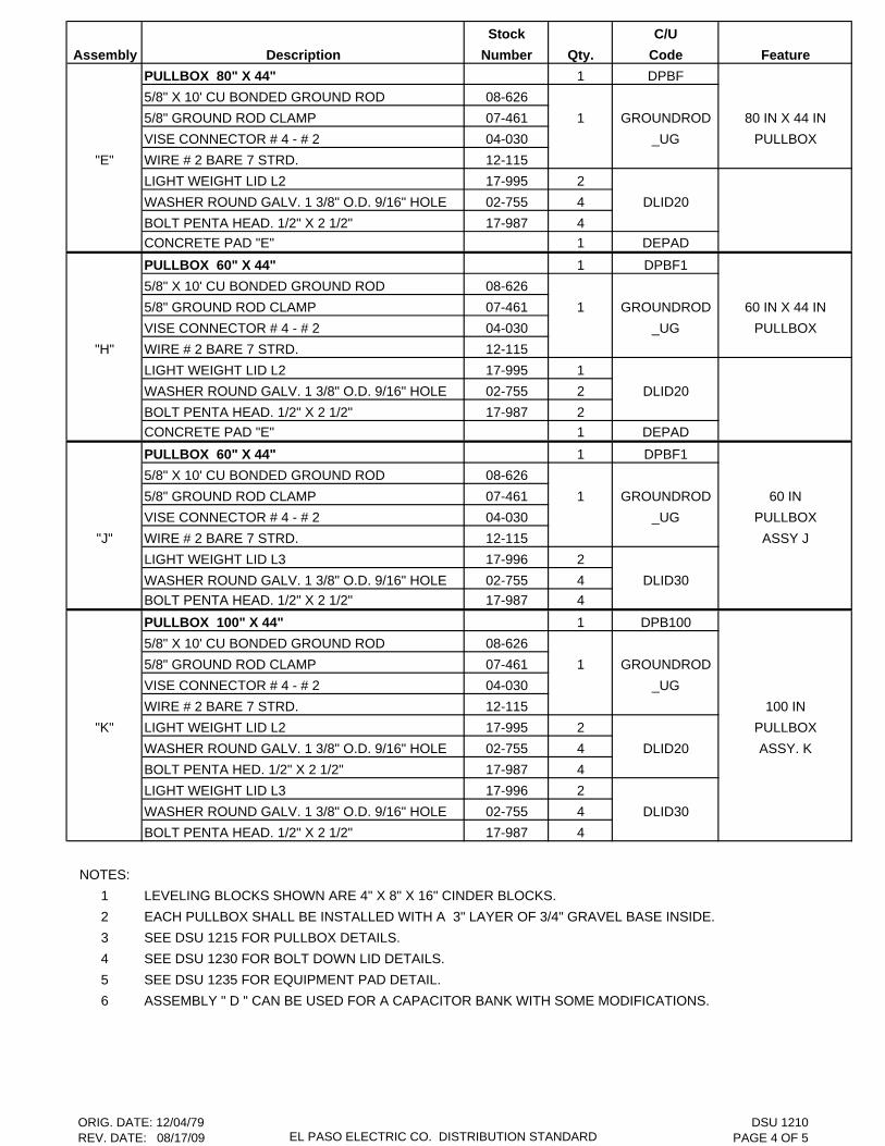
Stock C/U
Assembly Description Number Qty. Code Feature
PULLBOX 80" X 44" 1 DPBF
5/8" X 10' CU BONDED GROUND ROD 08-626
5/8" GROUND ROD CLAMP 07-461 1 GROUNDROD 80 IN X 44 IN
VISE CONNECTOR # 4 - # 2 04-030 _UG PULLBOX
"E" WIRE # 2 BARE 7 STRD. 12-115
LIGHT WEIGHT LID L2 17-995 2
WASHER ROUND GALV. 1 3/8" O.D. 9/16" HOLE 02-755 4 DLID20
BOLT PENTA HEAD. 1/2" X 2 1/2" 17-987 4
CONCRETE PAD "E" 1 DEPAD
PULLBOX 60" X 44" 1 DPBF1
5/8" X 10' CU BONDED GROUND ROD 08-626
5/8" GROUND ROD CLAMP 07-461 1 GROUNDROD 60 IN X 44 IN
VISE CONNECTOR # 4 - # 2 04-030 _UG PULLBOX
"H" WIRE # 2 BARE 7 STRD. 12-115
LIGHT WEIGHT LID L2 17-995 1
WASHER ROUND GALV. 1 3/8" O.D. 9/16" HOLE 02-755 2 DLID20
BOLT PENTA HEAD. 1/2" X 2 1/2" 17-987 2
CONCRETE PAD "E" 1 DEPAD
PULLBOX 60" X 44" 1 DPBF1
5/8" X 10' CU BONDED GROUND ROD 08-626
5/8" GROUND ROD CLAMP 07-461 1 GROUNDROD 60 IN
VISE CONNECTOR # 4 - # 2 04-030 _UG PULLBOX
"J" WIRE # 2 BARE 7 STRD. 12-115 ASSY J
LIGHT WEIGHT LID L3 17-996 2
WASHER ROUND GALV. 1 3/8" O.D. 9/16" HOLE 02-755 4 DLID30
BOLT PENTA HEAD. 1/2" X 2 1/2" 17-987 4
PULLBOX 100" X 44" 1 DPB100
5/8" X 10' CU BONDED GROUND ROD 08-626
5/8" GROUND ROD CLAMP 07-461 1 GROUNDROD
VISE CONNECTOR # 4 - # 2 04-030 _UG
WIRE # 2 BARE 7 STRD. 12-115 100 IN
"K" LIGHT WEIGHT LID L2 17-995 2 PULLBOX
WASHER ROUND GALV. 1 3/8" O.D. 9/16" HOLE 02-755 4 DLID20 ASSY. K
BOLT PENTA HED. 1/2" X 2 1/2" 17-987 4
LIGHT WEIGHT LID L3 17-996 2
WASHER ROUND GALV. 1 3/8" O.D. 9/16" HOLE 02-755 4 DLID30
BOLT PENTA HEAD. 1/2" X 2 1/2" 17-987 4
NOTES:
1 LEVELING BLOCKS SHOWN ARE 4" X 8" X 16" CINDER BLOCKS.
2 EACH PULLBOX SHALL BE INSTALLED WITH A 3" LAYER OF 3/4" GRAVEL BASE INSIDE.
3 SEE DSU 1215 FOR PULLBOX DETAILS.
4 SEE DSU 1230 FOR BOLT DOWN LID DETAILS.
5 SEE DSU 1235 FOR EQUIPMENT PAD DETAIL.
6 ASSEMBLY " D " CAN BE USED FOR A CAPACITOR BANK WITH SOME MODIFICATIONS.
ORIG. DATE: 12/04/79REV. DATE: 08/17/09 EL PASO ELECTRIC CO. DISTRIBUTION STANDARD
DSU 1210PAGE 4 OF 5

THIS PAGE LEFT BLANK INTENTIONALLY
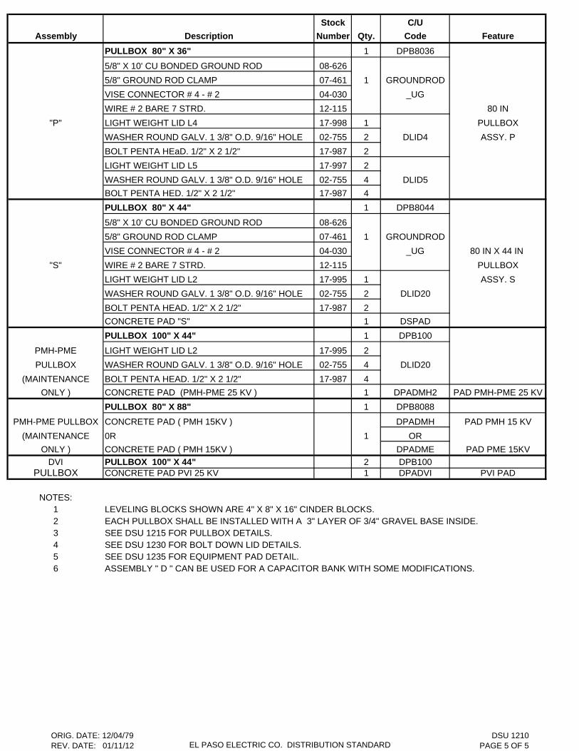
Stock C/U
Assembly Description Number Qty. Code Feature
PULLBOX 80" X 36" 1 DPB8036
5/8" X 10' CU BONDED GROUND ROD 08-626
5/8" GROUND ROD CLAMP 07-461 1 GROUNDROD
VISE CONNECTOR # 4 - # 2 04-030 _UG
WIRE # 2 BARE 7 STRD. 12-115 80 IN
"P" LIGHT WEIGHT LID L4 17-998 1 PULLBOX
WASHER ROUND GALV. 1 3/8" O.D. 9/16" HOLE 02-755 2 DLID4 ASSY. P
BOLT PENTA HEaD. 1/2" X 2 1/2" 17-987 2
LIGHT WEIGHT LID L5 17-997 2
WASHER ROUND GALV. 1 3/8" O.D. 9/16" HOLE 02-755 4 DLID5
BOLT PENTA HED. 1/2" X 2 1/2" 17-987 4
PULLBOX 80" X 44" 1 DPB8044
5/8" X 10' CU BONDED GROUND ROD 08-626
5/8" GROUND ROD CLAMP 07-461 1 GROUNDROD
VISE CONNECTOR # 4 - # 2 04-030 _UG 80 IN X 44 IN
"S" WIRE # 2 BARE 7 STRD. 12-115 PULLBOX
LIGHT WEIGHT LID L2 17-995 1 ASSY. S
WASHER ROUND GALV. 1 3/8" O.D. 9/16" HOLE 02-755 2 DLID20
BOLT PENTA HEAD. 1/2" X 2 1/2" 17-987 2
CONCRETE PAD "S" 1 DSPAD
PULLBOX 100" X 44" 1 DPB100
PMH-PME LIGHT WEIGHT LID L2 17-995 2
PULLBOX WASHER ROUND GALV. 1 3/8" O.D. 9/16" HOLE 02-755 4 DLID20
(MAINTENANCE BOLT PENTA HEAD. 1/2" X 2 1/2" 17-987 4
ONLY ) CONCRETE PAD (PMH-PME 25 KV ) 1 DPADMH2 PAD PMH-PME 25 KV
PULLBOX 80" X 88" 1 DPB8088
PMH-PME PULLBOX CONCRETE PAD ( PMH 15KV ) DPADMH PAD PMH 15 KV
(MAINTENANCE 0R 1 OR
ONLY ) CONCRETE PAD ( PMH 15KV ) DPADME PAD PME 15KV
DVI PULLBOX 100" X 44" 2 DPB100PULLBOX CONCRETE PAD PVI 25 KV 1 DPADVI PVI PAD
NOTES:1 LEVELING BLOCKS SHOWN ARE 4" X 8" X 16" CINDER BLOCKS.2 EACH PULLBOX SHALL BE INSTALLED WITH A 3" LAYER OF 3/4" GRAVEL BASE INSIDE.3 SEE DSU 1215 FOR PULLBOX DETAILS.4 SEE DSU 1230 FOR BOLT DOWN LID DETAILS.5 SEE DSU 1235 FOR EQUIPMENT PAD DETAIL.6 ASSEMBLY " D " CAN BE USED FOR A CAPACITOR BANK WITH SOME MODIFICATIONS.
ORIG. DATE: 12/04/79REV. DATE: 01/11/12 EL PASO ELECTRIC CO. DISTRIBUTION STANDARD
DSU 1210PAGE 5 OF 5
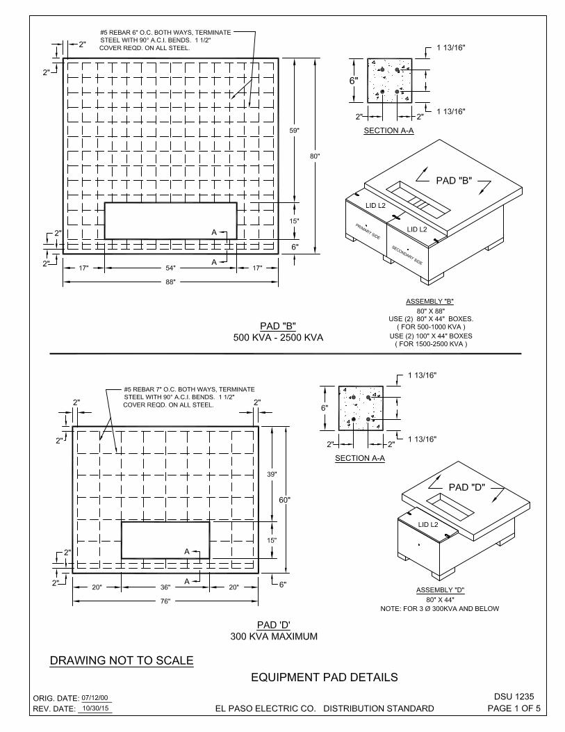
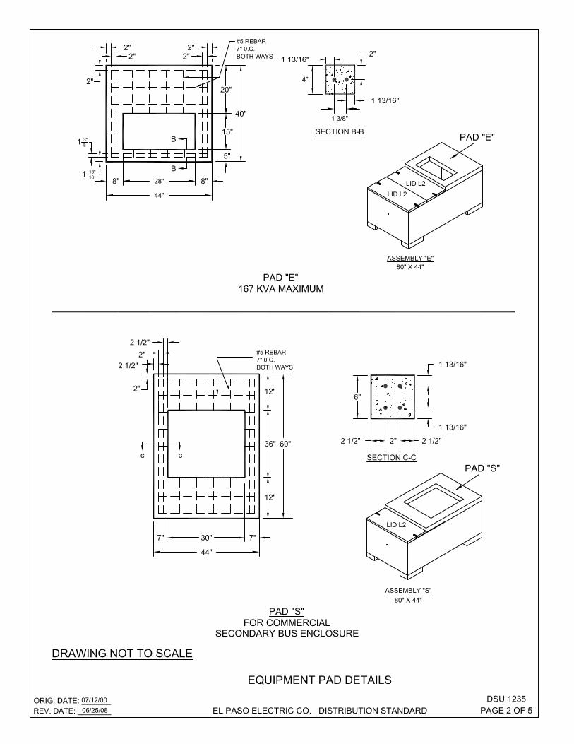
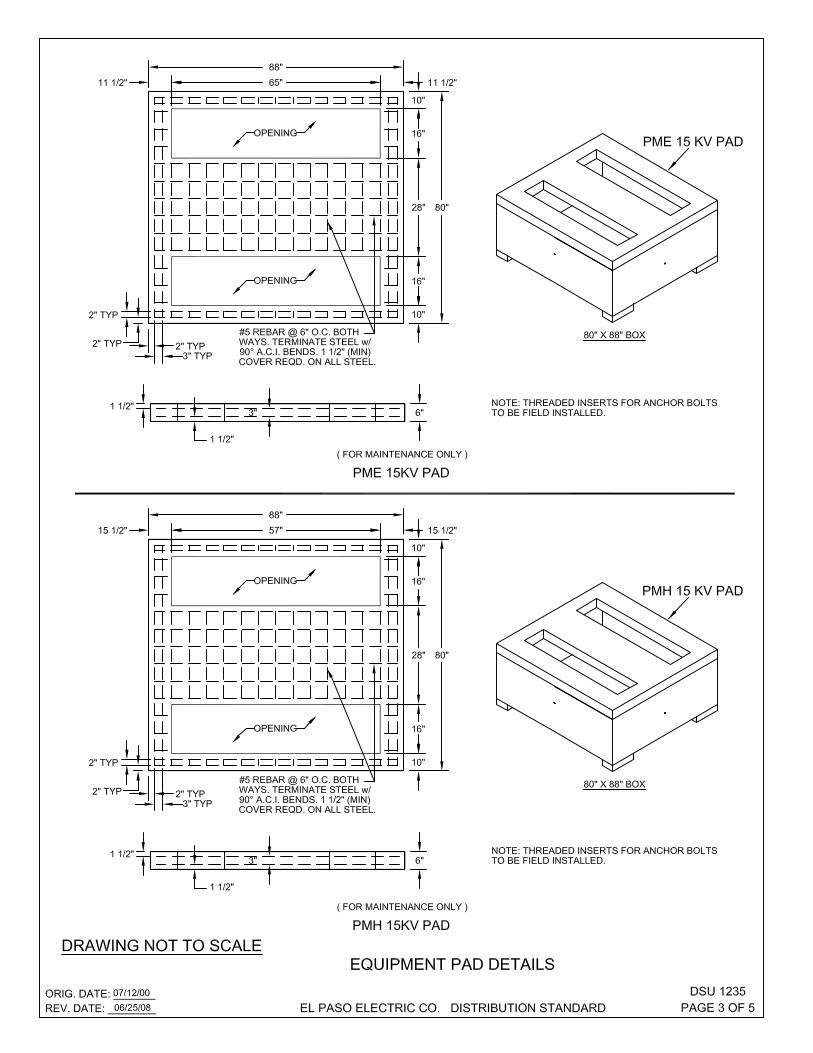


Stock C/UDescription Number Qty. Code Feature
TRANSFORMER PAD "B" N/A 1 DBPAD PADBTRANSFORMER PAD "D" N/A 1 DDPAD PADDTRANSFORMER PAD "E" N/A 1 DEPAD PADETRANSFORMER PAD "S" N/A 1 DSPAD PADSCONCRETE PAD PME (15 KV ) ( MAINT. ONLY ) N/A 1 DPADPME PADPME15CONCRETE PAD PMH (15 KV ) ( MAINT. ONLY ) N/A 1 DPADPMH PADPMH15CONCRETE PAD PVI (15 KV ) ( 25KV ) N/A 1 DPADVI PVIPADCONCRETE PAD PME & PMH ( 25 KV ) N/A 1 DPADMH2 PADPMHPME25KV( MAINT. ONLY )
NOTES:1 PAD "E" SHALL BE 4" THICK WITH REBAR AT 2" DEPTH.2 ALL CONCRETE SHALL BE 4000 PSI AT 28 DAYS.3 ALL EXPOSED EDGES SHALL BE CHAMFERED 3/4".4 ALL STEEL TO BE # 5 REBAR TERMINATE STEEL WITH 90 ACI. BEND.5 ALL STEEL TO HAVE MINIMUM COVER OF 1 1/2".
ORIG. DATE: 07/12/00REV. DATE: 08/17/09 EL PASO ELECTRIC CO. DISTRIBUTION STANDARD
DSU 1235PAGE 5 OF 5

THIS PAGE LEFT BLANK INTENTIONALLY