
Blind source separation for classification and detection of flaws in impact-echo testing
13
1 Blind source separation for classification and detection of flaws in impact-echo testing Addisson Salazar, Luis Vergara, Jorge Igual, Jorge Gosalbez Departamento de Comunicaciones, Universidad Politécnica Valencia, Camino de Vera s/n, 46022 Valencia, Spain, e-mail: [email protected] Abstract This paper presents a technique for defect detection and material classification based on blind source separation by ICA for application in impact-echo testing. The transfer functions between the impact point and the defects in the material are modelled as “sources” for blind source separation. The sensors located on the material surface measure a convolutive mixture of the contribution of each of the defects. From spectral analysis the dominant resonance frequencies, varying from homogeneous to defective material, are selected. These frequencies are processed by instantaneous ICA in order to obtain more information about the defects using bootstrap resampling to analyze the stability of the solution. Results show that source estimates fit well with the theoretical response of the material. In addition, it has been found that the number of defects can be estimated by ICA in simulations and experiments with various defective parallelepiped-shape materials of aluminium alloy series 2000. Keywords: BSS, Convolutive ICA, Impact-echo, Non-destructive testing, flaw detection. 1. Introduction A model of Independent Component Analysis applied to non destructive evaluation by impact-echo has recently been introduced. This approach included a new model of the sources as the filters between the impact point and the defects inside the material [1]. The independence of the sources was checked and the model is applicable in a bulk surrounding the centre of a parallelepiped-shape material. The aim of this paper is to present the application of ICA for the purpose of obtaining additional information on the flaws in materials, by means of working with instantaneous algorithms at particular frequencies, instead of dealing with the whole convolutive problem [2]. The resonance frequencies are obtained by spectral analysis, and the dominant frequencies that show a variation between homogeneous and non- homogeneous parallelepiped-shape materials are selected for BSS. These frequencies are extracted from the ‘residual deconvolutioned signal’ defined in the model. The stability of the BSS solution is analyzed using bootstrap resampling and a separability matrix is obtained for separating the estimated source signals [3]. The separable estimated source signals are compared with the theoretical response of the material, calculated by transient dynamic analysis through three-dimensional finite element models, for determining the reliability of the defect detection. The final objective of the line of research associated with this work is to develop a low-cost operating system for classifying and imaging the status of block shaped materials. The impact-echo is a technique for non-destructive evaluation based on monitoring the surface motion resulting from a short-duration mechanical impact. It has been widely used in applications of concrete structures in civil engineering. Cross-sectional modes in impact-echo signals have been analyzed in elements of different shapes, such as, circular and square beams, beams with empty ducts or cement fillings, rectangular columns, post-tensed structures, and tendon ducts. Impact-echo has been used in determining superficial crack depth, evaluation of early age concrete hardness, evaluation of structural integrity, crack propagation tracing and detection of steel corrosion damage in concrete reinforcement. A displacement of the fundamental frequency to a lower value is the key to identifying the presence of a crack [4]. This technique has recently been used in testing marble blocks for general status classification and discontinuity location inside the blocks [5]. The physical phenomenon of impact-echo corresponds to wave propagation in solids. When a disturbance (stress or displacement) is applied suddenly at a point on the surface of a solid, such as by impact, the disturbance propagates through the solid as three different types of stress waves: a P-wave, an S-wave, and an R-wave. The P-wave is associated with the propagation of normal stress and the S-wave
-
Upload
independent -
Category
Documents
-
view
0 -
download
0
Transcript of Blind source separation for classification and detection of flaws in impact-echo testing
1
Blind source separation for classification and detection of flaws in impact-echo testing
Addisson Salazar, Luis Vergara, Jorge Igual, Jorge Gosalbez
Departamento de Comunicaciones, Universidad Politécnica Valencia, Camino de Vera s/n, 46022 Valencia, Spain, e-mail: [email protected]
Abstract This paper presents a technique for defect detection and material classification based on blind source separation by ICA for application in impact-echo testing. The transfer functions between the impact point and the defects in the material are modelled as “sources” for blind source separation. The sensors located on the material surface measure a convolutive mixture of the contribution of each of the defects. From spectral analysis the dominant resonance frequencies, varying from homogeneous to defective material, are selected. These frequencies are processed by instantaneous ICA in order to obtain more information about the defects using bootstrap resampling to analyze the stability of the solution. Results show that source estimates fit well with the theoretical response of the material. In addition, it has been found that the number of defects can be estimated by ICA in simulations and experiments with various defective parallelepiped-shape materials of aluminium alloy series 2000. Keywords: BSS, Convolutive ICA, Impact-echo, Non-destructive testing, flaw detection.
1. Introduction
A model of Independent Component Analysis applied to non destructive evaluation by impact-echo has recently been introduced. This approach included a new model of the sources as the filters between the impact point and the defects inside the material [1]. The independence of the sources was checked and the model is applicable in a bulk surrounding the centre of a parallelepiped-shape material. The aim of this paper is to present the application of ICA for the purpose of obtaining additional information on the flaws in materials, by means of working with instantaneous algorithms at particular frequencies, instead of dealing with the whole convolutive problem [2]. The resonance frequencies are obtained by spectral analysis, and the dominant frequencies that show a variation between homogeneous and non-homogeneous parallelepiped-shape materials are selected for BSS. These frequencies are extracted from the ‘residual deconvolutioned signal’ defined in the model.
The stability of the BSS solution is analyzed using bootstrap resampling and a separability matrix is obtained for separating the estimated source signals [3]. The separable estimated source signals are compared with the theoretical response of the material, calculated by transient dynamic analysis through three-dimensional finite element models, for determining the reliability of the defect detection. The final objective of the line of research associated with this work is to develop a low-cost operating system for classifying and imaging the status of block shaped materials.
The impact-echo is a technique for non-destructive evaluation based on monitoring the surface motion resulting from a short-duration mechanical impact. It has been widely used in applications of concrete structures in civil engineering. Cross-sectional modes in impact-echo signals have been analyzed in elements of different shapes, such as, circular and square beams, beams with empty ducts or cement fillings, rectangular columns, post-tensed structures, and tendon ducts. Impact-echo has been used in determining superficial crack depth, evaluation of early age concrete hardness, evaluation of structural integrity, crack propagation tracing and detection of steel corrosion damage in concrete reinforcement. A displacement of the fundamental frequency to a lower value is the key to identifying the presence of a crack [4]. This technique has recently been used in testing marble blocks for general status classification and discontinuity location inside the blocks [5].
The physical phenomenon of impact-echo corresponds to wave propagation in solids. When a disturbance (stress or displacement) is applied suddenly at a point on the surface of a solid, such as by impact, the disturbance propagates through the solid as three different types of stress waves: a P-wave, an S-wave, and an R-wave. The P-wave is associated with the propagation of normal stress and the S-wave
2
is associated with shear stress, both of them propagate into the solid along spherical wave fronts. In addition, a surface wave, or Rayleigh wave (R-wave) travels throughout a circular wave front along the material surface [6]. The phenomenon of volumetric wave propagation can be modelled by means of the following two equations [7],
klijkliji
j
ij ScTtu
xT
=∂∂
=∂
∂ ,2
2
0ρ (1)
Where,
0ρ : Material density.
iu : Length elongation with respect to starting point in force direction.
j
ij
x
T
∂
∂: Force variation in i direction due to deformations in j directions.
ijklc : Elastic constant tensor (Hooke’s law).
klS : Strain or relative volume change under deformation in face l in direction k in unitary cube that represents a material element.
That is to say, force variation in the direction i due to face stresses in j directions of the material elementary cube, is equal to the mass per volume (density) times the strain acceleration (Newton’s third law in tensorial form). To derive an analytical solution to problems that involve stress wave propagation in delimited solids is very difficult, and this is the reason why the existing bibliography is not very extensive. Numeric models, such as the Finite Element Method (FEM), can be used to obtain the material theoretical response. Several studies have been made that give a good approximation to the theoretical response calculated by FEM and the results obtained in experimental studies [8].
ICA is a powerful statistical technique that has been successfully applied in different areas such as speech processing, telecommunication, and biomedical signal processing [9] [10]. Nevertheless, the first reference to applying convolutive ICA to impact-echo testing is very recent [1]. The objective of convolutive ICA is to reconstruct L+1 mixing matrices and the T source signal vectors from a D-dimensional convolutive mixture. The conventional form of the convolutive ICA generative model is
TtttL
,,1 ,)()()(0
K=−=∑=τ
ττ sAx (2)
where x is a D by 1 vector, s is a K by 1 vector and A is a D by K matrix. The K-dimensional source
signal vectors are assumed temporally independent. L is assumed to be so large that the correlations in the process x can be explained by the mixing matrices. In the frequency domain the convolution becomes a product of Fourier transforms
)()()( ωωω sAx ⋅= (3)
Section 2 of this paper describes the impact-echo problem formulation from the ICA approach and its application at selected frequencies for classification and defect detection. The use of bootstrapping for analyzing solution stabilization is also discussed. Section 3 contains two parts: simulations and experiments. In simulations, various finite element models and parameters of the transient analysis are described. This part includes the estimated sources obtained by applying the JADE [11] algorithm to simulated specimens (0.07x0.05x0.22 m.) of aluminium alloy series 2000. The second part of section 3 contains the experimental results using the same algorithms as in the first part, but applied to laboratory specimens of aluminium alloy series 2000 of the same dimensions as in part 1. The equipment setup used in the experiments is also included. Both simulations and experiments tested different sensor positions and the estimated sources were checked with the theoretical response of the material. Finally, section 4 includes the conclusions and future work.
3
2. Formulation
In this section the principal aspects of the ICA model applied to impact-echo are reviewed and a useful implementation for classifying the general material condition is proposed by analyzing the first powerful frequencies of the signals. These frequencies vary regularly from homogeneous to defective materials, and the convolutive model can be solved as an “instantaneous” problem for each of the analyzed frequencies. The frequency component permutation problem is thus avoided. In order to assess the quality of results concerning the separation of the estimated sources, a resampling approach based on bootstrapping for stabilization analysis is used. An explanation of the application of this technique to the present problem is included at the end of this section.
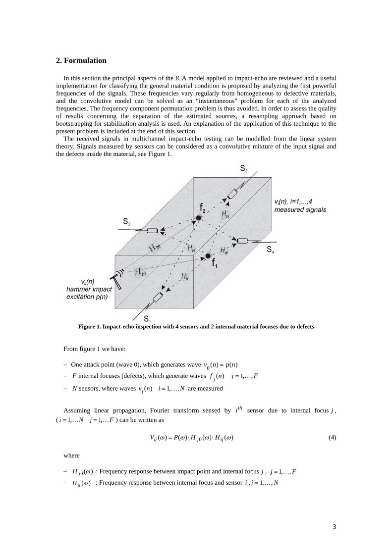
The received signals in multichannel impact-echo testing can be modelled from the linear system theory. Signals measured by sensors can be considered as a convolutive mixture of the input signal and the defects inside the material, see Figure 1.
Figure 1. Impact-echo inspection with 4 sensors and 2 internal material focuses due to defects
From figure 1 we have:
− One attack point (wave 0), which generates wave )()(0 npnv =
− F internal focuses (defects), which generate waves Fjnf j ,,1 )( K=
− N sensors, where waves Ninvi ,,1 )( K= are measured
Assuming linear propagation, Fourier transform sensed by thi sensor due to internal focus j , ( FjNi KK ,1 ,1 == ) can be written as
)()()()( 0 ωωωω ijjij HHPV ⋅⋅= (4)
where − )(0 ωjH : Frequency response between impact point and internal focus j , Fj ,,1K=
− )(ωijH : Frequency response between internal focus and sensor i , Ni ,,1 K=
4
− )(ωP : Impact signal spectrum The spectrum of the signal sensed by sensor i , can be calculated as
⎥⎥
⎦
⎤
⎢⎢
⎣
⎡+⎟
⎟
⎠
⎞
⎜⎜
⎝
⎛⋅⋅= ∑
=
)()()()()(1
0 ωωωωω i
F
jijji HHHPV (5)
where )(ωiH is the direct path frequency response between excitation and sensor i in absence of
internal defects. We define the "residual deconvolutioned signal" (RDS) as
)()()()( ω
ωω
ω ii
i HPVR −= (6)
RDS can be used for determining whether the first material classification is defective or non-defective
material. Replacing Equation (5) in Equation (6) becomes
)()()(1
0 ωωω ij
F
jji HHR ⋅=∑
=
(7)
In order to get information such as number, shape and location of the flaws in a defective material, the
parameters for a classification process can be extracted from Equation (7), or we can undertake a blind separation source process by ICA. Considering a BSS problem by ICA, to find information on the inner sources or material flaws, the following formulation can be outlined.
For eachω , considering all the sensors, from Equation (7) can be written
)()()( ωωω hMr ⋅= (8)
where the matrix and vector elements are defined as follows
[ ] )(i ωiR=r (sample vector, Ni ,,1K= )
[ ] )(j 0 ωjH=h (source vector, transfer functions between the impact point and the defects, Fj ,,1K= )
[ ] )(ji, ωijH=M (mixture matrix) A conventional convolutive ICA model, as in Equation (3), has been derived. It is known that the
conditions to apply ICA are the mutual statistical independence of the sources and one Gaussian source at most. These fundamental assumptions of BSS have to be fulfilled for the transfer functions between the impact point and the defects in the proposed model. Due the complexity of deriving an analytical solution of transfer functions for the volumetric wave propagation phenomenon, the FEM was used to check the conditions for applying BSS.
As we presented in [1], transfer function was calculated in various defective models at 540 locations throughout 15 depth levels moving in axis z from 0 to material length and different x and y coordinate values; the coordinate system as Figure 2. Correlation and higher order statistics between one source with each other of the 540, including it itself, were calculated using displacement modulus normalized signals. Two different curve types were found, first one was obtained for sources at the extremes of z value coordinates (front and back face) and second one for sources at coordinates no located at the extreme values of z.
The first curve showed that given a first source fixed at one extreme of the material length in axis of load application direction (axis z). Its correlation with a second source moving in axis z decreases the longer is the distance separation between both, until the second one reaches centre of material length.
5
After that, values increase as the second source location is closer to the first one source opposite extreme. Increase of correlation is due to the effects caused by multiple reflections in the close proximity of side boundaries and symmetry factors. The second curve showed that given a first source fixed at intermediate localization on axis z, its correlation with other sources decreases steadies the longer distance separation between both. Calculation of fourth order moments and cumulants threw consistent results with correlations. For a source at intermediate localization in axis z, cross-cumulant gave values near to zero over all distances and zero in an interval at the bulk centre.
To check the source pdf Gaussianity, the transfer function (source) was evaluated in points surrounding the defects in the material. The histograms for the sources were evaluated finding that the sources were not Gaussians. From the previous analysis it can be concluded that the sources are independent and can be separated in a source separation distance interval, assuming sources no located at the extreme values at application load axis. However the limitation of the source separation interval is not significant because detecting flaws at the bulk centre, where it can be more difficult to find them by other techniques, is quite important in non destructive evaluation.
Source outlined as transfer function between the impact and a flaw inside the material behaves in a way depending on its location inside the material. Such defined source can become distinguishable and discernable according to many factors such as geometry, attenuation, propagation velocity, in-homogeneities and backscattering of the material. In addition, phenomenon of compression, shear and superficial wave propagation is complex which defines a non deterministic problem for source separation by applying ICA.
Frequency domain estimation of Equation (8) leads to a set of conventional “instantaneous” ICA problems, one for each frequency, with an underlying intensive permutation problem. There are various approaches to solving this problem, such as prior smoothness information, information maximization or high-dimensional optimizations [12-14]. However, the processing of only the dominant frequencies that change from homogeneous to defective blocks using conventional instantaneous algorithms like JADE or TDSEP [15] is adequate for analyzing the condition of the material, thus avoiding the frequency permutation problem.
In order to evaluate the quality of results from ICA processing, a technique based on bootstrap resampling [3] has been used. The application of this technique to the present problem is described next. Firstly, the ICA algorithm processes the sample vector of the RDS evaluated at a particular kω . Then an iterative bootstrap procedure is followed a number of times. For each iteration, the ICA algorithm processes a sample vector generated (bootstrap samples) by taking i.i.d. random variables from the empirical distribution of the original sample vector. Some data points might occur several times, while others might not occur at all in a particular bootstrap sample. Each of the iterations of the bootstrap procedure produces a mixing or source separating matrix used for calculating a separability matrix S . This latter defines a stable higher dimensional source signal subspace obtained by elementary rotations within all the two-dimensional planes spanned by the coordinate axes. The components in S are reordered so that clusters in the separability matrix are visible [16]. Thus each ijS measures how stable
the ICA solution is with respect to a rotation in the ji − plane. Thus, a low ijS corresponds to a good separability between estimated source i and j .
From the ICA application results, including estimated sources and separability matrix, the analysis at different frequencies of the RDS leads to finding information on the defects in order to classify the material. In addition, the estimated sources can be compared with the theoretical responses calculated through finite elements.
3. Results and discussion
The proposed technique has been tested by means of simulations and laboratory experiments. The first part of this section contains the results of applying the technique to 12 finite element models with one and two defects, and material properties corresponding to an aluminium alloy series 2000 (AL). The second part includes experiments with lab specimens of AL with one and two defects using a sensor configuration composed by 6 accelerometers. Both the simulations and experiments checked three RDS frequencies for applying JADE algorithm.
Before the application of BSS, the signals were passed through a narrow band filter and then the RDS was calculated using Equation (6). The RDS frequency was defined as the central frequency around
6
which the signals were band-pass filtered. The filter bandwidth was of the magnitude order of the observing interval inverse, thus it can be considered that there are not significant variations at the spectrum in that narrow band.
The direct transfer function between the impact point and the sensors )(ωiH , used in Equation (6), was calculated in simulations as the nodal solution of a FEM analysis for a homogeneous model. In the experiments, )(ωiH was calculated by measuring the material response in impact-echo testing on the sane testing specimen before making it defective. Thus regularization techniques were not applied because it was not required directly deconvolve experimental data with numerically computed transfer functions.
3.1. Simulations
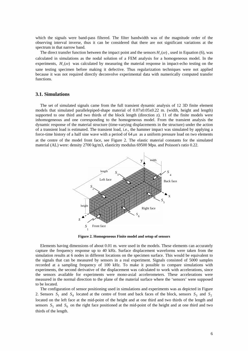
The set of simulated signals came from the full transient dynamic analysis of 12 3D finite element models that simulated parallelepiped-shape material of 0.07x0.05x0.22 m. (width, height and length) supported to one third and two thirds of the block length (direction z). 11 of the finite models were inhomogeneous and one corresponding to the homogeneous model. From the transient analysis the dynamic response of the material structure (time-varying displacements in the structure) under the action of a transient load is estimated. The transient load, i.e., the hammer impact was simulated by applying a force-time history of a half sine wave with a period of 64 sµ as a uniform pressure load on two elements at the centre of the model front face, see Figure 2. The elastic material constants for the simulated material (AL) were: density 2700 kg/m3, elasticity modulus 69500 Mpa. and Poisson's ratio 0.22.
Figure 2. Homogeneous Finite model and setup of sensors Elements having dimensions of about 0.01 m. were used in the models. These elements can accurately
capture the frequency response up to 40 kHz. Surface displacement waveforms were taken from the simulation results at 6 nodes in different locations on the specimen surface. This would be equivalent to the signals that can be measured by sensors in a real experiment. Signals consisted of 5000 samples recorded at a sampling frequency of 100 kHz. To make it possible to compare simulations with experiments, the second derivative of the displacement was calculated to work with accelerations, since the sensors available for experiments were mono-axial accelerometers. These accelerations were measured in the normal direction to the plane of the material surface where the ‘sensors’ were supposed to be located.
The configuration of sensor positioning used in simulations and experiments was as depicted in Figure 2. Sensors 1S and 4S located at the centre of front and back faces of the block, sensors 3S and 2S located on the left face at the mid-point of the height and at one third and two thirds of the length and sensors 5S and 6S on the right face positioned at the mid-point of the height and at one third and two thirds of the length.
Back face
6
S
5
S
1S
4S
3S
x
2
S
y
z
Left face
Right face
Front face
width
height
length
7
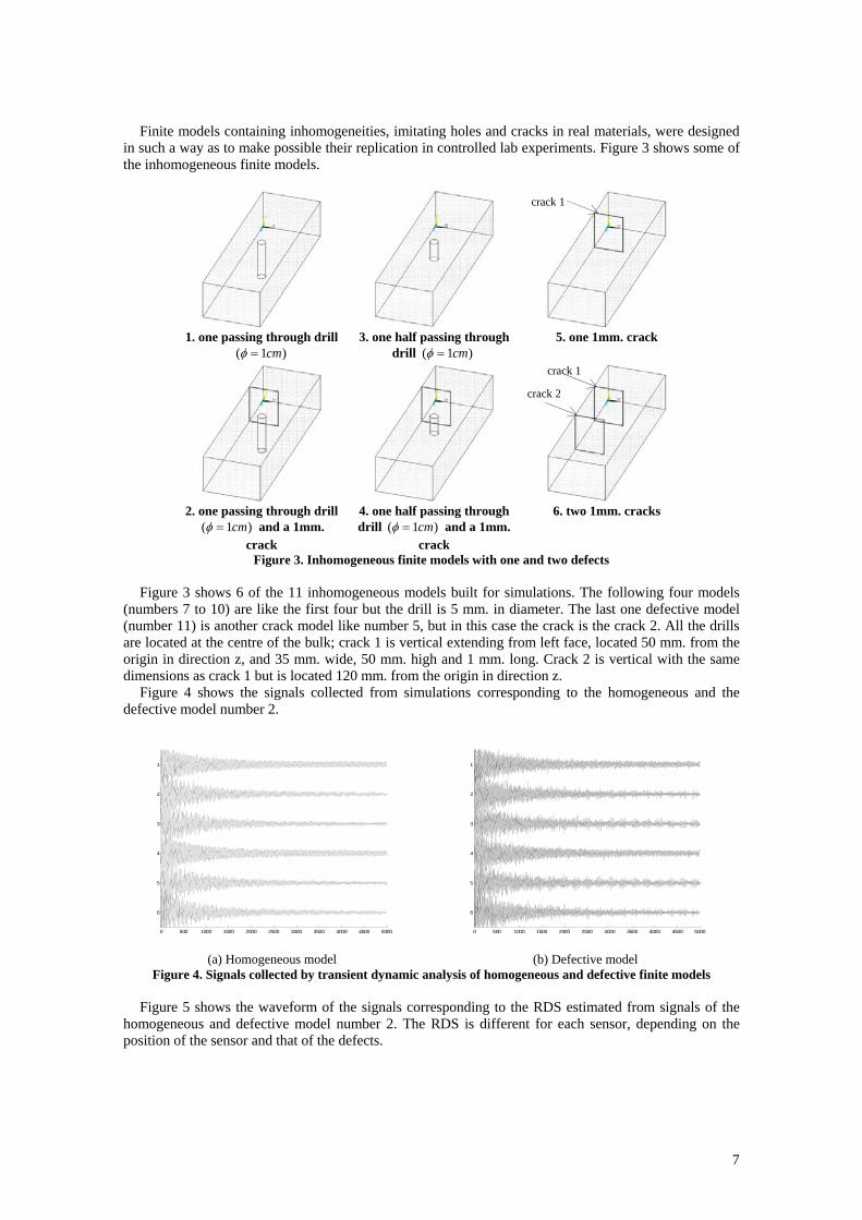
Finite models containing inhomogeneities, imitating holes and cracks in real materials, were designed in such a way as to make possible their replication in controlled lab experiments. Figure 3 shows some of the inhomogeneous finite models.
1. one passing through drill
)1( cm=φ 3. one half passing through
drill )1( cm=φ 5. one 1mm. crack
2. one passing through drill
)1( cm=φ and a 1mm. crack
4. one half passing through drill )1( cm=φ and a 1mm.
crack
6. two 1mm. cracks
Figure 3. Inhomogeneous finite models with one and two defects
Figure 3 shows 6 of the 11 inhomogeneous models built for simulations. The following four models (numbers 7 to 10) are like the first four but the drill is 5 mm. in diameter. The last one defective model (number 11) is another crack model like number 5, but in this case the crack is the crack 2. All the drills are located at the centre of the bulk; crack 1 is vertical extending from left face, located 50 mm. from the origin in direction z, and 35 mm. wide, 50 mm. high and 1 mm. long. Crack 2 is vertical with the same dimensions as crack 1 but is located 120 mm. from the origin in direction z.
Figure 4 shows the signals collected from simulations corresponding to the homogeneous and the defective model number 2.
0 500 1000 1500 2000 2500 3000 3500 4000 4500 5000
1
2
3
4
5
6
0 500 1000 1500 2000 2500 3000 3500 4000 4500 5000
1
2
3
4
5
6
(a) Homogeneous model (b) Defective model
Figure 4. Signals collected by transient dynamic analysis of homogeneous and defective finite models
Figure 5 shows the waveform of the signals corresponding to the RDS estimated from signals of the homogeneous and defective model number 2. The RDS is different for each sensor, depending on the position of the sensor and that of the defects.
crack 1
crack 1
crack 2
8
0 500 1000 1500 2000 2500 3000 3500 4000 4500 5000
1
2
3
4
5
6
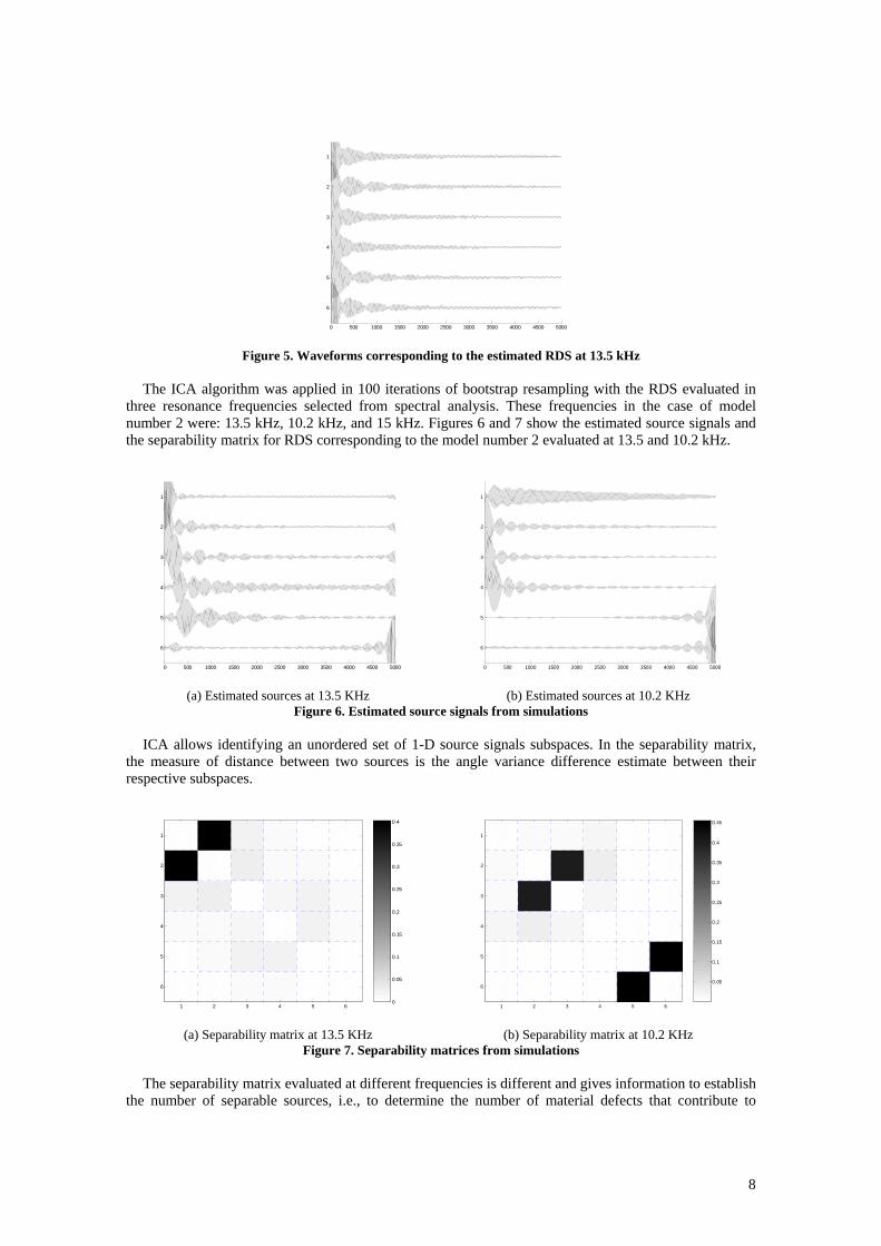
Figure 5. Waveforms corresponding to the estimated RDS at 13.5 kHz
The ICA algorithm was applied in 100 iterations of bootstrap resampling with the RDS evaluated in
three resonance frequencies selected from spectral analysis. These frequencies in the case of model number 2 were: 13.5 kHz, 10.2 kHz, and 15 kHz. Figures 6 and 7 show the estimated source signals and the separability matrix for RDS corresponding to the model number 2 evaluated at 13.5 and 10.2 kHz.
0 500 1000 1500 2000 2500 3000 3500 4000 4500 5000
1
2
3
4
5
6
0 500 1000 1500 2000 2500 3000 3500 4000 4500 5000
1
2
3
4
5
6
(a) Estimated sources at 13.5 KHz (b) Estimated sources at 10.2 KHz
Figure 6. Estimated source signals from simulations ICA allows identifying an unordered set of 1-D source signals subspaces. In the separability matrix,
the measure of distance between two sources is the angle variance difference estimate between their respective subspaces.
1 2 3 4 5 6
1
2
3
4
5
6
0
0.05
0.1
0.15
0.2
0.25
0.3
0.35
0.4
1 2 3 4 5 6
1
2
3
4
5
60.05
0.1
0.15
0.2
0.25
0.3
0.35
0.4
0.45
(a) Separability matrix at 13.5 KHz (b) Separability matrix at 10.2 KHz
Figure 7. Separability matrices from simulations
The separability matrix evaluated at different frequencies is different and gives information to establish the number of separable sources, i.e., to determine the number of material defects that contribute to
9
altering the standard spectrum of a homogeneous material. It can also be used for estimating a measure of similarity between the defects.
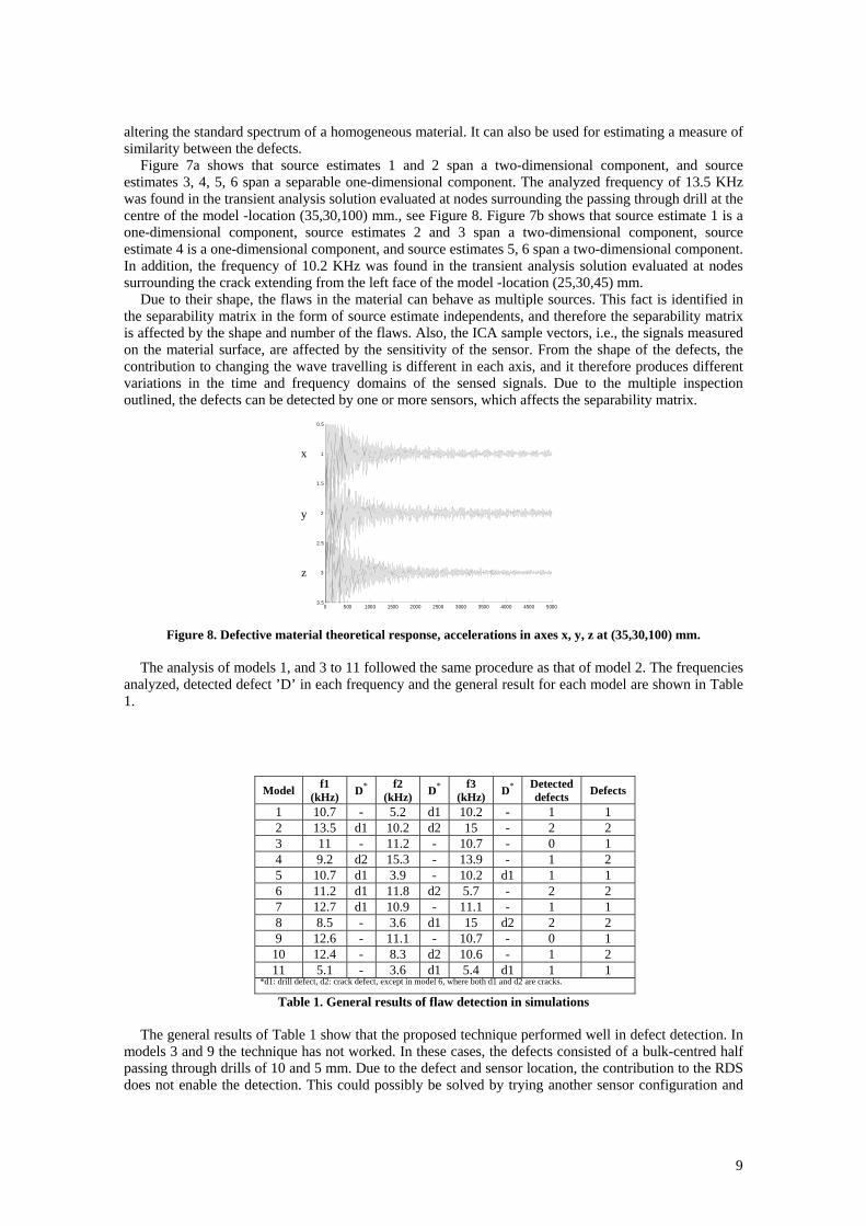
Figure 7a shows that source estimates 1 and 2 span a two-dimensional component, and source estimates 3, 4, 5, 6 span a separable one-dimensional component. The analyzed frequency of 13.5 KHz was found in the transient analysis solution evaluated at nodes surrounding the passing through drill at the centre of the model -location (35,30,100) mm., see Figure 8. Figure 7b shows that source estimate 1 is a one-dimensional component, source estimates 2 and 3 span a two-dimensional component, source estimate 4 is a one-dimensional component, and source estimates 5, 6 span a two-dimensional component. In addition, the frequency of 10.2 KHz was found in the transient analysis solution evaluated at nodes surrounding the crack extending from the left face of the model -location (25,30,45) mm.
Due to their shape, the flaws in the material can behave as multiple sources. This fact is identified in the separability matrix in the form of source estimate independents, and therefore the separability matrix is affected by the shape and number of the flaws. Also, the ICA sample vectors, i.e., the signals measured on the material surface, are affected by the sensitivity of the sensor. From the shape of the defects, the contribution to changing the wave travelling is different in each axis, and it therefore produces different variations in the time and frequency domains of the sensed signals. Due to the multiple inspection outlined, the defects can be detected by one or more sensors, which affects the separability matrix.
0 500 1000 1500 2000 2500 3000 3500 4000 4500 5000
0.5
1
1.5
2
2.5
3
3.5
Figure 8. Defective material theoretical response, accelerations in axes x, y, z at (35,30,100) mm.
The analysis of models 1, and 3 to 11 followed the same procedure as that of model 2. The frequencies
analyzed, detected defect ’D’ in each frequency and the general result for each model are shown in Table 1.
Model f1 (kHz) D* f2
(kHz) D* f3 (kHz) D* Detected
defects Defects
1 10.7 - 5.2 d1 10.2 - 1 1 2 13.5 d1 10.2 d2 15 - 2 2 3 11 - 11.2 - 10.7 - 0 1 4 9.2 d2 15.3 - 13.9 - 1 2 5 10.7 d1 3.9 - 10.2 d1 1 1 6 11.2 d1 11.8 d2 5.7 - 2 2 7 12.7 d1 10.9 - 11.1 - 1 1 8 8.5 - 3.6 d1 15 d2 2 2 9 12.6 - 11.1 - 10.7 - 0 1
10 12.4 - 8.3 d2 10.6 - 1 2 11 5.1 - 3.6 d1 5.4 d1 1 1
*d1: drill defect, d2: crack defect, except in model 6, where both d1 and d2 are cracks.
Table 1. General results of flaw detection in simulations
The general results of Table 1 show that the proposed technique performed well in defect detection. In models 3 and 9 the technique has not worked. In these cases, the defects consisted of a bulk-centred half passing through drills of 10 and 5 mm. Due to the defect and sensor location, the contribution to the RDS does not enable the detection. This could possibly be solved by trying another sensor configuration and
y
z
x
10
exploring more frequencies. In the case of models 4 and 10 a similar situation occurs because of the half-passing through drill. In the other models the technique performed correctly.
In defective models the propagated waves have to surround the defects and their energy decreases. Also, multiple reflections and diffraction with the defect borders become reflected waves, some of them with a changed propagation mode, i.e., P-waves are reflected as S-waves and vice versa. The displacement waveform patterns are affected by the shape of the defects [17].
3.2. Experiments
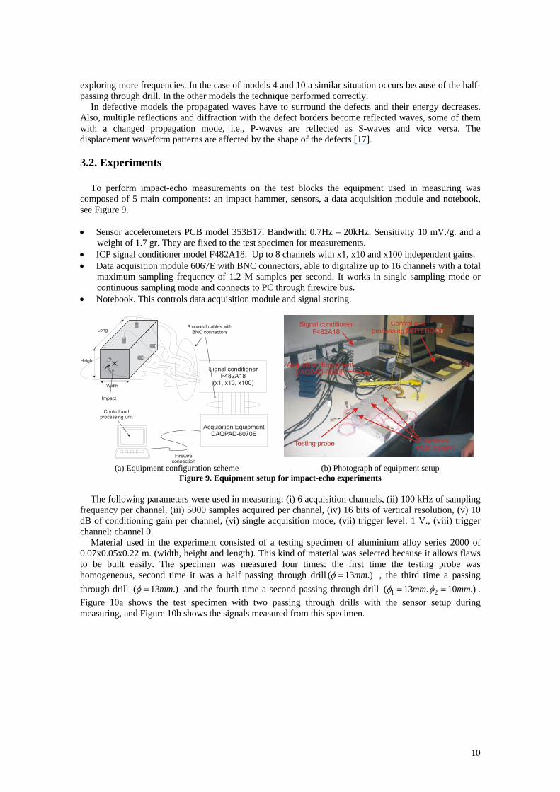
To perform impact-echo measurements on the test blocks the equipment used in measuring was composed of 5 main components: an impact hammer, sensors, a data acquisition module and notebook, see Figure 9. • Sensor accelerometers PCB model 353B17. Bandwith: 0.7Hz – 20kHz. Sensitivity 10 mV./g. and a
weight of 1.7 gr. They are fixed to the test specimen for measurements. • ICP signal conditioner model F482A18. Up to 8 channels with x1, x10 and x100 independent gains. • Data acquisition module 6067E with BNC connectors, able to digitalize up to 16 channels with a total
maximum sampling frequency of 1.2 M samples per second. It works in single sampling mode or continuous sampling mode and connects to PC through firewire bus.
• Notebook. This controls data acquisition module and signal storing.
Long
Width
Acquisition EquipmentDAQPAD-6070E
Signal conditionerF482A18
(x1, x10, x100)
8 coaxial cables withBNC connectors
Firewireconnection
Height
Control andprocessing unit
Impact
(a) Equipment configuration scheme (b) Photograph of equipment setup
Figure 9. Equipment setup for impact-echo experiments
The following parameters were used in measuring: (i) 6 acquisition channels, (ii) 100 kHz of sampling frequency per channel, (iii) 5000 samples acquired per channel, (iv) 16 bits of vertical resolution, (v) 10 dB of conditioning gain per channel, (vi) single acquisition mode, (vii) trigger level: 1 V., (viii) trigger channel: channel 0.
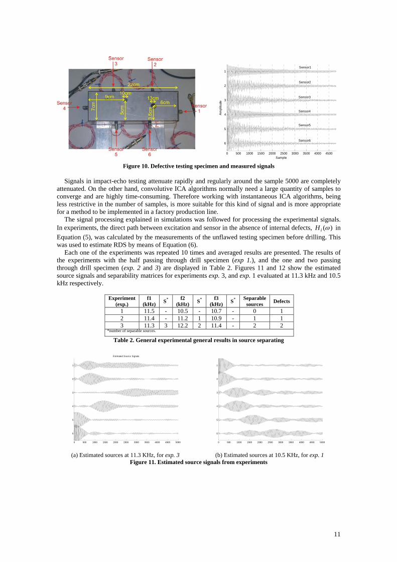
Material used in the experiment consisted of a testing specimen of aluminium alloy series 2000 of 0.07x0.05x0.22 m. (width, height and length). This kind of material was selected because it allows flaws to be built easily. The specimen was measured four times: the first time the testing probe was homogeneous, second time it was a half passing through drill .)13( mm=φ , the third time a passing through drill .)13( mm=φ and the fourth time a second passing through drill .)10 .13( 21 mmmm == φφ . Figure 10a shows the test specimen with two passing through drills with the sensor setup during measuring, and Figure 10b shows the signals measured from this specimen.
11
0 500 1000 1500 2000 2500 3000 3500 4000 4500
1
2
3
4
5
6
Sample
Am
plitu
de
Sensor1
Sensor2
Sensor3
Sensor4
Sensor5
Sensor6
Figure 10. Defective testing specimen and measured signals
Signals in impact-echo testing attenuate rapidly and regularly around the sample 5000 are completely attenuated. On the other hand, convolutive ICA algorithms normally need a large quantity of samples to converge and are highly time-consuming. Therefore working with instantaneous ICA algorithms, being less restrictive in the number of samples, is more suitable for this kind of signal and is more appropriate for a method to be implemented in a factory production line.
The signal processing explained in simulations was followed for processing the experimental signals. In experiments, the direct path between excitation and sensor in the absence of internal defects, )(ωiH in Equation (5), was calculated by the measurements of the unflawed testing specimen before drilling. This was used to estimate RDS by means of Equation (6).
Each one of the experiments was repeated 10 times and averaged results are presented. The results of the experiments with the half passing through drill specimen (exp 1.), and the one and two passing through drill specimen (exp. 2 and 3) are displayed in Table 2. Figures 11 and 12 show the estimated source signals and separability matrices for experiments exp. 3, and exp. 1 evaluated at 11.3 kHz and 10.5 kHz respectively.
Experiment (exp.)
f1 (kHz) S* f2
(kHz) S* f3 (kHz) S* Separable
sources Defects
1 11.5 - 10.5 - 10.7 - 0 1 2 11.4 - 11.2 1 10.9 - 1 1 3 11.3 3 12.2 2 11.4 - 2 2
*number of separable sources.
Table 2. General experimental general results in source separating
0 500 1000 1500 2000 2500 3000 3500 4000 4500 5000
1
2
3
4
5
6
Estimated Source Signals
0 500 1000 1500 2000 2500 3000 3500 4000 4500 5000
1
2
3
4
5
6
(a) Estimated sources at 11.3 KHz, for exp. 3 (b) Estimated sources at 10.5 KHz, for exp. 1
Figure 11. Estimated source signals from experiments
12
Separability Matrix
1 2 3 4 5 6
1
2
3
4
5
6
0
0.05
0.1
0.15
0.2
0.25
0.3
0.35
0.4
1 2 3 4 5 6
1
2
3
4
5
60.05
0.1
0.15
0.2
0.25
0.3
0.35
0.4
(a) Separability matrix at 11.3 KHz, for exp. 3 (b) Separability matrix at 10.5 KHz, for exp. 1
Figure 12. Separability matrices from experiments
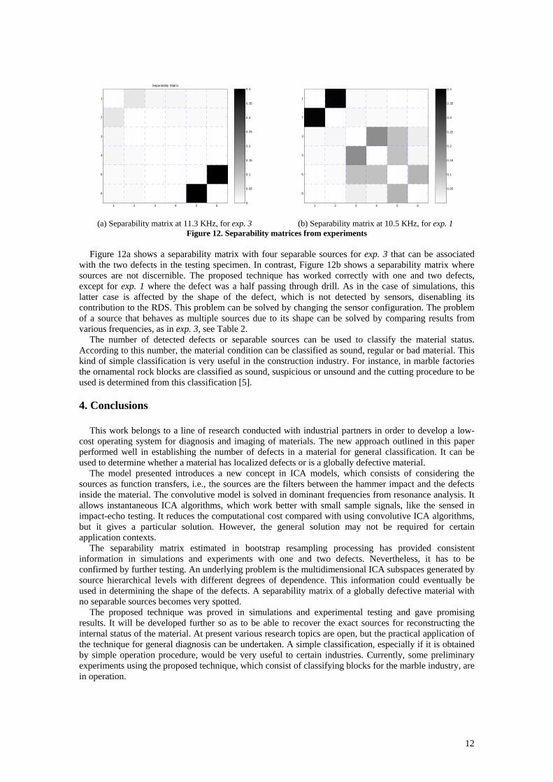
Figure 12a shows a separability matrix with four separable sources for exp. 3 that can be associated with the two defects in the testing specimen. In contrast, Figure 12b shows a separability matrix where sources are not discernible. The proposed technique has worked correctly with one and two defects, except for exp. 1 where the defect was a half passing through drill. As in the case of simulations, this latter case is affected by the shape of the defect, which is not detected by sensors, disenabling its contribution to the RDS. This problem can be solved by changing the sensor configuration. The problem of a source that behaves as multiple sources due to its shape can be solved by comparing results from various frequencies, as in exp. 3, see Table 2.
The number of detected defects or separable sources can be used to classify the material status. According to this number, the material condition can be classified as sound, regular or bad material. This kind of simple classification is very useful in the construction industry. For instance, in marble factories the ornamental rock blocks are classified as sound, suspicious or unsound and the cutting procedure to be used is determined from this classification [5].
4. Conclusions
This work belongs to a line of research conducted with industrial partners in order to develop a low-cost operating system for diagnosis and imaging of materials. The new approach outlined in this paper performed well in establishing the number of defects in a material for general classification. It can be used to determine whether a material has localized defects or is a globally defective material.
The model presented introduces a new concept in ICA models, which consists of considering the sources as function transfers, i.e., the sources are the filters between the hammer impact and the defects inside the material. The convolutive model is solved in dominant frequencies from resonance analysis. It allows instantaneous ICA algorithms, which work better with small sample signals, like the sensed in impact-echo testing. It reduces the computational cost compared with using convolutive ICA algorithms, but it gives a particular solution. However, the general solution may not be required for certain application contexts.
The separability matrix estimated in bootstrap resampling processing has provided consistent information in simulations and experiments with one and two defects. Nevertheless, it has to be confirmed by further testing. An underlying problem is the multidimensional ICA subspaces generated by source hierarchical levels with different degrees of dependence. This information could eventually be used in determining the shape of the defects. A separability matrix of a globally defective material with no separable sources becomes very spotted.
The proposed technique was proved in simulations and experimental testing and gave promising results. It will be developed further so as to be able to recover the exact sources for reconstructing the internal status of the material. At present various research topics are open, but the practical application of the technique for general diagnosis can be undertaken. A simple classification, especially if it is obtained by simple operation procedure, would be very useful to certain industries. Currently, some preliminary experiments using the proposed technique, which consist of classifying blocks for the marble industry, are in operation.
13
Acknowledgements
This work has been supported by Spanish Administration under grant TIC 2002-04643 and Universidad Politécnica Valencia under interdisciplinary grant 2003-0554. We would like to thank the R+D+i Linguistic Assistance Office at the Universidad Politecnica of Valencia for their help in revising this paper.
References [1] A. Salazar, L. Vergara, J. Igual, J. Gosalbez, R. Miralles, ICA model applied to multichannel non-destructive evaluation by impact-echo, Proceedings of the 5th International Conference on Independent Component Analysis and Blind Signal Separation, p. 470-477, 2004. [2] L.K. Hansen, M. Dyrholm, A prediction matrix approach to convolutive ICA, Proceedings of IEEE Workshop on Neural Networks for Signal Processing XIII, p. 249-258, 2003. [3] F. Meinecke, A. Ziehe, M. Kawanabe, K.R. Müller, Resampling approach to estimate the stability of one-dimensional or multidimensional independent components, IEEE Transactions on Biomedical Engineering, v. 49, n. 12, p. 1514-1525, 2002. [4] M. Sansalone, W.B. Streett, Impact-echo: Non-destructive evaluation of concrete and masonry, Bullbrier Press, USA, 1997. [5] L. Vergara, J. Gosálbez, J. Fuente, R. Miralles, I. Bosch, A. Salazar, A. López, L. Domínguez, Ultrasonic Nondestructive testing on Marble Block Rocks, Materials Evaluation, American Society for Non-destructive Testing, v. 62, n. 1, p. 73-78, 2004. [6] N.J. Carino, The impact-echo method: an overview, Proceedings of the Structures congress and exposition, American society of civil engineers, Washington DC, USA, 2001. [7] J.D. Cheeke, Fundamentals and Applications of Ultrasonic Waves, CRC Press LLC, USA, 2002. [8] O. Abraham, C: Leonard, P. Côte, B. Piwakowski, Time-frequency Analysis of Impact_Echo Signals: Numerical Modelling and Experimental Validation, ACI Materials Journal, v. 97 n. 6, p. 645-657, 2000. [9] A. Hyvärinen, Independent Component Analysis, John Wiley & Sons, 2001. [10] A. Cichocki, S. Amari, Adaptive Blind Signal and Image Processing: Learning algorithms and applications, John Wiley & Sons, 2001. [11] J.F. Cardoso, A Souloumiac, Blind beamforming for non gaussian signals, IEE Proceedings-F, v. 140, n. 6, p. 362-370, 1993. [12] L. Parra, C. Spence, Convolutive blind source separation of non-stationary sources, IEE Trans. on Speech and Audio Processing, v. 8, p. 320-327, 2000. [13] S. Douglas, A. Chichocki, S. Amari, Self-whitening algorithms for adaptive equalization and deconvolution, IEEE Trans. on Signal processing, v. 47, p. 1161-1165, 1999. [14] H. Attias, C.E. Schreiner, Blind source separation and deconvolution: the dynamic component analysis algorithm, Neural Computation, v. 10, n. 6, p. 1373-1424, 1998. [15] A. Ziehe, K.R. Müller, TDSEP- an efficient algorithm for blind separation using time structure, Proceedings of the 8th International Conference on Artificial Neural Networks, ICANN'98, Perspectives in Neural Computing, p. 675-680, 1998. [16] R.O. Duda, P.E. Hart, D.G. Stork, Pattern Classification, 2nd ed., New York: Wiley, 2001. [17] M. Sansalone, N.J. Carino, N.N. Hsu, Transient stress waves interaction with planar flaws, Batim-Int-Build-Res-Pract., v. 16 n. 1, p. 18-24, 1988.