BLENDING BY RATIONAL CANAL AND RINGED SURFACES
94
BLENDING BY RATIONAL CANAL AND RINGED SURFACES Michal Bizzarri Dissertation thesis Supervisor: Doc. RNDr. Miroslav Lávička, Ph.D. Plzeň, 2014
-
Upload
khangminh22 -
Category
Documents
-
view
0 -
download
0
Transcript of BLENDING BY RATIONAL CANAL AND RINGED SURFACES

BLENDING BY RATIONAL CANALAND RINGED SURFACES
Michal Bizzarri
Dissertation thesisSupervisor: Doc. RNDr. Miroslav Lávička, Ph.D.
Plzeň, 2014

KONSTRUKCE RACIONÁLNÍCHPŘECHODOVÝCH KANÁLOVÝCHA PRSTENCOVÝCH PLOCH
Michal Bizzarri
Dizertační práce
Školitel: Doc. RNDr. Miroslav Lávička, Ph.D.Plzeň, 2014

i
Annotation
In this thesis we study rational techniques for computing exact/approximate parameteriza-tions of canal and ringed surfaces. In the first part of the thesis we focus on canal surfacesgiven implicitly – the designed approach is based on computing approximate topology-basedparameterizations of the so called contour curves on the given canal surface. The method canbe directly applied on the practical problem of parameterizing implicit blends consisting ofparts of canal (or canal-surface-like) surfaces. In the second part of the thesis we study a con-dition guaranteeing the rationality of the contour curves on canal surfaces given by medialaxis transforms. These curves are then used for a computation of rational parameterizationsof canal surfaces with Pythagorean normals. Using the contour curves the parameteriza-tion algorithm enables us to construct the whole family of rational canal (blending) surfacessharing the same silhouette at once, which is especially useful for constructing blends satis-fying certain constrains, e.g. when avoiding obstacles or bypassing other objects is required.The last part of the thesis is devoted to rational ringed surfaces – we design the algorithmfor blending by these surfaces between two ringed surfaces which can be adjusted for con-structing blends avoiding obstacles or for constructing general n-way blends between severalringed surfaces.
Keywords
Canal surfaces, ringed surfaces, rational parameterizations, blends, contour curves, criticalpoints, rational offsets, SOS decomposition, PH and MPH curves, PN surfaces, Ferguson’scubic.

ii
Anotace
V této práci studujeme racionální techniky vhodné pro výpočet přesných/přibližných para-metrizací kanálových a prstencových ploch. V první části práce se soustředíme na implicitnězadané kanálové plochy – navržený přístup je založen na výpočtu přibližné parametrizacetak zvaných obrysových křivek na zadané kanálové ploše. Tato metoda může být přímoaplikována na praktické problémy parametrizace implicitních přechodových ploch sestáva-jících z částí kanálových (nebo přibližně kanálových) ploch. V druhé části práce studujemepodmínku zajišťující racionalitu obrysových křivek na kanálových plochách zadaných po-mocí střední osy a poloměrové funkce. Tyto křivky jsou poté použity k výpočtu racionálníparametrizace kanálových ploch s pythagorejskými normálami. Použití obrysových křivekv algoritmu parametrizace dovoluje v jednom kroku zkonstruovat celou třídu racionálníchkanálových (přechodových) ploch, což je speciálně výhodné pro konstruování přechodovýchploch splňujících jistá omezení, např. pokud je požadováno, aby se daná plocha vyhnulaprekážkám. Poslední část této práce je věnována racionálním prstencovým plochám, po-mocí nichž je navržena metoda konstrukce prechodových ploch mezi dvěmi prstensovýmiplochami. Tato metoda může být použita pro konstrukci přechodových ploch, které se majívyhnout jistým překážkám nebo pro konstrukci přechodových ploch mezi několika prsten-covými plochami.
Klíčová slova
Kanálové plochy, prstencové plochy, racionalní parametrizace, přechodové plochy, obrysovékřivky, kritické body, racionální ofsety, SOS dekompozice, PH a MPH křivky, PN plochy,Fergusonova kubika.

Preface
This Ph.D. thesis contains the crucial results of research undertaken at the Departmentof Mathematics of the University of West Bohemia in Plzeň during my Ph.D. study –we have studied and designed various rational parameterization techniques mostlyconnected with canal and ringed surfaces. The thesis is based on the selected paperswhich have been published in (or submitted to) distinguished peer-reviewed archivedjournals – for a greater clarity, the papers in which the author of the thesis participatedare marked by [∗] whenever they are cited.
[8∗] Bizzarri, M., and Lávička, M. A symbolic-numerical method for computingapproximate parameterizations of canal surfaces. Computer-Aided Design 44, 9(2012), 846 – 857.
[9∗] Bizzarri, M., and Lávička, M. Parameterizing rational offset canal surfaces viarational contour curves. Computer-Aided Design 45, 2 (2013), 342 – 350.
[10∗] Bizzarri, M., and Lávička, M. A symbolic-numerical approach to approximateparameterizations of space curves using graphs of critical points. Journal of Com-putational and Applied Mathematics 242, (2013), 107 – 124.
[11∗] Bizzarri, M., and Lávička, M. Approximation of implicit blends by canal sur-faces of low parameterization degree. In Mathematical Methods for Curves andSurfaces, vol. 8177 of Lecture Notes in Computer Science. Springer Berlin Heidel-berg, 2014, 34 – 48.
[12∗] Bizzarri, M., and Lávička, M.Onmodelling with rational ringed surfaces. Sub-mitted to Computer-Aided Design, (2014).
[13∗] Bizzarri, M., Lávička, M., and Vršek, J. Canal surfaces with rational contourcurves and blends bypassing the obstacles. Submitted toComputer-Aided Design,(2014).
The results from the aforementioned papers have been suitably ordered and slightlyreformulated to increase the compactness and the readability of the entire thesis. The
iii

iv
paper [10∗] deals with the problem of computing approximate topology-based param-eterizations of real spatial algebraic curves using their graphs of critical points. Thealgorithm from [10∗] is then used in the papers [8∗] and [11∗] where the methods forcomputing approximate parameterizations of implicitly defined canal surfaces are de-signed. The next two papers [9∗] and [13∗] are devoted to the canal surfaces withrational contour curves. These curves are then used for the computation of rationalparameterizations of adaptive blending surfaces (avoiding obstacles, bypassing otherobjects, etc.) providing rational offsets. Finally, the modelling with rational ringedsurfaces is thoroughly studied in [12∗].
All the presented papers are the common work of me and my supervisor doc. RNDr.Miroslav Lávička, Ph.D. I would like to express my sincere thanks to Miroslav for hisfriendly and professional guidance and for his constant support.
My special thanks belong to my brother RNDr. Jan Vršek, Ph.D. who cooperated withme on several problems and, among others, significantly contributed to paper [13∗].
I also want to express my deep gratitude to my family, my girlfriend Klára and myclose friends for their encouragement, inspiration and permanent support during thestudy and during writing of this thesis.
I hereby declare that this doctoral thesis is my own work based on the selected cru-cial results which were obtained during my research and my Ph.D. study in the years2010–2014 at the Department of Mathematics.
Plzeň, March 17, 2014, ..................................

Contents
Preface iii
1 Introduction 1
2 Preliminaries 4
2.1 Algebraic curves and surfaces . . . . . . . . . . . . . . . . . . . . . . . . 4
2.2 Curves with Pythagorean hodographs and surfaces with Pythagoreannormals . . . . . . . . . . . . . . . . . . . . . . . . . . . . . . . . . . . . . 6
2.3 Canal surfaces and contour curves . . . . . . . . . . . . . . . . . . . . . . 10
2.4 Ringed surfaces . . . . . . . . . . . . . . . . . . . . . . . . . . . . . . . . 13
2.5 Approximate parameterization techniques . . . . . . . . . . . . . . . . . 14
2.6 Sum of squares decomposition . . . . . . . . . . . . . . . . . . . . . . . . 16
3 Approximate parameterization of implicitly given canal surfaces 18
3.1 Motivation - implicit blends . . . . . . . . . . . . . . . . . . . . . . . . . 18
3.2 Graphs of critical points of spatial curves . . . . . . . . . . . . . . . . . . 19
3.3 Algorithm of approximation . . . . . . . . . . . . . . . . . . . . . . . . . 22
3.4 Algorithm of low degree approximation . . . . . . . . . . . . . . . . . . 26
4 Rational canal surfaces with rational contour curves 34
4.1 Motivation – parameterizations derived from rational curves on canalsurfaces . . . . . . . . . . . . . . . . . . . . . . . . . . . . . . . . . . . . . 34
v

CONTENTS vi
4.2 Rational contour curves on canal surfaces . . . . . . . . . . . . . . . . . 36
4.2.1 Rational contour curves w.r.t. the directions of the coordinate axes 37
4.2.2 Rational contour curves w.r.t. a general direction . . . . . . . . . 40
4.3 Computing the rational contour curves for canal surfaces with polyno-mial MATs . . . . . . . . . . . . . . . . . . . . . . . . . . . . . . . . . . . 43
4.3.1 Canal surfaces with quadratic MATs . . . . . . . . . . . . . . . . 44
4.3.2 Canal surfaces with cubic MATs . . . . . . . . . . . . . . . . . . . 47
4.4 Blending by canal surfaces with rational contour curves . . . . . . . . . 50
4.4.1 Blending based on the MPH interpolation. . . . . . . . . . . . . . 50
4.4.2 Blending based on the SOS decomposition . . . . . . . . . . . . . 52
4.4.3 Blends bypassing the obstacles . . . . . . . . . . . . . . . . . . . 54
5 Modelling with rational ringed surfaces 58
5.1 Rationality of ringed surfaces . . . . . . . . . . . . . . . . . . . . . . . . 58
5.1.1 Rationality of special classes of ringed surfaces . . . . . . . . . . 59
5.1.2 Rationality of general ringed surfaces . . . . . . . . . . . . . . . 61
5.2 Blending by ringed surfaces . . . . . . . . . . . . . . . . . . . . . . . . . 64
5.3 Adaptive blending and shape optimization . . . . . . . . . . . . . . . . . 67
5.4 Contour curves and approximate parameterizations of implicitly givenblends. . . . . . . . . . . . . . . . . . . . . . . . . . . . . . . . . . . . . . 70
5.5 Blending three or more ringed surfaces . . . . . . . . . . . . . . . . . . . 75
6 Conclusion 78

Chapter 1Introduction
Exploring the history of geometric modelling in industrial and related applicationssuch as Computer Aided Design andManufacturing (CAD and CAM), Geometric Mod-elling, Computational Geometry, Robotics, Image Processing, Computer Graphics,etc., we can see that rational techniques and rational representations were at the veryfoundation. When computers allowed machining of 3D shapes, a necessity to define acomputer-compatible description of those objects appeared. The most promising rep-resentation was soon identified to be the parametric one since parametric descriptionsenable to generate points on curves and surfaces and they are also suitable e.g. for sur-face plotting, computing transformations, determining offsets, computing curvaturesor shading and colouring, for curve-curve and surface-surface intersection problems,cf. e.g. [29,31]. Of course the most important parameterizations (among all) are thosethat can be described with the help of polynomials or rational functions since these de-scriptions can be easily included into standard CAD systems (e.g. milling cutters, cut-ting machines, etc.). Hence a major breakthrough in geometric modeling was broughtabout the theory of polynomial Bézier and B-spline curves and surfaces, combinedlater with their rational counterparts, see [29,31].
Unfortunately, not every geometric object (curve, surfaces, volume) can be describedusing rational parameterizations – see [84] for more details. We recall that for algebraiccurves and surfaces, various symbolic computation based techniques can be found –see e.g. [78,82,89,91,92] for an exact parameterization of curves, and [1,68,79–81,87]for surfaces. However, these techniques are often algorithmically very difficult. And,as mentioned above, they cannot deal with all algebraic curves and surfaces, sincean exact rational parameterization does not exist in the generic case. Approximatetechniques, which generate a parameterization within a certain region of interest, arethen necessary to avoid these problems.
This thesis is devoted to one of themost important classes of technical surfaces, namelyto canal and ringed surfaces. Ringed surfaces are generated by sweeping a circle withvariable radius – which is contained in a plane with a possibly non-constant normalvector – along a directrix curve, see [45]. By using circles in the normal plane of thedirectrix one obtains normal ringed surfaces. Special cases include Darboux cyclides
1

CHAPTER 1. INTRODUCTION 2
(see [23,26]) which can carry up to six families of real circles, see also [5,15,54,72,88].Ringed surfaces are well suited e.g. for designing pipe structures in plant modeling,cf. [14, 16]. A special method for computing the intersection of two ringed surfaces isdescribed in [41].
The class of ringed surfaces contains a special subclass of canal surfaces that are ob-tained as the envelopes of a one-parameter family of spheres, see e.g. [28]. Specialcases include pipe surfaces (obtained for spheres of constant radius) and surfaces of rev-olution (generated by spheres whose centers are located on a given line). Canal surfacesare (generally non-normal) ringed surfaces. Dupin cyclides – which can be defined asthe envelopes of all spheres touching three given spheres – form probably the moststudied family of canal surfaces [52,71,85].
It was proved in [59, 68] that any canal surface with a rational spine curve (which isthe curve formed by the centers of the moving spheres) and a rational radius functionadmits a rational parameterization. An algorithm for generating rational parameteri-zations of canal surfaces was presented in [57]. Analogous result was proven also fornormal ringed surfaces – in particular a normal ringed surface with rational directrixand a rational radius function is rational, see [59]. In this thesis we will extend this re-sult for an arbitrary ringed surface with rational directrix, rational normal vector fieldand radius function equal to the square root of some non-negative rational function.
The canal surfaces have been studied more thoroughly than the ringed surfaces andone can find many applications in CAD based on canal surfaces. Let us recall, forinstance, the operation of blending which is one of the most important operations inComputer-Aided (Geometric) Design. The main purpose of this operation is to gener-ate one or more surfaces that create a smooth joint between the given shapes. Blend-ing surfaces are necessary for rounding edges and corners of mechanical parts, or forsmooth connection of separated objects, see e.g. [30, 44] and references therein. Canalsurfaces are often used as blending surfaces between two given surfaces [4]. Howevernot for all input shapes (ending with circular profiles), the canal surfaces are suitableas blending primitives. We recall e.g. the case when oblique cones shall be blended –then the ringed surfaces find their straightforward application.
This thesis, where the new methods for computing exact and approximate parameter-izations of canal and ringed surfaces are presented, is divided into three main parts.The first part is devoted to the case when canal surfaces are not given by their spinecurves and radius functions but implicitly e.g. as a result of some blending technique.In particular we show, how approximate parameterizations of implicitly given canalsurfaces can be computed. Important contributions for blending by implicitly givensurfaces can be found in [42,43,73]. Several methods for constructing implicit blendswere thoroughly investigated in [38–40,94]. In addition, as our approach yields ‘only’approximate parameterizations, it can also be used for blends not being canal surfacesexactly but only approximately. For overview of several blending techniques (includ-ing implicit ones) see [4].
In the second part of this thesis we turn our attention to canal surfaces defined by theirspine curves and radius functions. In particular we study a condition guaranteeing

CHAPTER 1. INTRODUCTION 3
that a given canal surface has rational contour curves. These curves are then used fora computation of rational parameterization providing rational offsets, i.e., it is PN pa-rameterization, for more details about PN surfaces see [32,58,66,67,70,76]. These pa-rameterizations find their application especially when the canal surfaces (e.g. blendsconsisting of parts of canal surfaces) shall be machined by milling cutter. To documenta practical usefulness of the presented approach, we design simple direct algorithmsfor computing rational offset blends between two canal surfaces based on the contourmethod. Using the contour curves the parameterization algorithm requires only oneMPH approximation/SOS decomposition for the whole family of rational canal (blend-ing) surfaces sharing the same silhouette, which is especially useful for constructingblends satisfying certain constrains, e.g. when avoiding obstacles or bypassing otherobjects is required.
In the last part of the thesis we deal with the question of the rationality of ringedsurfaces – in particular we show which ringed surface are rational and how their ra-tional parameterizations can be computed. Then we design a blending method basedon interpolation by Pythagorean curves in plane and show how this method can bemodified to satisfy some constraints, e.g. to avoid obstacles or bypass other objects.Another modification of the method enables to construct n-way blending surfaces be-tween n ringed surfaces. We also design a method for approximating the implicitlygiven blends by rational ring surfaces based on approximation of contour curves.
The remainder of this thesis is organized as follows. Chapter 2 summarizes some basicdefinitions and notions necessary for right understanding of the thesis. Chapter 3 isdevoted to the method of approximating implicitly given blends by canal surfaces. InChapter 4 we study canal surfaces with rational contour curves which are then used forconstructing blends satisfying certain constrains. Chapter 5 deals with the blendingby rational ringed surfaces and in Chapter 6 we conclude the thesis.

Chapter 2Preliminaries
This chapter serves as a survey of basic definitions and notions aboutparticular topics from algebraic geometry and geometric modelling whichwill be used in this thesis. It is divided into six sections – the first oneis devoted to the introduction to the theory of algebraic curves. The sec-ond section summarizes some fundamental facts about Pythagorean hodo-graph curves and surfaces with Pythagorean normal vector fields. In thethird and fourth section we recall some basic notions concerning canaland ringed surfaces, respectively. In the fifth section one can find severalalgorithms concerning approximate parameterizations of algebraic curvesand the last one recalls some basic facts about the problem of decomposingpolynomials into sum of squares.
2.1 Algebraic curves and surfaces
We start with short recalling necessary fundamental properties of algebraic curves andsurfaces, as special cases of algebraic varieties, which are then used in the followingtext. More details can be found e.g. in [17, 37, 82, 84, 91, 92]. Throughout this thesis,let R and C be the fields of real and complex numbers, respectively.
An affine algebraic variety V in Cn is defined as the set of all points satisfying the system
of polynomial equations f1(x1, . . . ,xn) = . . . = fk(x1, . . . ,xn) = 0, i.e.,
V =(a1, . . . ,an)
⊤ ∈Cn | fi(a1, . . . ,an) = 0 for all i = 1, . . . ,k. (2.1)
The polynomials f1, . . . , fk ∈ C[x1, . . . ,xn] are called defining polynomials of the variety V .The dimension of V is the transcendence degree over C of the function field C(V ) of allrational functions on V , with values in C, see [84].
Remark 2.1. Motivated by consequent applications, for the purpose of this thesis wefocus only on varieties (curves/surfaces) given as the complete intersection of hyper-
4

CHAPTER 2. PRELIMINARIES 5
p
p
ptp tp
Figure 2.1: An x-critical point (left), a y-critical point (middle) and a singular point(right).
surfaces. We recall that a variety V is considered as the so-called complete intersec-tion of k hypersurfaces if the ideal of V is generated by exactly n − k elements, seee.g. [24, 37, 86] for more details. Moreover, the ideal theory is also very suitable whendefining the degree and irreducibility of algebraic varieties – essentially, the degree ofV is d1 · · ·dk , where d1, . . . ,dk are the algebraic degrees of f1, . . . , fk , respectively and V isirreducible if and only if the ideal of V is a prime ideal.
In what follows we will focus only on algebraic planar and spatial curves, i.e., thealgebraic varieties of dimension 1 in C
2 andC3, respectively and on algebraic surfaces,
i.e., the algebraic varieties of dimension 2 in C3. An affine planar algebraic curve D is
the set of zeros of a polynomial in two variables, i.e.,
D = (a1,a2)⊤ ∈C2 | f (a1,a2) = 0. (2.2)
An affine spatial algebraic curve C is defined as the set all solutions of a system of twopolynomial equations, i.e.,
C = (a1,a2,a3)⊤ ∈C3 | f (a1,a2,a3) = g(a1,a2,a3) = 0. (2.3)
Finally, an affine algebraic surface S is the set of zeros of a polynomial in three variables,i.e.,
S = (a1,a2,a3)⊤ ∈ C3 | f (a1,a2,a3) = 0. (2.4)
For the purpose of computing approximate parameterizations of algebraic curves, whichis a necessary part of the algorithms presented in Chapter 3, we introduce a specialpoints on curves which reflect the change of the shape w.r.t. a given direction.
Definition 2.2. A point p on algebraic curve C at which C possesses the tangent vectortp is called a critical point w.r.t. the vector (direction) v if
tp · v = 0, (2.5)
where ‘·’ denotes the standard Euclidean inner product. Points which are critical w.r.t.all directions are called singular points.

CHAPTER 2. PRELIMINARIES 6
The critical points on planar curves w.r.t. the directions of the coordinate axes areshown in Figure 2.1.
Remark 2.3. By the definition of the critical points on curves all lines and planarcurves in the space would consist of critical points only. However, the critical pointswere introduced in order to indicate a change of the curve shape with respect to agiven direction. Hence, when the whole curve (or its whole component) consists solelyof such points these points will not be considered as critical in what follows.
Let V be a variety of dimension d over a field C. Then V is said to be unirational, orparametric, if there exists a rational map P : Cd →V such that P (Cd) is dense in V . Wespeak about a (rational) parameterization P (t1, . . . , td ) of V . Furthermore, if P defines abirational map then V is called rational, and we say that P (t1, . . . , td ) is a proper parame-terization. By a Riemann’s theorem, an irreducible planar curve has a parametrizationiff it has a proper parametrization iff its genus is zero, i.e., iff the following relationholds
12(d − 1)(d − 2) =
n∑
i=1
δpi , (2.6)
where d is the degree of C and p1, . . . ,pn are the singular points of the so called associ-ated projective curve C∗ (the curve in the projective space defined by the homogeniza-tion F(x,y,z) of the defining polynomial f (x,y) of C) possessing the delta invariantsδp1
, . . . ,δpn , respectively – for more details see [84, 91]. Hence, for planar curves thenotions of rationality and unirationality are equivalent for any field.
For every irreducible spatial curve C there always exists a birational transformationbetween the points of C and the points of a certain irreducible planar curve D, see forinstance [91]. Hence, the rationality problem of the spatial curve C is equivalent to therationality problem of the corresponding planar curve D – i.e., C can be rationally pa-rameterized if and only if its birationally projected image D fulfils the condition (2.6).
In the surface case, the theory differs as Castelnuovo’s theorem holds only for alge-braically closed fields of characteristic zero. By this theorem, a surface has a parame-trization iff it has a proper parametrization iff the arithmetical genus pa and the secondplurigenus P2 are both zero (see [84] for definitions of these notions).
2.2 Curves with Pythagorean hodographs and surfaceswith Pythagorean normals
In this section the fundamental properties of Pythagorean hodograph curves in Eu-clidean and Minkowski plane/space and surfaces with Pythagorean normal vectorfields will be recalled.
Given a regular C1 parametric curve x(t) = (x1(t),x2(t))⊤, the offset of x(t) is the set ofall points in R
2 that lie at a perpendicular distance δ from x(t). For the sake of brevity

CHAPTER 2. PRELIMINARIES 7
we omit the dependence on parameter t whenever no confusion is likely to arise. Thetwo branches of the offset (i.e., inner and outer one-sided offsets) are given by
x±δ (t) = x± δn, n =x′⊥
‖x′‖ , (2.7)
where ‖x′‖ =√(x′1
)2+(x′2
)2and x′⊥ = (−x′2,x′1)⊤.
A study of offset rationality led to the class of planar Pythagorean hodograph (PH)curves. These curves are defined as rational curves x = (x1,x2)⊤ fulfilling the distin-guishing condition
x′ · x′ = (x′1)2 + (x′2)
2 = σ2, (2.8)
where σ is a rational function. Since the rationality of a δ-offset curve x±δ of a rationalcurve only depends on the rationality of the unit normal field n, cf. (2.7), planar PHcurves possess (piece-wise) rational offsets.
Pythagorean hodograph curves were originally introduced in [33] as planar polynomialcurves. It was proved [33, 55] that the coordinates of hodographs of polynomial PHcurves and σ form the following Pythagorean triples
x′1 = m(k2 − l2
),
x′2 = 2mkl,σ = m
(k2 + l2
),
(2.9)
where k, l,m ∈ R[t] are any non-zero polynomials and k, l are relatively prime.
A generalization of polynomial PH curves to rational ones was introduced and studiedin [70]. This approach uses the dual representation of a planar curve considered as anenvelope of its tangents
T (t) : n · x− h = 0, h ∈R(t). (2.10)
In order to guarantee the rationality of (2.7), the unit normal field n must rationallyparameterize the unit circle S1. Hence, there must exist relatively prime polynomialsk, l such that
n(t) =(
2klk2 + l2
,k2 − l2k2 + l2
)⊤. (2.11)
In addition, to simplify further computations we set g = h(k2 + l2), i.e., the dual repre-sentation of any arbitrary PH curve is
(2kl,k2 − l2
)⊤ · x− g = 0. (2.12)
Consequently, a parametric representation of all planar rational PH curves is obtainedas the envelope of their tangents given by (2.12) in the form
x(t) =(=2(ll ′ − kk′)g + (k2 − l2)g ′
2(k2 + l2)(kl ′ − k′l) ,(k′l + kl ′)g − klg ′(k2 + l2)(kl ′ − k′l)
)⊤. (2.13)

CHAPTER 2. PRELIMINARIES 8
Furthermore, the representation of offsets can be easily obtained by translating thetangents by a distance δ, i.e., it is sufficient to replace g = h(k2+ l2) by g = (h±δ)(k2+ l2)in (2.13).
Analogously for the surface case, consider a regular C1 surface x : R2→ R3 given by a
rational parameterization x. The δ-offset of x is the set of all points in R3 that lie at a
distance δ from x. The two branches of the offset are given by
x±δ (u,v) = x± δn, n =xu × xv‖xu × xv‖
, (2.14)
where xu and xv are the partial derivatives with respect to u and v, respectively.
A study of offset rationality for surfaces led to the class of surfaces with Pythagoreannormal vector fields, introduced in [70], distinguished by the condition (the so calledPN property)
‖xu × xv‖2 = σ2, (2.15)
where σ is a rational function. In addition, it can be proved that σ2 = EG − F2,where E,F,G are the coefficients of the first fundamental form, and thus the PN con-dition (2.15) shows that the PN surfaces in R
3 are simultaneously the surfaces withPythagorean area elements.
In what follows, we will consider only non-developable PN surfaces. Such surfacesx can be obtained as the envelope of a two-parametric set of the associated tangentplanes
T (u,v) : n · x− h = 0, (2.16)
where h(u,v) is a rational function and n is a rational parameterization of the unitsphere S2, cf. [70],
n(u,v) =(
2kmk2 + l2 +m2 ,
2lmk2 + l2 +m2 ,
k2 + l2 −m2
k2 + l2 +m2
)⊤, (2.17)
with k, l,m fulfilling the condition gcd(k, l,m) = 1. A parametric representation of anarbitrary non-developable PN surface can be then obtained from the system of equa-tions T = 0, Tu = 0, Tv = 0 (where Tx denote the partial derivative of T w.r.t. x) usingCramer’s rule – see formula (3.3) in [70]. Furthermore, the representation of offsetscan be again easily obtained by translating the tangent planes by a distance δ, i.e., it issufficient to replace h by h± δ in (2.16).
Consider a planar domain Ω ⊂ R2 and the family of all inscribed discs in Ω partially
ordered with respect to inclusion. An inscribed disc is called maximal if it is not con-tained in any other inscribed disc. Then themedial axisMA(Ω) is the locus of all centers(x1,x2)⊤ of maximal inscribed discs and the medial axis transform MAT(Ω) is obtainedby appending the corresponding disc radii r to the medial axis, i.e., MAT consists ofpoints x = (x1,x2, r)⊤.
For a C1 segment x = (x1,x2, r)⊤ of MAT(Ω) we can compute the corresponding bound-ary of Ω from the envelope formula, cf. [21,62], in the form
x±r (t) =(x1x2
)− r
x′12 + x′2
2
[r ′(x′1x′2
)±√x′1
2 + x′22 − r ′2
(−x′2x′1
)]. (2.18)

CHAPTER 2. PRELIMINARIES 9
A study of rationality of envelopes (2.18) led to the class of Minkowski Pythagoreanhodograph (MPH) curves introduced in [62]. MPH curves are defined as rational curvesx = (x1,x2, r)⊤ in three-dimensional space fulfilling the condition
x′12 + x′2
2 − r ′2 = σ2, (2.19)
where σ ∈ R(t). The PH condition (2.8) is now fulfilled with respect to the inner prod-uct
〈u,v〉 = u1v1 +u2v2 − u3v3. (2.20)
A three-dimensional real affine space along with the indefinite bilinear form (2.20) iscalled Minkowski space and denoted R
2,1. We recall that the squared norm of a vectoru ∈ R2,1 with respect to the indefinite Minkowski inner product (2.20), can be positive,negative or zero. Hence, we distinguish three types of vectors: a vector u is calledspace-like if 〈u,u〉 > 0, time-like if 〈u,u〉 < 0, and light-like (or isotropic) if 〈u,u〉 = 0.Considering their tangent vectors we analogously speak about space-, light-, or time-like curves.
Now, we recall the result from [49] that any rational MPH curve x in R2,1 can be con-
structed starting from an (associated) planar rational PH curve y in R2 and a rational
function r in the formx(t) = (y1 + rn1,y2 + rn2, r)
⊤ , (2.21)
where n = (n1,n2)⊤ = y′⊥/σ.
Using (2.21) and (2.13), we can show that a curve x ∈ R2,1 is an MPH curve if and onlyif there exist two polynomials k, l and two rational functions q, r such that
x =1
2(k2 + l2)(kl ′ − k′l)
2(ll ′ − kk′)g + (k2 − l2)g ′2(k′l + kl ′)g − 2klg ′
0
+
r
k2 + l2
2klk2 − l2k2 + l2
. (2.22)
Obviously, polynomial MPH curves form a proper subset of the set of rational MPHcurves described by (2.22). It turns out that we can efficiently adapt the approachfor relating planar rational and polynomial PH curves used in [35] and show that anypolynomial MPH curve in R
2,1 can be obtained using (2.22) by setting
g(t) = 2kl∫
(km−ln)dt−(k2−l2)∫
(kn+lm)dt−(k2+l2)∫
(lm−kn)dt,
r(t) =∫
(lm−kn)dt,(2.23)
where k, l,m,n are arbitrary polynomials. Substituting (2.23) into (2.22) we obtain analternative to the original formula for polynomial MPH curves presented in [62]
x′1 = km− ln, x′2 = −kn − lm, r ′ = −kn+ lm, = km+ ln. (2.24)
A prominent role is played by polynomial MPH curves given by a polynomial (asso-ciated) PH curve y ⊂ R
2 and a polynomial r. Recalling [50], these curves have theform
x(t) = (y1 + py′2,y2 − py′1,pσ)⊤, (2.25)

CHAPTER 2. PRELIMINARIES 10
Figure 2.2: An envelope (yellow) of one-parameter family of spheres (blue) – a canalsurface.
where y′1,y′2,σ are given by (2.9) and p is an arbitrary polynomial. In addition, let y be
a polynomial PH curve of degree d1, and d2 is the degree of p then it holds
deg(x) = d1 + d2 − 1. (2.26)
2.3 Canal surfaces and contour curves
A canal surface S is the envelope of a 1-parameter family of spheres F whose centerstrace a curve m in R
3 and possess radii r (see Figure 2.2), i.e.,
F(t) : ‖x−m(t)‖2 − r(t)2 = 0, t ∈ I , (2.27)
where x = (x,y,z)⊤. The curve m is called the spine curve and r the radius function of S .For constant r we obtain a pipe surface. The defining equations for the canal surface Sare
F(t) = 0, F ′(t) = 0, (2.28)
where F ′ is the derivative of F with respect to t. After eliminating the parameter tfrom (2.28) one can get the corresponding implicit equation f (x) = 0 of S . The linearequation F ′ = 0 describes the plane with the normal vector m′, i.e., perpendicular tothe spine curve m. Thus the canal surface S contains a one parameter set of the socalled characteristic circles F ∩F ′, see Figure 2.3 (left), and hence canal surfaces belongto the so called ringed surfaces, see Chapter 5. It can be proved that the envelope (i.e.the canal surface) is real iff the condition
‖m′(t)‖2 − r ′2(t) ≥ 0 (2.29)
is fulfilled for all t ∈ I .
By appending the corresponding sphere radii r to the points of the spine curve weobtain the medial axis transform MAT, i.e., the curve m. For the sake of clarity, weidentify the canal surface S ⊂ R
3 with its medial axis transform m = (m, r)⊤ ⊂ R3,1,
see [62, 68], where R3,1 is the 4-dimensional Minkowski space serving as the natural
ambient space for MATs of canal surfaces, cf. (2.27).

CHAPTER 2. PRELIMINARIES 11
Figure 2.3: A characteristic circle (black) of a canal surface, left and associated footpoints on contour curves, right.
As proved in [57, 68], any canal surface given by a rational MAT possesses a rationalparameterization. A method which uses MPH representation and Lorentzian geom-etry to parameterize canal surfaces was presented in [19, 20]. Nevertheless, it mustbe emphasized that the computation of rational parameterizations of canal surfaces isstill a challenging problem, which is equivalent to the SOS (sum of squares) problemfor non-negative polynomials. And in addition, we have to be aware of another im-portant issue. There exist rational canal surfaces with non-rational MATs, i.e., r is asquare root of a rational function, see [64].
In this thesis we compute the rational parameterization of a given canal surface by ro-tating one curve c(t) on it (different from the characteristic circles) around the tangentsof the spine curve m(t). Thus the parameterization of S will be in the form
s(t,u) =m(t) +(ϕ(u) +m′(t)) ⋆ (c(t)−m(t)) ⋆ (ϕ(u)−m′(t))
(ϕ(u) +m′(t)) ⋆ (ϕ(u)−m′(t)) , (2.30)
where ϕ(u) is a rational function, the sums ϕ(u) ±m′(t) of scalars and vectors areconsidered as quaternions, and ⋆ is the operation of quaternion multiplication
(a+ a) ⋆ (b +b) = ab − a ·b+ ab+ ba+ a×b, (2.31)
see [2, 36] for more details about quaternions. For any t = t0 the rational functionϕ(u) determines a rational parameterization of the associated characteristic circle. Anyrational choice of ϕ(u) yields the rational parameterization of a canal surface – forthe sake simplicity we choose ϕ(u) = u for the low rational degree of s(t,u) in u, andϕ(u) = 2u/(1−u2) for a relatively uniform distribution of the t-parameter lines (clearly,the given generating curve c(t) is determined by zero rotation angle, i.e., by the choiceu = 1).
Let us emphasize that when using the spine curve and another curve for computingthe rational parameterization of S , we have to guarantee that their parameterizations

CHAPTER 2. PRELIMINARIES 12
c+v
c−v
m
c+v
c−vm
Figure 2.4: The two branches c±v of a contour curve (blue) on a canal surface S (yellow)with the spine curve m (black).
are closely related. We say that the curve c corresponds in parameter with the givencurve m in the interval I if it holds
c′(t) · (c(t)−m(t)) = 0, for all t ∈ I . (2.32)
Hence, considering the spine curve m and one curve c on a given canal surface Swhich are corresponding in parameter we have ensured that the point c(t0) lies at thecharacteristic circle of S corresponding to the sphere centered at m(t0) and with theradius r(t0), for all t0 ∈ I .
By analogy we can define a correspondence in parameter for two arbitrary curves c1and c2 (different from the characteristic circles) on a canal surface S . We say that c1and c2 correspond in parameter in the interval I if the points c1(t0) and c2(t0) lie on thesame characteristic circle of S for all t0 ∈ I . The points c1(t0) and c2(t0) are then calledthe associated foot points, see Figure 2.3 (right).
A prominent role among all curves on a given canal surface is played by the so calledcontour curves which e.g. enable to construct the whole family of rational canal sur-faces sharing the same silhouette, as we will see.
Definition 2.4. A contour curve Cv w.r.t. the vector v of the canal surface S is a curve on Sdifferent from its characteristic circles and consisting of all the points at which the normalsof S are orthogonal to v.
A contour curve Cv w.r.t. the vector v corresponds to the silhouette of the given canalsurface when projecting it to the plane with the normal vector v, see Figure 2.4. With-out loss of generality, we may assume in what follows that v is a unit vector.
Contour and spine curves are related with the valuable property – in particular for acontour curve cv w.r.t. the vector v on a canal surface with the spine curve m (cv andm correspond in parameter in I ) the following equality holds:
(cv −m) · v = 0, for all t ∈ I . (2.33)

CHAPTER 2. PRELIMINARIES 13
Figure 2.5: An arbitrary (left) and normal (right) ringed surface (green) with a directrix(black), vectors corresponding to the orientation function (blue) and sweeping circles(blue).
This follows from the fact that the normal lines of a canal surface are actually thenormal lines of the corresponding spheres and normal lines at the points of the contourcurve are perpendicular to the given direction.
When a canal surface is given by its implicit equation f (x) = 0 then the contour curvew.r.t. the vector v is determined as the complete intersection of two algebraic surfacesdefined by the polynomials
f (x) and fv(x) = ∇f (x) · v, (2.34)
where ∇f stands for the gradient of f .
2.4 Ringed surfaces
A ringed surface R, see Figure 2.5, is a surface generated by sweeping a circle centeredat a curve d, called the directrix, lying in a plane with the prescribed normal vector n,called the orientation function, and possessing a radius described by the radius function. We will shortly write R : (d,n,). When n × d′ = o (i.e., the orientation functiondescribes the field of the directrix tangent’s directions) we speak about the normalringed surfaces, see Figure 2.5, right.
Since all canal surfaces, cf. Section 2.3, contain 1-parameter family of circles (charac-teristic circles) they constitute a special subclass of the ringed surfaces – in particularevery canal surface is a ringed surfaces with
d =m− rr ′
‖m′‖2m′, n =m′, =
r√‖m′‖2 − r ′2‖m′‖ . (2.35)
On the other hand a ringed surface is a canal surface iff
((n ·d′)d′ + (′)n′)×n ≡ o, (2.36)

CHAPTER 2. PRELIMINARIES 14
p1
p1 p1
p2
p2
p2
tp1
tp1
tp1
tp2
tp2
tp2
Figure 2.6: Ferguson’s cubics for different initial data.
see [5], where also a close relation of ringed/canal surfaces to Darboux cyclides isinvestigated.
A parameterization s(t,u) of the ringed surface R can be obtained analogously as a pa-rameterization of canal surfaces, see (2.30), by rotating the points of a (suitably chosen)curve c(t) on R (different from any of the sweeping circles) around the correspondingline element
(d(t),n(t)
), i.e., we arrive at
s(t,u) = d(t) +(ϕ(u) +n(t)) ⋆ (c(t)−d(t)) ⋆ (ϕ(u)−n(t))
(ϕ(u) +n(t)) ⋆ (ϕ(u)−n(t)) . (2.37)
Hence the problem of computing a rational parameterization of R is reduced to theproblem of finding a rational curve c ⊂ R. All such curves (except from the sweepingcircles) can be written in the form
c = d+ n⊥
‖n⊥‖ , (2.38)
where n⊥ is a certain vector field perpendicular to the vector field n.
Remark 2.5. Contour curves of ringed surfaces can be defined analogously as contourcurves of canal surfaces, cf. Definition 2.4, and for a ringed surface implicitly definedby a polynomial f (x), the contour curve w.r.t. the vector v is also given by (2.34).
2.5 Approximate parameterization techniques
In this thesis we introduce some algorithms which are based on parameterizing certainplanar/spatial algebraic curves. The approximate parameterization of the curve C willbe computed by approximating particular arcs of C by suitable segments of a chosenpolynomial/rational curve. For the sake of simplicity, we use the so called Ferguson’scubic. However, an arbitrary – and at any time replaceable – suitable free-form curvecan be used instead.

CHAPTER 2. PRELIMINARIES 15
The Ferguson’s cubic is determined by the two points p1 and p2 and by the tangentvectors tp1
and tp2at these points, see Figure 2.6, and it is given by the formula
f(t) = F1p1 +F2p2 +F3 tp1+F4 tp2
, t ∈ [0,1], (2.39)
where
F1 = 2t3 − 3t2 +1, F2 = −2t3 +3t2, F3 = t3 − 2t2 + t, F4 = t
3 − t2. (2.40)
The deviation of the planar parametric curve c(t), t ∈ I from the curve given by theimplicit equation h = 0 can be measured by the following integral
∫
I
h2(c(t))‖∇h(c(t))‖2 dt (2.41)
and by analogy the deviation of the spatial curve c(t), t ∈ I from the one given by theimplicit equation f = g = 0 can be computed by
∫
I
(f 2(c(t))‖∇f (c(t))‖2 +
g2(c(t))‖∇g(c(t))‖2
)dt. (2.42)
For the sake of completeness the deviation of the parametric surface s(t,u), t ∈ I , u ∈ Jfrom the surface defined by polynomial f can be measured by
∫
J
(∫
I
f 2(s(t,u))‖∇f (s(t,u))‖2 dt
)du. (2.43)
Furthermore we formulate the problem of approximate parameterization as an opti-mization process – hence e.g. the classical Newton’s method for computing the rootsof a system of non-linear equations can be used, see for instance [25,63,75].
Let us consider a system of non-linear equations
F(x) = 0, (2.44)
where F(x) is a given vector-function of the vector argument x = (x1,x2, . . . ,xn)⊤. New-ton’s method is based on the linearization of the function F(x). The iteration processcan be shortly written in the form
x(i+1) = x(i) − F(x(i))F′(x(i))
= x(i) − J−1(x(i))F(x(i)), i = 0,1,2, . . . , (2.45)
where J(x) is the Jacobian of F(x). A remarkable property of the Newton’s method is itsquadratic convergence. On the other hand, to ensure any convergence at all, the initialvalue x0 must be chosen sufficiently close to the (yet unknown) root x, see e.g. [75].

CHAPTER 2. PRELIMINARIES 16
2.6 Sum of squares decomposition
The sum of squares (SOS) problem is closely connected with solving polynomial equa-tions, for more details see e.g. [22, 61]. A polynomial τ over reals is said to be positivesemidefinite (PSD), or positive definite (PD) if τ(t) ≥ 0, or τ(t) > 0 for all t ∈ R. We saythat τ is a sum of squares if the degree of τ is even and it can be written as a sum ofsquares of other polynomials. It is obvious that SOS decomposition of τ implies itsnonnegativity. However, the converse is not true in general – the construction of PSDpolynomials which are not sums of squares was first described by Hilbert in 1888.
For the sake of brevity, we recall only elementary notions dealing with the univariatepolynomials where the situation becomes much easier than in the general case. It canbe shown that every PSD univariate polynomial is a sum of just two squares. In thissection we show how the decomposition of a polynomial τ ∈ R[t] can be computed,i.e., we want to find two polynomials f ,g ∈R[t] such that
τ = f 2 + g2. (2.46)
Let us recall that a real polynomial in one variable is PSD iff its leading coefficient ispositive and its roots are either complex in conjugate pairs or real with even multiplic-ity. Of course, the SOS decomposition (2.46) is by no mean unique; for an arbitrary ϕthe polynomials
fϕ = cosϕ f − sinϕ g and gϕ = cosϕ g + sinϕ f (2.47)
solve the problem as well, i.e., formula (2.47) generates an equivalence class of decom-positions. For a polynomial τ of degree 2n, there exist 2n−1 non-equivalent classes ofdecompositions, see [57]. Hence in order to obtain all possible decompositions we haveto compute 2n−1 particular non-equivalent decompositions and use formula (2.47) togenerate all of them.
Of course, it is not easy to get the initial decomposition (f ,g), because we are not ableto compute the exact roots, in general. And another limitation appears when we wantto work only with polynomials with rational coefficients, when the SOS decomposi-tion may include more than two squares. Nonetheless, in this thesis we are going todecompose quadratic and quartic polynomials, only, and thus the computation of aSOS decomposition can be achieved symbolically. In particular we can obtain a de-composition (2.46) with the help of the roots of τ which can be computed using thediscriminant for quadratic τ and the so called Ferrari’s formulas for quartic τ.
Example 2.6. If τ is a quadratic PSD polynomial, we can write its factorization asfollows
τ(t) = λ(t −α − βi)(t −α + βi), (2.48)
where α,β ∈ R and λ ∈ R+. Then there exists only one equivalence class of the decom-position generated e.g. by
f (t) =√λ(t −α), g =
√λβ. (2.49)

CHAPTER 2. PRELIMINARIES 17
Example 2.7. For a quartic PSD polynomial
τ(t) = λ(t −α − βi)(t −α + βi)(t −γ − δi)(t −γ + δi), (2.50)
where α,β,γ,δ ∈ R and λ ∈R+ we use the Fibonacci’s identities
(a2 + b2)(c2 + d2) = (ac ± bd)2 + (ad ∓ bc)2 (2.51)
and obtain two non-equivalent decompositions in the form
f1,2(t) =√λ (δ(t −α)± β(t −γ)) , g1,2(t) =
√λ ((t −α)(t −γ)∓ βδ) . (2.52)

Chapter 3Approximate parameterization ofimplicitly given canal surfaces
In this chapter, we present two methods (Sections 3.3 and 3.4) forthe computation of approximate rational parameterizations of implicitlygiven canal surfaces. Both methods are based on computing approximateparameterizations of contour curves on a given canal surface which is per-formed by constructing their graphs of critical points (cf. Section 3.2) andafterwards replacing its edges by a suitable free-form curve. More pre-cisely the method described in Section 3.3 starts with computing approxi-mate parameterizations of the both branches of the z-contour curve of thegiven canal surface. From these parameterizations an approximation ofits spine curve is reconstructed and afterwards its approximate parame-terization is computed. The improvement of the method producing theparameterization having the lower rational degree is introduced in Sec-tion 3.4. The main idea of the improved method is based on computingthe parameterizations (corresponding in parameter) of three different con-tour curves and from them we reconstruct the spine curve with the samedegree as the approximated contour curves. Both methods are mainly suit-able for implicit blend surfaces of the canal-surface-type. The papers inwhich the author of the thesis participated and which contain the author’smain contribution to this topic are – [8∗], [11∗], [10∗], [13∗].
3.1 Motivation - implicit blends
Let us consider two canal (ringed) surfaces R1 and R2 (e.g. cones or cylinders of rev-olution) implicitly defined by polynomials f1 and f2, and bounded by planes P1 andP2 defined by f10 and f20, respectively. Then in [39] the implicit blending surface Bbetween R1 and R2 (and joining R1 and R2 in P1 and P2, respectively) is constructed
18

CHAPTER 3. CANAL SURFACES GIVEN IMPLICITLY 19
R1
R2
P1P2
R1
R2
B
Figure 3.1: A Hyperboloid of one sheet (blue) and a cylinder (green), both bounded byplanes (light blue and light green), left and the implicit blend (yellow) between thesesurfaces, right.
and defined by the polynomial
f = f1(1−λ)f n+120 − f2λf n+110 , (3.1)
where λ ∈ (0,1) and n ∈ N, see Figure 3.1. Now the problem can be formulated asfollows: How the approximation of this implicitly given blending surface can be com-puted? In this chapter we solve this problem by approximating the given blendingsurface by a suitable rational canal surface.
3.2 Graphs of critical points of spatial curves
This section is devoted to the special graphs of spatial algebraic curves reflecting theirshape and topology. Constructing such graphs is especially useful when approximat-ing these curves.
The construction starts with computing the critical points of a given spatial curve Cw.r.t. the chosen basis vectors of R3 – we use the standard (canonical) basis, i.e.
e1 = (1,0,0)⊤, e2 = (0,1,0)⊤, e3 = (0,0,1)⊤. (3.2)
Then we connect the critical points appropriately by line segments such that each linesegment corresponds to some real part of C. Such an arrangement of line segments iscalled a graph of critical points of C and is denoted by G(C). It is beyond the scope ofthis thesis to go into details, so we recall only basic steps – for more details see [10∗].We only recall that for curves with non-complicated topology (which are assumed in

CHAPTER 3. CANAL SURFACES GIVEN IMPLICITLY 20
our approach as we deal with curves on canal surfaces playing a role in technical ap-plications, e.g. in blending) the graph of critical points is topologically equivalent tothe given curve.
The construction of the graph of critical points G(C) of a spatial algebraic curve Cimplicitly defined by polynomials f and g proceeds in computing all the x-, y- andz-critical points (the critical points w.r.t. e1, e2 and e3, respectively) of C, projecting Cto the plane z = 0 (πz : C 7→ πz(C)) and constructing the planar critical graph G(πz(C))which contains the projections of all the critical points of C as its vertices, and finallylifting its edges back to space, see Algorithm 1.
Algorithm 1 Construction of the graph of critical points
INPUT: A spatial curve C defined by the polynomials f and g and a set M of someprescribed points on C.
1: Compute the x-coordinates x1 < . . . < xk of x-, y- and z-critical points of C, of thesingular points of πz(C) obtained only by the projection πz and of points from M;
2: For every xi , compute the real roots of h(xi ,y): yi,1 < yi,2 < . . . < yi,s, where h =Resz(f ,g);
3: For all points (xi ,yi,j )⊤ compute the number of left and right branches going fromthese points;
4: Connect the points (xi ,yi,j )⊤ with the points (xi+1,yi+1,j )⊤ appropriately;5: Delete such singular points of πz(C) which are not the projections of the singular
points of C, see [10∗];6: Delete all vertices of G(πz(C)) which are not the projections of critical points or
points from the set M;7: Lift the edges of G(πz(C)) to the space and hence obtain G(C);
OUTPUT: The graph G(C) of critical points of C having its critical points and thepoints from the set M as its vertices.
Remark 3.1. For later use, we need G(C) to contain some additional points as its ver-tices, thus we introduce the set M, which enables us to prescribe the vertices of theconstructed graph. Hence, the graph will contain only the points from M and thecritical points of C.
In Algorithm 1 we require G(C) to contain the critical points of C as its vertices. Thex-critical points of C satisfy the condition
fy gz − fz gy = 0. (3.3)
First, we compute the real roots x1 < x2 < . . . < xk of
Resy
(Resz (f ,g) ,
∂Resz (f ,g)∂y
), (3.4)
where Resx(f ,g) denotes the resultant of the polynomials f and g with respect to x.The computation of the roots of polynomials in one variable is a numerically well

CHAPTER 3. CANAL SURFACES GIVEN IMPLICITLY 21
pp p
B
B
B
Figure 3.2: Construction of bounding boxes at the critical points.
handled problem. Now, for every root xi we compute all the associated real rootsyi,1 < yi,2 < . . . < yi,si of
gcd(Resz (f ,g) (xi ,y),
∂Resz (f ,g)∂y
(xi ,y)). (3.5)
Note that if the coordinates xi are approximate numbers we may need to compute theapproximate greatest common divisors, see for instance [74]. Finally, we compute thecorresponding z-coordinates of x-critical points by solving the equation (again basedon computing the approximate gcd, in general)
gcd(f (xi ,yi,j , z),g(xi ,yi,j , z)
)= 0. (3.6)
It is guaranteed (we recall the space general position from [10∗]) that exactly onereal root zi,j is obtained for each (xi ,yi,j )⊤. Hence, we arrive at all x-critical points(xi ,yi,j , zi,j )⊤. Analogously, we compute the y- and z-critical points of C. Let us empha-size that the singular points of C are simultaneously x-, y- and z-critical.
Remark 3.2. Let us note that extra factors may arise during the process of resultantcomputation. Hence, it must be verified that all obtained points fulfil the conditionsfor critical points of C.
We also need to compute the number of the left and right branches going from a par-ticular point p (Step 3 in Algorithm 1) on the planar curve πz(C). This can be doneby the following method: We enclose p by a small box B such that the curve πz(C)does not intersect the box B in the bottom and in the top and, moreover, there existsexactly one intersection point (the point p) of the vertical line going through the pointp with the curve πz(C) in the box, see Figure 3.2. Then the number of the right and leftintersection points yields the number of half-branches to the right and to the left at p,respectively, cf. [18] for more details of this technique.
Finally, we show how the vertices of G(πz(C)) can be connected. We write the sequenceRi of vertices (xi ,yi,j )⊤ where each vertex occurs as many times as it has half-branchesto the right, and the sequence Li+1 of vertices (xi+1,yi+1,j )⊤ where each vertex again

CHAPTER 3. CANAL SURFACES GIVEN IMPLICITLY 22
occurs as many times as it has half-branches to the left, for particular i. Then, them-thvertex from Ri is connected with the m-th vertex from Li+1. Note that the way how toconnect the vertices by edges is uniquely determined since any incorrect connectingvertices lead to at least one intersection of two edges at a non-critical point.
3.3 Algorithm of approximation
In this section we summarize the method for computing an approximate parameteri-zation of the canal surface S defined by the polynomial f , for more detail see [8∗]. Themethod starts with constructing the graph of critical points G(C) = G(C1) ∪ G(C2) ofboth branches of the z-contour curve C = C1∪C2 and consequently replacing the edgesof G(C) by the arcs of Ferguson’s cubic – this step is formulated as an optimizationprocess.
Since we require that the parameterizations of C1 and C2 correspond in parameter wehave to add all corresponding foot points of all the critical points of C to the set ofvertices of G(C). Hence the both branches of G(C) will possess the same number of thevertices and moreover the corresponding vertices will be the associated foot points.
Let p = (p1,p2,p3)⊤ ∈ C1, then by formula (2.33) the corresponding foot point q ∈ C2possesses the same z-coordinate p3 as p has. Hence we arrive at the points q1, . . . ,qsby cutting the curve C with the plane z = p3; in particular we solve the system of non-linear equations
f = fz = z − p3 = 0. (3.7)
Now, we have to choose the right point q = qi from the set of points q1, . . . ,qs. This canbe easily checked as the normal lines of S at the points p and q have to intersect in thepointm such that ‖p−m‖ = ‖q−m‖.
Thus firstly we parameterize C1 such that for each edge ei ∈ G(C1) (joining points pi andpi+1) we construct the Ferguson’s cubic fi(t,α1
i ,α2i ) going from pi to pi+1 and possessing
the tangent vectors α1i tpi and α
2i tpi+1 at these points. Then we minimize the objective
function
Φi(α1i ,α
2i ) =
∫ 1
0
(f 2(fi(t,α1
i ,α2i ))
‖∇f (fi(t,α1i ,α
2i ))‖2
+f 2z (fi(t,α
1i ,α
2i ))
‖∇fz(fi(t,α1i ,α
2i ))‖2
)dt (3.8)
to get the particular lengths of the tangent vectors tpi and tpi+1 and substitute them tofi(t,α1
i ,α2i ). In order to minimize objective function (3.8) we used the Newton’s itera-
tion process (see [8∗]) since it allows us to handle the integral, however any other opti-mization method could be used instead – for example it is acceptable to use Newton-Cotes integration formulas to dispose of the integral and afterwards minimize thefunction by an arbitrary optimization method.
Then we compute the approximate parameterization of the second branch C2 of thez-contour curve but only in the plane xy again by replacing the edges of the pro-jected graph of critical points πz(C2) by Ferguson’s cubic with free parameters (the

CHAPTER 3. CANAL SURFACES GIVEN IMPLICITLY 23
f
g
f′⊥
g′⊥
b1 b2
p
f
g
f′⊥
g′⊥
b1
b2
p
Figure 3.3: Curves approximately corresponding in parameter – in the plane xy, leftand in the space (on a canal surface), right.
lengths of the tangent vectors) and minimize the objective function, which now shouldmeasure the deviance of the planar parametric curve from πz(C2) (given implicitly byh = Resz(f , fz)) and moreover the deviance of the correspondence in parameter withthe projected parametric curve πz(f).
According to Preliminaries, the deviance of g from h = 0 is measured using (2.41), i.e.,
Φ1(β1,β2) =
∫ 1
0
(h2(g(t,β1,β2))‖∇h(g(t,β1,β2))‖2
)dt. (3.9)
Next we define a suitable function which measures the deviance of the correspondencein parameter of two planar parametric curves f and g as follows. Let b1 and b2 be theintersection points (curves) of the axis p of the segment fg with the normal lines of fand g, respectively. Then f and g correspond in parameter if b1(t) = b2(t) for all t ∈[0,1] and the deviance of the approximate correspondence in parameter correspondsto the distance between b1 and b2 (see Figure 3.3, left), i.e.,
Φ2(β1,β2) =
∫ 1
0‖b1(t,β
1,β2)−b2(t,β1,β2)‖2dt, (3.10)
where
b1(t) = g+‖f− g‖2
2(f− g) · g′⊥g′⊥, and b2(t) = f+
‖f− g‖22(f− g) · f′⊥ f
′⊥. (3.11)
Thus, let us recall, that we replace the edges li ∈ πz(G(C2)) (joining points πz(qi ) andπz(qi+1)) by Ferguson’s cubic πz(gi )(t,β1i ,β
2i ) going from πz(qi ) to πz(qi+1) and pos-
sessing the tangent vectors β1i πz(tqi ) and β2i πz(tqi+1) at these points and minimize the
objective functionΦi(β
1i ,β
2i ) = Φ
1i (β
1i ,β
2i ) +wΦ
2i (β
1i ,β
2i ), (3.12)
where w is a suitably chosen weigh and Φ1i and Φ
2i correspond to objective functions
(3.9) and (3.10). The minimizing process could be again achieved e.g. by Newton’siteration process.

CHAPTER 3. CANAL SURFACES GIVEN IMPLICITLY 24
Finally, we reconstruct the spine curve m of S by lifting the approximation
b(t) =b1 +b2
2. (3.13)
of the bisector curve of πz(f) and πz(g) to the space. From property (2.33) the spinecurve and the z-contour curve possess the same third coordinate.
Then rotating f around the tangents of m yields the parameterization of a given canalsurface. The whole method is summarized in Algorithm 2.
Algorithm 2 Approximate parameterization of implicitly defined canal surface.
INPUT: Defining polynomial f of a canal surface S .1: Construct a graph of critical points G(C) of the z-contour curve having as vertices
its critical points and their associated foot points – it consists of two paths G(C1) :p1, . . . ,pk and G(C2) : q1, . . . ,qk ;
2: for each i ∈ 1, . . . ,k − 1 do3: Compute the approximate parameterization fi of the particular part of C1 be-
tween the points pi and pi+1;4: Compute the approximate parameterization πz(gi ) of the particular part of the
projected curve πz(C2) between the points πz(qi ) and πz(qi+1) approximatelycorresponding in parameter with πz(fi );
5: Compute the bisector bi of πz(fi ) and πz(gi ) and reconstruct the approximateparameterization mi := (b1i ,b
2i , f
3i )⊤ of the spine curve of S ;
6: Rotate fi around the tangents of mi - obtain parameterization si ;7: end for
OUTPUT: The piecewise approximate parameterization s1(t,u), . . . ,sk(t,u) of S .
Remark 3.3. We recall that the deviance of the approximately parameterized surfaces(t,u) from the implicitly given surface given by polynomial f can be computed byintegral (2.43) and when needed Algorithm 2 can be adjusted to perform adaptiverefinement in order to increase the accuracy. In particular we can divide the edgesof the graph of critical points to increase the number of arcs of Ferguson’s cubics, formore details see [8∗].
Let us note that when we approximate a canal surface S , e.g. some blending surface,we are interested only in some prescribed part of S bounded e.g. by planes Pi . Hencewe slightly modify the construction of the graph of critical points of the contour curvesto achieve this – i.e., we consider only the critical points in the corresponding regioninterest and add all the intersections of C with the planes Pi to the set of the vertices ofG(C).
Example 3.4. We compute the approximate parameterization of the canal surface B(see Fig 3.4, left), obtained by formula (3.1) (for λ = 1/4 and n = 2) as an implicitblending surface between the cone f1 = −x2 + 2x + y2 + z2 − 4 and the cylinder f2 =y2 + z2 − 2 bounded by the planes f10 = x + 2 and f20 = x − 2, respectively. Hence B isdefined by the following polynomial

CHAPTER 3. CANAL SURFACES GIVEN IMPLICITLY 25
Figure 3.4: Implicit blending surface (yellow) between two canal surfaces (blue), leftfrom Example 3.4 and right from Example 3.5.
f = −3x5 +24x4 +2x3y2 +2x3z2 −82x3 −24x2y2−24x2z2 +180x2 +24xy2 +24xz2 −168x − 32y2 − 32z2 +112.
No critical points are on the contour curve, hence the approximate parameterizationof f will be composed of only one part. The error of the approximation measured byintegral (2.43) is less then 2.1 · 10−4.
Example 3.5. We approximate the implicit blending surface (see Figure 3.4, right)given by the polynomial
f = −7√2x5+14
√2x4z−42
√2x4−14
√2x3y2+3x3y2−7
√2x3z2+3x3z2+84
√2x3z−
70√2x3 − 6x3 + 9x2y2z − 111
√2x2y2 + 9x2z3 − 69
√2x2z2 + 168
√2x2z − 18x2z +
82√2x2+9xy2z2−54
√2xy2z−168
√2xy2+162xy2+9xz4−54
√2xz3−84
√2xz2+
144xz2 + 220√2xz + 168
√2x − 324x + 3y2z3 − 27
√2y2z2 + 162y2z − 274
√2y2 +
3z5 − 27√2z4 +156z3 − 164
√2z2 − 324z +436
√2.
This surface was again obtained by by formula (3.1) (for λ = 7/10 and n = 2) as ablending surface between two implicitly given cylinders
f1 = y2 + z2 − 2, and f2 = x
2 − 2xz+2y2 + z2 − 2, (3.14)
bounded by the planes
f10 = x +2, and f20 = x + z − 3√2. (3.15)
Although the shape of the computed blend f looks like a canal surface it is not exactlysurface of this type. Anyway, we may still use our method – now for approximating theblend by a canal surface. The contour curve contains 4 critical and 4 boundary points:4 on the first branch and 4 (being simultaneously the foot points) on the second branch.Hence the approximation of the blending surface will be composed of three parts. Theerror of the approximation measured by integral (2.43) is less then 1.8 · 10−2.

CHAPTER 3. CANAL SURFACES GIVEN IMPLICITLY 26
Remark 3.6. In Example 3.5, we applied our method on the implicit blend f whichwas not exactly a canal surface. In these cases it is necessary to measure how a givensurface differs from an exact canal surface. This could be achieved e.g. by consideringtwo contour curves with respect to two different directions (not only the directionperpendicular to the xy plane), constructing the approximations of the spine curvefor both directions and measure the Hausdorff distance between these two curves. Ifthe error (distance between the approximations of the spine curve) is acceptable (i.e.,less than some prescribed ε) we can use Algorithm 2. An alternative approach is tocompute the approximate parameterization of the implicit surface and subsequentlycheck whether the error is less than a chosen ε.
3.4 Algorithm of low degree approximation
A drawback of the method presented in the previous section lies in the fact that it pro-duces parameterizations with the high rational bidegree. This is caused by the qualityof the reconstructed spine curve which is rational of degree seven. In this section, weintroduce the method from [11∗] yielding the polynomial cubic approximations (corre-sponding in parameter) of contour and spine curves which will be consequently usedfor computing an approximate parameterization of a given canal surface having therational degree [7,4] in t and [2,2] in u.
The idea of the method is based on property (2.33). In particular the parameterizationscx = (c1x , c
2x , c
3x)⊤, cy = (c1y , c
2y , c
3y )⊤ and cz = (c1z , c
2z , c
3z )⊤ (corresponding in parameter) of
the contour curves Cx,Cy and Cz are computed and afterwards the parametric descrip-tion of the spine curve is derived in the form
m(t) =(c1x , c
2y , c
3z
)⊤. (3.16)
Thus the problem of computing the approximation m of the spine curve of a givencanal surface is reduced to the problem of computing approximate parameterizationsof the particular branches of contour curves, e.g. C+x ,C+y and C+z . Moreover m is poly-nomial if c+x ,c
+y and c+z are polynomial and it has the degree which is equal to the
maximum of the degrees of c1x , c2y , c
3z .
A limitation of this method and the method presented in the previous section lies inthe fact that they are not independent of the coordinate system – i.e. when a canalsurface is in a special position this methods (designed in [8∗] and [11∗]) may lead tosome difficulties, see Example 3.7. These problems can be easily avoided consideringthe contour curves w.r.t. a general viewpoint. Hence according to [13∗] instead ofconsidering contour curves w.r.t. the directions of the coordinate axes we considerthe contour curves w.r.t. the three linearly independent vectors and using them wereconstruct the spine curve. More precisely, we compute the parameterizations cv1 ,cv2 and cv3 (corresponding in parameter) of three different contour curves on S w.r.t.the linearly independent vectors v1, v2 and v3, respectively. Then the spine curve

CHAPTER 3. CANAL SURFACES GIVEN IMPLICITLY 27
Figure 3.5: The z-contour curve (left) and three different contour curves w.r.t. thegeneral viewpoints on the canal surface (right) from Example 3.7.
possesses the parameterization
m =
v1v2v3
−1
·
v⊤1 · cv1v⊤2 · cv2v⊤3 · cv3
. (3.17)
In this case ‘·’ denotes the matrix product.
Example 3.7. Let us consider the canal surface S implicitly given by the polynomial
f = 2304x6 + 6912x4y2 + 768x4z2 + 4608x4z − 1296x4 + 6912x2y4 + 1536x2y2z2 −4608x2y2z + 2592x2y2 − 1280x2z4 + 3072x2z3 + 1632x2z2 − 1440x2z + 216x2 +2304y6+768y4z2−9216y4z−1296y4−1280y2z4−8704y2z3+4512y2z2+288y2z−216y2 +256z6 − 1536z5 +2672z4 − 1056z3 − 24z2 +72z − 9.
We want to compute an approximate parameterization of S in some prescribed bound-ing box B. The methods based on the contour curves w.r.t. the directions of the co-ordinate axes cannot be applied as the z-contour curve Cz lying in B is closed andthus cannot be used for parameterizing the whole part of S in B, see Figure 3.5 (left).An easy way to overcome this problem is considering other three viewpoints, see Fig-ure 3.5 (right).
We proceed analogously as in the previous section. First we construct the graphs ofthe critical points G(Cv1),G(Cv2) and G(Cv3) of the contour curves Cv1 ,Cv2 and Cv3 , re-spectively, such that each graph will contain the critical points of the correspondingcontour curve and the foot points associated with the critical points of the two othercontour curves as its vertices. The algorithm for constructing the graphs of criticalpoints having in addition some prescribed points as its vertices is described in Sec-tion 3.2. In what follows it is sufficient to use only one branch from each constructedgraph of critical points – in particular, we will use G(C+v1),G(C
+v2) and G(C
+v3).
Since the considered contour curves are related to canal surfaces originating in tech-nical applications (i.e., with non-complicated topology), the individual graphs are thepaths only. Thus, we can consider that G(C+v1) is composed of the path p1, . . . ,pk , G(C+v2)

CHAPTER 3. CANAL SURFACES GIVEN IMPLICITLY 28
p1
p2p3
p4 = r4
p5
q1
q2 q3q4
q5
r1
r2 r3
r5
Figure 3.6: One branch from each constructed graph of critical points of contourcurves.
of the path q1, . . . ,qk , andG(C+v3) of the path r1, . . . ,rk and being simultaneously satisfiedthat pi ,qi and ri are the associated foot points, see Figure 3.6 for a particular exampleof the constructed graphs of critical points.
Remark 3.8. When reducing the graphs G(Cvi ), i = 1,2,3, to G(C+vi ), it is convenient toomit from our further considerations the vertices which appeared in G(Cvi ) as the footpoints associated to the critical points of C−vi .
Our goal is to replace the edges pi ,pi+1 ∈ G(C+v1), qi ,qi+1 ∈ G(C+v2) and ri ,ri+1 ∈ G(C+v3)
by suitable Ferguson’s cubics fi , gi and hi , respectively, such that fi is an approximateparameterization of the corresponding segment of C+v1 , gi of C
+v2 , hi of C
+v3 and fi , gi and
hi approximately correspond in parameter. This step will be formulated as an opti-mization process – when interpolating points pi , pi+1 and normalized tangent vectorstpi , tpi+1 at these points. We set the lengths of the tangent vectors at pi , pi+1 as free pa-rameters α1
i and α2i . By analogy we obtain parameter β1i ,β
2i and γ1
i ,γ2i . Now, we need
to find such particular values of α1i ,α
2i ,β
1i ,β
2i ,γ
1i ,γ
2i that the corresponding parame-
terizations will approximate the contour curves and simultaneously be approximatelycorresponding in parameter.
As a function which measures the deviation of the approximate parameterization f(t),t ∈ [0,1] from their exact implicit representation f = g = 0 we use the function (2.42),i.e.,
Φ(f ,g,f) =∫ 1
0
(f 2(f(t)‖∇f (f(t)‖2 +
g2(f(t)‖∇g(f(t)‖2
)dt. (3.18)
For our purposes, we construct
Φ1(α1,α2) = Φ(f , fv1 ,f), Φ2(β1,β2) =Φ(f , fv2 ,g), Φ3(γ1,γ2) =Φ(f , fv3 ,h), (3.19)
In addition, we need a function measuring the deviance of the correspondence in pa-rameter of the parameterizations f, g and h. The function responsible for the deviance

CHAPTER 3. CANAL SURFACES GIVEN IMPLICITLY 29
of the correspondence in parameter of the curves f and g lying on a canal surface Sdefined by the polynomial f will be taken as the distance of the intersection points ofthe normal lines of S at f and gwith the bisector plane of f and g (see Figure 3.3, right),i.e.,
Ψ(f,g, f ) =∫ 1
0‖b1 −b2‖2 dt, (3.20)
where
b1 = f+‖f− g‖2
2(g− f) · ∇f (f)∇f (f) and b2 = g+‖f− g‖2
2(f− g) · ∇f (g)∇f (g). (3.21)
Thus we arrive at two further objective functions:
Ψ1(α1,α2,β1,β2) =Ψ(f,g, f ), Ψ2(α1,α2,γ1,γ2) =Ψ(f,h, f ). (3.22)
To sum up, the global objective function will be of the form
Υ(α1i ,α
2i ,β
1i ,β
2i ,γ
1i ,γ
2i ) = (Φ1 +Φ2 +Φ3) +w(Ψ1 +Ψ2) (3.23)
for some weight w (in all presented examples we have chosen w = 1). In order tominimize Υ we used the Newton’s iteration process. The whole method for computingapproximate parameterizations of implicitly given canal surfaces is summarized inAlgorithm 3.

CHAPTER 3. CANAL SURFACES GIVEN IMPLICITLY 30
Algorithm 3 Approximate parameterization of implicitly defined canal surface.
INPUT: Defining polynomial f of a canal surface S .1: Choose three linearly independent vectors v1,v2,v3;2: Construct graphsG(Cv1), G(Cv2) and G(Cv3) of critical points having the critical and
its associated foot points of the contour curves Cv1 , Cv2 and Cv3 as its vertices;3: Reduce the computed graphs to G(C+v1), G(C
+v2) and G(C
+v3) only, i.e., consider the
graphs reflecting only one of the two branches for each contour curve. Each graphis composed of k − 1 edges (k vertices);
4: for each i = 1, . . . ,k − 1 do5: Construct Ferguson’s cubic fi(t,α1
i ,α2i ) matching the points pi ,pi+1 (the ver-
tices of the i-th edge of G(C+v1)) and the tangent vectors α1i tpi ,α
2i tpi+1 ;
6: Construct Ferguson’s cubic gi(t,β1i ,β2i ) matching the points qi ,qi+1 (the ver-
tices of the i-th edge of G(C+v2)) and the tangent vectors β1i tqi ,β2i tqi+1 ;
7: Construct Ferguson’s cubic hi(t,γ1i ,γ
2i ) matching the points ri ,ri+1 (the ver-
tices of the i-th edge of G(C+v3)) and the tangent vectors γ1i tri ,γ
2i tri+1 ;
8: Minimize the objective function Υ(α1i ,α
2i ,β
1i ,β
2i ,γ
1i ,γ
2i ) to get the particular
lengths of the tangent vectors tpi ,tpi+1 ,tqi ,tqi+1 ,tri ,tri+1 – obtain the cubics fi ,giand hi approximating the contour curves;
9: Reconstruct the approximation of the spine curve of S from fi ,gi and hi , cf.(3.17);
10: Rotate fi around the tangents of mi – this yields the approximate parameteri-zation si(t,u) of the corresponding part of S ;
11: end for
OUTPUT: The piecewise approximate parameterization s1(t,u), . . . ,sk−1(t,u).
Remark 3.9. Instead of minimizing the objective function Υ(α1i ,α
2i ,β
1i ,β
2i ,γ
1i ,γ
2i ), one
can firstly compute an approximate parameterization f of C+v1 and then construct twonew objective functions considering the other contour curves C+v2 and C+v3 . Thus, wehave altogether three objective functions, the first one is
Υ1(α1,α2) = Φ(f , fv1 ,f). (3.24)
Hence after minimizing Υ1(α1,α2) the approximation f(t) = f(t,α1,α2) of C+v1 is com-puted and we formulate another two objective functions concerning C+y and C+z :
Υ2(β1,β2) =Φ(f , fv2 ,g) +Ψ(f,g, f ), (3.25)
andΥ3(γ1,γ2) =Φ(f , fv3 ,h) +Ψ(f,h, f ). (3.26)
The objective functions Υ1, Υ2 and Υ3 can be minimized separately, which is lesscomplicated since we minimize (integrate/evaluate) less complicated functions havingonly two variables. On the other hand when computing the “fixed” parameterizationf first, the error is slightly bigger – our tests have shown that the error rises approxi-mately ten times when using the simplified approach.

CHAPTER 3. CANAL SURFACES GIVEN IMPLICITLY 31
Remark 3.10. The deviance of the approximation si(t,u) from the implicitly given sur-face defined by a polynomial f can be again computed by integral (2.43) and whenneeded Algorithm 3 can be easily modified to perform the adaptive refinement simi-larly to the method presented in [8∗]. It is enough to increase the number of the edgesof the constructed graphs when needed.
The most difficult part of Algorithm 3 consists in step 2. Firstly, the critical points ofthe contour curves have to be computed and secondly, for each critical point the asso-ciated foot points have to be found. Let us consider that the point p1 ∈ C+v1 is known.We shall find points p2 ∈ C−v1 , q1,q2 ∈ Cv2 and r1,r2 ∈ Cv3 such that p1,p2,q1,q2,r1,r2are the associated foot points, i.e., they lie on the same characteristic circle.
Clearly, from property (2.33) the associated foot point p2 ∈ C−v1 lies in the plane goingthrough p1 and having the normal vector equal to v1. Thus we arrive at the pointsp12, . . . ,p
s2 by intersecting the curve Cv1 with that plane, i.e. we solve the system of
non-linear equations
f (x) = 0, fv1(x) = 0, v1 · (x−p1) = 0. (3.27)
Now, we have to choose the right point p2 = pi2 from the set of points p12, . . . ,p
s2. For
this we use the fact that the normal lines of S at the points p1 and p2 have to intersectat the point m such that ‖p1 −m‖ = ‖p2 −m‖.
Thus, we have the points p1 ∈ C+v1 and p2 ∈ C−v1, i.e., the points lying on the samecharacteristic circle. By cutting the remaining critical curves Cv2 and Cv3 by the planesv2 · (x −m) = 0 and v3 · (x −m) = 0 (where m is the intersection point of the normallines of S at the points p1 and p2) we arrive at the associated foot points q1,q2 ∈ Cyand r1,r2 ∈ Cz, respectively. Finally, as in the previous step the “right” points need tobe chosen as the points having the same distance from m as p1 and p2 have and all sixlie in the same plane.
As in the previous method we deal with the canal surface given only in some prescribedarea of interest, hence we have to consider the boundary points in the algorithm.
Proposition 3.11. Algorithm 3 yields a G1 continuous rational parameterization of themaximal rational degree [7,4] in t and [2,2] in u.
Proof. In Algorithm 3, the parameterizations of contour curves are polynomial G1
continuous parameterizations of degree 3 in t; so is the parameterization of the spinecurve, cf. (3.17). Hence, using (2.30) we arrive at a G1 continuous parameterizationof the canal surface having the maximal rational degree [7,4] in t. The rational degreeof the parameterization in u depends on the choice of the rational function ϕ(u); thechoice ϕ(u) = u leads to the rational degree [2,2] in u.
Example 3.12. Let us consider the following cubic polynomial parameterizations ofthe contour curves:
c+x = c−z = (t3,0, t)⊤ and c−y = (t3, t,0)⊤. (3.28)

CHAPTER 3. CANAL SURFACES GIVEN IMPLICITLY 32
Then the parameterization of the spine curve (using (3.16)) is of the form
m = (t3, t, t)⊤. (3.29)
It is easy to certify that formula 2.32 is fulfilled, i.e., the parameterizations c+x , c−y and c−z
are corresponding in parameter withm (and hence also mutually). Rotating c+x aroundthe tangents ofm (using formula (2.30)) yields the following rational parameterizationof the corresponding canal surface
s(t,u) =
9t7 + t3
(u2 − 4
)+2tu
9t4 +u2 +2,2(9t5 + t
)
9t4 +u2 +2,t(u − 3t2
)2
9t4 +u2 +2
⊤
(3.30)
having bidegree (7,2).
Example 3.13. We parameterize the implicit canal surface S given by the polynomial
f = 16x6 +48x4y2 +16x4z2 − 160x4z − 32x4 − 288x3yz − 288x3y +288x3z +288x3 +48x2y4+32x2y2z2−104x2y2z−280x2y2+144x2yz+1008x2y−128x2z3+480x2z2−168x2z − 776x2 − 288xy3z + 360xy3 + 288xy2z + 72xy2 − 256xyz3 + 384xyz2 +672xyz − 1480xy + 256xz3 − 384xz2 − 672xz + 1048x + 16y6 + 16y4z2 + 56y4z −59y4+144y3z−180y3+64y2z3+192y2z2−672y2z+334y2+128yz3−192yz2−336yz +524y +256z4 − 704z3 +240z2 +808z − 635
in the region bounded by the planes
P1 : 8x +4y − 12z +57 = 0 and P2 : 8x +4y +4z − 11 = 0. (3.31)
In particular, we are interested in the part of S in the region fulfilling P1 > 0 andP2 < 0, see Figure 3.7 (left). First, we determine the contour curves w.r.t. the standardbasis vectors (3.2), i.e., the curves defined by f = fx = 0, f = fy = 0 and f = fz = 0.The next step is to compute the critical and bounding points of those curves, and toeach of those points compute the associated foot points (the points lying on the samecharacteristic circles and on the other two contour curves). Then we construct thegraph having those computed points as vertices and choose only one branch from eachcontour curve. Deleting redundant points (foot points corresponding to the criticalpoints on the second, not chosen, branches of the contour curves) yields the graph ofcritical points. In this particular example the graph of critical points is composed ofthe following three paths:
G (C+x ) =((−3,1, 9
4
)⊤,(−1,1, 1
4
)⊤, (0,1,0)⊤ ,
(1,1,
14
)⊤);
G(C+y
)=
(−34− 15
√3
13,−3
2,87− 40
√3
52
)⊤,(−1,−1
2,−5
4
)⊤,
(12,0,−√32
)⊤,(75,12,− 1
20
)⊤ ;
G (C+z ) =((−1,−3, 9
4
)⊤,(15,−7
5,14
)⊤,(45,−3
5,0
)⊤,(75,15,14
)⊤).

CHAPTER 3. CANAL SURFACES GIVEN IMPLICITLY 33
Figure 3.7: Implicitly given canal surface (yellow) together with the bounding planes(blue), left and the parameterized part of a implicitly given canal surface together withthe spine and contour curves and the bounding, critical and its associated foot points,right from Example 3.13.
Next we compute the parameterizations f, g and h of the chosen branches of the con-tour curves such that we replace the edges of the corresponding graph of critical pointsby Ferguson’s cubics and minimize the objective functions (3.23). Finally, we recon-struct the approximationm of the spine curve and by rotation of the one of the contourcurves, e.g. f around the tangents of the spine curve m we obtain an approximate pa-rameterization of the canal surface in the given region. The parameterized part of thecanal surface with the contour and spine curves and the vertices of the graph of criti-cal points is shown in Figure 3.7 (right). The error of the approximation, measured byintegral (2.43), is less than 6 · 10−5.

Chapter 4Rational canal surfaces with rationalcontour curves
In this chapter, we will study a condition which guarantees that a givencanal surface has rational contour curves. These curves are then used fora computation of rational parameterizations providing rational offsets.To document a practical usefulness of the presented approach, we designsimple direct algorithms for computing rational offset blends between twocanal surfaces based on the contour method. A main advantage of the de-signed blending technique is its simplicity and especially its usefulness forconstructing blends satisfying certain constrains, e.g. when avoiding ob-stacles or bypassing other objects is required. Compared to other methodsour approach needs only one SOS decomposition or MPH interpolationfor the whole family of rational canal surfaces sharing the same silhou-ette, see Figure 4.1. The papers in which the author of the thesis partici-pated and which contain the author’s main contribution to this topic are– [9∗], [13∗].
4.1 Motivation – parameterizations derived from ratio-nal curves on canal surfaces
Let us assume that the spine curve and one curve (corresponding in parameter with thespine curve) on the canal surface are given. We have to emphasize one important fact,i.e., it is not generally guaranteed that the obtained rational parameterization fulfillsthe PN condition. As known, all surfaces of revolution are canal surfaces – the nextsimple example demonstrates a situation when a rational parameterization of a canalsurface does not fulfill the PN condition.
Example 4.1. Let us consider two lines given by the parametric equations
m(t) = (t,0, t)⊤ and c(t) = (t,1,1)⊤, t ∈R (4.1)
34

CHAPTER 4. CANAL SURFACES WITH RATIONAL CONTOUR CURVES 35
Figure 4.1: Adaptive blend surface(s) (yellow, orange, red, green) between two cylin-ders (blue) sharing the same silhouette w.r.t. a prescribed projection.
such that c corresponds in parameter with m since
(m− c)⊤ · c′ = (0,−1,−1+ t) · (1,0,0)⊤ = 0. (4.2)
In this chapter we multiply vectors and matrices and hence for the sake of clarity ‘·’will be taken only as the matrix product. Rotating c around the tangents of m yieldsthe following parameterization of the canal surface:
s(t,u) =(tu2 − 2u +2u2 +2
,2(t − 1)u +u2−2
u2 +2,2t +u2 +2uu2 +2
)⊤. (4.3)
Although s(t,u) obtained by formula (2.30) is rational it is not PN since the corre-sponding area element
σ(t,u)2 =4(t2 − 2t +2
)
(u2 +2)2(4.4)
is not a perfect square, i.e., the PN condition is not satisfied.
It is a well-known fact that all canal surfaces with rational MATs are PN surfaces (i.e.,surfaces with rational offsets) – this can be easily justified by realizing that the δ-offsetsto any rational canal surface (m, r)⊤ are again rational canal surfaces given by rational(m, r±δ)⊤. So the question reads why the rational parameterization of the canal surfacefrom Example 4.1 is not PN. Firstly, we compute the corresponding MAT
m(t) =(t,0, t,
√t2 − 2t +2
)⊤. (4.5)

CHAPTER 4. CANAL SURFACES WITH RATIONAL CONTOUR CURVES 36
We can see that this MAT is non-rational; in particular the spine curve is rational butthe radius function is not. We will investigate this observation in more detail.
As the vector n = c−m is a normal vector of the canal surface S at the point s(t,1) thenthe unit normal vector field of S can be easily computed by rotating
c−m‖c−m‖ (4.6)
around the tangents of m using (2.30). Furthermore, assuming that ‖c−m‖ (which isnothing else than r) is a rational function we can compute the rational unit normalvector field of S , and thus the corresponding parameterization s(t,u) of the canal sur-face S (obtained by formula (2.30)) is PN. To sum up, rational parameterizations ofcanal surfaces obtained by (2.30) such that the spine curve is rational but the radiusfunction is non-rational do not satisfy the PN condition.
To reformulate this PN condition problem, if a rational MAT m = (m, r)⊤ is given thenwe have to find a rational curve f on the unit sphere (see (4.6)) such that the corre-sponding curve c =m+ rf on the canal surface corresponds in parameter with m. Thiscan be equivalently written as
f⊤ ·m′ + r ′ ≡ 0, (4.7)
which is a equation solved in [59,68]. Considering the explicit formula for all rationalcurves f on the unit sphere (see [27])
f(t) =(2(p0p1 − p2p3)p20 + p
21 + p
22 + p
23
,2(p0p2 + p1p3)
p20 + p21 + p
22 + p
23
,p21 + p
22 − p20 − p23
p20 + p21 + p
22 + p
23
)⊤, (4.8)
where p0(t),p1(t),p2(t),p3(t) ∈R[t], we arrive at the condition
2(p0p1 − p2p3)m′1 +2(p0p2 + p1p3)m′2+
+(p21 + p
22 − p20 − p23
)m′3 +
(p20 + p
21 + p
22 + p
23
)r ′ = 0. (4.9)
Nevertheless the choice of the polynomials p0,p1,p2,p3 such that condition (4.9) issatisfied is a non-trivial problem. We will discuss it for some purposely selected curvesin Section 4.2.1.
4.2 Rational contour curves on canal surfaces
It was shown in the previous section that the rationality of a curve c ⊂ S correspondingin parameter with a rational spine curvem does not have to guarantee the PN propertyof the parameterization s of the obtained canal surface S . Now, we will study contourcurves on S with the property that if they are rational then s is a PN parameterization.

CHAPTER 4. CANAL SURFACES WITH RATIONAL CONTOUR CURVES 37
4.2.1 Rational contour curves w.r.t. the directions of the coordinateaxes
According to formula (2.18) the parameterizations of the branches of the contour curvew.r.t. the coordinate vector e3 = (0,0,1)⊤ (z-contour curve) corresponding in parameterwith m are of the form
c±z (t) =m− rr ′
m′±
m′⊥√‖ m′‖2 − r ′2
‖ m′‖2
, (4.10)
where
m′= (m′1,m
′2,0)
⊤ and
m′⊥
= (−m′2,m′1,0)⊤. By analogy we can define x- and y-contour curves, i.e., contour curves w.r.t. e1 = (1,0,0)⊤ and e2 = (0,1,0)⊤, respectively.
It follows from (4.10) that for (m1,m2, r)⊤ being an MPH curve in R2,1 the branches c±z
of the z-contour curve corresponding in parameter with m are rational curves. More-over since the corresponding normal vectors are
n±(t,1) =c±z −m‖c±z −m‖
= −r ′
m′±
m′⊥√‖ m′‖2 − r ′2
‖ m′‖2
, (4.11)
the parameterization of the canal surface computed by rotating the points of the czaround the tangents of m is PN.
Our further considerations are motivated by the ideas from [49] (see Lemma 5) wherethe interplay between spatial MPH curves and planar PH curves is thoroughly in-vestigated. Before we continue we introduce, for the sake of clarity, some projec-tions which relate MAT of S with several other curves. For the given medial axistransform m = (m1,m2,m3, r)⊤ ⊂ R
3,1, the spine curve is m = (m1,m2,m3)⊤ ⊂ R3 and
c± = (c±1 , c±2 ,m3)⊤ ⊂ R
3 is the associated contour curve corresponding in parameter. Theresulting canal surface S is obtained as the envelope by the mapping γ1, which is thewell-known cyclographic mapping R
3,1 → R3 studied e.g. in the context of Laguerre
geometry, see [69, 71]. Projecting the curves m,c± to plane R2 by the mapping π2 we
obtain the curves m = (m1,m2)⊤ and c± = (c±1 , c±2 )⊤. Finally, MAT of the the planar
domain bounded by c± will be denoted by m = (m1,m2, r)⊤ ⊂ R2,1 (conversely, c± are
obtained from m as envelopes via the cyclographic mapping γ2 : R2,1 → R2). For the
sake of completeness we introduce the mapping π1 sending m ⊂ R3,1 to m ⊂ R
2,1. SeeFigure 4.2 for all relations.
As proved in [49], m ⊂ R2,1 is an MPH curve iff the associated c± ⊂ R
2 is a PH curve.Hence we immediately arrive at
Proposition 4.2. The parameterization s of the canal surface S defined by the medial axistransform m and obtained by rotating the points of e.g. c+ around the tangents of m is PNif c+ is a planar PH curve.
Remark 4.3. When a polynomial MAT is given such that it holds
m(t) =(∫
(ln − km) dt,∫
(kn+ lm) dt,∫
(lm− kn) dt)⊤, (4.12)

CHAPTER 4. CANAL SURFACES WITH RATIONAL CONTOUR CURVES 38
m
m
m
m
R3,1 R3
R2,1
R2
c+
c−
c+
c−r
r
r
r
rγ1
π1
γ2
π2
n(t)
n(1, t)
Figure 4.2: Demonstration of the rationality of unit normal vector field of a given canalsurface.
cf. (2.24), then the substitution
p0 = k, p1 = l, p2 = k, p3 = −l (4.13)
into formula (4.8) leads to the corresponding rational z-contour curve c =m+ rf.
Example 4.4. Let us consider the medial axis transform
m(t) =(−3t2,−3t + t3, t,3t + t3
)⊤. (4.14)
One can easily show that m(t) =(−3t2,−3t + t3,3t + t3
)⊤is a spatial MPH curve, and
the associated curve
c+(t) =
−t2
(t2 − 3
)
t2 +1,− 4t3
t2 +1
⊤
(4.15)

CHAPTER 4. CANAL SURFACES WITH RATIONAL CONTOUR CURVES 39
Figure 4.3: Three canal surfaces with PN parameterizations computed for the MATshaving the same first two coordinates m1,m2 and the radius function r but different inthe third coordinate m3.
is a planar PH curve. Rotating the corresponding contour curve c+ along the tangentsof m yields the canal surface with the the area element in the form
σ2(t,u) =
2t
(t2 +3
)(3t4 +12t3u +18t2 +36tu − u2 − 10
)
(9t4 +18t2 +u2 +10)2
2
, (4.16)
i.e., s(t,u) is a PN parameterization.
The previous observation (combined with the approach from [49]) suggests a simplemodeling technique with PN canal surfaces. It is enough to construct a certain planarPH curve, i.e., c+, and then to choose two rational functions r and m3 to obtain asuitable canal surface described by a rational offset parameterization. This offers asufficient flexibility for modeling purposes. Figure 4.3 shows three canal surfaces withPN parameterizations sharing the same m ⊂ R
2,1 (and thus also c± ⊂ R2) but differing
in m3.
Of course, a special role among all canal surfaces (especially because of applicationpurposes) is played by those having the polynomial MATs. The approach from [50]shows how to get polynomial m from polynomial c±, see (2.25). Hence, we obtain thatany polynomial MAT in R
3,1 of a canal surface S which gives a polynomial contourcurve with respect to the xy-plane can be expressed in the form
m =(∫
m(k2 − l2)dt +2pmkl,∫
2mkl dt − pm(k2 − l2), q, pm(k2 + l2))⊤, (4.17)
where k(l), l(t),m(t),p(t),q(t) are arbitrary non-zero polynomials such that k(t), l(t) arerelatively prime, cf. (2.25) and (2.9).
The canal surfaces obtained from polynomial MATs in the form (4.17) by rotating thepoints of the associated polynomial contour curve along the corresponding tangents of

CHAPTER 4. CANAL SURFACES WITH RATIONAL CONTOUR CURVES 40
the spine curve are rational PN surfaces with the rational degree
(max3d1 +3d2 − 5,3d3 − 2,max2d1 +2d2 − 4,2d3 − 2) in t and (2,2) in u,(4.18)
where d1 is the degree of the polynomial PH curve c+, d2 is the degree of the polyno-mial p and d3 is the degree of the polynomial q.
Remark 4.5. When a polynomial MAT is given by (4.17), then the substitution
p0 = −l, p1 = k, p2 = l, p3 = k, (4.19)
into formula (4.8) leads to the corresponding polynomial contour curve c =m+ rf.
Example 4.6. Let us consider the contour curve
c+(t) =(3t +3t2,3t2 +2t3,1
)⊤. (4.20)
It can be obtained by appending q = 1 as the z-coordinate to the PH curve gained fromformula (2.9) by setting k = t + 1, l = t and m = 3. Then by choosing e.g. p = 1− t into(4.17) we arrive at the polynomial MAT
m(t) =(9t +3t2 − 6t3,−3− 3t +9t2 +2t3,1,3+3t − 6t3
)⊤. (4.21)
Rotating c+ along the tangents of m yields the PN parameterization of the canal sur-face.
Example 4.7. Let us consider a canal surface defined by the following quintic MAT
m(t) =( 1225
(−24t5 +65t3 +15t2 − 150t
),
1225
(−57t5 − 80t3 − 105t2 − 75t
),
190
(6t5 +10t3 − 15t2 +60t
),130
(−6t5 +10t3 +15t2
))⊤, (4.22)
we arrive at the conclusion that the contour curves w.r.t. the axis directions are notrational since
m′i2 +m′j
2 − r ′2 , σ2 (4.23)
for any i, j ∈ 1,2,3, i , j. However when considering contour curves w.r.t. a generalvector (not only the directions of the coordinate axes) we can obtain a rational contourcurve, see Example 4.10 in the following section.
4.2.2 Rational contour curves w.r.t. a general direction
In this section we generalize the condition for the rationality of the contour curvesw.r.t. a general vector. For computing the parameterizations c±v of the both branches ofthe contour curve Cv w.r.t. the general vector v on the canal surface given by its MAT,we orthogonally project the spine curve m to a plane νv going through the origin andhaving the normal vector v. Then we compute the parameterization of the projectionof the contour curve and lift it back.

CHAPTER 4. CANAL SURFACES WITH RATIONAL CONTOUR CURVES 41
The orthogonal projection πv : R3→ νv is realized as follows:
πv(m) =m− (m⊤ · v)v. (4.24)
According to (4.10) the contour curve w.r.t. the vector v possesses the following pa-rameterization
c±v =m− r r′ πv(m)′ ± (πv(m)′ × v)
√‖πv(m)′‖2 − r ′2
‖πv(m)′‖2 . (4.25)
After some simplifications we obtain
c±v =m− r r′(m′ − v(m′⊤ · v))± (m′ × v)
√‖m′‖2 − (m′⊤ · v)2 − r ′2
‖m′‖2 − (m′⊤ · v)2 . (4.26)
Proposition 4.8. The general contour curve (4.26) of the canal surface defined by the medialaxis transform m = (m, r)⊤ is rational iff there exists a rational function σ such, that
‖m′‖2 − (m′⊤ · v)2 − r ′2 = σ2. (4.27)
Moreover, since the unit normal vectors of the given canal surface along c±v are of theform
n±v =c±v −m‖c±v −m‖
= −r′(m′ − v(m′⊤ · v))± (m′ × v)
√‖m′‖2 − (m′⊤ · v)2 − r ′2
‖m′‖2 − (m′⊤ · v)2 (4.28)
the parameterization of the canal surface yields the associated Pythagorean normals,see the following proposition
Proposition 4.9. The parameterizations s± of the canal surface defined by m = (m, r)⊤
computed by rotating the points of the contour curve c±v around the tangents of m is PN iffthere exists a rational function σ such, that condition (4.27) is satisfied.
Example 4.10. The canal surface from Example 4.7 does not possess rational contourcurves w.r.t. any direction of the coordinate axes. Nevertheless for the unit vector
v =(−23,−1
3,23
)⊤(4.29)
we get
‖m′‖2 − (m′⊤ · v)2 − r ′2 =(2t3 + t2
)2, (4.30)
and hence the associated general contour curve w.r.t. the vector v is rational, cf. (4.27).
Remark 4.11. Let us recall that for z-contour curves, i.e., for the contour curves w.r.t.the vector e3, condition (4.27) degenerates to the following MPH-condition in R
2,1, see(4.10)
m′12 +m′2
2 − r ′2 = σ2. (4.31)

CHAPTER 4. CANAL SURFACES WITH RATIONAL CONTOUR CURVES 42
Using explicit formula (4.28) for the unit normal vectors of the given canal surfacealong c±v we can immediately write down a parameterization of the given canal surfacederived from quaternion formula (2.30) in the form
s± =m+ r2n±v +2 (m′ ×n±v) +m′ × (m′ ×n±v)− r ′m′
‖m′‖2 + 2 . (4.32)
Remark 4.12. The curves in R3,1 satisfying condition (4.27) are the Pythagorean hodo-
graph (PH) curves in 4-dimensional space w.r.t. the inner product defined by the ma-trix
A =(I− v · v⊤ o
o⊤ −1
), (4.33)
where o = (0,0,0)⊤. Thus we can write
m′⊤ ·A ·m′ = ‖m′‖2 − (m′⊤ · v)2 − r ′2. (4.34)
Remark 4.13. Condition (4.27) actually means that the projection πv(m) of the spinecurve m to the plane ν together with the radius function r form a rational MPH curve.This is satisfied if r is a rational function and the projection πv(cv) of the contour curvecv is a rational PH curve.
Now, the natural question reads as follows: What the curves satisfying condition (4.27)look like? We will answer it at least for polynomial curves. From (2.24), the polynomialcurves satisfying condition (4.27) w.r.t. the vector e3, i.e., the curves whose projectioninto the hyperplane z = 0 are MPH curves in R
2,1, are of the form
x′ = p1p4 − p2p3;y′ = p1p3 + p2p4;z′ = p5;r ′ = p1p3 − p2p4;σ ′ = p2p3 + p1p4,
(4.35)
where p1(t),p2(t),p3(t),p4(t),p5(t) ∈R[t].
Now we describe a rotation, which transforms the vector e3 to the vector v – usingmatrix representation we have
B = 2(v+ e3) · (v+ e3)
⊤
‖(v+ e3)‖2− I (4.36)
Then rotating (x′,y′, z′)⊤ from (4.35) with the help of matrix (4.36) yields the explicitformulas for the hodograph of all polynomial curves satisfying condition (4.27)
x′ =(a2
c +1− 1
)(p1p4 − p2p3) +
ab
c +1(p1p3 + p2p4) + a p5,
y′ =ab
c +1(p1p4 − p2p3) +
(b2
c +1− 1
)(p1p3 + p2p4) + b p5,
z′ = a (p1p4 − p2p3) + b (p1p3 + p2p4) + c p5,r ′ = p1p3 − p2p4,σ ′ = p2p3 + p1p4,
(4.37)

CHAPTER 4. CANAL SURFACES WITH RATIONAL CONTOUR CURVES 43
where v = (a,b,c)⊤ ∈ S2.
Although the main role in this chapter play canal surfaces with polynomial MATs thefollowing example shows that the theory holds for the canal surfaces with rationalMATs, in general.
Example 4.14. Let us consider the canal surface given by the rational quadratic MAT
m(t) =(t2 − tt2 +1
,2t
t2 +1,t2 +2tt2 +1
)⊤, r(t) =
t2
t2 +1. (4.38)
Then for the vector v = (−1/3,2/3,2/3)⊤ we obtain
‖m′‖2 − (m′⊤ · v)2 − r ′2 =
4√2t
(3t2 +1)2
2
. (4.39)
Hence, the contour curve w.r.t. v is rational, i.e.,
c±v(t) =
−4√2t2 +7t2 ∓ 17t17(t2 +1)
,2(3√2t2 + t2 ∓ 17t
)
17(t2 +1),2(2√2t2 +5t2 ± 17t
)
17(t2 +1)
⊤
, (4.40)
and an exact rational parameterization of the corresponding canal surface can be ob-tained symbolically just by substituting to (2.30).
4.3 Computing the rational contour curves for canal sur-faces with polynomial MATs
In this section, we will investigate the existence of rational general contour curves overreals for canal surfaces defined by the polynomial MATs. Let the spine curvem ∈ R3[t]and the radius function r ∈ R[t] be given. Then the problem is to find a unit vectorv ∈ S2 and a polynomial σ ∈ R[t] such that equation (4.27) is fulfilled. After denotingτ = ‖m′‖2 − r ′2 we have
τ = (m′⊤ · v)2 +σ2. (4.41)
As the first consequence we see a necessary condition on (m, r)⊤ – namely the polyno-mial τ must be PSD. So our goal is to find an SOS decomposition of τ = f 2ϕ + g2ϕ (cf.(2.47)) and a unit vector v such that
m′⊤ · v = gϕ , (4.42)
which implies σ = fϕ and therefore the associated contour curve is rational. We willwrite p = [p0, . . . ,pn]⊤ for the coordinate vector of a polynomial p =
∑ni=0pit
i . With thisnotation, (4.42) can be rewritten as
M · v = gϕ , (4.43)

CHAPTER 4. CANAL SURFACES WITH RATIONAL CONTOUR CURVES 44
where M is the matrix with the columns being the coordinate vectors of m′ and f andg are the coordinate vectors of the polynomials from some particular SOS decomposi-tion of τ. M is a matrix with degm′ + 1 = degm rows and 3 columns. Thus togetherwith the parameter ϕ and the condition v⊤ · v = 1 we obtain degm+ 1 equations with4 unknowns. From this, we can see that no solution can be generally expected fordegm > 3. In what follows the analysis of the low degree cases will be provided.
The canal surfaces with linear MATs are rotational surfaces, namely cylinders andcones. They contain rational contour curves w.r.t. all unit vectors (except the vec-tor parallel to the axis of the cylinder or the cone) and the branches of these contourcurves are straight lines.
The canal surfaces with quadratic and cubicMATs aremore interesting, cf. Sections 4.3.1and 4.3.2.
4.3.1 Canal surfaces with quadratic MATs
Firstly, we recall that the canal surfaces defined by quadratic MATs (i.e., their rationalparameterizations of minimal degree, Bézier representations and implicit equations)were thoroughly studied in [53]. In this section we will focus only on properties deal-ing with the rationality of their general contour curves.
Since all quadratic polynomial curves are parabolas and the rationality of the contourcurve does not obviously depend on isometries, scaling and reparamaterizations, wemay assume w.l.o.g. that a real quadratic MAT is in the following canonical form
m(t) =(t2
2,at,0,
b
2t2 + ct + d
)⊤, (4.44)
where a,b,c,d ∈R. All the solutions of (4.43) are then given by
v(ϕ,ψ) =(f2 cosϕ + g2 sinϕ,
f1 cosϕ + g1 sinϕa
,ψ
)⊤, (4.45)
where f = (f1, f2)⊤, g = (g1,g2)⊤ are the associated coordinate vectors of the decompo-sition of τ, ϕ ∈ [0,2π) and ψ ∈ R. In order to find rational contour curves we need toidentify all unit vectors in (4.45). Geometrically it is equivalent to find the intersec-tion of the elliptic cylinder (4.45) with the unit sphere v⊤ ·v = 1. We will show that theintersection consists of two great circles, i.e., the ellipse
e(ϕ) =(f2 cosϕ + g2 sinϕ,
f1 cosϕ + g1 sinϕa
)⊤(4.46)
has the unit semi-major axis. Implicitizing ellipse (4.46) and substituting the followingdecomposition of τ
f =√1− b2
(t − bc
1− b2
), g =
√a2 (1− b2)− c2√1− b2
, (4.47)

CHAPTER 4. CANAL SURFACES WITH RATIONAL CONTOUR CURVES 45
c+v1
mm
c+v2
Figure 4.4: The plus branch of an arbitrary rational contour curve (blue), left and theplus branch of the rational contour curve with the minimal arc length (blue), right ona canal surface (yellow).
yields(c2 − a2)x2 − 2abcxy + a2(b2 − 1)y2 − a2(b2 − 1)− c2 = 0 (4.48)
and the associated canonical form of (4.48) is
λ1x2
−a00+λ2y
2
−a00= 1, (4.49)
where λ1,λ2 are the eigenvalues of the matrix of the quadratic terms(c2 − a2 −abc−abc a2
(b2 − 1
)), (4.50)
and a00 = −a2(b2 − 1) − c2 is the absolute term in the equation (4.48). Hence, we arriveat the following canonical form of the ellipse (4.48)
x2
1+
y2
1− b2 − c2
a2
= 1, (4.51)
and we can immediately formulate:
Theorem4.15. For any canal surface S with a quadratic MAT satisfying τ = ‖m′‖2−r ′2 ≥ 0,there exists two 1-parameter families of vectors v, corresponding to two great circles on theunit sphere, which yield rational contour curves Cv on S .
For b = c = 0 the canal surface becomes a pipe. In this case two great circles are coinci-dent and all the solutions lie in the plane parallel to the plane of parabola.
Proposition 4.16. For any pipe surface S with a quadratic spine curve m and radius r,there exists exactly one rational contour curve, namely
c±v =m± r n, (4.52)
where n is a unit vector perpendicular to the plane of the parabolic MAT.

CHAPTER 4. CANAL SURFACES WITH RATIONAL CONTOUR CURVES 46
Remark 4.17. Considering the 1-parameter family of vectors v (cf. Theorem 4.15),which yield corresponding rational contour curves c±v , one can require some additionalextra criterion when choosing a particular v. As a natural condition can be takenfor instance the minimal arc length of the obtained contour curve since the contourcurves with the minimal arc lengths do not wind too much around the canal surfaces.This guarantees a better distribution of the parameter lines on the canal surface. InFigure 4.4, the plus branch of some arbitrary rational contour curve (top) and the plusbranch of a rational contour curve with the minimal arc length (bottom) on a givencanal surface are shown.
We have already answered the question which unit vectors yield rational contour curveson a canal surface given by a quadratic MAT. In addition, another interesting questionis which unit vectors give at least real contour curves (regardless of their rationality),i.e., for which v ∈ S2 is the following condition satisfied?
ρ = ‖m′‖2 − (m′⊤ · v)2 − r ′2 ≥ 0. (4.53)
Using canonical form (4.44) of a quadratic MAT and denoting v = (x,y,z)⊤, we arriveat
ρ(t) = ρ2t2 + ρ1t + ρ0, (4.54)
whereρ0 = a
2(1− y2)− c2; ρ1 = −2(axy + bc); ρ2 = 1− b2 − x2. (4.55)
The necessary and the sufficient conditions of non-negativity of the quadratic polyno-mial ρ are the positivity of the coefficient of the quadratic term of ρ, i.e., ρ2 > 0 and thenon-positivity of the discriminant of ρ, i.e.,
D = (c2 − a2)x2 − 2abcxy + a2(b2 − 1)y2 − a2(b2 − 1)− c2 ≤ 0. (4.56)
Hence the boundary curves enclosing the region on the unit sphere corresponding tothe vectors giving the real contour curves are defined as
D = 0 and x2 + y2 + z2 = 1, (4.57)
which are exactly the curves on S2 corresponding to the vectors giving the rationalcontour curves, see (4.48). Then by parameterizing the ellipse D = 0 and substitutingthis parameterization to ρ2 (only its x-coordinate is sufficient) we obtain the inequalityof the form
p2(s)(1− b2)q2(s) > 0, (4.58)
where p(s),q(s) are some polynomials in s. This condition is always satisfied since thepositivity of 1 − b2 follows from condition (2.29) and it can be shown that for 1 − b2being positive p (and thus also ρ2) is never zero. Hence the condition ρ2 > 0 is satisfiedfor all vectors satisfying the condition D ≤ 0.
Theorem 4.18. For any canal surface S with a quadratic MAT satisfying τ = ‖m′‖2 − r ′2 ≥0, the great circles on the unit sphere S2 corresponding to the vectors giving the rationalcontour curves delimite the region on S2 corresponding to the vectors giving the real contourcurves.

CHAPTER 4. CANAL SURFACES WITH RATIONAL CONTOUR CURVES 47
Figure 4.5: All possible unit vectors (red) giving a rational contour curve from Exam-ple 4.19 – for the canal surface (left), and for the pipe surface (right) .
Example 4.19. Let us consider the canal surface S defined by the quadratic MAT,where
m(t) = (t2, t,0)⊤ and r(t) =t2
2+t
2+1. (4.59)
The canal surface fulfills non-degenerative condition (2.29), i.e., τ is PSD, and hence itcontains two 1-parameter families of real rational contour curves corresponding to twogreat circles on the unit sphere, see Figure 4.5 (left). These great circles are simultane-ously the boundary curves delimitating the region on S2 corresponding to the vectorsgiving the real contour curves – i.e., the parts of the sphere lying inside the cylinder.For the pipe surface defined by m from (4.59) and r = const., there exists 1-parametersystem of unit vectors corresponding to one great circle on the unit sphere all givingone rational contour curve, see Figure 4.5 (right) and of course all vectors from S2 givereal contour curves.
4.3.2 Canal surfaces with cubic MATs
For a spatial cubic spine curve (we omit the planar case), the matrix M is 3 × 3 andregular. Hence, the solution of (4.43) has the form
v =M−1 · gϕ . (4.60)
Moreover, as v is a unit vector we obtain
g⊤ϕ · (M−⊤ ·M−1) · gϕ = 1. (4.61)

CHAPTER 4. CANAL SURFACES WITH RATIONAL CONTOUR CURVES 48
The matrix G = M−⊤ ·M−1 is regular and symmetric. Thus x⊤ ·G · x = 1 describes aregular quadric in R
3 with the center at the origin. So, we can transform (4.42) tothe problem of intersection of the quadric x⊤ ·G · x = 1 with a curve parameterized asx(ϕ) = cosϕ f + sinϕ g, which is a conic section. For the sake of simplicity we denotec := cosϕ and s := sinϕ. Thus, we solve the system
(c f+ s g)⊤ ·G · (c f+ s g) = 1, c2 + s2 = 1, (4.62)
which leads to the homogeneous quadratic equation
c2(f⊤ ·G · f− 1) + 2cs(f⊤ ·G · g) + s2(g⊤ ·G · g− 1) = 0. (4.63)
Denotingα := f⊤ ·G · f, β := f⊤ ·G · g, γ := g⊤ ·G · g (4.64)
we arrive at the following solution
c =λ√λ2 +1
, s =1√λ2 +1
, (4.65)
where
λ1,2 =−β ±
√β2 − (α − 1)(γ − 1)α − 1 , (4.66)
and
v =M−1 · λf+ g√λ2 +1
. (4.67)
Thus we can formulate
Theorem 4.20. For a canal surface with the cubic MAT satisfying τ = ‖m′‖2−r ′2 ≥ 0, thereexists a vector v such that cv is rational over reals iff at least for one (of two non-equivalent)decomposition of τ
β2 − (α − 1)(γ − 1) ≥ 0, (4.68)
where α,β,γ are defined in (4.64).
Computing the vectors ensuring rational contour curves for canal surfaces with cubicMAT leads to two quadratic equations (corresponding to two non-equivalent decom-positions of τ) and each of them possesses two (generally complex) solutions. Sincethe opposite vectors solve the problem as well (however give the same contour curve)we have at most 8 different (complex) vectors. In fact, the opposite vectors correspondto exchanging f and g. So we can formulate the following proposition.
Proposition 4.21. For a canal surface with the cubic MAT there exist at most 8 differentreal vectors ensuring the rationality of the corresponding contour curve.
Now, let us focus on pipe surfaces. As in the quadratic case we can write a canoni-cal representative of all cubically parameterized real polynomial spine curves (up tosimilarities and a reparameterization) in the form
m(t) =(t3
3+ at,
bt2
2+ ct,dt
)⊤, (4.69)

CHAPTER 4. CANAL SURFACES WITH RATIONAL CONTOUR CURVES 49
Figure 4.6: All possible unit vectors (red) giving a rational contour curve from Exam-ple 4.23 – for the canal surface (left), and for the pipe surface (right).
where a,b,c,d ∈R. Then the discriminants of (4.63) are of the form
D1 =
[(β − δ)2 − b2
]2
[(α −γ)2 + b2] [(β + δ)2 − b2] , D2 =
[(β + δ)2 − b2
]2
[(α −γ)2 + b2] [(β − δ)2 − b2] , (4.70)
where α ± βi,γ ± δi (α,γ ∈R, β,δ ∈ R+) are the roots of τ (for r ′ = 0), i.e.,
τ(t) = t4 + (2a+ b2)t2 +2bct + a2 + c2 + d2
= (t −α − βi)(t −α + βi)(t −γ − δi)(t −γ + δi). (4.71)
Hence the non-negativity of the discriminants D1 and D2 depends only on the polyno-mials
h1 = (β + δ)2 − b2, h2 = (β − δ)2 − b2, (4.72)
respectively. Solving (4.71) as a system of equations for coefficients of τ yields
a =12
(−2α2 − b2 + β2 + δ2
);
c =α(β − δ)(β + δ)
b;
d =
√− (4α2 + b2) [(β + δ)2 − b2] [(β − δ)2 − b2]
2b,
(4.73)
and since m possesses real coefficients[(β + δ)2 − b2
] [(β − δ)2 − b2
](4.74)
have to be a non-positive polynomial. Hence h1 is a non-negative and h2 a non-positivepolynomial, in general. We arrive at the following conclusion:

CHAPTER 4. CANAL SURFACES WITH RATIONAL CONTOUR CURVES 50
Proposition 4.22. For any pipe surface with the cubic spine curve, there exists a real vector(at most 4 different vectors) ensuring the rationality of the corresponding contour curve.
Example 4.23. Let us consider the canal surface S given by the cubic MAT, where
m(t) =(3t3 − 4t2 − 4t,3t3 +4t2 +4t,3t − 5t2
)⊤, (4.75)
andr(t) = 3t3 +3t2 − 5t. (4.76)
Since condition (4.68) is satisfied for both non-equivalent classes of decompositionthere exist 8 vectors yielding the rational contour curves on S , see Figure 4.6 (left). Forthe pipe surface given by m from (4.75) and r = const., there exist 4 vectors ensuringthe rationality of the corresponding contour curves, see Figure 4.6 (right).
4.4 Blending by canal surfaceswith rational contour cur-ves
This section is devoted to presenting two simple methods for the computation of ablending canal surface between two prescribed canal surfaces based on the parame-terizing contour curves. Such a blending surface shall smoothly join two given canalsurfaces. Hence, if we consider the MAT representation of the given canal surfaces andthe blending surface in R
3,1 this problem can be transformed into the G1/C1 Hermiteinterpolation of data in 4-dimensional space.
Thus let us consider the MAT representation of two given canal surfaces S1 and S2 inthe form
m1(t) = (m1, r1)⊤, m2(t) = (m2, r2)
⊤. (4.77)
Without loss of generality, we can suppose that both surfaces are defined for t ∈ [0,1]since if not it could be fixed by linear reparameterization. Then we interpolate thefollowing Hermite data in R
3,1
p1 =m1(1), t1 =m′1(1), p2 =m2(0), t2 =m′2(0), (4.78)
by a curve m(t) = (m, r)⊤, t ∈ [0,1] with at least C1/G1 continuity and compute therational parameterization of the corresponding blending surface.
The choice of the interpolation curve can make the computation of the parameteriza-tion of the corresponding blend easier. In Section 4.4.1 the blending method based ontheMPH interpolation is designed and Section 4.4.2 is devoted to the blending methodbased on the SOS computations.
4.4.1 Blending based on the MPH interpolation.
In this section, we present a method for constructing a canal blending surface betweentwo given canal surfaces based on interpolating by MPH curve in R
2,1. We interpolate

CHAPTER 4. CANAL SURFACES WITH RATIONAL CONTOUR CURVES 51
Hermite boundary data (4.78) by a curve m(t) = (m1,m2,m3, r)⊤ such that the first twocoordinates together with the fourth coordinate (m1,m2, r)⊤ have a Pythagorean hodo-graph in R
2,1. Now, we construct the corresponding boundary curve
c(t) = (c1, c2)⊤ inR
2 and lift it back to space and obtain c(t) = (c1, c2,m3)⊤. Finally, rotating the pointsof c around the tangents of m(t) = (m1,m2,m3)⊤ yields a PN parameterization of therequired blending canal surface.
Hence, we have to adapt the classical algorithms for Hermite interpolations by MPHcurves such that we interpolate 4-dimensional data and obtain a curve whose first twocoordinates together with the fourth coordinate possess the Pythagorean hodograph inthe Minkowski space R2,1.
Our method is independent from a particular procedure for Hermite interpolation byplanar MPH curves. And, obviously, this step can be easily replaced by a better ornew technique. Nevertheless, we need some well-known testing procedure to presenta functionality of the presented method. In our examples we have chosen a variantof the algorithm introduced in [47] however any arbitrary alternative method can beused – we recall e.g. [46,48,50,51].
Let us emphasize that when a higher then G1 continuity is needed it is enough tochoose an interpolation method by MPH curves ensuring required continuity. Thus,the continuity of the blend surface depends only on the continuity of the MPH inter-polant, i.e., it is independent of our “contour method”.
Example 4.24. Let two canal surfaces be given by their MATs:
m1(t) =(2t − 1,4t2 − 1,4t2 − 8t +4, t2 + 1
4
)⊤,
m2(t) =(4t2,4t2 +6t +2,8t3, 4t
2
3 +2t +1)⊤,
(4.79)
where t ∈ [0,1] for both curves. We compute the Hermite interpolation of boundarydata (4.78), i.e.
p1 = (1,3,0, 54 )⊤, t1 = (2,8,0,2)⊤,
p2 = (0,2,0,1)⊤, t2 = (0,6,0,2)⊤,(4.80)
such that the first two coordinates together with the fourth coordinate form an MPHcurve, compute its corresponding contour curve and rotating its points around thetangents of the spine curve yields a PN parameterization of the blend between thegiven canal surfaces, see Figure 4.7 (left).
Example 4.25. Let us consider the cylinder C1 given by
2x2 − 2xy − 2xz +2y2 − 2yz +2z2 − 3 = 0 (4.81)
and the cone C2 defined by the equation
7x2 − 4xy +4xz − 20x +4y2 +8yz − 24y +4z2 − 24z +36 = 0. (4.82)
We want to construct a blending surface B between C1 and C2 joining the given canalsurfaces along the circles in the planes described by the linear equations
x + y + z = 0 and x +2y − 2z − 8 = 0, (4.83)

CHAPTER 4. CANAL SURFACES WITH RATIONAL CONTOUR CURVES 52
Figure 4.7: PN blending canal surface (green) between two given canal surfaces (blue)from Example 4.24, left and from Example 4.25, right.
respectively. This can be easily reduced to the problem of interpolating the followingdata:
p1 = (0,0,0,1)⊤, v1 = (1,1,1,0)⊤,p2 = (2,3,0,2)⊤, v2 = (1,2,−2,1)⊤. (4.84)
Our solution is presented in Figure 4.7 (right).
4.4.2 Blending based on the SOS decomposition
This section is devoted to presenting two simple algorithms for the computation ofa blending canal surface with the polynomial MAT of degree 2 and 3 between twoprescribed canal surfaces. We simply interpolate Hermite data (4.78) by a quadraticbiarc or Ferguson’s cubic and compute the corresponding rational contour curve ifexists.
To have guaranteed the PSD property of the polynomial τ associated to a quadratic orcubic MAT of the constructed blending canal surface, which is a necessary conditionfor using SOS decompositions, we will assume in what follows that the given Hermitedata p1,p2;t1,t2 span a hyperplane ζ = 〈p1;p2−p1,t1,t2〉 such that the angle betweenthis hyperplane ζ and the coordinate hyperplane r = 0 is less than or equal to π/4.Then the angle between all lines in ζ, including the tangents of the constructed MAT,and the hyperplane r = 0 is also less than or equal to π/4, which implies condition(2.29). These input data are called admissible data. To decide if the input Hermitedata p1,p2;t1,t2 are admissible it is enough to consider the normal vector nζ of thehyperplane ζ which must be non-space-like, i.e., it must hold
〈nζ ,nζ〉 ≤ 0, where nζ = (p2 −p1)× t1 × t2. (4.85)
Remark 4.26. Quadratic MATs (i.e., parabolas) are planar and cubic MATs are lyingin 3D space. Hence the requirement that the given Hermite data are admissible (inour sense) guarantees that the constructed interpolating parabolas/cubics (containedin ζ) satisfy the PSD property. Of course, working only with the admissible data iscondition which is satisfactory but not necessary. However, our tests showed that inthe majority of practical situations given data are of this type.

CHAPTER 4. CANAL SURFACES WITH RATIONAL CONTOUR CURVES 53
Figure 4.8: PN blending canal surface composed of two parts (yellow and orange)between two given canal surfaces (blue) from Example 4.27, left and PN blendingcanal surface (yellow) between two given canal surfaces (blue) from Example 4.28,right.
In Section 4.3.1 we showed that for a quadratic MAT (satisfying the PSD propertyof the polynomial τ) there always exist two 1-parameter families of vectors yieldingthe rational contour curves. Hence we design a method for constructing a blendingcanal surface having quadratic MAT between two other canal surfaces. Since parabolascan interpolate only planar data we have to use quadratic biarc which can interpolatespatial C1 data. In particular, for the points p1,p2 and the tangent vectors t1,t2 at thesepoints (p1,p2;t1,t2 are admissible data), we construct two Bézier quadratic curves(parabolas)
a(t) =2∑
i=0
ai B3i
(t
τ
), t ∈ [0,τ],
b(t) =2∑
i=0
bi B3i
(t − τ1− τ
), t ∈ [τ,1],
(4.86)
where ai and bi , i = 0,1,2 are the control points and
Bni (t) =(n
i
)ti(1− t)n−i , i = 0,1, . . . ,n, (4.87)
are the Bernstein basis polynomials. To interpolate the input data the conditions a(0) =p1, a
′(0) = t1, b(1) = p2 and b′(1) = t2 must be satisfied. Hence we arrive at
a1 = p1, a2 = p1 +τ
2t1, b2 = p2 −
1− τ2
t2, b3 = p2. (4.88)
In addition, to guarantee the C1 continuity at the join point (a(τ) = b(τ) and a′(τ) =b′(τ)) we have
a3 = b1 = (1− τ)p1 + τp2 +τ(1− τ)
2(t1 − t2). (4.89)
Example 4.27. Let us consider two canal surfaces given by the following MATs:
m1(t) =(13(2t +1),
19(2t +1)2 − 3,−1
9(2t +1)2,
118
(2t2 +2t +5
))⊤,
m2(t) =(4t2,2t(2t +3),8t3 − 3,4t2 +2t +1
)⊤.
(4.90)

CHAPTER 4. CANAL SURFACES WITH RATIONAL CONTOUR CURVES 54
0 1 t
f (t)
λ
τ
0 1 t
f1
f4
f3
f2
y
Figure 4.9: One dimensional non-zero Ferguson’s distance function (composed of twoparts) having zero values and derivatives at t = 0 and t = 1, left and different distancefunctions used for the construction of the adaptive blends shown in Figure 4.1, right.
We interpolate the admissible Hermite C1 data (4.78) in R3,1 by a quadratic biarc hi ,
i = 1,2 and for each hi we compute the vector vi ensuring the rationality of the corre-sponding contour curve ci . Rotating the points of ci around the tangents of hi yieldsa piecewise PN parameterization of the blending surface (composed of two parts) be-tween the given canal surfaces, see Figure 4.8, left.
In Section 4.3.2, it was shown that for a real canal surface defined by the cubic MAT therational contour curve exists if condition (4.68) is fulfilled. Hence in such cases we canuse canal surfaces with cubic MAT for the blending process – it is enough to interpolatehermite data (4.78) by Ferguson’s cubic and rotate the corresponding rational contourcurve around the tangents of the spine curve.
Example 4.28. We construct a blending canal surface with a cubic MAT between twonon-rational canal surfaces defined as
m1(t) =(sin
(t +12
)− 1,cos
(t +12
), e
t+12 − 3,2 t−3
2
)⊤,
m2(t) =(tan(3t),−12t,sin(3t)− 1,27t
)⊤.
(4.91)
Thus we compute the Ferguson’s cubic h matching the admissible Hermite C1 data(4.78). Since condition (4.68) is fulfilled we can compute the rational contour curve c±vw.r.t. a suitable vector v. Finally, by rotating the points of e.g. c+v around the tangentsof hwe arrive at the PN parameterization of the blending surface, see Figure 4.8, right.
4.4.3 Blends bypassing the obstacles
In this subsection we deal with the problem of constructing a blending surface be-tween two given canal surfaces which satisfies a certain constraint, in particular if it isrequired that the constructed blend shall bypass some obstacle(s). We will see an ad-vantage of the contour method which allows us to generate at once a whole family ofrational canal surfaces having the same projection of the contour curve (the silhouette)w.r.t. some vector v, see Figure 4.1.

CHAPTER 4. CANAL SURFACES WITH RATIONAL CONTOUR CURVES 55
Figure 4.10: A blending surface (yellow) between two canal surfaces (blue) without anobstacle (left) and with an obstacle (middle and right).
Firstly, we construct a classical blending surface, see Sections 4.4.1 and 4.4.2 – weobtain a blending canal surface that is described by amedial axis transformm = (m, r)⊤
and the rationality of its contour curve cv w.r.t. the vector v is generally guaranteed.Then we construct a new spine curve and a new contour curve in the form
m∗ =m+ vf , c∗v = cv + vf , (4.92)
obtained from the original spine curvem and the original contour curve cv using somesuitable rational distance function f continuous on (0,1) and satisfying the conditions
f (0) = 0, f ′(0) = 0, f (1) = 0, f ′(1) = 0. (4.93)
The distance function f enables to modify the blending canal surface in the v-directionand thus to satisfy the constraints. We emphasize that the original and also the newcanal surfaces possess the same projection w.r.t. the direction v, both have the con-tour curve being rational w.r.t. the direction v, and both are blending the given canalsurfaces.
The natural question reads how to choose the aforementioned distance function f .A suitable non-zero function of the lowest degree satisfying (4.93) and one extra-condition f (τ) = λ can be e.g. the following function of degree 4
f (t) =λ
(τ − 1)2τ2 (t − 1)2t2. (4.94)
However in what follows we will use a different function composed of the two partswhich is of degree 3 only. Moreover, it is ensured that [τ,λ] is an extreme of f , seeFigure 4.9, left
f (t) =
λτ3t2(3τ − 2t), t ∈ [0,τ];λ
(1−τ)3 (t − 1)2(2t − 3τ +1), t ∈ [τ,1]. (4.95)
Remark 4.29. For the modification of the adaptive blends presented in Figure 4.1 wehave used the distance functions f1, f2, f3, f4 whose graphs are shown in Figure 4.9,right.

CHAPTER 4. CANAL SURFACES WITH RATIONAL CONTOUR CURVES 56
Figure 4.11: Two blending surfaces (yellow and green) between the given canal sur-faces (blue and red) – intersecting (left) and after modification bypassing (right).
Example 4.30. A rational blending canal surface between two given canal surfaceswas computed by the designed contour method, see Figure 4.10 (left). Hence, its spinecurve m, the radius function r and the rational contour curve cv are known. Now, thetask is to modify this blending surface such that it bypasses a sphere which is givenby its center x and the radius R. We construct a new blending surface (bypassing thegiven sphere) with the same silhouette, see Figure 4.10 (middle, right). This can besimply done by computing a new spine curve m∗ and the corresponding contour curvec∗v according to (4.92), where the function f is chosen as in (4.95). A right choice ofthe values τ and λ shall guarantee that the new blending surface does not intersect thegiven sphere – in particular it must hold for all t ∈ [0,1]
‖m(t)− x‖ > r(t) +R. (4.96)
Example 4.31. In this example we consider the problem of constructing two differentblending surfaces between two pairs of given canal surfaces such that the constructedblends bypass each other, i.e., they do not intersect. Using the contour method wecan easily (and independently) construct the blending surfaces B1 and B2 and thenwe modify them suitably (to ensure that they do not intersect), see Figure 4.11. Thenon-intersection of the constructed canal surfaces can be verified e.g. by the methodsform [60].
Remark 4.32. Let us discuss one detail of the above presented approach. When usingthe quadratic-biarc-method for the computation of the blend avoiding a given obstaclewe have to, in fact, compute rational parameterizations of two canal surfaces (since theblend is composed of the two parts). Hence for each part we have to find a vector givingthe rational contour curve. Nevertheless, when modifying the double-blend to bypassthe given obstacle it must be satisfied that the both parts possess the rational contourcurve with respect to the same direction. However, this can be always done since foreach canal surface with the quadratic MAT there exist two one-parameter families ofvectors corresponding to the two great circles on the unit sphere giving the rationalcontour curves. And the great circles always intersect in the real points.

Chapter 5Modelling with rational ringed surfaces
In this chapter we will focus on modelling with the ringed surfaces. Firstlywe study the question of the rationality of those surfaces – in particularwe show which ringed surface are rational and how their rational param-eterizations can be computed. Then we design a blending method basedon interpolation by Pythagorean curves in the plane and show how thismethod can be modified to satisfy some constraints, e.g. to avoid obsta-cles or bypass other objects. Another modification of the method enablesto construct n-ways blending surfaces between n ringed surfaces. We alsodesign a method for approximating the implicitly given blends by ratio-nal ring surfaces based on approximation of contour curves. The paper inwhich the author of the thesis participated and which contain the author’smain contribution to this topic is – [12∗].
5.1 Rationality of ringed surfaces
In what follows, we will consider the ringed surface R : (d,n,) given by a rational di-rectrix d, rational radius function and rational orientation function n. As discussedin Section 2.4, to compute a rational parameterization ofR it is enough to find a ratio-nal curve
f(t) =n⊥
‖n⊥‖ , (5.1)
associated to n. This is a curve lying on the unit sphere S2 whose parameterization fsatisfies the conditions
n · f ≡ 0, f · f ≡ 1. (5.2)
57

CHAPTER 5. MODELLING WITH RATIONAL RINGED SURFACES 58
5.1.1 Rationality of special classes of ringed surfaces
Before we show a general result on the rationality of the ringed surfaces we presentsome special cases. These cases are mentioned and discussed especially because oftheir straightforward application potential in geometric modelling (blending, approx-imate parameterizations, etc.) – see the subsequent sections.
In [34] the so called polynomial Pythagorean curves (shortly P-curves) were introducedas polynomial curves x in R
3 satisfying the defining condition
x · x = σ2 (5.3)
for some polynomial σ ∈R[t]. This approach can be directly generalized to any dimen-sion and also to rational curves.
P-curves possess a distinguished feature suitable for our construction, i.e., they enableto find immediately an associated polynomial/rational curve x⊥ with the same polyno-mial/rational norm σ and fulfilling the property x·x⊥ ≡ 0. In particular, all polynomialP-curves can be written in the form:
x =(x20 + x
21 − x22 − x23,2(x1x2 − x0x3) ,2(x0x2 + x1x3)
)⊤(5.4)
andσ = x20 + x
21 + x
22 + x
23, (5.5)
where xi ∈ R[t]. Then there exist curves x⊥1 and x⊥2 such that ‖x‖2 = ‖x⊥1 ‖2 = ‖x⊥2 ‖2 = σ2
and x · x⊥1 = x · x⊥2 = x⊥1 · x⊥2 = 0 and are of the following form, see [90]
x⊥1 =(2(x1x2 + x0x3) ,x
20 − x21 + x22 − x23,2(x2x3 − x0x1)
)⊤(5.6)
andx⊥2 =
(2(x1x3 − x0x2) ,2(x0x1 + x2x3) ,x20 − x21 − x22 + x23
)⊤. (5.7)
Hence, if the orientation function n of some ringed surfaceR is a P-curve we can easilyfind a spherical curve f in the form (5.1) by choosing some φ ∈ [0,2π) and setting
f =cos(φ)n⊥1 + sin(φ)n⊥2
σ, (5.8)
where n⊥i have the meaning of x⊥i for x := n. Consequently, we compute a rationalparameterization of R using this f (and from it derived c).
Proposition 5.1. Let be given a ringed surfaceR : (d,n,) such that the orientation functiondescribes a spatial polynomial P-curve. Consider a spherical curve f associated to n in theform (5.8) and the corresponding curve c on the ringed surface R in the form (2.38). Thenparameterization (2.37) is rational.
Example 5.2. If n is a constant orientation function then it is obviously a P-curve.Hence all ringed surfaces of this type can be parameterized rationally using the aboveapproach.
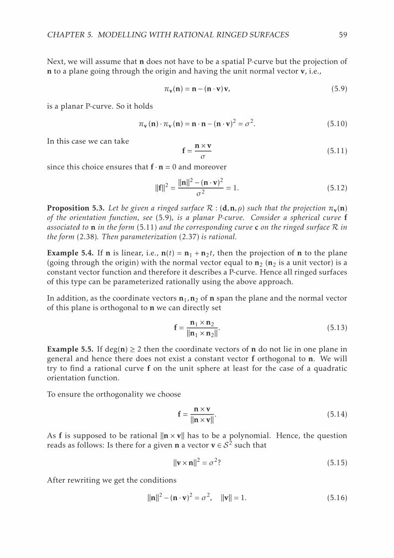
CHAPTER 5. MODELLING WITH RATIONAL RINGED SURFACES 59
Next, we will assume that n does not have to be a spatial P-curve but the projection ofn to a plane going through the origin and having the unit normal vector v, i.e.,
πv(n) = n− (n · v)v, (5.9)
is a planar P-curve. So it holds
πv (n) ·πv (n) = n ·n− (n · v)2 = σ2. (5.10)
In this case we can takef =
n× vσ
(5.11)
since this choice ensures that f ·n = 0 and moreover
‖f‖2 = ‖n‖2 − (n · v)2σ2 = 1. (5.12)
Proposition 5.3. Let be given a ringed surface R : (d,n,) such that the projection πv(n)of the orientation function, see (5.9), is a planar P-curve. Consider a spherical curve fassociated to n in the form (5.11) and the corresponding curve c on the ringed surface R inthe form (2.38). Then parameterization (2.37) is rational.
Example 5.4. If n is linear, i.e., n(t) = n1 + n2t, then the projection of n to the plane(going through the origin) with the normal vector equal to n2 (n2 is a unit vector) is aconstant vector function and therefore it describes a P-curve. Hence all ringed surfacesof this type can be parameterized rationally using the above approach.
In addition, as the coordinate vectors n1,n2 of n span the plane and the normal vectorof this plane is orthogonal to n we can directly set
f =n1 ×n2
‖n1 ×n2‖. (5.13)
Example 5.5. If deg(n) ≥ 2 then the coordinate vectors of n do not lie in one plane ingeneral and hence there does not exist a constant vector f orthogonal to n. We willtry to find a rational curve f on the unit sphere at least for the case of a quadraticorientation function.
To ensure the orthogonality we choose
f =n× v‖n× v‖ . (5.14)
As f is supposed to be rational ‖n × v‖ has to be a polynomial. Hence, the questionreads as follows: Is there for a given n a vector v ∈ S2 such that
‖v×n‖2 = σ2? (5.15)
After rewriting we get the conditions
‖n‖2 − (n · v)2 = σ2, ‖v‖ = 1. (5.16)

CHAPTER 5. MODELLING WITH RATIONAL RINGED SURFACES 60
In Chapter 4, the similar conditions to (5.16) appeared. In more detail, the existenceof a rational contour curve on the canal surface with the spine curve m and the radiusfunction r depends on the existence of a real solution of equation (4.27). In Section 4.3it was proved that (4.27) possesses a real solution for all pipe surfaces (r = const.)when deg(m) ≤ 3. This implies that equation (5.16) has a real solution for all quadraticorientation functions.
Remark 5.6. In other words, Example 5.5 shows that for any quadratic curve a planegoing through the origin such that the projected curve to this plane is a planar P-curveexist.
5.1.2 Rationality of general ringed surfaces
In this section we will present how the curve f can be found for a general R : (d,n,).In [56] and [68] a similar equation to (5.2), which is a crucial step for the computationof a rational parameterization of pipe/canal and normal ringed surfaces, is solved anddiscussed. Here, we exploit the idea introduced in [68]. The solution of (5.2) is a curvef such that for each t ∈R the point f(t) lies on the unit circle c(t) centered at the originand lying in the plane having the normal vector n(t). When projecting the circles c(t)via the stereographic projection δ : S2→ ν (where ν denotes the plane z = 0) with thecenter (0,0,1)⊤, we obtain the circles in ν having the centers s(t) and radii ρ(t)
s = −(n1,n2,0)⊤
n3, ρ = −‖n‖
n3. (5.17)
Remark 5.7. It is obvious that when n3 = 0, i.e., the circle c contains the center (0,0,1)⊤,the projection δ(c) is a straight line going through the origin and having (n2,−n1,0)⊤as its direction vector.
Now, it is enough to find some rational curve h such that for each t ∈ R the pointh(t) lies on the circle δ(c(t)) Since the radius function ρ is not rational in general, wecompute the sum of squares (SOS) decomposition of ρ2. In particular, if g = (g1,g2,0)⊤
is a planar curve satisfying‖n‖2 = g21 + g22 (5.18)
then the curve h can be written as follows:
h = s+gn3. (5.19)
Finally the inverse projection δ−1 : ν→ S2 yields the curve f solving equation (5.2).
f =(2h1,2h2,‖h‖2 − 1)⊤
‖h‖2 +1. (5.20)
Hence we can formulate the following theorem.
Theorem 5.8. Any ringed surface R : (d,n,) with a rational directrix, radius and orienta-tion function is rational.

CHAPTER 5. MODELLING WITH RATIONAL RINGED SURFACES 61
We have proved that all ringed surfaces with rational directrices, radius functions andorientation functions are rational. However, a natural question follows: Do exist otherrational ring surfaces which are not given by rational d,n,? And the answer is yes.
Consider a canal surface S (which belongs to the class of ringed surfaces) determinedby a rational spine curve m and a rational (sphere) radius function r. Such a canalsurface is rational, see [68]. Nevertheless, considering it as a ringed surface R andcomputing its directrix, radius function and orientation function according to (2.35),the (circle) radius function is a square root of a non-negative rational function
=
√
r2‖m′‖2 − r ′2‖m′‖2 . (5.21)
So we will continue with our considerations further and prove that a general ringedsurface R : (d,n, =
√R) with a rational directrix, a rational orientation function and
a radius function equal to the square root of some non-negative rational function isrational.
W.l.o.g. we can assume that n is a polynomial orientation function. Our goal is to finda rational curve f satisfying
n · f ≡ 0 and f · f ≡ R. (5.22)
For such a curve f we can construct a corresponding rational curve on R in the form
c = d+ f‖f‖ = d+ f. (5.23)
Equation (5.22) describes a curve f with the property that for each t ∈ R it holds f(t) ∈c(t), where c is the great circle of the sphere centered at the origin with the radius
√R
and lying in the plane having the normal vector n. Hence we seek f determined by a1-parameter system of circles
c(t) : x · x−R(t) = 0, x ·n(t) = 0, (5.24)
where x = (x,y,z)⊤. Projecting c to the plane ν we obtain a 1-parameter system ofellipses
(n1x +n2y)2 +n23
(x2 + y2 −R
)= 0 (5.25)
and the lifting (the inverse of the above projection) is described by
z = −n1x +n2yn3
. (5.26)
Ellipses (5.25) have centers at the origin and the directions of their axes are
a1 = (−n2,n1)⊤, a2 = (n1,n2)⊤. (5.27)
Hence by transforming (5.25) via the transformation (composition of a rotation and ascaling)
x→−n2x′ +n1y′, y→ n1x′ +n2y
′ (5.28)

CHAPTER 5. MODELLING WITH RATIONAL RINGED SURFACES 62
we get (n21 +n
22
)n23 x
′2 +(n21 +n
22
)‖n‖2 y′2 − n23R = 0. (5.29)
Now using the projective coordinates, multiplying equation (5.29) by(n21 +n
22
)and
performing transformation
X ′→ X ′′
n3(n21 +n
22
) , X ′→ Y ′′
n21 +n22
, Z ′→ Z ′′
n3(5.30)
we arrive at the following 1-parameter system of ellipses:
X ′′2 + ‖n‖2 Y ′′2 −(n21 +n
22
)R Z ′′2 = 0. (5.31)
Equation (5.31) can be rationally transformed to the following one
A(t) X2 +B(t) Y 2 +C(t) Z2 = 0, (5.32)
where A,B,C possess only complex 1-multiple roots and A,B neither B,C neither A,Cdo not have common roots. When τ is a real root of e.g. A, it has to be 2p-multiple(sinceA is a PSD polynomial) andwe can perform transformation Y → Y ′/(t−τ)p whichfixes the problem. By analogy the multiple roots can be handled. If τ is a common rootof A and B, we can multiply whole equation (5.32) by (t − τ)(t − τ) and perform thetransformation Y → Y ′/((t − τ)(t − τ)), Z→ Z ′/((t − τ)(t − τ)).
In [65] one particular rational solution of equation (5.32) is constructed. For the sakeof completeness we recall the approach only shortly.
We start with constructing polynomials
X(t) =(l+m)/2∑
i=0
xiti , Y (t) =
(k+m)/2∑
i=0
yiti , Z(t) =
(k+l)/2∑
i=0
ziti , (5.33)
where k = deg(A), l = deg(B) and m = deg(C).
Now for a root τ of A we obtain equation
B(τ)Y 2(τ) +C(τ)Z2(τ) = 0, (5.34)
which can be factorized as(√B(τ)Y (τ) +
√C(τ)Z(τ)
)(√B(τ)Y (τ)−
√C(τ)Z(τ)
)= 0, (5.35)
or (√B(τ)Y (τ) + i
√C(τ)Z(τ)
)(√B(τ)Y (τ)− i
√C(τ)Z(τ)
)= 0 (5.36)
according to the signs of B(τ) and C(τ). Then for a complex conjugate par of roots(τ,τ) we can choose two complex linear factors from factorizations (5.35) or 5.36 suchthat adding and subtracting them yields two linear equations with real coefficients.Performing this algorithm for all roots of A,B and C yields k+l+m real linear equationswhich have 3-parametric solution since X(t),Y (t) and Z(t) have k+ l+m+3 coefficients.

CHAPTER 5. MODELLING WITH RATIONAL RINGED SURFACES 63
By substituting the 3-parametric solution to equation (5.32) and setting t = 0 we obtaina homogeneous implicit equation of a conic with the three parameters as its variables.Now it remains to choose the remaining three parameters such that the resulting equa-tion gives a real point on the conic which certainly contains real points since it is thelinearly transformed conic (5.32) for t = 0, for more details see [65].
Finally we transform the solution X(t),Y (t),Z(t) of (5.31) back and obtain
f(t) =
−n2X +n1n3Y(n21 +n
22
)Z
,n1X +n2n3Y(n21 +n
22
)Z,−YZ
⊤
. (5.37)
Clearly, this approach can be generalized for rational n and R. We simply multiplyequation (5.31) by the denominators of ‖n‖2 and (n21 + n
22)R and obtain an equation
which could be also rationally transformed to (5.32). Hence, we can formulate thefollowing theorem.
Theorem 5.9. Any ringed surface R : (d,n, =√R) with a rational directrix, rational
radius function and orientation function equal to the square root of a non-negative rationalfunction is rational.
5.2 Blending by ringed surfaces
Consider two ringed surfaces R1 and R2 given by their directrices, radius functionsand orientation functions, i.e.,
R1 : (d1,n1,1) (t), R2 : (d2,n2,2) (t), t ∈ [0,1]. (5.38)
Our goal is to construct a blending ringed surface B between R1 and R2. When inter-polating given Hermite data in R
7
p1 = (d1,n1,1)⊤(1), t1 = (d′1,n′1,′1)⊤(1)
p2 = (d2,n2,2)⊤(0), t2 = (d′2,n′2,′2)⊤(0)
(5.39)
by a curve b(t) = (d,n,)(t)⊤, t ∈ [0,1], with C1/G1 continuity we obtain a blendingsurface B which will join R1 and R2 with C1/G1 continuity, too.
In the previous section it was shown that an arbitrary rational curve b = (d,n,)⊤
describes a rational ring surface B : (d,n,) and its rational parameterization can becomputed by the SOS decomposition (which is solvable only numerically. in general).However, as indicated in Propositions 5.1 and 5.3, using some special curves (wheninterpolating (5.39)) will make the computation of the parameterization of the cor-responding blending ringed surface considerably easier as it allows to avoid the SOSdecomposition. Let us discuss this way in more detail.
When interpolating Hermite data sampled from the orientation functions, i.e., n1(1),n′1(1); n2(0), n′2(0), by a P-curve we immediately obtain a curve with the polynomial

CHAPTER 5. MODELLING WITH RATIONAL RINGED SURFACES 64
norm and fulfilling the condition on orthogonality. So we will focus on this part of theinterpolation. The interpolation by polynomial P-curves is based on solving quadraticquaternion equations as in the case of spatial PH curves, see [34]. Consequently, Her-mite data sampled from the directrices together with radius functions, i.e., d1(1),1(1), d′1(1),
′1(1); d2(0), 2(0), d′2(0),
′2(0), can be interpolated by an arbitrary ra-
tional curve. To sum up, we will interpolate
p11 = (d1,1)⊤(1), t11 = (d′1,
′1)⊤(1)
p12 = (d2,2)⊤(0), t12 = (d′2,
′2)⊤(0)
(5.40)
by a suitable rational curve (e.g. Ferguson’s cubic) and
p21 = n1(1), t21 = n′1(1)
p22 = n2(0), t22 = n′2(0)
(5.41)
by a suitable spatial rational P-curve (e.g. spatial P-curve of degree 6, see [34] for moredetails). Then the assumptions of Proposition 5.1 are satisfied and we can construct arational parameterization of B.
Nevertheless, Proposition 5.3 offers even an easier way. It is enough to interpolate 2-dimensional data (sampled from the projection of the orientation functions to a coordi-nate plane) by a planar P-curve. This can be done by solving “only” complex quadraticequations. The remaining coordinate of the orientation function together with the di-rectrix and the radius function will be obtained via the interpolation by some rationalcurve. Thus, we will interpolate
p11 = (d1,n
31,1)
⊤(1), t11 = (d′1,n′13,′1)
⊤(1)p12 = (d2,n
32,2)
⊤(0), t12 = (d′2,n′23,′2)
⊤(0)(5.42)
by a suitable rational curve (e.g. Ferguson’s cubic) and
p21 = (n11,n
21)⊤(1), t21 = (n′1
1,n′12)⊤(1)
p22 = (n12,n
22)⊤(0), t22 = (n′2
1,n′22)⊤(0)
(5.43)
by a suitable planar rational P-curve (e.g. planar P-curve of degree 6).
Now, we show how the interpolation by a planar P-curve can be computed. As inthe case of planar PH curves we use a complex representation of points/curves in theplane. Then the curve x(t) is a polynomial P-curve iff it can be written as
x(t) =w2(t), (5.44)
where w(t) = w1(t) + i w2(t) is a polynomial with the complex coefficients, which canbe described by the Bernstein-Bézier form
w(t) =n∑
i=0
(n
i
)(1− t)n−itiwi , wi ∈C. (5.45)
Conditions for C1 Hermite interpolation
x(0) = p1, x′(0) = t1, x(1) = p2, x′(1) = t2, (5.46)

CHAPTER 5. MODELLING WITH RATIONAL RINGED SURFACES 65
yield four complex quadratic equations which have a solution for n ≥ 3. Hence, forn = 3 (i.e., the P-curves is of degree six) we obtain two distinct solutions:
w0 =√p1, w1 =
6p1 + t16√p1
, w2 = ±6p2 − t26√p2
, w3 = ±√p2. (5.47)
As in the case of interpolating by planar PH quintics it can be shown that the “moresuitable” interpolant is the one with + sign.
To sum up, the C1 interpolation by planar P-curve is simple and straightforward sinceit is enough to substitute given Hermite data (in the form of the complex representa-tion of points in the plain) to (5.47) and obtain the solution. A main drawback of thisapproach is that the resulting P-curve has degree 6, which could be for some applica-tions considered as too high.
However, the degree of the interpolant can be reduced by using P-biarcs, which is amethod successfully used for PH curves, [3, 6]. In particular we construct two quarticP-curves
x1(t) =
2∑
i=0
(2i
)(1− t)n−itiwi
2
, t ∈ [0,τ],
x2(t) =
2∑
i=0
(2i
)(1− t)n−itiwi+3
2
, t ∈ [τ,1].(5.48)
which have to satisfy the Hermite C1 conditions:
x1(0) = p1, x′1(0) = t1, x2(1) = p2, x′2(1) = t2 (5.49)
and moreover these curves are joining with the C1 continuity in a value τ ∈ (0,1) of theparameter t. This gives two additional conditions
x1(τ) = x2(τ), x′1(τ) = x′2(τ). (5.50)
Solving (5.49) and (5.50) yields three distinct solutions, however only two of them givea regular P-curve:
w0 =√p1, w1 =
4p1 + t14√p1
, w2 =(τ − 1)
(±√p1t2 +
√p2 (4p1 + t1)
)± 4√p1p2
4√p1√p2τ
,
w3 =τ(−√p2t1 ±
√p1 (4p2 − t2)
)− 4p1
√p2
4√p1√p2(τ − 1)
, w4 = ±4p2 − t24√p2
, w5 = ±√p2.
(5.51)And again, the “more suitable” interpolant is the one with + sign.
The whole method for the construction of a blending surface B between two ringedsurfaces, described above, is summarized in Algorithm 4.
Example 5.10. Consider two ringed surfaces given by
d1 =(2t − 6,2t2 − 5, t3
)⊤, n1 = (1, t, t)⊤ , 1 =
t2
4+1,
d2 = (3sin(t), t, log(t +1))⊤ , n2 = (4,sin(t), t)⊤ , 2 = t +2.(5.52)

CHAPTER 5. MODELLING WITH RATIONAL RINGED SURFACES 66
Figure 5.1: Blending ringed surface (green) and optimized blending (as much as pos-sible normal) ringed surface (red) between two ringed surfaces (blue) from Exam-ple 5.10.
Algorithm 4 Blending by ringed surfaces
INPUT: Two ringed surfacesR1 andR2 given by directrices, orientation functions andradius functions, cf. (5.38).
1: Interpolate data (5.42) by a Ferguson’s cubic f;2: Interpolate data (5.43) by a planar polynomial P-curve of degree six or by a P-biarc
of degree four – obtain curve g with the norm equal to a polynomial σ;
3: Construct a curve c = (f1, f2, f3)⊤ + f5
(g2,−g1,0)⊤σ on B;
4: Using the curve c and formula (2.37) compute a rational parameterization of B;
OUTPUT: The parameterization s(t,u) of the blending surface B between the givenringed surfaces R1 and R2.
According to Algorithm 4 we interpolate data (5.42) by the Ferguson’s cubic and data(5.43) by the planar P-curve of degree six and compute the corresponding rationalparameterization of the resulting ringed surface, see Figure 5.1, left.
Remark 5.11. We would like to emphasize that using ringed surfaces for the operationof blending significantly extends the family of surfaces (and their mutual positions)which can be blended. For instance, the surfaces from Example 5.10 have to be blendedby (non-canal) ringed surface as they are not canal surfaces. Moreover, even when wewant to construct blends between two specially situated canal surfaces it may occur aposition which cannot be successfully solved by a canal-surface-blend but it is possibleto find a suitable ringed-surface-blend, see Figure 5.2.
5.3 Adaptive blending and shape optimization
In Chapter 4, the contour curves on canal surfaces were investigated and used for con-structing a whole family of canal surfaces sharing the same silhouette w.r.t. a parallelprojection while only one SOS decomposition/MPH interpolation was necessary to beprovided for the computation of their parameterizations. This approach is especiallyuseful for constructing blends satisfying certain constrains, e.g. when avoiding obsta-

CHAPTER 5. MODELLING WITH RATIONAL RINGED SURFACES 67
Figure 5.2: Blending ringed surface (yellow) between two canal surfaces (blue).
cles or bypassing other objects is required. The constructed blending surface can beeasily modified only with the help of a certain distance function.
When using ringed surfaces for constructing blends with constraints, the situation issignificantly easier. The key step of the computation of a parameterization of a curveon a ringed surfaceR (and thus also a parameterization ofR) is the computation of theunit rational vector field f orthogonal to the orientation function n ofR (cf. (5.2)). Thiscan be done by decomposing a polynomial/rational function into a sum of squares orby modelling with P-curves. However, this computation step does not depend on thedirectrix d and therefore d could be adjusted as the prescribed constraints require. Inparticular, we construct a new directrix
d∗ = d+ vf , (5.53)
obtained from the original directrix d by adding in a suitable direction v some (ra-tional) distance function f . Analogously to Section 4.4.3 f should be continuous on(0,1) and satisfying conditions (4.93). This distance function f enables to modify theblending ringed surface in the v-direction. In examples presented in Figure 5.3, thefollowing distance function w.r.t. the vector v = (0,0,λ)⊤ for different values of τ andλ were applied
f (t,τ) =(1− t)2t2(t(2− 4τ) + τ(5τ − 3))
(1− τ)3τ3 . (5.54)
Example 5.12. Consider two normal ringed surfaces R1 and R2 defined by
d1 =(sin(t)− 4,cos(t),2t − 5
)⊤, 1 = 2t−2;
d2 = (t,−t,sin(t))⊤ , 2 = 3t2 ,
(5.55)
and a prescribed sphere with the center at (−1.4,−0.3,−1.2)⊤ and the radius equal to0.75 (taken as a obstacle). Firstly, we construct a blending ringed surface by Algo-rithm 4, see Figure 5.4, left. Then we adjust the blend so that it avoids the prescribed

CHAPTER 5. MODELLING WITH RATIONAL RINGED SURFACES 68
Figure 5.3: Adaptive blending ringed surface(s) (green, red, orange, yellow) betweentwo cylinders (blue) differing only in the third coordinate of the directrices.
sphere, i.e., we modify its directrix according to (5.53). Analogously to canal surfaces,see condition (4.96), we use the following condition as the satisfying (not necessary)criterion for blending surface with the directrix d∗ and the radius function not inter-secting the sphere centered at s and with the radius r:
‖d∗(t)− s‖ > (t) + r, (5.56)
for all t ∈ [0,1]. We used the distance function (5.54) and
v =(15,45,35
)⊤and τ =
12. (5.57)
The new constructed blend does not intersect the sphere (see Figure 5.4, right) since
mint∈[0,1]
(‖d∗(t)− s‖ − (t)− r) 0.0228 > 0. (5.58)
The shape variability (especially suitable for modelling purposes) of ringed surfacescan be used when e.g. one wants to optimize (in some sense) the shape of the alreadyconstructed blend. As a particular example, we choose a criterion that the shape of themodified blend is as close as possible to the shape of a normal ringed surface. This isa natural criterion from the point of view of practical applications as we would like toavoid the situations when the normals n differ too much from the tangents of d.
The presented approach starts with the computation of a blending ringed surface, e.g.by Algorithm 4. So, we have the directrix d, orientation function n, radius function and some function f satisfying (5.2). We construct the new directrix d∗, cf. (5.53),where the distance function can be chosen as e.g. (5.54). We leave the vector v and

CHAPTER 5. MODELLING WITH RATIONAL RINGED SURFACES 69
Figure 5.4: A blending ringed surface (green) intersecting the given obstacle (red)and a blending ringed surface (yellow) avoiding the given obstacle (red) between tworinged surfaces (blue) from Example 5.12.
the parameters of the distance function as free parameters and optimize the followingobjective function ∫
I
((f · (d∗)′)2
‖f‖2‖(d∗)′‖2 +((f×n) · (d∗)′)2
‖f×n‖2‖(d∗)′‖2
)dt, (5.59)
which measures the deviance of the vectors (d∗)′ from the vectors n.
In Figure 5.1, right the blending surface from Example 5.10 modified by the previousapproach to be as close as possible to a normal ringed surface is shown.
Example 5.13. Let be given two canal surfaces S1 and S2 defined by the cubic/quadraticmats
m1 =(0.3t − 1.1, (1.1− 0.3t)2 − 1, (0.3t − 1.1)3,0.03t2 − 0.22t +0.736667
)⊤,
m2 =(0.3t +2,2(0.3t +1)2, (0.3t +1)2,0.045t2 +0.3t +1
)⊤.
(5.60)
We consider them as ringed surfaces and compute their directrices, orientation func-tions and radius functions, cf. (2.35). Then we construct a blending ringed surfaceusing Algorithm 4, see Figure 5.5, left. Finally involving the distance function (5.54)(where we set τ = 1/2) and minimizing integral (5.59), we arrive at the vector
v (−0.23824,−1.04859,0.13459)⊤ , (5.61)
yielding a blending ringed surface which is “more normal” than the original one, seeFigure 5.5, right.
5.4 Contour curves and approximate parameterizationsof implicitly given blends.
We start with investigating contour curves on ringed surfaces and then we focus oncomputing approximate parameterizations of implicitly given ringed surfaces gainede.g. by some implicit blending techniques, cf. Section 3.1.

CHAPTER 5. MODELLING WITH RATIONAL RINGED SURFACES 70
Figure 5.5: A blending ringed surface (green) and an optimized blending (almost nor-mal) ringed surface (red) between two canal surfaces (blue) from Example 5.13.
As in the case of canal surfaces, a contour curve Cv w.r.t. the vector v (a curve consistingof all the points at which the normals ofR are orthogonal to v) on a ringed surface cor-responds to the silhouette of the given ringed surface when projecting it to the planewith the normal vector v. We recall that studying projected contour curves (silhou-ettes) do not only help to create a first visual perception of the shape of the studiedobject but they have also many practical applications – for instance, in reconstructionof the 3D object from a 2D image, in rendering, in computing the visible area, whendeleting invisible curves, see [7,77,83,93].
Contrary to canal surfaces, the expression of contour curves for a general ringed sur-face is more complicated and contains even nested square roots. More precisely, aparameterization of the contour curve w.r.t. the vector v can be computed as the enve-lope of the family of ellipses obtained by projecting the family of sweeping circles
‖x−d‖2 − 2 = 0, (x−d) ·n = 0 (5.62)
in the projection πv, see (5.9).
Nonetheless, studying the resulting parametric expression in more detail is beyond thescope of this thesis. Here we only consider some special cases (special ringed surfaces)having the contour curves without nested square roots in their parametric expressions.One of the special situation occurs when the ellipses (projected characteristic circlesin the projection πv) degenerate to line segments. This happens when the orientationfunction n is orthogonal to the direction v of the projection πv.
Consider a ringed surface R : (d,n,) and a vector v for which the following conditionholds
n · v ≡ 0. (5.63)
Then the orthogonal projection πv sends the generating circles of R to the line seg-ments and the contour curve of R w.r.t. v is of the form
c±v = d± n× v‖n‖ . (5.64)
Thus we can formulate the following proposition.

CHAPTER 5. MODELLING WITH RATIONAL RINGED SURFACES 71
Proposition 5.14. Consider a vector v and a ringed surface R : (d,n,) with the orienta-tion function satisfying (5.63). Then R possesses a rational contour curve w.r.t. v iff theorientation function n corresponds to a P-curve.
Corollary 5.15. Any normal ringed surface with the directrix being a quadratic PH curvepossesses a rational contour curve.
The usefulness of the contour curves on ringed surfaces can be demonstrated on theproblem of approximating implicitly given blends by a rational ringed surface.
Let us consider the problem formulated in Section 3.1, i.e., we want to approximatea blending surface B implicitly given by polynomial f between two normal ringedsurfaces R1 and R2 (e.g. cones or cylinders of revolution) implicitly determined bypolynomials f1 and f2, and bounded by planes P1 and P2 (perpendicular to their direc-trices) described by linear polynomials f10 and f20, respectively.
In Chapter 3 the methods for computing approximate parameterizations of implic-itly given canal surfaces based on approximating their contour curves by polynomialcubics were designed. The algorithm described in Section 3.4 starts with computingthe polynomial cubic approximate parameterizations of three different contour curvesof the given canal surface S . From these parameterizations an approximation of thespine curve (also polynomial of degree 3) of S is reconstructed and consequently anapproximate parameterization of S is computed.
An analogous approach can be used for computing approximate parameterizations ofimplicitly given ringed surfaces. We also (approximately) parameterize three differentcontour curves on the given ringed surface B and reconstruct an approximation of thedirectrix and the orientation function from these parameterizations.
In the case of canal surfaces the contour curves satisfy equality (2.33), which allows usto compute easily the parameterization of the spine curve from the parameterizationsof three different contour curves, cf. (3.17). However, this advantageous equality is notsatisfied for general ringed surfaces. So one can ask: Why to use the contour curves (inthe case of ringed surfaces) while any arbitrary curves on B can be used instead withthe same effect? Nonetheless the answer is simple: The contour curves on surfaces (notonly ringed or canal) implicitly given by a polynomial f can be easily described as acomplete intersection of two algebraic surfaces defined by (2.34).
We start with choosing three different contour curves Cv1 , Cv2 and Cv3 on B. Then we
compute the intersection points p1i , . . . ,p
kii of the plane P1 and the contour curves Cvi ,
i.e., we solve the following system of equations
f10 = 0, f = 0, fvi = 0, i = 1,2,3. (5.65)
Analogously by solving
f20 = 0, f = 0, fvi = 0, i = 1,2,3, (5.66)
we obtain the intersection points q1i , . . . ,q
kii of the plane P2 and the contour curve Cvi .
Then we choose points pi ∈ p1i , . . . ,p
kii and qi ∈ q1
i , . . . ,qkii such that pi qi lie on the

CHAPTER 5. MODELLING WITH RATIONAL RINGED SURFACES 72
same branch of the contour curve Cvi – this can be done e.g. by considering a topol-ogy (constructing topological graphs) of the contour curves, for more details see Sec-tion 3.2.
From pi and qi , i = 1,2,3, the centers of the characteristic circles s1 and s2 can bereconstructed. In particular the center of the circle passing through the points pi iscomputed as follows
s =p1 +p2
2+(a ·b)− ‖b‖22‖a×b‖2
((a ·b)a− ‖a‖2b
), (5.67)
where a = p2 − p1 and b = p3 − p1. Then we construct an auxiliary approximation dof the directrix curve of B by interpolating points s1 and s2 with the tangent vectorsbeing the normal vectors of the planes P1 and P2 by the Ferguson’s cubic. The lengthsof n1 and n2 can be chosen e.g. according to the distance of s1 and s2 – our tests haveshown that using the lengths of n1 and n2 both equal to the distance of s1 and s2 workssufficiently.
Now we compute approximate parameterizations cv1 , cv2 and cv3 of the particularbranches of the contour curves Cv1 , Cv2 and Cv3 so that we construct the Ferguson’scubics joining the points pi and qi with the tangent vectors αitpi and βitqi with thelengths αi and βi as free parameters, where
txi =∇f (xi )×∇fvi (xi )‖∇f (xi )×∇fvi (xi )‖
. (5.68)
Finally we compute the “optimal” values of the free parameters αi and βi by minimiz-ing the following objective function
Ω =Φ(f , fv1 ,cv1) +Φ(f , fv2 ,cv2) +Φ(f , fv3 ,cv3) +wΨ(d,cv1 − cv2 ,cv1 − cv3), (5.69)
where w is a suitable weight, the objective function
Φ(f ,g,c) =∫
I
f 2(c)‖∇f (c)‖2 +
g2(c)‖∇g(c)‖2 dt (5.70)
is responsible for the deviance of the approximate parameterization c from the implicitrepresentation f = g = 0, cf. (2.42) and the objective function
Ψ(n,a,b) =∫
I
(a ·n)2
‖a‖2‖n‖2 +(b ·n)2
‖b‖2‖n‖2 dt (5.71)
measures the deviance of the approximation of the normal vector of the plane spannedby the vectors a, b from the vector n.
The whole method of computing an approximate parameterization of the implicitlygiven ringed surface is summarized in Algorithm 5.
Remark 5.16. When the blend, which shall be approximated, is of a more complexshape, then a refinement can be done to increase the accuracy. In particular we can

CHAPTER 5. MODELLING WITH RATIONAL RINGED SURFACES 73
Algorithm 5 Approximate parameterization of implicitly given ringed surface.
INPUT: A ringed surface B (blend) given by the implicit equation f = 0 and twoplanes P1 and P2 (bounding B) defined by the polynomials f10 and f20.
1: Choose three different (unit) vectors vi , i = 1,2,3 and determine contour curvesCvi , implicitly defined by polynomials f , fvi , cf. (2.34);
2: Compute the intersection points p1i , . . . ,p
kii of Cvi with P1, and q1
i , . . . ,qkii of Cvi with
P2, cf. (5.65) and (5.66);
3: Choose pi ∈ p1i , . . . ,p
kii and qi ∈ q1
i , . . . ,qkii such that couple piqi corresponds to
the particular segment of Cvi ;4: Compute the centers s1 and s2 of the circles going through pi and qi , respectively,
cf. (5.67);5: Take the normal vectors nj , j = 1,2 of the planes Pj , i.e., given by the coefficients
of the linear terms of the polynomials fj0;
6: Construct the Ferguson’s cubic d interpolating the points s1 and s2 and the vectorsw1 n1 and w2 n2, where w1 and w2 are chosen according to the distance of s1 ands2;
7: Construct the Ferguson’s cubics cvi interpolating the points pi and qi with thetangent vectors αitpi and βitqi (see (5.68)) with the lengths αi and βi as free param-eters;
8: Minimize the objective function (5.69) and set the obtained values of αi and βi tothe parameterizations cvi ;
9: Reconstruct the directrix d by computing the center of the 1-parameter family ofcircles going through cvi , see (5.67);
10: Reconstruct the orientation function n = (cv1 − cv2)× (cv1 − cv3);11: Compute an approximate parameterization of B using one of the curves cvi and
formula (2.37);
OUTPUT: The approximate parameterization s(t,u) of the ringed surface B.
modify Algorithm 5 analogously to Algorithms 2 and 3 such that we can consider thecritical points of the contour curves when parameterizing them. Then the blendingsurface will be composed of more parts and each part will be approximated anal-ogously as we discussed above. An easier way of providing a refinement (withoutcomputing the critical points) is to divide the input blending surface into a suitablenumber of parts by cutting it by planes Pτi , τi ∈ (0,1), where
Pτi : d′(τi) · (x−d(τi )) = 0. (5.72)
Remark 5.17. Let us note that it is enough to use only two contour curves in the pa-rameterization process. Since contour curves possess two real branches in general, wecan work with the two real branches c±v1 of one contour curve Cv1 and one real branchc+v2 of another contour curve Cv2 .
Example 5.18. We compute an approximate parameterization of the ringed surfaceB defined by the polynomial f , see Figure 5.6, obtained by the method from [39],

CHAPTER 5. MODELLING WITH RATIONAL RINGED SURFACES 74
Figure 5.6: Implicit blending surface (green) between two cylinders (blue) from Exam-ple 5.18.
cf. (3.1), where we have set λ = 1/2 and n = 2, as an implicit blending surface betweenthe cylinders given by
f1 = y2 + z2 − 9, f2 = x
2 − 2xy − 12x + y2 +12y +2z2 +28, (5.73)
bounded by the planesf10 = x = 0, f20 = x + y = 10, (5.74)
respectively. We start with computing approximate parameterizations of the contourcurves w.r.t. the vectors
v1 = (0,0,1)⊤, v2 = (0,1,0)⊤, v3 =(0,
1√2,1√2
)⊤. (5.75)
From these parameterizations we reconstruct the directrix d and the orientation func-tion n. Finally, we compute the approximate parameterization of B by using one ofthe curves cvi and formula (2.37). The error of the approximation measured by inte-gral (2.43) is less than 2.1 ·10−2 when using parameterization of one part and 3.7 ·10−4when using parameterizations of two parts.
5.5 Blending three or more ringed surfaces
In this section, we will deal with the problem of constructing a blending surface be-tween three or more ringed surfaces. The method is based on choosing an auxiliarysphere and separately constructing blending ringed surfaces between the given ringedsurfaces and the sphere by the methods discussed in the previous sections.
Consider the (parts of the) three ringed surfaces Ri , i = 1,2,3 given by
Ri : (di ,ni ,i )(t), t ∈ [0,1]. (5.76)
Firstly, we choose an auxiliary sphere S in a suitable position “between” Ri simulta-neously not intersecting them – e.g., we can choose the center s of S on the line going

CHAPTER 5. MODELLING WITH RATIONAL RINGED SURFACES 75
Figure 5.7: A blending surface (green) between three ringed surfaces (blue) from Ex-ample 5.20, left and a blending surface (red) between five ringed surfaces (blue), right.
through the center of the inscribed circle of the triangle joining points di(1) and havingthe direction vector perpendicular to the plane containing points di(1), i.e.,
s = y(1) +α [(d1(1)−d2(1))× (d1(1)−d3(1))] , α ∈R, (5.77)
where
y(t) = d1 +(d2 −d1)‖d3 −d1‖+ (d3 −d1)‖d2 −d1‖‖d2 −d1‖+ ‖d3 −d1‖+ ‖d3 −d2‖
. (5.78)
The parameter α is set to reflect the angle between d′i(1) and the plane containingpoints di(1). The radius r of S has to be chosen so that S does not intersect any of Ri ,i.e.
r ∈(0, mini=1,2,3
‖pi − s‖). (5.79)
Next, for each ringed surface Ri we consider the sphere S as a ringed surface Si givenby
n∗i =di(1)− s‖di(1)− s‖
,
d∗i = s− rn∗i + t(2rn∗i ),
r∗i =√r2 − ‖d∗i − s‖2 = 2r
√t(1− t).
(5.80)
For each i ∈ 1,2,3, this enables to describe the sphere S as a family of circles (denotedby Si) set coherently with the end circles of a particular Ri
Now, for each i ∈ 1,2,3 we compute a classical blending surface Bi between Ri andSi (see Algorithm 4) such that we interpolate Hermite data
pi = (di ,ni ,i )⊤(1), vi = (d′i ,n′i ,′i)⊤(1)
p∗i = (d∗i ,n∗i ,∗i )⊤(λi ), v∗i =
((d∗i
)′,(n∗i
)′,(∗i
)′)⊤(λi ),
(5.81)

CHAPTER 5. MODELLING WITH RATIONAL RINGED SURFACES 76
where λi ∈ (0,1) corresponds to a particular selected circle ci ∈ Si at which Bi joins Si .Parameters λi have to be chosen so that the circles ci , i = 1,2,3, do not intersect eachother.
Remark 5.19. Let us note that in the construction of the multiple blends the positionand the radius of the auxiliary sphere (and even the circles on the sphere at which theblend surfaces join it) can be chosen freely (only some natural criteria must be satis-fied). Hence the multiple blends can be easily modified according to further prescribedrequirements reflecting additional modelling conditions.
Example 5.20. We construct a blending surface between three given (normal) ringedsurfaces R1,R2 and R3 given as follows:
d1 =(14t3 − 23t2 +12t − 9,4t − 7,0
)⊤, n1 = d′1, 1 =
16(t +4);
d2 =(−4t3 +4t +6,−2t3 +3t2 +4t − 8,0
)⊤, n2 = d′2, 2 =
12(2− t2);
d3 =(0,2t3 − 5t2 +8,2t3 − 3t2 +4t − 8
)⊤, n3 = d′3, 3 =
16(9− 4t).
(5.82)
We have chosen the auxiliary spheres with the following center and radius
s = (0.5,0.3,−0.25)⊤ , r = 2.6, (5.83)
and all the parameters λi were set to 0.2, see Figure 5.7, left.
Analogously, we can construct general n-way blends between n ringed surfaces; Fig-ure 5.7 (right) presents 5-way blend between five given ringed surfaces.

Chapter 6Conclusion
In this thesis the techniques for computing exact/approximate parameterizations ofcanal and ringed surfaces was presented and studied. Firstly we focused on canal sur-faces given implicitly – the designed approach is based on computing approximatetopology-based parameterizations of spatial curves lying on the given canal surface.The method can be directly applied on the practical problem of parameterizing im-plicit blends consisting of parts of canal (or canal-surface-like) surfaces.
Then we studied a condition guaranteeing the rationality of contour curves on canalsurfaces. These curves were then used for a computation of rational PN parameteri-zations of canal surfaces, where PN stands for Pythagorean normals. Our approachextends the results about rational spatial MPH curves and the associated planar PHcurves and relates them with the contour curves of canal surfaces given by their me-dial axis transforms. In addition, methods for constructing (adaptive) rational offsetblends between two canal surfaces were presented. A functionality of all these algo-rithms was demonstrated on several examples.
Finally we studied rational ringed surfaces which have been used for construction(adaptive) blends between two and more ringed surfaces. We also presented a methoddealing with approximating implicitly given blends by rational ringed surfaces.
77

Bibliography
[1] Abhyankar, S., and Bajaj, C. Automatic parametrization of rational curves andsurfaces ii: cubics and cubicoids. Computer-Aided Design 19, 9 (1987), 499 – 502.
[2] Altmann, S. L. Rotations, quaternions, and double groups. Dover Publications,2005.
[3] Bastl, B., Bizzarri, M., Krajnc, M., Lávička, M., Slabá, K., Šír, Z., Vitrih, V., andŽagar, E. C1 hermite interpolation with spatial pythagorean-hodograph cubicbiarcs. Journal of Computational and Applied Mathematics 257 (Feb. 2014), 65–78.
[4] Bastl, B., Jüttler, B., Lávička, M., and Schulz, T. Blends of canal surfaces frompolyhedral medial surface transform representations. Computer-Aided Design De-sign 43, 11 (2011), 1477–1484.
[5] Bastl, B., Jüttler, B., Lávička, M., Schulz, T., and Šír, Z. On the parameteriza-tion of rational ringed surfaces and rational canal surfaces. To appear in Mathe-matics in Computer Science, 2014.
[6] Bastl, B., Slabá, K., and Byrtus, M. Planar hermite interpolation with uniformand non-uniform tc-biarcs. Computer Aided Geometric Design 30, 1 (2013), 58 –77. Recent Advances in Applied Geometry.
[7] Benichou, F., and Eiber, G. Output sensitive extraction of silhouettes from polyg-onal geometry. In Computer Graphics and Applications, 1999. Proceedings. SeventhPacific Conference on (1999), pp. 60–69.
[8] Bizzarri, M., and Lávička, M. A symbolic-numerical method for computingapproximate parameterizations of canal surfaces. Computer-Aided Design 44, 9(2012), 846 – 857.
[9] Bizzarri, M., and Lávička, M. Parameterizing rational offset canal surfaces viarational contour curves. Computer-Aided Design 45, 2 (2013), 342–350.
[10] Bizzarri, M., and Lávička, M. A symbolic-numerical approach to approximateparameterizations of space curves using graphs of critical points. Journal of Com-putational and Applied Mathematics 242 (2013), 107 – 124.
78

BIBLIOGRAPHY 79
[11] Bizzarri, M., and Lávička, M. Approximation of implicit blends by canal surfacesof low parameterization degree. In Mathematical Methods for Curves and Surfaces,vol. 8177 of Lecture Notes in Computer Science. Springer Berlin Heidelberg, 2014,pp. 34–48.
[12] Bizzarri, M., and Lávička, M. On modelling with rational ringed surfaces. sub-mitted to Computer-Aided Design (2014).
[13] Bizzarri, M., Lávička, M., and Vršek, J. Canal surfaces with rational contourcurves and blends bypassing the obstacles. submitted to Computer-Aided Design(2014).
[14] Bloomenthal, J. Modeling the mighty maple. SIGGRAPH Comput. Graph. 19, 3(July 1985), 305–311.
[15] Blum, R. Circles on surfaces in the Euclidean 3-space. InGeometry and DifferentialGeometry, vol. 792 of Lecture Notes in Mathematics. Springer Berlin / Heidelberg,1980, pp. 213–221.
[16] Boudon, F., Meyer, A., and Godin, C. Survey on computer representations oftrees for realistic and efficient rendering. Tech. Rep. RR-LIRIS-2006-003, LIRISUMR 5205 CNRS/INSA de Lyon/Université Claude Bernard Lyon 1/UniversitéLumiére Lyon 2/École Centrale de Lyon, Feb. 2006.
[17] Brieskorn, E., and Knörer, H. Plane Algebraic Curves. Birkhäuser Basel, 1986.
[18] Cheng, J., Lazard, S., Peñaranda, L., Pouget, M., Rouillier, F., and Tsigaridas,E. On the topology of planar algebraic curves. In Proceedings of the 25th annualsymposium on Computational geometry (New York, NY, USA, 2009), SCG ’09, ACM,pp. 361–370.
[19] Cho, H., Choi, H., Kwon, S.-H., Lee, D., and Wee, N.-S. Clifford algebra,Lorentzian geometry and rational parametrization of canal surfaces. ComputerAided Geometric Design 21 (2004), 327–339.
[20] Choi, H., and Lee, D. Rational parametrization of canal surface by 4 dimensionalMinkowski Pythagorean hodograph curves. In Proceedings of the Geometric Model-ing and Processing 2000 (Washington, DC, USA, 2000), GMP ’00, IEEE ComputerSociety, pp. 301–309.
[21] Choi, H. I., Han, C. Y., Moon, H. P., Roh, K. H., and Wee, N. S. Medial axis trans-form and offset curves by Minkowski Pythagorean hodograph curves. Computer-Aided Design 31, 1 (Jan. 1999), 59–72.
[22] Choi, M. D., Lam, T. Y., and Reznick, B. Sums of squares of real polynomials.Proceedings of Symposia in Pure Mathematics 58 (1995), 103–126.
[23] Coolidge, J. A Treatise on the Circle and Sphere. Clarendon Press, 1916.
[24] Cox, D. A., Little, J., and O’Shea, D. Ideals, Varieties, and Algorithms: An Intro-duction to Computational Algebraic Geometry and Commutative Algebra. Springer-Verlag New York, Inc., Secaucus, NJ, USA, 2007.

BIBLIOGRAPHY 80
[25] Daniels, R. W. Introduction to Numerical Methods and Optimization Techniques.Elsevier Science Ltd, 1978.
[26] Darboux, J. Sur le contact des courbes et des surfaces. Bulletin des Sciences Math-ématiques 2, 4 (1880), 348–384.
[27] Dietz, R., Hoschek, J., and Jüttler, B. An algebraic approach to curves andsurfaces on the sphere and on other quadrics. Computer Aided Geometric Design10, 3-4 (1993), 211–229.
[28] Dohm, M., and Zube, S. The implicit equation of a canal surface. J. Symb. Comput.44 (February 2009), 111–130.
[29] Farin, G. Curves and Surfaces for Computer-Aided Geometric Design. AcademicPress, 1988.
[30] Farin, G. Curves and surfaces for CAGD: A practical guide. Morgan KaufmannPublishers Inc., San Francisco, CA, USA, 2002.
[31] Farin, G., Hoschek, J., and Kim, M.-S., Eds. Handbook of Computer Aided Geomet-ric Design. Elsevier, 2002.
[32] Farouki, R. Pythagorean-Hodograph Curves: Algebra and Geometry Inseparable.Springer, 2008.
[33] Farouki, R., and Sakkalis, T. Pythagorean hodographs. IBM Journal of Researchand Development 34, 5 (1990), 736–752.
[34] Farouki, R. T., and Giannelli, C. Spatial camera orientation control by rotation-minimizing directed frames. Computer Animation and Virtual Worlds 20, 4 (2009),457–472.
[35] Farouki, R. T., and Pottmann, H. Polynomial and rational Pythagorean-hodograph curves reconciled. In Proceedings of the 6th IMA Conference on theMathematics of Surfaces (New York, NY, USA, 1996), Clarendon Press, pp. 355–378.
[36] Goldman, R. Understanding quaternions. Graphical Models 73 (March 2011),21–49.
[37] Harris, J. Algebraic Geometry: A First Course. Springer-Verlag, 1992.
[38] Hartman, E. Blending of implicit surfaces with functional splines. Computer-Aided Design 22 (October 1990), 500–506.
[39] Hartmann, E. Gn-continuous connections between normal ringed surfaces. Com-puter Aided Geometric Design 18, 8 (2001), 751 – 770.
[40] Hartmann, E. Implicit Gn-blending of vertices. Computer Aided Geometric Design18, 3 (2001), 267 – 285.

BIBLIOGRAPHY 81
[41] Heo, H.-S., Hong, S., Seong, J.-K., Kim, M.-S., and Elber, G. The intersectionof two ringed surfaces and some related problems. Graphical Models 63 (2001),228–244.
[42] Hoffmann, C., and Hopcroft, J. Quadratic blending surfaces. Computer-AidedDesign 18, 6 (1986), 301 – 306.
[43] Hoffmann, C., H. J. Automatic surface generation in computer aided design. TheVisual Computer 1, 2 (1985), 92–100. cited By (since 1996) 16.
[44] Hoschek, J., and Lasser, D. Fundamentals of computer-aided geometric design. AKPeters, 1993.
[45] Johnstone, J. A new intersection algorithm for cyclides and swept surfaces usingcircle decomposition. Computer Aided Geometric Design 10, 1 (1993), 1 – 24.
[46] Kim, G.-I., and Ahn, M.-H. C1 Hermite interpolation using MPH quartic. Com-puter Aided Geometric Design 20 (2003), 469–492.
[47] Kosinka, J., and Jüttler, B. G1 Hermite interpolation byMinkowski Pythagoreanhodograph cubics. Computer Aided Geometric Design 23 (2006), 401–418.
[48] Kosinka, J., and Jüttler, B. C1 Hermite interpolation by Pythagorean hodographquintics in Minkowski space. Advances in Computational Mathematics 30 (2009),123–140.
[49] Kosinka, J., and Lávička, M. On rational Minkowski Pythagorean hodographcurves. Computer Aided Geometric Design 27, 7 (2010), 514–524.
[50] Kosinka, J., and Lávička, M. A unified Pythagorean hodograph approach to me-dial axis transform and offset approximation. Journal of Computational and Ap-plied Mathematics 235, 12 (2011), 3413–3424.
[51] Kosinka, J., and Šír, Z. C2 Hermite interpolation by Minkowski Pythagoreanhodograph curves and medial axis transform approximation. Computer AidedGeometric Design In Press (2010).
[52] Krasauskas, R., andMäurer, C. Studying cyclides with Laguerre geometry. Com-puter Aided Geometric Design 17, 2 (2000), 101–126.
[53] Krasauskas, R., and Zube, S. Canal surfaces defined by quadratic families ofspheres. In Geometric Modeling and Algebraic Geometry, B. Jüttler and R. Piene,Eds. Springer Berlin Heidelberg, 2008, pp. 79–92.
[54] Krasauskas, R., and Zube, S. Bézier-like parametrizations of spheres and cy-clides using geometric algebra. In 9th International Conference on Clifford Al-gebras and their Applications in Mathematical Physics (2011), K. Guerlebeck, Ed.http://www.mif.vu.lt/~rimask/en/.
[55] Kubota, K. Pythagorean triples in unique factorization domains. American Math-ematical Monthly 79 (1972), 503–505.

BIBLIOGRAPHY 82
[56] Lü, W., and Pottmann, H. Pipe surfaces with rational spine curve are rational.Computer Aided Geometric Design 13 (1996), 621–628.
[57] Landsmann, G., Schicho, J., and Winkler, F. The parametrization of canal sur-faces and the decomposition of polynomials into a sum of two squares. Journal ofSymbolic Computation 32, 1-2 (2001), 119 – 132.
[58] Lávička, M., and Bastl, B. Rational hypersurfaces with rational convolutions.Computer Aided Geometric Design 24, 7 (2007), 410–426.
[59] Lü, W., and Pottmann, H. Pipe surfaces with rational spine curve are rational.Computer Aided Geometric Design 13, 7 (Oct. 1996), 621–628.
[60] Ma, Y., Tu, C., andWang, W. Distance computation for canal surfaces using cone-sphere bounding volumes. Comput. Aided Geom. Des. 29, 5 (June 2012), 255–264.
[61] Marshall, M. Positive Polynomials and Sums of Squares. Mathematical surveysand monographs, v. 146. Amer Mathematical Society, 2008.
[62] Moon, H. Minkowski Pythagorean hodographs. Computer Aided Geometric Design16 (1999), 739–753.
[63] Neumaier, A. Introduction to Numerical Analysis. Cambridge University Press,2001.
[64] Peternell, M. Rational families of conics and quadrics. In The Mathematics ofSurfaces (1998), vol. VIII, Information Geometers, pp. 369–382.
[65] Peternell, M. Rational families of conics and quadrics. The Mathematics of Sur-faces 8 (1998), 369–382.
[66] Peternell, M., and Manhart, F. The convolution of a paraboloid and aparametrized surface. Journal for Geometry and Graphics 7, 2 (2003), 157–171.
[67] Peternell, M., and Odehnal, B. Convolution surfaces of quadratic triangularBézier surfaces. Computer Aided Geometric Design 25 (2008), 116–129.
[68] Peternell, M., and Pottmann, H. Computing rational parametrizations of canalsurfaces. Journal of Symbolic Computation 23 (February 1997), 255–266.
[69] Peternell, M., and Pottmann, H. A Laguerre geometric approach to rationaloffsets. Computer Aided Geometric Design 15 (1998), 223–249.
[70] Pottmann, H. Rational curves and surfaces with rational offsets. Computer AidedGeometric Design 12, 2 (1995), 175–192.
[71] Pottmann, H., and Peternell, M. Applications of Laguerre geometry in CAGD.Computer Aided Geometric Design 15 (1998), 165–186.
[72] Pottmann, H., Shi, L., and Skopenkov, M. Darboux cyclides and webs from cir-cles. Computer Aided Geometric Design 29, 1 (2012), 77 – 97.

BIBLIOGRAPHY 83
[73] Rockwood, A. P. Displacement method for implicit blending surfaces in solidmodels. vol. 8, pp. 279–297. cited By (since 1996) 32.
[74] Rupprecht, D. An algorithm for computing certified approximate gcd of n uni-variate polynomials. Journal of Pure and Applied Algebra 139, 1-3 (1999), 255 –284.
[75] Ryaben’kii, V. S., and Tsynkov, S. V. A Theoretical Introduction to Numerical Anal-ysis. Chapman and Hall/CRC, 2006.
[76] Sampoli, M. L., Peternell, M., and Jüttler, B. Rational surfaces with linearnormals and their convolutions with rational surfaces. Computer Aided GeometricDesign 23, 2 (2006), 179–192.
[77] Schein, S., and Elber, G. Adaptive extraction and visualization of silhouettecurves from volumetric datasets. The Visual Computer 20, 4 (2004), 243–252.
[78] Schicho, J. On the choice of pencils in the parametrization of curves. Journal ofSymbolic Computation 14 (December 1992), 557–576.
[79] Schicho, J. Rational parametrization of surfaces. Journal of Symbolic Computation26, 1 (1998), 1–29.
[80] Schicho, J. Proper parametrization of real tubular surfaces. J. Symb. Comput. 30(November 2000), 583–593.
[81] Sederberg, T., and Snively, J. Parametrization of cubic algebraic surfaces. InProceedings on Mathematics of surfaces II (New York, NY, USA, 1988), ClarendonPress, pp. 299–319.
[82] Sendra, J., and Winkler, F. Symbolic parametrization of curves. Journal of Sym-bolic Computation 12, 6 (1991), 607–631.
[83] Seong, J.-K., Kim, K.-J., Kim, M.-S., and Elber, G. Perspective silhouette of ageneral swept volume. Visual Computer 22, 2 (2006), 109–116. cited By (since1996)4.
[84] Shafarevich, I. Basic algebraic geometry. Springer Verlag, 1974.
[85] Shene, C.-K. Blending two cones with Dupin cyclides. Computer Aided GeometricDesign 15, 7 (1998), 643 – 673.
[86] Smith, K. E., Kahanpää, L., Kekäläinen, P., and Traves, W. An Invitation toAlgebraic Geometry. Springer, 2000.
[87] Szilágyi, I., Jüttler, B., and Schicho, J. Local parametrization of cubic surfaces.Journal of Symbolic Computation 41 (January 2006), 30–48.
[88] Takeuchi, N. Cyclides. Hokkaido Mathematical Journal 29, 1 (2000), 119.
[89] van Hoeij, M. Rational parametrizations of algebraic curves using a canonicaldivisor. Journal of Symbolic Computation 23 (1997), 209–227.

BIBLIOGRAPHY 84
[90] Wagner, M. G., and Ravani, B. Curves with rational frenet-serret motion. Com-puter Aided Geometric Design 15, 1 (1997), 79 – 101.
[91] Walker, R. Algebraic Curves. Princeton University Press, 1950.
[92] Winkler, F. Polynomial Algorithms in Computer Algebra. Texts and Monographs inSymbolic Computation. Springer-Verlag, 1996.
[93] Xuejun, L., Jiaguang, S., and Changgui, Y. Extracting silhouette curves of NURBSsurfaces by tracing silhouette points. Tsinghua Science and Technology 3, 2 (1998),1005–1008.
[94] Zhou, P., and Qian, W.-H. Blending multiple parametric normal ringed surfacesusing implicit functional splines and auxiliary spheres. Graphical Models 73, 4(2011), 87 – 96.

List of publications
Publications in journals with impact factor
• Bastl, B., Bizzarri, M., Krajnc, M., Lávička, M., Slabá, K., Šír, Z., Vitrih, V., andŽagar, E. C1 Hermite interpolation with spatial Pythagorean-hodograph cubicbiarcs. Journal of Computational and Applied Mathematics 257, (2014), 65 – 78.
• Bizzarri, M., and Lávička, M. A symbolic-numerical approach to approximateparameterizations of space curves using graphs of critical points. Journal of Com-putational and Applied Mathematics 242, (2013), 107 – 124.
• Bizzarri, M., and Lávička, M. Parameterizing rational offset canal surfaces viarational contour curves. Computer-Aided Design 45, 2 (2013), 342 – 350.
• Bizzarri, M., and Lávička, M. A symbolic-numerical method for computingapproximate parameterizations of canal surfaces. Computer-Aided Design 44, 9(2012), 846 – 857.
Publications in journals (without impact factor) indexed on Scopus
• Bizzarri, M., and Lávička, M. Approximation of implicit blends by canal sur-faces of low parameterization degree. In Mathematical Methods for Curves andSurfaces, vol. 8177 of Lecture Notes in Computer Science. Springer Berlin Heidel-berg, 2014, 34 – 48.
• Bizzarri, M., and Lávička, M. Algorithm for the Parameterization of RationalCurves Revisited. Journal for Geometry and Graphics 15, (2011), 1 – 18.
• Bizzarri, M., and Lávička, M. A note on the rational parameterization of alge-braic curves in Mathematica. Journal of Interdisciplinary Mathematics 12, (2009),293 – 317.
85

Other publications
• Bizzarri, M., and Lávička, M. On Canal Surfaces with Polynomial MATs andRational Contour Curves. In Proceedings of the 33nd Conference on Geometry andGraphics, (2013).
• Bizzarri, M., and Lávička, M. On Computing Approximate ParameterizationsOf Algebraic Surfaces. Journal of Applied Mathematics, (2012), 347 – 357.
• Bizzarri, M., and Lávička, M.Rational approximation of implicit blends of canal-surface-type. In Proceedings of the 32nd Conference on Geometry and Graphics,(2012).
• Bizzarri, M., and Lávička, M. Symbolic Algorithm For Computing ApproximateParameterizations Over Rationals. Journal of Applied Mathematics, (2011), 629 –638.
• Bizzarri, M., and Lávička, M. Approximate parameterizations of space algebraiccurves. In Proceedings of the 31nd Conference on Geometry and Graphics, (2011).
Submitted papers
• Bastl, B., Bizzarri, M., Kovač, B., Krajnc, M., Lávička, M., Počkaj, K., Slabá,K., Šír, Z., and Žagar, E. C2 Hermite interpolation by Pythagorean-hodographquintic triarcs. Submitted to Computer Aided Geometric Design, (2014).
• Bizzarri, M., and Lávička, M. On modelling with rational ringed surfaces. Sub-mitted to Computer-Aided Design, (2014).
• Bizzarri, M., Lávička, M., and Vršek, J. Canal surfaces with rational contourcurves and blends bypassing the obstacles. Submitted to Computer-Aided Design,(2014).