![EE]I!' - DunDraCon](https://static.fdokumen.com/doc/165x107/63170fc39076d1dcf80ba715/eei-dundracon.jpg)
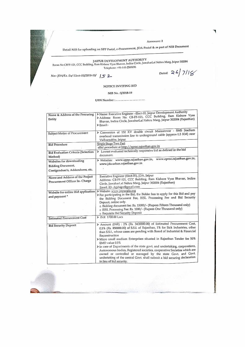
BID ENQUIRY NO. : JDA/EE/Elect-III/2018-19/05
393
JAIPUR DEVELOPMENT AUTHORITY, JAIPUR BID ENQUIRY NO. : JDA/EE/Elect-III/2018-19/05 BIDDING DOCUMENTS FOR DESIGN, MANUFACTURE, TESTING AT WORKS AND SUPPLY OF 132 KV SINGLE CORE XLPE CABLE FOR ESTABLISHING OF 132 KV DOUBLE CIRCUIT (1200 SQ. MM) BETWEEN SMS STADIUM GSS TO 132 KV TOWER AT NBCC BUILDING SAHAKAR MARG BY CONVERTING EXISTING 132 KV DOUBLE CIRCUIT OVERHEAD TRANSMISSION LINE INCLUDING INFRONT OF VIDHAN SABHA (JAIPUR) (APPROX. 1.5 KM) INCLUDING DETAILED ROUTE SURVEY, LAYING AND INSTALLATION OF CABLE ALONGWITH ASSOCIATED ACCESSORIES/ ITEMS AND CIVIL WORKS, AND CONTRUCTION OF 1 NOS. 220 KV TYPE C TOWER NARROW BASE (250 MTR SPAN) ALONGWITH DISMANTLING OF EXTING 132 KV TOWERS
-
Upload
khangminh22 -
Category
Documents
-
view
1 -
download
0
Transcript of BID ENQUIRY NO. : JDA/EE/Elect-III/2018-19/05

JAIPUR DEVELOPMENT AUTHORITY, JAIPUR
BID ENQUIRY NO. : JDA/EE/Elect-III/2018-19/05
BIDDING DOCUMENTS FOR
DESIGN, MANUFACTURE, TESTING AT WORKS AND SUPPLY OF
132 KV SINGLE CORE XLPE CABLE FOR ESTABLISHING OF 132
KV DOUBLE CIRCUIT (1200 SQ. MM) BETWEEN SMS STADIUM
GSS TO 132 KV TOWER AT NBCC BUILDING SAHAKAR MARG BY
CONVERTING EXISTING 132 KV DOUBLE CIRCUIT OVERHEAD
TRANSMISSION LINE INCLUDING INFRONT OF VIDHAN SABHA
(JAIPUR) (APPROX. 1.5 KM) INCLUDING DETAILED ROUTE
SURVEY, LAYING AND INSTALLATION OF CABLE ALONGWITH
ASSOCIATED ACCESSORIES/ ITEMS AND CIVIL WORKS, AND
CONTRUCTION OF 1 NOS. 220 KV TYPE C TOWER NARROW BASE
(250 MTR SPAN) ALONGWITH DISMANTLING OF EXTING 132 KV
TOWERS
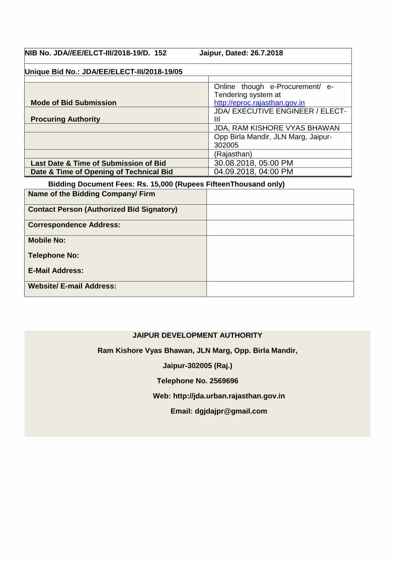
NIB No. JDA//EE/ELCT-III/2018-19/D. 152 Jaipur, Dated: 26.7.2018
Unique Bid No.: JDA/EE/ELECT-III/2018-19/05
Mode of Bid Submission
Online though e-Procurement/ e-Tendering system at http://eproc.rajasthan.gov.in
Procuring Authority JDA/ EXECUTIVE ENGINEER / ELECT-III
JDA, RAM KISHORE VYAS BHAWAN
Opp Birla Mandir, JLN Marg, Jaipur-302005
(Rajasthan) Last Date & Time of Submission of Bid 30.08.2018, 05:00 PM Date & Time of Opening of Technical Bid 04.09.2018, 04:00 PM
Bidding Document Fees: Rs. 15,000 (Rupees FifteenThousand only)
Name of the Bidding Company/ Firm
Contact Person (Authorized Bid Signatory)
Correspondence Address:
Mobile No:
Telephone No:
E-Mail Address:
Website/ E-mail Address:
JAIPUR DEVELOPMENT AUTHORITY
Ram Kishore Vyas Bhawan, JLN Marg, Opp. Birla Mandir,
Jaipur-302005 (Raj.)
Telephone No. 2569696
Web: http://jda.urban.rajasthan.gov.in
Email: [email protected]

ABBREVIATIONS
XLPE Cross-linked polyethylene
AC Alternate Current
ACSR Aluminum Conductor Steel Reinforced
Amps. Amperes
AMR Automaic Meter Reading
Auto Automatic
BCU Bay Control Unit
BDS Bid Data Sheet
BG Bank Gaurantee
BOM Bill of Material
BOQ Bill of Quantity
BPU Bay Protection Unit
CB Circuit Breaker
CE Chief Engineer
CERC Central Electricity Regulatory Commission
CIF Cost including Insurance & Freight
CIP Carriage Insurance Paid
cm. Centimetre
CMD Chairman & Managing Director
CST Central Sales Tax
CT Current Transfromer
CTD Capacitor Tripping Device
Cu. m Cubic meter
dB Decibel
DC Direct Current
Deg. C Degrees Centigrade
dm. Decimetre
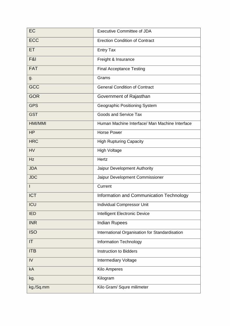
EC Executive Committee of JDA
ECC Erection Condition of Contract
ET Entry Tax
F&I Freight & Insurance
FAT Final Acceptance Testing
g. Grams
GCC General Condition of Contract
GOR Government of Rajasthan
GPS Geographic Positioning System
GST Goods and Service Tax
HMI/MMI Human Machine Interface/ Man Machine Interface
HP Horse Power
HRC High Rupturing Capacity
HV High Voltage
Hz Hertz
JDA Jaipur Development Authority
JDC Jaipur Development Commissioner
I Current
ICT Information and Communication Technology
ICU Individual Compressor Unit
IED Intelligent Electronic Device
INR Indian Rupees
ISO International Organisation for Standardisation
IT Information Technology
ITB Instruction to Bidders
IV Intermediary Voltage
kA Kilo Amperes
kg. Kilogram
kg./Sq.mm Kilo Gram/ Squre milimeter

km. Kilometre
kV Kilo Volt
kVA Kilo Volt Ampere
kVp. Kilo volts peak
kVrms. Kilo volts root mean square
kW Kilo watt
LA/SA Lightning Arrester/ Surge Arrester
LD Liquidated Damages
LOI Letter of Intent
LOI Letter of Intent
LTOA Long Term Open Access
LV Low Voltage
Max. Maximum
Min. Minimum
MIS Management Information System
mm. Millimetre
MS Flat Mild Steel Flat
MTOA Medium Term Open Access
MVA Mega Volt Ampere
MW Mega Watt
NC Normally Close
NCT Neutral Current Transformer
NIB Notice Inviting Bid
Nigam Rajasthan Rajya Vidyut Prasaran Nigam Ltd.
NO Normally Open
OA Open Access
OLTC On Load Tap Changer
ONAF Oil Natural Air Forced
ONAN Oil Natural Air Natural

OTI Oil Temperature Indicator
p.f Power Factor
P.U. Per Unit
PBG Performance Bank Guarantee
PP&D Project Planning and Design
PQ Pre-Qualification
PVC Poly Vinyal Chloride
QAP Quality Assurance Plan
RERC Rajasthan Electricity Regulatory Commission
RISL RajCOMP Info Services Limited
RTPP Rajasthan Transparency in Public Procurement
RVPN/RVPNL Rajasthan Rajya Vidyut Prasaran Nigam Limited
SAS Substation Automation System
SCADA Supervisory Control and Data Acquisition
SCC Special Condition of Contract
Sec. Seconds
SF6 Sulphur Hexa Flouride
SLDC State Load Despatch Center
SPPP State Procurement Portal
sq.mm Al. Cable Square millimeter Aluminium cable
sq.mm Cu. Cable Square millimeter Copper cable
STOA Short Term Open Access
STOMS Smart Transmission Operation Management System
TIN Tax Identification Number
TRV Transient Recovery Voltage
UAT User Acceptance Testing
UI Unit Inter-change
UTS Ultimate Tensile Strength
V Volts

GST Value Added Taxes
WTI Winding Temperature Indicator


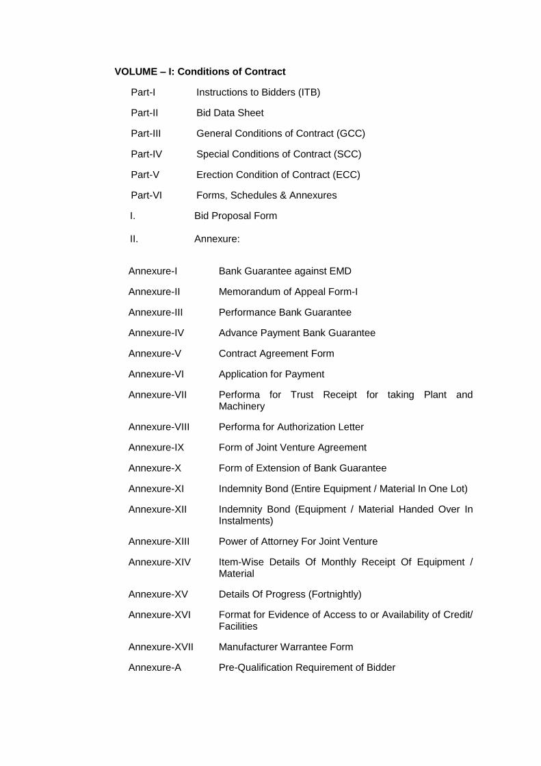
VOLUME – I: Conditions of Contract
Part-I Instructions to Bidders (ITB)
Part-II Bid Data Sheet
Part-III General Conditions of Contract (GCC)
Part-IV Special Conditions of Contract (SCC)
Part-V Erection Condition of Contract (ECC)
Part-VI Forms, Schedules & Annexures
I. Bid Proposal Form
II. Annexure:
Annexure-I Bank Guarantee against EMD
Annexure-II Memorandum of Appeal Form-I
Annexure-III Performance Bank Guarantee
Annexure-IV Advance Payment Bank Guarantee
Annexure-V Contract Agreement Form
Annexure-VI Application for Payment
Annexure-VII Performa for Trust Receipt for taking Plant and Machinery
Annexure-VIII Performa for Authorization Letter
Annexure-IX Form of Joint Venture Agreement
Annexure-X Form of Extension of Bank Guarantee
Annexure-XI Indemnity Bond (Entire Equipment / Material In One Lot)
Annexure-XII Indemnity Bond (Equipment / Material Handed Over In Instalments)
Annexure-XIII Power of Attorney For Joint Venture
Annexure-XIV Item-Wise Details Of Monthly Receipt Of Equipment / Material
Annexure-XV Details Of Progress (Fortnightly)
Annexure-XVI Format for Evidence of Access to or Availability of Credit/ Facilities
Annexure-XVII Manufacturer Warrantee Form
Annexure-A Pre-Qualification Requirement of Bidder
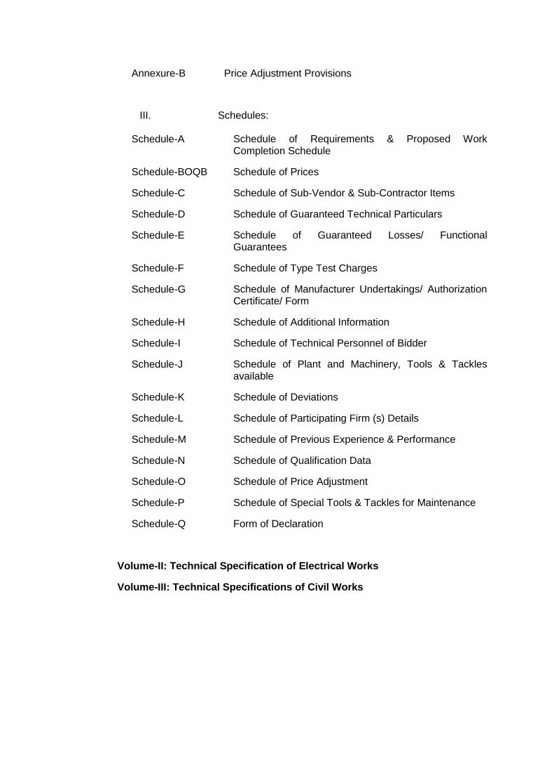
Annexure-B Price Adjustment Provisions
III. Schedules:
Schedule-A Schedule of Requirements & Proposed Work Completion Schedule
Schedule-BOQB Schedule of Prices
Schedule-C Schedule of Sub-Vendor & Sub-Contractor Items
Schedule-D Schedule of Guaranteed Technical Particulars
Schedule-E Schedule of Guaranteed Losses/ Functional Guarantees
Schedule-F Schedule of Type Test Charges
Schedule-G Schedule of Manufacturer Undertakings/ Authorization Certificate/ Form
Schedule-H Schedule of Additional Information
Schedule-I Schedule of Technical Personnel of Bidder
Schedule-J Schedule of Plant and Machinery, Tools & Tackles available
Schedule-K Schedule of Deviations
Schedule-L Schedule of Participating Firm (s) Details
Schedule-M Schedule of Previous Experience & Performance
Schedule-N Schedule of Qualification Data
Schedule-O Schedule of Price Adjustment
Schedule-P Schedule of Special Tools & Tackles for Maintenance
Schedule-Q Form of Declaration
Volume-II: Technical Specification of Electrical Works
Volume-III: Technical Specifications of Civil Works
VOLUME-I PART-I
INSTRUCTION TO BIDDERS
Preamble
This Part (Part-I) of the Bidding Documents provides the information necessary for bidders to prepare responsive bids, in accordance with the requirements of the JDA/Nigam. It also provides information on bid submission, opening and evaluation, and on contract award. This Part (Part-I) contains provisions that are to be used unchanged unless Part-II, which consists of provisions that supplement, amend, or specify in detail, information or requirements included in Part-I and that are specific to each procurement, and/or otherwise. If there is a conflict between the provisions of Part-I & Part-II, the provisions of Part-II shall prevail.
However, provisions governing the performance of the Contractor, payments under the contract or matters affecting the risks, rights and obligations of the parties under the contract are not included in this part but instead under Part – III: General Conditions of Contract, Part-V: Erection Condition of Contract and/or Part – IV: Special Conditions of Contract.
Further in all matters arising out of the provisions of this Part – I and the Part – II of the Bidding Documents, the laws of the Union of India shall be the governing laws and courts of Jaipur shall have exclusive jurisdiction.
A. Introduction
1.0 Source of Funds
1.1 The Owner named in the BDS intends to use domestic funding (Owner’s Internal Resources/Domestic Borrowings/Bonds) for this Project.
All eligible payments under the contract for the packages, for which this Invitation for Bids is issued, shall be made by the JDA named in the BDS.
2.0 Eligible Bidders
2.1 The eligibility criteria is given in Annexure A.
3.0 Eligible Plant, Equipment, and Services
3.1 For the purposes of these Bidding Documents, the words “facilities,” “plant andequipment,” “installation services,” etc., shall be construed in accordance withthe respective definitions given to them in the General Conditions of Contract.
3.2 All plant and equipment to be supplied and installed and services carried outunder the contract shall have their origin in any country barring those countriesagainst whom sanction for conducting business is imposed by Government ofIndia and barring those firms with whom business is banned by the JDA/Nigam.
3.3 For purposes of this clause, “origin” means the place where the plant andequipment or component parts thereof are mined, grown, or produced. Plantand equipment are produced when, through manufacturing, processing orsubstantial and major assembling of components, a commercially recognizedproduct results that is substantially different in basic characteristics or inpurpose or utility from its components.
3.4 The origin of the plant, equipment, and services is distinct from the nationalityof the Bidder.
3.5 Plants and Equipments shall be standard items/ equipmenst of the manufacturer (s), which are produced in volume and used by large number of users in India/ abroad. The item/ equipments must be associated with specific make, model numbers/ item code with printed literature describing configuration and functionality.
4. Cost of Bidding
4.1 The Bidder shall bear all costs associated with the preparation and submission of its bid including post-bid discussions, technical and other presentations etc., and the JDA will in no case be responsible or liable for these costs, regardless of the conduct or outcome of the bidding process.
B. The Bidding Documents
5. Contents of Bidding Document
5.1 The facilities required, bidding procedures, contract terms and technical requirements are prescribed in the Bidding Documents. The Bidding Documents comprise of the following and shall include amendments, if any, thereto:
Notice Inviting Bid
5.2 The Bidder is expected to examine all instructions, forms, terms, specifications and other information in the Bidding Documents. Failure to furnish all information required by the Bidding Documents or submission of a bid not substantially responsive to the Bidding Documents in every respect will be at the Bidder’s risk and may result in rejection of its bid.

5.3 Scope of Work is given in Volume-II & III of Bidding Documents titled “Technical Specifications for Electrical Works” & “Technical Specification for Civil Works”
6. Clarification of Bidding Documents; and Pre-Bid Meeting
6.1 A prospective Bidder requiring any clarification of the Bidding Documents may notify the JDA in writing or by cable (hereinafter, the term cable is deemed to include Electronic Data Interchange (EDI) or telefax) at the JDA’s mailing address indicated in the BDS. Similarly, if a Bidder feels that any important provision in the documents, such as those listed in ITB Sub-Clause 22.4.1, will be unacceptable, such an issue should be raised as above. The JDA will respond in writing to any request for clarification or modification of the Bidding Documents that it receives not later than twenty (20) days prior to the original deadline for submission of bids prescribed by the JDA. The JDA shall not be obliged to respond to any request for clarification received later than the above period. Further, the mere request for clarification from the Bidders shall not be a ground for seeking extension in the deadline for submission of bids. Written copies of the JDA’s response (including an explanation of the query but without identifying the source of inquiry) will be sent to all prospective bidders that have received the Bidding Documents.
6.2 The Bidder is advised to visit and examine the site where the facilities are to be installed and its surroundings and obtain for itself on its own responsibility and cost all information that may be necessary for preparing the bid and entering into a contract for supply and installation of the facilities. The costs of visiting the site shall be at the Bidder’s own expense.
6.3 The Bidder and any of its personnel or agents will be granted permission by the JDA/ Nigam to enter upon its premises and lands for the purpose of such inspection, but only upon the express condition that the Bidder, its personnel and agents will release and indemnify the JDA/ Nigam and its personnel and agents from and against all liability in respect thereof and will be responsible for death or personal injury, loss of or damage to property and any other loss, damage, costs and expenses incurred as a result of the inspection.
6.4 The Bidder’s designated representative(s) is/are invited to attend a pre-bid meeting, which, if convened, will take place at the venue and time stipulated in the BDS. The purpose of the meeting will be to clarify any issues regarding the Bidding Documents in general and the Technical Specifications in particular. The Bidder is requested, as far as possible, to submit any question in writing, to reach the JDA not later than one week before the meeting. It may not be practicable at the meeting to answer questions received late, but questions and responses will be transmitted as indicated hereafter. Minutes of the meeting, including the text of the questions raised (without identifying name of the bidders) and the responses given, together with any responses prepared after the meeting, will be transmitted without delay to all purchasers of the Bidding Documents. Any modification of the Bidding Documents listed in ITB Sub-Clause 5.1, which may become necessary as a result of the pre-bid meeting shall be made by the JDA exclusively through the issue of an Addendum pursuant to ITB Clause 7 and not through the minutes of the pre-bid meeting.
Non-attendance at the pre-bid meeting will not be a cause for disqualification of a bidder.
7. Amendment of Bidding Documents

7.1 At any time prior to the deadline for submission of bids, the JDA may, for any reason, whether at its own initiative, or in response to a clarification requested by a prospective Bidder, amend the Bidding Documents.
7.2 The amendment will be notified on the websites for viewing/ downloading by all prospective bidders and will be binding on them. Bidders are required to check/ updated themselves for any amendments on specified websites and it will be assumed that the information contained therein will have been taken into account by the Bidder in its bid.
7.3 In order to afford reasonable time to the prospective Bidders to take the amendment into account in preparing their bid, the JDA may, at its discretion, extend the deadline for the submission of bids, in such cases; the JDA will notify all bidders through website notification of the extended deadline.
C. Preparation of Bids
8. Language of Bid
8.1 The bid prepared by the Bidder and all correspondence and documents exchanged by the Bidder and the JDA related to the bid shall be written in the English language, provided that any printed literature furnished by the Bidder may be written in another language, as long as such literature is accompanied by English translation of its pertinent passages, in which case, for purposes of interpretation of the bid, the English translation shall govern.
9. Documents Comprising the Bid
9.1 The bid submitted by the Bidder shall comprise of the following documents:
(a) Bid Proposal Form duly completed and signed by the Bidder, together with all Attachments (available in Part-VI). All Attachments have been identified in ITB Sub-Clause 9.3 below.
(b) Price Schedules (available in Part-VI) duly completed by the Bidder.
(c) Technical Data Sheets (available in Part-VI), if any, duly completed by the Bidder.
9.2 Bidders shall note that, they shall quote their proposals strictly conforming to the technical details, design as specified in the bidding document. Any offer based on the alternate design shall not be considered. Bid with alternative time schedule is not acceptable.
9.3 Each Bidder shall submit with its bid the following attachments:
(a) Attachment 1: Bid Security (Earnest Money Deposit)
An earnest money deposit furnished in accordance with ITB Clause 13.
(b) Attachment 2: Power of Attorney
A power of attorney, duly notarized, indicating that the person(s) signing the bid has (ve) the authority to sign the bid and thus that the bid is binding upon the Bidder during full period of its validity, in accordance with ITB Clause 14.
(C) Attachment 3: Bidder’s Eligibility and Qualifications

In the absence of pre-qualification, documentary evidence establishing that the Bidder is eligible to bid in accordance with ITB Clause 2 and is qualified to perform the contract in accordance with Annexure– A, if its bid is accepted.
The documentary evidence of the Bidder’s eligibility to bid shall establish to the JDA’s satisfaction that the Bidder, at the time of submission of its bid, is eligible as defined in ITB Clause 2.
The documentary evidence of the Bidder’s qualifications to perform the contract, if its bid is accepted, shall establish to the JDA’s satisfaction that the Bidder has the financial, technical, production, procurement, shipping, installation and other capabilities necessary to perform the contract, and, in particular, meets the experience and other criteria outlined in the Qualification Requirement for the Bidders in Annexure– A.
As per Annexure– A, the bid can be submitted by an individual firm or a joint venture of not more than two firms.Bids submitted by a joint venture of not more than two firms as partners shall comply with the following requirements:
i. The bid shall include all the information required for Attachment 3 as described above for each joint venture partner.
ii. The bid shall be signed so as to be legally binding on all partners.
iii. One of the partners responsible for performing a key component of the contract shall be designated as leader; this authorization shall be evidenced by submitting with the bid a power of attorney signed by legally authorized signatories as per Annexure-XIII, Part-VI Vol-I.
iv. The leader shall be authorized to incur liabilities and receive instructions for and on behalf of any and all partners of the joint venture, and the entire execution of the contract, including payment, shall be done exclusively with the leader, provided otherwise requested by the joint venture and agreed between the JDA and the leader.
v. All partners of the joint venture shall be liable jointly and severally for the execution of the contract in accordance with the contract terms.
vi. A copy of the agreement entered into by the joint venture partners shall be submitted with the bid as per Annexure-IX, Part-VI Vol-I, including interalia delineation of responsibilities and obligations of each partners appended thereto, notwithstanding the joint and several liability.
vii. The joint venture agreement should indicate precisely the responsibility of all members of JV in respect of planning, design, manufacturing, supply, installation, commissioning and testing. All members of JV should have active participation in execution during the currency of the contract. This should not be varied/modified subsequently without prior approval of the JDA; and
In order for a joint venture to qualify, each of its partners or combination of partners must meet the minimum criteria listed in the Qualification Requirement for the Bidder in enclosed Annexure-A for an individual
Bidder for the component of the contract they are designated to perform. Failure to comply with this requirement will result in rejection of the joint venture bid.
A firm can be a partner in only one joint venture; bids submitted by joint ventures including the same firm as partner will be rejected.
In the case of a Bidder who offers to supply and/or install plant and equipment under the contract that the Bidder did not manufacture or otherwise produce and/or install, the Bidder shall (i) have the financial and other capabilities necessary to perform the contract; (ii) have been duly authorized by the manufacturer or producer of the related plant and equipment or component as per Performa in Attachment 7to supply and/or install that item in the JDA’s country; and (iii) be responsible for ensuring that the manufacturer or producer complies with the requirements of ITB Sub-Clause 3.2 and meets the minimum criteria listed for an individual Bidder for that item.
(d) Attachment 4: Eligibility and Conformity of the Facilities
Documentary evidence established in accordance with ITB Clause 3 that the facilities offered by the Bidder in its bid or in any alternative bid (if permitted pursuant to ITB Sub-Clause 9.2) are eligible and conform to the Bidding Documents.
The documentary evidence of the eligibility of the facilities shall consist of a statement showing/ indicating the country of origin of the plant and equipment offered, which shall be confirmed by a certificate of origin issued at the time of shipment.
The documentary evidence of the conformity of the facilities to the Bidding Documents may be in the form of literature, drawings and data, and shall furnish:
i. a detailed description of the essential technical and performance characteristics of the facilities;
ii. a list giving full particulars, including available sources, of all spare parts, special tools, etc., necessary for the proper and continuing functioning of the facilities for a period of Fifteen (15) years following completion of facilities in accordance with provisions of contract; and
iii. a commentary on the JDA’s Technical Specifications and adequate evidence demonstrating the substantial responsiveness of the facilities to those specifications. Bidders shall note that standards for workmanship, materials and equipment designated by the JDA in the Bidding Documents are intended to be descriptive (establishing standards of quality and performance) only and not restrictive. The Bidder may substitute alternative standards, brand names and/or catalog numbers in its bid, provided that it demonstrates to the JDA/ Nigam’s satisfaction that the substitutions are substantially equivalent or superior to the standards designated in the Technical Specifications.
iv. All details regarding after sale & service support offered.
v. All details regarding proposed training for JDA/ Nigam’s personnel.
vi. Detailed answers to all the Questions in the Questionnaire, if prescribed in the Bidding Document.
vii. Details establishing the responsiveness of the offer in accordance with Technical Specification, Volume-II & III.
(e) Attachment 5: Subcontractors/ Sub-Vendors Proposed by the Bidder
The Bidder shall include in its bid details of all major items of supply or services that it proposes to purchase or sublet, and shall give details of the name and nationality of the proposed Subcontractor, including vendors, for each of those items. Bidders are free to list more than one Subcontractor against each item of the facilities. Quoted rates and prices will be deemed to apply to whichever Subcontractor is appointed, and no adjustment of the rates and prices will be permitted.
The Bidder shall be responsible for ensuring that any Subcontractor proposed complies with the requirements of ITB Clause 2, and that any plant, equipment or services to be provided by the Subcontractor comply with the requirements of ITB Clause 3 and Qualification Requirement for subcontractors or Sub-vendors given in the specifications.
The JDA reserves the right to delete any proposed Subcontractor from the list prior to award of contract, and after discussion between the JDA and the Contractor, the corresponding enclosure to the form of Contract Agreement shall be completed, listing the approved Subcontractors for each item concerned.
(f) Attachment 6: Deviations
In order to facilitate evaluation of bids, deviations, if any, from the terms and conditions or Technical Specifications shall be listed in Attachment 6 to the bid. However, the attention of the bidders is drawn to the provisions of ITB Sub-Clause 22.4 regarding the rejection of bids that are not substantially responsive to the requirements of the Bidding Documents.
Bidder’s attention is also drawn to the provisions of ITB Sub-Clause 22.4.1.
(g) Attachment 7: Manufacturer’s Undertakings/ Authorization Certificate/ Form
(h) Attachment 8: Schedule of Requirements & Proposed Work Completion Schedule.
(i) Attachment 9: Guarantee Declaration.
(j) Attachment 10: Price Adjustment Data
(k) Attachment 11: The bidder, if is a Micro, Small or Medium enterprise as per the Micro, Small and Medium enterprise development act, 2006 (MSMED Act 2006) and registered with the authorities under the above Act for the items / services covered under this tender, then the firm has to indicate the Entrepreneurs Memorandum No. (Twelve Digit) and scanned copy of the certificate issued by the Authorities under the MSMED Act, 2006 should be furnished with the bid.
10. Bid Form and Price Schedules

10.1 The Bidder shall complete the Bid Form and the appropriate Price Schedules furnished in the Bidding Documents as indicated therein, following the requirements of ITB Clauses 11 and 12.
11.0 Bid Price
11.1 Unless otherwise specified in the Technical Specifications, bidders shall quote for the entire facilities on a “single responsibility” basis such that the total bid price covers all the Contractor’s obligations mentioned in or to be reasonably inferred from the Bidding Documents in respect of the design, manufacture, including procurement and subcontracting (if any), delivery, construction, installation and completion of the facilities including supply of mandatory spares (if any). This includes all requirements under the Contractor’s responsibilities for testing, pre-commissioning and commissioning of the facilities and, where so required by the Bidding Documents, the acquisition of all permits, approvals and licenses, etc.; the operation, maintenance and training services and such other items and services as may be specified in the Bidding Documents, all in accordance with the requirements of the General Conditions of Contract. Items against which no price is entered by the Bidder will not be paid for by the JDA when executed and shall be deemed to be covered by the prices for other items.
11.2 Bidders are required to quote the price for the commercial, contractual and technical obligations outlined in the Bidding Documents. If a Bidder wishes to make a deviation, such deviation shall be listed in Attachment-6 of its bid.
11.3 The Bidder shall indicate on the appropriate Price Schedules attached to these documents, the unit prices and total Bid Prices of the goods and services including spares & special tools and tackles, if any, it proposes to provide under the Contract.
The Price Schedule shall contain the following :
SUPPLY part : Substation/ Line Equipments/ Items & Mandatory Spares, Testing/ Measuring Equipments and Tools & Tackles & Type Test Charges (if Indicated)[Including of Local Transportation including of Port handling, port clearance, port charges (if applicable), Insurance and Other incidental services applicable with all taxes and duties]
SERVICES : Installation Services including Erection Works, insurance covers other than inland transit insurance, Miscellaneous services such as Maintenance, Training & Handholding and other Services as specified in the bidding document.
Bidders shall note that the plant and equipment included in Price Schedule (Supply part) above exclude materials used for civil, building and other construction works. All such materials shall be included and priced under Price Schedule (Services Part).
11.3.1 The bid price for,
(i) the items for which quantities have been indicated as lumpsum or lot or set and/or
(ii) where the quantities are to be estimated by the Bidder shall remain constant unless there is change made in the Scope of Work by JDA.
The quantities and unit prices

(i) subsequently arrived while approving the Bill of Quantities (BOQ) /Billing breakup of lumpsum quantities/lot/Set and/or
(ii) estimated by the bidder shall be for on account payment purpose only.
In case additional quantities, over and above the quantities BOQ/billing breakup and /or estimated by the bidder, are required for successful completion of the scope of work as per Technical Specification, the Bidder shall execute additional quantities of these items for which no additional payment shall be made over and above the lumpsum bid price. In case quantities of these items supplied at site are in excess of that required for successful completion of scope of work, such additional quantities shall be the property of the bidders and they shall be allowed to take back the same from the site for which no deduction from the lumpsum bid price shall be made. Further, in case actual requirement of quantities for successful completion of scope of work is less than the quantities identified in the approved BOQ /billing break-up and/or estimated by the bidder, the lumpsum bid price shall remain unchanged and no deduction shall be made from the lumpsum price due to such reduction of quantities.
11.3.2 It shall be the responsibility of the bidders to pay all statutory taxes, duties and levies to the concerned authorities for such surplus material, which would otherwise have been, lawfully payable. The bidders shall submit an indemnity bond to keep JDA harmless from any liability, before release of such material to the bidder by JDA.
11.3.3 Set/Lot/Lumpsum shall be governed as per the requirement of the corresponding item description read in conjunction with relevant provisions of Technical Specifications.
11.4 In the schedules, Bidder shall give the required details and a breakdown of their price as follows:
(a) Plant and equipment including mandatory spares manufactured or fabricated, shall be quoted on an EXW (ex-factory, ex-works, ex-warehouse or off-the-self, as applicable) basis and Type Test Charges (if indicated), shall also be quoted in Schedule-BOQ.
In respect of direct transaction between the JDA and the Contractor,
EXW price shall be inclusive of all cost as well as duties and taxes (viz., customs duties & levies, duties, sales tax/GST etc.) paid or payable on components, raw materials and any other items used for their consumption incorporated or to be incorporated in the Plant & Equipment.
Sales tax/GST, excise duty, local tax and other levies for equipment/items under direct transaction including entry tax as applicable for destination site/state shall not be included in the EXW price but shall be indicated wherever applicable in respective column of Price Schedule.
Whenever EXW price is quoted exclusive of excise duty and/or GST, then the due credit under the GSTscheme as per the relevant Government policies wherever applicable shall be taken into account by the Bidder while quoting bid price.
In respect of bought-out finished items, which shall be dispatched directly from the sub-vendor’s works to the JDA’s site (sale-in-transit),
EXW price shall be inclusive of all cost as well as duties and tax (viz. Custom duties & levies, Excise duties, sales tax/GST etc.) paid or payable. While quoting the EXW price, inclusive of excise duty and/or GST, the due credit under the GST scheme as per the relevant Government policies wherever applicable shall be taken into account by the Bidder.
Further, Bidders offering (i) imported Equipments/items as ‘Off the Shelf’ or dispatched directly from the Indian Port of disembarkation and/or (ii) bought-out finished Equipments/items as ‘Off the Self’ items or dispatched directly from the Bidder’s works, the price of such Equipments/items shall be inclusive of all cost as well as duties and tax (viz., customs duties & levies, Excise duties, sales tax/GST etc.) paid or payable.
However, entry tax as applicable for destination site/state shall not be included in the EXW price but shall be indicated separately in respective column of Schedule BOQ (Supply).
Requisite Sales Tax Declaration forms for all the equipments/items to be supplied from within India shall be furnished by the JDA.
(b) Local transportation, insurance and other Services incidental to delivery of the Plant and Equipment including mandatory spares to be supplied shall be quoted separately in Schedule-BOQ: Supply.
(c) Installation Charges shall be quoted separately (Schedule-BOQB2: Services) and shall include rates and prices for all labour, Contractor's equipment, temporary works, materials, consumables and all matters and things of whatsoever nature, provision of operations and maintenance manuals, etc. wherever identified in the Bidding Documents as necessary for the proper execution of all installation services except those priced in other Schedules.
(d) The break-up of Training & Handholding and Maintenance Charges shall be furnished separately in Schedule-BOQB2. Similarly, the break-up of Type test charges (if specified), shall also be furnished separately in Schedule-F/ BOQ (as specified).
(e) The bidder shall include the Sales Tax/GST on Works Contract, Turnover Tax or any other similar taxes under the Sales Tax/GST Act for supply and services to be performed, as applicable in their quoted bid price and JDA would not bear any liability on this account. JDA on behalf of Owner shall, however, deduct such taxes at source for supply and services and issue Tax Deducted at Source (TDS) Certificate to the bidder.
(f) The Bidder shall quote the prices inclusive of applicable Service Tax and surcharge/ cess etc. Any statutory variation in the service tax will be to contractor’s accounts. The bidder shall give Service Tax registration number. Depositing the Service Tax with appropriate authority within stipulated period shall be the bidder’s liability.
(g) The Income Tax, surcharge on income tax and other corporate taxes the bidder shall be responsible for such payment to the concerned authorities. JDA shall deduct tax at source, required as per statutory provisions and issue necessary Certificate to the Contractor.

11.4.1 Discount(s)/rebate(s) offered by the bidder shall be indicated as a percentage of price component(s). Bidder shall also indicate in his bid, the price component(s) on which the discount is to be applied.
11.5 The prices shall be in accordance with the following:
Adjustable Price: Prices quoted by the Bidder shall be subject to adjustment during performance of the contract to reflect changes in the cost elements such as labor, material, etc. in accordance with the procedures specified in the bid document and incorporated in the contract. The price adjustment provision will not be taken into consideration in bid evaluation.
12. Bid Currencies
12.1 Prices shall be quoted in Indian Rupees Only.
13. Bid Security (Earnest Money)
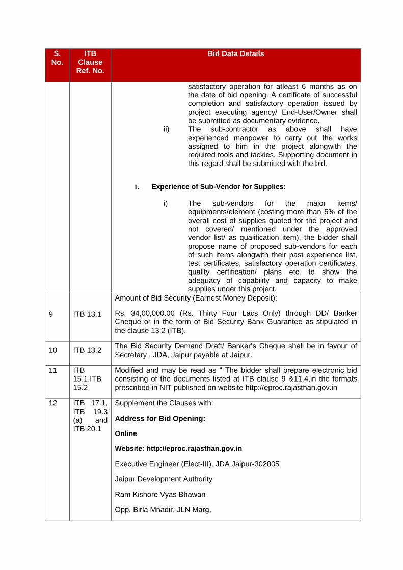
13.1 The Bidder shall furnish, as part of its bid, a bid security in the amount and currency as stipulated in the BDS. The bid security must be submitted in the form provided in the Bidding Documents.
13.2 The bid security shall, at the bidder’s option,
100% in the form of crossed bank Demand draft/Banker's cheque from a scheduled commercial bank in favour of JDA or a bank guarantee from a scheduled commercial bank selected by the bidder and located in India as stipulated in the BDS.
The format of the bank guarantee shall be in accordance with the form of bidsecurity included in the Bidding Documents. Bid security shall remain valid fora period of 120 days beyond the original bid validity period, and beyondany extension subsequently requested under ITB Sub-Clause 14.2.
13.3 Any bid not accompanied by an acceptable bid security shall be rejected by the JDA and shall be returned unopened
13.4 The bid securities of unsuccessful bidders will be returned after the signing of contact agreement with the successful bidder.
13.5 The successful Bidder shall be required to keep its bid security valid for asufficient period till the performance security(ies) pursuant to ITB Clause 32 are furnished to the satisfaction of the JDA.The bid security of the successful Bidder will be returned when the Bidder hassigned the Contract Agreement, pursuant to ITB Clause 31, and has furnishedthe required performance security pursuant to ITBClause 32
13.6 The bid security may be forfeited
(a) If the Bidder withdraws its bid after submission and up to the period of bid validity specified by the Bidder in the Bid Proposal Form; or
(b) If a Bidder does not accept the corrections to arithmetical errors identifiedduring preliminary evaluation of his bid pursuant to ITB Sub-Clause 22.2;or
(c) If, as per the requirement of Qualification Requirements the Bidder isrequired to submit a Deed of Joint Undertaking and he fails to submit thesame, duly attested by Notary Public of the place(s) of the respectiveexecutants (s), within ten days from the date of intimation of post – biddiscussion; or

(d) in the case of a successful Bidder, if the Bidder fails within the specifiedtime limit
(i) to sign the Contract Agreement, in accordance with ITB Clause 31,or
(ii) to furnish the required performance security(ies), in accordancewith ITB Clause 32.
13.7 No interest shall be payable by the JDA on the above Bid Securities.
14. Period of Validity of Bid
14.1 Bids shall remain valid for a period of 180 days after the date of opening of techno-commercial bids prescribed by the JDA, pursuant to ITB Sub-Clause 17.1. A bid valid for a shorter period shall be rejected by the JDA as being non-responsive.
14.2 In exceptional circumstance, the JDA may solicit the Bidder’s consent to an extension of the bid validity period. The request and responses thereto shall be made in writing or by cable. If a Bidder accepts to prolong the period of validity, the bid security shall also be suitably extended. A Bidder granting the request will not be required or permitted to modify its bid.
15. Format and Signing of Bid
15.1 The Bidder shall prepare bid in the digital/electronicmodefor uploading on e-procurement website in the format/ type of file specified.All the documents uploaded should be digitally signed with the DSC of authorized signatory.
15.2 The bid, consisting of the documents listed in ITB Clause 9, shall be typed or written in legible ink and shall be signed/ digitally signed by the Bidder or a person (s) duly authorized to bind the Bidder to the contract. The letter of authorization shall be indicated by written power of attorney accompanying the bid and submitted as Attachment 2 to the Bid under ITB Sub-Clause 9.3. All pages of the bid, except for un-amended printed literature, shall be initialled/ digitally signed by the person signing the bid.
15.3 The bid shall contain no alterations, omissions or additions, unless such corrections are initialled/ digitally signed by the person(s) signing the bid.
D. Submission of Bids
16. Sealing and Marking of Bids
16.1 Bidders must submit their bids online at e-Procurement portal i.e. http://eproc.rajasthan.gov.in.
16.2 Documents in e-formats (as specified) shall be received online on the Government of Rajasthan e-procurement portal (http://eproc.rajasthan.gov.in) in following three Envelopes:
First Envelope: Bid Security (Earnest Money Deposit) Documents, Tender Document Cost and Tender Processing fees.
Second Envelope: Techno-Commercial Bid Documents
Third Envelope: Financial/ Price Bid Documents
The above documents shall be in the e-format (as per type i.e. pdf, xls etc. as specified) and required to be uploaded on and before the prescribed tender submission date and time.
16.3 First Envelope documents i.e. Bid Security (Earnest Money Deposit Documents), Tender Document Cost and Tender Processing fees in original shall be sealed in separate envelope. The same shall be submitted/ delivered be addressed to the JDA at the address given in the BDS, and bear the contract name indicated in the BDS, the Invitation for Bids title and number indicated in the BDS, and the statement “Do Not Open Before [date],” to be completed with the time and date specified in the BDS, pursuant to ITB Sub-Clause 20.1.
16.4 If the first envelope is not sealed and marked as required by ITB Sub-Clause 16.3 above, the JDA will assume no responsibility for the bid’s misplacement or premature opening. If the first envelope discloses the Bidder’s identity, the JDA will not guarantee the anonymity of the bid submission, but this disclosure will not constitute grounds for bid rejection.
17. Deadline for Submission of Bids
17.1 Bids shall be received online at e-Procurement portal and up to the time and date specified in the NIB. In the event of the specified date for the submission of bid [first envelope (consisting of original documents)] being declared a holiday for the JDA, the same will be received up-to the appointed time on the next working day.
17.2 The JDA may, at its discretion, extend this deadline for submission of bids by amending the Bidding Documents in accordance with ITB Sub-Clause 7.3 for the reasons specified therein at any time prior to opening of bids by the JDA pursuant to ITB Clause 20, in which case all rights and obligations of JDA and bidders will thereafter be subject to the deadline as extended.
18. Late Bids
18.1 Any bid [first envelope (consisting of original documents)]received by the JDA after the bid submission deadline prescribed by the JDA, pursuant to ITB Clause 17, will be rejected and returned unopened to the Bidder.
19. Modification and Withdrawal of Bids
19.1 If permitted on e-Procurement portal, a Bidder may withdraw its Bid or re-submit its Bid (technical and/ or financial cover) as per the instructions/ procedure mentioned at e-Procurement website under the section "Bidder's Manual Kit".
19.2 Bids withdrawn shall not be opened and processed further.
E. Bid Opening and Evaluation
20. Opening of Bids by JDA
20.1 The JDA will open the bids in public, including modifications made pursuant to ITB Clause 19, in the presence of bidders’ designated representatives (not more than 2 Persons) who choose to attend, at the time, date, and location stipulated in the BDS. The bidders’ representatives who are present shall sign a register evidencing their attendance. In the event of the specified date for the submission of bid [first envelope (consisting of original documents)] being declared a holiday for the JDA, the same will be received up-to the appointed time on the next working day for opening of bids.
20.2 All the documents comprising of technical Bid/ cover shall be opened & downloaded
from the e-Procurement website (only for the bidders who have submitted the prescribed fee(s) to RISL).For all Bids, the bidders’ names, the techno-commercial bid, including deviation, the presence of bid security (Earnest Money Deposit), and any such other details as the JDA may consider appropriate, will be announced by the JDA at the opening.
No bid shall be rejected at bid opening except for late bids pursuant to ITB Clause 18 and
bids not accompanied with bid security (earnest money deposit),proof of payment or instrument of the required price of bidding document and processing feeis found to be prima facie unacceptable. Such bids shall be returned to the Bidder unopened. However, opening of bid accompanied with the bid security shall not be construed to imply its acceptability which shall be examined in detail pursuant to ITB Clause 22.
20.3 The price bid of only technically & commercially qualified bidders shall be opened on
subsequent dates in presence of representatives of qualified bidders. The time & date of price bid shall be conveyed to the qualified bidders.
20.4 The bidder's names, bid prices, any discounts and such other details as the JDA, at its discretion, may consider appropriate will be announced at the opening of price bids.
20.5 No electronic recording devices will be permitted during bid opening.
21. Clarification of Bids
21.1 During bid evaluation, the JDA may, at its discretion, ask the Bidder for a clarification of its bid. The request for clarification and the response shall be in writing, and no change in the price or substance of the bid shall be sought, offered or permitted.
22. Preliminary Examination of Bids
22.1 The JDA will examine the bids to determine whether they are complete, whether any computational errors have been made, whether required sureties have been furnished, whether the documents have been properly signed, and whether the bids are generally in order.
22.2 Arithmetical errors will be rectified on the following basis.
i) If there is adiscrepancy between the unit price and the total price, which is obtained bymultiplying the unit price and quantity, or between subtotals and the total price,the unit or subtotal price shall prevail, and the total price shall be correctedunless in the opinion of the Procuring entity there is an obvious misplacement of the decimal point in the unit price, in which case the total price as quoted shall govern and the unit price shall be corrected.
ii) If there is a discrepancy between words and figures, the amount in words will prevailunless the amount expressed in words is related to an arithmetic error, in which case the amount in figures shall prevail subject to (i) above.
iii) However, in case of items quoted without indicating any quantity or the items for which the quantities are to be estimated by the Bidder, the total price quoted against such items shall prevail.
The subtotal, total price orthe total bid price, irrespective of the discrepancy between the amountindicated in words or figures shall be rectified in line with the procedureexplained above. If the Bidder that submitted the lowest evaluated bid does not accept the correction of errors, its bid shall be disqualified and its Bid Security (earnest money deposit)shall beforfeited.

The prices of all such item(s) against which the Bidder has not quoted rates/amount (viz., items left blank or against which ‘-‘is indicated) in the Price Schedules will be deemed to have been included in other item(s).
If the discount(s)/rebate(s) offered by the Bidder is a percentage discount and the price component(s) on which the said discount is not indicated in the bid, the same shall be considered on the total bid price [i.e. proportionately on each price component], in the event of award. However, if lump-sum discount is offered, the same shall be considered in full on the Ex-works price component (by proportionately reducing Ex-works price of individual items), in case of award. Further, Conditional discounts/rebates, if any, offered by the bidder shall not be taken into consideration for evaluation. It shall, however, be considered in case of award.
In respect of taxes, duties and other levies indicated by the Bidder in the Bid, which are reimbursable in line with the provisions of the Bidding Documents, any liability arising due to inappropriate quotation of applicable rates of taxes & duties in price schedule by the bidder(s) shall be borne by respective bidder(s) in the manner below:
(a) For evaluation of the financial bid: i. In case the bidder quotes the taxes & duties higher than the
prevailing rates, the evaluation of bid shall be done considering the applicable rates of taxes & duties keeping the ex-works price same as quoted by the bidder.
ii. In case the bidder quotes the taxes & duties lower than the prevailing rates, unless it is specifically indicated with supporting document that lower taxes and duties are applicable to them as concessional rates, the evaluation of bid shall be done considering the applicable rates of taxes & duties and the ex-works price shall be reduced accordingly keeping the FORD prices same as quoted by the bidder.
In above case, the Purchase/ Work Order(s) shall be awarded to the successful bidder(s) on the basis of adjusted price with applicable rates of taxes & duties.
(b) In case any successful bidder quotes the prices with concessional rates of taxes & duties applicable to it, the Purchase/ Work Order shall be awarded with quoted concessional rates of taxes & duties. However, no variation in such concessional taxes & duties up to maximum current applicable rates shall be allowed.
The Bidder should ensure that the prices furnished in various price schedules are consistent with each other. In case of any inconsistency in the prices furnished in the specified price schedules to be identified in Bid Form for this purpose, the JDA shall be entitled to consider the highest price for the purpose of evaluation and use the lowest of the prices in these schedules for the purpose of award of the Contract
22.3 The JDA may waive any minor informality, nonconformity or irregularity in a bid that does not constitute a material deviation, whether or not identified by the Bidder in
Attachment-6 to its bid, and that does not prejudice or affect the relative ranking of any Bidder as a result of the technical and commercial evaluation, pursuant to ITB Clauses 24 and 25.
22.4 Prior to the detailed evaluation, the JDA will determine whether each bid is of acceptable quality, is complete and is substantially responsive to the Bidding Documents. Any deviations, conditionality or reserGSTion introduced in Attachment-6 and/or in the Bid Form, Price Schedules & Technical Data Sheets and covering letter, or in any other part of the bid will be reviewed to conduct a determination of the substantial responsiveness of the bidder’s bid. For purposes of this determination, a substantially responsive bid is one that conforms to all the terms, conditions and specifications of the Bidding Documents without material deviations, objections, conditionality or reserGSTions. A material deviation, objection, conditionality or reserGSTion is one (i) that affects in any substantial way the scope, quality or performance of the contract; (ii) that limits in any substantial way, inconsistent with the Bidding Documents, the JDA’s rights or the successful Bidder’s obligations under the contract; or (iii) whose rectification would unfairly affect the competitive position of other bidders who are presenting substantially responsive bids.
22.4.1 Bids containing deviation on following critical provisions will be considered non-responsive.
a) Terms of Payment: Clause 9.7 Part GCC, Volume-I
b) Bid Security (Earnest Money Deposit): Clause 13.0, Part ITB Volume-I and Part-II BDS
c) Contract Performance: Clause 32.0, Part ITB, Volume-I & Clause 10.0 Part GCC Volume-I
d) Completion Time Guarantee: Clause 27.0, Part GCC, Volume-I
e) Price Basis and Payment: Clause 11.0, Part ITB, Volume-I and Clause 9.0 Part General Conditions of Contract.
f) Guarantee: Clause 10.0, Part GCC, Volume-I.
22.4.2 Regarding deviations, conditionality or reserGSTions introduced in the bid, which will be reviewed to conduct a determination of substantial responsiveness of the Bidder’s bid as stated in ITB Sub-Clause 22.4, the order of precedence of these documents to address contradictions, if any, in the contents of the bid, shall be as follows:
I. Covering Letter
II. Bid Form
III. Attachment-6: Deviations
IV. Price Schedule
V. Technical Data Sheet
VI. Any other part of the bid
Contents of the document at Sr. No. I above will have overriding precedence over other documents (Sr. No. II to VI above). Similarly, contents of document at Sr. No. II above will have overriding precedence over other documents (Sr. No. III to VI above), and so on.
22.5 If a bid is not substantially responsive, it will be rejected by the JDA, and may not subsequently be made responsive by the Bidder by correction of the nonconformity. The JDA’s determination of a bid’s responsiveness is to be based on the contents of the bid itself without recourse to extrinsic evidence.
23. Conversion to Single Currency
23.1 This shall not be applicable as the prices are to be quoted in Indian Rupees only.
24. Technical-Commercial Evaluation
24.1 The JDA will first carry out a detailed evaluation of the techno-commercial bids (First Part of Two Part Bid) of the bidders found meeting the requirements of bid security (earnest money deposit) and other instructions mentioned in the bid document in order to determine whether the technical & commercial aspects are in accordance with the requirements set forth in the Bidding Documents. In order to reach such a determination, the JDA will examine and compare the Qualification Requirements and technical & commercial aspects of the bids on the basis of the information supplied by the bidders, taking into account the following factors, for which the JDA reserves the right to request for any additional information during the techno-commercial evaluation:
(a) Meeting of Qualification Requirements i) In the absence of pre-qualification, the JDA will determine to its satisfaction
whether the Bidder is qualified, as per the Qualification Requirement specified in Annexure – A to satisfactorily perform the contract. The JDA shall be the sole judge in this regard and the JDA’s interpretation of the Qualification Requirement shall be final and binding.
ii) The capabilities of the vendors and subcontractors proposed in Attachment 5 to the bid to be used by the Qualified Bidder will also be evaluated for acceptability. Should a vendor or subcontractor be determined to be unacceptable, the bid will not be rejected, but the Bidder will be required to substitute an acceptable vendor or subcontractor without any change to the bid price.
(b) overall completeness and compliance with the Technical Specifications and
Drawings; deviations from the Technical Specifications & Commercial Requirements as identified in Attachment-6 to the bid and those deviations not so identified; suitability of the facilities offered in relation to the environmental and climatic conditions prevailing at the site; and quality, function and operation of any process control concept included in the bid. The bid that does not meet minimum acceptable standards of completeness, consistency and detail will be rejected for non-responsiveness.
(c) achievement of specified performance criteria by the Equipment/ facilities (d) type, quantity and long-term availability of mandatory and recommended
spare parts and maintenance services, (e) any other relevant factors, if any, listed in the BDS, or that the JDA deems
necessary or prudent to take into consideration.
24.2 Alternatives are not permitted, but have in any event been offered, they may be ignored for evaluation.
24.3 The price part (Second Part of Two Part Bid) of the bids of the techno-commercially qualified bidders i.e. found suitable/ responsive after scrutiny/ evaluation as per Clause 24.1 ITB shall only be opened.
25. Price Evaluation
25.1 The comparison shall be on the total price in Price Schedule No. BOQB: Grand Summary (Total of Schedule Nos. BOQ: Supply& BOQB2: Services).
The comparison shall also include the applicable taxes, duties and other levies, which are reimbursable/ Levyable in line with the provisions of the Bidding Documents.
The JDA's comparison will also include the costs resulting from application of the evaluation procedures described in ITB Sub-Clause 25.2 & 25.3.
25.2 The JDA’s evaluation of a Price bid will take into account, in addition to the bid prices indicated in Price Schedule Nos. BOQ andBOQB2, the following costs and factors that will be added to each Bidder’s bid price in the evaluation using pricing information available to the JDA, in the manner and to the extent indicated in ITB Sub-Clause 25.3 and in the Technical Specifications:
(a) the performance of the equipment offered;
(i) Bidder shall state the guaranteed performance or efficiency of the Equipments, named in the BDS, in response to the Technical Specifications. Equipment offered shall have minimum performance specified in Technical Specification to be considered responsive. Bids offering Equipment with a performance less than the specified may be rejected.
(ii) For the purpose of evaluation, the adjustment on the basis of per unit of differential loss in terms of Indian Rupees indicated in the BDS will be added to the bid price.
The best parameter of loss quoted at rated parameters for the equipment by any technically responsive bidder shall be taken as basis and that quoted by the particular bidder shall be used to arrive at differential price to be applied for the bid.
(b) any other relevant factors listed in BDS.
The estimated effect of the price adjustment provisions of the Conditions of Contract, applied over the period of execution of the contract, shall not be taken into account in bid evaluation.
25.3 Pursuant to ITB Sub-Clause 25.2, the following evaluation methods will be followed:
(a) Time schedule (program of performance)
The plant and equipment covered by this bidding shall have the ‘Taking Over’ by the JDA/ Nigam after successful Completion within the period specified in BDS. Bidders are required to base their prices on the time schedule specified as above. No credit will be given to earlier completion. Bids offering completion beyond the specified period will be rejected.
(b) Guaranteed Performance Efficiency/ Parameters of the Equipments
(i) Bidder shall state the guaranteed performance parameters or efficiency of the Equipments, named in the BDS, in response to the Technical Specifications. Equipment offered shall have a minimum (or

a maximum, as the case may be) level of guarantees specified in the Technical Specifications to be considered responsive. Bids offering plant and equipment with guarantees less (or more) than the minimum (or maximum) specified shall be rejected.
(ii) For the purposes of evaluation, the adjustment specified in the BDS will be added to the bid price for each drop (or excess) in the guarantees offered by the Bidder.
25.4 Any adjustments in price that result from the above procedures shall be added, for purposes of comparative evaluation only, to arrive at an “Evaluated Bid Price.” Bid prices quoted by bidders and rectified as per ITB Sub Clause 22.2shall remain unaltered.
26. Purchase/Domestic Preference
26.1 No Purchase Preference will be allowed to any Units (including SSI Units)/ Public Sector Enterprises of Rajasthan & Other States/ Union Territories in evaluation and comparison of bids.
27. Contacting the JDA
27.1 From the time of bid opening to the time of contract award, if any Bidder wishes to contact the JDA on any matter related to its bid, it should do so in writing.
27.2 Any effort by a Bidder to influence the JDA in the JDA’s bid evaluation, bid comparison or contract award decisions may result in rejection of the Bidder’s bid.The JDA shall be the sole judge in this regard.
F. Award of Contract
28. Award Criteria
28.1 Subject to ITB Clause 29, the JDA will award the contract to the successful Bidder (also referred to as the L1 Bidder)whose bid has been determined to be substantially responsive and to be the lowest evaluated bid. The JDA shall be the sole judge in this regard.
The JDA reserves the right to waive minor deviations if they do not materially affect the capacity and capability of the Bidder to perform the contract.
28.2 Bidder would be required to comply with all other requirements of the Bidding Documents except for those deviations which are accepted by the JDA.
28.3 The JDA reserves the right to vary the quantity of any of the spares and/or delete any items of spares altogether at the time of Award of Contract.
28.4 The mode of contracting with the successful bidder will be as per stipulation outlined in Clause GCC 2.1 and briefly indicated below:
28.4.1 The award shall be made as follows:
The contract shall be awarded assingle indivisible contracthaving separate price schedules for supply and services.
29. JDA’s Right to Accept any Bid and to Reject any or all Bids

29.1 The JDA reserves the right to accept or reject any bid, and to annul the bidding process and reject all bids at any time prior to award of contract, without thereby incurring any liability to the affected Bidder or bidders or any obligation to inform the affected Bidder or bidders of the grounds for the JDA’s action.
30. Notification of Award
30.1 Prior to the expiration of the period of bid validity and extended validity period, if any, the JDA will notify the successful bidder in writing by registered letter or by cable or telex or FAX, to be confirmed in writing by registered letter, that its bid has been accepted.
30.2 The notification of award will constitute the formation of the contract.
30.3 Upon the successful Bidder’s executing contract agreement and furnishing of the performance security pursuant to ITB Clause 31, 32, the JDA will promptly discharge the bid securities, pursuant to ITB Sub-Clause 13.4 & 13.5.
31. Signing the Contract Agreement
31.1 At the same time as the JDA notifies the successful bidder that its bid has been accepted, the JDA will send the bidder the detailed letter of Award, incorporating all agreements between the parties.
31.2 Within 15 days of receipt of the detailed letter of Award, the successful bidder shall sign and date the same and return it to the JDA.
31.3 The bidder will prepare the Contract Agreement (in three originals) and the same will be signed within 30(thirty) days of issue of detailed letter of award. The Contractor shall be provided with one signed original and the rest will be retained by the JDA.
32. Performance Security
32.1 Within thirty (30) days after receipt of the letter of award, the successful Bidder shall furnish the performance security for 10% (Ten percent) of the contract price plus additional performance securities, if any, in line with the requirement of Qualification Requirements, in the amount given in the BDS and in the form provided in Part-VI, Annexures, of the Bidding Documents. The performance security of a joint venture shall be in the name of Lead Partner of Joint Venture or in the name of the joint venture submitting the bid. The Stamp Duty and Surcharge will be as applicable as per Rajasthan Stamp Act.
32.2 The Performance Guarantee shall cover additionally the following guarantees to the Owner:
a) The successful bidder guarantees the successful and satisfactory operation of the equipment furnished and erected under the contract as per the specifications and documents.
b) The successful bidder further guarantees that the equipment provided and installed by him shall be free from all defects in design, material and workmanship and shall upon written notice from the JDA fully remedy free of expenses to the JDA such defects as developed under the normal use of the said equipment within the period of guarantee specified in the relevant clause of the GCC/SCC.
32.3 The contract performance guarantee is intended to secure the performance of the entire contract. However, it is not to be construed as limiting the damages under clause entitled "Equipment Performance Guarantees" in Technical Specifications and damages stipulated in other clauses in the Bid documents.
33. Graft & Commission etc.
Any graft, commission, gift or advantage given promised or offered by or on behalf of the contractor or his partner, agent, officers, director, employee or servant or any one on his or their behalf in relation to the obtaining or to the execution of this or any other contract with the JDA, shall in addition to any criminal liability which it may incur, subject the contractor to the cancellation of this and all other contracts and also to payment of any loss or damage to the JDA resulting from any cancellation. The JDA shall then be entitled to deduct the amount so payable from any monies otherwise due to contractor under the contract.
34.0 Code of Integrity and no conflict of interest
34.1 Code of integrity
Any person participating in a procurement process shall:
a) not offer any bribe, reward or gift or any material benefit either directly or indirectly in exchange for an unfair advantage in procurement process or to otherwise influence the procurement process;
b) not misrepresent or omit that misleads or attempts to mislead so as to obtain a financial or other benefit or avoid an obligation;
c) not indulge in any collusion, Bid rigging or anti-competitive behaviour to impair the transparency, fairness and progress of the procurement process;
d) not misuse any information shared between the procuring Entity and the bidders with an intent to gain unfair advantage in the procurement process;
e) not indulge in any coercion including impairing or harming or threatening to do the same, directly or indirectly, to any party or to its property to influence the procurement process;
f) not obstruct any investigation or audit of a procurement process;
g) disclose conflict of interest, if any; and
h) disclose any previous transgressions with any entity in India or any other country during the last three years or any debarment by any other entity.
34.2 Conflict of Interest
A Bidder may be considered to be in conflict of interest with one or more parties in a bidding process, if, bidder, including but not limited to:
a) have controlling partners / shareholder in common; or
b) receive or have received any direct or indirect subsidy from any of them; or
c) have the same legal representative for purposes of the Bid; or
d) have a relationship with each other, directly or through common third parties, that puts them in a position to have access to information about or influence on the bid of another bidder; or influence the decisions of the procuring entity regarding the bidding process; or
e) the bidder participates in more than one bid in a bidding process. Participation by a bidder in more than one bid will result in the disqualification of all bids in which the bidder is involved. However, this does not limit the inclusion of the same sub-contractor, not otherwise participating as a bidder, in more than one Bid, or
f) the bidder or any of its affiliates participated as a consultant in the preparation of the design or technical specifications of the Goods, works or Services that the subject of the Bid; or
g) Bidder or any of its affiliates has been hired (or is proposed to be hired) by the procuring entity as engineer-in-charge / consultant for the contract.
The Bidder shall have to give a declaration regarding compliance of the Code of Integrity prescribed in the Act, the Rules and stated above in this Clause along with its Bid, in the format specified in Schedule-V.
Breach of Code of Integrity by the Bidder: - Without prejudice to the provisions of Chapter IV of the Rajasthan Transparency in Public Procurement Act, in case of any breach of the Code of Integrity by a Bidder or prospective Bidder, as the case may be, the Procuring Entity may take appropriate action in accordance with the provisions of sub-section (3) of section 11 and section 46 of the Act.
35.0 Grievance Redressal during procurement process
Any grievance of a Bidder pertaining to the procurement process shall be by way of filing an appeal to the First or Second Appellate Authority, as the case may be, as specified in the BDS, in accordance with the provisions of chapter III of the Act and chapter VII of the Rules and as given hereunder.
35.1 Filling of appeal
If any bidder or prospective bidder is aggrieved that any decision, action or omission of the procuring entity is in contravention to the provisions of the Act or the Rules or the Guidelines issued there under, he may file an appeal to First Appellate Authority, as specified in the Bidding Document with a period of ten days from the date of such decision or action, omission, as the case may be, clearly giving the specific ground or grounds on which he feels aggrieved:
Provided that after the declaration of a bidder as successful the appeal may be filed only by a Bidder who has participated in procurement proceedings:
Provided further that in case a Procuring Entity evaluates the Technical Bids before the opening of the Financial Bids, an appeal related to the matter of

Financial Bids may be filed only by a Bidder whose technical bid is found to be acceptable.
35.2 The officer to whom an appeal is filed under para (1) shall deal with the appeal as expeditiously as possible and shall endeavor to dispose it of within thirty days from the date of the appeal.
35.3 If the officer designated under para (1) fails to dispose of the appeal filed within the period specified in para (2), or if the Bidder or prospective bidder or the Procuring Entity is aggrieved by the order passed by the First Appellate Authority, the bidder or prospective bidder or the procuring entity, as the case may be, may file a second appeal to Second Appellate Authority specified in the Bidding Document in this behalf within fifteen days from the expiry of the period specified in para (2) or of the date of receipt of the order passed by the First Appellate Authority, as the case may be.
35.4 Appeal not to lie in certain cases:
An appeal shall lie against any decision of the Procuring Entity relating to the following matters, namely:
a) Determination of need of procurement;
b) Provisions limiting participation of bidders in the bid process;
c) The decision of whether or not to enter into negotiations;
d) Cancellation of a procurement process;
e) Applicability of the provisions of confidentiality.
35.5 Form of Appeal
a) An appeal under para (1) or (3) above shall be in the annexed form along-with as many copies as there are respondents in the appeal.
b) Every appeal shall be accompanied by an order appealed against, if any, affidavit verifying the facts stated in the appeal and proof of payment of fees.
c) Every appeal may be presented to First Appellate Authority or Second Appellate Authority, as the case may be, in person or through registered post or authorized representative.
35.6 Fee for Filing appeal
a) Fee for first appeal shall be rupees two thousand five hundred and for second appeal shall be Rupees ten thousand, which shall be non-refundable.
b) The fee shall be paid in the form of bank demand draft or banker’s cheque of a scheduled bank in India payable in the name of Appellate Authority concerned
35.7 Procedure for disposal of appeal
a) The First Appellate Authority or Second Appellate Authority, as the case may be, upon filing of appeal, shall issue notice accompanied by copy of
appeal, affidavit and documents, if any, to the respondents and fix date of hearing.
b) On the date fixed for hearing, the First Appellate Authority or Second Appellate Authority, as the case may be, shall :
i) Hear all the parties to appeal present before him; and
ii) Peruse or inspect documents, relevant records or copies thereof relating to the matter.
c) After hearing the parties, perusal or inspection of documents and relevant records or copies thereof relating to the matter, the Appellate Authority concerned shall pass an order in writing and provide the copy of order to the parities to appeal free of cost.
The order passed under sub-clause (c) above shall also be placed on the State Public Procurement Portal.
VOLUME-I
PART-II
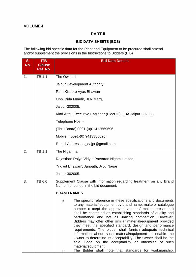
BID DATA SHEETS (BDS)
The following bid specific data for the Plant and Equipment to be procured shall amend and/or supplement the provisions in the Instructions to Bidders (ITB)
S. No.
ITB Clause Ref. No.
Bid Data Details
1. ITB 1.1 The Owner is:
Jaipur Development Authority
Ram Kishore Vyas Bhawan
Opp. Birla Mnadir, JLN Marg,
Jaipur-302005.
Kind Attn.: Executive Engineer (Elect-III), JDA Jaipur-302005
Telephone Nos.:-
(Thru Board) 0091-(0)01412569696
Mobile: : 0091-(0) 9413385626
E-mail Address: [email protected]
2. ITB 1.1 The Nigam is:
Rajasthan Rajya Vidyut Prasaran Nigam Limited,
`Vidyut Bhawan’, Janpath, Jyoti Nagar,
Jaipur-302005.
3. ITB 6.0 Supplement Clause with information regarding treatment on any Brand Name mentioned in the bid document:
BRAND NAMES
i) The specific reference in these specifications and documents to any material/ equipment by brand name, make or catalogue number (except the approved vendors/ makes prescribed) shall be construed as establishing standards of quality and performance and not as limiting competition. However, Bidders may offer other similar material/equipment provided they meet the specified standard, design and performance requirements. The bidder shall furnish adequate technical information about such material/equipment to enable the Owner to determine its acceptability. The Owner shall be the sole judge on the acceptability or otherwise of such material/equipment.
ii) The Bidder shall note that standards for workmanship,
S. No.
ITB Clause Ref. No.
Bid Data Details
material and equipment, and reference to brand name or catalogue numbers designated by the Owner in its Technical Specifications wherever appearing are intended to be descriptive only and not restrictive. The Bidder may substitute alternative standards, brand name and /or catalogue numbers in its bid, provided that it demonstrates to the Owner's satisfaction that the substitutions are substantially equivalent or superior to those designed in the Technical Specification. The Bidder will have to get approved the vendors list / brand name for ensuring best quality and workmanship of products.
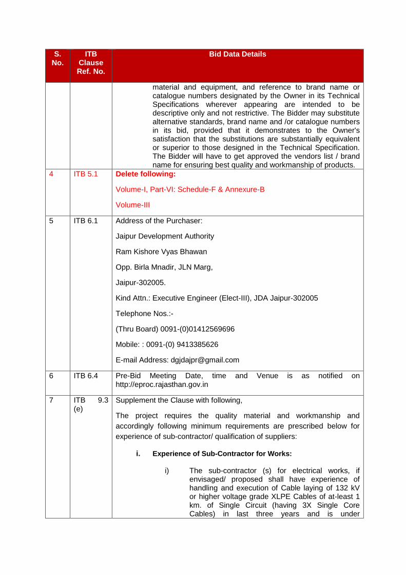
4 ITB 5.1 Delete following:
Volume-I, Part-VI: Schedule-F & Annexure-B
Volume-III
5 ITB 6.1
Address of the Purchaser:
Jaipur Development Authority
Ram Kishore Vyas Bhawan
Opp. Birla Mnadir, JLN Marg,
Jaipur-302005.
Kind Attn.: Executive Engineer (Elect-III), JDA Jaipur-302005
Telephone Nos.:-
(Thru Board) 0091-(0)01412569696
Mobile: : 0091-(0) 9413385626
E-mail Address: [email protected]
6 ITB 6.4 Pre-Bid Meeting Date, time and Venue is as notified on http://eproc.rajasthan.gov.in
7 ITB 9.3 (e)
Supplement the Clause with following,
The project requires the quality material and workmanship and
accordingly following minimum requirements are prescribed below for
experience of sub-contractor/ qualification of suppliers:
i. Experience of Sub-Contractor for Works:
i) The sub-contractor (s) for electrical works, if envisaged/ proposed shall have experience of handling and execution of Cable laying of 132 kV or higher voltage grade XLPE Cables of at-least 1 km. of Single Circuit (having 3X Single Core Cables) in last three years and is under
S. No.
ITB Clause Ref. No.
Bid Data Details
satisfactory operation for atleast 6 months as on the date of bid opening. A certificate of successful completion and satisfactory operation issued by project executing agency/ End-User/Owner shall be submitted as documentary evidence.
ii) The sub-contractor as above shall have experienced manpower to carry out the works assigned to him in the project alongwith the required tools and tackles. Supporting document in this regard shall be submitted with the bid.
ii. Experience of Sub-Vendor for Supplies:
i) The sub-vendors for the major items/ equipments/element (costing more than 5% of the overall cost of supplies quoted for the project and not covered/ mentioned under the approved vendor list/ as qualification item), the bidder shall propose name of proposed sub-vendors for each of such items alongwith their past experience list, test certificates, satisfactory operation certificates, quality certification/ plans etc. to show the adequacy of capability and capacity to make supplies under this project.
9 ITB 13.1
Amount of Bid Security (Earnest Money Deposit):
Rs. 34,00,000.00 (Rs. Thirty Four Lacs Only) through DD/ Banker Cheque or in the form of Bid Security Bank Guarantee as stipulated in the clause 13.2 (ITB).
10 ITB 13.2 The Bid Security Demand Draft/ Banker’s Cheque shall be in favour of Secretary , JDA, Jaipur payable at Jaipur.
11 ITB 15.1,ITB 15.2
Modified and may be read as “ The bidder shall prepare electronic bid consisting of the documents listed at ITB clause 9 &11.4,in the formats prescribed in NIT published on website http://eproc.rajasthan.gov.in
12 ITB 17.1, ITB 19.3 (a) and ITB 20.1
Supplement the Clauses with:
Address for Bid Opening:
Online
Website: http://eproc.rajasthan.gov.in
Executive Engineer (Elect-III), JDA Jaipur-302005
Jaipur Development Authority
Ram Kishore Vyas Bhawan
Opp. Birla Mnadir, JLN Marg,
S. No.
ITB Clause Ref. No.
Bid Data Details
Jaipur-302005.
Time and date for Bid Opening:
As specified on Website: http://eproc.rajasthan.gov.in
(a) Bid Title:
Bid Enquiry No. JDA/EE/Elect-III/2018-19/05 : Conversion of 132 KV double circuit Mansrovar - SMS Stadium overhead transmission line to underground cable (Approx- 1.5 KM) near Vidhansabha Jaipur
13 ITB 25.2(a)(i)
Applicable for 132 kV XLPE Cable
14 ITB 25.2(a) (ii)
Differential Price Factors for Evaluation
The factors and the respective Indian Rupees value per unit of differential loss for purpose of calculating differential price for evaluation shall be as stipulated below:
A. 132 kV XLPE Cable
The factors and the corresponding Indian Rupees value per unit of differential loss for the purpose of calculation of differential price for the bid evaluation shall be Rs. 1,34,000.00 per kW per 1000 mtr cable length.
The best parameter of loss quoted at rated voltage, rated current 750 A by any technically responsive bidder shall be taken as basis and that quoted by the particular bidder shall be used to arrive at differential price to be applied for the bid.
15 ITB 25.3 (a)
The Time for Completion shall be as under :
Description Duration in Months from the date of Notification of Award
Go-Live/Taking Over by the JDA/ Nigam upon successful Completion of:
Bid Enquiry No. JDA/EE/Elect-III/2018-19/05:
Conversion of 132 KV double circuit Mansrovar - SMS Stadium overhead transmission line to underground cable (Approx- 1.5 KM) near Vidhansabha Jaipur
Completion of Facilities as per Scope of Work:04 Months
16
ITB 25.3 (b)
This shall be applied as per the provision of Technical Specification, Volume-II of the Bidding Documents and Clause ITB 25.2(a)

S. No.
ITB Clause Ref. No.
Bid Data Details
17 ITB 32.1 As per article 13 – A of Rajasthan Stamp Act., the Stamp duty and Surcharge will be @ 0.25% of Amount of BG security subject to maximum limit of Rupees 25000.00

VOLUME-I
PART-III
GENERAL TERMS & CONDITIONS OF CONTRACT (GCC)
Preamble
This Part (Part –III) of the Bidding Documents [named as General Conditions of Contract (GCC)] provides all the rights and obligations of the parties under the Contract. This part contains provisions that are to be used unchanged unless Part – IV [named as Special Conditions of Contract (SCC)] states otherwise as any changes in GCC or any complementary information that may be needed has been shown in SCC. If there is a conflict between the provisions of Part-III & Part-IV, the provisions of Part-IV shall prevail.
Wherever the contents, terms and conditions mentioned in technical specification differ from those mentioned in Part-III General Conditions of Contract (GCC), the former shall prevail.
A. DEFINITION AND INTERPRETATION:

1.0 DEFINITION OF TERMS
1.1 When the words 'Approved'. 'Subject to Approval', 'Satisfactory', 'Equal to’, 'proper'. 'requested', 'As directed'. 'where directed', 'when directed', 'determined by' , 'accepted ' , 'permitted', or words and phrases of like importance are used the approval, judgment, direction etc. is understood to be a function of the owner/Engineer.
1.2 'The contract' means the agreement entered into between owner/ JDA and contractor as per the contract agreement signed by the parties, including all attachments and appendices thereto and all documents incorporated by reference there in.
1.3 'Contractor' or 'Supplier' shall mean the bidder whose bid will be accepted by the owner for the award of the works and shall include such successful bidder's legal representatives, successors and permitted assigns.
1.5 'Consulting Engineer' /'consultant' shall mean any firm or person duly appointed as such from time to time by the owner.
16. The term 'Contract price' shall mean the lumpsum price quoted by the contractor in his bid with additions and 'or deletions as may be agreed and incorporated in the letter of Award, for the entire scope of the works.
1.7 'Commercial operation' shall mean the conditions of operation in which the complete equipment covered under the contract is officially declared by the owner to be available for continuous operation at different loads upto and including rated capacity , such declaration by the owner, however, shall not relieve or prejudice the contractor of any of his obligations under the contract.
1.8 'Codes' shall mean the following, including the latest amendments, and/or replacements if any:
a) Indian Electricity Act.2003, and Rules and Regulations made there under.
b) Indian Factory Act.1948, and rules and regulations made there under.
c) Indian Explosive Act.1884, and rules and regulations made there under.
d) Indian Petroleum Act, 1934, and rules and regulations made there under.
e) A.S.M.E. Test codes.
f) A.I.E.E. Test codes.
g) American Society of Materials Testing codes.
h) Standards of the Indian Standards Institution.
i) Other Internationally approved standards and/or rules and regulations touching the subject-matter of the contract.
1.9 ‘Contract Performance Guarantee' shall also mean 'Contract Performance Security'.
1.10 'Date of contract' shall mean the date on which notice of award of contract/letter of Award has been issued.
1.11 'Drawings', 'Plans' shall mean all:

a) Drawings furnished by the owner/consultant as a basis for bid/ proposals.
b) Supplementary drawings furnished by the owner/consultant to clarify and to define in greater detail the intent of the contract.
c) Drawings submitted by the contractor with his bid provided such drawings are acceptable to the owner/ consultant.
d) Drawings furnished by the owner/consultant to the contractor during the progress of the work and
e) Engineering data and drawings submitted by the contractor during the progress of the work provided such drawings are acceptable to the Engineer/owner.
1.12 “Facilities” means the Plant and Equipment to be supplied and installed, as well as all the Installation Services to be carried out by the Contractor under the Contract.
1.13 The term 'Final Acceptance/Taking over' shall mean the owner's written acceptance of the work performed for Plant and Equipments under the contract , after successful commissioning/completion of performance and guarantee tests, as specified in the accompanying Technical specification or otherwise agreed in the contract.
1.14 'Guarantee Period'/Maintenance period' shall mean the period during which the contractor shall remain liable for repair or replacement of any defective part of the works performed under the contract.
1.15 'Engineer' shall mean the officer appointed in writing by the Owner to act as Engineer from time to time for the purposes of the contract.
1.16 The term 'Equipment Portion' of the contract price shall mean the ex-works value of the equipment.
1.17 The terms 'Equipment', 'Stores' and 'Materials' shall mean and include equipment , stores and materials to be provided by the contractor under the contract.
1.18 The term 'Erection portion' of the contract price shall mean the value of field activities of the Works including erection, testing and putting into satisfactory operation including successful completion of performance and guarantee test to be performed at site by the contractor including cost of insurances.
1.19 'Inspector' shall mean the owner or any person nominated by the owner from time to time, to inspect the equipment, stores or works under the contract and/or the duly authorized representative of the owner.
1.20 “Installation Services” means all those services ancillary to the supply of the Plant and Equipment for the Facilities, to be provided by the Contractor under the Contract; e.g., transportation and provision of marine or other similar insurance, inspection, expediting, site preparation works (including the provision and use of Contractor’s Equipment and the supply of all construction materials required), installation, testing, pre-commissioning, commissioning, operations, maintenance, the provision of operations and maintenance manuals, training, etc.
1.21 'Latent Defects' shall mean such defects caused by faulty design, material or workmanship which cannot be detected during inspection, testing etc. based on the technology available for carrying out such tests.
1.22 'Manufacturer's Works' or 'Contractor's Works'. shall mean the place of work used by the manufacturer, the contractor, their collaborators /associate or sub- contractors for the performance of the contract.
1.23 “Month” means calendar month of the Gregorian calendar.
1.24 "Nigam" shall mean the RAJASTHAN RAJYA VIDYUT PRASARAN NIGAM LTD. The "Purchaser" shall mean the JDA.
1.25 Notice of Award of Contract/'Letter of Award'/'Telex of award' shall mean the official issue date of detailed award/ order.
1.26 “Owner” means the firm/corporation/government entity, named in the SCC, who has decided to set up the Facilities and shall includes the legal successors or permitted assigns of the Owner.
1.27 “Origin” means the place where the materials, equipment and other supplies for the Facilities are mined, grown, produced or manufactured, and from which the services are provided. Plant and equipment are produced when, through manufacturing, processing or substantial and major assembling of components, a commercially recognized product results that is substantially different in basic characteristics or in purpose or utility from its components.
1.28 “Plant and Equipment” means permanent plant, equipment, machinery, apparatus, articles and things of all kinds to be provided and incorporated in the Facilities by the Contractor under the Contract (including the spare parts to be supplied by the Contractor under GCC Sub-Clause 4.0 hereof), but does not include Contractor’s Equipment.
1.29 'Performance and guarantee test' shall mean all operation al checks and tests required to determine and demonstrate capacity, efficiency, and operating characteristics as specified in the contract documents.
1.30 “SCC” means the Special Conditions of Contract.
1.31 `Specifications' shall mean the specification and bidding document forming a part of the contract and such other schedules and drawings as may be mutually agreed upon.
1.32 'Site' shall mean and include the land and other places on, into or through which the works and the related facilities are to be erected or installed and any adjacent land, paths, street or reservoir which may be allocated or used by the owners or contractor in the performance of the contract.
1.33 “Subcontractor”/”vendor”/”sub-vendor” means firms/ corporations/government entities to whom execution of any part of the Facilities, including preparation of any design or supply of any Plant and Equipment, is sub-contracted directly or indirectly by the Contractor with the consent of the JDA/Nigam in writing, and includes its legal successors or permitted assigns.
1.34 Test on completion shall mean such tests as prescribed in the contract to be performed by the contractor before the work is taken over by the owner.
1.35 'Works' shall mean and include the furnishing of equipment, labour and services, as per the specifications and complete erection, testing and putting into satisfactory operation including all transportation, handling, unloading and storage at the site as defined in the contract.
1.36 'Writing' shall include any manuscript, type written or printed statement, under or over signature and/or seal as the case may be.
1.37 Words imparting the singular only shall also include the plural and vice-versa where the context so requires.
1.38 Words imparting 'person' shall include firms, companies, corporation and associations or bodies of individuals, whether incorporated or not.
1.39 Terms and expressions not herein defined shall have the same meanings as are assigned to them in the Indian Sales of Goods Act(1930), falling that in the Indian Contract Act(1872) and falling that in the General clauses Act (1897) including amendments thereof if any. The various Acts and Regulations are normally available for sale from the following addresses:
i) Deputy Controller.,
Publication Department
Government of India,
Civil Lines, DELHI-110006.
ii) Deptt. of Publication,
(Government of India),
Kitab Mahal, Unit No.21, Emporia Building,
Baba Kharak Singh Marg, NEW DELHI-110001.
Or
With leading authorized government of India Book - sellers.
2.0 Interpretation
2.1 Contract
The Contracts to be entered into with the successful Bidder shall be as defined in SCC.
2.2 Contract Documents
2.2.1 The term contract documents shall mean and include the following which shall be deemed to form an integral part of the contract.
a) Invitation of Bid including letter forwarding the bidding documents, Instructions to bidders, general terms and conditions of contract and all other documents included under Volume I and the Special conditions of contract.
b) Contract agreement duly executed in relevant form of Part-VI, Annexures.
c) Specifications of the equipment to be furnished and erected under the contract as brought out in the accompanying Technical specifications.
d) Contractor's bid proposal and the documents attached thereto including the letters of clarifications thereto between the contractor and the

owner/consultant prior to the Award of Contract except to the extent of repugnancy.
e) All the materials, literature, data and information of any sort given by the contractor along with his bid, subject to the approval of the owner/consultant.
f) Letter of Award and any agreed variations of the conditions of the documents and special terms and conditions of contract, if any.
2.2.2 In the event of any conflict between the above mentioned documents, the matter shall be referred to the Engineer whose decision shall be considered as final and binding upon the parties.
2.3 Language & Measures
All documents pertaining to the contract including specification, schedules, notices, correspondence, operating and maintenance instructions, drawings or any other writing shall be written in English language. The Metric system of measurement shall be used exclusively in the contract.
2.4 Singular and Plural
The singular shall include the plural and the plural the singular, except where the context otherwise requires.
2.5 Headings
The headings and marginal notes in the General Conditions of Contract are included for ease of reference, and shall neither constitute a part of the Contract nor affect its interpretation.
2.6 Entire Agreement
Subject to GCC Sub-Clause 15.0 hereof, the Contract constitutes the entire agreement between the JDA and Contractor with respect to the subject matter of Contract and supersedes all communications, negotiations and agreements (whether written or oral) of parties with respect thereto made prior to the date of Contract.
2.7 Amendment
No amendment or other variation of the Contract shall be effective unless it is in writing, is dated, expressly refers to the Contract, and is signed by a duly authorized representative of each party hereto.
2.8 Independent Contractor
The Contractor shall be an independent contractor performing the Contract. The Contract does not create any agency, partnership, joint venture or other joint relationship between the parties hereto.
Subject to the provisions of the Contract, the Contractor shall be solely responsible for the manner in which the Contract is performed. All employees, representatives or Subcontractors engaged by the Contractor in connection with the performance of the Contract shall be under the complete control of the Contractor and shall not be deemed to be employees of the JDA, and nothing

contained in the Contract or in any subcontract awarded by the Contractor shall be construed to create any contractual relationship between any such employees, representatives or Subcontractors and the JDA.
2.9 Joint Venture
If the Contractor is a joint venture of not more than two firms, all such firms shall be jointly and severally bound to the JDA for the fulfillment of the provisions of the Contract and shall designate one of such firms to act as a leader with authority to bind the joint venture. The composition or the constitution of the joint venture shall not be altered without the prior written consent of the JDA.
2.10 Non-Waiver
2.10.1 Subject to GCC Sub-Clause 2.10.2 below, no relaxation, forbearance, delay or indulgence by either party in enforcing any of the terms and conditions of the Contract or the granting of time by either party to the other shall prejudice, affect or restrict the rights of that party under the Contract, nor shall any waiver by either party of any breach of Contract operate as waiver of any subsequent or continuing breach of Contract.
2.10.2 Any waiver of a party’s rights, powers or remedies under the Contract must be in writing, must be dated and signed by an authorized representative of the party granting such waiver, and must specify the right and the extent to which it is being waived.
2.11 Severability
If any provision or condition of the Contract is prohibited or rendered invalid or unenforceable, such prohibition, invalidity or unenforceability shall not affect the validity or enforceability of any other provisions and conditions of the Contract.
2.12 Country of Origin
“Origin” means the place where the materials, equipment and other supplies for the Facilities are mined, grown, produced or manufactured, and from which the services are provided. Plant and equipment are produced when, through manufacturing, processing or substantial and major assembling of components, a commercially recognized product results that is substantially different in basic characteristics or in purpose or utility from its components.
2.13 Notices
2.13.1 Unless otherwise stated in the Contract, all notices to be given under the Contract shall be in writing, and shall be sent by personal delivery, special courier, telegraph, facsimile or Electronic Data Interchange (EDI) to the address of the relevant party set out in the Contract Agreement, with the following provisions:
(a) Any notice sent by telegraph, facsimile or EDI shall be confirmed within two (2) days after dispatch by notice sent by special courier, except as otherwise specified in the Contract.
(b) Any notice sent by special courier shall be deemed (in the absence of evidence of earlier receipt) to have been delivered ten (10) days after dispatch. In proving the fact of dispatch, it shall be sufficient to show that the envelope containing such notice was properly addressed, stamped and

conveyed to the postal authorities or courier service for transmission by special courier. Provided further that whenever the postal authorities or courier service provide a proof of delivery, the same shall also be applicable for presenting the fact of dispatch.
(c) Any notice delivered personally or sent by telegraph, facsimile or EDI shall be deemed to have been delivered on date of its dispatch.
(d) Either party may change its postal, facsimile or EDI address or addressee for receipt of such notices by ten (10) days’ notice to the other party in writing.
2.13.2 Notices shall be deemed to include any approvals, consents, instructions, orders and certificates to be given under the Contract.
2.14 Governing Law & its Jurisdiction
The Contract shall be governed by and interpreted in accordance with laws of Union of India and the Courts of Jaipur shall have exclusive jurisdiction in all maters arising under this Contract.
B. SUBJECT MATTER OF CONTRACT
3. Scope of Facilities
3.1 Unless otherwise expressly limited in the Technical Specifications, the Contractor's obligation shall include the provision of all Plant and Equipment and the performance of all Installation Services required for the design, the manufacture (including procurement, quality assurance, construction, installation, associated civil works, Pre-commissioning and delivery) of the Plant and Equipment and the installation, completion, commissioning and performance testing of the facilities in accordance with the plans, procedures, specifications, drawings, codes and any other documents as specified in the Technical specifications. Such specifications include, but are not limited to, the provision of supervision and engineering services; the supply of labour, materials, equipment, spare parts (as specified in GCC Clause 4 below) and accessories; Contractor's Equipment; construction utilities and supplies; temporary materials, structures and facilities; transportation (including without limitation, custom clearance, port handling, unloading and hauling to, from and at the Site); storage and training except for those supplies, works and services that will be provided or performed by the JDA/ Nigam.
3.2 The Contractor shall, unless specifically excluded in the Contract, perform all such work and/or supply all such items and materials not specifically mentioned in the Contract but that can be reasonably inferred from the Contract as being required for attaining Completion of the Facilities as if such work and/or items and materials were expressly mentioned in the Contract.
4.0 Spares
4.1 All the spares for the equipment under the contract will, strictly, conform to the specification and documents and will be identical to the corresponding main equipment/components supplied under the contract and shall be fully interchangeable.
4.2 All the mandatory spares covered under the contract shall be produced alongwith the main equipment as a continuous operation and the delivery of the spares will be effected alongwith the main equipment in a phased manner and the delivery would be completed by the respective dates for the various categories of equipment as per the agreed network. In case of recommended spares the above will be applicable provided the order for the recommended spares has been placed with the contractor prior to commencement of manufacture of the main equipment.
4.3 The quality plan and the inspection requirement finalized for the main equipment will also be applicable for the corresponding spares.
4.4 The contractor will provide the owner with the manufacturing drawings, catalogues, assembly drawings and any other document required by the owner so as to enable the owner to identify the recommended spares. Such details will be furnished to the owner as soon as they are pre pared but in any case not later than six months prior to commencement of manufacture of the corresponding main equipment.
4.5 The contractor will provide the owner with all the addresses and particulars of his sub-suppliers while-placing the order on vendors for items/components/equipments covered under the contract and will further ensure with his vendors that the owner, if so desires, will have the right to place order(s) for spares directly on them on mutually agreed terms based on offers of such vendors.
4.6 Warranty for spares
The contractor shall warrant that all spares supplied will be new and in accordance with contract documents and will be free from defects in design, materials and workmanship and shall further guarantee as under:
4.6.1 For 5 years operational spares (both mandatory and recommended)
a) The spares of both categories (i.e. Mandatory & Others as recommended by the contractor for five (5) years successful operation will be manufactured with main equipment, the warrantee of such equipments will be 12 months from the scheduled date of commercial operation of the last unit of main equipment under the contract. In case of any failure in the original component/equipments due to faulty designs, materials and workmanship, the corresponding spare parts, if any, supplied will be replaced without any extra cost to the owner unless a joint examination and analysis by the owner and the contractor of such spare parts prove that the defect found in the original part that failed, can safely be assumed not to be present in spare parts. Such replaced spare parts will have the same warranty as applicable to the replacement made for the defective original part/component provided that such replacement for the original equipment and the spare replaced are again manufactured together. The discarded spare parts will become the property of the contractor as soon as they have been replaced by the contractor.
b) For the item of spares ordered/to be ordered by the owner for 5 years operational requirement of the equipment, which are not manufactured as a continuous operation together with the manufacture of the corresponding main equipment/component, will be warranted for 250

days of trouble free operation if used within a period of 18 months (reckoned from the date of delivery at site). However, if such spare parts are put to use after 18 months of the delivery at site then the guarantee of such spares will stand valid till the expiry of 36 months from the scheduled date of the completion of commissioning of the last unit of equipment or 250 days of trouble free operation after such spares are put in service, whichever is earlier.
4.6.2 The warranty of spares that are not used within 18 months from the respective dates of the delivery at site covered in para (b) above will, however, be subject to the condition that all such spares have been stored/maintained /preserved in accordance with contractor's standard recommended practice, if any, and the same have been furnished to the owner.
4.7 To enable the owner to finalize the requirement of recommended spares which are ordered subsequent to placement of order for main equipment in addition to necessary technical details catalogue and such other information brought- out here-in-above, the Contractor will also provide a justification in support of reasonableness of the quoted prices of spares which will, inter-alia, include documentary evidence that the prices quoted by the contractor to the owner are not higher than those charged by them from other customers in the same period.
4.8 In addition to the spares recommended by the Contractor, if the owner further identifies certain particular items of spares, the contractor will submit the prices and delivery quotations for such spares within 30 days of receipt of such request with validity period for 6 months for consideration by the owner and placement of order for additional spares if owner so desires.
4.9 The contractor shall guarantee the long term availability of spares to the owner for the full life of the equipment covered under the contract. The contractor shall guarantee that before going out of production of spare parts of the equipment, he shall give the owner at least twelve (12) months advance notice so that the later may order his bulk requirement of spares, if he so desires. The same provision will also be applicable to Sub-contractor of any spares by the contractor or his sub-contractors. Further, in case of discontinuance of manufacture of any spares by the contractor or his sub-contractors, the contractor will provide the owner, two years in advance, full manufacturing drawings, material specifications and technical information required by the owner for the purpose of manufacture of such items.
4.10 Further in case of discontinuance of supply of spares by the contractor or his sub-contractors, the contractor will provide the owner with full information for replacement of such spares with other equivalent makes, if so required by the owner.
4.11 The prices of all future requirements of items of spares beyond 5 years operational requirement will be derived from the corresponding ex-works price at which the order for such spares have been placed by owner as part of mandatory spares or recommended spares. Ex-works order price of future spares shall be computed in accordance with the price of spares indicated in the contract. The above option for procuring future long term requirement of spares by the owners shall remain valid for a period of 5 years from successful completion of commissioning last unit of equipment.

4.12 The contractor will indicate in advance the delivery period of the items of spares, which the owner may procure in accordance with above sub-clause. In case of emergency requirements of spares, the contractor would make every effort to expedite the manufacture and delivery of such spares on the basis of mutually agreed time schedule.
4.13 In case the contractor fails to supply the mandatory, recommended or long term spares in accordance with the terms stipulated above, the owner shall be entitled to purchase the same from alternate sources at the risk and the cost of the contractor and recover from the contractor. The excess amount paid by the owner over the rates worked on the above basis. In the event of such risk purchase by the owner, the purchases will be as per the works and procurement policy of the owner prevalent at the time of such purchases and the owner at his option may include a representative of the contractor in finalizing the purchases.
4.14 It is expressly understood that the final settlement between the parties in terms of relevant clauses of the bidding documents shall not relieve the contractor of any of his obligations under the provision of long term availability of spares unless otherwise discharged in writing by the owner.
4.15 In case the Contractor fails to supply the spares parts in accordance with the terms stipulated above, the JDA shall sanction the Contractor declaring them ineligible for a stated period of time for future projects.
5.0 Effectiveness of Contract
The contract shall be considered as having come into force from the date of the Notification of Award unless otherwise provided in the Notification of Award.
6.0 Time- The Essence of Contract
6.1 The time and the date of completion of the contract as stipulated in the contract by the owner without or with modifications, if any, and so incorporated in the letter of Award, shall be deemed to be the essence of the Contract. The contractor shall so organize his resources and perform his work on facilities so as to complete it not later than the date agreed to.
6.2 The contractor shall submit a detailed PERT network/bar chart within the time frame agreed consisting of adequate number of activities covering various key phases of the work such as design, procurement, manufacturing , shipment and field erection activities within fifteen (15) days of the date of Notice of Award of contract. This network shall also indicate the interface facilities to be provided by the owner and the dates by which such facilities are needed. The contractor shall discuss the network so submitted with the owner and the agreed network shall form part of the contract documents. As provided in the clause of Terms of payment in this part finalization of the network/BAR charts will be precondition to release of any initial advance to the contractor. During the performance of the contract, if in the opinion of the Engineer, proper progress is not maintained, suitable changes shall be made in the contractor's operations to ensure proper progress without any cost implication to the owner. The interface facilities to be provided by the owner in accordance with the agreed network shall also be reviewed while reviewing the progress of the contractor.
6.3 Based on the above agreed network/bar chart fortnightly reports shall be submitted by the Contractor as directed by the Engineer.
6.4 Subsequent to the finalization of the network, the contractor shall make available to the Engineer a detailed manufacturing programme, in line with the agreed contract network such manufacturing programme shall be reviewed, updated and submitted to the Engineer once every two months thereafter.
6.5 The above bar charts/manufacturing programme shall be compatible with the Owner's computer environment and furnished to the Owner on such media as may be desired by the Owner.
7.0 Completion of Contract
7.1 Unless otherwise terminated under the provisions of any other relevant clause, this contract shall be deemed to have been completed on the expiry of the guarantee period as provided for under the clause entitled 'Guarantee' in this Part of the Volume-I.
C. Payment
8. Contract Price
8.1 The Contract Price shall be as specified in Letter of Award.
8.2 The Contract Price shall be subject to adjustment in accordance with the provisions of Price Adjustment to the Contract Agreement. The Contract Price shall be increased or reduced on account of variation in quantity in accordance with Clause 42 of GCC.
8.3 Subject to site conditions, examination & Validation of various project data and estimation of difficulties in successful performing of facilities, the Contractor shall be deemed to have satisfied itself as to the correctness and sufficiency of the Contract Price, which shall, except as otherwise provided for in the Contract, cover all its obligations under the Contract.
9.0 Payment Procedure & Terms
9.1 The payment to the contractor for the performance of the works under the contract will be made by the owner as per the guidelines and conditions specified herein. All payment made during the contract shall be on account payments only. The final payment will be made on completion of all works and on fulfillment by the contractor of all his liabilities under the contract.
9.2 Currency of payment
All payments under the contract shall be in Indian Rupees only
9.3 Due dates for payment
The initial advance amount shall be payable after fulfillment of all the conditions laid down in the General conditions of contracts, clause 9.7 below and receipt of the Contractor's invoice alongwith all necessary supporting documents for such advance payment. The price component of the initial advance amount will become due for payment within thirty (30) days of receipt of the contractor's invoice. Owner will make interim advance payment and progressive payment as and when the payment is due as per the terms of payment set forth in the subsequent clauses. Progressive payments shall be payable by the owner generally within (30) days of the date of receipt of contractor's bill/invoice note by the owner, provided the documents submitted are complete in all respects and contractor have fulfill all contractual formalities. All out efforts shall be made by JDA to make the due payments in 30
days as above, however no interest on delayed payment shall be payable and such delay will not entitle contractor for any compensation or extension in time.
9.4 Payment schedule
The contractor shall prepare and submit to the Engineer for approval, a detailed break-up of Lumpsump/ Lot/ Set/Job Items. This complete detailed price break-up shall be furnished in accordance with the agreed detailed PERT network of the contractor setting forth his starting and completion dates for the various key phases of Supplies/ Works prepared as per condition in Clause 6.0 of this Part GCC of Volume I for scheduling of payments. Any payment for items identified as Lumpsum/ Lot/ Set/Job Items under the contract shall only be made after the contractor's price breakup is approved by the Engineer.
9.5 Application for payment
9.5.1 The contractor shall submit application for the payment in the prescribed proforma of the owner. Proforma for application for payment is enclosed as Annexure-VI Part-VI of Volume I.
9.5.2 Each such application shall state the amount claimed and shall set forth in detail, in the order of the payment schedule, particulars of the works including the works executed at site and of the equipment shipped/brought on to the site pursuant to the contract upto the date mentioned in the application and for the period covered since the last preceding certificate, if any.
9.5.3 Every interim payment certificate shall certify the Contract value of the works executed upto the date mentioned in the application for the payment certificate, provided that no sum shall be included in any interim payment certificate in respect of the works that, according to the decision of the Engineer, does not comply with the contract, or has been performed, at the date of certificate prematurely.
9.6 Mode of payment
9.6.1 Payment due on despatch of equipment shall be made by the owner directly to the contractor as per the payment schedule.
9.6.2 The payment of the advance, test charges, if any, price adjustment, any other supply payment, taxes and duties(whenever admissible) inland transportation(including port handling), insurance and the erection portion of the works shall be made direct to the contractor by the owner.
9.7 Terms of payment
9.7.1 The payment for the material / equipment / erection work on order shall be made as under only after execution of the contract agreement & furnishing of security deposit and performance security Bank guarantee as per relevant clauses.
9.7.2 All payments shall be made in accordance to Clause 9.3 above from the date of
submission of duly verified bills and completion of all contractual formalities as per requirement of contract.
9.7.3 The payment terms shall be as under: (A) Price Component for Equipment and its Erection, Testing and Commissioning
(i) Interest Bearing Advance (Optional*): Twenty percent (20%) of the total Contract price(including mandatory spares and Testing and measuring instruments) shall be paid as an initial advance on presentation of the following:
a) Contractor's unconditional acknowledgement of the Letter of Award and
execution of contract agreement. b) Contractor's invoice. c) An unconditional & irrevocable Bank Guarantee for the equivalent amount of
advance as per proforma Annex-IV attached in Part-VI, Vol. I (Conditions of Contract), which shall be initially valid upto the end of 90 days after the scheduled completion and shall be extended from time to timeif required under the contract. The bank guarantee shall be considered for release after adjustment of advance and interest there upon in full under the contract. The reduction of Advance payment bank guarantee may be allowed to the extent the advance amount is adjusted.
d) An unconditional & irrevocable Bank Guarantee for Ten percent (10%) of the
total Contract price towards contract Performance security Guarantee as per proforma Annex-II attached in Part-VI, Volume-I (Conditions of Contract) which shall be initially valid upto 12 Calendar months after the scheduled commissioning and issue of taking over certificate of the works in all respect in accordance with the clause No. 32.0 of Part ITB, Vol. I, and shall be extended from time to time as may be required under the contract.
e) Submission of detailed PERT/ BAR chart based on the work schedule stipulated
in the letter of award and its approval by the owner.
Note:* This payment is an optional payment. The Contractor has the option of taking the interest bearing initial advance or otherwise. In case, the Contractor opts for this interest bearing initial advance, the same shall be paid to the Contractor on fulfilment of above conditions and an interest on monthly outstanding amount will be charged at the rate of 12.25 % per annum. The monthly outstanding amount for the purpose of calculating the interest shall be worked out at the end of each calendar month considering proportionate adjustment of advance against dispatch payment as per mentioned terms. In case, the Contractor opts not to take interest bearing advance as above, it would be mandatory for him to submit the documents listed at Sl. No. (a), (c), (d) and (e) above within thirty (30) days of issuance of contract.
f) Approval of all designs, drawings & guaranteed technical particulars as identified
in Technical Specifications, Volume-II & III of the Bidding Documents. g) Approval of all quality plans and sub-vendor list. h) Approval of type test reports in case type tests are not required to be repeated. i) Submission of certificate of establishing of contractors’ site office (s) at
respective site (s).
(ii) Progressive Payment
a) (i) Payment equal to 70% # (Seventy percent) of the value of the work done / material or equipment erected at site of GSS/ Line(it includes foundation +
supply + ETC) shall be made to the contractor on the Erection of the material / equipment at site on the basis of certificate issued by engineer in-charge that this much quantity has been erected by the contractor at site. However, before despatch of material / equipment at site, contractor shall be required to get it inspected and cleared from the purchaser which will be further verified by the Engineer-in-charge before installation at site.
(ii) Payment of mandatory spares, Testing and measuring instruments and
other material not requiring ETC
Payment equal to 70% # (Seventy percent) of the value of the mandatory spares, Testing and measuring instruments shall be made to the contractor on the erection of similar material / equipment at site on the basis of certificate issued by Engineer in-charge.
# In case, the Contractor opts not to take interest bearing initial advance then this payment shall be 90% instead of 70%.
b) Out of the balance 10% amount, 8% (eight percent) payment including
material not requiring ETC shall be made, if any, after commissioning@ of equipment / material in full (at Rated Voltage) or part thereof including material not requiring ETC, after adjustment of due recoveries/ damages, if any and proof of submission of required number of reproducible, O&M manuals, approved drawings, data sheets, test reports, pamphlets and manuals of spares, maintenance and testing equipment of the sub-station/ line.
c) Final 2% (two percent) payment including material not requiring ETC shall be
made after submission of taking over certificate after adjustment of due recoveries/damages, if any.
Note: Relief to the contractor shall be provided if contractor is not able to complete
the commissioning due to any deficiencies on the part of JDA or reasons not attributable to contractor. @ “Commissioning” for the purpose of payments shall mean satisfactory completion of all supplies, erection, inspection, commissioning checks and successful completion of all site tests and continuous energisation of the equipment/materials at rated voltage at site as per the Contract and to the satisfaction/approval ofJDA/ Nigam.

(B) Nil
(C) Maintenance Charges
The payment terms of maintenance services/ charges shall be as per the stipulated terms and conditions of the Maintenance Contract in SCC.
(D) Training & Handholding Charges
The 100% payment with taxes shall be released after the successful completion of training programme (s) on-site as well as at bidder’s/ Manufacturer works/ Handholding.
(E) Price Adjustment (a) Any variation in Contract Price due to price adjustment provisions of Clause 12.0
below shall be effected on presentation of invoice supported by calculations as per formula specified therein along with documentary evidence for different indices applicable for Price Adjustment.
(b) Price decrease
For any reduction in Contract Price due to price adjustment provisions as per Clause 12.0 below shall be effected by recovering 100% of the reduction amount from any of the Contractor’s invoices falling immediately due for payment or any other payments.
(c) Price increase For Supply Portion:
The price variation shall be allowed on 98% value of the material / equipment.
For any increase in Contract Price after final price adjustment provisions as per Clause 12.0 below shall be Hundred percent (100%)after submission of final RA bill.
For Erection Portion The price variation shall be allowed on 100% value of the Erection Portion. For any increase in Contract Price after final price adjustment provisions as per
Clause 12.0 below shall be Hundred percent (100%) of the final Price adjustment amount for the erection part after submission of final RA bill.
9.7.4 In emergent conditions/ cases, on authorization from the main Contractor, payment to Sub–vendors/sub-contractors of the Contractor shall be considered for disbursed by JDA directly in their account, as per payment terms.
10.0 Guarantee
10.1 Contract Performance Guarantee
10.1.1 The contractor shall warrant that the equipment will be new, unused and in accordance with the contract documents and free from defects in material and workmanship for a period of twelve (12) calendar months commencing immediately upon the satisfactory commissioning of all equipments of facility through Contract Performance Guarantee of the amount equivalent to 10% of
the Contract Value plus additional performance securities, if any, in line with the requirement of Qualification Requirements. The contractor's liability shall be limited to the re placement of any defective parts in the equipment of his own manufacture or those of his sub-contractors, under normal use and arising solely from faulty design, materials and/or workmanship provided always that such defective parts are repairable at the site and are not in meantime essential in the commercial use of the equipment. Such replaced/defective parts shall be returned to the Contractor unless otherwise arranged. No repairs or replacement shall normally be carried out by the Engineer when the equipment is under the supervision of the Contractor's supervisory Engineer.
10.1.2 In the event of any emergency where in the judgment of the Engineer, delay would cause serious loss or damages, repairs or adjustment may be made by the Engineer or a third party chosen by the Engineer without advance notice to the contractor and the cost of such work shall be paid by the contractor. In the event such action is taken by the Engineer, the contractor will be notified promptly and he shall assist wherever possible in making necessary corrections. This shall not relieve the contractor of his liabilities under the terms and conditions of the contract.
10.1.3 If it becomes necessary for the contractor to replace or renew any defective portions of the works, the provision of this clause shall apply to portion of the works so replaced or renewed until the expiry of twelve (12) months from the date of such replacement or renewal for all equipments. If any defects are not remedied within a reasonable time, the Engineer may proceed to do the work at the contractor's risk and cost, but without prejudice to any other rights which the owner may have against the contractor in respect of such defects.
10.1.4 The repaired or new parts will be furnished and erected free of cost by the contractor. If any repair is carried out on his behalf at the site, the contractor shall bear the cost of such repairs.
10.1.5 The cost of any special or general overhaul rendered necessary during the maintenance period due to defects in the equipment or defective work carried out by the con tractor, the same shall be borne by the contractor.
10.1.6 The acceptance of the equipment by the Engineer shall in no way relieve the contractor of his obligations under this clause.
10.1.7 In the case of those defective parts which are not repair able at site but are essential for the commercial operation of the equipment, the contractor and the Engineer shall mutually agree to a programme of replacement or renewal which will minimize interruption to the maximum extent, in the operation of the equipment.
10.1.8 At the end of the contract performance guarantee Period, the Contractor's Liability ceases except for latent defects. The Contractor's liability for latent defects warranty shall be limited to period of Five (5) years from the end of contract performance guarantee Period. For the purpose of this clause, the latent defects shall be the defects inherently lying within the material or arising out of design deficiency, which do not manifest themselves during the contract performance guarantee Period defined in this GCC Clause 10, but later.
In respect of goods supplied by sub-contractors to the contractor where a guarantee (more than 12 months) is provided by such sub contractor, the owner shall be entitled to benefit of such longer guarantee.
10.1.9 The provisions contained in this clause will not be applicable:
a) If the owner has not used the equipment according to generally approved industrial practice and in accordance with the conditions of operation specified and in accordance with operating manuals, if any.
b) In cases of normal wear and tear of the parts to be specifically mentioned by the contractor in the offer.
10.2 Manufacturer’s Warranty and Mode of Bank Guarantee [Common for all types]
10.2.1 A manufacturer's warrantee on Rs. 100.00 Rajasthan State Non Judicial stamp paper in the proforma prescribed. Such warrantee shall be attested either by a first class Magistrate or Notary Public.
10.2.2 All the bank guarantees towards advance, bid security & performance security shall have to be furnished from an Indian scheduled/nationalized bank on the Rajasthan State Non judicial stamp paper of Rs.100.00 (purchased in the name of guarantor/issuing bank) duly authenticated either by a first class Magistrate or Notary Public or directly confirmed by the issuing Bank towards advance/security/Performance security in favour of "The Chief Engineer (PP&D), JDA, Jaipur". All the Bank Guarantees shall be submitted to the purchaser.
10.2.3 The bank guarantees should remain valid upto the last day of calendar month and be furnished in whole rupees.
10.2.4 The contractor shall keep the Bid Bank Guarantee valid till the Performance Security submitted by him is accepted by the purchaser.
10.2.5 Bank charges or any other charges, if any, shall be to the Contractor's account. If the Contractor fails to provide the Security within the period specified, such failure shall constitute a breach of the Contract and the JDA shall be entitled to make other arrangements at the risk and expenses of the Contractor and the Earnest money deposited by the Contractor shall stand forfeited by the JDA.
10.2.6 All the bank guarantees towards advance, bid security& performance security shall be paid to JDA on first demand without conditions or proofs.
10.2.7 The Bank Guarantees shall be furnished by the bidder / contractor, after checking the same correctly as per the checklist.
10.3 Indemnity
10.3.1 For the equipment/material to be provided by the Contractor, it will be the responsibility of the Contractor to take delivery, unload and store the materials at Site and execute an Indemnity Bond and obtain authorization letter from JDA as per proforma enclosed in Part-VI, Vol-I, in favour of the JDA against loss, damage and any risks involved for the full value of the materials. This Indemnity Bond shall be furnished by the Contractor before commencement of the supplies

and shall be valid till the scheduled date of Taking Over of the equipment by the JDA.
10.3.2 In case of Contracts, where the JDA hands over his equipment/ material to the Contractor for executing the Contract, then the Contractor shall, at the time of taking delivery of the equipment/ material through Bill of Lading or other despatch documents, furnish trust Receipt for Plant, Equipment and Materials and also execute an Indemnity Bond in favour of the JDA in the form acceptable to the JDA for keeping the equipment in safe custody and to utilize the same exclusively for the purpose of the said Contract. Samples of proforma for the Trust receipt and Indemnity Bond are enclosed in Part-VI, Vol-I. The JDA shall also issue a separate Authorization Letter to the Contractor to enable him to take physical delivery of plant, equipment and materials from the JDA as per proforma in Part-VI, Vol-I.
11.0 Taxes and Duties
11.1 The Contractor shall be entirely responsible for payment of all taxes, duties, licence fees and other such levies legally payable/incurred until delivery of the contracted supplies to the JDA.
If it is statutory requirement to make deductions towards such taxes and duties or any other applicable taxes and duties, the same shall be made by the JDA and a certificate for the same shall be issued to the Contractor.
11.2 The Contractor shall be solely responsible for the taxes that may be levied on the Contractor's persons or on earnings of any of his employees and shall hold the JDA indemnified and harmless against any claims that may be made against the JDA. The JDA does not take any responsibility whatsoever regarding taxes under Indian Income Tax Act, for the Contractor or his personnel. If it is obligatory under the provisions of the Indian Income Tax Act, deduction of Income Tax at source shall be made by the JDA.
11.3 In respect of direct transaction between the JDA and the Contractor, the EXW price is inclusive of all cost as well as duties and tax (viz., custom duties & levies, duties, sales tax/GST etc.) paid or payable on components, raw materials and any other items used for their consumption incorporated or to be incorporated in the Plant & Equipment.
Sales tax/GST, excise duty, local tax and other levies for the Equipment/items under ‘direct transaction’ including entry tax as applicable for destination site are not included in the EXW price. These amounts will be payable (along with subsequent variation if any), by the JDA on the supplies made by the Contractor but limited to the tax liability on the transaction between the JDA and the Contractor. JDA shall, however, issue requisite sales tax declaration form.
In respect of bought-out finished items, which shall be dispatched directly from the sub-vendor’s works to the JDA’s site (sale-in-transit), the EXW price is inclusive of all cost as well as duties and taxes (viz., custom duties & levies, duties, sales tax/GST etc.) paid or payable and any such taxes, duties, levies additionally payable will be to Contractor's account and no separate claim on this behalf will be entertained by the JDA. JDA, shall, however, issue requisite sales tax declaration forms.
Further, the EXW price of (i) imported Equipments/items offered as ‘Off the Shelf’ or dispatched directly from the Indian Port of disembarkation and/or (ii) bought-out finished Equipments/items as ‘Off the Self’ items or dispatched directly from the Contractor’s works are inclusive of all cost as well as duties and taxes (viz., custom

duties & levies, duties, sales tax/GST etc.) paid or payable and no separate claim on this behalf will be entertained by the JDA. JDA shall, however, issue requisite sales tax declaration form.
For payment/reimbursement of Sales Tax, wherever applicable, in respect of despatches made directly from Contractor's works, invoices raised by the Contractor shall be accepted as documentary evidence and for payment/reimbursement of GST, TAXABLE invoices raised by the Contractor shall be accepted as documentary evidence. Similarly, pre-numbered invoices duly signed by authorized signatory shall be considered as evidence for payment of Excise Duty.
11.4 Entry tax as applicable for destination site on all items of supply including bought-out finished items, which shall be dispatched directly from the sub-vendor’s works to the JDA’s site (sale-in-transit) shall be indicated separately in relevant price schedule. The applicable entry tax in respect of all the items of supply would be deducted by the JDA.
If the applicability of Entry Tax is changed due to change in the place of sourcing of the material later on (i.e. during performance of contract), the arisen additional liability, if any,shall be on the account of the contractor however arisen benefit, if any, shall be to the account of JDA
11.5 The Bidder shall quote the prices inclusive of applicable Service Tax and surcharge/ cess etc. Any statutory variation in the service tax will be to contractor’s accounts. The bidder shall give Service Tax registration number. Depositing the Service Tax with appropriate authority within stipulated period shall be the bidder’s liability.
11.6 Sales Tax/GST on Works Contract (WCT i.e. Work Contract Tax), Turnover Tax or any other similar taxes under the Sales Tax/GST Act for supply and services to be performed in India, as applicable is included in Contract Price and JDA would not bear any liability on this account. JDA shall, however, deduct such taxes at source for supply and services and issue Tax Deduction at Source (TDS) Certificate to the Contractor.
11.7 For the purpose of the Contract, it is agreed that the quoted Price specified in Contract is based on the taxes, duties, levies and charges prevailing at the date seven (07) days prior to the last date of bid submission (hereinafter called “Tax” in this GCC Sub-clause 11.7).
If any rates of Tax are increased or decreased, a new Tax is introduced, an existing Tax is abolished, or any change in interpretation or application of any Tax occurs in the course of the performance of the Contract (i.e. during scheduled completion period as per contract), which was or will be assessed on the Contractor in connection with performance of the Contract, an equitable adjustment of the Contract price shall be made to fully take into account any such change by addition to the Contract price or deduction therefrom, as the case may be, in accordance with GCC Clause 40 (Changes in Laws and Regulations) hereof. However, adjustments as above would be restricted to direct transactions between the JDA and the Contractor for which the taxes and duties are reimbursable by the JDA as per the Contract. Beyond the scheduled completion period, the arisen additional liability, if any, consequent to statutory variation in taxes over and above applicable taxes at the end of stipulated completion period shall be on the account of the contractor however arisen benefit, if any, shall be to the account of JDA.
The Contractor is obligated to keep the JDA notified of the aforesaid statutory variations within 15(fifteen) days of such variation coming into effect.
These adjustments shall not be applicable on procurement of raw materials, intermediary components etc by the Contractor and also not applicable on the bought out items dispatched directly from sub-vendor’s works to site.
In respect of raw materials, intermediary components etc and bought out items, neither the JDA nor the Contractor shall be entitled to any claim arising due to increase or decrease in the rate of Tax, introduction of a new Tax or abolition of an existing Tax in the course of the performance of the Contract.
11.8 Royalty Tax
In pursuance of the notification issued by Department of Mines, Government of Rajasthan vide circulars dt.15.11.11, 18.10.12 & 9.1.13 regarding royalty tax determination and deposition of the same in the department of Mines & Geology, the contractor shall be responsible for legitimacy of the civil material used in construction of the transmission line/ Substation. The contractor shall also be responsible for compliance of the instructions contained in the said circulars and further amendments, if any. The payment of RA bills shall be made after ensuring compliance of the guidelines contained in the above circulars by the contractor.
In case any liability / dues against royalty is finalized by the Department of Mines, GOR, the firm shall be fully responsible for payment of such dues to the Mining Department or the same may be deducted / recovered by the JDA from the financial hold available under this contract or any other contact of JDA or its successor companies of erstwhile RSEB.
12.0 Price Adjustment
12.1 The Bidder shall quote base price for the Ex-works Price components of the equipment/materials and erection price components. These price components paid by Purchaser for certain equipment/ materials, as specified, shall be subject to price adjustment to reflect changes in the cost of labour and material components as per the price adjustment provisions contained herein.
12.2 The ex-works price components of Erection Hardware, Control & Relay Panels, Bus Post and Disc Insulators, LT Switchgear, Battery & Battery Chargers, DG Set, C&F, PLCC Equipment, Illumination System, Air Conditioning System, Fire Protection System, Substation Automation, spares and testing & maintenance equipment etc. and other items not specifically mentioned below shall remain firm and no price adjustment, whatsoever, shall be applicable for the price component of these items. Further, prices for Survey, type test, freight & insurance, training & handholding, Maintenance Charges and other charges, if any, shall be firm and no price adjustment shall be applicable for these price components.
12.3 Price Adjustment on Ex-Works Prices:
12.3.1 The Ex-works prices of main equipment viz.
For EHV Substations:
Auto/ Power Transformer, Shunt Reactors, LT Transformers, CB, CT, CVT, Isolators, Surge Arrestor, Cables & Structures; the complete equipment procured as spares (for CB, CT, CVT, Isolators, SA only),
For EHV Lines:

Tower Material, Earth Wire, GI Bolts & Nuts, GI Step Bolts, Electro-Galvanized Spring Washers
shall be subject to price adjustment as per relevant price variation formula wherever applicable appended at Annexure-B.
12.3.2 For the purpose of price adjustment, the date of despatch means the date on which the material is notified as being ready for inspection (date of receipt of inspection call by JDA), scheduled date of dispatch or actual date of dispatch or actual date of erection (If applicable and falling after contractual completion period), whichever is beneficial to the JDA. Scheduled date of dispatch will be Ex-work date of dispatch, governed by the accepted Bar Chart/PERT Network for supplies wherein supply schedule for main equipment/ Items, cables, structures etc. will be indicated. Further, no price increase shall be allowed beyond the original delivery dates unless specifically stated in the Time Extension Letter, if any, issued by the Owner. The Owner will, however, be entitled to any decrease in the Contract Price which may be caused due to lower price adjustment amount in case of delivery of Goods beyond the original delivery dates. Therefore, in case of delivery of Goods beyond the original delivery dates, the liability of the Owner shall be limited to the lower of the price adjustment amount which may work out either on date on which the material is notified as being ready for inspection (date of receipt of inspection call by JDA) or schedule date or actual date of despatch of Goods or actual date of erection (If applicable and falling after contractual completion period).
12.3.3 Provisional & Final Price Adjustment:
The contractor shall submit the price adjustment claims as follows:
Provisional Price Adjustment:
The contractor shall submit the provisional price adjustment claim (after shipment of material at site) considering the date of dispatch as the date on which the material is notified as being ready for inspection (date of receipt of inspection call by JDA), scheduled date of dispatch or actual date of dispatch, whichever is beneficial to the JDA.
Final Price Adjustment:
The contractor shall submit the Final price adjustment claim (after erection of material at site) considering the date of dispatch as the date on which the material is notified as being ready for inspection (date of receipt of inspection call by JDA), scheduled date of dispatch or actual date of dispatch or actual date of erection (If applicable and falling after contractual completion period), whichever is beneficial to the JDA.
12.3.4 Price Adjustment Ceiling:
The total adjustment for LT Transformer, Auto/ Power Transformer, Reactor, CB, CT, CVT, Surge Arrestor, ISO, Power & Control Cables and Sub-station Structures [ for EHV Substations] and Tower Material, Earth Wire, GI Bolts & Nuts, GI Step Bolts, Electro-Galvanized Spring Washers [for EHV Lines] shall not be subject to any ceiling whatsoever individually of the respective Ex-works prices of LT Transformer, Auto/ Power Transformer, Reactor, CB, CT, CVT, SA, ISO, Power & Control Cables and Sub-station Structures [for EHV Substations]

and Tower Material, Earth Wire, GI Bolts & Nuts, GI Step Bolts, Electro-Galvanized Spring Washers [for EHV Lines].
12.4 Price Adjustment on Erection Prices:
12.4.1 The Erection Price Component (including charges for civil works) shall be subject to price adjustment as per price variation formula wherever applicable appended at Annexure-B.
12.4.2 For the purpose of price adjustment, the billing period shall mean the billing period as per Contract time schedule i.e., the agreed Bar Chart or actual period, whichever is beneficial to the JDA. The Billing period for various erection activities will be as per agreed erection Bar Chart indicating monthly schedule of erection activities for completion of works. Further, no price increase shall be allowed beyond the original erection dates unless specifically stated in the Time Extension letter, if any, issued by the Owner. The Owner will, however, be entitled to any decrease in the Contract Price which may be caused due to lower price adjustment amount in case of delays beyond the original erection dates. Therefore, in case of delays beyond the original erection dates, the liability of the Owner shall be limited to lower of the price adjustment amount which may work out either on schedule date or actual date of erection (including civil works).
12.4.3 Price Adjustment Ceiling:
The total price adjustment for Erection (including charges for civil works) Price Component shall not be subject to any ceiling whatsoever.
12.5 In case of non-publication of applicable indices on a particular date, which happens to be the applicable date for price adjustment purposes, the published indices prevailing immediately prior to the particular date shall be applicable.
12.6 The Contractor shall promptly submit price adjustment calculation on quarterly
basis, whether such adjustment is positive or negative.
D. Intellectual Property
13.0 Patent Rights and Royalties
Royalties and fees for patents covering materials, articles, apparatus, devices, equipment or processes used in the works shall be deemed to have been included in the Contract Price. The Contractor shall satisfy all demands that may be made at any time for such royalties or fees and he alone shall be liable for any damages or claims for patent infringements and shall keep the Owner indemnified in that regard. The Contractor shall, at his own cost and expense, defend all suits or proceedings that may be instituted for alleged infringement of any patents involved in the works, and, in case of an award of damages, the contractor shall pay for such award. In the event of any suit or other proceedings instituted against the owner, the same shall be defended at the cost and expense of the Contractor who shall also satisfy/comply with any decree, order or award made against the owner. But it shall be understood that no such machine, plant, work, material or thing has been used by the owner for any purpose or any manner other than that for which they have been furnished and installed by the contractor and specified under these specifications. Final payment to the Contractor by the Owner will not be made while any such suit or claim remains

un-settled. In the event any apparatus or equipment, or any part thereof furnished by the Contractor, is in such suit or proceedings held to constitute infringement, and its use is enjoined, the Contractor shall at his option and at his own expense, either procure for the owner, the right to continue the use of said apparatus, equipments, or part thereof, replace it with non-infringing apparatus or equipment or modify it, so it becomes non/infringing.
14.0 Copy Right
14.1 The copyright in all drawings, documents and other materials containing data and information furnished to the JDA/ Nigam by the Contractor herein shall remain vested in the Contractor or, if they are furnished to the JDA/ Nigam directly or through the Contractor by any third party, including supplies of materials, the copyright in such materials shall remain vested in such third party.
The JDA/ Nigam shall however be free to reproduce all drawings, documents and other material furnished to the JDA/ Nigam for the purpose of the Contract including, if required, for operation and maintenance.
14.2 The copyright in all drawings, documents and other materials containing data and information furnished to the Contractor by the JDA/ Nigam herein shall remain vested in the JDA/ Nigam.
15.0 Confidentiality of Information
15.1 The contractor shall not, without the Owner's prior written consent, disclose the contract or any provision thereof or any specification, plan, drawing, pattern, sample or information furnished by or on behalf of the owner in connection therewith, to any person other than a person employed by the contractor in the performance of the contract. Disclosure to any such employed person shall be made in confidence and shall extend only so far as may be necessary for purposes of such performance.
15.2 The contractor shall not, without the owner's prior written consent, make use of any document or information enumerated in various contract documents except for purpose of performing the contract.
15.3 The contractor shall not communicate or use in advertising, publicity, sales releases or in any other medium, photographs or other reproduction of the Works under this contract, or descriptions of the site, dimensions, quantity, quality or other information, concerning the works unless prior written permission has been obtained from the owner.
15.4 Any document, other than the contract itself, enumerated in various contract documents shall remain the property of the owner and shall be returned (in all copies) to the owner on completion of the contractor's performance under the contract if so required by the owner.
E. Execution of Facilities
16.0 Inspection and Testing
16.1 The engineer and his duly authorized representative shall have at all reasonable times access to the contractors premises of works and shall have the power at all reasonable time to inspect drawing of any portion of the work or examine the materials and workmanship of the plant being manufactured on other premises, the contractor shall obtain for the engineer and for his duly authorized representative

permission to inspect it as if the plant was manufactured on the contractor's own premises.
16.2 The engineer shall on giving seven days notice in writing to the contractor setting out any grounds of objections which he may have in respect of the work, be at liberty to reject any drawing and all or any plant or workmanship connected with such work which in his opinion are not in accordance with the contract or are in his opinion, defective for any reason whatsoever.
16.3 The contractor shall state in his bid the places of manufacture, testing and inspection
of various equipments offered by him. Unless specifically provided otherwise all tests shall be made at the contractor's works before shipment.
16.4 The contractor shall intimate atleast 15 days in advance through notice(s) about the
readiness of material for despatch commensurate with specific delivery schedule so as to enable the JDA/ Nigam to depute his representative for inspection testing and checking of the material/equipment. For this purpose the date of receipt of the letter in the office of the purchasing authority shall be deemed as the date of call for inspection and not the date mentioned in the letter and the date of despatch. In case, material/equipment is not found ready by the representative of the JDA/ Nigam deputed for inspection to the extent of the quantity indicated in the inspection call with tolerance of (-) 10% or if the inspection is not got carried out by any, reason(s) on account of the supplier an amount of Rs.3000.00 only for the manufacturer’s work located in Rajasthan and an amount of Rs. 10000.00 only for the manufacturer's works located outside Rajasthan will become payable by the contractor on this account to the Senior Accounts Officer (EA & Cash), JDA, Jaipur. The contractor will deposit the amount with the Senior Accounts Officer (EA & Cash), JDA, Jaipur immediately under intimation to the purchasing authority, failing which the subsequent call for inspection shall not be entertained.
16.5 The material/equipment shall be offered duly packed so as to enable the inspecting
officer to seal. 16.6 In all cases where the contract provides for tests, whether at the premises of works of
the contractor or any sub contractor’s site the contractor except where otherwise specified shall provide free of charge to the JDA/ Nigam, such labour, materials, electricity fuel water, stores apparatus and instruments as may reasonably be demanded to carry out efficiently such tests of the plant, in accordance with the contract and shall give facilities to the engineer or his authorized representative to accompany such testing.
16.7 The purchaser reserve the right of having any inspection or special test of a
reasonable nature at contractor's premises or at sites in addition to those prescribed in applicable standards and the enclosed technical specification.
16.8 When the tests have been satisfactorily completed at the contractor's/ subcontractors
works the engineer shall issue a certificate to that effect but if the tests were not witnessed by the engineer or his representative, the certificate would be issued after the receipt of test certificate by the engineer. No plant shall be shipped before such a certificate has been issued. The satisfactory completion of these tests or the issue of this certificate shall not bind the purchaser to accept the plant, should it on further tests after erection, be found not to comply with the contract.
16.9 The authorized representative of the JDA/ Nigam shall have at all reasonable times
access to the works and premises of the manufacturer and / or his associates, if any,
and shall be free to inspect the works, examine and test the product(s) including raw material used and the workmanship employed during/ after manufacture.
16.10 The manufacturer shall also furnish the latest calibration certificate of the testing
instruments / equipment used for the testing of the material / equipments as covered in the JDA order, to the inspecting officer. The testing instruments / machines should be got calibrated by the manufacturer from time to time from the manufacturer of the testing instruments or any Govt. recognized testing laboratory or any NABL accredited Laboratory. The calibration certificate should not in any case, be older than one year at the time of presenting the same to the Inspecting Officer. In case however, the manufacturer fails to comply with the conditions as aforesaid a certificate in writing of the inspector / representative of the JDA/ Nigam that the manufacturer has failed to provide the facilities shall be conclusive.
16.11 Unless the inspection is specifically waived no material shall be despatched without
inspection and clearance for despatch by the JDA/ Nigam's representative. 16.12 The owner reserve the right to reject all or any part of the material being
manufactured or awaiting despatch, due to any defect or deviations from the standard specification prescribed as observed during the inspection. In case of any dispute/ difference in this regard the decision of the Chief Engineer (PP&D) shall be final and binding.
16.13 The JDA/ Nigam also reserves the right to get the material/equipment tested in any
recognized Government Laboratory & claiming any compensation or rejecting the material/ equipment, if not found in accordance with the specification. All charges consequent to such rejection and replacement/ rectification shall be borne by the contractor.
16.14 The following facilities shall be provided by the contractor at his own cost to the
Inspecting Officer (s) of JDA/ Nigam.
a) Suitable accommodation. In case of joint inspection, single or shared double room accommodation shall be provided.
b) Local conveyance between arrival point, place of stay, works and departure point.
c) Supplier shall arrange “To and Fro” Air tickets of economy class for journey of inspecting officer(s) from nearest airport of the work place of inspecting officer to their works or the place where inspection is to be carried out and back at suppliers cost after coordinating with the inspecting officer(s). Suitable transport facility for the inspecting officer(s) from his work place to the nearest airport for “To and Fro” journey will also be arranged by the supplier.
In case, if place of inspection is not connected through Air, the supplier will arrange “To and Fro” Air tickets of economy class at their cost up to the nearest Airport of the place of inspection and onward journey from nearest airport to place of inspection and back by suitable means i.e. Taxi / Train (IIndA.C.Class) at the cost of supplier.
In case, the place of inspection is within 500KMs distance from, the head quarter of the inspecting officer, the supplier will make suitable travelling arrangement up to the destination of inspection and back by Taxi / Train (IInd A.C. Class) at supplier’s Cost.
No deductions towards air fare / travelling expenses will be made by the payment making authority if the inspection is waived by the competent authority.
17.0 Packaging, Forwarding and Shipment
17.1 The contractor, wherever applicable, shall after proper painting, pack and crate all equipment in such a manner as to protect them from deterioration and damage during rail and road transportation to the site and storage at the site till the time of erection, . The contractor shall be held responsible for all damages due to improper packing.
17.2 The contractor shall notify the owner of the date of each shipment from his works, and the expected date of arrival at the site for the information of the owner.
17.3 The contractor shall also give all shipping information concerning the weight, size and content of each packing including any other information the owner may require.
17.4 The following documents shall be sent by registered post to the owner within 7 days from the date of shipment, to enable the owner to make progressive payments to the contractor:
i) Application for payment alongwith two copies (original plus one copy) of invoice, with receipted challan, inspection/despatch clearance certificate, packing list, insurance certificate & other despatch documents to the payment Autority.
ii) copy of application form for payment alongwith copy of invoice, packing list, despatch document i.e. LR, despatch clearance, test certificate to the site engineer incharge.
iii) copy of application form for payment alongwith copy of invoice, receipted challan, despatch clearance, insurance certificate, packing list & copy of other despatch documents to the designated purchasing officer of Nigam.
iv) One copy of application form for payment alongwith invoice & other despatch documents to the A.O. (MM), JDA, Jaipur for arranging 'C' form. 'C' form shall be issued after completion of entire supply of material.
17.5 The contractor shall prepare detailed packing list of all packages and containers bundles and loose material forming each and every consignment despatched to site. The contractor shall further be responsible for making all necessary arrangements for loading, unloading and other handling right from his works upto the site and also till the equipment is erected, tested and commissioned. He shall be solely responsible for proper storage and safe custody of all equipment.
18.0 Codes and Standards
The goods supplied under this Contract shall conform to the Code and standards mentioned in the Technical Specification, and, when no applicable standard is mentioned, to the authoritative standard appropriate to the good and such standards shall be the latest issued by the concerned institution.
19.0 Engineer’s Decision
19.1 In respect of all matters which are left to the decision of the Engineer including the granting or with-holding of the certificates , the Engineer shall, if required to do so by the Contractor, give in writing a decision thereon.

19.2 If, in the opinion of the contractor, a decision made by the Engineer is not in accordance with the meaning and intent of the Contract the Contractor may file with the Engineer, within fifteen (15) days after receipt of the decision, a written objection to the decision . Failure to file an objection within the allotted time will be considered as an acceptance of the Engineer's decision and decision shall become final and binding.
19.3 The Engineer's decision and the filing of the written objection thereto shall be a condition precedent to the right to request for settlement. It is the intent of the Agreement that there shall be no delay in the execution of the works and the decision of the Engineer as rendered shall be promptly observed.
20.0 Power to Vary or Omit Work
20.1 No alterations, amendments, omissions, suspensions or variations of the works (hereinafter referred to as 'variation') under the contract as detailed in the contract documents, shall be made by the contractor except as directed in writing by the Engineer, but the Engineer shall have full powers subject to the provisions hereinafter contained, from time to time during the execution of the contract, by notice in writing to instruct the contractor to make such variation without prejudice to the contract . The contractor shall carry out such variation and be bound by the same conditions as far as applicable as though; the said variations occurred in the contract documents. If any suggested variations would, in the opinion of the contractor, if carried out, prevent him from fulfilling any of his obligations or guarantees under the contract, he shall notify the Engineer thereof in writing and the Engineer shall decide forthwith whether or not, the same shall be carried out and if the Engineer confirms his instructions, the contractor's obligations and guarantees shall be modified to such an extent as may be mutually agreed. Any agreed difference in cost occasioned by any such variation shall be added to or deduced from the contract price as the case may be.
20.2 In the event of Engineer requiring any variation, a reasonable and proper notice shall be given to the contractor to enable him to work his arrangement accordingly, and in cases where goods or materials are already prepared or any design, drawings or pattern made or work done requires to be altered, a reasonable and agreed sum in respect thereof shall be paid to the contractor.
20.3 In any case in which the contractor has received instructions from the Engineer as to the requirement of carrying out the alterations or additional or substituted work which either then or later on, will in the opinion of the contractor, involve a claim for additional payment, the contractor shall immediately and in no case later than thirty (30) days, after receipt of the instructions afore said and before carrying out the instructions, advise the Engineer to that effect. But the Engineer shall not become liable for the payment of any charges in respect of any such variations, unless the instructions for the performance of the same shall be confirmed in writing by the Engineer.
20.4 If any variation in the works results in reduction of contract price, the parties shall agree, in writing, so to the extent of any change in the price, before the contractor proceeds with the change.
20.5 In all the above cases, in the event of a disagreement as to the reasonableness of the said sum, the decision of the Engineer shall prevail.
20.6 Notwithstanding anything stated above in this clause, the Engineer shall have the full power to instruct the contractor , in writing during the execution of the contract to vary

the quantities of the items or groups of items in accordance with the provisions of clause entitled 'Quantity Variation’ in Part GCCof this Volume-I . The Contractor shall carry out such variations and be bound by the same conditions as though the said variations occurred in the contract documents. However, the contract price shall be adjusted at the rates and the prices provided/ decided by JDA in the Contract.
21.0 Assignment and Sub-letting of Contract
21.1 The contractor after informing the Engineer and getting his written approval, assign or sub-let the contract or any part thereof other than for raw materials, for minor details or for any part of the plant for which sub-vendor/ Services for which sub-contractors are identified in the contract. Suppliers/ Sub-Contractors of the equipment/ services not identified in the contract or any change in the identified suppliers/ sub-contractor shall be subjected to approval by the Engineer. The experience list of equipment vendors/ sub-contractor under consideration by the contractor for this contract shall be furnished to the Engineer for approval in the bid proposal/ prior to procurement of all such items & equipments/ Sub-letting of Services. Such assignment/sub- letting shall not relieve the contractor of any obligation, duty or responsibility under the contract. Any assignment as above, without prior written approval of Engineer, shall be void.
21.2 For components/equipment procured by the Contractor for the purposes of the contract, after obtaining the written approval of the owner, the contractor's purchase specification and enquiries shall call for quality plans to be submitted by the suppliers alongwith their proposals. The quality plans called for from the Vendors shall set out, during the various stages of manufacture and installation, the quality practices and procedures followed by the Vendor's quality control organization, the relevant reference documents/standard used, acceptance level, inspection documentation raised, etc. Such quality plans of the successful vendors shall be discussed and finalized in consultation with the Engineer and shall form a part of the purchase order/ contract between the contractor and the Vendor, within 3 weeks of the release of the purchase orders/contracts for such bought out items/components a copy of the same without price details but together with detailed purchase specifications, quality plans and delivery conditions shall be furnished to the Engineer by the Contractor.
22.0 Co-operation with Other Contractor and Consulting Engineers
The contractor shall agree to cooperate with the owner's other contractors and consulting Engineers and freely exchange with them such technical information as is necessary to obtain the most efficient and economical design and to avoid unnecessary duplication of efforts. The Engineer shall be provided with three copies of all correspondence addressed by the contractor to other contractors and consulting engineers of the owner in respect of such exchange of technical information.
23.0 Progress Report and Photographs
23.1 During the various stages of the work in pursuance of the contract, the contractor shall at his own cost submit periodic progress reports as may be reasonably required by the Engineer with such materials as, charts, net-works, photographs, test certificates, etc. Such progress reports shall be in the form and size as may be required by the engineer and shall be submitted in at least three (3) copies.

24.0 Training of Owner Personnel
24.1 The contractor shall undertake to train free of cost, engineering personnel selected and sent by the owner at the works of the contractor unless otherwise specified in the SCC. The period and the nature of training for the individual personnel shall be agreed upon mutually between the contractor and the owner. These engineering personnel shall be given special training in the shops, where the equipment will be manufactured and/or in their collaborator's works and where possible, in any other plant where equipment manufactured by the contractor or his collaborator is under installation, operation, or testing to enable those personnel to become familiar with the equipment being furnished by the contractor. The details of the no. of persons to be trained, period of training, nature of training etc. shall be as mutually agreed.
24.2 All traveling and living expenses for the engineering personnel to be trained during the total period of training will be borne by the owner. These engineering personnel, while undergoing training, shall be responsible to the contractor for discipline.
24.3 The owner shall not be entitled for any rebate whatsoever on any account in the event of his failing to avail of the training facilities, for any reason.
25.0 Reconciliation of Accounts
The contractor shall prepare and submit every six months, a statement covering payments claim and the payment received vis-a-vis the works executed, for reconciliation of accounts with the owner. The contractor shall also prepare and submit a detailed account of owner issue material received and utilized by him for reconciliation purpose in a format to be discussed and finalized with the owner before the award of the contract.
26.0 Taking Over
Upon successful completion of all the tests to be performed at site on equipments furnished and erected by the contractor, the engineer shall issue to the contractor a taking Over Certificate as a proof of the final acceptance of the equipment. Such certificate shall not unreasonably be withheld nor will the engineer delay the issuance thereof on account of minor omissions or defects which do not affect the commercial operation and/or cause any serious risk to the equipment. Such certificate shall not relieve the contractor of any of his obligations which otherwise survive, by the terms and conditions of the contract after issue of such certificate.
F. Guarantees & Liabilities:
27.0 Completion Time Guarantee
27.1 The time and the date of delivery/completion period specified in the contract shall be deemed to be the essence of the contract and the facilities shall have to be completed no later than the period specified therein. If the Contractor fails to comply with the Time for Completion for the whole of the facilities, (or a part for which a separate time for completion is agreed) then the Contractor shall pay to the JDA recovery for such default, without prejudice to the JDA’s other rights and remedies under the Contract, as follows:
a Delay over and above the prescribed completion 2.5% of the total contract price
period upto 1/4th of scheduled completion period;
b Delay exceeding 1/4th period but not exceeding 1/2 of scheduled completion period;
5% of the total contract price
c Delay exceeding 1/2 period but not exceeding 3/4th of scheduled completion period;
7.5 % of the total contract price
d Delay exceeding 3/4th period of scheduled completion;
10% of the total contract price
Note: - Any fraction in such calculation shall be rounded off to the nearest one.
The JDA may, without prejudice to any other method of recovery, deduct the amount
of such recovery from any payment immediately falling due or to become due to the Contractor. The payment or deduction of such recovery shall not relieve the Contractor from his obligation to complete the Works, or from any other of his obligations and liabilities under the Contract.
27.2 Any financial liability arising from and consequent upon the failure of the contractor to adhere to the stipulated completion schedule shall be to the contractor's account.
28.0 Functional Performance Guarantees:
Liquidated damages for not meeting performance guarantees during the performance and guarantee tests shall be assessed and recovered from the contractor as detailed in Technical Specification/Special Conditions of contract. Such liquidated damages shall be without any limitation whatsoever and shall be in addition to recoveries/ damages, if any payable under any other clause of conditions of contract.
29.0 Demurrage, Wharfage etc.
All demurrage, wharfage and other expenses incurred due to delayed clearance of the material or any other reason shall be to the account of the contractor.
30.0 Deduction from Contract Price
30.1 All costs, damages or expenses which the owner may have paid, for which under the contract the contractor is liable, will be claimed by the owner. All such claims shall be billed by the owner to the contractor regularly as and when they fall due. Such bills shall be supported by appropriate and certified vouchers or explanations, to enable the contractor to properly identify such claims. Such claims shall be paid by the Contractor within thirty (30) days of the receipt of the corresponding bills and if not paid by the contractor within the aforesaid period, the owner may then deduct the amount, from any payment due or becoming due by him to the contractor under the contract or from the ongoing other contracts of the contractor or may be recovered by actions of Law or otherwise.
30.2 The Supplier / Contractor shall be required to deposit the amount of recoveries finalized within a period of 30 days of receipt of intimation failing which the dues shall be recovered from the financial hold of the supplier available with the JDA. In case, where the amount of recoveries against a firm / supplier exceed its financial hold, the JDA will be at liberty to effect such recoveries out of the financial hold / pending payments of the supplier available with other successor Companies of erstwhile RSEB.

31.0 Replacement of Defective Part and Materials
31.1 If during the performance of the Contract, the Engineer shall decide and inform in writing to the contractor that the contractor has manufactured any equipment, material or part of equipment unsound and imperfect or has furnished any equipment inferior to the quality specified , the Contractor on receiving details of such defects or deficiencies shall at his own expense within seven (7) days of his receiving the notice, or otherwise, within such time as may be reasonably necessary for making it good, proceed to alter, reconstruct or remove such works and furnish fresh equipment/materials upto the standards of the specifications. In case the contractor fails to do so, the Engineer may on giving the contractor seven (7) days notice in writing of his intentions to do so, proceed to remove the portion of the Works so complained and at the cost of the contractor perform all such work or furnish all such equipment/material provided that nothing in this clause shall be deemed to deprive the owner or affect any rights under the contract which the owner may otherwise have in respect of such defects and deficiencies.
31.2 The contractor's full and extreme liability under this clause shall be satisfied by the payment to the owner of the extra cost, of such replacement procured including erection as provided for in the Contract, such extra cost being the ascertained difference between the price paid by the owner for such replacements and the contract price by portion for such defective equipment/materials/works and repayments of any sum paid by the owner to the contractor in respect of such defective equipment/material. Should the owner not so replace the defective equipment/materials the contractor's extreme liability under this clause shall be limited to repayment of all sums paid by the owner under the contract for such defective equipment /materials.
32.0 No Waiver of Rights
Neither the inspection by the owner or the Engineer or any of their officials, employees, or agents nor any order by the owner or the Engineer for payment of money or any payment for or acceptance of, the whole or any part of the works by the owner or the Engineer, nor any extension of time , nor any possession taken by the Engineer shall operate as a waiver of any provision of the contract, or of any power herein reserved to the owner or any right to damages herein provided nor shall any waiver of any breach in the contract be held to be a waiver of any other or subsequent breach.
33.0 Certificate not to affect Right of Owner and Liability of Contractor
No interim payment certificate of the Engineer, nor any sum paid on account by the owner, nor any extension of time for execution of the works granted by the engineer shall affect or prejudice the rights of the owner against the contractor or relieve the contractor of his obligation for the due performance of the contractor, or be interpreted as approval of the works done or of the equipment furnished and no certificate shall create liability for the owner to pay for alterations, amendments, variations or additional works not ordered, in writing, by the Engineer or discharge the liability of the contractor for the payment of damages whether due, ascertained, or certified or not or any sum against the payment of which he is bound to indemnify the owner, nor shall any such certificate nor the acceptance by him of any sum paid on account or otherwise affect or prejudice the rights of owner against the contractor.
34.0 Defense of Suits

If any action in Court is brought against the owner or Engineer or an officer or agent of the owner, for the failure, omission or neglect on the part of the Contractor to perform any acts , matters, covenants or things under the contract , or for damage or injury caused by the alleged omission or negligence on the part of the contractor, his agents, representatives or his Sub- Contractors, or in connection with any claim based on lawful demands of sub-contractors, workman, suppliers or employees, the contractor shall in all such cases indemnify and keep the owner, and the Engineer and/or his representative, harm less from all losses, damages, expenses or decrees arising of such action.
35.0 Liabilities
The liabilities towards satisfactory performance shall lie on the bidder upto the end of the Guarantee/Warranty period, and till such time the contractual liabilities and responsibilities of the contractor, shall prevail.
36.0 Liabilities for accident and Damages
Under the contract, the contractor shall be responsible for loss or damage to the plant until the successful completion of commissioning as defined elsewhere in the bid document.
37.0 Delay by Owner or his Authorized Agents
37.1 In case the contractor's performance is delayed due to any act of omission on the part of the owner or his authorized agents and immediately notified by contractor to JDA / Nigam, then the contractor may be given due extension of time for the completion of the works, to the extent such omission on the part of the owner or his authorized agents, to the extent such omission on the part of the owner has caused delay in the contractor's performance of the contract.
Regarding reasonableness or otherwise of the extension of time, the decision of the Engineer shall be final.
37.2 The contractor shall not be entitled to claim any compensation for such delays.
G. Risk Distribution
38.0 Transfer of Title
38.1 Transfer of the title in respect of equipment and materials supplied/ erected by the contractor for JDA / Nigam in pursuant to the terms of the contract shall pass on to JDA / Nigam.
38.2 This transfer of title shall not be constructed to mean the acceptance and the
consequent 'Taking over' of equipment and materials. The contractor shall continue to be responsible for the quality and performance of such equipment and materials and for their compliance with the specifications until 'Taking over' and the fulfillment of guarantee provisions of the contract.
38.3 This transfer of title shall not relieve the contractor from the responsibility for all risks
of loss or damage to the equipment and materials as specified under the clause entitled 'Insurance' of this part.
39.0 Insurance
39.1 All the owner supplied material will be insured by the Contractor. The contractor at his cost shall arrange, secure and maintain all insurance as may be pertinent to the works and obligatory in terms of law to protect his interest and interests of the owner against all perils detailed herein. The form and the limit of such insurance as defined herein together with the under-writer in each case shall be acceptable to the owner. However, irrespective of such acceptance, the responsibility to maintain adequate insurance coverage at all time during the period of contract shall be of contractor alone. The contractor's failure in this regard shall not relieve him of any of his contractual responsibilities and obligations. The insurance covers to be taken by the contractor shall be in a joint name of the owner and the contractor. The contractor shall, however, be authorized to deal directly with insurance company or companies and shall be responsible in regard to maintenance of all insurance covers. Further the insurance should be in freely convertible currency.
39.2 Any loss or damage to the equipment during handling, transportation, storage,
erection, putting into satisfactory operation and all activities to be performed till the successful completion of commissioning of the equipment shall be to the account of the contractor. The contractor shall be responsible for preference of all claims and make good the damages or loss by way of repairs and/or replacement of the equipment, damages or lost. The transfer to title shall not in any way relieve the contractor of the above responsibilities during the period of contract. The contractor shall provide the owner with copy of all insurance policies and documents taken out by him in pursuance of the contract. Such copies of documents shall be submitted to the owner immediately after such insurance coverage. The contractor shall also inform the owner in writing at least sixty (60) days in advance regarding the expiry/ cancellation and/or change in any of such documents and ensure revalidation, renewal etc. as may be necessary well in time.
39.3 The perils required to be covered under the insurance shall include, but not be limited
to fire, earth quake and allied risks, miscellaneous accidents(erection risks), workman compensation risks, loss or damage in transit, theft, pilferage, riot and strikes and malicious damages, civil commotion, weather conditions, accidents of all kinds, etc. The scope of such insurance shall be adequate to cover the replacement/reinstatement cost of the equipment for all risks upto and other costs till TOC. The insurance policies to be taken should be on replacement value basis and/or incorporating escalation clause. Notwithstanding the extent of insurance cover and the amount of claim available from the underwriters, the contractor shall be liable to make good the full replacements/rectification value of all equipment/materials and to ensure their availability as per project requirements.
39.4 All costs on account of insurance liabilities covered under the contract will be on
contractor's account and will be included in contractor price. However, the owner may from time to time, during the pendency of the contract, asks the contractor in writing to limit the insurance coverage, risks and in such a case, the parties to the contract will agree for a mutual settlement, for reduction in contract price to the extent of reduced premium amount. The contractor, while arranging the insurance shall ensure to obtain all discounts on premium which may be available for higher volume or for reason of financing arrangement of the project.
39.5 Further, all the equipment and materials being erected (as per Technical
Specification), shall also be kept insured by the contractor for replacement/reinstatement value against loss, damage, theft, pilferage, fire etc. for the complete period of erection and commissioning up to the time of taking over the Substations/ Lines covered under the respective packages by the Owner.
It will be the responsibility of the Contractor to lodge, pursue and settle all claims (for all the equipment and materials including Owner supplied items) with the Insurance Company and the Owner shall be kept informed about it. The Contractor shall replace the lost/damaged goods promptly irrespective of the settlement of the claims by the underwriters and ensure that the work progress is as per agreed schedules. The losses, if any, in such replacement will have to be borne by the Contractor.
39.6 The insurance of material and equipments shall be taken from the General Insurance
Corporation of India or may other Insurance Company [appearing in the approved list for non-life insurer of Insurance Regulatory and Development Authority (IRDA)] approved by the purchaser. The insurance policy shall have jurisdiction of courts at Jaipur (Rajashtan) only.
39.7 The clause entitled 'insurance' under the section ECC of this Volume-I cover the
additional insurance requirements for the portion of the works to be performed at the site.
40. Change in Laws and Regulations
40.1 If, after the date seven (07) days prior to the date of Bid Opening, any law, regulation, ordinance, order or by-law having the force of law is enacted, promulgated, abrogated or changed in India (which shall be deemed to include any change in interpretation or application by the competent authorities) that subsequently affects the costs and expenses of the Contractor and/or the Time for Completion, the Contract Price shall be correspondingly increased or decreased, and/or the Time for Completion shall be reasonably adjusted to the extent that the Contractor has thereby been affected in the performance of any of its obligations under the Contract. However, these adjustments would be restricted to direct transactions between the JDA and the Contractor and not on procurement of raw materials, intermediary components etc. by the Contractor for which the JDA shall be the sole judge. Notwithstanding the foregoing, such additional or reduced costs shall not be separately paid or credited if the same has already been accounted for in the price adjustment provisions where applicable, in accordance with the Contract.
41.0 Force Majeure
41.1 “Force Majeure” shall mean any war, hostility, acts of public enemy, civil commotion, sabotage, fire, floods, explosion, epidemics, quarantine restrictions, strikes, lockouts, or acts of God which is unavoidable notwithstanding the reasonable care of the party affected.
41.2 Neither party shall be considered to be in default or in breach of his obligations under the Contract to the extent that performance of such obligation is prevented by any circumstances of Force majeure, which arises after date of Notification of Award till contractual delivery completion period.
41.3 If either party is prevented, hindered or delayed from or in performing any of its obligations under the Contract by an event of Force Majeure, then it shall notify the other in writing of the occurrence of such event and the circumstances thereof within fourteen (14) days after the occurrence of such event.
41.4 The party who has given such notice shall be excused from the performance or punctual performance of its obligations under the Contract for so long as the relevant event of Force Majeure continues and to the extent that such party’s performance is prevented, hindered or delayed. The Time for Completion shall be extended accordingly.

H. Change in Contract Elements
42.0 Quantity Variation
42.1 JDA’s Right to Vary Quantities
i. If the JDA does not procure any subject matter of procurement or procures less than the quantity specified in the Bidding Documents due to change in circumstances, the Bidder shall not be entitled for any claim or compensation.
ii. Repeat orders for extra items or additional quantities may be placed, on the rates and conditions given in the contract. Delivery or completion period may also be proportionately increased. The limits of repeat order shall be as under-
(a) 50% of the quantity of the individual items and 50% of the value of original contract in case of works; and
(b) 50% of the value of goods or services of the original contract.
42.2 For the Items where Quantities are defined/identified by the JDA in the bid document/ contract:
a) The contractor is bound to execute/complete the scope of work with variation in quantities. The quantities of Individual Items may vary to any extent, however it shall be permitted within the ceiling of (+) 1% (One percent only) [FOR SUBSTATION AND RELATED PACKAGES]/ (+) 3% (Three percent only) [FOR TRANSMISSION LINE AND RELATED PACKAGES] of Contract value of Goods and Services Contracts taken together.
b) However, if the following condition arises,
i. The relative evaluated position of the contractor changes i.e. Total evaluated cost increases from the nearest higher evaluated bidder within above limit [(+) 1 %/ (+) 3% as applicable].
OR
ii. The above limit [(+) 1 %/ (+) 3% as applicable] is crossed due to further increase of quantities of individual items for completion of scope of work,
Then the lumpsum reduction of amount in the exceeded payable amount shall be computed as under:
n R = ∑ Qn (CP- LP) 1 Where, R = Lumpsum Reduction amount (in Rs.)
n = Number of items for which contract unit prices/ charges (for Supply & Services taken together or Supply only or Services only, as applicable) are higher than the lowest unit prices/ charges (for Supply & Services taken together or Supply only of Services only, as applicable) among all the qualified bidders.

Q = Quantity Exceeded on individual item after meeting any of the conditions mentioned as above. (Considering proportionate increase of each Quantities)
CP = Contract Unit Price/ Charges (for Supply & Services taken together or Supply only or Services only, as applicable) (in Rs.)
LP = Lowest Unit Price/ Charges [for Supply & Services taken together or Supply Only or Services only, as applicable) among all the qualified bidders] (In Rs.)
c) The provisional lumpsum reduction in amount shall be reviewed/ evaluated and recovered/ effected at every 5% increase after any of the above mentioned conditions prescribed above are met. The final lumpsum reduction amount after adjusting previously reduced provisional amounts, if any shall be settled on the completion of the facilities as per the scope of works.
42.3 The Contract Price for (i) items for which quantities have been indicated as lumpsum/lot/set /job and (ii) items for which quantities were to be estimated by the Bidder, including additional items [falling under (i) and/or (ii)] considered necessary by the Bidder for successful completion of the works as per Technical Specification and indicated by him in his Bid shall remain constant unless there is change made in the Scope of Work by the Purchaser. The quantities and unit prices (a) subsequently arrived while approving the Billing break-up of lumpsum/lot/set/Job quantities and/or (b) quantities estimated by the Bidder/Contractor shall be for on account payment purpose only. In case additional quantities, over and above the quantities in Billing Break-up and or estimated by the Bidder/Contractor, are required for the successful completion of the scope of work as per Technical Specification, the Contractor shall execute additional quantities of these items for which no additional payment shall be made over and above the lumpsum Contract Price.
In case quantities of these items supplied at site are in excess of that required for successful completion of scope of work, such additional quantities shall be property of the Contractor and they shall be allowed to take back the same from the site for which no deduction from the lumpsum Contract Price shall be made. Further, in case actual requirement of quantities for successful completion of scope of work is less than the quantities identified in the approved billing break up and/or estimated by the Bidder/Contractor, the lumpsum Contract Price shall remain unchanged and no deduction shall be made from the lumpsum price due to reduction of quantities. It shall be the responsibility of the Bidder to pay all statutory taxes, duties and levies to the concerned authorities for such surplus material which would otherwise have been, lawfully payable. The Bidders shall submit an indemnity bond to keep JDA harmless from any liability before release of such material to the Bidder by JDA.
42.4 The contract price shall accordingly be adjusted based on the unit rates available/ identified in the contract for the change in quantities as above. The base unit rates, as identified in the contract as above at Clause 42.2 shall however remain constant during the currency of the contract. In case the unit rates are not available for the change in quantity, the same shall be subject to mutual agreement.
43.0 Suspension of Work
43.1 The owner reserves the right to suspend and reinstate execution of the whole or any part of the works without invalidating the provisions of contract. Orders for suspension or reinstatement of the works will be issued by the Engineer to the
contractor in writing. The time for completion of the works will be extended for a period equal to duration of the suspension.
43.2 Any necessary and demonstrable cost incurred by the contractor as a result of such suspension of the works will be paid by the owner, provided such costs are substantiated to the satisfaction of the Engineer. The owner shall not be responsible for any liabilities if suspension or delay is due to some default on the part of the contractor or his sub- contractor.
44.0 Termination
44.1 Termination for JDA’s Convenience
44.1.1 The JDA may at any time terminate the Contract for any reason by giving the Contractor a notice of termination that refers to this GCC Sub-Clause 44.1.
44.1.2 Upon receipt of the notice of termination under GCC Sub-Clause 44.1.1, the Contractor shall either immediately or upon the date specified in the notice of termination
(a) cease all further work, except for such work as the JDA may specify in the notice of termination for the sole purpose of protecting that part of the Facilities already executed, or any work required to leave the Site in a clean and safe condition
(b) terminate all subcontracts, except those to be assigned to the JDA pursuant to paragraph (d) (ii) below
(c) remove all Contractor’s Equipment from the Site, repatriate the Contractor’s and its Subcontractors’ personnel from the Site, remove from the Site any wreckage, rubbish and debris of any kind, and leave the whole of the Site in a clean and safe condition
(d) In addition, the Contractor, subject to the payment specified in GCC Sub-Clause 44.1.3, shall
(i) deliver to the JDA / Nigam the parts of the Facilities executed by the Contractor up to the date of termination
(ii) to the extent legally possible, assign to the JDA / Nigam all right, title and benefit of the Contractor to the Facilities and to the Plant and Equipment as of the date of termination, and, as may be required by the JDA / Nigam, in any subcontracts concluded between the Contractor and its Subcontractors
(iii) deliver to the JDA / Nigam all non-proprietary drawings, specifications and other documents prepared by the Contractor or its Subcontractors as at the date of termination in connection with the Facilities.
44.1.3 In the event of termination of the Contract under GCC Sub-Clause 44.1.1, the JDA shall pay to the Contractor the following amounts:
(a) the Contract Price, properly attributable to the parts of the Facilities executed by the Contractor as of the date of termination
(b) the costs reasonably incurred by the Contractor in the removal of the Contractor’s Equipment from the Site and in the repatriation of the Contractor’s and its Subcontractors’ personnel

(c) any amounts to be paid by the Contractor to its Subcontractors in connection with the termination of any subcontracts, including any cancellation charges
(d) costs incurred by the Contractor in protecting the Facilities and leaving the Site in a clean and safe condition pursuant to paragraph (a) of GCC Sub-Clause 44.1.2
(e) the cost of satisfying all other obligations, commitments and claims that the Contractor may in good faith have undertaken with third parties in connection with the Contract and that are not covered by paragraphs (a) through (d) above.
44.2 Termination for Contractor’s Default
44.2.1 The JDA, without prejudice to any other rights or remedies it may possess, may terminate the Contract forthwith in the following circumstances by giving a notice of termination and its reasons therefor to the Contractor, referring to this GCC Sub-Clause 44.2:
(a) if the Contractor becomes bankrupt or insolvent, has a receiving order issued against it, compounds with its creditors, or, if the Contractor is a corporation, a resolution is passed or order is made for its winding up (other than a voluntary liquidation for the purposes of amalgamation or reconstruction), a receiver is appointed over any part of its undertaking or assets, or if the Contractor takes or suffers any other analogous action in consequence of debt
(b) if the Contractor assigns or transfers the Contract or any right or interest therein in violation of the provision of GCC Clause 45.
(c) if the Contractor, in the judgment of the JDA has engaged in corrupt or fraudulent practices in competing for or in executing the Contract as per ITB Clause No. 34.0
44.2.2 If the Contractor
(a) has abandoned or repudiated the Contract
(b) has without valid reason failed to commence work on the Facilities promptly or has suspended (other than pursuant to GCC Sub-Clause 43) the progress of Contract performance for more than twenty-eight (28) days after receiving a written instruction from the JDA / Nigam to proceed
(c) persistently fails to execute the Contract in accordance with the Contract or persistently neglects to carry out its obligations under the Contract without just cause
(d) refuses or is unable to provide sufficient materials, services or labor to execute and complete the Facilities in the manner specified in the program furnished under GCC Sub-Clause 6.0 at rates of progress that give reasonable assurance to the JDA / Nigam that the Contractor can attain Completion of the Facilities by the Time for Completion as extended,
then the JDA may, without prejudice to any other rights it may possess under the Contract, give a notice to the Contractor stating the nature of the default and requiring the Contractor to remedy the same. If the Contractor fails to remedy or
to take steps to remedy the same within fourteen (14) days of its receipt of such notice, then the JDA may terminate the Contract forthwith by giving a notice of termination to the Contractor that refers to this GCC Sub-Clause 44.2.
44.2.3 Upon receipt of the notice of termination under GCC Sub-Clauses 44.2.1 or 44.2.2, the Contractor shall, either immediately or upon such date as is specified in the notice of termination,
(a) cease all further work, except for such work as the JDA may specify in the notice of termination for the sole purpose of protecting that part of the Facilities already executed, or any work required to leave the Site in a clean and safe condition
(b) terminate all subcontracts, except those to be assigned to the JDA pursuant to paragraph (d) below
(c) deliver to the JDA / Nigam the parts of the Facilities executed by the Contractor up to the date of termination
(d) to the extent legally possible, assign to the JDA / Nigam all right, title and benefit of the Contractor to the Facilities and to the Plant and Equipment as of the date of termination, and, as may be required by the JDA / Nigam, in any subcontracts concluded between the Contractor and its Subcontractors
(e) deliver to the JDA / Nigam all drawings, specifications and other documents prepared by the Contractor or its Subcontractors as of the date of termination in connection with the Facilities.
44.2.4 The JDA / Nigam may enter upon the Site, expel the Contractor, and complete the Facilities itself or by employing any third party. The JDA may, to the exclusion of any right of the Contractor over the same, take over and use with the payment of a fair rental rate to the Contractor, with all the maintenance costs to the account of the JDA and with an indemnification by the JDA for all liability including damage or injury to persons arising out of the JDA’s use of such equipment, any Contractor’s Equipment owned by the Contractor and on the Site in connection with the Facilities for such reasonable period as the JDA considers expedient for the supply and installation of the Facilities.
Upon completion of the Facilities or at such earlier date as the JDA thinks appropriate, the JDA shall give notice to the Contractor that such Contractor’s Equipment will be returned to the Contractor at or near the Site and shall return such Contractor’s Equipment to the Contractor in accordance with such notice. The Contractor shall thereafter without delay and at its cost remove or arrange removal of the same from the Site.
44.2.5 Subject to GCC Sub-Clause 44.2.6, the Contractor shall be entitled to be paid the Contract Price attributable to the Facilities executed as of the date of termination, the value of any unused or partially used Plant and Equipment on the Site, and the costs, if any, incurred in protecting the Facilities and in leaving the Site in a clean and safe condition pursuant to paragraph (a) of GCC Sub-Clause 44.2.3. Any sums due to the Nigam from the Contractor accruing prior to the date of termination shall be deducted from the amount to be paid to the Contractor under this Contract.
44.2.6 If the JDA / Nigam completes the Facilities, the cost of completing the Facilities by the JDA / Nigam shall be determined.

If the sum that the Contractor is entitled to be paid, pursuant to GCC Sub-Clause 44.2.5, plus the reasonable costs incurred by the JDA / Nigam in completing the Facilities, exceeds the Contract Price or the entire Facilities if entire Facilities have been completed or the price for part of the Facilities if part of the Facilities have been completed, the Contractor shall be liable for such excess.
If such excess is greater than the sums due the Contractor under GCC Sub-Clause 44.2.5, the Contractor shall pay the balance to the JDA, and if such excess is less than the sums due the Contractor under GCC Sub-Clause 44.2.5, the JDA shall pay the balance to the Contractor. For facilitating such payment the Nigam shall encash the Bank Guarantees of the Contractor available with the JDA and retain such other payments due to the Contractor under the Contract in question or any other Contract that the JDA may have with the Contractor.
The JDA and the Contractor shall agree, in writing, on the computation described above and the manner in which any sums shall be paid.
44.3 In this GCC Clause 44, the expression “Facilities executed” shall include all work executed, Installation Services provided, and all Plant and Equipment acquired (or subject to a legally binding obligation to purchase) by the Contractor and used or intended to be used for the purpose of the Facilities, up to and including the date of termination.
44.4 In this GCC Clause 44, in calculating any monies due from the JDA to the Contractor, account shall be taken of any sum previously paid by the JDAto the Contractor under the Contract, including any advance payment paid pursuant to the corresponding Terms of Payments of the Contract Agreement.
44.5 In addition, such action by the owner as aforesaid shall not relieve the contractor of his liability to pay recovery for delay in completion of works as defined in clause 27.0 of this Part.
44.6 Such action by the owner as aforesaid the termination of the contract under this clause shall not entitle the contractor to reduce the value of the contract performance Guarantee nor the time thereof. The contract performance guarantee shall be valid for the full value and for the full period of the contract including guarantee period.
45.0 Assignment
45.1 Neither the JDAnor the Contractor shall, without the express prior written consent of the other party (which consent shall not be unreasonably withheld), assign to any third party the Contract or any part thereof, or any right, benefit, obligation or interest therein or thereunder, except that the Contractor shall be entitled to assign either absolutely or by way of charge any monies due and payable to it or that may become due and payable to it under the Contract.
46.0 Frustration of Contract
46.1 In the event of frustration of the contract because of supervening impossibility in items of section 56 of the Indian Contract ACT, the parties shall be absolved of their responsibility to perform the balance portion of the contract, subject to provisions contained in sub-clause 46.3 below.

46.2 In the event of non-availability or suspension of funds for any reasons whatsoever (except for reason of will full or flagrant breach by the owner) and/or contractor then the works under the contract shall be suspended.
46.3 Furthermore, if the owner is unable to make satisfactory alternative arrangements for financing to the contractor in accordance with the terms of the contract within three months of the event, the parties hereto shall be relieved from carrying out further obligations under the contract treating it as frustration of the contract.
46.4 In the event referred to in sub-clauses 46.1 and 46.2 above the parties shall mutually discuss to arrive at reasonable settlement on all issues including amounts due to either party for the work already done on "quantum merit" basis which shall be determined by mutual agreement between the parties.
I. Resolution of Dispute
47.0 SETTLEMENT OF DISPUTES
47.1 All disputes, differences, questions whatsoever so arising between the JDA& Contractor upon or in relation to or in connection with contract shall be deemed to have arisen at Jaipur (Rajasthan) and no court other than court in Jaipur shall have jurisdiction to entertain the same.
47.2 The settlement of dispute can be referred for decision by contractor to the Committee of JDA / Nigam by depositing prescribed fees in cash/demand draft/pay order with the Sr. Accounts Officer (EA & Cash), JDA, Jaipur. The details of the centralized Standing Committee for settlement of disputed claims under conditions of contract relating to JDA as under:-
1) Jaipur Development Commissioner - Chairman
2) Director (Finance) JDA - Member
3) Director (Engg-2) JDA - Member
4) C E (PPD), RVPN - Member
5) C E (T&C), Jaipur Zone RVPN - Member
6) S E (Elect.), JDA - Member Secretary
The committee shall consider all cases for settlement of disputed claims relating to purchases, works, turnkey contracts and labour contracts, civil works etc. Further, this committee shall also take decision whether a particular matter is required to be referred to the Board for approval before settlement. The following guide lines are prescribed for referring the matter to this committee:
i) Disputes will be referred contract wise.
ii) Disputes involving amount above Rs.1.00 lacs only will be referred / entertained.
iii) Non-refundable fee shall be deposited by the contractor / firm @ 2% of disputed amount as claimed by the contractor / firm subject to maximum fee of Rs.1.00 lac.
iv) Application for settlement and procedure to be followed shall be on the lines as mentioned under PWF & AR Part-III.
48.0 DEBARMENT FROM BIDDING
48.1 A bidder shall be debarred in a procurement process for a period not exceeding three years commencing from the date on which he was debarred:
a) if he has been convicted of an offence under the prevention of corruption Act, 1988 (Central Act No.49 of 1988); or
b) if he has been convicted of an offence under the Indian Penal Code, 1860
(Central Act No.45 of 1860) or any other law for the time being in force, for causing any loss of life or property or causing a threat to public health as part of execution of a public procurement contract; or
c) a bidder has breached the code of integrity prescribed in terms of ‘Code of
integrity for bidders’ specified in ITB ; or
48.2 A bidder may be debarred in a procurement process for a period not exceeding three years commencing from the date on which he was debarred, where the entire bid security or the entire performance security or any substitute thereof, as the case may be, of a bidder has been forfeited by a procuring entity in respect of any procurement process or procurement contract.
48.3 The procuring entity shall not debar a bidder under this clause unless such bidder has been given a reasonable opportunity of being heard.

VOLUME-I
PART-IV
SPECIAL CONDITIONS OF CONTRACT (SCC)
The following bid specific data for the Plant and Equipment to be procured shall amend and/or supplement the provisions in the General Conditions of Contract (GCC)
Sl. No.
GCC Clause
Ref. No.
Amendment/Supplement to GCC
1. GCC 1.0
The Owner is:
Jaipur Development Authority
Ram Kishore Vyas Bhawan
Opp. Birla Mnadir, JLN Marg,
Jaipur-302005.
Kind Attn.: Executive Engineer (Elect-III), JDA Jaipur-302005
Telephone Nos.:-
(Thru Board) 0091-(0)01412569696
Mobile: : 0091-(0) 9413385626
E-mail Address: [email protected]
2. GCC 1.0
The Nigam is:
Rajasthan Rajya Vidyut Prasaran Nigam Limited,
`Vidyut Bhawan’, Janpath, Jyoti Nagar,
Jaipur-302005.
3. GCC 2.1
Addition of following new Sub-Clauses after GCC 2.1
GCC 2.1.1 The Contracts to be entered into with the successful Bidder shall be as under :
The contract shall be awarded in single indivisible contract having separate price schedules for supply and services.
GCC 2.1.2 The award of single indivisible contract with separate price schedules for supply and servicesshall not in any way dilute the single source responsibility of the Contractor for the successful completion of the facilities as per Specification.
GCC 2.1.3 The Contract will be signed in two originals and the Contractor shall be provided with one signed original and the rest will be retained by the JDA.
GCC 2.1.4 The Contractor shall provide free of cost to the JDA/Nigam all the

Sl. No.
GCC Clause
Ref. No.
Amendment/Supplement to GCC
engineering data, drawing and descriptive materials submitted with the bid, in at least two (2) copies to form a part of the Contract immediately after Notification of Award.
GCC 2.1.5 Subsequent to signing of the Contract, the Contractor at his own cost shall provide the JDA / Nigam with at least Three (3) true copies of Contract Agreement within fifteen (15) days after signing of the Contract.
4. GCC 6 Supplement this Clause, Time for Completion shall be as under :
Description Duration in Months from the date of Notification of Award
Go-Live/Taking Over by the JDA / Nigam upon successful Completion of:
Bid Enquiry No. JDA/EE/Elect-III/2018-19/05 : Conversion of 132 KV double circuit Mansrovar - SMS Stadium overhead transmission line to underground cable (Approx- 1.5 KM) near Vidhansabha Jaipur
Completion of Facilities as per Scope of Work:04 Months
5. GCC 9.7.3
Clause (D) & (E) Deleted
6. GCC 10.1.1
Supplementing the Clause with,
An additional Bank Guarantee towards performance from any scheduled bank for an amount equivalent to 10% of the value of cable termination and jointing kits (material and ETC cost) shall be furnished after completion of 12 months [as indicatedin Clause 10.1.1 (GCC)] which shall be further valid for aperiod of 48 months, so that the performance guarantee for these items shall be for a total period of 60 months after the date of commissioning of the 132 kV Cable Systems.
7 GCC 12
Deleted, Not Applicable, Prices/ Charges offered for all the items shall be FIRM.
8. GCC 28.0
Supplementing Sub-Clause GCC 28.1
a. Applicable for 132 kV XLPE Cable b. LD for Non-Performance of the Equipment/ Item
Differential Price Factors for Liquidated Damages
The factors and the respective Indian Rupees value per unit of differential loss for purpose of calculation of liquidated damages shall be as stipulated below:
A. 132 kV XLPE Cable
In case of 132 kV XLPE Cable, if during inspection at manufacturer's works measured value of losses at rated

Sl. No.
GCC Clause
Ref. No.
Amendment/Supplement to GCC
voltage and rated current [750 A] per 1000 mtr. is found to be more than the guaranteed required values of losses, the Liquidated Damages shall be Rs. 1,34,000.00 per kW per 1000 mtr cable length.
The cable under no circumstances shall be accepted if the measured losses are more than +15 percent of the guaranteed losses at rated voltage quoted by the bidders.
The amount of liquidated damages so recoverable shall be as per the aforesaid ceiling and shall not prejudice the contractor's other liabilities under the Contract in any manner. The liquidated damages for shortfall in guaranteed parameters and for delay in completion are independent of each other and shall be levied separately and concurrently.
9 GCC Clause No. 11.5
The clause amended and to be read as:
The Bidder shall quote the prices exclusive of applicable Service Tax and surcharge/ cess etc. and indicate it separately wherever specified. Any statutory variation in the service tax during contractual period shall only be on the JDA’s account. After the contractual delivery period, if the service tax is reduced the benefit shall be on account of JDA, however on any increase in service tax it shall be on the contractor’s account. The bidder shall give Service Tax registration number. Depositing the Service Tax with appropriate authority within stipulated period shall be the bidder’s liability.
10 GCC Clause No. 11.6
The clauses supplement / read with following:
“The deduction of WCT/GST shall now be governed as per the GOR latest rules”
11 ECC Clause No. 2.0 & 13.0
The clauses supplement/ read with following:
“All the contracts with JDA shall require registration of workers under the building and other construction workers (Regulation of Employment & Conditions of Services Act), 1996 and extension of benefit to such workers under the Act” [ Reference be made to GOR Department of Labour notification No. 10166 dated 22.05.2010 and GOR Finance Department (G&T Division) Circular No. PWF&AR/47/2010 dated 27.07.2010]
VOLUME-I
PART-V
ERECTION CONDITION OF CONTRACT (ECC)
Preamble

This Part (Part –III) of the Bidding Documents [named as Erection Conditions of Contract (GCC)] provides all the rights and obligations of the parties under the Contract. This part contains provisions that are to be read in conjunction and supplemented with the other parts of the condition of contracts and technical specifications.
1.0 General
1.1 The following shall supplement the conditions already contained in the other parts of these specifications and document and shall govern the portion of the works of this Contract to be performed at Site.
1.2 The Contractor upon signing of the Contract shall, in addition to a project Coordinator, nominate another responsible officer as his representative at Site suitably designated for the purpose of overall responsibility and co-ordination of the works to be performed at Site. Such person shall function from the Site office of the Contractor during the pendency of Contract.
2.0 Regulation of Local Authorities and Statutes

2.1 The Contractor shall comply with all the rules and regulations of local authorities during the performance of his field activities. He shall also comply with the Minimum Wages Act, 1948 and the Payment of Wages Act (both of the Government of India) and the rules made there under in respect of any employee or workman employed or engaged by him or his Sub-Contractor.
2.2 All registration and statutory inspection fees, if any, in respect of his work pursuant to this contract shall be to the account of the Contractor. However, any registration and statutory inspection fees lawfully payable under any statutory laws and its amendments from time to time during erection in respect of the equipment ultimately to be owned by the Owner, shall be to the account of the Owner. Should any such inspection or registration need to be rearranged due to the fault of the Contractor or his sub Contractor, the additional fees to such inspection and/or registration shall be borne by the Contractor.
3.0 Owner’s Lien on Equipment
3.1 The Owner shall have lien on all equipment including those of the Contractor brought to the Site for the purpose of erection, testing and commissioning of the equipment to be supplied & erected under the Contract. The Owner shall continue to hold the lien on all such equipment throughout the period of contract. No material brought to the Site shall be removed from the Site by the Contractor and/or his Sub-Contractors without the prior written approval of the Engineer.
4.0 Inspection, Testing and Inspection Certificates
4.1 The provisions of the clause entitled Inspection, Testing and Inspection Certificates under Technical Specification; section GCC shall also be applicable to the erection portion of the Works. The Engineer shall have the right to re-inspect any equipment though previously inspected and approved by him at the Contractor's works, before and after the same are erected at Site. If by the above inspection, the Engineer rejects any equipment, the Contractor shall make good for such rejections either by replacement or modification/repairs as may be necessary to the Satisfaction of Engineer. Such replacements will also include the replacements or re-execution of such of those works of other contractors and /or agencies, which might have got damaged or affected by the replacements or re- work done to the Contractor's works.
5.0 Access to Site and Works on Site
5.1 Suitable access to and possession of the Site shall be accorded to the Contractor by the owner in reasonable time.
5.2 The works so far as it is carried out on the Owner's premises, shall be carried out at such time as the Owner may approve and the Owner shall give the Contractor reasonable facilities for carrying-out the works.
5.3 In the execution of the works, no person other than the Contractor or his duly appointed representative, Sub- Contractor and workmen, shall be allowed to do work on the Site, Except by the special permission, in writing of the Engineer or his representative.
6.0 Contractor’s Site Office Establishment
6.1 The Contractor shall establish a Site Office at the Site and keep posted an authorized representative for the purpose of the Contract. Any written order or instruction of the
Engineer or his duly authorized representative shall be communicated to the said authorized resident representative of the Contractor and the same shall be deemed to have been communicated to the Contractor at his legal address.
7.0 Co-Operation with Other Contractors
7.1 The Contractor shall co-operate with all other Contractors or tradesmen of the Owner, who may be performing other works on behalf of the owner and the workmen who may be employed by the Owner and doing work in the vicinity of the Works under the Contract. The Contractor shall also so arrange to perform his work as to minimize, to the maximum extent possible, interference with the work of other Contractors and their workmen. Any injury or damage that may be sustained by the employees of the other Contractors and the Owner, due to the Contractor's work shall promptly be made good at the Contractor's own expense. The Engineer shall determine the resolution of any difference or conflict that may arise between the Contractor and other Contractors or between the Contractor and the workmen of the Owner in regard to their work. If the work of the Contractor is delayed because of any acts of omission of another Contractor, the Contractor shall have no claim against the Owner on that account other than an extension of time for completing his Works.
7.2 The Engineer shall be notified promptly by the Contractor of any defects in the other Contractor's works that could affect the Contractor's Works. The Engineer shall deter mine the corrective measures if any, required to rectify this situation after inspection of the works and such decisions by the Engineer shall be binding on the Contractor.
8.0 Discipline of Workmen
8.1 The Contractor shall adhere to the disciplinary procedure set by the Engineer in respect of his employees and work men at Site. The Engineer shall be at liberty to object to the presence of any representative or employee of the Contractor at the Site. If in the opinion of the Engineer such employee has mis-conducted himself or is incompetent or negligent or otherwise undesirable and then the Contractor shall remove such a person objected to and provide in his place a competent replacement.
9.0 Contractor’s Field Operation
9.1 The Contractor shall keep the Engineer informed in advance regarding his field activity plans and schedules for carrying-out each part of the works. Any review of such plan or schedule or method of work by the Engineer shall not relieve the Contractor of any of his responsibilities towards the field activities. Such reviews shall also not be considered as an assumption of any risk or liability by the Engineer or the Owner or any of his representatives and no claim of the Contractor will be entertained because of the failure of inefficiency of any such plan or schedule or method of work reviewed. The Contractor shall be solely responsible for the safety, adequacy and efficiency of plant and equipment and his erection methods.
9.2 The Contractor shall have the complete responsibility for the conditions of the Work- site including the safety of all persons employed by him or his Sub- Contractor and all the properties under his custody during the performance of the work. This requirement shall apply continuously till the completion of the Contract and shall not be limited to normal working hours. The construction review by the Engineer is not intended to include review of Contractor's safety measures in, on or near the worksite, and their adequacy or otherwise.
10.0 Photograph and Progress Report

10.1 The Contractor shall furnish three (3) prints each to the Engineer of progress photographs of the work done at Site. Photographs shall be taken as and when indicated by the Engineer or his representative. Photographs shall be adequate in size and number to indicate various stages of erection. Each photographs shall contain the date, the name of the Contractor and the title of the photograph.
10.2 The above photographs shall accompany the monthly progress report detailing-out the progress achieved on all erection activities as compared to the schedules. The report shall also indicate the reasons for the variance between the scheduled and actual progress and the action proposed for corrective measures, wherever necessary.
11.0 Manpower Report
11.1 The contractor shall submit to the Engineer, on the first day of every month, a man hour schedule for the month, detailing the man hours scheduled for the month, skill-wise and area wise.
11.2 The Contractor shall also submit to the Engineer, on the first day of every month a man power report of the previous month detailing the number of persons scheduled to have been employed and actually employed, skill wise and the areas of employment of such labour.
12.0 Protection of Work
12.1 The Contractor shall have total responsibility for protecting his works till it is finally taken over by the Engineer. No claim will be entertained by the Owner or by the Engineer for any damage or loss to the contractor's works and the contractor shall be responsible for complete restoration of the damaged works to original conditions to comply with the specification and drawing, should any such damage to the contractor's works occur because of any other party not being under his supervision or control, the Contractor shall make his claim directly with the party concerned. If disagreement or conflict or dispute develops between the Contractor and the other party or parties concerned regarding the responsibility for damage to the contractor's works, the same shall be resolved as per the provisions of the Clause 7.0 above entitled "Cooperation with other Contractors " .The Contractor shall not cause any delay in the repair of such damaged works because of any delay in the resolution of such dispute. The Contractor shall proceed to repair the Work immediately and no cause thereof will be assigned pending resolution of such disputes.
13.0 Employment of Labour
13.1 The Contractor will be expected to employ on the work only his regular skilled employees with experience of his particular work. No female labour shall be employed after darkness. No person below the age of eighteen years shall be employed.
13.2 All traveling expenses including provisions of all necessary transport to and from Site, lodging allowances and other payments to the Contractor's employees shall be the sole responsibility of the Contractor.
13.3 The hours of work on the Site shall be decided by the Owner and the Contractor shall adhere to it. Working hours will normally be eight(8) hours per day, Monday through Saturday.
13.4 The Contractor's employees shall wear identification badges while on work at Site.
13.5 In case the Owner becomes liable to pay any wages or dues to the labour or any Government agency under any of the provisions of the Minimum Wages Act, Workmen Compensation Act, contract Labour Regulation Abolition Act or any other law due to act of omission of the Contractor, the Owner may make such payments and shall recover the same from the Contractor's bills.
13.6 The contractor shall have to submit a certificate that he has an establishment covered under the provisions of Employees Provident Fund (EPF) Act 1952 & having a separate registration number with provident fund commissioner.
14.0 Facilities to be Provided by the Owner
14.1 Space
Land for Contractor's Office, Store, Workshop etc.
a) The Engineer shall at his discretion and for the duration of execution of the Contract make available at site, land for construction of Contractor's field office, work shop, stores, magazines for explosives in isolated locations, assembling yard, etc. required for execution of the contract. Any construction of temporary roads, offices, workshop, etc. as per plan approved by the Engineer shall be done by the Contractor at his cost.
b) On completion of work the Contractor shall hand over the land duly cleaned to the Engineer Until and unless the Contractor has handed over the vacant possession of land allotted to him for the above purpose, the payment of his final bill shall not be made. The contractor shall be made liable to pay for the use and occupation at the rates to be determined by the Engineer if the Contractor over stays in the land after the Contract is completed.
14.2 Electricity Power supply
Where power supply is available with the Owner for construction purpose the same will be provided at the job site at one point of the distribution system as may be decided by Engineer at the prevailing charges for consumption in works. Electricity furnished will be 440volts, 3 phase, 50 cycles and 230 volts, 1 phase, 50 cycles. Each Contractor shall provide and install all necessary transformers, switchgear, wiring fixtures, bulbs and other temporary equipment for further distribution and utilization of energy for power and lighting and shall remove the same on completion of the work. Should, however, electricity be used in the Contractors labour/staff colony, the power so consumed shall be charged at the prevailing tariff rate of DISCOMs as prevalent for that area at the time of award of work, the supply may be withdrawn if the power is used for purposes other than for the work of the project and the Contractor shall not be entitled to any claim whatsoever on account of any such action taken by the Engineer.
14.3 Water
Supply of water will be made available for the construction purposes wherever water is available at prevailing rates and the same shall be given at an agreed single point at the site. Any further distribution will be the responsibility of the Contractor. Drinking water if available will also be provided at one agreed point in the site at the prevailing rates. Further distribution either to his labour colony or his work Site or to his office shall be the responsibility of the Contractor.
15.0 Facilities to be provided by the Contractor
15.1 Tools, tackles and scaffoldings
The Contractor shall provide all the construction equipment, tools, tackles and scaffoldings required for pre- assembly, erection, testing and commissioning of the equipment covered under the Contract. He shall submit a list of all such materials to the Engineer before the commencement of pre-assembly at Site. These tools and tackles shall not be removed from the Site without the written permission of the Engineer.
15.2 Communication
The owner will extend the telephone & telex facilities, if available at Site, for purpose of Contract. The Contractor shall be charged at actuals for such facilities.
15.3 First aid
The Contractor shall provide necessary first-aid facilities for all his employees, representatives and workmen working at the Site. Enough number of Contractor's personnel shall be trained administering first aid.
The Owner, in case of any emergency, will help contractor to arrange 3rd Party services of an ambulance for transportation to the nearest hospital, if available.
15.4 Cleanliness
The Contractor shall be responsible for keeping the entire area allotted to him clean and free from rubbish, debris etc, during the period of Contract. The Contractor shall employ enough number of special personnel to thoroughly clean his work area atleast once in a day. All such rubbish and scrap material shall be stacked or disposed in a place to be identified by the Engineer. Materials and Stores shall be so arranged to permit easy cleaning of the area. In areas where equipment might drip oil and cause damage to the floor surface a suitable protective cover of a flame resistant oil proof sheet shall be provided to protect the floor from such damage.
Similarly the labour colony, the offices and the residential areas of the Contractor's employees and workmen shall be kept clean and neat to the entire satisfaction of the Engineer. Proper sanitary arrangements shall be provided by the Contractor, in the work-areas, office and residential areas of the Contractor.
16.0 Lines and Grades
16.1 All the works shall be performed to the lines grades and eleGSTions indicated on the drawings. The Contractor shall be responsible to locate and lay-out the works. Basic horizontal and vertical control points will be established and marked by the Engineer at site at suitable points. These points shall be used as datum for the works under the Contract. The Contractor shall inform the Engineer well in advance of the times and places at which he wishes to do work in the area allotted to him so that suitable datum points may be established and checked by the engineer to enable the Contractor to proceed with his works. Any work done without being properly located may be removed and\or dismantled by the Engineer at Contractor's expense.
17.0 Fire Protection
17.1 The work procedures that are to be used during the erection shall be those which minimize fire hazards to the extent practicable. Combustible materials, combustible waste and rubbish shall be collected and removed from the Site at least once each day. Fuels, oils and volatile or inflammable materials shall be stored away from the
construction and equipment and materials storage areas in safe containers. Un-treated materials shall not at all be used at Site for any other purpose unless otherwise specified. If any such materials are received with the equipment at the Site, the same shall be removed and replaced with acceptable material before moving into the construction or storage area.
17.2 Similarly corrugated paper fabricated cartons etc. will not be permitted in the construction area either for storage or for handling of materials. All such materials used shall be of water proof and flame resistant type. All the other materials such as working drawings, plans etc. which are combustible but are essential for the works to be executed shall be protected against combustion resulting from welding sparks, cutting flames and other similar fire sources.
17.3 All the Contractor's supervisory personnel and sufficient number of workers shall be trained for fire-fighting and shall be assigned specific fire protection duties. Enough of such trained personnel must be available at the Site during the entire period of the Contract.
17.4 The Contractor shall provide enough fire protection equipment of the type and number for the ware-houses, office, temporary structures, labour colony area etc. Access to such fire protection equipment shall be easy and kept open at all time.
18.0 Security
18.1 The Contractor shall have total responsibility for all equipment and materials in his custody/stores, loose, semi-assembled and/ or erected by him at Site. The Con tractor shall make suitable security arrangements including employment of security personnel to ensure the protection of all material, equipment and works from theft, fire, pilferage and any other damages and loss. All materials of the Contractor shall enter and leave the project Site only with the written permission of the Engineer in the prescribed manner.
19.0 Contractor’s Area Limits
19.1 The Engineer will mark-out the boundary limits of access rods, parking spaces, storage and construction areas for the Contractor and the Contractor shall not tresspass the areas not so marked out for him. The Contractor shall be responsible to ensure that none of his personnel move out of the areas marked out for his operations. In case of such a need for the Contractor's personnel to work out of the areas marked out for him, the same shall be done only with the written permission of the Engineer.
20.0 Contractor’s Co-Operation with the Owner
20.1 In case where the performance of the erection work by the Contractor affects the operation of the system facilities of the Owner, such erection work of the Contractor shall be scheduled to be performed only in the manner stipulated by the Engineer and the same shall be acceptable at all times to the Contractor. The Engineer may impose such restrictions on the facilities provided to the Contractor such as electricity, water etc. as he may think fit in the interest of the Owner and the Contractor shall strictly adhere to such restrictions and co-operate with the Engineer. It will be the responsibility of the Contractor to provide all necessary temporary instrumentation and other measuring devices required during start-up and operation of the equipment systems which are erected by him. The Contractor shall also be responsible for flushing and initial filling of all the oil and lubricants required for the equipment furnished and erected by him, so as to make such equipment ready for operation. The Contractor shall be responsible for supplying such flushing oil and

other lubricants unless otherwise specified elsewhere in the document and specification.
21.0 Pre-Commissioning Trials and Initial Operations
21.1 The pre-commissioning trials and initial operations of the equipment furnished and erected by the Contractor shall be the responsibility of the Contractor as detailed in relevant clauses in Technical specification and General Technical Requirements/ conditions. The Contractor shall provide, in addition, test instruments, calibrating devices, etc. and labour required for successful performance of these trials. If it is anticipated that the above test may prolong for a long time, the Contractor's workmen required for the above test shall always be present at Site during such trials.
22.0 Material Handling and Storage
22.1 All the equipment furnished under the Contract and arriving at Site shall be promptly received, unloaded, Transported and stored in the Storage spaces by the Contractor.
22.2 Contractor shall be responsible for examining all the shipment and notify the Engineer immediately of any damage, shortage, discrepancy etc. for the purpose of Engineer's information only. The Contractor shall submit to the Engineer every week a report detailing all the receipts during the week. However, the Contractor shall be solely responsible for any shortages or damage in transit, handling and/or in storage and erection of the equipment at Site. Any demurrage, wharfage and other such charges claimed by the transporters, railways etc. shall be to the account of the Contractor.
22.3 The Contractor shall maintain an accurate and exhaustive record detailing out the list of all equipment received by him for the purpose of erection and keep such record open for the inspection of the Engineer-in charge.
22.4 All equipment shall be handled very carefully to prevent any damage or loss. No bare wire ropes, slings, etc. shall be used for unloading and/or handling of the equipment without the specific written permission of the Engineer. The equipment stored shall be properly protected to pre vent damage either to the equipment or to the floor where they are stored. The equipment from the store shall be moved to the actual location at the appropriate time so as to avoid damage of such equipment at Site.
22.5 The Contractor shall ensure that all the packing materials and protection devices used for the various equipment during transit and storage are removed before the equipment are installed.
22.6 The Consumable and other supplies likely to deteriorate due to storage must be thoroughly protected and stored in a suitable manner to prevent damage or deterioration in quality by storage.
22.7 All the materials stored in the open or dusty location must be covered with suitable weather-proof and flame proof covering material wherever applicable.
22.8 If the materials belonging to the Contractor are stored in areas other than those earmarked for him, the Engineer will have the right to get it moved to the area earmarked for the Contractor at the Contractor's cost.
23.0 Construction Management
23.1 The field activities of the Contractors working at Site, will be coordinated by the Engineer and the Engineer's decision shall be final in resolving any disputes or
conflicts between the contractor and other Contractors and tradesmen of the Owner regarding scheduling and coordination of work. Such decision by the Engineer shall not be a cause for extra compensation or extension of time for the Contractor.
23.2 The Engineer shall hold weekly meetings of all the Contractors working at Site, at a time and place to be designated by the Engineer. The Contractor shall attend such meetings and take notes of discussions during the meeting and the decision of the Engineer and shall strictly adhere to those decisions in performing his works. In addition to the above weekly meeting, the Engineer may call for other meeting either with individual contractors or with selected number of Contractors and in such a case the Contractor if called, will also attend such meetings.
23.3 Time is the essence of the Contract and the Contractor shall be responsible for performance of his works in accordance with the specified construction schedule. If at any time, the Contractor is falling behind the schedule, he shall take necessary action to make good for such delays by increasing his work force or by working overtime or otherwise accelerate the progress of the work to comply with the schedule and shall communicate such actions in writing to the Engineer, satisfying that his action will compensate for the delay. The Contractor shall not be allowed any extra compensation for such action.
23.4 The Engineer shall, however, not be responsible for providing additional labour and/or materials or supply or any other services to the Contractor except for the Coordination work between various Contractors as set out earlier.
24.0 Field Office Records
24.1 The Contractor shall maintain at his site office upto- date copies of all drawings, specifications and other Contract Documents and any other supplementary data complete with all the latest revisions thereto. The Contractor shall also maintain in addition the continuous record of all changes to the above Contract Documents, drawings, specifications, supplementary data, etc. effected at the field and on completion of his total assignment under the Contract shall incorporate all such changes on the drawings and other engineering data to indicate as installed conditions of the equipment furnished and erected under the Contract. Such drawings and engineering data shall be submitted to the Engineer in required number of copies.
25.0 Contractor’s Material brought on to Site
25.1 The Contractor shall bring to Site all equipment, components, parts, materials, including construction equipment, tools & tackles for the purpose of the works under intimation to the Engineer. All such goods shall, from the time of their being brought vest in the Owner, but may be used for the purpose of the Works only and shall not on any account be removed or taken away by the Contractor without the written permission of the Engineer, The Contractor shall nevertheless be solely liable and responsible for any loss or destruction thereto and damage thereto.
25.2 The Owner shall have a lien on such goods for any sum or sums which may at any time be due or owing to him by the Contractor, under, in respect of or by reasons of the Contract. After giving a fifteen (15) days notice in writing of his intention to do so, the Owner shall be at liberty to sell and dispose off any such goods, in such manner as he shall think fit including public auction or private treaty and to apply the proceeds in or towards the satisfaction of such sum or sum due as aforesaid.
25.3 After the completion of the Works, the Contractor shall remove from the Site under the direction of the Engineer the materials such as construction equipment, erection
tools and tackles, scaffolding etc. with the written permission of the Engineer. If the Contractor fails to remove such materials, within fifteen (15) days of issue of a notice by the Engineer to do so then the Engineer shall have the liberty to dispose off such materials as detailed under clause 25.2 above and credit the proceeds thereto to the account of the Contractor.
26.0 Protection of Property and Contractor’s Liability
26.1 The Contractor shall be responsible for any damages resulting from his operations. He shall also be responsible for protection of all persons including members of public and employees of the owner and the employees of other contractors and Sub-contractors and all public and private property including structures, building, other plants and equipments and utilities either above or below the ground.
26.2 The Contractor will ensure provision of necessary safety equipment such as barriers, sign-boards, warning lights and alarms, etc to provide adequate protection to persons and property. The Contractor shall be responsible to give reasonable notice to the Engineer and the Owner of public or private property and utilities when such property and utilities are likely to get damaged or injured during the performance of his works and shall make all necessary arrangements with such owners, related to removal and / or replacement or protection of such property and utilities.
27.0 Painting
27.1 All exposed metal parts of the equipment including piping, structures railing etc. wherever applicable, after installation unless otherwise surface protected, shall be first painted with atleast one coat of suitable primer which matches the shop primer paint used, after thoroughly cleaning all such parts of all dirt, rust scales, grease, oil and other foreign materials by wire brushing, scraping or sand blasting and the same being inspected and approved by the Engineer for painting. Afterwards, the above parts shall be finished painted with two coats of allowed resin machinery enamel paints. The Quality of the finish paint shall be as per the standards of ISI or equivalent and shall be of the colour as approved by the Engineer.
28.0 Insurance
28.1 In addition to the conditions covered under the Clause entitled "Insurance" in General Terms and Conditions of Contract of this Volume-I, the following provisions will also apply to the portion of works to be done beyond the Contractor's own or his Sub-Contractor's manufacturing works.
28.2 Workmen’s Compensation Insurance
This insurance shall protect the Contractor against all claims applicable under the Workmen's Compensation Act, 1948 (Government of India). This policy shall also cover the Contractor against claims for injury, disability, disease or death of his or his Sub- Contractor's employee, which for any reason are not covered under the Workmen's Compensation Act, 1948. The liabilities shall not be less than:
Workmen's Compensation: As per statutory Provisions
Employee's liability: As per statutory provisions
28.3 Comprehensive Automobile Insurance

This insurance shall be in such a form to protect the Contractor against all claims for injuries, disability, disease and death to members of public including the Owner's men and damage to the property of other arising from the use of motor vehicles during on or off the Site operations, irrespective of the ownership of such vehicles.
28.4 Comprehensive General Liability Insurance
28.4.1 The insurance shall protect the Contractor against all claims arising from injuries, disabilities, disease or death of members of public or damage to property of others, due to any act or omission on the part of the Con tractor, his agents his employees, his representatives and Sub-contractors or from riots, strikes and civil commotion. This insurance shall also cover all the liabilities of the Contractor arising out of the Clause entitled Defence of Suits under General Terms and Conditions of Contract of this Volume-I.
28.4.2 The hazards to be covered will pertain to all the works and areas where the Contractor, his Sub-contractors, his agents and his employees have to perform work pursuant to the Contract.
28.5 The above are only illustrative list of insurance covers normally required and it will be the responsibility of the Contractors to maintain all necessary insurance coverage to the extent both in time and amount to take care of all his liabilities either direct or indirect, in pursuance of the Contract.
29.0 Unfavorable Working Conditions
29.1 The Contractor shall confine all his field operations to those works which can be performed without subjecting the equipment and materials to adverse effect during inclement weather conditions, like monsoon, storms, etc. and during other unfavourable construction conditions. No field activities shall be performed by the Contractor under conditions which might adversely affect the quality and efficiency thereof, unless special precautions or measures are taken by the Contractor in a proper and satisfactory manner in the performance of such Works and with the Concurrence of the Engineer. Such unfavourable construction conditions will in no way relieve the Contractor of his responsibility to perform the Works as per the Schedule.
30.0 Protection of Monuments and Reference Points
30.1 The Contractor shall ensure that any finds such as relic, antiquity, coins, fossils, etc. which he may come across during the course of performance of his works either during excavation or elsewhere, are properly protected and handed over to the Engineer. Similarly the Contractor shall ensure that the bench marks, reference points, etc., which are marked either with the help of Engineer or by the Engineer shall not be disturbed in any way during the performance of his works. If, any work is to be performed which disturb such reference the same shall be done only after these are transferred to other suitable locations under the direction of the Engineer. The Contractor shall provide all necessary materials and assistance for such relocation of reference points etc.
31.0 Work Safety & Regulations
31.1 The Contractor shall ensure proper safety of all the workmen, materials plant and equipments belonging to him or to JDA / Nigam or to others, working at the Site. The Contractor shall also be responsible for provision of all safety notices and safety equipment required both by the relevant legislations and the Engineer as he may deem necessary.

31.2 All equipment used in Construction and erection by Contractor shall meet Indian/ International Standards and where such standards do not exist, the Contractor shall ensure these to be absolutely safe. All equipments shall be strictly operated and maintained by the Contractor in accordance with manufacturer's operation Manual and safety instructions and as per Guideline/Rules of JDA / Nigam in this regard.
31.3 Periodical Examinations and all lifting /hoisting equipment & tackles shall be carried-out in accordance with the relevant provisions of Factories Act 1948, Indian Electricity Act 1910 and associated Laws/Rules in force from time to time. A register of such examinations and tests shall be properly maintained by the Contractor and will be promptly produced as and when desired by Engineer or by the person authorized by him.
31.4 The Contractor shall provide suitable safety equipment of prescribed standard to all employees and workmen according to the need, as may be directed by Engineer who will also have right to examine these safety equipment to determine their suitability, reliability, acceptability and adaptability.
31.5 Where explosives are to be used, the same shall be used under the direct control and Supervision of an expert, experienced, qualified and competent person strictly in accordance with the Code of Practices/Rules framed under Indian Explosives Act pertaining to handling, storage and use of explosives.
31.6 The Contractor shall provide safe working conditions to all workmen and employees at the Site including safe means of access, railings, stairs, ladders, scaffoldings etc. The scaffoldings shall be erected under the Control and supervision of an experienced and competent person. For erection, good and standard quality of material only shall be used by the Contractor.
31.7 The Contractors shall not interfere or disturb electric fuses, wiring and other electrical equipment belonging to the Owner or other contractor under any circumstances, whatsoever, unless expressly permitted in writing by JDA / Nigam to handle such fuses, wiring or electrical equipment.
31.8 Before the Contractor connects any electrical appliances to any plug or socket belonging to the other contractor or Owner, he shall:
a. Satisfy the Engineer that the appliance is in good working conditions.
b. Inform the Engineer of the maximum current rating, voltage and phases of the appliances.
c. Obtain permission of the Engineer detailing the sockets to which the appliances may be connected.
31.9 The Engineer will not grant permission to connect until he is satisfied that:
a. The appliance is in good condition and is fitted with suitable plug.
b. The appliance is fitted with a suitable cable having two earth conductors, one of which shall be an earthed metal sheath surrounding the cores.
31.10 No electric cable in use by the Owner will be disturbed without prior permission. No weight of any description will be imposed on any cable and no ladder or similar equipment will rest against or attached to it.
31.11 No repair work shall be carried out on any live equipment. The equipment must be declared safe by the Engineer and a permit to work shall be issued by the Engineer
before any repair work is carried out by the Contractor. While working on electric lines/equipment whether live or dead, suitable type and sufficient quantity of tools will have to be provided by Contractor to electricians/ workmen/ officer.
31.12 The Contractors shall employ necessary number of qualified, full time electricians/ Electrical supervisors to maintain his temporary electrical installations.
31.13 The Contractor employing more than 250 workmen whether temporary, casual, probationer, regular or permanent or on contract, shall employ at least one full time officer exclusively as safety officer to supervise safety aspects of the equipment and workmen, who will coordinate with the Project Safety officer. In case of work being carried out through sub-contractors, the sub- contractor's workmen/employees will also be considered as the Contractor's employees/workmen for the above purpose.
The name and address of such Safety Officer of Contractor will be promptly informed in writing to Engineer with a copy of Safety Officer-Incharge before he starts work or immediately after any change of the incumbents is made during currency of the Contract.
31.14 In case any accident occurs during the construction/erection or other associated activities undertaken by the Contractor thereby causing any minor or major or fatal injury to his employees due to any reason, whatsoever, it shall be the responsibility of the Contractor to promptly inform the same to the Engineer in prescribed form and also to all the authorities envisaged under the applicable laws.
31.15 The Engineer shall have the right at his sole discretion to stop the work, if in his opinion the work is being carried out in such a way that it may cause accidents and endanger the safety of the persons and /or property, and/or equipments. In such cases, the Contractor shall be informed in writing about the nature of hazards and possible injury/accident and he shall comply to remove short -comings promptly. The Contractor after stopping the specific work can, if felt necessary, appeal against the order of stoppage of work to the Engineer within 3 days of such stoppage or work and decision of the Engineer in this respect shall be conclusive and binding on the Contractor.
31.16 The Contractor shall not be entitled for any damages/compensation for stoppage of work due to safety reasons as provided in Clause 31.15 above and the period of such stoppage of work will not be taken as an extension of time for completion of work and will not be the ground for waiver of levy of liquidated damages.
31.17 It is mandatory for the Contractor to observe during the execution of the works, requirements of safety rules which would generally include but not limited to following:
SAFETY RULES:
a) Each employee shall be provided with initial indoctrination regarding safety by the Contractor, so as to enable him to conduct his work in a safe manner.
b) No employee shall be given a new assignment of work unfamiliar to him without proper introduction as to the hazards incident thereto, both to himself and his fellow employees.
c) Under no circumstances shall an employee hurry or take unnecessary chance when working under hazardous conditions.
d) Employees must not leave naked fires unattended. Smoking shall not be permitted around fire prone areas and adequate fire fighting equipments be provided at Crucial locations.
e) Employees under the influence of any intoxicating beverage, even to the slightest degree shall not be permitted to remain at work.
f) There shall be a suitable arrangement at every work site for rendering prompt and sufficient first aid to the injured.
g) The staircases and passage ways shall be adequately lighted.
h) The employees when working around moving machinery must not be permitted to wear loose garments. Safety shoes are recommended when working in shops or places where materials or tools are likely to fall. Only experienced workers shall be permitted to go behind guard rails or to clean around energized or moving equipment.
i) The employees must use the standard protection equipment intended for each job. Each piece of equipment shall be inspected before and after it is used.
j) In cases or rock excavation blasting shall invariably be done through licensed blasters and other precautions during blasting and storage/transport of charge material shall be observed strictly.
31.18 The Contractor shall follow and comply with all JDA / Nigam safety Rules, relevant provisions of applicable laws pertaining to the safety of workmen, employees, plant and equipment as may be prescribed from time to time without any demur, protest or contest or reserGSTion. In case of any discrepancy between statutory requirement and R R V P N L safety Rules referred above, the later shall be binding on the Contractor unless the statutory provisions are more stringent.
31.19 If the Contractor fails in providing safe working environment as per JDA / Nigam Safety Rules or continues the work even after being instructed to stop work by the Engineer as provided in Clause 31.15 above, the Contractor shall promptly pay to JDA, on demand by the owner compensation at the rate of Rs. 5000/- per day or part thereof till the instructions are complied with and so certified by the Engineer. However, in case of accident taking place causing injury, to any individual, the provisions contained in Clause 31.20 shall also apply in addition to compensation mentioned in this para.
31.20 If the Contractor does not take all safety precautions and/or fails to comply with the Safety rules as prescribed by JDA / Nigam or under the applicable law for the safety of the equipment and plant and for the safety of personnel and the Contractor does not prevent hazardous conditions which cause injury to his own employees or employees of other contractors, or JDA / Nigam employees or any other person who are at Site or adjacent thereto, the Contractors shall be responsible for payment of compensation as per the statutory provisions in this regard.
31.21 If the contractor observes all the Safety Rules and Codes, Statutory Laws and Rules during the currency of Contract awarded by the Owner and no accident occurs then JDA / Nigam may consider to issue a certificate regarding “ACCIDENT FREE WORKING '.
32.0 Code Requirements

32.1 The erection requirements and procedure to be followed during the installation of the equipment shall be in accordance with the relevant Codes and accepted good engineering practice, the Engineer's Drawings and other applicable Indian recognized codes and laws and regulations of the Government of India.
33.0 Commissioning Spares
33.1 It will be the responsibility of the Contractor to provide all commissioning spares required for initial operation till the equipment is declared by the owner as ready for commissioning. The contractor shall furnish a list of all commissioning spares within 60 days from the date of letter of Award and such list shall be reviewed by the owner and mutually agreed to. However such review and agreement will not absolve the contractor of his responsibilities to supply all commissioning spares so that initial operation does not suffer for want of commissioning spares. All commissioning spares shall be deemed to be included in the scope of the contract at no extra cost to the owner.
33.2 These spares shall be received and stored by the Contractor atleast 3 months prior to the schedule date of commencement of commissioning of the respective equipment and utilised as and when required. The un-utilised spares and replaced parts, if any, at the end of successful completion of performance and guarantee test shall be the property of the contractor and he will be allowed to take these parts back at his own cost with the permission of Engineer.
VOLUME-I
PART-V
BPF, ANNEXURE, SCHEDULES
BID PROPOSAL FORM
[Techno Commercial Bid (Part-1)]
Bid Proposal Ref. No.: .............................. Date: ……….
To,
The Executive Engineer (Elect-III)
Jaipur Development authority
Jaipur- 302 005.
Sub: Proposal for DESIGN, MANUFACTURE, TESTING AT WORKS AND SUPPLY OF
132 KV SINGLE CORE XLPE CABLE FOR ESTABLISHING OF 132 KV DOUBLE
CIRCUIT (1200 SQ. MM) BETWEEN SMS STADIUM GSS TO 132 KV TOWER AT NBCC
BUILDING SAHAKAR MARG BY CONVERTING EXISTING 132 KV DOUBLE CIRCUIT
OVERHEAD TRANSMISSION LINE INCLUDING INFRONT OF VIDHAN SABHA (JAIPUR)
(APPROX. 1.5 KM) INCLUDING DETAILED ROUTE SURVEY, LAYING AND
INSTALLATION OF CABLE ALONGWITH ASSOCIATED ACCESSORIES/ ITEMS AND
CIVIL WORKS, AND CONTRUCTION OF 1 NOS. 220 KV TYPE C TOWER NARROW
BASE (250 MTR SPAN) ALONGWITH DISMANTLING OF EXTING 132 KV TOWERS
against Bid Enquiry No. JDA/EE/Elect-III/2018-19/05
Dear Ladies and/or Gentlemen,
1.0 Having examined the Bidding Documents, including Amendment Nos. (Insert Numbers) ……… dated ........................ the receipt of which is hereby acknowledged, we the undersigned, offer to design, manufacture, test, deliver, install and commission (including carrying out Trial Operation, Performance & Guarantee Test as per provision of Technical Specification) the Facilities under the above-named package in full conformity with the said Bidding Documents for the amount indicated and enclosed in the Price Bid (Part-2) separately, in accordance with the terms and conditions of the Bidding Documents and are made part of this bid.
2.0 Attachments to the Bid Form
In line with the requirement of the Bidding Documents, we enclose herewith the following Attachments to the Bid Form:
(a) Attachment 1: Bid Security (Earnest Money Deposit) in the form of ................................* for a sum of................................................ (Name of currency and amount in words and figures)
* Please fill in the alternative chosen in line with Clause 13.2 Part-I (ITB), Vol.-I of the Bidding Documents.
(b) Attachment 2: A power of attorney duly authorized by a Notary Public indicating that the person(s) signing the bid have the authority to sign the bid and thus that the bid is binding upon us during the full period of its validity in accordance with the ITB Clause 14.
(c) Attachment 3: The documentary evidence that we are eligible to bid in accordance with ITB Clause 2. Further, in terms of ITB Clause 9.3(c) & (e), the qualification data has been furnished as per your format enclosed with the bidding documents [Schedule-N]. * Further, the required deed of Joint Venture Agreement signed by us and our Partners has also been furnished as per your format [Annexure-IX]. Further the required deed of Joint Undertaking signed by us and our Collaborator/Manufacturers has also been furnished as per your format.
(d) Attachment 4: The documentary evidence establishing in accordance with ITB Clause 3, Vol.-I of the Bidding Documents that the facility offered by us are eligible facilities and conform to the Bidding Documents has been furnished as Attachment 4. Moreover, a list of Special Tools & Tackles to be furnished

by us, the cost of which is included in our Bid Price, is also enclosed as per your format as Schedule-P
(e) Attachment 5: The details of all major items of services or supply which we propose subletting in case of award, giving details of the proposed subcontractor/sub-vendor for each item.
(f) Attachment 6: The variation and deviations from the requirements of the Conditions of Contract, Bid Data Sheet and other commercial conditions, Technical Specification and Drawings (excluding critical provisions as mentioned at clause 6.0 below) in your format enclosed with the Bidding Documents.
(g) Attachment 7: Manufacturer Undertakings/ Authorization Certificate/ Form
(h) Attachment 8: Schedule of Requirements & Proposed Work Completion Schedule
(i) Attachment 9: Guarantee Declaration.
(j) Attachment 10: Filled up information regarding Price Adjustment Data as per the format enclosed in the bidding documents.
(k) Attachment 11: The bidder, if is a Micro, Small or Medium enterprise as per the Micro, Small and Medium enterprise development act, 2006 (MSMED Act 2006) and registered with the authorities under the above Act for the items / services covered under this tender, then the firm has to indicate the Entrepreneurs Memorandum No. (Twelve Digit) and scanned copy of the certificate issued by the Authorities under the MSMED Act, 2006 should be furnished with the bid.
3.0 Price Schedules
3.1 In line with the requirements of the Bidding documents, we enclose herewith the following Price Schedules, duly filled - in as per your proforma:
Main Price Schedule-BOQB: Grand Summary (Schedule BOQ )
Sub-Price Schedules:
Schedule-BOQ (SUPPLY) : Substation/ Line Equipments/ Items & Mandatory Spares, Testing/ Measuring Equipments and Tools & Tackles & Type Test Charges (if Indicated) [Including of Local Transportation including of Port handling, port clearance, port charges (if applicable), Insurance and Other incidental services applicable with all taxes and duties]
Schedule-BOQ (SERVICES) : Installation Services including Erection Works, insurance covers other than inland transit insurance, Miscellaneous services such as Maintenance, Training & Handholding and other Services as specified in the bidding document.
3.2 We are aware that the Price Schedules do not generally give a full description of the Work to be performed under each item and we shall be deemed to have read the Technical Specifications and other sections of the Bidding Documents and Drawings to ascertain the full scope of Work included in each item while filling-in the rates and

prices. We agree that the entered rates and prices shall be deemed to include for the full scope as aforesaid, including overheads and profit.
3.3 We declare that as specified in Clause 11.5, Part –I: ITB, Vol.-I of the Bidding Documents, prices quoted by us in the Price Schedules shall be subject to Price Adjustment during the execution of Contract in accordance with the price adjustment provisions specified in bid document/ contract.
3.4 We understand that in the price schedules,
i) If there is adiscrepancy between the unit price and the total price, which is obtained bymultiplying the unit price and quantity, or between subtotals and the total price,the unit or subtotal price shall prevail, and the total price shall be correctedunless in the opinion of the Procuring entity there is an obvious misplacement of the decimal point in the unit price, in which case the total price as quoted shall govern and the unit price shall be corrected..
ii) If there is a discrepancy between words and figures, the amount in words will prevailunless the amount expressed in words is related to an arithmetic error, in which case the amount in figures shall prevail subject to (i) above.
iii) However, in case of items quoted without indicating any quantity or the items for which the quantities are to be estimated by the Bidder, the total price quoted against such items shall prevail.
The subtotal, total price orthe total bid price, irrespective of the discrepancy between the amountindicated in words or figures shall be rectified in line with the procedure explained above. If the Bidder that submitted the lowest evaluated bid does not accept the correction of errors, its bid shall be disqualified and its Bid Security (earnest money deposit)shall beforfeited.
3.5 We declare that items left blank in the Schedules will be deemed to have been included in other items. The TOTAL for each Schedule and the TOTAL of Grand Summary shall be deemed to be the total price for executing the Facilities and sections thereof in complete accordance with the Contract, whether or not each individual item has been priced.
4.0 We confirm that except as otherwise specifically provided our Bid Prices include all taxes, duties, levies and charges as may be assessed on us, our Sub-Contractor/Sub-Vendor or their employees by all municipal, state or national government authorities in connection with the Facilities, in India.
4.1 100% of applicable Taxes and Duties (for direct transaction between JDAand us), which are payable by the Nigam under the Contract, shall be reimbursed by the Nigam after despatch of equipment on production of satisfactory documentary evidence by the Contractor in accordance with the provisions of the bidding documents.
4.2 We further understand that notwithstanding 4.0 above, in case of award on us, you shall also bear and pay/reimburse to us, Excise Duty, Sales Tax/GST (but not the surcharge in lieu of Sales Tax/GST), local tax and other levies in respect of direct transaction between you and us, imposed on the Plant & Equipment including Mandatory Spare Parts specified in Schedule No.BOQ of Price Schedule to be incorporated into the Facilities; by the Indian Laws.
4.3 We also understand that, in case of award on us, you shall deduct Entry tax as applicable for destination site on all items of supply including bought-out finished items, which shall be dispatched directly from the sub-vendor’s works to the JDA /
Nigam’s site (sale-in-transit). We agree that, If the applicability of Entry Tax is changed due to change in the place of sourcing of the material later on (i.e. during performance of contract), the arisen additional liability, if any, shall be on our account however arisen benefit, if any, shall be to the account of JDA.
4.4 We confirm that we shall also get registered with the concerned Sales Tax Authorities, in the state where the project is located.
4.5 We confirm that for bought out items which shall be despatched directly by us under the Contract (as referred in Clause 5.1 below) to the project site, no duties and taxes (viz., custom duties & levies, duties, sales tax/GST etc.) paid or payable and any such taxes, duties, levies additionally payable will be to our account and no separate claim on this behalf will be entertained by the JDA. However, you will issue requisite Sales Tax declaration/GSTable forms in respect of such bought out items, on production of documentary evidence of registration with the concerned Sales Tax Authorities.
5.0 Construction of the Contract
5.1 We declare that we have studied clause GCC 2.1 relating to mode of contracting for bidders and we are making this proposal with a stipulation that you shall award Single indivisible contract for supply of all equipment/ material including mandatory spares & testing to be conducted, port handling and custom clearance of imported goods (if any), inland transportation for delivery at site, insurance, unloading, storage, handling at site and for providing all the services i.e. installation, testing and commissioning including Trial Operation in respect of all the equipment supplied including other services specified in the bid Documents.
6.0 We have read the provisions of following clauses and confirm that the specified stipulations of these clauses are acceptable to us:
a) Terms of Payment: Clause 9.7 Part GCC, Volume-I
b) Bid Security (Earnest Money Deposit): Clause 13.0, Part ITB Volume-I and Part-II BDS
c) Contract Performance: Clause 32.0, Part ITB, Volume-I & Clause 10.0 Part GCC Volume-I
d) Completion Time Guarantee: Clause 27.0, Part GCC, Volume-I
e) Price Basis and Payment: Clause 11.0, Part ITB, Volume-I and Clause 9.0 Part General Conditions of Contract.
f) Guarantee: Clause 10.0, Part GCC, Volume-I.
Further we understand that deviation taken in any of the above clauses by us shall make our bid non-responsive as per provision of bidding documents and rejected by you.
7.0 We undertake, if our bid is accepted, to commence the work on Facilities immediately upon your Notification of Award to us, and to achieve Completion within the time stated in the Bidding Documents.
8.0 If our bid is accepted, we undertake to provide an Advance Payment Security and Performance Security (ies) in the form and amounts, and within the times specified in the Bidding Documents.
9.0 We agree to abide by this bid for a period of 180 days from the date fixed for submission of bids as stipulated in the Bidding Documents, and it shall remain binding upon us and may be accepted by you at any time before the expiration of that period.
10.0 Until a formal Contract is prepared and executed between us, this bid, together with your written acceptance thereof in the form of your Notification of Award shall constitute a binding contract between us.
11.0 We understand that you are not bound to accept the lowest or any bid you may receive.
12.0 Electronic Communication: We propose to send the communications to us on following E-mail address for fast disbursement of replies/ information/queries etc.:
1. Email Address-I: _______________________________ 2. Email Address-II:_______________________________
However, we fully understand and agree that the hard copy shall only be send to our postal address and the same shall prevail in case of any discrepancy exist between soft and hard copy.
13.0 We, hereby, declare that only the persons or firms interested in this proposal as principals are named here and that no other persons or firms other than those mentioned herein have any interest in this proposal or in the Contract to be entered into, if the award is made on us, that this proposal is made without any connection with any other person, firm or party likewise submitting a proposal is in all respects for and in good faith, without collusion or fraud.
Dated this ____ day of ________20__
Thanking you, we remain,
Yours faithfully,
(Signature)..................................
(Printed Name)............................
(Designation)...............................
(Common Seal)...........................
Date:
Place:
Business Address:
Country of Incorporation:

(State or Province to be indicated)
Name of the Principal Officer:
Address of the Principal Officer:
Note: Bidders may note that no prescribed proforma has been enclosed for:
(a) Attachment 2: Power of Attorney.
(For Attachments 2, Bidders may use their own proforma for furnishing the required information with the bid).
BID FORM
[Price Bid (Part-2)]
Bid Proposal Ref. No.: .............................. Date: ……….
To,
The Executive Engineer (Elect-III)
Jaipur Development authority
Jaipur- 302 005.
Sub: Proposal for DESIGN, MANUFACTURE, TESTING AT WORKS AND SUPPLY OF
132 KV SINGLE CORE XLPE CABLE FOR ESTABLISHING OF 132 KV DOUBLE
CIRCUIT (1200 SQ. MM) BETWEEN SMS STADIUM GSS TO 132 KV TOWER AT NBCC
BUILDING SAHAKAR MARG BY CONVERTING EXISTING 132 KV DOUBLE CIRCUIT
OVERHEAD TRANSMISSION LINE INCLUDING INFRONT OF VIDHAN SABHA (JAIPUR)
(APPROX. 1.5 KM) INCLUDING DETAILED ROUTE SURVEY, LAYING AND
INSTALLATION OF CABLE ALONGWITH ASSOCIATED ACCESSORIES/ ITEMS AND
CIVIL WORKS, AND CONTRUCTION OF 1 NOS. 220 KV TYPE C TOWER NARROW
BASE (250 MTR SPAN) ALONGWITH DISMANTLING OF EXTING 132 KV TOWERS
against Bid Enquiry No. JDA/EE/Elect-III/2018-19/05
Dear Ladies and/or Gentlemen,
1.0 In continuation of our Techno Commercial Bid (Par-1), we hereby submit the Price Bid (Part-2), both of which shall be read together and in conjunction with each other, and shall be construed as an integral part of our Bid. Accordingly, we the undersigned, offer to design, manufacture, test, deliver, install and commission

(including carrying out Trial Operation, Performance & Guarantee Test as per provision of Technical Specification) under the above-named package in full conformity with the said Bidding Documents for the sum of ………*….. (Specify the currency and the amount in figures & words) …………. or such other sums as may be determined in accordance with the terms and conditions of the Bidding Documents.
* Un-Priced Schedule be submitted with Techno-Commercial Bid.
The above amounts are in accordance with the price schedules attached herewith and are made part of this bid.
2.0 Price Schedules
2.1 In line with the requirements of the Bidding documents, we enclose herewith the following Price Schedules, duly filled - in as per your proforma:
Main Price Schedule-BOQB: Grand Summary (Schedule BOQ )
Sub-Price Schedules:
Schedule-BOQ (SUPPLY) : Substation/ Line Equipments/ Items & Mandatory Spares, Testing/ Measuring Equipments and Tools & Tackles & Type Test Charges (if Indicated) [Including of Local Transportation including of Port handling, port clearance, port charges (if applicable), Insurance and Other incidental services applicable with all taxes and duties]
Schedule-BOQ (SERVICES) : Installation Services including Erection Works, insurance covers other than inland transit insurance, Miscellaneous services such as Maintenance, Training & Handholding and other Services as specified in the bidding document.
2.2 We are aware that the Price Schedules do not generally give a full description of the Work to be performed under each item and we shall be deemed to have read the Technical Specifications and other sections of the Bidding Documents and Drawings to ascertain the full scope of Work included in each item while filling-in the rates and prices. We agree that the entered rates and prices shall be deemed to include for the full scope as aforesaid, including overheads and profit.
2.3 We declare that as specified in Clause 11.5, Part –I: ITB, Vol.-I of the Bidding Documents, prices quoted by us in the Price Schedules shall be subject to Price Adjustment during the execution of Contract in accordance with the price adjustment provisions specified in bid document/ contract.
2.4 We understand that in the price schedules,
i) If there is adiscrepancy between the unit price and the total price, which is obtained bymultiplying the unit price and quantity, or between subtotals and the total price,the unit or subtotal price shall prevail, and the total price shall be correctedunless in the opinion of the Procuring entity there is an obvious misplacement of the decimal point in the unit price, in which case the total price as quoted shall govern and the unit price shall be corrected..
ii) If there is a discrepancy between words and figures, the amount in words will prevailunless the amount expressed in words is related to an arithmetic error, in which case the amount in figures shall prevail subject to (i) above.

iii) However, in case of items quoted without indicating any quantity or the items for which the quantities are to be estimated by the Bidder, the total price quoted against such items shall prevail.
The subtotal, total price orthe total bid price, irrespective of the discrepancy between the amountindicated in words or figures shall be rectified in line with the procedureexplained above. If the Bidder that submitted the lowest evaluated bid does not accept the correction of errors, its bid shall be disqualified and its Bid Security (earnest money deposit)shall beforfeited.
2.5 We declare that items left blank in the Schedules will be deemed to have been included in other items. The TOTAL for each Schedule and the TOTAL of Grand Summary shall be deemed to be the total price for executing the Facilities and sections thereof in complete accordance with the Contract, whether or not each individual item has been priced.
3.0 We confirm that except as otherwise specifically provided our Bid Prices in this Price Bid include all taxes, duties, levies and charges as may be assessed on us, our Sub-Contractor/Sub-Vendor or their employees by all municipal, state or national government authorities in connection with the Facilities, in India.
3.1 100% of applicable Taxes and Duties (for direct transaction between JDAand us), which are payable by the JDAunder the Contract, shall be reimbursed by the JDAafter despatch of equipment on production of satisfactory documentary evidence by the Contractor in accordance with the provisions of the bidding documents.
3.2 We further understand that notwithstanding 3.0 above, in case of award on us, you shall also bear and pay/reimburse to us, Excise Duty, Sales Tax/GST (but not the surcharge in lieu of Sales Tax/GST), local tax and other levies in respect of direct transaction between you and us, imposed on the Plant & Equipment including Mandatory Spare Parts specified in Schedule No.BOQ of Price Schedule to be incorporated into the Facilities; by the Indian Laws.
3.3 We also understand that, in case of award on us, you shall deduct Entry tax as applicable for destination site on all items of supply including bought-out finished items, which shall be dispatched directly from the sub-vendor’s works to the JDA / Nigam’s site (sale-in-transit). We agree that, If the applicability of Entry Tax is changed due to change in the place of sourcing of the material later on (i.e. during performance of contract), the arisen additional liability, if any, shall be on our account however arisen benefit, if any, shall be to the account of JDA.
3.4 We confirm that we shall also get registered with the concerned Sales Tax Authorities, in the state where the project is located.
3.5 We confirm that for bought out items which shall be despatched directly by us under the contract to the project site, no duties and taxes (viz., custom duties & levies, duties, sales tax/GST etc.) paid or payable and any such taxes, duties, levies additionally payable will be to our account and no separate claim on this behalf will be entertained by the JDA. However, you will issue requisite Sales Tax declaration/GSTable forms in respect of such bought out items, on production of documentary evidence of registration with the concerned Sales Tax Authorities.
*4.0 (For Joint Venture only) We, the Partners of Joint Venture submitting this bid, do agree and confirm that in case of Award of Contract on the Joint Venture, we shall be jointly and severally liable and responsible for the execution of the Contract in accordance with Contract terms and conditions.
5.0 We, hereby, declare that only the persons or firms interested in this proposal as principals are named here and that no other persons or firms other than those mentioned herein have any interest in this proposal or in the Contract to be entered into, if the award is made on us, that this proposal is made without any connection with any other person, firm or party likewise submitting a proposal is in all respects for and in good faith, without collusion or fraud.
Dated this ____ day of ________20__
Thanking you, we remain,
Yours faithfully,
** (Signature)..................................
(Printed Name)............................
(Designation)...............................
(Common Seal)...........................
Date:
Place:
Business Address:
Country of Incorporation:
(State or Province to be indicated)
Name of the Principal Officer:
Address of the Principal Officer:
* Applicable in case of a bid from Joint Venture of firms.
** (To be signed by the Lead partner in case of Joint venture)

ANNEXURE-I (Attachment-1)
PROFORMA OF BID BANK GUARANTEE (FOR EARNEST MONEY)
(Bank Guarantee in lieu of 100% of earnest money on non-judicial stamp paper of Rajasthan Govt. worth Rs.[calculated at the applicable rate as per the Rajasthan Stamp Act.]-)
The Executive Engineer (Elect-III) GUARANTEE NO.________
Jaipur Development Authority, DATE __________________
Jaipur-302005 AMOUNT _______________
DATE OF VALIDITY_______________
DATE OF VALIDITY WITH GRACE PERIOD_______________________
THIS DEED OF GUARANTEE is made this day __________ of __________________ of the year _________ between the Executive Engineer (Elect-III), JDA, Jaipur (which expression shall unless excluded by or repugnant to the context includes his successors, assigns and his authorized representatives, hereinafter called “The Owner”) of the one part and the _______________________________, having its Head office at _______________________________hereinafter called "The Bank" (which expression shall unless excluded by or repugnant to the context includes its successors and assigns) of the other part.
Whereas .............................[name of the Bidder] (hereinafter called “the Bidder”), having their/its Registered/Head office at _________________________, has submitted its bid dated .............................[date of submission of bid] for the supply of......................... [name of material].
AND WHEREAS as per the terms of the specification it was provided that the bidder should furnish a Bank Guarantee equivalent to ________% of the total bid guarantee (Earnest money) of Rs____________(Rupees_________________) to protect the owner against the risk of bidder’s conduct (to execute the contract documents and performance security etc.)
AND WHEREAS at the request of the bidder the Bank has agreed to execute these presents.

NOW THIS INDENTURE WITNESS AND IT IS HEREBY AGREED AND DECLARED by the and between the parties hereto as follows:
1. KNOW ALL PEOPLE by these present that We.......................... [name of bank] are bound unto.................................... [name of Purchaser] in the sum of Rs.*________________ for which payment well and truly to be made to the said owner, the Bank binds itself, its successors, assigns and his authorized representatives by these presents. Sealed with the Common Seal of the said Bank this _____ day of ____________ 200________
2. THE CONDITIONS of this obligation are:
1. If the Bidder withdraws its Bid during the period of bid validity specified by the Bidder in the Bid Form; or
2. If the bidder refuses to accept the correction of error in his Bid; or
3. If the Bidder, having been notified of the acceptance of its Bid by the Purchaser during the period of bid validity:
(a) fails or refuses to execute the Contract agreement, if required; or
(b) fails or refuses to furnish the performance security, in accordance with the General Conditions of Contract.
3. We undertake to pay to the owner up to the above amount upon receipt of its first written demand, without the owner having to substantiate its demand, provided that in its demand the Purchaser will note that the amount claimed by it is due to it owing to the occurrence of one or all of the three conditions, specifying the occurred condition or conditions.
4. The decision of the Jaipur Development Authority shall be final whether breach has been committed on the right to demand the amount of guarantee from us, which has accrued to the Owner.
5. This guarantee shall not cease or determine, if the owner grants time or indulgence or vary the terms of the bid with the bidder or without our consent or knowledge.
6. The guarantee herein contained shall not be affected by any change in the constitution of the bidder.
7. We, _____________________ further undertake not to evoke this guarantee during its currency except with the previous consent of the Jaipur Development Authority.
8. All disputes arising under the said guarantee between the Bank and the JDAor between the bidder and the Nigam pertaining to the guarantee shall be subject to the jurisdiction of Courts in Jaipur, Rajasthan alone.
9. This guarantee will remain in force up to and including two hundred ten (210) days after the date of the opening of bids, i.e. upto ______________________, with a further grace period of Ninety (90) days and any demand in respect thereof should reach the __________ (mention the branch of the Bank situated in Jaipur at which the claim is payable) Bank not later than the above date.
Yours faithfully,

Bankers (EXECUTANT)
Signed by the above named Bank in presence of: -
(Signature with full Name and Address)
Witness: -
1.
2.
Attested by Notary Public, First Class Magistrate or directly confirmed by the executing bank.
____________________________________________________________________________________ *The Bidder should insert the amount of the guarantee in words and figures denominated in the currency of bid. This figure should be same as shown in clause No. 1.03 of the instructions to bidders. Note: In case the bid is submitted by a Joint Venture, the Bid Bank guarantee shall be in the name of Lead partner or in the name of joint venture partners submitting the Bid covering all the partners of the joint venture.

Annexure-II
FORM NO.1 (See Rule 83)
Memorandum of appeal under the Rajasthan Transparency in Public Procurement Act, 2012 Appeal No.________ of _________
Before the ________________________ (First or Second Appellate Authority) 1. Particulars of appellant :
i) Name of the appellant ii) Official address, if any iii) Residential Address
2. Name and address of the respondent(s):
i)
ii)
iii)
3. Number and date of the order appealed against and name and designation of the officer/ authority who passed the order (copy enclosed), or a statement of a decision, action or omission of the Procuring Entity in contravention to the Provisions of the Act by which the appellant Is aggrieved.
4. If the appellant proposes to be represented by a representative, the name and postal address of the representative:
5. Number of affidavits and documents enclosed with the appeal:
6. Grounds of appeal : ____________________________________________________
____________________________________________________
(Supported by an affidavit)
7. Prayer : ____________________________________________________ ____________________________________________________
Place ___________________
Date ___________________
Appellant’s Signature
ANNEXURE-III
PERFORMANCE SECURITY BANK GUARANTEE FORM
(Performance Bank Guarantee on non-judicial stamp paper of Rajasthan Govt. worth Rs..[calculated at the applicable rate as per the Rajasthan Stamp Act.]-)
The Executive Engineer (Elect-III) GUARANTEE NO.________
Jaipur Development Authority, DATE __________________

Jaipur-302005 AMOUNT _______________
The Executive Engineer (Elect-III) DATE OF VALIDITY_______________
DATE OF VALIDITY WITH GRACE PERIOD_______________________
Dear Sir,
THIS DEED OF GUARANTEE is made this day __________ of __________________ of the year _________ between the Executive Engineer (Elect-III), JDA, Jaipur (which expression shall unless excluded by or repugnant to the context includes his successors, assigns and his authorized representatives, hereinafter called “The owner”) of the one part and the _______________________________, having its Head office at _______________________________hereinafter called "The Bank" (which expression shall unless excluded by or repugnant to the context includes its successors and assigns) of the other part.
WHEREAS MESSERS ________________________ (hereinafter called “The Contractor”), having their/its Registered/Head office at _________________________, agreed to execute the work to the Executive Engineer (Elect-III), JDA, Jaipur against Work Order No. __________________ dated _____ (hereinafter referred to as the contract).
AND WHEREAS as per the terms of the contract it was provided that the contractor should furnish a Bank Guarantee equivalent to ________% of the total contract value of Rs.__________(Rupees____________) by way of security for execution of work as per the said contract, so as to make it meet the guarantee and requirements of the contract.
AND WHEREAS at the request of the contractor the Bank has agreed to execute these presents.
NOW THIS INDENTURE WITNESS AND IT IS HEREBY AGREED AND DECLARED by the and between the parties hereto as follows:
1. The Bank hereby guarantees to the JDA the fulfillment by the contractor of the various obligations imposed on him under the aforesaid contract including the obligations of the contractor to timely supply materials of the good quality, design, workmanship and execution
of work and the bank further guarantees to the JDA that the contractor shall substitute and supply any material & execute the work free of cost that may be required due to defects arising from faulty material, design, workmanship and execution of work and the Bank
undertakes to indemnify and keep the JDA indemnified to the extent of Rs. _________ ( Rupees ______________) against any loss or damage that may be caused to or suffered by
the JDA by reason of any failure by the contractor to timely supply materials of good quality,
design, workmanship and executing the work as aforesaid and further undertake to pay to the
JDAon demand a sum not exceeding Rs. ________ (Rupees __________________) in the event of the contractor failing or neglecting to perform and discharge the aforesaid duties and obligations on their part to be observed and performed under the said contract.
The decision of the JDA as to whether the contractor has failed or neglected to perform or
discharge his duties and obligations as aforesaid and as to the amount payable to the JDA by the Bank herein shall be final and binding on the Bank.

2. The guarantee herein contained shall remain in full force and effect during the period that would be taken for the performance of the said contract and it shall continue to be
enforceable till all the obligations to the JDA under or by force of the contract have been fully and properly discharged by the said contractor, subject however, to the conditions that the
JDA will have no right under this guarantee after 12 months from the date of taking over of sub-station /bays/line, provided further that if any claim arises by virtue of this guarantee before the aforesaid date, the same shall be enforceable against this bank notwithstanding the fact that the same is enforced after the aforesaid date.
3. The guarantee herein contained shall not be affected by any change in the constitution of the contractor or Bank.
4. The JDA shall have the fullest liberty without affecting the guarantee to postpone for any time
and from time to time any of the powers exercisable by the JDA against contractor and either
to enforce or forebear from enforcing any of terms and conditions of the said contract and the
Bank shall not be released from its liability under this guarantee and exercise of the JDAof the liberty with reference to the matter aforesaid or by the reasons time being given to the
contractor or any other forbearance, act or omission on the part of the JDA to the contractor or by any other matter or thing whatsoever which under the law relating to the sureties shall not for this provision have the effect of so releasing the bank from such liability.
5. The Bank further undertake not to revoke this guarantee during its currency except with the
previous consent of the JDA in writing.
6. All disputes arising under the said guarantee, between the Bank and the JDAor between the
contractor and the JDApertaining to this guarantee, shall be subject to the jurisdiction of
Courts, only at Jaipur in Rajasthan alone.
7. Notwithstanding anything contained herein before, the Bank's liability under this guarantee is restricted to Rs. _________ (Rupees _____________) and the guarantee shall remain in force upto __________________________________. Unless demand or claim in writing is presented on the ___________________ (mention the branch of the bank situated in Jaipur at which the claim is payable) Bank within six months from that date, the Bank shall be released and discharged from all liabilities thereunder. However the validity of the bank
guarantee shall be extended as and when required by the JDA.
9. IN WITNESS WHEREOF THE BANK HAS executed these presents the day and year written above.
Yours faithfully,
Bankers (EXECUTANT)
Signed by the above named Bank in presence of: -
(Signature with full Name and Address)
Witness: -
1.
2.
Attested by Notary Public, First Class Magistrate or directly confirmed by the executing bank.

Note: In case the bid is submitted by a Joint Venture, the Bid Bank guarantee shall be in the name of Lead partner or in the name of joint venture partners submitting the Bid covering all the partners of the joint venture.

ANNEXURE - IV
ADVANCE PAYMENT BANK GUARANTEE
(Advance Bank Guarantee on non-judicial stamp paper of Rajasthan Govt. worth Rs.[calculated at the applicable rate as per the Rajasthan Stamp Act.]-)
The Executive Engineer (Elect-III) GUARANTEE NO.________
Jaipur Development Authority, DATE __________________
Jaipur-302005 AMOUNT _______________
The Executive Engineer (Elect-III) DATE OF VALIDITY_______________
DATE OF VALIDITY WITH GRACE PERIOD_______________________
THIS DEED OF GUARANTEE is made this day __________ of __________________ of the year _________ between the Executive Engineer (Elect-III), JDA, Jaipur (which expression shall unless excluded by or repugnant to the context includes his successors, assigns and his authorized representatives, hereinafter called “The Owner”) of the one part and the _______________________________, having its Head office at _______________________________hereinafter called "The Bank" (which expression shall unless excluded by or repugnant to the context includes its successors and assigns) of the other part.
WHEREAS MESSERS ________________________ (hereinafter called “The Contractor”), having their/its Registered/Head office at _________________________, agreed to execute the work to the Executive Engineer (Elect-III), JDA, Jaipur against Work Order No. __________________ dated _____ (hereinafter referred to as the contract).
AND WHEREAS in terms of the Purchase Order, the purchaser has agreed to pay to the contractor an amount of Rs._________________(Rupees _________________ ) as advance against submission ,by the said contractor, of a Bank Guarantee for a like sum.
AND WHEREAS the said purchaser has agreed to accept a Bank Guarantee from _________________, the Bankers of the said contractor.
AND WHEREAS at the request of the contractor the Bank has agreed to execute these presents.
NOW THIS INDENTURE WITNESS AND IT IS HEREBY AGREED AND DECLARED by the and between the parties hereto as follows:
1. We, _________________ hereby irrevocably guarantee the due fulfillment by the said contractor of the said work order regarding execution of work as per agreement and we also hereby guarantee payment to the said Owner upto and not exceeding altogether a sum of Rs.____________(Rupees_______________), if the delivery of the material / equipments
and completion of substation/Line is delayed from the date of contractual delivery / completion period to the date of actual delivery / completion and / or the amount if any payable by the contractor to the said purchaser on account of any breach on the part of said contractor in the performance of the said work order regarding supply and erection of material for __________________.
2. The decision of the JDAshall be final whether breach has been committed on the right to
demand the amount of guarantee from us, which has accrued to the purchaser.
3. This guarantee shall not cease or determine, if the Owner grants time or indulgence or vary the terms of the contract with the contractor or without our consent or knowledge.
4. The guarantee herein contained shall not be affected by any change in the constitution of the contractor.
5. We, _____________________ further undertake not to revoke this guarantee during its
currency except with the previous consent of the JDA.
6. All disputes arising under the said guarantee between the Bank and the JDAor between the
contractor and the JDApertaining to this guarantee shall be subject to the jurisdiction of Courts in Jaipur, Rajasthan alone.
7. This guarantee shall become operative on the day on which the said advance payment of Rs. ______________ is received by the contractor.
8. NOT WITHSTANDING anything contained herein before, our liability under this guarantee is restricted to Rs. ______________(Rupees_______________), if the delivery of the material and completion of substation / bay/Line is delayed from the date of contractual delivery / completion period to the date of actual delivery / completion.
9. Our guarantee shall remain in force until ____ or 90 days from the date of actual taking over of the bays/line whichever is later, but not later than __________, unless a demand or claim in writing is presented to __________ (mention the branch of the Bank situated in Jaipur at which the claim is payable) under the guarantee within six months from that date i.e. on or before _________ all the rights of the owner under the said guarantee shall be forfeited and we shall be released and discharged from all liabilities there-under.
Dated this _________________day __________ of the year _____
Yours faithfully,
EXECUTENT
Signed by the above named Bank in presence of: -
(Signature with full Name and Address)
Witness

1.
2.
Attested by Notary Public, First Class Magistrate or directly confirmed by the executing bank.
Note: In case the bid is submitted by a Joint Venture, the Bid Bank guarantee shall be in the name of Lead partner or in the name of joint venture partners submitting the Bid covering all the partners of the joint venture.
ANNEXURE – V
JAIPUR DEVELOPMENT AUTHORITY
(@0.25% of the contract value subject to maximum of Rs. Fifteen Thousand on Rajasthan Government Non-Judicial Stamp)
AGREEMENT

(FOR WORK CONTRACT)
This Indenture made at ________ on ______ this _____ day of the Month of ________________ of the year ____________ between the Executive Engineer (Elect-III), JDA, Jaipur (hereinafter referred to as the owner which expression unless the context does not permit includes his successors and assigns) of the one part and
(I) To be used in case of Limited Companies
Messers____________________________________ a private/ Public Limited Company incorporated _____________________ under the ____________________________ companies Act and having its Registered office at _____________________ (hereinafter referred to as Contractors/suppliers which expression unless the context does not permit includes their successors and permitted assigns).
(II) To be used in case of Partnership concerns
Messers ________________________________ a Partnership Firm consisting of the following Partners namely:
(Name) (Age) (Residence) (Occupation)
1.
2.
3.
(hereinafter referred to as Contractor which expression unless the context does not permit includes their respective heirs, executors, administrators, legal representatives, permitted assigns) of the second part, witnesseth as follows:-
1 The contractor, does by these presents agree to execute the work to the owner and the owner does agree to get the work execute from the contractor, the material specified in the Work order No. ___________ dated __________ and amendment letter No. __________ dated __________ appended and on the terms & conditions contained in the said order and amendment letter. The General terms of the contract appended hereto are considered a part of this agreement.
2. The specification of the execution of work to be executed under this agreement shall be as set forth in the schedule referred to above.
3 (a) The contractor is to execute the work order:-
(i) Cost/prices ______________________

(b) Cost/ charges etc. which may be payable as per Clause No. ______ of Work order would be the Owner’s liability and if incurred would be to his account.
(c) If so required by the Owner, the Contractor will book the consignments by Rail/Road to any destination stipulated by the Owner.
(d) In case the consignments are to be insured to cover risks in transit, such insurance charges, if payable extra would be to the owner’s account.
(e) The Purchaser shall reimburse to the Contractor all such expenditure, if any, that may be incurred by the contractor in this behalf under sub-clause (b), (c) and (d) of this clause by payment from time to time on receipt of the bills from the contractor supported by receipt of acknowledgement granted by owner for works received.
4 In case of dispute as to whether any execution of work are or are not in accordance with specifications set-forth in the schedule, the decision of the Chief Engineer, JDA shall be final and binding on both the parties.
5 The completion shall be effected and completed as per clause No. ______ of the Work order from the date of this work order and amendment letter No. _____ dated. The first installment of works will begin as per clause No. _____ of the W.O. and amendment letter No. _______ dt. _____ to the Work order.
6 Payment of the price for the execution of work under this agreement shall be as under:
(a) As per clause No. _______ of the work order and amendment letter No. _____ dated _____ to the W.O.
7 The contractor is also bound to fulfill all the conditions mentioned in the above work order.
8 The work to be executed under this agreement shall be as per terms and conditions mentioned in the above work order.
9 If any sum remains due or becomes recoverable from the Contractor on account of the non-fulfillment of this agreement or on account of any other reason, the Contractor shall pay the same immediately on demand. If the contractor do not make such payment on demand, the owner shall be entitled to recover the same from the Contractor as arrears of Land Revenue.
10 All dispute arising under this Agreement between the Owner & Contractor, pertaining to the said Work Order, shall be subject to the jurisdiction of Courts, only at Jaipur (Rajasthan) only.
11. In witness of the due execution of this agreement the parties have hereunder set their hands the day and the year first above written.
Signed and delivered by
In case of Limited/Partnership Shri__________ (1)Signature
Companies & Firms Designation (2)Signature
For and on behalf of ____________________ (1) Signature
In presence of witnesses (2) Signature
Signed and delivered by

In case of individuals Shri________________ (1) Signature
Signed and delivered by
In case of Individuals Shri_________________ (1) Signature
In the presence of witness:
(1) Shri__________________ Designation (1) Signature
(2) Shri _________________ Designation (2) Signature
Signed and delivered by the ___________________ JDAby order and on behalf of the JDA.
Jaipur Development Authority
(Seal to be affixed)
ANNEXURE - VI
PROFORMA FOR APPLICATION FOR PAYMENT
Project :
Equipment package : Date :
Name of Contractor : Contract No. :
Contract Value : Contract Name :
Unit reference : Application Serial number :
To
________________________________
JDA, Jaipur
Dear Sir,
APPLICATION FOR PAYMENT
Pursuant to the above referred Contract Dated _____________ the undersigned hereby applies for payment of
the sum of _____________ (specify amount and currency in which claim is made).
2. The above amount is on account of: (check whichever applicable)
Initial advance (Schedule **)
Interim payment as advance (Schedule**)
Progressive payment against despatch of equipment (Schedule**)
Progressive payment against receipt of equipment (Schedule**)

Progressive payment against Erection (Schedule**)
Ocean freight & marine insurance (Schedule**)
Inland transportation (Schedule**)
Inland insurance
Price adjustment
Extra work not specified in Contract
(Ref. Contract change order No. _________________________________)
Other (specify)
Final payment (Schedule**)
as detailed in the attached schedule(s) which form an integral part of this application.
3. The payment claimed is as per item(s) No(s) of the payment schedule annexed to the above mentioned
Contract.
4. The application consists of this page, a summary of claim statement (Schedule**) and the following
signed schedule.
1. ______________________________________________________________
2. ______________________________________________________________
3. ______________________________________________________________

The following documents are also enclosed.
1. ______________________________________________________________
2. ______________________________________________________________
3. ______________________________________________________________
Signature of Contractor/
Authorised Signatory
*Application for payment will be made to 'Engineer' as to be designated for this purpose
at the time of award of the Contract.
** Proforma for the Schedules will be mutually discussed and agreed to during the
finalisation of the Contract Agreement.
ANNEXURE - VII
TRUST RECEIPT TO BE FURNISHED BY CONTRACTOR BEFORE BORROWING
EQUIPMENT/MATERIAL ORIGINALLY OWNED BY JDA AND SHALL BE VALID TILL THE
SCHEDULED DATE OF RETURNING THEM

We M/s _________________________________ have been awarded a Contract No.
_______________ dated _______________ for ________________ by JDA, Jaipur.
We do hereby acknowledge the receipt of the Plant, Equipment and Materials as are fully
described and mentioned under Documents of title/RR/LR etc. and in the Schedule annexed
hereto, which shall form an integral part of this receipt, as “Trustee” of JDA The aforesaid
materials etc. so received by us shall be exclusively used in the successful performance of the
aforesaid contract and for no other purpose whatsoever. We undertake not to create any
charge, lien, or encumbrance over the aforesaid materials etc. in favour of any other
person/institution(s) /Banks.
FOR M/s _______________________
(AUTHORISED SIGNATORY)
SEAL OF COMPANY
Dated:
Place:
ANNEXURE - VIII
PROFORMA OF AUTHORISATION LETTER
JAIPUR DEVELOPMENT AUTHORITY
REF. NO.
DATE
M/s _________________________
______________________________
______________________________
Ref: Contract No. ______________ dated ___________ for _________ awarded by JDA.
Dear Sir,
Kindly refer to Contract No. __________________ dated ___________ for ___________
you are hereby authorised on behalf of Executive Engineer (Elect-III), JDA, Jaipur, and its
project at ____________ to take physical delivery of materials/equipment covered under
despatch document/consignment note No. ______________ dated _________ and as detailed
in the enclosed schedule for the sole purpose of successful performance of the aforesaid
contract and for no other purpose, whatsoever.
(Signatory of Project Authority)**
Designation ________________
Date __________________
Encls: As above.
ANNEXURE - IX
FORM OF JOINT VENTURE AGREEMENT
( ON NON JUDICIAL STAMP PAPER OF APPROPRIATE VALUE TO BE PURCHASED
IN THE NAME OF JOINT VENTURE)
PROFORMA OF JOINT VENTURE AGREEMENT BETWEEN .....................
………………………. AND ………………………………FOR BID SPECIFICATION No.
………………………….OFJDA.
This joint venture agreement executed on this ………………… day of
……………………….two thousand ………………. between M/s …………….. a company
incorporated under the laws of …………………..and having its registered office at
…………………(hereinafter called the “lead Partner” which expression shall include its successors,
executors and permitted assigns), M/s ……………………….. a company incorporated under the laws
of ……………………and having its registered office at ………………… (hereinafter called the
“Partner” which expression shall include its successors, executors and permitted assigns) and M/s
………………….. a company incorporated under the laws of ……………………………………. and
having its registered office at …………………………(hereinafter called the “Partner” which
expression shall include its successors, executors and permitted assigns) for the purpose of making a
bid and entering into a contract (in case of award) against the Specification No. …………………. for
construction of ---------------------------- with JDA. (hereinafter called the “purchaser’.
WHEREAS the purchaser invited bids as per the above mentioned specification for the design,
manufacture, supply of equipment/materials stipulated in the bidding documents under subject
package for the -----------------------------.
AND WHEREAS clause 2, Part-ITB (Eligible Bidders) and Annexure-A, BDS forming part of the
bidding documents, inter-alia stipulates that a Joint venture of two or more qualified manufacturers as
partners, meeting the requirements of Annexure-A (BDS), as applicable may bid, provided the Joint
Venture fulfills all other requirements under 2 of ITB (Eligible Bidders) and Annexure-A, BDS
(Qualifying requirements of bidder for ------------------------------------) and in such a case, the Bid
Proposal Form shall be signed by all the partners so as to legally bind all the partners of the joint
venture, who will be jointly and severally liable to perform the contract and all obligations hereunder.
The above clause and Annexure-A further states that the Joint Venture agreement shall be attached to
the bid and the contract performance guarantee will be as per the format enclosed with the bidding
document without any restrictions or liability for either party.
AND WHEREAS the bid has been submitted to the Purchaser vide proposal No. …………………..
dated …………….. by Lead partner based on the Joint Venture agreement between all the partners
under these presents and the bid in accordance with the requirements of clause 2, Part-ITB (Eligible
Bidders) and Annexure ‘A’ BDS (Qualifying requirements of bidder for -----------------------------------
-), has been signed by all the partners.
NOW THIS INDENTURE WITNESSETH AS UNDER:
In consideration of the above premises and agreements all the partners to this Joint Venture do hereby
now agree as follows:

1. In consideration of the award of the contract by the purchaser to the Joint Venture partners,
we, the partners to the Joint Venture agreement do hereby agree that M/s ……………………. shall
act as Lead Partner and further declare and confirm that we shall jointly and severally be bound unto
the Purchaser for the successful performance of the contract and shall be fully, responsible for the
design, manufacture, supply, and successful performance of the material/equipment in accordance
with the contract.
2. In case of any breach of the said contract by the Lead Partner or other partner(s) of the Joint
Venture agreement, the partner(s) do hereby agree to be fully responsible for the successful
performance of the contract and to carry out all the obligations and responsibilities under the contract
in accordance with the requirement of the contract.
3 Further, if the purchaser suffers any loss or damage on account o any breach in the contract or
any shortfall in the performance of the Equipment/material in meeting the performances guaranteed as
per the specification in terms of the Contract, the partner(s) of these presents undertake to promptly
make good such loss or damages caused to the Purchaser, on its demand without any demur. It shall
not be necessary or obligatory for the Purchaser to proceed against Lead Partner to these presents
before proceeding against or dealing with other Partner(s).
4. The financial liability of the Partners of this Joint Venture agreement to the Purchaser, with
respect to any of the claims arising out of the performance or non-performance of the obligations set
forth in the said Joint Venture agreement, read in conjunction with the relevant conditions of the
contract shall, however, not be limited in any way so as to restrict or limit the liabilities of any of the
partners of the joint venture agreement.
5. It is expressly understood and agreed between the partners to this joint venture agreement that
the responsibilities and obligations of each of the partners shall be as delineated in separate Appendix
("To be incorporated suitably by the Partners) to this agreement. It is further agreed by the Partners
that the above sharing of responsibilities and obligations shall not in any way be a limitation of joint
and several responsibilities of the partners under this contract.
6. This Joint Venture agreement shall be construed and interpreted in accordance with the laws
of India and the courts of Jaipur shall have the exclusive jurisdiction in all matters arising thereunder.
7. In case of an award of a contract, we the partners to the Joint Venture agreement do hereby
agree that we shall be jointly and severally responsible for furnishing a contract performance security
from a bank in favour of the purchaser in the currency of the contract.
8. It is further agreed that the Joint Venture agreement shall be irrevocable and shall form an
integral part of the contract, and shall continue to be enforceable till the purchaser discharges the
same. It shall be effective from the date first mentioned above for all purposes and intents.
IN WITNESS WHEREOF, the partners to the Joint Venture agreement have through their authorised
representatives executed these presents and affixed common seals of their companies, on the day,
month and year first mentioned above.
1. Common seal of …………..
has been affixed in my/our presence pursuant
to the
Board of Director's
Resolution dated ...........
For Lead Partner
(Signature of
authorised representative)

Name ………………………………
Designation……………………..
Common Seal of the Company
Signature ……………………………….
Name ………………………………..
Designation ……………………….
2. Common seal of …………..
has been affixed in my/our presence pursuant
to the
Board of Director's
Resolution dated .................
For Lead Partner
(Signature of
authorised representative)
Name ………………………………
Designation……………………..
Common Seal of the Company
Signature ……………………………….
Name ………………………………..
Designation ……………………….
WITNESSES
1. …………………………………… 2. …………………………………
(Signature) (Signature)
Name ………………………….. Name ………………………..
……………………………………. ……………………………….
(Official address) (Official address)
ANNEXURE - X
FORM OF EXTENSION OF BANK GUARANTEE
Ref. No. ……………………. Dated……………..
The Executive Engineer (Elect-III),
Jaipur Development Authority,
Jaipur-302 005.
Dear Sirs,
Sub: - Extension of Bank Guarantee No. …………….. for an amount …………….favouring
yourselves expiring on …………..on account of M/s ………………. in respect of contract No.
…………….. dated ……………… (hereinafter called Original Bank Guarantee).
At the request of M/s ………………….. we …………….. Bank, Branch office at
………………………and having its Head Office at ……………………………. and having extend
our liability under the above mentioned Guarantee No. …………………..dated ……………. for a
further period of …………………. years/month from ………… to expire on …………………….
except as provided above, all other terms and conditions of the Original Bank Guarantee No.
………….. dated …………….. shall remain unaltered and binding.
Please treat this as an integral part of the Original Guarantee to which it would be attached.
Yours faithfully,
For ………………
Manager/Agent/Accountant
Power of Attorney No. ………
Dated…………………….
SEAL OF BANK
NOTE : The non-judicial stamp paper of appropriate value shall be purchased in the name of the Bank
who has issued the Bank Guarantee.
ANNEXURE - XI

PROFORMA OF INDEMNITY BOND TO BE EXECUTED BY THE CONTRACTOR
BORROWING EQUIPMENT/MATERIAL ORIGINALLY OWNED BY JDA AND SHALL
BE VALID TILL SCHEDULED DATE OF RETURNING THEM
(Entire Equipment/material consignment in one lot)
(On non-judicial stamp paper of appropriate value)
INDEMNITY BOND
THIS INDEMNITY BOND is made this …………. day of ………… 20 …… by …….. a company
registered under the Companies Act,1956/Partnership firm/proprietary concern having its Registered
Office at …………. (hereinafter called as 'Contractor' or 'Obligor' which expression shall include its
successors and permitted assigns) in favour of Executive Engineer (Elect-III), JDA, Jaipur and its
project at ………….(hereinafter called JDA which expression shall include its successors and
assigns):
WHEREAS JDA has awarded to the Contractor a contract for ……………. vide its Letter of
Intent/Contract No……………….. dated ………. and its Amendment No. …….. and amendment No.
………….. (applicable when amendments have been issued) (hereinafter called the Contract") in
terms of which JDA is required to hand over various Equipment/material to the Contractor for
execution of the Contract.
And WHEREAS by virtue of clause No. ……….. of the said contract, the contractor is required to
execute an Indemnity Bond in favour of JDA for the Equipment/material handed over to it by JDA for
the purpose of performance of the Contract/Erection portion of the contract (hereinafter called the
"Equipment/material").
NOW THEREFORE, this Indemnity Bond witnesseth as follows:
1. That in consideration of various Equipment/material as mentioned in the Contract, valued at
Rs. ………………… (Rupees ……...........…….) handed over to the Contractor for the
purpose of performance of the contract, the contractor hereby undertakes to indemnify and
shall keep JDA indemnified, for the full value of the Equipment/material. The contractor
hereby acknowledges receipt of the Equipment/material as per despatch title documents
handed over to the contractor duly endorsed in their favour and detailed in the schedule
appended hereto. It is expressly understood by the Contractor that handing over of the
despatch title documents in respect of the said Equipment/materials duly endorsed by JDA in
favour of the contractor shall be construed as handing over of the Equipment/material
purposed to be covered by such title documents and the contractor shall hold such
Equipment/material in trust as a Trustee for on behalf of JDA.
2. That the contractor is obliged and shall remain absolutely responsible for the safe
transit/protection and custody of the Equipment/material at JDA project site against all risks
whatsoever till the Equipment/material are duly used/erected in accordance with the terms of
the contract and the plant/package duly erected and commissioned in accordance with the
terms of the contract, is taken over by the JDA. The contractor undertakes to keep JDA
harmless against any loss or damage that may be caused to the Equipment/material.
3. The contractor undertakes that the Equipment/material shall be used exclusively for the
performance/execution of the contract strictly in accordance with its terms and conditions and
no part of the Equipment/material shall be utilised for any other work or purpose whatsoever.
The contractor also undertakes not to create any charge, lien, or encumbrance over the
aforesaid material/equipment etc. in favour of any other person/institution(s) Banks. It is

clearly understood by the contractor that non-observance of the obligations under this
Indemnity Bond by the Contractor shall inter-alia constitute a criminal breach of trust on the
part of the contractor for all intents and purpose including legal/penal consequences.
4. That JDA is and shall remain the exclusive Owner of the Equipment/material free from all
encumbrances, charges or liens of any kind, whatsoever. The Equipment/material shall at all
times be open to inspection and checking by engineer-in-charge/Engineer or other
employees/agents authorised by him in this regard. Further, JDA shall always be free at all
times to take possession of the Equipment/material in whatever from the Equipment/materials
may be, if in its opinion, the Equipment/material are likely to be endangered, mis-utilised or
converted to use other than those specified in the contract, by any acts of omission or
commission on the part of the contractor or any other person or on account of any reason
whatsoever and the contractor binds himself and undertakes to comply with the directions of
demand of JDA to return the Equipment/material without any demur or reserGSTion.
5. That this indemnity Bond is irrevocable. If at any time any loss or damage occurs to the
Equipment/material or the same or any part thereof is mis-utilised in any manner whatsoever,
then the contractor hereby agrees that the decision of the Engineer-in-charge/Engineer of
JDA as to assessment of loss or damage to the Equipment/material shall be final and binding
on the contractor. The contractor binds itself and undertakes to replace the lost and/or
damaged Equipment/material at its own cost and/or shall pay the amount of loss of JDA
without any demur, reserGSTion or protest. This is without prejudice to any other right or
remedy that may be available to JDA against the contract under the contract and under this
Indemnity Bond.
6. Now the condition of this Bond is that if the contractor shall duly and punctually comply with
the terms and conditions of this Bond to the satisfaction of JDA, then, the above bond shall
be void, but otherwise, it shall remain in full force and virtue.
IN WITNESS WHEREOF, the contractor has hereunto set its hand through its authorized
representative under the common seal of the company, the day, month and year first above mentioned.
SCHEDULE
Particulars of the
Equipment/mater
ial handed over
Quantity Particulars of
Despatch title
Documents
______________
_
RR/GR No. date
Bill of lading and
Carrier
Value of the
Equipment/material
Signature of
Attorney token of
receipt.
__________________________________________________________________________________
_____________
For and on behalf of
M/s /……………….
WITNESS
1. 1. Signature …………. Signature ………………..
2. Name ……………….. Name …………………..
3. Address …………….. Designation ………….
Authorised representative
2. 1. Signature …………..
2. Name ………………..
3. Address …………….. (Common Seal)
(In case of Company)
________________________________________________________________________
Note:- *Indemnity Bonds are to be executed by the authorised person and (i) in case of contracting
Company under common seal of the Company or (ii) having the power of attorney issued under
common seal of the company with authority to execute Indemnity Bonds, (iii) In case of (ii), the
original Power of Attorney if it is specifically for this Contract or a Photostat copy of the Power of
Attorney if it is General Power of Attorney and such documents should be attached to Indemnity
Bond.
ANNEXURE - XII
PROFORMA OF INDEMNITY BOND TO BE EXECUTED BY THE CONTRACTOR FOR
THE EQUIPMENT/MATERIAL HANDED OVER IN INSTALLMENTS BY JDA FOR
PERFORMANCE OF ITS CONTRACT
AND SHALL BE VALID TILL THE SCHEDULE DATE OF RETURNING THEM

( On non-judicial stamp paper of appropriate value)
INDEMNITY BOND
THIS INDEMNITY BOND is made this …………. day of ………… 20 …… by …….. a company
registered under the Companies Act,1956/Partnership firm/proprietary concern having its Registered
Office at …………. (hereinafter called as 'Contractor' or 'Obligor' which expression shall include its
successors and permitted assigns) in favour of Executive Engineer (Elect-III), JDA, Jaipur and its
project at ………….(hereinafter called JDA which expression shall include its successors and
assigns):
WHEREAS JDA has awarded to the Contractor a contract for ……………. vide its Letter of
Intent/Contract No……………….. dated ………. and its Amendment No. …….. and amendment No.
………….. (applicable when amendments have been issued) (hereinafter called the Contract") in
terms of which JDA is required to hand over various Equipment/material to the Contractor for
execution of the Contract.
And WHEREAS by virtue of clause No. ……….. of the said contract, the contractor is required to
execute an Indemnity Bond in favour of JDA for the Equipment/material handed over to it by JDA for
the purpose of performance of the Contract/Erection portion of the contract (hereinafter called the
"Equipment/material").
NOW THEREFORE, this Indemnity Bond witnesseth as follows:
1. That in consideration of various Equipment/material as mentioned in the Contract, Valued at
Rs. ………………… (Rupees ………….) to be handed over to the Contractor in installments from
time to time for the purpose of performance of the contract, the contractor hereby undertakes to
indemnify and shall keep JDA indemnified, for the full value of the equipment/material. The
contractor hereby acknowledges receipt of the initial installment of the equipment/material as per
details in the schedule appended hereto. Further, the contractor agrees to acknowledge receipt of the
subsequent installment of the equipment/material as required by JDA in the form of schedules
consecutively numbered which shall be attached to this Indemnity Bond so as to form integral parts of
this Bond. It is expressly understood by the Contractor that handing over of the despatch title
documents in respect of the said Equipment/materials duly endorsed by JDA in favour of the
contractor shall be construed as handing over of the Equipment/material purposed to be covered by
such title documents and the contractor shall hold such Equipment/material in trust as a Trustee for on
behalf of JDA.
2. That the contractor is obliged and shall remain absolutely responsible for the safe
transit/protection and custody of the Equipment/material at JDA project site against all risks
whatsoever till the Equipment/material are duly used/erected in accordance with the terms of the
contract and the plant/package duly erected and commissioned in accordance with the terms of the
contract, is taken over by the JDA. The contractor undertakes to keep JDA harmless against any loss
or damage that may be caused to the Equipment/material.
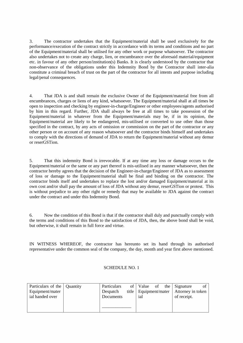
3. The contractor undertakes that the Equipment/material shall be used exclusively for the
performance/execution of the contract strictly in accordance with its terms and conditions and no part
of the Equipment/material shall be utilised for any other work or purpose whatsoever. The contractor
also undertakes not to create any charge, lien, or encumbrance over the aforesaid material/equipment
etc. in favour of any other person/institution(s) Banks. It is clearly understood by the contractor that
non-observance of the obligations under this Indemnity Bond by the Contractor shall inter-alia
constitute a criminal breach of trust on the part of the contractor for all intents and purpose including
legal/penal consequences.
4. That JDA is and shall remain the exclusive Owner of the Equipment/material free from all
encumbrances, charges or liens of any kind, whatsoever. The Equipment/material shall at all times be
open to inspection and checking by engineer-in-charge/Engineer or other employees/agents authorised
by him in this regard. Further, JDA shall always be free at all times to take possession of the
Equipment/material in whatever from the Equipment/materials may be, if in its opinion, the
Equipment/material are likely to be endangered, mis-utilised or converted to use other than those
specified in the contract, by any acts of omission or commission on the part of the contractor or any
other person or on account of any reason whatsoever and the contractor binds himself and undertakes
to comply with the directions of demand of JDA to return the Equipment/material without any demur
or reserGSTion.
5. That this indemnity Bond is irrevocable. If at any time any loss or damage occurs to the
Equipment/material or the same or any part thereof is mis-utilised in any manner whatsoever, then the
contractor hereby agrees that the decision of the Engineer-in-charge/Engineer of JDA as to assessment
of loss or damage to the Equipment/material shall be final and binding on the contractor. The
contractor binds itself and undertakes to replace the lost and/or damaged Equipment/material at its
own cost and/or shall pay the amount of loss of JDA without any demur, reserGSTion or protest. This
is without prejudice to any other right or remedy that may be available to JDA against the contract
under the contract and under this Indemnity Bond.
6. Now the condition of this Bond is that if the contractor shall duly and punctually comply with
the terms and conditions of this Bond to the satisfaction of JDA, then, the above bond shall be void,
but otherwise, it shall remain in full force and virtue.
IN WITNESS WHEREOF, the contractor has hereunto set its hand through its authorised
representative under the common seal of the company, the day, month and year first above mentioned.
SCHEDULE NO. 1
Particulars of the
Equipment/mater
ial handed over
Quantity Particulars of
Despatch title
Documents
_____________
Value of the
Equipment/mater
ial
Signature of
Attorney in token
of receipt.
RR/GR No. date
Bill of lading and
Carrier
( Please number subsequent schedules )
__________________________________________________________________________________
______________
For and on behalf of
M/s /……………….
WITNESS
1. 1. Signature …………. Signature ………………..
2. Name ……………….. Name …………………..
3. Address …………….. Designation ………….
Authorised representative
2. 1. Signature …………..
2. Name ………………..
3. Address …………….. (Common Seal)
(In case of Company)
________________________________________________________________________
Note:- *Indemnity Bonds are to be executed by the authorised person and (i) in case of contracting
Company under common seal of the Company or (ii) having the power of attorney issued under
common seal of the company with authority to execute Indemnity Bonds, (iii) In case of (ii), the
original Power of Attorney if it is specifically for this Contract or a Photostat copy of the Power of
Attorney if it is General Power of Attorney and such documents should be attached to Indemnity
Bond.
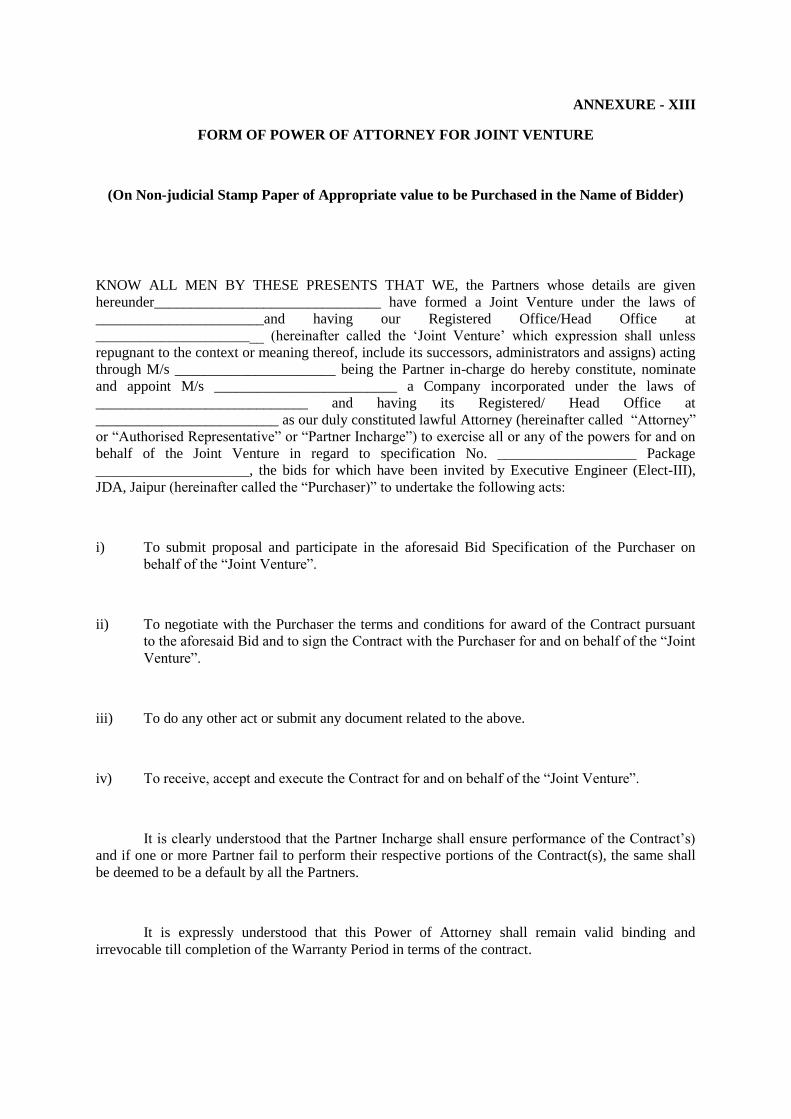
ANNEXURE - XIII
FORM OF POWER OF ATTORNEY FOR JOINT VENTURE
(On Non-judicial Stamp Paper of Appropriate value to be Purchased in the Name of Bidder)
KNOW ALL MEN BY THESE PRESENTS THAT WE, the Partners whose details are given
hereunder_______________________________ have formed a Joint Venture under the laws of
_______________________and having our Registered Office/Head Office at
_______________________ (hereinafter called the ‘Joint Venture’ which expression shall unless
repugnant to the context or meaning thereof, include its successors, administrators and assigns) acting
through M/s ______________________ being the Partner in-charge do hereby constitute, nominate
and appoint M/s _________________________ a Company incorporated under the laws of
_____________________________ and having its Registered/ Head Office at
_________________________ as our duly constituted lawful Attorney (hereinafter called “Attorney”
or “Authorised Representative” or “Partner Incharge”) to exercise all or any of the powers for and on
behalf of the Joint Venture in regard to specification No. ___________________ Package
_____________________, the bids for which have been invited by Executive Engineer (Elect-III),
JDA, Jaipur (hereinafter called the “Purchaser)” to undertake the following acts:
i) To submit proposal and participate in the aforesaid Bid Specification of the Purchaser on
behalf of the “Joint Venture”.
ii) To negotiate with the Purchaser the terms and conditions for award of the Contract pursuant
to the aforesaid Bid and to sign the Contract with the Purchaser for and on behalf of the “Joint
Venture”.
iii) To do any other act or submit any document related to the above.
iv) To receive, accept and execute the Contract for and on behalf of the “Joint Venture”.
It is clearly understood that the Partner Incharge shall ensure performance of the Contract’s)
and if one or more Partner fail to perform their respective portions of the Contract(s), the same shall
be deemed to be a default by all the Partners.
It is expressly understood that this Power of Attorney shall remain valid binding and
irrevocable till completion of the Warranty Period in terms of the contract.

The Joint Venture hereby agrees and undertakes to ratify and confirm all the whatsoever the
said Attorney/Authorised Representative quotes in the bid, negotiates and signs the contract with the
Purchaser and/or proposes to act on behalf of the Joint Venture by virtue of this Power of Attorney
and the same shall bind the Joint Venture as if done by itself.
IN WITNESS THEREOF the Partners Constituting the Joint Venture as aforesaid have
executed these presents on this ___________ day of ________ under the Common Seal(s) of their
Companies.
For and on behalf of
the partners of Joint Venture
________________________
________________________
________________________
The Common Seal of the above Partners of the Joint Venture:
The Common Seal has been affixed there unto in the presence of:
WITNESS
1. Signature ______________________ 2. Signature __________________
Name ______________________ Name
__________________
Designation ______________________ Designation ________________
Occupation ______________________ Occupation _________________
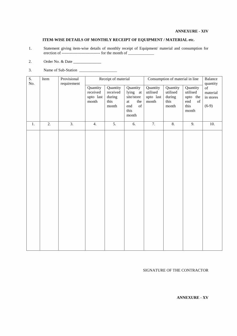
ANNEXURE - XIV
ITEM-WISE DETAILS OF MONTHLY RECEIPT OF EQUIPMENT / MATERIAL etc.
1. Statement giving item-wise details of monthly receipt of Equipment/ material and consumption for
erection of ----------------------------- for the month of _____________
2. Order No. & Date ______________
3. Name of Sub-Station ___________________
S.
No.
Item Provisional
requirement
Receipt of material Consumption of material in line Balance
quantity
of
material
in stores
(6-9)
Quantity
received
upto last
month
Quantity
received
during
this
month
Quantity
lying at
site/store
at the
end of
this
month
Quantity
utilised
upto last
month
Quantity
utilised
during
this
month
Quantity
utilised
upto the
end of
this
month
1. 2. 3. 4. 5. 6. 7. 8. 9. 10.
SIGNATURE OF THE CONTRACTOR
ANNEXURE - XV

DETAILS OF PROGRESS
1. Details of progress achieved during I/II fort-night of month _______________
2. Order No. and Date ______________________________
3. Name of Project : ________________________________
(A) S.No. Erection
activity
(All)
Unit Total
work
involved
Work
done
upto last
fortnight
Work
done
during
fortnight
Total
work
done
upto this
report
Balance
work to
be done
Remarks
1. 2. 3. 4. 5. 6. 7. 8. 9. 10.
(B) Details of work done (activity-wise)
SIGNATURE OF THE CONTRACTOR
Annexure-XVI
FORMAT FOR EVIDENCE OF ACCESS
TO OR AVAILABILITY OF CREDIT/FACILITIES
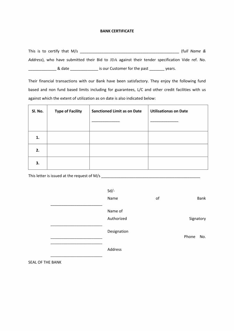
BANK CERTIFICATE
This is to certify that M/s ______________________________________________ (full Name &
Address), who have submitted their Bid to JDA against their tender specification Vide ref. No.
_____________ & date _____________ is our Customer for the past _______ years.
Their financial transactions with our Bank have been satisfactory. They enjoy the following fund
based and non fund based limits including for guarantees, L/C and other credit facilities with us
against which the extent of utilization as on date is also indicated below:
Sl. No. Type of Facility Sanctioned Limit as on Date
_____________
Utilisationas on Date
_____________
1.
2.
3.
This letter is issued at the request of M/s ______________________________________________
Sd/-
Name of Bank ________________________
Name of
Authorized Signatory ________________________
Designation ________________________ Phone No. ________________________
Address ________________________
SEAL OF THE BANK

ANNEXURE-XVII
MANUFACTURER’S WARRANTEE FORM
(FOR SUPPLY PART)
(Warrantee to be furnished on non-judicial stamp paper of Rajasthan Govt. worth Rs.500/-)
To,
The Executive Engineer (Elect-III) Jaipur Development Authority, Jaipur-302005
Dear Sir,
THIS DEED OF GUARANTEE is made this day __________ of __________________ of the year _________ between the Executive Engineer (Elect-III), JDA, Jaipur (which expression shall unless excluded by or repugnant to the context includes his successors and assigns) of the one part and _______________________________ , _______________________________hereinafter called "The Contractor" (which expression shall unless excluded by or repugnant to the context includes its successors and assigns) of the other part.
WHEREAS MESSERS ________________________ (hereinafter called the contractor) agreed to supply the material for erection of RTU System __________________ (Name of sub stations) to the JDAagainst Purchase Order No. __________________ dated _____ (hereinafter referred to as the contract).
AND WHEREAS as per the terms of the contract it was provided that the contractor should furnish a Warrantee for supplying any material free of cost that may be required due to defects arising from faulty materials, design and workmanship, so as to make it meet the guarantees and requirements of the contract.
AND WHEREAS at the request of the JDA, the contractor M/s ______________ has agreed to execute these presents.
NOW THIS INDENTURE WITNESS AND IT IS HEREBY AGREED AND DECLARED by the and between the parties hereto as follows:
1. The Contractor hereby guarantees to the JDA the fulfillment by the contractor of the various obligations imposed on him under the aforesaid contract including the obligations of the contractor to supply materials of the good quality, design and workmanship and the Contractor further guarantees to the JDA that they (M/s

______________) shall substitute and supply any material free of cost that may be required due to defects arising from faulty material, design and workmanship and the Contractor undertakes to indemnify and keep the JDA indemnified to the extent of full value of contract (Rs. _________) (in words Rupees ______________) against any loss or damage that may be caused to or suffered by the JDA by reason of any failure by the contractor to supply materials of good quality, design and workmanship as aforesaid .
The decision of the JDAas to whether the contractor ( M/s ____________) have failed or neglected to perform or discharge their duties and obligations as aforesaid shall be final and binding on the Contractor.
2. The Warrantee herein contained shall remain in full force and effect during the period that would be taken in the performance of the said contract and it shall continue to be valid till all the obligations to the JDAunder or by force of the contract have been fully and properly discharged by the said contractor, subject however, to the conditions that the JDAwill have no right under this Warrantee after 12 months from the date of commissioning/taking over of the sub station, provided further that if any, claim arises by virtue of this Warrantee before the aforesaid date, the same shall be enforceable against the Contractor notwithstanding the fact that the same is enforced after the aforesaid date.
3. The Warrantee herein contained shall not be affected by any change in the constitution of the Contractor.
4. The Contractor further undertakes not to revoke this Warrantee during its currency except with the previous consent of the JDAin writing.
5. All disputes arising under the said Warrantee, between the Contractor and the JDAshall be subject to the jurisdiction of Courts, only at Jaipur in Rajasthan alone.
IN WITNESS WHEREOF THE CONTRACTOR HAS executed these presents the day and year written above.
Yours faithfully,
(EXECUTANT)
Signed by the above named Contractor in presence of: -
(Signature with full Name and Address)

Witness: -
1.
2.
(Attested by Notary Public or First Class Magistrate or directly confirmed by the executing Contractor).
ANNEXURE-A
PRE-QUALIFICATION REQUIREMENT FOR THE WORK OF ”DESIGN, MANUFACTURE, TESTING AT WORKS AND SUPPLY OF 132 KV SINGLE CORE XLPE CABLE FOR ESTABLISHING OF 132 KV DOUBLE CIRCUIT (1200 SQ. MM) BETWEEN SMS STADIUM GSS TO 132 KV TOWER AT NBCC BUILDING SAHAKAR MARG BY

CONVERTING EXISTING 132 KV DOUBLE CIRCUIT OVERHEAD TRANSMISSION LINE INCLUDING INFRONT OF VIDHAN SABHA (JAIPUR) (APPROX. 1.5 KM) INCLUDING DETAILED ROUTE SURVEY, LAYING AND INSTALLATION OF CABLE ALONGWITH ASSOCIATED ACCESSORIES/ ITEMS AND CIVIL WORKS, AND CONTRUCTION OF 1 NOS. 220 KV TYPE C TOWER NARROW BASE (250 MTR SPAN) ALONGWITH DISMANTLING OF EXTING 132 KV TOWERS” Qualification of bidder will be based on meeting the minimum pass/fail criteria specified in table below regarding the Bidder’s technical experience and financial position as demonstrated by the Bidder’s responses in the corresponding Bid Schedules.
Technical experience and financial resource of any sub-contractor/ subsidiary/ associate group or company shall not be taken into account in determining the Bidder’s compliance with the qualifying criteria. The bidder shall be required to furnish the information as detailed hereunder:-
S. No.
Qualifying Requirement details Supporting documents required.
1 2 3
1.1 BIDDER STATUS :
1. This Invitation for Bids, issued by the JDA is open to all firms including company (ies), Government owned Enterprises registered and incorporated in India as per companies Act, 1956, barring Government Department as well as foreign bidders/MNCs not registered and incorporated in India and those bidders with whom business is banned by the JDA.
2. The bidder should be registered under GSTAct.
Memorandum of Association, Registration Certificate as per Companies act.
Copy of GST Registration.
1.2
TECHNICAL EXPERIENCE :
1a. The bidder must be a manufacturer, who hasdesigned, manufactured 132 kV or above voltage grade single core XLPE cable of equal (i.e. 1200 Sq. mm) or higher conductor cross sectionwith Vertical Catenary Vulcanization (VCV) or Continuous Catenary Vulcanization (CCV) or Horizontal MDCV process and type tested the same within last 7 (Seven) years from National/ International accredited laboratory as per reference standards such as IEC 60502 -2 IS- 7098-3, IEC 60840 or any other equivalent standard as on the date of techn-commercial bid opening. He must have supplied at-least 20 km [of which atleast 10 km should be of equal (i.e. 1200 Sq. mm.) or higher conductor corss section] of 132 kV or above voltage grade single core XLPE cable in last seven years and atleast 06 km of 132
1. Bidder shall submit the following documents duly certified by Chartered accountant:
i. Documents showing adequate EHV class cable design infrastructure, manufacturing facilities, capacity and procedures including quality control with complete details of manufacturing process of cable in fulfillment to qualification criteria Point 1.2 (1a).
ii. Past Supply of 132 kV or above voltage grade single core XLPE cable as required for meeting qualification criteriaPoint 1.2 (1a).
2. End User Certificate for satisfactory operation of supplied 132 kV Single Core XLPE cable in

kV Single Core XLPE cable supplied should be in satisfactory operation for one year in India in last five years as on the date of techno-commercial bid opening.
OR
1b. The bidder must be an authorized firm of the manufacturer (s) meeting the above criteria (1a) provided that the manufacturer (s) authorizes the bidder for full backup supply and service support as per appended performa (Schedule-G). 2. The bidder (who are fulfilling the criteria 1a or 1b above) should have successful commissioning experience (including detailed route survey, erection, testing and commissioning of cable laying, Cable kits, jointing Kits, End termination kits along-with associated civil works) of at-least 5 Km ( Single Circuit having 3 X Single Core Cables of 132 kV or above voltage grade) or 2.5 Km. (Double Circuit having 3 X Single Core cable of 132 kV or above grade in each circuit) in India and those are in satisfactory operation for at least 1 year as on the date of techno-commercial bid opening. 3. The bidder (who are fulfilling the criteria 1a or 1b above) shall supply the cable kit/ accessories from the manufacturer who has designed, manufactured the cable kit/ accessories for 132 kV Single Core XLPE cable suitable for cross section as required in the bid and type tested the same within last 7 (Seven) years from National/ International accredited laboratory as per reference standards such as IEC 60840 or any other equivalent standard as on the date of techn-commercial bid opening. Manufacturer must have supplied at-least 24 Nos. of Straight through Joint and atleast 06 Nos. of Outdoor
satisfactory operation to meet the qualification criteria Point 1.2 (1a).
3. The type test certificates of 132 kV or above voltage grade cable of equal (i.e. 1200 Sq. mm) or higher conductor cross section as required meeting qualification criteriaPoint 1.2 (1a).
Authorization Certificate from Manufacturer (s) for compliance of Point 1a is required to be submitted in Schedule-G.
End User Certificate for satisfactory operation of complete cable system for one year to meet the qualification criteria at Point 1.2 (2).
1. Bidder shall submit the following
documents duly certified by Charted accountant:
i. Past Supply of 132 kV Single Core XLPE Cable kit/ accessories as required for meeting qualification criteria Point 1.2 (3).
2. End User Certificate for satisfactory operation of supplied 132 kV Single Core XLPE Cable kit/ accessories in satisfactory operation to meet the qualification criteria Point 1.2 (3).
3. The type test certificates of 132 kV Single Core XLPE Cable kit/ accessories as required for meeting qualification criteria Point 1.2 (3).
4. Authorization Certificate from Manufacturer (s) for compliance of Point 1.2 (3) is required to be submitted in Schedule-G.

cable end terminiation kit for 132 kV Single Core XLPE cable in last seven years and atleast 06 Nos. of Straight through Joint and atleast 03 Nos. of Outdoor cable end terminiation kit for 132 kV Single Core XLPE cable should have been under satisfactory operation of one year in India in last five years as on the date of techno-commercial bid opening.
1.3
FINANCIAL POSITION :
1. The bidders shall meet Minimum Average Annual Turnover (MAAT) for best three (3) financial years out of last five (5) financial years: Rs. 3000 Lacs
i) Audited balance sheets and income statement as detailed in Schedule-N. or
ii) CA certificate.
2. Bidder shall have Liquid Assets (LA=Current Assets- inventories) or/and evidence of access to or availability of credit facilities: Rs. 500 Lacs
i) Audited balance sheets and income statement as detailed in Schedule-N. or
ii) CA certificate.
iii) For credit facilities: Certificate from bank as per Annexure-XIII.
3. The Net Worth of the bidder for last three (3) years should be positive.
i) Audited balance sheets and income statement as detailed in Schedule-N. or
ii) CA certificate.
1.4 JOINT VENTURE
In case a bid is submitted by a Joint Venture (JV) [up to two firms only as partners], Joint venture shall meet collectively all the requirement of Clause No. 1.2 & 1.3 above. The figure of average annual turnover and liquid assets/credit facilities for each of the partners of the JV shall be added together to determine the JV’s compliance with the minimum qualifying criteria set out in Clause 1.3 above. However, for a JV to be qualified, the partner(s) of JV must also meet the following minimum criteria:
i) The lead partner shall meet Clause No. 1.2, (2) as above and not less than 50% of the minimum criteria given at Clause 1.2 above.
ii) The other partner
a) Shall meet not less than 25% of the minimum criteria given at Clause No. 1.3 and,
Joint Venture Agreement (Annexure-IX) and Power of Attorney for Joint Venture (Annexure-XIII)
b) Shall meet remaining qualifying
requirements for collective fulfillment of Clause No. 1.2 above.
iii) A firm can be a partner in only one
joint venture; bid submitted by Joint 1 Venture including the same firm as partner will be rejected.
Failure to comply with these requirements as above will result in rejection of the joint venture’s bid.
1.5 DECLARATION BY BIDDER:
The bidder should be qualified, not be insolvent, not be in receivership, not be Bankrupt or being wound up, should not have affairs administered by a court or a judicial officer, should not have business activities suspended, should not be blacklisted by any utility /agency, should not have a conflict of interest etc.
Declaration in Schedule – Q.
SCHEDULE-A (Attachment-8)
A. SCHEDULE OF REQUIREMENTS (SOR):
The schedule of requirement in respect of ‘Major Goods and Services’, ‘Mandatory Spares, Testing & Measuring Instruments, Tools & Tackles’ and ‘Work Schedule’ are listed below:
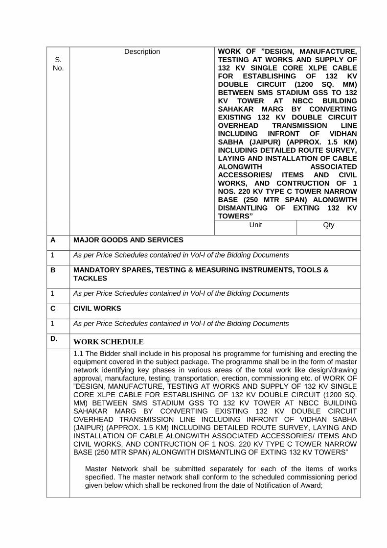
S.
No.
Description WORK OF ”DESIGN, MANUFACTURE, TESTING AT WORKS AND SUPPLY OF 132 KV SINGLE CORE XLPE CABLE FOR ESTABLISHING OF 132 KV DOUBLE CIRCUIT (1200 SQ. MM) BETWEEN SMS STADIUM GSS TO 132 KV TOWER AT NBCC BUILDING SAHAKAR MARG BY CONVERTING EXISTING 132 KV DOUBLE CIRCUIT OVERHEAD TRANSMISSION LINE INCLUDING INFRONT OF VIDHAN SABHA (JAIPUR) (APPROX. 1.5 KM) INCLUDING DETAILED ROUTE SURVEY, LAYING AND INSTALLATION OF CABLE ALONGWITH ASSOCIATED ACCESSORIES/ ITEMS AND CIVIL WORKS, AND CONTRUCTION OF 1 NOS. 220 KV TYPE C TOWER NARROW BASE (250 MTR SPAN) ALONGWITH DISMANTLING OF EXTING 132 KV TOWERS”
Unit Qty
A MAJOR GOODS AND SERVICES
1 As per Price Schedules contained in Vol-I of the Bidding Documents
B MANDATORY SPARES, TESTING & MEASURING INSTRUMENTS, TOOLS & TACKLES
1 As per Price Schedules contained in Vol-I of the Bidding Documents
C CIVIL WORKS
1 As per Price Schedules contained in Vol-I of the Bidding Documents
D. WORK SCHEDULE
1.1 The Bidder shall include in his proposal his programme for furnishing and erecting the equipment covered in the subject package. The programme shall be in the form of master network identifying key phases in various areas of the total work like design/drawing approval, manufacture, testing, transportation, erection, commissioning etc. of WORK OF ”DESIGN, MANUFACTURE, TESTING AT WORKS AND SUPPLY OF 132 KV SINGLE CORE XLPE CABLE FOR ESTABLISHING OF 132 KV DOUBLE CIRCUIT (1200 SQ. MM) BETWEEN SMS STADIUM GSS TO 132 KV TOWER AT NBCC BUILDING SAHAKAR MARG BY CONVERTING EXISTING 132 KV DOUBLE CIRCUIT OVERHEAD TRANSMISSION LINE INCLUDING INFRONT OF VIDHAN SABHA (JAIPUR) (APPROX. 1.5 KM) INCLUDING DETAILED ROUTE SURVEY, LAYING AND INSTALLATION OF CABLE ALONGWITH ASSOCIATED ACCESSORIES/ ITEMS AND CIVIL WORKS, AND CONTRUCTION OF 1 NOS. 220 KV TYPE C TOWER NARROW BASE (250 MTR SPAN) ALONGWITH DISMANTLING OF EXTING 132 KV TOWERS”
Master Network shall be submitted separately for each of the items of works specified. The master network shall conform to the scheduled commissioning period given below which shall be reckoned from the date of Notification of Award;
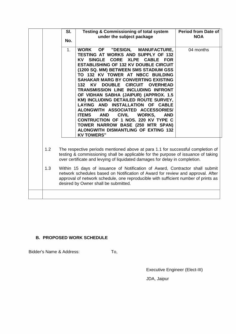
Sl.
No.
Testing & Commissioning of total system under the subject package
Period from Date of NOA
1. WORK OF ”DESIGN, MANUFACTURE, TESTING AT WORKS AND SUPPLY OF 132 KV SINGLE CORE XLPE CABLE FOR ESTABLISHING OF 132 KV DOUBLE CIRCUIT (1200 SQ. MM) BETWEEN SMS STADIUM GSS TO 132 KV TOWER AT NBCC BUILDING SAHAKAR MARG BY CONVERTING EXISTING 132 KV DOUBLE CIRCUIT OVERHEAD TRANSMISSION LINE INCLUDING INFRONT OF VIDHAN SABHA (JAIPUR) (APPROX. 1.5 KM) INCLUDING DETAILED ROUTE SURVEY, LAYING AND INSTALLATION OF CABLE ALONGWITH ASSOCIATED ACCESSORIES/ ITEMS AND CIVIL WORKS, AND CONTRUCTION OF 1 NOS. 220 KV TYPE C TOWER NARROW BASE (250 MTR SPAN) ALONGWITH DISMANTLING OF EXTING 132 KV TOWERS”
04 months
1.2 The respective periods mentioned above at para 1.1 for successful completion of testing & commissioning shall be applicable for the purpose of issuance of taking over certificate and levying of liquidated damages for delay in completion.
1.3 Within 15 days of issuance of Notification of Award, Contractor shall submit network schedules based on Notification of Award for review and approval. After approval of network schedule, one reproducible with sufficient number of prints as desired by Owner shall be submitted.
B. PROPOSED WORK SCHEDULE
Bidder's Name & Address: To,
Executive Engineer (Elect-III)
JDA, Jaipur
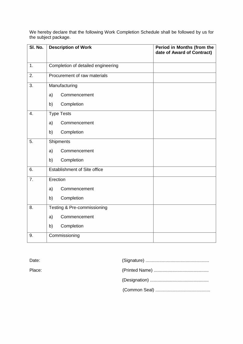
We hereby declare that the following Work Completion Schedule shall be followed by us for the subject package.
Sl. No. Description of Work Period in Months (from the date of Award of Contract)
1. Completion of detailed engineering
2. Procurement of raw materials
3. Manufacturing
a) Commencement
b) Completion
4. Type Tests
a) Commencement
b) Completion
5. Shipments
a) Commencement
b) Completion
6. Establishment of Site office
7. Erection
a) Commencement
b) Completion
8. Testing & Pre-commissioning
a) Commencement
b) Completion
9. Commissioning
Date: (Signature) ...................................................
Place: (Printed Name) ............................................
(Designation) ...............................................
(Common Seal) ............................................

Schedule-BOQ
Conversion of 132 KV double circuit Mansrovar - SMS Stadium overhead transmission
line to underground cable (Approx- 1.5 KM) near Vidhansabha Jaipur against Bid
enquiry No. JDA/EE/Elect-III/2018-19/05
(GRAND SUMMARY)
Bidder's Name and Address:
S. No. Description Total Price (INR)
1 TOTAL SCHEDULE NO. BOQ
SUPPLY PART
2 TOTAL SCHEDULE NO. BOQ
SERVICE PART
3 GRAND TOTAL BOQ [1+2]
Date: Signature:
Place: Printed Name:
Designation:
Common Seal:

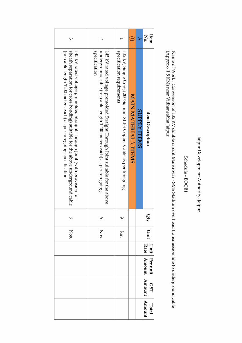
Jaipu
r Dev
elop
men
t Au
tho
rity, Jaip
ur
Sch
edu
le - BO
QB
1
Nam
e of W
ork
: Co
nv
ersion
of 132 K
V d
ou
ble circu
it Man
srov
ar - SM
S S
tadiu
m o
verh
ead tran
smissio
n lin
e to u
nd
ergro
un
d cab
le (A
pp
rox
- 1.5 KM
) near V
idh
ansab
ha Jaip
ur
Item
N
o.
item D
escriptio
n
Qty
U
nit
Un
it R
ate
Pe
r un
it A
mo
un
t G
ST
A
mo
un
t T
ota
l A
mo
un
t
A
SU
PP
LY
ITE
MS
(I) M
AIN
MA
TE
RIA
L \
ITE
MS
1 132 k
V, S
ing
le Co
re,1200 Sq
. mm
XL
PE
Co
pp
er Cab
le as per fo
rego
ing
sp
ecification
requ
iremen
ts 9
km
2 145 k
V rated
vo
ltage p
remo
lded
Straig
ht T
hro
ug
h Jo
int su
itable fo
r the ab
ov
e u
nd
ergro
un
d cab
le (for cab
le leng
th 1200 m
eters each) as p
er foreg
oin
g
specificatio
n
6 N
os.
3 145 k
V rated
vo
ltage p
remo
lded
Straig
ht T
hro
ug
h Jo
int (w
ith p
rov
ision
for
sheath
separatio
n fo
r cross b
on
din
g) su
itable fo
r the ab
ov
e un
derg
rou
nd
cable
(for cab
le leng
th 1200 m
eters each) as p
er foreg
oin
g sp
ecification
6
No
s.

4
145 kV
rated v
oltag
e prem
old
ed o
utd
oo
r end
termin
ation
kit co
mp
lete with
accesso
ries suitab
le for th
e abo
ve u
nd
ergro
un
d cab
le and
suitab
le for
termin
ation
in O
utd
oo
r typ
e switch
yard
as per th
e requ
iremn
t of fo
rego
ing
sp
ecification
12 N
os.
5 S
olid
bo
nd
ing
Lin
k b
ox
with
Lin
k p
lates, bo
nd
ing
& g
rou
nd
ing
cable
com
plete w
ith o
ther asso
ciated accesso
ries for 1-p
hase
12 N
os.
6 C
ross b
on
din
g L
ink
bo
x, C
o-ax
ial bo
nd
ing
cable, S
heath
Vo
ltage L
imiters
(SV
L) co
mp
lete with
oth
er associated
accessories fo
r each 3-p
hase circu
it 2
Set
7
Galv
anized
Steel S
up
po
rting
Stru
ctures alo
ng
with
clamp
s, con
necto
rs, nu
t-b
olts, w
ashers, fo
un
datio
n b
olts etc. fo
r Ou
tdo
or 132 k
V C
able en
d
termin
ation
s (a com
po
site structu
re to m
ou
nt lin
k b
ox
es and
the cab
le end
term
inatio
ns) fo
r each p
hase
6 S
et
8 G
alvan
ized S
teel sup
po
rting
structu
res / A
rrang
emen
t, Gan
try stru
ctures,
Lad
ders etc. F
or S
uitab
le and
safe termin
ation
s of X
LP
E cab
le from
Term
inal
To
wers m
aintain
ing
statuto
ry clearan
ces and
safety as p
er IE R
ules
1 L
ot
9 132 K
V class o
f 120 KV
rating
ligh
tenin
g A
rrester (LA
) 6
No
s
10 E
arthin
g M
aterial inclu
din
g cast iro
n p
ipes w
ith su
itable clam
ps, ch
arcol,
com
mo
n salt etc. co
mp
lete set for each
Cab
le Circu
it. 2
Set
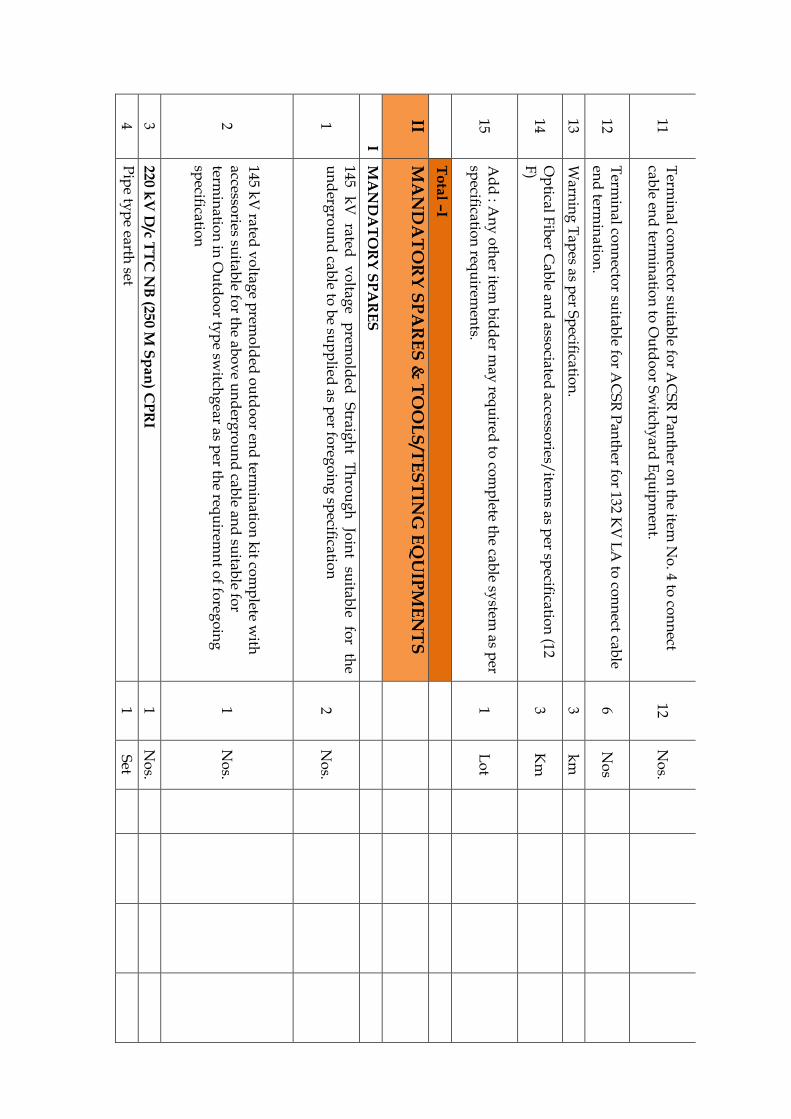
11 T
ermin
al con
necto
r suitab
le for A
CS
R P
anth
er on
the item
No
. 4 to co
nn
ect cab
le end
termin
ation
to O
utd
oo
r Sw
itchy
ard E
qu
ipm
ent.
12 N
os.
12 T
ermin
al con
necto
r suitab
le for A
CS
R P
anth
er for 132 K
V L
A to
con
nect cab
le en
d term
inatio
n.
6 N
os
13 W
arnin
g T
apes as p
er Sp
ecification
. 3
km
14 O
ptical F
iber C
able an
d asso
ciated accesso
ries/item
s as per sp
ecification
(12 F
) 3
Km
15 A
dd
: An
y o
ther item
bid
der m
ay req
uired
to co
mp
lete the cab
le system
as per
specificatio
n req
uirem
ents.
1 L
ot
T
ota
l –I
II M
AN
DA
TO
RY
SP
AR
ES
& T
OO
LS
/TE
ST
ING
EQ
UIP
ME
NT
S
I M
AN
DA
TO
RY
SP
AR
ES
1
145 k
V
rated
vo
ltage
prem
old
ed
Straig
ht
Th
rou
gh
Jo
int
suitab
le fo
r th
e u
nd
ergro
un
d cab
le to b
e sup
plied
as per fo
rego
ing
specificatio
n
2 N
os.
2
145 kV
rated v
oltag
e prem
old
ed o
utd
oo
r end
termin
ation
kit co
mp
lete with
accesso
ries suitab
le for th
e abo
ve u
nd
ergro
un
d cab
le and
suitab
le for
termin
ation
in O
utd
oo
r typ
e switch
gear as p
er the req
uirem
nt o
f foreg
oin
g
specificatio
n
1 N
os.
3 2
20
kV
D/c T
TC
NB
(25
0 M S
pa
n) C
PR
I 1
No
s.
4 P
ipe ty
pe earth
set 1
Set

5 D
ang
er Plate
1 N
os.
6 P
hase P
late 1
Set
7 N
um
ber P
late 1
No
s.
8 A
CS
R P
anth
er con
du
ctor
0.15 K
m
9 D
T H
ardw
are for p
anth
er 6
Set
10 D
isc Insu
lator 120 K
N
120 N
os.
11 E
arth W
ire 7/3.15 m
m
0.05 K
m
12 (1) S
train A
ssemb
ly
2 N
os.
13 (1)16*35
0.015 M
T
14 (2)16*40
0.065 M
T
15 (3)16*45
0.05 M
T
16 (4)16*50
0.07 M
T
17 (5)16*55
0.075 M
T
18 (6)16*60
0.035 M
T
19 (7)16*65
0.035 M
T
20 (8)16*70
0.0035 M
T
21 (9)16*75
0.04 M
T
22 (10)16*85
0.15 M
T
23 S
tep B
olt
0.03 M
T
24 S
prin
g W
asher
0.03 M
T
T
ota
l of II
III S
UP
PL
Y &
ER
RE
CT
ION
OF
OL
TE
EQ
UIP
ME
NT
S
I (O
ptic
al lin
e T
ransm
issio
n e
quip
men
t) OLT
E E
QU
IPM
EN
TS
0
0
1
220 k
V G
SS S
anganer e
nd
0
0

A
OLTE
EQ
UIP
ME
NT c
on
sis
ting o
f 1
Set
0
Fu
lly W
ired C
abin
et
with
base 19"
equ
ipm
en
t ra
ck (in
cl.
fron
t cover,
cable
tray, c
om
mon
card
s) w
ith F
an
un
it an
d C
on
trol, S
yn
ch
ron
isatio
n, A
larm
, du
al
Pow
er s
upply
inpu
t cable
s.
0
0
0
Cen
tral P
rocessin
g C
ard
- CPU
- 2 N
os.
0
0
0
Pow
er s
upply
un
it -48V
DC
- 2 N
os.
0
0
0
OLTE
- 4 P
ort S
TM
-1(1
55 M
bps C
ard
) alo
ngw
ith S
FPs- 1
Set
0
0
0
OF
C P
atc
h C
ord
s - (S
et o
f 48 N
os.)-1
Set
0
0
0
8 P
ort 2
w/4w
E&
M In
terfa
ce C
ard
- 1 N
o.
0
0
0
4 P
ort D
ata
Inte
rface C
ard
- 2 N
os.
0
0
0
Eth
ern
et o
ver S
DH
tran
sport c
ard
(with
fou
r 10/100 b
aseT, o
ne 1
00B
ase-F
X
an
d o
ne 1
000B
ase-L
X/S
X fro
nt in
terfa
ces)- 1
No.
0
0
0
4 C
om
man
d In
tegra
ted T
ele
pro
tectio
n C
ard
- 2 N
os.
0
0
0
Lin
e D
iffere
ntia
l rela
y in
terfa
ce c
ard
(4 p
orts
)- 1 N
o.
0
0
0
Inte
rface cable
s fo
r Pow
er,
data
, voic
e,
tele
pro
tectio
n,
time syn
ch
ron
isatio
n
etc
as p
er re
spectiv
e s
ite re
qu
irem
en
t- 1 L
OT
0
0
0
En
gin
eerin
g O
rder W
ire P
hon
e- 1
No.
0
0
B
Ele
ctro
nic
Priv
ate
Au
tom
atic
Exch
an
ge (E
PA
X)
1
Set
2
220 k
V G
SS M
an
saro
var e
nd
0
0
A
OLTE
EQ
UIP
ME
NT c
on
sis
ting o
f 1
Set
0
Fu
lly W
ired C
abin
et
with
base 19"
equ
ipm
en
t ra
ck (in
cl.
fron
t cover,
cable
tray, c
om
mon
card
s) w
ith F
an
un
it an
d C
on
trol, S
yn
ch
ron
isatio
n, A
larm
, du
al
Pow
er s
upply
inpu
t cable
s.
0
0
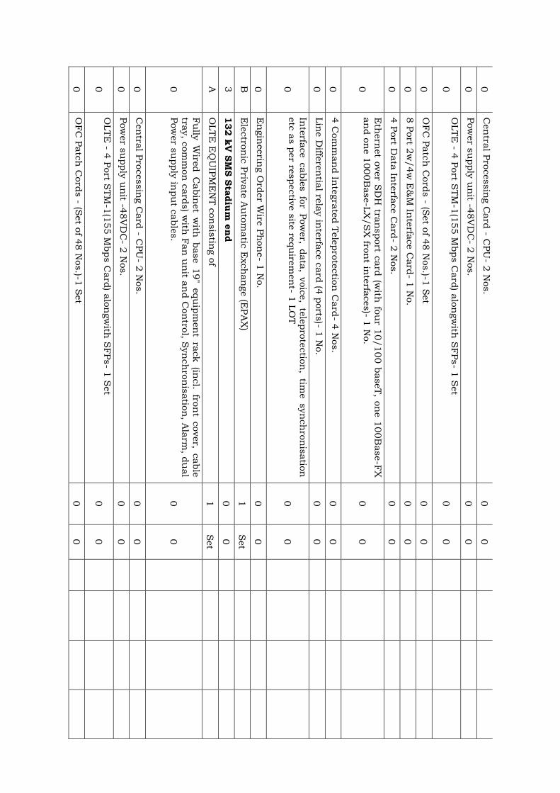
0
Cen
tral P
rocessin
g C
ard
- CPU
- 2 N
os.
0
0
0
Pow
er s
upply
un
it -48V
DC
- 2 N
os.
0
0
0
OLTE
- 4 P
ort S
TM
-1(1
55 M
bps C
ard
) alo
ngw
ith S
FPs- 1
Set
0
0
0
OF
C P
atc
h C
ord
s - (S
et o
f 48 N
os.)-1
Set
0
0
0
8 P
ort 2
w/4w
E&
M In
terfa
ce C
ard
- 1 N
o.
0
0
0
4 P
ort D
ata
Inte
rface C
ard
- 2 N
os.
0
0
0
Eth
ern
et o
ver S
DH
tran
sport c
ard
(with
fou
r 10/100 b
aseT, o
ne 1
00B
ase-F
X
an
d o
ne 1
000B
ase-L
X/S
X fro
nt in
terfa
ces)- 1
No.
0
0
0
4 C
om
man
d In
tegra
ted T
ele
pro
tectio
n C
ard
- 4 N
os.
0
0
0
Lin
e D
iffere
ntia
l rela
y in
terfa
ce c
ard
(4 p
orts
)- 1 N
o.
0
0
0
Inte
rface cable
s fo
r Pow
er,
data
, voic
e,
tele
pro
tectio
n,
time syn
ch
ron
isatio
n
etc
as p
er re
spectiv
e s
ite re
qu
irem
en
t- 1 L
OT
0
0
0
En
gin
eerin
g O
rder W
ire P
hon
e- 1
No.
0
0
B
Ele
ctro
nic
Priv
ate
Au
tom
atic
Exch
an
ge (E
PA
X)
1
Set
3
132 k
V S
MS S
tadiu
m e
nd
0
0
A
OLTE
EQ
UIP
ME
NT c
on
sis
ting o
f 1
Set
0
Fu
lly W
ired C
abin
et
with
base 19"
equ
ipm
en
t ra
ck (in
cl.
fron
t cover,
cable
tra
y, c
om
mon
card
s) w
ith F
an
un
it an
d C
on
trol, S
yn
ch
ron
isatio
n, A
larm
, du
al
Pow
er s
upply
inpu
t cable
s.
0
0
0
Cen
tral P
rocessin
g C
ard
- CPU
- 2 N
os.
0
0
0
Pow
er s
upply
un
it -48V
DC
- 2 N
os.
0
0
0
OLTE
- 4 P
ort S
TM
-1(1
55 M
bps C
ard
) alo
ngw
ith S
FPs- 1
Set
0
0
0
OF
C P
atc
h C
ord
s - (S
et o
f 48 N
os.)-1
Set
0
0

0
8 P
ort 2
w/4w
E&
M In
terfa
ce C
ard
- 1 N
o.
0
0
0
4 P
ort D
ata
Inte
rface C
ard
- 2 N
os.
0
0
0
Eth
ern
et o
ver S
DH
tran
sport c
ard
(with
fou
r 10/100 b
aseT, o
ne 1
00B
ase-F
X
an
d o
ne 1
000B
ase-L
X/S
X fro
nt in
terfa
ces)- 1
No.
0
0
0
4 C
om
man
d In
tegra
ted T
ele
pro
tectio
n C
ard
- 2 N
os.
0
0
0
Lin
e D
iffere
ntia
l rela
y in
terfa
ce c
ard
(4 p
orts
)- 1 N
o.
0
0
0
Inte
rface cable
s fo
r Pow
er,
data
, voic
e,
tele
pro
tectio
n,
time syn
ch
ron
isatio
n
etc
as p
er re
spectiv
e s
ite re
qu
irem
en
t- 1 L
OT
0
0
0
En
gin
eerin
g O
rder W
ire P
hon
e- 1
No.
0
0
B
Ele
ctro
nic
Priv
ate
Au
tom
atic
Exch
an
ge (E
PA
X)
1
Set
4
Ele
ctro
nic
Pu
sh
Bu
tton
Tele
ph
on
e In
stru
men
ts w
ith re
qu
ired a
ccessorie
s e
tc.
10
Nos.
5
Lapto
p (C
ore
2 D
uo, 2
.4 G
Hz, 1
5"T
FT, 1
60 G
B H
DD
, 2 G
B R
AM
, DV
D R
/W
)
with
con
figu
ratio
n S
oftw
are
for a
ll Com
mu
nic
atio
n E
qu
ipm
en
ts a
s o
ffere
d
1
No.
6
Add: A
ny o
ther ite
m b
idder m
ay re
qu
ire to
com
ple
te th
e O
LTE
Syste
m a
s p
er
specific
atio
n re
qu
irem
en
ts
1
LO
T
II O
PG
W/O
FC
AN
D H
AR
DW
AR
E F
ITT
ING
/ A
CC
ESSO
RIE
S
1
OPG
Wire
15
km
2
Insta
llatio
n
Hard
ware
fo
r above
OPG
W,
Inclu
din
g
all
cable
s
Fittin
gs
&
Accessorie
s
like
su
spen
sio
n
cla
mps,
ten
sio
n
cla
mps.
vib
ratio
n
dam
pers
,
earth
ing cla
mps,d
ow
n le
adcla
mps,In
line splic
e en
clo
ure
s/ Join
t B
oxes etc
(O
ne S
et is
com
ple
te fo
r 1 k
m T
ran
sm
issio
n L
ine)
15
Set
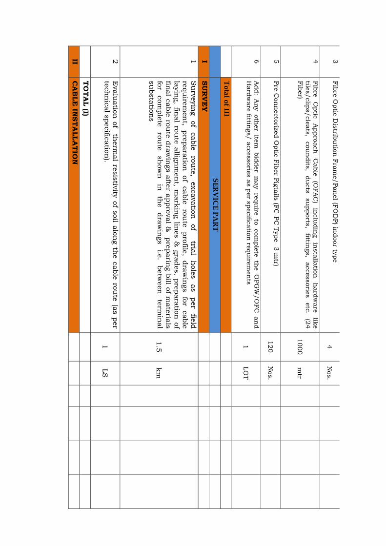
3
Fib
re O
ptic
Dis
tribu
tion
Fra
me/Pan
el (F
OD
P) in
door ty
pe
4
Nos.
4
Fib
re
Optic
A
ppro
ach
C
able
(O
FA
C)
inclu
din
g
insta
llatio
n
hard
ware
lik
e
tiles/clip
s/cle
ats
, cou
ndits
, du
cts
su
pports
, fittin
gs,
accessorie
s
etc
. (2
4
Fib
er)
1000
mtr
5
Pre
Con
necto
rized O
ptic
Fib
er P
igta
ils (F
C-P
C T
ype- 3
mtr)
120
Nos.
6
Add:
An
y oth
er
item
bid
der
may re
qu
ire to
com
ple
te th
e O
PG
W/O
FC
an
d
Hard
ware
fittings/ a
ccessorie
s a
s p
er s
pecific
atio
n re
qu
irem
en
ts
1
LO
T
T
ota
l of III
S
ER
VIC
E P
AR
T
I SU
RV
EY
1
Su
rveyin
g
of
cable
ro
ute
, excavatio
n
of
tria
l h
ole
s
as
per
field
re
qu
irem
en
t, pre
para
tion
of
cable
ro
ute
pro
file,
dra
win
gs fo
r cable
la
yin
g, fin
al ro
ute
allig
nm
en
t, mark
ing lin
es &
gra
des, p
repara
tion
of
final c
able
rou
te d
raw
ings a
fter a
ppro
val &
pre
parin
g b
ill of m
ate
rials
fo
r com
ple
te
rou
te
sh
ow
n
in
the
dra
win
gs
i.e.
betw
een
te
rmin
al
su
bsta
tion
s
1.5
km
2
Evalu
atio
n o
f therm
al re
sis
tivity
of s
oil a
lon
g th
e c
able
rou
te (a
s p
er
tech
nic
al s
pecific
atio
n).
1
LS
T
OT
AL (I)
II C
AB
LE
INST
ALLA
TIO
N
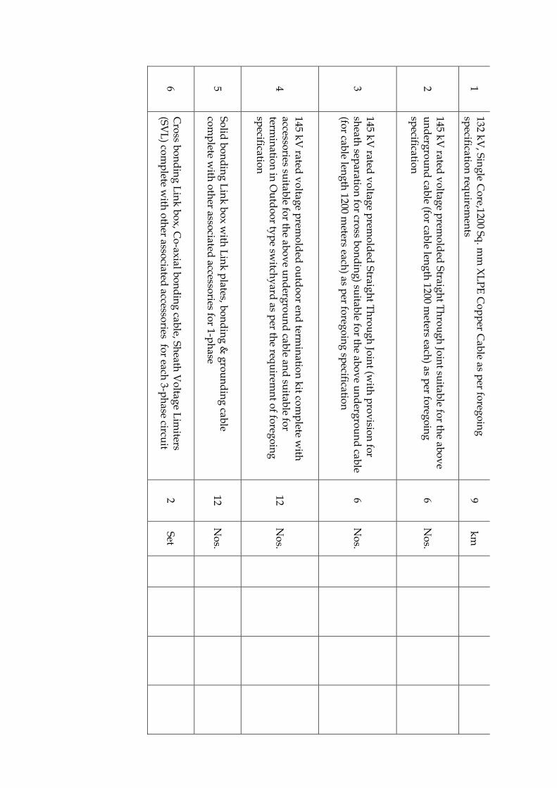
1 132 k
V, S
ing
le Co
re,1200 Sq
. mm
XL
PE
Co
pp
er Cab
le as per fo
rego
ing
sp
ecification
requ
iremen
ts 9
km
2 145 k
V rated
vo
ltage p
remo
lded
Straig
ht T
hro
ug
h Jo
int su
itable fo
r the ab
ov
e u
nd
ergro
un
d cab
le (for cab
le leng
th 1200 m
eters each) as p
er foreg
oin
g
specificatio
n
6 N
os.
3 145 k
V rated
vo
ltage p
remo
lded
Straig
ht T
hro
ug
h Jo
int (w
ith p
rov
ision
for
sheath
separatio
n fo
r cross b
on
din
g) su
itable fo
r the ab
ov
e un
derg
rou
nd
cable
(for cab
le leng
th 1200 m
eters each) as p
er foreg
oin
g sp
ecification
6
No
s.
4
145 kV
rated v
oltag
e prem
old
ed o
utd
oo
r end
termin
ation
kit co
mp
lete with
accesso
ries suitab
le for th
e abo
ve u
nd
ergro
un
d cab
le and
suitab
le for
termin
ation
in O
utd
oo
r typ
e switch
yard
as per th
e requ
iremn
t of fo
rego
ing
sp
ecification
12 N
os.
5 S
olid
bo
nd
ing
Lin
k b
ox
with
Lin
k p
lates, bo
nd
ing
& g
rou
nd
ing
cable
com
plete w
ith o
ther asso
ciated accesso
ries for 1-p
hase
12 N
os.
6 C
ross b
on
din
g L
ink
bo
x, C
o-ax
ial bo
nd
ing
cable, S
heath
Vo
ltage L
imiters
(SV
L) co
mp
lete with
oth
er associated
accessories fo
r each 3-p
hase circu
it 2
Set
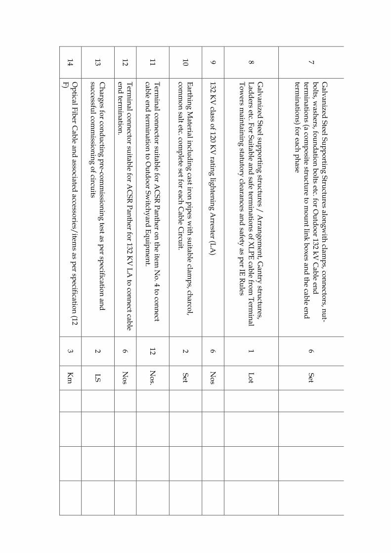
7
Galv
anized
Steel S
up
po
rting
Stru
ctures alo
ng
with
clamp
s, con
necto
rs, nu
t-b
olts, w
ashers, fo
un
datio
n b
olts etc. fo
r Ou
tdo
or 132 k
V C
able en
d
termin
ation
s (a com
po
site structu
re to m
ou
nt lin
k b
ox
es and
the cab
le end
term
inatio
ns) fo
r each p
hase
6 S
et
8 G
alvan
ized S
teel sup
po
rting
structu
res / A
rrang
emen
t, Gan
try stru
ctures,
Lad
ders etc. F
or S
uitab
le and
safe termin
ation
s of X
LP
E cab
le from
Term
inal
To
wers m
aintain
ing
statuto
ry clearan
ces and
safety as p
er IE R
ules
1 L
ot
9 132 K
V class o
f 120 KV
rating
ligh
tenin
g A
rrester (LA
) 6
No
s
10 E
arthin
g M
aterial inclu
din
g cast iro
n p
ipes w
ith su
itable clam
ps, ch
arcol,
com
mo
n salt etc. co
mp
lete set for each
Cab
le Circu
it. 2
Set
11 T
ermin
al con
necto
r suitab
le for A
CS
R P
anth
er on
the item
No
. 4 to co
nn
ect cab
le end
termin
ation
to O
utd
oo
r Sw
itchy
ard E
qu
ipm
ent.
12 N
os.
12 T
ermin
al con
necto
r suitab
le for A
CS
R P
anth
er for 132 K
V L
A to
con
nect cab
le en
d term
inatio
n.
6 N
os
13 C
harg
es for co
nd
uctin
g p
re-com
missio
nin
g test as p
er specificatio
n an
d
successfu
l com
missio
nin
g o
f circuits
2 L
S
14 O
ptical F
iber C
able an
d asso
ciated accesso
ries/item
s as per sp
ecification
(12 F
) 3
Km
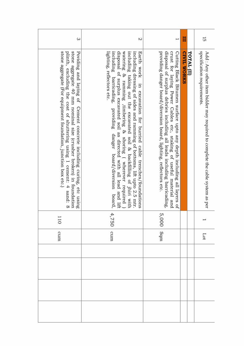
15 A
dd
: An
y o
ther item
bid
der m
ay req
uired
to co
mp
lete the cab
le system
as per
specificatio
n req
uirem
ents.
1 L
ot
T
OT
AL (II)
III C
IVIL
WO
RK
S
1
Cu
tting B
lack B
itum
en
su
rface u
pto
an
y d
epth
inclu
din
g a
ll layers
of
cru
st
for
layin
g
Pow
er
Cable
s
etc
, sta
kin
g
of
usefu
l m
ate
rial
an
d
dis
posal o
f su
rplu
s d
ebrie
s in
clu
din
g a
ll leads in
clu
din
g b
arric
adin
g,
pro
vid
ing d
an
ger b
oard
/div
ers
ion
board
, ligh
ting, re
flecto
rs e
tc.
5,0
00
Sqm
2
Earth
w
ork
in
excavatio
n
for
bu
rried
cable
tre
nch
es/fo
un
datio
ns
inclu
din
g d
ressin
g o
f sid
es a
nd ra
mm
ing o
f botto
ms, lift u
pto
2.5
mtr.
inclu
din
g
takin
g ou
t th
e
excavate
d
soil
&
backfillin
g of
jhiri
with
w
ate
ring
&
ram
min
g
,timberin
g
&
sh
orin
g
( w
here
ver
requ
ired
) dis
posal
of
su
rplu
s excavate
d soil
as dire
cte
d w
ith all
lead an
d lift
inclu
din
g
barric
adin
g,
pro
vid
ing
dan
ger
board
/div
ers
ion
board
, lig
htin
g, re
flecto
rs e
tc.
4,7
50
cu
m
3
Povid
ing an
d la
yin
g of
C
em
en
t con
cre
te in
clu
din
g cu
ring,
etc
u
sin
g
sto
ne aggre
gate
40 m
m n
om
inal
size
(c
rush
er
bro
ken
) in
fo
un
datio
n
plin
th,
exclu
din
g th
e cost
of
sh
utte
ring u
sin
g 1 cem
en
t: 4 san
d:
8
sto
ne a
ggre
gate
(For e
qu
ipm
en
t fou
ndatio
n, ju
nctio
n b
ox e
tc.)
110
cu
m
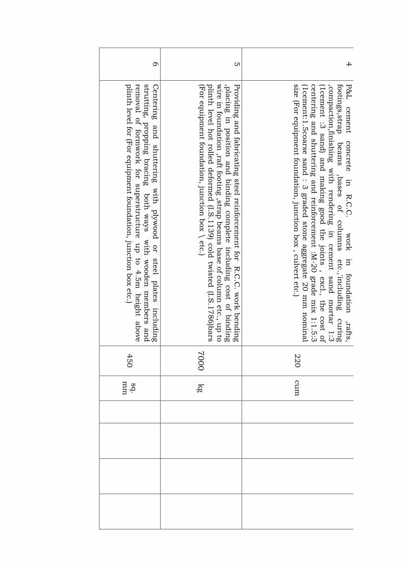
4
P&
L
cem
en
t con
cre
te
in
R.C
.C.
w
ork
in
fo
un
datio
n
,rafts
, fo
otin
gs,s
trap
beam
s
,bases
of
colu
mn
s
etc
.,'inclu
din
g
cu
ring
,com
pactio
n,fin
ish
ing
with
re
nderin
g
in
cem
en
t san
d
morta
r 1:3
(1
cem
en
t :3
san
d)
an
d m
akin
g good th
e jo
ints
,
excl.,
the cost
of
cen
terin
g an
d sh
utte
ring an
d re
info
rcem
en
t :M
-20 g
rade m
ix 1:1
.5:3
(1
cem
en
t:1.5
coars
e s
an
d : 3
gra
ded s
ton
e a
ggre
gate
20 m
m n
om
inal
size
(For e
qu
ipm
en
t fou
ndatio
n, ju
nctio
n b
ox , c
ulv
ert e
tc.)
220
cu
m
5
Pro
vid
ing a
nd fa
bric
atin
g s
teel re
info
rcem
en
t for R
.C.C
. work
ben
din
g
,pla
cin
g in
positio
n an
d bin
din
g com
ple
te in
clu
din
g cost
of
bin
din
g
wire
in fo
un
datio
n ,ra
ft footin
g ,s
trap b
eam
s b
ase o
f colu
mn
etc
., up to
plin
th le
vel h
ot ro
lled d
efo
rmed (I.S
.1139) c
old
twis
ted (I.S
.1786)b
ars
(F
or e
qu
ipm
en
t fou
ndatio
n, ju
nctio
n b
ox \
etc
.) 7000
kg
6
Cen
terin
g
an
d
sh
utte
ring
with
ply
wood
or
ste
el
pla
tes
inclu
din
g
stru
tting,
pro
ppin
g bra
cin
g both
w
ays w
ith w
ooden
m
em
bers
an
d
rem
oval
of
form
work
fo
r su
pers
tructu
re
up
to
4.5
m
heig
ht
above
plin
th le
vel fo
r (For e
qu
ipm
en
t fou
ndatio
n, ju
nctio
n b
ox e
tc.)
450
sq.
mm

7
Pro
vid
ing &
Fix
ing o
f ste
el fe
bric
atio
n m
ade o
f an
gle
s, te
es, s
qu
are
bars
or o
ther fla
ts b
lack p
ipe w
ith h
old
fast a
nd fittin
gs c
om
ple
te a
s
per d
esig
n a
nd d
raw
ing in
clu
din
g c
uttin
g w
eld
ing a
nd fa
bric
atio
n w
ith
prim
ing c
oat o
f redoxid
e.
4500
Kg
8
Pro
vid
ing ,L
ayin
g an
d Join
ting R
CC
cla
ss N
P-2
N
on
Pre
ssu
re pip
es
(IS:4
58 M
ark
) of a
ppro
ved m
ake w
ith c
olla
rs, jo
inte
d w
ith C
M 1
:2 o
r h
avin
g
Spig
ot
an
d
socket
en
ds
with
fle
xib
le
rubber
rings
join
t in
clu
din
g te
stin
g o
f join
ts e
tc. c
om
ple
te: 4
50 m
m D
90
RM
9
Pro
vid
ing &
Fix
ing o
f Rein
forc
ed F
erro
Cem
en
t Cable
Tre
nch
Covers
desig
ned fo
r 'A
' &
'A
A'
loadin
g du
ly m
ark
ed on
cover
with
adequ
ate
re
info
rcem
en
t h
avin
g
thic
kn
ess
75m
m
to
100
mm
an
ti corro
siv
e
bitu
men
pain
ed M
S pla
te R
im an
d M
S liftin
g h
ooks adm
ixtu
res lik
e
pla
stic
izer
bon
d
-impro
vin
g
com
pou
nd,
sh
rinkage
resis
tan
ce
com
pou
nd, a
bra
sio
n re
sis
tan
t com
ple
te a
s p
er a
ppro
ved d
esig
n ( F
or
cable
join
t box) (F
or a
ny s
pan
) 100
Sqm
10
Pro
vid
ing &
Layin
g H
DPE
pip
e h
eavy du
ty o
f appro
ved m
ake jo
inte
d
with
solv
en
t cem
en
t
(i) 2
50 m
m d
ia.
120
RM
(ii) 1
00 m
m d
ia. F
or O
ptic
al F
ibre
Cable
1.5
kM
11
Su
pply
an
d la
yin
g in
ter
lockin
g R
CC
cable
covers
as per
appro
ved
dra
win
g
1,4
00
Sqm
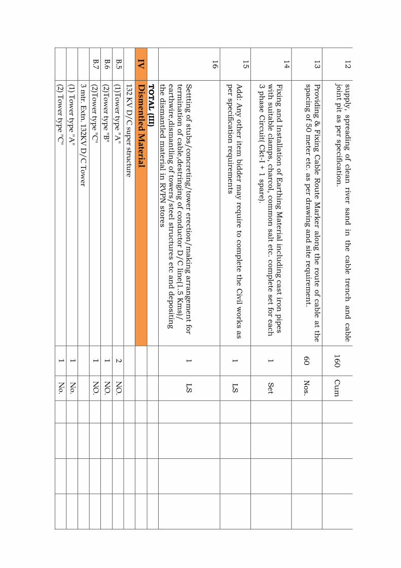
12
su
pply
, spre
adin
g of
cle
an
riv
er
san
d in
th
e cable
tre
nch
an
d cable
jo
int p
it as p
er s
pecific
atio
n.
160
Cu
m
13
Pro
vid
ing &
Fix
ing C
able
Rou
te M
ark
er a
lon
g th
e ro
ute
of c
able
at th
e
spacin
g o
f 50 m
ete
r etc
. as p
er d
raw
ing a
nd s
ite re
qu
irem
en
t. 60
Nos.
14
Fix
ing a
nd In
sta
llatio
n o
f Earth
ing M
ate
rial in
clu
din
g c
ast iro
n p
ipes
with
su
itable
cla
mps, c
harc
ol, c
om
mon
salt e
tc. c
om
ple
te s
et fo
r each
3 p
hase C
ircu
it( Ckt-I +
1 s
pare
). 1
Set
15
Add: A
ny o
ther ite
m b
idder m
ay re
qu
ire to
com
ple
te th
e C
ivil w
ork
s a
s
per s
pecific
atio
n re
qu
irem
en
ts
1
LS
16
Setttin
g o
f stu
bs/con
cre
ting/to
wer e
rectio
n/m
akin
g a
rran
gem
en
t for
term
inatio
n o
f cable
,destrin
gin
g o
f con
du
cto
r D/C
line(1
.5 K
ms)/
earth
wire
,dis
man
tling o
f tow
ers
/ste
el s
tructu
res e
tc a
nd d
epositin
g
the d
ism
an
tled m
ate
rial in
RV
PN
sto
res
1
LS
T
OT
AL (III)
IV
Dism
en
tled
Ma
teria
l
132 K
V D
/C
sup
er structu
re
B.5
(1)To
wer ty
pe "A
" 2
NO
.
B.6
(2)To
wer ty
pe "B
" 1
NO
.
B.7
(2)To
wer ty
pe "C
" 1
NO
.
3 m
tr. Ex
tn. 132K
V D
/C
To
wer
(1) T
ow
er typ
e "A"
1 N
o.
(2) T
ow
er typ
e "C"
1 N
o.

132K
V D
/C
Narro
w b
ase tow
ers
B.13
(1) To
wer ty
pe"C
" 2
No
.
3 m
tr. Ex
tn. 132K
V D
/C
Narro
w b
ase To
wer
(1) T
ow
er typ
e "C"
1 N
o.
C9
Hard
ware fo
r AC
SR
Pan
ther C
on
du
ctor
(iv)
(1) Do
ub
le Ten
sion
H/
W
24 S
et
(iii) (2) S
ing
le Ten
sion
H/
W
51 S
et
(i) (3) S
ing
le Su
spen
sion
H/
W
2 S
et
(ii) (4) D
ou
ble S
usp
ensio
n H
/W
12
Set
C10
Co
nd
ucto
r acc. Fo
r AC
SR
Pan
ther
(i) (4) P
.A. R
od
s 12
Set
(iv)
(5) Vib
ration
Dam
per
69 N
o.
C11
Hard
ware fo
r E/
Wire fo
r 7/3.15 m
m
(ii) (1) S
train A
ssemb
ly
10 N
o.
(v)
(2) Su
spen
sion
Assem
bly
2
No
.
(i) (3) V
ibratio
n D
amp
er 10
No
.
C8
AC
SR
Pan
ther C
on
du
ctor
9 K
M
D7(ii)
Earth
Wire 7/
3.15 mm
1.5
KM
C(1)(iii)
120 KN
Disc In
sulato
r 990
NO
.
C(1)(ii)
70 KN
Disc In
sulato
r 234
NO
.
D6(b
) P
ipe ty
pe earth
ing
set 6
SE
T
D 5 (iii)
Ph
ase Plate
6 S
ET
D 5(ii)
Nu
mb
er Plate
6 N
O.
D5 (i)
Dan
ger P
late 6
NO
.
D 1
GI N
ut B
olt
(1)16*35
0.2100 M
T
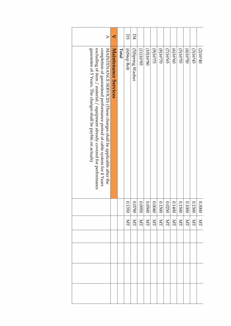
(2)16*40
0.3000 M
T
(3)16*45
0.1300 M
T
(4)16*50
0.1000 M
T
(5)16*55
0.1500 M
T
(6)16*60
0.1400 M
T
(7)16*65
0.0250 M
T
(8)16*70
0.1500 M
T
(9)16*75
0.0040 M
T
(10)16*80
0.0500 M
T
(11)16*85
0.0950 M
T
D4
(5)Sp
ring
Wash
er 0.0790
MT
D3
(6)Step
Bo
lt 0.1350
MT
T
ota
l
V
Main
ten
an
ce S
erv
ices
A
MA
INT
EN
AN
CE
SE
RV
ICE
S (T
hese ch
arges sh
all be ap
plicab
le after the
com
pletio
n o
f gau
ranteed
perfo
rman
ce perio
d o
f cable sy
stem fo
r 4 Years
exclu
din
g o
f item /
material /
equ
ipm
ent alread
y co
vered
for p
erform
ance
gau
rantee o
f 5 Years. T
he ch
arges sh
all be p
ayb
le on
actuals)

1 M
ainten
ance serv
ices per v
isit tow
ards an
y b
reakd
ow
n o
f cable sy
stem, w
hich
in
lcud
es services o
f exp
ert eng
ineers, tech
nician
s, alon
gw
ith n
ecessary to
ols /
tack
les, testing
equ
ipm
ents, fau
lt locatin
g eq
uip
men
ts to b
e detect th
e fault
and
its suseq
uen
t, rectification
s, re-testing
and
restorin
g th
e electric sup
ply
th
rou
gh
cable sy
stem.
1 Jo
b
T
ota
l of A
Su
pp
ly Ite
m (I+
II+III)
T
ota
l of B
Se
rvice
Pa
rt (I+II+
III+IV
+V
)
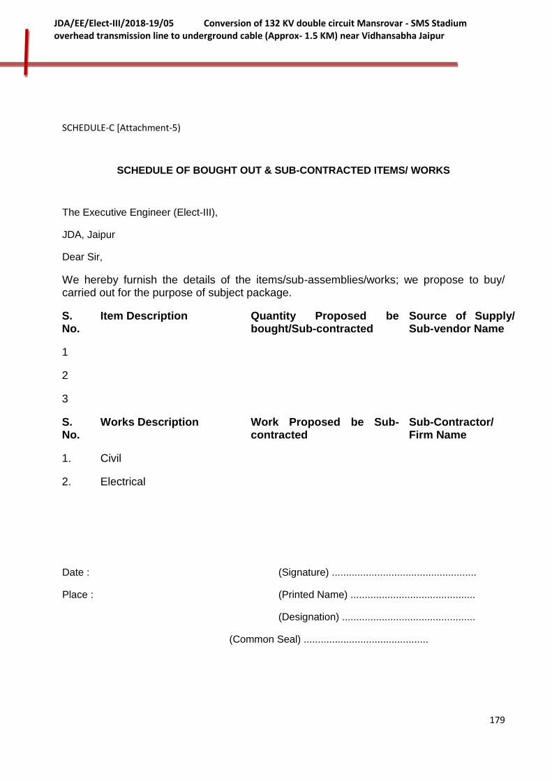
179
JDA/EE/Elect-III/2018-19/05 Conversion of 132 KV double circuit Mansrovar - SMS Stadium overhead transmission line to underground cable (Approx- 1.5 KM) near Vidhansabha Jaipur
SCHEDULE-C [Attachment-5)
SCHEDULE OF BOUGHT OUT & SUB-CONTRACTED ITEMS/ WORKS
The Executive Engineer (Elect-III),
JDA, Jaipur
Dear Sir,
We hereby furnish the details of the items/sub-assemblies/works; we propose to buy/ carried out for the purpose of subject package.
S. No.
Item Description Quantity Proposed be bought/Sub-contracted
Source of Supply/ Sub-vendor Name
1
2
3
S. No.
Works Description Work Proposed be Sub-contracted
Sub-Contractor/ Firm Name
1. Civil
2. Electrical
Date : (Signature) ...................................................
Place : (Printed Name) ............................................
(Designation) ...............................................
(Common Seal) ............................................

180
JDA/EE/Elect-III/2018-19/05 Conversion of 132 KV double circuit Mansrovar - SMS Stadium overhead transmission line to underground cable (Approx- 1.5 KM) near Vidhansabha Jaipur
SCHEDULE-D
GUARANTEED TECHNICAL PARTICULAR
NOTE: All technical particulars shall be filled in. Reference to drawings/ catalogues/ brochures, etc. is not acceptable.
S. No. Description Technical Particular
S-IA 132 kV XLPE CABLE
1 Name of Manufacturer
2 Country of Manufacture
3 Type of cable
4 Applicable Standard
5 (a) Rated nominal voltage
(b) Rated Maximum voltage
6 Whether suitable for
(a) Earthed System
(b) Unearthed System
7 Nominal cross-sectional area of conductor ( Sq.mm )
8 Conductor
(a) Material
(b) Shape & formation
(c) Diameter of conductor ( mm )
(d) i). No. of strands(wires) in conductor
ii) Nominal dia of each inlet wire in conductor before compacting
(e)Thickness of semi conducting tape
9 Conductor Screen
(a) Material
(b)Thickness ( mm )
(c) Maximum volume resistivity (at 25 ° Degree Centigrade) before and after ageing ( Ohm – cm )
10 Maximum value of electric stresses at the conductor screen (Calculation to be shown separately) ( KV/mm)
11 Insulation
(a)Material/Composition
(b)Dia of cable over the insulation (mm )
(c )Radial thickness
i)Minimum Average ( mm )
ii) Minimum at Any Point ( mm )
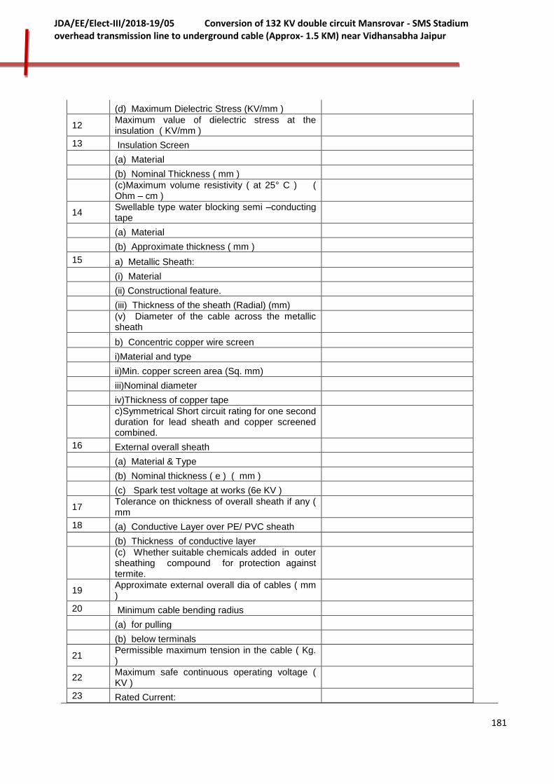
181
JDA/EE/Elect-III/2018-19/05 Conversion of 132 KV double circuit Mansrovar - SMS Stadium overhead transmission line to underground cable (Approx- 1.5 KM) near Vidhansabha Jaipur
(d) Maximum Dielectric Stress (KV/mm )
12 Maximum value of dielectric stress at the insulation ( KV/mm )
13 Insulation Screen
(a) Material
(b) Nominal Thickness ( mm )
(c)Maximum volume resistivity ( at 25° C ) ( Ohm – cm )
14 Swellable type water blocking semi –conducting tape
(a) Material
(b) Approximate thickness ( mm )
15 a) Metallic Sheath:
(i) Material
(ii) Constructional feature.
(iii) Thickness of the sheath (Radial) (mm)
(v) Diameter of the cable across the metallic sheath
b) Concentric copper wire screen
i)Material and type
ii)Min. copper screen area (Sq. mm)
iii)Nominal diameter
iv)Thickness of copper tape
c)Symmetrical Short circuit rating for one second duration for lead sheath and copper screened combined.
16 External overall sheath
(a) Material & Type
(b) Nominal thickness ( e ) ( mm )
(c) Spark test voltage at works (6e KV )
17 Tolerance on thickness of overall sheath if any ( mm
18 (a) Conductive Layer over PE/ PVC sheath
(b) Thickness of conductive layer
(c) Whether suitable chemicals added in outer sheathing compound for protection against termite.
19 Approximate external overall dia of cables ( mm )
20 Minimum cable bending radius
(a) for pulling
(b) below terminals
21 Permissible maximum tension in the cable ( Kg. )
22 Maximum safe continuous operating voltage ( KV )
23 Rated Current:
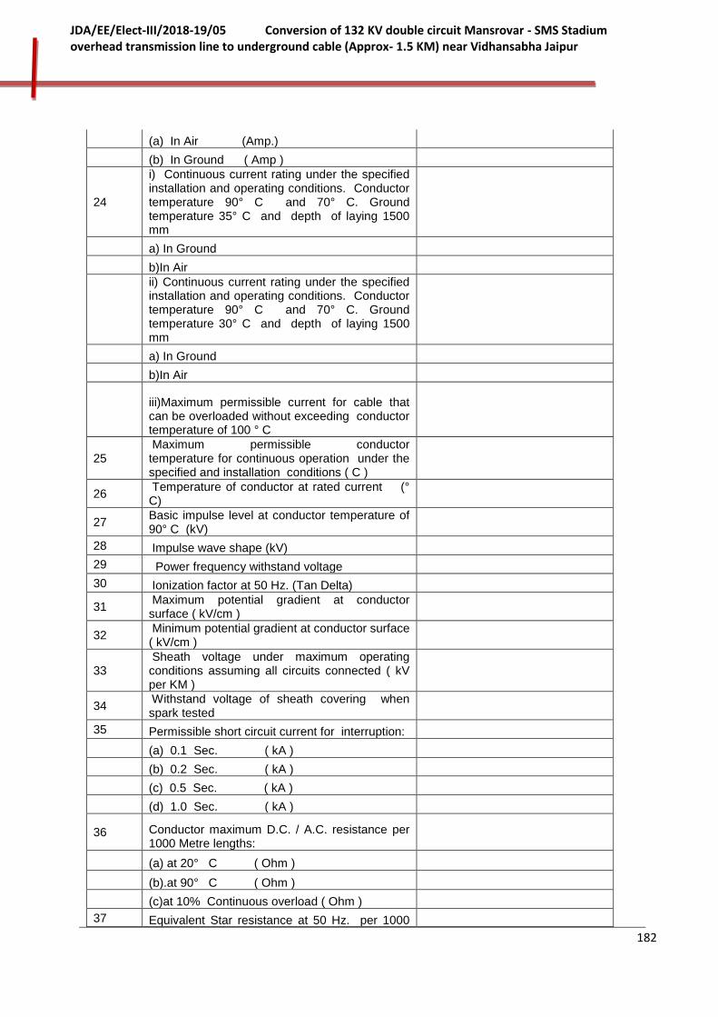
182
JDA/EE/Elect-III/2018-19/05 Conversion of 132 KV double circuit Mansrovar - SMS Stadium overhead transmission line to underground cable (Approx- 1.5 KM) near Vidhansabha Jaipur
(a) In Air (Amp.)
(b) In Ground ( Amp )
24
i) Continuous current rating under the specified installation and operating conditions. Conductor temperature 90° C and 70° C. Ground temperature 35° C and depth of laying 1500 mm
a) In Ground
b)In Air
ii) Continuous current rating under the specified installation and operating conditions. Conductor temperature 90° C and 70° C. Ground temperature 30° C and depth of laying 1500 mm
a) In Ground
b)In Air
iii)Maximum permissible current for cable that can be overloaded without exceeding conductor temperature of 100 ° C
25 Maximum permissible conductor temperature for continuous operation under the specified and installation conditions ( C )
26 Temperature of conductor at rated current (° C)
27 Basic impulse level at conductor temperature of 90° C (kV)
28 Impulse wave shape (kV)
29 Power frequency withstand voltage
30 Ionization factor at 50 Hz. (Tan Delta)
31 Maximum potential gradient at conductor surface ( kV/cm )
32 Minimum potential gradient at conductor surface ( kV/cm )
33 Sheath voltage under maximum operating conditions assuming all circuits connected ( kV per KM )
34 Withstand voltage of sheath covering when spark tested
35 Permissible short circuit current for interruption:
(a) 0.1 Sec. ( kA )
(b) 0.2 Sec. ( kA )
(c) 0.5 Sec. ( kA )
(d) 1.0 Sec. ( kA )
36 Conductor maximum D.C. / A.C. resistance per 1000 Metre lengths:
(a) at 20° C ( Ohm )
(b).at 90° C ( Ohm )
(c)at 10% Continuous overload ( Ohm )
37 Equivalent Star resistance at 50 Hz. per 1000

183
JDA/EE/Elect-III/2018-19/05 Conversion of 132 KV double circuit Mansrovar - SMS Stadium overhead transmission line to underground cable (Approx- 1.5 KM) near Vidhansabha Jaipur
Metre length
of 3 phase current
(a)at 20° C ( Ohm )
(b) at 90 ° C ( Ohm )
(c) at 10% continuous overload (Ohm )
38 Star reactance at 50 Hz. per 1000 Metre length (Ohm)
39 Impedance at 50 Hz. per 1000 Metre length
(a) at 20° C ( Ohm )
(b)at 90° C ( Ohm )
(c) at 10% continuous overload ( Ohm )
40 Positive and negative sequence reactance per 1000 Meters length Ohm)
41 Zero sequence data per 1000 Metre length
( a)Series resistance (Ohm)
(b)Series reactance (Ohm)
( c )Shunt capacitive reactance (Ohm)
42 Sheath resistance at 20° C per 1000 Metres length ( Ohm )
43 Surge impedance of the cable in Ohms.
44 Self electrostatic capacitance per 1000 metres length(micro farads)
45 Dielectric dissipation factor at rated voltage
46 I.R. value at ambient temperature per 1000 metres length (Ohm-cm)
47 P.F. at conductor temperature of 90 ° C and at
a)50% of rated phase to neutral voltage
b).100% of rated phase to neutral Voltage
48 Guaranteed Losses per 1000 Metres length: (Detailed working sheet should be furnished)
a) Dielectric losses per phase at rated voltage and rated current (kW)
b)Copper losses per phase at rated voltages and rated current (kW)
c) Other losses (sheath/screen losses/ Phase at rated voltage and current (kW)
d) Losses due to reinforcement if any (kW)
e)Total losses at rated continuous current (kW)
49
Short circuit capacity of conductor for one second assuming conductor temperature of 90 ° C prior to short circuit and 250 ° C during short circuit
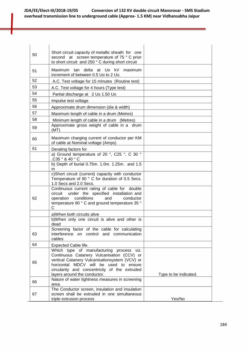
184
JDA/EE/Elect-III/2018-19/05 Conversion of 132 KV double circuit Mansrovar - SMS Stadium overhead transmission line to underground cable (Approx- 1.5 KM) near Vidhansabha Jaipur
50 Short circuit capacity of metallic sheath for one second at screen temperature of 75 ° C prior to short circuit and 250 ° C during short circuit
51 Maximum tan delta at Uo kV maximum increment of between 0.5 Uo to 2 Uo.
52 A.C. Test voltage for 15 minutes (Routine test)
53 A.C. Test voltage for 4 hours (Type test)
54 Partial discharge at 2 Uo 1.50 Uo
55 Impulse test voltage
56 Approximate drum dimension (dia & width)
57 Maximum length of cable in a drum (Metres)
58 Minimum length of cable in a drum (Metres)
59 Approximate gross weight of cable in a drum (MT)
60 Maximum charging current of conductor per KM of cable at Nominal voltage (Amps)
61 Derating factors for
a) Ground temperature of 20 °, C25 °, C 30 ° ,C35 ° & 40 ° C
b) Depth of burial 0.75m. 1.0m. 1.25m. and 1.5 m
c)Short circuit (current) capacity with conductor Temperature of 90 ° C for duration of 0.5 Secs. 1.0 Secs and 2.0 Secs.
62
Continuous current rating of cable for double circuit under the specified installation and operation conditions and conductor temperature 90 ° C and ground temperature 35 ° C
a)When both circuits alive
b)When only one circuit is alive and other is dead
63 Screening factor of the cable for calculating interference on control and communication cables
64 Expected Cable life.
65
Which type of manufacturing process viz. Continuous Catanery Vulcanisation (CCV) or vertical Catanery Vulcanisationsystem (VCV) or horizontal MDCV will be used to ensure circularity and concentricity of the extruded layers around the conductor. Type to be indicated.
66 Nature of water tightness measures in screening area.
67 The Conductor screen, insulation and insulation screen shall be extruded in one simultaneous triple extrusion process Yes/No

185
JDA/EE/Elect-III/2018-19/05 Conversion of 132 KV double circuit Mansrovar - SMS Stadium overhead transmission line to underground cable (Approx- 1.5 KM) near Vidhansabha Jaipur
68
The cross linking, curing and cooling shall be carried out in one operation and shall be a dry curing process under high pressure to eliminate the formation of voids in the insulation and contaminants in the dielectric. Yes/No
69
Process conditions such as curing and cooling temperature, production speed etc. shall be closely monitored during manufacture to ensure a good degree of cross linking through the whole insulation. Yes/No
70 i) Loading of the extruder in the manufacturing plant shall be performed entirely closed and dust proof. Yes/No
ii) The entire line of processing shall be controlled from a computerized central control console. Yes/No
iii) Contamination shall be avoided by use of a fully enclosed material handling system. Yes/No
iv) The use of special means like pressurized air etc. for transport of granules shall, as for as practicable, be avoided. Yes/No
71 Detailed list of testing facilities available at the works of supplier’s for testing material as per clause 8 above. Furnished
S-II 145 kV XLPE CABLE TERMINATIONS AND JOINTING KITS
A. OUTDOOR CABLE END TERMINATIONS
1 Nominal System Voltage U
2 Rated/Highest System Voltage Um
3 Rated frequency & No. of phase
4 Installation
5 Name and address of manufacturer of end termination
6 Nomenclature of kit.
7 Type of Kit
8
Suitable for Single Core Copper Conductor XLPE cable Conforming to IEC 60502-2 and IEC 60840:2004-04 or IS 7098(part-3) amended upto date and as per Section -1 of the specification.
9 Maximum conductor size
10 Rated continuous current
11 Applicable standard for testing
12 Maximum allowable Pd-level
13 Type of Insulator.
14 Creepage distance
15 Colour
16 Maximum allowable temperature for cable and accessories
i) At rated full load and at site condition
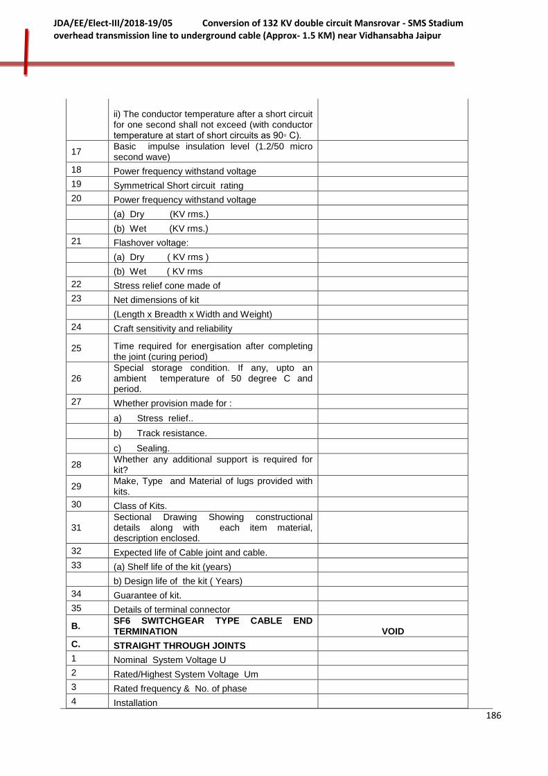
186
JDA/EE/Elect-III/2018-19/05 Conversion of 132 KV double circuit Mansrovar - SMS Stadium overhead transmission line to underground cable (Approx- 1.5 KM) near Vidhansabha Jaipur
ii) The conductor temperature after a short circuit for one second shall not exceed (with conductor temperature at start of short circuits as 90◦ C).
17 Basic impulse insulation level (1.2/50 micro second wave)
18 Power frequency withstand voltage
19 Symmetrical Short circuit rating
20 Power frequency withstand voltage
(a) Dry (KV rms.)
(b) Wet (KV rms.)
21 Flashover voltage:
(a) Dry ( KV rms )
(b) Wet ( KV rms
22 Stress relief cone made of
23 Net dimensions of kit
(Length x Breadth x Width and Weight)
24 Craft sensitivity and reliability
25 Time required for energisation after completing the joint (curing period)
26 Special storage condition. If any, upto an ambient temperature of 50 degree C and period.
27 Whether provision made for :
a) Stress relief..
b) Track resistance.
c) Sealing.
28 Whether any additional support is required for kit?
29 Make, Type and Material of lugs provided with kits.
30 Class of Kits.
31 Sectional Drawing Showing constructional details along with each item material, description enclosed.
32 Expected life of Cable joint and cable.
33 (a) Shelf life of the kit (years)
b) Design life of the kit ( Years)
34 Guarantee of kit.
35 Details of terminal connector
B. SF6 SWITCHGEAR TYPE CABLE END TERMINATION VOID
C. STRAIGHT THROUGH JOINTS
1 Nominal System Voltage U
2 Rated/Highest System Voltage Um
3 Rated frequency & No. of phase
4 Installation
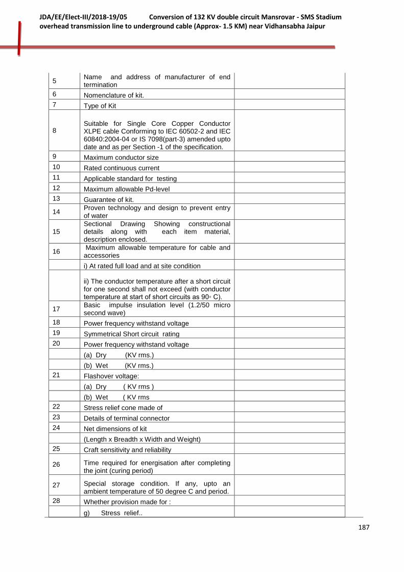
187
JDA/EE/Elect-III/2018-19/05 Conversion of 132 KV double circuit Mansrovar - SMS Stadium overhead transmission line to underground cable (Approx- 1.5 KM) near Vidhansabha Jaipur
5 Name and address of manufacturer of end termination
6 Nomenclature of kit.
7 Type of Kit
8 Suitable for Single Core Copper Conductor XLPE cable Conforming to IEC 60502-2 and IEC 60840:2004-04 or IS 7098(part-3) amended upto date and as per Section -1 of the specification.
9 Maximum conductor size
10 Rated continuous current
11 Applicable standard for testing
12 Maximum allowable Pd-level
13 Guarantee of kit.
14 Proven technology and design to prevent entry of water
15 Sectional Drawing Showing constructional details along with each item material, description enclosed.
16 Maximum allowable temperature for cable and accessories
i) At rated full load and at site condition
ii) The conductor temperature after a short circuit for one second shall not exceed (with conductor temperature at start of short circuits as 90◦ C).
17 Basic impulse insulation level (1.2/50 micro second wave)
18 Power frequency withstand voltage
19 Symmetrical Short circuit rating
20 Power frequency withstand voltage
(a) Dry (KV rms.)
(b) Wet (KV rms.)
21 Flashover voltage:
(a) Dry ( KV rms )
(b) Wet ( KV rms
22 Stress relief cone made of
23 Details of terminal connector
24 Net dimensions of kit
(Length x Breadth x Width and Weight)
25 Craft sensitivity and reliability
26 Time required for energisation after completing the joint (curing period)
27 Special storage condition. If any, upto an ambient temperature of 50 degree C and period.
28 Whether provision made for :
g) Stress relief..

188
JDA/EE/Elect-III/2018-19/05 Conversion of 132 KV double circuit Mansrovar - SMS Stadium overhead transmission line to underground cable (Approx- 1.5 KM) near Vidhansabha Jaipur
h) Track resistance.
i) Sealing.
29 Whether any additional support is required for kit?
30 Make Type and Material of lugs provided with kits.
31 Class of Kits.
32 Expected life of Cable joint and cable.
33 Details of terminal connector
34 (a) Shelf life of the kit (years)
b) Design life of the kit ( Years)
D LINK BOX FOR EARTHING & EARTHING CABLE WITH PVC INSULATION
1 Make
2 Type
3 Detailed dimension and internal arrangement of Single/ Three Phase Link boxes with direct grounding
4 Detailed dimension and internal arrangement of Three Phase Link boxes for cross bonding with SVL
5 Earthing of sheath/screen at cross bonding points and termination ends
6 PVC insulated single core/ concentric/ coaxial cable to be used for sheath bonding (earthing) suitable for 40 kA for 1 second.
7 Insulation of above earthing cable
8 Voltage rise of the insulation sheath controlled within voltage
9 Surge voltage limiter
E SUPPORTING STRUCTURE & ANGLE BRACKET SUPPORTS FOR CABLE
1 Detail drawing enclosed
2 Overall height of structure
S-III CABLE INTALLATION
A. PVC Warning Tape
1 Colour
2 Thickness
3 Width
4 Marking/ Printing
B. Cable Covers
1 Dimension
2 Design
3 Drawing
4 Breaking Load

189
JDA/EE/Elect-III/2018-19/05 Conversion of 132 KV double circuit Mansrovar - SMS Stadium overhead transmission line to underground cable (Approx- 1.5 KM) near Vidhansabha Jaipur
C. Cable Route/ Joint Marker
1 Size
2 Drawing
D. HDPE PIPES
1 Make
2 Thickness
3 Diameter
S-IV FIBER OPTIC CABLE
1 Make
2 Type
3 Standard Complied to
4 DWSM Optic Fiber Characteristics
i Fiber Description
ii MFD
iii Cladding Diameter
iv Mode field Connectivity Error
v Cladding non-circularity
vi Cable cut-off wavelength
vii 1550 loss performance
viii Proof Test Level
ix Attenuation Co-efficient
x Chromatic Dispersion
xi Zero Dispersion wavelength
xii Zero Dispersion slope
xiii Polarization mode dispersion coeffcient
xiv Temprature depandance
xv Bend Performance
3
Suitability for OLTE with integrated Multiplexer at terminal substations [having a range of access interfaces for telephony, data and LAN. Transport facilities shall include optical and electrical STM-1 SDH & ATM aggregate interfaces (155Mbit/s) and a range of PDH optical and electrical interfaces] Yes/No
4 Whether suitable for Buried application as per specification requirements Yes/No
5 Whether catalog and Type test certificates for offered fiber optic cable enclosed Yes/No
S-V SURGE ARRESTOR
1. Name of Manufacturer
2. Arrestor class & type
3. Applicable Standard
4. Rated Arrestor Voltage (kV)

190
JDA/EE/Elect-III/2018-19/05 Conversion of 132 KV double circuit Mansrovar - SMS Stadium overhead transmission line to underground cable (Approx- 1.5 KM) near Vidhansabha Jaipur
5. Maximum Continuous Operating voltage (MCOV)-(kV)
6. Nominal Discharge Current (kA) with 8/20 Micro-second wave
7. Long Duration Discharge
8. Maximum Energy Discharge Capability (kJ/kV of rated voltage of arrestor)
9. Maximum switching current impulse residual voltage at
i) 1000 Amps kVp
ii) 250 Amps kVp
10. Maximum residual voltage with Steep current impulse (1/20micro second) at 10 kA ( kVp)
11. Maximum residual voltage For Lightning impulse current 8/20 Micro-second wave (kVp)
i) 5 kA
ii) 10 kA
iii) 20 kA
12. Safe Fault Current (kA)
13. Arrestor Housing:
(i) Lightning impulse withstand voltage of Arrestor housing with 1.2/50 micro-second wave (kVp).
(ii)One minute power frequency withstand voltage of housing (dry/wet) - kv (r.m.s.)
(iii) Total creepage distance (mm):
(iv) Dry arcing distance (mm):
(v) Cantilever strength: (N-M):
(vi) Internal diameter (mm) :
(vii) Thickness (mm) :
14 Continuous current at COV and ambient temperature
a) resistive component (mA rms)
b) capacitive component (mA rms)
15. High Current short duration impulse withstand level with 4/10 micro second wave ( kA ) Peak
16. Pressure Relief Class
17. Over-voltage withstand Capability kV
a) 10 seconds
b) 1 second
c) 0.1 second
18. a) Reference Voltage (kVp)
b) Reference Current (kA) guaranteed by the manufacturer
19. (i)Number of Units per phase :

191
JDA/EE/Elect-III/2018-19/05 Conversion of 132 KV double circuit Mansrovar - SMS Stadium overhead transmission line to underground cable (Approx- 1.5 KM) near Vidhansabha Jaipur
(ii) Voltage rating of each unit:
(iii) Ht. of longest unit:
20. Minimum total creepage distance (mm)
21. Leakage Current (mA)
22. Total weight of Arrestor (kg)
23. Maximum cantilever strength of Surge Arrester (Including Wind Load)
24. Overall Height of Surge Arrestors (mm)
25. Maximum distance recommended from equipment to be protected by Surge Arrester (mm)
26. Minimum distance between grounded object( mm)
27. Minimum distance between Arrester phase legs (mm)
28. Any other particulars
29. Whether pressure relief devices provided YES /NO
30. Prospective symmetrical fault current kA(rms)
31. a) High current value employed for pressure relief test
b) Low current value employed for pressure relief test
32. Metal oxide discs:
a) Country of manufacture
b) Size of discs (Diameter and thickness) mm
c) How the electricity contact is Ensured between blocks
d) Medium of heat dissipation from the blocks to the surrounding
33. Partial discharge level pC
34. Radio interference level at 1.1 COV
35. Weight of one complete single from the blocks to the surrounding phase arrester, Kg.
36. Surge Monitor:
a) Type
b) Minimum lightning impulse Current 98/20 micro sec.) to Which surge counter will Respond successfully
c) Whether the surge monitor has been successfully Tested for high current Impulses, long duration Current impulse & low Current response test YES / NO
d) Scale range of leakage Current Meter
37. a) Recommended protective Distance of surge arrester from Transformer, m
b) Protective distance of LA (m)
- Forward

192
JDA/EE/Elect-III/2018-19/05 Conversion of 132 KV double circuit Mansrovar - SMS Stadium overhead transmission line to underground cable (Approx- 1.5 KM) near Vidhansabha Jaipur
- Backward
38. Are LAs are suitable for hot line washing YES /NO
39. Whether following curves / Drawings enclosed with offer:
a) Volt time characteristic YES /NO
b) Voltage current characteristic of arrester YES /NO
c) Type test has been conducted as per IEC-99-4 & IS: 5621 YES /NO
d) Type test reports submitted along With the offer YES /NO
e) Drawing outline Dimensions for Installation enclosed YES /NO
f) Drawing of mounting flange Dimension details enclosed YES /NO
g) Drawing of earthing arrangement provided Enclosed YES /NO
h) Details for surge monitor enclosed YES /NO
i) Each arrestor unit with sealed Housing to be tested for leakage YES /NO
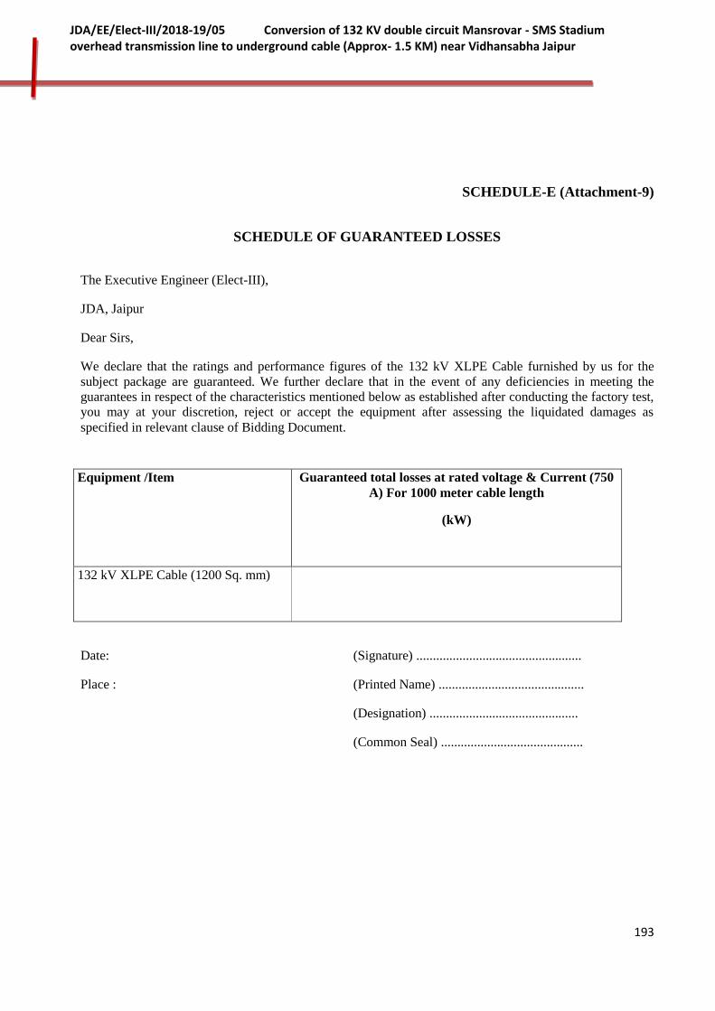
193
JDA/EE/Elect-III/2018-19/05 Conversion of 132 KV double circuit Mansrovar - SMS Stadium overhead transmission line to underground cable (Approx- 1.5 KM) near Vidhansabha Jaipur
SCHEDULE-E (Attachment-9)
SCHEDULE OF GUARANTEED LOSSES
The Executive Engineer (Elect-III),
JDA, Jaipur
Dear Sirs,
We declare that the ratings and performance figures of the 132 kV XLPE Cable furnished by us for the
subject package are guaranteed. We further declare that in the event of any deficiencies in meeting the
guarantees in respect of the characteristics mentioned below as established after conducting the factory test,
you may at your discretion, reject or accept the equipment after assessing the liquidated damages as
specified in relevant clause of Bidding Document.
Equipment /Item Guaranteed total losses at rated voltage & Current (750
A) For 1000 meter cable length
(kW)
132 kV XLPE Cable (1200 Sq. mm)
Date: (Signature) ..................................................
Place : (Printed Name) ............................................
(Designation) .............................................
(Common Seal) ...........................................

194
JDA/EE/Elect-III/2018-19/05 Conversion of 132 KV double circuit Mansrovar - SMS Stadium overhead transmission line to underground cable (Approx- 1.5 KM) near Vidhansabha Jaipur
SCHEDULE-G (Attachment-7)
MANUFACTURER’S AUTHORIZATION CERTIFICATE
(To be issued on the Manufacturer Firm’s Letterhead for __________________)
The Executive Engineer (Elect-III),
JDA, Jaipur
Dear Sir,
1. I/We hereby confirm to supply ________________________________________ (Specify Item
Name) to M/s ___________________________ as quoted by them to JDA against their NIT
No. JDA/EHV/A&SP/TN-05. We also confirm to be fully responsible for providing after sale
services in India for the same for atleast 10 Years after commissioning of equipment.
2. I/ We hereby confirm to provide necessary support to M/s ___________________ in terms of
technical know-how, spares etc. and meeting of guarantee and warranty obligations of
________________________________________ (Specify Item Name) as per GCC/SCC and
specifications.
I [Mr. _____________________ (Name of Authority)] am fully authorized to issue this
certificate on behalf on M/s _________________________.
Name of issuing Authority ____________
Signature of Issuing Authority ____________
Address of Issuing Authority ______________
Phone No. of Issuing Authority ____________

195
JDA/EE/Elect-III/2018-19/05 Conversion of 132 KV double circuit Mansrovar - SMS Stadium overhead transmission line to underground cable (Approx- 1.5 KM) near Vidhansabha Jaipur
Fax no. of Issuing Authority _______________
SCHEDULE-H
SCHEDULE OF ADDITIONAL INFORMATION
The Executive Engineer (Elect-III),
JDA, Jaipur
Dear Sir,
We have enclosed with our proposal the following additional information for the subject package.
Sl. No. Brief description of Information Ref. & Page No.
Date: (Signature) ..................................................
Place: (Printed Name) ............................................
(Designation) .............................................
(Common Seal) ...........................................
Note: Continuation sheets of like size and format may be used as per Bidder's requirements and annexed to this Schedule.

196
JDA/EE/Elect-III/2018-19/05 Conversion of 132 KV double circuit Mansrovar - SMS Stadium overhead transmission line to underground cable (Approx- 1.5 KM) near Vidhansabha Jaipur
Schedule-I
SCHEDULE OF TECHNICAL PERSONNEL OF BIDDER
(TO BE FILLED IN AND SIGNED BY THE BIDDER)
Bidder Name and Address
S.No. Description Name Length of service in the firm
Qualification Professional experience
and details of work carried
out
Remarks
1. 2. 3. 4. 5 6. 7.
Place
Signature
Name
Status
Whether authorised attorney
of the Biding company
Name of the Biding company
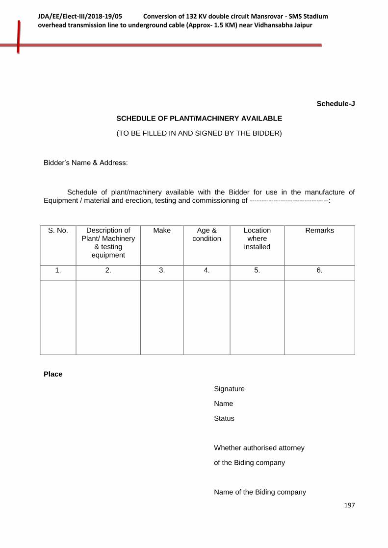
197
JDA/EE/Elect-III/2018-19/05 Conversion of 132 KV double circuit Mansrovar - SMS Stadium overhead transmission line to underground cable (Approx- 1.5 KM) near Vidhansabha Jaipur
Schedule-J
SCHEDULE OF PLANT/MACHINERY AVAILABLE
(TO BE FILLED IN AND SIGNED BY THE BIDDER)
Bidder’s Name & Address:
Schedule of plant/machinery available with the Bidder for use in the manufacture of Equipment / material and erection, testing and commissioning of ---------------------------------:
S. No. Description of Plant/ Machinery
& testing equipment
Make Age & condition
Location where
installed
Remarks
1. 2. 3. 4. 5. 6.
Place
Signature
Name
Status
Whether authorised attorney
of the Biding company
Name of the Biding company

198
JDA/EE/Elect-III/2018-19/05 Conversion of 132 KV double circuit Mansrovar - SMS Stadium overhead transmission line to underground cable (Approx- 1.5 KM) near Vidhansabha Jaipur
Schedule-K
SCHEDULE OF DEVIATIONS
(TO BE FILLED IN AND SIGNED BY THE BIDDER)
1. COMMERCIAL DEVIATIONS
Bidder's Name & Address: To,
The Executive Engineer (Elect-III),
JDA, Jaipur
Dear Sirs,
Sub. : Commercial Deviations for the work of " Conversion of 132 KV double circuit Mansrovar - SMS Stadium overhead transmission line to underground cable (Approx- 1.5 KM) near Vidhansabha Jaipur" against tender enquiry No. JDA/EE/Elect-III/2018-19/05
The following are the Commercial Deviations and variations from and exceptions to the specifications and documents for the subject package. These deviations and variations are exhaustive. Except for these deviations, the entire work shall be performed as per your specifications and documents.
Volume/Clause Ref./Page No.
As specified in the specification
Commercial deviation and variation to the specification
Date : (Signature) ..................................................
Place : (Printed Name) ............................................
(Designation) .............................................
(Common Seal) ...........................................
Note : Continuation sheets of like size and format may be used as per Bidder's requirements and annexed to this Schedule.
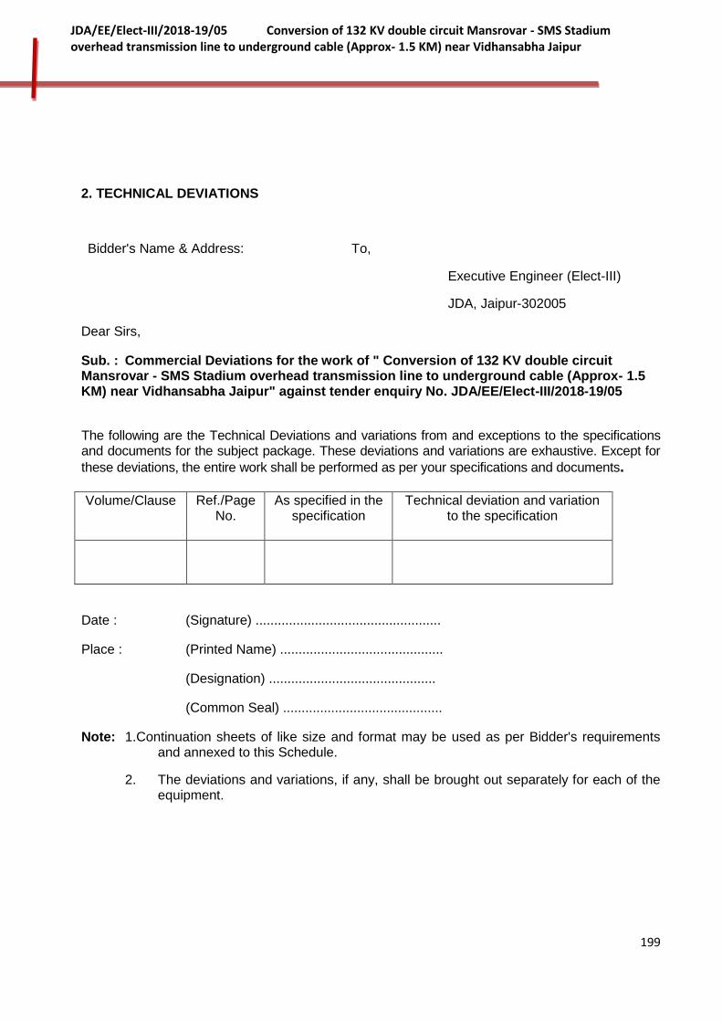
199
JDA/EE/Elect-III/2018-19/05 Conversion of 132 KV double circuit Mansrovar - SMS Stadium overhead transmission line to underground cable (Approx- 1.5 KM) near Vidhansabha Jaipur
2. TECHNICAL DEVIATIONS
Bidder's Name & Address: To,
Executive Engineer (Elect-III)
JDA, Jaipur-302005
Dear Sirs,
Sub. : Commercial Deviations for the work of " Conversion of 132 KV double circuit Mansrovar - SMS Stadium overhead transmission line to underground cable (Approx- 1.5 KM) near Vidhansabha Jaipur" against tender enquiry No. JDA/EE/Elect-III/2018-19/05
The following are the Technical Deviations and variations from and exceptions to the specifications and documents for the subject package. These deviations and variations are exhaustive. Except for
these deviations, the entire work shall be performed as per your specifications and documents. Volume/Clause Ref./Page
No. As specified in the
specification Technical deviation and variation
to the specification
Date : (Signature) ..................................................
Place : (Printed Name) ............................................
(Designation) .............................................
(Common Seal) ...........................................
Note: 1.Continuation sheets of like size and format may be used as per Bidder's requirements and annexed to this Schedule.
2. The deviations and variations, if any, shall be brought out separately for each of the equipment.

200
JDA/EE/Elect-III/2018-19/05 Conversion of 132 KV double circuit Mansrovar - SMS Stadium overhead transmission line to underground cable (Approx- 1.5 KM) near Vidhansabha Jaipur
Schedule-L
PARTICULARS OF PARTICIPATING FIRMS
Participating Firms shall furnish following information in Separate sheet /statement along with Techno-Commercial bid to be opened on scheduled date of Bid opening.
S. No Description Details to be filled by Bidder
1 Name & Address
2 Details to be furnished:
i) Full Legal Name
ii) Full Address of
a. Registered office
b. Office where to corresponded:
iii) Authorized Contact Person(s):
(Power of Attorney to be enclosed)
iv) Phone No.
v) Telex No.
vi) Telefax No./Email
vii) Nature of registration of agency. (Whether sole/proprietor/ partnership/ private limited public limited).
viii) Memorandum of Understanding and Articles of Association of the Agency.
3 BASIS OF PARTICIPATION:
The firm shall clearly indicate whether it:
Desires to take up the entire work of design, supply and implementation of 132 kV XLPE Cable Systemto be completed as per Specification
4 EXPERIENCE IN EXECUTION OF 132 kV or above

201
JDA/EE/Elect-III/2018-19/05 Conversion of 132 KV double circuit Mansrovar - SMS Stadium overhead transmission line to underground cable (Approx- 1.5 KM) near Vidhansabha Jaipur
voltage grade XLPE Cable System on date of bid opening
a) Firms intending to participate for these works should furnish briefly their past experience in the enclosed Schedule-M
b) Indicate the responsibility under taken in the field of specialization in executing 132 kV or above voltage grade XLPE Cable System
i) Design and engineering
ii) Preparation of specification for procurement items.
iii) Procurement
iv) Construction and erection
v) Testing and commissioning
vi) Performance guarantee(s)
vii) Operation and maintenance
c) What was the financing arrangement for above work? Whether the funding was done by the firm or through a separate financial institution.
5 FINANCIAL DETAILS:
Firms are required to furnish details of financial structure of the company and provide Annual Financial Report and Balance Sheet of the company for the last 3(Three)years and following clearance certificate:
a) Annual Financial report
b) Balance Sheet
c) Solvency Certificate
6 Firms are required to indicate funding proposals for the design, supply and implementation of 132 kV or above voltage grade XLPE Cable System
i) Equity proposed to be brought in:
a) by firm's own source
b) by Financial institution(s)
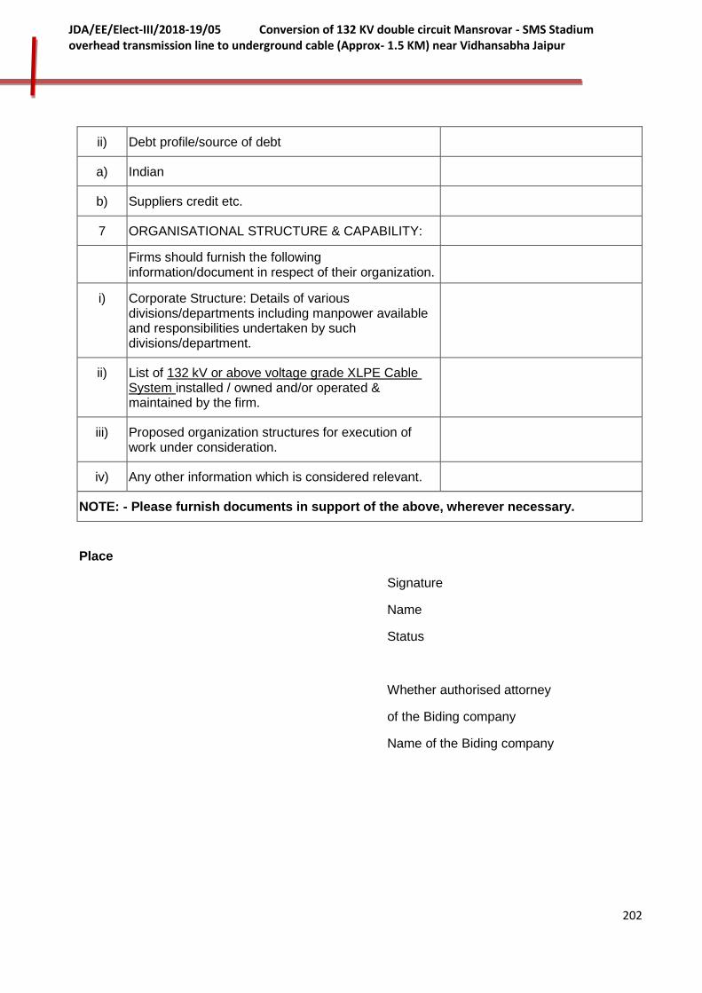
202
JDA/EE/Elect-III/2018-19/05 Conversion of 132 KV double circuit Mansrovar - SMS Stadium overhead transmission line to underground cable (Approx- 1.5 KM) near Vidhansabha Jaipur
ii) Debt profile/source of debt
a) Indian
b) Suppliers credit etc.
7 ORGANISATIONAL STRUCTURE & CAPABILITY:
Firms should furnish the following information/document in respect of their organization.
i) Corporate Structure: Details of various divisions/departments including manpower available and responsibilities undertaken by such divisions/department.
ii) List of 132 kV or above voltage grade XLPE Cable System installed / owned and/or operated & maintained by the firm.
iii) Proposed organization structures for execution of work under consideration.
iv) Any other information which is considered relevant.
NOTE: - Please furnish documents in support of the above, wherever necessary.
Place
Signature
Name
Status
Whether authorised attorney
of the Biding company
Name of the Biding company
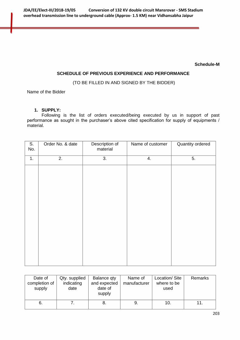
203
JDA/EE/Elect-III/2018-19/05 Conversion of 132 KV double circuit Mansrovar - SMS Stadium overhead transmission line to underground cable (Approx- 1.5 KM) near Vidhansabha Jaipur
Schedule-M
SCHEDULE OF PREVIOUS EXPERIENCE AND PERFORMANCE
(TO BE FILLED IN AND SIGNED BY THE BIDDER)
Name of the Bidder
1. SUPPLY: Following is the list of orders executed/being executed by us in support of past performance as sought in the purchaser’s above cited specification for supply of equipments / material.
S. No.
Order No. & date Description of material
Name of customer Quantity ordered
1. 2. 3. 4. 5.
Date of completion of
supply
Qty. supplied indicating
date
Balance qty and expected
date of supply
Name of manufacturer
Location/ Site where to be
used
Remarks
6. 7. 8. 9. 10. 11.

204
JDA/EE/Elect-III/2018-19/05 Conversion of 132 KV double circuit Mansrovar - SMS Stadium overhead transmission line to underground cable (Approx- 1.5 KM) near Vidhansabha Jaipur
2. ERECTION TESTING AND COMMISSIONING:
S. No.
Description of the 132 kV or above voltage grade XLPE Cable System
Number and date of the order
Name of the customer
1. 2. 3. 4.
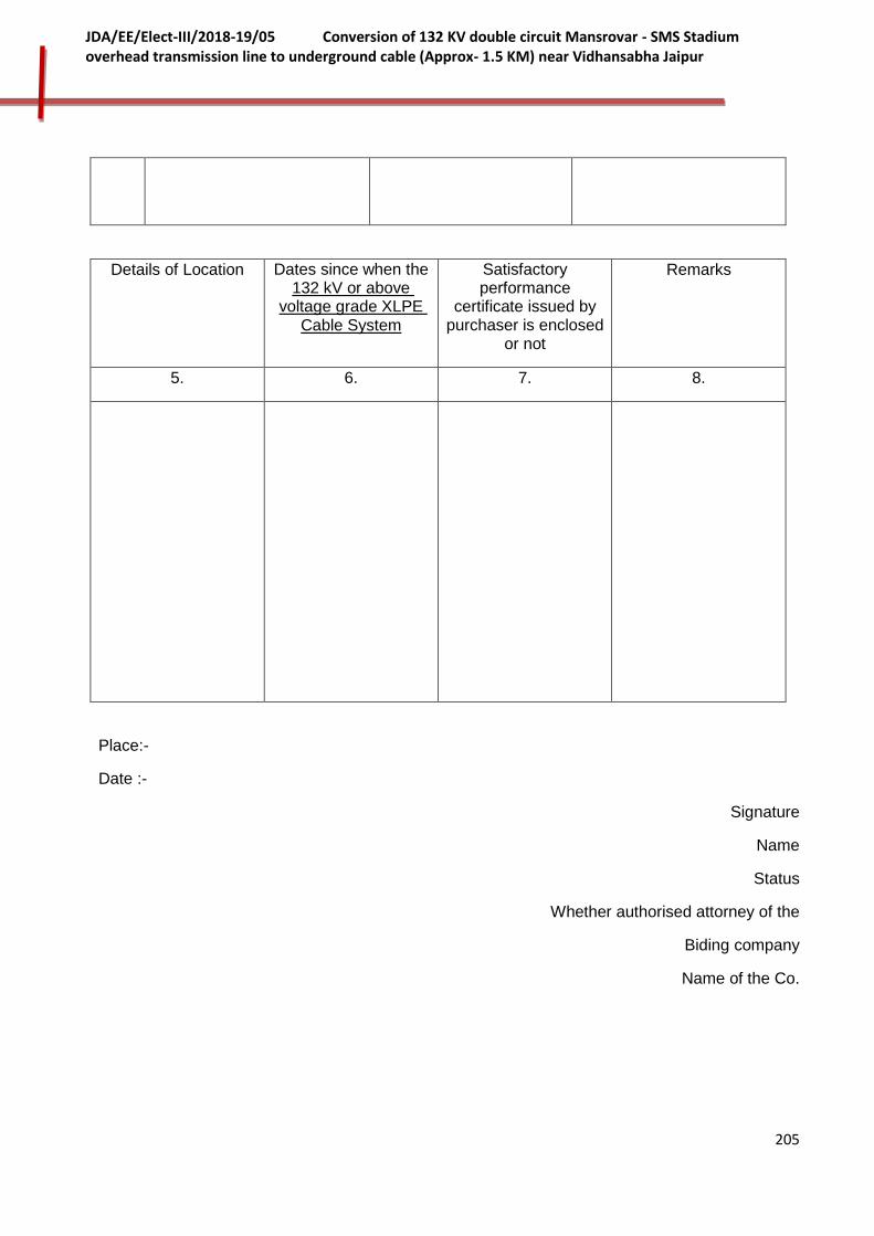
205
JDA/EE/Elect-III/2018-19/05 Conversion of 132 KV double circuit Mansrovar - SMS Stadium overhead transmission line to underground cable (Approx- 1.5 KM) near Vidhansabha Jaipur
Details of Location Dates since when the 132 kV or above
voltage grade XLPE Cable System
Satisfactory performance
certificate issued by purchaser is enclosed
or not
Remarks
5. 6. 7. 8.
Place:-
Date :-
Signature
Name
Status
Whether authorised attorney of the
Biding company
Name of the Co.

206
JDA/EE/Elect-III/2018-19/05 Conversion of 132 KV double circuit Mansrovar - SMS Stadium overhead transmission line to underground cable (Approx- 1.5 KM) near Vidhansabha Jaipur
Schedule-N
QUALIFYING REQUIREMENT DATA
Bidder’s Name & Address:
In accordance with the clause 2.0 of Part-ITB, ANNEXURE-A (BDS), we are furnishing the following details/ documents in support of Qualifying Requirement for the work of " Conversion of 132 KV double circuit Mansrovar - SMS Stadium overhead transmission line to underground cable (Approx- 1.5 KM) near Vidhansabha Jaipur" against tender enquiry No. JDA/EE/Elect-III/2018-19/05
1.0 Attached copies of original documents defining.
(a) The constitution or legal status:
(b) The place of registration and principal place of business;
(c) Written power of attorney of the signatory of the bid to commit the Bidder.
2.0 Attached copies of original agreements (in case of bid by a Joint Venture)
(a) The bids signatured by all partners so as to legally bind both partners, jointly & severally; and
(b) submitted with the joint venture agreement providing the joint and several liability of both partners in the event the contract is awarded to us.
(c) submitted with a Power of Attorney signed by legally authorized signatories of both partners, in favour of the lead partner.
3.0 Attached copies of original letter of authority to seek reference from our banks.
4.0 General Information
All individual firms and each Partner of joint venture bidding for the Substation are requested to complete the information in this form. The requisite information to be provided for all firms (individual Sole bidder as well as all partners of joint venture bidder).
Where the Bidder proposes to use named Sub-vendors/ subcontractors for critical components of the Equipments/ works, the following information should also be supplied for the subcontractor(s).
1. Name of firm
2. Head Office address
3. Telephone Contact Person

207
JDA/EE/Elect-III/2018-19/05 Conversion of 132 KV double circuit Mansrovar - SMS Stadium overhead transmission line to underground cable (Approx- 1.5 KM) near Vidhansabha Jaipur
4. Fax
5. Place of incorporation/ registration Year of incorporation/ registration
5.0 Joint Venture Summary
Names of all Partners of a joint venture 1 .Partner 2. Partner
6.0 General Experience Record
Name of Bidder or Partner of a Joint Venture
All individual firms and both partners of a joint venture are requested to complete the information in this form.
6.1 Average Annual Turnover
The information supplied should be the annual turnover of the Bidder (or each member of a joint venture) for last five financial years.
Use a separate sheet for each partner of the joint venture.
Bidders should not be required to enclose testimonial certificates and publicity material with their application; they will not be taken into account in the evaluation of qualification. Annual Turnover Data
S. No. Year Turnover
1
2
3
4
5
The audited balance sheets and income statements of Bidder (or each member of a joint venture) (separate) for last 5 years are enclosed with the Bid.
6.2 Liquid Assets
We hereby confirm that the liquid assets (current assets minus inventories) and/ or evidence of excess to or availability of credit facilities of our company, i.e. ____ (name of Bidder and/ or Joint Venture Partner), as on ______ (date) is Rs._______ million.
The audited balance sheets and income statements of Bidder (or each member of a joint venture) (separate) for last 5 years are enclosed with the Bid.
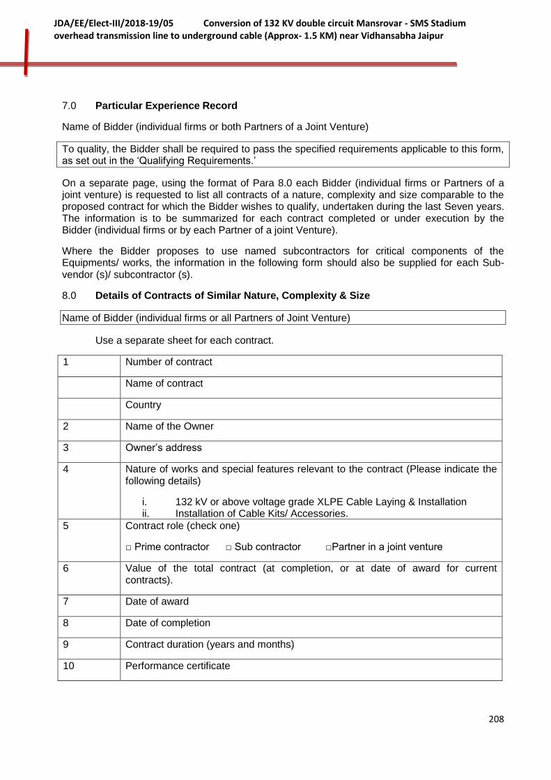
208
JDA/EE/Elect-III/2018-19/05 Conversion of 132 KV double circuit Mansrovar - SMS Stadium overhead transmission line to underground cable (Approx- 1.5 KM) near Vidhansabha Jaipur
7.0 Particular Experience Record
Name of Bidder (individual firms or both Partners of a Joint Venture)
To quality, the Bidder shall be required to pass the specified requirements applicable to this form, as set out in the ‘Qualifying Requirements.’
On a separate page, using the format of Para 8.0 each Bidder (individual firms or Partners of a joint venture) is requested to list all contracts of a nature, complexity and size comparable to the proposed contract for which the Bidder wishes to qualify, undertaken during the last Seven years. The information is to be summarized for each contract completed or under execution by the Bidder (individual firms or by each Partner of a joint Venture).
Where the Bidder proposes to use named subcontractors for critical components of the Equipments/ works, the information in the following form should also be supplied for each Sub-vendor (s)/ subcontractor (s).
8.0 Details of Contracts of Similar Nature, Complexity & Size
Name of Bidder (individual firms or all Partners of Joint Venture)
Use a separate sheet for each contract.
1 Number of contract
Name of contract
Country
2 Name of the Owner
3 Owner’s address
4 Nature of works and special features relevant to the contract (Please indicate the following details)
i. 132 kV or above voltage grade XLPE Cable Laying & Installation ii. Installation of Cable Kits/ Accessories.
5 Contract role (check one)
□ Prime contractor □ Sub contractor □Partner in a joint venture
6 Value of the total contract (at completion, or at date of award for current contracts).
7 Date of award
8 Date of completion
9 Contract duration (years and months)
10 Performance certificate

209
JDA/EE/Elect-III/2018-19/05 Conversion of 132 KV double circuit Mansrovar - SMS Stadium overhead transmission line to underground cable (Approx- 1.5 KM) near Vidhansabha Jaipur
9.0 Summary Sheet: Current Contract Commitments or Works in Progress.
Name of Bidder (individual firms or all Partners of Joint Venture)
Bidders (individual firms and each Partner in case of a Joint Venture) should provide information on their current commitments on all contracts that have been awarded, or for which a letter of intent or acceptance has been received, or for contracts approaching completion, but for which an unqualified, full completion certificate has yet to be issued.
Name of Contract (reported on para 7.0)
Value of outstanding work (current Indian Rupees)
Estimated
completion date
1
2
3
4
5
6
10.0 Manufacturing Capabilities for 132 kV XLPE Cable
1. Name of Manufacturer
2. Address of Manufacturer
................................................................
................................................................
3. Manufacturing Capacity
4. Qty. manufactured in last five years
Year1 Year2 Year3 Year4 Year5
5. Details of year-wise current commitments
In case, Bidder is not owning the manufacturing facilities as specified in relevant para of Annexure-A, then he should furnish the above information in respect of manufacturers from whom he has assured access to (through hire, lease manufacturing agreement, availability of manufacturing capacity or other means) these manufacturing facilities. Further, he must enclose

210
JDA/EE/Elect-III/2018-19/05 Conversion of 132 KV double circuit Mansrovar - SMS Stadium overhead transmission line to underground cable (Approx- 1.5 KM) near Vidhansabha Jaipur
commitment letter from such manufacturers confirming that, based on known commitments, these facilities shall be available for use in the proposed contract.
11.0 Financial Capability
Name of Bidder (individual firms or all Partners of Joint Venture)
Bidders (individual firms or both Partners of Joint Venture) should provide financial information to demonstrate that they meet the requirements stated in the Qualifying Requirements. Each Bidder or Partner of a Joint Venture must fill in this form. If necessary, use separate sheets to provide complete banker information. A copy of the audited balance sheet should be attached.(Supported by duly authenticated by Chartered Accounted)
(a)
Banker Name of banker
Address of banker
................................................................................
Telephone Contract name and title
Fax
(b) In accordance with Clause 2 ITB, Annexure-A (BDS) of the bidding documents, certificate(s) from Banker issued on _______ (date) as per requisite format, indicating various fund based/ non fund based limits sanctioned to the Bidder or each member of the joint venture and the extent of litigation as on date is/ are enclosed. The consolidated position showing all the un-utilized limits available with our various banker(s) and/or FI(s), total of un-utilized limit added together etc. is also enclosed.
12.0 CV of the Project Manager to be attached.
Date:
Place:
Signature (Printed Name)
(Designation) (Common Seal)
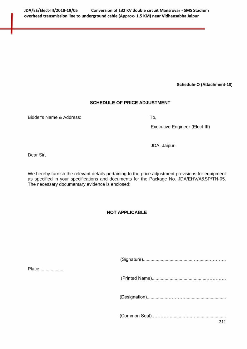
211
JDA/EE/Elect-III/2018-19/05 Conversion of 132 KV double circuit Mansrovar - SMS Stadium overhead transmission line to underground cable (Approx- 1.5 KM) near Vidhansabha Jaipur
Schedule-O (Attachment-10)
SCHEDULE OF PRICE ADJUSTMENT
Bidder's Name & Address: To,
Executive Engineer (Elect-III)
JDA, Jaipur.
Dear Sir,
We hereby furnish the relevant details pertaining to the price adjustment provisions for equipment as specified in your specifications and documents for the Package No. JDA/EHV/A&SP/TN-05. The necessary documentary evidence is enclosed:
NOT APPLICABLE
(Signature)........................................….........………..
Place:...................
(Printed Name)...........................................………….
(Designation)................…………................................
(Common Seal).…………..........…...….......................

212
JDA/EE/Elect-III/2018-19/05 Conversion of 132 KV double circuit Mansrovar - SMS Stadium overhead transmission line to underground cable (Approx- 1.5 KM) near Vidhansabha Jaipur
SCHEDULE-P
SCHEDULE OF SPECIAL TOOLS & TACKLES FOR MAINTENANCE
Bidder's Name & Address: To,
Executive Engineer (Elect-III)
JDA, Jaipur.
We hereby furnishing below the list of special tools & tackles for maintenance of equipment for the subject package.
Sl. No.
For Equipment Item Description Unit Quantity
Date : (Signature) ...................................................
Place : (Printed Name) ............................................
(Designation) ...............................................
(Common Seal) ............................................
213
JDA/EE/Elect-III/2018-19/05 Conversion of 132 KV double circuit Mansrovar - SMS Stadium overhead transmission line to underground cable (Approx- 1.5 KM) near Vidhansabha Jaipur
SCHEDULE-Q
214
JDA/EE/Elect-III/2018-19/05 Conversion of 132 KV double circuit Mansrovar - SMS Stadium overhead transmission line to underground cable (Approx- 1.5 KM) near Vidhansabha Jaipur
Declaration by the Bidder regarding qualifications
215
JDA/EE/Elect-III/2018-19/05 Conversion of 132 KV double circuit Mansrovar - SMS Stadium overhead transmission line to underground cable (Approx- 1.5 KM) near Vidhansabha Jaipur
Declaration by the Bidder
In relation to my / or Bid submitted to _________________ for procurement of __________________ in response to their Notice Inviting Bids No._______________ Dated ___________ I/we hereby declare under Section-7 of Rajasthan Transparency in Public Procurement Act, 2012, that:
1. I/we possess the necessary professional, technical, financial and managerial resources and competence required by the Bidding Document issued by the procuring Entity;
2. I/we have fulfilled my/our obligation to pay such of the taxes payable to the union and the state Government or any local authority as specified in the Bidding Document;
3. I/we are not insolvent, in receivership, bankrupt or being wound up, not have my/our affairs administered by a court or a judicial officer, not have my/our business activities suspended and not the subject of legal proceedings for any of the foregoing reasons;
4. I/we do not have, and our directors and officers not have, been convicted of any criminal offence related to my/our professional conduct or the making of false statements or misrepresentations as to my /our qualifications to enter into a procurement contract within a period of three years preceding the commencement of this procurement process, or not have been otherwise disqualified pursuant to debarment proceedings;
5. l/We do not have a conflict of interest as specified in the Act Rules and the Bidding Document, which materially affects fair competition;
Signature of Bidder
Name :
Designation :
Address:
Date :
Place:

216
JDA/EE/Elect-III/2018-19/05 Conversion of 132 KV double circuit Mansrovar - SMS Stadium overhead transmission line to underground cable (Approx- 1.5 KM) near Vidhansabha Jaipur
VOLUME-II
TECHNICAL SPECIFICATION FOR ELECTRICAL WORKS
Preamble
This volume of the bidding documents provides the information related to the project. The project details consist of the project objective, outcome, phases/ milestones, timelines along-with the other technical details/ specification for bidder to formulate and submit their bid. This volume shall consist of following parts:
Part-I: Project
Part-II: General Technical Requirement/Conditions (GTR/GTC)
Part-III: Specific Technical Requirements
In case of any discrepancy between Part-PROJECT, Part-GTR/GTC and other technical specifications on scope of works, Part-PROJECT shall prevail over all other parts.
217
JDA/EE/Elect-III/2018-19/05 Conversion of 132 KV double circuit Mansrovar - SMS Stadium overhead transmission line to underground cable (Approx- 1.5 KM) near Vidhansabha Jaipur
PART-I-PROJECT
1.0 GENERAL:
1.1 PREAMBLE:
1.1.1. Rajasthan Rajya Vidyut Prasaran Nigam Limited is responsible for transmission of electrical power in the state of Rajasthan and henceforth referred to as Nigam.
1.1.2. The Nigam is responsible for establishing EHV sub-stations and associated transmission interconnections under the transmission programme and to meet the consumers demand.
The JDA has been entrusted for the work of Conversion of 132 KV double circuit Mansrovar - SMS Stadium overhead transmission line to underground cable (Approx- 1.5 KM) near Vidhansabha Jaipur for which RVPN has issued adminstrative and technical sanction to carry out the work by JDA.
This project includes DESIGN, MANUFACTURE, TESTING AT WORKS AND
SUPPLY OF 132 KV SINGLE CORE XLPE CABLE FOR ESTABLISHING OF 132
KV DOUBLE CIRCUIT (1200 SQ. MM) BETWEEN SMS STADIUM GSS TO 132
KV TOWER AT NBCC BUILDING SAHAKAR MARG BY CONVERTING EXISTING
132 KV DOUBLE CIRCUIT OVERHEAD TRANSMISSION LINE INCLUDING
INFRONT OF VIDHAN SABHA (JAIPUR) (APPROX. 1.5 KM) INCLUDING
DETAILED ROUTE SURVEY, LAYING AND INSTALLATION OF CABLE
ALONGWITH ASSOCIATED ACCESSORIES/ ITEMS AND CIVIL WORKS, AND
CONTRUCTION OF 1 NOS. 220 KV TYPE C TOWER NARROW BASE (250 MTR
SPAN) ALONGWITH DISMANTLING OF EXTING 132 KV TOWERS
1.2 The scope of works in this bid document (Specifications) covers scope as in clause 2.0 for executing the above mentioned works on Total responsibility basis.
Before proceeding with the termination work at new/existing sub-station and proposed cable laying at designated route, the bidder shall fully familiarize himself with the site conditions and General arrangements & schemes etc. Though the owner shall endeavor to provide the information, it shall not be binding for the Owner to provide the same.
The bidders are advised to visit the sub-station sites, proposed route of cable laying and acquaint themselves with the topography, infrastructure and design philosophy. The bidders shall be fully responsible for providing all equipments, materials, system, and services specified or otherwise which are required to complete the proposed XLPE cable circuits between tapping point and the substations in all respects in this project. Non-visiting of sub-station site and proposed route will not be acceptable as an excuse for claiming changes/variations.

218
JDA/EE/Elect-III/2018-19/05 Conversion of 132 KV double circuit Mansrovar - SMS Stadium overhead transmission line to underground cable (Approx- 1.5 KM) near Vidhansabha Jaipur
2.0 SCOPE:
2.1 Supply of equipments/materials:
2.1.1 Design, Engineering, Manufacture, Testing at Manufacturer’s works and supply of following Items/ equipments.
i) 132 kV, 1200 Sq. mm, Single Core XLPE Copper Cable along with associated cable accessories complete with all fittings/ components (necessary for the satisfactoryperformance and easeof maintenance) required for specified/approved laying formation/ group.
ii) 145 kV pre-molded Outdoor Cable end Termination alongwith porcelain/composite bushing for termination in outdoor type switchgear suitable for cable at i) above.
iii) Pre-Molded Straight through Joint Kits suitable for the cable at i) above
iv) Solid bonding Link box with Link plates, bonding & grounding cable complete with other associated accessories.
v) Cross bonding Link box, Co-axial bonding cable, Sheath Voltage Limiters (SVL) complete with other associated accessories
vi) 132 kV Lighting/ Surge Arrestors
vii) HDPE Pipes, Warning tapes, Cable covers, Cable Markers etc.
viii) Underground Fiber Optic Cable alongwith associated accessories
ix) Earthing Materials
x) Mandatory Spares & Other Miscellaneous Items.
2.1.2 Structures:
Design, fabrication and supply of:
i) Galvenized steel Structure (complete with nut-bolts, washers, foundation bolts etc.) with the provision to install 132 kV cable termination and Link box for termating of 132 kV Single Core XLPE Cable at Substation end.
ii) Galvenized steel Structure/ arrangement consisting of attachments, ladders, plates & accessories etc. (complete with nut-bolts, washers etc.) with the provision to install 132 kV cable end termination, Link boxes and LAs on 132 kV D/C D- Type Tower Structure. The structure arrangement shall be installed on 132 kV Double Circuit Tower (with Vertical Configurations) to terminate one cable circuit maintaining all the safety and electrical clearances as per IE Rules.
2.1.3 Any other equipment / material required for successful completion of the project.
2.2 Erection, Testing & Commissioning:
2.2.1. Surveying of cable route, excavation of trial holes as per field requirement, preparation of cable route profile, drawing for cable laying final route alignment, marking lines and grades, preparation of final cable route drawings after approval and preparing bill of material.

219
JDA/EE/Elect-III/2018-19/05 Conversion of 132 KV double circuit Mansrovar - SMS Stadium overhead transmission line to underground cable (Approx- 1.5 KM) near Vidhansabha Jaipur
2.2.2 To obtain necessary clearance for excavation work from the concerned authorities on behalf of the JDA/ Nigam and provide requisite copies of information, maps, survey report etc. to the authorities. The JDA/ Nigam shall assist the contractor in obtaining such clearances by providing the authority letter or any other relevant document. The contractor shall make an all out efforts with the concerned authority to get clearances expeditiously and to negotiate the least cost to the JDA/ Nigam. JDAshall furnish all required guarantees and make payments to the concerned authorities. The contractor shall ensure quick and speedy clearances in order to implement the project within stipulated schedule. In case the authorities have some objections on certain sections of routes proposed and are unwilling to provide clearances, the contractor shall propose an alternate route, promptly carrying out the survey and submit specific survey report for that and reapply for clearance after taking into account the comments/objections of the authority.
2.2.3 Evaluation of thermal resistivity of soil along the cable route
2.2.4 Handling, transportation and storage of cable drums and associated accessories to/at Site.
2.2.5 Laying of cables in the formation and group as approved by JDA/ Nigam as per standard cable installation procedure and using cable installation equipments as per requirement.
2.2.6 Supply and installation of all critical installation materials like trefoil clamps, neoprene cushions, support brackets, etc as required for complete route.
2.2.7 Laying of fiber optic cable in the formation as approved by JDA/ Nigam as per
standard cable installation procedure and using cable installation equipments as per requirement.
2.2.8 Installation of warning tape, providing bricklayer of minimum class designation 50 (50 kg/sq.cm) as covers en-route (underground portion only), construction of jointing bays, backfilling of trenches & restoration as per specification.
2.2.9 Road crossings through HDPE pipe for each cable and restoration as per specification. All major / important road where open digging is not permitted, cables are to be laid in HDPE pipes using Trench-less technology
2.2.10 Installation of Cable markers as per statutory requirements shall be provided all along the route at a maximum distance of 50 meters and other important locations. Also the location of underground cable shall be clearly indicated on the marker.
2.2.11 Installation of straight through joints
2.2.12 Installation of Link boxes along with associated accessories.
2.2.14 Installation of outdoor end terminations for cables with Porcelain/ composite bushing (for connection to Outdoor Switchgear/ Line).
2.2.15 Installation of Lightning Arrestor at LILO Point with suitable supporting, clamps fixture, nut bolts, washer etc.

220
JDA/EE/Elect-III/2018-19/05 Conversion of 132 KV double circuit Mansrovar - SMS Stadium overhead transmission line to underground cable (Approx- 1.5 KM) near Vidhansabha Jaipur
2.2.16 Pre-commissioning tests [List to be submitted by successful bidder in conformity to standards and manufacturer practices (to be approved by JDA/ Nigam) for these tests]
2.2.17 Commissioning of circuits.
2.3 Civil Works:
2.3.1. Earthwork in excavation for cable trench preparation.
2.3.2 Laying of cable, cover the cable with concrete block/ tile and river sand cushioning.
2.3.3 Disposal of surplus earth with all leads and lifts.
2.3.4 Supply and laying of recast RCC chambers with manhole cover of suitable depth for cable joint.
2.3.5 Making good all dismantling/ demolitions (Ramp/ curbs/ drains/ sewer Lines/ water supply lines) immediately after laying of cable.
2.3.6 Foundation of fabricated support structures for Outdoor cable end terminations.
2.3.7 All materials required for the civil construction / installation work shall be supplied by the contractor. The cement and steel shall also be supplied by the contractor.
2.3.8 Any other civil work required for successful completion of the project.
2.4 Soil Data The bidder shall be responsible for carrying out the required survey and should fully satisfy himself about the nature of soil expected to be encountered prior to the submission of bid.
The unit rate quoted by the Bidder for underground portion shall be irrespective of soil type such as normal soil, soft rock, hard rock and crossings such as pavements, all types of roads, rivers, nallah, culverts, rail track etc. encountered during the actual installation. The Bidders are required to make their own estimates and offer a single uniform rate applicable for all kinds of soil strata and crossings. The JDA shall not entertain any additional claims/payments for any type of soil/crossings encountered during installation. JDA/ Nigam strongly recommends site visits/investigation by the bidders (at their own cost) before submission of the bid for proper estimations. The contractor shall be required to carry out excavation and back filling in accordance with this specification and provide all additional items required at its own cost for proper installation not limited to those described in this specifications.
Unit rate for excavation and Backfilling shall interalia include all related works/activities such as excavation, blasting of rocks and backfilling oftrench, fixing of gradient of trench, excavation of trial pits if required, clearing of bushes, roots of trees along the trenches, cutting of bushes, trees, shoring, dewatering, excavation and backfilling of any temporary manhole, support of the existing facilities/plant, removal of let out material, breaking of pavement, clearing of obstacles, temporary reinstatement of footpath wherever required, providing all types of markers, warning bricks and tapes etc, suitable structure/techniques material for crossings (road, rail, culvert, river etc) for installation of HDPE pipe and other installation
221
JDA/EE/Elect-III/2018-19/05 Conversion of 132 KV double circuit Mansrovar - SMS Stadium overhead transmission line to underground cable (Approx- 1.5 KM) near Vidhansabha Jaipur
materials etc. The BOQ in the bid price schedules indicates the total route length to be implemented under subject package.
2.5 Earthing:
This includes complete design and after due approval of owner, supply of earthing rods, earthing pits, earthing materials and earthing conductors etc. wherever applicable for complete route and for connecting to earth mat at both the terminal substations.
However, the successful bidder is required to thoroughly conduct soil resistivity measurements at site for the purpose of adequate earthing material requirements (as per applicable standards) during detailed engineering and submission of the same along with requisite calculations for the approval of JDA/ Nigam before execution.
2.6 Brief Description of Project and Execution Plan:
The salient features of the project and its execution plan/works are as follows:
a) Proposed Project:
Conversion of 132 KV double circuit Mansrovar - SMS Stadium overhead transmission line to underground cable (Approx- 1.5 KM) near Vidhansabha Jaipur
b) Terminal Site/ Substation:
One End: 132 kV Substation SMS Stadium (Jaipur) (Existing)
Proposed 132 kV Double Circuit as above from LILO Point of 132 kV Tower at NBCC Building [Existing]
c) Communication Link: The communication link between the terminal substations mentioned at b) above shall be through fiber optic cable (to be supplied and installed under this project) and OPGW (to be supplied and installed by other contractor). The fiber optic cabling up to terminal point to overhead optical ground wire/ terminal optical equipments shall be in the scope of the contractor. The terminal optical equipment at terminal substations shall be in the scope of other contractor. The contractor shall terminate the fibers on Optical Distribution Frame at terminal substations/ Junction box of OPGW at LILO Point. The contractor shall co-ordinate, exchange necessary information, associate in testing and commissioning of the communication link with the other contractor.
d) The brief particulars of the 132kV system parameters are given here under: (i) Nominal system voltage : 132 kV rms
(ii) Highest system voltage : 145 kV rms

222
JDA/EE/Elect-III/2018-19/05 Conversion of 132 KV double circuit Mansrovar - SMS Stadium overhead transmission line to underground cable (Approx- 1.5 KM) near Vidhansabha Jaipur
(iii) Impulse withstand voltage 1.2/50 : 650 kV peak
micro seconds wave of positive/
negative polarity
(iv) System Frequency : 50 Hz
(v) No. of phase per circuit : Three
(vi) System Earthing : Effectively
Grounded
(vii) Rated short time current : 31.5 kA
(viii) Duration of fault current : one second
e) Installation Data: Brief particulars of installation data are as under:
Location : Jaipur, India Route : Please refer enclosed drawings No of cables : Double Circuit (comprising of 3 cables in trefoil
formation in each circuit Type of laying : Direct burial in ground Depth of burial : 1.5 metres Characteristics of soil : Generally leveled.
At cable depth presence of micro-organisms in the soil shall be taken into account.
Type of the road surface: To be physically examined by bidder based
on route layout.
f) It is proposed to execute the work of proposed project of cable system as follows:
i. Route Survey: The survey shall be conducted for underground routes to finalize the route and paths for the underground cable. The survey shall interalia include the following minimum activities:
Map Study: The Contractor shall arrange topographical maps and other maps of the concerned area in proper scale. All links shall then carefully be studied using maps. Various feasible alternative routes shall be identified on the maps and the Contractor shall shortlist most suitable route. Collection of details of other Utilities: Contractor shall arrange information about existing underground facilities for the proposed routes. To do so as built drawing or route index diagram for various services viz water works, electric supply utilities, telecom services providers, public health, gas/oil authorities etc. may be collected from
223
JDA/EE/Elect-III/2018-19/05 Conversion of 132 KV double circuit Mansrovar - SMS Stadium overhead transmission line to underground cable (Approx- 1.5 KM) near Vidhansabha Jaipur
the concerned authorities. In case details are not available, the Contractor shall assess suitably by conducting enquiries and surveys.
Identification of underground cable route: The Contractor shall propose most suitable route for link keeping in view the following broad criteria:
1. The route shall be as straight and short as possible. 2. The route shall have minimum obstacles in order to minimize
reinstatement cost. 3. Clearances required from other authorities/bodies are minimum
and that the clearances can be obtained expeditiously. 4. Wet or unstable ground shall be avoided to the extent possible. 5. The route for the cable shall be away from the carriageway of the
road to the extent possible. 6. The route shall be suitable for placing manholes wherever required. 7. Future expansion of roads shall be taken into consideration. 8. Road, rail, river culvert (nallah) crossing, trenches digging shall be
minimum. 9. As far as possible underground cable route shall be on the
opposite side of the existing cables laid by DOT/BSNL or other utilities. Wherever both routes fall on the same side of the road, a spacing of about 2.0 m is to be maintained, to the extent possible.
10. Care must be taken to avoid choosing routes, roads, areas that are prone to floods etc.
After finalizing the best alternative route, some trial pits shall be dug at suitably selected locations to assess the obstacles. It is necessary to locate the trial pits at proposed manhole locations. They shall be dug carefully keeping watch for the existing underground facilities. The presence of each type of facilities shall be recorded in the inspection note of the trial pit alongwith their sites sketches are kept in record for future reference. These details shall be enclosed alongwith the survey report.
The Contractor shall submit the survey report with the most suitable route for cable link along with details above. Contractor shall submit the final survey report for approval before implementation. The final survey report shall include atleast the following:-
1. A drawing of the proposed route indicating all details of the route including relevant details of soil strata, bridges, culverts, causeways, rail over/under bridges, defense area, underground gas/oil/water pipes line, power and communication cable routes, other important landmarks etc.
2. The distance of the cable route from the center of the road/rail/river/bridge/culvert etc. shall be indicated on the route maps as well as documented in table.
3. City/town/village/forest/defense etc. area coverage. 4. Sections of the links where Trench-less Digging may be
required.

224
JDA/EE/Elect-III/2018-19/05 Conversion of 132 KV double circuit Mansrovar - SMS Stadium overhead transmission line to underground cable (Approx- 1.5 KM) near Vidhansabha Jaipur
5. Location and number of permanent and temporary manholes.
6. Location of all turns, bends and major landmarks. 7. List of authorities from which clearance shall be required to
be obtained from each relevant section.
The final survey report shall have to be approved by the Nigam and requisite clearances need to be obtained before the cable installation work is commenced.
The contractor shall prepare and submit for approval by the Nigam, specific construction drawings for all types of soil strata/crossings taking into consideration the guidelines given in this specification. The construction/implementation shall be carried out as per the approved drawings.
The construction drawings shall interalia include the longitudinal sectional diagram of the trench for different soil strata and detail arrangement of crossings, number of pipes, size of pipes, location and position of manholes, other details as per the technical specifications
ii. Evaluation of thermal resistivity of soil along the cable route iii. The ampacity calculation of the cable current carrying capacity after
applying suitable de-rating factors as per design parameters, sheath voltages under normal and short circuit conditions and SVL selection calculations, short circuit rating calculations for bonding and earthing cables, charging current and calculation of all design data/parameters as per the approved layout/formation/grouping.
iv. Unloading and loading of the cable drums and accessories, clearing through customs, transportation to the site and storage.
v. Excavation of the trenches for 132 kV cables. vi. Laying of XLPE and Fiber Cables as per approved formation/ group in
cable trenches including supply and installation of HDPE pipes wherever necessary.
vii. Straight Jointing of cables wherever approved. viii. Installation of link boxes, bonding & grounding cable, SVL and required
earthing as per approval. ix. Backfilling of trenches as per installation procedure approved including
RCC covers, warning tapes, river sand cushions, joint markers, cable route markers alongwith associated civil works.
x. Restoration and making good of all dismantling/ demolition immediately after cable laying.
xi. Installation of structures alongwith foundation at terminal substations as per approved location in the substations/ LILO point.
xii. Installation of Outdoor cable end terminations for connection to outdoor 132 kV Bay to other outdoor equipments at 132 kV Switchyard/ to line at LILO Point.
xiii. Installation of Lightning Arrestors at LILO terminal point. xiv. Pre-commissioning testing of cable as per manufacturer practices and
standard/ statutory requirements. xv. Commissioning of cable circuits.
225
JDA/EE/Elect-III/2018-19/05 Conversion of 132 KV double circuit Mansrovar - SMS Stadium overhead transmission line to underground cable (Approx- 1.5 KM) near Vidhansabha Jaipur
The bidder may visit the site/ route and if he/they proposes to execute the work in a manner different from that proposed above, he/they shall bring out scheme clearly spelt out in his/their offer.
2.7 Project Management:
2.7.1 The contractor shall also be responsible for the overall co-ordination with internal/external agencies, project management, supervision of works, training of owner’s manpower, loading, unloading, handling, moving it to final destination for successful erection, testing and commissioning of the substation.
2.7.2 The contractor shall provide experienced, skilled, knowledgeable and competent personnel for all phases of the project, so as to provide the Owner with a high quality system.
2.7.3 The successful contractor/ bidder shall submit the PERT (in MS-Project format) with detailed activity plan for the approval of Nigam. The fortnightly/ monthly progress report in the same format i.e. MS–Project (showing the base line dates and actual progress accomplished) be submitted for the effective monitoring of the project.
2.8 Typical drawings / documents:
The typical drawings/ documents furnished below are for the tender purpose and for the general guidance of the bidder:
S. No.
Drawing Description Drawing No.
1 Tentative route for laying of 132 kV XLPE Cable from 132 kV Substation SMS Stadium to LILO point of 132 kV Tower at NBCC Building at sahakar Marg.
JDA/TN-05/Drg-1
2 Final Arrangement of after Cable Laying and reinstatement of Road
JDA/TN-05/Drg-2
3 Cross Sectional View of Open Cut Road Crossing
JDA/TN-05/Drg-3
4 RCC Cable Covers JDA/TN-05/Drg-4
5 Cross Sectional View of Road Crossing by Trenchless Method
JDA/TN-05/Drg-5
6 Cross Sectional details of 132 kV UG cable joint markers
JDA/TN-05/Drg-6
226
JDA/EE/Elect-III/2018-19/05 Conversion of 132 KV double circuit Mansrovar - SMS Stadium overhead transmission line to underground cable (Approx- 1.5 KM) near Vidhansabha Jaipur
7 Typical 132 kV joint bay for 3-Phase Ckt
JDA/TN-05/Drg-7
8 Cross Sectional details of 132 kV UG cable route markers
JDA/TN-05/Drg-8
9 Cleat (3 Phase Type) for Cable Tray JDA/TN-05/Drg-9
10 Warning Tape JDA/TN-05/Drg-10
Successful bidder shall verify the drawings and furnish modified design, if any. Drawings shall be submitted for approval of owner, whether with or without modified designs. Only after the approval of owner, the drawings shall be released for construction/installation.
2.9 Specific exclusions: The followings are the only exclusions from the bidder’s scope:
i) Road restoration charges or any other charges/fees to be paid to the civic/ local authorities, if required, for crossing the cables.
The bidder shall clearly confirm exclusions in his offer.
2.10 Completion of Project: Any other items not specifically mentioned in the specification but which are required for erection, testing and commissioning and satisfactory operation of the cable system are deemed to be included in the scope of the specification unless specifically excluded. For such items, bidders are advised to include them in their quoted items showing their quantities and Unit Prices in the schedule of prices.
2.11 Maintenance Services: The successful bidder shall provide maintenance services after the expiry of standard guarantee/ warranty period of cable system (excluding of item/material/equipment already covered for performance guarantee of 5 years for which the successful bidder shall provide services, if required, free of cost up to its guaranteed performance period) for 4 years on per visit chargeable basis on the rates as decided/ approved and included in the letter of award. Maintenance service per visit towards any breakdown of cable system shall include services of expert engineers, technicians alongwith necessary tools/tackles, testing equipments, fault locating equipments to detect the fault and its subsequent rectification, re-testing and restoring the electric supply through cable system.
3.0 Physical and Other Parameters:
3.1 Meteorological data:
The metrological data of the substations is indicated at clause 33.0 of GTR (Part-II, Volume II). However for design purposes, ambient temperature should be considered as 50 Deg.C.
227
JDA/EE/Elect-III/2018-19/05 Conversion of 132 KV double circuit Mansrovar - SMS Stadium overhead transmission line to underground cable (Approx- 1.5 KM) near Vidhansabha Jaipur
4.0 Schedule of Quantities:
i. The requirement of various items/equipment, civil works, mandatory spares, & maintenance charges are indicated in schedule of prices (Volume-I, Schedule-BOQB and associated sub-schedules).
ii. All equipment/items andcivil works for which bill of quantity has been indicated in schedule of prices (Volume-I, Schedule-B), the payment shall be governed as per the Clause “Quantity Variation” [Clause 42.0, GCC, Part-III, Vol-I of specification.
iii. Wherever, Items for which (a) Quantities have been indicated as lumpsum/lot/set/Job and (b) items for which quantities were to be estimated by the Bidder, including additional items [falling under (a) and/or (b)] considered necessary by the Bidder for successful completion of the works as per Technical Specification and indicated by him in his Bid shall remain constant unless there is change made in the Scope of Work by the Purchaser. The quantities and unit prices (a) subsequently arrived while approving the Bill of Quantities (BOQ)/Billing break-up of lumpsum/lot/set/Job quantities and/or (b) quantities estimated by the Bidder/Contractor shall be for on account payment purpose only. In case additional quantities, over and above the quantities in BOQ/Billing Break-up and or estimated by the Bidder/Contractor, are required for the successful completion of the scope of work as per Technical Specification, the Contractor shall execute additional quantities of these items for which no additional payment shall be made over and above the lumpsum Contract Price.
iv. Bidder should include all such items in the schedule of prices, which are not specifically mentioned but are essential for the execution of the contract. Item which explicitly may not appear in various schedules and required for successful commissioning of substation shall be included in the bid price and shall be provided at no extra cost to Owner.
5.0 Vendors/ Makes:
The bidder shall offer other items i.e. LAs, fiber optic cables etc. (to be supplied in this contract) of reputed makes/vendors having sufficient manufacturing experience and installations under satisfactory operations. The design and workmanship of these items shall also be in accordance with the best engineering practices, highest quality standards to ensure satisfactory performance and service life of the cable system and accessories. The contractor shall ensure compatibility of fittings and joints, if procured, from other vendors. However, the purchaser reserve right to approve/ask for alternative/other/equivalent makes/ vendors subject to meeting of technical specifications, previous performances (with State/ Central Transmission Utilities, Public Sector Undertakings such as NTPC/NHPC etc.), availability of after sales support/services etc. in the overall interest of Nigam/ Project.
6.0 Reference Drawings: The reference (Typical) drawings, which form a part of the specifications, are given at Annexure-V2-P1-1. The enclosed drawings give the basic scheme, layout etc. In case of any discrepancy between the drawings and text of specification, the

228
JDA/EE/Elect-III/2018-19/05 Conversion of 132 KV double circuit Mansrovar - SMS Stadium overhead transmission line to underground cable (Approx- 1.5 KM) near Vidhansabha Jaipur
requirements of text shall prevail in general. However, the Bidder is advised to get these clarified from Nigam in case of any doubt.
7.0 Mandatory spares: The Mandatory spares shall be included in the bid proposal by the bidder. The prices of these spares shall be given by the bidder in the relevant schedule of price and will be considered for evaluation of bid. The quantities for the ordering shall be decided as per the equipment offered, maintenance needs and finalization of maintenance terms & conditions etc. and shall be incorporated in the letter of award.
8.0 Order of Precedence of different Sections of Technical Specification (Volume-II):
8.1 Part-I: Project 8.2 Part-II: General Technical Requirement/Conditions (GTR/GTC) 8.3 Part-III: Specific Technical Requirements
Section-I: 132 kV XLPE Cable
Section-II: Cable Terminations and Jointing Kits
Section-III: Installation of Cables
Section-III (A): Scope, Route Survey, Works requirement and statutory clearances
Section-III (B): Laying and Installation of cable
Section-III (C): Details of Jointing and Termination works of Cable
Section-III (D): Civil and Structural Works
Section-III (E): Earthing, Site Testing, commissioning of complete cable system
Section-IV: Un-Armoured underground fiber optic Cable
Section-V: Surge Arrestor
In case of any discrepancy between Part-PROJECT, Part-GTR/GTC and other technical specifications on scope of works, Part-PROJECT shall prevail over all other sections.
In case of any discrepancy between Part-GTR/GTC and individual sections for various equipments, requirement of individual item/equipment section shall prevail.
9.0 Specific Requirements:
The bidder shall be responsible for safety of human and equipment during the working as per Indian standards/IE Rules/IE Act and local authority regulations. It will be the responsibility of the Contractor to co-ordinate and obtain Electrical Inspector's clearance before commissioning. Any additional items, modification due
229
JDA/EE/Elect-III/2018-19/05 Conversion of 132 KV double circuit Mansrovar - SMS Stadium overhead transmission line to underground cable (Approx- 1.5 KM) near Vidhansabha Jaipur
to observation of such statutory authorities shall be provided by the Contractor at no extra cost to the Owner.
10.0 Facilities to be provided by the Owner:
10.1 Owner may consider the contractors request / help him to make available the auxiliary power supplies (DISCOM) on chargeable basis at a single point in the terminal Substation. The prevailing energy rates of the DISCOM shall be applicable. All further distribution from the same for construction and permanent auxiliary supply shall be made by the contractor. However, in case of failure of power due to any unavoidable circumstances, the contractor shall make his own necessary arrangements like diesel generator sets etc. at his own cost so that progress of work is not affected and owner shall in no case be responsible for any delay in works because of non-availability of power.
10.2 The contractor shall make his own arrangement for construction water supply at his own cost and the Owner shall in no case be responsible for any delay in works because of non-availability or inadequate availability of water.
230
JDA/EE/Elect-III/2018-19/05 Conversion of 132 KV double circuit Mansrovar - SMS Stadium overhead transmission line to underground cable (Approx- 1.5 KM) near Vidhansabha Jaipur
ANNEXURE-V2-P1-1
STATEMENT SHOWING THE LIST OF DRAWING FOR THE WORK OF DESIGN,
MANUFACTURE, TESTING AT WORKS AND SUPPLY OF 132 KV SINGLE CORE XLPE
CABLE FOR ESTABLISHING OF 132 KV DOUBLE CIRCUIT (1200 SQ. MM) BETWEEN SMS
STADIUM GSS TO 132 KV TOWER AT NBCC BUILDING SAHAKAR MARG BY CONVERTING
EXISTING 132 KV DOUBLE CIRCUIT OVERHEAD TRANSMISSION LINE INCLUDING
INFRONT OF VIDHAN SABHA (JAIPUR) (APPROX. 1.5 KM) INCLUDING DETAILED ROUTE
SURVEY, LAYING AND INSTALLATION OF CABLE ALONGWITH ASSOCIATED
ACCESSORIES/ ITEMS AND CIVIL WORKS, AND CONTRUCTION OF 1 NOS. 220 KV TYPE
C TOWER NARROW BASE (250 MTR SPAN) ALONGWITH DISMANTLING OF EXTING 132
KV TOWERS
S. No.
Drawing Description Drawing No.
1 Tentative route for laying of 132 kV XLPE Cable from 132 kV Substation SMS Stadium to LILO point of 132 kV Tower at NBCC Building at sahakar Marg.
JDA/TN-05/Drg-1
2 Final Arrangement of after Cable Laying and reinstatement of Road
JDA/TN-05/Drg-2
3 Cross Sectional View of Open Cut Road Crossing
JDA/TN-05/Drg-3
4 RCC Cable Covers JDA/TN-05/Drg-4
5 Cross Sectional View of Road Crossing by Trenchless Method
JDA/TN-05/Drg-5
6 Cross Sectional details of 132 kV UG cable joint markers
JDA/TN-05/Drg-6
7 Typical 132 kV joint bay for 3-Phase Ckt
JDA/TN-05/Drg-7
8 Cross Sectional details of 132 kV UG cable route markers
JDA/TN-05/Drg-8
231
JDA/EE/Elect-III/2018-19/05 Conversion of 132 KV double circuit Mansrovar - SMS Stadium overhead transmission line to underground cable (Approx- 1.5 KM) near Vidhansabha Jaipur
9 Cleat (3 Phase Type) for Cable Tray JDA/TN-05/Drg-9
10 Warning Tape JDA/TN-05/Drg-10
232
JDA/EE/Elect-III/2018-19/05 Conversion of 132 KV double circuit Mansrovar - SMS Stadium overhead transmission line to underground cable (Approx- 1.5 KM) near Vidhansabha Jaipur
Drg No. JDA/TN-05/Drg. 1

233
JDA/EE/Elect-III/2018-19/05 Conversion of 132 KV double circuit Mansrovar - SMS Stadium overhead transmission line to underground cable (Approx- 1.5 KM) near Vidhansabha Jaipur
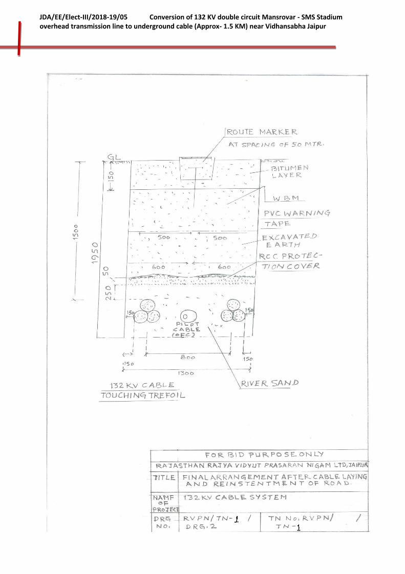
234
JDA/EE/Elect-III/2018-19/05 Conversion of 132 KV double circuit Mansrovar - SMS Stadium overhead transmission line to underground cable (Approx- 1.5 KM) near Vidhansabha Jaipur

235
JDA/EE/Elect-III/2018-19/05 Conversion of 132 KV double circuit Mansrovar - SMS Stadium overhead transmission line to underground cable (Approx- 1.5 KM) near Vidhansabha Jaipur
Drg No. JDA/TN-05/Drg. 3

236
JDA/EE/Elect-III/2018-19/05 Conversion of 132 KV double circuit Mansrovar - SMS Stadium overhead transmission line to underground cable (Approx- 1.5 KM) near Vidhansabha Jaipur
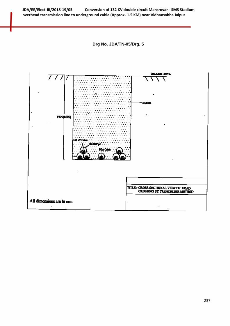
237
JDA/EE/Elect-III/2018-19/05 Conversion of 132 KV double circuit Mansrovar - SMS Stadium overhead transmission line to underground cable (Approx- 1.5 KM) near Vidhansabha Jaipur
Drg No. JDA/TN-05/Drg. 5
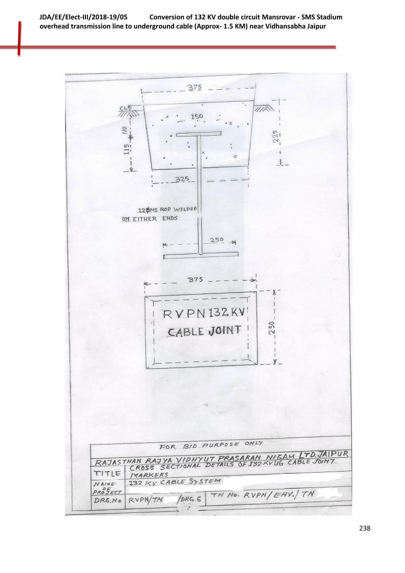
238
JDA/EE/Elect-III/2018-19/05 Conversion of 132 KV double circuit Mansrovar - SMS Stadium overhead transmission line to underground cable (Approx- 1.5 KM) near Vidhansabha Jaipur
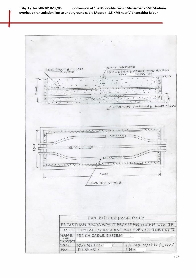
239
JDA/EE/Elect-III/2018-19/05 Conversion of 132 KV double circuit Mansrovar - SMS Stadium overhead transmission line to underground cable (Approx- 1.5 KM) near Vidhansabha Jaipur

240
JDA/EE/Elect-III/2018-19/05 Conversion of 132 KV double circuit Mansrovar - SMS Stadium overhead transmission line to underground cable (Approx- 1.5 KM) near Vidhansabha Jaipur

241
JDA/EE/Elect-III/2018-19/05 Conversion of 132 KV double circuit Mansrovar - SMS Stadium overhead transmission line to underground cable (Approx- 1.5 KM) near Vidhansabha Jaipur

242
JDA/EE/Elect-III/2018-19/05 Conversion of 132 KV double circuit Mansrovar - SMS Stadium overhead transmission line to underground cable (Approx- 1.5 KM) near Vidhansabha Jaipur

243
JDA/EE/Elect-III/2018-19/05 Conversion of 132 KV double circuit Mansrovar - SMS Stadium overhead transmission line to underground cable (Approx- 1.5 KM) near Vidhansabha Jaipur
VOLUME - II
TECHNICAL SPECIFICATIONS
PART-II: GENERAL TECHNICAL REQUIREMENTS/CONDITIONS (GTR/GTC)
1. 0 GENERAL
1.1 This section stipulates the General Technical Requirements under the Contract and will from an integral part of the Technical Specification.
1.2 The provisions under this section are intended to supplement general requirements for the materials, equipments and services covered under other sections and are not exclusive. However in case of conflict between the requirements specified in this section and requirements specified under other sections, the requirements specified under respective sections shall hold good.
2.0 INSTRUCTION TO BIDDERS
2.1 The bidders shall submit the technical requirements, data and information as per the technical data and information as per the technical data sheets provided in the Volume I of bid documents.
2.2 The bidders shall furnish catalogues, engineering data, technical information design documents, drawings etc., fully in conformity with the technical specification.
2.3 It is recognized that the Contractor may have standardized on the use of certain components, materials, processes or procedures different than those specified herein. Ultimate proposals offering similar equipment based on the manufacturer's standard practice will also be considered provided such proposals meet the specified designs, standard and performance requirements and are acceptable to the Owner. Unless brought out clearly, the Bidder shall be deemed to conform to this specification scrupulously. All deviations from the specification shall be clearly brought out in the respective schedules of deviations. Any discrepancy between the specification and the catalogues or the bid, if not clearly brought out in the schedule, will not be considered as valid deviation.
2.4 Wherever a material or article is specified or defined by the name of a particular brand, Manufacturer or Vendor, the specific name mentioned shall be understood as establishing type, function and quality and not as limiting competition.
2.5 Equipment furnished shall be complete in every respect with all mountings, fittings, fixtures and standard accessories normally provided with such equipment and/or needed for erection, completion and safe operation of the equipment as required by applicable codes though they may not have been specifically detailed in the Technical Specifications unless included in the list of exclusions. Materials and components not specifically stated in the specification but which are necessary for commissioning and satisfactory operation of the switchyard unless specifically excluded shall be deemed to be included in the scope of the specification and shall be supplied without any extra cost. All similar standard components/ parts of similar standard equipment provided shall be inter-changeable with one another.
2.6 Unless brought out clearly in the respective schedule of deviations, it will be considered

244
JDA/EE/Elect-III/2018-19/05 Conversion of 132 KV double circuit Mansrovar - SMS Stadium overhead transmission line to underground cable (Approx- 1.5 KM) near Vidhansabha Jaipur
that, the Bid Proposal scrupulously conforms compliance to the specification. The bidders must bring out all the deviations in the bid proposal.
2.7 In case there is a discrepancy between the data of offered equipment and catalogue furnished, and unless the deviation are brought out clearly in the Technical Deviation Schedule, the equipment will be deemed to conform compliance to the specification scrupulously.
3.0 STANDARDS
3.1 The works covered by the specification shall be designed, engineered, manufactured, built, tested and commissioned in accordance with the Acts, Rules, Laws and Regulations of India.
3.2 The equipment to be furnished under this specification shall conform to latest issue with all amendments of standard specified under Annexure – V2-P2-3 of this part as well as under respective parts of the specification.
3.3 In addition to meeting the specific requirement called for in the respective sections of the Technical Specification, the equipment shall also conform to the general requirement of the relevant standards, which shall form an integral part of the specification.
3.4 The Bidder shall note that standards mentioned in the specification are not mutually exclusive or complete in themselves, but intended to compliment each other.
3.5 The Contractor shall also note that list of standards presented in this specification is not complete. Whenever necessary the list of standards shall be considered in conjunction with specific IS/IEC.
3.6 When the specific requirements stipulated in the specifications exceed or differ than those required by the applicable standards, the stipulation of the specification shall take precedence.
3.7 Other internationally accepted standards which ensure equivalent or better performance than that specified in the standards referred shall also be accepted copies of such standards shall be submitted by the bidder.
3.8 In case governing standards for the equipment is different from IS or IEC, the salient points of difference shall be clearly brought out along with English language version of standard or relevant extract of the same. The equipment conforming to standards other than IS/IEC shall be subject to Owner's approval.
3.9 The bidder shall clearly indicate in his bid the specific standards in accordance with which the works will be carried out.
4.0 SERVICES TO BE PERFORMED BY THE EQUIPMENT BEING FURNISHED
4.1 EHV equipment and system shall be designed to meet the following major system technical parameters as bought out as hereunder:

245
JDA/EE/Elect-III/2018-19/05 Conversion of 132 KV double circuit Mansrovar - SMS Stadium overhead transmission line to underground cable (Approx- 1.5 KM) near Vidhansabha Jaipur
S. No. Description of Parameter
400 kV System
220 kV System
132 kV System
33 kV System
1. System Operating Voltage
400 kV 220 kV 132 kV 33 kV
2. Maximum Operating Voltage of the system (rms)
420 kV 245 kV 145 kV 36 kV
3. Rated Frequency 50 Hz 50 Hz 50 Hz 50 Hz
4. No. of Phase 3 3 3 3
5. Rated Insulation Level
i) Full wave impulse withstand voltage (1.2/50 micro. Sec.)
1550 kVp 1050 kVp 650 kVp 170 kVp
ii)Switching Impulse withstand voltage (250/2500 micro sec.) dry and wet
1050 kVp - - -
iii) One minute power frequency dry and wet withstand voltage (rms)
630 kV 460 kV 275 kV 80 kV
6. Corona Extinction Voltage
320 kV 156 kV 105 kV -
7. Max. radio interference voltage for frequency between 0.5 MHz and 2 MHz at 320 kV rms for 400 kV system and 156kV rms for 220 kV system & 92 kV rms for 132 kV
1000 micro-volt
1000 micro-volt
500 micro-volt -
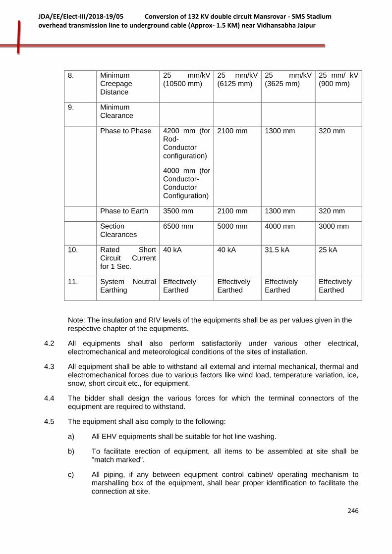
246
JDA/EE/Elect-III/2018-19/05 Conversion of 132 KV double circuit Mansrovar - SMS Stadium overhead transmission line to underground cable (Approx- 1.5 KM) near Vidhansabha Jaipur
8. Minimum Creepage Distance
25 mm/kV (10500 mm)
25 mm/kV (6125 mm)
25 mm/kV (3625 mm)
25 mm/ kV (900 mm)
9. Minimum Clearance
Phase to Phase 4200 mm (for Rod-Conductor configuration)
4000 mm (for Conductor-Conductor Configuration)
2100 mm 1300 mm 320 mm
Phase to Earth 3500 mm 2100 mm 1300 mm 320 mm
Section Clearances
6500 mm 5000 mm 4000 mm 3000 mm
10. Rated Short Circuit Current for 1 Sec.
40 kA 40 kA 31.5 kA 25 kA
11. System Neutral Earthing
Effectively Earthed
Effectively Earthed
Effectively Earthed
Effectively Earthed
Note: The insulation and RIV levels of the equipments shall be as per values given in the respective chapter of the equipments.
4.2 All equipments shall also perform satisfactorily under various other electrical, electromechanical and meteorological conditions of the sites of installation.
4.3 All equipment shall be able to withstand all external and internal mechanical, thermal and electromechanical forces due to various factors like wind load, temperature variation, ice, snow, short circuit etc., for equipment.
4.4 The bidder shall design the various forces for which the terminal connectors of the equipment are required to withstand.
4.5 The equipment shall also comply to the following:
a) All EHV equipments shall be suitable for hot line washing.
b) To facilitate erection of equipment, all items to be assembled at site shall be "match marked".
c) All piping, if any between equipment control cabinet/ operating mechanism to marshalling box of the equipment, shall bear proper identification to facilitate the connection at site.

247
JDA/EE/Elect-III/2018-19/05 Conversion of 132 KV double circuit Mansrovar - SMS Stadium overhead transmission line to underground cable (Approx- 1.5 KM) near Vidhansabha Jaipur
d) The supplier shall supply type tested equipments, materials. The type test reports shall be furnished by the supplier along with equipment/ material drawings. In the event of any discrepancy i.e., any test report not acceptable due to any design / manufacturing changes or due to non – compliance with the requirement stipulated in the technical specification or IEC/IS, same shall be carried out without any additional cost to owner. Only in case of repetition of the type test, if required by the owner, these tests shall be payable.
4.6 Operating times of circuit breakers, protective relays and PLCC equipment have been specified in respective sections. However bidder is allowed to have minor variations the individual equipment timings subject to the condition that overall fault clearing time remains within 100ms.
5.0 ENGINEERING DATA
5.1 The furnishing of engineering data by the Contractor shall be in accordance with the Schedule for each set of equipment as specified in the Technical Specifications.
5.2 The review of these data by the Owner will cover only general conformance of the data to the specifications and documents, interfaces with the equipment provided under the specifications, external connections and of the dimensions which might affect substation layout. This review by the Owner may not indicate a thorough review of all dimensions, quantities and details of the equipment, materials, any devices or items indicated or the accuracy of the information submitted. This review and/or approval by the Owner shall not be considered by the Contractor, as limiting any of his responsibilities and liabilities for mistakes and deviations from the requirements, specified under these specifications and documents.
5.3 All engineering data submitted by the Contractor after final process including review and approval by the Owner shall form part of the Contract Document and the entire works performed under these specifications shall be performed in strict conformity, unless otherwise expressly requested by the Owner in Writing.
6.0 DOCUMENTS
6.1 List of Documents
6.1.1 The bidder must furnish a detailed list of drawing/documents along with the bid proposal which he intends to submit to the owner after award of the contract.
6.1.2 The contractor shall necessarily submit all the drawing/documents unless anything is waived.
6.1.3 The contractor shall submit 6 (six) sets of drawing / design documents / test reports as may be required for the approval of the owner.
6.2 All engineering data submitted by the contractor after final process including review and approval by the owner shall form part of the Contract Document and the entire works performed under these specifications shall be performed in strict conformity, unless otherwise expressly requested by the Owner in Writing.
6.3 DRAWINGS
6.3.1 All drawings submitted by the Contractor including those submitted at the time of bid shall be in sufficient detail to indicate the type, size, arrangement, material
248
JDA/EE/Elect-III/2018-19/05 Conversion of 132 KV double circuit Mansrovar - SMS Stadium overhead transmission line to underground cable (Approx- 1.5 KM) near Vidhansabha Jaipur
description, Bill of Materials, weight of each component, break-up for packing and shipment, dimensions, internal & the external connections, fixing arrangement required and any other information specifically requested in the specifications.
6.3.2 Each drawing submitted by the Contractor shall be clearly marked with the name of the
Purchaser, the unit designation, the specifications title, the specification number and the
name of the Project. If standard catalogue pages are submitted, the applicable items shall
be indicated therein. All titles, noting, markings and writings on the drawing shall be in
English. All the dimensions should be in metric units.
6.3.3 Further work by the Contractor shall be in strict accordance with these drawings and no
deviation shall be permitted without the written approval of the Purchaser, if so required.
6.4 The review of these data by the Purchaser will cover only general conformance of
the data to the specifications and documents, interfaces with the equipment provided
under the specifications, external connections and of the dimensions which might affect
substation layout. This review by the Purchaser may not indicate a thorough review of all
dimensions, quantities and details of the equipment, materials, any devices or items
indicated or the accuracy of the information submitted. This review and/or approval by the
Purchaser shall not be considered by the Contractor, as limiting any of his
responsibilities and liabilities for mistakes and deviations from the requirements,
specified under these specifications and documents.
6.5 All manufacturing and fabrication work in connection with the equipment prior to the
approval of the drawings shall be at the Contractor’s risk. The Contractor may make any
changes in the design which are necessary to make the equipment conform to the
provisions and intent of the Contract and such changes will again be subject to approval
by the Purchaser. Approval of Contractor’s drawing or work by the Purchaser shall
not relieve the contractor of any of his responsibilities and liabilities under the Contract.
6.6 All engineering data submitted by the Contractor after final process including review
and approval by the Purchaser shall form part of the Contract Document and the
entire works performed under these specifications shall be performed in strict
conformity, unless otherwise expressly requested by the Purchaser in Writing.
6.7 APPROVAL PROCEDURE
The scheduled dates for the submission of the drawings as well as for, any data/information to be furnished by the Purchaser would be discussed and finalized at the time of award. The following schedule shall be followed generally for approval and for providing final documentation.
S. No. Description Schedule/ Remark
1 Approval/comments by Purchaser on initial submission
As per agreed schedule
2 Resubmissions (Whenever Required)
Within 3 (three) weeks (from date of comments required) including both ways postal time).

249
JDA/EE/Elect-III/2018-19/05 Conversion of 132 KV double circuit Mansrovar - SMS Stadium overhead transmission line to underground cable (Approx- 1.5 KM) near Vidhansabha Jaipur
3 Approval or comments Within 3 weeks of receipt of resubmission.
4 Furnishing of distribution copies in bound volume (5 copies per substation and one copy for Corporate Office)
2 weeks from the date of final approval
5 Furnishing of Distribution Copies of Test Reports
a) Type test reports (one copy per substation plus one copy for corporate office)
b) Routine Test Reports (one copy per substation plus one copy for corporate office)
2 weeks from the date of final approval
6 Furnishing of Instruction/ Operation Manuals (4 Copies per substation and two copies for corporate Office)
As per agreed Schedule
7 VCD highlighting installation and maintenance techniques requirements of circuit breaker and isolators (one per substation plus one for corporate office)
As per agreed Schedule
8 As built drawings & CDs/ Optical Discs (two set per substation & one set for Corporate Office)
On Completion of entire Works
NOTE:
(1) The contractor may please note that all resubmissions must incorporate all comments given in the earlier submission by the Purchaser or adequate justification for not incorporating the same must be submitted failing which the submission of documents is likely to be returned.
(2) All major drawings should be submitted in Auto Card Version 2000 or better.
(3) The instruction Manuals shall contain full details of drawings of all equipment being supplied under this contract, their exploded diagrams with complete instructions for storage, handling, erection, commissioning, testing, operation, trouble shooting, servicing and overhauling procedures.
(4) If after the commissioning and initial operation of the substation, the instruction manuals require any modifications/ additions/changes, the same
250
JDA/EE/Elect-III/2018-19/05 Conversion of 132 KV double circuit Mansrovar - SMS Stadium overhead transmission line to underground cable (Approx- 1.5 KM) near Vidhansabha Jaipur
shall be incorporated and the updated final instruction manuals shall be submitted by the Contractor to the Purchaser.
(5) The Contractor shall furnish to the Purchaser catalogues of spare parts.
7.0 COLOUR SCHEME AND CODES FOR PIPE SERVICE
7.1 The contractor shall propose a color scheme for those equipments/ items for which the color scheme has not been specified in the specification for the approval of Owner. The decision, of Owner shall be final. The scheme shall include:
- Finishing colour of indoor equipment.
- Finishing colour of outdoor equipment
- Finish colour of all cubicles
- Finishing colour of various auxiliary system equipment including piping
- Finishing colour of various building items.
7.2 All steel structures, plates etc., shall be painted with non-corrosive paint on a suitable primer. It may be noted that normally all Owner's electrical equipment in Owner's switchyard are painted with shade 697 of IS-5. All the indoor cubicles shall be of same colour scheme and for other miscellaneous items colour scheme will be approved by the Owner.
8.0 MATERIAL/WORKMANSHIP
8.1 General Requirement
8.1.1 Where the specification does not contain characteristics with reference to workmanship, equipment, materials and components of the covered Equipment, it is understood that the same must be new, of highest grade and of the best quality of their kind, conforming to best engineering practice and suitable for the purpose for which they are intended.
8.1.2 Incase where the equipment, materials or components are indicated In the specification as "similar" to any special standard, the Owner shall decide upon the question of similarity. When required by 'the specification or when required by the Owner the Contractor shall submit, for approval, all the information concerning the materials or components to be used in manufacture. Machinery, equipment, materials and components supplied, installed or used with out such approval shall run the risk of subsequent rejection, it being understood that the cost as well as the time delay associated with the rejection shall be borne by the Contractor.
8.1.3 The design of the Works shall be such that Installation, future expansions, replacements and general maintenance may be undertaken with a minimum of time and expenses. Each component shall be designed to be consistent with its duty and suitable factors of safety, subject to mutual agreements and shall be used throughout the design. All joints and fastenings shall be devised, constructed and documented so that the component parts shall be accurately positioned and restrained to fulfill their required function. In general, screw threads shall be standard metric threads. The use of other thread forms will only be permitted when prior approval has been obtained from the Owner.
8.1.4 Whenever possible, all similar part of the Works shall be made to gauge and shall also be

251
JDA/EE/Elect-III/2018-19/05 Conversion of 132 KV double circuit Mansrovar - SMS Stadium overhead transmission line to underground cable (Approx- 1.5 KM) near Vidhansabha Jaipur
made interchangeable with similar parts. All spare parts shall be interchangeable with, and shall be made of the same materials, and workmanship as the corresponding parts of the Equipment supplied under the Specification. Wherever feasible, common component units shall be employed in different piece of equipment in order to minimize spare part stocking requirements. All equipment of the same type and rating shall be physically and electrically interchangeable.
8.1.5 All materials and equipment shall be installed in strict accordance with the manufacturer’s recommendation(s). Only first call work in accordance with the best modern practices will be accepted. Installation shall be constructed as being the erection of equipment at its permanent location. This unless otherwise specified, shall include unpacking, cleaning and lifting into position, grouting, leveling, aligning, coupling of or bolting down to previously installed equipment bases/ foundations, performing the alignment check and final adjustment prior to initial operation, testing and commissioning in accordance with the manufacturer's tolerances and instructions and the Specification. All factory assembled rotating machinery shall be checked for alignment and adjustments made as necessary to re-establish the manufacturer's limits suitable guards shall be provided for the protection of personnel on all exposed rotating and / or moving machine parts and shall be designed for easy installation and removal for maintenance purposes. The spare equipment(s) shall be Installed at designated locations and tested for healthiness.
8.1.6 The Contractor shall apply oil and grease of the proper specification to suit the machinery, as is necessary for the installation of the equipment. Lubricants used for installation purposes shall be drained out and the system flushed through where necessary for applying the lubricant required for operation. The contractor shall apply all operational lubricants to the equipment installed by him.
8.1.7 All oil, grease and other consumables used in the works/ equipment shall be purchased in India unless the contractor has any special requirement for the specific application of a type of oil or grease not available in India. If such is the case he should declare in the proposal, where such oil or grease is available. He shall help Owner in establishing equivalent Indian make and Indian Contractor. The same shall be applicable to other consumables too.
8.1.8 A cast iron or welded steel base plate shall be provided for all rotating equipment which are to be installed on a concrete base unless otherwise agreed to by the Owner. Each base plate shall support the unit and its drive assembly, shall be of design with pads for anchoring the units and shall have a raised up all around and shall have threaded in air connections, if so required.
8.2 Provisions for exposure to Hot and-Humid climate
Outdoor equipment supplied under the specification shall be suitable for service and storage under tropical conditions of high temperature, high humidity, heavy rainfall and environment favorable to the growth of fungi and mildew. The indoor equipments located in non-air-conditioned areas shall also be of same type.
8.2.1 Space Heaters
8.2.1.1 The heaters shall be suitable for continuous operation at 240V as supply voltage. On-off switch and fuse shall be provided.
8.2.1.2 One or more adequately rated thermostatically controlled heaters shall be supplied to prevent condensation in any compartment. The heaters shall be installed in the
252
JDA/EE/Elect-III/2018-19/05 Conversion of 132 KV double circuit Mansrovar - SMS Stadium overhead transmission line to underground cable (Approx- 1.5 KM) near Vidhansabha Jaipur
lower portion of the compartment and electrical connections shall be made from below the heaters to minimize deterioration of supply wire insulation. The heaters shall be suitable to maintain the compartment temperature to prevent condensation.
8.2.1.3 The heaters shall be suitably designed to prevent any contact between the -heater wire and the air and shall consist of coiled resistance wire centered in a metal sheath and completely encased in a highly compacted powder of magnesium oxide or other material having equal heat conducting and electrical insulation properties, or they shall consist of resistance wire wound on a ceramic and completely covered with a ceramic material to prevent any contact between the wire and the air. Alternatively, they shall consist of a resistance wire mounted into a tubular ceramic body built into an envelop of stainless steel or the resistance wire is wound on a tubular ceramic body and embedded in vitreous glaze. The surface temperature of the heaters shall be restricted to a value which will not shorten the life of the heater sheaths or that of insulated wire or other component in the compartments.
8.2.2 Fungi static varnish: Besides the space heaters, special and fungus resistant varnish shall be applied on parts which may be subjected or predisposed to the formation of fungi due to the presence of deposit of nutrient substances. The varnish shall not be applied to any surface of part where the treatment will interfere with the operation or performance of the equipment. Such surfaces or parts shall be protected against the application of the varnish.
8.2.3 Ventilation opening: In order to ensure adequate ventilation, compartments shall have ventilation openings provided with fine wire mesh of brass to prevent the entry of dirt and dust. Outdoor compartment openings shall be provided with shutter type blinds.
9.0 RATING PLATES, NAME PLATES AND LABELS
9.1 Each main and auxiliary item of substation is to have permanently attached to it in a conspicuous position a rating plates of non-corrosive material upon which is to be engraved manufacturer's name, year of manufacture, equipment name type or serial number together with details of the loading conditions under which the item of substation In question has been designed to operate, and such diagram plates as may be required by the owner. Tile rating plate of each equipment shall be according to IEC requirement.
9.2 All such nameplates, instruction plates, rating plates shall be with English inscription.
10.0 FIRST FILL OF CONSUMABLES, OIL AND LUBRICANTS:
All the first fill of consumables such as oils, lubricants, filling compounds, touch up paints, soldering/ brazing material for a copper piping of circuit breakers and essential chemicals etc., which will be required to put the equipment covered under the scope of the specifications, into successful Operation, shall be furnished by the Contractor unless specifically excluded under the exclusions in these specifications and documents.

253
JDA/EE/Elect-III/2018-19/05 Conversion of 132 KV double circuit Mansrovar - SMS Stadium overhead transmission line to underground cable (Approx- 1.5 KM) near Vidhansabha Jaipur
11.0 DESIGN IMPROVEMENTS 11.1 The bidder shall note that the equipment offered by him in the bid only shall be
accepted for supply. However, the NIGAM or the Contractor may propose changes in the specification of the equipment or quality thereof and if the parties agree upon any such changes the specification shall be modified accordingly.
11.2 If any change is such that it affects the price and schedule of completion, the extent of change in the price and/or schedule of completion shall be mutually agreed in writing before the Contractor proceeds with the change. Following such agreement the provisions thereof, shall be deemed to have been amended accordingly.
11.3 Any change in design or manufacturing process which the CONTRACTOR incorporates in the equipment as a measure of improvement on his own shall not entitle him for any extra payment.
12.0 QUALITY ASSURANCE PROGRAM
12.1 To ensure that the equipment and services under the scope of this Contract whether manufactured or performed within the Contractor's Works or at his Sub- Contractor's premises or at the Owner's site or at any other place of Work are in accordance with the specifications, the Contractor shall adopt suitable quality assurance program to control such activities at all points necessary. such program shall be outlined by the Contractor and shall be finally accepted by the Owner after discussions before the award of Contract. A quality assurance program of the contractor shall generally cover the following:
1) His organization structure for the management and implementation of the proposed quality assurance program;
2) Documentation control system;
3) Qualification data for bidder's key personnel;
4) The procedure for purchases of materials, parts components and selection of sub-contractor's services including vendor analysis, source inspection, incoming raw material inspection, verification of material purchases etc;
5) System for shop manufacturing and site erection controls including process controls and fabrication and assembly control;
6) Control of non-conforming Items and system for corrective actions;
7) Inspection and test procedure both for manufacture and field activities;
8) Control of calibration and testing of measuring instruments and field activities
9) System for indication and appraisal of inspection status.
10) System for quality audits
11) System for authorizing release of manufactured product to the purchaser system for maintenance of records:
12) System for handling storage and delivery; and

254
JDA/EE/Elect-III/2018-19/05 Conversion of 132 KV double circuit Mansrovar - SMS Stadium overhead transmission line to underground cable (Approx- 1.5 KM) near Vidhansabha Jaipur
13) A quality plan detailing out the specific quality control measures and procedures adopted for controlling the quality audit surveillance of the system and procedure of the contractor/ his vendor’s quality management and control activities.
The Owner or his duly authorized representative reserves the right to carry out quality audit and quality surveillance of the system and procedure of the Contractor/his vendor's quality management and control activities.
12.2 Quality assurance Document:
The Contractor shall be required to- submit the following Quality Assurance Documents within three weeks after dispatch of the equipment.
a) All Non-Destructive Examination procedures stress relief and weld repair procedure actually used during fabrication and reports including radiography interpretation reports.
b) Welder and welding operator qualification certificates.
c) Welder's identification list, listing welders and welding operator's qualification procedure and welding identification symbols.
d), Raw material test reports oil components as specified by the specification
and/or agreed to in the quality plan.
e) Stress relief time temperature charts/oil impregnation time temperature charts.
f ) Factory test results for testing required as per applicable codes/mutually agreed quality plan standards refereed in the technical specification.
g) The quality plan with verification of various customer inspection points (CIP) as mutually agreed and methods used to verify the inspection and testing points in the quality plan were performed satisfactorily.
13.0 INSPECTION, TESTING & INSPECTION CERTIFICATE:
13.1 The NIGAM, his duly authorized representative and/or out side inspection agency acting on behalf of the NIGAM/ Owner shall have at all reasonable times access to the Contractor's premises or Works and shall have the power at all reasonable times to inspect and examine the materials and workmanship of the Works during its manufacture or erection and if part of the Works is being manufactured or assembled at other premises or works, the Contractor shall obtain from the manufacturer / his duly authorized representative permission for inspection by NIGAM as if the works were manufactured or assembled on the Contractor's own premises or works with the concurrence of NIGAM. The NIGAM reserves the right to witness any or all type, acceptance and routine tests specified, for which at least 15 (Fifteen) days notice in advance shall be given by the Contractor. Contractor shall ensure before giving notices for type test that all drawings and quality plans have been got approved. The equipment shall be despatched to site only after approval of test certificates by the NIGAM.
13.2 The Contractor shall give the NIGAM/Inspector Fifteen (15) days written notice of any material being ready for testing, for each stage of testing as identified in the approved quality plan and CIP. Such tests shall be to the Contractor’s account. The

255
JDA/EE/Elect-III/2018-19/05 Conversion of 132 KV double circuit Mansrovar - SMS Stadium overhead transmission line to underground cable (Approx- 1.5 KM) near Vidhansabha Jaipur
NIGAM/Inspector, unless witnessing of the tests is virtually waived, will attend such tests within fifteen (15)days of the date of which the equipment is notified as being ready for test/inspection, failing which the Contractor may proceed with the test which shall be deemed to have been made in the Inspector's presence and he shall forthwith forward to the NIGAM six copies of duly certified test reports.
13.3 The NIGAM or Inspector shall, within fifteen (15) days from the date of inspection as defined herein give notice in writing to the Contractor, of any objection to any drawings and/or any equipment and workmanship which in his opinion is not in accordance with the Contract. The Contractor shall give due consideration to such objections and shall either make the modifications that may be necessary to meet the said objections or shall confirm in writing to the NIGAM/Inspector giving reasons therein, that no modifications are necessary to comply with the Contract.
13.4 When the factory tests have been completed at the Contractor's or Sub-Contractor's works, the NIGAM/Inspector shall issue a certificate to this effect within fifteen (15) days after completion of tests but if the tests are not witnessed by the NIGAM/Inspector, the certificate shall be issued within fifteen (15) days of receipt of the Contractor's Test certificate by the NIGAM/Inspector. Failure of the NIGAM / Inspector to issue such a certificate shall not prevent the Contractor from proceeding with the Works. The completion of these tests or the issue of the certificate shall not bind the NIGAM / Owner to accept the equipment, should it on further tests after erection, be found not to comply with the Contract.
13.5 In all cases where the contract provides for tests whether at the premises or works of the Contractor or of any Sub-Contractor, the Contractor except where otherwise specified shall provide free of charge such items as labour, materials, electricity, fuel water, stores, apparatus and instruments as may be reasonably demanded by the NIGAM/Inspector or his authorized representative to carry out effectively such tests of the equipment in accordance with the Contract and shall give facilities to the NIGAM/Inspector or to his authorized representative to accomplish testing.
13.6 The inspection by NIGAM and issue of Inspection Certificate thereon shall in no way limit the liabilities and responsibilities of the Contractor in respect of the agreed quality assurance programme forming a part of the Contract.
13.7 Material Inspection Clearance Certificate (MICC) shall be issued by the NIGAM after inspection of the equipment. NIGAM may waive off the presence of NIGAM's inspecting engineer. In that case test will be carried out as per approved QP & test certificate will be furnished by the Contractor for approval. MICC will be issued only after review & approval of the test reports.
13.8 The NIGAM /Owner will have the right of having at his own expenses any other test(s) of reasonable nature carried out at Contractor's premises or at site or in any other place in addition to aforesaid type and routine tests, to satisfy that the material comply with the specification.
13.9 The NIGAM /Owner reserves the right for getting any field tests conducted on the completely assembled equipment at site.
13.10 Factory tests The equipment offered shall be subjected all type, routine and acceptance tests as per the relevant standards specified.
13.11 Routine tests: 13.11.1 After completion of manufacture of the equipment routine tests shall be performed as
per Approved standards free of cost and requisite copies of test certificates shall be furnished.
13.11.2 Various components of the equipment shall be routine tested in accordance with approved standards and manufacturer’s standards.
256
JDA/EE/Elect-III/2018-19/05 Conversion of 132 KV double circuit Mansrovar - SMS Stadium overhead transmission line to underground cable (Approx- 1.5 KM) near Vidhansabha Jaipur
13.11.3 Each completely wired cubicle shall be tested to ensure that all of its protective control systems are satisfactorily functioning as required.
13.12 Type Tests: 13.12.1 After completion of manufacture, atleast one equipment of each type offered shall be
type tested as specified in relevant standards and in standard specification(s) and requisite number of copies of test certificates as per distribution schedule shall be furnished.
13.12.2 The NIGAM may, at his discretion, waive type tests provided type test reports of tests carried out on identical equipment(s) manufactured by the Contractor are furnished. The Bidder shall furnish copies of such type test reports with the Bid.
13.12.3 All the equipment offered, shall be fully type tested as per the relevant standards before commencement of supply. The bidder shall furnish three sets of the type test reports along with the offer. Bids offered without type test reports will be treated as incomplete and termed as non-responsive and rejected. The dates of type tests shall not be pertaining to a period earlier than 7 (Seven) years reckoned from the date of bid opening. In case the type test reports pertain to a period earlier than 7 years the bidder if contract is awarded shall arrange repetition of those type tests free of cost if requested by NIGAM. Bids not agreeing this condition shall be rejected. Further, in the event of any discrepancy in the test reports i.e. any test report not acceptable due to any design/manufacturing changes (including substitution of components) or due to non-compliance with the requirement stipulated in the Technical Specification or any/all additional type tests not carried out, same shall be carried out without any additional cost implication to the Purchaser.
The NIGAM reserves the right to demand repetition of some or all the type tests in the presence of purchaser's representative even in cases where type tests have been earlier conducted not earlier than 7 years considered from the date of bid opening and test reports are duly enclosed to the bid. For this purpose the bidder shall quote unit rates for carrying out each type test. Payment would be made for only such type tests for which, bidder has already enclosed type test reports conducted on an equipment similar to one offered in the bid but nevertheless the NIGAM has asked to repeat the test in his/Engineer's presence. NIGAM reserves the right to witness all the type tests. For witnessing type test, contractor will give 45 (forty five) days advance notice. The rates quoted for type test (as mentioned) shall be included in the bid evaluation. In case Bidder does not indicate charges for any of the type tests or does not mention the name of any test in the price schedules, it will be presumed that the particular test has been offered free of charge. Further, in case any Bidder indicates that he shall not carry out a particular test; his offer shall be considered incomplete and shall be liable to be rejected.
13.12.4 The Purchaser also reserves the right to waive the repeating of type tests partly or fully and in case of waival, test charges for the same shall not be payable.
13.13 TEST REPORTS
Four (4) copies of all tests reports shall be supplied for approval before shipment of equipment. The receipts shall indicate clearly the standard values specified for each test, to facilitate checking of the test reports. Fourteen (14) bound copies of test report shall be submitted after approval of test results along with the equipment. These shall incorporate all tests carried out on all equipment and its components, as well as characteristic curves of the equipment, including reports on official tests,

257
JDA/EE/Elect-III/2018-19/05 Conversion of 132 KV double circuit Mansrovar - SMS Stadium overhead transmission line to underground cable (Approx- 1.5 KM) near Vidhansabha Jaipur
waves, failure, detention data and copies of final test oscillograms, as relevant in terms of the applicable technical specifications. Test reports of factory tests carried out on the equipment shall furnish the following information: i) Complete identification data including serial number. ii) Method of application and duration of tests. iii) A description of the test equipment with diagram showing arrangement of the
test instruments and devices. iv) Sample computation, where necessary of desirable, to show the test values
employed in the equations. v) Curves showing relation of tests quantities. vi) Data in tabulated form. vii) Comparison of the test results with the guarantee requirements of the
specifications and explanation of deviations, if any. viii) Oscillograms, if any.
13.14 Testing Facility The Bidder shall state in the proposal, testing facilities available at his at his sub-contractor’s works. Should full capacity testing equipment be not available at his works, the Bidder shall state in his bid where he would arrange to get the full capacity tests carried out. For such of the characteristics for which he proposes to adopt any alternative to full capacity testing, he shall state in his bid the method proposed to be adopted giving detailed computations and full justifications for suitability of the method to reliably ascertain equipment characteristics corresponding to full capacity testing.
14.0 COMMISSIONING CUM ACCEPTANCE TESTS
14.1 On completion of erection of the equipment and before commissioning, each item of the equipment shall be thoroughly cleaned and then inspected jointly by the NIGAM and the Contractor for correctness and completeness of installation and acceptability for commissioning, leading to initial pre-commissioning tests at site. The list of pre-commissioning tests to be performed shall be as mutually agreed and included in the Contractor's quality assurance programme.
14.2 The Contractor's commissioning Engineers, specifically identified as far as possible, shall be responsible for carrying out all the pre-commissioning tests. On completion of inspection, checking and after the pre-commissioning tests are completed satisfactorily over, the complete equipment shall be placed on Initial Operation during which period the complete equipment shall be operated integral with subsystems and supporting equipment as a complete system.
14.3 The specific tests to be conducted on equipment have been brought out in the respective technical specifications.
14.4 The contractor in-charge of erection testing and commissioning shall provide, at free of cost, all testing instruments, control equipment etc., for conducting above tests, in fully calibrated condition along valid Calibration Certificates. The NIGAM reserves the right to get the testing instruments/control equipment re-calibrated before the test at a laboratory of his choice at the cost of the contractor. NIGAM will apply proper corrections in calculations, to take into account conditions which do not correspond to the specified conditions.
14.5 Any special equipment, tools and tackles required for the successful completion of the Commissioning Tests shall be provided by the Contractor, free of cost.
14.6 The guaranteed performance figures of the equipment shall be provided by the Contractor during these commissioning and acceptance Tests. Should the results of

258
JDA/EE/Elect-III/2018-19/05 Conversion of 132 KV double circuit Mansrovar - SMS Stadium overhead transmission line to underground cable (Approx- 1.5 KM) near Vidhansabha Jaipur
these tests show any decrease from the guaranteed values the Contractor shall modify the equipment as required to enable it to meet the guarantees. In such case, commissioning and acceptance Tests shall be repeated within one month, from the date the equipment is ready for re-test and all cost for modifications including labour materials and the cost of additional testing to prove the equipment meets the guarantee, shall be borne by the Contractor.
15.0 PACKAGING
15.1 All the equipments shall be suitably protected, coated, covered or boxed and crated to prevent damage or deterioration during transit, handling and storage at Site till the time of erection. On request of the Owner, the Contractor shall also submit packing details/ associated drawing for any equipment/material under his scope of supply, to facilitate the Owner to repack any equipment/ material at a later date, in case the need arises. While packing all the materials, the limitation from the point of view of availability of Railway wagon sizes in India should be taken account of. The Contractor shall be responsible for any loss or damage during transportation, handling and storage due to improper packing. Any demurrage, wharf age and other such charges claimed by the transporters, railways etc., shall be to the account of the Contractor. Owner takes no responsibility of the availability of the wagons.
16.0 PROTECTION
All coated surfaces shall be protected against abrasion, impact, discoloration and any other damages. All exposed threaded portions shall be suitably protected with either a metallic or a non-metallic protecting device. All ends of all valves and piping and conduit equipment connections shall be properly sealed with suitable device to protect them from damage. The parts which are likely to get rusted, due to exposure to weather should also be properly treated and protected in a suitable manner.
17.0 FINISHING OF METAL SURFACES
17.1 GENERAL
All metal surfaces shall be subjected to treatment for anti-corrosion protection. All ferrous surfaces for external use unless otherwise stated elsewhere in the specification or specifically agreed, shall be hot-dip galvanized after fabrication. High tensile steel nuts & bolts and spring washers shall be electro, galvanized to service condition 4.All steel conductors including those used for earthing/ grounding (above ground level) shall also be galvanized according to IS: 2629.
17.2 HOT DIP GALVANISING
17.2.1 The minimum weight of the zinc coating shall be 610 gm / sq. mm and minimum thickness of coating shall be 85 microns for all items thicker than 6mm. For items lower than 6mm thickness shall be as per relevant ASTM. For surface which shall be embedded in concrete, the zinc coating shall be 610 gm/sq. mm minimum.
17.2.2 The galvanized surfaces shall consist of a continuous and uniform thick coating of zinc, firmly adhering to the surface of steel. The finished surface shall be clean and smooth and shall be free from defects like discolored patches, bare spots, unevenness of coating, spelter which is loosely attached to the steel globules,

259
JDA/EE/Elect-III/2018-19/05 Conversion of 132 KV double circuit Mansrovar - SMS Stadium overhead transmission line to underground cable (Approx- 1.5 KM) near Vidhansabha Jaipur
spiky deposits, blistered surface, flaking or peeling off, etc. The presence of any of these defects noticed on visual or microscopic inspection shall render the material liable to rejection.
17.2.3 After galvanizing, no drilling or welding shall be performed on the galvanized parts of the equipment excepting that nuts may be threaded after galvanizing. Sodium dichromate treatment shall be provided to avoid formation of white rust after hot dip galvanization.
17.2.4 The galvanized steel shall be subjected to six one-minute dips in copper sulphate solution as per IS : 2633.
17.2.5 Sharp edges with radii less than 2.5min shall be able to withstand four immersions of the Standard Preece test. All other coatings shall withstand six immersions. The following galvanizing tests should essentially be performed as relevant Indian Standard.
- Coating thickness
- Uniformity of zinc
- Addison test
- Mass of zinc coating
17.2.6 Galvanized material must be transported properly to ensure that galvanized surfaces are not damaged during transit. Application of zinc rich paint at site shall not be allowed.
17.3 PAINTING
17.3.1 All sheet steel work shall be degreased, pickled, phosphates in accordance with the IS - 6005 "Code of practice for phosphating iron and sheet". All surfaces which will not be easily accessible) after shop assembly shall before hand be treated and protected for the life of the equipment. The surfaces which are to be finished painted after installation or require corrosion protection until installation, shall be shop painted with atleast two coats of primer. Oil, grease, dirt and swap shall be thoroughly removed by emulsion cleaning. Rust and scale shall be removed by pickling with dilute acid followed by washing with running water, rinsing with slightly alkaline hot water and drying.
17.3.2 After phosphating, thorough rinsing shall be carried out with clean water followed by final rinsing with dilute dichromate solution and oven drying. The phosphate coating shall be scaled with application of two coats of ready mixed, stoving type zinc chromate primer. The first coat may be "flash dried" while the second coat shall be stoved.
17.3.3 After application of the primer, two coats of finishing synthetic enamel paint shall be applied, each coat followed by stoving. The second finishing coat shall be applied after inspection of first coat of painting.
17.3.4 The exterior colour of the paint shall be as per shade No. 697 of IS-5 and inside shall be glossy white. Each coat of primer and finishing paint shall be of slightly different shade to enable inspection of the painting. A small quantity of finishing paint shall be supplied for minor touching up required at site after installation of the
260
JDA/EE/Elect-III/2018-19/05 Conversion of 132 KV double circuit Mansrovar - SMS Stadium overhead transmission line to underground cable (Approx- 1.5 KM) near Vidhansabha Jaipur
equipments.
17.3.5 In case the Bidder proposes to follow his own standard surface finish and protection procedures or any other established painting procedures, like electrostatic painting etc.) the procedure shall be submitted along with the Bids for Owner's review & approval.
18.0 HANDLING, STORING AND INSTALLATION
18.1 In accordance with the specific installation instructions as shown on manufacturer's drawings or as directed by the owner or his representative, the Contractor shall unload, store, erect, install, wire, test and place into commercial use all the equipment included in the contract. Equipment shall be installed in a neat, workmanlike manner so that it is level, plumb, and square and properly aligned and oriented. Commercial use of switchyard equipment means completion of all site tests specified and energisation at rated voltage.
18.2 Contractor may engage manufacturer's Engineers to supervise the unloading, transportation to site, storing, testing and commissioning of the various equipment being procured by them separately. Contractor shall unload, transport, store, erect, test and commission tile equipment as per instructions of the manufacturer's supervisory Engineer(s) and shall extend full cooperation to them.
18.3 In case of any doubt/ misunderstanding as to tile correct interpretation of manufacturer's drawings or instructions, necessary clarifications shall be obtained from the Owner. Contractor shall be held responsible for any damage to the equipment consequent to not following manufacturer's drawings/ instructions correctly.
18.4 Where assemblies are supplied in more than one section, Contractor shall make all necessary mechanical and electrical connections between sections including the connection between buses. Contractor shall also do necessary adjustment/ alignment necessary for proper operation of circuit breakers, isolators and their operating mechanisms. All components shall be protected against damage during unloading, transportation, storage, installation, testing and commissioning. Any equipment damaged due to negligence or carelessness or otherwise shall be replaced by the contractor at his own expense.
18.5 Contractor shall be responsible for examining all the shipments and notify and owner immediately of any damage, shortage, discrepancy etc., for the purpose of purpose of Owner's information only. The Contractor shall submit to the Owner every week a report detailing all the receipts during the weeks. However, the Contractor shall be solely responsible for any shortages or damages in transit, handling and/or in storage and erection of the equipment at Site. Any demurrage, what age mid other such charges claimed by the transporters, railways etc., shall be to the, account of the Contractor.
18.6 The Contractor shall be fully responsible for the equipment/ material until the same is handed over to the Owner in an operating condition after commissioning, Contractor shall be responsible for the maintenance of the equipment/material while in storage as well as after erection until taken over by Owner, as well as protection of the same against theft, element of nature, corrosion, damages etc.
18.7 Where material/ equipment is- unloaded by Owner before the contractor arrives at

261
JDA/EE/Elect-III/2018-19/05 Conversion of 132 KV double circuit Mansrovar - SMS Stadium overhead transmission line to underground cable (Approx- 1.5 KM) near Vidhansabha Jaipur
site or even when he is at site, Owner by right can hand over the same to Contractor and there upon it will be the responsibility of Contractor to store the material in an orderly and proper manner.
18.8 The Contractor shall be responsible for making suitable indoor storage facilities, to store all equipment, which require indoor storage.
18.9 The word 'erection' and 'installation' used in the specification are synonymous.
18.10 All outdoor equipment except marshalling kiosk shall be suitable for hot little washing.
18.11 Exposed parts shall be placed high enough above ground to meet the requirements of electrical and other statutory safety codes.
18.12 The minimum Phase to earth, phase to phase and section clearance for the various voltage levels of the switchyard are given below:
400 kV 220 kV 132KV 33KV (a) Phase to phase 4200mm 2100mm 1300mm 1200mm (b) Phase to earth 3500mm 2100mm1300mm 1200mm (c) Ground clearance 8000mm 5500mm 4600mm 3700mm (d) Sectional clearance 6500mm 5000mm 4000mm 3000mm
However, the clearance as shown in the layout drawing shall be maintained. In case of Switchyard Equipments/ Switchgears, the minimum phase to earth clearance (live part clearance) shall be accordance with the relevant IEC/ IS for insulation co-ordination.
The design and workmanship shall be in accordance with the best engineering practices to ensure satisfactory performance throughout the service life. If at any stage during the execution of the Contract, it is observed that the erected equipment(s) do not meet the above minimum clearances, the Contractor shall immediately proceed to correct the discrepancy at his risks and cost.
19.0 PROTECTIVE GUARDS
19.1 Suitable guards shall be provided for protection of personnel on all exposed rotating and/or moving machine parts. Any such guards with necessary spares and accessories shall be designed for easy installation and immoral for maintenance purpose.
20.0 DESIGN CO-ORDINATION
20.1 The Contactor will be responsible for the selection and design of appropriate equipments to provide the best co-ordinate performance of the entire system. The basic design requirements are detailed out in this specification. The design of various components, sub-assemblies and assemblies shall be so done that it facilitates easy field assembly and maintenance.
20.2 The Contractor has to co-ordinate designs and terminations with the agencies (if any) who are consultants/ Contractor/supplier for the Owner. The names of agencies shall be intimated to the successful bidders.
262
JDA/EE/Elect-III/2018-19/05 Conversion of 132 KV double circuit Mansrovar - SMS Stadium overhead transmission line to underground cable (Approx- 1.5 KM) near Vidhansabha Jaipur
21.0 DESIGN CO-ORDINATION MEETING
The Contractor will be called upon to attend design co-ordination meetings with the Engineer, other Contractors/Supplier and the Consultants of the Owner (if any) during the period of Contract. The contractor shall attend such meetings at his own cost at Jaipur or at mutually agreed venue as and when required and fully co-operate with such persons and agencies involved during those discussions.
22.0 TOOLS AND TACKLES
22.1 A complete outfit of tools, spanners, gauges, slings and other lifting devices (excluding Cranes), instruments and all other appliances necessary or convenient for the complete assembly, erection at site, dismantling and maintenance of the plant along with racks for holding them shall be supplied and included in the Contract. Spanners shall be single ended and made to fit each size, of nut and bolt of the plant. Two sets of spanners, tools and appliances shall be supplied. He shall also provide a durable storage box with lock for such tools. The prices for all items (tools & tackles) mentioned in the price schedule shall be included in the quoted bid price and no separate payment shall be made for these items.
22.2 ERECTION AND MAINTENANCE TOOLS:
The tender shall indicate separately in his offer any special erection and maintenance tools required for installing the equipment offered. Prices of these shall be indicated separately in a appropriate schedule of prices. However, these shall not be considered for tender evaluation. The NIGAM/Owner reserves the right to place order for any/ all the items at the prices quoted during the period of the contract.
23.0 EQUIPMENT BASES
A cast iron or welded steel base plate shall be provided for all rotating equipment, which is to be installed on a concrete base unless otherwise agreed to by the Owner. Each base plate shall support the unit and its drive assembly, shall be of a neat design with pads for anchoring the units, shall have a raised lip all around, and shall have threaded drain connections.
24.0 AUXILIARY SUPPLY
24.1 The auxiliary power for station supply, including the equipment drive, cooling system of any equipment, lighting etc., shall be designed for the specified parameters as under. The DC supply for the instrumentation and PLCC/OLTE system shall also confirming the parameters as indicated in the following.
Normal voltage
Variation in voltage
Frequency in Hz
Phase / wire
Neutral connection
415 V +10%
-10 %
50±3% 4 wire Solidly earthed
240 V +10%
-10 %
50± 3 % 2 wire Solidly earthed
220 V +10 % DC Isolated 2

263
JDA/EE/Elect-III/2018-19/05 Conversion of 132 KV double circuit Mansrovar - SMS Stadium overhead transmission line to underground cable (Approx- 1.5 KM) near Vidhansabha Jaipur
-10% wire system
110 V +10%
-10%
DC Isolated 2 wire system
48 V +10%
-10%
DC 2 wire system (+) earthed
25.0 SUPPORT STRUCTURE:
25.1 Typical drawings of equipment support structures are enclosed to the bid documents. Based on the equipments to be supplied, height of center line of live point indicated the layout / cross section drawings the successful bidder has to furnish the drawing for owners approval only after approval of the drawing the fabrication of structures are to be taken up. Any substructure or adopter plate required to meet the above bus termination height other than the standard structure will also have to be supplied by the Contractor as part of the equipment. All brackets, angles, stool or other members necessary for attaching the operating mechanism to the supporting structure shall be engineered and supplied as integral part of the equipment. The support structures for all equipments shall be supplied by the Contractor.
25.2 The, support structures should be hot dip galvanized with minimum 610 gram / m2 net of zinc.
25.3 In case of any deviation in this regard the bid is liable to be considered technically non-responsive and shall be liable to be rejected.
25.4 Support structure shall meet the following mandatory requirements:
25.4.1 The minimum vertical clearance from any energized metal part of the equipment / post insulator from Ground level shall be 8, 5.5, 4.7 and 4.0 meters for 400 kV, 220 kV, 132 kV and 33 kV equipments respectively.
25.4.2 The minimum vertical distance from the bottom of the lowest porcelain part of the bushing, porcelain enclosures or supporting insulators to the bottom of the equipment base, where it rests on the foundation pad shall be 2.50 metres.
26.0 CLAMPS AND CONNECTORS INCLUDING TERMINAL CONNECTORS:
26.1 All power clamps and connectors shall conform to IS : 5561 & NEMA CC1and shall be made of materials listed below:
a) For connecting ACSR conductors shall be of fired wedge type
Aluminum alloy casting, conforming to designation A6 of IS:617 and shall be tested for all test as per IS:617
b) For connecting equipment terminals made of copper with ACSR conductors
Bimetallic connectors made from aluminum alloy casting, conforming to designation A6 of IS:617 with 2 mm thick bimetallic liner and shall be tested

264
JDA/EE/Elect-III/2018-19/05 Conversion of 132 KV double circuit Mansrovar - SMS Stadium overhead transmission line to underground cable (Approx- 1.5 KM) near Vidhansabha Jaipur
as per IS:617
c) Bolts, nuts and plain washers for above clamps and connectors (a) & (b)
Stainless steel minimum size M12.
d) For connecting G.I. Galvanized mild steel shield wire
e) i) Bolts, nuts & plain,
washers
ii) Spring washers for items ‘a’ to ‘c’
i) Electro-galvanized for sizes below M12,for others hot dip galvanized.
ii) Electro-galvanized mild steel suitable for at least service condition-3 as per IS:1573
26.2 Each equipment shall be supplied with the necessary terminals and connectors, as required by the ultimate design for the particular installation. The conductor terminations of equipment shall be either expansion, sliding or rigid type. The requirement regarding external corona and RIV as specified for any equipment shall include its terminal fittings and the equipment shall be factory tested with the connectors in position. If corona rings are required to meet these requirements they shall be considered as part of that equipment and included in the scope of work.
26.3 Where copper to aluminum connections are required, bi-metallic clamps shall be used, which shall be properly designed to ensure that any deterioration of the connection is kept to a minimum and restricted to parts which are not current carrying or subjected to stress.
26.4 Low voltage connectors, grounding connectors and accessories for grounding all equipment as specified in each particular case, are also included in the scope of Work.
26.5 No current carrying part of any clamp shall be less than 10mm thick. All ferrous parts shall be hot dip galvanized. Copper alloy liner of minimum 2mm thickness shall be cast integral with aluminum body for Bi-metallic clamps.
26.6 Lateral load deflection test shall be carried out as an acceptance test. The test procedure and accepted norms shall be mutually discussed and agreed to.
26.7 All casting shall be free from blow holes, Surface blisters, cracks and cavities. All sharp edges and corners shall be blurred and rounded off.
26. 8 Flexible connectors, braids or laminated straps made for the terminal clamps for bus posts shall be suitable for both expansion or through (flexed/sliding) type connection as required. In all the cases the clamp height (top of the mounting pad to centre line of the tube) should be same.
26.9 Clamp shall be designed to carry the same current as the conductor and the temperature rise shall be equal or less than that of the conductor at the specified ambient temperature. The rated current for which the clamp/connector is designed
265
JDA/EE/Elect-III/2018-19/05 Conversion of 132 KV double circuit Mansrovar - SMS Stadium overhead transmission line to underground cable (Approx- 1.5 KM) near Vidhansabha Jaipur
with respect to the specified reference ambient temperature, shall also be indelibly marked on each component of the clamp/ connector, except on the hardware.
26.10 All current carrying parts shall be designed and manufactured to have minimum contact resistance.
26.11 VOID
26. 12 TESTS
26.12.1 Clamps and connectors should be type tested as per IS:5561 and shall also be subjected to routine tests as perIS:5561. Type tests/special tests shall be carried out onthree samples. The following is the list of type tests.
1) Temperature rise test (maximum temperature rise allowed is 35ºC over 50ºC ambient)
2) Short times current test
3) Resistance test and tensile test.
27.0 CONTROL CABINETS, JUNCTION BOXES, TERMINAL BOXES, MARSHALLING BOXES FOR OUTDOOR EQUIPMENT
27.1 All types of boxes, cabinets etc. shall generally conform to and be tested in accordance with IS : 5039 / IS : 8623, IEC-439, as applicable, and the clauses given below:
27.2 Control cabinets, junction boxes, Marshalling boxes & terminal boxes shall be made of sheet steel or aluminum enclosure and shall be dust, water and vermin proof. Sheet steel used shall be at least, 2.0 mm thick cold rolled or 2.5 mm hot rolled. The box shaft be properly braced to prevent wobbling. There shall be sufficient reinforcement to provide level surfaces, resistance to vibrations and rigidity during transportation and installation. In case of aluminum enclosed box the thickness of aluminum shall be such that it provides adequate rigidity and long life as comparable with sheet steel of specified thickness
27.3 The enclosures of the control cabinets, junction boxes, terminal boxes & marshalling boxes shall provide a degree of protection of not less than (IP:55). After, protection degree test of marshalling kiosk, 2.5 KV rms for 1(one) minute, insulation resistance and functional test should have been conducted. In case these tests have not been carried out during IP: 55 test, then the contractor shall carry out the IP-55 test along with these tests, at his cost.
27.4 Cabinet/boxes shall be free standing floor mounting type, wall mounting type or pedestal mounting type as per requirements.
27.5 Cabinet/ boxes shall be provided with double hinged doors with padlocking arrangements. The distance between two hinges shall be adequate to ensure uniform sealing pressure against atmosphere. The quality of the gasket shall be such that it does not get damaged/ cracked during the operation of the equipment.
27.6 All doors removable covers and plates shall be gasketed all around with suitably profiled EPDM gaskets. The gasket shall be tested in accordance with approved quality plan. The quality of gasket shall be such that it does not get damaged/

266
JDA/EE/Elect-III/2018-19/05 Conversion of 132 KV double circuit Mansrovar - SMS Stadium overhead transmission line to underground cable (Approx- 1.5 KM) near Vidhansabha Jaipur
cracked during the ten years of operation of the equipment or its major overhaul whichever is earlier. All gasket surfaces shall be smooth, straight and reinforced if necessary to minimize distortion and to make a tight seal. Ventilating louvers, if provided, shall have screen and fillers. The screen shall be fine wire mesh made of brass.
27.7 All boxes/cabinets shall be designed for the entry of cables from bottom by means of weather proof and dust-proof connections. Boxes and cabinets shall be designed with generous clearances to avoid interference between the wiring entering from below and any terminal blocks or accessories mounted within the box or cabinet. Suitable cable gland plate projecting at least 150mm above the base of the marshalling kiosk/box shall be provided for this purpose along with the proper blanking plates. Necessary number of cable glands shall be supplied and fitted on this gland plate. The gland shall project at least 25mm above gland plate to prevent entry of moisture in cable crutch. Gland plate shall have provision for some future glands to be provided later, if required. The Nickel plated glands shall be dust proof, screw on & double compression type and made of brass. The gland shall have provision for securing amour of the cable separately. The glands shall conform to BS:6121.
27.8 A 240V, single phase, 50Hz, 15 amp AC plug and socket shall be provided in the cabinet with ON-OFF switch for connection of hand lamps. Plug and socket shall be of industrial grade.
27.9 For illumination of Control cabinet a 20 Watts fluorescent tube shall be provided.
27.10 All control switches shall be of rotary switch type band Toggle/piano switches shall not be accepted.
27.11 Earthing
Positive earthing of the cabinet shall be ensured by providing two separate earthing pads. The earthing wire shall be terminated on to the earthing pad and secured by the use of star or self-etching washer. Earthing of hinged door shall be done by using a separate flexible earthing wire.
27.12 Tests
a) The marshalling kiosks shall be subject to routine tests as per IS:5039.
b) The following routine tests shall also be conducted.
i) Check for wiring
ii) Visual and dimension check
c) Marshalling kiosks shall be provided with danger plate and a diagram showing the numbering/ connection/ferruling by pasting the same on the inside of the door.
28.0 Auxiliary Switches
The auxiliary switch shall confirm to the following type tests:
a) Electrical endurance test - A minimum of 2000 operation for 2A DC with a

267
JDA/EE/Elect-III/2018-19/05 Conversion of 132 KV double circuit Mansrovar - SMS Stadium overhead transmission line to underground cable (Approx- 1.5 KM) near Vidhansabha Jaipur
time constant greater than or equal to 20 millisecond with a subsequent examination of mV drop/visual; defects/ temperature rise test.
b) Mechanical endurance test. A minimum of 1,00,000 operations with a subsequent checking of contact pressure test/visual examination.
c) Heat run test on contacts.
d) IR/HV test etc.
29.0 TERMINAL BLOCKS AND WIRING
29. 1 Control and instrument leads from the switchboards or from other equipment will be brought to Perennial boxes or control cabinets in conduits. All inter-phase and external connections to equipment or to control cubicles will be made through terminal blocks.
29.2 Terminal blocks shall be 1100V grade and have continuous rating to carry the maximum expected current on the terminals. Those shall be of moulded piece, complete with insulated barriers stud type terminals, washers, nuts and lock nuts. The terminal blocks shall be non-disconnecting stud type (5 mm dia) equivalent to Elmex type.CATM4 Phoenix cage clamp type of Wage or equivalent. The insulating material of terminal block shall be Nylon 6.6, which shall be free of halogens, fluorocarbons etc.
29.3 Terminal blocks for current transformers and voltage transformer secondary leads shall be provided with test links and isolating facilities. The current transformer secondary leads shall also be provided with short-circuiting and earthing facilities.
29.4 The terminal shall be such that maximum contact area is achieved when a cable is terminated. The terminal shall have a locking characteristic to prevent cable from escaping from the terminal clamp unless it is done intentionally.
29.5 The conducting part in contact with cable shall preferably be tinned or silver plated however Nickel plated copper or zinc plated steel shall also be acceptable.
29.6 The terminal blocks shall be of extendable design.
29.7 The terminal blocks shall have locking arrangement to prevent its escape from the mounting rails.
29.8 The terminal blocks shall be fully enclosed with removable covers of transparent, non-deteriorating type plastic material. Insulating barriers shall be provided between the terminal blocks. These barriers shall not hinder the operator from carrying out the wiring without removing the barriers.
29.9 Unless otherwise specified terminal blocks shall be suitable for connecting the following conductors on each side.
a) All circuits except : Minimum of two nos. of 2.5 Sq. mm
CT circuits copper flexible.
b) All CT circuits : Minimum of 4 Nos. of 10Sq. mm copper flexible
29.10 The arrangements shall be in such a manner so that it is possible to safely connect or
268
JDA/EE/Elect-III/2018-19/05 Conversion of 132 KV double circuit Mansrovar - SMS Stadium overhead transmission line to underground cable (Approx- 1.5 KM) near Vidhansabha Jaipur
disconnect terminals on live circuits and replace fuse links when the cabinets is live.
29.11 At least 20% spare terminals shall be provided on each panel/ cubicle/ box and these spare terminals shall be uniformly distributed on all terminal rows.
29.12 There shall be minimum clearance of 250mm between the First/bottom row of terminal block and the associated cable gland plate. Also the clearance between two rows of terminal blocks shall be minimum of 150mm.
29.13 The Contractor shall furnish all wire, conduits and terminals for the necessary inter-phase electrical connections (where applicable) as well as between phases and common terminal boxes or control cabinets.
29.14 All input and output, terminals of each control cubicle shall be tested for surge withstand capability in accordance with the relevant IEC Publications, in both longitudinal and transverse modes. The Contractor shall also provide all necessary filtering, surge protection, interface relays and any other measures necessary to achieve an impulse withstand level at the cable interfaces of the equipment.
30.0 LAMPS AND SOCKETS
30.1 Lamps: All incandescent lamps shall use a socket base as per IS1258, except in the case of signal lamps.
30.2 Sockets
All sockets (convenience outlets) shall be suitable to accept both 5 Amp & 15 Amp pin round Standard Indian plugs. They shall be switched sockets with shutters.
30.3 Hand Lamp: A 240 Volts, single Phase, 50 Hz AC plug point shall be provided in the interior of each cubicle with ON-OFF switch for connection of hand lamps.
30.4 Interior lighting: Each panel shall be provided with a 20 watts fluorescent lighting fixture of Standard Indian type or l5watts compact fluorescent tube rated for 240 Volts, single Phase, 50 Hz supply for the, interior illumination of the panel during maintained. The Fittings shall be complete with switch fuse unit and switching of fittings shall be controlled by the respective panel door switch.
30.5 Switches and Fuses:
30.5.1 Each control panel shall be provided with necessary arrangements for receiving, distributing, isolating and fusing of DC and AC supplies for various control, signaling, lighting and space heater circuits. The incoming and sub-circuits shall be separately provided with switch fuse units. Selection of the main and Sub-circuit fuse ratings shall be such as to ensure selective clearance of sub-circuit faults. Potential circuits for relaying and metering shall be protected by fuses.
30.5.2 All fuses shall be of HRC cartridge type conforming to IS:9228 mounted on plug-in type fuse bases. Miniature circuit breakers with thermal protection and alarm contacts will also be accepted. All accessible live connection to fuse bases shall be adequately shielded. Fuses shall have operation indicators for indicating blown fuse condition. Fuse carrier base shall have imprints of the. fuse rating and voltage.
30.5.3 All control switches shall be of rotary type and toggle/plano switches shall not be accepted.

269
JDA/EE/Elect-III/2018-19/05 Conversion of 132 KV double circuit Mansrovar - SMS Stadium overhead transmission line to underground cable (Approx- 1.5 KM) near Vidhansabha Jaipur
31.0 Bushings, hollow Column Insulators, Support Insulators:
31.1 Bushings shall be manufactured and tested in accordance with IS:2099 & IEC: 137 while hollow column insulators shall be manufactured and tested in accordance with IEC 233/IS:5621.The support insulators shall be manufactured and tested as per 1S-254-1./1UC 168 and IEC 273. The insulators shall also conform to IEC 815 as applicable.
31.2 Support insulators, bushings and hollow column insulators shall be manufactured from high quality porcelain. Porcelain used shall be homogeneous, free from land nations, cavities and other flaws or imperfections that might affect the mechanical or dielectric quality and shall be thoroughly vitrified tough and impervious to moisture.
31.3 Glazing of the porcelain shall be uniform brown in color, free from blisters, burrs and similar other defects.
31.4 Support insulators/ bushings/ hollow column insulators shall be designed to have ample insulation, mechanical strength and rigidity for the conditions under which they will be used.
31.5 When operating at normal rated voltage there shall be no electric discharge between the conductors and bushing which would cause corrosion or injury to conductors, insulators or supports by the formation of substances produced by chemical action. No radio interference shall be caused by the insulators/bushing-, when operating at the normal rated voltage.
31.6 Bushing porcelain shall be robust and capable of withstanding the internal pressures likely to occur in service. The, design and location of clamps and the shape and the strength of the porcelain flange securing the bushing to the tank shall be such that there is no risk of fracture. All portions of the assembled porcelain enclosures and supports other than gaskets, which may in any way be exposed to the atmosphere shall be composed of completely non hygroscopic material such as metal or glazed porcelain.
31.7 All iron parts shall be hot dip galvanized and all joints shall be airtight. Surface of joints shall be trued up porcelain parts by grinding and metal parts by matching. Insulators/bushing design shall. be such as to ensure a uniform compressive pressure on the joints.
31.8 Tests: In accordance with the requirements stipulated under Clause No.13.0 of this Section bushing, hollow column insulators and support insulators shall conform to type tests and shall be subjected to routine tests in accordance with IS : 2009 & IS : 2544.
31.9 Technical parameters of bushing/hollow column insulators/support insulators:
S. No Particulars For 400 KV system
For 220 KV system
For 132 KV system
1 Rated voltage (KV) 420 245 145
2 Impulse withstand ±1425 ±1050 ±650
3 Switching surge with stand voltage (dry and wet) (KVP)
±1050 - -
270
JDA/EE/Elect-III/2018-19/05 Conversion of 132 KV double circuit Mansrovar - SMS Stadium overhead transmission line to underground cable (Approx- 1.5 KM) near Vidhansabha Jaipur
4 Power frequency withstand voltage (dry and wet)KV rms
630 460 275
5 Total creepage distance (mm)
10500 6125 3625
6 Pollution class-III heavy (as per IEC 71) and as specified in section-2 for all class of equipment.
7 Insulator shall also meet requirement of relevant standards for 400KV, 220 kV, 132 KV & 33KV system, as applicable having alternate long & short sheds
32.0 MOTORS
Motors shall be "'Squirrel Cage" three, phase induction motors of sufficient size capable of satisfactory operation for the application and duty as required to the driven equipment and shall conform to type tests and shall be subjected to routine test as per applicable standards. The motors shall be of approved make
32.1 Enclosures
a) Motors to be installed outdoors without enclosure shall have hose proof enclosure equivalent to IP 55 as per IS:,4691. For motors to be installed indoor i.e. inside a box, the motor enclosures, shall be dust proof equivalent. to IP 44 as per IS:4691.
b) Two independent earthing points shall be provided on opposite sides of the motor for bolted connection of earthing conductor.
c) Motors shall have drain plugs so located that they will drain water resulting from condensation or other causes from all pockets in the motor casting.
d) Motors weighing more than 25Kg. shall be provided with eyebolts, lugs or other means to facilitate lifting.
32.2 Operational Features:
a) Continuous motor rating (name plate rating) shall be at least ten (10) percent. above the maximum load demand of the driven equipment at design duty point and the motor shall not be over loaded at any operating point of' driven equipment that will rise in service.
b) Motor shall be capable at giving rated output without reduction in the expected life span when operated continuously in the system having the particulars, as given in Clause 21.4.0 of this section.
32.3 Starting Requirements:
a) All induction motors shall be suitable for full voltage direct-on-line starting. These shall be capable of starting and accelerating to the rated speed alongwith the driven equipment without exceeding the acceptable winding temperature even when the supply voltage drops down to 80% of the rated voltage.
271
JDA/EE/Elect-III/2018-19/05 Conversion of 132 KV double circuit Mansrovar - SMS Stadium overhead transmission line to underground cable (Approx- 1.5 KM) near Vidhansabha Jaipur
b) Motors shall be capable of withstanding the electrodynamics stresses and heating imposed if it is started at a voltage of 110% of the rated value.
c) the locked rotor current. shall not exceed six (six) times the rated full l load current for all motors, subject to tolerance as, give in IS325
d) Motors when started with the driven equipment imposing full starting torque under the supply voltage conditions specified under Clause 24.0 shall be capable of withstanding atleast two successive starts from cold condition at room temperature and one start from hot condition without injurious heating and winding. The motors shall also be suitable for three equally spread starts per hour under the above referred supply condition,
e) The locked rotor withstand time under hot condition at 110% of rated voltage shall be more than starting time with the driven equipment of minimum permissible voltage by at least two seconds or 15% of the accelerating time whichever is greater. In case it is not possible to meet the above requirement, the Bidder shall offer centrifugal type speed switch mounted on the motor shall. which shall remain closed for speed lower than 20% arid open for speeds above 20% of the rated. speed. The speed switch shall be capable of withstanding 120% of the rated speed in either direction of rotation.
32.4 Running Requirements:
a) The maximum permissible temperature rise over the ambient temperature of 50 degree C shall be within the limits specified in IS:325 (for 3 - phase induction motors) after adjustment due to increased ambient temperature specified. The limits specified in IS:325 (for 3- phase induction motors)after adjustment due to increase ambient temperature specified.
b) The double amplitude of motor vibration shall be with in the limits specified in IS 4729. Vibration shall also be within the limits specified by the relevant standard for the driven equipment when measured at the motor bearings.
c) All the induction motors slit-All be capable of running at. 80% of rated voltage for a period or 5 minutes wit-it rated load commencing from hot condition.
32.5 TESTING AND COMMISSIONING
An indicatives list of tests is given below. Contractor shall perform any additional test based on specialties of the items as per the field Q.P instructions of the equipment contractor or Owner without any extra cost to the Owner. The Contractor Shall arrange all instruments required for Conducting these tests along with calibration certificates and shall furnish the list, of instruments to the Owner for approval.
a) Insulation resistance
b) Phase Sequence and proper direction of Rotation
c) Any motor operating incorrectly shall be checked to determine the cause and conditions corrected.

272
JDA/EE/Elect-III/2018-19/05 Conversion of 132 KV double circuit Mansrovar - SMS Stadium overhead transmission line to underground cable (Approx- 1.5 KM) near Vidhansabha Jaipur
33.0 CLIMATIC CONDITIONS:
Equipment to be supplied against this specification shall be suitable for satisfactory operation under the following tropical conditions.
Max. ambient air temperature: 55 degree C. Max. daily average ambient air temp: 45 degree C. Max. yearly weighted average ambient: 35 degree C. temp. Min. ambient air temp: (-) 5 degree C. Max. humidity: 100%. Average number of thunder storm: 40 days per annum. Average annual rain fall: 15 cm to 100 cm. No. of months during which tropical: 4 months (June monsoon conditions prevail. to Sept.) Average number of rainy days: 120 days. per annum. Altitude above MSL: Varies from 61 meters to 815.00 meters. Seismic Zone Horizontal acceleration: 0.3g. Degree of Pollution: Heavy. Intensity of Solar radiation: 1 KW/Sq.m Max. wind load: 195 Kg/Sq.M.
34.0 MEASURING INSTRUMENTS 34.1 All instruments and meters shall be suitable for operation under the climatic conditions
prevailing at site. The instrument cases shall be dust proof, water tight, vermin proof and specially constructed to adequately protect the instruments against damages for deterioration due to high ambient temperatures and humidity, special care being taken in the protection of instruments for outdoor service. The details, pointers etc., shall be designed to facilitate accurate reading by minimizing parallax and glare from instrument window and by providing clear, bold dial markings. The size of dial and length of the scales of indicating instruments shall be subject to the approval of the NIGAM in each case. The scale of the indicating instrument shall cover approximately 300 degrees movement of the indicator. The scale plates of panel mounted indicating instruments shall have a permanent white matty finish with black graduation. The pointers or the pointer indicating contact setting (in contact working instruments) shall be distinguished from the main pointer by a distinct colour and/or shape. The current transformer shall be designed for secondary current of One Ampere and Voltage transformer shall be designed for secondary voltage of 110 volts or 110/3 V as specified, unless stated otherwise.
273
JDA/EE/Elect-III/2018-19/05 Conversion of 132 KV double circuit Mansrovar - SMS Stadium overhead transmission line to underground cable (Approx- 1.5 KM) near Vidhansabha Jaipur
34.2 Instruments mounted on panels shall be of the semi flush type and shall be back-connected. All instruments on a switchboard or instrument panel shall be of matching pattern, shape and finish so as to present a pleasing appearance consistent with the functional requirements. The finish of the instrument case shall be subject to the approval of the NIGAM. All instruments shall be designed for accurate measurement under all conditions of operations and any errors due to change in the ambient temperature, over the entire range of temperatures obtainable at site, shall be kept to a minimum. The instruments shall be provided with all the auxiliary appliances and any special tools required for their maintenance.
34.3 The metric units shall be used for marking the instrument dials. The range shall generally be such that the normal operating values are indicated in the middle third of the scale.
34.4 All electrical instrument coils shall be designed for continuous operation on atleast 110 percent of the full rated current and for potential of the instruments. The instrument coil rating shall be coordinated with those of the associated instrument transformers.
34.5 The VA burden of instrument coils shall be as low as possible, consistent with the best modern design.
34.6 Electrical indicating instruments shall comply generally with the requirements of the Indian/IEC or any other International Standards and shall be of the accuracy specified in relevant sections.
34.7 Recording instruments shall be of the strip chart type with chart scales having suitable width. The charts shall be gear-driven by a self-starting synchronous motor wound spring device having ample torque even at reduced voltage and with at least 8 hours spring reserves. The device for producing the record on the chart shall be a reliable ink recording or printing type and shall produce clear, legible record under all normal conditions of operation. The recording instruments shall be of withdrawal type for easy access to maintenance work. Sufficient number of chart rolls, recording ink for two years of operation and any special tools required for the maintenance of the instruments shall be furnished with each recorder.
34.8 Integrating watt-hour meters shall comply generally with the requirements of the International Standards and shall be first grade for the purpose of accuracy classification.
34.9 Contact making instruments shall have contacts suitable for 240 Volts, A.C. or 220 Volts D.C. Circuits.
34.10 All instruments shall have as high accuracy as possible consistent with best modern design. The construction of instruments shall be mechanically sound and shall ensure permanence in the accuracy. The limits of error for different instruments shall be stated in the Bid and their accuracy classification, where otherwise not specified, shall be subject to the approval of the NIGAM. All instruments shall be tested in accordance with the requirements of the standard, wherever specified. In case where no specific standards are mentioned, the Contractor shall submit the list of the standards in accordance with the Instruments proposed to be manufactured and tested and these shall be subject to the approval of the NIGAM in every case.
34.11 The instruments shall be capable of withstanding the following tests viz., effect of shock, effect of vibration and effect of humidity and dielectric tests of 2000 volts RMS to ground for one minute in accordance with relevant standards.

274
JDA/EE/Elect-III/2018-19/05 Conversion of 132 KV double circuit Mansrovar - SMS Stadium overhead transmission line to underground cable (Approx- 1.5 KM) near Vidhansabha Jaipur
35.0 EARTHING
35.1 The Contractor shall provide earthing terminals on all the equipment supplied under the Contract and shall connect the earthing conductors to these terminals as approved or directed by the NIGAM.
35.2 Unless specified otherwise, the earthing conductors from the station earthing bus to the equipment will be provided by the Contractor. The Contractor shall provide suitable test terminals at convenient points of the equipment being supplied to enable periodic testing of the resistivity and insulation level of the equipment.
36.0 UNITS 36.1 Metric units according to the latest edition of the relevant Indian/IEC publications shall
be used for this Contract. 36.2 For the purpose of design/calculations, M.K.S. units shall be used and the equivalent
British units may be given in the brackets. 37.0 DESIGN AND STRESSES 37.1 The design, dimensions and materials of all parts of the equipment shall be such that
they will not suffer damage under the most adverse service conditions. Mechanism shall be so constructed as to avoid sticking due to rust or corrosion.
37.2 The Contractor shall be responsible for an adequate design. The principal stresses in the materials used shall be indicated in the Bid.
37.3 The equipment shall be designed for operation in an earthquake zone. The equipment and each part of it shall be strong enough and sufficiently well connected to resist total operating stresses, including any stress resulting from an earthquake with a ground acceleration of 0.3 g. in any horizontal direction and 2/3rd of above value in vertical direction.
37.4 All equipment shall be designed to: i) minimize the risk of fire and any consequential damage; ii) prevent accidental contact with live parts; iii) be capable of continuous operation or as required with minimum attention and
maintenance under the conditions prevailing in a power development in a tropical climate.
37.5 Complete information regarding maximum unit stresses used in the design shall be provided by the Contractor.
38.0 ELECTRICITY RULES
All works shall conform to the rules in force under the Indian Electricity Act, 2003 and other applicable legislations.
39.0 COOPERATION WITH OTHER MANUFACTURERS
Contractor shall exchange, with other manufacturers of items not covered in this specification or alternatively covered in these specifications but forming partial supply of others, all necessary drawings, templates, gauges and other information required to ensure the complete and proper design and coordinated manufacture of all connecting or related parts of the various equipment.

275
JDA/EE/Elect-III/2018-19/05 Conversion of 132 KV double circuit Mansrovar - SMS Stadium overhead transmission line to underground cable (Approx- 1.5 KM) near Vidhansabha Jaipur
40.0 COORDINATION WITH OTHER CONTRACTORS
It is envisaged that there will be a number of areas where there would be an interface between equipment to be supplied under this contract and equipment proposed to be purchased from other contractors such as line contractors etc. The Contractor shall cooperate with the NIGAM to Co-ordinate with all other manufacturers involved in design, control and instrumentation system which will perform the role contemplated without any problem. There shall be no extra cost payable for performing this role.
41.0 LIMIT OF CONTRACT
Equipment furnished shall be complete in every respect with all mountings, fittings, fixtures and standard accessories normally provided with such equipment and/or needed for erection, completion and safe operation of the equipment as required by applicable codes though they may not have been specifically detailed in the respective specifications unless included in the list of exclusions. All similar standard equipment provided, shall be interchangeable with one another.
42.0 FOUNDATIONS
Foundations shall be laid in accordance with the basic design data to be supplied by the Contractor. All fixtures necessary for proper erection of embedded parts shall be supplied by the Contractor. The Contractor shall furnish designs for foundation and supporting structures for all equipment.
43.0 SEISMIC FORCES
The equipment shall be designed to withstand seismic forces corresponding to a seismic coefficient 0.3 g. in the horizontal direction and 2/3rd of above value in vertical direction. Details of the calculations made for the designs of the various equipment taking into account the above seismic forces shall be furnished to the NIGAM.
44.0 DEGREE OF PROTECTION
The enclosures of the Control Cabinets, Junction boxes and Marshalling Boxes, Panels etc., to be installed shall provide degree of protection as detailed here under unless stated otherwise in the respective technical specification: a) Installed out door: IP-55 b) Installed indoor in air conditioned area: IP-31 c) Installed in covered area: IP-52 d) Installed indoor I non air conditioned area where possibility of entry of water is limited: IP-41 e) For LT Switchgear (AC & DC distribution Boards): IP-52 The degree of protection shall be in accordance with IS: 13947 (Part-I) / IEC-947 (Part-II) / IS: 12063 / IEC 529. Type test report for degree of protection test, on each type of the box shall be submitted for approval.

276
JDA/EE/Elect-III/2018-19/05 Conversion of 132 KV double circuit Mansrovar - SMS Stadium overhead transmission line to underground cable (Approx- 1.5 KM) near Vidhansabha Jaipur
ANNEXURE-V2-P2-1
CORONA AND RADIO INTERFERENCE VOLTAGE (RIV) TEST
1. General
Unless otherwise stipulated, all equipment (except Auto Transformer & Shunt Reactor) together with its associated connectors, where applicable, shall be tested for external corona both by observing the voltage level for the extinction of visible corona under falling power frequency voltage and by measurement of radio interference voltage (RIV).
2. Test Levels:
The test voltage levels for measurement of external RIV and for corona extinction voltage are listed under the relevant clauses of the specification.
3. Test Methods for RIV:
3.1 RIV tests shall be made according to measuring circuit as per International Special-Committee on Radio Interference (CISPR) Publication 16-1(1993) Part -1. The measuring circuit shall preferably be tuned to frequency with 10% of 0.5 Mhz but other frequencies in the range of 0.5 MHz to 2 MHz may be used, the measuring frequency being recorded. The results shall be in microvolts.
3.2 Alternatively, RIV tests shall be in accordance with NEMA standard Publication No. 107-1964, except otherwise noted herein.
3.3 In measurement of, RIV, temporary additional external corona shielding may be provided. In measurements of RIV only standard fittings of identical type supplied with the equipment and a simulation of the connections as used in the actual installation will be permitted in the vicinity within 3.5 meters of terminals.
3.4 Ambient noise shall be measured before and after each series of tests to ensure that there is no variation in ambient noise level. If variation is present, the lowest ambient noise level will form basis for the measurements. RIV levels shall be measured at increasing and decreasing voltages of 85%, 100%, 115% and 130% of the specified RIV test voltage for all equipment unless otherwise specified. The specified RIV test voltages are listed in the detailed specification together with maximum permissible RIV level in microvolts.
3.5 The metering instruments shall be as per CISPR recommendation or equivalent device so long as it has been used by other testing authorities.
3.6 The RIV measurement may be made with a noise meter. A calibration procedure of the frequency to which noise meter shall be tuned shall establish the ratio of voltage at the high voltage terminal to voltage read by noise meter.
4. Test Methods for Visible Corona
The purpose of this test is to determine the corona extinction voltage of apparatus, connectors etc. The test shall be carried out in the same manner as RIV test described above with the exception that RIV measurements are not required during test and a search technique shall be used near the onset and extinction voltage, when the test voltage is raised and lowered to determine their precise values. The test voltage shall be raised to 130% of RIV test voltage and maintained there for five minutes. In case corona inception does not take place at 130 %, test shall be stopped, otherwise test shall be continued and the voltage will then be decreased slowly

277
JDA/EE/Elect-III/2018-19/05 Conversion of 132 KV double circuit Mansrovar - SMS Stadium overhead transmission line to underground cable (Approx- 1.5 KM) near Vidhansabha Jaipur
until all visible corona disappears. The procedure shall be repeated at least 4 times with corona inception and extinction voltage recorded each time. The corona extinction voltage for purposes of determining compliance with the specification shall be the lowest of the four values at which visible corona (negative or positive polarity) disappears. Photographs with laboratory in complete darkness shall be taken under test conditions, at all voltage steps i.e. 85%, 100%, 115% and 130%. Additional photographs shall be taken at corona inception and extinction voltages. At least two views shall be photographed in each case using Panchromatic film with an ASA daylight rating of 400 with an exposure of two minutes at a lens aperture of f/5.6 or equivalent. The photographic process shall be such that prints are available for inspection and comparison with conditions as determined from direct observation. Photographs shall be taken from above and below the level of connector so as to show corona on bushing, insulators and all parts of energised connectors.
The photographs shall be framed such that test object essentially, fills the frame with no cut-off.
4.1 The test shall be recorded on each photograph. Additonal photograph shall be taken from each camera position with lights on to show the relative position of test object to facilitate precise corona location from the photographic evidence.
4.2 In addition to photographs of the test object preferably four photographs shall be taken of the complete test assembly showing relative positions of all the test equipment and test objects. These four photographs shall be taken from four points equally spaced around the test arrangement to show its features from all sides. Drawings of the laboratory and test set up locations shall be provided to indicate camera positions and angles. The precise location of camera shall be approved by Purchaser’s inspector, after determining the best camera locations by trial energisation of test object at a voltage which results in corona.
4.3 The test to determine the visible corona extinction voltage need not be carried out simultaneously with test to determine RIV levels.
4.4 However, both test shall be carried out with the same test set up and as little time duration between tests as possible. No modification on treatment of the sample between tests will be allowed. Simultaneous RIV and visible corona extinction voltage testing may be permitted at the discretion of Purchaser’s inspector if, in his opinion, it will not prejudice other test.
5. Test Records:
In addition to the information previously mentioned and the requirements specified as per CISPR or NEMA 107-1964 the following data shall be included in test report:
a) Background noise before and after test.
b) Detailed procedure of application of test voltage.
c) Measurements of RIV levels expressed in micro volts at each level.
d) Results and observations with regard to location and type of interference sources detected at each step.
e) Test voltage shall be recorded when measured RIV passes through 100 microvolts in each direction.
f) Onset and extinction of visual corona for each of the four tests required shall be recorded.
278
JDA/EE/Elect-III/2018-19/05 Conversion of 132 KV double circuit Mansrovar - SMS Stadium overhead transmission line to underground cable (Approx- 1.5 KM) near Vidhansabha Jaipur
ANNEXURE- V2-P2-2
SEISMIC WITHSTAND TEST PROCEDURE:
The seismic withstanding test on the complete equipment shall be carried out alongwith supporting structure. The Bidder shall arrange to transport the structure from his Supplier's premises/sites for the purpose of seismic withstand test only. The seismic level specified shall be applied at the base of the structure. The accelerometers shall be provided at the Terminal Pad of the equipment and any other point as agreed by the Owner. The seismic test shall be carried out in all possible combinations of the equipment. The seismic test procedure shall be furnished for approval of the Owner.

279
JDA/EE/Elect-III/2018-19/05 Conversion of 132 KV double circuit Mansrovar - SMS Stadium overhead transmission line to underground cable (Approx- 1.5 KM) near Vidhansabha Jaipur
ANNEXURE- V2-P2-3
LIST OF SPECIFICATIONS
GENERAL STANDARDS AND CODES
India Electricity Rules
Indian Electricity Act
Indian Electricity (Supply) Act
Indian Factories Act
IS-5, - Colors for Ready Mixed Paints and Enamels.
IS-335, - New Insulating Oils.
IS-617, - Aluminum and Aluminum Alloy Ingots and
Castings for General Engineering Purposes
IS-1448 (P1 to P 145) - Methods of Test for Petroleum and its Products.
IS-2071 (P1 to P3) - Methods of High Voltage Testing.
IS-12063 - Classification of degrees of protection provided by enclosures of electrical equipment.
IS-2165
P1:1997 - Insulation Coordination.
P2:1983
IS-3043 - Code of Practice for Earthing
IS-6103 - Method of Test for Specific Resistance (Resistivity) of Electrical Insulating Liquids
IS-6104 - Method of Test for Interfacial Tension of Oil against Water by the Ring Method
IS-6262 - Method of test for Power factor & Dielectric Constant of Electrical Insulating Liquids.
IS-6792 - Method for determination of electric strength of insulating oils.
IS-5578 - Guide for marking of insulated conductors.
IS-11353 - Guide for uniform system of marking & identification of conductors & apparatus terminals.
IS-8263 - Methods for Radio Interference Test on High voltage Insulators.
IS-9224 (Part 1,2&4) - Low Voltage Fuses
IEC-60060 (Part 1 to P4) - High Voltage Test Techniques
IEC 60068 - Environmental Test
IEC-60117 - Graphical Symbols

280
JDA/EE/Elect-III/2018-19/05 Conversion of 132 KV double circuit Mansrovar - SMS Stadium overhead transmission line to underground cable (Approx- 1.5 KM) near Vidhansabha Jaipur
IEC-60156, - Method for the Determination of the Electrical Strength of Insulation Oils.
IEC-60270, - Partial Discharge Measurements.
IEC-60376 - Specification and Acceptance of New Sulphur Hexafloride
IEC-60437 - Radio Interference Test on High Voltage Insulators.
IEC-60507 - Artificial Pollution Tests on High Voltage Insulators to be used on AC Systems.
IEC-6094 - Common Specification for High Voltage Switchgear & Controlgear Standards.
IEC-60815 - Guide for the Selection of Insulators in respect of Polluted Conditions.
IEC-60865 (P1 & P2) - Short Circuit Current - Calculation of effects.
ANSI-C.1/NFPA.70 - National Electrical Code
ANSI-C37.90A - Guide for Surge Withstand Capability (SWC) Tests
ANSI-C63.21, - Specification for Electromagnetic Noise and
C63.3 - Field Strength Instrumentation 10 KHz to 1 GHZ
C36.4ANSI-C68.1 - Techniques for Dielectric Tests
ANSI-C76.1/EEE21 - Standard General Requirements and Test Procedure for Outdoor Apparatus Bushings.
ANSI-SI-4 - Specification for Sound Level Metres
ANSI-Y32-2/C337.2 - Drawing Symbols
ANSI-Z55.11 - Gray Finishes for Industrial Apparatus and Equipment No. 61 Light Gray
NEMA-107T - Methods of Measurements of RIV of High Voltage Apparatus
NEMA-ICS-II - General Standards for Industrial Control and Systems Part ICSI 109
CISPR-1 - Specification for CISPR Radio Interference Measuring Apparatus for the frequency range 0.15 MHz to 30 MHz
CSA-Z299.1-1978h - Quality Assurance Program Requirements
CSA-Z299.2-1979h - Quality Control Program Requirements
CSA-Z299.3-1979h - Quality Verification Program Requirements
CSA-Z299.4-1979h - Inspection Program Requirements
TRANSFORMERS AND REACTORS
IS:10028 (Part 2 & 3) - Code of practice for selection, installation & maintenance of Transformers (P1:1993),(P2:1991), (P3:1991)
IS-2026 (P1 to P4) - Power Transformers
281
JDA/EE/Elect-III/2018-19/05 Conversion of 132 KV double circuit Mansrovar - SMS Stadium overhead transmission line to underground cable (Approx- 1.5 KM) near Vidhansabha Jaipur
IS-3347 (part 1 to Part 8) - Dimensions for Porcelain transformer Bushings for use in lightly polluted atmospheres.
IS-3639 - Fittings and Accessories for Power Transformers
IS-6600 - Guide for Loading of Oil immersed Transformers.
IEC-60076 (Part 1 to Part 5) - Power Transformers
IEC-60214 - On-Load Tap-Changers.
IEC-60289 - Reactors.
IEC- 60354 - Loading Guide for Oil - Immersed power transformers
IEC-60076-10 - Determination of Transformer and Reactor Sound Levels
ANSI-C571280 - General requirements for Distribution, Power and Regulating Transformers
ANSI-C571290 - Test Code for Distribution, Power and Regulation Transformers
ANSI-C5716 - Terminology & Test Code for Current Limiting Reactors
ANSI-C5721 - Requirements, Terminology and Test Code for Shunt Reactors Rated Over 500 KVA
ANSI-C5792 - Guide for Loading Oil-Immersed Power
Transformers upto and including 100 MVA with 55 deg C or 65 deg C Winding Rise
ANSI-CG,1EEE-4 - Standard Techniques for High Voltage Testing
CIRCUIT BREAKERS
IEC-62271-100 - High Voltage Alternating Current Circuit
Breakers
IEC-60427 - Synthetic Testing of High Voltage alternating current circuit Breakers.
IEC-61264 - Pressurised Hollow Column Insulators
CURRENT TRANSFORMERS, VOLTAGE TRANSFORMERS AND COUPLING
CAPACITOR VOLTAGE TRANSFORMERS
IS-2705- (P1 to P4) - Current Transformers.
IS:3156- (P1 to P4) - Voltage Transformers.
IS-4379 - Identification of the Contents of Industrial Gas Cylinders
IEC-60044-1 - Current transformers.
IEC-60044-2 - Voltage Transformers.
IEC-60358 - Coupling capacitors and capacitor dividers.
282
JDA/EE/Elect-III/2018-19/05 Conversion of 132 KV double circuit Mansrovar - SMS Stadium overhead transmission line to underground cable (Approx- 1.5 KM) near Vidhansabha Jaipur
IEC-60044-4 - Instrument Transformers: Measurement of Partial Discharges
IEC-60481 - Coupling Devices for power Line Carrier Systems.
ANSI-C5713 - Requirements for Instrument transformers
ANSIC92.2 - Power Line Coupling voltage Transformers
ANSI-C93.1 - Requirements for Power Line Carrier Coupling Capacitors BUSHING
IS-2099 - Bushings for Alternating Voltages above 1000V
IEC-60137 - Insulated Bushings for Alternating Voltages above 1000V
SURGE ARRESTERS
IS-3070 (PART2) - Lightning arresters for alternating current systems: Metal oxide lightning arrestors without gaps.
IEC-60099-4 - Metal oxide surge arrestors without gaps
IEC-60099-5 - Selection and application recommendation
ANSI-C62.1 - IEE Standards for S A for AC Power Circuits
NEMA-LA 1 - Surge Arresters
CUBICLES AND PANELS & OTHER RELATED EQUIPMENTS
IS-722, IS-1248, IS-3231, 3231 (P-3) - Electrical relays for power system protection
IS:5039 - Distributed pillars for Voltages not Exceeding 1000 Volts.
IEC-60068.2.2 - Basic environmental testing procedures Part 2: Test B: Dry heat
IEC-60529 - Degree of Protection provided by enclosures.
IEC-60947-4-1 - Low voltage switchgear and control gear.
IEC-61095 - Electromechanical Contactors for household and similar purposes.
IEC-60439 (P1 & 2) - Low Voltage Switchgear and control gear assemblies
ANSI-C37.20 - Switchgear Assemblies, including metal enclosed bus.
ANSI-C37.50 - Test Procedures for Low Voltage Alternating
Current Power Circuit Breakers
ANSI-C39 - Electric Measuring instrument
ANSI-C83 - Components for Electric Equipment
IS: 8623: (Part I to 3) - Specification for Switchgear & Control Assemblies.
NEMA-AB - Moulded Case Circuit and Systems
NEMA-CS - Industrial Controls and Systems

283
JDA/EE/Elect-III/2018-19/05 Conversion of 132 KV double circuit Mansrovar - SMS Stadium overhead transmission line to underground cable (Approx- 1.5 KM) near Vidhansabha Jaipur
NEMA-PB-1 - Panel Boards
NEMA-SG-5 - Low voltage Power Circuit breakers
NEMA-SG-3 - Power Switchgear Assemblies
NEMA-SG-6 - Power switching Equipment
NEMA-5E-3 - Motor Control Centers
1248 (P1 to P9) - Direct acting indicating analogue electrical measuring instruments & their accessories.
Disconnecting switches
IEC-60129 - Alternating Current Disconnectors (Isolators) and Earthing switches
IEC-1129 - Alternating Current Earthing Switches Induced Current switching
IEC-60265 (Part 1 & Part 2) - High Voltage switches
ANSI-C37.32 - Schedule of preferred Ratings, Manufacturing Specifications and Application Guide for high voltage Air Switches, Bus supports and switch accessories
ANSI-C37.34 - Test Code for high voltage air switches
NEMA-SG6 - Power switching equipment
PLCC and line traps
IS-8792 - Line traps for AC power system.
IS-8793 - Methods of tests for line traps.
IS-8997 - Coupling devices for PLC systems.
IS-8998 - Methods of test for coupling devices for PLC systems.
IEC-60353 - Line traps for A.C. power systems.
IEC-60481 - Coupling Devices for power line carrier systems.
IEC-60495 - Single sideboard power line carrier terminals
IEC-60683 - Planning of (single Side-Band) power line carrier systems.
CIGRE – Tele-protection report by Committee 34 & 35.
CIGRE - Guide on power line carrier 1979.
CCIR - International Radio Consultative Committee
CCITT - International Telegraph & Telephone Consultative Committee
EIA - Electric Industries Association
Protection and control equipment

284
JDA/EE/Elect-III/2018-19/05 Conversion of 132 KV double circuit Mansrovar - SMS Stadium overhead transmission line to underground cable (Approx- 1.5 KM) near Vidhansabha Jaipur
IEC-60051: (P1 to P9) - Recommendations for Direct Acting indicating analogue electrical measuring instruments and their accessories.
IEC-60255 (Part 1 to part 23) - Electrical relays.
IEC-60297 (P1 to P4) - Dimensions of mechanical structures of the 482.6mm (19 inches) series.
IEC-60359 - Expression of the performance of electrical & electronic measuring equipment.
IEC-60387 - Symbols for Alternating-Current Electricity meters.
IEC-60447 - Man machine interface (MMI) – Actuating principles.
IEC-60521 - Class 0.5, 1 and 2 alternating current watthour metres
IEC-60547 - Modular plug-in Unit and standard 19-inch rack mounting unit based on NIM Standard (for electronic nuclear instruments)
ANSI-81 - Screw threads
ANSI-B18 - Bolts and Nuts
ANSI-C37.1 - Relays, Station Controls etc.
ANSI-C37.2 - Manual and automatic station control, supervisory and associated telemetering equipment
ANSI-C37.2 - Relays and relay systems associated with electric power apparatus
ANSI-C39.1 - Requirements for electrical analog indicating instruments
MOTORS
IS-325 - Three phase induction motors.
IS-4691 - Degree of protection provided by enclosure for rotating electrical machinery.
IEC-60034 (P1 to P19:) - Rotating electrical machines
IEC-Document 2 - Three phase induction motors
(Central Office) NEMA-MGI Motors and Generators
Electronic equipment and components
MIL-21B, MIL-833 & MIL-2750
IEC-60068 (P1 to P5) Environmental testing
IEC-60326 (P1 to P2) : Printed boards Material and workmanship standards
IS-1363 (P1 to P3) - Hexagon headbolts, screws and nuts of product grade C.
IS-1364 (P1 to P5) - Hexagon head bolts, screws and nuts of products grades A and B.
IS-3138 - Hexagonal Bolts and Nuts (M42 to M150)

285
JDA/EE/Elect-III/2018-19/05 Conversion of 132 KV double circuit Mansrovar - SMS Stadium overhead transmission line to underground cable (Approx- 1.5 KM) near Vidhansabha Jaipur
ISO-898 - Fasteners: Bolts, screws and studs
ASTM - Specification and tests for materials
Clamps & connectors
IS-5561 - Electric power connectors.
NEMA-CC1 - Electric Power connectors for sub station
NEMA-CC 3 - Connectors for Use between aluminium or aluminum- Copper Overhead Conductors
Bus hardware and insulators
IS: 2121 - Fittings for Aluminum and steel cored Al conductors for overhead power lines.
IS-731 - Porcelain insulators for overhead power lines with a nominal voltage greater than 1000 V.
IS-2486 (P1 to P4) - Insulator fittings for overhead power lines with a nominal voltage greater than 1000 V.
IEC-60120 - Dimensions of Ball and Socket Couplings of string insulator units.
IEC-60137 - Insulated bushings for alternating voltages above 1000 V.
IEC-60168 - Tests on indoor and outdoor post insulators of ceramic material or glass for Systems with Nominal Voltages Greater than 1000 V.
IEC-60233 - Tests on Hollow Insulators for use in electrical equipment.
IEC-60273 - Characteristics of indoor and outdoor post insulators for systems with nominal voltages greater than 1000V.
IEC-60305 - Insulators for overhead lines with nominal voltage above 1000V-ceramic or glass insulator units for a.c. systems Characteristics of String Insulator Units of the cap and pintype.
IEC-60372 (1984) - Locking devices for ball and socket couplings of string insulator units: dimensions and tests.
IEC-60383 (P1 and P2) - Insulators for overhead lines with a nominal voltage above 1000 V.
IEC-60433 - Characteristics of string insulator units of the long rod type.
IEC-60471 - Dimensions of Clevis and tongue couplings of string insulator units.
ANSI-C29 - Wet process proelain insulators
ANSI-C29.1 - Test methods for electrical power insulators
ANSI-C92.2 - For insulators, wet-process porcelain and toughened glass suspension type
ANSI-C29.8 - For wet-process porcelain insulators apparatus, post-type
ANSI-G.8 - Iron and steel hardware
CISPR-7B - Recommendations of the CISPR, tolerances of form and of Position, Part 1

286
JDA/EE/Elect-III/2018-19/05 Conversion of 132 KV double circuit Mansrovar - SMS Stadium overhead transmission line to underground cable (Approx- 1.5 KM) near Vidhansabha Jaipur
ASTM A-153 - Zinc Coating (Hot-Dip) on iron and steel hardware
Strain and rigid bus-conductor
IS-2678 - Dimensions & tolerances for Wrought Aluminum and Aluminum Alloys drawn round tube.
IS-5082 - Wrought Aluminum and Aluminum Alloy Bars.Rods, Tubes and Sections for Electrical purposes.
ASTM-B 230-82 - Aluminum 1350 H19 Wire for electrical purposes
ASTM-B 231-81 - Concentric - lay - stranded, aluminum 1350 conductors
ASTM-B 221 - Aluminum - Alloy extruded bar, road, wire, shape
ASTM-B 236-83 - Aluminum bars for electrical purpose (Busbars)
ASTM-B 317-83 - Aluminum-Alloy extruded bar, rod, pipe and structural shapes for electrical purposes (Bus Conductors)
Batteries and batteries charger
Battery
IS:1651 - Stationary Cells and Batteries, Lead-Acid Type (with Tubular Positive Plates)
IS:1652 - Stationary Cells and Batteries, Lead-Acid Type (with Plante Positive Plates)
IS:1146 - Rubber and Plastic Containers for Lead-Acid Storage Batteries
IS:6071 - Synthetic Separators for Lead-Acid Batteries
IS:266 - Specification for Sulphuric Acid
IS:1069 - Specification for Water for Storage Batteries
IS:3116 - Specification for Sealing Compound for Lead-Acid Batteries
IS:1248 - Indicating Instruments
Battery Charger
IS:3895 - Mono-crystalline Semiconductor Rectifier Cells and Stacks
IS:4540 - Mono-crystalline Semiconductor Rectifier Assemblies and Equipment.
IS: 6619 - Safety Code for Semiconductor Rectifier Equipment
IS:2026 - Power Transformers
IS:2959 - AC Contactors for Voltages not Exceeding 1000 Volts
IS:1248 - Indicating Instruments
IS:2208 - HRC Fuses
287
JDA/EE/Elect-III/2018-19/05 Conversion of 132 KV double circuit Mansrovar - SMS Stadium overhead transmission line to underground cable (Approx- 1.5 KM) near Vidhansabha Jaipur
IS:13947 (Part-3) - Air break switches, air break disconnectors & fuse combination units for voltage not exceeding 1000V AC or 1200V DC
IS:2147 - Degree of protection provided by enclosures for low voltage switchgear and control gear.
IS:6005 - Code of practice for phosphating of Iron and
Steel
IS:3231 - Electrical relays for power system protection
IS:3842 - Electrical relay for AC Systems
IS:5 - Colours for ready mix paint
IEEE-484 - Recommended Design for installation design and installation of large lead storage batteries for generating stations and substations.
IEEE-485 - Sizing large lead storage batteries for generating stations and substations
Wires and cables
ASTMD-2863 - Measuring the minimum oxygen concentration to support candle like combustion of plastics (oxygen index)
IS-694 - PVC insulated cables for working voltages upto and including 1100 Volts.
IS-1255 - Code of practice for installation and maintenance of power cables, upto and including 33 kV rating
IS-1554 (P1 and P2) - PVC insulated (heavy duty) electric cables (part 1) for working voltage upto and including 1100 V.- Part (2) for working voltage from 3.3 kV upto and including 11kV.
IS:1753 - Aluminium conductor for insulated cables
IS:2982 - Copper Conductor in insulated cables.
IS-3961 (P1 to P5) - Recommended current ratings for cables.
IS-3975 - Mild steel wires, formed wires and tapes for armouring of cables.
IS-5831 - PVC insulating and sheath of electric cables.
IS-6380 - Elastometric insulating and sheath of electric cables.
IS-7098 - Cross linked polyethylene insulated PVC sheathed cables for working voltage upto and including 1100 volts.
IS-7098 - Cross-linked polyethyle insulated PVC sheathed cables for working voltage from 3.3kV upto and including 33 kV.
IS-8130 - Conductors for insulated electrical cables and flexible cords.
IS-1753 - Aluminum Conductors for insulated cables.
IS-10418 - Specification for drums for electric cables.
288
JDA/EE/Elect-III/2018-19/05 Conversion of 132 KV double circuit Mansrovar - SMS Stadium overhead transmission line to underground cable (Approx- 1.5 KM) near Vidhansabha Jaipur
IEC-60096 (part 0 to p4) - Radio Frequency cables.
IEC-60183 - Guide to the Selection of High Voltage Cables.
IEC-60189 (P1 to P7) - Low frequency cables and wires with PVC insulation and PVC sheath.
IEC-60227 (P1 to P7) - Polyvinyl Chloride insulated cables of rated voltages up to and including 450/750V.
IEC-60228 - Conductors of insulated cables
IEC-60230 - Impulse tests on cables and their accessories.
IEC-60287 (P1 to P3) - Calculation of the continuous current rating of cables (100% load factor).
IEC-60304 - Standard colours for insulation for low frequency cables and wires.
IEC-60331 - Fire resisting characteristics of Electric cables.
IEC-60332 (P1 to P3) - Tests on electric cables under fire conditions.
IEC-60502 - Extruded solid dielectric insulated power cables for rated voltages from 1 kV upto to 30 kV
IEC-754 (P1 and P2) - Tests on gases evolved during combustion of electric cables.
Air conditioning and ventilation
IS-659 - Safety code for air conditioning
IS-660 - Safety code for Mechanical Refrigeration
ARI:520 - Standard for Positive Displacement Refrigeration Compressor and Condensing Units
IS:4503 - Shell and tube type heat exchanger
ASHRAE-24 - Method of testing for rating of liquid coolers
ANSI-B-31.5 - Refrigeration Piping
IS:2062 - Steel for general structural purposes
IS:655 - Specification for Metal Air Dust
IS:277 - Specification for Galvanised Steel Sheets
IS-737 - Specification for Wrought Aluminium and Aluminium Sheet & Strip
IS-1079 - Hot rolled cast steel sheet & strip
IS-3588 - Specification for Electrical Axial Flow Fans
IS-2312 - Propeller Type AC Ventilation Fans
BS-848 - Methods of Performance Test for Fans
BS-6540 Part-I - Air Filters used in Air Conditioning and General Ventilation
289
JDA/EE/Elect-III/2018-19/05 Conversion of 132 KV double circuit Mansrovar - SMS Stadium overhead transmission line to underground cable (Approx- 1.5 KM) near Vidhansabha Jaipur
BS-3928 - Sodium Flame Test for Air Filters (Other than for Air Supply to I.C. Engines and Compressors)
US-PED-2098 - Method of cold DOP & hot DOP test
MIL-STD-282 - DOP smoke penetration method
ASHRAE-52 - Air cleaning device used in general ventilation for removing particle matter
IS:3069 - Glossary of Terms, Symbols and Units Relating to Thermal Insulation Materials.
IS:4671 - Expanded Polystyrene for Thermal Insulation Purposes
IS:8183 - Bonded Mineral Wool
IS:3346 - Evaluation of Thermal Conductivity properties by means of guarded hot plate method
ASTM-C-591-69 - Standard specification for rigid preformed cellular urethane thermal insulation
IS:4894 - Centrifugal Fans
BS:848 - Method of Performance Test for Centrifugal Fans
IS:325 - Induction motors, three-phase
IS:4722 - Rotating electrical machines
IS:1231 - Three phase foot mounted Induction motors, dimensions of
IS:2233 - Designations of types of construction and mounting arrangements of rotating electrical machines
IS:2254 - Vertical shaft motors for pumps, dimensions of
IS:7816 - Guide for testing insulation resistance of rotating machines
IS:4029 - Guide for testing three phase induction motors
IS:4729 - Rotating electrical machines, vibration of, Measurement and evaluation of
IS:4691 - Degree of protection provided by enclosures for rotating electrical machinery
IS:7572 - Guide for testing single-phase a.c. motors
IS:2148 - Flame proof enclosure for electrical apparatus
BS:4999 - Noise levels (Part-51)
Galvanizing
IS-209 - Zinc Ingot
IS-2629 - Recommended Practice for Hot-Dip galvanizing on iron and steel.
IS-2633 - Methods for testing uniformity of coating of zinc coated articles.
ASTM-A-123 - Specification for zinc (Hot Galavanizing)
290
JDA/EE/Elect-III/2018-19/05 Conversion of 132 KV double circuit Mansrovar - SMS Stadium overhead transmission line to underground cable (Approx- 1.5 KM) near Vidhansabha Jaipur
Coatings, on products Fabricated from rolled, pressed and forged steel shapes, plates, bars and strips.
ASTM-A-121-77 - Zinc-coated (Galvanized) steel barbed wire
Painting
IS-6005 - Code of practice for phosphating of iron and steel.
ANSI-Z551 - Gray finishes for industrial apparatus and equipment
SSPEC - Steel structure painting council
Fire protection system
Fire protection manual issued by tariff advisory committee (TAC) of India
HORIZONTAL CENTRIFUGAL PUMPS
IS:1520 - Horizontal centrifugal pumps for clear, cold and fresh water
IS:9137 - Code for acceptance test for centrifugal & axial pumps
IS:5120 - Technical requirement - Rotodynamic special purpose pumps
API-610 - Centrifugal pumps for general services- Hydraulic Institutes Standards
BS:599 - Methods of testing pumps
PTC-8.2 - Power Test Codes - Centrifugal pumps
DIESEL ENGINES
IS:10000 - Methods of tests for internal combustion engines
IS:10002 - Specification for performance requirements for constant speed compression ignition engines for general purposes (above 20 kW)
BS:5514 - The performance of reciprocating compression ignition (Diesel) engines, utilising liquid fuel only, for general purposes
ISO:3046 - Reciprocating internal combustion engines performance
IS:554 - Dimensions for pipe threads where pressure tight joints are required on threads
ASME Power Test Code - Internal combustion engine PTC-17 - Codes of Diesel Engine Manufacturer’s Association, USA
PIPING VALVES & SPECIALITIES
IS:636 - Non percolating flexible fire fighting delivery hose
IS:638 - Sheet rubber jointing and rubber inserting jointing
IS:778 - Gun metal gate, globe and check valves for general purpose
IS:780 - Sluice valves for water works purposes (50 to 300 mm)

291
JDA/EE/Elect-III/2018-19/05 Conversion of 132 KV double circuit Mansrovar - SMS Stadium overhead transmission line to underground cable (Approx- 1.5 KM) near Vidhansabha Jaipur
IS:901 - Couplings, double male and double female instantaneous pattern for fire fighting
IS:902 - Suction hose couplings for fire fighting purposes
IS:903 - Fire hose delivery couplings branch pipe nozzles and nozzle spanner
IS:1538 - Cast iron fittings for pressure pipes for water, gas and sewage
IS:1903 - Ball valve (horizontal plunger type) including floats for water supply purposes
IS:2062 - SP for weldable structural steel
IS:2379 - Colour Code for the identification of pipelines
IS:2643 - Dimensions of pipe threads for fastening purposes
IS:2685 - Code of Practice for selection, installation and maintenance of sluice valves
IS:2906 - Sluice valves for water-works purposes (350 to 1200 mm size)
IS:3582 - Basket strainers for fire fighting purposes(cylindrical type)
IS:3589 - Electrically welded steel pipes for water, gas and sewage (150 to 2000 mm nominal diameter)
IS:4038 - Foot valves for water works purposes
IS:4927 - Unlined flax canvas hose for fire fighting
IS:5290 - Landing valves (internal hydrant)
IS:5312 - Swing check type reflex (non-return) valves (Part-I)
IS:5306 - Code of practice for fire extinguishing installations and equipment on premises
Part-I - Hydrant systems, hose reels and foam inlets Part-II - Sprinkler systems
BS:5150 - Specification for cast iron gate valves
MOTORS & ANNUNCIATION PANELS
IS:325 - Three phase induction motors
IS:900 - Code of practice for installation and maintenance of induction motors
IS:996 - Single phase small AC and universal electric motors
IS:1231 - Dimensions of three phase foot mounted induction motors
IS:2148 - Flame proof enclosure of electrical apparatus
IS:2223 - Dimensions of flange mounted AC induction motors
IS:2253 - Designations for types of construction and mounting arrangements of rotating electrical machines
IS:2254 - Dimensions of vertical shaft motors for pumps
292
JDA/EE/Elect-III/2018-19/05 Conversion of 132 KV double circuit Mansrovar - SMS Stadium overhead transmission line to underground cable (Approx- 1.5 KM) near Vidhansabha Jaipur
IS:3202 - Code of practice for climate proofing of electrical equipment
IS:4029 - Guide for testing three phase induction motors
IS:4691 - Degree of protection provided by enclosure for rotating electrical machinery
IS:4722 - Rotating electrical machines
IS:4729 - Measurement and evaluation of vibration of rotating electrical machines
IS:5572 - Classification of hazardous areas for electrical
(Part-I) installations (Areas having gases and vapours)
IS:6362 - Designation of methods of cooling for rotating electrical machines
IS:6381 - Construction and testing of electrical apparatus with type of protection ‘e’
IS:7816 - Guide for testing insulation for rotating machine
IS:4064 - Air break switches
IEC DOCUMENT 2 - Three Phase Induction Motor
(Control Office) 432
VDE 0530 Part I/66 - Three Phase Induction Motor
IS:9224 - HRC Fuses (Part-II)
IS:6875 - Push Button and Control Switches
IS:694 - PVC Insulated cables
IS:1248 - Indicating instruments
IS:375 - Auxiliary wiring & busbar markings
IS:2147 - Degree of protection
IS:5 - Colour Relay and timers
IS:2959 – Contactors
PG Test Procedures
NFPA-13 - Standard for the installation of sprinkler system
NFPA-15 - Standard for water spray fixed system for the fire protection
NFPA-12A - Standard for Halong 1301 Fire Extinguishing System
NFPA-72E - Standard on Automatic Fire Detectors
Fire Protection Manual by TAC (Latest Edition)
NFPA-12 - Standard on Carbon dioxide extinguisher systems
293
JDA/EE/Elect-III/2018-19/05 Conversion of 132 KV double circuit Mansrovar - SMS Stadium overhead transmission line to underground cable (Approx- 1.5 KM) near Vidhansabha Jaipur
IS:3034 - Fire of industrial building: Electrical generating and distributing stations code of practice
IS:2878 - CO2 (Carbon dioxide) Type Extinguisher
IS:2171 - DC (Dry Chemical Powder) type
IS:940 - Pressurised Water Type
D.G. SET
IS:10002 - Specification for performance requirements for constant speed compression ignition (diesel engine) for general purposes
IS:10000 - Method of tests for internal combustion engines
IS:4722 - Rotating electrical machines-specification
IS:12063 - Degree of protection provided by enclosures
IS:12065 - Permissible limit of noise levels for rotating electrical machines.
- Indian Explosive Act 1932
Steel structures
IS-228 (1992) - Method of Chemical Analysis of pig iron, cast iron and plain carbon and low alloy steels.
IS-802 (P1 to 3:) - Code of practice for use of structural steel in overhead transmission line towers.
IS-806 - Code of practice for use of steel tubes in general building construction
IS-808 - Dimensions for hot rolled steel beam, column channel and angle sections.
IS-814 - Covered electrodes for manual arc welding of carbon of carbon manganese steel.
IS-816 - Code of Practice for use of metal arc welding for general construction in Mild steel
IS-817 - Code of practice for training and testing of metal arc welders. Part 1 : Manual Metal arc welding.
IS-875 (P1 to P4) - Code of practice for design loads (other than earthquake) for buildings and structures.
IS-1161 - Steel tubes for structural purposes.
IS-1182 - Recommended practice for radiographic examination of fusion welded butt joints in steel plates.
IS-1363 (P1 to P3) - Hexagonal head bolts, screws & nuts of products grade C.
IS-1364 - Hexagon head bolts, screws and nuts of product grades A and B.
IS-1367 (P1 to P18) - Technical supply condition for threaded steel fasteners.
IS-1599 - Methods for bend test.

294
JDA/EE/Elect-III/2018-19/05 Conversion of 132 KV double circuit Mansrovar - SMS Stadium overhead transmission line to underground cable (Approx- 1.5 KM) near Vidhansabha Jaipur
IS-1608 - Method for tensile testing of steel products.
IS-1893 - Criteria for earthquake resistant design of structures.
IS-1978 - Line Pipe.
IS-2062 - Steel for general structural purposes.
IS-2595 - Code of practice for Radiographic testing.
IS-3063 - Single coil rectangular section spring washers for bolts, nuts and screws.
IS-3664 - Code of practice for ultrasonic pulse echo testing by contact and immersion methods.
IS-7205 - Safety code for erection of structural steel work.
IS-9595 - Recommendations for metal arc welding of carbon and carbon manganese steels.
ANSI-B18.2.1 - Inch series square and Hexagonal bolts and screws
ANSI-B18.2.2 - Square and hexagonal nuts
ANSI-G8.14 - Round head bolts
ASTM-A6 - Specification for General Requirements for rolled steel plates, shapes, sheet piling and bars of structural use
ASTM-A36 - Specifications of structural steel
ASTM-A47 - Specification for malleable iron castings
ASTM-A143 - Practice for safeguarding against embilement of Hot Galvanized structural steel products and procedure for detaching embrilement
ASTM-A242 - Specification for high strength low alloy structural steel
ASTM-A283 - Specification for low and intermediate tensile strength carbon steel plates of structural quality
ASTM-A394 - Specification for Galvanized steel transmission tower bolts and nuts
ASTM-441 - Specification for High strength low alloy structural manganese vanadium steel.
ASTM-A572 - Specification for High strength low alloy colombium- Vanadium steel of structural quality
AWS D1-0 - Code for welding in building construction welding inspection
AWS D1-1 - Structural welding code
AISC - American institute of steel construction
NEMA-CG1 - Manufactured graphite electrodes
Piping and pressure vessels
IS-1239 (Part 1 and 2) - Mild steel tubes, tubulars and other wrought steel fittings
295
JDA/EE/Elect-III/2018-19/05 Conversion of 132 KV double circuit Mansrovar - SMS Stadium overhead transmission line to underground cable (Approx- 1.5 KM) near Vidhansabha Jaipur
IS-3589 - Seamless Electrically welded steel pipes for water, gas and sewage.
IS-6392 - Steel pipe flanges
ASME - Boiler and pressure vessel code
ASTM-A120 - Specification for pipe steel, black and hot dipped, zinc-coated (Galvanized) welded and seamless steel pipe for ordinary use
ASTM-A53 - Specification for pipe, steel, black, and hotdipped, zinc coated welded and seamless
ASTM-A106 - Seamless carbon steel pipe for high temperature service
ASTM-A284 - Low and intermediate tensile strength carbonsilicon steel plates for machine parts and general construction.
ASTM-A234 - Pipe fittings of wrought carbon steel and alloy steel for moderate and eleGSTed temperatures
ASTM-S181 - Specification for forgings, carbon steel for general purpose piping
ASTM-A105 - Forgings, carbon steel for piping components
ASTM-A307 - Carbon steel externally threated standard fasteners
ASTM-A193 - Alloy steel and stainless steel bolting materials for high temperature service
ASTM-A345 - Flat rolled electrical steel for magnetic applications
ASTM-A197 - Cupola malleable iron
ANSI-B2.1 - Pipe threads (Except dry seal)
ANSI-B16.1 - Cast iron pipe flangesand glanged fitting.
Class 25, 125, 250 and 800
ANSI-B16.1 - Malleable iron threaded fittings, class 150 and 300
ANSI-B16.5 - Pipe flanges and flanged fittings, steel nickel alloy and other special alloys
ANSI-B16.9 - Factory-made wrought steel butt welding fittings
ANSI-B16.11 - Forged steel fittings, socket-welding and threaded
ANSI-B16.14 - Ferrous pipe plug, bushings and locknuts with piple threads
ANSI-B16.25 - Butt welding ends
ANSI-B18.1.1 - Fire hose couplings screw thread.
ANSI-B18.2.1 - Inch series square and hexagonal bolts and screws
ANSI-B18.2.2 - Square and hexagonal nuts
NSI-B18.21.1 - Lock washers
296
JDA/EE/Elect-III/2018-19/05 Conversion of 132 KV double circuit Mansrovar - SMS Stadium overhead transmission line to underground cable (Approx- 1.5 KM) near Vidhansabha Jaipur
ANSI-B18.21.2 - Plain washers
ANSI-B31.1 - Power piping
ANSI-B36.10 - Welded and seamless wrought steel pipe
ANSI-B36.9 - Stainless steel pipe
Other civil works standards
IS-269 - 33 grade ordinary portland cement.
IS2721 - Galvanized steel chain link fence fabric
IS-278 - Galvanized steel barbed wire for fencing.
IS-383 - Coarse and fine aggregates from natural sources for concrete.
IS-432 (P1 and P2) - Mild steel and medium tensile steel bars and hard-dawn steel wire for concrete reinforcement.
IS-456 - Code of practice for plain and reinforced concrete.
IS-516 - Method of test for strength of concrete.
IS-800 - Code of practice for general construction in steel.
IS-806 - Steel tubes for structural purposes.
IS-1172 - Basic requirements for water supply, drainage and sanitation.
IS-1199 - Methods of sampling and analysis of concrete.
IS-1566 - Hard-dawn steel wire fabric for concrete reinforcement.
IS-1742 - Code of Practice for Building drainage.
IS-1785 - Plain hard-drawn steel wire for prestressed concrete.
IS-1786 - High strength deformed Steel Bars and wires for concrete reinforcement.
IS-1811 - Methods of sampling Foundry sands.
IS-1893 - Criteria for earthquake resistant design of structures.
IS-2062 - Steel for general structural purposes.
IS-2064 - Selection, installation and maintenance of sanitary appliances-code of practices.
IS-2065 - Code of practice for water supply in buildings.
IS-2090 - High tension steel bars used in prestressed concrete.
IS-2140 - Standard Galvanized steel wire for fencing.
IS-2470 (P1 & P2) - Code of practice for installation of septic tanks.
IS-2514 - Concrete vibrating tables.
297
JDA/EE/Elect-III/2018-19/05 Conversion of 132 KV double circuit Mansrovar - SMS Stadium overhead transmission line to underground cable (Approx- 1.5 KM) near Vidhansabha Jaipur
IS-2645 - Integral cement waterproofing compounds.
IS-3025 (Part 1 to
Part 48) - Methods of sampling and test (Physical and chemical) for water and waste water.
IS-4091 - Code of practice for design and construction of foundations for transmission line towers and poles.
IS-4111 (Part 1 to P5) - Code of practice for ancillary structures in sewerage system.
IS-4990 - Plywood for concrete shuttering work.
IS-5600 - Sewage and drainage pumps.
National building code of India 1970
USBR E12 - Earth Manual by United States Department of the interior Bureau of Reclamation
ASTM-A392-81 - Zinc/Coated steel chain link fence fabric
ASTM-D1557-80 - test for moisture-density relation of soils using 10-lb (4.5 kg) rame land 18-in. (457 mm) Drop.
ASTM-D1586 - Penetration Test and Split-Barrel (1967) - Sampling of Soils
ASTM-D2049-69 - Test Method for Relative Density of Cohesionless Soils
ASTM-D2435 - Test method for Unconsolidated, (1982) - Undrained Strengths of Cohesive Soils in Triaxial Compression.
BS-5075 - Specification for accelerating Part I Admixtures, Retarding Admixtures and Water Reducing Admixtures.
CPWD - Latest CPWD specifications
ACSR CONDUCTOR
IS:6745 Methods for Determination of BS:443-1969 Mass of zinc coating on zinc coated Iron and Steel Articles
IS:8263 Methods for Radio Interference IEC:437-1973 Test on High Voltage Insulators
NEMA:107-1964
CISPR
IS:209 Zinc Ingot
BS:3436-1961
IS:398 Aluminum Conductors for IEC:209-1966 Part - V Overhead Transmission Purposes
BS:215(Part-II) Aluminium Conductors galvanized IEC:209- 1966 steel reinforced extra high
BS:215(Part-II) voltage (400 kV and above)

298
JDA/EE/Elect-III/2018-19/05 Conversion of 132 KV double circuit Mansrovar - SMS Stadium overhead transmission line to underground cable (Approx- 1.5 KM) near Vidhansabha Jaipur
IS:1778 Reels and Drums forBS:1559-1949 Bare Conductors
IS:1521 Method for Tensile Testing ISO/R89- 1959 of steel wire
IS:2629 Recommended practice for Hot dip Galvanising on Iron
and Steel.
IS:2633 Method for Testing Uniformity of coating of zinc Coated Articles.
IS:4826 Hot dip galvanised coatings on round steel wires ASTMA-472-729
GALVANISED STEEL EARTHWIRE
IS:1521 Method for Tensile Testing ISO/R:89-1959 of Steel Wire
IS:1778 Reels and Drums for Bare Conductors
IS:2629 Recommended practice forHot Dip Galvanising on Ironand Steel.
IS:2633 Methods for testing Uniformityof Coating of Zinc Coated Articles.
IS:4826 Hot dip Galvanised Coatings ASTM:A 475-72a on Round Steel Wires BS:443-1969
IS:6745 Method for Determination BS:443-1969of mass of Zinc Coating on Zinc coated Iron and Steel Articles.
IS:209 Zinc ingot BS:3463-1961
IS:398 (Pt. I to Aluminum Conductors for BS:215 (Part-II)
P5:1992) overhead transmission purposes.
Lighting Fixtures and Accessories
(i) IS:1913 General and safety requirements for electric lighting fittings.
(ii) IS:3528 Water proof electric lighting fittings.
(iii) IS:4012 Dust proof electric lighting fittings.
(iv) IS:4013 Dust tight proof electric lighting fittings.
(v) IS:10322 Industrial lighting fittings with metal reflectors.
(vi) IS:10322 Industrial lighting fittings with plastic reflectors.
(vii) IS:2206 Well glass lighting fittings for use under ground in mines (non flameproof type).
(viii) IS:10322 Specification for flood light.
(ix) IS:10322 Specification for decorative lighting outfits.
(x) IS:10322 Lumanaries for street lighting
(xi) IS:2418 Tubular flourescent lamps
(xii) IS:9900 High pressure mercury vapour lamps.
299
JDA/EE/Elect-III/2018-19/05 Conversion of 132 KV double circuit Mansrovar - SMS Stadium overhead transmission line to underground cable (Approx- 1.5 KM) near Vidhansabha Jaipur
(xiii) IS:1258 Specification for Bayonet lamp fluorescent lamp.
(xiv) IS:3323 Bi-pin lamp holder tubular flourescent lamps.
(xv) IS:1534 Ballasts for use in flourescent lighting fittings (Part-I)
(xvi) IS:1569 Capacitors for use in flourescent lighting fittings.
(xvii)IS:2215 Starters for flourescent lamps.
(xviii)IS:3324 Holders for starters for tubular flourescent lamps
(xix) IS:418 GLS lamps
(xx) IS:3553 Water tight electric fittings
(xxi) IS:2713 Tubular steel poles
(xxii)IS:280 MS wire for general engg. Purposes
Conduits, Accessories and Junction Boxes
(1) IS:9537 Rigid steel conduits for electrical wiring
(2) IS:3480 Flexible steel conduits for electrical wiring
(3) IS:2667 Fittings for rigid steel conduits for electrical wiring
(4) IS:3837 Accessories for rigid steel conduits for electrical wiring
(5) IS:4649 Adaptors for flexible steel conduits.
(6) IS:5133 Steel and Cast Iron Boxes
(7) IS:2629 Hot dip galvanising of Iron & Steel.
Lighting Panels
(1) IS:13947 LV Switchgear and Control gear(Part 1 to 5)
(2) IS:8828 Circuit breakers for over current protection for house hold and similar installations.
(3) IS:5 Ready mix paints
(4) IS:2551 Danger notice plates
(5) IS:2705 Current transformers
(6) IS:9224 HRC Cartridge fuse links for voltage above 650V(Part-2)
(7)IS:5082 Wrought aluminium and Al. alloys, bars, rods, tubes and sections for electrical purposes.
(8)IS:8623 Factory built Assemblies of Switchgear and Control Gear for voltages upto and including 1000V AC and 1200V DC.
(9)IS:1248 Direct Acting electrical indicating instruments
300
JDA/EE/Elect-III/2018-19/05 Conversion of 132 KV double circuit Mansrovar - SMS Stadium overhead transmission line to underground cable (Approx- 1.5 KM) near Vidhansabha Jaipur
Electrical Installation
(1) IS:1293 3 pin plug
(2) IS:371 Two to three ceiling roses
(3) IS:3854 Switches for domestic and similar purposes
(4) IS:5216 Guide for safety procedures and practices in electrical work.
(5) IS:732 Code of practice for electrical wiring installation (system voltage not exceeding 650 Volts.)
(6) IS:3043 Code of practice for earthing.
(7) IS:3646 Code of practice of interior illumination part II & III.
(8) IS:1944 Code of practice for lighting of public through fares.
(9) IS:5571 Guide for selection of electrical equipment for hazardous areas.
(10) IS:800 Code of practice for use of structural steel in general building construction.
(11) IS:2633 Methods of Testing uniformity of coating on zinc coated articles.
(12) IS:6005 Code of practice for phosphating iron and steel.
(13) INDIAN ELECTRICITY ACT
(14) INDIAN ELECTRICITY RULES
LT SWITCHGEAR
IS:8623 (Part-I) Specification for low voltage switchgear and control gear assemblies
IS:13947 (Part-I) Specification for low voltage switchgear and control gear, Part 1 General Rules
IS:13947 (part-2) Specification for low voltage switchgear and control gear, Part 2 circuit breakers.
IS:13947 (part-3) Specification for low voltage switchgear and control gear.
Part 3 Switches, Disconnectors, Switch-disconnectors and fuse combination units
IS:13947 (part-4) Specification for low voltage switchgear and control gear.
Part 4 Contactors and motors starters.
IS:13947 (part-5) Specification for low voltage switchgear and control gear.
Part 5 Control-circuit devices and switching elements
IS:13947 (part-6) Specification for low voltage switchgear and control gear.
Part 6 Multiple function switching devices.
IS:13947 (part-7) Specification for low voltage switchgear and control gear.

301
JDA/EE/Elect-III/2018-19/05 Conversion of 132 KV double circuit Mansrovar - SMS Stadium overhead transmission line to underground cable (Approx- 1.5 KM) near Vidhansabha Jaipur
Part 7 Ancillary equipments
IS:12063 Degree of protection provided by enclosures
IS:2705 Current Transformers
IS:3156 Voltage Transformers
IS:3231 Electrical relays for power system protection
IS:1248 Electrical indicating instruments
IS:722 AC Electricity meters
IS:5578 Guide for Marking of insulated conductors of apparatus terminals
IS:13703 (part 1) Low voltage fuses for voltage not exceeding 1000V AC or 1500V DC Part 1 General Requirements
IS:13703 (part 2) Low voltage fuses for voltage not exceeding 1000V
AC or 1500V DC Part 2 Fuses for use of authorized persons
IS:6005 Code of practice of phosphating iron and steel
IS:5082 Wrought Aluminum and Aluminum alloys for electrical purposes
IS:2633 Hot dip galvanizing.

302
JDA/EE/Elect-III/2018-19/05 Conversion of 132 KV double circuit Mansrovar - SMS Stadium overhead transmission line to underground cable (Approx- 1.5 KM) near Vidhansabha Jaipur
ANNEXURE- V2-P2-4
LIST OFDRAWINGS/DOCUMENTS
1. Route Survey Report
2. Cable Laying Arrangement Drawing/ Documents
3. Cable Termination at Tower End Arrangement Drawing/ Documents
4. 132 kV Cable
- GAdrawing
- GTP
- TypetestReports
5. 145 kV Cable Kits/ Accessories
- GAdrawing
- GTP
- TypetestReports
6. Link Boxes with SVL
- GAdrawing
- GTP
- TypetestReports
7. Optic Fiber Cable
- GAdrawing
- GTP
- TypetestReports
8. CivilWorks
- Cable Jointing Chamber Drawing/ Document
- RCC Cover Drawing/ Document
- Foundation for all type of Structures
NOTE:Thelistofdrawings/documentsmentionedaboveisastandardlist.SomeoftheitemsmaynotbeapplicableandneednottobereferredforaparticularLine/ substationpackage.
303
JDA/EE/Elect-III/2018-19/05 Conversion of 132 KV double circuit Mansrovar - SMS Stadium overhead transmission line to underground cable (Approx- 1.5 KM) near Vidhansabha Jaipur
VOLUME - II
PART-III: SPECIFIC TECHNICAL REQUIREMENTS
Section No. Particulars
Section-I 132 kV XLPE Cable
Section-II Cable Terminations and Jointing Kits
Section-III Installation of Cables
Section-III (A) Scope, Route Survey, Works requirement and statutory clearances
Section-III (B) Laying and Installation of cable
Section-III (C) Details of Jointing and Termination works of Cable
Section-III (D) Civil and Structural Works
Section-III (E) Earthing, Site Testing, commissioning of complete cable system
Section-IV Un-Armoured underground fiber optic Cable
Section-V Surge Arrestor

304
JDA/EE/Elect-III/2018-19/05 Conversion of 132 KV double circuit Mansrovar - SMS Stadium overhead transmission line to underground cable (Approx- 1.5 KM) near Vidhansabha Jaipur
SECTION – I
132 kV XLPE CABLE
INDEX
S.NO. PARTICULARS
1 SCOPE
2 STANDARDS
3 CLIMATIC CONDITIONS AND LAYING CONDITIONS
4 DESIGN & TECHNICAL DETAILS
5 MATERIAL AND CABLE CONSTRUCTION
6 MANUFACTURING PROCESS
7 QUALITY ASSURANCE
8 TESTING
9 TESTING FACILITIES AND TESTS CERTIFICATES
10 INSPECTION AND TRAINING AT MANUFACTURER’S WORKS
11 MARKING ON OUTER SHEATH
12 SEALING AND DRUMMING
13 STANDARD LENGTH AND QUANTITY TOLERANCE
14 DETAILS OF PAST EXPERIENCE
15 GUARANTEED TECHNICAL PARTICULARS
16 ABSOLUTE GUARANTEES
Annexure-V2-S1-1 DESIRED TECHNICAL PARTICULARS OF XLPE CABLE
305
JDA/EE/Elect-III/2018-19/05 Conversion of 132 KV double circuit Mansrovar - SMS Stadium overhead transmission line to underground cable (Approx- 1.5 KM) near Vidhansabha Jaipur
TECHNICAL SPECIFICATION FOR 132kV XLPE CABLE
1.0 SCOPE
1.1 Scope includes manufacture, testing before dispatch and delivery FOR destination of
132kV, 1200sq mm, Single core , circular stranded Milken copper conductor XLPE power cable conforming to the IEC 60502-2 for construction and IEC 60840:2004-04 for testing/IS 7098(Part-3) unless otherwise stipulated in this Section.
2.0 STANDARDS
2.1 Unless otherwise stated hereafter, rating, characteristics, test and procedures etc. concerning the 132 kV XLPE cable shall be preferably as per IEC/BIS standards given below and shall be in compliance with the latest editions or revisions thereof and meeting the constructional details and testing requirement as stipulated in foregoing clauses also.
IEC: 60228 Conductor for insulated cable.
IEC: 60229 Tests on cable over sheaths.
IEC: 60230 Impulse tests on cables and their accessories.
IEC: 60270 Partial discharge measurements.
IEC: 60287-1-1 Calculation of continuous current carrying capacity.
IEC: 60502 Power Cables with extruded insulation and their accessories.
IEC: 60840:2004-04
Test for power cables with extruded insulation for rated voltage above 30 kV up to 150 kV.
BIS: 7098
(Part-3)
XLPE cable specification-for working voltages from 66 kV up to and including 220 kV.
IEEE :48 Test procedures and requirements for high voltage cable terminations.
2.2 The 132 kV XLPE cable may conform to any other authorities’ standards, which ensures an equal or better quality than the standard mentioned above. The bidder must specifically indicate the standards to which the cable conforms and indicate all deviations (if any) from the preferred IEC codes that affect performance and rating.
2.3 Compliance of the 132 kV XLPE cable manufactured with the provisions of this specification does not relieve him of the responsibility of furnishing 132 kV XLPE cable and accessories of proper design, electrically and mechanically suited to meet the operating guarantees at the specified service conditions.
2.4 If there are, in the opinion of the bidder, any conflicts between these codes and this specification, these contradictions shall be brought to the attention of the owner.

306
JDA/EE/Elect-III/2018-19/05 Conversion of 132 KV double circuit Mansrovar - SMS Stadium overhead transmission line to underground cable (Approx- 1.5 KM) near Vidhansabha Jaipur
3.0 CLIMATIC CONDITIONS AND LAYING CONDITIONS
The XLPE Power cable shall be suitable for continuous & satisfactory operation under
following conditions; 3.1 Climatic conditions
i) Peak ambient temperature in shade 50º C
ii) Maximum average ambient temperature in 24 hours period in shade.
40º C
iii) Min. ambient air temperature in shade (-) 5º C
iv) Maximum temperature attainable by an object exposed to sun
55º C
v) Maximum relative humidity 100%
v) Minimum relative humidity 10%
vi) Average number of thunder storm days per annum. 40
vii) Average number of rainy days per annum. 100
viii) Average annual rainfall 10 to 100 cm
ix) Number of months of tropical Monsoon conditions. 4 months
x) Maximum wind pressure. 100kg /sq.mm
xi) Altitude not exceeding 1000 M
3.2 Conditions of laying:
i) Laid directly in ground /metaled road. ii) Installed outdoor in free air in vertical position. iii) Drawn into underground ducts/trenches below metaled road. iv) Laid directly in open trench in GIS/AIS Grid sub station.
3.3 Condition of installation of XLPE cable:
i) Ground Temp. 35ºC
ii) Maximum conductor temp 90ºC
iii) Air temperature 50ºC
iv) Depth of burial 1.5 m approx
v) Formation 2 Ckt. each in trefoil
vi) Bonding of metallic sheath Cross Bonding
vii) Number of 3 phase circuits Ckt-I &II
viii Thermal Resistivity of soil 150ºC cm/W or as per site conditions

307
JDA/EE/Elect-III/2018-19/05 Conversion of 132 KV double circuit Mansrovar - SMS Stadium overhead transmission line to underground cable (Approx- 1.5 KM) near Vidhansabha Jaipur
4.0 DESIGN & TECHNICAL DETAILS 4.1 1200Sq. mm. Single Core XLPE Cable suitable for 132kV nominal system shall have
construction as under: The cable shall be made of stranded, compacted circular Milken conductor, electrolytic
grade copper, tapped with semi conducting tape. Conductor screening shall be with extruded semi-conducting thermosetting compound layer. The cable shall be insulated with completely dry cured XLPE insulation (of 145 kV highest system voltage). Insulation screening for non-metallic part shall be with extruded semi-conducting thermosetting compound layer. Taping with semi-conducting water swellable tape shall be provided for longitudinal water sealing. Screening for metallic part shall be with corrugated Aluminium or Lead Alloy E sheathed in combination with bedding of semi-conducting tape (s). Armouring shall be with annealed copper wire screen and taped with open helix copper tape binder, if required followed by suitable non-metallic tap binder and overall extruded black, PE or PVC Sheath with outer conductive coating. Power cable shall conform to the IEC 60502-2 for construction and IEC 60840:2004-04 for testing /IS 7098- (Part-3) and foregoing paras of this specification.
4.2. The protective covering of neoprene, polyethylene or other material of suitable
composition, inert to lead or copper or aluminium, shall be applied over the cable sheath to provide effective protection against chemical and electrolytic corrosion. The covering shall be watertight, electrically insulated, rodent proof and vermin proof.
4.3 The offered XLPE cable for 132 kV earthed system shall meet the technical particulars indicated in Annexure-V2-P3-S1-1.
4.4 The XLPE Cable shall be suitable for use where combined ambient temperature and temperature rise due to load result in conductor temperature not exceeding 90º C under normal operation and 250º C under short circuit conditions.
4.5 Offered XLPE cable end termination as well as jointing kits shall be of rated short circuit current of 40kA for duration of 1 Sec.
4.6 132 kV XLPE cable shall be designed to withstand the mechanical, electrical and thermal
stresses under the steady state and transient/ fault conditions and shall be suitable for proposed method of installation.
4.7 The cable shall be suitable for underground buried installation with uncontrolled back fill and some of areas to be flooded by water in rainy season.
4.8 The sheath/screen bonding system shall provide a continuous current path through the
cable sheath & jointing kits and shall be bonded. The bonding ends shall be suitably earthed with/ without SVL as per the approved configuration/ design.
4.9 The sheath voltage under full load conditions shall not exceed the voltage specified /allowed in relevant standards for safety of personal as well satisfactory working of cable. Sheath shall be solidly grounded at suitable locations (middle as well as at terminals substations) with / without SVL. Bidder must indicate details of configuration proposed
308
JDA/EE/Elect-III/2018-19/05 Conversion of 132 KV double circuit Mansrovar - SMS Stadium overhead transmission line to underground cable (Approx- 1.5 KM) near Vidhansabha Jaipur
along with sufficiency calculation with the bid so as to limit induced voltage of sheath within 65V
4.10 The charging current of the cable shall be as low as possible.
4.11 The XLPE cable shall be capable of withstanding the normal stresses associated with transportation, erection, reeling and unreeling operations without getting deformed.
4.12 The XLPE cable shall be used on System Voltage of 132kV for 3- phase AC earthed
system. The cables shall be suitable for continuous operation at a power frequency voltage 10% higher than system voltage.
4.13 Cables will be protected from over voltages caused by lighting strikes or switching surges
by means of station type lightning arrestors located at terminal substations. The terminal substation yard equipment and all overhead 132 kV transmission lines will be shielded against direct lighting strokes by overhead ground wires.
4.14 Repaired cables shall not be accepted. 5.0 MATERIAL AND CABLE CONSTRUCTION 5.1 Conductor 5.1.1 The stranded, very well compacted, round conductor shall be made of annealed plain
copper wires complying to the requirement of flexibility Class-2 of IEC: 60228/IS 8130. The conductor shall have high compactness & smooth surface finish.
5.1.2. The minimum number of wires in conductor and D.C. resistance shall be as per table-II of
IEC: 60228 / IS 8130. The grade and quality of the copper used for the conductor shall be as per IEC/IS standard but shall not be less than the International Annealed Copper Standard (IACS) of 100% with purity of the order of 99.99%.
5.1.3 The nominal area of conductor shall be 1200 Sq mm. 5.2 Conductor Screen 5.2.1 The conductor screen consisting of semi conducting compound layer confirming IEC/IS,
shall be provided over the conductor by extrusion which will not only eliminate the risk of electric discharge at the interface between conductor and insulation but will also present a very smooth protrusion free interface with the insulation to eliminate any localized stress concentration. The conductor screen shall be continuous and cover whole surface of conductor. The screen shall be firmly bonded to XLPE insulation.
5.2.2 The minimum thickness of extruded conductor screen shall be 1.0 mm. The outer surface
of the conductor screen shall be circular and free from irregularities. A non-hygroscopic semi-conducting tape, if required, shall be applied to the conductor under extruded layer to prevent penetration of compound into the conductor interstices.
5.3 Insulation 5.3.1 The Insulation composed of a special super clean grade layer of cross linked polyethylene
(XLPE), shall comply with the requirement of IS 7902 (Part-3) / Table-IV of IEC 60840
309
JDA/EE/Elect-III/2018-19/05 Conversion of 132 KV double circuit Mansrovar - SMS Stadium overhead transmission line to underground cable (Approx- 1.5 KM) near Vidhansabha Jaipur
2004-04 read with clause 5.3.2 below. The insulation shall be applied by extrusion over the conductor screen and vulcanized using dry curing process to form a compact homogeneous body free from micro voids and contaminants.
5.3.2 The average thickness of insulation, in a void free manner & suitable for the continuous
highest system voltage 145 kV shall be not less than the nominal value (ti) of 18 mm as specified in table 5 of IS 7098 (part-3), while the smallest of the measured values of thickness of insulation shall not fall below the nominal value (ti) by more than 0.1 ti.
5.3.3 The eccentricity of insulation should not be more than 10%. 5.4 Insulation Screening 5.4.1 The insulation screening shall consist of two parts, namely, non-metallic and metallic. 5.4.2 Non-metallic part (extrusion) 5.4.2.1 A non-metallic insulation screen of semi conducting compound similar to conductor
screen (clause 5.2) for similar purpose shall be applied directly over the insulation core by extrusion and shall be continuous and cover whole surface area of insulation. It shall be firmly bonded to the insulation.
5.4.2.2 The minimum thickness of extruded insulation screen layer shall be 0.8 mm. The ovality of
the core shall be not more than 5%. 5.4.3 Non metallic part (taped)-Longitudinal water barrier 5.4.3.1 Under-sheath, water barrier shall consist of a synthetic semi-conducting moisture swell-
able layer (non woven synthetic tape with suitable water swellable absorbent tape with suitable overlap) covering the whole surface area of the insulation screen. The barrier shall restrict longitudinal water penetration under the metallic sheath. The nominal thickness of water swell-able tape shall be 0.3 mm.
5.4.3.2 The semi conducting compound and the semi conducting tape shall compatible with the insulating material and suitable for the operating temperature of the cable.
5.4.4 Metallic Part- Radial Water Barrier The metallic sheath of extruded corrugated Aluminium sheath or Lead alloy E shall be
provided over the non-metallic part of the insulation screening. Metallic sheath, together with copper screen (if required) shall be able to withstand short circuit current of 40 kA for duration of one second. The details of metallic sheaths are as under:
5.4.4.1 Lead alloy E Sheath
i. The lead alloy sheath shall have composition as per IS: 692. The lead alloy E Sheath shall be extruded using a continuous screw press and shall be free from all extrusion defects. The nominal thickness of lead alloy E sheath shall be as per IEC 60502-2 /IS 7098 (Part-3).
ii. The bedding over the Metallic sheath shall be of semi conducting tape(s).
310
JDA/EE/Elect-III/2018-19/05 Conversion of 132 KV double circuit Mansrovar - SMS Stadium overhead transmission line to underground cable (Approx- 1.5 KM) near Vidhansabha Jaipur
iii. Copper wire screen of annealed plain copper wires with gap shall be helically applied over the Radial Water Barrier lead alloy metallic sheath.
iv. The diameter of copper wire in the screen shall not be less than 0.8 mm. The perpendicular gap between two adjacent wires shall not be more than 4.0 mm.
v. An open-helix copper tape of binder shall be applied over the copper wire screen. The nominal thickness of the tape shall not be less than 0.1 mm. The minimum thickness shall not fall below the nominal value by more than 10%. Suitable non-metallic binder tape may also be applied over the copper screen to prevent the penetration of the outer sheath in to the screen.
5.4.4.2 Corrugated Aluminium Sheath:
i. When the corrugated aluminum sheath is used, it shall be applied by extrusion/ seam welded and then passing through a corrugating head. The corrugating head contains rotating dies to form the valleys between the ribs like sine wave and produce to correct diameter of sheath to fit over the insulation. The sheath shall be free from pinholes flaws and other imperfections. When the aluminum sheath is applied directly over the extruded semi-conducting layer or inner plastic bedding, suitable non-metallic tape(s) may be applied under the aluminum sheath to prevent heat transfer onto the plastic material during the manufacturing.
ii. The nominal thickness of aluminium sheath shall be as per IEC 60502-2 /IS 7098 (Part-3) Table 6B.
iii. The minimum thickness at any point shall not fall below the nominal value by more than 10%.
iv. Anti-corrosive compound shall be applied over the aluminum sheath. 5.5 Outer Sheath 5.5.1 The outer sheath shall consist of an extruded layer of black, PE or PVC type ST-2 as per
IEC 60502-2. 5.5.2 The nominal thickness of outer sheath shall not be less than the value calculated as per
the recommendation of IEC 60502/ IS 7098 (Part-3). The outer sheath shall be of sufficient hardness to discourage termite and rodent attack
5.5.3 Outer conductive coating/ layer
The outer conductivelayer shall be of Graphite coating applied at works. This conductive layer/coating must facilitate testing of the non metallic outer sheath. This test is important to ensure the physical integrity of the cable from time to time be it at the factory, after transportation, directly after laying upon completion of the installation, or periodically thereafter.
6.0 MANUFACTURING PROCESS 6.1 XLPE cable should be processed in a modern triple head extrusion manufacturing line.
XLPE extrusion and curing through Continuous Catanery Vulcanisation (CCV) or vertical Catanery Vulcanisation system (VCV) or horizontal MDCV will be used to ensure circularity and concentricity of the extruded layers around the conductor.
6.2 The Conductor screen, insulation and insulation screen shall be extruded in one
simultaneous triple extrusion process (Clause No 14.2.1 of IS 7098-3) through common
311
JDA/EE/Elect-III/2018-19/05 Conversion of 132 KV double circuit Mansrovar - SMS Stadium overhead transmission line to underground cable (Approx- 1.5 KM) near Vidhansabha Jaipur
triple cross head. The extruders and triple cross head shall be designed to prevent stagnation of materials in eliminate hot spots and ensure smoothness of the conductor screen and core screen surfaces.
6.3 The cross linking, curing and cooling shall be carried out in one operation and shall be a
dry curing process under high pressure to eliminate the formation of voids in the insulation and contaminants in the dielectric.
6.4 Process conditions such as curing and cooling temperature, production speed etc. shall be
closely monitored during manufacture to ensure a good degree of cross linking through the whole insulation.
6.5 The manufacturing process shall be desired to eliminate irregularities like protrusions,
voids and contaminations etc. to ensure the long term reliability of the cable. 6.6 Loading of the extruder in the manufacturing plant shall be performed entirely closed and
dust proof. The entire line of processing should be controlled from a computerized central control console. Contamination shall be avoided by use of a fully enclosed material handling system. The use of special means like pressurized air etc. for transport of granules shall, as for as practicable, be avoided.
7.0 QUALITY ASSURANCE 7.1 Raw materials used for manufacture of cable shall be of highest quality and material
received by manufacturer should be checked / tested to ensure that it meets manufacturer’s material specification. The materials shall be clean and packed in moisture and dust proof packing.
7.2 As the Quality control of EHV XLPE cables while manufacturing is very critical so expert
supervision is required for raw material testing, in process checks and also for final testing. A specially trained quality assurance team should be in place for maintenance of the quality at an optimum level at the plant. Complete details of manufacturing process along with details of automatic manufacturing plant, list of officers /staff to supervise the manufacturing and other details desired as per clause No. 12.0 under heading QUALITY ASSURANCE PROGRAM of GTR/GTC (Volume-II, Part -II) shall be furnished by bidder in the bid.
7.3 Quality assurance plan indicating test /checks of raw material, process of manufacturer and final inspection with customer hold point shall be submitted to the purchaser for approval.
8.0 TESTING 8.1 The proposed manufacturer of EHV cable should have already type tested 132 kV voltage
grade XLPE cable of same rated voltage and construction as offered in the bid (in line with Standards specified in the technical specification)in any National/ Internationally accrediated laboratory within the last 7 (Seven) years from the date of opening of the techno-commercial bid. The bidder shall be required to submit the Type Test Reports along with the techno-commercial offer.
312
JDA/EE/Elect-III/2018-19/05 Conversion of 132 KV double circuit Mansrovar - SMS Stadium overhead transmission line to underground cable (Approx- 1.5 KM) near Vidhansabha Jaipur
If the 132 kV Voltage grade XLPE cable as above is not type tested for equal (i.e. 1200 Sq. mm) or higher conductror cross section, the bidder has to arrange for type testing of the 132 kV Voltage grade XLPE cable at no cost to the purchaser. In such cases bidder/ contractor shall provide Undertaking with the techno-commercial bid along with DD / Pay order amounting to Rs. 10 lacs or equivalent bank guarantee from a Nationalized / Scheduled bank in prescribed per-forma at Annexure-V2-S1-2 to furnish the successful type test report in six months from the award of contract for 132 kV Voltage grade XLPE Cable of equal (i.e. 1200 Sq.mm) or higher conductor cross section. In case the bidder/ contractor fails in submitting the valid type test report in six months as above, Nigam reserves the right to invoke / forfeit their above bank guarantee / DD / pay order, bid security along-with cancellation of the order/ contract.
All type (if envisaged as above), sample and routine tests as per IEC 60840:2004-04 and IS 7098 (Part.-3) given below shall be carried out. Type test (if envisaged as above) to be performed on a sample from any lot of cable manufactured will be witnessed by representative of JDA. The sample tests, routine tests will also be witnessed by Nigam/JDA engineers before dispatch.
Notwithstanding anything stated above, the purchaser’s decision in this regard shall be final and binding on the bidder/contractor.
8.2 Type Tests 8.2.1 The type tests shall be carried out on cable as specified in IEC- 60840 third edition 2004-
04 amended up to date of testing by manufacturer, at manufacturer’s works (as approved/ envisaged), in presence of Nigam/ JDA engineers before the dispatch of cables. The following tests shall be included in the type tests along- with other balance type tests given in IS: 7098 (Part-3), on cable and cable jointing kits:
8.2.2 Electrical type tests. 8.2.2.1 Test Voltage Values Prior to the electrical type tests, the insulation thickness of the cable shall be measured by
the method specified in 8.1 of IEC 60811-1-1 on a representative piece of the length to be issued for the tests, to check that the average thickness is not excessive compared with the nominal value.
If the average thickness of the insulation does not exceed the nominal value by more than
5%, the test voltages shall be the values specified in Table 4 of IEC 60840: 2004 for the rated voltage of the cable.
If the average thickness of the insulation exceeds the nominal value by more than 5% but
by not more than 15%, the test voltage shall be adjusted to give an electrical stress at the conductor screen equal to that applying when the average thickness of the insulation is equal to the nominal value and the test voltages are the normal values specified for the rated voltage of the cable.
The cable length used for the electrical type tests shall not have an average thickness
exceeding the nominal value by more than 15%.

313
JDA/EE/Elect-III/2018-19/05 Conversion of 132 KV double circuit Mansrovar - SMS Stadium overhead transmission line to underground cable (Approx- 1.5 KM) near Vidhansabha Jaipur
8.2.2.2 Tests and sequence of tests (IEC 60840:2004-04) The tests in items a) to h) shall be made in the following sequence:
IEC 60840 :2004-04
a) bending test on the cable followed by installation of the accessories and a partial discharge test at ambient temperature.
Clause No.12.3.3 Clause No.12.3.4.
a) Tan delta measurement Note: This test may be carried out on a different cable
sample with special test terminations from that used for the reminder of the sequence of the tests.
Clause No.12.3.5.
b) heating cycle voltage test Clause No.12.3.6.
c) Partial discharge tests - at ambient temperature, and - at high temperature.
Clause No.12.3.4.
d) lightning impulse voltage test followed by a power frequency voltage test
Clause No.12.3.7.
e) Partial discharge tests, if not previously carried out in item d) above.
As per IS/IEC
f) Tests of outer protection for buried joints. Annexure-H
Examination of the cable system with cable and accessories on completion of the above tests.
Clause No. 12.3.8
The resistivity of the cable semi–conducting screens (clause 12.3.9 of IEC 60840:2004-04)
shall be measured on a separate sample. Test voltages shall be in accordance with the values given in the appropriate column of
table-.4 of IEC 60840:2004-04. 8.2.3 Non electrical type tests on cable components and on completed cable.
The tests are as follows:
a) Check of cable construction. Clause 12.4.1
b) Tests for determining the mechanical properties of insulation before and after ageing.
Clause 12.4.2
c) Test for determining the mechanical properties of over sheaths before and after ageing.
Clause 12.4.3
d) Ageing tests on pieces of complete cable to check compatibility of materials.
Clause 12.4.4
e) Pressure test at high temperature on over sheath. Clause 12.4.6
f) Hot set test for XLPE insulations. Clause 12.4.10
g) Measurement of density of HDPE insulation Clause 12.4.11
h) Measurement of carbon black content of black PE over sheaths.
Clause 12.4.12
i) Shrinkage test for PE, HDPE and XLPE insulations Clause 12.4.13
j) Shrinkage test for PE over sheaths Clause 12.4.14
k) Water penetration test Clause 12.4.18
l) Tests on components of cables with a longitudinally Clause 12.4.19

314
JDA/EE/Elect-III/2018-19/05 Conversion of 132 KV double circuit Mansrovar - SMS Stadium overhead transmission line to underground cable (Approx- 1.5 KM) near Vidhansabha Jaipur
applied metal foil.
m) Other balance tests as per IS 7098-3. The list of such test alongwith sequence in which these tests will be conducted is to be given in the bid.
8.2.4 Following additional type test shall be carried out on outer sheath of XLPE insulated HT
cable: Chemical composition test for verifying lead sheath composition as per IS: 403-1997.
8.2 SAMPLE TESTS ON CABLES
8.3.1 The following tests, along with other balance Special/Acceptance tests given in IS: 7098
(Part-3) shall be carried out on samples which, for tests in items (b) and (g) may be on drum lengths of cable, to represent batches as per IEC 60840 third edition 2004-04(amended upto date).
IEC 60840: 2004-04
a) Conductor examination. Clause 10.4
b) Measurement of electrical resistance of conductor and of metallic screen
Clause 10.5
c) Measurement of thickness of insulation and over sheath Clause 10.6
d) Measurement of thickness of metallic sheath Clause 10.7
e) Measurement of diameter Clause 10.8
f) Hot set test for XLPE insulation. Clause 10.9
g) Measurement of capacitance. Clause 10.10
h) Measurement of density of HDPE insulation Clause 10.11
i) Water penetration test. Clause 12.4.18
j) Test on component of cables with a longitudinally applied metal foil.
Clause 12.4.19
k) Annealing test. As per IS/IEC
l) Void and contaminations test Clause 20.1 IS 7098-3
m) Partial discharge test(to be conducted on full drum length)
As per IS/IEC
n) High voltage test: The cable shall withstand any failure of AC power frequency voltage of 3 times rated voltage for 4 hours
Clause 20.17 of IS 7098-3
8.3.2 The above sample tests a) to h) shall be carried out on one length from each batch
manufacturing series of the same type and cross section size of cable, but shall be limited to not more than 10% of the number of lengths in any contract, rounded to nearest whole number.
8.3.3 The frequency of the tests in item i) and j) shall be one test. 8.4 Routine Tests on cable The following routine tests shall be carried out on each manufactured length of cable-. IEC 60840: 2004-04
a) Partial discharge test Clause 9.2.

315
JDA/EE/Elect-III/2018-19/05 Conversion of 132 KV double circuit Mansrovar - SMS Stadium overhead transmission line to underground cable (Approx- 1.5 KM) near Vidhansabha Jaipur
b) Voltage test. Clause 9.3 c) Electrical test on over sheath of cable. Clause 9.4 d) Conductor resistance test.
The order in which these tests to carried out shall be indicated in the bid by bidder. 8.5 Test at site after installation 8.5.1 Pre-commissioning tests on site, which shall be performed by the successful bidder, shall
include the following: a) DC voltage test on outer sheath at 10 kV (DC) for one minute (as per clause 5 of IEC:
60229) between metallic sheath/ screen and external conducting surface. b) Conductor resistance of each complete circuit. c) On completion of cable and jointing work, the complete installation shall be checked with a
DC voltage of 3 U applied for 15 minutes. d) AC test voltage for 24 hrs with phase to earth voltage of the system (Uo) this is alternative
to DC voltage test as per (d) above. 9.0 TESTING FACILITIES AND TESTS CERTIFICATES 9.1 The XLPE Cables should meet the requirement of all tests including special tests
as specified in clause 8 above. The bidder shall furnish latest complete tests certificates for all type tests (not older than seven years as on the date of Bid opening) prescribed in clause 8 above for132 kV voltage grade XLPE cable of same rated voltage and construction as offered in the bid (in line with Standards specified in the technical specification)in any National/ Internationally accrediated laboratory within the last 7 (Seven) years from the date of opening of the techno-commercial bid. Please also refer Clause No 1.2 of Qualification requirements of Bidder
9.2 The bidder must have all testing facilities available at their works for testing the material as
per clause 8 above. Detailed list of testing equipment along with relevant tests must be furnished with the tender other wise offers is likely to be ignored.
10.0 INSPECTION & TRAINING AT MANUFACTURER’S WORKS 10.1 The 132kV XLPE cable should be manufactured and tested while manufacturing as per
approved Quality Assurance plan and foregoing specification. Supplier shall intimate the programme of manufacturing of the XLPE cable in advance. The inspection during manufacturing shall be carried out by the JDA engineers at various stages of manufacture. The successful bidder shall grant free access to the purchaser's representative at a reasonable time when the work is in progress.
10.2 VOID
10.3 Inspection and acceptance of any equipment/material under this specification by the
purchaser shall not relieve the supplier of his obligation of furnishing equipment in accordance with the specification and shall not prevent subsequent rejection if the equipment/material is found to be defective.

316
JDA/EE/Elect-III/2018-19/05 Conversion of 132 KV double circuit Mansrovar - SMS Stadium overhead transmission line to underground cable (Approx- 1.5 KM) near Vidhansabha Jaipur
10.4 The supplier shall present the latest Calibration Certificate(s) of testing instruments /
equipments to be used for the testing of the material covered in the Purchase Order to the authorized inspecting officer/ inspecting agency of the purchaser. The testing instruments /meters/apparatus etc should be got calibrated by the supplier from time to time from independent test laboratory/house having valid accredition from National Accredition Board for Testing and Calibrating Laboratories for the testing equipments / original manufacturer having credibility to NABL/NPL or equivalent.
10.5 The calibration certificate(s) should not in any case be older than one year at the time of
presenting the same to the inspecting officer/ inspecting agency of the purchaser. The testing instruments/ equipments should be duly sealed by the Calibrating Agency and mention thereof shall be indicated in the calibration certificate(s).
10.6 The purchaser reserves the right to insist for witnessing the sample/routine tests of the
bought out raw material/items used in manufacturing of cables. 11.0 MARKING ON OUTER SHEATH. 11.1 The following particulars shall be marked on cable outer sheath :
a) Manufacturer’s name/ or trade name b) Voltage grade viz. 132 kV (nominal) c) Cable size ( no. of core x conductor cross section) d) Year of manufacture. e) Purchaser’s name i.e. JDA
11.2 The spacing between one set of marking and the beginning of the next on the legend shall not exceed 150 mm.
11.3 Besides above, progressive sequential marking of length shall also be provided at every
one meter, which shall be clear and legible sequential length working by embossing in same colour as that of outer sheath is permitted.
12.0 SEALING AND DRUMMING 12.1 Immediately after the works tests, both ends of every length of cable shall be sealed by
means of heat shrinkable end caps. 12.2 Cables shall be wound on returnable metallic drums. All the drums shall be arranged to
take a round spindle and be legged with strong closely fitting wooden battens so as to prevent damage in the cable. Each drum shall be bear an identification number permanently stenciled or branded on the outside of the flange.
12.3 Cable reels shall be of rugged construction, with a drum diameter of ample dimensions to
accommodate the single conductor. Manufacturer shall be responsible for any damage to the cables during transit. Changes in the shape of the cable during transit shall not result in deformation in metallic drum. .A detail of Steel Drum/real is to be furnished by bidder in their bid.
12.4 The cable drum/ reel shall carry the following information clearly marked on one flange of
the drum.

317
JDA/EE/Elect-III/2018-19/05 Conversion of 132 KV double circuit Mansrovar - SMS Stadium overhead transmission line to underground cable (Approx- 1.5 KM) near Vidhansabha Jaipur
a) Manufacturer's name, Brand or trade mark. b) Conductor of cable. c) Type of cable and voltage grade. d) Size of cable. e) Length of cable on the drum. f) Direction of rotation of drum (by means of an arrow). g) Net weight h) Gross weight. i) Year of manufacture. j) Confirming to IEC/IS No…… k) Purchase order details. l) Name of owner. m) Name of consignee.
13.0 STANDARD LENGTH AND QUANTITY TOLERANCE 13.1 Standard length of cable per drum shall be of 500-600M. Longer drum length shall be
preferred. The bidder shall indicate offered Standard length of cable per drum. A tolerance of ± 3% will be permissible on standard drum length. The ordered quantity of the cable(s) can be supplied with quantity tolerance of (±) 2%. Exact drum length shall be decided after route survey after award of contract (please refer Clause-1.2.0, Part-III Section-III (A).
14.0 DETAILS OF PAST EXPERIENCE 14.1 The details of past orders executed by the bidder shall be indicated in the relevant
schedule. 15.0 GUARANTEED TECHNICAL PARTICULARS 15.1 The bidder shall furnish guaranteed technical particulars of cable in the relevant schedule-
D enclosed
16.0 ABSOLUTE GUARANTEES 16.1 All commissioning tests and performance tests shall be treated as absolute guarantee and
in the event of failure in any of such test(s) the bidder shall take steps to rectify/replace/modify at his cost the defective components(s), assemblies. The equipment after such rectification/repair shall be re-tested at bidder cost at site
16.2 The satisfactory performance of materials supplied shall be guaranteed for a period of 12
months from the date of commissioning of 132 kV complete cable system. Any defects noticed during the above period should be rectified by the Contractor, free of cost within 24 hrs from the date of failure and they shall be guaranteed for 12 months from the date of re-commissioning of such equipments. For cable joints and sealing end joints additional performance shall be as per clause No. 23 of Section -II.
318
JDA/EE/Elect-III/2018-19/05 Conversion of 132 KV double circuit Mansrovar - SMS Stadium overhead transmission line to underground cable (Approx- 1.5 KM) near Vidhansabha Jaipur
17.0 FUNCTIONAL GUARANTEES, LIQUIDATED DAMAGES FOR NON-PERFORMANCE 17.1 The bidder shall indicate values of total losses (kW) per 1000 meter of cable in the relevant
schedule of guarantees.
17.2 Differential Price Factors for Evaluation and Liquidated Damages
The factors and the respective Indian Rupees value per unit of differential loss for the purpose of calculation of differential price for the bid evaluation as specified in Volume-I, Part-VI, SCC Clause 8, and Liquidated Damages shall be as stipulated below:-
The factors and the respective Indian Rupees Value per unit of differential loss over and above the guaranteed for the purpose of calculation of liquated damages for non-performances shall be as stipulated below:
S. No Item Value in Indian Rupees per kilowatt
per 1000 mtr. cable Length
1. 132 kV XLPE Rs. 1,34,000.00
Cable
17.3 The cable system under no circumstances shall be accepted if the measured losses are more than +15 percent of the guaranteed losses at rated voltage quoted by the bidders.
____________
319
JDA/EE/Elect-III/2018-19/05 Conversion of 132 KV double circuit Mansrovar - SMS Stadium overhead transmission line to underground cable (Approx- 1.5 KM) near Vidhansabha Jaipur
ANNEXURE –V2-P3-S1-1
DESIRED TECHNICAL PARTICULARS OF XLPE CABLE
S. No. Particulars Technical Details
Cable Single Core, Copper Conductor
XLPE cable
1. Applicable standard Conforming to IEC 60502-2 and
IEC 60840:2004-04 or IS 7098(part-3)amended up to date.
2. System voltage & frequency 132 ± 10% kV, 50 Hz ±3%
3. Rated& Highest System Voltage 145 kV
4. Suitable for earthed system YES
5. CONDUCTOR
i) Material Annealed Plain Copper wires
Conforming to IEC 60228/IS: 8130
ii) Nominal cross-sectional area 1200 Sq.mm
iii)
Construction of conductor/flexibility
class
Class-2, IEC 228 / IS: 8130
iv) Shape and formation Stranded Milliken very well
compacted circular conductor v) Approx overall diameter of conductor to be indicated
6. CONDUCTOR SCREENING
i) Material & type Extruded, semi conducting
compound layer.
ii) Grade As per IEC/IS
iii) Thickness 1.0 mm
7. INSULATION
i) Material Cross linked polyethylene(XLPE)
ii) Special Super clean grade Nominal thickness of insulation
Table-IV of IEC 60840:2004-04./ 7098 (Part 3) 18 mm As per 7098 (Part 3)
8. INSULATION SCREENING
A Non-metallic part(extruded)
i) Material Extruded semi conducting
Compound layer.
ii) Grade As per IEC/IS: 7098 (Part 3)
iii) Min. thickness. 0.8 mm
B
Non-metallic part (taped) longitudinal water barrier over insulation screen.
i) Material
Synthetic Non-woven semi conducting Water swell-able tape
ii) Min. thickness As per standard.
C METALLIC SHEATH
i) Material Corrugated Aluminium / Lead alloy
“E” sheath IS 692
ii) Min. Thickness(mm) Conforming to IEC 60502-2/ IS:
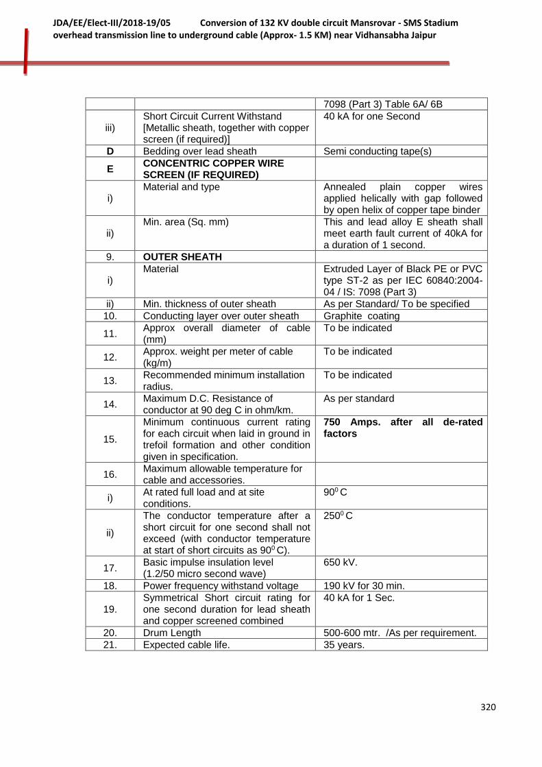
320
JDA/EE/Elect-III/2018-19/05 Conversion of 132 KV double circuit Mansrovar - SMS Stadium overhead transmission line to underground cable (Approx- 1.5 KM) near Vidhansabha Jaipur
7098 (Part 3) Table 6A/ 6B
iii) Short Circuit Current Withstand [Metallic sheath, together with copper screen (if required)]
40 kA for one Second
D Bedding over lead sheath Semi conducting tape(s)
E CONCENTRIC COPPER WIRE SCREEN (IF REQUIRED)
i) Material and type Annealed plain copper wires
applied helically with gap followed by open helix of copper tape binder
ii) Min. area (Sq. mm) This and lead alloy E sheath shall
meet earth fault current of 40kA for a duration of 1 second.
9. OUTER SHEATH
i) Material Extruded Layer of Black PE or PVC
type ST-2 as per IEC 60840:2004-04 / IS: 7098 (Part 3)
ii) Min. thickness of outer sheath As per Standard/ To be specified
10. Conducting layer over outer sheath Graphite coating
11. Approx overall diameter of cable (mm)
To be indicated
12. Approx. weight per meter of cable (kg/m)
To be indicated
13. Recommended minimum installation radius.
To be indicated
14. Maximum D.C. Resistance of conductor at 90 deg C in ohm/km.
As per standard
15.
Minimum continuous current rating for each circuit when laid in ground in trefoil formation and other condition given in specification.
750 Amps. after all de-rated factors
16. Maximum allowable temperature for cable and accessories.
i) At rated full load and at site conditions.
900 C
ii)
The conductor temperature after a short circuit for one second shall not exceed (with conductor temperature at start of short circuits as 900 C).
2500 C
17. Basic impulse insulation level (1.2/50 micro second wave)
650 kV.
18. Power frequency withstand voltage 190 kV for 30 min.
19. Symmetrical Short circuit rating for one second duration for lead sheath and copper screened combined
40 kA for 1 Sec.
20. Drum Length 500-600 mtr. /As per requirement.
21. Expected cable life. 35 years.
321
JDA/EE/Elect-III/2018-19/05 Conversion of 132 KV double circuit Mansrovar - SMS Stadium overhead transmission line to underground cable (Approx- 1.5 KM) near Vidhansabha Jaipur
Annexure-V2-P2-S1-2
BANK GUARANTEE IN LIEU OF FURNISHING TYPE TEST CERTIFICATE
[On Rajasthan Non Judicial Stamp paper worth Rs.100) (or as per applicability of stamp duty for the secured amount)]
To,
The Executive Engineer (Elect-III),
JDA, Jaipur.
Dear Sir,
Whereas JDA Jaipur (hereinafter called the purchaser) has issued a tender enquiry under TN-______for procurement of _____________ (name of materials) . Whereas M./S._____________(hereinafter called the bidder ) has furnished a bid for supply of _____________to the The Executive Engineer (Elect-III), Jaipur or his nominated officer(s) .
Whereas in accordance with the provisions of the specification of the aforesaid TN______ , the bidder can deposit a bank guarantee in lieu of the requirement of furnishing the type test report.
Whereas, M/S.____________ (the bidder ) have requested us (name of the bank) to furnish the bank guarantee , in lieu of the type test report , for an amount equivalent to Rs.__________(in words also) only. Under this bank guarantee, we (name of the bank) hereby undertake unconditionally and irrevocably to guarantee as primary obligatory and not as surety merely, the payment to the purchaser on his first demand without whatsoever right of objection on our part and without his first claim to the bidder, in the amount not exceeding (amount of guarantee in figures and words ) ______________.
Payment pursuant in this undertaking will be demanded by the purchaser from the bank and will be met by the bank without question in the case in which the bidder, on receipt of the order and / or after the acceptance of this tender, makes default in furnishing the required type test reports. As to whether the occasion or ground has arisen for such demand the decision of the Chief Engineer (PP&D) , Rajasthan Rajya Vidyut Prasaran Nigam Ltd, Jaipur or any other officer exercising the powers of Chief Engineer, Rajasthan Rajya Vidyut Prasaran Nigam Ltd , shall be final.
The liability of the bank shall not at any time exceed Rs. ____________ (Rs. in words).
The under taking will be determined on ____________but will not withstanding such determination, continue to be in-force till the expiry of 3 months from that date.
No indulgence or grant of time by the purchaser to the bidder without the acknowledgement of the bank will discharge the liabilities of the bank under guarantee.
The guarantee herein contain shall not be affected by any change in the constitution of the bidder.
All disputes arising under the said guarantee between the bank and the bidder or between the bidder and the purchaser pertaining to the guarantee shall be subject to the jurisdiction of courts only at Jaipur in Rajasthan.
The bank further undertakes not to revoke this guarantee during its currency except with previous consent of the CE (PP&D), JDA, Jaipur.

322
JDA/EE/Elect-III/2018-19/05 Conversion of 132 KV double circuit Mansrovar - SMS Stadium overhead transmission line to underground cable (Approx- 1.5 KM) near Vidhansabha Jaipur
Notwithstanding anything contain herein before, the bank's liability under this guarantee is restricted to Rs. ______________( Rupees in words) and the guarantee shall remain in force upto ___________. Unless demand or claim in writing is presented on the bank within 3 months from that date the bank shall be released and discharge from all liabilities there under.
IN WITNESS WHEREOF the Bank has executed these presents the
day________________month ________and year ______.
Yours faithfully,
(Bankers)
Executant
Witness: 1.
2.
ATTESTED BY NOTARY PUBLIC.
NOTE:-The bank guarantee shall be valid at least for a period of 12 months from the date of technical bid opening

323
JDA/EE/Elect-III/2018-19/05 Conversion of 132 KV double circuit Mansrovar - SMS Stadium overhead transmission line to underground cable (Approx- 1.5 KM) near Vidhansabha Jaipur
SECTION – II
145 kV XLPE CABLE TERMINATIONS AND JOINTING KITS
INDEX
S. No. PARTICULARS
1 SCOPE
2 STANDARDS
3 SYSTEM CONFIGURATION
4 GENERAL DETAILS OF CABLE KITS
5 TYPE & MAKE OF CABLE KITS
6 ELECTRICAL CHARACTERISTICS OF CABLE KITS
7 DESIGN AND COMPONENTS FEATURE OF CABLE KITS
8 LINK BOX FOR EARTHING & EARTHING CABLE WITH PVC INSULATION
9 SUPPORTING STRUCTURE & ANGLE BRACKET SUPPORTS FOR CABLE
10 CABLE END TERMINALS (OUT DOOR TYPE) CONNECTORS
11 CABLE FAULT LOCATION EQUIPMENT
12 TESTING INSTRUMENTS & DEVICES
13 SPARES PARTS.
14 EARTHING
15 TESTS
16 QUALITY ASSURANCE
17 TEST CERTIFICATES
18 INSPECTION AND TRAINING AT MANUFACTURER’S WORKS
19 FIRE RESISTANCE
20 INTERCHANGEABILITY
21 COMPLETENESS OF CABLE KIT FOR EASY INSTALLATION
22 GUARANTEED AND OTHER TECHNICAL PARTICULARS
23 GUARANTEE
24 SPECIAL TOOLS & TACKLES
25 MANUALS AND LITERATURE ON CABLE & CABLE KITS
26 TRAINING DURING ERECTION
Annexure- V2-P3-S2-1
DESIRED TECHNICAL PARTICULARS FOR CABLE END TERMINATION AND STRAIGHT THROUGH JOINT KIT

324
JDA/EE/Elect-III/2018-19/05 Conversion of 132 KV double circuit Mansrovar - SMS Stadium overhead transmission line to underground cable (Approx- 1.5 KM) near Vidhansabha Jaipur
TECHNICAL SPECIFICATION FOR 145 kV CABLE TERMINATION AND JOINTING KITS FOR
1 X 1200 SQ. MM XLPE CABLE
1.0 SCOPE 1.1 The scope includes supply, testing at manufacturer’s works before dispatch and delivery of
Internationally reputed make of following types of cable sealing ends, (end terminals/pot heads), and straight through joints conforming to relevant IEC, unless otherwise stipulated in the Section-IIand all other accessories as well as consumables etc. suitable for XLPE cable (Section-I). These kits and accessories shall be integral part of 145kV cable system.
I. VOID II. 145 kV rated, Outdoor cable sealing ends confirming to IEC 60840 – 2004 for testing
for terminating the 145kV highest voltage XLPE cables in outdoor yard at existing 132 kV tower at NBCC Building Sahakar Marg (Jaipur) and LILO point of 132 KV SMS Stadium GSS (Jaipur, Rajasthan) along with all the necessary supporting structure, fittings & mountings for Ckt-I& Ckt-II.
III 145 kV rated, Outdoor Straight through joints confirming to IEC 60840-2004 for testing for jointing of highest voltage 145 kV XLPE buried underground cables for existing 132 kV tower at NBCC Building Sahakar Marg (Jaipur) and LILO point of 132 KV SMS Stadium GSS (Jaipur, Rajasthan) for Ckt-I& Ckt-II.
1.2 Single/ Three phase Earth Link boxes with all associated accessories (for the connection of the cable sheath of 132 kV rated XLPE cable) suitable for cross bonding arrangement of the complete cabling system.
1.3. Cable Fault Location Equipment (optional item) and one set of special tools and equipment for handling, assembly, installation, erection and dismantling of the 132 kV XLPE cables and auxiliary equipment ( if if indicated in price schedule).
List of special tools and testing equipments which will be brought for installation and commissioning of the cable system by contractor (on returnable basis) shall be enclosed with bid.
1.4 All the testing devices and instruments etc. including HV Generator required for final acceptance testing and commissioning shall be responsibility of the contractor and no separate cost/ rental is payable. The testing devices etc. shall be taken back by the contractor after successful testing & commissioning. The testing instruments and devices indicated/ mentioned in price schedule may be ordered by Nigam, if required (to be assessed based on finalization of maintenance contract/ requirements) and the payment shall be made based on unit prices specified in the contract. List of special tools and equipment required for testing of power cable shall be enclosed with bid.
1.5 It is not the intent to specify completely herein, all details of design and construction of the equipment/system and accessories required. However, the cable system and its installation shall be complete with all accessories, conform in all respects, to high standard of engineering, design and workmanship and be capable of performing the continuous commercial operation up to guarantee in a manner acceptable to JDA/Nigam.

325
JDA/EE/Elect-III/2018-19/05 Conversion of 132 KV double circuit Mansrovar - SMS Stadium overhead transmission line to underground cable (Approx- 1.5 KM) near Vidhansabha Jaipur
2.0 STANDARDS
Unless otherwise stated hereafter, rating, characteristics, test and procedures etc. concerning the 132 kV XLPE cable accessories shall preferably be as per IEC standards wherever existing and shall be in compliance with the latest editions or revisions thereof. Although a few preferred IEC standards are mentioned below but the list is not exhaustive and may be improved.
IEC: 60840:2004-04 Test for power cables with extruded insulation for rated voltage above 30 kV up to 150 kV
IEC : TS 60859 Cable connection for Gas insulated metal enclosed switchgear for rated voltages of 72.5 kV and above.
IEC: 62271-203 Gas-insulated metal- enclosed switchgear for rated voltages of 72.5 kV and above.
IEC: 60228 Conductor for insulated cable
IEC: 60229 Tests on cable over sheaths
IEC: 60230 Impulse tests on cables and their accessories
IEC: 60270 Partial discharge measurements
IEC: 60287 Calculation of continuous current carrying capacity
IEC: 60502 Power Cables with extruded insulation and their
accessories.
BIS: 7098
(Part-3)
XLPE cable specification-for working voltages from 66 kV up to and including 220 kV.
IEEE 48-1990 IEEE Standard Test, Procedure & requirement for high voltage alternating current cable terminations
3.0 SYSTEM CONFIGURATION
3.1 The 132 kV systems will be solidly grounded. Cables will be protected from over voltages caused by lighting strikes or switching surges by means of station type lighting arrestors termination near to line at existing 132 kV tower at NBCC Building Sahakar Marg (Jaipur) and LILO point of 132 KV SMS Stadium GSS (Jaipur, Rajasthan). The yard equipment and incoming/ outgoing transmission line feeders at 132 kV Substation SMS Stadium will be shielded against direct lighting strokes by overhead ground wires. LA shall be provided on cable ends at existing 132 kV tower at NBCC Building Sahakar Marg (Jaipur) and LILO point of 132 KV SMS Stadium GSS (Jaipur, Rajasthan) [to be provided and installed by bidder under this package].
326
JDA/EE/Elect-III/2018-19/05 Conversion of 132 KV double circuit Mansrovar - SMS Stadium overhead transmission line to underground cable (Approx- 1.5 KM) near Vidhansabha Jaipur
4.0 GENERAL DETAILS OF CABLE KITS
4.1 All the Cable Sealing end/end termination kits and straight through joints, rated for 145kV,
shall be of pre-molded type from one of internationally repute manufacturer of proven design which has already been extensively used and fully type tested.
4.2 The offered kits shall be easy in handling, simple to install without much skill with minimum
tools at site. 4.3 All cable sealing end and Straight through joints shall be suitable for connecting single
core XLPE Copper Conductor XLPE cables for a maximum continuous voltage of 145 kV and core cross section of 1200 sq mm details in section-I.
4.4 The kits shall be suitable for storage without deterioration at a temperature up to 55º C
and shall have unlimited shelf life. The kits of the identical type brand and rated voltage as offered in the bid shall have proven performance of at least two years in Indian or similar conditions
4.5 The offered XLPE cable Termination and straight through jointing kits for 132 kV earthed
system shall meet the technical particulars indicated in Annexure –V2-P3-S2-2.
4.6 The cable termination shall be fully dry insulated for easy mounting and testing and it shall be free of maintenance.
. 4.7 Field tests of sealing end terminals shall be made in conjunction with the 132 kV cables after installation of the cables and terminals.
5.0 TYPE & MAKE OF CABLE KITS
5.1 VOID
5.2 OUTDOOR TYPE SEALING END.
5.2.1 The premoulded cable sealing end, conforming to IEC 60840-2004-04 for testing, of termination for maximum continuous voltage of 145 kV cables at the outdoor yard shall be supplied by the cable manufacturer. The contractor shall be responsible for correct termination of each cable to sealing ends, installation of the cable sealing end and providing of terminal connectors for connecting to terminal conductor. The requisite interconnection between line end & sealing end is required to be designed (as per safety and statutory provision aspects) and executed (after approval of Nigam) by successful bidder.
5.2.2 The silicone rubber /composite bushing termination of rated capacity, suitable for outdoor installation in moderately polluted atmosphere shall be used. It should resistant to UV exposure. The termination stress control shall be means of stress cone.
5.2.3 The stress cone made of silicone rubber shall inhibit possible mechanical stress and deformation of the cable insulation surface during operation and also shall be capable of accommodating minor radial and longitudinal movement without determent to the dielectric stress in the insulation shield.
327
JDA/EE/Elect-III/2018-19/05 Conversion of 132 KV double circuit Mansrovar - SMS Stadium overhead transmission line to underground cable (Approx- 1.5 KM) near Vidhansabha Jaipur
5.3 STRAIGHT THROUGH JOINTS
5.3.1 The premoulded straight through joints for XLPE cable (section I), conforming to IEC 60840-2004-04 for testing, shall be suitable for underground buried installation with incorporated back fill and chances of flooding by water. The straight through joints should be absolutely impervious to the entry of water. The manufacturer shall use the proven technology and design to prevent entry of water or any other liquid inside the straight through joints and cables.
5.3.2 The stress cone made of silicone rubber shall inhibit possible mechanical stress and
deformation of the cable insulation surface during operation and also shall be capable of accommodating minor radial and longitudinal movement without determent to the dielectric stress in the insulation shield.
5.4 MAKE OF CABLE KITS
Please refer to the Clause 1.2 of the Qualification Requirements (Annexure-A) of this specification for Qualification of Cable Accessories/ Kits to be supplied under this project.
6.0 ELECTRICAL CHARACTERISTICS OF CABLE KITS
6.1 The Cable Termination and straight through jointing kits accessories shall be capable of
carrying the specified rated current continuously without exceeding the specified temperature limitations.
6.2 The cable Termination and straight through jointing kits accessories to be supplied against this specification shall be rated for 40 kA for 1 second.
6.3 The sheath voltage under full load conditions shall not exceed 65 V specified / allowed in relevant standards for safety of personal as well satisfactory working of cable. The sheath shall solidly grounded at the switch gear end & at the pot yard terminations.
6.4 The fault level withstand capacity of end termination and straight through jointing kits should be strictly matching with the parameters of cables for which the kits are intended to be used.
6.5 After jointing by straight through joints and connecting the cable with terminal ends, the complete cable composite cable sheath screen bonding system shall provide a continuous current path through the cable sheath/screen and shall be bonded and earthed at both ends.
6.6 The XLPE Cable Termination and straight through jointing kits shall be suitable for use where combined ambient temperature and temperature rise due to load result in conductor temperature not exceeding 90º C under normal operation and 250º C under short circuit conditions.
328
JDA/EE/Elect-III/2018-19/05 Conversion of 132 KV double circuit Mansrovar - SMS Stadium overhead transmission line to underground cable (Approx- 1.5 KM) near Vidhansabha Jaipur
6.7 132 kV XLPE cable Termination and straight through jointing kits shall be designed to withstand the mechanical, electrical and thermal stresses under the steady state and transient/ fault conditions and shall be suitable for proposed method of installation.
7.0 DESIGN & COMPONENTS FEATURES OF CABLE KITS The following consideration shall be taken into account in the design of the product,
material properties & components of cable kits. 7.1. The most important part of cable accessories is the stress grading device, the stress cone.
The pre-molded cone shall be made of insulating and conducting silicone rubber molded together in the shape of geometric stress control unit. The synthetic insulating compound shall be used together with stress cone to improve the electrical properties inside the termination. The compound should swell the insulation of the cone and the cable to some extent so as to improve the electrical strength along with interface.
7.2 For XLPE cable, the critical part of the operation is making an electrical connection
between the stress relief device and insulation screen. If any air pocket created, then discharge and break down can occur. As such connection method and material should be such that no risk of cable damage arises and that the jointer can check the result of his work at every stage. Thus the installation instruction should be easy to follow and should be well illustrative.
7.3 The design shall be such that when the cone is supplied, the diameter of hole in the cone
shall be smaller than the diameter over cable insulation. After the cone is pushed on, the elasticity of silicone rubber should guarantee an active pressure on the cable insulation to ensure that no voids appear between the cone and the cable even after years of load cycling.
7.4 The Straight through joints shall be pre-molded construction. This design shall comprise a factory tested synthetic rubber joint, with all stress management element provided during the moulding process in the factory. The dielectric design of the Straight through joints shall be optimized. The electric stress distribution along the interface between the insulator and the cable shall take in to account the dimensions of the joint and the dielectric permittivity of the cable insulation. The material of insulator shall have good thermo mechanical behavior.
7.5 The materials used in the assembly of the Straight through joints shall be compatible with the material of the insulator and the cable insulation. The conductor shall be connected by means of an approved arrangement. The tensile strength of the connector shall meet the requirements of the copper conductor.
7.6 Every single stress cone & the stress grading device shall be tested electrically prior to delivery in presence of purchaser. Each stress cone shall be marked with an individual number and JDA and a certificate containing detailed specification of test shall be included with every delivery.
7.7 The different accessories shall be type tested according to SEN, IEC- 60840:2004-04 and
IEEE standards which include tests for impulse, AC, load cycling and partial discharge. Before delivery every stress cone shall be installed on cable and care fully checked to establish that it is PF free in presence of owner’s representative(s).

329
JDA/EE/Elect-III/2018-19/05 Conversion of 132 KV double circuit Mansrovar - SMS Stadium overhead transmission line to underground cable (Approx- 1.5 KM) near Vidhansabha Jaipur
7.8 Details of proper stress control, stress grading and non tracking arrangement in the termination & joints details shall be elaborated in the offer. Detailed sectional view of assemblies shall be submitted along with the offer. The application of stress control system shall be safe, foolproof & independent of cable jointers skills. The stress control method should withstand expansion & contraction of cable during load cycling.
7.9 The jointing kits offered shall be so designed so as to prevent discharge/ leakage at the cut back, nicks scratches on XLPE insulations. Full details of method of discharge prevention shall be indicated by the bidder.
7.10 The cable end termination and straight through joints shall be designed in such a way so
as to give track resistant, erosion & weather resistance protection to the cable insulation. The outdoor end termination & straight through joints shall be totally sealed against ingress of moisture of environment.
7.11 All end outdoor terminations shall be provided with rain sheds/ creepage petticoats. The
weather sheds shall be non-tracking weather resistant hydrophobic and have smooth surface to collect any water/ dirt etc. The design of rain skirts shall avoid any skirt to skirt conducting path under heavy rain condition.
7.12 For XLPE cables, the lugs should withstand thermal short circuit of 250 deg. centigrade.
For XLPE cables, the ferrule should be suitable for compacted conductor & should withstand thermal short circuit of 250 deg centigrade.
7.13 Design features may be highlighted in bid and the mouldings of rubber components should
be aimed to achieve a smooth finish on interior and exterior of the components. 7.14 The kits shall be provided with protection against rodent & termite attack. 7.15 The kits offered shall provide for total environment sealing of the cable crutch and at the
lugs end. The details of which shall be offered along with the offer. Provision for effective screening over each core shall be made and bidder shall categorically confirm this aspect in their offer.
7.16 The materials & components of kits, not specifically stated in the specification, but which
are essential for satisfactory operation of cable shall be deemed to be included without any extra cost.
7.17 The earthing arrangement shall form part of the terminations joints and shall be protected
from erosion either by suitable tape or tube (Section-III). 7.18 The word "JDA" along with trade name of the manufacturer, month/ year of manufacture,
size etc. shall be embossed/ engraved for the purpose of identification. 7.19 The adequate provisions for eliminating the chances of entrapment of air at steps formed
by semicon screen shall be made. 7.20 The terminations joints shall be supplied in kit form. All insulation and sealing materials,
consumable items, conductor fittings, earthing arrangements & lugs etc. should be provided. Requisite No. and size of lugs & ferrules depending upon the type of the cable shall be provided in the kit. Lugs & Ferrules shall be of crimping type and shall confirm to the relevant standard applicable to XLPE cables.

330
JDA/EE/Elect-III/2018-19/05 Conversion of 132 KV double circuit Mansrovar - SMS Stadium overhead transmission line to underground cable (Approx- 1.5 KM) near Vidhansabha Jaipur
8.0 LINK BOX FOR EARTHING & EARTHING CABLE WITH PVC INSULATION
8.1 Bidder shall carry out the earthing of sheath/screen in the cross bonding configuration. The successful bidder shall submit the complete sheath voltage calculation alongwith identification of major/minor sections for cross bonding. The 3 Phase Link Boxes with SVLs shall be installed at cross bonding points and Three/ Single Phase Link boxes with direct grounding at cable termination ends at terminal substations/LILO Point. The bonding lead/ grounding cable of suitable sizes (as per sufficiency/adequacy calculation submitted by successful bidder and approved by Nigam) shall be used for connecting cable sheath to earth.
9.0 SUPPORTING STRUCTURE & ANGLE BRACKET SUPPORTS FOR CABLE
9.1 Any support structures and cable clamps required to support the cables between the trays and the sealing end supports will be supplied and installed by the bidder.
9.2 VOID
9.3 Fabricated structure of suitable height, to be approved by purchaser, shall be provided and installed by manufacturer of cable for supporting the Outdoor cable sealing end at at existing 132 kV tower at NBCC Building Sahakar Marg (Jaipur) and at SMS Stadium GSS, Jaipur Rajasthan. The height of the structure shall be such that the terminal connection to receive the purchaser’s ACSR Panther conductor/ 38 mm Al. Pipe, at a height of 5 meters. Exact height shall be intimated/ confirmed to the successful bidder while approval of drawings. The structures shall be of galvanized steel structural sections. Anchor bolts, washers etc will be supplied and installed by successful bidder of cable.
9.4 The supporting structure shall be suitable to withstand the wind pressure, seismic forces and the short circuit forces, etc., and the design shall have with an adequate factor of safety as specified in I.E. rules 1956.
9.5 The bidder shall furnish the design and fabrication drawings of these structures & foundation anchor bolts, and design calculations etc.
9.6 The bidder shall quote for unit prices for support structure for each single core cable to suit the end terminations supplied by him.
10.0 CABLE END TERMINALS (OUT DOOR TYPE) CONNECTORS
10.1 The terminal connector/clamps shall be suitable for connection to Panther ACSR/ 38 mm Al. Pipe conductor at existing 132 kV tower at NBCC Building Sahakar Marg (Jaipur) and at SMS Stadium GSS, Jaipur Rajasthan ends. The terminal connector shall be of bimetallic type to connect the copper stud of the cable terminal end to the ACSR/ Al. Pipe conductor.
10.2 The type and size of the conductor will be confirmed to the successful bidder.
10.3 The connector/clamp shall be designed to overcome:
i) Galvanic Corrosion.
ii) Thermal Cycling.

331
JDA/EE/Elect-III/2018-19/05 Conversion of 132 KV double circuit Mansrovar - SMS Stadium overhead transmission line to underground cable (Approx- 1.5 KM) near Vidhansabha Jaipur
10.4 The current carrying capacity of the connector/clamps shall be greater than the maximum capacity of the power cable. The terminal clamp shall be free from burrs, voids, and blow holes.
10.5 The terminals clamps shall have passed tests for short circuit current capability and temperature rise.
11.0 CABLE FAULT LOCATION EQUIPMENT This cable fault locating equipment shall be suitable for routine checking, Pre-locating,
pinpointing and insulation testing on underground cable rating from 33kV to 132 kV grade PILCA, XLPE, PVC etc. during O&M.
12.0 TESTING INSTRUMENTS & DEVICES
12.1 The contractor shall arrange for all testing devices, instruments etc. required during assembly, erection, testing and commissioning of 132 kV XLPE cable.
12.2 All the testing devices and instruments etc. including HV Generator required for final acceptance testing and commissioning shall be responsibility of the contractor and no separate cost/ rental is payable. The testing devices etc. shall be taken back by the contractor after successful testing & commissioning.
13.0 SPARES PARTS.
The mandatory spare parts as indicated in the price shedled shall be offered/ qupted by the bidder.
In addition, the contractor shall submit a list of recommended spare parts, if any, for the successful operation of the 132 kV XLPE Cables.
14.0 EARTHING 14.1 Bidder shall carry out the earthing of sheath/screen at cross bonding points as well as at
both of termination ends of 145 kV cable using insulation sheath bonding (earthing) cable of required size through Link box with/ without surge voltage limiter at cross bonding points and terminal substations.
14.2 Earthing shall be as per relevant standards and the details of the earthing arrangement offered for the cable accessories shall be submitted along with the offer.
14.3 The sheath/screen shall bound in the earth station through disconnecting type link boxes.
14.4 Screen continuity by using tinned copper mesh and earth continuity by tinned copper braids of appropriate size shall be provided for transfer of screen/ earth in straight through joints.
15.0 TESTS 15.1 The testing of Cable termination for Gas Insulated Metal enclosed Switchgear, outdoor
type sealing end and straight through jointing kits for XLPE Cable shall be as per IEC: 60840:2004-04 and IEEE: 48. All the type tests(Conducting of Type testsare not envisaged in the specification and successful type test certificate are to be submitted by

332
JDA/EE/Elect-III/2018-19/05 Conversion of 132 KV double circuit Mansrovar - SMS Stadium overhead transmission line to underground cable (Approx- 1.5 KM) near Vidhansabha Jaipur
bidder as per Qualification Requirements), sample tests and routine tests shall be carried out on thecable kits (referred as accessories in IEC) at their manufacture’s works.
15.2 The above tests (Conducting of Type testsare not envisaged in the specification and
successful type test certificate are to be submitted by bidder as per Qualification Requirements)shall be carried out in presence of purchaser's representative as per relevant standard IEC: 60840:2004-04 and IEEE: 48 at bidder’s cost and the sampling plan shall be 1 percent subject to minimum of one number.
15.3 The contractor shall make available to the JDA Engineer a complete set of detailed data, required for inspection and tests.
15.4 Details of Tests The bidder must specify the details of the type(Conducting of Type test are not envisaged
in the specification and successful test certificate are to be submitted by bidder as per Qualification Requirements), sample and routine tests to be conductedon offered cable kits at their works along with the standards applicable in their offer.
15.5 Type tests on accessories (kits) Type tests on accessories (kits) shall be conducted as per clause 14, Annexure-C of IEC
60840:2004 at the manufacturer’s work. (Conducting of Type testsare not envisaged in the specification and successful type test certificate are to be submitted by bidder as per Qualification Requirements).
15.6 Sample tests on accessories (Kits). Sample tests on accessories (Kits) shall be conducted as per IEC 60840:2004 and IEEE:
48. Some important tests are summarized for ready reference. 15.6.1 Tests on components The characteristics of each component of kit shall be verified in accordance with the
specifications of the accessories (kit) manufacturer, either through test reports from the sub supplier of a given component or through internal tests conducted at works of cable kit manufacturer.
The manufacturer of a given accessory (Kit) shall provide a list of the tests to be
performed on each component, indicating the frequency of each test. The components shall be inspected against their drawings. There shall be no deviations outside the declared tolerances.
15.6.2 Tests on complete accessory (Kit): For accessories, where the main insulation cannot be routine tested (Clause 9.1 of IEC
60840:2004), the following electrical tests shall be carried out by the manufacturer on a fully assembled accessory.
a) Partial discharge test (Clause 9.2 of IEC 60840:2004) b) Voltage test (Clause 9.3 of IEC 60840:2004)
333
JDA/EE/Elect-III/2018-19/05 Conversion of 132 KV double circuit Mansrovar - SMS Stadium overhead transmission line to underground cable (Approx- 1.5 KM) near Vidhansabha Jaipur
The sequence in which these tests shall be carried out shall be indicated in bid. These tests shall be performed on one accessory of each type.
15.7. Routine Tests Routine test shall be conducted as per IEC 60840:2004. Some important tests are
summarized for ready reference. The main insulation of each prefabricated accessory shall undergo following tests (a) Partial discharge test Clause 9.2 of IEC 60840:2004 (b) Voltage tests Clause 9.3 of IEC 60840:2004 according to either 1), 2) or 3) below: 1) on accessories installed on cable. 2) by using a host accessory into which a component of an accessory is submitted for test. 3) by using a simulated accessory rig in which the electrical stress environment of a main insulation component is reproduced.
16.0 QUALITY ASSURANCE 16.1 Raw materials used for manufacture of cable shall be of highest quality and material
received by manufacturer should be checked / tested to ensure that it meets manufacturer’s material specification. The materials shall be clean and packed in moisture and dust proof packing.
16.2 As the Quality control of EHV XLPE cables termination& jointing kits and accessories
while manufacturing is very critical so expert supervision is required for raw material testing, in process checks and also for final testing. A specially trained quality assurance team should be in place for maintenance of the quality at an optimum level at the plant. Complete details of manufacturing process along with details of automatic manufacturing plant, list of officers /staff to supervise the manufacturing and other details desired as per clause No. 12.0 under heading QUALITY ASSURANCE PROGRAM of GTR/GTC (Volume-II, Part -II) shall be furnished by bidder in the bid.
16.3 Quality assurance plan indicating test /checks of raw material, process of manufacturer
and final inspection with customer hold point shall be submitted to the purchaser for approval.
17.0 TEST CERTIFICATES The latest complete type test certificates (conducted during last 7 years from date of
tender along with attested drawing) in duplicate for all types of terminations &joints of offered design/ material conducted at Inter National repute test house confirming to IEC: 680840:1999 or 2004 must be enclosed with the offer. The offer without type tests results shall be ignored.
18.0 INSPECTION & TRAINING AT MANUFACTURER’S WORKS

334
JDA/EE/Elect-III/2018-19/05 Conversion of 132 KV double circuit Mansrovar - SMS Stadium overhead transmission line to underground cable (Approx- 1.5 KM) near Vidhansabha Jaipur
18.1 The 132kV XLPE cable termination for Gas Insulated Metal enclosed Switchgear, outdoor type sealing end and straight through jointing kits and other accessoriesshould be manufactured and tested while manufacturing as per approved Quality Assurance plan and foregoing specification. Supplier shall intimate the programme of manufacturing of the cabletermination& jointing kits and accessories in advance. The inspection during manufacturing shall be carried out by the JDA engineers at various stages of manufacture. The successful bidder shall grant free access to the purchaser's representative at a reasonable time when the work is in progress.
18.2 VOID 18.3 Inspection and acceptance of any equipment/material under this specification by the
purchaser shall not relieve the supplier of his obligation of furnishing equipment in accordance with the specification and shall not prevent subsequent rejection if the equipment/material is found to be defective.
18.4 The supplier shall present the latest Calibration Certificate(s) of testing instruments /
equipments to be used for the testing of the material covered in the Purchase Order to the authorized inspecting officer/ inspecting agency of the purchaser. The testing instruments /meters/apparatus etc should be got calibrated by the supplier from time to time from independent test laboratory/house having valid accredition from National Accredition Board for Testing and Calibrating Laboratories for the testing equipments / original manufacturer having credibility to NABL / NPL or equivalent.
18.5 The calibration certificate(s) should not in any case be older than one year at the time of
presenting the same to the inspecting officer/ inspecting agency of the purchaser. The testing instruments/ equipments should be duly sealed by the Calibrating Agency and mention thereof shall be indicated in the calibration certificate(s).
18.6 The purchaser reserves the right to insist for witnessing the sample/routine tests of the
bought out raw material/items used in manufacturing of cable end terminations/ joints. 19.0 FIRE RESISTANCE The cable terminations shall be fire resistant. The components of kits shall have flame
retardant property. 20.0 INTERCHANGEABILITY The components of different number of the kits shall be inter-changeable in case the need
arises. 21.0 COMPLETENESS OF CABLE KIT FOR EASY INSTALLATION 21.1 The bidder shall offer complete material and components for each kit so as to meet one
termination complete in all respects. The bidder shall indicate the list of the material/ components with quantities of each or cable end termination.
21.2 An instruction manual in English, indicating the complete method/ proceedings adopted for
installations of kits, preferably with more diagrams/ pictorial presentation shall be supplied with each kit. Various items, quantity thereof against each kit must be indicated in the instruction manual.
335
JDA/EE/Elect-III/2018-19/05 Conversion of 132 KV double circuit Mansrovar - SMS Stadium overhead transmission line to underground cable (Approx- 1.5 KM) near Vidhansabha Jaipur
21.3 The detailed bill of material and installation instructions shall be provided with each kit for
verification by purchaser's inspecting officer & at Nigam's stores/ site. 21.4 All components shall be sealed separately and marked clearly for the purpose of
identification of each component. All components shall be supplied in single package as a complete kit for one termination joints and shall bear manufacturer's name & cable size of kit size for which it can be used.
21.5 The Bidder shall also indicate shelf life & ideal life of kit contents. 22.0 GUARANTEED & OTHER TECHNICAL PARTICULARS 22.1 The bidder shall furnish the guaranteed & other technical particulars of the kit offered by
him in Annexure- V2-P3-S2-1 attached with the specifications. The particulars which are subject to guarantee shall be clearly indicated. Without schedule of GTP, completely filled, the offer shall not be acceptable.
22.2 The bidder shall highlight the various technical aspects of the kits offered by him. 23.0 GUARANTEE The cable termination & straight through joints shall bear guarantee for five years from the
date of commissioning. Any defect noticed in the kit shall be attended by the bidder immediately but not later than 24 hours in Jaipur City on getting the complaints and if required shall be replaced and installed free of cost, otherwise the same will be arranged at the supplier's risk and cost. For this purpose, successful bidder shall furnish Manufacturer's warranty on Rajasthan Non-judicial stamp paper worth Rs.100/- or as applicable in a manner as detailed in GCC.
24.0 SPECIAL TOOLS & TACKLES
Complete out fit of tools, special tools, spanners and other lifting devices, instrument and appliance necessary for the complete assembly, erection at site, dismantling and maintenance of Power Cable including all accessories (kits) covered by the contract together with suitable racks for holding them shall be arranged by the contractor.
25.0 MANUALS AND LITERATURE ON CABLE & CABLE KITS
The following documents should be furnished along with the bid:
i) Dimensioned cross sectional details of the cable.
ii) Current carrying capacities “with supporting calculated data” of the cable and de-rated factors.
iii) Instructions Manual on cable laying installation, storage, handling, maintenance, fault finding, repairs, preventive maintenance, etc.,
iv) Type, acceptance and routine test certificates on the cable as per relevant IS, IEC or other International standards.

336
JDA/EE/Elect-III/2018-19/05 Conversion of 132 KV double circuit Mansrovar - SMS Stadium overhead transmission line to underground cable (Approx- 1.5 KM) near Vidhansabha Jaipur
v) Dimensioned cross sectional details of the straight through Joint kit alongwith bill of materials.
vi) Instructions Manual on the method and formation on cable joining techniques of the straight through joint.
vii) Type, acceptance and routine test certificate on the straight through joints.
viii) OGA drawing of the cable end termination.
ix) Dimensioned cross sectional details of cable end terminations with bill of materials.
x) Instructions Manual on the method and formation on cable joining techniques of the cable end terminations.
xi) Type, acceptance and routine test certificate on the cable end terminations.
xii) OGA drawing of the cable termination structure alongwith the bill of materials.
xiii) Literature on special Tools & Plant.
xiv) Literature on sheath bonding, maintenance of link boxes.
xv) Any other relevant literature/manual.
xvi) Drawing showing additional details as per clause 5.3.2
26.0 TRAININGDURING ERECTION While erection the bidder shall arrange demonstration of use of kits (ordered by purchaser)
for giving the demonstration and training to the 3 or more personnel of the JDA for getting acquainted with the cable jointing method/ procedure free of cost.
____________________

337
JDA/EE/Elect-III/2018-19/05 Conversion of 132 KV double circuit Mansrovar - SMS Stadium overhead transmission line to underground cable (Approx- 1.5 KM) near Vidhansabha Jaipur
Annexure- V2-P3-S2-1
DESIRED TECHNICAL PARTICULARS OF XLPE CABLE KITS & ACCESSORIES
A. OUTDOOR CABLE END TERMINATION
1 Nominal System Voltage U 132 kV( rms)
2. Rated/Highest System Voltage Um 145 kV (rms)
3 Rated frequency & No. of phase 50 Hz ±3%, Three ( 3)
4 Installation Outdoor
5. Name and address of manufacturer of end termination
Refer clause no 5, Section-II
6. Nomenclature of kit. To be indicated
7. Type of Kit Pre-molded
8 Suitable for Single Core Copper Conductor XLPE cable Conforming to IEC 60502-2 and IEC 60840:2004-04 or IS 7098(part-3) amended upto date and as per Section -1 of the specification.
Yes
9 Maximum conductor size To be indicated
10 Rated continuous current Maximum current of the cable
11 Applicable standard for testing IEC 60840 : 2004-04 & IEEE-48
12. Maximum allowable Pd-level As per IEC
13 Type of Insulator. Silicone/Composite.
14. Creepage distance 25 mm/kV (Total > 2900 mm)
15 Colour Brown/ Grey
16. Maximum allowable temperature for cable and accessories
i) At rated full load and at site condition
ii) The conductor temperature after a short circuit for one second shall not exceed (with conductor temperature at start of short circuits as 90◦ C).
90◦ C
338
JDA/EE/Elect-III/2018-19/05 Conversion of 132 KV double circuit Mansrovar - SMS Stadium overhead transmission line to underground cable (Approx- 1.5 KM) near Vidhansabha Jaipur
250◦C
17. Basic impulse insulation level
(1.2/50 micro second wave)
650 kV
18. Power frequency withstand voltage 190 kV for 30 min.
19. Symmetrical Short circuit rating 40 kA for 1 Sec.
20 Power frequency withstand voltage
(a) Dry (kV rms.)
(b) Wet (kV rms.)
To be indicated
21. Flashover voltage:
(a) Dry ( kV rms )
(b) Wet ( kV rms
To be indicated
22 Stress relief cone made of Silicone rubber
23. Net dimensions of kit
(Length x Breadth x Width and Weight)
To be indicated
24. Craft sensitivity and reliability To be indicated
25. Time required for energisation after completing the joint (curing period)
To be indicated
26. Special storage condition. If any, upto an ambient temperature of 50 degree C and period.
To be indicated
27. Whether provision made for :
a) Stress relief. b) Track resistance. c) Sealing.
Yes
28. Whether any additional support is required for kit?
If so, give details.
29. Make, Type and Material of lugs provided with kits.
Details to be given by bidder.
30. Class of Kits. Details to be given by bidder
31. Sectional Drawing Showing constructional details along with each item material, description enclosed.
Yes.
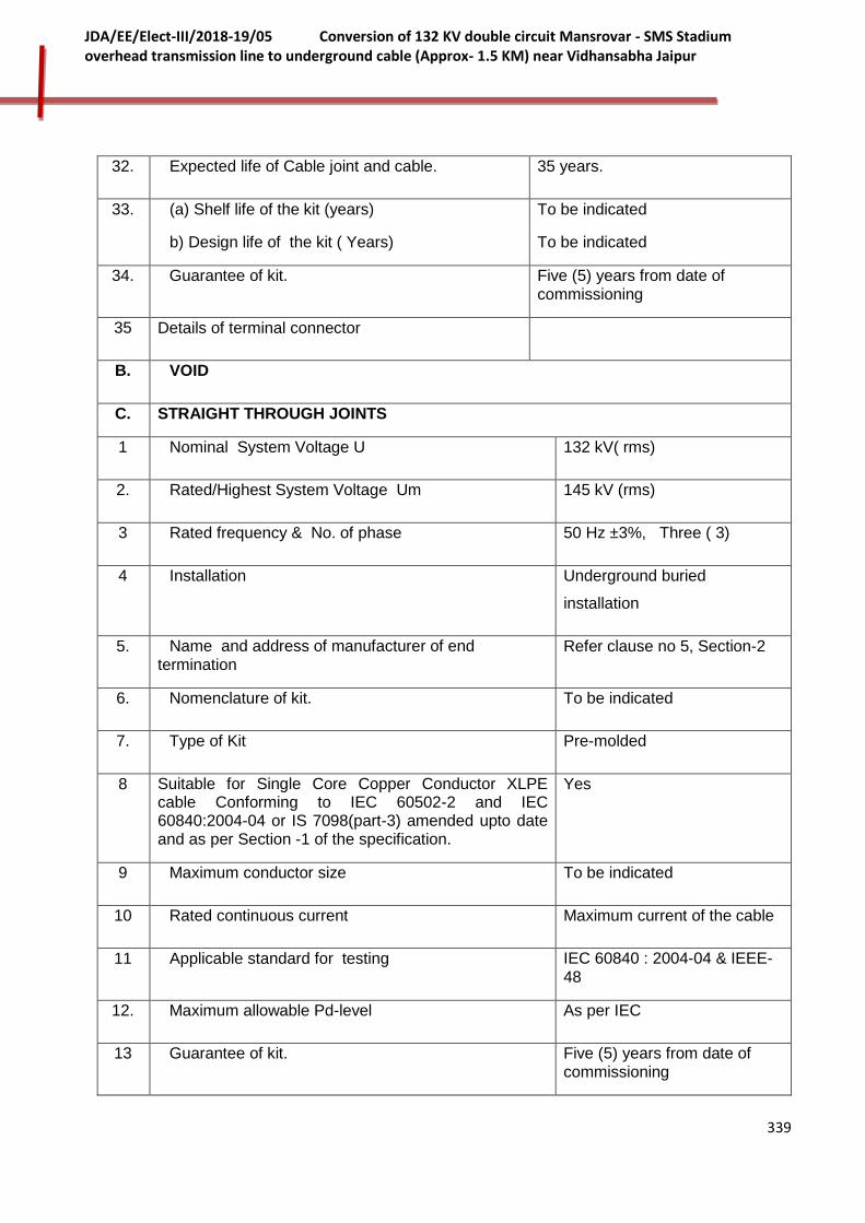
339
JDA/EE/Elect-III/2018-19/05 Conversion of 132 KV double circuit Mansrovar - SMS Stadium overhead transmission line to underground cable (Approx- 1.5 KM) near Vidhansabha Jaipur
32. Expected life of Cable joint and cable. 35 years.
33. (a) Shelf life of the kit (years)
b) Design life of the kit ( Years)
To be indicated
To be indicated
34. Guarantee of kit. Five (5) years from date of commissioning
35 Details of terminal connector
B. VOID
C. STRAIGHT THROUGH JOINTS
1 Nominal System Voltage U 132 kV( rms)
2. Rated/Highest System Voltage Um 145 kV (rms)
3 Rated frequency & No. of phase 50 Hz ±3%, Three ( 3)
4 Installation Underground buried
installation
5. Name and address of manufacturer of end termination
Refer clause no 5, Section-2
6. Nomenclature of kit. To be indicated
7. Type of Kit Pre-molded
8 Suitable for Single Core Copper Conductor XLPE cable Conforming to IEC 60502-2 and IEC 60840:2004-04 or IS 7098(part-3) amended upto date and as per Section -1 of the specification.
Yes
9 Maximum conductor size To be indicated
10 Rated continuous current Maximum current of the cable
11 Applicable standard for testing IEC 60840 : 2004-04 & IEEE-48
12. Maximum allowable Pd-level As per IEC
13 Guarantee of kit. Five (5) years from date of commissioning

340
JDA/EE/Elect-III/2018-19/05 Conversion of 132 KV double circuit Mansrovar - SMS Stadium overhead transmission line to underground cable (Approx- 1.5 KM) near Vidhansabha Jaipur
14 Proven technology and design to prevent entry of water
Yes
15. Sectional Drawing Showing constructional details along with each item material, description enclosed.
Yes.
16. Maximum allowable temperature for cable and accessories
i) At rated full load and at site condition
ii) The conductor temperature after a short circuit for one second shall not exceed (with conductor temperature at start of short circuits as 90◦ C).
90◦ C
250◦C
17. Basic impulse insulation level
(1.2/50 micro second wave)
650 kV
18. Power frequency withstand voltage 190 kV for 30 min.
19. Symmetrical Short circuit rating 40 kA for 1 Sec.
20 Power frequency withstand voltage
(a) Dry (KV rms.)
(b) Wet (KV rms.)
As per IEC
21. Flashover voltage:
(a) Dry ( KV rms )
(b) Wet ( KV rms
To be indicated by bidder
22 Stress relief cone made of Silicone rubber
23. Details of terminal connector To be furnished
24. Net dimensions of kit
(Length x Breadth x Width and Weight)
To be indicated
25. Craft sensitivity and reliability To be indicated
26. Time required for energisation after completing the joint (curing period)
To be indicated
27. Special storage condition. If any, upto an ambient temperature of 50 degree C and period.
To be indicated
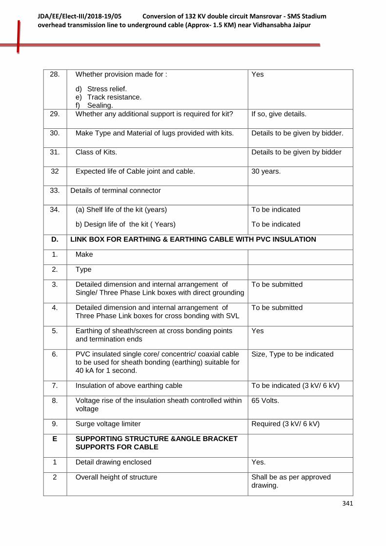
341
JDA/EE/Elect-III/2018-19/05 Conversion of 132 KV double circuit Mansrovar - SMS Stadium overhead transmission line to underground cable (Approx- 1.5 KM) near Vidhansabha Jaipur
28. Whether provision made for :
d) Stress relief. e) Track resistance. f) Sealing.
Yes
29. Whether any additional support is required for kit? If so, give details.
30. Make Type and Material of lugs provided with kits. Details to be given by bidder.
31. Class of Kits. Details to be given by bidder
32 Expected life of Cable joint and cable. 30 years.
33. Details of terminal connector
34. (a) Shelf life of the kit (years)
b) Design life of the kit ( Years)
To be indicated
To be indicated
D. LINK BOX FOR EARTHING & EARTHING CABLE WITH PVC INSULATION
1. Make
2. Type
3. Detailed dimension and internal arrangement of Single/ Three Phase Link boxes with direct grounding
To be submitted
4. Detailed dimension and internal arrangement of Three Phase Link boxes for cross bonding with SVL
To be submitted
5. Earthing of sheath/screen at cross bonding points and termination ends
Yes
6. PVC insulated single core/ concentric/ coaxial cable to be used for sheath bonding (earthing) suitable for 40 kA for 1 second.
Size, Type to be indicated
7. Insulation of above earthing cable To be indicated (3 kV/ 6 kV)
8. Voltage rise of the insulation sheath controlled within voltage
65 Volts.
9. Surge voltage limiter Required (3 kV/ 6 kV)
E SUPPORTING STRUCTURE &ANGLE BRACKET SUPPORTS FOR CABLE
1 Detail drawing enclosed Yes.
2 Overall height of structure Shall be as per approved drawing.
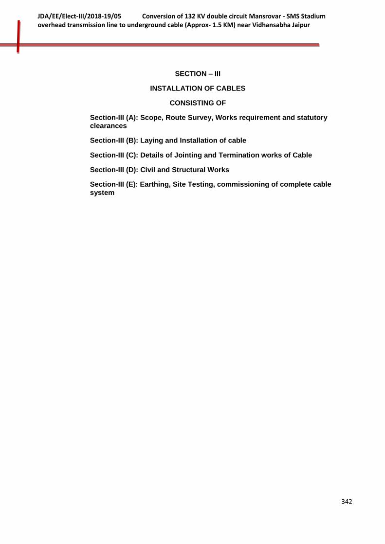
342
JDA/EE/Elect-III/2018-19/05 Conversion of 132 KV double circuit Mansrovar - SMS Stadium overhead transmission line to underground cable (Approx- 1.5 KM) near Vidhansabha Jaipur
SECTION – III
INSTALLATION OF CABLES
CONSISTING OF
Section-III (A): Scope, Route Survey, Works requirement and statutory clearances
Section-III (B): Laying and Installation of cable
Section-III (C): Details of Jointing and Termination works of Cable
Section-III (D): Civil and Structural Works
Section-III (E): Earthing, Site Testing, commissioning of complete cable system
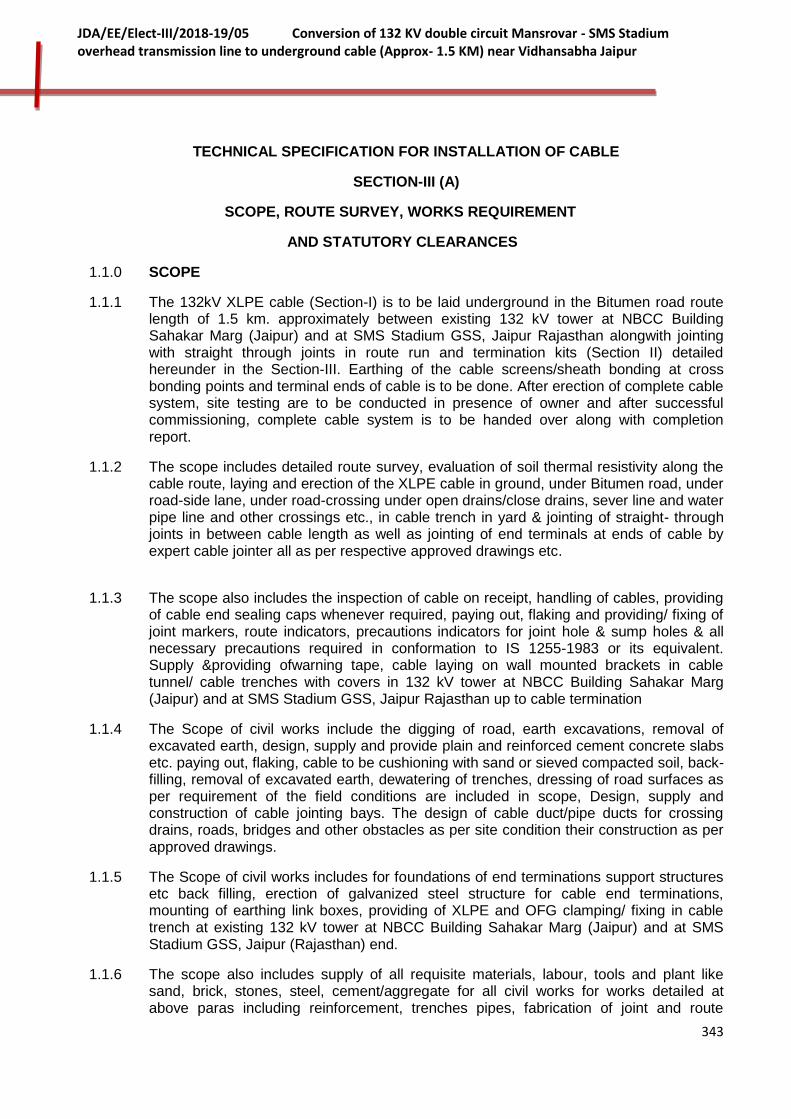
343
JDA/EE/Elect-III/2018-19/05 Conversion of 132 KV double circuit Mansrovar - SMS Stadium overhead transmission line to underground cable (Approx- 1.5 KM) near Vidhansabha Jaipur
TECHNICAL SPECIFICATION FOR INSTALLATION OF CABLE
SECTION-III (A)
SCOPE, ROUTE SURVEY, WORKS REQUIREMENT
AND STATUTORY CLEARANCES
1.1.0 SCOPE
1.1.1 The 132kV XLPE cable (Section-I) is to be laid underground in the Bitumen road route length of 1.5 km. approximately between existing 132 kV tower at NBCC Building Sahakar Marg (Jaipur) and at SMS Stadium GSS, Jaipur Rajasthan alongwith jointing with straight through joints in route run and termination kits (Section II) detailed hereunder in the Section-III. Earthing of the cable screens/sheath bonding at cross bonding points and terminal ends of cable is to be done. After erection of complete cable system, site testing are to be conducted in presence of owner and after successful commissioning, complete cable system is to be handed over along with completion report.
1.1.2 The scope includes detailed route survey, evaluation of soil thermal resistivity along the cable route, laying and erection of the XLPE cable in ground, under Bitumen road, under road-side lane, under road-crossing under open drains/close drains, sever line and water pipe line and other crossings etc., in cable trench in yard & jointing of straight- through joints in between cable length as well as jointing of end terminals at ends of cable by expert cable jointer all as per respective approved drawings etc.
1.1.3 The scope also includes the inspection of cable on receipt, handling of cables, providing of cable end sealing caps whenever required, paying out, flaking and providing/ fixing of joint markers, route indicators, precautions indicators for joint hole & sump holes & all necessary precautions required in conformation to IS 1255-1983 or its equivalent. Supply &providing ofwarning tape, cable laying on wall mounted brackets in cable tunnel/ cable trenches with covers in 132 kV tower at NBCC Building Sahakar Marg (Jaipur) and at SMS Stadium GSS, Jaipur Rajasthan up to cable termination
1.1.4 The Scope of civil works include the digging of road, earth excavations, removal of excavated earth, design, supply and provide plain and reinforced cement concrete slabs etc. paying out, flaking, cable to be cushioning with sand or sieved compacted soil, back-filling, removal of excavated earth, dewatering of trenches, dressing of road surfaces as per requirement of the field conditions are included in scope, Design, supply and construction of cable jointing bays. The design of cable duct/pipe ducts for crossing drains, roads, bridges and other obstacles as per site condition their construction as per approved drawings.
1.1.5 The Scope of civil works includes for foundations of end terminations support structures etc back filling, erection of galvanized steel structure for cable end terminations, mounting of earthing link boxes, providing of XLPE and OFG clamping/ fixing in cable trench at existing 132 kV tower at NBCC Building Sahakar Marg (Jaipur) and at SMS Stadium GSS, Jaipur (Rajasthan) end.
1.1.6 The scope also includes supply of all requisite materials, labour, tools and plant like sand, brick, stones, steel, cement/aggregate for all civil works for works detailed at above paras including reinforcement, trenches pipes, fabrication of joint and route

344
JDA/EE/Elect-III/2018-19/05 Conversion of 132 KV double circuit Mansrovar - SMS Stadium overhead transmission line to underground cable (Approx- 1.5 KM) near Vidhansabha Jaipur
makers, materials like wall brackets, anchor bolts etc and all other consumable required for the completion of the work.
1.1.7 Supply of all consumable and sundry materials not included in the specification in detail but is necessary to meet the intent of the project.
1.1.8 The successful bidder shall carry out all activities connected with the laying and installation of the power cables & arrange for security till commissioning and handling over to the JDA/Nigam and completion of the work for which the project is intended and to the full satisfaction of the owner.
1.1.9 However, alternate installation arrangements offered from the bidders with clear justification for these alternatives will be considered by the owner, if they prove to be of a better and economical design.
1.2.0 CABLE LENGTHS AND ROUTE SURVEY
1.2.1 Bidder shall conduct detailed survey of cable route and accordingly finalize the route plan. The final total quantity, the number of drums, the length of cable on each drum etc shall be ascertained by the successful bidder after detailed survey and identifying locations of jointing bays with in two months from the date of letter of award. The route plan and actual lengths of 132 kV XLPE cables required shall be submitted to purchaser for approval. Additional length of cable, if required, in addition to the cable already ordered against tendered quantity shall be covered in ±changes (refer clause no.42 of GCC of Contract, Volume-I) and shall be supplied by bidder at extra prorated /unit cost to the purchaser alongwith prorate cost of associated installation additional works.
1.2.2 The route plan of the cable is enclosed with bid documents for reference only to enable the bidder to have assessment of the work involved in broad way. The bidder is advised to visit the site and acquaint themselves with the topography, infrastructure and requirements etc. The contractor shall be fully responsible for providing all equipment, materials, T&P and services specified or otherwise which are required to complete the erectionand successful commissioning of 132 kV cable system in all respects.
1.2.3 The bidder shall quote in his bid to carry out all the cable installation work as per the specification/site requirement of the purchaser for bid evaluation.
1.2.4 The arrangement of laying the cable under road, the road side lane, under the road crossing etc are indicated in enclosed drawing section of bid documents for reference of bidders The bidder should furnish the drawings of arrangement of laying under above cases along with others to meet site condition.
1.3.0. CODES AND STANDARDS
1.3.1 Cable installation shall be carried out generally as per following applicable standards and other relevant applicable standards unless otherwise stated
IS 1255 Installation and maintenance of power Cable
IS: 5820 Specification for pre-cast concrete cable
IS: 209 Quality of zinc for galvanizing.
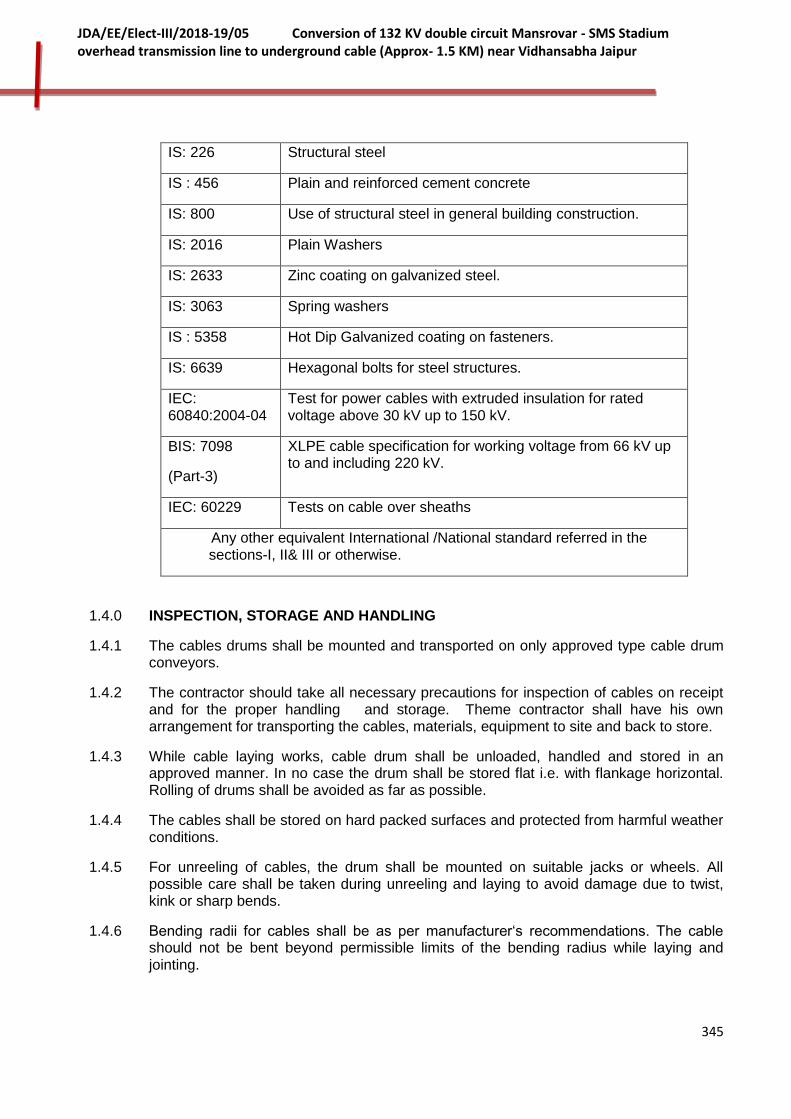
345
JDA/EE/Elect-III/2018-19/05 Conversion of 132 KV double circuit Mansrovar - SMS Stadium overhead transmission line to underground cable (Approx- 1.5 KM) near Vidhansabha Jaipur
IS: 226 Structural steel
IS : 456 Plain and reinforced cement concrete
IS: 800 Use of structural steel in general building construction.
IS: 2016 Plain Washers
IS: 2633 Zinc coating on galvanized steel.
IS: 3063 Spring washers
IS : 5358 Hot Dip Galvanized coating on fasteners.
IS: 6639 Hexagonal bolts for steel structures.
IEC: 60840:2004-04
Test for power cables with extruded insulation for rated voltage above 30 kV up to 150 kV.
BIS: 7098
(Part-3)
XLPE cable specification for working voltage from 66 kV up to and including 220 kV.
IEC: 60229 Tests on cable over sheaths
Any other equivalent International /National standard referred in the sections-I, II& III or otherwise.
1.4.0 INSPECTION, STORAGE AND HANDLING
1.4.1 The cables drums shall be mounted and transported on only approved type cable drum conveyors.
1.4.2 The contractor should take all necessary precautions for inspection of cables on receipt and for the proper handling and storage. Theme contractor shall have his own arrangement for transporting the cables, materials, equipment to site and back to store.
1.4.3 While cable laying works, cable drum shall be unloaded, handled and stored in an approved manner. In no case the drum shall be stored flat i.e. with flankage horizontal. Rolling of drums shall be avoided as far as possible.
1.4.4 The cables shall be stored on hard packed surfaces and protected from harmful weather conditions.
1.4.5 For unreeling of cables, the drum shall be mounted on suitable jacks or wheels. All possible care shall be taken during unreeling and laying to avoid damage due to twist, kink or sharp bends.
1.4.6 Bending radii for cables shall be as per manufacturer‘s recommendations. The cable should not be bent beyond permissible limits of the bending radius while laying and jointing.
346
JDA/EE/Elect-III/2018-19/05 Conversion of 132 KV double circuit Mansrovar - SMS Stadium overhead transmission line to underground cable (Approx- 1.5 KM) near Vidhansabha Jaipur
1.4.7 Manufacturer’s instructions shall be strictly adhered to.
1.5.0 EXECUTION OF WORK
1.5.1 This specification is intended for general description of quality of materials and workmanship of finished work. They are not intended to cover the minute details. The work shall be executed in accordance with the best modern practices, Indian standards (I.S.) and other relevant codes.
1.5.2 The specification shall be read in conjunction with the other parts of the bid documents.
1.5.3 The purchaser’s decision shall be final on any issue in respect of installation.
1.5.4 The bidder shall prepare the drawings for applicable filed conditions of cable installation like cables directly buried, below metaled road, in ducts, in road crossing, on drainage crossings, cable jointing bays, main holes and other drawings referred in foregoing paras etc. and furnish 3 copies of each to the owner for approval .and 6 sets of final approved drawings for execution of work
1.5.5 All works are to be executed by bidder only after due approval of the JDA engineer and under his supervision.
1.6.0 STATUTORY CLEARANCES
1.6.1 The installation of cables shall be as per established code or practice and fulfill the requirements of status. All clearances as per statute shall be maintained from other utility services, like telephones, water supply, power supply etc.
1.6.2 The civic highways/traffic authorities etc. charge as per their standard schedules for grant of permission for trenching. These charges are towards restoration of the surface to its original condition. These charges shall be paid by the owner as per actual, on production of bills/demand notices.
1.7.0 EXPERTISE OF UNIT TO HANDLE WORK
1.7.1 Cable laying/erection unit shall be having good experience( at least 5-7 years) of similar work of 66 kV and above class cables and have at least completed 5 such jobs of 66 kV and above class cables but at least conducted 2 jobs of 132 kV and above cables. Unit in-charge should have at least 15 years of experience of EHV class cable laying /erection.
1.7.2 The cables jointing and termination work shall be carried out by experienced cable jointer who shall have more than 15 years experience in jointing and termination of 33 kV or higher voltage grade XLPE cables and have at least completed 5 such jobs of 132 kV and above class cables. The certified cable jointer should be stationed in India.
1.7.3 The bidder should give the bio data of team in-charge and other engineers/ supervision/experts along with the bid to access the capability of bidder in this respect. Bidder should also enclose the list of such work conducted alongwith bid.
347
JDA/EE/Elect-III/2018-19/05 Conversion of 132 KV double circuit Mansrovar - SMS Stadium overhead transmission line to underground cable (Approx- 1.5 KM) near Vidhansabha Jaipur
1.8.0 PREVENTION FROM TRAFFIC ACCIDENTS WHILE WORK IN PROGRESS.
1.8.1 Suitable barriers should be erected between the cable trench and pedestrian/ motorway to prevent accidents. The barriers shall be painted with yellow and black or red and white coloured cross stripes. Warning and caution boards should be consciously displayed. Red lights as warning signal should be placed along the trench during the nights.
1.8.2 The excavated material shall be properly stored to avoid obstruction to public and traffic movement.
1.9.0 DAMAGE TO PUBLIC PROPERTY WHILE WORK
1.9.1 The contractor shall take all precautions while excavation of trench, trial pits etc., to protect the public and private properties and to avoid accidental damage. Any damage so caused shall be immediately repaired and brought to the notice of the concerned and to the JDA Engineer/purchaser
1.9.2 The contractor shall bear all responsibilities and liabilities and shall bear all costs of the damages so caused by him or by his workman or agents.
1.9.3 At places where the cables cross private roads, gates of residential houses or buildings, the cables shall be laid in PVC pipes of adequate strength.
1.10.0 DOCUMENTATION
1.10.1 Bidder should enclose complete literature of with bid.
i) Laying method and precautions to be made.
ii) Method and detailed description of joints through straight through terminals.
iii) Method and detailed description of cable end terminals joints.
1.10.2 The following documents should be furnished on award of the contract:
The contractor shall prepare the route layout plan indicating the road crossing, crossing across drains, nallahs, etc., and location of the straight through joints and relevant and associated drawings.
1.11.0 INSPECTION AND SITE TESTING WHILE WORK
1.11.1 The material and equipment covered under this contract are subject to strict codes of owner approved Q.A.P. inspection and tests.
1.11.2 Approval or passing of any such testing/inspection by the owner shall not however prejudice the right of the owner to reject the material equipment if it does not comply with the specification when installed and or fails to give the intended service.
1.11.3 A complete test schedule/program shall be furnished by the contractor.
1.11.4 The bidder shall provide test pieces as required in quantity, to determine the quality of material supplied under this contract. If any test piece fails to comply with the requirement the Engineer may reject the whole material represented by the test pieces.

348
JDA/EE/Elect-III/2018-19/05 Conversion of 132 KV double circuit Mansrovar - SMS Stadium overhead transmission line to underground cable (Approx- 1.5 KM) near Vidhansabha Jaipur
1.11.5 In the case of stage inspection while erection work, the bidder shall proceed from one stage to another only after the component is inspected by the Engineer and permission given to proceed further. The same procedure shall apply for any rectification or repairs suggested by the Engineer.
1.11.6 The contractor shall give the owner 3/5 days written notice for inspection/site tests. The Engineer shall within 3 days of the inspection give notice in writing to the bidder of any defects noticed during inspection/ site tests. The bidder shall take corrective measures and shall confirm in writing, of the compliance or otherwise with due reason.
1.11.7 The purchaser or the Engineer shall have the right to inspect any machinery, material, structure, equipment, plant or workmanship furnished or used by the contractor and may reject any or all which is defective or unsuitable for the use and purpose intended or which is not in accordance with the specification.
1.11.8 The contractor on demand by the owner shall remedy or replace at his expense such defective material/plant equipment. In the event of the failure by the contractor for correcting the defect or replacement of the material/equipment plant the owner may take such remedial measures necessary at the expense of the contractor.
1.11.9 In the event of inspection by the engineer, and the inspection revealing Goods/materials not in conformity with the standard/specification, the owner shall specify additional tests/inspection procedures, if required to ascertain compliance with specifications.
1.11.10. A set of latest relevant approved drawings/data shall be made available to the Engineer during inspection.
1.11.11 The Engineer shall issue a certificate for having inspected the material/equipment within seven days of inspection. The issue of the certificate does not bind the purchaser to accept the material should it no further tests on installation be found not to comply with the contract specification.
1.11.12 The bidder shall grace to conduct all or repeat the tests already conducted, for the satisfaction of the purchaser.
_______________
349
JDA/EE/Elect-III/2018-19/05 Conversion of 132 KV double circuit Mansrovar - SMS Stadium overhead transmission line to underground cable (Approx- 1.5 KM) near Vidhansabha Jaipur
SECTION-III(B)
LAYING AND INSTALLATION OF CABLE
2.1.0 132 kV XLPE power cable (Section-I) shall be laid throughout the routeas under:
Six Nos. cable length: 132 kV XLPE cable three (3) single cores in trefoil formation in Ckt-I and Ckt-II to form 132 kV Ckt-I and Ckt-II.
However, as per requirement of the field, the cables shall also have to be laid as per approved drawings:
1. In ducts. 2. In HDPE pipes at road crossings (pipes to be filled with sand/suitable material
after cabling) 3. In air at terminations. 4. At varying depths due to obstructions. 5. HDPE Pipes at crossing of private loads, gates of residential houses/buildings. 6. On trough under bridge.
2.2.0 LAYING OF POWER AND OFC CABLES
2.2.1 Two circuits of the 132 kV XLPE cable shall be laid in the same trench/ duct along with optical fiber cables in 100 mm PVC conduit pipe (to be supplied by the bidder against present bid) as indicated in drawing No. JDA/TN-05/ Drg-02. The contractor shall furnish detailed drawing complying with all applicable standards for approval by the owner.
2.2.2 The cable shall be laid wherever required in HDPE pipes of ISI approved quality refer in drawing No. JDA/TN-05/ Drg- 03/ 05.
2.3.0 TRENCHING
2.3.1 The cable trench work involves earth excavation for cable trench, back filling and removal of excess earth from site. The work site shall be left as clean as possible.
2.3.2 The trench shall be excavated using manual /mechanical modes as per field conditions. Most main roads are of asphalt surface and some of the roads with cement concrete surface.
2.3.3 Where paved footpaths are encountered, the pavement slabs shall be properly stored and reinstated. Identification markers of other services shall be properly stored and restored.
2.3.4 The sides of the excavated trenches shall wherever required, be well shored up.
2.3.5 The bottom of the excavated trench should be leveled flat and free from any object which would damage the cables. Any gradient encountered shall be gradual.
2.4.0 DEPTH OF LAYING OF CABLES
Depth of laying shall be 1.5 m. During detailed engineering depth offered for more than 1.5 m at typical location (s) shall be accepted subject to approval of JDA/Nigam.
350
JDA/EE/Elect-III/2018-19/05 Conversion of 132 KV double circuit Mansrovar - SMS Stadium overhead transmission line to underground cable (Approx- 1.5 KM) near Vidhansabha Jaipur
2.5.0 PAYING OUT THE CABLE
The excavated cable trench shall be drained of all water and the bed surface shall be smooth, uniform and fairly hard before paying out the cable. The cable shall be rolled in the trench on cable rollers, spaced out at uniform intervals. The paying out process must be smooth and steady without subjecting the cable to abnormal tension. The cable on being paid out shall be smoothly and evenly transferred to the ground after providing the cushion. The cables shall never be dropped. All snake bends shall be straightened. Suitable size cable stocking pulling eye shall be used for pulling the cable. While pulling the cable by winches or machines, the tension loading shall be by tension indicator and shall not exceed the permissible value for the cable. The cable laying shall be performed continuously at a speed not exceeding 200 to 300 meters per hour.
2.6.0 CABLE END SEALS
The cable end seals shall be checked after laying and if found damaged shall immediately be resealed. Sufficient number of heat shrinkable cable end sealing caps shall be stocked at site stores for testing and jointing work. The integrity of the outer sheath shall be checked after the cable is laid in position.
2.7.0 FLAKING
The cables shall be flaked and left with slight extra lengths at jointing bays for expansion and flexibility. This shall have prior approval of Engineer.
2.8.0 SAND CUSHION
The sand cushion for the cables shall be provided as per the drawings. Sand covering shall be done by hand and in such manner as to provide complete envelope for the cables.
2.9.0 SAND BEDDING
The cable shall be completely surrounded by well-compacted cable sand to such a thickness and of such size that the cable is protected against damage. The thickness of the cable sand should normally be a minimum of 10 cm in all directions from the cable surface.
2.10.0 THERMAL BACKFILL
Based on the evaluation of soil thermal resistivity along the cable route and after approval from the JDA the contractor shall design, specify, supply, lay and monitor the installation of thermal backfill surrounding the cables.
2.11.1 IMMEDIATE ENVELOPE TO CABLE
The option on the use of the material that immediately envelopes the cable viz., thermal backfill or sand or sieved native soil rests with the JDA. The contractor shall seek prior approval on the use of the envelop material from the JDA before execution of the works.
2.12.0 BACK FILLING
Normally back filling shall consist of the material earlier excavated. However, bigger stones or pieces of rock should be removed.

351
JDA/EE/Elect-III/2018-19/05 Conversion of 132 KV double circuit Mansrovar - SMS Stadium overhead transmission line to underground cable (Approx- 1.5 KM) near Vidhansabha Jaipur
2.13.0 PREVENTION OF DAMAGE DUE TO SHARP EDGES
2.13.1 After the cables have been laid in the trench and until the cables are covered with protective covering, no sharp metal tool shall be used in the trench or placed in such a position that may fall into the trench.
2.13.2 Straight and curved rollers used shall have no sharp projecting parts liable to damage the cable.
2.13.3 While pulling through pipes and ducts, the cable shall be protected to avoid damage due to sharp edges.
2.13 4 The cables shall never be bent, beyond the specified bending radius.
2.14.0 WARNING TAPE
A pre-warning, Red colour plastic/ PVC tape, 450 mm wide 100 microns thick, shall be laid at approx. 0.4 m above the cable specified depth, throughout the cable route. The tape shall carry the legend printed in black continuously as under CAUTION; JDA, 132000 V CABLES.
2.15.0 IDENTIFICATION
An identification marker/Tag of lead of size 50 mm x25 mm x2 mmshall be provided at 2.5 meter intervals through out the route length of the cable and fastened with a suitable nylon string. The marker shall be embossed/ bunched on both sides with the letters JDA 145 kV, Ckt-I, JDA OFC, JDA 145 kV, Ckt-II respectively. In case of double circuits phase identification by colored PVC tape shall be at 1 M interval. Alternatively plastic tags may be used. These tags should also be fixed at the cable inlet and outlets of a duct, tunnel, manhole and joint bays.
2.16.0CABLE OVER BRIDGES
2.16.1 Wherever the cable route crosses the bridges, the cables shall be laid in ducts. In existing ducts by removing and replacing the R.C.C. covers and properly back filled.
2.16.2 Cable Crossing Open Drains With Long Span
a) Wherever the cable route has to cross an open drain, with a long span, the cable shall be laid in suitable size ducts or pipes, suitably jointed with collars. The entire duct system shall be designed as per civil engineering practice and shall be got approved by the concerned authorities and owner.
b) At places where the cables cross private roads, gates of residential houses or buildings, the cables shall be laid in HDPE pipes.
2.17.0 ROAD CUTTING
The road cutting, whether of cement concrete/ asphalt or macadam road surface shall be taken after obtaining approval for cutting from the civic authorities, traffic police, telephone authorities and work should be planned to be completed in the shortest possible time. Where necessary the work shall be planned during night or light traffic periods.
352
JDA/EE/Elect-III/2018-19/05 Conversion of 132 KV double circuit Mansrovar - SMS Stadium overhead transmission line to underground cable (Approx- 1.5 KM) near Vidhansabha Jaipur
2.18.0 ROAD CROSSING
HDPE pipes shall be used for cable. Pipes diameter should not be less than 1.5 times the cable diameter.
2.19.0 FOOTPATH CUTTING
The slabs, kerb-stones, on the roads shall be removed and reinstated without damage.
2.20.0 REINSTATEMENT
2.20.1 After the cables and pipes have been laid and before the trench is backfilled all joints and cable positions should be carefully plotted and preserved till such time the cable is energized and taken over by the Engineer. The protective covers shall then be provided, the excavated soil riddled, sieved and replaced. It is advisable to leave a crown of earth not less than 50 mm and not more than 100 mm in the centre and tapering towards the sides of the trench.
2.20.2 The temporary reinstatement of roadways should be inspected at regular intervals, more frequently in rainy season and immediately after overnight rain for checking settlement and if required the temporary reinstatement should be done.
2.20.3 After the subsidence has ceased the trench may be permanently reinstated and the surface restored to the best possible condition.
2.20.4 The road surface being cement concrete, asphalt or tarred macadam, resurfacing will be done by the civic authorities at owner’s cost. The fixing of markers etc. shall be co-ordinated by bidder.
2.20.5 All works shall be carried out under supervision of the engineer in charge or his representative.
2.21.0 CABLE ROUTE MARKERS/CABLE JOINT MARKERS
2.21.1 Permanent means of indicating the position of joints and cable route shall be fabricated, supplied and erected by successful bidder as per approved drawings.
2.21.2 Markers provided shall be as per the field requirement, if the route passes through open
fields, markers should be conspicuously visible and above ground surface.
2.21.3 The marker should incorporate the relevant information. The name of the JDA, voltage,
circuit and distance of cable from the marker
2.22.0 TOOLS AND PLANTS
2.22.1 The successful bidder shall have all necessary tools, plant and equipment to carry out the survey and cable installation work.
2.22.2 The bidders are instructed to give all the details of equipment at their disposal, to carry out the work successfully and speedily.

353
JDA/EE/Elect-III/2018-19/05 Conversion of 132 KV double circuit Mansrovar - SMS Stadium overhead transmission line to underground cable (Approx- 1.5 KM) near Vidhansabha Jaipur
2.23.0 MAINTENANCE OF SITE CONDITIONS
The contractor shall clean the completed cable route and shall remove all surplus and waste materials, empty cable reels etc. preferably the same day but not later than the next day after the particular work is completed.
2.24.0 BENDING RADIUS
The minimum bending radius of XLPE insulated cables are as follows:
Cable Bending radius
Single Core 25 X Overall diameter of cable
___________

354
JDA/EE/Elect-III/2018-19/05 Conversion of 132 KV double circuit Mansrovar - SMS Stadium overhead transmission line to underground cable (Approx- 1.5 KM) near Vidhansabha Jaipur
SECTION-III(C)
DETAILS FOR JOINTING AND TERMINATION WORKS OF CABLES
3.1.0 GENERAL
3.1.1 The cable jointing personnel and his crew shall have good experience in the type of joints and terminations that are used. The jointing work shall commence as soon as two or three lengths of cables have been laid. All care should be taken to protect the factory-plumbed caps/ seals on the cable ends, and the cable end shall be sealed whenever the end is exposed for tests.
3.1.2 Jointing of cables in carriage ways, drive ways under costly paving, under concrete or asphalt surfaces and in proximity to telephone cables, and water mains should be avoided whenever possible.
3.1.3 Sufficient over lap of cables shall be allowed for making the joints.
3.1.4 The joint bay should be of sufficient dimensions to allow the jointers to work with as much freedom of movement and comfort as possible. Sufficient space should be kept below the cable to be jointed.
3.1.5 The joints of different phases shall be staggered in the jointing bay.
3.1.6 During the cable jointing works, the overlapping cable portions are cut for suitable positioning of Cable Joints. In this process, lot of cable pieces gets accumulated as wastage/ scrap. Such wastage of cable for jointing shall be limited to 1 (One) Percent of the total cable length supplied (as per approved survey) over and above this limit it is to be borne by the contractor.
3.1.7 All accessories and consumables used in the termination should be of good quality and compatible with the cable.
3.2.0 JOINTING BAYS
3.2.1 The bidder shall identify the location of the joint bays after carrying out detailed survey of the cable route and excavation of the trial pits. The delivery lengths of the cables shall match the location.
3.2.2 In case of underground portion, the joint bay should have a flat and level surface lined with bricks and properly plastered. The retaining walls on all sides, to the required height shall be of brick/stone masonry. The top of the wall shall have a cement concrete bed 1:2:4 with 20 mm size aggregate all-round. The top shall be covered with pre-fabricated RCC slabs and with an inspection cover. At the bottom in a corner, a sump pit shall be made for bailing out water.
3.2.3 The contractor shall submit design and drawing of joint bay for both underground and bridge portion for approval of the JDA/Nigam.
3.3.0 SUMP HOLES
3.3.1 When jointing cables in water logged ground or under unforeseen rainy conditions, a sump hole should be made at one end of the joint bay, in such a position so that the
355
JDA/EE/Elect-III/2018-19/05 Conversion of 132 KV double circuit Mansrovar - SMS Stadium overhead transmission line to underground cable (Approx- 1.5 KM) near Vidhansabha Jaipur
accumulated water can be pumped or baled out by buckets, without causing interference to the jointing operation.
3.4.0 TENTS/COVERS
An enclosure or suitable protection cover shall be used in all circumstances wherever jointing work is carried out in the open irrespective of the weather conditions. The joint shall be made in dust free, moisture free and clean atmosphere. The full details of the cover and how it will be provided at site so as to ensure full compliance to the requirements of this clause should be furnished by the bidder along with the offer.”
3.5.0 PRECAUTIONS BEFORE MAKING A JOINT
The cable end seals should not be opened until all necessary precautions have been taken to prevent circumstances arising out of rainy/ inclement weather conditions, which might become uncontrollable.
If the cable end seals or cable ends are found to have suffered damage the cables should not be jointed, without tests and rectification.
3.6.0 MEASUREMENT OF INSULATION RESISTANCE
Before jointing, the insulation resistance of both sections of cables shall be checked.
3.7.0 IDENTIFICATION OF PHASES AT JOINT BAYS
The identification of each phase shall be clearly and properly noted. The cables shall be jointed as per the approved design. Each cable shall have identification for phase at joint bays.
3.8.0 MAKING A STRAIGHT THROUGH JOINT
3.8.1 Comprehensive jointing instructions of the straight through joints detailed in section-II of this specification shall be supplied by the manufacture of jointing kits and same shall be meticulously followed by bidders’ jointers.
3.8.2 The materials used in the joints like ferrules, screen/sheath continuity bonds, lugs etc., shall be of good quality and conform to standards.
3.8.3 The jointing tools shall be appropriate and as per the requirement of jointing HV XLPE cables.
3.9.0 MAKING A CABLE END TERMINATIONS
3.9.1 The cable end terminations and its supporting structures shall be as per section-II of this specification. The preparation of the cable end for installing the terminations and the precautions to be taken before fixing the terminations shall be followed as in the case of the cable jointing procedures.
3.9.2 The instructions furnished by the manufacturer of cable terminals ends shall be strictly followed.
3.9.3 At cable terminating end, the following provisions for supply and erections are to be included.

356
JDA/EE/Elect-III/2018-19/05 Conversion of 132 KV double circuit Mansrovar - SMS Stadium overhead transmission line to underground cable (Approx- 1.5 KM) near Vidhansabha Jaipur
(i) A sufficient length of spare cable shall be left in the ground, for future needs. (ii) The rise of the cable immediately from the ground shall be enclosed in PVC/PE
pipe of suitable diameter to protect against direct exposure to the sun. (iii) The cable shall be properly fastened using non-metallic clamps. (iv) Appropriate labels shall be fixed identifying the phase circuit, voltage and date of
commissioning etc., on the cable supporting structure. (v) The sealing end shall be mounted on pedestal insulators to isolate them from their
supporting steel work. (vi) Protection from contact with the exposed metal work at the termination shall be
provided by resin bonded glass fiber shroud. (vii) Providing earth stations with all required materials, like leads, connectors etc.
3.9.4 Appropriate rating of Lightning Arrestor for protection of the cables from lightning shall be provided at LILO Point.
3.10.0 BONDING OF SCREEN/ SHEATH
The screens at both ends/ cross bonded points en-route, shall be brought out and bonded to the earth station through disconnecting type link boxes and through SVL wherever applicable.
The sheath bonding as per relevant standards shall be done to effectively to reduce sheath voltage below the acceptable level 65 Volts. Bidders shall give complete details of the type of the bonding offered with its effect with the designed current
3.11.0 CONNECTION OF RADIAL WATER BARRIER AND CABLE SCREEN
If the metallic radial water barrier is insulated from the metallic wire screen a connection suitable to carry the currents occurring during operation must be installed between metallic radial water barrier of the cable and metallic wire screen in joints and sealing ends.
3.12.0 CABLE TERMINATING STRUCTURES.
3.12.1 The cable terminating structure (section-II) shall be fixed on the cement concrete foundation, the design and drawings of which shall be submitted to ?NigamJDA for their approval during the course of detailed engineering
3.12.2 After fixing the end termination, the cable shall be fixed to the support, with non-magnetic material clamps to the required height securely
.3.12.3 The mounting structure includes the supports for cable end boxes, link boxes and any other structure required for the intent of the contract.
3.12.4 All steel sections used shall be free from all imperfections, mill scales, slag intrusions, laminations, fillings, rust etc., which may impair their strength, durability and appearance. All materials shall be of tested quality only unless otherwise permitted by the JDA/Nigam.
__________
357
JDA/EE/Elect-III/2018-19/05 Conversion of 132 KV double circuit Mansrovar - SMS Stadium overhead transmission line to underground cable (Approx- 1.5 KM) near Vidhansabha Jaipur
SECTION –III (D)
SPECIFICATION FOR CIVIL AND STRUCTURAL WORKS
4.1.0 EXCAVATION
4.1.1 The specification covers excavation for cable trenches, ducts, structural foundation, jointing bays.
4.1.2 The contractor shall control the grading in the vicinity of all excavations so that the surface of the ground will be properly sloped or diked to prevent surface water from running into the excavated area during construction.
4.1.3 The excavation shall include the removal of all materials required to execute the work properly and shall be made with sufficient clearance to permit the placing, inspection and setting of forms and completion of all works for which the excavation was done.
4.1.4 The sides and bottoms of excavation shall be cut sharp and true. Under cutting shall not be permitted. Earth sides of excavation shall not be used in lieu of form work for replacement of concrete unless authorized by the Engineer where the limitations of space for large excavation necessitate such decision.
4.1.5 When machines are used for excavation the last 300 mm before reaching the required level shall be excavated by hand or by such equipment that will leave the soil at required final level in its natural condition.
4.1.6 The bottom of the excavation shall be trimmed to the required level and when carried below such level by error, shall be brought to level, by filling with lean concrete of 1:4:8 Mix at contractors cost.
4.1.7 All excavation for installation of underground facilities shall be open cuts.
4.1.8 The excavation for foundation where specified shall be carried out at least 75 mm or as specified in relevant drawing below the bottom of the structure concrete and then be brought to the required level by placing lean concrete of 1:4:8 mix or as specified with aggregate of 40 mm nominal size.
4.1.9 When the excavation requires tracing, sheeting, shoring strutting etc. the contractor shall submit to the Engineer in charge drawings showing arrangement and details of proposed installation and shall obtain the approval from the Engineer in charge before proceeding with the work.
4.1.10 The contractor shall have to constantly pump out the water collected in the pits, trenches due to rain, sub-soil, springs etc., and maintain dry working conditions at no extra cost to the owner.
4.2.0 DISPOSAL OF EXCAVATED EARTH
4.2.1 The contractor shall arrange to transport the surplus excavated earth by mechanical transport. It shall however be ensured that no stacked/disposed shall be as directed by the Engineer-in-charge.
4.2.2 However the contractor shall take all precautions at the site of excavation for the keeping the free flow of vehicular and human traffic and to avoid inconvenience in general. The soil transported for disposal shall be stacked, leveled and dressed neatly.
358
JDA/EE/Elect-III/2018-19/05 Conversion of 132 KV double circuit Mansrovar - SMS Stadium overhead transmission line to underground cable (Approx- 1.5 KM) near Vidhansabha Jaipur
4.3.0 BACK FILLING MATERIALS
4.3.1 The backfilling of excavated trenches around foundation shall consist of one of the following materials as the Engineer-in-charge may direct in each location.
i) Selected sieved earth from excavated soil.
ii) Selected sieved earth brought from borrows area.
iii) Sand filling (sieved).
4.3.2 Filling shall be done after the concrete or masonry work has fully set and its curing completed.
4.3.3 The contractor shall fill in and around any work until it has been properly reinstated and approved by the Engineer-in-charge.
4.4.0 BACK FILLING FOR CABLE TRENCH
4.4.1 Back filling shall be done in horizontal layers of thickness not exceeding 300 mm thickness, free from pockets with careful watering where necessary for compaction. The backfill shall be riddled earth free from materials likely to cause damage to the cables.
4.4.2 The thermal backfill surrounding the cable shall be as per the design approved by the owner.
4.5.0 SPECIFICATION FOR CEMENT CONCRETE
4.5.1 For the cement concrete, plain or reinforced for general use, requirement of concrete for nominal mix, strength and quality pouring at all levels, from works, protection covering, finishing, add mixtures, inserts curing etc., the provision of the latest revision of IS: 456 shall be complied with, unless permitted otherwise by any other Indian Standard codes, shall form the part of the specification to the extent applicable within specification. The cement used shall comply with IS: 12269 (OPC). The metal (Jelly) used in PCC/RCC shall be properly graded and machine mixed.
4.6.0 CURING AND PROTECTION OF CONCRETE
4.6.1 All fresh concrete shall be covered with the layer of an absorbent material and kept constantly wet for a period of seven days or more for the date of placing concrete. The immature concrete shall be protected from the damages and contamination that would impair the strength of the concrete.
4.7.0 PRECAST RCC ITEMS
4.7.1 The concrete mix for the various types of pre-cast units shall conform to IS: 456. The aggregate shall be mixed by weight and water cement ratio shall be controlled to obtain the dense concrete and the strength required. The reinforcement shall be as per the design approved. The curing shall be carried out for the period of minimum seven days from the date of casting and the pre-cast element shall be cured by flooding with water of minimum 25 mm depth over the element for the period mentioned above.
4.7.2 All the pre-cast element shall be marked, appropriately as specified.

359
JDA/EE/Elect-III/2018-19/05 Conversion of 132 KV double circuit Mansrovar - SMS Stadium overhead transmission line to underground cable (Approx- 1.5 KM) near Vidhansabha Jaipur
4.8.0 FOUNDATION
Foundations for mounting structures in cement concrete shall be casted by bidder as per approved drawings.
4.9.0 BOLTS, NUTS AND WASHERS
Standard bolts, nuts and washers shall be used in all works. These should be galvanized in accordance with IS: 5358.
4.10.0 PAINTING
Outdoor Kiosk for link boxes etc., shall be painted with anticorrosive paint and red oxide as primer and two coats of enamel paint. The boxes should be appropriately labeled as per installation at site regarding the S. No., location, type caution board/danger.
4.11.0 MATERIALS USED IN CABLE LAYING
Specification in brief on the materials used in installation of the 132kV underground cables, like RCC precast cable protection covers, precluded cement concrete blocks for cable route/joint indication, cable and mounting structures joint bays, earthing and other miscellaneous materials are given below. All materials shall conform to relevant standards and shall be approved by the Engineer.
4.12.0 RCC PRE CAST CABLE PROTECTION COVERS
These should be fabricated as per the design supplied by the purchaser. The reinforced cement concrete cement concrete should be in the proportion 1:1.5: 3 of 20 mm and down size aggregate and steel reinforcement of 6mm diameter mild steel rods should be used and cured as per civil Engineering standards. The covers should carry the legends JDA 132 kV CABLES, Ckt-I OR JDA 132 kV CABLES, Ckt-II as the case may be The covers should be free from burrs and projecting edges so that they may be easily laid to butt. The average breaking load shall be 450 kgs for the cover slabs.
4.13.0 CABLE ROUTE MARKERS/JOINT MARKERS
4.13.1 Permanent and durable type, cable route markers/joint indicating blocks should be provided as per the design approved by the purchaser.
4.13.2 The cement concrete block should be made by the wet process and the concrete shall consists of one part cement, two parts sand, four parts aggregate of size 20mm and down.
4.13.3 The marking block should be given a smooth cover surface or cement mortar and shall have the appropriate legends, 5mm deep engraved on them as “JDA 132kV CABLE Ckt- I” OR “JDA 132kV CABLE Ckt- II”, “JDA 132kV CABLE JOINT Ckt- I” OR “JDA 132kV CABLE JOINT. Ckt- II”.
4.14.0 PIPES
4.14.1 HDPE Pipes of ISI mark, of approved diameter and thickness, of good quality shall be used for formation of cable ducts. All sundry materials like coupling, collars, and caps to cover the pipe ends before cable is pulled in shall be provided. Bidder shall indicate diameter and thickness of these pipes in bid itself. Bidder shall indicate size of HDPE pipe diameter end thickness in bid itself.

360
JDA/EE/Elect-III/2018-19/05 Conversion of 132 KV double circuit Mansrovar - SMS Stadium overhead transmission line to underground cable (Approx- 1.5 KM) near Vidhansabha Jaipur
4.14.2 Hume pipes and accessories conforming to IS shall be used, if required, below Nallah, bridges Reinforced Hume pipe shall not be used for laying single core power cable, in one cable per pipe arrangement.
4.14.3 Hume pipes without steel reinforcement stoneware pipes, PVC pipes can also be used where the cable passes through the passage or drive ways of public and private buildings.
4.14.4 The bidder shall furnish the design drawings of foundations, foundation anchor bolts, and design calculations etc., of these structures.
4.15.0 SAND
4.15.1 Sand supplied for backfill shall be river sand, free from flakes, dust, earth, organic matter and large pebbles and stones and should be free from any chemical contaminants likely to have corrosive action on the cable coverings. The sand should be sieved through a mesh to remove all large stones and pebbles. The sand shall be properly graded and shall conform to IS: 383 for concreting work.
4.15.2 The owner will decide on the requirement of the use of sand depending on the availability of the excavated earth to be used for backfill. The sand should be used with the approval of the owner as a backfill.
4.16.0 QUANTITIES
4.16.1 The bidder shall indicate the ceiling volumes/quantities for excavation and RCC works and steel structure works, wherever specifically indicated.
4.16.2 The bidder shall quote unit rates also for the items of works. He shall have to quote the total price for each of the works.
The quoted price shall also include supply of all material transportation charges, taxes, duties, Octroi and toll tax, labour, construction, plant and equipment and fixtures, fittings and all temporary and permanent works necessary for satisfactory completion in all respects.
4.16.3 The Measurement for the payment of earth excavation will be based on volume calculations of pit/trench. The unit of measurement shall be cubic meters. Nothing extra would be payable for slopes, shoring strutting, etc., irrespective of whatever is provided. If directed by the Engineer in charge, the excavation shall be done on the slopes from slope stability point of view at no extra cost to the owner.
4.16.5 If the contractor is directed by the Engineer in charge to excaGSTe to a lower level then that indicated on the drawing, such additional excavation shall be paid for at the applicable unit rates.
4.16.6 LEAD AND LIFT
The rates quoted for all items of works shall include all lifts and leads wherever applicable unless otherwise specified.

361
JDA/EE/Elect-III/2018-19/05 Conversion of 132 KV double circuit Mansrovar - SMS Stadium overhead transmission line to underground cable (Approx- 1.5 KM) near Vidhansabha Jaipur
4.16.7 Payments for back filling shall be based on the volume of consolidated fill. This volume shall be derived from the difference between the volume of excavation and that of the structure (concrete work, sand filling), or trench as the case may be.
4.16.8 BY MECHANICAL TRANSPORT
The rate for this item shall include loading, carriage, unloading, stacking and dressing etc., complete. In no case the excavated soil shall be stacked upto the distance of 1.5 Mtrs. from the edge of excavation or one third the depth of exaction whichever is more.
4.16.9 The measurements of various civil works shall be jointly recorded by the contractor and the Engineer in charge and duly certified.
4.16.10 The contractor shall be responsible for estimates, assumptions and conclusions regarding the nature of the materials to be excavated and difficulty of making and maintaining of required excavations and performing the work required as shown on the drawing and in accordance with these specifications. Cofferdams, sheeting, shoring, draining, dewatering etc. shall be furnished and installed as required and the cost thereof shall be included in the rate quoted. The contractor shall be held responsible for any damage to any part of the work and properly caused by collapse of sides of excavation. The materials can be salvaged if it can be done with safety for the work and structure and as approved by the Engineer in charge.
4.16.11 However, no extra claim shall be entertained for material not salvaged or any other damage to contractors properly as the results of the collapse. He shall not be entitled to any claim for redoing the excavation as a result of the same.
____________
362
JDA/EE/Elect-III/2018-19/05 Conversion of 132 KV double circuit Mansrovar - SMS Stadium overhead transmission line to underground cable (Approx- 1.5 KM) near Vidhansabha Jaipur
SECTION-III (E)
EARTHING, SITE TESTING, COMMISSIONING OF
COMPLETE CABLE SYSTEM
5.1.0 EARTHING OF SYSTEM
5.1.1 The earthing system required is for the
a) Earthing of all non-current carrying metal parts and
b) Earthing system for cable screens/sheath bonding at terminations.
5.1.2 The latest edition of following standards and codes are applicable:-
i) IS: 3043: Code or practice for earthing.
ii) IS: 2309: Code of practice for the protection of buildings and allied structures against lightning.
iii) Indian Electricity Rules 1956: Provision of Rules on EHV systems
iv) IEEE– 80: Guide for safety in sub-station grounding.
5.1.3 All equipment, supporting and mounting structures of the installation shall be bonded together and connected by separate and distinct conductor to earth electrode.
5.2.0 EARTH CONDUCTOR
The earth conductor shall be of G.I flat, of approved size and shall be protected against mechanical damage and corrosion. The connection of the earth continuity conductors to earth bus and earth electrodes shall be strong, secure and sound and shall be easily accessible.
5.3.0 PIPE EARTH STATION
5.3.1 The pipe earth electrodes shall be in conformity with IS: 3043, buried vertically and the pit filled with alternate layers of charcoal, salt and earth. The earth lead shall be properly fastened with brass bolts, nuts and connections shall be enclosed in a masonry chamber. The chamber shall be provided with a RCC inspection cover.
5.3.2 The connection between the earthing terminal of equipment and earth electrode shall be made by short and direct earthing lead, free from kinks and splices.
5.3.3 The distance between any two electrode shall not be less than twice and length of the electrode.
5.3.4 All joints shall be covered with suitable compound to protect against corrosion. Earthing connections with equipment earthing terminals shall be of bolted type. The contact surfaces shall be free from scale, paint, enamels, grease, rust or dirt. Two bolts shall be provided for making earth connection. The bolted connections after being checked and tested shall be painted with anticorrosive paint or compound.
5.3.5 Welds and brazed joints shall be treated with red lead and afterwards coated with bitumen compound to prevent corrosion.
5.3.6 Steel to copper connection shall be brazed type and shall be treated to prevent moisture ingress.
363
JDA/EE/Elect-III/2018-19/05 Conversion of 132 KV double circuit Mansrovar - SMS Stadium overhead transmission line to underground cable (Approx- 1.5 KM) near Vidhansabha Jaipur
5.3.7 The resistance of the welded joint shall not be more than the resistance of equivalent length of the conductor.
5.3.8 All welded joints shall be made by electric are welding. All welded joints shall be allowed to cool down gradually to atmospheric temperature.
5.3.9 Arc welding with large diameter conductor shall be done with low hydrogen content electrodes.
5.4.0 BONDING OF CABLE SCREENS/SHEATH
5.4.1 Each single phase cable shall have a separate earth for the screen earthing. The system short circuit level is 40 kA for 1 sec. The earthing lead at solid earth position shall be single core, 300 sq.mm copper conductor PVC insulated 3.3 KV voltage grade (or appropriate size/type supported by calculation and approved by Nigam) cable.
5.5.0 EARTH TESTS
5.5.1 Tests on earths shall be carried out by the contractor in presence of JDA Engineer for testing the effectiveness of earth resistance of electrodes and the results furnished to the owner.
TESTS ON CABLE SYSTEM
5.6.0 ELECTRICAL TESTS AFTER INSTALLATION
5.6.1 The contractor shall conduct the following tests during and after installation of complete cable system (section-I, II and III) as per IEC 60840:2004-04.
5.6.2 In the event of the installation failing the tests, the contractor shall at his expense identify the cause and rectify the defects and render the installation serviceable.
5.7.0 D.C. TESTING
a) The insulation resistance of each cable length shall be checked after laying and before jointing and terminating.
b) Polarization Index test.
c) After laying, jointing and terminating the cables shall be tested with all accessories.
5.8.0 AC TESTING
5.8.1 The installation shall be tested with AC voltage at power frequency.
5.8.2 The installation shall withstand for 5 minutes with the phase to phase voltage applied between the conductor and metallic screen/sheath.
OR
5.8.3 Test for 24 hours with normal operative voltage of the system.
5.9.0 TESTS ON NON METALLIC SHEATH
The non-metallic sheath shall be subjected to test as per IEC publication 60229. The bidder can recommend any other test, for satisfactory performance of the installed system.
5.10.0 Any other site installation / commissioning tests as specified in section I & II shall be conducted by the bidder in presence of JDA Engineer.
__________

364
JDA/EE/Elect-III/2018-19/05 Conversion of 132 KV double circuit Mansrovar - SMS Stadium overhead transmission line to underground cable (Approx- 1.5 KM) near Vidhansabha Jaipur
SECTION – IV
UNARMOURED UNDERGROUND FIBER OPTIC CABLE
INDEX
S. No. Particular
1.0 TECHNICAL SPECIFICATION FOR UNARMORED
UNDERGROUND FIBER OPTIC CABLE
2.0 GENERAL
3.0 APPLICABLE STANDARDS
4.0 FIBRE TYPE(s) AND COUNTS
5.0 OPTICAL CAHRACTERISTICS
6.0 GENERAL CONSTRUCTION
7.0 COLOUR CODING AND FIBRE IDENTIFICATION
8.0 STRENGTH MEMBERS
9.0 FILLING COMPOUND
10.0 THE SHEATH/INNER JACKET
11.0 THE OUTER JACKET/TERMITE PROTECTION
12.0 RIP CORD
13.0 MECHANICAL PARAMETRS AND TESTS
14.0 OPTICAL FIBRE CABLE MARKING
15.0 OPERATING INSTRUCTIONS
16.0 TEST AND INSPECTION

365
JDA/EE/Elect-III/2018-19/05 Conversion of 132 KV double circuit Mansrovar - SMS Stadium overhead transmission line to underground cable (Approx- 1.5 KM) near Vidhansabha Jaipur
TECHNICAL SPECIFICATIONS
FOR
UNARMORED U/G FIBER OPTIC
CABLE
1.0 TECHNICAL SPECIFICATIONS FOR UNARMORED U/G FIBEROPTIC CABLE
This section describes the functional requirements, major technical parameters and Type and Factory Acceptance Testing requirements for underground fiber optic cable. Marking, packaging and transportation requirements have also been described.
2.0 GENERAL
The underground fiber optic cable shall be unarmored. The cable should be of low weight, small volume and high flexibility. The mechanical design and construction of each unit shall be inherently robust and rigid under all condition of operation, adjustment, replacement, storage and transport.
3.0 APPLICABLE STANDARDS
The cable shall conform to the standards named below and the technical specifications described in the following sections:
• ITU-T Recommendations G-652.
• Electronic Industries Association, EIA/TIA 455-78A, 455-3A, 455-62A, 455-164A/ 167A/174. 455-168A/ 169A/ 175A, 455-176, 455-59, EIA/TIA 598, EIA 455-104.
• International Electro technical Commission standards, IEC 60304, IEC 60794-
1-2, IEC 60811-5-1.
• Bell core GR-20.
4.0 FIBER TYPE(S) AND COUNTS
The cable shall contain 12 Dual Window Single Mode (DWSM) fibers conforming to G.652 as per the Technical parameters stipulated in the following sections.
5.0 OPTICAL CHARACTERISTICS
The attenuation coefficient for wavelength between 1525nm and 1575nm shall not exceed the attenuation coefficient at 1550nm by more than 0.05dB/km. The attenuation coefficient between 1285nm and 1330nm shall not exceed the attenuation coefficient at 1310nm by more than 0.05dB/km. The attenuation of the fibre shall be distributed uniformly throughout its length such that there are no point discontinues in excess of 0.1dB. The fibre attenuation characteristics specified in table A shall be “guaranteed” fibre attenuation of any & every fibre reel. Further the average cabled fibre attenuation, averaged over 100kms of cabled fibre, (as measured during the factory acceptance testing) shall be as
366
JDA/EE/Elect-III/2018-19/05 Conversion of 132 KV double circuit Mansrovar - SMS Stadium overhead transmission line to underground cable (Approx- 1.5 KM) near Vidhansabha Jaipur
specified in Table A. DWSM fibers shall conform to the requirements specified in Table A below:
Table A
DWSM Optical Fibre Characteristics
Fibre Description: Dual Window Single-Mode
Mode Field Diameter: 8.6 to 9.5nm um(±10% of the nominal value)
Cladding Diameter: 125.0 µm± 2µm
Mode field Concentricity Error: ≤ 1.0 µm
Cladding non-circularity: ≤2%
Cable Cut off Wavelength ≤1260nm
1550 loss performance: As per G.652
Proof Test Level: ≥0.35Gpa
Attenuation coefficient @ 310nm ≤0.35 dB/Km
@1550nm ≤ 0.23 dB/Km
Chromatic Dispersion: Maximum:
20 ps/(nm . km) 1550 nm
3.5 ps/ (nm . km) 1288-1339nm
5.3 ps/ (nm . km) 1271-1360nm
Zero Dispersion Wavelength: 1300 to 1324 nm
Zero Dispersion Slope: ≤0.093 ps/(nm2- km) maximum
Polarization mode dispersion
Coefficient: ≤ 0.5 ps/ km^ ¹/²
Temperature Dependence: Induced attenuation ≤0.05 dB
(-60 ºC + 85 ºC)
Bend performance: @1310nm(75n±2nmdia Mandrel), 100
turns:
Attenuation rise <0.05 dB/km
@1550nm(75±2nmdia Mandrel), 100
turns:
Attenuation rise <0.10 dB/km
367
JDA/EE/Elect-III/2018-19/05 Conversion of 132 KV double circuit Mansrovar - SMS Stadium overhead transmission line to underground cable (Approx- 1.5 KM) near Vidhansabha Jaipur
@1550nm(32±0.5 dia Mandrel),
1 turn:
Attenuation rise <0.50 dB/km
6.0 GENERAL CONSTRUCTION
The optical cable shall consist of a central fibre optic unit protected by one or more layers of helically wound anti-hygroscopic tape or yarn. The central fibre optic unit shall be designed to house and protect the fibers from damage due to forces such as crushing, bending, twisting, tensile stress and moisture, wide temperature variations, hydrogen evolution etc. The fibre shall be of loose tube construction. The inner polyethylene jacket and outer sheath jackets shall be free from pinholes, joints, splits or any other defects,. All fibre optic cable shall have a minimum service life span of 25 years.
7.0 COLOUR CODING & FIBRE IDENTIFICATION
Individual optical fibers within a fibre unit, and fibre units shall be identifiable in accordance with EIA/TIA598 or IEC 60304 or Bellcore GR-20 colour –coding scheme. The colour coding system shall be discernible throughout the design life of the cable. Colouring utilized for colour coding optical fibers shall be integrated into the fibre coating and shall be homogeneous. The colour shall not bleed from one fibre to another and shall not fade during fibre preparation for termination or splicing. Each cable shall have traceability of each fibre back to the original fibre manufacturer’s fibre number and parameters of the fibre. If more than the specified number of fibers included in any cable, the spare fibers shall be tested by the cable manufacturer and any defective fibre shall be suitably bundled, tagged and identified at the factory by the vendor.
8.0 STRENGTH MEMBERS
The central fibre optic unit should include a central strength member of Fibre Reinforced Plastic (FRP) or other suitable material. Peripheral strength members and aramid yarns are also acceptable. The central FRP strength member may be of slotted type with SZ lay (reverse oscillation lay) of fibre units or it may be cylindrical type with helical lay of fiber units.
9.0 FILLING COMPOUND
The interstices of the central fibre optic unit and cable shall be filled with a suitable compound to prohibit any moisture ingress or any longitudinal water migration within fibre optic unit or along the fibre optic cable. The water tightness of the cable shall meet or exceed the test performance criteria as per IEC60794-1-2-F5. The filling compound used shall be a non-toxic homogeneous water proofing compound that is free of dirt and foreign matter, anti-hygroscopic, electrically nonconductive and non- nutritive to fungus. The compound shall also be fully compatible with all cable components it may come in contact with and shall inhibit the generation of hydrogen within the cable. The filling compound shall remain stable for ambient temperature up to +70 ºC and shall not drip, flow or leak with age or at change of temperatures. Reference method to measure drip point shall be as per IEC60811-5-1 and drip point shall not be less than 70 ºC.
368
JDA/EE/Elect-III/2018-19/05 Conversion of 132 KV double circuit Mansrovar - SMS Stadium overhead transmission line to underground cable (Approx- 1.5 KM) near Vidhansabha Jaipur
10.0 THE SHEATH/INNER JACKET
The sheath shall be black, smooth, concentric, and shall be free from holes, splits, blisters and other surface flaws. The sheath shall be extruded directly over the central fibre optic unit and shall also be non-hygroscopic. The cable sheath design shall permit easy removal without damage to the optical fibres or fibre units. The sheath shall be made from good quality of weather resistant polyethylene compound (Black High Density Polyethylene-HDPE) and thickness shall be ≥ 1.8mm.
11.0 THE OUTER JACKET/TERMITE PROTECTION
A circular jacket of not less than 0.65mm Polymide-12(Orange Nylone-12) material should be applied over the sheath as an outer jacket. The outer jacket shall have smooth finish and shall be termite resistant.
12.0 RIP CORD
Suitable rip cord(s) shall be provided to open the outer sheath of the cable. The rip cord(s) shall be properly waxed to prevent wicking action and shall not work as a water carrier.
13.0 MECHANICAL PARAMETERS & TESTS
(i) TENSILE STRENGTH
The cable shall be of sufficient strength to withstand a load of value T (N) = 9.81 x 2.5 x W Newton or 2670 N whichever is higher (where W is the mass in Kg of 1 Km cable). The load shall be sustained for 10 minutes and the strain of the fiber monitored. The load shall not produce a strain exceeding 0.25% in the fiber and shall not cause any permanent damage to any constituent part of the cable. The change in optical attenuation during or after the application of the rated tensile load in accordance with IEC 60794-1-2-EI procedure shall not exceed 0.05dB/Km both for 1310 nm and 1550 nm wavelength. The attenuation shall be noted before strain, and after release of strain for all the fibers.
(ii) CRUSH TEST (COMPRESSIVE STRENGTH)
The cable shall withstand a compressive force of at least 2000 N. applied for at least 60 seconds between two plates of 100mm x 100mm in accordance with IEC60 794-1-2-E3 procedure. This compressive load applied in accordance with IEC60794-1-2-E3 shall not cause any permanent damage to any constituent part of the cable.
The change in optical attenuation during or after the application of the compressive load shall not exceed 0.05dB/Km both 1310nm and 1550nm wavelength. The attenuation shall be noted before and after the test for all the fibers.
(iii) BEND RADIUS The cable bend radius under no load shall be less than or equal to 20 times the cable diameter. The test method shall be according to the IEC60794-1-2-E11 (procedure-I). The fibers and component parts of the cable shall not suffer permanent damage when the cable is repeatedly wrapped and unwrapped 4 complete turns of 10 complete cycles around a mandrel of 20 times to the cable diameter. The change in optical attenuation after the test shall not exceed 0.05dB/Km both for 1310nm and 1550nm wavelength. The attenuation shall be noted before and after the test for all the fibers. Outer Jacket shall not
369
JDA/EE/Elect-III/2018-19/05 Conversion of 132 KV double circuit Mansrovar - SMS Stadium overhead transmission line to underground cable (Approx- 1.5 KM) near Vidhansabha Jaipur
show any cracks visible to the naked eye when examined whilst still wrapped on the mandrel.
(iv) CABLE BENDING TEST (REPEATED BENDING)
The cable shall withstand repeated bending when tested in accordance with EIA- 455-104 and shall not cause any permanent damage to any constituent part of the cable. The cable sample shall be at least 5 meters or more. The change in optical attenuation during or after the application of the repeated bending test shall not exceed 0.05dB/Km for all the fibers. The attenuation shall be noted before and after the test for all the fibers. The test requirement shall be as mentioned below:
Weight 5Kg
Minimum distance from pulley centre to holding 216 mm
device
Minimum distance from weight to pulley centre 457mm
Pulley diameter 20 times to the
cable Dia.
Angle of turning 90º
No. of cycles 30
Time required for 30 cycles 2 min.
(v) IMPACT TEST
The cable shall withstand at least 10 impacts of 50N load from a 0.5 meter height with impacting surface radius of 300mm. This impact load applied at the same place in accordance with IEC60794-1-2-E4 shall not cause any permanent damage to any constituent part of the cable. The change in optical attenuation during or after the application of the impact load shall not exceed 0.05dB/Km. The attenuation shall be noted before and after the test for all the fibers.
(vi) TORSION TEST
The cable shall withstand 10 cycles of ±180º torsion with 100N load applied on a 2m sample. This load cycle applied in accordance with IEC60794-1-2-E7 shall not cause any permanent damage to any constituent part of the cable. The change in optical attenuation during or after the application of the torsion load shall not exceed 0.05dB/km for all the fibers. The attenuation shall be noted before and after the test.
370
JDA/EE/Elect-III/2018-19/05 Conversion of 132 KV double circuit Mansrovar - SMS Stadium overhead transmission line to underground cable (Approx- 1.5 KM) near Vidhansabha Jaipur
(vii) KINK TEST (RESISTANCE)
When a cable of sample length 10 times the minimum bend radius as defined above is subjected to kinking, it shall not result in any fibre breakage and the kink shall disappear after normalizing the cable. The change in optical attenuation after the application of the kink in accordance with IEC60794-1-2-E10 shall not exceed 0.05dB/km for all the fibers.
(viii) WATER PENETRATION TEST (RESISTANCE TO WATER INGRESS)
The resistance to water ingress of the cable shall meet or exceed the test performance criteria as as per IEC60794-1-2-F5 method F5B. Before applying the water tight sleeve at one end the outer jacket shall be stripped. A water soluble fluorescent dye shall be used for testing. The duration of test shall be 7 days. In addition after the test the cable shall be ripped open and distance up to which water has seeped shall be noted.
(ix) DRIP TEST (SEEPAGE OF FILLING COMPOUND)
For testing, a sample of 30cm length of the cable with one end sealed by the end cap will be taken and outer jacket, sheath, binder tapes shall be removed by 5cms from open end of the sample. The filling compound will be wiped thoroughly and the sample be kept vertically with open end down ward in the oven for 24 hours at 70 ºC. Temperature with a filter paper under the sample. The filter paper should not indicate any sign of drip or oily impression. The reference test specification shall be as per IEC60811-5-1 to measure drip point.
(x) ENVIRONMENTAL TEST
Temperature cycling test shall be carried out on one drum length of the cable to ensure stability of attenuation parameter of the cable when subjected to temperature change which may occur during storage, transportation, and operation. The permissible temperature range for storage and operation will be from -20ºC to +70ºC. The rate of change of temperature during test shall be 1ºC per minute. The cable shall be kept for 12 hours at each of the following temperature and should follow the specification IEC60794-1-2-F1. Two cycles shall be performed.
TA2 -20ºC
TA1 -10-ºC
TB1 +60ºC
TB2 +70ºC
The attenuation shall be measured at the end of each temperature range both at 1310nm & 1550nm. The change of attenuation of fibre used shall be ≤ 0.05 dB both for 1310 & 1550nm for entire range of temperature for all the fibers in each cycle.
371
JDA/EE/Elect-III/2018-19/05 Conversion of 132 KV double circuit Mansrovar - SMS Stadium overhead transmission line to underground cable (Approx- 1.5 KM) near Vidhansabha Jaipur
(xi) TERMITE RESISTANCE TEST
The outer jacket shall be demonstrated to be termite resistant. The exact procedure for the test shall be mutually agreed between the Contractor and the Employer and shall generally be in line with test procedures followed by reputed test laboratories.
(xii) ABRASION TEST
To be conducted as per IEC 60794-1-E2 or equivalent international test method.
(xiii) FLEXURE RIGIDITY TEST
To be conducted as per ASTM D-790. The test shall not cause any permanent damage to any constituent part of the cable. The change in optical attenuation after the test shall not exceed 0.05 dB/km. The attenuation shall be noted before and after the test for all the fibers.
(xiv) FIGURE OF EIGHT TEST:
1000m of cable shall be uncoiled from the drum and arranged in figure of eight, each loop having a maximum, dimension of 2m. It shall be possible to arrange cable in figure of 8 with relative ease and the cable shall not show any visible damages.
(xv) CABLE AGEING TEST:
After Environmental test the cable shall be subjected to a temperature of 85 ± 2 ºC for 168 hours. Cable shall then be brought to ambient temperature and stabilized for 24hours. The change in optical attenuation after the test shall not exceed 0.05dB/km. For 1310 as well as 1550nm wavelengths. The attenuation shall be noted before and after the test for all the fibers.
(xvi) EMBITTERMENT TEST OF LOOSE TUBE:
The minimum length of the test sample depend of the outside diameter of the loose tube and should be 85mm for tubes upto 2.5mm outside dia. The length of the bigger tubes should be calculated by using the following equation:
Lo > 100 x ((D² + d ²) /4)½
Where
Lo = Length of tube under test
D = Outside dia of loose tube
d = inside dia of loose tube
Both the ends of a buffer tube test sample may be mounted in a tool which is clamped in jaws of a tensile machine which exert a constant rate of movement. The movable jaw may
372
JDA/EE/Elect-III/2018-19/05 Conversion of 132 KV double circuit Mansrovar - SMS Stadium overhead transmission line to underground cable (Approx- 1.5 KM) near Vidhansabha Jaipur
move at a rate if 50mm per minute toward the fixed jaw. Under load the tube will bend, so that the tube is subjected to tensile and compressive stresses. The fixture for holding the tube should be designed in a manner that the tube might bend in all directions without further loading. The tube should not get embrittled. No ink should appear on the tube up to the safe bend dia of tube (20D) where D is the outside diameter of the loose tube. There should not be any physical damage or mark on the tube surface.
(xvii) KINK RESISTANCE TEST ON THE LOOSE TUBE:
A longer length of the loose tube is taken (with fibre and gel), a loop is made and loop is reduced to the minimum bend radius of loose tube i.e. 20 D. (where D is the outside dia of the loose tube). This test is to be repeated 4 times on the same sample length of the loose tube. No damage or kink should appear on the surface of the tube.
(xviii) DRAINAGE TEST FOR LOOSE TUBE:
A tube length to 40cm shall b e cut and filled with filling gel ensuring there are no air bubbles and the tube is completely full. The filled tube is placed in a horizontal position on a clean worktop and cut 5cm from each end so that the finished length of the sample is 30cm. The filled tube shall be left in a horizontal position at an ambient temperature for 24 hrs. The sample tube is then suspended vertically in an environment heat oven over a weighed beaker. It is left in the oven at a temperature of 70 ºC for a period of 24 hrs. At the end of the 24hrs period the beaker is checked and weighed to see if there is any gel in beaker. There shall be no gel or oil in the beaker.
(xix) CHECK OF EASY REMOVAL OF SHEATH:
The sheath shall be Cut in circular way using a sheath removal tool and the about
300mm length of the sheath should be removed in one operation. It should be observed during sheath removal process that no undue extra force is applied and no component part of the cable is damaged. It shall be possible to remove the sheath easily. Easy removal of both the outer jacket and the inner sheath shall be checked separately.
(xx) EFFECT OF AGGRESSIVE MEDIA ON THE CABLE SURFACE (ACIDIC AND ALKALINE BEHAVIOUR)
The test shall be conducted as per method no.ISO175. The two test samples of the finished cable each of 600mm in length are taken and the ends of the samples shall be sealed. These test samples are put in the PH4 and PH10 solutions separately.
After 30 days these samples are taken out from the solutions and examined for any corrosion etc. on the sheath and other markings of the cables. The sample should not show any effect of these solutions of the sheath and other marking of the cable.
14.0 OPTICAL FIBRE CABLE MARKING
A suitable marking shall be applied in order to identify this cable from the other cables. Marking on the cable shall be indelible, of durable quality, shall last long and shall be applied at regular interval of one-meter length. Marking shall be imprinted and must clearly contrast with the surface and colors used must withstand the environmental influences experienced in the field.
The accuracy of the sequential marking must be within ±0.5% of the actual measured length. The sequential length marking must not rub off during normal installation. In case
373
JDA/EE/Elect-III/2018-19/05 Conversion of 132 KV double circuit Mansrovar - SMS Stadium overhead transmission line to underground cable (Approx- 1.5 KM) near Vidhansabha Jaipur
laser printing is used the marking shall not exceed 0.15mm depth. The optical fibre cable shall have the following markings in every metre.
Type of Cable
Running meter length
No. of fibres
Type of fibre
Laser symbol & caution notice
Year of manufacture and batch no.
Manufacturer’s name
JDA
15.0 OPERATING INSTRUCTIONS
Complete technical literature in English with detailed cable construction diagram of various sub-component with dimensions and test data of the cable shall be provided. All aspects of installation shall also be covered in the handbook.
16.0 TEST AND INSPECTION:
The general conditions for Type and Factory Acceptance Testing shall be as follows:-
16.1 TYPE TEST
Type testing shall be carried out as per IEC for fiber optic cable & the tests listed in table B shall be carried out as type tests for fibers.
Table B
Sr. Test Name Acceptance Test procedure
No. Criteria
1. Attenuation TS Table A EIA/TIA 455-78A
2. Attenuation TS Table A EIA/TIA 455-78A
Variation with
wavelength
3. Attenuation at TS Table A EIA/TIA 455-78A
WaterPeak
4. Temp. Cycling EIA/TIA 455-3A,
(Temp. dependence 2 cycles
of Attenuation)

374
JDA/EE/Elect-III/2018-19/05 Conversion of 132 KV double circuit Mansrovar - SMS Stadium overhead transmission line to underground cable (Approx- 1.5 KM) near Vidhansabha Jaipur
5. Attenuation with Bending (Bend
Performance)
Type Tests For Optic Fibres
6. Mode Field diameter EIA/TIA 455-164A/
167A/174
7. Chromatic Dispersion EIA/TIA 455-168A/
169A/175A
8 Cladding Diameter EIA/TIA 455-176
9 Point Discontinuities of attenuation EIA/TIA 455-59
10 Core-Clad concentricity error EIA/TIA 455-176
16.2 FACTORY ACCEPTANCE TESTING
The tests listed in Table C shall be carried out as Factory Acceptance Test for Underground fibre optic cable.
Table C
Factory Acceptance Tests on Underground Fibre Optic Cable
Sr. Factory Acceptance Test
No.
1. Attenuation Co-efficient (1310, 1550, and WaterPeak)
2. Point discontinuities of attenuation
3. Chromatic Dispersion
4. Visual Material verification and dimensional checks as per approved drawings
5. Resistance to Water Ingress test
6. Tensile strength test/Strain test
7. Impact test
8. Kink test
375
JDA/EE/Elect-III/2018-19/05 Conversion of 132 KV double circuit Mansrovar - SMS Stadium overhead transmission line to underground cable (Approx- 1.5 KM) near Vidhansabha Jaipur
SECTION – V
SURGE ARRESTERS
TECHNICAL SPECIFICATION
OF
SURGE ARRESTERS 1.0 SCOPE:
1.1 This specification covers design, engineering, manufacture, assembly, stage testing
inspection and testing before supply and delivery at site/CIP destination of 132 kV surge arrestors complete with all fittings, accessories, associated equipment and mandatory spares specified herein which are required for efficient and trouble free operation as specified hereunder for erection at tapping point of existing 132 kV tower at NBCC Building Sahakar Marg (Jaipur) and LILO point of 132 KV SMS Stadium GSS (Jaipur, Rajasthan).
1.2 It is not the intent to specify completely herein all the details of the design and construction
of equipment. However, the equipment shall conform in all respects to high standards of engineering, design and workmanship and shall be capable of performing in continuous commercial operation. The NIGAM will interpret the meanings of drawings and specification and shall have the power to reject any work or material which, in his judgment is not in accordance therewith. The offered equipment shall be complete with all components necessary for their effective and trouble free operation. Such, components shall be deemed to be within the scope of bidder's supply irrespective of whether those are specifically brought out in this specification and / or the commercial order or not.
2.0 STANDARDS:
2.1 The Surge Arrestors shall conform to the latest revisions with amendments available of
relevant standards, rules and codes some of which are listed herein for ready reference, unless otherwise specified elsewhere in this specification.
S. No. Standard Ref No Title
1. IEC 99-4 Specification Part-4 for Surge
Arrestors without gap for AC system.
2. a. IS : 15086 Specification for Lightning Arrestors for Alternating current system Part-I.
IS : 3070 (Part-III) b. IS11993 Gapless metal oxide surge arrestors
3. IS : 2629 Recommended Practice for hot dip galvanizing of iron and steel.
4. IS : 2633 Method For testing uniformity of coating on Zinc coated articles.
5. IS : 5621 Specification for large hollow

376
JDA/EE/Elect-III/2018-19/05 Conversion of 132 KV double circuit Mansrovar - SMS Stadium overhead transmission line to underground cable (Approx- 1.5 KM) near Vidhansabha Jaipur
porcelain for use in electrical installation.
6. IS : 13947 Degree of protection provided by enclosures for low voltage switchgear and control.
7. IEC :71 Electrical clearances 8. IS : 12063 Classification of degrees
of protection provided by enclosures of Electrical equipment .
__________________________________________________________________________ NOTE :
i) For the purpose of this specification all technical terms used herein after shall have the meaning as per IEC Specification. ii) For the parameters of the Arrestor which are not specified in IEC specification for Surge Arrestors, the provisions of IS 3070 (Part-I) shall be applicable.
3.0 SERVICE CONDITIONS: 3.1 CLAMATIC CONDITIONS: Refer clause 33.0 of GTC (Part-II, Volume-II) 3.2 Auxiliary Power Supply: Refer clause 24.0 of GTC (Part-II, Volume-II) 4.0 PRINCIPAL PARAMETERS:
The Surge Arresters offered under this specification shall conform to the parameters given below:
S. No. Particulars 220kV 132kV 33 kV
1. a. Nominal System voltage(kV rms) 220 132 33 b. Nominal discharge current --10 kA of 8/20 Micro Sec Wave -- 2. Highest System voltage (kV rms) 245 145 36 3. Installation class -- Outdoor Station Class -- 4. A. 1.2/50 micro second
impulse voltage withstand level a. Transformers (kVp) 950 550 170 b. Other equipment and lines(kVp) 1050 650 170
B. One unit power frequency dry and wet With standard voltage (kV rms) 460 275 70
5. Minimum prospective symmetrical 40 31.5 25 fault current for 1 second at Arrester location (kA rms)
6. Anticipated levels of temporary over voltage and its duration a) Voltage (p.u.) 1.5/1.2 1.5/1.2 5/1.2 b) Duration (Seconds) 1/10 1/10 1/ 10
7. Neutral Grounding E.E E.E E.E 8. Number of Phases Three Three Three 9. Minimum creepage distance (mm) 6125 3625 900

377
JDA/EE/Elect-III/2018-19/05 Conversion of 132 KV double circuit Mansrovar - SMS Stadium overhead transmission line to underground cable (Approx- 1.5 KM) near Vidhansabha Jaipur
10. Seismic acceleration ---0.3 g Horizontal --- 11. Max. radio interference volt (min. volts) 1000 500 micro volts -
For frequency between 0-5 MHz at 156 kV rms at 92 kV rms and 2 MHz in all positions Note: E.E. = Effectively Earthed.
5.0 GENERAL REQUIREMENTS: 5.1.1 The Surge Arresters shall conform to the technical requirements as per Annexure –V2-
P3-S5-1, IEC99-4. 5.1.2 The surge arresters shall be of heavy duty station class and gapless type without any
series or shunt gaps.
5.2 Each individual unit of Surge Arrestor shall be hermetically sealed and fully protected against ingress of moisture.
5.3 The Surge Arrestors shall be fitted with pressure relief devices and arc diverting ports and shall be tested as per the requirements of IEC specification for minimum prospective symmetrical fault current as specified in clause 4.0 (5).
5.4 The Grading ring on each complete Arrestor for proper stress distribution shall be provided if required for attaining all the relevant technical parameters.
5.5 PROTECTIVE LEVELS:
The basic insulation levels and switching impulse withstand levels of the lines and equipment to be protected, have been specified in clause 4.0, “Principal Parameters". The protective characteristics of the Arresters offered shall be clearly specified in the schedule of Guaranteed Technical Particulars.
5.6 DUTY REQUIREMENTS: 5.6.1 The surge arresters shall be capable of discharging over-voltages occurring during
switching of unloaded transformers and long lines 5.6.2 245/ 145 kV class arrester shall be capable for discharging energy equivalent to class 3 of
IEC 699 for 245/145 kV systems on two successive operations and energy equivalent to class 2 in case of 33kV system.
5.6.3 The surge arrester shall be adequately designed to withstand specified dynamic over voltages after discharge of two surges of class-I duty.
5.6.4 Surge arrestor shall be capable of discharging long duration surges of multiple lightning strokes, severe switching surges and temporary power frequency surges.
5.6.5 The reference current of the arresters shall be high enough to eliminate the influence of grading and stray capacitance on the measured reference voltage.
5.6.6 The Surge Arresters shall be suitable for hot line washing. 5.6.7 The surge arresters are being provided to protect the following equipment whose
insulation levels are indicated in the table given below:
Equipment to be protected
Lightning impulse (kVp) for 245 kV system
Lightning impulse (kVp) for 145 kV system
Lightning impulse (kVp) for 36 kV system

378
JDA/EE/Elect-III/2018-19/05 Conversion of 132 KV double circuit Mansrovar - SMS Stadium overhead transmission line to underground cable (Approx- 1.5 KM) near Vidhansabha Jaipur
Power transformer ± 950 ± 550 ± 170
Instrument transformer ± 1050 ± 650 ± 170
CB / Isolator Phase to ground
± 1050 ± 650 ± 170
Across open contacts ± 1200 ± 750 ± 195
5.6.8 The duty cycle of CB installed in 245 kV, 145 kV and 36kV systems of the Owner shall be
O-0.3 sec-CO-3 min-CO. The surge arrester shall be suitable for such circuit breaker duties in the system.
5.6.9 Arresters shall be designed with sufficient cantilever strength to meet stress due to specified wind speed and seismic acceleration.
5.6.10 Arresters shall require no routine maintenance upkeep, or attendance, except as required to remove pollution contaminants.
5.7 CONSTRUCTION AND FEATURES:
5.7.1 The hermetic seal shall be effective for the entire life time of the Arrester and under the
service conditions as specified The Bidder shall furnish sectional view of the Arrestor, showing details of sealing employed
5.7.2 The Surge Arresters shall be fitted with pressure relief devices and arc diverting ports and shall be tested as per the requirements of IEC specification for minimum prospective symmetrical fault current as specified in clause 4.0 (5). Details shall be furnished in the bid. The bidder shall furnish in the offer, a sectional view of pressure relief device employed in the Surge Arrestors offered.
5.7.3 The Grading ring on each complete Arrester for proper stress distribution shall be provided if required for attaining all the relevant technical parameters.
5.7.4 All the units of Arrestors of same rating shall be interchangeable without adversely affecting the performance.
5.7.5 The Surge Arrestors shall be suitable for pedestal type mounting. 5.7.6 All the necessary flanges, bolts, nuts, clamps etc., required for assembly of complete
Arrestor with accessories for mounting on support structure to be supplied by the contractor, are in contractor’s scope of supply.
5.7.7 The drilling details for mounting the Arrestor supporting structures shall be indicated by the Bidder.
5.7.8 The minimum permissible separation between the Surge Arrestor and any earthed object shall be indicated by the Bidder in his offer.
5.7.9 Seals shall be provided in such a way that these are always effectively maintained even when discharging rated lightning current.
5.7.10 The energy handling capability of each rating of Arrester offered, supported by calculations, shall be furnished in the offer.
5.7.11 The non- linear blocks shall be of sintered metal oxide material. These shall be provided in such a way as to obtain robust construction with excellent mechanical electrical properties even after repeated operations.
5.7.12 Arresters shall incorporate an anti-contamination feature to prevent arrester failure consequent to uneven voltage gradient across the stack, in the event of contamination of the arrester porcelain.
5.7.13 The arrester assembly shall consist of arrester unit, line terminal, earth terminal, insulating base and other hardware required for installation as given in clause 5.10. Insulating base shall have a provision for bolting it to flat surface of structure.
379
JDA/EE/Elect-III/2018-19/05 Conversion of 132 KV double circuit Mansrovar - SMS Stadium overhead transmission line to underground cable (Approx- 1.5 KM) near Vidhansabha Jaipur
5.7.14 The manufacturer shall submit date on rejection rate of Zno blocks during manufacturing/operation for the past three years.
5.7.15 The heat treatment cycle details along with necessary quality checks used for individual blocks along with insulation layer formed across each block are to be furnished. Metalizing coating thickness for reduced resistance between adjacent discs is to be furnished with additional information schedule of bid proposal sheets along with procedure for checking the same Details of thermal stability test for uniform distribution of current on individual disc is to be furnished.
5.8 Porcelain Housing: 5.8.1 All porcelain housings shall be free from lamination cavities or other flaws affecting the
maximum level of mechanical and electrical strength. Arrester shall not fail due to arrester porcelain contaminations.
5.8.2 The porcelain shall be well vitrified and non-porous. 5.8.3 The creepage distance of the Arrestor housing shall be as per Clause 4.0 above. 5.8.4 The porcelain petticoat shall be preferably of self-cleaning type (Aero foil design). The
details of the porcelain housing such as height, angle of inclination, shape of petticoats, gap between the petticoats, diameter (ID and OD) etc. shall be indicated in a detailed drawing.
5.8.5 The Arrestor housing shall conform to the requirements of IS: 3070 specification and clause 31.0 of GTC (Part-II, Volume-II)
5.9 Galvanisation, Nickel Plating etc: 5.9.1 All ferrous parts exposed to atmosphere shall be hot dip galvanised as per IS: 2629 as
amended from time to time., Tinned copper/ brass lugs shall be used for internal wiring of discharge counter. Screws used for electrical connections shall be either made of brass or nickel plated.
5.9.2 Ground terminal pads and name plate brackets shall be hot dip galvanised. 5.9.3 The material shall be galvanised only after completing all shop operations. 5.10 Accessories and Fittings: 5.10.1 Arresters shall be provided fasteners for stacking units together, discharge counters with
leakage current meters and terminal connectors. The end fittings shall be of non-magnetic and corrosion proof material suitable for outdoor installations.
5.10.2 Self contained and suitably enclosed Discharge counters shall be provided for each single pole of 245 & 132 kV Arrestors only. The discharge counter shall be provided with milli-ammeter for measuring the leakage current which shall not require any DC or AC Aux. Supply. It shall be suitable for out door use. The installation of discharge counter shall not adversely affect the Arrestor performance.
5.10.3 The discharge counter shall register operation whenever lightning or any other type of surge strikes the Surge Arrestor. The discharge counters shall be capable of counting at least 9999 discharges. It shall not be possible to reset the counter.
5.10.4 All necessary accessories and earthing connection leads between the bottom of the Arrestor and the discharge counter shall be in the bidder's scope of supply. The connecting lead between discharge counter and Surge Arrestor shall be of copper flat of size 25 x 4 mm and minimum of 1.5 metre length. The discharge counter shall be so designed that the readings of discharge recorded by the counter and the readings of the milli-ammeter shall be clearly visible through an inspection window to a person standing on ground. The minimum height of support structures to be provided shall be 2.55 m.

380
JDA/EE/Elect-III/2018-19/05 Conversion of 132 KV double circuit Mansrovar - SMS Stadium overhead transmission line to underground cable (Approx- 1.5 KM) near Vidhansabha Jaipur
Surge monitor comprising discharge counter and leakage current meter shall conform to environment protection corresponding to IP: 55. Each Surge monitor shall have terminals of robust construction for connection to earthing lead and these shall be suitably arranged so as to enable the incoming and outgoing connections to be made with minimum bends. Proper functioning of the Surge Counter with Surge Arrestor shall be ensured by the contractor.
5.10.5 Following performance is desired from the discharge counter:
a. The material used in the discharge counter shall be such that it can safely withstand discharge current of the surge arrester.
b. The discharge counter shall operate for a minimum lightning impulse current (8/20) of 100amps and maximum of high current impulse 4/10, 100 kA peak (2 application)
c. The discharge counter shall operate perfectly if the interval time of multiple lighting strokes is more than 0.1 second.
d. The discharge counter shall have negligible effect on the protection level of the surge arrester.
e. Long duration current impulses corresponding to the discharge class of the surge arrester with which it is to be used.
f. Normal discharge current corresponding to the discharge current of the surge arrester with which it is to be used.
g. The potential across the discharge counter shall be less than 10V (rms.) under normal conditions.
5.10.6 In case of 33 kV surge arrester all accessories and earthing connection leads between arrester and earth grid G.I. flat shall be arranged.
5.10.7 Terminal connectors conforming to IS: 5561 shall be supplied along with the arrestor. The size & rating of the terminal connector shall be suitable to receive the following ACSR conductor /Al. pipe sizes.
S. No System voltage
Conductor Horizontal / Vertical takeoff
Mounting
1. 132 kV Single ACSR Panther
Vertical/Horizontal for LA at Line ends
Support Structure
5.10.8 Terminal connectors shall be subjected to type, routine and acceptance tests as per IS
5561-1970. The connectors shall be tested with the code name of the ACSR/Al. Pipe which it should receive. Terminal connectors shall meet the requirements specified under clause 26.0 of GTC (Part-II, Volume-II)
5.11 The grounding terminals shall be suitable for accommodating raiser of 50 mm x 6mm / 50 mm x 8 mm MS Flat (grounding) connection to 100 x16 mm earth mat.
5.12 Name Plate: The arrestor shall be provided with non-corrosive legible name plate conforming to provisions and indelibly marked with the following information. 1. JDA 2. Order no. 3. Manufacturer's name or trade mark and identification no. of the Arrester being
supplied. 4. Rated Voltage.

381
JDA/EE/Elect-III/2018-19/05 Conversion of 132 KV double circuit Mansrovar - SMS Stadium overhead transmission line to underground cable (Approx- 1.5 KM) near Vidhansabha Jaipur
5. Maximum Continuous operating voltage. 6 Type. 7. Rated Frequency. 8. Nominal discharge current. 9. Long Duration discharge class. 10. Pressure relief current in kA rms. 11. B.I.L. of the equipment to be protected. 12. Year of manufacture.
5.13 The Guaranteed Technical Particulars for the material being supplied shall be provided with this bid. The bids received without these particulars will be considered non-responsive.
6.0 TESTS: 6.1 TYPE TESTS: 6.1.1 The Surge Arrestors of the type and design offered should have been fully type tested
as per the relevant standards. The date of type tests conducted shall be the latest and not earlier than five years from the date of bid opening. The Bidder shall furnish two sets of Type Test reports, along with the offer. The bids received without type test reports will be considered Non-Responsive.
6.1.2 The test report of the following additional type tests shall also be submitted for the
NIGAM’s review: a. Radio interference voltage test b. Seismic withstand test c. Contamination test d. Temporary over voltage withstand test
6.1.3 The artificial pollution test shall be carried out as per applicable standards. This test shall be considered as a type test.
6.2 Acceptance and Routine Tests: 6.2.1 All acceptance and routine tests as stipulated in the relevant standards shall be
carried out by the Supplier in the presence of the Purchaser's representative free of cost.
6.2.2 Acceptance tests, whenever possible shall be conducted on the complete arrester unit. The number of samples to be subjected to acceptance tests shall be decided by the NIGAM at the time of actual testing.
6.2.3 The following acceptance tests shall be made on the nearest whole number to the cube root of the No. of Arrester to be supplied. a) Acceptance tests: 1. Measurement of power frequency reference voltage of the arrester units. 2. Lightning Impulse Residual voltage on arrester units (IEC clause 6.3.2) 3. Internal Ionization or partial discharge test. 4. The galvanisation test on expose metal parts. The special tests of thermal stability test and watt loss test shall be carried out as acceptance test free of cost.
6.2.4 b) Routine tests: 1. Measurement of reference voltage. 2. Residual voltage test of arrester unit 5kA (8/20µs), 10 kA (8/20 µs) and 20 kA (8/20µs) as per provisions of clause 8.1 (b) of IEC: 99-4. 3. Internal Ionization or partial discharge test. 4. Sealing test.

382
JDA/EE/Elect-III/2018-19/05 Conversion of 132 KV double circuit Mansrovar - SMS Stadium overhead transmission line to underground cable (Approx- 1.5 KM) near Vidhansabha Jaipur
5. Vertical check on completely assembled surge arresters as a sample test on each lot. 6. Power losses are measured at 0.8 times rated voltage on each arrester. 7. Check of internal corona made at 1.05 times COV. Each unit is checked to have steady internal corona level less than 50 pC in a pass/no-pass test. 8. Tightness check to made on each unit in pass/no-pass test. Maximum permissible leakage is 0.0001 cc/sec at a pressure difference of 0.1 MPa.
9. Dimensional Verification 10. Galvanizing Test 11. Porosity Test.
6.2.5 Surge monitors
(a) The functional (operational) acceptance tests shall be carried out on the Surge counter by way of checking its operation at the following nominal discharge currents:
a) 100 Amps with 8/20 microsecond wave shape. b) 10 kA with 8/20 microsecond wave shape.
(b) Surge monitors shall also be connected in series with the test specimens during Residual voltage and current impulse withstand tests to verify efficacy of the same. Surge monitor with current meter shall have practically no effect on performance and protection level of the surge arrestor. The Additional tests: 1. Routine tests on Hallow column Insulators.
Arrester housing shall be type tested as per IEC 60233/IS: 5621. All routine tests shall be conducted on the hollow column insulators as per standards in addition to the following
a. Ultrasonic test as a routine test. b. Pressure test as a routine test. c. Bending load test in 4 directions at 50 % specified bending load as a routine test. d. Bending load test in 4 directions at 100 % specified bending load as a sample test on each lot. e. Burst pressure test as a sample test on each lot.
7.0 INSPECTION: Please refer to relevant clause clause 13.0 of GTC (Part-II, Volume-II).
8.0 QUALITY ASSURANCE PLAN: Refer to relevant clause clause 33.0 of GTC
(Part-II, Volume-II) 9.0 DOCUMENTATION: 9.1 All drawings shall conform to International Standards Organization (ISO) 'A' series
of drawing sheet/Indian Standards Specification. All drawings shall be in ink and suitable for micro filming. All dimensions and data shall be in S.I. units only.
9.2 List of Drawings and Documents. The Bidder shall furnish four sets of following drawings along with his offer: i) General outline drawings of the complete Arrestors with technical parameters. ii) Drawing showing clearances from grounded and other live objects and between adjacent poles of Surge Arrestors, required at various heights of Surge Arrestors. iii) Drawings showing details of pressure relief devices. iv) Detailed Drawing of discharge counters along with the wiring and schematic drawing of discharge counter and meter.
383
JDA/EE/Elect-III/2018-19/05 Conversion of 132 KV double circuit Mansrovar - SMS Stadium overhead transmission line to underground cable (Approx- 1.5 KM) near Vidhansabha Jaipur
v) Outline drawing of insulating base. vi) Details of grading ring if used. vii) Mounting Details of Surge Arrestors. viii) Details of line terminal and ground terminals. ix) volt-time characteristics of Surge Arrestors. x) Details of galvanizing being provided on different ferrous parts. xi) The detailed dimensional drawing of porcelain housing such as ID,OD, thickness and insulator details such as height, profile of petticoats, angle of inclination and gap between successive petticoats, total creepage distance etc.,
9.2.1. The contractor should within two weeks of placement of order, submit four sets of final versions of all the above said drawings for NIGAM's approval. The NIGAM shall communicate his approval/comments on the drawings within two weeks from the date of receipt of drawings. The contractor shall if necessary, modify the drawings and resubmit four copies of the modified drawings for NIGAM's approval within two weeks from the date of NIGAM's comments. The NIGAM shall communicate his approval within two weeks from the date of receipt of the revised drawings. After receipt of NIGAM's approval, the contractor shall within three weeks, submit 20 prints and two good quality reproducible of the approved drawings for NIGAM / owner's use.
9.2.2 The approval of the drawings by the NIGAM/Owner shall not relieve the contractor for his responsibility and liability for ensuring correctness and correct interpretation of the latest revision of applicable standards, rules and codes of practices.
9.2.3 The contractor shall supply instructions manuals as per clause 6.0 of GTC (Part-II, Volume-II)
9.3 TEST REPORTS: i) Four copies of acceptance test reports shall be furnished to the NIGAM. One copy will be returned, duly certified by the NIGAM and only thereafter shall the materials be despatched. ii) All records of routine test reports shall be maintained by the contractor at his works for periodic inspection by the NIGAM. iii) All test reports of tests conducted during manufacture shall be maintained by the contractor. These shall be produced for verification as and when requested for by the NIGAM/ Owner.
10.0 PACKING AND FORWARDING: Refer to relevant clause clause 15.0 of GTC
(Part-II, Volume-II).
11.0 GUARANTEED TECHNICAL PARTICULARS: The Guaranteed Technical particulars for the equipment being supplied shall be provided with the Bid as specified.The Bids received without guaranteed technical particulars shall be treated as Non-responsive.

384
JDA/EE/Elect-III/2018-19/05 Conversion of 132 KV double circuit Mansrovar - SMS Stadium overhead transmission line to underground cable (Approx- 1.5 KM) near Vidhansabha Jaipur
ANNEXURE-V2-P3-S5-1
TECHNICAL REQUIREMENTS FOR METAL OXIDE (GAPLESS) ARRESTER S. No. Particulars 220 kV 132 kV 33kV ------------------------------------------------------------------------------------------------------------ 1. Rated Arrester 198 120 30
Voltage kV 2. a. M.C.O.V. 168 102 25
(kV r.m.s.) Max. continuous
operating voltage at 50 deg C.
b. Max. discharge capacity --5 KJ/kV referred to-- 4.5kJ/kV at arrestor rated arrester voltage rating and 4.9kJ/kV corresponding to min. at COV discharge characteristics. 3. Installation -- outdoor -- outdoor 4. Class station class station class 5. Type of --Single column-- Single column ,
Construction for --Single Phase-- Single Phase. 10 kA rated Arrester.
6. a. Nominal discharge 10 10 10 current corresponding to 8/20 microsecond wave shape ( kA r.m.s.)
b. Max. residual voltage at 10kA nominal discharge current 600 kVp 330 kVp 85 kVp
c. Max. residual voltage at 5kA 560 kVp 310 kVp 7. Type of mounting --Pedestal-- Pedestal 8. Connection -- P/E-- P/E
(between phase to earth P/E) (between phase to phaseP/P)
9. Long duration discharge class -- 3 -- 2 10. Ratio of switching 2 2
impulse residual voltage to rated voltage of Arrester.
11. Minimum Prospective 40 31.5 25 symmetrical fault current for pressure relief test ( kA rms) 12. Voltage ( corona -------- Rated voltage of the Arrester -------------- extinction ) (kV rms) 13. Whether insulating base YES YES Only insulating base and discharge counter with milli-ammeter are required.

385
JDA/EE/Elect-III/2018-19/05 Conversion of 132 KV double circuit Mansrovar - SMS Stadium overhead transmission line to underground cable (Approx- 1.5 KM) near Vidhansabha Jaipur
14. Pressure relief class ----------- A ---------------- 15. Low Current Long duration -------- As per IEC ------------- test value 16. Max. switching surge residual 500 280kVp --- voltage (1kA) 17. High current short duration
test value (4/ 10 micro -- 100 --
second wave) kAp
------------------------------------------------------------------------------------------------------------

Na
me
of th
e
Bid
de
r/ Bid
din
g
Firm
/ Co
mp
an
y
:
Sl.
No
.
Item
De
scriptio
nQ
ua
ntity
Un
itsB
AS
IC R
AT
E In
Fig
ure
s To
be
en
tere
d
by
the
Bid
de
r in
Rs. P
Pe
r Un
it GS
T in
Rs. P
TO
TA
L A
MO
UN
T
With
ou
t Ta
xe
s in
Rs. P
TO
TA
L A
MO
UN
T
With
Ta
xe
s in
Rs. P
TO
TA
L A
MO
UN
T
In W
ord
s
12
34
56
7 =
(3*5
)8
= (7
*(5 +
6))
9
1S
UP
PL
Y IT
EM
S
MA
IN M
AT
ER
IAL
\ IT
EM
S
21
32
kV
, Sin
gle C
ore,1
20
0 S
q. m
m X
LP
E C
op
per C
ab
le as p
er
foreg
oin
g sp
ecificatio
n req
uirem
ents
9k
m0
.00
0.0
0IN
R Z
ero O
nly
31
45
kV
rated
vo
ltag
e prem
old
ed S
traig
ht T
hro
ug
h Jo
int su
itab
le for
the a
bo
ve u
nd
ergro
un
d ca
ble (fo
r cab
le leng
th 1
20
0 m
eters each
) as
per fo
rego
ing
specifica
tion
6N
os.
0.0
00
.00
INR
Zero
On
ly
41
45
kV
rated
vo
ltag
e prem
old
ed S
traig
ht T
hro
ug
h Jo
int (w
ith
pro
visio
n fo
r shea
th sep
ara
tion
for cro
ss bo
nd
ing
) suita
ble fo
r the
ab
ov
e un
derg
rou
nd
cab
le (for ca
ble len
gth
12
00
meters ea
ch) a
s
per fo
rego
ing
specifica
tion
6N
os.
0.0
00
.00
INR
Zero
On
ly
51
45
kV
rated
vo
ltag
e prem
old
ed o
utd
oo
r end
termin
atio
n k
it
com
plete w
ith a
ccessories su
itab
le for th
e ab
ov
e un
derg
rou
nd
cab
le an
d su
itab
le for term
ina
tion
in O
utd
oo
r typ
e switch
ya
rd a
s
per th
e requ
iremn
t of fo
rego
ing
specifica
tion
12
No
s.0
.00
0.0
0IN
R Z
ero O
nly
6S
olid
bo
nd
ing
Lin
k b
ox
with
Lin
k p
lates, b
on
din
g &
gro
un
din
g
cab
le com
plete w
ith o
ther a
ssocia
ted a
ccessories fo
r 1-p
ha
se 1
2N
os.
0.0
00
.00
INR
Zero
On
ly
7C
ross b
on
din
g L
ink
bo
x, C
o-a
xia
l bo
nd
ing
cab
le, Sh
eath
Vo
ltag
e
Lim
iters (SV
L) co
mp
lete with
oth
er asso
ciated
accesso
ries for ea
ch
3-p
ha
se circuit
2S
et0
.00
0.0
0IN
R Z
ero O
nly
8G
alv
an
ized
Steel S
up
po
rting
Stru
ctures a
lon
gw
ith cla
mp
s,
con
necto
rs, nu
t-bo
lts, wa
shers, fo
un
da
tion
bo
lts etc. for O
utd
oo
r
13
2 k
V C
ab
le end
termin
atio
ns (a
com
po
site structu
re to m
ou
nt
link
bo
xes a
nd
the ca
ble en
d term
ina
tion
s) for ea
ch p
ha
se
6S
et0
.00
0.0
0IN
R Z
ero O
nly
9G
alv
an
ized
Steel su
pp
ortin
g stru
ctures /
Arra
ng
emen
t, Ga
ntry
structu
res, La
dd
ers etc. Fo
r Su
itab
le an
d sa
fe termin
atio
ns o
f XL
PE
cab
le from
Term
ina
l To
wers m
ain
tain
ing
statu
tory
cleara
nces a
nd
safety
as p
er IE R
ules
1L
ot
0.0
00
.00
INR
Zero
On
ly
10
13
2 K
V cla
ss of 1
20
KV
ratin
g lig
hten
ing
Arrester (L
A)
6N
os
0.0
00
.00
INR
Zero
On
ly
PR
ICE
SC
HE
DU
LE
(Th
is BO
Q te
mp
late
mu
st no
t be
mo
difie
d/re
pla
ced
by
the
bid
de
r an
d th
e sa
me
sho
uld
be
up
loa
de
d a
fter fillin
g th
e re
lev
en
t colu
mn
s, else
the
bid
de
r is liab
le to
be
reje
cted
for th
is ten
de
r. Bid
de
rs are
allo
we
d to
en
ter th
e B
idd
er N
am
e a
nd
Va
lue
s on
ly )
Item
Wise
Bo
Q
Te
nd
er In
vitin
g A
uth
ority
: JAIP
UR
DE
VE
LO
PM
EN
T A
UT
HO
RIT
Y, JA
IPU
R.
Na
me
of W
ork
: Co
nv
ersio
n o
f 13
2 K
V d
ou
ble
circuit M
an
srov
ar - S
MS
Sta
diu
m o
ve
rhe
ad
tran
smissio
n lin
e to
un
de
rgro
un
d ca
ble
(Ap
pro
x- 1
.5 K
M) n
ea
r Vid
ha
nsa
bh
a Ja
ipu
r.
Co
ntra
ct No
: 05
/20
18
-19
Valid
atePrin
tHelp

Sl.
No
.
Item
De
scriptio
nQ
ua
ntity
Un
itsB
AS
IC R
AT
E In
Fig
ure
s To
be
en
tere
d
by
the
Bid
de
r in
Rs. P
Pe
r Un
it GS
T in
Rs. P
TO
TA
L A
MO
UN
T
With
ou
t Ta
xe
s in
Rs. P
TO
TA
L A
MO
UN
T
With
Ta
xe
s in
Rs. P
TO
TA
L A
MO
UN
T
In W
ord
s
12
34
56
7 =
(3*5
)8
= (7
*(5 +
6))
9
11
Ea
rthin
g M
ateria
l inclu
din
g ca
st iron
pip
es with
suita
ble cla
mp
s,
cha
rcol, co
mm
on
salt etc. co
mp
lete set for ea
ch C
ab
le Circu
it.2
Set
0.0
00
.00
INR
Zero
On
ly
12
Term
ina
l con
necto
r suita
ble fo
r AC
SR
Pa
nth
er on
the item
No
. 4 to
con
nect ca
ble en
d term
ina
tion
to O
utd
oo
r Sw
itchy
ard
Eq
uip
men
t.1
2N
os.
0.0
00
.00
INR
Zero
On
ly
13
Term
ina
l con
necto
r suita
ble fo
r AC
SR
Pa
nth
er for 1
32
KV
LA
to
con
nect ca
ble en
d term
ina
tion
.6
No
s 0
.00
0.0
0IN
R Z
ero O
nly
14
Wa
rnin
g T
ap
es as p
er Sp
ecificatio
n.
3k
m0
.00
0.0
0IN
R Z
ero O
nly
15
Op
tical F
iber C
ab
le an
d a
ssocia
ted a
ccessories/
items a
s per
specifica
tion
(12
F)
3K
m0
.00
0.0
0IN
R Z
ero O
nly
16
Ad
d : A
ny
oth
er item b
idd
er ma
y req
uired
to co
mp
lete the ca
ble
system
as p
er specifica
tion
requ
iremen
ts.1
Lo
t0
.00
0.0
0IN
R Z
ero O
nly
17
MA
ND
AT
OR
Y S
PA
RE
S &
TO
OL
S/T
ES
TIN
G E
QU
IPM
EN
TS
MA
ND
AT
OR
Y S
PA
RE
S
18
14
5k
Vra
tedv
olta
ge
prem
old
edS
traig
ht
Th
rou
gh
Join
tsu
itab
lefo
r
the u
nd
ergro
un
d ca
ble to
be su
pp
lied a
s per fo
rego
ing
specifica
tion
2N
os.
0.0
00
.00
INR
Zero
On
ly
19
14
5 k
V ra
ted v
olta
ge p
remo
lded
ou
tdo
or en
d term
ina
tion
kit
com
plete w
ith a
ccessories su
itab
le for th
e ab
ov
e un
derg
rou
nd
cab
le an
d su
itab
le for term
ina
tion
in O
utd
oo
r typ
e switch
gea
r as
per th
e requ
iremn
t of fo
rego
ing
specifica
tion
1N
os.
0.0
00
.00
INR
Zero
On
ly
20
22
0 k
V D
/c TT
C N
B (2
50
M S
pa
n) C
PR
I1
No
s.0
.00
0.0
0IN
R Z
ero O
nly
21
Pip
e typ
e earth
set1
Set
0.0
00
.00
INR
Zero
On
ly
22
Da
ng
er Pla
te1
No
s.0
.00
0.0
0IN
R Z
ero O
nly
23
Ph
ase P
late
1S
et0
.00
0.0
0IN
R Z
ero O
nly
24
Nu
mb
er Pla
te1
No
s.0
.00
0.0
0IN
R Z
ero O
nly
25
AC
SR
Pa
nth
er con
du
ctor
0.1
5K
m0
.00
0.0
0IN
R Z
ero O
nly
26
DT
Ha
rdw
are fo
r pa
nth
er6
Set
0.0
00
.00
INR
Zero
On
ly
27
Disc In
sula
tor 1
20
KN
12
0N
os.
0.0
00
.00
INR
Zero
On
ly
28
Ea
rth W
ire 7/
3.1
5 m
m0
.05
Km
0.0
00
.00
INR
Zero
On
ly
29
(1) S
train
Assem
bly
2N
os.
0.0
00
.00
INR
Zero
On
ly
30
(1)1
6*3
50
.01
5M
T0
.00
0.0
0IN
R Z
ero O
nly
31
(2)1
6*4
00
.06
5M
T0
.00
0.0
0IN
R Z
ero O
nly
32
(3)1
6*4
50
.05
MT
0.0
00
.00
INR
Zero
On
ly
33
(4)1
6*5
00
.07
MT
0.0
00
.00
INR
Zero
On
ly
34
(5)1
6*5
50
.07
5M
T0
.00
0.0
0IN
R Z
ero O
nly
35
(6)1
6*6
00
.03
5M
T0
.00
0.0
0IN
R Z
ero O
nly
36
(7)1
6*6
50
.03
5M
T0
.00
0.0
0IN
R Z
ero O
nly
37
(8)1
6*7
00
.00
35
MT
0.0
00
.00
INR
Zero
On
ly
38
(9)1
6*7
50
.04
MT
0.0
00
.00
INR
Zero
On
ly
39
(10
)16
*85
0.1
5M
T0
.00
0.0
0IN
R Z
ero O
nly
40
Step
Bo
lt0
.03
MT
0.0
00
.00
INR
Zero
On
ly
41
Sp
ring
Wa
sher
0.0
3M
T0
.00
0.0
0IN
R Z
ero O
nly
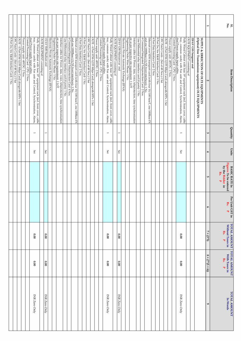
Sl.
No
.
Item
De
scriptio
nQ
ua
ntity
Un
itsB
AS
IC R
AT
E In
Fig
ure
s To
be
en
tere
d
by
the
Bid
de
r in
Rs. P
Pe
r Un
it GS
T in
Rs. P
TO
TA
L A
MO
UN
T
With
ou
t Ta
xe
s in
Rs. P
TO
TA
L A
MO
UN
T
With
Ta
xe
s in
Rs. P
TO
TA
L A
MO
UN
T
In W
ord
s
12
34
56
7 =
(3*5
)8
= (7
*(5 +
6))
9
42
SU
PP
LY
& E
RR
EC
TIO
N O
F O
LT
E E
QU
IPM
EN
TS
(Op
tical lin
e T
ran
smissio
n e
qu
ipm
en
t) OL
TE
EQ
UIP
ME
NT
S
43
22
0 k
V G
SS
Sa
ng
an
er e
nd
44
OL
TE
EQ
UIP
ME
NT
con
sisting
of
45
Fu
llyW
iredC
ab
inet
with
ba
se1
9"
equ
ipm
ent
rack
(incl.
fron
tco
ver,
cab
le
tray
,co
mm
on
card
s)w
ithF
an
un
ita
nd
Co
ntro
l,S
yn
chro
nisa
tion
,A
larm
,
du
al P
ow
er sup
ply
inp
ut ca
bles.
1S
et0
.00
0.0
0IN
R Z
ero O
nly
46
Cen
tral P
rocessin
g C
ard
- CP
U- 2
No
s.
47
Po
wer su
pp
ly u
nit -4
8V
DC
- 2 N
os.
48
OL
TE
- 4 P
ort S
TM
-1(1
55
Mb
ps C
ard
) alo
ng
with
SF
Ps- 1
Set
49
OF
C P
atch
Co
rds - (S
et of 4
8 N
os.)-1
Set
50
8 P
ort 2
w/
4w
E&
M In
terface C
ard
- 1 N
o.
51
4 P
ort D
ata
Interfa
ce Ca
rd- 2
No
s.
52
Eth
ernet
ov
erS
DH
tran
spo
rtca
rd(w
ithfo
ur
10
/1
00
ba
seT,
on
e1
00
Ba
se-FX
an
d o
ne 1
00
0B
ase-L
X/
SX
fron
t interfa
ces)- 1 N
o.
53
4 C
om
ma
nd
Integ
rated
Telep
rotectio
n C
ard
- 2 N
os.
54
Lin
e Differen
tial rela
y in
terface ca
rd (4
po
rts)- 1 N
o.
55
Interfa
ceca
bles
for
Po
wer,
da
ta,
vo
ice,telep
rotectio
n,
time
syn
chro
nisa
tion
etc as p
er respectiv
e site requ
iremen
t- 1 L
OT
56
En
gin
eering
Ord
er Wire P
ho
ne- 1
No
.
57
Electro
nic P
riva
te Au
tom
atic E
xch
an
ge (E
PA
X)
58
22
0 k
V G
SS
Ma
nsa
rov
ar en
d1
Set
0.0
00
.00
INR
Zero
On
ly
59
OL
TE
EQ
UIP
ME
NT
con
sisting
of
60
Fu
llyW
iredC
ab
inet
with
ba
se1
9"
equ
ipm
ent
rack
(incl.
fron
tco
ver,
cab
le
tray
,co
mm
on
card
s)w
ithF
an
un
ita
nd
Co
ntro
l,S
yn
chro
nisa
tion
,A
larm
,
du
al P
ow
er sup
ply
inp
ut ca
bles.
1S
et0
.00
0.0
0IN
R Z
ero O
nly
61
Cen
tral P
rocessin
g C
ard
- CP
U- 2
No
s.
62
Po
wer su
pp
ly u
nit -4
8V
DC
- 2 N
os.
63
OL
TE
- 4 P
ort S
TM
-1(1
55
Mb
ps C
ard
) alo
ng
with
SF
Ps- 1
Set
64
OF
C P
atch
Co
rds - (S
et of 4
8 N
os.)-1
Set
65
8 P
ort 2
w/
4w
E&
M In
terface C
ard
- 1 N
o.
66
4 P
ort D
ata
Interfa
ce Ca
rd- 2
No
s.
67
Eth
ernet
ov
erS
DH
tran
spo
rtca
rd(w
ithfo
ur
10
/1
00
ba
seT,
on
e1
00
Ba
se-FX
an
d o
ne 1
00
0B
ase-L
X/
SX
fron
t interfa
ces)- 1 N
o.
68
4 C
om
ma
nd
Integ
rated
Telep
rotectio
n C
ard
- 4 N
os.
69
Lin
e Differen
tial rela
y in
terface ca
rd (4
po
rts)- 1 N
o.
70
Interfa
ceca
bles
for
Po
wer,
da
ta,
vo
ice,telep
rotectio
n,
time
syn
chro
nisa
tion
etc as p
er respectiv
e site requ
iremen
t- 1 L
OT
71
En
gin
eering
Ord
er Wire P
ho
ne- 1
No
.
72
Electro
nic P
riva
te Au
tom
atic E
xch
an
ge (E
PA
X)
73
13
2 k
V S
MS
Sta
diu
m en
d1
Set
0.0
00
.00
INR
Zero
On
ly
74
OL
TE
EQ
UIP
ME
NT
con
sisting
of
75
Fu
llyW
iredC
ab
inet
with
ba
se1
9"
equ
ipm
ent
rack
(incl.
fron
tco
ver,
cab
le
tray
,co
mm
on
card
s)w
ithF
an
un
ita
nd
Co
ntro
l,S
yn
chro
nisa
tion
,A
larm
,
du
al P
ow
er sup
ply
inp
ut ca
bles.
1S
et0
.00
0.0
0IN
R Z
ero O
nly
76
Cen
tral P
rocessin
g C
ard
- CP
U- 2
No
s.
77
Po
wer su
pp
ly u
nit -4
8V
DC
- 2 N
os.
78
OL
TE
- 4 P
ort S
TM
-1(1
55
Mb
ps C
ard
) alo
ng
with
SF
Ps- 1
Set
79
OF
C P
atch
Co
rds - (S
et of 4
8 N
os.)-1
Set
80
8 P
ort 2
w/
4w
E&
M In
terface C
ard
- 1 N
o.
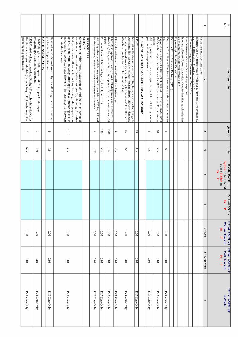
Sl.
No
.
Item
De
scriptio
nQ
ua
ntity
Un
itsB
AS
IC R
AT
E In
Fig
ure
s To
be
en
tere
d
by
the
Bid
de
r in
Rs. P
Pe
r Un
it GS
T in
Rs. P
TO
TA
L A
MO
UN
T
With
ou
t Ta
xe
s in
Rs. P
TO
TA
L A
MO
UN
T
With
Ta
xe
s in
Rs. P
TO
TA
L A
MO
UN
T
In W
ord
s
12
34
56
7 =
(3*5
)8
= (7
*(5 +
6))
9
81
4 P
ort D
ata
Interfa
ce Ca
rd- 2
No
s.
82
Eth
ernet
ov
erS
DH
tran
spo
rtca
rd(w
ithfo
ur
10
/1
00
ba
seT,
on
e1
00
Ba
se-FX
an
d o
ne 1
00
0B
ase-L
X/
SX
fron
t interfa
ces)- 1 N
o.
83
4 C
om
ma
nd
Integ
rated
Telep
rotectio
n C
ard
- 2 N
os.
84
Lin
e Differen
tial rela
y in
terface ca
rd (4
po
rts)- 1 N
o.
85
Interfa
ceca
bles
for
Po
wer,
da
ta,
vo
ice,telep
rotectio
n,
time
syn
chro
nisa
tion
etc as p
er respectiv
e site requ
iremen
t- 1 L
OT
86
En
gin
eering
Ord
er Wire P
ho
ne- 1
No
.
87
Electro
nic P
riva
te Au
tom
atic E
xch
an
ge (E
PA
X)
88
Electro
nic
Pu
shB
utto
nT
eleph
on
eIn
strum
ents
with
requ
ireda
ccessories
etc.1
Set
0.0
00
.00
INR
Zero
On
ly
89
La
pto
p(C
ore
2D
uo
,2
.4G
Hz
,1
5"T
FT
,1
60
GB
HD
D,
2G
BR
AM
,D
VD
R/
W)
with
con
figu
ratio
nS
oftw
are
for
all
Co
mm
un
icatio
nE
qu
ipm
ents
as
offered
10
No
s.0
.00
0.0
0IN
R Z
ero O
nly
90
Ad
d:
An
yo
ther
itemb
idd
erm
ay
requ
ireto
com
plete
the
OL
TE
Sy
stema
s
per sp
ecificatio
n req
uirem
ents
1N
o.
0.0
00
.00
INR
Zero
On
ly
91
OP
GW
/OF
C A
ND
HA
RD
WA
RE
FIT
TIN
G/ A
CC
ES
SO
RIE
S
92
OP
G W
ire1
5k
m0
.00
0.0
0IN
R Z
ero O
nly
93
Insta
llatio
nH
ard
wa
refo
ra
bo
ve
OP
GW
,In
clud
ing
all
cab
lesF
itting
s&
Accesso
rieslik
esu
spen
sion
clam
ps,
tensio
ncla
mp
s.v
ibra
tion
da
mp
ers,
earth
ing
clam
ps,d
ow
nlea
dcla
mp
s,Inlin
esp
liceen
clou
res/Jo
int
Bo
xes
etc
(On
e Set is co
mp
lete for 1
km
Tra
nsm
ission
Lin
e)
15
Set
0.0
00
.00
INR
Zero
On
ly
94
Fib
re Op
tic Distrib
utio
n F
ram
e/P
an
el (FO
DP
) ind
oo
r typ
e4
No
s.0
.00
0.0
0IN
R Z
ero O
nly
95
Fib
reO
ptic
Ap
pro
ach
Ca
ble
(OF
AC
)in
clud
ing
insta
llatio
nh
ard
wa
relik
e
tiles/clip
s/clea
ts,co
un
dits,
du
ctssu
pp
orts,
fitting
s,a
ccessories
etc.(2
4
Fib
er)
10
00
mtr
0.0
00
.00
INR
Zero
On
ly
96
Pre C
on
necto
rized
Op
tic Fib
er Pig
tails (F
C-P
C T
yp
e- 3 m
tr)1
20
No
s.0
.00
0.0
0IN
R Z
ero O
nly
97
Ad
d:
An
yo
ther
itemb
idd
erm
ay
requ
ireto
com
plete
the
OP
GW
/O
FC
an
d
Ha
rdw
are fittin
gs/
accesso
ries as p
er specifica
tion
requ
iremen
ts1
LO
T0
.00
0.0
0IN
R Z
ero O
nly
98
SE
RV
ICE
PA
RT
SU
RV
EY
99
Su
rvey
ing
of
cab
lero
ute,
exca
va
tion
of
trial
ho
lesa
sp
erfield
requ
iremen
t,p
repa
ratio
no
fca
ble
rou
tep
rofile,
dra
win
gs
for
cab
le
lay
ing
,fin
al
rou
tea
llign
men
t,m
ark
ing
lines
&g
rad
es,p
repa
ratio
n
of
fina
lca
ble
rou
ted
raw
ing
sa
ftera
pp
rov
al
&p
repa
ring
bill
of
ma
terials
for
com
plete
rou
tesh
ow
nin
the
dra
win
gs
i.e.b
etween
termin
al su
bsta
tion
s
1.5
km
0.0
00
.00
INR
Zero
On
ly
10
0E
va
lua
tion
of
therm
al
resistivity
of
soil
alo
ng
the
cab
lero
ute
(as
per tech
nica
l specifica
tion
).1
LS
0.0
00
.00
INR
Zero
On
ly
10
1C
AB
LE
INS
TA
LL
AT
ION
10
21
32
kV
, Sin
gle C
ore,1
20
0 S
q. m
m X
LP
E C
op
per C
ab
le as p
er
foreg
oin
g sp
ecificatio
n req
uirem
ents
9k
m0
.00
0.0
0IN
R Z
ero O
nly
10
31
45
kV
rated
vo
ltag
e prem
old
ed S
traig
ht T
hro
ug
h Jo
int su
itab
le for
the a
bo
ve u
nd
ergro
un
d ca
ble (fo
r cab
le leng
th 1
20
0 m
eters each
) as
per fo
rego
ing
specifica
tion
6N
os.
0.0
00
.00
INR
Zero
On
ly

Sl.
No
.
Item
De
scriptio
nQ
ua
ntity
Un
itsB
AS
IC R
AT
E In
Fig
ure
s To
be
en
tere
d
by
the
Bid
de
r in
Rs. P
Pe
r Un
it GS
T in
Rs. P
TO
TA
L A
MO
UN
T
With
ou
t Ta
xe
s in
Rs. P
TO
TA
L A
MO
UN
T
With
Ta
xe
s in
Rs. P
TO
TA
L A
MO
UN
T
In W
ord
s
12
34
56
7 =
(3*5
)8
= (7
*(5 +
6))
9
10
41
45
kV
rated
vo
ltag
e prem
old
ed S
traig
ht T
hro
ug
h Jo
int (w
ith
pro
visio
n fo
r shea
th sep
ara
tion
for cro
ss bo
nd
ing
) suita
ble fo
r the
ab
ov
e un
derg
rou
nd
cab
le (for ca
ble len
gth
12
00
meters ea
ch) a
s
per fo
rego
ing
specifica
tion
6N
os.
0.0
00
.00
INR
Zero
On
ly
10
51
45
kV
rated
vo
ltag
e prem
old
ed o
utd
oo
r end
termin
atio
n k
it
com
plete w
ith a
ccessories su
itab
le for th
e ab
ov
e un
derg
rou
nd
cab
le an
d su
itab
le for term
ina
tion
in O
utd
oo
r typ
e switch
ya
rd a
s
per th
e requ
iremn
t of fo
rego
ing
specifica
tion
12
No
s.0
.00
0.0
0IN
R Z
ero O
nly
10
6S
olid
bo
nd
ing
Lin
k b
ox
with
Lin
k p
lates, b
on
din
g &
gro
un
din
g
cab
le com
plete w
ith o
ther a
ssocia
ted a
ccessories fo
r 1-p
ha
se 1
2N
os.
0.0
00
.00
INR
Zero
On
ly
10
7C
ross b
on
din
g L
ink
bo
x, C
o-a
xia
l bo
nd
ing
cab
le, Sh
eath
Vo
ltag
e
Lim
iters (SV
L) co
mp
lete with
oth
er asso
ciated
accesso
ries for ea
ch
3-p
ha
se circuit
2S
et0
.00
0.0
0IN
R Z
ero O
nly
10
8G
alv
an
ized
Steel S
up
po
rting
Stru
ctures a
lon
gw
ith cla
mp
s,
con
necto
rs, nu
t-bo
lts, wa
shers, fo
un
da
tion
bo
lts etc. for O
utd
oo
r
13
2 k
V C
ab
le end
termin
atio
ns (a
com
po
site structu
re to m
ou
nt
link
bo
xes a
nd
the ca
ble en
d term
ina
tion
s) for ea
ch p
ha
se
6S
et0
.00
0.0
0IN
R Z
ero O
nly
10
9G
alv
an
ized
Steel su
pp
ortin
g stru
ctures /
Arra
ng
emen
t, Ga
ntry
structu
res, La
dd
ers etc. Fo
r Su
itab
le an
d sa
fe termin
atio
ns o
f XL
PE
cab
le from
Term
ina
l To
wers m
ain
tain
ing
statu
tory
cleara
nces a
nd
safety
as p
er IE R
ules
1L
ot
0.0
00
.00
INR
Zero
On
ly
11
01
32
KV
class o
f 12
0 K
V ra
ting
ligh
tenin
g A
rrester (LA
)6
No
s0
.00
0.0
0IN
R Z
ero O
nly
11
1E
arth
ing
Ma
terial in
clud
ing
cast iro
n p
ipes w
ith su
itab
le clam
ps,
cha
rcol, co
mm
on
salt etc. co
mp
lete set for ea
ch C
ab
le Circu
it.2
Set
0.0
00
.00
INR
Zero
On
ly
11
2T
ermin
al co
nn
ector su
itab
le for A
CS
R P
an
ther o
n th
e item N
o. 4
to
con
nect ca
ble en
d term
ina
tion
to O
utd
oo
r Sw
itchy
ard
Eq
uip
men
t.1
2N
os.
0.0
00
.00
INR
Zero
On
ly
11
3T
ermin
al co
nn
ector su
itab
le for A
CS
R P
an
ther fo
r 13
2 K
V L
A to
con
nect ca
ble en
d term
ina
tion
.6
No
s 0
.00
0.0
0IN
R Z
ero O
nly
11
4C
ha
rges fo
r con
du
cting
pre-co
mm
ission
ing
test as p
er specifica
tion
an
d su
ccessful co
mm
ission
ing
of circu
its2
LS
0.0
00
.00
INR
Zero
On
ly
11
5O
ptica
l Fib
er Ca
ble a
nd
asso
ciated
accesso
ries/item
s as p
er
specifica
tion
(12
F)
3K
m0
.00
0.0
0IN
R Z
ero O
nly
11
6A
dd
: An
y o
ther item
bid
der m
ay
requ
ired to
com
plete th
e cab
le
system
as p
er specifica
tion
requ
iremen
ts.1
Lo
t0
.00
0.0
0IN
R Z
ero O
nly
11
7C
AB
LE
INS
TA
LL
AT
ION
11
8C
uttin
gB
lack
Bitu
men
surfa
ceu
pto
an
yd
epth
inclu
din
ga
llla
yers
of
crust
for
lay
ing
Po
wer
Ca
bles
etc,sta
kin
go
fu
seful
ma
terial
an
d
disp
osa
lo
fsu
rplu
sd
ebries
inclu
din
ga
lllea
ds
inclu
din
g
ba
rricad
ing
,p
rov
idin
gd
an
ger
bo
ard
/d
iversio
nb
oa
rd,
ligh
ting
,
reflectors etc.
5,000 S
qm
0.0
00
.00
INR
Zero
On
ly
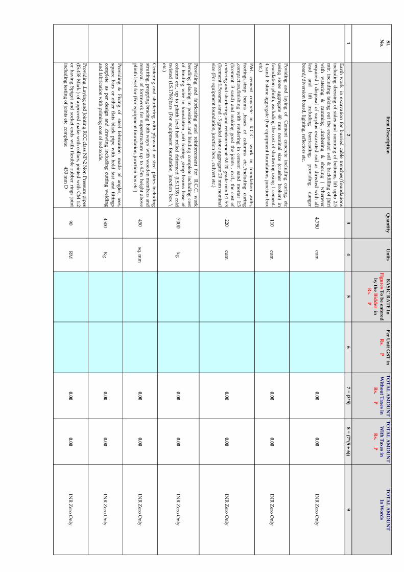
Sl.
No
.
Item
De
scriptio
nQ
ua
ntity
Un
itsB
AS
IC R
AT
E In
Fig
ure
s To
be
en
tere
d
by
the
Bid
de
r in
Rs. P
Pe
r Un
it GS
T in
Rs. P
TO
TA
L A
MO
UN
T
With
ou
t Ta
xe
s in
Rs. P
TO
TA
L A
MO
UN
T
With
Ta
xe
s in
Rs. P
TO
TA
L A
MO
UN
T
In W
ord
s
12
34
56
7 =
(3*5
)8
= (7
*(5 +
6))
9
11
9E
arth
wo
rkin
exca
va
tion
for
bu
rriedca
ble
trench
es/fo
un
da
tion
s
inclu
din
gd
ressing
of
sides
an
dra
mm
ing
of
bo
ttom
s,lift
up
to2
.5
mtr.
inclu
din
gta
kin
go
ut
the
exca
va
tedso
il&
ba
ckfillin
go
fjh
iri
with
wa
tering
&ra
mm
ing
,timb
ering
&sh
orin
g(
wh
erever
requ
ired)
disp
osa
lo
fsu
rplu
sex
cav
ated
soil
as
directed
with
all
lead
an
dlift
inclu
din
gb
arrica
din
g,
pro
vid
ing
da
ng
er
bo
ard
/d
iversio
n b
oa
rd, lig
htin
g, reflecto
rs etc.
4,750 cu
m0
.00
0.0
0IN
R Z
ero O
nly
12
0P
ov
idin
ga
nd
lay
ing
of
Cem
ent
con
cretein
clud
ing
curin
g,
etc
usin
gsto
ne
ag
greg
ate
40
mm
no
min
al
size
(crush
erb
rok
en)
in
fou
nd
atio
np
linth
,ex
clud
ing
the
cost
of
shu
ttering
usin
g1
cemen
t:
4sa
nd
:8
ston
ea
gg
rega
te(F
or
equ
ipm
ent
fou
nd
atio
n,
jun
ction
bo
x
etc.)
11
0cu
m0
.00
0.0
0IN
R Z
ero O
nly
12
1P
&L
cemen
tco
ncrete
inR
.C.C
.w
ork
info
un
da
tion
,rafts,
foo
ting
s,strap
bea
ms
,ba
seso
fco
lum
ns
etc.,'inclu
din
gcu
ring
,com
pa
ction
,finish
ing
with
rend
ering
incem
ent
san
dm
orta
r1
:3
(1cem
ent
:3sa
nd
)a
nd
ma
kin
gg
oo
dth
ejo
ints
,ex
cl.,th
eco
sto
f
centerin
ga
nd
shu
ttering
an
drein
forcem
ent
:M-2
0g
rad
em
ix1
:1.5
:3
(1cem
ent:1
.5co
arse
san
d:
3g
rad
edsto
ne
ag
greg
ate
20
mm
no
min
al
size (F
or eq
uip
men
t fou
nd
atio
n, ju
nctio
n b
ox
, culv
ert etc.)
22
0cu
m0
.00
0.0
0IN
R Z
ero O
nly
12
2P
rov
idin
ga
nd
fab
ricatin
gsteel
reinfo
rcemen
tfo
rR
.C.C
.w
ork
ben
din
g,p
lacin
gin
po
sition
an
db
ind
ing
com
plete
inclu
din
gco
st
of
bin
din
gw
irein
fou
nd
atio
n,ra
ftfo
otin
g,stra
pb
eam
sb
ase
of
colu
mn
etc.,u
pto
plin
thlev
elh
ot
rolled
defo
rmed
(I.S.1
13
9)
cold
twisted
(I.S.1
78
6)b
ars
(Fo
req
uip
men
tfo
un
da
tion
,ju
nctio
nb
ox
\
etc.)
7000k
g0
.00
0.0
0IN
R Z
ero O
nly
12
3C
enterin
ga
nd
shu
ttering
with
ply
wo
od
or
steelp
lates
inclu
din
g
struttin
g,
pro
pp
ing
bra
cing
bo
thw
ay
sw
ithw
oo
den
mem
bers
an
d
remo
va
lo
ffo
rmw
ork
for
sup
erstructu
reu
pto
4.5
mh
eigh
ta
bo
ve
plin
th lev
el for (F
or eq
uip
men
t fou
nd
atio
n, ju
nctio
n b
ox
etc.) 4
50
sq. m
m0
.00
0.0
0IN
R Z
ero O
nly
12
4P
rov
idin
g&
Fix
ing
of
steelfeb
ricatio
nm
ad
eo
fa
ng
les,tees,
squ
are
ba
rso
ro
ther
flats
bla
ckp
ipe
with
ho
ldfa
sta
nd
fitting
s
com
plete
as
per
desig
na
nd
dra
win
gin
clud
ing
cuttin
gw
eldin
g
an
d fa
brica
tion
with
prim
ing
coa
t of red
ox
ide.
45
00
Kg
0.0
00
.00
INR
Zero
On
ly
12
5P
rov
idin
g,L
ay
ing
an
dJo
intin
gR
CC
class
NP
-2N
on
Pressu
rep
ipes
(IS:4
58
Ma
rk)
of
ap
pro
ved
ma
ke
with
colla
rs,jo
inted
with
CM
1:2
or
ha
vin
gS
pig
ot
an
dso
cket
end
sw
ithflex
ible
rub
ber
ring
sjo
int
inclu
din
g testin
g o
f join
ts etc. com
plete: 4
50
mm
D9
0R
M0
.00
0.0
0IN
R Z
ero O
nly

Sl.
No
.
Item
De
scriptio
nQ
ua
ntity
Un
itsB
AS
IC R
AT
E In
Fig
ure
s To
be
en
tere
d
by
the
Bid
de
r in
Rs. P
Pe
r Un
it GS
T in
Rs. P
TO
TA
L A
MO
UN
T
With
ou
t Ta
xe
s in
Rs. P
TO
TA
L A
MO
UN
T
With
Ta
xe
s in
Rs. P
TO
TA
L A
MO
UN
T
In W
ord
s
12
34
56
7 =
(3*5
)8
= (7
*(5 +
6))
9
12
6P
rov
idin
g&
Fix
ing
of
Rein
forced
Ferro
Cem
ent
Ca
ble
Tren
ch
Co
vers
desig
ned
for
'A'&
'AA
'loa
din
gd
uly
ma
rked
on
cov
erw
ith
ad
equ
ate
reinfo
rcemen
th
av
ing
thick
ness
75
mm
to1
00
mm
an
ti
corro
sive
bitu
men
pa
ined
MS
pla
teR
ima
nd
MS
lifting
ho
ok
s
ad
mix
tures
like
pla
sticizer
bo
nd
-imp
rov
ing
com
po
un
d,
shrin
ka
ge
resistan
ceco
mp
ou
nd
,a
bra
sion
resistan
tco
mp
letea
sp
era
pp
rov
ed
desig
n ( F
or ca
ble jo
int b
ox
) (Fo
r an
y sp
an
)
10
0S
qm
0.0
00
.00
INR
Zero
On
ly
12
7P
rov
idin
g&
La
yin
gH
DP
Ep
ipe
hea
vy
du
tyo
fa
pp
rov
edm
ak
e
join
ted w
ith so
lven
t cemen
t
12
8(i) 2
50
mm
dia
.1
20
RM
0.0
00
.00
INR
Zero
On
ly
12
9(ii) 1
00
mm
dia
. Fo
r Op
tical F
ibre C
ab
le1
.5k
M0
.00
0.0
0IN
R Z
ero O
nly
13
0S
up
ply
an
dla
yin
gin
terlo
ckin
gR
CC
cab
leco
vers
as
per
ap
pro
ved
dra
win
g
1,400 S
qm
0.0
00
.00
INR
Zero
On
ly
13
1su
pp
ly,
sprea
din
go
fclea
nriv
ersa
nd
inth
eca
ble
trench
an
dca
ble
join
t pit a
s per sp
ecificatio
n.
16
0C
um
0.0
00
.00
INR
Zero
On
ly
13
2P
rov
idin
g&
Fix
ing
Ca
ble
Ro
ute
Ma
rker
alo
ng
the
rou
teo
fca
ble
at
the sp
acin
g o
f 50
meter etc. a
s per d
raw
ing
an
d site req
uirem
ent.
60
No
s.0
.00
0.0
0IN
R Z
ero O
nly
13
3F
ixin
g a
nd
Insta
llatio
n o
f Ea
rthin
g M
ateria
l inclu
din
g ca
st iron
pip
es with
suita
ble cla
mp
s, cha
rcol, co
mm
on
salt etc. co
mp
lete set
for ea
ch 3
ph
ase C
ircuit( C
kt-I +
1 sp
are).
1S
et0
.00
0.0
0IN
R Z
ero O
nly
13
4A
dd
: An
y o
ther item
bid
der m
ay
requ
ire to co
mp
lete the C
ivil
wo
rks a
s per sp
ecificatio
n req
uirem
ents
1L
S0
.00
0.0
0IN
R Z
ero O
nly
13
5
Setttin
g o
f stub
s/co
ncretin
g/
tow
er erection
/m
ak
ing
arra
ng
emen
t
for term
ina
tion
of ca
ble,d
estring
ing
of co
nd
ucto
r D/
C lin
e(1.5
Km
s)/ ea
rthw
ire,dism
an
tling
of to
wers/
steel structu
res etc an
d
dep
ositin
g th
e dism
an
tled m
ateria
l in R
VP
N sto
res
1L
S0
.00
0.0
0IN
R Z
ero O
nly
13
6D
isme
ntle
d M
ate
rial
13
71
32
KV
D/C
sup
er stru
cture
13
8 (1
)To
wer ty
pe "A
" 2
NO
.0
.00
0.0
0IN
R Z
ero O
nly
13
9(2
)To
wer ty
pe "B
"1
NO
.0
.00
0.0
0IN
R Z
ero O
nly
14
0(2
)To
wer ty
pe "C
" 1
NO
.0
.00
0.0
0IN
R Z
ero O
nly
14
13
mtr. E
xtn
. 13
2K
V D
/C
To
wer
14
2(1
) To
wer ty
pe "A
"1
No
.0
.00
0.0
0IN
R Z
ero O
nly
14
3(2
) To
wer ty
pe "C
"1
No
.0
.00
0.0
0IN
R Z
ero O
nly
14
41
32
KV
D/
C N
arro
w b
ase to
wers
14
5(1
) To
wer ty
pe"C
"2
No
.0
.00
0.0
0IN
R Z
ero O
nly
14
63
mtr. E
xtn
. 13
2K
V D
/C
Na
rrow
ba
se To
wer
14
7(1
) To
wer ty
pe "C
"1
No
.0
.00
0.0
0IN
R Z
ero O
nly
14
8H
ard
wa
re for A
CS
R P
an
ther C
on
du
ctor
14
9(1
) Do
ub
le Ten
sion
H/
W2
4S
et0
.00
0.0
0IN
R Z
ero O
nly
15
0(2
) Sin
gle T
ensio
n H
/W
51
Set
0.0
00
.00
INR
Zero
On
ly
15
1(3
) Sin
gle S
usp
ensio
n H
/W
2S
et0
.00
0.0
0IN
R Z
ero O
nly
15
2(4
) Do
ub
le Su
spen
sion
H/
W1
2S
et0
.00
0.0
0IN
R Z
ero O
nly
15
3C
on
du
ctor a
cc. Fo
r AC
SR
Pa
nth
er

Sl.
No
.
Item
De
scriptio
nQ
ua
ntity
Un
itsB
AS
IC R
AT
E In
Fig
ure
s To
be
en
tere
d
by
the
Bid
de
r in
Rs. P
Pe
r Un
it GS
T in
Rs. P
TO
TA
L A
MO
UN
T
With
ou
t Ta
xe
s in
Rs. P
TO
TA
L A
MO
UN
T
With
Ta
xe
s in
Rs. P
TO
TA
L A
MO
UN
T
In W
ord
s
12
34
56
7 =
(3*5
)8
= (7
*(5 +
6))
9
15
4(4
) P.A
. Ro
ds
12
Set
0.0
00
.00
INR
Zero
On
ly
15
5(5
) Vib
ratio
n D
am
per
69
No
.0
.00
0.0
0IN
R Z
ero O
nly
15
6H
ard
wa
re fo
r E/W
ire fo
r 7/3
.15
mm
15
7(1
) Stra
in A
ssemb
ly1
0N
o.
0.0
00
.00
INR
Zero
On
ly
15
8(2
) Su
spen
sion
Assem
bly
2N
o.
0.0
00
.00
INR
Zero
On
ly
15
9(3
) Vib
ratio
n D
am
per
10
No
.0
.00
0.0
0IN
R Z
ero O
nly
16
0A
CS
R P
an
ther C
on
du
ctor
9K
M0
.00
0.0
0IN
R Z
ero O
nly
16
1E
arth
Wire 7
/3
.15
mm
1.5
KM
0.0
00
.00
INR
Zero
On
ly
16
21
20
KN
Disc In
sula
tor
99
0N
O.
0.0
00
.00
INR
Zero
On
ly
16
37
0 K
N D
isc Insu
lato
r 2
34
NO
.0
.00
0.0
0IN
R Z
ero O
nly
16
4P
ipe ty
pe ea
rthin
g set
6S
ET
0.0
00
.00
INR
Zero
On
ly
16
5P
ha
se Pla
te6
SE
T0
.00
0.0
0IN
R Z
ero O
nly
16
6N
um
ber P
late
6N
O.
0.0
00
.00
INR
Zero
On
ly
16
7D
an
ger P
late
6N
O.
0.0
00
.00
INR
Zero
On
ly
16
8G
I Nu
t Bo
lt0
.21
00
MT
0.0
00
.00
INR
Zero
On
ly
16
9(1
)16
*35
0.3
00
0M
T0
.00
0.0
0IN
R Z
ero O
nly
17
0(2
)16
*40
0.1
30
0M
T0
.00
0.0
0IN
R Z
ero O
nly
17
1(3
)16
*45
0.1
00
0M
T0
.00
0.0
0IN
R Z
ero O
nly
17
2(4
)16
*50
0.1
50
0M
T0
.00
0.0
0IN
R Z
ero O
nly
17
3(5
)16
*55
0.1
40
0M
T0
.00
0.0
0IN
R Z
ero O
nly
17
4(6
)16
*60
0.0
25
0M
T0
.00
0.0
0IN
R Z
ero O
nly
17
5(7
)16
*65
0.1
50
0M
T0
.00
0.0
0IN
R Z
ero O
nly
17
6(8
)16
*70
0.0
04
0M
T0
.00
0.0
0IN
R Z
ero O
nly
17
7(9
)16
*75
0.0
50
0M
T0
.00
0.0
0IN
R Z
ero O
nly
17
8(1
0)1
6*8
00
.09
50
MT
0.0
00
.00
INR
Zero
On
ly
17
9(1
1)1
6*8
50
.07
90
MT
0.0
00
.00
INR
Zero
On
ly
18
0(5
)Sp
ring
Wa
sher
0.1
35
0M
T0
.00
0.0
0IN
R Z
ero O
nly
18
1(6
)Step
Bo
lt0
.13
50
MT
0.0
00
.00
INR
Zero
On
ly
18
2M
AIN
TE
NA
NC
E S
ER
VIC
ES
18
3M
AIN
TE
NA
NC
E S
ER
VIC
ES
(Th
ese cha
rges sh
all b
e ap
plica
ble
after th
e com
pletio
n o
f ga
ura
nteed
perfo
rma
nce p
eriod
of ca
ble
system
for 4
Yea
rs exclu
din
g o
f item /
ma
terial /
equ
ipm
ent
alrea
dy
cov
ered fo
r perfo
rma
nce g
au
ran
tee of 5
Yea
rs. Th
e cha
rges
sha
ll be p
ay
ble o
n a
ctua
ls)
18
4M
ain
tena
nce serv
ices per v
isit tow
ard
s an
y b
reak
do
wn
of ca
ble
system
, wh
ich in
lcud
es services o
f exp
ert eng
ineers, tech
nicia
ns,
alo
ng
with
necessa
ry to
ols /
tack
les, testing
equ
ipm
ents, fa
ult
loca
ting
equ
ipm
ents to
be d
etect the fa
ult a
nd
its suseq
uen
t,
rectificatio
ns, re-testin
g a
nd
restorin
g th
e electric sup
ply
thro
ug
h
cab
le system
.
1Jo
b0
.00
0.0
0IN
R Z
ero O
nly
To
tal in
Fig
ure
s0
.00
0.0
0IN
R Z
ero O
nly
Qu
ote
d R
ate
in W
ord
s
INR
Ze
ro O
nly