BFE25June.qxd (Page i) - The National Disability Authority
59
5 external detail design 88 Part three Buildings 5.5.3 Maintenance of pavements and roadways Work on pavements and roadways, such as the renewal of surfaces, of buried cables or pipework etc, can be small in extent and duration, but still present a hazard to passers-by, especially to people with visual impairments or using wheelchairs. Protection must be provided, ideally with a 1100mm high rigid hoarding, in a colour which contrasts with the surroundings, and which would resist toppling when walked into. Next best is the erection of close mesh, semi-rigid plastic netting, provided that it is properly secured. This can, however, cause di≤culties for people with visual impairments, as a long cane can catch in the netting.
-
Upload
khangminh22 -
Category
Documents
-
view
0 -
download
0
Transcript of BFE25June.qxd (Page i) - The National Disability Authority
5 external detail design
88
0 chapter title
89
Part threeBuildings
5.5.3 Maintenance of pavements and roadwaysWork on pavements and roadways, such as the renewal of surfaces, of
buried cables or pipework etc, can be small in extent and duration, but
still present a hazard to passers-by, especially to people with visual
impairments or using wheelchairs. Protection must be provided, ideally
with a 1100mm high rigid hoarding, in a colour which contrasts with the
surroundings, and which would resist toppling when walked into. Next
best is the erection of close mesh, semi-rigid plastic netting, provided
that it is properly secured. This can, however, cause di≤culties for people
with visual impairments, as a long cane can catch in the netting.
9190
6.1 Principles
Circulation throughout a building should be as simple as possible. The
journey from pavement or car park, right through to a specific room, should
be easy to follow and negotiate. This principle applies to all space en-route,
including the car park or pavement, the site itself, the entrance and
reception areas, corridors, stairs, lifts, toilets and specific rooms. It must
be assumed that not all users of a particular building will be familiar
with its layout.
Circulation areas should be spacious and well lit. They should be well
defined and di≠erentiated from work spaces or waiting areas. Floor
markings, screens, colours and finishes of floors, walls and ceilings, along
with di≠erent lighting patterns, will assist users in recognising distinct
areas and in orientating themselves within the building. Clear and com-
prehensive signage at appropriate points throughout the building will
assist people in locating specific areas or facilities. Similarly, doors and
doorways should be of adequate dimension and easily identified,
approached and operated.
Each storey of a building should be designed so as to allow independent
access and circulation by people with disabilities. Changes of level within
a storey should be avoided if at all possible. Where this is not possible in
an existing building, necessitating the incorporation of a ramp, passenger
lift or platform lift, the new element should be of adequate dimension and
detail, and located so as not to discriminate against someone who may be
forced to use it.
Buildings should be managed properly, so that circulation areas are not
used as storage areas, thereby reducing clear widths.
Building design
part threeBuildings
6

6 building design
93
6 building design
92
Adequate space is required for a wheelchair user to turn outside a door
in the event of the entrance being locked. This is particularly important
at the top of ramps and at entrances at the end of long passages. An
1800mm diameter circle inscribes the required space. Where an entrance
is at the top of a ramp, it is essential that there is adequate landing space
so that a wheelchair user does not have to open a door while trying not
to roll back down the ramp, !section 5.2.1.
Every accessible entrance must incorporate a flush threshold. This may
necessitate a creative approach to weatherproofing. A recessed entrance,
or the provision of a canopy, will do much to facilitate weatherproofing
and will also provide protection from rain for those waiting outside. The
recess or canopy should be a minimum of 1200mm deep and have clear
a head height of 2200–2500mm. Plan recessed doorways to allow a
wheelchair user 500mm clear space to approach the door handle. Provision
of drainage gullies can significantly reduce water penetration while not
inhibiting access.
ChecklistEntrances
• Provide directional signs towards the entrance.
• Make all entrances accessible.
• Where this is not possible in existing buildings, make the principal
entrance accessible.
• Avoid making only secondary entrances accessible.
• Provide separate pedestrian and goods entrances.
• Provide adequate lighting.
• Provide a canopy or door recess for people waiting to gain entrance.
• Identify the entrance by structure, colour, sound and/or tactile
di≠erentiation of the ground.
• Avoid sharp edges and hazardous projections.
• See guidance on door intercoms,!section 7.6.
6.2 Entrances
Every building entrance should be easy to locate. The route to the entrance
should be free of hazards such as changes in level, poorly located street
or garden furniture and branches or balconies overhanging less than
2200mm above the pavement. Doors and windows should not open out
onto pavements or circulation routes, !section 5.1.4.
The entrance should be clearly distinguishable from the rest of the
building. The door itself should contrast in colour from the surrounding
structure. For people with visual impairments, a change in surface texture
in the pavement will signal the entrance. Audio clues, such as a small
fountain or rustling plants, will also assist. Artificial lighting can highlight
the entrance to a building and make it more obvious at night-time for
everyone, but especially for those with impaired vision.
Provide generously-sized doorways,!sections 6.3 and 6.6, and ensure
that doors and their closing mechanisms do not require undue force to
operate. Revolving doors are not suitable for use by disabled people. Door
furniture should be easy to use,!section 8.4. Intercom systems should
incorporate visual indicators, such as a video monitor or flashing light, in
order to facilitate people with hearing di≤culties,!section 7.6. Door
furniture and intercoms should be located at an appropriate height,
!section 8.4.
Where underground car parking is provided, both the lift access and the
principal entry to the building from that storey should be accessible from
the car park. The principles outlined above should apply to the route
from the car to the entrances and lifts,!section 5.4.3.
In new buildings, the principal entrance or entrances must be fully
accessible to all. It is not acceptable that people with disabilities should
be required to use a secondary entrance. Secondary entrances should,
in any case, be fully accessible.
In existing buildings, site constraints may make it di≤cult to provide
independent access for people with physical disabilities to the main
entrance. All possibilities, including technical solutions such as platform
lifts,!section 6.7.5, should be considered in these circumstances. It may,
however, be necessary to use a secondary entrance as the principal access
for people with disabilities. If this is the case, the secondary entrance
should be used for general access and not just for wheelchair users.
It is never acceptable that a service entrance be the sole point of access
for people with disabilities. Discrimination of this nature would be unac-
ceptable in respect of any group.
Canopy overhead and1800mm diameter turning circle
figure 15 Space outside door
6 building design
95
6 building design
94
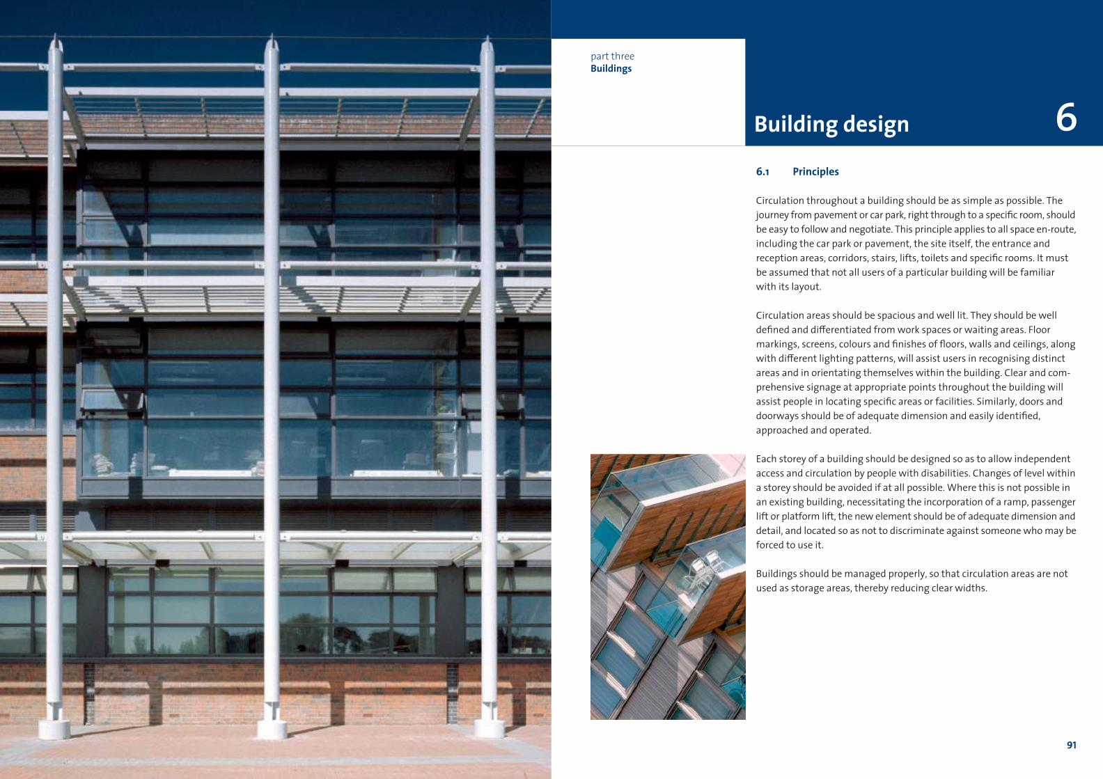
6.3 Entrance lobbies
Lobbies should be designed so as to be spacious, with adequate space for
wheelchair users to manoeuvre.
Entrance lobbies must be dimensioned in such a way that a wheelchair
user and a person assisting them can to move clear of the first door
before using the second. This requires a clear dimension between door
swings of 1600mm. At the same time, there must be room for another
person to pass by in the opposite direction. Matwells should be designed
so that the mat is flush with the surrounding floor surface. The mat should
not be compressible or have deep pile as this presents a di≤culty for
people using crutches or wheelchairs. There should be an unobstructed
dimension of at least 500mm, minimum 300mm, adjacent to the leading
edge of a single door. See opposite for examples of suitable entrance lob-
bies. For details of doors and doorways,!section 6.6.
ChecklistEntrance lobbies
• Provide minimum 1600mm long space for wheelchair users to clear
one door before approaching the next.
• Where winged doors are used, both sets should open in the same
direction.
• Provide 500mm approach to the door handle.
• Avoid matwells projecting over floor level.
• Avoid compressible or deep pile mats or floor finishes.
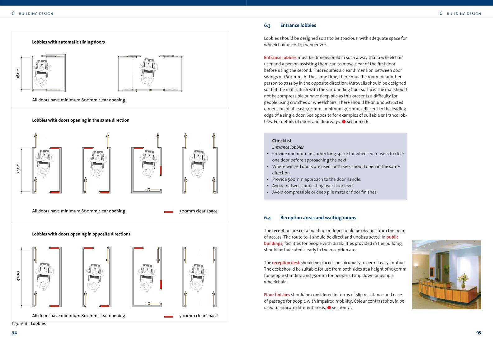
6.4 Reception areas and waiting rooms
The reception area of a building or floor should be obvious from the point
of access. The route to it should be direct and unobstructed. In publicbuildings, facilities for people with disabilities provided in the building
should be indicated clearly in the reception area.
The reception desk should be placed conspicuously to permit easy location.
The desk should be suitable for use from both sides at a height of 1050mm
for people standing and 750mm for people sitting down or using a
wheelchair.
Floor finishes should be considered in terms of slip resistance and ease
of passage for people with impaired mobility. Colour contrast should be
used to indicate di≠erent areas,!section 7.2.
Lobbies with doors opening in opposite directions
Lobbies with doors opening in the same direction
Lobbies with automatic sliding doors
1600
2400
3200
500mm clear spaceAll doors have minimum 800mm clear opening
500mm clear spaceAll doors have minimum 800mm clear opening
All doors have minimum 800mm clear opening
figure 16 Lobbies
6 building design
97
6 building design
96
ChecklistReception areas and waiting rooms
• Reception desk/counter to be placed conspicuously, to permit easy
location.
• Desk/counter to be suitable for use from both sides by people both
standing and seated.
• Desk to have counter loop fitted for communication with hearing
aid users.
• Public telephone to be at height suitable for all users and equipped
with inductive coupler,!section 8.3.
• For external communication, provide a TDD as well a standard tele-
phone,!section 8.3.
• Select seating for ease of use and comfort.
• Waiting area to have space for wheelchair users.
• Direction signs for people progressing further into the building to
be supported by tactile information such as raised print map, Braille
information etc,!section 8.2.2.
6.5 Horizontal circulation
6.5.1 GeneralHorizontal circulation spaces, whether along corridors or through open
plan areas, should be designed for ease of movement. Space requirements
vary for di≠erent people, depending on their circumstances. The space
requirements for a person using a wheelchair are greater than most. As
such, they are the most frequently cited and, if adhered to, they will suit
everybody else.
While people with disabilities need to have access to all areas of a building,
it is nonetheless appropriate, where practicable, to locate the principalspaces in a public building, such as conference or meeting rooms, at the
entrance level. This makes things easier for all, both in everyday use and
in an emergency, particularly for those with stamina and orientation
di≤culties.
Circulation routes should be clear of obstacles and have adequate head-
room. Where consistent with fire regulations, avoid the use of internal
lobbies and minimise the number of door sets along circulation routes.
Windows should not open into circulation areas so as to cause obstruction
or to reduce corridor width.
For discussion of finishes to floors and other surfaces,!sections 7.2 and 7.3.
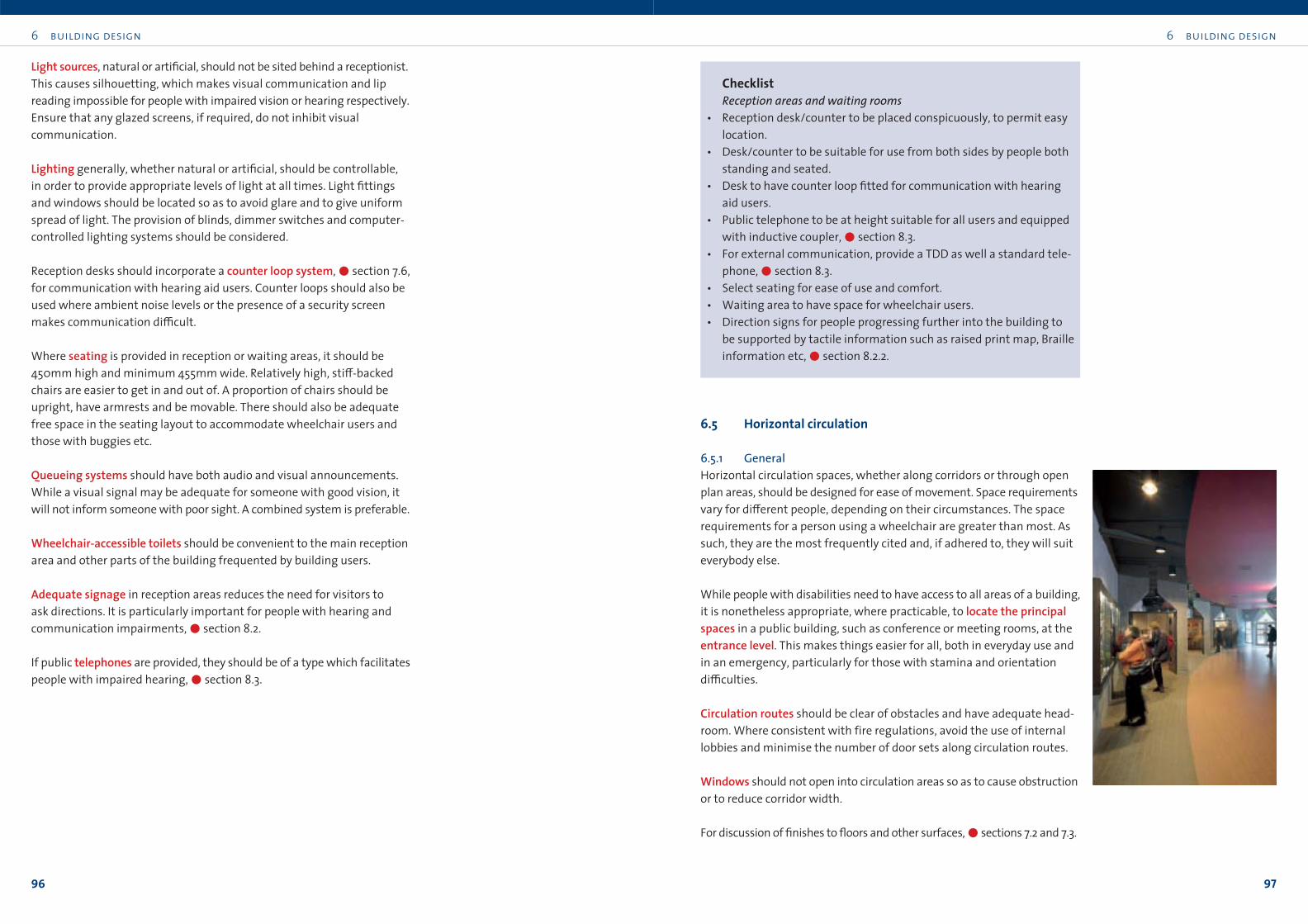
Light sources, natural or artificial, should not be sited behind a receptionist.
This causes silhouetting, which makes visual communication and lip
reading impossible for people with impaired vision or hearing respectively.
Ensure that any glazed screens, if required, do not inhibit visual
communication.
Lighting generally, whether natural or artificial, should be controllable,
in order to provide appropriate levels of light at all times. Light fittings
and windows should be located so as to avoid glare and to give uniform
spread of light. The provision of blinds, dimmer switches and computer-
controlled lighting systems should be considered.
Reception desks should incorporate a counter loop system,!section 7.6,
for communication with hearing aid users. Counter loops should also be
used where ambient noise levels or the presence of a security screen
makes communication di≤cult.
Where seating is provided in reception or waiting areas, it should be
450mm high and minimum 455mm wide. Relatively high, sti≠-backed
chairs are easier to get in and out of. A proportion of chairs should be
upright, have armrests and be movable. There should also be adequate
free space in the seating layout to accommodate wheelchair users and
those with buggies etc.
Queueing systems should have both audio and visual announcements.
While a visual signal may be adequate for someone with good vision, it
will not inform someone with poor sight. A combined system is preferable.
Wheelchair-accessible toilets should be convenient to the main reception
area and other parts of the building frequented by building users.
Adequate signage in reception areas reduces the need for visitors to
ask directions. It is particularly important for people with hearing and
communication impairments,!section 8.2.
If public telephones are provided, they should be of a type which facilitates
people with impaired hearing,!section 8.3.
6 building design
99
6 building design
98
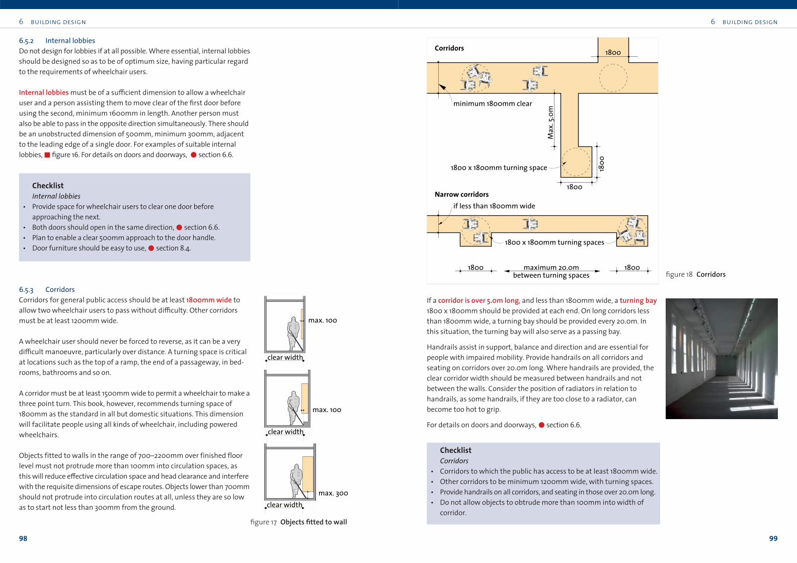
If a corridor is over 5.0m long, and less than 1800mm wide, a turning bay1800 x 1800mm should be provided at each end. On long corridors less
than 1800mm wide, a turning bay should be provided every 20.0m. In
this situation, the turning bay will also serve as a passing bay.
Handrails assist in support, balance and direction and are essential for
people with impaired mobility. Provide handrails on all corridors and
seating on corridors over 20.0m long. Where handrails are provided, the
clear corridor width should be measured between handrails and not
between the walls. Consider the position of radiators in relation to
handrails, as some handrails, if they are too close to a radiator, can
become too hot to grip.
For details on doors and doorways,!section 6.6.
ChecklistCorridors
• Corridors to which the public has access to be at least 1800mm wide.
• Other corridors to be minimum 1200mm wide, with turning spaces.
• Provide handrails on all corridors, and seating in those over 20.0m long.
• Do not allow objects to obtrude more than 100mm into width of
corridor.
6.5.2 Internal lobbiesDo not design for lobbies if at all possible. Where essential, internal lobbies
should be designed so as to be of optimum size, having particular regard
to the requirements of wheelchair users.
Internal lobbies must be of a su≤cient dimension to allow a wheelchair
user and a person assisting them to move clear of the first door before
using the second, minimum 1600mm in length. Another person must
also be able to pass in the opposite direction simultaneously. There should
be an unobstructed dimension of 500mm, minimum 300mm, adjacent
to the leading edge of a single door. For examples of suitable internal
lobbies,"figure 16. For details on doors and doorways, !section 6.6.
ChecklistInternal lobbies
• Provide space for wheelchair users to clear one door before
approaching the next.
• Both doors should open in the same direction,!section 6.6.
• Plan to enable a clear 500mm approach to the door handle.
• Door furniture should be easy to use,!section 8.4.
6.5.3 CorridorsCorridors for general public access should be at least 1800mm wide to
allow two wheelchair users to pass without di≤culty. Other corridors
must be at least 1200mm wide.
A wheelchair user should never be forced to reverse, as it can be a very
di≤cult manoeuvre, particularly over distance. A turning space is critical
at locations such as the top of a ramp, the end of a passageway, in bed-
rooms, bathrooms and so on.
A corridor must be at least 1500mm wide to permit a wheelchair to make a
three point turn. This book, however, recommends turning space of
1800mm as the standard in all but domestic situations. This dimension
will facilitate people using all kinds of wheelchair, including powered
wheelchairs.
Objects fitted to walls in the range of 700–2200mm over finished floor
level must not protrude more than 100mm into circulation spaces, as
this will reduce e≠ective circulation space and head clearance and interfere
with the requisite dimensions of escape routes. Objects lower than 700mm
should not protrude into circulation routes at all, unless they are so low
as to start not less than 300mm from the ground.
clear width
max. 100
max. 100
max. 300
clear width
clear width
figure 17 Objects fitted to wall
1800
1800
1800
Max
. 5.0
m
minimum 1800mm clear
Narrow corridors
Corridors
1800
1800 x 1800mm turning spaces
1800
if less than 1800mm wide
maximum 20.0mbetween turning spaces
1800 x 1800mm turning space
figure 18 Corridors
6 building design
101
6 building design
100
6.6.2 Entrance doorsThe clear opening width of a door at an entrance to a building must be at
least 800mm. Where there are double doors, at least the leading door
leaf must have a clear opening width of 800mm.
Revolving doors and turnstilesConventional revolving doors present considerable di≤culty for many
users. They are inaccessible for wheelchair users and can be hazardous
to people with visual impairments. Revolving doors should be avoided,
in favour of sliding or hinged doors. In existing buildings, revolving doors
should be removed.
Turnstiles are not suitable for people with impairments. Accordingly,
provide a clearly indicated accessible gate adjacent to the turnstile,
!section 9.9.
Powered doorsAutomatic doors make buildings easy to access for everybody, particularly
for people with impairments. They are particularly useful where a high
force would otherwise be required to open the door, such as a door to a
pressurised compartment of a building.
Powered doors can be of sliding or swing type. Sliding doors are preferable
to swing doors, as their action is less likely to block users passing through.
Such doors should be capable of manual operation in the event of power
failure.
Automatic operation: The door opening device should allow adequate time
for people who move slowly to pass through. Doors should remain open
for more than 3 seconds and require a maximum force of 6.75kg to resist
movement. To minimise confusion as people search for opening devices,
and to prevent surprise, automatic doors should be indicated as such.
Button control operation: Locate button controls on swing doors at an
accessible operation point, clear of the door swing.
Detailing: Powered doors can pose entrapment hazards. Sliding doors
can catch a limb or clothing against a stationary surface, while swing
doors can have a crushing e≠ect. The danger is lessened by reducing the
motive power to the minimum necessary. In addition, sliding doors can
be designed to slide into a recess, out of harm’s way.
Sensors should be provided to detect people of all shapes and sizes passing
through automatic doors to ensure that they do not close onto someone.
A continuous beam over the full height of the door will detect all obstruct-
ions. Avoid systems which detect obstructions only at specific heights.
6.6 Doors
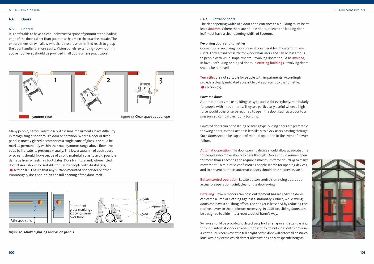
6.6.1 GeneralIt is preferable to have a clear unobstructed space of 500mm at the leading
edge of the door, rather than 300mm as has been the practice to date. The
extra dimension will allow wheelchair users with limited reach to grasp
the door handle far more easily. Vision panels, extending 500–1500mm
above floor level, should be provided in all doors where practicable.
Many people, particularly those with visual impairments, have di≤culty
in recognising a see-through door or partition. Where a door or fixed
panel is mostly glazed or comprises a single pane of glass, it should be
marked permanently within the 1200–1500mm range above floor level,
so as to indicate its presence visually. The lower 400mm of such doors
or screens should, however, be of a solid material, so as to avoid possible
damage from wheelchair footplates. Door furniture and, where fitted,
door closers should be suitable for use by people with disabilities,
!section 8.4. Ensure that any surface-mounted door closer or other
ironmongery does not inhibit the full opening of the door itself.
1 2 3
500mm clear
1500
500
Min. 400 solid
Permanentglass markings1200–1500mmover floor
figure 20 Marked glazing and vision panels
figure 19 Clear space at door ope
6 building design
103
6 building design
102
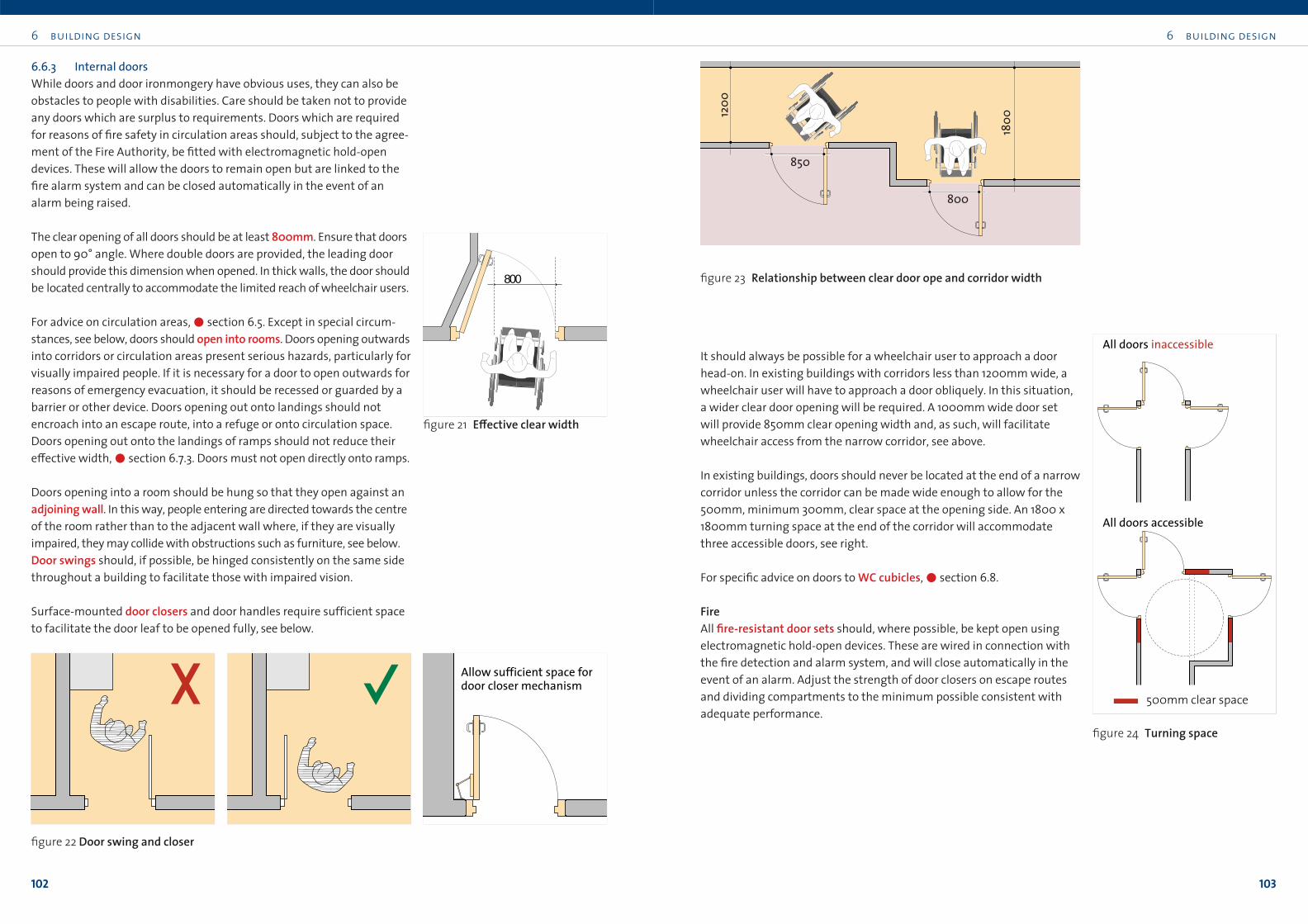
It should always be possible for a wheelchair user to approach a door
head-on. In existing buildings with corridors less than 1200mm wide, a
wheelchair user will have to approach a door obliquely. In this situation,
a wider clear door opening will be required. A 1000mm wide door set
will provide 850mm clear opening width and, as such, will facilitate
wheelchair access from the narrow corridor, see above.
In existing buildings, doors should never be located at the end of a narrow
corridor unless the corridor can be made wide enough to allow for the
500mm, minimum 300mm, clear space at the opening side. An 1800 x
1800mm turning space at the end of the corridor will accommodate
three accessible doors, see right.
For specific advice on doors to WC cubicles,!section 6.8.
FireAll fire-resistant door sets should, where possible, be kept open using
electromagnetic hold-open devices. These are wired in connection with
the fire detection and alarm system, and will close automatically in the
event of an alarm. Adjust the strength of door closers on escape routes
and dividing compartments to the minimum possible consistent with
adequate performance.
6.6.3 Internal doorsWhile doors and door ironmongery have obvious uses, they can also be
obstacles to people with disabilities. Care should be taken not to provide
any doors which are surplus to requirements. Doors which are required
for reasons of fire safety in circulation areas should, subject to the agree-
ment of the Fire Authority, be fitted with electromagnetic hold-open
devices. These will allow the doors to remain open but are linked to the
fire alarm system and can be closed automatically in the event of an
alarm being raised.
The clear opening of all doors should be at least 800mm. Ensure that doors
open to 90° angle. Where double doors are provided, the leading door
should provide this dimension when opened. In thick walls, the door should
be located centrally to accommodate the limited reach of wheelchair users.
For advice on circulation areas,!section 6.5. Except in special circum-
stances, see below, doors should open into rooms. Doors opening outwards
into corridors or circulation areas present serious hazards, particularly for
visually impaired people. If it is necessary for a door to open outwards for
reasons of emergency evacuation, it should be recessed or guarded by a
barrier or other device. Doors opening out onto landings should not
encroach into an escape route, into a refuge or onto circulation space.
Doors opening out onto the landings of ramps should not reduce their
e≠ective width,!section 6.7.3. Doors must not open directly onto ramps.
Doors opening into a room should be hung so that they open against an
adjoining wall. In this way, people entering are directed towards the centre
of the room rather than to the adjacent wall where, if they are visually
impaired, they may collide with obstructions such as furniture, see below.
Door swings should, if possible, be hinged consistently on the same side
throughout a building to facilitate those with impaired vision.
Surface-mounted door closers and door handles require sufficient space
to facilitate the door leaf to be opened fully, see below.
Allow sufficient space for door closer mechanism
figure 22 Door swing and closer
850
800
1200
1800
All doors accessible
All doors inaccessible
500mm clear space
figure 24 Turning space
figure 23 Relationship between clear door ope and corridor width800
figure 21 E≠ective clear width
6 building design
105
6 building design
104
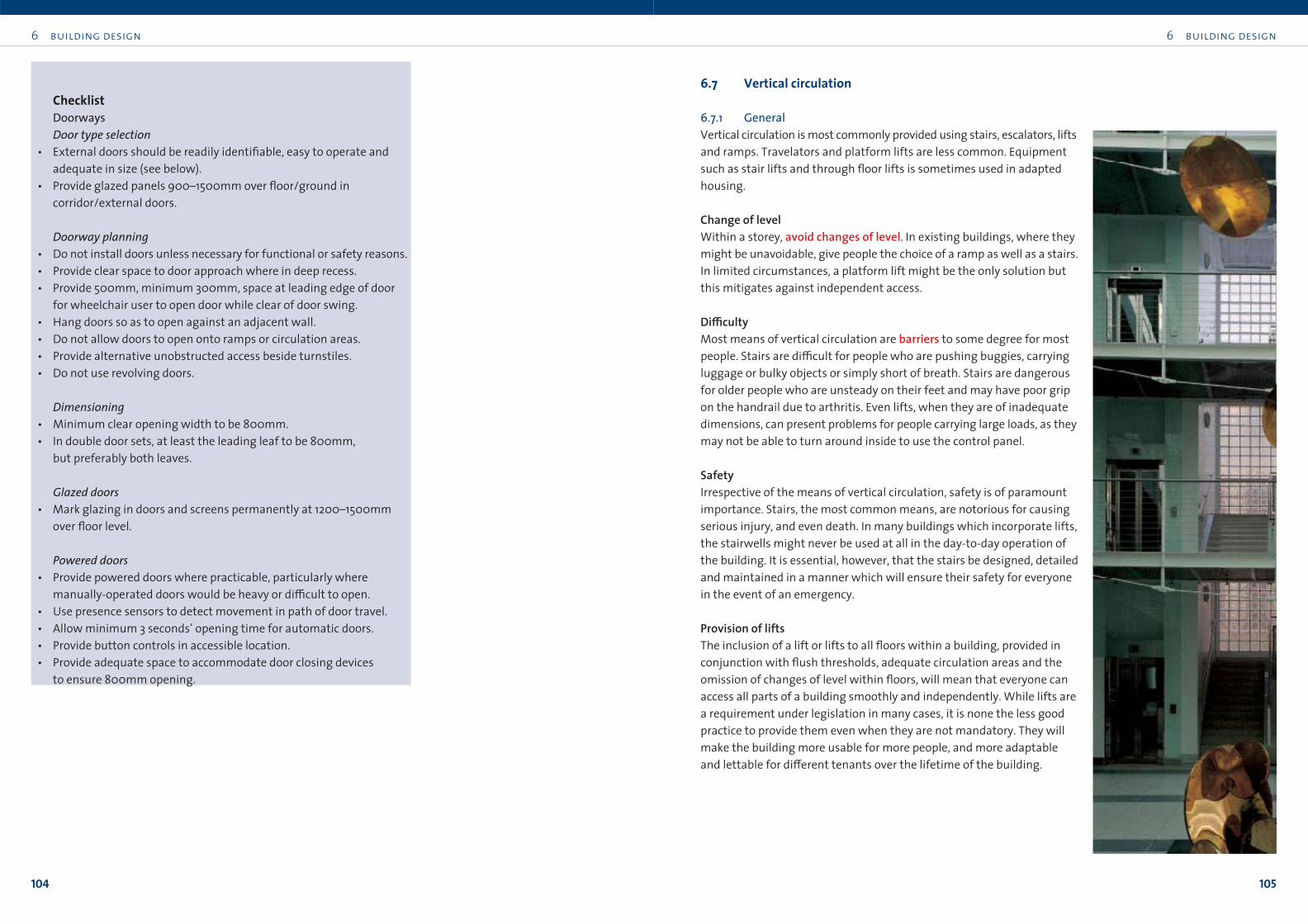
6.7 Vertical circulation
6.7.1 GeneralVertical circulation is most commonly provided using stairs, escalators, lifts
and ramps. Travelators and platform lifts are less common. Equipment
such as stair lifts and through floor lifts is sometimes used in adapted
housing.
Change of levelWithin a storey, avoid changes of level. In existing buildings, where they
might be unavoidable, give people the choice of a ramp as well as a stairs.
In limited circumstances, a platform lift might be the only solution but
this mitigates against independent access.
Di≤cultyMost means of vertical circulation are barriers to some degree for most
people. Stairs are di≤cult for people who are pushing buggies, carrying
luggage or bulky objects or simply short of breath. Stairs are dangerous
for older people who are unsteady on their feet and may have poor grip
on the handrail due to arthritis. Even lifts, when they are of inadequate
dimensions, can present problems for people carrying large loads, as they
may not be able to turn around inside to use the control panel.
SafetyIrrespective of the means of vertical circulation, safety is of paramount
importance. Stairs, the most common means, are notorious for causing
serious injury, and even death. In many buildings which incorporate lifts,
the stairwells might never be used at all in the day-to-day operation of
the building. It is essential, however, that the stairs be designed, detailed
and maintained in a manner which will ensure their safety for everyone
in the event of an emergency.
Provision of liftsThe inclusion of a lift or lifts to all floors within a building, provided in
conjunction with flush thresholds, adequate circulation areas and the
omission of changes of level within floors, will mean that everyone can
access all parts of a building smoothly and independently. While lifts are
a requirement under legislation in many cases, it is none the less good
practice to provide them even when they are not mandatory. They will
make the building more usable for more people, and more adaptable
and lettable for di≠erent tenants over the lifetime of the building.
ChecklistDoorwaysDoor type selection
• External doors should be readily identifiable, easy to operate and
adequate in size (see below).
• Provide glazed panels 900–1500mm over floor/ground in
corridor/external doors.
Doorway planning• Do not install doors unless necessary for functional or safety reasons.
• Provide clear space to door approach where in deep recess.
• Provide 500mm, minimum 300mm, space at leading edge of door
for wheelchair user to open door while clear of door swing.
• Hang doors so as to open against an adjacent wall.
• Do not allow doors to open onto ramps or circulation areas.
• Provide alternative unobstructed access beside turnstiles.
• Do not use revolving doors.
Dimensioning• Minimum clear opening width to be 800mm.
• In double door sets, at least the leading leaf to be 800mm,
but preferably both leaves.
Glazed doors• Mark glazing in doors and screens permanently at 1200–1500mm
over floor level.
Powered doors• Provide powered doors where practicable, particularly where
manually-operated doors would be heavy or di≤cult to open.
• Use presence sensors to detect movement in path of door travel.
• Allow minimum 3 seconds’ opening time for automatic doors.
• Provide button controls in accessible location.
• Provide adequate space to accommodate door closing devices
to ensure 800mm opening.
6 building design
107
6 building design
106
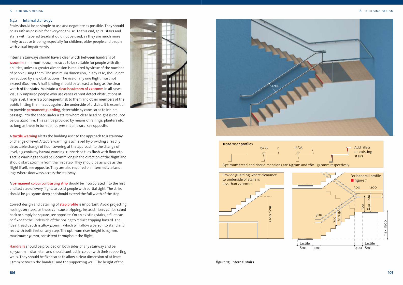
6.7.2 Internal stairwaysStairs should be as simple to use and negotiate as possible. They should
be as safe as possible for everyone to use. To this end, spiral stairs and
stairs with tapered treads should not be used, as they are much more
likely to cause tripping, especially for children, older people and people
with visual impairments.
Internal stairways should have a clear width between handrails of
1200mm, minimum 1000mm, so as to be suitable for people with dis-
abilities, unless a greater dimension is required by virtue of the number
of people using them. The minimum dimension, in any case, should not
be reduced by any obstructions. The rise of any one flight must not
exceed 1800mm. A half landing should be at least as long as the clear
width of the stairs. Maintain a clear headroom of 2200mm in all cases.
Visually impaired people who use canes cannot detect obstructions at
high level. There is a consequent risk to them and other members of the
public hitting their heads against the underside of a stairs. It is essential
to provide permanent guarding, detectable by cane, so as to inhibit
passage into the space under a stairs where clear head height is reduced
below 2200mm. This can be provided by means of railings, planters etc,
so long as these in turn do not present a hazard, see opposite.
A tactile warning alerts the building user to the approach to a stairway
or change of level. A tactile warning is achieved by providing a readily
detectable change of floor covering at the approach to the change of
level, e.g corduroy hazard warning, rubberised tiles flush with floor etc.
Tactile warnings should be 800mm long in the direction of the flight and
should start 400mm from the first step. They should be as wide as the
flight itself, see opposite. They are also required on intermediate land-
ings where doorways access the stairway.
A permanent colour contrasting strip should be incorporated into the first
and last step of every flight, to assist people with partial sight. The strips
should be 50–75mm deep and should extend the full width of the step.
Correct design and detailing of step profile is important. Avoid projecting
nosings on steps, as these can cause tripping. Instead, risers can be raked
back or simply be square, see opposite. On an existing stairs, a fillet can
be fixed to the underside of the nosing to reduce tripping hazard. The
ideal tread depth is 280–320mm, which will allow a person to stand and
rest with both feet on any step. The optimum riser height is 145mm,
maximum 150mm, consistent throughout the flight.
Handrails should be provided on both sides of any stairway and be
45–50mm in diameter, and should contrast in colour with their supporting
walls. They should be fixed so as to allow a clear dimension of at least
45mm between the handrail and the supporting wall. The height of the
2200
clea
r
Provide guarding where clearance to underside of stairs is less than 2200mm
For handrail profile, figure 7
15/25 15/25Tread/riser profiles
Add fillets on existing stairs
Optimum tread and riser dimensions are 145mm and 280– 320mm respectively
1200
tactile800
tactile800400
300
400
300 1200
max
. 180
0700 840-
900 70
084
0-10
00
figure 25 Internal stairs
6 building design
109
6 building design
108
platform lift may su≤ce, but only if kept for the exclusive use of people
with impairments,!section 6.7.5.
Ramps should have a maximum gradient of 1 :20. Many wheelchair users
have great di≤culty in pushing themselves up, or controlling their descent,
at a steeper gradient.
The clear width for an internal ramp should be 1200mm, minimum
1000mm. Ramps longer than 9.0m must have landings and no section of
the ramp should be longer than 9.0m. Note that BS 8300:2001 limits these
distances to 6.0m. The landing should be at least as long as the narrowest
clear width of the ramp. If a doorway opens onto the landing, there must
be at least 1300m between the end of the sloped section and the doorway,
"figure 7. The top and bottom landings of any ramp, irrespective of its
length, should be 1800 x 1800mm.
Passing bays will be required if a ramp is less than 1800mm wide and
longer than 20.0m including the landings, just as if it were a corridor.
Passing bays should be 1800 x 1800mm and should be located on the flat
at intermediate landings. There should be no more than 20.0m between
passing bays.
All ramps should have a raised kerb on any open side. Kerbs must be at
least 75mm high above the ramp surface.
Handrails should be provided on both sides of the flights and landings.
They should be 45–50mm in diameter, spaced 45mm from the wall,
840–900mm above the ramp surface and 840–1000mm above the land-
ing surface. They should extend at least 300mm beyond the ramp onto
the top and bottom landings and should be continuous on intermediate
landings. Where a handrail terminates, it must have a closed end which
turns back onto a supporting wall or, in the case of a handrail on an open
side, turns down for 150mm,"figure 7. Advice on handrails on stairways
also applies to ramps.
A tactile warning, in the form of a corduroy type material or rubberised
tiles etc, should be provided in advance of any change in level. It should
be the full width of the ramp and should occupy the space 400–1200mm
from the ramp.
handrail should be 840–900mm above the pitch line of the steps. A sec-
ond handrail, 700mm above the pitch line of the steps, is desirable,
"figure 7. The handrail should be 840–1000mm above any landing and
should extend 300mm beyond the first and last step of a flight.
Handrails should be continuous around half-landings, unless there are
doors leading from them. This will assist someone with a visual impair-
ment, as well as people with impaired mobility.
Access on existing stairs can be improved by fitting new or additional
handrails, by providing contrasting adhesive or painted nosings, by fit-
ting non-slip nosings and by the possible provision of additional space
on landings by removing cupboards or ducts.
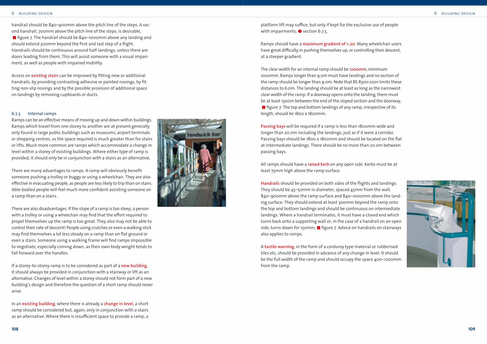
6.7.3 Internal rampsRamps can be an e≠ective means of moving up and down within buildings.
Ramps which travel from one storey to another are at present generally
only found in large public buildings such as museums, airport terminals
or shopping centres, as the space required is much greater than for stairs
or lifts. Much more common are ramps which accommodate a change in
level within a storey of existing buildings. Where either type of ramp is
provided, it should only be in conjunction with a stairs as an alternative.
There are many advantages to ramps. A ramp will obviously benefit
someone pushing a trolley or buggy or using a wheelchair. They are also
e≠ective in evacuating people, as people are less likely to trip than on stairs.
Able-bodied people will feel much more confident assisting someone on
a ramp than on a stairs.
There are also disadvantages. If the slope of a ramp is too steep, a person
with a trolley or using a wheechair may find that the e≠ort required to
propel themselves up the ramp is too great. They also may not be able to
control their rate of descent! People using crutches or even a walking stick
may find themselves a lot less steady on a ramp than on flat ground or
even a stairs. Someone using a walking frame will find ramps impossible
to negotiate, especially coming down, as their own body weight tends to
fall forward over the handles.
If a storey-to-storey ramp is to be considered as part of a new building,
it should always be provided in conjunction with a stairway or lift as an
alternative. Changes of level within a storey should not form part of a new
building’s design and therefore the question of a short ramp should never
arise.
In an existing building, where there is already a change in level, a short
ramp should be considered but, again, only in conjunction with a stairs
as an alternative. Where there is insu≤cient space to provide a ramp, a
6 building design
111
6 building design
110
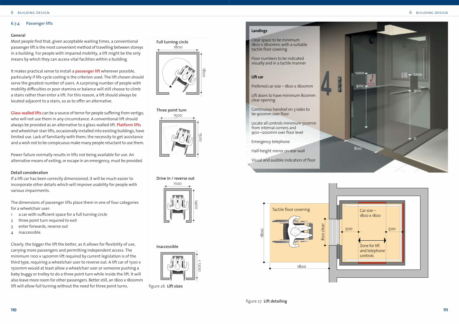
6.7.4 Passenger lifts
GeneralMost people find that, given acceptable waiting times, a conventional
passenger lift is the most convenient method of travelling between storeys
in a building. For people with impaired mobility, a lift might be the only
means by which they can access vital facilities within a building.
It makes practical sense to install a passenger lift wherever possible,
particularly if life-cycle costing is the criterion used. The lift chosen should
serve the greatest number of users. A surprising number of people with
mobility di≤culties or poor stamina or balance will still choose to climb
a stairs rather than enter a lift. For this reason, a lift should always be
located adjacent to a stairs, so as to o≠er an alternative.
Glass-walled lifts can be a source of terror for people su≠ering from vertigo,
who will not use them in any circumstance. A conventional lift should
always be provided as an alternative to a glass-walled lift. Platform liftsand wheelchair stair lifts, occasionally installed into existing buildings, have
limited use. Lack of familiarity with them, the necessity to get assistance
and a wish not to be conspicuous make many people reluctant to use them.
Power failure normally results in lifts not being available for use. An
alternative means of exiting, or escape in an emergency, must be provided.
Detail considerationIf a lift car has been correctly dimensioned, it will be much easier to
incorporate other details which will improve usability for people with
various impairments.
The dimensions of passenger lifts place them in one of four categories
for a wheelchair user:
1 a car with su≤cient space for a full turning circle
2 three point turn required to exit
3 enter forwards, reverse out
4 inaccessible.
Clearly, the bigger the lift the better, as it allows for flexibility of use,
carrying more passengers and permitting independent access. The
minimum 1100 x 1400mm lift required by current legislation is of the
third type, requiring a wheelchair user to reverse out. A lift car of 1500 x
1500mm would at least allow a wheelchair user or someone pushing a
baby buggy or trolley to do a three point turn while inside the lift. It will
also leave more room for other passengers. Better still, an 1800 x 1800mm
lift will allow full turning without the need for three point turns.
1800
1500
1100
1400 < 1200
15001800
Full turning circle
Three point turn
Drive in / reverse out
Inaccessible
figure 26 Lift sizes
500500
800
clear
1800
1800
Tactile floor covering
Zone for lift and telephone controls
Car size –1800 x 1800
900
0
1200
900
800
1200
Landings
Clear space to be minimum 1800 x 1800mm, with a suitable tactile floor covering
Floor numbers to be indicated visually and in a tactile manner
Lift car
Preferred car size – 1800 x 1800mm
Lift doors to have minimum 800mmclear opening
Continuous handrail on 3 sides to be 900mm over floor
Locate all controls minimum 500mmfrom internal corners and 900–1200mm over floor level
Emergency telephone
Half-height mirror on rear wall
Visual and audible indication of floor
figure 27 Lift detailing
6 building design
113
6 building design
112
that someone entered a lift car and the doors closed, only to find that
their child or dog on the end of the lead was still standing on the landing!
The emergency telephone is an important component of the lift car. The
phone should be obvious and readily retrievable. It should be suitable for
use by people with impaired hearing, !section 8.3. Place the telephone
so that the handset base is 900–1200mm over floor level, and positioned
500mm from corners. Mark the cabinet clearly and position the door so
that it does not obstruct access to the telephone when open. Avoid sharp
edges to the door and provide a handle which is operable by people with
impaired grip. Provide a sign on the door with the words ‘emergency
telephone’ in minimum 20mm high lettering, red upper and lower case
on white background, with a minimum 100mm high telephone symbol.
Instructions for use of the telephone should be in minimum 10mm high
lettering, sited on the inside of the cabinet door or on the telephone itself.
Once lifted from the cradle, the telephone should indicate automatically
which lift, if there is more than one, is the source of the call, and then allow
two-way conversation. Avoid telephones which require dialling unless
the building does not have a control room. Some emergency telephones
will signal an alarm when the door of the cabinet is opened. If this is the
case, provide a notice to that e≠ect.
ChecklistLifts
• If at all possible, lift cars to be 1800 x 1800mm.
• Landing and car controls to be 900–1200mm above floor level.
• Controls to be 500mm from internal corners, with visual and tactile
indication.
• Car floor level indicators to be visual and audible.
• Controls to permit adequate time to enter and leave lift.
• Provide handrails in lift car.
• Lift telephone to have hard of hearing facility.
• Provide a half-height mirror on the car wall opposite the entry doors.
All lifts, of whichever category, require the installation of a half-heightmirror on the wall opposite the door, to allow someone to see what is
behind if they need to reverse out,"figure 27.
The landing and car controls should be 500mm, from any adjacent wall
or projecting surface, 900–1200mm from floor level and with minimum
900mm clear approach in front. Locate control buttons in a contrasting
colour surround, well spaced and, ideally, facing upwards at a 45° angle.
The numbers should be raised minimum 1.5mm from the button face
and be minimum 15mm high.
On landings, there should be a clear space of 1800mm square, minimum
1500mm, outside the lift door. This should be marked with a tactile floor
covering. Floor numbers should be indicated both visually and in a tac-
tile manner. Large raised relief characters and Braille text is ideal. If it is
not possible to use both, only raised relief characters should be provided,
!section 8.2.2. The lift signalling system should provide both visualand audible confirmation on each landing that the lift is answering a
call, and that it has arrived. A gong on each landing will provide
su≤cient audible notice.
Inside the lift, an announcement on arrival should state the appropriate
floor and that the doors are opening, and then repeat the floor of arrival.
It should then state the next direction of travel and that the doors are
about to close.
Handrails at 900mm above floor level should be provided on three sides,
"figure 27, and should follow the advice on handrails generally,
!section 6.7.3.
Lift doors should have a minimum 800mm clear opening. Doors should
stay open for a minimum of 8 seconds. Doors should stay open longer in
lifts where a significant proportion of the people using them are elderly
or have disabilities. Provide a ‘rapid close’ button and a ‘hold open’ button
in the lift car. There should also be a ‘hold open’ button on landings which
should hold the door open for 30 seconds. Doors requiring manual oper-
ation should be avoided.
Various door opening mechanisms are available which will re-open the
door in the event of an obstruction. Curtain-type sensors on the leading
edge of the door can be hazardous or frightening, as they require physical
contact in order to be activated. An array of photoelectric cells over the
full height of the door is much better, as it can detect the presence of an
interruption without physical contact and can make the door stay open
or re-open automatically. A single photoelectric cell is dangerous as it
will detect obstruction only at one level. It has been known to happen
6 building design
115
6 building design
114
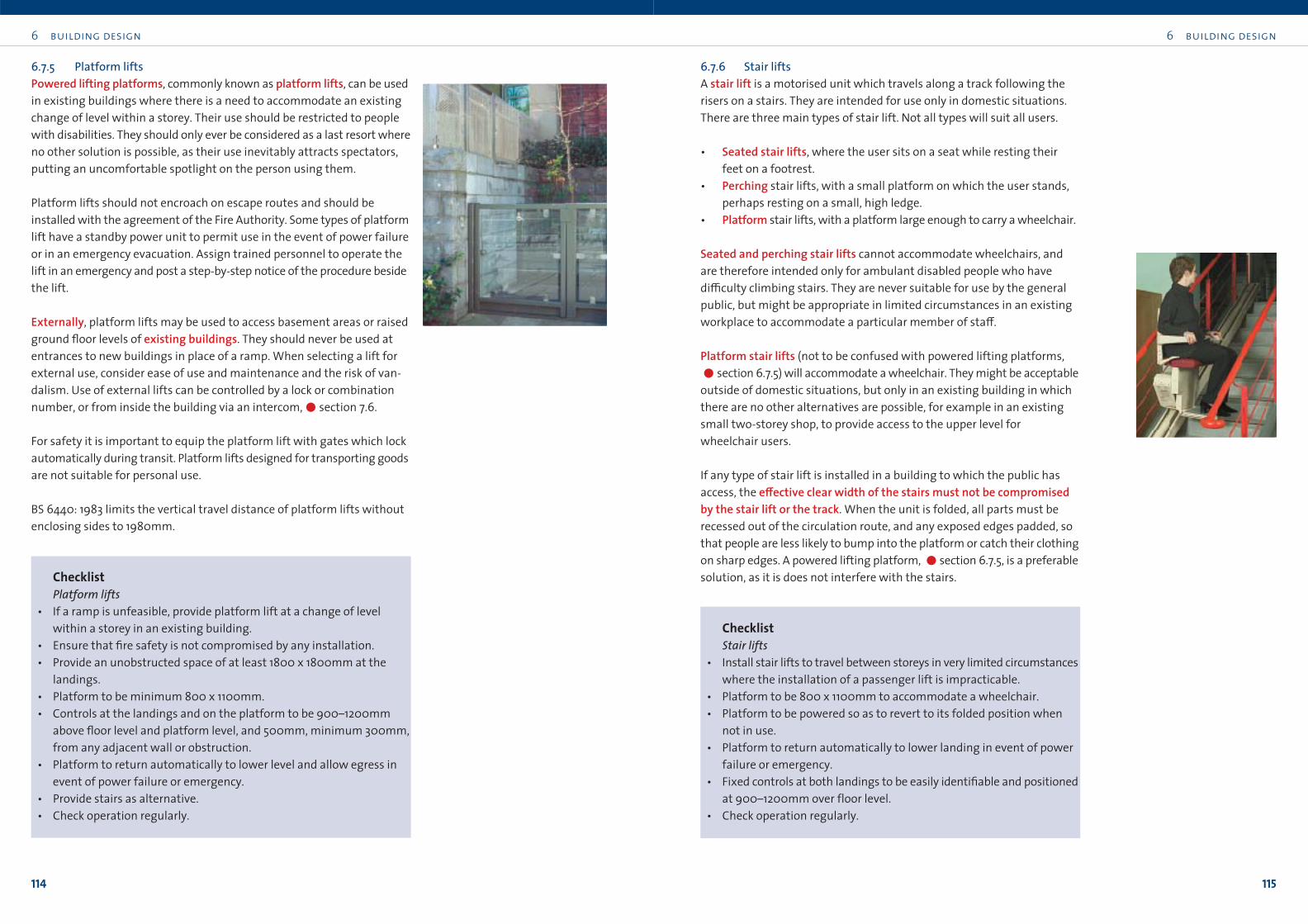
6.7.6 Stair liftsA stair lift is a motorised unit which travels along a track following the
risers on a stairs. They are intended for use only in domestic situations.
There are three main types of stair lift. Not all types will suit all users.
• Seated stair lifts, where the user sits on a seat while resting their
feet on a footrest.
• Perching stair lifts, with a small platform on which the user stands,
perhaps resting on a small, high ledge.
• Platform stair lifts, with a platform large enough to carry a wheelchair.
Seated and perching stair lifts cannot accommodate wheelchairs, and
are therefore intended only for ambulant disabled people who have
di≤culty climbing stairs. They are never suitable for use by the general
public, but might be appropriate in limited circumstances in an existing
workplace to accommodate a particular member of sta≠.
Platform stair lifts (not to be confused with powered lifting platforms,
!section 6.7.5) will accommodate a wheelchair. They might be acceptable
outside of domestic situations, but only in an existing building in which
there are no other alternatives are possible, for example in an existing
small two-storey shop, to provide access to the upper level for
wheelchair users.
If any type of stair lift is installed in a building to which the public has
access, the e≠ective clear width of the stairs must not be compromisedby the stair lift or the track. When the unit is folded, all parts must be
recessed out of the circulation route, and any exposed edges padded, so
that people are less likely to bump into the platform or catch their clothing
on sharp edges. A powered lifting platform, !section 6.7.5, is a preferable
solution, as it is does not interfere with the stairs.
ChecklistStair lifts
• Install stair lifts to travel between storeys in very limited circumstances
where the installation of a passenger lift is impracticable.
• Platform to be 800 x 1100mm to accommodate a wheelchair.
• Platform to be powered so as to revert to its folded position when
not in use.
• Platform to return automatically to lower landing in event of power
failure or emergency.
• Fixed controls at both landings to be easily identifiable and positioned
at 900–1200mm over floor level.
• Check operation regularly.
6.7.5 Platform liftsPowered lifting platforms, commonly known as platform lifts, can be used
in existing buildings where there is a need to accommodate an existing
change of level within a storey. Their use should be restricted to people
with disabilities. They should only ever be considered as a last resort where
no other solution is possible, as their use inevitably attracts spectators,
putting an uncomfortable spotlight on the person using them.
Platform lifts should not encroach on escape routes and should be
installed with the agreement of the Fire Authority. Some types of platform
lift have a standby power unit to permit use in the event of power failure
or in an emergency evacuation. Assign trained personnel to operate the
lift in an emergency and post a step-by-step notice of the procedure beside
the lift.
Externally, platform lifts may be used to access basement areas or raised
ground floor levels of existing buildings. They should never be used at
entrances to new buildings in place of a ramp. When selecting a lift for
external use, consider ease of use and maintenance and the risk of van-
dalism. Use of external lifts can be controlled by a lock or combination
number, or from inside the building via an intercom,!section 7.6.
For safety it is important to equip the platform lift with gates which lock
automatically during transit. Platform lifts designed for transporting goods
are not suitable for personal use.
BS 6440: 1983 limits the vertical travel distance of platform lifts without
enclosing sides to 1980mm.
ChecklistPlatform lifts
• If a ramp is unfeasible, provide platform lift at a change of level
within a storey in an existing building.
• Ensure that fire safety is not compromised by any installation.
• Provide an unobstructed space of at least 1800 x 1800mm at the
landings.
• Platform to be minimum 800 x 1100mm.
• Controls at the landings and on the platform to be 900–1200mm
above floor level and platform level, and 500mm, minimum 300mm,
from any adjacent wall or obstruction.
• Platform to return automatically to lower level and allow egress in
event of power failure or emergency.
• Provide stairs as alternative.
• Check operation regularly.
6 building design
117
6 building design
116
generally unisex and accessed separately from other sanitary accommo-
dation. Do not assume that providing a wheelchair accessible toiletallows all other toilets in the building to be minimum size and to beshoehorned into the most awkward spaces.
Plan all toilets to facilitate the needs of a full range of possible users. Take
into account people’s varying levels of ability to manoeuvre. This ability
is a≠ected by many things, including body weight, overall health, use of
a walking stick, poor vision, limited reach, arm strength, or whether
someone is simply carrying parcels or minding small children. Personal
preference and levels of ability will influence how individuals will access
a toilet. As such, layouts need to be flexible to accommodate di≠erent
use patterns. Many people will need more space than the bareminimum, to allow them to get in with their shopping bags, briefcase etc,
and close the door behind them.
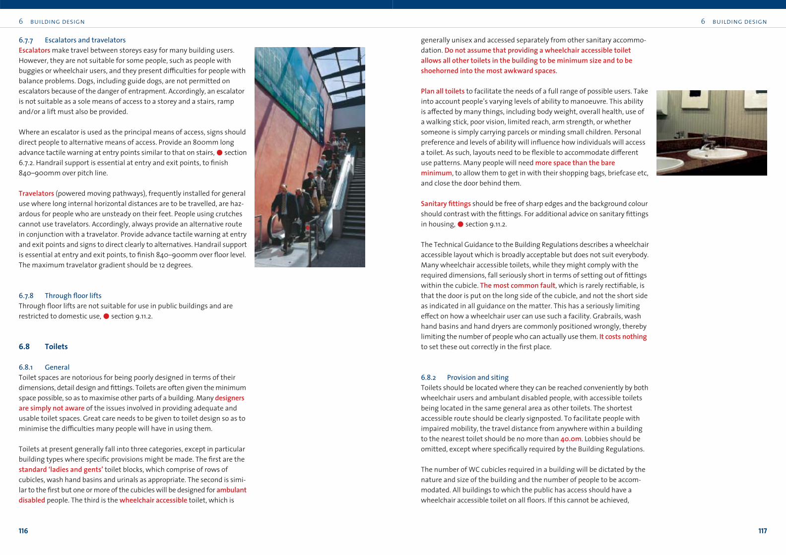
Sanitary fittings should be free of sharp edges and the background colour
should contrast with the fittings. For additional advice on sanitary fittings
in housing,!section 9.11.2.
The Technical Guidance to the Building Regulations describes a wheelchair
accessible layout which is broadly acceptable but does not suit everybody.
Many wheelchair accessible toilets, while they might comply with the
required dimensions, fall seriously short in terms of setting out of fittings
within the cubicle. The most common fault, which is rarely rectifiable, is
that the door is put on the long side of the cubicle, and not the short side
as indicated in all guidance on the matter. This has a seriously limiting
e≠ect on how a wheelchair user can use such a facility. Grabrails, wash
hand basins and hand dryers are commonly positioned wrongly, thereby
limiting the number of people who can actually use them. It costs nothingto set these out correctly in the first place.
6.8.2 Provision and sitingToilets should be located where they can be reached conveniently by both
wheelchair users and ambulant disabled people, with accessible toilets
being located in the same general area as other toilets. The shortest
accessible route should be clearly signposted. To facilitate people with
impaired mobility, the travel distance from anywhere within a building
to the nearest toilet should be no more than 40.0m. Lobbies should be
omitted, except where specifically required by the Building Regulations.
The number of WC cubicles required in a building will be dictated by the
nature and size of the building and the number of people to be accom-
modated. All buildings to which the public has access should have a
wheelchair accessible toilet on all floors. If this cannot be achieved,
6.7.7 Escalators and travelatorsEscalators make travel between storeys easy for many building users.
However, they are not suitable for some people, such as people with
buggies or wheelchair users, and they present di≤culties for people with
balance problems. Dogs, including guide dogs, are not permitted on
escalators because of the danger of entrapment. Accordingly, an escalator
is not suitable as a sole means of access to a storey and a stairs, ramp
and/or a lift must also be provided.
Where an escalator is used as the principal means of access, signs should
direct people to alternative means of access. Provide an 800mm long
advance tactile warning at entry points similar to that on stairs,!section
6.7.2. Handrail support is essential at entry and exit points, to finish
840–900mm over pitch line.
Travelators (powered moving pathways), frequently installed for general
use where long internal horizontal distances are to be travelled, are haz-
ardous for people who are unsteady on their feet. People using crutches
cannot use travelators. Accordingly, always provide an alternative route
in conjunction with a travelator. Provide advance tactile warning at entry
and exit points and signs to direct clearly to alternatives. Handrail support
is essential at entry and exit points, to finish 840–900mm over floor level.
The maximum travelator gradient should be 12 degrees.
6.7.8 Through floor liftsThrough floor lifts are not suitable for use in public buildings and are
restricted to domestic use,!section 9.11.2.
6.8 Toilets
6.8.1 GeneralToilet spaces are notorious for being poorly designed in terms of their
dimensions, detail design and fittings. Toilets are often given the minimum
space possible, so as to maximise other parts of a building. Many designersare simply not aware of the issues involved in providing adequate and
usable toilet spaces. Great care needs to be given to toilet design so as to
minimise the di≤culties many people will have in using them.
Toilets at present generally fall into three categories, except in particular
building types where specific provisions might be made. The first are the
standard ‘ladies and gents’ toilet blocks, which comprise of rows of
cubicles, wash hand basins and urinals as appropriate. The second is simi-
lar to the first but one or more of the cubicles will be designed for ambulantdisabled people. The third is the wheelchair accessible toilet, which is

6 building design
119
6 building design
118
wheelchair accessible toilets must be located so that they are never more
than one floor away, with access to that floor available via an accessible
lift. In existing buildings which have no lift to their upper floors, wheelchair
accessible toilets and toilets for ambulant disabled people should be sited
at entrance level. Where a building only requires one or two toilets, they
should be unisex, with at least one of them being wheelchair accessible.
Where occupancy demands more than two, there should be at least one
unisex wheelchair accessible toilet, in association with the required
number of ladies and gents toilets. Where occupancy exceeds 100 people,
a second unisex wheelchair accessible toilet should be provided. Additional
provision may be required depending on location or the nature of the
building.
All buildings or parts of buildings open to the public must have at least
one unisex wheelchair accessible toilet, approached separately from other
sanitary accommodation.
6.8.3 Standard ladies and gents toilet blocksA clear space of at least 1200 x 1200mm should be provided outside both
the toilet lobby door, if any, and the cubicle door. Any lobby should conform
to the guidelines in this book,!section 6.3.
Cubicles should be su≤ciently sized so as to allow someone to enter and
close the door behind them with ease. It is not acceptable that they might
have to squeeze in between the toilet and the cubicle wall, so as to clear a
path for the door swing. Cubicle doors should have a lever door handle and
a locking device which is easy to grasp. Doors should open inwards and
should have a pivot hinge set and removable door stops. At least one in six
cubicles should be suitable for ambulant disabled people,!section 6.8.4.
Cubicle doors should not open outwards, as they may be a hazard to
someone outside the door. In existing buildings where no other solution
is available, an outward opening door may be unavoidable. If this is the
case, hang the door to open against a perpendicular wall, to minimise
risk of collision with those passing,!section 6.6. If an outward opening
door has to be fitted, provide an additional pull handle to enable it to be
closed with ease,!section 6.8.5.
The WC pan should finish 395–410mm over floor level, so as to be suit-
able for most users. In buildings with a high occupancy of small children,
a lower height may be used. The flush control on the cistern should be a
lever or spatula type.
Washbasins should finish 750–900mm over floor level. Where feasible,
provide a choice of heights within this range, so as to accommodate
children and people of di≠erent heights. Lever taps o≠er ease of use,
500
60060
0
Min. 1200 clear
Avoid steps
380
700
395 –
41090
0
750
Provide a choice of heights of wash hand basins between 750mm and 900mm
Provide lever, automaticor push button type taps
Provide spatula type lever handle on WC
1800
750
figure 28 Standard ladies and gents
especially for people with poor grip or arthritic hands. Push-button and
automatic taps are also available.
Urinals should be stall type or wall-hung bowls, at minimum 750mm
centres, with no step leading up to them. Urinal troughs should never
be used, as visually impaired people often run their hands along walls to
orient themselves and so may encounter the unprotected surface. In a
row of urinals, place one in six at a lower height, 380mm over finished
floor, instead of the standard 500mm. Provide grab rails located
between pairs of urinals, to allow both left and right hand support.
Provide minimum 750 x 1200mm clear space in front of urinals to
permit a forward approach.
Earthing connections to pipework should not project so as to cause an
obstruction or personal injury.
6 building design
121
6 building design
120
ChecklistStandard toilet blocks
• Clear space of 1200 x 1200mm outside all lobby and cubicle doors.
• One in six cubicles to be suitable for ambulant disabled people,
!section 6.8.4.
• Cubicle doors to open inwards.
• WC pan seat to be 395–410mm over floor.
• Washbasins to finish 750–900mm over floor.
• Taps to be lever type or automatic.
• Urinals to have 750 x 1200mm clear approach.
• One in six urinals to be 380mm over floor.
6.8.4 Accessible cubicles for ambulant disabled peopleThese toilets are suitable for people who are unsteady on their feet or
who have di≤culty with balance. They are generally located within the
ladies and gents toilet blocks, and are essentially a larger than average
cubicle with grab rails on the walls, essential for many ambulant disabled
people.
Given the small additional space requirements of such a cubicle, serious
consideration should be given to designing and fitting out all cubicles to
this standard. If this is not possible, at least one in six cubicles should be
suitable for ambulant disabled people.
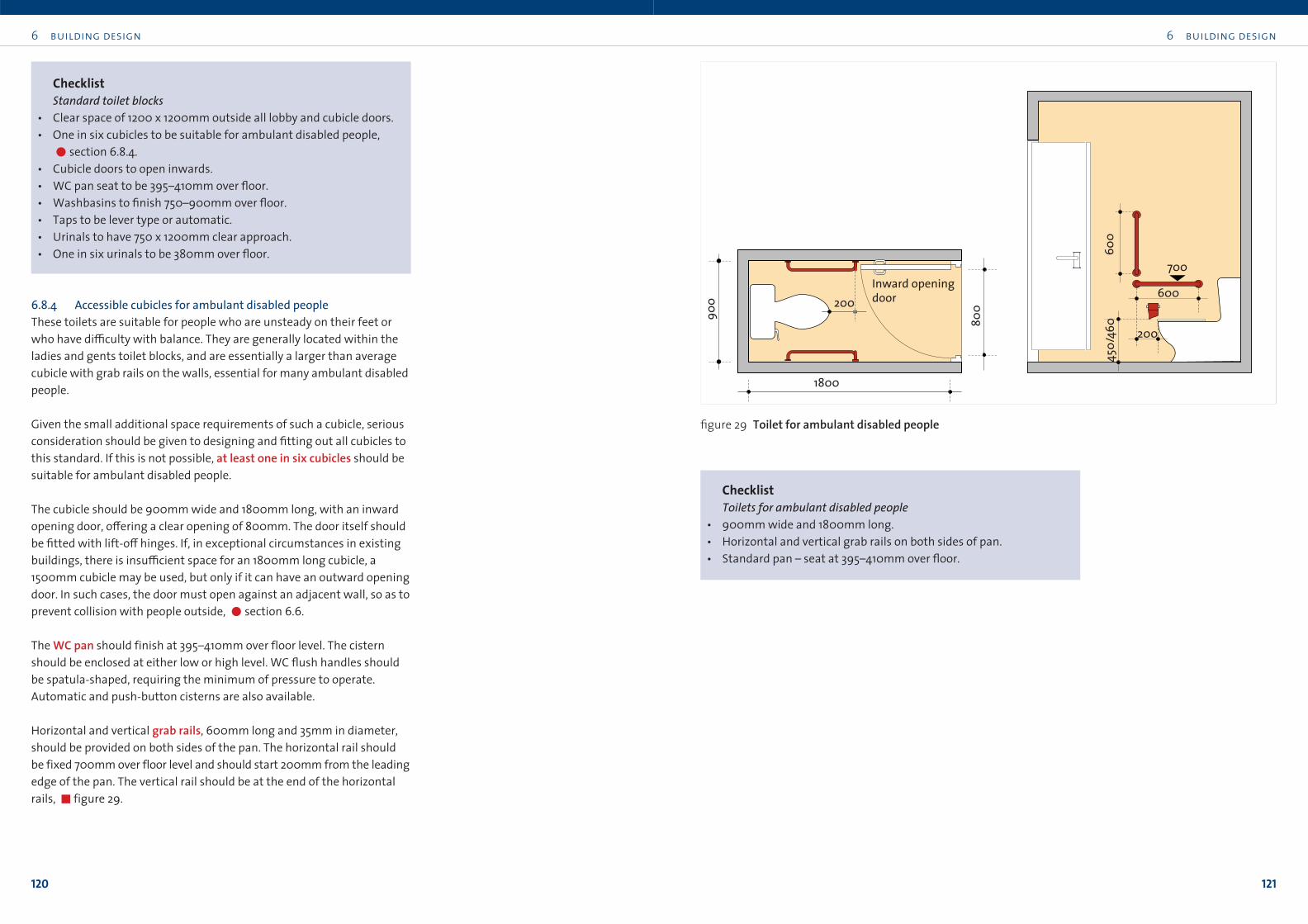
The cubicle should be 900mm wide and 1800mm long, with an inward
opening door, o≠ering a clear opening of 800mm. The door itself should
be fitted with lift-o≠ hinges. If, in exceptional circumstances in existing
buildings, there is insu≤cient space for an 1800mm long cubicle, a
1500mm cubicle may be used, but only if it can have an outward opening
door. In such cases, the door must open against an adjacent wall, so as to
prevent collision with people outside, !section 6.6.
The WC pan should finish at 395–410mm over floor level. The cistern
should be enclosed at either low or high level. WC flush handles should
be spatula-shaped, requiring the minimum of pressure to operate.
Automatic and push-button cisterns are also available.
Horizontal and vertical grab rails, 600mm long and 35mm in diameter,
should be provided on both sides of the pan. The horizontal rail should
be fixed 700mm over floor level and should start 200mm from the leading
edge of the pan. The vertical rail should be at the end of the horizontal
rails, "figure 29.
1800
200
80090
0
Inward openingdoor
700
600
200
600
450/
460
figure 29 Toilet for ambulant disabled people
ChecklistToilets for ambulant disabled people
• 900mm wide and 1800mm long.
• Horizontal and vertical grab rails on both sides of pan.
• Standard pan – seat at 395–410mm over floor.
6 building design
123
6 building design
122
Long section
Plan
Short section
750200
250
Keep area clear of all obstructionsPull handle
400
450/
500
1500
750
clear80
0 cle
ar
500
600
2700
1700
1200
450/460
700
Hooks
ShelvesSoap800
Paper rollBin
Hot-airhand dryer
450
460
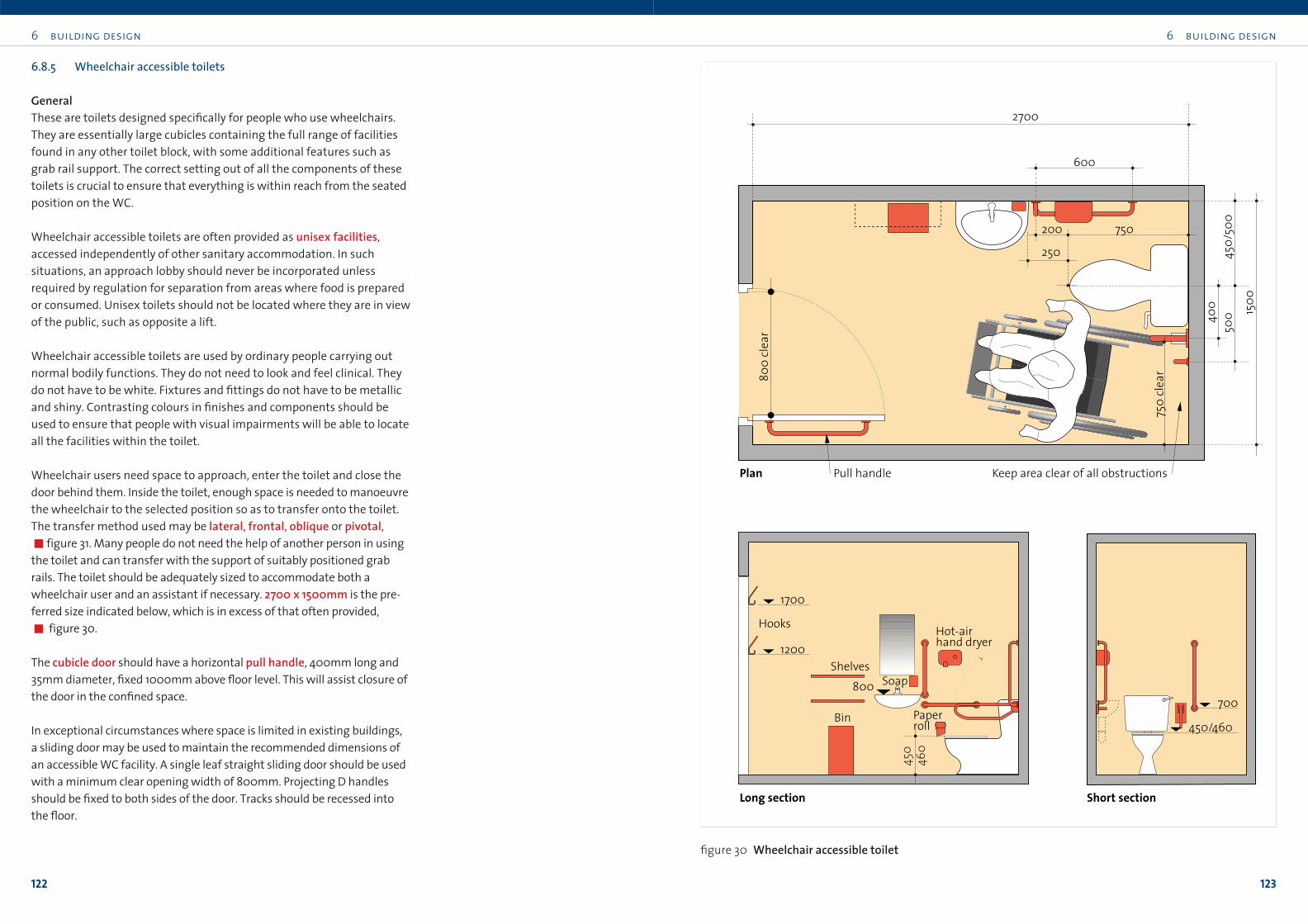
figure 30 Wheelchair accessible toilet
6.8.5 Wheelchair accessible toilets
GeneralThese are toilets designed specifically for people who use wheelchairs.
They are essentially large cubicles containing the full range of facilities
found in any other toilet block, with some additional features such as
grab rail support. The correct setting out of all the components of these
toilets is crucial to ensure that everything is within reach from the seated
position on the WC.
Wheelchair accessible toilets are often provided as unisex facilities,
accessed independently of other sanitary accommodation. In such
situations, an approach lobby should never be incorporated unless
required by regulation for separation from areas where food is prepared
or consumed. Unisex toilets should not be located where they are in view
of the public, such as opposite a lift.
Wheelchair accessible toilets are used by ordinary people carrying out
normal bodily functions. They do not need to look and feel clinical. They
do not have to be white. Fixtures and fittings do not have to be metallic
and shiny. Contrasting colours in finishes and components should be
used to ensure that people with visual impairments will be able to locate
all the facilities within the toilet.
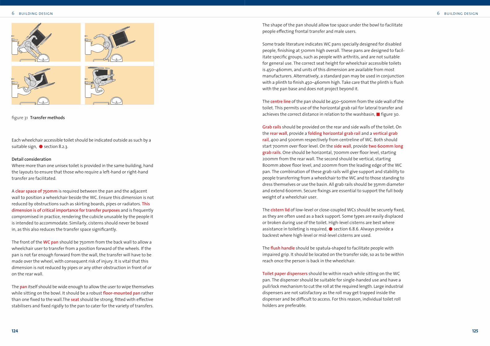
Wheelchair users need space to approach, enter the toilet and close the
door behind them. Inside the toilet, enough space is needed to manoeuvre
the wheelchair to the selected position so as to transfer onto the toilet.
The transfer method used may be lateral, frontal, oblique or pivotal,!figure 31. Many people do not need the help of another person in using
the toilet and can transfer with the support of suitably positioned grab
rails. The toilet should be adequately sized to accommodate both a
wheelchair user and an assistant if necessary. 2700 x 1500mm is the pre-
ferred size indicated below, which is in excess of that often provided,
! figure 30.
The cubicle door should have a horizontal pull handle, 400mm long and
35mm diameter, fixed 1000mm above floor level. This will assist closure of
the door in the confined space.
In exceptional circumstances where space is limited in existing buildings,
a sliding door may be used to maintain the recommended dimensions of
an accessible WC facility. A single leaf straight sliding door should be used
with a minimum clear opening width of 800mm. Projecting D handles
should be fixed to both sides of the door. Tracks should be recessed into
the floor.
6 building design
125
Each wheelchair accessible toilet should be indicated outside as such by a
suitable sign, !section 8.2.3.
Detail considerationWhere more than one unisex toilet is provided in the same building, hand
the layouts to ensure that those who require a left-hand or right-hand
transfer are facilitated.
A clear space of 750mm is required between the pan and the adjacent
wall to position a wheelchair beside the WC. Ensure this dimension is not
reduced by obstructions such as skirting boards, pipes or radiators. Thisdimension is of critical importance for transfer purposes and is frequently
compromised in practice, rendering the cubicle unusable by the people it
is intended to accommodate. Similarly, cisterns should never be boxed
in, as this also reduces the transfer space significantly.
The front of the WC pan should be 750mm from the back wall to allow a
wheelchair user to transfer from a position forward of the wheels. If the
pan is not far enough forward from the wall, the transfer will have to be
made over the wheel, with consequent risk of injury. It is vital that this
dimension is not reduced by pipes or any other obstruction in front of or
on the rear wall.
The pan itself should be wide enough to allow the user to wipe themselves
while sitting on the bowl. It should be a robust floor-mounted pan rather
than one fixed to the wall.The seat should be strong, fitted with e≠ective
stabilisers and fixed rigidly to the pan to cater for the variety of transfers.
6 building design
124
figure 31 Transfer methods
The shape of the pan should allow toe space under the bowl to facilitate
people e≠ecting frontal transfer and male users.
Some trade literature indicates WC pans specially designed for disabled
people, finishing at 510mm high overall. These pans are designed to facil-
itate specific groups, such as people with arthritis, and are not suitable
for general use. The correct seat height for wheelchair accessible toilets
is 450–460mm, and units of this dimension are available from most
manufacturers. Alternatively, a standard pan may be used in conjunction
with a plinth to finish 450–460mm high. Take care that the plinth is flush
with the pan base and does not project beyond it.
The centre line of the pan should be 450–500mm from the side wall of the
toilet. This permits use of the horizontal grab rail for lateral transfer and
achieves the correct distance in relation to the washbasin,"figure 30.
Grab rails should be provided on the rear and side walls of the toilet. On
the rear wall, provide a folding horizontal grab rail and a vertical grabrail, 400 and 500mm respectively from centreline of WC. Both should
start 700mm over floor level. On the side wall, provide two 600mm longgrab rails. One should be horizontal, 700mm over floor level, starting
200mm from the rear wall. The second should be vertical, starting
800mm above floor level, and 200mm from the leading edge of the WC
pan. The combination of these grab rails will give support and stability to
people transferring from a wheelchair to the WC and to those standing to
dress themselves or use the basin. All grab rails should be 35mm diameter
and extend 600mm. Secure fixings are essential to support the full body
weight of a wheelchair user.
The cistern lid of low-level or close-coupled WCs should be securely fixed,
as they are often used as a back support. Some types are easily displaced
or broken during use of the toilet. High-level cisterns are best where
assistance in toileting is required,!section 6.8.6. Always provide a
backrest where high-level or mid-level cisterns are used.
The flush handle should be spatula-shaped to facilitate people with
impaired grip. It should be located on the transfer side, so as to be within
reach once the person is back in the wheelchair.
Toilet paper dispensers should be within reach while sitting on the WC
pan. The dispenser should be suitable for single-handed use and have a
pull/lock mechanism to cut the roll at the required length. Large industrial
dispensers are not satisfactory as the roll may get trapped inside the
dispenser and be di≤cult to access. For this reason, individual toilet roll
holders are preferable.
6 building design
127
The wash hand basin should be 250mm from the leading edge of the
WC. The tap should be on the side away from the WC or in the middle.
This will ensure that the tap and sink are usable while sitting on the WC.
Basin height should be 800mm from floor to rim. Basin dimension
should be 450 x 300mm approximately. Care is needed in siting larger
basins, as they may intrude on the circulation space around the WC pan.
Provide a plug that is easy to use.
Provide a single mixer tap with lever operation for ease of use. Automatic
infra-red and push-button taps may also be considered, although some
confusion will be experienced until these are more commonly found.
Soap dispensers should have pull levers to dispense the soap, rather than
push buttons.
Hand dryers, whether hand towels or hot air dryers, should be easy to
use and reach while sitting on the WC pan. Site hand dryers with the
underside 1100mm over floor level and 600mm from internal corners. To
minimise obstruction, use a slim line type, to project maximum 130mm
from the wall.
The mirror over the sink should start 900–1000mm above floor level and
finish 1600–1800mm above floor level.
A shelf is useful. It should be 750–1000mm over floor level, sited clear of
manoeuvring space, such as in the corner beside the door.
Provide a sealed waste container located at the side of the basin away
from the WC.
Provide coat hooks at both 1200mm and 1700mm over floor level, so as
to suit both ambulant people and wheelchair users.
Provide an alarm to summon help. Install the alarm so that it can be used
in the area where transfer from wheelchair to toilet takes place. For
details on alarm types, !section 7.9.
The floor should be covered with slip-resistant material. A drainage gul-
ley is desirable, with a slight fall on the floor towards the gulley.
A baby-changing facility is often incorporated in wheelchair accessible
toilets. A pull-down changing unit ensures that the service does not
impact on the accessibility of the toilet for people with disabilities.
Where possible, provide separate accommodation.
6 building design
126
In public buildings, where vandalism might be anticipated or where non-
disabled people might use a wheelchair accessible toilet, management
will need to exercise vigilance to ensure that toilets are available when
required by disabled users. The practice of keeping wheelchair accessible
toilets locked, with the key kept in another location, should be discouraged
unless absolutely essential. Where unavoidable, the universal key systemshould be used,!Appendix 1.
ChecklistWheelchair accessible toilets
• Cubicle to be 1500mm wide and 2700mm long.
• Ensure all dimensions of space and positioning of fittings are strictly
adhered to.
• Inward opening door on short side.
• WC seat height 450–460mm.
• Securely fix cistern lids to WCs.
• Provide backrest where high level cisterns are used.
• Use lever type flush handles.
• Avoid split toilet seats.
• Locate flush handle on transfer side in wheelchair accessible WC.
• Rinse basin to be 450mm x 300mm, and 800mm above floor.
• Use single mixer taps with lever or automatic operation.
• Mirrors and coat hooks to be universally accessible.
• Floor finish to be slip-resistant.
• Provide easy-to-use locks.
• Ensure sanitary fittings contrast in colour with the walls.
• Avoid fittings with sharp edges.
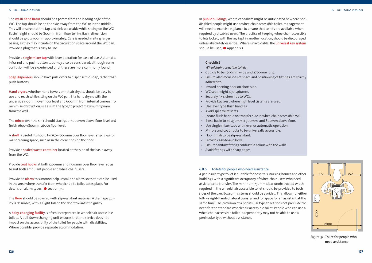
6.8.6 Toilets for people who need assistanceA peninsular type toilet is suitable for hospitals, nursing homes and other
buildings with a significant occupancy of wheelchair users who need
assistance to transfer. The minimum 750mm clear unobstructed width
required in the wheelchair accessible toilet should be provided to both
sides of the pan. Boxed-in cisterns should be avoided. This allows for either
left- or right-handed lateral transfer and for space for an assistant at the
same time. The provision of a peninsular type toilet does not preclude the
need for the standard wheelchair accessible toilet. People who can use a
wheelchair accessible toilet independently may not be able to use a
peninsular type without assistance.
750750
2000
2700
figure 32 Toilet for people who need assistance
6 building design
129
6 building design
128
6.9 Bathrooms and shower rooms
6.9.1 GeneralBathing facilities are provided for public use in a range of building types,
including guest accommodation, sports buildings, hospitals and some
workplaces. Bathrooms can present a myriad of obstacles and hazards to
all sorts of users, not least to those who have impairments. By carefully
detailing bathroom layouts and correct specification of fittings, the
potential di≤culties and hazards can be significantly reduced.
In general, if correctly detailed, showers are more accessible and safer
than baths. In guest accommodation, at least half of the en-suites in
wheelchair accessible rooms should incorporate a level deck showerrather than a bath. In standard rooms, the majority of people use the
bath as a shower, and not as a bath. Consideration should therefore be
given to fitting a proportion of standard rooms with showers rather than
baths, and o≠ering guests a choice.
In bathrooms for general use, provide fittings which suit the broadest
range of users. Provide a mirror over each washbasin, to extend from
900 to 1800mm over floor level. This will facilitate people standing or
using a wheelchair.
Position towel rails etc at a height to provide access for all: maximum
1300mm over floor level, 1000mm for children. Shelves at di≠erent heights,
in the range 450–1300mm over finished floor, will satisfy most users.
Switches and controls should be at a readily accessible height of 900–
1200mm over finished floor. Hairdryers, shaving sockets and other fittings
should also be reachable, with controls which are simple to operate.
Avoid loose mats as they can be a trip hazard.
To ensure that wheelchair users and others can open windows, site
opening lights at accessible height. Provide winding or mechanical remote
control gear only where this is not possible. Controls for ventilation
equipment must also be accessible.
Make sure that all washing facilities in workplaces, including showers
and drenches, are usable by people with physical and sensory impairments,
at the least making provision to adapt the components as the need arises.
6.9.2 Wheelchair accessible bathroomsThe clear space required for a wheelchair user to transfer into a bath is
minimum 1800mm long x 1200mm wide. The person transferring into
the bath lowers themselves with the aid of a grab rail. A ledge or platform
at the bath end, minimum 400mm long, will facilitate a wheelchair user
to e≠ect a two-stage transfer into the bath.
Bath profile should allow the user to slide down gently into the water.
People have a tendency to slide down into a long bath until their feet
meet the support provided by the bath end, so a 1600mm bath length is
preferable to 1700mm. Rim height should be 450mm. Avoid bucket or steep
end baths, as these are di≤cult to enter and exit. A slip-resistant base helps
control movement and enhances safety. Built-in slip resistance is prefer-
able to loose mats.
Grab rails will facilitate stability. Provide one 500mm long vertical grab
rail and one 1200mm long horizontal grab rail,!figure 33. This will facil-
itate sliding down into the bath from the ledge, as well as getting back
up on it. Both grab rails should be 35mm diameter.
Bath taps should be lever type. Taps located centrally on the inner rim
of the bath are generally preferred as they do not inhibit access or cause
obstruction. If taps are positioned at the end of the bath, provide space
there to allow a wheelchair user to get into a position to reach them.
Washbasins, as distinct from rinse basins used in lavatories, should be
wider than conventional sizes (c. 500mm) to accommodate face and hair
washing. The washbasin should finish 750–800mm over finished floor
level, have 700mm knee space and should project 430–450mm from the
wall. Adjustable washbasins, which can be varied in height from 750–
900mm over finished floor level, suit di≠erent users and are ideal.
Dimensions apply equally to standard washbasins, to vanity units and
built-in basins.
The knee space under the unit should be free of obstructions and should
not be boxed in. Pedestals inhibit manoeuvrability and should be avoided.
Use brackets instead. Protect water supply pipes if they are exposed to leg
or foot contact.
The washbasin should ideally be within reach of the WC. In this situation,
take care to maintain adequate toilet transfer space,"section 6.8.5.
Other fittings should be positioned as described in "section 6.9.1.
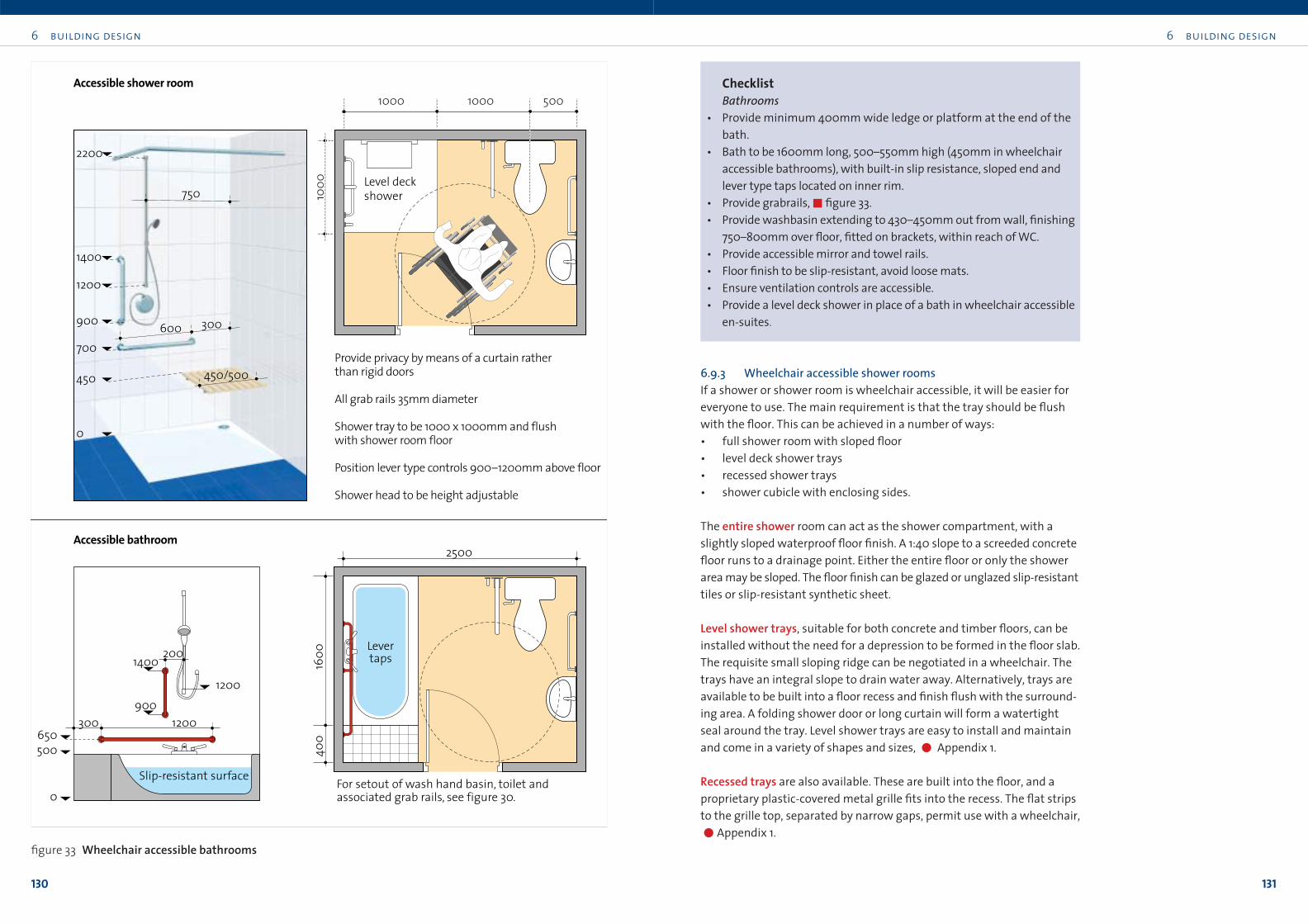
6 building design
131
6 building design
130
ChecklistBathrooms
• Provide minimum 400mm wide ledge or platform at the end of the
bath.
• Bath to be 1600mm long, 500–550mm high (450mm in wheelchair
accessible bathrooms), with built-in slip resistance, sloped end and
lever type taps located on inner rim.
• Provide grabrails,!figure 33.
• Provide washbasin extending to 430–450mm out from wall, finishing
750–800mm over floor, fitted on brackets, within reach of WC.
• Provide accessible mirror and towel rails.
• Floor finish to be slip-resistant, avoid loose mats.
• Ensure ventilation controls are accessible.
• Provide a level deck shower in place of a bath in wheelchair accessible
en-suites.
6.9.3 Wheelchair accessible shower roomsIf a shower or shower room is wheelchair accessible, it will be easier for
everyone to use. The main requirement is that the tray should be flush
with the floor. This can be achieved in a number of ways:
• full shower room with sloped floor
• level deck shower trays
• recessed shower trays
• shower cubicle with enclosing sides.
The entire shower room can act as the shower compartment, with a
slightly sloped waterproof floor finish. A 1:40 slope to a screeded concrete
floor runs to a drainage point. Either the entire floor or only the shower
area may be sloped. The floor finish can be glazed or unglazed slip-resistant
tiles or slip-resistant synthetic sheet.
Level shower trays, suitable for both concrete and timber floors, can be
installed without the need for a depression to be formed in the floor slab.
The requisite small sloping ridge can be negotiated in a wheelchair. The
trays have an integral slope to drain water away. Alternatively, trays are
available to be built into a floor recess and finish flush with the surround-
ing area. A folding shower door or long curtain will form a watertight
seal around the tray. Level shower trays are easy to install and maintain
and come in a variety of shapes and sizes, " Appendix 1.
Recessed trays are also available. These are built into the floor, and a
proprietary plastic-covered metal grille fits into the recess. The flat strips
to the grille top, separated by narrow gaps, permit use with a wheelchair,
"Appendix 1.
400
1600
Slip-resistant surface0
500650
1400
1200900
1200300
200 Lever taps
For setout of wash hand basin, toilet and associated grab rails, see figure 30.
2500
1000
1000 1000 500
Level deckshower
700600 300
450/500450
0
900
1400
1200
2200
750
Provide privacy by means of a curtain rather than rigid doors
All grab rails 35mm diameter
Shower tray to be 1000 x 1000mm and flushwith shower room floor
Position lever type controls 900–1200mm above floor
Shower head to be height adjustable
Accessible shower room
Accessible bathroom
figure 33 Wheelchair accessible bathrooms

6 building design
133
6 building design
132
A shower cubicle is essentially an accessible level tray complete with
enclosing side walls and top. The tray, fitted to a level floor, has a low lip
or small ramp for wheelchair access and can be fitted with integral corner
seat and electric shower with, in many instances, a WC. As it is delivered
to the site ready assembled, this type of cubicle is relatively simple to
install, !Appendix 1.
In all shower rooms, tiling or sheet flooring material should be detailed
so as to contain the water and to avoid sharp edges or trims. Durability is
important.
The shower tray should be 1000 x 1000mm and, ideally, open on two
adjoining sides. A clear transfer area, minimum dimension 1000 x
1400mm for side approach and 1000 x 1200mm for forward approach, is
essential. These transfer areas can be shared with those for a WC.
An unobstructed turning circle of 1500mm diameter inside the shower
room will allow a three point turn. An 1800mm circle allows full turning.
A flip-up seat should be provided on the wall adjoining that with the
shower controls. It should be 500mm wide, finishing 450mm over floor
level, in a position suitable for easy wheelchair transfer.
Shower curtains are the most convenient method of providing privacy
where required, as rigid doors demand space to swing and can be hazard-
ous where people are manoeuvring.
Provide two 35mm diameter grab rails. One should be horizontal, 600mm
long, sited 700mm over the finished floor level, and the other vertical,
from 900–1400mm over finished floor level,"figure 33.
The controls for temperature and flow rate should be lever type and easy
to use. The shower head should be adjustable from 1200–2200mm over
floor level. All controls should be easy to read and use and should be
positioned 900–1200mm over floor level, !section 8.5. Thermostatic
control is essential to avoid scalding.
A full-length warm air body dryer should be considered. This is a fan which
distributes warm air through grilles in a vertical conduit and is particularly
useful for people who have di≤culty in drying themselves due to restrict-
ed movement. It can be located easily within a bathroom or shower room
without intrusion on the overall floorspace.
ChecklistShower rooms and compartments
• Provide clear approach to tray, sized as above.
• Shower trays to be level entry type, minimum 1000 x 1000mm.
• Fix 35mm diameter horizontal grab rails,"figure 33.
• Provide suitably adjustable shower head.
• Provide flip-up shower seat.
• Use fabric shower curtains rather than glass doors.
• Floor finish to be slip-resistant.
6.9.4 Improvements to existing showers and bathroomsImprovements can be made within existing facilities, even where a fully
accessible arrangement is impossible to provide. The following features
are useful and easily achieved:
• fit grab rails and shower seat
• replace any fixed shower heads with a flexible hose
• replace existing shower trays with flush trays
• fit easily-operated lever taps
• fit easily-operated shower controls, with clearly legible indications of
shower settings
• provide a large changing cubicle with wide door or curtain
• provide a full-length warm air body dryer.
135
7.1 General
Detail design is a crucial part of good building design. Just as proper detailing
will make a particular building feature easy to use, poor detailing can render
it unusable. Detailing is a very broad term, covering everything from the
selection of wall and floor finishes to the location of light switches. It
encompasses window and door ironmongery, colours, signage, power
outlets, furniture and machines, ventilation, lighting and communication
systems. Without proper detailing, many buildings would simply fail to
perform adequately.
Detail design
part threeBuildings
7
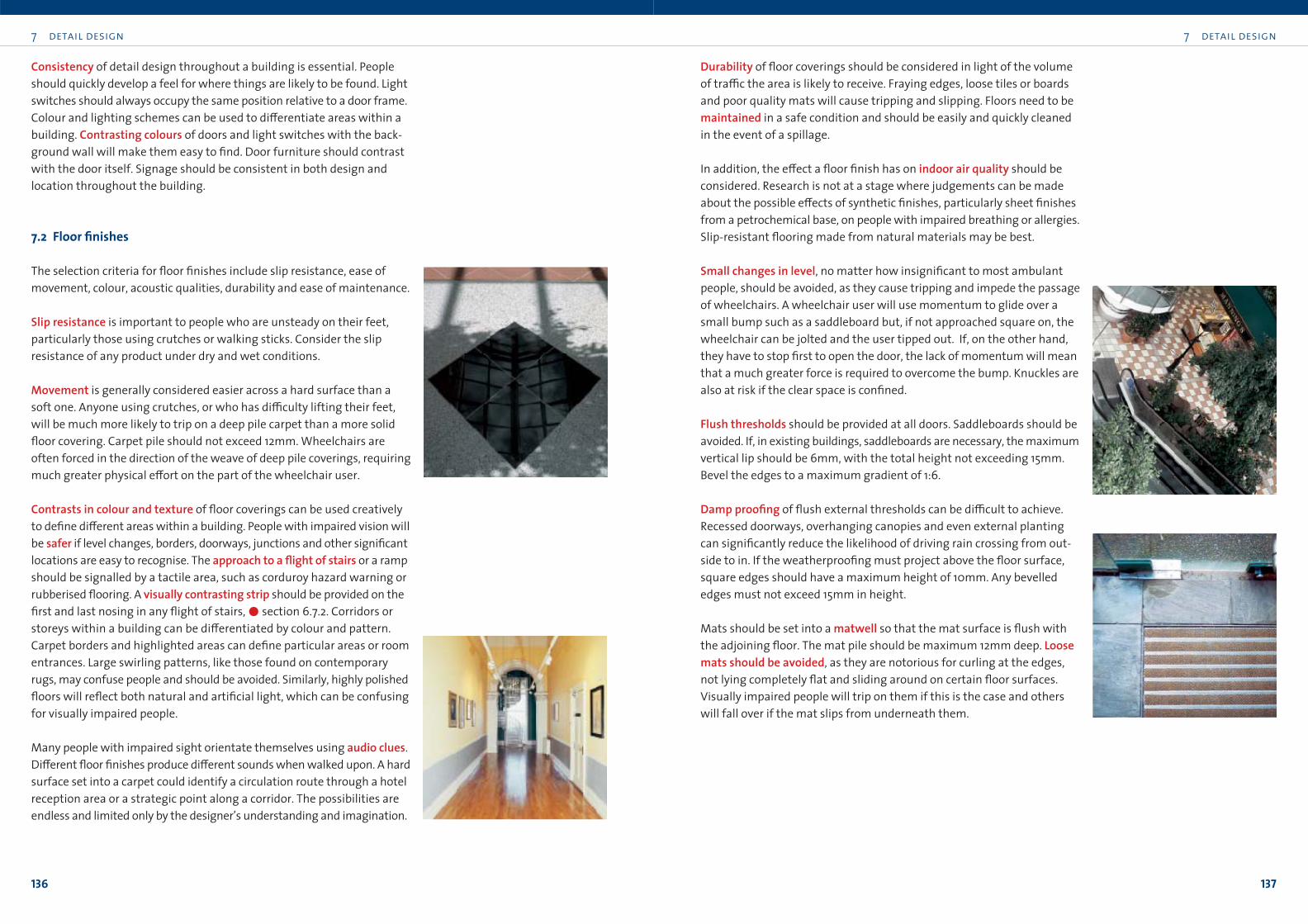
7 detail design
137
7 detail design
136
Durability of floor coverings should be considered in light of the volume
of tra≤c the area is likely to receive. Fraying edges, loose tiles or boards
and poor quality mats will cause tripping and slipping. Floors need to be
maintained in a safe condition and should be easily and quickly cleaned
in the event of a spillage.
In addition, the e≠ect a floor finish has on indoor air quality should be
considered. Research is not at a stage where judgements can be made
about the possible e≠ects of synthetic finishes, particularly sheet finishes
from a petrochemical base, on people with impaired breathing or allergies.
Slip-resistant flooring made from natural materials may be best.
Small changes in level, no matter how insignificant to most ambulant
people, should be avoided, as they cause tripping and impede the passage
of wheelchairs. A wheelchair user will use momentum to glide over a
small bump such as a saddleboard but, if not approached square on, the
wheelchair can be jolted and the user tipped out. If, on the other hand,
they have to stop first to open the door, the lack of momentum will mean
that a much greater force is required to overcome the bump. Knuckles are
also at risk if the clear space is confined.
Flush thresholds should be provided at all doors. Saddleboards should be
avoided. If, in existing buildings, saddleboards are necessary, the maximum
vertical lip should be 6mm, with the total height not exceeding 15mm.
Bevel the edges to a maximum gradient of 1:6.
Damp proofing of flush external thresholds can be di≤cult to achieve.
Recessed doorways, overhanging canopies and even external planting
can significantly reduce the likelihood of driving rain crossing from out-
side to in. If the weatherproofing must project above the floor surface,
square edges should have a maximum height of 10mm. Any bevelled
edges must not exceed 15mm in height.
Mats should be set into a matwell so that the mat surface is flush with
the adjoining floor. The mat pile should be maximum 12mm deep. Loosemats should be avoided, as they are notorious for curling at the edges,
not lying completely flat and sliding around on certain floor surfaces.
Visually impaired people will trip on them if this is the case and others
will fall over if the mat slips from underneath them.
Consistency of detail design throughout a building is essential. People
should quickly develop a feel for where things are likely to be found. Light
switches should always occupy the same position relative to a door frame.
Colour and lighting schemes can be used to di≠erentiate areas within a
building. Contrasting colours of doors and light switches with the back-
ground wall will make them easy to find. Door furniture should contrast
with the door itself. Signage should be consistent in both design and
location throughout the building.
7.2 Floor finishes
The selection criteria for floor finishes include slip resistance, ease of
movement, colour, acoustic qualities, durability and ease of maintenance.
Slip resistance is important to people who are unsteady on their feet,
particularly those using crutches or walking sticks. Consider the slip
resistance of any product under dry and wet conditions.
Movement is generally considered easier across a hard surface than a
soft one. Anyone using crutches, or who has di≤culty lifting their feet,
will be much more likely to trip on a deep pile carpet than a more solid
floor covering. Carpet pile should not exceed 12mm. Wheelchairs are
often forced in the direction of the weave of deep pile coverings, requiring
much greater physical e≠ort on the part of the wheelchair user.
Contrasts in colour and texture of floor coverings can be used creatively
to define di≠erent areas within a building. People with impaired vision will
be safer if level changes, borders, doorways, junctions and other significant
locations are easy to recognise. The approach to a flight of stairs or a ramp
should be signalled by a tactile area, such as corduroy hazard warning or
rubberised flooring. A visually contrasting strip should be provided on the
first and last nosing in any flight of stairs,!section 6.7.2. Corridors or
storeys within a building can be di≠erentiated by colour and pattern.
Carpet borders and highlighted areas can define particular areas or room
entrances. Large swirling patterns, like those found on contemporary
rugs, may confuse people and should be avoided. Similarly, highly polished
floors will reflect both natural and artificial light, which can be confusing
for visually impaired people.
Many people with impaired sight orientate themselves using audio clues.
Di≠erent floor finishes produce di≠erent sounds when walked upon. A hard
surface set into a carpet could identify a circulation route through a hotel
reception area or a strategic point along a corridor. The possibilities are
endless and limited only by the designer’s understanding and imagination.
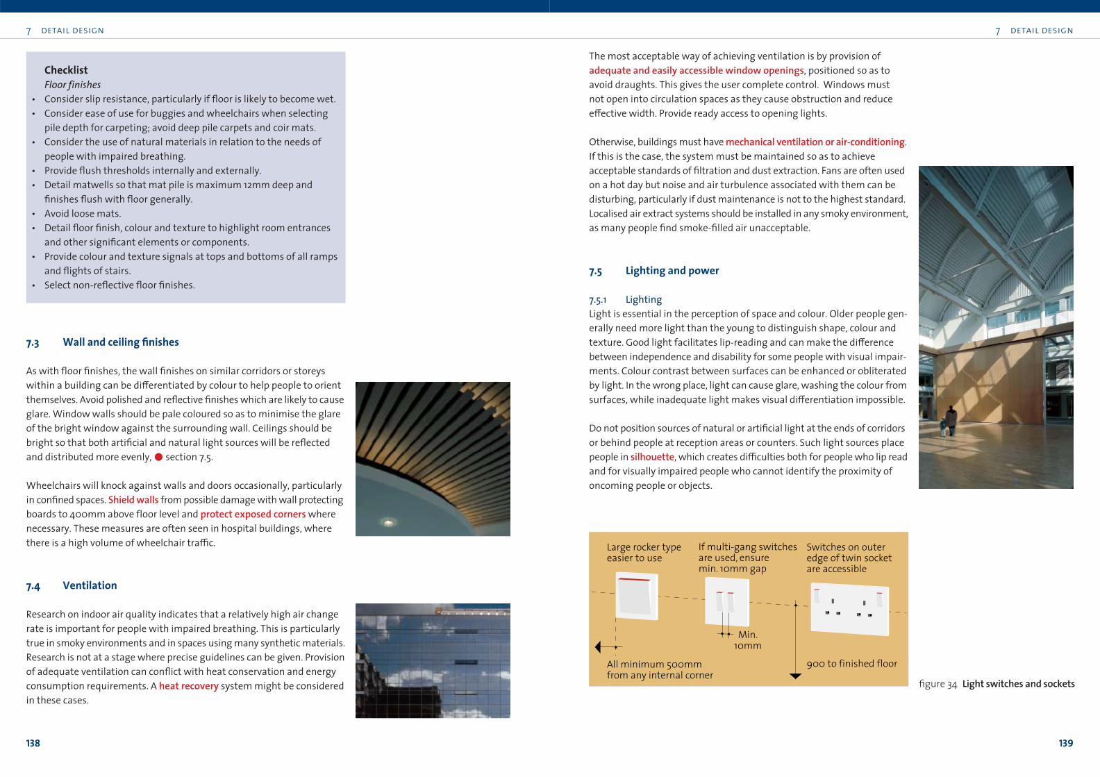
7 detail design
139
7 detail design
138
The most acceptable way of achieving ventilation is by provision of
adequate and easily accessible window openings, positioned so as to
avoid draughts. This gives the user complete control. Windows must
not open into circulation spaces as they cause obstruction and reduce
e≠ective width. Provide ready access to opening lights.
Otherwise, buildings must have mechanical ventilation or air-conditioning.
If this is the case, the system must be maintained so as to achieve
acceptable standards of filtration and dust extraction. Fans are often used
on a hot day but noise and air turbulence associated with them can be
disturbing, particularly if dust maintenance is not to the highest standard.
Localised air extract systems should be installed in any smoky environment,
as many people find smoke-filled air unacceptable.
7.5 Lighting and power
7.5.1 LightingLight is essential in the perception of space and colour. Older people gen-
erally need more light than the young to distinguish shape, colour and
texture. Good light facilitates lip-reading and can make the di≠erence
between independence and disability for some people with visual impair-
ments. Colour contrast between surfaces can be enhanced or obliterated
by light. In the wrong place, light can cause glare, washing the colour from
surfaces, while inadequate light makes visual di≠erentiation impossible.
Do not position sources of natural or artificial light at the ends of corridors
or behind people at reception areas or counters. Such light sources place
people in silhouette, which creates di≤culties both for people who lip read
and for visually impaired people who cannot identify the proximity of
oncoming people or objects.
ChecklistFloor finishes
• Consider slip resistance, particularly if floor is likely to become wet.
• Consider ease of use for buggies and wheelchairs when selecting
pile depth for carpeting; avoid deep pile carpets and coir mats.
• Consider the use of natural materials in relation to the needs of
people with impaired breathing.
• Provide flush thresholds internally and externally.
• Detail matwells so that mat pile is maximum 12mm deep and
finishes flush with floor generally.
• Avoid loose mats.
• Detail floor finish, colour and texture to highlight room entrances
and other significant elements or components.
• Provide colour and texture signals at tops and bottoms of all ramps
and flights of stairs.
• Select non-reflective floor finishes.
7.3 Wall and ceiling finishes
As with floor finishes, the wall finishes on similar corridors or storeys
within a building can be di≠erentiated by colour to help people to orient
themselves. Avoid polished and reflective finishes which are likely to cause
glare. Window walls should be pale coloured so as to minimise the glare
of the bright window against the surrounding wall. Ceilings should be
bright so that both artificial and natural light sources will be reflected
and distributed more evenly,!section 7.5.
Wheelchairs will knock against walls and doors occasionally, particularly
in confined spaces. Shield walls from possible damage with wall protecting
boards to 400mm above floor level and protect exposed corners where
necessary. These measures are often seen in hospital buildings, where
there is a high volume of wheelchair tra≤c.
7.4 Ventilation
Research on indoor air quality indicates that a relatively high air change
rate is important for people with impaired breathing. This is particularly
true in smoky environments and in spaces using many synthetic materials.
Research is not at a stage where precise guidelines can be given. Provision
of adequate ventilation can conflict with heat conservation and energy
consumption requirements. A heat recovery system might be considered
in these cases.
Switches on outer edge of twin socketare accessible
Large rocker typeeasier to use
If multi-gang switches are used, ensure min. 10mm gap
900 to finished floorAll minimum 500mm from any internal corner
Min. 10mm
figure 34 Light switches and sockets
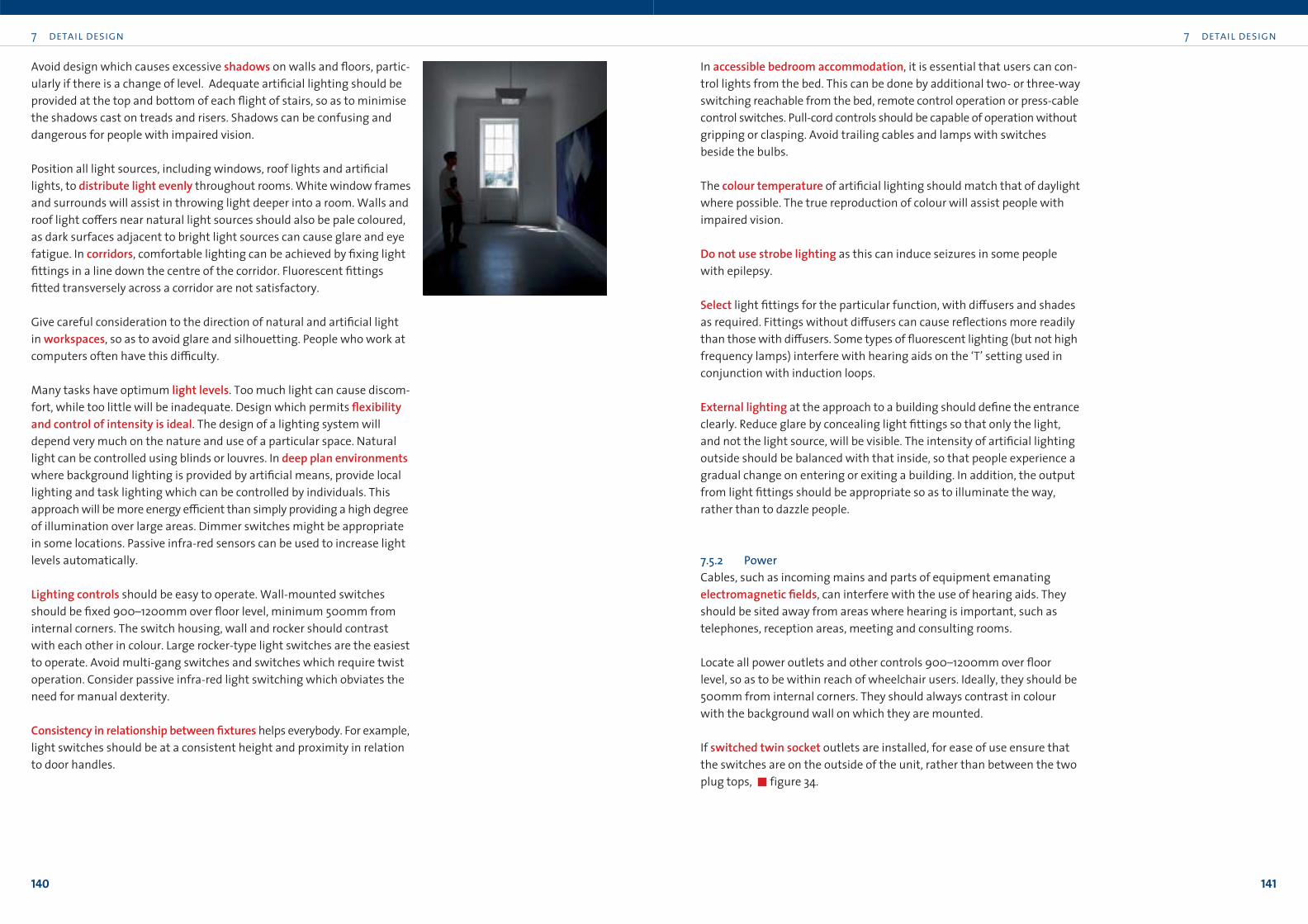
7 detail design
141
7 detail design
140
In accessible bedroom accommodation, it is essential that users can con-
trol lights from the bed. This can be done by additional two- or three-way
switching reachable from the bed, remote control operation or press-cable
control switches. Pull-cord controls should be capable of operation without
gripping or clasping. Avoid trailing cables and lamps with switches
beside the bulbs.
The colour temperature of artificial lighting should match that of daylight
where possible. The true reproduction of colour will assist people with
impaired vision.
Do not use strobe lighting as this can induce seizures in some people
with epilepsy.
Select light fittings for the particular function, with di≠users and shades
as required. Fittings without di≠users can cause reflections more readily
than those with di≠users. Some types of fluorescent lighting (but not high
frequency lamps) interfere with hearing aids on the ‘T’ setting used in
conjunction with induction loops.
External lighting at the approach to a building should define the entrance
clearly. Reduce glare by concealing light fittings so that only the light,
and not the light source, will be visible. The intensity of artificial lighting
outside should be balanced with that inside, so that people experience a
gradual change on entering or exiting a building. In addition, the output
from light fittings should be appropriate so as to illuminate the way,
rather than to dazzle people.
7.5.2 PowerCables, such as incoming mains and parts of equipment emanating
electromagnetic fields, can interfere with the use of hearing aids. They
should be sited away from areas where hearing is important, such as
telephones, reception areas, meeting and consulting rooms.
Locate all power outlets and other controls 900–1200mm over floor
level, so as to be within reach of wheelchair users. Ideally, they should be
500mm from internal corners. They should always contrast in colour
with the background wall on which they are mounted.
If switched twin socket outlets are installed, for ease of use ensure that
the switches are on the outside of the unit, rather than between the two
plug tops, !figure 34.
Avoid design which causes excessive shadows on walls and floors, partic-
ularly if there is a change of level. Adequate artificial lighting should be
provided at the top and bottom of each flight of stairs, so as to minimise
the shadows cast on treads and risers. Shadows can be confusing and
dangerous for people with impaired vision.
Position all light sources, including windows, roof lights and artificial
lights, to distribute light evenly throughout rooms. White window frames
and surrounds will assist in throwing light deeper into a room. Walls and
roof light co≠ers near natural light sources should also be pale coloured,
as dark surfaces adjacent to bright light sources can cause glare and eye
fatigue. In corridors, comfortable lighting can be achieved by fixing light
fittings in a line down the centre of the corridor. Fluorescent fittings
fitted transversely across a corridor are not satisfactory.
Give careful consideration to the direction of natural and artificial light
in workspaces, so as to avoid glare and silhouetting. People who work at
computers often have this di≤culty.
Many tasks have optimum light levels. Too much light can cause discom-
fort, while too little will be inadequate. Design which permits flexibilityand control of intensity is ideal. The design of a lighting system will
depend very much on the nature and use of a particular space. Natural
light can be controlled using blinds or louvres. In deep plan environmentswhere background lighting is provided by artificial means, provide local
lighting and task lighting which can be controlled by individuals. This
approach will be more energy e≤cient than simply providing a high degree
of illumination over large areas. Dimmer switches might be appropriate
in some locations. Passive infra-red sensors can be used to increase light
levels automatically.
Lighting controls should be easy to operate. Wall-mounted switches
should be fixed 900–1200mm over floor level, minimum 500mm from
internal corners. The switch housing, wall and rocker should contrast
with each other in colour. Large rocker-type light switches are the easiest
to operate. Avoid multi-gang switches and switches which require twist
operation. Consider passive infra-red light switching which obviates the
need for manual dexterity.
Consistency in relationship between fixtures helps everybody. For example,
light switches should be at a consistent height and proximity in relation
to door handles.
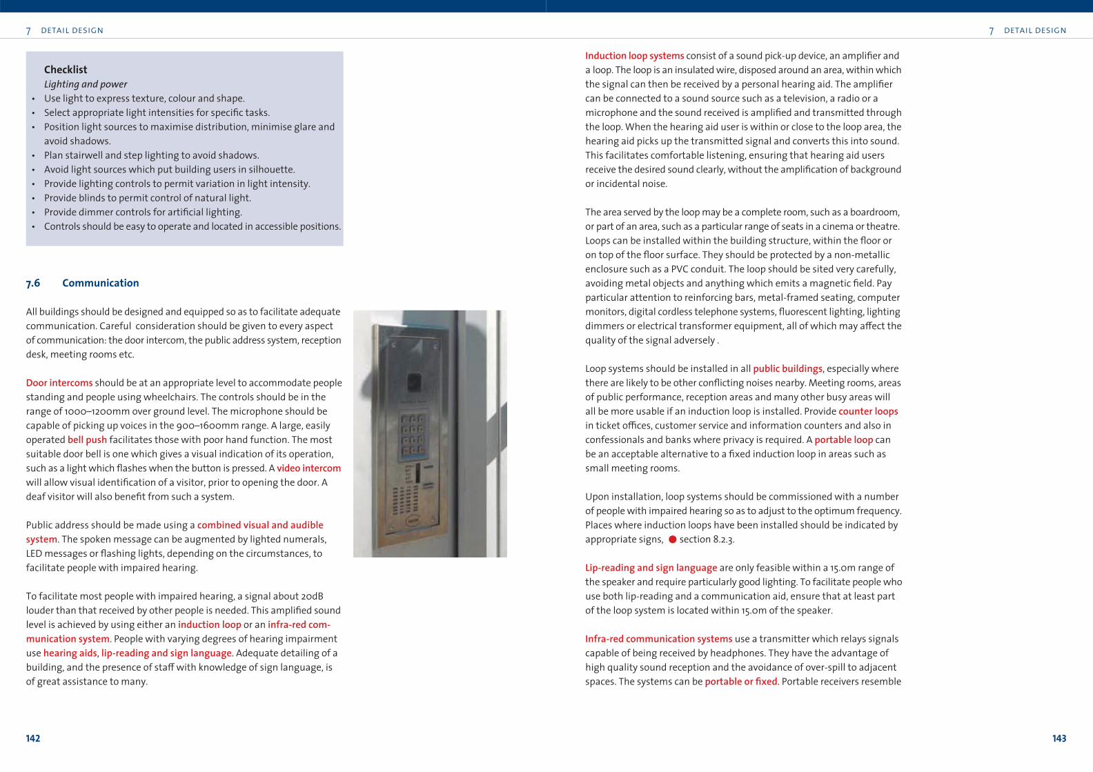
7 detail design
143
7 detail design
142
Induction loop systems consist of a sound pick-up device, an amplifier and
a loop. The loop is an insulated wire, disposed around an area, within which
the signal can then be received by a personal hearing aid. The amplifier
can be connected to a sound source such as a television, a radio or a
microphone and the sound received is amplified and transmitted through
the loop. When the hearing aid user is within or close to the loop area, the
hearing aid picks up the transmitted signal and converts this into sound.
This facilitates comfortable listening, ensuring that hearing aid users
receive the desired sound clearly, without the amplification of background
or incidental noise.
The area served by the loop may be a complete room, such as a boardroom,
or part of an area, such as a particular range of seats in a cinema or theatre.
Loops can be installed within the building structure, within the floor or
on top of the floor surface. They should be protected by a non-metallic
enclosure such as a PVC conduit. The loop should be sited very carefully,
avoiding metal objects and anything which emits a magnetic field. Pay
particular attention to reinforcing bars, metal-framed seating, computer
monitors, digital cordless telephone systems, fluorescent lighting, lighting
dimmers or electrical transformer equipment, all of which may a≠ect the
quality of the signal adversely .
Loop systems should be installed in all public buildings, especially where
there are likely to be other conflicting noises nearby. Meeting rooms, areas
of public performance, reception areas and many other busy areas will
all be more usable if an induction loop is installed. Provide counter loopsin ticket o≤ces, customer service and information counters and also in
confessionals and banks where privacy is required. A portable loop can
be an acceptable alternative to a fixed induction loop in areas such as
small meeting rooms.
Upon installation, loop systems should be commissioned with a number
of people with impaired hearing so as to adjust to the optimum frequency.
Places where induction loops have been installed should be indicated by
appropriate signs, !section 8.2.3.
Lip-reading and sign language are only feasible within a 15.0m range of
the speaker and require particularly good lighting. To facilitate people who
use both lip-reading and a communication aid, ensure that at least part
of the loop system is located within 15.0m of the speaker.
Infra-red communication systems use a transmitter which relays signals
capable of being received by headphones. They have the advantage of
high quality sound reception and the avoidance of over-spill to adjacent
spaces. The systems can be portable or fixed. Portable receivers resemble
ChecklistLighting and power
• Use light to express texture, colour and shape.
• Select appropriate light intensities for specific tasks.
• Position light sources to maximise distribution, minimise glare and
avoid shadows.
• Plan stairwell and step lighting to avoid shadows.
• Avoid light sources which put building users in silhouette.
• Provide lighting controls to permit variation in light intensity.
• Provide blinds to permit control of natural light.
• Provide dimmer controls for artificial lighting.
• Controls should be easy to operate and located in accessible positions.
7.6 Communication
All buildings should be designed and equipped so as to facilitate adequate
communication. Careful consideration should be given to every aspect
of communication: the door intercom, the public address system, reception
desk, meeting rooms etc.
Door intercoms should be at an appropriate level to accommodate people
standing and people using wheelchairs. The controls should be in the
range of 1000–1200mm over ground level. The microphone should be
capable of picking up voices in the 900–1600mm range. A large, easily
operated bell push facilitates those with poor hand function. The most
suitable door bell is one which gives a visual indication of its operation,
such as a light which flashes when the button is pressed. A video intercomwill allow visual identification of a visitor, prior to opening the door. A
deaf visitor will also benefit from such a system.
Public address should be made using a combined visual and audible system. The spoken message can be augmented by lighted numerals,
LED messages or flashing lights, depending on the circumstances, to
facilitate people with impaired hearing.
To facilitate most people with impaired hearing, a signal about 20dB
louder than that received by other people is needed. This amplified sound
level is achieved by using either an induction loop or an infra-red com-munication system. People with varying degrees of hearing impairment
use hearing aids, lip-reading and sign language. Adequate detailing of a
building, and the presence of sta≠ with knowledge of sign language, is
of great assistance to many.

7 detail design
145
7 detail design
144
7.7.2 Hot water deliveryIn public buildings, the temperature of hot water in washbasins should
be restricted to no more than 43°C and should be thermostatically con-
trolled in showers. People with poor heat register are likely to be scalded
if water is too hot. The same is true for people with impaired movement,
who may not be able to react quickly when scalding water issues from a
tap or shower head.
Signs alerting people as to how to control water temperature properly are
helpful, particularly in hotel bedrooms, sports centres and the like. Shower
heads should be adjustable, to permit direction of the water away from
the body in the event of a sudden change in water flow or temperature.
7.8 Automated teller machines and ticket dispensers
Machines for dispensing money, tickets or small goods should be accessibleand, where possible, should be located on the same level as the adjacent
floor or pavement.
The approach to dispensers should be clear and unobstructed, and at least
900mm wide. The clear area immediately in front of the machine should
be at least 1800 x 1800mm, to allow a wheelchair user to approach the
controls sideways, and to turn around after use. An area of this dimension
also a≠ords an element of privacy at ATMs if the queue starts outside the
area.
A canopy, extending minimum 1200mm from the building face, should be
fitted over any external machine, to o≠er some protection from the rain.
The canopy should be fixed not less than 2200mm above ground, so as
not to cause an overhead obstruction.
a small radio, with communication via headphones. Bench-fitted types
require headphones to be plugged into a socket provided. They cannot,
however, be used in conjunction with hearing aids unless an additional
receiver is fitted. They are most commonly used where multi-lingual
communication is required. They can be used in theatres and concert
halls, where the headphones can be collected from and returned to a
cloakroom attendant. Their disadvantage, in many circumstances, is that
a sole user will be very conspicuous and people will often prefer to struggle
to hear rather than choose to use the system.
ChecklistCommunication systems
• Install induction and counter loops in all public buildings, especially
in auditoria, meeting rooms, ticket o≤ces, areas requiring
confidentiality and where glazed screens a≠ect communication.
• Provide appropriate signs to indicate installation of induction and
counter loops.
• Make portable loops available for areas without permanent loop
systems.
• Ensure that at least part of any loop system is located within 15.0m
of the person speaking.
• Consider infra-red communication systems in theatres and concert
halls.
• Locate doorbell controls 900–1200mm over finished ground level.
• Use large bell pushes, supplemented by light to indicate use.
• Use combined visual/audible public address and queueing systems.
7.7 Heating and hot water
7.7.1 Space heatingOptimum room temperature varies from one person to another. People
who sit at desks will feel cold sooner than people who are moving
around. People with impaired mobility may be particularly a≠ected in
this way. On the other hand, some people are susceptible to heat stress
and care must be taken that room temperature is not set too high. As
with ventilation and lighting, adequate control and flexibility should be
provided to try to suit as many people as possible.
People with poor heat register can burn themselves without realising it.
Low temperature radiators should be provided where the occupancy is
likely to include older people and young children. Minimum 900
500
Min
imum
1200
mm
to
any
obs
truc
tion
1200
dee
p ca
nopy
ATM
Min
imum
900
1800 diameter clear if full turn is required
Canopy overhead to be minimum 2200mm and maximum 2500mm above ground levelto protect from rain
figure 35 ATM
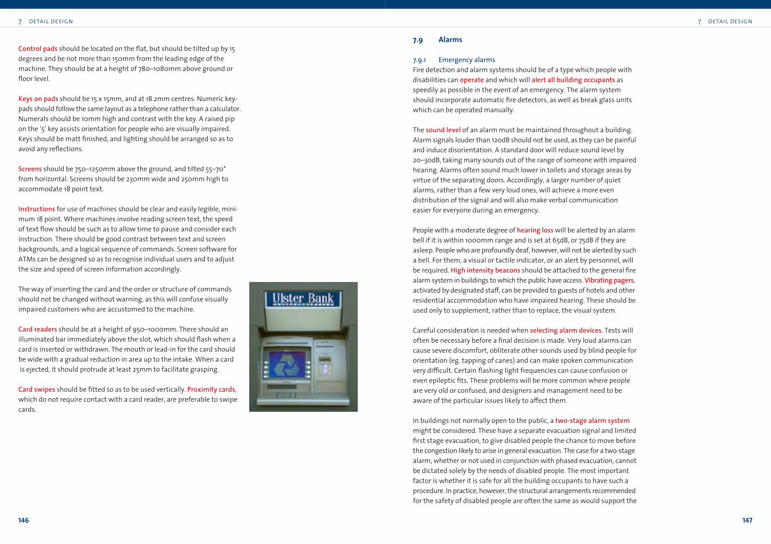
7 detail design
147
7.9 Alarms
7.9.1 Emergency alarmsFire detection and alarm systems should be of a type which people with
disabilities can operate and which will alert all building occupants as
speedily as possible in the event of an emergency. The alarm system
should incorporate automatic fire detectors, as well as break glass units
which can be operated manually.
The sound level of an alarm must be maintained throughout a building.
Alarm signals louder than 120dB should not be used, as they can be painful
and induce disorientation. A standard door will reduce sound level by
20–30dB, taking many sounds out of the range of someone with impaired
hearing. Alarms often sound much lower in toilets and storage areas by
virtue of the separating doors. Accordingly, a larger number of quiet
alarms, rather than a few very loud ones, will achieve a more even
distribution of the signal and will also make verbal communication
easier for everyone during an emergency.
People with a moderate degree of hearing loss will be alerted by an alarm
bell if it is within 1000mm range and is set at 65dB, or 75dB if they are
asleep. People who are profoundly deaf, however, will not be alerted by such
a bell. For them, a visual or tactile indicator, or an alert by personnel, will
be required. High intensity beacons should be attached to the general fire
alarm system in buildings to which the public have access. Vibrating pagers,
activated by designated sta≠, can be provided to guests of hotels and other
residential accommodation who have impaired hearing. These should be
used only to supplement, rather than to replace, the visual system.
Careful consideration is needed when selecting alarm devices. Tests will
often be necessary before a final decision is made. Very loud alarms can
cause severe discomfort, obliterate other sounds used by blind people for
orientation (eg. tapping of canes) and can make spoken communication
very di≤cult. Certain flashing light frequencies can cause confusion or
even epileptic fits. These problems will be more common where people
are very old or confused, and designers and management need to be
aware of the particular issues likely to a≠ect them.
In buildings not normally open to the public, a two-stage alarm systemmight be considered. These have a separate evacuation signal and limited
first stage evacuation, to give disabled people the chance to move before
the congestion likely to arise in general evacuation. The case for a two-stage
alarm, whether or not used in conjunction with phased evacuation, cannot
be dictated solely by the needs of disabled people. The most important
factor is whether it is safe for all the building occupants to have such a
procedure. In practice, however, the structural arrangements recommended
for the safety of disabled people are often the same as would support the
7 detail design
146
Control pads should be located on the flat, but should be tilted up by 15
degrees and be not more than 150mm from the leading edge of the
machine. They should be at a height of 780–1080mm above ground or
floor level.
Keys on pads should be 15 x 15mm, and at 18.2mm centres. Numeric key-
pads should follow the same layout as a telephone rather than a calculator.
Numerals should be 10mm high and contrast with the key. A raised pip
on the ‘5’ key assists orientation for people who are visually impaired.
Keys should be matt finished, and lighting should be arranged so as to
avoid any reflections.
Screens should be 750–1250mm above the ground, and tilted 55–70°
from horizontal. Screens should be 230mm wide and 250mm high to
accommodate 18 point text.
Instructions for use of machines should be clear and easily legible, mini-
mum 18 point. Where machines involve reading screen text, the speed
of text flow should be such as to allow time to pause and consider each
instruction. There should be good contrast between text and screen
backgrounds, and a logical sequence of commands. Screen software for
ATMs can be designed so as to recognise individual users and to adjust
the size and speed of screen information accordingly.
The way of inserting the card and the order or structure of commands
should not be changed without warning, as this will confuse visually
impaired customers who are accustomed to the machine.
Card readers should be at a height of 950–1000mm. There should an
illuminated bar immediately above the slot, which should flash when a
card is inserted or withdrawn. The mouth or lead-in for the card should
be wide with a gradual reduction in area up to the intake. When a card
is ejected, it should protrude at least 25mm to facilitate grasping.
Card swipes should be fitted so as to be used vertically. Proximity cards,
which do not require contact with a card reader, are preferable to swipe
cards.
0 chapter title
149
8.1 General
Design, selection and location of fittings, furniture and machinery should
take account of the diversity of the people who will use them. Good design
facilitates all. Whenever possible, select equipment capable of single-handed operation.
Finishes should resist dust accumulation and be easily cleaned. Deep pile
carpets, heavy curtains and soft furniture, often associated with comfort,
can hold large volumes of dust, which can exacerbate breathing di≤culties
for many people. Particular attention should be given to specification of
finishes in areas where people with breathing di≤culties might have to
sleep or spend long periods of time. Provide a choice of accommodationin hotels, with an appropriate proportion of dust-free, smoke-free and
regular rooms.
Furniture and fittings
part threeBuildings
8
7 detail design
148
adoption of two-stage fire alarms and phased evacuation as a matter of
course. A fire alarm system to BS 5839: Part 1 will generally be suitable for
people with disabilities, but in certain circumstances, additional provisions
may be desirable.
Break glass units should be 900–1200mm above finished floor level,
500mm clear of room corners, and be positioned where the adjacent floor
is unlikely to be obstructed. A minimum of 900mm wide clear space is
necessary to allow a wheelchair user to approach and activate a unit.
Break glass units should be capable of being operated by simple hand, arm
or general limb movement. Avoid systems which require the use of keys
or dextrous hand movements. The units should be red, easily identifiable,
contrasting with their background and located generally near exit points.
Consideration should be given to how far people with mobility impairments
must travel to reach one. No specific advice can be given in this regard, save
to say that more, and not fewer, should be provided in any given building.
7.9.2 Other alarmsWheelchair accessible toilets and bathrooms should be fitted with an
alarm to be activated by the user in the event of emergency. Several
types are available:
• one which activates a light and sound outside the toilet area to
attract the attention of passers-by
• one wired from the toilet to a central control point
• a radio transmitter type alarm to a central point.
The latter two may have a facility for two-way speech. The alarm
should be operable by means of two distinctive push buttons, sited both
at 900mm and at 200mm over floor level. A pull cord extending to the
ground has been the conventional practice but it is not ideal as it often
mistaken for a light switch.
ChecklistFire detection and alarm systems
• In public buildings, supplement the audible alarm by visual indicators.
• Consider two-stage alarm system in buildings not normally open to
the public.
• A larger number of relatively quiet alarms is preferable to a few
extremely loud sounders.
• Alarms should be fitted in all accessible sanitary accommodation.
• Break glass units should be 900–1200mm above finished floor level.
• In hotels etc, provide people with impaired hearing with vibrating
pagers.
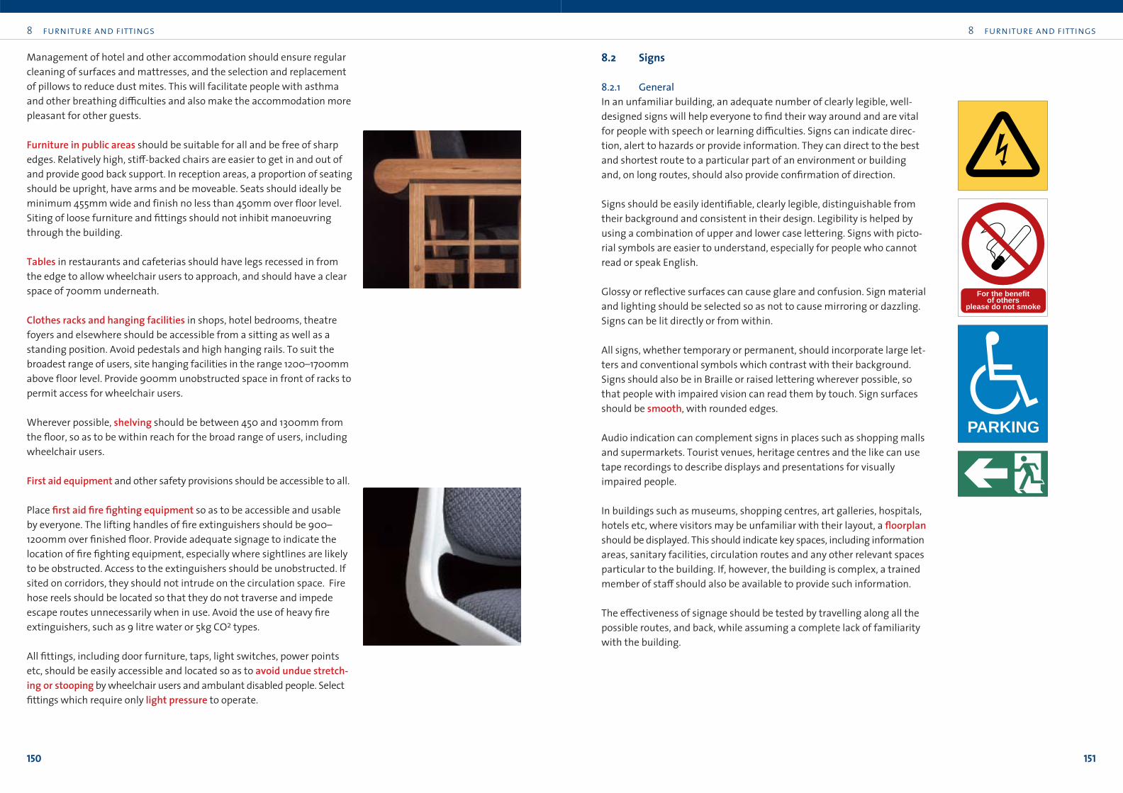
8 furniture and fittings
151
8 furniture and fittings
150
Management of hotel and other accommodation should ensure regular
cleaning of surfaces and mattresses, and the selection and replacement
of pillows to reduce dust mites. This will facilitate people with asthma
and other breathing di≤culties and also make the accommodation more
pleasant for other guests.
Furniture in public areas should be suitable for all and be free of sharp
edges. Relatively high, sti≠-backed chairs are easier to get in and out of
and provide good back support. In reception areas, a proportion of seating
should be upright, have arms and be moveable. Seats should ideally be
minimum 455mm wide and finish no less than 450mm over floor level.
Siting of loose furniture and fittings should not inhibit manoeuvring
through the building.
Tables in restaurants and cafeterias should have legs recessed in from
the edge to allow wheelchair users to approach, and should have a clear
space of 700mm underneath.
Clothes racks and hanging facilities in shops, hotel bedrooms, theatre
foyers and elsewhere should be accessible from a sitting as well as a
standing position. Avoid pedestals and high hanging rails. To suit the
broadest range of users, site hanging facilities in the range 1200–1700mm
above floor level. Provide 900mm unobstructed space in front of racks to
permit access for wheelchair users.
Wherever possible, shelving should be between 450 and 1300mm from
the floor, so as to be within reach for the broad range of users, including
wheelchair users.
First aid equipment and other safety provisions should be accessible to all.
Place first aid fire fighting equipment so as to be accessible and usable
by everyone. The lifting handles of fire extinguishers should be 900–
1200mm over finished floor. Provide adequate signage to indicate the
location of fire fighting equipment, especially where sightlines are likely
to be obstructed. Access to the extinguishers should be unobstructed. If
sited on corridors, they should not intrude on the circulation space. Fire
hose reels should be located so that they do not traverse and impede
escape routes unnecessarily when in use. Avoid the use of heavy fire
extinguishers, such as 9 litre water or 5kg CO2 types.
All fittings, including door furniture, taps, light switches, power points
etc, should be easily accessible and located so as to avoid undue stretch-ing or stooping by wheelchair users and ambulant disabled people. Select
fittings which require only light pressure to operate.
8.2 Signs
8.2.1 GeneralIn an unfamiliar building, an adequate number of clearly legible, well-
designed signs will help everyone to find their way around and are vital
for people with speech or learning di≤culties. Signs can indicate direc-
tion, alert to hazards or provide information. They can direct to the best
and shortest route to a particular part of an environment or building
and, on long routes, should also provide confirmation of direction.
Signs should be easily identifiable, clearly legible, distinguishable from
their background and consistent in their design. Legibility is helped by
using a combination of upper and lower case lettering. Signs with picto-
rial symbols are easier to understand, especially for people who cannot
read or speak English.
Glossy or reflective surfaces can cause glare and confusion. Sign material
and lighting should be selected so as not to cause mirroring or dazzling.
Signs can be lit directly or from within.
All signs, whether temporary or permanent, should incorporate large let-
ters and conventional symbols which contrast with their background.
Signs should also be in Braille or raised lettering wherever possible, so
that people with impaired vision can read them by touch. Sign surfaces
should be smooth, with rounded edges.
Audio indication can complement signs in places such as shopping malls
and supermarkets. Tourist venues, heritage centres and the like can use
tape recordings to describe displays and presentations for visually
impaired people.
In buildings such as museums, shopping centres, art galleries, hospitals,
hotels etc, where visitors may be unfamiliar with their layout, a floorplanshould be displayed. This should indicate key spaces, including information
areas, sanitary facilities, circulation routes and any other relevant spaces
particular to the building. If, however, the building is complex, a trained
member of sta≠ should also be available to provide such information.
The e≠ectiveness of signage should be tested by travelling along all the
possible routes, and back, while assuming a complete lack of familiarity
with the building.
For the benefit �of others �
please do not smoke
PARKING
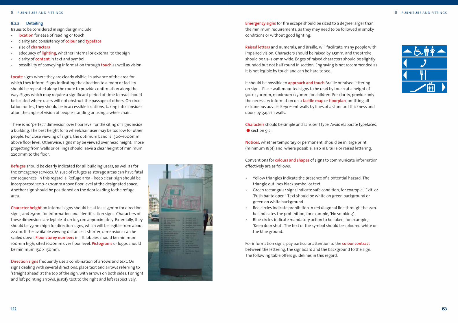
8 furniture and fittings
153
8 furniture and fittings
152
8.2.2 DetailingIssues to be considered in sign design include:
• location for ease of reading or touch
• clarity and consistency of colour and typeface• size of characters• adequacy of lighting, whether internal or external to the sign
• clarity of content in text and symbol
• possibility of conveying information through touch as well as vision.
Locate signs where they are clearly visible, in advance of the area for
which they inform. Signs indicating the direction to a room or facility
should be repeated along the route to provide confirmation along the
way. Signs which may require a significant period of time to read should
be located where users will not obstruct the passage of others. On circu-
lation routes, they should be in accessible locations, taking into consider-
ation the angle of vision of people standing or using a wheelchair.
There is no ‘perfect’ dimension over floor level for the siting of signs inside
a building. The best height for a wheelchair user may be too low for other
people. For close viewing of signs, the optimum band is 1300–1600mm
above floor level. Otherwise, signs may be viewed over head height. Those
projecting from walls or ceilings should leave a clear height of minimum
2200mm to the floor.
Refuges should be clearly indicated for all building users, as well as for
the emergency services. Misuse of refuges as storage areas can have fatal
consequences. In this regard, a ‘Refuge area – keep clear’ sign should be
incorporated 1200–1500mm above floor level at the designated space.
Another sign should be positioned on the door leading to the refuge
area.
Character height on internal signs should be at least 37mm for direction
signs, and 25mm for information and identification signs. Characters of
these dimensions are legible at up to 5.0m approximately. Externally, they
should be 75mm high for direction signs, which will be legible from about
22.0m. If the available viewing distance is shorter, dimensions can be
scaled down. Floor storey numbers in lift lobbies should be minimum
100mm high, sited 1600mm over floor level. Pictograms or logos should
be minimum 150 x 150mm.
Direction signs frequently use a combination of arrows and text. On
signs dealing with several directions, place text and arrows referring to
‘straight ahead’ at the top of the sign, with arrows on both sides. For right
and left pointing arrows, justify text to the right and left respectively.
Emergency signs for fire escape should be sized to a degree larger than
the minimum requirements, as they may need to be followed in smoky
conditions or without good lighting.
Raised letters and numerals, and Braille, will facilitate many people with
impaired vision. Characters should be raised by 1.5mm, and the stroke
should be 1.5–2.0mm wide. Edges of raised characters should be slightly
rounded but not half round in section. Engraving is not recommended as
it is not legible by touch and can be hard to see.
It should be possible to approach and touch Braille or raised lettering
on signs. Place wall-mounted signs to be read by touch at a height of
900–1500mm, maximum 1250mm for children. For clarity, provide only
the necessary information on a tactile map or floorplan, omitting all
extraneous advice. Represent walls by lines of a standard thickness and
doors by gaps in walls.
Characters should be simple and sans serif type. Avoid elaborate typefaces,
!section 9.2.
Notices, whether temporary or permanent, should be in large print
(minimum 18pt) and, where possible, also in Braille or raised lettering.
Conventions for colours and shapes of signs to communicate information
e≠ectively are as follows.
• Yellow triangles indicate the presence of a potential hazard. The
triangle outlines black symbol or text.
• Green rectangular signs indicate safe condition, for example, ‘Exit’ or
‘Push bar to open’. Text should be white on green background or
green on white background.
• Red circles indicate prohibition. A red diagonal line through the sym-
bol indicates the prohibition, for example, ‘No smoking’.
• Blue circles indicate mandatory action to be taken, for example,
‘Keep door shut’. The text of the symbol should be coloured white on
the blue ground.
For information signs, pay particular attention to the colour contrastbetween the lettering, the signboard and the background to the sign.
The following table o≠ers guidelines in this regard.
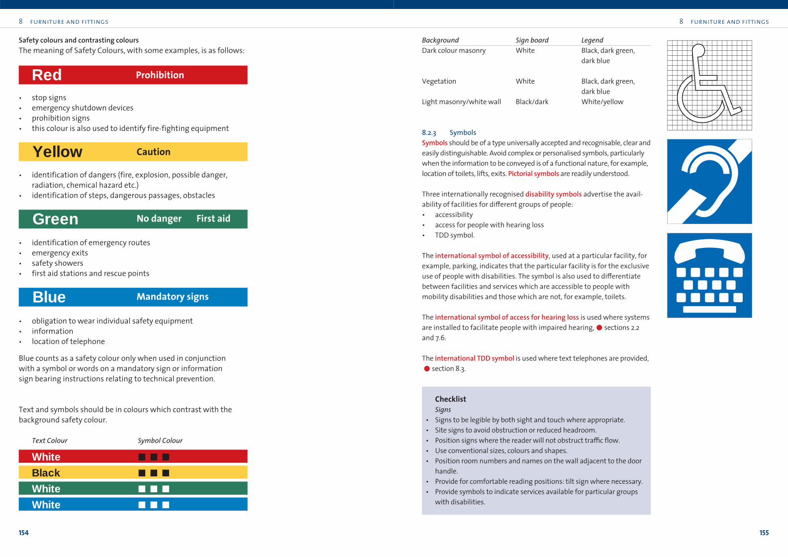
8 furniture and fittings
155
8 furniture and fittings
154
Background Sign board LegendDark colour masonry White Black, dark green,
dark blue
Vegetation White Black, dark green,
dark blue
Light masonry/white wall Black/dark White/yellow
8.2.3 SymbolsSymbols should be of a type universally accepted and recognisable, clear and
easily distinguishable. Avoid complex or personalised symbols, particularly
when the information to be conveyed is of a functional nature, for example,
location of toilets, lifts, exits. Pictorial symbols are readily understood.
Three internationally recognised disability symbols advertise the avail-
ability of facilities for di≠erent groups of people:
• accessibility
• access for people with hearing loss
• TDD symbol.
The international symbol of accessibility, used at a particular facility, for
example, parking, indicates that the particular facility is for the exclusive
use of people with disabilities. The symbol is also used to di≠erentiate
between facilities and services which are accessible to people with
mobility disabilities and those which are not, for example, toilets.
The international symbol of access for hearing loss is used where systems
are installed to facilitate people with impaired hearing,!sections 2.2
and 7.6.
The international TDD symbol is used where text telephones are provided,
!section 8.3.
ChecklistSigns
• Signs to be legible by both sight and touch where appropriate.
• Site signs to avoid obstruction or reduced headroom.
• Position signs where the reader will not obstruct tra≤c flow.
• Use conventional sizes, colours and shapes.
• Position room numbers and names on the wall adjacent to the door
handle.
• Provide for comfortable reading positions: tilt sign where necessary.
• Provide symbols to indicate services available for particular groups
with disabilities.
White """
Black """
White """
White """
Red Prohibition
Yellow Caution
Green No danger First aid
Blue Mandatory signs
Safety colours and contrasting coloursThe meaning of Safety Colours, with some examples, is as follows:
• stop signs
• emergency shutdown devices
• prohibition signs
• this colour is also used to identify fire-fighting equipment
• identification of dangers (fire, explosion, possible danger,
radiation, chemical hazard etc.)
• identification of steps, dangerous passages, obstacles
• identification of emergency routes
• emergency exits
• safety showers
• first aid stations and rescue points
• obligation to wear individual safety equipment
• information
• location of telephone
Blue counts as a safety colour only when used in conjunction
with a symbol or words on a mandatory sign or information
sign bearing instructions relating to technical prevention.
Text and symbols should be in colours which contrast with the
background safety colour.
Text Colour Symbol Colour
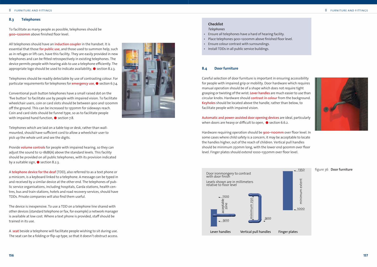
8 furniture and fittings
157
8 furniture and fittings
156
ChecklistTelephones
• Ensure all telephones have a hard of hearing facility.
• Place telephones 900–1200mm above finished floor level.
• Ensure colour contrast with surroundings.
• Install TDDs in all public service buildings.
8.4 Door furniture
Careful selection of door furniture is important in ensuring accessibility
for people with impaired grip or mobility. Door hardware which requires
manual operation should be of a shape which does not require tight
grasping or twisting of the wrist. Lever handles are much easier to use than
circular knobs. Hardware should contrast in colour from the background.
Keyholes should be located above the handle, rather than below, to
facilitate people with impaired vision.
Automatic and power-assisted door opening devices are ideal, particularly
when doors are heavy or di≤cult to open, !section 6.6.2.
Hardware requiring operation should be 900–1100mm over floor level. In
some cases where child safety is a concern, it may be acceptable to locate
the handles higher, out of the reach of children. Vertical pull handles
should be minimum 250mm long, with the lower end 900mm over floor
level. Finger plates should extend 1000–1350mm over floor level.
8.3 Telephones
To facilitate as many people as possible, telephones should be
900–1200mm above finished floor level.
All telephones should have an induction coupler in the handset. It is
essential that those for public use, and those used to summon help, such
as in refuges or lift cars, have this facility. They are easily provided in new
telephones and can be fitted retrospectively in existing telephones. The
device permits people with hearing aids to use a telephone e≤ciently. The
appropriate logo should be used to indicate availability,!section 8.2.3.
Telephones should be readily detectable by use of contrasting colour. For
particular requirements for telephones for emergency use,!section 6.7.4.
Conventional push button telephones have a small raised dot on the
‘five button’ to facilitate use by people with impaired vision. To facilitate
wheelchair users, coin or card slots should be between 900 and 1200mm
o≠ the ground. This can be increased to 1350mm for sideways reach.
Coin and card slots should be funnel type, so as to facilitate people
with impaired hand function,!section 7.8.
Telephones which are laid on a table top or desk, rather than wall-
mounted, should have su≤cient cord to allow a wheelchair user to
pick up the whole unit and see the digits.
Provide volume controls for people with impaired hearing, so they can
adjust the sound to 12-18dB(A) above the standard levels. This facility
should be provided on all public telephones, with its provision indicated
by a suitable sign,!section 8.2.3.
A telephone device for the deaf (TDD), also referred to as a text phone or
a minicom, is a keyboard linked to a telephone. A message can be typed in
and received by a similar device at the other end. The telephones of pub-
lic service organisations, including hospitals, Garda stations, health cen-
tres, bus and train stations, hotels and road recovery services, should have
TDDs. Private companies will also find them useful.
The device is inexpensive. To use a TDD on a telephone line shared with
other devices (standard telephone or fax, for example) a network manager
is available at low cost. Where a text phone is provided, sta≠ should be
trained in its use.
A seat beside a telephone will facilitate people wishing to sit during use.
The seat can be a folding or flip-up type, so that it doesn’t obstruct access.
900900
1100
min
imum
250
acce
ptab
le zo
ne min
imum
exte
nt
1000
1350
Lever handles Vertical pull handles Finger plates
Door ironmongery to contrast with door finishLevels shown are in millimeters relative to floor level
figure 36 Door furniture

8 furniture and fittings
159
8 furniture and fittings
158
ChecklistDoor furniture
• Hardware which is to be operated should contrast in colour with
door leaf.
• Site door controls at height for both seated and standing users.
• Locate letter boxes 900mm above ground level.
• If a door closer is necessary, ensure it is delayed-action or slow-action
type, and operated at maximum 12Nm pressure.
• Use cranked hinges where necessary to achieve requisite opening
widths.
• Kick plates, where provided, should be minimum 400mm high.
• Site and dimension pull handles to allow knuckles to clear adjacent
frames or leaves.
8.5 Switches and controls
The advice in this book relates to the design of controls for general use,
operated on a day-to-day basis by a broad range of people. Controls for
specific use, operated by a limited number of people after special train-
ing, are outside the scope of this book.
Controls should be obvious, easy to reach, simple to operate and consis-tent in design. They should be easy to grip, turn or twist. Controls and
switches should be adequate in size and contrast in colour with their
background. When used for similar operations in the same location, con-
trol panels and switches should function in the same way or sequence.
Height of a control panel may vary, depending on the type of switch used
and whether it is associated with a dial or other visual indicator. Switches
on inclined surfaces are easier to operate than those on vertical surfaces.
Controls on a vertical surface should be in the range of 900–1200mm
above floor level. Controls on a flat surface should be tilted up by 15° and
finish 780–1080mm above floor level. All switches and controls should be
at least 500mm from any obstruction, such as internal corners. The
approach should be at least 900mm wide.
When installing wall-mounted lighting switches in dwellings, provide
20mm deep switch housings in lieu of the usual 10mm, to facilitate
possible future installation of remote control switches,!section 9.11.2.
Hardware on emergency exit doors should be capable of easy operation
for people with impaired grip. Mechanisms which demand a
lifting/pushing motion are hard to use. Direct push operation is better.
Where kick plates are provided to protect against damage to door finish-
es (desirable where there is a significant occupancy of wheelchair users)
these should extend to the full door width and 400mm up from the door
base.
With respect to door closers, a door is considered ‘heavy’ if, when it is
pushed by someone using a wheelchair, it resists opening, and the per-
son in the wheelchair moves backwards. Where heavy doors are used, or
where a self-closing device is fitted, resistance to opening should not
exceed 12Nm pressure. Delayed-action door closers assist accessibility by
making continued pressure against the door unnecessary as the person
passes through.
Site letter boxes 900mm over ground level to facilitate use without
bending, and provide a level approach minimum 900mm wide. For more
discussion on doors at entrances,!section 6.6.2.
Where an existing doorset is too narrow for wheelchair access, and
where it is impossible to widen the opening, the clear ope width can
sometimes be increased by fitting the door leaf with cranked hinges, to
allow it stand open clear of the doorway.
Use cranked hinges to maintain maximum clear opening
figure 37 Cranked hinges
8 furniture and fittings
161
ChecklistSwitches and controls
• Switches and controls should be readily detectable and operable
by light pressure and without undue stretching or stooping.
• Locate switches and controls 500mm, minimum 300mm, from
internal corners.
• Optimum general operating zone is 900–1200mm.
• Switches should be large and easy to operate.
• Avoid the use of switches demanding finger dexterity.
• Make sets of controls consistent in design for easy use.
• Controls should be on inclined surfaces where possible.
• Use colour to locate controls and to distinguish between operations.
• Provide automatic or remote controls where possible.
• Arrange controls in a logical operating sequence.
• Any instructions should be easily readable and simply phrased.
• Wall-mounted lighting switches in dwellings should have 20mm
deep switch housings.
8 furniture and fittings
160
Colour can be used in many ways. Colour contrast between a switch and
the wall can help people to locate the switch. Colour can also be used as a
means of detecting the state or function of a single-function switch. For
example, red indicates ‘stop’ or ‘o≠’, while green indicates ‘go’ or ‘on’.
Similarly, colour may be used on dials where, for example, ‘full’ may be
indicated by the colour black and ‘empty’ by white. Where a switch is not
available in a colour which contrasts with its surroundings, coloured mar-
gins, which are capable of providing the necessary contrast, are available
for some of the more common switch types, such as lights or sockets.
Controls should generally be in reach of a wheelchair user, except where
interference by children might be an issue. For discussion on light switches
and power outlets, !section 7.5.
Switches vary in type, depending on function. Many domestic appliances,
such as cookers, microwave ovens and the like, are operated by small
buttons which are di≤cult to see, twist or turn. The ESB and An Bord Gáis
can advise on domestic appliances which are fitted with alternative control
mechanisms and Consumer Choice magazine often evaluates accessible
features in its surveys.
Switching by sensors is becoming widely used, particularly for lighting.
Sensors can be activated through movement, temperature change, the
sound of a voice, a break in electronic circuitry or infra-red beams. Such
arrangements, used in automatic water taps, light switching and door
opening gear, are ideal as they are independent of ability or disability.
Where infra-red beams are used as a means of detection for automatic
doors etc, ensure that people of small stature or in wheelchairs can be
detected,!section 6.7.4.
When arranging switches on control panels, place the most important
switches in the most obvious locations. Priority displays should be sited
within a cone vision of 30°. Controls or displays with similar functions
should be grouped together. Position controls so that, when being used,
the relevant displays are not obscured. Items should be capable of being
located in a sequence, to enable progress from left to right and from top
to bottom. Large buttons are easier to operate than those which require
finger dexterity. For ease of operation the space between buttons should
be at least 15mm clear in both directions. Where switches project, the
distance from the face should be 5–12mm. It should not be necessary to
press switches below the surrounding surface. On switched twin socketoutlets, ensure that the switches are on the outer edges of the plate, rather
than between the two plug tops, "figure 35.
For advice on ATMs and ticket machines, !section 7.8.
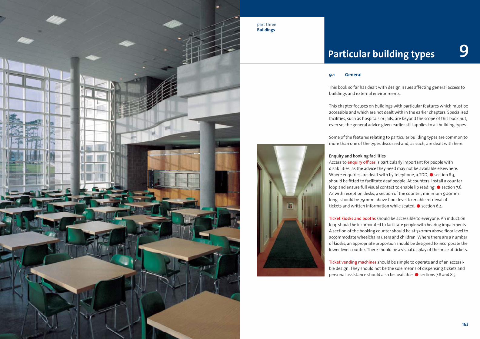
0 chapter title
163
9.1 General
This book so far has dealt with design issues a≠ecting general access to
buildings and external environments.
This chapter focuses on buildings with particular features which must be
accessible and which are not dealt with in the earlier chapters. Specialised
facilities, such as hospitals or jails, are beyond the scope of this book but,
even so, the general advice given earlier still applies to all building types.
Some of the features relating to particular building types are common to
more than one of the types discussed and, as such, are dealt with here.
Enquiry and booking facilitiesAccess to enquiry o≤ces is particularly important for people with
disabilities, as the advice they need may not be available elsewhere.
Where enquiries are dealt with by telephone, a TDD,!section 8.3,
should be fitted to facilitate deaf people. At counters, install a counter
loop and ensure full visual contact to enable lip reading,!section 7.6.
As with reception desks, a section of the counter, minimum 900mm
long, should be 750mm above floor level to enable retrieval of
tickets and written information while seated,!section 6.4.
Ticket kiosks and booths should be accessible to everyone. An induction
loop should be incorporated to facilitate people with hearing impairments.
A section of the booking counter should be at 750mm above floor level to
accommodate wheelchairs users and children. Where there are a number
of kiosks, an appropriate proportion should be designed to incorporate the
lower level counter. There should be a visual display of the price of tickets.
Ticket vending machines should be simple to operate and of an accessi-
ble design. They should not be the sole means of dispensing tickets and
personal assistance should also be available,!sections 7.8 and 8.5.
Particular building types
part threeBuildings
9
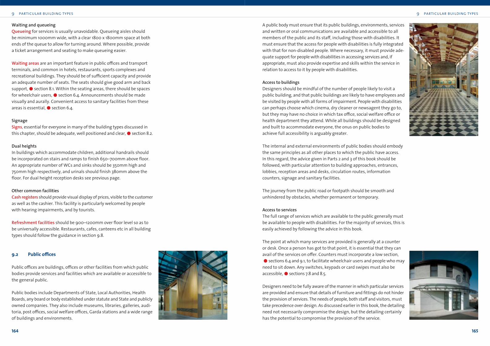
9 particular building types
165
9 particular building types
164
A public body must ensure that its public buildings, environments, services
and written or oral communications are available and accessible to all
members of the public and its sta≠, including those with disabilities. It
must ensure that the access for people with disabilities is fully integrated
with that for non-disabled people. Where necessary, it must provide ade-
quate support for people with disabilities in accessing services and, if
appropriate, must also provide expertise and skills within the service in
relation to access to it by people with disabilities.
Access to buildingsDesigners should be mindful of the number of people likely to visit a
public building, and that public buildings are likely to have employees and
be visited by people with all forms of impairment. People with disabilities
can perhaps choose which cinema, dry cleaner or newsagent they go to,
but they may have no choice in which tax o≤ce, social welfare o≤ce or
health department they attend. While all buildings should be designed
and built to accommodate everyone, the onus on public bodies to
achieve full accessibility is arguably greater.
The internal and external environments of public bodies should embody
the same principles as all other places to which the public have access.
In this regard, the advice given in Parts 2 and 3 of this book should be
followed, with particular attention to building approaches, entrances,
lobbies, reception areas and desks, circulation routes, information
counters, signage and sanitary facilities.
The journey from the public road or footpath should be smooth and
unhindered by obstacles, whether permanent or temporary.
Access to servicesThe full range of services which are available to the public generally must
be available to people with disabilities. For the majority of services, this is
easily achieved by following the advice in this book.
The point at which many services are provided is generally at a counter
or desk. Once a person has got to that point, it is essential that they can
avail of the services on o≠er. Counters must incorporate a low section,
!sections 6.4 and 9.1, to facilitate wheelchair users and people who may
need to sit down. Any switches, keypads or card swipes must also be
accessible,!sections 7.8 and 8.5.
Designers need to be fully aware of the manner in which particular services
are provided and ensure that details of furniture and fittings do not hinder
the provision of services. The needs of people, both sta≠ and visitors, must
take precedence over design. As discussed earlier in this book, the detailing
need not necessarily compromise the design, but the detailing certainly
has the potential to compromise the provision of the service.
Waiting and queueingQueueing for services is usually unavoidable. Queueing aisles should
be minimum 1000mm wide, with a clear 1800 x 1800mm space at both
ends of the queue to allow for turning around. Where possible, provide
a ticket arrangement and seating to make queueing easier.
Waiting areas are an important feature in public o≤ces and transport
terminals, and common in hotels, restaurants, sports complexes and
recreational buildings. They should be of su≤cient capacity and provide
an adequate number of seats. The seats should give good arm and back
support,!section 8.1. Within the seating areas, there should be spaces
for wheelchair users,!section 6.4. Announcements should be made
visually and aurally. Convenient access to sanitary facilities from these
areas is essential,!section 6.4.
SignageSigns, essential for everyone in many of the building types discussed in
this chapter, should be adequate, well positioned and clear,!section 8.2.
Dual heights In buildings which accommodate children, additional handrails should
be incorporated on stairs and ramps to finish 650–700mm above floor.
An appropriate number of WCs and sinks should be 350mm high and
750mm high respectively, and urinals should finish 380mm above the
floor. For dual height reception desks see previous page.
Other common facilitiesCash registers should provide visual display of prices, visible to the customer
as well as the cashier. This facility is particularly welcomed by people
with hearing impairments, and by tourists.
Refreshment facilities should be 900–1200mm over floor level so as to
be universally accessible. Restaurants, cafes, canteens etc in all building
types should follow the guidance in section 9.8.
9.2 Public o≤ces
Public o≤ces are buildings, o≤ces or other facilities from which public
bodies provide services and facilities which are available or accessible to
the general public.
Public bodies include Departments of State, Local Authorities, Health
Boards, any board or body established under statute and State and publicly
owned companies. They also include museums, libraries, galleries, audi-
toria, post o≤ces, social welfare o≤ces, Garda stations and a wide range
of buildings and environments.
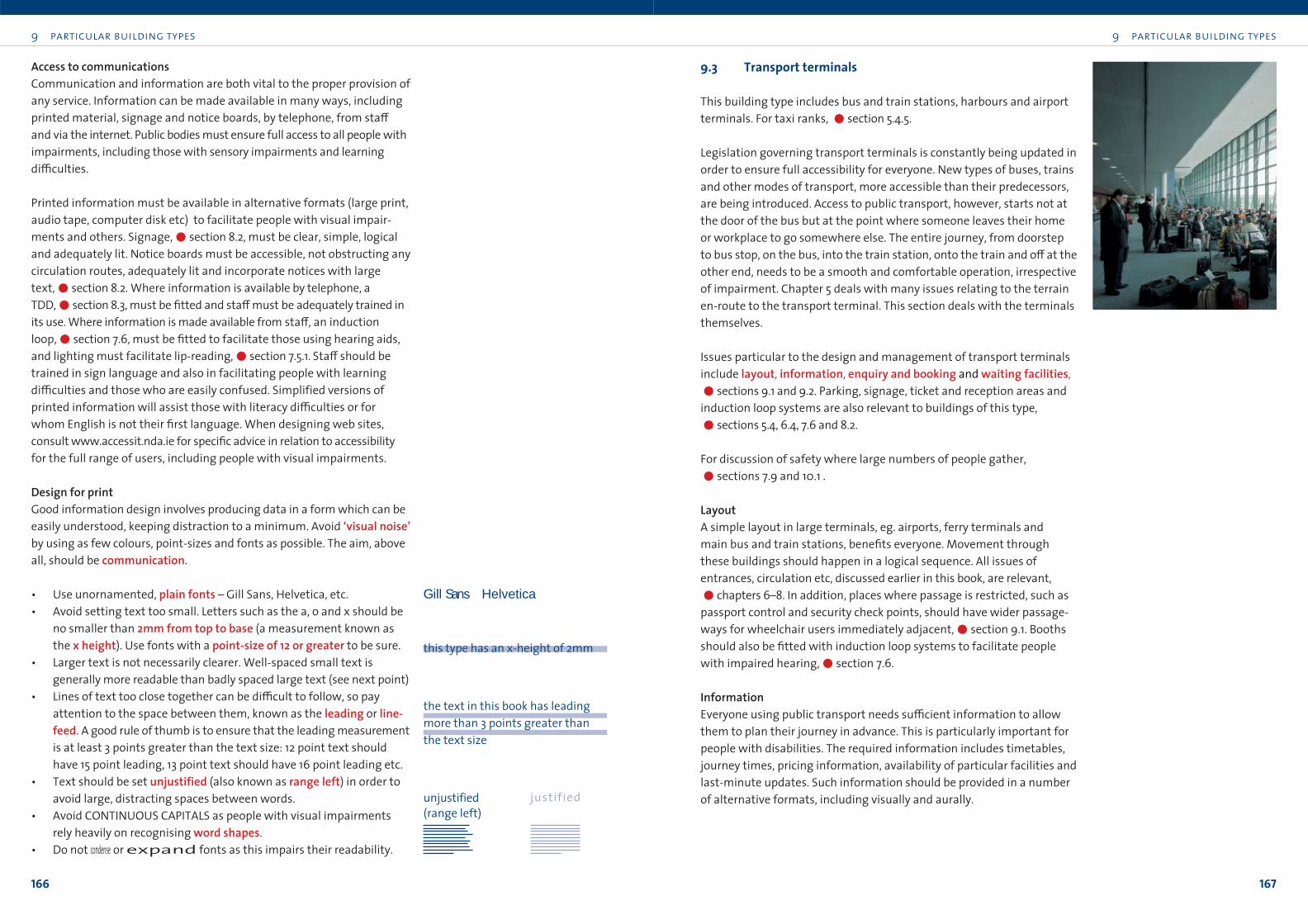
9 particular building types
167
9 particular building types
166
9.3 Transport terminals
This building type includes bus and train stations, harbours and airport
terminals. For taxi ranks, !section 5.4.5.
Legislation governing transport terminals is constantly being updated in
order to ensure full accessibility for everyone. New types of buses, trains
and other modes of transport, more accessible than their predecessors,
are being introduced. Access to public transport, however, starts not at
the door of the bus but at the point where someone leaves their home
or workplace to go somewhere else. The entire journey, from doorstep
to bus stop, on the bus, into the train station, onto the train and o≠ at the
other end, needs to be a smooth and comfortable operation, irrespective
of impairment. Chapter 5 deals with many issues relating to the terrain
en-route to the transport terminal. This section deals with the terminals
themselves.
Issues particular to the design and management of transport terminals
include layout, information, enquiry and booking and waiting facilities,!sections 9.1 and 9.2. Parking, signage, ticket and reception areas and
induction loop systems are also relevant to buildings of this type,
!sections 5.4, 6.4, 7.6 and 8.2.
For discussion of safety where large numbers of people gather,
!sections 7.9 and 10.1 .
LayoutA simple layout in large terminals, eg. airports, ferry terminals and
main bus and train stations, benefits everyone. Movement through
these buildings should happen in a logical sequence. All issues of
entrances, circulation etc, discussed earlier in this book, are relevant,
!chapters 6–8. In addition, places where passage is restricted, such as
passport control and security check points, should have wider passage-
ways for wheelchair users immediately adjacent,!section 9.1. Booths
should also be fitted with induction loop systems to facilitate people
with impaired hearing,!section 7.6.
InformationEveryone using public transport needs su≤cient information to allow
them to plan their journey in advance. This is particularly important for
people with disabilities. The required information includes timetables,
journey times, pricing information, availability of particular facilities and
last-minute updates. Such information should be provided in a number
of alternative formats, including visually and aurally.
Access to communicationsCommunication and information are both vital to the proper provision of
any service. Information can be made available in many ways, including
printed material, signage and notice boards, by telephone, from sta≠
and via the internet. Public bodies must ensure full access to all people with
impairments, including those with sensory impairments and learning
di≤culties.
Printed information must be available in alternative formats (large print,
audio tape, computer disk etc) to facilitate people with visual impair-
ments and others. Signage,!section 8.2, must be clear, simple, logical
and adequately lit. Notice boards must be accessible, not obstructing any
circulation routes, adequately lit and incorporate notices with large
text,!section 8.2. Where information is available by telephone, a
TDD,!section 8.3, must be fitted and sta≠ must be adequately trained in
its use. Where information is made available from sta≠, an induction
loop,!section 7.6, must be fitted to facilitate those using hearing aids,
and lighting must facilitate lip-reading,!section 7.5.1. Sta≠ should be
trained in sign language and also in facilitating people with learning
di≤culties and those who are easily confused. Simplified versions of
printed information will assist those with literacy di≤culties or for
whom English is not their first language. When designing web sites,
consult www.accessit.nda.ie for specific advice in relation to accessibility
for the full range of users, including people with visual impairments.
Design for printGood information design involves producing data in a form which can be
easily understood, keeping distraction to a minimum. Avoid ‘visual noise’by using as few colours, point-sizes and fonts as possible. The aim, above
all, should be communication.
• Use unornamented, plain fonts – Gill Sans, Helvetica, etc.
• Avoid setting text too small. Letters such as the a, o and x should be
no smaller than 2mm from top to base (a measurement known as
the x height). Use fonts with a point-size of 12 or greater to be sure.
• Larger text is not necessarily clearer. Well-spaced small text is
generally more readable than badly spaced large text (see next point)
• Lines of text too close together can be di≤cult to follow, so pay
attention to the space between them, known as the leading or line-feed. A good rule of thumb is to ensure that the leading measurement
is at least 3 points greater than the text size: 12 point text should
have 15 point leading, 13 point text should have 16 point leading etc.
• Text should be set unjustified (also known as range left) in order to
avoid large, distracting spaces between words.
• Avoid CONTINUOUS CAPITALS as people with visual impairments
rely heavily on recognising word shapes.
• Do not condense or expand fonts as this impairs their readability.
Gill Sans Helvetica
this type has an x-height of 2mm
the text in this book has leading
more than 3 points greater than
the text size
unjustified
(range left)
justified
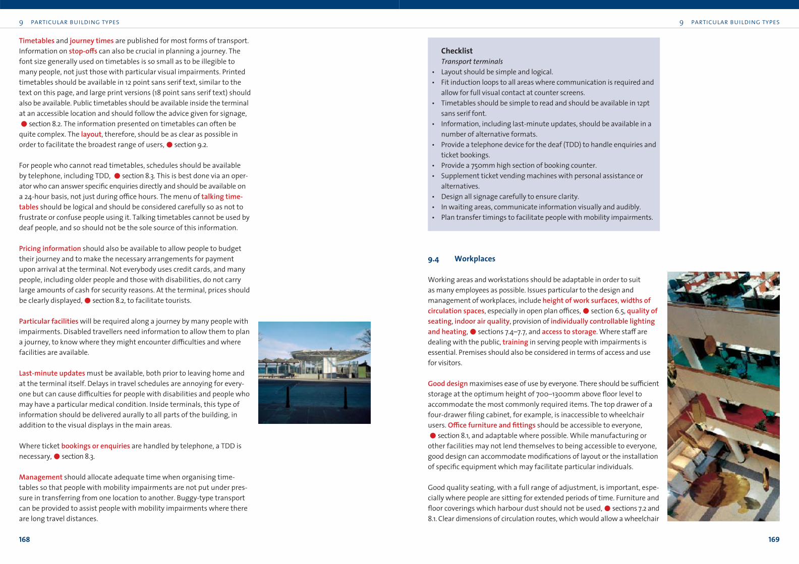
ChecklistTransport terminals
• Layout should be simple and logical.
• Fit induction loops to all areas where communication is required and
allow for full visual contact at counter screens.
• Timetables should be simple to read and should be available in 12pt
sans serif font.
• Information, including last-minute updates, should be available in a
number of alternative formats.
• Provide a telephone device for the deaf (TDD) to handle enquiries and
ticket bookings.
• Provide a 750mm high section of booking counter.
• Supplement ticket vending machines with personal assistance or
alternatives.
• Design all signage carefully to ensure clarity.
• In waiting areas, communicate information visually and audibly.
• Plan transfer timings to facilitate people with mobility impairments.
9.4 Workplaces
Working areas and workstations should be adaptable in order to suit
as many employees as possible. Issues particular to the design and
management of workplaces, include height of work surfaces, widths ofcirculation spaces, especially in open plan o≤ces,!section 6.5, quality ofseating, indoor air quality, provision of individually controllable lightingand heating,!sections 7.4–7.7, and access to storage. Where sta≠ are
dealing with the public, training in serving people with impairments is
essential. Premises should also be considered in terms of access and use
for visitors.
Good design maximises ease of use by everyone. There should be su≤cient
storage at the optimum height of 700–1300mm above floor level to
accommodate the most commonly required items. The top drawer of a
four-drawer filing cabinet, for example, is inaccessible to wheelchair
users. O≤ce furniture and fittings should be accessible to everyone,
!section 8.1, and adaptable where possible. While manufacturing or
other facilities may not lend themselves to being accessible to everyone,
good design can accommodate modifications of layout or the installation
of specific equipment which may facilitate particular individuals.
Good quality seating, with a full range of adjustment, is important, espe-
cially where people are sitting for extended periods of time. Furniture and
floor coverings which harbour dust should not be used,!sections 7.2 and
8.1. Clear dimensions of circulation routes, which would allow a wheelchair
9 particular building types
169
9 particular building types
168
Timetables and journey times are published for most forms of transport.
Information on stop-o≠s can also be crucial in planning a journey. The
font size generally used on timetables is so small as to be illegible to
many people, not just those with particular visual impairments. Printed
timetables should be available in 12 point sans serif text, similar to the
text on this page, and large print versions (18 point sans serif text) should
also be available. Public timetables should be available inside the terminal
at an accessible location and should follow the advice given for signage,
!section 8.2. The information presented on timetables can often be
quite complex. The layout, therefore, should be as clear as possible in
order to facilitate the broadest range of users,!section 9.2.
For people who cannot read timetables, schedules should be available
by telephone, including TDD, !section 8.3. This is best done via an oper-
ator who can answer specific enquiries directly and should be available on
a 24-hour basis, not just during o≤ce hours. The menu of talking time-tables should be logical and should be considered carefully so as not to
frustrate or confuse people using it. Talking timetables cannot be used by
deaf people, and so should not be the sole source of this information.
Pricing information should also be available to allow people to budget
their journey and to make the necessary arrangements for payment
upon arrival at the terminal. Not everybody uses credit cards, and many
people, including older people and those with disabilities, do not carry
large amounts of cash for security reasons. At the terminal, prices should
be clearly displayed,!section 8.2, to facilitate tourists.
Particular facilities will be required along a journey by many people with
impairments. Disabled travellers need information to allow them to plan
a journey, to know where they might encounter di≤culties and where
facilities are available.
Last-minute updates must be available, both prior to leaving home and
at the terminal itself. Delays in travel schedules are annoying for every-
one but can cause di≤culties for people with disabilities and people who
may have a particular medical condition. Inside terminals, this type of
information should be delivered aurally to all parts of the building, in
addition to the visual displays in the main areas.
Where ticket bookings or enquiries are handled by telephone, a TDD is
necessary,!section 8.3.
Management should allocate adequate time when organising time-
tables so that people with mobility impairments are not put under pres-
sure in transferring from one location to another. Buggy-type transport
can be provided to assist people with mobility impairments where there
are long travel distances.
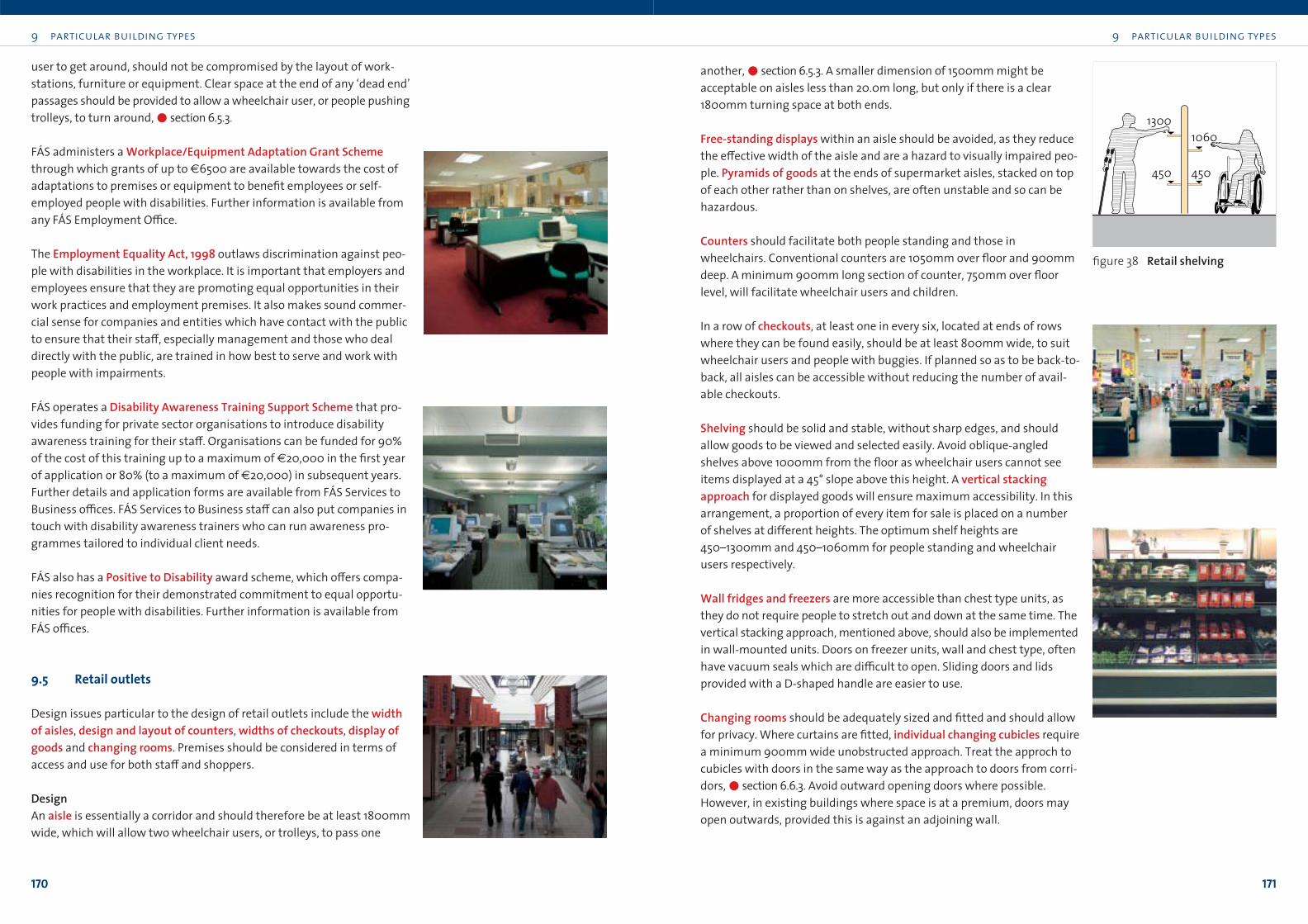
9 particular building types
171
9 particular building types
170
another,!section 6.5.3. A smaller dimension of 1500mm might be
acceptable on aisles less than 20.0m long, but only if there is a clear
1800mm turning space at both ends.
Free-standing displays within an aisle should be avoided, as they reduce
the e≠ective width of the aisle and are a hazard to visually impaired peo-
ple. Pyramids of goods at the ends of supermarket aisles, stacked on top
of each other rather than on shelves, are often unstable and so can be
hazardous.
Counters should facilitate both people standing and those in
wheelchairs. Conventional counters are 1050mm over floor and 900mm
deep. A minimum 900mm long section of counter, 750mm over floor
level, will facilitate wheelchair users and children.
In a row of checkouts, at least one in every six, located at ends of rows
where they can be found easily, should be at least 800mm wide, to suit
wheelchair users and people with buggies. If planned so as to be back-to-
back, all aisles can be accessible without reducing the number of avail-
able checkouts.
Shelving should be solid and stable, without sharp edges, and should
allow goods to be viewed and selected easily. Avoid oblique-angled
shelves above 1000mm from the floor as wheelchair users cannot see
items displayed at a 45° slope above this height. A vertical stackingapproach for displayed goods will ensure maximum accessibility. In this
arrangement, a proportion of every item for sale is placed on a number
of shelves at different heights. The optimum shelf heights are
450–1300mm and 450–1060mm for people standing and wheelchair
users respectively.
Wall fridges and freezers are more accessible than chest type units, as
they do not require people to stretch out and down at the same time. The
vertical stacking approach, mentioned above, should also be implemented
in wall-mounted units. Doors on freezer units, wall and chest type, often
have vacuum seals which are di≤cult to open. Sliding doors and lids
provided with a D-shaped handle are easier to use.
Changing rooms should be adequately sized and fitted and should allow
for privacy. Where curtains are fitted, individual changing cubicles require
a minimum 900mm wide unobstructed approach. Treat the approch to
cubicles with doors in the same way as the approach to doors from corri-
dors,!section 6.6.3. Avoid outward opening doors where possible.
However, in existing buildings where space is at a premium, doors may
open outwards, provided this is against an adjoining wall.
user to get around, should not be compromised by the layout of work-
stations, furniture or equipment. Clear space at the end of any ‘dead end’
passages should be provided to allow a wheelchair user, or people pushing
trolleys, to turn around,!section 6.5.3.
FÁS administers a Workplace/Equipment Adaptation Grant Schemethrough which grants of up to €6500 are available towards the cost of
adaptations to premises or equipment to benefit employees or self-
employed people with disabilities. Further information is available from
any FÁS Employment O≤ce.
The Employment Equality Act, 1998 outlaws discrimination against peo-
ple with disabilities in the workplace. It is important that employers and
employees ensure that they are promoting equal opportunities in their
work practices and employment premises. It also makes sound commer-
cial sense for companies and entities which have contact with the public
to ensure that their sta≠, especially management and those who deal
directly with the public, are trained in how best to serve and work with
people with impairments.
FÁS operates a Disability Awareness Training Support Scheme that pro-
vides funding for private sector organisations to introduce disability
awareness training for their sta≠. Organisations can be funded for 90%
of the cost of this training up to a maximum of €20,000 in the first year
of application or 80% (to a maximum of €20,000) in subsequent years.
Further details and application forms are available from FÁS Services to
Business o≤ces. FÁS Services to Business sta≠ can also put companies in
touch with disability awareness trainers who can run awareness pro-
grammes tailored to individual client needs.
FÁS also has a Positive to Disability award scheme, which o≠ers compa-
nies recognition for their demonstrated commitment to equal opportu-
nities for people with disabilities. Further information is available from
FÁS o≤ces.
9.5 Retail outlets
Design issues particular to the design of retail outlets include the widthof aisles, design and layout of counters, widths of checkouts, display ofgoods and changing rooms. Premises should be considered in terms of
access and use for both sta≠ and shoppers.
DesignAn aisle is essentially a corridor and should therefore be at least 1800mm
wide, which will allow two wheelchair users, or trolleys, to pass one
figure 38 Retail shelving
1300
450450
1060
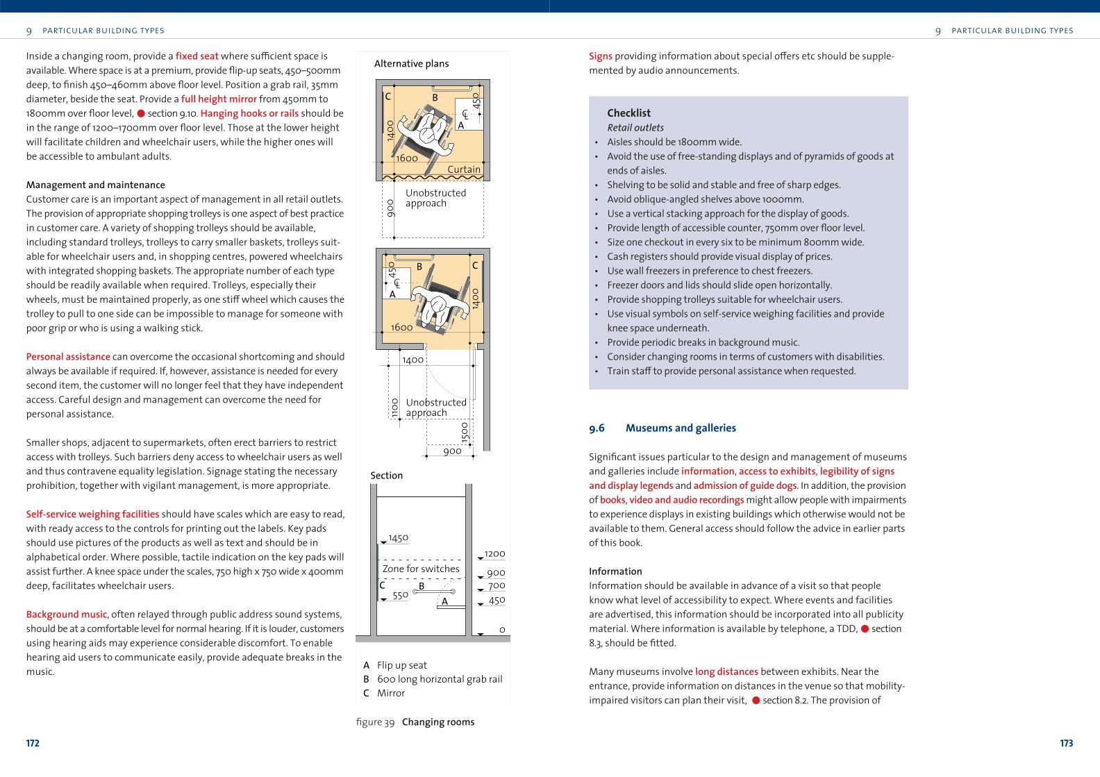
9 particular building types
173
9 particular building types
172
Signs providing information about special o≠ers etc should be supple-
mented by audio announcements.
ChecklistRetail outlets
• Aisles should be 1800mm wide.
• Avoid the use of free-standing displays and of pyramids of goods at
ends of aisles.
• Shelving to be solid and stable and free of sharp edges.
• Avoid oblique-angled shelves above 1000mm.
• Use a vertical stacking approach for the display of goods.
• Provide length of accessible counter, 750mm over floor level.
• Size one checkout in every six to be minimum 800mm wide.
• Cash registers should provide visual display of prices.
• Use wall freezers in preference to chest freezers.
• Freezer doors and lids should slide open horizontally.
• Provide shopping trolleys suitable for wheelchair users.
• Use visual symbols on self-service weighing facilities and provide
knee space underneath.
• Provide periodic breaks in background music.
• Consider changing rooms in terms of customers with disabilities.
• Train sta≠ to provide personal assistance when requested.
9.6 Museums and galleries
Significant issues particular to the design and management of museums
and galleries include information, access to exhibits, legibility of signsand display legends and admission of guide dogs. In addition, the provision
of books, video and audio recordings might allow people with impairments
to experience displays in existing buildings which otherwise would not be
available to them. General access should follow the advice in earlier parts
of this book.
InformationInformation should be available in advance of a visit so that people
know what level of accessibility to expect. Where events and facilities
are advertised, this information should be incorporated into all publicity
material. Where information is available by telephone, a TDD,!section
8.3, should be fitted.
Many museums involve long distances between exhibits. Near the
entrance, provide information on distances in the venue so that mobility-
impaired visitors can plan their visit, !section 8.2. The provision of
Inside a changing room, provide a fixed seat where su≤cient space is
available. Where space is at a premium, provide flip-up seats, 450–500mm
deep, to finish 450–460mm above floor level. Position a grab rail, 35mm
diameter, beside the seat. Provide a full height mirror from 450mm to
1800mm over floor level,!section 9.10. Hanging hooks or rails should be
in the range of 1200–1700mm over floor level. Those at the lower height
will facilitate children and wheelchair users, while the higher ones will
be accessible to ambulant adults.
Management and maintenanceCustomer care is an important aspect of management in all retail outlets.
The provision of appropriate shopping trolleys is one aspect of best practice
in customer care. A variety of shopping trolleys should be available,
including standard trolleys, trolleys to carry smaller baskets, trolleys suit-
able for wheelchair users and, in shopping centres, powered wheelchairs
with integrated shopping baskets. The appropriate number of each type
should be readily available when required. Trolleys, especially their
wheels, must be maintained properly, as one sti≠ wheel which causes the
trolley to pull to one side can be impossible to manage for someone with
poor grip or who is using a walking stick.
Personal assistance can overcome the occasional shortcoming and should
always be available if required. If, however, assistance is needed for every
second item, the customer will no longer feel that they have independent
access. Careful design and management can overcome the need for
personal assistance.
Smaller shops, adjacent to supermarkets, often erect barriers to restrict
access with trolleys. Such barriers deny access to wheelchair users as well
and thus contravene equality legislation. Signage stating the necessary
prohibition, together with vigilant management, is more appropriate.
Self-service weighing facilities should have scales which are easy to read,
with ready access to the controls for printing out the labels. Key pads
should use pictures of the products as well as text and should be in
alphabetical order. Where possible, tactile indication on the key pads will
assist further. A knee space under the scales, 750 high x 750 wide x 400mm
deep, facilitates wheelchair users.
Background music, often relayed through public address sound systems,
should be at a comfortable level for normal hearing. If it is louder, customers
using hearing aids may experience considerable discomfort. To enable
hearing aid users to communicate easily, provide adequate breaks in the
music.
B
B
B
C
C
C
Section
A Flip up seatB 600 long horizontal grab railC Mirror
Alternative plans
A
A
1600
900
1500
1400
1400
Unobstructedapproach
Zone for switches
Unobstructedapproach
450
450
CL
CL
1100
1400
900
450700
0
12001450
550
900
1600
Curtain
A
figure 39 Changing rooms
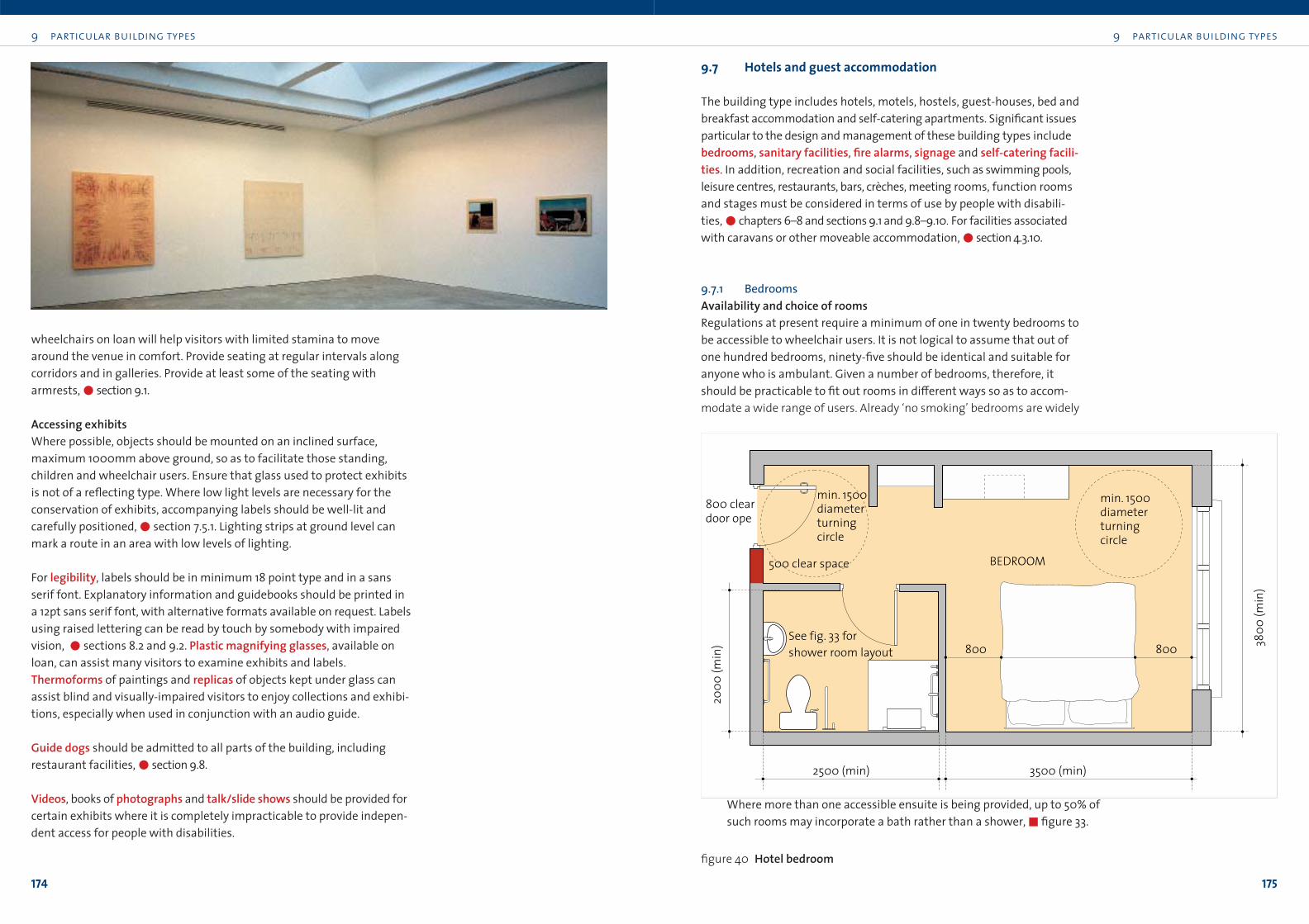
9 particular building types
175
9 particular building types
174
9.7 Hotels and guest accommodation
The building type includes hotels, motels, hostels, guest-houses, bed and
breakfast accommodation and self-catering apartments. Significant issues
particular to the design and management of these building types include
bedrooms, sanitary facilities, fire alarms, signage and self-catering facili-ties. In addition, recreation and social facilities, such as swimming pools,
leisure centres, restaurants, bars, crèches, meeting rooms, function rooms
and stages must be considered in terms of use by people with disabili-
ties,!chapters 6–8 and sections 9.1 and 9.8–9.10. For facilities associated
with caravans or other moveable accommodation,!section 4.3.10.
9.7.1 BedroomsAvailability and choice of roomsRegulations at present require a minimum of one in twenty bedrooms to
be accessible to wheelchair users. It is not logical to assume that out of
one hundred bedrooms, ninety-five should be identical and suitable for
anyone who is ambulant. Given a number of bedrooms, therefore, it
should be practicable to fit out rooms in di≠erent ways so as to accom-
modate a wide range of users. Already ‘no smoking’ bedrooms are widely
wheelchairs on loan will help visitors with limited stamina to move
around the venue in comfort. Provide seating at regular intervals along
corridors and in galleries. Provide at least some of the seating with
armrests,!section 9.1.
Accessing exhibitsWhere possible, objects should be mounted on an inclined surface,
maximum 1000mm above ground, so as to facilitate those standing,
children and wheelchair users. Ensure that glass used to protect exhibits
is not of a reflecting type. Where low light levels are necessary for the
conservation of exhibits, accompanying labels should be well-lit and
carefully positioned,!section 7.5.1. Lighting strips at ground level can
mark a route in an area with low levels of lighting.
For legibility, labels should be in minimum 18 point type and in a sans
serif font. Explanatory information and guidebooks should be printed in
a 12pt sans serif font, with alternative formats available on request. Labels
using raised lettering can be read by touch by somebody with impaired
vision, !sections 8.2 and 9.2. Plastic magnifying glasses, available on
loan, can assist many visitors to examine exhibits and labels.
Thermoforms of paintings and replicas of objects kept under glass can
assist blind and visually-impaired visitors to enjoy collections and exhibi-
tions, especially when used in conjunction with an audio guide.
Guide dogs should be admitted to all parts of the building, including
restaurant facilities,!section 9.8.
Videos, books of photographs and talk/slide shows should be provided for
certain exhibits where it is completely impracticable to provide indepen-
dent access for people with disabilities.
min. 1500 diameter turning circle
min. 1500 diameter turning circle
3800
(min
)
2000
(min
)
3500 (min)2500 (min)
BEDROOM500 clear space
800 clear door ope
See fig. 33 for shower room layout 800 800
figure 40 Hotel bedroom
Where more than one accessible ensuite is being provided, up to 50% of
such rooms may incorporate a bath rather than a shower,"figure 33.
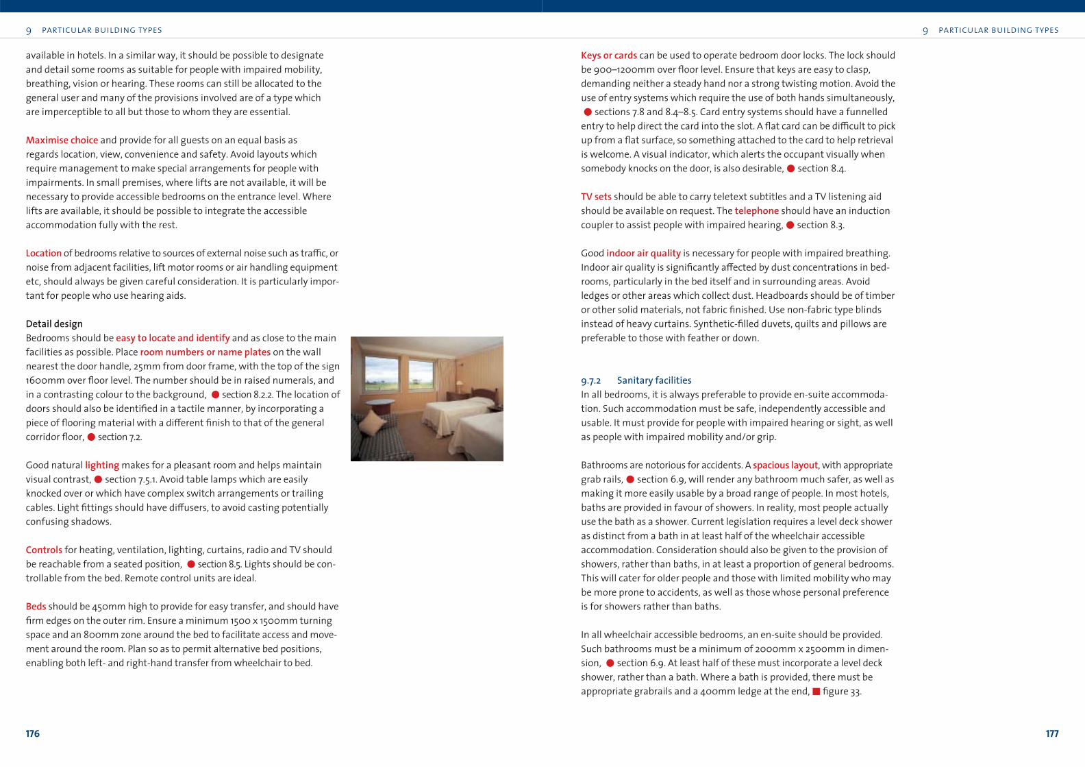
9 particular building types
177
9 particular building types
176
Keys or cards can be used to operate bedroom door locks. The lock should
be 900–1200mm over floor level. Ensure that keys are easy to clasp,
demanding neither a steady hand nor a strong twisting motion. Avoid the
use of entry systems which require the use of both hands simultaneously,
!sections 7.8 and 8.4–8.5. Card entry systems should have a funnelled
entry to help direct the card into the slot. A flat card can be di≤cult to pick
up from a flat surface, so something attached to the card to help retrieval
is welcome. A visual indicator, which alerts the occupant visually when
somebody knocks on the door, is also desirable,!section 8.4.
TV sets should be able to carry teletext subtitles and a TV listening aid
should be available on request. The telephone should have an induction
coupler to assist people with impaired hearing,!section 8.3.
Good indoor air quality is necessary for people with impaired breathing.
Indoor air quality is significantly a≠ected by dust concentrations in bed-
rooms, particularly in the bed itself and in surrounding areas. Avoid
ledges or other areas which collect dust. Headboards should be of timber
or other solid materials, not fabric finished. Use non-fabric type blinds
instead of heavy curtains. Synthetic-filled duvets, quilts and pillows are
preferable to those with feather or down.
9.7.2 Sanitary facilitiesIn all bedrooms, it is always preferable to provide en-suite accommoda-
tion. Such accommodation must be safe, independently accessible and
usable. It must provide for people with impaired hearing or sight, as well
as people with impaired mobility and/or grip.
Bathrooms are notorious for accidents. A spacious layout, with appropriate
grab rails,!section 6.9, will render any bathroom much safer, as well as
making it more easily usable by a broad range of people. In most hotels,
baths are provided in favour of showers. In reality, most people actually
use the bath as a shower. Current legislation requires a level deck shower
as distinct from a bath in at least half of the wheelchair accessible
accommodation. Consideration should also be given to the provision of
showers, rather than baths, in at least a proportion of general bedrooms.
This will cater for older people and those with limited mobility who may
be more prone to accidents, as well as those whose personal preference
is for showers rather than baths.
In all wheelchair accessible bedrooms, an en-suite should be provided.
Such bathrooms must be a minimum of 2000mm x 2500mm in dimen-
sion, !section 6.9. At least half of these must incorporate a level deck
shower, rather than a bath. Where a bath is provided, there must be
appropriate grabrails and a 400mm ledge at the end,"figure 33.
available in hotels. In a similar way, it should be possible to designate
and detail some rooms as suitable for people with impaired mobility,
breathing, vision or hearing. These rooms can still be allocated to the
general user and many of the provisions involved are of a type which
are imperceptible to all but those to whom they are essential.
Maximise choice and provide for all guests on an equal basis as
regards location, view, convenience and safety. Avoid layouts which
require management to make special arrangements for people with
impairments. In small premises, where lifts are not available, it will be
necessary to provide accessible bedrooms on the entrance level. Where
lifts are available, it should be possible to integrate the accessible
accommodation fully with the rest.
Location of bedrooms relative to sources of external noise such as tra≤c, or
noise from adjacent facilities, lift motor rooms or air handling equipment
etc, should always be given careful consideration. It is particularly impor-
tant for people who use hearing aids.
Detail designBedrooms should be easy to locate and identify and as close to the main
facilities as possible. Place room numbers or name plates on the wall
nearest the door handle, 25mm from door frame, with the top of the sign
1600mm over floor level. The number should be in raised numerals, and
in a contrasting colour to the background, !section 8.2.2. The location of
doors should also be identified in a tactile manner, by incorporating a
piece of flooring material with a di≠erent finish to that of the general
corridor floor,!section 7.2.
Good natural lighting makes for a pleasant room and helps maintain
visual contrast,!section 7.5.1. Avoid table lamps which are easily
knocked over or which have complex switch arrangements or trailing
cables. Light fittings should have di≠users, to avoid casting potentially
confusing shadows.
Controls for heating, ventilation, lighting, curtains, radio and TV should
be reachable from a seated position, !section 8.5. Lights should be con-
trollable from the bed. Remote control units are ideal.
Beds should be 450mm high to provide for easy transfer, and should have
firm edges on the outer rim. Ensure a minimum 1500 x 1500mm turning
space and an 800mm zone around the bed to facilitate access and move-
ment around the room. Plan so as to permit alternative bed positions,
enabling both left- and right-hand transfer from wheelchair to bed.
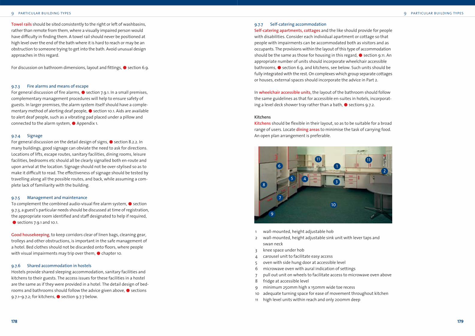
9 particular building types
179
9 particular building types
178
9.7.7 Self-catering accommodationSelf-catering apartments, cottages and the like should provide for people
with disabilities. Consider each individual apartment or cottage so that
people with impairments can be accommodated both as visitors and as
occupants. The provisions within the layout of this type of accommodation
should be the same as those for housing in this regard,!section 9.11. An
appropriate number of units should incorporate wheelchair accessible
bathrooms,!section 6.9, and kitchens, see below. Such units should be
fully integrated with the rest. On complexes which group separate cottages
or houses, external spaces should incorporate the advice in Part 2.
In wheelchair accessible units, the layout of the bathroom should follow
the same guidelines as that for accessible en-suites in hotels, incorporat-
ing a level deck shower tray rather than a bath,!sections 9.7.2.
KitchensKitchens should be flexible in their layout, so as to be suitable for a broad
range of users. Locate dining areas to minimise the task of carrying food.
An open plan arrangement is preferable.
Towel rails should be sited consistently to the right or left of washbasins,
rather than remote from them, where a visually impaired person would
have di≤culty in finding them. A towel rail should never be positioned at
high level over the end of the bath where it is hard to reach or may be an
obstruction to someone trying to get into the bath. Avoid unusual design
approaches in this regard.
For discussion on bathroom dimensions, layout and fittings,!section 6.9.
9.7.3 Fire alarms and means of escapeFor general discussion of fire alarms,!section 7.9.1. In a small premises,
complementary management procedures will help to ensure safety of
guests. In larger premises, the alarm system itself should have a comple-
mentary method of alerting deaf people,!section 10.1. Aids are available
to alert deaf people, such as a vibrating pad placed under a pillow and
connected to the alarm system,!Appendix 1.
9.7.4 SignageFor general discussion on the detail design of signs,!section 8.2.2. In
many buildings, good signage can obviate the need to ask for directions.
Locations of lifts, escape routes, sanitary facilities, dining rooms, leisure
facilities, bedrooms etc should all be clearly signalled both en-route and
upon arrival at the location. Signage should not be over-stylised so as to
make it di≤cult to read. The e≠ectiveness of signage should be tested by
travelling along all the possible routes, and back, while assuming a com-
plete lack of familiarity with the building.
9.7.5 Management and maintenance To complement the combined audio-visual fire alarm system,!section
9.7.3, a guest’s particular needs should be discussed at time of registration,
the appropriate room identified and sta≠ designated to help if required,
!sections 7.9.1 and 10.1.
Good housekeeping, to keep corridors clear of linen bags, cleaning gear,
trolleys and other obstructions, is important in the safe management of
a hotel. Bed clothes should not be discarded onto floors, where people
with visual impairments may trip over them,!chapter 10.
9.7.6 Shared accommodation in hostelsHostels provide shared sleeping accommodation, sanitary facilities and
kitchens to their guests. The access issues for these facilities in a hostel
are the same as if they were provided in a hotel. The detail design of bed-
rooms and bathrooms should follow the advice given above,!sections
9.7.1–9.7.2; for kitchens,!section 9.7.7 below.
2
345
6
8
7
9
111 11
10
1 wall-mounted, height adjustable hob
2 wall-mounted, height adjustable sink unit with lever taps and
swan neck
3 knee space under hob
4 carousel unit to facilitate easy access
5 oven with side hung door at accessible level
6 microwave oven with aural indication of settings
7 pull out unit on wheels to facilitate access to microwave oven above
8 fridge at accessible level
9 minimum 250mm high x 150mm wide toe recess
10 adequate turning space for ease of movement throughout kitchen
11 high level units within reach and only 200mm deep
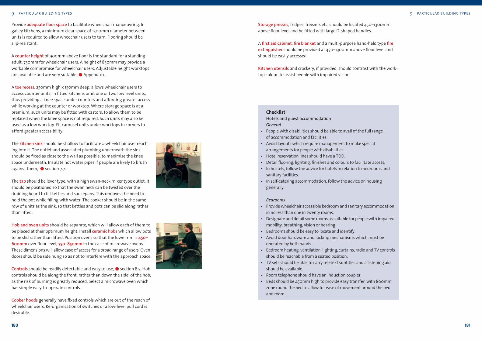
9 particular building types
181
9 particular building types
180
Storage presses, fridges, freezers etc, should be located 450–1300mm
above floor level and be fitted with large D-shaped handles.
A first aid cabinet, fire blanket and a multi-purpose hand-held type fireextinguisher should be provided at 450–1300mm above floor level and
should be easily accessed.
Kitchen utensils and crockery, if provided, should contrast with the work-
top colour, to assist people with impaired vision.
ChecklistHotels and guest accommodationGeneral
• People with disabilities should be able to avail of the full range
of accommodation and facilities.
• Avoid layouts which require management to make special
arrangements for people with disabilities.
• Hotel reservation lines should have a TDD.
• Detail flooring, lighting, finishes and colours to facilitate access.
• In hostels, follow the advice for hotels in relation to bedrooms and
sanitary facilities.
• In self-catering accommodation, follow the advice on housing
generally.
Bedrooms• Provide wheelchair accessible bedroom and sanitary accommodation
in no less than one in twenty rooms.
• Designate and detail some rooms as suitable for people with impaired
mobility, breathing, vision or hearing.
• Bedrooms should be easy to locate and identify.
• Avoid door hardware and locking mechanisms which must be
operated by both hands.
• Bedroom heating, ventilation, lighting, curtains, radio and TV controls
should be reachable from a seated position.
• TV sets should be able to carry teletext subtitles and a listening aid
should be available.
• Room telephone should have an induction coupler.
• Beds should be 450mm high to provide easy transfer, with 800mm
zone round the bed to allow for ease of movement around the bed
and room.
Provide adequate floor space to facilitate wheelchair manoeuvring. In
galley kitchens, a minimum clear space of 1500mm diameter between
units is required to allow wheechair users to turn. Flooring should be
slip-resistant.
A counter height of 900mm above floor is the standard for a standing
adult, 750mm for wheelchair users. A height of 850mm may provide a
workable compromise for wheelchair users. Adjustable height worktops
are available and are very suitable,!Appendix 1.
A toe recess, 250mm high x 150mm deep, allows wheelchair users to
access counter units. In fitted kitchens omit one or two low level units,
thus providing a knee space under counters and a≠ording greater access
while working at the counter or worktop. Where storage space is at a
premium, such units may be fitted with castors, to allow them to be
replaced when the knee space is not required. Such units may also be
used as a low worktop. Fit carousel units under worktops in corners to
afford greater accessibility.
The kitchen sink should be shallow to facilitate a wheelchair user reach-
ing into it. The outlet and associated plumbing underneath the sink
should be fixed as close to the wall as possible, to maximise the knee
space underneath. Insulate hot water pipes if people are likely to brush
against them, !section 7.7.
The tap should be lever type, with a high swan-neck mixer type outlet. It
should be positioned so that the swan neck can be twisted over the
draining board to fill kettles and saucepans. This removes the need to
hold the pot while filling with water. The cooker should be in the same
row of units as the sink, so that kettles and pots can be slid along rather
than lifted.
Hob and oven units should be separate, which will allow each of them to
be placed at their optimum height. Install ceramic hobs which allow pots
to be slid rather than lifted. Position ovens so that the lower rim is 450–600mm over floor level, 750–850mm in the case of microwave ovens.
These dimensions will allow ease of access for a broad range of users. Oven
doors should be side hung so as not to interfere with the approach space.
Controls should be readily detectable and easy to use,!section 8.5. Hob
controls should be along the front, rather than down the side, of the hob,
as the risk of burning is greatly reduced. Select a microwave oven which
has simple easy-to-operate controls.
Cooker hoods generally have fixed controls which are out of the reach of
wheelchair users. Re-organisation of switches or a low-level pull cord is
desirable.
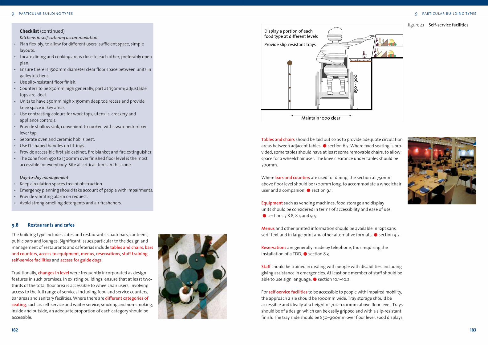
9 particular building types
183
9 particular building types
182
Tables and chairs should be laid out so as to provide adequate circulation
areas between adjacent tables,!section 6.5. Where fixed seating is pro-
vided, some tables should have at least some removable chairs, to allow
space for a wheelchair user. The knee clearance under tables should be
700mm.
Where bars and counters are used for dining, the section at 750mm
above floor level should be 1500mm long, to accommodate a wheelchair
user and a companion,!section 9.1.
Equipment such as vending machines, food storage and display
units should be considered in terms of accessibility and ease of use,
!sections 7.8.8, 8.5 and 9.5.
Menus and other printed information should be available in 12pt sans
serif text and in large print and other alternative formats,!section 9.2.
Reservations are generally made by telephone, thus requiring the
installation of a TDD,!section 8.3.
Sta≠ should be trained in dealing with people with disabilities, including
giving assistance in emergencies. At least one member of sta≠ should be
able to use sign language,!section 10.1–10.2.
F0r self-service facilities to be accessible to people with impaired mobility,
the approach aisle should be 1000mm wide. Tray storage should be
accessible and ideally at a height of 700–1200mm above floor level. Trays
should be of a design which can be easily gripped and with a slip-resistant
finish. The tray slide should be 850–900mm over floor level. Food displays
Checklist (continued)
Kitchens in self-catering accommodation• Plan flexibly, to allow for di≠erent users: su≤cient space, simple
layouts.
• Locate dining and cooking areas close to each other, preferably open
plan.
• Ensure there is 1500mm diameter clear floor space between units in
galley kitchens.
• Use slip-resistant floor finish.
• Counters to be 850mm high generally, part at 750mm; adjustable
tops are ideal.
• Units to have 250mm high x 150mm deep toe recess and provide
knee space in key areas.
• Use contrasting colours for work tops, utensils, crockery and
appliance controls.
• Provide shallow sink, convenient to cooker, with swan-neck mixer
lever tap.
• Separate oven and ceramic hob is best.
• Use D-shaped handles on fittings.
• Provide accessible first aid cabinet, fire blanket and fire extinguisher.
• The zone from 450 to 1300mm over finished floor level is the most
accessible for everybody. Site all critical items in this zone.
Day-to-day management• Keep circulation spaces free of obstruction.
• Emergency planning should take account of people with impairments.
• Provide vibrating alarm on request.
• Avoid strong-smelling detergents and air fresheners.
9.8 Restaurants and cafes
The building type includes cafes and restaurants, snack bars, canteens,
public bars and lounges. Significant issues particular to the design and
management of restaurants and cafeterias include tables and chairs, barsand counters, access to equipment, menus, reservations, sta≠ training,
self-service facilities and access for guide dogs.
Traditionally, changes in level were frequently incorporated as design
features in such premises. In existing buildings, ensure that at least two-
thirds of the total floor area is accessible to wheelchair users, involving
access to the full range of services including food and service counters,
bar areas and sanitary facilities. Where there are di≠erent categories ofseating, such as self-service and waiter service, smoking and non-smoking,
inside and outside, an adequate proportion of each category should be
accessible.
Maintain 1000 clear
850
- 900
Display a portion of each food type at different levels
Provide slip-resistant trays
figure 41 Self-service facilities
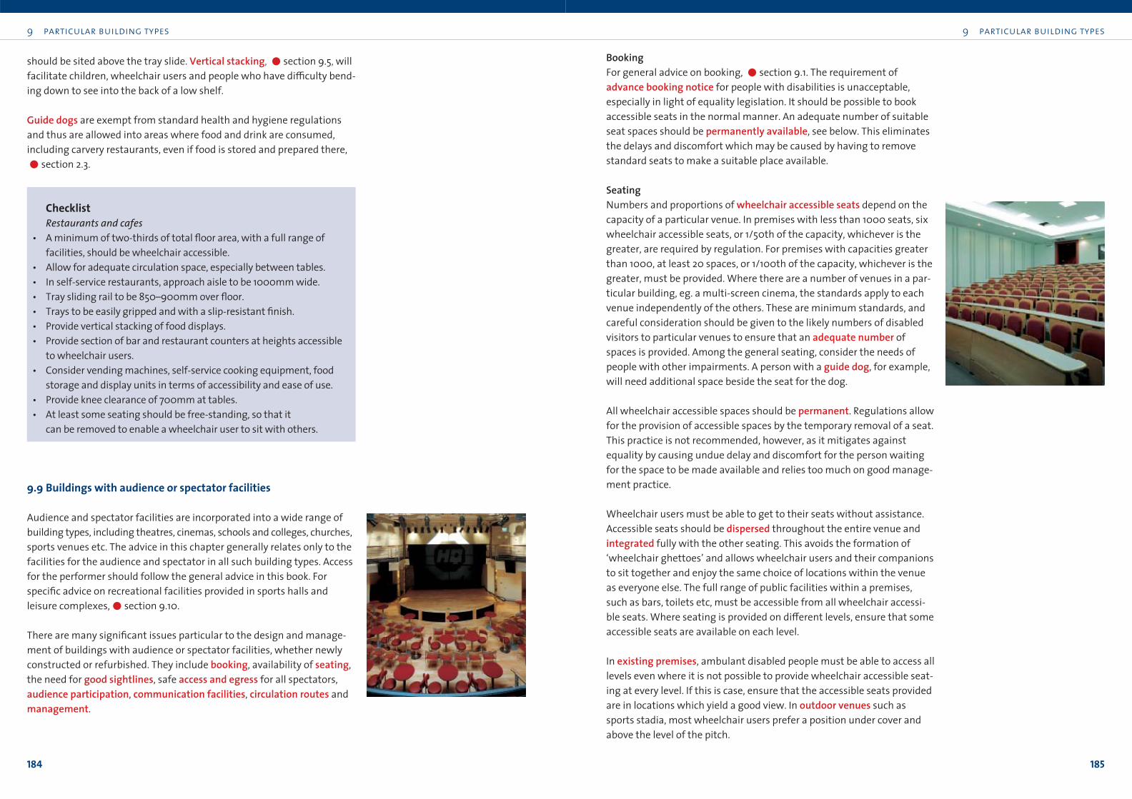
9 particular building types
185
9 particular building types
184
BookingFor general advice on booking, !section 9.1. The requirement of
advance booking notice for people with disabilities is unacceptable,
especially in light of equality legislation. It should be possible to book
accessible seats in the normal manner. An adequate number of suitable
seat spaces should be permanently available, see below. This eliminates
the delays and discomfort which may be caused by having to remove
standard seats to make a suitable place available.
SeatingNumbers and proportions of wheelchair accessible seats depend on the
capacity of a particular venue. In premises with less than 1000 seats, six
wheelchair accessible seats, or 1/50th of the capacity, whichever is the
greater, are required by regulation. For premises with capacities greater
than 1000, at least 20 spaces, or 1/100th of the capacity, whichever is the
greater, must be provided. Where there are a number of venues in a par-
ticular building, eg. a multi-screen cinema, the standards apply to each
venue independently of the others. These are minimum standards, and
careful consideration should be given to the likely numbers of disabled
visitors to particular venues to ensure that an adequate number of
spaces is provided. Among the general seating, consider the needs of
people with other impairments. A person with a guide dog, for example,
will need additional space beside the seat for the dog.
All wheelchair accessible spaces should be permanent. Regulations allow
for the provision of accessible spaces by the temporary removal of a seat.
This practice is not recommended, however, as it mitigates against
equality by causing undue delay and discomfort for the person waiting
for the space to be made available and relies too much on good manage-
ment practice.
Wheelchair users must be able to get to their seats without assistance.
Accessible seats should be dispersed throughout the entire venue and
integrated fully with the other seating. This avoids the formation of
‘wheelchair ghettoes’ and allows wheelchair users and their companions
to sit together and enjoy the same choice of locations within the venue
as everyone else. The full range of public facilities within a premises,
such as bars, toilets etc, must be accessible from all wheelchair accessi-
ble seats. Where seating is provided on di≠erent levels, ensure that some
accessible seats are available on each level.
In existing premises, ambulant disabled people must be able to access all
levels even where it is not possible to provide wheelchair accessible seat-
ing at every level. If this is case, ensure that the accessible seats provided
are in locations which yield a good view. In outdoor venues such as
sports stadia, most wheelchair users prefer a position under cover and
above the level of the pitch.
should be sited above the tray slide. Vertical stacking, !section 9.5, will
facilitate children, wheelchair users and people who have di≤culty bend-
ing down to see into the back of a low shelf.
Guide dogs are exempt from standard health and hygiene regulations
and thus are allowed into areas where food and drink are consumed,
including carvery restaurants, even if food is stored and prepared there,
!section 2.3.
ChecklistRestaurants and cafes
• A minimum of two-thirds of total floor area, with a full range of
facilities, should be wheelchair accessible.
• Allow for adequate circulation space, especially between tables.
• In self-service restaurants, approach aisle to be 1000mm wide.
• Tray sliding rail to be 850–900mm over floor.
• Trays to be easily gripped and with a slip-resistant finish.
• Provide vertical stacking of food displays.
• Provide section of bar and restaurant counters at heights accessible
to wheelchair users.
• Consider vending machines, self-service cooking equipment, food
storage and display units in terms of accessibility and ease of use.
• Provide knee clearance of 700mm at tables.
• At least some seating should be free-standing, so that it
can be removed to enable a wheelchair user to sit with others.
9.9 Buildings with audience or spectator facilities
Audience and spectator facilities are incorporated into a wide range of
building types, including theatres, cinemas, schools and colleges, churches,
sports venues etc. The advice in this chapter generally relates only to the
facilities for the audience and spectator in all such building types. Access
for the performer should follow the general advice in this book. For
specific advice on recreational facilities provided in sports halls and
leisure complexes,!section 9.10.
There are many significant issues particular to the design and manage-
ment of buildings with audience or spectator facilities, whether newly
constructed or refurbished. They include booking, availability of seating,
the need for good sightlines, safe access and egress for all spectators,
audience participation, communication facilities, circulation routes and
management.
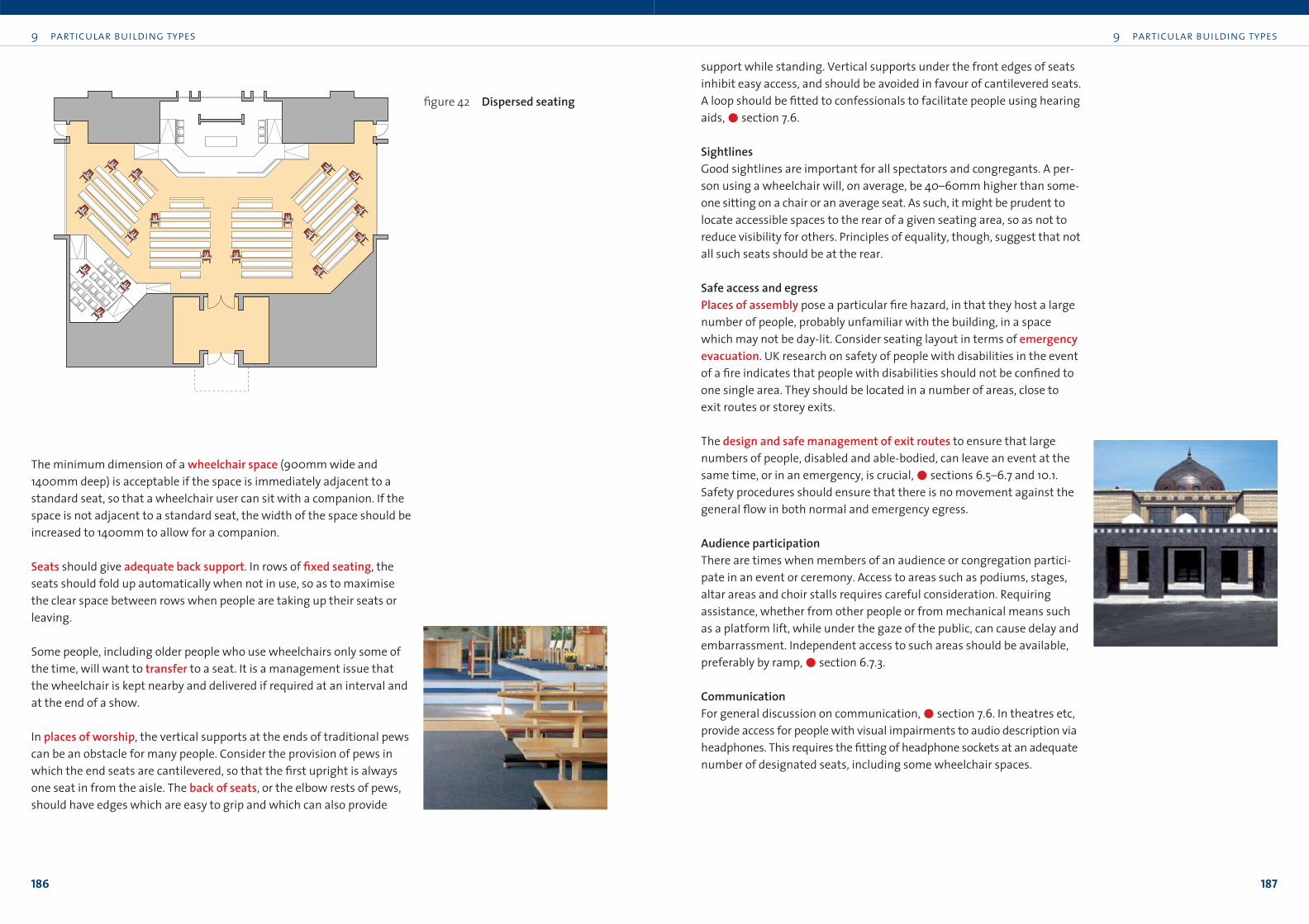
9 particular building types
187
9 particular building types
186
support while standing. Vertical supports under the front edges of seats
inhibit easy access, and should be avoided in favour of cantilevered seats.
A loop should be fitted to confessionals to facilitate people using hearing
aids,!section 7.6.
SightlinesGood sightlines are important for all spectators and congregants. A per-
son using a wheelchair will, on average, be 40–60mm higher than some-
one sitting on a chair or an average seat. As such, it might be prudent to
locate accessible spaces to the rear of a given seating area, so as not to
reduce visibility for others. Principles of equality, though, suggest that not
all such seats should be at the rear.
Safe access and egressPlaces of assembly pose a particular fire hazard, in that they host a large
number of people, probably unfamiliar with the building, in a space
which may not be day-lit. Consider seating layout in terms of emergencyevacuation. UK research on safety of people with disabilities in the event
of a fire indicates that people with disabilities should not be confined to
one single area. They should be located in a number of areas, close to
exit routes or storey exits.
The design and safe management of exit routes to ensure that large
numbers of people, disabled and able-bodied, can leave an event at the
same time, or in an emergency, is crucial,!sections 6.5–6.7 and 10.1.
Safety procedures should ensure that there is no movement against the
general flow in both normal and emergency egress.
Audience participationThere are times when members of an audience or congregation partici-
pate in an event or ceremony. Access to areas such as podiums, stages,
altar areas and choir stalls requires careful consideration. Requiring
assistance, whether from other people or from mechanical means such
as a platform lift, while under the gaze of the public, can cause delay and
embarrassment. Independent access to such areas should be available,
preferably by ramp,!section 6.7.3.
CommunicationFor general discussion on communication,!section 7.6. In theatres etc,
provide access for people with visual impairments to audio description via
headphones. This requires the fitting of headphone sockets at an adequate
number of designated seats, including some wheelchair spaces.
The minimum dimension of a wheelchair space (900mm wide and
1400mm deep) is acceptable if the space is immediately adjacent to a
standard seat, so that a wheelchair user can sit with a companion. If the
space is not adjacent to a standard seat, the width of the space should be
increased to 1400mm to allow for a companion.
Seats should give adequate back support. In rows of fixed seating, the
seats should fold up automatically when not in use, so as to maximise
the clear space between rows when people are taking up their seats or
leaving.
Some people, including older people who use wheelchairs only some of
the time, will want to transfer to a seat. It is a management issue that
the wheelchair is kept nearby and delivered if required at an interval and
at the end of a show.
In places of worship, the vertical supports at the ends of traditional pews
can be an obstacle for many people. Consider the provision of pews in
which the end seats are cantilevered, so that the first upright is always
one seat in from the aisle. The back of seats, or the elbow rests of pews,
should have edges which are easy to grip and which can also provide
figure 42 Dispersed seating
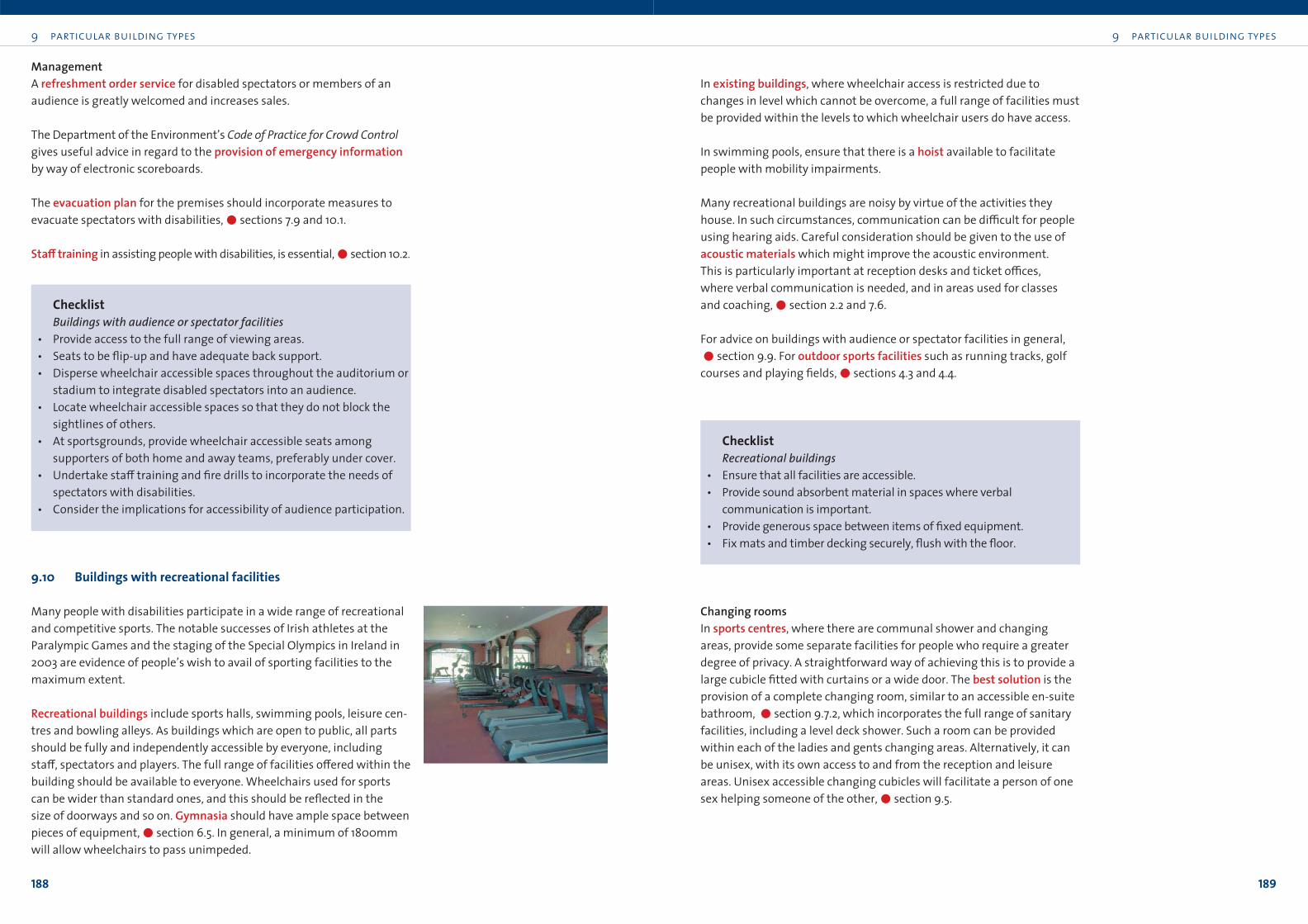
9 particular building types
189
9 particular building types
188
In existing buildings, where wheelchair access is restricted due to
changes in level which cannot be overcome, a full range of facilities must
be provided within the levels to which wheelchair users do have access.
In swimming pools, ensure that there is a hoist available to facilitate
people with mobility impairments.
Many recreational buildings are noisy by virtue of the activities they
house. In such circumstances, communication can be di≤cult for people
using hearing aids. Careful consideration should be given to the use of
acoustic materials which might improve the acoustic environment.
This is particularly important at reception desks and ticket o≤ces,
where verbal communication is needed, and in areas used for classes
and coaching,!section 2.2 and 7.6.
For advice on buildings with audience or spectator facilities in general,
!section 9.9. For outdoor sports facilities such as running tracks, golf
courses and playing fields,!sections 4.3 and 4.4.
ChecklistRecreational buildings
• Ensure that all facilities are accessible.
• Provide sound absorbent material in spaces where verbal
communication is important.
• Provide generous space between items of fixed equipment.
• Fix mats and timber decking securely, flush with the floor.
Changing roomsIn sports centres, where there are communal shower and changing
areas, provide some separate facilities for people who require a greater
degree of privacy. A straightforward way of achieving this is to provide a
large cubicle fitted with curtains or a wide door. The best solution is the
provision of a complete changing room, similar to an accessible en-suite
bathroom, !section 9.7.2, which incorporates the full range of sanitary
facilities, including a level deck shower. Such a room can be provided
within each of the ladies and gents changing areas. Alternatively, it can
be unisex, with its own access to and from the reception and leisure
areas. Unisex accessible changing cubicles will facilitate a person of one
sex helping someone of the other,!section 9.5.
ManagementA refreshment order service for disabled spectators or members of an
audience is greatly welcomed and increases sales.
The Department of the Environment’s Code of Practice for Crowd Controlgives useful advice in regard to the provision of emergency informationby way of electronic scoreboards.
The evacuation plan for the premises should incorporate measures to
evacuate spectators with disabilities,!sections 7.9 and 10.1.
Sta≠ training in assisting people with disabilities, is essential,!section 10.2.
ChecklistBuildings with audience or spectator facilities
• Provide access to the full range of viewing areas.
• Seats to be flip-up and have adequate back support.
• Disperse wheelchair accessible spaces throughout the auditorium or
stadium to integrate disabled spectators into an audience.
• Locate wheelchair accessible spaces so that they do not block the
sightlines of others.
• At sportsgrounds, provide wheelchair accessible seats among
supporters of both home and away teams, preferably under cover.
• Undertake sta≠ training and fire drills to incorporate the needs of
spectators with disabilities.
• Consider the implications for accessibility of audience participation.
9.10 Buildings with recreational facilities
Many people with disabilities participate in a wide range of recreational
and competitive sports. The notable successes of Irish athletes at the
Paralympic Games and the staging of the Special Olympics in Ireland in
2003 are evidence of people’s wish to avail of sporting facilities to the
maximum extent.
Recreational buildings include sports halls, swimming pools, leisure cen-
tres and bowling alleys. As buildings which are open to public, all parts
should be fully and independently accessible by everyone, including
sta≠, spectators and players. The full range of facilities o≠ered within the
building should be available to everyone. Wheelchairs used for sports
can be wider than standard ones, and this should be reflected in the
size of doorways and so on. Gymnasia should have ample space between
pieces of equipment,!section 6.5. In general, a minimum of 1800mm
will allow wheelchairs to pass unimpeded.
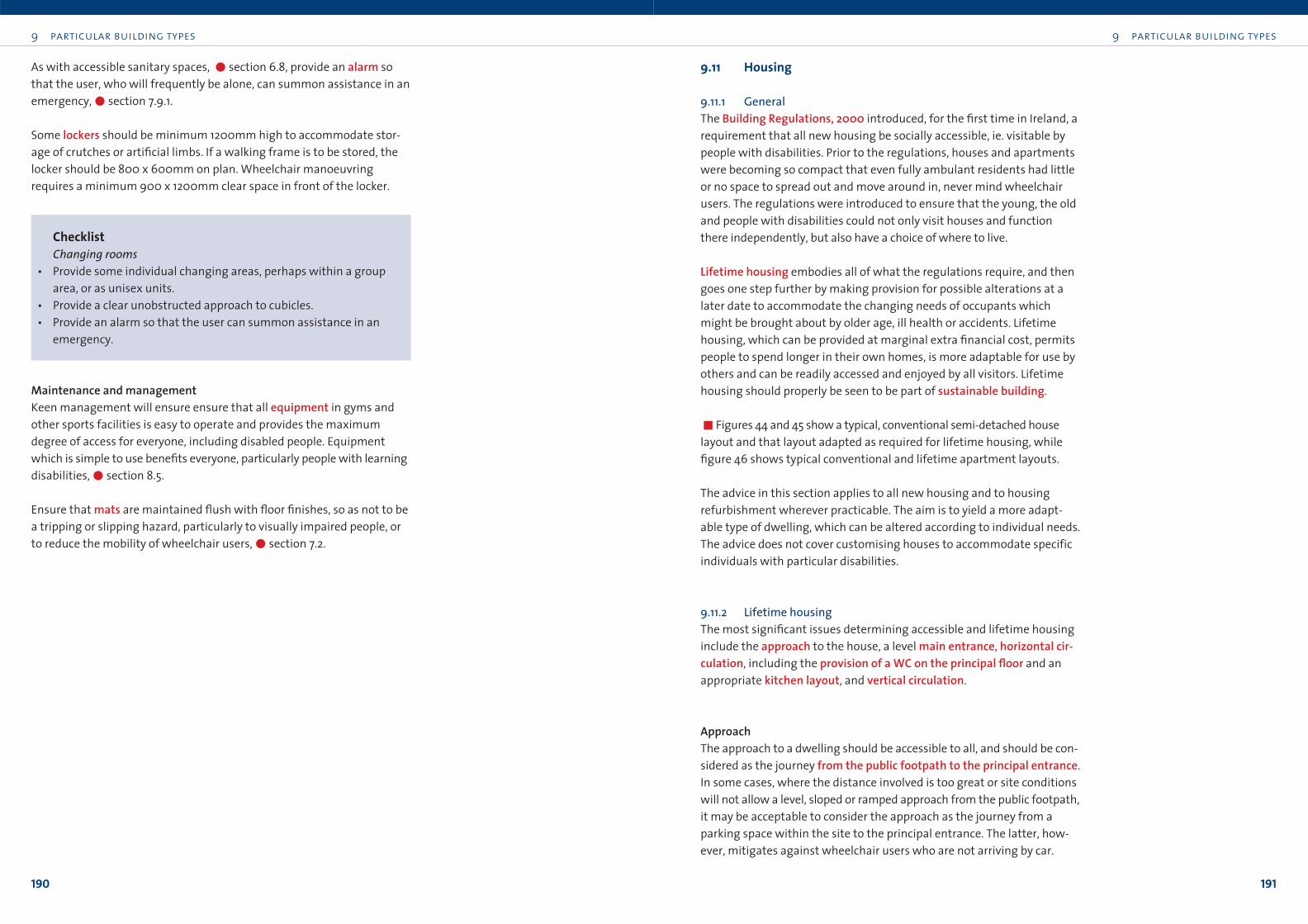
9 particular building types
191
9 particular building types
190
9.11 Housing
9.11.1 GeneralThe Building Regulations, 2000 introduced, for the first time in Ireland, a
requirement that all new housing be socially accessible, ie. visitable by
people with disabilities. Prior to the regulations, houses and apartments
were becoming so compact that even fully ambulant residents had little
or no space to spread out and move around in, never mind wheelchair
users. The regulations were introduced to ensure that the young, the old
and people with disabilities could not only visit houses and function
there independently, but also have a choice of where to live.
Lifetime housing embodies all of what the regulations require, and then
goes one step further by making provision for possible alterations at a
later date to accommodate the changing needs of occupants which
might be brought about by older age, ill health or accidents. Lifetime
housing, which can be provided at marginal extra financial cost, permits
people to spend longer in their own homes, is more adaptable for use by
others and can be readily accessed and enjoyed by all visitors. Lifetime
housing should properly be seen to be part of sustainable building.
!Figures 44 and 45 show a typical, conventional semi-detached house
layout and that layout adapted as required for lifetime housing, while
figure 46 shows typical conventional and lifetime apartment layouts.
The advice in this section applies to all new housing and to housing
refurbishment wherever practicable. The aim is to yield a more adapt-
able type of dwelling, which can be altered according to individual needs.
The advice does not cover customising houses to accommodate specific
individuals with particular disabilities.
9.11.2 Lifetime housingThe most significant issues determining accessible and lifetime housing
include the approach to the house, a level main entrance, horizontal cir-culation, including the provision of a WC on the principal floor and an
appropriate kitchen layout, and vertical circulation.
ApproachThe approach to a dwelling should be accessible to all, and should be con-
sidered as the journey from the public footpath to the principal entrance.
In some cases, where the distance involved is too great or site conditions
will not allow a level, sloped or ramped approach from the public footpath,
it may be acceptable to consider the approach as the journey from a
parking space within the site to the principal entrance. The latter, how-
ever, mitigates against wheelchair users who are not arriving by car.
As with accessible sanitary spaces, "section 6.8, provide an alarm so
that the user, who will frequently be alone, can summon assistance in an
emergency,"section 7.9.1.
Some lockers should be minimum 1200mm high to accommodate stor-
age of crutches or artificial limbs. If a walking frame is to be stored, the
locker should be 800 x 600mm on plan. Wheelchair manoeuvring
requires a minimum 900 x 1200mm clear space in front of the locker.
ChecklistChanging rooms
• Provide some individual changing areas, perhaps within a group
area, or as unisex units.
• Provide a clear unobstructed approach to cubicles.
• Provide an alarm so that the user can summon assistance in an
emergency.
Maintenance and managementKeen management will ensure ensure that all equipment in gyms and
other sports facilities is easy to operate and provides the maximum
degree of access for everyone, including disabled people. Equipment
which is simple to use benefits everyone, particularly people with learning
disabilities,"section 8.5.
Ensure that mats are maintained flush with floor finishes, so as not to be
a tripping or slipping hazard, particularly to visually impaired people, or
to reduce the mobility of wheelchair users,"section 7.2.
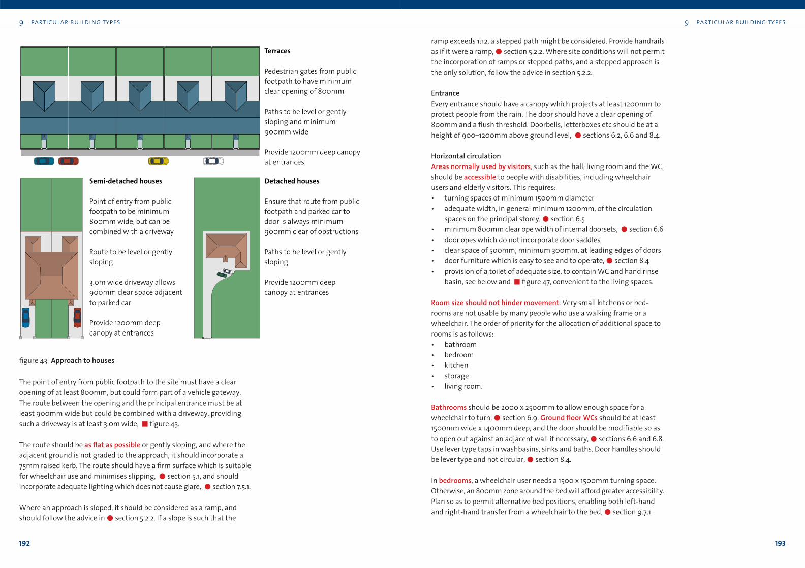
9 particular building types
193
The point of entry from public footpath to the site must have a clear
opening of at least 800mm, but could form part of a vehicle gateway.
The route between the opening and the principal entrance must be at
least 900mm wide but could be combined with a driveway, providing
such a driveway is at least 3.0m wide, !figure 43.
The route should be as flat as possible or gently sloping, and where the
adjacent ground is not graded to the approach, it should incorporate a
75mm raised kerb. The route should have a firm surface which is suitable
for wheelchair use and minimises slipping, "section 5.1, and should
incorporate adequate lighting which does not cause glare, "section 7.5.1.
Where an approach is sloped, it should be considered as a ramp, and
should follow the advice in"section 5.2.2. If a slope is such that the
9 particular building types
192
ramp exceeds 1:12, a stepped path might be considered. Provide handrails
as if it were a ramp,"section 5.2.2. Where site conditions will not permit
the incorporation of ramps or stepped paths, and a stepped approach is
the only solution, follow the advice in section 5.2.2.
EntranceEvery entrance should have a canopy which projects at least 1200mm to
protect people from the rain. The door should have a clear opening of
800mm and a flush threshold. Doorbells, letterboxes etc should be at a
height of 900–1200mm above ground level, "sections 6.2, 6.6 and 8.4.
Horizontal circulationAreas normally used by visitors, such as the hall, living room and the WC,
should be accessible to people with disabilities, including wheelchair
users and elderly visitors. This requires:
• turning spaces of minimum 1500mm diameter
• adequate width, in general minimum 1200mm, of the circulation
spaces on the principal storey,"section 6.5
• minimum 800mm clear ope width of internal doorsets, "section 6.6
• door opes which do not incorporate door saddles
• clear space of 500mm, minimum 300mm, at leading edges of doors
• door furniture which is easy to see and to operate,"section 8.4
• provision of a toilet of adequate size, to contain WC and hand rinse
basin, see below and !figure 47, convenient to the living spaces.
Room size should not hinder movement. Very small kitchens or bed-
rooms are not usable by many people who use a walking frame or a
wheelchair. The order of priority for the allocation of additional space to
rooms is as follows:
• bathroom
• bedroom
• kitchen
• storage
• living room.
Bathrooms should be 2000 x 2500mm to allow enough space for a
wheelchair to turn,"section 6.9. Ground floor WCs should be at least
1500mm wide x 1400mm deep, and the door should be modifiable so as
to open out against an adjacent wall if necessary,"sections 6.6 and 6.8.
Use lever type taps in washbasins, sinks and baths. Door handles should
be lever type and not circular,"section 8.4.
In bedrooms, a wheelchair user needs a 1500 x 1500mm turning space.
Otherwise, an 800mm zone around the bed will a≠ord greater accessibility.
Plan so as to permit alternative bed positions, enabling both left-hand
and right-hand transfer from a wheelchair to the bed,"section 9.7.1.
Terraces
Pedestrian gates from public footpath to have minimum clear opening of 800mm
Paths to be level or gently sloping and minimum 900mm wide
Provide 1200mm deep canopyat entrances
Semi-detached houses
Point of entry from public footpath to be minimum 800mm wide, but can be combined with a driveway
Route to be level or gently sloping
3.0m wide driveway allows900mm clear space adjacent to parked car
Provide 1200mm deep canopy at entrances
Detached houses
Ensure that route from publicfootpath and parked car to door is always minimum 900mm clear of obstructions
Paths to be level or gently sloping
Provide 1200mm deep canopy at entrances
figure 43 Approach to houses
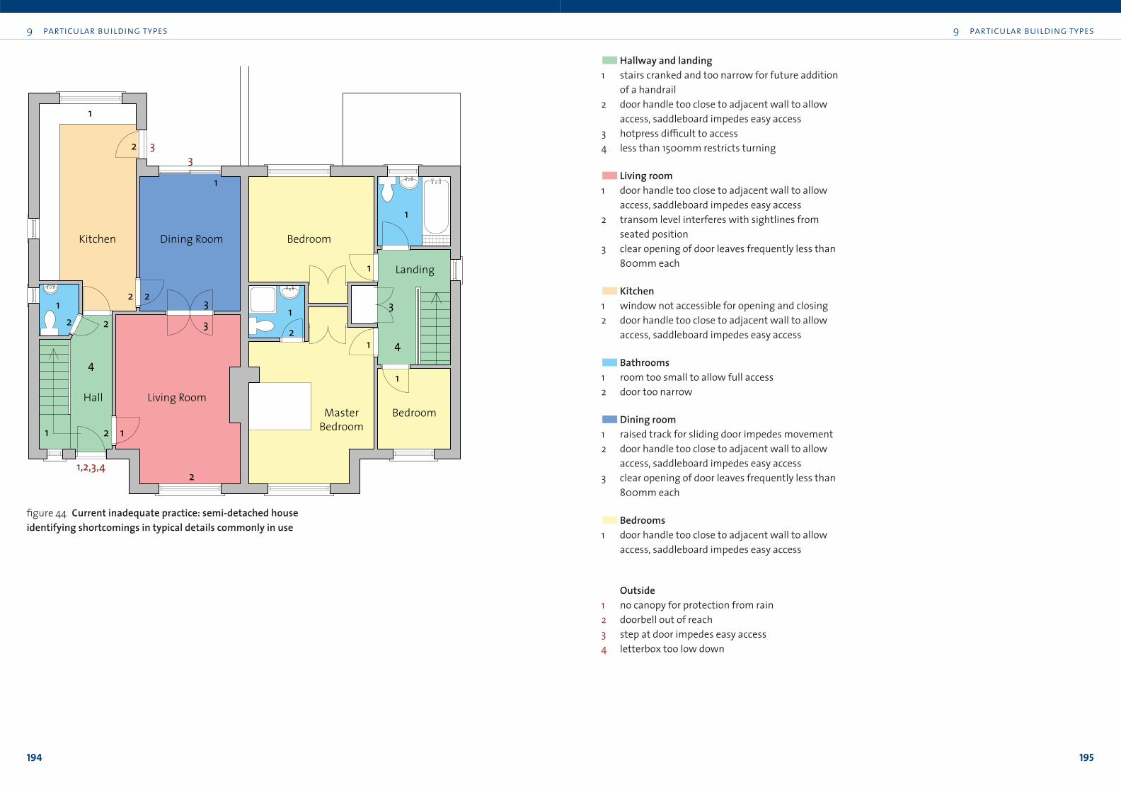
9 particular building types
195
9 particular building types
194
Living RoomHall
Dining Room Bedroom
Landing
BedroomMasterBedroom
Kitchen
2
1
1
3
4
1
1
2
1
1
2
4
1
22
2 2 31
1
1
3
332
1,2,3,4
!!Hallway and landing1 stairs cranked and too narrow for future addition
of a handrail
2 door handle too close to adjacent wall to allow
access, saddleboard impedes easy access
3 hotpress di≤cult to access
4 less than 1500mm restricts turning
!! Living room1 door handle too close to adjacent wall to allow
access, saddleboard impedes easy access
2 transom level interferes with sightlines from
seated position
3 clear opening of door leaves frequently less than
800mm each
!!Kitchen1 window not accessible for opening and closing
2 door handle too close to adjacent wall to allow
access, saddleboard impedes easy access
!!Bathrooms1 room too small to allow full access
2 door too narrow
!!Dining room1 raised track for sliding door impedes movement
2 door handle too close to adjacent wall to allow
access, saddleboard impedes easy access
3 clear opening of door leaves frequently less than
800mm each
!!Bedrooms1 door handle too close to adjacent wall to allow
access, saddleboard impedes easy access
Outside1 no canopy for protection from rain
2 doorbell out of reach
3 step at door impedes easy access
4 letterbox too low down
figure 44 Current inadequate practice: semi-detached house identifying shortcomings in typical details commonly in use
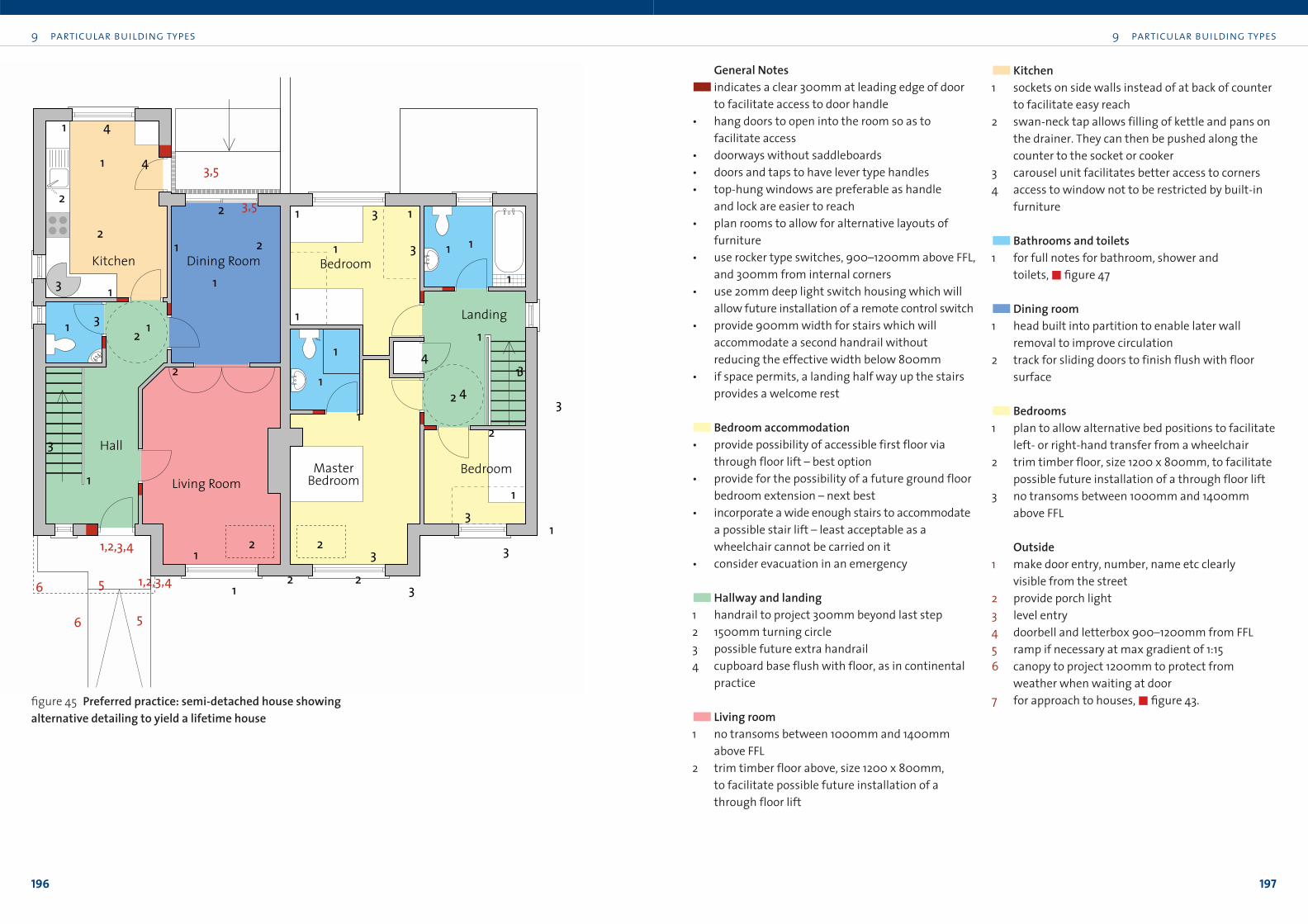
General Notes!! indicates a clear 300mm at leading edge of door
to facilitate access to door handle
• hang doors to open into the room so as to
facilitate access
• doorways without saddleboards
• doors and taps to have lever type handles
• top-hung windows are preferable as handle
and lock are easier to reach
• plan rooms to allow for alternative layouts of
furniture
• use rocker type switches, 900–1200mm above FFL,
and 300mm from internal corners
• use 20mm deep light switch housing which will
allow future installation of a remote control switch
• provide 900mm width for stairs which will
accommodate a second handrail without
reducing the effective width below 800mm
• if space permits, a landing half way up the stairs
provides a welcome rest
!!Bedroom accommodation• provide possibility of accessible first floor via
through floor lift – best option
• provide for the possibility of a future ground floor
bedroom extension – next best
• incorporate a wide enough stairs to accommodate
a possible stair lift – least acceptable as a
wheelchair cannot be carried on it
• consider evacuation in an emergency
!!Hallway and landing1 handrail to project 300mm beyond last step
2 1500mm turning circle
3 possible future extra handrail
4 cupboard base flush with floor, as in continental
practice
!! Living room1 no transoms between 1000mm and 1400mm
above FFL
2 trim timber floor above, size 1200 x 800mm,
to facilitate possible future installation of a
through floor lift
!!Kitchen1 sockets on side walls instead of at back of counter
to facilitate easy reach
2 swan-neck tap allows filling of kettle and pans on
the drainer. They can then be pushed along the
counter to the socket or cooker
3 carousel unit facilitates better access to corners
4 access to window not to be restricted by built-in
furniture
!!Bathrooms and toilets1 for full notes for bathroom, shower and
toilets,!figure 47
!!Dining room1 head built into partition to enable later wall
removal to improve circulation
2 track for sliding doors to finish flush with floor
surface
!!Bedrooms1 plan to allow alternative bed positions to facilitate
left- or right-hand transfer from a wheelchair
2 trim timber floor, size 1200 x 800mm, to facilitate
possible future installation of a through floor lift
3 no transoms between 1000mm and 1400mm
above FFL
Outside1 make door entry, number, name etc clearly
visible from the street
2 provide porch light
3 level entry
4 doorbell and letterbox 900–1200mm from FFL
5 ramp if necessary at max gradient of 1:15
6 canopy to project 1200mm to protect from
weather when waiting at door
7 for approach to houses,!figure 43.
9 particular building types
197
9 particular building types
196
Living Room
Hall
Dining Room Bedroom
Landing
BedroomMasterBedroom
Kitchen1
22
3
21
1
1
2
43
1
1
11 3
1
3
1
2 2
3
6
3,5
5
1,2,3,4
3 1
1 4
1
22
1
21
1
1
2
43
1
1
11 3
1
3
1
2 2
3
6
3,5
5
1,2,3,4
3 1
1 4
figure 45 Preferred practice: semi-detached house showing alternative detailing to yield a lifetime house
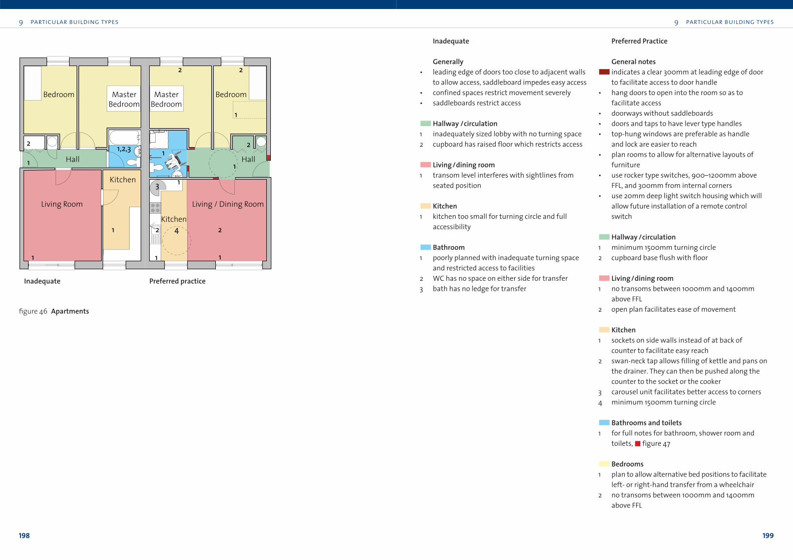
Inadequate
Generally• leading edge of doors too close to adjacent walls
to allow access, saddleboard impedes easy access
• confined spaces restrict movement severely
• saddleboards restrict access
!!Hallway /circulation1 inadequately sized lobby with no turning space
2 cupboard has raised floor which restricts access
!! Living/dining room1 transom level interferes with sightlines from
seated position
!!Kitchen1 kitchen too small for turning circle and full
accessibility
!!Bathroom1 poorly planned with inadequate turning space
and restricted access to facilities
2 WC has no space on either side for transfer
3 bath has no ledge for transfer
Preferred Practice
General notes!! indicates a clear 300mm at leading edge of door
to facilitate access to door handle
• hang doors to open into the room so as to
facilitate access
• doorways without saddleboards
• doors and taps to have lever type handles
• top-hung windows are preferable as handle
and lock are easier to reach
• plan rooms to allow for alternative layouts of
furniture
• use rocker type switches, 900–1200mm above
FFL, and 300mm from internal corners
• use 20mm deep light switch housing which will
allow future installation of a remote control
switch
!!Hallway /circulation1 minimum 1500mm turning circle
2 cupboard base flush with floor
!! Living/dining room1 no transoms between 1000mm and 1400mm
above FFL
2 open plan facilitates ease of movement
!!Kitchen1 sockets on side walls instead of at back of
counter to facilitate easy reach
2 swan-neck tap allows filling of kettle and pans on
the drainer. They can then be pushed along the
counter to the socket or the cooker
3 carousel unit facilitates better access to corners
4 minimum 1500mm turning circle
!!Bathrooms and toilets1 for full notes for bathroom, shower room and
toilets,!figure 47
!!Bedrooms1 plan to allow alternative bed positions to facilitate
left- or right-hand transfer from a wheelchair
2 no transoms between 1000mm and 1400mm
above FFL
9 particular building types
199
9 particular building types
198
1
1
2 1,2,3
1 22 4
3
1
1
1
1
22
1
2
1
Hall Hall
BedroomBedroom MasterBedroom
MasterBedroom
Kitchen
Kitchen
Living / Dining RoomLiving Room
figure 46 Apartments
Inadequate Preferred practice
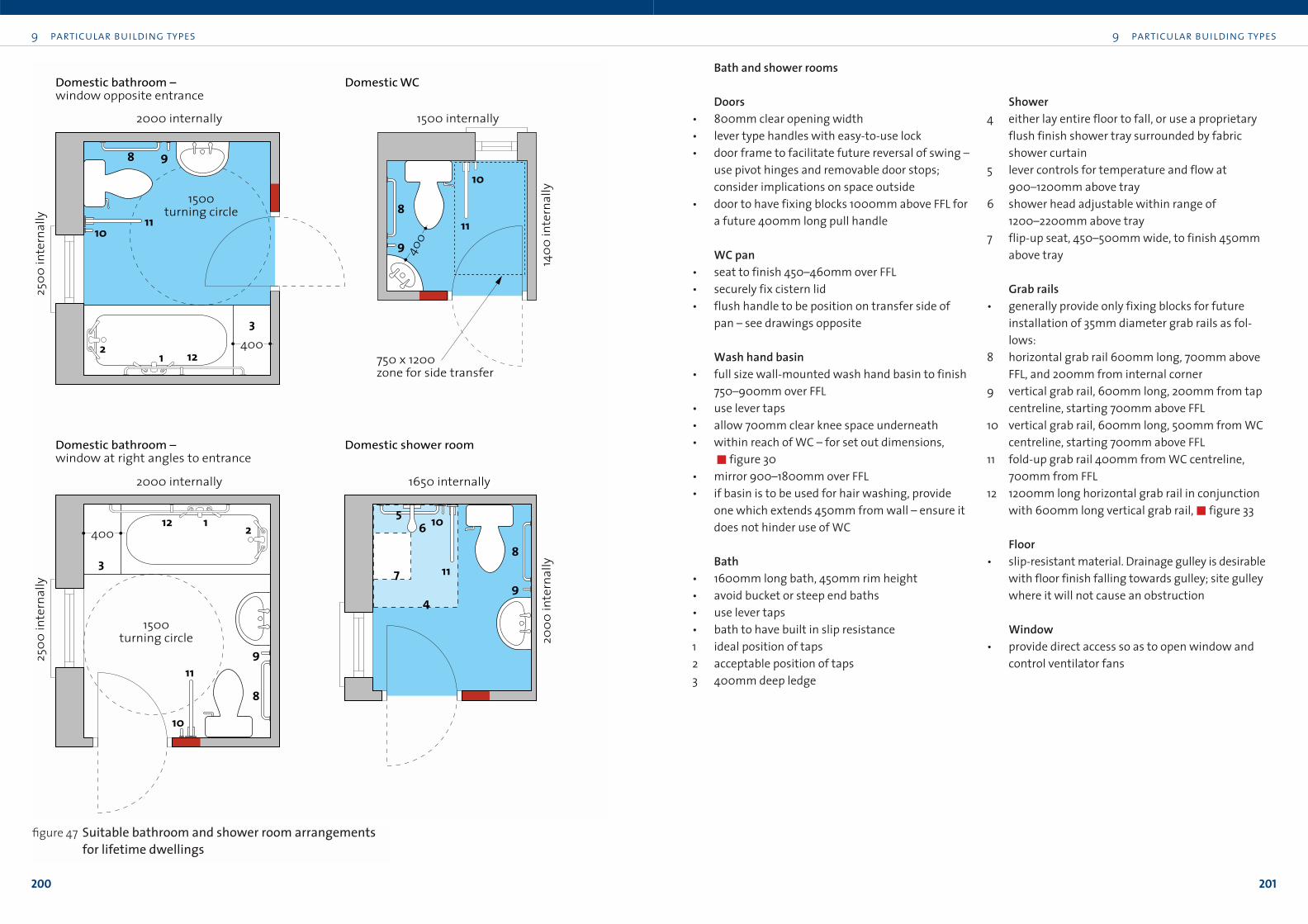
9 particular building types
201
9 particular building types
200
3
1 122
8
9
8
9
10
1056112
3
8
9
10
11
2
7
4
11
11
8 9
1011
1500 turning circle
2500
inte
rnal
ly
2000 internally 1650 internally
2500
inte
rnal
ly
2000 internally 1500 internally
750 x 1200 zone for side transfer
1500 turning circle
1400
inte
rnal
ly20
00 in
tern
ally
Domestic bathroom –window opposite entrance
Domestic bathroom –window at right angles to entrance
Domestic WC
Domestic shower room
400
400
400
figure 47 Suitable bathroom and shower room arrangements for lifetime dwellings
Bath and shower rooms
Doors• 800mm clear opening width
• lever type handles with easy-to-use lock
• door frame to facilitate future reversal of swing –
use pivot hinges and removable door stops;
consider implications on space outside
• door to have fixing blocks 1000mm above FFL for
a future 400mm long pull handle
WC pan• seat to finish 450–460mm over FFL
• securely fix cistern lid
• flush handle to be position on transfer side of
pan – see drawings opposite
Wash hand basin• full size wall-mounted wash hand basin to finish
750–900mm over FFL
• use lever taps
• allow 700mm clear knee space underneath
• within reach of WC – for set out dimensions,
!figure 30
• mirror 900–1800mm over FFL
• if basin is to be used for hair washing, provide
one which extends 450mm from wall – ensure it
does not hinder use of WC
Bath• 1600mm long bath, 450mm rim height
• avoid bucket or steep end baths
• use lever taps
• bath to have built in slip resistance
1 ideal position of taps
2 acceptable position of taps
3 400mm deep ledge
Shower4 either lay entire floor to fall, or use a proprietary
flush finish shower tray surrounded by fabric
shower curtain
5 lever controls for temperature and flow at
900–1200mm above tray
6 shower head adjustable within range of
1200–2200mm above tray
7 flip-up seat, 450–500mm wide, to finish 450mm
above tray
Grab rails• generally provide only fixing blocks for future
installation of 35mm diameter grab rails as fol-
lows:
8 horizontal grab rail 600mm long, 700mm above
FFL, and 200mm from internal corner
9 vertical grab rail, 600mm long, 200mm from tap
centreline, starting 700mm above FFL
10 vertical grab rail, 600mm long, 500mm from WC
centreline, starting 700mm above FFL
11 fold-up grab rail 400mm from WC centreline,
700mm from FFL
12 1200mm long horizontal grab rail in conjunction
with 600mm long vertical grab rail,!figure 33
Floor• slip-resistant material. Drainage gulley is desirable
with floor finish falling towards gulley; site gulley
where it will not cause an obstruction
Window• provide direct access so as to open window and
control ventilator fans
9 particular building types
203
9 particular building types
202
ChecklistHousing! figures 45-47 for typical lifetime semi-detached house, apartment,
bathroom and shower room layouts.
Building approach• Provide easy access to parking space.
• Approach should be as flat as possible with a firm surface.
• Provide handrails on any inclined approach.
• Provide adequate lighting which does not cause glare.
• Door entry, number and dwelling name (if any) should be clearly
visible from street.
Entrance• Thresholds at front and back entrances should be level.
• Protect entrances with canopies, minimum 1200mm deep, recesses
and landscaping.
Internal planning generally• Plan flexibly, to allow for di≠erent users: enough space,
straightforward layouts.
• Locate dining and cooking areas close to each other, preferably
open plan.
• Use slip-resistant floor finishes.
• Locate window opening lights for easy access. Top-hung casements
may be particularly suitable.
• Allow for the possible inclusion of a through floor lift or a ground floor
bedroom extension at a later date.
Internal circulation• 1500mm diameter turning circle at critical positions ensures universal
access.
• Doorsets to have minimum 800mm clear ope width.
• Provide 500mm, minimum 300mm, clear space at door leading edges.
• Use lever handle door ironmongery.
• Corridors to be ideally 1200mm wide.
• Doorways internally with level thresholds – avoid door saddles.
• Stairway to be two flights where possible, with 900mm long landings.
Sanitary accommodation• Provide an accessible toilet and rinse basin downstairs.
• Bathroom to be minimum 2000 x 2500mm,!figure 47.
Kitchens should have a continuous counter and sequence of units. This
will allow users to slide objects along, rather than constantly lift them
from one place to another,"section 9.7.7. Counter height should be
850mm generally, possibly with a low section at 750mm. There should
be a toe recess of 250mm high x 150mm deep at all counters. Provide a
minimum 1500 x 1500mm turning circle to allow the wheelchair user to
manoeuvre. Install a shallow sink, convenient to the cooker, with lever-
operated swan-neck mixer taps. Fit carousel units under worktops in
corners for greater accessibility.
The floor of storage closets should be flush with the adjoining finished
floor level to ensure full access for wheelchair users.
Vertical circulationMost domestic accidents happen on stairs. Lifetime housing should ideally
incorporate two short flights of stairs, in preference to one long one, each
with a maximum rise of 1800m and landings which are at least 900mm
long. This will not only make for a safer stairs, but will make it more
manageable as the occupants grow old. Achieving this involves challenges
to the conventional design of dwellings, and can require some additional
floor space. The opportunities for doing so are greater in one-o≠ housing
than in the standard house type.
All stairs in housing should have a clear unobstructed width of 800mm,
which will permit the incorporation of a folding stairlift without compro-
mising usability by ambulant people. Each step should have a maximum
rise of 175mm and a minimum going of 280mm. There should be a con-
tinuous handrail on each side of the flight and landings,"section 6.7.
Lifetime housing should also provide for the fitting of a through floor lift.
This is easily done by trimming the first floor joists to allow a section of floor,
800 x 1200mm, to be removed with ease at a later date,"section 6.7.8.
Proper selection and detailing of fixtures and fittings can assist usability
significantly. Locate socket outlets 900–1200mm above floor level and use
rocker-type light switches,"sections 7.5 and 8.5. Switch housings should
be 20mm deep to permit the fitting of dimmer switches and remote
control switching at a later date.

205
9 particular building types
204
Checklist (continued)
Kitchen• Counters should be continuous and 850mm high generally, part at
750mm; adjustable height counters are ideal.
• Provide 1500 x 1500mm turning circle.
• Units should have a toe recess 250 high x 150mm deep, with knee
space in key areas.
• Carousel corner units under worktops provide the most accessible
layout.
• Use contrasting colours to distinguish kitchen elements.
• Provide shallow sink, convenient to cooker, with swan-neck mixer
lever tap.
• Split oven and ceramic hob is best.
• The zone 450–1300mm over finished floor level is the most
accessible for everybody. Site all critical items in this zone.
Bedrooms• 800mm clear zone around beds facilitates access.
• Plan bedrooms to allow both left- and right-hand transfer from
wheelchair to bed.
Services• Use rocker-type light switches in 20mm deep switch housings.
• Locate switches and socket outlets, TV and telephone points so they
are accessible without undue stretching or stooping, 900–1200mm
above floor level, and 500mm, minimum 300mm, from internal
corners.
Part fourThe building in use