Bentley Civil Guide
110
Bentley Civil Guide V8i SELECTseries 3 Transitioning to Bentley Civil Survey Written By: Lou Barrett, BSW-Development, Civil Design Team Members: Chris Pair, Greg Ashe, Gabriel Vacarasu - BSW-Development, Civil Design Bentley Systems, Incorporated 685 Stockton Drive Exton, PA 19341 www.bentley.com
-
Upload
khangminh22 -
Category
Documents
-
view
2 -
download
0
Transcript of Bentley Civil Guide

Bentley Civil Guide
V8i SELECTseries 3
Transitioning to Bentley Civil Survey
Written By: Lou Barrett, BSW-Development, Civil Design
Team Members: Chris Pair, Greg Ashe, Gabriel Vacarasu - BSW-Development, Civil Design
Bentley Systems, Incorporated
685 Stockton Drive
Exton, PA 19341
www.bentley.com

Table of Contents
Guide: -Transitioning to Bentley Civil Survey
Copyright © 2012 Bentley Systems, Inc.
This page left intentionally blank.

Guide: Transitioning to Bentley Civil Survey iii
Copyright © 2013 Bentley Systems, Inc.
Table of Contents Preface ............................................................................................................... 1
Chapter 1: Getting Started ........................................................................................ 3
Overview ........................................................................................................................................ 3
New Features / Enhancements ....................................................................................................... 3
Personnel Requirements ................................................................................................................. 3
Prerequisites .................................................................................................................................... 4
General Checklist ............................................................................................................................. 5
Chapter 2: Workspaces ............................................................................................. 7
Overview of Civil Workspace ........................................................................................................... 7
� Accessing the Civil Workspace ................................................................................... 7
Chapter 3: MicroStation Resources for Surveys ................................................... 11
Overview ...................................................................................................................................... 11
DGN Libraries ................................................................................................................................. 11
Levels ...................................................................................................................................... 12
Text Styles ...................................................................................................................................... 12
� Exercise: Create Text Style ....................................................................................... 12
Element Templates ........................................................................................................................ 14
� Exercise: Create Element Templates ........................................................................ 15
Chapter Summary .......................................................................................................................... 17
Chapter 4: Coordinate Systems .............................................................................. 19
Overview ...................................................................................................................................... 19
Setting the GCS .............................................................................................................................. 19
Using Favorites to Manage GCS ..................................................................................................... 19
� Exercise: Setting up Favorites File ........................................................................... 20
Chapter Summary .......................................................................................................................... 23
Chapter 5: Seed Files .............................................................................................. 25
Overview ...................................................................................................................................... 25
2D or 3D Files / Models ................................................................................................................. 25
� Set Up Seed File ........................................................................................................ 25
� Set up Graphical Coordinate System (optional) ....................................................... 26
Annotation Scale ............................................................................................................................ 26
� Exercise: Assign Annotation Scale ............................................................................ 26
Civil Formatting Options ................................................................................................................ 27
� Exercise: Set the Civil Formatting Options in Design File Settings ........................... 29

Table of Contents
iv Guide:- Transitioning to Bentley Civil Survey
Copyright © 2012 Bentley Systems, Inc.
Workspace > Preferences > Civil Formatting ....................................................................... 30
� Exercise: Set the Civil Formatting Options In Workspace Preferences..................... 31
Chapter Summary .......................................................................................................................... 32
Chapter 6: Configuration Variables ........................................................................ 33
Overview ...................................................................................................................................... 33
SELECTSeries3 Configuration Variables .......................................................................................... 33
Current Configuration Variables .................................................................................................... 34
Variables Still Used in SELECT series 3 .................................................................................. 34
Chapter Summary .......................................................................................................................... 34
Chapter 7: Data Collection Requirements .............................................................. 35
Overview ...................................................................................................................................... 35
Set-up and Use of TIW Files ........................................................................................................... 35
Project Explorer .............................................................................................................................. 36
Civil Standards ...................................................................................................................... 37
� Exercise: Set-up of Project Settings in Project Explorer ........................................... 37
� Review Data Files and Categorize ............................................................................. 38
Chapter Summary .......................................................................................................................... 39
Chapter 8: Managing Project Settings .................................................................... 41
Overview ...................................................................................................................................... 41
One Setting or Several? .................................................................................................................. 41
Editing Options ............................................................................................................................... 42
Settings Options ............................................................................................................................. 43
� Set Up for Project Settings ........................................................................................ 43
General Settings ............................................................................................................................. 44
� Setting and Using VBA Macros .................................................................................. 44
� Setting and Using Validating Rules ........................................................................... 46
Points ...................................................................................................................................... 49
� Setting Control Point Features .................................................................................. 49
Linking Codes.................................................................................................................................. 51
Legacy GEOPAK Linking Codes ............................................................................................. 51
Legacy DA or InRoads Survey Linking and Control Codes .................................................... 53
Control Codes ....................................................................................................................... 53
Reviewing or Setting Up Linking Codes ................................................................................ 54
Link Codes ............................................................................................................................. 54
� Setting Linking Codes ................................................................................................ 54
� Setting Feature Exclusion .......................................................................................... 57
Least Squares Defaults ................................................................................................................... 58
Elements Symbology ...................................................................................................................... 61
Terrain Model ................................................................................................................................. 61
Data File Parsing ............................................................................................................................. 62
Data Import Items ................................................................................................................ 62
� Setting Data Import Items ......................................................................................... 63
Substitution Strings ........................................................................................................................ 65

Table of Contents
Guide: Transitioning to Bentley Civil Survey v
Copyright © 2013 Bentley Systems, Inc.
� Define Substitution Strings ....................................................................................... 66
Separators ...................................................................................................................................... 67
Chapter Summary .......................................................................................................................... 67
Chapter 9: Survey Features .................................................................................... 69
DGN Libraries ................................................................................................................................. 69
Set-Up of DGN Libs – One or Many ..................................................................................... 69
Linking Legacy Settings .................................................................................................................. 69
� Creating the XML Formatted File From the GEOPAK SMD File ................................ 69
� Exercise: Link Active Styles ....................................................................................... 71
What happened - Inroads? .................................................................................................. 71
What happened - GEOPAK? ................................................................................................. 74
What happened? - MX ......................................................................................................... 75
Linking Survey Styles ...................................................................................................................... 76
� Link Survey Styles to DGNLib .................................................................................... 76
Chapter Summary .......................................................................................................................... 77
Chapter 10: Pre-Deployment Tasks ........................................................................ 79
Overview ...................................................................................................................................... 79
Create Custom TIW Files and Incorporate into Standards ............................................................ 79
� Create Custom TIW Files and Set Up for Production ............................................... 80
Saving Your TIW File ............................................................................................................. 86
Additional Tools in the Wizard ............................................................................................. 86
How Multiple Filters Operate .............................................................................................. 86
Completing the TIW file Set Up ..................................................................................................... 87
Setting Up Testing Environment .................................................................................................... 89
Configuration Variables ....................................................................................................... 89
� Add Configuration Variables to the Workspace ....................................................... 90
� Set up Final Testing Procedure – Seed Files ............................................................. 91
� Set up Final Testing Procedure – DGN Libs .............................................................. 92
� Final Testing Procedure – Data Collection................................................................ 93
Chapter Summary .......................................................................................................................... 95
Glossary ............................................................................................................. 97

Table of Contents
vi Guide:- Transitioning to Bentley Civil Survey
Copyright © 2012 Bentley Systems, Inc.
This page left intentionally blank.

Guide: Transitioning to Bentley Civil Survey 1
Copyright © 2013 Bentley Systems, Inc.
Preface In this guide, we will set up a Bentley Civil Survey “environment” and review or create all relevant
resources. Depending on your current software, you may already have these tasks completed. In
these cases, a review would be prudent, and then move onto the next task. In some cases, the tasks
do not have to be completed in the same order as in the guide or can be done simultaneously.
The target audience is CAD support staff, CAD Managers or power users. As its goal is the set-up of
Bentley Civil Survey, it is not intended as an end user guide.
This guide is equally applicable for the MX, InRoads or GEOPAK families of products. Each product
contains the identical Bentley Civil Survey toolset and identical workflow. However, the
transitioning tasks may vary, so the differences will be identified.
Keep in mind that there is no ONE correct way to transition to Bentley Civil Survey. This guide
presents suggestions and best practices and it is the responsibility of each organization to determine
how they fit into your standard policies, procedures and operations.
Note Prerequisite Knowledge Level: Participant should have a basic understanding of survey
principles and be fluent in the set-up and minimal use of one of the Bentley Power
products or CAD and the native application (MX, InRoads or GEOPAK).

Preface
2 Guide: Transitioning to Bentley Civil Survey
Copyright © 2013 Bentley Systems, Inc.
This page left intentionally blank.

Guide: Transitioning to Bentley Civil Survey 3
Copyright © 2013 Bentley Systems, Inc.
Chapter 1: Getting Started
OVERVIEW
This guide is developed to assist organizations transitioning to Bentley Civil Survey SELECT series 3.
Depending on your current version, you may already have some steps completed. If so, just skip
over them and continue with the next section.
Whether you are using GEOPAK Survey, InRoads Survey, or Data Acquisition, you will find
transitioning to SELECT series 3 is the same procedures. Whether there are deviations based on
current product (such as linking Survey Features), the guide shows all three, therefore, select the
one that is appropriate for you.
There is not just one way to set-up a survey environment, so utilize the guide to step through the
processes and note where you may need to review your current environment. Your workflows and
business processes will ultimately guide your decisions.
NEW FEATURES / ENHANCEMENTS
Many new important tools / processes that are in Bentley Civil Survey that was not in native
products include:
• Reporting using style sheets
• Media File attachments
• Message Center Icons/sprites
• Use of most MS edit commands on Survey elements
• VBA support
• Navigation tools from the grid
• Importing of Geodetic data now supported
PERSONNEL REQUIREMENTS
The target audience for this guide is the administrative / support staff responsible for CAD
applications. It requires knowledge and permissions for administrative set-up such as workspaces,
creation of seed files and other resources. It does not require extensive knowledge of actual
running of the software. In some of the sections, it requires knowledge of your organization’s
survey workflows and standards. In these areas, it is advisable to work with a colleague who is an
expert in these areas, but again, ability to run the software is not critical.

Prerequisites
4 Guide: Transitioning to Bentley Civil Survey
Copyright © 2013 Bentley Systems, Inc.
PREREQUISITES
In order to plan a successful transition, a wide variety of current data / standards is helpful. This
includes:
• SMD, XIN, PSS, or other current features database
• Current collection codes used in the field (includes point codes, linking codes, etc.)
• Sample of each type of survey data, i.e. one per equipment type, or data type (topo,
drainage, utilities, etc.)
• ASCII file with all survey features for testing
• MicroStation resources - Cell libraries, custom line styles, level libraries, current
DGNlibs
• Current training materials which may outline current workflows
In some cases, the information is needed to upgrade to SELECT series 3, some is needed for testing,
while other data is needed for reference only. You may want to use the Examples – Civil workspace
as a starting point, rather than beginning from scratch.

General Checklist
Guide: Transitioning to Bentley Civil Survey 5
Copyright © 2013 Bentley Systems, Inc.
GENERAL CHECKLIST
The general tasks for transitioning into Bentley Civil Survey include:
• Create or review work spaces.
• Create MicroStation resources: levels, element templates – existing terrain,
observation, control.
• Review coordinate systems.
• Set up or modify seed files.
• Review configuration variables.
• Review data collection requirements (i.e., feature codes, etc.).
• Address survey features in DGN Lib.
• Define survey settings within DGN Lib(s).
• Pre-deployment Testing.
Note that you may not have to do all these tasks, depending on the product you are currently using.
The order of these tasks may vary, and several can be done simultaneously, depending on resources.

General Checklist
6 Guide: Transitioning to Bentley Civil Survey
Copyright © 2013 Bentley Systems, Inc.
This page left intentionally blank.

Guide: Transitioning to Bentley Civil Survey 7
Copyright © 2013 Bentley Systems, Inc.
Chapter 2: Workspaces
OVERVIEW OF CIVIL WORKSPACE
A workspace is a custom MicroStation environment or configuration. By selecting a workspace, you
customize your Civil product (and MicroStation) for a specific discipline, project, or task. The
workspace contains directories (or pointers) for DGN files and libraries, seed files, cell libraries,
symbology resources, configuration variables, and so on.
Workspaces can be set up on an enterprise, site, or project level. You may want to set up a
workspace specifically for surveys. If you have not set up workspaces before, or are unfamiliar with
some of its aspects, you may want to review our civil example workspace. This is delivered by
default with all product installs.
� Accessing the Civil Workspace
Objective:
We’ll utilize the workspace for general review and set-up. Again, if you have your own workspace,
you may want to utilize that or make comparisons to see what is different.
Procedure:
1. Double-click the Bentley Civil icon (any Inroads, GEOPAK or MX product) on your desktop.

Overview of Civil Workspace
8 Guide: Transitioning to Bentley Civil Survey
Copyright © 2013 Bentley Systems, Inc.
2. In the File Open dialog, set the following (lower right corner):
FIELD ENTRY
User Examples
Project Bentley-Civil-Metric or Bentley-Civil-Imperial
Interface Bentley-Civil
3. At the top of the File Open dialog, click New File.
4. Create a folder at c:\ named Survey_Transition and a file named test.dgn.
5. Click Open.
6. Select Workspace > Configuration from the main menu bar.
7. Scroll down the list and review the Civil configuration variables. Consult the help file to see
descriptions and possible values (covered later in chapter 6).
8. In Windows Explorer, Navigate to:
C:\ProgramData\Bentley\*Civil_Product_Name*\WorkSpace\Projects\Examples. The
example pcf files and associated sample folders are located here.
9. Using any text editor, open either Bentley-Civil-Metric.pcf or Bentley-Civil-Imperial.pcf.

Overview of Civil Workspace
Guide: Transitioning to Bentley Civil Survey 9
Copyright © 2013 Bentley Systems, Inc.
10. Note there are sections for generic MicroStation and Civil, along with product specific
variables. The workspace knows what product you are using and sets the appropriate
variables. As this is a general workspace for all users, they may be information that is not
needed for surveys (for example, superelevation). Rather than delete it, just ignore it, as it
will not be utilized by the software.

Overview of Civil Workspace
10 Guide: Transitioning to Bentley Civil Survey
Copyright © 2013 Bentley Systems, Inc.
This page left intentionally blank.

Guide: Transitioning to Bentley Civil Survey 11
Copyright © 2013 Bentley Systems, Inc.
Chapter 3: MicroStation Resources for Surveys
OVERVIEW
SELECT series 3 has added functionality in Surveys and terrain models where new or revised
MicroStation resources may be needed. These include:
• Levels
• Text styles
• Element templates
The general workflow is to create levels first, then create element templates, and from those you
can create feature definitions. If text styles are to be used in the feature definition creations, you
will want to create those after doing the levels.
DGN LIBRARIES
A DGN library, sometimes referred to as a DGNLib, contains data that is shared throughout files and
among users. These shared resources consist of things that you define and name, which are used as
standards by members of a workgroup.
The shared resources in a DGN library are created using MicroStation and Civil tools, the same way
they are created in a DGN file. MicroStation examples include: fonts, cells, levels, text styles, etc. A
complete list can be found in the MicroStation help. Civil examples include Feature Definitions
(including Survey Features), and Design Standards.
Each cell, level, feature definition or standard and so on defined in a DGN library has a unique name
that identifies it. When you use a cell, level, line style, text style, feature definition or design
standard from a DGN library, it is copied to your open DGN file and is given the same name. This
allows you to compare the local resource to the DGN library resource with the same name, to see if
the contents of the DGN library have changed, to see if the local resource is out of sync with the
DGN library resource, and to selectively apply updates to the local resource.
In addition to promoting the sharing of data and standards, DGN libraries provide other advantages:
• They provide structure, yet allow for exceptions when needed. You start with the
resources from a DGN library, but they are not “locked” to prohibit you from
changing them. You can make changes to the local resources as required by your
customers.
• DGN libraries allow administrators to create shared resources in one place and to
distribute them to many users. Having a central location for resources makes the
maintenance and management of them easier.
• When you edit a DGN library you can use Edit > Undo and Edit > Redo. For example,
because menu customizations are stored in DGN libraries, you can use Edit > Undo
and Edit > Redo while using the Customize dialog.

Levels
12 Guide: Transitioning to Bentley Civil Survey
Copyright © 2013 Bentley Systems, Inc.
If you are part of a small organization, you may want to store all of your resources in one DGN
library, which is simpler and requires less administration. If you are part of a larger company with
resources for different disciplines and different projects, it makes sense to place them in multiple
DGN libraries according to discipline or project.
Many shared resources are stored in "ustation.dgnlib", which is delivered with the product. In
addition, many of the Civil DGNlibs are provided in the Civil Imperial and Metric workspaces, also
delivered in the product.
We could create both text styles and element templates in the same DGNLib. How the DGNLibs are
set up and what specific standards are contained in each one is up to the individual manager or
organization that is creating them.
LEVELS
The levels can be created in an individual DGNLib, or they can be created in your standard DGNLib
with all levels from other functional groups. The area of interest is terrain models. Feature
definitions or element templates can be used to display terrain models in various configurations,
i.e., contours, just triangles, triangles and borders, etc. Therefore, you may want to add levels for
these additional options. Since the options are customized for your organization, you may want to
review what the various functional groups might want to see for some standard terrain model
displays. Note the users can always set their own options, so focus on standard options that would
be commonly used.
TEXT STYLES
Text styles are named sets of text attributes, such as font, width, height, and color that allow you to
place text within a model or workspace in a consistent and automated manner. Element templates
can use text styles for additional standardization text styles specified in the DGN Lib are copied to
the local file. When used, they are not automatically updated when the DGN Lib version changes.
Keep in mind text elements can be placed without text styles. One example for the use of text styles
is in terrain model contour labeling.
� Exercise: Create Text Style
Exercise Objective:
We will create a new text style within MicroStation to be used for labeling contours and we’ll create
this text style in a DGN Library.
Procedure:
1. Create a new file called TextStyles.dgnlib.
Text Styles
Guide: Transitioning to Bentley Civil Survey 13
Copyright © 2013 Bentley Systems, Inc.
2. Open the Text Style dialog using Element > Text Styles.
3. Use the Style > New menu option to create a new text style “Major Contours – Existing
Ground”.
4. Select the General tab, setting the following:
Color = Blue
Text Height = 0.03
Text Width = 0.03
Justification = Center Center
All other toggles should be disabled.
5. Select the Background tab, setting the following:
Fill Color = BG (Select the ‘B’ on the color picker)
Offset X = 0.02
Offset Y = 0.02

Element Templates
14 Guide: Transitioning to Bentley Civil Survey
Copyright © 2013 Bentley Systems, Inc.
Color = BG (Select the ‘B’ on the color picker)
6. Exit the dialog and save settings.
ELEMENT TEMPLATES
An element template is a component of a DGN library that defines properties of elements. Element
templates can used as part of a Civil feature definition which can be applied to existing elements or
for element placement. The primary purpose of element templates is to increase consistency when
drawing.
Note The use of MicroStation element templates to control civil artifacts is a new concept in
Bentley Civil V8i SELECTseries3, one which we’ll introduce here within the context of their
use in DGN Libraries.
Element templates can be used within feature definitions, terrain models, and profiles. Within
survey, they can also be used to define observations, setups, and control points. Note that the
survey entities do not utilize text, therefore, text styles are not needed in their element templates.

Element Templates
Guide: Transitioning to Bentley Civil Survey 15
Copyright © 2013 Bentley Systems, Inc.
� Exercise: Create Element Templates
Exercise Objective:
Continue to familiarize ourselves with DGN Libraries while at the same time introducing Element
Templates.
Procedure:
1. Create a new file Terrain.dgnlib.
2. Open the Element Templates dialog using Element > Element Templates.
3. Expand the tree for Terrain.dgnlib.
4. Right-click on the category Terrain and select New Template.

Element Templates
16 Guide: Transitioning to Bentley Civil Survey
Copyright © 2013 Bentley Systems, Inc.
5. Name the New Template ‘Drainage’.
6. Right-Click on Drainage and select Add > Terrain Model > Contours. This will add new
options to the dialog.
7. Expand the Contours tree and set the following:
Major Interval = 5
Minor Interval = 1
Major Contours
Color = Blue
Display Text = Yes
Text Style = Major Contours – Existing Ground
Text Interval = 200
Minor Contours
Color = Red
Display Text = No
8. Repeat steps 3-5 to create a second element template named “Survey”.
9. Expand the Contours tree and set the following:
Major Interval = 10
Minor Interval = 2
Major Contours
Color = Green

Chapter Summary
Guide: Transitioning to Bentley Civil Survey 17
Copyright © 2013 Bentley Systems, Inc.
Display Text = No
Minor Contours
Color = Orange
Display Text = No
10. Close the dialog.
CHAPTER SUMMARY
In this chapter, we have introduced the ability to use Element Templates to control the display and
labeling of Terrain Models. We have also shown how to create these in a DGN Library along with
other standards such as text styles, so that these standards can be stored and maintained in a
central location and then distributed across an organization.

Chapter Summary
18 Guide: Transitioning to Bentley Civil Survey
Copyright © 2013 Bentley Systems, Inc.
This page left intentionally blank.

Guide: Transitioning to Bentley Civil Survey 19
Copyright © 2013 Bentley Systems, Inc.
Chapter 4: Coordinate Systems
OVERVIEW
MicroStation V8i introduced the ability to assign Geographic Coordinate Systems (GCS) to design file
models. This functionality allows the user to specify the position of the design contents on the
earth´s surface. Once that position is established, the design can then be easily coordinated with
other data for which the geographic location is also known. With civil operations, this can be very
useful since civil applications can make use of this GCS when importing data in order to ascertain the
location of the imported data and perform a re-projection if required.
SETTING THE GCS
During the setup of your survey environment, along with general deployment, it is prudent to
determine how you want to handle Geographic Coordinate Systems. If your organization uses a
limited number of GCS within, then you may want to set it in your seed file. One example may be
state plane coordinates. However, if you have numerous GSC’s, you may not want to create
numerous seed files in order to have one set to each GCS. In this case, a better option is to train
your users how to set the geographic court system.
You may want to identify those GCS is better used within your organization. Looking at the generic
list of default GCS provided with your install, it is rather lengthy. There are three options on how you
can customize your GCS, so your users see what they need, not all of them. This can be done by
utilizing favorites. Deleting the unwanted projections is not an option.
Keep in mind, setting the GCS is a MicroStation option, not a civil option.
USING FAVORITES TO MANAGE GCS
The favorites is pointed to by the variable: MS_GEOCOORDINATE_FAVORITESFILES.
Note the MicroStation help states: “Directory set aside for quick access to geographic coordinate
systems. The contents of this directory appear in the Favorites folder on the Select Geographic
Coordinate System dialog´s Library tab.” In fact, it is a file that is pointed to, not a directory.
By default it is here: $(_USTN_HOMEROOT)GeoCoordFavorites.xml. If you are using the default
installation, the following path is used:
c:\Users\firstname.lastname\AppData\Local\Bentley\CivilProductName\8.11\***\GeoCoordFavorite
s.xml.
There are two options to manage Favorites on an enterprise basis. The simplest approach is to
simply right click on the top level of the Favorites file icon and select “Create New Subgroup” to
create a folder beneath it. You can make further subgroups in the hierarchy as well.
The second option is to put multiple favorites files in the MS_GEOCOORDINATE_FAVORITESFILES
configuration variable, with the file names separated by semicolons.
The first option is easier for a DOT to implement. The second option is really for an engineering
company that wants to get favorites files from more than one DOT.

Using Favorites to Manage GCS
20 Guide: Transitioning to Bentley Civil Survey
Copyright © 2013 Bentley Systems, Inc.
A third option is for the user to control their own favorites. In that case, the users just need to point
the variable to an empty file and MicroStation will add the coordinates as they are favorited.
� Exercise: Setting up Favorites File
Objective:
Set up the xml favorites file for enterprise standardization. We’ll create 2 groups with 3 Favorites in
each. The two groups could represent districts or units within your organization that utilize different
GCS. Another option is to set up one for Imperial projects and one for Metric projects.
Procedure:
1. Using Windows Explorer, copy your default GeoCoordFavorites.xml to a working directory
and rename to reflect your organization. We’ll use DOT_GCS_favorites.xml.
2. Open the file test.dgnlib.
3. Select Workspace > Configuration from the MicroStation main menu bar.
4. Scroll down to MS_GEOCOORDINATE_FAVORITESFILES, and edit to your working test
directory and file from step 1.
5. Click OK to close the Configuration dialog.
6. When prompted to save changes to the configuration file, click Yes.
7. Exit the file and re-enter for the configuration variable to take effect.
8. Select Tools> Geographic > Select from the main MicroStation menu.

Using Favorites to Manage GCS
Guide: Transitioning to Bentley Civil Survey 21
Copyright © 2013 Bentley Systems, Inc.
9. Select the Select Library tool (second from the left).
10. Highlight Favorite, then right-click and select New Subgroup.
11. Create a group called District A. Repeat the process and create another subgroup called
District B. Add a description, if desired.
12. Click on the Search tab to find the entries you want to use.
13. In the Search Text field, enter part or all of the desired text. Then click Find Now to view
the entries. (Note you may also search through the hierarchy in within the Library tab.)
Once the entries are displayed, highlight the desired Key Name, and click Add to Favorites.
Note that there are three entries with the same name, but the units are different! Select
carefully. In this, we’re using U.S. Survey foot, which is the last entry in the list.

Using Favorites to Manage GCS
22 Guide: Transitioning to Bentley Civil Survey
Copyright © 2013 Bentley Systems, Inc.
14. Continue selecting until you have all six entries saved to Favorites, then click the Library tab
again.
15. While the counties were saved to Favorites, they are under the main entry, rather than our
groups. This is easy to fix, just highlight one of the entries, right-click and select Cut (or
Copy if you need it in both districts. Then click on the Subgroup and paste. Move
Hennepin, Ramsey and Anoka to District A, and Stearns, Kandiyohi, and Wright to District B.
16. Click OK to complete the Favorites and close the dialog. Note your design file working units
should match the units of your selection. If not, a Warning message is displayed.

Chapter Summary
Guide: Transitioning to Bentley Civil Survey 23
Copyright © 2013 Bentley Systems, Inc.
17. Using a text editor, open the XML file in your working directory. The Favorites have been
written into the file.
18. The XML can be moved to a central location and the configuration variable can be set up in
your workspace.
CHAPTER SUMMARY
In this chapter, you have reviewed your organization’s use of GCS to determine how many are
utilized. Once that number has been determined, it can influence whether to include the GCS as
part of your seed files or not. You also need to decide if you want to include some type of
management using Favorites or let the users control the GCS usage.

Chapter Summary
24 Guide: Transitioning to Bentley Civil Survey
Copyright © 2013 Bentley Systems, Inc.
This page left intentionally blank.

Guide: Transitioning to Bentley Civil Survey 25
Copyright © 2013 Bentley Systems, Inc.
Chapter 5: Seed Files
OVERVIEW
Seed files have always been an important part of a MicroStation configuration. The power of the
seed file is that it can be used to standardize drawings as every new file that you create will have the
same attributes (e.g. global origin, color table, cell library attachments, working units, views, etc.) as
those that are in the seed file. In Bentley Civil V8i SELECTseries 3, there are certain civil settings and
attributes that you will want to consider setting in your design file. These include:
• Settings > Design File > Civil Formatting
• Workspace > Preferences (seed file or preferences)
• Annotation Scale
Note Note it is not necessary to re-create your seed files from scratch, if you are currently using
Bentley V8i. If you are using a V7 version or earlier, it is desirable to create your seed files
from scratch.
2D OR 3D FILES / MODELS
Generally, survey data can be placed in a 3-D MicroStation file or model. This facilitates the creation
and placement of terrain models, drainage data, and other survey features where the elevation is
important.
However, keep in mind the limitation if you are working with horizontal geometry. Horizontal
geometry utilizes 2-D elements, therefore, if you are using existing alignments or edges of
pavement, you may want to flatten your 3-D survey file into 2-D for usage of those particular
elements.
� Set Up Seed File
Objective:
Create a seed file for use with SELECT series 3 Survey tools. Note if you already have seed files, you
may want to review them to see what needs to be updated, rather than creating a new one.
Procedure:
1. Select File > New from the MicroStation main menu, create a new file seed.dgn. You will
have to change the seed file from 2D to 3D. Make sure you are selecting the correct units
as indicated in the file name (metric or imperial).
2. Select Settings > Design File Settings.
3. Highlight Working Units. Set the appropriate units.
4. Highlight Civil Formatting.
5. Set the desired values in each section.

Annotation Scale
26 Guide: Transitioning to Bentley Civil Survey
Copyright © 2013 Bentley Systems, Inc.
6. Click OK to close the dialog.
7. Select File > Save Settings to retain the settings.
� Set up Graphical Coordinate System (optional)
Objective:
If you have decided to set the GCS with in your seed file, now is the time to do it. If you are not
setting the GCS within your seed file, skip this exercise and leave the GCS undefined.
Procedure:
1. Continue in seed.dgn.
2. Select Tools >Geographic > Select Geographic Coordinate System from the main
MicroStation menu.
3. Select the From Library icon, second from the left.
4. Select the desired GCS, then click OK. The selected GCS is displayed in the dialog.
5. Select File >Save Settings to retain the GCS.
ANNOTATION SCALE
Annotation Scale allows a user to set the default scale factor within a particular design file model.
This scale is then applied to any text, line styles and cells (if the cells are enabled to recognize the
annotation scale) that are drawn in the model.
� Exercise: Assign Annotation Scale
Exercise Objective:
Familiarize ourselves with Annotation Scales and the ability to assign them to a design file model.
Procedure:
1. Continue in seed.dgn.
2. Click File > Models to open the Models dialog.

Civil Formatting Options
Guide: Transitioning to Bentley Civil Survey 27
Copyright © 2013 Bentley Systems, Inc.
3. On the dialog, click the Edit Model Properties icon to open the Model Properties dialog.
4. Change the Annotation Scale from Full Size 1=1 to 1”=50’ using the pick list.
5. Click OK to close the Model Properties dialog.
6. Close the Models dialog.
7. Select File >Save Settings to retain the settings.
CIVIL FORMATTING OPTIONS
Most MicroStation users are very familiar with the Settings > Design File dialog, which allows you to
control the settings of such things as Active Scale, Angle Readout and Working Units, to name just a
few. In Bentley Civil V8i SELECTseries 3, there is now an option for civil settings that allows the same
degree of control over civil annotation within the design file.
Next, we’ll review the options we have to control civil formatting using the Settings > Design File
dialog and how those options can be set in the seed file.
Below is a brief description of each option and its functionality.
EXPORT TO NATIVE
“Export to Native” is a functionality within Bentley Civil V8i SELECTseries 3 that allows the user to
keep a version of the native geometry database (.GPK, .ALG, .FIL) in synch with civil geometry stored
within the design file. For example, when enabled the user can store an alignment in the design file
and that alignment will be automatically stored in the native geometry database as well. Delete that
alignment from the design file, and that alignment will be deleted from the native geometry
database. This “Export to Native” functionality is feature based in that the option to “Export to
native” must be set to “true” or “false” for each particular feature.
This option in the Design File Settings dialog controls whether Civil Geometry is exported to the
native database automatically or not. When set to “Use Feature Setting”, then any civil geometry
elements will be exported to the native database when stored with a feature that has the Export to
Native option set to “true”. When set to Manual, Civil Geometry elements can only be exported to

Civil Formatting Options
28 Guide: Transitioning to Bentley Civil Survey
Copyright © 2013 Bentley Systems, Inc.
the native database via a manual export, regardless of whether the feature being used allows for it
or not.
COORDINATE SETTINGS
This option allows the user to control the display and precision of their coordinates within any of the
civil dialogs. In addition, this setting also controls how any inputted coordinates will be interpreted.
For example, if set to “X, Y” then all coordinates will be interpreted and displayed as being in the “X,
Y” format. If set to “Nothing, Easting” then the same would apply. Note the displayed elevation for
survey data utilizes the MicroStation’s accuracy setting, while all X,Y data uses the Civil Formatting
settings.
RATIO SETTINGS (DISTANCE: OFFSET)
This option allows the user to control the display and precision of their ratios within any of the civil
dialogs. In addition, this setting also controls how any inputted ratios will be interpreted. For
example, if set to “1:D” then all ratios will be interpreted and displayed in this format (e.g. 1:100,
1:50, etc.). If set to “D:1” then the ratios would be similarly displayed and interpreted (e.g. 5:1, 10:1,
etc.).
STATION SETTINGS
Here, the user can control the format, delimiter and precision of the station values to be used and
displayed in the civil dialogs. In addition, there are two options to control how equations are
represented within the station values.
By Name – This is the standards InRoads presentation (A100+00, B105+00, etc.).
By Index – This is the standard GEOPAK presentation (100+00 R 1, 105+00 R 2, etc.).
RADIUS SETTINGS
Degrees of Curve Method – Two options are available, Arc and Chord.
Degree of Curve Length – This sets the standard definition of a 1^ curve.
Radius Toggle Char – This allows the user to specify which character will be used within the civil
dialogs to ‘toggle’ between a radius definition and a degree of curve definition.

Civil Formatting Options
Guide: Transitioning to Bentley Civil Survey 29
Copyright © 2013 Bentley Systems, Inc.
PROFILE SETTINGS
This option allows the user to control the precision and display/input formats of slopes and ratios
within a profile context. In addition, the default Vertical Curve Parameter Format (Radius, K Value or
M Value) can be set as well.
� Exercise: Set the Civil Formatting Options in Design File Settings
Exercise Objective:
Familiarize ourselves with Civil Formatting options within Design File Settings and the assign them to
the seed file.
Procedure:
1. Continue in seed.dgn.
2. Select Settings > Design File from the main MicroStation menu.
3. Highlight Civil Formatting.
4. Set the appropriate settings in each section, then click OK to close the dialog. For Survey
functions, focus on Export Settings, Coordinate Settings, and Station Settings.
5. Select File >Save Settings to retain the settings.

Civil Formatting Options
30 Guide: Transitioning to Bentley Civil Survey
Copyright © 2013 Bentley Systems, Inc.
WORKSPACE > PREFERENCES > CIVIL FORMATTING
Finally, we’ll review the options we have to control civil formatting under the Workspace >
Preferences dialog and how those options can be set in the seed file.
Whereas the MicroStation Design File Settings allow for the configuring of standards within a design
file that can be propagated throughout an organization, the Workspace Preferences are more
geared toward the individual user. In other words, they allow each user to control settings such as
the look and feel of MicroStation – things that a user may prefer but don’t have an overall effect on
the project data.
In the same vein, civil formatting options have been added to Workspace Preferences in Bentley
Civil V8i SELECTseries 3. These are option that have no overall effect on the generated design data,
but are geared more toward the look and feel of civil on a user level.
Although geared more toward individual users, an organization may want to set some of these as
default values in their seed files.
MANIPULATOR SETTINGS
These settings allow the user to control the settings and symbology of the civil geometry
manipulators and any associated text.
SURVEY LOCATOR
This setting is used by the Survey tools to control the display and symbology of the locator.

Civil Formatting Options
Guide: Transitioning to Bentley Civil Survey 31
Copyright © 2013 Bentley Systems, Inc.
MAXIMUM ERROR ELLIPSE
Survey only – This setting allows the user to specify a major error ellipse value with regard to the
standard deviation resulting from a Least Squares Adjustment. Any standard deviation exceeding
this limit would result in a graphical flag based on this symbology.
MEDIUM ERROR ELLIPSE
Survey only – This setting allows the user to specify a medium error ellipse value with regard to the
standard deviation resulting from a Least Squares Adjustment. Any standard deviation exceeding
this limit would result in a graphical flag based on this symbology.
MINIMUM ERROR ELLIPSE
Survey only – This setting allows the user to specify a minimum error ellipse value with regard to the
standard deviation resulting from a Least Squares Adjustment. Any standard deviation exceeding
this limit would result in a graphical flag based on this symbology.
� Exercise: Set the Civil Formatting Options In Workspace Preferences
Exercise Objective:
Familiarize ourselves with Civil Formatting options within the Workspace Preferences and the assign
them to the seed file.
Procedure:
1. Continue in seed.dgn.

Chapter Summary
32 Guide: Transitioning to Bentley Civil Survey
Copyright © 2013 Bentley Systems, Inc.
2. Select Workspace > Preferences from the main MicroStation menu.
3. Highlight View Options - Civil.
4. Set the appropriate settings in the Survey Locator, and Error Ellipse sections, then click OK
to close the dialog.
5. Select File >Save Settings to retain the settings.
CHAPTER SUMMARY
In this chapter, we have set up a new seed file or reviewed your current seed file. This includes
checking the working units first, setting the geographic coordinate system, if needed, and reviewing
various preferences and civil formatting settings.
Keep in mind that to cover all the requirements of your survey personnel (and other users), multiple
seed files may be needed. However, the creation procedure is the same for all seed files.
Guide: Transitioning to Bentley Civil Survey 33
Copyright © 2013 Bentley Systems, Inc.
Chapter 6: Configuration Variables
OVERVIEW
All Bentley Civil products use configuration variable files to get values for settings that vary from
system to system and from user to user.
For example, the product needs to find its main resource file. Rather than always looking for a file
named "ustation.rsc" in a specific directory, it expands the configuration variable MS_RSRC (defined
in the configuration variable file) to get a filename and location. That way (assuming the
configuration variable file is correct) the product finds the file regardless of its name and location.
Each configuration variable has two parts — its name and its definition. Variable definitions can be
literal strings or combinations of strings and references to other variables.
An important part of being able to control your standards and preferences within an organization is
the use of these configuration variables. Bentley Civil V8i SELECTseries3 contains several new
configuration variables that allow you to control such items as the location of preferences to the
specifics of a survey tool. It may be prudent to review your current configuration variables as many
are still in use.
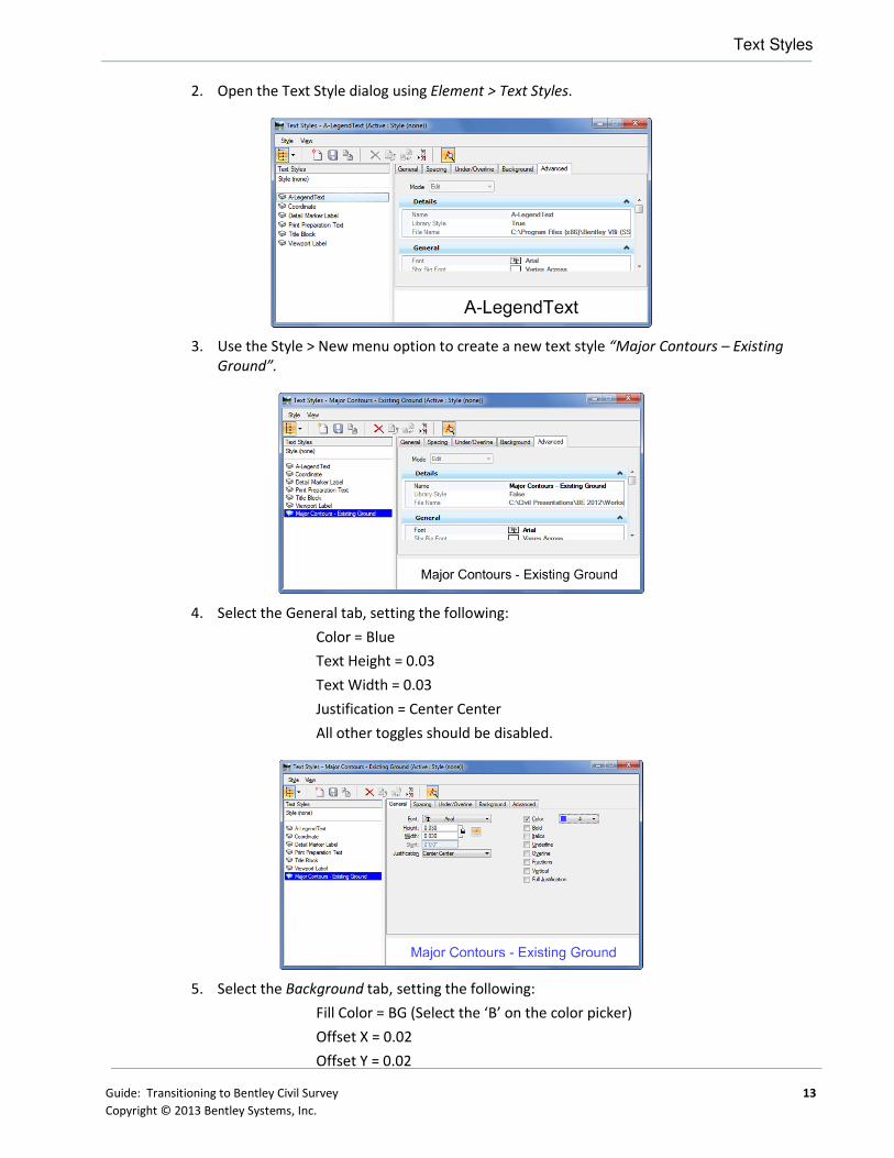
SELECTSERIES3 CONFIGURATION VARIABLES
First, let’s look at a list of the new survey-related Civil configuration variables in SELECTseries 3 with
a brief description of each one. Not all of these variables will be set or even used by every
organization, but they are all listed here for your convenience. Keep in mind some of these settings
impact areas outside of Surveys.
CONFIGURATION VARIABLE DESCRIPTION
CIVIL_XIN_FILE Defines the default XIN file. (InRoads only)
CIVIL_CIVILSETTINGS_READONLY If set to a value of 1, all standards, preferences or features that come from a DGN Library are persisted as read-only in the active file.
CIVIL_SURVEY_DISABLE_DIVIDE_BY_TWELVE If set to a value of 1, this variable indicates that the sizes read from a GEOPAK SMD XML file should not be divided by 12 when linked into Survey Feature Definitions. (Applicable for GEOPAK XML SMD files in an English environment only)
CIVIL_SURVEY_ELEVATION_POSITION_FIVE_ANGLE
If set to a value of 1, allow the elevation annotation to be rotated by the angle specified when the label position is set to position 5. (GEOPAK XML SMD only)
CIVIL_SURVEY_USERTIW_FOLDER Defines an alternate directory where user .TIW files can be located.
CIVIL_SURVEY_STYLEFILE Defines the Style file that is linked in the Survey Feature definitions. Available options are an XIN from InRoads, an XML from a GEOPAK SMD or a PSS from MX.
CIVIL_SURVEY_SURVEYOPTIONS_NAME As the XIN can contain multiple instances of Survey Options, this allows the

Current Configuration Variables
34 Guide: Transitioning to Bentley Civil Survey
Copyright © 2013 Bentley Systems, Inc.
definition of a particular Survey Options to apply when reading the XIN file. If this variable is not defined, then the LAST occurrence of the Survey Options is used. (InRoads only)
CIVIL_SURVEY_GEOID_BINFILE_FOLDER Defines an alternate directory where the GEOID BIN files may be located. If not set, the standard GEOID BIN location is used.
CIVIL_REPORTS_DIRECTORY If the variable is set to a valid directory location, then the software looks at this specific location to locate the XML reports. If this variable is NOT set or it's set to an invalid location, then the software would look at the location where Civil installs the reports by default. NOTE: If the InRoads Project Default XSL location is defined then that is used before CIVIL_REPORTS_DIRECTORY. This maintains continuity for InRoads users.
CIVIL_CONTENTMANAGEMENTDGNLIBLIST This variable defines both the directory and specific file name of the feature definitions DGN Library.
CIVIL_PROJECTSETTINGSDGNLIBLIST This variable defines both the directory and specific file name of the project settings DGN Library.
CIVIL_CIVILTMDGNLIBLIST This variable defines both the directory and specific file name of the terrain model filters DGN Library.
CIVIL_SURVEY_APPEND_ATTRIBUTES_TO_DESCRIPTIONS
If this variable is set (=1) then any attributes associated with a point during the import process will be written to the point’s DESCRIPTION field as well as the attribute field. By populating the DESCRIPTION field, the data can be annotated graphically as the DESCRIPTION. The ATTRIBUTE field cannot be annotated.
CURRENT CONFIGURATION VARIABLES
Next, let’s look at a list of the current Survey-related configuration variables with a brief description
of each one. Not all of these variables will be set or even used by every organization, but they are all
listed here for your convenience. Note while transitioning to Bentley Survey Select series 3, you will
need to leave any variable currently in use, until all users have transitioned.
VARIABLES STILL USED IN SELECT SERIES 3
CONFIGURATION VARIABLE DESCRIPTION
CIVIL_XIN_FILE Defines the default XIN file. (InRoads only)
GPK_SURVMNGR_SMDFILE Denotes the default SMD file as well as the default directory for SMD files. When initially invoking the Survey Manager, this SMD file appears in the Path dialog. Moreover, when selecting File > Open, the directory tree is set where this SMD file resides, even if another SMD file from another directory is the current SMD. Not setting this configuration variable would cause Survey Manager to initially look for ...\GEOPAK\bin\default.smd. Subsequent searches would start in the same directory as the current SMD file.
CHAPTER SUMMARY
At the conclusion of this chapter, you should have a list of current and new configuration variables
and the appropriate setting(s) for your organization.

Guide: Transitioning to Bentley Civil Survey 35
Copyright © 2013 Bentley Systems, Inc.
Chapter 7: Data Collection Requirements
OVERVIEW
Bentley Civil Survey supports a variety of data collector formats with unreduced data and most any
ASCII file containing reduced survey data or even just XYZ data. Features include embedded linking,
feature, and control codes, linking together shots based upon defined chains, comments and
support for the situation where the user does not have a "continuation" linking code for each shot
but wants these shots connected.
The ASCII files need not conform to any particular structure or format other than a requirement that
each point entry be restricted to a single row. The ASCII file should not contain more than one point
per row. Similarly, multiple rows should not be required to define a single point code.
Within the row containing point code data, virtually no restrictions are placed on the arrangement
and separation of survey data. Individual data items (point code, x-coordinate, y-coordinate, z-
coordinate, point number) can be arranged in either free form or column formats. In addition,
extraneous information may be present in the row and ignored by Bentley Civil. Data items in the
free form format can be separated by spaces, commas, dashes, etc.
Two pieces of information are required to load (process) survey data:
• select the survey file(s)
• identify the file format
Note The critical task is setting up the standard formats used at your organization (if they are
not in the examples provided) and add them to the pick list for your survey users. You
want to focus on the standard formats, as the users can always add a project-specific
format that is rarely used. This format file, along with other project settings we’ll add
later, determine what is processed and how the final results display.
SET-UP AND USE OF TIW FILES
Each format is stored within a Text Import Wizard (*.TIW) file and by default are located in
C:\ProgramData\Bentley\Civil\SurveyTools\8.11.9\en\Data. To find them on your machine, just
search for *.TIW.
The TIW files delivered with the install are just a variety of examples to help get users started. They
include data collector formats as well as ASCII coordinate data files. In these tasks, you need the set
of common formatted files used within your organization. It is also prudent to collaborate with
surveyors within your organization who are very knowledgeable on how your organization collects
data, i.e., feature codes, equipment types, processing work flows. It is not necessary that they know
how to run the software, data collection knowledge is paramount.

Project Explorer
36 Guide: Transitioning to Bentley Civil Survey
Copyright © 2013 Bentley Systems, Inc.
Note The file format for TIW has not changed in SELECT series 3. Therefore, if you have
previously created TIW files for your data formats, it is not necessary to recreated them.
The general workflow is: (These steps will be repeated for each data format in your standard
collection.)
• Determine if you have previously created a TIW file for the data.
• Determine if the file is from a data collector or ASCII coordinate files. If data is post-
processed within the data collector software, you’ll probably have just the
coordinate files. If it is raw data from the data collector, you’ll need the brand /
model of equipment, and control information (which may be in a separate file).
Raw data processing will include Least Network Squares adjustment, based on
project settings.
• Review the list of samples to determine if your data matches one of the provided
formats. If it potentially matches, note the name of the TIW file, set it aside and
move to the next format. If not, mark it for TIW file creation and move on. Note
the TIW are ASCII and can be opened with any text editor to see the details of the
format. If you cannot find your data collector brand / model in the samples, contact
Bentley to determine if the data collector is supported.
Most organizations will set a path for the TIW files (so you can have them on a server, rather than
installed on every machine; as it’s easier to change). You may want to remove the TIW files from
the pick list that your users would never use (such as those for data collector equipment brands that
are not used within your organization), and add those that fit your business needs. In that way, your
users will only see what is applicable for them, rather than the entire list. In the ASCII formats, both
NE and XY coordinate options are provided as customers use either format.
To view the available TIW files, we can access the folder via Windows Explorer, however, we can
also see them in the Project Explorer. As we will be using the Project Explorer extensively in later
exercises, you may want to get familiar with it now.
PROJECT EXPLORER
Project Explorer is a standard dialog with tree views for Links and Files for managing data in the
current MicroStation project. This capability has been expanded to manage civil data by adding tabs
for Survey, Civil Model and Civil Standards. Two tabs are critical for survey environment set-up /
testing:
• Survey – used extensively by users for processing, reviewing and manipulating data.
In this guide, it will be used for the testing tasks, emulating the user experience.
• Civil Standards – used to define civil standards to be used by Survey users. In this
guide, it will be used for defining project settings, data collection formats and other
important survey standards.
Note Understanding the Project Explorer is paramount, as many of the settings and standards
need to be created / reviewed / edited within it.
The Project Explorer is accessible from MicroStation > File > Project Explorer or from the Primary
Tool Bar. There are settings to control which tabs are displayed and you will be using the dialog. If
the Project Explorer is not visible on your Primary Toolbar then right-click on the toolbar and toggle
on Project Explorer. This command can be docked on either the left of right side of the screen in a
pinned or unpinned state. Please open the command and leave the dialog on the desktop undocked.

Project Explorer
Guide: Transitioning to Bentley Civil Survey 37
Copyright © 2013 Bentley Systems, Inc.
The first step in the hierarchy is design file. Any design files attached to this design file will also
appear in the tree view. When present a plus (+) to the left of an item indicates additional
information in the tree.
Each item has a selection of actions available by right-clicking ranging from commands to properties
that are appropriate actions for that data type.
CIVIL STANDARDS
The Civil Standards tab provides access to features and settings stored in DGNLIB or design files.
The top level has the current design file and Libraries. Libraries are the collection of DGNLib files that
are associated with the MicroStation project. As settings and standards are used, they are copied
into the design file.
Under the Design File and Libraries are the following sections:
• Civil Cells – a collection that can be placed as a whole
• Design Standards – include curve tables for horizontal and vertical curves by speed
• Feature Management – holds the collection of features
• Filters – contains filters and filter groups for import from graphics
• Project Settings – contain Corridor and Survey settings
• Roundabouts – contains the list of roundabouts available for placement
Note For Survey, we will focus on Project Settings and Feature Management.
� Exercise: Set-up of Project Settings in Project Explorer
Exercise Objective:
Familiarize yourself with Project Explorer’s Civil Standards tabs for review / set-up of Survey
standards.
Procedure:
1. Select File > New from the MicroStation main menu, create a new DGNLib file
survey_data.dgnlib. Be sure to use your seed file created or reviewed in the previous
chapter.
The tabs that are visible in Project Explorer can be configured in each design file.
2. Open File > Project Explorer to view the options. At the top you see the various tabs set to
true.
3. Open MicroStation > Settings > Project Explorer to view the options. At the top you see
the various tabs set to true.
4. Change the File, Links, and Civil Model tabs to False since we are not going to use them;
and then click OK. On the dismissal of the Settings, the Project Explorer changes and the
File, Link and Civil Model tabs are no longer available.
Hint In dialogs which have True/False or On/Off instead of clicking on the drop
down item and selecting the state you can change binary state items by double
clicking on the name.
5. Select the Civil Standards tab.
6. Expand Project Settings by clicking on the + to the left of the item.
Project Explorer
38 Guide: Transitioning to Bentley Civil Survey
Copyright © 2013 Bentley Systems, Inc.
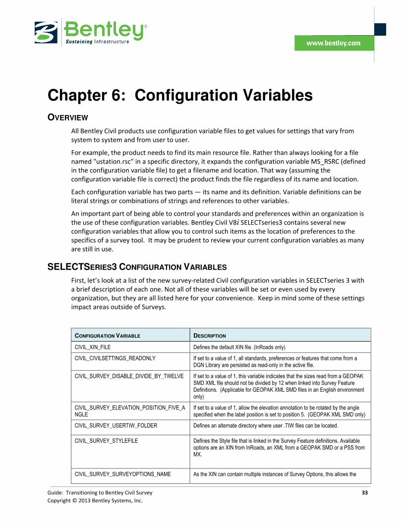
7. Highlight Survey, right-click and select New from the pop-up menu.
8. Highlight New Survey Setting, right-click and select Properties.
9. Expand the Data File Parsing section by clicking on the down arrow on the right side of the
section header.
10. On the Data Import Items line, right-click on the File button to the right side of the field.
This opens the Data Import Items dialog.
In this dialog, we can see the Title column contains the description of each of the TIW files
and the Format File column contains the TIW file name. Note that some of the raw files do
not have a format file. These formats are built into the software, so no TIW file is needed.
� Review Data Files and Categorize
Objective:
The objective of this exercise is to review each data format and categorize it. The result should be
four separate stacks of data:
• Raw data collector files with associated TIW file.
• Raw data collector files with no TIW file.
• Coordinate files with associated TIW file.

Chapter Summary
Guide: Transitioning to Bentley Civil Survey 39
Copyright © 2013 Bentley Systems, Inc.
• Coordinate files with no associated TIW file.
Keep in mind this is our preliminary assessment. If a file is in the wrong category, we can reassess
during the testing phase.
Procedure:
1. Continue in survey_data.dgnlib. The Data Import Items dialog should already be open from
within Project Explorer. This was done in the previous exercise.
2. Let’s look at raw data files first. Using your first data format file, scan the Title column to
see if there is a match. For example, if it’s a raw file and you have Geodimeter, you’ll have
to know whether it Geodimeter 400 or Geodimeter 500. . There are also numerous
formats, for example, for Topcon. Your surveyor can provide this information. Once you’ve
found the correct title, look in the format file column to see if there is an associated TIW
file. If there is, open the file with any text editor. You can view the specifics of each piece of
data to determine if it’s a match for your data. If it is a match, note the name of the title
and moved to the next continue the process for all your raw data files.
3. Next, let’s look at the coordinate files, in ASCII format. Double-click on the format file
column, which will sort the data. This will put all the ASCII file formatted files together for
easy viewing. Then, again, one file at a time, determine if there is a file that meets your
format. If you are unsure, you may want to open the TIW file to review the details of each
data item. If the format matches your file, make a note of the name and moved to the next
file. If not, make a note, the file and format will need to be added. Repeat the process for
all data formats. At the conclusion of this step, all data formats should be classified into
those with associated TIW files and those without.
CHAPTER SUMMARY
At the conclusion of this chapter, you should have reviewed all your data collection datasets and
determined the status of TIW files.

Chapter Summary
40 Guide: Transitioning to Bentley Civil Survey
Copyright © 2013 Bentley Systems, Inc.
This page left intentionally blank.

Guide: Transitioning to Bentley Civil Survey 41
Copyright © 2013 Bentley Systems, Inc.
Chapter 8: Managing Project Settings
OVERVIEW
Now that we’ve completed the general review of our TIW File requirements, we need to step back
for a moment to look at more generic project settings. Therefore, let’s look at Project Settings >
Survey within Civil Standards.
By right-clicking and selecting Properties, we see the project settings.
We can ignore the General and Extended categories, as there are no user inputs in these sections.
However, we have seven other sections of settings to review. As we review, you’ll want to make
notes on the settings for your organization.
ONE SETTING OR SEVERAL?
In order to review our TIW files, we created a survey setting. The question is, will one setting.
suffice, or do we need multiple settings? In order to answer that question, we need to review what
settings are included. It’s not based just on the TIW file settings, but several other sections of
settings as well. These include linking codes, lease network squares adjustment default values, and

Editing Options
42 Guide: Transitioning to Bentley Civil Survey
Copyright © 2013 Bentley Systems, Inc.
terrain model information. If we need different values within the sections, then we will need to
create a second setting. The user will specify one setting for each DGN file, not for each field book.
Therefore, it is preferential to minimize the number of settings. On another factor to take into
consideration is if the various datasets are to be interfaced together. For example, in order to edit
the data from various files, it is desirable to use the same setting.
EDITING OPTIONS
While many of the settings are toggles or from pick list, other settings require a table format. These
tables are all set up the same for ease of use. These tables can be found in:
• Data Import Items
• VBA Feature Macros
• Validating Rules
• Control Point Features
• Feature Exclusions.
• Substitute Strings
In all cases, the table is accessed by clicking on the far right side of the adjacent cell. One example
table is depicted below. The icons at the top of the table provide tools for editing. Scrollbars are
provided in the bottom in the right side.
Note The number and content of columns in each table varies depending on the type of table.
ICON / TOOL DESCRIPTION
Accept This is crucial. When you have completed your edits, you must click Accept in order to retain them. Clicking Accept also closes the dialog. If you close the dialog without accepting, all current edits are lost.
Add / New Includes a blank line at the bottom of the list for additional types. Once the line is added, the appropriate fields can be edited.
Delete Removes the selected line from the list. Highlight the line (s) to be deleted. Note small black triangle in the leftmost column indicates the selected line. Click Delete. Although the lines are deleted from the display, they are not actually deleted until Accept is clicked.
Use (Data Import Items Only)
Sets Use column to True, which exposes the data item to the user. This can also be accomplished by the toggle in the Use column.
Exclude (Data Import Items Only)
Sets Use column to False, which hides the data item to the user. This can also be accomplished by the toggle in the Use column. This is a good method to hide infrequently used data items without deleting them.
Reset (Data Import Items Only)
Resets the entire list to default values, bringing back default lines that may have been deleted, and changing edited settings back to their defaults. Use this setting. Cautiously, as your edited changes may be lost

Settings Options
Guide: Transitioning to Bentley Civil Survey 43
Copyright © 2013 Bentley Systems, Inc.
SETTINGS OPTIONS
Let’s look at each section to review the various options. Small exercises are included for setting
more complex options, however, you may want to wait until you have reviewed all options, then
create your Project Settings.
� Set Up for Project Settings
Objective:
The objective of this exercise is to open Project Settings so we can make adjustments wherever
needed in the subsequent sections. Therefore, subsequent exercises will assume your DGN Lib file is
active and that Project Settings is open and ready for editing.
Procedure:
1. Open DGNLib file survey_data.dgnlib. This was created in the previous chapter.
2. Open File > Project Explorer.
3. Select the Civil Standards tab.
4. Expand Project Settings by clicking on the + to the left of the item.
5. Highlight New Survey Setting, right-click and select Properties.
You are now ready to begin editing any of the Settings sections. They can be done in any
order.

General Settings
44 Guide: Transitioning to Bentley Civil Survey
Copyright © 2013 Bentley Systems, Inc.
GENERAL SETTINGS
The General Settings are detailed in the table below:
SETTING DESCRIPTION
Create Log File True specifies to create a history log of changes, everything. The ASCII log is named after the current MicroStation model (in our case default) with a .log extension and placed in working directory by default. Subsequent sessions are appended to the log file, as long as the option is set to True. When set to False, no log is created.
Append Notes to Description If set to True, it uses the data collector note field and appends to the point’s description field. If set to False, the note from the data collector will be ignored.
Use Annotation Scale True or False – If set to True, the text sizes set within the XIN or XML file are adjust based on the Annotation Scale in the active file. If set to False, no adjustment is made and text sizes are based only on the XIN or SML file.
Use VBA Macros True specifies to use a VBA application to perform advanced functions on survey data. Set to False if you do not want any VBA macros to perform. This works in conjunction with the VBA Feature Macros option.
VBA Feature Macros Click in the adjacent cell then click the browse button to open the VBA Feature Macros dialog. Choose from the available macros then click accept to deploy the selection.
Validating Rules Click in the adjacent cell then click the browse button to open the Validations dialog. Choose from the available rules then click accept to deploy the selection. For example, you can set limits on elevations or coordinates, rod heights, etc. to conform to your organization. If an elevation is outside your range, a warning or error message is displayed.
� Setting and Using VBA Macros
Objective:
In this exercise, we will learn how to set a feature to utilize a VBA macro. One VBA provided in the
default install is smartsolids.mvba, which extrudes linear features (such as pipes) in the 3D model.
Procedure:
1. Continue in the DGNLib file survey_data.dgnlib. This was created in the previous chapter;
the Project Explorer was opened to Civil Standards and Survey Project Settings.

General Settings
Guide: Transitioning to Bentley Civil Survey 45
Copyright © 2013 Bentley Systems, Inc.
2. Expand the General Settings section by clicking on the black arrow on the right side of the
section header.
3. Toggle Use VBA Macros to True.
4. Click in the cell to the right of VBA Feature Macros.
5. Click New to add a new line to the table. Note, you may add several lines at one time.
6. Select the Object Type, either Point or Line.
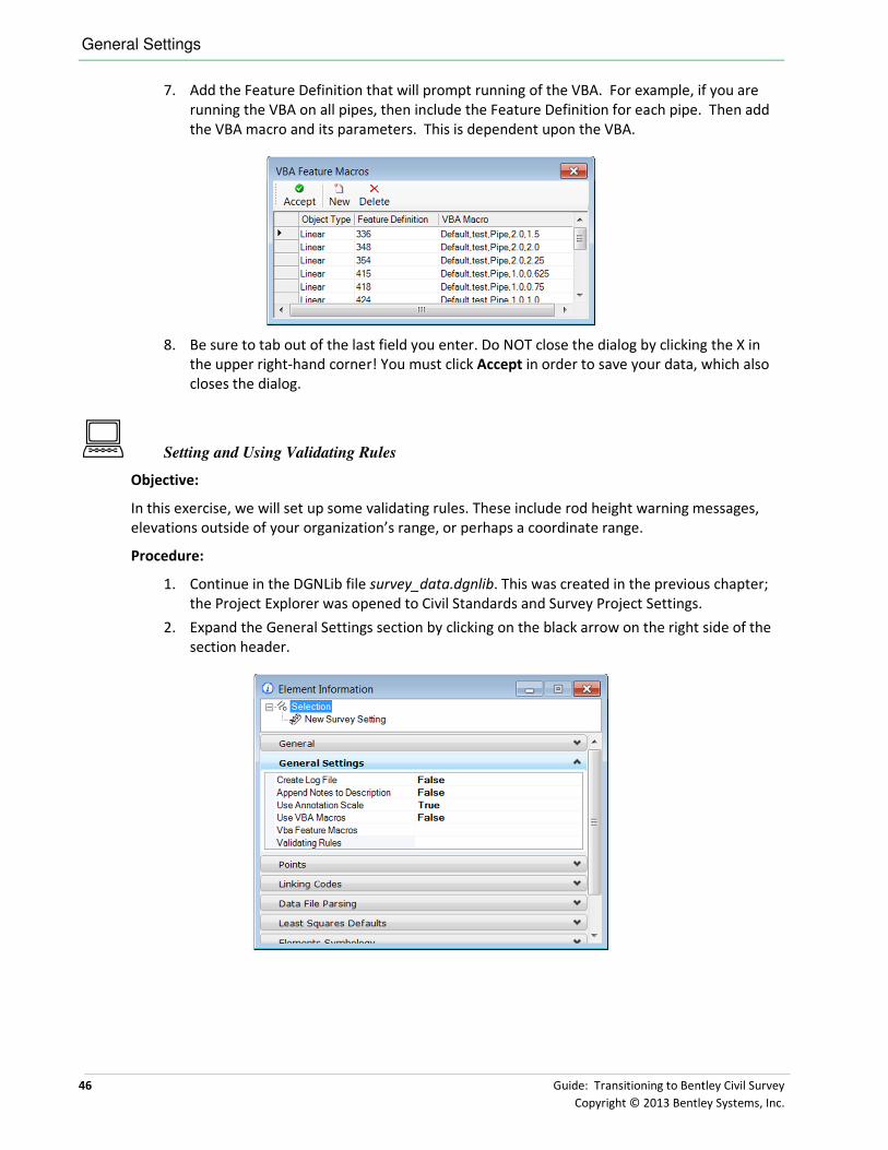
General Settings
46 Guide: Transitioning to Bentley Civil Survey
Copyright © 2013 Bentley Systems, Inc.
7. Add the Feature Definition that will prompt running of the VBA. For example, if you are
running the VBA on all pipes, then include the Feature Definition for each pipe. Then add
the VBA macro and its parameters. This is dependent upon the VBA.
8. Be sure to tab out of the last field you enter. Do NOT close the dialog by clicking the X in
the upper right-hand corner! You must click Accept in order to save your data, which also
closes the dialog.
� Setting and Using Validating Rules
Objective:
In this exercise, we will set up some validating rules. These include rod height warning messages,
elevations outside of your organization’s range, or perhaps a coordinate range.
Procedure:
1. Continue in the DGNLib file survey_data.dgnlib. This was created in the previous chapter;
the Project Explorer was opened to Civil Standards and Survey Project Settings.
2. Expand the General Settings section by clicking on the black arrow on the right side of the
section header.
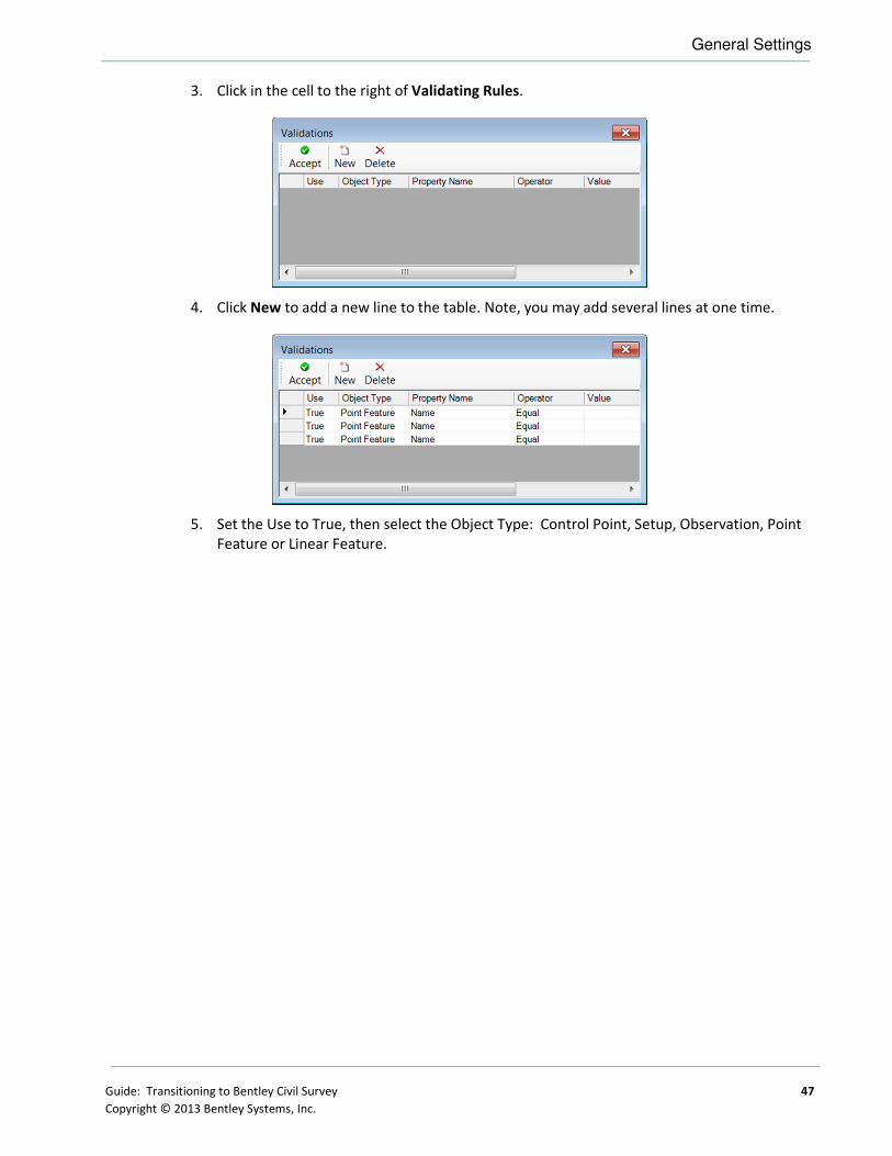
General Settings
Guide: Transitioning to Bentley Civil Survey 47
Copyright © 2013 Bentley Systems, Inc.
3. Click in the cell to the right of Validating Rules.
4. Click New to add a new line to the table. Note, you may add several lines at one time.
5. Set the Use to True, then select the Object Type: Control Point, Setup, Observation, Point
Feature or Linear Feature.

General Settings
48 Guide: Transitioning to Bentley Civil Survey
Copyright © 2013 Bentley Systems, Inc.
6. Next, select the Property Name that defines what will be validated. Note the Property
Name options vary depending upon the Object Type selected.
PROPERTY NAME OBJECT TYPE
CONTROL
POINT OBSERVATION SET UP LINEAR
FEATURE POINT
FEATURE
Name X X X X
Feature Definition X X X
Description X X X
Easting X X
Northing X X
Elevation X X
Length X
Point Count X
Rod Height X
Horizontal Angle X
Vertical Angle X
Slope Distance X
Tolerance X
Height X
Circle X
Backsight direction X
Backsight Type X
Occupy X
Occupy Feature Definition X
Occupy Easting X
Occupy Northing X
Occupy Elevation X
Backsight X
Backsight Feature Definition X
Backsight Easting X
Backsight Northing X
Backsight Elevation X
7. Select the Operator from the list: List, Greater, Less or Equal, Greater or Equal, Equal, Not
Equal, Contains, Between, Begins With, or Ends With.
8. Enter the appropriate Value.
9. Enter the (optional) Description.

Points
Guide: Transitioning to Bentley Civil Survey 49
Copyright © 2013 Bentley Systems, Inc.
10. Continuing entering validating rules. One example is depicted below.
11. Be sure to tab out of the last field you enter. Do NOT close the dialog by clicking the X in
the upper right-hand corner! You must click Accept in order to save your data, which also
closes the dialog.
POINTS
Two options are supported in the Points section.
OPTION DESCRIPTION
Import Coordinate Records Always - Any collected coordinates are also loaded in addition to angles and distances
Never - Collected coordinates are never loaded; only angles and distances.
As Control - All collected coordinates are also loaded in addition to angles and distances. The coordinates are used as control points for the network least squares processing.
As Control by Feature Definition - Collected coordinates whose feature code is defined in the Control Point Feature dialog are also loaded in addition to angles and distances. The coordinates are used as control points for the network least squares processing.
Control Point Features This dialog works in conjunction with the As Control by Feature Definition. Click in the adjacent cell then click the browse button to open the Control Point Features dialog. Click Add to add a line to the dialog. Enter the feature of the Control Point and tab. Add as many features as desired, then be sure to Accept to store the entry and close the dialog. If the dialog is closed without Accepting, all current additions or changes are lost.
� Setting Control Point Features
Objective:
In this exercise, we will add several feature definitions as control points.

Points
50 Guide: Transitioning to Bentley Civil Survey
Copyright © 2013 Bentley Systems, Inc.
Procedure:
1. Continue in the DGNLib file survey_data.dgnlib. This was created in the previous chapter;
the Project Explorer was opened to Civil Standards and Survey Project Settings.
2. Expand the Points section by clicking on the black arrow on the right side of the section
header.
3. Click in the cell to the right of Control Point Features.
4. Click New to add a new line to the table. Note, you may add several lines at one time.

Linking Codes
Guide: Transitioning to Bentley Civil Survey 51
Copyright © 2013 Bentley Systems, Inc.
5. Add each Feature Definition which will be used for control.
6. Do NOT close the dialog by clicking the X in the upper right-hand corner! You must click
Accept in order to save your data, which also closes the dialog.
LINKING CODES
The three options provided within the Linking Codes section enable a wide variety of options which
will cover most organizations. If you are currently using capital Bentley Survey, you should be able to
use your current linking codes set up with no change in your data collection methods. However, if
you are using an older version, you may want to review some of the options to see if you can
enhance your data collection codes. If you do not have legacy settings, you may want to adopt the
DA Linking codes options as they are more robust.
Warning Linking codes CANNOT contain ANY part of a feature (example ST
link code and STEPS) causes problems.
LEGACY GEOPAK LINKING CODES
Legacy GEOPAK Survey creates linear elements of the linear data if linking codes are used in the field
while collecting the data. Linking codes are special characters prepended to the feature in the field.
GEOPAK Survey (in the downloaded raw mode) supports the following default linking codes. Note
the codes are user definable.
OPTIONS (DEFAULTS) DESCRIPTION
BL* Begin Line
EL* End Line (not necessary)
CL* Close Figure
PC* Begin Curve (tangent to previous line)
OC* Point on Curve (begin/end non-tangent curve)
PT* End Curve (tangent to next line)
CC* Point of Compound or Reverse curve
CF* Curve Fit (spline fit to irregular curves)

Linking Codes
52 Guide: Transitioning to Bentley Civil Survey
Copyright © 2013 Bentley Systems, Inc.
These codes can be upper or lower case. Below is a sample sequence:
Point Description
5 BL*CURB1 BL*SW1 WV
6 CURB1
7 SW1 PP
8 PC*CURB1
10 PT*CURB1
11 CURB1 SW1
12 OC*SW1
13 SW1
14 SW1
15 SW1
16 OC*SW1
17 CL*SW1
18 BL*CURB1
Note Spaces between the code, asterisk, and line description: (BL * SW1) are supported.
IMPORTANT: Lines are connected by the order of point numbers. The point numbers do not have to
be sequential, but they must be in increasing order. Since the actual mapping is produced by the
reduced coordinate file and not the raw data file, the point numbers determine the sequence, not
the order of field location (order of shots in raw data file).
In the above example, point 5 begins two lines, CURB1 and SW1. CURB1 and SW1 are Line
Description(s). A line description must be a whole word (no spaces). WV (Water Valve) is not the
beginning of a line because it is not preceded by a BL*'. The following lines will be drawn:
First Line (CURB1): 5 to 6 to 8 (begin curve tangent from 6 to 8) to 10 (end curve tangent from 10 to
11). Since 18 begins a new CURB1, point 11 is the end of the first line (the EL code is not necessary
to end a line).
Second Line (SW1): 6 to 7 to 11 to 12 (begin non-tangent circular curve), through points on curve
13,14,15, to 16 (end non-tangent curve) to 17 (CL closes figure). Points 13-15 are used to define the
curve.
ALL LINES MUST START WITH A BL* or the equivalent user-defined begin line code. No lines will be
connected to a point unless the point description matches a BL* LINE DESCRIPTION.
Note Combining codes and line descriptions within a single point description is supported.
For example,
Point Description
BL*SW1 BL*CURB1
The above example begins a SW1 line and a CURB1 line.
Chain Names: The survey chain name is derived from the feature. In the above example 2 chains are
created, CURB1 and SW1. In the case where another chain is started (BL* CURB1) and that name has
already been used, then the name will be incremented by 1. The chain name in this case will be
CURB1-1.
CALC Points: For shots that are double coded as above, the raw data for that shot is duplicated and
stored with a point named CALCXX, beginning with CALC1. This allows the double coded shots to
represent two features with different geometry codes. For example, one feature may be a straight

Linking Codes
Guide: Transitioning to Bentley Civil Survey 53
Copyright © 2013 Bentley Systems, Inc.
line while the other feature is a curve. The CALC points are numbered sequentially even between
multiple sets of data in the same directory. A file named CALCPTS.NUM is located in the projected
directory and contains the next available CALC point number. The creation of these CALC points
takes place in the conversion from Raw Data to OBS.
LEGACY DA OR INROADS SURVEY LINKING AND CONTROL CODES
Data collected in field survey data can use linking codes to enable creation of and geometry changes
for linear features as the data is processed.
Control Codes provide the ability to enable special treatment of specific points to be automatically
implemented during the data processing.
Linking codes can be Alpha or Numeric values. Control codes can only possess Alpha values.
LINKING CODES
Note Linking Codes can be Alpha or Numeric values. They can be before or after the Field code.
They must be separated from the Field code with a space.
LINKING CODE DESCRIPTION
Start Begins creating a Linear Feature
StartPC Starts a linear feature in Arc Mode
ArcPC Specifies the beginning of a tangential arc or curve within a Linear Feature
NonTanPC Beginning of a non-tangential arc or curve within a Linear Feature
ArcSingle Creates a three point arc with previous and next points (does not work at beginning or end of a Linear Feature)
ArcToArc Ends previous tangent arc and begins another tangent arc (must be preceded by ArcPC)
NonTanPT End of a non-tangential arc or curve within a Linear Feature
ArcPT End of a tangential arc or curve within a Linear Feature
ArcToggle Toggles between NonTanPC and NonTanPT (depends on pairing)
End Ends the linear feature (not necessary in most cases)
CloseShape Closes the ends of the linear feature by adding right angle at both ends and intersecting
Close Closes the Linear Feature back to the first point
CONTROL CODES
Control codes must be assigned after the Field code. Control codes can only be Alpha values.
Control and Linking codes can both be used on the same point as long as the Control code is last.
Control codes must be separated from the Field or Linking code with a space.
CONTROL CODES DESCRIPTION
CircleDiameter Draws a circle of specified diameter around this point (must be within Linear Feature)
CircleRadius Draws a circle with specified radius around this point (must be within Linear Feature)
RectangleWidth Draws a rectangle from two points and specified width (must be within Linear Feature)
TapeDistance Applies field measured distances to the Linear Feature. All measurements are applied 90 degrees from previous segment. Positive values turn right, and negative values turn left. (must be within Linear Feature)
JoinPoint Joins this point to specified point name (does NOT have to be in linear feature)

Linking Codes
54 Guide: Transitioning to Bentley Civil Survey
Copyright © 2013 Bentley Systems, Inc.
NewTemplate Same as InRoads TMPL Consecutive Start codes will get this linear feature paralleled and translated based off of initial points
Elevation Sets the Elevation of this point
UpDown Changes final elevation coordinate of point by value entered
LeftRight Changes final coordinate of point by adjusting left (-) or right (+) of measured observation by value entered
FrontBack Changes final coordinate of point by adding or subtracting a distance from the measured distance
AttributeName One method of getting attributes for a point (pairs with Value)
AttributeValue One method of getting attributes for a point (pairs with Name)
AttributeArray One method of getting attributes for a point (Names and Value in array)
TerrainSpot Include in DTM as spot
TerrainNoSpot Do not Include in DTM
TerrainBreak include in DTM as break
TerrainNoBreak do not include in DTM
REVIEWING OR SETTING UP LINKING CODES
Five options needs to be defined while setting up the Linking Codes:
• Link Codes - sets the actual codes.
• Link Code Position - sets the position of the code.
• Linear Feature Linking Method – defines how to link using the field code.
• Linear Feature Linking - defines how to link using either linking codes or point list.
• Feature Exclusions – defines feature definitions that are not used when creating
linear features.
LINK CODES
The first section is very important as it defines the linking codes. The default provided with the
install may be sufficient in many cases as it’s the Bentley DA default from SELECT series 2.
Therefore, it may be easier to tweak the default for your customization rather than starting from
scratch.
� Setting Linking Codes
Objective:
In this exercise, we will review / edit linking codes.
Procedure:
1. Continue in the DGNLib file survey_data.dgnlib. This was created in the previous chapter;
the Project Explorer was opened to Civil Standards and Survey Project Settings.

Linking Codes
Guide: Transitioning to Bentley Civil Survey 55
Copyright © 2013 Bentley Systems, Inc.
2. Expand the Linking Codes section by clicking on the black arrow on the right side of the
section header.
3. Click in the cell to the right of Link Codes.
The default link codes and associated data are displayed.
4. Edit the information to conform to your organizational standards. If you are using legacy
GEOPAK codes, you need to add them to the list. You may also want to turn the Use
Column to False for link codes you are not using.
5. Do NOT close the dialog by clicking the X in the upper right-hand corner! You must click
Accept in order to save your data, which also closes the dialog.
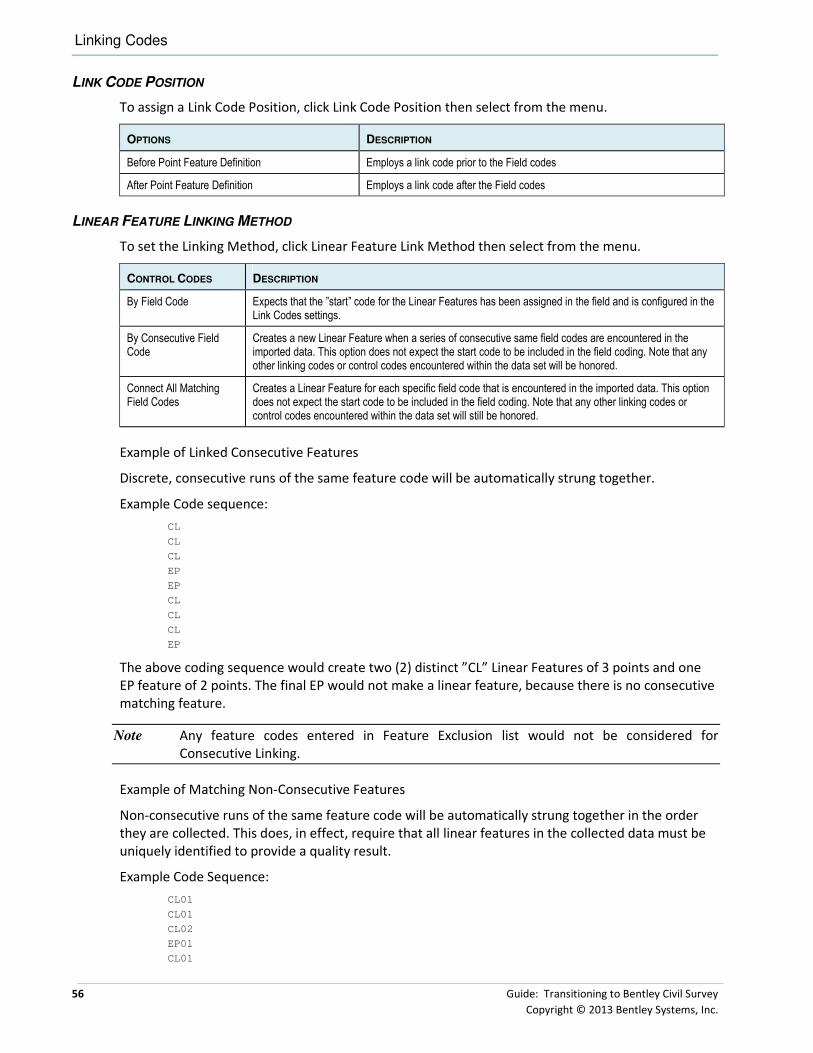
Linking Codes
56 Guide: Transitioning to Bentley Civil Survey
Copyright © 2013 Bentley Systems, Inc.
LINK CODE POSITION
To assign a Link Code Position, click Link Code Position then select from the menu.
OPTIONS DESCRIPTION
Before Point Feature Definition Employs a link code prior to the Field codes
After Point Feature Definition Employs a link code after the Field codes
LINEAR FEATURE LINKING METHOD
To set the Linking Method, click Linear Feature Link Method then select from the menu.
CONTROL CODES DESCRIPTION
By Field Code Expects that the ”start” code for the Linear Features has been assigned in the field and is configured in the Link Codes settings.
By Consecutive Field Code
Creates a new Linear Feature when a series of consecutive same field codes are encountered in the imported data. This option does not expect the start code to be included in the field coding. Note that any other linking codes or control codes encountered within the data set will be honored.
Connect All Matching Field Codes
Creates a Linear Feature for each specific field code that is encountered in the imported data. This option does not expect the start code to be included in the field coding. Note that any other linking codes or control codes encountered within the data set will still be honored.
Example of Linked Consecutive Features
Discrete, consecutive runs of the same feature code will be automatically strung together.
Example Code sequence:
CL
CL
CL
EP
EP
CL
CL
CL
EP
The above coding sequence would create two (2) distinct ”CL” Linear Features of 3 points and one
EP feature of 2 points. The final EP would not make a linear feature, because there is no consecutive
matching feature.
Note Any feature codes entered in Feature Exclusion list would not be considered for
Consecutive Linking.
Example of Matching Non-Consecutive Features
Non-consecutive runs of the same feature code will be automatically strung together in the order
they are collected. This does, in effect, require that all linear features in the collected data must be
uniquely identified to provide a quality result.
Example Code Sequence:
CL01
CL01
CL02
EP01
CL01

Linking Codes
Guide: Transitioning to Bentley Civil Survey 57
Copyright © 2013 Bentley Systems, Inc.
BC01
CL02
CL01
EP01
The above coding sequence would create linear features for CL01, CL02, and EP01.
BC01 would not make a linear feature, because there are no matching codes within the data.
Note Any feature codes entered in Feature Exclusion list would not be considered for Non-
Consecutive Linking.
LINEAR FEATURE LINKING
To set the Linear Feature Linking, click Linear Feature Linking then select from the menu. Each has
advantages and disadvantages.
OPTIONS DESCRIPTION
By Linking Codes Creates Dynamic Link linear features and has a property type of GeneratedByLinking.
Force Point List Features Forces create Point List type linear features instead of the default Dynamic Link linear features.
FEATURE EXCLUSION
Feature Exclusion is utilized in conjunction with the Linking Methods to assign specific codes that
will NOT be connected by linear features. Example codes may be ground shots, power poles,
manholes, etc.
� Setting Feature Exclusion
Objective:
In this exercise, we will add several feature exclusions.
Procedure:
1. Continue in the DGNLib file survey_data.dgnlib. This was created in the previous chapter;
the Project Explorer was opened to Civil Standards and Survey Project Settings.
2. Expand the Linking Codes section by clicking on the black arrow on the right side of the
section header.

Least Squares Defaults
58 Guide: Transitioning to Bentley Civil Survey
Copyright © 2013 Bentley Systems, Inc.
3. Click in the cell to the right of Feature Exclusions.
4. Click New to add a new line to the table. Note, you may add several lines at one time.
5. Add each Feature Definition which will be excluded. Specify the exact code (Equal), the
code prefix, the code suffix or characters that codes contain to exclude from Linear Feature
creation.
6. Do NOT close the dialog by clicking the X in the upper right-hand corner! You must click
Accept in order to save your data, which also closes the dialog.
LEAST SQUARES DEFAULTS
Least Squares adjustments and blunder detection may be applied to survey raw data. The
adjustments and reports are automatic when the Adjustments box is checked. The adjustments and
adjustment settings apply to the entire field book. Traverse data will not be adjusted unless there
are control points stored.

Least Squares Defaults
Guide: Transitioning to Bentley Civil Survey 59
Copyright © 2013 Bentley Systems, Inc.
This section contains the defaults utilize when a least squares adjustment is processed.
Most of these settings are device-dependent. For example, the Distance constant is dependent on
the device used to measure distances. Most modern electronic distance measuring (EDM)
equipment has an inherent accuracy of 0.01 - 0.02 feet.
OPTIONS DESCRIPTION
Combined Scale Factor Option
Select Do Not Use, Compute From Control Points, Compute For Each Observation, Use Manual Combined Factor
Combined Scale Factor Value
Specifies the Combined Scale Factor Value.
Display errors in Message Center
True or False
Add-on for Distance Constant
Accuracy of measured distances based on a set of redundant measurements
Add-on for Distance PPM
The parts per million correction for measured distances based on the principle that an error will be proportional to the length of the line. This is device dependent as well, but not to be confused with the corrective PPM applied for atmospheric conditions on the instrument itself.
Add-on for Horizontal angle
Inherent accuracy of measured angles based on a set of redundant measurements
Add-on for Azimuth Accuracy of azimuth - This is not the same as angle accuracy; it is based on the accuracy of a predefined direction used as a backsight.
Add-on for Trig level constant
Accuracy of elevations measured with total station distance/vertical angle calculations
Add-on for Trig level PPM
Parts per million additive for measured trig elevations. As with Distance PPM, this is based on the length of the error being proportional to the length of the line.
Add-on for Differential leveling Constant
Accuracy of elevations derived from differential levels, using leveling instrument and leveling rod and taking into consideration that backsights and foresights are equal in length and that readings are taken to a rod held plumb.
Default Distance error estimate
The computed factor applied to a set of measured distances based on the precision or repeatability of those measurements as related to predefined coordinates used to control the traverse

60 Guide: Transitioning to Bentley Civil Survey
Copyright © 2013 Bentley Systems, Inc.
Default Distance PPM
The corrective factor that is actually applied according to the Error Distant Constant
Default Horizontal angle error estimate
The computed factor applied to a set of measured angles based on the precision or repeatability of those measurements as related to predefined coordinates used to control the traverse
Default Azimuth error estimate
The corrective factor that is applied according to the repeated angular measurements in the traverse and the actual Azimuth direction as determined by predefined coordinates
Default Trig Level Constant error estimate4
The corrective factor that is applied according to the repeated angular measurements in the traverse and the actual elevations generated as determined by predefined coordinates
Default Differential Leveling Constant
The corrective factor that is applied according to the determined error in balancing a level run based on predefined bench mark values
Distance tolerance Total estimated distance error for the length of the traverse based on adjusted distances compared to averaged distances and predefined coordinates for the closing distance
Angle tolerance Total estimated Angular error for the traverse based on adjusted angles compared to averaged angles and predefined coordinates for the closing direction
Elevation tolerance Total elevation difference for trigonometric elevations based on adjusted elevations compared to averaged elevations and predefined elevation values at the closing point.
Setup Error Estimated systematic error inherent when setting up over a point.
XYZ decimal places Number of decimal places used in reports.
Use repetition error PLUS add-ons for error estimation
True value sets the error estimates as a function of the standard error in the mean plus user defined additions which are defined by constant and ppm add-ons values. False value sets the error estimates generated only by user supplied constant and ppm input error values. Default values only, no add-ons will be added.
Compute Coordinate standard error and error ellipses
If set to True, Survey computes the coordinate standard errors and error ellipses. Errors based on user-defined tolerances are displayed using the Elipses Settings in Workspace > Preferences > View Options – Civil.
Compute earth curvature and atmospheric refraction
True or False to correct for earth curvature - Most modern instruments only account for the Earth's curvature and refraction when computing and exporting coordinates, as that factor is used in generating coordinate values internally. If only raw data is imported, the angles and distances recorded and exported in the raw data file are NOT corrected for curvature and refraction. This should be turned on when using raw data and running any form of adjustment.
Balance Angles True or False - Angles are automatically balanced as part of the Least Squares Adjustment proves.

Elements Symbology
Guide: Transitioning to Bentley Civil Survey 61
Copyright © 2013 Bentley Systems, Inc.
ELEMENTS SYMBOLOGY
OPTIONS DESCRIPTION
Observations Element Template Select an Element Template used for drawing / displaying Observations.
Observations Size Multipler for size, i.e., 2 would be twice the size, 0.5 would be half size.
Control Points Element Template Select an Element Template used for drawing / displaying Control Points.
Control Points Size Multipler for size, i.e., 2 would be twice the size, 0.5 would be half size.
Setups Element Template Select an Element Template used for drawing / displaying Setups.
Setups Size Multipler for size, i.e., 2 would be twice the size, 0.5 would be half size.
TERRAIN MODEL
Five options are supported in the Terrain Model section. The most critical option is whether to
automatically create terrain models, or whether the users want to control went terrain models are
made. If the field book data requires a lot of editing, the user may not want the terrain model
created, as it would be constantly updating. Other options include parameters for the created
terrain model.

Data File Parsing
62 Guide: Transitioning to Bentley Civil Survey
Copyright © 2013 Bentley Systems, Inc.
OPTIONS DESCRIPTION
Create Terrain Model for All Field Books
When set to True, the terrain model is automatically created whenever data is loaded into a field book. When set to False, the user needs to create the terrain model at the appropriate time.
Name Name of the created terrain model.
Feature Definition Default Feature Definition to be used when Survey creates terrain models. Keep in mind, the user can always assign a different Feature Definition at any time.
Edge Method Method used during the creation of the terrain model relating to external triangles.
None-No external triangles are dissolved.
Remove Slivers-Long, thin triangles are dissolved based on a formula hard coded within the software. There are no user defined parameters.
Max Triangle Length-External triangles whose external edge is longer in length than the specified distance are dissolved. The side option does not apply to internal triangles, only those on the edge of the model.
Length Value of the maximum length of the triangle edge used during the creation of the terrain, when the Edge Method is set to Max Triangle Length.
DATA FILE PARSING
The Data File Pursing section is critical, as it defines the format of the datasets the surveyors load.
We will utilize the information gathered in the previous chapter relating to TIW files. This section
also identifies substitution string information and separators.
DATA IMPORT ITEMS
The Data Import Items dialog defines new file types to be imported as well as enabling or disabling
certain file types. The extensions defined in the Filter column of the Data Import Item dialog play an
important role in Bentley Civil Survey. Whenever a file is dragged and dropped or a file is opened via
Load File, the file extension of the file being loaded is compared to all of the filters in the Data
Import Item dialog. Any rows that are FALSE will not be considered for that file filter. If a file is being
imported that has multiple matching rows for the Filter, then the user is prompted to select the
desired file conversion type.
OPTIONS DESCRIPTION
Use Use indicates if the Data Import Item should be used when new files are loaded. If set to FALSE then this parser or file interpreter will not be used. If set to TRUE, then this parser may be used.
Vendor Indicates the origin of the file parser or the file interpreter.
Title Title is the title of the file parser or interpreter.
Filter Filter is the extension of the file being loaded. Multiple extensions can be specified by separating them with a semi-colon (;) such as *.RW5;*.RAW.
File Type Input File Type In indicates the source file type being processed.
File Type Output File Type Out indicates the output file type that the parser creates from the input file. The Neutral file is the common internal file type that Civil Survey uses in most cases.
Executable Path Executable Path If an external parser is defined in the Executable field, then this path indicates the location where the executable is located.

Data File Parsing
Guide: Transitioning to Bentley Civil Survey 63
Copyright © 2013 Bentley Systems, Inc.
Executable Executable is an alternate, user developed, parser program that can be used to parse files that Civil Survey cannot parse.
Format File Format File specifies a TIW (Text Input Wizard) file that Civil Survey uses to parse the data.
Projection Name In Projection Name In indicates the coordinate projection system of the source file. The name is the same name used in MicroStation Geographic Coordinate System dialog.
Projection Name Out Projection Name Out indicates the coordinate projection system of the destination file. The name is the same name used in MicroStation Geographic Coordinate System dialog.
Leica and Trimble will be processed differently with survey tools than in native applications. Most
native parsers are still available, but some have been replaced.
Mapping will not match 100% for any of the three existing products, but is as close as possible.
� Setting Data Import Items
Objective:
In this exercise, we will review editing and setting up a new TIW file.
Procedure:
1. Continue in the DGNLib file survey_data.dgnlib. This was created in the previous chapter;
the Project Explorer was opened to Civil Standards and Survey Project Settings.
2. Expand the Data File Parsing section by clicking on the black arrow on the right side of the
section header.

Data File Parsing
64 Guide: Transitioning to Bentley Civil Survey
Copyright © 2013 Bentley Systems, Inc.
3. Click in the cell to the right of Data Import Items.
4. Click New to add a new line to the table, which has some fields already populated. These
are just defaults, and can be changed as needed. Note, you may add several lines at one
time. You also may need to stretch the dialog and adjust column widths to see the
Executable and Format File columns.
5. Add each of your TIW files (one per line) that are not already in the list. Populate the fields:
• Use: True
• Vendor: <use your Vendor name>
• Title: <use your own Title here>
• Filter: <use your own file filter here>, example, *.txt
• FileTypeIn: Neutral
• Executable Path: <leave blank>
• Executable: survey.exe
• FormatFile: <your TIW file>, example *.tiw click in the field and navigate to your
standard TIW directory!
6. While in this dialog, you may want to do some cleanup. For example, the users will see all
of the data import items listed for the appropriate extension. You may want to just delete
those that are never used by your organization. Another option is to set the Use column to
False.

Substitution Strings
Guide: Transitioning to Bentley Civil Survey 65
Copyright © 2013 Bentley Systems, Inc.
7. Do NOT close the dialog by clicking the X in the upper right-hand corner! You must click
Accept in order to save your data, which also closes the dialog.
SUBSTITUTION STRINGS
Substitution strings allow descriptions or codes to be entered and associated with a number or text
string during the initial loading of a data file. Some older data collectors do not allow alpha codes so
numeric codes are required. Another reason for using numeric codes is to save space. Most data
collectors only allow 14-16 characters of input for codes. By using numeric codes, the length of the
field required can be reduced.
Note Substitution strings only work during initial loading; they are not used as data is edited or
modified.
For example, if the Linking code in the raw data was recorded as 1 for the start of a line it will be
replaced by whatever is set in the String Substitution dialog, which should be the same as the one
set for Start in the Link Codes dialog. Generally, users in the field use this to save time, so instead of
typing something like BL*EP, they type 1 EP. In this case they must set the option use substitute
strings to True, then in the String Substitution dialog under substitute type 1 and under with type
BL* and in the Link Codes dialog set START to BL*.
This also works for Point codes or description/feature definitions. Example, if a point code of an
object on the standards is ROCK, but the user uses 1000 instead in the field to save time typing. The
software replaces 1000 by ROCK which in turn matches what was set for that object in the Feature
definition style file thus drawing those points with the selected preferences for ROCK.
Consider the following example:
Raw Data (Point Number Code)
10 1 159
11 FH
12 159
13 3 159
14 EP
15 3 159
16 2 159
Point 10 code gets translated to BL* EP, point 12 gets translated to EP, point 13 and 15 get
translated to OC* EP and point 16 gets translated to EL* EP. Notice that each whole integer number
contained within a description or point code gets translated to the corresponding String Substitution
Table match. Nothing is done to point 11, as there are no numeric character candidates for
substitution.

Substitution Strings
66 Guide: Transitioning to Bentley Civil Survey
Copyright © 2013 Bentley Systems, Inc.
OPTIONS DESCRIPTION
Use Substitute Strings When set to True, the software performs a search and replace on the raw data before processing.
Substitute Strings Substitute Strings allows descriptions or codes to be entered and associated with a number.]’
During loading, each whole number in the code field is compared to the substitution table. If a
match is found then that code is replaced by the text value of that description.
Warning InRoads users, feature codes should not contain linking code
character strings. Use Substitute Strings to fix.
� Define Substitution Strings
Objective:
In this exercise, we will define various substitution strings.
Procedure:
1. Continue in the DGNLib file survey_data.dgnlib. This was created in the previous chapter;
the Project Explorer was opened to Civil Standards and Survey Project Settings.
2. Expand the Data File Parsing section by clicking on the black arrow on the right side of the
section header.
3. Click in the cell to the right of Substitute Strings.

Separators
Guide: Transitioning to Bentley Civil Survey 67
Copyright © 2013 Bentley Systems, Inc.
4. Click New to add a new line to the table. Note, you may add several lines at one time.
5. Add each String Substitution by completing the three fields (per line):
• Whole Word require whole word matching, specify True or False
• Substitute - search string to be replaced
• With - string that replaces the search string
One sample dialog is illustrated below:
6. Do NOT close the dialog by clicking the X in the upper right-hand corner! You must click
Accept in order to save your data, which also closes the dialog.
SEPARATORS
Two separator options are supported in the project settings.
OPTIONS DESCRIPTION
Description Separator Character(s) utilized to separate feature data from the point description. Each character entered in the field is considered to be a Feature unless a specific comment delimiter is encountered. For example, the field code EP BROKEN would be considered a double coded shot representing two features, one EP and the other BROKEN. If the intention is to describe the feature with a description or comment, then define a Description delimiter and all characters following this delimiter will be treated as the point Description. Note the default is two hyphens.
Attribute Separator Character(s) utilized to separate the feature from any point attributes.
CHAPTER SUMMARY
In this chapter, we covered the critical aspects of the Project Settings. This should be a major focus
of the set up prior to testing and deployment of Bentley Civil Survey. Your DGN Lib file should now
have a complete set of project settings. Once again, you may want to go back and review each
section and adjust settings as needed. The exercises have demonstrated the more complex settings,
while those that are toggles or key in fields were not illustrated.

Chapter Summary
68 Guide: Transitioning to Bentley Civil Survey
Copyright © 2013 Bentley Systems, Inc.
This page left intentionally blank.

Guide: Transitioning to Bentley Civil Survey 69
Copyright © 2013 Bentley Systems, Inc.
Chapter 9: Survey Features
DGN LIBRARIES
As we have seen, many of the standards and preferences are located within DGN Libraries,
commonly referred to as DGNLibs. DGN Libraries are design files typically used as a shared resource
in order to store such things as cells, levels, text styles, etc. They allow administrators to store
standards and features in one place and then distribute them to many users across an organization.
MicroStation has used this functionality in previous releases and now the civil products will take
advantage of this same functionality.
SET-UP OF DGN LIBS – ONE OR MANY
Administrators can store MicroStation and civil resources within a single DGN Lib for ease of
updating in a single file. However, another option is to split into several DGN Libs; for example,
MicroStation for levels, texts styles, and generic artifacts; one for Civil with its feature definitions,
survey features, and Design Standards. Another option is to split according to what group is
responsible for the information. Example may be MicroStation DGN Lib is controlled by the IT
group, Design Standards may be controlled by your Standards Engineer, while Survey Project
Settings may be controlled by your registered Land Surveyor. Keep in mind that your Survey settings
do interact with generic feature definitions in that you can’t have duplicate names. That is another
consideration
LINKING LEGACY SETTINGS
Bentley Civil products, GEOPAK, InRoads and MX each have files that define names of styles and
how they are drawn in graphics. These files represent an investment in time and effort so the
transfer of these styles to features in the DGNLIB is important. Specifically we are not importing the
styles. The files are linked to features of the same name in the DGNLIB. These features are looking
up symbology out of a .DDB, .PSS or .XIN file and placing graphics with those values.
Note It is important to know that Survey styles are linked separately from generic (Design)
features.
If you are linking survey features from GEOPAK, you cannot use the Survey Manager Database
(SMD) directly. You must use the outputted XML format.
� Creating the XML Formatted File From the GEOPAK SMD File
Objective:
The objective of this exercise is to create the XML file from the legacy GEOPAK SMD file.
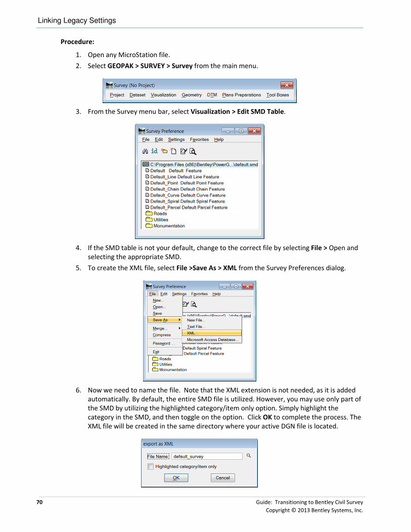
Linking Legacy Settings
70 Guide: Transitioning to Bentley Civil Survey
Copyright © 2013 Bentley Systems, Inc.
Procedure:
1. Open any MicroStation file.
2. Select GEOPAK > SURVEY > Survey from the main menu.
3. From the Survey menu bar, select Visualization > Edit SMD Table.
4. If the SMD table is not your default, change to the correct file by selecting File > Open and
selecting the appropriate SMD.
5. To create the XML file, select File >Save As > XML from the Survey Preferences dialog.
6. Now we need to name the file. Note that the XML extension is not needed, as it is added
automatically. By default, the entire SMD file is utilized. However, you may use only part of
the SMD by utilizing the highlighted category/item only option. Simply highlight the
category in the SMD, and then toggle on the option. Click OK to complete the process. The
XML file will be created in the same directory where your active DGN file is located.

Linking Legacy Settings
Guide: Transitioning to Bentley Civil Survey 71
Copyright © 2013 Bentley Systems, Inc.
� Exercise: Link Active Styles
Exercise Objective:
You will link the product files of your choice, review the properties and learn what changes are
necessary to get the appropriate graphics. You will do this for both survey and design entries.
Getting Started
GEOPAK: Set the filter to .DDB and select the file from the data directory.
InRoads: Set the filter to .XIN and select the file from the data directory.
MX: Set the filter to .PSS and select the file MXRoad.pss from the data directory.
Procedure
1. Create a new DGNLib called features.dgnlib.
2. Open the Project Explorer and the Civil Standards tab.
3. Click on the Feature Management +. There should be nothing under the entry.
4. Right-click on Feature Management and select Link Active Feature Styles. Note if you are
using GEOPAK, Use Item Name option.
InRoads options GEOPAK options MX options
Upon selection the styles are read into the DGNLIB file as linear, point and surface
features.
WHAT HAPPENED - INROADS?
The XIN was read.
• All feature names must be unique.
• Features have three types: Linear, Point and Surface.
• Survey features are linked separately.
• All styles which have the Geometry Line, Curve or Spiral defined on are added to the
linear section.
• All styles which have the Surface setting for 3-D/Plan Display turned on are added to
the linear section.
• All styles where the Geometry Points is defined are added to the Point section.
• All styles that have the Surface Setting for Components turned are added to the
Surface section.
• Names are assigned in the order Surface > Linear > Point.

Linking Legacy Settings
72 Guide: Transitioning to Bentley Civil Survey
Copyright © 2013 Bentley Systems, Inc.
EXAMPLE
Pavement style fits all sections. Pavement is the name added to Surfaces, Pavement-Lin is added to
Linear and Pavement-Pnt added to Points. If Pavement only had geometry defined in the XIN file
then Pavement is the name in Linear and Pavement-Pnt is the name in Points.
INROADS MAPPING FOR LINKED STYLES
Feature InRoads Style
Linear Linked Style Symbology
Plan – Line Geometry Line Plan Line
Plan – Curve Geometry Curve Plan Line
Plan – Spiral Geometry Spiral Plan Line
Profile – Line Geometry Line Profile Line
Profile – Parabola Geometry Curve Profile Line
Cross Section Point Surface Cross Section Point
3D – Line Surface Plan Line
Survey – Point Survey Plan Point
Survey – Line Survey Plan Line
Intersected Profile Point Geometry Point Plan Point
Projected Profile Line Surface Plan Line
Point
3D – Plan Geometry Point Plan Point
Surface
Profile
Cross Section Surface Cross Section Line
3D Element Template
HOW THE LINKING WORKS
A native style is linked to a particular attribute such as Plan or 3D.

Linking Legacy Settings
Guide: Transitioning to Bentley Civil Survey 73
Copyright © 2013 Bentley Systems, Inc.
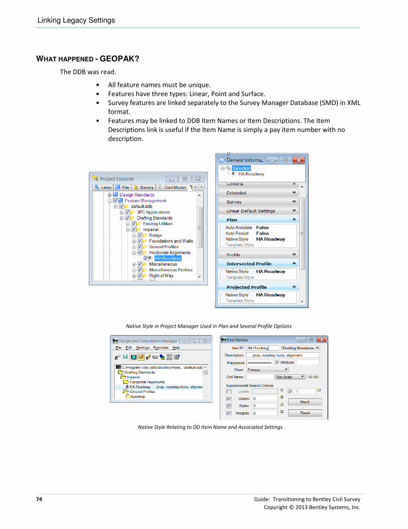
Linking Legacy Settings
74 Guide: Transitioning to Bentley Civil Survey
Copyright © 2013 Bentley Systems, Inc.
WHAT HAPPENED - GEOPAK?
The DDB was read.
• All feature names must be unique.
• Features have three types: Linear, Point and Surface.
• Survey features are linked separately to the Survey Manager Database (SMD) in XML
format.
• Features may be linked to DDB Item Names or Item Descriptions. The Item
Descriptions link is useful if the Item Name is simply a pay item number with no
description.
Native Style in Project Manager Used in Plan and Several Profile Options
Native Style Relating to DD Item Name and Associated Settings

Linking Legacy Settings
Guide: Transitioning to Bentley Civil Survey 75
Copyright © 2013 Bentley Systems, Inc.
WHAT HAPPENED? - MX
The PSS was read into a flat structure the same as we get in Style Set Editor.
Since a MX PSS only holds a single style representation and does not distinguish between plan /
profile / section / 3d, by default the same style definition is applied to each persona. The persona
styles can be modified later to take advantage of different display representations.
The MX string feature types are matched to the appropriate feature definitions from the following
table:
FEATURE SUPPORTED MX STRING TYPES DEFAULT STYLE MAPPING
Surface Cross Section strings
Long Section Strings
Triangulation Strings
MicroStation Element Template
On import a new Element Template is created
- Category ( PSS name) > Feature Name
Using feature style to define Level, color, linestyle, weight, material (if defined).
Linear Feature Strings
Interface Strings
Master Strings
Geometry Strings
PSS feature
Point Survey Station
Point
Cadastre
PSS feature
Feature names must be unique and names are assigned in the order Surface > Linear > Point.
The PSS structure is ‘flat’ and so all features are initially loaded to match this historic flat feature
definition structure. However this is an opportunity to categorize features into groups, possibly of
similar features or into a method of your own choosing, too enhance the normal MX feature
structure.
Example the MXRoad.pss could be imported and grouped with sub categories for all the different
string features that fit the category like Carriageways / Shoulders / Alignments / Earthworks etc.
In this case, create a category called MXRoad and move all features under it.

Linking Survey Styles
76 Guide: Transitioning to Bentley Civil Survey
Copyright © 2013 Bentley Systems, Inc.
LINKING SURVEY STYLES
Note the linking in the previous section did not include Survey. They are linked separately.
� Link Survey Styles to DGNLib
Objective:
We will link the Survey styles to this DGNLIB.
Procedure:
The steps vary because the linked file is identified from disk as opposed to the loaded .XIN file.
1. Continue in features.dglib.
2. Right-click menu on Feature Management and select Link Survey Feature Definitions from
the pop-up menu.
This dialog allows you to select the three style files for GEOPAK, InRoads and MX.
InRoads: Select the … \data\standards\civil.xin and then select Open to
process this file into the DGNLIB file.

Chapter Summary
Guide: Transitioning to Bentley Civil Survey 77
Copyright © 2013 Bentley Systems, Inc.
GEOPAK: Select … \data\standards\civil.xin smd.xml (SMD file in xml format)
and then select Open to process this file into the DGNLIB file.
MX: Create a new Category Simple Survey and Select the …
\data\standards\Simple Survey.pss.
Note The survey features are created if they did not exist in the previously imported files. If the
feature does exist then the survey information is added to the existing feature.
Figure 1 Survey Defined Figure 2 No Survey Defined
CHAPTER SUMMARY
These steps are how style files are linked to features in a DGNLIB. You did not transfer the
symbology into the DGNLib. You have created entries that are linked back to the XML (of
SMD)/PSS/XIN file where the native product symbology is defined or to element templates in a
DGNLib.

Chapter Summary
78 Guide: Transitioning to Bentley Civil Survey
Copyright © 2013 Bentley Systems, Inc.
This page left intentionally blank.

Guide: Transitioning to Bentley Civil Survey 79
Copyright © 2013 Bentley Systems, Inc.
Chapter 10: Pre-Deployment Tasks
OVERVIEW
Now we have completed most of our setup tasks. This includes our DGN Lib’s, seed files, and project
settings. We’ve also set up our features. Our final tasks include critical testing, and setting up any T
IW files that we need to customize. This is the time where we check our results, to ensure that our
data is processed. This includes the correct cells for point features checking the linking codes to be
sure our linear features are chained together properly, checking our feature definitions to ensure
correct symbology. This will require some survey expertise to ensure the results are in compliance
with your organization’s business model. This final testing can also be utilized to confirm or adjust
your survey workflow as needed. In most cases, workflow changes will not be necessary, however, it
depends upon the current version you are using. The exercises in this chapter will emulate the
workflows of your actual survey users, so you can use these as a starting point if you need training
exercises or quick start information.
CREATE CUSTOM TIW FILES AND INCORPORATE INTO STANDARDS
One final task is to create the TIW file for any of the data import files that have not yet been
addressed. Note to put into production is a three-step process:
• create the TIW file,
• move into the standard TIW folder,
• add to the Data Import Items dialog.
You must have the actual dataset file, not just a hard copy to complete this procedure.
Before you import a file using the Text Import Wizard, you define a general format, called a wizard,
that can be used repeatedly to import any number of files of the same type. A wizard describes 1)
the contents of each column of data, 2) whether the columns are fixed-width or are separated by
delimiters, and 3) which rows to import.
A wizard is made up of one or more filters. Filters are sets of parameters that describe different
groups of lines within the file to import. In many cases, a wizard will consist of a single filter. This is
the case with uniform data files. In a uniform data file, all the data lines to be read are of the same
format. Because of the consistency of format, a wizard needs only one filter to describe a uniform
data file. When you define a wizard for importing a uniform data file, the wizard and the filter are
one and the same.
Non-uniform data files, on the other hand, contain rows of various formats (different rows exhibit
different formats) in a single data file. To accommodate multiple row-formats, a wizard must
contain more than one filter. Specifically, a wizard needs one filter for each type of row-format to be
accommodated. In the process of defining a wizard for importing a non-uniform data file, you define
multiple filters that, taken together, constitute the wizard.

Create Custom TIW Files and Incorporate into Standards
80 Guide: Transitioning to Bentley Civil Survey
Copyright © 2013 Bentley Systems, Inc.
� Create Custom TIW Files and Set Up for Production
Objective:
The objective of this exercise is to create and deploy the TIW file for any of the data import files that
have not yet been addressed. Repeat the process for all custom datasets. You can create all TIW
files, then incorporate into the Data Import Items dialog.
It is important to note that each file (not each field book) can have only one Survey Project settings.
Once the Project Settings has been selected, it cannot be removed from the file. Therefore, it is the
best practice to create the customized TIW files using a file other than the DGN Lib where the
project settings are contained, if you have multiple Survey Project settings.
Procedure:
1. Open test*.dgn.
2. Open File > Project Explorer.
3. Select the Survey tab.
4. Expand Default by clicking on the plus sign.
5. Right–click Field Books and select New…
6. When prompted for the Selecting Settings, select the DGNLib you created with your Survey
Project Settings and click Accept. If you do not see your DGNLib listed, your configuration
variable is not set up properly. If you are not prompted for Selecting Settings, your file
already has one assigned. In this case, create a new file for your seed file.
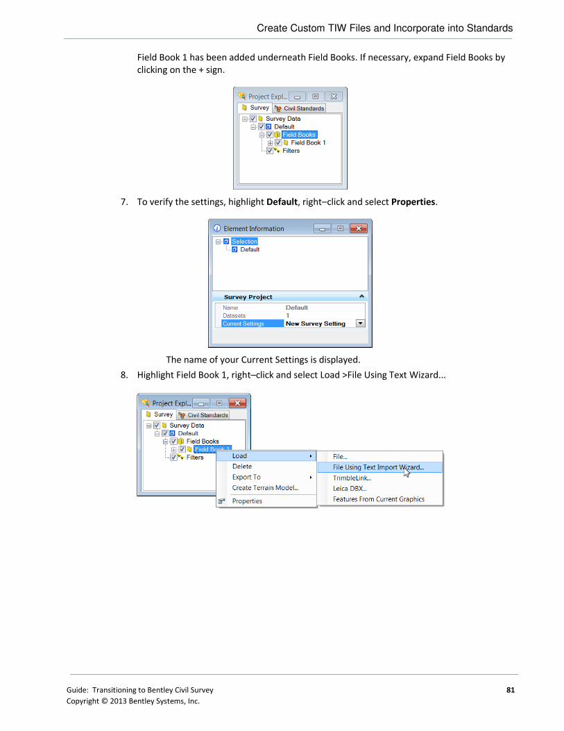
Create Custom TIW Files and Incorporate into Standards
Guide: Transitioning to Bentley Civil Survey 81
Copyright © 2013 Bentley Systems, Inc.
Field Book 1 has been added underneath Field Books. If necessary, expand Field Books by
clicking on the + sign.
7. To verify the settings, highlight Default, right–click and select Properties.
The name of your Current Settings is displayed.
8. Highlight Field Book 1, right–click and select Load >File Using Text Wizard...

Create Custom TIW Files and Incorporate into Standards
82 Guide: Transitioning to Bentley Civil Survey
Copyright © 2013 Bentley Systems, Inc.
9. Navigate to your data set file, select the file and click Open. Note you may have to change
the file filter to all files, if you don’t see your file name in the correct folder.
The Text Import Wizard dialog opens with the selected file displayed.
10. Several options for Text File Type need to be defined.
OPTION DESCRIPTION
Projections If you are using Projections, click the Projections button and enter Source and Target GCS data.
Remember to click Accept after populating the dialog to remember the information and close the dialog.
Record Format If your data format is consistent from one line to the next, set the Record Format to Uniform. If not, set the Record Format to Nonuniform. In the case of multiple line formats, you’ll need to set up filters for each variation.
Data Format Specify if the file is organized according to a free form or a column based format.
Delimited - With free form formats, data does not necessarily line up column wise; i.e., the decimal point for an x-coordinate does not always occupy the same column. Each individual data item is separated by some form of delimiter: space, comma, dash, semi-colon, etc.

Create Custom TIW Files and Incorporate into Standards
Guide: Transitioning to Bentley Civil Survey 83
Copyright © 2013 Bentley Systems, Inc.
Fixed - Column based formats, always line up column wise. With a column based format, spaces or other delimiters may not be found between individual data items.
Start Row If there are header rows before the actual data, determined the first row of data and set the start row number. If the entire file is raw data, set the start row 1.
11. Click Next to proceed in the wizard. Note the wizard looks different, depending on the
options selected in the previous wizard.
12. A. Let’s look at delimited files first.
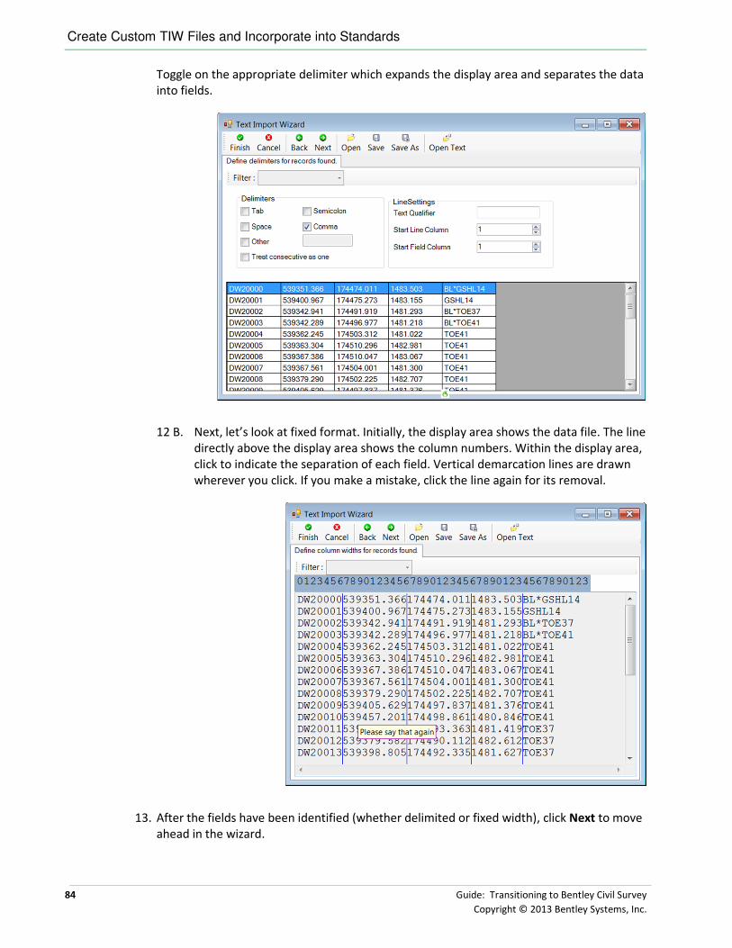
Create Custom TIW Files and Incorporate into Standards
84 Guide: Transitioning to Bentley Civil Survey
Copyright © 2013 Bentley Systems, Inc.
Toggle on the appropriate delimiter which expands the display area and separates the data
into fields.
12 B. Next, let’s look at fixed format. Initially, the display area shows the data file. The line
directly above the display area shows the column numbers. Within the display area,
click to indicate the separation of each field. Vertical demarcation lines are drawn
wherever you click. If you make a mistake, click the line again for its removal.
13. After the fields have been identified (whether delimited or fixed width), click Next to move
ahead in the wizard.

Create Custom TIW Files and Incorporate into Standards
Guide: Transitioning to Bentley Civil Survey 85
Copyright © 2013 Bentley Systems, Inc.
14. For each field, select the data type from the pick list. If the field is not to be used, leave it
set to Skip.
One sample of a completed column formats is illustrated below.
15. Click Finish. When prompted to create a TIW file, click Yes.
16. In the Save Text Import Wizard File dialog, name the TIW File and place in the folder with
your other customized TIW files specified by your configuration variable or place in the
default directory.
17. When prompted to save TIW file format in import settings, click No. If we click yes, the TIW
file format is added to the Project Settings in our active file. We want to add it into our
DGN Lib instead.
Note We still need to add the TIW file into our data import items list. We will do that in the next
exercise. But before we leave the wizard, let’s look at a few more tips and tricks.

Create Custom TIW Files and Incorporate into Standards
86 Guide: Transitioning to Bentley Civil Survey
Copyright © 2013 Bentley Systems, Inc.
SAVING YOUR TIW FILE
The Text Import Wizard will not allow to you save a wizard until you specify, on the Step 3 dialog, at
least the northing and the easting data columns (see the section called Columns Required for Import
for details on which columns are required for each of the various data types). If you try to save a
wizard before fulfilling the minimum requirements for a filter, the software will display an error
message that attempts to describe specifically what requirements the wizard is failing to meet.
One you have defined at least one filter, you can save the wizard, even if you are in the process of
defining an additional filter. (Recall that wizards for importing non-uniform files can comprise more
than one filter.)
ADDITIONAL TOOLS IN THE WIZARD
Several tools located at the top of the Text Import Wizard are detailed in the table below.
TOOL DESCRIPTION
Finish Click for completion of Wizard
Cancel Closes the current wizard without saving the current settings.
Back Backs up one screen in the Wizard process.
Next Moves forward one screen in the Wizard process.
Open Open an existing TIW file for review / editing.
Save Saves the current TIW file with the same name.
Save As Saves the current TIW file to a new name.
Open Text Opens a (dataset) file and displayed in the review area.
HOW MULTIPLE FILTERS OPERATE
This section describes how multiple filters are used to process a non-uniform data file, files whose
various rows exhibit varying data formats.
Each filter that you define is added to the wizard by means of the Add button on the Text Import
Wizard - Step 2 dialog. The order in which you add the filters is critical because the order determines
which filter is applied to a particular line when that line satisfies more than one filter.
It is possible for a single line in a data file to satisfy the conditions of more than one filter.
The wizard makes a single pass through the data file, reading one line at a time. To each line, the
wizard applies the filters in the order in which they were added to the list on the Text Import Wizard
- Step 2 dialog. The filters are applied one-at-a-time until one of them successfully matches the
particular row of data, or until they all fail. A match occurs when a data line satisfies the filter's
Include parameters, defined on the Text Import Wizard - Step 2 dialog.
Once a match occurs between the data line and a filter, the data line is imported according to all the
parameters specified in the corresponding filter. After importing the data line, the wizard moves on
to the next line in the data file. If no match occurs even after all filters have been attempted, the
data line is ignored, and the wizard moves on to the next line in the data file.

Completing the TIW file Set Up
Guide: Transitioning to Bentley Civil Survey 87
Copyright © 2013 Bentley Systems, Inc.
COMPLETING THE TIW FILE SET UP
Procedure:
1. Open DGNLib file survey_data.dgnlib.
2. Open File > Project Explorer and select the Civil Standards tab.
3. Expand Project Settings by clicking on the + to the left of the item.
4. Highlight New Survey Setting, right-click and select Properties.
5. Expand the Data File Parsing section by clicking on the black arrow on the right side of the
section header.

Completing the TIW file Set Up
88 Guide: Transitioning to Bentley Civil Survey
Copyright © 2013 Bentley Systems, Inc.
6. Click in the cell to the right of Data Import Items.
7. Click New to add a new line to the table, which has some fields already populated. These
are just defaults, and can be changed as needed. Note, you may add several lines at one
time. You also may need to stretch the dialog and adjust column widths to see the
Executable and Format File columns.
8. Add each of your TIW files (one per line) that are not already in the list. Populate the fields:
• Use: True
• Vendor: <use your Vendor name>
• Title: <use your own Title here>
• Filter: <use your own file filter here>, example, *.txt
• FileTypeIn: Neutral
• Executable Path: <leave blank>
• Executable: survey.exe
• FormatFile: <your TIW file>, example *.tiw click in the field and navigate to your
standard TIW directory!
9. While in this dialog, you may want to do some cleanup. For example, the users will see all
of the data import items listed for the appropriate extension. You may want to just delete
those that are never used by your organization. Another option is to set the Use column to
False.
10. Do NOT close the dialog by clicking the X in the upper right-hand corner! You must click
Accept in order to save your data, which also closes the dialog.

Setting Up Testing Environment
Guide: Transitioning to Bentley Civil Survey 89
Copyright © 2013 Bentley Systems, Inc.
SETTING UP TESTING ENVIRONMENT
In this section, we need to pull together all of the various components that we have completed in
setting up our environment. This includes testing our configuration variables, reviewing our seed
files, and ensuring that the DGN Lib’s are in place and pointers to them are working.
Note An exact match from your native survey mapping may not occur. We tried to match as
much as possible, but variations will occur.
CONFIGURATION VARIABLES
In earlier chapters, we determined what configuration variables to use and the value appropriate for
your organization. Now we need to incorporate those configuration variables into our workspace.
Keep in mind they should be done in the workspace for your survey users, or on a project level or a
site level basis.
To configuration variables are critical to the deployment of survey.
CONFIGURATION VARIABLE DESCRIPTION
CIVIL_SURVEY_STYLEFILE Defines the Style file that is linked in the Survey Feature definitions. Available options are an XIN from InRoads, an XML from a GEOPAK SMD or a PSS from MX.
CIVIL_SURVEY_USERTIW_FOLDER Defines an alternate directory where user .TIW files can be located.
If the CIVIL_SURVEY_STYLEFILE variable is not defined, the user is prompted every time a survey
DGN file is opened. In addition, any survey processing will not be drawn with the appropriate Survey
Feature definitions.
The CIVIL_SURVEY_USERTIW_FOLDER configuration is optional but very helpful if you want to store
the TIW files in a central location, rather than on each machine. The software will still use the
default location to find the standard TIW files, such as those for raw files from various data
collectors. The use of this variable will augment the selection by pointing to a folder on a central
server.
Other important configuration variables are those that point to DGN Lib’s and also the configuration
variable for reports, if customize reports for surveys are used.
CONFIGURATION VARIABLE DESCRIPTION
CIVIL_REPORTS_DIRECTORY If the variable is set to a valid directory location, then the software looks at this specific location to locate the XML reports. If this variable is NOT set or it's set to an invalid location, then the software would look at the location where Civil installs the reports by default. NOTE: If the InRoads Project Default XSL location is defined then that is used before CIVIL_REPORTS_DIRECTORY. This maintains continuity for InRoads users.
CIVIL_CONTENTMANAGEMENTDGNLIBLIST This variable defines both the directory and specific file name of the feature definitions DGN Library.
CIVIL_PROJECTSETTINGSDGNLIBLIST This variable defines both the directory and specific file name of the project settings DGN Library.
CIVIL_CIVILTMDGNLIBLIST This variable defines both the directory and specific file name of the terrain model filters DGN Library.

Setting Up Testing Environment
90 Guide: Transitioning to Bentley Civil Survey
Copyright © 2013 Bentley Systems, Inc.
� Add Configuration Variables to the Workspace
Objective:
The objective of this exercise is to add the configuration variables to the workspace and test. Note
detailed instructions are not included, due to the wide variety of workspace set up options. Many of
the configuration variables can be added within your seed file and saved to the PCF. In more direct
option is to edit the PCF file, being careful with syntax. Refer back to chapter 6 entitled
“Configuration Variables” and chapter 2 entitled “Workspaces”.
Note If you have your own workspace, you will want to utilize it.
Procedure:
1. In Windows Explorer, Navigate to:
C:\ProgramData\Bentley\*Civil_Product_Name*\WorkSpace\Projects\Examples. The
example pcf files and associated sample folders are located here.
2. Using any text editor, open either Bentley-Civil-Metric.pcf or Bentley-Civil-Imperial.pcf.
3. Add in your configuration variables and their values. To add comments, use the # symbol
to begin the line. When complete, save the file.
4. Double-click the Bentley Civil icon (any Inroads, GEOPAK or MX product) on your desktop.

Setting Up Testing Environment
Guide: Transitioning to Bentley Civil Survey 91
Copyright © 2013 Bentley Systems, Inc.
5. In the File Open dialog, set the following to access your configuration (lower right corner):
FIELD ENTRY
User Examples
Project Bentley-Civil-Metric or Bentley-Civil-Imperial
Interface Bentley-Civil
6. At the top of the File Open dialog, click New File.
7. In the folder c:\Survey_Transition, create a file named test2.dgn.
8. Click Open.
9. Select Workspace > Configuration from the main menu bar.
10. Scroll down the list and check the Civil configuration variables with your list. Consult the
help file to see descriptions and possible values (covered in chapter 6).
11. Make any changes / corrections as needed. Keep in mind you may have to get in and out
of the file for the changes to take effect.
� Set up Final Testing Procedure – Seed Files
Objective:
The objective of this exercise is to check the file settings when creating a new file (using our seed
file). Repeat this process for all seed files you’ve created.
Procedure:
1. Select File > New from the MicroStation main menu, create a new file test*.dgn. Make
sure you are selecting the seed file you previously created for survey.
2. Select Settings > Design File Settings.
3. Highlight Working Units. Ensure the appropriate units are set.
4. Highlight Civil Formatting.
5. Ensure the desired values are set in each section, then click OK to close the dialog.

Setting Up Testing Environment
92 Guide: Transitioning to Bentley Civil Survey
Copyright © 2013 Bentley Systems, Inc.
6. If you are setting the GCS in your seed files, select Tools >Geographic > Select Geographic
Coordinate System from the main MicroStation menu.
7. Verify the displayed GCS, then close the dialog.
8. To check the Annotation Scale(if you are using), click File > Models to open the Models
dialog.
9. Click the Edit Model Properties icon to open the Model Properties dialog.
10. Verify the Annotation Scale then click OK to close the Model Properties dialog.
11. Review / adjust the settings in Project Explorer. Currently, you may have only the Civil
Standards and Survey tabs active. Your users will need the Civil Model (for terrain models)
and may want Files and Links. Adjust at this time, the easiest solution is to open all tabs
and let the users turn off what they do not want.
12. If any changes are needed, opened the seed file and make the changes. Then create a new
file using the updated seed file and repeat the process.
� Set up Final Testing Procedure – DGN Libs
Objective:
The objective of this exercise is to check to ensure the DGN Lib pointers and files are correct.
Procedure:
1. Select File > New from the MicroStation main menu, create a new file test*.dgn. Make
sure you are selecting the seed file you previously created for survey. Open the file.
2. Open File > Project Explorer and select the Civil Standards tab. Note you should have two
entries directly under Civil Standards: your active file AND Libraries.
3. Expand Libraries by clicking on the + to the left of the item.
4. Expand Feature Definitions and locate the DGN Lib containing your survey feature
definitions. Note there may be numerous DGN Lib files containing various other feature
definitions.

Setting Up Testing Environment
Guide: Transitioning to Bentley Civil Survey 93
Copyright © 2013 Bentley Systems, Inc.
5. Expand the DGN Lib to ensure the XIN or XML file is listed and contains feature definitions.
6. Scroll down and expand Project Settings and locate the DGN Lib containing your project
settings.
7. Check any other DGN Libs that you have created and have set up pointers via configuration
variables.
� Final Testing Procedure – Data Collection
Objective:
The objective of this important exercise is to check that data processing is correct. It’s not sufficient
enough to just draw the data, but to verify features, linear connections, proper cells, etc. therefore,
it is highly recommended to have your surveyors, standards personnel and power users all working
on this final procedure.
Procedure:
1. Select File > New from the MicroStation main menu, create a new file test*.dgn. Make
sure you are utilizing the seed file you previously created for survey. Open the file.
2. Open File > Project Explorer and select the Survey tab.

Setting Up Testing Environment
94 Guide: Transitioning to Bentley Civil Survey
Copyright © 2013 Bentley Systems, Inc.
3. Expand Default by clicking on the plus sign.
4. Drag and drop your dataset file into the Project Explorer.
5. When prompted for the Selecting Settings, select the DGNLib you created with your Survey
Project Settings and click Accept. If you do not see your DGNLib listed, your configuration
variable is not set up properly. If you are not prompted for Selecting Settings, your file
already has one assigned. In this case, create a new file.
If you have multiple TIW files set up with your dataset file extension (for example *.txt),
you’ll be prompted to select the desired format. (If you only have one TIW file for the
dataset file extension, you won’t see this dialog.) Highlight and click Apply.
6. Default 1 has been added underneath Field Books. If necessary, expand Field Books by
clicking on the + sign.

Chapter Summary
Guide: Transitioning to Bentley Civil Survey 95
Copyright © 2013 Bentley Systems, Inc.
7. Expand ALL Point Features and review the points. Any that are shown in red with the
warning triangle are not found and need to be addressed.
8. Repeat the process with the ALL Linear Features.
9. Review the drawing to ensure proper symbology, cells, etc. Make any changes /
corrections to the appropriate resource and begin the process again with a clean seed file.
10. Repeat the process for all dataset files.
CHAPTER SUMMARY
We have now worked through how to transition to Bentley Civil Survey by setting up workspaces,
creating seed files and DGN Libs, and setting up other resources.
Keep in mind that there is no ONE correct way to transition to Bentley Civil Survey. This guide
presents suggestions and best practices and it is the responsibility of each organization to determine
how they fit into your standard policies, procedures and operations.
It is impossible to cover all situations and all aspects of transitions in this guide. For specific
questions, contact your Bentley personnel for assistance.

Chapter Summary
96 Guide: Transitioning to Bentley Civil Survey
Copyright © 2013 Bentley Systems, Inc.
This page left intentionally blank.

Guide: Transitioning to Bentley Civil Survey 97
Copyright © 2013 Bentley Systems, Inc.
Glossary
2D Point Feature Contains no elevation (Z). 2D Point Features are defined and stored in plan model.
3D Geometry 3D geometry is created in 3D model by mathematically combining the horizontal
and vertical geometry to create 3D elements. These 3D geometry elements in turn
define a design model.
3D Model This is created and managed automatically. User can interact with it but this is not
usually required. The mathematical combination of Plan Geometry and Profile
Geometry is stored in the 3D model.
3D Point Feature 3D points can be defined in plan model or 3D model. They are stored in 3D model
but represented in both plan and 3D.
Active Object The current object to which is added all geometry which is created.
Active Profile Of the multiple possible profiles for an element, the active profile is the one used
for design. The active profile is combined with the horizontal geometry to build a
3D element which is used in the 3D model.
Active Terrain
Model
One terrain model can be designated as “Active”. The active terrain model is the
one used to display “existing ground”; in other words the one which displays
automatically in a profile model when it is opened. The active terrain model is also
the one which is targeted by side slopes unless the template defines a different
target by name.
ALG A legacy (proprietary) InRoads file containing coordinate geometry information,
superelevation, and alignment information for a specific geometry project.
Alignment A linear feature which serves the special purpose of defining the centerline or
baseline of a roadway.
Apply Linear
Template
Applies a corridor template along a feature while hiding some of the complexity of
creating a corridor.
Apply Surface
Template
Applies a corridor template to a terrain model for the purpose of creating
components (such as pavement layers) under the terrain model.
Arc Definition Curve definition method generally used in roadway applications. The radius R is
used to define the curve and is defined by the equation R=5729.58/D where the
degree of curvature D is the central angle subtended by a 100-foot arc. Set in the
Design File Settings > Civil Formatting under Radius Settings. See also Chord
Definition.
Aspect An angular measure of the direction that the face of a surface is oriented. The
format of the value is dependent on angular settings In the DGN file.

Glossary
98 Guide: Transitioning to Bentley Civil Survey
Copyright © 2013 Bentley Systems, Inc.
Base Geometry In many instances the geometry element will be trimmed. The original (or base),
untrimmed element is always preserved as it is the storage for the rule.
Boundary (Terrain
Model)
Used to constrain the external boundary of the terrain model. No triangles are
created outside the boundary. In addition, any point data outside the boundary is
ignored.
Break Line A surface feature consisting of a collection of spatial coordinates that have an
implied linear relationship. No triangle side (in the triangulated surface) can cross
over a break line.
Break Void A closed area of missing or obscured data that uses the elevations of each vertex,
while the void lines between successive void coordinates are inserted as break
lines. Therefore, break voids change the slope and elevations of the TIN surface.
Cardinal Points One of the points used to define the geometry of an alignment. Cardinal points
include PC, PT, PI, and CC points for horizontal geometry and VPC, VPI and VPT for
vertical geometry.
Centroid (triangle) Geometric center of a triangle in a terrain model.
Chord Definition Curve definition method generally used in railway applications. The radius R is
used to define the curve, and is defined by the equation R=50/SIN(0.5*D) where
the degree of curvature D is the central angle subtended by a 100-foot chord. See
also Arc Definition.
Civil Cell Used as a mechanism to preconfigure commonly used complex geometric layouts.
These layouts will commonly be stored in DGNLIB files for reuse across multiple
projects but it is possible and sometimes useful to store directly in an active DGN
file for use in that single location. The civil cell will contain horizontal geometry
and can also contain the vertical geometry.
Civil Message
Center
Used to display a continuous updating log of Civil messages, including warnings
and errors. As errors and warnings are resolved, they are removed from the list.
New messages are added whenever the conditions warrant. Most messages relate
to civil geometry, superelevation, and corridor modeling.
Civil Template A civil design concept used most often for corridor modeling but also has other
applications. The Civil Template defines the cross-sectional shape of the object
being modeled. This cross-section is then “extruded along” a 3D geometry
element to form the final model. The corridor template can create or target
features such as road edges. The result is the creation of a corridor.
Clipping Reference Clipping allows you to remove areas of overlap when working with multiple
corridors in a single surface. For example, in a corridor intersected by a crossing
roadway, clipping would be used to remove all overlapped features within the
intersection.
Complex Terrain
Model A terrain model created by merging or appending two or more terrain models.

Glossary
Guide: Transitioning to Bentley Civil Survey 99
Copyright © 2013 Bentley Systems, Inc.
Context Toolbox When an element is selected, hovering over the element provide a heads-up and
context sensitive toolbar which pops up at the cursor. This toolbar provides a few
of the most commonly used tools which operate on the element selected element
type. The first tool in this toolbar is always Quick Properties.
Contour A linear symbol representing points of equal elevation relative to a given datum.
Contour, Isopach Contours of a delta terrain model which represent cut and fill values as contours,
not elevations. A positive contour represents fill, while a negative contour is cut.
Contour, Major The primary elevation line indicating a specific elevation in a surface model.
Usually major contours are drawn with a heavier line weight or using a different
color. Elevation text labels are usually drawn in association with major contours.
Contour, Minor A secondary elevation line indicating a specific elevation in a surface model. Minor
contours are often drawn without special color or weight indexing and without
elevation text labels.
Corridor A civil object used for modeling a roadway and is automatically managed by the
corridor modeling tools.
Cross Section
Model
DGN models (extracted perpendicular to defined horizontal geometry) with special
station elevation coordinates defined and other specialized capabilities such as
view exaggeration. Cross section stations match the interval in the template drop
when a corridor is used as the basis. When horizontal geometry is utilized, the left
/ right offsets and interval are user-defined.
Curve Stroking Stroking is the process of automatically adding shots to the terrain model or
corridor by interpolating new shots from the curved sections of the data. This
distance is used to interpolate new shots along the curved element in corridor
processing and applying linear templates. This value is used as a perpendicular
minimum distance from chords generated along the arc. Chords are drawn along
the arc and the perpendicular distance is measured from the middle of each chord
to the arc. If this distance is larger than the Curve Stroking, the process is repeated
with a shorter chord length. This process is repeated until the end of the curve is
reached. The flatter the curve, the fewer number of points will be calculated. The
steeper the curve, the greater number of points that will be calculated.
DDB File GEOPAK file (Design DataBase) which contains features definitions, associated
symbology and annotation settings.
Delta Terrain
Model
A surface containing data derived from the difference in elevation between two
terrain models or a terrain model and a plane.
Dialog The tool settings box for the active command. The dialog shows all available
options for a command. For most civil commands, most of the time, the dialog can
be hidden and ignored since the user is given all necessary instruction and inputs
by way of the cursor prompt. The dialog is necessary for configuring command
customizations.
Drape The process of vertically projecting elements onto a surface so that the element
elevations are defined by the surface.

Glossary
100 Guide: Transitioning to Bentley Civil Survey
Copyright © 2013 Bentley Systems, Inc.
Drape Void A closed area of missing or obscured data where the void coordinates are not
included in the triangulation. Voids are inserted post triangulation. The void
coordinates and lines are draped on the TIN surface. Even though a user must
provide an elevation for the Drape Void vertices, the user elevations are changed
to the elevation of the TIN surface at the XY Drape Void coordinate position.
Element Template MicroStation concept which allows preconfigured definitions for symbology and
other miscellaneous display of MicroStation elements and civil features.
End Condition A specialized component of a corridor template which provides information tie
into active surface.
End Condition
Exception
Used to modify the behavior of an end condition solution without requiring the
use of additional template drops. When an end condition exception is added, it
must be edited to change its behavior.
Export to Native Option to automatically or manually push horizontal and vertical geometry into
native products (InRoads - ALG, MX - PSS and GEOPAK - GPK).
Feature A Feature is anything that can be seen or located and is a physical part of your
design, representing a real world thing. A feature’s definition is one of its
properties. At any given time in the design process, the feature will have a
Horizontal Geometry, a Vertical Geometry, 3D Geometry or a combination to
define its location.
Feature Definition Used to define options when creating features. These are the items which are
created in advance, usually used across multiple projects and define symbology,
annotation and quantities. The feature definition is assigned (usually) in the plan
model and profile/3D feature definitions follow from there.
Feature Name Each Feature can have a name.
Gap When a feature is trimmed the part(s) which are invisible on the base geometry.
GPK A legacy (proprietary) GEOPAK database containing coordinate geometry
information.
Graphical Filter Using in developing terrain models, an automated way of storing search settings
for graphic elements when creating terrain models using 3D element. A graphical
filter can be created for each feature (i.e., spots, breaks, voids) then the filters can
be defined as a Graphical filter group.
Heads Up Prompt Command instructions are given in a heads up and dynamic prompt which floats at
the cursor.
Horizontal
Geometry
The elements which define the horizontal layout of the design. These elements
are 2D elements even if the DGN model is 3D. Horizontal Geometry may be points,
lines, arcs, spirals, splines or any combination in a complex element.
Interval When a feature is trimmed the part(s) which are visible on the base geometry.
Island Closed area used to place within a void, i.e., islands in the middle of rivers, lakes,
etc.

Glossary
Guide: Transitioning to Bentley Civil Survey 101
Copyright © 2013 Bentley Systems, Inc.
Key Station Additional station added to the corridor to force processing at the particular
location.
LIDAR (Light Detection And Ranging) is an optical scanning technology which scans
ground and other physical features to produce a 3D model.
Linear Feature In plan model, composed of lines, arcs, spirals, splines or combinations of these. In
profile model, composed of lines, parabola, splines or combinations of these.
Linear Stroking Stroking is the process of automatically adding shots to the terrain model or
corridor by interpolating new shots from the linear sections of the data. Linear
stroking is measured along the element. Interpolated vertices are added
whenever the distance between the vertices is greater than the linear stroking
value (in master units).
Manipulators The heads up, on-screen editing interface. Only the most common properties are
presented in manipulators. Manipulators are in two types: graphical and text
Overlay Vertical
Adjustment
Within Corridor Model, tool used to develop a vertical geometry (based on milling
and overlay parameters) and apply to the corridor.
Parametric
Constraints Used to set up constraint value overrides for specified station ranges.
Plan Model The usual DGN model, used for laying out horizontal geometry. Best practices will
dictate that this is a 2D DGN model but 3D DGN model can be used. This is where
geometric layouts and corridor definitions are kept. The geometric layouts are not
only alignments but also edges, parking, striping, sidewalks, etc.
Point Features Defined by a single X, Y (Z optional) location. A point need not be a feature. It may
be defined as a non-featurized point by way of AccuDraw, Civil AccuDraw, Snap or
a data point. Non featurized points are use to control the construction of Linear
Features.
Point Cloud A set of vertices in a 3D coordinate system and these vertices are defined the by X,
Y and Z coordinates. Point clouds are usually created by 3D scanners. These
devices measure a large number of points on the surface of an object and output a
point cloud as a data file. The point cloud represents the visible surface of the
object that has been scanned or digitized.
Point Control Used to modify the behavior of points in a template. These controls take
precedence (they override) over existing constraints on the point.
Project Explorer MicroStation's interface for browsing elements in a DGN file. Extended by civil to
accommodate specialized civil needs.
PSS File MX file (Plans Style Set) which provides the graphical representation for the MX
string features.
Reference Element The rule for some geometry is a calculation from another element. This other
element is the reference element.

Glossary
102 Guide: Transitioning to Bentley Civil Survey
Copyright © 2013 Bentley Systems, Inc.
Secondary
Alignment
Used to modify the direction of cross section processing. By default, as any given
station, the cross section is created orthogonal to the main alignment/feature. If a
secondary alignment exists, then that portion of the cross section which lies
outside the secondary alignment will be orthogonal to the secondary alignment
instead of the main alignment.
SEP File / Method Uses the superelevation settings which originated in GEOPAK.
SMD File GEOPAK file (Survey Manager Database) which contains survey features definitions
and associated element and textual settings.
Spot Elevation A set of X, Y, Z coordinates representing a point on the terrain model surface.
There is no implied relationship between regular points.
SRL File / Method Uses the superelevation settings which originated in MX.
Superelevation
Lane
The closed area defined by the superelevation tools used for the limits of
transition calculations and pivoting location.
Superelevation
Section
Area along a horizontal geometry element, where superelevation will be
calculated.
Target Aliasing Used to create the desired results when working with multiple surfaces without
having to edit the template from the template library. Target aliases can also be
used so that one corridor can target the solution of another corridor.
Template Drop An area (usually defined by station limits) along a corridor to which a specific
template is applied.
Template Library A file that stores definitions for templates, generally with an ITL file extension.
Template
Transition
The transition indicator occurs in the corridor between templates of differing
names.
Terrain Model A three-dimensional DGN element defined by spots, break lines, voids, holes,
contours to model a surface on the earth.
Tooltips When hovering the cursor over an element or a handle, a tooltip is shown which
gives explanatory information.
Trace Slope Upstream - The indicated path follows the steepest ascent from a user-defined
point through the terrain model terminating at a high point or the edge of the
terrain model.
Downstream - The indicated path follows the steepest descent from a user-defined
point through the terrain model terminating at a low point or the edge of the
terrain model.
Vertical Alignment A linear feature in profile model which serves the special purpose of defining the
elevations of an alignment.
Vertical Geometry The elements which define the vertical layout of a corresponding horizontal
geometry element. These vertical elements are 2D and are stored in a profile
model.

Glossary
Guide: Transitioning to Bentley Civil Survey 103
Copyright © 2013 Bentley Systems, Inc.
Void Closed shape to demarcate areas of missing data or obscure areas. No point or
break data located within the void area is utilized and no triangles are created
inside the void areas. The Void coordinates are included in the triangulation and
void lines between successive void coordinates are inserted as drape lines on the
surface. Therefore, they do not change the slope or elevations of the surface.
Watershed Defined by either a low point within the terrain model or a low edge point along
the terrain model edge, it's the closed area wherein all water would drain to the
low point.
XIN File InRoads file which contains features definitions, associated styles, annotation, and
other settings.

Glossary
104 Guide: Transitioning to Bentley Civil Survey
Copyright © 2013 Bentley Systems, Inc.
This page left intentionally blank.