Beitman - Early 1955 Television Servicing Information - TV-9
194
Most - e - Needed EARLY 1955 VOLUME TV -9 Television Servicing Information VOLUME TV -9 $ PRICE 2 AO THEORY smaimit ... Compiled by M. N. BEITMAN SUPREME PUBLICATIONS
-
Upload
khangminh22 -
Category
Documents
-
view
0 -
download
0
Transcript of Beitman - Early 1955 Television Servicing Information - TV-9
Most - e - Needed
EARLY 1955VOLUME TV -9
TelevisionServicing Information
VOLUME TV -9
$PRICE
2AO
THEORY
smaimit...
Compiled by
M. N. BEITMAN
SUPREME PUBLICATIONS
Most -often - Needed
1955VOLUME TV -9
TelevisionServicing Information
1111.
1 u t '0,1211 N, t'71.17
Compiled by
M. N. BEITMAN
Supreme Publications
MOST -OFTEN -NEEDED 1955 TELEVISION SERVICING INFORMATION
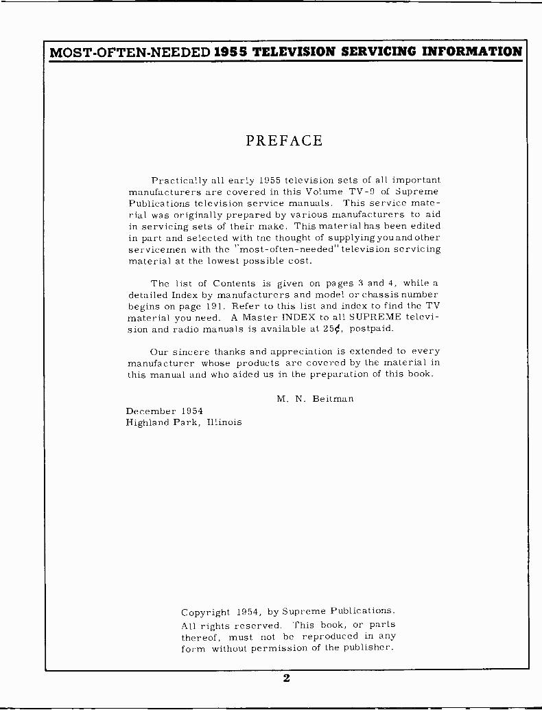
PREFACE
Practically all early 1955 television sets of all importantmanufacturers are covered in this Volume TV -9 of SupremePublications television service manuals. This service mate-rial was originally prepared by various manufacturers to aidin servicing sets of their make. This material has been editedin part and selected with tne thought of supplying you and otherservicemen with the "most -often -needed" television servicingmaterial at the lowest possible cost.
The list of Contents is given on pages 3 and 4, while adetailed Index by manufacturers and model or chassis numberbegins on page 191. Refer to this list and index to find the TVmaterial you need. A Master INDEX to all SUPREME televi-sion and radio manuals is available at 250, postpaid.
Our sincere thanks and appreciation is extended to everymanufacturer whose products are covered by the material inthis manual and who aided us in the preparation of this book.
M. N. BeitmanDecember 1954Highland Park, Illinois
Copyright 1954, by Supreme Publications.All rights reserved. This book, or partsthereof, must not be reproduced in anyform without permission of the publisher.
2
MOST -OFTEN -NEEDED 1955 TELEVISION SERVICING INFORMATION
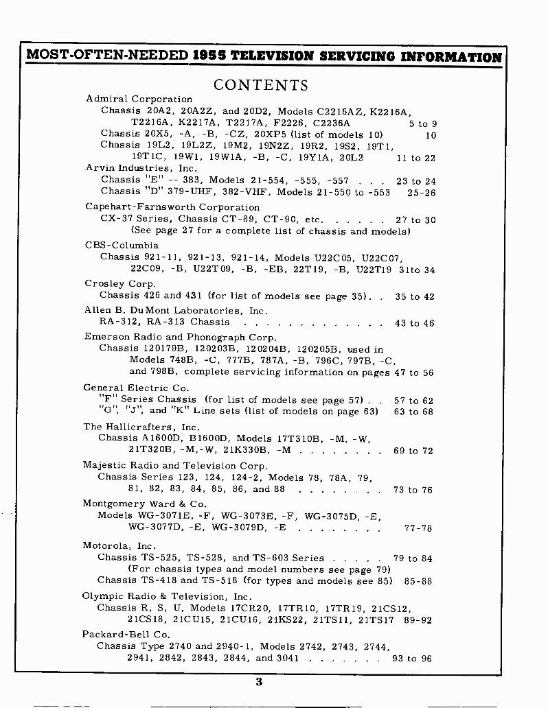
CONTENTSAdmiral Corporation
Chassis 20A2, 20A2Z, and 20D2, Models C2216AZ, K2216A,T2216A, K2217A, T2217A, F2226, C2236A 5 to 9
Chassis 20X5, -A, -B, -CZ, 20XP5 (list of models 10) 10Chassis 19L2, 19L2Z, 19M2, 19N2Z, 19R2, 19S2, 19T1,
19T1C, 19W1, 19W1A, -B, -C, 19Y1A, 20L2 11 to 22Arvin Industries, Inc.
Chassis "E" -- 383, Models 21-554, -555, -557 . . . 23 to 24Chassis "D" 379 -UHF, 382 -VHF, Models 21-550 to -553 25-26
Capehart-Farnsworth CorporationCX-37 Series, Chassis CT -89, CT -90, etc. 27 to 30
(See page 27 for a complete list of chassis and models)CBS -Columbia
Chassis 921-11, 921-13, 921-14, Models U22C05, U22C07,22C09, -B, U22T09, -B, -EB, 22T19, -B, U22T19 31to 34
Crosley Corp.Chassis 426 and 431 (for list of models see page 35). . 35 to 42
Allen B. Du Mont Laboratories, Inc.RA -312, RA -313 Chassis 43 to 46
Emerson Radio and Phonograph Corp.Chassis 120179B, 120203B, 120204B, 120205B, used in
Models 748B, -C, 777B, 787A, -B, 796C, 797B, -C,and 798B, complete servicing information on pages 47 to 56
General Electric Co."F" Series Chassis (for list of models see page 57) . . 57 to 62"G", "J", and "K" Line sets (list of models on page 63) 63 to 68
The Hallicrafters, Inc.Chassis A1600D, B1600D, Models 17T310B, -M, -W,
21T320B, -M,-W, 21K330B, -M 69 to 72Majestic Radio and Television Corp.
Chassis Series 123, 124, 124-2, Models 78, 78A, 79,81, 82, 83, 84, 85, 86, and 88 73 to 76
Montgomery Ward & Co.Models WG-3071E, -F, WG-3073E, -F, WG-3075D, -E,
WG-3077D, -E, WG-3079D, -E 77-78
Motorola, Inc.Chassis TS -525, TS -528, and TS -603 Series 79 to 84
(For chassis types and model numbers see page 79)Chassis TS -418 and TS -518 (for types and models see 85) 85-88
Olympic Radio & Television, Inc.Chassis R, S, U, Models 17CR20, 17TR10, 17TR19, 21CS12,
21CS18, 21CU15, 21CU16, 21KS22, 21TS11, 21TS17 89-92Packard -Bell Co.
Chassis Type 2740 and 2940-1, Models 2742, 2743, 2744,2941, 2842, 2843, 2844, and 3041 93 to 96
3
MOST -OFTEN -NEEDED 195 5 TELEVISION SERVICING INFORMATION
Philco Corp.List of models of "CII line receivers (also data on D-182) 97
TV -300 and TV -301 Chassis 98 to 106TV -350 and TV -354 Chassis 107 to 114
R. C. A. VictorModels 24S529(U), 24S531(U), 24S532(U) using Chassis 115-120
KCS84F, KCS84H, KCS84J, or KCS84K, andModels 24T420(U), 24T435(U) using Chassis KCS84C, -E
Models 17S450(U), 17S451(U), 17S453(U), using ChassisKCS87(A); Models 21S348K(U), 21S355K(U), 21S357K(U),21S362K(U), 21S367K(U), 21S369K(U), using ChassisKCS88, -A, -F, or -H; Models 21S501(U) to 21S506(U),21S517(U) to 21S519(U), 21S521(U) to 21S526(U).21S537(U), 21S5251(U), 21S5252(U), using ChassisKCS88B, -C, D, E, J, K, L, M, V, or VA; Models21S548(U) using Chassis KCS88N or KCS88P. . 121 to 128
Raytheon Manufacturing Co.17T18 and 21T19 Chassis (For list of models see 130)
Sears, Roebuck & Co.Chassis 528.271, 528.292, 528.300, 528.303 . 133 to 136
Sentinel Radio Corp.Models 1U-701, 1U-711, 1U-714, 1U-721, 1U-724, 1U-752,
1U-755, 1U-758, 1U-762, 1U-765, 1U-768, 1U-791 137-142Models 1U-901, 1U-911, 1U-914, 1U-921, 1U-924, 1U-991 143
Sparks-Withington Co. (Sparton)Models 11T210, 12A204, 12A210, and 14A204 . 147 to 149
Standard Coil VHF -UHF Tuner 150
Stewart -Warner ElectricModels 17T -9620A, -B, 21C -9630A, -AB, -C, -CB, -D 151-153Models 21C -9700R, -RB, -W, -WB, -X, -XB . . . 154 to 156
Stromberg-Carlson Company21T and 22T Series Receivers 157 to 160
129 to 132
Sylvania Electric Products, Inc.Chassis 1-522-1, -2, Models 596 Series 161 to 166
Trav-ler Radio Corp.Chassis Nos. 47A3, 48A3, 48A4, 48C4, 49A4 . 167 to 170
Westinghouse Electric Corp.Chassis V-2313, V-2314, V-2323, V-2324 171 to 178
(For list of models see page 171)Zenith Radio Corp.
Chassis 19M20(Z), 19M21(Z), 20M20(Z), 20M21(Z) and19R20, 19R21, 19R22, 22R20, 22R21 179 to 190(For a complete list of models see page 179)
Index 191-192
4
MOST -OFTEN -NEEDED 1958 TELEVISION SERVICING INFORMATION
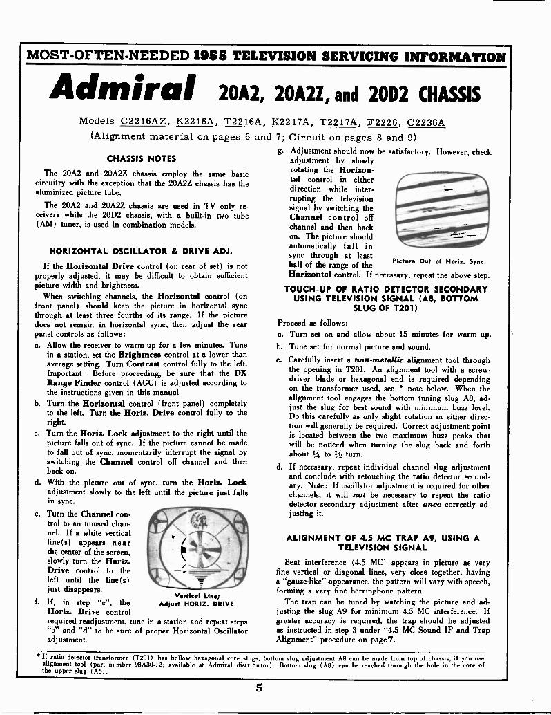
Admiral 20A2, 20A2Z, and 20D2 CHASSISModels C2216AZ, K2216A, T2216A, K2217A, T2217A, F2226, C2236A
(Alignment material on pages 6 and 7; Circuit on pages 8 and 9)
CHASSIS NOTES
The 20A2 and 20A2Z chassis employ the same basiccircuitry with the exception that the 20A2Z chassis has thealuminized picture tube.
The 20A2 and 20A2Z chassis are used in TV only re-ceivers while the 20D2 chassis, with a built-in two tube(AM) tuner, is used in combination models.
HORIZONTAL OSCILLATOR & DRIVE ADJ.
If the Horizontal Drive control (on rear of set) is notproperly adjusted, it may be difficult to obtain sufficientpicture width and brightness.
When switching channels, the Horizontal control (onfront panel) should keep the picture in horizontal syncthrough at least three fourths of its range. If the picturedoes not remain in horizontal sync, then adjust the rearpanel controls as follows:a. Allow the receiver to warm up for a few minutes. Tune
in a station, set the Brightness control at a lower thanaverage setting. Turn Contrast control fully to the left.Important: Before proceeding, be sure that the DXRange Finder control (AGC) is adjusted according tothe instructions given in this manual
b. Turn the Horizontal control (front panel) completelyto the left. Turn the Horiz. Drive control fully to theright.
c. Turn the Horiz. Lock adjustment to the right until thepicture falls out of sync. If the picture cannot be madeto fall out of sync, momentarily interrupt the signal byswitching the Channel control off channel and thenback on.
d. With the picture out of sync, turn the Horiz. Lockadjustment slowly to the left until the picture just fallsin sync.
e. Turn the Channel con-trol to an unused chan-nel. If a white verticalline(s) appears nearthe center of the screen,slowly turn the Horiz.Drive control to theleft until the line(s)just disappears.
f. If, in step "e", theHoriz. Drive controlrequired readjustment, tune in a station and repeat steps"c" and "d" to be sure of proper Horizontal Oscillatoradjustment.
Vertical Line;Adjust HORIZ. DRIVE.
g. Adjustment should now be satisfactory. However, checkadjustment by slowlyrotating the Horizon-tal control in eitherdirection while inter-rupting the televisionsignal by switching theChannel control offchannel and then backon. The picture shouldautomatically fall insync through at least
ofhalf of the range of theHorizontal control. If necessary, repeat the
Horiz. Sync.
above step.
TOUCH-UP OF RATIO DETECTOR SECONDARYUSING TELEVISION SIGNAL (A8, BOTTOM
SLUG OF T201)
Proceed as follows:a. Turn set on and allow about 15 minutes for warm up.b. Tune set for normal picture and sound.c. Carefully insert a non-metallic alignment tool through
the opening in T201. An alignment tool with a screw-driver blade or hexagonal end is required dependingon the transformer used, see * note below. When thealignment tool engages the bottom tuning slug A8, ad-just the slug for best sound with minimum buzz level.Do this carefully as only slight rotation in either direc-tion will generally be required. Correct adjustment pointis located between the two maximum buzz peaks thatwill be noticed when turning the slug back and forthabout 1/4 to 1/2 turn.
d. If necessary, repeat individual channel slug adjustmentand conclude with retouching the ratio detector second.ary. Note: If oscillator adjustment is required for otherchannels, it will not be necessary to repeat the ratiodetector secondary adjustment after once correctly ad-justing it.
ALIGNMENT OF 4.5 MC TRAP A9, USING ATELEVISION SIGNAL
Beat interference (4.5 MC) appears in picture as veryfine vertical or diagonal lines, very close together, havinga "gauze -like" appearance, the pattern will vary with speech,forming a very fine herringbone pattern.
The trap can be tuned by watching the picture and ad-justing the slug A9 for minimum 4.5 MC interference. Ifgreater accuracy is required, the trap should be adjustedas instructed in step 3 under "4.5 MC Sound IF and TrapAlignment" procedure on page7.
If ratio detector transformer (T201) has hollow hexagonal core slugs, bottom slug adjustment Afi can be made from top of chassis, if you usealignment tool (part number 98A30.12; available at Admiral distributor). Bottom slug (A8) can be reached through the hole in the core ofthe upper slug (A6).
Picture Out
5

MOST -OFTEN -NEEDED 1955 TELEVISION SERVICING INFORMATION20A2, 20A2Z and 20D2 IMPORTANT ALIGNMENT HINTS
The following suggestions should be performed if difficulty isexperienced during the alignment procedure.1. IF CIRCUIT INSTABILITY: When spot frequency aligningthe IF amplifiers, the VTVM pointer may swing when the hand isplaced too near the IF transformers. When viewing the IF re-sponse curve on an oscilloscope, the curve may change shape withhand capacity, especially when aligning A2 (3rd IF transformerT303). To correct either of these conditions, the following align-ment hints should be tried:
(a) Check the generator output leads to be certain that theunshielded portion (especially the grounded lead) be as short aspracticable.
(b) Be sure that a decoupling network is used at the videodetector output and that the leads on the network are kept asshort as possible (see figure 10).
(c) Construct a special tube shield as shown in figure 7. Thisis made from an ordinary tube shield and four 10,000 ohm re-sistors. Keep the spacing between the two halves of the shieldat a minimum (1/2 inch).
TO TESTPOINT .V
(810Ct0-----AT2ThRF AMP. RF AMP. MIXERI --r
C101 C104 C106
6BC5 6J6OR
A5 23.1 MC MAX. MIXER
A13HF OSC.
ADJ.
PLATE
Figure 9. Top View of TV TunerShowing Adjustment Locations.
10.000 OHMS
CHASSIS
51101010 -
Figure 10. Decoupling Filter.
TO SCOPEOR VTVM310
TYYED
(d) The use of a non-metallic alignment tool, approximatelyeight inches long (part number 98A30-12), will permit adjust-ment without coming too near to the transformers.
TO GENERATORHIGH SIDE
TO GENERATOR
LOW SIDE
23.1 MCA5 MAXMIXER PLATE
Al27.25MC MIN
TRAP
A3V 25.3MC MAX
1ST IF
FOUR
10 K RESISTORSEQUALLY SPACED
- 1/4" GAP
Figure 7. Special Tube Shield forIF Alignment and IF Response Curve Check.
TOP OH SIDE
POINT
1000 OHMS1305
A302
0 0 33 NEC
0
A423.1 MC MAX ' 0
2ND IF1120T 411( MS
-A2 UN 8206
25.3MC MAX 320 OHM 03RD IF
TEST POINTNEG. OF 6205ELEC. 4MFD
TEST POINTJCT. OF C206R206 8 R207
OTEST POINT
JCT. OF L302AND L303
A8 A6 -A7 A9(BOTTOM SLUG) ( TOP SLUG) 4.5 MC MAX 4.5 MC MIN4.5 MC ZERO 4.5 MC MAX SOUND TRAP
RATIO JDET. Pffi. RATIO DE T. TAKEL OFF
Figure 11. Bottom View of Chassis Showing Test Point Connectionsand IF Alignment Data.
IF AMPLIFIER AND TRAP ALIGNMENT Connect bias battery; negative to test point "T", see
figure 11, positive to chassis. A 41/2 volt battery isrequired for all steps below.
Disconnect antenna. Connect a jumper wire acrossthe antenna terminals.
Set Channel Selector to channel 12 or other unassign-
ed high channel, to prevent interference during align-ment.
Set the Contrast control fully to the left (counterclock-
wise). Allow about 15 minutes for receiver and test equip-
ment to warm up. Use lowest DC scale on VTVM.
StepSignal
Gen. Freq.VTVM and Signal
Generator ConnectionsInstructions Adjust
1 *27.25 MC VTVM high side to test point "V" through Connect a 41/2 volt bias battery to test Al for minimum.
2 25.3 MCa decoupling filter; see figs. 10 and 11,common to chassis.
point "T".Use lowest DC scale on VTVM. When peak-
A2 and A3 for maxi -mum.
3 23.1 MC Generator high side to 6J6 (V102) specialtube shield. Connect low side to bottom
ing, keep reducing generator output forVTVM reading of approx. 1 volt or less. A4 and A5 for maxi -
4 *27.25 MC part of the tube shield, see figure 7. If unstable, refer to section 1 of the mum.Repeat step 1 above."Alignment Hints"
5 To insure correct IF alignment, make the "IF Response Curve Check" given below.
Before proceeding, be sure to check the signal generator used in alignment against a crystal calibrator or other frequency standard forabsolute frequency calibration required for this operation.
6

MOST -OFTEN -NEEDED 1955 TELEVISION SERVICING INFORMATIONIF RESPONSE CURVE CHECK 20A2, 20A2Z and 20D2
Receiver Controlsand Bias Battery G
Sweepor
MarkerGenerator Oscilloscope Instructions
Set Channel Selectoron channel 12 or anunassigned high chan-nel. Contrast controlfully to the left. Con-nect negative of 41/2volt bias battery totest point "T"; posi-tive to chassis.
21.25MC
MARKER
(MAY NOT
BE VISIBLE)
AT LEAST 95%
MEASURED
Connect high side to6J6 mixer-osc. specialtube shield, see fig.7. Connect low sideto bottom part oftube shield. Set sweepfrequency to 23MC,and sweep width ap-proximately 7MC.
If an external markergenerator is used,loosely couple highside to sweep genera-tor lead on tubeshield, low side tochassis. Marker fre-quencies indicated onIF Response Curve.
25.75MCMARKER
50%
-I-A304MAXIMUMDIFFERENCE IN HEIGHT OF PEAKS
SHOULD NOT EXCEED 30'/.
FROM HIGHEST PEAK
Figure 12. Ideal IF Response Curve.
Connect to test point"V" through a de -
coupling filter, seefigs. 10 and 11. Mark-er pips on scope willbe more distinct if a
capacitor from 100mmfd. to 1000 mmfd.is connected acrossthe oscilloscope input.
TOA11-0 If 12 it M Al 2211214LI IKEIR 1211.'ILL 451 CAM 2051E101 02 15.15K 111111
Check curve obtained against ideal re-sponse curve in fig. 12. Note toleranceson curve. Keep marker and sweep out-puts at very minimum to prevent over-loading. A reduction in sweep outputshould reduce response curve amplitudewithout altering the shape of the re-sponse curve. If the curve is not withintolerance or the markers are not in theproper location on the curve, touchupwith IF slugs as instructed below.Important: If curve changes shape withhand capacity, see section 1 of "Align-ment Hints':
25.1'0 MCMARKER
10110 -Of Of M 111 a WILL MAMA, AMYAl ALSO CAKE 10511101 N 22111 41111.
Figure 13. IF Response Curves, Incorrect Shape.
If it is necessary to adjust for approximate equal peaks andmarker location, carefully adjust alignment slugs as instructedunder the above figures. It should not be necessary to turn theslugs more than one turn in either direction.
If the curve cannot be made to resemble the response curveshown at left, repeat all steps under "IF Amplifier and TrapAlignment" making sure that generator frequencies are accurateand adjustments are carefully made. If a satisfactory curve can-not be obtained after repeating these steps, it may be necessaryto change IF amplifier tubes or check for a defective circuitcomponent to be sure that each stage is operating properly.
4.5 MC SOUND IF AND TRAP ALIGNMENTSee page 6' for touch-up of ratio detector using television
signal without test equipment.a. Connect signal generator high side to pin 2 of V304
(6AL5) through a .01 mfd. capacitor, connect lowside to chassis.
b. Allow about 15 minutes for receiver and test equip-ment to warm up.
c. Set Contrast control fully to the left (counterclockwise).
Step
1
2
3
d. Use a non-metallic alignment tool. If Ratio Det.Transformer (T2 0 1) has hollow core slugs, bottom slugadjustment A8 can be made from top of chassis, ifyou use alignment tool, part number 9 8A3 0-1 2 ob-tainable from Admiral distributor.
Signal Gen.Freq. (MC) VTVM Connections Instructions Adjust
When using a signal generator, be sure to check it against a crystal calibrator or other frequency standard for accuratefrequency calibration at 4.5 MC. Accuracy required is within one kilocycle.IMPORTANT: If a signal generator and frequency standard are not available, alignment can be made using a TV stationsignal. Tune in a station and follow step 1, 2 and 3 below. If necessary use a higher scale on the VTVM.
Set to
exactly4.5 MC
High side totest point "Y";
common to chassis.
High side totest point "Z";
common to chassis.
High side totest point "Y";
common to chassis.
Use lowest DC scale on VTVM.A6 and A7 for maximum (keep reducinggenerator output to keep VTVM at ap-prox. 1 volt).
Use zero center scale on VTVM, if avail-able.
A8 for zero on VTVM (the correct zeropoint is located between a positive anda negative maximum). If A6 was faroff, repeat step 1.
Connect a 10 mmfd. capacitor from pin7 of V305 (12BY7) to pin 7 of V201(6AU6).Use lowest DC scale on VTVM.
A9 for minimum.
7
MOST -OFTEN -NEEDED 1955 TELEVISION SERVICING INFORMATION I
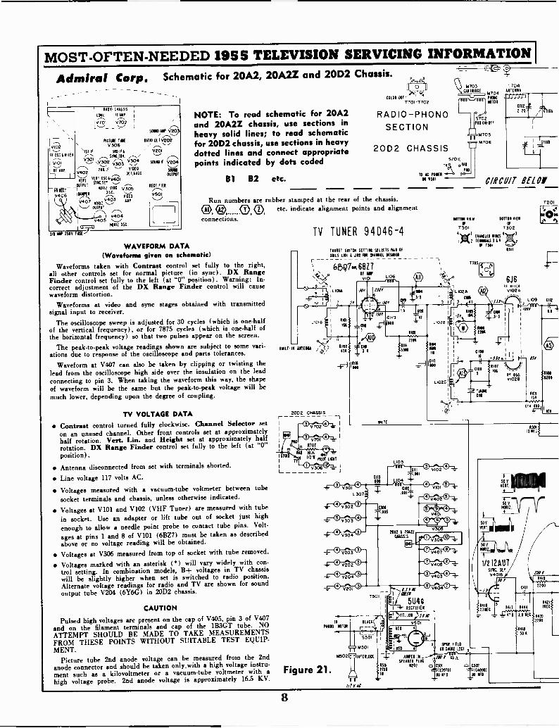
Admiral Corp. Schematic for 20A2, 20A2Z and 20D2 Chassis.
0306 ...-..,
'4T if SUET& v201,---, MICAH. ,---.../ "---'......... y30.r,2 v- saw if 7.--- \
V204...._...,
7---N 20.1F ."---' 5111E0V402 OE TA ACC
511110
\'''''VER(T VsETE1NcT .055°E,,131
OUTPUT
- OUTPU
" ,..--,DISC. ,.......,
V406 15"" VIDEO
0407 .V4.,,03 AMP
AI '- OUTPUT
RADIO CHASSIS
CONY. iF.ANP. I
10701 V702 I
,L_._., __, _ I ,---N
SOLZD IMP V201
PICT1.11 TIN RA110 DE I V202
v102
RE OSC &NIS! I
V101
AF 11P,
V404
(1 11110115 050
S/1 AMP 2305 FUSE}
HOME syNC. v305 RECTIFIER
0501
NOTE: To read schematic for 20A2and 20A2Z chassis, use sections inheavy solid lines; to read schematicfor 20D2 chassis, use sections in heavydotted lines and connect appropriatepoints indicated by dots coded
61 62 etc.
COLOR DOT
T701-7702
RADIO-PHONOSECTION
20D2 CHASSIS
M703CARTRIDGE
P505000701
5702MO ON -OFF
M705
M706
5701E
TyA DT"TO IC POKI ""
01 1501
Run numbers are rubber stamped at the rear of the chassis.C>,4 0 0 etc. indicate alignment points and alignmentconnections
WAVEFORM DATA(Waveforms given on schematic)
Waveforms taken with Contrast control set fully to the right,all other controls set for normal picture (in sync). DX RangeFinder control set fully to the left (at "0" position). Warning: In-correct adjustment of the DX Range Finder control will causewaveform distortion.
Waveforms at video and sync stages obtained with transmittedsignal input to receiver.
The oscilloscope sweep is adjusted for 30 cycles (which is one-halfof the vertical frequency), or for 7875 cycles (which is one-half ofthe horizontal frequency) so that two pulses appear on the screen.
The peak -to -peak voltage readings shown are subject to some vari-ations due to response of the oscilloscope and parts tolerances.
Waveform at V407 can also be taken by clipping or twisting thelead from the oscilloscope high side over the insulation on the leadconnecting to pin 3. When taking the waveform this way, the shapeof waveform will be the same but the peak -to -peak voltage will bemuch lower, depending upon the degree of coupling.
TV VOLTAGE DATAContrast control turned fully clockwise. Channel Selector seton an unused channel. Other front controls set at approximatelyhalf rotation. Veil. Lin. and Height set at approximately halfrotation. DX Range Finder control set fully to the left (at "0"position).
Antenna disconnected from set with terminals shorted.
Line voltage 117 volts AC.
Voltages measured with a vacuum -tube voltmeter between tube
socket terminals and chassis, unless otherwise indicated.
Voltages at V101 and V102 (VHF Tuner) are measured with tube
in socket. Use an adapter or lift tube out of socket just highenough to allow a needle point probe to contact tube pins. Volt-
ages at pins 1 and 8 of V101 (6BZ7) must be taken as describedabove or no voltage reading will be obtained.
Voltages at V306 measured from top of socket with tube removed.
Voltages marked with an asterisk (*) will vary widely with con-trol setting. In combination models, B+ voltages in TV chassiswill be slightly higher when set is switched to radio position.Alternate voltage readings for radio and TV are shown for soundoutput tube V204 (6Y6G) in 20D2 chassis.
CAUTION
Pulsed high voltages are present on the cap of V405, pin 3 of V407and on the filament terminals and cap of the 1B3GT tube. NOATTEMPT SHOULD BE MADE TO TAKE MEASUREMENTSFROM THESE POINTS WITHOUT SUITABLE TEST EQUIP-MENT.
Picture tube 2nd anode voltage can be measured from the 2ndanode connector and should be taken only.with a high voltage instru-
ment such as a kilovoltmeter or a vacuum -tube voltmeter with a Figure 21.high voltage probe. 2nd anode voltage is approximately 163 KV.
TV TUNER 94D46-4
IF ANIv.01
010IA
HILT ARENA
1 570
L
2002 CHASSIS
TURRET ALTON SETTING SELECTS PAIR OfCOILS 1.10111102 FOR 011,1411 DOWER
6.13970 6BZ 7
7
10A 04
l'21 MOT LOT
0306 -_J
v304
TO
NON ROTOR
M502
L307
M501
INTERMIT
015ONO
06
LIO 5
20A2 1 20121ciass3
Lira'
If1 /oar
5U4CI RECTIFIER
I, YELLOW
0 V402 00%7'0
0401
0501-FRED
: IRED-TE7-z guy FIELD
KO ON CHOKE 1.501
V404
L704ANTENNA
CIRCUIT BEt Of
DITTO ram IOTTOI cifyAE Of
T301 7302
11414150 BIKES
1).4,2 1EMINALS I I I ,
If Tim11/1
TIDE
11-102A
COI3 AT
-3
JIMPER ._=43A2/ °ssa- SPOUSES PLUG lA
is01 N202 n 0501 o IS022101 T (C10711)
60 NEDT1
0
C40911)1
1
TUNING
Clot
50
VENT.
ROOM
20500
6J6UI 6.111
01021
-.11/6
1201
5109 au
0.1
1101
1200
35I I'
RaiINFO
12.2
//71',K
8
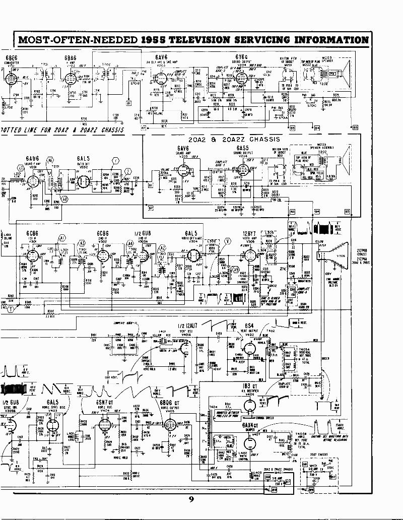
I MOST -OFTEN -NEEDED 19S S TELEVISION SERVICING INFORMATION
6BE6 6BA60 AMP
v701 /02 /SOT701 7702
C/09100
1 YES
70TTED LINE FOR 10/12 1 20121 CHASSIS
201
104
L103MAC0113
6AU6SOUND 11111,(i) v201
L 2014 SIC
1303
331
ow3 NEC
6CB6ISO IF
0309
0305
1000
7201
/NY
1107 0
0301 AN'0.0 0E4
L30122 25ist
6AL5RATIO DOT
02020 -4P
.11-1-11110112.
1/2 6U8SYNC. 110.03038
-mIII YERT.
404
0412
111/
1101111.
6AL5401111 STE DISC I
0403
130) 0423-Jr /1'
10000%
1424MOK
4Y
/S YCM3
.001
422200
allni 44140112.-7-- 0125
N E4.
C411
00221
644 .0E_O__47
0/240
470A
-C410
I"'
L401 -,71X0112.." C411
Loa ''.,_tj"33
11/127
471211
C2045 i
4. 2 500
02054 0
0201310
210 IF0302
7301 01 3
25.3NC
515101
5%
6AV6AN DE T. AVC SOO. AMP
V200
2 /Y R212
R225 "-*"-47 NEC
470 .01.0--
Con00 T
VOLUME
ffnori
x11 4
410
I/2 6U83RD IF03034
/MY
21.1 NC
2
C3044
0307 00.
13121000
120
50010 OUTPUT02046116
C
SOO Y DOCP/PI Off 41 4 goo ,,,..,,,,
r....saii"0:5 1" 3 ... ' .10217211 zso r -AI
, 1214 el? am i 2407 t1213 !A 150 5
L 4701_ /001/1..6_.._F)
001704 VIEW p 4203Of SOCLET ,TOP 4111 PLM SPEAKER
4201 4202 KM -
TO 11111 TO
Of 51.14 0501 L
7202
0227 4 122$--ww.-N-mw-- 40221134022 - 5100 5% 3600 5% - 10410
1210 4220ION -02074 610 40 51 a 0207
201110 JO ED
50
PRO MO.
TV
OIA
03291
270021
PM RAO 1224
J A Tv 1223 N/00211
STOIC 15151
VOLMER2
20A2 & 20A2Z CHASSIS6AV6 6AS5
S01110 AMP SOUND OUTPUT
V203 /900
0210
22 0
COOPtilfONO -S
T224 ,711
4700 1 NEC
132141 11117
0213 1 4NEC 0215
34005%
C20720 OFD
6AL541010 017 I A ACC
v304 r L3-627-.Sr ;-,0011
0320Or 5 4710
1311Air
4700
1314 0/31 CM C112 L100 4.5MC3011 -1 I-- 3120
47 001
- " 1315.±.42:4
330 0 RAKEF14111 -r -i-
1311 = 44 14NV, NINE rflT511 _i _l_
COletilf 13110-14\
1401 1442 __11441_ z C*,
221 ; WM UM 0041
C403: C4 C405 i
0027
1303 2310
2151C1
- 27
T011111011 If D
154.E11.1
TOY
0204ISO 2' iC21T
0216
101F0
BOTTOM VIE!OF SOCNET
1201
TO FIN 1 TO LOf 504 0501
022,* 0222t*" 113291
040
2207$ a O 0200060 40 MD
132156430313-6.1
R122102011
1000
000704$
2700 20
m203SPEAKER AS5E111111
111117202
TOP VIEI OfP1310 0202 :
3 1100
ILK - 11ED
FIELD
TEL -KO
_J
.11011.
o
12Bri r6' ii RvT.
viDEO ANP I 0311m305I
0321..
if 1002. L_ -E1 _22
L 300- -J 1321
-1 7/321 1 2
I
200
120
)
ow" 0315 2-2k 1IBM
10423410311 I,343
A e_i 4 1000
10114114_ 0010411755
0502 r t _
f2 1324 lif 0331ow 033/81.4/2"
2TO 1. 150 PC"SSW IS COW , I
13E3 ILI !NI, 12 M - , 1
u4 'I' 1151/1 ,_ j 1334J 4514 51
1/212AU7 6S4-4-VEIT OSC EAT OUTPUT 7402
04014
CIEETI 1 -JO
1404(14141)
218 1415
NEM 00101.2O NEI- C
1200 VEIT.
11406
100
S.F.
CMIT
-r14111....±.A 150 V GO
9 .I- CMS irns - lig'i +.3
111-11.1100,1r.0011517111 Vtit611Q6 CT
354
c6SN1 CT
10111, M. 21,_....,_.00434
C420
0404 /IS I'
8421 310 COI 1435 -JOY/4040u1MO .--1Y -, Y
0112 1E
3 400430
1431
0 Y5 1201
1432 470 11 414 0424
1
142/001
1431*M A0144510 0412 10 110
CA231 143741
11431180..._0__114311
WWI. MOLL I
.047
20
546.
4
Mt
5
0401 v402 11.0E
Or Hop.400A
1110CIII211/11.
VEIT LH
170
4
044140171
.1 011
41017 1410
1- 121
4.0 RECTIFIER
15321100
$9MIT
1.5
0
It
I 1413
1560
1412! 74034! VERTMAL
540 !EF. TIME5-4 47 o.
TOTAL
c4n
27C..011I
183 CTCOVPL-a ATE
6.5CC421
01
11415
540
ISOY
140 MOMVOLTAGE
4.5 KV
WEN
Ti
0406
11417404 47.
NNW &MaiMOH Of PIN
3
1;0
1433 i HOW150.4 MINE
104VEIT sir
15004
WEI if* 31 _ ___ 11111111.
4- a4
fIlt1 3 V407 C4211- 40412. WIN, SFr $44'0071T$44'0071OM' 740313
1
41 4443 I OFF. TORE ArfOlf &OWN
11171 I 100020 TO 31.A..
1
1
TOTAL
COMA 54IE10
61X4 CT
J
0442 !fa U,1 L4021000 Li.. 1110111JIOY c oo 2002 01M5.515
0% r rHo
0420WOY
-C425 047
047 4% 10%
200/2 1 20121 CHASSISL403 -kI4011111112
LIT. L'iJ 3/1 Allt.
250
31
250
211P484200221
21ZP4ANW 1 NOD
8111TE 0043101.20
9
MOST -OFTEN -NEEDED 1955 TELEVISION SERVICING INFORMATION
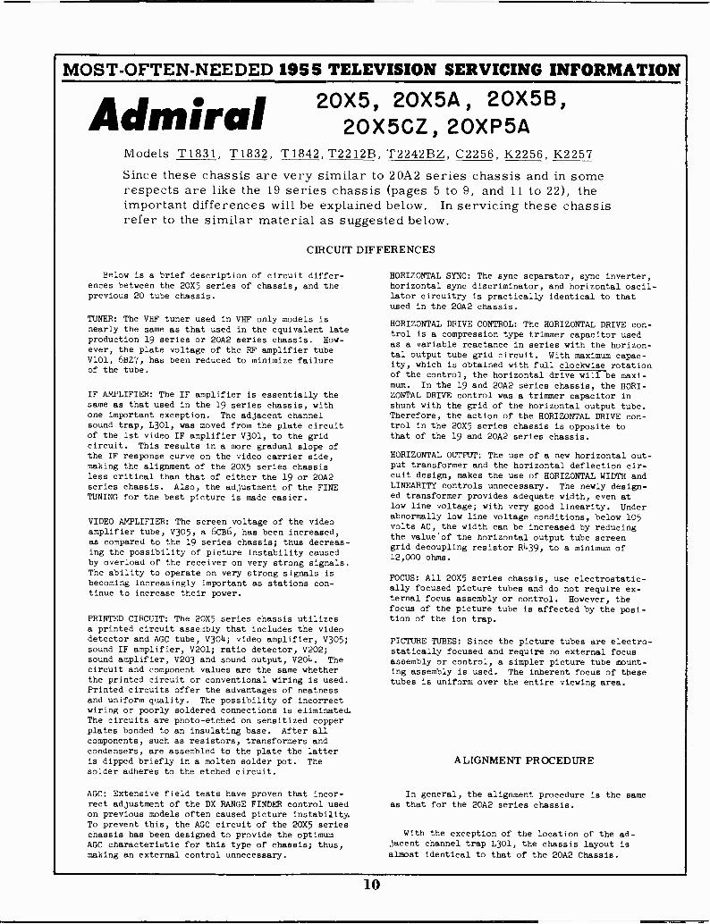
20X5, 20X5A, 20X5B,Admiral 20X5CZ, 20XP5AModels T1831, T1832, T1842, T2212B, T2242BZ, C2256, K2256, K2257Since these chassis are very similar to 20A2 series chassis and in somerespects are like the 19 series chassis (pages 5 to 9, and 11 to 22), theimportant differences will be explained below. In servicing these chassisrefer to the similar material as suggested below.
CIRCUIT DIFFERENCES
Below is a brief description of circuit differ-ences between the 20X5 series of chassis, and theprevious 20 tube chassis.
TUNER: The VHF tuner used in VHF only models isnearly the same as that used in the equivalent lateproduction 19 series or 20A2 series chassis. How-ever, the plate voltage of the RF amplifier tubeV101, 6BZ7, has been reduced to minimize failureof the tube.
IF AMPLIFIER: The IF amplifier is essentially thesame as that used in the 19 series chassis, withone important exception. The adjacent channelsound trap, L301, was moved from the plate circuitof the 1st video IF amplifier V301, to the gridcircuit. This results in a more gradual slope ofthe IF response curve on the video carrier side,making the alignment of the 20X5 series chassisless critical than that of either the 19 or 20A2series chassis. Also, the adjustment of the FINETUNING for the best picture is made easier.
VIDEO AMPLIFIER: The screen voltage of the videoamplifier tube, V305, a 6CB6, has been increased,as compared to the 19 series chassis; thus decreas-ing the possibility of picture instability causedby overload of the receiver on very strong signals.The ability to operate on very strong signals isbecoming increasingly important as stations con-tinue to increase their power.
PRINTED CIRCUIT: The 20X5 series chassis utilizesa printed circuit assembly that includes the videodetector and AGC tube, V304; video amplifier, V305;sound IF amplifier, V201; ratio detector, V202;sound amplifier, V203 and sound output, V204. Thecircuit and component values are the same whetherthe printed circuit or conventional wiring is used.Printed circuits offer the advantages of neatnessand uniform quality. The possibility of incorrectwiring or poorly soldered connections is eliminated.The circuits are photo -etched on sensitized copperplates bonded to an insulating base. After allcomponents, such as resistors, transformers andcondensers, are assembled to the plate the latteris dipped briefly in a molten solder pot. Thesolder adheres to the etched circuit.
AGC: Extensive field tests have proven that incor-rect adjustment of the DX RANGE FINDER control usedon previous models often caused picture instability.To prevent this, the AGC circuit of the 20X5 serieschassis has been designed to provide the optimumAGC characteristic for this type of chassis; thus,making an external control unnecessary.
HORIZONTAL SYNC: The sync separator, sync inverter,horizontal sync discriminator, and horizontal oscil-lator circuitry is practically identical to thatused in the 20A2 chassis.
HORIZONTAL DRIVE CONTROL: The HORIZONTAL DRIVE con-trol is a compression type trimmer capacitor usedas a variable reactance in series with the horizon-tal output tube grid circuit. With maximum capac-ity, which is obtained with full clockwise rotationof the control, the horizontal drive will be maxi-mum. In the 19 and 20A2 series chassis, the HORI-ZONTAL DRIVE control was a trimmer capacitor inshunt with the grid of the horizontal output tube.Therefore, the action of the HORIZONTAL DRIVE con-trol in the 20X5 series chassis is opposite tothat of the 19 and 20A2 series chassis.
HORIZONTAL OUTPUT: The use of a new horizontal out-put transformer and the horizontal deflection cir-cuit design, makes the use of HORIZONTAL WIDTH andLINEARITY controls unnecessary. The newly design-ed transformer provides adequate width, even atlow line voltage; with very good linearity. Underabnormally low line voltage conditions, below 105volts AC, the width can be increased by reducingthe value'of the horizontal output tube screengrid decoupling resistor R439, to a minimum of12,000 ohms.
FOCUS: All 20X5 series chassis, use electrostatic-ally focused picture tubes and do not require ex-ternal focus assembly or control. However, thefocus of the picture tube is affected by the posi-tion of the ion trap.
PICTURE TUBES: Since the picture tubes are electro-statically focused and require no external focusassembly or control, a simpler picture tube mount-ing assembly is used. The inherent focus of thesetubes is uniform over the entire viewing area.
ALIGNMENT PROCEDURE
In general, the alignment procedure is the sameas that for the 20A2 series chassis.
With the exception of the location of the ad-jacent channel trap L301, the chassis layout isalmost identical to that of the 20A2 Chassis.
10
MOST -OFTEN -NEEDED 1955 TELEVISION SERVICING INFORMATION
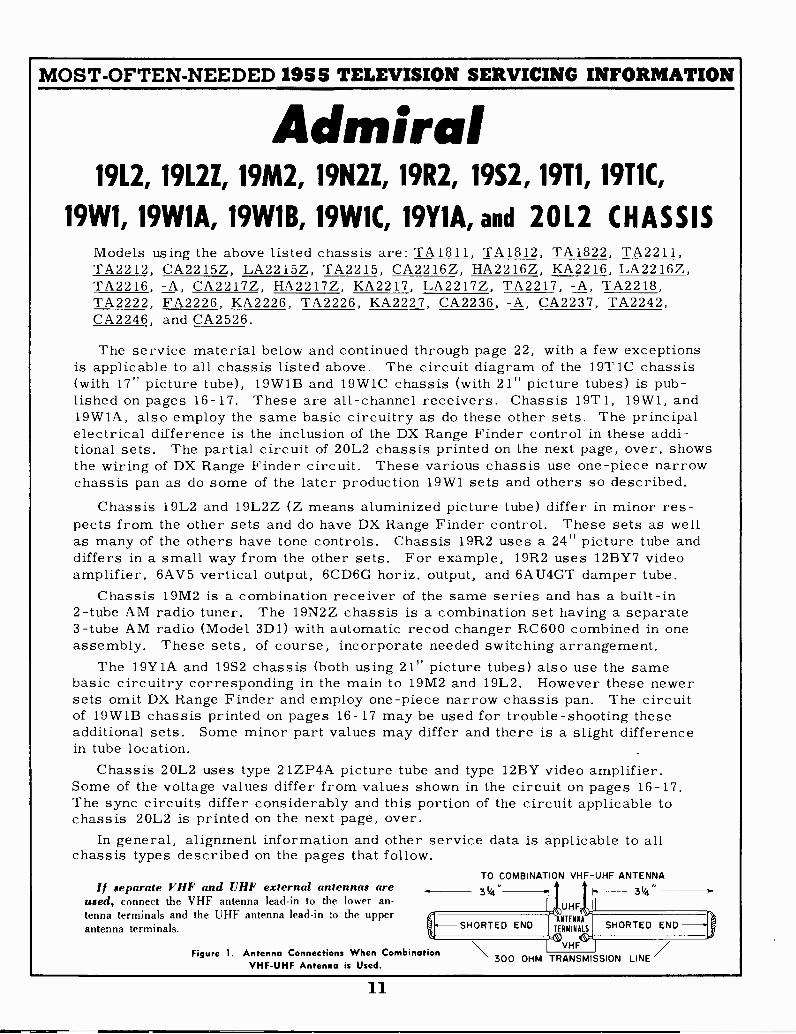
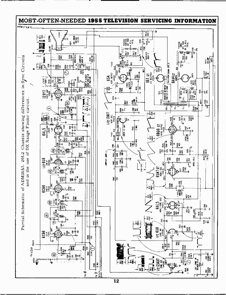
Admiral19L2, 19L2Z, 19M2, 19N2Z, 19R2, 19S2, 19T1, 19T1C,
19W1, 19W1A, 19W1B, 19W1C, 19Y1A, and 20L2 CHASSISModels using the above listed chassis are: TA1811, TA1812, TA1822, TA2211,TA2212, CA2215Z, LA2215Z, TA2215, CA2216Z, HA2216Z, KA2216, LA2216Z,TA2216, -A, CA2217Z, HA2217Z, KA2217, LA2217Z, TA2217, -A, TA2218,TA2222, FA2226, KA2226, TA2226, KA2227, CA2236, -A, CA2237, TA2242,CA2246, and CA2526.
The service material below and continued through page 22, with a few exceptionsis applicable to all chassis listed above. The circuit diagram of the 19T1C chassis(with 17" picture tube), 19W1B and 19W1C chassis (with 21" picture tubes) is pub-lished on pages 16-17. These are all -channel receivers. Chassis 19T1, 19W1, and19W1A, also employ the same basic circuitry as do these other sets. The principalelectrical difference is the inclusion of the DX Range Finder control in these addi-tional sets. The partial circuit of 20L2 chassis printed on the next page, over, showsthe wiring of DX Range Finder circuit. These various chassis use one-piece narrowchassis pan as do some of the later production 19W1 sets and others so described.
Chassis 19L2 and 19L2Z (Z means aluminized picture tube) differ in minor res-pects from the other sets and do have DX Range Finder control. These sets as wellas many of the others have tone controls. Chassis 19R2 uses a 24" picture tube anddiffers in a small way from the other sets. For example, 19R2 uses 12BY7 videoamplifier, 6AV5 vertical output, 6CD6G horiz. output, and 6AU4GT damper tube.
Chassis 19M2 is a combination receiver of the same series and has a built-in2 -tube AM radio tuner. The 19N2Z chassis is a combination set having a separate3 -tube AM radio (Model 3D1) with automatic recod changer RC600 combined in oneassembly. These sets, of course, incorporate needed switching arrangement.
The 19Y1A and 19S2 chassis (both using 21" picture tubes) also use the samebasic circuitry corresponding in the main to 19M2 and 19L2. However these newersets omit DX Range Finder and employ one-piece narrow chassis pan. The circuitof 19W1B chassis printed on pages 16-17 may be used for trouble -shooting theseadditional sets. Some minor part values may differ and there is a slight differencein tube location.
Chassis 20L2 uses type 21ZP4A picture tube and type 12BY video amplifier.Some of the voltage values differ from values shown in the circuit on pages 16-17.The sync circuits differ considerably and this portion of the circuit applicable tochassis 20L2 is printed on the next page, over.
In general, alignment information and other service data is applicable to allchassis types described on the pages that follow.
If separate VHF and UHF external antennas areused, connect the VHF antenna lead-in to the lower an-tenna terminals and the UHF antenna lead-in the upperantenna terminals.
TO COMBINATION VHF -UHF ANTENNA
31/4" 11 F 31/4"
SHORTED END
Figure 1. Antenna Connections When CombinationVHF -UHF Antenna is Used.
UHFANTENNA
TERMINALS
'-(1)VHF
300 OHM TRANSMISSION LINE
SHORTED END
11
TE
;
T0
c2o1
1430
1fi
lo)
To
13
1331
TO
D15
NE
C62
9 re
SO
K,
Part
ial S
chem
atic
of
AD
MIR
AL
20L
2 C
hass
is s
how
ing
diff
eren
ces
in S
ync
Cir
cuits
and
in th
e us
e of
DX
Ran
ge F
inde
r ci
rcui
t.
-,1
t,L3
011
45.3
C32
21I
12
001
PG
441_
,C
301
72
L51
<_
J03
31
1337
330
3.3
III
6 C
B6
ST
IFv3
01
,to03
0641 03
02
0301
/JO
Y2.
2
0304
6CB
6?N
D IF
V30
2 /104
'
1.30
1T
301
Or
5
40C
111
11.
2511
45.3
1309
21
:00
5
2r 3
(074
,
001
1301
1011
i 113
1010
00
1305
1000
2 /Y *311
/JO
Y 1313
244
5'4
1/2
6U8
3 R
D If
v303
3 /Mr
6AL5
1.3/
4V
IDE
O D
ELI
AC
C.
V30
4,-
-L30
2--jr
L309
T 3
02
1 .43
3
DII ,,S
1350
y14
1(a1
4r
it_7
'41
21
NC
j1
I.
10,3
11 t
1319
i4"
.7,
in, 1.1
414
,7,4
704
- .0
11
1314 10
53°0
4 "W
I - -
-1(
14-
1(-1
-)I
--4 $1
315
3301
I
C:3
°209
Fil
izoI
4311
ctic
:
IT
001
300
1C
31I
C31
2
2
C30
7C
306
.016
.005
!(!i1
)20
0307
1.50
E2
1311
-A
MP
561
C32
0 IF 2-2(
152161
00 C31
3- -T-.
..-1.
,L3
04!
300
4.91
1i1
.4-
4.
TI
If60O
RIZ
V
1ID
EO
2817
P-1
_31:
151
VO
AI
V30
5
-' 00
211
C3I
8
moo
rL
_ 33
1J
L 30
6 -
- 1
IR
Y/0
07:
5521
I
*323
33
011.
ILO
ILT
O
7:47
4 114
"1
YE
""F
_L J
ILIA
PO
O10
4230
)
(94
1011
ED
01
IE 22
1328
2112
300
tt21
30
216
C31
9*3
33
erza
ssth
1004
I
A32
4 ;-
-195
02r
- -
221
R33
1C
PE
JCV
44."
IfS
tifow
Is00
51,2
10 I
0:78
iT,IM
-1*3
25W
U 1
.1/1
d II
.-.-
n,
I
Ann
e6.
16V
" M
INN
,_c"
"_'
j 400
0303
451
(1-a
s(1.
.A.
1/2
12A
111
SM. S
EP./
V40
11 JO
2
2112
A41
$
330(
2
r4115
0 K
1301
0110
0101
211
9991
111
nato
0-70
A
CSO
IC
502
I1C
OO
7D1
C40
6114
600f
900
101)
7(11
mio
rs
AM
0P22
0
--1-
-II
V40
111.
40 VE
AT
1/2
6U8
SY
NC
. IN
V.
V30
313
C4I
2
8421
ME
C
1141
104
4414
20
Vrr
ilrIE
C22
00
NO
Y Y 9 /5C
413
-If
.001
0422
2200
"r7
lay HOA
R.
Y7/
1.00
144
2310
06
5% 0424
1000 5%
:2
18 V
1101
112.
6AL5
BO
AR
.S
YN
C. D
I
Ci
v403
C4I
7
.002
21
C41
5 11
.004
7
4426
L401
4011
1LO
CK
.
4427
'k471 21
CO
MM
" fia
-//.
1/2
12A
U7
1401
VE
RT
. 05C
.
;14,
,,,...
.~,..
...._
402
_ __
RC
M 5
3_2
0444
TE
IAN
AID
V40
10
224
1200
0200
.0jii
150.
E il
016
0., 1
1.1
P
0401
C40
404
051
002-
105I
01T
1200
MT
I35
V
1101
12.
_L-.
6SN
7 C
T
yRO
SH
. 214
SC
.(JO
mfic
t,A
k421
139
056
0( C41
11
.003
9
/Y3e
04'
1429
1500
0423
044
3104
2210
NE
D25
4
NO
W. H
OLD
ME
I I -
JOY
1140
4
2000
4110
.101
.01.
2 N
EC
0420 21
044
34
(-44
"4-4
10%
3600
0421
8438
1406
106
C40
1
I.64
110
70
150
V60
111
0012
.Y
_
68Q
6 C
TH
OA
R. O
UT
PU
TV
405
-JO
Y
0102
NO
Y 3
431
482
4430
4436
1204
A40
211E
051
504
24
1006
0437
047
47 II
4439
8200 20
r'120
1'
VE
IT
0401
Or
S A
lp`
1407
2114
111.
.51E
114
10 120
6S4
VE
RT
. OU
TP
UT
0402
0100
1
211 @6
i10
112
0 #/0
1402
1LU
E
0yor
910
00.1
191
11S
LUE
AM
P
60 V
VE
RT
TE
1.01
1
0/Jr
NO
Y
200
MO
EV
OLT
A*
16.5
AV
C 4
10
2011
101,
4411
3000
VE
R1.
1.11
. RE
D
560. 4
24. 3
21,
04 1240
00
21
1B3
CT
N.Y
. RE
CT
IFIE
RV
406
0441
T40
4 ME
N 1
101(
11N
OS/
I1 O
f N
OS
TE
L
7.5A
E0
0413
I 1560
1 T
4034
A41
21
VE
RT
ICA
L56
01
HT
YO
KE
5-0
4110
1
TO
TA
L
BLA
CK
i04
14.
"21
1'A
NN
."I(
2100
.01
CO
UP
LAT
E!
0420
151
6306
-12
;.0
1-
L
60 VE
RT
.
CR
EE
II-L-
134
,,12
5.,,,
EI
BLU
E(
4425 4.7
NE
C
470
0416
IE."
'
0433
1100
11.
DR
IVE
150
.40
Y
-042
510
I-T .0
47
CO
RO
NA
511
11.0
6AX
4 G
TD
OH
RE
D3
-
4442
1R
ED
d`
L402
1000
Li4
WID
TH
211
1111
1110
CO
NT
RO
L
3 V
401
C42
1'47
1000
6 IOO
Y
1403
B11
0111
.
Off.
101
2!
20T
O 3
8.3.
'
TO
TA
L
WH
ITE
104
30
?10
%
C42
6
.047 10
%pi
c4:1
0z3
Nt
3140
A1
250
Y
MOST -OFTEN -NEEDED 1955 TELEVISION SERVICING INFORMATION19T1, 19W1, 19W1A, 19L2, 19L2Z, 19M2, 19N2Z and 1911
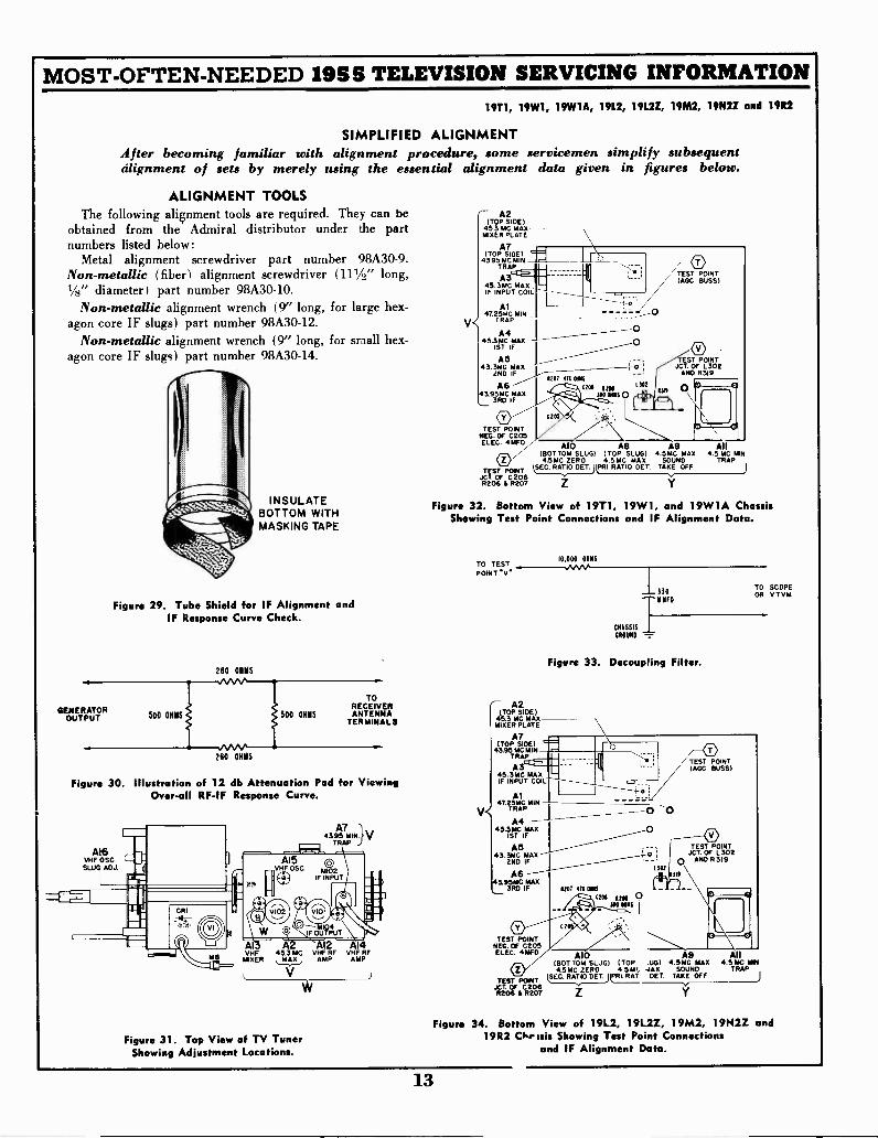
SIMPLIFIED ALIGNMENTAfter becoming familiar with alignment procedure, some servicemen simplify subsequentalignment of sets by merely using the essential alignment data given in figures below.
ALIGNMENT TOOLSThe following alignment tools are required. They can be
obtained from the Admiral distributor under the partnumbers listed below:
Metal alignment screwdriver part number 98A30-9.Non-metallic (fiber) alignment screwdriver (111A" long,1/s" diameter) part number 98A30-10.
Non-metallic alignment wrench (9" long, for large hex-agon core IF slugs) part number 98A30-12.
Non-metallic alignment wrench (9" long, for small hex-agon core IF slugs) part number 98A30-14.
INSULATEBOTTOM WITHMASKING TAPE
Figure 29. Tube Shield for IF Alignment andIF Response Curve Check.
GENERATOROUTPUT 500 OHM
260 OHMS
260 OHMS
500 OHMS
TORECEIVERANTENNA
TERMINALS
Figure 30. Illustration of 12 db Att t ion Pad for ViewingOver-all RF-IF Response Curve.
A16VHF OSC.SLUG ADJ.
43.95 MIN}VTRAP
A7
Al A Al2 Al4VHF 45.3 MC VHF RF VHF RF
MIXER AMP AMP
V
Figure 31. Top View of TV TunerShowing Adjustment Locations.
V<
A2(TOP SIDE)
453 MC MAXMIXER PLATE
AT(TOP SIDE)
43.95 MC MINTRAP
A345.3MC MAXIF INPUT COIL
Al47.25,JC MIN
TRAP
A445.31sMTC
IFMC
A43.3MC
S
2ND IF1207 4/11041$
A6 c208 12N
3RD IF
,3413.95MC MAX 3240111160
TEST POINTNEG. OF 0205ELEC. 4 MFD A10 A8 A9 All
(BOTTOM SLUG) (TOP SLUG) .5 MC MAX 4.5 MC MINO 4.5MC ZERO 4.5 MC MAX SOUND TRAP
TEST PONT SEC.RATIO DET PRI. RATIO GET. TARE OFF
JC CT. OFR206 & R202067
OO
TEST POINT)AGO BUSS)
OTEST POINT
JCT. OF L302AND R3I9
0
Figure 32. Bottom View of 19T1, 19W1, and 19W1A ChassisShowing Test Point Connections and IF Alignment Data.
TO TESTPOINT *V'
10,000 OHMS
1- A2(TOP SIDE)
45.3 MC MAXMIXER PLATE
AT(TOP SIDE)
TRAP43.95
M MIN
A07 IN
45.3MC MAXIF INPUT COIL
CHASSISGROUND -
330TO SCOPEOR V TVM
Figure 33. Decoupling Filter.
Al47.25MC MINv. TRAP
A4-45.3MC MAX
1ST IF
AS43.3MG MAX
2ND IF
A6143.95M0 MAX
3RD IF
TEST POINTNEG. OF 0205ELEC. 4 MED A10 A9
(BOT TOM SLUG) ( TOP .UG) 4.5 MC MAX4.5 MC ZERO 4.5 MC .IAX SOUND
CI! RATDE T TAKE OFFTEST POINT JSEC-
RATIO DET'JCT OF C206R206 A ROOT
0 -0O
oTEST POINTIAGC BUSS)
TEST POINT0 , JCT. OF L302- 0 AND R319
1302
5207 411 MSS - - - -C204 gra 0
310 MIS
All4.5 MC YIN
TRAP
Figure 34. Bottom View of 19L2, 19L2Z, 19M2, 19N2Z and19R2 Cke Isis Showing Test Point Connections
and IF Alignment Data.
13
MOST -OFTEN -NEEDED 1955 TELEVISION SERVICING INFORMATION19T1, 19W1, 19W1A, 19L2, 19L2Z, 19M2, 1 9N2Z and 19R2
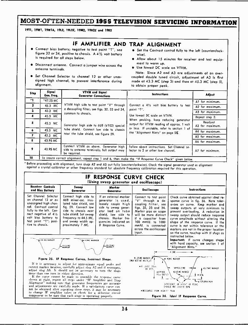
IF AMPLIFIER AND TRAP ALIGNMENT Connect bias battery; negative to test point "T", see Set the Contrast control fully to the left (counterclock-
figure 32 or 34, positive to chassis. A 4 1/2 volt battery wise).is required for all steps below. Allow about 15 minutes for receiver and test equip-
ment to warm up. Disconnect antenna. Connect a jumper wire across theID Use lowest DC scale on VTVM.antenna terminals.
Note: Since A2 and A3 are adjustments of an over- Set Channel Selector to channel 12 or other unas- coupled double tuned circuit, adjustment of A3 is first
signed high channel, to prevent interference during made at 43.3 MC (step 3) and then at 45.3 MC (step 5),alignment. to obtain proper peak.
Step SignalGen. Freq.
VTVM and SignalGenerator Connections Instructions Adjust
*1 *47.25 MCVTVM high side to test point "V" througha decoupling filter; see figs. 32, 33 and 34,common to chassis.
Generator high side to 6U8 (V102) specialtube shield. Connect low side to chassisnear the tube shield, see figure 29.
Connect a 41/2 volt bias battery to testpoint "T".
Use lowest DC scale on VTVM.When peaking, keep reducing generatoroutput for VTVM reading of approx. 1 voltor less. refer to section 1 ofIf unstable,the "Alignment Hints" on page 1S.
Al for minimum.2 45.3 MC A2 for maximum.3 43.3 MC A3 for maximum.4 45.3 MC Repeat step 2.
5 45.3 MC ReadjustA3 for maximum.
6 45.3 MC A4 for maximum.7 43.3 MC A5 for maximum.8 43.95 MC A6 for maximum.
9 43.95 MCConnect VTVM as above. Generator highside to antenna terminals; full output maybe required.
Follow above instructions. Set Channel se -lector to 2 or other low channel. A7 for minimum.
10 To insure correct alignment, repeat step 1 and 6, then make the "IF Response Curve Check" given below.
* Before proceeding with alignment, turn slugs A2 and A3 out fully (counterclockwise). Check the signal generator used in alignmentagainst a crystal calibrator or other frequency standard for absolute frequency calibration required for this operation.
IF RESPONSE CURVE CHECK(Using sweep generator and oscilloscope)
Receiver Controlsand Bias Battery
SweepGenerator
MarkerGenerator Oscilloscope Instructions
Set Channel Selectoron channel 12 or anunassigned high chan-nel. Contrast controlfully to the left. Con-nect negative of 41/2volt bias battery totest point "T"; posi-tive to chassis.
Connect high side to6U8 mixer-osc. insu-lated tube shield, seefig. 29. Connect lowside to chassis neartube shield. Set sweepfrequency to 44.5 MC,and sweep width ap-proximately 7 MC.
If an external markergenerator is used,loosely couple highside to sweep gener-ator lead on tubeshield, low side tochassis. Marker fre-quencies indicated onIF Response Curve.
Connect to test point"V" through a de -
coupling filter, see
figs. 32, 33 and 34.Marker pips on scopewill be more distinctif a capacitor from100 mmfd. to 1000mmfd. is connectedacross the oscilloscopeinput.
42 MC MARKER
45 75 MCMARKER
45.75 MCMARKER
Figure 35. IF Response Curves, Incorrect Shape.If it is necessary to adjust for approximate equal peaks and
correct marker location, carefully adjust slug A2 and if necessary,adjust slug A3. It should not be necessary to turn the slugsmore than one turn in either direction.
If the curve cannot be made to resemble the response curveshown at right, repeat all steps under "IF Amplifier and TrapAlignment" making sure that generator frequencies are accurateand adjustments are carefully made. If a satisfactory curve can-not be obtained after repeating these steps, it may be necessaryto change IF amplifier tubes or check for a defective circuitcomponent to be sure that each stage is operating properly.
41.05MC MARKER(MAT NOT BE VISIBLE)
Check curve obtained against ideal re-sponse curve in fig. 36. Note toler-ances on curve. Keep marker andsweep outputs at very minimum toprevent overloading. A reduction insweep output should reduce responsecurve amplitude without altering theshape of the response curve. If thecurve is not within tolerance or themarkers are not in the proper locationon the curve, touchup with IF slugs asinstructed below.Important: If curve changes shapewith hand capacity, see section 1 of"Alignment Hints."4 5MC -]
42M C MARKER
AT LEAST 26dbOR 95'/.
INAPPROX.
ITdb (85°/.)- - -NEASURt() FROM
APPROX.3MC
4395 MC MARKER
50%
*-30% MAXIMUMDIFFERENCE IN HEIGHT OF PEAKS
SHOULD NOT EXCEED 30%
HIGHEST PEAK
t45.tSMC MARKER
Figure 36. Ideal IF Response Curve.
14

MOST -OFTEN -NEEDED 1955 TELEVISION SERVICING INFORMATION19T1, 19W1, 1 9W1 A, 19L2, 1 9L2Z, 19M2, 1 9N2Z and 19R2
4.5 MC SOUND IF AND TRAP ALIGNMENTSee below for touch-up of ratio detector using television
signal without test equipment.Connect signal generator high side to pin 2 of V304 Use a non-metallic alignment tool. If Ratio Det.
(6A15) through a .01 mfd. capacitor, connect low Transformer (T201) has hollow core slugs, bottom slug
side to chassis. adjustment A8 can be made from top of chassis, ifAllow about 15 minutes for receiver and test equip- you use alignment tool, part number 98A30-12 ob-
ment to warm up. tainable from Admiral distributor.Set Contrast control fully to the left (counterclockwise).
Step Signal Gen.Freq. (MC)
I VTVM C ,ions 1 Instructions Adjust1
When using a signal generator, be sure to check it against a crystal calibrator or other frequency standard for accuratefrequency calibration at 4.5 MC. Accuracy required is within one kilocycle.
IMPORTANT: If a signal generator and frequency standard are not available, alignment can be made using a TV station
signal. Tune in a station and follow steps 1, 2 and 3 below. If necessary use a higher scale on the VTVM.
1
Set toexactly4.5 MC
High side totest point "Y";
common to chassis.Use lowest DC scale on VTVM.
A8 and A9 for maximum (keep reduc-ing generator output to keep VTVM atapprox. 1 volt).
2High side to
test point "Z";common to chassis.
Use zero center scale on VTVM, ifavailable.
A10 for zero on VTVM (the correct zeropoint is located between a positive anda negative maximum). If A8 was faroff, repeat step 1.
3
High side totest point "Y";
common to chassis.
*Connect a 10 mmfd. capacitor frompin 5 of V305 (6CB6) to pin 7 of V201(6AU6). Use lowest DC scale on VTVM.
All for minimum.
In 19R2 chassis, connect 10 mmfd. capacitor from pin 7 of V305 (12 BY7) to pin 7 of V201 (6AU6).
TOUCH-UP OF RATIO DETECTOR SECONDARYUSING TELEVISION SIGNAL (MO, BOTTOM
SLUG OF T201)
"Adjustment A10 is accessible through the %" hole(just below T201) in bottom of the cabinet or the chassismounting shelf, located toward the left side facing the rearof the set. See figures 32 and 34. Removal of the chassisis therefore not required. Adjustment need be made onone channel only. Proceed as follows:
a.
b.
c.
Turn set on and allow about 15 minutes for warm up.Tune set for normal picture and sound.Carefully insert a non-metallic alignment tool throughthe opening in cabinet bottom below T201. An align-ment tool with a screwdriver blade or hexagonal end isrequired depending on the transformer used, see " notebelow. When the alignment tool engages the bottomtuning slug A10, adjust the slug for best sound withminimum buzz level. Do this carefully as only slightrotation in either direction will generally be required.Correct adjustment point is located between the twomaximum buzz peaks that will be noticed when turningthe slug back and forth about 1/4 to 1/2 turn.
ALIGNMENT OF 4.5 MC TRAP All, USING ATELEVISION SIGNAL
Beat interference (4.5 MC) appears in picture as veryfine vertical or diagonal lines, very close together., having
a "gauze -like" appearance, the pattern will vary with speech,forming a very fine herringbone pattern.
The trap can be tuned by watching the picture and adjust.ing slug All for minimum 4.5 MC interference. If greateraccuracy is required, the trap should be adjusted as in-structed in step 3 of the "4.5 MC Sound IF and TrapAlignment".
IMPORTANT ALIGNMENT HINTSThe following suggestions should be followed if diffi-
culty is experienced during the alignment procedure.1. IF CIRCUIT INSTABILITY: When spot frequencyaligning the IF amplifiers, the VTVM pointer may swingwhen the hand is placed too near the IF transformers. Whenviewing the IF response curve on an oscilloscope, the curvemay change shape with hand capacity, especially whenaligning A6 (3rd IF transformer T303). To correct eitherof these conditions, the following alignment hints shouldbe tried:
(al Check the generator output leads to be certain thatthe unshielded portion (especially the grounded lead) be asshort as practicable.
(b) Be sure that a decoupling network is used at the videodetector output and that the leads on the network are keptas short as possible (See figure 33).
(c) For injecting IF signal use an insulated tube shieldover V102 (6U8) Oscillator -Mixer tube. Insulate bottominside of tube shield with masking tape; see figure 29.
(d) The use of a non-metallic alignment tool, approxi-mately eight inches long (part number 98A30-12), will per-mit adjustment without coming too near to the transformers.
° Ratio detector transformer T201) has hollow hexagonal core slugs, bottom slug adjustment Alt) can be made from top of chassis, if you usealignment tool (part number 98A30-12; available at Admiral distributor). Bottom slug (A10) can be reached through the hole in the tore ofthe upper slug (A8).
15
Ia
BUILT -I UHF ANT.CI
tra
MOST -OFTEN -NEEDED 1955 TELEVISION SERVICING INFORMATION
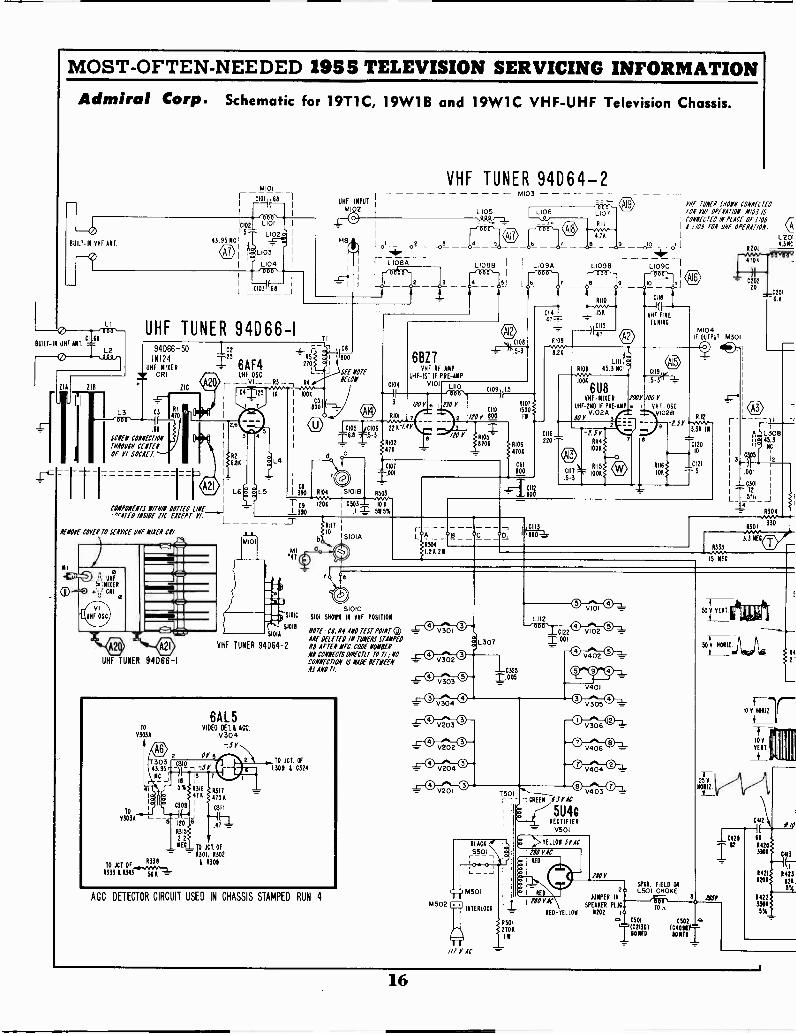
Admiral Corp. Schematic for 19T1C, 19W1B and 19W1C VHF -UHF Television Chassis.
LI
.68
L2
ZIA 118
UHF TUNER 94D66 -I94D66-50 Ice
IN124 25
UHF MIXER 6AF43E CR!
L3 3
(
1
18
MIEN CONNECTIONwow WOWOf VI SOCKET
RI
470
TIC
UHF OSC- R3
C4 125 IS
r
2,6
cootwars //ms DOTTED 1/11E_j'"01TE0 INSIDE PC EXCEPT Y/.
IfIlOYE COVEN TO SEAT/CE ONE WEI Cl/
UHF TUNER 94066-1
R2
641
6
TI
UHF INPUT
MI02
CC
114 = 1 800270
L_ J SEE NOTEKIN
R4
1006
C51
800
_Isms Loos-r-6.3 1-.5-3
VHF TUNEMR,94064-2
0104
3
L 105
4 gL1088 -I I- L1094
--,Ho,-4
6BZ7VHF RF AMP
UHF-IST IF PRE -AMPVIOI L110
m, 010874.5-3
C109 11 5
/104
R101 7...v226144
8102476
6 1
1.10 YC110
R107
1500moy 800
YI
8206
001
C
3980 8104 51018 8503
' C9 1206 C503- 106391:1 515%
R106
ROA
C111
800
CII2800
471
6109
L1098
VHF IONEN SHOPII CONNECTEDTON Yllf OPERATION A110.1 ISCONNECTED IN PLACE 0f 1/01i 1109 TON Of OPERATION
_0,(2 LI6201
434C
L.109Cpar-
O
CII8
UHF FINE
TUNICM104
IF OUTPUT M301
8.24
6U8VHF -MIXER 100Y 100 Y
UHF -2/1D IF PRE -414P 6 VHF-OSC
SOYV1024 VI028
CHO_220
LSER114
1006
C111 1006.5-3
(i)
9 1.SYRI12
3.34 10
012010
C121
5
."4';
SIOIC
$1018
$ 01A
VHF TUNER 94064-2
L A °E1
R504
1.26211
r
4706
C20220
6201
^6.8
f,, L5.33084
,14. tip
12
I 001
I C301
6333.IS NECNEC
72
= R304
R301330
wvv.3.3 MEC
SIOIC5101 5H01111 IN VHF POSITION
NOTE.- CS. N4 AND TEST POINT 0>Alf DELETED IN WENS STAMPEDNI NEM NEC. CODE MISERNI CONNECTS aRanr TO Tl ;NOCONNECTION 141( /EINEMNJ 140 TI.
TO
03036
TO
43033
T30343.95
NC
41
6A15VIDEO DET.A ACC.
V304-.5Y
Or
5 120
6315
2.2NEC TD JCT. OF
6301, 11302R338 11309
TO JCT133311343 Nit
.47
TO JCT. OF
1309 8 C324
AGC DETECTOR CIRCUIT USED IN CHASSIS STAMPED RUN 4
_ V301
V302
V303
V304
V203
V202
V204
V201
M502
//I Y AC
307
LII2
I.00-C3255
150-- 1CREE1 fir AC
5U4c
CI22
1.001
R108 45.311C..4.1006
V102
0 V402 0
RECTIFIER
= V501
I
I
far1
5P611. FIELDHOC
OA
EI
2 L501 CHOKEJUMPER 111 3L i j !IONIC
SPEAKER PLUC 10 A.-L-RED- TT 1.1.011 N202 i
8501 0501 0502
III2706
801107 1
C401111
801E0_
V401
V305
V306
V406
V404
0 0V403 =
5.301 -4=
501 VERT
50 Y 1101111.
25V10111.
044
10429
Ia
II11
14
2
I/O
14203301
1422ssu5%
413
L15.1' _1
16

;A U 6
18011 AMPV201
MOST -OFTEN -NEEDED 1955 TELEVISION SERVICING INFORMATION
Admiral 19T1, 19T1C, 19W1, 19W1A, 19W1B, 19W1C, 19Y1A,
19L2, 19L2I, 19M2, 19N2Z, 19R2, and 19S2 CHASSIS
.005I 03330
/JOY
T20i
6AL5RATIO DEW.
V202or -.IP
0207 7109 05
6AV6SOUND AMP
V203
680
/4513 MOH /5 0011101/03 Alf 1101 15f0 /5
458 1.9115 ClaSSIS
/502 COUPLATE
6306-5
6AS5SOUND OUTPUT
v204
1301
r T -1 101 110,' ---)I -3 05 0I AI_ I 0214la 1I 020 I /1" 7____)f__
8216 -10701I '"; J 0213 22_ .01
2 NEC ; 1210 I;212 , -.0218-111 4101 J 1500 t 85222 &MD
.0017::: 5% '5
822468 6
1ITTON VIII1200 OF SOCKET
6201
r- -01203
KBESPEAKER
11:202
Id
to
2 AEO 1 - -
15010101E 00 SPQR.TEL at., FIELD
el
TOP VIE8 Of
8180 4202
;CB6ISI IfV301
/JOY5 0307 1304
/JOY 2.2 \41.25NC
012
C315
.150303
17
0302
.001 13351000
BOTTOM 46CB6VIEW
T302; 2 1/2 6U8T02'2700 IF 6311 3RD IF
V303A
1301 Or
45'3/4C r
V302
5
123061 Otl: COIN 25 %2
3 El_.001 ,
13011000
IP
'JOY
/JOY
1311
241
2
6636 03011 150
83 4313
-TC319 .005 0308
)H-;-' .001
in1312 9311
o 330
IJOY1302 643.3 NC
0, - 3
IIV
8338 561 =
1303
500041''5
T303 C3.013 95/ -21-,
NC 3 7
S% 0315 c 2317
2.2 SIIOAMEC
*-1-1Al
6AL5VIDEO HI &ACC
V304
02138 Tc2131 C213C 001Joon WONFD 9.10100 11011Z.3S3
6CB6 r ISc5-1VIDEO LIP.
V305 I
L309 1/ ISOM
302-
05 5 0321
22
L303
C3
R319
56000311721--
6.8
L.30411.510
MIL TEAT
75141 V : 7 V-9-
3 5735
320EC
32111208131
1000
CONTRAST
10
1F
N322
2, /770
0323
L 333 _ 1
L306-1 -
111111111111111111111
0316
80VVER
.0321 f101 I
Il
.22
13265.61101
8330ISO.'
R237211
L323 8334 K
COUPLATE 6306-12 11 IBMICHWSS
r_A_C315 1329T i 50 f. 2108
_CDT
1.5 MEC 6806
12Al7 1/2 6 U8SEPARATOR SYNC CLIPPER,40IA 4103 V30313
TV , 1 MEC
7..2.C401-- --19(-
° .1;1104
1 40 1
302 201112.
JOY
4405COUPLATE 63C6 - II
..v140? 3.71141- -1409.
221 8200 8200 I,
0.:121 it (14005 0
0404.C40°55f
6SNicT1.OSC.CONTROL
1140302
31 155
321
30010413
022
1/2 6SN7crRORIE. 05C.
V4030
A' -SOY
22 18K
200r VEIT.
1404C
D
1/2 12AUTT401 VERT. OSC.
YELLOW ROD V4011
VERT. HOLD 1.2 NEC
012511011Z HOLD
1426 1477
.3\ 1412
101
150- V
VERT.
i2,1413
INIC
C401
611
1.041
401 1404KOY 8129 I A120112.
6200 35"I 8418. L401 1214
95.1
C111
1131
35002.
_11LO111CK jCS1
.01
M% 0431
1201
11430
501 221
159 1101117171
0120
680C13010-110
NOMIZ.C411 DM(120
I/3
1131
6B06crNORILOUTPUT
V404
1113415
10422
041
143882
1431820021
0405oliC
II. NEC
HEICHT _J1111.05110,00
120 VERT LIN.
6S4
.°'JVVY
4500 511
20002 VERT
C41/1105 SEE MYff015 0414ENT OUTPUT 1402 IffOlf 1145301/55.
V402 1LUE
fiIMY
C409100100.__.01
1115
1000..
1.502
2010C410 0 D.RED
ILACI
/MITE _
3E1109 2412
S60 1
5
1119310
T403AVERTICAL0E8 1011
TOTAL
RED
5155
I7BP4A119710
21WP4119111 I IONIC)
V306
1405
500.
1B3cTHIGH VOLTAGE SECT
V405
CONNECTS TO
PIN 6 0f 9405
1 2
1114i2700 COUKATE
6301.121 10427
.01
GREEN
1444 C421561 1.01
40
gar r.
vir 50VVERT.
DID ANODE
VOLTALE
1519
1 in CORONA 3 1E10
6AX4CT 1111
NEB
35.:4105:
8431 843Aso -1200 1000 2224
120: r 21-)1..-C423 .241
.011 10%
10%
1SOY
L402CDT
ITE
1501 121 01401 3/8 1110 2502 FUSE
5
DANPENI1142,
v406 17, 1440
I 1000
L 1
0421
)1
.1
L403110012 LIN.
WHITE
140387 HOIIZONTAL
DEF. YOKE2010 38..TOTAL
250011
C411/0"Sff MINN 11114
EMI 01190/55
17
MOST -OFTEN -NEEDED 1955 TELEVISION SERVICING INFORMATION19T1, 19W1, 19W1A, 19L2, 19L2Z, 19M2, 19N2Z and 19R2
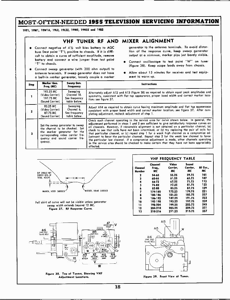
VHF TUNER RF AND MIXER ALIGNMENTConnect negative of 41/2 volt bias battery to AGC generator to the antenna terminals. To avoid distor-buss (test point "T"), positive to chassis. If it is diffi- tion of the response curve, keep sweep generatorcult to obtain a curve of sufficient amplitude, remove output at a minimum, marker pips just barely visible.battery and connect a wire jumper from test point Connect oscilloscope to test point "W" on tuner"T" to chassis. (figure 38). Keep scope leads away from chassis.Connect sweep generator (with 300 ohm output) toantenna terminals. If sweep generator does not have Allow about 15 minutes for receiver and test equip -a built-in marker generator, loose y couple a marker ment to warm up.
StepMarker Gen.
Freq. (MC)Sweep Gen.Frequency
Instructions
1
193.25 MC(Video Carrier)
197.75 MC(Sound Carrier)
SweepingChannel 10.
See frequencytable below.
Alternately adjust Al2 and A13 (figure 38) as required to obtain equal peak amplitudes andsymmetry, consistent with flat top appearance, proper band width and correct marker 1=-tion; see figure 37.
2
83.25 MC(Video Carrier)
87.75 MC(Sound Carrier)
SweepingChannel 6.
See frequencytable below.
Adjust 414 as required to obtain curve having maximum amplitude and flat top appearanceconsistent with proper band width and correct marker location; see figure 37. After corn -pleting adjustment, recheck adjustment of step 1.
3
Set the sweep generator to sweepthe channel to be checked. Setthe marker generator for thecorresponding video carrier fre-quency and sound carrier fre-quency.
Check each channel operating in the service area for curve shown below. In general, theadjustment performed in steps 1 and 2 are sufficient to give satisfactory response curves onall channels. However, if reasonable alignment is not obtained on a particular channel, (a)check to see that coils have not been intermixed, or (b) try replacing the pair of coils forthat particular channel, or (c) repeat step 1 for a weak high channel as a compromise ad-justment to favor the particular channel. Repeat step 2 for the weak low channel to favorthe particular low channel. If a compromise adjustment is made, other channels operatingin the service area should be checked to make certain that they have not been appreciablyaffected.
VHF FREQUENCY TABLE
DIP SHOULD NOT
ChannelNumber
ChannelFreq.,MC
VideoCarrier,
MC
SoundCarrier,
MCHF Osc.,
MC
EXCEED 307. OFTOTAL HEIGHT
2 54-60 55.25 59.75 101
3 60.66 61.25 65.75 107Hal-- 4.5NC
4 66.72 67.25 71.75 113
5 76.82 77.25 81.75 123
6 82.88 83.25 87.75 129MARKER, VIDEO CARRIER MARKER, SOUND CARRIER 7 174.180 175.25 179.75 221
8 180.186 181.25 185.75 2279 186.192 187.25 191.75 233
Full skirt of curve will not be visible unless generator 10 192.198 193.25 197.75 239
sweep width extends beyond 12 MC. 11 198.204 199.25 203.75 245
Figure 37. RF Response Curve. 12 204.210 205.25 209.75 251
13 210-216 211.25 215.75 257
416VHF OSCSLUG ADJ.
A74395 MIN.
TRAP
41 A2 Al2 A14VHF 45.3 MC VHF RF VHF RFMIXER MAX AMP AMP
V.
Figure 38. Top of Tuners, Showing VHFAdjustment Locations.
416VHF OSC
SLUG AN
Figure 39. Front View of Tuner.
18
MOST -OFTEN -NEEDED 1955 TELEVISION SERVICING INFORMATION19T1, 19W1, 19W1A, 19L2, 19L2Z, 19M2, 19N2Z and 19R2
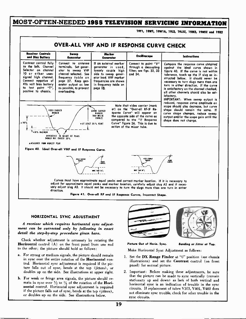
OVER-ALL VHF AND IF RESPONSE CURVE CHECKReceiver Controlsand Bias Battery
SweepGenerator
MarkerGenerator
Oscilloscope Instructions
Contrast control fullyto the left. ChannelSelector on channel10 or other unas-signed high channel.Connect negative of41/2 volt bias batteryto test point "T",positive to chassis.
Connect to antennaterminals. Set gener-ator to sweep VHFchannel selected. See
frequency table onpage 27. Keep gen-erator output as lowas possible, to preventoverloading.
If an external markergenerator is used,loosely couple highside to sweep gener-ator lead. VHF markerfrequencies are shownin frequency table onpage IS.
Connect to point "V"through a decouplingfilter; see figs. 32, 33and 34.
50%
MAXIMUM
DIFFIDENCE IN NEICIIT OF PEAKSSNOW) NOT EXCEED 50.1.
MEASURED FRO* DIDNEST PEAK
SOUND CADDIEDMADDED
OM DOI BEVISIBLE)
AT LEAST 95'4 POINT
Figure 40. Ideal Over-all VHF and IF Response Curve.
Note that video carrier (marker) on the "Over-all RF-IF Re-sponse Curve" will appear onthe opposite side of the curve ascompared to the "IF ResponseCurve" figure 36. This is due toaction of the mixer tube.
Compare the response curve obtainedagainst the ideal curve shown infigure 40. If the curve is not withintolerance, touch up the IF slug as in-structed below. It should never benecessary to turn slugs mare than oneturn in either direction. If the curveis satisfactory on the channel checked,all other channels should also be sat-isfactory.IMPORTANT: When sweep output isreduced, response curve amplitude onscope should also decrease, but curveshape should remain the same. Ifcurve shape changes, reduce sweepoutput and/or the scope gain until theshape does not change.
Curves must have approximate equal peaks and correct marker location. If it is necessary toadjust for approximate equal peaks and marker location, carefully adjust slug A2 and if neces-sary adjust slug A3. It should not be necessary to turn the slugs more than one turn in eitherdirection.
Figure 41. Over-all RF and IF Response Curves, Incorrect Shape.
HORIZONTAL SYNC ADJUSTMENT
A receiver which requires horizontal sync adjust-ment can be corrected only by following in exactdetail the step-by-step procedure given here.
Check whether adjustment is necessary by rotating theHorizontal control (A) on the front panel from one endto the other; the picture should hold as follows:
a. For strong or medium signals, the picture should remainin sync over the entire rotation of the Horizontal con-trol. Horizontal sync adjustment is required if the pic-ture falls out of sync, bends at the top (jitters), ordoubles up on the side. See illustrations at upper right.
b. For weak or fringe area signals, the picture should re-main in sync over 1/, to 3/4 of the rotation of the Hori-zontal control. Horizontal sync adjustment is requiredif the picture falls out of sync, bends at the top (jitters),or doubles up on the side. See illustrations below.
Picture Out of Horiz. Sync. Bending or Jitter at Top.
Make Horizontal Sync Adjustment as follows:
1. Set the DX Range Finder at "0" position (see chassisillustrations) and set the Contrast control (on frontpanel) for normal picture.
2. Important: Before making these adjustments, be surethat the picture can be made to sync vertically (remainstationary up and down) as lack of both vertical andhorizontal sync is an indication of trouble in the synccircuits. If replacement of tubes V303, V401, V4.03 doesnot eliminate sync trouble, check for other trouble in thesync circuits.
19
MOST -OFTEN -NEEDED 1955 TELEVISION SERVICING INFORMATION19T1, 19W1, 19W1 A, 1912, 19L2Z, 19M2, 19N22 and 19R2
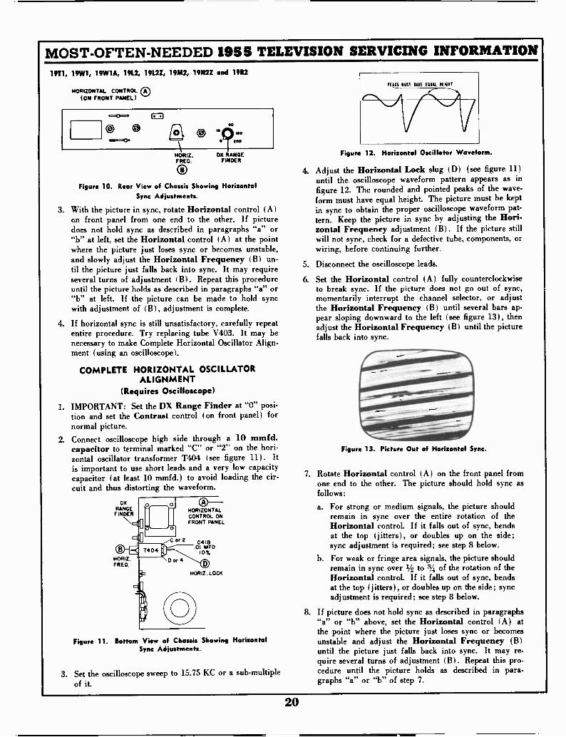
HORIZONTAL CONTROL 0(ON FRONT PANEL)
Oopa
CI
HORIZ.FRED.
ODX RANGE
FINDER
Figure 10. Rear View of Chassis Showing HorizontalSync Adjustments.
3. With the picture in sync, rotate Horizontal control (A)on front panel from one end to the other. If picturedoes not hold sync as described in paragraphs "a" or"b" at left, set the Horizontal control (A) at the pointwhere the picture just loses sync or becomes unstable,and slowly adjust the Horizontal Frequency (B) un-til the picture just falls back into sync. It may requireseveral turns of adjustment I B). Repeat this procedureuntil the picture holds as described in paragraphs "a" or"b" at left. If the picture can be made to hold syncwith adjustment of (B), adjustment is complete.
4. If horizontal sync is still unsatisfactory, carefully repeatentire procedure. Try replacing tube V403. It may benecessary to make Complete Horizontal Oscillator Align-ment (using an oscilloscope).
COMPLETE HORIZONTAL OSCILLATORALIGNMENT
(Requires Oscilloscope)
1. IMPORTANT: Set the DX Range Finder at "0" posi-tion and set the Contrast control (on front panel) fornormal picture.
2. Connect oscilloscope high side through a 10 mmfd.capacitor to terminal marked "C" or "2" on the hori-zontal oscillator transformer T404 (see figure 11). Itis important to use short leads and a very low capacitycapacitor (at least 10 mmfd.) to avoid loading the cir-cuit and thus distorting the waveform.
DXRANGEFINDER
or 2
HORIZ.FRED.
HORIZONTALCONTROL ONFRONT PANEL
C4I801 MFD
10%
HORIZ. LOCK
Figure 11. Bottom View of Chassis Showing HorizontalSync Adjustments.
3. Set the oscilloscope sweep to 15.75 KC or a sub -multipleof it.
PEAKS MUST NAVE EQUAL HEMP
Figure 12. Horizontal Oscillator Waveform.
4. Adjust the Horizontal Lock slug (D) (see figure 11)until the oscilloscope waveform pattern appears as infigure 12. The rounded and pointed peaks of the wave-form must have equal height. The picture must be keptin sync to obtain the proper oscilloscope waveform pat-tern. Keep the picture in sync by adjusting the Hori-zontal Frequency adjustment (B). If the picture stillwill not sync, check for a defective tube, components, orwiring, before continuing further.
5. Disconnect the oscilloscope leads.
6. Set the Horizontal control (A) fully counterclockwiseto break sync. If the picture does not go out of sync,momentarily interrupt the channel selector, or adjustthe Horizontal Frequency ( B ) until several bars ap-pear sloping downward to the left (see figure 13), thenadjust the Horizontal Frequency (B) until the picturefalls back into sync.
Figure 13. Pi Out of Horizontal Sync.
7. Rotate Horizontal control (A) on the front panel fromone end to the other. The picture should hold sync asfollows:
a. For strong or medium signals, the picture shouldremain in sync over the entire rotation of theHorizontal control. If it falls out of sync, bendsat the top (jitters), or doubles up on the side;sync adjustment is required; see step 8 below.
b. For weak or fringe area signals, the picture shouldremain in sync over 1/2 to a of the rotation of theHorizontal control. If it falls out of sync, bendsat the top (jitters), or doubles up on the side; syncadjustment is required; see step 8 below.
8. If picture does not hold sync as described in paragraphs"a" or "b" above, set the Horizontal control (A) atthe point where the picture just loses sync or becomesunstable and adjust the Horizontal Frequency (B)until the picture just falls back into sync. It may re-quire several turns of adjustment (B). Repeat this pro-cedure until the picture holds as described in para-graphs "a" or "b" of step 7.
20
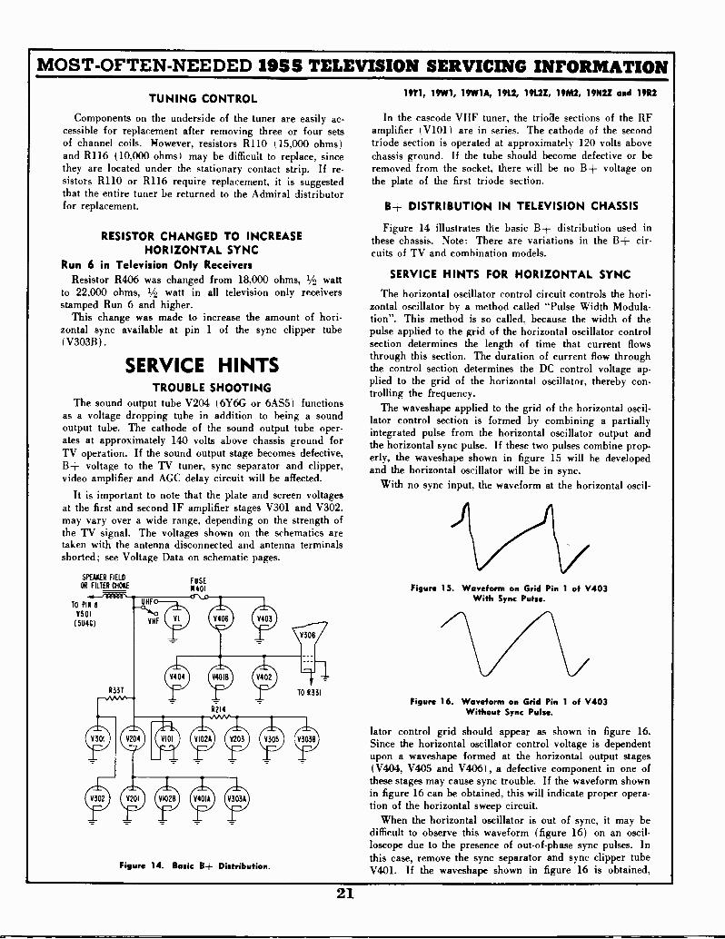
MOST -OFTEN -NEEDED 1955 TELEVISION SERVICING INFORMATION
TUNING CONTROL
Components on the underside of the tuner are easily ac-cessible for replacement after removing three or four setsof channel coils. However, resistors R110 (15,000 ohms)and R116 (10,000 ohms) may be difficult to replace, sincethey are located under the stationary contact strip. If re-sistors R110 or R116 require replacement, it is suggestedthat the entire tuner be returned to the Admiral distributorfor replacement.
RESISTOR CHANGED TO INCREASEHORIZONTAL SYNC
Run 6 in Television Only ReceiversResistor R406 was changed from 18,000 ohms, 1/2 watt
to 22,000 ohms, 1/2 watt in all television only receiversstamped Run 6 and higher.
This change was made to increase the amount of hori-zontal sync available at pin 1 of the sync clipper tube(V30313).
SERVICE HINTSTROUBLE SHOOTING
The sound output tube V204 (6Y6G or 6AS5) functionsas a voltage dropping tube in addition to being a soundoutput tube. The cathode of the sound output tube oper-ates at approximately 140 volts above chassis ground forTV operation. If the sound output stage becomes defective,B+ voltage to the TV tuner, sync separator and clipper,video amplifier and AGC delay circuit will be affected.
It is important to note that the plate and screen voltagesat the first and second IF amplifier stages V301 and V302,may vary over a wide range, depending on the strength ofthe TV signal. The voltages shown on the schematics aretaken with the antenna disconnected and antenna terminalsshorted; see Voltage Data on schematic pages.
SPEAKER FIELD
OR FILTER CHOKE
f X0000TO PIN 8
V501
(5040)
Figure 14. Basic B+ Distribution.
19T1, 19W1, 19W1A, 191.2, 19L2Z, 19M2, 19N2Z and 19R2
In the cascode VHF tuner, the triode sections of the RFamplifier (V101) are in series. The cathode of the secondtriode section is operated at approximately 120 volts abovechassis ground. If the tube should become defective or beremoved from the socket, there will be no B+ voltage onthe plate of the first triode section.
B+ DISTRIBUTION IN TELEVISION CHASSIS
Figure 14 illustrates the basic B+ distribution used inthese chassis. Note: There are variations in the B+ cir-cuits of TV and combination models.
SERVICE HINTS FOR HORIZONTAL SYNC
The horizontal oscillator control circuit controls the hori-zontal oscillator by a method called "Pulse Width Modula-tion". This method is so called, because the width of thepulse applied to the grid of the horizontal oscillator controlsection determines the length of time that current flowsthrough this section. The duration of current flow throughthe control section determines the DC control voltage ap-plied to the grid of the horizontal oscillator, thereby con-trolling the frequency.
The waveshape applied to the grid of the horizontal oscil-lator control section is formed by combining a partiallyintegrated pulse from the horizontal oscillator output andthe horizontal sync pulse. If these two pulses combine prop-erly, the waveshape shown in figure 15 will be developedand the horizontal oscillator will be in sync.
With no sync input, the waveform at the horizontal oscil-
Figure 15. Waveform on Grid Pin 1 of V403With Sync Pulse.
Figure 16. Waveform on Grid Pin 1 of V403Without Sync Pulse.
lator control grid should appear as shown in figure 16.Since the horizontal oscillator control voltage is dependentupon a waveshape formed at the horizontal output stages(V404, V405 and V406), a defective component in one ofthese stages may cause sync trouble. If the waveform shownin figure 16 can be obtained, this will indicate proper opera-tion of the horizontal sweep circuit.
When the horizontal oscillator is out of sync, it may bedifficult to observe this waveform (figure 16) on an oscil-loscope due to the presence of out -of -phase sync pulses. Inthis case, remove the sync separator and sync clipper tubeV401. If the waveshape shown in figure 16 is obtained,
21
MOST -OFTEN -NEEDED 1955 TELEVISION SERVICING INFORMATION19T1, 19W1, 19W1A, 19L2, 19L2Z, 19M2, 19N2Z and 1982
place the sync and separator tube back into its socket. Then,remove the horizontal oscillator and control tube V403(6SN7GT). Conventional, well -shaped sync pulses shouldappear at control grid (pin 1) of V403.
If there are no sync pulses, or the pulses are of low orvarying amplitude, accompanied with noise, the sync cir-cuits should be checked. However, if the sync pulses arewell -shaped and of constant amplitude, the horizontal oscil-lator may be misaligned. Place V403 back into its socketand make "Complete Horizontal Oscillator Alignment"given on page 20.
If it is impossible to sync the picture, or obtain the cor-rect waveform at terminal "C", check for a defective com-ponent.
HORIZONTAL SYNC INSTABILITY
Horizontal sync instability occurring after the receiverhas been operated for a short period of time, may be dueto change in capacitor C418 (.01 mfd, 4.00 volts, paper,107( ). The slight change in capacity that occurs with tem-perature rise, may be enough to cause the circuit to becomeunstable. To minimize this possible trouble, a capacitor( with negative temperature coefficient) is used for capacitorC418, part number 64A2-16.
If capacitor C418 is suspected as being the cause of hori-zontal sync instability, it should be replaced only with a.01 mfd, 107( , paper capacitor, Admiral part number64A2-16 or Sprague part number 68P8. Important: Afterreplacing capacitor C418, it may be necessary to make"Complete Horizontal Oscillator Alignment" (using an os-cilloscope) as instructed on page 20.
MISCELLANEOUS TROUBLE DUE TOFAULTY TUBES
Faulty tubes cause the majority of receiver troubles. Thelist below contains most common troubles which are gen-erally due to faulty tubes.
a. Poor fringe area reception due to low B plus voltage.Check the 5U4G tube.
b. Poor fringe area reception due to low sensitivity. Checkthe 6BQ7A or 6BZ7 tube in VHF tuner.
c. Picture and sound separated due to IF oscillation. Checkthe 6CB6 and 6U8 tubes in IF amplifier.
d. Picture bending caused by leakage between tube ele-ments. Check 6CB6 tube in IF amplifier.
e. Poor sync stability, usually more noticeable in verticalcircuit. Check 6U8 and 12AU7 tubes (V303 and V401).
f. Washed out picture due to negative grid current. Check6CB6 or 12BY7 tube (V305).
EXCESSIVE SNOW IN PICTURE DUE TOFAULTY TUBES
Excessive snow in the picture can be caused by faultytubes in the receiver. Check receiver as follows:
Short circuit the antenna terminals and turn the Contrastcontrol fully clockwise.
Connect a vacuum tube voltmeter from test point "V" tochassis. Set the channel selector on an unassigned channel.If the voltmeter reading exceeds .6 volt negative, excessivereceiver (tube) noise is indicated. This condition canusually be corrected by tube substitution. Substitute tubesin the following order: Video detector tube V304, RFoscillator tube V102, RF amplifier tube V101 and IF am-plifier tubes V301, V302 and V303.
Corona or arcing in the second anode supply can alsocause a high noise reading at the video detector resultingin excessive snow in weak signal areas.
ELIMINATING RF INTERFERENCE BYALIGNMENT OF 43.95 MC TRAP A7
Antenna trap L103 (adjustment A7, figures 32 and 34)is aligned for minimum response at 43.95 MC, see IF Am-plifier and Trap Alignment on page 24. Trap L103 attenu-ates interfering signals in the 41 MC IF frequency range.The antenna trap should generally never require realign-ment in the field. However, if RF interference is experiencedfrom radio transmitters or other sources at frequencies(harmonics or fundamentals) in the 41 MC range, thetrap may be realigned to minimize the interference. Thetrap must be tuned when the interference appears. If theinterference is intermittent, tuning the trap may be difficult.
To tune trap, use a non-metallic alignment wrench witha 5/16" hexagonal shank, part number 98A30-12. In sometuners a non-metallic alignment screwdriver with a 1/8"wide blade is required. Tune trap by observing the pictureand adjusting slug A7 for minimum of interference. Itshould not be necessary to turn the slug A7 more than afew turns in either direction. IMPORTANT: Do not turnthe slug completely counterclockwise as channel 2 inter-ference may result.
IMPROVING UHF RECEPTION WHEN ONLY ONEOR TWO CHANNELS ARE RECEIVED
If only one or two UHF channels are being received, re-ception can often be improved by adjusting the oscillatortrimmer which is located at the rear of the tuner; trimmerat lower right hand side. This is especially true if theUHF oscillator tube VI (6AF4) has been changed andthe channels are below 55.
Adjust trimmer while observing picture, tune trimmerfor best picture with minimum of snow. Retune receiverand repeat adjustment.
REPAIRING KNOBS WITH METAL RIM
The metal rim of some television or radio tuning knobsmay become loose and slip as the knob is rotated. To repairsuch knobs, merely punch an indentation in the rim of theknob using a center -punch (preferably automatic). As analternative, a soldering iron can be used by applying thetip to the rear edge of the knob in order to flow the plasticinto full contact with the metal rim.
It is recommended that the knobs be repaired ratherthan replaced, since there may be dimensional differencesin some replacement knobs. Changes have been made toknobs of later production receivers to prevent slipping ofthe metal rim.
22

MOST -OFTEN -NEEDED 1955 TELEVISION SERVICING INFORMATION
ARVIN INDUSTRIES, INC.
Chassis "E" -- 383Models 21-554, -555, -557
(Circuit diagram on thenext page, over.)
STAGGER TUNED I.F. ALIGNMENT PROCEDURE
I. Set tuner to channel 9-10 or 11.2. Connect variable bias supply to junction R2Il 4 0207. Adjust bias for -2 volts.3. Connect VTVM across R212. Isolate VTVM with 18K resistor. Use -SV scale.4. Connect RF signal generator to mixer tube shield (VII 5./6). Lift mixer tube shield until it is ust ungrounded.S. Good R.F. grounding between TV receiver on test and test equipment is necessary. A metal surface bench top
should be used to insure proper RF grounding. Use isolation transformer between chassis and AC line.
STEP FREQUENCY ADJUSTMENT INSTRUCTIONS
I. 41.25 Mc L20I for min.
42.9 Mc Tuner coil for max. L7 (top of tuner)
3. 45 Mc L202 for max. Recheck steps 2 and 3
4,
5.
42.9 Mc
45.3 Mc
'T201 for max.
T202 for max.
6. 44 Mc T203 for max.
OVERALL SWEEP CHECK
Recheck steps 4, 5 and 6
I. Connect RF signal generator to chassis near V4 for marker generator. Push shield down on mixer tube.2. Connect oscilloscope across R2I2. Isolate oscilloscope lead with 300 p.taf to ground and 18K
resistor in series.3. Increase bias to -2.5 volts4. Connect sweep generator to antenna terminals. Adjust sweep generator L tuner to charimi 10.
To chassis300
150%
11 . 25
40%
ADJUSTMENT INSTRUCTIONS
T202 T202 positions 45.75 markerT201 T201 positions 42.75T203 T203 adjusts tilt of curve
Note: If desired curve cannot be obtained, slight adjustment of tunercoil and L202 may be necessary.
SOUND AND 4.5 MC TRAP ALIGNMENT
I. Tune in available TV station and reduce signal into set until hiss is heard with sound. This can be done byinserting an attenuator in the antenna lead-in or by removing antenna lead-in from the set and stray feedingin signal by placing lead-in in close proximity of the set.
2. Set buns control in the middle of its range. Adjust take off coil (top LION, LIOZ, Quad rature coil (L103)and buss contra/ for cleanest sound and minimum buss. If any adjustment cause hiss to disappear reducesignal into set until hiss reappears and continue with adjustments.
1 I s F. Output
2. B + 110V DC-ar
3. H
4 HZ
5. AGC
O
O
O
O
0
N D I GATOR
STATIONSELECTOR
FINE TUNING
HORIZ. HOLD
VERT. HOLD
BR IGHTNESS
CONTRAST
ON-OFF VOLUME
23
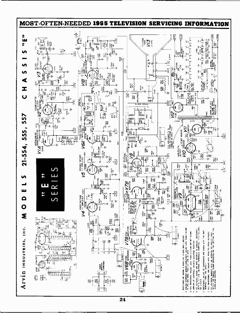
Arv
inIN
DU
STR
IES,
IN
C. M
OD
EL
S 21
-554
,555
,557
C52 00
1
C51
.001
TU
NE
RA
NT
EN
NA
TE
RM
INA
LS
N.=
r676
0
42O
1
ee
E
SE
RIE
S
FIR
ST
PIC
TU
RE
V4
I.F. A
MP
LIF
IER
flos
s3C
86L
202
I45
80
C2.
6)2
5L
L201
4it5
MC
5 _I
L--
1110
7I
R20
110
00
1120
227
00
0203
1000
+0.
5
4-10
51,
R20
347
4204
470
0204
1
1120
,
INT
ER
CA
RR
IER
0103
V/ A
SO
UN
D A
MP
LIF
IER
EA
W87
._
SE
CO
ND
PIC
TU
RE
1/5
IF
AM
PLI
FIE
Rric
ov3C
B6
040
:42.
9PA
C
4 0
0.60 R20
647
0200
045 1
-L C
207
I 22
90
R10
247
00-0
3v9560
0
0 T
O f4
0104
6.2
0105
LIO
l.0
1
CIO
33 C10
247
R10
156
KID
CH
ASS
IS"E
"S
OU
ND
LIM
ITE
RD
ET
EC
TO
R01
10
38N
616%
R10
4
6500
1071
1000
LI03
700
R10
350
0
if01
08 0
91
R8
500K
AU
DIO
V3
OU
TP
UT
'+94
VO
LUM
EC
ON
TR
OL
R10
6C
I33
0K20
FD
0.10
9.2
244
7106
7R
105
6800
=
EE
O
TH
IRD
PIC
TU
RE
v6A
F A
MP
LIF
IER
r5U
8B
_LE
7202
0
45.3
60R
208
0208
ISO
1470
R20
747
0
101
+10
50
T20
3
108
001
0209
R20
947
0 EC
I
4431
C
DE
TE
CT
OR
-IN
641
)1
0212 10
L203
9°'"1
IGF
EE
N
0210
000
,14
BLA
CK
AG
O45
2 4275
SY
NC
6 5V
R10
915
0
BLU
ET
IOI
SP
R
350
00E
D
4110
470
ID
1
0 IA
FD
I C2
AB
LUE
0216
3. 3
V11
3 -
VID
EO
0216
AM
PLI
FIE
R47
101
I6A
W 8
.+
60v
To+
7o .
(---
--4.
5mC
-\",
--02
13 a
44=
+93
T"9
.L2
05-3
.- 0
800,
909
9D
7,L2
0425
0,..
.82
13IM
8i1
505
022K
L206
t76
MI T
OM
O V
R21
4
5600
R2I
282
R21
1M
EG
i
ID
1
R22
0
1132
1515
00
CO
NT
RA
ST
CO
NT
RO
L
0215
I1000
R21
656
1
R30
1GA
'p
SY
NC
;v6z
SE
PA
A1D
Ru
1573
0
0302
.01
)
P20,
!,EG
----
13.1
00
3.0
47
V7,
4 S
YN
C.A
MP
LIF
IER
6SN
7GT
A
8303
100K
R30
4
EC
I
22K
=-
R30
847
K
C30
447
00
R30
712
00
Im
IR
ES
IST
AN
CE
AR
E S
PA
WN
IN O
HM
S (
N. K
100
0, M
EG
1,0
00,0
00.
2. U
NLE
SS
OT
HE
RW
ISE
MA
RK
ED
. CA
PA
CIT
AN
CE
VA
LUE
S L
ES
S T
HA
N 1
1.01
ME
IN L
IED
, AN
D M
OR
E T
HA
N IL
O I
AR
E IN
UU
FD
.
3.C
OIL
RE
SIS
TA
NC
E V
ALU
ES
LE
SS
TH
AN
11.
01 O
HM
ME
NO
T S
HO
WN
.
4A
RR
OW
S A
T C
ON
TR
OLS
IND
ICA
TE
CLO
CK
WIS
E R
OT
AT
ION
.
5D
C. V
OLT
AG
ES
SH
OW
N M
E W
ITH
RE
SP
EC
T T
O C
HA
SS
IS; M
EA
SU
RE
DW
ITH
AV
T V
.M,
AN
TE
NN
A T
ER
MIN
ALS
SH
OR
TE
D, 1
17 V
A.C
. LIN
E60
CY
CLE
S.
0R
ES
IST
AN
CE
VA
LUE
S O
F C
OM
PO
NE
NT
S A
RE
SH
OW
N W
ITH
TH
E P
AR
TR
EM
OV
ED
FR
OM
TH
E C
IRC
UIT
7 A
LL W
AV
EF
OR
MS
AR
E S
HO
WN
WIT
H P
EA
K -
TO
- P
EA
K V
OLT
AG
ES
.
8D
C V
OLT
AG
ES
MA
RK
ED
WIT
H A
N A
ST
ER
ISK
(W
I SH
OU
LDV
AR
YW
ITH
IN T
HE
RA
NG
ES
SH
OW
N D
EP
EN
DIN
G O
N T
HE
SE
TT
ING
OF
TH
EA
SS
OC
IAT
ED
CO
NT
RO
L.
C30
522
VE
RT
ICA
LO
SC
L L
AT
OR
V78
020
TO
+ 7
0 V
II..
6SN
7GT
A R31
539
0K
DE
PE
ND
ING
ON
HE
IGH
TS
VE
RT
HO
LD C
ON
TR
OL
TO
-la
y.
GR
EE
10K
--R
309
s,
306
700 I IC
WR
3101
330
1301
CO
N=
C30
9R
ED
3003
474)
pR314
4312
2.2
DR
EG
ME
G
C31
1O
31.2
VE
RT
ICA
L
I
.003
3ua
,O
UT
PU
T
11)6
K
TD
160
FD
4317
220
020
Ch0
1Z'
R_
42...
1084
0529
0R
422
MO
N
/ R31
140
0KH
EI
VE
RT
ICA
LiI M
EG
440
820
R40
217
00,,
47K
HO
LD
C40
2
VE
RT
ICA
LLI
NE
AR
ITY
HO
RIZ
CN
TA
_A
OS
CIL
LAT
OR
V9
6SN
7G
TA
+17
0v(.
406
48v
220
R40
51.
8 M
EG
i3,1
10em
M2V
TO
-0V
R4.
06-0
.30
NO
WA
150
K
CN
:004
04
TI 1.02
2
.47
R40
339
00
LF
ma;
it*tw
4408
150K
16,7
94-
TD1
AV
E,
13,7
50--
R40
9IKK
0407
ID
1302
GR
EE
N, -
C31
7
4011
FD
C2
C
°
fi 43
2,
8322
0,s
C,3
41
056
YO
KE
RE
D
3
R32
412
0K
R32
310
0K
BR
IGH
TN
ES
S
R32
510
0K
R32
9
0315
10K
C31
6
8217
2700
R32
810
K
R21
1347
004W
C28
R21
900
0
20
PIC
TU
RE
TU
BE
V13
2 I Y
P4
MO
Go
TH
IS W
IRE
CO
NN
EC
TS
TO
TE
RM
. NO
. 3 C
1N S
OM
E T
RA
NS
FO
RM
ER
S O
N E
AR
LY P
RO
-D
UC
TIO
N.
HO
RIZ
ON
TA
LO
UT
PU
TD
O N
OT
ME
AS
UR
E
WO
.250
06G
c4,7
0409
.°V
47C
° D
AM
PE
R00
471
R41
4r
R41
3N
IIW
O47
2W
°68
KR
410
8412
(50K Toe
R41
139
K
2AX
T4
G "21
3KV
-704
1004
7
T;2
71
V/2
10 2
8
7;7;
H I
-VR
EC
T
8415 8
1402
DU
MM
Y L
UG
NO
.3
--/O
NT
ON
RA
NS
LAS
IER
PR
OD
UC
TIO
N.45
4 O
F IK
2BC
ON
NE
CT
S T
OC
OR
ON
AS
HIE
LD-P
IN 7
OF
102
8
R40
622
0K
R32
6R
327
2200
8200
126
511
110
1
12.8
Raj
0II
II
L00
150
ME
DIS
OM
FD
FU
SE
RE
CT
IFIE
RS
ELE
NU
M11
3ALI
CI3
E1
OH
MY
0 3C
IIVA
C
(R41
8 )1
VII
010
V9
v3--
- V
E1
V7
V2
8420
100
4W
NE
G T
EM
PC
OE
F R
ES
-OF
F S
W
0 s'
N3T
'RL
04 lE
1
117
VA
CLI
NE
CH
AS
SIS
°Rau
74
77
4
013
V/5
vla
34
,5
8419
220K
0412
ICO
O Ic
a 10
007
.IS 3
.11,
01E
61
CO
NT
RO
L7
7M
OU
NT
ING
aOlil
RA
NE
L3
R42
110K
L402
Va
v5V
6V
RF
C
1 12
01
265
+29
0
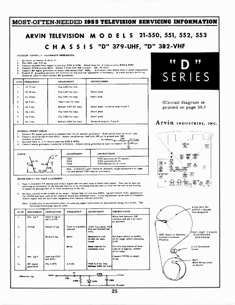
MOST -OFTEN -NEEDED 1955 TELEVISION SERVICING INFORMATION
ARVIN TELEVISION MODELS 21-550, 551, 552, 553
CHASSIS "D" 379 -UHF, "D" 382 -VHFSTAGGER -TUNED I. F. ALIGNMENT PROCEDURE
I. Set tuner to channel 9-10 or 11.2. Pull AGC tube VIO out3. Connect variable bias supply to junction 5304 4 R306. Adjust bias for -2 volts junction 5202 la R205.4. Connect VTVM across 5212. Isolate VTVM with 18K resistor. Use -Sy scale.S. Connect IF signal generator to mixer tube shield (vzo 6X8). Lift mixer tube shield until it isjust ungrounded.6. Good R. T. grounding between TV receiver on test and test equipment is necessary. A metal surface bench top.
should be used to insure proper RF grounding.
STEP FREQUENCY ADJUSTMENT INSTRUCTIONS
1. 39.75 mc Top 1.202 for min.
2 47.25 mc. Top L201 for min. Outer peak
3. 41, 25 mc .. Top T201 for mi.. Outer peak
4. 42.9 mc. Tuner coil for max.
5. 45.2 mc. Bottom T201 for max. Outer peak --recheck steps 4 and 5.
6. 42.1 mc. Top T202 for max. Outer peak
7. 45.7 mc. Top T203 for nu:. Outer peak
8. 44.1 mc. Bottom T204 for max. Recheck mep 6, 7 and 8
OVERALL SWEEP CHECKI. Connect RF signal generator to chassis near V4 for marker generator. Push shield down on mixer .ube.2. Connect oscilloscope across R212. Isolate oscilloscope lead with 300 old to ground and 18K
reitor in series. To clus.... " To sco3. Increase bias to -3.5 volts at junction R202 k 5205.4. Connect sweep generator to antenna terminals. Adjust sweep generator It tuner to channel 10.1300 PO
CURVE ADJUSTMENT INSTRUCTIONS11.25
T203 'T203 positions 45.75 marker5.75 T202 T202 positions 42.25
5042.2 T204 T204 adjust tilt of curve
5 55% Note: If desired curve cannot be obtained, slight adjustment of tunsm42.75 coil and bottom T201 may be necessary.
SOUND AND 4.5 MC TRAP ALIGNMENT
I. Tune in available TV station and reduce signal into set until hiss is heard with sound. This can be done byInserting an attenuator in the antenna lead-in or by removing antenna lead-in from the set and stray feedingin signal by placing lead-in in close proximity of the set.
2. Set buzz control in the middle of its range. Adjust take o f coil (top T205), top and bottom T101, guadraturecoil (L102) and bus: control for cleanest sound and minimum buss_ If any adjustment cause hiss to disappearreduce signal into set until hiss reappears and continue with adjustments.
Note: If difficulty is encountered eith r in reducing signal sufficiently or adjustments being very broad. The.following proceed. may be used.
STEP EQUIPMENT CONNECTION FREQUENCY ADJUSTMENT INSTRUCTIONS
I. Det. Jig Input of Jig topin 2 of V2
Keep lead between ISKresistor and pin 2 e shortas possible
2. VTVM Output of jig Tune in availablechannel
T205 Top (only), TI01(top and bottom) for
3. Remove jig Same Quadratare coil(L102) for max.sound
Set buss control in middleof its range before adjustingL102
4. Same Dona ceatrol fornilainasn buss
Correct adjustment of busscontrol le approa, middleof its range
S. Det. Jig Junction 0321and 5333
Connect VTVM to outputof jig
6. RF signalgenerator
Pin 1 (V7) 4.8 roc Time 4.S ear trapaortas TAOS for min.
*Detector Jig47mpm--*SW-I
1554705
4705
1N34 1000
VTVM
Or and
tt D 11
SERIES
(Circuit diagram isprinted on page 30.)
Arvin INDUSTRIES, INC.
UHF Tuner in ExtremeCounterclockwisePosition
Arvin Part No.A25313-1 SpringTwo Required
VHF -UHF TUNERSTRINGINGDIAGRAM
2 1/2 ClockwiseTurns
StartHook String Loopon Eyelet
25
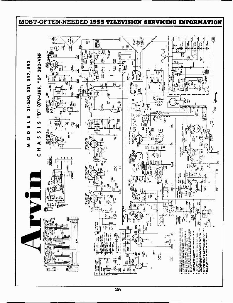
TE
RM
INA
L m
ew10
IMF
TU
TO
RO
RA
NG
ER
evpr
eNA
NIA
0301
IImO
Arv
in
R.F
. A G
CC
LAM
P
IINt
RS
3 M
IK 2
C53
.00
TU
NE
RC
54 D
OA
NT
EN
NA
HM
6BN
TERNINA19
R55
UN
F
NA
C51
1A
NT
EN
NA
TE
RM
INA
IS
F.
PLU
G T
OO
N T
UN
ER
C20
2
L202
39.T
5M
L
TU
BE
47
64U
6N
eer
I11
2111
9TIM
E O
WE
S A
RE
SW
AN
IN D
AM
S A
1, 9
.000
. IA
EA
100
op00
.W
AS
S O
RM
IPM
SE
NA
KE
D. C
OM
MA
= W
INS
LE
SS
NP
R (
ID 1
AR
EIN
UO
, IM
O A
CM
E1
101
AR
E IN
MA
D5
CO
IL A
SS
IST
AN
CE
WO
ES
LES
S T
IAN
v.,
Nur
sol
oA
RR
045
AT
CO
MM
IND
ICA
TE
CS
CO
NA
SE
RO
TA
TO
R
ft 0.
D.r
oAtr
vt=
rza
gIY
U a
rfp
vis
rz,
SD OYMII
RU
NT
.= IM
N13
OF
CO
MP
CM
EN
TS
AR
E N
OM
WIT
H T
IM P
AR
TR
EM
OV
ED
NC
R T
NE
CP
CU
IT
2A
LL V
INS
FO
RM
S N
M M
OR
N M
TN
IRA
s -I
D -
FM
MA
SS
ES
...
FIR
ST
PIC
TU
RE
I.F A
MP
LIF
IER
_L-6
r.s6
2460
V4
Tw
o
ItI
I
1000
Eli
Ard
L
Lam
caw
OW
R20
4C
OO
CO
O
I
7-L
CG
O6
CO
OV2I
UN
OM
111
4
MO
DE
LS 2
1-55
0,55
1,55
2,55
3
CH
AS
SIS
"D
379
-U
HF
, "D
" 38
2 -V
HF
TA
INO
INA
L A
RM
"ria
NO
NLE
S.1
SE
CO
ND
PIC
TU
RE
I F. A
MP
LIF
IER
6C96
221
HO
RIZ
ON
TA
LP
HA
SE
CO
MP
AR
ER
4-0
4,12
L6-
°6S
N7G
TA
V12
8
Etiz
inzr
orttl
.:1T
rE'rr
.z.v
, YA
M -
7411
5171
,311
034A
lgV
al -
311'
,;j24
'r '"
r"-
.74-
7/11
I""
. EA
MO
YIN
INA
LOT
TE
DA
01.1
NM
MO
ON
- um
rS
1531
1
laI
V/2
46S
N7
GT
A
,1
R 3
7zz
zz00
22
IgT
ION
TA
LH
OR
IZO
NT
AL
70, *
3,7,
6,oe
lO
SC
ILLA
TO
R
moR
iz
G
Ac,
goot
,
V/4
2600
44os
IIQD
VP:
INT
ER
CA
R H
IER
SO
UN
D A
MP
LIF
IER
TH
IRD
PIC
TU
RE
I. F
. AM
PU
FIE
R60
716
8209
i.
CO
OIC
CO
VE
RT
ICA
LV
ER
TIC
AL
OU
TP
UT
O.,
OS
CIL
LAT
OR
-rN
7V
ISIB
6IN
663
VE
RT
ICA
LLI
NE
AR
ITY
HO
RIZ
ON
TA
LO
UT
PU
T
RIB
MR
aw6-
\ _9
M
D -
KO
FU
SE
=A235
AU
DIO
OU
TN
OV
T10
2
70
Es R
ED
C3C 10
0R
FD
SO
UN
D U
MIT
ER
-R
OG
DE
TE
CT
OR
440
BN
6
1i0.
T-4
RI3
74,
SA
,
YE
LLO
W
PO
WE
R
RE
CT
IFIE
RS
L -1
0P
MS
PE
AK
ER
SP
I
V/8
PIC
TU
RE
TU
BE
2 IA
MP
4 O
R2I
AM
P4A
1_ N
NiD
225
1=12
1.I
NIT
STI
GS
A
ZO
NT
AL
LIN
E M
ITT
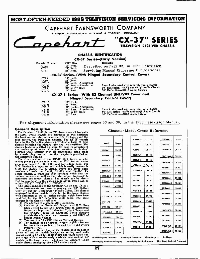
MOST -OFTEN -NEEDED 1955 TELEVISION SERVICING INFORMATION
CAPEHART-FARNSWORTH COMPANYA DIVISION OF INTERNATIONAL TELEPHONE & TELEGRAPH CORPORATION
"CX-37" SERIESTELEVISION RECEIVER CHASSIS
CHASSIS IDENTIFICATIONCX-37 Series-(Early Version)
Chassis Number CRT Size RemarksCT75 17" Rect. Described on page 33, in 1953 TelevisionCT77 21" Rect.CT81 21" Rect. Servicing Manual (Supreme Publications).
CX-37 Series-(With Hinged Secondary Control Cover)CT89 17" Rect.CT90 21" Rect.CT115 21" Rect.-AluminizedCT133 21" Rect.-Aluminized Less Audio, used with separate radio chassisCT95 24" or 27" Rect. 90° Deflection-6AV6 and 6AQ5 Audio CircuitCT130 24" Rect. 90° Deflection-6BK5 Audio Circuit
CX-37-1 Series-(With 82 Channel UHF/VHF Tuner andHinged Secondary Control Cover)
CT110 17" Rect.CT108 21" Rect.CT116 21" Rect.-AluminizedCT134 21" Rect.-Aluminized Less Audio, used with separate radio chassisCT112 24" or 27" Rect. 90* Deflection-6AV6 and 6AQ5 Audio CircuitCT131 24" Rect. 90° Deflection-6BK5 Audio Circuit
For alignment information please see pages 33 and 36, in the 1953 Television Manual.
General DescriptionThe Capehart CX-37 Series TV chassis are all basically
the same. These chassis are composed of two sections;the front section referred to as the RF-IF Chassis and therear section, the Deflection Chassis. The RF-IF chassisbolts to the Deflection chassis providing a basic 21 tubechassis including the picture tube and two rectifiers. Thechassis features a tilted IF strip for ease in adjustrhentand replacing of tubes. Complete isolation is obtainedbetween these sections with all connections being madeby a male plug inserted into the receptacle provided onthe deflection chassis.
The front portion of the RF-IF Unit forms a solidmount for the picture tube while the H.V. Section servesas a rear mount for the CRT and Deflection Yoke. TheH.V. Section is a separate unit which is easily removablefrom the chassis for servicing. There are three basicversions of each the CX-37, CX-37R and CX-37-1 TVseries chassis. A chart has been provided which lists thevarious versions as well as the information necessary todetermine the correct chassis. The chassis can be identi-fied by stamping on the chassis rear apron which can beeither "CX-37", "CX-37R" or "CX-37-1".
The latest additions to the Capehart CX-37 and CX-37-1Series Instruments are those employing the "90° Deflec-tion" 24" and 27" Rectangular Picture Tubes. The chassisemployed in these models is similar to the basic chassiswith exception of the deflection circuits which have beenmodified for the 90* deflection angle tubes. The basicchanges in the chassis itself are:
(1) The addition of a second 5U4G Rectifier.(2) Revision of the Horizontal Output and H.V. Rec-
tifier circuit by use of a 6CD6G tube as HorizontalOutput, an improved Horizontal Flyback Trans. andtwo 6AX4GT tubes as Dampers. These changesprovide the additional scan necessary and 20KV ofSecond Anode Voltage.
(3) The use of a 6AV5GT tube as Vertical Output.(4) The addition of an external magnetic (PM) focuser
for use with magnetically focused 24CP4 and 27GP4Picture Tubes.
In addition to these changes the chassis used in higherpriced 24" and 27" models incorporate an improved audiocircuit using a 6AV6 1st audio stage and 6AQ5 audio out-put stage with a continuously variable tone control. 24"models in the lower price bracket use the standard CX-37audio circuit employing the 6BK5 audio output.
Chassis -Model Cross Reference
4C 174MS-1 CT -110 11924.13-1 CT -112
Model Chassis3C21 4M CT -121 12 F274M CT -95
11174MS CT -126 SC2148 CT -121 12F274M-1 CT -112
IT17411S CT -126 5C21.1M-1 CT -12315W214MD- I CT -134
1T174M-1 CT -110 5C2148-1 CT -123
15W21480-1 CT -134
1T17411-1 CT -110 5C214MD CT -115
16T244M CT -95
IT174MS-1 CT -127 5C214MD-1 CT -116
16T244M-1 CT -112
111748S-1 CT -127 71-1214M CT -121
16T244MS CT -130
2T214M- I CT -108 7112148 CT -121
1672.14MS-1 CT -131
2T2148-1 CT -108 711214M-1 CT -123
16124435 CT -130
2T214MD CT -115 7H2148.1 CT -123
16T2448S-1 CT -131
2T214MD-1 CT -116 992 I 4MD CT -115
16T244ES CT -130
27214MS CT -128 9F214MD-1 CT -116
161244ES-1 CT -131
272146S CT -128 9921480 CT -115
2T214MS-1 CT -129 9F2148D- 1 CT -11618W21490-1 CT -134
I9C214M CT -1,432T214BS-1 CT -129 11F244M CT -95
19C214M-1 CT -1444C174M-1 CT -110 11F244M- I CT -112
19C214MD CT -1454C 1 74MD CT -99 1192448 CT -95
19C214MD-1 CT -1464C 174M5 CT -99
MS-Mahogany Floratone BS-Bisque Floratone M-Mahogany B-Bisque
MD-Highly Polished Mahogany BD-Highly Polished Bisque FD-Highly Polished Fruitwood.
27
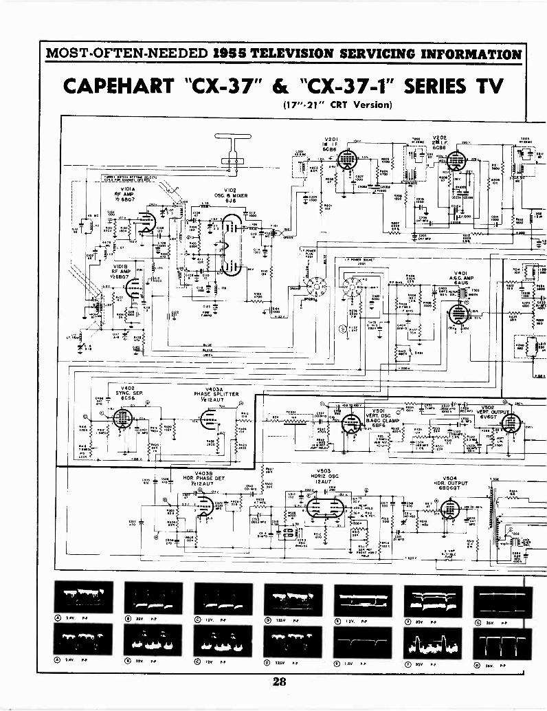
MOST -OFTEN -NEEDED 1955 TELEVISION SERVICING INFORMATION
CAPEHART "CX-37" & "CX-37-1" SERIES TV(17"21" CRT Version)
VIO1ARF AMPV2 6807
40
V1018RF AMP
V26807
Leos
.000
pia
V102050 8 MIXER
0 6J6L 11
V201I.F.
6086
4201
1.202 V2028.flogc
6086
ti(1jc.t.
1111140v
aL-003-Z--'C2044
"11"00
i
cxro000
xw
7.-..-.047
C22214 Iwt30
000
40442PL.4201 I 4022 90.97
.020.
44011000
V401A.GC. AMP
6AU6
itro ravoinr "."Mt.
S01
00
.2S
90
.*224- 3900
3.97 1.21490
4240MO
V402I SYNC. SEP.
all .1. 6056WO
5
V403APHASE SPLITTER
Ye l 2 AU 7
L213
c:°:= To`t-V4038
HOR. PHASE DET.YI 2 AU7
45
T 730
V501Ct
VERT. OSC.a AGC CLAMP
68F6Sy
711.
''s170137InZ-on.t.Tiet V502001, ." VERT. OUTPU6V6GT
C4S4044 WO210%
I
70';
524
7.030v.
220V
222
V503HORIZ. 05C.
12AU7V504
NOR. OUTPUT6806GT
way/Varifer
CI 2.4V. P -P
err 1,",
0 2AV. P -P
ON.
CI 32V. PP
feAlika
0 32V P -P
orpo.,....
0 I2V. 1,11
74. .4.
40114°
12V. P-11
wiefolliwpr
0 123V. P -P
Prp qP1041.
0 12011. P -P
22.1211M2121213M11,
0 I .2V. P -P
CI 1.2V.
$1111,188001111,00
C) 32V. P -P
CI 22V P -P
2411. 1-11
26V. P -P
28
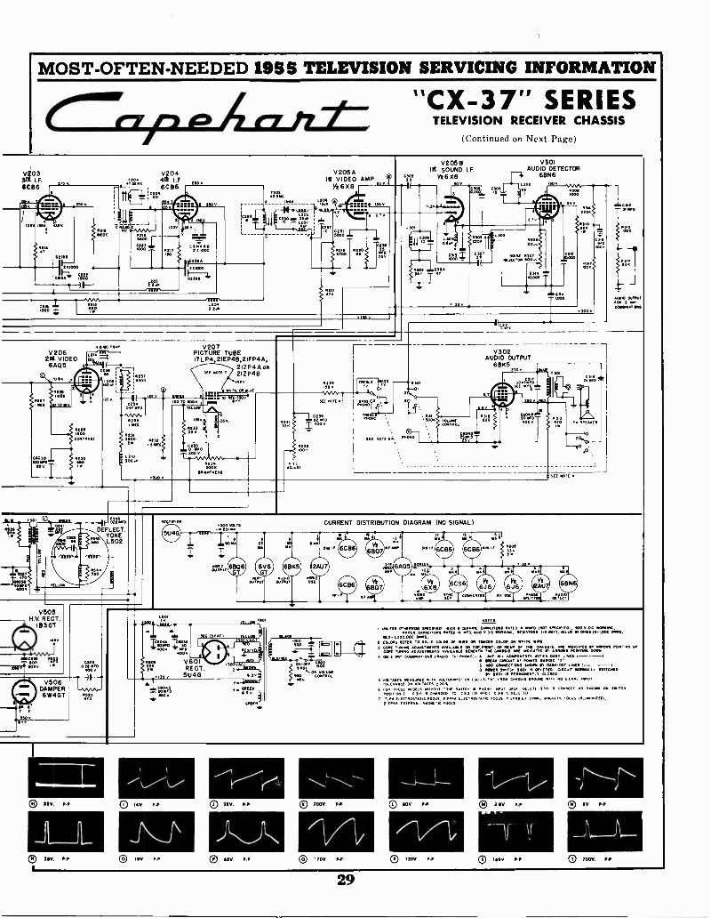
MOST -OFTEN -NEEDED 1955 TELEVISION SERVICING INFORMATION
"CX-37" SERIESTELEVISION RECEIVER CHASSIS
(Continued on Next Page)
VI 0I3F.
6086
13511 155V 135
V20442 I.F.6C86
icw
90
12050 310
V 205 AIA VIDEO AMP
5091Ve 6%13
3 3
I)
V2056IN SOUND I.F.
Ve6Xe30 V
V301AUDIO DETECTOR
F-43 6806L302 150V
V206212 VIDEO6A05
1141C TRAP V207PICTURE TUBE17LP4,21EP4B,21FP4A,
21ZP4A oft212P4BRIM
L RIO3000
REM A CCWON bouST
ORIMT11551
V302AUDIO OUTPUT
6BK5
2g0*
200 0
TOirr 1? PP SPEAKER
u010 0.111001OR 3-M.
CONONNATIEDel
BM?MO
EamS
V505H V RECT.
183 GT
CA2,? !ai/95 V 10 v
C5130.12
POO
V506DAMPER6W4GT
0 3$V P-P
L0 3110 P -P
SOO VOLTS-.NESINA
CURRENT DISTRIBUTION DIAGRAM (NO SIGNAL)
OUTPUT
1.0.0A MO
350 150E1 YELLOW
1."50V0ROOV 1E10
0091
111
V601RECT
35 V 5U4GftrA
00
0 INV P -P
1\0 I 3V P -P
CI 210 P -P
0 65V P -P
001ovv
C0025
...LON VOLUMLEMO. CONTRO0.1E0
® 700V P -P
r4/0 170V P -P
NOM"
vffl.E53 OTREs1115 SPECRIED PICA LEANING CAPACITORS RATIO OfOT SPECIFIED, SOO v DC POPPING.PPER PA.r0R5 RATED iN .00, GOO v RINSIONs NTT. AALvE 01 MIES III L000 MRS,
1M11 1,000,000 001151E COLORS REPER TO SOL. COLON Of MEE OR IMMO COLOR 0111 10,0 VIRE
TUNING O. AV ON TOP. PRON MOPS Or 04.63.6. API AIMCATED PROMS 11010910 VP.COM TUNA00 NOAUSTNENT5 AMNAOLE ORNEATN T. A.NE INO.CATEO G. AMMONS POINTING DOWN.
ON I.ITAT COMOINAT.ONS INALLO-TV-INION01. . JAI,LL
LOTAPONENTS ENTHIN DASH LINES I ---ICACI, AI POINTS. NARKED 1
C Aw
5r
ONNECTION5 50111 111.014 -DOT LiNES I- -10 POMO MIT. 5201 r5 0912TED CiRCUIE NOINIALLA 5191110010
Sbi 15 psousseurL3 CLOSET,B. rgiz,G.L,L.MED,SOZ..s2....201LIOHNTST ON fOU L. FN. ..1010 CNASS4S GROUNO WET ..MFUT
6 FOR EmOSt MODELS wirmour TowE swil.CT. PETO. .P.PUT +AG, DILI ILE SAO, .RELT AS .. SWITCH
POS.TION C .S CrIPPREO TO C313 0'
CILIEEECTROSTAT.0 FOCUS. MARA ELECTROSTATIC FOCUS 'LEAFS FETEARAL 410.6IFELC OCUS211. EXTERNAL MAGNETIC FOCUS
0 soy P -P
0 rlor., {LP
8 35V.
--T0 rep, Prr,
29

MOST -OFTEN -NEEDED 1955 TELEVISION SERVICING INFORMATIONCapehart TROUBLE -SHOOTING NOTES ON THEPicture Circuits
No Picture, No Sound, Raster PresentUse oscilloscope to trace video signal. If video is not
present at output of Video Detector check:(A) R -F Tubes V101 and V102 or I -F tubes V201, 202,
203 and 204.(B) Video Detector Crystal (IN64) and associated
components.(C) Voltage Readings on all R -F and I -F tubes.(D) Plate and Screen load resistors and by pass ca-
pacitors in R -F and I -F Stages.If video signal at Video Detector is normal check:(A) Voltage readings on 1st Video Amp. (%6X8)
V205B.(B) Resistors R219, R220, R224, R225 and R226.(C) Peaking Coil L206 for open.
Horizontal Sync-AFC and Sweep Circuits1. Loss of Horizontal Sync:
If Vertical Sync is critical also check:(A) Sync Sep. 6BE6 or 6CS6 (V402) and Phase
Splitter, 12AU7 (V403) tubes.(B) Sync Coupling Capacitors C406 and C408. (Note:
C408 not used in chassis coded "D-3" or later.)(C) Open Resistors R222, R419, R418, R422; R423
or R424.If Vertical Sync is normal check:(A) Open Capacitors, C510 or C506.(B) Open Resistors R505, R502 or R507.
2. "Jittery" Horizontal Sync:Check:(A) Horiz. Phase Det., 12AU7 (V403B) tube.(B) Value of resistors R503, R504 and R508.(C) Capacitor C513 for open.
3. Extreme Horiz. Sweep Distortion (Picture Distorted- Horiz. Sync critical).Check:(A) Horiz. Phase Det. 12AU7 (V403B) and Horiz.
Osc., 12AU7 (V503) tubes for Heater to Ca-thode leakage.
4. Three Overlapping Pictures (Horiz. Osc. frequencytoo high).If adjustment of Horiz. Osc. cannot correct condition,check:(A) Horiz. Osc., 12AU7 (V503) tube by substitution.(B) Capacitor C517 for open.(C) Resistor R515 for open.
5. Tearing at top of Picture.If adjustments of Horiz. Osc., AGC and Pix LockControl do not correct condition, check:(A) Capacitor C515 for open.
6. No Raster - No High Voltage.Use oscilloscope to check waveform at grid (pin 5)of Horiz. Output 6BQ6GT (V504). If waveform isnormal, check:(A) Horiz. Output 6BQ6GT (V504), H. V. Rectifier
1B3GT (V505) and Damper 6W4GT (V506)tubes.
(B) H. V. Circuit fuse (.2 amp.) for open.(C) Horiz. Winding of Defl. Yoke and Horiz. Output
Trans. (T502) for open.(D) Parallel Resistor R522 and Capacitor C523 for
open.(E) 6BQ6GT Screen Load Resistor R519 for open.If waveform at grid (pin 5) of 6BQ6GT (V504) isnot normal, check:(A) Horiz. Osc., 12AU7 (V503) tube.(B) Coupling Capacitor C518 and Resistor R517 for
open.Horiz. Osc. plate load resistors R509 and R514for open.Horiz. Ringing Coil L501 for open. Also checkvalues of other components in Horiz. Osc. circuit.
7. Insufficient Horiz. Sweep.If condition cannot be corrected by adjustment ofHoriz. Drive and Width, check:(A) Horiz. Osc. 12AU7 (V503), Horiz. Output
6BQ6GT (V504) and Damper 6W4GT (V506)tubes.
(B) Voltage readings on Horiz. Osc. 12AU7 andHoriz. Output 6BQ6GT.
(C)
(D)
CX-37 SERIES TV CHASSIS (Continued)(C) Value of Capacitor C524 in Damper circuit, also
capacitors C518, C517 and other components inHoriz. Osc. circuit.
(D) Capacitor C520 for open.8. Insufficient Horiz. Sweep with Foldover on Right Side.
Check:(A) Capacitor C518 for leakage.
9. Horiz. Foldover in Center of Picture.Check:(A) Capacitor C520 for leakage.
10. Trapezoidal Raster-Horiz. Sweep Decreased.Check:(A) Horiz. Winding of Defl. Yoke for partial short.(B) Capacitor C528 (across Mi of yoke winding) for
short.
Vertical Sync and Sweep Circuits1. Loss of Vertical Sync or Critical Hold.
Use oscilloscope to check sync signal at grid (pin 1)of Vertical Osc., 6BF6 (V501). If sync signal is normal,check:(A) Values of capacitors C534, C530, C535, C529, Re-
sistors R540 and R542 and other components inVertical Osc. circuit.
If sync signal is not normal, check:(A) Sync Separator 6BE6 or 6CS6 (V402) and Phase
Splitter '12AU7 (V403A) tubes by substitution.(B) Voltage readings and waveforms in Sync Separ-
ator and Phase Splitter circuits.(C) Integrating Network (PC501).(D) Coupling Capacitors C408 and C537 for open.(E) Resistor R413 for open.
2. Loss of Vertical SweepCheck:(A) Vertical Oscillator 6BF6 (V501) and Vert. Output
6V6 (V502) tubes by substitution. Use oscillo-scope to check waveform at plate (pin 3) of Ver-tical Output, 6V6 (V502). If waveform is normal,check:
(A) Vertical Winding of Deflection Yoke.(B) Vertical Output Transformer T501.(C) Capacitor C541 for short.If waveform is not normal, check:(A) Voltage Reading in Vertical Osc. (V501) and Ver-
tical Output (V502) circuits.(B) Vertical Output Transformer T501 for open
primary.(C) Resistors R527, R529, R531, R532, Capacitors
C603B, C530, C532, C536 for open also check othercomponents in Vertical Osc. circuit.
3. Insufficient Vertical ScanUse oscilloscope to check waveform at plate (pin 3)of Vertical Output, 6V6 (V502). If waveform is normal,check:(A) Vertical Winding of Deflection Yoke for partial
short.(B) Vertical Output Transformer T501 for partial
short.(C) Capacitor, C541 for leak.If waveform is not normal, check:(A) Vertical Osc., 6BF6 (V501) and Vertical Output,
6V6 (V502) tubes by substitution.(B) Voltage readings on V501 and V502.(C) Capacitor C603C for open.(Di Capacitors C529, C530, C532, Resistors R527,
R529, R531, R532 and other components asso-ciated with V501 and V502.
4. Extreme compression of Scan Lines at Bottom withStretching at top.Check:(A) Adjustments of Vert. Hold, Linearity and Height.(B) Capacitor C534 for open.
5. Vertical Fnldover at top-poor Vert. Linearity.Check:(A) Value of Resistor, R535 and Capacitor, C533.
6. Two Pictures Vertically-Linearity Distorted.Adjust Vertical Hold to stop roll, check:(A) Capacitor C529 for leakage.
7. Vertical Scan Reduced with Stretching at Top.Check:(A) Adjustment of Vert. Hold, Linearity and Height.(B) Capacitors C534 and C533 for change in value.
30
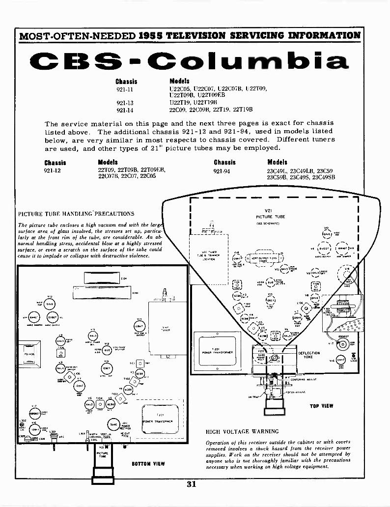
MOST -OFTEN -NEEDED 1955 TELEVISION SERVICING INFORMATION
ESSI-Ccolurribia.Chassis Models921-11 U22C05, U22C07, U22C07B, U22T09,
U22T09B, U22T09EB921-13 U22T19, U22T19B921-14 22C09. 22C09B. 22T19. 22T19B
The service material on this page and the next three pages is exact for chassislisted above. The additional chassis 921-12 and 921-94, used in models listedbelow, are very similar in most respects to chassis covered. Different tunersare used, and other types of 21" picture tubes may be employed.
Chassis Models921.12 22T09, 22T09B, 22T09EB,
22C07B, 22C07, 22C05
PICTURE TUBE HANDLING'PRECAUTIONS
The picture tube encloses a high vacuum and with the largsurface area of glass involved, the stresses set up, particu-larly at the front rim of the tube, are considerable. An ab-normal handling stress, accidental blow at a highly stressedsurface, or even a scratch on the surface of the tube couldcause it to implode or collapse with destructive violence.
019
010
Au010
7 Pt AuON 04/1.1,11.
302
0309.
VII
= 0309
.301
VII
T*6
Sc'
CI"
ANN PC VIAN ,
1.106
V7
Via
90.7 *NailPT,
.)TED A4
6 7104
V.2
V3
10)Rmv
S(0
7103
V
L303 WIDTH VERT LINCONTROL MI,co,
C201
V.
Ve AIN OUTIN7
'lot
1102
RECT.
V20
ER
00 NMIP202
v211e LiePICTURE
TUBE
3
1.1
'UN( ER
LI" I
O
7
T20,
)POWER TRANFONMF R
'WC
BOTTOM VIEW
Chassis921-94
SCE TUNERTUBE N TRIMMER
LOCATION
J
Models23C49L, 23C49LB, 23C5923C59B, 23C49S, 23C49SB
V21
PICTURE TUBE
(SEE SCHEMATIC)
V16
0:: VERT. OUTPUT% ,-r
`_TRANS
"r
0.019/1 HO*01536A...L3 MX 31
T 201POWER TRANSFORMER
0
\SYNC6" ir.lit33-
;a3(29211
06
HIGH VOLTAGE WARNING
VIO.(6506)
VII 6v6GT t 1 6w4OT 1019/NINA OuTPVT NOiDANPER
09164,51Or°
DEFLECTIONYOKE
CENTERING ADJUST.
016
AtI2
Operation of this receiver outside the cabinet or with coversremoved involves a shock hazard from the receiver powersupplies. Work on the receiver should not be attempted byanyone who is not thoroughly familiar with the precautionsnecessary when working on high voltage equipment.
ovv
1302
31
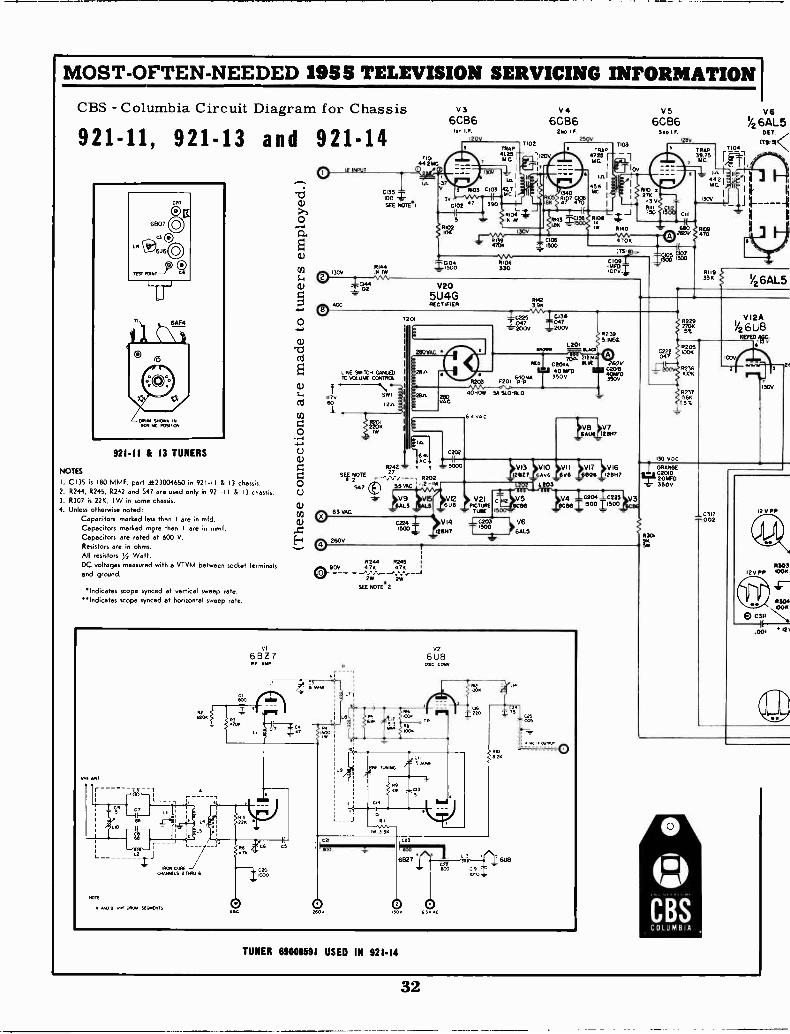
MOST -OFTEN -NEEDED 1955 TELEVISION SERVICING INFORMATION I
CBS - Columbia Circuit Diagram for Chassis
921-11, 921-13 and 921-1419? 1 F
120Y24e
250V7103
921.11 & 13 TUNERS
NOTES
I. C135 is 180 MMF. part 4t 23004650 in 921-11 & 13 chassis.2. R244. R245, R242 and S47 are used only in 921.11 8 13 chassis.3. R307 is 22K. IW in some chassis.4. Unless otherwise noted:
Capacitors marked less than I are in mid.Capacitors marked more than I ere in rnmf.Capacitors are rated at 600 V.Resistors are in ohms.All resistors ya Walt.DC voltages measured with a VTVM between socket terminalsand ground.
Indicetes scope synced at vertical sweep rate.Indicates scope synced at horizontal sweep rate.
F. 1 T
W;SEE NOTE.1
19144130V IR IW
LANE WATCH GANGED10 VOLUME CONTROL
T201
V36CB6
71044 2MC
V205U4GRECTIFIER
2130VAC
2611
7'11,I.
AL
402
0 11242 Y 7 - 50000 SEI P2FOTE ,. 17.,---, 192020 9470
551,1c '1.2-iw
Cl)l)63 VAL
C1)
E-1 6.% 2600
TRAP41.25,
Ft
V46CB6
7102
120V
R142396
8KClO
f°83
11347Cl2;;V"i c,, 6200V 200V
097
40 54 51.01310
V9 V8 VI2 V2164E5 606 PICA
TullE
0224 VI4 02031500 T121H7
R244 R245 1
4 K47 1
SEE NOTE 2
TUNER 69000191 USED IN 921.14
R229
5%
R2051006
8236
R79756K
551
L201-
Vs6CB6
Sea I.I.
TRAP39.75
, MC.
RI401, :709.05A.
4'09
260VC201940100350V
C p2 V5 V4 c204 0223 V36C96 we. I 1500 11500
V6GALS
I/2 6711_5
1/2 6AL5
V12A/26U8
130V
11303.2V PP WON
8304OOK
K.00, in
32
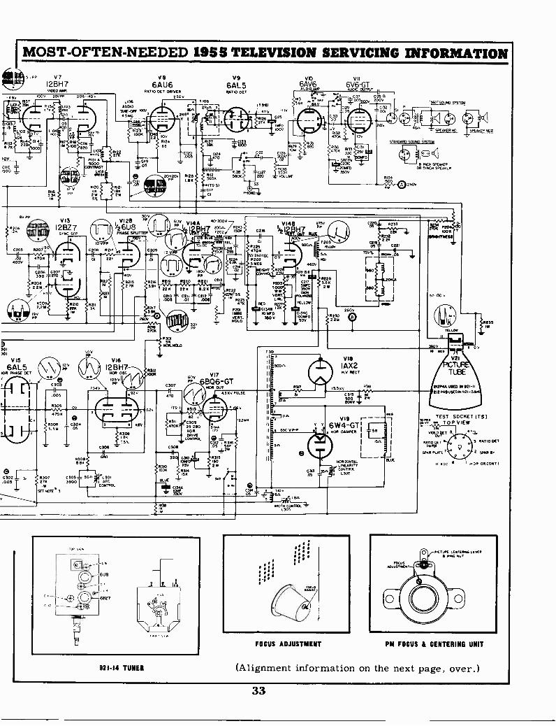
IMOST -OFTEN -NEEDED 1955 TELEVISION SERVICING INFORMATIONII 11 Nita 5,08 V7
12BH7vIDEO AMR
490111
1.0 396
RII3471
b°2RU22
00v 20070 206-1400
CH4
TOO
100
300 2
L104PEP
3
$,s
05
7{`)0119M 3100 20
11.117
15,
12 V
1TE
PICH Al5000
CONTRASTL108
8/1
V86AU6
RATIO DET DRIVER250v
L106AUDIO
1510E-OPF 1056
4S160_
61231006
0120 0121Ilk IBIS2W 255%
0
CII9.05
11, "I 1
1.111 T4 IT
1100
012468
1-
.z4e,v
L
.005
20-120V RI25PPLSO
V96AL5156710 OET.
T106
-2qir T 5-61
470 "HV
R 26,425276
1/D1000
/4127 -1-C123391( ICOO
0224 0122 0126
470ce
R25600
IT -3/
NT
P101817120 C127 250K5606 1220 VOLUME R134
vo6AuADV,06
VII6V016G TNJ 0121027 ,
09 6 8 . . 4 9
R:i 3'2
ISyP-Z .4MN '.54; ,C00137 02 28?
p4C129
05'30
420K a 1091
8129g 20 C13
25V
'360.SOLND SYSTDA
4.2On
- SPEAKER 031 I SPEAKER 7802
S7660ARD SOLAR/ SISTER
53
PHOM0
708
1WGREEN
C2010201160350V
4 0 60V
1E1 <ROR
1601 SPEAKEROR 51/404 SPEAKER
6V PP
020612
401111.8.1 4 61
6,44;1101
C205 0213/P
4706400v
V13
12K7SYNC SEP
0206 0207390 -.4,270
R20822 Id/
", 84 V
R20922M
19V
30V01 29 PP
1/2 6U 8PHASE SPUTTER
R210 02112211 156
10VPP
0208 0214 0209
221.
90y
01
8216390
02173
26,0
301301
V15
6AL5105 PHASE DET
E)2 IC30 _L..
.0051
128PP
C303
.005
R305 OV
470e)
R306 - C3043.3M T .05
0307276
I W
SEE NOTE 3
50V
2 3 4 V
105VPP
R2113
2706
R312WOK
6,48 V I4A 40-200010HT2c2
2
R 19 0
V i 4 e743C 216 I /1,T
01
R2254700
5°. 6000002025 REG
101290601 Ill
180V5PPR I
I( 226 8.21
la ct
0/1/1'o'IPA IIIgi1511
P30151(
NOR. NOLO
Nor
. 9 V
C306
R3011 68°6.86
R3098K
T5%
C305 50A. LArc/1
3900CONTROL
62V
C307
470
ITS-Il
c%tir
300
C213
taitC2002
02
1GHT 2
P203
WW'5% VERT.R223 LIM.476 RED
0201 01349 1.26114E6 10 MP D
HOLDVERT. 350 V
VI760V6806-GT
NOR OUT
0313
03114706
0309
C30925-250NOR.DRIVE
CONTROL
39 C3/0
7CIT(25VR314156
BLUE =;a9'
81
N
875PP
OWE
V
20°3ALL. OS -
"V% .1711
Isso
I I
001
4600
m08- 8.6
021151/WD350v
vcv!,6..4
YELLOW
Cil4CDOD300
R2295.61(
W
05
11230,(22M
260V
R2
2265232
13011.3
11 SCOn
II
11
1
43 80 PULS
121
C403121566E316.05
214
0315ISO2W
pa/
Pm
.22.4A
IW
921.14 TUNER
V113
IAX2M.V. RECT.
1556v
0315 Rd500 T 2r
R38
8111119MIESS
52-130 v
235116
YELLOW
390061
nY Y
650 V INP
9.4%
V19 -16W4-GT INOR. DAMPER -LI
I 15A.
NDR1ZGNTALLINEARITY
W -A641 L30OL2
COL
40510v
05 T 1 611.
WIDTH E01110EIL1303
L__
FOCUS ADJUSTMENT
V21
TUBE
1212P4A USED IN 921.41
212 P48 USED w 921-136
'TEST SOCKET ITS)'A R. TOP VIEW
NCE&RET 5
0611260 -
SP6R PLATE 7
3 RAW/ OE%
2 SPIV/ a.
11101 DRCONTI
PM FOCUS & CENTERING UNIT
(Alignment information on the next page, over.)
33
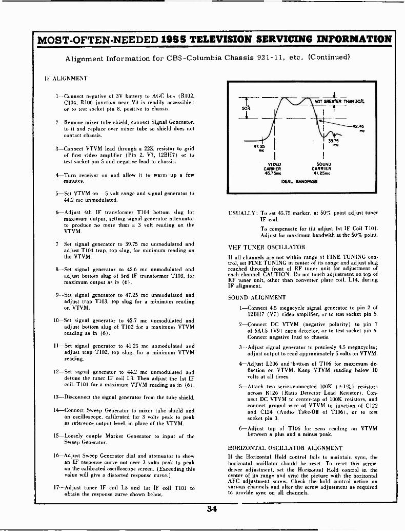
MOST -OFTEN -NEEDED 1955 TELEVISION SERVICING INFORMATION
Alignment Information for CBS -Columbia Chassis 921-11, etc. (Continued)
IF ALIGNMENT
1-Connect negative of 3V battery to AGC bus (R102,C104. R106 junction near V3 is readily accessible)or to test socket pin 8. positive to chassis.
2-Remove mixer tube shield, connect Signal Generator,to it and replace over mixer tube so shield does notcontact chassis.
3-Connect VTVM lead through a 22K resistor to gridof first video amplifier (Pin 2. V7, 12BH7) or totest socket pin 5 and negative lead to chassis.
4-Turn receiver on and allow it to warm up a fewminutes.
5-Set VTVM on -5 volt range and signal generator to44.2 mc unmodulated.
6-Adjust 4th IF transformer T104 bottom slug formaximum, output, setting signal generator attenuatorto produce no more than a 3 volt reading on theVTVM.
7-Set signal generator to 39.75 mc unmodulated andadjust T104 trap, top slug, for minimum reading onthe VTVM.
8-Set signal generator to 45.6 mc unmodulated andadjust bottom slug of 3rd IF transformer T103, formaximum output as in (6).
9-Set signal generator to 47.25 mc unmodulated andadjust trap T103, top slug for a minimum readingon VTVM.
10-Set signal generator to 42.7 mc unmodulated andadjust bottom slug of T102 for a maximum VTVMreading as in (6).
11-Set signal generator to 41.25 mc unmodulated andadjust trap T102, top slug, for a minimum VTVMreading.
12-Set signal generator to 44.2 mc unmodulated anddetune the tuner IF coil L3. Then adjust the 1st IFcoil. T101 for a maximum VTVM reading as in (6I.
13-Disconnect the signal generator from the tube shield.
14-Connect Sweep Generator to mixer tube shield andan oscilloscope, calibrated for 3 volts peak to peakas reference output level, in place of the VTVM.
15-Loosely couple Marker Generator to input of theSweep Generator.
16-Adjust Sweep Generator dial and attenuator to showan IF response curve not over 3 volts peak to peakon the calibrated oscilloscope screen. (Exceeding thisvalue will give a distorted response curve.)
17-Adjust tuner IF coil L3 and 1st IF coil T101 toobtain the response curve shown below.
USUALLY: To set 45.75 marker, at 505, point adjust tunerIF coil.
To compensate for tilt adjust 1st IF Coil T101.Adjust for maximum bandwith at the 50% point.
VHF TUNER OSCILLATOR
If all channels are not within range of FINE TUNING con-trol, set FINE TUNING in center of its range and adjust slugreached through front of RF tuner unit for adjustment ofeach channel. CAUTION: Do not touch adjustment on top ofRF tuner unit, other than converter plate coil. L14, duringIF alignment.
SOUND ALIGNMENT
1-Connect 4.5 megacycle signal generator to pin 2 of12BH7 (V7) video amplifier, or to test socket pin 5.
2-Connect DC VTVM (negative polarity) to pin 7of 6AL5 (V9) ratio detector, or to test socket pin 6.Connect negative lead to chassis.
3-Adjust signal generator to precisely 4.5 megacycles;adjust output to read approximately 5 volts on VTVM.
4-Adjust L106 and bottom of T106 for maximum de-flection on VTVM. Keep VTVM reading below 10volts at all times.
5-Attach two series -connected 100K (±1%) resistorsacross R126 (Ratio Detector Load Resistor). Con-nect DC VTVM to center -tap of 100K resistors, andconnect ground wire of VTVM to junction of C122and C124 (Audio Take -Off of T106), or to testsocket pin 3.
6-Adjust top of T106 for zero reading on VTVMbetween a plus and a minus peak.
HORIZONTAL OSCILLATOR ALIGNMENT
If the Horizontal Hold control fails to maintain sync, thehorizontal oscillator should be reset. To reset this screw-driver adjustment, set the Horizontal Hold control in thecenter of its range and sync the picture with the horizontalAFC adjustment screw. Check the hold control action onvarious channels and alter the screw adjustment as requiredto provide sync- on all channels.
34
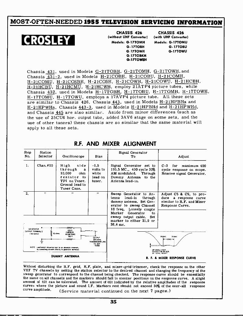
MOST -OFTEN -NEEDED 1955 TELEVISION SERVICING INFORMATION
CROSLEYCHASSIS 426
(without UHF Converter)
Models: G-17TOMHG- 17TOBHG-17TOWHG-17TOBKH13-17TOWEH
CHASSIS 426(with UHF Converter)
Models: G-17TOMUG-17TOBUG-17TOWU
Chassis 431, used in Models G-21TOBH, G-21TOMH, G-21TOWH, andChassis 431-2, used in Models H-21COBH, H-21COBU, H-21COMH,H-21COMU, H-21COSBH, H-21COSH, H-21COWH, H-21COWU, H-21HCBH,H-21HCBU, H-21HCMU, H-21HCWH, employ 21ATP4 picture tubes, whileChassis 432, used in Models H-17TOBH, H-17TOBU, H-17TOMH, H-17TOWH,H-17TOMU, H-17TOWU, employs a 17AVP4 picture tube. All these setsare similar to Chassis 426. Chassis 443, used in Models H-21HPBHa andH-21HPWHa, Chassis 443-3, used in Models H-21HPBHd and H-21HPWHd,and Chassis 445 are also similar. Aside from minor differences (such asthe use of 25CU6 hor. output tube, added 3AV6 stage on some sets, and theuse of other tuners) these chassis are so similar that the same material willapply to all these sets.
R.F. AND MIXER ALIGNMENTStepNo.
StationSelector Oscilloscope Bias
Signal GeneratorAdjust
1. Chan. #10 High sidethrough a10,000 ohmresistor toTP1 on Tuner.Ground lead toTuner Case.
-1.5volts towhitelead ontuner.
Signal Generator set to195.5 MC., 400 cycle 30%AM modulated. ThroughDummy Antenna to theAntenna lead-in.
C-3 for maximum 400cycle response on scope.Remove signal Generator.
2.
GENERATOR
OUTPUT TERM& SI 50 owns)
_L
rvwv
W°'""
RESISTORSCARBON
150,1
NOTE - Lead length should be kept ban absolute 'menus,by connectn network Orectly to generator terronala
OUTPUT300otrns
TRANSMISSION LIVETO ANTTERM.
DUMMY ANTENNA
Sweep Generator to An-tenna lead-in throughdummy antenna. Set Gen-erator to sweep Channel10 freq. Loosely coupleMarker Generator tosweep output cable. Setmarker to either 21.9 or26.4 mc.
Adjust C5 & C9, to pro-duce a response curvesimilar to R.F. and MixerResponse Curve.
f
2GAMC 21.91IC
DIP SHOULD NOTEXCEED 3db ON 30%OF TOTAL HEIGHT
R. F. & MIXER RESPONSE CURVE
Without disturbing the R.F. grid, R.F. plate, and mixer -grid trimmer, check the response on the otherVHF TV channels by setting the station selector to the desired channel and changing the frequency of thesweep generator to correspond to the channel being checked. The response curve should be essentiallythe same on all channels and the markers should fall in similar positions on the response curve. A slightamount of tilt can be tolerated. The amount of tilt indicated by the relative amplitudes of the responsecurves where the picture and sound I.F. Markers rest should not exceed 30% of the over-all responsecurve amplitude. (Service material continued on the next 7 pages.)
35
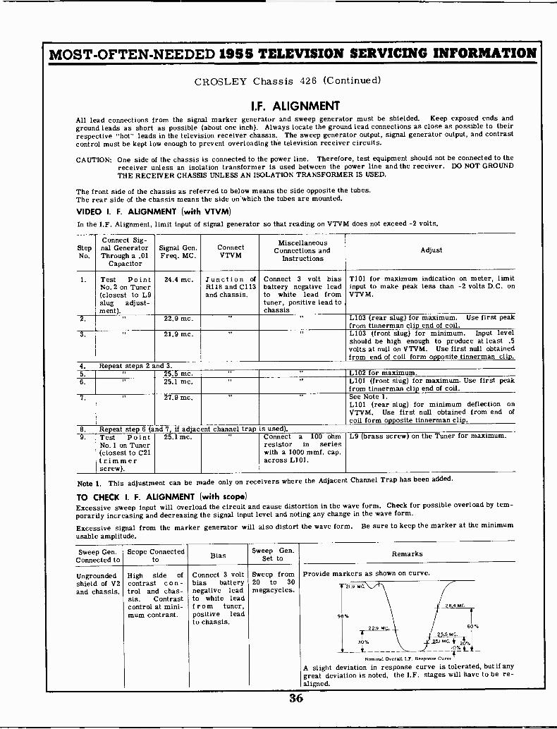
MOST -OFTEN -NEEDED 1955 TELEVISION SERVICING INFORMATION
CROSLEY Chassis 426 (Continued)
I.F. ALIGNMENTAll lead connections from the signal marker generator and sweep generator must be shielded. Keep exposed ends andground leads as short as possible (about one inch). Always locate the ground lead connections as close as possible to theirrespective "hot" leads in the television receiver chassis. The sweep generator output, signal generator output, and contrastcontrol must be kept low enough to prevent overloading the television receiver circuits.
CAUTION: One side of the chassis is connected to the power line. Therefore, test equipment should not be connected to thereceiver unless an isolation transformer is used between the power line and the receiver. DO NOT GROUNDTHE RECEIVER CHASSIS UNLESS AN ISOLATION TRANSFORMER IS USED.
The front side of the chassis as referred to below means the side opposite the tubes.The rear side of the chassis means the side onWhich the tubes are mounted.
VIDEO I. F. ALIGNMENT (with VTVM)In the I.F. Alignment, limit input of signal generator so that reading on VTVM does not exceed -2 volts.
StepNo.
Connect Sig-nal GeneratorThrough a .01
Capacitor
Signal Gen.Freq. MC.
ConnectVTVM
MiscellaneousConnections and
InstructionsAdjust
1. Test PointNo.2 on Tuner(closest to L9slug adjust-ment).
24.4 mc. Junction ofR118 and C113and chassis.
Connect 3 volt biasbattery negative leadto white lead fromtuner, positive lead tochassis
T101 for maximum indication on meter, limitinput to make peak less than -2 volts D.C. onVTVM.
2. It 22.9 mc. It It L103 (rear slug) for maximum. Use first peakfrom tinnerman clip end of coil.
3. ,, 21.9 mc. r. ,, L103 (front slug) for minimum. Input levelshould be high enough to produce at least .5volts at null on VTVM. Use first null obtainedfrom end of coil form opposite tinnerman clip.
4. Repeat steps 2 and 3.5. 25.5 mc. ,, ,, L102 for maximum.6. ,. 25.1 mc. ,, 19 L101 (front slug) for maximum. Use first peak
from tinnerman clip end of coil.7. It 27.9 mc. It ,, See Note 1.
L101 (rear slug) for minimum deflection onVTVM. Use first null obtained from end ofcoil form opposite tinnerman clip.
8. Repeat step 6 (and 7, if adjacent channel trap is used).9. Test Point
No.1 on Tuner(closest to C21trimmerscrew).
25.1 mc. Connect a 100 ohmresistor in serieswith a 1000 mmf. cap.across L101.
L9 (brass screw) on the Tuner for maximum.
Note 1. This adjustment can be made only on receivers where the Adjacent Channel Trap has been added.
TO CHECK I. F. ALIGNMENT (with scope)Excessive sweep input will overload the circuit and cause distortion in the wave form. Check for possible overload by tem-porarily increasing and decreasing the signal input level and noting any change in the wave form.
Excessive signal from the marker generator will also distort the wave form. Be sure to keep the marker at the minimumusable amplitude.
Sweep Gen.Connected to
Scope Connectedto Bias
Sweep Gen.Set to Remarks
Ungrounded High side of Connect 3 volt Sweep from Provide markers as shown on curve.shield of V2and chassis.
contrast con -trol and chas-sis. Contrastcontrol at mini-
bias batterynegative leadto white leadfrom tuner,
20 to 30megacycles. 21.9 NOW
26.4 MC
mum contrast. positive leadto chassis.
98%
22.9 MG. 60%
t 23.5 MC.
30% 25.1 MC. ii A%
A slight deviationgreat deviationaligned.
___ 10% LiNominal Overall I.F. Response Curve
in response curve is tolerated,is noted, the I.F. stages will have
but if anyto be re-
36
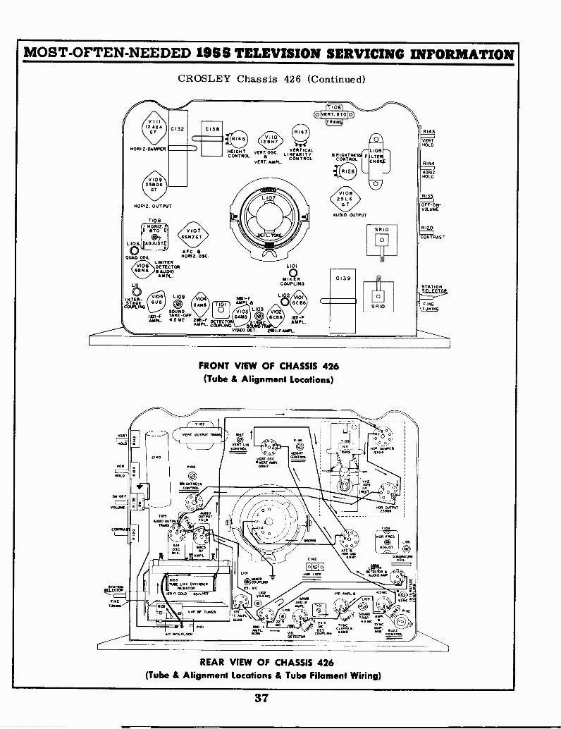
MOST -OFTEN -NEEDED 1955 TELEVISION SERVICING INFORMATION
CROSLEY Chassis 426 (Continued)
0138
rT 106
V CRT. 8TO[IT RANO
HEIGHT VERT. OSC.LINEARITYVERTICAL
CONTROLVERT. AMPL.
HORIZ. OUTPUT
1108HORIZ.!'
TO GTO u
L106 OAD?./IT.0®LQUAD. COIL
VERT
HOLD
NOR
014 -OFF
VOLUME
CONTEMN
STATIONSELECTOR
FINET
LIMITERDETECTOR&AUDIO
AMPL.
L109
eSOUND1=4 TAGE-OFF
"PL. 4.5 MC.21114 DETECTORAMPL. COUPLING SEA
VIDEO OE T.
L101
elCOUPLING
T105
ALSO OUTTRANS
LI 2
AUDIO OUTPUT
SRIO
0
0139
SRIO
FRONT VIEW OF CHASSIS 426(Tube & Alignment Locations)
T 103
VENT OUTPUT TRIMS
Ri26
C.)PRI OPR NESS
CONTROL
AUDIOOUTPU T.5L6
ROCSRF
AMPL
11153
TUBE LIFE EMMENRENSTOR
125,1 COLD 454sTRIT
VHF 11F TONER
VERT LINCONTROL
VERT OSCOVERT 10411L
121111,
*NEILGCSE
RI44
ONIIT
CONTAIN
MAN1110 IFAMPL
244MC
via COUPLINGOET
DETECTOR
OHOS OANDER
ass
HOR OUTPUT251106
T 106
\NOR FRED
uSTAFC 6NOR 0%
ESN)
VIE AMPL
i.smc
'5"5 AMPL
- 4i,"' 32
,e. T. AP
5SYNC SYNCCLIPPER Mel61.11 im, Kai
CONTROL
REAR VIEW OF CHASSIS 426(Tube & Alignment Locations & Tube Filament Wiring)
R143
VERT.HOLD
R164
HORIZ.HOLD
81201
CONTRAS'
STATIONSELECTOR
FINETUNING
37
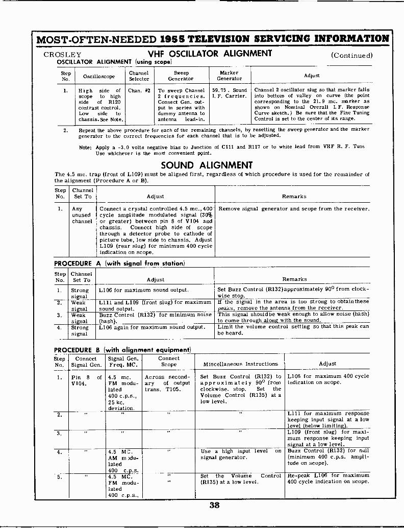
MOST -OFTEN -NEEDED 1955 TELEVISION SERVICING INFORMATIONCROSLEY VHF OSCILLATOR ALIGNMENT (Continued)
OSCILLATOR ALIGNMENT (using scope)
StepNo. Oscilloscope
ChannelSelector
SweepGenerator
MarkerGenerator Adjust
1. High side ofscope to highside of R120contrast control,Low side tochassis. See Note.
Chan. #2 To sweep Channel2 frequencies.Connect Gen. out-put in series withdummy antenna toantenna lead-in.
59.75. SoundI. F. Carrier.
Channel 2 oscillator slug so that marker fallsinto bottom of valley on curve (the pointcorresponding to the 21.9 mc. marker asshown on Nominal Overall I. F. ResponseCurve sketch.) Be sure that the Fine TuningControl is set to the center of its range.
2. Repeat the above procedure for each of the remaining channels, by resetting the sweep generator and the markergenerator to the correct frequencies for each channel that is to be adjusted.
Note: Apply a -3.0 volts negative bias to Junction of C111 and R117 or to white lead from VHF R. F. TuneUse whichever is the most convenient point.
SOUND ALIGNMENTThe 4.5 mc. trap (front of L109) must be aligned first, regardless of which procedure is used for the remainder ofthe alignment (Procedure A or B).
StepNo.
ChannelSet To Adjust Remarks
1. Anyunusedchannel
Connect a crystal controlled 4.5 mc., 400cycle amplitude modulated signal (30%or greater) between pin 8 of V104 andchassis. Connect high side of scopethrough a detector probe to cathode ofpicture tube, low side to chassis. AdjustL109 (rear slug) for minimum 400 cycleindication on scope.
Remove signal generator and scope from the receiver.
PROCEDURE A (with signal from station)
StepNo.
ChannelSet To Adjust Remarks
1. Strongsignal
L106 for maximum sound output. Set Buzz Control (R132)approximately 90° from clock -wise stop.
2. Weaksignal
L111 and L109 (front slug) for maximumsound output.
If the signal in the area is too strong to obtain thesepeaks, remove the antenna from the receiver.
3. Weaksignal
Buzz Control (R132) for minimum noise(hash),
This signal should be weak enough to allow noise (hash)to come through along with the sound.
4. Strongsignal
L106 again for maximum sound output. Limit the volume control setting so that this peak canbe heard.
PROCEDURE B (with alignment equipment)StepNo.
ConnectSignal Gen.
Signal Gen.Freq. MC.
ConnectScope Miscellaneous Instructions Adjust
1. Pin 8 ofV104.
4.5 mc.FM modu-lated400 c.p.s.,25 kc.deviation.
Across second-ary of outputtrans. T105.
Set Buzz Control (R132) toapproximate l y 90° fromclockwise. stop. Set theVolume Control (R135) at alow level.
L106 for maximum 400 cycleindication on scope.
2. ,, ,, It L111 for maximum responsekeeping input signal at a lowlevel (below limiting).
3. II It II ,, L109 (front slug) for maxi-mum response keeping inputsignal at a low level.
4. ., 4.5 MIAM m >du-lated400 c.p.s.
ft Use a high input level onsignal generator.
Buzz Control (R132) for null(minimum 400 c.p.s. ampli-tude on scope).
5. ,, 4.5 MC.FM modu-lated400 c.p.s.,
,,,,
Set the Volume Control(R135) at a low level.
Re -peak L106 for maximum400 cycle indication on scope.
38
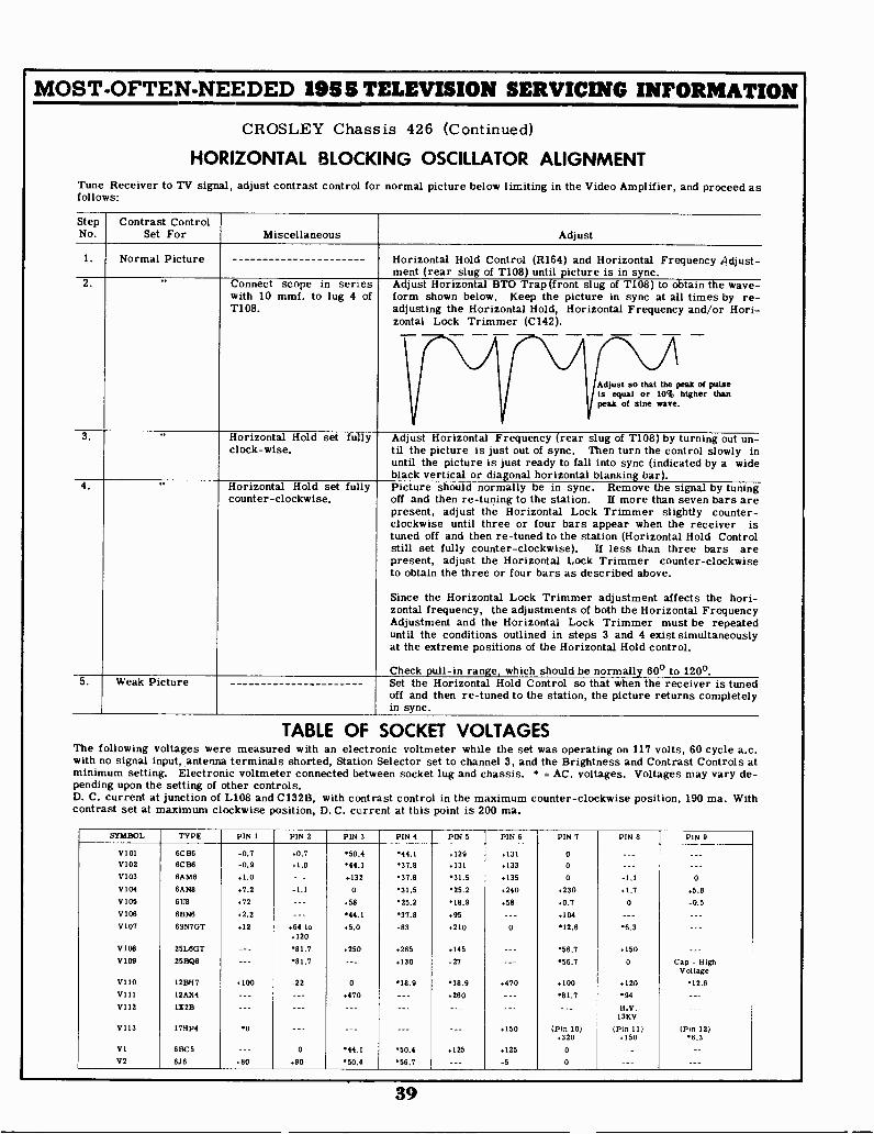
MOST -OFTEN -NEEDED 1955 TELEVISION SERVICING INFORMATION
CROSLEY Chassis 426 (Continued)
HORIZONTAL BLOCKING OSCILLATOR ALIGNMENTTune Receiver to TV signal, adjust contrast control for normal picture below limiting in the Video Amplifier, and proceed asfollows:
StepNo.
Contrast ControlSet For Miscellaneous Adjust
1. Normal Picture Horizontal Hold Control (R164) and Horizontal Frequency Adjust-ment (rear slug of T108) until picture is in sync.
2. ,, Connect scope in series Adjust Horizontal BTO Trap (front slug of T108) to obtain the wave -with 10 mmf. to lug 4 of form shown below. Keep the picture in sync at all times by re -T108. adjusting the Horizontal Hold, Horizontal Frequency and/or Hori-
zontal Lock Trimmer (C142).- -- - -Adjust so that the peak of pulseIs equal or 10% higher thanpeak of sine wave.
3. " Horizontal Hold set fully Adjust Horizontal Frequency (rear slug of T108) by turning out un-clock-wise. til the picture is just out of sync. Then turn the control slowly in
until the picture is just ready to fall into sync (indicated by a wideblack vertical or diagonal horizontal blanking bar).
4. " Horizontal Hold set fully Picture should normally be in sync. Remove the signal by tuningcounter -clockwise. off and then re -tuning to the station. If more than seven bars are
present, adjust the Horizontal Lock Trimmer slightly counter-clockwise until three or four bars appear when the receiver istuned off and then re -tuned to the station (Horizontal Hold Controlstill set fully counter -clockwise). If less than three bars arepresent, adjust the Horizontal Lock Trimmer counter -clockwiseto obtain the three or four bars as described above.
Since the Horizontal Lock Trimmer adjustment affects the hori-zontal frequency, the adjustments of both the Horizontal FrequencyAdjustment and the Horizontal Lock Trimmer must be repeateduntil the conditions outlined in steps 3 and 4 exist simultaneouslyat the extreme positions of the Horizontal Hold control.
Check pull -in range, which should be normally 60° to 120°.5. Weak Picture Set the Horizontal Hold Control so that when the receiver is tuned
off and then re -tuned to the station, the picture returns completelyin sync.
TABLE OF SOCKET VOLTAGESThe following voltages were measured with an electronic voltmeter while the set was operating on 117 volts, 60 cycle a.c.with no signal input, antenna terminals shorted, Station Selector set to channel 3, and the Brightness and Contrast Controls atminimum setting. Electronic voltmeter connected between socket lug and chassis. * = AC. voltages. Voltages may vary de-pending upon the setting of other controls.D. C. current at junction of L108 and C132B, with contrast control in the maximum counter -clockwise position, 190 ma. Withcontrast set at maximum clockwise position, D. C. current at this point is 200 ma.
SYMBOL TYPE PIN 1 PIN 2 PIN 3 PIN 4 PIN 5 PIN 6 PIN 7 PIN 8 PIN 0
V101 6C 136 -0.7 «0.7 50.4 .44.1 .129 +131 0 --- ---V102 6C136 -0.9 .1.0 44.1 37.8 +131 +133 0 ---V103 6148 +1.0 --- +132 37.8 31.5 +135 0 -1.1V104 6AN8 +7.2 -1.1 0031.5 25.2 +240 +230 .1.7 +5.8
V105 6118 +72 +58 25.2 113.9 +58 +0.7 0 -0.5V106 8BN6 +2.2 --- 44.1 37.8 +95 --- +104 ---V107 6SN7GT +12 +64 to +5.0 -83 .21012.60 .6.3
+120
V108 25L6GT .81.7 +250 .265 +145 .56.7 .150 ___
V109 25BQ6 --- *81.7 --- +130 -27 56.7 0 Cap - HighVoltage
V110 12BH7 100 -22 0 18.9 18.9 .470 +100 .120 12.0VIII 12AX4 --- --- +470 --- +260 .81.7 94 ---V112 1X28 --- --- --- N.V.
13KV
V113 17:1P4 .0 --- --- --- +150 (Pin 10) (Pin 11) (Pin 12)+320 .150 .6.3
VI 613C5 --- 0 .44.1 50.4 .125 .125 0 --- ---V2 616 +80 .90 .50.4 56.7 --- -5 0
39

MOST -OFTEN -NEEDED 1955 TELEVISION SERVICING INFORMATION
CROSLEY Chassis 426 Circuit Diagram
4708
470K
470UHF TUNER 5
FUNCTION SNITCH
-USED ON vHF UlfMODELS ONLY ToaeXplACLENTEFILOG4
VHFANT 00 470
SEE SCNEP4ATiCON PAGE 18. 0
(NIGH MEI
rimw
R101
470K
C10
--4--K470
R102
470K
P101
06102
470K4NWV71
470
TO % TUNER 13*
INPUT 260V
VHF RF TUNER PART NO.157282SEE SCHEMATIC ON PRECEDING PAGE
R152
7.5
0 0
V1016086
IET PIK. I -F
L101
,,251MC-05 RI..
AAV:::f + -4-, ii-' 15K I CI4
}.L47 R104
TEL.
100
47., . -c15
Jor ,....4 R108
I C20;
1000 _ iew800 WO C103 4700I 001
.= MFD.
t153v
DC CURRENT
f\ 172 MAA 1_108
22v. P -P
r06000 YEL
SR101
039 a4cie,I- 140
MFD.C0101
SW I
12AX4GT 25806VIII V109
R153
25 OHM -COLD V108430HM- HOT
HEATER CURRENT LALLIMITING RESISTOR 25L6GT(TUBE LIFE EXTENDER)
50^ C1328
04
200MFD 0.2v. P -P
R -F TUNER
6.16 6CB6V2 VI
RI54
43
I
6CB6V101
L102253.40
SEE NOTE II-4-0129
10K
Tv°330K
I
T.x.D.
Ta2446
1 I
219NC
6V102G86
UO3 it2M2 PIK I -F
1.14181
6CB6 6108V102 - V103
6BN6V106
1.004MFD
44v. P -P
6A283V104
.0.48
R112 MT
1000
.006FD_L
Rill8
41-171_106
V104BF26.11/48SYNC.
CLIPPER
128H7
4
68
.14-150 I
F.
17V. P -P .05
RI
3911-)22K
0141 36 v P -P
77V P -P
-1- V1058F26U8
SYNC.4MPL.
C442 1109LOC
10-160
6547 GT 17Hp4
0 107 VII3
RI56 R157 RI58
43 43 43 43C256
1- psL,---
TERMNAL Locoions
2 3
4
1108
L3
TIO9
40
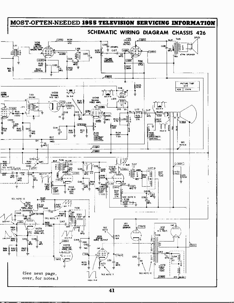
I MOST -OFTEN -NEEDED 1985 TELEVISION SERVICING INFORMATION
SCHEMATIC WIRING DIAGRAM CHASSIS 426
R131113K
V106
LIM8ER-DETECTOR
&I WO AWL.
.2.63
RI321000
BUZZCONTROL
.j471/ RI 34
01231
To'MFG
470
L106
CI 251
T5
CI263
RI350= C127 .111V
I(330K Z
MFD.
.0011/FD.
V10825L6GTAU01
OUTPU0T
ka
RI36
RI3756011
470K
,.f...eaav
2603
TOLUE 105
0C128
MFD.
RED
SP 01
/I03AMANI
PIX I- F
2;
TIOI24.mc---
6 glie--- R I 15 3; I- - ; ..wio
RII4100
0109
1005MFD
7- RI 161000
0101001
WD.
R117
GII 6 I MEG
I/PFD
VIO3B26AM8
VID. DET
L104 11112G.
0600'-
cii2
10 T -q,MFD
01141
-11711-5V RP
5.611
01160116
VIDEO WM..Y26AP18
viO4A SOV e-PLIO9 -LOU r
son_
CI 15 33 L112 < cap'7
R1258.2K
I5MFD
R12015 00CONTRAS
TROLTCON
SOV P -P
/1YEL'. 0 YELLOw11 3
RI
RI 2 3 L105 < 27K4.71( a..a
33K
R124NAV5 6K
NFU
RI27100K
3 7
CONTROL
RI 265MEGBRIGHTNESS
PICTURE TUBEV113
426 1 1711P4
70y P -P
6
SEE
NOTE 6
RI41
4.7KSEE NOTE II ci31
I #701 3 kall9I22 K .005.005 701MFD i ton
RI42MMI1000
z50V. P -P
SEE NOTE 10
\\....R16470KSToP
I70K
HORIZ. HOLD
N.
eux 'n06 TELLON
963. P -P
2
RI43 %2!MEG. VI 10AMK VERT.STOP Ku i'21281.17
CONT VERT
CI33
.005 CI34MID.
..115v1 047 1203MFD 1, P
/ 035 1164
=
C143
233
F5956011
1.4 V. P -P R160150K
27K
RI661001(
C146
64 TO 12043
RI67 1
150K18" P -P
8169_ 1811
SEE NOTE 9
a tt2 7MEG.
3 V107AY26SN7GT
710812. AFC.
R161 RI62150K 100K
0144 CI 451
MFD. /OD.25 1.02
821(RI63
T108
37.5"
a 4
C1471( i31 a
220- --111,738-
-131Tr/ MFD
110 V. P -P
V10764gitS747GT
Z 09C.
4
- V I \e."7".,
(See next page,over, for notes.)
0149±
C150
560
R170470K
C136
611
OvERt V
P -P.1 ELLE TIO7
VII0 B0005 Vz12BH7MFD. VERT
OUTPUT
RI45
7tZ..5%4
1.110-T
82011
510EG.IMEG. STOP
HEIGHTCONT.
RI473
7502 014
VERTLIN.
RED
(.0051
20
L107 -A
MED. -7-
SEE NOTE 8RI46
1511
30G38-}FDL20
MFD.
VERT.MELYOKE
4300V I
815039011
R151820K
SEENOTE
5
V10925606
HCRIZ OUTPUT
yap
100 P -P
6 C151
22.R173 05
-._. \MFD
'=
SEE NOTE 7
VIIII2AX4
DAMPER
8171188
.1-714101f
16.
0
(
VI I 21228
H V RECT.4
109
0 13 K V
1 vcas.-0153 8 00 au :_.2154a 0 .T17
/2 L I07B
HCR1ZDEFLYOKE
1
SEE NOTE 12
J..**
1
RED t6L.10K
41

MOST -OFTEN -NEEDED 1955 TELEVISION SERVICING INFORMATIONCROSLEY Chassis 426 (Continued)
NOTES1. All D.C. voltages measured with an electronic voltmeter connected from socket lug to chassis. Some
voltages are variable depending upon signal input. Voltages shown were measured with a signal volt-age of 850,000 microvolts and with a normal picture on the picture tube and the contrast and bright-ness controls set for 50 volts peak to peak on the cathode (pin 11) of the picture tube. Socket volt-age tolerance 10%. 1
2. Supply voltage, 117 volts, 60 cycle AC.3. K = 1000.4. On all capacitance values in mmf. and all resistance values in ohms unless otherwise noted.5. R171 is a special 2 watt resistor capable of standing overload for limited periods of time. Replace
with part number 156911-3.6. Better focus may be obtained with replacement picture tubes if the electronic focus anode is con-
nected to a point other than +150 volts. Suggested points to try are: chassis ground, +260 volts,+300 (picture tube, pin 10) and +480 volts.
7. R173 was added on some receivers to minimize horizontal overdrive, noticeable by a vertical whiteband slightly left of the center of the raster. Because of individual tube characteristics, overdrivemaybe introduced when the 25BQ6GT tube is replaced in a set that is not provided with R173. In thiscase it will be necessary to correct the overdrive condition by adding a 22 ohm, 10%, 1/2 watt re-sistor, part number 39374-5. Disconnect tube socket, pin 8, from ground and insert the resistor be-tween the pin and the chassis.
8. In some sets R128 is a 12,000 ohm, 10%, 2 watt resistor (part No. 39374-214). In such cases R148is a 18,000 ohm, 10%, 2 watt resistor (part No. 39374-216) or a 22,000 ohm, 10%, 2 watt resistor(part No. 39374-217).
9. In some sets R169 is a 15,000 ohm, 10%, 1/2 watt resistor (part No. 39374-39).10. In some later production sets, Horizontal Hold control R164 has an overall resistance of 145,000
ohms, with a 70,000 ohm stop. This control will be marked with part No. B-157802-1-2 orB-157802-1-3. It is directly interchangeable with the earlier control marked B-157802-1-1, whichhas an overall resistance of 170,000 ohms with a 70,000 ohm stop. It will be noticed, however, thatthe control with the lower overall resistance gives a somewhat wider hold range.
11. On the Vertical Integrating Network C131, leads 2 and 3 are closely spaced, and lead 2 is the mid-dle lead. On the Sync Take -Off Network C129, leads 1 and 2 are closely spaced, and lead 2 is themiddle one. When replacing either of these units, the leads must be connected as shown in theschematic in order to obtain satisfactory operation.
12. CODE CHANGE - The schematic and parts list as given are for chassis 426, Code C. This chassisincorporated a change (not found in the Code B chassis) to improve the operation of the horizontaloutput circuit. In the Code B chassis the Horizontal Deflection Transformer was of an earlier de-sign. C152 was either one 22 mmf., 10%, 3KV, Disc Capacitor (part No. 157811-1), or two 22 mmf.capacitors wired in parallel.When it is necessary to install a new transformer (part No. 157820-6) in a Code B chassis, it will benecessary to increase the total capacity of C152 to 68 mmf., + 10%, at 3 KV. working voltage. Thismay be done by adding either one or two 22 mmf., capacitors in parallel to the existing capacitors,or by replacing them with a 68 mmf., 10%, 3KV. capacitor (part No. 158215-3).
13. Vertical jitter may be caused by an intermittent contact between ground spring and picture tube,particularly on early production sets that used the brass spring. The trouble may be corrected byreplacing the spring with the new type wire spring, part number 158197. An alternate method is touse a small (1")square of copper screening between the brass spring and the picture tube, taping thescreen to the tube with a plastic tape such as "Scotch" tape.
PRODUCTION CHANGESThe to/lowing changes have been incorporated in later production Chassis 426:
I. R156, R157, and R158, filament shunt resistors (43 ohm, 10%, 2 watt), are replaced by 11174, 126 ohm, 10%, 10 watt resistor, Part No. 158230. The change In theschematic is given in Figure 1. Chassis 426 incorporating this change are stamped with code letter F or later.
a, ha.SKS
VI
rawTEPLOEE
12..0i 26E06Val V009
ar53
4325 0/114 -COLD
,11111T C.V./EN rRESISTOR
1146E LIFE 14TENDERI
6266 6.4MV,02 41.3
RIM
126
2. On Chassis 428 (Code Letter D or later) R132 is a 500 ohm control, Part No. 157955-2. Chassis with earlier code letters have a 1000 ohm control, Part No.157955-1. The change simplifies the sound alignment. When adjusting the Buts Control for a null, the low value resistance makes It easier to find the null.
3. On Chassis 426 (Code Letter D or later) a wiring change was made in the vertical circuit to avoid excessive height by reducing theplate voltage on V110A (verti-cal oscillator tube). However, no parts were added or deleted. The change on the schematic is shown in Figure 2.If it is desired to make this change on earlier chassis, remove the red lead wire between the positive terminal of the electrolytic capacitor C138 and lug 2 of theHeight Control 11146. Then connect a length of hookup wire from positive terminal of C138 to the junction of R150 and 11151 (On the terminal board directly abovethe Height Control).NOTE: On some chassis which did not incorporate the above change, a 1 megohm, 10%, 1/2 watt resistor (Part No. 39374-61) has been inserted between lug 3 ofthe Height Control R1413 and the grid (pin 7) of the V11013. Since this is not used on all chassis, no code letter was assigned. The 1 megohm resistor compen-&Iles for the low overall resistance value of the control when that resistance approaches 4 megohms (lower limit at 20% tolerance). When installing a replace-ment control which has a similar low overall resistance, either of the above methods may be used to decrease the height of the picture.
42
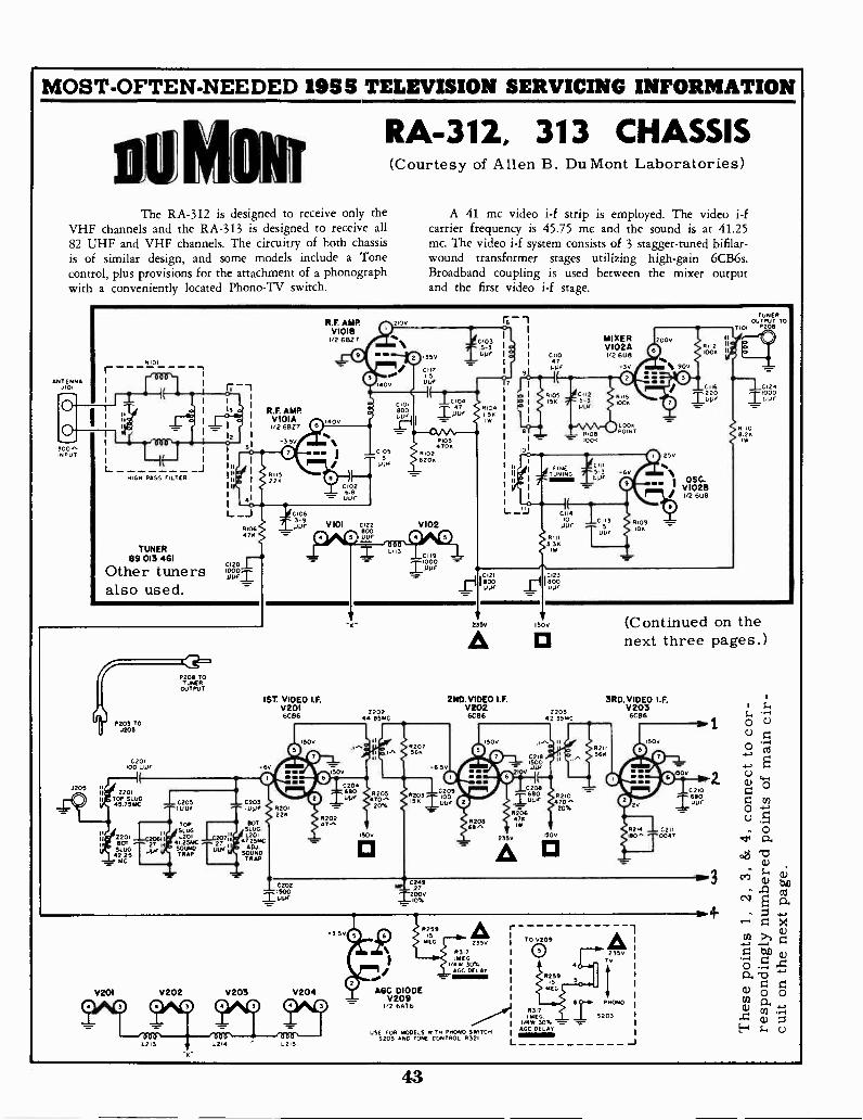
MOST -OFTEN -NEEDED 19U TELEVISION SERVICING INFORMATION
RA -312, 313 CHASSIS
The RA -312 is designed to receive only theVHF channels and the RA -313 is designed to receive all82 UHF and VHF channels. The circuitry of both chassisis of similar design, and some models include a Tonecontrol, plus provisions for the attachment of a phonographwith a conveniently located Phono-TV switch.
ANTENNAJ101
00"NPU
(Courtesy of Allen B. Du Mont Laboratories)
A 41 mc video i-f strip is employed. The video i-fcarrier frequency is 45.75 mc and the sound is at 41.25mc. The video i-f system consists of 3 stagger -tuned bifilar-wound transformer stages utilizing high -gain 6CB6s.Broadband coupling is used between the mixer outputand the first video i-f stage.
N101
L _JHIGH PASS FILTER
TUNER89 013 461
Other tunersalso used.
R.F. AMP.VIOIAI/2 6827
5
R115226
3 5v
O
0
R.F. AMPVI018I/2 6BZ ?
0
1400
O
MI MI
0
2100
RN
0,4
40V
0 1350
C117
I
0010268uur
0106470
C120113).4).i
II
P203 TOJ205
C201,00 0011
2201TOP SLUG45.75mC
220180TSLUG42.25
MC
02013 TOTUNER
OUTPUT
_L 0205-IOU
TOPSLUGL201
41 25AKSOUNDTRAP
- C2031000
80TSLUG.L2Cli
4725mCADJ.
SOUNDTRAP
C1063.91JUr 0 0V 101 0122
8000210
01018000011
CIOS
IA*
Lns
004
1/1:RI04
51<
Iw
R1034704
#1028204
V102
0000
I6--1IL 1,
11
011047
1JUC
MIXER 2000V102A1/2 6U8
RIOT156
-
CII2
U
0108
3v
0R J1 6
1004
LOOAPOINT
0RN
-E.
FINETUNING 5-3
01.10
O
RIP33Iw
0114Io
UV,0113
O
0109109
O
25V
0112*OA
90V
O
OSC.
V2°62,!
0121800IJOr
C1238001J11,
TUNEROUTPUT TO
P208
81108.29
C,24
1ST. VIDEO I.F.V2016CB6
I 020211100
220244 SSMC
0249
V235V 150v
2ND. VIDEO I.F.V2026086
020868"2350
0210470^
20%
680j_00,
220342 351.4C
150v
(Continued on thenext three pages.)
3RD. VIDEO I.F.V203
6086
02110047
-3.50
V201 V202 V203 V204
0 0 0L213
0 0 0 0
0 R 259 AMEG
AGC DIODEV2092 6A56
23500317MEG
i/48, 30%AGC DELAY
USE FOR MODELS WIT? pNONO SWITCH5203 AND TONE CONTROL R32I
L2 4 22215
rTO 0209
0
0317ImEG.
1/4w 30%AGC DELA.
-
235vTv
IINONO
5201
1
1
O0 g:
O 'RI
C.)
O 0
0
0Ia.
OCJ "Fu
Ce; 61;
alE
0 X
cl) 0 0cn ca.(1)
a)
43
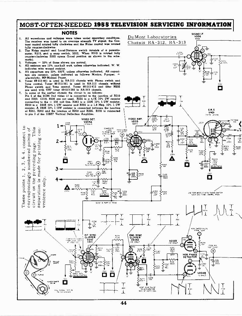
MOST -OFTEN -NEEDED 1955 TELEVISION SERVICING INFORMATION I
NOTES1. All waveforms and voltages were taken under operating conditions.
The receiver was tuned to an average strength TV signal, the Con-trast control rotated fully clockwise and the Noise control was rotatedhilly counter -clockwise.
2. The Noise control and Local -Distance switch consists of a potentio-meter, 11319, and a snap switch, S202. When R319 is rotated fullycounter -clockwise S202 opens (Local position as shown in the sche-matic).
3. Voltages ± 20% of those shown are normal.4. All resistors are 10%, one-half watt, unless otherwise indicated. W. W.
indicates wire wound resistor.5. All capacitors are 20%, 500V, unless otherwise indicated. All capaci-
tors are ceramic, unless indicated as follows: M -mica, P -paper, ±-electrolytic, MP -Molded Paper.
6. Tuner 89 013 461 is used in RA -312 chassis with Phono switch andTone control. Tuner 89 013 561 is used in RA -312 chassis withoutPhono switch and Tone control. Tuner 89 012 912 and filter N202are used with UHF tuner 89 013 293 in RA -313 chassis.
7. In some of the earlier chassis the circuit is as follows:Pin 6 of the 6CB6 2nd video i-f is connected to the junction of 11210and Z203. C218, 11206 are not used. 11222 is a 4.7% 10% 2W resistorconnecting to the + 235 volt line. 11262 is a 120% 10% I/2W resistor,11258 is a 220% 10% 1/2W resistor and 11266 is a 1.8 Meg. 10% 1/2Wresistor. A 180% 10% 1/2W resistor is connected between the junctionof 11261, 11262 and the junction of 11260 and 11266. 11300 is connectedto pin 3 of the 12BH7 Vertical Deflection Amplifier.
K SH
,5v7-
2 TURNS
3
4.4
220444wo
VIDEO DET.V204A
2 64.5
02.35
8215470,3
205.
501
0
00
Du Mont LaboratoriesChassis RA -312, RA -313
511v
COMPOSITEVIDEO PICA VIDEO
TO R268 A 15T TEST POINTSTNC CLIPPER
4 5v L202 0203
If C2 5
1.7V6I
8207IF AGC
TEST POINT
R205Fir AGO
TEST POIN O
A235v
R2584704
START
PULLETSHAFT
TUNER SHAFTDRUM
75v
8256.00.
-CMC05,C .0E0.203
AT 210 LE,
50v
0
R2E9330K
4 5." aRN
82183 SK
1204VIOLET10-^
0261/MEG
P R2605 u(G
75..6257 5202
60 LOCAL -CG D,STANc
6-
219
8262iOOK574
VIDEO AMP.V2056865
C2292 2 00,
111--, 000 --9-1205
0217VIOLET0,5 47004
6.1002,6
T2001
M1HFIC2508266 IX.MEG
210v
R2218 24
C2860
R22241, °'5 6K2Vi
250v
8220
10253330PP,
5202 IS PART OF R319
C256ID
UUF
1ST SYNCCLIPPER
V21068E6
83193mEG 30".NOISE 005780.
DAL 511666 L.SF 5 !cc
PA. 313
8272SON R62,-7,0
25v
0254 82672262.
150100
827.34706
C2I 5
0222000
IS
0
88
2ND SYNCCLIPPERV2I2A11 12AU7
05
C23047
VP
TD52
L2.J456.015,3
L207o 54.02'5L 206wHITE
822454
wW
235v
AR263
18.K.
C2520033002
8264,20K
0221471.1,05.
C222TDFIS
SOUND I.F.V2066Au6
1451
O
oo0 020I32
8235 0231220 01
J203
022022
400VPI RR
#313 15v
15* TO
20% ISO
CONTRAST
8225
150v
0
#226100420%
8238K 20%
150v
0
C.R.T.V401
178.4 20'0'4
MP C223
Zt'Iy
TO P202
O BLUEHV.
°0 0EL BL
R31213I MEGI/0 W20%
BRIGHTNESS
ISO,
0
RED
142
405+
C284RN
2002
8305MEG20%
ifg,
60C
#2461004
USE FOR MODELS WITH PHONO SWITCH5203 AND TONE ft:INTRO,. 8321
I T
751 201
I 711
V2I28V2 12407
45v
O R2T840,5
'544
WPM
C259/001
8280
0260003300v
HOR SWEEP PULSEFROM 7204
0
r°IWIN
0 08295
P206 AFCTEST 601NT
C276
I1V1501 DETECTOR 206,
0oR271
660,5
R273470,5
0258001
1008
ART SFNC PULSETO INT GRATOR
5201 AT vERT 05C,
HOR. PHASE
5.3v
C262`T001
V20482 6AL5
B. V
0261
2002033
44
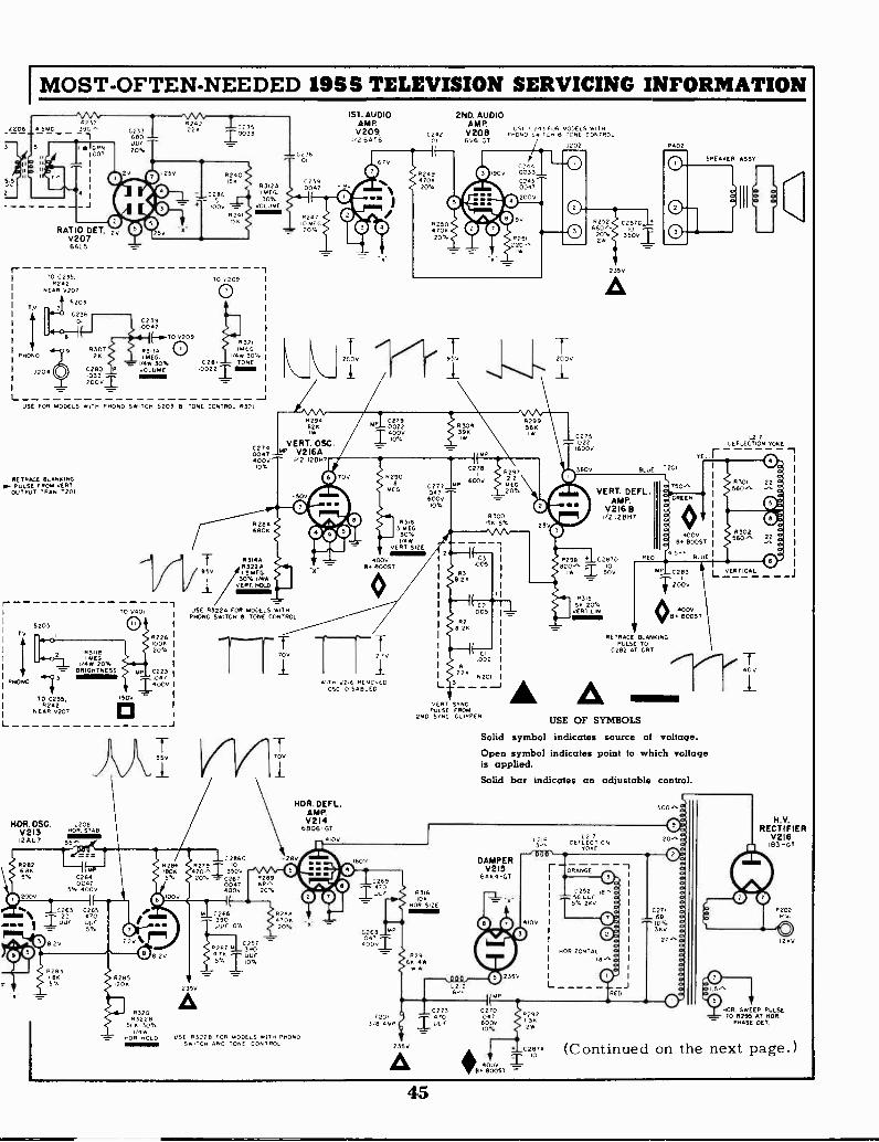
2206
3
55
MOST -OFTEN -NEEDED 1955 TELEVISION SERVICING INFORMATION
TV
PmONO
L
RAT 0 DET. 2
V20764L5
TO C235,#242
NEAR 0207
2204
5203
C2,(1/01
6242228
C239.0047
4 IE-5.700209
10033
TO 0209
0
151. AUDIO 2ND. AUDIOAMP AMP0235 usL C.7,11 ,C2 MODELS M,rnV20% 0222 V208 Im0,./ sm,rem 8 TONE CONTROL
2264T6 01 6V6-GT/202
83124MEG30%
VOLUME
R3218307 R3111% 0 IF.FEG
128 1FAE6 ow 305...- imiw 30% C281 TONE
P0280 VOLUME .00221'208:103v:11
77.-J
USE FOR MODELS *128 P4050 SWITCH 0203 5 TONE CONTROL R321
RETRACE BLANKING0- PULSE FROM VERTOUTPUT TRAP 2201
r -TO 0401
5203 0TV
PROPS
L
R3mB1MEG
24w 20%BRIGHTNESS
TO 0235,8242
NEAR 0207
.500
0
R226'00420%
P C223047
.1400V
HOR. OSC. L208V213 8017 STAR
12 AU 7
82826885%
2000
FN.
C2640047
5% .00V
0263 026522
°.7°UUF .
8.2v
R28308 8285
204
2v%
02740047400V*%
8284680K
83144R322AI 5 MEG
30% iNIKKVERT MOLD
C23601
C2390047
R2A7FAEG
20%
829482X
VERT. 05C° V216A
22 12887
02790022400V*%
1130439
#299564
r0 70v
0°
500
iviloa
USE 11322A FOR MODELS wiTmPmONO SWITCH 8 TONE CONTROL
J
'x'
I rT700 270
829018
MEG
83183 MEG.
30%IMP/
VERT 512E
4000BY BOOST
K4 I35v
8 2,
R320R3228
504 30%4w
HOR HOLD
0286C -289
VJ_1.1. 3500020% ,r,267
0047400v
C266390up
'..:[.-
*%
P 287 1C3907
'51,K IOU':
77 77
235v
A
R28968"20%
8288470820%
WITH v2* FREM0,C0OSC MARLED
NOR. DEFL.AMP.V2I4
6806-GT4100
osE R3228 808 MODELS W,TH ONONOSw,Cm AND TONE CONTROL
160
0269470
F)40'0vi
8203,8 A
C277OAT600V0%
2
C27811297
6000
P300I5K 5%
( C3005
R38.28
( C2005
R28 28
CI
oczRI
228N201
VERT SyNCPULSE FROM
2ND SYNC CLIPPER USE OF SYMBOLS
J-
12002
8252 C287C680,, 1020% 3500214
235V
A
C275.0221600V
8402
TEL r
ER ASST
III
L217DEFLECTION YOKE
3000 BLUE 1201
O
230°0
77RETRACE BLANKING
PULSE TOC282 AT CRT
VERT. DEFLAMP.
Y216 B1/212887
R298 . 02870820^ 0
R31558 20%
ART LIN
750-'
GREEN
4000By BOOST
c>8301 22 a
560,,
5#63930. 22
P 0283
4-2000
400vB BOOST
L 3-- - - -1 A ASolid symbol indicates source of voltage.
Open symbol indicates point to which voltageis applied.Solid bar indicates an adjustable control.
500-,
R316
NOR SIZE
R29168 4w
235V
A
0001.2126,^
DAMPERV2I5
64184-GT
1(88
CO247600210A
L216
000
8292
2
102874
.0. ROOSTPOOV ")
L
L217DEFLECICN
TOME
JTIANGE
J
0L VE#TICAL _ _J
co_
ec
tl
0271 g68
3;(2
%LT
RECTIFIERV216
I83-GT
P20271v
MDR. SW EP PULSE- TO R295 AT NOR.
PHASE OCT
(Continued on the next page.)
45

MOST -OFTEN -NEEDED 1955 TELEVISION SERVICING INFORMATION
P201
POWER RECT.0217
720225,0v SUKG
Th AC2878 0286A
4CC'v 3tw
235v MOM5200
111150
6.3VAC
GRN
C2868
1 ,g g
POWERRECT.V2I951140
__ED . NCO,RA -303 GINC.) IN NODE.5F4312 *ITN P1050
Sw0TE11 B TONE CC NT RC,
This is a part of the main circuit shown on previous pages.
(Continued)
RA -312, 313
UNDERCHASSIS VOLTAGE POINTS
8314 VERT MOLDR327I TONE I P11060
000 L5 ONLY1
8319 NOISECONTROL
235V
R306
150V
S203 TV-PHONOSNITCH
NOR NOLO R220OR R322(1(PHONO
MODELS ONLY)
200v
-o -90V3v25v
05C.MIXER
v002GUI
1.
1350
6v 21070z
00-3.5 -
R -F AMP.v 006
BITT202
VERT. HOLDR3220 (P7060MODELS ONLY)
r, _Finn2500 2350 TB13
CI A
VOLUME 11312AOR R3110 PROMO
MODELS ONLY)
C286
L207
( -tr )J205U
Z201
'BIG
235V
P207 0AGE
TEST ACANT
0150v
0
-3201
210
1542
tso
BRIGHTNESS 1312BOR R 11131PHONO
MODELS ONLY)
250
RATIO DET.0207GALS
VIDEO °ET.HOR. PHASE
DET.vilMO V204 -.'"At/. 6ALS
P204-4 3v
2v
1ST. V.I.F.020)
Co GOBSov
Z202
2ND. V. 1. F.02026"6
2100 1500
2v
L201 POWERRECTIFIER
219
250v 5040
Ac
-50vlab
Z203rov
3RD. V.I.F. 2ND. SYNCV203 CLIPPER
1500
"" _00 _"
Tbi0
Z204 !Tv
15V 045v
HOR. PHASEDET.
12t"2AuT3v Ow P2061ST. SYNC CLIPPER AFC TEST
2POINT
'o -
2100 1_, u7 1--I 1-1-35v 25V
GOV
VIDEO AMP. NOISEINVERTER1300v205 210 620
"A5 GO"Te9
1_,1 1-.1
L211L 2ND. AUDIO
AMP0201
SOUND I.F. 9 "6 61v206"U6
145V
P205®TgTZNT 90V
Ts
1ST. AUDIOAMP520)EATS
2009
n nnJ202
O
200V 6.20
HOR OSC.v iSQM??
1000
102
330v
VERT. OSC.VERT. AMP230 =1
TB4
nnnT B5
01?201
GC
R3I8. VERT40Tei 00
1-1 1-
ez A25002500
2500
nn,T B3
400
-25v
400V R3152500 AC VERT.
POWERLIN
RECTIFIER0217
I 5V4G
250v
C287
400
560V
HOR. DEFL.AMP. zlsvV214
4130 GT A
H.V. RECT.02111
i83-GT
12 KvTHIGH VOLTAGE)
)=,L208NOR
IJ STAB
F0520
235V
4 OV
DAMPER0215
GAXAGT
46
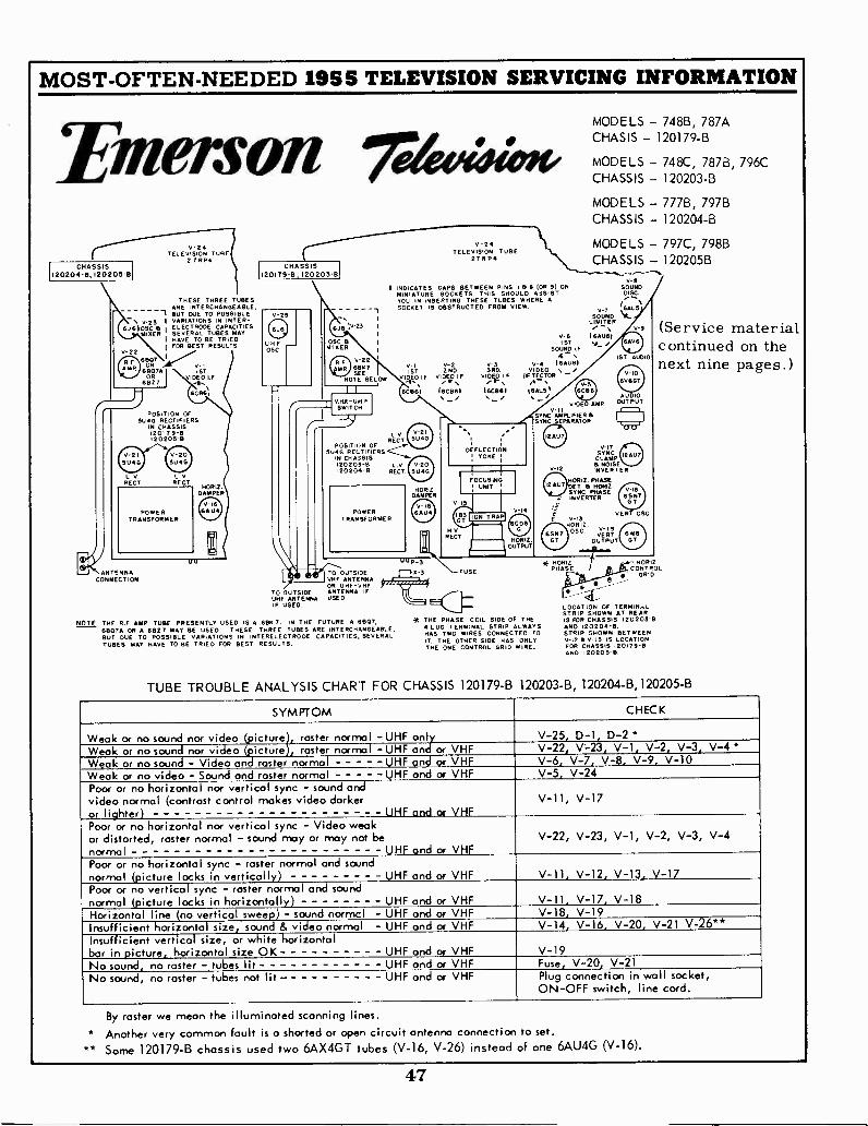
MOST -OFTEN -NEEDED 1955 TELEVISION SERVICING INFORMATION
MODELS - 748B, 787A
Emerson reteedoktoge CHASIS - 120179-B
MODELS - 748C, 787B, 796CCHASSIS - 120203-B
MODELS - 777B, 797BCHASSIS - 120204-B
v24 V -24 MODELS - 797C, 798BTELEVISION TUBE TELEVISION TUBE
271VP4 27 RP4CHASSIS
I 20204 -B, 120205-BCHASSIS
120179-8, 120 20 3B
CHASSIS - 120205B......,,,,--..------N.
THESE THREE TUBESARE INTERCHANGEABLE,
V -aI INDICATES GAPS BETWEEN PINS 19 8 (OR 9) ON SOUND
MINIATURE SOCKETS. THIS SHOULD ASSIST DISC.YOU IN INSERTING THESE TUBES WHERE ASOCKET IS OBSTRUCTED FROM VIEW. I
-I BUT DUE TO POSSIBLE-. \ ,23 I VARIATIONS IN INTER-
646105C 8 1 ELECTRODE CAPACITIES,MIXER SEVERAL TUBES MAY
I HAVE TO BE TRIED1 FOR BEST RESULTS
V-22
60R7 V-1A '
. 6807A1ST
OR IMO I F61327 ,II.
V_25
U4g --
i,
.1,23
OSC aMIXER
R 22Hp 6EIK7
SEENOTE BELOW
SOUND <t5LIMITER, Y-9
V-6 16AUe11ST
SOUNDy
I.F,
- 1ST AU010v- i V-2 v-3 V-4 16AU611ST 2ND 3RD VIDEO \ /
V14.0 I.F VI3E9,1 F VIDEO F. DE,TE.E.TOR - V-10
'6V6GT
(Service materialcontinued on thenext nine pages.)
67661V-5
I I 6CS61 ISCB6I I6CE161 16ALS I GCBS\_/ \-/ AUDIOVHF-umF vIDEO AMP OUTPuT
POSITION OFSWITCH v -ii
5U4G RECTIFIERS YSYNC AMPLIFIERSSYNC.SEPARATOR I i
IN CHASSIS120179-13120205-9
V-21 V-20SU4G SWIG
/-L V V 2'
RECT SU4GPOSITION OF
5114G RECTIFIERSiN CHASSiS120203-B L V v-20
/.
DEFLECTION/ YOKE I
'o -a)2AU7
V-17STNCCLAMP 12AU7
a NOISE
L V L VRECT RECT.
120204-B RECT. 5U4G 7
FOCUSING
vI2 INVERTER
HOME PHASEHORi 2
DAMPERHORI2 : UNIT 12"7 DU a HORI2 , .
SYNC PHASE - -
POWERv IS
SAU POWER
DAMPER
V ie66U4
V ISEINVERTER SN
GT
TRANSFORMER TRANSFORMER I niON TRAP VERT OSCv -I341414
wvRECT.
HORIZ.es., OSC. ,re,;T. 6
HORI2.OUTPUT
GT OUTPUT GT
..ANTENNA .4/117COUTSIDE
" P-3i
HORI* PHASECONTROLX 3 FUSE
8 GRIDCONNECTION
To OUTSIDEIF ANTENNAIF u//0.
NOTE THE R F AMP TUBE PRESENTLY USED IS A 88K 7. IN
61307A OR A 6627 MAY BE USED. THESE THREE TUBESBUT DUE TO POSSIBLE VARIATIONS IN INTERELECTRODETUBES MAY HAVE TO BE TRIED FOR BEST RESULTS.
TUBE TROUBLE ANALYSIS
- I VMF ANTENNAOR UHF -VHFANTEMA IFUSED /
THE FUTURE A 6907, * THE PHASEARE INTERCHANGEABLE, LUG TERMINALCAPACITIES, SEVERAL HAS TWO
IT. THE OTHERTHE ONE
CHART FOR CHASSIS
-4_1LOCTION OF TERm11.1.,STRIP SHOWN AT REAR
COIL SIDE OF THE IS FOR CHASSIS 120203-9STRIP ALWAYS AND 120204-B.
WIRES CONNECTED TO STRIP SHOWN BETWEENSIDE HAS ONLY v-12 a V -I3 IS LOCATION
CONTROL GRID WIRE. FOR CHASSIS 120179-8AND 120205-B.
120179-B 120203-B, 120204 -B,120205 -B
SYMPTOM CHECK
Weak or no sound nor video (picture), raster normal -UHF only V-25, D-1, D-2 *Weak or no sound nor video (picture), raster normal -UHF and or VHF V-22, V-23, V-1, V-2, V-3, V-4 Weak or no sound - Video and raster normal UHF and or VHF V-6, V-7, V-8, V-9, V-10Weak or no video - Sound and raster normal UHF and or VHF V-5, V-24Poor or no horizontal nor vertical sync - sound andvideo normal (contrast control makes video darkeror liohter) UHF and or VHF
V-11, V-17
Poor or no horizontal nor vertical sync - Video weakor distorted, raster normal - sound may or may not benormal UHF and or VHF
V-22, V-23, V-1, V-2, V-3, V-4
Poor or no horizontal sync - raster normal and soundnormal (picture locks in vertically) UHF and or VHF V-11, V-12, V-13, V-17Poor or no vertical sync - raster normal and soundnormal (picture locks in horizontally) UHF and or VHF V-11, V-17, V-18Horizontal line (no vertical sweep) - sound normal - UHF and or VHF V-18, V-19Insufficient horizontal size, sound & video normal - UHF and or VHF V-14, V-16, V-20. V-21 V-26**Insufficient vertical size, or white horizontalbar in picture, horizontal size OK UHF and or VHF V-19No sound, no raster - tubes lit UHF and or VHF Fuse, V-20, V-21No sound, no raster - tubes not lit - UHF and or VHF Plug connection in wall socket,
ON -OFF switch, line cord.
By roster we mean the illuminated scanning lines.
* Another very common fault is a shorted or open circuit antenna connection to set.** Some 120179-B chassis used two 6AX4GT tubes (V-16, V-26) instead of one 6AU4G (V-16).
47
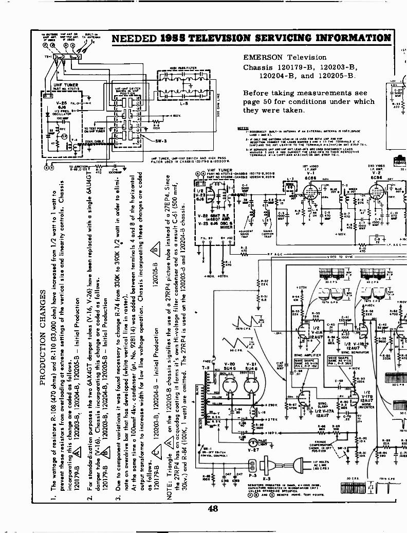
PR
OD
UC
TIO
N C
HA
NG
ES
I.T
he w
atta
ge o
f res
isto
rs R
-108
(47
0 oh
ms)
and
R-1
10 (
33,0
00 o
hm)
have
incr
ease
d fr
om 1
/2 w
att t
o 1
wat
t to
prev
ent t
hese
res
isto
rs fr
om o
verlo
adin
g at
ext
rem
e se
tting
s of
the
vert
ical
siz
e an
d lin
earit
y co
ntro
ls. C
hass
isin
corp
orat
ing
this
cha
nge
are
code
d as
follo
ws.
I.=
1201
79-B
A 1
2020
3-B
, 120
204-
B, 1
2020
5-B
- In
itial
Pro
duct
ion
:1,.
1-. ,g
2.F
or s
tand
ardi
zatio
n pu
rpos
es th
e tw
o 6A
X4G
T d
ampe
r tu
bes
(V-1
6, V
-26)
hav
e be
en r
epla
ced
with
a s
ingl
e 6A
U4G
T...
-da
mpe
r tu
be V
-16)
. Cha
ssis
inco
rpor
atin
g th
is c
hang
e ar
e co
ded
as fo
llow
s.
zit\
1202
03-B
, 120
204-
B, 1
2020
5-B
- In
itial
Pro
duct
ion
I.,.
1201
79-B
o-3.
Due
to c
ompo
nent
var
iatio
ns it
was
foun
d ne
cess
ary
to c
hang
e R
-74
from
330
K to
390
K 1
/2 w
att i
n or
der
to e
limi-
1 §:
1Tna
te a
n ov
erdr
ive
bar
that
has
dev
elop
ed (
whi
te v
ertic
al li
ne in
ras
ter)
.A
t the
sam
e tim
e a
100m
mf 4
kv. c
onde
nser
(pt
. No.
928
114)
was
add
ed b
etw
een
term
inal
s 4
and
8of
the
horiz
onta
l
outp
ut tr
ansf
orm
er to
incr
ease
wid
th fo
r lo
w li
ne v
olta
ge o
pera
tion.
Cha
ssis
inco
rpor
atin
g th
ese
chan
ges
are
code
d
as fo
llow
s.12
0179
-B12
0203
-B, 1
2020
4-B
- In
itial
Pro
duct
ion
1202
05-B
A
NO
TE
: Tria
ngle
on th
e 12
0205
-B c
hass
is s
igni
fies
the
use
of a
27R
P4
pict
ure
tube
inst
ead
of a
27E
P4.
Sin
ce
the
27R
P4
has
an a
cqua
dag
coat
ing
it fo
rms
it's
own
Hi -
volta
ge fi
lter
cond
ense
ran
d as
a r
esul
t C-6
1 (5
00 m
mf,
30kv
.) a
nd R
-84
(100
K,
1w
att)
are
om
itted
. The
27R
P4
is u
sed
on th
e 12
0203
-d a
nd 1
2020
4-B
chas
sis.
4
SLA
CK
BLA
CK
10 U
000
1 m00
< 0ro
oa
L
1 N
O
o <
m90
$- lt2
r
1 L
ro.7
171-
70. CA
r -
L_
300
0111
1 L
INE
I IN
-J
ED
cp4
(I)
11)
cri
0cn
c.n
Cl
ED
0+cn-
cn'1 cD
0"'
1--,
a)-
)
Z''
2 C
rcl
10 -E
D0
...-3
oo
ra.
-'a)
(f)
cl, co
O
,--4
.
.-a.
. va
r,.
O1-
-,E
n1 ED
Ev
O 0 ,'
n..,
CI
(1)
0E
D0
c..3
11&
)td
co0-
ED
n+-.
(.1)
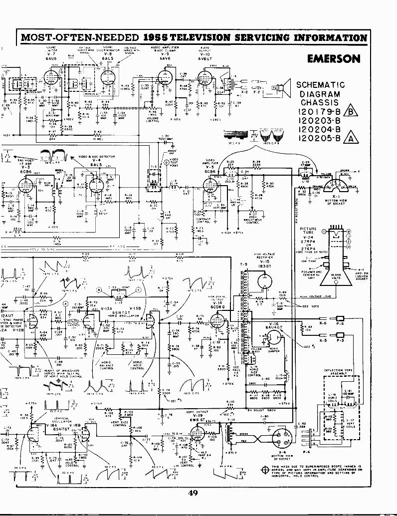
IMOST -OFTEN -NEEDED 195 TELEVISION SERVICING INFORMATIONwmc
DSOUND VOLTAGE SOUND VOLTAGE
LIMITER vAArs ATH DISCRIMINATOR vARIES WITH
V- 7 SIGNAL V-8 SIGNALA .1
6AU6 6AL5, 1 7 ..,_ ov
-.9v57v 1570 or -I
R-34
C9470
0
-1600141
:ME 00T 7 6
C -301C-324 68 - 5000
MAE'MMf
VIDEOp -P
3R0MAP
V-36CB6 ISO
Lv.
R -I58200 'C
C -1268
30F
113,,14
O
68 Ux 0 0
L - 6
GC
00
5000106K
22
1875 C
C-14
MMF8 ° 170
C-1310003414F
R-/6mEG
VIDEO TO Sr,
re77_f_875 c P S
C-47.001
7875 L P
R-66
46 228 14 - 0022 .05.MOO AT."
12AU7 ' R-6582K
. SYNC. PHASERTER IS HOR1Z.3E DETECTOR I3
12A V -I28
0-43
70IMF
C - 5I
i3v
L-73. 0 I
C-72.0047
8-97100K
R-64B2K
R-396800
-J.661rN Do T 7 6
R-42 R-44iOOK 68K
R -41tOOK
R-17IOTA
68
1,7B 75CP5
C-SI100 MMF
8-H-C-49.001
C -SO
I.015R-69- 120010011
7875 C PS
ON1 05
VALprAgs.2v 3
I(\ C-48
.001
HEIGHT OF wAvESHAPEg8RfEa;NI.TIL
CONTROL.
.444;494 v Pao
+275 V.
R-98ISO K
30 CPS
7875 CPS
30 CPS
VERTICALOSCILL ATOR
V -18A V -18B6SN7GT 70
V I
C -74.0047
R-101820K
751VERTHOLDCONTROL
30 CPS
7875 C P S
+2750
90VTO 1250
P -P
R.4510 MEG
C2,3 C-340022
Imm' 1"--
-43
D
MA'IO MEG
L 7
A. 68 UH
C .1811000MMF I
1 r C C
C 53 0047
10R-70 L-13IS K032v V -13A V -I3
6SN7GTHORtZ. OSCILLATOR
AUDIO AMPLIFIER(*ACC CLAMP
V-96AV6
92
IR-472208
R-46I MEG v
VOLUMECONTROL
7 v TO 9.401
Z HOR1Z ZHORIZBALANCE HOLDCONTROL CONTROL
AUDIOOUTPulV -I0
6V6GT
23Sv 85 of
001 R-49 R-50470 1500
+160V +2900
C-205000 SUP
'Or
/ ''FilFTT-5
(-11I°-10,00,1
20014
8.5v
L Et
40uH
R-224700
2150
0
R-114
VIDEOAMPLIFIER
V -S
6C86
11C
8-2 P-2iND
- 3980
pOy
30 C P 5 070 C P
0 0477 250u
C -23O1000 MME
0-241500
CONTRASTCONTROL
8-23MEG
C ,(2)2
C-57 R -79.001 66
C-56390MMF
/7875 CPS
74330K
`SEE .3
OS
-105EG
C-7711
+ C-78
-1
875 CPS
R 272 OK -
BRIGHTNESSCONTROL
+1600. +2 5v
HORIZONTALOUTPUT
V-146CD6G
C-59 I
R-110100
T- 9
700R-IIS
47
C-83100MMF
SEEPAGE
243
+ 2TSV
R-304705
HIGH VOLTAGERECTIFIER
V -I5IB3GT
2.7
R -84100K,
7. 500 '1.--MMF
V-166AU4 GT
ELL DOOW H AMMIT PPER
L-14HORIZSIZE
14 7L-15
C-60 1004.CONTROL
.15000
ed3.0.3/3"-WV-46%-eR -ill R-118 R-11961300 6800 6600 vs
R-110
VERT. OUTPUTV-19
6W6 GT
-.5v TO 2.4V 5
C-79100 400
n-106 T R-1082 2
470MEG -
R-107511
VERT
30 C PS LIN. CONTROL
.e±r
33K
,SEE
7-10
+ 2750
EMERSON
SCHEMATICDIAGRAMCHASSIS A120 I 79-B /B\I20203 -BI20204 -B AI20205 -B /A\
RAGNIN
C-2666X- I
BOTTOM VIEWOF SOCKET
PICTURETUBEV-24
2 7RP4OR
2 7EP 4(SEE PAGE 24 NOTE)
+ BOOST 580V
C-80DI
275
SEEPAGE 24
WI
6REE
+ 275 V.
S CPS
500v
X-4BOTTOM VIEW
OF SOCKET
O 12
I-1 _--4.7 7ION TRAP
m-i-T'VC 1=0*---__ 5-2FOCUSER AND ANTI PINCENTERING 18,000
CUSHIONUNIT VOLTS MAGNET0
Gm VOLTAGE LEAD
1, --SEE NOTE
X-6
10K
x-5SEE .2
C-1:12
P-4
P-6
P-5
DEFLECTION YOKEASSEMBLYr
I L-IB404.12
II COILS
C-81100 NNE
3 I
L-17 1
VERTCOILS
-J
THIS HASH DUE TO SUPERIMPOSED SCOPE IMAGES ISNORMAL AND NAY VARY IN AMPLITUDE DEPENDING ONTYPE OF PICTURE INFORMATION AND SETTING OFHORIZONTAL MOLD CONTROL.
49

MOST -OFTEN -NEEDED 1955 TELEVISION SERVICING INFORMATIONEMERSON Television Chassis 120179-B, 120203-B, 120204-B, 120205-B, continued
Models 7483, 784C, 787A, 787B and 786C incorporating chassis 120179-B and 120203-B are ALL CHANNELUHF - VHF RECEIVERS.' Combination VHF and UHF tuning is achieved through the use of two tuners which areconnected to the same tuning knobs making VHF or UHF channel tuning very simple. The VHF cascode turrettuner has 13 positions (one more than the conventional type), 12 being used for VHF reception, (channels 2 to 13),while the 13th or UHF position is used to activate the proper UHF circuits and provides additional amplification forthe converted 40 me UHF signals.
Models 777B, 797B, 797C and 7988 incorporating chassis 120204-8 and 120205-B are VHF receivers which can,if desired, be easily adapted to UHF by means of interchangeable channel strips or by use of an external converter.
0000TVIRONIT n fJI BATTING LU'S
to olOviDuAL cm.. *TOMO - - - - - mu orc-7,-7-4617-. ITM9=Oo TkOMIT1011. POETS ASH okOADOMO to Toff /AMON PI TYCO INSIOCTIVO Ar.MI
Toe 3V011.O MAP CIO 0/ 1/2 V-22 0.44LOCATO IOo
3- ALL INSMIAOC2 VAL. A*2 /o OoS oODO,ANO ,CAPAVTAsCr Yalta* OMo oo, 6...22 OTOO / 60002.*2 3,0,2D / C 10.
t."4 I/0BAL.300ANT. INPUT L 4
0
ARC 0
OOP
1/2 V-226BK7
-a° 140 TC-2UHF STRIP 70s113 TM POSITION,
960110
66007 `Li so,j,. C-5 I.,.
1000.0[
* 270 V 0--1,63
* 160V 0 ".""'630.0 "''
VIDEOI. FOUTPUT
IiaSR -,m
1Amcce l<
NOSS*C-17
FINETUNING
1/2 V-236J6 '"
*TOO OA
T -I
4.4 TO C -4I.04 34
L
MCI, mj4-7
!
TEST POINT
12-11
y. 1/2 V-23IZ 6J6
c-oo
TC -e
21
c-61-3
STRIP/3 TN KOITIOO1j 960 7 70
Woo.
TUNER PART NO. 470712 748 rumt MOT, SCHEMATIC PART NO, 950246NOTE
MIT 0. TO POONELE rMIAYT K
TIOKI 1011.11HLEEMOTIC EXCAM.1".."".Tune' MT nAvl TO OE TREIO FOP IMMILTS.TE
SCHEMATIC DIAGRAM OF VHF TUNER 470712 USED ON UHF -VHF CHASSIS 120179-B, 120203-8
ANT. INPUTSAL.300.11
ABC 0
+270V.0
+160V.0
6.3V.
/S
ROA980630
R.FANF1/2 V-226807
L 3 41 I
Ls
C -II TO C -IS PI NOS. I40407
TUNER PART NO. 470696
R 1
-7
L-9
.
AK MOUNTED oM MOIVIOUALCOMMEL TIMOIT.181704 KNOTS 400 ht...0IN
9111174MCE WLUES Aft9
rica CORER Of TRE111 91171 0110ELOCATMM 11.01.1 E.01 TME TUOIE11.
3- 4U.111 OM. AMO CANCITAITCEMK IN NMI MUM* OTHEIMMEMOICATEO.
I .1.M SONE TIME"
' : L-10 Ti L-12 nite /.1:.*.c`T'.°.7.c:f.:.
--i..,
.. 1 4.111 UN 1000 ,,,, g,.
MID L-13 1410633
1L-11 1/s V-23 194 -, _VIDEOT- I
960634
9.I
-... I C 1 I OUTPUT1 C J6
7
-as -a4C-6
4.
R -I0WC
IV.' 1960831
4.-
L. -J
'OSCILLATOR11/2 V-23I 646
MECHANICAL PARTS CAN BE ORDERED BY NAMINGPARTS FUNCTION AND NOTING THE TUNER PT NO.
NOTE: THE 8.F AMP TUBE PRESENTLY USED IS A 6807. IN TIE FUTURE A 8007, SOOTS OR A 8027 NAYDE MO. TREK 7141411 TOMS ENE NOTZECNANSEASLE. ROT DOE TO POSSIIIL VAR! AT IONS IN
IN RODE CAPACITIES. TUBES WY NAVE TO SE TR1(0 FOR REST NRSULTII
E$01
TEST POINT
A2 -A13
9110C- 13Si-03
M0 I
V: I
SCHEMATIC PART NO. 950219
SCHEMATIC DIAGRAM OF TURRET TYPE TUNER USED ON VHF CHASSIS 120204-B, 120205-B
50
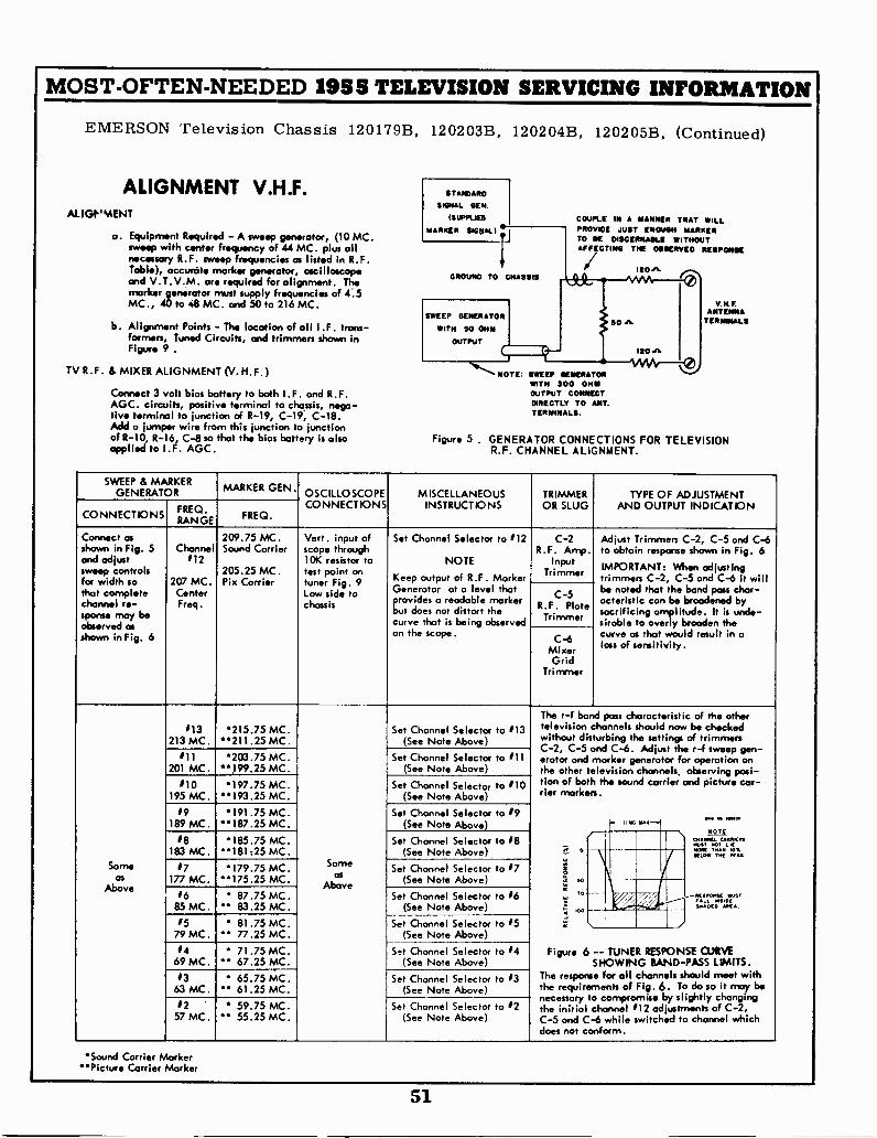
MOST -OFTEN -NEEDED 1955 TELEVISION SERVICING INFORMATION
EMERSON Television Chassis 120179B, 120203B, 120204B, 120205B, (Continued)
ALIGNMENT V.H.F.ALIGP'MENT
STANDARD
SIGNAL GEN.
ISUPPLIES COUPLE IN A MANNER TNAT MILL
a. Equipment Required - A sweep generator, (10 MC.MARKER SIGNAL) PROVIOE JUST ENOUGH MARKER
TO ME DISCERNABLE WITHOUTsweep with center frequency of 44 MC. plus allnecessary R. F . sweep frequencies as listed in R.F. i'Table), accurate marker generator, oscilloscope
GROUNO TO CHASSIS
AFFECTING THE 0111SERVE0 RESPONSE
Ito" ..-...,I '0,'and V.T.V.M. are required for alignment. The
marker generator must supply frequencies of 4.5.....
MC., 40 to 48 MC. and 50 to 216 MC.
b. Alignment Points - The location of all I .F. trans-formers, Tuned Circuits, and trimmers shown in
SWEEP GENERATOR
WITH SO OHM
OUTPUT
50 JL
V. 14F.
TERMINALS
Figure 9 . ISO"rot
TV R. F. & MIXER ALIGNMENT (V. H. F. ) NOTE. SWEEP GENERATOR uWITH 300 OHM
Connect 3 volt bias battery to both I .F. and R.F. OUTPUT CONNECTDIRECTLY TO ANT.AGC. circuits, positive terminal to chassis, nega-
flue terminal to junction of R-19, C-19, C-18. TERMINALS.
Add a jumper wire from this junction to junctionof R-10, R-16, C-8 so that the bias battery is also Figure 5 . GENERATOR CONNECTIONS FOR TELEVISIONapplied to I .F. AGC. R.F. CHANNEL ALIGNMENT.
SWEEP & MARKERGENERATOR MARKER GEN.
OSCILLOSCOPE MISCELLANEOUS TRIMMER TYPE OF ADJUSTMENT
CONNECTIONS FREQ.RANGE FREQ.
CONNECTIONS INSTRUCT IONS OR SLUG AND OUTPUT INDICATION
Connect asshown in Fig. 5and adjustsweep controls
Channel112
209.75 MC.Sound Carrier
205.25 MC.
Vert. input ofscope through10K resistor totest point on
Set Channel Selector to 112
NOTE
Keep output of R.F. Marker
C-2R.F. Amp.
InputTrimmer
Adjust Trimmers C-2, C-5 and C-6to obtain response shown in Fig. 6
IMPORTANT: When adjustingtrimmers C-2, C-5 and C-6 it willfor width so
that completechannel re-sponse may be
207 MC.CenterFreq.
Pix Carrier tuner Fig. 9Low side tochassis
Generator at a level thatprovides a readable markerbut does not distort thecurve that is being observed
C-5R.F. PlateTrimmer
be noted that the bond pass char -acteristic can be broadened bysacrificing amplitude. It is unde-sirable to overly broaden theobserved as
shown in Fig. 6 on the scope.C-6
MixerGrid
Trimmer
curve as that would result in aloss of sensitivity.
113213 MC.
'215.75 MC.211.25 MC.
Set Channel Selector to 113(See Note Above)
The r -f band pass characteristic of the othertelevision channels should now be checkedwithout disturbing the settings of trimmersC-2, C-5 C-6. Adjust the
#11201 MC.
'203.75 MC.*199.25 MC.
Set Channel Selector to 111(See Note Above)
and r -f sweep gen-erator and marker generator for operation onthe other television channels, observing posi-
#10195 MC.
*197.75 MC.193.25 MC.
Set Channel Selector to 110(See Note Above)
tion of both the sound carrier and picture car -tier markers.
19189 MC.
191.75 MC.187.25 MC.
Set Channel Selector to 19(See Note Above) "K OW
...........
#8 185.75 MC. Set Channel Selector to 18 Ial('
zrt.,-,7-183 MC. 181725 MC. (See Note Above) r°
1 r 171`.'7:: X.,* ..
Same /7 179.75 MC.175.25
Sameas
Set Channel Selector to 17 ias 177 MC. MC. (See Note Above) ,t, soAboveAbove
1685 MC.
87.75 MC. 83.25 MC.
Set Channel Selector to 16(See Note Above)
' OUSTRESPONSESIDEIC, MSPIAIM A.
#5 81.75 MC. Set Channel Selector to 15 li''
IIILe79 MC. 77.25 MC. (See Note Above)
#469 MC.
71.75 MC. 67.25 MC.
Set Channel Selector to 14(See Note Above)
Figure 6 -- TUNER RESPONSE OJRVESHOWING BAND-PASS LIMITS.
1363 MC.
65.75 MC." 61.25 MC.
Set Channel Selector to 13(See Note Above)
The response for all channels should meet withthe requirements of Fig. 6. To do so it may be
by changing12
57 MC. 59.75 MC.
55.25 MC.Set Channel Selector to 12
(See Note Above)
necessary to compromise slightlythe initial channel 112 adjustments of C-2,C-5 and C-6 while switched to channel whichdoes not conform.
Sound Carrier MarkerPicture Carrier Marker
51
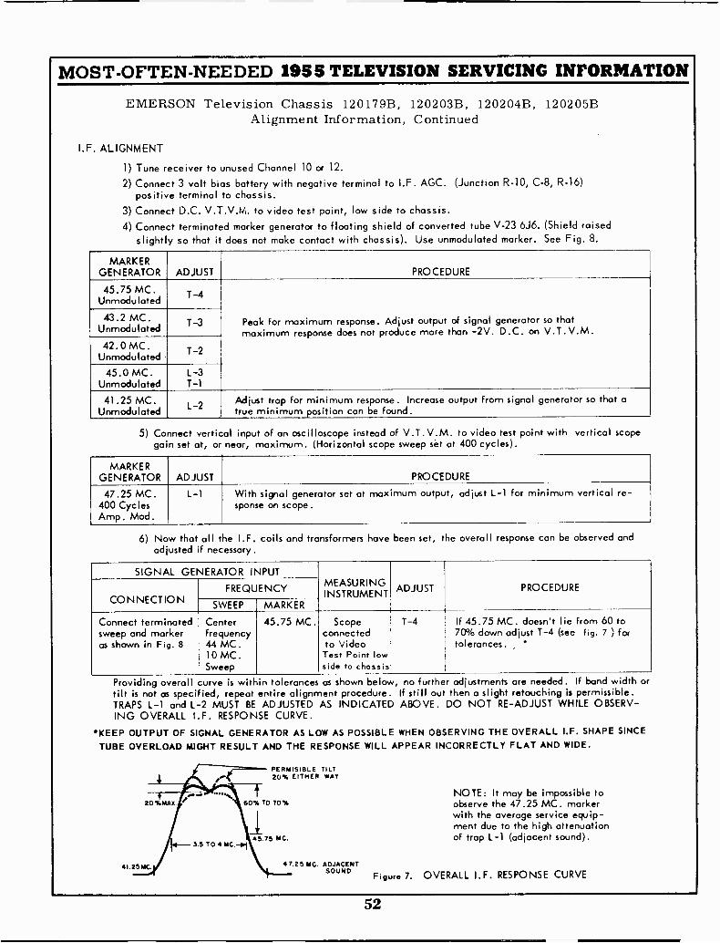
MOST -OFTEN -NEEDED 1955 TELEVISION SERVICING INFORMATION
I.F.
EMERSON Television Chassis 120179B, 120203B, 120204B, 120205BAlignment Information, Continued
ALIGNMENT
1) Tune receiver to unused Channel 10 or 12.2) Connect 3 volt bias battery with negative terminal to I.F. AGC. (Junction R-10, C-8, R-16)
positive terminal to chassis.3) Connect D.C. V.T.V.M. to video test point, low side to chassis.4) Connect terminated marker generator to floating shield of converted tube V-23 6J6. (Shield raised
slightly so that it does not make contact with chassis). Use unmodulated marker. See Fig. 8.
MARKERGENERATOR ADJUST PROCEDURE
45.75 MC.Unmodulated
T-4
Peak for maximum response. Adjust output of signal generator so thatmaximum response does not produce more than -2V. D.C. on V.T.V.M.
43.2 MC.Unmodulated T-3
42.0 MC.Unmodulated T-2
45.0 MC.Unmodulated
L-3T-1
41.25 MC.Unmodulated
L-2Adjust trap for minimum response. Increase output from signal generator so that atrue minimum position can be found.
5) Connect vertical input of an oscilloscope instead of V.T.V.M. to video test point with vertical scopegain set at, or near, maximum. (Horizontal scope sweep set at 400 cycles).
MARKERGENERATOR ADJUST PROCEDURE
47.25 MC.400 CyclesAmp. Mod.
L-1 With signal generator set at maximum output, adjust L-1 for minimum vertical re -sponse on scope.
6) Now that all the I.F. coils and transformers have been set, the overall response can be observed andadjusted if necessary.
SIGNAL GENERATOR INPUTMEASURINGADJUSTINSTRUMENT
PROCEDURE
CONNECTIONFREQUENCY
SWEEP MARKER
Connect terminatedsweep and markeras shown in Fig. 8
Centerfrequency44 MC.10 MC.Sweep
45.75 MC. Scopeconnectedto VideoTest Point lowside to chassis
1-4 If 45.75 MC. doesn't lie from 60 to70% down adjust 1-4 (see fig. 7 ) fortolerances. *
Providing overalltilt is not as specified,TRAPS L-1 and L-2ING OVERALL I.F.
KEEP OUTPUT OF SIGNALTUBE OVERLOAD MIGHT
Alllk,
curve
MUSTRESPONSE
is withinrepeat
BE
GENERATORRESULT
60%
I45.75
MC. -01
tolerancesentire alignmentADJUSTED
CURVE.
AS LOW
AND THE RESPONSE
PERMISIBLE20% EITHER
TO 70%
MC.
47.25 .MC.
as shown below, no further adjustments are needed. If band width orprocedure. If still out then a slight retouching is permissible.
AS INDICATED ABOVE. DO NOT RE -ADJUST WHILE OBSERV-
AS POSSIBLE WHEN OBSERVING THE OVERALL I.F. SHAPE SINCEWILL APPEAR INCORRECTLY FLAT AND WIDE.
TILTWAY
NOTE: It may be impossible toobserve the 47.25 MC. markerwith the average service equip-ment due to the high attenuationof trap L-1 (adjacent sound).
ADJACENTSOUND
Figure 7. OVERALL I.F. RESPONSE CURVE
.....20%MAY
3.5 TO
41.25 MC.
52
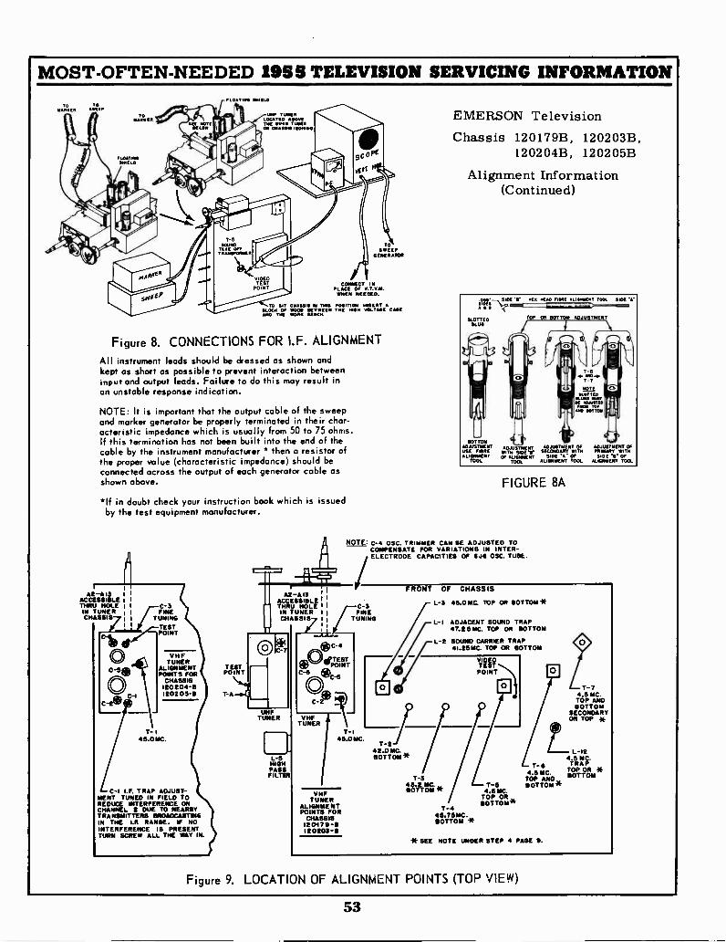
MOST -OFTEN -NEEDED 1955 TELEVISION SERVICING INFORMATION
NAR'KEN s
FLoATNGSHIELD
FLOATING SHIELD
UHF TUNERLOCATED AOvETHE SIAS TUNESON CHASSIS Iearfro
TOSWEEP
GENERATOR
CONNECT INPLACE OF V.Y.Y.M.WHEN NEEDED.
TO SIT HASSiS el THIS POSITIONBLOCK OF WOOD BETWEEN THE NISH IVOLTASE CASEAND TIC WORK BENCH.
Figure 8. CONNECTIONS FOR I.F. ALIGNMENT
All instrument leads should be dressed as shown andkept as short as possible to prevent interaction betweeninput and output leads. Failure to do this may result inan unstable response indication.
NOTE: It is important that the output cable of the sweepand marker generator be properly terminated in their char-acteristic impedance which is usually from 50 to 75 ohms.If this termination has not been built into the end of thecable by the instrument manufacturer * then a resistor ofthe proper value (characteristic impedance) should beconnected across the output of each generator cable asshown above.
*If in doubt check your instruction book which is issuedby the test equipment manufacturer.
A2 -A13ACCESSIBLETHRU HOLEIN TUNERCHASSIS
1 C-3
TUNINGTUNING
TESTPOINT
VHFTUNER
ALIGNMENTPOINTS FOR
CHASSIS12020413120205-6
T- I45.0 MC.
C -I I.F. TRAP ADJUST-MENT TUNED IN FIELD TOREDUCE INTERFERENCE ONCHANNEL 2 DUE TO NEARBYTRANSMITTERS BROADCASTINGIN THE I.F. RANGE. IF NOINTERFERENCE IS PRESENTTURN SCREW ALL THE WAY IN.
TESTPOINT
T -A
A2 -A13, 1
1
ACCESSIBLE I,'
THRU HOLE I C-3IN TUNER 1 1 FINECHASSIS 1 , TUNING
II
SLOTTEDSLUG
BOTTOMADJUSTMENT ADJUSTMENT ADJUSTMENT Of ADJUSTMENT OFUSE FIBRE WITH SECONDARY WITH PRIMARy WITHALIGNMENT OF ALIGNMENT SIDE 'A OF SIOE '11. OF
TOOL TOOL ALIGNMENT TOOL ALIGNMENT TOOL
EMERSON TelevisionChassis 120179B, 120203B,
120204B, 120205B
Alignment Information(Continued)
.opr- SIDE Ir HEa HEAD FINN ALI...EMT TOOL SIDE\oTOP OR BOTTOM ADJUSTMENT
FIGURE 8A
NOTE, C-4 OSC. TRIMMER CAN BE ADJUSTED TOCOMPENSATE FOR VARIATIONS IN INTER -ELECTRODE CAPACITIES OF 6J6 OSC. TUBE.
UHFTUNER
L-5HIGHPASSFILTER
C-5
T -I5.0 MC.
VHFTUNER
ALIGNMENTPOINTS FOR
CHASSIS1201711-9120203-B
FRONT OF CHASSIS
T-2/42.0 MC.BOTTOM w
L-3 45.0 MC, TOP OR BOTTOM*
L -I ADJACENT SOUND TRAP47.26 MC. TOP OR BOTTOM
L-2 SOUND CARRIER TRAP41.25MC. TOP OR BOTTOM
T-343.2 MC.BOTTOM *
T-445.76MC.BOTTOM *
T-64.5 MC.
TOP ANDT-6 BOTTOM'S
4.6 MC.TOP OR BOTTOM"
* SEE NOTE UNDER STEP 4 PAGE 9.
T-7.5 MC.TOP ANDBOTTOM
SECONDARYON TOP *
L 12.5 MC.TRAPTOP OR *BOTTOM
Figure 9. LOCATION OF ALIGNMENT POINTS (TOP VIEW)
53
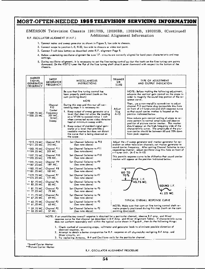
MOST -OFTEN -NEEDED 1955 TELEVISION SERVICING INFORMATION
EMERSON Television Chassis 120179B, 120203B, 120204B, 120205B, (Continued)Additional Alignment Information
R.F. OSCILLATOR ALIGNMENT (V.H.F.)
1. Connect maker and sweep generator as shown in Figure 5, low side to chassis.
2. Connect scope to junction L-8, R-22, low side to chassis or video test point.3. Connect 3 volt bias battery as described under R.F. alignment Page 8.
4. Before undertaking oscillator alignment be sure I.F. circuits are correctly aligned for band pass characteristic and trapsettings.
5. During oscillator alignment, it is necessary to set the fine tuning control so that the tooth on the fine tuning corn pointsdownward. On the 470712 tuner the flat of the fine tuning shaft should point downward with respect to the bottom of thechassis.
MARKERSIGNAL
GENERATORFREQUENCY
SWEEPGENERATORFREQUENCY
MISCELLANEOUSINSTRUCTIONS
TRIMMEROR
SLUG
TYPE OF ADJUSTMENTAND OUTPUT INDICATION
209.75 MC.**205.25 MC.
Channel#12
CenterFrequency
207 MC.10 MC.
Sweep
Be sure that fine tuning control hasbeen properly positioned (tooth on thecam pointing down)
NOTE
During this step and thru-out all suc-seeding steps it is necessary to:
1. Keep output of sweep generator at alevel that does not allow the readingon a VTVM to exceed minus 1 voltwhen connected across video detectorload at minimum sweep width.
2. Keep output of standard signal gen-erator at a level that provides areadable marker but does not distortthe curve that is being observed onthe scope.
AdjustSlugA-12
NOTE: Before making the following adjustment,advance the vertical gain control on the scope inorder to magnify the sound trap portion of the re -sponse curve.
Then, use a non-metallic screwdriver to adjustchannel #12 oscillator slug (accessible thru holeon front of r -f tuner unit)and shift response curveso that sound carrier marker is located at theposition indicated below.
Now reduce gain control setting of scope to re -store pattern to normal amplitude and observeposition of picture carrier marker. This markershould appear on the high frequency side of thecharacteristic curve. The amplitude of the pic-hire carrier should be between 60 and 70% downfrom peak response.
*215.75 MC."211.25 MC.203.75 MC.
199.25 MC.*197.75 MC.
**193.25 MC.I91.75 MC.
187.25 MC.'185.75 MC.
"181.25 MC.179.75 MC.
175.25 MC. 87.75 MC.
83.25 MC. 81.75 MC.
77.25 MC. 71.75 MC.
67.25 MC. 65.75 MC.
61.25 MC.* 59.75 MC.
55.25 MC.
Channel 013213 MC.
Channel #11201 MC.
Channel 110195 MC
Channel #9189 MC.
Channel #8183 MC.
Channel #7177 MC.
Channel #685 MC.
Channel #579 MC.
Channel #469 MC.
Channel #363 MC.
Channel #2.57 MC.
Set Channel Selector to #13(See note above)
Set Channel Selector to #11(See note above)
Set Channel Selector to #10(See note above)
Set Channel Selector to #9(See note above)
Set Channel Selector to #8(See note above)
Set Channel Selector to #7(See note above)
Set Channel Selector to #6(See note above)
Set Channel Selector to #5(See note above)
Set Channel Selector to #4(See note above)
Set Channel Selector to #3(See note above)
Set Channel Selector to #2(See note above)
Adjust the r -f sweep generator and marker generator for op -eration on other television channels; set marker generator tosound carrier frequency. After setting Channel Selector to cor-responding channel, adjust oscillator slug thru hole on front ofr -f tuner unit. (A-2 to A-13)
This permits response curve to be shifted so that sound carriermarker will appear at the position indicated below.
60 TO70%
+ PIX I.F.45.75 MC.
SOUND I. F.
41.25 MC.
TYPICAL OVERALL RESPONSE CURVE
NOTE: Make sure that cam on fine tuning control shaft re-mains properly positioned during this step (tooth on the cornpointing downward).
NOTE: If an unsatisfactory overall response is obtained for a particular channel, observe R -F amp. and Mixerresponse curve for that channel (as described in R -F Amp. and Mixer Alignment Table). If characteristic curvedoes not conform reasonably well within the typical curve shown in Figure 6 then do the following things:
1. Check method of connecting scope, voltmeter and generator leads to eliminate possible distortion ofobserved response, or:
2. Attempt to obtain a better compromise for R.F. response on all channels by realigning R -F Amp. andMixer circuits, or:
3. Try replacing Antenna, R -F and Oscillator coils for the particular channel.
'Sound Carrier MarkerPicture Carrier Marker
R,F. OSCILLATOR ALIGNMENT PROCEDURE
54
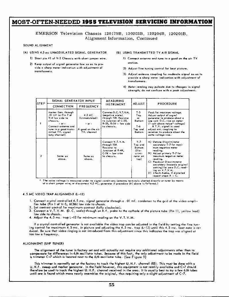
MOST -OFTEN -NEEDED 1955 TELEVISION SERVICING INFORMATION
EMERSON Television Chassis 120179B, 120203B, 120204B, 120205B,Alignment Information, Continued
SOUND ALIGNMENT
(A) USING 4.5 mc UNMODULATED SIGNAL GENERATOR (B)
1) Short pin #1 of V-3 Chassis with short jumper wire.
2) Keep output of signal generator low so as to pro-vide a sharp meter indication with adjustment oftransformers.
USING TRANSMITTED TV AIR SIGNAL
1) Connect antenna and tune to a good on the air TVstation.
2) Adjust fine tuning control for best picture.
3) Adjust antenna coupling for moderate signal so as toprovide a sharp meter indication with adjustment oftransformers.
4) Meter reading may pulsate due to changes in signalstrength; do not confuse with a peak adjustment.
STEPSIGNAL GENERATOR INPUT MEASURING
INSTRUMENT ADJUST PROCEDURECONNECTION FREQUENCY
1
Marker Gen. through.01 MF to Pin 7 ofV-4 low side tochassis.
Connect antenna andtune in a good trans-mitted TV. signal(any channel)
4.5 MC(ljnmodulated)
A good on the airTV. channel
Conntec D.C. V.T.V.M.(negative scale)through 10K Resistorto Junction of C-30,R-35, R-36 - low sideto chassis.
T-5Topor
Bottom
T-6Top and
Bottom
Peak for maximum voltage.Adjust output of signalgenerator to produce about aone volt D.C. rise on meter(1 volt above noise* voltage)
If T.V. signal is usedadjust ant. coupling toreceiver to produce about thesome voltage rise.
2 Same asabove.
Same asabove.
Connect V.T.V.M.through 10K
Junction of R-44,C-34 - low sideto chassis.
T-7Top andBottom(Dis-crimi-
nator ontop)
A) Detune Discriminatorsecondary T-7 for maxi -mum negativereading.
B) Adjust primary T-7 formaximum negative meterreading.
C) Readjust Discriminatorsecondary (towards originalsetting) for zero D.C. read-ing on V.T.V.M.
D) Check Audio, if distortedrepeat steps A - C.
* The noise voltage is measured under no signal conditions (antenna terminals shor ed directly at tuner by meansof a short jumper wire; or disconnect 4.5 MC. generator if procedure (A) above is followed.)
4.5 MC VIDEO TRAP ALIGNMENT (L-12)
1. Connect crystal controlled 4.5 mc. signal generator through a .01 mf. condenser to the grid of the video ampli-fier tube (Pin 1 of V-5, 6CB6) low side to chassis.
2. Set contrast control for maximum contrast (fully clockwise).3. Connect a V.T.V.M. (D.C. scale) through an R.F. probe to the cathode of the picture tube (Pin 11, yellow lead)
low side to chassis.4. Adjust the 4.5 mc. trap L-12 for minimum reading on the V.T.V.M.
If a crystal controlled generator is not available the video trap can be adjusted in the field by setting the fine tun-ing control for maximum 4.5 mc. in picture and adjusting the 4.5 mc. trap (L-12) until this 4.5 mc. beat note is re-duced. Be sure that video ringing is not introduced from this adjustment since this indicates the trap was aligned attoo low a frequency.
ALIGNMENT (UHF TUNER)
The alignment of the tuner is factory set and will actually not require any additional adjustments other than tocompensate for differences in 6J6 oscillator tubes. Because of this fact, the only adjustment to be made in the fieldis trimmer C-7 which is located next to the 6J6 oscillator tube. (See Figure 9)
This trimmer is normally set at the factory to track the highest U. H.F.channel (83). This must be done with aU. H.F. sweep and marker generator. In the field however, this equipment is not readily available and C-7 shouldtherefore be used to track the highest U. H.F. channel received in the area. It is usually best to try a few 6J6 tubesuntil one is found which more nearly resembles the original, thus requiring only a slight adjustment of C-7.
55
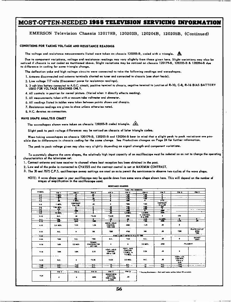
MOST -OFTEN -NEEDED 1955 TELEVISION SERVICING INFORMATION
EMERSON
CONDITIONS
The
Duenoticedto difference
The
I. Antenna
2. Line
3. 3USED
4. All
5. All6. All
7. Resistance
8. N.C.
WAVE SHAPE
The
Slight
Whensible
The
Tocharacteristics1. Connect
2. Low3. The
NOTE:
Television Chassis 120179B,
FOR TAKING VOLTAGE AND RESISTANCE READINGS
voltage and resistance measurements listed were taken on chassis
to component variations, voltage and resistance readings mayif chassis is not coded as mentioned above. Slight variations
in coding for same triangle change.
deflection yoke and high voltage circuits were connected to take
disconnected and antenna terminals shorted on tuner and connected
voltage 117 volts (Disconnect power for resistance readings).
volt bias battery connected to A.G.C. circuit, positive terminal to chassis,FOR VOLTAGE READINGS ONLY.
controls in position for normal picture. (Varied when it directly
measurements taken with a vacuum tube voltmeter and ohmmeter.
readings listed in tables were taken between points shown and chassis.
readings are given in ohms unless otherwise noted.
denotes no connection.
ANALYSIS CHART
waveshapes shown were taken on chassis 120205-B coded triangle.
peak to peak voltage differences may be noticed on chassis
taking waveshapes on chassis 120179-B, 120203-B and 120204-Bdue to differences in chassis coding for the same change. See
peak to peak voltage given may also vary slightly depending
accurately observe the wave shapes, the relatively high input capacityof the television set.
antenna and tune receiver to channel where best reception has
end of the probe is connected to CHASSIS and the contrast control
30 and 7875 C.P.S. oscilloscope sweep settings are used so as
A wave shape seen in your oscilloscope may be upside downstages of amplification in the oscilloscope used.
RESISTANCE
120203B, 120204B,
120205-B, coded with
vary slightly from thosemay be noticed on chassis
the following readings
to chassis (use short
negative terminal to
effects reading).
120205B, (Continued)
a triangle. Agiven here. Slight variations may also
120179-B, 120203-B & 120204-B
and waveshapes.
leads).
junction of R-10, C-8, R-16 BIAS BATTERY
a slight peak to peak variations arePage 24 for further information.
variations.
must be reduced so as not to change the
observe two cycles of the wave shape.
here. This will depend on the number
bedue
pos-
operating
of
of later triangle codes.
bear in mind thatProduction changes on
on signal strength and component
of an oscilloscope
been obtained in the past.
is set at MAXIMUM CONTRAST.
to permit the serviceman to
from same wave shape shown
READINGS
SYMBOLTUBE PIN NUMBERS
PIN 1 PIN 2 PIN 3 PIN 4 PIN S PIN 6 PIN 7 PIN 11 PIN 9
V-1 MEG. 47 .02 Q '1311 I311 0_
V.2 I 47 0 0 I3K '13K 0
94 0 In .02 0 1311 I3K 0
7-4 .02 I MEG. 6 0 150K 0 4.741
V-5 1 MEG.CONTRAST
0 to 130 .02 0 221( I3K CONTRAST0 to 13K
- - -:1 14 MEG. 0 0 .02 '1311 1311 367:
' 4; 0 0 .02 931- Crv-11
V.9 10 MEG.1001(
0
00
N-----.02
TOOKTONTLS MEG. 13 MEG. 23316
V-10 N.C. .04 16.511 I6.511 4700V. CONTROL
0 to 210K 0 470
9.11 14.7K 0 .03 02 5.511 2.3 MEG. 0
220 264K 100K 0 0 11116 330K 4.70 .02
V -I3 2.4 MEG. 3711 I.2KHORIZ. HOLD
CONTROL100K -140K
4400 1.20 .02 0
V.14 N.C. 0PLATE100 .22K 476K 100 .02 '2241CAP OF
11063011
9.15 PINS 2 %ND 7 INFINITE PLATE 1011
V-16 220 N.C. 3211 N.C. 140 N.C. .05 0NAGIGTUSED
V-10 163K 2.2 MEGFRINGE
COMPENSATOROFF IRK
0 0 2.2 MEG. 470K FILAMENT
--.1
VI0 1001C 16.10 2.2KVERT. HOLD
CONTROL020 to LK
VERT. SIZECONTROL1.S MEG. to3.2 MEG.
2.2k .03 0
V.19 N.C. 0 14.20 14.3K 2.5 MEG. N.C. .02
LIN.CONTROL470
0 to5.40
-_VERT.
N.C. I4 1( N.C. N.C. 11,C, 11 1(N.C.IS140 N.C. 15 6.5 N.C. 141(
V..,11, Room... - 9.11 omit motor omlos (*loot 30 soyoo1a1.
V-24
PIN 1 PIN 2 PIN 10 PIN II PIN 12
0 0 112011
BRIGHTNESSCONTROL
22011 to 2400to Y2OK
.02
56
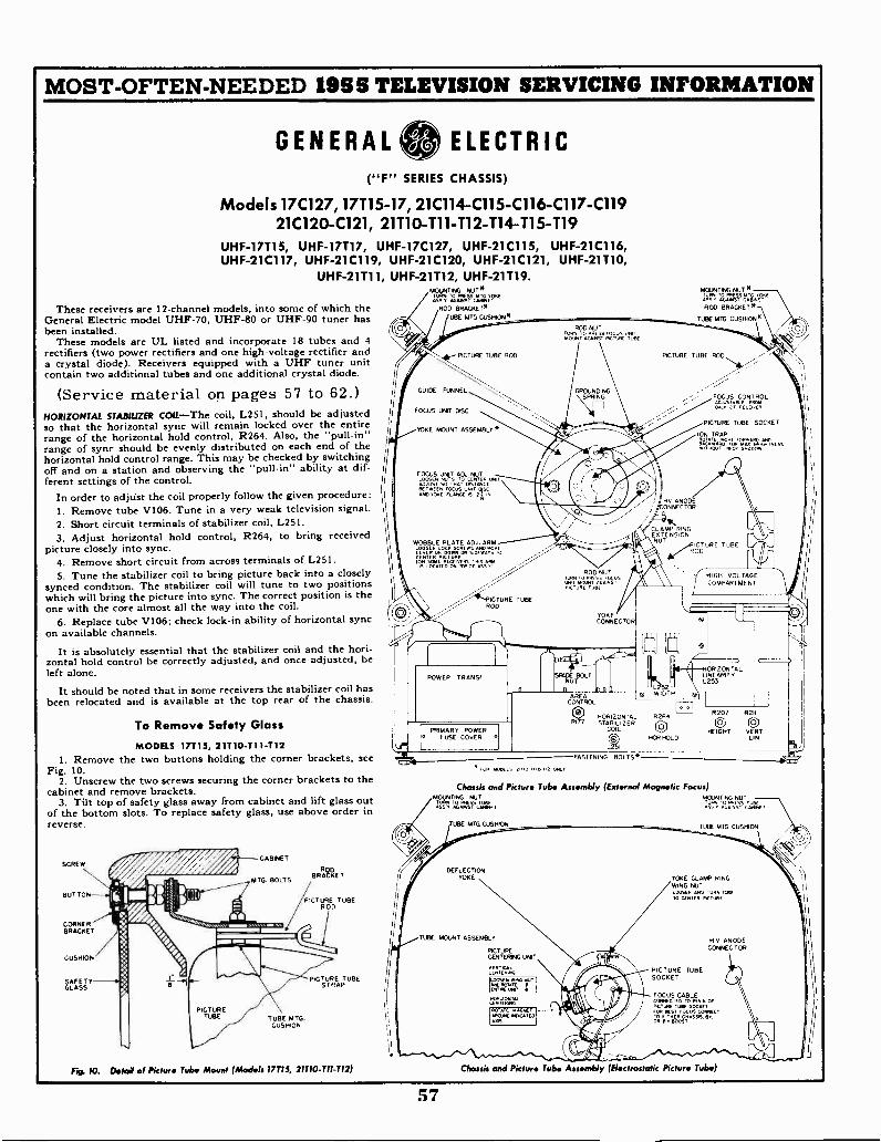
MOST -OFTEN -NEEDED 1955 TELEVISION SERVICING INFORMATION
GENERAL ELECTRIC("F" SERIES CHASSIS)
Models 17C127, 17T15-17, 21C114 -C115 -C116 -C117 -C11921C120 -C121, 21110 -T11 -T12 -T14 -T15 -T19
UHF -17715, UHF -17T17, UHF -17C127, UHF -21C115, UHF -21C116,UHF -21C117, UHF -21C119, UHF -21C120, UHF -21C121, UHF -21T10,
UHF -21711, UHF -21T12, UHF -21719.
These receivers are 12 -channel models, into some of which theGeneral Electric model UHF -70, UHF -80 or UHF -90 tuner hasbeen installed.
These models are UL listed and incorporate 18 tubes and 4rectifiers (two power rectifiers and one high -voltage rectifier anda crystal diode). Receivers equipped with a UHF tuner unitcontain two additional tubes and one additional crystal diode.
(Service material on pages 57 to 62.)HORIZONTAL STABILIZER COIL-The coil, L251, should be adjustedso that the horizontal sync will remain locked over the entirerange of the horizontal hold control, R264. Also, the "pull -in"range of sync should be evenly distributed on each end of thehorizontal hold control range. This may be checked by switchingoff and on a station and observing the "pull -in" ability at dif-ferent settings of the control.
In order to adjust the coil properly follow the given procedure:1. Remove tube V106. Tune in a very weak television signal.2. Short circuit terminals of stabilizer coil, L251.3. Adjust horizontal hold control, R264, to bring received
picture closely into sync.4. Remove short circuit from across terminals of L251.5. Tune the stabilizer coil to bring picture back into a closely
synced condition. The stabilizer coil will tune to two positionswhich will bring the picture into sync. The correct position is theone with the core almost all the way into the coil.
6. Replace tube V106; check lock -in ability of horizontal syncon available channels.
It is absolutely essential that the stabilizer coil and the hori-zontal hold control be correctly adjusted, and once adjusted, beleft alone.
It should be noted that in some receivers the stabilizer coil hasbeen relocated and is available at the top rear of the chassis.
To Remove Safety Glass
MODELS 17715, 21110-T11.112I. Remove the two buttons holding the corner brackets, see
Fig. 10.2. Unscrew the two screws securing the corner brackets to the
cabinet and remove brackets.3. Tilt top of safety glass away from cabinet and lift glass out
of the bottom slots. To replace safety glass, use above order inreverse.
SCREW
BUT TON
CORNERBRACKET
CUSHION
GLASSY
CABINET
MTG. BOLTSORRAnET
PICTURE TUBEROD
TUBE MTG.CUSHION
PICTURE TUBESTRAP
MOUNTING WIT*TSn Tzw=m" "
ROD BRACKET*TUBE MIS CUSH ON*
FOCUS UNIT DISC
YOKE MOUNT ASSEMBLY
FOCUS UNIT AN NUTLOOSEN NUTS TO CENTER uNIADJUST SO TR, DISTRNCEBETWEEN FOCUS UNITAN. YORE FLANGE IS 2 iN
ICTURE TUBEROD
POWER TR ANSE
PRIMARY POWERP FUSE COVER .7
ROD NUT
ROD NUT
Z711ZY'RICTURE TUBE
YOKECONNECTOR
311SPREE BOLT
NUTaAUG
FOR NOCE, ,TiO, Tv B I, ONLY
AREACONTROL
HORIZONTALSTABILI ZER
COIL
FASTENING BOLTS*
MOUNTING NUT *
Tx: zmw cc
ROD BRACKET*
TUBE MTG CUSHION
PICTURE TUBE ROD
PICTURE TUBE SOCKET
ION TRAPROTATE v( OKRApp
Raw°, NEC. SNA00.
NU ANODEONNEC TOR
itsCLAMP RINGEXTENSIONNUT
PICTURE TUBE
HIGH- VOLTAGECOMPARTMENT
HORZONTALLINEARITYL253
R207 R211
O 0HEIGHT VERT
LIN
Chassis and Picture Tube Assembly (External Magnetic Focus)MOUNTING PUT
Tan 'zzirJ.44,
TUBE MTG CUSH
DEFLECTIONYOKE
TUBE MOUNT ASSEMBLY
PICTURECENTERING UNIT
VERTLu.NIENVED
UXISEN OAK T I
tnrtIRIET e
Egyar,zROTATE MAGNETMORO NOPCATEDANS
TUBE RIG CUSHION
YOKE CLAMP RINGWING NUTLOOSEN A. TURN Yr.TO CENTER NCTURE
NV ANODECONNECTOR
PICTURE TUBESOCKET
FOCUS CABLECONNECTED TO PIN 6 OFPTURE TUBE SOCKETFOR BEST FOCUS CONNECTTE, ['THEIR CHASSIS,. BOOST
Fig. 10. Deka of Picture Tube Mown (Models 17715, 21T10 -T11 -T12) Chassis and Pkture Tube Assembly (Electrostatic Picture Tube)
57
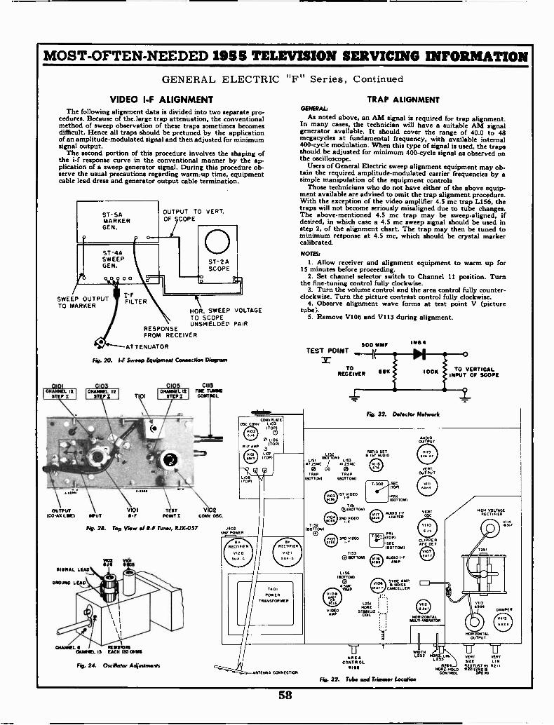
MOST -OFTEN -NEEDED 1955 TELEVISION SERVICING INFORMATION
GENERAL ELECTRIC
VIDEO I -F ALIGNMENTThe following alignment data is divided into two separate pro-
cedures. Because of the large trap attenuation, the conventionalmethod of sweep observation of these traps sometimes becomesdifficult. Hence all traps should be pretuned by the applicationof an amplitude -modulated signal and then adjusted for minimumsignal output.
The second portion of this procedure involves the shaping ofthe i-f response curve in the conventional manner by the ap-plication of a sweep generator signal. During this procedure ob-serve the usual precautions regarding warm-up time, equipmentcable lead dress and generator output cable termination.
ST- 5AMARKERGEN.
SWEEP OUTPUTTO MARKER
0101CHANNEL 12
STEP I
47-1'
-n1
OUTPUT(CO -AX LINE)
F
FILTER
OUTPUT TO VERT.OF COPE
ST- 2ASCOPE
HOR. SWEEP VOLTAGETO SCOPE
RESPONSEUNSHIELDED PAIR
FROM RECEIVER
AT TENuATOR
Fig. 20. I -F Sweep Equipment Connection
0103CHANNEL II
STEP I
0105
T 01
CII5FINE TUNINGCONTROL
V101 TI ST V102MUT R -F POINT I CONY OSC
Fig. 28. Top View of R -F Tuner, RJX-057 J002UNE POWER
V102 V1016.16 61106
SIGNAL LEAD
GROUND LEAD
CHANNEL 6 RESISTORSCHANNEL 13 EACH 120 OHMS
Fig. 24. Oscillator Adjustments
COW/ PLATECONV L103
(TOP)
"F" Series, Continued
ANTENNA CONNECTION
TRAP ALIGNMENTGENERAL:
As noted above, an AM signal is required for trap alignment.In many cases, the technician will have a suitable AM signalgenerator available. It should cover the range of 40.0 to 48megacycles at fundamental frequency, with available internal400 -cycle modulation. When this type of signal is used, the trapsshould be adjusted for minimum 400 -cycle signal as observed onthe oscilloscope.
Users of General Electric sweep alignment equipment may ob-tain the required amplitude -modulated carrier frequencies by asimple manipulation of the equipment controls
Those technicians who do not have either of the above equip-ment available are advised to omit the trap alignment procedure.With the exception of the video amplifier 4.5 mc trap L156, thetraps will not become seriously misaligned due to tube changes.The above -mentioned 4.5 mc trap may be sweep -aligned, ifdesired, in which case a 4.5 mc sweep signal should be used instep 2, of the alignment chart. The trap may then be tuned tominimum response at 4.5 mc, which should be crystal markercalibrated.
NOTES:
1. Allow receiver and alignment equipment to warm up for15 minutes before proceeding.
2. Set channel selector switch to Channel 11 position. Turnthe fine-tuning control fully clockwise.
3. Turn the volume control and the area control fully counter-clockwise. Turn the picture contrast control fully clockwise.
4. Observe alignment wave forms at test point V (picturetube).
5. Remove V106 and V113 during alignment.
500 MMFTEST POINT ...1
L '52(SOTTO
4i 2SMC
eTRAP
BOTTOM)
T152(BOTTOM)
TORECEIVER
L1534125 MC
0TRAP
(BOTTOM)
ST, ()IDEO
®18(IT TO,
2NO VIDEO
3R0 VIDEO T
TIS3(BOTTOM)
L 156(BOTTOM)
o
4 5MCTRAP
VIDEOAMP
IN64
TO VERTICALINPUT OF SCOPE
Fig. 33. Detector Network
RATIO SET8 1ST AUDIO
SECDOR
(BOTTOM)
AUDIO I -FLIMITER
PRI"°1 ITOPI
'SEC(BOTTOM)
V 116 AUADIOpi F
L251MORI
STASILIZCOIL
AREACONTROL
RIBS
SYNC AMP15 NOISE
CANCELLER
AUDIOOUTPUT
VERTOUT PUT
VERTOSC
IO
CLIPPERAFC DE T
U
HORIZONTALMULTI -VIBRATOR
WIDTHL252 ETIFT.SL IN.
R264MORI-NOLO
CONTROL
SIGN VOLTAGERECTIFIER
HORIZONTALOUTPUT
VERT VERTS1Z E L IN
iliggToRt; ""3RD RI
VH4'4341
PER
Fig. 32. Tube and Trimmer Location
58
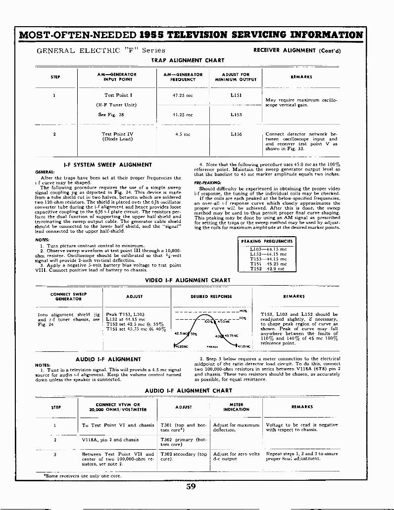
MOST -OFTEN -NEEDED 1955 TELEVISION SERVICING INFORMATIONGENERAL ELECTRIC "F" Series RECEIVER ALIGNMENT (Cont'd)
TRAP ALIGNMENT CHART
STEPAM-GENERATOR
INPUT POINTAM-GENERATOR
FREQUENCYADJUST FOR
MINIMUM OUTPUTREMARKS
1 Test Point I
(R-F Tuner Unit)
See Fig. 28
47.25 mc L151May require maximum oscillo-scope vertical gain.
41.25 mc L153
2 Test Point IV(Diode Load)
4.5 mc L156 Connect detector network be -tween oscilloscope input andand receiver test point V asshown in Fig. 33.
I -F SYSTEM SWEEP ALIGNMENT 4. Note that theGENERAL:
reference point. Maintainthat the baseline to
After the traps have been set at their proper frequencies thei-f curve may be shaped. PRE -PEAKING:
The following procedure requires the use of a simple sweep Should difficultysignal coupling jig as depicted in Fig. 24. This device is made i-f response, the tuningfrom a tube shield cut in two halves, between which are soldered If the coils are eachtwo 120 -ohm resistors. The shield is placed over the 6J6 oscillator an over-all i-f responseconverter tube during the i-f alignment and hence provides loose proper curve willcapacitive coupling to the 6J6 i-f plate circuit. The resistors per- method may be usedform the dual function of supporting the upper half -shield and This peaking mayterminating the sweep output cable. The generator cable shield for setting the trapsshould be connected to the lower half shield, and the "signal" ing the coils for maximumlead connected to the upper half -shield.
NOTES:
I. Turn picture contrast control to minimum.2. Observe sweep waveform at test point III through a 10,000-
ohm resistor. Oscilloscope should be calibrated so that h -voltsignal will provide 2 -inch vertical deflection.
3. Apply a negative 5 -volt battery bias voltage to test pointVIII. Connect positive lead of battery to chassis.
VIDEO I -F ALIGNMENT CHART
following procedure uses 45.0the sweep generator
45 mc marker amplitude
be experienced in obtainingof the individual coils
peaked at the below -specifiedcurve which closely
be achieved. After thisto thus permit proper
be done by using an AM signalor the sweep method may
amplitude at the desired
mc as the 100%output level so
equals two inches.
the proper videomay be checked.
frequencies,approximates the
is done, the sweepfinal curve shaping.
as prescribedbe used by adjust -
marker points.
PEAKING FREQUENCIES
L103-44.15 mcL152-44.15 mcT153-44.15 mcT151-45.25 mcT152-42.9 mc
CONNECT SWEEPGENERATOR
ADJUST DESIRED RESPONSE REMARKS
Into alignment shield jigand r -f tuner chassis, seeFig. 24
Peak T153, L103L152 at 44.15 mcT152 set 42.5 mc La 55%T151 set 45.75 mc @, 40%
_140%
lio%00% 45.0 MC
42.5 MC 55%45.75 MC
4125MC K... 47 25MC
T153, L103 and L152 should bereadjusted slightly, if necessary,to shape peak region of curve asshown. Peak of curve may fallanywhere between the limits of110% and 140% of 45 mc 100%reference point.
AUDLO I -F ALIGNMENT 2. Step 3 below requires a meter connection to the electricalNOTES: midpoint of the ratio detector load circuit. To do this, connect
1. Tune in a television signal. This will provide a 4.5 mc signal two 100,000 -ohm resistors in series between V118A (6T8) pin 2source for audio i-f alignment. Keep the volume control turned and chassis. These two resistors should be chosen, as accuratelydown unless the speaker is connected. as possible, for equal resistance.
AUDIO I -F ALIGNMENT CHART
STEPCONNECT VTVM OR
20,000 OHMS/VOLTMETER ADJUSTMETER
INDICATIONREMARKS
1 To Test Point VI and chassis T301 (top and bot-torn core*)
Adjust for maximumdeflection.
Voltage to be read is negativewith respect to chassis.
2 V118A, pin 2 and chassis T302 primary (bot-tom core)
3 Between Test Point VII andcenter of two 100,000 -ohm re-sistors, see note 2.
T302 secondary (topcore).
Adjust for zero voltsd -c output
Repeat steps 1, 2 and 3 to assureproper final adjustment.
*Some receivers use only one core.
59
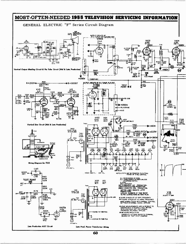
MOST -OFTEN -NEEDED 1955 TELEVISION SERVICING INFORMATIONGENERAL ELECTRIC "F" Series Circuit Diagram
ROOST
60
0 © 0
YON
awl". NIL.
Vertical Output Blanking Circuit & Pix Tube Circuit (Mid & Late Production)
B+250V
R201 C202 R202
821,00 82KTO PINT -c201OF V107 .T:00iMF
0254
C203470
VIDEODET
LI5 RI83470K
TEST POINT 1/2W3ZIff
AccI -F
AGCR -F TUNE
R22I
)grET. 3 MEG
R220V110 4.7 MEG
6.15VERT. OSC C206
R204
27K1 OLOK OR
VERT.HOLDR2051256
R208
0 IMFOR
TAM56W
C207
.022MF
TO R181
Vertical Six. Circuit (Mid & Late Production)
Wiring Diagram for T153
C I65
C153.05 AAF
RI806801(
RI842201(
CI71.2
RI 88AREACONTROL2MEG
253470K
R254
C253470
Late Production AGC Circuit
V107ASYNC
CLIPPER
VIII6AH4GT
VERT. OUTP.
TO T2015 B C208
R210330
VERT.LIN.
R211OK
C401100 .9-61F I
75V _
1401
1403YOKE PLUGINTERLOCK
54014
F401FUSE4 AMP
117 V
R401
402 30K
r(k14131
1170-60
OUTPUTCIRCUITSCULTS OFR -F TuNER RJK052-057VIO2Aj2 -6J6
CONY.
T1TO OSCI
*TESTI POINT
IO
+250V
it
2
44-4IL.3 6.3VAC404I 4
5800--10V/TUNER AGC
B + BOOST piPliTCEIWITA SLF3-.E UPCRFqx017,V102A
1/2 12AT7CON( 1
VI20 V1215U46 51.14GRECT, RECT.
6 4
0103 V104 6C6CB6 6C86
3 4 3 4
41.25 MCTRAP
CI566
CI I
C152
T ' 28152
LI51 .47.25 MC 1,00K
TRAP nA-1-
CI74-
IZIK800
13RD 81 TEST POINT
V103 V 1046C861ST IrF 2
6ND C136
220V T151 200V
R15356
TESTPOINT II
TO 0151
+250VFIL.6.3V AC
AGO
63V2 BOVL
RI54 +160V
CIIRT41(
J402FOR UHF ONLY)
AGC
M2MF
R402
3000WW
R405 AUDIO OUTPU680 C4018 2W t. 30MF
8+ 260 V - 350Vita
L401580
470 ." .c..02850 D
M.,2, 2W -140MFRF
CAOI A5.50V-L350V 350V
5 V i0 vin V 19 V107 vi12 VII5 Via6AU6
R403
6 6J5 6AHOGT 6V6GT 12AT7 12AU7 6A04
©ws9 4 S(47 1492
3C4800
HEAD
1403YOKE PLUS
TERLOCKF401FUSE4 AMP
5401
070-40',
1401
END FIL. UHF FIL.
V120 VI215U40 WIGAEU REV'
V106 V118 4108 409 0116 V11312AT7 676 6407 PIK 6CB6 6806
(OR 6CL6)
NOTE Al 8275 MAY BE REMOVED TO EXTENDRANGE OF SYNC CONTROL.
+160V
+225V
B+260V
1-2 OV
10 L40i
ALL RESISTANCES IN OHMS.ALL CAPACITANCES IN MMFD UNLESS
OTHERWISE NOTED.6.1000MEGH,000,000
(1ST P.hNOICATES 1ST PRODUCTION.(2110P)INDICATES 2ND PRODUCTION.(3ROP.I INDICATES 3RD PRODUCTION.
DOTTED UNES INDICATE LATERPRODUCTIONS.CIRCLED NUMBERS AT YOKE REFERTO PIN CONNECTIONS ON YOKE PLUG.
3
* SCOPE SYNCED AT 1/2 VERT. FREQUENCY.** SCOPE SYNCED AT 1/2 HORIZ. FREQUENCY.
WAVE SHAPES TAKEN WITH NORMAL CONTROLSETTINGS a NORMAL SIGNAL APPLIED.
VOLTAGE MEASUREMENTS ARE IN RESPECT TOCHASSIS WITH A 20,000 0/vOLT METER,WITH CONTROLS SET FOP NORMALOPERATION, NO SIGNAL APPLIED.
A MEASURED WITH VTVMENCIRCLED LETTERS REFER TO TERMINALBOARDS OF TEST POINT DIAGRAM......6.3vAC to rum PLS.
.6.3VAG TO TUBE FLS.
Late Prod. Power Transformer Wiring
8180
2.2 NEC
(saR179!MEG 8188
R177470/K AREA
2 MEG
CONTROL
00V
TESTPOINT
C252 14'0C3
.0047 ..254i --47250MF 470K
-2.1V
V 1166CB6
AUDIO I -F AMR
210V
NB
165V
630218K
C302T1300
60
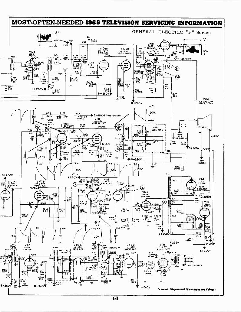
MOST -OFTEN -NEEDED 1958 TELEVISION SERVICING INFORMATION
1152
8157III
C157800 B+ 260V
CI59800
V1056C863R0 I -F
0
CI60
815800
RI59
18K
B+260V
V107A255 1/2 I2AT 7/OK YNC. CLIP
1
F4 5V
T301TRANS.4.5 MC
1
II 4
iT8
3L _
03035000
8+26
R3034700
1W
V
R201
T*
POINT
Y15I LI571153 - 1086
81604700
I W
M 810602
8 214 R207 R2I5
2.7MEG VERT. 2 G
V110625
ERT. OSC.
VIO7B1/2 12417
PHASE OFT.-I.75V
C254
180
V1176 AU6
LIMITER
R305100K
TESTPOINT
R2522.2K
R3064706
B+2
c165 POINTTST
451.1CTRAP
I MEG OR1.5 MEG
R208100K
N.V.F 27V cer
C207
.022MF
C204.IMF
.5.3V8204100K
R2051256
VERTHOLD
R166686 OR33K
8209
MEG
50V
+ 250V 4c259.0039a MF
C23056
MF_2
V106A V10681/2 12AT7SYNC. AMPL.
I/2 I 2AT 7NOISE CANCL
C166.2MF
B +BOOST (PIN IO-y109)
V III6AH4GT
VERT. OUTPUT
.022 MF
VERT.LIN.
82628200
R260 I
I MEG 560
235VC208-1_
047
909 -30V
C402R217 3511
30 MFR210220
330 350V 414_1_+
RED 3C40ID - 82I 2 I-
I100MF 470
411 75 V
GENERAL ELECTRIC "F" Series
V1086AG7 2
0168 VIDEO AMPL.
.05WR1682206
CONTRAST
81692.2 MEG.
B +260V
r GREEN 7
82162200
**
R I 7 11100V
225VC170
L I 58 IMF TESTPOINT 35-115V
30001
- 350V
8171IRK2W
300V
270 pH
RI 72
WW
8173826
D201DEFT. YOKE
3511.
2
8261826
3 8.2V
C257 275 328264.001220K...: 200K
HORR259 MF 0258 ' HOLD826 05MF__ __SEE NOTE A
L251HOR.STAB.
190V
V 11212AU7HOR. M.V.
5V
1302
RA-T10-0-ETTII TRANS. 1
27K 030725000
RATIO DET.
R257
0
20V
R26347K
200/ R2676800
R266
0255 -560
B +260V
6806HOR. OUT.
R269330
R270150
8268 484706
V 118 A 3 V 118B1/2 678 TEST
830915 MEG (maw p) 1/4 6T8
POINT
R31122K F .1 CONTROL
C312 VOLUME
AUDIO AMP.
310
C.C1 Z.°°CZft ;3201IST.
C309_4
33K
fC 317
.01MF
GONSkES- ONLY
R 3I 4470K
0315
C263.IMF
V
4. C4020- 10M F
25 V
R27IISK2W
B+260V
VII96 V6 GT
AUDIO OUTP.
6316 23008MF
R175100K
BRIGHTNESS
R 181 Ri 7 6MEG 100K
YOKECONN.
:1529r1
6265
7
+255V
1000V
8315
_10_0_0_;
(3RDR313 14470K
+240V
/ RED260V
R3174702W
V I 09PICTURE TUBE1701.4.21Ep4-4
8+260V
C2.04766 MFT
V 114183
H.V. RECT.
83972.2K(3ROP)
8274
2206
.-16KV
VI156A54
DAMPER
HORZ.LIN.0268
01MF T8+ BOOST
B+ 260V
LOUDSPEAKER
Schematic Diagram with Waveshapes and Voltages
61
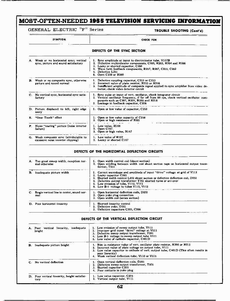
MOST -OFTEN -NEEDED 1955 TELEVISION SERVICING INFORMATIONGENERAL ELECTRIC "F" Series TROUBLE SHOOTING (Cont'd)
SYMPTOM CHECK FOR
DEFECTS OF THE SYNC SECTION
A. Weak or no horizontal sync; vertical 1. Sync amplitude at input to discriminator tube, V107Bsync, picture and sound satisfactory 2. Defective multivibrator components, C260, R263, R264 and R266
3. Leaky or shorted capacitor, C2604. Wave form feedback components, R257, R267, C255, C2625. Defective L2516. Open C259 or R260
B. Weak or no composite sync, otherwise 1. Defective coupling capacitor, C252 or C253picture and sound normal 2. Incorrect value of plate resistor, R255 or R256
3. Insufficient amplitude of composite signal applied to sync amplifier from video de-tector; check video detector circuit
C. No vertical sync, horizontal sync satis- 1. Sync pulse at input of vert. oscillator, check integrator circuitfactory 2. Vertical oscillator frequency, if far off from 60 cps, check vertical oscillator com-
ponents such as C207, R204, R209 and R2183. Leakage in feedback capacitor, C206
D. Picture displaced to left, right edgewavy
1. Open or low value of capacitor, C253
E. "Gear Tooth" effect 1. Open or low value capacity of C2582. Open or high resistance of R261
F. Noise "tearing" picture (noise inverter 1. Low value, R169failure) 2. Open C167.
3. Open or high value, R167
G. Weak composite sync (attributable to 1. Low value of R167excessive noise inverter clipping) 2. Leaky or shorted C167
DEFECTS OF THE HORIZONTAL DEFLECTION CIRCUITS
A. Too great sweep width, reception nor- 1. Open width control coil (shunt section)mal otherwise 2. Open winding between width coil shunt section taps on horizontal output trans-
former, T251
B. Inadequate picture width 1. Correct waveshape and amplitude of input "drive" voltage at grid of V1132. Leaky capacitor C2653. Shorted width control L252 shunt section or defective deflection coil, D2514. Defective output transformer T251 shorted turns or arc -over5. Low emission of tube, V113, V1156. Low B+ voltage to tubes V112, V113
C. Single vertical line in center, sound nor- 1. Open horizontal deflection coils, D251mal 2. Open yoke plug connection
3. Open width coil (series section)
D. Poor horizontal linearity 1. Shorted linearity control2. Defective yoke, D2513. Defective capacitors C265, C266
DEFECTS OF THE VERTICAL DEFLECTION CIRCUIT
A. Poor vertical linearity, inadequate 1. Low emission of sweep output tube, V111height 2. Improper grid input "drive" voltage at V111
3. Defective sweep output transformer, T2014. Low B+ voltage to sweep output tube V1115. Low value of cathode capacitor, C401D
B. Inadequate picture height 1. Rise in resistance value of vert. oscillator plate resistor, R206 or R2152. Incorrect value of plate voltage on output tube, V1113. Low value capacitor in cathode of vert. output tube, C401D (This often results in
poor linearity)4. Weak vertical deflection tube, V110 or V111
C. No vertical deflection 1. Open vertical deflection coils, D2012. Defective sweep output transformer, T2013. Shorted capacitor C2054. Poor contacts in yoke plug
D. Poor vertical linearity, height satisfac- 1. Low value capacitor, C205tory 2. Vertical output tube, V111
62

MOST -OFTEN -NEEDED 1955 TELEVISION SERVICING INFORMATION
GENERAL ELECTRIC
The "G", "J", and "K" Line setsare similar to "F" Series and toeach other. For circuit diagramof "G" Line see pages 64-65, for"J" pages 66-67, and "K" page 68.
"G" Line, Models 17T20, 21C103,21C104 21T22, 21T23, 21T24, 21T25."J" Line, Models 21C350, 21C351,21T30, and 21T31."K" Line, Models 17T14, 17T15,17T16, 21T17, and 21T18.
CSC
CONY PLATE U3544 I5MC
PF AMP
VHF
L_SEE NOTE
CONY
UHF
NOTETHESE TUBES ARE NOTINTERCHANGEABLEREPLACE WITH SAME TUBETYPE AS INSTALLED INFACTORY
T4 01ROWER TRANS.
LI51
LI52.LINKSEC.
T152
2NO.PF(RIDE())
L1.56
S MCTRAP
LI53SSMCTRAP -
c;L16I34.25MC
IST YIDE0 ,T15IITT I -FIDEO)
I- F AMP2ND VIDEO
1-F AMP3RD VIDEO
(2.Ti533RDVIDEO)
RIO. AMP
RECT
RATA xi, ALAMP 5 DELAYED AGC
302RATIO DET
SEC.
LIMITER
<>T3C4.5 MLFm
ALA I -F AMPNOISE CANC.
SYNC AMPHORZ BLANKING
PELT
AUDIO OUT
SYNC PHASESPL-ITTER
SYNCoLIPPER4:022 PHASE DET
HORZ REACTNORZ OSC.
HORZ. DISCHARGEAEC KEYER
F25IFUSE 3/RAMP
HORZ OUT
Location of tubes and adjustments in "J" Line sets.
OOcr
(11):6=
ti
NO_J 2
63
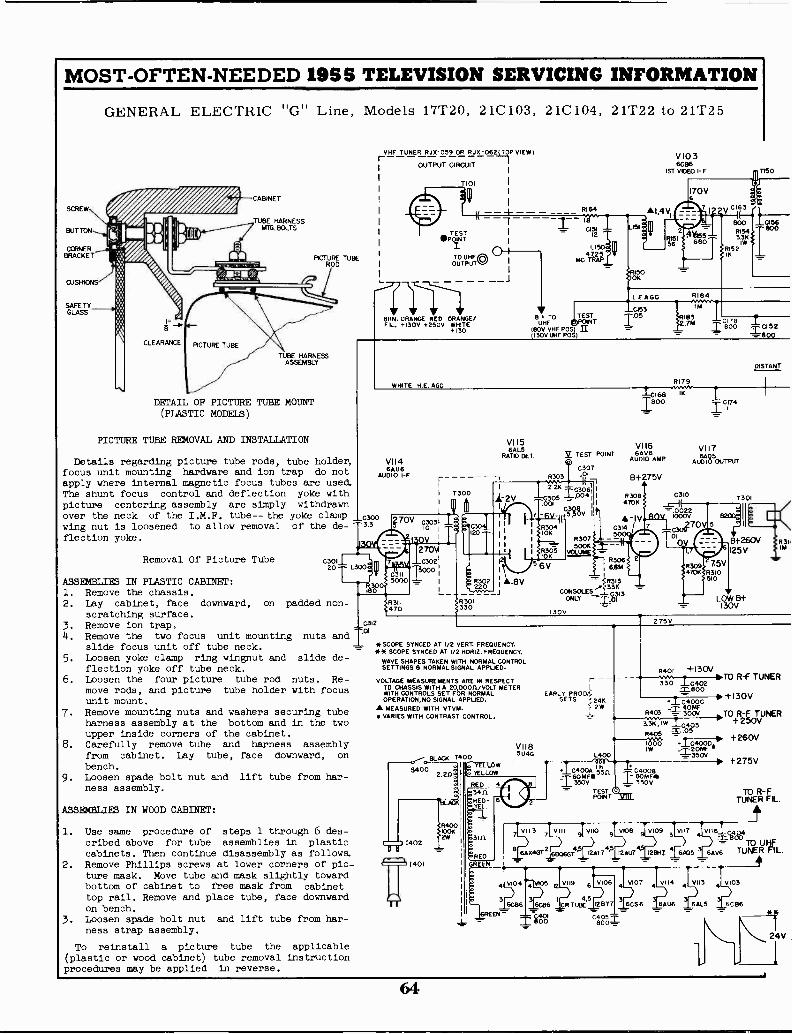
MOST -OFTEN -NEEDED 1955 TELEVISION SERVICING INFORMATION
SCREW
BUTTON
CORNERBRACKET
CUSHIONS
SAFETYGLASS
GENERAL ELECTRIC "G" Line, Models 17T20, 21C 103, 21C 104, 21T22 to 21T25
CLEARANCE
CABINET
TUBE HARNESSMTG. BOLTS
MCTRURE TUBEOD
TUBE HARNESSASSEMBLY
DETAIL OF PICTURE TUBE MOUNT(PLASTIC MODELS)
PICTURE TUBE REMOVAL AND INSTALLATION
Details regarding picture tube rods, tube holder,focus unit mounting hardware and ion trap do notapply where internal magnetic focus tubes are use&The shunt focus control and deflection yoke withpicture centering assembly are simply withdrawnover the neck of the I.M.F. tube-- the yoke clamp 000wing nut is loosened to allow removal of the de- 3.3
flection yoke.
Removal Of Picture Tube
ASSEMBLIES IN PLASTIC CABINET:1. Remove the chassis.2. Lay cabinet, face downward, on
scratching surface.3. Remove ion trap.
. Remove the two focus unit mountingslide focus unit off tube neck.
5. Loosen yoke clamp ring wingnut andflection yoke off tube neck.
6. Loosen the four picture tube rod nuts.move rods, and picture tube holder with focusunit mount.
7. Remove mounting nuts and washers securing tubeharness assembly at the bottom and in the twoupper inside corners of the cabinet.
8. Carefully remove tube and harness assemblyfrom cabinet. Lay tube, face downward, on
bench.9. Loosen spade bolt nut and lift tube from har-
ness assembly.
ASSEMBLIES IN WOOD CABINET:
C301120 -r
O
11
I
padded non -
nuts and
slide de-
Re -
1. Use same procedure of steps 1 through 6 des-cribed above for tube assemblies in plasticcabinets. Then continue disassembly as follows.
2. Remove Phillips screws at lower corners of pic-ture mask. Move tube and mask slightly towardbottom of cabinet to free mask from cabinettop rail. Remove and place tube, face downwardon bench.Loosen spade bolt nut and lift tube from har-ness strap assembly.
To reinstall a picture tube the applicable(plastic or wood cabinet) tube removal instructionprocedures may be applied in reverse.
rVHF TUNER RJX-059 OR RJX -0623P VIEW)
OUTPUT CIRCUIT
T101
BRN. ORANGE RED ORANGE/FL. +130V +250V WHITE
+130
HITE H E AGO
V1146AU6
AUDIO I -F
I 7300
70V cum)10
I OV270NA
7 1".....6C00300211
6115000
I
R3Il470
C312
R164
B+ TO TESTUHF NT
1130V VPOS)
130V UHF P0s)II
VI 156AL5
RATA DET.
R303
V1036096
IST VIDEO I- F
1.4V
168Doc)
V116
V TEST POINTEAV6AUDIO AMP
0307.01
"%WI6305 I
oa 1
-.
R304 03
500K -R307 _.21410K
Ma11 R306
6V &am
.8V 11:R313
CONSOIFS''.33KR33300
130
1
:WLY
--"zzR3
B+275V
R3084701(
-1V
T150
ase800
DISTANT
R179
IK
0174
V117
AUDIO OUTPUT
0310
=.00221000V
030p0V01
OV
275V
7301
B+260V25V
LOW B+I30V
R31.IM
* SCOPE SYNCED AT 1/2 VERT. FREQUENCY.** SCOPE SYNCED AT 1/2 HOME. FREQUENCY.
WAVE SHAPES TAKEN WITH NORMAL CONTROLSETTINGS B NORMAL SIGNAL APPLIED.
VOLTAGE MEASUREMENTS ARE IN RESPECTTO CHASSIS WITH A 200000/VOLT METERWITH CONTROLS SET FOR NORMALOPERATION,NO SIGNAL APPLIED.
A MEASURED WITH VTVM. VARIES WITH CONTRAST CONTROL,
BLACK T400 YELLOWS YELLOW
V1185U4G
EARLY PROD!.SETS ;24K
2W1
L40014
TD4o0AollBOMF
TTIIPOINT
R401 -H3OV
330 8402.T.800
+1C400CR403 .100'FV
3 ,U.* 10403
V113 VIII VII
RED
V108 V109 VI
GRUA
6AX4GT
311'1
I2AT7 12AU7
14011
I
TO R -F TUNER
p. -t-I30V
TO+R2-;0TVUNER
I04000a+260V
_= 350V
4V105 ev119 6 V106 M
4,5360436 6056
ThREEN=_CR TUBE I2BY _6cS 6
-110001 CM'
111. +275V
TO R -FTUNER FL.
VI 61 c4 04M. BOO
TO UHF6AV6 TUNER Fl L.
6AU6 1 GALS
V103
6C B6 **
24V
64
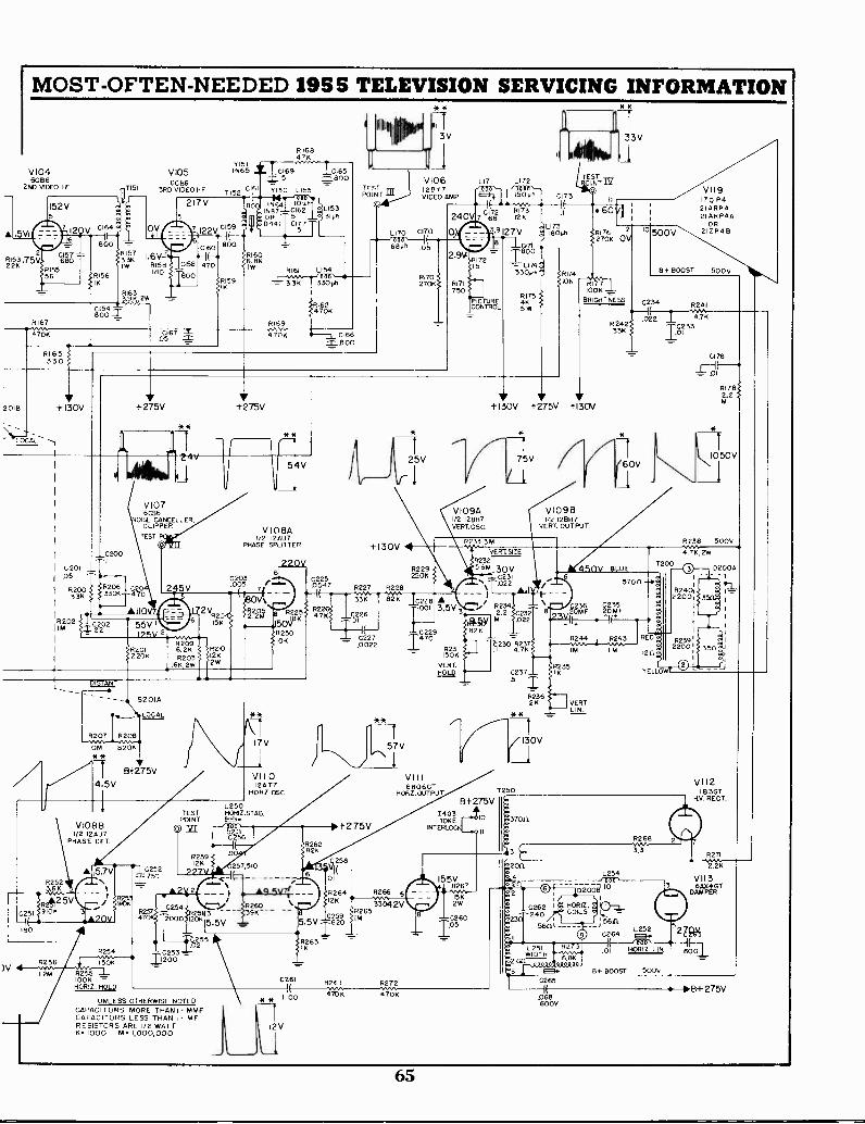
MOST -OFTEN -NEEDED 1955 TELEVISION SERVICING INFORMATION
V1046286
2ND VIDEO I -F
2213c .755,
2018
)V
R167Kvv..4706
LOCAL --
2251
801(
33 K
R202IIM
+130V
I 0201.05
R200
1151
RI5733K1W
628631313 VIDEO 1-F
+275V
V1076 CS6
NOISE CANCEL ER,CLIPPER
TEST
Y151
71520161
R1606 8KIW
RI6847K
V105 IN65 12169 101655 =800
Y150 L155
R161 L154
3.3K 330 Ph
iT,KT mqAir"
3VI I n 33V
V106 L171 L172128Y7VIDEO AMP
LI70 2170-6-, II 0 0
680, .05
470K _L CL66=80C
V108A12AU7
PHASE SPLITTER
9170270K
7 228173
;927V
157 = LU4330,h
PICTURECONTROL
V109A1/2 12897VERT.OSC
TESTNT IY
1804h270K OV
+130V 1-275V 1-130V
VERTSIZER232
636N 30V
2203228207
R32300 245V .005 /7
2225
77
R227 R228.`, 022321
A.14700047
*--1( wv, -...,..1 i
336 82K 6228 A:0
,X22°2 55V
2V,, 20 . R2 2, ,Cn R 22 56 I5K ''''' 50viK
R25047K
..7.23i26-.001 3.5V 3
4*§/1 .00 '6
R2324
1755 I2202272
I(--- 82K =R209 10K I-2472029
6 2, 8210 --T .0
22201% R203 126 = 4231.,230 4R 2717
16K,2W 2WVERT.506 4235ILIC
DISTANT
V10981/2 12887
VERT. OUTPUT
R207 R208
IOM 820K* *
7 Bt275V4 5V
V1088I/212AU7
PHASE DE T.
A 15.7VR252
424125V310K
R256
8254
150K
12M R256 -1_100K "-HORIZ.12f0
12252T750
R257
VI I 0I2AT7
HORZ.OSC.
L250TEST HORIZ.STAB.POINT
2000 120K
f.0 2552
C253 =.200-=-
UNLESS OTHERWISE NOTEDCAPACITORS MORE THAN!. MMFCAPACITORS LESS THAN I MERESISTORS ARE I/2 WATTK 1000 M 1,000,000
257.510
...I 826039K
+130V 4
VIII6 BO 6 GT
HORZ. OUTPUT
1-2 75V
N58
01
R264 R266I2K v***33042V
R2C259 im
65I I5.5V 620
R263
C261
1100 7°K
12V
B -I -275V
1903YOKE
INTERLOC
I55V8267
I5K2W
-6260105
R2362K VERT
LIN
L 254DIU
10 200,,P (3
2262 I HORIZ. g IaZ240
5611COILS m
5611L L252 27(15OHORiZ 8001
000
MLW,2D5T,.
68673R2
61- "'" """
VII9170 P42IARP421 AR P4A
OR212 P48
6+ BOOST 500v
YELLOW
R268Ny.
3.3
2176
1
RI782.2
1050V
R238 500V
476,2W
2265
.068I(
600V
B+ BOOST 5005
VI 12I B3GT
HV RECT.
R271
;Tic
VII36AX4 GT
DAMPER
--10.6+ 275V
65
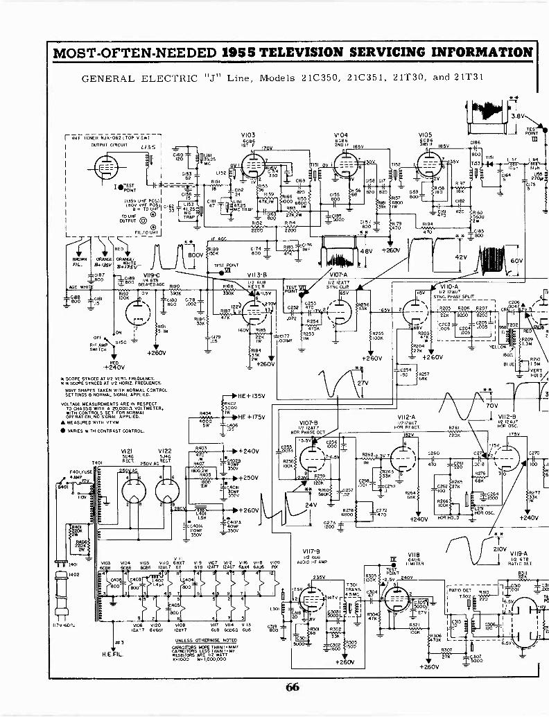
MOST -OFTEN -NEEDED 1955 TELEVISION SERVICING INFORMATION
GENERAL ELECTRIC "J" Line, Models 21C350, 21C351, 21T30, and 21T31
r VHF TUNER RJX-062 (TOP VIEW) 7OUTPUT CIRCUIT L.I35
L
BROWNFIL.
AGO
ORANGE
01871800
HIT
0181115
OFF - L
R -F AMP5150
SWITCH-,
(135V UHF POS./(80V VHF POS.), 0162
+ TO UHF I 33
TO UHF 0 IOUTPUT Qv
0FIL.TO UHL'
RED
ORANGE/WHITE
734.17$V
.7_c1e9 VI19-C=eoo DELAYED
4190
R192 OV 390K100K 6
TI(81
P-1 /
ON
REO
+240V
.R191i5. IM
+260V
* SCOPE SYNCED AT 1/2 VERT. FREQUENCY.**SCOPE SYNCED AT 1/2 HORIZ. FREQUENCY.
WAVE SHAPES TAKEN WITH NORMAL CONTROLSETTINGS & NORMAL SIGNAL APPLIED.
VOLTAGE MEASUREMENTS ARE IN RESPECTTO CHASSIS WITH A 20,000.0 VOLTMETER,WITH CONTROLS SET FOR NORMALOPERATION, NO SIGNAL APPLIED.
MEASURED WITH VTVM
VARIES WITH CONTRAST CONTROL.
T401
F401, FUSE4 AMP
I I7V
VI 215U4GRECT.
V1225U4G
OV AC RECT
82
L15341.25MC
**
LI6139.25MC
LI52
RI51
18
IF AGO
RI89
800V 1506
-1 TEST POINT
6--411,21
V1036086
1ST IF170V
I 0169...- _.1
820kRI66 RIDS
000 6890
-MO TRAP __1( RI93 '
ILC163.
2'2W2wvx , -I-C185---- 800 --- '- 4I52 RI54
5000vv- ..,,9/'2200 2200
V1046CEI62ND IF 185V
0178.0021
RI86331(
6188
3306
122)RI87 2
97K
113 4330
0174800
1/2 6U8KEYER
A-I.5V
160V
-C179 226105 IW
6404
40005W 406
.05
R4023000IW
R1843362W
+260V
HE+ 135V
HE +175V
11800,2W 11800
I.5H
2WC3
" C402440MFIC11400NIAF
350V4_350V
+240V
itaP350V
+250V
+260V
51 OV
: k
- v
V107-81/2 I2AT?
HOR. PHASE DET
-00335
R2581001(
VIIIV103 V104 V105 V110 68X7 VII9 1907 9112 V116 V118 V109
6C:6 6C 6C86 12AU7 GT 6T8 12977 12AU7 6A)(4 6AU6 FIX
0408800
Ft 3
H.E.FI L.
4
3
9106 VI20I2AT7 6V6GT
L301
V108 VII7 V114 VII312817
C319608 6CD6G 6U8 800
UNLESS OTHERWISE NOTED
CAPACITORS MORE THAN I UHFCAPACITORS LESS THAN I MFRESISTORS ARE I/O WATT6.1000 U. ipoopoo
C2561000
AZ:S.5,
A* R261 __C2571206
I560%37.02
24V
1 0273 -I_1200
V117-81/2 6U8
AUDIO AMP
235V
6
R276800
VAT. 65V
R255<100K
+260V
R262.2
0272
T47°
VI0560E163120 IF iv
5
8197IF -Y181(09,41
C182
ZE61 820R194
v470wm,
616056002W
-C183* ifM800
42V
arVI 10-AISV I/2 12AU7
SYNC. PHASE SPLITn 0206
\ I R205 R206 R207 I GR.0047
**
3.8V
TESPOINT
m
L157 L164
lOon
C164
/1C203 I
68VR203 I .005
1.005 0204 .005 I
476
R204226 V
+260V
7,--0254180
VI 12-A1/2 ICAO
HOR REACT 4261*novo"220K
0260
470
YELLO..
180(1
BLUE
**
70V
V112 -BI/2 12 907HOR OS C.
027
.0018
R276
L25IHOR OSC.
+240V KR HOLD
V118IX 6906
ELIMITER
R305
TTPOINT
100K 12.5V 04097301 5
-7.5V TRANS.4.5 MC -47 'r
., .i
so 83031500
+260V
1001(
J_
175V
3IphL155
220L6
175
42101.5M
VERTHOLD/
C270
6
R27733KIW
+240V
rA121109 VI 19-AI/O 6T8
RATIO DET
TRATIO DET. 6310I T302
70KI
L_-6.5V
R307WN.
1F IS0007027K
+260V
221
.mS3(:;
TEPC
T
66
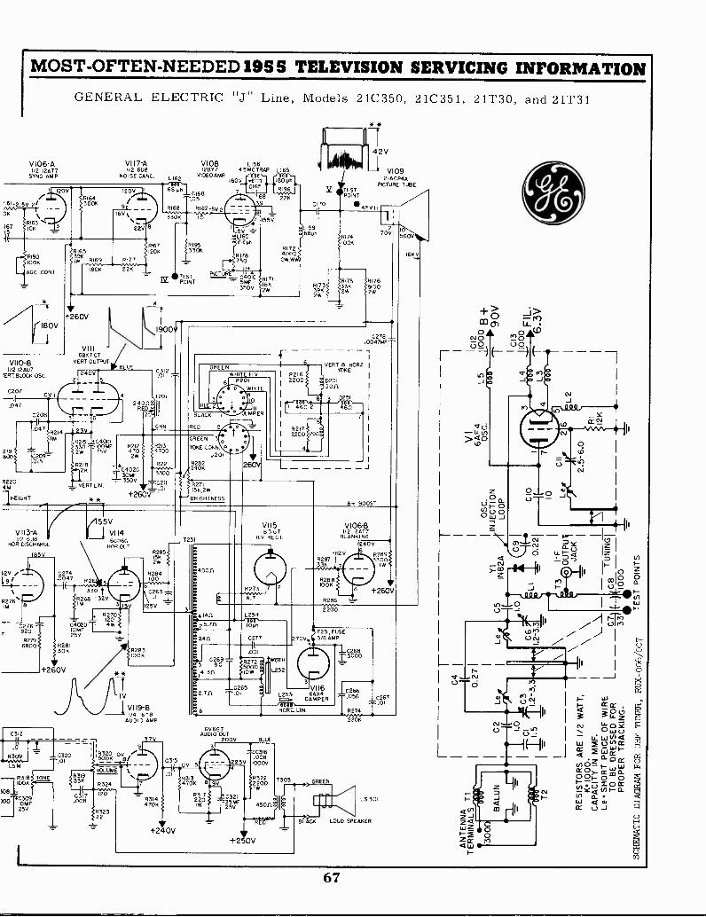
161...2.5V
DK
16715
MOST -OFTEN -NEEDED 1955 TELEVISION SERVICING INFORMATION
GENERAL ELECTRIC "J" Line, Models 21C350, 21C351, 21T30, and 21T31
V106 -A1/2 12AT7
SYNC AMP
120V
RI642/
9180100K
AGC COST
*
-7 +260V
VI17-A1/2 6U8
NOISE CANC.
16V%
22V
91653,,{?/K
_6169 6I77rnti180K 22K
V110 -B1/2 12AU7
IERT BLOCK. OSC.
0207
.047
2;9800
R2204M
]HEIGHT
V I13 -A1/2 GUN
HOR DISCHARGE
OV
{2V /
7476'
.276820
6800P279
R28130K
1-260V
VERT OUTPUTBLUE
VIII6BX7GT
82153302W
L162
68 41I000
8168
330K--
0168,05
R182-5,./ 2
V108 LI5612BY7 45MG TRAP L165
VIDEO AMP 000,- -"DOD,-160V ..411 1800
C165 - 01196
68 22K39
R178,-- 750
TEST PICTURE lfrPOINT ----- 5MF
350V
1900v
C312.
T20/
RES24:7n,.;
'C4010_100MF 6212
75V 4702W
GRN
82134700
55V
RI 724000
101.1,W.
9171I28WK
* *
142V
V1092 IACP4A
PICIURE TUBEIt TESTPOINT
.145V 111CI70
.1
1317339K2W
817533K2W
BLACK 1
RED 2
6221 R2820402C
23303300 -0
350VVERT LIN iViC.0111
:R2715K 2W
+260V-BRIGHTNESS
55V
1 VI 14
330 t
6C06GHOR OUT
6268 -32V3
I R270- 120
?0147T 4W25V
R283100K
IV
V119 -B1/4 6T8
AUDIO AMP
R28515K2W
R284100
125
40011.
25.711
2411
VII51 B3 GT
1-1 V RECT.
R273
4.7
L254000,1046
C277
.001
C1286(..7 01272
14.311 IOW5000
02652.701
6
6V6GTAUDIO OUT
7V 200V BLUE
C320
1.5. T.°1
IOOKTONE
{08i1%MF
25V
VERT a HOR2.YOKE
8+
R17691002W
.0004277W7F
BOOST
V106-81/2 12AT7
BLANKING
-112 VR28733K
R286von,2200
240V6
R289
+260V
F251, FUSE270 3/0 AMP
102681.5000
VII6L253 6894{1.{. DAMPER
'00 0HOR7_ LIN.
1C2660 026, 7
LS 301
LOUD SPEAKER
+> -21>- te)CD 01 Li-o 0 (.0
cvo "} 0±5=i0 o
oci-(5-U -L/)>040
tD
L__
a_0QUOOW
CI -
<IU- 15
>-13
cv 0
W- cc cri" o z
CV IL 0 SE° W- U./ V) <I
ILI 0 in Cr
4Cr 2 War011v)0 -r
CC)>- CLILI0 Ch- 0 00to CL
En aCr L.)
67
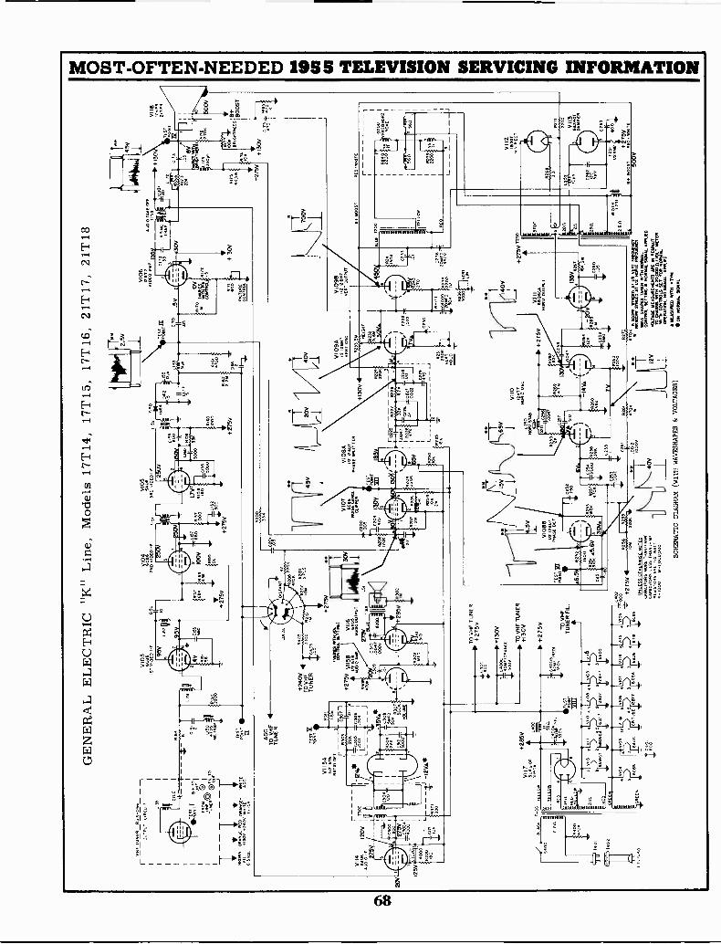
eov
GE
NE
RA
L E
LE
CT
RIC
"K
" L
ine,
Mod
els
17T
14, 1
7T15
, 17T
16, 2
1T17
, 21T
18
Hf
TU
NE
RR
J8-0
66
OU
TP
UT
CIR
CU
IT
s,
-10
Ilia
NT
81
.T,0
MO
Cc)
)fm
,T0
7:0
ALOE
II
V11
4
A U
DiO
6209
120V
275V
125%
;
190
1T
401
r---
\1.0
0
7s s
-60
VI I
5A
$/2
616
RA
T. M
T ,r
-I2V
A*
Apo
l+
F
VII
7S
uRO
OR
Su4
GA
AG
CT
O V
HF
T
UN
ER
;Zit
R3i
Fa%
.01
4
LSOG
004
1
5VA
*C
308
SM
fD50
V0V
,V
OLU
ME
+28
5V
111T
X1:
7ffi
0 06
4}v
109
16
9A
u,s
A,
5
6C86
SA
ucC
R T
Ubf
1288
76C
36U
S
1)n'
V10
3
1ST
nr0
rf
+24
0VT
O V
HF
TU
NE
R
CO
O +27
50
LOC
AL
'Alf
inA
Tiv
+27
5V v
i158
2 616
VII6
6A05
Au0
100L
ITP
U
+28
5V
, TO
VH
F T
UN
ER
/02o
0+
2 7
5V
;sec
.120
,,,c
+13
0V4t
ro0
AR
GE
I,
p. T
+1?
3V0H
,F, T
UN
ER
+27
5V TO
VH
FT
UN
ER
FIL
I'al
250
V10
E0I
F
250V
+27
5V R 0
0
V10
5
3R0
v$13
f0T
1
+27
5V
/ /;C
C45
V
PO
INT
CI .0S
V10
701
08A
M...I.
.P
HA
SE
SP
LIT
TE
Rif2
i2A
u7
CLI
PP
ER
iTE
ST
"005
R2C
6.1
0?99
1300
120K
130V
_
r'oOA
i__i
tm__
=s_
÷:2
75v
OM
220K
ccsa
232
'Goo
VI 0
88
UN
LES
S O
TH
EF
IVIIS
E N
OT
ES
CA
PA
CIT
OR
S IM
RE
TH
AN
Imm
icA
PA
c,T
OR
S L
ES
S T
HA
N t
ME
RE
SIS
TO
RS
AR
E11
2 R
AT
,K
000
m 0
0000
0
F02
2522
782
20
L250
HO
R2
ST
AR
VI 0
9A1/
2 i2
8H7
vER
T O
SC
8233
3
228
C23
222
7I
.022
0110
JgV
,,c.
VIO
E;
v /g
20 A
MP
+13
0V
wN
,L'
c400
0vE
RT
HO
LD
+27
5V
21*2
-14V
.1
'91V
'
47:K
SCHEMATIC DIAGRAM (WITH WAVESHARES & VOLTAGES)
8272
VI 0
98
+27
5V T
230
T23
0
VIII
606
nOR
IZ O
uT6A
PuT
"A°
.7°'
.114
6%74
21%
°.T
AT
AU
117
WIC
WA
VE
SH
AP
ES
TA
KE
N M
TN
NO
RM
AL
CO
NT
RO
L S
ET
TIN
G N
OR
MA
L S
IGN
AL
AP
PLI
ED
.
VO
LTA
GE
ME
AS
UR
EM
EN
TS
ME
N R
ES
PE
CT
TO
MO
NS
MT
N A
ZO
OM
anO
LT M
ET
ER
OP
TS
CO
NT
RO
LS S
ET
FO
RNORMAL
NO
SIG
NA
L O
AR
ED
ME
AS
UR
ED
WIT
H A
TO
M
*ON
NO
RM
AL
SIG
NA
L
urlo
OT
ZE
Off
19.-
RO
OS
T
YE
LLO
W
RE
O
1111
1-01
1111
4-T..5
V
R17
34631 +27
5V
TE
ST
PO
INT
173
EZ
+13
0V
VrO
=
RE
D /w
HIT
E
T
VII
B17
vp4
2,3.
1
8+ BO
OS
T
C26
3
80E
01+
75V
4. B
OO
ST
RE
O /*
HIT
E
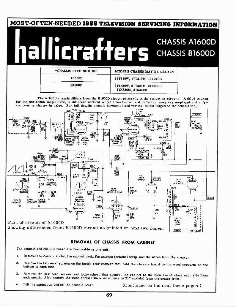
MOST -OFTEN -NEEDED 1955 TELEVISION SERVICING INFORMATION
hallicrafter5CHASSIS A1600D
CHASSIS B1600D
*CHASSIS TYPE NUMBER MODELS CHASSIS MAY BE USED IN
A1600D 17T310W, 17T310M, 17T310B
B1600D 21T320W, 21T320M, 21T320B21K330M, 21K330B
The A1600D chassis differs from the B1600D circuit primarily in the deflection circuits. A 6CU6 is usedfor the horizontal output tube, a different vertical output transformer and deflection yoke are employed and a fewcomponents change in value. For full details consult horizontal and vertical output stages on the schematics,
- icor;2T,O oo m.000 31cm91_
I MFD CI61 1.01
D_2
.005MF -
R143Lira
11,W
D UE 1106 YELLOW/
C135.047MFD
5V1
_ro/ C135
.033V1 10A
MFD3VERT.
Y2128117VERT.
%)27,000
14I RI6613,3,000 RI67
8h9(3 tp 15/4000
C 10.1 3:61-4 33
30V.P-P
R159560
1.4v P -P N160ect000
F1161I5b
a_2sy, ,---
ii.------s,
, la- ,, 2 7MEG3 , ' V107A
F265N7GT7;11 1.63RIZ. AFC.
144 1 0145ilkI_
A.R162 R163 -"100,0008200
Part of circuit of A1600DShowing differences from B1600D circuit as printed on next two pages.
65v P -P
18,000
C1471220
1108
57.5"
1203PP
MF Dr
Hrv
1100P -P C1491--..).215vi
V107 El I 0I50_igawacr = 560Z. 090.
RI 70470,0001
V110 8VtI28H7
0'1.1111°07/".
,,yR
P- P) OWE 1107
arm
..II 54 S'R
!MEGSTOP.-tq1.[-'
HEIGHT RI473
CONY. I 750
R145
CI36.005MFD
V10961306
HORIZ. OUTPUT
C
0
VERYLIN. RI48
18,000, 2WAniff.
R128
15000,2W
SEEN fa ;51TkJ"L107 -A
VERTDEF LYOKE
<9;
RED 0
CI4
300V
RI50390,000
R151szopooi
RI71
10,0002W
VIII
6/1.K4DAMPER 260V
4,VII2
13213H V RECT.
T 09
4. 140 V
3 04
C153a .01 I
C152 < a MFD
168CI51
22 MFD05RI7 3
7 7L10713HORIZ
DEFLYOKE
C154
47
Ei_W-r;
REMOVAL OF CHASSIS FROM CABINET
The chassis and chassis board are removable as one unit.
1. Remove the control knobs, the cabinet back, the antenna terminal strip, and the wires from the speaker.
2. Remove the two wood screws on the inside rear corners that hold the chassis board to the wood supports on thebottom of each side.
3. Remove the hex head screws and lockwashers that connect the cabinet to the base board along each side fromunderneath. Also remove the wood screw (two wood screws on 21" models) from the center front.
4. Lift the cabinet up and off the chassis board. (Continued on the next three pages.)
69

MOST -OFTEN -NEEDED MS TELEVISION SERVICING INFORMATION
PRIVASSOAS,
21" Tube Mounting1600D Chassis
C1024--4-1(470
1102
470K
C16350001000v-if-R 176
336lw
/7/7REAR TUBE CHASSIS
SUPPORT
P101
CA102
1152
7.25W
1 I
SWI
VIII T102
7 8
PIN 21109
CIO10 CLIP
MONTH'SCana
CONTR.PATO WI
TUNE.
IMF
NUR..SOCCET
V101
--c.tie 6086137 PIX. I -F
L101
VI ) / V2 \r A. 000/---:---3,-.. ,i-
'.6./6,
VHF R -F TUNER
ID2017
25.11FIC
HALLICRAFTERS, INC.
VHF
21" CHASSIS
B1600D
RUN 1
L10225.5NC
isov
2
R105 # R1062700 . 47
R104m4v1000
L160
57$
15K
004o.25v1Dg
DEPENDS ONSTRENGTH
SIGNAL
V102 L103 116086
242 PIK
1+14061
10R09
00R110
"7005*1000* IMFD tRin
47
Pi 9 mc
007
RII2 IMFD1000 T-
68
R103
0622.05
MFD
./\/\/ L10822V P -P
SRO
0139_)
LIASR102
220
vEL.
50." C132B 0.76 P -P
200MFD.
Abaft!
140 - 2mFD MFD 0.21 P -P
R FE - V2
4 3
I
0 0
I ..-r.
_Lv108
2 A 7 ).-
RI77-I
_ _ PC101-1_I -1_0157 P178
T270 330K
I IC158I
Tfelo-
....L.CIS9
."T-25 241.
:
RI38820K
TUNER 55 v. PP
V 1 I
113_._
Id
NOTES:
I ALL vCUPGES MEASURED WITH AN ELECTRCNIS VOLTMETERCONNECTED FROM SOCKET LUG TO CHASSIS, 9EE FOOTNOTE
2 SUPPLY VCITAGE 117 VOLTS 60 CYCLE AC.
3. K 10004.ALL CAPACITANCE VALUE IN MMF ALL RESISTANCE
veLuES IN CHESS I.R1LESS OTHERWISE NOTED.
10,000
42 V-1
R175680K
V104BI'26AN8SYNC.
CLIPPER
11406,8K
1W
C13Q1_,7012_5 65
536. P-
[7;11;917922K
0141
,._NOV P -P
o VIC6B
37 v. P -P
V101 V102 V103
3/14 3/1, 4 ASL110
w '------ o_fr 0-01_..-:- CI55 - C156
I'MMFD MFD
' =
VIIO V109 Y107 YI06 V105 V104 6113
4 9 5 2/17 8'7 3/14 4/1S 4S 12/\1
*SomE vCUAGES AE PIRIPILE IvoLuon *gym *ERE REARM
WITH A NORMAL POVIRE 061 TIE NcTuRE TUBE AND THE CONTRAST
AND DRIGNINESS OCPHROL SET FOR 50 VOLTS PEAR TO PEAK ONTHE 0.1101001 (RN II) OF THE PiCTURF 1I.11F.S00111 SWAGE11:URINCEI 10i
TIOI
PIED 001
1'264.18SYNC.AMPL
25v.P-p
042 NOWLOCK
10-160
TERANAL LCCAPCMS
TIO6
4
2 3
70
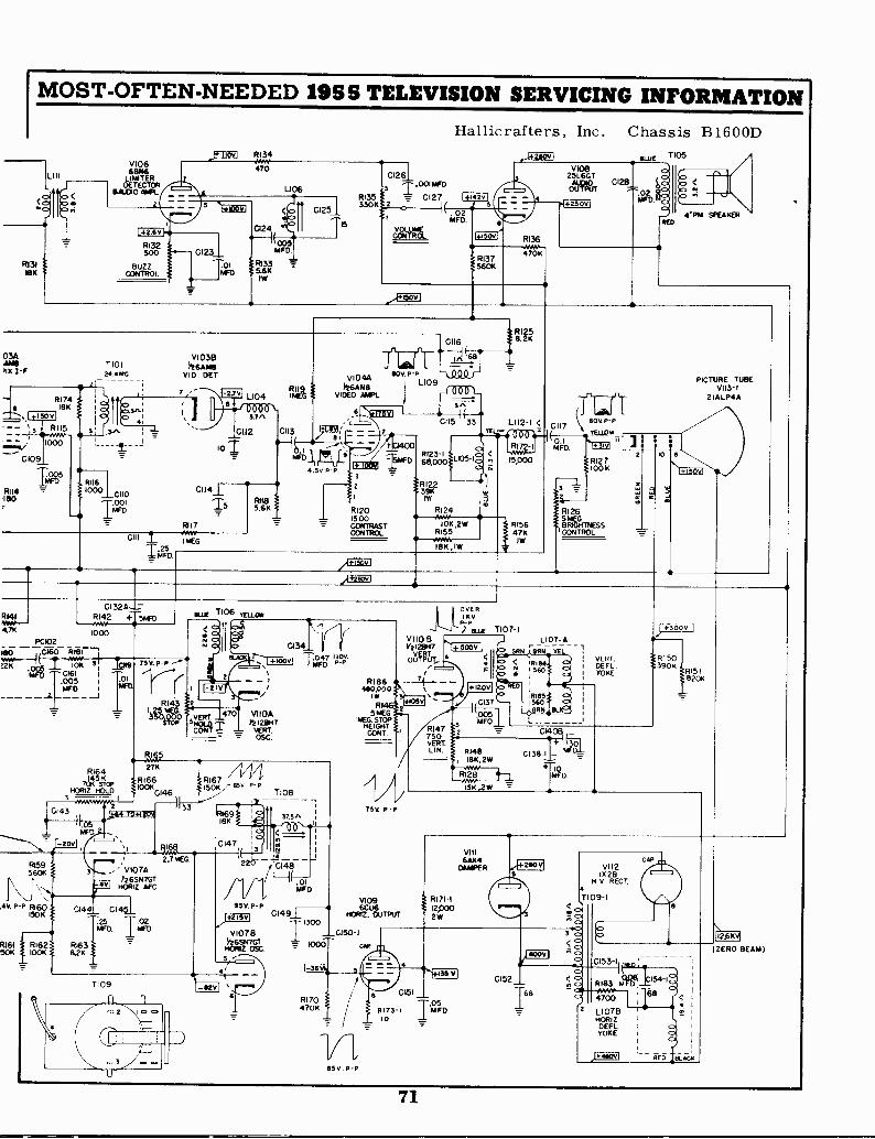
RI69I8K
olaC147 A
- 1
2
MFID
85 V. P -PC149_E-.
T 1300VI078 _C150-1
114S+17GTZ.056. 1000 CA'
5
41
MOST -OFTEN -NEEDED 195 5 TELEVISION SERVICING INFORMATION
V10613846
LIMiTERDET
SALVOECTORASP_
1+261
RI32500
RI31 BUZZ183 CONTROL
_tALJ*v R134
470
L)06
s
024
C1231 MFD.-105/
1 -1;6 111.6K1W
CI251
TIS
Hallicrafters, Inc. Chassis B1600D
C1261I .000A
C127M4135 =330K12
02MFD
ROL
426
14450dr
4137
R136
4703
.,}05.2a1
03A V1036IAIAB TIOI II26AMBMx 1-F NANO VI D. DET
RI 7418K
- RI I5,1C109
R114180
2
311610001CII0
1.001,..D
7 -276
I L104
02-7.9v0
ra1
10112 C113 Pt101 C.
11IFDA.PPkg4.5v.P-11
CI14±
RII7
C111
IFD
C132ALRI42 + 5T.CDAwe1000
PC102
1-8_Nl-ET CUO '1181
Aisr,12K
os
01611.2Frl
1,9 75 V. P -P
01NFU
WI/
T5
1MEG
P118
CII6
711-iirfr0 Q.0 r
V104A80V P -P
VIDEO AWL.
L1090 OTPr6AN8
\MIM I
C115 33
:1516FD
2
R1201500CONTRASTCONTROL
R123 -I68,000
/R12239KIN
L105-
RI24
10K ,2WRI55-WA18K , IW
fTR
L112 -I <
I41
RI72-
15,000
1315647K
IW
wpig
ISSP)so VERTor m.'.
our T106
e.;rs;
C,0ar.
2+15011
.1+26ovI
216
C134-_
TI°I'vi Tar. '47.
470T VIIOAre12.13/17
VERTOSC.
FA9p
R164 /14427K
145 K RI66 RI67HORZ HOLD 1100146146
TIO87014 STOP 150K
3
CI43
-20V
R15956011 3 V107A
146SN7G14V1 HORIZ AFC.
33
11 MO2.7 MSG.
.4V. P -P R160 0144 C1451150K
.25 T.02MFD MED
RI61 # RI62 R1631150K 100K 8.2K
T109
RI 70470K
65 v. P P
RI 86440,000
IW
81465 ME
!WC. STOPG.HEIGHT
CONT.
756 P P
2
V109
NORI62.UtoUTPUT
OVERI K V
P -P) ELLIE
VI108V21 28H7
OUTPUT
C151
4175.1 I UFO05.
10
71
n07-11107-A
TEL 1VERT.
I DEFLI YOKE
R147750VERT.LIN.
+ 505V IGRN ;ORR
RI84E 31 560
+12011 E8WED
iOe25VL6GT
OUTPUT
1425061
C1281 (
MFD
TI;r1CII7
c 80V P -P
YELLOW I
1132
)FIISK
s
&WRI26ITNESSCONTROL
CI37 8I561150
ORR II..005MFD
2
7105
RE D
JO
PICTURE TUBEVI13-1
21 ALP4A
6
\l+i50v1
)R1503906
IRIS!820K
7,7 CI4 _
RI48if3K.2W
153,2W
T41 DCI38-I _
+I 10MFD.
R171 -I12P002W
35V
VIII64X4
DIAPER
68
VII 2IX 213
N I/ RECT.
T 09-I
3 c410.
<2C153 -I
RI83 1541- 010-4Arer--
c) 47002
L107E140312DEFLYOKE
J.410VI -- c7c5
12.6104
( ZERO BEAM)
71
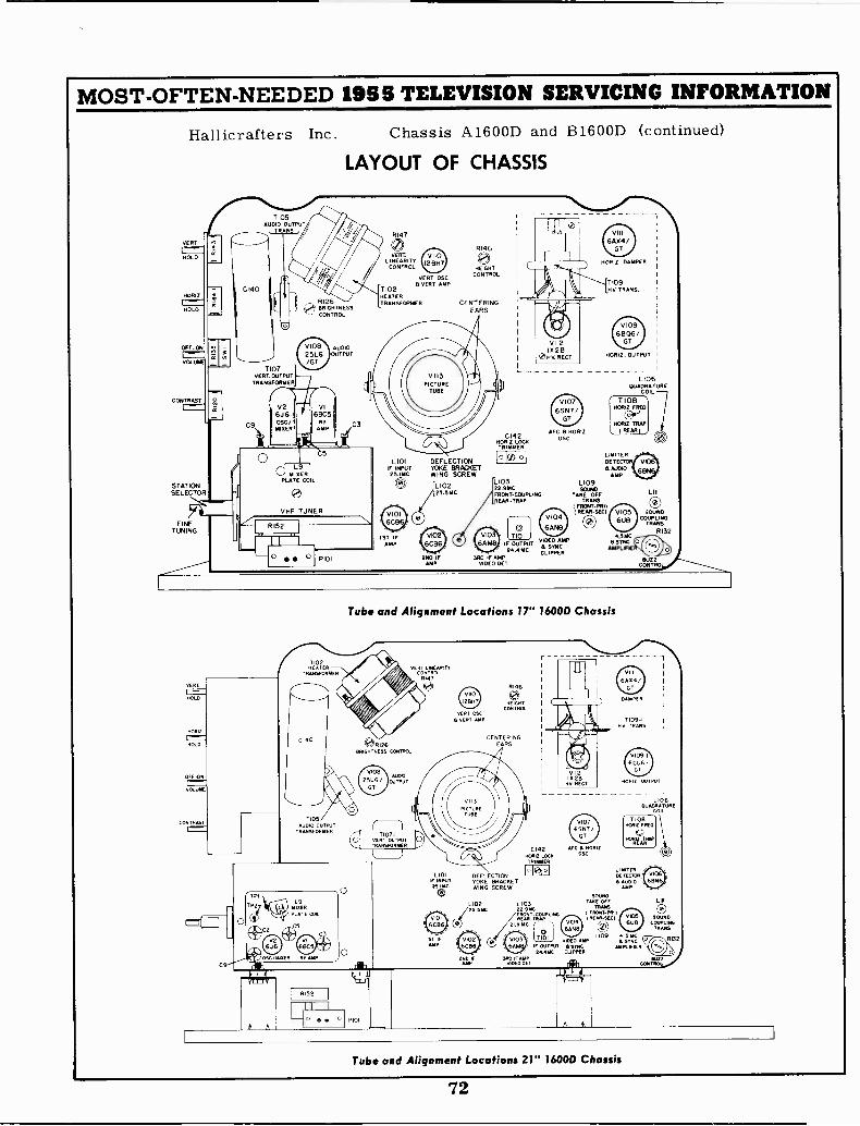
MOST -OFTEN -NEEDED 1955 TELEVISION SERVICING INFORMATION
Hallicrafters Inc. Chassis A1600D and B1600D (continued)
LAYOUT OF CHASSIS
VERT »,
;HOLD
HORIZ.
r"" --HOLD
CONTRAS
STATIONSELECTOR
FINETUNING
VERT
HOLD
Nom2
HOLD
OFF -ON
yaw.
CONTRAST
AUDIO OUTPUTTI OS
OUTPUT
*.R1261410'
k...), BRIGHTNESSCONTROL
A A
v10825L6/GT
VI613C5
R FAMP
0 yi-ix9ERPLATE COIL
VHF TUNER
RI 5 2
AUDIOOUTPUT
VERTLINEARITY
CONTROL
TI02HEATERTRANSFORMER CENTERING
EARS
128H7
RI96
HEIGHTCONTROL
L101IF INPUT2 5.IMC
O
1ST IFAMP
VERT OSCVERT AMP
DEFLECTIONYOKE BRACKETWING SCREW
IL25.5MC
2ND IFAMP
0142Holuz.LOCKTRIMMER
L10322.9MCFRONT -COUPLINGREAR -TRAP
V1076SN7i
GT
AFC B HORI2OSC
0 6ANBVI TIO1
IF OUTPUT V.1,,,°4N.24. MC
CLIPPERSRO IF AMP
VIDEO DET
VIII6,404/
GT
NORiz DAMPER
T109NV TRANS
V1096806/
GT
RORIE OUTPUT
LIMITERDET
AUDIOAYR
L109SOUND
TAKE OFFTRANS
I FRONT-PRI)I REAR -SEC)
0
L106QUADRA TORE
COIL
a5MCSING
AMPLIFIE
Tube and Alignment Locations lr 1600D Chassis
Lll P101L
1101INPUT
251.
yYR7 OSCVERT AMP
P146
0cg4THT
CENTERINGEARS
0142KNIT LUCK
TRIMMER
DEFLECTIONYOKE BRACKETWING SCREW
Arc a HORIzoso
SOUND
L102 L 103 TmE oFF Lill
25.514c 22 9NC TRANS
ER., COUPLING I FRONT...11 0.RE -TRAP ,REAR.SECI VC6 SOUND
21.5 MC OURCO)
COUPLINGTRAMS
LICRD CS.VIDEO AMP a SYNC
F OUTPUT ISYNG Ampunot24 AMC CUPP.
SRO !TAMPMCDO OCT
SOUNDCOUPLING
TRANS
R132
RUZZCONTRO
DAMPER
T109 -INV TRANS
RORIE OUTPUT
L106RuADRATuRE
FAIL
TIORNow FRED
LIMITERDETECTOR6 ADDIO
AMP
0TIOI
A A
fAMTROU
Tube and Alignment Locations 21" 1600D Chassis
72
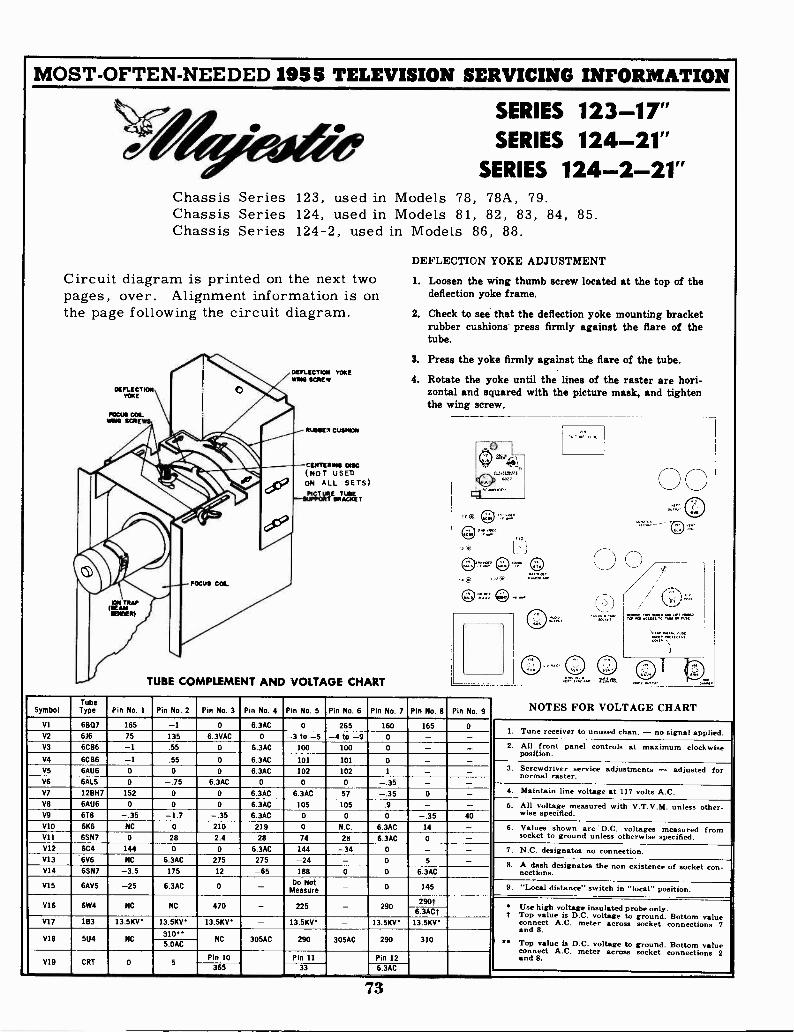
MOST -OFTEN -NEEDED 1955 TELEVISION SERVICING INFORMATION
Circuit diagrampages, over.the page following
DEFL1CTFOSIYOKE
0
Chassis SeriesChassis SeriesChassis Series
is printed on theAlignment information
the circuit diagram.
1111111111111C11,111111111b
SERIES 123-17"0
SERIES 124-21"SERIES 124-2-21"
123, used in Models 78, 78A, 79.124, used in Models 81, 82, 83, 84, 85.124-2, used in Models 86, 88.
DEFLECTION YOKE ADJUSTMENT
next two 1. Loosen the wing thumb screw located at the top of theis on deflection yoke frame.
2. Check to see that the deflection yoke mounting bracketrubber cushions press firmly against the flare of thetube.
3. Press the yoke firmly against the flare of the tube.DEFLECTION YOKEWING SCREW 4. Rotate the yoke until the lines of the raster are hori-
zontal and squared with the picture mask, and tightenthe wing screw.
FOCUS COLINNS SCSI - --
RUSSEI CUSHION
I .. CENTERNN ONIC(NOT
XI: V USEDON ALL SETS)
m
68
egt0. (101.7 0 0
N
:srATZEDRTATKIEE
3. rlJ 0 01 :.
FOCUS COL
gn : @ ':''' @r , ,,, ......*
.
.
TUBE COMPLEMENT AND VOLTAGE CHART 4;::- :AM .....
SymbolTubeType Pin No. 1 Pin No. 2 Pin No. 3 Pin No. 4 Pin No. 5 Pin No. 6 Pin No. 7 Pin No. 8 Pin No. 9 NOTES FOR VOLTAGE CHART
VI 6807 165 -1 0 6.3AC 0 265 160 165 01. Tune to -
V2 616 75 135 6.3VAC 0 -3 to -5 -4 to -9 0 - - receiver unused chan. no signal applied.
V3 6CB6 -1 .55 0 6.3AC 100 100 0 - - 2. All front panel controls at maximum clockwise6.3AC 101 101 0
Position.V4
VS
6CB6
6AU6
-10
.55
0
0
0 6.3AC 102 102 1
--
-- 3. Screwdriver service adjustments - adjusted for
normal raster.6.3AC 0 0 0 -V6
V7
6A15
12BH7
0
152
-.750 0 6.3AC 6.3AC 57
-.35-.35
-0 - 4. Maintain line voltage at 117 volts A.C.
V8 6AU6 0 0 0 6.3AC 105 105 .9 - - 6. All voltage measured with V.T.V.M. unless other -V9 6T8 -.35 -1.7 -.35 6.3AC 0 0 0 -.35 40 wise specified.
VlO 6K6 NC 0 210 219 0 N.C. 6.3AC 14 - 6. Values shown are D.C. voltages measured fromVII 6SN7 0 28 2.4 28 74 28 6.3AC 0 - socket to ground unless otherwise specified.
V12 6C4 144 0 0 6.3AC 144 -34 0 - - 7. N.C. designates no connection.V13 6V6 NC 6.3AC 275 275 -24 - 0 5 - 8. A dash designates the non existence of socketV14 6SN7 -3.5 175 12 -65 188 0 0 6.3AC
con -nections.
V15 6AV5 -25 6.3AC 0 - Do NotMeasure - 0 145 9. "Local distance" switch in "local" position.
290290f
Use highV16 6W4 NC NC 470 - 225 -6.3ACf voltage insulated probe only.
f Top value is D.C. voltage to ground. Bottom valueV17 1B3 13.5KV 13.5KV 13.5KV' - 13.5KV' - 13.5KV 13.5KV connect A.C. meter across socket connections 7
8.
V18 5U4 NC310**
NC 305AC 290 305AC 290 310and
5.0AC Top value is D.C. voltage to ground. Bottom valueconnect A.C. meter across socket 2
V19 CRT 0 5Pin 10 Pin 11 Pin 12
connectionsand 8.
365 33 6.3AC --,,
73
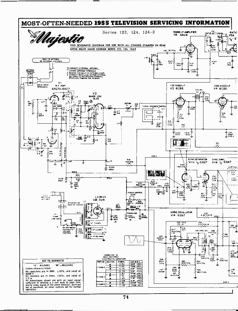
MOST -OFTEN -NEEDED 1955 TELEVISION SERVICING INFORMATION
ANTENNATINMINAL
!TRIP
R330I
-
LI
10
ANTENNAOR ES AAAAAA ANTENNA
VI30011. INPUT R F AMPIMPEDANCE
DLT
R22206
Series 123, 124, 124-2
THIS SCHEMATIC DIAGRAM FOR USE WITH ALL CHASSIS STAMPED IN REAR
SOUND I.F AMPLIFIERV8 6AU6
UPPER RIGHT HAND CORNER SERIES 123, 124, 124-2
TO CONNECT EKTERNAL ANTENNA
LOOSEN ANTENNA TERMINALS2-11(310v1 THE BUILT-IN ANTENNA LEADS.3 -CONNECT 3000 LEAD-IN FROM (ETERNAL
ANTENNA TO THE ANTENNA TERMINALSTI106.ND TIPITEN TN( SCRENS.
680 7A/6BZ 76 r--1
:10Thca 1, !i5-3 1 I L 3
I
I
5 r .516'14 47
C2 000
RS154
CIS3-9 47K
L51
TEST e>20622 247 MC cis
L 0 TI I2C
V2MIXER -05G.
6J6
I R4I 1011
4
I C:11
R710K
-3
CIO
C2I
I.__ rws __C12TIMING
C14. T 0156
WHITE
R69
C231 -.I5000 I 2211
C29I4 Me
450VA
IJTv 11211D60 CYCLEA C ONLY
f3 AmP
LINE FUSE
C76.6
RIO15k
C 230.5000
8113
1200%
Mh22/
INTERLOCK ON "BACK OF CHASSIS
ON -OFF SNITCHHANGED TOVOLUMECONTROL
RCA
R740016
10%
KEY TO SCHEMATIC
"K"=KILOHMS "M"=MEGOHMSUnless otherwise noted:All capacitors are in MMF, ±20%, and rated at400W V.All resistors are in ohms, ±-20%, and rated at1/2 w.All waveshapes shown are with an input signalsufficient to develop a 3 volt peak to peak com-posite video signal at the 'video detector. Contrastset at maximum, all other controls set for normaloperation.
L.V. RE CT.VI8 5U4
WI
RY
:AW.117
2750
L17ROA
IO
2
L
:3vT 3AMPS626.
MYINAT !EA/APS v,
NNE .T211
6. 3v AT 6.5 sows
CAPI02IF
400V.616
12.
6116
C92 (39010%
C91 810000 47n
210%C 93AN000
rlo
Ai:Alio_R. T_ ASS _
Toil
RIO,100
C,90.38
40
PRINOT
IK
4 516C.
RATICV9AI/2- 6
15001C 95
i ST VIDEO I.FV3 6CB6
LOCAL-015TANCE'SwiTON
5 3- -
44//56126
210.4
225V
240 MCTI vEL
5
61,761
010%
330
- C220
anaR19
2Ka%
2 NO VIDEOV4 6CB6
2120
102.
CII500
C22.1 C21A5000 5000
CI
125 my200 V
RP,100
R45000612M
R474750 A C35
ICIVI 1350 5000
FOCUS CONTROL-.0W
R46 R662254W0 A 470210%4W
35061 L le
FOCUS COL
MINIF D M4C0640
CONNECTION OFMULTI -SECTIONED
(LEGION:X.671C CAPACITORS
PART NO SECTION SYMBOL f CAP a W Vea C-62 40%, -50v
C-5455-3 M C-64 ROME -4500
C-72 4 mr -300- C-104 4 MF - 450V
C- 6 3 405E -450V
C-5435-3 C- 31 40 ME - 450v
A C 29 1 Vf - 450v- C -I06 MF - 4500
C-50 100MF- 50VC-5.429 2
A C-102 251F 50V
CSI
RAO5t10%
3
00 T R49
530K R5I TO22 C43
.210%3.6R ml
5%
SYNC. SEPARATOR
VIIA 1/2- 6SN7
45056G
_10%"'TCO2210
6
SYNC.AMPLVile 1/2-6SN7
COO2.2x
710%
R533.50
CA1
VERTICAL
34220
Coe2000
022 Air
HORIZ.OSCILLATORVI4 6SN7
12 873.30.0% ICU
V
HON HOLD
6.20.IO
R0576±10%1W
%A.A.
16011 FRED AD. pee476,0%
I if .
C
HORIR STABIL I
( C159330±10%ay 071
R83 6000 12000 6)%
1000!5%
Res706
150147
C 73560' 1
225 v
C7440-370'NORtong
C75
5%
74
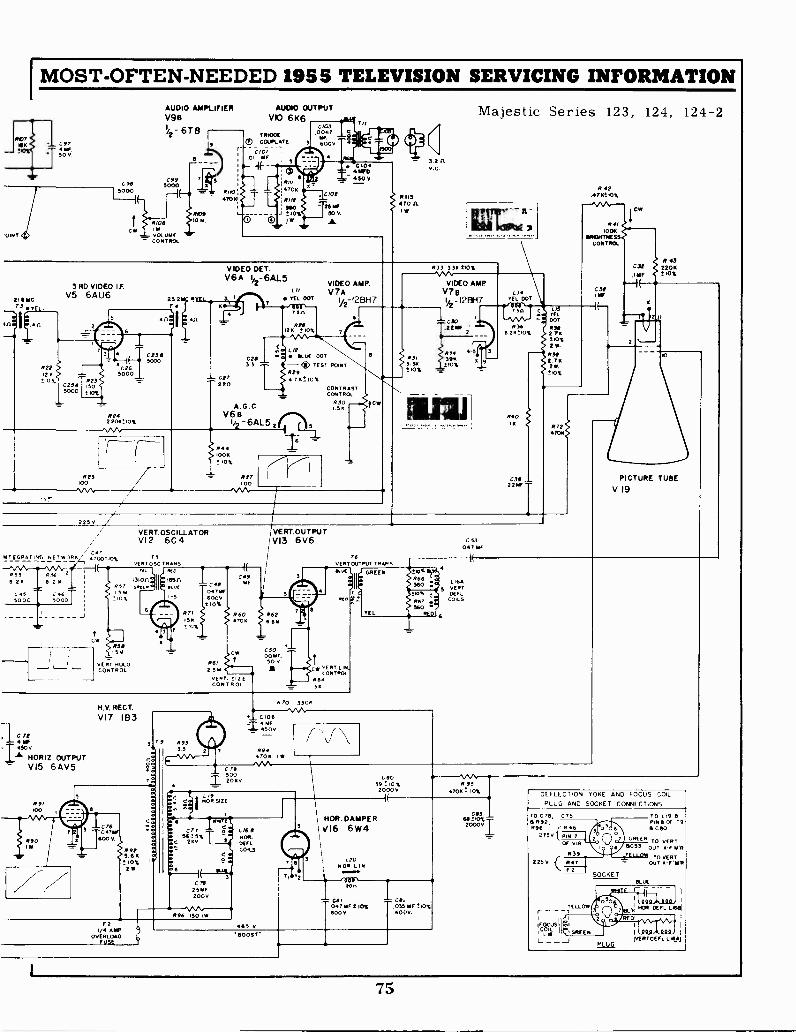
IMOST -OFTEN -NEEDED 1955 TELEVISION SERVICING INFORMATION
C974-50 0.
AUDIO AMPLIFIERV98
2-67 8
C99C98 5000
5000
KF
I 2100
DINTC
VOLUMECONTROL
410910 OA
ROO470
AUDIO OUTPUTVIO 6K6
TRIODECOL/PLATE
CIO'01 1AF
RIII470x
RI It540
J 010%)4/
Cff/30047NE
3 6000
. ClotT25 hi
50 V
A.
fit
Tll
C104:50 V.
-2, 3.2Av.0
R 113470
I
Majestic Series 123, 124, 124-2
3 RD VIDEO IFV5 6AU6 23.2
411
0258
422 C2612 K 5000
C254 ',235000 !CS
424, no%
223O 0
r4
VIDEO OFT.V6 A I - 6AL5
- Ct?
L /0
TEL DOT600
Sn
RPO126 10%
C2I]3 T
A. G .0v6e
1/2 -641_5 zrTh
VIDEO AMP.V 7
y2-12BH 7
itilLUE 007- 4, TEST 80NT229 76010%
R44IOOK
ION
1121100
CONTRASTCONTROL
2301.59
404
233 336 210%
VIDEO AMPV7 B L
V2-12BH7 TEL DOT
,341 C ld,CL
C30 DOT
.22 1238 2493
1/400 % 2 711
20%
234 5 3 23*231 396 63 39 9- 2.761,0%
2r.l'10%
24010
C311.22W
R72706
R 4241710.10t
R411001,
141130.111455CONTROL
C3tIs
CM
C32.111F
ff 432208
ION
2250
VERT. OSCILLATORVI 2 6C4
/ c47.± TItE2. L!'_._,../.EIE°1E 4100110%
(vE7(l
L,
RT osc TRANS
Ks, 856211 26 a 26 1310n
R37 cArEft IL'0,47W
16521
1,70
S
11 I C48I1115-C:050 3'040'0T 110% 60ov1 W
2 KM
C
II
L__J L_ vERT NOLDCONTROL
5Y
75
R71INK010%
R61
2.514
vERT. SIZECONTROL
VERT.OUTPUTV13 6V6
C rt4 VI
_T 4500HORIZ. OUTPUTVI5 6 AV5
29i100
003/0 2
8901
zz
N.V. RECT.
VI7 1B3
Cr60478$
4000
4925.68010%2
9 2933.1
R 70 3309NA".
C1064 NF4500
2944706 I
TEL
C33047 IIFF
PICTURE TUBE
V 19
010'
560655.
267 .560
RED
J
0645 VERT
DEFLCOILS
6
C 79
502060
019NOR SIZE
C 8039010%
20000R 93
4706 = ION
r5415%
260
25W200v
R96 150 IMF2
1/4 AIDOVERLOAD
FUSE
LIESNOR.0EFL.COILS
65 V
NOR. DAMPERV16 6W4
020NOR LIN
066ton
CJ/047 SF ION6000
CO..01518F 110%600V.
'BOOST'
C83602000V
DEFLECTION YOKE AND FOCUS COILPLUG AND SOCKET CONNECTIONS
o ca 892.R96 8,16
2750 f p,7,OF via
225V
COILLM
R39R47F2
SOCKET
To 019 aP1718 OF 19
C130
TO vERTOUT RER
TO VERTWT 4-F RER
8L0(
1
IVERTDEFL LIRA
75
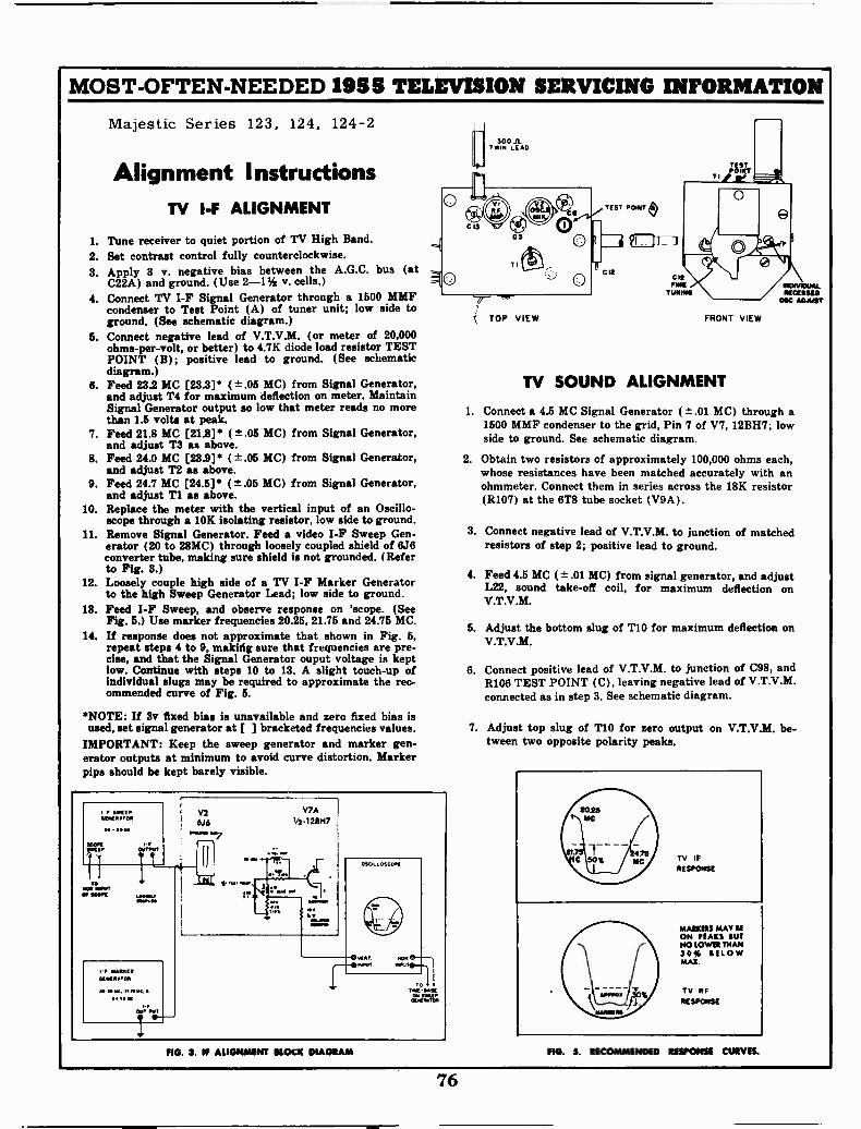
MOST -OFTEN -NEEDED 1955 TELEVISION SERVICING INFORMATION
Majestic Series 123, 124, 124-2
Alignment I nstructionsTV I -F ALIGNMENT
1. Tune receiver to quiet portion of TV High Band.2. Set contrast control fully counterclockwise.3. Apply 3 v. negative bias between the A.G.C. bus (at
C22A) and ground. (Use 2-11/2 v. cells.) 04. Connect TV I -F Signal Generator through a 1600 MMF
condenser to Test Point (A) of tuner unit; low side toground. (See schematic diagram.)
6. Connect negative lead of V.T.V.M. (or meter of 20,000ohms -per -volt, or better) to 4.7K diode load resistor TESTPOINT (B); positive lead to ground. (See schematicdiagram.)
6. Feed 23.2 MC [23.3]* ( ± .05 MC) from Signal Generator,and adjust T4 for maximum deflection on meter. MaintainSignal Generator output so low that meter reads no morethan 1.5 volts at peak.
7. Feed 21.8 MC [21.8]' ( ±.05 MC) from Signal Generator,and adjust T3 as above.
8. Feed 24.0 MC [23.9] ( ±.05 MC) from Signal Generator,and adjust T2 as above.
9. Feed 24.7 MC [24.5]* ( ±.05 MC) from Signal Generator,and adjust T1 as above.
10. Replace the meter with the vertical input of an Oscillo-scope through a 10K isolating resistor, low side to ground.
11. Remove Signal Generator. Feed a video I -F Sweep Gen-erator (20 to 28MC) through loosely coupled shield of 6J6converter tube, making sure shield is not grounded. (Referto Fig. 3.)
12. Loosely couple high side of a TV I -F Marker Generatorto the high Sweep Generator Lead; low side to ground.
13. Feed I -F Sweep, and observe response on 'scope. (SeeFig. 5.) Use marker frequencies 20.25, 21.75 and 24.75 MC.
14. If response does not approximate that shown in Fig. 5,repeat steps 4 to 9, making sure that frequencies are pre-cise, and that the Signal Generator ouput voltage is keptlow. Continue with steps 10 to 13. A slight touch-up ofindividual slugs may be required to approximate the rec-ommended curve of Fig. 5.
*NOTE: If 3v fixed bias is unavailable and zero fixed bias isused, set signal generator at [ ] bracketed frequencies values.
IMPORTANT: Keep the sweep generator and marker gen-erator outputs at minimum to avoid curve distortion. Markerpips should be kept barely visible.
SWEEPSENEAATOR
ICORr[,
V2616
V7A'/2-125H7
TOWA NOWT0. *GOON A.
GENERATCNI
NE NINA. E. Es.. *AEA NE
Out INET-
RIv%.1%
OSCNE.OSCo.
eve.,ANNIT
too* a
TOV. SASEGoo S.
GENERATOR
FIG. 3. IF ALIGNMENT BLOCK DIAGRAM
30011TWIN LEAD
VI
G IS
G
0
TOP VIEW
TEST POINT
B Qt
FRONT VIEW
TV SOUND ALIGNMENT
1. Connect a 4.5 MC Signal Generator ( ± .01 MC) through a1500 MMF condenser to the grid, Pin 7 of V7, 12BH7; lowside to ground. See schematic diagram.
2. Obtain two resistors of approximately 100,000 ohms each,whose resistances have been matched accurately with anohmmeter. Connect them in series across the 18K resistor(R107) at the 6T8 tube socket (V9A).
3. Connect negative lead of V.T.V.M. to junction of matchedresistors of step 2; positive lead to ground.
4. Feed 4.5 MC ( ± .01 MC) from signal generator, and adjustL22, sound take -off coil, for maximum deflection onV.T.V.M.
5. Adjust the bottom slug of T10 for maximum deflection onV.T.V.M.
6. Connect positive lead of V.T.V.M. to junction of C98, andR106 TEST POINT (C), leaving negative lead of V.T.V.M.connected as in step 3. See schematic diagram.
7. Adjust top slug of T10 for zero output on V.T.V.M. be-tween two opposite polarity peaks.
MARKERS MAY UON PEAKS BUYNO LOWER THAN30% BELOWMAX.
TV RFRESPONSE
FIG. 5. RECOMMENDED RESPONSE CURVES.
76
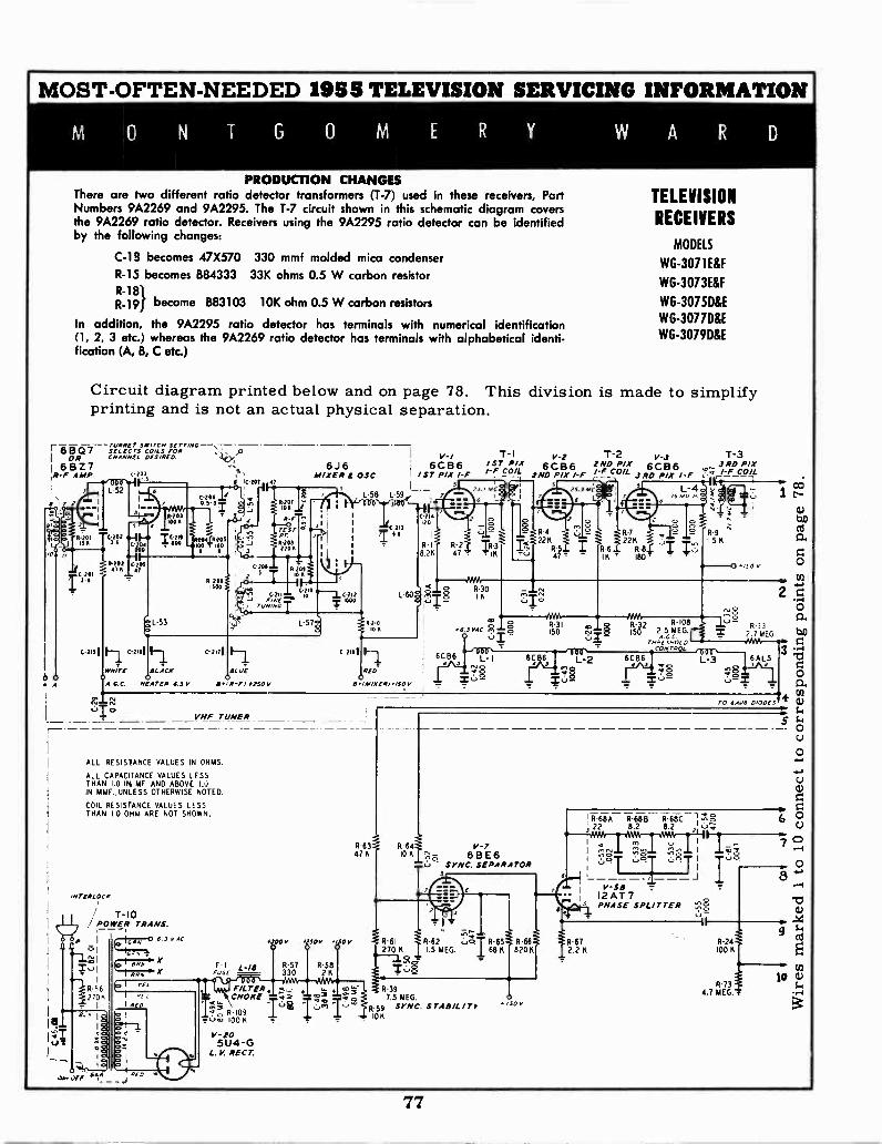
MOST -OFTEN -NEEDED 1955 TELEVISION SERVICING INFORMATION
PRODUCTION CHANGESThere are two different ratio detector transformers (T-7) used in these receivers, PartNumbers 9A2269 and 9A2295. The T-7 circuit shown in this schematic diagram coversthe 9A2269 ratio detector. Receivers using the 9A2295 ratio detector can be identifiedby the following changes:
C-18 becomes 47X570 330 mmf molded mica condenserR-15 becomes B84333 33K ohms 0.5 W carbon resistorR-18R.19/ become B83103 10K ohm 0.5 W carbon resistors
In addition, the 9A2295 ratio detector has terminals with numerical identification(1, 2, 3 etc.) whereas the 9A2269 ratio detector has terminals with alphabetical identi-fication (A, B, C etc.)
TELEVISION
RECEIVERS
MODELS
WG-3071E&F
WG-3073E&F
WG-3075D&E
WG-3077D&E
WG-3079D&E
Circuit diagram printed below and on page 78. This division is made to simplifyprinting and is not an actual physical separation.
re1YCif;11I-f ;357-Y,f'; .14/
S 17
I OR CII4NMEL DESIRED.
6827,R -F AMP ,:20
1 5
3
/ 1C.207I T 0 ii, C-204 2 1 IIr
0 3.31 si
A.O.C. HEATER 8.3 V
V-/6J 6 ; B 6
MIXER OSC. I /ST6CPIX I -F47
o1.1.17. I L58 L58 -01
5 -4..
R -F ^ ' 0.214
..-0 r .111 JC 213 20
<7(;05: .71220 n
C-2011 .io,II 20I1 '
TIt
H..,..
MO4: (-21.., C211 ,_,
71346,44CTi,,,,,-
c 2171
II.4.9
iC-212,000
08204
30 R -F/ 475014
VHF TUNER
ALL RESISTANCE VALUES IN OHMS.
ALL CAPACITANCE VALUES LESSTHAN 1.0 IN MF AND ABOVEIN MMF UNLESS OTHERWISE NOTED.
COIL RESISTANCE VALUES LESSTHAN I 0 OHM ARE NOT SHOWN.
MitERLOCF
T-10./ POWER TRANS.
I 6.1 v1oi Cc, ,
L -57g
R I
8 28
L-60°8 612
10
c 2131 F--i
RED'
84 IMIXER,o/S0V
T -I/ST PIX/-F CO/L
R-30IA
co
88.3VAC 8o -
6CB6-I
. ,
V-26CB6
2ND PIX I -F
T-2 V-3 T-32 NO Pile 6CB6 3RD PIX/-F COIL I -F COIL
R6
R-7
22KR-8..0 I
-
R-3OI R-32 R-108IS 150 2 5
,,,,A55,0, 0CONTROL
L
R-63 R 64 , V-7478 10K 68 E 6
SYNC. SEPARATOR5
ar,31,_ L-18
0300V 48.50V 4ISO
R-5826
FILTER. R-39IkCHOKE '40 7.5 MEG.
vc, R 109 16a -1,AI- R 59 SYNC. S TAB& / I'
6C 64
10KI' 6.. 100K
V-205U4 -G
L.V. RECT.
_..§2V
coPT 1 r-
ta.oa)
R-9ry
I 5 K
O
L -2 6CB6Ina .444D0-0 oL-3 GALS
TO 64,5 0,006S
R 68A R-686 R -68C22 8.2 8.2 '
Im
TV-58 -
12 AT 7PHASE SPLITTER
R-672.2 K
Iuc
2 -IO
R 33?.7 MEG. z
3 :61
0
M
5-- 0O
OJ
6 0
8
7.1a)
9 (.,34
R-24100 A
cn
R4.7 MEG.'-:
10 a)
77
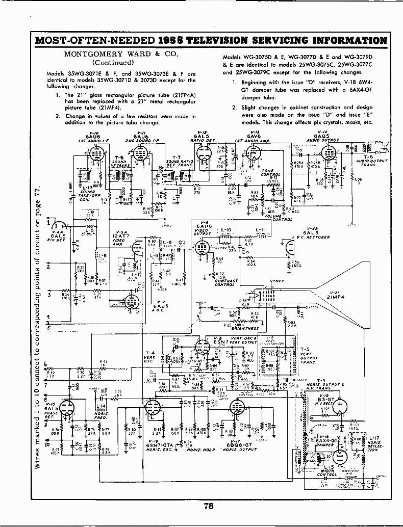
MOST -OFTEN -NEEDED 1955 TELEVISION SERVICING INFORMATION
t--
(1)40Cd
a.
O
MONTGOMERY WARD & CO.(Continued)
Models 35WG-3071E & F, and 35WG-3073E & F areidentical to models 35WG-3071D & 3073D except for thefollowing changes.
1. The 21" glass rectangular picture tube (21FP4A)has been replaced with a 21" metal rectangularpicture tube (21MP4).
2. Change in values of a few resistors were made inaddition to the picture tube change.
1
V-4 A6AL5
C.)PI% DE T.
frC.)
0
0Gt.
40 3 R344701(
r -I
O
"Cl
a,En
a)
O
O
V-106AU6
1ST AUDIO I -F5
R -IIL-13100 =
SOUNDTAKE -OFFCO/L R -I2
IK
RIOI 22 K I
I L-5160 0412. /1
R-361001( R-37
4.76
R 3847 K
6AU62ND SOUND I -F
5
V -5AI2AT7VIDEOAMP.
.I,U G R-91
I1(250
L. R69 R70 '''....-- 15-i 3.36 2.216 -ir,,,,,,;,O is
7
O 8V-/s6AL5PHASE
"CiDE T.
a) 9
G1
cd
10R-75
4) 470 K
$.4
R 76_27K
V -If6AL5
RATIO DEr
T-7SOUND RATIODE rTRANS.
15KR-42
R -4I R-43
331( I MEG '2'
*150V
IV-9
6AU6A.G.C.
VERT. 1
OSC. I a
R 82I.
MEG.
R-96 R-972.2K 1501(
.650
1,--Rr.11:49
Models WG-3075D & E, WG-3077D & E and WG-3079D& E are identical to models 25WG-3075C, 25WG-3077Cand 25WG-3079C except for the following changes:
1. Beginning with the issue "D" receivers, V-18 6W4-GT damper tube was replaced with a 6AX4-GTdamper tube.
2. Slight changes in cabinet construction and designwere also made on the issue "D" and issue "E"models. This change affects pix crystals, masks, etc.
V -I3
6AV6/ sr AUDIO AMP.
TONECONTROL
R-721.5 MEG.
R-71 R-231 MEG. 10 MEG.
VOLUMECONTROL
L -II/DO MU
844 ---0/1M100 R.84
100 K
0.300 V
R-25 500 KBRIGHTNESS
6AQ5AUDIO OUTPUT
3
V -4B6AL5
D.C. RESTORER
R-50I MEG.
R-552.2 K
V -B VERT. OSC.8 L -I26SN 7 VERT. OUTPUT p,,VGRrirON COIL .5
G rA
11-85820
R 51 vc- or R-87MEG.IS H000 2.2 MEG
e '2554fft (71
6.1 k.3",
R-99 R-I0015.615 47016
150 KH09/2
OR/ YE
6-It iR-93r
1 _ Iso o oR-516007uI
' '-' ...; R: 09
MEG:
2 . 11 E R -59680
i-o-NAA--Q
R90,8 MEG lil--.3 "" T-9
R-95 -.-g,-: HORIZ. OUTPUT s6.81(" ''' N.V. TRANS.
,-- ,.i-- -,GONI,OL
HeIGA+r1,3 --4. 1 V-/9R -1C3 47K
Is 11133-GT
1
H.M8R10( 4CT
5 1
V-2/21MP4
11-0 3000
`,-";:R -1000I
..J2z1(
1 0
G.
V -I6 94R V-17 300,6SN7-GTA r--4 50 K 6BQ6-GTHORIZ. OSC. # IIORIZ. HOLD NOR/Z. OUTPUT
T-5VERTOUTPUTTRANS.
AlNa
S
I v-/8?, 6A X4-GT
L, I DAMPER
..°ae 0.53+,
r G
101T-8
AUDIO OUTPUTTRANS.
R-2916
1250 2.
R -i051 MEG.
73.
L-15WIDTH
CON TROL
L -I66E5 moayr.comrRoc -0
X I L-17INOR/Z.DTIELLEC-
.300v
78
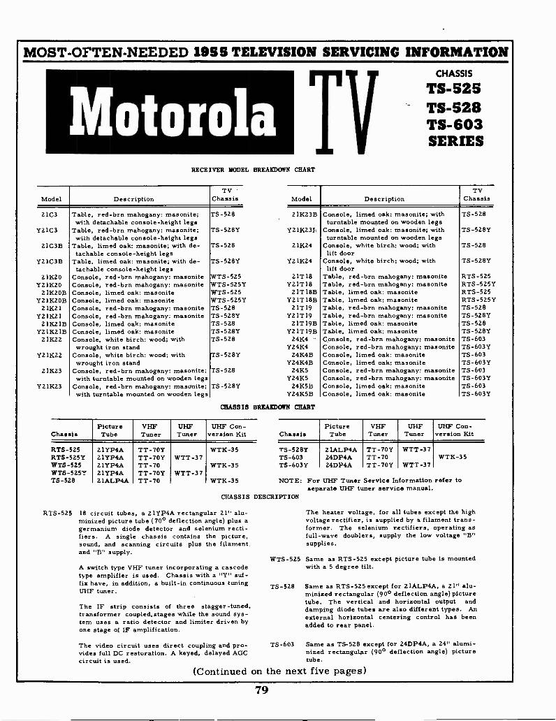
MOST -OFTEN -NEEDED 1955 TELEVISION SERVICING INFORMATION
Motorola TRECEIVER MODEL BREAKDOWN CHART
Model DescriptionTV
Chassis
2103
Y21C3
21C3B
Y21C3B
21K20Y21K20
21K2OBY21K2OB
21K21Y21K21
21K21BY21K21B
21K22
Y21K22
21K23
Y21K23
Table, red-brn mahogany: masonite; TS -528with detachable console -height legs
Table, red-brn mahogany: masonite; TS -528Ywith detachable console -height legs
Table, limed oak; masonite; with de- TS -528tachable console -height legs
Table, limed oak: masonite; with de- TS -528Ytachable console -height legs
Console, red-brn mahogany: masonite TS -525Console, red-brn mahogany: masonite WTS-525YConsole, limed oak: masonite WTS-525Console, limed oak: masonite WTS -525YConsole, red-brn mahogany: masonite TS -528Console, red-brn mahogany: masonite TS -528YConsole, limed oak: masonite TS -5Z8Console, limed oak: masonite TS -528YConsole, white birch: wood; with TS -528wrought iron stand
Console, white birch: wood; with TS -528Ywrought iron stand
Console, red-brn mahogany: masonite; TS -528with turntable mounted on wooden legs
Console, red-brn mahogany: masonite; TS -528Ywith turntable mounted on wooden legs
CHASSIS
CHASSIS
TS -525TS -528TS -603SERIES
Model DescriptionTV
Chassis
21K23B
Y21K23E
21K24
Y21K24
21T18Y21T18
21T 18BY21T 18B
21T19Y21T19
21T 19BY21T19B
24K4Y24K4
24K4BY24K4B
24K5Y24K5
24K5BY24K5B
BREAKDOWN CHART
ChassisPictureTube
VHFTuner
UHFTuner
UHF Con -version Kit
RTS-525RTS -525YWTS -525WTS-525YTS -528
21YP4A21YP4A21YP4A21YP4A21ALP4A
TT -70YTT -70YTT -70TT -70YTT -70
WTT -37
WTT-37
WTK-35
WTK-35
WTK-35
Console, limed oak: masonite; withturntable mounted on wooden legs
Console, limed oak: masonite; withturntable mounted on wooden legs
Console, white birch: wood; withlift door
Console, white birch: wood; withlift door
Table, red-brn mahogany: masoniteTable, red-brn mahogany: masoniteTable, limed oak: masoniteTable, limed oak: masoniteTable, red-brn mahogany: masoniteTable, red-brn mahogany: masoniteTable, limed oak: masoniteTable, limed oak: masoniteConsole, red-brn mahogany: masoniteConsole, red-brn mahogany: masoniteConsole, limed oak: masoniteConsole, limed oak: masoniteConsole, red-brn mahogany: masoniteConsole, red-brn mahogany: masoniteConsole, limed oak: masoniteConsole, limed oak: masonite
TS -528
TS -528Y
TS -528
TS -528Y
RTS-525RTS-525YRTS-525RTS-525YTS -528TS -528YTS -528TS -528YTS -603TS -603YTS -603TS -603YTS -603TS -603YTS -603TS -603Y
ChassisPicture
TubeVHF
TunerUHF
TunerUHF Con -
version Kit
TS -528YTS -603TS -603Y
21ALP4A24DP4A24DP4A
TT -70YTT -70TT -70Y
WTT -37
WTT-37WTK-35
NOTE: For UHF Tuner Service Information refer toseparate UHF tuner service manual.
CHASSIS DESCRIPTION
RTS-525 18 circuit tubes, a 21YP4A rectangular 21" alu-minized picture tube (70° deflection angle) plus agermanium diode detector and selenium recti-fiers. A single chassis contains the picture,sound, and scanning circuits plus the filament.and "B" supply.
A switch type VHF tuner incorporating a cascodetype amplifier is used. Chassis with a "Y" suf-fix have, in addition, a built-in continuous tuningUHF tuner.
The IF strip consists of three stagger -tuned,transformer coupled,stages while the sound sys-tem uses a ratio detector and limiter driven byone stage of IF amplification.
The video circuit uses direct coupling and pro-vides full DC restoration. A keyed, delayed AGCcircuit is used.
The heater voltage, for all tubes except the highvoltage rectifier, is supplied by a filament trans-former. The selenium rectifiers, operating asfull -wave doublers, supply the low voltage "B"supplies.
WTS-525 Same as RTS-525 except picture tube is mountedwith a 5 degree tilt.
TS -528 Same as RTS-525 except for 21ALP4A, a 21" alu-minized rectangular (90° deflection angle)picturetube. The vertical and horizontal output anddamping diode tubes are also different types. Anexternal horizontal centering control has beenadded to rear panel.
TS -603 Same as TS -528 except for 24DP4A, a 24" alumi-nized rectanguliar (90° deflection angle) picturetube.
(Continued on the next five pages)
79
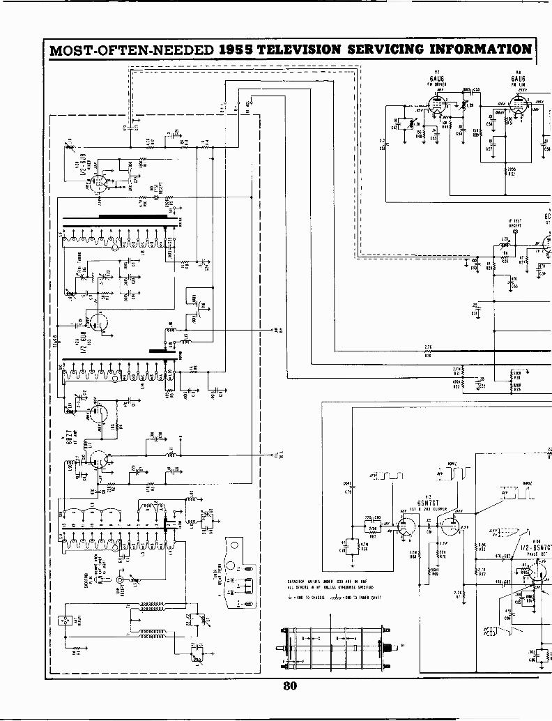
MOST -OFTEN -NEEDED 1955 TELEVISION SERVICING INFORMATION
L_
wee715 o4r.
"If. '',.1, .-TI, (..i,s -
orsco
t
O
wotr.:2
000'
mr1r,Am.
0 0 0 0 0 ,
000
-.000000000,--
-- 000000000000000000'
1
V7
6AU6FN DRIVEN
rrr
2.70
R20
Vs
6AU6FN LIN
IF TEST
RECEPT
0125,
IA,!;7%
17016.33
6C1ST
170
16'34
CJT
23N021
4700
R22
125T32
133011 4'001
112003
2R
.0047
C79
mt'- 2700
R6767
41.1_ 4.711
c fir R66
SAID -N,
V13
6SN7GT, 1ST I 2ND CLIPPER
05
Or
CAPACITOR VALUES UNDER 1000 ARE IN NIIF
ALL OTHERS IN NF UNLESS OTHERWISE SPECIFIED
- CND TO CHASSIS /77117 END TO TUNER SHAFT
el
It220R70
560R69
ur
5
I Y
2.20
HORIZ
1/2- 6SN7G-
80

2.24453
I MOST -OFTEN -NEEDED 1955 TELEVISION SERVICING INFORMATIONTONE
V9
.0047I(SL
RATIO 061
6414NicTtlik6W6GT
TELEVISION CHASSIS TS -525A-006AL5 460
IM 330 .005 066
-3;i 11RI31130 9IIJF
VOLUME "4
AUDIO AMP TTO
,tsar 513 19
AUDIO
5AVC
062.00T65 TAP Thlt.4 NO
ONE
fie5111005508
OOL 1067I.
Car
See next page for service hints.
IV;
IC
SPAR
QO 13 $711
MOTOROLA, INC.7.5
1104701 082563 tt0101 C432
AEI
01 073
140 Mf
- C77
120011f
- C754
464 SW ON VC
6.6 CAI
465 IL
10 44
110 ALI-RED
414-101
.1140 ME
7146
INTERL
MO
ISO
T5
22
37!
029
13013 /1 2
470
C36 47 C38
15 43010
V4
6C B6 1125E
2ND IFTRAP
IMP
421
433
.001 21 201, 470
504C40 1,23'31 C41 L2TF, 52304
043
V5
6C B6340 IF
1!081
SE VICE
TEST RfCEPT
ROT VIEE
FIL VIO
IF ACC
4701_
C391.1126
081
236t 432
126e4TO
-1E44
INV
L_
17
CAI
1.,,,,_046 5..9747
1420
111:5 645
129 L30
___
20014F
iC144 ar-1-__
134 4.540TRAP
101'
L33 31
NIR 8.264 15
4.7K437
30 046
L35
104
005
749
'3204 CONTRAST1139
06
12817VIDEO Alf
30 Mf
-70504
1 3.1
130
504
4.71 L31
106443443
470
046
226
.441
+ +
101
191 VELD
HOLD
.003
C89
-war IP4.74976 .01
T"
.01
.8511 92 ,[74HRBI
080447
VISA
Iril
100
015
6SN7GTROW 0 C
.194
-6;
014A
1/2 - 12 BH7VERT 050
\ 051(097. .005)101D5
5.6K712
16941
496ILO 1E0
1120499
VERT
SIT
0158
,So1/2 -128H7AM/
VERT OUTPUT469
T" SHY54 ii
468 /1".,
/1000
1.041 (699
750
60 If 495
CT4C 8.28494
VERT LIN710Y
RECUT
0106
BOOTSTRAP
1/12
6AU660100 ADO
P
34: ,L-1
0E71 YOKEL42
oa
MEC? 1000$ SRLAIT STRAPIIMA PM I TO PM 10 OR Pm
OM,
.0051 CIO 470
97/1081
390 96 4/
5.6648 500
1101112 05C
1251 WEFT
-T- 471
401495/e 2501
.0041 L40 ROT
G75
9041
12
ID
696
490
390 3300
0103 493
11241011 1506 1506
1182 491
4.76491
5 II1
0751
4.1149?
.039
0102
660
4'2198
-Jar
5
V16
6806GTNORIZ OUTPUT
r113
51
0 00 00 0, --OS
000"0410s
VI8
IB 3G TNV RECT
000
3.3
L4I
1 I500 3 VII
6AX4GTDAMPER
L 4 3
V19
2IYP4APICTURE TUBE
113 COARECTIORS
0 0 0 0 01I 5 4 3 0i
III
CHO
100
Ri01
.412
.005
CIII
511
0 -BRIGHTNESS
.9103
-PO 10 NY
* 00 MOT MEASURE WITH ORDINARY EOUIPMENT
470, 104
15081
tar
1
60C
81

MOST -OFTEN -NEEDED 1955 TELEVISION SERVICING INFORMATION
Alignment Information for Motorola TS -525, TS -528, and TS -603 Series
15% VALLEYALLOWED
50-65%
42.25
41.25
45%
4725
4
41.25 47.25
SOUND
MARKER
EL BATTERY
UHF INPUT
RECEPT
LIX003' -
VI6B07AAT AMP
MIXER TEST
C120 EL13 RECEPT
6U8010 MIXED
OLI9 C22
IF TEST
RECEPT
(g0 -
L25
V36CB6isr IF
1ST IF 14I.2511C TRAP
V4
6CB6240 IF
2ND IfTop
V5
6CB6340 If
MIXER ALIGN
IF ALIGN
5
V9TI 6AL5
POINT CO Of
L344 SIIC TRAP
SERVICE
TEST
RECEPT
SWEEP AND MARKER
GENERATOR
VI 2
6AU6KEYED AGO
VI5
6SN7GTNOR 050
VI7 6AX4GT DAMPERCTS-5251
(£09 T 925-S1) indino 80H 199009 910
VII61116GT
AUDIO OUTPUT
JAUDIO ALIGNTEST POINT V14
12BH7 (TS- 25)£09 I 92G -S1)/189
VERT OSCA OUTPUT
- SEC (ROT)
PRI (TOP)
V7
6AU6FM DRIVER
L38
12BY7ID E0 AMP
VIO
6SNIGTOR PIUSE DEI AU010 AMP
V13
6SN7GT1ST 2ND
CLIPPER,/
FIGURE 8. TUBE LOCATIONS & IF ALIGNMENT DETAIL
IF AND MIXER ALIGNMENT
1. Remove horizontal output tube (V-16) to eliminate RF in-terference. Connect a 2500 ohm 10 watt resistor from chas-sis ground to B++ (250V bus) to normalize voltages.
2. Remove antenna and make following connections: (SeeFigure 8).
a. Connect a 6 volt battery between pin 1 (IF AGC bus)of service test receptacle and ground. Positive side of bat-tery goes to ground.
b. Disable tuner oscillator by grounding pin 9 of V-2(6U8) and turn channel selector to channel 13.
c. Connect sweep generator to IF test receptacle andoscilloscope to detector load resistor (pin 3 of service testreceptacle).
3. Center sweep frequency at 44 Mc with a sweep width of10 Mc and adjust generator output below point of receiver
limiting (approximately 3 volts peak -to -peas at detectorload).
111
VI8183GTPV REST
VI6 HOW HOR OUT (TS -525)
09 4 826-S1)113dMVO loonys /IA
Adjust At Marker Freq. For
T-5 top 41.25 Mc Minimum, See Figure 8T-6 top 47.25 Mc Minimum, See Figure 8T -5 bot 42.25 Mc Marker at proper point,
See Figure 8T-6 bot 45. 75 Mc Marker at proper point,
See Figure 8T-7 bot ton of curve Flat too. See Figure 8
As some adjustments interact,tain proper curve.5. Move generator to mixeracross R-1054. 7K ohms). See
L-19 & 42.25 -L-25 45. 75 Mc
repeat as necessary to ob-
test receptacle and shortFigure 9 for R-10 location.
Proper curve, See Figure 8.If desired overall responsecannot be, obtained, checkdressing of bypass capaci-tors, especially the screenbypassing of the 1st & 2ndIF tubes. These leadlengths are critical andshould be kept short anddressed to obtain properresponse.
82
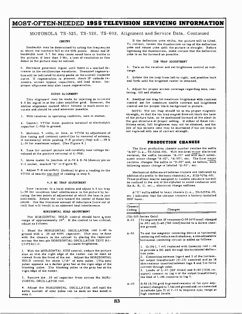
MOST -OFTEN -NEEDED 1955 TELEVISION SERVICING INFORMATION
MOTOROLA TS -525, TS -528, TS -603,
CHECKS
Bandwidth may be determined by noting the frequenciesat which the markers fall at the 50% points. Mixer and IFbandwidth over 3.7 Mc may cause sound bars or burble inthe picture; if less than 3 Mc, a loss of resolution or finedetail in the picture may be noticed.
6. Decrease generator signal until there is a marked de-crease in the oscilloscope waveform. Unwanted regenera-tionwill be indicated by sharp peaks on the overall responsecurve. If regeneration is present, check IF cathode re-sistors, screen bypass capacitors, and lead dress. Im-proper alignment may also cause regeneration.
AUDIO ALIGNMENT
This alignment may be made by injecting an accurate4.5 Mc signal in at the video amplifier grid. However, thestation alignment method which follows is much more ac-curate and should be used whenever possible.
1. With receiver in operating condition, tune in station.
2. Connec-. VTVM from positive terminal of electrolyticcapacitor C. -50B to ground.
3. Maintain 5 volts, or less, at VTVM by adjustment offine tuning and contrast control (or by removal of antenna,if necessary) while peaking T-8 primary (top) and L-38 &L-39 for maximum output. (See Figure 8.)
4. Tune for normal picture and carefully note voltage de-veloped at the positive terminal of C -50B.
5. Move meter to junction of R-54 & R-56 (dummy pin onV-9 socket, marked "X" in Figure 8).
6. Adjust T-8 secondary (bottom) to give a reading on theVTVM of exactly one-half of reading in step 4.
4.5 MC TRAP ADJUSTMENT
Tune receiver to a local station and adjust 4.5 Mc trapL-34 for minimum beat interference in the picture by lo-cating the two points of adjustment at which the beat is justnoticeable. Rotate the core toward the center of these twopoints. Use the minimum amount of inductance (core out ofcoil) that will result in no apparent beat interference.
HORIZONTAL HOLD ADJUSTMENT
The HORIZONTAL HOLD control should have %syncrange of approximately 20°. If the control is too critical,adjust as follows:
1. Shunt the HORIZONTAL OSCILLATOR coil 1.-40 toground with a .25 mf 400V capacitor. This may be donewith the chassis in the cabinet by placing the capacitoracross the two -pin HORIZONTAL OSCILLATOR TEST RE-CEPTACLE. Increase brightness.
2. With the HORIZONTAL SIZE control, reduce the picturesize so that the right edge of the raster can be seen asviewed frcm the front of the set. Adjust the HORIZONTALHOLD control for about 1/16" of sync pulse. (The syncpulse appears as a darker gray bar at the right edge of theblanking pulse. The blanking pulse is the gray bar at theright edge of the raster.
3. Remove the .25 mf capacitor from across the HORI-ZONTAL OSCILLATOR coil.
4. Adjust the HORIZONTAL OSCILLATOR coil until thesame amount of sync pulse can be seen as was noted instep 2.
Alignment and Service Data, ContinuedIf the deflection yoke shifts, the picture will be tilted.
To correct, loosen the thumbscrew on top of the deflectionyoke and rotate yoke until the picture is straight. Beforetightening the thumbscrew, make certain that the deflectionyoke is as far forward as possible.
ION TRAP ADJUSTMENT
1. Turn on the receiver and set brightness control at mid-range.
2. Rotate the ion trap from left to right, and position backand forth until the brightest raster is obtained.
3. Adjust for proper screen coverage regarding size, cen-tering, tilt and shadow.
4. Readjust ion trap for maximum brightness with contrastcontrol set for maximum usable contrast and brightnesscontrol set for proper black background in picture.
NOTE: The ion trap should be of the proper magneticstrength, so that the ion trap magnet does not touch the baseof the picture tube, or be positioned forward of the slash inthe gun structure at proper setting. If either of these con-ditions exist, full brightness may not be obtained, and thelife of the picture tube may be shortened if the ion trap isnot replaced with one of correct strength.
PRODUCTION CHANGESThe first production chassis number carries the suffix
"A-00" (i.e., TS -525A-00). With the first minor electricalrevision, the suffix becomes "A-01" and with each subse-quent minor change "A-02", "A-03", etc. The first majorrevision changes the suffix to "B-00" and, as before, eachfollowing minor change is labeled "B-01", etc.
Mechanical differences between chassis are indicated byaddition of a prefix to the basic chassis (i.e., RTS-525A-00).These prefixes maybe assigned In random sequence butwillbe confined to the end of the alphabet to avoid confusion withthe A, B, C, etc. , electrical change suffixes.
A"Y" suffix added to basic chassis (i.e., TS-525YA-00,etc.) indicates that the chassis contains a factory -installedUHF tuner.
ChassisCoding Changes
(TS -5Z5 Series Only)A-01 To improve the IF response C-38 (470 mmf) changed
to .001 mf; C-40 (560 mmf)moved to a direct chas-sis ground.
A-02
A-03
To aid the magnetic centering device in horizontalcentering and reduce neck shadows, a non-adjustablehorizontal centering circuit is added as follows:
1. C-106 (. 1 mf) replaced with linearity coil L-44to provide a DC path through the horizontal el eflec-tion yoke.2. Connection between lugs 4 and 5 of the horizon-tal output transformer (T-13) removed and an 18ohm resistor inserted between lugs 4 and 5 to forcecurrent through yoke.3. Leads of L-41 (RF choke) and R-83 (150K re-sistor) connect to lug 4 of the output transformer;the lead of L-44 connects to lug 5.
R-66 (4.7M grid to ground resistor of 1st sync sep-arator) changed to 1.5M and ground end re -connectedto cathode (pin 3) of V-13 to improve sync range athigh contrast levels.
83
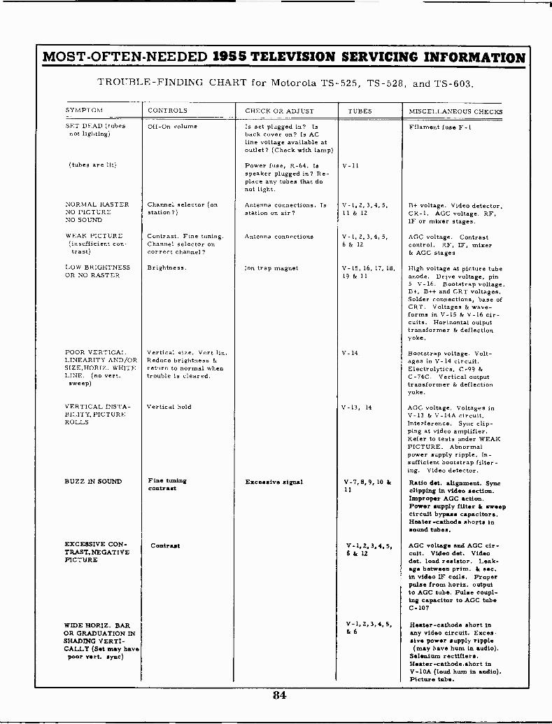
MOST -OFTEN -NEEDED 1955 TELEVISION SERVICING INFORMATION
TROUBLE -FINDING CHART for Motorola TS -525, TS -528, and TS -603.
SYMPTOM CONTROLS CHECK OR ADJUST TUBES MISCELLANEOUS CHECKS
SET DEAD (tubesnot lighting)
Off -On volume Is set plugged in? Isback cover on? Is ACline voltage available atoutlet? (Check with lamp)
Filament fuse F-1
(tubes are lit) Power fuse, R-64. Isspeaker plugged in? Re-place any tubes that donot light.
V -11
NORMAL RASTER Channel selector (on Antenna connections. Is V -1, 2, 3, 4, 5, B+ voltage. Video detector,NO PICTURENO SOUND
station?) station on air? 11 & 12 CR-1. AGC voltage. RF,IF or mixer stages.
WEAK PICTURE(insufficient con-
Contrast. Fine tuning.Channel selector on
Antenna connections V-1,2,3,4,5,6 & 12
AGC voltage. Contrastcontrol. RF, IF, mixer
trast) correct channel? & AGC stages
LOW BRIGHTNESS Brightness. Ion trap magnet V-15, 16, 17, 18, High voltage at picture tubeOR NO RASTER 19 & 11 anode. Drive voltage, pin
5 V -16. Bootstrap voltage.D+, B++ and CRT voltages.Solder connections, base ofCRT. Voltages & wave-forms in V-15 & V-16 cir-cuits. Horizontal outputtransformer & deflectionyoke.
POOR VERTICAL Vertical size. Vert lin. V - 14 Bootstrap voltage. Volt -LINEARITY AND/OR Reduce brightness & ages in V-14 circuit.SIZE.HORIZ. WHITE return to normal when Electrolytics, C-99 &LINE. (no vert.sweep)
trouble is cleared. C -74C. Vertical outputtransformer & deflectionyoke.
VERTICAL INSTA- Vertical hold V-13, 14 AGC voltage. Voltages inBILITY, PICTURE V-13 & V -14A circuit.ROLLS Interference. Sync clip-
ping at video amplifier.Refer to tests under WEAKPICTURE. Abnormalpower supply ripple. In-sufficient bootstrap filter-ing. Video detector.
BUZZ IN SOUND Fine tuning Excessive signal -V-7, 8,5. 10 & Ratio det. alignment. Synccontrast 11 clipping in video section.
Improper AGC action.Power supply filter & sweepcircuit bypass capacitors.Heater -cathode shorts insound tubes.
EXCESSIVE CON- Contrast V-1, Z. 3,4. 5, AGC voltage and AGC cir -TRAST.NEGATIVEPICTURE
6 & 12 cult. Video det. Videodet. load resistor. Leak-age between prim. & sec.in video IF coils. Properpulse from horiz. outputto AGC tube. Pulse coupl-ing capacitor to AGC tubeC-107
WIDE HORIZ. BAR V-1.2,3,4, 5, Heater -cathode short inOR GRADUATION INSHADING VERTI-
& 6 any video circuit. Excessive power supply ripple
CALLY (Set may havepoor Vert. sync)
(may have hum in audio).Selenium rectifiers.Heater -cathode.short inV -10A (loud hum in audio).Picture tabe.
84
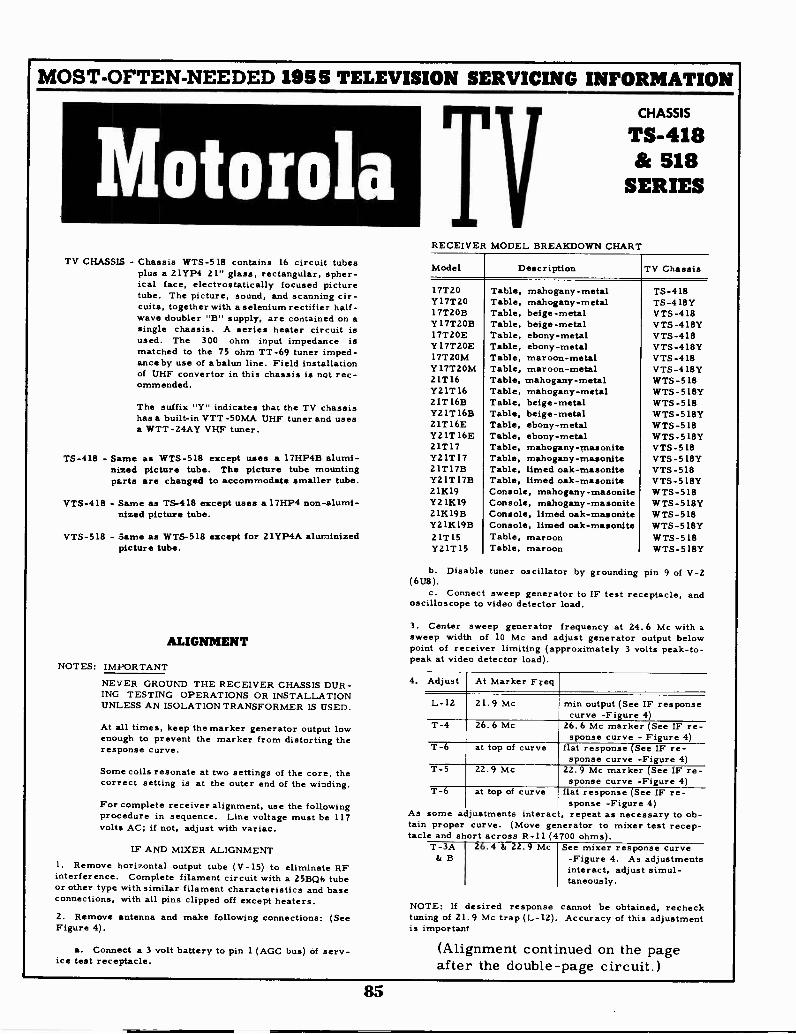
MOST -OFTEN -NEEDED 1955 TELEVISION SERVICING INFORMATION
MotorolaTV CHASSIS - Chassis WTS-518 contains 16 circuit tubes
plus a 21YP4 21" glass, rectangular, spher-ical face, electrostatically focused picturetube. The picture, sound, and scanning cir-cuits, together with a selenium rectifier half -wave doubler "B" supply, are contained on asingle chassis. A series heater circuit isused. The 300 ohm input impedance ismatched to the 75 ohm TT -69 tuner imped-ance by use of a balun line. Field installationof UHF convertor in this chassis is not rec-ommended.
The suffix "Y" indicates that the TV chassishas a built-in VTT-50MA UHF tuner and usesa WTT-24AY VHF tuner.
TS -418 - Same as WTS-5I8 except uses a I7HP4B alumi-nized picture tube. The picture tube mountingparts are changed to accommodate smaller tube.
VTS-418 - Same as TS -418 except uses a 17HP4 non -alumi-nized picture tube.
VTS-518 - Same as WTS-518 except for 21YP4A aluminizedpicture tube.
ALIGNMENT
NOTES: IMPORTANT
NEVER GROUND THE RECEIVER CHASSIS DUR-ING TESTING OPERATIONS OR INSTALLATIONUNLESS AN ISOLATION TRANSFORMER IS USED.
At all times, keep the marker generator output lowenough to prevent the marker from distorting theresponse curve.
Some coils resonate at two settings of the core, thecorrect setting is at the outer end of the winding.
For complete receiver alignment, use the followingprocedure in sequence. Line voltage must be 117volts AC; if not, adjust with variac.
IF AND MIXER ALIGNMENT1. Remove horizontal output tube (V-15) to eliminate RFinterference. Complete filament circuit with a 25BQ6 tubeor other type with similar filament characteristics and baseconnections, with all pins clipped off except heaters.2. Remove antenna and make following connections: (SeeFigure 4).
a. Connect a 3 volt battery to pin 1 (AGC bus) of serv-ice test receptacle.
TCHASSIS
TS -418518
SERIES
RECEIVER MODEL BREAKDOWN CHART
Model Description TV Chassis
17T20Y 17T2017T2OBY 1 7T2OB17T2OEY 17T2OEI7TZOMY 17TZOM21T16Y21T1621T 16BY21T 16B21T16EY21T 16E21T17Y21T1721T17BY21T 17B211(19Y21K1921K19BYZ1K19B21T 15Y21T 15
Table, mahogany -metalTable, mahogany -metalTable, beige -metalTable, beige -metalTable, ebony -metalTable, ebony -metalTable, maroon -metalTable, maroon -metalTable, mahogany -metalTable, mahogany -metalTable, beige -metalTable, beige -metalTable, ebony -metalTable, ebony -metalTable, mahogany-masoniteTable, mahogany-masoniteTable, limed oak-masoniteTable, limed oak-masoniteConsole, mahogany-masoniteConsole, mahogany-masoniteConsole, limed oak-masoniteConsole, limed oak-masoniteTable, maroonTable, maroon
TS -418TS -418YVTS-418VTS-418YVTS -418VTS-418YVTS-418VTS-418YWTS-518WTS-518YWTS -518WTS-518YWTS-518WTS-518YVTS -518VTS-518YVTS -518VTS-518YWTS-518WTS-518YWTS-518WTS-518YWTS-518WTS-518Y
b. Disable tuner oscillator by grounding pin 9 of V-2(6U8).
c. Connect sweep generator to IF test receptacle, andoscilloscope to video detector load.
3. Center sweep generator frequency at 24.6 Mc with asweep width of 10 Mc and adjust generator output belowpoint of receiver limiting (approximately 3 volts peak -to -peak at video detector load).
Adjust At Marker Freq
L-12 21.9 Mc min output (See IF responsecurve -Figure 4)
T-4 26.6 Mc 26.6 Mc marker (See IF re-sponse curve - Figure 4)
T-6 at top of curve flat response (See IF re-sponse curve -Figure 4)
T-5 22.9 Mc 22.9 Mc marker (See IF re-sponse curve -Figure 4)
T-6 at top of curve flat response (See IF re-sponse -Figure 4)
As some adjustments interact, repeat as necessary to ob-tain proper curve. (Move generator to mixer test recep-tacle and short across R-11 (4700 ohms).
T -3A 2.4 & 22.9 Mc& B
See mixer response curve-Figure 4. As adjustmentsinteract, adjust simul-taneously.
NOTE: If desired response cannot be obtained, rechecktuning of 21.9 Mc trap (L-12). Accuracy of this adjustmentis important
(Alignment continued on the pageafter the double -page circuit.)
85
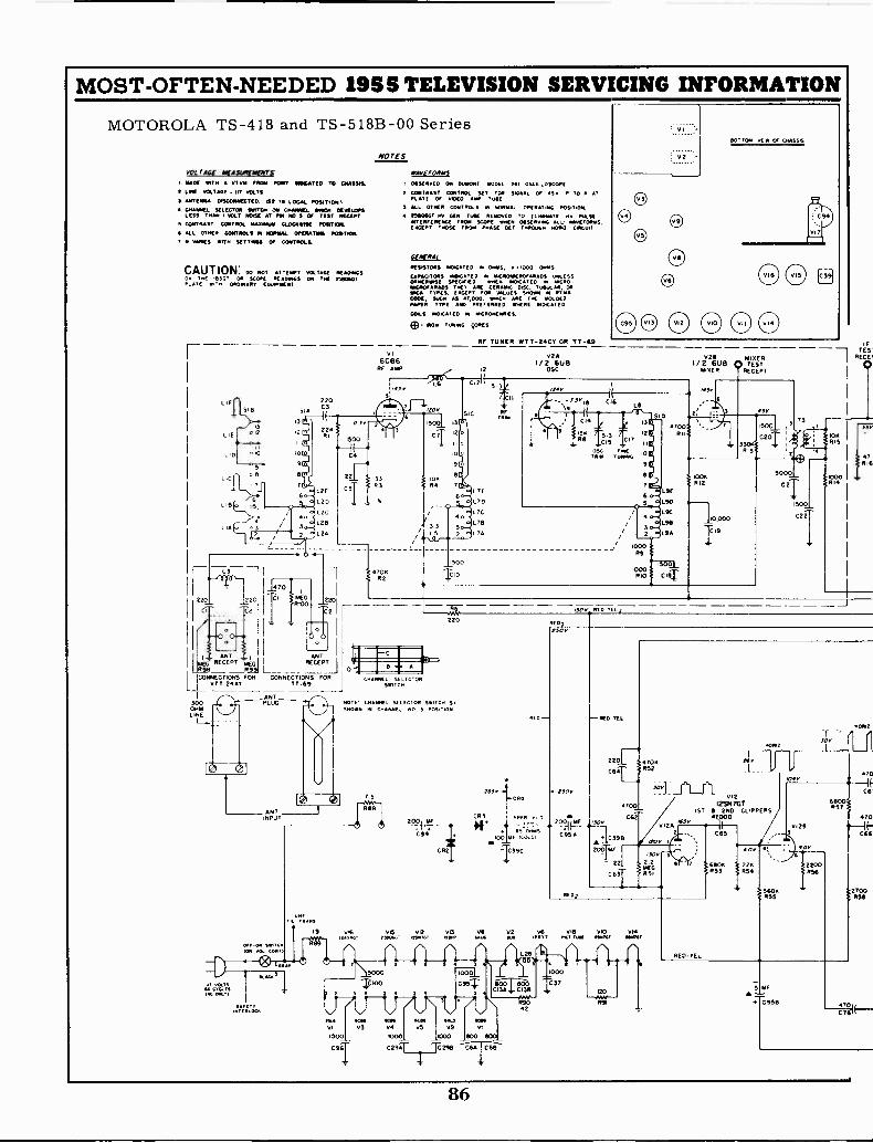
MOST -OFTEN -NEEDED 1955 TELEVISION SERVICING INFORMATION
MOTOROLA TS -418 and TS -518B-00 Series
NOTES
VOL TIOC NIA$11101ENTS.I. HYDE NoTH A VT. IRON POINT NOICATE0 TO CRASS&t ONE VOLTAU II? VOLTS
S ANTENNA ORSCONNEOTEla 1St IN LOCAL POSITION)CALLIONL SELECTOR SWOT. ON CHANNEL WITCH DEVELOPSLESS THAN I VOLT MSC AT PIN mee S OF TEST ACCEPT.
5 CONTRAST CONTROL KARMA CLOCKWISE POSTON.
4 ALL OTHER CONTROLS NORNAL OPERATOR. TOSTION.
7 or VANES MTN SETTNOIS OF CONTROLS
CAUTION. Do NOT AMEN, VOLTAGE WRONGSON THE 4536T OR SCOPE REM:M.5 oft THE 25806GTPL ATE WIT 14 TRE.NRY EONINENT
F--
220
CI
VI6C96
RF MAP
220C3
22KRI
1500
c21 33-CS
R3L2E
LOD
12C
L20
L2A
WIVE FORMS
OliStevt El ON DUMONT NOM L /44 OSC L °SCOPE
2 CON CONTROL SET FOR SIGNAL OF 450 P TO P ATPLATE OF VIDEO RAW TARE
ALL STRIA CONTROLS IN WHORL OPERATING POSITION
TWIG, NV GIN TIE REMOVED TO A.ANTATE ooy SASSINTERFERENCE FROM SCOPE RHIN ORSERvoK ALL- sAKFORNS,EAGER, THOSE F RON PHASE OE T THROOGN NOME Cast,
I17STORS NOKATED N OARS, 0.1000 OHMS
CAPAGTORS RTINCATED N NICROINCROFARADS UNLESSOTHERWISE SPEC., *NEN MPG A T m NKR°IIIKROFRAOS T ARE CERAMIC DISC, TAMA.. ORMA TYPES, E 'KEPT FOR VALUES SHOWN NRT NCOCK, SUCH AS 47.000, N.C ARE THE 001010PAPER TYPE SRO NKR( PONCA T CO
COILS MOICT E0 M NKRONENRIES
MON TUNING (ORES.
13
10
9
RF TUNER WTT-24CT OR TT -69
c,zi
IC
0201/2 eUe
OSC
o L7E
LTD
15 2 LTA
L F
L 1 0
L.
SIB
2
o 10
o
IT
9
2
220
co
ANT I ANT
MEGRECEPT MEG RECEPTR9B R99 l_CONNECTIONS FOR CONNECTIONS FOR
OTT -2477 TT -69
ANT300 PLUGORMLINE
01,-04 SINT.ION VO, GOUT
CHFNINL SELIG ITSNITCH
5 -3 /"4vII
-3328 CI6I5,
CIA 3
2" 15 :" 11
OSC FRETR N ',NOM
V28 MERI/ 2 6U8 0 TESTMISER RECEPT
510 (r's
6 o-I
1500
710
220
NO T E. CHANNEL SOL EC 1 ON SWITCH SISHOWN NI trqNNEI. NO 5 POSITION
)Aa31"1"1,"1??
EEEEE OC
116
A-ORG
RED
RE 02
"SOY
ot D200)im,CR3
194*,COLOi C959-OpMF
TCR2 39C
EL,
RED TEL
RED,
2201CAT
4 of.3 o-o2
1000R9
1000RIO
4700RII
N/3
100KRI2
LSE
90
SC
L_10,000911
9A T19
1500.1
C18
1500
C20310KRIT
5000
C21
032
TL,S1.4700
C62
HORo7
BEY
VI212eN7GT/ 1ST & 2110 CLIPPERS
47,000V120 H
C65/Roy
'MT°- 2 3. 2.2
MEGCR3 11351
015 V12 013 V2 V6 vI8 VIO 014MOW. 45.04, .100 WO if NY INC, INTST *M
2.6 GEAR ECM SCAN *ALS SODA
V3 V4 175 V9 V1
1000 1000 1000 SOO 800
C290[ 'a298 C6AIC68
'20
At
PA'
RED -TEL
f 0v
22KR54
60K5
-f50v
/04v
H0.12
70
VI28
%W."'
6800057
S 10A---
0958
C61
470
C66
2700050
86

MOST -OFTEN -NEEDED 1955 TELEVISION SERVICING INFORMATION
2
C44
VA6AU6
FW DRIVER LIMITER140 v
L20n:6
5000
C45
15
1531140
4700 4700
TE4.1220041
220
R39
VIGALS
RATIO DET
1000
330
0m45
5000
C57
VIDA1/2-6SN7GT
150 WINO AMPCONTSIM A 7
TAP5000 vo,.-7,-.E
C561 MEGR318
C55
16176
003 MEC513
I500/1 7
.41v
23L6GTAUDIO OUTPUT
777 v Ku
C6002
5
0CSI
330149
v 1501,
SPRR flEcEPTTS (TOP WWI
4-1160
4700026
MG IMO
'seovrIcaLDI
t
SPARIPIN VIE RI
02 130
V36C B6
1ST IF Amp115 v
(663 444 07
TcL7CONNECT IONS VO
6C B62ND If AMP
APOP
0.6v
4020
°V:
_11000
25
a
C241000
TO N T5CONNECTIONS
CHASSIS
5
43)
CS3T
V56CB6
300 IF AMP151V
.L 2
219 TRAP
30
C30
1500
C28
SERVICERECEPTACLE
(BOTTOM viEml
L I 3 I LYEL DOT, TEL DOT
C35
L 11® It CPI 4041- REDDOT,*
' 14
-F-1.111!"
LJ000024
3,9
C 3331
5
1.5 MEGAhVo0100
R101
7 IO o
V612877
VIDEO
RED , YEA, 130 V
43
L16 4,5 .0RED -TEL "4
DOT 7
1500.1
CO RNT1RAST
1300
0,000 EA,
L i8BRN GRETm
.10 elf DOT
'4T5
226033
5. LOCAL WW1
- SUBURBAN 5000 sow
I FRINGE C313 C40
O 0 522 1 AREA SELECTOR
SWITCH(SHOWN IN SUBURBAN POSITION)
3900037
1200:
467304'
I9
DOTDOT
RED -TEL)
RE 0
30
150 I,
22. 10
59 R60
4700C68 5504
STOP
11, 013A
1/2-121367\E RT 13LOCK 05C
9
YE.
C 705
C 72
106
0000
HOLDvERT 769
850K061
WV
0101
I/ 2 -6SNIGT IPHASE DET MF
70
Dce i5061-0000--i506*Me
30 C82 075 vi1112201)
; CRT
CBI
4 7 mCG
R74 01_617)0617,
);1COLA. P.;7.61: 1
+7- tOv
103v
C
6,1
47000,_
Vie6 SN 7 GT
140612 OSC
390
CCIA
'Thoo1ceiT
-to 01-1MORI! 05C
TEST RECEPT
VI381/2-12867
VERT OUTPUT
1007011,
1162
236002 R63
3*.
L23.011112
OSC
11000678
0 TIC)
VERTvERLI
S MEG064
STOP
140V
R66750
30 mf 10 Mf
- C390 C74
8200-065
62°,
TORE RECEPT(BO T7061 vEml
DEFLECTION YOKENESS 5 MEG
RN VERT o R69
L 22A
VERT
L228
L22C
NORIZ
L220
110012
866
1000042 094
.1 ME
2200R95
01.4
EL 7
O AEC, 400v
BLUE NOTERE LOW
VINPICTURE TUBEITHP4 S 17HP48 IN TS -418 SER217P4 B 2ITP4A IN TS -518 SER
vi4B
SOKSTOP
10012HOLD2006810
76
4500V
1,15
25806GT80462 OUT PUT 8 RV GEM
5000
3901 C1113-TOO-
2011 4;;31 'X;
39.000
Ce9
70
C76 -T
7,3
4700!WVRe5
I2AX4GTDA SP RIG
DIODE
160v
T9°
C97
5000C93
HORizSIZE
BOOTSTRAP
V I 718 3GT
Hy AEC,
3-2:
18R96 /30VIAN
NOTE..SHUNTING STRAP ISMOUNTED BETWEEN PIN 6AND EITHER PIN 10(BOOTSTRAP) OR PIN I
IGROUNCI)
'ii
(II CONNECTIONS
87
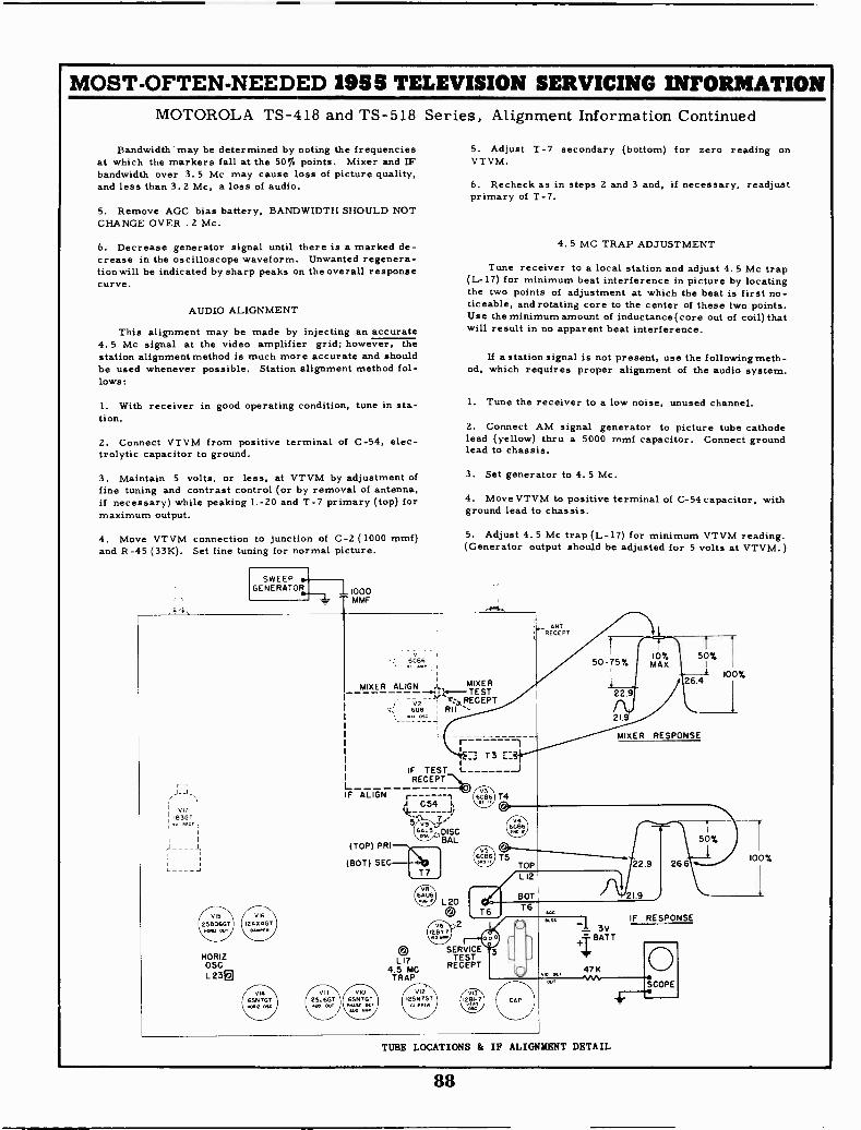
MOST -OFTEN -NEEDED 1955 TELEVISION SERVICING INFORMATIONMOTOROLA TS -418 and TS -518 Series, Alignment Information Continued
Bandwidth may be determined by noting the frequenciesat which the markers fall at the 50% points. Mixer and IFbandwidth over 3.5 Mc may cause loss of picture quality,and less than 3.2 Mc, a loss of audio.
5. Remove AGC bias battery, BANDWIDTH SHOULD NOTCHANGE OVER .2 Mc.
6. Decrease generator signal until there is a marked de-crease in the oscilloscope waveform. Unwanted regenera-tionwill be indicated by sharp peaks on the overall responsecurve.
AUDIO ALIGNMENT
This alignment may be made by injecting an accurate4.5 Mc signal at the video amplifier grid; however, thestation alignment method is much more accurate and shouldbe used whenever possible. Station alignment method fol-lows:
1. With receiver in good operating condition, tune in sta-tion.
2. Connect VTVM from positive terminal of C-54, elec-trolytic capacitor to ground.
3. Maintain 5 volts, or less, at VTVM by adjustment offine tuning and contrast control (or by removal of antenna,if necessary) while peaking L-20 and T-7 primary (top) formaximum output.
4. Move VTVM connection to junction of C-2 (1000 mmf)and R-45 (33K). Set fine tuning for normal picture.
SWEEPGENERATOR 1000
MMF
5. Adjust T-7 secondary (bottom) for zero reading onVTVM.
6. Recheck as in steps 2 and 3 and, if necessary, readjustprimary of T-7.
4.5 MC TRAP ADJUSTMENT
Tune receiver to a local station and adjust 4.5 Mc trap(L-17) for minimum beat interference in picture by locatingthe two points of adjustment at which the beat is first no-ticeable, and rotating core to the center of these two points.Use the minimum amount of inductance (core out of coil) thatwill result in no apparent beat interference.
If a station signal is not present, use the followingmeth-od, which requires proper alignment of the audio system.
1. Tune the receiver to a low noise, unused channel.
2. Connect AM signal generator to picture tube cathodelead (yellow) thru a 5000 mmf capacitor. Connect groundlead to chassis.
3. Set generator to 4.5 Mc.
4. Move VTVM to positive terminal of C-54 capacitor, withground lead to chassis.
5. Adjust 4.5 Mc trap (L-17) for minimum VTVM reading.(Generator output should be adjusted for 5 volts at VTVM.)
ANTRECEPT
HORIZOSGL23g
vi
6C56
MIXER ALIGN A. MIXER-.Irk- TESTv2 -1 r:.),RECEPT
6U8 Ril **,
MIXER RESPONSE
T 3 1:3IF TEST L
REGERT
F ALIGNA C54 1,14:
5v9 -T.-DISCBAL
(TOP) PRI
(BOT) SEC
VIO6SN7GT0.1.5( OLT
0LI7
4.5 MCTRAP
TUBE LOCATIONS & IF ALIGNMENT DETAIL
88
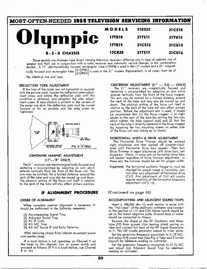
MOST -OFTEN -NEEDED 1955 TELEVISION SERVICING INFORMATION
OlympicR - S - U CHASSIS
MODELS
17TR1O
17TR19
17CR20
21KS22 21CS18
2ITS11
21CSI2
21TS17
21TU14
21CU1S
21CU16
These models are nineteen tube direct viewing television receivers differing only in type of cabinet, size ofspeaker and their use in conjunction with a radio receiver and automatic record changer in the combinationmodels. A 17" electrostatically focused rectangular tube (17HP4) is used in the 17" models and a 21" magnet-icallyi21 ZP4Bfocused and rectangular tube is used in the 21" models. Replacement, in all cases, must be of
12IZP4Athe identical size and type.
DEFLECTION YOKE ADJUSTMENTIf the lines of the raster ore not horizontal or squared
with the picture mask. Loosen the deflection yoke adjust-ment screw and rotate the deflection yoke until thiscondition is obtained, and retighten the yoke adjust-ment screw. If neck shadow is evident or the corners o;the raster are dark, the deflection yoke must be movedforward as far as possible and the wing screw re -tightened.
-.ADJUSTMENT WING NOTTOR DEMME:01 YOKE
CENTERING MAGIETS
ION TRAPMEAN EIEMEIII
FIG. 2 21R.ONLY
CENTERING MAGNET ADJUSTMENT
(1711-"R" ONLY)The 21" receivers are electromagnetically focused and
centering is accomplished by adjusting an arm whichextends vertically from the front of the focus coil. Thisarm may be rotated, for a limited distance, around theneck of the tube and may also be moved up and down.The physical setting of the focus coil itself in relationto the neck of the tube will also affect picture position.
IF ALIGNMENT PROCEDURE
ORDER OF ALIGNMENT
When complete receiver alignment is necessary, itshould be performed in the following sequence:
(I) Accompanying Sound Trap(2) Adjacent Sound Trap(3) Pix IF Coils(4) 4.5 MC Trap(5) 4.5 MC Sound IF and Ratio Detector
After removing chassis from cabinet re -connect powerand speaker plugs.
If a local station is not operating on Channel 9 setthe tuner to this channel, turn on power switch andproceed as follows: (If 9 is a local station, use Channel8 or 10.)
CENTERING ADJUSTMENT (21" - S -U - ONLY)The 21" receivers are magnetically focused and
centering is accomplished by adjusting an arm whichextends vertically from the front of the focus magnet.This arm may be rotated for a limited distance, aroundthe neck of the tube and may also be moved up anddown. The physical setting of the focus coil itself in
relation to the neck of the tube will also affect pictureposition. Before the adjustment arm is used, it shouldbe ascertained that (I) the focus magnet is at rightangles to the neck of the tube (by setting the two nutswhich tighten the tube support rods) and (2) that theneck of the tube is directly centered in the focus magnet(by loosening the two mounting screws on either sideof the focus coil and sliding up or down).
HORIZONTAL WIDTH & DRIVE ADJUSTMENTThe Horizontal Drive Trimmer should be screwed
tight (clockwise) and then backed off (counter -clock-wise) until Horizontal Drive bars appear. Then turnDrive Trimmer in again (clockwise) until drive bars, justdisappear. (Note: In some sets no horizontal drive barswill appear regardless of Drive Trimmer adjustment. In
these sets the trimmer should be set for proper width.
Important: The horizontal oscillator frequency must bechecked for proper range of horizontal con-trol after any adjustment of horizontal drive(C67). Any adjustment of C67 will usuallyrequire resetting of the horizontal frequencyadjustment coil (L-16).
(Continued on page 92)
ACCOMPANYING AND ADJACENT SOUND TRAPSInsert a 100,000 ohm 1/2 watt resistor in series with
the "Hot Lead" of the electronic voltmeter and connectto the junction of L12 and C25. Meter switch should beset to the lowest negative scale. Ground lead of metershould be connected to chassis.
Remove the shield of the RF Oscillator and Mixertube (V2) from ground clips leaving shield resting ontube and connect hot lead of the RF Signal Generatorto it. This will couple generator output to mixer plate.
Set the generator frequency accurately to 21.75 MC,and adjust (L9) sound trap (See Fig. 6 Tube and TrimmerLayout) for minimum reading on voltmeter.
Set the generator frequency accurately to 27.75 MCand adjust (L6) Adjacent Sound Trap for minimumreading on voltmeter.
89
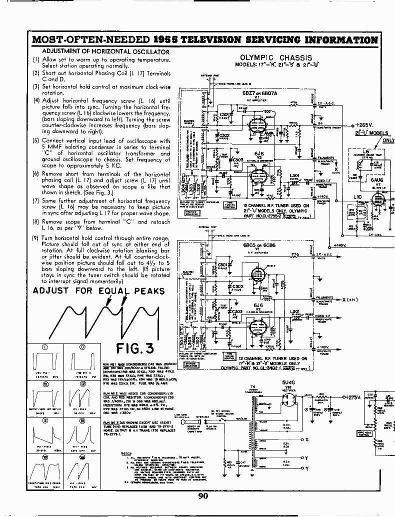
MOST -OFTEN -NEEDED 1955 TELEVISION SERVICING INFORMATIONADJUSTMENT OF HORIZONTAL OSCILLATOR
(I) Allow set to warm up to operating temperature.Select station operating normally.
(2) Short out horizontal Phasing Coil (L 17) TerminalsC and D.
(3) Set horizontal hold control at maximum clock -wiserotation.
(4) Adjust horizontal frequency screw (L 16) untilpicture falls into sync. Turning the horizontal fre-quency screw (L 16) clockwise lowers the frequency,(bars sloping downward to left). Turning the screwcounter -clockwise increases frequency (bars slop-ing downward to right).
Connect vertical input lead of oscilloscope with5 MMF isolating condenser in series to terminal"C" of horizontal oscillator transformer andground oscilloscope to chassis. Set frequency ofscope to approximately 5 KC.
(6) Remove short from terminals of the horizontalphasing coil (L 17) and adjust screw (L 17) untilwave shape as observed on scope is like thatshown in sketch. (See Fig. 3.)
Some further adjustment of horizontal frequencyscrew (L 16) may be necessary to keep picturein sync after adjusting L 17 for proper wave shape.
Remove scope from terminal "C" and retouchL 16, as per "9" below.
Turn horizontal hold control through entire range.Picture should fall out of sync at either end ofrotation. At full clockwise rotation blanking baror jitter should be evident. At full counter -clock-wise position picture should fall out to 41/2 to 5bars sloping downward to the left. (If picturestays in sync the tuner switch should be rotatedto interrupt signal momentarily)
(5)
(7)
(8)
(9)
ADJUST FOR EQUAL PEAKS
ouTHrt.rem Her NET 111
110 CPS 205
m1.- INN
NMI APS 75v
VI) - PIN 5
30 CII5 1E0 Y.
VI3 Pm 330 CPS NNW
vir - PlOt71173 CPS no
reoneenea. e e. Hue I.Fill/11 CPS 150r
77v15 - uS71110 CPS Ov
FIG.3RUN N91 WAS: (CONDENSERS) C42 WAS .C6/400VAND C61 VAS D01/600V 10%10IL FILLED).(RESISTORS) R12 WAS 10K11; R30 WAS 471(112R; R38 WAS 331(.114 R46 VMS 22K).1R53 WAS 121(11±10%; R54 VMS L5 ME611410%;R76 WAS 22ICII 2W. FUSE WAS 1/4 AMP.
II
STATIONINLECTIM
'I
°JET'
OLYMPIC CHASSISMODELS: 171-PR; 21"-.S° 8 21.41
NTEINGA NWT
Seen TRANS. LINE LEAD lir
)404
FINETooCONT..
ANTINNA MET
O
ouTune OF TOME! CONTAININTOONE OE !ETA OF
K 15) C SACMS SAO,a.
6BZ7 oft 61307AVI
AE AMPLIFIER
L301WINE 0011
12 CHANNEL R.F. TUNER USED ON
21":1.1.MODELS ONLY, OLYMPICPART NO.CL-2755-T!".",?
100.011mol LINE LEAD IN
6BC5 oft 6CB6R F AMPLIFIER
000'
6J 6
a ISV2
C303 N.POIN CMPOOTEN
MOf
FINETUNIS,
CONTROL
.000
; /OM 1I 4. 140 V.RED/WANT[
TRAe-
12 CHANNEL R.F. TUNER USED ON& 21"=S' MODELS ONLY
OLYMPIC PART NO. CL -3402 tjounljo Tv -pooh,
47k
FILAMENTS
VIDEO LEmum/
it +140V
In VI
+140V.
1.1. LE- AOC.WirITE
1-41'
FILAMENTS
-r "I;Z:".""
L'441. VIDEO I.F.
301IS UK
M-N/WHITE
RUN Ng 2 WAS: ADDED COB CONDENSER; L10COIL AND R29 RESISTOR. (CONDENSERS) C58WAS .1/400V.; C61 a CAB WAS mule.(RESISTORS) R72 WAS 82)(11 *5% 119 ;R79 WAS 47KIL 1W.; 154 450V. UNE IN HOW.
0N orF sorrosOM WAS +3130V. ON Mum VOLUNF0020LINE
:or : v. c LLLLL (Kr FITROI.
RUN N2 31.11S SHOWN) EXCEPT USE 1133/037 Ci:=11TM V16) REPLACES 1028 AND TP.2771-2 110011[T 010
&WOWSHORIZ. OUTPUT H.V. TRANS. ITS) REPLACES [moot vexTR-2771-1.
NOTES:
Au. OSSIO7014 E .0 a TOLIalmoM S5 WATT 1.1.5.OT01111.11. 0270100.O.
FAA INCA He cmmeae 0000441144 21tOl R501.11A.054 MINIMISE 1.11CINIM.
3 ALL VOLTAIMS IMANI0110 POINTS INCIMATN0 "MAIAMP COMMIS, 1111140 AN luICTRONIC VOLTINTOILALL VOLTNE 001105851, CAMINO 1TN ANmoor vOLTA4 OF Tr VOLTS. Cr45/11, A.C. MTNT1001111. SONO& /IMO WITS 001FTRAIIT COOTOOLO POrmet PO VOLTS RAN TO PIM AT KINESCOPE.
*A COMM CONOMMIMAIL DISC TWO.
5U4GV18
RECTIFIER
0+265V.zt:ti MODELS
/ONLY
AINACENT 1011110 MAP I
27.75 OS I
9."- X (4.3',)
14P0101111
ToANSFOINNIN
90
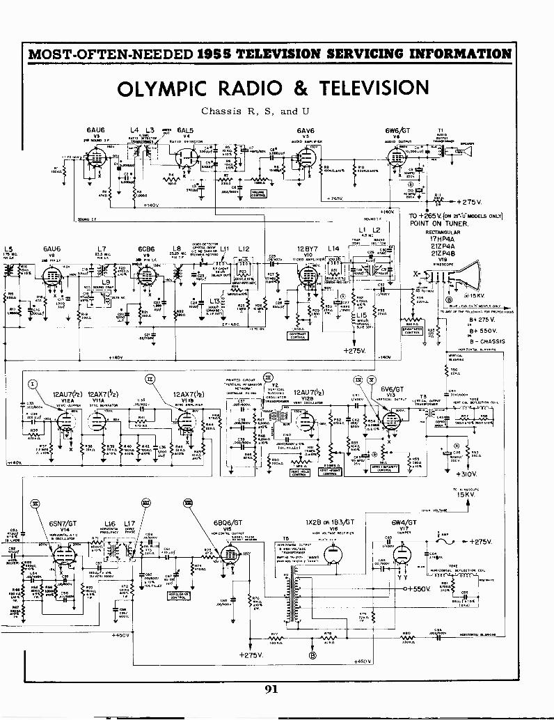
MOST -OFTEN -NEEDED 1955 TELEVISION SERVICING INFORMATION
L5 6AU61,75 MC. VONA LF.
SRO P/0 I.F.
6AU61/5
2. SOUPED I
I V.
OLYMPIC RADIO & TELEVISIONChassis R, S, and U
L4 L3 TN' 6AL5DETECTOR
04RATIO,15491(991.1119 RAT 10 DETECTOR
7
ISOn St. IRMA.05* C65301Aili .0O2/400T
V
VIDEO DETECTOR
L7 6CB6 L8 c'''' '`'m L11 L12. 2 ma in. on23.5 MC.V9 2515 MC m.ou no sneoFIN IF..IN I FEM PI LP.
11 r', -T 1
12AU7(1/2) 12AX7('/2)12A VI1A
SYNC. CLIPPER ST NC RENARATOR
Il ROY 1000.
C ES
.05/0000
R 40 0422 RIO
A10 RIOIE
6SN7/GT L16 L177063 V14
FOOOTCA PHASE
AID%m NIzoNTALeCOSCILLATOR
n71r
c --1IA ILVEIN
CAR47141
IO%MRILVERI
:+o: R73,,?
c571-2' lir-- -"Ars ...IL .sC54 C60.0 4000 55 ,51.1,(111 10000
:10.4 V 4:07
antf
7
ro'4.'068 69
VR70 R2150 5
IRA% MOM 6 5%.
12AX7(11/2)V1113
NC AMPLIFIER
+450V
DRITEtONTRoL
6AV6vs
AUDIO AMPLIFIER
+ 265V.
1 TO L500
PRINTED CIRCINTNERTICAL iNTEGRATOR T2
NETSFORK VERT1CLORIN/MUM PC -100 BLOCKiN
OSCILLATORTINSFORNER
TALLow
C39 Raj006/600 4200.11.
.10%
N.. C40
.0047/1100V RIOS.101,1..20) R51
LS NEILAAP%
6BQ6/GTV15
ON1AL OUTpuT
:arm
CONTRASTCONTROL
N
IvCONTROLol
12AU 7(1/2)VI2B
VERT OSCILLATOR
VERT 4EIGNTCONTROL
6W6/GT
.010 OUTPUT
1130K.D..10%
+140V.
SOUND I F
.V4000052
17A'
+275V.
1X2B oa 183/GTV16
Hi. VOLTA. RECTIFIER
T5NoRIZON AL OUTPUT IR. VOLTAGE
TRANSFORM.11.4/4.'
MART *04. rIn17112 -10 EA,
R76 --IN.GAIL.0%
+275V.
TN.1/46v6,GTV13
VERTICL OUTPUT
T1Roo ID
OuTPuTTRANVOINIMI
VERT LMEARITYCONTROL
SPERM,
RII
+275V.
TO +265V. (ON 21.:11 MODELS ONLY)
POINT ON TUNER.RECTANGULAR
17H P4A21ZP4A21Z P4B
VI 9KINESCOPE
R34220 Ha
L
. TEND ON MOOELS
TO .T OF THE FOLLOWING FOR OPROPER FOCUS
B+ 275 V.OR
B+ 550V.
B - CHASSISOPIIONTAL FAA. 0
BLANKING
T3VERTIIRANCAL VOWEL,. CO,
I II
T
mmt _-aeonA,04
O-TC46 R59o RFD/
550 v
+310V.
1 OR VOLTAIRE
/0 KINESCOPE
15KV.
+450 V
6W4/GTV17
DAMPER
C63
V4000
566!00 00My.
Y Y
+275V.
rootmon 1IONTAI DIVLECION COIL
RBI
0+550V. .70040%
S6cKR
ooiiu
MTV 41.00/
C65II--5.of *I"
HORIZONTAL BLANKING
91

MOST -OFTEN -NEEDED 1955 TELEVISION SERVICING INFORMATION
VT VM
0
I
VOLTMETER AND CRYSTAL DIODECONNECTIONS
FIG.5
PIX IF COIL ADJUSTMENT
Olympic Chassis R, S, and U (Continued)TO C.R. TUBE
\\\CATHODE LEAD(YELLOW
1.75 MC
23.0 MC.
26.25 MC.
2775 MC.(ADJ. SOUND TRAP)
50%
STANDARD RESPONSE CURVE FIG. 4Adjust the following slugs for maximum output at fre-
quencies and sequence indicated with meter and gen-erator connected as above: (See Sound Traps above).
L301 22.5 MCL5 25.75 MCL7 23.5 MCL8 25.25 MC
Note: After setting L5 DO NOT readjust to improve
wave shape.
If oscillation occurs during alignment, temporarily raisefrequency of L8 by turning screw counter -clockwise untilscrew projects approximately 3/4''. Oscillation is evi-denced by high reading on voltmeter (-5V to -20V)with signal generator OFF and no signal coming inthrough the antenna terminals. After properly adjust-ing L301, L5 and L7 reset L8 to proper frequency, if ithad been necessary to detune.
Connect hot lead of sweep generator through a 330uuf condenser to test.point on tuner and connect groundlead to chassis.
Connect vertical input terminal of oscilloscope tojunction of peaking coil L12 and C25 and connectground lead of scope to chassis.
Connect I .5 V flashlight battery with positive terminalto chassis and negative terminal to junction of R13 andC2I. This point is AGC bias voltage. Set tuner toChannel 9 unless local station is operating on this fre-quency, in which case an adjacent channel should beused.
Set Sweep Generator frequency to IF sweep on the20 to 30 MC range.
Adjust sweep generator output to produce a curveon the scope which is approximately 2/3 of the screendiameter.
Loosely couple output of RF signal generator byusing shield on V2 and set frequency of RF signal gen-erator to 26.25 MC (marker).
Curve shown on scope should be similar to the re-sponse curve shown in Figure 4. For proper setting ofthe pix carrier the 26.25 MC marker should appear onthe curve at a point approximately 50% of the verticalheight of the curve.
To obtain this setting retouch L8.
Reset RF signal generator frequency to 23.0 MC andretouch L301 and L7 for correct positioning of markeron curve.
Recheck setting of 26.25 MC marker to make sureThat position has not shifted on curve.
Disconnect bias battery.
Note: If the curve cannot be made to appear asabove due to a local station or other inter-ference, or if multiple markers appear, remove(VI - 6BZ7 or 6E307) RF tube from tuner.
TRAP ALIGNMENT
Connect voltmeter lead to Diode crystal rectifier asshown in Fig. 5. Connect Diode crystal rectifier betweenC.R. Tube Cathode lead (yellow wire) and chassisground. Signal generator is connected at junction ofL12 and C33. Set contrast control at maximum andvoltmeter to 3 volt scale (negative). Remove 6CB6 (V9)from socket. Use maximum output of generator at 4.5MC. Adjust LI, top of TR-3386 for minimum readingon meter.
When it is necessary to retouch this trap in the field,proper adjustment can be made by using the local sta-tion signal and turning the Fine Tuning Control to bringfine herringbone sound beat into the picture. The 4.5MC trap (LI) should then be adjusted to minimize thisbeat interference.
SOUND IF TRANSFORMER, (4.5 MC) ANDRATIO DETECTOR ADJUSTMENT
In view of the fact that the transmitted sound signalfrom a TV station is probably the most accurate avail-able, as far as frequency is concerned, it is recom-mended that a working signal be used for sound align-ment. The set should be connected to an antenna, turnedon, allowed to warm up for about 5 to 10 minutes andthen tuned for the best picture. A vacuum tube volt-meter should be connected to Pin 2-V4 and the meterset to the minus 30 volt scale. The bottom of the 4.5MC Sound IF Transformer (L2) and the primary of theRatio Detector (L4 - bottom of the chassis) should betuned for maximum deflection of the meter. The vacuumtube voltmeter should then be connected to the junc-tion of R7 and C6 and one side of the volume controland the secondary of the Ratio Detector (L3 - topadjustment) should be adjusted for a zero reading withthe meter set to the 3 volt scale. The secondary canalso be adjusted by ear tuning L3 for the eliminationof buzz in the sound.
92

MOST -OFTEN -NEEDED 1955 TELEVISION SERVICING INFORMATION
OarAataloffeeeThe Packard -Bell television receivers described in this
manual incorporate either chassis type 2740 or 2940-1. Thetelevision portion is identical on each, but the 2940-1 chassisincludes a two tube standard broadcast tuner. All modelsuse a 21 inch rectangular electrostatic focus picture tube.
The following table indicates the type chassis and TVtuner used in the respective models.
VHF VHF/UHFTuner Tuner
(10534A) (10535C)Chassis
Type
Model 2742 2842 2740
Model 2743 2843 2740
Model 2744 2844 2740
Model 2941 3041 2940-1
PRODUCTION MODIFICATIONS:
The following modifications were made after productionof the receiver had begun and are listed to point out varia-tions in production from the schematics shown in thismanual. The reason for the change is shown in capitalletters.
A. INCREASE TONE CONTROL RANGE. In early productionof chassis 2740, capacitor C-11 was .005 mfd. Its valuewas changed to .01 mfd. This is the series capacitor inthe tone control section.
B. INCREASE AUDIO OUTPUT. Ratio detector transformer29068 was replaced by ratio detector transformer 29054.In connec-ion with this change, R-7 was changed from82 to 47C ohms, and a resistor R-97 (22,000 ohms, 1/2watt, 10%) was added between the screen of V-2 andthe low -B bus.
C. PREVENT REGENERATION IN MODELS USING VHF/UHF TUNER 10535C. (See Fig. 12).
1. Capacitor, ceramic, 5000 mmf, (23931) added as by-pass from R -F tuner filament terminal (C) to ground.
2. Capacitor, ceramic, 10,000 mmf, (23939) added asby-pass from 135 volt bus at power transformer toground. The ground lug of terminal strip must besoldered to chassis.
3. Capacitor, ceramic, 5000 mmf, (23931) added as by-pass from pin 4 to pin 7 of V-9, 4th Pix I -F.
4. Radio Frequency choke (29551) added between pin4 of V -B and pin 4 of V-9. These points were formerlyconnected directly together.
5. Resistor, 100 ohm, 1/2 watt, (73013) inserted betweenpin 6 of V-9 and tie point previously connected to t.
6. R-21, E dropping resistor to R -F tuner (4700 ohm2 watt; replaced by 5000 ohm 5 watt 10% resistor,
D. IMPROVE SOUND I -F SENSITIVITY. Resistor R-1, 10,000ohms, 1/2 watt, was removed from the receiver. Thisformerly was connected across the sound I -F inputcoil L-' .
MODELS WITH 2740 CHASSIS:IMPROVED PERFORMANCE IN FRINGEAND HIGH SIGNAL AREAS.
The addition of delayed AGC circuitry has been incor-porated in the production of these models. Improved per-formance will be noted in fringe areas, as evidenced byan increase in signal-to-noise ratio due to the RF amplifierbias beingheld near zero for low signal input.
High signal areas will benefit because of the muchgreater input signal now required to produce overload orcross -modulation effects.
Chassis incorporating this delay circuit can be identi-fied by the AGC control located on the chassis rear apronnear the horizontal drive control.
CC, ,,A a c
>a AAIAcArc OF
vet*,AA4A
v -ro64 V6
A Al
6A C/6Ict-ya0 A C
ace AY A cro rchve4
If the delayed AGC circuit is added to a 2740 chassiscontaining a VHF/UHF (all -channel) tuner, the followingadditional changes must be made:
1. Add ground wire directly to chassis from pin 3(ground side of heater) on 2nd and 4th I -F tubes,V-7 and V-9.
2. Add ceramic- capacitor, 5000 mmf, part number23931, between pins 3 and 4 of 2nd I -F tube, V-7.
3. Also add a 5000 mmf capacitor, part number23931, between pin 6 of pix detector, V-10, andtuner side of 1 megohm isolation resistor in delayedAGC circuit.
COMPLETE REALIGNMENT IS NECESSARY UPON INSTAL-LATION OF DELAYED AGC.
(Circuit diagram on page 94, over.)
NOTE: TUBE LOCATIONS, TEST POINTS, AND ADJUST-MENTS ON THE 2740 AND 2940-1 CHASSIS ARE IDEN-TICAL EXCEPT THAT THE 2740 DOES NOT HAVE THESTANDARD BROADCAST (AM) TUNER.
NOTES
R-1 not used.
R-19 used on 2740, not used on 2940-1R-89 not used on 2740, used on 2940-1R-90 not used on 2740, used on 2940-1
C-15 is .01 mfd on 2740, .005 mfd on 2940-1.C-29 not used.
C-34 not used.
C-49 not used.
C-67 not used on 2740, used on 2940-1.
93
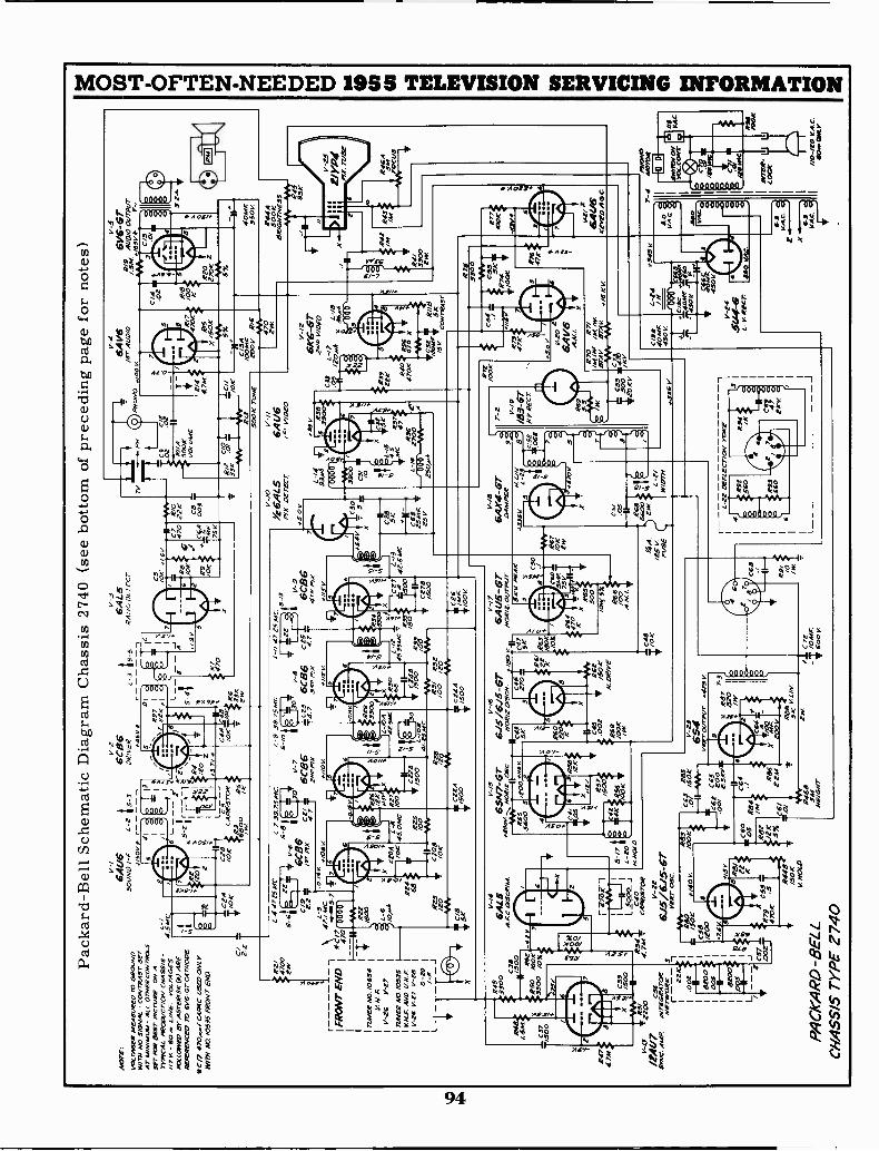
Pack
ard
-Bel
l Sch
emat
ic D
iagr
am C
hass
is 2
740
(see
bot
tom
of
prec
edin
g pa
ge f
or n
otes
)
AC
ME
:
VO
LTA
GE
S M
EA
SU
RE
D 2
0 G
RO
WL'
Wiry
NO
SIG
NA
L -
CO
NT
RA
ST
SE
TA
T M
INIA
MA
I- A
LL O
TH
ER
cov
750.
5S
ET
FO
R B
ES
T P
ICT
UR
E O
N A
TY
PIC
AL
AR
ON
/CT
/0V
CN
AS
S/S
-11
7 V
- 6
0L/
NE
. VO
LTA
GE
SF
OLL
OW
ED
BY
AS
TE
RIS
K (
WA
RE
RE
FE
RE
NC
ED
TO
6V
6-62
CA
TR
OD
E.
L-/
4.5M
C
Nay
*C/7
470
.4,/
C49
4C U
SE
0 O
NLY
WIT
II A
O. /
0535
FR
ON
T E
NO
o al
p
*RE
I47
00er
,
TU
NE
R A
O. /
0534
V N
. F.
V-5
6V
-27
TU
NE
R N
0./0
535
V.N
.F. A
ND
UH
F.
V-1
6 V
-Z
7 V
-221
S-1
0
-41.
;
R47
4741
.4
X/5
001
'.C
39%
.'
fyt
IIR
54 .
V-1
5zz
oo.0
.7,4
. -
MA
Wc5
5S
YN
C. 4
M12
AIT
EG
RA
roe
NE
TW
OR
K3
r -: 1
.002 62
00!
oos
MO
O*
15L
__ ' C
57 .4
.IT
0.1"
wC
ZA
TIO
KC
/ 8E1.
V-/
6.41
/650
UN
D /-
F11
50v
1-4
.172
541C
.
5-6 4:
Z-C
/9
FR
ON
T E
ND
1*\
5Z4:
0/
/V
A 4
,
L-2
15_3
1-7.
39.7
.541
C.
5-8
V-6
6C86
/52
FIX
0.13
z N
osy
v-2
6C26
DR
IVE
R st6v
V-3
GA
LSR
A ,0
DE
TE
CT
01c,
R97
I
IX
7 22
Ko
IIR7 470
"41'
; $L6
KS
W
L-3
33.7
5 A
le.
4725
4C.
543
lkV
-96C
B6
429
FIX
V-7
30'
v-21
6C86
CZ
Y66
'86
C25
7 1.
znte
put
"4.7
357
47.1
/0v
s//2V.
C5
/OK
s/ 6
11
C7
470
R9
/OK
_-/
'75
V
4 //S
lt
;300
"R
3IN
12I
!...!
a`a
.O
xx
L -/
OA
'...,'
X.2
tlC
ZO
A42
.51C
,R
30V",
,10
% 4
5.0t
dc10
.3, 5
TC
520a
7
L-13
41'5
.LT
301_
,.5
35A
C 4
'1
BO
,24,
t42.
51,4
C/2
25cz
,1-4
, ''1
1G-1
/00
gof2
s3,
CZ
O8
/500
WI-
4-4A
+V
-R
I342
21.v
.`i4
,7k
R3t
432
/20
/OK
/20
/00
/co
/500
WV
WV
v.,.
;SK
,CZ
A02
45
T/5
001.
r ,C
,5,6
*/00
V
L-6
-7, /
0,4
Re4 68
B
V-/
4V
-15
V-/
6
6Avc
is7-
6 -s
rR
....9
SA
LE65
N7-
67"
615/
615-
GT
.,...-
-,,,,
Inea
. 1._
..__I
OS
C.N
OR
teD
/ScN
.,,,
,,,N
OR
IZ.0
1./7
-PIA
T33
00C
38A
.AC
DIS
cRO
.4.
N/5
00C
46C
4755
2 -I
xR
5010
057
12.5
5/5
00 z
o/t.s
y5,
5600
53
2201
5S
KV
PE
RK
5
21C
5033
00 /0
%t
4C
f56
5/0
i1'
K2
1607
.07
..<...
...-.
..`
4.6
/0%
/C
60
61
if4
[4/
3/2
5K
264
47
V.
Iv5R
0655
0x
KX
5X
.X.,,
,W
VC
45R
62.'
R57
.002
14z
/50°
?R59
/50K
566
5 17
T4K
fsr,
/5...
c.
N. a
e/Y
e
/00
L 20
N. M
CV
D
775R
"
Ls C
40C
AM
IS2O
R
v-zz
6J5/
6J5-
6TV
ER
T O
SC
.
WA
160
/ OK
C58
/200
-Z6
#140
V.
/00K
C63
565
.0/
/50K
1.cz
C65
.00/
ZO
O7/
3V2.
5R-V
w
XI&R
R.c
60X
.05
34,
'C
64I
4 M
K C
gT
If-
II"
.e.
5% ,
ZZ
A4
R.4
480/
/505
V. N
OLO
4IV
S,
PA
CK
AR
D -
BE
LLC
HA
SS
IS T
YP
E 2
740
654V
-2.4
ourv
vr +
475
v
R46
8IW
Vce
z35
4-;
/06+
KH
E/O
NT
600
V.
e A
./8
5 V
FU
SE
49/ /0
W.
5/0
22K
CB
.003
1
oN0
R//4
500K
VO
LuM
E
V-4
V -
S
6AV
6/s
r 41
/0/0
#100
V
Riz
`6?
--A
c;"
5/3
V-/
0%
6AL5
6AU
6P
m D
ET
EC
T/
VID
EO
v-/.9
6AX
4-G
T L-2/
WID
TH
r -z V
-/9
/6S
-E
TN
Y S
EC
T
L-22
DE
FLE
CT
/ON
YO
RE
)rC
/34
/004
1,10
0vR
/6W
V47
0
y 1,20
Z
6A V
6A
.N C/3
36-
5440
/45
IN45
0V--
1-24
5141
-6L.
v R
ecr
6V6-
67*
Aco
o ou
rpur
65V
9r-
/V
V*
5a
.0/
ale
0 4044
s35
0v
444A
500K
8R/G
IITN
ES
S40
4% W
V44
5
V -
ES
ZY
YPI TU
BE
...6/
76.
4U6
Kev
roA
.G.0
XV
AC
.
T 4
AK
OD
It
/10-
IZO
VA
.C.
4104
. OIL
Y
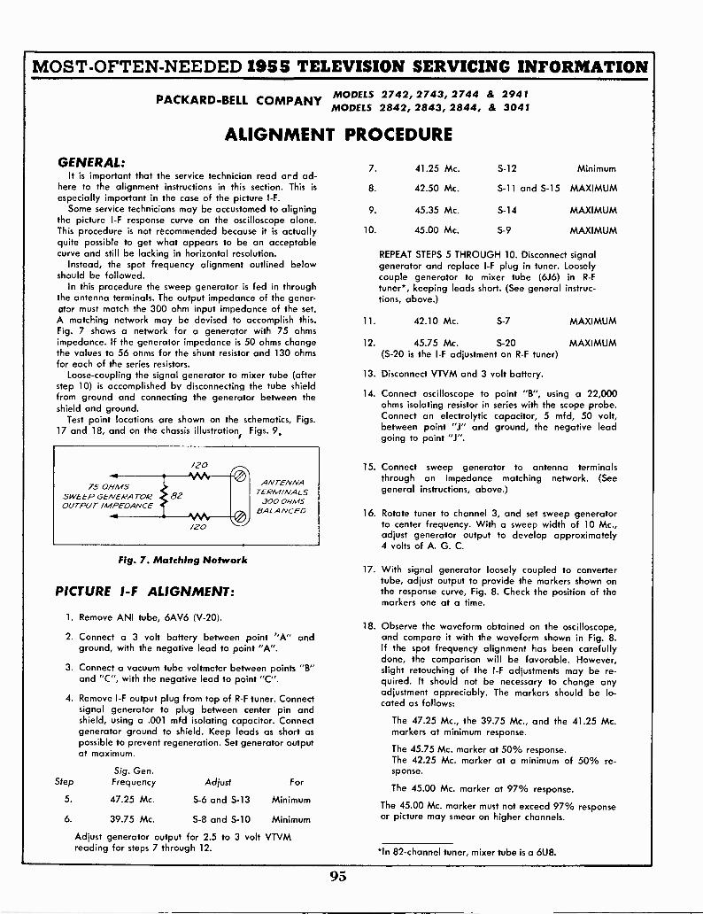
MOST -OFTEN -NEEDED 1955 TELEVISION SERVICING INFORMATION
PACKARD-BELL COMPANY MODELS 2742, 2743, 2744 &MODELS 2842, 2843, 2844, &
ALIGNMENT PROCEDUREGENERAL:
It is important that the service technician read and ad-here to the alignment instructions in this section. This is
especially important in the case of the picture I -F.
Some service technicians may be accustomed to aligningthe picture I -F response curve on the oscilloscope alone.This procedure is not recommended because it is actuallyquite possible to get what appears to be an acceptablecurve and still be lacking in horizontal resolution.
Instead, the spot frequency alignment outlined belowshould be followed.
In this procedure the sweep generator is fed in throughthe antenna terminals. The output impedance of the gener-ator must match the 300 ohm input impedance of the set.A matching network may be devised to accomplish this.Fig. 7 shows a network for a generator with 75 ohmsimpedance. If the generator impedance is 50 ohms changethe values to 56 ohms for the shunt resistor and 130 ohmsfor each of the series resistors.
Loose -coupling the signal generator to mixer tube (afterstep 10) is accomplished by disconnecting the tube shieldfrom ground and connecting the generator between theshield and ground.
Test point locations are shown on the schematics, Figs.17 and 18, and on the chassis illustration, Figs. 9,
75 OHMSSWEEP GENERATOROUTPUT IMPEDANCE
ANTENNATERMINALS300 OHMSBALANCED
Fig. 7. Matching Network
PICTURE I -F ALIGNMENT:
1. Remove ANI tube, 6AV6 (V-20).
2. Connect a 3 volt battery between point "A" andground, with the negative lead to point "A".
3. Connect a vacuum tube voltmeter between points "B"and "C", with the negative lead to point "C".
4. Remove I -F output plug from top of R -F tuner. Connectsignal generator to plug between center pin andshield, using a .001 mfd isolating capacitor. Connectgenerator ground to shield. Keep leads as short aspossible to prevent regeneration. Set generator outputat maximum.
Step
5.
Sig. Gen.Frequency
47.25 Mc.
6. 39.75 Mc.
Adjust
S-6 and S-13
S-8 and S-10
For
Minimum
Minimum
Adjust generator output for 2.5 to 3 volt VTVMreading for steps 7 through 12.
29413041
7. 41.25 Mc. S-12 Minimum
8. 42.50 Mc. S-11 and S-15 MAXIMUM
9. 45.35 Mc. S-14 MAXIMUM
10. 45.00 Mc. 5-9 MAXIMUM
REPEAT STEPS 5 THROUGH 10. Disconnect signalgenerator and replace I -F plug in tuner. Looselycouple generator to mixer tube (6J6) in R -F
tuner*, keeping leads short. (See general instruc-tions, above.)
11. 42.10 Mc. S-7 MAXIMUM
12. 45.75 Mc. S-20 MAXIMUM(S-20 is the I -F adjustment on R -F tuner)
13. Disconnect VTVM and 3 volt battery.
14. Connect oscilloscope to point "B", using a 22,000ohms isolating resistor in series with the scope probe.Connect an electrolytic capacitor, 5 mfd, 50 volt,between point "J" and ground, the negative leadgoing to point "J".
15. Connect sweep generator to antenna terminalsthrough an impedance matching network. (Seegeneral instructions, above.)
16. Rotate tuner to channel 3, and set sweep generatorto center frequency. With a sweep width of 10 Mc.,adjust generator output to develop approximately4 volts of A. G. C.
17. With signal generator loosely coupled to convertertube, adjust output to provide the markers shown onthe response curve, Fig. 8. Check the position of themarkers one at a time.
18. Observe the waveform obtained on the oscilloscope,and compare it with the waveform shown in Fig. 8.If the spot frequency alignment has been carefullydone, the comparison will be favorable. However,slight retouching of the I -F adjustments may be re-quired. It should not be necessary to change anyadjustment appreciably. The markers should be lo-cated as follows:
The 47.25 Mc., the 39.75 Mc., and the 41.25 Mc.markers at minimum response.
The 45.75 Mc. marker at 50% response.The 42.25 Mc. marker at a minimum of 50% re-sponse.
The 45.00 Mc. marker at 97% response.
The 45.00 Mc. marker must not exceed 97% responseor picture may smear on higher channels.
*In 82 -channel tuner, mixer tube is a 6U8.
95
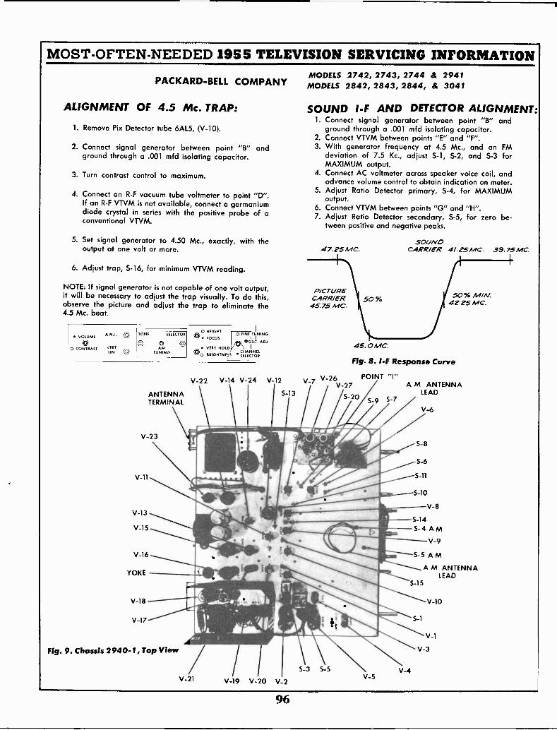
MOST -OFTEN -NEEDED 1955 TELEVISION SERVICING INFORMATION
PACKARD-BELL COMPANY
ALIGNMENT OF 4.5 Mc. TRAP:
1. Remove Pix Detector tube 6AL5, (V-10).
2. Connect signal generator between point "B" andground through a .001 mfd isolating capacitor.
3. Turn contrast control to maximum.
4. Connect an R -F vacuum tube voltmeter to point "D".If an R -F VTVM is not available, connect a germaniumdiode crystal in series with the positive probe of aconventional VTVM.
5. Set signal generator to 4.50 Mc., exactly, with theoutput at one volt or more.
6. Adjust trap, S-16, for minimum VTVM reading.
NOTE: If signal generator is not capable of one volt output,it will be necessary to adjust the trap visually. To do this,observe the picture and adjust the trap to eliminate the4.5 Mc. beat.
VOLUME A.N.I. 0
0 CONTRAST VERTLIN Vi
TONE SELECTOR
0 OoAM
TUNING
ANTENNATERMINAL
V-23
V-11
V-13
V-15
V-16
YOKE
V-18
V-17
Fig. 9. Chassis 2940-1, Top View
0 HEIGHT I
0 FINE TUNING\V FOCUS I I
00SC ADJ VERT HOLDC I I
0 BRIGHTNESS r4EIC'ITNC!;;1.
_I j
V-22
V-21
V-14 V-24 V-12
5-13
V-19 V-20 V-2
MODELS 2742, 2743, 2744 & 2941MODELS 2842, 2843, 2844, & 3041
SOUND I -F AND DETECTOR ALIGNMENT:1. Connect signal generator between point "8" and
ground through a .001 mfd isolating capacitor.2. Connect VTVM between points "E" and "F".3. With generator frequency at 4.5 Mc., and an FM
deviation of 7.5 Kc., adjust S-1, S-2, and S-3 forMAXIMUM output.
4. Connect AC voltmeter across speaker voice coil, andadvance volume control to obtain indication on meter.
5. Adjust Ratio Detector primary, S-4, for MAXIMUMoutput.
6. Connect VTVM between points "G" and "H".7. Adjust Ratio Detector secondary, S-5, for zero be-
tween positive and negative peaks.
SOUND47.25 MC. CARR/ER 4/.2. 5 MC. 39.75 MC.
R/CTURECARR/ER 50 %45.75 MC.
45.0 MC
50% M/A./.42.25 MC.
Fig. 8. I -F Response Curve
V-7 V-26 POINT "I"V-27 A M ANTENNA
LEAD5-20
S-9 5-7V-6
V-8
S-14
- S-4 AMV-9
5-5 A M
A M ANTENNALEAD
5-15
5-3 5-5 V-4V-5
V-10
5-1
V-1
V-3
96
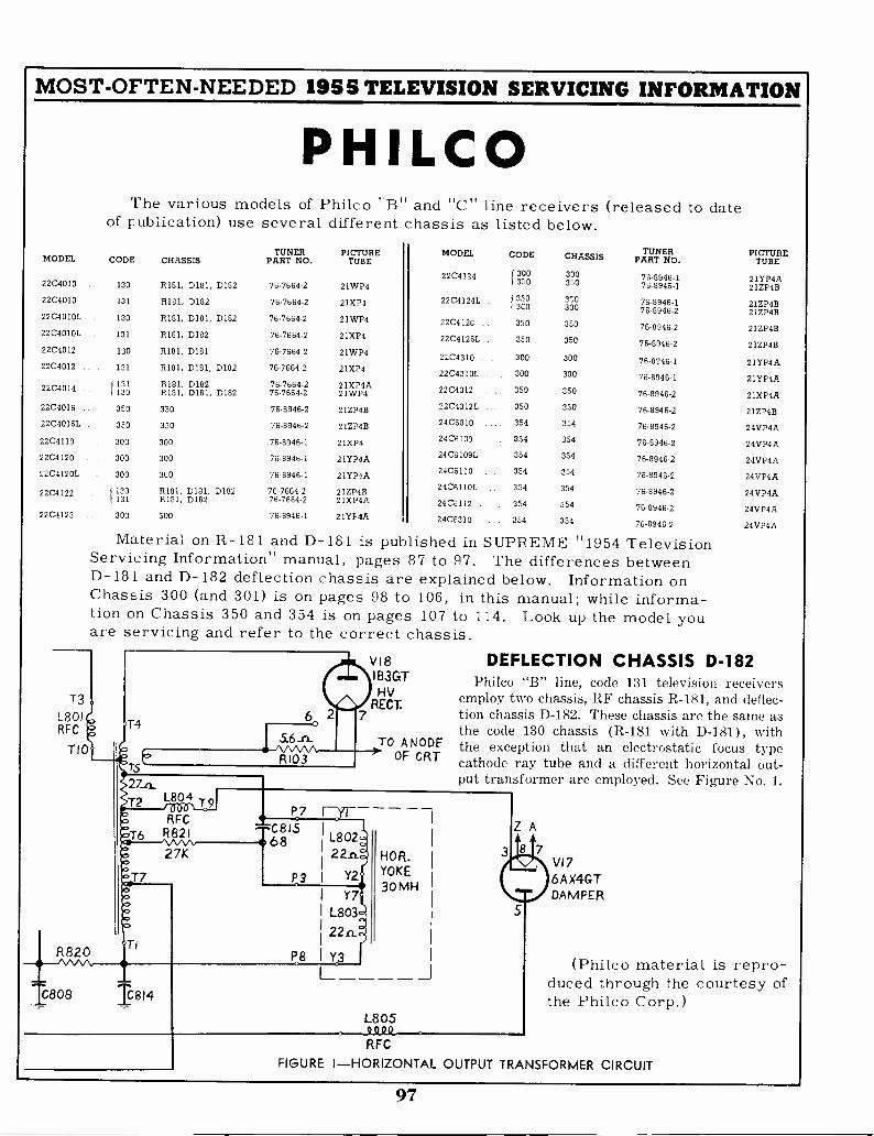
MOST -OFTEN -NEEDED 1955 TELEVISION SERVICING INFORMATION
PHILCOThe various models of Philco "B" and "C" line receivers (released to date
of publication) use several different chassis as listed below.
MODEL CODE CHASSISTUNER
PART NO.PICTURE
TUBEMODEL CODE CHASSIS TUNER
PART NO.PICTURE
TUBE
2204010 130 R181, DI81, D182 76-7664-2 21WP422C4124
{
300350
76-8946-176-8946-1
21YP4A21ZP4B
2204010 131 R181, D182 76-7664-2 21XP4 22C4I24L I 3503C0
350300
76-8946-176-8946-2
21ZP4B21ZP4B22C4010L 130 R181, D181, D182 76-7664-2 21WP4 22C4126 350 350 76-8946-2 21ZP4B22C4010L 131 5181, 0182 76-7664-2 21XP4 2204126L 350 350 76-8946-2 21ZP4B2204012 130 R181, D181 76-7664-2 21WP4 22C4310 300 300 76-8946-1 21YP4A2204012 131 R181, D181, D182 76-7669-2 21XP4 22C4310L 300 300 76-8946-1 2 IYP4A
22C4014 {131130
5181, D182R181, DI81, D182
76-7664-276-7664-2
21XP4A21WP4 2204312 350 350 76-8946-2 21XP4A
2204016 350 350 76-8946-2 21ZP4B 22C4312L 350 350 76-8946-2 21ZP4B
22C40I6L 350 350 76-8946-2 21ZP4B 2406010 354 354 76-8946-2 24VP4A
2204119 . 300 300 76-8946-1 21XP4 24C6109 354 354 76-8946-2 24VP4A
22C4120 300 300 76-8946-1 21YP4A 24C6109L 354 354 76-8946-2 24VP4A
22C4120L 300 300 76-8946-1 21YP4A 29C6110 354 354 76-8946-2 24VP4A
1 1337R181, D181, D182 76-7664-2 2IZP4B 24C6110L 354 354 76-8946-2 24VP4A2204122R181, D182 76-7664-2 21XP4A 2400112 354 354 76-8946-2 24VP4A
2204123 300 300 76-8946-1 21YP4A 2406310 354 354 76-8946.2 24VP4A
Material on R-181 and D-181 is published in SUPREME "1954 TelevisionServicing Information" manual, pages 87 to 97. The differences betweenD-181 and D-182 deflection chassis are explained below. Information onChassis 300 (and 301) is on pages 98 to 106, in this manual; while informa-tion on Chassis 350 and 354 is on pages 107 to 114. Look up the model youare servicing and refer to the correct chassis.
T3L801RFC
T I 0
R820
T460
R103
V18I B3GTHV
RECT.7
27_n_
T2 L804/06-0
RFC
TO ANODEOF CRT
DEFLECTION CHASSIS D-182Philco "B" line, code 131 television receivers
employ two chassis, RF chassis R-181, and deflec-tion chassis D-182. These chassis are the same asthe code 130 chassis (R-181 with D-181), withthe exception that an electrostatic focus typecathode ray tube and a different horizontal out-put transformer are employed. See Figure No. 1.
P7 17171--
T6 R8210815 L802
27K146
22.n.
T7 P3 I Y2
Ti
1808 1814
Y7L803
22.n.
P8 I Y3
HOR.YOKE
30 MH
L805949Q
Z A
8 7VI 7
6 A X4GTDAMPER
(Philco material is repro-duced through the courtesy ofthe Philco Corp.)
RFC
FIGURE I-HORIZONTAL OUTPUT TRANSFORMER CIRCUIT
97
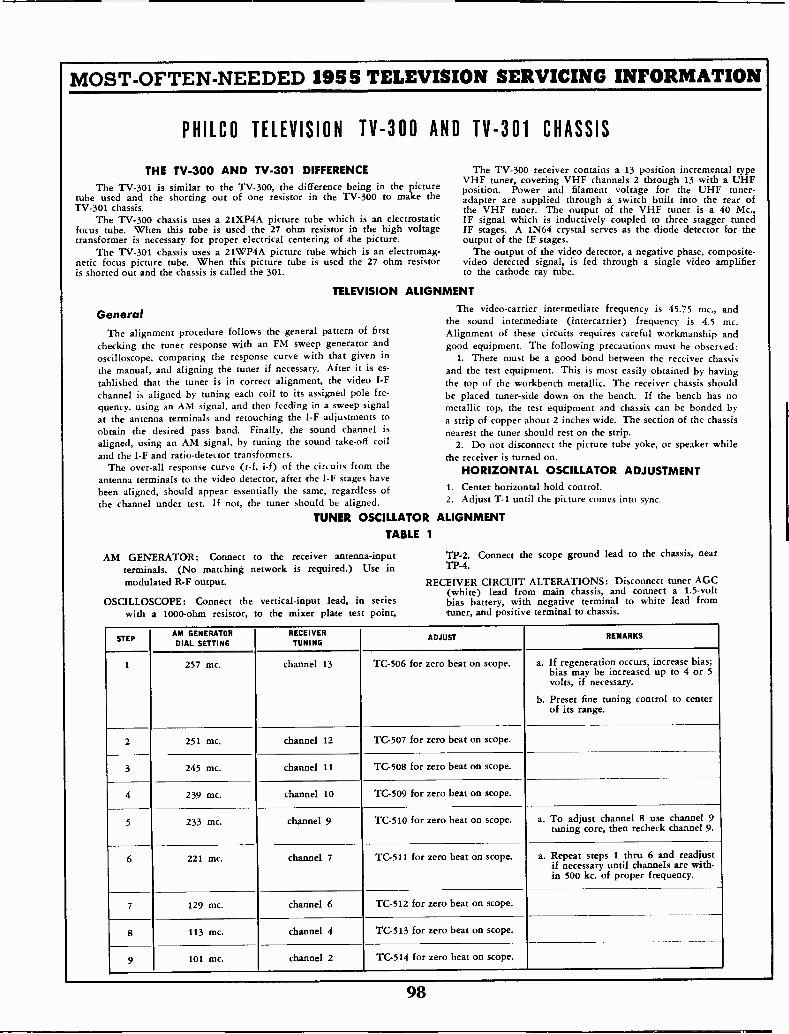
MOST -OFTEN -NEEDED 1955 TELEVISION SERVICING INFORMATION
Thetube usedTV -301
Thefocustransformer
Thenetic focusis shorted
General
checkingoscilloscope,thetablishedchannelquency,atobtainaligned,and
antennabeenthe
PHILCO TELEVISION TV -300 AND TV -301 CHASSIS
THE TV -300 AND TV -301 DIFFERENCE The TV -300 receiver contains a 13 position incremental
TV -301 is similar to the TV -300, the difference being in the pictureVHF tuner, covering VHF channels 2 through 13 with
Power and filament voltage for the UHFand the shorting out of one resistor in the TV -300 to make the adapter are supplied through a switch built into the
chassis. the VHF tuner. The output of the VHF tuner is aTV -300 chassis uses a 21XP4A picture tube which is an electrostatic IF signal which is inductively coupled to three stagger
tube. When this tube is used the 27 ohm resistor in the high voltage IF stages. A 1N64 crystal serves as the diode detectoris necessary for proper electrical centering of the picture. output of the IF stages.
TV -301 chassis uses a 21WP4A picture tube which is an electromag- The output of the video detector, a negative phase, composite-picture tube. When this picture tube is used the 27 ohm resistor video detected signal, is fed through a single video amplifier
out and the chassis is called the 301. to the cathode ray tube.
TELEVISION ALIGNMENT
The video -carrier intermediate frequency is 45.75 mc.,the sound intermediate (intercarrier) frequency is 4.5
The alignment procedure follows the general pattern of first Alignment of these circuits requires careful workmanshipthe tuner response with an FM sweep generator and good equipment. The following precautions must he observed:
comparing the response curve with that given in 1. There must be a good bond between the receiver chassismanual, and aligning the tuner if necessary. After it is es- and the test equipment. This is most easily obtained by having
that the tuner is in correct alignment, the video I -F the top of the workbench metallic. The receiver chassis shouldis aligned by tuning each coil to its assigned pole fre- be placed tuner -side down on the bench. If the bench hasusing an AM signal, and then feeding in a sweep signal metallic top, the test equipment and chassis can be bonded
the antenna terminals and retouching the I -F adjustments to a strip of copper about 2 inches wide. The section of the chassisthe desired pass band. Finally, the sound channel is nearest the tuner should rest on the strip.using an AM signal, by tuning the sound take -off coil 2. Do not disconnect the picture tube yoke, or speaker while
the I -F and ratio -detector transformers. the receiver is turned on.The over-all response curve (r -f, i-f) of the circuits ftom the HORIZONTAL OSCILLATOR ADJUSTMENT
terminals to the video detector, after the I -F stages havealigned, should appear essentially the same, regardless of 1. Center horizontal hold control.
channel under test. If not, the tuner should be aligned. 2. Adjust T-1 until the picture comes into sync.
TUNER OSCILLATOR ALIGNMENTTABLE 1
AM GENERATOR: Connect to the receiver antenna -input TP-2. Connect the scope ground lead to the chassis, nearterminals. (No matching network is required.) Use in TP-4.
modulated R -F output. RECEIVER CIRCUIT ALTERATIONS: Disconnect tuner AGC(white) lead from main chassis, and connect a 1.5 -volt
OSCILLOSCOPE: Connect the vertical -input lead, in series bias battery, with negative terminal to white lead fromwith a 1000 -ohm resistor, to the mixer plate test point, tuner, and positive terminal to chassis.
typea UHFposition.
tuner -rear of
40 Mc.,tuned
for the
andmc.and
noby
STEPAM GENERATORDIAL SETTING
RECEIVERTUNING
ADJUST REMARKS
1 257 Inc. channel 13 TC-506 for zero beat on scope. a. If regeneration occurs, increase bias;bias may be increased up to 4 or 5volts, if necessary.
b. Preset fine tuning control to centerof its range.
2 251 mc. channel 12 TG507 for zero beat on scope.
3 245 mc. channel 11 TG508 for zero beat on scope.
4 239 mc. channel 10 TC-509 for zero beat on scope.
5 233 mc. channel 9 TC-510 for zero beat on scope. a. To adjust channel 8 use channel 9tuning core, then recheck channel 9.
6 221 mc. channel 7 TC-511 for zero beat on scope. a. Repeat steps 1 thru 6 and readjustif necessary until channels are with-in 500 kc. of proper frequency.
7 129 mc. channel 6 TC-512 for zero beat on scope.
8 113 mc. channel 4 TC-513 for zero beat on scope.
9 101 mc. channel 2 TC-514 for zero beat on scope.
98
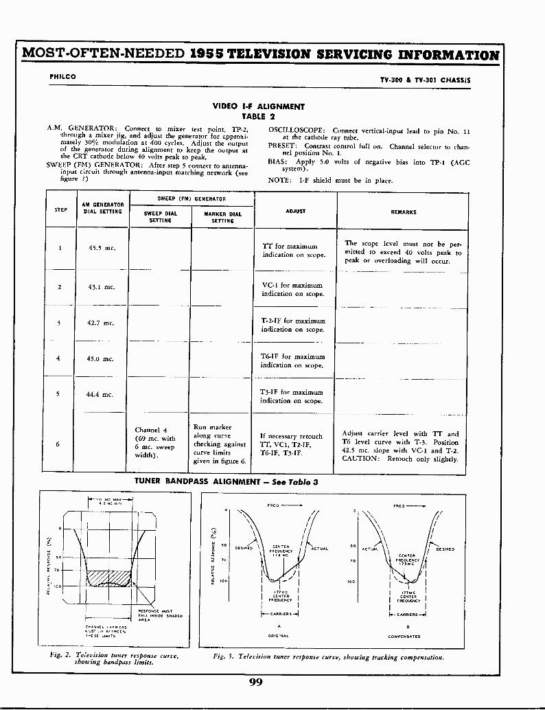
MOST -OFTEN -NEEDED 1955 TELEVISION SERVICING INFORMATION
PHILCO TV -300 & TV -301 CHASSIS
VIDEO I -F ALIGNMENTTABLE 2
A.M. GENERATOR: Connect to mixer test point, TP-2,through a mixer jig, and adjust the generator for approxi-mately 30% modulation at 400 cycles. Adjust the outputof the generator during alignment to keep the output atthe CRT cathode below 40 volts peak to peak.
SWEEP (FM) GENERATOR: After step 5 connect to antenna -input circuit through antenna -input matching network (seefigure ?)
OSCILLOSCOPE: Connect vertical -input lead to pin No. 11at the cathode ray tube.
PRESET: Contrast control full on. Channel selector to chan-nel position No. 1.
BIAS: Apply 5.0 volts of negative bias into TP-1 (AGCsystem).
NOTE: I -F shield must be in place.
STEPAM GENERATORDIAL SETTING
SWEEP (FM) GENERATOR
ADJUST REMARKSSWEEP DIALSETTING
MARKER DIALSETTING
1 45.5 mc. Ti' for maximumindication on scope.
The scope level must not be per-
mitted to exceed 40 volts peak topeak or overloading will occur.
2 43.1 mc. VC -1 for maximumindication on scope.
3 42.7 mc. T -2 -IF for maximumindication on scope.
4 45.0 mc. T6 -IF for maximumindication on scope.
5 44.4 mc. T3 -IF for maximumindication on scope.
6
Channel 4(69 mc. with6 mc. sweepwidth).
kRunmareralong curvechecking againstcurve limitsgiven in figure 6.
If necessary retouchTT, VC1, T2 -IF,T6 -IF, T3 -IF.
Adjust carrier level with TT andT6 level curve with T-3. Position42.5 mc. slope with VC -1 and T-2.CAUTION: Retouch only slightly.
TUNER BANDPASS ALIGNMENT - See Table 3
RESPONSE MUSTFALL INSIDE SHADEDAREA
CHANNEL CARRIERSLIE DETwECM
THESE LIMITS
Fig. 2. Television tuner response curve,showing bandpass limits.
FRED FRED
50O
N
CENTER 50DESIRED ACTUALFREQUENCY / DESIRED
119 MC CENTER7C 70 FREQUENCY
75 MCAI
\I 0 100
i770ACCENTER
FREQUENCY
IA- CARRIERS
ORIGINAL
I 177.0CCENTER
FREQUENCY
/1.- CARRIERS -4
COMPENSATED
Fig. 3. Television tuner response curve, showing tracking compensation.
99
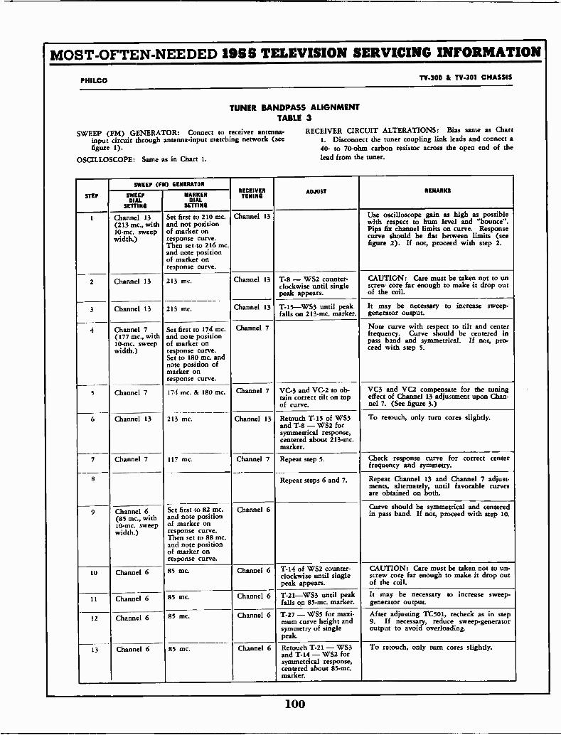
MOST -OFTEN -NEEDED 1955 TELEVISION SERVICING INFORMATION
PHILCO TV -300 & TV -301 CHASSIS
TUNER BANDPASS ALIGNMENTTABLE 3
SWEEP (FM) GENERATOR: Connect to receiver antenna -input circuit through antenna -input matching network (seefigure 1).
OSCILLOSCOPE: Same as in Chart 1.
RECEIVER CIRCUIT ALTERATIONS: Bias same as ChartI. Disconnect the tuner coupling link leads and connect a40- to 70 -ohm carbon resistor across the open end of thelead from the tuner.
STEP
SWEEP (FM) GENERATORRECEIVERTUNING
ADJUST REMARKSSWEEPDIAL
SETTING
MARKERDIAL
SETTING
t Channel 13(213 mc., with10-mc. sweepwidth.)
Channel 13
Set first to 210 mc.and not positionof marker onresponse curve.Then set to 216 mc.and note positionof marker onresponse curve.
Channel 13 Use oscilloscope gain as high as possiblewith respect to hum level and "bounce".Pips fix channel limits on curve. Responsecurve should be flat between limits (seefigure 2). If not, proceed with step 2.
2 213 mc.
213 mc.
Channel 13 T-8 - WS2 counter-clockwise until singlepeak appears.
CAUTION: Care must be taken not to unscrew core far enough to make it drop outof the coil.
3 Channel 13 Channel 13 T-15-WS3 until peakfalls on 213-mc. marker.
It may be necessary to increase sweep -generator output.
4
5
Channel 7(177 mc., with10-mc. sweepwidth.)
Channel 7
Set first to 174 mc.and note positionof marker onresponse curve.Set to 180 mc. and
position ofmarker onresponse curve.
Channel 7 Note curve with respect to tilt and centerfrequency. Curve should be centered inpass band and symmetrical. If not, pro -teed with step 5.
17.1 mc. & 180 mc. Channel 7 VC -3 and VC -2 to ob-min correct tilt on topof curve.
VC3 and VC2 compensate for the tuningeffect of Channel 13 adjustment upon Chan -nel 7. (See figure 3.)
6 Channel 13 213 mc. Channel 13 Retouch T-15 of WS3and T-8 - WS2 forsymmetrical response,centered about 213-mc.marker.
To retouch, only turn cores slightly.
7
8
Channel 7 117 mc. Channel 7 Repeat step 5. Check response curve for correct centerfrequency and symmetry.
Repeat steps 6 and 7. Repeat Channel 13 and Channel 7 adjust-ments, alternately, until favorable curvesare obtained on both.
9 Channel 6(85 mc., with10-mc. sweepwidth.)
Sct first to 82 mc.and note positionof marker onresponse curve.Then set to 88 mc.and note positionof marker onresponse curve.
Channel 6 Curve should be symmetrical and centeredin pass band. If not, proceed with step 10.
10 Channel 6 85 mc. Channel 6 T-14 of WS2 counter-clockwise until singlepeak appears.
CAUTION: Care must be taken not to un-screw core far enough to make it drop outof the coil.
11 Channel 6 85 mc. Channel 6 T-21-WS3 until peakfalls on 85-mc. marker.
It may be necessary to increase sweep -generator output.
12 Channel 6 85 mc. Channel 6 T-27 - WS5 for maxi-mum curve height andsymmetry of singlepeak.
After adjusting TC501, recheck as in step9. If necessary, reduce sweep -generatoroutput to avoid overloading.
13 Channel 6 85 mc. Channel 6 Retouch T-21 - WS3and T-14 - WS2 forsymmetrical response,centered about 85-mc.marker.
To retouch, only turn cores slightly.
100
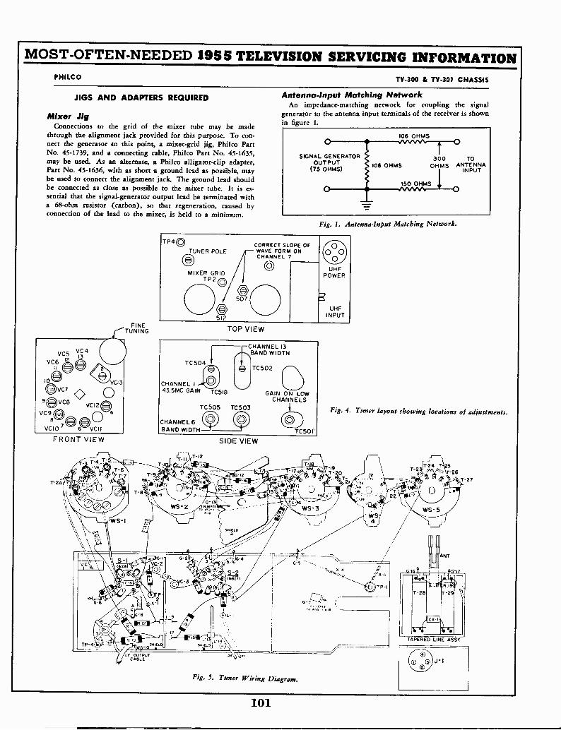
MOST -OFTEN -NEEDED 19SS TELEVISION SERVICING INFORMATIONPHILCO TV -300 & TV -301 CHASSIS
JIGS AND ADAPTERS REQUIRED
Mixer JigConnections to the grid of the mixer tube may be made
through the alignment jack provided for this purpose. To con-nect the generator to this point, a mixer -grid jig, Philco PartNo. 45-1739, and a connecting cable, Philco Part No. 45-1635,may be used. As an alternate, a Philco alligator -clip adapter,Part No. 45-1636, with as short a ground lead as possible, maybe used to connect the alignment jack. The ground lead shouldbe connected as close as possible to the mixer tube. It is es-sential that the signal -generator output lead be terminated witha 68 -ohm resistor (carbon), so that regeneration, caused byconnection of the lead to the mixer, is held to a minimum.
FINEaTUNING
VC.5, 13VC4
VC6
10
19 N9VC79evc. VC12
VC98 a._
071VC 6 VCII
VCI3
O
FRONT VIEW
T.2A
g
T-4.9)
_\\
5,-6
T-8
I
Antenna -Input Matching NetworkAn impedance -matching network for coupling the signal
generator to the antenna input terminals of the receiver is shownin figure I.
Fig. I. Antenna -Input Matching Network.
TP40TUNER POLE
0MIXER GRID
TP 2
512
CORRECT SLOPE OFWAVE FORM ONCHANNEL 7
O
O507
UHFPOWER
FUHF
INPUT
TOP VIEW
CHANNEL 13BAND WIDTH
TC504re -N
CHANNEL I --mg43.5MC GAIN TC5I8
TC505 TC503
CHANNEL 6BAND WIDTH
TC502
GAIN ON LOWCHANNELS
(0)TC501'
T -I
T-12
SIDE VIEW
13111.4-41M W 5
472,,,
G -r. I
isc.6
WS -3
Fig. 4. Tuner layout showing locations of adjustments.
9T- 0
P
TP-4
CD-L 9
2
4PLEL
L-19
L- I
7)
4G-5
G -7
yo'Vin
I F OUTPutCABLE
OR
Fig. 5. Tuner Wiring Diagram.
a
WS
w.g
22
TP-I
224 T
WS -5
S
T-26
ANT
kT-27
TAPERED LINE ASSY.
J
101

MOST -OFTEN -NEEDED 1955 TELEVISION SERVICING INFORMATION
PHILCO TV -300 & TV -301 CHASSIS
SOUND ALIGNMENTTABLE 4
A.M. GENERATOR: Connect the "hot" lead through a 2200ohm resistor to the junction of C-24, X3 and the xtaldet. Adjust generator for 400v. modulation at approxi-mately 30% modulation.
0a.
eNi 50ce
4
100
imiiiiiiim bli lanai111111011111111111101111111Rung rimmlusiirs1111111 1pp Al 1
NM III LIU:41111:91:11
111111114.41141
odd eihrip...k inufpli.. ... 1. ... /MEM II NM111011111111 P. 19111,111111111111IIMpiplilL11/1111111111111iblifilindilliiiiiidilliiiiii9111111111111 III lb 111111111
66 68.5 71
67.25 70.25VIDEO 50%
CARRIER CHECK POINTFREQUENCY IN MC
Fig. 6. Over-all R -F, I -F response curve,showing tolerance limits.
VOLTMETER: Use V.T.V.M. on 20,000 -ohms -per -volt volt-meter. Connect through a crystal probe to pin No. 11of the picture tube in step 1 and to pin No. 3 of the 6W6audio output tube in the remainder of the steps.
STEP
AMGENERATOR
DIALSETTING
ADJUST REMARKS
I4.5 mc.
modulatedT7 -IF for mini-mum indication.
Voltmeter throughxtal probe.Plate of videoamplifier.
24.5 mc.
modulatedT5 top for maxi-mum indication.
a. Volume controlfull on.
b. Voltmeter thruxtal probe to6W6 pin No. 3.
c. Keep generatorlevel low to pre-vent overload.
34.5 mc.
modulated
T5 bottom formaximum indica-tion.
4 4.5 mc.modulated
T4 -IF for maxi -mum indication.
Fig. 7. Base Layout - Top View - TV -300 Chassis.
102

MOST -OFTEN -NEEDED 1955 TELEVISION SERVICING INFORMATIONPHILCO TV -300 & TV -301 CHASSIS
_00.04111011
Fig. 8. Composite Signal, Pin 2 of12BY7, 6 volts, 60 c.p.s.
Fig. 9. Composite Signal, Pin 2 of12BY7, 6 volts, 15,750 c.p.s.
OSCILLOSCOPE WAVEFORM PATTERN - TV -300
These waveforms were taken with the receiver adjusted for an approximate peak -to -peak output of 6 volts at the video detector. The voltages given with the waveformsare approximate peak -to -peak values. The frequencies shown are those of the wave-forms - not the sweep rate of the oscilloscope. The waveforms were taken with anoscilloscope having good high -frequency response. With oscilloscopes having poorhigh -frequency response, the sharp peaks of the horizontal waveforms will be morerounded than those shown, and the peak -to -peak voltages will differ from those shown.
Fig. 10. Video Amplifier Plate, 83 volts,60 c.p.s.
Fig. 11. Sync Separator Grid, Pin 2, 90volts, 60 c.p.s.
Fig. 12. Sync Separator Plate, Pin 1, 30 Fig. 13. Vertical -Oscillator Grid, Pin 7, Fig. 14. Vertical -Output Grid, Pin 2, 72volts, 15:750 c.p.s. 140 volts, 60 c.p.s. volts, 60 c.p.s.
Fig. 15. Vertical -Output Plate, Pin 9, Fig. 16. Phase Comparer, Pin 6, 7 volts, Fig. 17. Horizontal Oscillator, junction900 volts, 60 c.p.s. 15,750 c.p.s. of L800 and R806, 43 volts, 15,750 c.p.s.
Fig. 18. Horizontal -Oscillator Cathode,Pins 3 and 8, 18 volts, 15,750 c.p.s.
Fig. 19. Horizontal -Oscillator Grid, Pin Fig. 20. Horizontal -Output Grid, Pin 5,2, 40 volts, 15,750 c.p.s. 120 volts, 15,750 c.p.s.
103
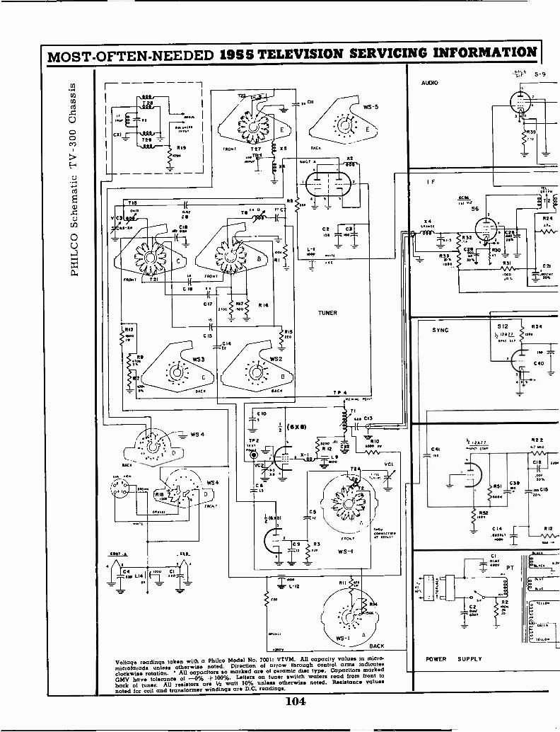
MOST -OFTEN -NEEDED 1955 TELEVISION SERVICING INFORMATION I
490
oo I
CX1.1---1 1r Pry
T29SOO
OraR19II
V
T 13
C3
Rt1ra
C11
MCI
X2Oa'
WS -5
L-11
C2 1 C3IISO
=
-"'"
AUDIO
S-9
R39
IAll
TUNER
T P 4
SACK
WS 4
IC 10Ts
TP2rt ST
VC
C
74.. ss
12-
(41 X 8)
R322.
$. 12
=L9MOO
rldwo. W10.
TI
Ron?
WS-I
cs. C13
10
VC1
1111010
tOrrICTIONAT 21111
eoe
L-12
120
Iswv
R11
WS -IA
ISO
BACK
Voltage readings taken with a Philco Modal No. 7001: VTVM. All capacity values in micro-microfarads unless otherwise noted. Direction of arrow through control arms indicatesclockwise rotation. All capacitors so marked are of ceramic disc type. Capacitors markedGMV have tolerance of -0% +100%. Letters on tuner switch waters read from front toback of tuner. All resistors are V2 watt 10% unless otherwise noted. Resistance valuesnoted for coil and transformer windings are D.C. readings.
IF
%4
6055is. ,tiF
S6
32
CISco
933 erro%
.0o.
20%
.00020%
SAW.
92447.
.0 21
mergr
SYNCS12 b R54
jI ITAI7SI. Ur
ISO
C 40
12 2 Az
C41 r.nn 10.1
CI0114,4,00.0
PT
Sr
C 2
POWER SUPPLY
R2
10
R224.7 WO
mnf.
Con
104
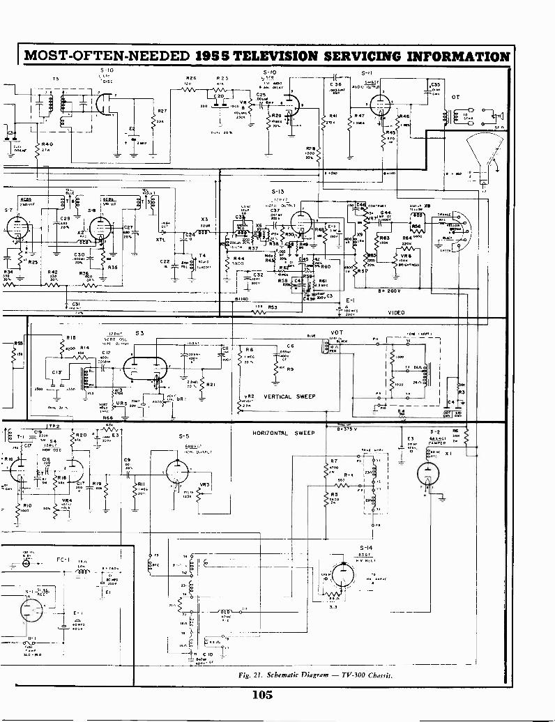
I MOST -OFTEN -NEEDED 1955 TELEVISION SERVICING INFORMATION
rT5
J1.7L
004W04021k
S -10R26
.20
E
1. 12*,
R27
535
350
R 2 3
C 20V9
1500
V01:2002505
006, 20%
5-10§-TA
1400& 642 022AT
C25.055.0
15.4r
R2910216201
C 36
21012
5-11
6AUDIO 0'1.114121
R47
1:C35
845114.20
4
0004
OT
sr a
521.
5-7202. v1E
T16
C2920
20;
s -e
X
OCO
C30" R25 zo,.
R34 R42 R46530 350 .1000
R35
20* --
C27Q820;
64
XTL
X3
T1C22 7000 Sown
o 111. y4,(022I I
C3
6 60
S-1312707
2,010 OUTPu
C37.124131+200
837
R4
C321020200
8140
003
40
:49
tox C 45 42o
R621. ',..14.11.R 60
a 14[2 R59-R58 CO ,,, 116I
o 2 24.4
2025 YrZOOV''
R5370%
000
c
x9
85
CO&NRAST
5. C44.Ire 8;
R63oR
150 01, x6
riff%ReC
R56NAA
R64,... 04(2220 2
4122En
VR82240 100
101 10100210.23
E -I
t 5060
111-2- 260V
VIDEO
R55R15
Hoe R1455.
12 B57 S3VERT OSC
v2111 01.Troa
C 124002
006910
DUO
C13-
25ooIevon
jMD 37e'
2.21 'L7rUR0020
713 '
U R 5302 TR66
/ TO 2
T -I X19220S4
R16
1000
Is. CI7 i?.607NOR 051.
Cie3251
820410
R4RIO
V0O1).--k 11010
C9.00.SO,
17 R19560
2224220 Tf. 21
C11
400+
R8114CA
20
C6
VR2 VERTICAL SWEEP2.35
VOT
L'noRio
407 1 v51111
r0
I000
26/1.0)
lsna
O
15-R3
C4
46,14 gat
S-5
48060110111. 0111701
VR3
HORIZONTAL SWEEP
8-1
. 01,510- 111.0
FC- I 621La. e . :see .1
oilRn".
E - I
04001,
0 .3.0350V
1TE
T...2.0v 07
8375 V
3.3
10611 to0110
S -14183 01N V RECO
E3
Re
225:
Fig. 21. Schematic Diagram - TV -300 Chassis.
105
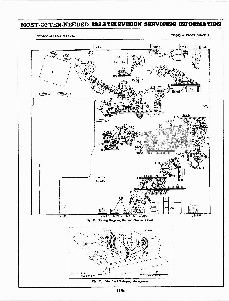
MOST -OFTEN -NEEDED 1955 TELEVISION SERVICING INFORMATION
PRIMO SERVICE MANUAL TV -300 & TV -30I CHASSIS
riv,,-, rivR -2 [1VR-3 0 n n ilLC
°14 ... 2aL__
I& . G -IFC
ics 0 13 E,-, fOlk*a_ ' II51-3)() 100 1
t, 1C ® ICI -
PT. ® 3)bras
4-2 0c) ,-gEit,B3 Ct. ®
I I
re 6; tol. R-7
} A k i o 3 4 0(2)1,,, . . . .4 Ia C-541P"'"°Ir e....\,....z:::
E -IV Ze.
'''' 8-4-
4
fij 1 C -I0.2\ ,.. -9 14 -gn l/ onCL -1 ict.,..:!.. '4,, cf 2=-, e 0
C II
m:3)4
4
4 ,14.
- d'.1)
474
,
, 1+ ilt 16R CL -1, IP r-Imito li .ci : -.. .. 6 7 8
MD Pc --41 C 19..,;, B 6b
, )CL -4 G-71
Joz .
' G-6 z 4 EV,r4tV" ,
c e x-"" CI r 1! s ®
. :. A
1.
VC -I
(-1 let 6) i)..4 a Am ,T,N 4'
'.!, .- " 1 °:,- 147. " al e? 4
_ . 0.. pa ; j '' - (27C_,
, Owi 46
7s
kli-'34
B -ti-, B-8 "6 ,...,,,.,
C'37 /49,
S -I2 8i ..11)
3 I,
Am.41 reSaMI
!
lig06, 5_13
.1 ,,Elosa, 01Ti CL -6I 8-9- -C3CL-7 . el
Ja.
_
2
ill," AB'. in
13
-lo
virV
G -I2
3( c1.- E-3te.A
L IVR-4 L IvB-s L hiR-6 LivR-7 L.NR-8
Fig. 22. Wiring Diagram, Bottoert View - TV -300.
1 TURNS
_,\ ' .,.....\--
...,
Etlib '4.2i TURN1
11-11112N5
1
liTURNS-' -. '- ''- --.
- -- -.% Ill ' ji
) + DAL ICORO
_--- - ---k- Ilr4----251" 1. \ i
.....=.DIAL COR WA" \\ ,..- - - -- DIAL CORD'S
Fig. 23. Dial Cord Stringing Arrangement.
106

MOST -OFTEN -NEEDED 1955 TELEVISION SERVICING INFORMATION
PHILCO TELEVISION TV -350 AND TV -354 CHASSIS
CIRCUIT DESCRIPTION OF TV -354
The TV -354 is the same as the TV -350 with the followingexceptions. The vertical output tube has been changed from a6S4 to a 6CM6. The horizontal output tube from a 6BQ6 to a6CD6. The damper tube in the TV -350 is a 6AX4, while the
damper tube in the TV -354 is a 6AU4GT. The power supply inthe TV -354 contains two 5U4G rectifiers. These changes havebeen made in the TV -354 to accommodate the larger picturetube.
HORIZONTAL -OSCILLATOR ADJUSTMENT
To adjust the horizontal -oscillator circuit, tune in a stationand proceed as follows:1. Reduce the width of the picture until approximately 1 inchof blank screen appears at the right-hand and left-hand sidesof the picture.2. Increase the BRIGHTNESS control setting until the blank-ing becomes visible. This will appear as a dark vertical baron each side of the picture.3. Connect a .1 mf condenser from the test point to ground.(The plate side of the horizontal ringing coil, T1, is connectedto the test point.)4. Set the HORIZONTAL HOLD control to the approximatecenter of its mechanical rotation.5. Adjust the HORIZONTAL HOLD CENTERING controluntil equal portions of the blanking bar appear on both sidesof the picture.6. Remove the .1 mf condenser from the test point.
7. Adjust the horizontal ringing coil, T1, until equal portionsof the blanking bar again appear on both sides of the picture.
8. Rotate the HORIZONTAL HOI.D control through itsrange. The picture should fall out of sync on both sides of thecenter of its rotation. If the picture does not fall out of sync
10K SOUNDCROSSOVER
BIAS 14 V
TOP VIEWOF PLUG
C+ -SCOPEGROUND
-C- BIAS -14 V
iii i'
4 1 5 2 3SOLDEREDTO SHELL
1500 111.1, F
TO OSCILLOSCOPE
C+
SCOPEGROUND
TO OSCILLOSCOPE
15K,1/2 WATTPART NO.66-3158340
10K, 1/2 WATTPART NQ 66-3108340MINIATURETUBE SHIELDPART NO. 56-5629FA3
SHELLPART NO. 56-1146-I5 PIN PLUGPART NO. 27-4785-3
Fig. 2. Video I -F Alignment Jig(Video Test Jack Adapter No. 1).
O
5 50
TO
on both sides, readjust the HORIZONTAL HOLD CENTER.ING control.
9. Rotate the HORIZONTAL HOLD control through itsrange, and observe the number of diagonal blanking bars thatappear just before the picture pulls into sync. The pull -inshould occur with from 1 to 2 diagonal bars when the syncposition is approached from either direction. If proper pull -inis not obtained, repeat the above procedure.
ADESIREP
LEAD "A"
TOP VIEWRI
2 2200
10.000
PART NO.66-3108340
BIAS -14V
SHELL PART NO56-1146-I
IREO
PART NO66-2228340
fUSE ONLY FORALIGNMENT OF4.5 MC SOUNDTRAP ITC 301)
TO SIGNAL GENOR SCOPE
(SHORT LEAD) BIAS +
TO SIGNAL GENOR SCOPE
1500PART NO.62-215001001
SOUND CROSSOVERBIAS -I4 V
LEAD 'A"
TO SIGNAL GENOR SCOPE
SOLDER TO SHELL
(SHORT LEAD/ BIAS+
TO SIGNAL GENOR SCOPE
PLUG PARTNO 27-4785-3
Fig. 3. Sound I -F Input Alignment Jig(Video Test Jack Adapter No. 2).
IICENTER
ER10uENCV
CORNERS
ORIGINAL
UL
FREO
COMO:: NEAT CO
'-"COO
Fig. 5. Television tuner response curve, showing tracking compensation.
107
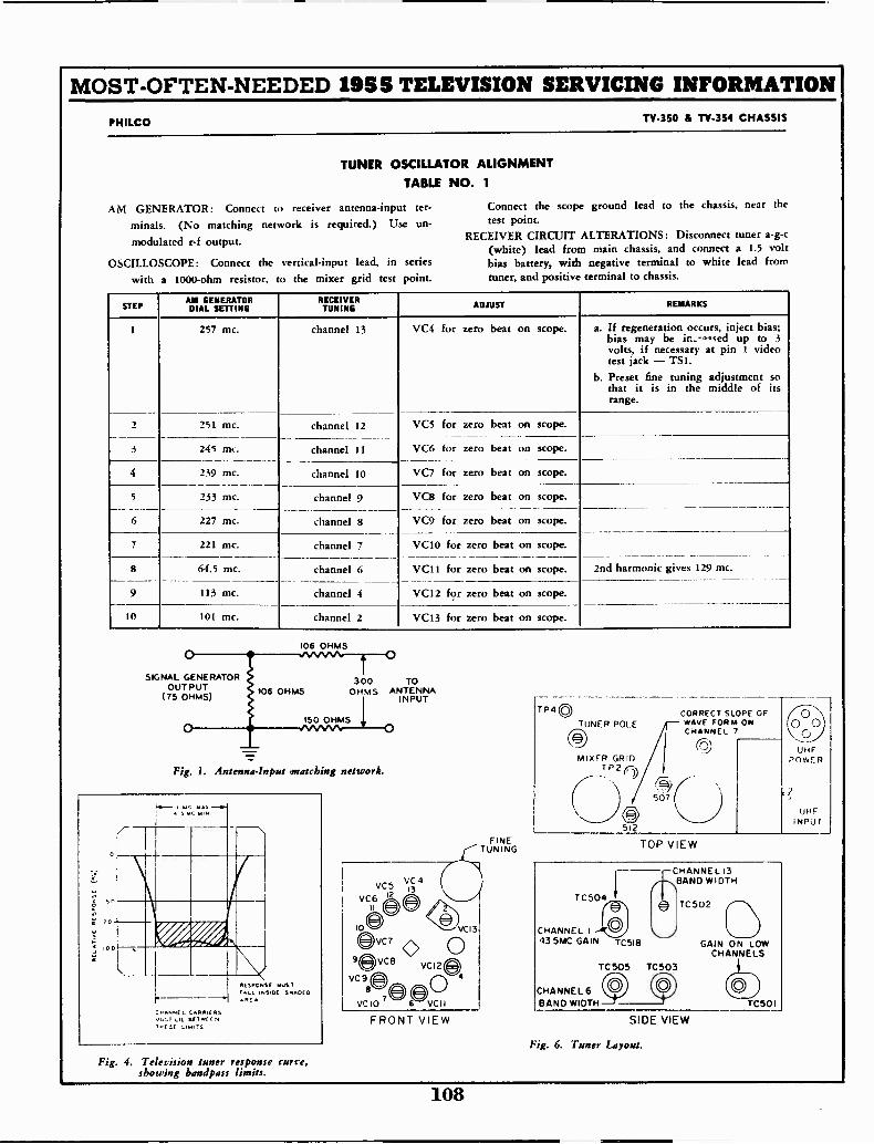
MOST -OFTEN -NEEDED 1955 TELEVISION SERVICING INFORMATION
PHILCO TV -350 & TV -354 CHASSIS
TUNER OSCILLATOR ALIGNMENTTABLE NO. 1
AM GENERATOR: Connect to receiver antenna -input ter-
minals. (No matching network is required.) Use un-
modulated r -f output.
OSCILLOSCOPE: Connect the vertical -input lead, in series
with a 1000 -ohm resistor, to the mixer grid test point.
Connect the scope ground lead to the chassis, near thetest point.
RECEIVER CIRCUIT ALTERATIONS: Disconnect tuner a -g -c(white) lead from main chassis, and connect a 1.5 voltbias battery, with negative terminal to white lead fromtuner, and positive terminal to chassis.
STEPAM GENERATORDIAL SETTING
RECEIVERTUNING ADJUST REMARKS
1
2
257 mc. channel 13 VC4 for zero beat on scope. a. If regeneration occurs, inject bias;bias may be in. -<-:,sed up to 3
volts, if necessary at pin 1 videotest jack - TS1.
b. Preset fine tuning adjustment sothat it is in the middle of itsrange.
251 mc. channel 12 VC5 for zero beat on scope.
3 245 mc. channel 11 VC6 for zero beat on scope.
4 239 mc. channel 10 VC7 for zero beat on scope.
5 233 mc. channel 9 VC8 for zero beat on scope.
6 227 mc. channel 8 VC9 for zero beat on scope.
7 221 mc. channel 7 VC10 for zero beat on scope.
8 64.5 mc. channel 6 VC11 for zero beat on scope. 2nd harmonic gives 129 mc.
9 113 mc. channel 4 VC12 for zero beat on scope.
10 101 mc. channel 2 VC13 for zero beat on scope.
106 OHMS
SIGNAL GENERATOROUTPUT
(75 OHMS)106 OHMS
300 TOOHMS ANTENNA
INPUT
150 OHMS
Fig. 1. Antenna -Input snatching network.
RESPONSE MUSTrLL SIDE SNROCOARE A
NNE CARRIERS;.CSLi( 611 WC C N
C,& 'S
Fig. 4. Television tuner response curve,showing band pass
VC5V4
VC612 C-
,009VC7
9evceVC9
a
VC
FRONT VIEW
FINETUNING
TP40TUNER POLE
MIXER GRID_TP2r5)
n512
CORRECT SLOPE OFWAVE FORM ONCHANNEL 7
TOP VIEW
TC504
CHANNEL I ..4g43 5MC GAIN Tcsig
TC 505
CHANNEL 6BAND WIDTH
CHANNEL 13BAND WIDTH
TC503
TC502
GAIN ON LOWCHANNELS
CCOTC501
SIDE VIEW
Fig. 6. Tuner Layout.
1
UHFINPUT
108
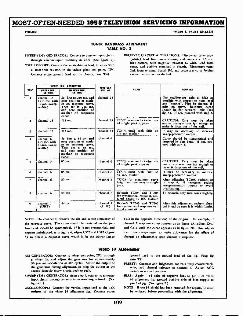
MOST -OFTEN -NEEDED 1955 TELEVISION SERVICING INFORMATIONPHILCO TV -350 & TV -354 CHASSIS
TUNER BANDPASS ALIGNMENTTABLE NO. 2
SWEEP (FM) GENERATOR: Connect to antenna -input circuitthrough antenna -input matching network (See figure 1).
OSCILLOSCOPE: Connect the vertical -input lead, in series witha 1C00 -ohm resistor, to the mixer plate test point, TP4.Connect scope ground lead to the chassis, near TP4.
RECEIVER CIRCUIT ALTERATIONS: Disconnect tuner a -g -c(white) lead from main chassis, and connect a 1.5 voltbias battery, with negative terminal to white lead fromtuner, and positive terminal to chassis. Disconnect tunerlink from terminal board, B-9, and connect a 40 to 70 -ohmcarbon resistor across the link.
STEP
SWEEP (FM) GENERATOR?ECEIVERTUNING ADJUST REMARKSSWEEP DIAL
SETTINGMARKER DIAL
SETTING
1
2
channel 13(213 mc. with10-mc. sweepwidth.)
Set first to 210 rile. andnote position of mark-er on response curve.Then set to 216 mc.and note position ofmarker on responsecurve.
channel 13 Use oscilloscope gain as high aspossible with respect to hum leveland "bounce". Pips fix channel li-mits on curve. Response curveshould be flat between limits (seefig. 5). If not, proceed with step 2.
channel 13
---213 mc. channel 13 TC502 counterclockwise un-
til single peak appears.--- - -
CAUTION: Care must be takennot to unscrew core far enough tomake it drop out of the coil.
3
4
5
channel 13 213 mc. channel 13
channel 6
channel 6
TC504 until peak falls on213 mc. marker.
_
It may be necessary to increasesweep -generator output.
channel 6(85 mc. with10-mc. sweepwidth.)
Set first to 82 mc. andnote position of mark-er on response curve.Then set to 88 mc.and note position ofmarker on response
Curve should be symmetrical andcentered in pass band. If not, pro-reed with step 5.
channel 6 85 mc. TC.503 counterclockwise un-tit single peak appears.
CAUTION: Care must be takennot to unscrew core far enough tomake it drop out of the coil.
6 channel 6 85 mc. channel 6 TC505 until peak falls on85 mc. marker.
It may be necessary to increasesweep -generator output.
7-
channel 6 85 mc.-channel 6 TC503 for maximum curve
height and symmetry of singlepeak.
After adjusting TC503, recheck asin step 4. If necessary, reducesweep -generator output to avoidoverloading.
8 channel 6 85 mc. channel 6 Retouch TC503 and TC505for symmetrical response, cen-tered about 85 mc. marker.
To retouch, only turn cores slightly.
9 channel 1
(UHF)44 mc. channel 1
(UHF)Retouch TC503 and TC505for symmetrical response cen-tered about 44 mc.
After this adjustment recheck than -nel 6 and be sure it is within limits.
NOTE: On channel 7, observe the tilt and center frequency ofthe response curve. The curve should be centered on the passband and should be symmetrical. If it is not symmetrical, andappears unbalanced, as in figure 6, adjust C507 and C512 (figure5) to obtain a response curve which is in the mirror image
(tilt in the opposite direction) of the original: for example, ifchannel 7 response curve appears as in figure 6A, adjust C507and C512 until the curve appears as in figure 7B. This adjust-ment over -compensates to make allowance for the effect ofchannel 13 adjustments upon channel 7 response.
VIDEO I -F ALIGNMENT
AM GENERATOR: Connect to mixer test point, TP2, througha mixer jig, and adjust the generator for approximately30 percent modulation at 400 cycles. Adjust the output ofthe generator during alignment, to keep the output at thesecond detector below 4 volt, peak to peak.
SWEEP (FM) GENERATOR: After step 7, connect to antenna -input circuit through antenna input matching network. (Seefigure 1.)
OSCILLOSCOPE: Connect the vertical -input lead to the 15Kresistor of the video i-f alignment jig. Connect scope
ground lead to the ground lead of the jig. Plug jiginto TS1.
PRESET: Contrast and Brightness controls fully counterclock-wise, and channel selector to channel 4. Adjust AGCswitch to normal position.
BIAS: Apply -14 volts of negative bias to pin 1 of videoi-f alignment jig; ground positive side of bias supply topin 3 of jig. (See figure 2.)
NOTE: If the i-f shield has been removed for repairs, it mustbe replaced before proceeding with the alignment.
109
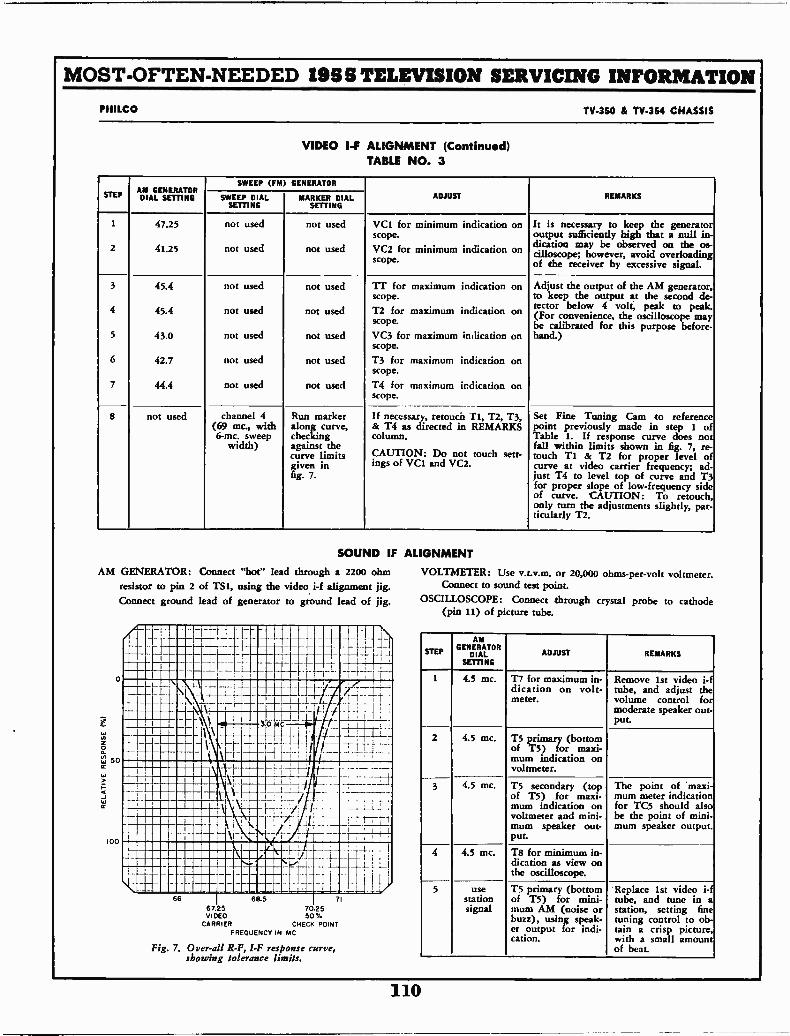
MOST -OFTEN -NEEDED 19S S TELEVISION SERVICING INFORMATION
PHILCO TV -350 & TV -354 CHASSIS
VIDEO I -F ALIGNMENT (Continued)TABLE NO. 3
STEPAM GENERATORAM
SETTING
SWEEP (FM) GENERATOR
ADJUST REMARKSSWEEP DIALSETTING
MARKER DIALSETTING
1 47.25 not used not used VC1 for minimum indication onscope.
It is necessary to keep the generatoroutput sufficiently high that a null in -
22 41.25 not used not used VC2 for minimum indication onscope.
dication may be observed on the os-cilloscope; however, avoid overloadingof the receiver by excessive signal.
3 45.4 not used not used TI' for maximum indication onscope.
Adjust the output of the AM generator,to keep the output at the second de-tector below 4 volt, peak to peak.4 45.4 not used not used T2 for maximum indication on
scope. (For convenience, the oscilloscope maybe calibrated for this purpose before -
5 43.0 not used not used VC3 for maximum indication onscope.
hand.)
6 42.7 not used not used T3 for maximum indication onscope.
7 44.4 not used not used T4 for maximum indication onscope.
8 not used channel 4(69 mc., with6-mc. sweep
width)
Run markeralong curve,checkingagainst thecurve limitsgiven infig. 7.
If necessary, retouch ri, T2, T3,& T4 as directed in REMARKScolumn.
CAUTION: Do not touch sett-ings of VC1 and VC2.
Set Fine Tuning Cam to referencepoint previously made in step 1 ofTable 1. If response curve does notfall within limits shown in fig. 7, re -touch Ti & T2 for proper level ofcurve at video carrier frequency; ad -just T4 to level top of curve and T3for proper slope of low -frequency sideof curve. CAUTION: To retouch,only turn the adjustments slightly, par-ticularly T2.
SOUND IF ALIGNMENTAM GENERATOR: Connect "hot" lead through a 2200 ohm
resistor to pin 2 of TS1, using the video i-f alignment jig.Connect ground lead of generator to ground lead of jig.
0
100
111111 1
-OXIIII -- - -
mmoms 11 riiiii
--!--1
_cMIMI=
.1._ _III -1--.
;
I - -,-1-1-::71_,
, ir i-t-t,-t1_,=7,i:
NMI 1 MN1.o
I -r-i- -kaliM11111E1M1111
1 ,.
1 III IMOM MNM _I
! fsli111111.11KM MI M
.4. .., I.. . /
- --. ./ i --"-":--,
E_NIIIIIIME=MMIIN
IIINIMENIMMII ,t , , , 1-1-7-1'MENIMEN1111111111111116.
MIN111011111111111114
.j,4._: _i_ 1
----4-r-7-7-1groommommums
111M.11 .91111111.41111111
I'MO , 4._ 1 ,
!
.
68.5 716667.25 70 25VIDEO 50%
CARRIER CHECK POINTFREQUENCY IN MC
Fig. 7. Over-all R -F, I -F response curve,showing tolerance limits.
VOLTMETER: Use v.t.v.m. or 20,000 ohms -per -volt voltmeter.Connect to sound test point.
OSCILLOSCOPE: Connect through crystal probe to cathode(pin 11) of picture tube.
STEP
AMGENERATOR
DIALSETTING
ADJUST REMARKS
1 4.5 mc. T7 for maximum in-dication on volt-meter.
Remove 1st video i-ftube, and adjust thevolume control formoderate speaker out-put.
2 4.5 mc. T5 primary (bottomof T5) for maxi-mum indication onvoltmeter.
_3 4.5 mc. T5 secondary (top
of T5) for maxi-mum indication onvoltmeter and mini-mum speaker out-put.
The point of maxi -mum meter indicationfor TC5 should alsobe the point of mini-mum speaker output.
4 4.5 mc. T8 for minimum in-dication as view onthe oscilloscope.
5 usestationsignal
T5 primary (bottomof T5) for mini-mum AM (noise orbuzz), using speak-er output for indi-cation.
Replace 1st video i-ftube, and tune in astation, setting finetuning control to Ob-tain a crisp picture,with a small amountof beat.
110
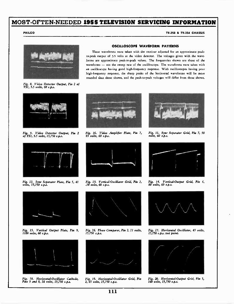
MOST -OFTEN -NEEDED 1955 TELEVISION SERVICING INFORMATION
PHILCO TV -350 & TV -354 CHASSIS
OSCILLOSCOPE WAVEFORM PATTERNS
These waveforms were taken with the receiver adjusted for an approximate peak -to -peak output of 3.5 volts at the video detector. The voltages given with the wave-forms are approximate peak -to -peak values. The frequencies shown are those of thewaveforms - not the sweep rate of the oscilloscope. The waveforms were taken witha oscilloscope having good high -frequency response. With oscilloscopes having poorhigh -frequency response, the sharp peaks of the horizontal waveforms will be morerounded than those shown, and the peak -to -peak voltages will differ from those shown.
Fig. 8. Video Detector Output, Pin 2 ofTS1, 3.5 volts, 60 c.p.s.
Fig. 9. Video Detector Output, Pin 2 Fig. 10. Video Amplifier Plate, Pin 7, Fig. 11. Sync Separator Grid, Pin 7, 38of TS1, 3.5 volts, 15,750 c.p.s. 83 volts, 60 c.p.s. volts, 60 c.p.s.
Fig. 12. Sync Separator Plate, Pin 5, 41volts, 15,750 c.ps.
1
Fig. 13. Vertical -Oscillator Grid, Pin 2, Fig. 14. Vertical -Output Grid, Pin 6,.34 volts, 60 c.p.s. 80 volts, 60 c.p.s.
Fig. 15. Vertical Output Plate, Pin 9, Fig. 16. Phase Comparer, Pin 2, 11 volts, Fig. 17. Horizontal Oscillator, 43 volts,1100 volts, 60 c.p.s. 15,750 c.ps. 15,750 c.p.s. test point.
Fig. 18. Horizontal -Oscillator Cathode, Fig. 19. Horizontal -Oscillator Grid, Pin Fig. 20. Horizontal -Output Grid, Pin 5,Pins 3 and 8, 18 volts, 15,750 c.p.s. 2, 65 volts, 15,750 c.p.s. 160 volts, 15,750 c.p.s.
111
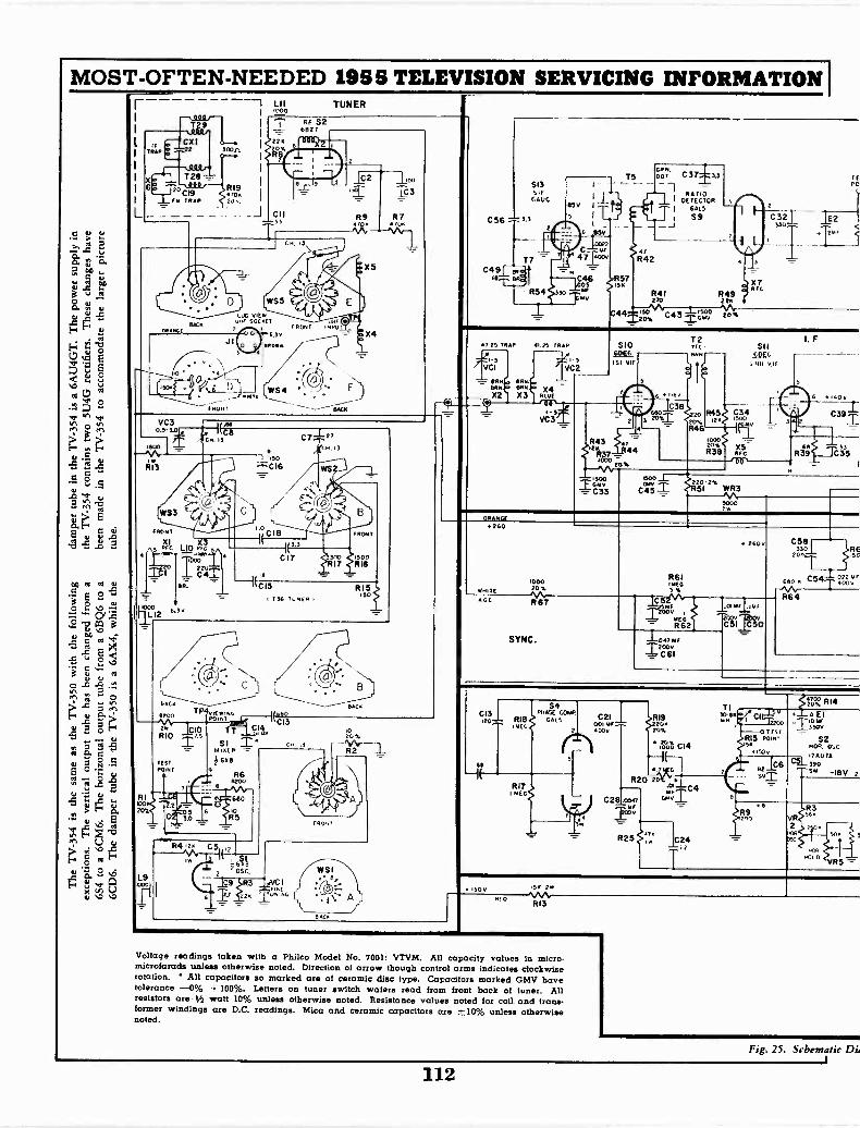
MOST -OFTEN -NEEDED 1955 TELEVISION SERVICING INFORMATION I
C 70..
>..8-84 =a. I,' c.H °a
c.
00. .,
?,
. 1' 5
ti pa 0
4r. '15 41.
0 re;
g.5 2 .5.
2 P.,5
E.
EO
r-E
-5 _o 3
(6 NI IN 1.7,
E .7;O E
750-0 r3_g `or rs
%.7
E 72 '4
E7.: 41 1?,
.00 aga
2.2 1U 7 O1 .9.o
-5 ,CL
EF6
6
O 4
e'V :".2
TRAP
6
L
T 9
T28
"CTRAFM
19P
BACK
30311.
RI900.
J1
'O
p 0_
Lit0300
TUNER
2220
_J CII
1.30so.
WS4
RE 5268Z7
2 II
E
VC30.5-3.0. KC
33.soo
P13
OR.
LI2 6"
RI
I.0
7
.150
C18 FRONT
3
C17RI7300 500
RI6
KCI5 R15136 TUNER 1
150
NACA
R4vrioN.6200T 1E
KM7.1 PIPsCI325 CIORIO
1 ST
201141
L9
_000TI
.2
0
BAC.
SI CH .5AIIREP -+OM
9R6
11200
680
R50
R412. c5 ,
61.I32 MC,
203.
R2
FRO.,
9 3 VC IFINE
Tumm.C.
W SI
BAC.
S13SIFC AUG
C56 -Ls
C4918
211
R54
Sly I
5 ILL _
6 soy
4714F
400V
RM.
T5 DOT C37 3.3
-1, RATIODETECTOR
TI 661.5J I S9
sC46 ,R57
1511
MV
47R42
R41270
R492217
X7RFC
C 321330
TFPC
-12
C44...2so sooC783 ZGMV
47,25 TRAP
VCI
eA 5077OR
X2 X3
41.25 TRP
_2' s7VC2
OLLIE4
5VC3
5106056ISE RIF
R4344
rot
R46
T2NFL -
OWN
6TuITv38
680 20 R45 C3432o% 24 1500
ry
10002038
R
x5FcR
I. F.
6 140v
C391
R391JC3S
oeoan
C452202%
51 WaR3
5000
ORANGE260
IT
GC
100020%6
SYNC.
4 260v
P61thIEG5%
C
V
8866R62
-.04744F
;.1C11
C581330 REi5C
R64
CI3120- R18
MEC
S4Ptol&L cow
cm.;
P17MEG
C2Iow ..--.
0v
P19200
20%
.0°00 C14
TI30-60Mm
4207C2 RI4
"ci2200
07731R15 POINT5F
150v
A. 6 82
R20 20
C28 con
R25 C24--ca
6
. AEI
TCA
52NOR.
cLI,29A: 7A
sr -I8V 2
R9VR2
Cvl'Sc
.0.11"°L° VR5
15011RED
R13
Voltage readings taken with a Philco Model No. 7001: VTVM. All capacity values in micro-microfaracis unless otherwise noted. Direction of arrow though control arms indicates clockwiserotation. All capacitors so marked are of ceramic disc type. Capacitors marked GMV havetolerance -0% +100%. Letters on tuner switch wafers read from front back of tuner. Allresistors are V2 watt 10% unless otherwise noted. Resistance values noted for coil and trans-former windings are D.C. readings. Mica and ceramic capacitors are ±10% unless otherwisenoted.
Fig. 25. Schematic DJ
112
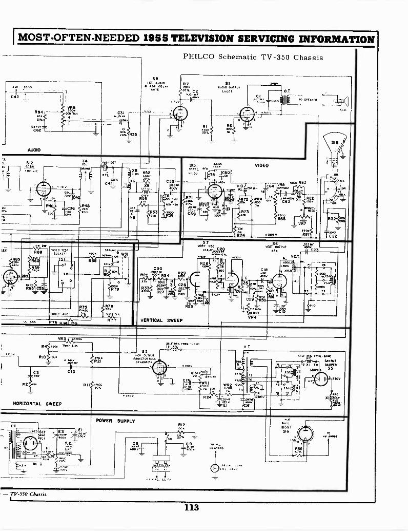
I MOST -OFTEN -NEEDED 195S TELEVISION SERVICING INFORMATION
PHILCO Schematic TV -350 Chassis
.IMP 2000
C42
R8410020%
.047 tarC62
AUDIO
VR82500
CONTROL
R35
S81ST. AUDIO
GC DELAY
4 C
R7220020% C2
0.01 korir11_,1
RI470020%
SIAUDIO OUTPUT
60601
R620101
7
2400
CI.022 hof
G60 v
42600
TO SPEAKER
32.0.
IL $12GCB&
3.D VIE
20
6 ,Geu20%
2v
R40
220
C
74TEL
C36R22048
1530 20%cMF
.164 GETKG.
DTL
cat]
X!h R523 6800
207.X6
w1
48
X9
GREYR55210
R53700
C55L.061561F400V
76-400NR
RED 0E0
3900R56
SIS2007 Of
V1UCU
R7I -
_11270.01 Oar
0;97 22
4.5 beGTRAP
Ts C60As
I .00
VIDEO
v TEL 34.-L
64R72 WR490 5030
row
P 70o gl300/ ',"
R73474
330
R74
VR8 IAA R83(ANTR0ST
0400
r610 0 V )ri7 R82504
2200R85 .00t
VR7=-
troaNESS
2200R8I
I ItOR.
BR
R32
Tr22
470.
30?
20.40
-3 6 85V
R686800R60
R595900
',DEO TESTSOC,ET
8200R63 C5L,
IS I
se
2
ST 000014700
058FRINGE
R. RPM
oXX -
R79
TUNER AGE
R75.0 MEG sR78tsit
510. 5%
P. AGO R76 to MEG %
C30.0047 MFR29R22 R34 ono27
0226. 31 C26R3 200v I .CO2.SETO C271 tcOV
VERTICAL SWEEP
S7VERT 05C
12 4U7.0,119
429 4f0v-
R
0
600 20DI
Ft.13 = =
MEG
RT SAEG0
+7.2v
1530
9
C
25 6MF
RAM
C29
S6 ,022VENT OUTPUT 4000
654 __1( C23
C18
4000
.047 .0
R30wIa
X2,3 MEGHEIGHT
VR4
V.O.T.
1000360v
10010OI 0
R 0
P9
7525
25n.000
4
10
--I
470 0R21
IT2
HORIZONTAL SWEEP
$3HUN OUTPUT
680601 OR 6C00OR 6806014
A 2600
1.2,75. FRED.- 1.0 MC73
01400
12.502w
C 17ta
v
H T
SELFRFCRIM. FREI,- 609.6
66040704111.20
S5
250V
REGRERES
RT.
CO $1756w4RECT6
Fl0.7 AMP
EE3 l
6.30PUSt205." 47 M1Z 1000
O 130 Mr71350V
F. C. =59n1.211=
POWER SUPPLY
INTER LOC.
.17 v At. Lu 1,
RI2100K
TO ALLHE AT E 05
cut LAND
RECO.
IB3GT516 ,
R564.70.
TOHv 4084E
- TV -350 Chassis.
113
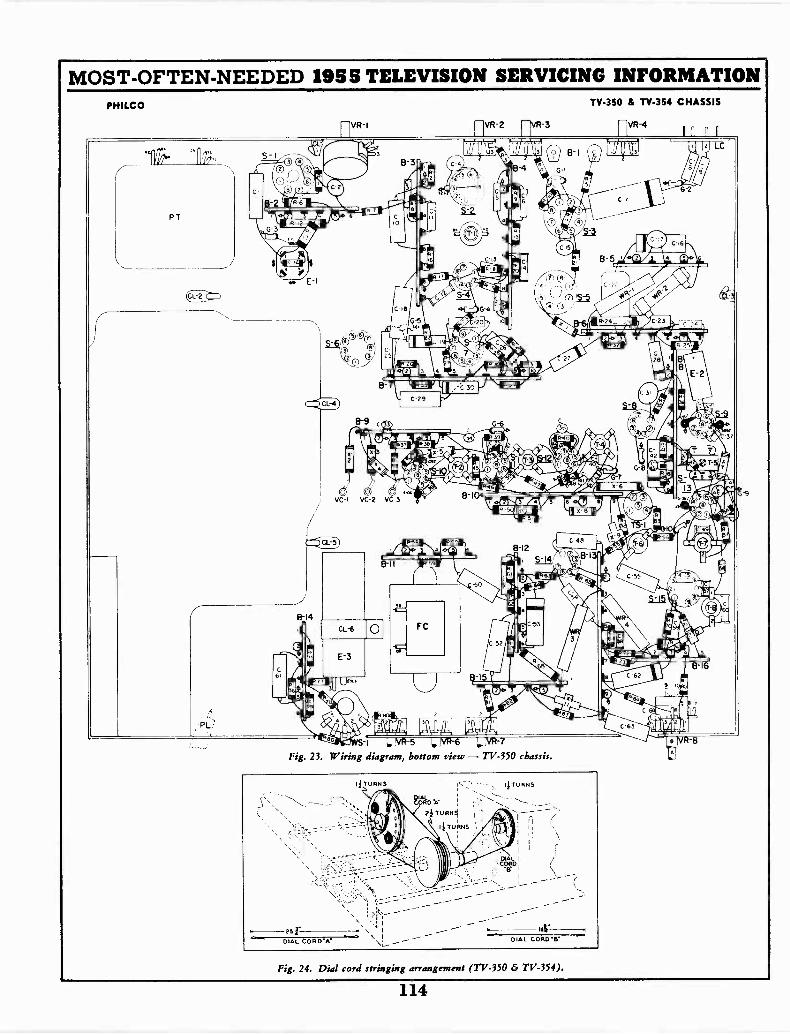
MOST -OFTEN -NEEDED 1955 TELEVISION SERVICING INFORMATIONPHILCO
Fig. 23. Wiring diagram, bottom view - TV -350 chassis.
TV -350 & TV -354 CHASSIS
Fig. 24. Dial cord stringing arrangement (TV -350 & TV -354).
114
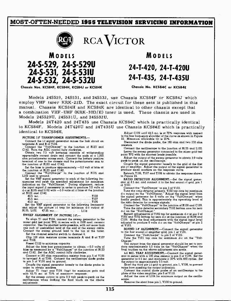
MOST -OFTEN -NEEDED 1955 TELEVISION SERVICING INFORMATION
RCAVICTORMODELS
24-S-529, 24 -S -529U24-S-531, 24 -S -531U24-S-532, 24 -S -532U
Chassis Nos. KCS84F, KCS84H, KCS84J or KCS84K
MODELS
24-T-420, 24 -T -420U
24-T-435, 24 -T -435UChassis No. KCS84C or KCS84E
Models 24S529, 24S531, and 24S532, use Chassis KCS84F or KCS84J whichemploy VHF tuner KRK-22D. The exact circuit for these sets is published in thismanual. Chassis KCS84H and KCS84K are identical to other chassis except thata combination VHF -UHF (KRK-30D/E) tuner is used. These chassis are used inModels 24S529U, 24S531U, and 24S532U.
Models 24T420 and 24T435 use Chassis KCS84C which is practically identicalto KCS84F. Models 24T420U and 24T435U use Chassis KCS84E which is practicallyidentical to KCS84H.
PICTURE I -F TRANSFORMER ADJUSTMENTS. -Connect the i-f signal generator across the link circuit on
terminals A and B of T104.Connect the "VoltOhmyst" to the junction of R123 and
C142. Turn the AGC control fully clockwise.Obtain two 7.5 volt batteries capable of withstanding
appreciable current drain and connect the ends of a 1,000ohm potentiometer across each. Connect the battery positiveterminal of one to the chassis and the potentiometer arm tothe junction of R123 and C142.
Set the bias to produce approximately -5.0 volt of bias atthe junction of R123 and C142.
Connect the "VoltOhmyst" to the junction of R135 andL102 and to ground.
Set the VHF signal generator to each of the following fre-quencies and peak the specified adjustment for maximumindication on the "VoltOhmyst." During alignment, reducethe input signal if necessary in order to produce 3.0 volts ofd -c at R135 and L102 with -5.0 volts of i-f bias at the junctionof R123 and C142.
44.5 mc TI0845.5 mc T10743.0 mc. TI06
Set the VHF signal generator to the following frequencyand adjust the picture i-f trap for minimum d -c output atR135, L102. 47.25 mc. L118
SWEEP ALIGNMENT OF PICTURE I -F.-To align T1 and T104, connect the sweep generator to the
mixer grid test point TP2, in series with a 1500 mmf. ceramiccapacitor. Use the shortest leads possible, with not more thanone inch of unshielded lead at the end of the sweep cable.Connect the sweep ground lead to the top of the tuner.
Set the channel selector switch to channel 4.Clip 330 ohm resistors across terminals A and B of T107
and T108.Preset C122.to minimum capacity.Adjust the bias box potentiometer to obtain -5.0 volts of
bias as measured by a "VoltOhmyst" at the junction of R123and C142. Set the AGC control fully clockwise.
Connect a 180 ohm composition resistor from pin 5 of V106to terminal A of T106. Connect the oscilloscope diode probeto pin 5 of V106 and to ground.
Couple the signal generator loosely to the diode probe inorder to obtain markers.
Adjus' Tl (top) and T104 (top) for maximum gain andwith 45.75 mc. at 75% of maximum response.
Set the sweep output to give 0.3 volt peak -to -peak on theoscilloscope when making the final touch on the aboveadjustment.
Adjust C122 until 42.5 mc. is at 70% response with respectto the low frequency shoulder of the curve as shown in Figure23. Maximum allowable tilt is 20%.
Disconnect the diode probe, the 180 ohm and two 330 ohmresistors.
Connect the oscilloscope to the junction of R135 and LI02.Leave the sweep generator connected to the mixer grid test
point TP2 with the shortest leads possible.Adjust the output of the sweep generator to obtain 3.0 volts
peak -to -peak on .the oscilloscope.Couple the signal generator loosely to the grid of the first
pix i-f amplifier. Adjust the output of the signal generator toproduce small markers on the response curve.
Retouch T106, T107 and TI08 to obtain the response shownin Figure 24.
RATIO DETECTOR ALIGNMENT. -Set the signal gener-ator at 4.5 mc. and connect it to the first sound i-f grid, pin 1of V101.
Connect the "VoltOhmyst" to pin 2 of V103.Tune the ratio detector primary, T102 top core for maximum
d -c output on the "VoltOhmyst." Adjust the signal level fromthe signal generator for 6 volts on the "VoltOhmyst" whenfinally peaked. This is approximately the operating level ofthe ratio detector for average signals.
Connect the "VoltOhmyst" to the junction of R108 and C109.Tune the ratio detector secondary T102 bottom core for zero
d -c on the "VoltOhmyst."Repeat adjustments of T102 top for maximum d -c at pin 2 of
V103 and T102 bottom for zero d -c at the junction of R108 andC109. Make the final adjustments with the signal input leveladjusted to produce 6 volts d -c on the "VoltOhmyst" at pin 2of V103.
SOUND I -F ALIGNMENT. -Connect the signal generatorto the first sound i-f amplifier grid, pin 1 of V101.
Connect the "VoltOhmyst- to pin 2 of V103:Tune the T101 top core for maximum d -c on the "Volt-
Ohmyst."The output from the signal generator should be set to pro-
duce approximately 6.0 volts on the "VoltOhmyst" when thefinal touches on the above adjustment are made.
4.5 MC. TRAP ADJUSTMENT. -Connect the signal gener-ator in series with a 100 ohm resistor to pin 2 of V109. Set thegenerator to 4.5 mc. and modulate it 30% with 400 cycles. Setthe output to approximately 0.5 volt.
Short the third pix i-f grid to ground, pin 1, V108, to preventnoise from masking the output indication.
Connect the crystal diode probe of an oscilloscope to theplate of the video amplifier, pin 9 of V110.
Adjust the core 'of L104 for minimum output on the oscillo-scope.
Remove the short from pin 1, V108 to ground.
115
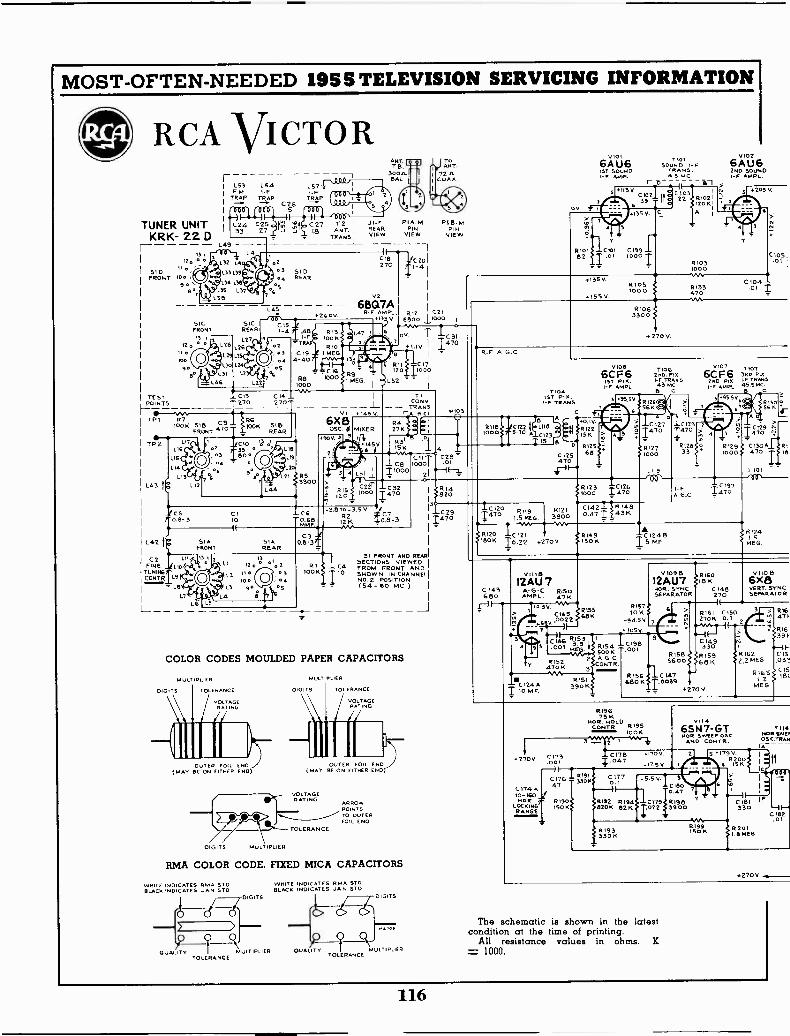
MOST -OFTEN -NEEDED 195S TELEVISION SERVICING INFORMATION
gli; RCA VICTOR
TUNER UNITKRK- 22 D
510FRONT
1
L53F.2.1
TRAP
1
1
L49 -
1.54I- FTRAP
SICFRONT
120
we90
SICREAR
L27126
L57I -F
TRAP
5
.2.5 SI D04 REAR
v2
LAS - 650.7A2609 R -F AMPL
133 VC15.41-4 ft L45 6,5
T11 F100KRIO
03 C19 1 MEG04
o5
TEST _ C13 C14 _POINTS T 270 270
V14.TPI
-
1515 1 176FRONT
00K SIBREAR
bI 4110
04703 frco*
TP
L43
142
12FINE
TuNIFIGCONTR.
- LB1
0090
76
. C16RB 1000000
C1 -CG10 -0.68
IMMF
C3S1A 5111 0.5 -3, -
FRONT REAR13
120 III! 0'. 21.2 110
$0 o
LI go4
- 1
C27 T2 I J1-, PI A M.8 ANT. I REAR PIN
TRANS VIEW VIEW
clIa
-270 11,_,2C20 I
- 1
iT11.321.01
CSIDm
5 IVO I1CO 'Jo
L52 " I
ANT.TB
300.12.BAL
TICONY
TRANS-1151
000 14701
c.a.SECTIONS
51 FRONT AND REAR
IOON 10 ,B.,2r1/N IN CHAINED
( 54 - 60 MC.)
COLOR CODES MOULDED PAPER CAPACITORS
MULTIPLIER
OUTER FOIL END(MAY BE ON EITHER END) (MAY BE ON OTHER ENO
MULTIPLIER
DIGITS TOLERANCE
VOLTAGERATING
DIGITS
OUTER FOIL END
VOLTAGERATING
:17;7TO OUTERFOIL ENO
Jam -TOLERANCE
MOLT !FLIER
RMA COLOR CODE, FIXED MICA CAPACITORS
WHITE INDICATES RMA STOSLACK INDICATES JAN STO
(I)
O UALiTV MULTIPLIER QUALITY' ? RMULTIPLIERTOLERANCE
WHITE INDICATES RMA STOBLACK INDICATES JAN STO
DIGITS DIGITS
TOLERANCE
ToANT.
720.COAX
F B MP121
VIEW
614820
--C 211470
C 174 A10-65NOR
LOCKING'RANGE
R -F A_G_C
IC1201470 1751366-TRI20 -I-C 121
518011 10,22 +2209
C143880
9111612AU7
Rt219800
E
A- G -C 6150AmP1- 4716
.052V V*4.C145
RISS68160022
61534
V 101
6A U6TNT SOUNDI -F AS,
00135 V._ C
R62101 C101 C199
-T .01 1000
0149150 K
9 5 ,19.41
470 K 3 mmwN.2 cSARiG50T4KCR6152
V104
6CF61ST PIXi-F AMPL
- C124 AT ict Air
R 15139016
RI571016
.94.52/.
V 105
81198.001
R1063300
0270V.
71062m0. PiXIF TRAIN45 MC.
C
C1271470
I- FA.G C
C 1248I 5 "F
r-
T101SOUND I -F
TRANS4.5 MC
C10322 C2g12L1
4_J
v,026AU62ND. SOUNDI -F ANAL.
.205V.
C104 -.01
V107
6CF6 3RD- FIX2ND INX I.F TRANS.I -F AMPL 45.5 MC.
R 1505611 4-
7 9
70
C41-7gAr 191
U01
R1241.5MEG.
V1095 R16. v110512AU7 £I/3K 6X8NOR. SYNC 1148 VERT. SYNCSEPARATOR 270 SEPARATOR
- IIRISI C15027011 0.1
:17"XC149330
6158 R1595600 6811
R156 1147650 IX T.0039 2
2709
( NR16
m 471
If; t96
2.2 MEG- .033R162 CIS
R165(%5(1.2
MEG.
R196755
NOR. HOLDCONTR 19195
100K
34-202700 501,;?
1- 176 = 330147
164°4
VIIA6SN7-GTNOR. SWEEP OSC
AND CONTR.
C175 '703T.047 -17.50
11770.1 5.59
Ciect
N902 294K 17291:99080
0.4.7
T 114MORAINE(OSE.TRAN
Z. 5.179V.R200
15K
8193330 K
IC
1181330 -IT-4
C162.01
61991506 R2o1
1.6 MEG
+270 V
The schematic is shown in the latestcondition at the time of printing.
All resistance values in ohms. K= 1000.
116

MOST -OFTEN -NEEDED 1955 TELEVISION SERVICING INFORMATION
T102RATIO DET
TRANS4.5 MC
I .154
+4.11
R10747
R10410 K
270V.
0106
SC B6SRD. Po(
ANAPL
CIRCUIT SCHEMATIC DIAGRAM ICCS84F OR ICCS841
V 103
6AL5RATIO
C1074 -470
-o 1100.47 +
1Ri10101,
+11.8V.
01,704 R108 IC188470 I 1470 39K 19022
5101 -FRONT 5101 -REAR12
T 1004TH Pu(I.FTRANs44.5 MC.
B c
C.Og 8
R1323.9 MEG
RI66 V11242200 12AU7
8167 SYNC 8169 0157OUTPUT 2, .0027
.84 v 6111C155 c-154 1815220 0082 601
2
0521
109412AU7 1102
2N0 Pix 120 M011DET (50NRED
-C134T 10
- C15382
c 185.001
virs-6CD6-GsoR. SWEEP
OUTPUT
CI 59.00398172
1.5 MEGVERT.HOLD
C167 RZOG
=1
.000" 47 ;73
-I 3 o C 113
z '°1-0 65Vt 2 I
RIII
R 112BI MEGVOL
CONT R11=1
.J101pHONOINPUT
® 4_
to l
R113IN 1215
L1044.5 MC.TRAP
v,046AV61ST AUDIO
Ampl
7 C116.01
OV
=-11
4 3
f:F75333K l -E. 20 MF.
5
0027
560 ;_C1178270 =4-
0105GAGS
AUDIOOUTPUT
V 110 A L1056X8 CI37 250 MU.I1VIDEO 47 0415.11211AmpL
11
19811. C118.0027
RI35 9
3900 C135 d --47 17.
1103250 RUN.GRN
V 11213
12AU7VERT SWEEP
oSc DISCO
3
6173
3.1HEIGHTcONTR.
C162 RI77.047 15 K
0160 R178
0.1 +2700
-C L109 C144WIDTH 180
V117
FIRS 6AU4.047 3 -GT
47 C190 1110 DAMPER270 15 mos
7
1C193 R136$.0035T ,20.=
8137 R13I2K 27K
+ 138 v.
16K)
R2I5
+270 V.
18,31g
T103AUDIOOUTPUTTRANS.
BLu
1
SPEAKER
A RED__C 119E120 NIT
+210V.
V1114
12AU7CI38 VIDEO
0.1 OUTPUT
225 V1106250
,E*
BLK BLK 7 12.50
214t470/1 814.4 0139
180 027
euNcrooN SW. Slot FRONT ANDREAR VIEWED FROM FRONT WITHCONTROL SHAFT IN MAN. COUNTERCLOCKWISE POSITION (P05.N0.1)
P05 I - TV. MIN HIGHS.I - TV NORMAL.3 TV. MIN. LOWS4- R1407.10. ',AM. HIGHS5- P1.1050. NORMAL6 _ PHONO. MIN. LOWS.
L106120 MU 1.1
BLU C1410.1
81405600 R1124
10KPIX.
CONTR.
V 113
R176 CI63 C167 8180 6A 0-SSWEEP
2215 .015 .027 2215 OUTPUT
C11 6110027 0164.022-481813315
cT.068
RI7912K
- 3 2
6146270
R17422 K
L107500 MU H
GRN.WRT
7500
.4270 V. la
CI24C30 MF.
,422015
+2700 R145200 K
BRIGHTNESSCONTR.
T112VERT. SWEEPOUTPUT TR.
1T5L711-
75VI -7
8152 4 3470N
17 1832.5 MEGVERT.LiNECONTR.
R185 +390K
R184390 K
VII6183-6T
RECT18.350V
R2I727K
C 188.047
820727K
Direction of arrows at controls indi-cates clockwise rotation.
61211
2530,
p102 -DEFLECTION YOKE PIN VIEW
RED
CI92 VERT. COILS I
120 1.113 L114 I
R2I3GRNtoo
R2II R212 I560 560
&K. RED
2
3
R,983300
V
rg7K
0118
24CP4AKINESCOPE
GLASSCOATING
CHANNELIND. LAMP
13RN
C 1690.1
0168047 R,89 IC170
157 1 10047
V119 V120
5U4 -G 5Y3-GTRECT RECT 1113
j102.FREARVIEW
ehC1194 CI17480 MF 100 MEI
GRN. HEW.
TEL 511
6R.VEL SA
B1
.270 VSUPPLY
W 108(1)5641
Sio3- INTE E1014
102
24-S-529, 24-S-53124-S-532
Figure 21 -Sound I -FResponse
4.5 MC
Figure 22 -Ratio Det.Response
42.5 MC70%
1154.60A,SUPPLY
45.75 MC75%75%
47258C
Figure 23-KRK22D
T1 and T104Response
Figure 24 -Overall I -F
Responsewith KRK22D
(For voltage information see the next three pages)
All voltages measured with "Volt-Ohmyst- and with no signal input. Volt-ages should hold within ±20% with117 v. a -c supply.
Schematic DiagramKCS84F or KCS84J
117
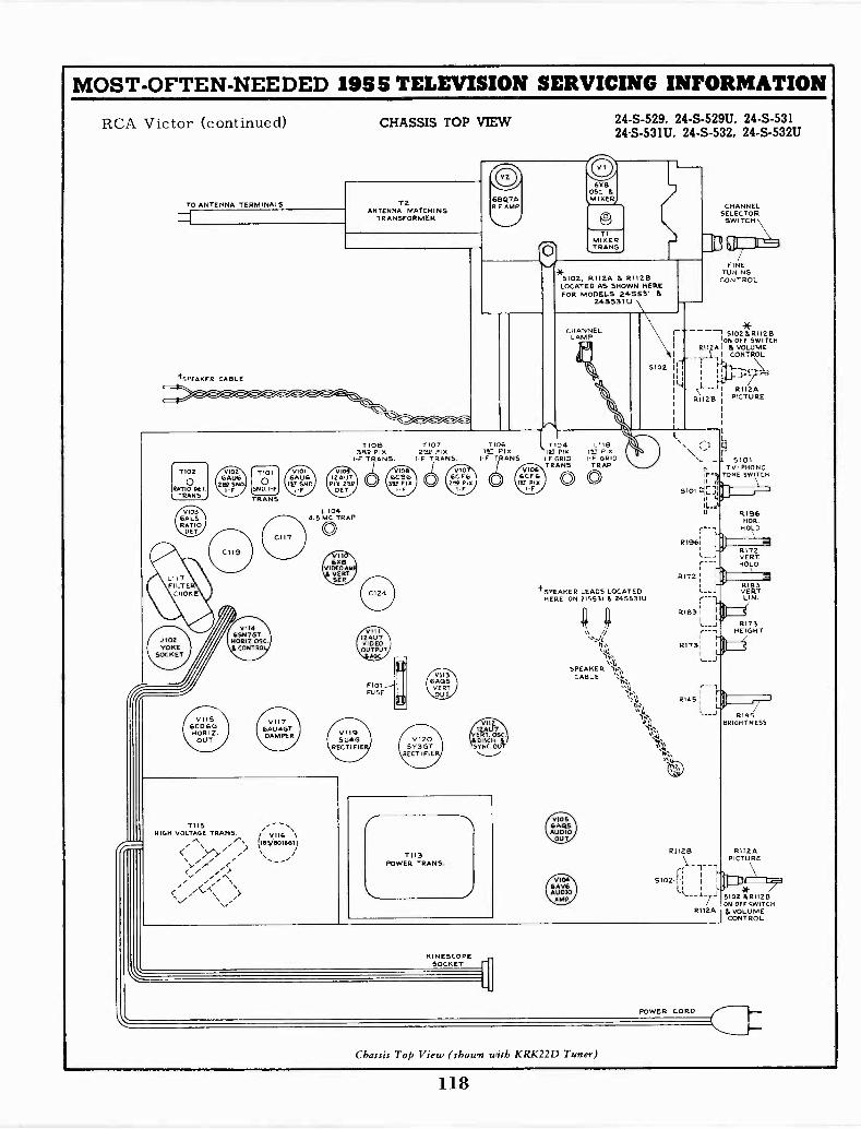
MOST -OFTEN -NEEDED 1955 TELEVISION SERVICING INFORMATION
RCA Victor (continued)
TO ANTENNA TERMINALS
tsPEAKER CABLE
CHASSIS TOP VIEW
\"... .1*.
24-S-529, 24 -S -529U, 24-S-53124 -S -531U, 24-S-532, 24 -S -532U
6X805C 15
6BQ7A IMIXER7R.F AMP.
Tio2
RATIO0 DE7TRANS.
7115HIGH VOLTAGE TRANS.
//'4>
TIOB3912 PIX
1.F TRANS.
L1044.5 MC TRAP
0
710723F PIX
I -F TRANS.
TWAYET PIX
I.F TRANS.
VII212AU7ERT. 05C.DISCH 6
SYNC. OUT
7113POWER TRANS.
KINESCOPESOCKET
TIMIXERTRANS.)
5102, R1126 P. R1125LOCATED AS SHOWN HEREFOR MODELS 245531
248531U
CHANNELLAMP
5102
7 04 L118IV pm IN! PIXF GRID 1F GRID
TRANS TRAP0 0
CHANNELSELECTOR
SWITCH \
FINETUNINGCONTROL
5102 IR1122,10NOFF SWITCH
R112A1 L VOLUMEI CONTROLif -I-
I I 2II
' it -.7I R112A
RI128 I PICTURE
RI96NOR.
HOLD
R1961 :131I 1 R172- VERT
T HOLD
RI72 : 3 2t SPEAKER LEADS LOCATED L__J VERT
RIBS
HERE ON 215531 6 245531U LIN.
4 4R163 i 1
I
L__J R173
(\\ /,1 r----1 HEIGHT
RI731 ) 74
sq., 1
L.); ...---JSPEAKER '5,-",
CABLE sa,,/,
,..,.
'ii:,s16
.,...
II,0i34
P'S
s 1.1
5101n TVPHONO;F.T TONE SWITCHII d
5101:144'"
5102--1:II
1
8145 1
RIASBRIGHTNESS
R1I2APICTURE
I 7.-1 5102 P.R112BONOFFswiTCH
R"ZA & VOLUMECONTROL
POWER CORD
Chassis Top View (shown with KRK22D Tuner)
118
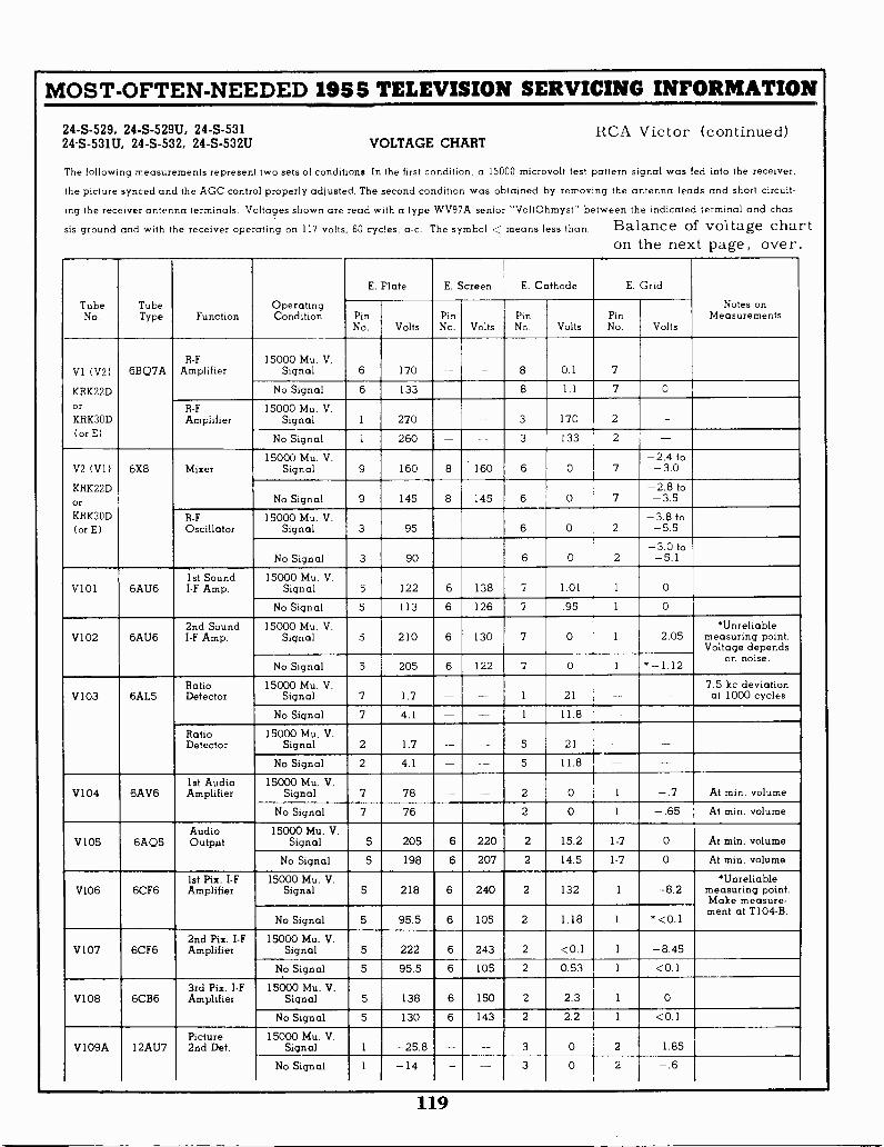
MOST -OFTEN -NEEDED 1955 TELEVISION SERVICING INFORMATION
24-S-529, 24 -S -529U, 24-S-531 RCA Victor (continued)24 -S -531U, 24-S-532, 24 -S -532U VOLTAGE CHART
The following measurements represent two sets of conditions. In the first condition, a 15000 microvolt test pattern signal was fed into the receiver,
the picture synced and the AGC control properly adjusted. The second condition was obtained by removing the antenna leads and short circuit-
ing the receiver antenna terminals. Voltages shown are read with a type WV97A senior -VoltOhmyst- between the indicated terminal and chas-
sis ground and with the receiver operating on 117 volts, 60 cycles, a -c. The symbol < means less than. Balance of voltage charton the next page, over.
TubeNo.
TubeType Function
OperatingCondition
E. Plate E. Screen E. Cathode E. Grid
Notes onMeasurementsPin
No. VoltsPinNo. Volts
PinNo. Volts
PinNo. Volts
VI (V2)
KRK22D
orKRK3OD
(or E)
6BQ7AR -F
Amplifier15000 Mu. V.
Signal 6 170 8 0.1 7
No Signal 6 133 8 1.1 7 0
R -F
Amplifier15000 Mu. V.
Signal 1 270 3 170 2
No Signal 1 260 - 3 133 2
V2 (V1)
KRK22DorKRK3OD
( or E)
6X8 Mixer15000 Mu. V.
Signal 9 160 8 160 6 0 7-2.4 to-3.0
No Signal 9 145 8 145 6 0 7-2.8 to-3.5
R -F
Oscillator15000 Mu. V.
Signal 3 95 -- - 6 0 2-3.8 to
-5.5
No Signal 3 90 - 6 0 2-3.0 to
-5.1
V101 6AU61st SoundI -F Amp.
15000 Mu. V.Signal 5 122 6 138 7 1.01 1 0
No Signal 5 113 6 126 7 .95 1 0
V102 6AU62nd SoundI -F Amp.
15000 Mu. V.Signal 5 210 6 130 7 0 1 -2.05
*Unreliablemeasuring point.Voltage depends
on noise.No Signal 5 205 6 122 7 0 1 * - 1.12
V103 6AL5RatioDetector
15000 Mu. V.Signal 7 1.7 - - 1 21
7.5 kc deviationat 1000 cycles
No Signal 7 4.1 1 11.8 --RatioDetector
15000 Mu. V.Signal 2 1.7 5 21
No Signal 2 4.1 - - 5 11.8
V104 8AV61st AudioAmplifier
15000 Mu. V.Signal 7 78 - - 2 0 1 -.7 At min. volume
No Signal 7 76 - 2 0 1 -.65 At min. volume
V105 6AC)5AudioOutput
15000 Mu. V.Signal 5 205 6 220 2 15.2 1-7 0 At min. volume
No Signal 5 198 6 207 2 14.5 1-7 0 At min. volume
V106 6CF61st Pix. I -FAmplifier
15000 Mu. V.Signal 5 218 6 240 2 132 1 -8.2
*Unreliablemeasuring point.Make measure-ment at T104 -B.
No Signal 5 95.5 6 105 2 1.18 1 *<0.1
V107 6CF62nd Pix. I -FAmplifier
15000 Mu. V.Signal 5 222 6 243 2 <0.1 1 -8.45
No Signal 5 95.5 6 105 2 0.53 1 <0.1
V108 6CB63rd Pix. I -FAmplifier
15000 Mu. V.Signal 5 138 6 150 2 2.3 1 0
No Signal 5 130 6 143 2 2.2 1 <0.1
V109A 12AU7Picture2nd Det.
15000 Mu. V.Signal
-
1 -25.8 - 3 0 2 -1.85No Signal I -14 -- -- 3 0 2 -.6
119

MOST -OFTEN -NEEDED 1955 TELEVISION SERVICING INFORMATION
RCA Victor (continued) 24-S-529, 24 -S -529U, 24-S-531VOLTAGE CHART 24 -S -531U, 24-S-532, 24 -S -532U
TubeNo.
TubeType Function
OperatingCondition
E. Plate E. Screen E. Cathode E GridNotes on
MeasurementsPinNo. Volts
PinNo. Volts
PinNo. Volts
PinNo. Volts
V109B 12AU7Horiz. SyncSeparator
15000 Mu. V.Signal 6 260 - 8 160 7 122
No Signal 6 253 - - -- 8 105 7 94.5
V110A 6X8VideoAmplifier
15000 Mu. V.Signal 9 120 8 147 6 .9 7 -1.85
AGC control set fornormal operation
No Signal 9 95 8 138 6 1.35 7 -.6AGC control set fornormal operation
V110B 6X8Vert. SyncSeparator
15000 Mu. V.Signal 3 79 6 .90 2 -26.8
No Signal 3 46.5 -- - 6 1.35 2 -2.1
VII1A 12AU7VideoOutput
15000 Mu. V.Signal 6 231 - - 8 13 7 0
No Signal 6 225 8 12.5 7 0
V 1 I 1 B 12AU7AGCAmplifier
15000 Mu. V.Signal 1 -55 - - 3 135 2 125
No Signal 1 0.3 - - 3 132 2 68,
V 112A 12AU7SyncOutput
15000 Mu. V.Signal 1 83 - -- 3 0 2 -3.28
No Signal 1 84 -- - 3 0 2 -1.3
V112B 12AU7VerticalOscillator& Discharge
15000 Mu. V.Signal 6 80 8 0 7 -63.5 of Vert. hold control
No Signal 6 182 - 8 0 7 -60Voltages shownare synced pix
adjustment
V113 6AQ5VerticalOutput
15000 Mu. V.Signal 5 253 6 262 2 0 1-7 -28.8
No Signal 5 245 6 253 2 0 1-7 -27.5
V114 6SN7GTHorizontalOsc. Control
15000 Mu. V.Signal 2 175 --- - 3 -3.5 1 -21
No Signal 2 170 - - 3 -5.5 1 -17.5
6SN7GTHorizontalOscillator
15000 Mu. V.Signal 5 183 - 6 0 4 -67
No Signal 5 179 -- - 6 0 4 -65
V115 6CD6GHorizontalOutput
15000 Mu. V.Signal Cap ' 8 193 3 22 5 -14
'High VoltagePulse Present
No Signal Cap 8 185 3 20.5 5 -13.5*High VoltagePulse Present
V1161B3GT;8016
H. V.Rectifier
15000 Mu. V.Signal Cap ' 2 & 7 18,700
*High VoltagePulse Present
No Signal Cap * - - 2 & 7 18,350 - *High VoltagePulse Present
V117 6AU4GT Damper15000 Mu. V.
Signal 5 261 - - 3 *
*High VoltagePulse Present
No Signal 5 253 - -- 3 *
*High VoltagePulse Present
V118 24CP4A Kinescope15000 Mu. V.
Signal Cap 18,700 10 428 11 44.5 2 0At averageBrightness
No Signal Cap 18,350 10 425 11 39.5 2 0At averageBrightness
V119V120
5U4G5Y3GT
Rectifiers15000 Mu. V.
Signal 4 & 6 - - - 2 & 8 277 -No Signal 4 & 6 - - 2 & 8 271
120

MOST -OFTEN -NEEDED 1955 TELEVISION SERVICING INFORMATION
RCAVICTORTELEVISION RECEIVERS -MODELS
21 -S -501(U), 21-5-502(U), 21 -S -503(U),
21 -S -504(U), 21-5-505(U), 21 -S -506(U),
21 -S -517(U), 21 -S -518(U), 21 -S -519(U),
21 -S -521(U), 21-5-522(U), 21 -S -523(U),
21 -S -525(U), 21-5-526(U), 21 -S -537(U),
21-5-5251(U), 21-5-5252(U)Chassis Nos. KCS88B, KCS88C, KCS88D, KCS88E, KCS88J,
KCS88K, KCS88L, KCS88M, KCS88V, or KCS88VA
21-5-348K, 21-S-348KU, 21 -S -355K,
21-S-355KU, 21 -S -357K, 21-S-357KU,
21-5-362K, 21-S-362KU, 21-5-367K,21-S-367KU, 21 -S -369K, 21-S-369KU
(Continued below and on the next 7 pages)
The models listed at left without thesuffix "U" are for VHF reception.These models use Chassis KCS88B,KCS88C, KCS88D, KCS88E, KCS88V,with tuner unit KRK-22D. The modelswith the suffix "U" use Chassis KCS88J,KCS88K, KCS88L, KCS88M, or KCS88VA,with VHF -UHF tuner unit KRK-30, andthe circuit for these sets is included.
Chassis Nos. KCS88, KCS88A, KCS88F or KCS88H
Models 21S548 (Ch'assis KCS88N) and 21S548Uwith the television sections very similar to theModels 17S450, 17S451, and 17S453, useChassis KCS87 with tuner KRK-32. Thesesame numbered models with a suffix "U"use Chassis KCS87A with tuner KRK-30A.These are similar sets to the ones coveredin these pages, but use 17HP4 picture tubes.
PICTURE
ON -OFF& SO JNDVOLUME
I ZONTAL(FRED )
HORIZONTALDRIVE
VHFCHANNELINDICATOR
HE IGHT
UHFCHANNELINDICATOR
VHF FINETUNING &UHF TUNING
VHF CHANNELSELECTOR
VERTICAL UHF CHANGEOVERBRIGHTNESS HOLD SW TCH
VERTICAL TV - PHONOLINEARITY TONE SW ITCH
Receiver Operating Controls (UHF -VHF Models).
The models listed at left without thesuffix "U" use Chassis KCS88, KCS88A,which are very similar to Chassis KCS-88B. The models with the suffix "U"use Chassis KCS88F or KCS88H whichare similar KCS88J, but use tunerKRK-31 for combined VHF and UHFreception. In general, this servicematerial is applicable to all models.
(Chassis KCS88P) are combinationssets described on these pages.
ION TRAP MAGNET ADJUSTMENT. -Set the ion trapmagnet approximately in the position shown in Figure 3.Starting from this position immediately adjust the magnet bymoving it forward or backward at the same time rotating itslightly around the neck of the kinescope for the brightestraster on the screen. Reduce the brightness control settinguntil the raster is slightly above average brilliance. Turn thefocus control (shown in Figure 3) until the line structure ofthe raster is clearly visible. Readjust the ion trap magnet formaximum raster brilliance. The final touches of this adjust-ment should be made with the brightness control at the maxi-mum clockwise position with which good line focus can bemaintained.
ION TRAP
FOCUScONTWX
FOCUS MAGNETPOSITIONING ADJUSTMENT
CENTERINGADJUSTMENT
LEVER
* FOCUS CONTROL AND ION TRAP LOCATIONSON VERTICALLY MOUNTED CHASSIS.
Figure 3 -Yoke and Focus Magnet Adjustments
DO NOT INSTALL, REMOVE OR HANDLE THE KINESCOPE IN ANY MANNER UNLESS SHATTER-PROOF GOGGLES ARE WORN. PEOPLE NOT SO EQUIPPED SHOULD BE KEPT AWAY WHILEHANDLING KINESCOPES. KEEP THE KINESCOPE AWAY FROM THE BODY WHILE HANDLING.
121
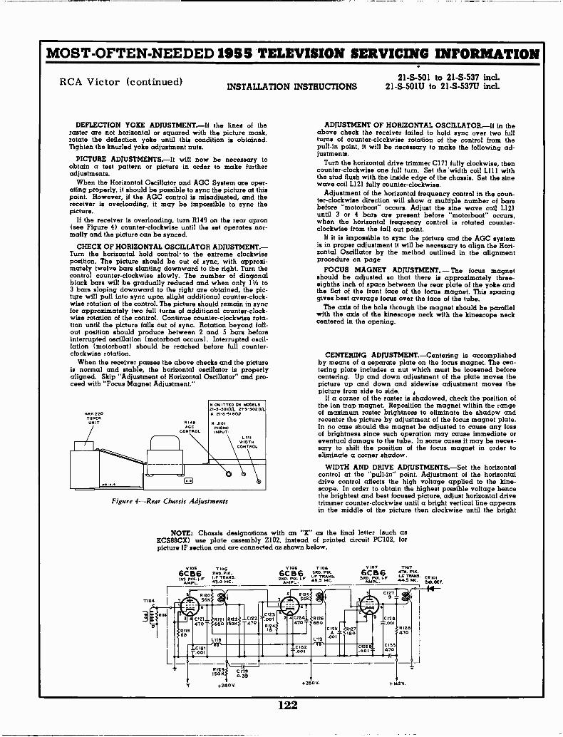
MOST -OFTEN -NEEDED 1955 TELEVISION SERVICING INFORMATION
RCA Victor (continued) 21-S-501 to 21-S-537 incl.INSTALLATION INSTRUCTIONS 21 -S -501U to 21 -S -537U incl.
DEFLECTION YOKE ADJUSTMENT.-If the lines of theraster are not horizontal or squared with the picture mask,rotate the deflection yoke until this condition is obtained.Tighten the knurled yoke adjustment nuts.
PICTURE ADJUSTMENTS.-It will now be necessary toobtain a test pattern or picture in order to make furtheradjustments.
When the Horizontal Oscillator and AGC System are oper-ating properly, it should be possible to sync the picture at thispoint. However, if the AGC control is misadjusted, and thereceiver is overloading, it may be impossible to sync thepicture.
If the receiver is overloading, turn R149 on the rear apron(see Figure 4) counter -clockwise until the set operates nor-mally and the picture can be synced.
CHECK OF HORIZONTAL OSCILLATOR ADJUSTMENT.-Turn the horizontal hold control' to the extreme clockwiseposition. The picture should be out of sync, with approxi-mately twelve bars slanting downward to the right. Turn thecontrol counter -clockwise slowly. The number of diagonalblack bars will be gradually reduced and when only 11/2 to3 bars sloping downward to the right are obtained, the pic-ture will pull into sync upon slight additional counter -clock-wise rotation of the control. The picture should remain in syncfor approximately two full turns of additional counter -clock-wise rotation of the control. Continue counter -clockwise rota-tion until the picture falls out of sync. Rotation beyond fall-out position should produce between 2 and 5 bars beforeinterrupted oscillation (motorboat occurs). Interrupted oscil-lation (motorboat) should be reached before full counter-clockwise rotation.
When the receiver passes the above checks and the pictureis normal and stable, the horizontal oscillator is properlyaligned. Skip "Adjustment of Horizontal Oscillator" and pro-ceed with "Focus Magnet Adjustment. -
OMITTED ON MODELS21-5-501(u), 21 -s -502M,6 21-5-518W)
Figure 4-Rear Chassis Adjustments
7104
ADJUSTMENT OF HORIZONTAL OSCILLATOR.-If in theabove check the receiver failed to hold sync over two fullturns of counter-cicckwise rotation of the control from thepull -in point, it will be necessary to make the following ad-justments.
Turn the horizontal drive trimmer C171 fully clockwise, thencounter -clockwise one full turn. Set the 'width coil L111 withthe stud flush with the inside edge of the chassis. Set the sinewave coil L121 fully counter -clockwise.
Adjustment of the horizontal frequency control in the coun-ter -clockwise direction will show a multiple number of barsbefore "motorboat" occurs. Adjust the sine wave coil L121until 3 or 4 bars are present before "motorboat" occurs,when the horizontal frequency control is rotated counter-clockwise from the fall out point.
If it is impossible to sync the picture and the AGC systemis in proper adjustment it will be necessary to align the Hori-zontal Oscillator by the method outlined in the alignmentprocedure on page
FOCUS MAGNET ADJUSTMENT. - The focus magnetshould be adjusted so that there is approximately three -eighths inch of space between the rear plate of the yoke andthe flat of the front face of the focus magnet. This spacinggives best average focus over the face of the tube.
The axis of the hole through the magnet should be parallelwith the axis of the kinescope neck with the kinescope neckcentered in the opening.
CENTERING ADJUSTMENT.-Centering is accomplishedby means of a separate plate on the focus magnet. The cen-tering plate includes a nut which must be loosened beforecentering. Up and down adjustment of the plate moves thepicture up and down and sidewise adjustment moves thepicture from side to side.
If a corner of the raster is shadowed, check the position ofthe ion trap magnet. Reposition the magnet within the rangeof maximum raster brightness to eliminate the shadow andrecenter the picture by adjustment of the focus magnet plate.In no case should the magnet be adjusted to cause any lossof brightness since such operation may cause immediate oreventual damage to the tube. In some cases it may be neces-sary to shift the position of the focus magnet in order toeliminate a corner shadow.
WIDTH AND DRIVE ADJUSTMENTS.-Set the horizontalcontrol at the -pull-in- point. Adjustment of the horizontaldrive control affects the high voltage applied tc the kine-scope. In order to obtain the highest possible voltage hencethe brightest and best focused picture, adjust horizontal drivetrimmer counter -clockwise until a bright vertical line appearsin the middle of the picture then clockwise until the bright
NOTE: Chassis designations with an "X" as the final letter (such asKCS88CX) use plate assembly Z102, instead of printed circuit PC102, forpicture IF section and are connected as shown below.
0 105 T1056CB6 2ND. PIA.
e,,,. F 1-F TRANS.AMPL. 43' MC'
3106 T1066CB6 3RD. FIX.2,10. I -F RANS.
45.5 MC.AMPL.
V107 T to7
6CB63RD PIX.1.0
AMPL.
4311 PIA.TRANS.CR101
44.5 MC. 2ND.060
811631 4
fN9
R120566
6
C121 _470'
_C 18001
:14! TgliNL118
CI23.00i
1211g4f.4;z:T
L1P3
!TIT -2 Mrs.001
C 125A
.001
8127ISO
e042513
3
C1279
0126001
Ci;028
C133470
8123ISO K
+280V.
110390.39
.2805. +112 V.
122
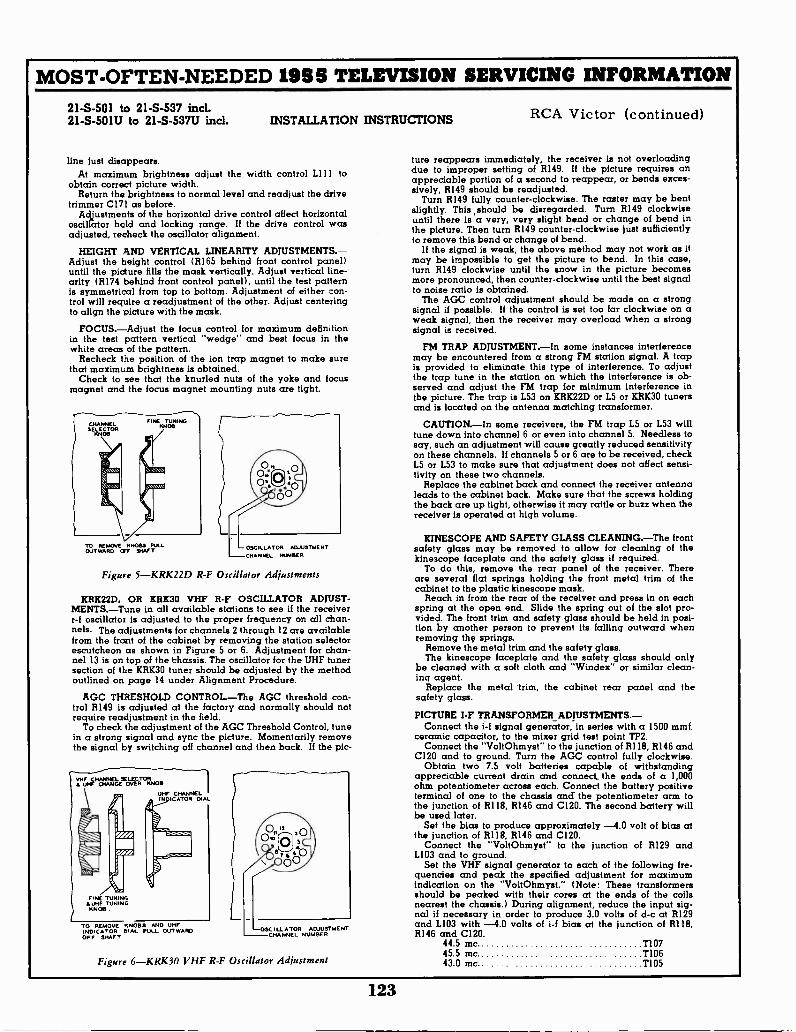
MOST -OFTEN -NEEDED 1955 TELEVISION SERVICING INFORMATION
21-S-501 to 21-S-537 incl.21 -S -501U to 21 -S -537U incl. INSTALLATION INSTRUCTIONS
line just disappears.At maximum brightness adjust the width control L111 to
obtain correct picture width.Return the brightness to normal level and readjust the drive
trimmer C171 as before.Adjustments of the horizontal drive control affect horizontal
oscillator hold and locking range. If the drive control wasadjusted, recheck the oscillator alignment.
HEIGHT AND VERTICAL LINEARITY ADJUSTMENTS.-Adjust the height control (R165 behind front control panel)until the picture fills the mask vertically. Adjust vertical line-arity (R174 behind front control panel), until the test patternis symmetrical from top to bottom. Adjustment of either con-trol will require a readjustment of the other. Adjust centeringto align the picture with the mask.
FOCUS.-Adjust the focus control for maximum definitionin the test pattern vertical "wedge" and best focus in thewhite areas of the pattern.
Recheck the position of the ion trap magnet to make surethat maximum brightness is obtained.
Check to see that the knurled nuts of the yoke and focusmagnet and the focus magnet mounting nuts are tight.
CHA NNE LSELECTOR
KNOB
FINE TUNINGKNOB
TO REMOVE KNOBS PULLOUTWARD OFF SHAFT
OSCILLATOR ADJUSTMENTCHANNEL NUMBER
Figure 5-KRK22D R -F Oscillator Adjustments
KRK22D, OR KRK30 VHF R -F OSCILLATOR ADJUST-MENTS.-Tune in all available stations to see if the receiverr -f oscillator is adjusted to the proper frequency on all chan-nels. The adjustments for channels 2 through 12 are availablefrom the front of the cabinet by removing the station selectorescutcheon as shown in Figure 5 or 6. Adjustment for chan-nel 13 is on top of the Chassis. The oscillator for the UHF tunersection of the KRK30 tuner should be adjusted by the methodoutlined on page 14 under Alignment Procedure.
AGC THRESHOLD CONTROL.-The AGC threshold con-trol R149 is adjusted at the factory and normally should notrequire readjustment in the field.
To check the adjustment of the AGC Threshold Control, tunein a strong signal and sync the picture. Momentarily removethe signal by switching off channel and then back. If the pic-
VHF CHANNEL SELECTORS. UHF CHANGE OVER KNOB
UHF CHANNELIN. GATOR DIALft
.......,....-..
FINE TUNING& UHF TUNINGKNOB
TO REMOVE KNOBS AND UHFINDICATOR DIAL PULL OUT WARDOFF SHAFT
OSCILLATOR ADJUSTMENTCHANNEL NUMBER
Figure 6-KRK30 VHF R -F Oscillator Adjustment
RCA Victor (continued)
ture reappears immediately, the receiver is not overloadingdue to improper setting of R149. If the picture requires anappreciable portion of a second to reappear, or bends exces-sively, R149 should be readjusted.
Turn R149 fully counter -clockwise. The raster may be bentslightly. This should be disregarded. Turn R149 clockwiseuntil there is a very, very slight bend or change of bend inthe picture. Then turn R149 counter -clockwise just sufficientlyto remove this bend or change of bend.
If the signal is weak, the above method may not work as itmay be impossible to get the picture to bend. In this case,turn R149 clockwise until the snow in the picture becomesmore pronounced, then counter -clockwise until the best signalto noise ratio is obtained.
The AGC control adjustment should be made on a strongsignal if possible. If the control is set too far clockwise on aweak signal, then the receiver may overload when a strongsignal is received.
FM TRAP ADJUSTMENT.-In some instances interferencemay be encountered from a strong FM station signal. A trapis provided to eliminate this type of interference. To adjustthe trap tune in the station on which the interference is ob-served and adjust the FM trap for minimum interference inthe picture. The trap is L53 on KRK22D or L5 or KRK30 tunersand is located on the antenna matching transformer.
CAUTION.-In some receivers, the FM trap L5 or L53 willtune down into channel 6 or even into channel 5. Needless tosay, such an adjustment will cause greatly reduced sensitivityon these channels. If channels 5 or 6 are to be received, checkL5 or L53 to make sure that adjustment does not affect sensi-tivity on these two channels.
Replace the cabinet back and connect the receiver antennaleads to the cabinet back. Make sure that the screws holdingthe back are up tight, otherwise it may rattle or buzz when thereceiver is operated at high volume.
KINESCOPE AND SAFETY GLASS CLEANING.-The frontsafety glass may be removed to allow for cleaning of thekinescope faceplate and the safety glass if required.
To do this, remove the rear panel of the receiver. Thereare several flat springs holding the front metal trim of thecabinet to the plastic kinescope mask.
Reach in from the rear of the receiver and press in on eachspring at the open end. Slide the spring out of the slot pro-vided. The front trim and safety glass should be held in posi-tion by another person to prevent its falling outward whenremoving the springs.
Remove the metal trim and the safety glass.The kinescope faceplate and the safety glass should only
be cleaned with a soft cloth and "Windex" or similar clean-ing agent.
Replace the metal trim, the cabinet rear panel and thesafety glass.
PICTURE I -F TRANSFORMER ADJUSTMENTS.-Connect the i-f signal generator, in series with a 1500 mmf.
ceramic capacitor, to the mixer grid test point TP2.Connect the -VoltOhmyst- to the junction of R118, R146 and
C120 and to ground. Turn the AGC control fully clockwise.Obtain two 7.5 volt batteries capable of withstanding
appreciable current drain and connect the ends of a 1,000ohm potentiometer across each. Connect the battery positiveterminal of one to the chassis and the potentiometer arm tothe junction of R118, R146 and C120. The second battery willbe used later.
Set the bias to produce approximately -4.0 volt of bias atthe junction of R118, R146 and C120.
Connect the "VoltOhmyst" to the junction of R129 andL103 and to ground.
Set the VHF signal generator to each of the following fre-quencies and peak the specified adjustment for maximumindication on the "VoltOhmyst." (Note: These transformersshould be peaked with their cores at the ends of the coilsnearest the chassis.) During alignment, reduce the input sig-nal if necessary in order to produce 3.0 volts of d -c at R129and L103 with -4.0 volts of i-f bias at the junction of R118,R146 and C120.
44.5 mc. T10745.5 mc. T10643.0 mc. T105
123
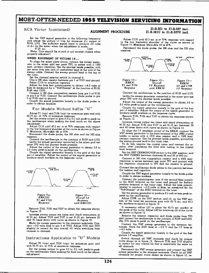
MOST -OFTEN -NEEDED 195S TELEVISION SERVICING INFORMATION
RCA Victor (continued)ALIGNMENT PROCEDURE
Set the VHF signal generator to the following frequencyand adjust the piciure i-f trap for minimum d -c output atR129, L103. Use sufficient signal input to produce 3.0 voltsof d -c on the meter when the adjustment is made.
47.25 mc. L102(Note: Core should be at end of coil nearest chassis when
properly adjusted.)
SWEEP ALIGNMENT OF PICTURE I -F.-To align the mixer plate circuit, connect the sweep gener-
ator to the mixer grid test point TP2, in series with a 1500mmf. ceramic capacitor. Use the shortest leads possible, withnot more than one inch of unshielded lead at the end of thesweep cable. Connect the sweep ground lead to the top ofthe tuner.
Set the channel selector switch to channel 4.Clip a 330 ohm resistor between pin 1 of V107 and ground.Preset C116 to minimum capacity.Adjust the bias box potentiometer to obtain -4.0 volts of
bias as measured by a "VoltOhmyst" at the junction of R118,R146 and C120.
Connect a 180 ohm composition resistor from pin 5 of V105to pin 6 of V105. Connect the oscilloscope diode probe to pin5 of V105 and to ground.
Couple the signal generator loosely to the diode probe inorder to obtain markers.
For Models Without Suffix "UnAdjust T1 (top) and 1104 (top) for maximum gain and with
45.75 mc. at 75% of maximum response.Set the sweep output to give 0.3 to 0.5 volt peak -to -peak on
the oscilloscope when making the final touch on the aboveadjustment.
Adjust C116 until 42.5 mc. is at 70% response with respectto the low frequency shoulder of the curve as shown in Figure9. Maximum allowable tilt is 20%.
Disconnect the diode probe, the 180 ohm and the 330 ohmresistors.
Connect the oscilloscope to the junction of R129 and L103.Leave the sweep generator connected to the mixer grid test
point TP2 with the shortest leads possible.Adjust the output of the sweep generator to obtain 3.0 to
5.0 volts peak -to -peak on the oscilloscope.Couple the signal generator loosely to the grid of the first
pix i-f amplifier. Adjust the output of the signal generator toproduce small markers on the response curve.
Figure 9--KRK22D
TI and T104Response
Figure 10 -Overall I -FResponse
with KRK22D
Retouch T105, T106 and T107 to obtain the response shownin Figure 10.
Increase sweep output ten times and check attenuation at41.25 mc. Adjust 1105 and 1107 to set 41.25 mc. between 25and 35 times down with curve as shown in Figure 10.
Move the sweep generator to the antenna terminals. Con-nect -3.0 volts bias to pin 5 of V103. Adjust T106 and T107.slightly to correct for any overall tilt while switching fromchannel to channel.
Instructions Applicable to "U" ModelsAdjust T2 (top) and T104 (top) for maximum gain and
with 45.75 mc. at 75% of maximum response.Set the sweep output to give 0.3 to 0.5 volt peak -to -peak
on the oscilloscope when making the final touch on the aboveadjustment.
21-S-501 to 21-S-537 incl.21 -S -501U to 21 -S -537U incl.
Adjust C116 until 42.5 mc. is at 70% response with respectto the low frequency shoulder of the curve as shown inFigure 11. Maximum allowable tilt is 20%.
Disconnect the diode probe, the 180 ohm and the 330 ohmresistors.
42.5MC70%
Figure 11-KRK30
T2 and T104Response
4575 MC75% ± 5%
42 5MC
Figure 12 -Overall
I -F Responsi.with KRK30
450MC90%
4575 MC-50%
42.5MC .45.75 M C
Figure 13-KRK30
L9 and C308I -F Response
Connect the oscilloscope to the junction of R129 and L103.Leave the sweep generator connected to the mixer grid test
point TP2 with the shortest leads possible.Adjust the output of the sweep generator to obtain 3.0 to
0.5 volts peak -to -peak on the oscilloscope.Couple the signal generator loosely to the grid of the first
pix i-f amplifier. Adjust the output of the signal generator toproduce small markers on the response curve.
Retouch T105, T106 and T107 to obtain the response shownin Figure 12.
Increase sweep output ten times and check attenuation at41.25 mc. Adjust 1105 and 1107 to set 41.25 mc. between 30and 40 times down with curve as shown in Figure 12.
To align the I -F amplifier circuit of the KRK30, connect theVHF sweep generator to the front terminal of the 1N82 crystalholder in series with a 1000 ohm resistor and a 1500 mmf.ceramic capacitor. Use the shortest leads possible, groundingthe sweep ground lead to the tuner case.
To do this, remove the crystal cover and connect the re-sistor, after insulating the lead with tubing, to the crystalfront terminal.
Set the UHF CHANGEOVER switch to the UHF position, andthe UHF TUNING between channels 68 and 69 at 800 mc.
Connect a 180 ohm composition resistor and a 1500 mmf.capacitor in series between test point TP3 and ground withthe capacitor connected to TP3 and the resistor to ground.
450MC Connect the oscilloscope diode probe to the junction between- 90 % the resistor and capacitor.
4575 MC Couple the VHF signal generator loosely to the diode probe- 50 % in order to obtain markers.
Connect the potentiometer arm of the second bias supplyto the AGC terminal on the tuner and ground the batterypositive terminal to the tuner case. Adjust the bias potenti-ometer to produce -3.0 volts of bias, as measured by the"VoltOhmyst" at the AGC terminal on the tuner.
Set the sweep generator to produce 0.5 volt or less peak -to -peak on the oscilloscope.
Adjust C308, on the UHF section, and L9, on the VHF sec-tion, of the tuner for maximum gain with 45.75 mc. and 42.5mc. markers as shown in figure 13.
If necessary adjust L27 to place the 45.75 mc. marker atthe peak of the curve. Adjust L43 for minimum tilt of the curveas shown in figure 13.
Remove the resistor, capacitor and diode probe from TP3and connect the oscilloscope to the junction of R129 and L103.Use 3.0v peak -to -peak on the oscilloscope.
Connect the VHF sweep generator to the antenna ter-minals. Keep the AGC bias at -3.0 V and the I -F bias at-4.0 volts.
Couple the signal generator loosely to the grid of the firstpicture I -F amplifier.
Switch through all VHF channels and check for propercurve shape as in figure 12. Retouch 1106 and 1107 slightlyto correct for any overall tilt that is essentially the same onall channels.
Disconnect the VHF sweep generator and connect the UHFsweep generator to the antenna terminals. Check on all UHFchannels for proper wave shape as shown in figure 12, re -
124
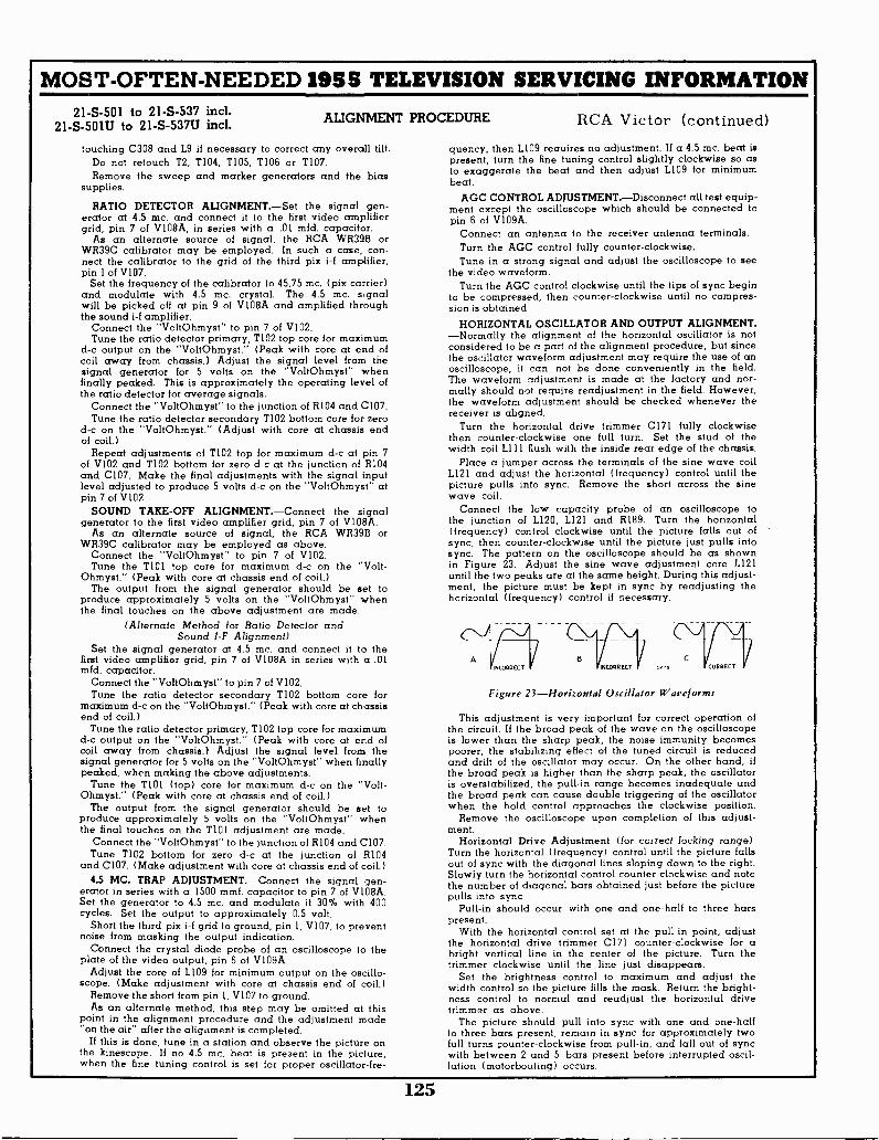
MOST -OFTEN -NEEDED 1955 TELEVISION SERVICING INFORMATION21-S-501 to 21-S-537 incl.
21 -S -501U to 21 -S -537U incl.ALIGNMENT PROCEDURE
touching C308 and L9 if necessary to correct any overall tilt.Do not retouch T2, T104, T105, T106 or T107.Remove the sweep and marker generators and the bias
supplies.
RATIO DETECTOR ALIGNMENT.-Set the signal gen-erator at 4.5 mc. and connect it to the first video amplifiergrid, pin 7 of V108A, in series with a .01 mfd. capacitor.
As an alternate source of signal, the RCA WR39B orWR39C calibrator may be employed. In such a case, con-nect the calibrator to the grid of the third pix i-f amplifier,pin 1 of V107.
Set the frequency of the calibrator to 45.75 mc. (pix carrier)and modulate with 4.5 mc. crystal. The 4.5 mc. s,gnalwill be picked off at pin 9 of V108A and amplified throughthe sound i-f amplifier.
Connect the "VoltOhmyst" to pin 7 of V102.Tune the ratio detector primary, T102 top core for maximum
d -c output on the "VoltOhmyst." (Peak with core at end ofcoil away from chassis.) Adjust the signal level from thesignal generator for 5 volts on the "VoltOhmyst" whenfinally peaked. This is approximately the operating level ofthe ratio detector for average signals.
Connect the "VoltOhmyst" to the junction of R104 and C107.Tune the ratio detector secondary T102 bottom core for zero
d -c on the "VoltOhmyst." (Adjust with core at chassis endof coil.)
Repeat adjustments of T102 top for maximum d -c at pin 7of V102 and T102 bottom for zero d -c at the junction of R104and C107. Make the final adjustments with the signal inputlevel adjusted to produce S volts d -c on the "VoltOhmyst" atpin 7 of V102
SOUND TAKE -OFF ALIGNMENT.-Connect the signalgenerator to the first video amplifier grid, pin 7 of V108A.
As an alternate source of signal, the RCA WR39B orWR39C calibrator may be employed as above.
Connect the "VoltOhmyst" to pin 7 of V102.Tune the T101 top core for maximum d -c on the "Volt-
Ohmyst." (Peak with core at chassis end of coil.)The output from the signal generator should be set to
produce approximately 5 volts on the "VoltOhmyst" whenthe final touches on the above adjustment are made.
(Alternate Method for Ratio Detector andSound I -F Alignment)
Set the signal generator at 4.5 mc. and connect it to thefirst video amplifier grid, pin 7 of V108A in series with a .01mfd. capacitor.
Connect the "VoltOhmyst" to pin 7 of V102.Tune the ratio detector secondary TI02 bottom core for
maximum d -c on the "VoltOhmyst." (Peak with core at chassisend of coil.)
Tune the ratio detector primary, T102 top core for maximumd -c output on the "VoltOhmyst." (Peak with core at end ofcoil away from chassis.) Adjust the signal level from thesignal generator for 5 volts on the "VoltOhmyst" when finallypeaked, when making the above adjustments.
Tune the T101 (top) core for maximum d -c on the "Volt-Ohmyst." (Peak with core at chassis end of coil.)
The output from the signal generator should be set toproduce approximately 5 volts on the "VoltOhmyst" whenthe final touches on the T101 adjustment are made.
Connect the "VoltOhmyst" to the junction of R104 and C107.Tune T102 bottom for zero d -c at the junction of R104
and C107. (Make adjustment with core at chassis end of coil.)4.5 MC. TRAP ADJUSTMENT.-Connect the signal gen-
erator in series with a 1500 mmf. capacitor to pin 7 of V108A.Set the generator to 4.5 mc. and modulate it 30% with 400cycles. Set the output to approximately 0.5 volt.
Short the third pix i-f grid to ground, pin 1, V107, to preventnoise from masking the output indication.
Connect the crystal diode probe of an oscilloscope to theplate of the video output, pin 6 of V109A.
Adjust the core of L109 for minimum output on the oscillo-scope. (Make adjustment with core at chassis end of coil.)
Remove the short from pin 1, V107 to ground.As an alternate method, this step may be omitted at this
point in the alignment procedure and the adjustment made"on the air" after the alignment is completed.
If this is done, tune in a station and observe the picture onthe kinescope. If no 4.5 mc. beat is present in the picture,when the fine tuning control is set for proper oscillator-fre-
RCA Victor (continued)quency, then L109 requires no adjustment. If a 4.5 mc. beat ispresent, turn the fine tuning control slightly clockwise so asto exaggerate the beat and then adjust L109 for minimumbeat.
AGC CONTROL ADJUSTMENT.-Disconnect all test equip-ment except the oscilloscope which should be connected topin 6 of V109A.
Connect an antenna to the receiver antenna terminals.Turn the AGC control fully counter -clockwise.Tune in a strong signal and adjust the oscilloscope to see
the video waveform.Turn the AGC control clockwise until the tips of sync begin
to be compressed, then counter -clockwise until no compres-sion is obtained.
HORIZONTAL OSCILLATOR AND OUTPUT ALIGNMENT.-Normally the alignment of the horizontal oscillator is notconsidered to be a part of the alignment procedure, but sincethe oscillator waveform adjustment may require the use of anoscilloscope, it can not be done conveniently in the field.The waveform adjustment is made at the factory and nor-mally should not require readjustment in the field. However,the waveform adjustment should be checked whenever thereceiver is aligned.
Turn the horizontal drive trimmer C171 fully clockwisethen counter -clockwise one full turn. Set the stud of thewidth coil L111 flush with the inside rear edge of the chassis.
Place a jumper across the terminals of the sine wave coilL121 and adjust the horizontal (frequency) control until thepicture pulls into sync. Remove the short across the sinewave coil.
Connect the low capacity probe of an oscilloscope tothe junction of L120, L121 and R189. Turn the horizontal(frequency) control clockwise until the picture falls out ofsync, then counter -clockwise until the picture just pulls intosync. The pattern on the oscilloscope should be as shownin Figure 23. Adjust the sine wave adjustment core L121until the two peaks are at the same height. During this adjust-ment, the picture must be kept in sync by readjusting thehorizontal (frequency) control if necessary.
Figure 23-Horizontal Oscillator Waveforms
This adjustment is very important for correct operation ofthe circuit. If the broad peak of the wave on the oscilloscopeis lower than the sharp peak, the noise immunity becomespoorer, the stabilizing effect of the tuned circuit is reducedand drift of the oscillator may occur. On the other hand, ifthe broad peak is higher than the sharp peak, the oscillatoris overstabilized, the pull -in range becomes inadequate andthe broad peak can cause double triggering of the oscillatorwhen the hold control approaches the clockwise position.
Remove the oscilloscope upon completion of this adjust-ment.
Horizontal Drive Adjustment (for correct locking range).Turn the horizontal (frequency) control until the picture fallsout of sync with the diagonal lines sloping down to the right.Slowly turn the horizontal control counter -clockwise and notethe number of diagonal bars obtained just before the picturepulls into sync.
Pull -in should occur with one and one-half to three barspresent.
With the horizontal control set at the pull -in point, adjustthe horizontal drive trimmer CI71 counter -clockwise for abright vertical line in the center of the picture. Turn thetrimmer clockwise until the line just disappears.
Set the brightness control to maximum and adjust thewidth control so the picture fills the mask. Return the bright-ness control to normal and readjust the horizontal drivetrimmer as above.
The picture should pull into sync with one and one-halfto three bars present, remain in sync for approximately twofull turns counter -clockwise from pull -in, and fall out of syncwith between 2 and 5 bars present before interrupted oscil-lation (motorboating) occurs.
125

MOST -OFTEN -NEEDED 1955 TELEVISION SERVICING INFORMATION
RCA Victor
TUNERI
UNIT 31 23 13 L2t
KRK- 30SI-E St -E
123 I REAR FRONT 13
LIB 2 12, 1.10 18
CIRCUIT SCHEMATIC DIAGRAM KCS88J, KCS88K, KCS88L, KCS88M or KCS88VA
16
J2I F
P302 INPUT
RIO1001( -
C 19 SI-231000 REAR
K 7
4 03.*5 9.
a -
TP I 4111
9*
C51470
C 230.68MMF
JI-F PI- mREAR PINVIEW VIEW
0260
I.10 \R2120
_ 3000 I moo
51
RI44 820
4\A.
-IC13 027 5270 Igg
REARSi C 0.0 7-451-C
126 ,FRONT
1.--r175 .2 7I)I 2.2 L33 EH H (-1000 /000 ......1
128124
. 3 1
L29123
.4 io. .
° C34IR571( IR2.11X39 0 ' 30 470
IL22 06 e-072 T V1
31
-) q050 CONTV2.TR2.
TP4'19 5I -87P- 2 136
V2IrT -11
L43
0S6C. )41CM8IXER C822°1 7
12833 E 6 300, >
C16 .'4+1450
L44 L4 " '15- -3 5
L
L45 L .3 1 +90v
-1'4476 L739
' . C21
4
7 .1, 0.0-3T_-,_. 148 1,'"3 117
L49 C 221 6210.8-3,. 120
ANT. MATCHING UNITLS L4 LI
F-14 I -F I- FI TRAP TRAP TROD
C25
51 A C27REAR FINE
I
.2 LS?,
*31.58f
15,:5
1.51155
SI-Aoo FRONT
O
1153
L52153
CI7 C18
C 241 R1210 I 100K
TP.3
--/C250.8- 3
CHANNEL SELECTOR SWITCH SIFRONT AND REAR SECTIONS VIEWEDFROM FRONT AND SHOWN INCHANNEL 1.10. 2 POSITION.
I- 11 HF SECTI ON -1-C300 /-/ 0,}{r/, OMITTED IN i
C303 C303 Z SOME UNITS I CR 301Ali 8I K3D OR
L303A = L3038 1311 11N 82le__,_.309 MIXER
®C3113 C-4307 0C3121 1 V301 C b.fl
_H1 A r 1E1 6AF4 T.-u
- - osc
R302680oC309
L 1000
123036800
R3012200
N N WHEN USING COMBINATION UHF- VHF ANT.CONNECT TRANSM. LINE To VHF TERMINALS.
FOR SEPARATE UHF AND VHF ANTENNAS.DISCONNECT mi 10 5 . AND CONNECT TRANsmLINES TO RESPECTIVE TERMINALS.
R5222K
UHF VHF
F41- ANTENNA*N.
it I TERM. BRO.
448551
517 SI
VHF UHF
C 305
T
I7C41 7
c3op / I 030 I
-79-3
I-304 -TB
+280 V.
c72, w104
R -FA-6 c
103
0260 V.
C 130.0022
7,041ST. PIK
I -F TRANS.
PC 101 ?
r;z:,°L.C101 TAKE OFF
3 TRANS
v N35
6CB6NS DIX I,
NIPL
V o,6AUG
SOUN DF AMPL
T noS2ND. FIX.
F TRANS43.0 MC.
c *0 .IV. A
R146 8117150 K 1000
C 1201 R118 c 119i7
0.471 33K 1470 =
S
01098
12AU 7A -G -CAmPL
0.5V
5[1/48151160K
ILI 4, ce,
.1-21300
0290V.
1'12350 5? C179
0.39. 280 V.
0131 30518K 6 X 8
1ST SYNC.C1410.1 +4631
2.2 3184
4,1
C140330
VII2
65N7 -6THOW. SWEEPOSC. B coNTR.
-21V I
RIBI EiE,3_,_330K HH
68R182 R1664_06462011 82 IQ 1-.022
8153
-4-100 K
J.50K-A-
(1660.47
R1853900
3 815391
RI5
ME
LI20140611FREE
Is 193 0
R18947 I(
C16- 7330
818600 K R190
I. 6.8MEG.
AP
The schematic is shown in the latest All capacitance values less than 1 incondition at the time of printing. MF and above 1 in MMF unless otherwise
All resistance value in ohms. K = 1000. noted.
250V.
126
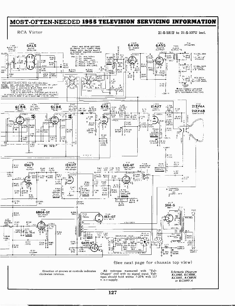
R105
R106
clockwise rotation.
MOST -OFTEN -NEEDED 1955 TELEVISION SERVICING INFORMATION
RCA Victor
T102RATIO OCTTRANS.4.5 MC
V 102
6A L5RATIO
DETECTOR
3.2
10KB C105 6 _LC108
leo 0.4710 K
DPI 1-2.9 V.
103cio60.IV
7
Ito.%004
)00RIO 4IC 10739K T033
Tv 101TEST
"' POINT5101
FRONT
FRONT AND REAR SECTIONSOF SWITCH 5101 VIEWED FROMFRONT WITH SWITCH SHAFTIN EXTREME CouNTER.CloCKENI5EPOSITION No. 1
P05.1 - TV. MIN. HIGHS2 - TV NORMAL3 - TV MIN. LOWS4 - PE1000. MIN HiGNs5 - P0000. NORMAL.6 - PHONO. MIN. LOWS.
* 5101REAR
610813I MEG.VOL.
CONTR
C 1 1 8C105 -1 1 F'.01 -1 1.1100
1 i (EgA3
4+10 MODELS 2155o,u 502U AND 518U KCS 8865311TTED- 5101,3101, W101, w102, C117 AND CHANNEL IND. LAMP.BANGED- cno9 TO .0047, C112 To .001.ONNEcTED-C1/39 To JUNCTION of 0104, RI54 AND C107
C112 BETWEEN 0103.7 AND &ND81.54,C11/3 AND V116 -I To GRD.V 116-10 To JUNCTION OF 0147,12197 AND IR 105.2
IN MODELS 218 523U(KCS 88VA) 000 Sls 537D (KCS 880)RANGED -CII3 To .0018 , 109 To .0027 AND C110 To .015
12
0100
6C 5 6 3RD P rt.
9Dm PL 45.5 MC.A.
+1240 20123 1360.3.201
812418
230V
2556
C
C182.001
LI19
V 107
6C B6360- PPL/R I -F
AM
K
2.2 V. Z
,125f$ 6127.001 180
5
7 1074TH RIX L103
TRANS CR 101 36 00.1.1MC_44.5 2ND DET ORNWHT
EP-Cr470
+280 v.
C
I
PC 102?
136V
1.001126
C133470
RI28470
?0128
110
R1293900
L 104250 MOH
GRN
42 V
v108 A
6X8Vi Of 0
AmPL.
9 380
R 130120
01290129.0039
C 110
00130 75rAti47 000.005
613?275
R 3212/5
1020
0132880 OF 'r'
V1036A V61ST AUDIO
AM PL.
_LC A113.0027
2 5
21 -S -501U to 21 -S -537U incl.
V 104
6AS5 T103AUDIO AUDIO
OUTPUT OUTPUT TR.
P.MSPEAKERS
240V BLU
1
o. 1 >t -, 'I
C117 g',r ,( I FAC52,48,LtryA
.0027 0'A'A
2. 8 'I SPKRS.114
C112 -L
1-.. 7 >-, \f* i
I L.,>_._-, A270 I1330)0 +I ,..,47 1 KCS 88 M
I C '+'.' 'g':c-'2:2ZZ,,R2,.,.._,>iii, qCOLOR00T
FOR CORRECT SPEAKERPHASING REFER TO COLORDOTS FOR PROPER CONNECTIONS.
1<05883,88K
1-5" 06 1-8'SPEAKER
8135 L106lc/ 250
MU
R1364700
R13415 K
VIIOA
R157 12AU733K SYNC. R162 C 145OUTPUT 22K .0033
+02 T0014233
64 -Lc NMI _LC14.6+7.9 V 2 10 K aj 220 10082
.021561:1. 390 K
C154 R158 y470 1200
RI613900
- C1700. I
081243
T
vii0 B12AU7VERT. SWEEP
OSC DISCH
RIGS 6 175 V8K
-GIV.
C.104369 ig-r"
R 1641.5 MEG
VERTICALHOLD
CONTR
1
C1470.1
+280V
RICO470K
8167 C152 0155 817222K .015 .022 22K
rC/115VO-Hh---4"1.0022 33'"'
S2'13_2,0-t(- 5
R173
0154470K
.068 R169 R174390K 2.5 MEG
VERT LINE
5 2CONTR
VIII
6K6-GTVERT SWEEP
OUTPUT
C1310.1
159
Z L 109
'64.5 MCTRAP
12AU7..00E0
OUTPUT
+280 V.
L IOU180 MU
wEcr C1350.1
+200V
6.80
R137470 4/1
R108010 K
PICTURECONTRASTCONTROL
C 134 B 014030 MD.141-
+820
T108vERT SWEEPOUTPUT TR.-
BL
C151 6168.056 18 K
R1653.5 MEG 0149
2 HEIGHT T .01CONTR.
RI7 I8200
#R120971(
LI 21H012
SINE WAVE
C168.01
RI92820 K
C169 R194470
R193I MEG
IR 19139 K
47
C17110-160NOR. DRIVECONTR.
tI02.0012
P101
v11.3
650.6-GT
0.3 AMP
E1OR SWEEPOUTPUT
158V.
C 1730.1
L'n
C174 RIBS0.27 / 100
RI9612K
05V T OTRANS.".'
I -
O
255VC156
,
1 8176 -1R
680 K175
B20 l<
0114
1B3-GTH -V REcT
+15,400V
_
1
RED
R 1423910
L 107mu.
SPNANT
01417500
0 V
+2800
R 177220K
R175200 K
BRIGHTNESS 2
CONTROL 3
R143470 K
0
10
R119ISO K
C157.022
5Ti
C1,5 -.047
C 176270
LIIIWIDTHCONTR.
V115
6A X4-GTDAMPER
.273L112 5
1.5 NUN
0177 C137120 330 DEFLECTION YOKE
-I F-.-161 - -1 RED
- I
C180 vERT. COILSI
1'191 L115 L114 N
R203Y IF. 1000
1g_ R201 R2021I=_ 560 560 I TEL
L _ _ BLK
pio2.PIN VIE
RED
15510.1
v116
21ZP4A2IZ P413KINESCOPE
J102F
REARO'ER
CHANNELNIJ
V 117
5U4 -GRECT. T1 I
- -1RED
1
1
RED..
I oI
GNN
GEN- TEL
.5V.30
V
L113
RN
6.30
S 102
BLK.REO
BLK
R204100 K
BLK- 8±1.J 5/03- INTERLOCK
+200vSUPPLY
-C132.4 C134.,180 Mr 11 00 Mr
115V 609SUPPLY
(See next page for chassis top view)
Direction of arrows at controls indicates All voltages measured with "Volt-Ohmyst- and with no signal input. Volt-ages should hold within 20% with 117v. a -c supply.
Schematic DiagramKCS881, KCS88K,KCS88L, KCS88M
or KCS88VA
127
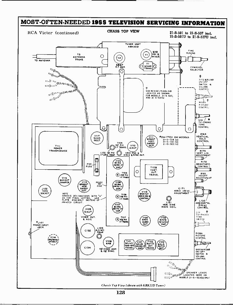
MOST -OFTEN -NEEDED 1955 TELEVISION SERVICING INFORMATION
RCA Victor (continued)
TO ANTENNA
JI02YOKE
SOCKET
*J101PHONO INPUT
JACK
V1I41111/B0161VIV RECTJ
VIIS6AX4GTDAMPER
T2ANTENNA
TRANS.
F101FUSE
V1136BQ6GT
HOR.SWEEP
OUT.
V11751J4GRECT.
PCIO2OR
NOTECHASSIS DESIGNATIONS WITH *X"AS THE FINAL LETTER, USEPLATE ASSEMBLY INSTEAD OFPRINTED CIRCUIT
12 AU7
VIDEO OUT.111 AG C
TUNER UNITKRK 22 D
68Q7RF AMP.
7104IV FIXI -F TRANS 12 AU7
21-S-501 to 21-S-537 incl.21 -S -501U to 21 -S -537U incl.
6xaOSC &MIXER
sioi a 5102/R108A aLOCATED AS SHOWNFOR MODELS 21-S-523,AND 2I -S -523U
VIII6K6GT
VERT.SWEEP
OUT.
TIOBVERTOUT
TRANS.
V11265N7GTORIZ.ODE. BCONTROL)
V104SASSAUDIOOUT.
FINETUNING
*OMITTED ON MODELS2I -S- 518 (U)21-S-501 (U)21-S-502 (U)
CHANNELSELECTOR
SIOi *TV -PHONOTONECONTROL
RI 6 4VERTICAL
HOLDCONTROL
111 \R174a
VERT. LIN.ADJUSTMENT
R178BRIGHTNESSCONTROL
RI65HEIGHT
ADJUSTMENT
C 171 KjHORIZ. DRIVE /,ADJUSTMENT
LI 21HOR. SINE
WAVE COIL
V1036AVG
151 AUDIOAMP
L1094.5 MCTRAP
0
CRASS TOP VIEW
VIOB6%6
Chassis Top View (shown with KRK22D Tuner)
128
L I20HORIZONTAL
(F REG))CONTROL
01 t- PH11:1;)
T11NESWITCH
RI 084PICTURECONTROL
S102 a R10813ON -OFFSWITCH SVOLUMECONTROL
/11
SPEAKER LEADSLOCATED HERE ON
MODELS 21- S - 523 (U) ONLY
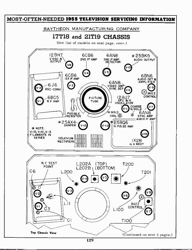
MOST -OFTEN -NEEDED 1955 TELEVISION SERVICING INFORMATION
RAYTHEON MANUFACTURING COMPANY
17T18 and 21T19 CHASSIS(See list of models on next page, over.)
12 BH7v. osc. a\OUTPUT \
* NOTE:V- IO. V-I2,V- 13FILAMENTS IN
SERIES
6CB62ND IF AMP
6CB61ST IF AMP
FUSIBLERESISTOR
*25AX4,DAMPER
SELENIUM IRECTIFIERS
L
6AN83RD IF AMP
f/TECTOR
6AN8VIDEO AM1:1
SYNC SEP
* 25BK5AUDIO OUTPUT
I 2AU7AFC a H.
OSCILLATORCOARSEH. HOLD /
H. HOLD W J 6AN8COIL 0 xv SYNC AMP
AUDIO IF AMP
-x-25BQ6H. PULSE AMP
6 BN6AUDIO DET aAMPLI FIER
()BUZZCONTROL
elI X2B
H. V. RECT ij
R. F TESTPOINT
C6
Top Chassis View
L 200
L202A (TOP) T200L202B (BOTTOM)
O
L100BUZZ
CONTROL
T201
T100
(Continued on next 3 pages.)129
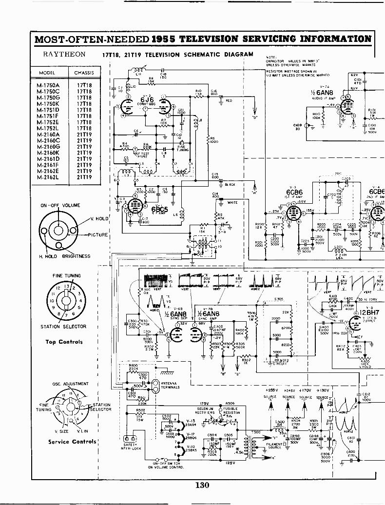
MOST -OFTEN -NEEDED 195S TELEVISION SERVICING INFORMATIONRAYTHEON
MODEL CHASSIS
M -1750AM -1750CM -1750GM -1750KM -1751DM -1751FM -1752EM -1752LM -2160AM -2160CM -2160GM -2160KM -2161DM -2161FM -2162EM -2162L
17718177181771817T18177181771817718177182171921719217192171921719217192171921719
ON -OFF VOLUME
I -L HOLD BRIGHTNESS
FINE TUNING
STATION SELECTOR
Top Controls
FINETUNING
OSC. ADJUSTMENT
V SIZE V LIN
17T18, 21T19 TELEVISION SCHEMATIC DIAGRAM
L II C18R8 120
V. HOLD
ICTURE
C7
IT
STATIONSELECTOR
Service Controls
R44700
C5I tO
LIO
ISK
6J6CONY- OSC
R 710K-9-3A/0-41
R6
R.F TESTPOINT
0-0- 0 0 0,0 !L3 L4
60 5
R32200
1G 300
T225000V
IGIO10
If F-4FINETUNING
G85
4 2
100001 1050
110.1.7.
Nor
RI5
R 115K
7
R 300 VERT VERT10 K
5000500VR3022 2M
- -T-- A 52)73 1
220K I
iill///ANTENNA LTERMINALS
C500470
220K
R502
133 L C50215W 5241 8 V-13
500V 25AX47
{,0SAFETY
INTER. LOCK
0503 2 V -I25000 25806
ON -OFF SWITCHON VOLUME CONTROL
C16BOO
BLACK
C14800
WHITE
NOTE:CAPACITOR VALUES INUNLESS OTHERWISE MARKED.
RESISTOR WATTAGE SHOWN IN1/2 WATT UNLESS OTHERWISE MARKED.
25V
.7V
8200 R20212 K 47
02001000500V
C$0930
V-3
6CB61ST IF AMP
155V
V-74
6AN8AUDIO IF AMP
-.4
L200C2Q3
"47
6vC143E- 5 O. 2N0 IF AM
a
62V0101470
658
RI 0133K1W
C10010K
500V
R203 204000
G5
5005
..C102013 -04:12g°
R205000=
li-I=' x 500V -
L201_Jo -06-
.2.2 UH1.6.1.
-A- -1- -r20V Y 68V 68VP -P P -I: P -P
VE HORIZ /
R303 R304 R30522K IM 560K
125V R506
SELENIUMRECTIFIERS
FUSIBLERESISTOR
C504 C505
v-io11MF 115005MF
v 9
2 5BK5 R503 14.54220K
830647KIW
T500
2000
820662
65V 7PP /
TP -P50V
MF200V
IV
C4002000
500V 1410-22V
_+255V +245V +170V +130V
SOURCE SOURCE SOURCE SVOICE1-1
n A A 41
R504-sevv -
R505 215'2700
'2500 P -P13W 5W
BERT
50 to 108V
V -B
12 BH7
C403.1MF200V
*E. ;791:7-.'CIO2OMF 10 MF + 0601
o FILAMENT 0
7.-
SOURCE -T.- 30 -AT -TI0600220
82
50 V ..C-11
C 50005 6
v. osc aOUTPUT
R403LOOK
V HOLD
130

R4046000
V. LIN.
MOST -OFTEN -NEEDED 1955 TELEVISION SERVICING INFORMATION
VOLTAGE READINGS TAKEN WITH A V.T.V.M., LINE VOLTAGEAT 115 V. AC AND THE ANTENNA SHORTED TO CHASSIS.
Raytheon Chassis 17T18 and 21T19NOTE COIL RESISTANCE READINGS NEAR COILS AND TRANSFORMERS WERE TAKEN WITH
AN OHMMETER DIRECTLY ACROSS COIL BEING MEASURED EXCEPT THOSE INDICATEDT100 L100
R103 CI6 BY AN ASTERISK (), ONE LEAD WAS DISCONNECTED. COILS SHOWN1
WITHOUT A READING HAVE A RESISTANCE OF LESS THAN ONE OHM.
.8"t 245V
R102750
BUZZ
L 202
0 to 6.5V
= C210 1
II5V
L202A
R215510
1000C207 (.208 L203680 T!,00. 35 229500V 1500V 2.8A.
V 5A
1/2 6AN83RD IF AMP
C213
15000500V
7200_ _
R2168IM
VOLUME I
-4
R106 L
330K
V- 5 B
1/26AN8DETECTOR 8 AGC
OV
VS
235V T101 PMSPEAKER
vB25K5 480AUDIO OUTPUT
R108ISOIW
L2092 2UH5.4n.
47
0108.OIMF600V
-0-
R216A1000PICTURE
4706 -Lr.
C222
T201
L.207305UH8.4n_
R2I856002W
I-208270 1.197.7n
CABINET
C22I1
1
33
7P- PI
VERT
C404MF 1-
400V
R24.g,54
R4H' 2,7p iOOK
-50,
75VP -P
R407R408
3MV. SIZE
IC4051000
500V
_ERc225Z450V
R41047K
VERT
BLUE T400
770n.
RED
WAVE FORMS WERE TAKEN WITH A TRANSMITTED SIGNAL AND PICTURE IN SYNC AT ALL TIMES.THE WAVE FORMS AND PEAK TO PEAK VOLTAGE READINGS MAY VARY WITH STRENGTH OF SIGNAL,PICTURE INFORMATION BEING TRANSMITTED, AND ADJUSTMENT OF VARIOUS CONTROLS. VS DENOTESPEAK TO PEAK VOLTAGE READINGS WILL VARY WITH SIGNAL.
R40933005W
BOOST490V
R22
6
REEN
226.IMF400V
10 0R220 TOOK 2_6,L210500K
BRIGHTNESS ±
C225
R222
1000
010246V
OV
68n.VERT.a/V.W
R229 R225560 560
,SLQA.11_,
495V
C227 R223__J .022M FT 22K NOTE:
1 * I
200V _i_ NOT INCLUDED5V 5V-. T IN ALL SETS
P- P1 _Y_
Honi2
DO
01
OK
602
.047MF200V IOVR6 3
82K R6053900
R60650K
H. HOLD R6I6
V -I I
R6I5 36100K . 04705 MF I2AU7
AFT B HOR.OSG
41 I7V
4) 2C603
MFIV- .022
- 200V
I85V
33K
L601 R60847K
1- 35 to190V
OL600
STABILIZER
74n.
R604 C604150K T .47MF
4. 200VR607
4 0068 600V
06071
330
62rt
022MF400V
T202
C22847
2 KV
1-4 I
5.9.n.
HORIZ
0230
473KV
//TI(///e. P°P
BOST15 MF C614200V
< C6I3220
HORIZ
NIkz260
R6I0 O. ....R609 100 49 082000609
.001 MF600V
R61470K
21NOTE:
610047M
-400V
150K MAY VARY/24V FROM 75010 910
P -P
V- I 2
258Q6H. PULSE AMP
130V
R6I282002W
245V
A4DAMPER
'a- <
L6028 UHIliI.
225n
010.5
4.6n
62AC611.IMF 490V
11Mi. BOOST
SOURCE400V
V-1517HP4
Or
2IYP4PICTURE TUBE
T600
R6I31,5
V-14
IX2BH. V. RECT
NOTE: Capacitor C608 should be 470 mmf and a 80-480mmf trimmer is connected in parallel with C608.
131

MOST -OFTEN -NEEDED 1955 TELEVISION SERVICING INFORMATIONRaytheon Manufacturing Company Chassis 17T18 and 21T19 (continued)
PRE -ALIGNMENT PRECAUTIONS1. If sweep generator does not have a balanced output,
connect a 150 ohm resistor in series with the groundlead and 150 ohms minus the internal resistance ofthe generator in series with the hot lead.
2. Connect a 1000 mmf capacitor across scope term-inals and a 10K ohm resistor in series with hot lead
as close to test point as possible.
3. Connect signal generator through a 1000 mmfcapacitor.
4. When aligning the IF Amplifier be sure tuner is setto channel 10.
VIDEO IF ALIGNMENT
StepNo.
1
SignalGeneratorFreq. (mc.)
SweepGeneratorFreq (mc.)
SignalInputPoint
OutputPoint
Remarks Adjust Response
23.926.3 25
Pin 8of V -5A
Scope at IFdefectoroutput
Connect shortbetween pin
5 and 6 of V-4
T200 pri. (top)T200 sec. (bot.)
Coupling rod
2Markers should fall 10% down. If response curve is not as shown, readjust coupling rod (bottom T200)for proper bandwidth and T200 primary and secondary for flat response and maximum gain.
3 21.3Converter
grid
VTVM atPin 8
of V -6A
Remove short.Adjust generator
for output of approx.2 volts DC on VTVM
L202B(bottom core)
Maximumreading
4 26.5 Convertergrid
VTVM atPin 8
of V -6A
Adjust generatorfor output of approx.2 volts DC on VTVM
L202A(top core)
Maximumreading
5 21.3 Convertergrid
VTVM atPin 8
of V -6A
Adjust generatorfor output of approx.2 volts DC on VTVM
L202B(bottom core)
Maximumreading
24.0 Convertergrid
VTVM atPin 8
of V -6A
Adjust generatorfor output of approx.2 volts DC on VTVM
L200 Maximumreading
25.0Converter
grid
VTVM atPinfor8
of V -6A
Adjust generatoroutputofapprox.
2 volts DC on VTVMLl 1 Maximum
reading
8 25 Convertergrid
Scope atPin 8
of V -6ALl 1 Rock for flat
response
923.8
26.6525 Converter
grid
Scope atPin 8
of V -6A
Markers should be50% down and re-sponse curve shouldbe as shown. If not,repeat alignment
Checkpointonly
4$6
Picture IF frequency 26.75 MC - Sound IF frequency 22.25MC.NOTE: A very short lead from the generator must be used to prevent regeneration.
SOUND IF ALIGNMENTSound Alignment can be performed without test equip-ment and without removing the picture tube from thechassis.
1. Tune in a TV station and adjust fine tuning untilsound bars just appear.
2. Turn T201 primary (furthest from chassis pan) slugall the way out (counter -clockwise).
3. Turn same T201 slug in (clockwise) until the horizon-tal scanning lines are smooth and continuous.
4. Readjust fine tuning for best picture with adequatesound.
5. Reduce signal strength at antenna terminals byof an attenuator or similar device until a "hiss"companies the sound.
6. Adjust sound pick -off transformer (T201 secondary),interstage transformer (7100), quadrature coil (L-100) and buzz control (R102) for maximum clearsound and minimum buzz.
7. If "hiss" disappears during step 3, further reducesignal strength.
useac -
132
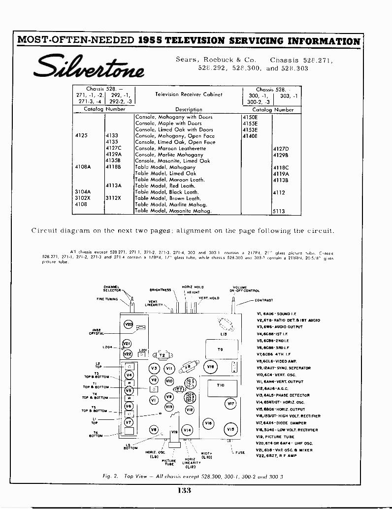
MOST -OFTEN -NEEDED 1955 TELEVISION SERVICING INFORMATION
StivrA&AteSears, Roebuck & Co. Chassis 528.271,
528.292, 528.300, and 528.303
Chassis271, -1, -2,1271-3, -4
528. -292, -1,
1 292-2, -3Television Receiver Cabinet
Description
Chassis300, -1,300-2, -3
528.-1 303, -11
Catalog Number Catalog NumberConsole, Mahogany with Doors 4150EConsole, Maple with Doors 4155EConsole, Limed Ook with Doors 4153E
4125 4133 Console, Mahogany, Open Face 4140E4135 Console, Limed Oak, Open Face4127C Console, Maroon Leatherette 4127D4129A Console, Marlite Mahogany 4129B4135B Console, Masonite, Limed Oak
4108A 4118B Table Model, Mahogany 4118CTable Model, Limed Oak 4119ATable Model, Maroon Leath. 4113B
4113A Table Model, Red Leath.3104A Table Model, Black Leath. 41123102X 3112X Table Model, Brown Leath.4108 Table Model, Marlite Mahog.
Table Model, Masonite Mahog. 5113
Circuit diagram on the next two pages alignment on the page following the circuit.
All chassis except 528.271, 271-1, 271-2, glass picture tube. Chassis528.271, 271-1, 271-2, 271-3 and 271-4 contain a 17BP4, 17" glass tube, while chassis 528.303 and 303-1 contain a 21WP4, 205/8" glasspicture tube.
CHANNELSELECTOR
FINE TUNING-
CRYSTAL
HORIZ. HOLD
\ HE IGHTVERT. HOLDVERT.
LINEARITY 11 /
ll
9L 204
11.7
TOP
T3TOP 6 BOTTOM
TI
TOP 5BOTTOM
14TOP 5 BOTTOM
TSTOP 4 BOTTOM
LITOP
T6BOTTOM -
a
00
BRIGHTNESS
edam.
0 o
4D
LS -BOTTOM
HORIZ. OSC.(L9)
VI9
`TE
41)
VOLUMEON -OFF CONTROL
LI3
T9
TIO
' 1_1
PICTURETUBE
\- WIDTH
NORIZ. (L 10)LINEARITY
(LI2)
FUSE
CONTRAST
VI, BAU6- SOUND I.F.
V2,678- RATIO DET. B IBT AUDIO
V3,6W6- AUDIO OUTPUT
V4,60815-157 I.F.
VS, 6C86- 2ND I.F.
V6, 6C86- 3RD I.F.
V7,6C86 4TH 1.F
V111,6CL6- VIDEO AMP.
V9, 12AU7- SYNC. SE PE RATOR
V10,6C4- VERT. OSC.
VII, GAM- VERT. OUTPUT
V12,6AU6-A.G.C.
VI3, GALS- PHASE DETECTOR
V14,6SN7/07- HOR II. OSC.
V16,6806 - HORIZ. OUTPUT
VI6,183/07- HIGH VOLT. RECTIFIER
V17,6AX4 DIODE DAMPER
V18, SU40 - LOW VOLT. RECTIFIER
VI9, PICTURE TUBE
V20,674 OR 6AF4 - UHF. OSC.
V21, 6U8 - VHF. OSC. 8 MIXERV22, 68Z7, R.F. AMP
Fig. 2. Top View Alt chassis except 528.300, 300-1, 300-2 and 300-3
133
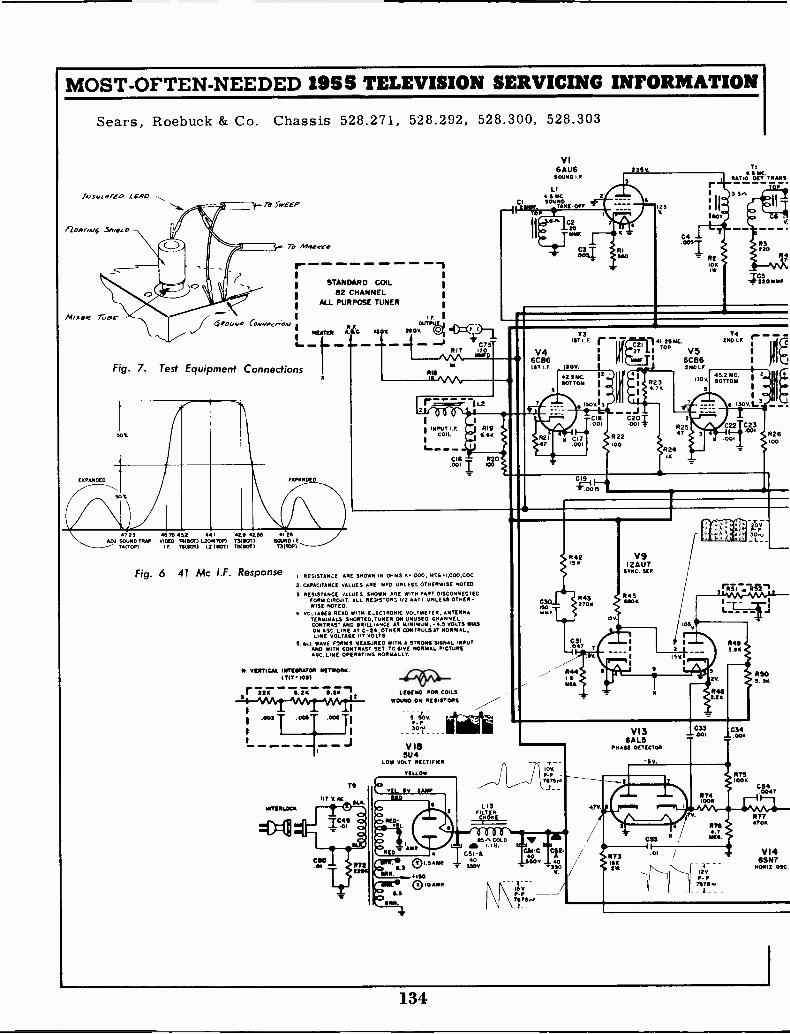
1-WerAAVA'Afil.00: .0061-1
L---- --J
MOST -OFTEN -NEEDED 1955 TELEVISION SERVICING INFORMATION
Sears, Roebuck & Co. Chassis 528.271, 528.292, 528.300, 528.303
lAys.,wrei. Lap
A.2011770./ 4 5,11.{.
/Hi see 7ai-
171 Sri -EP
To MAIIr1,1P
44004,0 Covweno
Fig. 7. Test Equipment
50t
50%
r -
Connections
4725 715 452 44.1 42.9 4255 41.25ADJ. SOUND TRAP VICO) T41801) L2ORTOP) T5111011 5010101
T41701,1 I.f TG(80T) LZ (10T) 7518011 73(T0P)
Fig. 6 41 Mc I.F. Response
STANDARD COIL62 CHANNEL
ALL PURPOSE TUNER
2800
1
1
F
-.8 C7Sr617 120
IMF
IK
18
-112 T6
11
VI6AU6 235KROUND 1.F.
LIU.S 1110SOUND
TAXI -Off
SA C220IOW
R1540
rU I
125
C4
180T
R210K10.
745 MC
RATIO OCT TRANS
P3220
11
C
V46CB61ST I.F. 1109.
2.9MC.BOTTOM
73Iv L F r 41.2511C.
I x=21 TOP
6CB6240 IF
2 4
R23 1300
4.7R
624IX
62547
2110 LF
45.2 MC.BOTTOM
C22I C23col
.001
NASPs.
R26100
I RESISTANCE ARE SHOWN IN OHMS 01000, mEG1,000,C0C
2. CAPACITANCE VALUES ARE STD UNLESS OTHERWISE NOTED
3 RESISTANCE 1ALUES SHOWN ARE WITH PART DISCONNECTECFORM CIRCUIT ALL 5E54510143 I42 WATT UNLESS OTHER-WISE NOTED.
vcLrAGES READ WITH ELECTRONIC VOLTMETER, ANTENNATERMINALS SHORTED, TUNER ON UNUSED CHANNEL.CONTRAST AND IIRILLiANCE AT MINIMUM. -4.5 VOLTS 41143ON VIC LINE AT C-24 OTHER CONTROLS AT NORMAL,LINE VOLTAGE HT VOLTS
S. ALL WAVE FORMS MEASURED IV TN STRONG SIGNAL INPUTAND WITH CONTRAST SET TO GIVE NORMAL PICTURE.GC. LINE OPERATING NORMALLY.
VERTICAI. 12171491117011 011111804K.(T17-1091
I. UPC 8.210 11.20 LEGEND FOR COILSWOUND ON RESISTORS.
P. P307.
V185U4
LOW VOLT. RECTIFIER
YELLOW
T11TEL. 54 3441E
RED
423
RID -
AMP
11.3SRN
4.3
L13FILTERSMOKE
rrn85" COLD
I SA ME
di 1.111.
C3I-40
390V,
000010 AMP
742IS
150.mmr.
V9I2AU7
STMC. SEP
R3270)1
3O
-LIKAA,MAALL--s- _
L
R493.011
ioy
.757524
MPG CON40
BO 44
V.
IS V.P -P71150
VI3GALS
PRASE DETECTOR
IV.
rt
C830-1 /773 .01
GN
C33- 001
TV.
11741000
C34_.001
6764.7MEG.
120P.P
75710
R503.30
C54.0047
7747011
VI46SN7
60012 osc
134

MOST -OFTEN -NEEDED 1955 TELEVISION SERVICING INFORMATION
V2818
06710 OFT I Ill AUDIO
R6li
'IV
50V
5
P140610
0-46SI
12.70R27
C:t.iRS
gZ1;500K
.12VOLUMECONTROL
R74MEC
CTS005
Sears, Roebuck & Co. Chassis 528,271, 528.292, 528.300, 528.303
55T.
R9X 2700
Re
1.6 MEG
V36W6
AUDIO OUTPUT240V I CUE
TLOUTPUT
TRANS
II
R1S220..24,
- :745 MC
1V6
6C8631401.P
tl
R2S150
5
TO540 I. F42.9 MC.SOT 709
130
130
C26
C25
.001
V76C86
41141 F 1300
Lieop'
T6ITN LE45.2BOTTOM
R94100
69
.0016
1064
1
701C71 1 C72I4.4 IMF 3
SJ
L3149 UNRED I VINT
V86C L6
VIDEO AMP
L7 1duimi.C>
R324.7K
SPEILICIR3.2
BLACK
L 4.5 MC TRAP15001412.oau(
(00
L8
C26100 47616111
to-6
350
R36105
VR343005,
CO ------
Ian
L6
--20-550 (OUT 100 AMPLITITUM OF VS )
1.,0-.I, MID AT 61401191061 carntw.
VI9
P11. TIME
I
265 UNILK S eRn
14113190.75 1001(OR. SRI
R392.2029.
2000P
30.1140P -P(71( 30,5u
(, I Wnr3041
V106C4 VII
T7 .571000 VEST 05C. 6AH4VERT, VEST OuTPuT
BLOCKING70605
/47 1100" 0 67EL. GREEN
C40RS 0 D '
2 3 ' ROSCole R57
'..545, Scut 21005, I ' 3.1 $00 R5I1
,C047ME0
C36 MOO
T 2.2I'3 VERT 156
C37 i-"-- 00100T
. MOLD4 'I hitil. .TC7,C:
r1216120 STOP
220
5647 7
- -.
- v - --P-
5Vp155V.
7 V_ Ta._711175.
L91401111 09c
R791.55
1113IC
CSI -0U
5'30 3.
R61300
TIvERT
OUTPUTTRAMS
700.9.
C52-0
00TR60,.
2.50vEICE LIN. 40
0.51-q Pen oR59 3504 M.470 I 4
I C42500.
ORM IL
IC45111113
4705 I 47OK
10
540 V.
1 C74.o47
V PP797561
1,77, - 646C3oos V12
6AU6 06
LevERT YOKE
C41
1.047
TOIL
164540
*65560
R11260K
514
C
CO.330NM,
ass1.20
50KPP
rani._
660VII
001512 OUTPUT
Rae100
1409
IS.IOU".
Re9150Sr
61
11'II
11%.
1101,11
11
11C 1990
IIIA 29IK
II ia'II
0COI
LIO11 STARTII c11 d
FINISMe
II G 1
5-30v,P -P
T10N01112. OUTPUT
TRANS R91
2153 4
00I
1 V
1095
R70100
R68leo
z R97
R69 C47120K
ID047183HIGH v01.7
RECTIFIER
C62-- 55 55F
IIAMCorp
LI190910. 7005
5n
C63
5157.
047
53\V--4(°' Ic4t5V16
C6S047
R11121111
rMF2 0v
VIT6614DAMPER
Lit1 00012
PO"
7
R98loo it
135
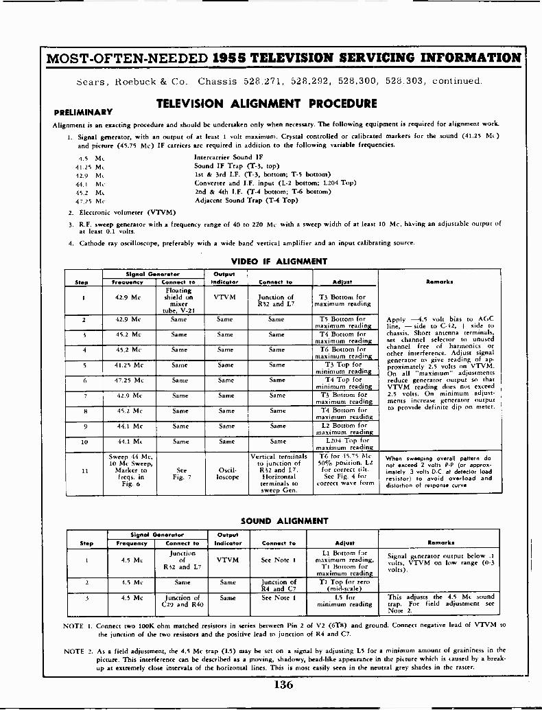
MOST -OFTEN -NEEDED 1955 TELEVISION SERVICING INFORMATION
Sears, Roebuck & Co. Chassis 528.271, 528.292, 528.300, 528.303, continued.
TELEVISION ALIGNMENT PROCEDUREPRELIMINARYAlignment is an exacting procedure and should be undertaken only when necessary. The following equipment is required for alignment work.
1. Signal generator, with an output of at least 1 volt maximum. Crystal controlled or calibrated markers for the sound (41.25 Mc)and picture (45.75 Mc) IF carriers are required in addition to the following variable frequencies.
4.5 Mc Intercarrier Sound IF41.25 Mc Sound IF Trap (T-3, top)42.9 Mt 1st & 3rd I.F. (T-3, bottom; T-5 bottom)44.1 Mc Converter and I.F. input (L-2 bottom; L204 Top)45.2 Mc 2nd & 4th I.F. (T-4 bottom; T-6 bottom)47.25 Mc Adjacent Sound Trap (T-4 Top)
2. Electronic voltmeter (VTVM)
3. R.F. sweep generator with a frequency range of 40 to 220 Mc with a sweep width of at least 10 Mc, having an adjustable output ofat least 0.1 volts.
4. Cathode ray oscilloscope, preferably with a wide band vertical amplifier and an input calibrating source.
VIDEO IF ALIGNMENT
StepSignal Generator Output
Indicator C t to Adjust Remarks
Apply -4.5 volt bias to AGCline, - side to C-42, + side tochassis. Short antenna terminals,set channel selector to unusedchannel free of harmonics orother interference. Adjust signalgenerator to give reading of ap-proximately 2.5 volts on VTVM.On all "maximum" adjustmentsreduce generator output so thatVTVM reading does not exceed2.5 volts. On minimum adjust -ments increase generator outputto provide definite dip on meter.
Fr Connect to
1 42.9 McFloatingshield on
mixertube. V-21
VTVM Junction ofR32 and L7
T3 Bottom formaximum reading
2 42.9 Mc Same Same Same T5 Bottom formaximum reading
3 45.2 Mc Same Same Same T4 Bottom formaximum reading
4 45.2 Mc Same Same Same T6 Bottom formaximum reading
5 41.25 Mc Same Same Same T3 Top forminimum reading
6 47.25 Mc Same Same Same T4 Top forminimum reading
7 42.9 Mc Same Same Same T3 Bottom formaximum reading
8 45.2 Mc Same Same Same T4 Bottom formaximum reading
9 44.1 Mc Same Same Same L2 Bottom formaximum reading
10 44.1 Mc Same Same Same L204 Top formaximum reading
11
Sweep 44 Mc,10 Mc Sweep,
Marker tofreqs. inFig. 6
SeeFig. 7
Oscil-loscope
Vertical terminalsto junction ofR32 and 17.Horizontalterminals tosweep Gen.
T6 for 45.75 Mc50% position. L2for correct tilt.See Fig. 4 for
correct wave form
When sweeping overall pattern donot exceed 2 volts P -P (or approx-imately .3 volts D.C. at detector loadresistor) to avoid overload anddistortion of response curve.
SOUND ALIGNMENT
StepSignal Generator Output
Indicator Connect to Adjust RemarksFrequency Connect to
1 4.5 McJunction
of1232 and L7
VTVM See Note 1LI Bottom far
maximum reading,TI Bottom for
maximum reading
Signal generator output below .1volts, VTVM on low range (0-3volts).
2 4.5 Mc Same Same Junction ofR4 and C7
T1 Top for zero(mid -scale)
3 4.5 Mc Junction ofC29 and R40
Same See Note I L5 forminimum reading
This adjusts the 4.5 Mc soundtrap. For field adjustment seeNote 2.
NOTE 1. Connect two 100K ohm matched resistors in series between Pin 2 of V2 (6T8) and ground. Connect negative lead of VTVM tothe junction of the two resistors and the positive lead to junction of R4 and C7.
NOTE 2. As a field adjustment, the 4.5 Mc trap (L5) may be set on a signal by adjusting L5 for a minimum amount of graininess in thepicture. This interference can be described as a moving, shadowy, bead -like appearance in the picture which is caused by a break-up at extremely close intervals of the horizontal lines. This is most easily seen in the neutral grey shades in the raster.
136
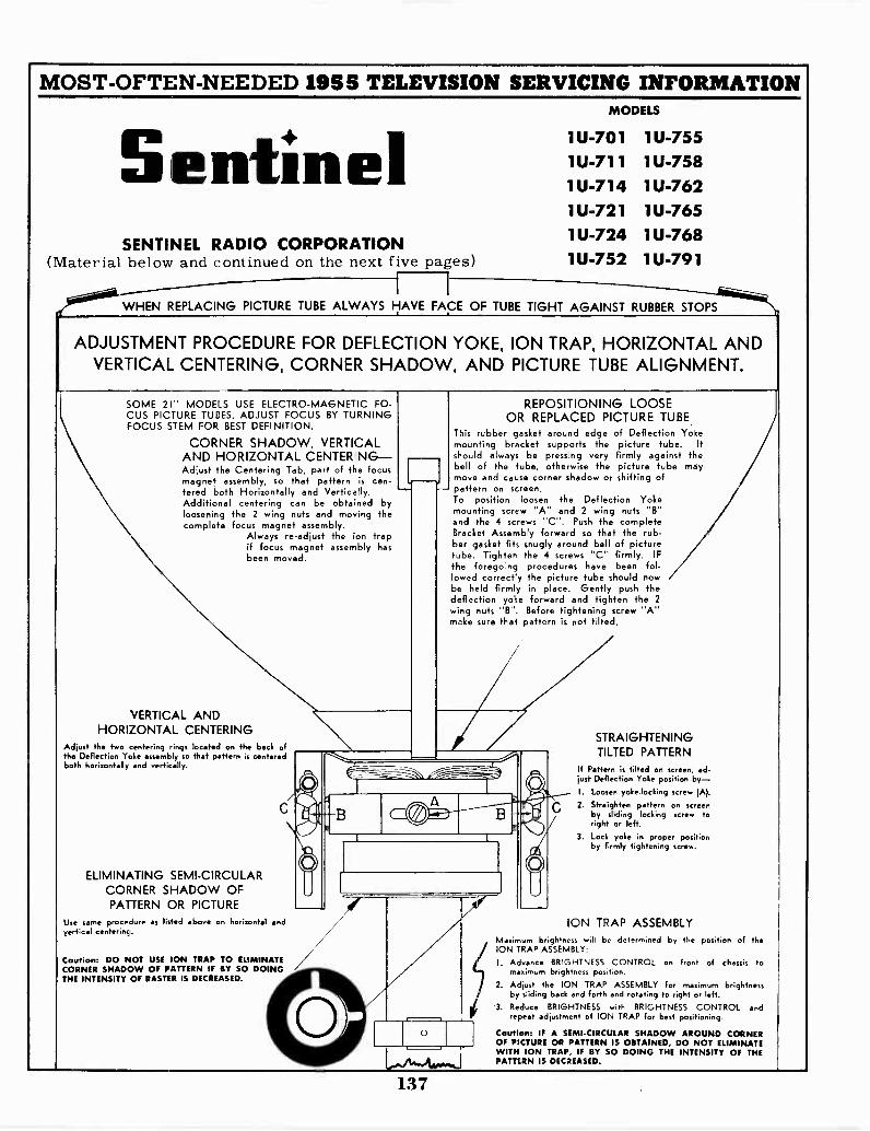
MOST -OFTEN -NEEDED 1955 TELEVISION SERVICING INFORMATIONMODELS
SentinelSENTINEL RADIO CORPORATION
(Material below and continued on the next five pages)
1U-701 1U-7551U-711 1U-7581U-714 1U-7621U-721 1U-7651U-724 1U-7681U-752 1U-791
WHEN REPLACING PICTURE TUBE ALWAYS HAVE FACE OF TUBE TIGHT AGAINST RUBBER STOPS
ADJUSTMENT PROCEDURE FOR DEFLECTION YOKE, ION TRAP, HORIZONTAL ANDVERTICAL CENTERING, CORNER SHADOW, AND PICTURE TUBE ALIGNMENT.
SOME 21" MODELS USE ELECTRO-MAGNETIC FO-CUS PICTURE TUBES. ADJUST FOCUS BY TURNINGFOCUS STEM FOR BEST DEFINITION.
CORNER SHADOW, VERTICALAND HORIZONTAL CENTER INGAdjust the Centering Tab, part of the focusmagnet assembly, so that pattern is cen-tered both Horizontally and Vertically.Additional centering can be obtained byloosening the 2 wing nuts and moving thecomplete focus magnet assembly.
Always re -adjust the ion trapif focus magnet assembly hasbeen moved.
VERTICAL ANDHORIZONTAL CENTERING
Adjust the two centering rings located on the beck ofthe Deflection Yoke assembly so that pattern is centeredboth horizontally and vertically.
ELIMINATING SEMI -CIRCULARCORNER SHADOW OFPATTERN OR PICTURE
Use same procedure as listed above on horizontal andvertical centering.
Caution: DO NOT USE ION TRAP TO ELIMINATECORNER SHADOW OF PATTERN IF BY SO DOINGTHE INTENSITY OF RASTER IS DECREASED.
REPOSITIONING LOOSEOR REPLACED PICTURE TUBE.
This rubber gasket around edge of Deflection Yokemounting bracket supports the picture tube. Itshould always be pressing very firmly against thebell of the tube, otherwise the picture tube maymove and cause corner shadow or shifting ofpattern on screen.To position loosen the Deflection Yokemounting screw "A" and 2 wing nuts "B"and the 4 screws "C". Push the completeBracket Assembly forward so that the rub -
aet fits snugly around bell of picturee. Tighten the 4 screws "C" firmly. IF
the foregoing procedures have been fol-lowed correct'y the picture tube should nowbe held firmly in place. Gently push thedeflection yoke forward and tighten the 2wing nuts "B". Before tightening screw "A"make sure that pattern is not tilted.
STRAIGHTENINGTILTED PATTERN
If Pattern is tilted on screen, ad-just Deflection Yoke position by-I. yoke -locking screw (A).
2. Straighten pattern on screenby sliding locking screw toright or left.
3. Lock yoke in proper positionby firmly tightening screw.
ION TRAP ASSEMBLYMaximum brightness will be determined by the position of theION TRAP ASSEMBLY:
I. Advance BRIGHTNESS CONTROL on front of chassis tomaximum brightness position.
2. Adjust the ION TRAP ASSEMBLY for maximum brightnessby sliding back and forth and rotating to right or left.Reduce BRIGHTNESS with BRIGHTNESS CONTROL andrepeat adjustment of ION TRAP for best positioning.
Caution: IF A SEMI -CIRCULAR SHADOW AROUND CORNEROF PICTURE OR PATTERN IS OBTAINED, DO NOT ELIMINATEWITH ION TRAP, IF BY SO DOING THE INTENSITY OF THEPATTERN IS DECREASED.
137
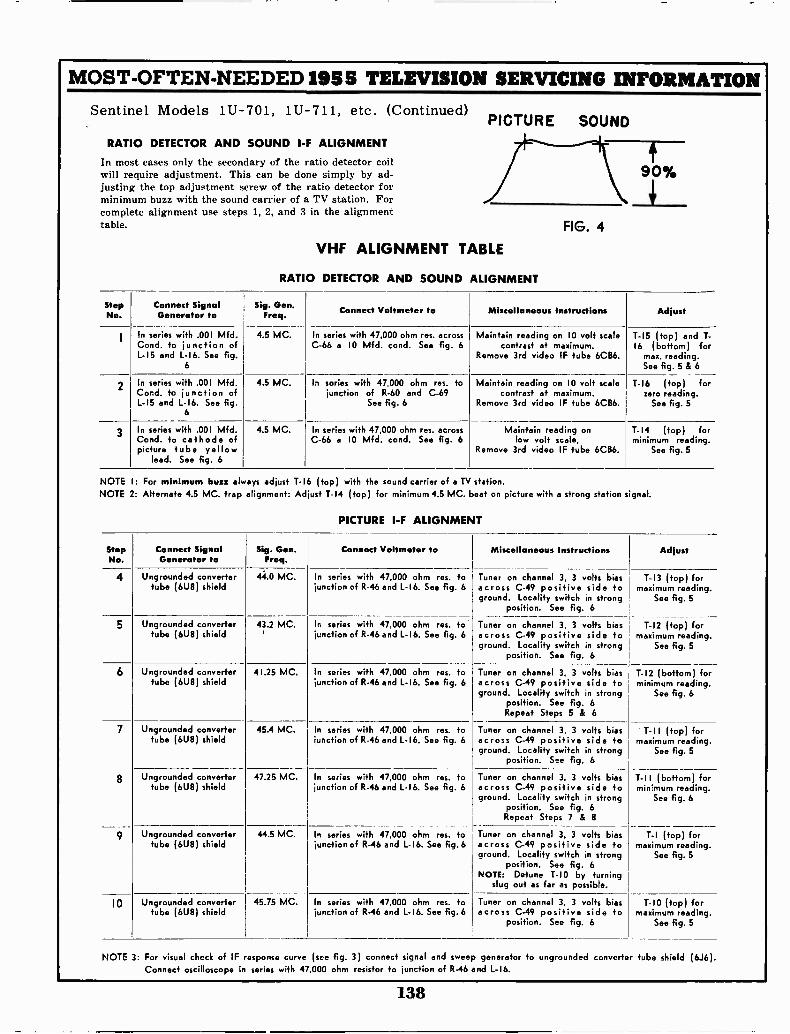
MOST -OFTEN -NEEDED 1955 TELEVISION SERVICING INFORMATIONSentinel Models 1U-701, 1U-711, etc. (Continued)
RATIO DETECTOR AND SOUND I -F ALIGNMENT
In most cases only the secondary of the ratio detector coilwill require adjustment. This can be done simply by ad-justing the top adjustment screw of the ratio detector forminimum buzzbuzz with the sound carrier of a TV station. Forcomplete alignment use steps 1, 2, and 3 in the alignmenttable.
VHF ALIGNMENT TABLE
RATIO DETECTOR AND SOUND
PICTURE SOUND
90%
FIG. 4
ALIGNMENT
StepNo.
C t SignalGenerator to
Sig. Gen.Freq. Connect Voltmeter to Miscell s Instructions Adjust
1 In series with .001 Mfd.Cond. to junction ofL -I5 and L-16. See fig.
6
4.5 MC. In series with 47,000 ohm res. acrossC-66 a 10 Mfd. cond. See fig. 6
Maintain reading on 10 volt scalecontrast at maximum.
Remove 3rd video IF tube 6CB6.
T -I5 (top) and T-16 (bottom) for
max. reading.See fig. 5 & 6
2 In series with .001 Mfd.Cord. to junction ofL -I5 and L -I6. See fig.
6
4.5 MC. In sories with 47,000 ohm res. fojunction of R-60 and C-69
See fig. 6
Maintain reading on 10 volt scalecontrast at maximum.
Remove 3rd video IF tube 6CB6.
T -I6 (top) forzero reading.
See fig. 5
3 In series with .001 Mfd.Cond. to cathode ofpicture tube yellow
lead. See fig. 6
4.5 MC. In series with 47,000 ohm res. acrossC-66 a 10 Mfd. cond. See fig. 6
Maintain reading onlow volt scale,
Remove 3rd video IF tube 6CB6.
T -I4 (top) forminimum reading.
See fig. 5
NOTE I: For minimum buzz always adjust T- 6 (top) with the sound carrier of a TV station.NOTE 2: Alternate 4.5 MC. trap alignment: Adjust T-14 (top) for minimum 4.5 MC. beat on picture with a strong station signal.
PICTURE I -F ALIGNMENT
StepNo.
Connect SignalGenerator to
Sig. Gen.Freq.
Connect Voltmeter to Miscell s Instructions Adjust
4 Ungrounded convertertube (6U8) shield
44.0 MC. In series with 47,000 ohm res. tojunction of R-46 and L-16. See fig. 6
Tuner on channel 3, 3 volts biasacross C-49 positive side toground. Locality switch in strong
position. See fig. 6
T -I3 (top) formaximum reading.
See fig. 5
5 Ungrounded convertertube (6U8) shield
43.2 MC. In series with 47,000 ohm res. tojunction of R-46 and L -I6. See fig. 6
Tuner on channel 3, 3 volts biasacross C-49 positive side toground. Locality switch in strong
position. See fig. 6
T -I2 (top) formaximum reading.
See fig. 5
6 Ungrounded convertertube (6U8) shield
41.25 MC. In series with 47,000 ohm res. tojunction of R-46 and L -I6. See fig. 6
Tuner on channel 3, 3 volts biasacross C-49 positive side toground. Locality switch in strong
position. See fig. 6
Repeat Steps 5 & 6
T -I2 (bottom) forminimum reading.
See fig. 6
7 Ungrounded convertertube (6U8) shield
45.4 MC. In series with 47,000 ohm res. tojunction of R-46 and L -I6. See fig. 6
In series with 47,000 ohm res. tojunction of R-46 and L-16. See fig. 6
Tuner on channel 3, 3 volts biasacross C-49 positive side toground. Locality switch in strong
position. See fig. 6
T -I I (top) formaximum reading.
See fig. 5
T -I I (bottom) forminimum reading.
See fig. 6
8 Ungrounded convertertube (6U8) shield
47.25 MC. Tuner on channel 3, 3 volts biasacross C-49 positive side toground. Locality switch in strong
position. See fig. 6Repeat Steps 7 & 8
9 Ungrounded convertertube (6U8) shield
44.5 MC.
45.75 MC.
response curveseries with 47,000
In series with 47,000 ohm res. tojunction of R-46 and L -I6. See fig. 6
Tuner on channel 3, 3 volts biasacross C-49 positive side toground. Locality switch in strong
position. See fig. 6NOTE: Detune T -I0 by turning
slug out as far as possible.
T -I (top) formaximum reading.
See fig. 5
10 Ungrounded convertertube (6U8) shield
In series with 47,000 ohm res. tojunction of R-46 and L-16. See fig. 6
(see fig. 3) connect signal and sweepohm resistor to junction of R-46
Tuner on channel 3, 3 volts biasacross C-49 positive side to
position. See fig. 6
T -I0 (top) formaximum reading.
See fig. 5
NOTE 3: For visual check of IFConnect oscilloscope in
generator to ungrounded converter tube shield (6.16).and L -I6.
138
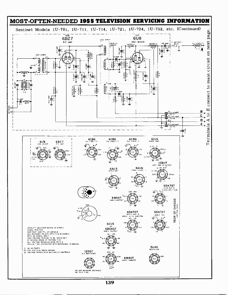
MOST -OFTEN -NEEDED 1955 TELEVISION SERVICING INFORMATION
r
T
1U-711, 1U-714, 1U-721, 1U-724, 1U-752, etc. (Continued)vie
6BZ7FIE AMP.
I.F
Sentinel Models 1U-701,
ANTSTRIP
OSC STRIP
'COUPLING
'47`7,;',.-
V17
6U8OSC-MIXER
I00,0004, MIXER
7
I F OUTPUT470 MN I PLUG I, VIDEO I. F.
4'T -.1-400000 "A
1000 mrAF
A I -0' 07 oFMF
Cli000
L--
TC-I9
-
65-90V.
- TO-v
L
61.1)3OSC. MITER
120V
205
6BZ7R F AMP
Ov
LOCALITY ADJUSTER SWITCH IN STRONGSIGNAL POSITION.CONTRAST CONTROL AT MINIMUM.ALL READINGS UNLESS SPECIFIED MEASUREDWITH NO SIGNAL INPUTHIGH VOLTAGE READING TO BE TAKEN ONLYAT SECOND ANODE OF PICTURE TUBE.
ALL VOL-AGE READINGS MADE WITH AVACUUM YuBE VOLTMETER, WITH REFERENCE TO GROUND.
AG VOLTAGESU 520 VOLTS DC ABOVE GROUND
VOLTAGE VARIES WITH SETTING OF CONTROLS
6CB61ST vIDEC I F
6.3*
25
125
I 360
1B3GTH.v. RECTIFIER
DO NOT MEASURE VOLTAGESON THIS TUBE
6CB6
6AL5RATIO Del
6W6GTAUDIO OUTPUT
6CU 6OR
6B06GTHORa OUTPUT
NC
NC
NC
NC i40
550 NC
-28
NC
6CB6
25
025
4, 225
6AU6.smc SOUND
95
95
255 265
6SN7GTAUDIO AMP
HORiZ A F C. CONTROLU.S -1.8
158
6W4GTHORIZ. DAMPER
O
2.5
6CL6VIDEO AMP
225.,
240
12BH7HART OSC 8 OUTPUT
e, 125 6.3*
c, .00
520
-28
0
65 N 7GTSYNC SEP 8
W.p,HSE SPLITTER
6SN7GTHoFta 05C
5U 4GRECTIFIER
285
a;an
a.
a)
0
0;-4
.r4U
,-1ctl
0
c)
a)
0
13C.
139
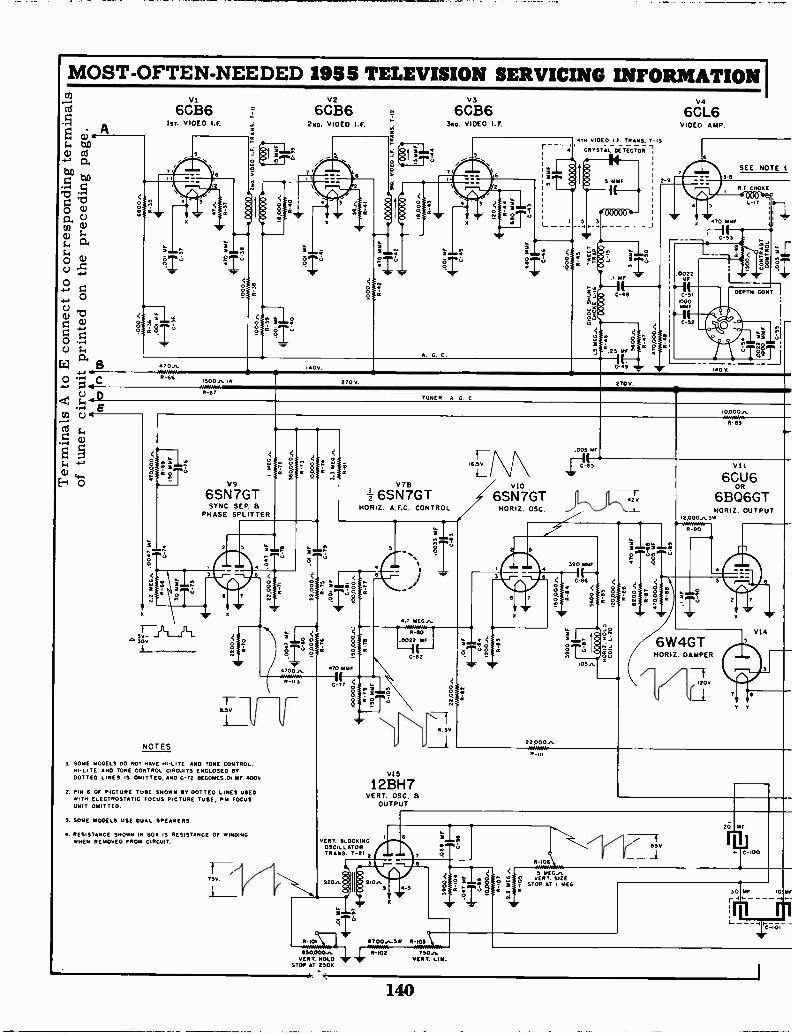
MOST -OFTEN -NEEDED 1955 TELEVISION SERVICING INFORMATION I
74 6C136 = 6636 663B6 6641_6vi V2
VIn. VIDEO I.F. 211o. V DEO LF. f Sno. VIDEO I.F. VIDEO AMP.
0.;$. 110
r to
"
-a0oQ)
o.co w
a.
BC
70.,R-66
NOTES
0
L_ 2 ,
3
3 5SEE NOTE
Ar CHORE2-9
00000 4--
C-46 DEPTH CONY
15006, 270V 270VR-67
V9
6SN7GTSYNC SEP. a
PHASE SPLITTER
115v
1 SOME. MODELS 00 NOT HAVE HI-LITE AND TONE CONTROL.HI-LITE AND TONE CONTROL CIRCUITS ENCLOSED STDOTTED LINES IS OMITTED. AND C-72 BECOMES.01 MF 4000
2. PIN 6 Of PICTURE TUBE SHOWN NT DOTTED LINES USEDWITH ELECTROSTATIC FOCUS PICTURE TUBE, Pld FOCUSUNIT OMITTED.
3. SOME MODELS USE DUAL SPEAKERS.
A. RESISTANCE SHOWN IN BOB IS RESISTANCE OF WINDING.WHEN REMOVED FROM CIRCUIT.
TUNER A C. C
V7B
6SN7GTHORIZ. A.F.C. CONTROL
4.7 mE6.6.._
R-60.0022 MF
C-62
12BH7VERT. OSC.
OUTPUT
VERT. BLOCKINGOSCILLATORTRANS. T 21
9206,
R.d% I 57 00.H_SW
VERT. HOLD
6* *A1110,000 .6.. ER -102 750
VERT. Lill..n.
STOP AT 2506
6SN7GT j1..\2vHORIZ. OSC.
6W4GTHORIZ. DAMPER
---f120v
77.I IR-i0L
5 MEG,.VERT. SIZE
STOP AT MEG
100006,
B -NO
Vii
6CU6OR
6B06GTHORIZ. OUTPUT
2
'9,
VI45
7 II
V IC -100
140
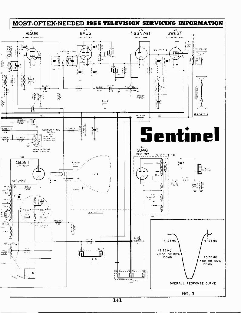
MOST -OFTEN -NEEDED 1955 TELEVISION SERVICING INFORMATIONV5 V6 V7A V8
6AU6 6AL5 -6SN7GT 6W6GT4 5MC SOUND I.F. RATIO DET. AUDIO AMP. AUDIO OUTPUT
O
O
8O
.005 is.
C-62
RATIO OET. COIL
C -6i
0
C-66
A 101 kW
470,- 33.0R-57 R-60
005 MfR
VOL. CONT_
68,000.,
63
SEE NOTE 1
-J
2700 50,1w 265 v
°P114 57E00E7
IIt O
22 000,
V12
005
LOCALITY ADJSWITCH
SW .I
WEAK SIGMEDIUM SIG.STRONG SIG.
SHOWN IN STRONGSIGNeL POSITION
1B3GTH.V. RECT.
H0R12 OUTPUTTRANS T-10
3130,i
IT
5
"^ITH
21
3T
2 5,1
35,
6.8,
.00000,5-96s
PM FOCUS
2 .0
UNIT
R-95
MF6
C -S. /
DE LOTION YOKET -P9
220000,,8-98
,5,000v
V18
SEE NOTE 2
220u,
R -u 0
VERT )UTP0TTRANS T-22
780.,T
12'1
AWAY*,5-109
300
R-109
6C MF
2
r
SEE NOTE 3
Sentinel013
5U4GRECTIFIER POWER TRANS T-20
29,
O,
L -
FILTERCHOKE
IP( 0-0600 "L-22
100 MF 60 ME
C-,01
TO 6W4GTFIL
-.I ----
FIG. 3
141
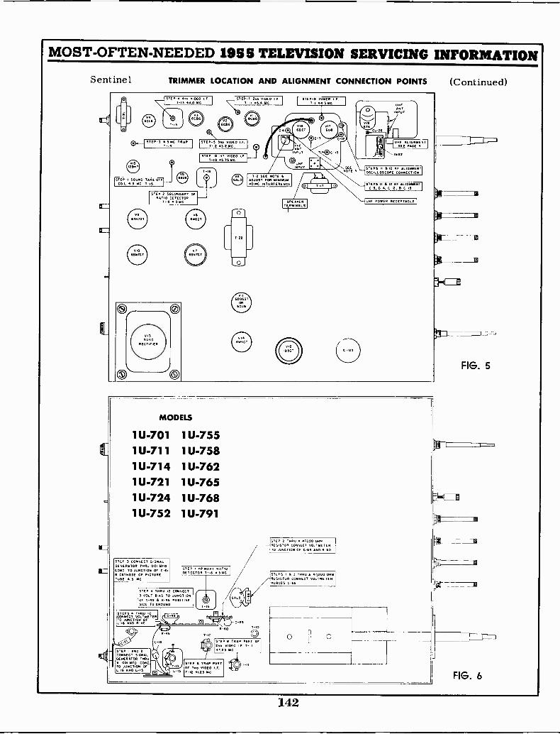
VII
MOST -OFTEN -NEEDED 1955 TELEVISION SERVICING INFORMATION
Sentinel TRIMMER LOCATION AND ALIGNMENT CONNECTION POINTS
60.8
STEP- 4T4 VIDEO I.F.
T -I3 ANA MC
43GCB*
I sTEPT 244 VIDEO I F
-i$ 9.4 MC
OH STEP -3 TRAP STEP -5 344 VIDEO I.F.T it 43 2 MC
I STEP 10 KT VIDEO I.F.T-10 45.75 MC
9STEP -I SOUND TAKE OFF
COIL 4.5 MC T -IS
T 16
STEP -2 SECONDARY OFRATIO DETECTOR
T16 5NC
641:GT
O
STEP -9 Tu.,. I.F.. 44 5 .AC
1.2 SEE NOTE 6ADJUST FOR MINIMUM4010 INTERFERENCE ciNEZEIIIRD
SPEAKER1111INLS
SEENOTE
O
6T4
OTT AL,4/6491: T
STEPS II it RF AL.OSCILLOSCOPE CONNECTION
STEPS II it RF ALIGNMENTC3, C-4, C -I2, C -IS
(Continued)
5
MODELS
1U-701 1U-7551U-711 1U-7581U-714 1U-7621U-721 1U-7651U-724 1U-7681U-752 1U-791
STEP 3 CONNECT SIGNALGENERATOR TNRU VCR MEDCOND. TO JUNCTION OF C -NIS CATNODE OF PICTURETUDE .3 YC
STEP I PRIMARY RATIODETECTOR T-16 4.51,1C
STEP TNRu I CONNECT3 VOLT BIAS TO JUNCTIONOF C49 A R46 POSITIVESIDE TO GROUND
STEPS 'NOW 10CONNECT VOLTMETERTO JUNCTION OF-IS AND 11-,14
STEP I AND 2CONNECT SIGNALGENERATOR THI.A .001 MED. COND.TO JUNCTION OFL -I4 ASO L-15
C-69
R-60 T -i0
STEP 0 TRAP PART OFVIDEO I.F. T -I1
2A25 ML
STEP II TRAP PARTOf 3. VIDEO I.F.T12 41.25 MC
STEP 2 TNNU T,000 ONORESISTOR CONNECT VOLTMETERTO JUNCTION OF C..69 AND R-60
STEPS I 3 THIN, 47,000 ONRESISTOR CONNECT VOLTMETERACROSS C-66
0 0
FIG. 5
J
FIG. 6
142
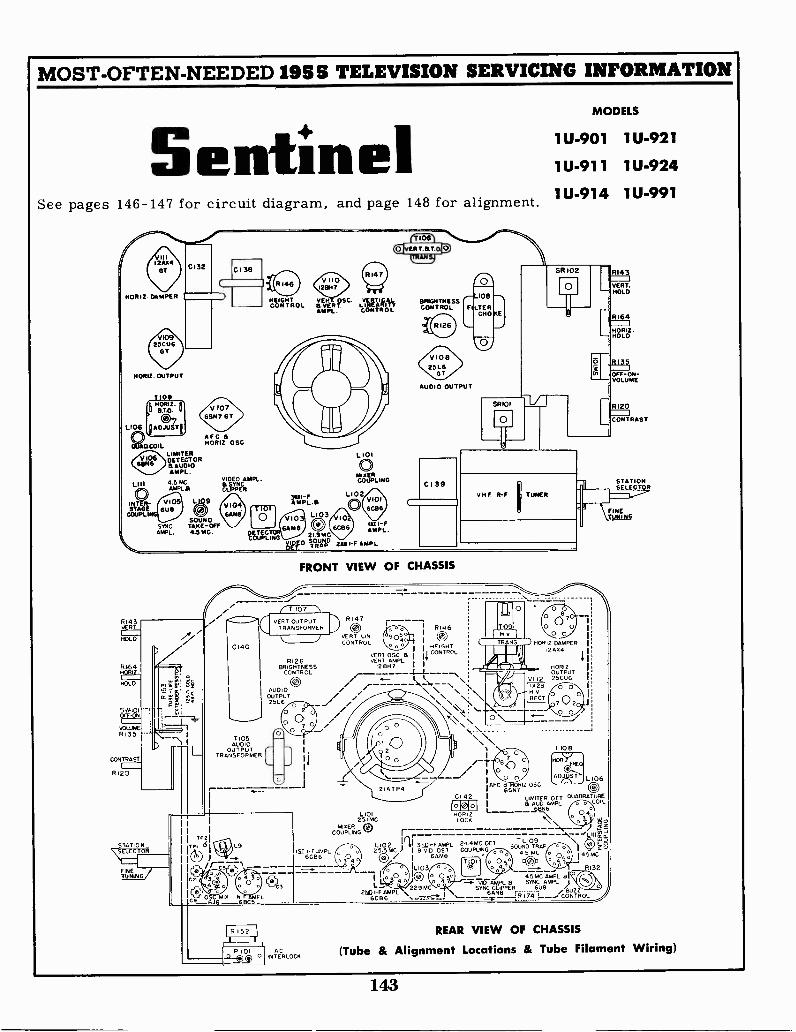
HEIGHTCONTROL gaif!5`. LIWINN9
AMPL. CONTROL
6SN7 GT
F CHORI2. 05C
LIMITERDETECTOR15 AUDIOAMPL.
4.5 MC.MAPLE
SOUNDSYNC TAKE -CifAMPL. 4.5 MC.
MOST -OFTEN -NEEDED 1955 TELEVISION SERVICING INFORMATION
SentinelSee pages 146-147 for circuit diagram, and page 148 for alignment.
HORI2. DAMPER
10925CU6
GT
HORIZ. OUTPUT
STAGECOUPLI
P143VERT
HOLD
14464HORIZ
LD
CONTRAST1
RI20
FINE
TP21
TOI L9
arcs
-71010
DETEC
<
7105AUDIO
OUTPUTTRANSFORMER
MIXERCOUPLING
re N)
BRIGHTNESS1013
CONTROL FILTERCHOKE
VIOEI25L6
GT
AUDIO OUTPUT
FRONT VIEW OF CHASSIS
R126BRIGHTNESS
CONTROL
C21
-
P 1010 1 INTERLOCKC
I RI46VERT LIN 0CONTROL 1
VERT OSC ao I I "EIGHT
vEll AMPL11 CONTROL
12 0,17
k
\/ r-/- -/' \ \ \ \
/ , \
1-F AMPL6C86
L10125 1MC
ECOUPLING
",.\.\ -- ----- - - - - ----------- ---\\ \\ N
5
/ 1.
,'--o , L106
'AFC 1ZsBIZ OSC 0CI 42 I LIMITER OCT OuADRATURE
I B AUD AMPL a COQ.
1------_Jk46TYN
L7\
MODELS
1U-901 1U-921
1U-911 1U-924
1U-914 1U-991
HOR,Z DAMPER 1
1 220,4
HOR1ZOUTPUT
V x1 21 26
NVRECT
1
T 10E1
14101HOR,ZLOCO
qET - -\-- '&10,2E1 IL102 ,,..E,D,_F AWL 24 4MC OCT -L109
SOUND TRAP\
2 5.5MC 2 I RAID DET COUPLING 45 MC 10/ 1 GAMS a 1 4 5MC
-- 1L1034t* -ff
RI32/
I1 , 4 5 MC AMPL GIT
L-0
29MC-"---7:7/10 AMPL a SYNC AMPL I
2ND i-F AMPL \ I \ 6ANB i4 ; jauz z6CB6
r,iAU
CONTROL
SYNC CLIPPER EI
RI43
VERT.HOLD
R164
HO RIZHOLD
RI35
OFF-04-VLUMEO
R120
CONTRAST
STATIONSELECTOR
FINETUNING
REAR VIEW OF CHASSIS
(Tube & Alignment Locations & Tube Filament Wiring)
143
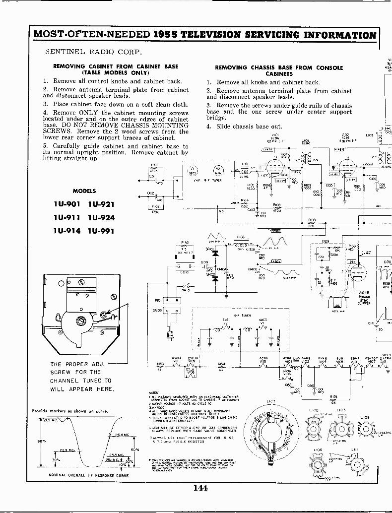
MOST -OFTEN -NEEDED 1955 TELEVISION SERVICING INFORMATION
SENTINEL RADIO CORP,
REMOVING CABINET FROM CABINET BASE(TABLE MODELS ONLY)
1. Remove all control knobs and cabinet back.2. Remove antenna terminal plate from cabinetand disconnect speaker leads.3. Place cabinet face down on a soft clean cloth.4. Remove ONLY the cabinet mounting screwslocated under and on the outer edges of cabinetbase. DO NOT REMOVE CHASSIS MOUNTINGSCREWS. Remove the 2 wood screws from thelower rear corner support braces of cabinet.5. Carefully guide cabinet and cabinet base toits normal upright position. Remove cabinet bylifting straight up.
MODELS
1U-901 1U-921
1U-911 1U-924
1U-914 1U-991
THE PROPER ADJ.SCREW FOR THECHANNEL TUNED TOWILL APPEAR HERE.
Provide markers as shown on curve.
21.9 MC.
98%
[ tMC.
4_%
NOMINAL OVERALL I -F
26.4 MC
25.5 MC.
ol4 1(470
4
6 %
R1011-'vwv
C102
1(470
R102
47QK
RI53
REMOVING CHASSIS BASE FROM CONSOLECABINETS
1. Remove all knobs and cabinet back.2. Remove antenna terminal plate from cabinetand disconnect speaker leads.3. Remove the screws under guide rails of chassisbase and the one screw under center supportbridge.4. Slide chassis base out.
6BC5
V2
VHF R -F TUNER
2
R105700
8104
8152
7 5SEE NOTE 7
RED
1000
V1016C86
SST PIX L10225.5MC
42V,
91075 10K
6
004J25v, k),201
R106 RI0947 1000
-11
R108NAN`
C103__ 4700r001
005
RII01000
V1026086
280 Pix IF
005MFD
RII2
R111
1000
68
L103
11
VI91
456An
219000101
22 9NC
C106
T.005F0
AGC
R103AWN,220
L108
00000V -L-22V ,P
SRI01 30's C132R ° 79 P -P
200NIFD
0139
6U6V2
040C
R. F TUNER
200MFD 0.2V P -P
68C5VI
4 3
QAX4 25CU6VIII V109
8 7
432
25L6V108
1AL
RI54
6C86V101
4
G129_
INW0K
220E
1.25 TTTT MEG
2I
45V. P -P
6%2642 6/I'6AN 8 6U8V104 V105
RI38MEG.
j.1691
V1048Y26A1.48SYNC.
CLIPPER
12887
3 5 4 S 4 5 4
43
NOTES'
I ALL VOLTAGES MEASURED WITH AN ELECTRONIC VCI_TMETERCONNECTED FROM SOCKET LUG TO CHASSIS, SEE FOOTNOTE
2 SUPPLY VOLTAGE 117 VOLTS 60 CfCLE AG3.K 10004 ALL C,APACITANCE VALUES IN MME a ALL RESISTANCE
NILUES IN OHMS UNLESS OTHERWISE NOTED5 LUG 3 CONNECTED TO BOOST VOLTAGE a LUG 3,885
CONNECTED INTERNALLY.
6.C134 MAY BE EITHER A.047 OR .033 CONDENSER.ALWAYS REPLACE WITH SAME VALUE CONDENSER.
7 ALWAYS USE EXACT REPLACEMENT FOR R -I5 2,A 7,5 OHM FUSIBLE RESISTOR
SOME vOLTAO6 ARE VARABLE At VOLTAGES 940. AtRE MEASUREDM11H NO., INCIIRE ON THE PGTURE TUBE IWO THE CONTRAST10% C. Nvo 10650 NESS awn°, so' FOR SO DOLTS PEAK TO PEN) ONTmE cArriCOE (RN m 1 Of THE PiCTsv, TLEIE.SOOKET VOLTAGETOLERANCE! 10i.
RESPONSE CURVE
2 7;TE7-irl,i
L107
68N6V106
0155
r80156
TatRI74(266
L102 L103
i-Lt4T,N6
0141
C130]
I7V.
81394713
35
7-20
7svP46SN7GT 21ATP4
10 107 V113
LI 09
LOCATINGLIP
144

IMOST -OFTEN -NEEDED 1955 TELEVISION SERVICING INFORMATIONSP 01
V106ow( 7105
CA21 LI II LIMITERDETECTOR
CAu911281 tg66N6. 470 2V5L1086GT
OUIRITBAJDi0 AWL 02
MFD.
I lovl C1251260v
4.PM. SPEAKERRED
C12 .095POD
MFD. R131)18K
2 601
RI32500
BUZZCONTROL
P134
L106
0124 iiiMED
TR
T5
-C-1 C126T.001MFD.
3135 GIST330K 2
MFD,ccVOLUMEcL
142v
z 5v
1.150vr RI36
4R137
706
560K
V103A V1038)060M8 TIOI 126Am8
3110 FIX 1-F 24.4140 RID. SET
10.14601
9, 1...14Ew I6 0 ii
P115_- Aw.,
l000
1 +.1.0 0109
-
. 00501081 MFD1-005 0114 7" R116 CHO
MED 100 10007.
E5'701 L104
ago37"
C112
10T
clod_T5
C111
11118
566
CII6
0 r
IMEG. VIDEO AMPL.Y26AN8V104A
_1000 L.
....\1+2111,4 1.41-CII5 33 LII2 < CII7 wv"
0113 911 L.1.: 71.1
eV(L---4 nr=i (0, ''Tu"-,R
U
MFD. .P.31v1
MFD 217.1,g . - 276U:,T<3V P -P
I.75MFD 1
_1_
o
336 3
L105
io To 2t,js
R12147
!Im
4._____
la) RI 24
=
RI 26Amm
BRIGHTNESS7 15005 66CONTRAST
1ggMriRotCONTROL
111258.26
j,{r moot
PiCTuRE TUBEVI I 3
11 6
1«15001
)26ov
1140.66
_
= VI0513426028SYNC.AMPL.
1.141V
47K
CI31_
0132A-_:RI42
000
22 706 ,10191_MED.
OOb .01
MFD NE
300 p -p
RI64145K
71:3( 5 02Kea. HOLD
3
ELL( TI06 y0,0%,
65V P -P
RI43i MEG. - VIIOA3605 ', vERT,STOP Hol_D, 112128H7
CONT. VERT.DSC.
C134_47047 11:1,.v.
MFD
, SEENOTE 6 3
25 MEG
imEG. STOPHEIGHTCONT.
CI43
R---)1 00
0142 NOR1ZLOCK1
6
81595606
1.4 P -P 81601506
2
276
R166 P1671006 1506 I'6"'
0146 1108
FM.8,
3
2.7mEG.
V107AF265N7GT
HOW. AFC.
i6161 11162 P163I50< 1006 826
0244 C1451
TOWINAL 00C31E113
T108
I 4
2 3
T 101
2 3
RED DOT
TIO9
-25TWD MFD. V1078Y26SN7GTHORIZ 0Sc
9:
-9001
T107
R169o8K p4-^
io
C1471E111
OIMFD
375,
p -PC1491
I3000150
CAP
R170470K
V10925C U6
1161112 OUTPUT
0173
100
OVER
P -P
ELLE
VII0 BF2128M7
OUTPUL
31400
6
RI47750VERTLIN.
0137
014B
T107 4
on 680GREEN -TEL
500.,EL. C136
1.005MFD.
1_10 7-AGRN-BLACK - 7
0156: T4.....,c)680, ,4'6
51MFD
7 51(
Ri57, c;
C14
30C138 -
20MED.
SEE NOTE 5.
3100PP
RI5039
RI5 I820K
CI51
-1.111000 P P
I p0AL
VIII12AX4
DAMPER5
C152 09.
182P o4 5
260 vI
FOCUSIt may be possible to obtain better focus with re-placement picture tubes, if the electronic focusanode is connected to a point other than the +150volt line.Suggested points to try are : chassis ground, +260volts, +285 volts (picture tube pin 10) and +480volt line.
V1121028
RECT.
71T109
6
g'T.
3 CI53<7, 11 I
.068I CI54
0
1417k5IFD. -7-6fl? 4 700 '4,
4 GREEN
I
)«48001 - p(15 BLALS
I 3KV.1
L107-13H OR IC.DEFtYOKE
145
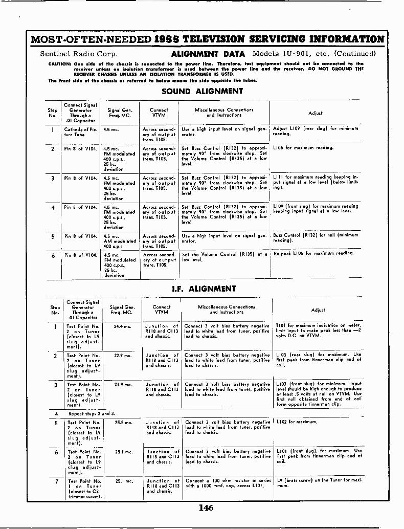
MOST -OFTEN -NEEDED 1955 TELEVISION SERVICING INFORMATIONSentinel Radio Corp. ALIGNMENT DATA Models 1U-901, etc. (Continued)
CAUTION: One side of the chassis is connected to the power line. Therefore, test equipment should not be connected to thereceiver unless an isolation transformer is used between the power line and the receiver. DO NOT GROUND THERECEIVER CHASSIS UNLESS AN ISOLATION TRANSFORMER IS USED.
The front side of the chassis as referred to below means the side opposite the tubes.
SOUND ALIGNMENT
StepNo.
Connect SignalGeneratorThrough a
.01 Capacitor
Signal Gen.Freq. MC.
ConnectVTVM
Miscellaneous Connectionsand Instructions Adjust
I Cathode of Pic-ture Tube
4.5 mc. Across second-ary of outputtrans. 1105.
Use a high input level on signal gen-erator.
Adjust 1109 (rear slug) for minimumreading.
2 Pin 8 of VI04. 4.5 mc.FM mocklated400 c.p.s.,25 kc.deviation
Across second-ary of outputtrans. T105.
Set Bun Control (R132) to approxi-mately 90° from clockwise stop. Setthe Volume Control (R135) at a lowlevel.
L106 for maximum reading.
3 Pin 8 of V104. 4.5 mc.FM modulated400 e.p.s.,25 kc.deviation
Across second-ary of outputtrans. T105.
Set Bun Control (RI32) to approxi-mately 90° from clockwise stop. Setthe Volume Control (R135) at a lowlevel.
LI II for maximum reading keeping in -put signal at a low level (below limit -ing).
4 Pin 8 of V104. 4.5 mc.FM modulated400 c.p.s.,25 kc.deviation
Across second-ary of outputtrans. T105.
Set Buzz Control (R132) to approxi-mately 90° from clockwise stop. Setthe Volume Control (R135) at a lowlevel.
L109 (front slug) for maximum readingkeeping input signal at a low level.
5 Pin 8 of V104. 4.5 mc.AM modulated400 c.p.s.
Across second-ary of outputtrans. TI05.
Use a high input level on signal gen-erator.
Bun Control (RI32) for null (minimumreading).
6 Pin 8 of V104. 4.5 me.FM modulated400 c.p.s.,25 kc.deviation
Across second-ary of outputtrans. TI05.
Set the Volume Control (R135) at alow level.
Re -peak L106 for maximum reading.
I.F. ALIGNMENT
StepNo.
Connect SignalGeneratorThrough a
.01 Capacitor
Signal Gen.Freq. MC.
ConnectVTVM
Miscellaneous Connectionsand Instructions Adjust
I Test Point No.2 on Tuner(closest to L9slug adjust-ment).
24.4 mc. Junction ofRI 18 and C113and chassis.
Connect 3 volt bias battery negativelead to white lead from tuner, positivelead to chassis.
TIOI for maximum indication on meter,limit input to make peak less than -2volts D.C. on VTVM.
2 Test Point No.2 on Tuner(closest to L9slug adjust-ment).
22.9 mc. Junction ofRI 18 and Cl 13and chassis.
Connect 3 volt bias battery negativelead to white lead from tuner, positivelead to chassis.
L103 (rear slug) for maximum. Usefirst peak from tinnerman clip end ofcoil.
3 Test Point No.2 on Tuner(closest to L9slug adjust-ment).
21.9 mc. Junction ofRI 18 and Cl 13and chassis.
Connect 3 volt bias battery negativelead to white lead from tuner, positivelead to chassis.
1103 (front slug) for minimum. Inputlevel should be high enough to produceat least .5 volts at null on VTVM. Usefirst null obtained from end of coilform opposite tinnerman clip.
4 Repeat steps 2 and 3.
5 Test Point No.2 on Tuner(closest to L9
slug adjust-ment).
25.5 mc. Junction ofRI 18 and CI 13and chassis.
Connect 3 volt bias battery negativelead to white lead from tuner, positivelead to chassis.
L102 for maximum.
6 Test Point No.2 on Tuner(closest to L9slug adjust-ment).
25.1 mc. Junction ofRI 18 and CII3and chassis.
Connect 3 volt bias battery negativelead to white lead from tuner, positivelead to chassis.
L101 (front slug), for maximum. Usefirst peak from tinnerman clip end ofcoil.
7 Test Point No.! on Tuner(closest to C2Itrimmer screw).
25.1 mc. Junction ofRI I8 and CI 13and chassis.
Connect a 100 ohm resistor in serieswith a 1000 mmf. cap. across LI01.
L9 (brass screw) on the Tuner for maxi-mum.
146
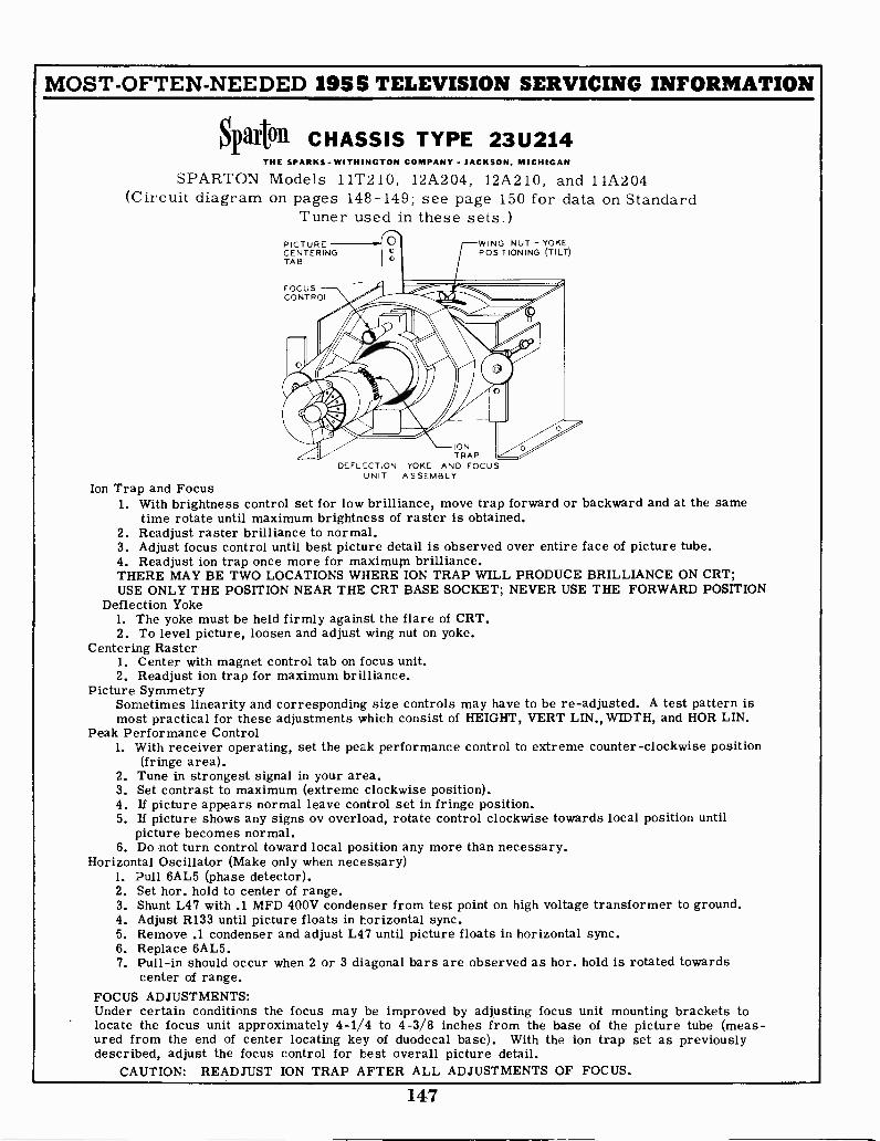
MOST -OFTEN -NEEDED 1955 TELEVISION SERVICING INFORMATION
Sparta CHASSIS TYPE 23U214THE SPARKS WITHINGTON COMPANY - JACKSON, MICHIGAN
SPARTON Models 11T210, 12A204, 12A210, and 14A204(Circuit diagram on pages 148-149; see page 150 for data on Standard
Tuner used in these sets.)PICTURECENTERINGTAB
FOCUSCONTROL
WING NUT - YOKEPOSITIONING (TILT)
IONTRAP
DEFL,ECTION YOKE AND FOCUSUNIT ASSEMBLY
Ion Trap and Focus1. With brightness control set for low brilliance, move trap forward or backward and at the same
time rotate until maximum brightness of raster is obtained.2. Readjust raster brilliance to normal.3. Adjust focus control until best picture detail is observed over entire face of picture tube.4. Readjust ion trap once more for maximum brilliance.THERE MAY BE TWO LOCATIONS WHERE ION TRAP WILL PRODUCE BRILLIANCE ON CRT;USE ONLY THE POSITION NEAR THE CRT BASE SOCKET; NEVER USE THE FORWARD POSITION
Deflection Yoke1. The yoke must be held firmly against the flare of CRT.2. To level picture, loosen and adjust wing nut on yoke.
Centering Raster1. Center with magnet control tab on focus unit.2. Readjust ion trap for maximum brilliance.
Picture SymmetrySometimes linearity and corresponding size controls may have to be re -adjusted. A test pattern ismost practical for these adjustments which consist of HEIGHT, VERT LEN., WIDTH, and HOR LIN.
Peak Performance Control1. With receiver operating, set the peak performance control to extreme counter -clockwise position
(fringe area).2. Tune in strongest signal in your area.3. Set contrast to maximum (extreme clockwise position).4. If picture appears normal leave control set in fringe position.5. If picture shows any signs ov overload, rotate control clockwise towards local position until
picture becomes normal.6. Do not turn control toward local position any more than necessary.
Horizontal Oscillator (Make only when necessary)1. Pull 6AL5 (phase detector).2. Set hor. hold to center of range.3. Shunt L47 with .1 MFD 400V condenser from test point on high voltage transformer to ground.4. Adjust R133 until picture floats in horizontal sync.5. Remove .1 condenser and adjust L47 until picture floats in horizontal sync.6. Replace 6AL5.7. Pull -in should occur when 2 or 3 diagonal bars are observed as hor. hold is rotated towards
center of range.FOCUS ADJUSTMENTS:Under certain conditions the focus may be improved by adjusting focus unit mounting brackets tolocate the focus unit approximately 4-1/4 to 4-3/8 inches from the base of the picture tube (meas-ured from the end of center locating key of duodecal base). With the ion trap set as previouslydescribed, adjust the focus control for best overall picture detail.
CAUTION: READJUST ION TRAP AFTER ALL ADJUSTMENTS OF FOCUS.
147
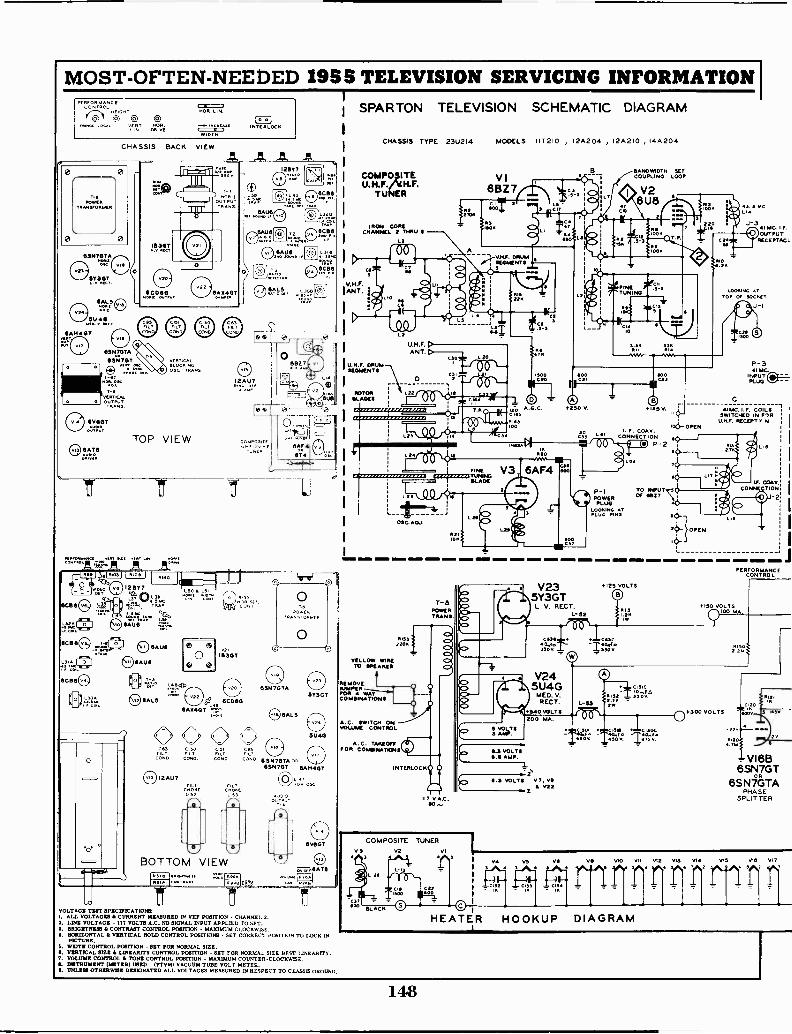
MOST -OFTEN -NEEDED 19SS TELEVISION SERVICING INFORMATION 1
1SPARTON TELEVISION SCHEMATIC DIAGRAMPr201=C'
1C -L3
,ocAL vL NT(1).
CAI VE
NOR N.
EDDINTERLOCK
MOT..
CHASSIS BACK VIEW
0 0
POWERTAANYORMEN
0 )0656470TA
57307
VERTICALAL
3C. 'PANS
O 6V607
TOP VIEWSATS
UTTRANS.
SC136
C).11.M.L6
12A1.17
IC.0.4405TEv.. rLNLRNT N4
674 .7:i-LJ
12677 4.30 L.5I
t(1.i1.1 VLtssE
6C1312
IoI.0. °
7j- BOTTOM VIEW11=1' C1313
LEI=
I
0 00
4D 0
VP,
I B307
49,. 13CD6015AXMIT
0000CO3
CONE. CONO. CONO
12AU7
655707*
CHASSIS TYPE 23U214 MODELS IIT 210 , 12A204 , I 2A 2 10 , 14A204
COMPO,ITE
TUNER
IRON CORECHANNEL 2 MIK/ 11
La
LtU.H.F.ANT. D
IU.N.F. DRUMSEGMENTS
'I°
LIP
°15- \
OSC.ADJ.
OR
VI6827
CPO.500
BANDWIDTH SETCOUPLING LOOP
V26U8
4114:33,1 .O,To A.G.C. 250 0.C .5
1003
ItI
+125V.
I. F. CORY.3. LIC34 C33 CONNECTION
00 P-2ma0
CD Lea
C37
P-1POWER
PLUGLOOKING ATPLUG PINS
OF Y2T
43.1 MC
j.341MC.I.F.
UPS , OUTPUTRECEPTACL
NO
LOOKING ATTOP Or SOCKET
J-1
P-3IMC.
INPUT Cijj.-- -PLUG
C
N IITC i.F. COILSSWITCHED IN FIRU.5F. RECEPTP N
If. COAX.CONFECTION
2
OPEN
220011331(
YELLOW WIRETO WEARER
REMOVE/WARMPOR 4 WAYCOMBINATIONS
A.G. SWITCH ONVOLUME CONTROL
A.G. TAKEOFFCIS FOR C OIMINATIONS
TILT vCAR. 6 SN7074. OS
631470T GA 540K
CA:13-4
VOLTAGE TEST SPECITICATIOWI. ALL VOLTAGES CURRENT MEASURED IN VW POSITION - CHANNEL 2.1. LINE VOLTAGE - 117 VOLTS A.G. NO SIGNAL INPUT APPLIED TO SET.3. BRIGHTNESS CONTRAST CONTROL POSITION - MAXIMUM CLOCKWISE.4. HORIZONTAL VERTICAL HOLD CONTROL POSITIONS - SET CORRECT POSITION TO LOCK IN
PICTURE.5. WIDTH CONTROL POSITION - SET FOR NORMAL SIZE.S. VERTICAL SIZE A LINEMUTT CONTROL POSITION - SET FOR NORMA.. SIZE BEST LINEARITY.7. VOLUME CONTROL II TONE CONTROL POSITION - MAXIMUM COUNTER -CLOCKWISE.S. INSTRUMENT (METER) USED - (VTVM) VACUUM TUBE VOLT METER.I. UNLESS OTHERwillE DESIGNATED ALL VOLTAGES MEASURED IN RESPECT TO CHASSIS GROUND.
INTERLOCK
T-6POWERTRANS.
V.A.C.SO
COMPOSITE TUNERVI
V235Y3GTL. V. RECT.
L- 32
200 MA.S VOLTS3 AMP.
S E VOLTSE S AMP.
6.3 VOLTS VT, VS
2V22
*125 VOLTS
W4OVI X4/0 I WA*Ia50V 450 V. ITS V.
Mir
PERFORMANCECONTRO
+ISO VOLTS100 MA
.300 VOLTS
.1
VI6B6SN7GT
6SN7GTAPHA SE
SPLITTER
,
3 3
_ C1,12
04 VS vS Ve va 511 VI2 VI3 VI! VIS V17
1,^4 r' rHEATER HOOKUP DIAGRAM
14.8

C41
MOST -OFTEN -NEEDED 1955 TELEVISION SERVICING INFORMATIONVI4
6V6GTPOWER AMP.
VI 06AU6
It! BOUND IF
5V
L30 V46CB611/ I. F. AMP.
MICA
CI22
MICA2K
010 V20
22001
PP
VI86AL5
HORIZ.PHASE DET.
DIAL LIGHTTYPE 47
TO 0.3 VOLTS
VII6AU6
2M12 SOUND I.F.5V is, a
2 0v
5/42.
22
CM
L3I V56CB6
the I. F. AMP.
VI5I 2AU7
SYNC. STRIPPER,AMP. t. CLIPPER
A C124
TANj1.10012
OSC.
V196 SN7GTAHORIZ. OSC.
& DISCHARGE400V
5012.7
0 T°. TERMINAL TAIT ON T-
25.4 gAre
1214 7214RI31 RISO
T-3
V12 VI36AL5 6AT6
RATIO DET AUCIO AMP.
VOLUMECONTROL
07150 VOLTS
L32r
1 46
C103A 1036
110RI2HOLD
:11
V76AU6A.G.C.
T I 12BYV87VIDEO LIMP.
CS.
11 11
V I6A6 SN7GT
6 SN7G TAVERT. OSC.
1-5 I. DISC. TUBEVERTICALBLOCKING 00
OSC.VELLOM 41[14
CD
V66CB6
361/ I.F. AMP
27011RRMAAV
014
VERTICALMOLD
sie CI20. MA1e
VW TITS V.
NOTE: FOR 214P4EI PICTURE TUBE, JUMPERWIRE CONNECTS, AS SHOWN, FROMTERMINAL 415 TO 31).FOR 112.174A PICTURE TUBE, JUMPER
p
10vo WIRE CONNECTS , AS SHOWN BY BROKER
LINE, FROM TERMINAL 46 TO 4111 ANDC134 IS OMITTED. 21+0 ANODE VOLTAGEIS THEN ID RV.
NOTE.The paints 1.3[21. by 1. num.rs I 2 3 4 5 6 4 7 are the alignmenttest ,ints referred in the alignment procedure.3 Pin e2 of V2 1611510NT. Mixer Tube.
Apply stignals for spot and sweep alignment of converter stage.2. For Tuner alignment Oct,3. Diode load reatator
Read D.C. output .re for SRO, - Mtg....Connect scope .re for vtsual 1.7. alignment
TO POINT XON V7(ewue)
G4300 VOLTS Aral
4. Cathode ofCPicture TubeRead A.C. output here uturall senIttivt,Connect
refor 4.5 Me trap alignment
5. Rat. Detector OutputRead D.C. here for alignment of suu. lake &I trap, tnt Ee 'Lind
F. transformer and pron., of ratIn detettor transform6. Ratio Detector Balancecl Out
Read D.C. here for altsnment of serond.,r, of italic detector trans.
7'K CONTRASTCONTROL
V176AH 4GT
VERT.OUTPUT
COMRIOT 100.43
SOV
Id V
00012. SET
A
270ROI
4/4V1F
+3400.
V92IZ P 4A
OR
2IZP4B17 BP4A
PICTURETUBE 4N RY
T-6VERT. OUTPUTTRANSFORMER
Tti-LOw
600 VOLTS
2tIG ANODE
100V.
100K
442..BRIGHTNESS
CONTROL
V21I B3G TH . V. RECT.
I KAP.
am TO SOANODE
V226AX4GT
DAMPER
L-49
L-50NOIRE.LINEARITY0.444
101
L -48A(zalvt;L-46VERY,YOKECOIL02,4
".'w" OL-465
L-51%MOTH
CONTROL
(zar../10L-46 D( row
)NORIZ.TORECOILIS..
CiMMOM
0011.
NOTE ADJUSTMENT OF CONE" .S.1, BRIGHTNESS,VERTICAL SIZE, HOF,LONTAL HOLD AND ROM, ,ONTAL DRIVE CONTROLS WILL CHANGE, VtILTAGESFROM THOSE INDICATED IN THEIR RESPECTIVEASSOCTATED CFRCUPTS.
WAVE FORMS TAKEN WITHCONTRAST CONTROL ADJUSTEDFOR SOV, P to It at PIN of VS,
149

MOST -OFTEN -NEEDED 1955 TELEVISION SERVICING INFORMATIONStandard Tuner used in Sparton Chassis 23U214, continued.
o.wn<-
N
0 Z <
0
0
a)eo
CakEcE
be 0
C.)
o (1.)
E-4
a)
0.
0
Cr)
R. F. Tuner.Figure 1 shows an exploded view of the composite Standard Coil tuner. It can readily be seen that separ-ate UHF and VHF assemblies have been combined mechanically and electrically to form the complete unit.Three concentric shafts are used to drive all of the UHF/VHF switching and tuning elements. Of these,the inside shaft rotates a 12 position VHF turret assembly and, ganged to this same shaft, three cam shapedielectric sections that tune the UHF decade coils through the UHF digit positions. The center shaft ro-tates the UHF decade turret and with an attached double action cam tilts the 45 MC I.F. rocker bar intoposition for UHF operation. The third or outside shaft drives the ganged VHF and UHF fine tuning cap-acitors.Block diagrams A and B show how the tuner circuits are arranged in the VHF and UHF positions.The antenna circuit of the VHF portion contains resonant circuits L2 -C8 and L3 -C7 which are fixedtuned for maximum rejection of interference in the I.F. band. ,Circuit C9 -L10 can be variably tuned toprovide additional attenuation of any specific interfering signal in the 35 to 48 MC region. Remainingcircuitry in the VHF section of the tuner is similar to that found in the straight VHF version, exceptthat a pentode triode (6U8) is used as the VHF oscillator mixer. The coupling circuit between the mixerplate and 1st video I.F. stage is described in the video I.F. section.A separate UHF antenna input is provided on the tuner. This is connected to capacitors C30 and C31,which together with coils L20 and L21 form a high pass filter with a cutoff frequency just below theUHF band. This system attenuates I.F., VHF and other interfering signals before they can enter theIN82 crystal mixer circuit.The remainder of the antenna circuit consists of a portion of the UHF decade coil assembly (D on theschematic diagram) plus trimmers C33 and C34, choke L6 and capacitor C164. Tuning coils L22 andL23 are connected to capacitor blades which are imbedded in the coil board assembly proper (see item64 to 71, figure 1). UHF channels within the range of a particular decade coil are tuned by movementof cam shaped dielectric sections which mechanically fit between these capacitor blades. To cover theentire UHF band eight separate decade coil board assemblies are switched in and out of the circuit byrotation of the UHF turret assembly (item 57, 58, shown in figure 1).
150
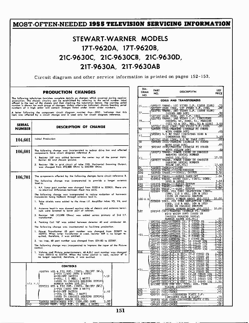
MOST -OFTEN -NEEDED 1955 TELEVISION SERVICING INFORMATION
STEWART-WARN ER MODELS17T -9620A, 17T -9620B,
21C -9630C, 21C-9630CB, 21C -9630D,21T -9630A, 21T-9630AB
Circuit diagram and other service information is printed on pages
PRODUCTION CHANGESThe following tabulation furnishes complete details on changes which occurred during receiverproduction. The chassis circuitry can be established by referring to the serial number labelaffixed to the rear of the chassis and then checking the tabulation below. The starting serialnumber is shown for each group of changes. Unless otherwise indicated, chassis bearing serialnumbers of a high order will contain changes listed under lower order numbers.
A letter fol'owing the component circuit diagram number thus -201A. indicates that thisitem was affected by a circuit change and is used only for circuit diagram reference.
SERIALNUMBER DESCRIPTION OF CHANGE
104,601 Initial Production
106,601 The following change was incorporated to reduce drive bar and affectedcomponents have circuit diagram reference A.
I. Resistor 169 was added between the center tap of the power trans-former 63 and chassis ground.
2. Resistor 106 in grid circuit of tube V10, Horizontal Scanning Output,was changed from 470,000 Ohms to 330,000 Ohms.
106,701 The components affected by the following changes have circuit reference B.
The following change was incorporated to provide a longer antennalead-in.
1. R.F. Tuner part number was changed from 522514 to 522931. There areno electrical differences between these two units.
The following change was incorporated to reduce radiation of harmonicfrequencies being fedback through antenna lead-in.
1. Tube shields were added to the three I.F. Amplifier tubes V3, V4, andVS.
2. Antenna lead-in was d r d against side of chassis and antenna termi-nals were lowered to lower part of cabinet.
3. Resistor 168 (15,000 Ohms) was added across primary of 3rd I.F.transformer.
4. Peaking Coil 167 was added between detector 40 and condenser 44.
The following change was incorporated to facilitate production.
1. Power Transformer 63 part number was changed from 522677 to522973. When latter transformer is used, resistor 169 is no longer re-quired, therefore, it was omitted.
2. on trap, 60 part number was changed from 521183 to 523001.
The following change was incorporated to improve the taper of the Picturecontrol.
1. Volume and Picture potentiometers, 46-A,B,C part number was changedfrom 522515 to 522744. When the latter control is used, resistor 47 isno longer required, therefore, it was omitted.
CONTROLS
'522744 VOLVOL 8c PIX POT. ( INCL. ON -OFF SW.)A -PIX ( 1500 OHMS r< WATT)B- ON- OFF SWITCHC-VOL. ( 1 MEG. WATT)
2.50
(USED IN CHASSIS BEARING SERIAL4 6 A r^I NUMBER ABOVE 106,701)
.5---2-2515 VOL & PIX POT. ( INC t. . ON -OFF SW.)
B- ON- OFF SWITCHA - PIX ( 3000 OHM k WATT)
C-VOL (1 MEG . ,i. WATT )( USED IN CHASSIS BEARING SERIAL( NUMBER BELOW 106,701)
59 520652 BRIGHTNESS POT. (100,000 OHM) I.001 9 52-2349 VERT . HOLD POT. (1
152-153.
GRAMNO.
NO.
DIA-PART DESCRIPTION
LIST
PRICE
COILS AND TRANSFORMERS
c J520977 TRANS. 1ST VIDEO I.F. (LESS SLUG) .75k 507357 SLUG CORE. 1ST VIDEO ICOIL .20)522791 TRANS . 2ND VIDEO I .F . ( LESS SLUG)
3 2 ( C ODED RED DOT) .80(507357 SLUG CORE, 2ND I.F. COIL 20
522703 TRANS. 3RD VIDEO I .F . ( INCLUDES39 CRYSTAL 40, COND . 41, PEAKING
COIL 42 & 167, RES. 43 & SLUG) 3.500357 SLUG CORE , 3RD VIDEO I .F . COIL .20
42 520985 COIL-PEAK/NG ( DOUBLE PI CODEDWITH GREEN DOT .65
)50960311.5
MC TRAP (INC1UDES SLUG &4B CONDENSER 49) 1.20
1;07357 SLUG CORE,TRAP COIL .2050 20689 COIL -PEAKING (SINGLE PI CODED
52 509342 COWITH _D0T1IL -PEAKING ( SINGLE PI CODEDWITH YELLOW DOT)
522973 TRANS. POWER ( USED IN CHASSISBEARING SERIAL NUMBER
63 ABOVE 106,701) 17 50522677 TRANS . POWER ( USED IN CHASSIS
BEARING SERIAL NUMBERBELOW 160,701) 1
65
65 22608 CHOKE --FILTER100 52251 TRANS . --SYNC ROG UIDE109 5224 9 TRANS .- --HORIZ . OUTPUT
.60
.503.509.50
118 509378 TRANS. ---AUDIO TAKE -OFF 1.50124 509706 TRANS. UND DISC. (INCL. COND.
124A &124B) 3.00142 509176 TRANS. ---AUDIO OUTPUT 1.85146 522674 TRANS.---VERT. OSC. 2.25161 522144 TRANS.-..-YERT. OUTPUT 4.00
(522924 YOKE. PIX TUBE DELFECTION (INCL.COND. 116 & RES. 1611 & 165)(USED IN CHASSIS BEARING
166-A.B SERIAL NUMBER ABOVE 106,701 10.00522699 YOKE, PIX TUBE DEFLECTION `IN L.
OOND. 116 & RES. 164 & 165)(USED IN CHASSIS BEARINGSERIAL NUMBER BELOW 06,701) 10.00
167 509340 COIL -PEAKING (SINGLE PI , CODEDWITH WHITE DOT) (USED INCHASSIS BEARING SERIALNUMBER ABOVE 106,701) 55
52070233 3
COIL -ANTENNA CH. 2 CODED 2Q 1.052070 COIL-ANTENNA CH. CODED 1.40520704 COIL -ANTENNA CH. 4 CODED 4Q9 1.40520705 COIL -ANTENNA CH. 5 CODED 5Q 1.40520706 COIL -ANTENNA CH. 6 CODED 6Q 1.40
bol_ 520707 COIL -ANTENNA CH. 7 CODED 7Q 1.15-- 520708 COIL -ANTENNA CH. 5 CODED bQ 1.1
520709 COIL -ANTENNA CH. 9 CODED . 5
520710 COIL -ANTENNA CH. 10 CODED 1 1.15520711 COIL -ANTENNA CH. 11 CODED 11Q 1.15520712 COIL -ANTENNA CH. 12 C DED20 1 COIL -ANTENNA Cl). 1 CODED 1 1.15
40 520701 COIL -CATHODE COUPLING .15520722 COIL-R.F. & OSC.
53
CH.32 CODED 2Q 1.
520723 COIL-R.F. & OSC. CH. CODED 9 1. 552072k COIL-R.F. & OSC. CH.45 CODED 4QQ 1.85eMELDI1.27R.F. & osc. CH. CODED 1.
520726 6 COIL-R.F. & OSC. cH..779
6 CODED 6o 1.85552072COIL-R.F. & OSC. CH CODED 1.70
413 520728 COIL-R.F. & OSC. CH.8 CODED 8Q 1.70520729 COIL-R.F. & OSC. CH.9 CODED 1.70520730 COIL-R.F. & OSC. CH.10 CODED 1 1.70520731 COIL-R.F. & OSC. CH.11 CODED 11 1.70520732 COIL-R.F. & OSC. CH.12 C DD 12 .7
520 COIL-R.F.CODED 139 1.70507 SLUG FOR OSC. COIL: ux. FINE
TUNING ADJUSTMENT .05
424 520714 COIL -CHOKE .15
426 520715 COIL -CHOKE .45
427 520734 COIL ---CONVERTER PLATE I.F.(INCLUDES SLUG & CLIP) 215
509062 SLUG CORE -CONVERTER PLATE COIL .12
-311
520518 COIL -CHOKE .10
44- 520520 COIL -CHOKE .10
151
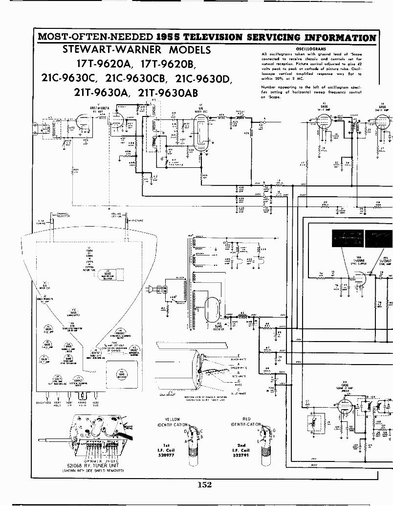
MOST -OFTEN -NEEDED 1955 TELEVISION SERVICING INFORMATIONSTEWART-WARNER MODELS OSCILLOGRAMS
All oscillograms taken with ground lead of 'Scopeconnected to receive chassis and controls set for
17T -9620A, 17T -9620B, normal reception. Picture control adjusted to give 42volts peak to peak at cathode of picture tube. Oscil-loscope vertical amplified response was flat to
21C -9630C, 21C-9630CB, 21C -9630D, within 20% at 2 MC.
21T -9630A, 21T-9630AB
EJNETUNING
616MIER OSC
6807.6807A111.241.11
646
641.16ITArLANP
VI
6607%16807ARI AMP
406
Of
ua
.:.
408 L__ 1_1
417
02
616MIXER OSC
4,6
409
OV
124
42
2
23
Number appearing to the left of oscillogram speci-fies setting of horizontal sweep frequency controlon 'Scope.
V]
66U61m I F AMP
c"" ; 1616
B"-
CHANNELSELECTOR
6605 '
SOIMO OUTPUT
GTSOUNOGRSCIMINATOR
SOUND ARP
611
FR
SANSWINO MAP
STNC SEPARATOR
112:11701
SYNC MAP 6411407
VERT BLOCKING OSC ROTTICA,Srmor.
VOLUMEOFF -ON
PICTURE
118P4
ITRP4OP
210P4om
21YPIAPICTURE TueE
11338T
176TITEr
680601ORIZERIOTutZTANNING
FUSE
4 AMP 250 VOLTLOCATED ON UNDERSOE
61N0TOF CHASSM
6SN7GT ... HORIZONTAL
NOW AF .0 WAVING
Mei SLOGANS OSC
VERT VERT TIORIZ VERT.HOLD LIN. HOLD SIZE
OPNMLK JHGFE521068 R.F. TUNER UNIT
(SHOWN WITH SIDE SHIELD REMOVED)
8
8
8p.
GS
X14
04
22 Z3
VA
66662nd I F AMP
O
Al
20
Tr
5AGRECTIFIER
44 aUN
)40
gL.;1
V68
VAAN8SYNC. CLIPPER
T6 1Y I
6841
1/212687SYNC. AMP
rs
44,
A
IlewsAAAA,0
BLACK -WHITE
GREEN -WHITE
RED-wmaE
WHILE
BLUE -WHILE
60170m VIEW OF CHASSIS SHOWINGCONNECTION TO F TUNER Lora
YELLOW
IDENTIFICATION
D
1stI.F. Coil520977
RED
IDENTIFICATION
2ndI.F. Coil522791
I"'65
ovVOA, 9
)2AT
1
[440
310
L-6
19
1/14
66116SOUND IF AMP
LIMITER
0 124
n21 123[Imomu,
152
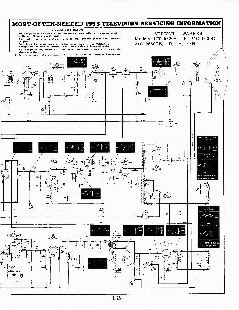
MOST -OFTEN -NEEDED 1955 TELEVISION SERVICING INFORMATIONVOLTAGE MEASUREMENTS
All voltages measured with a 20,000 Ohm per volt meter with the receiver connected toa 117 volt 60 cycle power supply.Tuner set to an inactive channel with antenna terminals shorted and connectedto ground.Controls set fo, normal reception-Picture control completely counterclockwise.Voltages marked with on asterisk (e) will vary widely with control settings.All voltages shown, except R.F. Tuner socket measurements, were taken under theabove conditions.R. F. tuner socket voltage measurements were token with tubes removed from sockets.
115
66116Rd I I AMP
0 V 3
240
6T8SONO DISCRIMINATOR
SOUND MAP
04
429
To 39.
Ts nas jO
VSA
V4SSN7 CTHMG All
/I46845
SWAM output
V
Va6SN9BIGTNOW &OCRING
OSCILLATOR
NNVe:NF IBIT
200
42
145
VGA
I/264N6VIDED AMP
via
04 61106GTNIRIUONIAL SCANNING
MONT
VAG
1/4124117VERT 1110CRINGMAWR
146
FRT
s49
ydgoMOLD
STEWART - WARNERModels 17T -9620A, -B, 21C -9630C,21C-9630CB, -D, -A, -AB.
VIIIB3GT
MGR vLITTAGERECTIFIER
VIZ
6W4GTWIR12011141
DAMPING
nA14461
OUTPIP
vr1711P4
OP
I7RP4OR
21v P4or
211 P4AMUM -WA
HORIZONTAL DEFLECTIONWAVEFORMS
MSS Lt. ISOOV
VOLTAGEMem. ninS al mean
-1rs NN \IN
CURRENTlaser1 Girl. male, 01633. 3 4444 ,nries3134.41131..31.44 4333431
ura.. 0,4
VERTICAL DEFLECT..wAVCIOR S
...11.1# 90v
VOLTAGEman. Mem pm Ta 01 nom
CAREIMInmm anew% .434.34.3 ... anrCF
mac tn. C031.113.3..31/0,
II
153
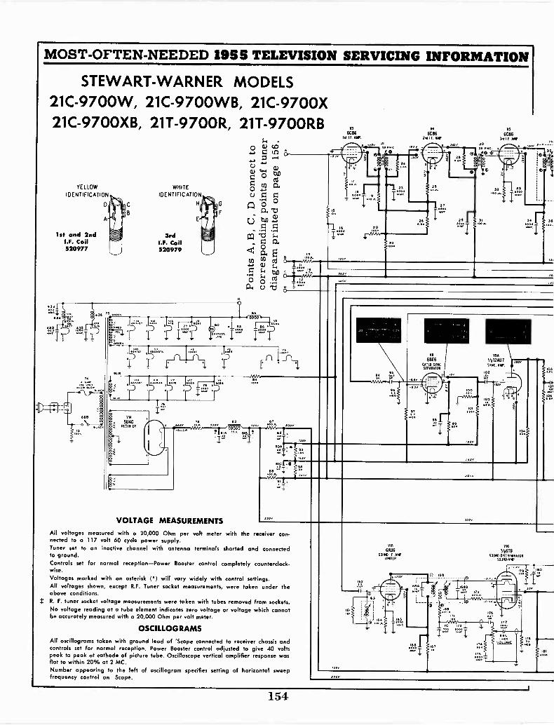
MOST -OFTEN -NEEDED 1955 TELEVISION SERVICING INFORMATION
STEWART-WARNER MODELS21C -9700W, 21C-9700WB, 21C -9700X21C-9700XB, 21T -9700R, 21T-9700RB
YELLOW WHITE
IDENTIFICATION IDENTIFICATION
1st and 2ndI.F. Coil520977
§ 75 66,66
pS
3rdI.F. Coil520979
414
5U4GRECTIFIER
VOLTAGE MEASUREMENTS
0
310
All voltages measured with a 20,000 Ohm per volt meter with the receiver con-nected to a 117 volt 60 cycle power supply.Tuner set to an inactive channel with antenna terminals shorted and connectedto ground.Controls set for normal reception-Power Booster control completely counterclock-wise.
Voltages marked with an asterisk (*) will vary widely with control settings.All voltages shown, except R.F. Tuner socket measurements, were taken under theabove conditions.R. F. tuner socket voltage measurements were taken with tubes removed from sockets.No voltage reading at a tube element indicates zero voltage or voltage which cannotbe accurately measured with a 20,000 Ohm per volt meter.
OSCILLOGRAMS
All oscillograms taken with ground lead of 'Scope connected to receiver chassis andcontrols set for normal reception. Power Booster control adjusted to give 40 voltspeak to peak at cathode of picture tube. Oscilloscope vertical amplifier response wasflat to within 20% at 2 MC.Number appearing to the left of oscillogram specifies setting of horizontal sweepfrequency control on Scope.
6CB61st I.E.MP.
162
(
V4
60862nd LF AMR
VI
6B(6GATED SYNC.SEPARATOR
320
NO
6CB60,5 IF. MP
30
0+
USA
1/212AU7SYNC AMP
VIE RIG
6AU6 1/2618SOUND I F AMP SOUND DISCRIMINATOR
LIMITER SOUND, AMP
120
162
0
67
0
1691116
ITONo6
il2
35
14
06
vOLUME
154
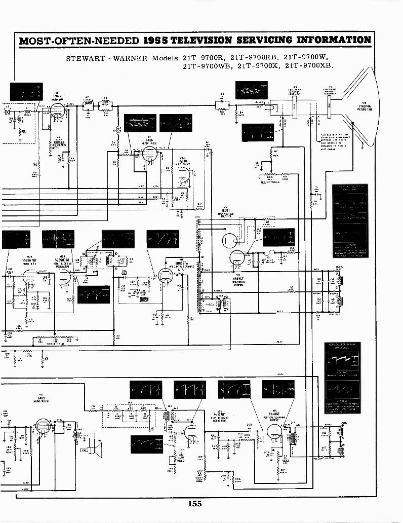
MOST -OFTEN -NEEDED 1955 TELEVISION SERVICING INFORMATION
OFF
112,7
V6
128TTNO A.
STEWART - WARNER Models 21T -9700R, 21T-9700RB, 21T -9700W,21T-9700WB, 21T -9700X, 21T-9700XB.
000
AlOAAll1/26SN7G1 1/26SNIGTHORIZ A F C HOW HOCKING
OSCIIAATOR110
-11
i.09 116
r
V11
6A05SOUND OUTPUT
g 21101.
Al
6AU6HEM AGC
LIMB
'/,608AGC CLAMP
- -
VII
6806610HORIZONTAL SCANNING
OUTPUT
tISY
11.. 1I01/
193
662. 662104
BRIGHTNESS
VIZ
18361MGR VOLTAGE
RECTIFIER .
013
6AXAGTHORIZONTAL
DAMPING
WIDTH
1/9B VII
9i12007 6AN4GTVERT BLOCKING VERTICAL SCANNING
OSCILLATOR OUTPUT
209
a'sr, 200
vE Ft§141
297 20s
VIA
21ALP4APICTURE TUBE
N W /OCRS.
.60A
t1,1,41. T LEE,.WAVEFORMS
30
VOCAL/TTFTT'F R1T T M TNT.
CURRENTlflR
e Mon co PPPPP 31611111
FRTIPOve Fgt. OWLVI
e
155
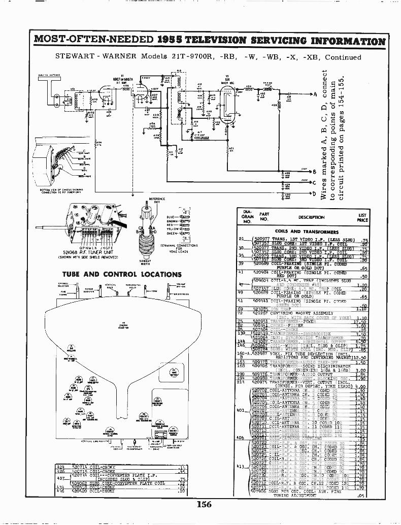
MOST -OFTEN -NEEDED 1955 TELEVISION SERVICING INFORMATIONSTEWART - WARNER Models 21T -9700R, -RB, -W, -WB, -X, -XB, Continued
6807 OR 6807ARIM/
/OS
BOTTOM VIEW OT CHASSIS SNOWINGCONNECTION TO HI 11.15E0 ONO
OPNMLN JHGFE521068 R.F. TUNER UNIT
(SHOWN WITH SIDE SHIELD REMOVED)506667WIDTH
BLUE -BROWRED -YELLOW 4,001:1
GREEN-}'
..11TERMINAL CONNECTIONS
FORYOKE LEADS
TUBE AND CONTROL LOCATIONS
424 520714- COIL -CHOKE426 520715 COIL -CHOKE
520714 COIL ---CONVERTER PLATE T.F.427--, (INCLUDES SLUG & CLIP)
509062 SLUG CORE -CONVERTER PLATE COIL414 520518 COIL -CHOKE4 16 520520 COIL -CHOKE
.15
.751
.1
.10
-0 ;i5z o z0.
ca
8 E aS-4
COC O 0C.) C.)
5.4
D o -4E.)
PART USTGRAMDESCRIPTIONNOPRICENO.
COILS AND TRANSFORMERS
21___TETTRrs..1S7VrE0 I.F.VC.CIOISeG)T. 1 .2
15030-- 520977 TRANS. 2ND VIDEO I.F. (LESS SLUG) .79
7357 SLUG CORE: 2ND VIDEO I F. COIL .2035___./ .. ::. ii 1. 0 --1. Ore I ./. Iir *I I - .
39 5206.- COIL -PEAKING (SINGLE PI. CODEDPURPLE OR GOLD DOT) .65
41 520984 CO/L-PEAKING (SINGLE PI. CODEDRED DOT) .50
(509601 COIL -4.5 MC. TRAP (INCLUDES SLUG47-- AND CONDENSER 448) 1.20
507357 SLUG CORE: 4.5 MC. TRAP COIL .2049 520689 COIL -PEAKING (SINGLE PI, CODED
PURPLE OR GOLD) .6551 509141 COIL -PEAKING (SINGLE PI. CODED
GREEN DOT)69 5234.5 ION TRAP 1.1072 521267 CENTERING MAGNET ASSEMBLY
(INC. WITH BACK COVER OF YOKE) 1 105 9 951 TRANSFORMER -POWER 17. 02 50 141 CHOKE --FILTER 3.5 507584 COIL --CHOKE .2130__J5225 9 TRANSFORMER--SYNCROGUIDE 1.50
15210.4 SLUG: SYNCROGUIDE TRANSFORMER144 52 417 TRANSFORMER. ORIZONTAL OUTP 6.50146 vs.. o --W # N L LUG & LIP
4.1; ; , i 4' '1 160-A.522987 YOKE. PIX TUBE DEFLECTION
MAGNETB RESISTORS AND CENTERING MAGNET)12.50163 509178 TRANSFORMER --AUDIO TAKE -OFF 1.50168 509706 TRANSFORMER --SOUND DISCRIMINATOR
(INCL. CONDENSERS 168A & 168B) 3.00190 5093/6 TRANSFORMER --AUDIO OUTPUT 1.85194 520980 TRANSFORMER--VERT. BLOCKING OSC. 1.90213 520975 TRANSFORMER--VERT. OUTPUT (INCL.
CONNEC. FOR DEFLEC. YOKE LEADS) 4 00520702 COIL -ANTENNA CH. 2 CODED 20_ 1%0
1.40iga COIL -ANTENNA N: 4 CODED 44 1.40520705 -OIL-ANTENNA CH. 5 CODED 1 405Q520706 COIL -ANTENNA CH. 6 CODED 61Q 1:40
401 52070/ COIL -ANTENNA CH. 7 CODED 70 1.15520705 COIL -ANTENNA CH. 5 CODED 80 1.15520709 COIL -ANTENNA CH. 9 CODED 90 1.15520710 COIL -ANTENNA CH, 10 CODED 109, 1.15520711 COIL -ANTENNA CH. 11 CODED 119 1.15
1 -:, 111 . @OM 1.15! '4 t, '4,),: . ov.10,
406 v v Tv. el' '
520722 'OIL-R.F. & OSC. CH.2 CODED 20 1.:5529723001L-R.F. & OSC. CH.3 CODED 3Q 10;5520724 COIL-R.F. & OSC. CH.4 CODED 4Q 1.I5
T1,735 COIL-R.F. & OSC. CH.5 CODED 59 1.557 6 COIL-R.F. & OSC. CH.6 CODED 6Q 1.85
520727 COIL-R.F. & OSC. my CODED 10 1.70413 520728 "OIL-R.F. & OSC, CH.8 CODED 50, 1.70520729 "OIL-R.F. & OSC. CH.9 CODED 90 1.70520730 COIL-R.F. & OSC. CH.10 CODED 100 1.70520711 COIL -R F & OSC. CH 11 CODED 110 1 70520732 COIL-R.F, & OSC. CH.12.CODED 12Q 1.70520733 COIL-R.F. & OSC. CH.13 CODED 130. 1.70507986 Sum FOR OSC. COIL: AUX. FINE
TUNING ADJUSTMENT .05
156
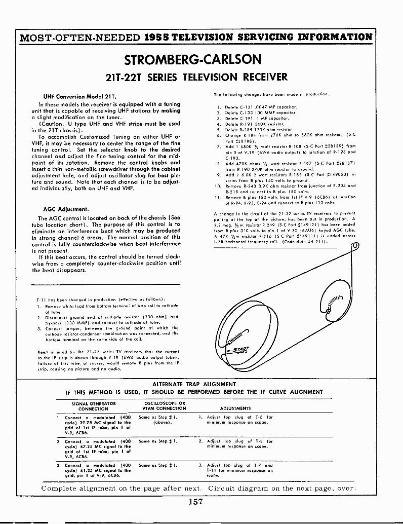
MOST -OFTEN -NEEDED 1955 TELEVISION SERVICING INFORMATION
STROMBERG-CARLSON211-221 SERIES TELEVISION RECEIVER
UHF Conversion Model 21T.In these -node's the receiver is equipped with a tuning
unit that is capable of receiving UHF stations by makinga slight modification on the tuner.
Cautior: U type UHF and VHF strips must be usedin the 21T chassis).
To accomplish Customized Tuning on either UHF orVHF, it may be necessary to center the range of the finetuning control. Set the selector knob to the desiredchannel and adjust the fine tuning control for the mid-point of its rotation. Remove the control knobs andinsert a thin non-metallic screwdriver through the cabinetadjustment hole, and adjust oscillator slug for best pic-ture and sound. Note that each channel is to be adjust-ed individually, both on UHF and VHF.
AGC Adjustment.
The AGC control is located on back of the chassis (Seetube location chart). The purpose of this control is toeliminate an interference beat which may be producedin strong channel 6 areas. The normal position of thiscontrol is fully counterclockwise when beat interferenceis not present.
If this beat occurs, the control should be turned clock-wise from a completely counter -clockwise positior untilthe beat disappears.
T-11 has been changed in production (effective as follows):1. Remove white lead from bottom terminal of trap coil to cathode
of tube.2. Disconnect ground end of cathode resistor (330 ohm] and
by-pass (330 MMF) and connect to cathode of tube.3. Connect jumper, between the ground point of which the
cathode resistor -condenser combination was connected, and thebottom terminal on the same side of the coil.
Keep in mind on the 21-22 series TV receivers that the currentto the IF strip is drawn through V-19 (6W6 audio output tube).Failure of this tube, of course, would remove B plus from the IF
strip, causing no picture and no audio.
The following changes hove been made in production.
1. Delete C-131 .0047 MF capacitor.2. Delete C.133 100 MMF capacitor.3. Delete C-191 .1 MF capacitor.4. Delete R-191 560K resistor.5. Delete R-185 120K ohm resistor.6. Change R-184 from 270K ohm to 560K ohm resistor. (S -C
Part :28188).7. Add 1 680K IA watt resistor R-108 (S -C Part :28189) from
pin 5 of V-19 (6W6 audio output) to junction of R-193 andC-193.
8. Add 470K ohms 1/2 watt resistor R-197 (S -C Part :28187)from R-190 270K ohm resistor to ground.
9. Add 2 6.8K 2 watt resistors R-185 (S -C Part :149053) in
series from B plus 150 volts to ground.10. Remove R-243 3.9K ohm resistor from junction of R-204 and
R-215 and connect to B plus 150 volts.11. Remove B plus 150 volts from 1st IF V-9 (6CB6) at junction
of R-94, R-93, C-94 and connect to B plus 110 volts.
A change in the circuit of the 21-22 series TV receivers to preventpulling at the top of the picture, has been put in production. A
2.2 meg. '/2w. resistor R-249 (S -C Part 5149121) has been addedfrom B plus 310 volts to pin 1 of V-20 (6AU6) keyed AGC tube.A 47K 1/2w resistor R-216 (S C Part ;;149111) is added acrossL-28 horizontal frequency coil. (Code date 54-211).
ALTERNATE TRAP ALIGNMENTIF THIS METHOD IS USED, IT SHOULD BE PERFORMED BEFORE THE IF CURVE ALIGNMENT
SIGNAL GENERATOR OSCILLOSCOPE ORCONNECTION VTVM CONNECTION ADJUSTMENTS
1. Connect a modulated (400 Some as Step ); 1.cycle) 39.75 MC signal to the (above).grid of 1st IF tube, pin 1 ofV-9, 6CB6.
1. Adjust top slug of T-6 forminimum response on scope.
2. Connect a modulated (400 Same as Step /t 1.cycle) 47.25 MC signal to thegrid of 1st IF tube, pin 1 ofV-9, 6CB6.
2. Adjust top slug of T-8 forminimum response on scope.
3. Connect a modulated (400 Same as Step It 1.cycle) 41.25 MC signal to thegrid, pin 1 of V-9, 6CB6.
3. Adjust top slug of T-7 andT-11 for minimum response onscope.
Complete alignment on the page after next. Circuit diagram on the next page, over.
157
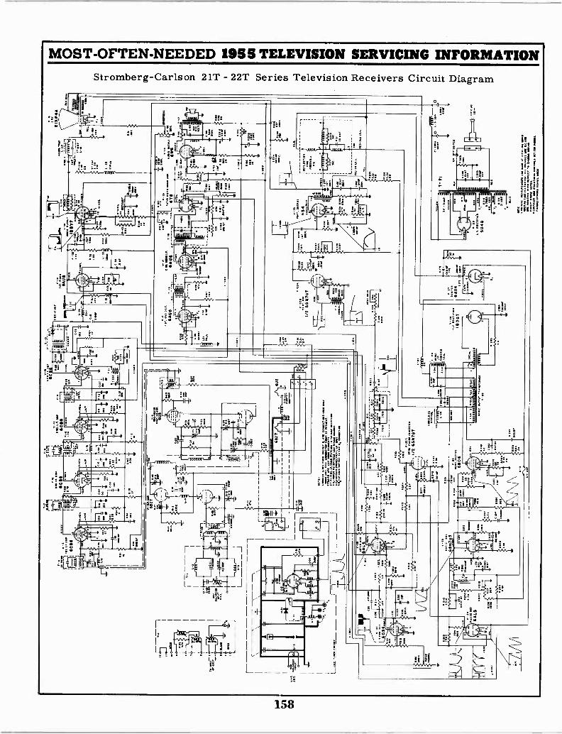
MOST -OFTEN -NEEDED 1955 TELEVISION SERVICING INFORMATION
Stromberg-Carlson 21T - 22T Series Television Receivers Circuit Diagram
158
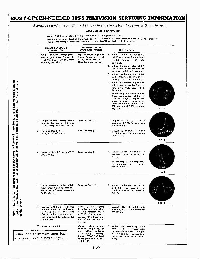
MOST -OFTEN -NEEDED 1955 TELEVISION SERVICING INFORMATIONStromberg-Carlson 21T - 22T Series Television Receivers (Continued)
ALIGNMENT PROCEDURE
Apply AGC bias of approximately 3 volts to AGC line (across C-160).Maintain the output level of the sweep generator to obtain a second detector output of 2 volts peak -to -peak. Oscilloscope should be calibrated to read 1 -VOLT per inch vertical deflection.
SIGNAL GENERATORCONNECTION
OSCILLOSCOPE ORVTVM CONNECTION ADJUSTMENTS
1. Output of 40MC. sweep gener- Input of scope to grid of 1. Adjust the bottom slug of T-7ator to grid of 1st IF tube, pin Video Amp., pin 1 of 1st IF transformer for low inter-1 of V9, 6CB6 thru 100 MMF V-13, 6AU6 thru 47K - mediate frequency (43.2 MCisolating capacitor. Ohm isolating resistor. approx.).
2. Adjust the bottom slug of T-93rd IF transformer for low fre-quency. (42.0 MC approx.).
3. Adjust the bottom slug of T-8
cs) al
c -t3c17) 'al
'I
4.
2nd IF transformer for high fre-quency. (45.0 MC approx.).Adjust the bottom slug of T-104th IF transformer for high in-termediate frequency. (44.5
0 g MC approx.).V 3E 0
-C
E E2
5. Maintaining the above relativefrequency positions of the in-dividual stages, adjust theslugs to produce a curve asshown with the 41.9 and 45.75oc
OC-0tu
at o
ai at-o
H
MC markers at 50% responseFig. 1.
2. Output of 40MC sweep gener-ator to junction of T-6 andL-18. Using 39.75MC marker.
Same as Step g 1. 1. Adjust the top slug of T-6 forresponse 39.75MC as shownon curve Fig. 2.
2 03. Same as Step 2. Same as Step g 1. 1. Adjust the top slug of 1-7 and
Using 41.25MC marker. T-11 for response as shown oncurve Fig. 2.
FIG. 1
Jrj39 7.s -
FIG. 2
4. Same as Step 1 using 47.25 Same as Step 1; 1.MC marker.
Adjust the top slug of T-8 forresponse curve as shown onFig. 3.
2. Repeat Step 1 (IF response)to reproduce the curve asshown in Fig. 1.
FIG. 3
5. Raise converter tube shieldfrom ground and connect out-put of 40 MC sweep generatorto the shield.
Same as Step # 1. 1. Adjust the bottom slug of 1-6and T-5 tuner assembly toproduce a curve as shown inFig. 4.
FIG. 4
6. Connect a 400 cycle modulated4.5 MC signal to the junctionof Video Detector M-13 andC-126. Adjust generator out-put to a level to ihdicate 1.5volts VTVM.
Connect 2-100K resistors 1. Adjust L-21, T-15, and the bot-in series from the plate tom slug of T-16 for maximumof ratio detector, pin 2 indication.of V-18, 6T8 to ground,connect VTVM from junc-tion of the resistors toground.
7. Same as Step 1; 6.
Tube and trimmer locationdiagram on the next page.
Connect VTVM ground 1.Lead to the junction ofthe 2-100K resistors(see step 1$6 above).Connect VTVM D.C. leadto the junction of C-181and R-181.
Adjust the secondary (topslug) of T-16 for zero voltsbetween the positive and nega-tive excursions. (Increase gen-erator output for good deflec-tion).
159

MOST -OFTEN -NEEDED 1955 TELEVISION SERVICING INFORMATION
Stromberg-Carlson Tube and Trimmer Location Diagram
21T -22T Series Television Receiver
o BRIGHTNESS R -I52
o HORIZ. HOLD R -25I
0 VERT. HOLD R-223
VOLUMECONTRAST
0R -I44
OSC. TRIMMERADJ. HOLE -V
C-23
MIX.-OSC.
CDC -28
©C -I9
R. F. AMR
C -I5 21T822TV.H.F. TUNER
21 T22 T
LOW FREQ. TRIMMER
U.H.F TUNER221 ONLY
SYNC.
SEPARATOR
VERT. OUTPUT
M-7T- 6
CON V.SEC.&39.75McTRAP
T-7 T
211SIVIDI. F.
TRANS4125 Mc VID. 4725m, 3r-VID.
I.F. AMP TRAP I.F. AMP. TRAP I.F. AMP
[OVID.
TRVS.3r-ci VID.
I. F.
TRANS.
T -I00.1=1 VID.
TRANSa
DET.
AUDIO OUTPUT RADIO DET.
AUDIO AMP.
POWER RECT.
T -2I
POWER
TRANSFORMER
T- t6
0RATIO DET
GND.
214 AUDIOAMP.
FOCUSSOCKET
GNO.
150V. 310V.
41.25 Mc TRAP
L-21
T-15
AUDIO I.F.
SOUND
TAKE OFF
6 AU6
I-- AUDIOI. F. AMP.
KEYED A.G.C.
HORIZ. AMP.
REAR SPKR SOCKET FOR R-258
R-53J I
KINESCOPE °LEADS- -2
VE SIZE@ o) LIN.-232 L-28 R-208
INTERLOCK A.G.0HORIZ. FR EQ CONT. FOR
IOVID.AMP.
SYNC. PHASE INV.a BLOCKING OSC.
L-27 4.5 MC. TRAP
VID. AMP. PHASE DET.
e -t
V-281B3
H.V. RECT.
M-2-II/4 AMP.
250 V.
HORIZ. DRIVE L-30 HORIZ. SIZE
RV__.))NOISE CANC.
-210 CONTR. 0L-29
YELLOW KINESCOPE LEADORIZ. LINE
NOTE: 1N105 Diode Detector is Located Under Removable Shield Cover of T-10 4th Video IF Trans.
161)
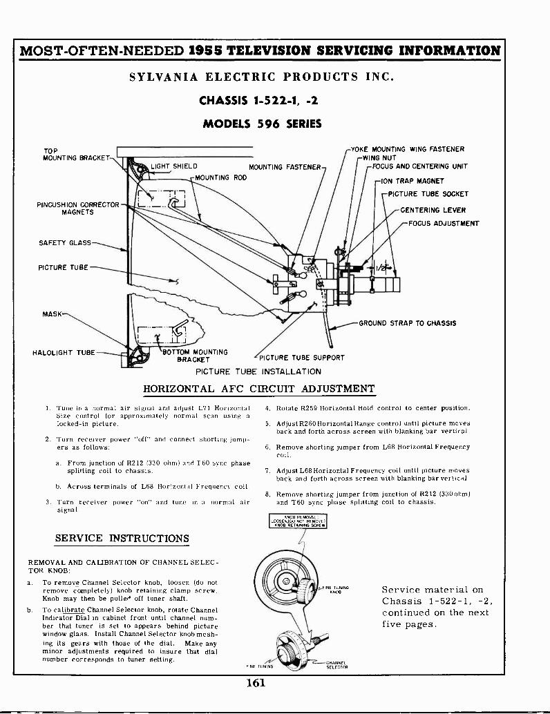
MOST -OFTEN -NEEDED 1955 TELEVISION SERVICING INFORMATION
SYLVANIA ELECTRIC PRODUCTS INC.
CHASSIS 1-522-1, -2
MODELS 596 SERIES
TOPMOUNTING BRACKET
PINCUSHION CORRECTORMAGNETS
SAFETY GLASS
PICTURE TUBE
MASK-.
HALOLIGHT TUBE
LIGHT SHIELD MOUNTING FASTENER
MOUNTING ROD
BOTTOM MOUNTINGBRACKET PICTURE TUBE SUPPORT
PICTURE TUBE INSTALLATION
YOKE MOUNTING WING FASTENERWING NUT
FOCUS AND CENTERING UNIT
-ION TRAP MAGNET
PICTURE TUBE SOCKET
CENTERING LEVER
FOCUS ADJUSTMENT
GROUND STRAP TO CHASSIS
HORIZONTAL AFC CIRCUIT ADJUSTMENT
1. Tune in a normal air signal and adjust L71 HorizontalSize control for approximately normal scan using alocked -in picture.
2. Turn receiver power "off" and connect shorting jump-ers as follows:
a. From junction of R212 (330 ohm) and 'I 60 sync phasesplitting coil to chassis.
b. Across terminals of L68 Horizontal Frequency coil.
3. Turn receiver power "on" and tune in a normal airsignal.
SERVICE INSTRUCTIONS
REMOVAL AND CALIBRATION OF CHANNEL SELEC-TOR KNOB:
a. To remove Channel Selector knob, loosen (do notremove completely) knob retaining clamp screw.Knob may then be pulled off tuner shaft.
b. To calibrate Channel Selector knob, rotate ChannelIndicator Dial in cabinet front until channel num-ber that tuner is set to appears behind picturewindow glass. Install Channel Selector knob mesh-ing its gears with those of the dial. Make anyminor adjustments required to insure that dialnumber corresponds to tuner setting.
4. Rotate R259 Horizontal Hold control to center position.
5. Adjust R260 Horizontal Range control until picture movesback and forth across screen with blanking bar vertical
6. Remove shorting jumper from L68 Horizontal Frequencycoil.
7. Adjust L68 Horizontal Frequency coil until picture movesback and forth across screen with blanking bar vertirA.
8. Remove shorting jumper from junction of R212 (330 ohm)and T60 sync phase splitting coil to chassis.
KNOB REMOVAL,LOOSENIDO NOT REMOVE)
KNOB RETAINING SCREW
FINE TUNING
FINE TUNINGKNOB
CHANNELSELECTOR
Service material onChassis 1-522-1, -2,continued on the nextfive pages.
161

HA
LO,1
516G
HT
T30
AC
PO
NE
RLI
NE
PLU
G
150
TE
RLO
CE
01/O
FF
DIN
T.
.DLI
GIN
TC
ON
NE
CT
OR
SO
CK
ET
TO
Pv1
,11
5
8125
390K
OR
S11
126
IRO
300
V
V14
11/2
112
AU
7A
. AM
P0
V13
12A
U7
NO
ISE
INV
ER
TE
R
Ac
C. 4/
5
TO
HO
PI .
SO
CK
ET
o"02
.R
202
01
54C
o2
39 7
5MC
AD
J P
ix
2
'MM
.'.
0211
11,1
2613
047-
00.
004
4.04
RE
M.5
2205
TO
05
NG
GG
C20
1
0110
C60
NO
40V
6-66
1,! V
5021
6CV
DC
b6 v
J H
O
001
6Z06
rG E
ZD
TIV
NG
T
77LS
I76
079
6.6
VT
9V
10V
IIxO
Ta
63N O
CO
LOR
DO
T
L37.
1.50
,L.
,LS
O
6CB
621
1.0E
0lir
AM
P
c7L
VT
II/21
12A
U7
SY
NC
SE
P
1,13
66.
R 0
982
11
GA
LS
DE
T
L54,
T55
,75
6,T
57,T
S9
0
vi40
/21
12A
U7
SY
NC
.0V
B C
LIP
PE
R
SC
HE
MA
TIC
DIA
GR
AM
FO
R 1
-522
-1,1
-522
-2 T
V C
HA
SS
IS.
T52
L55
V9
GA
NG
fT
52E
NO
SA
ND
IF A
MR
NO
TE
S O
N W
AV
EF
OR
M,
I - T
HE
TE
RM
S"3
0370
17.1
175.
RE
FE
R
2-T
i."72
2raw
pros
i-0,-
TO
PO
SIT
IVE
PO
LAR
ITY
.3-
WA
VE
FO
RM
S .1
/ NO
T B
E ID
EN
TIC
AL
TO
TH
OS
E S
HO
WN
DU
E T
O C
HA
RA
C-
TE
RIS
TIC
S O
F S
CO
PE
US
ED
1150
EF
OR
MS
ME
AS
UE
D S
OH
RE
-S
PE
CT
TO
CH
AS
SIS
UN
LES
S O
NE
R-
NO
SE
IND
ICA
TE
D5
-CO
NT
RA
ST
CO
NT
RO
L S
ET
TO
51.
0501
4
VS
6CB
6
C20
/
004/
rte'
1i
AT
El
.00.
0047
8255
8201
1
(1/2
1G
AM
S
;.1 .r
XpE
0
V15
12A
U7
VE
RT
0 C
0212 00
4282
20
6614
7GT
AN
OR
OS
C
L
CIC
O 1-ve
on$
6668
vizo
jo
v$o
GA
LS11
A41
,0 0
E7
eT4c
737,
RIO
J
0211
-.I
.1P
Ug
G.
.022
'1IV
;
C5
100
L102
166
0 I
5.01
.
MO
O°M
EG
.
TE
SP
L T
E
07 1
121
12A
U7
I ST
SO
UN
D IF
SY
RO
N.
or5r
6W6G
TV
ER
T O
UT
PU
T,
RE
M
60 Y
1111
0/
6SN
7GT
AN
OR
05C
0255
."1.
2.
OV
551
666
IST
aAF
AT
G 0
1A
MP
.00E
AG
C C
LAM
P,
TO
RO
CA
IUG
57
601
7' 0
0 0
10
BO
K4/
05,/,
wo
.9W
130
39K
C2S
7
001
CP
3610
611
een
50V
R2.
MO
O
SIM
EA
SuR
ED
W. A
vliv
m R
ICH
VO
LTA
GE
PR
OB
E0
...N
E 5
5 C
ON
TR
OL
AT
MU
M R
I. P
EA
K V
OLT
AG
E O
F S
HO
RT
DU
RA
TIO
N M
AY
AN
D A
TLI
NE
VO
LTA
GE
ME
TE
R R
EA
DIN
G O
F IS
] VO
LTS
,*C
ON
TR
AS
T C
ON
TR
OL
AT
MIN
IMU
MD
AM
AG
ED
AM
AG
E M
ET
ER
US
ED
FO
R T
. ME
AS
UR
EM
EN
TO
ME
R C
ON
DIT
ION
S O
F N
OR
MA
L S
IGN
AL,
NO
BR
IGH
T-
VO
LTA
GE
SO
UR
CE
S A
RE
IND
ICA
TE
D B
E E
NC
IRC
LED
SY
MB
OLS
,N
ES
S A
ND
CO
RR
EC
T S
CA
N S
IZE
CO
RR
ES
PO
ND
. SY
MB
OLS
WIT
HO
UT
GA
LLE
S IN
OC
AT
E V
OLT
.E T
IE P
OvO
LTA
GE
S A
PE
ME
AS
UR
ED
TO
CH
AS
SIS
UN
LES
S O
TH
ER
WIS
E IN
DIC
AT
ED
US
ING
vA
CU
V14
TU
BE
VO
LTM
ET
ER
ME
AS
UR
EM
EN
T C
ON
DIT
ION
S,U
NLE
SS
OT
HE
RW
ISE
NO
TE
DO
UR
CE
. VO
LT,6
0.C
YC
LE ,
AN
TE
NN
A D
ISC
ON
NE
CT
ED
, AN
TE
NN
A T
ER
MIN
ALS
SH
OR
TE
D A
NO
GR
OU
ND
ED
, PIC
TU
RE
CO
NT
RA
ST
AT
MA
XIM
UM
, BR
IGH
TN
ES
S A
T M
INIM
UM
-O
TH
ER
CO
NT
RO
LS A
T N
OR
MA
L P
OS
ITIO
NS
AV
ER
AG
E V
OLT
AG
ES
AN
D C
OG
RE
SIS
TA
NC
ES
AR
ER
ES
IST
AN
CE
OF
'AM
C/C
OIL
15
FO
R E
NT
. WIN
DIN
GR
ES
IST
AN
CE
IS H
OT
SH
OW
N W
HE
RE
...O
S A
RE
TO
O S
MA
LL .
w10
ELV
VA
RIA
BLE
.
AR
RO
WS
AT
CO
MN
OLS
IND
ICA
TE
CLO
CK
WIS
E R
OT
AT
ION
OF
CO
NT
RO
LS
1601
1
R10
/15
.1.6
6
07
RIIO
Rill
C10
9330K
Ow
TO
AG
C B
US
IA1
6
1213
77
VID
EO
AM
P
zson
1520
69
6AU
4GT
6V6G
T. O
UT
PU
TR
I
oxnEcioR
PL G
FO270-3.3
4 A
MP
.P
OS
E
5.30
OW
0640
41O
400
V
RI5
4
0260
N 12
TH
E H
IGH
VO
LTA
GE
LE
AD
TO
TH
E P
ICT
UR
E T
UB
E M
AY
HA
VE
A P
OT
EN
TIA
L O
F ie
poo
VO
LTS
. PR
EC
AU
TIO
NS
SH
OU
LD B
E O
BS
ER
VE
D W
HE
N T
HE
CH
AS
SIS
ISR
EM
OV
ED
FR
OM
TH
E C
AB
INE
T F
OR
SE
RV
ICE
PU
RP
OS
ES
.
DO
NO
T O
PE
RA
TE
TH
E R
EC
EIV
ER
WIT
H T
HE
KV
CO
VE
RR
EM
OV
ED
.
ALW
AY
S W
EA
R S
AF
ET
Y G
OG
GLE
S A
ND
GLO
VE
S W
HE
NN
EC
ES
SA
RY
TO
RE
MO
VE
TH
E P
ICT
UR
E T
UB
E.
SP
EA
PIE
R P
LUG
IIS
OC
KE
T
50
7610
0,1
42,0
00V
H V
CO
NN
EC
TO
RS
OC
KE
T
002
2
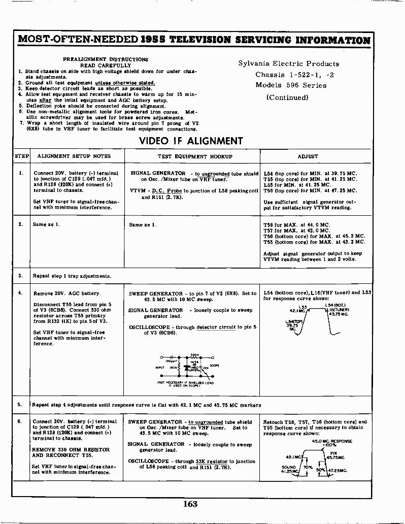
MOST -OFTEN -NEEDED 1955 TELEVISION SERVICING INFORMATION
1. Standsis
2. Ground3. Keep4. Allow
utes5. Deflection6. Use
allic7. Wrap
(6X8)
PREALIGNMENT INSTRUCTIONSREAD CAREFULLY Sylvania
chassis on side with high voltage shield down for under chas-adjustments. Chassis
all test equipment unless otherwise stated. Models
Electric Products1-522-1, -2
596 Series(Continued)
detector circuit leads as short astest equipment and receiver chassis
after the intial equipment and AGC
possible.to warm up for 15 min-battery setup.
alignment.powdered iron cores. Met-
screw adjustments.around pin 7 prong of V2
test equipment connections.
VIDEO IF ALIGNMENT
yoke should be connected duringnon-metallic alignment tools forscrewdriver may be used for brass
a short length of insulated wiretube in VHF tuner to facilitate
STEP ALIGNMENT SETUP NOTES TEST EQUIPMENT HOOKUP ADJUST
1. Connect 20V. battery (-) terminalto junction of C129 (. 047 mfd. )and R128 (120K) and connect (+)terminal to chassis.
Set VHF turner to signal -free chan-nel with minimum interference.
SIGNAL GENERATOR - to ungrounded tube shield L54 (top core) for MIN. at 39. 75 MC.T55 (top core) for MIN. at 41. 25 MC.L55 for MIN. at 41. 25 MC.T56 (top core) for MIN. at 47. 25 MC.
Use sufficient signal generator out-put for satisfactory VTVM reading.
on Osc. /Mixer tube on VHF tuner.
VTVM - D.C. Probe to junction of L58 peaking coiland R151 (2. 7K).
2. Same as 1. Same as 1. T58 for MAX. at 44.0 MC.T57 for MAX. at 42. 0 MC.T56 (bottom core) for MAX. at 45.2 MC.T55 (bottom core) for MAX. at 43. 2 MC.
Adjust signal generator output to keepVTVM reading between 1 and 2 volts.
3. Repeat step 1 trap adjustments.
4. Remove 20V. AGC battery.
Disconnect T55 lead from pin 5of V3 (6CB6). Connect 330 ohmresistor across T55 primaryfrom R132 (1K) to pin 5 of V3.
Set VHF tuner to signal -freechannel with minimum inter-ference.
SWEEP GENERATOR - to pin 7 of V2 (6X8). Set to43. 5 MC with 10 MC sweep.
SIGNAL GENERATOR - loosely couple to sweepgenerator lead.
OSCILLOSCOPE - through detector circuit to pin 5
L54 (bottom core), L16(VHF tuner) and L53for response curve shown:
L53 L54 (30T.)42.1 MC. 16(TUNER)
45.75 MC.
L54(T'0P)39.75
MC.of V3 (6CB6).
220KO--1.00../ 1N34 :
0., . SCOPEINPUT 120K INcK/- ,001
CRYSTAL
(NOT NECESSARY ,F SHIELDED LEADS USED ON SCOPE1
5. Repeat step 4 adjustments until response curve is flat with 42. 1 MC and 45.75 MC markers
6. Connect 20V. battery (-) terminalto junction of C129 (. 047 mfd.)and R128 (120K) and connect (+)terminal to chassis.
REMOVE 330 OHM RESISTORAND RECONNECT T55.
Set VHF tuner to signal -free chan-nel with minimum interference.
SWEEP GENERATOR - to ungrounded tube shield Retouch T58, T57, T56 (bottom core) andT55 (bottom core) if necessary to obtainresponse curve shown:
45.0 MC. RESPONSE-100%
on Osc. /Mixer tube on VHF tuner. Set to43. 5 MC with 10 MC sweep.
SIGNAL GENERATOR - loosely couple to sweepgenerator lead.
OSCILLOSCOPE - through 33K resistor to junction
PIX42.1 MC. 45.75MC.
SOUND41.25 i SOY, 47.2 5 MC.
of L58 peaking coil and R151 (2.7K).
163

MOST -OFTEN -NEEDED 1955 TELEVISION SERVICING INFORMATION
Sylvania Electric Chassis 1-522-1, -2, Alignment Information, Continued
4.5MC TRAP ALIGNMENTSTEP ALIGNMENT SETUP NOTES TEST EQUIPMENT HOOKUP ADJUST
1. Short pin 2 of V6 (6AM8) tochassis.
SIGNAL GENERATOR - to pin 2 of V8 (12BY7).Set to 4.5 MC.
VTVM - R. F. Probe to pin 11 of V24 (Picture
L61 for MINIMUM.
Tube); Ground Lead to chassis.
SOUND ALIGNMENT
STEP ALIGNMENT SETUP NOTES TEST EQUIPMENT HOOKUP ADJUST
1. short pin 1 of V5 (6CB6) to chassis.
DO NOT GROUND VTVM.
SIGNAL GENERATOR #1 - through 1K resistor to T52 (both cores) for MAXIMUM.T59 (both cores) for MAXIMUM.
Use peak resulting in greatestseparation of cores.
Repeat adjustments until max -imum reading is reached.
pin 2 of V6 (6AM8). Set to 45.0 MC.
SIGNAL GENERATOR #2 - through 1K resistor topin 2 of V6 (6AM8). Set to 4. 5 MC.
OR
SIGNAL GENERATOR - through 1K resistor topin 2 of V6 (6AM8). Set to 45.0 MC with acrystal controlled 4. 5 MC marker.
ALSO
VTVM - D. C. Probe to pin 5 of V10 (6AL5); GroundLead to pin 7 of V10 (6AL5).
2. Same as 1. USE SAME SIGNAL GENERATOR HOOKUP AS INSTEP 1.
VTVM - D.C. Probe through 100K resistor to term-
T52 (top core) for ZERO.
Use lowest VTVM scale set tozero center. At correct coresetting, a slight turn of corewill give either a positive ornegative reading.
inal #1 of de -emphasis plate; Ground Lead tojunction of two matched 100K resistors con-nected in series across R106 (68K).
3. Remove test equipment and resistors; then, tune in a weak station and adjust T52 (top core) for optimum signal-to-noise ratio.
ALTERNATE SOUND ALIGNMENTSTEP ALIGNMENT SETUP NOTES TEST EQUIPMENT HOOKUP ADJUST
1. Connect a good antenna instal-lation to receiver.
Set VHF tuner to a strong sta-tion.
DO NOT GROUND VTVM.
VTVM - D. C. Probe to pin 5 of V10 (6AL5); Ground
T52 (both cores) for MAXIMUM.T59 (both cores) for MAXIMUM.
Use peak resulting in greatest separationof cores.
Repeat adjustments until maximumreading is reached.
Lead to pin 7 of V10 (6AL5).
2. Same as 1. VTVM - D.C. Probe through 100K resistor to term- T52 (top core) for ZERO.
Use lowest VTVM scale set tozero center. At correct coresetting, a slight turn of corewill give either a positive ornegative reading.
inal #1 of de -emphasis plate; Ground Lead tojunction of two matched 100K resistors con-nected in series across R106 (68K).
3. Remove test equipment and resistors; then, tune in a weak station and adjust T52 (top core for optimum signal-to-noise ratio....
164
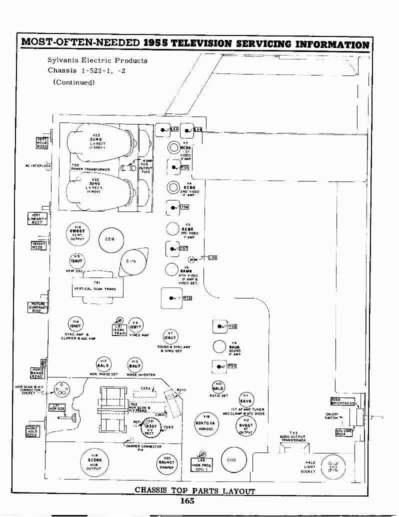
MOST -OFTEN -NEEDED 1955 TELEVISION SERVICING INFORMATIONSylvania Electric ProductsChassis 1-522-1, -2
(Continued)
HOLDR220
AC INTERLOCK
VERTLINEARITY
R227
HEIGHTR225
PICTURE(CONTRAST}
R152
HORIZ.RANGER260
NOR SCAN a H VCONNECTORSOCKET
HORIZ.HOLDR259
V235U4 GL.V RECT0.300V
T50POWER TRANSFORMER
V225U40
L.v RECT.(1140v)
V1661116 GT
VE PT.OUTPUT
VERT OSC.
SYNC. AMP. aCLIPPER & AGC AMP
L7iHOR SIZE
L I
14.SMCTRAP)
12BY7
VIDEO AMP
NOR. PHASE DET NOISE INVERTER
VI96 GD6G
HOROUTPUT
0259
1B 3GTH V
RECT.
V3B6
I STVIDEOIF AMP
vo6G 136
2ND VIDEOIF AMP
SOUND a SYNC. AMP SYNC SEP
V206AU4GTDAMPER
RATIO SET
VIP
6SN7G TA
NOR071
L68(HOP. FRED.
COIL )
1ST AF AMP, TUNERAGC CLAMP a ATC DIODE
VI2
6V6G TAFTPUT
CHASSIS TOP PARTS LAYOUT165
ON/OFFSWITCH'.
VOLUMER104T53
AUDIO OUTPUTTRANSFORMER
HALOLIGHT
SOCKET
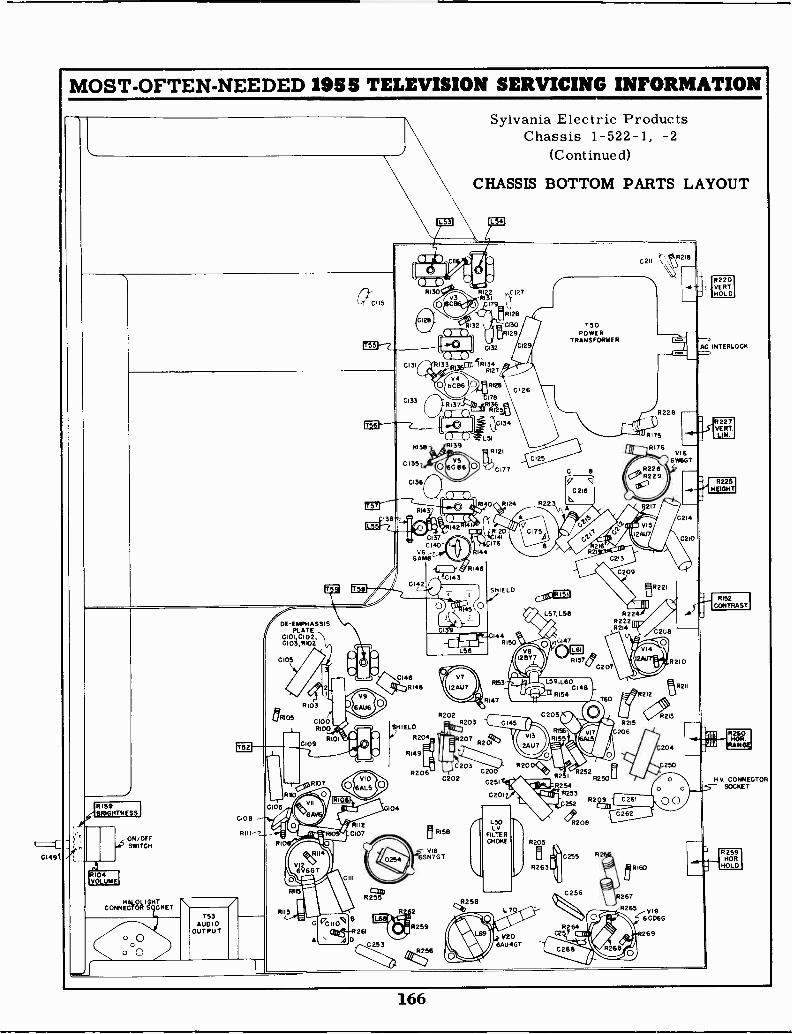
C I 491
MOST -OFTEN -NEEDED 1955 TELEVISION SERVICING INFORMATION
0C115
Sylvania Electric ProductsChassis 1-522-1, -2
(Continued)
CHASSIS BOTTOM PARTS LAYOUT
ITT
OW nwav N
0131
0133
RI30
c)
ev.0
R130
C135
C136
OTt33
v46086
8137
onoco Il=RI39
C2I1R2I6
RI 2 0127RI31
179
6128
8132 1 J,RCl30 T50RI29 POWER
TRANSFORMER0132
81346127
0 Rt26
SW Jo
1786136
RI25
L51
1k11 RIR143
trP WS .Z" ,RI4238
0137
R159
ON/OFFSWITCH
6104VOLUME
CONNECTOR
DE-EMPHASS1SPLATE
C1010102,C103,R102
CIO/2
8105
CI08
0
O00
153AUDIO
OUTPUT
RH!
8103
C1008100
R01 09
101
A
A
gor* 111
V9
6AU6
B
R
261
02530253
C 1
V66 AMI3
G142
CI46RI48
I
44
8146tC14 3
T0
L56
SHIELD
R204
RI49
R206
104
R 2
4m
0202
RI58
V186SN7GT
R259
R256
R2028203 0145
8207
C203 R20C200
0251
C20
1-5°
FILTERCHOKE
LV
8258
0134
121
0177
129
C126
RI24
RI20144
76
SHIELD
44R150
q0 216
A
L57, L56
0147
RI57C207
R153 L59,L60C148
IIIRI54R147 160
G205
R1561%PqeRI5 44IR2 2
R250-r , R254
3
11111 252
L7
AW1**9)
V206AUIGT
8205
R263
.4--
R228
nil.RI75
R176VI 6
6 MGT
2269
217
0214
C 210
mR221
R226222R214
8215
206
IIV
212
8209 0261
R206
255
0256
0262
R160
R264
0208
8210
,R211
R2I3
0204
C250
V196 0066
69
8220VERTHOLD
AC INTERLOCK
- 2271VERTLIP.
R225HE4
RI52CONTRAST
7260
RANGE,
N. V CONNECTORSOCKET
R259NOR
HOLD
166

MOST -OFTEN -NEEDED 1955 TELEVISION SERVICING INFORMATION
TRAY-LER RADIO CORPORATION
Chassis Nos. 48A3 and 48A4The material on pages 167 through 170 is exact for chassis listed above.Chassis 47A3 is the same except a different tuner is used.Chassis 48C4 is very similar to these models.Chassis 49A4 is almost the same, but uses still another type tuner.The alignment information applies to all these chassis.
FRONT PANEL CONTROLS
U.H.F. DECADE SELECTORPICTURE FINE TUNING SHAFT
HORIZONTAL VERTICAL BRIGHTNESSOFF -SOUND HOLD HOLD
V.H.F. SELECTOR BU.H.F UNIT SELECTOR
FIGURE -I
ALIGNMENT INFORMATION
The 40 Mc IF amplifier strip can be aligned by following the procedure listedbelow. These instructions are to be used in conjunction with schematic diagram
These IF transformers use a threaded coil form with a powdered iron corehaving a 3/16" hex center and is to be adjusted with a non-metallic alignmenttool with a 3/16" hex stud. One such item is the Walsco 2526 molded -nylon tool.
1. Tune receiver to channel 12.2. Set PICTURE control fully counter -clockwise (minimum).3. Connect negative lead of 3 -volt battery at point (B) shown on
schematic diagram; connect positive lead to chassis.4. Connect vertical input of oscilloscope at point (A); connect
ground lead to chassis.5. Connect sweep generator (40 to 48 Mc) to loosely coupled shield of
6J6 or 6U8 oscillator -mixer tube making certain that shield is notgrounded. Connect ground lead to chassis.
6. Connect synchronized sweep voltage from sweep signal generator tohorizontal input of oscilloscope for horizontal deflection.
7. Marker generator frequencies are 41.25 Mc for sound carrier and 45.75Mc for video carrier.
8, Adjust IF coils and transformers L-6. L-47, L-49. IJ-48. and L-50 forresponse curve similar to figure below with markers as shown,
9, L-6 Mixer plate coil of tuner tuned near center of pass band atapproximately 43.5 Mc. Detuning affects dip at bottom of response curve.
10. L-47 IF input coil tuned near center of passband at approximately 44.5Mc. Detuning affects dip at bottom of response curve.
11. L-49 (bottom) 1st IF transformer tuned to low side of pass band atapproximately 42.5 Mc. Detuning affects low side of response curve.Sound carrier trap coil (top) tuned to 41.25 Mc.
12. L-48 (bottom) 2nd IF transformer tuned to high side of passband atapproximately 45.5 Mc. Detuning affects high side of response curve.Adjacent channel sound carrier trap (top) tuned to 47.25 Mc.
13, L-50 3rd IF transformer tuned to center of passband at approximately44 Mc. Detuning tilts bottom of response curve.
167
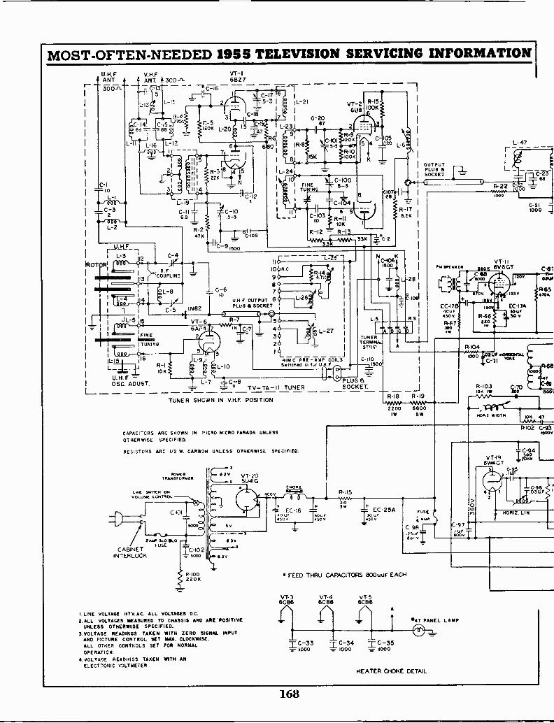
MOST -OFTEN -NEEDED 1955 TELEVISION SERVICING INFORMATIONU.H.FANT
ST)O-n-
10
L-1
C-32
V.RFANT. # 300
JL 5
L-15
C-14 C-I5c68
L -I6
R-4.70t.
L -I2
/ROT RIL-3
1
_L
IL 1
L_U.H FOSC ADUST.
VT -16BZ7
D:16 -1L-21
0-175-3
_--
IC -18 7n-5
3.,
IZOK L-20 15 --i-_-47.2 L-23
--'-- 'Ft,S91 R-9
5 FS15K
C-510_31I
680 1R-8.0
0-2047
VT -26U8
2
R-10
R-I51100K
51C -I054 220 L_
2 1
r R-3 8 4 5 L-24 _-
C -I00INE
II } 226 It .._1,c lipyi -F
I I N31
I 145-3j_
I
-.....___,C12
2 1 TUN
L7-19I ...i-/-
C-II C-10 1 .C -I04
R36
6.81 S-3 1- - 11_1 R -II=Cii1)03
10K I
R-2 ?" R-12 = R -I347K _L --',-09
-_-_- -ww-4-vom_ 536L -9
33K1300
0107ee
eC
6
.-_-
R-1711.26
C-610
1N82
R.FCOUPLING
IC-5
JL-5 115e
r r
TUNING
R-110K
VT -66AF4
L_ =
11
100.09 R411;
67
U.H.F OUTPUTPLUG SOCKET ;
S 30-R-7 5
IK
L-26
C-7 4 L-27 1
36261 t
41171 C PRE -TtNIP COILSS.tched m 1%a U.H F
NC150100
L.S
TUNERTERMINAL.
STRIP
C -I100--j1500
-1---=-
OUTPUTPLUG KSOCKET
RU IP(AKCIN
EC -17IOU,4104
R -F7
ow
L- 47
L
VT -116V 6GT
C {8&Goo
V
R-66EEO
IV/
C100-201
C.61I -
05W
I4-6570K
R-104
PLUG BTV -TA -11 TUNER SOCKET _J
TUNER SHOWN IN V RE POSITION
CAPACITORS ARE SHOWN IN 511CR0 MICRO FARADS UNLESS
OTHERWISE SPECIFIED.
RESISTORS AR: 1/2 W. CARBON UNLESS OTHERWISE SPECIFIED.
POW('TRA1310117CI
LPL &win .4 ON00 LUtat CO:07406
/ 2 "AI SLOOLO
CABINETFUSE
C-101
5000
IC -102INTERLOCK I - woo
8-100220K
6.3v VT -201 5U4 G
Sv
4C V
4 30X
6.3V
LINE VOLTAGE II7V.AC. ALL VOLTAGES D.C.2.ALL VOLTAGES MEASURED TO CHASSIS AND ARE' POSITIVE
UNLESS OTHERWISE SPECIFIED.3.VOLTAOE READINGS TAKEN WITH ZERO SIGNAL INPUT
AND PICTURE CONTROL SET MAX. CLOCKWISE.ALL OTHER CONTROLS SET FOR NORMALOPERATION.
4. VOLTAGE READINGS TAXEN WITH ANELECTnONIC VOLTMETER
C Woe(MGR!!
EC -1640 r.r
R-18 R-19
2200 680068001W SW
1000 U F HOINIONTAL
c -ii wKE
7
R-10310K 10
Si070Fes
18001
WIDTH 108 47
R-115
HIS
EC -25A1;0141
4S0 50 v30 Ur-
+. S.ruSE
4 A UP
C 98
600v
0ID
C-97uf =
*000
VT -196W4GT
R-102 C-9315000
IC-94SOO
2080
C-95IUF
C-9603L1
HORIZ. LIN.
FEED THRU CAPACITORS 800uuF EACH
VT -36CB6
VT -46C B6
VT- 56CB6
A
I
C-33 T C-34 T C-35= 1000 = 1000 = 1000
*47 PANEL LAMP
-1-
HEATER CHOKE DETAIL
168
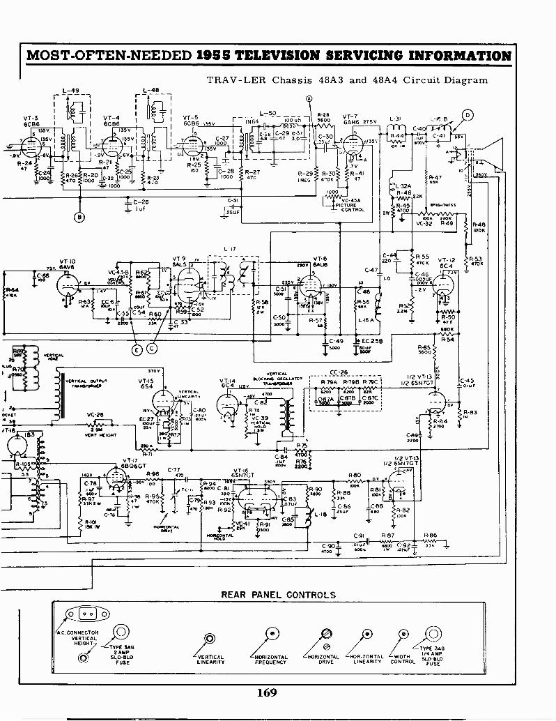
MOST -OFTEN -NEEDED 1955 TELEVISION SERVICING INFORMATION
L-49F
s
ii
1-48
VT -3 1 VT -4 VT -56CB6 I
1 6CB6 6CB6135v I 1
-.F I I35V
5 5
7 I35 V.6
1
1
,c,
.I I635VI - 7
--Is--.96I.9Vi
2 6 02I 13V 2
R-24 R -2I47 R-25
47C-21000= -.-
-2370
150C-22 R -2
C0 -32 1 000470 10
1144knoit
25u0
140 7114.1,061.
7
ic-26I .1 uf.
TRAV-LER Chassis 48A3 and 48A4 Circuit Diagram
135V
1
6 mooC-27
135V
I
C-281000
IN64L-50 R-28
100 uh I 5600
C-36 C-29 C-3768 -4 7 3.0
I
R-27470
C-3025u.1
VT -76AH6
2
5
7v
R-29 R-30 R-41ME,-; 470K 47
4
275VcAcr-r-er<)D
4" R-44.-"" L-41 1 ssv6135\' -5.10,-ILO4001
0.4
VERTICAL OUTPUTT RAM11701414ER 654
370v
VC -26
2.561vcort HEIGHT
140V
C-781
R-101leg IW
asusC-76
C-31
12511F
L-17
1000
VC -43APICTURE
CONTROL2
L -32AR-46
R-454700
A
R-47
RAKR4TNESS
1008 2206VC -32 R-49
2106 6AU6
23
iR-5811K2w
C-51SCOO
C-506000
3
130V
166.
a
R-57M
15000
C-47
220 470 KI
C-46
C-441 R-55
11.0 0A,F.
1
e48 - 2V7
R-541156
L2M
L-16
C-49 EC 25BItowj R-85
5600
VIIRT1CAL CC -26
VT -I5 VT -14 SLOCK440 OWL LA/C0nwspoma. 1479A R-798 R 79c
VERTICAL0.141:4417 v
QV
111V C-80=.23ur
EC -21.1407
,-7.4 3 4006430236 vg
220
R-71
0C4 'Loy
- 47°D
6 C'8R.74
VC -39
nosin'CALtr.
VT -176606GT
C-775
R-96 470
v. 100
P-98 R-9547 470KIW
1401Rev(
TC-It
IC -
470
VT -I66SN7GT
R-94 ii5Vwoo C 81
38Q-13v
R-93 *OK15" R-92
1401MITLI
R-75
C-84 7ur R-76
4c4v 2200.
30V
1/2 VT -I31/2 6SN7GT
1200 8200 2214
A C-878 C -87C
C-89=2200
vT-126C41 2.37
NA -WW-R-504711
680K
R-54
3406
R-48100K
R-53470K
>00
C-45x.2 011.L
R -840V
R-83
2700
83-021../F
46 C.yitZt1 iR 91 ssoO
SOO
81171.
R-90Ssoo
L-31 L-16.8
1/2 VT -131/2 6SN7GT
5
R-80
10014
V 4
R-88 68133K
100AA A
C 86 C-88L.18 2so R 82Itsur
1005
C-91 R-87 R-86
0.01 kt,s,fC-901 .
I s4 .0 1llf33.
4700
REAR PANEL CONTROLS
.C. CONNECTORVERTICAL
HEIGHTTYPE 3AG
2 AMPSLO-8L0
FUSEVERTICALLINEARITY
TYPE 3AG
HORIZONTAL HORIZONTAL HORIZONTAL WIDTH1/4 AMP.
LINEARITY CONTROL FUSEFREQUENCY DRIVE
169
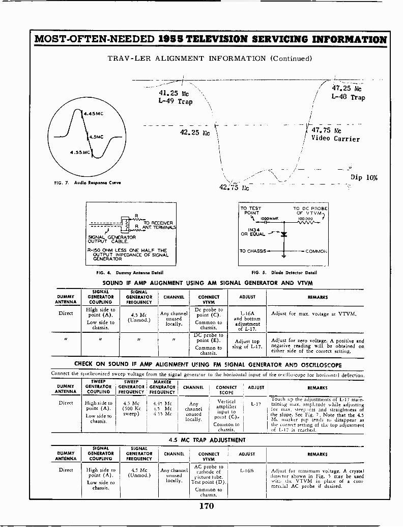
MOST -OFTEN -NEEDED 1955 TELEVISION SERVICING INFORMATION
TRAV-LER ALIGNMENT INFORMATION (Continued)
41.25 McL-49 Trap
42.25 Mc
47.25 McL-48 Trap
t47.75/ Video Carrier
Dip 10%FIG. 7. Audio Response Cure*
--- TO RECEIVERR ANT TERMINALS
SIGNAL GENERATOROUTPUT CABLE.
R150 OHM LESS ONE HALF THEOUTPUT IMPEDANCE OF SIGNALGENERATOR
FIG. 4. Dummy Antenna Detail
42,7O Mc
TO TEST TO DC PROBEPOINT OF VTVM.)
1000 MAW. 100.000 f
IN34OR EQUAL
TO CHASSIS COMMON
FIG. 5. Diode Detector Detail
SOUND IF AMP ALIGNMENT USING AM SIGNAL GENERATOR AND VTVM
DUMMYANTENNA
SIGNALGENERATORCOUPLING
SIGNALGENERATORFREQUENCY
CHANNEL CONNECTVTVM
ADJUST REMARKS
DirectHigh side topoint (A).Low side to
chassis.
4.5 Mc(Unmod .)
Any channelunusedlocally.
Dc probe topoint (C).Common to
chassis.
L -16Aand bottomadjustmentof L-17.
Adjust for max. voltage at VTVM.
as sa is IIDC probe topoint (E).Common to
chassis.
Adjust topslug of L-17.
Adjust for zero voltage. A positive andnegative reading will be obtained oneither side of the correct setting.
CHECK ON SOUND IF AMP ALIGNMENT USING FM SIGNAL GENERATOR AND OSCILLOSCOPEConnect the ynchronized sweep voltage from the signal generator to the horizontal input of the oscilloscope for horizontal deflection.
DUMMYANTENNA
SWEEPGENERATORCOUPLING
SWEEP 1 MARKERGENERATOR GENERATORFREQUENCY . FREQUENCY
CHANNEL CONNECT ADJUSTSCOPE
REMARKS
Direct High side topoint (A).Low side to
chassis.
4.5 Mc 4.45 Mc(500 Kc .1.5 Mcsweep) 4.55 Mc
Anychannelunusedlocally.
Verticalamplifierinput to
point (C).Common to
chassis.
L-17Touch up the adjustments of L-17 main -taining max. amplitude while adjustingfor max. steei,ncss and straightness ofthe slope. See Fig. 7. Note that the 4.5Mc marker pip tends to disappear asthe correct setting of the top adjustmentof L-17 is reached.
4.5 MC TRAP ADJUSTMENT
DUMMYANTENNA
SIGNALGENERATORCOUPLING
SIGNALGENERATORFREQUENCY
CHANNEL CONNECT ADJUSTVTVM
REMARKS
Direct High side topoint (A).Low side to
chassis.
4.5 Mc(Unmod.)
Any channelunusedlocally.
AC probe tocathode of
picture tube.Test point (D).
Common tochassis.
L- 16B Adjust for minimum voltage. A crystaldetector shown in Fig. 5 may be usedwith the VTVM in place of a com-mercial AC probe if desired.
170

MOST -OFTEN -NEEDED 1955 TELEVISION SERVICING INFORMATION
WestinghouseCHASSIS ASSEMBLY V-2313 AND Y-2323
CHASSIS ASSEMBLIES V-2313-15, V-2313-25, and V-2313-35
Several different variations of the V-2313 chassis are used in current production. The differences willbe found in the type of CRT used and the mounting bracket of the off -on -volume control.
CHASSIS ASSEMBLIES V-2323-101, V-2323-201, and V-2323-301
When the letter "U"appears in the model number, it indicates thar the receiver contains a type V-2323chassis. The V-2323 chassis is identical to the V-2313 chassis with the exception that an all -channelVHF -UHF combination tuner has been factory installed to provide UHF reception of the UHF televisionchannels (14 through 83) in addition to the VHF channels (2 through 13).
Several different variations of the V-2323 chassis are used in current production. The differences willbe found in the VHF -UHF tuner combinations, the type of CRT used and the mounting bracket of theoff-on-volume control. The dash numbers following the basic chassis number identifies these variations.
Models H-838K21B, H -841T21, H -842T21, H -843K21, H -844K21, H -847K21,H -848K21, H -861T21, H -862T21, H -863T21, H -864T21, H -865T21, H -866T21,H -867T21, H -868T21, H -871T21, and H -872T21.Models with same numbers having letters KU in place of K and TU in place ofT, contain a built-in all channel VHF -UHF combination RF tuner.
CHASSIS ASSEMBLY V-2314 OR V-2324CHASSIS ASSEMBLIES V-2314-15 AND V-2314-25
Several different variations of the V-2314 chassis are used in current production. The differences willbe found in the type of RF tuner and CRT used.
Models H -853K24, H -854K24, H -869K24, H -870K24, H -875T24, -A, H-876T24,H -877T24, H -878K24, and H -881K24.
Models with same numbers having letters KU in place of K, and TU in place ofT, contain a built-in all channel VHF -UHF combination RF tuner.
All the sets listed on this page are similar in most respects. The alignmentinformation on pages 172 and 173 is applicable to all sets. Since there area number of important circuit differences between the two groups of chassis,the circuit diagram for Chassis V-2313 (and V-2323) is printed on pages 174-175, while the circuit for Chassis V-2314 (and V-2324) is on pages 176-177.Figure 6, top view of each type of chassis, is printed on page 178, and willaid you in locating tubes and alignment adjustments.
CRITICAL LEAD DRESS
All leads that can result in interaction between stages due to RF pick-up must be dressedclose to the chassis. Leads in this category include the heater, AGC and B4 leads, these leadsmust be long enough to permit dressing close to the chassis.
All leads located near the horizontal multivibrator trimmer capacitor, C421, must be dressedaway from the capacitor and close to the chassis.
Video peaking coils should be dressed away from the chassis and clear of adjacent parts.
The lead-in from the antenna terminals tt) the tuner must be dressed away from the IF stripto prevent "RF" tweet from interfering with the picture.
171
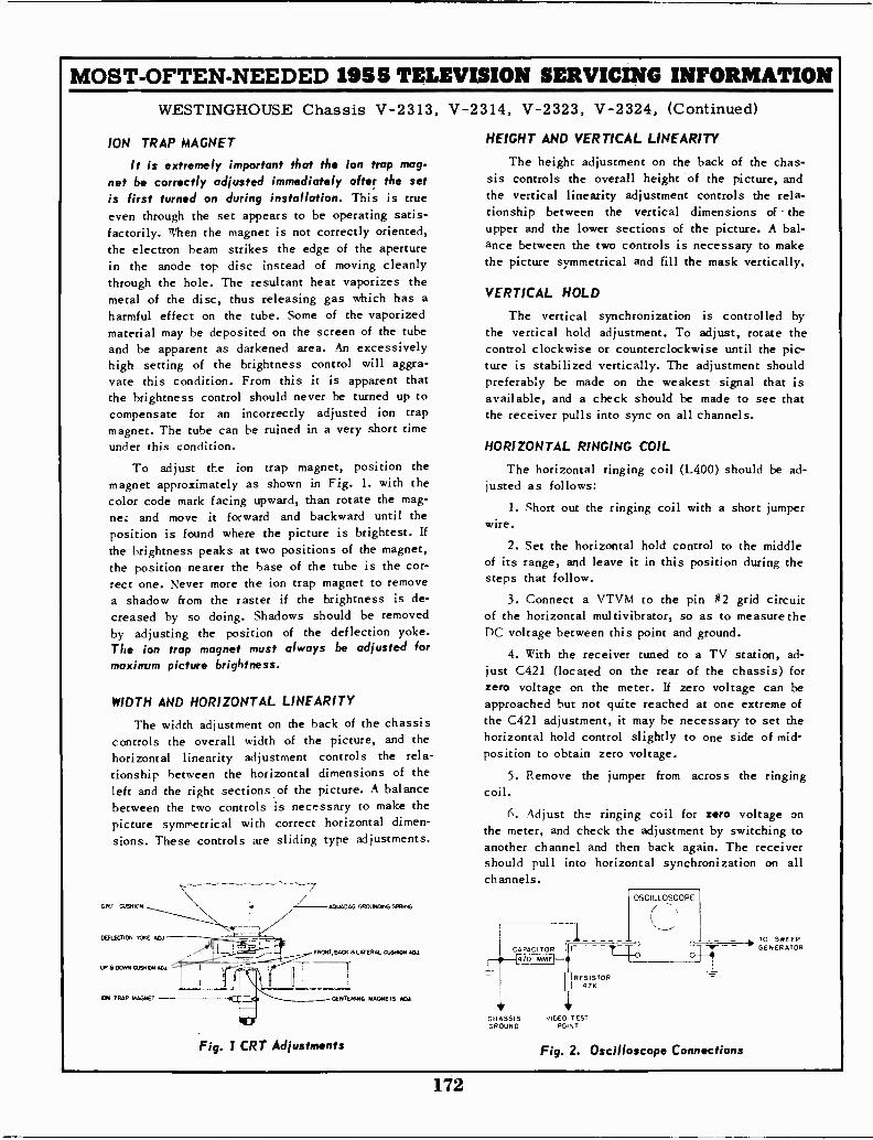
MOST -OFTEN -NEEDED 1955 TELEVISION SERVICING INFORMATIONWESTINGHOUSE Chassis V-2313, V-2314, V-2323, V-2324, (Continued)
ION TRAP MAGNET
It is extremely important that the ion trap mag-net be correctly adjusted immediately after the setis first turned on during installation. This is trueeven through the set appears to be operating satis-factorily. When the magnet is not correctly oriented,the electron beam strikes the edge of the aperturein the anode top disc instead of moving cleanlythrough the hole. The resultant heat vaporizes themetal of the disc, thus releasing gas which has aharmful effect on the tube. Some of the vaporizedmaterial may he deposited on the screen of the tubeand be apparent as darkened area. An excessivelyhigh setting of the brightness control will aggra-vate this condition. From this it is apparent thatthe brightness control should never be turned up tocompensate for an incorrectly adjusted ion trapmagnet. The tube can be ruined in a very short timeunder this condition.
To adjust the ion trap magnet, position themagnet approximately as shown in Fig. 1. with thecolor code mark facing upward, than rotate the mag-net and move it forward and backward until theposition is found where the picture is brightest. If
the brightness peaks at two positions of the magnet,the position nearer the base of the tube is the cor-rect one. Never more the ion trap magnet to removea shadow from the raster if the brightness is de-creased by so doing. Shadows should be removedby adjusting the position of the deflection yoke.The ion trap magnet must always be adjusted formaximum picture brightness.
WIDTH AND HORIZONTAL LINEARITY
The width adjustment on the back of the chassiscontrols the overall width of the picture, and thehorizontal linearity adjustment controls the rela-tionship between the horizontal dimensions of theleft and the right sections of the picture. A balancebetween the two controls is necessary to make thepicture symmetrical with correct horizontal dimen-sions. These controls are sliding type adjustments.
C RT CUSHION
DEFLECTION TORE API --
UP G DORM CASTER
ION TRAP MAGNET
- AOUADAG GROUNDING SPRING
FRONT, BACK 8 LATERAL CUSTOM MT
jCENTERING MAGNETS ADA
Fig. 1 CRT Adjustments
HEIGHT AND VERTICAL LINEARITY
The height adjustment on the back of the chas-sis controls the overall height of the picture, andthe vertical linearity adjustment controls the rela-tionship between the vertical dimensions of theupper and the lower sections of the picture. A bal-ance between the two controls is necessary to makethe picture symmetrical and fill the mask vertically.
VERTICAL HOLD
The vertical synchronization is controlled bythe vertical hold adjustment. To adjust, rotate thecontrol clockwise or counterclockwise until the pic-ture is stabilized vertically. The adjustment shouldpreferably be made on the weakest signal that isavailable, and a check should be made to see thatthe receiver pulls into sync on all channels.
HORIZONTAL RINGING COIL
The horizontal ringing coil (L400) should be ad-justed as follows:
1. Short out the ringing coil with a short jumperwire.
2. Set the horizontal hold control to the middleof its range, and leave it in this position during thesteps that follow.
3. Connect a VTVM to the pin #2 grid circuitof the horizontal multivibrator, so as to measure theDC voltage between this point and ground.
4. With the receiver tuned to a TV station, ad-just C421 (located on the rear of the chassis) forzero voltage on the meter. If zero voltage can beapproached but not quite reached at one extreme ofthe C421 adjustment, it may he necessary to set thehorizontal hold control slightly to one side of mid -position to obtain zero voltage.
5. Remove the jumper from across the ringingcoil.
(. Adjust the ringing coil for zero voltage onthe meter, and check the adjustment by switching toanother channel and then back again. The receivershould pull into horizontal synchronization on allchannels.
CAPACITOR470 MMFI--11
CHASSIS J ICE,: TESTGROUND Pc1NT
RESISTOR47K
OSCILLOSCOPE
-')
Fig. 2. Oscilloscope Connections
TO SWEEPGENERATOR
172
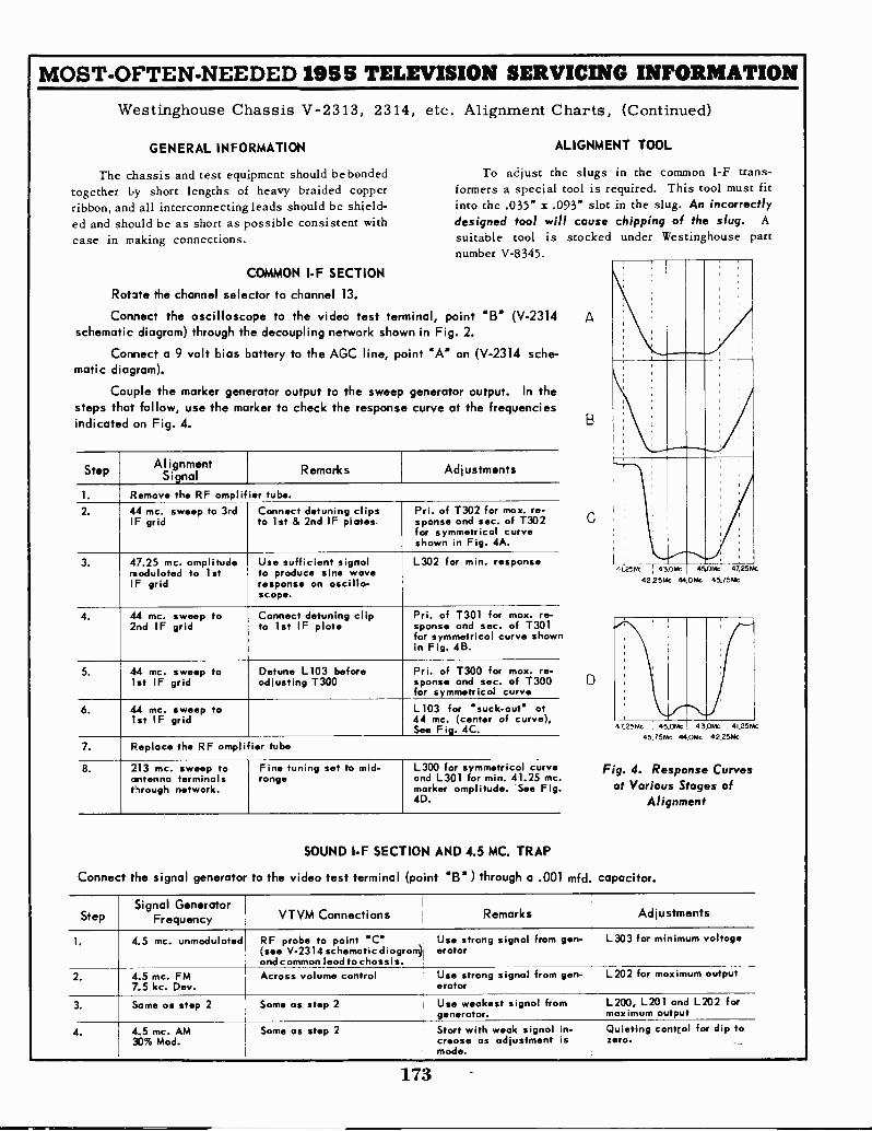
MOST -OFTEN -NEEDED 1955 TELEVISION SERVICING INFORMATION
Westinghouse Chassis V-2313, 2314, etc. Alignment Charts, (Continued)
GENERAL INFORMATION ALIGNMENT TOOL
The chassis and test equipment should be bonded To adjust the slugs in the common I -F trans -together by short lengths of heavy braided copper formers a special tool is required. This tool must fitribbon, and all interconnecting leads should be shield- into the .035" x .093" slot in the slug. An incorrectly
ed and should be as short as possible consistent with designed tool will cause chipping of the slug. A
ease in making connections. suitable tool is stocked under Westinghouse partnumber V-8345.
COMMON I -F SECTION
Rotate the channel selector to channel 13.
Connect the oscilloscope to the video test terminal, point "I3' (V-2314 Aschematic diagram) through the decoupling network shown in Fig. 2.
Correct 9 bias battery AGC line, 'A"a volt to the point on (V-2314 sche-matic diagram).
Couple the marker generator output to the sweep generator output. In thesteps that follow, use the marker to check the response curve at the frequenciesindicated on Fig. 4. B
StepAlignment
Signal Remarks Adjustments1
1. Remove the RF amplifier tube.
2. 44 mc. sweep to 3rdIF grid
Connect detuning clipsto 1st & 2nd IF plates.
Pri. of T302 for max. re -sponse and sec. of T302 Ci
for symmetrical curveshown in Fig. 4A.
3. 47.25 mc. amplitude Use sufficient signal L302 for min. response L. .
modulated to 1stIF grid
to produce sine waveresponse on oscillo-scope.
41.25Nt 4 3.0Mc
422514c 4445.0hic; 41.26MC
OW 45.75kk
4. 44 mc. sweep to Connect detuning clip Pri. of T301 for max. re -2nd IF grid to 1st IF plate sponse and sec. of T301
for symmetrical curve shownin Fig. 4B.
5. 44 mc. sweep to1st IF grid
Detune L103 beforeadjusting T300
Pri. of 1300 for max. re -sponse and sec. of T300for symmetrical curve
6. 44 mc. sweep to1st IF
L103 for 'suck -out' at44 mc. (center of curve),gridSee Fig. 4C. 47.25Mc , 45.0Mc 4 3 OP& 41.25Mc
7.45.7514c 44 OW 42 25tAc
Replace the RF amplifier tube
8. 213 mc. sweep toantenna terminalsthrough network.
Fine tuning set to mid-range
L300 for symmetrical curve Fig. 4. Response Curvesand L301 for min. 41.25 mc.marker amplitude. 'See Fig. at Various Stages of4D. Alignment
SOUND I -F SECTION AND 4.5 MC. TRAP
Connect the signal generator to the video test terminal (point "B" ) through a .001 mfd. capacitor.
StepSignal Generator
Frequency VTVM Connections Remarks Adjustments
1. 4.5 mc. unmodulated RF probe to point "C"(see V-2314 schematic diagram)and common lead to chassis.
Use strong signal from gen-orator
L303 for minimum voltage
2. 4.5 mc. FM Across volume control7.5 kc. Dev.
Use strong signal from gen-orator
L202 for maximum output
3. Same as step 2 Same as step 2 Use weakest signal fromgenerator.
L200, L201 and L202 formaximum output
4. 4.5 mc. AM Same as step 230% Mod.
Start with weak signal in-crease as adjustment ismade.
Quieting control for dip tozero.
173
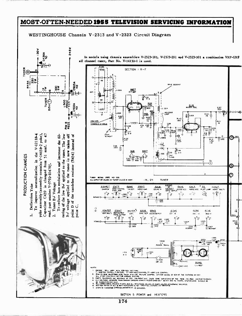
MOST -OFTEN -NEEDED 1955 TELEVISION SERVICING INFORMATION
WESTINGHOUSE Chassis V-2313 and V-2323 Circuit Diagram
2 .t- :o
H
pIO3 oac%cp °
I+CC 000-
>If/ 0
In models using chassis assemblies V-2323-101, V-2323-201 and V-2323-301 a combination VHF -UHFall channel tuner, Part No. V-14130-1 is used.
+
I )1, .4..... 1...ti m+'tEl 0 0 Vg. 2 V w V
Ja al BD4
cb "i a) 1""
iou: ° .1
V, V g ,-Tr . S a>
in 8 - in vre Irs
2 . a. Ee oa 0 t0 1. t1 NC3' a" S :4
g0 u o ...
tesa -o *.d
.o 1 " -
0....N tj aP 7' trs :: A
.,ON os Cs!
IA .0 TJ ff. 2 Eaa'6' E 0 cr-' V 0 o..0 ,t, , r.
bo E st ":1 lo
>.o 0 r -8 0
1 e a: IR gww 0
0 /O.4) *--'>, Ma\ .04j > 0 R.....
ulD CS V-5o 2 1 3' 1
...I
(.1 "pi E.._ ..,
cd 1:0 0 X 00 . pp 4.re ej 0sr V .!.,0 .t' or 0 00 o a z 0 ,,, 7:i a U
1-4 -1 .,a
. /.., 1.. .., > a. r,,...; a....- - E T. 'I, 73 ,-,o -.>, 0 E cs: B co n. Z.
2Lon.
SECTION I R -F
A
IRON CORE
CNANNELS 2 THRo
DRUMSEGMENT
11.100
L1000
ROO220
6SZ7 F AMP
DRUM SEGMENT
RION4709
SIM I ? I Lice.eige, 9 I A0J.COUR
'S LOOP
ng{0000
c ics Cr C1401 f.
Girl3-9
P4V
6827
loco LIDloco s soo 7
0127.005
EIL
I(
RIIIIA
"
TUNER RUM COPE NO. IONALL CAPACITOR VALUES IN TUNER GIVEIV IN MMF. -15,-25 TUNER
6.3VAL
6A)1" 12AT1, _011_61_ 12_8(7 &AI&DAMPER STNC CONTROL FM.DET. VIDEO AMP SOUND IF
SYNC AMP
7/411 4 4 5 irj, 3/L.L5055-
63VAL-0
6SN7GT 126H7 SEE Note/PERT. MULTI. VERSECTOUTPU1PPETR CRT.
lAgl 5 I
inos
6AU6SYNC. SEP
663666AU6 6AL5 w raffiji
630661 METED ACC IORIZ AFC. PILOT LAMP HORIZ MULTINOME OUTPUT
`881
6BK5 6CB6AUDIO OUTPUT 1ST IE
L501 1.502m.U
6 3 44 4 S
60662ND LE
C5 05NIS
T500v.
POWER TRANS.
II1V 7,,?,04 _1_,,5,. iiA- C
= T' 0,-._____.SW 500OFF - ON
seoCIDIF
063 VAL
6CB63RD IF
3)_.1.503I NW
Cero'I= HJI
L50025 V 243V
[sow
5U4G RECT
NOTES:
I. VOLTAGE ROLL VARY WITH CONTROL. SET TING.A *CRAFTING CONTROL. PICTEIRE. 1.7 I vERT.HOLD CONTROL,ft PERT. LIN. cowrie...
2. Km -TO -PEA. wavEFORmS WERE TAKEN WITH THE PICTURE CONTROL SET FOR SIGINAL OF 60V AT THE CATHODE OF CRTALL OTHER CONTROLS SET FOR NORMAL PICTURE
3. PARTS TOLERANCE AND RESPONSE OF TEST MOMENT MAY CAUSE SOME VARIATIONS OF THE PIM -TO-PEAR VOLTAGE READINGS.A. 0-C VOLTAGES MEASURE FROM CHASSIS GROUND USING A 20.000 OHM/VOLT METER AND NC SIGNAL INPUT READING SHOULD NE
AS SHOWN! 20 PER CENT.S. ALL CAPACITANCE vALUES IN MFD. AND ALL RESISTANCE VALUES IN OHMS uNLESS_OTNERWESE SFECIFIED.6. WATTAGE RATING OF ALL Vt WATT RESISTORS IS NOT SPECIFIED, OTHERS S oNDICATED.
2IVPI IN Al CHASSIS ZIWMA IALUMINIZED) IH E CHASSIS.
7W
21ST
R4543
SECTION 5 POWER and HEATERS
174
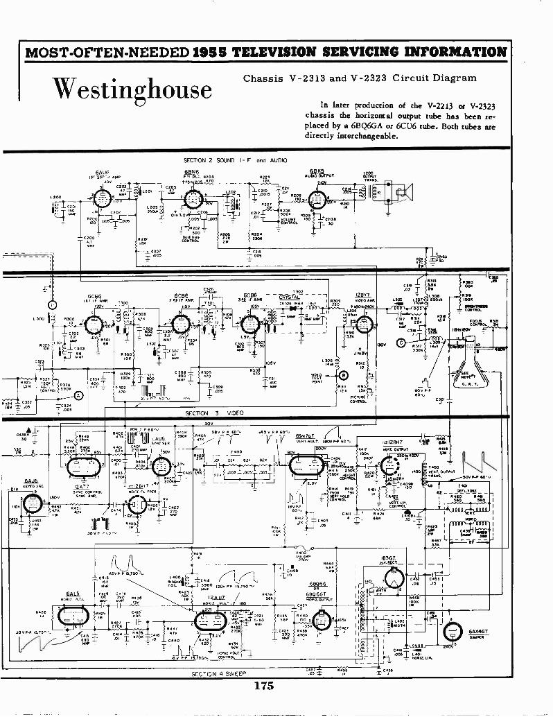
MOST -OFTEN -NEEDED 1955 TELEVISION SERVICING INFORMATION
WestinghouseChassis V-2313 and V-2323 Circuit Diagram
In later production of the V-2213 or V-2323chassis the horizontal output tube has been re-placed by a 6BQ6GA or 6CU6 tube. Both tubes aredirectly interchangeable.
1 4, WC:1- AMP.
1. 200
C200,
1106C203
47MMF
0203 g35061,
8201L26
C207T-005
SECTION 2 SOUND I- F and AUDIO
031_46' IA OLT 8203.t75,470
C205 71777 is
12°1--00,
520,13$
11205Q UIETING t 22KCONTROL 2W
6223124
T;c:"-j-C211'158207
6BK5AUDIO OUTPUT
1031
C218206 6
.05006 5209vOLUMET 801 ""C213BCONTROL _ 30
-C215=.005
16210°TaftTRANS.
1.1-M
6C6611, 17 AMP 1300
1206 -10
4.300 I' #300 I a,0 7
2.2N,
:M
00 i 3 303
I ?-1- 11Ar6B
If3325
1.5/4
42:1"--i 0322ISM T .05
R32775004G.C.
CONTROL
R3263903
-0324I .005
830168
11330113K
R3034,10
C3600
4, 63291000
302470
A31:?C 0306MF 2.2
um,1.3
#00
TRIL PT/P P 60
3047
C3246714146
6CB6292 IF AMP
301156r -41 odo II
ID 12
2
R30468.
C 308 I-4%305
4
8315Care 3.9002 2 SW
606 r - TRTstiZi - - ---I 12802 0 L30113 ED IF AMR ,
1 0309 1/1020 .40P. L306 1.30783 290.C6706-11164 1997 win IvuukorMy I 22° # lecnoroc,v Oro
5 4100 i a *I rnr \ 1 21.^..."--1. L 3 0 5 T -12 6
t..t.,?2,0241'
-"I': Bus" C31756 8226
R381OM
1.5V
CfK41
470YMF
10 5091.005
ISV
T
30o
11i301-1470
1056L 306
MDEO-C311 TEST
9°C/4517
PONT
4.
SECTION 3 VIDEO
310336
4.18338
R312 1
10
11211 8313120 L50
PICTURECONTROL
1306
60 V P.P80".,
C321 -.1
1.320006
634N0)06
I 2526
CO N8111121121.666
TROL
FOCUS 8321CONTROL 216
8516120V
C436#1+" I- 258SW0448
1Y 3308
1106
C435
6AU6KEYED AGC
5
1306
#4492206
R27
40006
5V
2
R4524.7iW
0453
214
2 AT 7SYNC CONTROL
SYNC AW.
R4024.711
200 P 60,,006
. 510C SE P.840121 0 270 MAW
C400 R404 r2.01 4700
R405
4510.16
3867
704
6
1/2 12 811
11015E CLIPPER
C4742V
R450
6405
5501/
718
46
r3.9.0.6
130
54 P 60, .45 v P -P 60,0406 --476
6 376
0402270
7400
R" IAI -226
403 398 I I .002 .005T
=I
R4I1100K
I VI
BOV
6521119.LT_050 T. mull,. 11100ILP 60,
166 MP606,
62.1.5
60/114 2, 45.,.
0426
850 P -P 13.750C412
150 811101N4L
40
056 COIL
C009 C3908
51616 MAK
I-19-18425
119
33 6 P.P 15,756 5.C 413i 660 Tm,
R42/2206
8438
2445'.005
II
R429566I.
0431
Cole5900 1200 PP 15,750 6.,MMT
110612. 'AULT . /60l2AU7
6 etrlij
C414 8426 470 2
3.26.01 I 47060440
01 60kR434
18 V 15,75 7576'.1..0°.°
11447 11
8436,560
0421
560
200V
2.1116
R442 1C405
L265
F4001/4 AMP2500
C4T96.:110
R4355.66
0423
MMF
1$00'11
0406 C407.04 .1
-304511411 "-I 18413 23065600 Re12.?
0444 R449 R427506 396 I0037.1101.6 "PKCONTROL
VERT. LIN.- C0071101.
C411 i-..... R 424 C,B+Z VE 1
4 T._ 680 30 _ I m...zur vrfrn 1
, 184231
I
1 ;431Pli I" Ic2W 51516 no 1
°457 L .----2#--7-71133K
40212BH7 %Er Rae66
OUTPUT #416330
4450 a ART. OUTPUT <INNt
' 3508,420V j7
I .1r.400
5. T/21S.to2E16 CRa
_,,,.....-50V 11-P 60 ' ,..
!c.:190e r.,, t 2401DEFL YOKEme ,
#460 11464 1560 MP- . 1
I
84446.80
4W
.6E00 6 GOR
6B06GTNORILOUTPUT
-_C0R440
ISO 5
-351/R4394706
18307
I
Ip
1i1Ao
4 1656
0427T.I
116
79
Ipto
2
2
.7)31-434.06 .15
- L402'WIDTH
04584006I.
C434
II
III
1.I 11i .0061 LZ8z.L.,
6AX4GT0441PER
SECTION 4 SWEEP04371.25 2
175
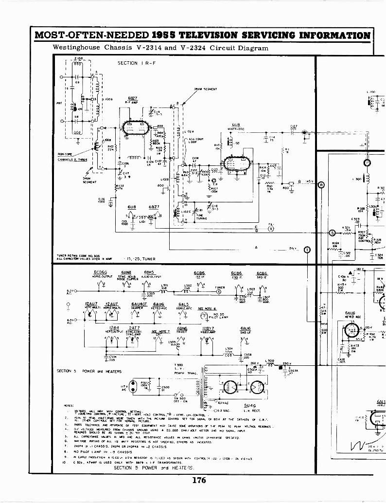
MOST -OFTEN -NEEDED 1955 TELEVISION SERVICING INFORMATIONWestinghouse Chassis V-2314 and V-2324 Circuit Diagram
IRON CORE1
CHANNELS 2 THRJ 6 I
DRUM
SEGMENT
SECTION I R-F
6-(a)
C1261000
01063
..7--1C117
02476
3-9
C119
IND4.470K
R103820K
. RIGS=1.56
i24 C107L5 47 _L
L029
BOO
6U8 6827
Lim I
6U8TAIXER-OSC
ORUM SEGMENT
wr, I
L 102A
ADJ. COUP.LOOP
Ci0847
C 127
I 75
IK
FIL
800
B 145v
L 200
C
A 215 V
TUNER RETMA COOS NO. 305ALL CAPACITOR VALUES GIVEN IN MMF - 15, -25, TUNER
R32418M
4N/VW7:7C322=1, .05
300
10K
C 32302
R325 -)L5
R327
AOCCCNTROL
R 301
C3
390.
C 324I 005
6CD66 6AN8 6BK5HOR12.OUTPUT SYNC.ejFalER AUDIO OUTPUT
7 5 4 /! L501, 1.141,
A.
6.3V0A.C.
4
T0035
I2AU 7 12 AU7 6AU4GTVERT.MULTI. HORIEKRA-71. DAMPER
S 4456AU6
KEYED AOC
L502
ISO. I F
4
§106_2n IF 3RD IF
1101 TUNER L503 4
- Huh
6AL5Hos !ZAK SEE NOTE 9
NO. 55PILOT LAMP
00600 C5072800 TacoIMF MMF.
12 B 4 12AT 7 68rt 12BY 7 6AU6vERT.OUTPUT SYNC.CONT. SEE NOTE 7 EM.DET. VIDEO.AMP SMILE.
SYNC.AMP. -Z91=---12/.. 4 3 5 4 3/1I4 3 5 4 5
L50115
T.ggs
SECTION 5 POWER and HEATERS
NOTES:
117AC
LCLTAGES WILL NAM WITH CONTROL SETTING .sCARETING CONTROL,: RCTuRE TT vERT HOtD CONTROL ,1* vERT. LEN .CONTROL
2. LEAK TO REA6 55/1/E7CRATS WERE TAKEN wITH THE PICTURE CCWITROL SET FOR SIGNAL OF 609 AT THE CATHODE OF C.R.T.ALL OTHER CONTFCLS SET FOR NORMAL PICTURE.3. PARTS TOLERANCE AND RESPONSE OF TEST EQUIPMENT 400 CAUSE SONS VARIATIONS OF THE PEAK' TO' PEAK VOLTAGE REACWIGS .4. 0-C VOLTAGES MEASURED FROM CHASSIS GROLNO USING A 20,000 01.m/ LOU METER AND 150 SIGNAL INPUT.READWG5 SHOIA.0 RE AS SHOWN 0 20 PER CENT.5. ALL CAPACITANCE ALLIES IN WM Ate ALL RESISTANCE VALUES IN 01.445 ENL155 OTHERWISE 5PECIFAU6. WATTAGE RATING OF ALL i/2 WATT RESISTORS IS NOT SPECIFIED, OTHERS AS INDICATED.7. 24OP4 84 -1 CHASSIS. 2413P4 OR 240P4A IN -2 CHASSIS9 NO PILOT LAMP IN -15 CHASSIS.9 N EARLY pROCuCTION A 15 00.' v2 w RESISTOR IS 5,..E.CED A5 SHOWN 15,TH CCNTRCT t5 -22 .27C9 01 v 6.163
10 . C 326, 47MMF IS USED ONLY WITH 9879 I -F TRANSFORMERS.
SECTION 5 POWER and FIE rE S.
T 500L. V .POWER TRANS,
SW 500OFF- ON
15041.101
/000\--- C508-005500
260 vL
250 v
C502A C503440 "r_40
5U4G 6J VAC. L . v. RECT.
i20 v
Af +C436 A30 IH 4 545002 W
UK6W
54
600)6W
6AU6KEYED *GC
C435.005
18 V
R4483308
O
S'5,
6 1120V
R 452 .
95 V 1 1 594.7I
4.
R45318112W
20 V I. I,
15,750 'NE
176
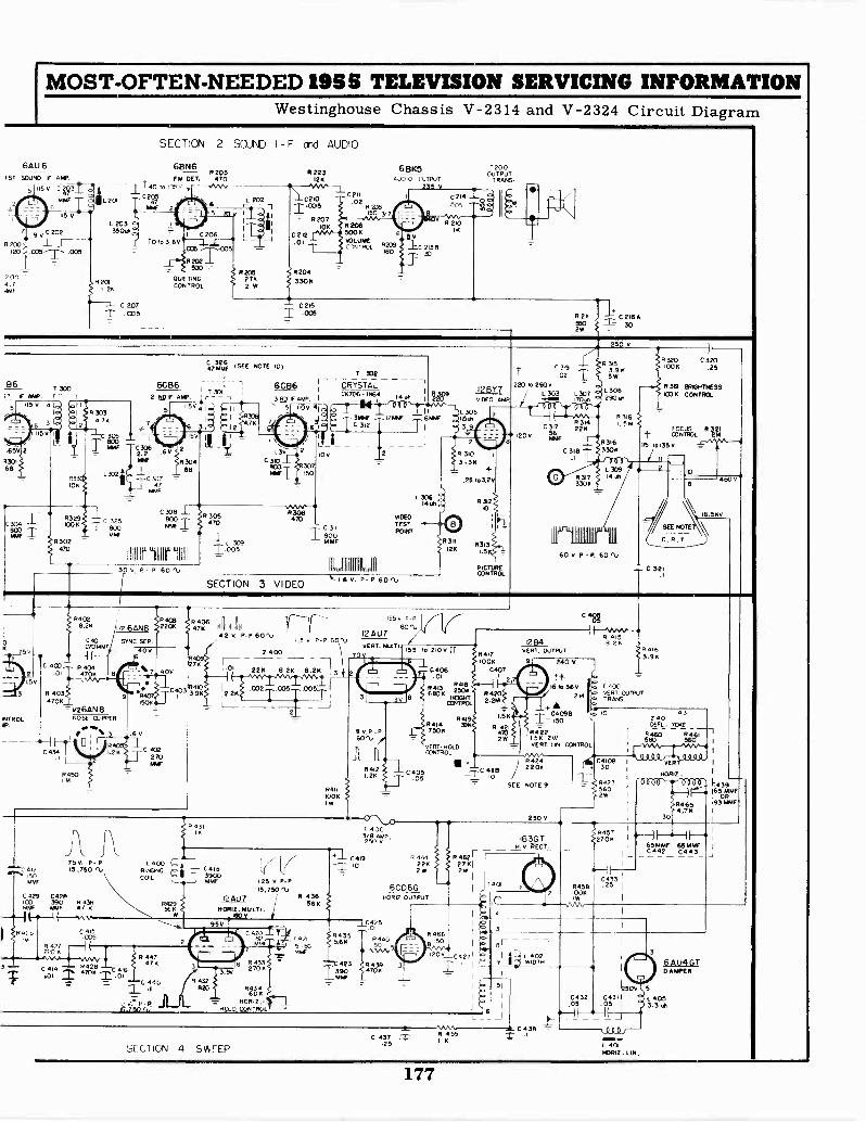
MOST -OFTEN -NEEDED 1955 TELEVISION SERVICING INFORMATIONWestinghouse Chassis V-2314 and V-2324 Circuit Diagram
6Au 615T SOUND IF IMP.
115V Ci93M6W
115 V
9V C2°2R200
.00-5
2004.746W
L 201
L 20335006
R2011.2K
C 207T .005
SECTION 2 SOUND I - F and AUDIO
6BN6R 223
FM OCT. 470 12K
C205
140 to 0.. / ---J VW. W V --j- C211
L 202 C20 .0247 661.1F 2 -1 14015
5 76 I
10,03.69.C 206
006 .7-T7,035
R202 _I_500 -.7
001E760CONTROL
L _
R2052762W
62071011
C212.01
R2043306
PAB.50 3.7
6BK5AUDIO CUTPuT
235V
720COUTPUT
TRANS.
C214Oo.003
R2065006 6014482CONTROL 206
160 30
R 210'K
- C215I .005
C:106 A
250 V
B6 T 300IT IF APP.
65 v 4 1.5,)
la R 303
3 1:
L..65V 2
4313166
4.71(
R106
S8329006
1.302SS 170
L302
47368W (SEE NOTE 0)
6086Tap ;2 NOW Ali. -10 ci,r;el
6 3 012
5
.5v
22.2
761E 830468
C30747
63064,76
T 332
6C86 r, CRYSTALC6706 iN64 14 USA
3 F A. 1110v
TC 3127
_ _t 2
1,39
C302
307161F 60
C 3081.
C:igg 1°0° IMMF
30 V P - P. 60
R 305470
T.-os
R308470
SECTION 3 VIDEO
110 V
C 311
_j_ 800- LIMP
Jill6.1.6 v. P
6060TESTPOeir
60 '1../
I2BY7VIDEO AMP
PICTURECONTROL
C 319
.02T3.9 656
220 10 2600503 L507 L290300.
CR314
2
22.1
C 3181
#3,73306
r
R 30
7.34
R31633011
1900L 19 _
R320 C320103K .25
L
939 ER1GHTNESSICOK CONTROL
FOCUS R 3 I
CONTROL 26115 70135 V
14 61
60 V. P - P 60 '14
C. R T.
= C 321
480
t0.560
84028.22
0
75
3
C401240686
-I(C 4C0 9404
01 T4706
R 1034708
v26AN8w iROLP.
C 434
NOISE CLIPPER
-I_1 3 1.69
R450
1.C 402
270Miff
4126e V. P- P 60'1.,
1.5 V. P -P 601.,
Z 400
FT -
226 8.26 8.26
00
3
R4111001(IW
R 431
c 41?756. P - P15 ,750 ,Lt RINGING
L 400C4I8 :I(7
00C4 -I
3900NNW
COIL
MAP 1414F 4 I 466 NOR12. MULT:5I2..515°V P':
C 429 C4214
MN*
12 Au7100 390 R 438
140v
/F14:-5
41
0415.035
C 420 _.t ;ly42 , 1 4 0
IN -I ( ...- ._ a ,c, - p,,ankm--11-aailaVaa.Ay,movvv,-, R 447
47K 5 11433,C.04114 I.,ge 6.04114 270K
C'.17 4' 4C, (.1432820i3.5V 86
270K
JUL.' J.FP p = 401412.-rag.250 T1., 80.3 CONTROL
R 436566
124u7
555. PP .1{60'1,
VERT. PAILTL
70
9 v. P -P
114121.26
\F 4003/8250'V
C419
R4355.66
,0
j_C&25
155 10 210V it
_LC406.01
R41R41.3 250,,0
801(NEIONT
CONTROL
R414R419
31167506
VERT. HOLDCONTROL
"1-
040.05
84)7iOOK
C407
R4202.26
156
R44212790
12 B4
C 48R
R 4158 29
VERT. OUTPUT
,)e
240 v
16 to 369 fr. 74002141 ART. OuTPuT
4- 098 10
64166416
150
R4221.58 2WVERT. LIN CONTROL
AAA.R4242206
SEE NOTE 9
250
3.96
2401DEFL. TOKE
11460 R4 5II 560 560
1
C4108. 30
235602W
8457III 3 gT 2706
H. V. RECT___
R 444 R 462r -I226 2761 . 1
2W 2W
6CD6GHOW OUTPUT
R 440
A.
#4"? 31390
SECTION 4 SvirEP
6466150
120V C4271'
T40
3
I
511
L 6 _1
R4581002
I vER
NOW
65886 115MMf- _1442_ 014 3_
C433 1.25 I
1
L539
!6 OR".931.1641
C432 C311.05 .05
' H
C 438 - 0110C 437 R 55 AT
-1 6-25 L 401
110812. LIN.
3
6AU4GTDARER
L 4053.3 61,
177
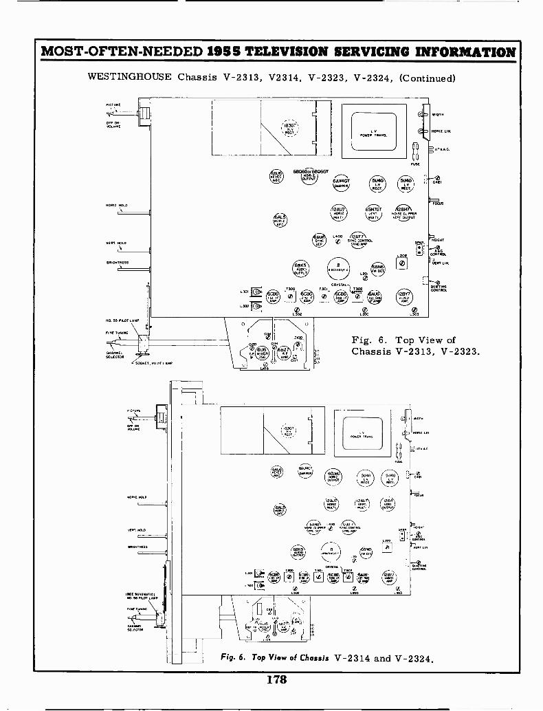
MOST -OFTEN -NEEDED 1955 TELEVISION SERVICING INFORMATION
WESTINGHOUSE Chassis V-2313, V2314, V-2323, V-2324, (Continued)
PICTURE
OFF -ON -VOLUME
NORIZ. NOLO
VERT. HOLD
BRIGHTNESS
NO. 55 PILOT
FINE TUNING
-t
CHANNELSELECTOR
SOCKET, PILOT LAMP
PiCTuglE
ANGORAYDLDME -"T
NOIRE. NOLO
wort. NOLO
ONONTNESS
117.. ECNEMATICINO. SS PILOT LANA
FINE Tri
GNO
z (-5L.103
6806Gor6806G700012.
OUTPUT
6605AUDIO
PUT
64X4GTPER
2AU7.44 z
CRYSTALT301
rinE
5046 5U40
SYNC CONTROLSYNC NW
I2BY7yip 0
MAP
WIDTH
NORM. LIN.
El
NEiGH1SPAR.
GC-- CONTROL
%1ERT LIN.
QUIETINGCONTROL
Fig. 6. Top View ofChassis V-2313,
07RfCT
LSDI [Q
L 3Do
lel
EAURGT
DAMPEN
ROWER TRANS
12 AUMDL) (12AU
(j,AmiN L400 671-7;\03011.50 t SYNC CONTROLSYNC SEP SYNC
B
CRYSTAL302 T 302
(tcael 4A1e,
L3OR L.00
5u4o
-Eh' L°
103
11,
OUP TINGCONTR..
Fig. 6. Top View of Chassis V-2314 and V-2324.
178
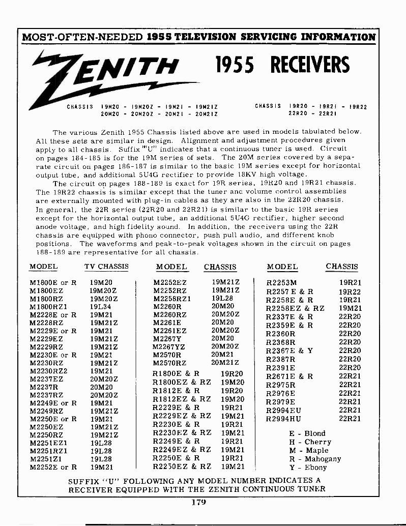
MOST -OFTEN -NEEDED 1955 TELEVISION SERVICING INFORMATION
EN/TH 1955 RECEIVERS
CHASSIS I9M20 - 19M20Z - I9M21 - 19M2IZ20M20 - 20M20Z - 20M2 I - 20M2IZ
CHASSIS I9R20 - 19R2I - I9R2222R20 - 22R2I
The various Zenith 1955 Chassis listed above are used in models tabulated below.All these sets are similar in design. Alignment and adjustment procedures givenapply to all chassis. Suffix I"Un indicates that a continuous tuner is used. Circuiton pages 184-185 is for the 19M series of sets. The 20M series covered by a sepa-rate circuit on pages 186-187 is similar to the basic 19M series except for horizontaloutput tube, and additional 5U4G rectifier to provide 18KV high voltage.
The circuit on pages 188-189 is exact for 19R series, 19R20 and 19R21 chassis.The 19R22 chassis is similar except that the tuner and volume control assembliesare externally mounted with plug-in cables as they are also in the 22R20 chassis.In general, the 22R series (22R20 and 22R21) is similar to the basic 19R seriesexcept for the horizontal output tube, an additional 5U4G rectifier, higher secondanode voltage, and high fidelity sound. In addition, the receivers using the 22Rchassis are equipped with phono connector, push pull audio, and different knobpositions. The waveforms and peak -to -peak voltages shown in the circuit on pages188-189 are representative for all chassis.
MODEL
M1800E or RM1800EZM180ORZM1800RZ1M2228E or RM2228RZM2229E or RM2229EZM2229RZM2230E or RM2230RZM2230RZ2M2237EZM2237RM2237RZM2249E or RM2249RZM2250E or RM2250EZM2250RZM2251EZ1M2251RZ1M2251Z1M2252E or R
TV CHASSIS MODEL
19M2019M2OZ19M2OZ19L3419M2119M21Z19M2119M21Z19M21Z19M2119M21Z19M2120M20Z20M2020M20Z19M2119M21Z19M2119M21Z19M21Z19L2819L2819L2819M21
CHASSIS MODEL CHASSIS
M2252EZ 19M21ZM2252RZ 19M21ZM2258RZ1 19L28M2260R 20M20M2260RZ 20M20ZM2261E 20M20M2261EZ 20M20ZM2267Y 20M20M2267YZ 20M20ZM2570R 20M21M2570RZ 20M21Z
R1800E & R 19R20RIME Z & RZ 19M20R1812E & R 19R20R1812EZ & RZ 19M20R2229E & R 19R21R2229EZ & RZ 19M21R2230E & R 19R21R2230E Z & RZ 19M21R2249E & R 19R21R2249EZ & RZ 19M21R2250E & R 19R21R2250EZ & RZ 19M21
R2253M 19R21R2257 E & R 19R22R2258E & R 19R21R2258EZ & RZ 19M21R2337E & R 22R20R2359E & R 22R20R2360R 22R20R2368R 22R20R2367E & Y 22R20R2387R 22R20R2391E 22R20R2671E & R 22R21R2975R 22R21R2976E 22R21R2979E 22R21R2994EU 22R21R2994HU 22R21
E - BlondH - CherryM - MapleR - MahoganyY - Ebony
SUFFIX "U" FOLLOWING ANY MODEL NUMBER INDICATES ARECEIVER EQUIPPED WITH THE ZENITH CONTINUOUS TUNER
179
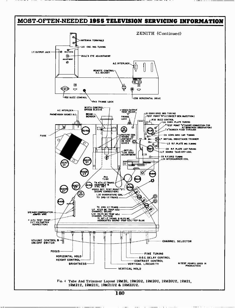
MOST -OFTEN -NEEDED 195$ TELEVISION SERVICING INFORMATION
ANTENNA TERMINALS
LIO OSC. IND. TUNING
I. F OUTPUT JACK
BULL'S EYE ADJUSTMENT
R32 BUZZ CONTROL
A.C. INTERLOCK-
PHONEVISION SOCKET A.C.
FUSE
SPEAKER COMPENSATION -JUMPER WIRE
A.F C. TEST POINT( V.T. VOLT METER
CONNECTION)
A.0 INTERLOCK
REMOTE CONTROLA.G. SOCKET
R43 FRINGE LOCK
WIDTH CONTROLBRASS SLEEVE
BEAMBENDER
PI XTUBE
/1", T4 4TH I.F. TRANS. ,;6csa ASSEMBLY B
XTAL DET.VIDEO DET. TEST POINT "D'
(SCOPE CONNECTION)L20 OUADRATURE COILT3 3RD I.F TRANS.
ZENITH (Continued)
C58 HORIZONTAL DRIVE
VIDEO OUTPUTTEST POINT
"J"FRINGELOCK
ICTURE CEN-TERING AD-JUSTMENTON YOKECOVER
T2 2ND I.F. TRANS.LI I 4725 MC. TRAP-ADJ.CHANNEL SOUNDL12 39.75 MC TRAP ADJ.CHANNEL PICTURE
TI 1ST I.F. TRANS. B 41.25 MC.ASSOCIATED SOUND TRAP COIL -TOP SLUG
L6 CONV GRID IND. TUNING1 TEST POINT 'A"( I.F. SWEEP GEN. INJECTION)
R32 BUZZ CONTROL3/-L8 CONV. PLATE TUNING
'TEST POINT "H'(SCOPE CONNECTION FORRF BAND PASS OBSERVATION )
X"SCREEN FEED THROUGH
C9 CONV. GRID CAP. TUNING
gL7 MUTUAL INDUCTANCE TRIMMER
VOLUME CONTROL &ON -OFF SWITCH
FOCUS
HORIZONTAL HOLD -HEIGHT CONTROL
BRIGHTNESS
tJ
L5 R.F. PLATE IND. TUNING
CB R.F. PLATE CAP. TUNINGLI7 SOUND TAKE -OFF COIL
- C5 R.F. GRID TUNINGLI9 INTERCARRIER COIL
CHANNEL SELECTOR
FINE TUNINGA.G.C. DELAY CONTROL
CONTRAST CONTROLVERTICAL LINEARITY
- VERTICAL HOLD
*TEST POINTS USED INPRODUCTION
Fig. 4 Tube And Trimmer Layout 19M20, 19M20Z, 19M20U, 19M2OUZ, 19M21,19M21Z, 19M21U, 19M21UZ & 19M22UZ.
180
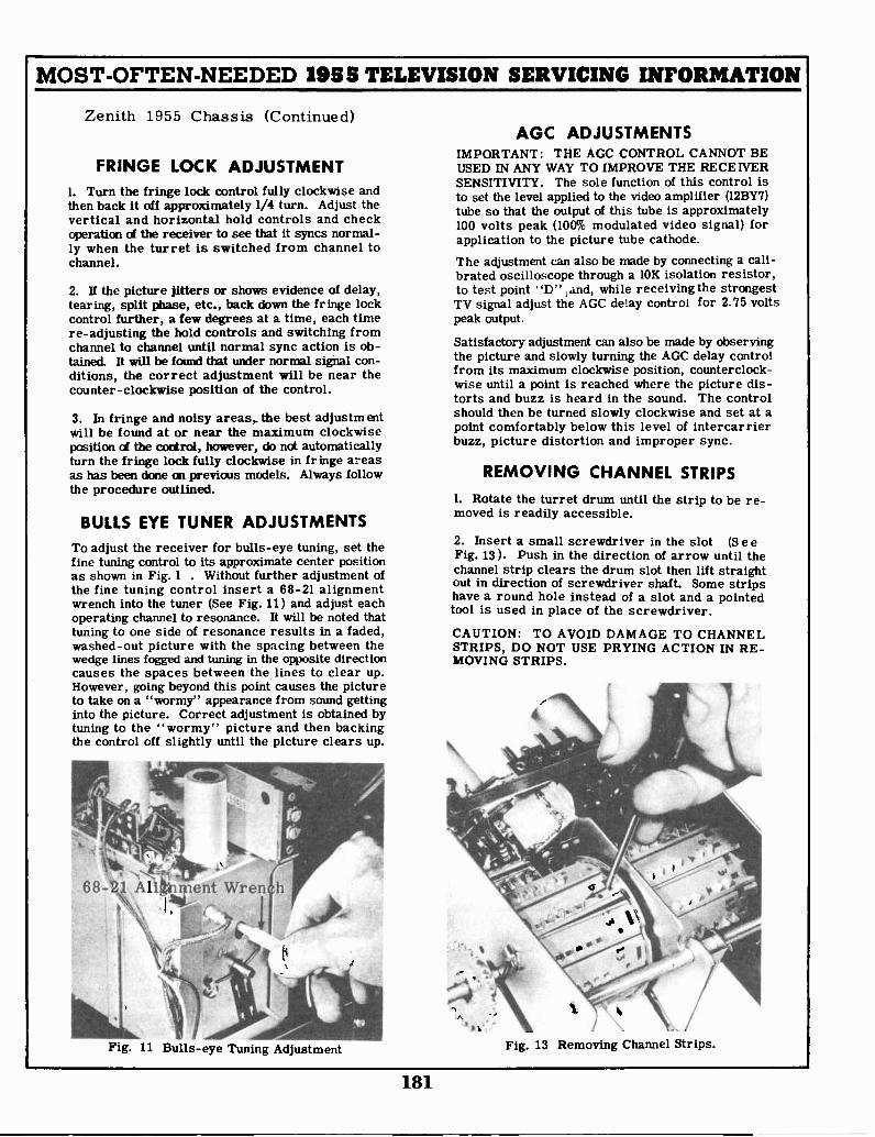
MOST -OFTEN -NEEDED 1955 TELEVISION SERVICING INFORMATION
Zenith 1955 Chassis (Continued)
FRINGE LOCK ADJUSTMENT1. Turn the fringe lock control fully clockwise andthen back it off approximately 1/4 turn. Adjust thevertical and horizontal hold controls and checkoperation of the receiver to see that it syncs normal-ly when the turret is switched from channel tochannel.
2. If the picture jitters or shows evidence of delay,tearing, split phase, etc., back down the fringe lockcontrol further, a few degrees at a time, each timere -adjusting the hold controls and switching fromchannel to channel until normal sync action is ob-tained. It will be found that under normal signal con-ditions, the correct adjustment will be near thecounter -clockwise position of the control.
3. In fringe and noisy areas,. the best adjustmentwill be found at or near the maximum clockwiseposition ci the control, however, do not automaticallyturn the fringe lock fully clockwise in fringe areasas has been done on previous models. Always followthe procedure outlined.
BULLS EYE TUNER ADJUSTMENTSTo adjust the receiver for bulls -eye tuning, set thefine tuning control to its approximate center positionas shown in Fig. 1 . Without further adjustment ofthe fine tuning control insert a 68-21 alignmentwrench into the tuner (See Fig. 11) and adjust eachoperating channel to resonance. It will be noted thattuning to one side of resonance results in a faded,washed-out picture with the spacing between thewedge lines fogged and tuning in the opposite directioncauses the spaces between the lines to clear up.However, going beyond this point causes the pictureto take on a "wormy" appearance from sound gettinginto the picture. Correct adjustment is obtained bytuning to the "wormy" picture and then backingthe control off slightly until the picture clears up.
68-21 AlittVent Wren
Fig. 11 Bulls -eye Tuning Adjustment
AGC ADJUSTMENTSIMPORTANT: THE AGC CONTROL CANNOT BEUSED IN ANY WAY TO IMPROVE THE RECEIVERSENSITIVITY. The sole function of this control isto set the level applied to the video amplifier (12BY7)tube so that the output of this tube is approximately100 volts peak (100% modulated video signal) forapplication to the picture tube cathode.The adjustment can also be made by connecting a cali-brated oscilloscope through a 10K isolation resistor,to test point "D" , and, while receiving the strongestTV signal adjust the AGC delay control for 2.75 voltspeak output.
Satisfactory adjustment can also be made by observingthe picture and slowly turning the AGC delay controlfrom its maximum clockwise position, counterclock-wise until a point is reached where the picture dis-torts and buzz is heard in the sound. The controlshould then be turned slowly clockwise and set at apoint comfortably below this level of intercarrierbuzz, picture distortion and improper sync.
REMOVING CHANNEL STRIPS1. Rotate the turret drum until the strip to be re-moved is readily accessible.
2. Insert a small screwdriver in the slot (S e eFig. 13). Push in the direction of arrow until thechannel strip clears the drum slot then lift straightout in direction of screwdriver shaft. Some stripshave a round hole instead of a slot and a pointedtool is used in place of the screwdriver.
CAUTION: TO AVOID DAMAGE TO CHANNELSTRIPS, DO NOT USE PRYING ACTION IN RE-MOVING STRIPS.
Fig. 13 Removing Channel Strips.
181

MOST -OFTEN -NEEDED 1955 TELEVISION SERVICING INFORMATION
ZENITH 1955 Chassis (Continued)
ALIGNMENT
TO RECEIVER ANTENNA TERMINALS
MATCHING TRANSFORMER50 OHMS UNBALANCED TO 300 OHMS BALANCED
HOOKED ENDFOR CONNECTINGTO VARIOUS GRIDS
470 MMFD.CERAMICCAPACITOR
GROUND DIRECTLYTO CHASSIS. DO NOTUSE LEADS.
56f).1/2 W 57.CARBONRESISTOR
SWEEP GENERATOROUTPUT CABLE
Fig. 14 IF-RF Alignment Fixtures
A suitable VHF and UHF sweep generator in con-junction with an accurate marker must be used foralignment work. It is very important to have thesweep generator output cable properly terminatedand to check whether or not its attenuator is reactive.If the attenuator is reactive or if the output cable isimproperly terminated, correct alignment cannot bemade since the degree of attenuation then may changethe shape as well as the amplitude of the responsecurve. The position of the attenuator should onlyvary the amplitude and not the shape of the responsecurve.
SOUND ALIGNMENTProper alignment of the 4.5 Mc intercarrier soundchannel can only be obtained if the signal to the re-ceiver antenna terminals is reduced to a level belowthe limiting point of the 6BN6 Gated Beam Detector.This level can be easily identified by the "hiss" whichthen accompanies the sound.
Various methods may be used to reduce the signallevel, however, it is recommended that a step atten-uator similar to the S-17203 unit be used for mostsatisfactory results.
1. Connect the step attenuator between the antennaand the receiver antenna terminals.
2. Tune in a tone modulated TV signal and adjust thestep attenuator until the signal is reduced to a levelwhere "hiss" is heard with the sound.
3. Adjust the sound take -off coil L17 (top and bottomslugs), intercarrier coil L19, quadrature coil L20and buzz control R32 for the cleanest sound andminimum buzz. It must be remembered that any ofthese adjustments may cause the "hiss" to disappearand further reduction of the signal will be necessaryso that the "hiss" does not disappear during align-ment.
If intercarrier buzz is in evidence, after all normalsound adjustments have been made, the cause may beattributed to one or more of the following:
1. Improper adjustment of the AGC delay control.
2. Defective 6AU6 sound limiter.
3. Extremely high signal levels which require atten-uation in the antenna circuit.
4. Transmitter over modulation.
VIDEO IF ALIGNMENT1. Slowly turn the channel selector until the turret ismade to rest between two channels. Connect the neg-ative lead of a 2 volt battery supply to terminal "E"(Fig. 27) and the positive lead to chassis. The biassupply should be made variable so that it caR bevaried from negative 3 volts to positive 3 volts. Keepthe supply leads short.2. Connect the calibrated oscilloscope through a10,000 ohm isolation resistor between terminal "D"and chassis. The sweep generator input to the re-ceiver should be adjusted for 3 volts peak to peakdetector output. Do not exceed this output levelduring any of the adjustments.
3. Feed the output from the sweep generator throughthe special termination unit shown in Fig. 14 to point"C" (Pin 1 of 6CB6, 3rd IF). Adjust the generatoruntil a pattern similar to Fig. 16 is obtained.
75MC 45 75MC
Fig. 16 4th IF Response.
4. Set the Marker Generator to 45.75 Mc and alter-nately adjust the top and bottom slugs of the 4th IFtransformer for maximum gain and symmetry withthe 45.75 Mc markers positioned as shown in Fig. 16The 39.75 Mc marker can be within 1.0.5 Mc of thespecified frequency. If the correct response curvecannot be obtained in this step, check the position ofthe two slugs to see that they are entering theirrespective coils from the opposite ends of the coilform. The position of the slugs near the center of thecoils may change the coefficient of coupling, makingcorrect alignment difficult if not impossible.
182
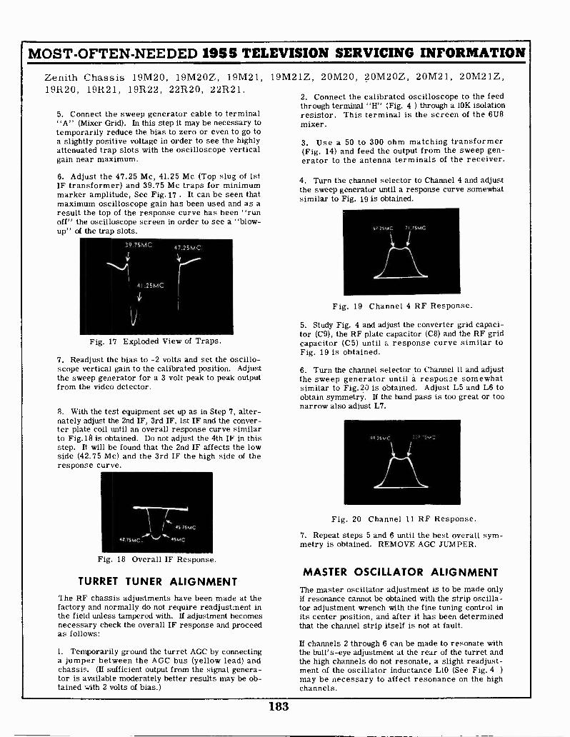
MOST -OFTEN -NEEDED 1955 TELEVISION SERVICING INFORMATION
Zenith Chassis 19M20, 19M20Z, 19M21, 19M21Z, 20M20, 20M20Z, 20M21, 20M21Z,19R20, 19R21, 19R22, 22R20, 22R21.
5. Connect the sweep generator cable to terminal"A" (Mixer Grid). In this step it may be necessary totemporarily reduce the bias to zero or even to go toa slightly positive voltage in order to see the highlyattenuated trap slots with the oscilloscope verticalgain near maximum.
6. Adjust the 47.25 Mc, 41.25 Mc (Top slug of 1stIF transformer) and 39.75 Mc traps for minimummarker amplitude, See Fig. 17 . It can be seen thatmaximum oscilloscope gain has been used and as aresult the top of the response curve has been "runoff" the oscilloscope screen in order to see a "blow-up" of the trap slots.
Fig. 17 Exploded View of Traps.
7. Readjust the bias to -2 volts and set the oscillo-scope vertical gain to the calibrated position. Adjustthe sweep generator for a 3 volt peak to peak outputfrom the video detector.
8. With the test equipment set up as in Step 7, alter-nately adjust the 2nd IF, 3rd IF, 1st IF and the conver-ter plate coil until an overall response curve similarto Fig.18 is obtained. Do not adjust the 4th IF in thisstep. It will be found that the 2nd IF affects the lowside (42.75 Mc) and the 3rd IF the high side of theresponse curve.
/11/4 45 75MC
42.75MC 45MC
Fig. 18 Overall IF Response.
TURRET TUNER ALIGNMENTThe RF chassis adjustments have been made at thefactory and normally do not require readjustment inthe field unless tampered with. If adjustment becomesnecessary check the overall IF response and proceedas follows:
1. Temporarily ground the turret AGC by connectinga jumper between the AGC bus (yellow lead) andchassis. (If sufficient output from the signal genera-tor is available moderately better results may be ob-tained with 2 volts of bias.)
2. Connect the calibrated oscilloscope to the feedthrough terminal "H" (Fig. 4 ) through a 10K isolationresistor. This terminal is the screen of the 6U8mixer.
3. Use a 50 to 300 ohm matching transformer(Fig. 14) and feed the output from the sweep gen-erator to the antenna terminals of the receiver.
4. Turn the channel selector to Channel 4 and adjustthe sweep generator until a response curve somewhatsimilar to Fig. 19 is obtained.
Fig. 19 Channel 4 RF Response.
5. Study Fig. 4 and adjust the converter grid capaci-tor (C9), the RF plate capacitor (C8) and the RF gridcapacitor (C5) until a response curve similar toFig. 19 is obtained.
6. Turn the channel selector to Channel 11 and adjustthe sweep generator until a response somewhatsimilar to Fig.20 is obtained. Adjust L5 and L6 toobtain symmetry. If the band pass is too great or toonarrow also adjust L7.
Fig. 20 Channel 11 RF Response.
7. Repeat steps 5 and 6 until the best overall sym-metry is obtained. REMOVE AGC JUMPER.
MASTER OSCILLATOR ALIGNMENTThe master oscillator adjustment is to be made onlyif resonance cannot be obtained with the strip oscilla-tor adjustment wrench with the fine tuning control inits center position, and after it has been determinedthat the channel strip itself is not at fault.
If channels 2 through 6 can be made to resonate withthe bull's-eye adjustment at the rear of the turret andthe high channels do not resonate, a slight readjust-ment of the oscillator inductance L10 (See Fig. 4 )
may be necessary to affect resonance on the highchannels.
183
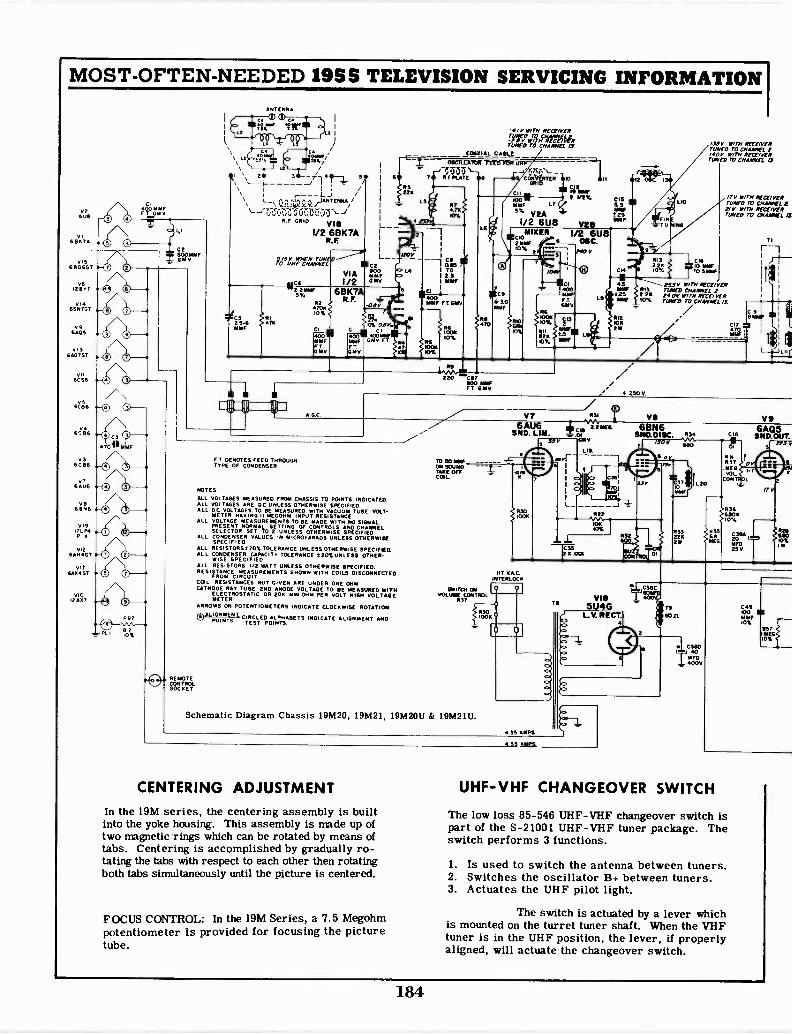
MOST -OFTEN -NEEDED 1955 TELEVISION SERVICING INFORMATION
V2608
vi6E1K7A
015613060T
V612877 w
vi46SN7ST
V96A05
v15607GT
VII6CS6
6a6
v.
V 56C86
V76AU6
vB6BN6
V1917111POI
V126AHSGT
vI76A%GT
V I 012007
O 0O 0O 0
O ID
O 00
O 0
0
0
O 0
4. 0
ANTENNA
E1 c1 I
`.- 7LJ /
L rIANTENNA/
6 C,117.:RE GRID Vie
1/2 6BK7AR.F.
Pe.5g,7-"cf,"mv%-"P czVIA Mr1/2 GMV11;62
6%
*C525-6YYF
F 6BK7AR" 8V4705?
F-0
10%
CADpiIMMFFTGMV
-tv worm RECEIVER
LTAIVIaTiVerECWIIrmvto CITAIRIEL
COAXIAL CABLE
22
l20
MMF G
FTGMV
LA
9
r;75;j-IF PLATE
LS
CI I
7R4.7xKY%
IMF FT WV
IRON
1001
RB170
- R
II
Iu
1008.Mau L7
51/2 6U8CIO
II1RER2MW10%
C96-00IMPF
RIO
10%
MINE2 I/29.
6 08C1/2 6U8
.
ON
400moorFTGMT
SOON105.
BOB
CIS05MMFS25
VteF
POO V 9
CIA
43YYF RIO
ERRIMF 10%
Rt2101216
,/58V WITH RECEIVERTUNE, ro CHARNEL140V wow RECEIVERTUNED IT) CHANNEL /5
LID
FINTU ING
RIO2ov.2K Femm,
TN) 5111W
Pig V WITH RECEIVERTIMED CHANNEL 2POOP WITH RECEIVERrimaro no CHANNEL IA
T71, row RECEIVERriono To CHARNEL 221 V WITH RECEIVERTUNE, m CHANNEL
C19
C17 inYIF
L
REMOTECONTROLSOCKET
A GC
fre
220 "co800 IMFFT GAM/
+ 250 v
FT DENOTES FEED THROUGHTYPE OF CONDENSER
NOTES
ALL VOLTAGES MEASURED FROM CHASSIS TO POINTS INDICATED.ALL VOLTAGES ARE DC UNLESS OTHERWISE SPECIFIEDALL DC VOLTAGES TO BE MEASURED WITH VACUUM TUBE VOLT-
METER HAVING II MEGOHM INPUT RESISTANCEALL VOLTAGE MEASUREMENTS TO BE MADE WITH NO SIGNAL
PRESENT NORMAL SETTING OF CONTROLS AND CHANNELSELECTOR SET TO 2 UNLESS OTHERWISE SPECIFIED
ALL CONDENSER VALUES IN MICROFARADS UNLESS OTHERWISESPECIFIED
ALL RESISTORS720% TOLERANCE UNLESS OTHERWISE SPECIFIEDALL CONDENSER CAPACITY TOLERANCE 20%UNLESS OTHER-
WISE SPECIFIEDALL RESISTORS I/2 WATT UNLESS OTHERWISE SPECIFIED.RESISTANCE MEASUREMENTS SHOWN WITH COILS DISCONNECTED
FROM CIRCUITCOIL RESISTANCES NOT GIVEN ARE UNDER ONE OHMCATHODE RAY TUBE 2ND ANODE VOLTAGE TO BE MEASURED WITH
ELECTROSTATIC OR 208 WIN OHM PER VOLT HIGH VOLTAGEMETER
ARROWS ON POTENTIOMETERS INDICATE CLOCKWISE ROTATION
® CIRCLED ALPHABETS INDICATE ALIGN PENT ANDPOINTSA LIGFIM%N7.
TEST POINTS
TO SO oarON SOUNDTAKE OFFCOIL.
Schematic Diagram Chassis 19M20, 19M21, 19M20U & 19M21U.
V7A6
SPI6UD.
LIM.
7
111 VACINTERLOCK
35 AMPS
NPA,CI2"E
01
L
CENTERING ADJUSTMENT
In the 19M series, the centering assembly is builtinto the yoke housing. This assembly is made up oftwo magnetic rings which can be rotated by means oftabs. Centering is accomplished by gradually ro-tating the tabs with respect to each other then rotatingboth tabs simultaneously until the picture is centered.
FOCUS CONTROL: In the I9M Series, a 7.5 Megohmpotentiometer is provided for focusing the picturetube.
35 AMPS,
ye
c.so5MEV
fin)400V
CIO
RNROT
I MEGVOL
CON L
680K10%
R356AMEG
V96AQ5
SMD.OUT.
20
MFD251.1
PEW
CAN100MME10%
10%ME
UHF-VHF CHANGEOVER SWITCH
The low loss 85-546 UHF -VHF changeover switch ispart of the S-21001 UHF -VHF tuner package. Theswitch performs 3 functions.
1. Is used to switch the antenna between tuners.2. Switches the oscillator Bi- between tuners.3. Actuates the UHF pilot light.
The switch is actuated by a lever whichis mounted on the turret tuner shaft. When the VHFtuner is in the UHF position, the lever, if properlyaligned, will actuate the changeover switch.
184

MOST -OFTEN -NEEDED 1955 TELEVISION SERVICING INFORMATION
V36 CB61ST I.F.
/2/1/
/Ai
L1224IMF
RIB
00%
MI/
72
ZENITH Chassis 19M20, 19M2OU, 19M21, and 19M21U.Chassis 19M20Z, 19M2OUZ, 19M21Z, and 19M21UZ,are similar but have a socket for UHF tuner connection.
V46 CE16END I.F.
!V
/2162 5
I RIB__I 2214
10%
,25
ISO0%
10
1419
R21
61100
.001
1422
.0%
L
R20120K10
R20120110%
Re170
VS6 CB6
3RD I.F.14
C50
mik1F 145a9 Ms
111411Wxi
1.16.15
DO
1261
J74,9KVA
C34
LIT3.11 -
SO MAIF,-
3.3 inifF51515 C33
6440,61F
821
10%
C318 -4 NED3509.
RE
To 6406GRID
V6I2BY7
VIDEO AMP.
Res
10%53K
ISKIOt
5640%
R27SR
+ON-19857 I
CON?
R2647K10%
100K R6555/ KOOK
10%
C.0015
R5115
10%
13).°
42868010%IR
VI9
2PI X
681'
C24
21
R52201
R29200KIMEIGHTNES S
CONTROL
2
10
72gpFEG"ArlFOCUS
250 V
0036°8
-'Rs
030810 WM4009
R53NSA. -220K 2206C47 1----'
28001
etcrsiSIN
RODEO F011COMENNATIONSONLO
113947010%
Rsi1090%
1
VIOAV2 I2AX7
ACC.791/
V
4903
R366801110%
Ue -114215K
66 CCONTROL
VII6CS6
SYNC.CLIP/toy R45 AI C42
0022
VIOB1/2 124X7
VERT. OSC./44 2
111822K
0%-.5 ro 6-180EPEPOF -)fIN UPON 1
LOCK SETT/S6 I
R46III
VERTICMJSIZE I
17711510._
10%
C311. 022
10%
VIZ6AH 4GTVERT. OUT
C47 loss2 001 jj
63 116 I- .11. RS2
10
fl'2%(10%- '1000%"
mc460022
1142647KC44 10%
VERT 33HOLD
RsT756
1.2509
SL
TO
R56560
036
C31040 MEDSO
50
DEFLcaLs
VISA/2 64127GT
A.F.C.091Y
V I3A1/2 6AQ7GT_HORIZONTAL
CONTROL
RST 1152
1 iiiM00ca001
52.00047.4
10%
113
27K0%
i5101E
4,3947010%
R59474110%IM
2/71'C54 Cst
5 6900%~ 1500 maim1
R5
mEC 2"L21HOME IUD mks,
HOLD
860 I C27
2741 .001288
c24
VI4A6SN7GT
NORM On.
-58V
801'
44350
VI45 VI51/2 6SN7GT IS 6 BO6GTNORIE.DISCH. HORI Z. OU
476
R2619CST
..--1220
3 1AMF
_ cs. s'°%- 680
inw Cip.HORIZ10% DRIVE
TRHADEER
R62
R52
100
:SySK
REMOVING TURRET TUNERFROM THE CHASSIS
1. Pull out the VHF power connector, UHF IF con-nector, VHF oscillator B+ connector, VHF IF con-nector and disconnect the antenna transmission line.
2. To insure proper indexing, note the channel towhich the receiver is tuned so that the tuner drumcan be rotated back to this channel before the unitis reassembled.
3. Loosen (do not remove) the hex head set screw inthe VHF tuner drive pulley and slide pulley off the finetuning shaft. Remove screws and hex nuts .
MA
FUSE
4. Gently pull the tuner out of its case
11
139
Cl5i9
047
7.3288
no c 31c10 NIFD
I B3GTVI6 475 v
H.V. RECT.
TO N v 1469
8 V IT5 6AX4GT
DAMPER A+5006
TTi
HORIZONTALDEFLECTION
COILS(BRASS SLEEVE
2/10TH CONTROL)
If, after the tuner is reinstalled, the fine tuningknob does not have normal mechanical travel (fromstop to stop of the lower pulley) and can be turned tohit only one stop, the dial cord can be made to Sliptowards the other stop by applying sufficient pressureto the fine tuning knob.
METAL WRAPPED RESISTORS
In servicing the TV receiver, the serviceman will findseveral circuits in which metal wrapped resistors areused. The metal wrapping dissipates much of theresistor heat and doubles the wattage rating. Inreplacing a resistor care should be used to mount itas the original. If the metal mounting clamp is dis-carded, the resistor wattage must be doubled.
R6533K
185
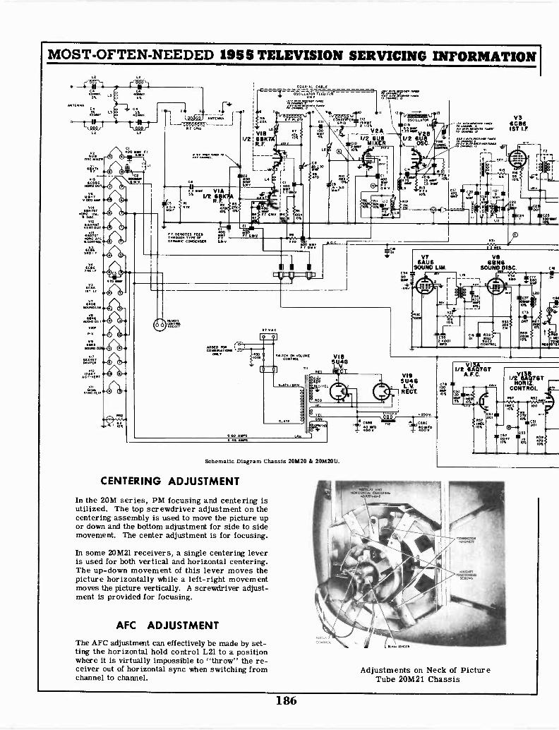
MOST -OFTEN -NEEDED 19SS TELEVISION SERVICING INFORMATION
C 11`100
4111OSC
f ell
VII6CD"
HOIN2 OUT
Vva'r-
VIAAIN TOT
MSC
RT
vlx
9AVDT
II CONTROL
G A'SIND
11416TWIT
v36C961IT T
GILSSOt9.01.91
MIZTDAMPIER
vt.6<S6
SYNC 411.
Prj. YL'YitiV ANTENNA
1---'-172;01?YrR F GRID
F T DENOTES FELDTHROWN TYPE OFCERAMIC CONDENSER
A0010 FORCOININATION3
ONLY
1/2
C
RS229
VIBLS
6BK7R.F.
COAXIAL CABLO
OSCILLATOR FEED FIM
;zarz,feyervr. 'wets
ITCH ON VOLUMECONTROL
°TN Vc .0R4C121,9!in
V2A1/2 6U8
cto MIXER2
VIES5U4GL.V.
RED RECT.
Schematic Diagram Chassis 20M20 4 20M20U.
CENTERING ADJUSTMENT
In the 20M series, PM focusing and centering isutilized. The top screwdriver adjustment on thecentering assembly is used to move the picture upor down and the bottom adjustment for side to sidemovement. The center adjustment is for focusing.
In some 20M21 receivers, a single centering leveris used for both vertical and horizontal centering.The up -down movement of this lever moves thepicture horizontally while a left -right movementmoves the picture vertically. A screwdriver adjust-ment is provided for focusing.
AFC ADJUSTMENT
The AFC adjustment can effectively be made by set-ting the horizontal hold control L21 to a positionwhere it is virtually impossible to "throw" the re-ceiver out of horizontal sync when switching fromchannel to channel.
OSCILLATOR
C15
ltrr̀1/213
1/2 6UOS
1:=';;17"" 'Alf.L.T.XT"-"r""
I fr
2 2 5E6
V36CB61ST
V86AU6 6BN6
SOUND LIM. SOUND DISC.
YIN It
VI95U46L.V.
RECT.
///scoto 230V
CrTIS TI2 CSC
00 V LT' 184n.
1 / 2 612117 G TA.f.C.
Adjustments on Neck of PictureTube 20M21 Chassis
CSI00T0%
INT
rz
"'own,
CS1001
R39
10%
CIO
01
CN
186
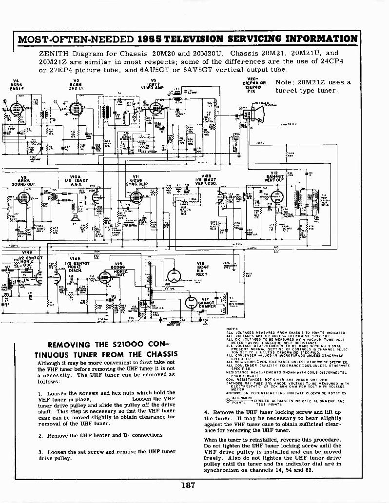
IMOST -OFTEN -NEEDED 1955 TELEVISION SERVICING INFORMATIONZENITH Diagram for Chassis 20M20 and 20M20U. Chassis 20M21, 20M21U, and20M21Z are similar in most respects; some of the differences are the use of 24CP4or 27EP4 picture tube, and 6AU5GT or 6AV5GT vertical output tube.
V46C111 6END I.F.
VS6C86
3RD I.F.
r
L
R24*21410%
V612 BY 7
VIDEO AMP
IS
64
5K10%2w
xirr
R 4633%6
10
10%
1111CrAO
62766 ICc
CON-TRASTCON6SOL
142
SRe
+ 250V
CF4
REJlnS
2046
V202IEP4A OR
21EP4111PI X
375
Note: 20M21Z uses aturret type tuner.
0. TO MV
R 106
V9'SDKS
SOUND OUT.
V1OA1/2 I 2A X7
A.G.C. R5
stsisSYNC. CLIP. R45 al
IOB1/2
VI2AX7
C2 VERT. OSC.
VI 2 R30 410,11
6AH4GTVERT. OUT.
T6
I IV
4110610%
690900
c% 75 YEG
272
7060%
Ted
irrga, 15'0
FRINGEOCR
R2
10%0%
R6
0%
646
c5
R76$506
090%3 qo
7314 q-vERT
HO' C69247K
250v
C7X001
lue
2280%
MEG
RSO
o,L
loo
R1770
qp
10%
rnc. r500 10R5
LIME66vv1,
C656 r; R7600 SAD ss
ax
00 v
T.VERY
089 LEL71010COILS
VI4A9I/2 6SN7G
H
C54 'a IW111411111rwt 15oorrr
R5
L2, ii SC461:/r re
IORIZ la%NOLO10LO
.0 C27
001
2206
K
VI4B
t425V
/2 6SN7GTHORIZ.DISCH.
10% 961
60014
VIS6C060
666700
71
VI1936GTH.VRECT.
RA,VOX3 3 10%
C650Morro
71
C047 109.
V176AX4GTDAMPER
ra 15
viii74±"MORIZ LIN.
REMOVING THE 521000 CON-TINUOUS TUNER FROM THE CHASSISAlthough it may be more convenient to first take outthe VHF tuner before removing the UHF tuner it is nota necessity. The UHF tuner can be removed asfollows:
1. Loosen the screws and hex nuts which hold theVHF tuner in place. Loosen the VHFtuner drive pulley and slide the pulley off the driveshaft. This step is necessary so that the VHF tunercase can be moved slightly to obtain clearance forremoval of the UHF tuner.
2. Remove the UHF heater and B+ connections
3. Loosen the set screw and remove the UHF tunerdrive pulley.
III C6015
10%
314
NORIOE FLECTiosCOILS
Ill
ash
3K
NOTESALL VOLTAGES MEASURED FROM CHASSIS TO POINTS INDICATED.ALL VOLTAGES ARE D.C.UNLESS OTHERWISE SPECIFIECALL DC VOLTAGES TO BE MEASURED WITH VACUUM TUBE VOLT-
METER HAVING II MEGOHM INPUT RESISTANCE.ALL VOLTAGE MEASUREMENTS TO BE MADE WITH NO SIGNAL
PRESENT NORMAL SETTING OF CONTROLS B CHANNEL SELEC-TOR SET TC 2 UNLESS OTHERWISE SPECIFIED
ALL CONJENSER VALUES IN MICROFARADS UNLESS OTHERWISESPECIFIED
ALL RES1.TORS C 20% TOLERANCE UNLESS OTHERWISE SPECIFIED.ALL CONDENSER CAPACITY TOLERANCE I.20% UNLESS OTHERWISE
SPECIFIED.RESISTANCE MEASUREMENTS SHOWN WITH COILS DISCONNECTEL
FROM CIRCUITCOIL RESISTANCES NOT GIVEN ARE UNDER ONE OHM.CATHODE RAY TUBE 2ND ANODE VOLTAGE TO BE MEASURED WITH
ELECTROSTATIC OR 20K MIN. OHM PER VOLT HIGH VOLTAGEMETER.
ARROWS ON POTENTIOMETERS INDICATE CLOCKWISE ROTATIONALIGNMENTPOINTS CIRCLED ALPHABETS INDICATE ALIGNMENT AND
TEST POINTS.
4. Remove the UHF tuner locking screw and lift upthe tuner. It may be necessary to bear slightlyagainst the VHF tuner case to obtain sufficient clear-ance for removing the UHF tuner.
When the tuner is reinstalled, reverse this procedure.Do not tighten the UHF tuner locking screw until theVHF drive pulley is installed and can be movedfreely. Also do not tighten the UHF tuner drivepulley until the tuner and the indicator dial are insynchronism on channels 14, 54 and 83.
187
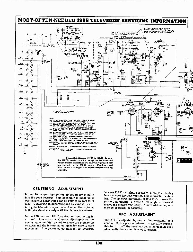
MOST -OFTEN -NEEDED 1955 TELEVISION SERVICING INFORMATION I
ANTENNA
VOLTAGES MEASURED WITH V T vMAPPRO1 10K/L I/2W ISOLATION RESISTOR(LEAD ON MEASURING END OF RESISTORMUST RE SHORT 1/4 INCH OR LESS I
V2GUS
VI61117A
01568066T
VS28,8'7
V14GSN7ST
V9HAGS
IN60/27GT
VII68E6
ROsl
V3SCRS
S31AL7M
VIISBNS
VI9
PIN
VI21254
VI7680407
VIO12AX7
2
1 ,1
i
1
Tri-, GRID COILS N
JAS USED ONCHANNELS 2.40
O 0
O 0O 0
O 0
O 0
O 0
O 0
0
0
NSFMYF
_11 4
I
L ). JANTENNA,/
gRFRIP-R-F GRID COILS AS v leussg ON "A""EV/2 68K7A
R. E
PiaC2
VIACGI 21).
/2 GMV
' 6BK7A5%
L
R. F.As -0.v10% . III J/
'0%, e.v.k_si eiza 46..M. 'jiff GMV FTET F THMV ASV
221
LS
233
-25 YO -7 V DEPENDING ON CHANNELNO, VINE YUNER, A HULL'S EYE serrING
COAXIAL CAILE
CrSCR-CAM,Pr vren-61rorp--/,`TY:0--R F PLATE IRS MI - CONVERTER
404 TAB ON SHIELD
-II Wk."L7 !29%
1/2 6U8 VU
/201/
L4
R
--1
H a(I 2 3I NSF
DI BOOMMF FT GMV
V.
100110%
12
Ls
RS70
C9
6-30NSF
coM1XER_ 1/2 6U82111MF 6 OC.10% 240 V
1042
R6100110%
121ION.
BOOMMFFTGrV
1,,
no LSIMO
CIS55MMF525
y.10 VII
23V
1(24111Es:3
4
CI4
I345 NNW.,
C11
R682 211
112
NE TUNING
LIO
R61101
SCI7 j]MMFIi
L
R9
A G C
220 C800 IMFFT GNI/
250 V
CISMMF
141Z. Lill
2411KIF5%
F T DENOTES FEED THROUGHTYPE OF CONDENSER.
NOTES
ALL VOLTAGES MEASURED FROM CHASSIS TO POINTS INDICATED.ALL VOLTAGES ARE DC UNLESS OTHERWISE SPECIFIEDALL DC VOLTAGES TO BE MEASURED WITH VACUUM TUNE VOLT-
METER HAVING 11 18880181 INPUT RESISTANCE.ALL VOLTAGE MEASUREMENTS TOSE MADE WITH NO SIGNAL
PRESENT NORMAL SETTING OF CONTROLS AND CHANNELSELECTOR SET TO 2 UNLESS OTHERWISE SPECIFIED
ALL CONDENSER VALUES IN MICROFARADS UNLESS OTHERWISESPECIFIED.
ALL RESISTORS320% TOLERANCE UNLESS OTHERWISE SPECIFIEDALL CONDENSER CAPACITY TOLERANCE t 20%0NLESS OTHER-
WISE SPECIFIEDALL RESISTORS I/O WATT UNLESS OTHERWISE SPECIFIED.RESISTANCE MEASUREMENTS SHOWN WITH COILS DISCONNECTED
FROM CIRCUIT.CON RESISTANCES NOT GIVEN ARE UNDER ONE 021MCATHODE RAY TUNE 2ND ANODE VOLTAGE TO RE MEASURED WITH
ELECTROSTATIC OR 201 MIN OHM PER VOLT HIGH VOLTAGEMETER
ARROWS ON POTENTIOMETERS INMATE CLOCKWISE ROTATION
"SlEi
peAlaLtitifsn crECsliED,ctliNSIXIDETS INDICATE ALIGNMENT AND
TO SOMMEON SOUNDTAKE OFFCOL
SWITCH ONVOLUME CONTROL
R37
Schematic Diagram 19R20 & 19R21 Chassis.The 19R22 chassis is similar except that the tuner andvolume control assemblies are externally mounted withplug-in cables as the 22R20 chassis. Waveforms andpeak to peak voltages are representative for allchassis.
6AU6 TCIGAs.
M"SNO.SSP IGNY
Fl
I7 VACINTERLOCK
RIO1001
7
35 AMPS
FYI
713
1.19
X001
R22
1
vs6BN6
SNO. DISC. R34
61110
ors
G PEP
01
-0 5114 GA
OR5049
L. V. RECT.
1332212W
VII
:AST.OI
R37to
MEGVOL
CON
R3668010%
LSO
rev 1W
CENTERING ADJUSTMENTIn the 19R series, the centering assembly is builtinto the yoke housing. This assembly is made up oftwo magnetic rings which can be rotated by means oftabs. Centering is accomplished by gradually ro-tating the tabs with respect to each other then rotatingboth tabs simultaneously until the picture is centered.
In the 22R series, PM focusing and centering isutilized. The top screwdriver adjustment on thecentering assembly is used to move the picture upor down and the bottom adjustment for side to sidemovement. The center adjustment is for focusing.
435 AMPS.
TV
GOA
CM.IMIU 40
MFD400104P.
C49100S10%ri
18:4110;
r:111111-0,.,
In some 22R20 and 22R21 receivers, a single centeringlever is used for both vertical and horizontal center-ing. The up -down movement of this lever moves thepicture horizontally while a left -right movementmoves the picture vertically. A screwdriver adjust-ment is provided for focusing.
AFC ADJUSTMENTThe AFC is adjusted by setting the horizontal holdcontrol L21 to a position where it is virtually imposs-ible to "throw" the receiver out of horizontal syncwhen switching from channel to channel.
188
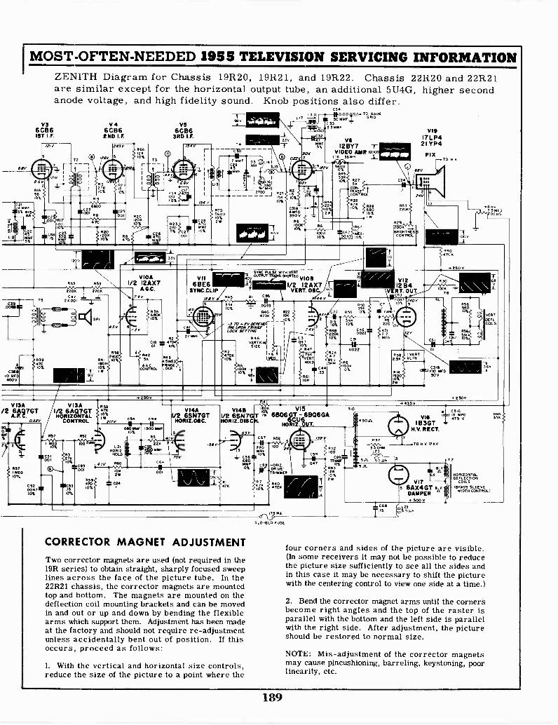
1.12
MOST -OFTEN -NEEDED 1958 TELEVISION SERVICING INFORMATION
60w
C2I29 LOAF'Si RI5
LMJC3219
10 MFO400 V
VS6CB61ST I.F.
ZENITH Diagram for Chassis 19R20, 19R21, and 19R22. Chassis 22R20 and 22R21are similar except for the horizontal output tube, an additional 5U4G, higher secondanode voltage, and high fidelity sound.
BO4- M%
11`,856.
VISA/2 6AC)7GT
A.F. C.092v
J
93942010%
V46CB6END I.F.
R20120010%
11597910%
I Wmy
VIOA1/2 I2AX7
I A.G.C.
C54
690 9191F10%
R42156
A C091801
1.21 I INCROR12
HOLD
R60
10k2W
VS6CB6
3RD I.F.
9232705% C2
00
96
T
Knob positions also differ.L17
C!0
MMF 95C29 MM
giMMFX 01
R705600
C28 Ty,
VII6 BE6
SYNC.CLIP
Lsv336
O%
V14AV2 6SN7GTNORILOSC.
L141LID
//HI2700 J .25
0%56 0%
90
C31A-4WD350 V
C94TO1341 R6r6
C 339)".' 4-W. 9 31.9F
V19
VSI2BY7
17 LP421 YP4
495:
VIDEO AMP KtLiEl 136490 PI%
TO H V
"WV
SYNC. PULSE WITH VERT
Wl'UT SHORTED V10S
1/2 12AX7VERT. OSC.
0093
R40 R224706
-5 ro KV OCPCNOFNO UPON FRO/OfLOCK .1( (7,4 I
R 6VERT IC NJ
SIZE I
4704 175 t0%
VI4SV2 6SN7Gtit:Ma. DISC
CORRECTOR MAGNET ADJUSTMENT
Two corrector magnets are used (not required in the19R series) to obtain straight, sharply focused sweeplines across the face of the picture tube. In the22R21 chassis, the corrector magnets are mountedtop and bottom. The magnets are mounted on thedeflection coil mounting brackets and can be movedin and out or up and down by bending the flexiblearms which support them. Adjustment has been madeat the factory and should not require re -adjustmentunless accidentally bent out of position. If thisoccurs, proceed as follows:
1. With the vertical and horizontal size controls,reduce the size of the picture to a point where the
HORIZDRIVETRIMMER
inSLO-6L0 FUSE
ACS.44 047
10%R47
CEI975966
0%R63i2610%
R2920069610111NE5
CONTROL
VIP12134
VERT. OUT.NC06.37
0%
1176 1VERT250 1LIN
0316100 MED50 V
C 3IC
V1610 4WD475 V
IB3GTN.V. RECT.
TO 11 V ITKV
VI?5 6AX4GT
DAMPER4- 500 V
5 5 Lin
T7
VERTOEFLCOLS
HORIZONTALDEFLECTION
COILS(BRASS SLEEVE
WIDTH CONTROL/
four corners and sides of the picture are visible.(In some receivers it may not be possible to reducethe picture size sufficiently to see all the sides andin this case it may be necessary to shift the picturewith the centering control to view one side at a time.)
2. Bend the corrector magnet arms until the cornersbecome right angles and the top of the raster isparallel with the bottom and the left side is parallelwith the right side. After adjustment, the pictureshould be restored to normal size.
NOTE: Mis-adjustment of the corrector magnetsmay cause pincushioning, barreling, keystoning, poorlinearity, etc.
189

MOST -OFTEN -NEEDED 1955 TELEVISION SERVICING INFORMATION
ZENITH RAD 10 CORPORATIONThis signal path chart will help you diagnose faults that may develop in the 1955Zenith television models.
AUDIODET.
,''73N6C136; 1ST. I.E.
: V4 *.
;6CB6:2ND...1 V5 %,3RD I.F.t6CB6;
1 DET. OUTPUCon nD 0****
It
4
R F . t*t.
" "MODELS 6AF4ONLY $ I t
...I.* 44.
0 SC.VIDEAMP
V202IEP4A OR2IEP4B
PIX
..""?VII -s
(FRINGE LOCK6 S6
#GATE)
:SYN
*4
AFFECTS PICTUREAND SOUND
1M a MM.
f A.G.C.ls%.
12VAI
SOUND OUT-PuT
VERT. -I'S
HORIZ.OUTPUT
V ERT. OUT.
t TOVERT.YOKE
DISCHARGE
18
146
LOW VOLTAGE RECT
V19
5U4G
LOW VOLTAGE RECT.
VERTICAL CIRCUIT ««« SOUND CIRCUIT ------HORIZONTAL CIRCUIT COMPOSITE VIDEO "A"A*WATTS 235 VOLTS- 117 A.G. 60 CYCLES
Signal Path Chart 20M20, 20M20Z, 20M2OUZ & 20M20U.
190

MOST -OFTEN -NEEDED 1955 TELEVISION SERVICING INFORMATION
Index Under each manufacturer's name are listed that make chassisand models in numerical order, at left. The corresponding pagenumber at right of each listing refers to the first page of each sec-tion dealing with such material.
Admiral Corp. Armiral, cont. CBS, continued Emerson, cont. Majestic, cont.19L2,19L2Z 11 T2242BZ 10 921-13 31 798B 47 88 7319M2 11 TA2242 11 921-14 31 120179B 47 123 7319N2Z 11 CA2246 11 120203B 47 124 7319R2 11 C2256 10 Crosley Corp. 1202048 47 124-2 73
G-17T0B 351952 11 K2256 10 120205B 4719T1, -C 11 K2257 10 G-17TOBK 35 Montgomery Ward19W1, -A 11 CA2526 11 G-17TOBU 35 GEneral-Electric WG-3071E,-F 7719W1B, -C 11 G-17TOMH 35 F 57 WG-3073E,-F 7719Y1A 11 Arvin G-17TOMU 35 G, J, K 63 WG-3075D,-E 7720A2, 20A2Z 5 21-550 25 G-17TOWEH 35 17C127 57 WG-3077D,-E 7720D2 5 21-551 25 G-17TOWH 35 17T14 63 WG-3079D,-E 7720L2 11 21-552 25 G-17TOWU 35 17T15 6320X5 10 21-553 25 H-17TOBH 35 17T16 63 Motorola, Inc.20X5A, -B 10 21-554 23 H-17TOBU 35 17T20 63 17T20 8520X5C 10 21-555 23 H-17TOMH 35 17T115 57 Yl7T20 8520XP5A 10 21-557 23 H-17TOMU 35 17T117 57 21C3 79TA1811 11 D-379 25 H-17TOWH 35 21C103 63 21K19 85TA1812 11 D-382 25 H-17TOWU 35 21C104 63 21K20 79TA1822 11 E-383 23 G-21TOBH 35 21C114 57 21K21 79T1331 10 G-21TOMH 35 21C115 57 21K22 79T1832 10 Canehart- G-21TOWH 35 21C116 57 21K23 79T1842 10 Farnsworth H-21COBH 35 21C117 57 21K24 79TA2211 11 1T174+ 27 H-21COBU 35 21C119 57 21T15 85TA2212 11 2T214+ 27 H-21COMH 35 21C120 57 21T16 85T2212B 10 4C174+ 27 H-21COMU 35 21C121 57 21T17 85CA 22152 11 5C214+ 27 H-21COSBH 35 21C350 63 21T18 79LA2215Z 11 9F214+ 27 H-21COSH 35 21C351 63 21T19 79TA2215 11 15W214+ 27 H-21COWH 35 21T10 57 Y21C3 79C2216AZ 5 16T244+ 27 H-21COWU 35 21T11 57 Y21K19 85GA2215Z 11 18W214 27 H-21HCBH 35 21T12 57 Y21K20 79HA2216Z 11 CX-37 27 H-21HCBU 35 21T14 57 Y21K21 79K2216A 5 CX-37-1 27 H-21HCMU 35 21T15 57 Y21K22 79KA2216 11 CT -89 27 H-21HCWH 35 21T17 63 Y21K23 79LA2216Z 11 CT -90 27 H-21HPBHa , d 35 21T18 63 Y21K24 79T2216A 5 CT -95 27 H-21HPWHa,d 35 21T19 57 Y21T15 85TA2216,-A 11 CT -108 27 426 35 21T22 63 Y21T16 85CA2217Z 11 CT -110 27 431 35 21T23 63 Y21T17 85HA2217Z 11 CT -112 27 431-2 35 21T24 63 Y21T18 79K2217A 5 CT -115 27 432 35 21T25 63 Y21T19 79KA2217 11 CT -116 27 443 35 21T30 63 24K4 79LA2217Z 11 CT -130 27 443-3 35 21T31 63 24K5 79T2217A 5 CT -131 27 445 35 Y24K4 79TA2217,-A 11 CT -133 27 Hallicrafters Y24K5 79TA2218 11 CT -134 27 Du Mont Labs. 17T310 69 TS -418 85TA2222 11 RA -312 43 21T320 69 VTS-413 85F2226 5 CBS -Columbia RA -313 43 21K330 69 TS -518 85FA2226 11 22C09, -B 31 A1600D 69 VTS-518 85KA2226 11 22T19, -B 31 Emerson Radio B1600D 69 WTS-518 85TA2226 11 U22C05 31 748B, -C 47 RTS-525 79KA2227 11 U22C07 31 777B 47 Majestic TS -525 79C2236A 5 U22T09 31 787A, -B 47 78, 78A 73 WTS-525 79CA2236,-A 11 U22T19 31 796C 47 79 73 TS -528 79GA2237 11 921-11 31 797B, -C 47 81 to 86 73 TS -603 79
191
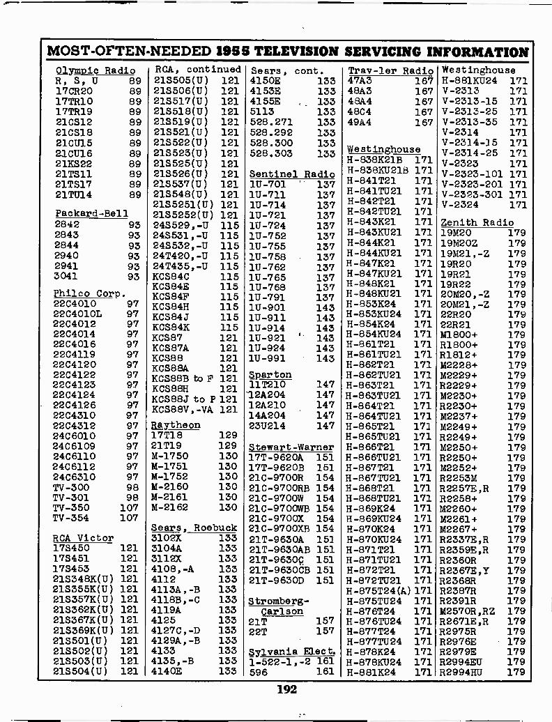
MOST -OFTEN -NEEDED 1955 TELEVISION SERVICING INFORMATIONOlympic Radio RCA, continued Sears, cont. Trav-ler Radio WeR, S, U 89 213505(U) 121 4150E 133 47A3 167 H-881KU24 17117CR20 89 21S506(U) 121 4153E 133 48A3 167 V-2313 17117TR10 89 213517 (U) 121 4155E 133 48A4 167 V-2313-15 17117TR19 89 215518(U) 121 5113 133 48C4 167 V-2313-25 17121CS12 89 213519(U) 121 528.271 133 49A4 167 V-2313-35 17121CS18 89 215521(U) 121 528.292 133 V-2314 17121CU15 8921CU16 8921KS22 89
21S522(U) 121218525(U) 121213525(U) 121
528.300 133528.303 133 Westinghouse
V-2314-15 171V-2314-25 171V-2323 171H-838K21B 171
21TS11 89 21S526(U) 121 Sentinel Radio H-838KU218 171 V-2323-101 17121TS17 8921TU14 89
Packard -Bell
21S537(U) 121215548(U) 1212135251(U) 1212155252(U) 121243529,-U 115245531,-U 115
H -841T21 171H-841TU21 171H -842T21 171H-842TU21 171H -843K21 171H-843KU21 171
V-2323-201 171V-2323-301 171V-2324 171
Zenith Radio
1U-701 1371U-711 1371U-714 1371U-721 1371U-724 1371U-752 137
2842 932843 93 19M20 1792844 932940 932941 933 041 93
Philco Corp.
243532,-U 11524T420, -U 11524T435, -U 115KCS84C 115KCS84E 115KCS84F 115KCS84H 115KCS84J 115KCS84K 115KCS87 121KCS87A 121KCS88 121KCS88A 121KCSB8B to F 121KCS88H 121KCS88J to P 121KCS88V,-VA 121
1U-755 1371U-758 1371U-762 1371U-765 1371U-768 1371U-791 1371U-901 1431U-911 1431U-914 1431U-921 1431U-924 1431U-991 143
Spar ton
H -844K21 171H-844KU21 171H -847K21 171H-847KU21 171H -848K21 171H-848KU21 171H -853K24 171H-853KU24 171H -854K24 171H-854KU24 171H -861T21 171H-861TU21 171H -862T21 171H-862TU21 171H -863T21 171H-863TU21 171H -864T21 171H-864TU21 171
19M20Z 17919M21, -Z 17919R20 17919R21 17919R22 17920M20, -Z 17920M21, -Z 17922R20 17922R 21 179M1800+ 179R1800+ 179R1812+ 179M2228+ 179M2229+ 179R2229+ 179M2230+ 179R2230+ 179M2237+ 179
22C4010 9722C4010L 9722C4012 9722C4014 9722C4016 9722C4119 9722C4120 9722C4122 9722C4123 9722C4124 9722C4126 9722C4310 97
11T210 14712A204 14712A210 14714A204 147
22C4312 97 agytheon 23U214 147 H -865T21 171 M2249+ 17924C 6010 97 17T18 129 H-865TU21 171 R2249+ 17924C6109 97 21T19 129 Stewart -Warner H -866T21 171 M2250+ 17924C6110 97 M-1750 130 17T -9620A 151 H-866TU21 171 R2250+ 17924C6112 97 M-1751 130 17T -9620B 151 H -867T21 171 M2252+ 17924C6310 97 M-1752 130 21C-970OR 154 H-867TU21 171 R2253M 179TV -300 98 M-2160 130 21C-9700RB 154 H -868T21 171 R2257E,R 179TV -301 98 M-2161 130 21C -9700W 154 H-868TU21 171 R2258+ 179TV -350 107 M-2162 130 21C-9700WB 154 H -869K24 171 M2260+ 179TV -354 107 21C -9700X 154 H-869KU24 171 M2261+ 179
Sears, Roebuck 21C-9700XB 154 H -870K24 171 M2267+ 179RCA Victor 3102X 133 21T -9630A 151 H-870KU24 171 R2337E,R 179173450 121 3104A 133 21T-9630AB 151 H -871 T21 171 R2359E,R 179173451 121 3112X 133 21T -9630p 151 H-871TU21 171 R2360R 179173453 121 4108,-A 133 21T-9630CB 151 H -872T21 171 R2367E,Y 17921S348K(U) 121 4112 133 21T -9630D 151 H-872TU21 171 R2368R 17921S355K(U) 121 4113A, -B 133 H-875T24(A)171 R2387R 17921S357K(U) 121 4118B, -C 133 Stromberg- H-875TU24 171 R2391R 17921S362K(U) 121 4119A 133 Carison H -876T24 171 M2570R,RZ 17921S367K(U) 121 4125 133 21T 157 H-876TU24 171 R2671E,R 17921S369K(U) 121 4127C, -D 133 22T 157 H -877T24 171 R2975R 179213501(U) 121 4129A, -B 133 H-877TU24 171 R2976E 179218502(U) 121 4133 133 Sylvania Elect. H -878K24 171 R2979E 17921S503(U) 121 4135,-B 133 1-522-1,-2 161 H-878KU24 171 R2994EU 179213504(U) 121 4140E 133 596 161 H -881K24 171 R2994HU 179
192
Another
Supreme Publications
Service Manual
Supreme Publications are Available at All Leading Parts Jobbers