Behavior and resistance of beam-column structural elements
11
Behavior and resistance of beam-column structural elements Anwar Badawy Badawy Abu-Sena ⁎, Mohamed Salah Al-Din Soliman, Omer Nazmi Ali Abdel-Nabi Faculty of Engineering (Shobra), Benha University, Egypt abstract article info Article history: Received 27 April 2011 Accepted 12 September 2011 Available online 5 October 2011 Keywords: Steel beam-column Lateral torsional buckling Flexural buckling Torsional buckling Finite element non-linear elasto-plastic analysis Ultimate resistance Codes of practice Most of the structural elements in a steel structure are subjected to bending moment and axial force simul- taneously. In some elements, one of the two components is relatively small compared to the other. Yet, the smaller component cannot be ignored due to the interactive behavior of the two components. Therefore, it is not adequate to design the beam-column element as a beam or a column by ignoring one of the two load components even if the ignored component is relatively small. Most of the design codes use empirical interaction equations that are based on semi-experimental semi- analytical results. Most of the design formulae adopted by the design codes do not explicitly account for the geometrical imperfection. This research aims at investigating the buckling behavior of steel beam-column elements for the sake of developing an analytical model to calculate their ultimate resistance under axial compression and bending moment. The analytical model will be based on Perry-type formulation, and it will account for the effect of initial imperfection. The model will be validated by comparing its results with those obtained by the Finite Element Non-Linear Elasto-Plastic analysis using ANSYS 5.4 program. Finally, a simple but rational design method based on the model, will be introduced. This method can be applied using a simple mathematical expression or charts and tables. The results of the developed design method will be compared with the design method of the international codes of practice for design of steel structures. On light of these comparisons, design recommendations are introduced. © 2011 Elsevier Ltd. All rights reserved. 1. Introduction Resistance and interactive buckling behavior attracted the attention of many researchers over the last four decades, however, due to its im- portance and complexity, this subject is still receiving the researchers’ interest. In 1977, Kanachalani [14] investigated the in-elastic behavior of 82 steel beam-column. He developed the well-known bilinear interaction equation that is being utilized by many international design codes. The AISC (LRFD) design manual [2] is adopting this bilinear interaction equation. Also, the Egyptian Code of Practice for Steel Design (LRFD) [10] is utilizing this equation. In 1985, Trahair [15] investigated the accuracy and applicability of the design formulae utilized by the Canadian Standard. He developed a simple computational procedure for estimating the in-plane strength, which generally leads to more accurate prediction than that of the code. He also developed two alternatives for estimating the out-of-plane strength of beam-column. In 1989, Geng-Shu and Shao-Fan [12] established an interactive buck- ling theory for built-up beam columns which can be used to determine the ultimate strength of the member taking account of various adverse influences of imperfections (residual stress, member's and chords' initial deflections and load eccentricity). They verified the applicability of the proposed theory by the finite integral method. In 2004, Aminmansour [3] introduced design aids including charts and tables to facilitate the application of the AISC (LRFD) [2] interaction equation. The proposed approach avoids the application of the iterative technique followed to select the most appropriate steel section. Several design examples have been given to explain the application of the pro- posed design approach. In 2004, Gonçalves and Camotim [13], examined the beam-column design approach adopted by the Eurocode (EC3) [11], using the finite el- ement non-linear analysis utilizing ABAQUS program. They compared the code design approach to the finite element analysis for different loading and boundary conditions. They highlighted the sensitivity of the code estimated strength to the C m value compared to the FE analy- sis. They concluded that the EC3 strength estimate is excellent for the in-plane strength of members with arbitrary boundary conditions. For low axial force, they concluded that the EC3 strength estimate is quite conservative. This research aims at investigating the interactive buckling behavior in beam-column. Two types of interaction will be studied; the elastic linear interaction and the non-linear interaction. The first type affects the critical buckling modes and the critical buckling loads. The second type affects the beam-column resistance. Mathematical models will be developed to predict both the interactive buckling stress and the Journal of Constructional Steel Research 71 (2012) 171–181 ⁎ Corresponding author. Tel.: + 20 2 011 067 6655. E-mail address: [email protected] (A.B. Badawy Abu-Sena). 0143-974X/$ – see front matter © 2011 Elsevier Ltd. All rights reserved. doi:10.1016/j.jcsr.2011.09.012 Contents lists available at SciVerse ScienceDirect Journal of Constructional Steel Research
Transcript of Behavior and resistance of beam-column structural elements
Journal of Constructional Steel Research 71 (2012) 171–181
Contents lists available at SciVerse ScienceDirect
Journal of Constructional Steel Research
Behavior and resistance of beam-column structural elements
Anwar Badawy Badawy Abu-Sena ⁎, Mohamed Salah Al-Din Soliman, Omer Nazmi Ali Abdel-NabiFaculty of Engineering (Shobra), Benha University, Egypt
⁎ Corresponding author. Tel.: +20 2 011 067 6655.E-mail address: [email protected] (A.B. Badawy
0143-974X/$ – see front matter © 2011 Elsevier Ltd. Aldoi:10.1016/j.jcsr.2011.09.012
a b s t r a c t
a r t i c l e i n f oArticle history:Received 27 April 2011Accepted 12 September 2011Available online 5 October 2011
Keywords:Steel beam-columnLateral torsional bucklingFlexural bucklingTorsional bucklingFinite element non-linear elasto-plasticanalysisUltimate resistanceCodes of practice
Most of the structural elements in a steel structure are subjected to bending moment and axial force simul-taneously. In some elements, one of the two components is relatively small compared to the other. Yet, thesmaller component cannot be ignored due to the interactive behavior of the two components. Therefore, itis not adequate to design the beam-column element as a beam or a column by ignoring one of the two loadcomponents even if the ignored component is relatively small.Most of the design codes use empirical interaction equations that are based on semi-experimental semi-analytical results. Most of the design formulae adopted by the design codes do not explicitly account forthe geometrical imperfection.This research aims at investigating the buckling behavior of steel beam-column elements for the sake ofdeveloping an analytical model to calculate their ultimate resistance under axial compression and bendingmoment. The analytical model will be based on Perry-type formulation, and it will account for the effect ofinitial imperfection. The model will be validated by comparing its results with those obtained by the FiniteElement Non-Linear Elasto-Plastic analysis using ANSYS 5.4 program.Finally, a simple but rational design method based on the model, will be introduced. This method can beapplied using a simple mathematical expression or charts and tables. The results of the developed designmethod will be compared with the design method of the international codes of practice for design of steelstructures. On light of these comparisons, design recommendations are introduced.
Abu-Sena).
l rights reserved.
© 2011 Elsevier Ltd. All rights reserved.
1. Introduction
Resistance and interactive buckling behavior attracted the attentionof many researchers over the last four decades, however, due to its im-portance and complexity, this subject is still receiving the researchers’interest.
In 1977, Kanachalani [14] investigated the in-elastic behavior of 82steel beam-column. He developed the well-known bilinear interactionequation that is being utilized by many international design codes.The AISC (LRFD) design manual [2] is adopting this bilinear interactionequation. Also, the Egyptian Code of Practice for Steel Design (LRFD)[10] is utilizing this equation.
In 1985, Trahair [15] investigated the accuracy and applicability ofthe design formulae utilized by the Canadian Standard. He developeda simple computational procedure for estimating the in-planestrength, which generally leads to more accurate prediction thanthat of the code. He also developed two alternatives for estimatingthe out-of-plane strength of beam-column.
In 1989, Geng-Shu and Shao-Fan [12] established an interactive buck-ling theory for built-up beam columns which can be used to determinethe ultimate strength of the member taking account of various adverse
influences of imperfections (residual stress, member's and chords' initialdeflections and load eccentricity). They verified the applicability of theproposed theory by the finite integral method.
In 2004, Aminmansour [3] introduced design aids including chartsand tables to facilitate the application of the AISC (LRFD) [2] interactionequation. The proposed approach avoids the application of the iterativetechnique followed to select the most appropriate steel section. Severaldesign examples have been given to explain the application of the pro-posed design approach.
In 2004, Gonçalves and Camotim [13], examined the beam-columndesign approach adopted by the Eurocode (EC3) [11], using thefinite el-ement non-linear analysis utilizing ABAQUS program. They comparedthe code design approach to the finite element analysis for differentloading and boundary conditions. They highlighted the sensitivity ofthe code estimated strength to the Cm value compared to the FE analy-sis. They concluded that the EC3 strength estimate is excellent for thein-plane strength of members with arbitrary boundary conditions. Forlow axial force, they concluded that the EC3 strength estimate is quiteconservative.
This research aims at investigating the interactive buckling behaviorin beam-column. Two types of interaction will be studied; the elasticlinear interaction and the non-linear interaction. The first type affectsthe critical buckling modes and the critical buckling loads. The secondtype affects the beam-column resistance. Mathematical models will bedeveloped to predict both the interactive buckling stress and the
a
172 A.B. Badawy Abu-Sena et al. / Journal of Constructional Steel Research 71 (2012) 171–181
ultimate resistance. Finite Element analysis usingANSYSprogramwill beapplied to validate the results obtained from the mathematical models.Eigen value analysiswill be used to verify the critical buckling interactionmathematical model, and non-linear elasto-plastic analysis will be uti-lized to validate the resistance estimation model. Finally, the developedmodels will be used to establish a rational simple design method thatcan be used to predict the ultimate resistance of beam-column structuralelements.
2. Critical buckling interaction
In general, the critical buckling load does not represent the strengthof members. In beam column members, the ultimate resistance is al-ways below the critical buckling loads. However, investigating the crit-ical buckling interaction still has its importance, because the criticalbuckling loads will be required in estimating the member strength.
In a column of doubly symmetric cross section, there are three indi-vidual buckling modes, flexural buckling about minor axis, torsionalbuckling andflexural buckling about themajor axis. In singly symmetricsection, one of the two flexuralmodes interactswith the torsionalmodeproducing the torsional-flexural mode reducing the number of individ-ual modes to only two [1,8,16]. In beams there is only one overall buck-ling mode; that is the lateral torsional buckling mode [5].
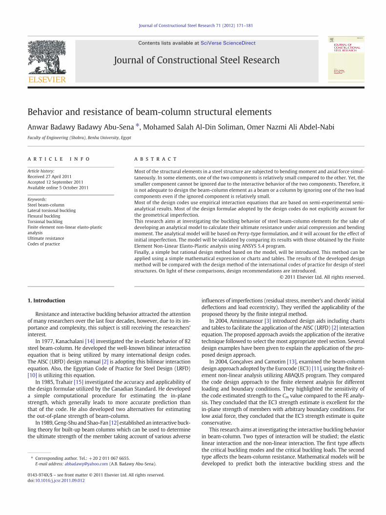
In the presence of axial load and bending moment, i.e., in a beam-column element, the lateral torsional buckling mode under bendingmoment initiates all the overall buckling modes of column, resultingin a single buckling mode that has three degrees of freedom v(x),w(x) and θ(x) as indicated in Fig. 1. The interactive buckling loadof the final mode is given by Trahair et al. [16]. The interactive crit-ical buckling loads are related by the following expression:
Mcr
MLTz
� �2¼ 1− Pcr
PEz
� �1− Pcr
PEy
!1− Pcr
PT
� �ð1Þ
Where;
Mcr and Pcr are the critical bucklingmoment and axial force respectivelyMLTz is the lateral torsional buckling moment about Z-axis (minor
axis)PEz, PEy are the critical buckling loads of the two individual Euler
modes about Z and Y axes respectivelyPT is the torsional buckling critical load.
L
Z
X
P
P
M
M
Z
Y
Mid-span cross section
w
v
0
(x)
Deformed Shape of
(x)
(x)
Fig. 1. Beam-column boundary conditions, loads, axes and deformed shape.
Critical loads of the individual buckling modes are given by thefollowing expressions [16]:
MLTz ¼πL
ffiffiffiffiffiffiffiffiffiffiffiffiffiffiffiffiffiffiffiffiffiffiffiffiffiffiffiffiffiffiffiffiEIz GJ þ π2ECw
L2
� �γ
vuut ð2:aÞ
PEz ¼π2EIzKLzð Þ2 ð2:bÞ
PEy ¼π2EIy
KLy� �2 ð2:cÞ
PT ¼ 1r2o
GJ þ π2ECw
L2
!ð2:dÞ
As per Ref. [16], the relation between the lateral displacement(v(x)), and section rotation (θ(x)) is given by:
v xð Þ ¼ Mcr
PEz−Pcrθ xð Þ ð3Þ
Where E is the modulus of elasticity, Iz and Iy are the minor andmajor moments of inertia as shown in Fig. 1, G is the shear modulus, Jis the St. Venant torsional constant, Cw is the warping constant, L is thebeam length and γ is a geometrical factor; that equals (1− Iz/ Iy).
For the sake of comparison and better understanding of the criticalbuckling interaction in beam-column Finite Element analysis has beenperformed using ANSYS program [4], for two beams of different geome-tries. The first beam is an I-section; that has the following dimensions:bf=200mm, tf=16mm, dw=600mm and tw=8mm. The secondbeam has also an I-section; that has the following dimensions:bf=150mm, tf=12mm, dw=500mm and tw=10mm. Dimensionsof the two beams are selected to avoid local and distortional buckling
Y
Z
SUB =1FREQ=.495692DMX =1.518
b
Fig. 2. (a) Buckled shape for first section, L=6.0 m, PcrPEz
¼ 0:346; McrMLTz
¼ 0:736
(b) Buckled shape for second section, L=6.0 m, PcrPEz¼ 0:646; Mcr
MLTz¼ 0:535.
.
173A.B. Badawy Abu-Sena et al. / Journal of Constructional Steel Research 71 (2012) 171–181
completely. In the vastmajority of the studied cases, the interactive buck-ling mode was the first Eigen mode. Twenty nine bending moment–normal force combinations have been considered for the first sectionand twenty three combinations have been considered for the second sec-tion. The considered cases include; pure axial compression, pure bendingmoment, combined bending and compression and combined bendingand tension force. Sample of the buckled deformed shapes of the twobeams are shown in Fig. 2a and b respectively.
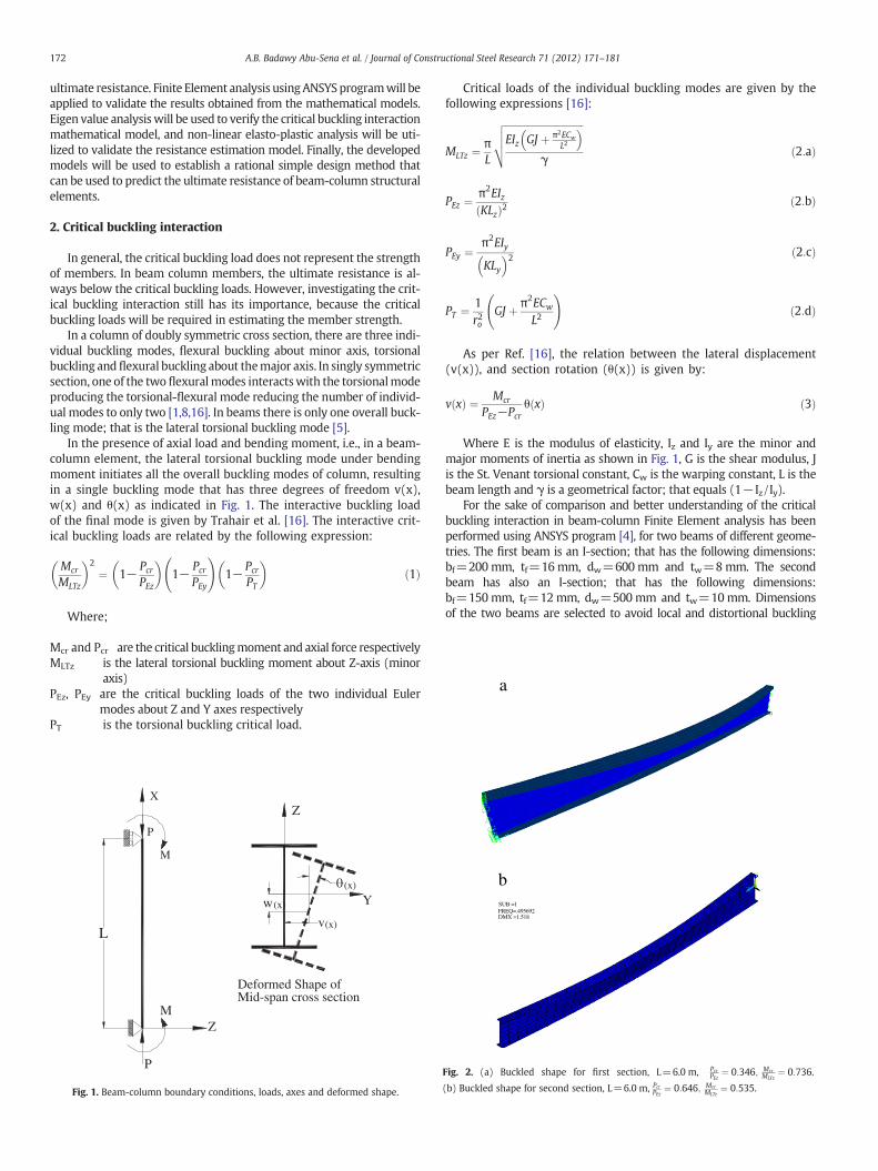
Fig. 3a and b shows a comparison between the results obtainedfrom the finite element analysis and the interactive critical bucklingstress predicted by Eq. (1).
It can be easily concluded from Fig. 3a and b that, there is an excel-lent agreement between the critical buckling interaction predicted bythe analytical solution expressed by Eq. (1) and that shown by the finiteelement analysis.
3. Non-linear interaction
Young's equation for imperfect columns was employed by Perry todevelop a mathematical model for calculating the ultimate resistanceof columns undergoing flexural buckling. This model is adopted by theBritish Standards BS5950 [7] and the Euro Code EC3 [11]. The same
-1.5
-1.25
-1
-0.75
-0.5
-0.25
0
0.25
0.5
0.75
1
-2.25 -2 -1.75 -1.5 -1.25 -1 -0.75 -0.5 -0.25 0
-1
-0.8
-0.6
-0.4
-0.2
0
0.2
0.4
0.6
0.8
1
-1.6 -1.4 -1.2 -1 -0.8 -0.6 -0.4 -0.2 0
a
b
Fig. 3. (a) Comparison between FE and theoretical solution for critical buckling interactio(b) Comparison between FE and theoretical solution for critical buckling interaction for sec
conceptwas applied by references [6] and [9] to estimate buckling resis-tance of beams undergoing lateral torsional buckling in presence of ini-tial imperfection.
Applying the Perry formulation enables the designer to take theeffect of initial imperfection into account. Most of the design codesneglect the effect of initial imperfection value, although it may havea significant effect on the element resistance as will be illustrated inthis research.
To investigate the non-linear interaction of a beam-column structuralelement in presence of initial imperfection, amathematicalmodelwill bedeveloped to account for the geometrical andmaterial non-linearity. Themodel will be verified by comparison to the finite element non-linearelasto-plastic analysis results. The proposed model is based on Perry-type formulation that is based on Young's equation of imperfect column.A rational design method based on the developed analytical model willbe introduced and its results will be compared with those of the designcodes of practice.
3.1. Mathematical formulation
For a simply supported beam-column with ends prevented fromtwisting and free to warp, the angle of rotation, and accordingly
0.25 0.5 0.75 1 1.25 1.5 1.75 2 2.25
Pcr
/PE
z
Mcr/MLTz
Finite Element
Theoritical Analysis
0.2 0.4 0.6 0.8 1 1.2 1.4 1.6
Pcr
/PE
z
Mcr/MLTz
Theoretical AnalysisFinite Element
n for first section; bf=200 mm, tf=16 mm, dw=600 mm, tw=8 mm, and L=6.0 m.ond section; bf=150 mm, tf=12 mm, dw=500 mm, tw=10 and L=6.0 m.
174 A.B. Badawy Abu-Sena et al. / Journal of Constructional Steel Research 71 (2012) 171–181
the lateral displacement, varies sinusoidally along the beam length.Fig. 1 shows the deformed shape of the mid-span cross section. Foran initial imperfection affine to the Eigen mode, the initial rotationand lateral displacement can be expressed by the following equations.
θo xð Þ ¼ θo sinπxL
� �ð4:aÞ
vo xð Þ ¼ vo sinπxL
� �ð4:bÞ
Where θo and vo are the initial imperfection amplitudes atmid-span.The relation between θo and vo at mid-span is given by Eq. (3).
Young's equation gives the relation between the applied load and thelateral deformation for a columnundergoingflexural buckling. For beamsundergoing lateral torsional buckling Young's equation has been succes-sively applied by [6,9] to predict the ultimate resistance of the beams.However, this type of formulation can be applied on beam-columnwith replacing the critical buckling loads of the individual modes by theinteractive buckling loads obtained from Eq. (1). According to Young'sequation, the relation between deformation at any load level and the ini-tial deformation is given by:
θ ¼ θo1−M=Mcr
ð5:aÞ
v ¼ vo1−M=Mcr
ð5:bÞ
Where, θ and v are the rotation and lateral displacement at any ap-plied load (M and P), and Mcr is the interactive critical buckling momentas per Eq. (1). The relation between θ/v and the appliedmoment is shownin Fig. 4.
The additional deformations (θ1 and v1) produce additional bend-ing and warping stress, these deformations are given by the followingexpression:
θ1 ¼ θ−θo ¼M
Mcr−Mθo ð6:aÞ
v1 ¼ v−vo ¼M
Mcr−Mvo ð6:bÞ
The additional rotation (θ1) produces an additional warping stress,while the additional lateral displacement (v1) produces an additional
Fig. 4. Load–displacement relationship (Young's equation).
moment about the minor axis (Mzm), which in turn produces an addi-tional normal stress. The additional Mzm can be given by the followingexpression:
Mzm xð Þ ¼ −EIzd2v1 xð Þdx2
¼ EIzM
Mcr−M
� �vo
π2
L2sin
πxL
ð7:aÞ
At mid-span Mzm has a maximum value that is given by the fol-lowing expression:
Mzm ¼ EIzM
Mcr−M
� �vo
π2
L2ð7:bÞ
Due to the translation of the cross section, the applied axial forceproduces additional moments about the two principal axes of thecross section. The values of these additional bending moments aregiven by the following expression:
Mzp xð Þ ¼ P � v xð Þ ¼ PMcr
Mcr−M
� �vo sin
πxL
ð8:aÞ
Myp xð Þ ¼ P �w xð Þ ¼ PMcr
Mcr−M
� �wo sin
πxL
ð8:bÞ
Aswill be illustrated later, considering the additionalmoment aboutthe major axis (Myp) will result in complicating the final solution be-cause it results in a third order equation. On the other hand ignoringthis moment relatively simplifies the final expression. It has been no-ticed that the effect of this component is minor and its contribution tothe final ultimate load is less than 1%. That is due to two reasons, thefirst is the relatively small value of wo compared to vo, and the secondis the fact that this moment is about the major axis, and accordingly itwill be divided by the major section modulus resulting in a very smallstress component. Therefore, it was decided to omit this componentfrom the final expression of the ultimate resistance.
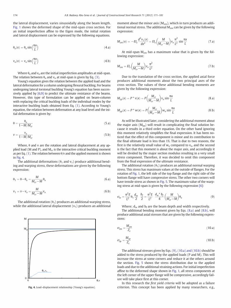
The additional rotation (θ1) produces an additional normal warpingstress. This stress has maximum values at the outside of flanges. For therotation of Fig. 1, the left side of the top flange and the right side of thebottom flange will have compressive stress. The other two corners willhave tensile stress as shown in Fig. 5. The maximum value of the warp-ing stress at mid-span is given by the following expression [6]:
σw ¼ π2EL2
θ1dw2
bf2
¼ π2EL2
dw� bf4
MMcr−M
� �θo ð9Þ
Where; dw and bf are the beam depth and width respectively.The additional bending moment given by Eqs. (8.a) and (8.b), will
produce additional axial stresses that are given by the following expres-sions:
σzm ¼ Mzm
Zzð10:aÞ
σzp ¼ Mzp
Zzð10:bÞ
The additional stresses given by Eqs. (9), (10.a) and (10.b) should beadded to the stress produced by the applied loads (P and M). This willincrease the stress at some corners and reduce it at the others aroundthe section. Fig. 5 shows the stress distribution due to the appliedloads and due to the additional straining actions. For initial imperfectionaffine to the deformed shape shown in Fig. 1, all stress components atthe left corner of the upper flange will be compressive, accordingly fail-ure will take place first at this corner.
In this research the first yield criteria will be adopted as a failurecriterion. This concept has been applied by many researchers, e.g.,
a) b) c)
d) e) f)
Fig. 5. Stress distribution due to applied and additional straining actions.
175A.B. Badawy Abu-Sena et al. / Journal of Constructional Steel Research 71 (2012) 171–181
references [6,9]. According to this concept, the ultimate resistance isrepresented by the load that causes first yield around the cross section.That means, the ultimate loads (Pu and Mu) are those loads that causethe first yield to take place at the point of maximum stress. FromFig. 5, the total stress at the left-hand-side corner of the top flangeshould be equated to the material yield stress to obtain the ultimate re-sistance. Applying this concept leads to the following expression:
σy ¼ σM þ σP þ σw þ σzm þ σzp ð11Þ
From Eq. (11), the following expression can be developed;
Mu
Zyþ Pu
Aþ π2E
L2dw� bf
4Mu
Mcr−Mu
� �θo þ
þ EIzZz
Mu
Mcr−Mu
� �vo
π2
L2þ Pu
Zz
Mcr
Mcr−Mu
� �vo ¼ σy
ð12Þ
Where, Zy and Zz are the modulii of section about the major andminor axes respectively. For an eccentricity (e), Pu can be replacedby Mu/e. Multiplying both sides of Eq. (12) by Zy, and rearrangingthe terms of the equation, result at the following expression:
μ �M2u− Mo þ μ þ η � voð ÞMcrð ÞMu þMo
�Mcr ¼ 0 ð13Þ
Where: μ and η are geometrical parameters given by:
μ ¼ 1þ ZyA � e ð14:aÞ
η ¼ Zye � ZZ
þ PEz� ZyMcr
� Zzþ bf � PEy PEz−Pcrð Þ
2M2cr
ð14:bÞ
vo is the initial lateral imperfection amplitude at mid-span, Mu is theultimate moment capacity of the beam-column element, Mo is theyield moment about major axis=Zy*σy, and Mcr is the interactivecritical buckling moment obtained from Eq. (1). Obtaining Mu from
Eq. (13) for a certain eccentricity, then Pu can be calculated. The ulti-mate bending moment can be obtained from Eq. (13), according towhich the ultimate bending moment can be given by:
Mu ¼ 12μ
Mo þ μ þ η � voð ÞMcr∓ffiffiffiffiffiffiffiffiffiffiffiffiffiffiffiffiffiffiffiffiffiffiffiffiffiffiffiffiffiffiffiffiffiffiffiffiffiffiffiffiffiffiffiffiffiffiffiffiffiffiffiffiffiffiffiffiffiffiffiffiffiffiffiffiffiffiffiffiffiffiffiffiffiffiffiffiffiffiMo þ μ þ η � voð ÞMcrð Þ2−4μMo
�Mcr
q� �ð15Þ
Pu ¼ Mu
eð16Þ
If the additional moment about the major axis (Myp) given byEq. (8.b) was considered in the mathematical formulation was goingto be more complicated, and Eq. (13) was going to be a third orderequation. As clarified earlier the effect of this term to the final ultimateresistance was found to be minor.
3.2. Finite element non-linear analysis
ANSYS Finite Element Program [4] is used as a numerical tool to ver-ify themodel developed in this research. Analyses have been carried outfor the second section, for different level of initial imperfections. Four-noded thick shell element is used in all the FE analyses in this research.The number of elements in the flanges is 4, and 6 elements are used fortheweb. The number of elements along the beam length is 30, as shownin Fig. 2b. The boundary conditions are chosen to verify the simply sup-ported conditions, i.e., the beam ends are prevented from translation inY and Z-directions and rotation about the X-axis. Warping and rotationabout Y and Z axes at the beam ends are allowed. The initial imperfec-tions for all the studied cases were chosen to be affine to the firstEigen mode (interactive mode between lateral torsional and flexuralmodes). Different eccentricities (e) were studied from zero (pure axialforce) to infinity (pure bending). Two different values of initial imper-fections have been considered vo=L/1000 and vo=L/2000.
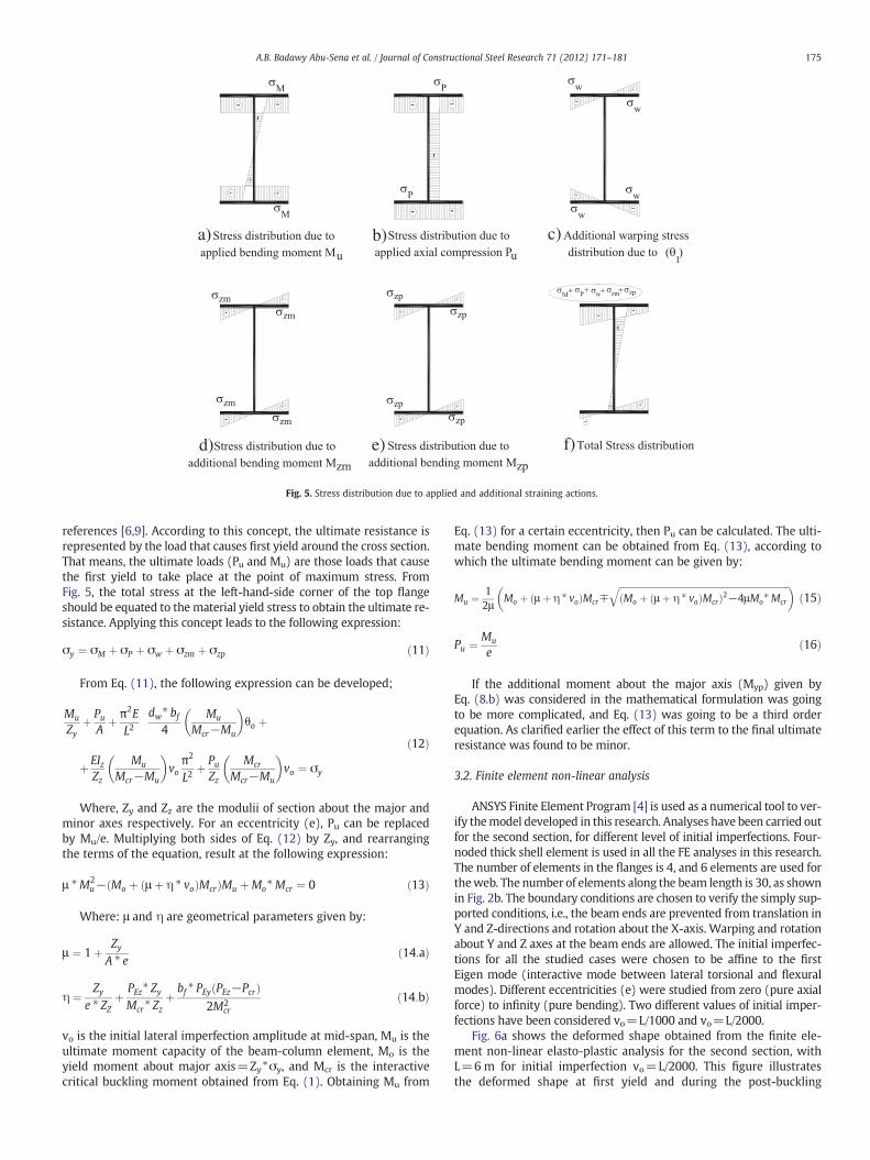
Fig. 6a shows the deformed shape obtained from the finite ele-ment non-linear elasto-plastic analysis for the second section, withL=6 m for initial imperfection vo=L/2000. This figure illustratesthe deformed shape at first yield and during the post-buckling
At first yield (displacement * 5) Post-buckling stage (displacement * 5)
At first yield (displacement * 5) Post-buckling stage (displacement * 5)
X
Y
Z
JAN 7 201121:12:41
X
Y
Z
JAN 7 201121:34:20
X
Y
Z
JAN 7 201121:16:29
X
Y
Z
JAN 7 201121:35:29
a b
c d
Fig. 6. (a) Deformed shape of the second section, L=6 m, vo=L/2000=3 mm, e/dw=0.5. (b) Deformed shape of the second section, L=6 m, vo=L/1000=6 mm, e/dw=0.5.
176 A.B. Badawy Abu-Sena et al. / Journal of Constructional Steel Research 71 (2012) 171–181
stage. Fig. 6b shows the deformed shape of the same beam, withvo=L/1000.
In the next section, results of the analytical model developed in thissection will be compared with those obtained by the finite elementnon-linear elasto-plastic analysis. To verify the developed model, ulti-mate resistance, load–displacement curves and stress distribution atfirst yield around the cross section obtained by the model will be com-pared to the corresponding results obtained from ANSYS.
4. Results and comparisons
Eqs. (15) and (16) have been applied to obtain the ultimate resistancefor beam columns of I-sections. The equations have been applied for dif-ferent values of initial imperfections, that are vo=0, L/2000, L/1000, andL/500, the corresponding value of θowas estimated fromEq. (3). Differenteccentricities ranging fromzero (axially loaded columns) to infinity (purebending) were investigated. Sixteen finite elements non-linear elasto-plastic analysis were performed for vo=L/2000 and L/1000, and withe/dw=0, 0.08, 0.25, 0.5, 1.0, 1.67, 16.7, and infinity.
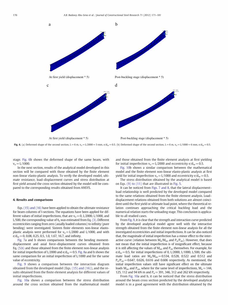
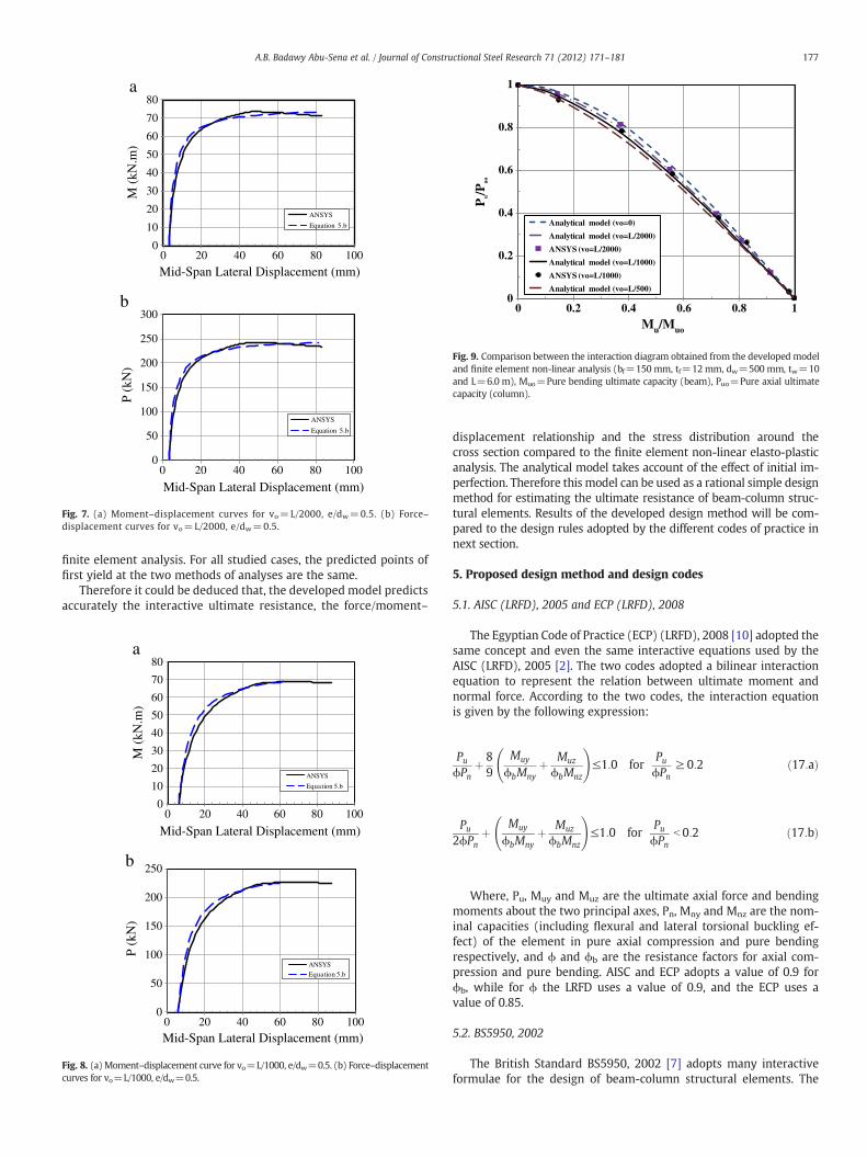
Fig. 7a and b shows comparisons between the bending moment-displacement and axial force–displacement curves obtained fromEq. (5.b) and those obtained from the finite element non-linear analysisfor initial imperfection of L/2000 and e/dw=0.5. Fig. 8a and b shows thesame comparison for an initial imperfection of L/1000 and for the samevalue of eccentricity.
Fig. 9 shows a comparison between the interaction diagramobtained from the developed model (Eqs. (15) and (16)), and the re-sults obtained from the finite element analysis for different values ofinitial imperfections.
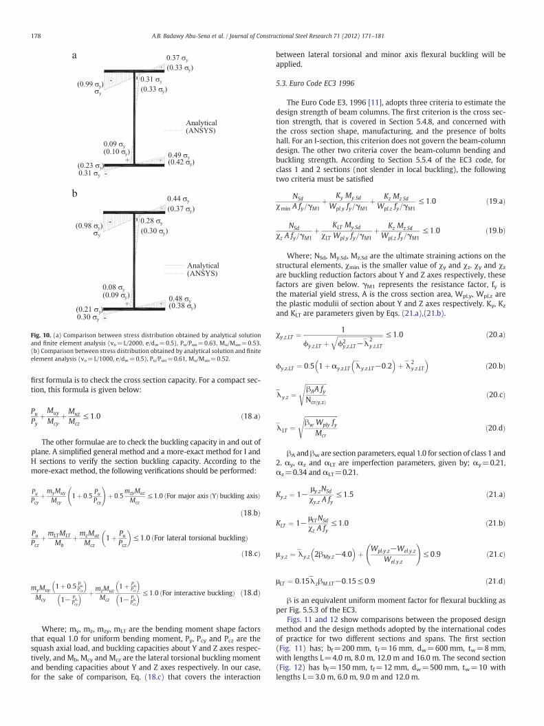
Fig. 10a shows a comparison between the stress distributionaround the cross section obtained from the mathematical model
and those obtained from the finite element analysis at first yieldingfor initial imperfection vo=L/2000 and eccentricity e/dw=0.5.
Fig. 10b shows a similar comparison between the mathematicalmodel and the finite element non-linear elasto-plastic analysis at firstyield for initial imperfection vo=L/1000 and eccentricity e/dw=0.5.
The stress distribution obtained by the analytical model is basedon Eqs. (9) to (11) that are illustrated in Fig. 5.
It can be noticed from Figs. 7 and 8, that the lateral displacement–load relationship is well predicted by the developed model comparedto the same relations obtained from the finite element analysis. Load–displacement relations obtained from both solutions are almost coinci-dent until thefirst yield or ultimate load point, where the theoretical re-lation continues approaching the critical buckling load and thenumerical relation starts the unloading stage. This conclusion is applica-ble to all studied cases.
FromFig. 9, it is clear that the strength and interaction curve predictedby the developed analytical model agree well with the interactivestrength obtained from the finite element non-linear analysis for all theinvestigated eccentricities and initial imperfections. It can be also noticedthat, themagnitude of initial imperfection has aminor effect to the inter-active curve (relation between Mu/Muo and Pu/Puo). However, that doesnot mean that the initial imperfection is of insignificant effect, becauseit is still affecting the values of Muo and Puo themselves. For example, fore/dw=0.5, for initial imperfections of 0, L/2000, L/1000, L/500, the ulti-mate load ratios are Mu/Muo=0.534, 0.528, 0.522 and 0.512 andPu/Puo=0.647, 0.626, 0.616 and 0.606 respectively. As mentioned, theinitial imperfection values still have significant effect on the ultimateloads Muo and Puo, where for the same level of imperfections, Mu=144,125, 112 and 94 kNm and Pu=391, 346, 312 and 262 kN respectively.
From Fig. 10a and b, it can be noticed that the stress distributionaround the beam cross section predicted by the developed analyticalmodel is in a good agreement with the distribution obtained by the
0
50
100
150
200
250
300
0 20 40 60 80 100
P (k
N)
ANSYS
Equation 5.b
0
10
20
30
40
50
60
70
80
0 20 40 60 80 100
M (
kN.m
)
Mid-Span Lateral Displacement (mm)
Mid-Span Lateral Displacement (mm)
ANSYS
Equation 5.b
a
b
Fig. 7. (a) Moment–displacement curves for vo=L/2000, e/dw=0.5. (b) Force–displacement curves for vo=L/2000, e/dw=0.5.
0
0.2
0.4
0.6
0.8
1
0 0.2 0.4 0.6 0.8 1
Pu/P
uo
Mu/Muo
Analytical model (vo=0)
Analytical model (vo=L/2000)
ANSYS (vo=L/2000)
Analytical model (vo=L/1000)
ANSYS (vo=L/1000)
Analytical model (vo=L/500)
Fig. 9. Comparison between the interaction diagram obtained from the developed modeland finite element non-linear analysis (bf=150 mm, tf=12mm, dw=500 mm, tw=10and L=6.0 m), Muo=Pure bending ultimate capacity (beam), Puo=Pure axial ultimatecapacity (column).
177A.B. Badawy Abu-Sena et al. / Journal of Constructional Steel Research 71 (2012) 171–181
finite element analysis. For all studied cases, the predicted points offirst yield at the two methods of analyses are the same.
Therefore it could be deduced that, the developed model predictsaccurately the interactive ultimate resistance, the force/moment–
0
50
100
150
200
250
0 20 40 60 80 100
P (k
N)
ANSYS
Equation 5.b
0
10
20
30
40
50
60
70
80
0 20 40 60 80 100
M (
kN.m
)
ANSYS
Equation 5.b
Mid-Span Lateral Displacement (mm)
Mid-Span Lateral Displacement (mm)
a
b
Fig. 8. (a)Moment–displacement curve for vo=L/1000, e/dw=0.5. (b) Force–displacementcurves for vo=L/1000, e/dw=0.5.
displacement relationship and the stress distribution around thecross section compared to the finite element non-linear elasto-plasticanalysis. The analytical model takes account of the effect of initial im-perfection. Therefore this model can be used as a rational simple designmethod for estimating the ultimate resistance of beam-column struc-tural elements. Results of the developed design method will be com-pared to the design rules adopted by the different codes of practice innext section.
5. Proposed design method and design codes
5.1. AISC (LRFD), 2005 and ECP (LRFD), 2008
The Egyptian Code of Practice (ECP) (LRFD), 2008 [10] adopted thesame concept and even the same interactive equations used by theAISC (LRFD), 2005 [2]. The two codes adopted a bilinear interactionequation to represent the relation between ultimate moment andnormal force. According to the two codes, the interaction equationis given by the following expression:
PuϕPn
þ 89
Muy
ϕbMnyþ Muz
ϕbMnz
!≤1:0 for
PuϕPn
≥ 0:2 ð17:aÞ
Pu2ϕPn
þ Muy
ϕbMnyþ Muz
ϕbMnz
!≤1:0 for
PuϕPn
b 0:2 ð17:bÞ
Where, Pu, Muy and Muz are the ultimate axial force and bendingmoments about the two principal axes, Pn, Mny and Mnz are the nom-inal capacities (including flexural and lateral torsional buckling ef-fect) of the element in pure axial compression and pure bendingrespectively, and ϕ and ϕb are the resistance factors for axial com-pression and pure bending. AISC and ECP adopts a value of 0.9 forϕb, while for ϕ the LRFD uses a value of 0.9, and the ECP uses avalue of 0.85.
5.2. BS5950, 2002
The British Standard BS5950, 2002 [7] adopts many interactiveformulae for the design of beam-column structural elements. The
a
b
Fig. 10. (a) Comparison between stress distribution obtained by analytical solutionand finite element analysis (vo=L/2000, e/dw=0.5), Pu/Puo=0.63, Mu/Muo=0.53.(b) Comparison between stress distribution obtained by analytical solution and finiteelement analysis (vo=L/1000, e/dw=0.5), Pu/Puo=0.61, Mu/Muo=0.52.
178 A.B. Badawy Abu-Sena et al. / Journal of Constructional Steel Research 71 (2012) 171–181
first formula is to check the cross section capacity. For a compact sec-tion, this formula is given below:
PuPy
þMuy
McyþMuz
Mcz≤ 1:0 ð18:aÞ
The other formulae are to check the buckling capacity in and out ofplane. A simplified general method and a more-exact method for I andH sections to verify the section buckling capacity. According to themore-exact method, the following verifications should be performed:
PuPcy
þmyMuy
Mcy1þ 0:5
PuPcy
!þ 0:5
mzyMuz
Mcz≤ 1:0 For major axis Yð Þ buckling axisð Þ
ð18:bÞ
PuPcz
þmLTMLT
MbþmzMuz
Mcz1þ Pu
Pcz
� �≤ 1:0 For lateral torsional bucklingð Þ
ð18:cÞ
myMuy
Mcy
1þ 0:5 PuPcy
� �1− Pu
Pcy
� � þmzMuz
Mcz
1þ PuPcz
� �1− Pu
Pcz
� � ≤ 1:0 For interactive bucklingð Þ ð18:dÞ
Where; my, mz, mzy, mLT are the bending moment shape factorsthat equal 1.0 for uniform bending moment, Py, Pcy and Pcz are thesquash axial load, and buckling capacities about Y and Z axes respec-tively, and Mb, Mcy and Mcz are the lateral torsional buckling momentand bending capacities about Y and Z axes respectively. In our case,for the sake of comparison, Eq. (18.c) that covers the interaction
between lateral torsional and minor axis flexural buckling will beapplied.
5.3. Euro Code EC3 1996
The Euro Code E3, 1996 [11], adopts three criteria to estimate thedesign strength of beam columns. The first criterion is the cross sec-tion strength, that is covered in Section 5.4.8, and concerned withthe cross section shape, manufacturing, and the presence of boltshall. For an I-section, this criterion does not govern the beam-columndesign. The other two criteria cover the beam-column bending andbuckling strength. According to Section 5.5.4 of the EC3 code, forclass 1 and 2 sections (not slender in local buckling), the followingtwo criteria must be satisfied
NSd
χmin A fy=γM1þ Ky My:Sd
Wpl:y fy=γM1þ Kz Mz:Sd
Wpl:z fy=γM1≤ 1:0 ð19:aÞ
NSd
χz A fy=γM1þ KLT My:Sd
χLT Wpl:y fy=γM1þ Kz Mz:Sd
Wpl:z fy=γM1≤ 1:0 ð19:bÞ
Where; NSd, My.Sd, Mz.Sd are the ultimate straining actions on thestructural elements, χmin is the smaller value of χy and χz. χy and χzare buckling reduction factors about Y and Z axes respectively, thesefactors are given below. γM1 represents the resistance factor, fy isthe material yield stress, A is the cross section area, Wpl.y, Wpl.z arethe plastic modulii of section about Y and Z axes respectively. Ky, Kz
and KLT are parameters given by Eqs. (21.a),(21.b).
χy;z;LT ¼ 1
ϕy;z;LT þffiffiffiffiffiffiffiffiffiffiffiffiffiffiffiffiffiffiffiffiffiffiffiffiffiffiffiffiffiffiϕ2y;z;LT− λ̄
2y;z;LT
q ≤ 1:0 ð20:aÞ
ϕy;z;LT ¼ 0:5 1þαy;z;LT λ̄y;z;LT−0:2� �
þ λ̄2y;z;LT
� �ð20:bÞ
λ̄y;z ¼ffiffiffiffiffiffiffiffiffiffiffiffiffiffiβAA fyNcrðy;zÞ
sð20:cÞ
λ̄LT ¼ffiffiffiffiffiffiffiffiffiffiffiffiffiffiffiffiffiffiffiffiffiffiβw Wply fy
Mcr
sð20:dÞ
βA and βw are section parameters, equal 1.0 for section of class 1 and2. αy, αz and αLT are imperfection parameters, given by; αy=0.21,αz=0.34 and αLT=0.21.
Ky;z ¼ 1−μy;zNSd
χy;z A fy≤ 1:5 ð21:aÞ
KLT ¼ 1− μLTNSd
χz A fy≤ 1:0 ð21:bÞ
μ y;z ¼ λ̄y;z 2βMy;z−4:0� �
þ Wpl:y;z−Wel:y;z
Wel:y;z
!≤ 0:9 ð21:cÞ
μLT ¼ 0:15 λ̄zβM:LT−0:15≤ 0:9 ð21:dÞ
β is an equivalent uniform moment factor for flexural buckling asper Fig. 5.5.3 of the EC3.
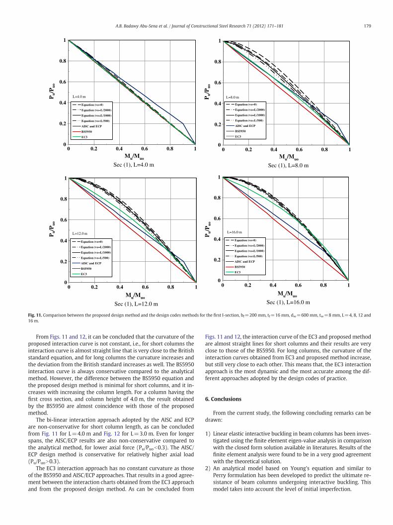
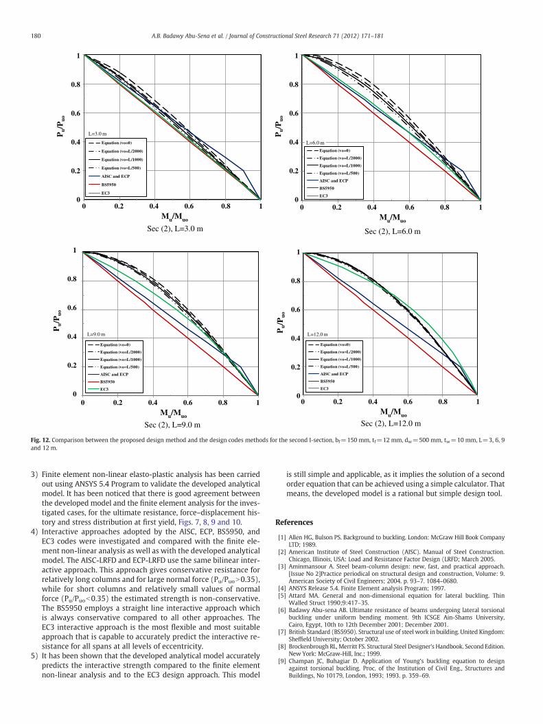
Figs. 11 and 12 show comparisons between the proposed designmethod and the design methods adopted by the international codesof practice for two different sections and spans. The first section(Fig. 11) has; bf=200 mm, tf=16 mm, dw=600 mm, tw=8 mm,with lengths L=4.0 m, 8.0 m, 12.0 m and 16.0 m. The second section(Fig. 12) has bf=150 mm, tf=12 mm, dw=500 mm, tw=10 withlengths L=3.0 m, 6.0 m, 9.0 m and 12.0 m.
0
1
0 1
L=8.0 m
Equation (vo=0)
Equation (vo=L/2000)
Equation (vo=L/1000)
Equation (vo=L/500)
AISC and ECP
BS5950
EC3
0
1
0 1
L=16.0 m
Equation (vo=0)
Equation (vo=L/2000)
Equation (vo=L/1000)
Equation (vo=L/500)
AISC and ECP
BS5950
EC3
Sec (1), L=4.0 m
0
0.2
0.4
0.6
0.8
0.2
0.4
0.6
0.8
0.2
0.4
0.6
0.8
0.2
0.4
0.6
0.8
1
0 0.2 0.4 0.6 0.8
0.2 0.4 0.6 0.8 0.2 0.4 0.6 0.8
0.2 0.4 0.6 0.81
L=4.0 m
Equation (vo=0)
Equation (vo=L/2000)
Equation (vo=L/1000)
Equation (vo=L/500)
AISC and ECP
BS5950
EC3
0
1
0 1
L=12.0 m
Equation (vo=0)
Equation (vo=L/2000)
Equation (vo=L/1000)
Equation (vo=L/500)
AISC and ECP
BS5950
EC3
Mu/Muo
Sec (1), L=8.0 m
Mu/Muo
Sec (1), L=16.0 m
Mu/Muo
Sec (1), L=12.0 m
Mu/Muo
Pu/P
uoP
u/P
uo
Pu/P
uoP
u/P
uo
Fig. 11. Comparison between the proposed design method and the design codes methods for the first I-section, bf=200 mm, tf=16 mm, dw=600 mm, tw=8 mm, L=4, 8, 12 and16 m.
179A.B. Badawy Abu-Sena et al. / Journal of Constructional Steel Research 71 (2012) 171–181
From Figs. 11 and 12, it can be concluded that the curvature of theproposed interaction curve is not constant, i.e., for short columns theinteraction curve is almost straight line that is very close to the Britishstandard equation, and for long columns the curvature increases andthe deviation from the British standard increases as well. The BS5950interaction curve is always conservative compared to the analyticalmethod. However, the difference between the BS5950 equation andthe proposed design method is minimal for short columns, and it in-creases with increasing the column length. For a column having thefirst cross section, and column height of 4.0 m, the result obtainedby the BS5950 are almost coincidence with those of the proposedmethod.
The bi-linear interaction approach adopted by the AISC and ECPare non-conservative for short column length, as can be concludedfrom Fig. 11 for L=4.0 m and Fig. 12 for L=3.0 m. Even for longerspans, the AISC/ECP results are also non-conservative compared tothe analytical method, for lower axial force (Pu/Puob0.3). The AISC/ECP design method is conservative for relatively higher axial load(Pu/PuoN0.3).
The EC3 interaction approach has no constant curvature as thoseof the BS5950 and AISC/ECP approaches. That results in a good agree-ment between the interaction charts obtained from the EC3 approachand from the proposed design method. As can be concluded from
Figs. 11 and 12, the interaction curve of the EC3 and proposed methodare almost straight lines for short columns and their results are veryclose to those of the BS5950. For long columns, the curvature of theinteraction curves obtained from EC3 and proposed method increase,but still very close to each other. This means that, the EC3 interactionapproach is the most dynamic and the most accurate among the dif-ferent approaches adopted by the design codes of practice.
6. Conclusions
From the current study, the following concluding remarks can bedrawn:
1) Linear elastic interactive buckling in beam columns has been inves-tigated using the finite element eigen-value analysis in comparisonwith the closed form solution available in literatures. Results of thefinite element analysis were found to be in a very good agreementwith the theoretical solution.
2) An analytical model based on Young's equation and similar toPerry formulation has been developed to predict the ultimate re-sistance of beam columns undergoing interactive buckling. Thismodel takes into account the level of initial imperfection.
L=6.0 m
Equation (vo=0)
Equation (vo=L/2000)
Equation (vo=L/1000)
Equation (vo=L/500)
AISC and ECP
BS5950
EC3
L=12.0 m
Equation (vo=0)
Equation (vo=L/2000)
Equation (vo=L/1000)
Equation (vo=L/500)
AISC and ECP
BS5950
EC3
Sec (2), L=3.0 m Sec (2), L=6.0 m
Sec (2), L=9.0 m Sec (2), L=12.0 m
L=3.0 m
Equation (vo=0)
Equation (vo=L/2000)
Equation (vo=L/1000)
Equation (vo=L/500)
AISC and ECP
BS5950
EC3
L=9.0 m
Equation (vo=0)
Equation (vo=L/2000)
Equation (vo=L/1000)
Equation (vo=L/500)
AISC and ECP
BS5950
EC3
0 0.2 0.4 0.6 0.8 1Mu/Muo
0 0.2 0.4 0.6 0.8 1Mu/Muo
0 0.2 0.4 0.6 0.8 1Mu/Muo
0 0.2 0.4 0.6 0.8 1Mu/Muo
0
0.2
0.4
0.6
0.8
1P
u/P
uo
0
0.2
0.4
0.6
0.8
1
Pu/P
uo
0
0.2
0.4
0.6
0.8
1
Pu/P
uo
0
0.2
0.4
0.6
0.8
1
Pu/P
uo
Fig. 12. Comparison between the proposed design method and the design codes methods for the second I-section, bf=150 mm, tf=12 mm, dw=500 mm, tw=10 mm, L=3, 6, 9and 12 m.
180 A.B. Badawy Abu-Sena et al. / Journal of Constructional Steel Research 71 (2012) 171–181
3) Finite element non-linear elasto-plastic analysis has been carriedout using ANSYS 5.4 Program to validate the developed analyticalmodel. It has been noticed that there is good agreement betweenthe developed model and the finite element analysis for the inves-tigated cases, for the ultimate resistance, force–displacement his-tory and stress distribution at first yield, Figs. 7, 8, 9 and 10.
4) Interactive approaches adopted by the AISC, ECP, BS5950, andEC3 codes were investigated and compared with the finite ele-ment non-linear analysis as well as with the developed analyticalmodel. The AISC-LRFD and ECP-LRFD use the same bilinear inter-active approach. This approach gives conservative resistance forrelatively long columns and for large normal force (Pu/PuoN0.35),while for short columns and relatively small values of normalforce (Pu/Puob0.35) the estimated strength is non-conservative.The BS5950 employs a straight line interactive approach whichis always conservative compared to all other approaches. TheEC3 interactive approach is the most flexible and most suitableapproach that is capable to accurately predict the interactive re-sistance for all spans at all levels of eccentricity.
5) It has been shown that the developed analytical model accuratelypredicts the interactive strength compared to the finite elementnon-linear analysis and to the EC3 design approach. This model
is still simple and applicable, as it implies the solution of a secondorder equation that can be achieved using a simple calculator. Thatmeans, the developed model is a rational but simple design tool.
References
[1] Allen HG, Bulson PS. Background to buckling. London: McGraw Hill Book CompanyLTD; 1989.
[2] American Institute of Steel Construction (AISC). Manual of Steel Construction.Chicago, Illinois, USA: Load and Resistance Factor Design (LRFD; March 2005.
[3] Aminmansour A. Steel beam-column design: new, fast, and practical approach.[Issue No 2]Practice periodical on structural design and construction, Volume: 9.American Society of Civil Engineers; 2004. p. 93–7. 1084–0680.
[4] ANSYS Release 5.4. Finite Element analysis Program; 1997.[5] Attard MA. General and non-dimensional equation for lateral buckling. Thin
Walled Struct 1990;9:417–35.[6] Badawy Abu-sena AB. Ultimate resistance of beams undergoing lateral torsional
buckling under uniform bending moment. 9th ICSGE Ain-Shams University,Cairo, Egypt, 10th to 12th December 2001; December 2001.
[7] British Standard (BS5950). Structural use of steel work in building. United Kingdom:Sheffield University; October 2002.
[8] Brockenbrough RL, Merritt FS. Structural Steel Designer's Handbook. Second Edition.New York: McGraw-Hill, Inc.; 1999.
[9] Champan JC, Buhagiar D. Application of Young's buckling equation to designagainst torsional buckling. Proc. of the Institution of Civil Eng., Structures andBuildings, No 10179, London, 1993; 1993. p. 359–69.

181A.B. Badawy Abu-Sena et al. / Journal of Constructional Steel Research 71 (2012) 171–181
[10] ECP. Egyptian Code of Practice for Steel Constructions; Load and Resistance FactorDesign (LRFD). First Edition. Cairo: Al-Ahram press; 2008.
[11] European Committee for Standardization (CEN), Euro code EC3. Design of SteelStructures, Part 1.1, General Rules and Rules for Buildings (ENV 1993-1-1); 1996.
[12] Geng-Shu T, Shao-Fan C. An interactive buckling theory for built-up beam-columnsand its application to centrally compressed built-up members. J Constr Steel Res1989;14(3):221–41.
[13] Gonçalves R, Camotim D. On the application of beam–column interaction formulaeto steel members with arbitrary loading and support conditions. J Constr Steel Res2004;60(3–5):433–50.
[14] Kanchanalai T. The design and behavior of beam-columns in un-braced steelframes. AISI Project No.189, Report No. 2, Civil Engineering, Structural ResearchLab, University of Texas-Austin, October, 1977; October 1977.
[15] Trahair NS. Design strength of steel beam-columns. Structural Engineering ReportNo. 132, Department of Civil Engineering, University of Alberta, December, 1985;December 1985.
[16] Trahair NS, Bradford MA, Nethercot DA, Gardner L. The behavior and design ofsteel structures to EC3. Fourth Edition. New York, USA: Taylor and Francis; 2008.