Basics of High-Voltage Test Techniques
12
Chapter 2 Basics of High-Voltage Test Techniques Abstract High-voltage (HV) testing utilizes the phenomena in electrical insula- tions under the influence of the electric field for the definition of test procedures and acceptance criteria. The phenomena—e.g., breakdown, conductivity, polari- zation and dielectric losses—depend on the insulating material, on the electric field generated by the test voltages and shaped by the electrodes as well as on envi- ronmental influences. Considering the phenomena, this chapter describes the common basics of HV test techniques, independent on the kind of the stressing test voltage. All details related to the different test voltages are considered in the relevant Chaps. 3–8. 2.1 External and Internal Insulations in the Electric Field In this section definitions of phenomena in electrical insulations are introduced. The insulations are classified for the purpose of high-voltage (HV) testing. Fur- thermore environmental influences to external insulation and their treatment for HV testing are explained. 2.1.1 Principles and Definitions When an electrical insulation is stressed in the electric field, ionization causes electrical discharges which may grow from one electrode of high potential to the one of low potential or vice versa. This may cause a high current rise, i.e., the dielectric looses its insulation property and thus its function to separate different potentials in an electric apparatus or equipment. For the purpose of this book, this phenomenon shall be called ‘‘breakdown’’ related to the stressing voltage: W. Hauschild and E. Lemke, High-Voltage Test and Measuring Techniques, DOI: 10.1007/978-3-642-45352-6_2, ȑ Springer-Verlag Berlin Heidelberg 2014 17
-
Upload
khangminh22 -
Category
Documents
-
view
3 -
download
0
Transcript of Basics of High-Voltage Test Techniques

Chapter 2Basics of High-Voltage Test Techniques
Abstract High-voltage (HV) testing utilizes the phenomena in electrical insula-tions under the influence of the electric field for the definition of test proceduresand acceptance criteria. The phenomena—e.g., breakdown, conductivity, polari-zation and dielectric losses—depend on the insulating material, on the electric fieldgenerated by the test voltages and shaped by the electrodes as well as on envi-ronmental influences. Considering the phenomena, this chapter describes thecommon basics of HV test techniques, independent on the kind of the stressing testvoltage. All details related to the different test voltages are considered in therelevant Chaps. 3–8.
2.1 External and Internal Insulations in the Electric Field
In this section definitions of phenomena in electrical insulations are introduced.The insulations are classified for the purpose of high-voltage (HV) testing. Fur-thermore environmental influences to external insulation and their treatment forHV testing are explained.
2.1.1 Principles and Definitions
When an electrical insulation is stressed in the electric field, ionization causeselectrical discharges which may grow from one electrode of high potential to theone of low potential or vice versa. This may cause a high current rise, i.e., thedielectric looses its insulation property and thus its function to separate differentpotentials in an electric apparatus or equipment. For the purpose of this book, thisphenomenon shall be called ‘‘breakdown’’ related to the stressing voltage:
W. Hauschild and E. Lemke, High-Voltage Test and Measuring Techniques,DOI: 10.1007/978-3-642-45352-6_2, � Springer-Verlag Berlin Heidelberg 2014
17

Definition The breakdown is the failure of insulation under electric stress, inwhich the discharge completely bridges the insulation under test and reduces thevoltage between electrodes to practically zero (collapse of voltage).
Note In IEC 60060-1 (2010) this phenomenon is referred to as ‘‘disruptive discharge’’.There are also other terms, like ‘‘flashover’’ when the breakdown is related to a dischargeover the surface of a dielectric in a gaseous or liquid dielectric, ‘‘puncture’’ when it occursthrough a solid dielectric and ‘‘sparkover’’ when it occurs in gaseous or liquid dielectrics.
In homogenous and slightly non-homogenous fields a breakdown occurs when acritical strength of the stressing field is reached. In strongly non-homogenousfields, a local stress concentration causes a localized electrical partial discharge(PD) without bridging the whole insulation and without breakdown of the stressingvoltage.
Definition A partial discharge is a localized electrical discharge that only partlybridges the insulation between electrodes, for details see Chap. 4.
Figure 1.2 shows the application of some important insulating materials. Tilltoday atmospheric air is applied as the most important dielectric of the externalinsulation of transmission lines and the equipment of outdoor substations.
Definition External insulation means air insulation including the outer surfaces ofsolid insulation of equipment exposed to the electric field, atmospheric conditions(air pressure, temperature, humidity) and to other environmental influences (rain,snow, ice, pollution, fire, radiation, vermin).
External insulation recovers its insulation behaviour in most cases after abreakdown and is then called a self-restoring insulation. In opposite to that, theinternal insulation of apparatus and equipment—such as transformers, gas-insu-lated switchgear (GIS), rotating machines or cables—is more affected by dis-charges, often even destroyed when a breakdown is caused by a HV stress.
Definition Internal insulation of solid, liquid or gaseous components is protectedfrom direct influences of external conditions such as pollution, humidity andvermin.
Solid and liquid- or gas-impregnated laminated insulation elements are non-self-restoring insulations. Some insulation is partly self-restoring, particularlywhen it consists e.g., of gaseous and solid elements. An example is the insulationof a GIS which uses SF6 gas and solid spacers. In case of a breakdown in an oil- orSF6 gas-filled tank, the insulation behaviour is not completely lost and recoverspartly. After a larger number of breakdowns, partly self-restoring elements have aremarkably reduced breakdown voltage and are not longer reliable.
The insulation characteristic has consequences for HV testing: Whereas for HVtesting of external insulation, the atmospheric and environmental influences haveto be taken into consideration, internal insulation does not require related specialtest conditions. In case of self-restoring insulation, breakdowns may occur duringHV tests. For partly self-restoring insulation, a breakdown would only be
18 2 Basics of High-Voltage Test Techniques

acceptable in the self-restoring part of the insulation. In case of non-self restoringinsulation no breakdown can be accepted during a HV test. For the details see Sect.2.4 and the relevant subsections in Chaps. 3 and 6–8.
The test procedures should guarantee the accuracy and the reproducibility ofthe test results under the actual conditions of the HV test. The different testprocedures necessary for external and internal insulations should deliver compa-rable test results. This requires regard to various factors such as
• random nature of the breakdown process and the test results,• polarity dependence of the tested or measured characteristics,• acclimatisation of test object to the test conditions,• simulation of service conditions during the test,• correction of differences between standard, test and service conditions, and• possible deterioration of the test object by repetitive voltage applications.
2.1.2 HV Dry Tests on External Insulation IncludingAtmospheric Correction Factors
HV dry tests have to be applied for all external insulations. The arrangement of thetest object may affect the breakdown behaviour and consequently the test result.The electric field at the test object is influenced by proximity effects such asdistances to ground, walls or ceiling of the test room as well as to other earthed orenergized structures nearby. As a rule of thumb, the clearance to all externalstructures should be not less than 1.5 times the length of the possible dischargepath along the test object. For maximum AC and SI test voltages above 750 kV(peak), recommendations for the minimum clearances to external earthed orenergized structures are given in Fig. 2.1 (IEC 60060-1:2010). When the necessaryclearances are considered, the test object will not be affected by the surroundingstructures.
Atmospheric conditions may vary in wide ranges on the earth. Nevertheless, HVtransmission lines and equipment with external insulations have to work nearlyeverywhere. This means on one hand that the atmospheric service conditions forHV equipment must be specified (and for these conditions it must be tested), andon the other hand the test voltage values for insulation coordination (IEC 60071:2010) must be related to a standard reference atmosphere (IEC 60060-1:2010):
• temperature T0 = 20 �C (293 K)• absolute air pressure p0 = 1,013 hPa (1,013 mbar)• absolute humidity h0 = 11 g/m3
The temperature shall be measured with an expanded uncertainty t B 1 �C, theambient pressure with p B 2 hPa. The absolute humidityh can be directly mea-sured with so-called ventilated dry-and wet-bulb thermometers or determined fromthe relative humidityR and the temperature t by the formula (IEC 60060-1:2010):
2.1 External and Internal Insulations in the Electric Field 19

h ¼ 6:11 � R � e17:6�t243þt
0:4615 � 273þ tð Þ : ð2:1Þ
If HV equipment for a certain altitude shall be designed according to thepressure-corrected test voltages, the relationship between altitude H/m andpressure p/hPa is given by
p ¼ 1; 013 � e H8150: ð2:2Þ
A test voltage correction for air pressure based on this formula can be rec-ommended for altitudes up to 3,000 m. For more details see Pigini et al. (1985),Ramirez et al. (1987) and Sun et al. (2009). The temperature t and the pressure pdetermine the air densityd, which influences the breakdown process directly:
d ¼ p
p0� 273þ t0
273þ t: ð2:3Þ
The air density delivers together with the air density correction exponent m(Table 2.1) the air density correction factor
k1 ¼ dm: ð2:4Þ
The humidity affects the breakdown process especially when it is determined bypartial discharges. These are influenced by the kind of test voltage. Therefore, fordifferent test voltages different humidity correction factors k2 have to be applied,which are calculated with the parameter k and the humidity correction exponent w
k2 ¼ kw; ð2:5Þ
0
peak of test voltage V p
16
m
12
8
4
clearance
400 800 1200 1600 kV 2000
Fig. 2.1 Recommendedclearances between testobject and extraneousenergized or earthedstructures
20 2 Basics of High-Voltage Test Techniques

with
DC : k ¼ 1þ 0:014 h=d� 11ð Þ � 0:00022 h=d� 11ð Þ2 for 1 g=m3\h=d;\15 g=m3;AC : k ¼ 1þ 0:012 h=d� 11ð Þ for 1 g=m3\h=d\15 g=m3;LI/SI : k ¼ 1þ 0:010 h=d� 11ð Þ for 1 g=m3\h=d\20 g=m3:
The correction exponents m and w describe the characteristic of possible partialdischarges and are calculated utilizing a parameter
g ¼ V50
500 � L � d � k ; ð2:6Þ
withV50 Measured or estimated 50 % breakdown voltage at the actual atmospheric
conditions, in kV (peak),L Minimum discharge path, in m,d Relative air density andk Dimension-less parameter defined with formula (2.5).
Note For withstand tests it can be assumed V50 � 1:1 � Vt (test voltage). Depending on theparameter g (Eq. 2.6), Table 2.1 or Fig. 2.2 delivers the exponents m and w.
According to IEC 60060-1:2010 the atmospheric correction factor
Kt ¼ k1 � k2; ð2:7Þ
shall be used to correct a measured breakdown voltage V to a value under standardreference atmosphere
V0 ¼ V=Kt: ð2:8Þ
Vice versa when a test voltage V0 is specified for standard reference atmo-sphere, the actual test voltage value can be calculated by the converse procedure:
V ¼ Kt � V0: ð2:9Þ
Because the converse procedure uses the breakdown voltage V50 (Eq. 2.6), theapplicability of Eq. (2.9) is limited to values of Kt close to unity, for Kt \ 0.95 it is
Table 2.1 Air density andhumidity correctionexponents m and w accordingto IEC 60060-1:2010
g m w
\0.2 0 00.2–1.0 g(g – 0.2)/0.8 g(g – 0.2)/0.81.0–1.2 1.0 1.01.2–2.0 1.0 (2.2 - g)(2.0 - g)/0.8[2.0 1.0 0
2.1 External and Internal Insulations in the Electric Field 21

recommended to apply an iterative procedure which is described in detail in AnnexE of IEC 60060-1:2010.
It is necessary to mention that the present procedures for atmospheric correc-tions are not yet perfect (Wu et al. 2009). Especially the humidity correction islimited only to air gaps and not applicable to flashovers directly along insulatingsurfaces in air. The reason is the different absorption of water by different surfacematerials. Furthermore the attention is drawn to the limitations of the applicationof humidity correction to h/d B 15 g/m3 (for AC and DC test voltages), respec-tively h/d B 20 g/m3 (for LI and SI test voltages). The clarification of the humiditycorrection for surfaces as well as the extension of their ranges requires furtherresearch work (Mikropolulos et al. 2008; Lazarides and Mikropoulos 2010; 2011)as well as the atmospheric correction in general for altitudes above 2,500 m
0 0.5 1.0 1.5 2.0
parameter g
1.0
0.8
0.6
0.4
0.2
exponent m
0 0.5 1.0 1.5 2.0 2.5 3.0
parameter g
1.0
0.8
0.6
0.4
0.2
exponent w
3.02.5
(a)
(b)
Fig. 2.2 Correctionexponents according to IEC60060-1:2010. am for airdensity. bw for air humidity
22 2 Basics of High-Voltage Test Techniques

(Ortega and Waters et al. 2007; Jiang et al. 2008; Jiang and Shu et al. 2008).Nevertheless, also the available correction to and from reference atmosphericconditions is important in HV testing of external insulation as it should be shownby two simple examples.
Example 1 In a development test, the 50 % LI breakdown voltage of an air insulateddisconnector [breakdown (flashover) path L = 1 m, not at the insulator surface] wasdetermined to V50 = 580 kV at a temperature of t = 30 �C, an air pressure ofp = 980 hPa and a humidity of h = 12 g/m3. The value under reference atmosphericconditions shall be calculated:
Air density d = (995/1,013) � (293/303) = 0.95;Parameter k = 1 ? 0.010 � ((12/0.95) -
11) = 1.02;Parameter g = 580/(500 � 1 � 0.95 � 1.02) = 1.20;Table 2.1: delivers the air density correctionexponent
m = 1.0;
and the humidity correction exponent w = (2.2 - 1.2) (2.0 - 1.2)/0.8 = 1.0;With the density correction factor k1 = 0.95;and the humidity correction factor k2 = 1.02;one gets the atmospheric correction factor Kt = 0.95 � 1.02 = 0.97.Under reference conditions the 50 % breakdownvoltage would be
V0250 = 580/0.97 = 598 kV.
Example 2 The same disconnector shall be type tested with a LI voltage of V0 = 550 kVin a HV laboratory at higher altitude under the conditions t = 15 �C, p = 950 hPa andh = 10 g/m3. Which test voltage must be applied?
Air density d = (950/1013) (293/288) = 0.954;parameter k = 1 ? 0.010 ((10/0.95) -
11) = 0.995;parameter g = 598/(500 � 1 � 0.95 � 0.995) = 1.265;Table 2.1: delivers the air density correctionexponent
m = 1.0;
and the humidity correction exponent w = (2.2 - 1.265)(2.0 - 1.265)/0.8 = 0.86;
With the density correction factor k1 = 0.954;and the humidity correction factor k2 = 0.9950.86 = 0.996;one gets the atmospheric correction factor Kt = 0.954 � 0.996 = 0.95.Under the actual laboratory conditions the testvoltage is
V = 550 � 0.95 = 523 kV.
The two examples show, that the differences between the starting and resultingvalues are significant. The application of atmospheric corrections is essential forHV testing of external insulation.
2.1 External and Internal Insulations in the Electric Field 23

2.1.3 HV Artificial Rain Tests on External Insulation
External HV insulations (especially outdoor insulators) are exposed to natural rain.The effect of rain to the flashover characteristic is simulated in artificial rain (orwet) tests (Fig. 2.3). The artificial rain procedure described in the following isapplicable for tests with AC, DC and SI voltages, whereas the arrangement of thetest object is described in the relevant apparatus standards.
The test object is sprayed with droplets of water of given resistivity and tem-perature (Table 2.2). The rain shall fall on the test object under an angel of about45�, this means that the horizontal and vertical components of the precipitationrate shall be identical. The precipitation rate is measured with a special collectingvessel with a horizontal and a vertical opening of identical areas between 100 and700 cm2. The rain is generated by an artificial rain equipment consisting of nozzlesfixed on frames. Any type of nozzles which generates the appropriate rain con-ditions (Table 2.2) can be applied.
Note 1 Examples of applicable nozzles are given in the old version of IEC 60-1:1989-11(Fig. 2, pp. 113–115) as well as in IEEE Std. 4–1995.
The precipitation rate is controlled by the water pressure and must be adjustedin such a way, that only droplets are generated and the generation of water jets orfog is avoided. This becomes more and more difficult with increasing size of thetest objects which requires larger distances between test object and artificial rainequipment. Therefore, the requirements of IEC 60060-1:2010 are only related toequipment up to rated voltages of Vm = 800 kV, Table 2.2 contains an actualproposal for the UHV range.
The reproducibility of wet test results (wet flashover voltages) is less than thatfor dry HV breakdown or withstand tests. The following precautions enableacceptable wet test results:
• The water temperature and resistivity shall be measured on a sample collectedimmediately before the water reaches the test object.
• The test object shall be pre-wetted initially for at least 15 min under the con-ditions specified in Table 2.2 and these conditions shall remain within thespecified tolerances throughout the test, which should be performed withoutinterrupting the wetting.
Note 2 The pre-wetting time shall not include the time needed for adjusting the spray. It isalso possible to perform an initial pre-wetting by unconditioned tap water for 15 min,followed without interruption of the spray by a second pre-wetting with the well condi-tioned test water for at least 2 min before the test begins.
• The test object shall be divided in several zones, where the precipitation rate ismeasured by a collecting vessel placed close to the test object and moved slowlyover a sufficient area to average the measured precipitation rate.
24 2 Basics of High-Voltage Test Techniques

• Individual measurements shall be made at all measuring zones considering alsoone at the top and one near the bottom of the test object. A measuring zone shallhave a width equal to that of the test object (respectively its wetted parts) and a
single line of nozzlesFig. 2.3 Artificial rain teston an 800 kV supportinsulator (Courtesy HSPCologne)
Table 2.2 Conditions for artificial rain precipitation
Precipitation condition Unit IEC 60060-1:2010 rangeforequipment of Vm B 800 kV
Proposed range for UHVequipment Vm [ 800 kV
Average precipitationrate of allmeasurements:
• Vertical component (mm/min) 1.0–2.0 1.0–3.0• Horizontal component (mm/min) 1.0–2.0 1.0–3.0Limits for any individual
measurement and foreach component
(mm/min) ±0.5 from average 1.0–3.0
Temperature of water (�C) Ambient temperature±15 K
Ambient temperature±15 K
Conductivity of water (lS/cm) 100 ± 15 100 ± 15
2.1 External and Internal Insulations in the Electric Field 25
maximum height of 1–2 m. The number of measuring zones shall cover the fullheight of the test object.
• The spread of results may be reduced if the test object is cleaned with a surface-active detergent, which has to be removed before the beginning of wetting.
• The spread of results may also be affected by local anomalous (high or low)precipitation rates. It is recommended to detect these by localized measurementsand to improve the uniformity of the spray, if necessary.
The test voltage cycle for an artificial rain test shall be identical to that for a drytest. For special applications different cycles are specified by the relevant appa-ratus committees. A density correction factor according to Sect. 2.1.2, but nohumidity correction shall be applied.
Note 3 IEC 60060-1:2010 permits one flashover in AC and DC wet tests provided that in arepeated test no further flashover occurs.
Note 4 For the UHV test voltage range, it may be necessary to control the electric field(e.g., by toroid electrodes) to the artificial rain equipment and/or to surrounding groundedor energized objects including walls and ceiling to avoid a breakdown to them. Alsoartificial rain equipment on a potential different from ground might be taken intoconsideration.
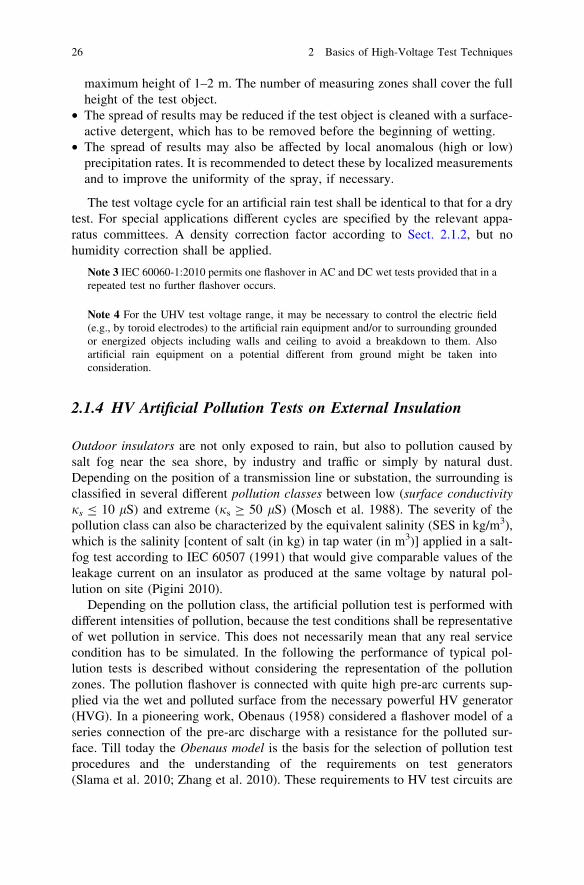
2.1.4 HV Artificial Pollution Tests on External Insulation
Outdoor insulators are not only exposed to rain, but also to pollution caused bysalt fog near the sea shore, by industry and traffic or simply by natural dust.Depending on the position of a transmission line or substation, the surrounding isclassified in several different pollution classes between low (surface conductivityjs B 10 lS) and extreme (js C 50 lS) (Mosch et al. 1988). The severity of thepollution class can also be characterized by the equivalent salinity (SES in kg/m3),which is the salinity [content of salt (in kg) in tap water (in m3)] applied in a salt-fog test according to IEC 60507 (1991) that would give comparable values of theleakage current on an insulator as produced at the same voltage by natural pol-lution on site (Pigini 2010).
Depending on the pollution class, the artificial pollution test is performed withdifferent intensities of pollution, because the test conditions shall be representativeof wet pollution in service. This does not necessarily mean that any real servicecondition has to be simulated. In the following the performance of typical pol-lution tests is described without considering the representation of the pollutionzones. The pollution flashover is connected with quite high pre-arc currents sup-plied via the wet and polluted surface from the necessary powerful HV generator(HVG). In a pioneering work, Obenaus (1958) considered a flashover model of aseries connection of the pre-arc discharge with a resistance for the polluted sur-face. Till today the Obenaus model is the basis for the selection of pollution testprocedures and the understanding of the requirements on test generators(Slama et al. 2010; Zhang et al. 2010). These requirements to HV test circuits are
26 2 Basics of High-Voltage Test Techniques

considered in the relevant Chaps. 3 and 6–8. Pollution tests of insulators for highaltitudes have to take into consideration not only the pollution class, but also theatmospheric conditions (Jiang et al. 2009).
The test object (insulator) must be cleaned by washing with tap water and thenthe pollution process may start. Typically the pollution test is performed withsubsequent applications of the test voltage which is held constant for a specified testtime of at least several minutes. Within that time very heavy partial discharges, so-called pre-arcs, appear (Fig. 2.4). It may happen that the wet and polluted surfacedries (which means electrically withstand of the tested insulator and passing thetest) or that the pre-arcs are extended to a full flashover (which means failingthe test). Because of the random process of the pollution flashover, remarkabledispersion of the test results can be expected. Consequently the test must berepeated several times to get average values of sufficient confidence or to estimatedistribution functions (see Sect. 2.4). Two pollution procedures shall be described:
The salt-fog method uses a fog from a salt (NaCl) solution in tap water withdefined concentrations between 2.5 and 20 kg/m3 depending on the pollution zone.A spraying equipment generates a number of fog jets each generated by a pair of
Pre-arc appears at the stalk of the insulator (location of highest current density)
Pre-arc extends and bridges the distance between two sheds.
Further extension of the pre-arc leads to bridging of two sheds.
Further extension and combination of pre-arcs causes the flashover of the insulator (final arc).
Fig. 2.4 Phases of apollution flashover of aninsulator (Courtesy of FHZittau, Germany)
2.1 External and Internal Insulations in the Electric Field 27

nozzles. One nozzle supplies about 0.5 l/min of the salt solution, the other one thecompressed air with a pressure of about 700 kPa which directs the fog jet to thetest object. The spraying equipment contains usually two rows of the describeddouble nozzles. The test object is wetted before the test. The test starts with theapplication of the fog and the test voltage value which should be reached—but notovertaken—as fast as possible. The whole test may last up to 1 h.
The pre-deposit method is based on coating the test object with a conductivesuspension of Kieselgur or Kaolin or Tonoko in water (&40 g/l). The conductivityof the suspension is adjusted by salt (NaCl). The coating of the test object is madeby dipping, spraying or flow-coating. Then it is dried and should become inthermal equilibrium with the ambient conditions in the pollution chamber. Finallythe test object is wetted by a steam-fog equipment (steam temperature B 40 �C).The surface condition is described by the surface conductivity (lS) measured fromthe current at two probes on the surface (IEC 60-1:1989, Annex B.3) or by theequivalent amount of salt per square centimetre of the insulating surface [so-calledsalt deposit density (S.D.D.) in mg/cm2]. The test can start with voltage applicationbefore the test object is wetted, or after wetting, when the conductivity has reachedits maximum. Details depend on the aim of the test, see IEC 60507:1991.
Both described procedures can be performed with different aim of the pollutiontest:
• determination of the withstand voltage for a certain insulator of specified degreeof pollution and a specified test time,
• determination of the maximum degree of pollution for a certain insulator at aspecified test voltage and specified test time.
Pollution tests require separate pollution chambers, usually with bushings forthe connection of the test voltage generator. Because of the salt fog and humidity,the HV test system itself is outside under clean conditions. Inside a salt-fogchamber, the clearances around the test object should be C0.5 m/100 kV but notless than 2 m. When no pollution chamber is available, also tents from plastic foilmay be applied, to separate the pollution area from the other areas of a HVlaboratory.
2.1.5 HV Tests on Internal Insulation
In a HV test field, the HV components of test systems are designed with anexternal indoor insulation usually. When internal insulation shall be tested, the testvoltage must be connected to the internal part of the apparatus to be tested. This isusually done by bushings which have an external insulation. For reasons of theinsulation co-ordination or of the atmospheric corrections, cases will arise that theHV withstand test level of the internal insulation exceeds that of the externalinsulation (bushing). Then the withstand level of the bushing must be enhanced topermit application of the required test voltages for the internal insulation. Usually
28 2 Basics of High-Voltage Test Techniques