*Basic Radio Physics - SANOG
199
lBasic Radio Physics Network Startup Resource Center www.nsrc.org These materials are licensed under the Creative Commons Attribution-NonCommercial 4.0 International license (http://creativecommons.org/licenses/by-nc/4.0/) Original Slides: Sebastian Büttrich, NSRC/ITU/wire.less.dk Edit: June 2012
-
Upload
khangminh22 -
Category
Documents
-
view
0 -
download
0
Transcript of *Basic Radio Physics - SANOG
lBasic Radio Physics
Network Startup Resource Centerwww.nsrc.org
These materials are licensed under the Creative Commons Attribution-NonCommercial 4.0 International license(http://creativecommons.org/licenses/by-nc/4.0/)Original Slides: Sebastian Büttrich, NSRC/ITU/wire.less.dk Edit: June 2012
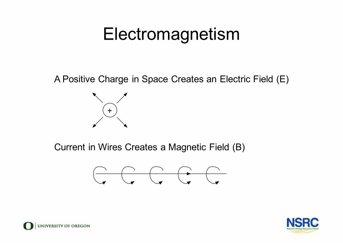
Electromagnetism
§ A Positive Charge in Space Creates an Electric Field (E)
§ Current in Wires Creates a Magnetic Field (B)
+
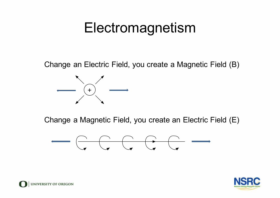
Electromagnetism
§ Change an Electric Field, you create a Magnetic Field (B)
§ Change a Magnetic Field, you create an Electric Field (E)
+
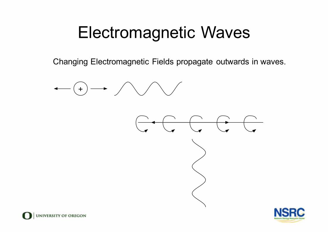
Electromagnetic Wavesl Changing Electromagnetic Fields propagate outwards in waves.
+
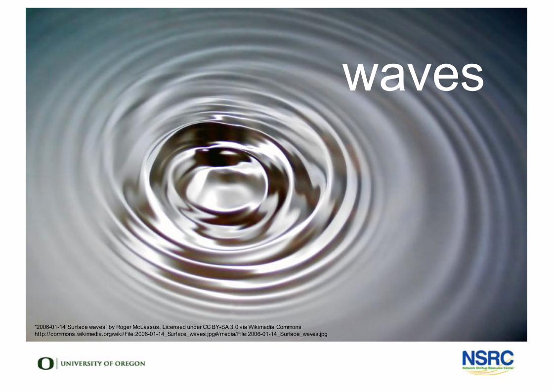
"2006-01-14 Surface waves" by Roger McLassus. Licensed under CC BY-SA 3.0 via Wikimedia Commons http://commons.wikimedia.org/wiki/File:2006-01-14_Surface_waves.jpg#/media/File:2006-01-14_Surface_waves.jpg
waves
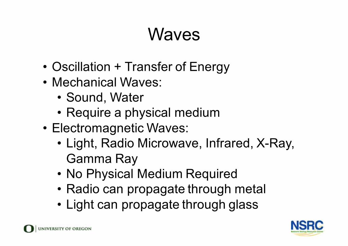
Waves
• Oscillation + Transfer of Energy• Mechanical Waves:
• Sound, Water• Require a physical medium
• Electromagnetic Waves:• Light, Radio Microwave, Infrared, X-Ray,
Gamma Ray• No Physical Medium Required• Radio can propagate through metal• Light can propagate through glass

c = λ * νc is the speed of light (in vacuum) 3×10
8m/s
λ Lambda is the wavelength [m]
ν Nu is the frequency [1/s = Hz]
• Light takes 8 minutes from Sun to Earth• How long does it take to go 100km?• Does it go as fast in a cable?
Electromagnetic Waves
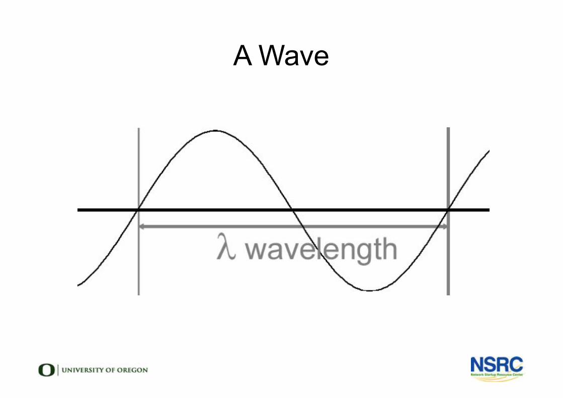
A Wave
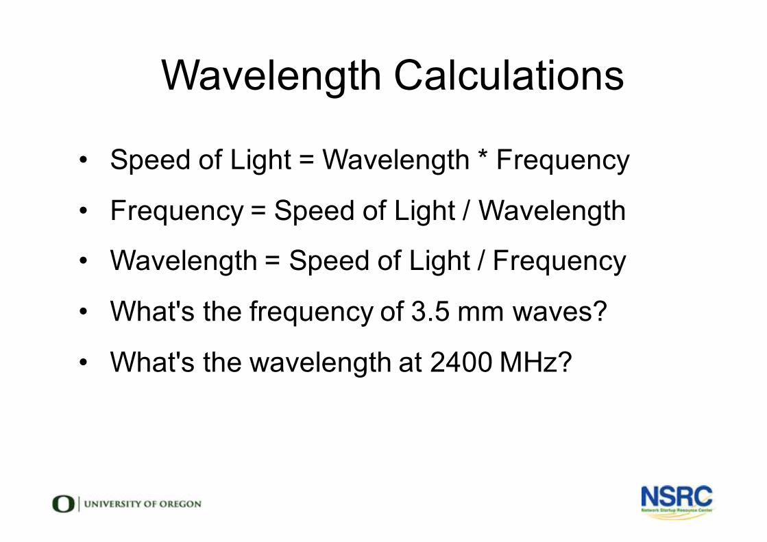
lWavelength Calculations
• Speed of Light = Wavelength * Frequency
• Frequency = Speed of Light / Wavelength
• Wavelength = Speed of Light / Frequency
• What's the frequency of 3.5 mm waves?
• What's the wavelength at 2400 MHz?
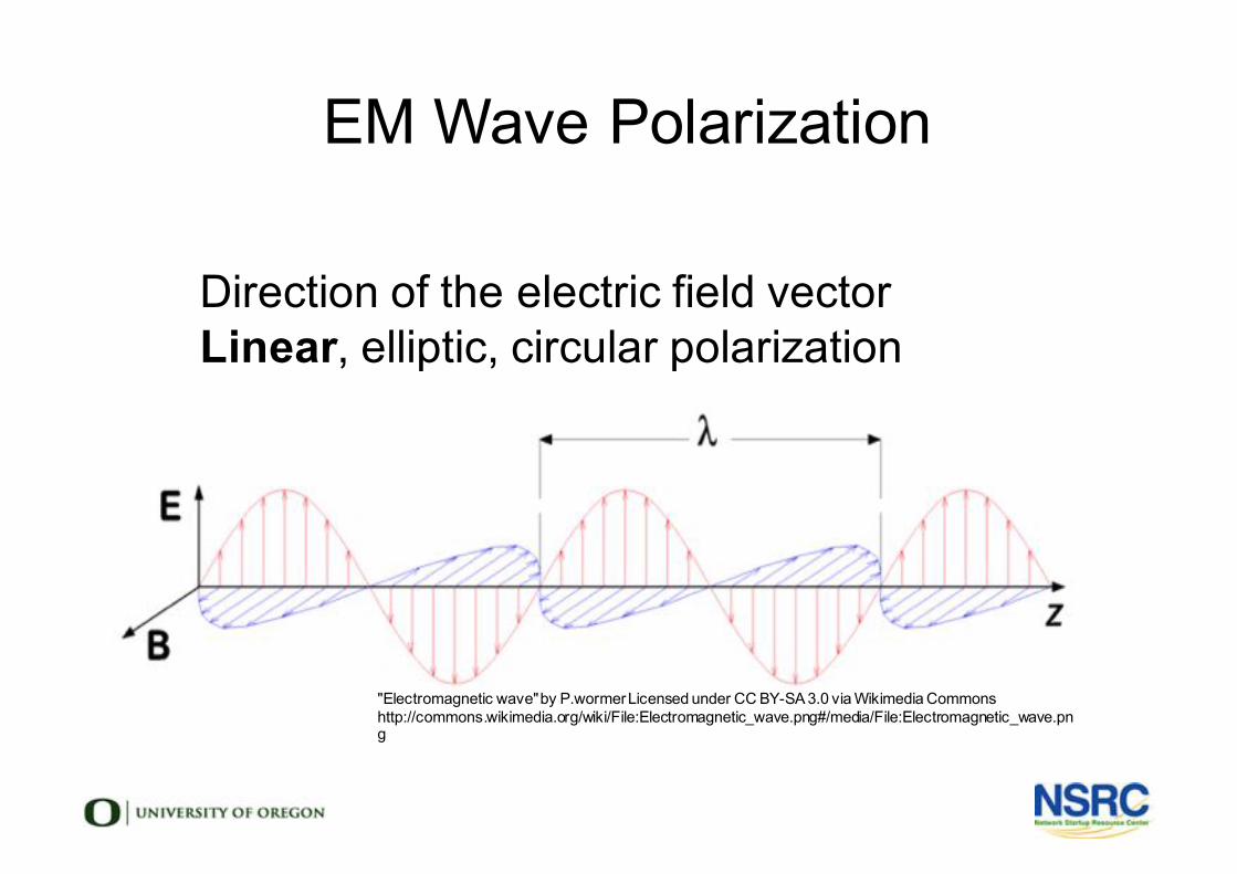
EM Wave Polarization
l Direction of the electric field vectorl Linear, elliptic, circular polarizationl
l
"Electromagnetic wave" by P.wormer Licensed under CC BY-SA 3.0 via Wikimedia Commons http://commons.wikimedia.org/wiki/File:Electromagnetic_wave.png#/media/File:Electromagnetic_wave.png
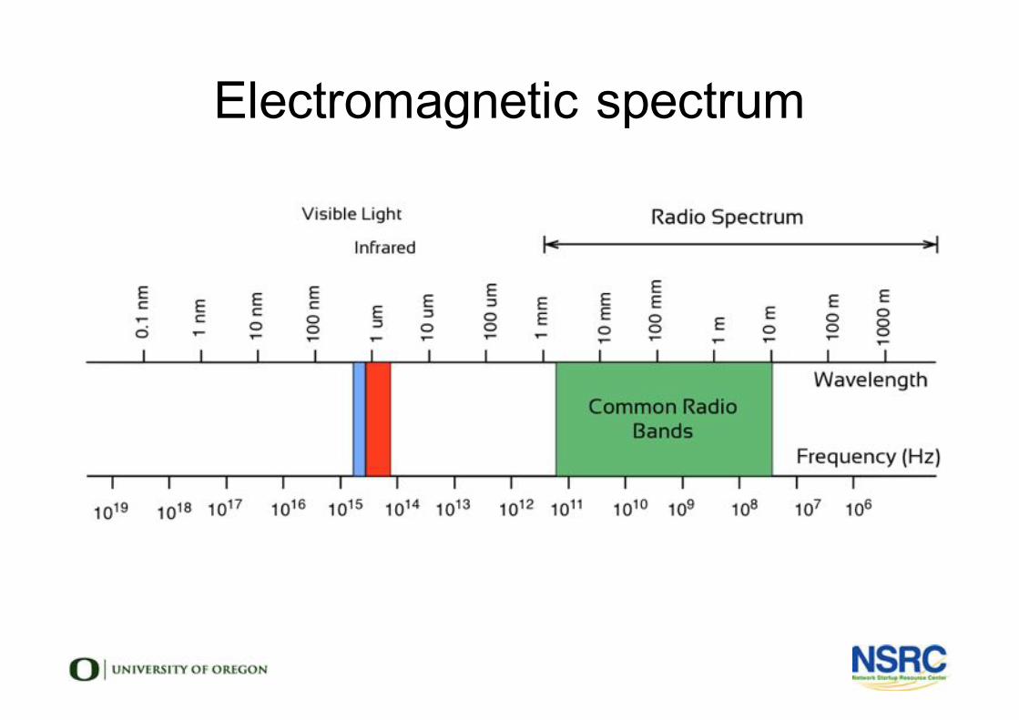
Electromagnetic spectrum
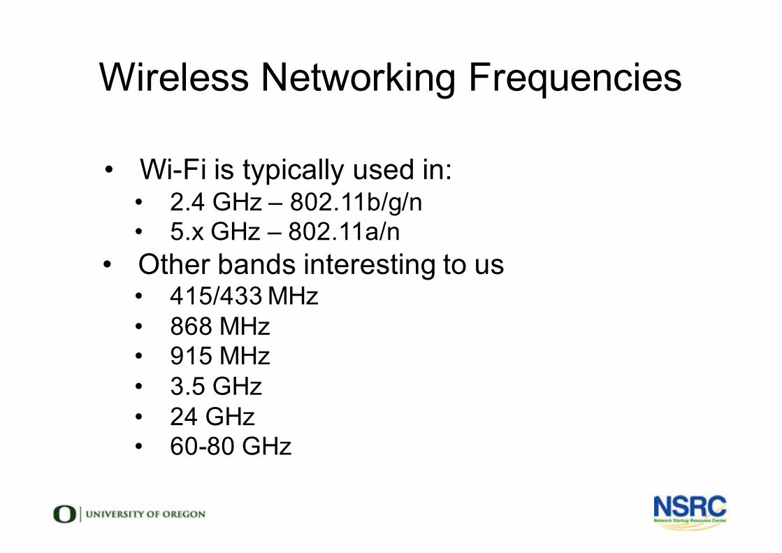
Wireless Networking Frequencies
• Wi-Fi is typically used in:• 2.4 GHz – 802.11b/g/n• 5.x GHz – 802.11a/n
• Other bands interesting to us• 415/433 MHz• 868 MHz• 915 MHz• 3.5 GHz• 24 GHz• 60-80 GHz
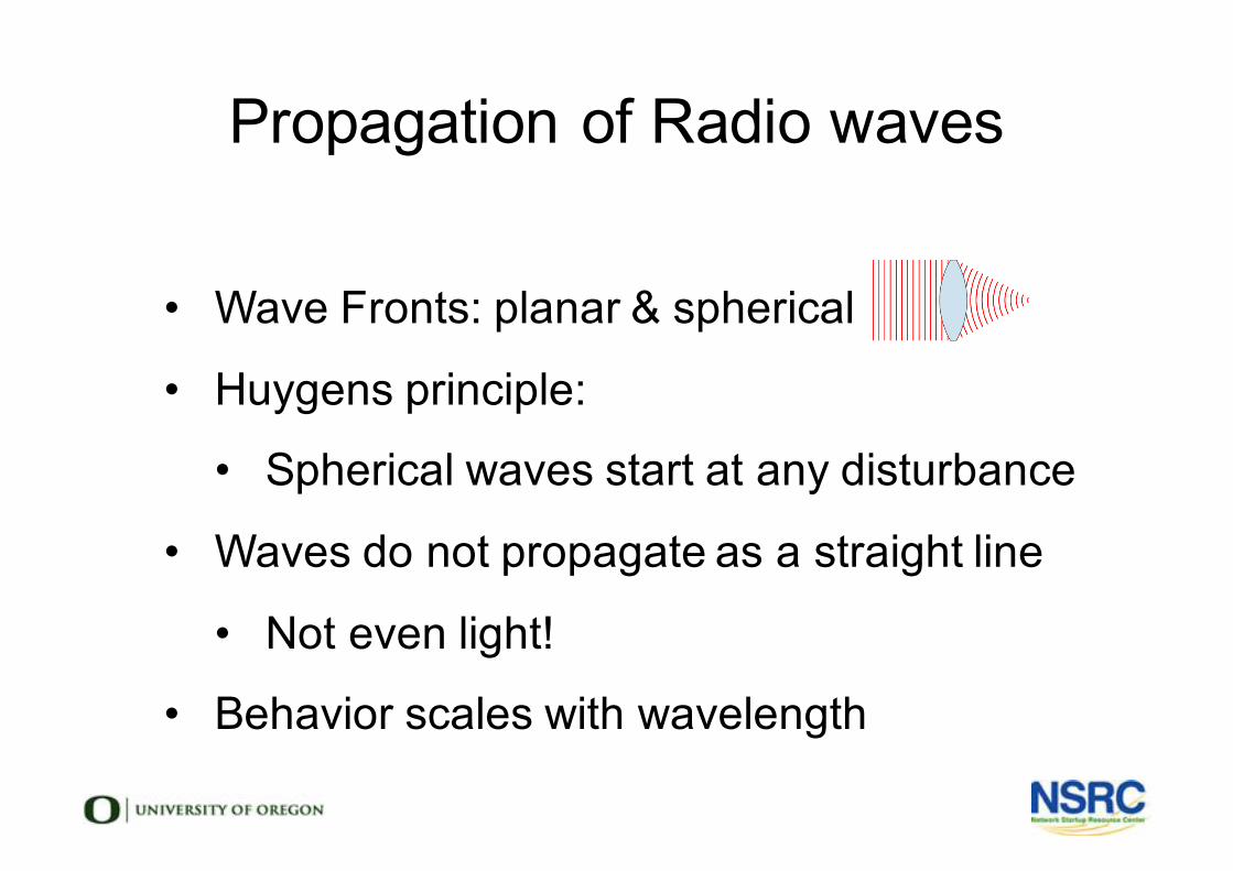
Propagation of Radio waves
• Wave Fronts: planar & spherical
• Huygens principle:
• Spherical waves start at any disturbance
• Waves do not propagate as a straight line
• Not even light!
• Behavior scales with wavelength
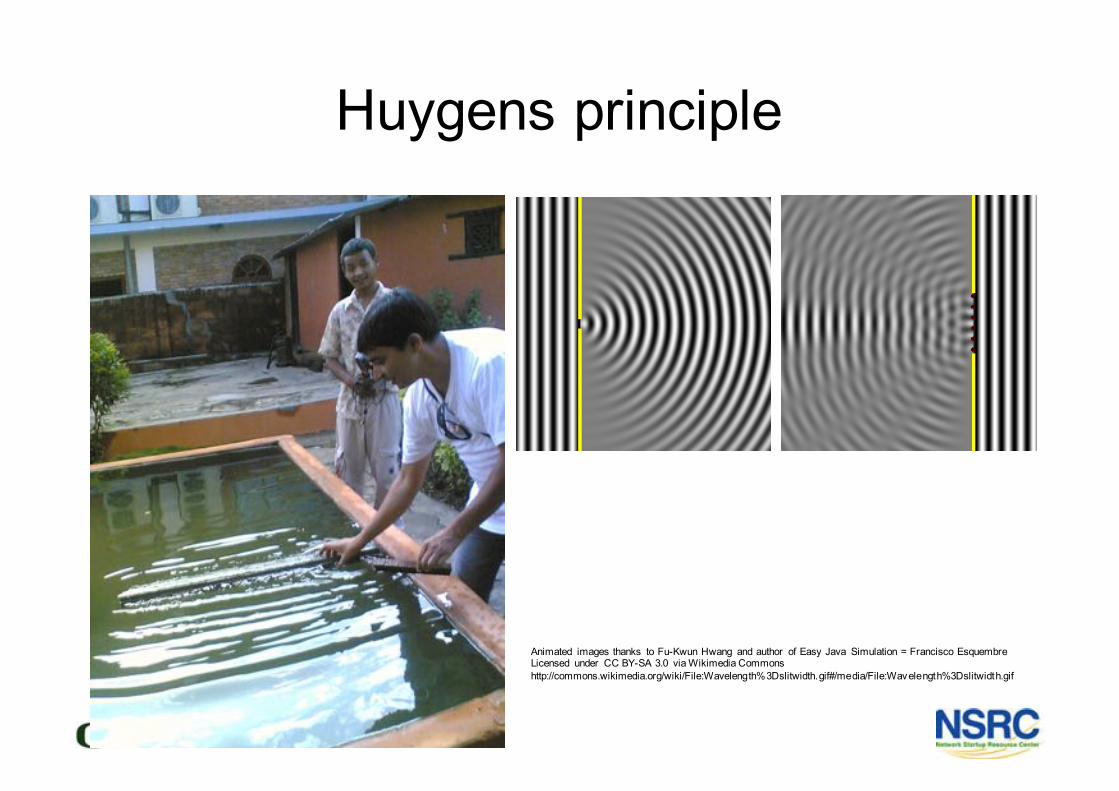
Huygens principle
Animated images thanks to Fu-Kwun Hwang and author of Easy Java Simulation = Francisco EsquembreLicensed under CC BY-SA 3.0 via Wikimedia Commonshttp://commons.wikimedia.org/wiki/File:Wavelength%3Dslitwidth.gif#/media/File:Wavelength%3Dslitwidth.gif
Radio Waves are Affected By
• Absorption
• Reflection
• Diffraction
• Interference
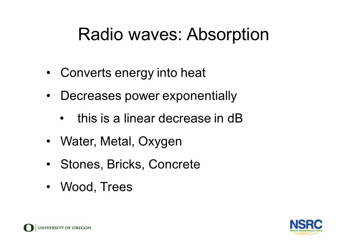
Radio waves: Absorption
• Converts energy into heat
• Decreases power exponentially
• this is a linear decrease in dB
• Water, Metal, Oxygen
• Stones, Bricks, Concrete
• Wood, Trees
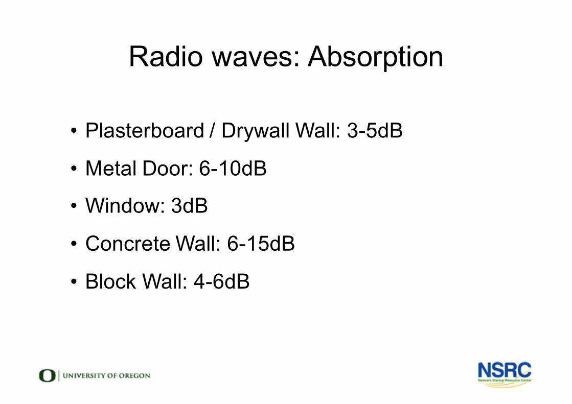
Radio waves: Absorption
• Plasterboard / Drywall Wall: 3-5dB
• Metal Door: 6-10dB
• Window: 3dB
• Concrete Wall: 6-15dB
• Block Wall: 4-6dB
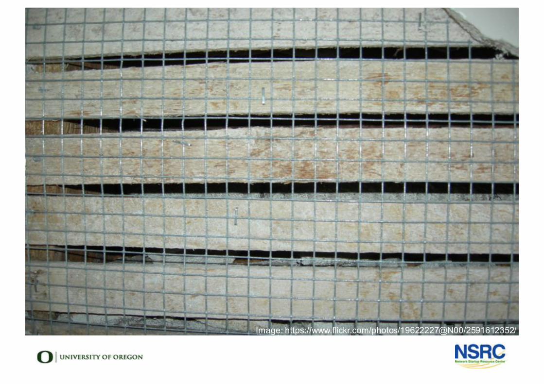
Image: https://www.flickr.com/photos/19622227@N00/2591612352/
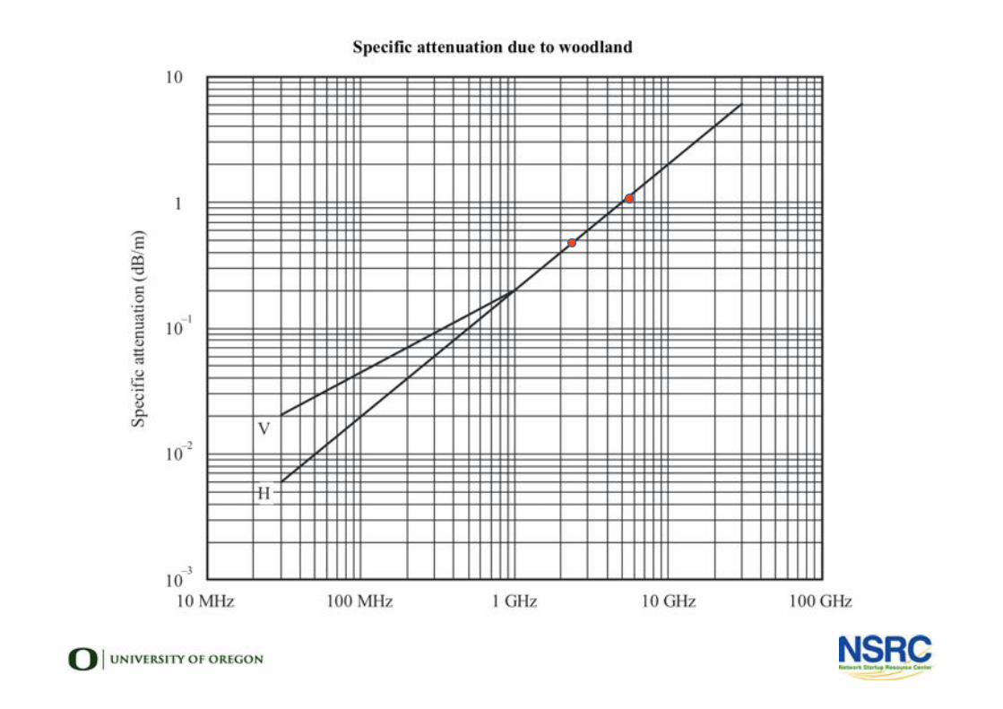
Image: https://www.flickr.com/photos/19622227@N00/2591612352/
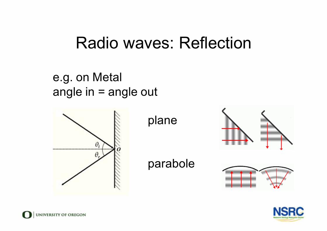
Radio waves: Reflection
l e.g. on Metall angle in = angle outl
l planel
l
l parabole
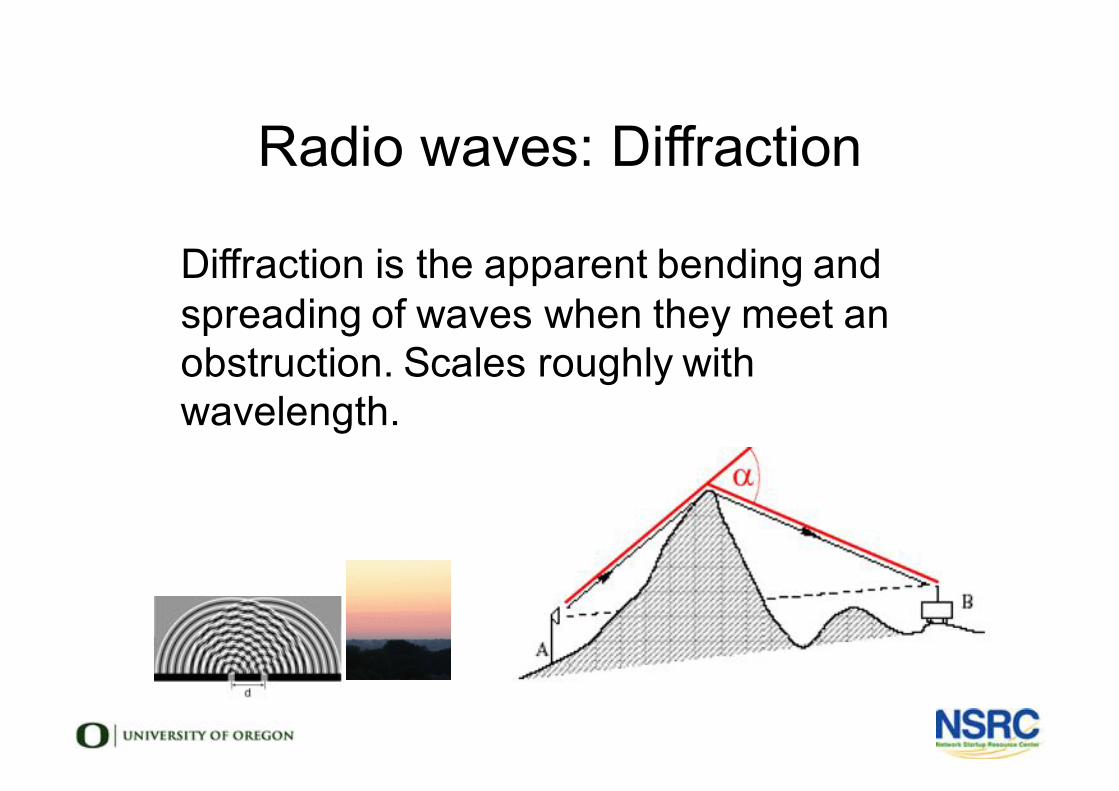
Radio waves: Diffraction
l Diffraction is the apparent bending and spreading of waves when they meet an obstruction. Scales roughly with wavelength.
Radio waves: Interference
l Interference is misunderstoodl Is it really interference?l Or are too lazy to find the real problem?l Maybe we don't care!
Two Meanings of Interference
• Physicists View:• The behavior of waves
• Engineer's View:• Noise that causes problems
• Both are important for Wireless• In different ways!
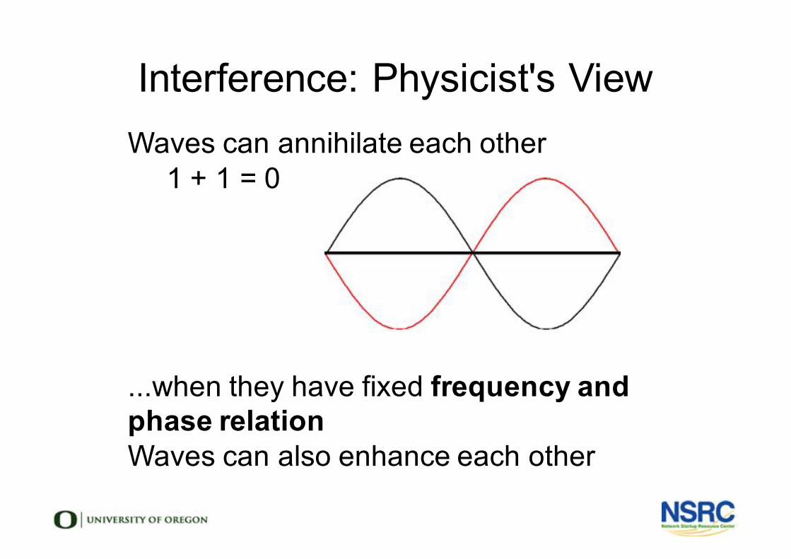
Interference: Physicist's Viewl Waves can annihilate each other
- 1 + 1 = 0-
-
-
-
-
l ...when they have fixed frequency and phase relation
l Waves can also enhance each otherl

Interference: an Experiment
• Take two laser pointers – one green, one red
• Cross the beams – will one change the other?
• Point them in the same direction, will one change the other?
• If you give signals with them, both in the same direction,
would you be able to read them?
• Now use two lasers of the same color – what happens?
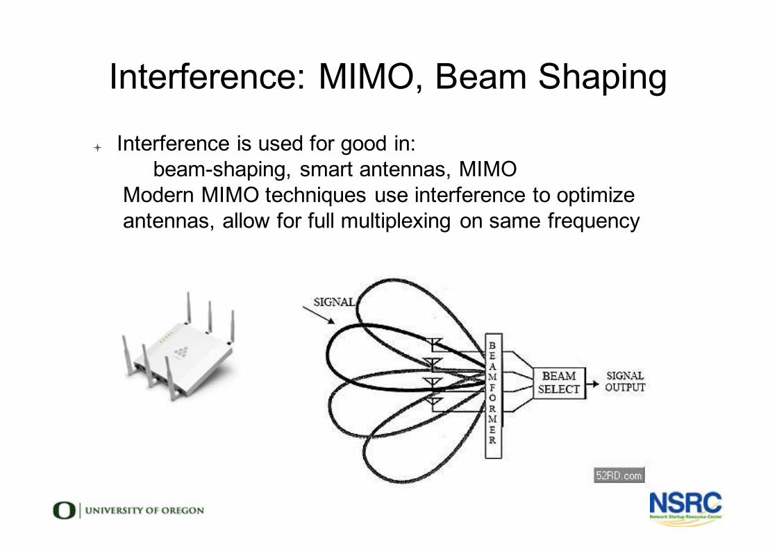
Interference: MIMO, Beam Shaping
l Interference is used for good in:- beam-shaping, smart antennas, MIMO
l Modern MIMO techniques use interference to optimize antennas, allow for full multiplexing on same frequency
l

MU-MIMO, Dynamic Beam Shaping
l In multi-antenna arrays, possibilities are virtually unlimitedl Fast processors use interference for good
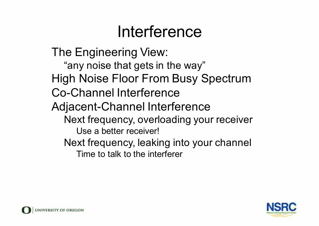
Interferencel The Engineering View:
- “any noise that gets in the way”l High Noise Floor From Busy Spectruml Co-Channel Interferencel Adjacent-Channel Interference
-Next frequency, overloading your receiverl Use a better receiver!
-Next frequency, leaking into your channell Time to talk to the interferer
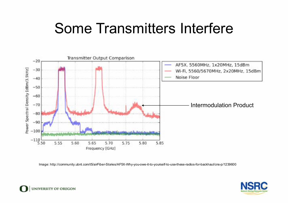
Some Transmitters Interfere
Image: http://community.ubnt.com/t5/airFiber-Stories/AF5X-Why-you-owe-it-to-yourself-to-use-these-radios-for-backhaul/cns-p/1239600
Intermodulation Product
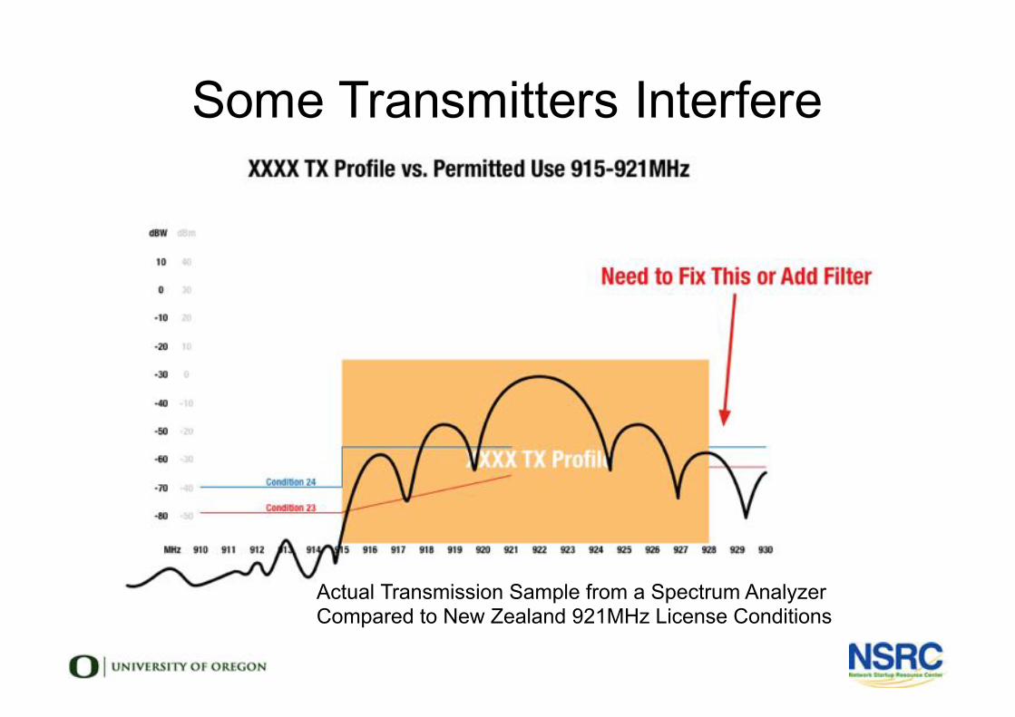
Some Transmitters Interfere
Actual Transmission Sample from a Spectrum AnalyzerCompared to New Zealand 921MHz License Conditions
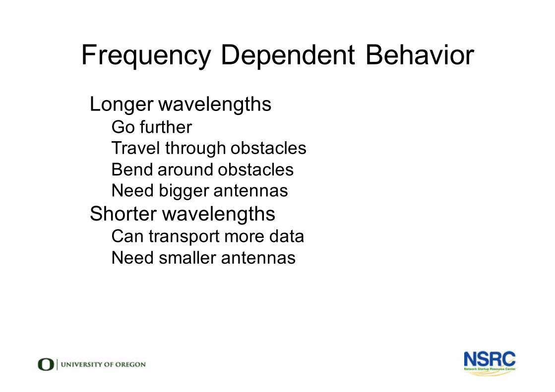
Frequency Dependent Behaviorl Longer wavelengths
-Go further-Travel through obstacles-Bend around obstacles -Need bigger antennas
l Shorter wavelengths-Can transport more data-Need smaller antennas
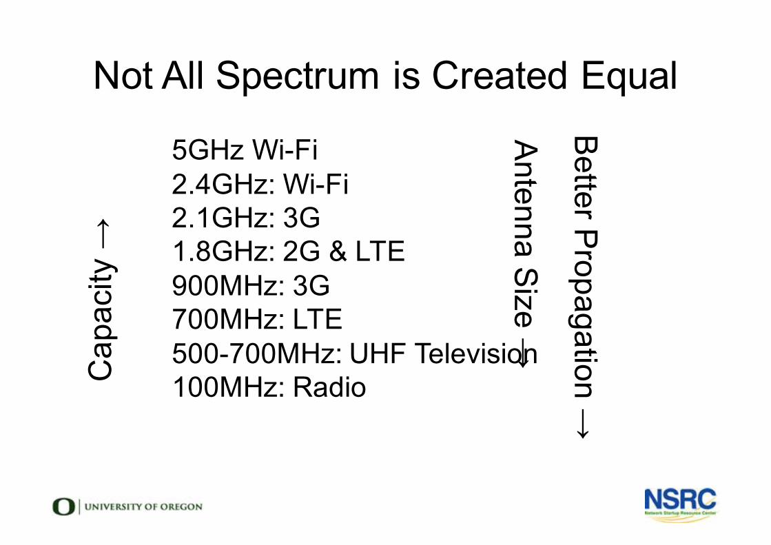
Not All Spectrum is Created Equal
l 5GHz Wi-Fil 2.4GHz: Wi-Fil 2.1GHz: 3Gl 1.8GHz: 2G & LTEl 900MHz: 3Gl 700MHz: LTEl 500-700MHz: UHF Televisionl 100MHz: Radio
Antenna Size →
Better Propagation →
Cap
acity
→
Radio Propagation in Free Space
l Free space lossl Fresnel zonesl Line of Sight
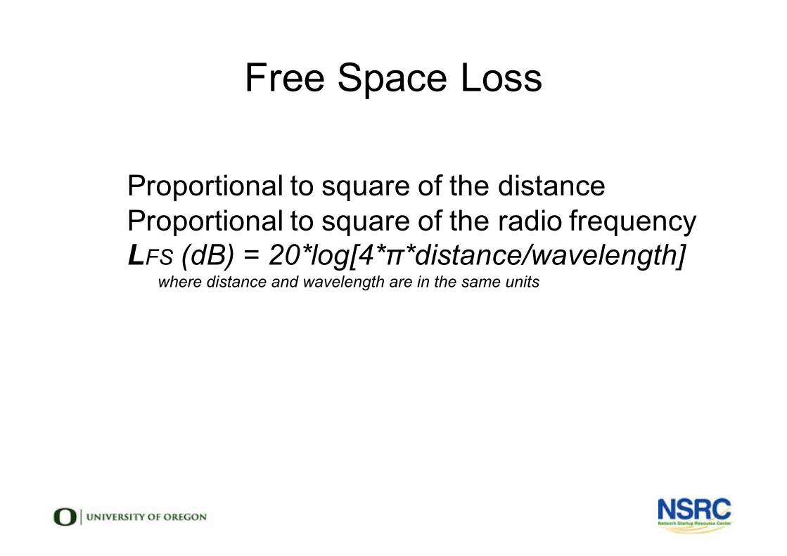
Free Space Loss
l Proportional to square of the distancel Proportional to square of the radio frequencyl LFS (dB) = 20*log[4*π*distance/wavelength]
- where distance and wavelength are in the same units
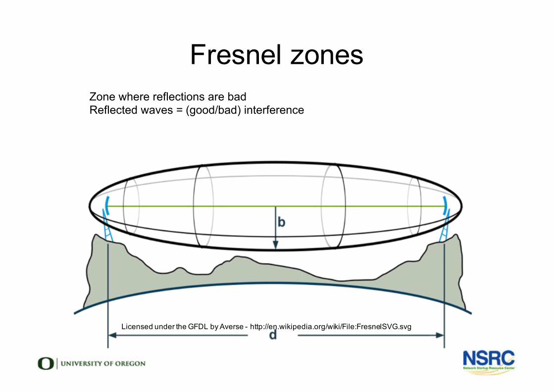
Fresnel zones
Licensed under the GFDL by Averse - http://en.wikipedia.org/wiki/File:FresnelSVG.svg
l Zone where reflections are badl Reflected waves = (good/bad) interference
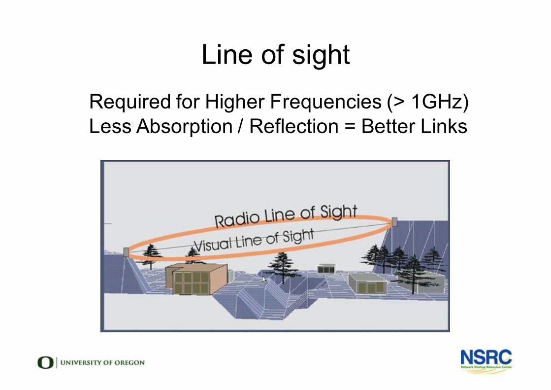
Line of sightl Required for Higher Frequencies (> 1GHz)l Less Absorption / Reflection = Better Links
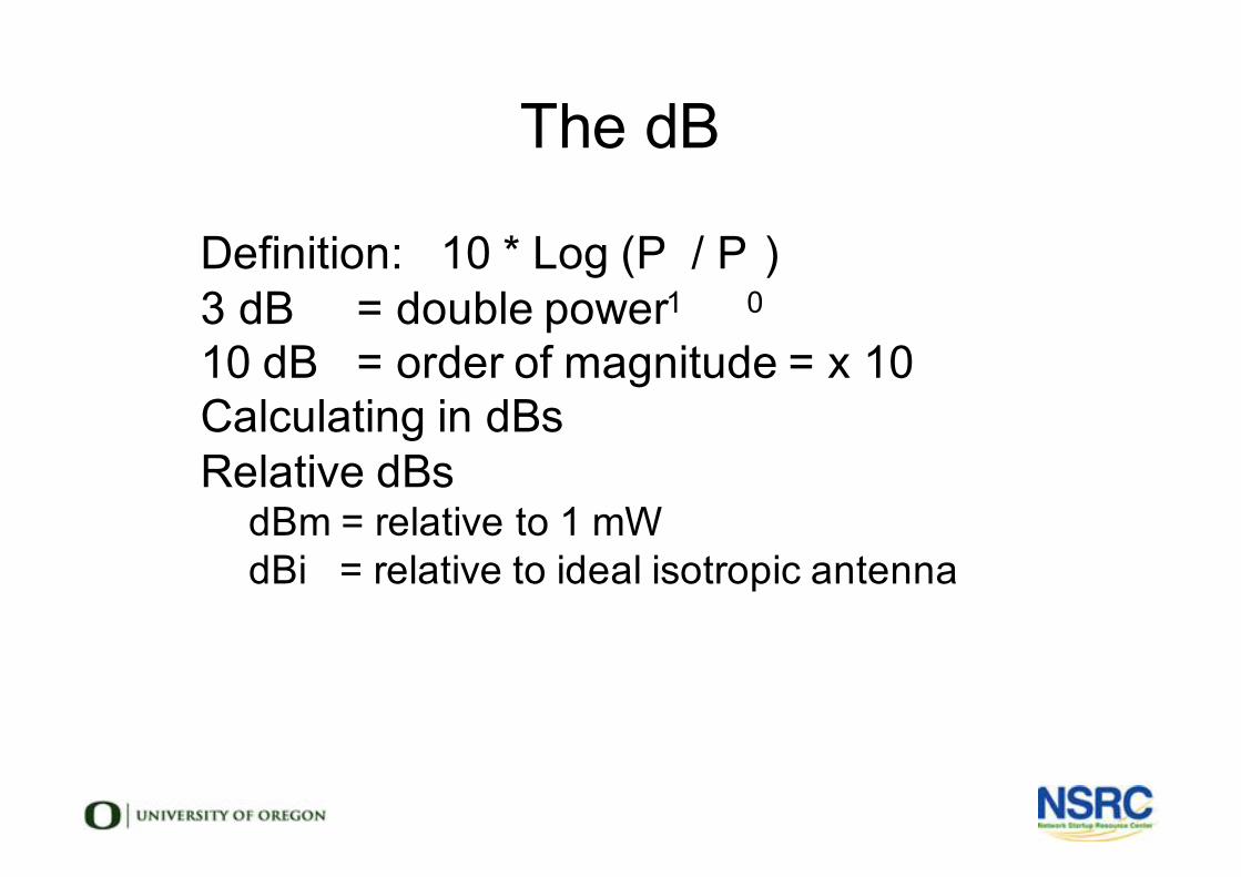
The dB
l Definition: 10 * Log (P1
/ P0)
l 3 dB = double powerl 10 dB = order of magnitude = x 10l Calculating in dBsl Relative dBs
-dBm = relative to 1 mW-dBi = relative to ideal isotropic antenna
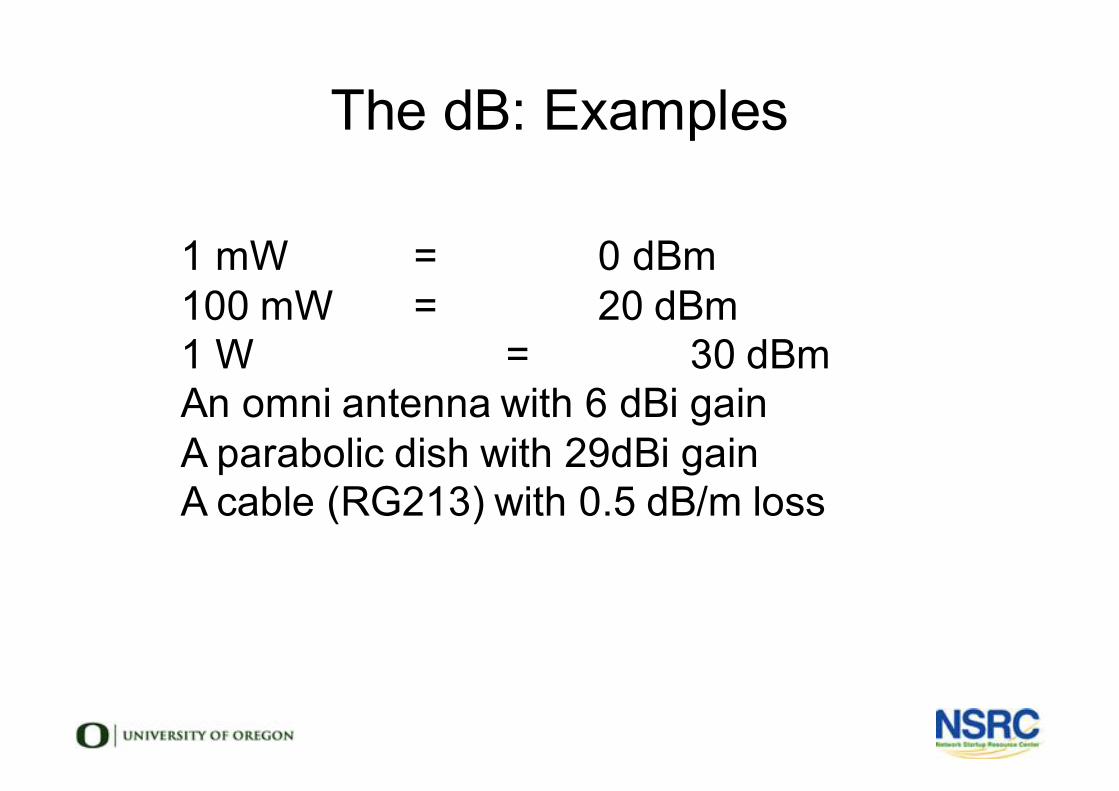
The dB: Examples
l 1 mW = 0 dBml 100 mW = 20 dBml 1 W = 30 dBml An omni antenna with 6 dBi gainl A parabolic dish with 29dBi gainl A cable (RG213) with 0.5 dB/m loss
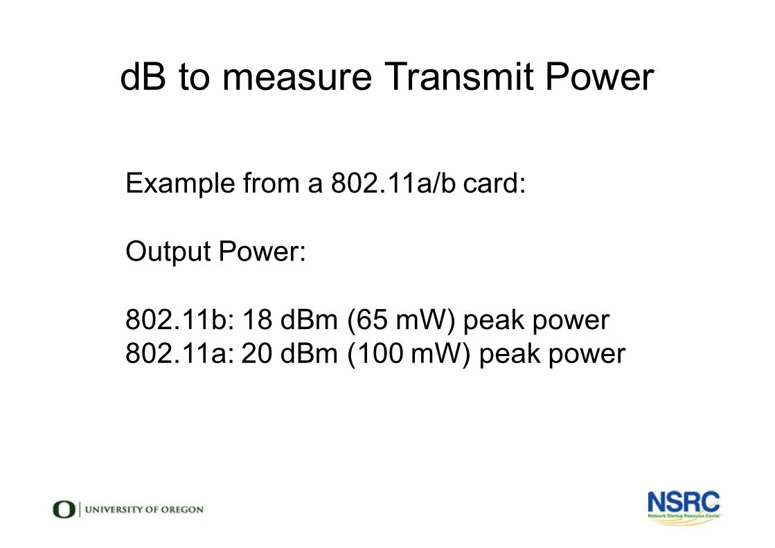
dB to measure Transmit Power
l Example from a 802.11a/b card:l
l Output Power: l
l 802.11b: 18 dBm (65 mW) peak power 802.11a: 20 dBm (100 mW) peak power
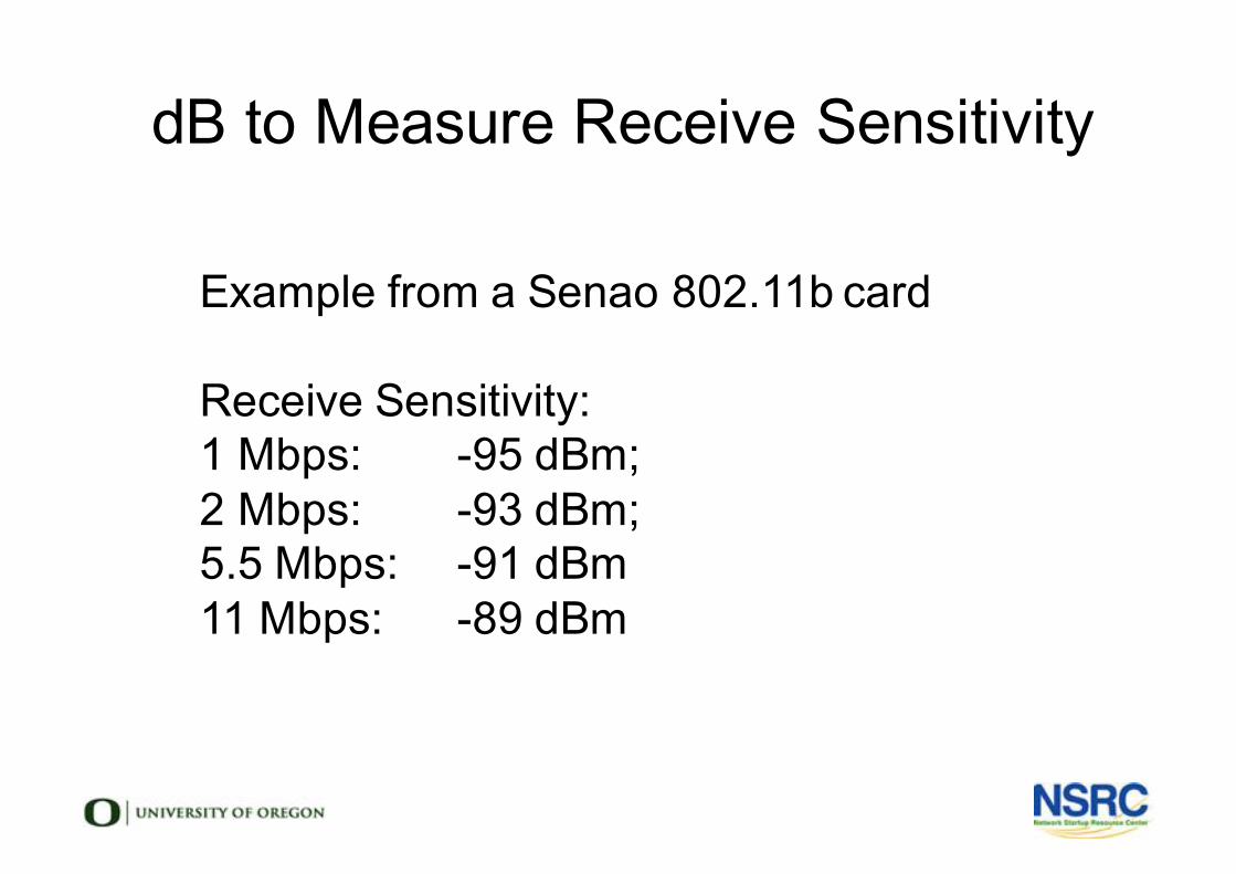
dB to Measure Receive Sensitivity
l Example from a Senao 802.11b cardl
l Receive Sensitivity: l 1 Mbps: -95 dBm; l 2 Mbps: -93 dBm; l 5.5 Mbps: -91 dBml 11 Mbps: -89 dBm
Radio Physics Matter
l Always! ... and especially ... l when an AP or 3G modem is under a desk
-or in a metal cabinet.l when winter turns to springtimel when it is rush hour in the cityl with long distance links (speed of light!)
Examples: Office network
l Offices typically have massive multi-path conditions cause by reflections
l Reflections: metal infrastructure (computers, radiators, desks, even CDs!)
l Absorbtion: from People, Plants, Booksl Choice of locations and antennas essential
Changing Seasons: Absorption
l Vegetation, humidity, rain and change with the seasons!
l Dry trees might be radio transparentl Wet green trees are not radio transparent
Rush Hour: Reflection/Diffractionl Urban conditions change with the dayl They change with the hour
-People, Vans, Cars-Electromagnetic Interference (Noise Floor)
l Test Monday what you measure Sundayl In the Afternoon.... In the Morning
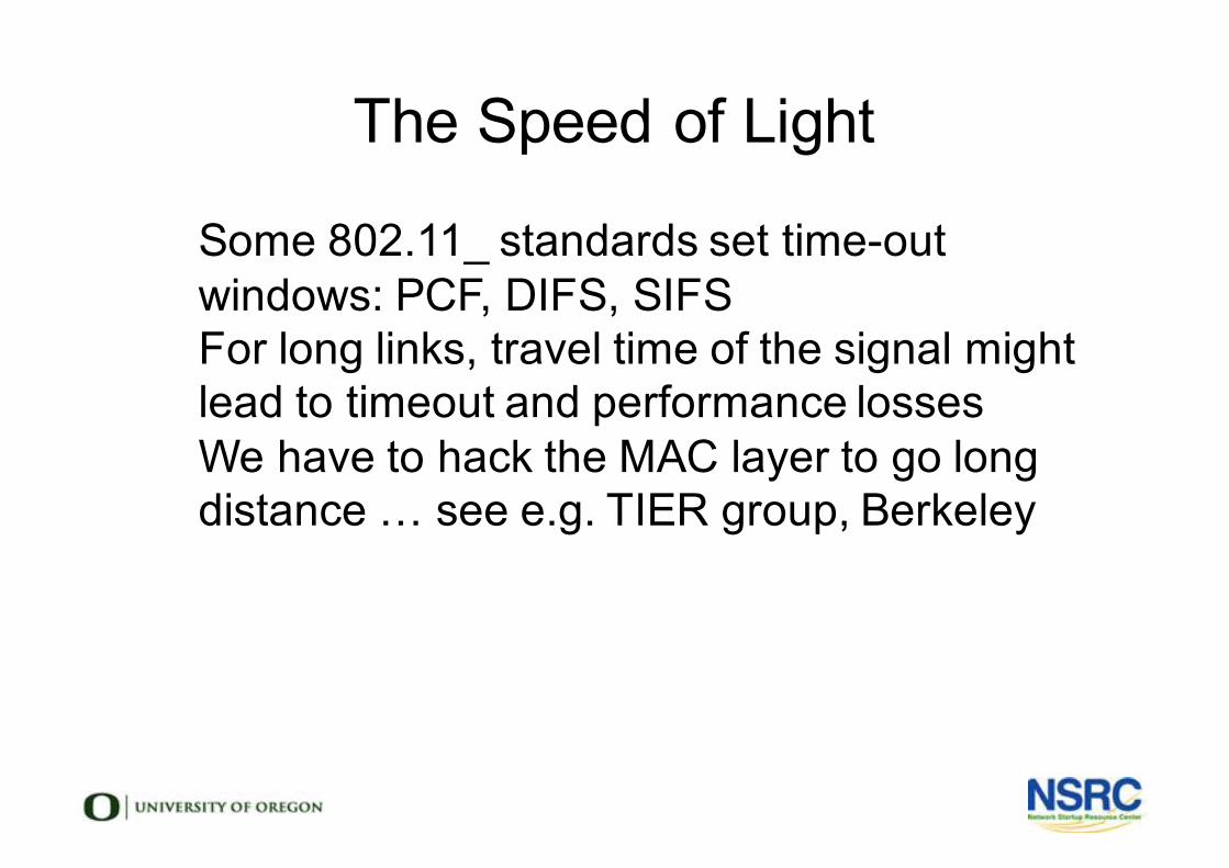
The Speed of Light
l Some 802.11_ standards set time-out windows: PCF, DIFS, SIFS
l For long links, travel time of the signal might lead to timeout and performance losses
l We have to hack the MAC layer to go long distance … see e.g. TIER group, Berkeley
lAntennas & Transmission Lines
Network Startup Resource Centerwww.nsrc.org
These materials are licensed under the Creative Commons Attribution-NonCommercial 4.0 International license(http://creativecommons.org/licenses/by-nc/4.0/)
Objectives
• This unit will help you to understand• How an antenna works
• How to read a radiation pattern
• How to choose the right antenna
• How transmission lines work
• How to choose the right transmission line
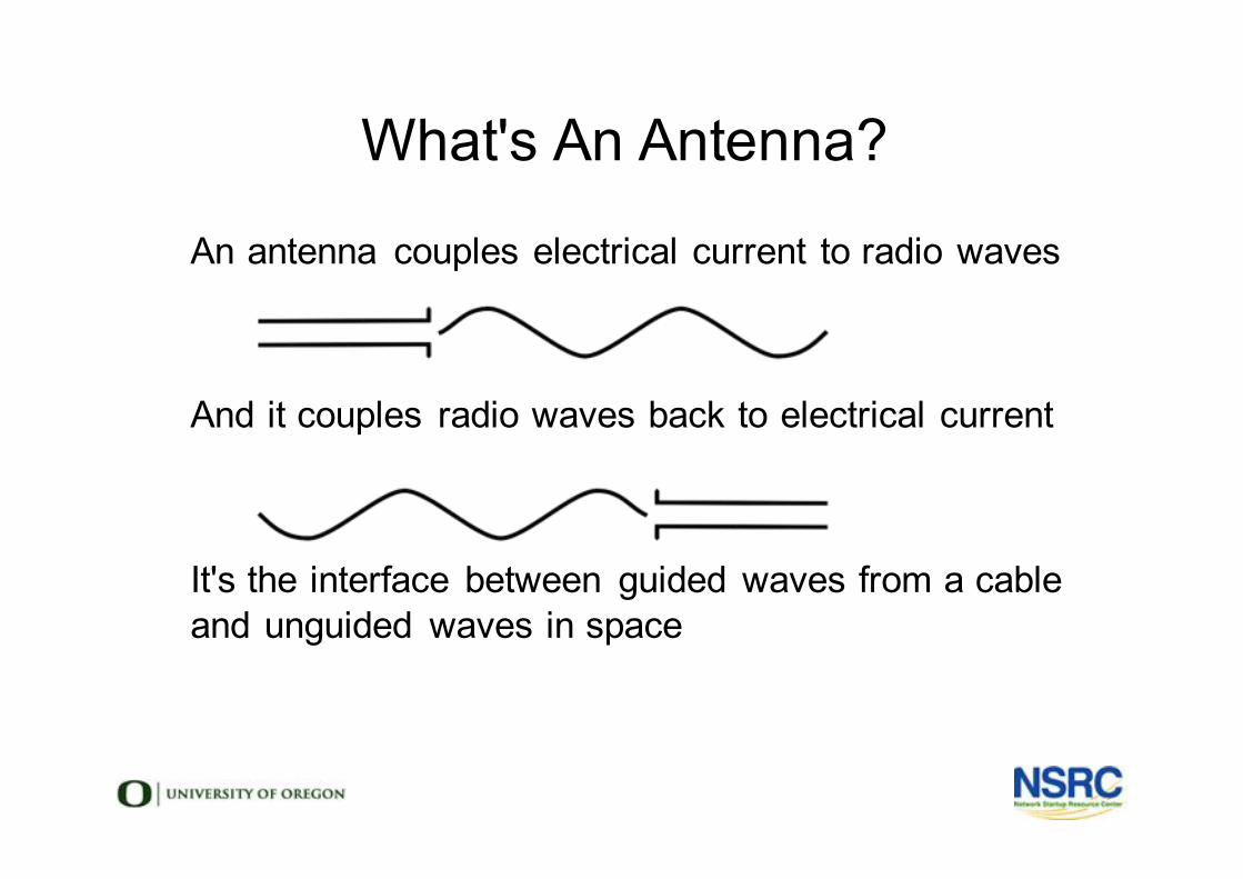
l An antenna couples electrical current to radio wavesl
l
l And it couples radio waves back to electrical currentl
l
l It's the interface between guided waves from a cablel and unguided waves in spacel
l
What's An Antenna?
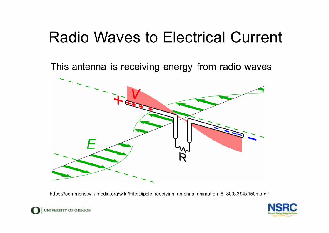
l This antenna is receiving energy from radio wavesl
Radio Waves to Electrical Current
https://commons.wikimedia.org/wiki/File:Dipole_receiving_antenna_animation_6_800x394x150ms.gif
General Antenna Properties• Directivity
• Gain, shown by Radiation Patterns
• Beamwidth, Lobes, Sidelobes, Nulls
• Front to Back Ratios
• Polarization
• Center Frequency
• Bandwidth (How far ⬆ & ⬇ below center Frequency?)
• Physical Size
• Impedance & Return Loss
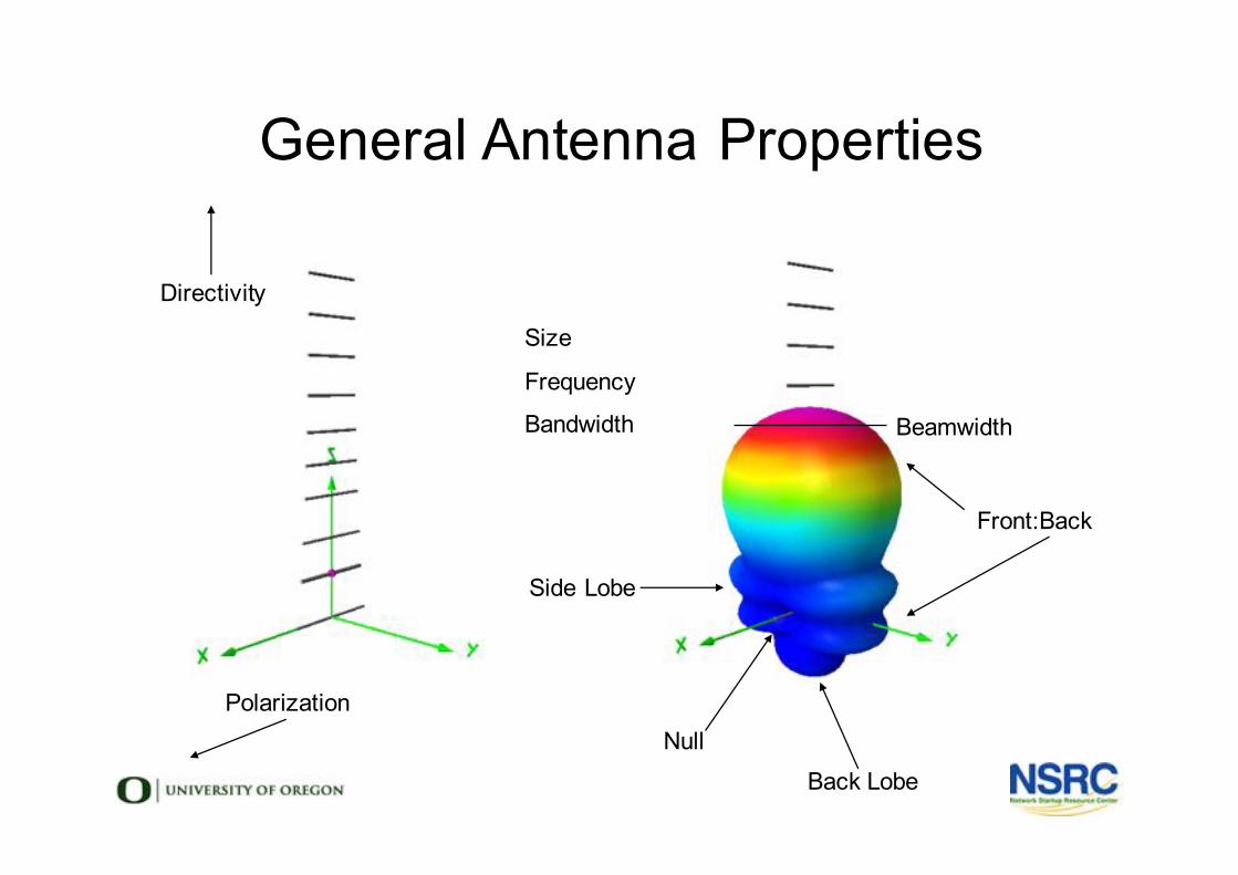
General Antenna Properties
Polarization
Directivity
Beamwidth
Side Lobe
Null
Front:Back
Back Lobe
l Size
l Frequency
l Bandwidth
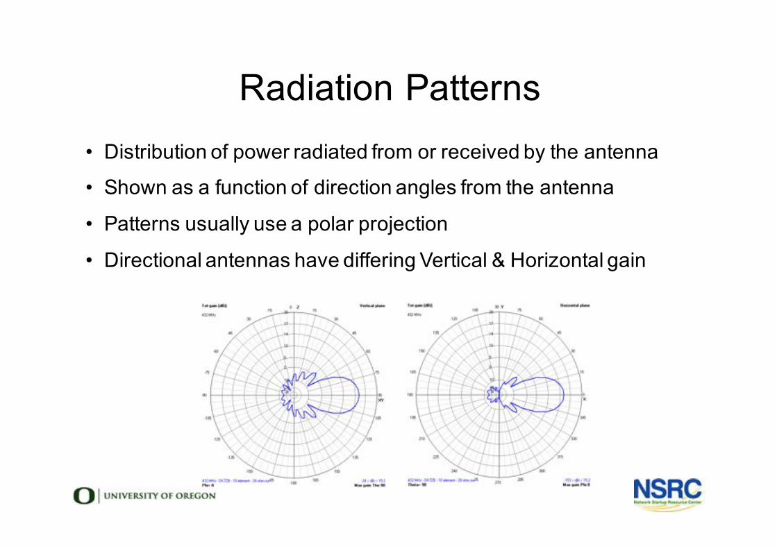
Radiation Patterns• Distribution of power radiated from or received by the antenna
• Shown as a function of direction angles from the antenna
• Patterns usually use a polar projection
• Directional antennas have differing Vertical & Horizontal gain
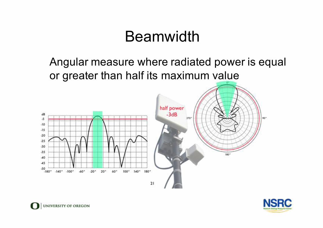
Beamwidthl Angular measure where radiated power is equal
or greater than half its maximum value
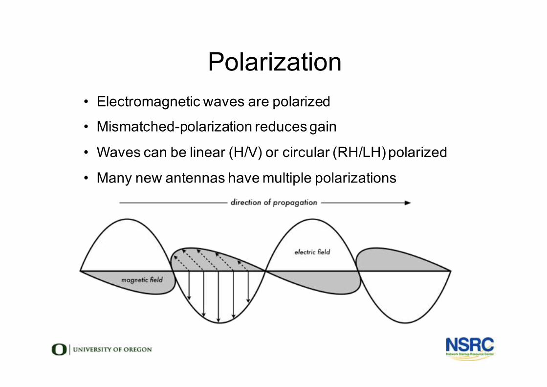
Polarization• Electromagnetic waves are polarized
• Mismatched-polarization reduces gain
• Waves can be linear (H/V) or circular (RH/LH) polarized
• Many new antennas have multiple polarizations
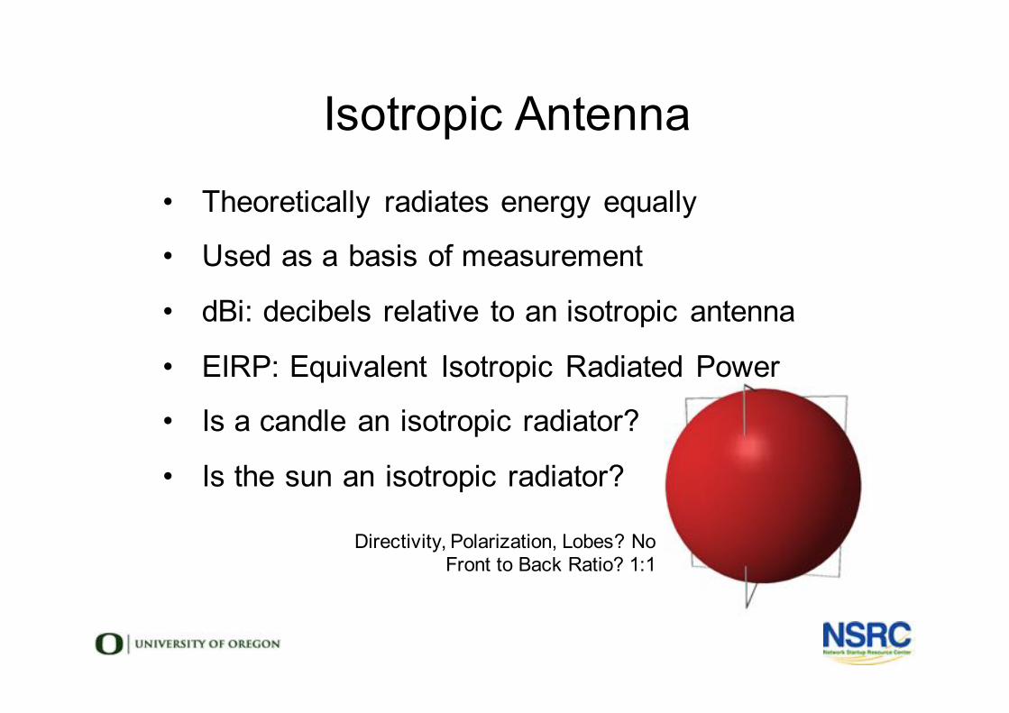
Isotropic Antenna
Directivity, Polarization, Lobes? NoFront to Back Ratio? 1:1
• Theoretically radiates energy equally
• Used as a basis of measurement
• dBi: decibels relative to an isotropic antenna
• EIRP: Equivalent Isotropic Radiated Power
• Is a candle an isotropic radiator?
• Is the sun an isotropic radiator?
Loop Antenna• Discovered in the 1830s by Michael Faraday
• to detect magnetic waves
• Used by Hertz to detect radio waves in 1887
• Small Loops (1/10 λ) receive magnetic waves
• Large Loops (1 λ) act like a folded dipole
• Loops are directional, not isotropic
• Small Loops have very low gain
• Do you have any Loop Antennas with you?
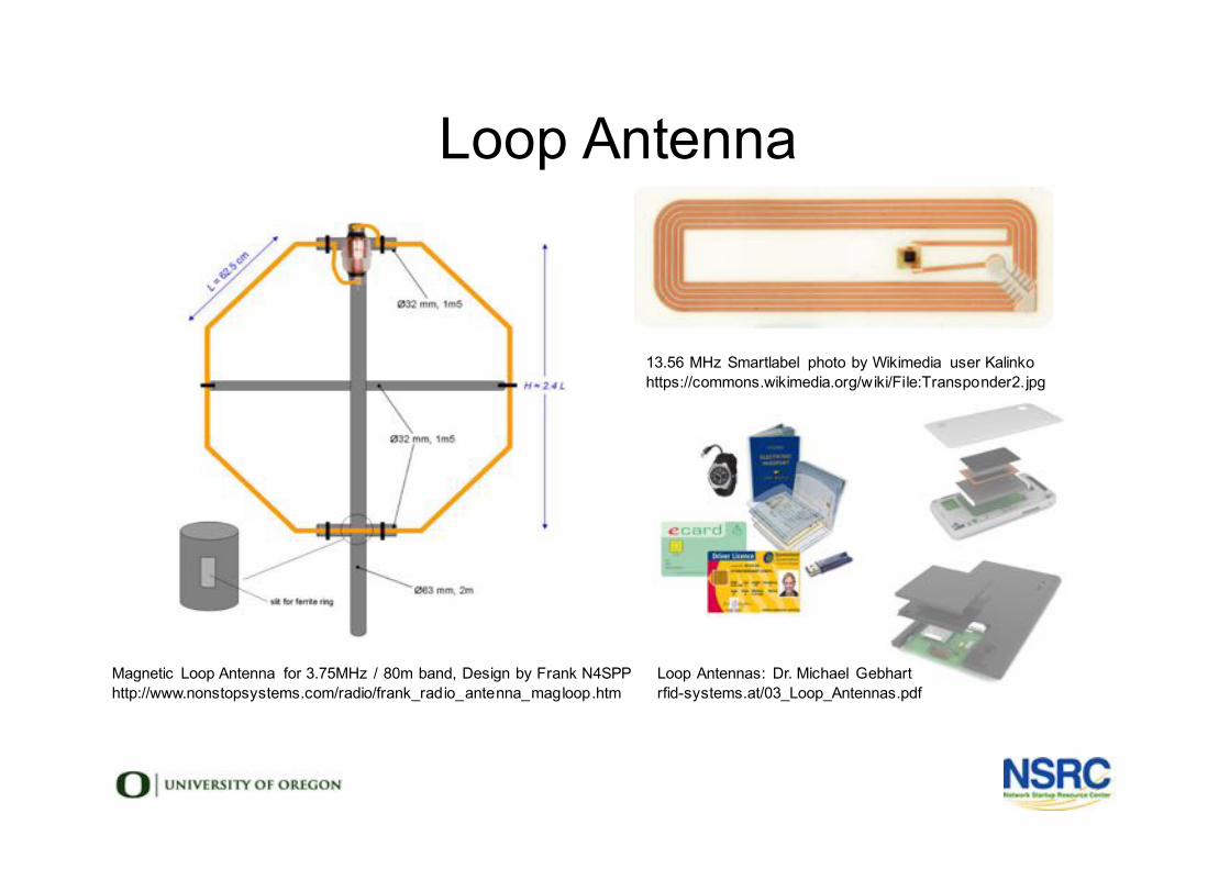
Magnetic Loop Antenna for 3.75MHz / 80m band, Design by Frank N4SPPhttp://www.nonstopsystems.com/radio/frank_radio_antenna_magloop.htm
Loop Antenna
13.56 MHz Smartlabel photo by Wikimedia user Kalinkohttps://commons.wikimedia.org/wiki/File:Transponder2.jpg
Loop Antennas: Dr. Michael Gebhartrfid-systems.at/03_Loop_Antennas.pdf
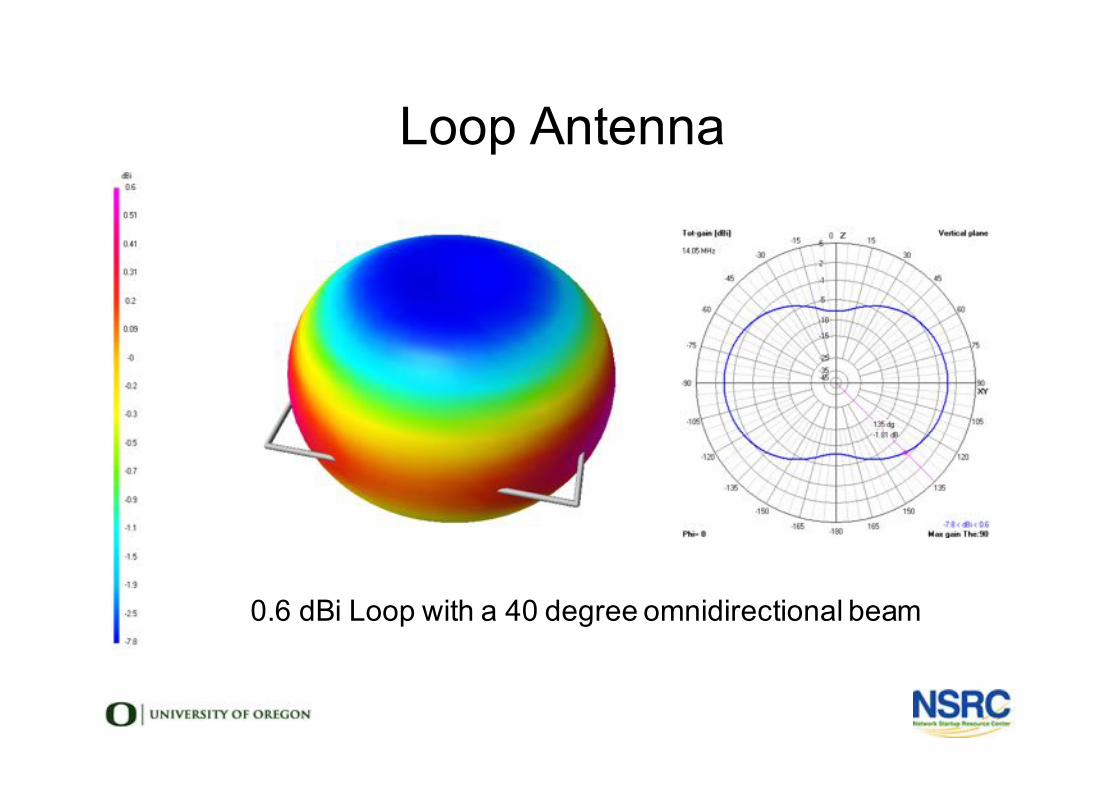
Loop Antenna
0.6 dBi Loop with a 40 degree omnidirectional beam
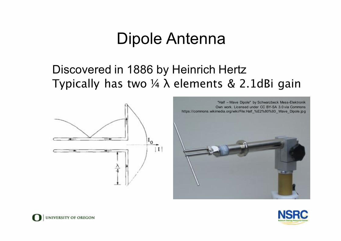
Dipole Antenna
l Discovered in 1886 by Heinrich Hertzl Typically has two ¼ λ elements & 2.1dBi gain
"Half – Wave Dipole" by Schwarzbeck Mess-ElektronikOwn work. Licensed under CC BY-SA 3.0 via Commons
https://commons.wikimedia.org/wiki/File:Half_%E2%80%93_Wave_Dipole.jpg
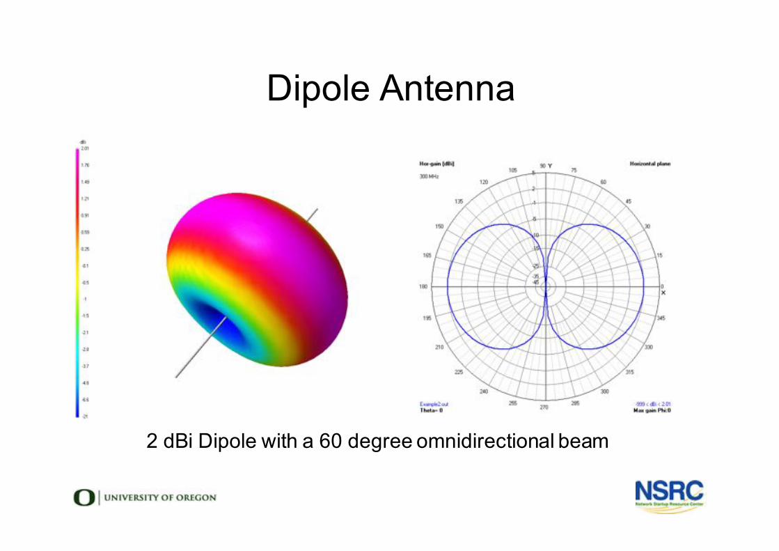
Dipole Antenna
2 dBi Dipole with a 60 degree omnidirectional beam
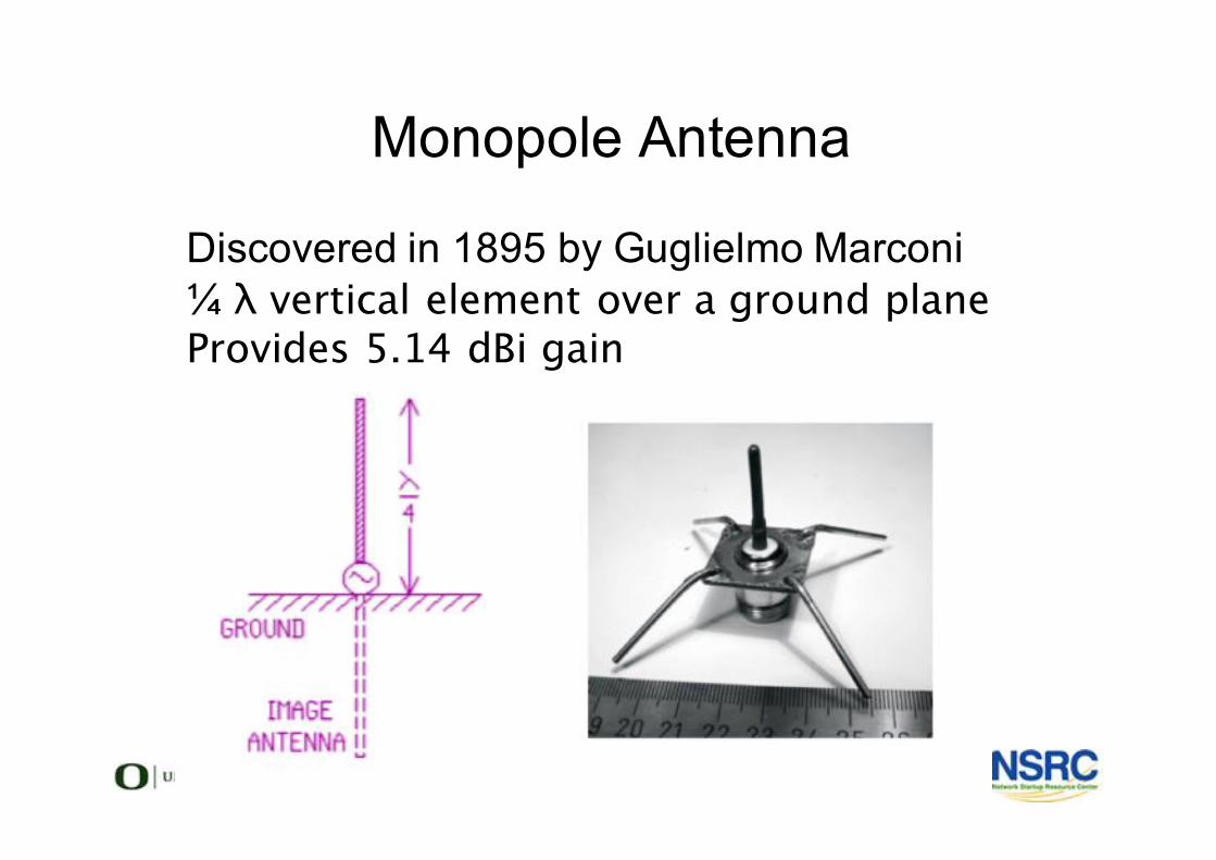
Monopole Antenna
l Discovered in 1895 by Guglielmo Marconil ¼ λ vertical element over a ground planel Provides 5.14 dBi gain
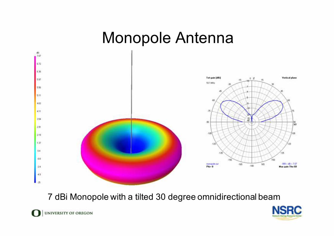
Monopole Antenna
7 dBi Monopole with a tilted 30 degree omnidirectional beam
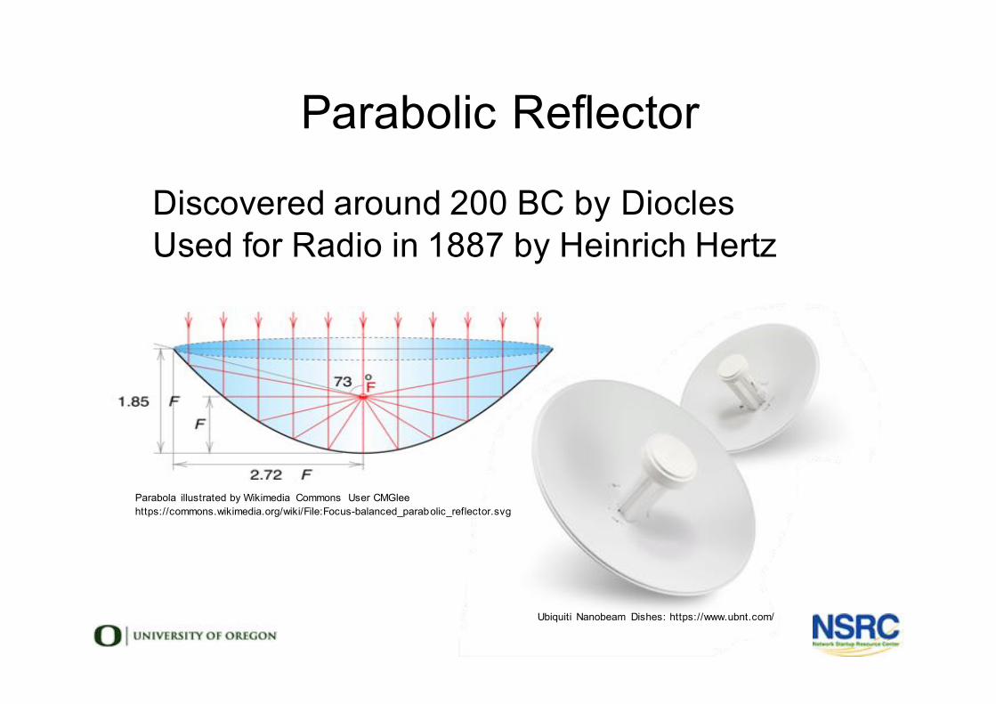
Parabolic Reflector
l Discovered around 200 BC by Diocles
l Used for Radio in 1887 by Heinrich Hertz
Parabola illustrated by Wikimedia Commons User CMGlee
https://commons.wikimedia.org/wiki/File:Focus-balanced_parabolic_reflector.svg
Ubiquiti Nanobeam Dishes: https://www.ubnt.com/
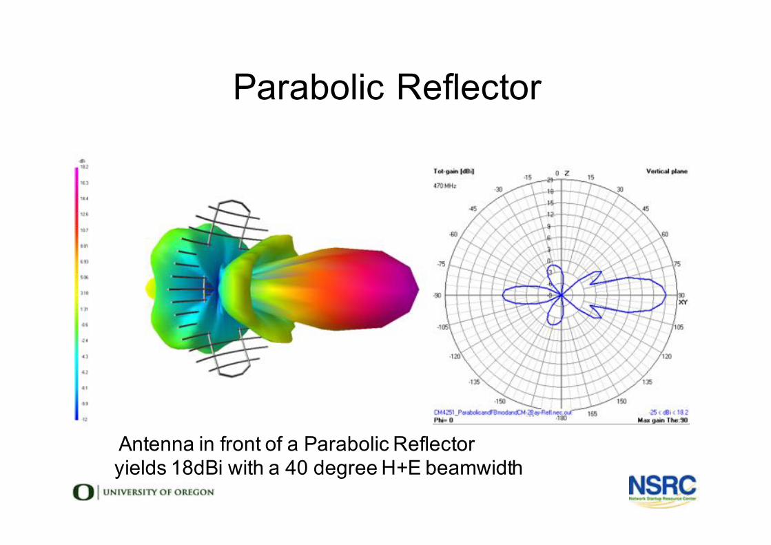
Parabolic Reflector
Antenna in front of a Parabolic Reflectoryields 18dBi with a 40 degree H+E beamwidth
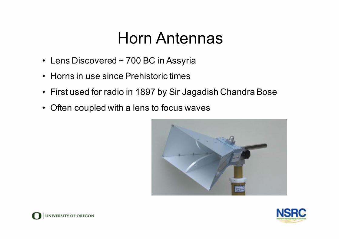
Horn Antennas• Lens Discovered ~ 700 BC in Assyria
• Horns in use since Prehistoric times
• First used for radio in 1897 by Sir Jagadish Chandra Bose
• Often coupled with a lens to focus waves
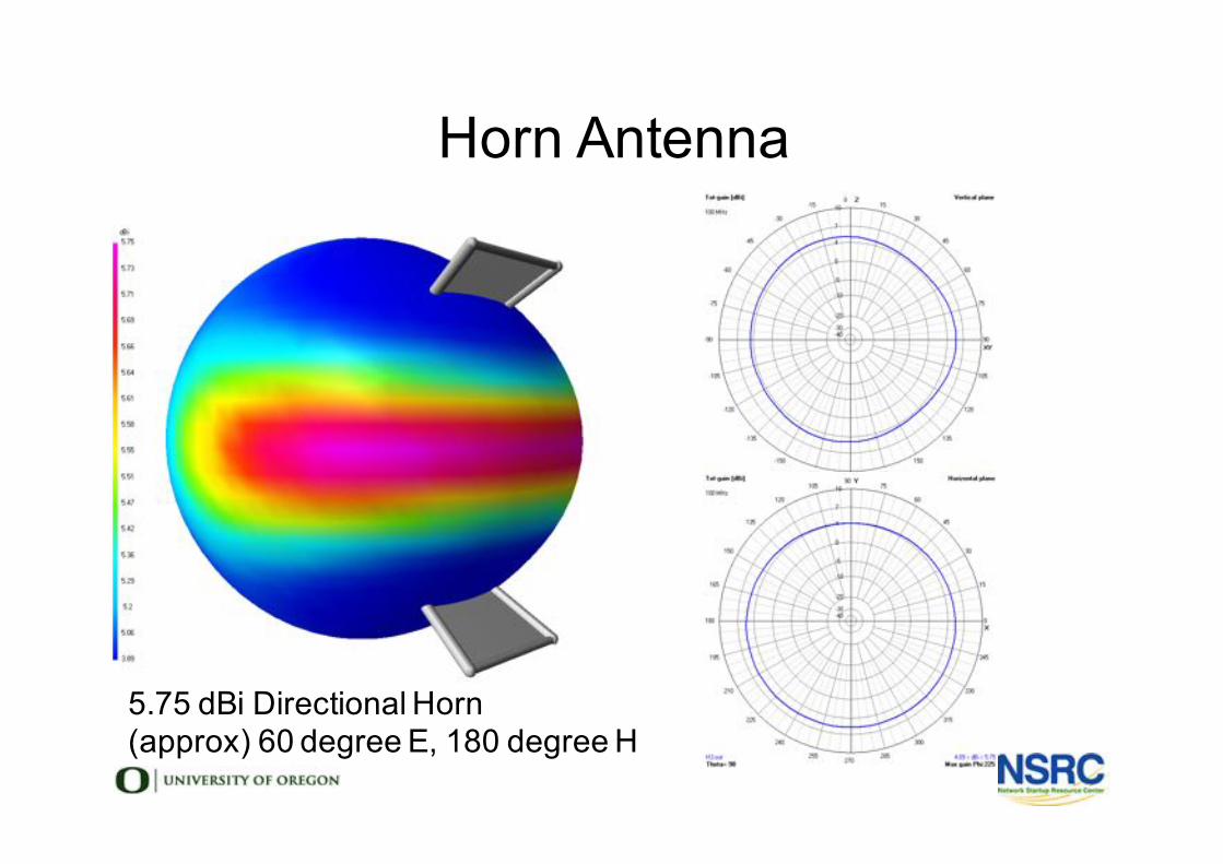
Horn Antenna
5.75 dBi Directional Horn(approx) 60 degree E, 180 degree H

Yagi-Uda (Yagi) Antenna
l Invented 1926 by Shintaro Uda & Hidetsugu Yagil Common from VHF up to 3 GHzl Low cost, light weight, durable, and high gain
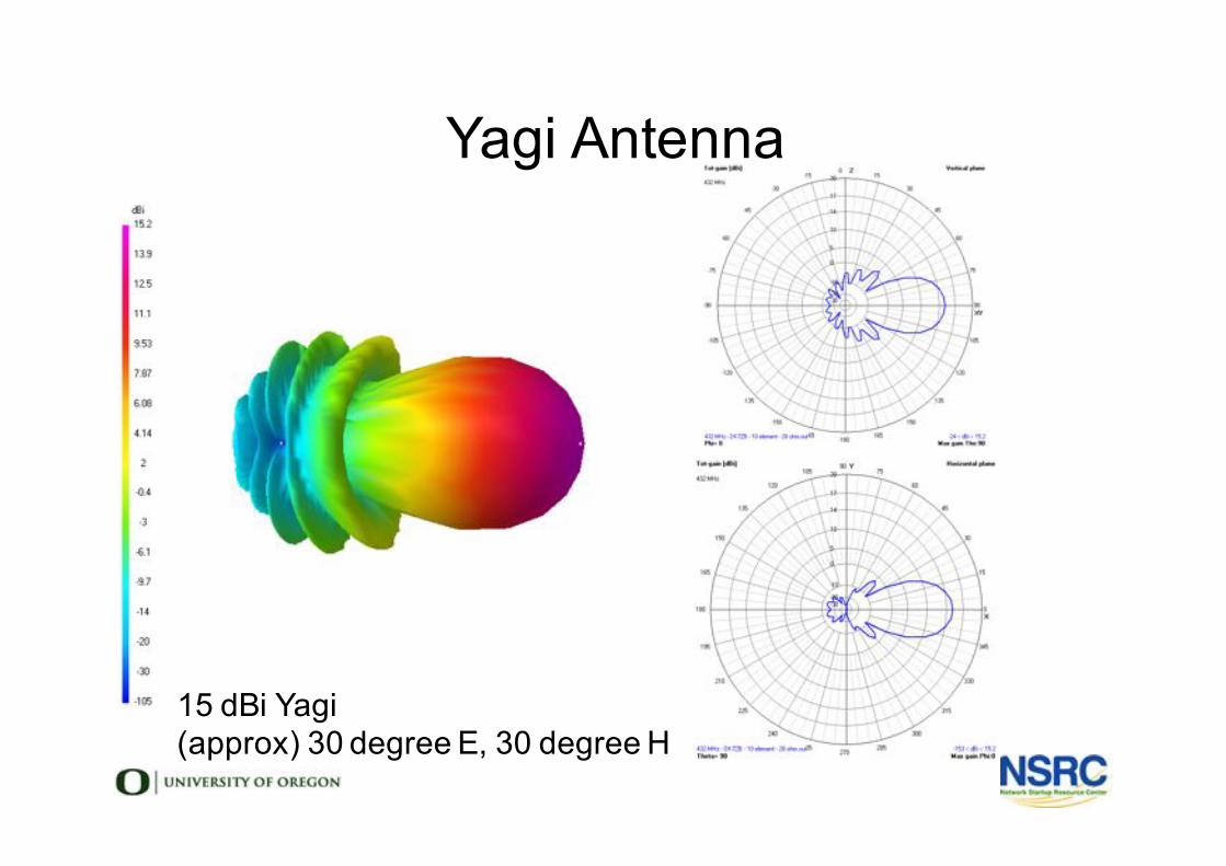
Yagi Antenna
15 dBi Yagi(approx) 30 degree E, 30 degree H
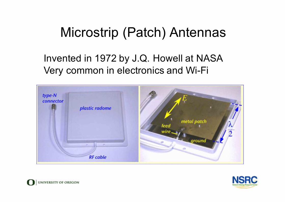
Microstrip (Patch) Antennas
l Invented in 1972 by J.Q. Howell at NASAl Very common in electronics and Wi-Fi
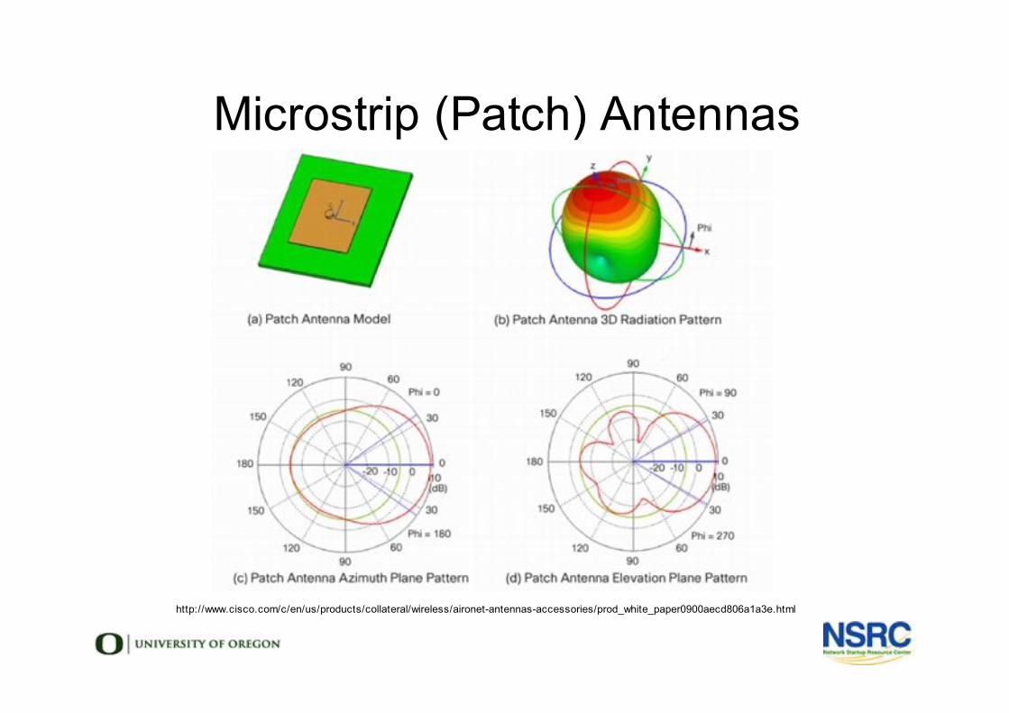
Microstrip (Patch) Antennas
http://www.cisco.com/c/en/us/products/collateral/wireless/aironet-antennas-accessories/prod_white_paper0900aecd806a1a3e.html
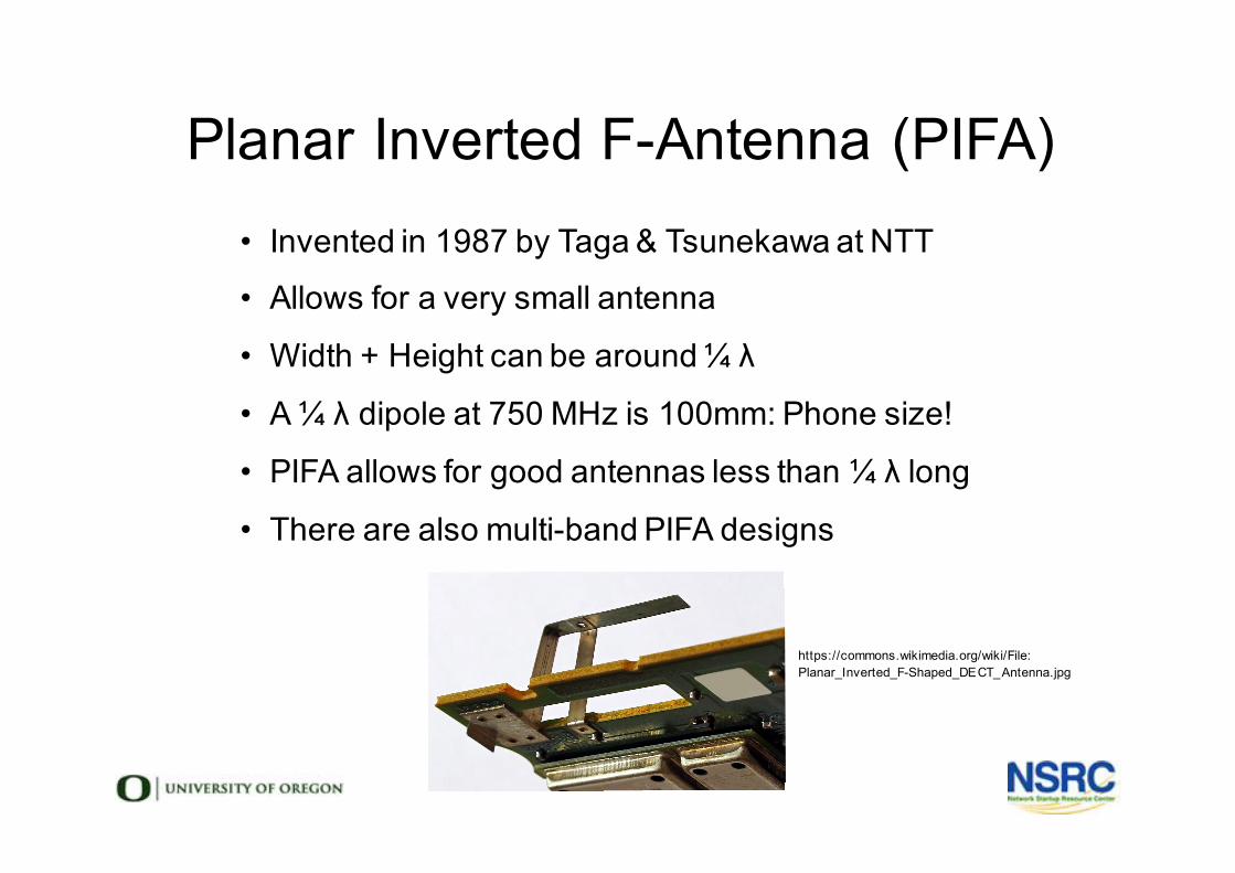
Planar Inverted F-Antenna (PIFA)
https://commons.wikimedia.org/wiki/File:Planar_Inverted_F-Shaped_DECT_Antenna.jpg
• Invented in 1987 by Taga & Tsunekawa at NTT
• Allows for a very small antenna
• Width + Height can be around ¼ λ
• A ¼ λ dipole at 750 MHz is 100mm: Phone size!
• PIFA allows for good antennas less than ¼ λ long
• There are also multi-band PIFA designs
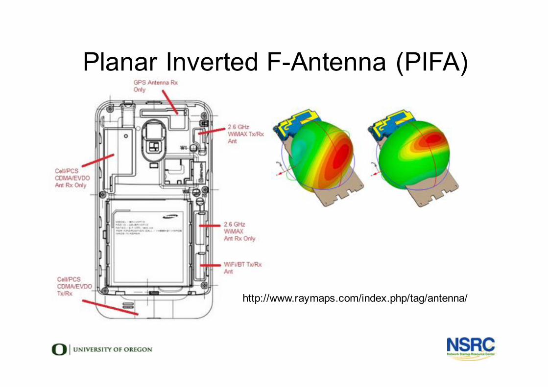
Planar Inverted F-Antenna (PIFA)
http://www.raymaps.com/index.php/tag/antenna/
Antenna Arrays
• Two or more antennas• Signals combined for multiple purposes
• increase gain• provide diversity receive• cancel interference• steer the direction of highest gain• locate the direction of received signals
• Most WiFi Sector Antennas are Arrays
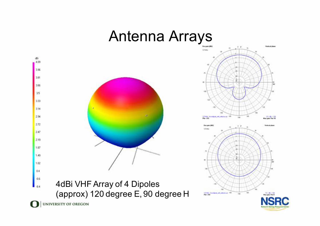
Antenna Arrays
4dBi VHF Array of 4 Dipoles(approx) 120 degree E, 90 degree H
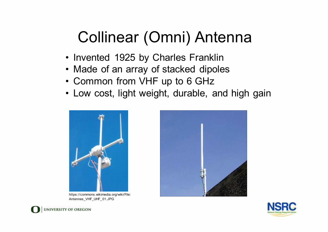
Collinear (Omni) Antenna
https://commons.wikimedia.org/wiki/File:Antennes_VHF_UHF_01.JPG
• Invented 1925 by Charles Franklin• Made of an array of stacked dipoles• Common from VHF up to 6 GHz• Low cost, light weight, durable, and high gain
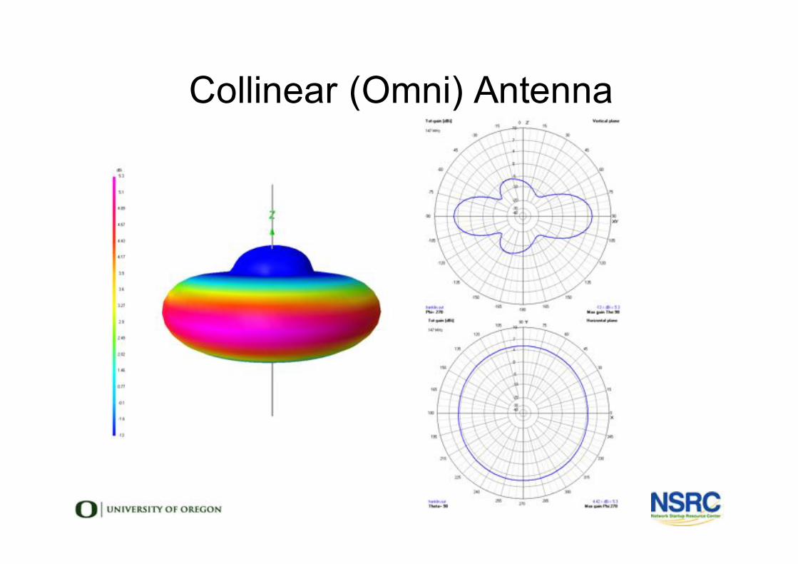
Collinear (Omni) Antenna
Choosing an Antenna• What frequency and bandwidth?
• What coverage do you need?
• Does physical size matter?
• Is your mast strong enough for a big antenna?
• Are aesthetics important?
• Is the environment windy?
• Maybe use a grid antenna with low surface area
• Is there ice?
• Use a dish with a plastic cover to keep the ice off
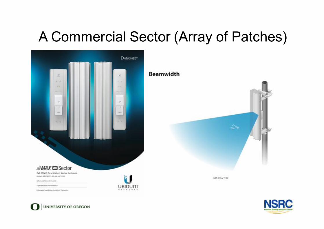
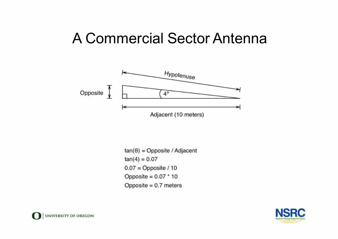
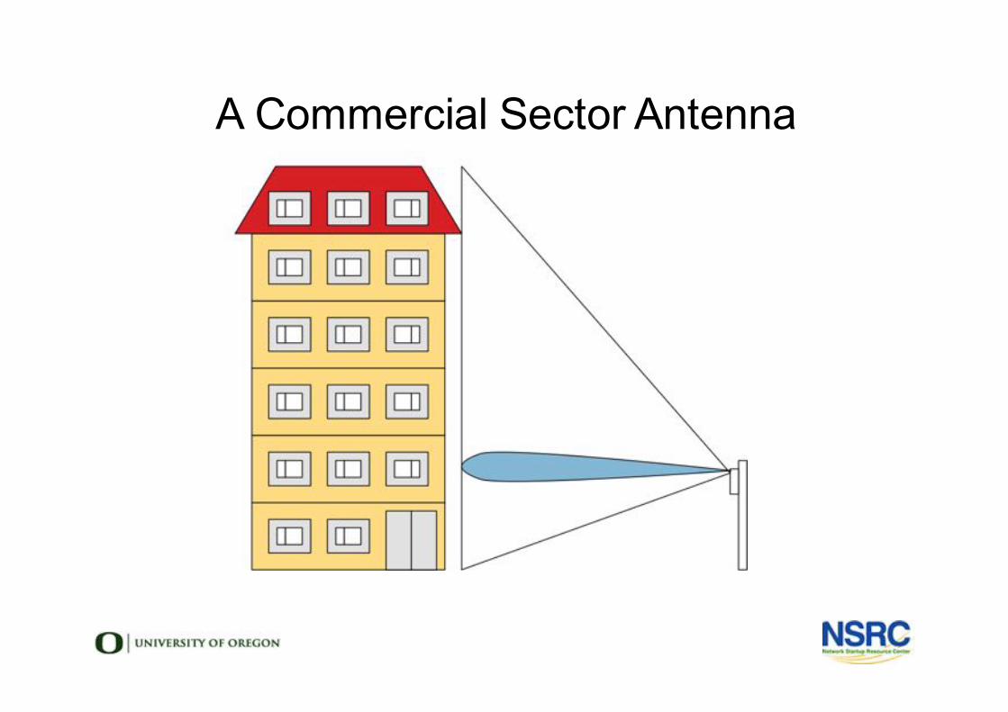
A Commercial Sector (Array of Patches)
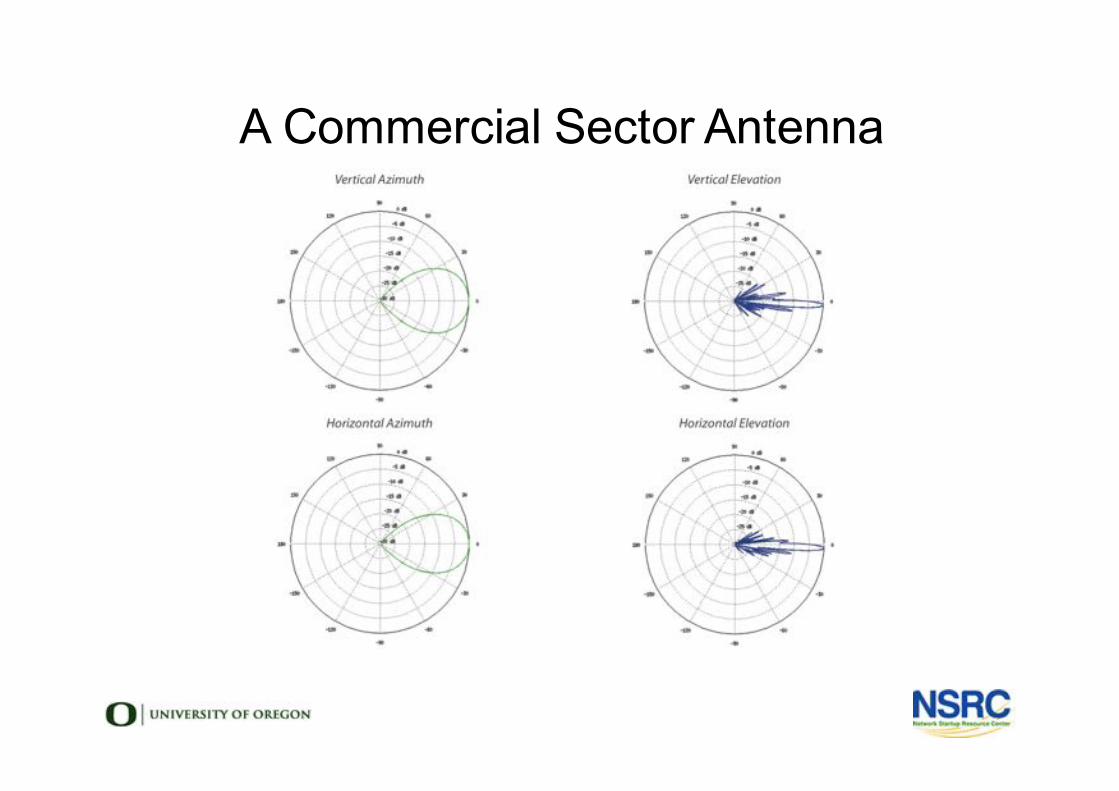
A Commercial Sector Antenna
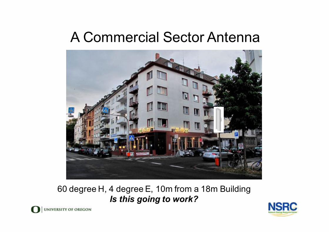
A Commercial Sector Antenna
60 degree H, 4 degree E, 10m from a 18m BuildingIs this going to work?
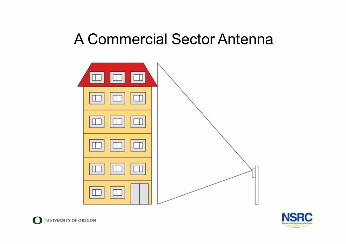
A Commercial Sector Antenna
A Commercial Sector Antenna
A Commercial Sector Antenna
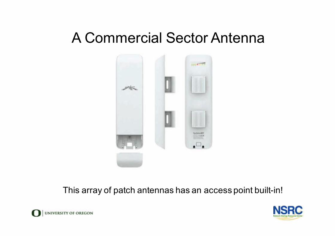
A Commercial Sector Antenna
This array of patch antennas has an access point built-in!
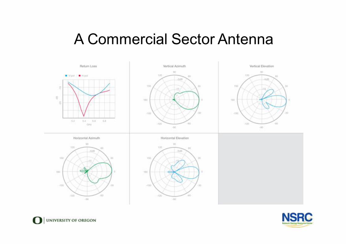
A Commercial Sector Antenna
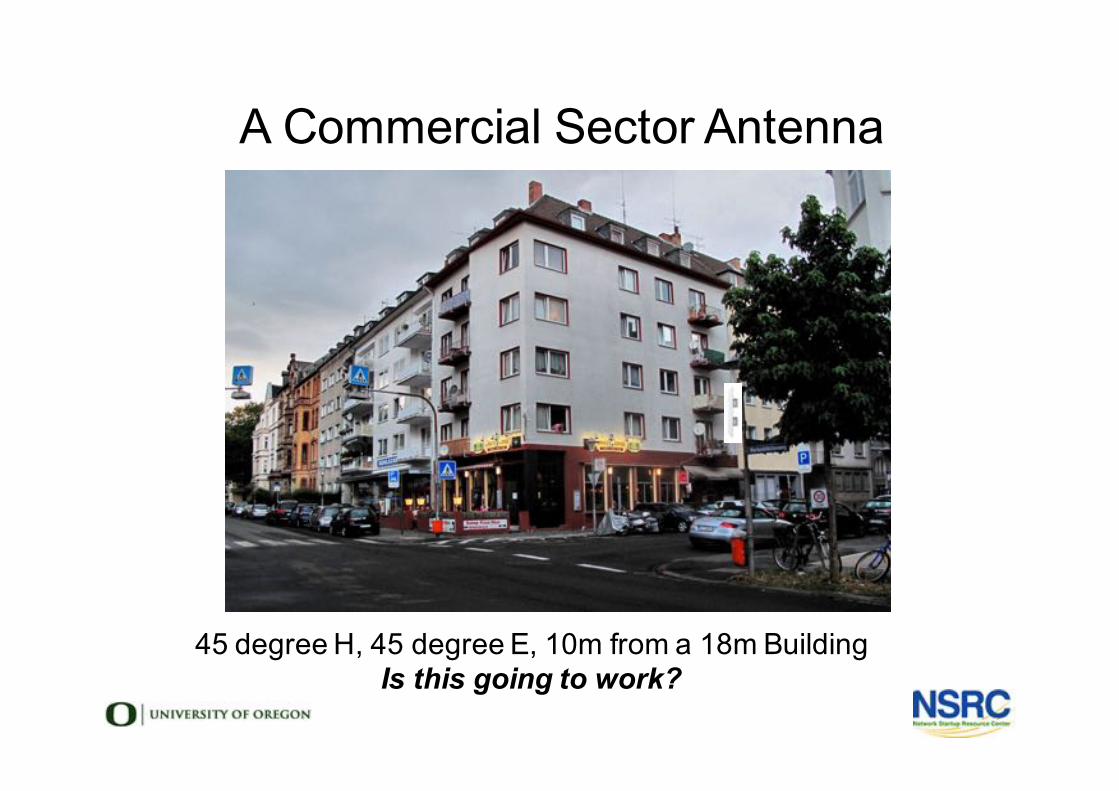
A Commercial Sector Antenna
45 degree H, 45 degree E, 10m from a 18m BuildingIs this going to work?
Making Your Own Antennas
• Free, Open Source Designs Available• Combine with Reflectors (Satellite Dishes) for high gain• Learn Collinear & Cantenna with WNDW (multiple languages)
• http://wndw.net/book.html• Make a BiQuad with Trevor Marshall (English)
• http://www.trevormarshall.com/biquad.htm• Make a Parabolic Reflector & More with M. Erskine (English)
• http://www.freeantennas.com/projects/template/index.html• Make a Collinear with Marty Bugs (English)
• http://martybugs.net/wireless/collinear.cgi
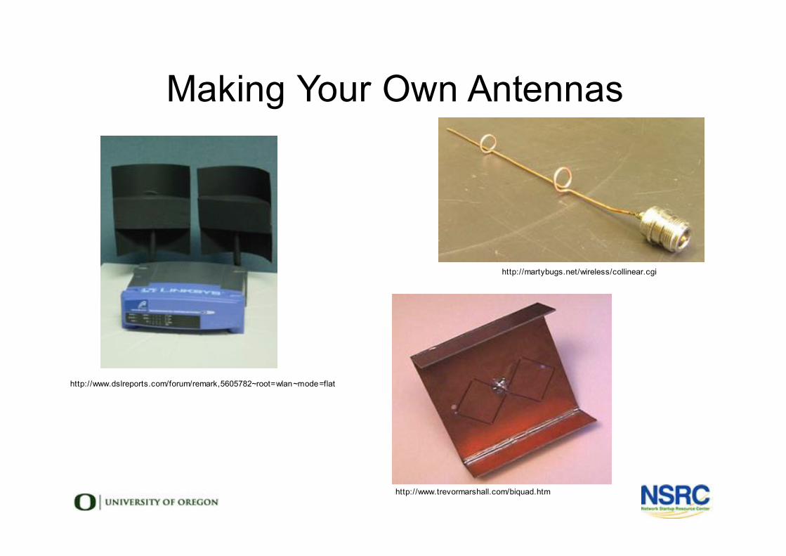
Making Your Own Antennas
http://www.dslreports.com/forum/remark,5605782~root=wlan~mode=flat
http://martybugs.net/wireless/collinear.cgi
http://www.trevormarshall.com/biquad.htm
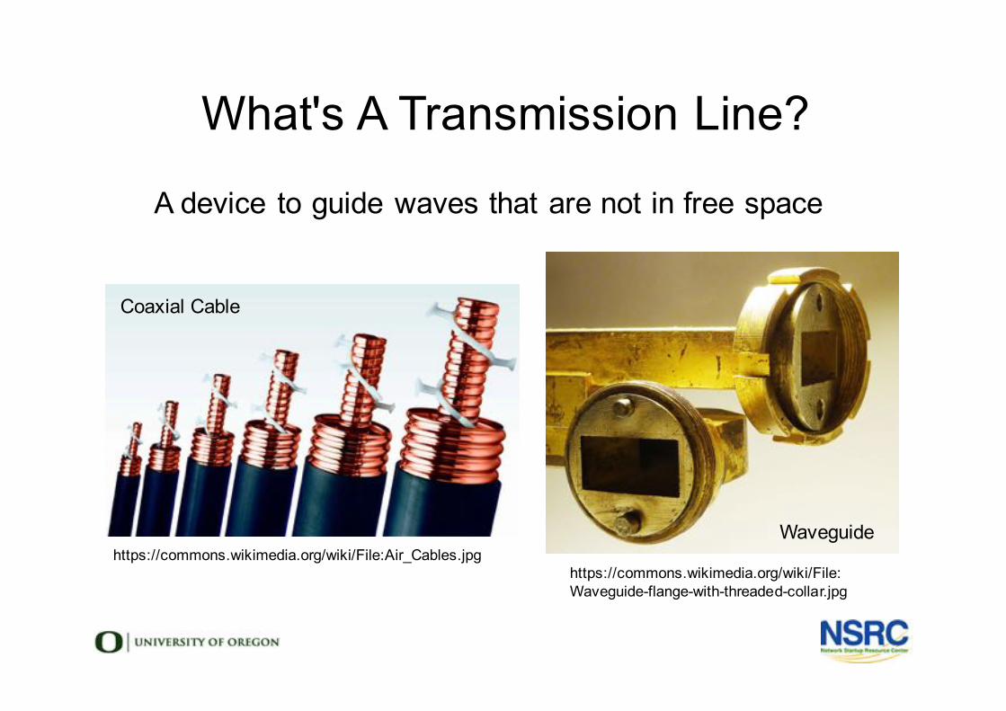
l A device to guide waves that are not in free spacel
What's A Transmission Line?
https://commons.wikimedia.org/wiki/File: Waveguide-flange-with-threaded-collar.jpg
https://commons.wikimedia.org/wiki/File:Air_Cables.jpg
Coaxial Cable
Waveguide
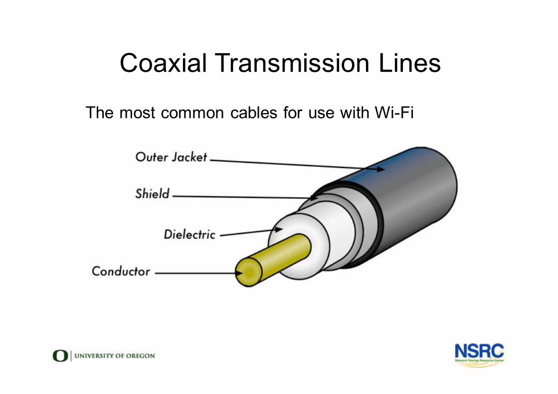
l The most common cables for use with Wi-Fil
Coaxial Transmission Lines
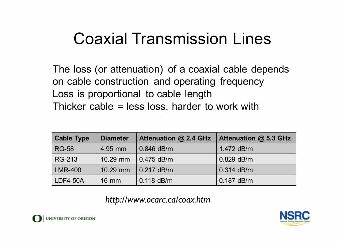
l The loss (or attenuation) of a coaxial cable depends on cable construction and operating frequency
l Loss is proportional to cable lengthl Thicker cable = less loss, harder to work withl
Coaxial Transmission Lines
Cable Type Diameter Attenuation @ 2.4 GHz Attenuation @ 5.3 GHzRG-58 4.95 mm 0.846 dB/m 1.472 dB/mRG-213 10.29 mm 0.475 dB/m 0.829 dB/mLMR-400 10.29 mm 0.217 dB/m 0.314 dB/mLDF4-50A 16 mm 0.118 dB/m 0.187 dB/m
http://www.ocarc.ca/coax.htm
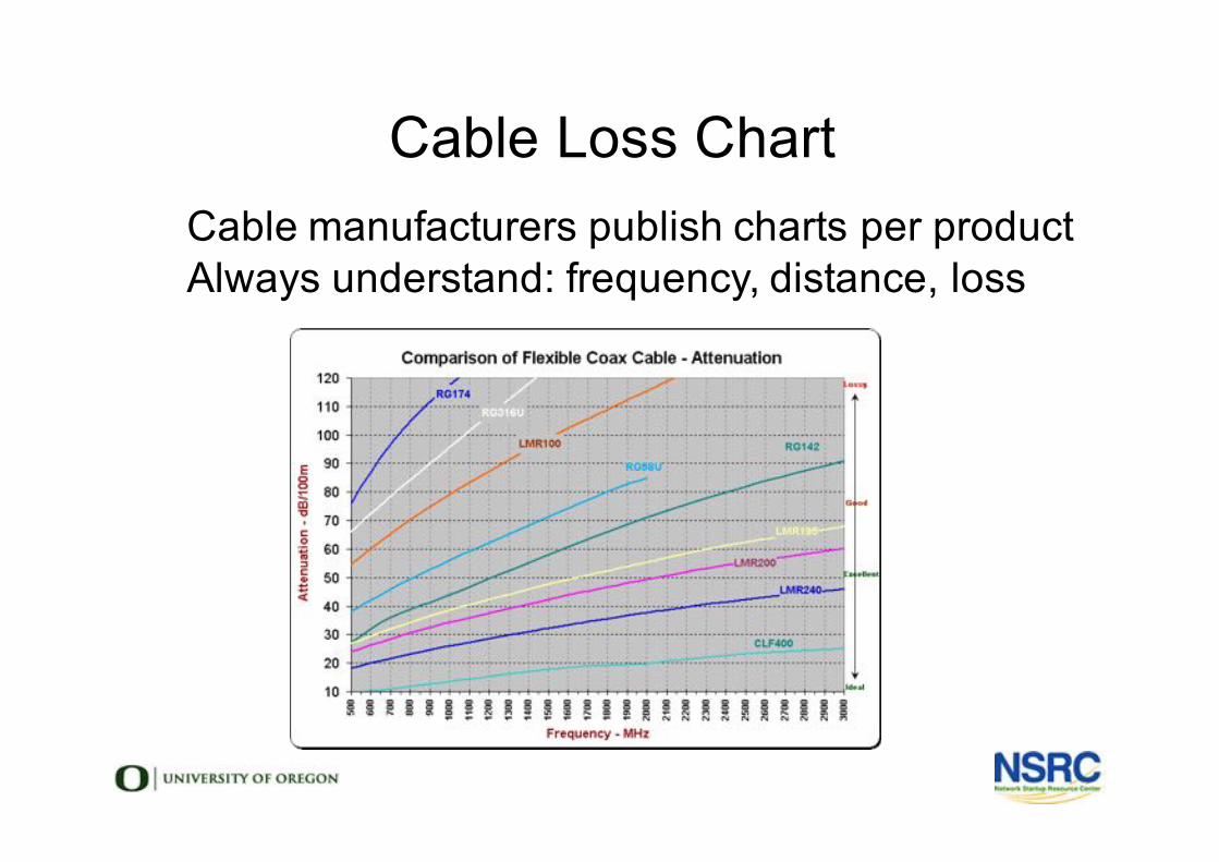
Cable Loss Chartl Cable manufacturers publish charts per productl Always understand: frequency, distance, loss
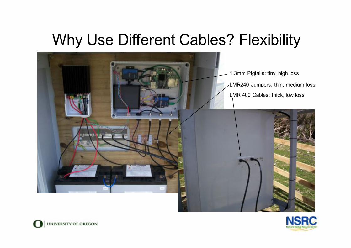
Why Use Different Cables? Flexibility
1.3mm Pigtails: tiny, high loss
LMR240 Jumpers: thin, medium loss
LMR 400 Cables: thick, low loss
Choosing Transmission Line
• What frequencies do you need?
• How much loss can your system tolerate?
• Does size matter? Flexibility?
• Using multiple types of line is ok!
Impedance• All materials oppose the flow of current
• This opposition is called impedance
• It's analogous to resistance in DC circuits
• Comms cable & antennas are usually 50 Ohms
• TV cable & antennas are usually 75 Ohms
• Always match impedance of cable & antennas
• Mis-match will cause reflections & high VSWR

Voltage Standing Wave Ratio• Impedance mismatch will result reflections
• VSWR is a function of the reflection coefficient
• Higher VSWR = less power from tx to antenna
• Lower VSWR = more power from tx to antenna
How could you Mismatch Impedance?
• UHF Television antennas are 75 Ohm
• UHF Television antennas cover 500-800 MHz
• RG-6 Cable is ideal for 500-800MHz. It's 75 Ohm
• All these things are inexpensive & available
• New LTE services use 700-800 MHz
• LTE radios are 50 Ohm
• Use TV equipment for LTE? Impedance Mismatch
Review
• How does an antenna work?
• What's a radiation pattern?
• How do you choose the right antenna?
• What does a transmission line do?
• How do you choose a transmission line?
lWireless Standards & Protocols
Network Startup Resource Centerwww.nsrc.org
These materials are licensed under the Creative Commons Attribution-NonCommercial 4.0 International license(http://creativecommons.org/licenses/by-nc/4.0/)Original Slides: Sebastian Büttrich, NSRC/ITU/wire.less.dk Edit: June 2012
Objectives
• Introduce Core Concepts & Terminology
• Shared Radio Spectrum Bands
• Wi-Fi & 802.11 radio channels
• Channel Access
• Wireless network topologies
• Wi-Fi modes of operation
• Basic wireless routing
What is Shared Spectrum?• Licenses give an exclusive right to use a frequency
• Radio & TV Stations, Cellular Operators
• Wi-Fi typically operates in shared spectrum
• Many networks on the same frequencies
• Use of shared spectrum is free in most countries
• Free does not always mean unregulated or unlicensed
• “Type Approved Devices”
• Maximum Power Limits & Radar Detect
• General User Radio Licenses
Is Shared Spectrum Important?• Innovation happens in shared spectrum
• The market size is greater
• No country-specific frequencies to develop for
• Wi-Fi is often faster than cellular
• Wi-Fi is usually cheaper than cellular
Industrial, Scientific, Medical (ISM) Bands
• Spectrum originally set aside for ISM equipment
• Opened for use in the US in the 1990s
• Wi-Fi works in 2.4 GHz and 5.8 GHz ISM spectrum
• ISM bands also exist at:
• 433 MHz
• 915 MHz
• 24 Ghz
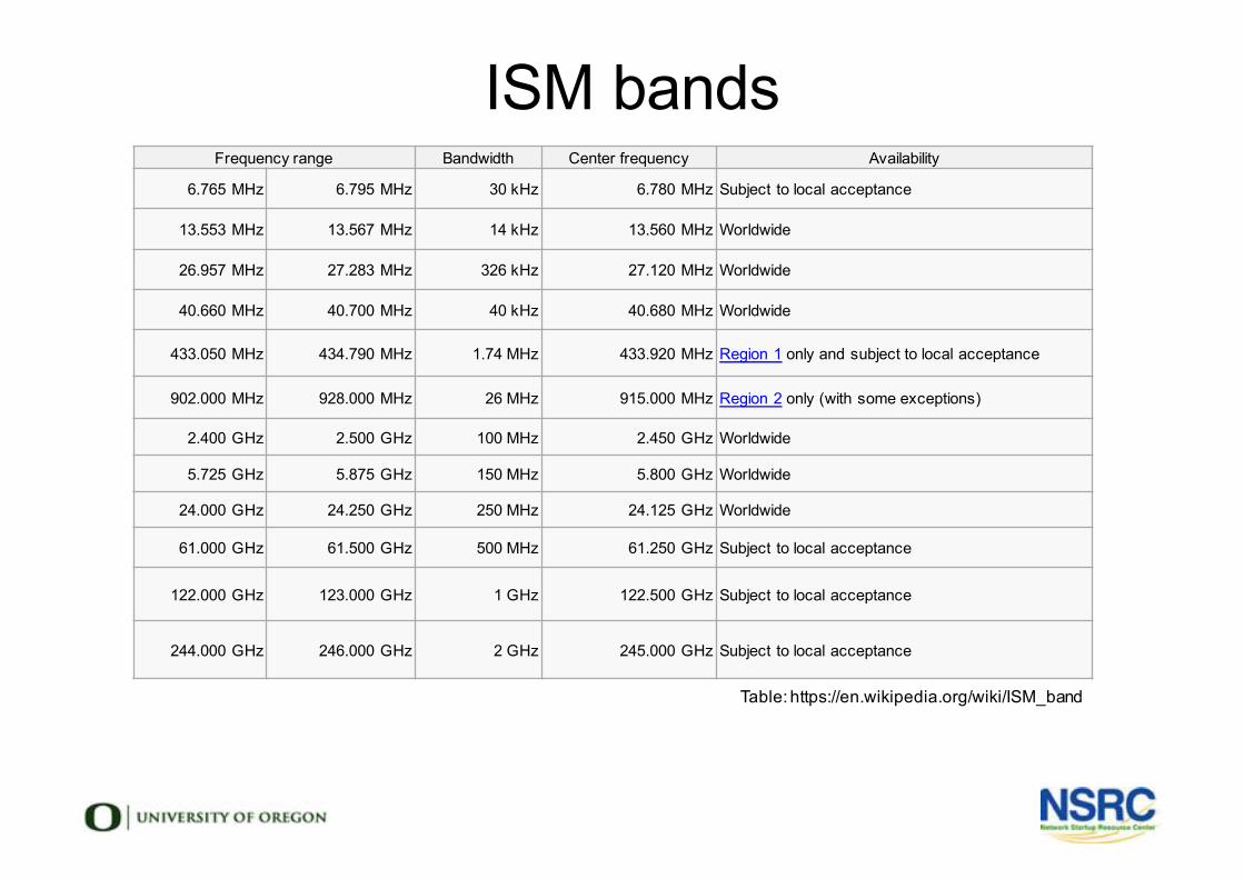
ISM bands
Table: https://en.wikipedia.org/wiki/ISM_band
Frequency range Bandwidth Center frequency Availability
6.765 MHz 6.795 MHz 30 kHz 6.780 MHz Subject to local acceptance
13.553 MHz 13.567 MHz 14 kHz 13.560 MHz Worldwide
26.957 MHz 27.283 MHz 326 kHz 27.120 MHz Worldwide
40.660 MHz 40.700 MHz 40 kHz 40.680 MHz Worldwide
433.050 MHz 434.790 MHz 1.74 MHz 433.920 MHz Region 1 only and subject to local acceptance
902.000 MHz 928.000 MHz 26 MHz 915.000 MHz Region 2 only (with some exceptions)
2.400 GHz 2.500 GHz 100 MHz 2.450 GHz Worldwide
5.725 GHz 5.875 GHz 150 MHz 5.800 GHz Worldwide
24.000 GHz 24.250 GHz 250 MHz 24.125 GHz Worldwide
61.000 GHz 61.500 GHz 500 MHz 61.250 GHz Subject to local acceptance
122.000 GHz 123.000 GHz 1 GHz 122.500 GHz Subject to local acceptance
244.000 GHz 246.000 GHz 2 GHz 245.000 GHz Subject to local acceptance
What is Wi-Fi?
• A Wi-Fi Alliance Trademark
• Not a strict technical term
• Wi-Fi is commonly used to refer to the
802.11 family of wireless standards
• Wi-Fi can run in ISM bands
• Wi-Fi is designed for shared spectrum
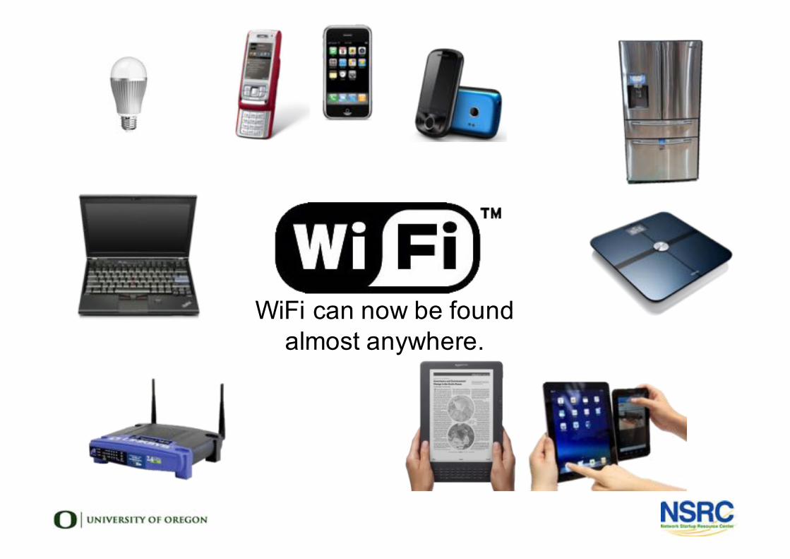
WiFi can now be found almost anywhere.
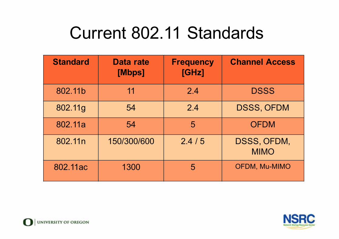
Current 802.11 StandardsStandard Data rate
[Mbps]Frequency
[GHz]Channel Access
802.11b 11 2.4 DSSS
802.11g 54 2.4 DSSS, OFDM
802.11a 54 5 OFDM
802.11n 150/300/600 2.4 / 5 DSSS, OFDM, MIMO
802.11ac 1300 5 OFDM, Mu-MIMO
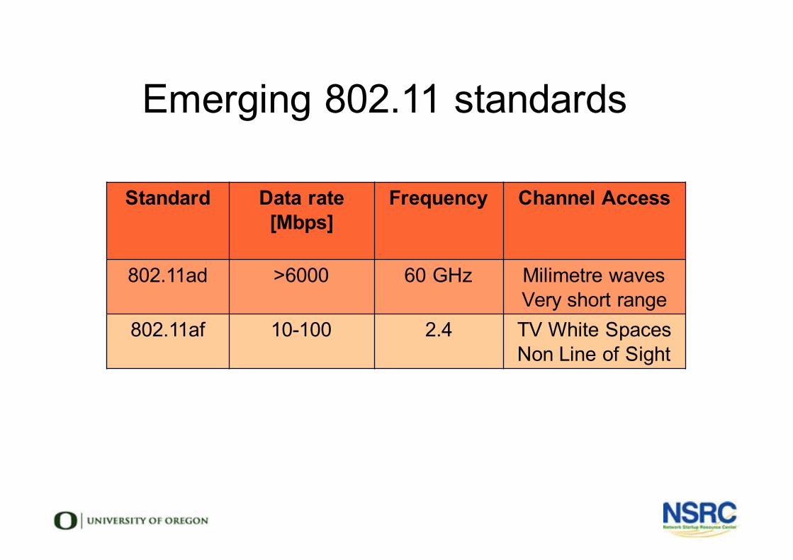
Emerging 802.11 standards
Standard Data rate [Mbps]
Frequency Channel Access
802.11ad >6000 60 GHz Milimetre wavesVery short range
802.11af 10-100 2.4 TV White SpacesNon Line of Sight
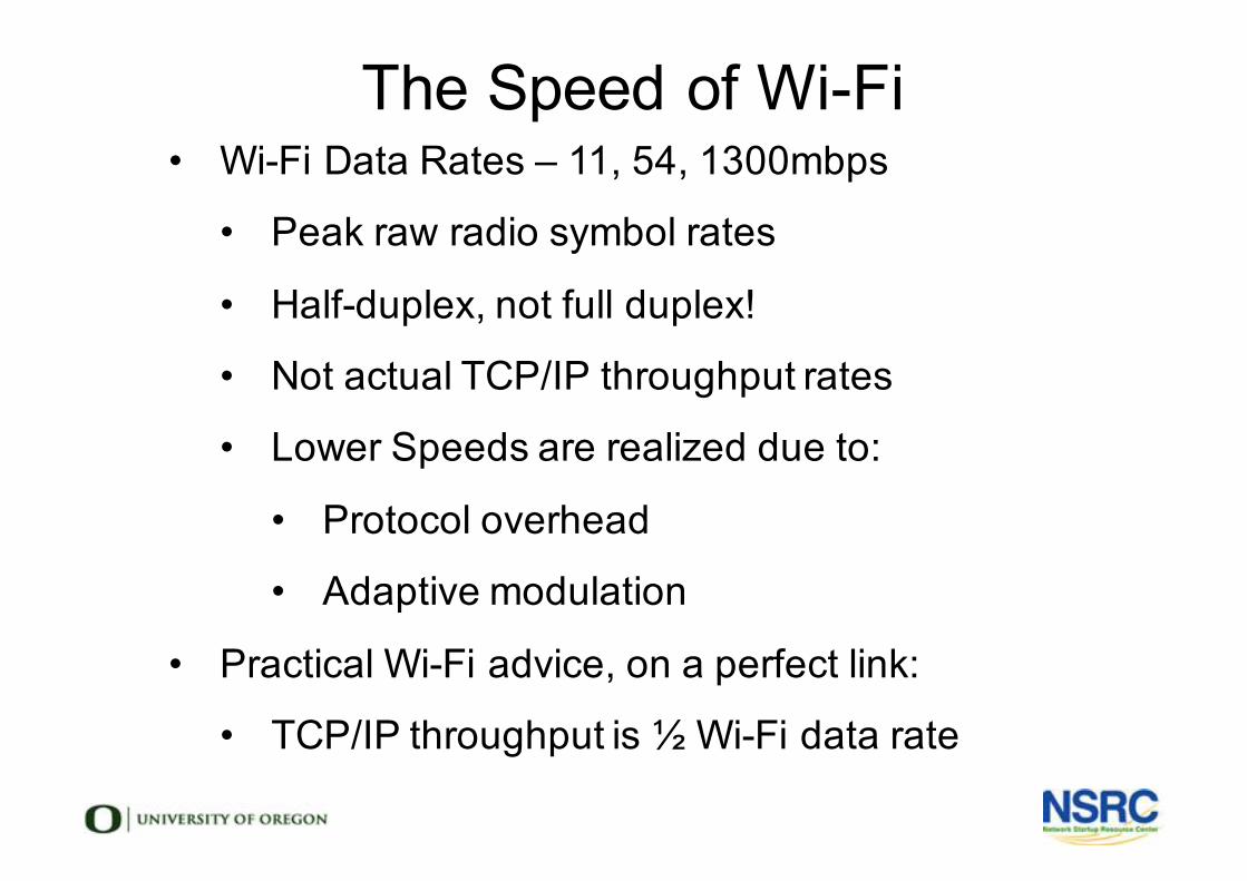
The Speed of Wi-Fi• Wi-Fi Data Rates – 11, 54, 1300mbps
• Peak raw radio symbol rates
• Half-duplex, not full duplex!
• Not actual TCP/IP throughput rates
• Lower Speeds are realized due to:
• Protocol overhead
• Adaptive modulation
• Practical Wi-Fi advice, on a perfect link:
• TCP/IP throughput is ½ Wi-Fi data rate
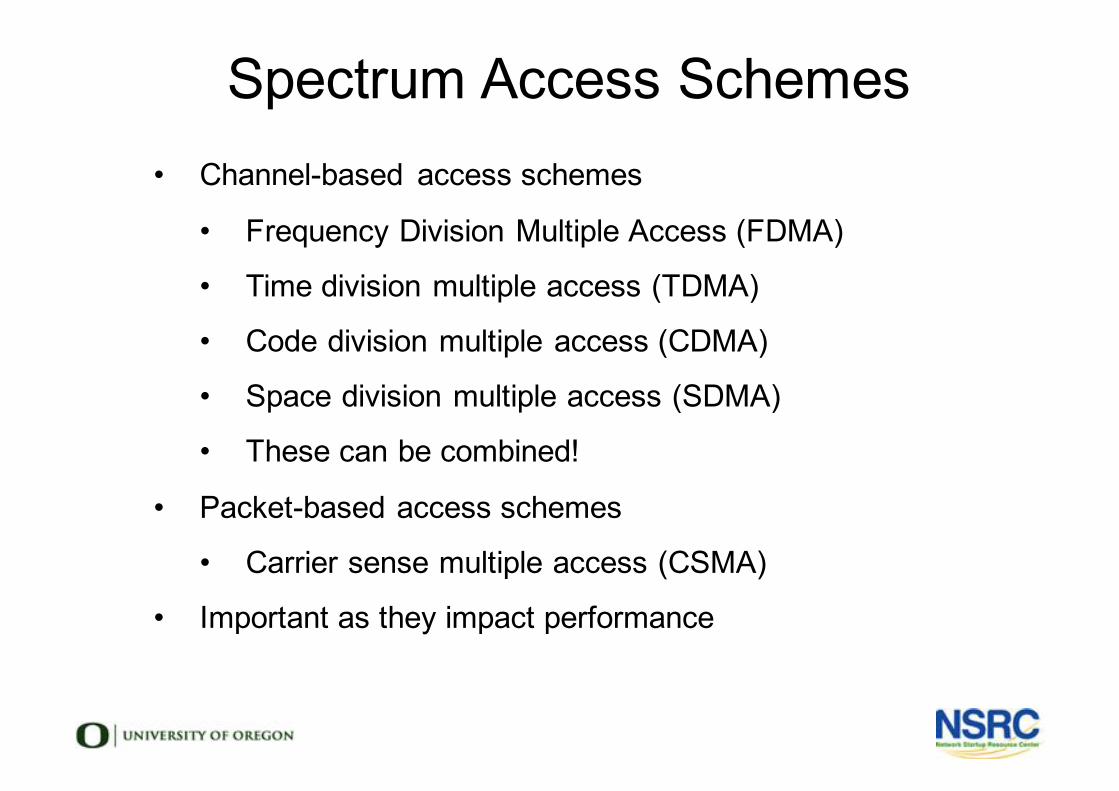
Spectrum Access Schemes• Channel-based access schemes
• Frequency Division Multiple Access (FDMA)
• Time division multiple access (TDMA)
• Code division multiple access (CDMA)
• Space division multiple access (SDMA)
• These can be combined!
• Packet-based access schemes
• Carrier sense multiple access (CSMA)
• Important as they impact performance
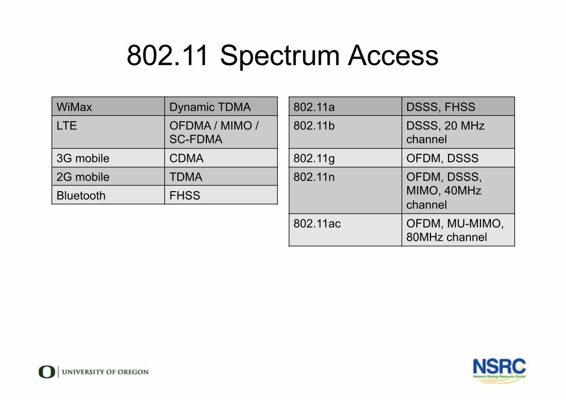
802.11 Spectrum AccessWiMax Dynamic TDMALTE OFDMA / MIMO /
SC-FDMA3G mobile CDMA2G mobile TDMABluetooth FHSS
802.11a DSSS, FHSS802.11b DSSS, 20 MHz
channel802.11g OFDM, DSSS802.11n OFDM, DSSS,
MIMO, 40MHz channel
802.11ac OFDM, MU-MIMO, 80MHz channel
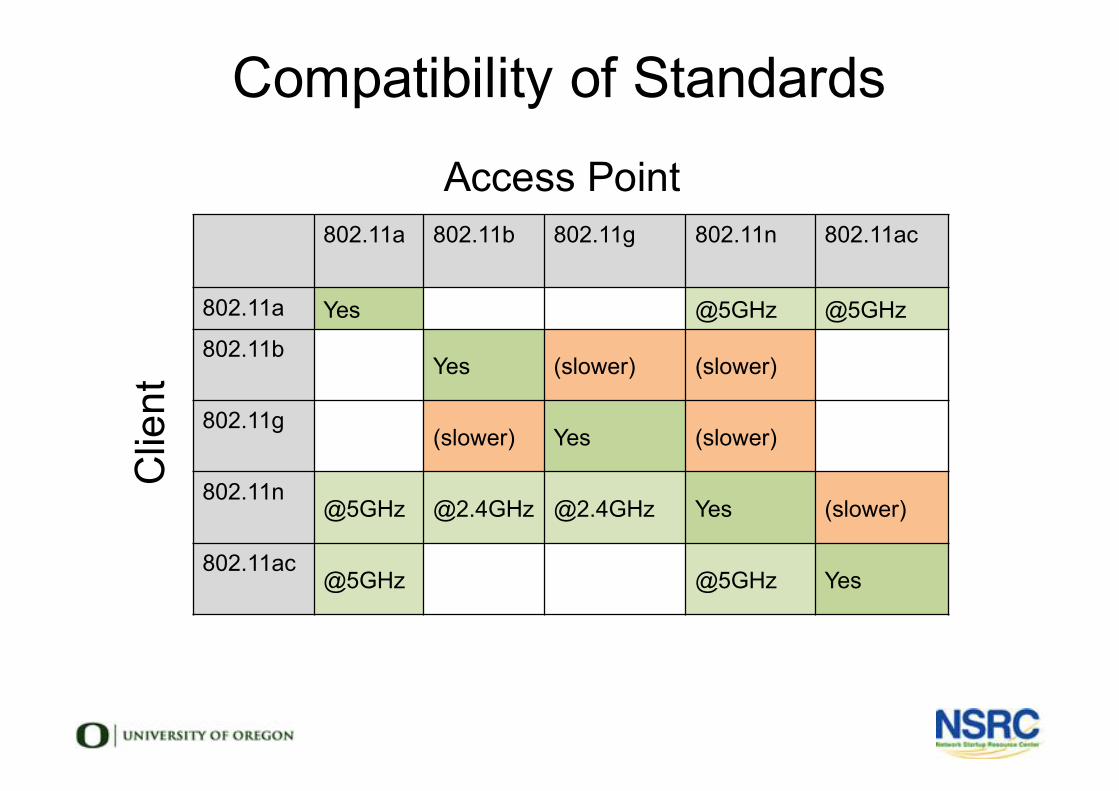
802.11a 802.11b 802.11g 802.11n 802.11ac
802.11a Yes @5GHz @5GHz802.11b
Yes (slower) (slower)
802.11g(slower) Yes (slower)
802.11n@5GHz @2.4GHz @2.4GHz Yes (slower)
802.11ac@5GHz @5GHz Yes
Compatibility of StandardsAccess Point
Clie
nt
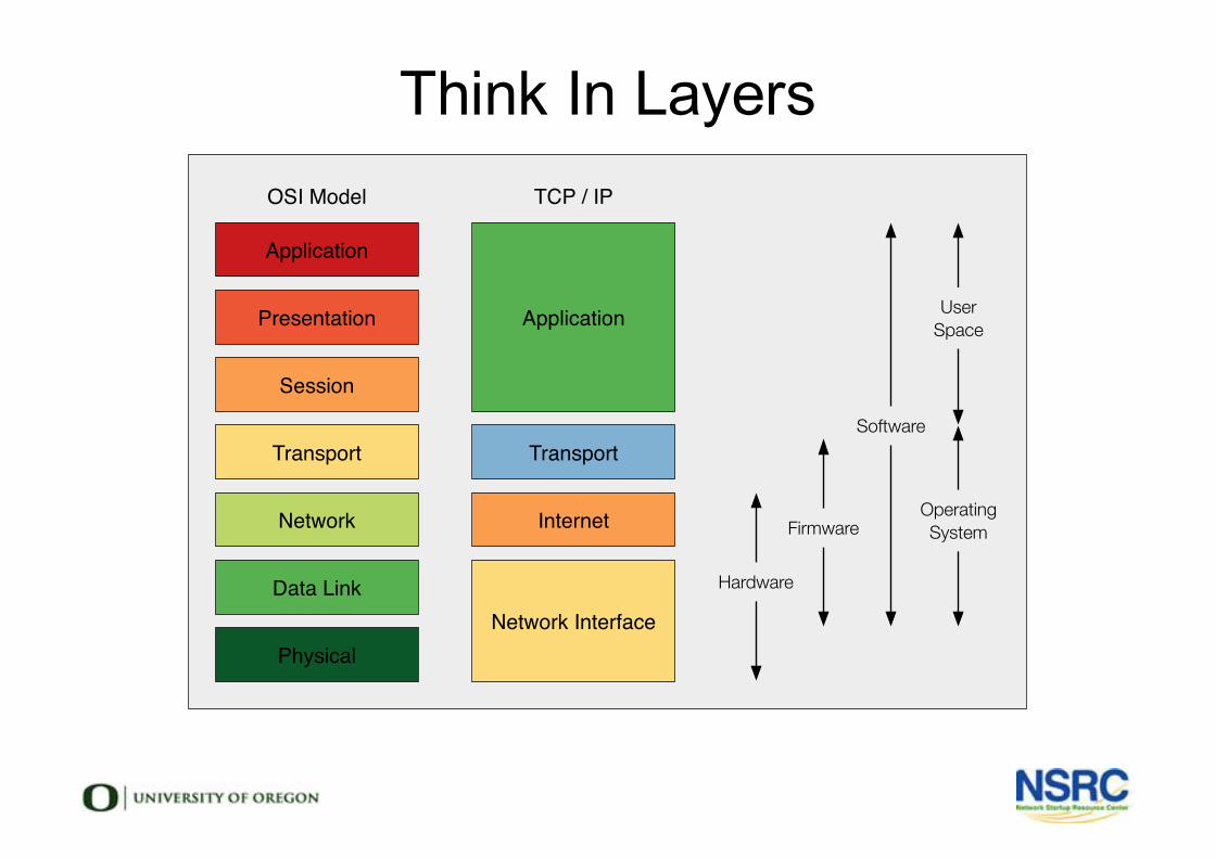
Think In Layers
Application
Presentation
Session
Transport
Network
Data Link
Physical
Application
Transport
Internet
Network Interface
Hardware
Firmware
Software
OperatingSystem
UserSpace
OSI Model TCP / IP
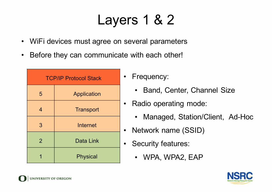
Layers 1 & 2
TCP/IP Protocol Stack
5 Application
4 Transport
3 Internet
2 Data Link
1 Physical
• Frequency:
• Band, Center, Channel Size
• Radio operating mode:
• Managed, Station/Client, Ad-Hoc
• Network name (SSID)
• Security features:
• WPA, WPA2, EAP
• WiFi devices must agree on several parameters
• Before they can communicate with each other!
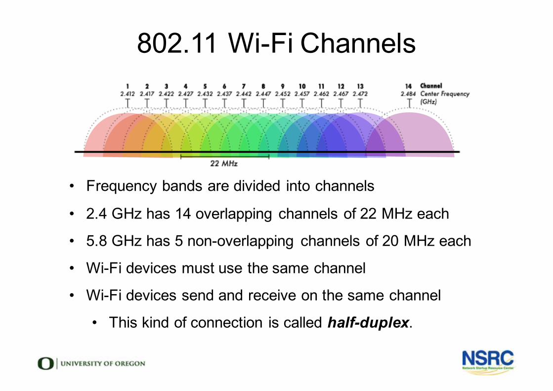
802.11 Wi-Fi Channels
• Frequency bands are divided into channels
• 2.4 GHz has 14 overlapping channels of 22 MHz each
• 5.8 GHz has 5 non-overlapping channels of 20 MHz each
• Wi-Fi devices must use the same channel
• Wi-Fi devices send and receive on the same channel
• This kind of connection is called half-duplex.
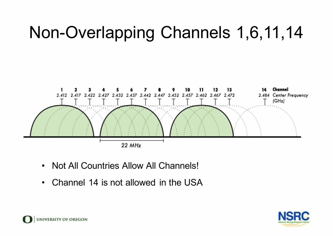
Non-Overlapping Channels 1,6,11,14
• Not All Countries Allow All Channels!
• Channel 14 is not allowed in the USA
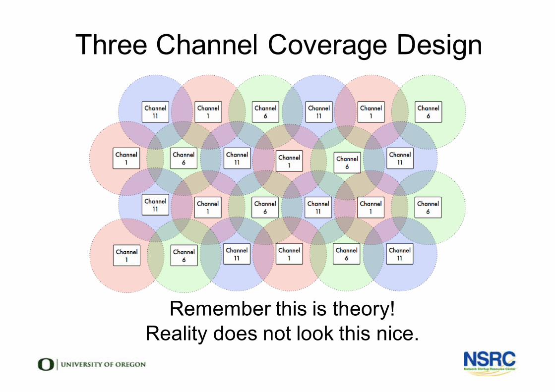
Remember this is theory!Reality does not look this nice.
Three Channel Coverage Design

Wireless Network Topologies
• Point to Point
• Point to Multipoint
• Multipoint to Multipoint
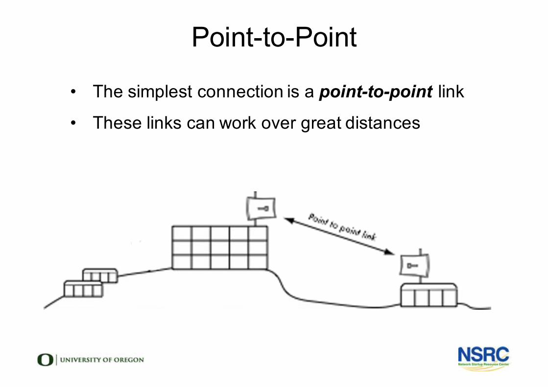
Point-to-Point
• The simplest connection is a point-to-point link
• These links can work over great distances
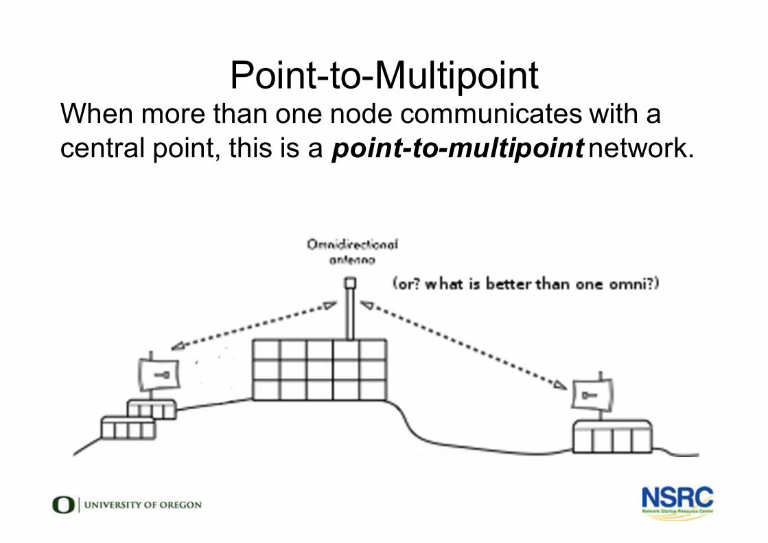
Point-to-MultipointWhen more than one node communicates with a central point, this is a point-to-multipoint network.

Multipoint-to-MultipointAny node may communicate with any other
This can be an “ad-hoc” or a planned mesh
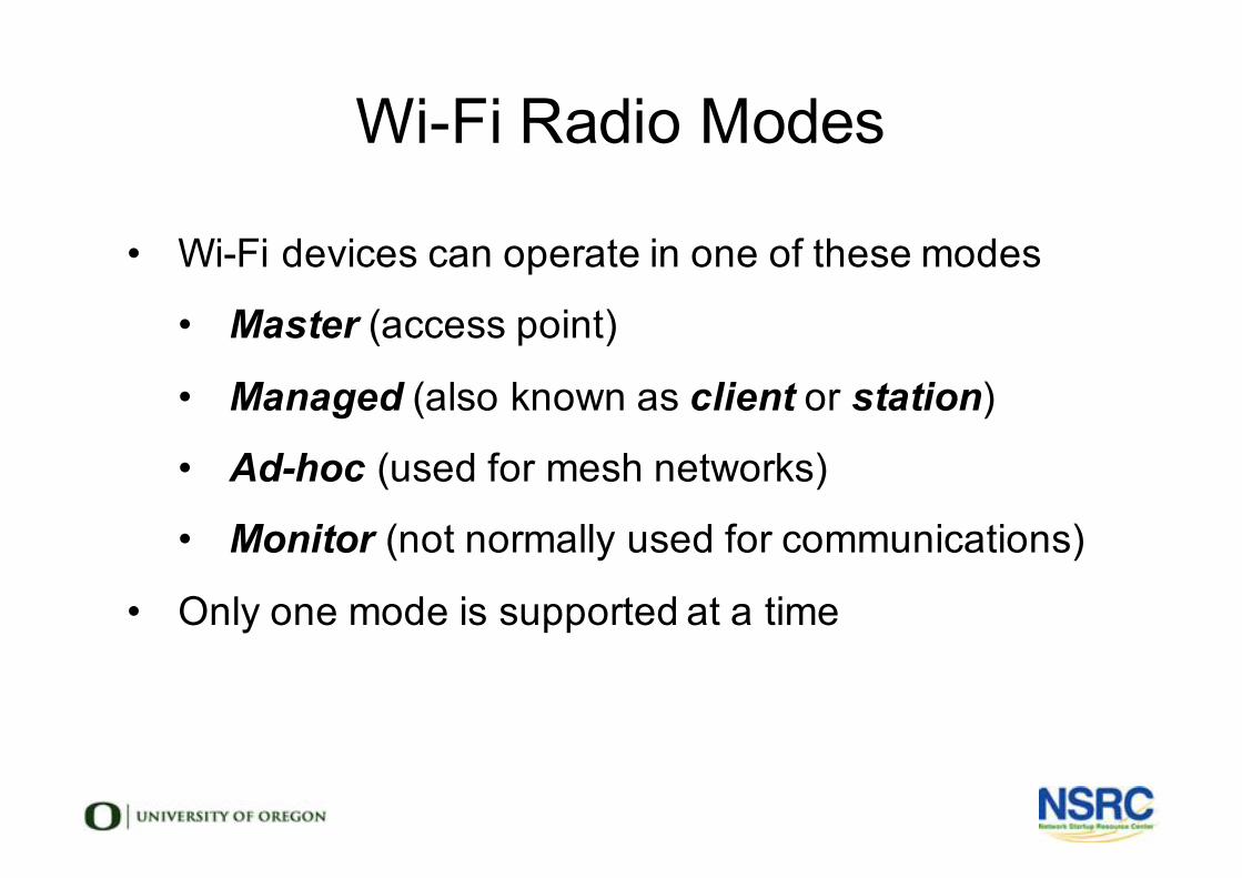
Wi-Fi Radio Modes
• Wi-Fi devices can operate in one of these modes
• Master (access point)
• Managed (also known as client or station)
• Ad-hoc (used for mesh networks)
• Monitor (not normally used for communications)
• Only one mode is supported at a time
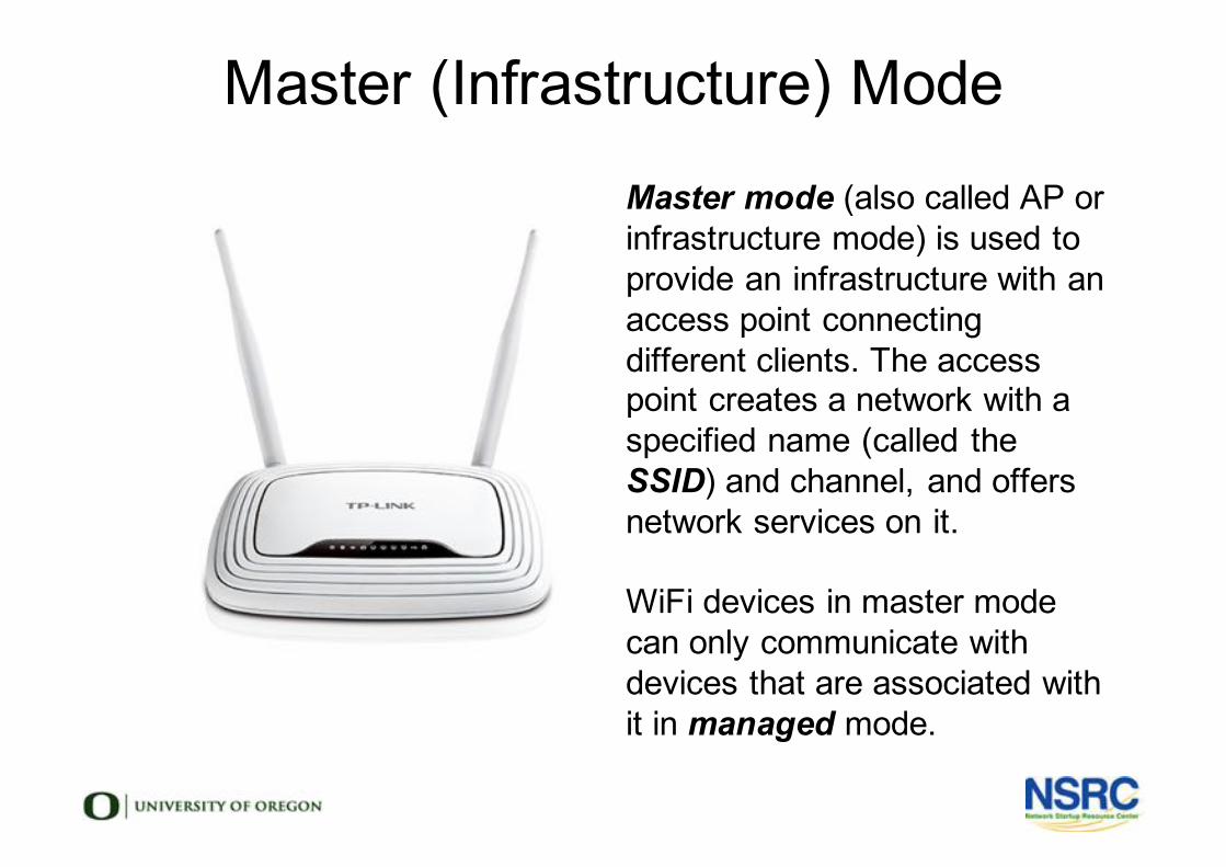
Master (Infrastructure) ModeMaster mode (also called AP or infrastructure mode) is used to provide an infrastructure with an access point connecting different clients. The access point creates a network with a specified name (called the SSID) and channel, and offers network services on it.
WiFi devices in master mode can only communicate with devices that are associated with it in managed mode.
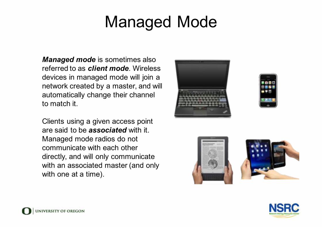
Managed Mode
l Managed mode is sometimes also referred to as client mode. Wireless devices in managed mode will join a network created by a master, and will automatically change their channel to match it.
l
l Clients using a given access point are said to be associated with it. Managed mode radios do not communicate with each other directly, and will only communicate with an associated master (and only with one at a time).
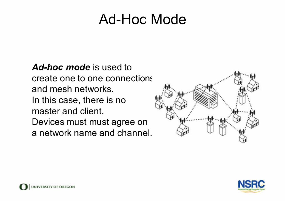
Ad-hoc mode is used to create one to one connections and mesh networks. In this case, there is no master and client.Devices must must agree on a network name and channel.
Ad-Hoc Mode
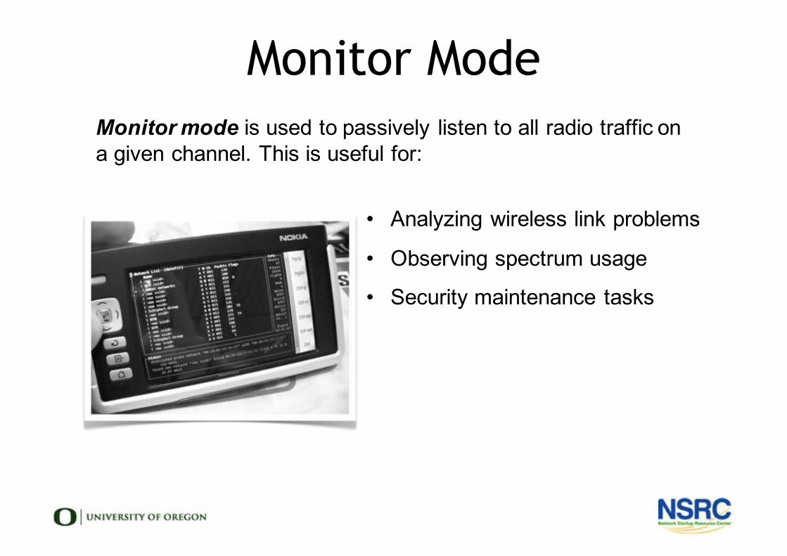
Monitor Mode
Monitor mode is used to passively listen to all radio traffic on a given channel. This is useful for:
• Analyzing wireless link problems
• Observing spectrum usage
• Security maintenance tasks
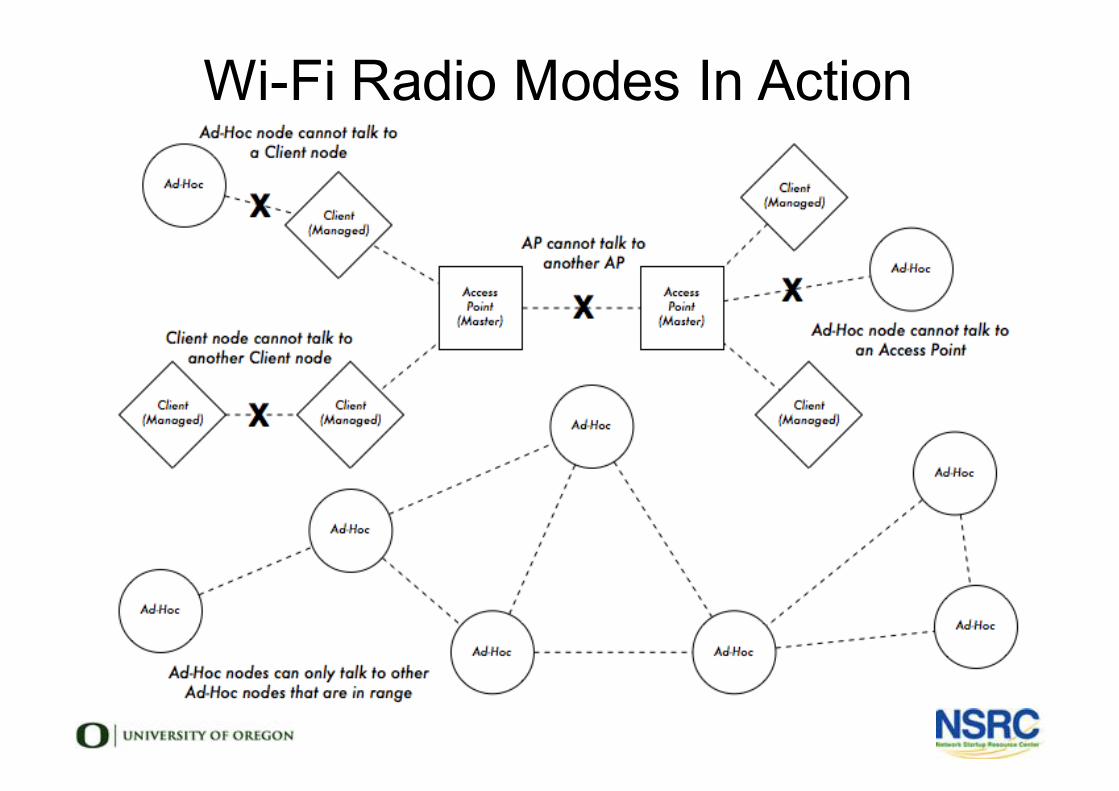
Wi-Fi Radio Modes In Action
Wireless Distribution System (WDS)
• Access Points can communicate with each other!
• But there can be many problems
• Cross-vendor compatibility
• Maximum throughput is halved at each hop
• Typically supports only 5 APs at a time
• WDS is rarely needed and not recommended.
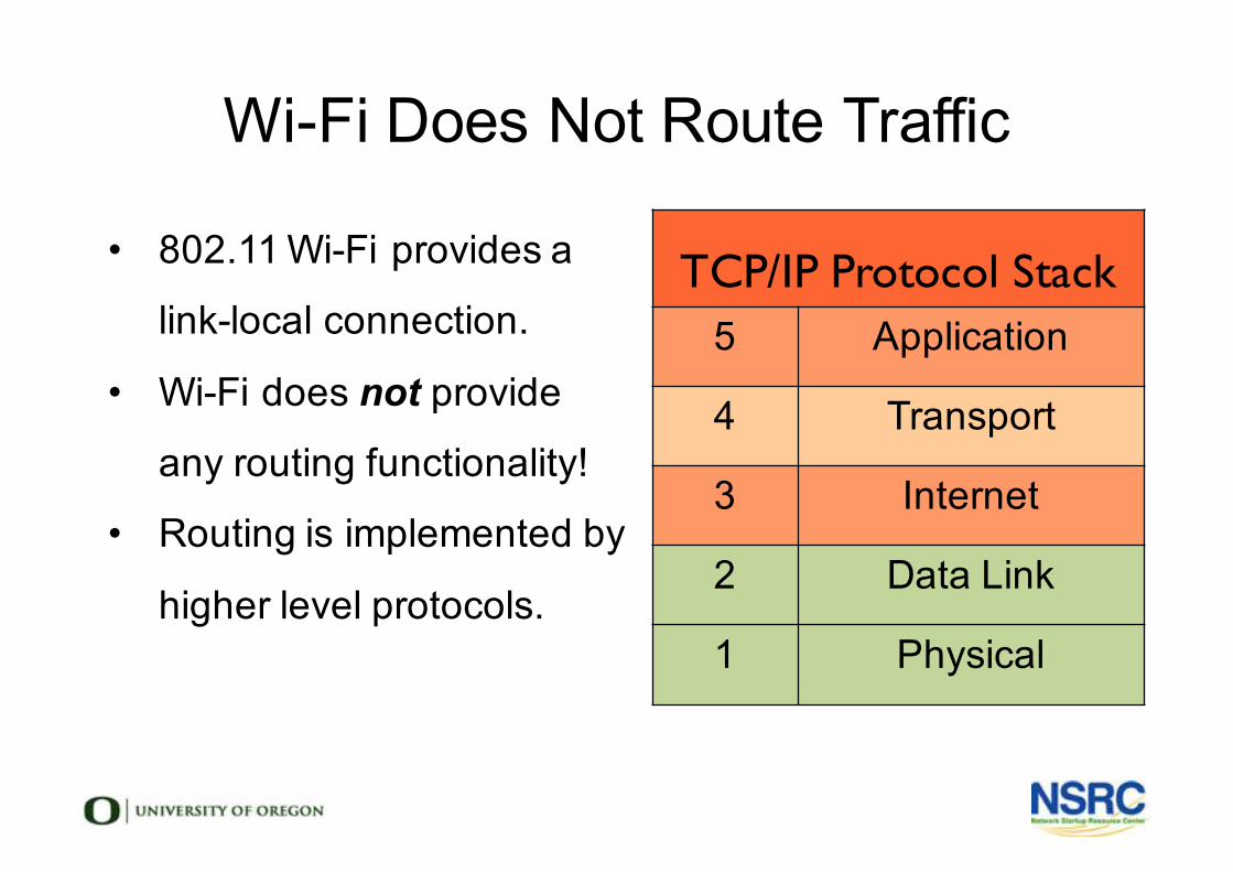
Wi-Fi Does Not Route Traffic
TCP/IP Protocol Stack5 Application
4 Transport
3 Internet
2 Data Link
1 Physical
• 802.11 Wi-Fi provides a
link-local connection.
• Wi-Fi does not provide
any routing functionality!
• Routing is implemented by
higher level protocols.
Bridged Networking• Appropriate for simple networks
• Advantages
• Very simple configuration
• Roaming works very well
• Disadvantages
• Efficiency falls as nodes are added
• All broadcast traffic is repeated
• Unstable on larger networks
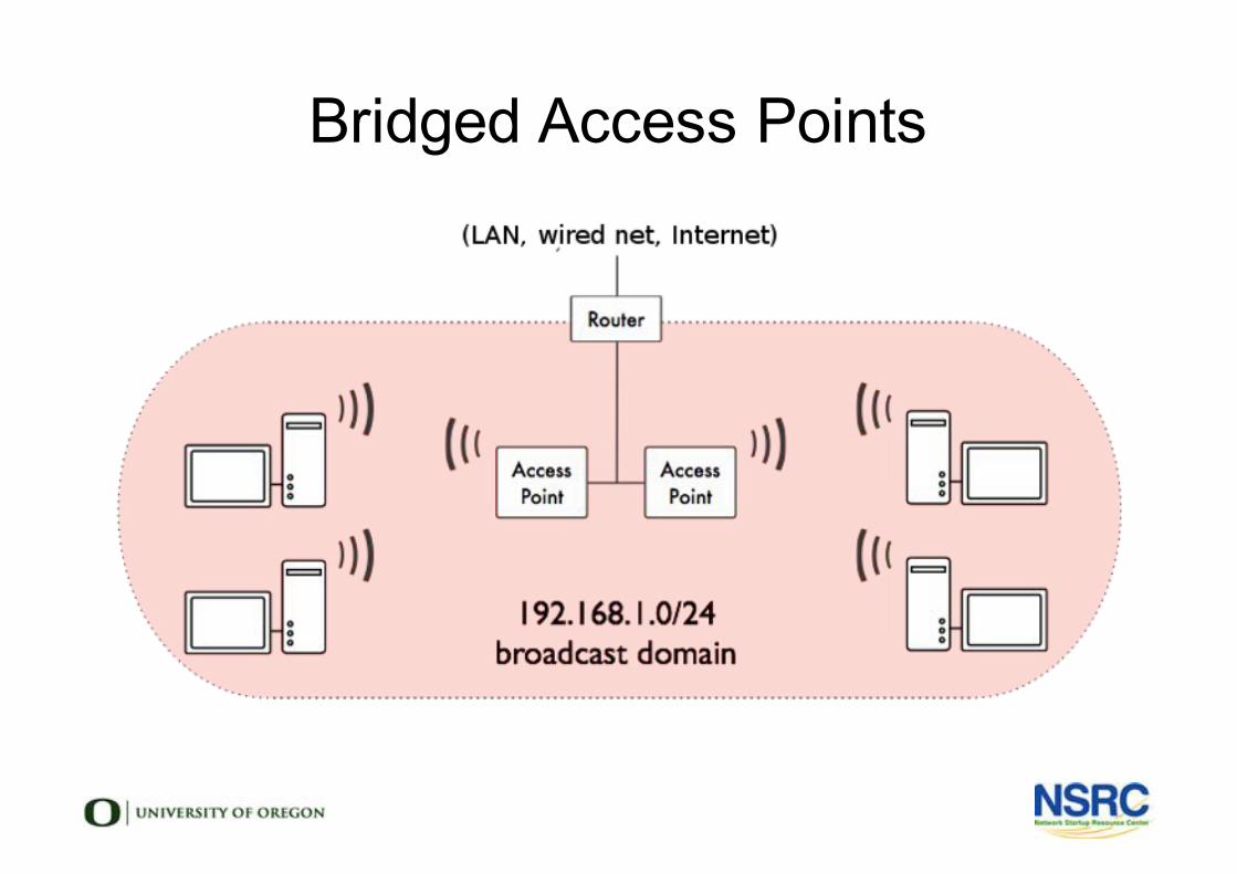
Bridged Access Points
Routed Networking• Route between nodes for large networks
• Static Routing
• Point-to-point links
• Simple networks
• Dynamic Routing
• RIP is a very old protocol with many problems
• OSPF is a modern protocol for dynamic routing
• RIP and OSPF do not perform well on unstable backbones
• Mesh Routing
• Standards & proprietary protocols available
• Can perform better than OSPF on unstable networks
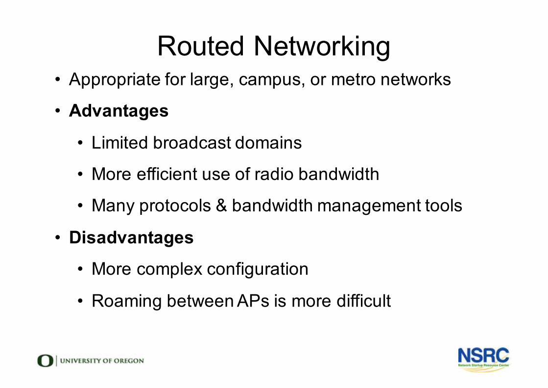
Routed Networking• Appropriate for large, campus, or metro networks
• Advantages
• Limited broadcast domains
• More efficient use of radio bandwidth
• Many protocols & bandwidth management tools
• Disadvantages• More complex configuration
• Roaming between APs is more difficult
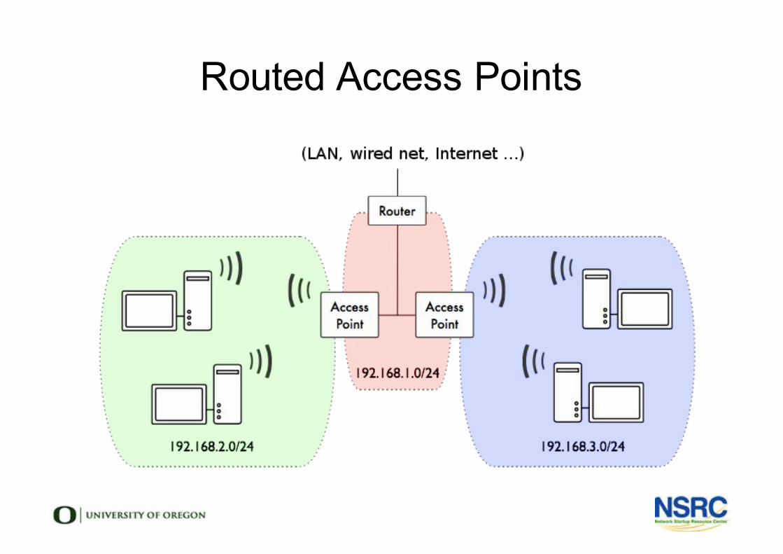
Routed Access Points
FrequentlyAsked
Questions

Frequently Asked Questions
l How fast? l How far?l How many clients?l Are all my devices compatible?l What should I buy?
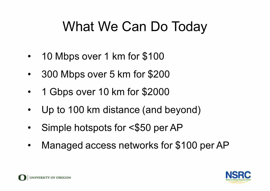
What We Can Do Today
• 10 Mbps over 1 km for $100
• 300 Mbps over 5 km for $200
• 1 Gbps over 10 km for $2000
• Up to 100 km distance (and beyond)
• Simple hotspots for <$50 per AP
• Managed access networks for $100 per AP
How Many Clients?• How many end users on one AP?
• 100 moderate users
• 10-30 heavy users
• Limitations
• Radio Spectrum
• Slowest Clients
• Backhaul & Core Network
• Access Point CPU / Packets Per Second
Problems For The Future
• Bring Your Own Device (BYOD) means 2-4 devices per person
• Power over Ethernet (PoE) at 100mbps is no longer enough
• 1gbps Ethernet is not enough for some 802.11ac access points
• Network security is difficult, and getting more difficult
• How will you manage your users?
Learning More
l Network Startup Resource Centerl http://nsrc.orgl ICTP Wireless | T/ICT4D Labl http://wireless.ictp.it/ l Wireless Networking for the Developing Worldl http://wndw.netl ICTP UNESCO Wireless Training Kitl http://140.105.28.115/groups/wtkit/
Thank you!
Questions and comments?
Email your workshop mailing list!
lWireless Authentication
Network Startup Resource Centerwww.nsrc.org
These materials are licensed under the Creative Commons Attribution-NonCommercial 4.0 International license(http://creativecommons.org/licenses/by-nc/4.0/)
What is Authentication?
• Verifying the claim that an entity is allowed to act on behalf of a given known identity
• More simply:• Is this person says who they say they are?• Can they prove it
• for example, with password, signature?• In our case, the entity is the software, acting on
behalf of the user controlling the computer.
Why Is It So Complicated?
• I am on a computer. Am I its owner?
• Device is not the same as person.
• I am a network administrator
• Should I have access to the finance system?
• I am connecting to the network from home
• Should I have access to all my work resources?
Authentication Core Concepts
• These are all different concepts:• Confidentiality• Access Control• Authentication• Authorization
Confidentiality
Ensure that only those who should have access to
information can indeed do so (usually encryption)
Authorization
Authorization defines what an entity (a user, a device)
is authorized (allowed), to access• Which networks (ACLs/filters)
• Which systems, which files ? (FS ACLs, permissions)
• When can they do that (time policies) ?
• Can they run an application or access a service ?
Access Control
l Access control is the mechanisms by which
rights &restrictions are controlled & enforced
Why Do We Authenticate?• We want to know: WHO, WHERE(*), WHEN
• Which user?
• What AP did they associate with?
• When did they log on ?
• What IP number did they have?
• PSK (Pre-Shared Key) cannot tell us this.
• Keys can be shared between users
• We can’t know who, where, or when.
Authentication Solutions
• We recommended two ways to do this:• Captive portal• 802.1X (EAPoL and EAP-TLS) (Preferred)
• Your choice depends on • The size of your organization• The maturity of your IT systems• Your human resources• Available user stores, databases
• For example, Active Directory or LDAP
Captive Portals: Positive
• Popular (public areas, airports, hotels…)
• Flexible
• Self-explanatory (web page), can enforce AUP
(Acceptable Use Policy) validation
• Relatively easy to implement
Captive Portals: Negative
• Not transparent
• Depend on browser
• Not standardized (different looks, different
credentials, …)
• Requires regular re-authentication (disruptive)
• Often unreliable and easy to break
Captive Portals: Redirection
• Any of the following methods can be used:• HTTP silent redirection• HTTP 30x redirect• IP hijacking• DNS hijacking• Certain URLs may be allowed
• e.g. Information, help, use policies pages
Captive Portals: Vendors• Many vendors and open source projects
• CoovaChilli, CoovaAP
• WiFidog
• M0n0wall, pfSense
• zeroshell
• Many networking vendors offer captive portals
• Aptilo, Aruba, Cisco, HP, Mikrotik, Ubiquiti
802.1x/EAP (WPA2 Enterprise)
• Originally designed for wired networks (EAPoL)
• Modified for wireless networks (RFC5216)
• Layer 2 protocol with 4 states:
1. Initialization (all traffic including DHCP)
2. Initiation (authenticator sends EAP-Requests, and client
responds with EAP-Response-Identity)
3. Negotiation of a method of authentication
4. Authentication if negotiation succeeds
• Traffic is allowed through
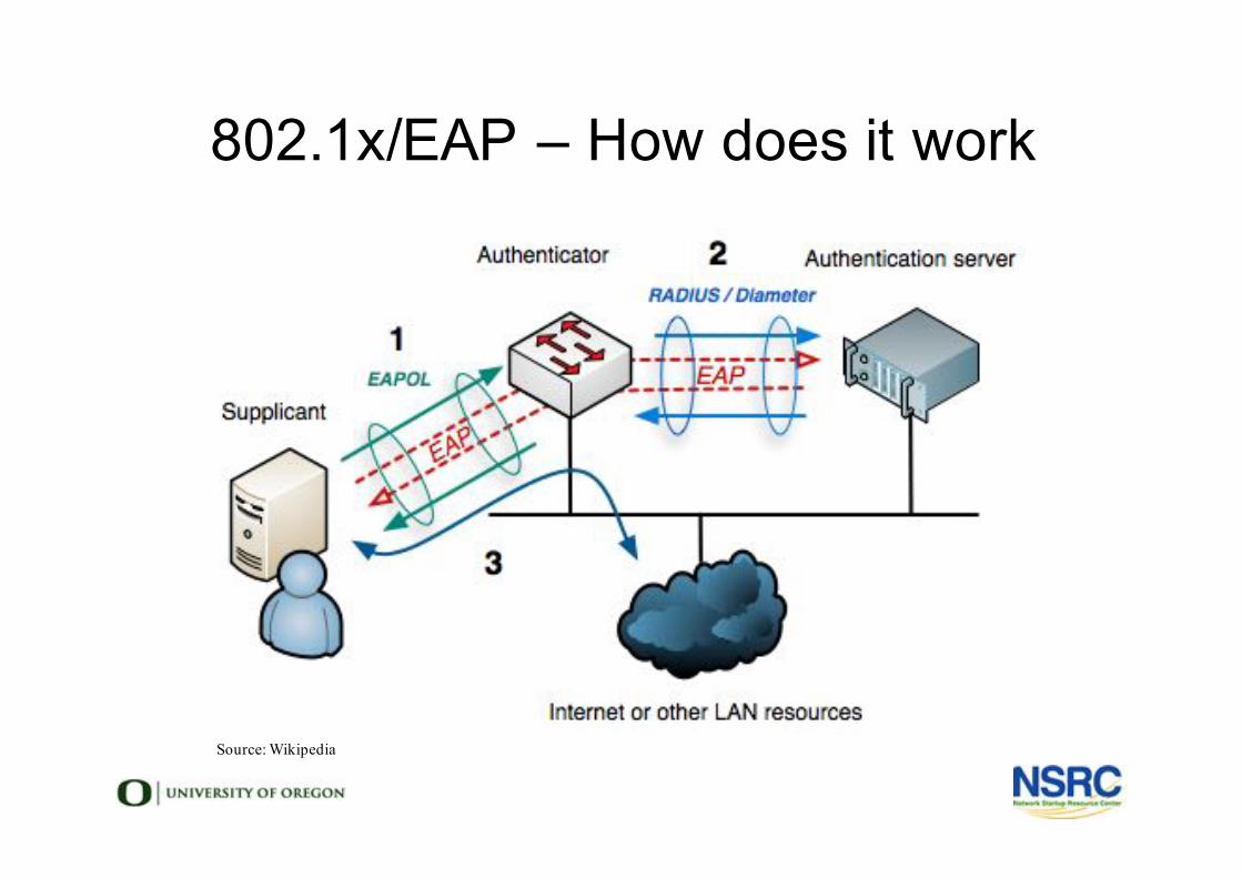
802.1x/EAP – How does it work
Source: Wikipedia

802.1x/EAP
• Positive
• Transparent for Applications
• In-line: does not require interaction with upper
layers like DHCP, IP, HTTP to function
• Standardized for both wired and wireless LANs
• Negative
• More challenging in deployment
• Requires external authentication server (RADIUS)
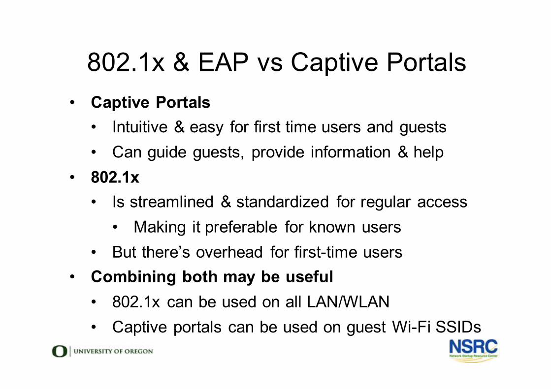
802.1x & EAP vs Captive Portals• Captive Portals
• Intuitive & easy for first time users and guests• Can guide guests, provide information & help
• 802.1x• Is streamlined & standardized for regular access
• Making it preferable for known users• But there’s overhead for first-time users
• Combining both may be useful• 802.1x can be used on all LAN/WLAN• Captive portals can be used on guest Wi-Fi SSIDs
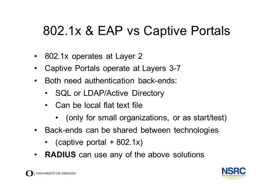
802.1x & EAP vs Captive Portals
• 802.1x operates at Layer 2
• Captive Portals operate at Layers 3-7
• Both need authentication back-ends:
• SQL or LDAP/Active Directory
• Can be local flat text file
• (only for small organizations, or as start/test)
• Back-ends can be shared between technologies
• (captive portal + 802.1x)
• RADIUS can use any of the above solutions
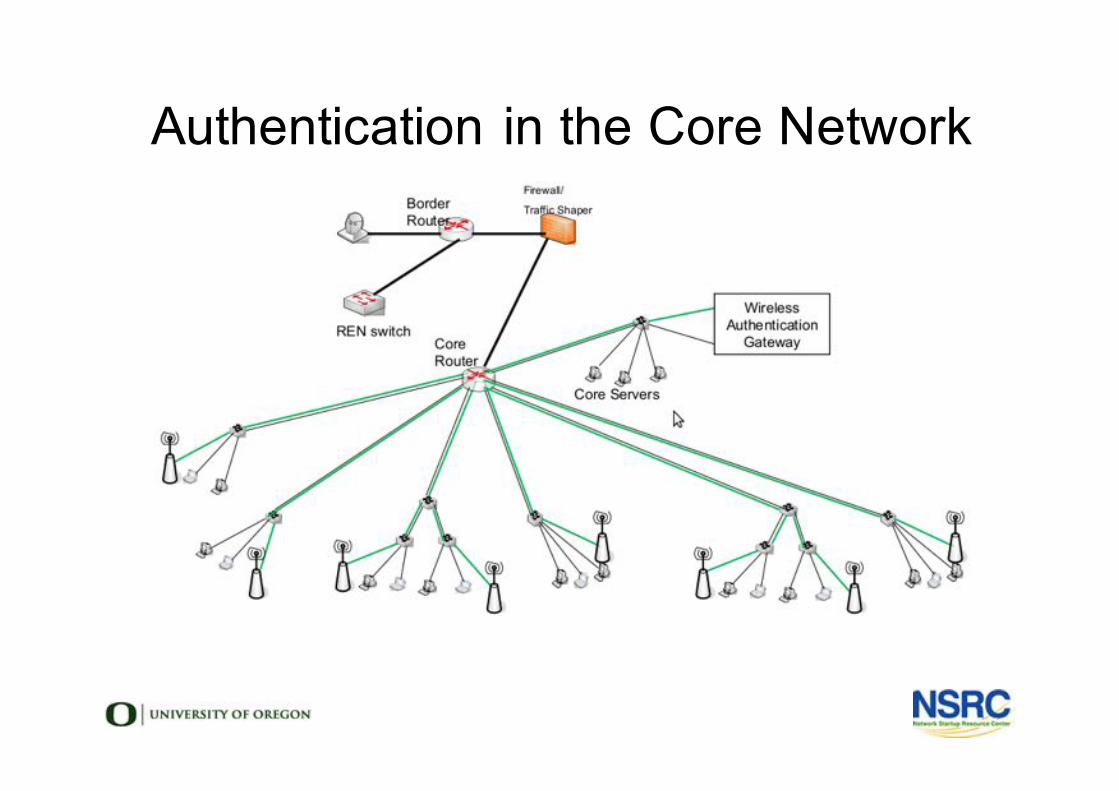
Authentication in the Core Network
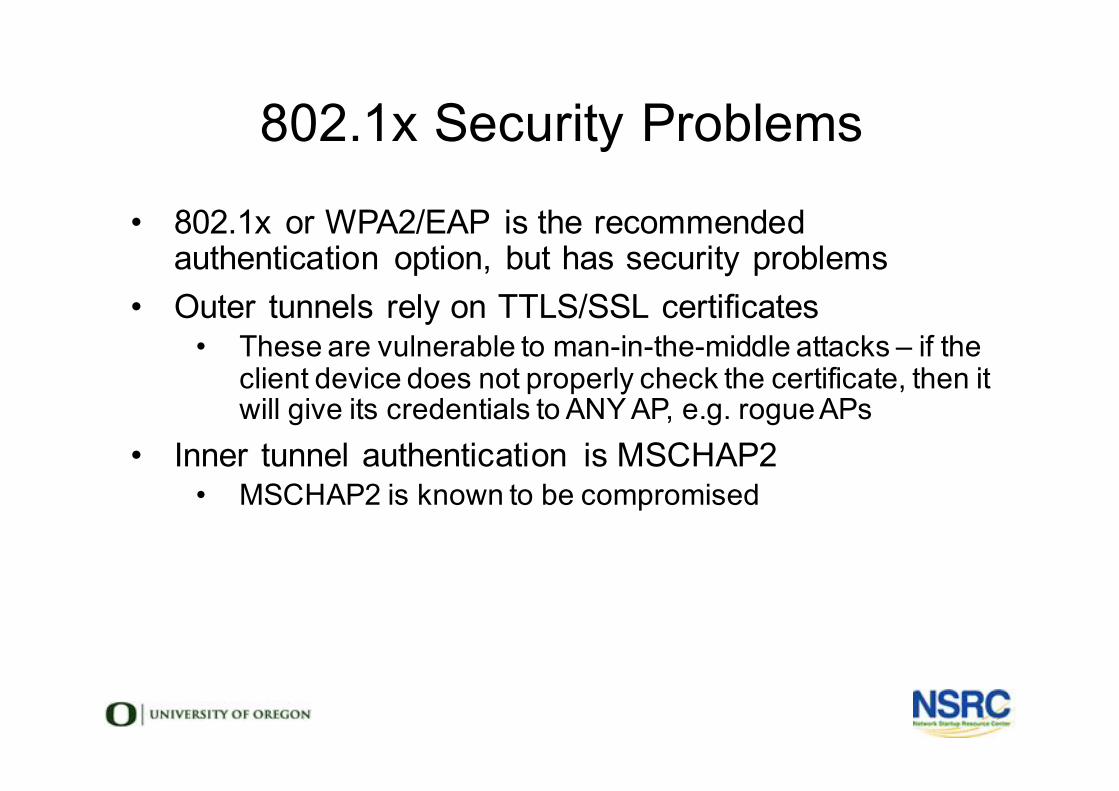
802.1x Security Problems
• 802.1x or WPA2/EAP is the recommended
authentication option, but has security problems
• Outer tunnels rely on TTLS/SSL certificates
• These are vulnerable to man-in-the-middle attacks – if the
client device does not properly check the certificate, then it
will give its credentials to ANY AP, e.g. rogue APs
• Inner tunnel authentication is MSCHAP2
• MSCHAP2 is known to be compromised
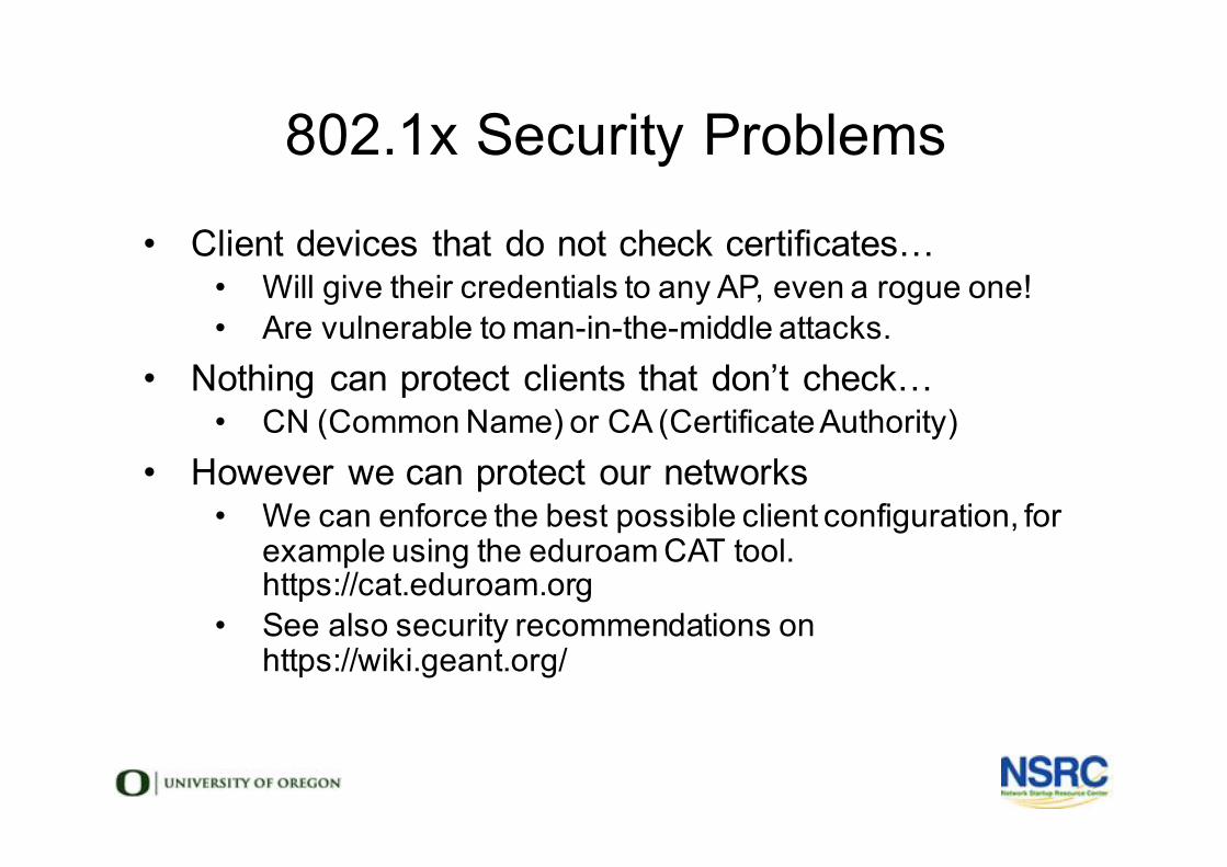
802.1x Security Problems
• Client devices that do not check certificates…• Will give their credentials to any AP, even a rogue one!
• Are vulnerable to man-in-the-middle attacks.
• Nothing can protect clients that don’t check…• CN (Common Name) or CA (Certificate Authority)
• However we can protect our networks• We can enforce the best possible client configuration, for
example using the eduroam CAT tool. https://cat.eduroam.org
• See also security recommendations on https://wiki.geant.org/
802.1x MITM Attack
• Get user to associate to rogue AP and start handshake & Authentication process
• Packet dump everything• Analyze the traffic, isolate the handshake• The outer tunnel is easy – as the attacker owns
certificate and keys• The inner tunnel (typically MSCHAP2) can be cracked
(via offline or online services)
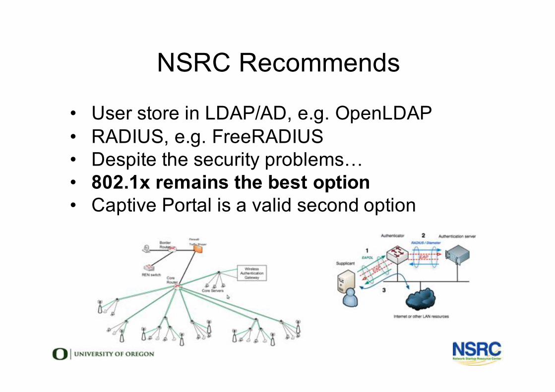
NSRC Recommends
• User store in LDAP/AD, e.g. OpenLDAP• RADIUS, e.g. FreeRADIUS• Despite the security problems…• 802.1x remains the best option• Captive Portal is a valid second option
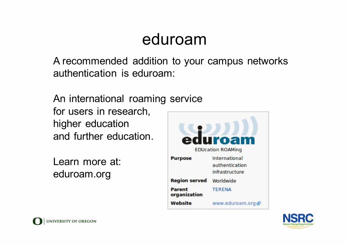
eduroaml A recommended addition to your campus networks
authentication is eduroam:l
l An international roaming service l for users in research, l higher education l and further education.l
l Learn more at:l eduroam.org

Building wireless core networks & point-to-point links
Network Startup Resource Centerwww.nsrc.org
These materials are licensed under the Creative Commons Attribution-NonCommercial 4.0 International license(http://creativecommons.org/licenses/by-nc/4.0/)
Roles of Wireless
• In integrated (campus) networks
• Infrastructure / Backbone
• Access / end user / hotspot
• Mixed roles in Mesh Networks
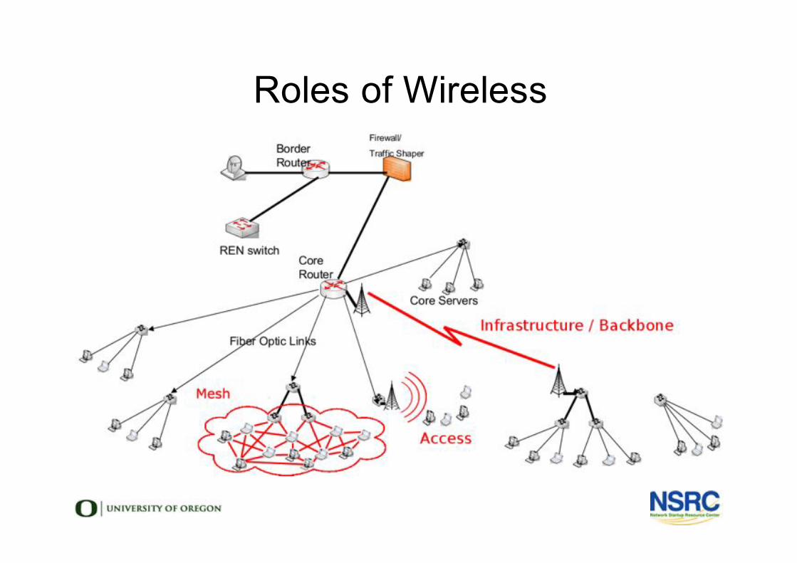
Roles of Wireless
How Far Can We Go?
• When building infrastructure, key question:
• How far can we go and still have
sufficient bandwidth and stability?
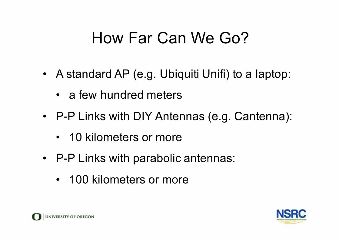
How Far Can We Go?
• A standard AP (e.g. Ubiquiti Unifi) to a laptop:
• a few hundred meters
• P-P Links with DIY Antennas (e.g. Cantenna):
• 10 kilometers or more
• P-P Links with parabolic antennas:
• 100 kilometers or more
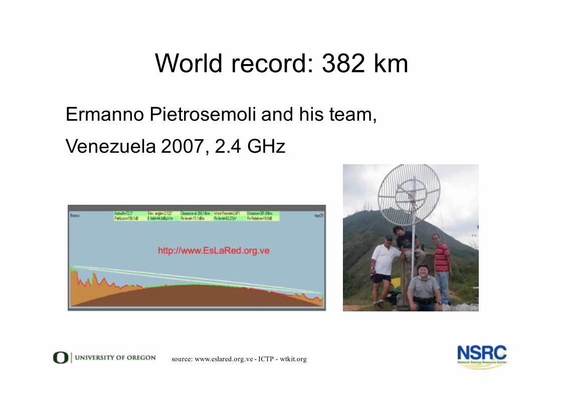
World record: 382 km
Ermanno Pietrosemoli and his team,Venezuela 2007, 2.4 GHz
source: www.eslared.org.ve - ICTP - wtkit.org
Link Budgets
• Not all links need to be world records
• But all links need planning
• The key to planning is a Link Budget
• Budget = Sum of all gains – sum of all loss
The Language of Link Budgets
• Some terms come from basic radio physics
• Free space loss, Fresnel zones, dB
• Some from antenna theory
• Gain, radiation patterns, EIRP
• Others are specific to radio linking
• Link Margin, RSSI, Transmit Power
EIRP: Effective Isotropic Radiated Power
• Hold your hand one meter from a candle
• You feel some warmth
• Put a reflector behind the candle
• You feel twice as much warmth!
• EIRP is a measure of radiated power relative to
an isotropic antenna.
• It’s the sum of TX power and antenna gain
Transmit (TX) Power
• Output from Radio
• Higher powers = lower modulation (less data)
• TX Power is always in data/spec sheets
• For wireless typically 20-30dBm
Cable Loss
• As per Antennas & Waveguide Unit
• Longer cables = more loss
• Higher frequencies = more loss
• Thinner cable = more loss
• Add at least .25 dB loss per connector
• Add 1 dB loss per lightning arrestor
• Keep your cables as short as possible
Antenna Gain
• Depends on Frequency
• Smaller Waves = More gain from same area• 300 mm antenna at 2.4 GHz = ~ 16 dBi
• 300 mm antenna at 5.7 GHz = ~ 23 dBi
• 250 mm antenna at 60 GHz = ~ 40 dBi
• Antenna gain directs power, does not amplify!
• Equal contribution to TX power and RX gain
RSSI: Received Signal Strength Indicator
• Commonly seen as “RSSI”
• A measurement of the received power
• Expressed in dBm (decibel milliwatts)
• Typically a negative number. Higher is better
• You might see:
• -8dBm on a 40 gbps fibre optic link
• -66dBm on 1.5 gbps radio link at 24 GHz
Link Margin
• How much signal is left after all loss & gain
• Most links require a margin of 20dB
• Higher signal to noise = better performance
• Links that will fade (rain, thermal) need more
Free Space Loss●Proportional to square of distance and square of frequency
●FSL (dB) = 20 x log[4π x distance/wavelength]
–where distance and wavelength are in the same units
●Free space loss is pure geometry – it has nothing to do with absorption, air, fog, rain or any obstacles!
Free Space Loss
• 20 x log[4π x distance/wavelength]
• where distance and wavelength are in the same units
• Free space loss is pure geometry – it has nothing to
do with absorption, air, fog, rain or any obstacles!
Absorption & Reflection
• Trees, bushes, buildings, cars, people
• We can't always avoid them
• Try to keep the Line of Sight free
• Obstructed paths will work, however
• Lower frequencies will work better
• Lower modulations & speeds necessary
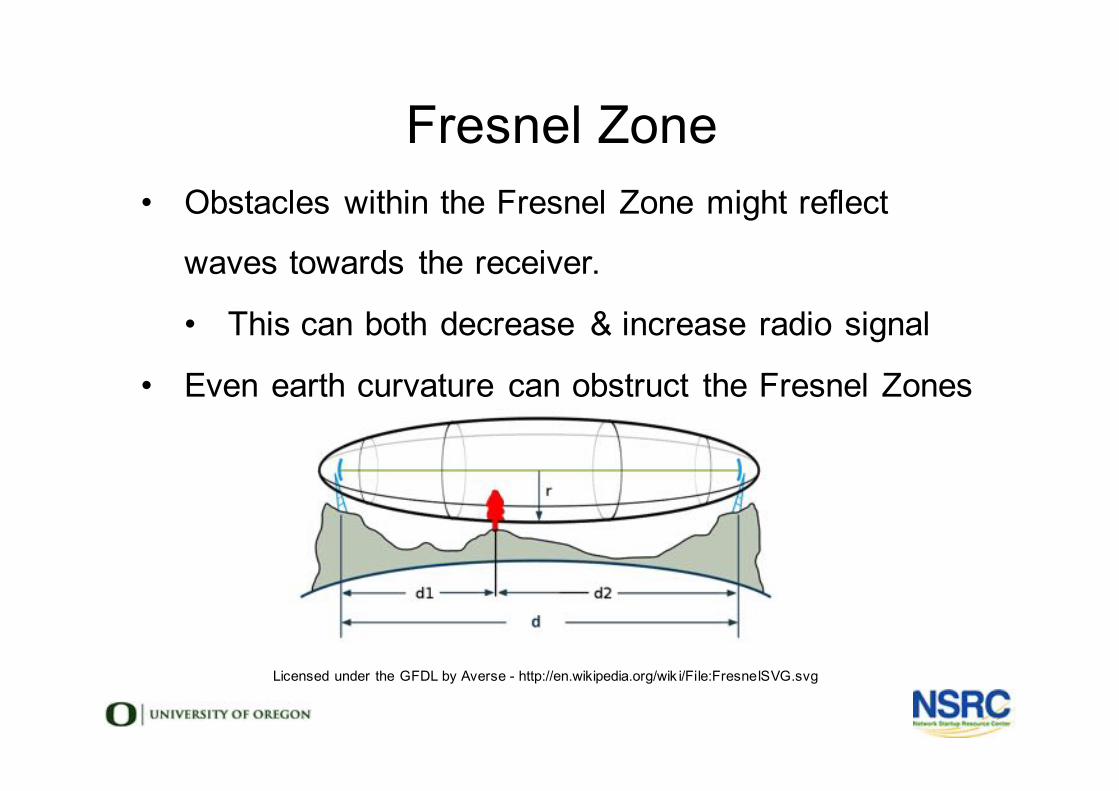
Fresnel Zone• Obstacles within the Fresnel Zone might reflect
waves towards the receiver.
• This can both decrease & increase radio signal
• Even earth curvature can obstruct the Fresnel Zones
Licensed under the GFDL by Averse - http://en.wikipedia.org/wik i/File:FresnelSVG.svg
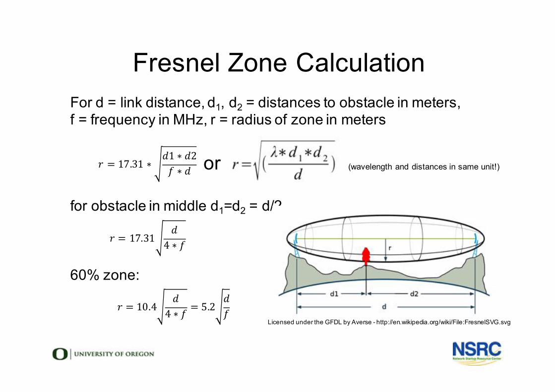
Fresnel Zone CalculationFor d = link distance, d1, d2 = distances to obstacle in meters, f = frequency in MHz, r = radius of zone in meters
or (wavelength and distances in same unit!)
for obstacle in middle d1=d2 = d/2
60% zone:
Licensed under the GFDL by Averse - http://en.wikipedia.org/wiki/File:FresnelSVG.svg
! = 17.31 ∗ (1 ∗ (2* ∗ (
! = 17.31 (4 ∗ *
! = 10.4 (4 ∗ * = 5.2 (
*
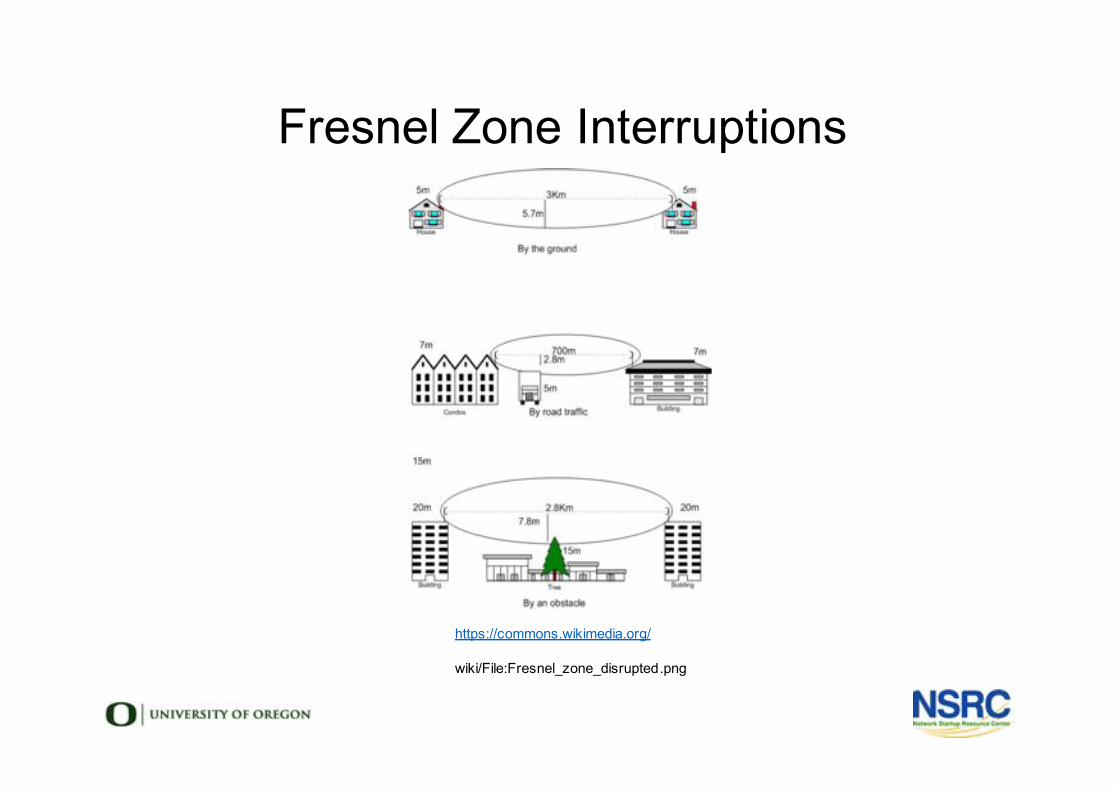
Fresnel Zone Interruptions
https://commons.wikimedia.org/
wiki/File:Fresnel_zone_disrupted.png
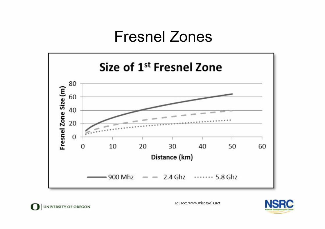
Fresnel Zones
source: www.wisptools.net
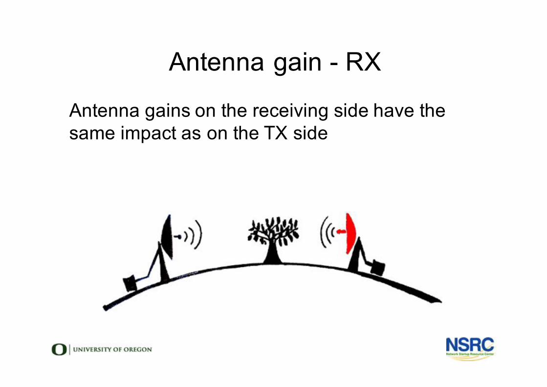
Antenna gain - RX
Antenna gains on the receiving side have the same impact as on the TX side
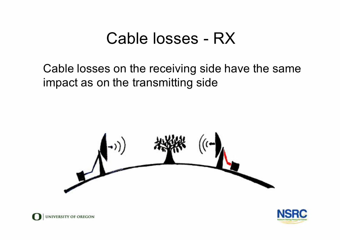
Cable losses - RX
Cable losses on the receiving side have the same impact as on the transmitting side
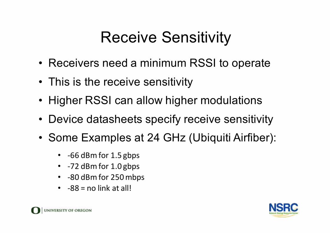
Receive Sensitivity• Receivers need a minimum RSSI to operate• This is the receive sensitivity• Higher RSSI can allow higher modulations• Device datasheets specify receive sensitivity• Some Examples at 24 GHz (Ubiquiti Airfiber):
• -66dBm for1.5gbps• -72dBm for1.0gbps• -80dBm for250mbps• -88=nolinkatall!
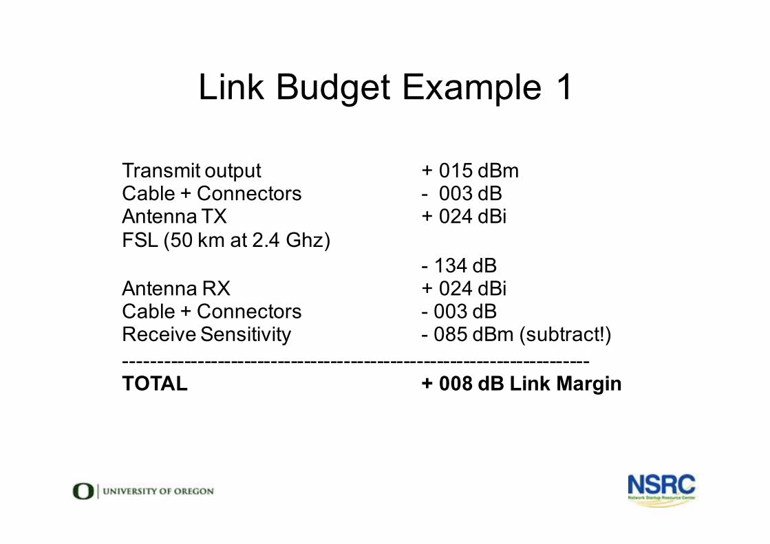
Link Budget Example 1
Transmit output + 015 dBmCable + Connectors - 003 dBAntenna TX + 024 dBiFSL (50 km at 2.4 Ghz)
- 134 dBAntenna RX + 024 dBiCable + Connectors - 003 dBReceive Sensitivity - 085 dBm (subtract!)----------------------------------------------------------------------TOTAL + 008 dB Link Margin
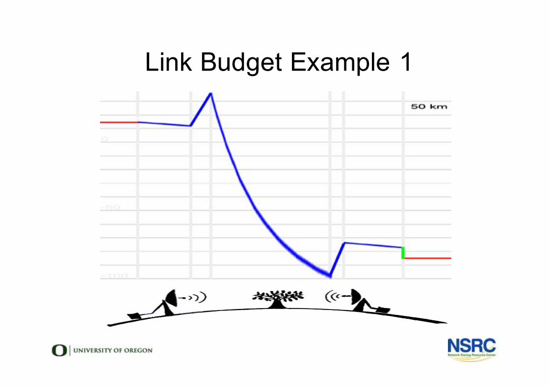
Link Budget Example 1
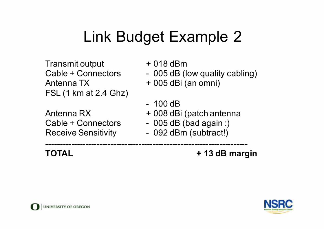
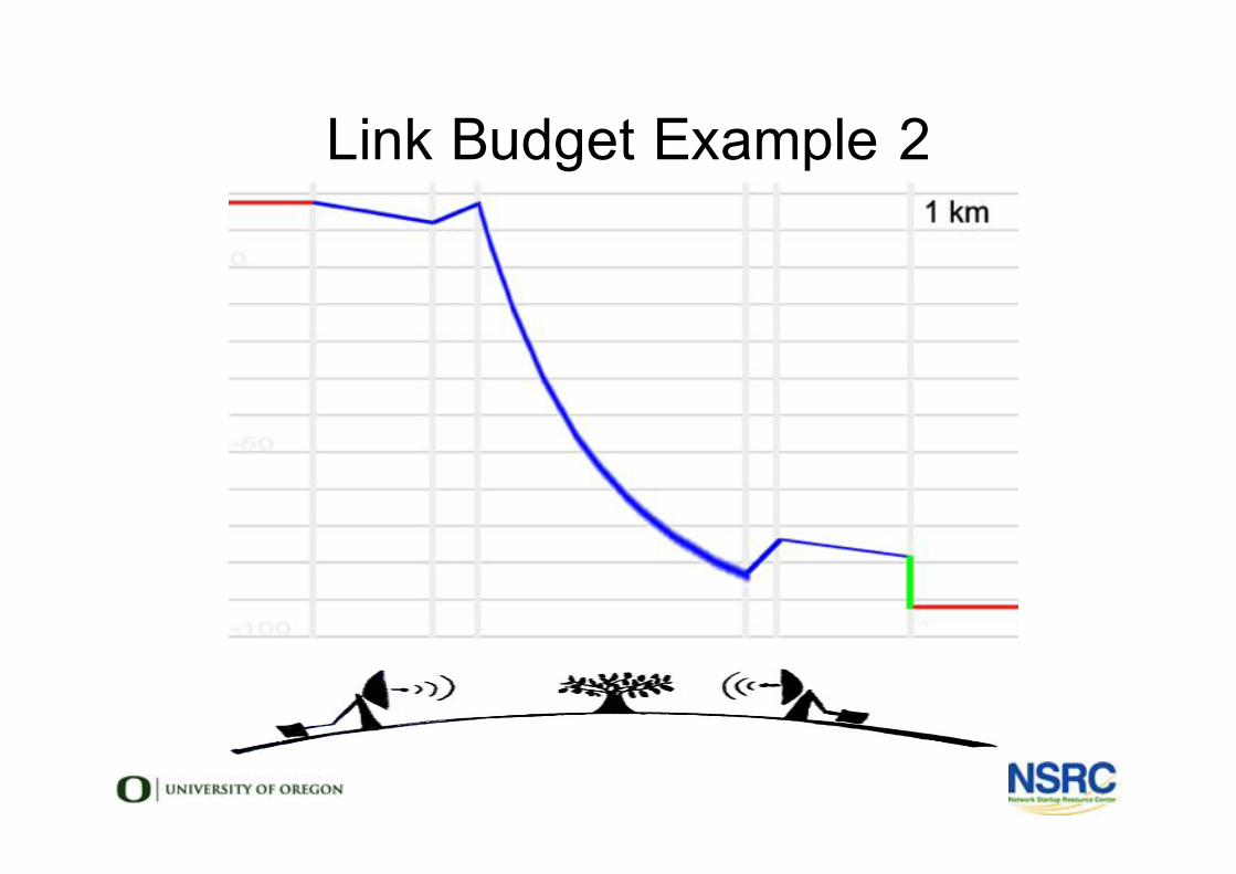
Link Budget Example 2
Transmit output + 018 dBmCable + Connectors - 005 dB (low quality cabling)Antenna TX + 005 dBi (an omni)FSL (1 km at 2.4 Ghz)
- 100 dBAntenna RX + 008 dBi (patch antennaCable + Connectors - 005 dB (bad again :)Receive Sensitivity - 092 dBm (subtract!)------------------------------------------------------------------------TOTAL + 13 dB margin
Link Budget Example 2
Link Simulation Software
• There are a number of very useful software tools for link and network simulation:
• RadioMobile: offline program and online http://www.cplus.org/rmw/rmonline.html
• CloudRF: https://cloudrf.com/
• Ubiquiti Airlink: https://airlink.ubnt.com/
• Vendor tools from Cambium, Mimosa, and more!
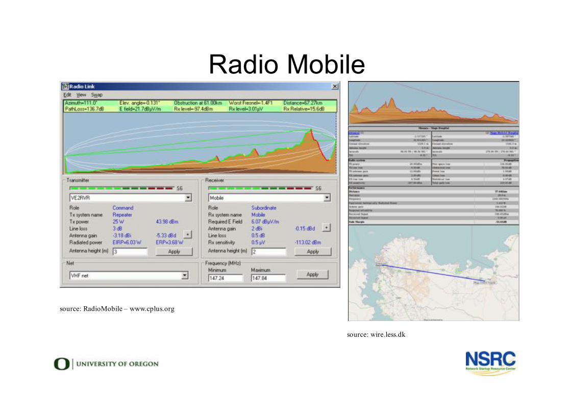
Radio Mobile
source: RadioMobile – www.cplus.org
source: wire.less.dk
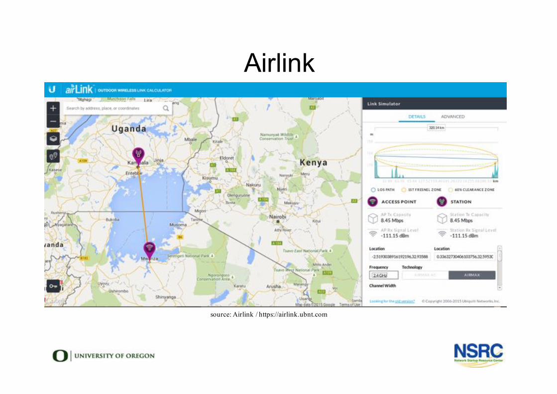
Airlink
source: Airlink / https://airlink.ubnt.com
Limits of software link simulation
• These tools, made for long range link simulation, can also be useful for metro / campus links.
• Free tools do not model clutter (buildings, obstacles, vegetation), or small changes in terrain.
• Paid tools (WinProp, EDX, etc.) can model everything.
• When planning a link, nothing can replace a site survey and the human eye.
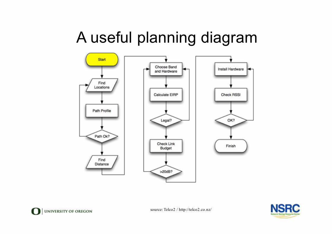
A useful planning diagram
source: Telco2 / http://telco2.co.nz/
You can read more here:
http://wndw.net