
Basic information on the surgical and prosthetic procedures
32
Temporization Impression taking Healing phase Implant Insertion Fine Implant Bed Preparation Basic Implant Bed Preparation Preoperative Planning Basic information on the surgical and prosthetic procedures Straumann® PURE Ceramic Implant
-
Upload
khangminh22 -
Category
Documents
-
view
7 -
download
0
Transcript of Basic information on the surgical and prosthetic procedures

Fina
l res
tora
tion
Tem
poriz
atio
nIm
pres
sion
taki
ngH
ealin
g ph
ase
Impl
ant I
nser
tion
Fine
Impl
ant B
ed P
repa
ratio
nBa
sic
Impl
ant B
ed P
repa
ratio
nPr
eope
rativ
e Pl
anni
ng
Basic information on the surgical and prosthetic procedures Straumann® PURE Ceramic Implant

About this guideThis surgical and prosthetic procedure describes the steps required for implantation and restoration of the Straumann® PURE Ceramic Implant. The Straumann® PURE Ceramic Implant System is recom-mended for use only by clinicians with advanced surgical skills. It is assumed that the user is familiar with placing dental implants. Not all detailed information will be found in this guide. Reference to existing Straumann procedure manuals will be made throughout this document.
1
Contents
1. Straumann® PURE Ceramic Implant 21.1 Introduction to the Straumann® PURE Ceramic Implant (Monotype) 2
1.2 Overview of the Straumann® PURE Ceramic Implant portfolio 3
2. Implant features and benefits 32.1 Design features 3
2.2 Surface 4
2.3 Material 4
3. Indications and contraindications 53.1 Intended use 5
3.2 Indications 5
3.3 Contraindications 5
4. Surgical procedure for Straumann® PURE Ceramic Implant (Monotype) 64.1 Preoperative planning 6
4.2 Basic implant bed preparation 10
4.3 Fine implant bed preparation 13
4.4 Implant insertion 14
5. Prosthetic procedure for Straumann® PURE Ceramic Implant (Monotype) 175.1 Protection during the healing phase 17
5.2 Impression taking 20
5.3 Temporization 22
5.4 Creation and cementation of the final restoration 24
6. Aftercare and cleaning of Straumann® PURE Ceramic Implants 26
7. Troubleshooting 267.1 Implant removal 26
7.2 Fracture of the abutment 26
8. Product reference list 27
9. Important guidelines 29
2
1. Straumann® PURE Ceramic Implant
1.1 INTRODUCTION TO THE STRAUMANN® PURE CERAMIC IMPLANT (MONOTYPE)
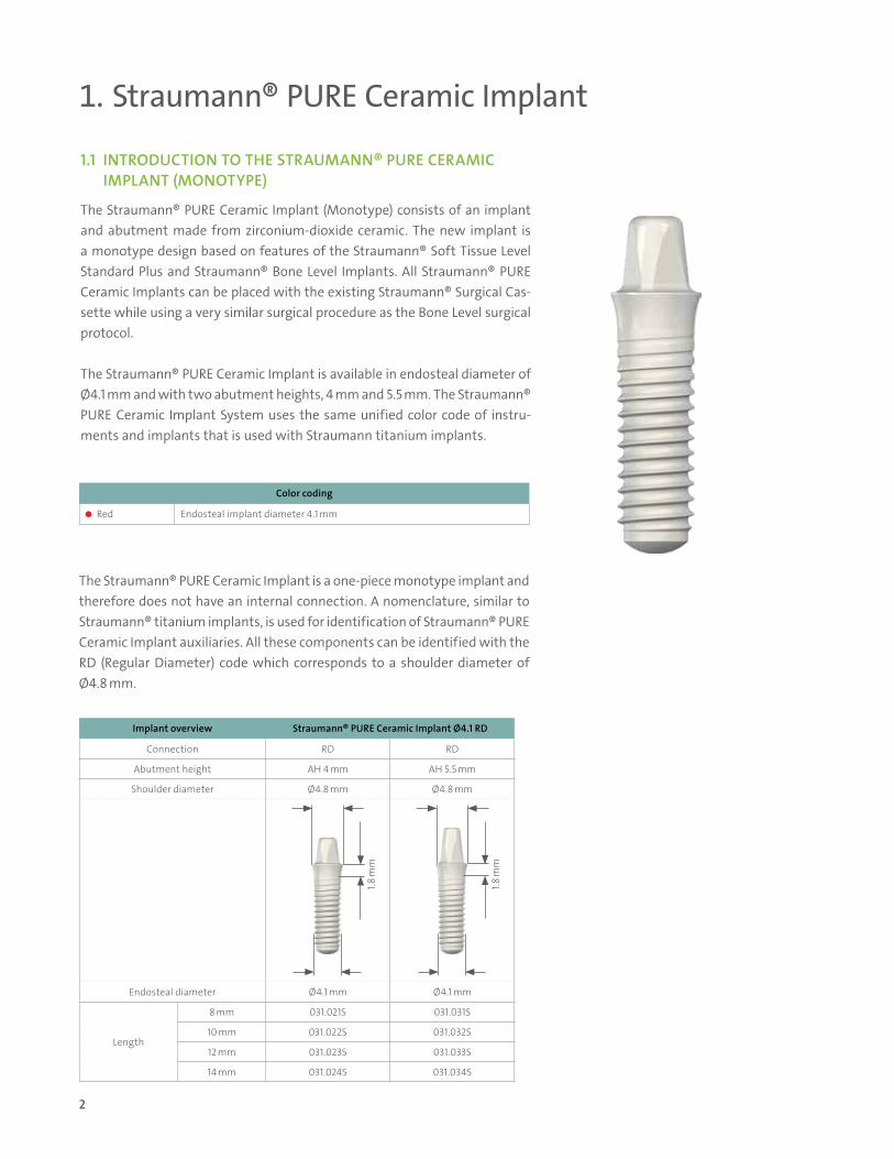
The Straumann® PURE Ceramic Implant (Monotype) consists of an implant and abutment made from zirconium-dioxide ceramic. The new implant is a monotype design based on features of the Straumann® Soft Tissue Level Standard Plus and Straumann® Bone Level Implants. All Straumann® PURE Ceramic Implants can be placed with the existing Straumann® Surgical Cas-sette while using a very similar surgical procedure as the Bone Level surgical protocol.
The Straumann® PURE Ceramic Implant is available in endosteal diameter of Ø4.1 mm and with two abutment heights, 4 mm and 5.5 mm. The Straumann® PURE Ceramic Implant System uses the same unified color code of instru-ments and implants that is used with Straumann titanium implants.
Color coding
Red Endosteal implant diameter 4.1 mm
The Straumann® PURE Ceramic Implant is a one-piece monotype implant and therefore does not have an internal connection. A nomenclature, similar to Straumann® titanium implants, is used for identification of Straumann® PURE Ceramic Implant auxiliaries. All these components can be identified with the RD (Regular Diameter) code which corresponds to a shoulder diameter of Ø4.8 mm.
Implant overview Straumann® PURE Ceramic Implant Ø4.1 RD
Connection RD RD
Abutment height AH 4 mm AH 5.5 mm
Shoulder diameter Ø4.8 mm Ø4.8 mm
Endosteal diameter Ø4.1 mm Ø4.1 mm
Length
8 mm 031.021S 031.031S
10 mm 031.022S 031.032S
12 mm 031.023S 031.033S
14 mm 031.024S 031.034S
1.8 m
m
1.8 m
m

3
1.2 OVERVIEW OF THE STRAUMANN® PURE CERAMIC IMPLANT PORTFOLIO
The Straumann® PURE Ceramic Implant System consists of only a few components.
2. Implant features and benefits
2.1 DESIGN FEATURES
Abutment design for cementable restorations Ivory color for natural-looking
esthetics
Conical thread in coronal region known from Bone Level Implants
Thread pitch 0.8 mm from Straumann® Bone Level Implants
1.8 mm machined neck
ZLA® surface topography comparable to Straumann® SLA®
Apical tip known from Bone Level/ Tapered Effect Implants
Surgical components Prosthetic components
• Implant• Position indicator
• Analog• Impression Cap• Protective Cap• Temporary Coping
4
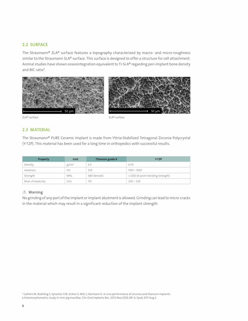
2.2 SURFACE
The Straumann® ZLA® surface features a topography characterized by macro- and micro-roughness similar to the Straumann SLA® surface. This surface is designed to offer a structure for cell attachment. Animal studies have shown osseointegration equivalent to Ti-SLA® regarding peri-implant bone density and BIC ratio*.
2.3 MATERIAL
The Straumann® PURE Ceramic Implant is made from Yttria-Stabilized Tetragonal Zirconia Polycrystal (Y-TZP). This material has been used for a long time in orthopedics with successful results.
WarningNo grinding of any part of the implant or implant abutment is allowed. Grinding can lead to micro-cracks in the material which may result in a significant reduction of the implant strength.
50 µm 50 µm
Property Unit Titanium grade 4 Y-TZP
Density g/cm3 4.5 6.05
Hardness HV 250 1100 –1500
Strength MPa 680 (tensile) ≥ 1200 (4-point bending strength)
Mod. of elasticity GPa 110 200 – 220
ZLA® surface SLA® surface
* Gahlert M, Roehling S, Sprecher CM, Kniha H, Milz S, Bormann K. In vivo performance of zirconia and titanium implants: a histomorphometric study in mini pig maxillae. Clin Oral Implants Res. 2012 Mar;23(3):281-6. Epub 2011 Aug 2.

5
3. Indications and contraindications
3.1 INTENDED USE
The Straumann® PURE Ceramic Implant (Monotype) is suitable for oral endosteal implantation in the upper and lower jaw and for the functional and esthetic oral rehabilitation of edentulous and partially edentulous patients (unless specific indications and limitations are specified).
3.2 INDICATIONS
The Straumann® PURE Ceramic Implant (Monotype) is indicated for restoration in single tooth gaps and in an edentulous or partially edentulous jaw. The prosthetic restorations used are single crowns, fixed partial or full dentures, which are connected to the implants through the corresponding components.
3.3 CONTRAINDICATIONS
Inadequate bone volume and/or quality, local root remnants, serious internal medical problems, uncon-trolled bleeding disorders, inadequate wound healing capacity, not completed maxillary and mandibular growth, poor general state of health, uncooperative, unmotivated patient, drug or alcohol abuse, psychoses, prolonged therapy-resistant functional disorders, xerostomia, weakened immune system, illnesses requiring periodic use of steroids, uncontrollable endocrine disorders. Allergies or hypersensitivity to chemical ingredients of the materials used: zirconium oxide (ZrO2), yttrium oxide (Y2O3), hafnium dioxide (HfO2), aluminum oxide (Al2O3).
Specific indications for Straumann® PURE Ceramic Implant (monotype)
Implant type Indications and distinctive festures Minimal ridge width*
Minimal gap width**
Straumann® PURE Ceramic Implant ∅ 4.1 mm RD
• For oral endosteal implant indications in the maxilla and mandible, for functional and esthetic rehabilitation of edentulous and partially edentulous patients
6 mm 7 mm
* Minimal ridge width: Minimal orofacial ridge width, rounded off to 0.5 mm ** Minimal gap width: Minimal mesial-distal gap width for a single-tooth restoration, between adjacent teeth, rounded off to 0.5 mm

6
4. Surgical procedure for Straumann® PURE Ceramic Implant (Monotype)
The workflow for the surgical procedure for the Straumann® PURE Ceramic Implant (Monotype) includes 4 steps: Preoperative planning, basic implant bed preparation, fine implant bed preparation and implant insertion.
4.1 PREOPERATIVE PLANNING
The monotype design of the Straumann® PURE Ceramic Implant (Monotype) requires the planning of implant placement to be very thorough and detailed. A prosthetic-driven planning is recommended and also particularly impor-tant as a perfect axis for implant insertion during implant bed preparation is crucial.
For the preoperative planning, the implant position and the planning aids will provide all information required to determine the most suitable position for the implant and its prosthetic reconstruction.
Caution: Straumann PURE Ceramic Implants are for clinical use as straight, no angular correction.
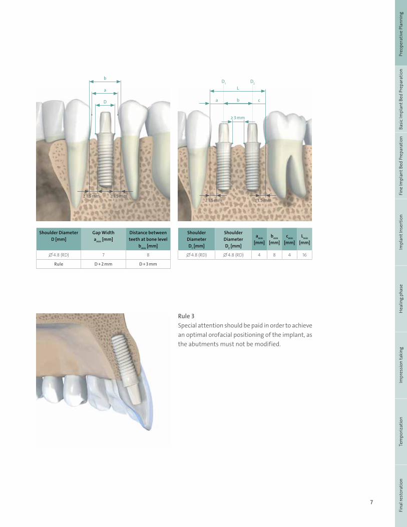
4.1.1 Implant positionTo plan implant positioning, the following three basic rules must be followed (see also Basic Information on the Surgical Procedures – Straumann® Dental Implant System, NAMLIT 1017.)
Rule 1Distance to adjacent tooth at bone level: The required minimal distance from the implant shoulder to the ad-jacent tooth at bone level (mesial and distal) is 1.5 mm.
Rule 2Distance to adjacent implants at bone level: The recommended mini-mal distance between two adjacent implant shoulders (mesiodistal) is 3 mm.
≥ 1.5 mm≥ 3 mm
7
Fina
l res
tora
tion
Tem
poriz
atio
nIm
pres
sion
taki
ngH
ealin
g ph
ase
Impl
ant I
nser
tion
Fine
Impl
ant B
ed P
repa
ratio
nBa
sic
Impl
ant B
ed P
repa
ratio
nPr
eope
rativ
e Pl
anni
ng
Shoulder DiameterD [mm]
Gap Width amin [mm]
Distance between teeth at bone level
bmin [mm]
∅ 4.8 (RD) 7 8
Rule D + 2 mm D + 3 mm
Shoulder DiameterD1 [mm]
Shoulder DiameterD2 [mm]
amin [mm]
bmin [mm]
cmin [mm]
Lmin [mm]
∅ 4.8 (RD) ∅ 4.8 (RD) 4 8 4 16
Rule 3Special attention should be paid in order to achieve an optimal orofacial positioning of the implant, as the abutments must not be modified.
b
L
a
D1 D2
cb
≥ 3 mm
a
D
≥ 1.5 mm ≥ 1.5 mm≥ 1.5 mm ≥ 1.5 mm
8
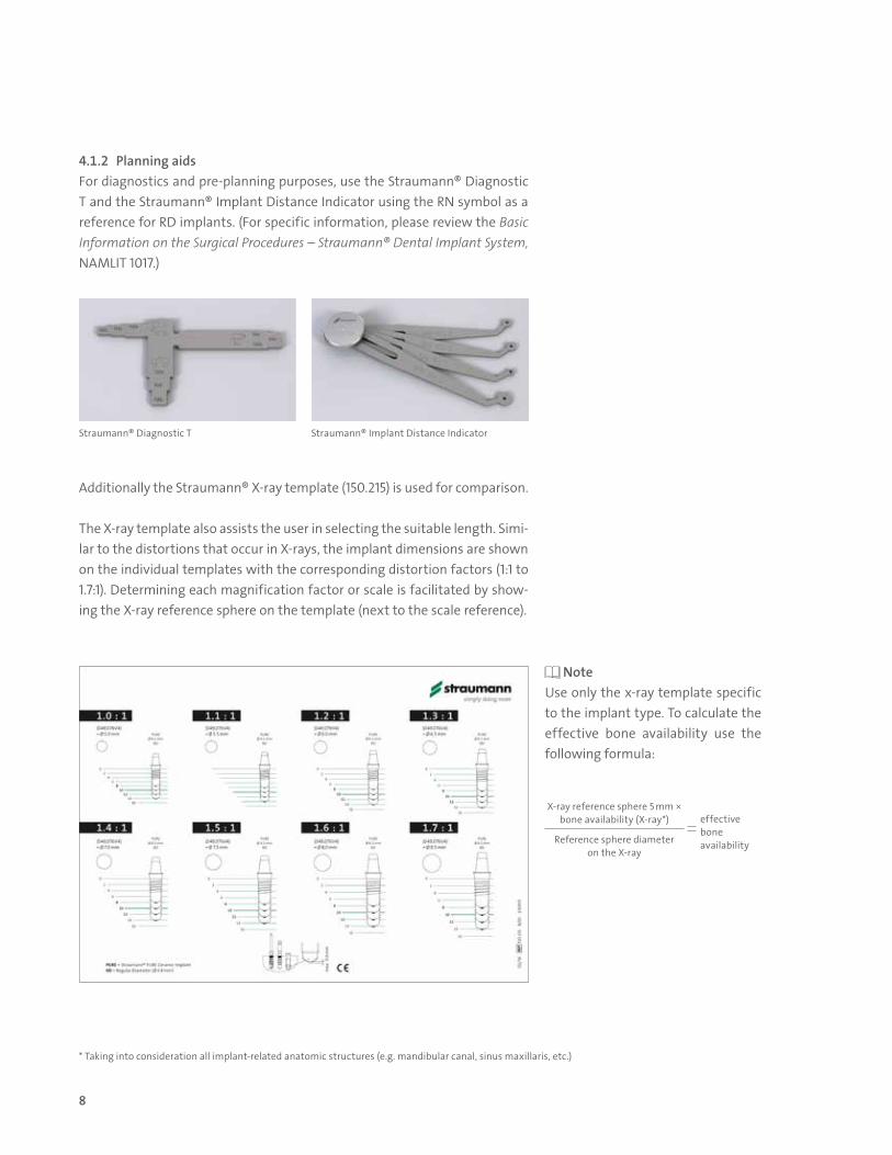
4.1.2 Planning aidsFor diagnostics and pre-planning purposes, use the Straumann® Diagnostic T and the Straumann® Implant Distance Indicator using the RN symbol as a reference for RD implants. (For specific information, please review the Basic Information on the Surgical Procedures – Straumann® Dental Implant System, NAMLIT 1017.)
Additionally the Straumann® X-ray template (150.215) is used for comparison.
The X-ray template also assists the user in selecting the suitable length. Simi-lar to the distortions that occur in X-rays, the implant dimensions are shown on the individual templates with the corresponding distortion factors (1:1 to 1.7:1). Determining each magnification factor or scale is facilitated by show-ing the X-ray reference sphere on the template (next to the scale reference).
Note Use only the x-ray template specific to the implant type. To calculate the effective bone availability use the following formula:
Straumann® Diagnostic T Straumann® Implant Distance Indicator
X-ray reference sphere 5 mm × bone availability (X-ray*) effective
bone availabilityReference sphere diameter
on the X-ray
* Taking into consideration all implant-related anatomic structures (e.g. mandibular canal, sinus maxillaris, etc.)
9
Fina
l res
tora
tion
Tem
poriz
atio
nIm
pres
sion
taki
ngH
ealin
g ph
ase
Impl
ant I
nser
tion
Fine
Impl
ant B
ed P
repa
ratio
nBa
sic
Impl
ant B
ed P
repa
ratio
nPr
eope
rativ
e Pl
anni
ng
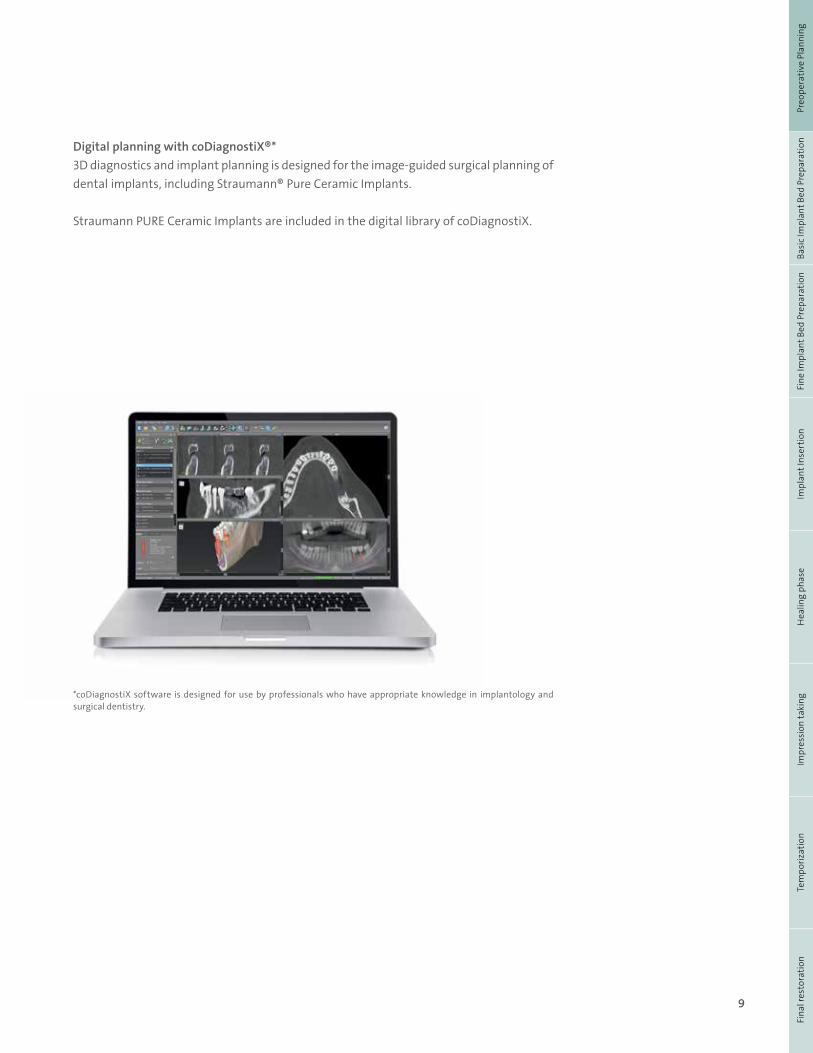
Digital planning with coDiagnostiX®*3D diagnostics and implant planning is designed for the image-guided surgical planning of dental implants, including Straumann® Pure Ceramic Implants.
Straumann PURE Ceramic Implants are included in the digital library of coDiagnostiX.
*coDiagnostiX software is designed for use by professionals who have appropriate knowledge in implantology and surgical dentistry.
10
4.2 BASIC IMPLANT BED PREPARATION
For preparing the implant bed the Straumann® Surgical Cassette is used. For the Straumann® PURE Ceramic Implant (Monotype) a specific new instrument is introduced in the procedure, and it is used only during the basic implant bed preparation.
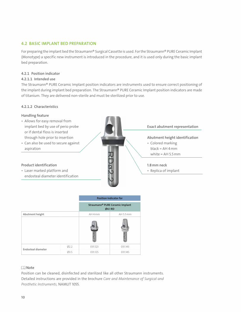
4.2.1 Position indicator4.2.1.1 Intended useThe Straumann® PURE Ceramic Implant position indicators are instruments used to ensure correct positioning of the implant during implant bed preparation. The Straumann® PURE Ceramic Implant position indicators are made of titanium. They are delivered non-sterile and must be sterilized prior to use.
4.2.1.2 Characteristics
Handling feature• Allows for easy removal from implant bed by use of perio probe or if dental floss is inserted through hole prior to insertion• Can also be used to secure against aspiration
Exact abutment representation
Abutment height identification• Colored marking black = AH 4 mm white = AH 5.5 mm
1.8 mm neck• Replica of implant
Product identification• Laser marked platform and endosteal diameter identification
Position Indicator for
Straumann® PURE Ceramic Implant Ø4.1 RD
Abutment height AH 4 mm AH 5.5 mm
Endosteal diameterØ2.2 031.123 031.143
Ø3.5 031.125 031.145
Note Position can be cleaned, disinfected and sterilized like all other Straumann instruments. Detailed instructions are provided in the brochure Care and Maintenance of Surgical and Prosthetic Instruments, NAMLIT 1055.
11
Fina
l res
tora
tion
Tem
poriz
atio
nIm
pres
sion
taki
ngH
ealin
g ph
ase
Impl
ant I
nser
tion
Fine
Impl
ant B
ed P
repa
ratio
nBa
sic
Impl
ant B
ed P
repa
ratio
nPr
eope
rativ
e Pl
anni
ng
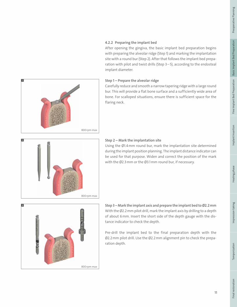
4.2.2 Preparing the implant bedAfter opening the gingiva, the basic implant bed preparation begins with preparing the alveolar ridge (Step 1) and marking the implantation site with a round bur (Step 2). After that follows the implant bed prepa-ration with pilot and twist drills (Step 3 – 5), according to the endosteal implant diameter.
Step 1 – Prepare the alveolar ridgeCarefully reduce and smooth a narrow tapering ridge with a large round bur. This will provide a flat bone surface and a sufficiently wide area of bone. For scalloped situations, ensure there is sufficient space for the flaring neck.
Step 2 – Mark the implantation siteUsing the Ø1.4 mm round bur, mark the implantation site determined during the implant position planning. The implant distance indicator can be used for that purpose. Widen and correct the position of the mark with the Ø2.3 mm or the Ø3.1 mm round bur, if necessary.
Step 3 – Mark the implant axis and prepare the implant bed to Ø2.2 mmWith the Ø2.2 mm pilot drill, mark the implant axis by drilling to a depth of about 6 mm. Insert the short side of the depth gauge with the dis-tance indicator to check the depth.
Pre-drill the implant bed to the final preparation depth with the Ø2.2 mm pilot drill. Use the Ø2.2 mm alignment pin to check the prepa-ration depth.
1
2
3
800 rpm max
800 rpm max
800 rpm max

12
After depth check with the alignment pin, insert the Ø2.2 mm monotype implant Position Indicator to check the implant position, angulation and restorability.
Depending on the implant that is placed, choose the correct position indicator, which visualizes the implant shoulder diameter of 4.8 mm (RD) and shows the future position of the implant shoulder and abutment. The hole in the abutment of the position indicator can be used for easy removal from implant bed and securing with a dental floss against in-haling/swallowing.
Step 4 – Widen the implant bed to Ø2.8 mmContinue with the implant bed preparation. If necessary, correct the implant position with the Ø2.8 mm pilot drill. Use the Ø2.8 mm depth gauge to check the preparation depth.
Step 5 – Widen the implant bed to Ø3.5 mmContinue with the Ø3.5 mm Straumann® Twist Drill PRO and check the final preparation depth with the Ø3.5 mm depth gauge.
After depth check with the depth gauge pin insert the Ø3.5 mm mono-type implant position indicator for check of implant position, angulation and restorability.
For an implant with an endosteal diameter of 4.1 mm, basic preparation ends here.
3
4
5
5
600 rpm max
500 rpm max

13
Fina
l res
tora
tion
Tem
poriz
atio
nIm
pres
sion
taki
ngH
ealin
g ph
ase
Impl
ant I
nser
tion
Fine
Impl
ant B
ed P
repa
ratio
nBa
sic
Impl
ant B
ed P
repa
ratio
nPr
eope
rativ
e Pl
anni
ng
4.3 FINE IMPLANT BED PREPARATION
The fine implant bed preparation encompasses profile drilling and subsequent tapping.
Step 1 – Profile drillThe profile drill prepares the implant bed for the Straumann® PURE Ceramic Implant and must be used to ensure that no excessive force is applied to the implant or implant bed during insertion.
For the Straumann® PURE Ceramic Implant (Monotype), a Straumann® Bone Level profile drill is to be used. Insert the profile drill up to the planned implant shoulder level.
Step 2 – Tapping the thread in dense boneTapping prepares the implant bed for a specific thread type, in the case of the Strau-mann® PURE Ceramic Implant it is the same tap that is used for Bone Level implants. It is an optional step that gives the surgeon the flexibility to adjust the surgical protocol to the bone class to help achieve optimal primary stability.
For further information, please refer to the Basic Information on the Basic Information on the Surgical Procedures – Straumann® Dental Implant System, NAMLIT 1017.
1
2

14
3.4.1 Opening the implant packageStep 1 – Opening of the blister and removal of the implant carrier
Note The blister ensures the sterility of the implant. Do not open the blister until immediately before implant placement.
Step 2 – Opening of the implant carrierHold the base of the implant carrier with two fingers in the middle. Using the other hand, lift off the lid. The implant is held by a ceramic pin.
Note The transfer piece is not pre-mounted. The transfer piece is an instrument used specifically with the Straumann® PURE Ceramic Implant System. It is made from medical grade stainless steel with a hard non-metallic coating.
1
2
Pre-defined breaking point• Pre-defined breaking point to ensure excess torque is not applied to the implant
Retentive ring• TAN ring to ensure secure retention to handpiece or ratchet
Hard coating• To reduce visible wear marks of the insertion tool on the ceramic abutment
Snap feature• To ensure secure retention of the implant
Marking dots• For ideal prosthetic abutment orientation• A quarter turn to the next drilled holes corresponds to a vertical displacement of 0.2 mm • Dots indicate distance to implant shoulder and are 1,2,3 mm away from it• During positioning of the transfer piece on implant, the dots are aligned with the flat sides of the implant abutment
Features
4.4 IMPLANT INSERTION

15
Fina
l res
tora
tion
Tem
poriz
atio
nIm
pres
sion
taki
ngH
ealin
g ph
ase
Impl
ant I
nser
tion
Fine
Impl
ant B
ed P
repa
ratio
nBa
sic
Impl
ant B
ed P
repa
ratio
nPr
eope
rativ
e Pl
anni
ng
The Straumann® PURE Ceramic Implant can be placed either (a) with the aid of the handpiece or (b) manually with the ratchet.
Step 3a – Attach the adapter to the handpieceConnect the transfer piece to an appropriate length adapter for the handpiece. Before push-ing down the adpater on the transfer piece, assure correct aligment of the octagon. A click is heard when the adapter is at-tached correctly. Remove the transfer piece by pulling it to the side.
Step 4a – Attach the transfer piece to the implantPush the transfer piece onto the implant abutment (snap on). A click is heard when the transfer piece is attached correctly.
Step 5a – Remove the implant from the carrier
Note By turning counterclockwise the implant can be removed from the ceramic pin.
Step 3b – Attach the adapter to the ratchetConnect the transfer piece to an appropriate length adapter for ratchet. Before pushing down the adpater on the transfer piece, assure correct aligment of the octagon. A click is heard when the adapter is attached correctly. Remove the transfer piece by pulling it to the side.
Step 4b – Attach the transfer piece to the implantPush the transfer piece onto the implant abutment (snap on). A click is heard when the transfer piece is attached correctly.
Step 5b – Remove the implant from the carrier
Note By turning counterclockwise the implant can be removed from the ceramic pin.
3a 3b
4a 4b
5a 5b

16
3.4.2 Placing the implant
Step 1 – Insert the implantAlways insert the implant to the correct depth. The implant is designed to have the implant shoulder sit 1.8 mm above the crestal bone. When using the handpiece, turn it clockwise with the recommended speed of 15 rpm.
Step 2 – Correct implant orientationWhile approaching the final implant position, ensure the dots on the transfer piece are positioned buccally/lingually. This will place the abut-ment walls parallel with neighboring teeth or implants which will reduce the chance of complications (lack of interdental space) during the restor-ative phase.
Caution: Avoid vertical position corrections using reverse rotations (counterclockwise). Reverse rotations may lead to a decrease in primary stability.
Step 3 – Removal of the transfer piece3a – Remove the handpiece vertically and disassemble the transfer piece from the adapter for the handpiece.
3b– Remove the ratchet from the adapter. Remove the adapter vertically from the implant and disassemble the transfer piece from the adapter.
CLINICAL CONSIDERATIONS FOR SUCCESS - SURGICAL
Ease of insertion• Always Profile• Tap according to bone type
Correct placement• Use of position indicators is critical • Digital treatment planning and guided surgery can also provide benefits
1a
2a
3a
1b
2b
3b
17
Fina
l res
tora
tion
Tem
poriz
atio
nIm
pres
sion
taki
ngH
ealin
g ph
ase
Impl
ant I
nser
tion
Fine
Impl
ant B
ed P
repa
ratio
nBa
sic
Impl
ant B
ed P
repa
ratio
nPr
eope
rativ
e Pl
anni
ng
The workflow for the prosthetic procedure for the Straumann® PURE Ceramic implant includes 4 steps: Protection during healing phase, impression taking, temporization and final restoration.
Note Micro-movements disturb osseointegration and can lead to loss of implants.
5. Prosthetic procedure for Straumann® PURE Ceramic Implant (Monotype)
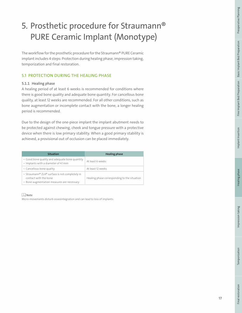
Situation Healing phase
• Good bone quality and adequate bone quantity• Implants with a diameter of 4.1 mm
At least 6 weeks
• Cancellous bone quality At least 12 weeks
• Straumann® ZLA® surface is not completely in contact with the bone• Bone augmentation measures are necessary
Healing phase corresponding to the situation
5.1 PROTECTION DURING THE HEALING PHASE
5.1.1 Healing phaseA healing period of at least 6 weeks is recommended for conditions where there is good bone quality and adequate bone quantity. For cancellous bone quality, at least 12 weeks are recommended. For all other conditions, such as bone augmentation or incomplete contact with the bone, a longer healing period is recommended.
Due to the design of the one-piece implant the implant abutment needs to be protected against chewing, cheek and tongue pressure with a protective device when there is low primary stability. When a good primary stability is achieved, a provisional out of occlusion can be placed immediately.
18
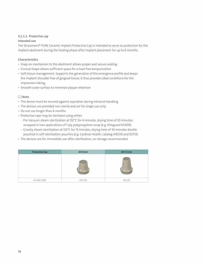
5.1.1.1 Protective capIntended useThe Straumann® PURE Ceramic Implant Protective Cap is intended to serve as protection for the implant abutment during the healing phase after implant placement for up to 6 months.
Characteristics• Snap-on mechanism to the abutment allows proper and secure seating• Conical shape allows sufficient space for a load-free temporization• Soft tissue management: Supports the generation of the emergence profile and keeps the implant shoulder free of gingival tissue; it thus provides ideal conditions for the impression taking. • Smooth outer surface to minimize plaque retention
Note• The device must be secured against aspiration during intraoral handling. • The devices are provided non-sterile and are for single use only. • Do not use longer than 6 months. • Protective caps may be sterilized using either: - Pre-Vacuum steam sterilization at 132°C for 4 minutes, drying time of 30 minutes; wrapped in two applications of 1-ply polypropylene wrap (e.g. Kimguard KC600). - Gravity steam sterilization at 132°C for 15 minutes, drying time of 30 minutes double pouched in self sterilization pouches (e.g. Cardinal Health; catalog #92510 and 92713). • The devices are for immediate use after sterilization, no storage recommended.
Protective Cap AH 4 mm AH 5.5 mm
For Ø4.1 (RD) 031.330 031.331
19
Fina
l res
tora
tion
Tem
poriz
atio
nIm
pres
sion
taki
ngH
ealin
g ph
ase
Impl
ant I
nser
tion
Fine
Impl
ant B
ed P
repa
ratio
nBa
sic
Impl
ant B
ed P
repa
ratio
nPr
eope
rativ
e Pl
anni
ng
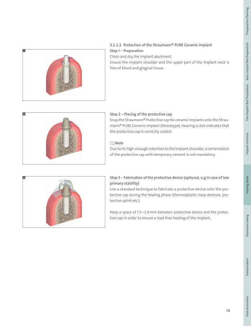
5.1.1.2 Protection of the Straumann® PURE Ceramic ImplantStep 1 – PreparationClean and dry the implant abutment. Ensure the implant shoulder and the upper part of the implant neck is free of blood and gingival tissue.
Step 2 – Placing of the protective capSnap the Straumann® Protective cap for ceramic implants onto the Strau-mann® PURE Ceramic Implant (Monotype). Hearing a click indicates that the protective cap is correctly seated.
Note Due to its high-enough retention to the implant shoulder, a cementation of the protective cap with temporary cement is not mandatory.
Step 3 – Fabrication of the protective device (optional, e.g in case of low primary stability)Use a standard technique to fabricate a protective device onto the pro-tective cap during the healing phase (thermoplastic clasp denture, pro-tective splint etc.).
Keep a space of 1.5 – 2.0 mm between protective device and the protec-tive cap in order to ensure a load-free healing of the implant.
1
2
3
20
5.2 IMPRESSION TAKING
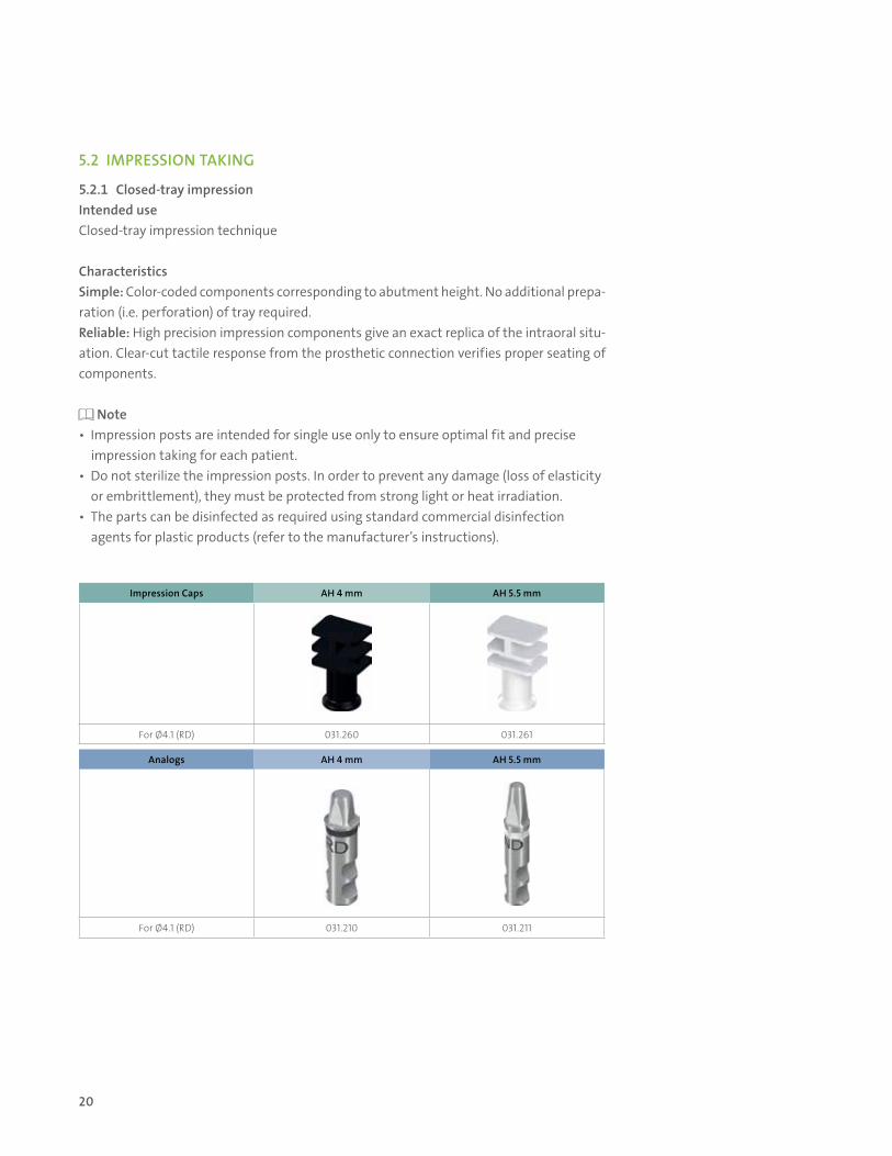
5.2.1 Closed-tray impressionIntended useClosed-tray impression technique
CharacteristicsSimple: Color-coded components corresponding to abutment height. No additional prepa-ration (i.e. perforation) of tray required.Reliable: High precision impression components give an exact replica of the intraoral situ-ation. Clear-cut tactile response from the prosthetic connection verifies proper seating of components.
Note• Impression posts are intended for single use only to ensure optimal fit and precise impression taking for each patient.• Do not sterilize the impression posts. In order to prevent any damage (loss of elasticity or embrittlement), they must be protected from strong light or heat irradiation.• The parts can be disinfected as required using standard commercial disinfection agents for plastic products (refer to the manufacturer’s instructions).
Impression Caps AH 4 mm AH 5.5 mm
For Ø4.1 (RD) 031.260 031.261
Analogs AH 4 mm AH 5.5 mm
For Ø4.1 (RD) 031.210 031.211
21
Fina
l res
tora
tion
Tem
poriz
atio
nIm
pres
sion
taki
ngH
ealin
g ph
ase
Impl
ant I
nser
tion
Fine
Impl
ant B
ed P
repa
ratio
nBa
sic
Impl
ant B
ed P
repa
ratio
nPr
eope
rativ
e Pl
anni
ng
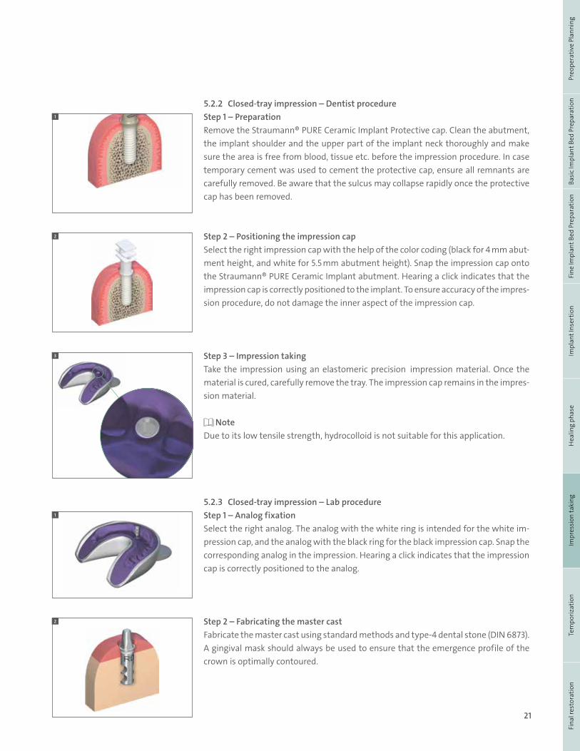
5.2.2 Closed-tray impression – Dentist procedureStep 1 – PreparationRemove the Straumann® PURE Ceramic Implant Protective cap. Clean the abutment, the implant shoulder and the upper part of the implant neck thoroughly and make sure the area is free from blood, tissue etc. before the impression procedure. In case temporary cement was used to cement the protective cap, ensure all remnants are carefully removed. Be aware that the sulcus may collapse rapidly once the protective cap has been removed.
Step 2 – Positioning the impression cap Select the right impression cap with the help of the color coding (black for 4 mm abut-ment height, and white for 5.5 mm abutment height). Snap the impression cap onto the Straumann® PURE Ceramic Implant abutment. Hearing a click indicates that the impression cap is correctly positioned to the implant. To ensure accuracy of the impres-sion procedure, do not damage the inner aspect of the impression cap.
Step 3 – Impression takingTake the impression using an elastomeric precision impression material. Once the material is cured, carefully remove the tray. The impression cap remains in the impres-sion material.
NoteDue to its low tensile strength, hydrocolloid is not suitable for this application.
5.2.3 Closed-tray impression – Lab procedureStep 1 – Analog fixationSelect the right analog. The analog with the white ring is intended for the white im-pression cap, and the analog with the black ring for the black impression cap. Snap the corresponding analog in the impression. Hearing a click indicates that the impression cap is correctly positioned to the analog.
Step 2 – Fabricating the master castFabricate the master cast using standard methods and type-4 dental stone (DIN 6873). A gingival mask should always be used to ensure that the emergence profile of the crown is optimally contoured.
2
1
2
3
1
22
5.3 TEMPORIZATION
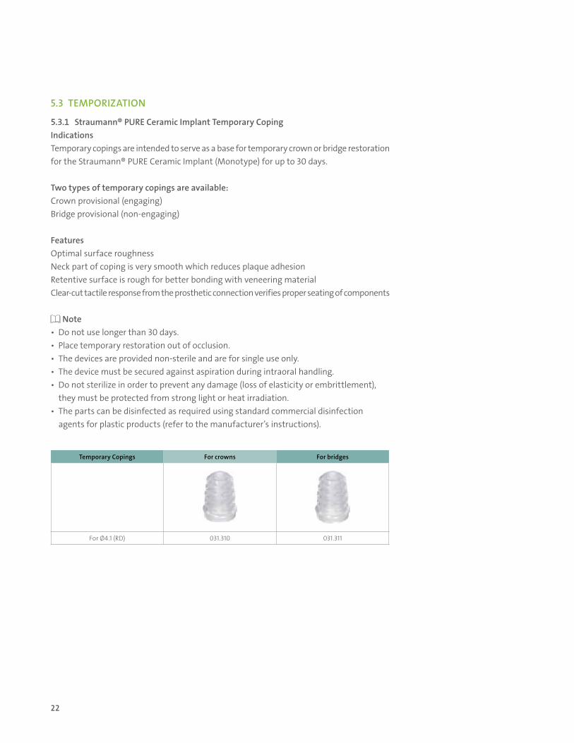
5.3.1 Straumann® PURE Ceramic Implant Temporary CopingIndicationsTemporary copings are intended to serve as a base for temporary crown or bridge restoration for the Straumann® PURE Ceramic Implant (Monotype) for up to 30 days.
Two types of temporary copings are available:Crown provisional (engaging) Bridge provisional (non-engaging)
FeaturesOptimal surface roughnessNeck part of coping is very smooth which reduces plaque adhesionRetentive surface is rough for better bonding with veneering materialClear-cut tactile response from the prosthetic connection verifies proper seating of components
Note• Do not use longer than 30 days. • Place temporary restoration out of occlusion.• The devices are provided non-sterile and are for single use only. • The device must be secured against aspiration during intraoral handling.• Do not sterilize in order to prevent any damage (loss of elasticity or embrittlement), they must be protected from strong light or heat irradiation.• The parts can be disinfected as required using standard commercial disinfection agents for plastic products (refer to the manufacturer’s instructions).
Temporary Copings For crowns For bridges
For Ø4.1 (RD) 031.310 031.311

23
Fina
l res
tora
tion
Tem
poriz
atio
nIm
pres
sion
taki
ngH
ealin
g ph
ase
Impl
ant I
nser
tion
Fine
Impl
ant B
ed P
repa
ratio
nBa
sic
Impl
ant B
ed P
repa
ratio
nPr
eope
rativ
e Pl
anni
ng
5.3.2 Chairside temporization with the Straumann® PURE Ceramic Implant Temporary Coping
Step 1– PreparationSnap the temporary coping onto the Straumann® PURE Ceramic Implant abutment in the patient’s mouth. Mark the appropriate height according to the individual situation and shorten the coping as necessary.
NoteThe temporary coping must be secured against aspiration.
Step 2 – Fabricate the provisional restorationUse a standard procedure to fabricate the provisional. The retention rings ensure proper mechanical bonding of the veneering material to the coping. The plateau of the cop-ing helps to prevent the veneering material from flowing under the implant shoulder.
Step 3 – Finalize fabrication of the provisional restorationAfter polymerization, take the provisional out of the mouth. Grind down and polish the emergence profile to achieve an even profile. To avoid tissue irritation the interface needs to be smooth and flush with the restoration
Step 4 – Inserting the provisionalRemove the lip of the snap-on mechanism from the temporary coping to allow proper extrusion of excess cement. Use a scalpel, knife or handpiece/rubber wheel. Apply temporary cement to the inner part of the coping and cement it onto the abutment.
NoteDo not use the Straumann® Reamer for 45° shoulders (046.243) as this will damage the internal connection of the temporary coping.Keep the temporary restoration out of occlusion.Temporary copings must not be kept in the mouth for longer than 30 days.
1
2
4
3
24
5.4 CREATION AND CEMENTATION OF THE FINAL RESTORATION
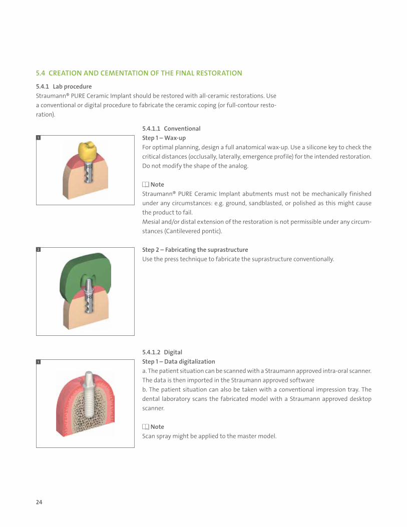
5.4.1 Lab procedureStraumann® PURE Ceramic Implant should be restored with all-ceramic restorations. Use a conventional or digital procedure to fabricate the ceramic coping (or full-contour resto-ration).
5.4.1.1 ConventionalStep 1 – Wax-upFor optimal planning, design a full anatomical wax-up. Use a silicone key to check the critical distances (occlusally, laterally, emergence profile) for the intended restoration. Do not modify the shape of the analog.
NoteStraumann® PURE Ceramic Implant abutments must not be mechanically finished under any circumstances: e.g. ground, sandblasted, or polished as this might cause the product to fail. Mesial and/or distal extension of the restoration is not permissible under any circum-stances (Cantilevered pontic).
Step 2 – Fabricating the suprastructureUse the press technique to fabricate the suprastructure conventionally.
5.4.1.2 DigitalStep 1 – Data digitalizationa. The patient situation can be scanned with a Straumann approved intra-oral scanner. The data is then imported in the Straumann approved softwareb. The patient situation can also be taken with a conventional impression tray. The dental laboratory scans the fabricated model with a Straumann approved desktop scanner.
NoteScan spray might be applied to the master model.
1
2
1

25
Fina
l res
tora
tion
Tem
poriz
atio
nIm
pres
sion
taki
ngH
ealin
g ph
ase
Impl
ant I
nser
tion
Fine
Impl
ant B
ed P
repa
ratio
nBa
sic
Impl
ant B
ed P
repa
ratio
nPr
eope
rativ
e Pl
anni
ng
Step 2 – Design of the Straumann® CARES® coping or full-contour crownThe restoration is designed with the Straumann approved software.Additional information on the different Straumann® CARES® prosthetic restorations are available in the brochure “Basic Information on Straumann® CARES® Tooth Pros-thetic Procedures”, available on the Straumann website: www. straumann.us.
NoteIf a scan spray was used for the data digitization, the default parameters of the “Die parameters” should be slightly adapted when designing the Straumann® CARES® prosthetic restoration with the Straumann® CARES® Visual software 7.x and higher.
Step 3 – Finalization of the Straumann® CARES® coping or full-contour crownDepending on the final material and processing technique selected, the delivered Strau-mann® CARES® coping and full-contour crown can be directly seated or finalized in different steps (e.g. layering).
5.4.2 Dentist procedureThe final restoration is placed on the master cast when delivered to the doctor’s office.
Final insertion:• Remove the temporary restoration• Clean the abutment thoroughly and remove all remaining temporary cement. • Prepare the surface of the Straumann® Ceramic Implant abutment, and of the superstructure according to the instructions given by the corresponding cement manufacturer. • Cement the superstructure onto the abutment. • Carefully remove any excess cement.
CLINICAL CONSIDERATIONS FOR SUCCESS - RESTORATIVE
• Design the restoration according to correct anatomical considerations• Do not modify the abutment so you don’t introduce microfractures into the
implant or abutment• Ensure that the restoration is seated stress-free. • Keep static, occlusal contacts low compared to neighboring teeth and avoid dynamic occlusal contacts. • Incomplete removal of excess cement may cause increased biofilm formation resulting in inflammation and infection.
2
3
26
6. Aftercare and cleaning of Straumann® PURE Ceramic Implants
7. Troubleshooting
Regular prosthetic aftercare of the Straumann® PURE Ceramic Implants is necessary, as in all implant systems. Since individual factors such as oral hygiene of the patient, cooperation, etc. are of great importance in determining regular prosthetic aftercare, the aftercare should be adapted to each patient individually.
Zirconia has very low affinity to plaque. However, regular and adequate prophylaxis is recommended. For cleaning Straumann® PURE Ceramic Implants, use teflon-based hand scalers and curettes.
Rinsing solutions of chlorhexidine and/or alcohol basis can be used temporarily without reservation. These solutions are not recommended for continuous use due to possible discoloration of the tooth hard substance as well as of cement gaps.
Do not use any ultrasound-operated, metallic cleaning aids for cleaning Straumann® PURE Ceramic Implants. Avoid application of ultrasound through metallic trans-mitters onto Straumann® PURE Ceramic Implants. The surface can be damaged permanently by incorrect use and application of ultrasound. When metallic clean-ing aids are used (ultrsound- operated scalers or hand curettes or scalers) metallic abrasion might occur on the surface of the implant.
Do not use any abrasive prophylactic pastes for cleaning Straumann® PURE Ceramic Implants. Powder/water jet cleaners are not suitable for cleaning Straumann® PURE Ceramic Implants.
7.1 IMPLANT REMOVAL
Non-osseointegrated implant (spinner)The Straumann® PURE Ceramic Implant transfer piece can be used to help remove a non- osseointegrated implant.
WarningOsseointegrated implant: Bone preservation is consid-ered to be a core competence required by the clinician in the case of implant removal. The clinician should use a technique suitable to the implant and patient situation.
7.2 FRACTURE OF THE ABUTMENT
If part of the abutment fractures, the clinician needs to determine if another restoration can be placed or the implant must be explanted. When determining if there is enough minimum support and retentive area, use the same parameters that apply for a natural tooth stump.
Chipping or cracking of crownIn the event of a chipped or cracked crown, where the crown needs to be removed, care should be taken to avoid damaging the implant shoulder or abutment.
27
Fina
l res
tora
tion
Tem
poriz
atio
nIm
pres
sion
taki
ngH
ealin
g ph
ase
Impl
ant I
nser
tion
Fine
Impl
ant B
ed P
repa
ratio
nBa
sic
Impl
ant B
ed P
repa
ratio
nPr
eope
rativ
e Pl
anni
ng
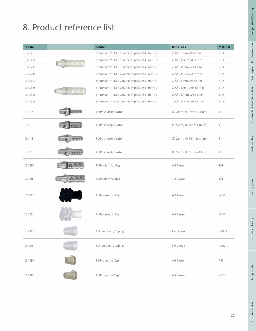
8. Product reference list
Art. No. Article Dimension Material
031.021S Straumann® PURE Ceramic Implant, Ø4.1 mm RD ZLA® L 8 mm, AH 4 mm ZrO2
031.022S Straumann® PURE Ceramic Implant, Ø4.1 mm RD ZLA® L 10 mm, AH 4 mm ZrO2
031.023S Straumann® PURE Ceramic Implant, Ø4.1 mm RD ZLA® L 12 mm, AH 4 mm ZrO2
031.024S Straumann® PURE Ceramic Implant, Ø4.1 mm RD ZLA® L 14 mm, AH 4 mm ZrO2
031.031S Straumann® PURE Ceramic Implant, Ø4.1 mm RD ZLA® L 8 mm, AH 5.5 mm ZrO2
031.032S Straumann® PURE Ceramic Implant, Ø4.1 mm RD ZLA® L 10 mm, AH 5.5 mm ZrO2
031.033S Straumann® PURE Ceramic Implant, Ø4.1 mm RD ZLA® L 12 mm, AH 5.5 mm ZrO2
031.034S Straumann® PURE Ceramic Implant, Ø4.1 mm RD ZLA® L 14 mm, AH 5.5 mm ZrO2
031.123 RD Position Indicator Ø2.2 mm, AH 4 mm, L 8 mm Ti
031.125 RD Position Indicator Ø3.5 mm, AH 4 mm, L 8 mm Ti
031.143 RD Position Indicator Ø2.2 mm, AH 5.5 mm, L 8 mm Ti
031.145 RD Position Indicator Ø3.5 mm, AH 5.5 mm, L 8 mm Ti
031.210 RD Implant Analog AH 4 mm TAN
031.211 RD Implant Analog AH 5.5 mm TAN
031.260 RD Impression Cap AH 4 mm POM
031.261 RD Impression Cap AH 5.5 mm POM
031.310 RD Temporary Coping For crown PMMA
031.311 RD Temporary Coping For bridge PMMA
031.330 RD Protective Cap AH 4 mm PEEK
031.331 RD Protective Cap AH 5.5 mm PEEK
28
9. Important guidelines
Please notePractitioners must have appropriate knowledge and instruc-tion in the handling of the Straumann CADCAM products or other Straumann products (“Straumann Products”) for using the Straumann Products safely and properly in accordance with the instructions for use.
The Straumann Product must be used in accordance with the in-structions for use provided by the manufacturer. It is the practi-tioner’s responsibility to use the device in accordance with these instructions for use and to determine, if the device fits to the individual patient situation.
The Straumann Products are part of an overall concept and must be used only in conjunction with the corresponding origi-nal components and instruments distributed by Straumann USA and Straumann Canada Ltd., its ultimate parent company and all affiliates or subsidiaries of such parent company (“Straumann”), except if stated otherwise in this document or in the instruc-tions for use for the respective Straumann Product. If use of products made by third parties is not recommended by Strau-mann in this document or in the respective instructions for use, any such use will void any warranty or other obligation, express or implied, of Straumann.
AvailabilitySome of the Straumann Products listed in this document may not be available in all countries.
Caution In addition to the caution notes in this document, our products must be secured against aspiration when used intraorally.
ValidityUpon publication of this document, all previous versions are superseded.
Documentation For detailed instructions on the Straumann Products contact your Straumann representative.
Copyright and trademarksStraumann® documents may not be reprinted or published, in whole or in part, without the written authorization of Strau-mann. Straumann® and/or other trademarks and logos from Straumann® mentioned herein are the trademarks or registered trademarks of Straumann Holding AG and/or its affiliates.
Explanation of the symbols on labels and instruc-tion leaflets
Batch code
Catalogue number
Sterilized using plasma
…min.
Lower limit of temperature
…max.
Upper limit of temperature
…max.
…min.
Temperature limitation
Caution: Federal law restricts this device to sale by or on the order of a dental pro-fessional.
Do not re-use
Non-sterile
Caution, consult accompanying documents
Use by
Keep away from sunlight
0123
Straumann Products with the CE mark fulfill the requirements of the Medical Devices Directive 93/42 EEC
Consult instructions for use

29

International Headquarters Institut Straumann AG Peter Merian-Weg 12 CH-4002 Basel, Switzerland Phone +41 (0)61 965 11 11 Fax +41 (0)61 965 11 01
Straumann North American Headquarters Straumann USA, LLC 60 Minuteman Road Andover, MA 01810 Phone 800/448 8168 (US) 800/363 4024 (CA) Fax 978/747 2490 www.straumann.us www.straumann.ca
CALI
T.109
9
1/17
V
1
© Straumann USA, LLC 2017. All rights reserved. Straumann® and/or other trademarks and logos from Straumann® that are mentioned herein are the trademarks or registered trademarks of Straumann Holding AG and/or its affiliates. All rights reserved.
May not be available in all countries, subject to regulatory approval and market release. Please ask your Straumann Territory Manager for more information and availability.
ifu.straumann.com