Basic Configuration: - Network and Security Specialist
209
Basic Configuration: Router Modes: Router>: User mode = Limited to basic monitoring commands Router#: Privileged mode (exec-level mode) = Provides access to all other router commands Router(config)#: global configuration mode = Commands that affect the entire system Router(config-if)#: interface mode = Commands that affect interfaces Router(config-subif)#: subinterface mode = Commands that affect subinterfaces Router(config-line)#: line mode = Commands that affect in lines modes (console, vty, aux…) Router(config-router)#: router configuration mode Interface Cofiguration: Router(config)#default int range fa 0/0 - 1 !(to clear all int config back to default) Router(config)#default int range fa 0/0 – 1, fa 0/4 - 5 Router(config)#int fa 0/0 Router(config-if)#mac-address 0000.1111.1111 !(hard code a mac address for ease of use) Router(config-if)#ip address 192.168.1.1 255.255.255.0 Clock commands: router# clock set 14:12:00 10 feb 2005 router# show clock enable, disable, conf t, end, exit(exec), exit(global), logout commands: Router(config)# do sh run !(use do to run any show command from any mode) Router> enable Password: <letmein> Router# disable Router> Router# configure terminal Router(config)# interface serial 1:1 Router(config-if)# alps ascu 4B Router(config-alps-ascu)# end Router# show interface serial 1:1 Router(config)# exit Router# disable Router> exit Router(config-subif)# exit Router(config-if)# Router(config)# exit Router# disable Router> logout keyboard shortcuts: Ctrl+A !(move to the start of the line) Ctrl+E !(move to the end of the line) Ctrl+shift+6 !(stop traceroute or ping) terminal command: terminal length 24 terminal history size 256 show history Verifying commands: sh version sh flash: sh run !(default commands don't show in run) sh start sh post sh arp sh hosts sh users !(to see the users who are loggedin to vty) sh processes cpu sh processes cpu sort !(more like top command in linux) sh process cpu history !(utilization over time)
-
Upload
khangminh22 -
Category
Documents
-
view
0 -
download
0
Transcript of Basic Configuration: - Network and Security Specialist

Basic Configuration: Router Modes:Router>: User mode = Limited to basic monitoring commandsRouter#: Privileged mode (exec-level mode) = Provides access to all other router commandsRouter(config)#: global configuration mode = Commands that affect the entire systemRouter(config-if)#: interface mode = Commands that affect interfacesRouter(config-subif)#: subinterface mode = Commands that affect subinterfacesRouter(config-line)#: line mode = Commands that affect in lines modes (console, vty, aux…)Router(config-router)#: router configuration modeInterface Cofiguration: Router(config)#default int range fa 0/0 - 1 !(to clear all int config back to default)Router(config)#default int range fa 0/0 – 1, fa 0/4 - 5Router(config)#int fa 0/0Router(config-if)#mac-address 0000.1111.1111 !(hard code a mac address for ease of use)Router(config-if)#ip address 192.168.1.1 255.255.255.0Clock commands:router# clock set 14:12:00 10 feb 2005router# show clockenable, disable, conf t, end, exit(exec), exit(global), logout commands:Router(config)# do sh run !(use do to run any show command from any mode)Router> enable Password: <letmein> Router# disable Router>Router# configure terminal Router(config)# interface serial 1:1 Router(config-if)# alps ascu 4B Router(config-alps-ascu)# end Router# show interface serial 1:1Router(config)# exit Router# disable Router> exitRouter(config-subif)# exit Router(config-if)#Router(config)# exit Router# disable Router> logout keyboard shortcuts:Ctrl+A !(move to the start of the line)Ctrl+E !(move to the end of the line)Ctrl+shift+6 !(stop traceroute or ping)terminal command:terminal length 24 terminal history size 256show historyVerifying commands:sh version sh flash:sh run !(default commands don't show in run)sh startsh postsh arp sh hostssh users !(to see the users who are loggedin to vty)sh processes cpush processes cpu sort !(more like top command in linux)sh process cpu history !(utilization over time)

sh ip int bripipe parameter: sh run | include hostnamesh run | include Revision| modifiedsh run | section fa 0/1sh run | begin line con 0 sh run | exclude interfaceresetting switch config: delete flash:vlan.daterase startreloadBasic switch/router setup commands:SW#setupSwitch(config)# hostname SW1SW1(config)# enable secret cisco !MD5 hashSW1(config)# enable password notcisco ! Clear textSW1(config)# line con 0SW1(config-line)# password ciscoSW1(config-line)# loginSW1(config)# line vty 0 4SW1(config-line)# password ciscoSW1(config-line)# loginSW1(config)# service password-encryption !(to encrypt all the password in the config)SW1(config)# banner motd $-=-=-=-=-=-=-=-=-=-=-=-=-=-=-=-=-UNAUTHORIZED ACCESS IS PROHIBITED-=-=-=-=-=-=-=-=-=-=-=-=-=-=-=-=-$SW1(config)# interface vlan 1SW1(config-if)# ip address 172.16.1.11 255.255.255.0 ! or DHCPSW1(config-if)# no shutdownSW1(config)# ip default-gateway 172.16.1.1SW1# copy running-config startup-configSW1# wrSW1(config)# no ip domain-lookupSW1(config)# line vty 0 4SW1(config-line)# history size 15SW1(config-line)# exec-timeout 0 0SW1(config-line)# logging synchronousConfiguring switch to use SSH:SW1(config)# ip domain-name example.comSW1(config)# username admin password ciscoSW1(config)# crypto key generate rsaHow many bits in the modulus [512]: 1024SW1(config)# ip ssh version 2SW1(config)# line vty 0 4SW1(config-line)# login localSW1(config-line)# transport input telnet sshSW1# show crypto key mypubkey rsaAliases:SW1(config)# alias exec c configure terminalSW1(config)# alias exec s show ip interface briefSW1(config)# alias exec sr show running-configDescription, mdix speed and duplex:SW1(config)# interface fastEthernet 0/1SW1(config-if)# description LINK TO INTERNET ROUTERSW1(config-if)# speed 100 !(Options: 10, 100, auto)

SW1(config)# interface range fastEthernet 0/5 - 10SW1(config-if-range)# duplex full !(options: half, full, auto)SW1(config-if)# mdix autoSW1(config-if)# no mdix autoCapturing wireshark packets on a router and export to tftp as pcap: R1#monitor capture 1 int fa0/0 both !(options: both | in | out)R1#monitor capture 1 match anyR1#monitor capture 1 startR1#monitor capture 1 export tftp://10.0.0.100/r1.marking.pcapR1#no monitor capture 1Test or verification by generating http traffic converting a router into a http server: R1(config)#username ali password ciscoR1(config)#username privilege 15R1(config)#ip http serverR1(config)#ip http authentication localR1(config)#ip http path bootflash:
R2#copy http://ali:cisco@R1_IP/FILE_NAME null:ping, traceroute, ssh and telnet: R1(config)#ip telnet tos B8R1#ping !(extended ping) (ASA# ping tcp www.testsite.com 443)R1#ping 8.8.8.8 source fa0/0R1#traceroute !(extended traceroute)R1#traceroute 8.8.8.8 R1#telnet bing.com 80R1#telnet 192.168.1.1 /source-interface loopback0R1#ssh -l root 192.168.1.1mac address table:sh mac-address-tablesh mac-address-table | include 9fe7sh mac-address-table countclear mac-address clear mac-address dynamicdebug matm all !(to see everything mac address table management switch does)arp: arp !('arp -a' for windows CLI)clear ip arpusing ACL with a debug command fot tshoot: R#access-list 1 permit host 10.0.0.2R#debug ip packet 1 detail

IPv4 ACLs (Access Control Lists)

1. There is a deny all at the end of the list2. Every entry in an ACL is ACE (Access-list Entry)
(randomly generated port numbers on the PCs are called ephemeral ports)
Standard Access List: Standard Access List close to the destination are best.R1(config)#access-list 1 permit 10.0.0.0 0.255.255.255R1(config)#access-list 1 deny host 10.0.0.1 logR1(config)#access-list 1 permit any any !(don't forget this as there is a default deny at the end)Extended Access list: Extended Access lists closer to the source are best.R1(config)#access-list 101 permit tcp 10.0.0.0 0.255.255.255 187.100.1.6 0.0.0.0 eq 20!(187.100.1.6 0.0.0.0 is the same as host 187.100.1.6)R1(config)#access-list 101 deny tcp any eq 22 host 10.0.0.1 range 22 23R1(config)#access-list 101 permit ip any any dscp cs2Apply this ACL to an interface:R1(config)#interface Fa0/1R1(config-if)#ip access-group 1 outORR1(config)#interface Fa0/0R1(config-if)#ip access-group 1 in

Time-based ACLs:R(config)#time-range TR_WORKDAYSR(config-time-range)#periodic weekdays 08:00 to 19:00!(Don't configure NTP unless mentioned in the LAB)R(config)#ip access-list extended 100R(config-ext-nacl)#27 permit tcp any any eq www time-range TR_WORKDAYS
Restricting Telnet access with an Access-list:R(config)#access-list 50 permit host 10.20.2.100R(config)#line vty 0 15R(config-line)#access-class 50 in
Block pings with acls:access-list 100 deny icmp any any echoaccess-list 100 deny icmp any any echo-replyaccess-list 100 permit ip any anyORaccess-list 101 deny icmp host 192.168.1.51 host 192.168.1.34 echoaccess-list 100 permit ip any anyEstablished keyword:Since IOS devices are not stateful (by default), return traffic needs to be allowed if there is an ACL in the path of the returning traffic. The ‘Established’ keyword in an ACE can be used allow the return traffic. The beauty of this keyword is that it doesn’t allow any originating traffic. The ACE with the established keyword has to be included in the ACL that is applied on the interface where the returning traffic is expected.access-list 101 permit tcp any any establishedaccess-list 101 deny ip any any logDynamic ACLs:Also known as Lock-and-Key Security.It creates temporary ACEs in the ACL applied in the path of the originating traffic for it to be allowed for a particular user for a specific time limit and then discard the entry after the idle/absolute timeout value has expired.You can only have one dynamic entry per ACL that is applied to an interface.

The users must pass a user authentication process (telnet) before they are permitted access to their designated hosts.Telneting to the interface has to be allowed in the ACL applied to the inbound interface. It should not be a part of the dynamic ACL.VTY lines have to be configured for either local/TACACS authentication.In case of local authentication username with password has to be created.absolute timer – specified in the ACLidle timer – specified in the autocommand access-enable timeout commandIdle timer should be less than the absolute timeout value.access-list dynamic-extended extends the timeout value by 6 minutes.access-list 101 permit eigrp any anyaccess-list 101 permit tcp any host 1.1.1.1 eq telnetaccess-list 101 dynamic dynacl timeout 2 permit ip any host 10.0.0.100access-list dynamic-extended!interface fa0/1 ip address 1.1.1.1 255.255.255.0 ip access-group 101 in!username user1 password cisco!line vty 0 4 login local autocommand access-enable timeout 1Reflexive ACLs:Also known as IP session filtering.Can be defined with extended named IP access lists onlyMakes the IOS device work somewhat in a stateful manner for the ACL configured.Unlike the ‘established’ which works only for TCP traffic, Reflexive ACLs work for TCP, UDP, ICMP and IGMP.For TCP, session ending is determined by the TCP flags or the timeout value. For UDP, the timeout value specifies when to end a session and do not allow the return traffic back in.Two ACLs to be created which will work in conjunction. One for outbound (originating) and one for inbound (returning).Outbound ACL will have the ‘reflect’ keyword. It is the ACL that matches the originating traffic.Inbound ACL will have the ‘evaluate’ keyword. It is the ACL that matches the returning traffic.Make sure to include any routing protocol traffic wherever required, to avoid breaking any neighboradjacency in the topology.ip access-list extended outboundacl permit tcp any any reflect TCP timeout 300 permit tcp any any reflect UDP timeout 60!ip access-list extended inboundacl permit eigrp any any evaluate TCP evaluate UDP!interface fa0/0 ip access-group outboundacl ininterface fa0/1 ip access-group inboundacl inOR

interface fa0/1 ip access-group outboundacl out ip access-group inboundacl inlog keyword:R1(config)# ip access-list extended Block_SSHR1(config-ext-nacl)# no 10R1(config-ext-nacl)# 10 deny tcp any any eq 22 logWhen log keyword is added SSH traffic will continue to be blocked and the ACL counters to increase, but the router will also generate a log message indicating when the match occurred, where the packet came from, and where the packet was headed:%SEC-6-IPACCESSLOGP: list Block_SSH denied tcp 10.0.12.2(28467) -> 1.1.1.1(22), 1 packetlog-input keyword:Imagine R2 and R3 are also supposed to be blocking SSH traffic, but one of them has had its ACL mistakenly erased. If a user from the LAN attempts to SSH to R1 via the unsecured router, the traffic will still be blocked at R1, but the log message won't help us determine where the leak is:%SEC-6-IPACCESSLOGP: list Block_SSH denied tcp 192.168.0.42(30316) -> 1.1.1.1(22), 1 packetTo provide even more detail in our ACL log entries, we can replace the log keyword with log-input. log-input includes all the detail provided by log plus some handy layer two information.R1(config)# ip access-list extended Block_SSHR1(config-ext-nacl)# no 10R1(config-ext-nacl)# 10 deny tcp any any eq 22 log-inputHere's what the log records when the same SSH attempt from the LAN is repeated:%SEC-6-IPACCESSLOGP: list Block_SSH denied tcp 192.168.0.42(15111) (FastEthernet0/1 c203.73ae.0001) -> 1.1.1.1(22), 1 packetNow we can easily determine both the incoming interface (FastEthernet0/1) and the source MAC address from the prior hop (c203.73ae.0001). Note that this MAC belongs to R3, not the origin host.These attributes clearly point to R3 as the unsecured router, and we can now move to secure it.
Verification and TSHOOT Commands:
(In the lab they could simply say to permit echo requests between two router (e.g. R3 and R1), but you need to be careful if you are running any routing protocols (eigrp or rip) to be permitted too, even if they haven't explicitly mentioned. Always verify by using log or log-input at the end of the ACLs and with debug commands).R2(config)#access-list 100 permit icmp host 3.3.3.3 host 1.1.1.1 echoR2(config)#access-list 100 permit eigrp any anyR2(config)#access-list 100 deny ip any any log

R2(config)#access-list 100 deny ip any any log-input
R(config)#ip access-list logging interval 500 !(in ms. This is the interval time it takes to send it to syslog)R(config)#ip icmp rate-limit unreachable 100 !(in ms)!(problem with this is that router will have to generate a huge amount of unreachable messages if someone pings hugely)
sh access-listssh ip access-listssh access-lists 1sh ip access-lists 1sh access-lists ACL_NAME1sh ip access-lists ACL_NAME1sh ip access-lists interface fa0/0sh ip int fa0/0sh time-rangesh time-range ACL_NAME1sh run | inc access-list

ARP (Address Resolution Protocol)/ARP Poisoning/DAI (Dynamic ARP Inspection)ARP:IP to MAC resolution for clients to connect on the same network. Devices keep this information in an ARP table.
C:\>arp -a !(to see PC's arp table)
ARP Poisoning and DAI: A hacker is connected to the switch and sends gratuitous ARPs to our client and router. It tells the client that it is the router and tells the router it is the client i.e. man-in-the-middle attack.
Configuring DHCP Snooping keeps track of MAC to IP bindings which helps in configuring DAI (Dynamic ARP Inspection) to avoid ARP poisoning.
SwitchA(config)#ip dhcp snoopingSwitchA(config)#ip dhcp snooping vlan 1 !(dhcp snooping needs to be enabled for DAI)
SwitchA(config)#ip arp inspection vlan 1 !(DAI needs to be enabled per VLAN)
SwitchA(config)#interface fa0/1SwitchA(config-if)#ip arp inspection limit rate 10
[You can use Cain & Abel application to test ARP Poisoning test]Verification and TSHOOT:sh ip arp inspection statistics !(to see the number of dropped arp packets)sh ip dhcp snooping binding

CDP (Cisco Discovery protocol) and LLDP (Link Layer Discovery Protocol)
LLDP: To support non-Cisco devices and to allow for interoperability between other devices, IOS also supports the IEEE 802.1AB Link Layer Discovery Protocol (LLDP). LLDP is a neighbor discovery protocol similar to CDP that is used for network devices to advertise information about themselves to other devices on the network. This protocol runs over the Data Link Layer, which allows two systems running different network layer protocols to learn about each other.LLDP supports a set of attributes that it uses to discover neighbor devices. These attributes contain type, length, and value descriptions and are referred to as TLVs. LLDP supported devices can use TLVs to receive and send information to their neighbors. This protocol can advertise details such as configuration information, device capabilities, and device identity.

The switch supports these basic management TLVs. These are mandatory LLDP TLVs:■ Port description TLV■ System name TLV■ System description TLV■ System capabilities TLV■ Management address TLV
Non-Cisco Device between two Cisco Devices:If an HP switch is connected between Cisco's R1 and R2 and when it receives the 01:00:0c:cc:cc:cc MAC (Multicast Address) it flood it out on all the ports and then R1/R2 will think they are directly connected, which is misleading so use lldp on those ports. This MAC addressis used by CDP/VTP/DTP/PAgP/UDLD.LLDP uses a Multicast MAC address of 01:80:c2:00:00:0eIt carries the information in Type link value (TLV) Field. LLDP has an extension MED (Media Discovery Protocol) that carried more information.
!(CDP is enabled by default on cisco devices, but LLDP is not)R(config)#cdp runR(config)#cdp timer 5 !(5 secs instead of default 60 secs)R(config)#cdp holdtime 35 !(35 secs instead of default 180 secs)R(config)#no cdp runR(config-if)#cdp enableR(config-if)#no cdp run !(turn it off on ports it is not needed | security measure)!(lldp has same commands as cdp, just use lldp instead of cdp in the same commands)R(config)#lldp runR(config-if)#lldp receive !(receive only)R(config-if)#lldp transmit !(transmit only)R(config-if)#no lldp receive R(config-if)#no lldp transmit
Verification and Tshoot command:(always check both cdp and lldp)(lldp commands contains more information)sh cdpsh cdp neighsh cdp neigh detailsh cdp neigh f0/0 detialsh cdp entry *sh cdp entry SW*sh cdp intsh cdp int fa0/0 !(shows set timers)sh cdp traffic

CONFIGURING SITE TO SITE IPSEC VPN TUNNEL BETWEEN CISCO ROUTERS
Site-to-Site IPSec VPN Tunnels are used to allow the secure transmission of data, voice and video between two sites (e.g offices or branches). The VPN tunnel is created over the Internet public network and encrypted using a number of advanced encryption algorithms to provide confidentiality of the data transmitted between the two sites.
This article will show how to setup and configure two Cisco routers to create a permanent secure site-to-site VPN tunnel over the Internet, using the IP Security (IPSec) protocol. In this article we assume both Cisco routers have a static public IP address. Readers interested in configuring support for dynamic public IP address endpoint routers can refer to our Configuring Site to Site IPSec VPN with Dynamic IP Endpoint Cisco Routers article.
IPSec VPN tunnels can also be configured using GRE (Generic Routing Encapsulation) Tunnels with IPsec. GRE tunnels greatly simply the configuration and administration of VPN tunnels and are covered in our Configuring Point-to-Point GRE VPN Tunnels article. Lastly, DMVPNs – a new VPN trend that provide major flexibility and almost no administration overhead can also be examined by reading our Understanding Cisco Dynamic Multipoint VPN (DMVPN), Dynamic Multipoint VPN (DMVPN) Deployment Models & Architectures and Configuring Cisco Dynamic Multipoint VPN (DMVPN) - Hub, Spokes , mGRE Protection and Routing - DMVPN Configuration articles.
ISAKMP (Internet Security Association and Key Management Protocol) and IPSec are essential to building and encrypting the VPN tunnel. ISAKMP, also called IKE (Internet Key Exchange), is the negotiation protocol that allows two hosts to agree on how to build an IPsec security association. ISAKMP negotiation consists of two phases: Phase 1 and Phase 2.
Phase 1 creates the first tunnel, which protects later ISAKMP negotiation messages. Phase 2 creates the tunnel that protects data. IPSec then comes into play to encrypt the data using encryption algorithms and provides authentication, encryption and anti-replay services.
IPSEC VPN REQUIREMENTS
To help make this an easy-to-follow exercise, we have split it into two steps that are required to get the Site-to-Site IPSec VPN Tunnel to work.
These steps are:
(1) Configure ISAKMP (ISAKMP Phase 1)
(2) Configure IPSec (ISAKMP Phase 2, ACLs, Crypto MAP)
Our example setup is between two branches of a small company, these are Site 1 and Site 2. Both the branch routers connect to the Internet and have a static IP Address assigned by their ISP as shown on the diagram:
http://www.firewall.cx/cisco-technical-knowledgebase/cisco-services-tech/908-cisco-dmvpn-models.html

Site 1 is configured with an internal network of 10.10.10.0/24, while Site 2 is configured with network 20.20.20.0/24. The goal is to securely connect both LAN networks and allow full communication between them, without any restrictions.
CONFIGURE ISAKMP (IKE) - (ISAKMP PHASE 1)
IKE exists only to establish SAs (Security Association) for IPsec. Before it can do this, IKE must negotiate an SA (an ISAKMP SA) relationship with the peer.
To begin, we’ll start working on the Site 1 router (R1).
First step is to configure an ISAKMP Phase 1 policy: R1(config)# crypto isakmp policy 1
R1(config-isakmp)# encr 3des
R1(config-isakmp)# hash md5
R1(config-isakmp)# authentication pre-share
R1(config-isakmp)# group 2
R1(config-isakmp)# lifetime 86400
The above commands define the following (in listed order): 3DES - The encryption method to be used for Phase 1.
MD5 - The hashing algorithm
Pre-share - Use Pre-shared key as the authentication method
Group 2 - Diffie-Hellman group to be used
86400 – Session key lifetime. Expressed in either kilobytes (after x-amount of traffic, change the key)
or seconds. Value set is the default value.
We should note that ISAKMP Phase 1 policy is defined globally. This means that if we have five different remote sites and configured five different ISAKMP Phase 1 policies (one for each remote router), when our router tries to negotiate a VPN tunnel with each site it will send all five policies and use the first match that is accepted by both ends.
Next we are going to define a pre shared key for authentication with our peer (R2 router) by using the following command: R1(config)# crypto isakmp key firewallcx address 1.1.1.2
The peer’s pre shared key is set to firewallcx and its public IP Address is 1.1.1.2. Every time R1 tries
to establish a VPN tunnel with R2 (1.1.1.2), this pre shared key will be used.
CONFIGURE IPSEC
To configure IPSec we need to setup the following in order:

- Create extended ACL
- Create IPSec Transform
- Create Crypto Map
- Apply crypto map to the public interface
Let us examine each of the above steps.
CREATING EXTENDED ACL
Next step is to create an access-list and define the traffic we would like the router to pass through the VPN tunnel. In this example, it would be traffic from one network to the other, 10.10.10.0/24 to 20.20.20.0/24. Access-lists that define VPN traffic are sometimes called crypto access-list or interesting traffic access-list. R1(config)# ip access-list extended VPN-TRAFFIC
R1(config-ext-nacl)# permit ip 10.10.10.0 0.0.0.255 20.20.20.0 0.0.0.255
CREATE IPSEC TRANSFORM (ISAKMP PHASE 2 POLICY)
Next step is to create the transform set used to protect our data. We’ve named this TS: R1(config)# crypto ipsec transform-set TS esp-3des esp-md5-hmac
The above command defines the following: - ESP-3DES - Encryption method
- MD5 - Hashing algorithm
CREATE CRYPTO MAP
The Crypto map is the last step of our setup and connects the previously defined ISAKMP and IPSec configuration together: R1(config)# crypto map CMAP 10 ipsec-isakmp
R1(config-crypto-map)# set peer 1.1.1.2
R1(config-crypto-map)# set transform-set TS
R1(config-crypto-map)# match address VPN-TRAFFIC
We’ve named our crypto map CMAP. The ipsec-isakmp tag tells the router that this crypto map is an IPsec crypto map. Although there is only one peer declared in this crypto map (1.1.1.2), it is possible to have multiple peers within a given crypto map.
APPLY CRYPTO MAP TO THE PUBLIC INTERFACE
The final step is to apply the crypto map to the outgoing interface of the router. Here, the outgoing interface is FastEthernet 0/1. R1(config)# interface FastEthernet0/1
R1(config- if)# crypto map CMAP
Note that you can assign only one crypto map to an interface.
As soon as we apply crypto map on the interface, we receive a message from the router that confirms isakmp is on: “ISAKMP is ON”.
At this point, we have completed the IPSec VPN configuration on the Site 1 router.
We now move to the Site 2 router to complete the VPN configuration. The settings for Router 2 are identical, with the only difference being the peer IP Addresses and access lists: R2(config)# crypto isakmp policy 1
R2(config-isakmp)# encr 3des
R2(config-isakmp)# hash md5
R2(config-isakmp)# authentication pre-share

R2(config-isakmp)# group 2
R2(config-isakmp)# lifetime 86400
R2(config)# crypto isakmp key firewallcx address 1.1.1.1
R2(config)# ip access-list extended VPN-TRAFFIC
R2(config-ext-nacl)# permit ip 20.20.20.0 0.0.0.255 10.10.10.0 0.0.0.255
R2(config)# crypto ipsec transform-set TS esp-3des esp-md5-hmac
R2(config)# crypto map CMAP 10 ipsec-isakmp
R2(config-crypto-map)# set peer 1.1.1.1
R2(config-crypto-map)# set transform-set TS
R2(config-crypto-map)# match address VPN-TRAFFIC
R2(config)# interface FastEthernet0/1
R2(config- if)# crypto map CMAP
NETWORK ADDRESS TRANSLATION (NAT) AND IPSEC VPN TUNNELS
Network Address Translation (NAT) is most likely to be configured to provide Internet access to internal hosts. When configuring a Site-to-Site VPN tunnel, it is imperative to instruct the router not to perform NAT (deny NAT) on packets destined to the remote VPN network(s).
This is easily done by inserting a deny statement at the beginning of the NAT access lists as shown below:
For Site 1’s router: R1(config)# ip nat inside source list 100 interface fastethernet0/1 overload
R1(config)# access-list 100 remark -=[Define NAT Service]=-
R1(config)# access-list 100 deny ip 10.10.10.0 0.0.0.255 20.20.20.0 0.0.0.255
R1(config)# access-list 100 permit ip 10.10.10.0 0.0.0.255 any
R1(config)# access-list 100 remark
And Site 2’s router: R2(config)# ip nat inside source list 100 interface fastethernet0/1 overload
R2(config)# access-list 100 remark -=[Define NAT Service]=-
R2(config)# access-list 100 deny ip 20.20.20.0 0.0.0.255 10.10.10.0 0.0.0.255
R2(config)# access-list 100 permit ip 20.20.20.0 0.0.0.255 any
R2(config)# access-list 100 remark
BRINGING UP AND VERIFYING THE VPN TUNNEL
At this point, we’ve completed our configuration and the VPN Tunnel is ready to be brought up. To initiate the VPN Tunnel, we need to force one packet to traverse the VPN and this can be achieved by pinging from one router to another: R1# ping 20.20.20.1 source fastethernet0/0
Type escape sequence to abort.
Sending 5, 100-byte ICMP Echos to 20.20.20.1, timeout is 2 seconds:
Packet sent with a source address of 10.10.10.1
.!!!!
Success rate is 80 percent (4/5), round-trip min/avg/max = 44/47/48 ms
The first ping received a timeout, but the rest received a reply, as expected. The time required to bring up the VPN Tunnel is sometimes slightly more than 2 seconds, causing the first ping to timeout.
To verify the VPN Tunnel, use the show crypto session command: R1# show crypto session
Crypto session current status

Interface: FastEthernet0/1
Session status: UP-ACTIVE
Peer: 1.1.1.2 port 500
IKE SA: local 1.1.1.1/500 remote 1.1.1.2/500 Active
IPSEC FLOW: permit ip 10.10.10.0/255.255.255.0 20.20.20.0/255.255.255.0
Active SAs: 2, origin: crypto map
CISCO VPN CLIENT CONFIGURATION - SETUP FOR IOS ROUTER
Remote VPN access is an extremely popular service amongst Cisco routers and ASA Firewalls. The flexibility of having remote access to our corporate network and its resources literally from anywhere in the world, has proven extremely useful and in many cases irreplaceable. All that is required is fast Internet connection and your user credentials to log in – all the rest are taken care by your Cisco router or firewall appliance.
To initiate the connection, we use the Cisco VPN client, available for Windows operating systems (XP, Vista, Windows 7 - 32 & 64bit), Linux, Mac OS X10.4 & 10.5 and Solaris UltraSPARC (32 & 64bit), making it widely available for most users around the globe. Cisco VPN Clients are available for download from our Cisco Downloads section.
The Cisco VPN also introduces the concept of ‘Split Tunneling'. Split tunneling is a feature that allows a remote VPN client access the company's LAN, but at the same time surf the Internet. In this setup, only traffic destined to the company's LAN is sent through the VPN tunnel (encrypted) while all other traffic (Internet) is routed normally as it would if the user was not connected to the company VPN.
Some companies have a strict policy that does not allow the remote VPN client access the Internet while connected to the company network (split tunneling disabled) while others allow restricted access to the Internet via the VPN tunnel (rare)! In this case, all traffic is tunnelled through the VPN and there's usually a web proxy that will provide the remote client restricted Internet access.
From all the above, split tunneling is the most common configuration of Cisco VPN configuration today, however for educational purposes, we will be covering all methods.
Setting up a Cisco router to accept remote Cisco VPN clients is not an extremely difficult task. Following each step shown in this article will guarantee it will work flawlessly.
Below is a typical diagram of a company network providing VPN access to remote users in order to access the company's network resources.
The VPN established is an IPSec secure tunnel and all traffic is encrypted using the configured encryption algorithm:

Engineers and administrators who need to restrict VPN user access to Layer-4 services e.g www, smtp, pop on a specific internal host (e.g web/email server) should read our How to Restrict Cisco IOS Router VPN Client to Layer-4 (TCP, UDP) Services - Applying IP, TCP & UDP Access Lists article.
The Cisco IPSec VPN has two levels of protection as far as credentials concern. The remote client must have valid group authentication credential, followed by valid user credential.
The group credentials are entered once and stored in the VPN connection entry, however the user credentials are not stored and requested every time a connection is established:
We should note that configuring your router to support Point-to-Point Tunnel Protocol VPN (PPTP) is an alternative method and covered on our Cisco PPTP Router Configuration article, however PPTP VPN is an older, less secure and less flexible solution. We highly recommend using Cisco IPSec VPN only.

In order to configure Cisco IPSec VPN client support, the router must be running at least the 'Advanced Security' IOS otherwise most of the commands that follow will not be available at the CLI prompt!
To begin, we need to enable the router's 'aaa model' which stands for 'Authentication, Authorisation and Accounting'. AAA provides a method for identifying users who are logged in to a router and have access to servers or other resources.
AAA also identifies the level of access that has been granted to each user and monitors user activity to produce accounting information.
We enable the 'aaa new-model' service followed by X-Auth for user authentication and then group authentication (network vpn_group_ml_1): R1# configure terminal
R1(config)# aaa new-model
R1(config)# aaa authentication login default local
R1(config)# aaa authentication login vpn_xauth_ml_1 local
R1(config)# aaa authentication login sslvpn local
R1(config)# aaa authorization network vpn_group_ml_1 local
R1(config)# aaa session-id common
When trying to establish an IPSec tunnel, there are two main phase negotiations where the remote client negotiates the security policies and encryption method with the Cisco VPN router.
Now we create the user accounts that will be provided to our remote users. Each time they try to connect to our VPN, they will be required to enter this information: R1(config)# username adminitrator secret $cisco$firewall
R1(config)# username firewallcx secret $fir3w@ll!
We next create an Internet Security Association and Key Management Protocol (ISAKMP) policy for Phase 1 negotiations. In this example, we've create two ISAKMP policies, and configure the encryption (encr), authentication method, hash algorithm and set the Diffie-Hellman group: R1(config)# crypto isakmp policy 1
R1(config-isakmp)# encr 3des
R1(config-isakmp)# authentication pre-share
R1(config-isakmp)# group 2
R1(config-isakmp)#
R1(config-isakmp)#crypto isakmp policy 2
R1(config-isakmp)# encr 3des
R1(config-isakmp)# hash md5
R1(config-isakmp)# authentication pre-share
R1(config-isakmp)# group 2
R1(config-isakmp)# exit
We now create a group and configure the DNS server and other parameters as required. These parameters are passed down to the client as soon as it successfully authenticates to the group: R1(config)# crypto isakmp client configuration group CCLIENT-VPN
R1(config-isakmp-group)# key firewall.cx
R1(config-isakmp-group)# dns 10.0.0.10
R1(config-isakmp-group)# pool VPN-Pool
R1(config-isakmp-group)# acl 120
R1(config-isakmp-group)# max-users 5
R1(config-isakmp-group)# exit
R1(config)# ip local pool VPN-Pool 192.168.0.20 192.168.0.25
The above configuration is for the 'CCLIENT-VPN' group with a pre-share key (authentication method configured previously) of 'firewall.cx'. Users authenticating to this group will have their DNS set to 10.0.0.10. A maximum of 5 users are allowed to connect simultaneously to this group and will have access to the resources governed by access-list 120.

Lastly, users authenticating to this group will obtain their IP address from the pool named 'VPN-Pool' that provides the range of IP address: 192.168.0.20 up to 192.168.0.25.
Creation of the Phase 2 Policy is next. This is for actual data encryption & IPSec phase 2 authentication: R1(config)# crypto ipsec transform-set encrypt-method-1 esp-3des esp-sha-hmac
R1(cfg-crypto-trans)#
The transformation named 'encrypto-method-1' is then applied to an IPSec profile named 'VPN-Profile-1': R1(config)# crypto ipsec profile VPN-Profile-1
R1(ipsec-profile)# set transform-set encrypt-method-1
Note the encryption and authentication method of our IPSec crypto tunnel as shown by a connected VPN client to the router with the above configuration:
Now its time to start binding all the above together by creating a virtual-template interface that will act as a 'virtual interface' for our incoming VPN clients. Remote VPN clients will obtain an IP address that is part of our internal network (see diagram above - 192.168.0.x/24) so we therefore do not require this virtual interface to have an ip address and configure it as an 'ip unnumbered' interface on our router's LAN interface.
Setting an interface as an ip unnumbered enables IP processing through it without assigning an explicit IP address, however you must bind it to a physical interface that does have an IP address configured, usually your LAN interface: R1(config)# interface Virtual-Template2 type tunnel
R1(config-if)# ip unnumbered FastEthernet0/0
R1(config-if)# tunnel mode ipsec ipv4
R1(config-if)# tunnel protection ipsec profile VPN-Profile-1
Above, our virtual template also inherits our configured encryption method via the 'ipsec profile VPN-Profile-1' command which sets the transform method to 'encrypt-method-1' (check previous configuration block) which in turn equals to 'esp-3des esp-sha-hmac'.

Notice how Cisco's CLI configuration follows a logical structure. You configure specific parameters which are then used in other sections of the configuration. If this logic is understood by the engineer, then decoding any given Cisco configuration becomes an easy task.
So far we've enabled the authentication mechanisms (aaa), created an ISAKMP policy, created the VPN group and set its parameters, configured the encryption method (transform-set) and binded it to the virtual template the remote VPN user will connect to.
Second-last step is to create one last ISAKMP profile to connect the VPN group with the virtual template: R1(config)# crypto isakmp profile vpn-ike-profile-1
R1(conf-isa-prof)# match identity group CCLIENT-VPN
R1(conf-isa-prof)# client authentication list vpn_xauth_ml_1
R1(conf-isa-prof)# isakmp authorization list vpn_group_ml_1
R1(conf-isa-prof)# client configuration address respond
R1(conf-isa-prof)# virtual-template 2
Last step is the creation of our access lists that will control the VPN traffic to be tunnelled, effectively controlling what our VPN users are able to access remotely.
Once that's done, we need to add a 'no NAT' statement so that traffic exiting the router and heading toward the VPN user is preserved with its private IP address, otherwise packets sent through the tunnel by the router, will be NAT'ed and therefore rejected by the remote VPN Client.
When NAT is enabled through a VPN tunnel, the remote user sees the tunnelled traffic coming from the router's public IP address, when in fact it should be from the router's private IP address.
We assume the following standard NAT configuration to provide Internet access to the company's LAN network: R1#show running-config
<output omitted>
ip nat inside source list 100 interface Dialer1 overload
access-list 100 remark -=[Internet NAT Service]=-
access-list 100 permit ip 192.168.0.0 0.0.0.255 any
access-list 100 remark
Based on the above, we proceed with our configuration. First, we need to restrict access to our remote VPN users, so that they only access our SQL server with IP address 192.168.0.6 (access-list 120), then we deny NAT (access-list 100) to our remote VPN Pool IP range:
R1(config)# access-list 120 remark ==[Cisco VPN Users]==
R1(config)# access-list 120 permit ip host 192.168.0.6 host 192.168.0.20
R1(config)# access-list 120 permit ip host 192.168.0.6 host 192.168.0.21
R1(config)# access-list 120 permit ip host 192.168.0.6 host 192.168.0.22
R1(config)# access-list 120 permit ip host 192.168.0.6 host 192.168.0.23
R1(config)# access-list 120 permit ip host 192.168.0.6 host 192.168.0.24
R1(config)# access-list 120 permit ip host 192.168.0.6 host 192.168.0.25
R1(config)# no access-list 100
R1(config)# access-list 100 remark [Deny NAT for VPN Clients]=-
R1(config)# access-list 100 deny ip 192.168.0.0 0.0.0.255 host 192.168.0.20

R1(config)# access-list 100 deny ip 192.168.0.0 0.0.0.255 host 192.168.0.21
R1(config)# access-list 100 deny ip 192.168.0.0 0.0.0.255 host 192.168.0.22
R1(config)# access-list 100 deny ip 192.168.0.0 0.0.0.255 host 192.168.0.23
R1(config)# access-list 100 deny ip 192.168.0.0 0.0.0.255 host 192.168.0.24
R1(config)# access-list 100 deny ip 192.168.0.0 0.0.0.255 host 192.168.0.25
R1(config)# access-list 100 remark
R1(config)# access-list 100 remark -=[Internet NAT Service]=-
R1(config)# access-list 100 permit ip 192.168.0.0 0.0.0.255 any
Note that for access-list 100, we could either 'deny ip host 192.168.0.6' to our remote clients, or as shown, deny the 192.168.0.0/24 network. What's the difference? Practically none. Denying your whole network the NAT service toward your remote clients, will make it easier for any future additions.
If for example there was a need to deny NAT for another 5 servers so they can reach remote VPN clients, then the access-list 100 would need to be edited to include these new hosts, where as now it's already taken care of. Remember, with access-list 100 we are simply controlling the NAT function , not the access the remote clients have (done with access-list 120 in our example.
At this point, the Cisco VPN configuration is complete and fully functional.
SPLIT TUNNELING
We mentioned in the beginning of this article that we would cover split tunneling and full tunneling methods for our VPN clients. You'll be pleased to know that this functionality is solely determined by the group's access-lists, which our case is access-list 120.
If we wanted to tunnel all traffic from the VPN client to our network, we would use the following access-list 120 configuration:
R1(config)# access-list 120 remark ==[Cisco VPN Users]==
R1(config)# access-list 120 permit ip any host 192.168.0.20
R1(config)# access-list 120 permit ip any host 192.168.0.21
R1(config)# access-list 120 permit ip any host 192.168.0.22
R1(config)# access-list 120 permit ip any host 192.168.0.23
R1(config)# access-list 120 permit ip any host 192.168.0.24
R1(config)# access-list 120 permit ip any host 192.168.0.25
In another example, if we wanted to provide our VPN clients access to networks 10.0.0.0/24, 10.10.10.0/24 & 192.168.0.0/24, here's what the access-list 120 would look like (this scenario requires modification of NAT access-list 100 as well):
R1(config)# access-list 120 remark ==[Cisco VPN Users]==
R1(config)# access-list 120 permit ip 10.0.0.0 0.0.0.255 host 192.168.0.20

R1(config)# access-list 120 permit ip 10.0.0.0 0.0.0.255 host 192.168.0.21
R1(config)# access-list 120 permit ip 10.0.0.0 0.0.0.255 host 192.168.0.22
R1(config)# access-list 120 permit ip 10.0.0.0 0.0.0.255 host 192.168.0.23
R1(config)# access-list 120 permit ip 10.0.0.0 0.0.0.255 host 192.168.0.24
R1(config)# access-list 120 permit ip 10.0.0.0 0.0.0.255 host 192.168.0.25
R1(config)#
R1(config)# access-list 120 permit ip 10.10.10.0 0.0.0.255 host 192.168.0.20
R1(config)# access-list 120 permit ip 10.10.10.0 0.0.0.255 host 192.168.0.21
R1(config)# access-list 120 permit ip 10.10.10.0 0.0.0.255 host 192.168.0.22
R1(config)# access-list 120 permit ip 10.10.10.0 0.0.0.255 host 192.168.0.23
R1(config)# access-list 120 permit ip 10.10.10.0 0.0.0.255 host 192.168.0.24
R1(config)# access-list 120 permit ip 10.10.10.0 0.0.0.255 host 192.168.0.25
R1(config)#
R1(config)#
R1(config)# access-list 120 permit ip 192.168.0.0 0.0.0.255 host 192.168.0.20
R1(config)# access-list 120 permit ip 192.168.0.0 0.0.0.255 host 192.168.0.21
R1(config)# access-list 120 permit ip 192.168.0.0 0.0.0.255 host 192.168.0.22
R1(config)# access-list 120 permit ip 192.168.0.0 0.0.0.255 host 192.168.0.23
R1(config)# access-list 120 permit ip 192.168.0.0 0.0.0.255 host 192.168.0.24
R1(config)# access-list 120 permit ip 192.168.0.0 0.0.0.255 host 192.168.0.25
R1(config)#
R1(config)#
R1(config)# no access-list 100
R1(config)# access-list 100 remark [Deny NAT for VPN Clients]=-
R1(config)# access-list 100 deny ip 10.0.0.0 0.0.0.255 host 192.168.0.20
R1(config)# access-list 100 deny ip 10.0.0.0 0.0.0.255 host 192.168.0.21
R1(config)# access-list 100 deny ip 10.0.0.0 0.0.0.255 host 192.168.0.22
R1(config)# access-list 100 deny ip 10.0.0.0 0.0.0.255 host 192.168.0.23
R1(config)# access-list 100 deny ip 10.0.0.0 0.0.0.255 host 192.168.0.24
R1(config)# access-list 100 deny ip 10.0.0.0 0.0.0.255 host 192.168.0.25

R1(config)#
R1(config)#
R1(config)# access-list 100 deny ip 10.10.10.0 0.0.0.255 host 192.168.0.20
R1(config)# access-list 100 deny ip 10.10.10.0 0.0.0.255 host 192.168.0.21
R1(config)# access-list 100 deny ip 10.10.10.0 0.0.0.255 host 192.168.0.22
R1(config)# access-list 100 deny ip 10.10.10.0 0.0.0.255 host 192.168.0.23
R1(config)# access-list 100 deny ip 10.10.10.0 0.0.0.255 host 192.168.0.24
R1(config)# access-list 100 deny ip 10.10.10.0 0.0.0.255 host 192.168.0.25
R1(config)#
R1(config)#
R1(config)# access-list 100 deny ip 192.168.0.0 0.0.0.255 host 192.168.0.20
R1(config)# access-list 100 deny ip 192.168.0.0 0.0.0.255 host 192.168.0.21
R1(config)# access-list 100 deny ip 192.168.0.0 0.0.0.255 host 192.168.0.22
R1(config)# access-list 100 deny ip 192.168.0.0 0.0.0.255 host 192.168.0.23
R1(config)# access-list 100 deny ip 192.168.0.0 0.0.0.255 host 192.168.0.24
R1(config)# access-list 100 deny ip 192.168.0.0 0.0.0.255 host 192.168.0.25
R1(config)# access-list 100 remark
R1(config)# access-list 100 remark -=[Internet NAT Service]=-
R1(config)# access-list 100 permit ip 10.0.0.0 0.0.0.255 any
R1(config)# access-list 100 permit ip 10.10.10.0 0.0.0.255 any
R1(config)# access-list 100 permit ip 192.168.0.0 0.0.0.255 any
When the VPN client connects, should we go to the connection's statistics, we would see the 3 networks under the secure routes, indicating all traffic toward these networks is tunnelled through the VPN:

CISCO VPN CONFIGURATION TIPS
Engineers and administrators who need to restrict VPN user access to Layer-4 services e.g www, smtp, pop on a specific internal host (e.g web/email server) should read our How to Restrict Cisco IOS Router VPN Client to Layer-4 (TCP, UDP) Services - Applying IP, TCP & UDP Access Lists article.
It is evident from our last example with the tunneling of our 3 networks, that should our VPN IP address pool be larger, for example 50 IP addresses, then we would have to enter 50 IPs x 3 Networks = 150 lines of code just for the access-list 120, plus another 150 lines for access-list 100 (no NAT)! That is quite a task indeed!
To help cut down the configuration to just a couple of lines, this is the alternative code that would be used and have the same effect:
Mark VPN Traffic to be tunnelled:
R1(config)# access-list 120 remark ==[Cisco VPN Users]==
R1(config)# access-list 120 permit ip 10.0.0.0 0.0.0.255 192.168.0.0 0.0.0.255
R1(config)# access-list 120 permit ip 10.10.10.0 0.0.0.255 192.168.0.0 0.0.0.255
R1(config)# access-list 120 permit ip 192.168.0.0 0.0.0.255 192.168.0.0 0.0.0.255
Do not NAT any traffic from our LANs toward VPN clients, but NAT everything else destined to the Internet:
R1(config)# access-list 100 remark [Deny NAT for VPN Clients]=-
R1(config)# access-list 100 deny ip 10.0.0.0 0.0.0.255 192.168.0.0 0.0.0.255
R1(config)# access-list 100 deny ip 10.10.10.0 0.0.0.255 192.168.0.0 0.0.0.255
R1(config)# access-list 100 deny ip 192.168.0.0 0.0.0.255 192.168.0.0 0.0.0.255
R1(config)# access-list 100 remark
R1(config)# access-list 100 remark -=[Internet NAT Service]=-
R1(config)# access-list 100 permit ip 10.0.0.0 0.0.0.255 any
R1(config)# access-list 100 permit ip 10.10.10.0 0.0.0.255 any
R1(config)# access-list 100 permit ip 192.168.0.0 0.0.0.255 any
The access-list 120 tells the router to tunnel all traffic from the three networks to our VPN clients who's IP address will be in the 192.168.0.0/24 range!
So, if the VPN client received from the VPN Pool, IP address 192.168.0.23 or 192.168.0.49, it really wouldn't matter as the '192.168.0.0 0.0.0.255' statement at the end of each access-list 120 covers both 192.168.0.23 & 192.168.0.49. Even replacing the '192.168.0.0 0.0.0.255' with the 'any' statement would have the same effect.
For 'access-list 100' that controls the NAT service, we cannot use the 'any' statement at the end of the DENY portion of the ACLs, because it would exclude NAT for all networks (public and private) therefore completely disabling NAT and as a result, Internet access.
As a last note, if it was required the VPN clients to be provided with an IP address range different from that of the internal network (e.g 192.168.50.0/24), then the following minor changes to the configuration would have to be made:

R1(config)# crypto isakmp client configuration group CCLIENT-VPN
R1(config-isakmp-group)# key firewall.cx
R1(config-isakmp-group)# dns 10.0.0.10
R1(config-isakmp-group)# pool VPN-Pool
R1(config-isakmp-group)# acl 120
R1(config-isakmp-group)# max-users 5
R1(config-isakmp-group)# exit
R1(config)#
R1(config)# ip local pool VPN-Pool 192.168.50.10 192.168.50.25
R1(config)#
R1(config)# interface Virtual-Template2 type tunnel
R1(config-if)# ip address 192.168.50.1 255.255.255.0
R1(config-if)# tunnel mode ipsec ipv4
R1(config-if)# tunnel protection ipsec profile VPN-Profile-1
Assuming 3 internal networks
Mark VPN Traffic to be tunnelled:
R1(config)# access-list 120 remark ==[Cisco VPN Users]==
R1(config)# access-list 120 permit ip 10.0.0.0 0.0.0.255 192.168.50.0 0.0.0.255
R1(config)# access-list 120 permit ip 10.10.10.0 0.0.0.255 192.168.50.0 0.0.0.255
R1(config)# access-list 120 permit ip 192.168.0.0 0.0.0.255 192.168.50.0 0.0.0.255
Do not NAT any traffic from our LANs toward VPN clients, but NAT everything else destined to the
Internet:
R1(config)# access-list 100 remark [Deny NAT for VPN Clients]=-
R1(config)# access-list 100 deny ip 10.0.0.0 0.0.0.255 192.168.50.0 0.0.0.255
R1(config)# access-list 100 deny ip 10.10.10.0 0.0.0.255 192.168.50.0 0.0.0.255
R1(config)# access-list 100 deny ip 192.168.0.0 0.0.0.255 192.168.50.0 0.0.0.255
R1(config)# access-list 100 remark
R1(config)# access-list 100 remark -=[Internet NAT Service]=-
R1(config)# access-list 100 permit ip 10.0.0.0 0.0.0.255 any
R1(config)# access-list 100 permit ip 10.10.10.0 0.0.0.255 any
R1(config)# access-list 100 permit ip 192.168.0.0 0.0.0.255 any

Using a Cisco IOS router as a VPN server
A router as a VPN Server?! Your first objection to using a Cisco router as a VPN server might be that you don't want to have to install the Cisco VPN client software on all the remote PC's. Every Windows PC comes with a VPN client already, so you, like me, probably want to just use that. By using the already installed client, you save on the time it would take to train users to download and configure a different VPN client. Thus, you will use the built-in Microsoft VPN client to connect to our VPN server.
Author's note The configuration on your existing Internet router may be complex. This download can't address all the possible configurations you may already have in place. By the way, for your IOS router to act as a VPN server, at all, you will need the DES or 3DES versions of the IOS. These are the versions that offer encryption, including the PPTP encryption we are using in the configurations below. The DES or 3DES versions will have a k8 or k9 in the filename of the IOS. These features must be licensed from Cisco and are not free, unless you already own that version of the IOS. For the purposes of this demonstration, we will be using a Cisco 2610 router as a basic PPTP VPN server. We will be demonstrating this using a local username/password database. The functionality is included to have the Cisco router go to a RADIUS server (like Microsoft IAS server) and authenticate with Windows Active Directory (AD) usernames/passwords. That type of configuration would be ideal with any more than a handful of VPN users. However, that configuration is more complex than this entry-level document will cover. For more information is, Cisco has published a document that covers using a Cisco IOS router with a MS IAS server for VPN.
Configuring the router The biggest question you may have after reviewing this configuration is- how does this fit in with your firewall? Well, you can use a Cisco router as a firewall to with something called CBAC (Context-based access control). This is also known as the Firewall Feature-set and you need a special version of the IOS to do this. The following configuration shows, step by step, how to configure the Cisco IOS router as a MS PPTP VPN server. The goal of this configuration is so that you can take all the defaults of the VPN client in Windows XP. All you will have to do is add a new connection, provide the name (or IP address) of the VPN server, and your username/password. Figure A shows your network will look like, in the end.

On the Cisco IOS router First you must make some changes on your router. First, you must enable
VPDN (virtual private dial-up networking). This is used for VPN client connectivity, as opposed to site-to-site, always up, VPN connectivity. To do so
use this command: Router(config)# vpdn enable
Create a VPDN group configured to PPTP, just like the Microsoft VPN client will use, by default:
Router(config)# vpdn-group TEST-VPN Router(config-vpdn)# accept-dialin Router(config-vpdn)# protocol pptp
Router(config-vpdn)# virtual-template 1 Router(config-vpdn)# exit
Here, we will configure our interfaces to match the diagram. Naturally, your IP address configuration will vary:
Router(config)# interface ethernet0/0 Router(config-if)# ip address 10.253.15.19 255.255.0.0
Router(config-if)# no shutdown Router(config)# interface ethernet0/1
Router(config-if)# ip address 10.123.123.123 255.255.255.0 Router(config-if)# no shutdown
Next, create your virtual-template that will apply to the inbound VPN connections. This template references the e0/1 interface for its IP address. It also references a pool of IP addresses that will be handed out to VPN clients.

Finally, it configures the PPP encryption and authentication mechanisms to match what the Microsoft VPN client defaults to: Router(config)# interface Virtual-Template1 Router(config-if)# ip unnumbered Ethernet0/1
Router(config-if)# peer default ip address pool defaultpool Router(config-if)# ppp encrypt mppe auto required
Router(config-if)# ppp authentication ms-chap ms-chap-v2 Now, create the pool of IP addresses. This pool should not already be in use
on the internal network you are connecting to: Router(config)# ip local pool defaultpool 10.123.123.1 10.123.123.10
After that, create a test user: Router(config)# username test password 0 test
Finally, configure authentication for PPP to use the local database. If you had a RADIUS server, this where you would point to the RADIUS server instead of
the local database: Router(config)# aaa new-model
Router(config)# aaa authentication ppp default local The complete configuration looks like this:
username test password 0 test aaa new-model
! !
aaa authentication ppp default local !
vpdn enable !
vpdn-group TEST-VPN ! Default PPTP VPDN group
accept-dialin protocol pptp virtual-template 1 !
interface Ethernet0/0 ip address 10.253.15.19 255.255.0.0
no shutdown interface Ethernet0/1
ip address 10.123.123.123 255.255.255.0 no shutdown !
interface Virtual-Template1 ip unnumbered Ethernet0/1 peer default ip address pool defaultpool ppp
encrypt mppe auto required ppp authentication ms-chap ms-chap-v2 !
ip local pool defaultpool 10.123.123.1 10.123.123.10
Windows client To connect to the new PPTP VPN server from a Windows workstation, click
Start | Control Panel | Network Connections. Click on New Connection Wizard. Click Next on the welcome screen. Select Connect to a network at my
workplace as shown in Figure B.
Figure B

Next, select Virtual Private Network Connection as shown in Figure C.
Figure C
You'll then see the Connection Name screen. Type in a name for the VPN Connection in the Company Name field as shown in Figure D. Click Next to
continue.
Figure D

Next, the VPN Server Selection screen appears. Type in the IP address or hostname for the VPN server (your IOS router's interface) into the Host name
field. In our case, this is 10.253.15.19 as you can see in Figure E.
Figure E
Take the default on the next screen (that this is for anyone's use) and click Next. Click Finish on the next screen. When done, you will see the screen
shown in Figure F below. Type in your test username (test) and test password (test).
Figure F

Click Connect. Once connected, you should see the VPN icon in your Windows tray, at the
bottom right of your screen. If you open the VPN connection and click on details, you should see that you received an IP address from the pool, as seen
in Figure G.
Figure G
You should be able to ping the LAN side of the router (the inside, private network) and any host on that network.

DHCP SnoopingIf you have a legitimate DHCP server in a server farm but on a different VLAN from where the clients are then if someone comes up with a rogue DHCP server on the same VLAN as clients, then the fake DHCP server will respond faster to client's DHCP discover request. If this succeeds he might assign the client with its own IP address as the default gateway for a man-in-the-middle attack.Another option would be to send your own IP address as the DNS server so you can spoof websites etc.The attacker could also send DHCP discover messages to the DHCP server and try to deplete its DHCP pool.
DHCP snooping: Interfaces that connect to clients should never be allowed to send a DHCP offer message. Make these ports untrusted. Interface configured trusted will allow/forward DHCP offer messages whereas untrusted will block them. We can also rate-limit interfaces to they can’t send an unlimited amount of DHCP discover messages, this will prevent attacks from depleting the DHCP pool.
SwitchA(config)#ip dhcp snooping !(enable globally)SwitchA(config)#no ip dhcp snooping information option !(By default the switch will add option 82 to the DHCP discover message before passing it along to the DHCP server. Some DHCP servers don’t like this and will drop the packet. If you client doesn’t get an IP address anymore after enabling DHCP snooping globally you should use the above command)
SwitchA(config)#ip dhcp snooping vlan 1 !(select vlan for which you want dhcp snooping)
SwitchA(config)#interface fa0/2SwitchA(config-if)#ip dhcp snooping trust !(this will be connected to the actual DHCP server)
SwitchA(config)#interface fa0/1SwitchA(config-if)#ip dhcp snooping limit rate 10 !(10 packets per sec)!(ideal to rate limit all the ports for DHCP packets except the DHCP server interface)Verification and TSHOOT:sh ip dhcp snooping !(to verify the config)sh ip dhcp snooping binding !(track keeping of MAC to IP bindings)

EIGRP (Enhanced Interior Gateway Routing Protocol)EIGRP is created by Cisco. This means you canrun it only on Cisco hardware, other vendors likeJuniper don't support it. EIGRP is called a hybridor advanced distance vector protocol and most ofthe rules we have seen in the distance vector alsoapply here:1. Split Horizon2. Route Poisoning3. Poison Reverse
EIGRP routers will start sending hello packets to other routers just like OSPF does, if you send hello packets and you receive them you will become neighbors. EIGRP neighbors will exchange routing information which will be saved
in the topology table. The best path from the topology table will be copied in the routing table.EIGRP uses a rich set of metrics namely bandwidth, delay, load and reliability. These values will be put into a formula and each link will be assigned a metric. The lower these metrics the better.The advertised distance is what your neighbor tellsyou how far is the destination for him and the feasible distance is your total distance to get to thedestination.

EIGRP does not use broadcast packets to send information to other neighbors but will use multicast or unicast. EIGRP has its own protocol number which is 88. Other protocol numbers you are familiar with are TCP (6) and UDP (17). The best path to the destination is called the successor. Thesuccessor will be copied from the topology table to the routing table. With EIGRP however it's possible to have a backup path which we call the feasible successor.Advertised distance of feasible successor < Feasible distance of successor.A router can become a backup path if he is closer to the destination than the total distance of your best path. Equal is not good. You will find both entries in the EIGRP topology but you will only find the successor in the routing table.
If you lose the successor because of a link failure EIGRP will copy/paste the feasible successor in the routing table. This is what makes EIGRP a fast.
Distance vector routing protocols only know whichway to go (vector) and how far away the destinationis (distance).Formula to determine EIGRP feasible successors ishow EIGRP can guarantee you that the backup pathis 100% loop-free. Whatever you learn on an interface you don’tadvertise back out of the sameinterface.
Advertised distance of feasiblesuccessor < Feasible distance of successor.
Passive routes are good that means route is there and working whereas active route is actively looking for a route
EIGRP metrics:1. Bandwidth (K1) (static and default)2. Load (K2) (dynamic)3. Delay (K3) (static and default)4. Reliability (K4) (dynamic)5. MTU (K5) We can see what K values are enabled or disabled by default. Only K1 and K3 are enabled by default.
Bandwidth:If you use the show interface FastEthernet 0/0 command you can see the interface information. You can see the bandwidth is 100000 Kbit (default) which is a 100Mbit interface.Jack(config)#interface fa0/0Jack(config-if)#bandwidth 500 !(kbps)

Bandwidth is a static value which can be changed by using the bandwidth command. This doesn’t change the actual bandwidth of the interface. This command is only used to influence routing protocols like EIGRP. Something to remember is that EIGRP will use the lowest bandwidth in the path from A to B (since this is the bottleneck).Load:R#sh interfaces fastEthernet 0/0 !(txload 1/255, rxload 1/255)Load will show you how busy the interface is based on the packet rate and the bandwidth on the interface. This is a value that can change over time so it’s a dynamic value.Delay:R#show interfaces fastEthernet 0/0 !(DLY 100 usec)Delay reflects the time it will take for packets to cross the link and is a static value. Cisco IOS will have default delay values for the different types of interface. A FastEthernet interface has a default delay of 100 usec.Jack(config)#interface fa0/0Jack(config-if)#delay 50 !(tens of microseconds)If you use the delay command you can change this value to influence routing protocols like EIGRP. It doesn’t actually change the delay for this interface but it is only used to influence routing protocols.EIGRP will accumulate all the delay values in the path from A to B.Reliability:R#sh interfaces fastEthernet 0/0 !(reliability 255/255)Reliability at 255/255 is 100%. This means that you don’t have issues on the physical or data-link layer. If you are having issues this value will decrease. Since this is something that can change it’s adynamic value.MTU:R#sh interfaces fastEthernet 0/0 !(MTU 1500 bytes)MTU or Maximum Transmission Unit is being exchanged between EIGRP neighbors but not used for the metric calculation.
Bandwidth and Delay are static values; a FastEthernet link is 100 Mbit and has a delay of 100usec. Ethernet for example is 10 Mbit and has a delay of 1000usec. These values don't change.Load is how busy your link is and reliability is how reliable your link is by looking at errors. Load and reliability are values that are dynamic because they can change over time. By default EIGRP only uses bandwidth and delay. Load and reliability are disabled by default. You don't want EIGRP routers sending updates every now and then because a link is suddenly busy.By default only K1 and K3 are enabled and we don’t use K2 or K4. This means that only bandwidthand delay are used in the formula.If you only use those two static values our EIGRP routers don’t have to do any recalculation unless an interface goes down or a router died.Since only K1 and K3 are enabled we can simplify the EIGRP formula:Metric = bandwidth (slowest link) + delay (sum of delays)1. Bandwidth: [10^7 / minimum bandwidth in the path] * 256.2. Delay: sums of delays in the path multiplied by 256 (in tens of microseconds).So the formula looks like:Metric = (10^7 / minimum bandwidth) * 256 + (sum of delays) * 256The multiplication of 256 is done so EIGRP is compatible with IGRP (the predecessor of EIGRP).EIGRP uses the slowest bandwidth in the path and the sum of delays:

We are looking at R1 and calculating the distance to get toR5. As you can see there is an upper path with some T1interfaces and a 64kbps link. The path below has two256kbps links.A T1 interface has a bandwidth of 1.554Mbit which isobviously better than 256kbps but the bottleneck in theupper path is our 64kbps link. Let’s throw these numbers forthe upper path in the EIGRP metric formula and see whathappens:The lowest bandwidth in the upper path is our 64kbps linkso the EIGRP bandwidthcalculation will look like this:Bandwidth = (10^7 / slowest link) * 256Bandwidth = (10,000,000 / 64) * 256 = 156,250 * 256 = 40,000,000
Now let’s look at the delay calculation for the upper path:Delay = [sum of delays] * 256Delay = [1000+1000+1000] * 256Delay = 768,000Let’s add those numbers together and we’ll have the total metric:Metric = bandwidth + delayMetric = 40,000,000 + 768,000Metric = 40,768,000
Let’s do the lower path as well:The lowest bandwidth in the lower path is 256kbps link so the EIGRP bandwidth calculation will look like this:Bandwidth = (107 / slowest link) * 256Bandwidth = (10,000,000 / 256) * 256 = 39062.5 * 256 = 10,000,000Now let’s look at the delay calculation for the lower path:Delay = [sum of delays] * 256Delay = [1000+1000] * 256Delay = 512,000Let’s add those numbers together and we’ll have the total metric:Metric = bandwidth + delayMetric = 10,000,000 + 512,000Metric = 10,512,000
Upper path metric = 40,768,000Lower path metric = 10,512,000The lower metric will be installed as the successor route in the routing table so the lower path will be used in this example.Maybe you are wondering what the formula looks like if you would enable loading (K2) and reliability (K4) as well, well here it is:Metric = [K1*bandwidth + ((K2*bandwidth)/(256-load))+K3*delay]If MTU (K5) is not equal to 0:Metric = Metric*[K5/(reliability+K4)] EIGRP Packets:EIGRP Uses 224.0.0.10 to forma neighbor relationship. Hello packetsare sent between EIGRP neighbors for neighbor discovery andrecovery. If you send hello packets and receive them then EIGRP willform a neighbor relationship with the other router.

As long as you receive hello packets from the other side EIGRP will believethat the other router is still there, as soon as you don’t receive them anymore you will drop the neighbor relationship called adjacency and EIGRP might have to look for another path for certain destinations.EIGRP uses RTP (Reliable Transport Protocol) and its function is to deliver EIGRPpackets between neighbors in a reliable and ordered way. It can use multicast or unicast and to keep things efficient not all packets are sent reliable. Reliable means that when we send a packet we wantto get an acknowledgment from the other side to make sure that they received it.EIGRP will send hello packets by using multicast on a multi-access network like Ethernet. Hello packets don’t have to be acknowledged since EIGRP uses a holddown time. If a router doesn’t receive hello packets in an X amount of time it will drop the neighbor adjacency.If there’s a change in the network you want to make sure all routers receive this routing update.Types of EIGRP packets:1. Hello: forms relationship (224.0.0.10 multicast address)2. Update: sends updates 3. Query: asks about routes4. Reply: response to a query5. ACK (Acknowledgement): ack the update, query and reply messagesHello packets are used for neighbor discovery. As soon as you send hello packets and receive them your EIGRP routers will try to form the neighbor adjacency.Update packets have routing information and are sent reliable to whatever router that requires this information. Update packets can be sent to a single neighbor using unicast or to a group of neighbors using multicast.Query packets are used when your EIGRP router has lost information about a certain network and doesn’t have any backup paths. What happens is that your router will send query packets to its neighbors asking them if they have information about this particular network.Reply packets are used in response to the query packets and are reliable.ACK packets are used to acknowledge the receipt of update, query and replay packets. ACK packets are sent by using unicast.Neighbor table is where EIGRP stores all information of directly connected neighbors. After we have become neighbors routers will exchange routing information which is stored in the EIGRP topology table. It’s possible to have multiple entries for a network in the topology table. The best information will be copied from the EIGRP topology table to the routing table.Process of becoming EIGRP neighbors and exchanging routing information:1. We have 2 routers called Jack and John and they areconfigured for EIGRP. As soon as we enable it for theinterface they will start sending hello packets. In thisexample router Jack is the first router to send a hello packet.2. As soon as router John receives the hello packet fromJack it will respond by sending update packets that containall the routing information that it has in its routing table.The only routes that are not sent on this interface are theone that John learned on this interface because of split-horizon. The update packet that router John will send hasthe initialization bit set so we know this is the “initializationprocess”. At this moment there is still no neighboradjacency until router John has sent a hello packet to Jack.3. Router Jack is of course not the only one sending hellopackets. As soon as router John sends a hello packet to Jackwe can continue to setup a neighbor adjacency.4. After both routers have exchanged hello packets we willestablish the neighbor

adjacency. Router Jack will send an ACK to let John know he received the updatepackets. The routing information in the update packets will besaved in the EIGRPtopology table.5. Router John is anxious to receive routing information aswell so Jack will send update packets to John who will savethis information in its EIGRP topology table.6. After receiving the update packets router John will sendan ACK back to Jack to let him know everything is ok.As soon as both routers have exchanged routinginformation they will select the best paths to eachdestination and copy those to the routing table. The best path in EIGRP is called the successor.Unequal load-balancing:EIGRP can do unequal load-balancing. Even better it will share trafficin a proportional way, if you have a feasible successor that has a feasible distance which is 5 times worse than the successor traffic will be shared in a 5:1 way.You load-balance successor and feasible successor using the variance command. The variance command works as a multiplier:Our successor has a feasible distance of 10.Our feasible successor has a feasibledistance of 109.In order to load-balance our feasible successor needs to have a lower feasible distance than the successor X multiplier.If we set the variance at 5, this is what we get:Feasible distance of successor is 10 x 5 (multiplier) = 50.109 is higher than 50 so still no load-balancing here.Set the variance at 11 and this is what we get:Feasible distance of successor is 10 x 11 = 110.109 is lower than 110 so now we will put the feasible successor in the routing table and start load-balancing.Only the successor is in the routing table but we activate load balancing so that the feasible successor will also be used.KingKong(config)#router eigrp 1KingKong(config-router)#variance 3!(e.g. (FD of successor)158720 x (variance)3 = 476160 < (FD of feasible succesor)412160)Configuration1:KingKong(config)#router eigrp 1 !(The “1” is the AS number and it has to be the same on all routers)KingKong(config-router)#no auto-summary !(On most IOS versions EIGRP will behave classful by default and we want it to be classless)!(Disabling auto-summary will ensure EIGRP sends the subnet mask along)KingKong(config-router)#network 192.168.13.0 !(Thesenetwork commands will activate EIGRP (hello packets) onall interfaces and advertise all networks that we have)KingKong(config-router)#network 192.168.12.0Ann(config)#router eigrp 1Ann(config-router)#no auto-summaryAnn(config-router)#network 192.168.13.0Ann(config-router)#network 192.168.34.0Carl(config)#router eigrp 1Carl(config-router)#no auto-summaryCarl(config-router)#network 192.168.12.0

Carl(config-router)#network 192.168.24.0Preston(config)#router eigrp 1Preston(config-router)#no auto-summaryPreston(config-router)#network 192.168.24.0Preston(config-router)#network 192.168.34.0Preston(config-router)#network 4.0.0.0Configuration2:Jack(config)#router eigrp 1Jack(config-router)#no auto-summaryJack(config-router)#network 1.1.1.0 0.0.0.255Jack(config-router)#network 192.168.12.0Jack(config-router)#exitJohn(config)#router eigrp 1John(config-router)#no auto-summaryJohn(config-router)#network 2.2.2.0 0.0.0.255John(config-router)#network 192.168.12.0John(config-router)#exitNetwork 1.1.1.0 0.0.0.255 means that I’m advertising networks that exist on interfaces that fall within the 1.1.1.0 – 1.1.1.255 range. If I don’t specify the wildcard you’ll find “network 1.0.0.0” in your configuration. The same thing applies to “network 2.2.2.0 /24”. It will work but also means that every interface that falls within the 1.0.0.0/8 or 2.0.0.0/8 range is going to run EIGRP. Network192.168.12.0 without a wildcard mask is fine since I’m using a /24 on this interface which is Class C.If you are working on a lab you can also type in network 0.0.0.0 which will activate EIGRP on all of your interfaces.Network command does two things:1. Send EIGRP packets on the interface that falls within the network command range.2. Advertise the network that is configured on the interface in EIGRP.If you want to advertise a network without sending EIGRP packets on the interface and forming EIGRP neighbors, use the passive interface command:John(config)#router eigrp 1John(config-router)#passive-interface loopback 0This will advertise the 2.2.2.0/24 network on router John’s loopback 0 interface without sending EIGRP packets to the loopback.John(config)#router eigrp 1John(config-router)#passive-interface defaultJohn(config-router)#no passive-interface fastEthernet 0/0If you have to configure an ISP router with 50+ interfaces you probably don’t want to type in this command on each of those interfaces. You can also configure passive-interface default and only activate the interfaces you want to run EIGRP on.Named EIGRP:Since IOS 15, EIGRP has a new method of configuration called named EIGRP. With the examples you have seen so far, we configured EIGRP globally and configured some other things like authentication on the interface(s). With named EIGRP, everything is done globally. If you try to configure EIGRP on an IOS 15.x router you’ll see this:R1(config)#router eigrp MY_NAMER1(config-router)#address-family ipv4 autonomous-system 12R1(config-router-af)#network 192.168.12.0R1(config-router-af)#af-interface FastEthernet 0/0R1(config-router-af-interface)#authentication mode md5R1(config-router-af-interface)#authentication key-chain MY_CHAINR1(config)#key chain MY_CHAIN

R1(config-keychain)#key 1R1(config-keychain-key)#key-string PASSWORDR2(config)#key chain MY_CHAINR2(config-keychain)#key 1R2(config-keychain-key)#key-string PASSWORDR2(config)#router eigrp 12R2(config-router)#network 192.168.12.0R2(config)#interface FastEthernet 0/0R2(config-if)#ip authentication key-chain eigrp 12 MY_CHAINR2(config-if)#ip authentication mode eigrp 12 md5EIGRP Authentication:Routing protocols can be configured to prevent receiving false routing updates and EIGRP is no exception. If you don’t use authentication and you are running EIGRP someone could try to form anEIGRP neighbor adjacency with one of your routers and try to mess with your network. EIGRP only offers MD5 authentication, there’s no plaintext authentication.Benefits:1. Your router will authenticate the source of each routing update packet that it will receive.2. Prevents false routing updates from sources that are not approved.3. Ignore malicious routing updates.A potential hacker could be sitting on your network with a laptop running GNS3 / Dynamips, boot up a Cisco router and try the following things:1. Try to establish a neighbor adjacency with one of your routers and advertise junk routes.2. Send malicious packets and see if you can drop the neighbor adjacency of one of your authorized routers.In order to configure EIGRP authentication we need to do the following:First you need to configure a key-chain and you can give it any name you want. Every key-chain can have a bunch of keys; each key will have a key-ID. The Key-chain can be different per router. The key-ID has to be the same on every router.
Finally you need to set a key-string per key-ID which is the password; this of course has to be the same. If you like you can also configure time duration for the different keys.KingKong(config)#key chain MYCHAINKingKong(config-keychain)#key 1KingKong(config-keychain-key)#key-string BANANAAnn(config)#key chain MYCHAINAnn(config-keychain)#key 1Ann(config-keychain-key)#key-string BANANA
KingKong(config)#interface fastEthernet 0/0KingKong(config-if)#ip authentication mode eigrp 1 md5KingKong(config-if)#ip authentication key-chain eigrp 1 MYCHAINAnn(config)#interface fastEthernet 0/0Ann(config-if)#ip authentication mode eigrp 1 md5Ann(config-if)#ip authentication key-chain eigrp 1 MYCHAINIf you want to spice it up a bit you can set an accept and expire lifetime on keys. The idea behind this is that you can have keys that are only valid for a day, a week, a month or something Before you configure keys with a limited lifetime make sure you set the correct time and date. You can do this manually on each router but it’s better to use a NTP (Network Time Protocol) server so all the routers have the same time/date.Summarization:Spade(config)#router eigrp 1Spade(config-router)#no auto-summary

Spade(config-router)#network 192.168.12.0Spade(config-router)#network 172.16.0.0Hearts(config)#router eigrp 1Hearts(config-router)#no auto-summaryHearts(config-router)#network 192.168.12.0
Spade(config)#interface fastEthernet 2/0Spade(config-if)#ip summary-address eigrp 1 172.16.0.0 255.255.254.0!(Both Spade and Hearts routing tables now will only show summarized address 172.16.0.0/23)EIGRP on Spade will create an entry in the routing table for the summary and it's pointing to the null0 interface. It does this to protect itself against routing loops. When you use summaries it's possible that other routers will send traffic to you for networks that you have no clue about where they are. When this happens the traffic will be forwarded to the null0 interface and dropped.Summarization does two things:1. Decrease the size of the routing table.2. Fewer routing updates.EIGRP has two ways of summarizing networks:1. Automatic summarization:o Subnets are summarized to the classful network.o This is the default for EIGRP.2. Manual summarization.You should disable EIGRP automatic summarizationsince it can cause issues with routing. EIGRP willsummarize to the classful network by default.
Note the 172.16.1.0 and 172.16.2.0 networks. Router Spade and router Clubs don’t send the subnet mask along with the routing update so it will advertise the classful network which is 172.16.0.0 in this case. Router Hearts thinks it can reach the 172.16.0.0 network by sending packets either left or right and if the metric is equal it will try to load-balance. This is going to cause problems.Spade(config)#router eigrp 1Spade(config-router)#no auto-summaryClubs(config)#router eigrp 1Clubs(config-router)#no auto-summaryType in the no auto-summary command to make sure EIGRP behaves classless and sends the subnetmask along. Router Spade and Clubs will send the subnet mask with their EIGRP update packets.
Manual summarization:Jack(config)#interface fastEthernet 0/0Jack(config-if)#ip summary-address eigrp 1 192.168.0.0 255.255.252.0I summarized those 4 networks into 192.168.0.0 /22. Youneed to specify the AS number and the subnet mask to sendalong the network.John shows "D 192.168.0.0/22 [90/156160] via192.168.12.1, 00:00:39, FastEthernet0/0".Jack shows "D 192.168.0.0/22 is a summary, 00:01:09,Null0".
Jack(config)#interface fastEthernet 0/0Jack(config-if)#ip summary-address eigrp 1 192.168.0.0 255.255.0.0John shows both "192.168.0.0/22 and 192.168.0.0/16" beccause you haven't removed 192.168.0.0/22.

Null0 interface:Used to avoid loops.
Jack(config)#ip route 0.0.0.0 0.0.0.0 192.168.12.2Jack shows "192.168.0.0/22 and 192.168.0.0/16 to Null0". Alsoshows "S* 0.0.0.0/0 [1/0] via 192.168.12.2"
This is what will happen if we don’t have the Null0 interface:1. Router John has the 192.168.0.0 /22 summary in its routing table.2. Router John sends an IP packet to 192.168.200.20 and forwards it to router Jack.3. Router Jack doesn’t have the 192.168.200.X network in its routing table but does have a default route.4. Router Jack will forward the IP packet to router John.5. We have a routing loop!IP Packets have a TTL (Time to Live) field so they won’t bounce around forever but it’s not a good thing. Thanks to our Null0 interface this is not going to happen.Router Jack will do a lookup in its routing table to see if anything matches 192.168.200.20. Our entry with 192.168.0.0/22 is more specific than 0.0.0.0/0 so that’s the one we are going to use. Packets will be forwarded to Null0.
Creating summaries has one more advantage besides reducing the size of routing tables. You will also haveless routing updates on your network. If 172.16.1.0/24goes down our router will send an update to its EIGRPneighbor which will pass it along to the other routersrunning EIGRP. The whole network is updating itselfbecause just a single interface went down. Summariescan help us here.If we had a summary configured on the left router to itsEIGRP neighbor nothing would happen as soon as ourinterface goes down. All the routers on the right side have172.16.0.0 /16 in their routing table and that’s it.
1. As soon as you delete the last specific route of thesummary, your summary will be deleted from the routing table.2. The lowest metric you have for a specific route will be used for the summary route.3. If you want you can specify a different AD (administrative distance) for yoursummary.EIGRP Advanced Features:EIGRP is designed for large enterprise networks but having one big EIGRP network (5000+ prefixes and many hops) can lead to some problems:1. Lots of EIGRP prefixes equal a large topology table and routing table.2. Calculating the successor router will take longer if you have many EIGRP neighbors and different paths.3. If there are many backup paths EIGRP will have to see if there are 1 or more feasible successors, this will take longer.4. More information means our EIGRP routers have to work harder to processeverything.5. When EIGRP loses a route and there is no feasible successor the route will go from passive to active and the router starts sending queries to its neighbors.6. EIGRP sends queries on all interfaces except the interface of the successor.

We have talked about summarization before and how it helps to reduce the size of the routing table and stops the query process.In the topology above we are running EIGRP on all of the routers. Router 1 has a link failure and as a result has lost its successor route to a particular network on the left side. There is no feasible successor so the route is going from passive to active and we will send a query to router 2 and 3.There are 2 things that can happen atthis moment:1. Router 2 or 3 has information aboutthis particular route and will sendinformation about it to router 1. Thequery process is now over.2. Router 2 or 3 don’t know anythingabout this route and will send a querythemselves to their neighbors router 4,5 and router 6 and 7. Router 2 or 3 willnot send a reply to router 1 until they heard a response from all their neighbors.In our topology nobody has a clue which network router 1 is looking for. They will forward their queries to their own neighbors. The red arrows indicate the query packet.There are no other neighbors behind router 4, 5, 6 or 7. They will send a reply to router 2 and 3 to let them know they don’t know the answer. Router 2 and 3 will send a reply to router 1 to tell them they are sorry but this is it. That’s a lot of packets for just one route that was lost.What if the reply from router 2 never makes it back to router 1. EIGRP is a reliable protocol and foreach query a router sends to its neighbors it must get a reply in response within 3 minutes. If the router does not receive a reply to all its outstanding queries it will put the route in SIA (Stuck in Active) state and will kill the neighbor adjacency. By dropping the neighbor adjacency you will loseall the routes you learned from this neighbor which means the router will start sending queries for all those routes as well.Reasons that a reply never makes it back:1. The router that gets the query is too busy because of memory problems or a CPU that’s too busy. It might not get the chance to process the incoming query or send a reply packet.2. There are problems with the link between the neighbors so not allpackets arrive.3. You have a unidirectional link failure so packets only flow in onedirection. This can happen with fiber links.Since IOS 12.1 Cisco decided to change the stuck in active processto reduce the number of unwanted lost neighbor adjacencies. Theyintroduced two new packets called SIA query and SIA reply.Before Cisco introduced SIA query and SIA reply this wouldhappen:1. Router 1 loses information about a network and has no feasiblesuccessor.2. Router 1 sends a query to router 2.3. Router 2 doesn’t know the answer so sends a query as well to router 3.4. Router 3 doesn’t know the answer and sends a reply to router 2.5. Router 2 sends a reply to router 1 to let him know he has no clue about this network.6. Because of congestion the reply from router 2 never makes it back to router 1.7. After 3 minutes router 1 will drop the neighbor adjacency with router 2 including all the routes it learnt from router 2.Now we have SIA query and SIA reply and things willwork a little bit different:1. Router 1 loses information about a network and has no feasible successors.2. Router 1 sends a query to router 2.

3. Router 2 doesn’t know the answer so sends a query as well to router 3.4. Router 3 doesn’t know the answer and sends a reply to router 2.5. Router 2 sends a reply to router 1 to let him know he has no clue about this network.6. Because of congestion the reply from router 2 never makes it back to router 1.7. After 1.5 minute router 1 will send a SIA query to router 2 to ask for its status.8. Router 2 will respond with a SIA reply and the neighbor adjacency will not bedropped.EIGRP stub:We have a company with a headquarters and 2 branch offices. The 2HQ routers are connected on the LAN using a Gigabit link. Thebranch offices are connected to both HQ routers using slow 64kbpsserial links. Once HQ 1 loses its route to the 1.1.1.0 /24 networkquery packets (red arrows) will fly everywhere which doesn’t soundlike a good idea to use the serial links for backup so we are going tochange this behavior by turning the branche routers into EIGRPstubs.If we configure the branch routers as stub routers they will notreceive queries from our HQ routers. This is a very good technique tostop query traffic.EIGRP stubs are not an “all or nothing” solution. We have differentflavors so you can choose to which types of routes the stub routershould receive queries or not. Here are the flavors we have:1. Receive-only: The stub router will not advertise any network.2. Connected: allows the stub router to advertise directly connectednetworks.3. Static: allows the stub router to advertise static routes (you have to redistribute them).4. Summary: allows the stub router to advertise summary routes.5. Redistribute: allows the stub router to advertise redistributed routes.The default is connected + summary. If you like you can mix some of the options with the exceptionof receive-only because it denies all advertisements. Redistribution is the importing and exporting of routing information from one routing protocol to another.
Jack(config)#router eigrp 123Jack(config-router)#network 192.168.12.0John(config-if)#router eigrp 123John(config-router)#network 192.168.12.0John(config-router)#network 2.2.2.0 0.0.0.255
John(config)#interface loopback 0John(config-if)#shutdown
John(config)#interface loopback 0John(config-if)#no shutdown
Jack(config)#router eigrp 12Jack(config-router)#eigrp stubJust so you know, if you configure EIGRP stub without any parameters then it will use “connected” and “summary” by default.Configuring the stub feature breaks the EIGRP neighbor adjacency.
John(config)#interface loopback 0

John(config-if)#shutdownRouter Jack will send a query towards router John because it has lost the 2.2.2.0 /24 network. It’s not receiving a query anymore from router John because it’s a stub router.Stub Options:Jack#show run | begin router eigrprouter eigrp 12network 192.168.12.0no auto-summaryJohn#show run | begin router eigrprouter eigrp 12network 192.168.12.0network 192.168.23.0no auto-summaryJames#show run | begin router eigrprouter eigrp 12network 3.3.3.0 0.0.0.255network 192.168.23.0no auto-summary
Jack(config)#router eigrp 12Jack(config-router)#network 1.1.1.0 0.0.0.255eigrp stub receive-only:Jack(config)#router eigrp 12Jack(config-router)#eigrp stub receive-onlyRouter Jack doesn’t advertise anything anymore so router John or James doesn’t know about the 1.1.1.0 /24 network anymore.!(Clear up the config)eigrp stub connected:John(config)#router eigrp 12John(config-router)#eigrp stub connectedRouter James only has 192.168.12.0 /24 in its routing table now, but Router John still knows 1.1.1.0/24. 1.1.1.0/24 is not advertised from router John to James because of the stub connected option.!(Clear up the config)eigrp stub static:John(config)#router eigrp 12John(config-router)#eigrp stub staticRouter James doesn’t have any EIGRP information anymore. It’s because router Johnonly advertises redistributed static routes. Router John still knows about network 1.1.1.0/24.John(config)#ip route 1.1.1.0 255.255.255.0 192.168.12.1John(config)#router eigrp 12John(config-router)#redistribute staticNow Router James will have 1.1.1.0/24.!(Clear up the config)eigrp stub summary:John(config)#router eigrp 12John(config-router)#eigrp stub summaryRouter James is clueless again because router John will only advertise summaryroutes.John(config)#interface fastEthernet 1/0John(config-if)#ip summary-address eigrp 12 1.1.0.0 255.255.0.0Now Router James will have 1.1.1.0/24.!(Clear up the config)

eigrp stub redistributed:John(config)#router eigrp 12John(config-router)#eigrp stub redistributedJohn(config)#interface loopback 1John(config-if)#ip address 2.2.2.2 255.255.255.0John(config)#router eigrp 12John(config-router)#redistribute connectedRouter James would now see 2.2.2.0 EIGRP Exterior redistributed route.show ip eigrp neighbors:1. H (Handle): Here you will find the order when the neighbor adjacency was established. Your firstneighbor will have a value of 0, the second neighbor a value of 1 and so on.2. Hold Uptime (sec): this is the holddown timer per EIGRP neighbor. Once this timer expires we will drop the neighbor adjacency. The default holddown timer is 15 seconds. On older IOS versions only a hello packet would reset the holddown timer but on newer IOS versions any EIGRP packet after the first hello will reset the holddown timer.3. SRTT (Smooth round-trip time): The number of milliseconds it takes to send an EIGRP packet to your neighbor and receive an acknowledgment packet back.4. RTO (Retransmission timeout): The amount of time in milliseconds that EIGRP will wait before retransmitting a packet from the retransmission queue to this neighbor.5. Q Cnt (Q count): The number of EIGRP packets (Update, Query or Reply) in the queue that are awaiting transmission. Ideally you want this number to be 0 otherwise it might be an indication of congestion on the network.6. Seq Num (Sequence number): This will show you the sequence number of the last update,query or reply packet that you received from your EIGRP neighbor.show ip eigrp topology:1. Passive: We like routing information to be passive which means that we have learned informationabout a network and there are no changes in the topology table.2. Active: Active is not good since it means we have lost information about a certain network and EIGRP doesn’t know another way of reaching this network. It will go into active mode and send query packets to all its neighbors asking them if they know how to reach this network.3. Reply Status: EIGRP will track all the query packets it has sent to neighbors since you need a reply in return. By setting the reply status flag it will do this.4. Sia Status (Stuck in Active): It means that EIGRP has notreceived a reply to a query packet from one of the neighborswithin the allowed time (about 3 minutes). When this happensEIGRP will drop the neighbor adjacency and it will be stuck in active.Verification and TSHOOT:sh ip route !(to see the routing table)sh ip router eigrp !(you will also see feasible successor if load balanced)!(D NETWORK [AD/METRIC] via NEXT_HOP, TIME_LEARNT, EXIT_INTERFACE)sh ip eigrp interfacessh ip eigrp neighborssh ip eigrp topology!(P NETWORK, 1 successors, FD is 158720 via NEXT_HOP (FD/AD), EXIT_INTERFACE)sh ip eigrp trafficclear ip eigrp neighbor !(reset the EIGRP neighbor adjacency on a router)debug ip eigrp packet debug ip eigrp neighborsdebug eigrp packets hellodebug eigrp packets updatedebug eigrp packets ackdebug eigrp packets query

debug eigrp packetssh ip protocols !(It will show you for which networks you are routing, passive interfaces and the administrative distance)!(Also shows K values)

EtherChannel:Etherchannel (link/bandwidth aggregation in the form of redundancy) is a technology that lets you bundle multiple physical links into a single logical link. STP blocks redundant links whereas etherchannel can be used to provide redundacncy i.e. load balance those links and will see it as one logical link. !(This doesn't work like MLPPP i.e. not true bandwidth increased)
1. Other vendor call it a LAG port (Link Aggregation Groups) instead of etherchannel2. 2950 supports max 8 ports to aggregate/max 8 ports can channel together (platform dependent)3. Even servers now support etherchannel (LACP compliant/NIC teaming) so LACP (LAG ports) can be configured between a server and a switch.4. Port-Channel/Channel-Group is a logical Etherchannel Interface represents bonded links5. Links should always be bundled as a multiple of 2 i.e. 2, 4, 8 etc.6. STP and CAM table see LAG as outgoing interface, not members.
Maximum number of links: 8 physical interfaces. Types: PAgP (Port Aggregation Group Protocol) (Cisco proprietary) and LACP (Link Aggregation Control Protocol)(IEEE Standard/802.3ad)Must match on individual interface and the opposite side: Duplex/Speed/Native VLAN/AllowedVLANs/Same switchport mode(access or trunk)/!(No interfaces in a bundle can be SPAN ports)
PagP Modes: On/Desirable/Auto/OffLACP Modes: On/Active/Passive/Off

EtherChannel L2 Configuration:
SwitchA(config)#default int range fa0/13 - 14SwitchA(config)#int range fa0/13 – 14SwitchA(config-if)#shutSwitchA(config-if)#channel-group 1 mode desirable !(options(LACP/PAgp): active/desirable, passive/auto, on)SwitchA(config-if)#no shutSwitchA(config)#interface port-channel 1SwitchA(config-if)#switchport trunk encapsulation dot1qSwitchA(config-if)#switchport mode trunk!(same an opposite config on SwitchB)!(same config when using LACP except for modes are different)!(Any changes now made on the port-channel interface will propagate down to member interfaces)!(Some platforms even protects you to make any changes on member interfaces individually)!(You can use the channel-protocol command to restrict anyone from selecting a mode that is not applicable to the selected protocol)
On Desirable/Active Auto/Passive Off
On Yes No No No
Desirable/Active No Yes Yes No
Auto/Passive No Yes No No
Off No No No No
Problems with L2 EtherChannel:
1. Put the server and the PCs in differnet VLANs to avoid broadcasts (flooded traffic) in the same domain (inherent problem in L2 etherchannel).2. If any of the interfaces goes down switch transitions through listening/learning etc. states. Also spanning tree converges again if the cost has changed (inherent problems in L2 etherchannel again).

L2 Problem: Order of opertaion when using ON mode is important:
!(If you are using mode ON then the order of operation is really key so always use 'shut' and 'no shut' commands as a protection mechanism)!(We are not allowed to learn mac addresses on blocked interface so the frame will be dropped)!(Also could cause loops, based on the order of operations, if ON mode is used)!(This is why we use negotiation i.e. LACP or PAgP instead of just ON mode)
EtherChannel misconfiguration guard: !(All BPDUs transmitted from individual ports in an etherchannel have the same Sending-Port-ID)
1. ON by default2. Detects (by inspecting STP Port-ID of received BPDUs) if remote end etherchannel is
misconfigured3. Places ports in err-disable if misconfiguration detected
SW1(config)#spa etherchannel guard misconfig !(ON by default)
EtherChannel L3 Configuration: SW1(config)# interface port-channel 1SW1(config-if)# no switchportSW1(config-if)# ip address 172.16.1.11 255.255.255.0SW1(config)# deafult int range fastethernet0/1 - 2SW1(config)# int range fastethernet0/1 – 2SW1(config-if-range)# no switchportSW1(config-if-range)# no ip addressSW1(config-if-range)# channel-group 1 mode desirable !(same an opposite config on SW2)!(same config when using LACP except for modes are different)

Load-Balancing (default 'src-mac'): dst-ip/dst-mac/src-dst-ip/src-dst-mac/src-ip/src-mac
!(Switch creates a hash based on the type of load balancing method. Locally significant)!(OK to have default 'src-mac' on SwitchA, but ideal to have 'dst-mac' on SwitchB)!(Some near switch platforms can even do load balancing based on port number i.e. tcp/udp ports)SwitchB(config)#port-channel load-balance dst-mac!(Higher level platforms like Nexus7K allows you to configure load balancing per port-channel, butcatalyst switches only allows it as a global command)
Single vs. MultiChassis EtherChannel:
MLAG (MultiChassis Link Aggregation)

Verification and Troubleshoting:1. Make sure you use the same etherchannel modes (types) on both sides and verify it using show commands. Cannot mix PagP and LACP2. Make sure at least one of the two switches uses desirable/active mode3. Make sure all the interfaces that needs adding to a port-channel have exact same config e.g. Speed/duplex/allowed VLANs/switchport (access/trunk)4. Do not configure a GigaStack gigabit interface converter (GBIC) as a part of EtherChannel5. A SPAN interface will not join etherchannel until SPAN is disabled6. Do not configure a secure port as a part of an etherchannel
SW1#clear pagp 1 countersSW1#clear lacp 1 counters
sh etherchannel summary !(best command to see if channel group is up or down)sh etherchannel summary | begin Group !(to see the grouped interfaces)sh etherchannel 1 port-channelsh interface port-channel 1sh spa active !(to verify etherchannel misconfiguration i.e. Bridging loop)sh spa summary !(to see if etherchannel misconfig guard is enabled. ON by default)sh etherchannelsh etherchannel 1 detail !(to see the modes)sh etherchannel 1 detail | inc reason !(to see the reason why port-channel was unable to bundle)sh ip int bri | inc Port !(to see if the port-channel is up)sh int fa0/12 etherchannelsh pagp neighborsh pagp counterssh lacp neighborsh lacp counterssh etherchannel load-balancesh spa int port-channel 1 !(to see the spa cost for port-channel)sh int trunksh int trunk port-channel 1sh spa vlan 1sh mac-address-table int po1 !(mac addresses are associated with po1 not member interfaces)

FHRP(First Hop Redundancy Protocol) / Gateway Redundancy: Creates a Virtual Gateway (i.e. Virtual MAC (VMAC) and Virtual IP (VIP)). (VIP goes into the DHCP options as the default gateway for the machines)1. There are methods on your OS (Windows/Linux/MacOS) to configure multiple gateways and gateway failover)2. Note: HSRP/VRRP active/master needs to be aligned with STP root-bridge3. Note: In case of GLBP you have to block the right link to make use of load-balancingTypes:
HSRP (Hot Standby Routing Protocol) (Cisco Proprietary):
SwitchA(config)#interface fa0/17SwitchA(config-if)#no switchportSwitchA(config-if)#ip address 192.168.1.1 255.255.255.0SwitchA(config)#interface fa0/19SwitchA(config-if)#no switchportSwitchA(config-if)#ip address 192.168.14.1 255.255.255.0SwitchA(config)#ip routingSwitchA(config)#ip route 0.0.0.0 0.0.0.0 192.168.14.4SwitchA(config)#interface fa0/17SwitchA(config-if)#standby 1 ip 192.168.1.3 !(create a stanby group and assign an IP)!(Same and opposite config on SwitchB)!(PC is configured with a default gateway of 192.168.1.3 i.e. Virtual Gateway's IP)!(HSRPv1 uses the 0000.0c07.acXX MAC address where XX is the HSRP group number e.g. 0000.0c07.ac01 for group 1)(HSRPv2 uses 0000.0C9F.FXXX MAC)!(By default the switch with the highest priority will become the active HSRP device. If the priority is the same then the highest IP address)

SwitchA(config)#interface fa0/17SwitchA(config-if)#standby 1 priority 150 !(default priority is 100)SwitchA(config-if)#standby 1 preempt !(could become active if router goes down & then up)SwitchA(config-if)#standby 1 preempt delay minimum 60ORSwitchA(config-if)#standby 1 preempt delay reload 60 !(If a router reboots it might need some time to “converge”)SwitchA(config-if)#standby 1 mac-address 0000.1111.5555 !(instead of using default hsrp MAC)SwitchA(config-if)#standby 1 version 2 !(version must be same on both devices)SwitchA(config-if)#standby 1 track loop 0 !(can be used when maintenance is required)SwitchA(config-if)#standby 1 name my-hsrp-name !(name of the group for ease)SwitchA(config-if)#standby 1 authentication md5 key-string md5pass !(prevent rogue hsrp router)!(can also use a key chain the same way you would use in eigrp or anywhere else)SwitchA(config-if)#standby 1 timers msec 100 msec 300 !(default hello 3 secs & hold 10 secs)
HSRP States:
!(Can use MSEC with HSRP v2)
Interface tracking (object tracking): 1. Select an interface to track and if it fails decrease the priority so that another device can become the active router. Tracking checks the line protocol status, but can also be configured to check if the route exists or with SLA probes.

SwitchA(config)#interface fa0/17SwitchA(config-if)#standby 1 preempt !(preemption is imp otherwise tracking is useless)SwitchB(config)#interface fa0/19SwitchB(config-if)#standby 1 preempt !(preemption is imp otherwise tracking is useless)
SwitchA(config-if)#standby 1 track fastEthernet 0/19ORSwitchB(config)#track 1 interface fastEthernet 0/19 line-protocol !(create a track object)SwitchA(config-if)#standby 1 track 1!(Test)SwitchA(config)#interface fa0/19SwitchA(config-if)#shutdown!(Verify)SwitchA#show standby | include Priority
Priority 140 (configured 150) !(by default decrements the priority by 10)SwitchA(config)#interface fa0/17SwitchA(config-if)#standby 1 track fastEthernet 0/19 60ORSwitchA(config-if)#standby 1 track 1 decrement 60!(If the links goes down again the priority will become 90 reducing it by 60 so the other device withdefault priority 100 will then become active)!(Interface tracking will only check the state of any interface not if anything fails upstream)IP SLA with object tracking:!(IP SLA can be used for many things. One of them is to generate a ping to a destination every X seconds and we can combine this with object tracking)SwitchA(config)#interface fa0/17SwitchA(config-if)#no standby 1 track fastEthernet 0/19 60SwitchA(config)#ip sla 1SwitchA(config-ip-sla)#icmp-echo 192.168.14.4SwitchA(config)#ip sla schedule 1 start-time now life foreverSwitchA(config)#track 1 rtr 1 reachabilitySwitchA(config)#interface fa0/19SwitchA(config-if)#standby 1 track 1 decrement 60!(Test)RouterA(config)#interface fa0/13RouterA(config-if)#shutdownVRRP:
1. Exactly same config as HSRP except we use vrrp instead of standby2. VRRP uses the 0000.5e00.01XX MAC address where XX is the VRRP group number.3. VRRP can have the same IP as that of the real interface as opposed to HSRP. The device that has got the real IP as the virtual IP becomes the master, priority is not looked at then because the priority of the master is set to the highest value of 255.4. VRRP has dead/holder timer as 3 sec (default) + the skew. (Skew time as (256-priority)/256 e.g. for default priority of 100 will be 256-100/256=0.609)5. Master timer advertisement when set in msec will still be advertised as 1 sec so always set the same timer manually on all the other backup routers. ('vrrp group 1 timers advertise msec 300' is useless when configured for msec)(Also force the backup routers to learn the timers as they don't bydefault 'vrrp group 1 timers learn')(If you increase the advertisement timer always do it on the master and learn on backups, otherwise it causes multiple master problem (mac flap notification))

50/50 load share config with HSRP or VRRP (Multiple HSRP/VRRP) Groups:R1(config)#interface fa1/0R1(config-if)#standby 1 ip 192.168.1.3R1(config-if)#standby 1 priority 150R1(config-if)#standby 2 ip 192.168.1.4R2(config)#interface fa1/0R2(config-if)#standby 1 ip 192.168.1.3R2(config-if)#standby 2 ip 192.168.1.4R2(config-if)#standby 2 priority 150!(ComputerA can use 192.168.1.3 as its default gateway. ComputerB can use 192.168.1.4 as its default gateway. We now have load sharing and R1 and R2 will be redundant for each other)!(DHCP server can be configured to round robin different gateways to different PCs)
GLBP:1. Single Virtual IP with mutiple MACs. AVG gives out different MACs to different clients and alsoto the AVFs for them to use.R1(config)#interface fa1/0R1(config-if)#glbp 1 ip 192.168.1.3R1(config-if)#glbp 1 preemptR1(config-if)#glbp 1 authentication md5 key-string mypass!(Same and opposite config on SwitchB)R1(config-if)#glbp 1 priority 150!(The virtual MAC address that GLBP uses is 0007.b400.XXYY (where X = GLBP group number and Y = AVF number))GLBP interface tracking:!(Interface tracking works differently for GLBP compared to HSRP or VRRP. It has a weighting mechanism whic is used to determine if a device can be AVF or not)

SwitchB#show glbp | include WeightingWeighting 100 (default 100)
SwitchB(config)#track 16 interface fastEthernet 0/16 line-protocolSwitchB(config)#track 17 interface fastEthernet 0/17 line-protocolSwitchB(config)#interface fa0/19SwitchB(config-if)#glbp 1 weighting track 16 decrement 20SwitchB(config-if)#glbp 1 weighting track 17 decrement 20SwitchB(config-if)#glbp 1 weighting 100 lower 70 upper 90!(Verify)SwitchB#show glbp | include Weighting
Weighting 100 (configured 100), thresholds: lower 70, upper 90!(Test and verify)!(Now shutdown int fa0/16)
!(Weighting 80 (configured 100), thresholds: lower 70, upper 90)!(Now shutdown int fa0/17)
!(Weighting 60, low (configured 100), thresholds: lower 70, upper 90)!(Now 'no shutdown' int fa0/16
!(Weighting 80, low (configured 100), thresholds: lower 70, upper 90)!(Now 'no shutdown' int fa0/17)
!(Weighting 100, low (configured 100), thresholds: lower 70, upper 90)GLBP weighted Load-Balancing: !(default I round-robin. If you have a beefier router you can use weighted load-balancing)!(configured on AVG)SwitchB(config)#interface fa0/19SwitchB(config-if)#glbp 1 load-balancing weightedSwitchB(config-if)#glbp 1 weighting 200 !(this switch will have double the traffic going through)Verification and Troubleshooting: sh standbysh standby brish standby fa0/17sh standby | inc prioritysh standby | inc timesh standby vlan 1sh standby alldebug standby eventsdebug standby errorsdebug standby packetsdebug standby events track!(Note: Exactly same commands for VRRP and GLBP, but use vrrp and glbp instead of stanby)sh ip arp !(verification of mac on the switch)c:\>ipconfig !(to verify the gateway configured on the PC)c:\>arp -a !(to verify the mac learned on the PC)c:\>tracert 8.8.8.8 !(Note: tracert shows the original active router IP instead of the VIP)sh glbp bri !(To see the active AVG & AVF. Also to verify the mac addresses of the AVF i.e. which one the PC if going through, as it will keep doing round-robin. Clear arp cache of the PC and verify again)

Comparison: HSRP VRRP GLBP
Protocol Cisco Proprietary/RFC 2281 IETF-RFC 3768 Cisco Proprietary
Number of Groups 16 groups max 255 max groups
Active/Standby 1 active, 1 standby and multiple listening**hello sent by active & standby
1 active and several listening**hello sent by only by master
1 AVG 2 or more AVFall AVFs are sending hellosReason: if one of the AVF goes down another AVF canbe allocated to do double duty
Virtual IP address Different from real IP address on interfaces
Can be the same as the real IP of an interface
Different from real IP address on interfaces
Multicast Address 224.0.0.2 v1224.0.0.102 v2
224.0.0.18 224.0.0.102
Tracking Interfaces or Objectsdefault decrement of 10
Objects Interfaces or Objectsobject tracking is weighted
Timers Hello 3 sec/Hold 10 sec Hello 1 sec/Hold 3.609 sec Hello 3 sec/Hold 10 sec
Authentication Supported Not Supported in RFC 3768
Load Balancing No (50/50 load share) No (50/50 load share) Yes
Default priority 100 100 100
Transport Port number UDP/1985 IP/112 (its own protocol) UDP/3222
OSI Layer Layer3 Layer3 Layer2
Election Active Router: 1. Highest Priority 2. Highest IP (tie breaker)
Master Router: 1. Highest Priority 2. Highest IP (tie breaker)
AVG: 1. Highest Priority 2. Highest IP (tie breaker)
Group Virtual MAC (X is the group number)
v1 0000.0c07.acXXv2 0000.0C9F.FXXX
0000.5e00.01XX 0007.b4XX.XXXX
IPv6 Support Yes No Yes
Preempt Not ON by default. If Active router (highest priority) is down and up again, preempt should be configured to become an active router again
By default preempt is ON inVRRP, If active router is down and up again, it will automatically become a Master router
Not ON by default. If AVG (highest priority) is down and up again, preempt should be configured to become an active router again
Redirection (Redirect Timers) for GLBP: 1. If AVF 1 goes down AVF 3 can be used to work on its MAC for by default 4 hours so AVF 3 will be doing double duty for 00:0104 MAC and also 00:0102 MAC. (In really it goes to the highest IP or priority holder so could possibly be the AVG itself)SwitchB(config)#interface fa0/19SwitchB(config-if)#glbp 1 timers redirect 60 !(in sec)

GRE (Generic Routing Encapsulation)
It puts IP packets into another IP packet so that they are tunneled. It is just a virtual link without any
IPSec security.
Now whenever the host sends something to the fileserver, R1 will put the IP packet from our host
into another IP packet and it will use the IP addresses on the tunnel interface as the source and
destination IP address. By building a tunnel between the routers (using their public IP addresses) we
can encapsulate the traffic between the host and fileserver (private IPs) and route it over the
Internet.
Cofiguration:
R1(config)#interface tunnel 1
R1(config-if)#tunnel source 1.1.1.1
R1(config-if)#tunnel destination 2.2.2.2
R1(config)#interface tunnel1
R1(config-if)#ip address 192.168.12.1 255.255.255.0
!(same and opposite config on R2)
R1#ping 192.168.12.2 !(to verify tunnel connectivity)
R1#ping 192.168.2.2 source 192.168.1.1 !(to verify end to end connectivity)
Configure any routing protocol:
R1(config)#router ospf 1
R1(config-router)#network 192.168.1.0 0.0.0.255 area 0
R1(config-router)#network 192.168.12.0 0.0.0.255 area 0
R2(config)#router ospf 1

R2(config-router)#network 192.168.2.0 0.0.0.255 area 0
R2(config-router)#network 192.168.12.0 0.0.0.255 area 0
Verification and TSHOOT:
sh ip int bri !(to see if tunnel interface is up)
sh int tunnel 1 !(to see the source and destination of tunnel)

IPv4 Subnetting:An IP address consists of 32 bits of information. Thesebits are divided into four sections, referred to as octetsor bytes, with each containing 1 byte (8 bits). You candepict an IP address using one of three methods:Dotted-decimal, as in 172.16.30.56Binary, as in 10101100.00010000.00011110.00111000Hexadecimal, as in AC.10.1E.38The network address (which can also be called thenetwork number) uniquely identifies each network.The node/host IP address is assigned to, and uniquely identifies, each machine on a network.Starting Octet shows which class the IP belongs to:Class A: 0 - 126Loopbak: 127Class B: 128 - 191Class C: 192 - 223Class D: 224 - 239Class E: 240 – 255
Loopback (localhost) Used to test the IP stack on the local computer. Can be anyaddress from 127.0.0.1 through 127.255.255.254.Broadcasts (layer 3) These are sent to all nodes on the network.Unicast This is an address for a single interface, and these are used to send packets to asingle destination host.Multicast These are packets sent from a single source and transmitted to many deviceson different networks. Referred to as “one-to-many.”
Classless inter-domain routing (CIDR) is a set of Internet protocol (IP)standards that is used to create unique identifiers for networks and individualdevices. The IP addresses allow particular information packets to be sent tospecific computers. Classless interdomain routing (CIDR) helps reduce thesize of routing tables by aggregating routes, and Network AddressTranslation (NAT), which reduces the number of required public IPaddresses used by each organization or company. The primary goal of CIDR is to improve the scalability of Internet routers’routing tables. Imagine the implications of an Internet router being burdenedby carrying a route to every class A, B, and C network on the planet.
CIDR uses both technical tools and administrative strategies to reduce thesize of the Internet routing tables. Technically, CIDR uses routesummarization, but with Internet scale in mind. For example, CIDR might beused to allow a large ISP to control a range of IP addresses from 198.0.0.0 to198.255.255.255.ISPs 2, 3, and 4 need only one route (198.0.0.0/8) in their routing tables tobe able to forward packets to all destinations that begin with 198. Note thatthis summary actually summarizes multiple class C networks—a typicalfeature of CIDR. ISP 1’s routers contain more detailed routing entries foraddresses beginning with 198, based on where they allocate IP addresses for

their customers. ISP 1 would reduce its routing tables similarly with large ranges used by the other ISPs.CIDR attacks the problem of large routing tables through administrative means as well. As shown inFigure 4-5 , ISPs are assigned contiguous blocks of addresses to use when assigning addresses for their customers. Likewise, regional authorities are assigned large address blocks, so when individual companies ask for registered public IP addresses, they ask their regional registry to assign them an address block. As a result, addresses assigned by the regional agency will at least be aggregatable into one large geographic region ofthe world. CIDR refers to the administrative assignment of large address blocks, and the related summarized routes, for the purpose of reducing the size of the Internet routing tables.Note: Because CIDR defines how to combine routes for multiple classful networks into a single route, some people think of this process as being the opposite of subnetting. As a result, many people refer to CIDR’s summarization results as supernetting.
Private Addressing:One of the issues with Internetgrowth was the assignment ofall possible network numbers toa small number of companies ororganizations. Private IPaddressing helps to mitigate thisproblem by allowing computersthat will never be directly connected to the Internet to not use public, Internet-routable addresses. For IP hosts that will purposefully have no direct Internet connectivity, you can use several reservednetwork numbers. In other words, any organization can use these network numbers. However, no organization is allowed to advertise these networks using a routing protocol on the Internet. Furthermore, all Internet routers should be configured to reject these routes.
Class C Subnettng: Binary Decimal CIDR---------------------------------------------------------00000000 = 255.255.255.0 /2410000000 = 255.255.255.128 /2511000000 = 255.255.255.192 /2611100000 = 255.255.255.224 /2711110000 = 255.255.255.240 /2811111000 = 255.255.255.248 /2911111100 = 255.255.255.252 /30Subnetting Steps: 1. How many subnets 2^x?2. How many hosts per subnet 2^y - 2?3. What are the valid subnets (256 - subnet_mask = each subnet block size)?4. What is the broadcast address of each subnet?5. What are valid hosts?
Example1: 192.168.10.0 = Network address255.255.255.128 = Subnet mask /251. 2^1 = 2 subnets. 2. 2^7 - 2 = 126 hosts per subnet.3. 256 - 128 = 128 block size

192.168.10.0 and 192.168.10.128 are two subnets.4. 192.168.10.127 and 192.168.10.255 are broadcast addresses.5. 192.168.10.1-126 and 192.168.10.129-254 are valid hosts.
Example2:192.168.10.0 = Network address255.255.255.252 = Subnet mask /301. 2^6 = 64 subnets. 2. 2^2 - 2 = 2 hosts per subnet.3. 256 - 252 = 4 block size.
/30 is usually used by Point-to-point WAN links.
Class B Subnetting:255.255.0.0 (/16)255.255.128.0 (/17) 255.255.255.0 (/24)255.255.192.0 (/18) 255.255.255.128 (/25)255.255.224.0 (/19) 255.255.255.192 (/26)255.255.240.0 (/20) 255.255.255.224 (/27)255.255.248.0 (/21) 255.255.255.240 (/28)255.255.252.0 (/22) 255.255.255.248 (/29)255.255.254.0 (/23) 255.255.255.252 (/30)
Example1:172.16.0.0 = Network address255.255.254.0 = Subnet mask /23
1. 2^7 = 128 subnets. 2. 2^9 - 2 = 510 hosts per subnet. 3. 256 - 254 = 2 block size.valid subnets are 0, 2, 4, 6, 8, etc., up to 254.First five subnets:
Example2:172.16.0.0 = Network address255.255.255.0 = Subnet mask /24
1. 2^8 = 256 subnets.2. 2^8 - 2 = 256 hosts per subnet.3. 256 - 255 = 1 block size.Valid subnets are 0, 1, 2, 3, etc., all the way to 255.
Example3:172.16.0.0 = Network address255.255.255.224 = Subnet mask /271. 2^11 = 2048.2. 2^5 - 2 = 30 hosts per subnet.3. 256 - 224 = 32 block size.Valid subnets are 0, 32, 64, 96, 128,160, 192, 224.

Class A Subnetting: 255.0.0.0 (/8)255.128.0.0 (/9) 255.255.240.0 (/20)255.192.0.0 (/10) 255.255.248.0 (/21)255.224.0.0 (/11) 255.255.252.0 (/22)255.240.0.0 (/12) 255.255.254.0 (/23)255.248.0.0 (/13) 255.255.255.0 (/24)255.252.0.0 (/14) 255.255.255.128 (/25)255.254.0.0 (/15) 255.255.255.192 (/26)255.255.0.0 (/16) 255.255.255.224 (/27)255.255.128.0 (/17) 255.255.255.240 (/28)255.255.192.0 (/18) 255.255.255.248 (/29)255.255.224.0 (/19) 255.255.255.252 (/30)
Example1:10.0.0.0255.255.0.0 (/16)1. Subnets? 28 = 256.2. Hosts? 216 – 2 = 65,534.3. Valid subnets? What is the interesting octet? 256 – 255 = 1. 0, 1, 2, 3, etc. (all in the second octet). The subnets would be 10.0.0.0, 10.1.0.0, 10.2.0.0, 10.3.0.0, etc., up to 10.255.0.0.
Example2:10.0.0.0255.255.240.0 (/20)1. Subnets? 212 = 4096.2. Hosts? 212 – 2 = 4094.3. Valid subnets? What is your interesting octet? 256 – 240 = 16. The subnets in the second octet area block size of 1 and the subnets in the third octet are 0, 16, 32, etc.
Example3:10.0.0.0255.255.255.192 (/26)1. Subnets? 218 = 262,144.2. Hosts? 26 – 2 = 62.3. Valid subnets? In the second andthird octet, the block size is 1, andin the fourth octet, the block size is64.
VLSM:Create many networks from a large single network using subnet masks of different lengths in various kinds of network designs is called VLSM (Variable Length Subnet Mask) networking.
192.168.10.0 = Network255.255.255.240 (/28) = Mask

Example1:
Example2:
192.168.10.0/28 - B192.168.10.16/28 - C192.168.10.32/27 - A192.168.10.64/26 - H192.168.10.128/26 - J192.168.10.192/28 - I192.168.10.208/28 - G 192.168.10.224/28 - K192.168.10.244/30 - D192.168.10.248/30 - E192.168.10.252/30 - F

Route summarization (also called route aggregation or supernetting):Example1:Let’s say we want to create the most optimal summary for the following 4 networks:192.168.0.0 / 24 subnet mask 255.255.255.0192.168.1.0 / 24 subnet mask 255.255.255.0192.168.2.0 / 24 subnet mask 255.255.255.0192.168.3.0 / 24 subnet mask 255.255.255.0Let’s convert these network addresses to binary:192.168.0.0 11000000 10101000 00000000 00000000192.168.1.0 11000000 10101000 00000001 00000000192.168.2.0 11000000 10101000 00000010 00000000192.168.3.0 11000000 10101000 00000011 00000000
Now we have to look how many bits these network addresses have in common. The first and secondoctets are the same, so that’s 16 bits.Let’s zoom in on the third octet:00000000000000010000001000000011Our summary address will be 192.168.0.0 /22 (subnet mask 255.255.252.0).
Example2:Let’s look at another example. Let’s say we want to summarize the following networks:172.16.0.0 / 16 subnet mask 255.255.0.0172.17.0.0 / 16 subnet mask 255.255.0.0172.18.0.0 / 16 subnet mask 255.255.0.0172.19.0.0 / 16 subnet mask 255.255.0.0172.20.0.0 / 16 subnet mask 255.255.0.0172.21.0.0 / 16 subnet mask 255.255.0.0172.22.0.0 / 16 subnet mask 255.255.0.0172.23.0.0 / 16 subnet mask 255.255.0.0Let’s look at it in binary first. I’ll write down the second octet since the first one is the same for all network addresses:16 0001000017 0001000118 0001001019 0001001120 0001010021 0001010122 0001011023 00010111The first 5 bits for all these addresses are the same. The first octet had 8 similar bits so that’s 8 + 5 =13 bits.The summary address will be 172.16.0.0 /13 (subnet mask will be 255.248.0.0).

NAT (Network Address Translation)
NAT enables a host that does not have a validregistered IP address to communicate withother hosts on the Internet. NAT has gainedsuch widespread acceptance that the majorityof enterprise IP networks today use private IPaddresses for most hosts on the network anduse a small block of public IP addresses, withNAT translating between the two.NAT translates, or changes, one or both IPaddresses inside a packet as it passes through arouter. In most cases, NAT changes the(typically private range) addresses used insidean enterprise network into addresses fromthe public IP address space. Static NAT:IP addresses statically mapped to each otherthrough configuration commands. Withstatic NAT:■ A particular Inside Local address alwaysmaps to the same Inside Global (public) IPaddress.■ If used, each Outside Local addressalways maps to the same Outside Global(public) IP address.■ Static NAT does not conserve public IPaddresses.Although static NAT does not help with IP address conservation, static NAT does allow an engineer to make an inside server host available to clients on the Internet, because the inside server will always use the same public IP address.Dynamic NAT Without PAT:Dynamic NAT (without PAT), like static NAT,creates a one-to-one mapping between an InsideLocal and Inside Global address. However, unlikestatic NAT, it does so by defining a set or pool ofInside Local and Inside Global addresses, anddynamically mapping pairs of addresses asneeded. Overloading NAT with Port AddressTranslation:NAT overloading , also known as Port AddressTranslation ( PAT) , is the NAT feature thatactually provides the significant savings of IPaddresses. PAT works by making large numbers of TCP or UDP flows from many Inside Local hosts appear to be the same number of large flows from one (or a few) host’s Inside Global addresses. With PAT, instead of just translating the IP address, NAT also translates the port numbers as necessary. And because the port number fields are 16 bits in length, each Inside Global IP address can support over 65,000 concurrent TCP and UDP flows. For example, in a network with 1000 hosts, a single public IP address used as the only Inside Global address could handle an average of six concurrent flows from each host to and from hosts on the Internet.


PC creates a socket choosing a random port number (ephemeral ports).
Configuration:Define the traffic to match:R(config)#access-list 10 permit 10.0.0.0 0.0.255.255 !(ACL to match)Static NAT: (Note: two way NAT. Just like a port-forward so be careful)R(config)#ip nat inside source static 10.0.0.19 192.0.2.1R(config)#ip nat outside source static 174.143.212.133 10.0.0.47Dynamic NAT: R(config)#ip nat pool MyPool 192.0.2.1 192.0.2.254 prefix-length 24 !(Public IP pools)R(config)#ip nat inside source list 10 pool MyPool !(actual NAT rule)R(config)#ip nat inside source static 10.0.0.42 192.0.2.42 !(can be combined with static)PAT: R(config)#ip nat inside source static tcp 10.0.0.3 80 192.0.2.1 80R(config)#ip nat inside source static tcp 10.0.0.3 443 192.0.2.1 443R(config)#ip nat inside source static tcp 10.0.0.10 3389 192.0.2.1 3389R(config)#ip nat inside source static tcp 10.0.0.11 3389 192.0.2.1 3390R(config)#ip nat inside source list 10 pool MyPool overloadORR(config)#ip nat inside source list 10 interface FastEthernet 0/0 overloadIdentify interfaces: (Note: should be the last step, especially in a production network)R(config)#int fa0/0R(config-if)#ip address dhcp !(ISP assigned IP for external interface)R(config-if)#ip nat outsideR(config)#int fa0/1R(config-if)#ip address 192.168.1.1R(config-if)#ip nat nat insideHow long the NAT translations or NAT Entries are kept for?udp: 1. udp timer is 5 minute before the nat translation timesout.tcp: 1. syn sent, but never received a syn/ack back so nat translation timeout is 1 min.2. syn and syn/ack received, but then only keepalives were seen by the router for 24 hours it will remove the nat entry. 3. someone who is finishing the session is sending tcp FIN or tcp RST to kill the session, router will still the nat entry for another 1 min. 4. if there was no graceful session end (e.g. cables disconnected), router if it doesn't see the keepalives for a 1 min will remove the entry.

NetflowSNMP tells how much traffic is going through the interface whereas Netflow tells what kind of traffic.A “flow” is a stream of packets between a source and destination. A flow is based on src-ip, dst-ip, src-port, dst-port; so if any of these are different it is considered a new flow.Some other fields could also be used to classify the packets to a certain flow:1. Layer 3 protocol type2. ToS byte (Type of Service)3. Input login Interface
Netflow is very useful, you can use it to detect what kind of traffic is running through your network,it's used to bill customers based on network usage and even to detect DoS attacks.
The netflow collector is an external server where you can send your netflow statistics to. This system will collect all netflow data and organizes it in a useful way. A netflow collector can give you information about the most visited websites, the most downloaded content, top talkers in your network and much more. It will depend on the netflow version however how much information it can give you.
Configuration:Router(config)#interface fastEthernet 0/0 !(the direction to monitor)Router(config-if)#ip flow ingressRouter(config-if)#ip flow egressRouter(config)#ip flow-export version 9 !(netflow version)Router(config)#ip flow-export destination 192.168.1.2 100 !(netflow collector)
Verification and TSHOOT:sh ip cache flow !(shows you netflow is working)

OSPF (Open Shortest Path First)
OSPF is a link-state routing protocol.
Link-state routing protocols are like your navigation system, they have a complete map of the network. If you have a full map of the network you can just calculate the shortest path to all the different
destinations out there. This is cool because if you know about all the different paths it's impossible to get a loop. The downside is that this is more CPU intensive than a distance vector routing protocol. Link-state means:1. Link: That's the interface of our router.2. State: Description of the interface and how it'sconnected to neighbor routers.Link-state routing protocols operate by sending link-state advertisements (LSA) to all other link-staterouters. All the routers need to have these link-stateadvertisements so they can build their linkstatedatabase or LSDB. If you have a lot of OSPF routers it might not be veryefficient that each OSPF router floods its LSAs to allother OSPF routers. Example 8 OSPF routers connected on a switch. Each of those routers isgoing to become OSPF neighbors with all of the other routers. Sending hellopackets, flooding LSAs and building the LSDB. We will get a full-mesh ofOSPF neighbors. Each router will flood LSAs to all other routers so we willhave a lot of OSPF traffic which is not very efficent so we use something called a DR (Designated Router). All our OSPF routers will only form a “full” neighbor adjacency with the DR and not with all the other routers. If DR crashes the BDR (Backup Designated Router) will take over. All our OSPF routers will only form full neighbor adjacencies with the DR and BDR and not with all other routers. We only use a DR/BDR on a multi-access network. An example of a multi-access network is using a switch. There is no need to do this on a point-to-point link. There is only one other router on the other side so there is no reason to select a DR/BDR. The LSDB is our full picture of the network, in network terms we call this the topology.Once every router has a complete map we can start calculating the shortest path to all the different destinations by using the shortest-path first (SPF) algorithm. The best information goes into the routing table. OSPF works with the concepts of areas and by default you will always have a single area, normally this is area 0 or also called the backbone area.You can have multiple areas example 1,2 and 3,but all of these areas must connect to the backbonearea. If you want to go from area 1 to area 2 youmust go through the backbone area to get there.

Our routers only have a full picture of the network topology within the area, the smaller your map the faster your SPF algorithm works.Keep in mind the SPF algorithm is from the 70's and OSPF was invented somewhere in the 80's we didn't have fancy Core 2 Duo / Quad and i7's back then.“Other routing domain” could be another network running anotherrouting protocol (perhaps EIGRP) and it's possible to import and exportroutes from EIGRP into OSPF or the other way around, this is calledredistribution.1. Routers in the backbone area (area 0) are called backbone routers.2. Routers between 2 areas (like the one between area 0 and area 1) arecalled area border routers or ABR.3. Routers that run OSPF and are connected to another network that runsanotherrouting protocol (for example EIGRP) are called autonomous systemborderrouters or ASBR.Routers have to be become neighbors first, once we have become neighbors we are going to exchange link-state advertisements.Once you configure OSPF your router will start sending hello packets. If you also receive hello packets from the other router you will become neighbors.Some of the fields in the hello packet have to match otherwise you won't become neighbors.
OSPF Packets and Neighbor Discover:OSPF uses its own protocol like EIGRPand doesn’t use a transport protocol likeTCP or UDP. If you would look at the IPpacket in wireshark you can see that OSPFhas protocol ID 89 for all its packets.
In my debug ip ospf packet at the previous page you could see T:1 which stands for packet type:1. Hello: neighbor discovery, build neighbor adjacencies and maintain them.

2. DBD: This packet is used to check if the LSDB between 2 routers is the same. The DBD is a summary of the LSDB.3. LSR: Requests specific link-state records from an OSPF neighbor.4. LSU: Sends specific link-state records that were requested. This packet is like an envelope with multiple LSAs in it.5. LSAck: OSPF is a reliable protocol so we have a packet to acknowledge the others.7 states in order to form neighbor adjacency:1. Down: no OSPF neighbors detected at this moment.2. Init: Hello packet received.3. Two-way: own router ID found in received hello packet.4. Exstart: master and slave roles determined.5. Exchange: database description packets (DBD) are sent.6. Loading: exchange of LSRs (Link state request) and LSUs (Linkstate update)packets.7. Full: OSPF routers now have an adjacency.7 States Example:1. As soon as I configure OSPF on router Nancy it will startsending hello packets. Router Nancy has no clue about other OSPFrouters at this moment so it’s in the down state. The hello packetwill be sent to the multicast address 224.0.0.5.2. Router Donna receives the hello packet and will put an entry forrouter Nancy in the OSPF neighbor table. We are now in the initstate.3. Router Donna has to respond to router Nancy with a hello packet.This packet is not sent using multicast but with unicast and in theneighbor field it will include all OSPF neighbors that router Donnahas. Router Nancy will see her own name in the neighbor field inthis hello packet. Router Nancy will receive this hello packet andsees her own router ID. We are now in the two-way state.[If the link we are using is a multi-access network OSPF has toelect a DR (Designated Router) and BDR (Backup DesignatedRouter). This has to happen before we can continue with the rest ofthe process]4. Our next stop is the exstart state. Our routers are ready to synctheir LSDB. At this step we have to select a master and slave role.The router with the highest router ID will become the master.Router Donna has the highest router ID and will become the master.5. In the exchange state our routers are sending a DBD with asummary of the LSDB. This way the routers can find out whatnetworks they don’t know about.6. When our routers receive the DBD from the other side they willdo a couple of things: Send an acknowledgement using the LSAck packet. Compare the information in the DBD with the information it
already has:o If the neighbor has new or newer information it will send
a LSR (Link State Request) packet to request for this information. When the routers start sending a LSR (Link State Request) we
are in the loadingstate.

The other router will respond with a LSU (Link State Update) with the requestedinformation.7. When router Nancy requested information about 2.2.2.0/24 it used a LSR. Router Donna will send the LSU with the information. Router Nancy will send an acknowledgment using a LSAck packet to finish. We are now in the full state. Both routers have a synchronized LSDB and we are ready to route.Hello packet:1. Router ID: Each OSPF router needs to have a unique ID which is the highest IPaddress on any active interface.2. Hello / Dead Interval: Every X seconds we are going to send ahello packet, if we don't hear any hello packets from our network forX seconds we declare you “dead” and we are no longer neighbors.These values have to match on both sides in order to becomeneighbors.3. Neighbors: All other routers who are your neighbors arespecified in the hello packet.4. Area ID: This is the area you are in. This value has to matchon both sides in order to become neighbors.5. Router Priority: This value is used to determine who willbecome designated orbackup designated router.6. DR and BDR IP address: Designated and Backup Designatedrouter.7. Authentication password: You can use clear text and MD5 authentication for OSPF which means every packet will be authenticated. 8. Stub area flag: Besides area numbersOSPF has different area types. Both routershave to agree on the area type in order tobecome neighbors.Each OSPF router needs to have a unique router ID which is based on the highest IP address on any active interface. If you have a loopback interface on your OSPF router then this IP address will be used as the router ID even when it's not the highest active IP address. Your loopback interface will never go down unless your router crashes.Using a loopback interface you can do two things:1. Advertise the IP address on the loopback interface in OSPF.2. Don't advertise the IP address on the loopback interface in OSPF.If you advertise it, other routers will be able to reach and ping the IPaddress on this loopback interface or even use it to telnet into therouter.SPF algorithm:The metric is what the routing protocol uses in order todetermine the best path. OSPF uses a metric called cost whichis based on the bandwidth of an interface, Cost = Reference Bandwidth / Interface BandwidthThe reference bandwidth is a default value on Cisco routerswhich is a 100Mbit interface. You divide the referencebandwidth by the bandwidth of the interface and you'll get thecost.Example: If you have a 100 Mbit interface what will the costbe?Cost = Reference bandwidth / Interface bandwidth.100 Mbit / 100 Mbit = COST 1

Example: If you have a 10 Mbit interface what will the cost be?100 Mbit / 10 Mbit = COST 10The lower the cost the better the path is.Example1:The path in the middle is 5+5 = 10. The path in the middle obviously has the lowest cost so this is the path we are going to use.Example2:As you can see the path through the router on top and the middle router have the same cost (5+5 = 10). The path is equal. We are going to use both paths and OSPF will load balance among them 50/50. Some things worth knowing about OSPF load balancing:1. Paths must have an equal cost.2. 4 equal cost paths will be placed in routing table.3. Maximum of 16 paths.4. To make paths equal cost, change the “cost” of a linkIf a path is not equal we can make it so by manually changing the cost or bandwidth of an interface.LSA:Each LSA has an aging timer which carries thelink-state age field. By default each OSPF LSAis only valid for 30 minutes. If the LSA expiresthen the router that created the LSA will resendthe LSA and increase the sequence number.1. If the LSA isn’t already in the LSDB it willbe added and a LSAck (acknowledgement)will be sent to the OSPF neighbor. The LSAwill be flooded to all other OSPF neighborsand we have to run SPF to update our routingtable.2. If the LSA is already in the LSDB and thesequence number is the same then we willignore the LSA.3. If the LSA is already in the LSDB and thesequence number is different then we have totake action:
a. If the sequence number is higher itmeans this information is newer and we haveto add it to our LSDB.
b. If the sequence number is lower it means our OSPF neighbor has an old LSA and we should help them. We will send a LSU (Link state update) includingthe newer LSA to our OSPF neighbor. The LSU is an envelope that can carrymultiple LSAs in it.It’s not just the sequence number that OSPF will look at to determine if a LSA is more recent. It willconsider the LSA to be more recent if it has:1. A higher sequence number.2. A higher checksum number.3. An age equal to the maximum age.4. If the link-state age is much younger.What do the sequence numbers look like for OSPF LSAs?1. There are 4 bytes or 32-bits.2. Begins with 0x80000001 and ends at 0x7FFFFFFF.3. Every 30 minutes each LSA will age out and will be flooded:
o The sequence number will increment by one.

With 32-bits we have a LOT of sequence numbers and every 30 minutes it will increase. If we make it to the last sequence number 0x7FFFFFFF it will wrap around and start again at 0x80000001. Every 30 minutes OSPF will flood a LSA to make sure the LSDB stays up to date andwhen it does this the sequence number will increase and OSPF will reset the max age when it receives a new LSA update.Configuration:Spade(config)#router ospf 1Spade(config-router)#network 192.168.23.0 0.0.0.255 area 0!(The number “1” is a process ID and you can choose any numberyou like. You wantyou can use a different number on each router)Network command actually does two things:1. Advertise the networks that fall within this range in OSPF.2. Activate OSPF on the interface(s) that fall within this range. Thismeans that OSPF will send hello packets on the interface.Clubs(config)#router ospf 1Clubs(config-router)#network 192.168.23.0 0.0.0.255 area 0By typing in the network command I am advertising the 192.168.23.0/24 network into the OSPF LSDB (Link State Database) so that it can be exchanged with other OSPF routers (i.e. LSAs), but I'm also sending OSPF hello packets on the interface that falls within the 192.168.23.0/24 range (in this case that's Fa1/0).Spade will try to become OSPF neighbors with router Clubs.When an interface is connected to a switch with computers, you probably don‟t want to send hello packets there since there is no OSPF router anyway. To block the hello packets but still advertise thenetwork in OSPF you can use the passive-interface command on the interface.Changing Router ID:Spade(config)#interface loopback 0 !(use highest loopback as router id)Spade(config-if)#ip address 2.2.2.2 255.255.255.0Spade#clear ip ospf processClubs(config-router)#router-id 3.3.3.3Clubs#clear ip ospf process
Spade(config)#router ospf 1Spade(config-router)#network 192.168.12.0 0.0.0.255 area 0Hearts(config)#router ospf 1Hearts(config-router)#network 192.168.12.0 0.0.0.255 area 0Hearts(config-router)#network 192.168.13.0 0.0.0.255 area 0Clubs(config)#router ospf 1Clubs(config-router)#network 192.168.13.0 0.0.0.255 area 0
From router Spade I can reach network 192.168.13.0/24 by going through router Clubs or Hearts. This is what the cost will be: Through Clubs: 1+1 = cost 2. Through Hearts: 10+1 = cost 11.
Obviously the path through router Clubs has the lowest cost. Clubs(config)#interface fastEthernet 0/0Clubs(config-if)#shutdownNow you can see that router Spade will reach network192.168.13.0/24 through router Hearts and it has a total cost of 11. Clubs(config)#interface fastEthernet 0/0Clubs(config-if)#no shutdown

Manually change the cost:Spade(config)#interface fastEthernet 1/0Spade(config-if)#ip ospf cost 50And as a result OSPF will prefer the slower Ethernet interface.Spade(config)#interface fastEthernet 1/0Spade(config-if)#no ip ospf cost 50
Router Clubs has two interesting entries. It has learned about the 192.168.12.0/24 network and it can reach it through 192.168.23.2 (router Spade) or through 192.168.13.1 (router Hearts). The cost of both paths is 11. OSPF will do load-balancing to reach this network.
Advertising Loopback interface:Spade(config)#router ospf 1Spade(config-router)#network 2.2.2.0 0.0.0.255 area 0Router Hearts will reach it by going through router Clubs. The total cost is 3:1 (FastEthernet) + 1 (FastEthernet) + 1 (Loopback) = 3.Router Clubs has a total cost of 2:1 (FastEthernet) + 1 (Loopback) = 2.The great thing about loopback interfaces is that they are reachable just like normal interfaces. You can ping them just like any other interface.
Advertising Default Route:We can also advertise a default route into OSPF. This might be useful if your router is connected to the Internet and you want to advertise this to other routers, this is how you do it:Spade(config)#router ospf 1Spade(config-router)#default-information originate always
You need to use the default-information originate command. If you don't already have a default route in your routing table then you need to add the always keyword.Router Hearts shows default route as "O*E2 0.0.0.0/0 [110/1] via 192.168.13.3, 00:00:50, FastEthernet1/0" and Router Clubs shows default route as "O*E2 0.0.0.0/0 [110/1] via 192.168.23.2, 00:00:45, FastEthernet0/0".
OSPF is authentication:1. OSPF can do MD5 authentication.2. OSPF can do clear text authentication.3. You can enable authentication for the entire area or a single interface.
Plain-text Authentication:Spade(config)#interface fastEthernet 1/0Spade(config-if)#ip ospf authenticationSpade(config-if)#ip ospf authentication-key secretClubs(config)#interface fastEthernet 0/0Clubs(config-if)#ip ospf authenticationClubs(config-if)#ip ospf authentication-key secret
“aut:0” means that this packet is not authenticated.“aut:1” means that this packet is authenticated with plain-text.“aut:2” means that this packet is authenticated with MD5.
MD5 authentication:

Clubs(config)#interface fastEthernet 1/0Clubs(config-if)#ip ospf authentication message-digestClubs(config-if)#ip ospf message-digest-key 1 md5 mykeyHearts(config)#interface fastEthernet 1/0Hearts(config-if)#ip ospf authentication message-digestHearts(config-if)#ip ospf message-digest-key 1 md5 mykey
Entire area Authentication:Clubs(config-if)#router ospf 1Clubs(config-router)#area 0 authenticationOr in case you want MD5 authentication:Clubs(config-if)#router ospf 1Clubs(config-router)#area 0 authentication message-digest
Change the OSPF timers:!(Timer intervals configured, Hello 10, Dead 40, Wait 40, Retransmit 5)Every 10 seconds an hello packet is sent and if we don't receive any hello packets for 40 seconds then we will declare our neighbor “dead”.These values have to match on both ends.Spade(config-if)#interface fastEthernet 1/0Spade(config-if)#ip ospf hello-interval 5Spade(config-if)#ip ospf dead-interval 15Clubs(config)#interface fastEthernet 0/0Clubs(config-if)#ip ospf hello-interval 5Clubs(config-if)#ip ospf dead-interval 15
Multi-area OSPF:Spade(config)#router ospf 1Spade(config-router)#network 1.1.1.0 0.0.0.255 area 0Spade(config-router)#network 192.168.12.0 0.0.0.255 area 0Clubs(config)#router ospf 1Clubs(config-router)#network 192.168.12.0 0.0.0.255 area 0Clubs(config-router)#network 192.168.23.0 0.0.0.255 area 1Hearts(config)#router ospf 1Hearts(config-router)#network 3.3.3.0 0.0.0.255 area 1Hearts(config-router)#network 192.168.23.0 0.0.0.255 area 1Routing tables will show the following:Router Spade has learned two networks andif you take a close look you can see it says“O IA”. The IA means Inter-Area and theseare the networks from another area.Router Clubs has learned about the loopbackinterfaces of router Spade and Hearts. As you can see these are normal “O” entries because router Clubs is in area 0 and area 1.Router Hearts looks similar to router Clubs. It has learned about the networks in area 0 and these show up as “O IA”.
DR and BDR Selection:DR and BDR election happens on a multi-access network andnot point-to-point networks.From router Nancy's perspective, router Susan is the BDR andDonna is the DR. So Nancy is DROTHER.

1. The router with the highest priority will become DR.2. The router with the second highest priority will become BDR.3. If the priority is the same the OSPF router ID is the tiebreaker.4. The higher router ID the better.5. DR/BDR election is non-preemptive. This means if you change the priority or router ID you haveto reset OSPF in order to select a new DR/BDR.6. Routers that are not DR or BDR show up as DROTHER.Changing priority to change DR/BDR:Nancy(config)#interface fastEthernet 0/0Nancy(config-if)#ip ospf priority 200 !(higher is good)You change the priority if you like by using the ip ospf priority command:1. The default priority is 1.2. A priority of 0 means you will never be elected as DR or BDR.3. You need to use clear ip ospf process before this change takes effect.Donna#clear ip ospf processSusan#clear ip ospf processSomething you need to be aware of is that the DR/BDRelection is per multi-access segment, not per area.2 multi-access segments:For each segment there will be a DR/BDR election.Router Nancy is the DR for the 192.168.12.0/24 segmentand router Susan is the DR for the 192.168.13.0/24segment.Point-to-point link:There is no election for DR orBDR. Makes sense because thereis always only one router on theother side.
Network Types:1. Non-Broadcast (NBMA)2. Point-to-multipoint3. Point-to-multipoint non-broadcast4. Broadcast5. Point-to-PointNon-broadcast (NBMA) and point-to-multipoint are defined in RFC 2328. Point-tomultipoint non-broadcast, broadcast and point-to-point are from Cisco.You can see what network type OSPF has selected for an interface by using the show ip ospf interface command. OSPF know the type automatically.Non-Broadcast network type:If you select the non-broadcast network type then OSPF will assume you are running a multi-accessnetwork. Couple of key things to remember here:1. Multi-access means we have to select a DR and BDR.2. Non-broadcast means that OSPF expects us to configure neighbors ourselves.There are 2 PVCs and there is no connection between Spoke1 and Spoke2. If we select the non-broadcast network type we are telling OSPF our network ismulti-access but in reality it’s not. There is only connectivity between the Hub router and the Spoke routers, not between the 2 spoke routers.Since Spoke2 can’t reach Spoke1 it can never setup a full OSPF neighbor adjacency and we’ll run into connectivity issues, Spoke1 or Spoke2 becomes a DR. So we have to make sure the Hub router becomes the DR and Spoke1 or Spoke2 will never become DR or BDR.

The Hub router can be reached by Spoke1 and Spoke2 so if it’s the DR they can do the full OSPF neighbor adjacency, exchange routing information.Hub(config)#interface serial 0/0Hub(config-if)#ip address 192.168.123.1 255.255.255.0Hub(config-if)#encapsulation frame-relayHub(config-if)#ip ospf network non-broadcastHub(config-if)#exitHub(config)#router ospf 1Hub(config-router)#network 192.168.123.0 0.0.0.255 area 0Hub(config-router)#neighbor 192.168.123.2Hub(config-router)#neighbor 192.168.123.3Use network nonbroadcast command to change the OSPF network type also specify the neighbors so OSPF switches to unicast.Spoke1(config)#interface serial 0/0Spoke1(config-if)#ip address 192.168.123.2 255.255.255.0Spoke1(config-if)#encapsulation frame-relaySpoke1(config-if)#ip ospf network non-broadcastSpoke1(config-if)#ip ospf priority 0 !(will never become DR/BDR)Spoke1(config-if)#exitSpoke1(config)#router ospf 1Spoke1(config-router)#network 192.168.123.0 0.0.0.255 area 0Spoke2(config)#interface serial 0/0Spoke2(config-if)#ip address 192.168.123.3 255.255.255.0Spoke2(config-if)#encapsulation frame-relaySpoke2(config-if)#ip ospf network non-broadcastSpoke2(config-if)#ip ospf priority 0 !(will never become DR/BDR)Spoke2(config-if)#exitSpoke2(config)#router ospf 1Spoke2(config-router)#network 192.168.123.0 0.0.0.255 area 0Both Spoke1 and Spoke2 will be DROTHER where there will be only Hub as the DR with no BDR.
Broadcast network type:It’s the EXACT same thing except we don’t have to configure neighbors. OSPF will use multicast and discover OSPF neighbors automatically. The broadcast network type is the default for Ethernet interfaces as well. Hub(config)#router ospf 1Hub(config-router)#no neighbor 192.168.123.2Hub(config-router)#no neighbor 192.168.123.3Hub(config-router)#exitHub(config)#interface serial 0/0Hub(config-if)#ip ospf network broadcastSpoke1(config)#interface serial 0/0Spoke1(config-if)#ip ospf network broadcastSpoke2(config)#interface serial 0/0Spoke2(config-if)#ip ospf network broadcastThere is one thing you have to be aware of: Make sure you have a frame-relay map statement with the broadcast keyword or you won’t be
able to send multicast on your frame-relay network. By default Inverse ARP is enabled and will do this for you, if you don’t have inverse ARP, make sure you add it.The broadcast and non-broadcast are the only 2 network types that require a DR or BDR. The other network types don’t.

Spoke1(config)#interface loopback 0Spoke1(config-if)#ip address 2.2.2.2 255.255.255.0Spoke1(config-if)#exitSpoke1(config)#router ospf 1Spoke1(config-router)#network 2.2.2.0 0.0.0.255 area 0Here is my frame-relay network once again but I’ve added a network behind Spoke1. We are using OSPF to advertise this 2.2.2.0 /24 network.If I’m telling OSPF the network is multi-access by using the broadcast or non-broadcast network type then Spoke2 thinks it can reach Spoke1 directly. We will see the 2.2.2.0/24 network in its routing table. Spoke2 thinks it can reach Spoke1 directly but in reality it has to go through our Hub router to get there. By the way you will see it showing 2.2.2.2/32 in the routing table even when configured 2.2.2.2/24 on the interface. In fact OSPF has one more network type, it’s loopback. OSPF will advertise a loopback as /32 no matter what you configured on the interface.Spoke1(config)#interface serial 0/0Spoke1(config-if)#frame-relay map ip 192.168.123.3 201Spoke2(config)#interface serial 0/0Spoke2 should now be able to ping 2.2.2.2
Point-to-multipoint network type:If I tell OSPF I’m using a point-to-point network by using point-to-point, point-to-multipoint or point-to-multipoint non-broadcast OSPF will see the network as a collection of point-to-point links.1. Automatic neighbor discovery so no need to configure OSPF neighbors yourself.2. No DR/BDR election since OSPF sees the network as a collection of point-to-point links.3. Only a single IP subnet is used.4. Make sure your frame-relay network is configured with the broadcast keyword.Hub(config)#interface serial 0/0Hub(config-if)#ip ospf network point-to-multipointSpoke1(config)#interface serial 0/0Spoke1(config-if)#ip ospf network point-to-multipointSpoke2(config)#interface serial 0/0Spoke2(config-if)#ip ospf network point-to-multipointThere’s no DR/BDR election anymore.What about the next hop IP addresses? Let me show you what I mean:Spoke2#show ip route ospf | include 2.2.2.2O 2.2.2.2 [110/129] via 192.168.123.1, 00:09:37, Serial0/0Now I’m using the point-to-multipoint OSPF network type you can see that 192.168.123.1 (Hub) is the next hop IP address. This is different compared to the broadcast / non-broadcast OSPF network types.The difference is that if you are using broadcast / non-broadcast you mighthave to add additional frame-relay maps to fix reachability problems between spoke routers.
Point-to-multipoint non-broadcast network type:It’s exactly the same as point-to-multipoint but the difference is in the non-broadcast. You’ll have tospecify neighbors yourself.Hub(config)#interface serial 0/0Hub(config-if)#ip ospf network point-to-multipoint non-broadcastHub(config-if)#exitHub(config)#router ospf 1Hub(config-router)#neighbor 192.168.123.2Hub(config-router)#neighbor 192.168.123.3Spoke1(config)#interface serial 0/0Spoke1(config-if)#ip ospf network point-to-multipoint non-broadcast

Spoke2(config)#interface serial 0/0Spoke2(config-if)#ip ospf network point-to-multipoint non-broadcast
Point-to-point:1. Automatic neighbor discovery so no need to configure OSPF neighbors yourself.2. No DR/BDR election since OSPF sees the network as a collection of point-to-point links.3. Normally uses for point-to-point sub-interfaces with an IP subnet per link.4. Can also be used for single IP subnets.Hub(config)#default interface serial 0/0Spoke1(config)#default interface serial 0/0Spoke2(config)#default interface serial 0/0
Hub(config)#interface serial 0/0Hub(config-if)#encapsulation frame-relayHub(config-if)#exitHub(config)#interface serial 0/0.102 point-to-pointHub(config-subif)#ip address 192.168.12.1 255.255.255.0Hub(config-subif)#frame-relay interface-dlci 102Hub(config-subif)#exitHub(config)#interface serial 0/0.103 point-to-pointHub(config-subif)#ip address 192.168.13.1 255.255.255.0Hub(config-subif)#frame-relay interface-dlci 103Spoke1(config)#interface serial 0/0Spoke1(config-if)#encapsulation frame-relaySpoke1(config-if)#interface serial 0/0.201 point-to-pointSpoke1(config-subif)#ip address 192.168.12.2 255.255.255.0Spoke1(config-if)#frame-relay interface-dlci 201Spoke2(config)#interface serial 0/0Spoke2(config-if)#encapsulation frame-relaySpoke2(config-if)#interface serial 0/0.301 point-to-pointSpoke2(config-subif)#ip address 192.168.13.3 255.255.255.0Spoke2(config-if)#frame-relay interface-dlci 301Keep in mind that physical interfaces are point-to-multipoint so I’m using sub-interfaces even on the spoke routers. Also don’t forget to specify the DLCI numbers on the subinterfaces.Hub(config)#router ospf 1Hub(config-router)#network 192.168.12.0 0.0.0.255 area 0Hub(config-router)#network 192.168.13.0 0.0.0.255 area 0Spoke1(config)#router ospf 1Spoke1(config-router)#network 192.168.12.0 0.0.0.255 area 0Spoke2(config)#router ospf 1Spoke2(config-router)#network 192.168.13.0 0.0.0.255 area 0

Verification and TSHOOT:sh ip ospf neighbor !(to see the full state of neighbor and DR/BDR/DROTHER) sh ip protocols !(to see the router id)sh ip route ospf !(O NETWORK_LEARNT [AD/METRIC] via NEXT_HOP, TIME, EXIT_INTERFACE)sh ip ospf interface fa1/0 !(to check the cost of an interface and timers)sh ip ospf database !(shows the LSDB/to see the LSAs)debug ip ospf packet debug ip ospf adj !(to see 7 states of adjacency)clear ip ospf process !(to restart the ospf process)

VACL (VLAN ACL)/PACL (Port ACL)Port security can only filter based on MAC addresses. To filter traffic within a VLAN there are other ways to do it:1. Routed ACL: This is a standard or extended access-list applies to a layer 3 (router) interface.2. Port ACL (PACL): This is a standard or extended access-list applies to a layer 2 (switchport) interface.3. VLAN ACL (VACL): This one is new; a VACL will apply to ALL traffic within a VLAN.
Create a VACL so ComputerA and ComputerB are unable to reach the server:SwitchA(config)#access-list 100 permit ip any host 192.168.1.100
SwitchA(config)#vlan access-map NOT-TO-SERVER 10 !(sequence 10)SwitchA(config-access-map)#match ip address 100 !(match and drop)SwitchA(config-access-map)#action dropSwitchA(config-access-map)#vlan access-map NOT-TO-SERVER 20 !(sequence 20)SwitchA(config-access-map)#action forward !(rest is match all forward)
SwitchA(config)#vlan filter NOT-TO-SERVER vlan-list 10 !(apply to VLAN 10)
Block IPv6 traffic for all hosts within a VLAN:
SwitchA(config)#mac access-list extended NO-IPV6 !(mac ACL)SwitchA(config-ext-macl)#permit any any 0x86DD 0x000 !(0x86DD is the ethertype for IPv6 traffic)
SwitchA(config)#vlan access-map BLOCK-IPV6 10SwitchA(config-access-map)#match mac address NO-IPV6SwitchA(config-access-map)#action dropSwitchA(config-access-map)#vlan access-map BLOCK-IPV6 20SwitchA(config-access-map)#action forward
SwitchA(config)#vlan filter NOT-TO-SERVER vlan-list 20

Port Security
Switch port security monitors a port to restrict thenumber of MAC addresses associated with that port inthe Layer 2 switching table. It can also enforce arestriction for only certain MAC addresses to bereachable out the port.To implement port security, the switch adds more logicto its normal process of examining incoming frames.Instead of automatically adding a Layer 2 switchingtable entry for the source MAC and port number, theswitch considers the port security configuration andwhether it allows that entry. By preventing MACs frombeing added to the switch table, port security can prevent the switch from forwarding frames to those MACs on a port.Port security supports the following key features:■ Limiting the number of MACs that can be associated with the port■ Limiting the actual MAC addresses associated with the port, based on threemethods:
■ Static configuration of the allowed MAC addresses■ Dynamic learning of MAC addresses, up to the defined maximum, where dynamic

entries are lost upon reload■ Dynamic learning but with the switch saving those entries in the configuration (called sticky learning)
1. Required, especially if BYOD are allowed on the network. 2. To avoid users plugging in rogue (APs, DHCPs, Raspberry pie (macof on Kali linux) etc.) to the network. An attacker could also claim to be the same MAC address as a legitimate user by simply sending a frame with that same MAC address. As a result, the switch would update its switching table and send frames to the attacker.3. Protect from MAC Flooding. When someone starts generating bogus MAC addresses the switch can only hold a limited amount in its CAM table (MAC address table).Once it’s full it won’t learn any new MAC addresses and as a result it will flood traffic. The attackercan run wireshark and try to capture some of the traffic of legitimate devices that is being flooded.
Configuration:SW(config)#interface fa0/1SW(config-if)#switchport mode access !(works only on access ports not on dynamic interfaces)!(it can be configured on a trunk port, but not a good idea as the max MACs need to be set)SW(config-if)#switchport port-security !(turn ON port security)SW(config-if)#switchport port-security violation shutdown !(options: shutdown | protect | restrict)!(default is shutdown)SW(config-if)#switchport port-security maximum 1 !(allows max 1 MAC address on the port)!(default max is 1)!(you might need max 2 MAC allowed if PC connected to Iphone and Iphone connected to switch)SW(config-if)#switchport port-security mac-address aaaa.bbbb.cccc !(can hard code the allowed MAC)ORSW(config-if)#switchport port-security mac-address sticky !(or to get the MACs the switch sees instead of manually adding them, based on max MACs value set)To bring the port manually up when it is in err-disable state, otherwise it will stay in it forever:SW(config)#interface fa0/1SW(config-if)#shutdownSW(config-if)#no shutdown
To automatically bring the port up when it is in err-disable state:SW(config)#errdisable recovery cause psecure-violation !(only when port security violation occurs)SW(config)#interface fa0/1SW(config-if)#switchport port-security aging time 10 !(in mins)!(default is 5 mins)

Verification and TSHOOT:
Check if an interface is in err-disabled and if so: A) check why this happened and B) solve the problem.sh port-securitysh port-security interface fa0/1 !(important)sh port-security addresssh interfaces fa0/1sh int status err-disablesh err-disable recoverysh mac-address-tablesh mac-address-table countsh run

HDLC (High-Level Data Link Control) and PPP (Point to Point Protocol)DTE (Data Terminal Equipment) is on customer side. DCE (Data Circuit-Terminating Equipment) is on ISP side and the clock speed is configured on DCE side. WAN protocols (WAN protocols operate on the physical and data link layer): PPP and HDLC.
HDLC: A leased line is an example of a point-to-point link and HDLC or PPP being Point-to-Point Protocols can be used on leased lines.HDLC is the default protocol on Cisco routers. Every vendor has a proprietary field in their HDLC implementation which is what makes it incompatible between vendors.
PPP:PPP operates on the data link layer (layer 2) but it is split into two pieces: 1. NCP: Network Control Protocol 2. LCP: Link Control ProtocolWhen PPP is enabled:1. LCP: Takes care of setting up the link.2. (Optional): Authentication.3. NCP: Makes sure we can send IP and other protocols across our PPP link.PPP Authentication (two methods):1. PAP (Password Authentication Protocol): This is plaintext! It will send the username and password over the PPP link and the router on the other side will check it.2. CHAP (Challenge Authentication Protocol): Instead of sending the password in plaintext we are going to send a “challenge” which is a hash of the password. This is far more secure.
Configuration:KingKong(config)#interface serial 0/0KingKong(config-if)#encapsulation ppp !(options: ppp | hdlc)!(same config on the other end)KingKong(config)#interface serial 0/0KingKong(config-if)#ip address 192.168.12.1 255.255.255.0KingKong(config-if)#clock rate 64000 !(ISP DCE side)KingKong(config-if)#no shut!(same and opposite IP config on the other end)KingKong(config)#username Skull password MYSECRET!(same and opposite config on the other end)KingKong(config)#interface serial 0/0KingKong(config-if)#ppp authentication chap!(same config on the other end)

PPPoE:PPP is also often used by ISPs for DSL connections so we use CHAP. Since the link between the DSL modem and the router or computer were mostly Ethernet links, PPPoE (PPP over Ethernet) was introduced. PPPoE creates a tunnel through the DSL connection so that PPP packets can be sent between the customer router and the ISP router.
Customer(config)#interface dialer 1 !(Configuration of a “dialer” interface where we configure the PPP settings)Customer(config-if)#encapsulation pppCustomer(config-if)#ip address negotiated
Customer(config-if)#dialer pool 1Customer(config-if)#mtu 1492Customer(config-if)#ppp authentication chap callin !(Configuration of CHAP authentication)Customer(config-if)#ppp chap hostname MYUSERNAMECustomer(config-if)#ppp chap password SECRET
Customer(config)#interface Fa0/0Customer(config-if-atm-vc)#pppoe-client dial-pool-number 1 !(Attaching the dialer interface to the interface facing the DSL modem.)
Verification and TSHOOT:sh controllers serial 0/0 !(shows if DCE or DTE side)sh interfaces serial 0/0 !(shows the encapsulation in use)debug ppp authentication !(“O” that stands for outgoing and the “I” for incoming)debug ppp negotiation!(First you will see the “LCP” messages that are setting up the link. Once LCP is done you see “IPCP” and “CDPCP” messages. This is NCP making sure that we can send IP and CDP traffic overour PPP link)

Protected Ports and Private VLANsProtected Ports (Private VLAN Edge): We can ensure ComputerA and ComputerB are unable to communicate with each other byusing protected ports. By default all switch ports are unprotected.
If someone takes over your ComputerB (Web Server) you can reduce the attack surface by preventing them from connecting to other servers (ComputerA) in your network.SwitchA(config)#interface fa0/1SwitchA(config-if)#switchport protectedSwitchA(config)#interface fa0/3SwitchA(config-if)#switchport protected!(Test using simple pings)Protected port <--> Unprotected = workingProtected port <--> Protected port = not workingPrivate VLANs: (Creates a VLAN within a VLAN)(Reduces attack vector)(This is used to by service providers to overcome the limitation with the number of vlans)Regardless of the design motivations behind grouping devices into VLANs, good design practices typically call for the use of a single IP subnet per VLAN. In some cases, however, the need to increase security by separating devices into many small VLANs conflicts with the design goal of conserving the use of the available IP subnets. The Cisco Private VLAN feature described in RFC 5517 addresses this issue. Private VLANs allow a switch to separate ports as if they were on different VLANs, while consuming only a single subnet.
A common place to implement Private VLANs is in the multitenant offerings of a service provider (SP). The SP can install a single router and a single switch. Then, the SP attaches devices from multiple customers to the switch. Private VLANs then allow the SP to use only a single subnet for the entire building, separating different customers’ switch ports so that they cannot communicate directly, while supporting all customers with a single router and switch.Conceptually, a Private VLAN is a mechanism that partitions a given VLAN into anarbitrary number of nonoverlapping sub-VLANs, or secondary VLANs . This partitioning is invisible to the outside world that continues to see only the original VLAN, in this context called the primary VLAN . An important consequence of this private partitioning is that from outside, the primary VLAN continues to use the same VLAN ID and IP subnet as the original VLAN. Internally,all secondary VLANs will share this common IP subnet, although each of them has a different, unique VLAN ID that is associated with the primary VLAN. Hence, a Private VLAN can be described as a cluster of one or more secondary VLANs, represented to the outside by a single primary VLAN.

If Private VLANs are in use, the rules of communication on a single switch can be summarized as follows:■ A port in a particular community VLAN(that is, a community port) can communicatewith all other ports in the same communityVLAN and with all promiscuous ports in thecorresponding primary VLAN.■ A port in a particular isolated VLAN (thatis, an isolated port) can communicate withall promiscuous ports in the correspondingprimary VLAN.■ A port in a particular primary VLAN (thatis, a promiscuous port) can communicate withall other promiscuous ports in the sameprimary VLAN and with all ports in allsecondary VLANs associated with thisprimary VLAN.The private VLAN always has one primaryVLAN. Within the primary VLAN you willfind the promiscuous port. All other ports areable to communicate with the promiscuousport.Within the primary VLAN you will encounterone or more secondary VLANs.There are two of secondary VLAN types:1. Community VLAN: All ports within thecommunity VLAN are able to communicatewith each other and the promiscuous port.2. Isolated VLAN: All ports within the isolatedVLAN are unable to communicate with eachother but they can communicate with thepromiscuous port.Secondary VLANS can always communicatewith the promiscuous port but they can nevercommunicate with other secondary VLANs.
NOTE: Hairpin Routing bypasses the Private VLAN security and can be avoided by configuring an ingress ACL to deny any traffic coming from and going to the same IP subnet.
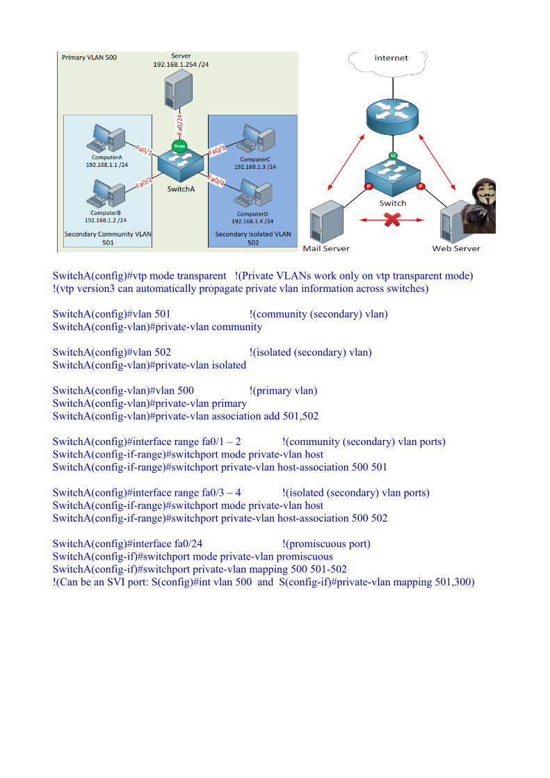
SwitchA(config)#vtp mode transparent !(Private VLANs work only on vtp transparent mode)!(vtp version3 can automatically propagate private vlan information across switches)
SwitchA(config)#vlan 501 !(community (secondary) vlan)SwitchA(config-vlan)#private-vlan community
SwitchA(config)#vlan 502 !(isolated (secondary) vlan)SwitchA(config-vlan)#private-vlan isolated
SwitchA(config-vlan)#vlan 500 !(primary vlan)SwitchA(config-vlan)#private-vlan primarySwitchA(config-vlan)#private-vlan association add 501,502
SwitchA(config)#interface range fa0/1 – 2 !(community (secondary) vlan ports)SwitchA(config-if-range)#switchport mode private-vlan hostSwitchA(config-if-range)#switchport private-vlan host-association 500 501
SwitchA(config)#interface range fa0/3 – 4 !(isolated (secondary) vlan ports)SwitchA(config-if-range)#switchport mode private-vlan hostSwitchA(config-if-range)#switchport private-vlan host-association 500 502
SwitchA(config)#interface fa0/24 !(promiscuous port)SwitchA(config-if)#switchport mode private-vlan promiscuousSwitchA(config-if)#switchport private-vlan mapping 500 501-502!(Can be an SVI port: S(config)#int vlan 500 and S(config-if)#private-vlan mapping 501,300)

Communication and tagging rules in PrivateVLANs:■ A port in a particular community VLAN (that is,a community port) can communicate with all otherports in the same community VLAN, with allpromiscuous ports in the corresponding primaryVLAN, and with all trunks.■ A port in a particular isolated VLAN (that is, anisolated port) can communicate with allpromiscuous ports in the corresponding primaryVLAN, and with all trunks.■ A port in a particular primary VLAN (that is, apromiscuous port) can communicate with all otherpromiscuous ports in the same primary VLAN,with all ports in all secondary VLANs associatedwith this primary VLAN, and with all trunks.■ A frame received on a community or isolatedport will be tagged with the ID of thecorresponding secondary VLAN when forwardedout a trunk.■ A frame received on a promiscuous port will betagged with the ID of the corresponding primaryVLAN when forwarded out a trunk.■ A frame received on a trunk tagged with acommunity or isolated VLAN IDwill beforwarded as if it was received ona local community or isolated portin the corresponding secondaryVLAN.■ A frame received on a trunktagged with a primary VLAN IDwill be forwarded as if it wasreceived on a local promiscuousport in the corresponding primary VLAN.There are two common misconceptions regarding the Private VLAN operation on trunks:1. The first misconception relates to thetagging. It is often incorrectly believedthat Private VLANs use double taggingon trunks. This belief is supported bythe apparent nesting of secondaryVLANs inside their associated primaryVLAN. In reality, secondary VLANs donot exist “inside” their primary VLAN;rather, they are only associated with it.This association merely indicates that aframe received in a secondary VLANcan be forwarded out promiscuous portsin the associated primary VLAN andvice versa.2. The second misconception is relatedto trunk port types. We have so far

described normal trunks ( switchport mode trunk ) that can be used both for ordinary and Private VLANs. There are, however, two special types of trunk ports with respect to Private VLANs. Thesespecial trunk port types are called Promiscuous PVLAN Trunk and Isolated PVLAN Trunk ports. Both these types shall not be used in ordinary Private VLAN deployments between switches supporting Private VLANs; rather, their usage is limited to a set of special scenarios. The SW1 switch is assumed to support Private VLANs while SW2 does not support them:1. The first special trunk type is the Promiscuous PVLAN Trunk . Whenever a frame from a secondary VLAN is going to be sent out such a trunk, its VLAN tag will be rewritten with the appropriate primary VLAN ID. This rewriting is necessary when a trunk carrying a set of VLANs including Private VLANs is to be connected to an external device that does not support Private VLANs, yet which shall be reachable from the Private VLANs as if connected to a promiscuous port. If, for example, a router-on-stick like R1 in Figure 2-3 is used to route between several VLANs including a primary VLAN, the external router does not understand that multiple secondaryVLANs actually map to a single primary VLAN. The Promiscuous PVLAN Trunk port will translate all secondary VLAN IDs into the corresponding primary VLAN ID so that the external router always sees only the primary VLAN.2. The second special type of a trunk is the Isolated PVLAN Trunk . This trunk type translates a primary VLAN ID into the ID of the isolated VLAN that is associated with the primary VLAN. This is used to extend the isolated VLAN over a trunk carrying multiple VLANs to a switch that does not support Private VLANs but is capable of isolating its own ports. To illustrate, entry-level Catalyst switches do not support Private VLANs but they support so-called protected ports (this feature is sometimes called the Private VLAN Edge). On these switches, a protected port can be configured using the switchport protected command. Protected ports configured with this command are prohibited from ever communicating with each other—in essence, they act just like isolated ports. Ifa frame is received on a promiscuous port in the primary PVLAN and is about to be sent out the Isolated PVLAN Trunk port, its VLAN tag currently carrying the primary VLAN ID will be rewritten to the isolated VLAN ID. If the neighboring switch has its protected ports assigned to the isolated VLAN (although the VLAN is not configured as isolated on that switch because it does not support Private VLANs), it will be able to forward the frame to the appropriate host. In Figure 2-3 , the Isolated PVLAN Trunk is used to extend the isolated PVLAN 199 from SW1 to SW2 that does not support PVLANs, yet is capable of locally isolating its ports in VLAN 199. SW2 will not allow these ports to communicate together while allowing them to communicate with the trunk toward SW1.SW1 will make sure that a frame received on another isolated port in VLAN 199 will not be forwarded out the isolated PVLAN trunk toward SW2, and that a frame tagged with VLAN 199 coming through the isolated PVLAN trunk from SW2 will not be forwarded out any other isolated port in the same secondary VLAN. This way, the isolated secondary VLAN is extended to SW2 without losing any of its isolated properties. Should, however, R1 or any other device on a promiscuous port send a packet to a station on SW2, this packet would ordinarily be tagged with primary VLAN 100. On the isolated PVLAN trunk on SW1, however, the tag 100 will be rewritten to 199 and forwarded to SW2, allowing the R1 on the promiscuous trunk to communicate with stations on SW2.So, in essence, the special nature of these trunks lies in the tag rewriting they perform:■ A Promiscuous PVLAN Trunk port rewrites the secondary VLAN ID into the pri maryPVLAN ID upon sending a frame. When a frame is received, no tag manipulation isperformed. Also, no tag manipulation is performed for frames in ordinary VLANs.■ An Isolated PVLAN Trunk port rewrites the primary VLAN ID into the isolated secondary VLANID upon sending a frame. When a frame is received, no tag manipulation is performed. Also, no tag manipulation is performed for frames in ordinary VLANs.

Points to remember:1. Devices within a community VLAN can communicate with each other AND the promiscuous port.2. Devices within an isolated VLAN cannot communicate with each other and can ONLY communicate with the promiscuous port.3. The promiscuous port can communicate with any other port.4. Secondary VLANs are unable to communicate with other secondary VLANs.5. Private VLANs can be spanned across multiple switches if you use trunks (same config on SwB).Keep in mind that you need at least a Cisco Catalyst 3560 switch to configure private VLANs. If you try this on a Cisco Catalyst 3550 you will notice that some of the commands are accepted but it won’t work.
Veritfication and TSHOOT:sh int fa0/1 switchportsh int fa0/1 switchport | inc Protectedsh vlan private-vlansh vlan private-vlan type

::::::::Notes:::::::::
(802.1q Tunneling/QinQ Tunneling)(Used for Metro-Ethernet Networks/Layer
2 VPN)
1.Layer 2 VPN over switched ethernet network (similar to lightweight
version of MPLS L2VPN)(Any transport over MPLS(AToM)/Virtual Private Lan
Services(VPLS) feature)
2.SP's PE adds additional 802.1q tag to all frames received from CE (called 'metro tag' or 'QinQ)(transport frames over the provider network)
3.PE assigns all CE facing ports to the same VLAN (one VLAN per customer
in P network)
4.deplolyed in metro-ethernet environment (transparent L2 trunk through
the services provider switches)
5.Can't be dynamically negotiated
6.cusctomer's traffic is segmented from the provider's traffic (metro tag
added and removed from end to end)
7.core of the service provider will know about the mac addresses of
customers
8.once configured CE switches will be able to see each other and won't see
any PE switches as cdp neighbors.
(802.1q Tunneling Design Issues)
1.Assumes layer 2 network end-to-end
->PE-P-PE links must all run layer 2 trunking
(implies scalability issues(ethernet inside and ethernet). If SP network
large they don't want to run layer2 everywhere, which is why MPLS layer2
VPNs over 802.1q tunnel. So both L2 and L3 services while tunneling the
traffic inside IP in the core)
2.Additional tags increase payload size (MTU issues)
->4 bytes per tag
->Potential to exceed MTU of transit path
->Ethernet doesn't support fragmentation
->PE should set the MTU higher than 1500 i.e 1504 to allow the 4 byte
metro-tag (it's important to do this)
3.Loss of control plane signaling for CE devices
->CDP, VTP, STP, etc. dropped by PE (as these are encoded with special
source and destination mac addresses and by default these can not be
inserted into the CAM table)(which is why Switch disables cdp by default)
(Layer 2 Protocol Tunneling)
1.Used to tunnel Layer 2 control plane protocols between ports
->typically used with 802.1q tunnel
2.Supports for CDP,VTP,STP,PAgP,LACP,UDLD.
(Etherchannel over 802.1 Tunnels)
1.CE can support aggregation of CE-PE links(e.g. 2xGigE per customer site)
2.Etherchannel always has to be point-to-point
(As many metro tags need as many links/ports being aggregated)(Implies one
metro tag per PE-CE link)
3.PE can tunnel negotiate aswell
4.If a frame leaves one CE and does not reach exactly the same to other
CE end then you have caused layer 2 loops

::::Commands and Configurations:::::
(802.1q tunneling/QinQ Tunneling)
->(CE/Customer Edge Switches configs)
(using a Routers S1 and S2 instead of switches in this case, just for the
lab, usually a switch with trunk connected to PE is used)
S1(config)#int f0/1.10
S1(config-if)#switchport
S1(config-if)#ip address
dot1q 10
10.0.0.1
255.255.255.0
S1(config)#int f0/1.20
S1(config-if)#switchport dot1q 20
S1(config-if)#ip address 20.0.0.1 255.255.255.0
S1(config)#int f0/1.30
S1(config-if)#switchport dot1q 30
S1(config-if)#ip address 30.0.0.1 255.255.255.0
S2(config)#int f0/1.10
S2(config-if)#switchport dot1q 10
S2(config-if)#ip address 10.0.0.1 255.255.255.0
S2(config)#int f0/1.20 S2(config-if)#switchport
dot1q 20
S2(config-if)#ip address 20.0.0.1 255.255.255.0
S2(config)#int f0/1.30
S2(config-if)#switchport dot1q 30
S2(config-if)#ip address 30.0.0.1 255.255.255.0
->(Provider Core Switches configs)
SW1(config)#no vlan 2-1000
SW1(config)#vlan 100
SW1(config)#system mtu 1504 (SW1(config)#system mtu jumbo <1500-9000> /
depends on the indiviual hardware platform)
SW2(config)#no vlan 2-1000
SW2(config)#vlan 100 SW2(config)#system mtu 1504
->(PE/Provider Edge Switches configs)
SW3(config)#int f0/1
SW3(config-if)#switchport mode dot1q-tunnel (tells switch to double tag
frames)
SW3(config-if)#switchport access vlan 100 (metro vlan assignment)
SW4(config)#int f0/1
SW4(config-if)#switchport mode dot1q-tunnel (tells switch to double tag
frames)
SW4(config-if)#switchport access vlan 100 (metro vlan assignment)
->(log message: %DOT1Q_Tunneling_MTU_Warning/1500 MTU insufficient/1504
required)(which is why core provider switches support MTU above 1500 and
giant/jumbo frames)
(Layer 2 Protocols Tunneling)
->(CE switched configs)
S1(config)#bridge 10 protocol ieee
S1(config)#bridge 20 protocol ieee
S1(config)#bridge 30 protocol ieee
S1(config)#int f0/1.10

S1(config-if)#bridge-group 10
S1(config)#int f0/1.20
S1(config-if)#bridge-group 20
S1(config)#int f0/1.30
S1(config-if)#bridge-group 30
S2(config)#bridge 10 protocol ieee
S2(config)#bridge 20 protocol ieee
S2(config)#bridge 30 protocol ieee
S2(config)#int f0/1.10
S2(config-if)#bridge-group 10
S2(config)#int f0/1.20
S2(config-if)#bridge-group 20
S2(config)#int f0/1.30
S2(config-if)#bridge-group 30
->(PE switches configs)
SW3(config)#int f0/1
SW3(config-if)#l2protocol-tunnel cdp
SW3(config-if)#l2protocol-tunnel rstp
SW3(config-if)#l2protocol-tunnel vtp
SW4(config)#int f0/1
SW4(config-if)#l2protocol-tunnel cdp
SW4(config-if)#l2protocol-tunnel rstp
SW4(config-if)#l2protocol-tunnel vtp
->(Avoid a problem of Customer's traffic leaking into the service
provider's network/Native VLAN PE-CE link)
if a frame from the customer's edge/CE has a native vlan that matches the
metro-vlan of the PE then the frame is not tagged by the PE, thus customer's
traffic leaks into the service provider's network. Solution to this is to
tag even the native vlan.
SW3(config)#vlan dot1q tag native
SW4(config)#vlan dot1q tag native

(Etherchannel over 802.1q/QinQ Tunnel)
(CE/Customer's Edge swicthes configs)
SW3(config)#default interface range fa0/1 - 2
SW3(config)#int range fa0/1 - 2
SW3(config-if-range)#shut
SW3(config-if-range)#channel-group 1 mode active (running
LACP/initiating negotiation)
->(will have to statically set the port-channel to trunk as DTP packets
were not tunneled through)
SW3(config)#int po1
SW3(config-if)#switchport trunk encapsulation dot1q
SW3(config-if)#switchport mode trunk
SW4(config)#default interface range fa0/1 - 2
SW4(config)#int range fa0/1 - 2
SW4(config-if-range)#shut
SW4(config-if-range)#channel-group 1 mode passive (running LACP/listening
negotiation)
SW4(config)#int po1
SW4(config-if)#switchport trunk encapsulation dot1q
SW4(config-if)#switchport mode trunk
(PE/Customer's Edge swicthes configs)
SW1(config)#vlan 101,102 (metro vlans)
SW1(config)#default int range fa0/1 - 2
SW1(config)#int fa0/1
SW1(config-if)#switchport access vlan 101
SW1(config-if)#switchport mode dot1q-tunnel
SW1(config)#int fa0/2
SW1(config-if)#switchport access vlan 102
SW1(config-if)#switchport mode dot1q-tunnel
SW1(config)#int range fa0/1 - 2
SW1(config-if-range)#l2protocol-tunnel point-to-point lacp
SW1(config)#int fa0/1
SW1(config-if)#l2protocol-tunnel rstp
SW1(config)#int fa0/2
SW1(config-if)#l2protocol-tunnel rstp
SW2(config)#vlan 101,102
SW2(config)#default int range fa0/1 - 2
SW2(config)#int fa0/1
SW2(config-if)#switchport access vlan 101
SW2(config-if)#switchport mode dot1q-tunnel
SW2(config)#int fa0/2
SW2(config-if)#switchport access vlan 102
SW2(config-if)#switchport mode dot1q-tunnel
SW2(config)#int range fa0/1 - 2
SW2(config-if-range)#l2protocol-tunnel point-to-point lacp
SW2(config)#int fa0/1
SW2(config-if)#l2protocol-tunnel rstp
SW2(config)#int fa0/2
SW2(config-if)#l2protocol-tunnel rstp

(no shut should be done once all config is done to avoid order of operation
problems and loops)
SW3(config)#int range fa0/1 - 2
SW3(config-if-range)#no shut
SW4(config)#int range fa0/1 - 2
SW4(config-if-range)#no shut
::::Verification/TSHOOT/Debugs/Show commands:::::
1.show dot1q-tunnel
2.sh spa vlan 100 (to check metro vlan)
3.sh int trunk
4.sh ip int bri
5.sh run int f0/1
6.sh arp
7.sh mac address-table dynamic vlan 100 (scalability issue: core of the
provider network knows the mac addresses of the end customer switches and
the hosts)
8.sh system mtu (need reloading)
9.sh l2protocol-tunnel
10.sh l2protocol-tunnel summary
11.sh run in | bridge|interface (to check CE side bridge group for stp)
12.sh spa 10 (to check end to end spanning-tree between CE switches over
the tunnel)
13.sh cdp nei (to check end to end cdp between CE switches over the tunnel)
14.sh vlan
15.sh etherchannel summary

16.sh int po1 switchport
17.sh run int fa0/1
--
(to put the interface back onto default settings)
S(config)#default int f0/1

------------------------------------------------------------

QoS (Quality of Service)
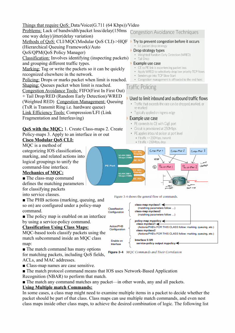
Things that require QoS: Data/Voice(G.711 (64 Kbps))/VideoProblems: Lack of bandwidth/packet loss/delay(150msone way delay)/jitter(delay variation)Methods of QoS: CLI/MQC(Modular QoS CLI)->HQF(Hierarchical Queuing Framework)/AutoQoS/QPM(QoS Policy Manager)Classification: Involves identifying (inspecting packets)and grouping different traffic types. Marking: Tag or write the packets so it can be quicklyrecognized elsewhere in the network. Policing: Drops or marks packet when limit is reached. Shaping: Queues packet when limit is reached. Congestion Avoidance Tools: FIFO(First In First Out)+ Tail Drop/RED (Random Early Detection)/WRED(Weighted RED) Congestion Management: Queuing(TxR is Transmit Ring i.e. hardware queue)Link Efficiency Tools: Compression/LFI (LinkFragmentation and Interleaving)
QoS with the MQC: 1. Create Class-maps 2. CreatePolicy-maps 3. Apply to an interface in or outCisco Modular QoS CLI:MQC is a method ofcategorizing IOS classification,marking, and related actions intological groupings to unify thecommand-line interface. Mechanics of MQC:■ The class-map commanddefines the matching parametersfor classifying packetsinto service classes.■ The PHB actions (marking, queuing, andso on) are configured under a policy-mapcommand.■ The policy map is enabled on an interfaceby using a service-policy command.Classification Using Class Maps:MQC-based tools classify packets using thematch subcommand inside an MQC classmap:■ The match command has many optionsfor matching packets, including QoS fields,ACLs, and MAC addresses.■ Class-map names are case sensitive.■ The match protocol command means that IOS uses Network-Based ApplicationRecognition (NBAR) to perform that match.■ The match any command matches any packet—in other words, any and all packets.Using Multiple match Commands:In some cases, a class map might need to examine multiple items in a packet to decide whether the packet should be part of that class. Class maps can use multiple match commands, and even nest class maps inside other class maps, to achieve the desired combination of logic. The following list

summarizes the key points regarding these more complex matching options:■ Up to four (CoS and IPP) or eight (DSCP) values can be listed on a single match cos , match precedence , or match dscp command, respectively. If any of the values are found in the packet, the statement is matched.■ If a class map has multiple match commands in it, the match-any or match-all(default) parameter on the class-map command defines whether a logical OR or alogical AND (default) is used between the match commands, respectively.■ The match class name command refers to another class map by name, nesting thenamed class map’s matching logic; the match class name command is considered tomatch if the referenced class map also results in a match.The following list highlights the key points regarding CB Marking configuration and logic:■ CB Marking requires CEF (enabled using the ip cefglobal command).■ Packets are classified based on the logic in MQC classmaps.■ An MQC policy map refers to one or more class mapsusing the class class-mapname command; packetsclassified into that class are then marked.■ CB Marking is enabled for packets either entering orexiting an interface using the MQC service-policy in |out policy-map-name interface subcommand.■ A CB Marking policy map is processed sequentially;after a packet has matched aclass, it is marked based on the set command(s) definedfor that class.■ You can configure multiple set commands in one class to set multiple fields, for example, to set both DSCP and CoS.■ Packets that do not explicitly match a defined class are considered to have matched a special classcalled class-default .■ For any class inside the policy map for which there is no set command, packets in that class are not marked.Classification Using NBAR:NBAR classifies packets that are normallydifficult to classify. For example, someapplications use dynamic port numbers, soa statically configured match command,matching a particular UDP or TCP portnumber, simply could not classify thetraffic. NBAR can look past the UDP andTCP header, and refer to the host name,URL, or MIME type in HTTP requests.(This deeper examination of the packetcontents is sometimes called deep packetinspection .) NBAR can also look past the TCP and UDP headers to recognize application-specific information. For example, NBAR allows recognition of different Citrix application types, and allows searching for a portion of a URL string.NBAR itself can be used for a couple of different purposes. Independent of QoS features, NBAR can be configured to keep counters of traffic types and traffic volume for each type. For QoS, NBAR can be used by CB Marking to match difficult-to-match packets. Whenever the MQC match protocol command is used, IOS is using NBAR to match the packets. Note: Before the 12.2T/12.3 IOS releases, the ip nbar protocol-discovery command was required onan interface before using a service-policy command that used NBAR matching. With 12.2T/12.3

train releases, this command is no longer required.The use of the match protocol command implies that NBAR will be used to match thepacket.Unlike most other IOS features, NBAR can be upgraded without changing to a later IOS version. Cisco uses a feature called Packet Description Language Modules (PDLM) to define new protocols that NBAR should match. When Cisco decides to add one or more new protocols to the list of protocols that NBAR should recognize, it creates and compiles a PDLM. You can then download the PDLM from Cisco, copy it into Flash memory, and add the ip nbar pdlm pdlm-name command to the configuration, where pdlm-name is the name of the PDLM file in Flash memory. NBAR can then classify based on the protocol information from the new PDLM.CB Marking Design Choices:The intent of CB Marking is to simplify the work required of other QoS tools bymarking packets of the same class with the same QoS marking. For other QoS tools to take advantage of those markings, packets should generally be marked as close to the ingress point of thepacket as possible. However, the earliest possible point might not be a trusted device. The followingrule summarizes how to choose the best location to perform marking:Mark as close to the ingress edge of the network as possible, but not so close to the edge that the marking is made by an untrusted device.Also note that Cisco recommends not to use more than four or five different service classes for data traffic. When you use more classes, the difference in behavior between the various classes tends to blur. For the same reason, do not give too many data service classes high-priority service.Marking Using Policers:Traffic policers measure the traffic rate for data entering or exiting an interface, with the goal of determining whether a configured traffic contract has been exceeded. The contract has two components: a traffic rate , configured in bits/second, and a burst size , configured as a number of bytes. If the traffic is within the contract, all packets are considered to have conformed to the contract. However, if the rate or burst exceeds the contract, some packets are considered to have exceeded the contract. QoS actions can be taken on both categories of traffic.The simplest form of policing enforces the traffic contract strictly by forwarding conforming packets and discarding packets that exceed the contract. However, both IOS policers allow a compromise action in which the policer marks down packets instead of dropping them. To mark down the packet, the policer re-marks a QoS field, typically IPP or DSCP, with a value that makes the packet more likely to be discarded downstream. For example, a policer could re-mark AF11 packets that exceed a contract with a new DSCP value of AF13, but not discard the packet. By doing so, the packet still passes through the router, but if the packet experiences congestion later in its travels, it is more likely to be discarded than it would have otherwise been.When marking requirements can be performed by using CB Marking, CB Marking should be used instead of either policer. However, if a requirement exists to mark packets based on whether they conform to a traffic contract, marking with policers must be used.QoS Pre-Classification:With unencrypted, unencapsulated traffic, routers can matchand mark QoS values, and perform ingress and egressactions based on markings, by inspecting the IP headers.However, what happens if the traffic is encrypted? If weencapsulate traffic inside a VPN tunnel, the original headersand packet contents are unavailable for inspection. The onlything we have to work with is the ToS byte of the original packet, which is automatically copied to the tunnel header (in IPsec transport mode, in tunnel mode, and in GRE tunnels) when the packet is encapsulated. But features like NBAR are broken when we are dealing with encapsulated traffic.The issue that arises from this inherent behavior of tunnel encapsulation is the inability of a router to take egress QoS actions based on encrypted traffic. To mitigate this limitation, Cisco IOS includes a feature called QoS pre-classification. This feature can be enabled on VPN endpoint

routers to permit the router to make egress QoS decisions based on the original traffic, before encapsulation, rather than just the encapsulating tunnel header. QoS pre-classification works by keeping the original, unencrypted traffic in memory until the egress QoS actions are taken.You can enable QoS pre-classification in tunnel interface configuration mode, virtualtemplate configuration mode, or crypto map configuration mode by issuing the qos pre-classify command. You can view the effects of pre-classification using several show commands, which include show interface and show crypto-map.Policy Routing for Marking:Policy routing provides the capability to route a packet based on information in the packet besides the destination IP address. The policy routing configuration uses route maps to classify packets. Theroute-map clauses include set commands that define the route (based on setting a next-hop IP address or outgoing interface).Policy routing can also mark the IPP field, or the entire ToS byte, using the set command in a route map. When you use policy routing for marking purposes, the following logic sequence is used:1. Packets are examined as they enter an interface.2. A route map is used to match subsets of the packets.3. Mark either the IPP or entire ToS byte using the set command.4. The traditional policy routing function of using the set command to define the route might also beconfigured, but it is not required.Policy routing should be used to mark packets only in cases where CB Marking is not available, or when a router needs to both use policy routing and mark packets entering the same interface.Class-maps (Classification): (There is always a default class-map that is match-any)R(config)#class-map web-traffic !(by default it takes it as match-all | more like and AND)R(config-cmap)#match protocol http !(NABR (Network Based Application Recognition))R(config-cmap)#match packet length min 400 max 600 !(in bytes)R(config)#class-map match-any web-traffic !(match-any is more like an OR)R(config)#class-map match-any ftp-trafficR(config-cmap)#match protocol ftpR(config)#access-list 5 permit host 192.1681.9R(config)#class-map hostR(config-cmap)#match access-group 5 !(to match access-list)Policy-maps: (One policy can be used for many classes)R(config)#policy-map LIMIT_HTTPR(config-pmap)#class web-trafficR(config-pmap-c)#police 500000 !(in kbps)R(config-pmap)#class ftp-trafficR(config-pmap-c)#bandwidth 500 !(guarantee bandwidth in kbps)R(config-pmap)#class class-defaultR(config-pmap-c)#fair-queueR(config-pmap-c)#random-detectApply the Policy: (One policy map per interface per direction can be applied)R(config)#int s0R(config-if)#service-policy input LIMIT_HTTP
RTP (Real-time Transfer Protocol) | RTCP (Real-time Transfer Control Protocol)R(config)#class-map testR(config-cmap)#description This is a test class

R(config-cmap)#match anyR(config-cmap)#match not access-group 10 !(match anything that does not include access-list 10)NBAR (Network Based Application Recognition):R(config)#class-map testR(config-cmap)#match protocol rtp!(NBAR matches based on application signatures i.e. DPI (Deep packet inspection))!(avoids using access-list which is only ports based and doesn't work for dynamic apps)!(PDLM (Packet Description Language Modules) i.e. application signatures)R(config)#int s0R(config-if)#ip nbar protocol discovery !(to turn the NBAR ON)R(config-if)#load-interval 60 !(for NABR to discover every 1 min instead of default 5 mins)
Types of Marking: Layer 2:Typically stripped at router hops e.g.CoS 3bits/FR DE 1bit/ATM CLP 1bit/MPLS Exp 3bitsLayer 3: Passes through routers e.g. ToS bytes: IP Precedence 3bits/DSCP (Differentiated Services

Code Point) 6bits. So First 3 bits IPP or First 6 bits as DSCP + Last 2 bits ECN.Packets marked as EF (Expedited Forwarding) should be given queuing preference so that they experience minimal latency, but the packets should be policed to prevent them from taking over a link and preventing any other types of traffic from exiting an interface during periods when this high-priority traffic reaches or exceeds the interface bandwidth. These suggested settings, and the associated QoS behavior recommended when using each setting, are called Per-Hop Behaviors (PHB) by DiffServ. Class Selector PHB and DSCP Values:IPP overlaps with the first 3 bits of the DSCP field because the DS field is simply a redefinition of the original ToS byte in the IP header. Because of this overlap, RFC 2475 defines a set of DSCP values and PHBs, called Class Selector (CS) PHBs that provide backward compatibility with IPP. A C&M feature can set a CS DSCP value, and if another router or switch just looks at the IPP field, the value will make sense from an IPP perspective.Besides defining eight DSCP values and their text names, the CS PHB also suggests a simple set of QoS actions that should be taken based on the CS values. The CS PHB simply states that packets with larger CS DSCPs should be given better queuing preference than packets with lower CS DSCPs.Assured Forwarding PHB and DSCP Values:The Assured Forwarding (AF) PHB (RFC 2597) defines four classes for queuing purposes, along with three levels of drop probability inside each queue. To mark packets and distinguish into which of four queues a packet should be placed, along with one of three drop priorities inside each queue, the AF PHB defines 12 DSCP values andtheir meanings. AF xywhere x implies one of four queues (values1 through 4) and y implies one of three droppriorities (values 1 through 3). The AF PHBsuggests that the higher the value of x in theDSCP name AF xy , the better the queuingtreatment a packet should get. Additionally,the AF PHB suggests that the higher the value of y in the DSCP name AF xy , the worse the drop treatment for those packets. (Treating a packet worse for drop purposes means that the packet has a higher probability of being dropped.) Note: To convert from the AF name to the decimal equivalent, you can use a simple formula. If you think of the AF values as AFxy, the formula is 8x + 2y = decimal value For example, AF41 gives you a formula of (8 * 4) + (2 * 1) = 34.Expedited Forwarding (EF) PHB actions:■ Queue EF packets so that they get scheduled quickly, to give them low latency.■ Police the EF packets so that they do not consume all bandwidth on the link orstarve other queues. The DSCP value defined for EF is named EF, with decimal value 46, binary value 101110.R(config)#class-map IP_PHONE_AUDIOR(config-cmap)#match protocol rtpR(config)#policy-map MARK_VOICER(config-pmap)#class IP_PHONE_AUDIOR(config-pmap-c)#set ip precedence critical !(set to value of 5 | Voice Bearer)R(config-pmap-c)#set ip dscp ef !(dscp value for VoIP | Expedited Forwarding)R(config)#int fa0/1R(config-if)#service-policy input MARK_VOICE !(marking is done on inbound direction)Layer 3: 1-byte ToS (Type of Service) DSCP (Differentiated Services Code Point) Marking:IP Precedence can only use first 3-bits from the ToS byte where as DSCP can use the whole. DSCP: 3 bits are major(higher is better)+3 bits are minor (drop preference)(higher is worse)+last 2

bits are ECN (Explicit Congestion Notification)Default – 0 (no minor or drop preference)AF (Assured Forwarding) AF12 where 1 is major and 2 is minorEF (Expedited Forwarding) Value 5 (VoIP) – (no minor or drop preference)CS (Class Selector) are simply IP Precedence (backward compatible with IP precedence)
Ethernet LAN Class of Service:Ethernet supports a 3-bit QoS marking field,but the field only exists when the Ethernetheader includes either an 802.1Q or ISLtrunking header. IEEE 802.1Q defines its QoSfield as the 3 most-significant bits of the 2-byte Tag Control field, calling the field theuser-priority bits . ISL defines the 3 least-significant bits from the 1-byte User field,calling this field the Class of Service (CoS) .WAN Marking Fields:Frame Relay and ATM support a single bit that can be set for QoS purposes, but these single bits areintended for a very strict use related to drop probability. Frames or cells with these bits set to 1 are considered to be better candidates to be dropped than frames or cells without the bit set to 1. Namedthe Frame Relay Discard Eligibility (DE) bit and the ATM Cell Loss Priority (CLP) bit, these bits can be set by a router, or by an ATM or Frame Relay switch. Router and switch drop features can then be configured to more aggressively drop frames and cells that have the DE or CLP bit set, respectively.MPLS defines a 3-bit field called the MPLS Experimental (EXP) bit that is intendedfor general QoSmarking. Often, C&M tools are used on the edge of MPLS networks to remap DSCP or IPP values to MPLS Experimental bit values to provide QoS inside the MPLS network.Locations for Marking and Matching:In such a network, the IPP and DSCP inside the IP packet remain intact from end to end. However, some devices might not be able to look at the IPP or DSCP fields, and some might find it more convenient to look at some other header field. For example, an MPLS Label Switch Router (LSR) inside the MPLS cloud can be configured to make QoS decisions based on the 3-bit MPLS EXP field in the MPLS label, but unable to look at the encapsulated IP header and DSCP field. In such cases, QoS tools might need to be configured on edge devices to look at the DSCP and then mark a different field.The rules for where these fields (CoS, DE, CLP, EXP) can be used are as follows:■ For classification: On ingress only, and only if the interface supports that particular header field■ For marking: On egress only, and only if the interface supports that particularheader field

Queuing:Cisco Router Queuing Concepts:Cisco routers can be configured to perform fancy queuing for packets that are waiting to exit an interface. For example, if a router receives 5 Mbps of traffic every second for the next several seconds, and all that traffic needs to exit a T1 serial link, the router can’t forward all the traffic. So, the router places the packets into one or more software queues , which can then be managed—thus impacting which packets get to leave next and which packets might be discarded.Software Queues and Hardware Queues:The queues created on an interface by the popularly known queuing tools are called software queues , as these queues are implemented in software. However, when the queuing scheduler picks the next packet to take from the software queues, the packet does not move directly out the interface. Instead, the router moves the packet from the interface software queue to a small hardware FIFO (first-in, first-out) queue on each interface. Cisco calls this separate, final queue either the transmit queue (Tx queue) or transmit ring (Tx ring), depending on the model of the router; generically, these queues are called hardware queues.Hardware queues provide the following features:¦ When an interface finishes sending a packet, the next packet from the hardware queue can be encoded and sent out the interface, without requiring a software interrupt to the CPU—ensuring fulluse of interface bandwidth.¦ Always use FIFO logic.¦ Cannot be affected by IOS queuing tools.¦ IOS automatically shrinks the length of the hardware queue to a smaller length than the default when a queuing tool is present.¦ Short hardware queue lengths mean packets are more likely to be in the controllable software queues, giving the software queuing more control of the traffic leaving the interface.R3(config)# int s 0/0R3(config-if)# tx-ring-limit 1 !(hardware queue length)Queuing tools can be used in conjunction with traffic shaping. Trafficshaping tools delay packets to ensure that a class of packets does not exceed a defined traffic rate. While delaying the packets, the shaping function queues the packets—by default in a FIFO queue.

Priority 33% is strict policed priority and wont go above this.33%(voice and video)+42%(http+https+ftp etc.)=75% total25% is always left for other (not classified) traffic.(Ethernet interface has 65% rule)(NOTE: NOT REQUIRED ANYMORE! with HQF/HQoS.Now it is 99% and only 1% is left for default class)
R2(config-if)#max-reserved-bandwidth 100 !(to bypass max 65% or 75% bandwidth limit)

Queuing Tools: CBWFQ and LLQThe classes defined in the policy map each define a single queue; as a result, the terms queue and class are often used interchangeably when working with LLQ and CBWFQ.CBWFQ and LLQ support 64 queues/classes.The maximum queue length can bechanged, with the maximum possible value andthe default length varying based on the modelof router and the amount of memory installed.They both also have one special queue calledthe class-default queue . This queue exists evenif it is not configured. If a packet does notmatch any of the explicitly configured classesin a policy map, IOS places the packet into the class-default class/queue. CBWFQ Basic Features and Configuration:The CBWFQ scheduler guarantees a minimum percentage of a link’s bandwidth to eachclass/queue. If all queues have a large number of packets, each queue gets the percentage bandwidthimplied by the configuration. However, if some queues are empty and do not need their bandwidth

for a short period, the bandwidth is proportionally allocated across the other classes. Defining and Limiting CBWFQ Bandwidth:In previous versions of Cisco IOS Software, the system checks a CBWFQ policy mapto ensure that it does not allocate too much bandwidth. These older versions of IOS perform the check when the service-policy output command was added; if the policy map defined too much bandwidth for that interface, the service-policy command was rejected. IOS defined the allowed bandwidth based on two interface subcommands: the bandwidth command and the reserved bandwidth that was implied by the max-reservedbandwidth command. The nonreservable bandwidth was meant for overhead traffic.In the IOS 15 code releases, themax-reserved-bandwidth commanddoes not have any effect on thequeuing system. IOS does not evencheck a policy map’s totalreservation parameters against themax-reserved-bandwidth settings.What’s more, these versions of IOSeven notify you of this fact. IOSallows a policy map to allocatebandwidth based on the int-bw . Inother words, on an interface withint-bw of 256 (256 kbps), the policymap could allocate the entire 256kbps of bandwidth.The bandwidth can also be definedas percentages using either thebandwidth percent or bandwidthremaining percent command. Whenyou use percentages, it is easier toensure that a policy map does notattempt to allocate too muchbandwidth.The bandwidth percent bw-percentcommand sets a class’s reserved bandwidth as a percentage of int-bw .The bandwidth remaining percent bw-percent command sets a class’s reserved bandwidth as a percentage of remaining bandwidth.Low-Latency Queuing:For delay (latency) sensitive traffic,LLQ is indeed the queuing tool ofchoice. LLQ looks and acts just likeCBWFQ in most regards, except itadds the capability for some queuesto be configured as low-latencyqueues. LLQ schedules thesespecific queues as strict-priorityqueues. In other words, LLQ alwaysservices packets in these priorityqueues first.While LLQ adds a low-latencyqueue to CBWFQ, it also preventsthe queue starvation that occurs withlegacy PQ. LLQ actually polices the

PQ based on the configured bandwidth. In effect, the bandwidth given to an LLQ priority queue is both the guaranteed minimum and policed maximum.Defining and Limiting LLQ Bandwidth:The LLQ priority command provides two syntax options for defining the bandwidth of an LLQ—a simple explicit amount or bandwidth as a percentage of interface bandwidth. (There is no remainingbandwidth equivalent for the priority command.) However, unlike the bandwidth command, both the explicit and percentage versions of the priority command can be used inside the same policy map.IOS still limits the amount of bandwidth in an LLQ policy map, with the actual bandwidth from both LLQ classes (with priority commands) and non-LLQ classes (with bandwidth commands) not being allowed to exceed max-res × int-bw .LLQ with More Than One Priority Queue:LLQ allows multiple queues/classes to be configured as priority queues. LLQ actually places the packets from multiple LLQs into a single internal LLQ. So, packets in the different configured priority queues still get scheduled ahead of nonpriority queues, but they are serviced based on their arrival time for all packets in any of the priority queues.For example by policing traffic in one class at one speed, and traffic in another class at another speed, you get more granularity for the policing function of LLQ. For example, if you are planning for video and voice, you can place each into a separate LLQ and get low-latency performance for both types of traffic, but at the same time prevent video traffic from consuming the bandwidth engineered for voice and vice versa.Miscellaneous CBWFQ/LLQ Topics:CBWFQ and LLQ allow a policy map to either allocate bandwidth to the class-default class, or not. When a bandwidth command is configured under class class-default , the class is indeed reserved that minimum bandwidth. (IOS will notallow the priority command in class-default.)When class class-default does not have abandwidth command, IOS internallyallocates any unassigned bandwidth amongall classes.In practice, a policy map might not havepackets in all queues at the same time. In thatcase, the queues get more than their reservedbandwidth. IOS allocates the extra bandwidthproportionally to each active class’sbandwidth reservation. Finally, IOS uses queuing only when congestion occurs. IOS considers congestion to be occurring when the hardware queue is full; that generally happens when the offered load of traffic is far less than the clock rate of the link. LLQ (PQ+CBWFQ):R3(config)#policy-map LLQR3(config-pmap)#class VoIPR3(config-pmap-c)#priority percent 10 !(defines an LLQ)R3(config-pmap-c)#class HTTPR3(config-pmap-c)#bandwidth remaining percent 10R3(config-pmap-c)#class SMTPR3(config-pmap-c)#bandwidth remaining percent 50R3(config-pmap-c)#class class-defaultR3(config-pmap-c)#bandwidth remaining percent 40R3(config-pmap-c)#fair-queueR3(config-pmap-c)#int fa0/0R3(config-if)#service-policy output LLQ !(Congestion management only happens when there is congestion on the link)

Weighted Random Early Detection:When a queue is full, IOS has no place to put newly arriving packets, so it discards them. This phenomenon is called tail drop . Often, when a queue fills, several packets are tail dropped at a time, given the bursty nature of data packets.Tail drop can have an overall negative effect on network traffic, particularly TCP traffic. When packets are lost, for whatever reason, TCP senders slow their rate of sending data. When tail drops occur and multiple packets are lost, the TCP connections slow even more.Interestingly, overall throughput can be improved by discarding a few packets as a queue begins to fill, rather than waiting for the larger impact of tail drops. Cisco created weighted random early detection (WRED) specifically for the purpose of monitoring queue length and discarding a percentage of the packets in thequeue to improve overall networkperformance. WRED uses several numericsettings when making its decisions.First, WRED uses the measuredaverage queue depth when decidingwhether a queue has filled enoughto begin discarding packets. WREDthen compares the average depth toa minimum and maximum queue threshold,performing different discard actions depending onthe outcome.When the average queue depth is between the twothresholds, WRED discards a percentage of packets.The percentage grows linearly as the average queuedepth grows from the minimum threshold to themaximum.The last of the WRED numeric settings that affect itslogic is the mark probability denominator (MPD).IOS calculates the discard percentage usedat the maximum threshold based on thesimple formula 1/MPD. In the figure, anMPD of 10 yields a calculated value of1/10, meaning that the discard rate growsfrom 0 percent to 10 percent as the averagequeue depth grows from the minimumthreshold to the maximum. Also, whenWRED discards packets, it randomlychooses the packets to discard.How WRED Weights Packets:WRED gives preference to packets withcertain IP Precedence (IPP) or DSCPvalues. To do so, WRED uses differenttraffic profiles for packets with differentIPP and DSCP values. A WRED trafficprofile consists of a setting for three keyWRED variables: the minimum threshold, the maximum threshold, and the MPD.WRED Configuration:Because WRED manages drops based on queue depth, WRED must be configuredalongside a particular queue. However, most queuing mechanisms do not support WRED; as a result, WRED can be configured only in the following locations:

¦ On a physical interface (with FIFO queuing)¦ For a non-LLQ class inside a CBWFQ policy map¦ For an ATM VCTo use WRED directly on a physical interface, IOS actually disables all other queuing mechanisms and creates a single FIFO queue. WRED then manages the queue with regard to drops. For CBWFQ, WRED is configured in a class inside a policy map, in the same location as the bandwidthand priority commands.Finally, calculation of the rolling average queue depth can be affected through configuring a parameter called the exponential weighting constant . A low exponential weighting constant means that the old average is a small part of the calculation, resulting in a more quickly changing average. The setting can be changed with the following command, although changing it is not recommended:random-detect exponential-weighting-constant exponent
Tail Drop Flaws: 1. TCP Synchronization 2. Traffic Starvation 3. Unbiased DroppingRED (Random Early Detection): Randomly drops packets from tcp flows to minimize TCP synchronization. Dropping becomes more aggressive as the queue fills.
WRED (Weighted Random Early Detection): Allows multiple RED profiles.Different queues of WRED to different classes of traffic e.g. different IP Precedence.R3(config-pmap-c)#random-detect !(uses Cisco default values | IP Precedence based)R3(config-pmap-c)#random-detect dscp-based !(recommended to use Cisco default values)R3(config-pmap-c)#random-detect dscp-based af11 10 50 10 !(10 is min threshold 50 is max threshold and 10 is MPD)
WRED ECN (Explicit Congestion Notification) Enhancements:R3(config-pmap-c)#random-detect ecn !(makes the router ECN compatible)!(ECN needs to be enabled on the PCs for it to work)

Link Efficiency Tools: 1. Header Compression: 1. For Voice 2. For Data2. LFI Tools: 1. For PPP Links 2. For Frame Relay
R3(config)#class-map IP_PHONE_AUDIOR3(config-cmap)#match protocol rtpR3(config)#policy-map COMPRESS_VOICER3(config-pmap)#class IP_PHONE_AUDIOR3(config-pmap-c)#compression header ip rtp !(IPHC: IP Header Compression)!(You will have to compress the rtp headers on both sides otherwise the calls fail)LFI (Link Fragmentation and Interleaving):

Do not enable LFI on links greater than 768 kbpsR3(config)#int s0/0R3(config-if)#encapsulation pppR3(config-if)#ppp multilinkR3(config-if)#no ip addressR3(config-if)#ppp multilink group 1R3(config)#int multilink 1R3(config-if)#ip address 10.1.1.1 255.255.255.0R3(config-if)#bandwidth 768 !(in kbps)R3(config-if)#ppp multilink fragment delay 10 !(ms)R3(config-if)#ppp multilink interleaveR3(config-if)#ppp multilink group 1R3#sh ppp multilinkCisco Switch Ingress Queuing:Cisco 3560 switches perform both ingress and egress queuing. They have two ingress queues, one of which can be configured as a priority queue. The ingress queues in the Cisco 3560 use a method called weighted tail drop , or WTD, to set discard thresholds for each queue.The 3560 packet scheduler uses a method called shared round-robin (SRR) to control the rates at which packets are sent from the ingress queues to the internal switch fabric. In shared mode, SRR shares the bandwidth between the two queues according to the weights that you configure. Bandwidth for each queue is guaranteed, but it is not limited. If one queue is empty and the other has packets, that queue is allowed to use all the bandwidth. SRR uses weights that are relative ratherthan absolute—only the ratios affect the frequency of dequeuing. SRR’s shared operation is much like CBWFQ configured forpercentages rather than bandwidth.If you plan to configure ingress queuing on your switches, you must determine the following:¦ Which traffic to put in each queue. By default, COS 5 traffic is placed in queue 2, and all other traffic is in queue 1. Traffic can also be mapped to queues based on DSCP value.¦ Whether some traffic needs priority treatment. If so, you will need to configure one of the queues as a priority queue.¦ How much bandwidth and buffer space to allocate to each queue to achieve the traffic split you need.¦ Whether the default WTD thresholds are appropriate for your traffic. The default treatment is to drop packets when the queue is 100 percent full. Each queue can have three different points, or thresholds, at which it drops traffic.Creating a Priority Queue:Either of the two ingress queues can be configured as a priority queue. You would usually use a priority queue for voice traffic to ensure that it is forwarded ahead of other traffic to reduce latency. To enable ingress priority queuing, use the mls qos srr-queue input priority-queue 'queue-id' bandwidth 'weight' command. The weight parameter defines the percentage of the link’s bandwidth that can be consumed by the priority queue when there is competing traffic in the nonpriority queue.Cisco 3560 Congestion Avoidance:The Cisco 3560 uses a congestion avoidance method known as weighted tail drop , or WTD. WTD is turned on by default when QoS is enabled on the switch. It creates three thresholds per queue, based on CoS value, for tail drop when the associated queue reaches a particular percentage.Because traffic in the priority queue is usually UDP traffic, you will probably leave that at the default of dropping at 100 percent. But in the other queue, youmight want to drop less business-critical traffic moreaggressively than others. For example, you can configurethreshold 1 so that it drops traffic with CoS values of 0–3 whenthe queue reaches 40 percent full, threshold 2 so that it dropstraffic with CoS 4 and 5 at 60 percent full, and finally threshold

3 drops CoS 6 and 7 traffic only when the queue is 100 percent full. The behavior of threshold 3 cannot be changed; it always drops traffic when the queue is 100percent full.Because WTD is configurable separately for all six queues in the 3560 (two ingress, four egress), a great deal of granularity is possible in 3560 configuration.Cisco 3560 Switch Egress Queuing:The concepts of egress queuing are similar to ingress. There are four queues per interface rather than two, but you can configure which CoS and DCSP values are mapped to those queues, the relative weight of each queue, and the drop thresholds of each. You can configure a priority queue, but it must be queue 1. WTD is used for the queues, and thresholds can be configured as with ingress queuing. One difference between the two is that many of the egress commands are given at the interface, whereas the ingress commands were global.A key difference between the ingress and egress queues is that the 3560 has a shaping feature that slows egress traffic. This can help prevent some types of denial of service (DoS) attacks and provides the means to implement subrate speed for Metro Ethernet implementations.The Cisco 3560 uses a relatively simple classification scheme, assuming that you consider only what happens when the forwarding decision has been made. These switches make most internal QoS decisions based on an internal DSCP setting. The internal DSCP is determined when the frame is forwarded. So, when a frame has been assigned an internal DSCP and an egress interface, the following logic determines into which of the four interface output queues the frame is placed:1. The frame’s internal DSCP is compared to a global DSCP-to-CoS map to determine a CoS value.2. The per-interface CoS-to-queue map determines the queue for a frame based on the assigned CoS.This section focuses on the scheduler, assuming that frames have been classified and placed into thefour output queues. In particular, the 3560 has two options for the scheduler, both using the acronym SRR: shared round-robin and shaped round-robin. The key differences between the two schedulers is that while both help to prevent queue starvation when a priority queue exists, the shaped option also rate-limits (shapes) the queues so that they do not exceed the configured percentage of the link’s bandwidth.To see the similarities and differences, it is helpful to think about both options without a PQ and with two scenarios: first, with all four queues holding plenty of frames, and second, with only one queue holding frames.In the first case, with all four output queues holding several frames, both shared and shaped modes work the same. Both use the configuration of weights for each queue, with the queues serviced proportionally based on the weights. The following two commands configure the weights, depending on which type of scheduling is desired on the interface:srr-queue bandwidth share weight1 weight2 weight3 weight4srr-queue bandwidth shape weight1 weight2 weight3 weight4For example, with the default weights of 25 for each queue in shared mode, still assuming that all four queues contain frames, the switch would service each queue equally.The two schedulers’ operations differ, however, when the queues are not all full. Consider a second scenario, with frames only in one queue with a weight of 25 (default) in that queue. With shared scheduling, the switch would keep servicing this single queue with that queue getting all the link’s bandwidth. However, with shaped scheduling, the switch would purposefully wait to service the queue, not sending any data out the interface so that the queue would receive only its configured percentage of link bandwidth—25 percent in this scenario.Next, consider the inclusion of queue 1 as the priority queue. First, consider a case where queues 2, 3, and 4 all have frames, queue 1 has no frames, and then some frames arrive in the egress PQ. The switch completes its servicing of the current frame but then transitions over to serve the PQ. However, instead of starving the other queues, while all the queues have frames waiting to exit the queues, the scheduler limits the bandwidth used for the PQ to the configured bandwidth. However, this limiting queues the excess rather

than discarding the excess. (In this scenario, the behavior is the same in both shaped and shared mode.)Finally, to see the differences between shared and shaped modes, imagine that the PQ still has manyframes to send, but queues 2, 3, and 4 are now empty. In shared mode, the PQ would send at full line rate. In shaped mode, the switch would simply not service the PQ part of the time so that its overall rate would be the bandwidth configured for that queue.Hopefully, these examples help demonstrate some of the similarities and differences between the SRR scheduler in shaped and shared modes. The following list summarizes the key points:¦ Both shared and shaped mode scheduling attempt to service the queues in proportion to their configured bandwidths when more than one queue holds frames.¦ Both shared and shaped mode schedulers service the PQ as soon as possible if atfirst the PQ is empty but then frames arrive in the PQ.¦ Both shared and shaped mode schedulers prevent the PQ from exceeding its configured bandwidthwhen all the other queues have frames waiting to be sent.¦ The shaped scheduler never allows any queue, PQ or non-PQ, to exceed its configured percentage of link bandwidth, even if that means that link sits idle.Note The 3560 supports the ability to configure shared mode scheduling on somequeues, and shaped mode on others, on a single interface. The difference in operation is that the queues in shaped mode never exceed their configured bandwidth setting.Mapping DSCP or CoS values to queues is done in global configuration mode, as with ingress queuing. Each interface belongs to one of two egress queue-sets . Buffer and WTD threshold configurations are done in globalconfiguration mode for each queueset.Bandwidth weights, shaped or shared mode,and priority queuing are configured perinterface.Example 4-6 shows an egress queueconfiguration. Buffers and the WTDthresholds for one of the queues are changedfor queue-set 1. Queue-set 1 is assigned toan interface, which then has sharingconfigured for queue 2 with a newcommand: srr-queue bandwidth shareweight1 weight2 weight3 weight4 . Shapingis configured for queues 3 and 4 with thesimilar command srr-queue bandwidth shapeweight1 weight2 weight3 weight4 . Queue 1is configured as a priority queue. When you configure the priority queue, the switch ignores any bandwidth values assigned to the priority queue in the share or shape commands. The 3560 also gives the ability to rate-limit the interface bandwidth with the command srr-queue bandwidth limit percent . In this example, the interface is limited by default to using 75 percent of its bandwidth. Implementing QoS on Catalyst Switches:
1. Allows traffic to be classified+marked as close to the source as possible2. Policing preformed as close to the source as possible (and more options) 3. Hardware vs. software switching (QoS is hardware based | ASIC)

Model 2950: 1P3Q | 4Q + Model 3550: 1P3Q2T | 4Q2T + Model 3750: 4Q3T +Model 4000: 1P3Q2T | 4Q2T + Model 6500: 2Q2T | 1P2Q2T | 1P3Q1T | 1P2Q1T3550(config)#mls qos !(turning ON qos on a switch)3550(config)#int fa0/13550(config-if)#mls qos trust device cisco-phone !(CDP needs to be enabled)3550(config-if)#mls qos trust device ip-precedence3550(config-if)#mls qos cos 53550(config-if)#auto qos voip cisco-phone !(options: cisco-phone | cisco-softphone)WRR (Weighted Round Robin):3550(config-if)#wrr-queue cos-map cos-map 1 0 1 2 !(CoS values of 0, 1 and 2 goes into queue 1)3550(config-if)#wrr-queue cos-map cos-map 2 3 43550(config-if)#wrr-queue cos-map cos-map 3 6 73550(config-if)#wrr-queue cos-map cos-map 4 5 3550(config-if)#wrr-queue bandwidth 5 6 10 1 !(Queue#1 is 5 and so on... | Relative values)3550(config-if)#priority-queue out !(the last queue becomes the priority queue)Shaping:Traffic shaping prevents the bit rate of thepackets exiting an interface fromexceeding a configured shaping rate. Todo so, the shaper monitors the bit rate atwhich data is being sent. If the configuredrate is exceeded, the shaper delayspackets, holding the packets in a shapingqueue . The shaper then releases packetsfrom the queue such that, over time, theoverall bit rate does not exceed theshaping rate.Shaping Terminology:Routers can send bits out an interface only at the physical clock rate. To average sending at a lower rate, the router has to alternate between sending packets and being silent. A shaper sets a static time interval, called Tc . Then, it calculates the number of bits that can be sent in the Tc interval such that, over time, the number of bits/ second sent matches the shaping rate.The number of bits that can be sent ineach Tc is called the committed burst(Bc). 8000-bit Bc can be sent in every125-ms Tc to achieve a 64-kbpsaverage rate. In other words, with aTc of 125 ms, there will be eight Tcintervals per second. If Bc bits (8000)are sent each Tc, eight sets of 8000bits will be sent each second,resulting in a rate of 64,000 bps.

Because the bits must be encoded on the link at the clock rate, the 8000 bits in each interval require only 62.5 ms (8000/128,000) to exit the interface onto the link. The graph shows the results: The interface sends at the line rate(access rate) for 62.5 ms, and thenwaits for 62.5 ms, while packetssit in the shaping queue.Shaping with an Excess Burst:To accommodate bursty datatraffic, shapers implement aconcept by which, after a period inwhich an interface sends relativelylittle data compared to its CIR,more than Bc bits can be sent inone or more time intervals. Thisconcept is called excess burst (Be). When using a Be, the shaper canallow, in addition to the Bc bits per Tc, Be extra bits to be sent. Depending on the settings, it might take one time interval to send the extra bits, or it might require multiple time intervals. Be also equal to 8000 bits. In this case, the Be extra bits are all sent in the first time interval after the relative inactivity.In the first interval, traffic shaping can send a total of 16,000 bits (Bc + Be bits). On a 128-kbps link, assuming a 125-ms Tc, all 125 ms is required to send 16,000 bits. In this particular case, after aperiod of inactivity, R1 sends continuously for the entire first interval. In the second interval, the shaper allows the usual Bc bits to be sent. In effect, with these settings, the shaper allows 187.5 ms of consecutive sending after a period of low activity.Underlying Mechanics of Shaping:Shapers apply a simple formula to the Tc, Bc, and shaping rate parameters:
Tc = Bc/shaping rateTraffic shaping uses a token bucket model to manage the shaping process. Imagine a bucket of size Bc, with the bucket filled with tokens at the beginning of each Tc. Shapers perform two main actions related to the bucket:1. Refill the bucket with new tokens at the beginningof each Tc.2. Spend tokens to gain the right to forward packets.Note that if some of the tokens from the previoustime interval are still in the bucket, some of the newtokens spill over the side of the bucket and arewasted.Traffic shaping implements Be by making the singletoken bucket bigger, with no other changes to thetoken-bucket model. The key difference using Be(versus not using Be) is that when some of the tokensare left in the bucket at the end of the time interval,and Bc tokens are added at the beginning of the next interval, more than Bc tokens are in the bucket—therefore allowing a larger burst of bits in this new interval.Generic Traffic Shaping:In older versions of IOS i.e. IOS 12 train, there was a concept of Generic Traffic Shaping (GTS) that functioned as a simple form of traffic shaping that was supported on most router interfaces but could not be used with flow switching. GTS was configured and applied to an interface or subinterface.GTS was enabled for all interface traffic with this interface-level command:
traffic-shape rate shaped-rate [ Bc ] [ Be ] [ buffer-limit ]

ORtraffic-shape group access-list-number shaped-rate { Bc } { Be }
In this command, the shaped rate was specified in bps, the Bc was in bits, and the Be was in bits. The buffer limit set the maximum size of the queue buffer and was specified in bps. Only the shaped rate was required. If you did not specify the Bc or the Be, both would have been set to one-quarter of the shaped rate by default.access-list 101 permit icmp any anyinterface fa 0/0traffic-shape group 101 500000 !(a CIR of 500000 specified and no Bc or Be)Class-Based Shaping:It allows you to create class maps and policy maps once and then reuse them for multiple interfaces,rather than redoing the entire configuration under each individual interface. The only new MQC command required to configure CB Shaping is the shape command. shape [average | peak] 'mean-rate' [[burst-size] [excess-burst-size]]
CB Shaping can be implemented for output packets only, and it can be associated with either a physical interface or a subinterface.
Example 5-2 CB Shaping of All Traffic Exiting S0/0.1 at 64 kbps:■ Interface clock rate is 128 kbps.■ Shape all traffic at a 64-kbps rate.■ Use the default setting for Tc.■ Shape traffic exiting subinterface s0/0.1.■ The software queuing on s0/0 will use WFQ (the default).■ The shaping queue will use FIFO (the default).policy-map shape-all
class class-defaultshape average 64000
interface serial0/0/0bandwidth 128
interface serial0/0/0.1service-policy output shape-all
So, all packets exiting s0/0.1 will be shaped to the defined rate of 64 kbps.CB Shaping defaults to a Bc and Be of 256 bits each.The CB Shaping shape commandrequires the shaping rate to be set.However, Bc and Be can be omitted,and Tc cannot be set directly. As aresult, CB Shaping calculates some orall of these settings. CB Shapingcalculates the values differently basedon whether the shaping rate exceeds 320 kbps.Tuning Shaping for Voice Using LLQ and a Small Tc:The configuration forces the Tc down to 10 ms, which means that each packet will experience only a short delay waiting for the beginning of the next Tc. By keeping Tc to a small value, the LLQ logic applied to the shaped packets does not have to wait nearly as long to release packets from the PQ, as compared with the default Tc settings.■ Enable LLQ to support a single G.729 voice call.■ Shape to 96 kbps—less than the clock rate (128 kbps), but more than the CIR ofthe VC.■ Tune Tc to 10 ms.class-map match-all voip-rtp

match ip rtp 16384 16383policy-map queue-voip
class voip-rtppriority 32
class class-defaultfair-queue
policy-map shape-allclass class-defaultshape average 96000 960service-policy queue-voip
interface serial0/0.1service-policy output shape-all
This example has only two queues, oneof which is an LLQ, so packets arealways taken from the LLQ if any arepresent in that queue.Configuring Shaping by Bandwidth Percent:■ The shape percent command uses the bandwidth of the interface or subinterfaceunder which it is enabled.■ Subinterfaces do not inherit the bandwidth setting of the physical interface, so if it is not set through the bandwidth command, it defaults to 1544.■ The Bc and Be values are configured as a number of milliseconds; the values are calculated as thenumber of bits that can be sent at the configured shaping rate, in the configured time period.■ Tc is set to configure the Bc value, which is in milliseconds.policy-map percent-test
class class-defaultshape average percent 50 125 ms
interface Serial0/1bandwidth 128service-policy output percent-test
CB Shaping to a Peak Rate:■ It calculates (or defaults) Bc, Be, and Tc the same way as the shape averagecommand.■ It refills Bc + Be tokens (instead of just Bc tokens) into the token bucket for each time interval.This logic means that CB Shaping gets the right to send the committed burst, and the excess burst, every time period. As a result, the actual shaping rate is as follows:
Shaping_rate = configured_rate (1 + Be/Bc)For example, the shape peak 64000 command, with Bc and Be defaulted to 8000 bitseach, results in an actual shaping rate of 128 kbps, based on the following formula:
64 (1 + 8000/8000) = 128Adaptive Shaping:Adaptive shaping configuration requires only a minor amount of effort compared to the topics covered so far. To configure it, just add the shape adaptive min-rate command under the shape command.policy-map shape-all
class class-defaultshape average 96000 9600shape adaptive 32000

Shaping:
CB
Policing Concepts:CB Policing is enabled for packets either entering or exiting an interface, or those entering or exiting a subinterface. It monitors, or meters , the bit rate of the combined packets; when a packet pushes the metered rate past the configured policing rate, the policer takes action against that packet. The most aggressive action is to discard the packet. Alternately, the policer can simply re-mark a field in the packet. This second option allows the packets through, but if congestion occurs at later places during a markeddown packet’s journey, it is more likely to be discarded.CB Policing categorizes packets into two or three categories, depending on the style of policing, and then applies one of these actions to each category of packet. The categories are conforming packets, exceeding packets, and violating packets.Single-Rate, Two-Color Policing (One Bucket):This method uses a single policing rate with no excess burst. The policer will then use only two categories ( conform and exceed ), defining a different action on packets of each type. (Typically, the conform action is to transmit the packet, with the exceed action either being to drop the packet or mark it down.)

While this type of policing logic is often called single-rate, two-color policing, it is sometimes called single-bucket, two-color policing because it uses a single token bucket for internal processing. Like shaping’s use of token buckets, the policer’s main logic relates to filling the bucketwith tokens and then spending the tokens. Over time, the policer refills the bucket according to the policing rate. For example, policing at 96 kbps, over the course of 1 second, adds 12,000 tokens to the bucket. (A token represents a byte with policers, so 12,000 tokens is 96,000 bits’ worth of tokens.)CB Policing does not refill the bucket based on a time interval. Instead, CB Policing reacts to the arrival of a packet by replenishing a prorated number of tokens into the bucket.The number of tokens is defined by the following formula: ((Current_packet_arrival_time - Previous_packet_arrival_time) x Police_rate)/8
Note that a token represents the right to send 1 byte, so the formula includes the division by 8 to convert the units to bytes instead of bits.The idea behind the formula is simple—essentially, a small number of tokens are replenished beforeeach packet is policed; the end result is that tokens are replenished at the policing rate. For example,for a police rate of 128 kbps, the policer should replenish 16,000 tokens per second. If 1 second has elapsed since the previous packet arrived,CB Policing would replenish the bucketwith 16,000 tokens. If 0.1 second has passedsince the previous packet had arrived, CBPolicing would replenish the bucket with0.1 second’s worth of tokens, or 1600tokens. If 0.01 second hadpassed, CB Policingwould replenish 160tokens at that time.The policer then considerswhether it shouldcategorize the newlyarrived packet as eitherconforming or exceedingthe traffic contract. Thepolicer compares thenumber of bytes in thepacket (represented hereas X p, with “p” meaning“packet”) to the numberof tokens in the tokenbucket (represented hereas X b, with “b” meaning“bucket”).As long as the overall bitrate does not exceed thepolicing rate, the packetswill all conform. However, if the rate is exceeded, as tokens are removed for each conforming packet, the bucket will eventually empty—causing some packets to exceed the contract. Over time, tokens are added back to the bucket, so some packets will conform. After the bit rate lowers below the policing rate, all packets will again conform to the contract.Single-Rate, Three-Color Policer (Two Buckets):When you want the policer to police at a particular rate, but to also support a Be, the policer uses two token buckets. It also uses all three categories for packets—conform, exceed, and violate.

Combining those concepts together, such policing is typically called single-rate, three-color policing.As before, CB Policing fills the buckets in reaction to packet arrival. (For lack of a better set of terms, this discussion calls the first bucket the Bc bucket, because it is Bc in size, and the other one the Be bucket, because it is Be in size.) CB Policing fills the Bc bucket just like a single-bucket model. However, if the Bc bucket hasany tokens left in it, some will spill;these tokens then fill the Be bucket.After filling the buckets, the policerthen determines the category for thenewly arrived packet. In this case, Xbc is the number of tokens in the Bcbucket, and X be is the number in the Be bucket.Two-Rate, Three-Color Policer (Two Buckets):The third main option for CB Policing uses two separate policing rates. The lower rate is the previously discussed committed information rate (CIR), and the higher, second rate is called the peak information rate (PIR) . Packets that fall under the CIR conform to the traffic contract. Packetsthat exceed the CIR, but fall below PIR, are considered to exceed the contract. Finally, packets beyond the PIR are considered to violate the contract.The key difference between the single-rate and dual-rate three-color policers is that the dual-rate method essentially allows sustained excess bursting. With a single-rate, threecolor policer, an excessburst exists, but the burst is sustained only until the Be bucket empties. A period of relatively low activity has to occur to refill the Be bucket. With the dual-rate method, the Be bucket does not rely on spillage when filling the Bc bucket. (Note that these buckets are sometimes called the CIR and PIR buckets with dual-rate policing.)The refilling of the twobuckets based on twodifferent rates is veryimportant. For example,imagine that you set aCIR of 128 kbps (16kilobytes/second) and aPIR of 256 kbps (32KBps). If 0.1 secondpassed before the nextpacket arrived, the CIRbucket would bereplenished with 1600tokens (1/10 of 1second’s worth oftokens, in bytes), whilethe PIR bucket would be replenished with3200 tokens. So, there are more tokens to usein the PIR bucket, as compared to the CIRbucket.Next, the policer categorizes the packet. Theonly difference in logic as compared with thesingle-rate, three-color policer is specificallyrelated to how tokens are consumed forconforming packets.In effect, by filling the Be bucket based on the higher PIR, but also draining tokens from the Be bucket for packets that conform to the lower CIR, the Be bucket has tokens that represent the

difference between the two rates.Class-Based Policing Configuration:CB Policing uses the familiar Modular QoS CLI (MQC) commands for configuration. The police command configures CB Policing inside a policy map. On the police command, you define the policing rate in bps, the Bc in bytes, and the Be in bytes, along with the actions for each category:
police bps burst-normal burst-max conform-action action exceed-action action [ violate-action action ]Single-Rate, Three-Color Policing of All Traffic:■ Create a single-rate, three-color policing configuration.■ All traffic is policed at 96 kbps at ingress.■ Bc of 1 second’s worth of traffic is allowed.■ Be of 0.5 second’s worth of traffic is allowed.■ The conform, exceed, and violate actions should be to forward, mark down to DSCP 0, and discard, respectively.policy-map police-all
class class-defaultpolice cir 96000 bc 12000 be 6000 conform-action transmit exceed-action set-dscp-transmit
0 violate-action dropinterface Serial1/0
encapsulation frame-relayservice-policy input police-all
The police command defines a single rate, but the fact that it is a three-color policing configuration, and not a two-color configuration, is not obvious at first glance. To configure a single-rate, three-color policer, you need to configure a violate action or explicitly set Be to something larger than 0.Policing a Subset of the Traffic:One of the advantages of CB Policing is the ability to perform policing per class. ■ Police web traffic at 80 kbps at ingress to the ISP-edge router. Transmit conforming and exceeding traffic, but discard violating traffic.■ Police all other traffic at 16 kbps at ingress to the ISP-edge router. Mark down exceeding and violating traffic to DSCP 0.■ For both classes, set Bc and Be to 1 second’s worth and 0.5 second’s worth of traffic, respectively.class-map match-all match-web
match protocol httppolicy-map police-web
class match-webpolice cir 80000 bc 10000 be 5000 conform-action transmit exceed-action transmit violate-action drop
class class-defaultpolice cir 16000 bc 2000 be 1000 conform-action transmit exceed-action set-dscp-transmit 0 violate-action set-dscp-transmit 0
interface Serial1/0encapsulation frame-relayservice-policy input police-web
CB Policing Defaults for Bc and Be:If you do not configure a Bc value on the police command, CB Policing configures a default value equivalent to the bytes that could be sent in 1/4 second at the defined policing rate. The formula is as follows: (CIR * 0.25 second) CIRBc = —––––––––––––––– = –––—––––
8 bits/byte 32The only part that might not be obvious is the division by 8 on the left—that is simply for the

conversion from bits to bytes. The math reduces to CIR/32. Also, if the formula yields a number less than 1500, CB Policing uses a Bc of 1500.Configuring Dual-Rate Policing:Dual-rate CB Policing requires thesame MQC commands, but withslightly different syntax on the policecommand, as shown here:
police {cir cir} [bc conform-burst] {pir pir} [be peak-burst] [conform-action action [exceed-action action [violate-action action ]]]Note that the syntax of this command requires configuration of both the CIR and a PIR because the curly brackets mean that the parameter is required. The command includes a place to set the Bc value and the Be value as well, plus the same set of options for conform, exceed, and violate actions. For example, if you wanted to perform dual-rate policing, with a CIR of 96 kbps and a PIR of 128 kbps, you would simply use a command like police cir 96000 pir 128000 , with optional settings of Bc and Be, plus the settings for the actions for each of the three categories.Multi-Action Policing:When CB Policing re-marks packets instead of discarding them, the design might call for marking more than one field in a packet. Marking multiple fields in the same packet with CB Policing is called multi-action policing .The police command uses a slightly different syntax to implement multi-action policing. By omitting the actions from the command, the police command places the user into a policing subconfiguration mode in which the actions can be added through separate commands (the conform-action , exceed-action , and violate-action commands). To configure multiple actions, one of these three action commands would be used more than once, which marks DSCP 0 and sets FR DE for packets that violate the traffic contract.R3(config)# policy-map testpol1R3(config-pmap)# class class-defaultR3(config-pmap-c)# police 128000 256000R3(config-pmap-c-police)# conform-action transmitR3(config-pmap-c-police)# exceed-action transmitR3(config-pmap-c-police)# violate-action set-dscp-transmit 0R3(config-pmap-c-police)# violate-action set-frde-transmitPolicing by Percentage:As it does with the shape command, Cisco IOS supports configuring policing rates as a percentage of link bandwidth. The Bc and Be values are configured as a number of milliseconds, from which IOS calculates the actual Bc and Be values based on how many bits can be sent in that many milliseconds.policy-map test-pol6
class class-defaultpolice cir percent 25 bc 500 ms pir percent 50 be 500 ms conform transmit exceed
transmit violate dropinterface serial0/0
bandwidth 256service-policy output test-pol6
Committed Access Rate:CAR implements single-rate, two-color policing. As compared with that same option in CB Policing, CAR and CB Policing have many similarities. They both can police traffic either entering or exiting an interface or subinterface; they can both police subsets of that traffic based on classification logic; and they both set the rate in bps, with Bc and Be configured as a number of bytes.

CAR differs from CB Policing regarding four main features, as follows:■ CAR uses the rate-limit command, which is not part of the MQC set of commands.■ CAR has a feature called cascaded or nested rate-limit commands, which allowsmultiple rate-limit commands on an interface to process the same packet.■ CAR does support Be; however, even in this case, it still supports only conform and exceed categories, and never supports a third (violate) category.■ When CAR has a Be configured, the internal logic used to determine which packets conform and exceed differs as compared with CB Policing.CAR puts most parameters on the rate-limit command, which is added under an interface or subinterface:
rate-limit {input | output} [access-group [rate-limit] acl-index] bps burstnormal burst-max conform-action conform-action exceed-action exceed-action ■ All traffic is policed at 96 kbps at ingress to the ISP-edge router.■ Bc of 1 second’s worth of traffic is allowed.■ Be of 0.5 second’s worth of traffic is allowed.■ Traffic that exceeds the contract is discarded.■ Traffic that conforms to the contract is forwarded with Precedence reset to 0.interface Serial1/0.1 point-to-point
ip address 192.168.2.251 255.255.255.0rate-limit input 96000 12000 18000 conform-action set-prec-transmit 0exceed-action dropframe-relay interface-dlci 103
To classify traffic, CAR requires the use of either a normal access control list (ACL) or a rate-limit ACL . A rate-limit ACL can match Multiprotocol Label Switching (MPLS) Experimental bits, IP Precedence, or MAC Address. For other fields, an IP ACL must be used. Example shows an example in which CAR polices three different subsets of traffic using ACLs for matching the traffic,as well as limiting the overall traffic rate. The criteria for this example are as follows (note that CAR allows only policing rates that are multiples of 8 kbps):■ Police all traffic on the interface at 496 kbps, but before sending this traffic on its way...■ Police all web traffic at 400 kbps.■ Police all FTP traffic at 160 kbps.■ Police all VoIP traffic at 200 kbps.■ Choose Bc and Be so that Bc has 1 second’s worth of traffic and Be provides noadditional burst capability over Bc.interface s 0/0rate-limit input 496000 62000 62000 conform-action continue exceed-action droprate-limit input access-group 101 400000 50000 50000 conform-action transmitexceed-action droprate-limit input access-group 102 160000 20000 20000 conform-action transmitexceed-action droprate-limit input access-group 103 200000 25000 25000 conform-action transmitexceed-action dropThe CAR configuration refers to IP ACLs to classify the traffic, using three different IP ACLs in this case. ACL 101 matches all web traffic, ACL 102 matches all FTP traffic, and ACL 103 matches all VoIP traffic.Under subinterface S0/0.1, four rate-limit commands are used. The first sets the rate for all traffic, dropping traffic that exceeds 496 kbps. However, the conform action is “continue.” This means that packets conforming to this statement will be compared to the next rate-limit statements, and when matching a statement, some other action will be taken. For example, web traffic matches the secondrate-limit command, with a resulting action of either transmit or drop. VoIP traffic would be compared with the next three rate-limit commands before matching the last one. As a result, all traffic is limited to 496 kbps, and three particular subsets of traffic are prevented from taking all the

bandwidth.CB Policing can achieve the same effect of policing subsets of traffic by using nested policy maps.Hierarchical Queuing Framework (HQF):Thus far we have discussed the deployment of our quality of service mechanism through the use of the MQC. It is the MQC that provides a means to configure QoS using a generic command-line interface to all types of interfaces and protocols. MQC is important because it is the mechanism of choice used to configure HQF for queuing and shaping.HQF is a logical engine used to support QoS features. The HQF hierarchy is a tree structure that is built using policy maps. When data passes through an interface using HQF, the data is classified so that it traverses the branches of the tree. Data arrives at the top of the tree and is classified on one ofthe leaves. Data then traverses down the hierarchy (tree) until it is transmitted out the interface at the root (trunk).policy-map class
class c1bandwidth 14
class c2bandwidth 18
policy-map map1class class-default
shape average 64000service-policy class
policy-map map2class class-default
shape average 96000map-class frame-relay fr1
service-policy output map1map-class frame fr2
service-policy output map2interface serial4/1
encapsulation frame-relayframe-relay interface-dlci 16
class fr1frame-relay interface-dlci 17
class fr2QoS Hierarchical Queuing Framework allows for faster deployment of QoSqueuing and shaping in large-scale networks. Furthermore, it also enablesconsistent queuing behavior that can be applied with a common MQC acrossall main Cisco IOS Software releases, making implementation of QoS easierand transparent regardless of the Cisco IOS Software release being used.HQF has built-in functionality that supports both distributed andnondistributed implementations, providing consistency of QoS featurebehavior across all software-forwarding hardware, thus makingimplementation of QoS easier and transparent, regardless of the platformbeing used. This consistency of behavior we are describing results inaccelerated delivery of feature enhancements and new QoS features indifferent Cisco IOS Software releases through different hardwaredeployments. In addition, advantages of HQF include multiple levels ofpacket scheduling and support for integrated Class-Based Shaping andqueuing, as well as the ability to apply fair queuing and drop policies on aper-class basis.These benefits are all made possible in the context of HQF because of newfunctionality that has been introduced. These features include the placement

of hierarchical policies with queuing features situated at every level of the HQF structure. This translates into the ability to apply Class-Based Queuing to any traffic class in the parent or child level of a hierarchical policy while simultaneously creating discrete service levels for different sessions or subscribers.Flow-Based Fair-Queuing Support in Class-Default:The fair-queuing behavior for the class-default class is flow based. This is a change from the weighted fair queuing (WFQ) behavior in previous releases. With flow-based fair queuing, the flow queues in the class-default class are scheduled equally instead of by weight based on the IP Precedence bits.Default Queuing Implementation for Class-Default:When you do not explicitly configure the class-default class in a policy map, its default queuing behavior is first in, first out (FIFO). You can configure the bandwidth , fairqueue , or service-policy commands in the class-default class to achieve different queuing behaviors.Class-Default and Bandwidth:The bandwidth assigned to the class-default class is the unused interface bandwidth not consumed by user-defined classes. By default, the class-default class receives a minimum of 1 percent of the interface bandwidth.Default Queuing Implementation for Shape Class:When you configure the shape command in a class, the default queuing behavior forthe shape queue is FIFO instead of weighted fair queuing (WFQ). You can configure the bandwidth , fair-queue , or service-policy commands in shape class to achieve different queuing behaviors.Policy Map and Interface Bandwidth:In HQF, a policy map can reserve up to 100 percent of the interface bandwidth. If you do not assign an explicit bandwidth guarantee to the class-default class, you can assign a maximum of 99 percent of the interface bandwidth to user-defined classes and reserve the other 1 percent for the class-default class.If you are migrating to Cisco IOS Release 12.4(20)T and the configured policy map allocates100 percent of the bandwidth to the user-defined classes, an error message appears in the console after booting the HQF image. The message indicates that the allocated bandwidth exceeds the allowable amount, and the service policy is rejected. In HQF, you must reconfigure the policy to account for the minimum 1 percent bandwidth guaranteed for the class-default. Then you can apply a service policy to the interface.Per-Flow Queue Limit in Fair Queue:In HQF, when you enable fair queuing, the default per-flow queue limit is 1/4 of the class queue limit. If you do not enable the queue limit in a class, the default per-flow queue limit is 16 packets (1/4 of 64).Oversubscription Support for Multiple Policies on Logical Interfaces:When you attach a shaping policy to multiple logical interfaces including a subinterface, and the sum of the shape rate exceeds the physical interface bandwidth, congestion at the physical interface results in back pressure to each logical interface policy. This back pressure causes each policy to reduce the output rate to its fair share of the interface bandwidth.Shaping on a GRE Tunnel:In HQF, you can apply the shaping to a generic routing encapsulation (GRE) tunnel by using a hierarchical service policy after encapsulation. This means that the shape rate is based on packets with tunnel encapsulation and L2 encapsulation.When configuring the shape feature in the parent policy applied to the tunnel interface, you can use the class-default class only. You cannot configure a user-defined class in the parent policy.Some QoS deployments include a service policy with queuing features applied at the tunnel or a virtual interface and a service policy with queuing features applied at the physical interface. You can apply a service policy with queuing features only at one of these interfaces.

Nested Policy and Reference Bandwidth for Child-Policy:In HQF, when you configure a nested policy with a child queuing policy under a parent shaping class, the reference bandwidth for the child queuing policy is taken from the following: minimum (parent shaper rate, parent class’s implicit/explicit bandwidth guarantee). When you do not define bandwidth for the parent class, the interface bandwidth divides equally among all parent classes as the implicit bandwidth guarantee.Handling Traffic Congestion on an Interface Configured with Policy:Map If an interface configured with a policy map is full of heavy traffic, the implicitly defined policer allows the traffic as defined in the bandwidth statement of each traffic class. The policer is activated whenever there is traffic congestion on an interface.Policing:
Policing:R3(config)#class-map P2PR3(config-cmap)#match protocol edonkeyR3(config)#policy-map P2P_POLICER3(config-pmap)#class P2PR3(config-pmap-c)#police 56000 confirm-actiontransmit exceed-action drop !(cir 56000 in bps)R3(config)#int s0/0R3(config-if)#service-policy input P2P !(Policing can be applied as an input instead of output)3 Token Bucket model:

conform-action: Bc (Committed Burst rate)exceed-action: Be (Excess Burst) (Bandwidth that was below Bc | Banked bandwidth)violate-action: DropR3(config-pmap-c)#police 150000 conform-action transmit exceed-action set-prec-transmit 0 violate-action drop !(CIR (Committed Information Rate) is 150000 bps Bc 4687 Be 4687)!(Bc and Be is calculated by dividing CIR by 32)Shaping:
LAR (Local Access Rate) e.g. E1 speedCIR (Committed Information Rate) lower than LARTc (Time Committed) e.g. ¼ (quarter) of a second.e.g. If CIR 100 kbps then Bc is 25 KbpsBc (Committed Burst) (Average) (ISP has committed to give us)Be (Excess Burst)(Peak)(Banked bandwidth) (Decided in a contract e.g. 25 Kbps)CIR=Bc / Tc Bc = CIR x Tc(Cisco by default uses 4th of a second for Tc)De (Discard Eligible) (ISP mark the marks the packets with DE 1 and could be dropped)(We can decide which traffic we want to mark with DE bit to avoid getting imp traffic dropped as Be)R1(config-pmap-c)#shape peak 500000 !(CIR is 500000 Kbps Cisco calculates the Bc and Be)R1(config-pmap-c)#shape average 500000 !(CIR is 500000 Kbps Cisco calculates the Bc and Be)R1(config-pmap-c)#shape average percent 50

Nested Classes/HQF or HQoS (Hierarchical Queuing Framework or Hirarchical QoS):

Example (Shaping): class-map match-all HTTP
match protocol httpclass-map match-all SQL
match protocol sqlserverclass-map match-all BITTORRENT
match protocol bittorrentclass-map match-all VOIP
match protocol rtp
policy-map INNER_POLICYclass HTTP
bandwidth percent 50 !(500Mbps for a gig link)class SQL
bandwidth percent 30 !(300Mbps for a gig link)class BITORRENT
bandwidth percent 10 !(100Mbps for a gig link)class VOIP
priority percent 5 !(50Mbps for a gig link)class class-default
bandwidth percent 1 !(this is there by default)(1Mbps for a gig link)
int gig1service-policy output INNER_POLICY
!(bandwidth percent is based on software defined bandwidth value and class reservations will change if we change the interface bandwidth value)int gig1bandwidth 500000 !(in kbps)--------------policy-map SHAPE_100Mbps
class class-defaultshape average 100 m !(100Mbps)service-policy INNER_POLICY
policy-map SHAPE_200Mbpsclass class-default
shape average 200 m !(200Mbps)service-policy INNER_POLICY
AutoQoS:AutoQoS is a macro that helps automate class-based quality of service (QoS) configuration. It creates and applies QoS configurations based on Cisco best-practice recommendations. Using AutoQoS provides the following benefits:■ Simpler QoS deployment.■ Less operator error, because most steps are automated.■ Cheaper QoS deployment because less staff time is involved in analyzing networktraffic and determining QoS configuration.■ Faster QoS deployment because there are dramatically fewer commands to issue.■ Companies can implement QoS without needing an in-depth knowledge of QoSconcepts.There are two flavors—AutoQoS for VoIP and AutoQoS for the Enterprise.AutoQoS for VoIP:

AutoQoS for VoIP is supported on most Cisco switches and routers, and provides QoS configuration for voice and video applications. It is enabled on individual interfaces, but creates both global and interface configurations. When enabled on access ports, AutoQoS uses Cisco Discovery Protocol (CDP) to detect the presence or absence of a Cisco phone or softphone, and configures the interface QoS appropriately. When enabled on uplink or trunk ports, it trusts the COSor DSCP values received and sets up the interface QoS.AutoQoS VoIP on Switches:AutoQoS assumes that switches will have two types of interfaces: user access and uplink. It also assumes that a user access interface might or might not have an IP phone connected to it. There is no need to enable QoS globally. After it is enabled for any interface, the command starts a macro that globally enables QoS, configures interface ingress and egress queues, configures class maps and policy maps, and applies the policy map to the interface.AutoQoS is enabled for an access interface by the interface-level command auto qos voip { cisco-phone | cisco-softphone }. When you do this, the switch uses CDP to determine whether a Cisco phone or softphone is connected to the interface. If one is not found, the switch marks all traffic down to DSCP 0 and treats it as best effort. This is the default behavior for a normal trunk port. If a phone is found, the switch then trusts the QoS markings it receives. On the ingress interface, the following traffic is put into the priority, or expedite, queue:■ Voice and video control traffic■ Real-time video traffic■ Voice traffic■ Routing protocol traffic■ Spanning-tree BPDU trafficAll other traffic is placed in the normal ingress queue. On the egress side, voice is placed in the priority queue. The remaining traffic is distributed among the other queues, depending on the number and type of egress queues supported by that particular switch or switch module.AutoQoS is enabled for an uplink port by the interface-level command auto qos voip trust . When this command is given, the switch trusts the COS values received on a Layer 2 port and the DSCP values received on a Layer 3 port.The AutoQoS macro also creates quite a bit of global configuration in the switch. It generates too much to reproduce here, but the following list summarizes the configuration created:■ Globally enables QoS.■ Creates COS-to-DCSP mappings and DSCP-to-COS mappings. As the traffic entersthe switch, the frame header containing the COS value is removed. The switch usesthe COS value in the frame header to assign a DSCP value to the packet. If thepacket exits a trunk port, the internal DSCP value is mapped back to a COS value.■ Enables priority or expedite ingress and egress queues.■ Creates mappings of COS values to ingress and egress queues and thresholds.■ Creates mappings of DSCP values to ingress and egress queues and thresholds.■ Creates class maps and policy maps to identify, prioritize, and police voice traffic. Applies those policy maps to the interface.For best results, enable AutoQoS before configuring any other QoS on the switch. You can then go back and modify the default configuration if needed to fit your specific requirements.AutoQoS VoIP on Routers:The designers of AutoQoS assumed that routers would be connecting to downstream switches or theWAN, rather than user access ports. Therefore, the VoIP QoS configuration is simpler. The command to enable it is auto qos voip [ trust ]. Make sure that the interface bandwidth is configuredbefore giving this command. If you change it later, the QoS configuration will not change. When you issue the auto qos voip command on an individual data circuit, the configuration it creates differs depending on the bandwidth of the circuit itself. Compression and fragmentation are enabledon links of 768 kbps bandwidth and lower. They are not enabled on links faster than 768 kbps. The router additionally configures traffic shaping and applies an AutoQoS service policy regardless of
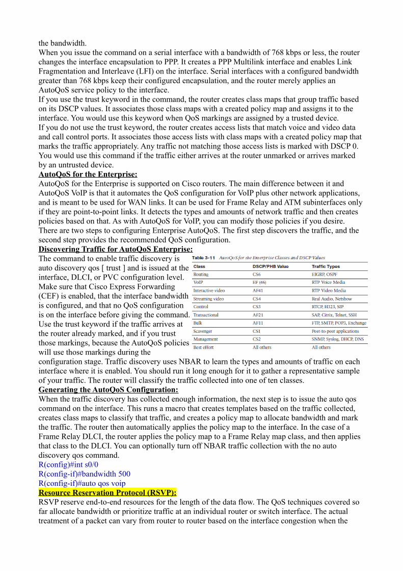
the bandwidth.When you issue the command on a serial interface with a bandwidth of 768 kbps or less, the router changes the interface encapsulation to PPP. It creates a PPP Multilink interface and enables Link Fragmentation and Interleave (LFI) on the interface. Serial interfaces with a configured bandwidth greater than 768 kbps keep their configured encapsulation, and the router merely applies an AutoQoS service policy to the interface.If you use the trust keyword in the command, the router creates class maps that group traffic based on its DSCP values. It associates those class maps with a created policy map and assigns it to the interface. You would use this keyword when QoS markings are assigned by a trusted device.If you do not use the trust keyword, the router creates access lists that match voice and video data and call control ports. It associates those access lists with class maps with a created policy map that marks the traffic appropriately. Any traffic not matching those access lists is marked with DSCP 0. You would use this command if the traffic either arrives at the router unmarked or arrives marked by an untrusted device.AutoQoS for the Enterprise:AutoQoS for the Enterprise is supported on Cisco routers. The main difference between it and AutoQoS VoIP is that it automates the QoS configuration for VoIP plus other network applications, and is meant to be used for WAN links. It can be used for Frame Relay and ATM subinterfaces only if they are point-to-point links. It detects the types and amounts of network traffic and then creates policies based on that. As with AutoQoS for VoIP, you can modify those policies if you desire. There are two steps to configuring Enterprise AutoQoS. The first step discovers the traffic, and the second step provides the recommended QoS configuration.Discovering Traffic for AutoQoS Enterprise:The command to enable traffic discovery isauto discovery qos [ trust ] and is issued at theinterface, DLCI, or PVC configuration level.Make sure that Cisco Express Forwarding(CEF) is enabled, that the interface bandwidthis configured, and that no QoS configurationis on the interface before giving the command.Use the trust keyword if the traffic arrives atthe router already marked, and if you trustthose markings, because the AutoQoS policieswill use those markings during theconfiguration stage. Traffic discovery uses NBAR to learn the types and amounts of traffic on each interface where it is enabled. You should run it long enough for it to gather a representative sample of your traffic. The router will classify the traffic collected into one of ten classes. Generating the AutoQoS Configuration:When the traffic discovery has collected enough information, the next step is to issue the auto qos command on the interface. This runs a macro that creates templates based on the traffic collected, creates class maps to classify that traffic, and creates a policy map to allocate bandwidth and mark the traffic. The router then automatically applies the policy map to the interface. In the case of a Frame Relay DLCI, the router applies the policy map to a Frame Relay map class, and then applies that class to the DLCI. You can optionally turn off NBAR traffic collection with the no auto discovery qos command.R(config)#int s0/0R(config-if)#bandwidth 500R(config-if)#auto qos voipResource Reservation Protocol (RSVP):RSVP reserve end-to-end resources for the length of the data flow. The QoS techniques covered so far allocate bandwidth or prioritize traffic at an individual router or switch interface. The actual treatment of a packet can vary from router to router based on the interface congestion when the

packet arrives and on each router’s configuration. When RSVP is used, each RSVP-enabled router along the path reserves bandwidth and the requested QoS for the duration of that flow. Reservations are made on a flow-by-flow basis, so eachhas its own reservation. In addition, reservations are unidirectional; one is made from source to destination, and another must be made from destination back to the source. RSVP is typically used in networks that have limited bandwidth and frequent congestion. It is most appropriate for traffic that cannot tolerate much delay or packet loss, such as voice and video.RSVP Process Overview:Some applications and devices are RSVP aware and initiate their own reservations. More typically, the gateways act in proxy for the devices, creating a reserved path between them. Reservations are made per direction per flow; a flow is identified in RSVP by a destination IP address, protocol ID, and destination port. One reservation is made from terminating to originating gateway, and another reservation is made from originating to terminating gateway.The RSVP reservation setup proceeds as follows:1. Router GW1 receives the first packet in a flow that needs a reservation made for it. GW1 sends an RSVP PATH message toward the destination IP address. PATH messages contain the IP address of the previous hop (PHOP) so that return messages can follow the same path back. They also describe the bandwidth and QoS needs of the traffic.2. The next-hop router, GW2, is configured with RSVP. It records the previous-hop information andforwards the PATH message on. Notice that it inserts its IP address as the previous hop. The destination address is unchanged.3. The third router, GW3, does not have RSVP configured. The PATH message looksjust like an IP packet to this router, and it will route the message untouched toward the destination, just as it would any IP packet.4. When the fourth router, GW4, receives the PATH message, it replies with a reservation (RESV) message to the previous-hop address listed in the PATH message. This RESV message requests the needed QoS. If any router along the way does not have sufficient resources, it returns an error message and discards the RSVP message. GW4 also initiates a PATH message toward GW1, to reserve resources in the other direction.5. The RESV and PATH messages again look like normal IP packets to GW3, the non-RSVP router, so it just routes the packets toward GW2. No resources are reserved on this gateway.6. GW2 receives the RESV message and checks to see whether it can supply the requested resources. If the check succeeds, it creates a reservation for that flow, and then forwards the RESV message to the previous-hop IP address listed in the PATH message it received earlier. When the other PATH message arrives, GW2 processes it and sends it on to GW1.7. When GW1 receives the RESV message, it knows that its reservation has succeeded. However, a reservation must be made in each direction for QoS to be provided to traffic flowing in both directions.8. GW1 responds to the second PATH message with an RESV message, which proceedsthrough the network as before. When GW4 receives the RESV message, resourceshave been reserved in both directions. GW4 responds with a ResvConf message,confirming the reservation.Data transmission has been delayed during the exchange of messages. When GW1 receives the ResvConf message, it knows that reservations have been made in both directions. Traffic can now proceed. RSVP will send periodic refresh messages along the call path, enabling it to dynamically adjust to network changes.Configuring RSVP:Before configuring RSVP, decide how much bandwidth to allocate per flow and how much total bandwidth to allow RSVP to use, per interface. Remember to allow bandwidth for all other applications that will use that interface.RSVP must be configured on each router that will create reservations, and at each interface the traffic will traverse. It is enabled at the interface configuration mode with the ip rsvp bandwidth

'total-kbps' 'single-flow-kbps' command. If you do not specify the total bandwidth to reserve, the router reserves 75 percent of the interface bandwidth. If no flow value is specified, any flow can reserve the entire bandwidth.To set the DSCP value for RSVP control messages, use the interface command ip rsvp signalling dscp 'dscp-value'.It is not necessary to configure RSVP on every single router within the enterprise. Because RSVP messages are passed through non-RSVP-enabled routers, it can be used selectively. You might enable it in sections of the network prone to congestion, such as areas with low bandwidth. In the core of the network, where bandwidth is higher, you might rely on LLQ/CBWFQ to handle the traffic. Using RSVP for Voice Calls:RSVP reserves resources, but it is up to each router to implement the appropriate QoS techniques todeliver those resources. Low-latency queuing (LLQ) is the QoS mechanism typically used for voice, putting voice in a priority queue with guaranteed but policed bandwidth. This is part of the DiffServ model of QoS. However, RSVP has its own set of queues that it puts reserved traffic into by default. These queues have a low weight, but they are not prioritized. What is needed is a way to put reserved voice traffic into the low-latency queue.By default, RSVP uses weighted fair queuing (WFQ) to provide its QoS. When using LLQ with class-based weighted fair queuing (CBWFQ), disable RSVP’s use of WFQ with the interface command ip rsvp resource-provider none . Also, by default, RSVP will attempt to process every packet (not just voice traffic). Turn this off with the interface command ip rsvp data-packet classification none . LLQ and CBWFQ should be configured as usual. RSVP will then reserve bandwidth for voice calls, and the gateway’s QoS processes will place voice traffic into the priority queue.Note When you are using LLQ, the priority queue size includes Layer 2 overhead.RSVP’s bandwidth statement does not take Layer 2 overhead into consideration. Therefore, when using both LLQ and RSVP, be sure to set the RSVP bandwidth equal to the Priority Queue minus the Layer 2 overhead.Configuring RSVP:R4(config)# int s0/1/0R4(config-if)# ip rsvp bandwidth 128 64R4(config-if)# ip rsvp signalling dscp 40R4(config-if)# ip rsvp resource-provider noneR4(config-if)# ip rsvp data-packet classification noneR4(config-if)# service-policy output LLQVerification and Troubleshooting:R1(config)#ip telnet tos B8 !(to test dscp field on wireshark captured traffic)R1#ping !(extended ping to test dscp field on wireshark captured traffic)
R3(config)#access-list 101 permit ip any any dcsp cs2R3(config)#access-list 101 permit ip any anyR3(config)#int fa0/0R3(config-if)#ip access-group 101 inR3#sh access-list 101 !(to verify if the dcsp is happening on the receiving router)
sh class-mapsh policy-mapsh policy-map int fa0/1 !(important command to see it all)sh ip nbar protocol-discovery stats bit-rate top-n 5 !(different types of traffic going through the router. This uses NBAR)sh ip nbarsh ip rtp header-compression

sh queue fa0/0sh mls qossh auto qos !(Displays the interface AutoQoS commands)sh mls qos !(Has several modifiers that display queuing and COS/DSCP mappings)sh policy-map interface !(Verifies the actions of the policy map on each interface specified)sh auto discovery qos !( Lists the types and amounts of traffic collected by NBAR)sh policy-map interface !(Displays each policy map and the actual effect it had on the interface traffic)sh controllers serial 0/0 !(find out the hardware queue length)sh ip rsvp interfacesh ip rsvp interface detailsh traffic-shape fa 0/0

RIP (Routing Information Protocol)RIP is a distance vector protocol. What direction should it go (vector)and how far away it is (distance). RIP uses hop count as its metricwhich is nothing more than counting the number of routers (hops) youhave to pass to get to your destination. Routers will copy their routingtable to their directly connected neighbor i.e. learning by rumour. If arouter receives information about a network it doesn't know about yet,it will add this information to its routing table.Every 30 seconds our routers will send a full copy of their routing tableto their neighbors who can update their own routing table.
Counting to infinity:When a network goes down the routers couldkeep on going updating themselves to infinitycreating a routing loop. IP packets have a TTL(Time to Live) field however so they won't looparound forever like Ethernet Frames do.To prevent routers from updating themselves overand over again we have a maximum. For RIP this is a hop count of 16. 16 is considered unreachableso the maximum number of hops you can have is 15. This problem is called counting to infinity.Split Horizon:Whatever you learn from your neighbor you are not going to advertise it back to him. We call this split horizon.Route Poisoning:Something else we do is that once a network goes down therouter will send a triggered update immediately to update itsneighbors.The triggered update will contain the network that is down andan infinite metric (16 in the case of RIP). Sending an update forthis network with an infinite metric is called route poisoning.

Poison Reverse:To make sure router Clubs does not update itself via some other router / path in the network, router Hearts will send a poison reverse in response to the route poison it has received from router Clubs.Route poisoning overrules split horizon.Holddown timer:There is one more thing we use with distancevector routing protocols. When router Hearts andSpade find out that our 3.3.3.0 /24 network isdown they will also start a holddown timer. Thisholddown timer will run for 180 seconds and itdoes the following:1. If we receive information about the 3.3.3.0 /24network from another router with the same or worse metric than wecurrently have, we ignore this information.2. If we receive information about the 3.3.3.0 /24 network from another router with a better metric, we stop the holddown timer and update our routing table with this new information.3. If we don't receive anything and the holddown timer elapses we remove this network from the routing table.Configuration:
Spade(config)#router ripSpade(config-router)#network 192.168.12.0Spade(config-router)#network 172.16.1.0Hearts(config)#router ripHearts(config-router)#network 192.168.12.0Hearts(config-router)#network 192.168.23.0Clubs(config)#router ripClubs(config-router)#network 172.16.0.0Clubs(config-router)#network 192.168.23.0At this moment we are running RIP version 1 which is classful. This means that router Spade advertises 172.16.1.0 /24 as 172.16.0.0 and router Clubs advertises 172.16.2.0 /24 as 172.16.0.0 as well.Whenever you learn about a networkfrom two difference sources with thesame metric, your router will doloadbalancing.For example when router Hearts receivesan IP packet meant for 172.16.1.1 it might send it to router Clubs and it will be dropped.Router Spade and Clubs both advertise 172.16.0.0 to router Hearts. Router Hearts stores this information in its routing table but doesn't advertise 172.16.0.0 to router Spade or Clubs because of split-horizon.
We need to make sure that router Spade and Clubs send a subnet mask with their routing updates. We need a classless routing protocol for this.

We can see that we by default we are running RIP version 1 and that we are sending RIP updates on interface FastEthernet 0/0 and 1/0. You can also see the networks that we are advertising (172.16.0.0 and 192.168.12.0).To show you the difference between a classful and classless routing protocol I will change the RIP version from version 1 (classful) to version 2 (classles):Spade(config)#router ripSpade(config-router)#version 2Spade(config-router)#no auto-summaryHearts(config)#router ripHearts(config-router)#version 2Hearts(config-router)#no auto-summaryClubs(config)#router ripClubs(config-router)#version 2Clubs(config-router)#no auto-summaryYou can see that router Hearts has learned aboutnetwork 172.16.1.0/24 and 172.16.2.0 /24. This isbecause Spade and Clubs are advertising 172.16.1.0/24and 172.16.2.0/24, not 172.16.0.0 anymore. Router Spade and Clubs also have learned about each other's networks.
Verification and TSHOOT:sh ip routesh ip route rip !(R NETWORK [AD/METRIC] via NEXT_HOP, TIME_LEARNT, EXIT_INTERFACE)sh ip protocolssh ip rip databasedebug ip ripsh ipv6 routesh ipv6 route rip sh ipv6 protocolssh ipv6 rip databasedebug ipv6 rip

How to use the Cisco IOS Policy-Based Routing Features The use of a dynamic routing protocol on a company’s WAN and LAN is standard
practice today. Whether you use OSPF or EIGRP to automatically determine the
path that your traffic takes, at some point, for some reason, you may want to direct
that traffic for yourself. In this article, we will learn what Policy-based routing is, how
it can help you, and what a basic configuration looks like.
What is Policy-based Routing?
With policy-based routing (which we will call PBR from here on out), you get the
option to implement policies that selectively cause packets to take different paths.
Additionally, PBR can mark packets so that certain types of traffic get prioritized.
One example of PBR is, say that your OSPF routing protocol says that a packet with
a destination of 10.1.1.1 should go out interface e0/0, you could create a policy so
that packets destined to 10.1.1.1, instead, go out interface e1/0. Or, you could make
this happen ONLY when the source of that packet was 192.168.1.1.
How does policy based routing work?
If you look at the Cisco IOS Order of Operations, Policy routing always happens
BEFORE regular routing. What policy routing does is to inspect the traffic on the
interface where the policy is applied and then, based on the policy, make some
decision. First, the traffic has to be identified "matched" according to the policy.
Second, for each match, there is something "set". What is set could be that the traffic
matches must exit out a different interface, or the traffic could be given a higher
priority, or it could choose to just drop that traffic.
The "matching" of the traffic is usually done with an ACL (access-control list) that
is referenced by a route-map. In the route-map, there is a "match" for the traffic
defined in that ACL then a "set" for that traffic where the network administrator
defines what he or she wants to happen to that traffic (prioritize it, route it differently,
drop it, or other actions). Policies can be based on IP address, port numbers,
protocols, or size of packets.
How to apply policy-based routing
Let’s look at an example of how we could use PBR. Say that we wanted to find any
traffic that is destined for IP device 10.1.1.1 and, instead of sending it wherever the
routing protocol says it should go, we are going to send it out interface Fa3/0.
To do this, here are the steps we would take:
Step 1 – define an ACL
Keep in mind that whatever is permitted by this ACL is what will be matched. You
don’t want to permit everything. Usually, I take advantage of the implicit deny at the

bottom of the ACL and just create an ACL that permits what I am going to take action
on in the route-map.
So, just create a simple ACL:
Router(config)# access-list 101 permit ip any host 10.1.1.1
This ACL permits only traffic with a destination IP of 10.1.1.1 (the traffic we want to
send elsewhere)
Step 2 – create a route-map
To create a route-map, go into route-map configuration mode, like this:
Router(config)# route-map reroute10traffic permit 10
Router(config-route-map)#
Next, set your match policy to match the traffic in ACL 101, like this:
Router(config-route-map)#match ip address 101
This will match all the traffic permitted through ACL 101.
Next, you need to set some action on that traffic. What do you want to happen to that
traffic? Let’s tell the router to send it out interface Fast Ethernet 3/0, like this:
Router(config-route-map)#set interface Fa3/0
Step 3 – Apply the route-map to the interface
Next, you need to apply this policy/route-map to the interface where the traffic is
coming in.
Router(config)# interface Fast Ethernet 3/0
Router(config-if)#ip policy route-map reroute10traffic
According to the official Cisco Policy Routing documentation, "One interface can
have a only one route map policy applied.tag; but you can have several route map
entries, each with its own sequence number. Entries are evaluated in order of their
sequence numbers until the first match occurs. If no match occurs, packets are
routed as usual."
Now exit and you are done!
You can view your route-maps with show route-map.
What do you need to know about match & set?
Route-map statements are made up of match and set commands. The set action
only happens when the match command is fulfilled.
Route-map statements can have multiple lines of match and set statements. the "10"
in the original route-map statement above is the line number of that route-map
statement. The numbers of the route-map statements are very important as they
determine the order that the statements are processed and they can also be used to
insert and delete individual statements.
Dual Internet connections in active/standby mode without BGP
Suppose that your company has two independent Internet connections: the first
used as main link and the second used ONLY in case of main connection fault.
What can we do to avoid a ‘manual’ switch of routing and NAT tables?
In general, in this case, the best solution is to use the BGP protocol with bofh providers,
but this solution can be very expensive, so are there other ways to implement this
process?
In my opinion, one of the best solutions is to use IPSLA, PBR and the EEM features
togheter, but what are these features? See you below each ones:
Cisco IOS IP SLAs allows you to montior, analyze and verify IP service levels for IP
applications and services, to increase productivity, to lower operational costs, and to
reduce occurances of network congestion or outages. IP SLAs uses active traffic
monitoring for measuring network performance.
Cisco Policy Based Routing provides a flexible mechanism for network
administrators to customize the operation of the routing table and the flow of traffic
within their networks. Cisco Policy Based Routing offers many advanced features,
including selection and forwarding of traffic to discreet Virtual Routing and
Forwarding (VRF) instances, as well as Enhanced Tracking of the availability of next-
hops.
Cisco IOS Embedded Event Manager (EEM) is a flexible subsystem that
provides real-time network event detection and onboard automation. It gives
you the ability to adapt the behavior of your network devices to align with your
business needs.
Example
Suppose that your company has two independent internet connections (ISP1 and ISP2)
connected to the Ciscozine router by two point-to-point connection (1.1.1.0/30 and
2.2.2.0/30). The ISP1 is the main connection, while the ISP2 is the backup connection.

Figure1
To check the ISP1 connection, the Ciscozine router will send continuously ICMP packet to
its default gateway (1.1.1.1):

Figure2
If the ISP1 has some troubles and the Ciscozine router does not receive the ICMP reply,
the Ciscozine router will change the default route (from 1.1.1.1 to 2.2.2.1) and it will
apply a new nat translation.

Figure3
Configuration:
Define the interfaces IP address:
interface FastEthernet0/0
ip address 1.1.1.2 255.255.255.252
no shut
interface FastEthernet0/1
ip address 2.2.2.2 255.255.255.252
no shut
interface FastEthernet1/0
ip address 192.168.1.1 255.255.255.0
no shut

Define the NAT interface (inside and outside); the LAN is the inside interface, while
the two WAN are the outside interfaces:
interface FastEthernet0/0
ip nat outside
interface FastEthernet0/1
ip nat outside
interface FastEthernet1/0
ip nat inside
Create a SLA object to send ICMP packet to the ISP1 default gateway (1.1.1.1) every 5
seconds:
ip sla 10
icmp-echo 1.1.1.1
timeout 1500
frequency 5
Note: The number “10” define the SLA object number; it will be used in the next step.
Note: In some case, it can be better track a public ip address, for instance 8.8.8.8
(Google public DNS server), instead of the default gateway (1.1.1.1).
Enable the SLA object “forever”:
ip sla schedule 10 life forever start-time now
Define the static routing with tracking/SLA features:
ip route 0.0.0.0 0.0.0.0 1.1.1.1 track 1
ip route 0.0.0.0 0.0.0.0 2.2.2.1 2
track 1 rtr 10 reachability
Note: The default gateway is 1.1.1.1 because it has a better administrative distance
(the default administrative distance for static route is 1) than the 2.2.2.1 gateway (it has
administrative distance “2”).
As you can see, the first route “ip route 0.0.0.0 0.0.0.0 1.1.1.1 track 1” has the track
feature enabled, linked to the SLA object; when the #10 SLA object goes down, the
route is deleted from the routing table, so the second route “ip route 0.0.0.0 0.0.0.0
2.2.2.1 2” will be installed in the routing table. Obviously when the ISP1 connection goes
up, the first route will be installed again and the second route deleted.
Define the ACL used by the NAT:

ip access-list extended NAT
permit ip 192.168.1.0 0.0.0.255 any
deny ip any any
Define the NAT overload used by the main connection (ISP1):
route-map isp1 permit 10
match ip address NAT
match interface FastEthernet0/0
ip nat inside source route-map isp1 interface FastEthernet0/0 overload
Note: With this configuration, the PAT is applied when a packet with source 192.168.1.x
exits to the fastethernet0/0. This happens when the default gateway is 1.1.1.1 (ISP1).
Define the NAT overload for the backup connection (ISP2):
route-map isp2 permit 10
match ip address NAT
match interface FastEthernet0/1
ip nat inside source route-map isp2 interface FastEthernet0/1 overload
Note: With this configuration, the PAT is applied when a packet with source 192.168.1.x
exits to the fastethernet0/1. This happens when the default gateway is 2.2.2.1 (ISP2).
At the end, it is recommended, but not mandatory, it is possible use EEM script to clear
automatically the NAT translation when the default route changes.
event manager applet check-isp
event track 1 state any
action 1.0 cli command "enable"
action 1.5 cli command "clear ip nat trans *"
action 2.0 syslog priority notifications msg "Nat translation cleared!"
The script monitors the track state #1 (it is related to the command “ip route 0.0.0.0
0.0.0.0 1.1.1.1 track 1”). If the track state changes, two tasks will be executed:
The “enable” and the “clear ip nat trans *” commands to flush the nat table.
A syslog message with the text “Nat translation cleared!”.
Remember: When The Port Translation (Overload) is enabled, non-DNS UDP
translations time out after 5 minutes, DNS times out in 1 minute, while TCP translations
time out after 24 hours, unless a RST or FIN is seen on the stream, in which case it
times out in 1 minute.
For those reasons, clearing the nat table can avoid:

an overfill of the NAT table
a “zombie” flows linked with the down connection
Some useful show commands:
When the main connection (ISP1) is up (see Figure2), the default gateway is 1.1.1.1:
Ciscozine#show ip route
Codes: C - connected, S - static, R - RIP, M - mobile, B - BGP
D - EIGRP, EX - EIGRP external, O - OSPF, IA - OSPF inter area
N1 - OSPF NSSA external type 1, N2 - OSPF NSSA external type 2
E1 - OSPF external type 1, E2 - OSPF external type 2
i - IS-IS, su - IS-IS summary, L1 - IS-IS level-1, L2 - IS-IS level-2
ia - IS-IS inter area, * - candidate default, U - per-user static route
o - ODR, P - periodic downloaded static route
Gateway of last resort is 1.1.1.1 to network 0.0.0.0
1.0.0.0/30 is subnetted, 1 subnets
C 1.1.1.0 is directly connected, FastEthernet0/0
2.0.0.0/30 is subnetted, 1 subnets
C 2.2.2.0 is directly connected, FastEthernet0/1
C 192.168.1.0/24 is directly connected, FastEthernet1/0
S* 0.0.0.0/0 [1/0] via 1.1.1.1
Ciscozine#
As a matter of fact, the return code of the SLA object is “OK”:
Ciscozine#show ip sla statistics
Round Trip Time (RTT) for Index 10
Latest RTT: 40 milliseconds
Latest operation start time: 22:52:30.487 UTC Fri Nov 22 2013
Latest operation return code: OK
Number of successes: 547
Number of failures: 16
Operation time to live: Forever
Ciscozine#
When the main connection goes down (Figure3), three things occurs.

1. Two logging messages will be generated: one defined by the IOS and one defined
“manually” with EEM feature.
Ciscozine#
Nov 22 22:52:51.459: %TRACKING-5-STATE: 1 rtr 10 reachability Up->Down
Nov 22 22:52:51.663: %HA_EM-5-LOG: check-isp: Nat translation cleared!
Ciscozine#
2. The SLA object state is “Timeout”:
Ciscozine#show ip sla statistics
Round Trip Time (RTT) for Index 10
Latest RTT: NoConnection/Busy/Timeout
Latest operation start time: 22:53:00.487 UTC Fri Nov 22 2013
Latest operation return code: Timeout
Number of successes: 549
Number of failures: 20
Operation time to live: Forever
Ciscozine#
3. The tracked route is deleted from the routing table and the backup route “ip route
0.0.0.0 0.0.0.0 2.2.2.1 2” is installed in the routing table:
Ciscozine#show ip route
Codes: C - connected, S - static, R - RIP, M - mobile, B - BGP
D - EIGRP, EX - EIGRP external, O - OSPF, IA - OSPF inter area
N1 - OSPF NSSA external type 1, N2 - OSPF NSSA external type 2
E1 - OSPF external type 1, E2 - OSPF external type 2
i - IS-IS, su - IS-IS summary, L1 - IS-IS level-1, L2 - IS-IS level-2
ia - IS-IS inter area, * - candidate default, U - per-user static route
o - ODR, P - periodic downloaded static route
Gateway of last resort is 2.2.2.1 to network 0.0.0.0
1.0.0.0/30 is subnetted, 1 subnets
C 1.1.1.0 is directly connected, FastEthernet0/0
2.0.0.0/30 is subnetted, 1 subnets
C 2.2.2.0 is directly connected, FastEthernet0/1

C 192.168.1.0/24 is directly connected, FastEthernet1/0
S* 0.0.0.0/0 [2/0] via 2.2.2.1
Ciscozine#
At the end, when the main connection goes up (see Figure3):
1. Two logging messages will be generated:
Ciscozine#
Nov 22 22:53:16.467: %TRACKING-5-STATE: 1 rtr 10 reachability Down->Up
Nov 22 22:53:16.667: %HA_EM-5-LOG: check-isp: Nat translation cleared!
Ciscozine#
2. The SLA object state is “OK”:
Ciscozine#show ip sla statistics
Round Trip Time (RTT) for Index 10
Latest RTT: 72 milliseconds
Latest operation start time: 22:53:25.487 UTC Fri Nov 22 2013
Latest operation return code: OK
Number of successes: 552
Number of failures: 22
Operation time to live: Forever
Ciscozine#
3. The ISP1 route is installed again in the routing table:
Ciscozine#show ip route
Codes: C - connected, S - static, R - RIP, M - mobile, B - BGP
D - EIGRP, EX - EIGRP external, O - OSPF, IA - OSPF inter area
N1 - OSPF NSSA external type 1, N2 - OSPF NSSA external type 2
E1 - OSPF external type 1, E2 - OSPF external type 2
i - IS-IS, su - IS-IS summary, L1 - IS-IS level-1, L2 - IS-IS level-2
ia - IS-IS inter area, * - candidate default, U - per-user static route
o - ODR, P - periodic downloaded static route
Gateway of last resort is 1.1.1.1 to network 0.0.0.0

1.0.0.0/30 is subnetted, 1 subnets
C 1.1.1.0 is directly connected, FastEthernet0/0
2.0.0.0/30 is subnetted, 1 subnets
C 2.2.2.0 is directly connected, FastEthernet0/1
C 192.168.1.0/24 is directly connected, FastEthernet1/0
S* 0.0.0.0/0 [1/0] via 1.1.1.1
Ciscozine#
Ciscozine#show ip sla statistics
Round Trip Time (RTT) for Index 10
Latest RTT: 72 milliseconds
Latest operation start time: 22:53:25.487 UTC Fri Nov 22 2013
Latest operation return code: OK
Number of successes: 552
Number of failures: 22
Operation time to live: Forever
Ciscozine#
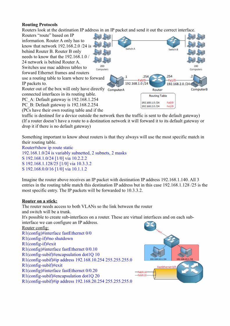
Routing ProtocolsRouters look at the destination IP address in an IP packet and send it out the correct interface.Routers “route” based on IPinformation. Router A only has toknow that network 192.168.2.0 /24 isbehind Router B. Router B onlyneeds to know that the 192.168.1.0 /24 network is behind Router A.Switches use mac address tables toforward Ethernet frames and routersuse a routing table to learn where to forwardIP packets to.Router out of the box will only have directlyconnected interfaces in its routing table.PC_A: Default gateway is 192.168.1.254PC_B: Default gateway is 192.168.2.254(PCs have their own routing table and if thetraffic is destined for a device outside the network then the traffic is sent to the default gateway)(If a router doesn’t have a route to a destination network it will forward it to its default gateway or drop it if there is no default gateway)
Something important to know about routers is that they always will use the most specific match in their routing table.Router#show ip route static192.168.1.0/24 is variably subnetted, 2 subnets, 2 masksS 192.168.1.0/24 [1/0] via 10.2.2.2S 192.168.1.128/25 [1/0] via 10.3.3.2S 192.168.0.0/16 [1/0] via 10.1.1.2
Imagine the router above receives an IP packet with destination IP address 192.168.1.140. All 3 entries in the routing table match this destination IP address but in this case 192.168.1.128 /25 is themost specific entry. The IP packets will be forwarded to 10.3.3.2.
Router on a stick:The router needs access to both VLANs so the link between the routerand switch will be a trunk. It's possible to create sub-interfaces on a router. These are virtual interfaces and on each sub-interface we can configure an IP address.Router config:R1(config)#interface fastEthernet 0/0R1(config-if)#no shutdownR1(config-if)#exitR1(config)#interface fastEthernet 0/0.10R1(config-subif)#encapsulation dot1Q 10R1(config-subif)#ip address 192.168.10.254 255.255.255.0R1(config-subif)#exitR1(config)#interface fastEthernet 0/0.20R1(config-subif)#encapsulation dot1Q 20R1(config-subif)#ip address 192.168.20.254 255.255.255.0

Two ways to fill the routing table of a router with information to reach the networks other than the connected: Static Routing Dynamic Routing
If you use static routing you will have to do everything by yourself. You tell the router where to send IP packets for a certain network, but it's a lot ofwork. Dynamic routing means we use a routing protocolthat will exchange networkinformation between routers. Static Route:R(config)#ip route <destination network> <subnet-mask> <next hop address>
Headquarters(config)#ip route 2.2.2.0 255.255.255.0 192.168.12.2
Default Route:R(config)#ip route 0.0.0.0 0.0.0.0 <next hop address>
Headquarters(config)#ip route 0.0.0.0 0.0.0.0 1.2.3.1
Dynamic Routing:Dynamic routing is where we use a routing protocol. Routing protocols will send network information to each other and they will keep it up-to-date. If there are any changes in the network our routers will update each other to reflect this new information.A routing protocol is used between routers to exchange routing information and build the routing table, but Routed protocols are the protocols that we are routin, for example IPv4 or IPv6. An autonomous system is a collection of routers/networks that belongs to a single administrative domain. Your internet service provider has its own network which is another autonomous system.Within an autonomous system we run a routingprotocol and we call these interior gatewayprotocols or IGP. OSPF and EIGRP are IGPs.Between autonomous systems we also run arouting protocol but we call these externalgateway protocols or EGP. You need to think onan internet scale here, the whole internet is abunch of autonomous systems connected to each otherand in between we run an EGP.There is only one routing protocol we use on theinternet which is called BGP (Border GatewayProtocol). BGP falls under Advanced Distance Vector category.Every routing protocol has a different view of the shortest path to get from source to destination andthey use metric to do this.OSPF uses something called cost as the metric and it will actually look at the bandwidth of an interface. OSPF will prefer a 100Mbit link over a 10Mbit link.

EIGRP is Cisco's flagship routing protocol and it can use multiple metrics. It will look at the bandwidth and delay of an interface and if you want it to you can make it look at the load and reliability of an interface as well.If we are running multiple protocols then AD (Administrative Distance) will determine which one to give priority. The lower the administrative distance the better. Directly connected route has an AD of 0. A static route has a very low administrative distance of 1. Sometimes you use a static routeto “overrule” a routing protocol's decisions. EIGRP has an administrative distance of 90 and OSPF has 110.Interior routing protocols are divided in three different classes: Distance Vector (RIP) Hybrid or Advanced Distance Vector (EIGRP) Link-State (OSPF)
EIGRP by nature is a distance vector class but has so many extra features which make it far more superior to a normal distance vector routing protocol like RIP. This is why Cisco decided to call it a “hybrid” or “advanced distance vector”.Routing protocols can be classful orclassless: Classful routing protocols DO NOT
send the subnet mask along with theirupdates. Classless routing protocols DO send the
subnet mask along with their updates.In classful situation router Spade isadvertising its 172.16.0.0 subnet without asubnet mask and router Clubs is also advertising its 172.16.0.0 subnet without a subnet mask as well. Hearts thinks it can reach the 172.16.0.0 network by sending packets either left or right and if the metric is equal it will try to load-balance. This is going to cause problems.In classless router Spade is now advertising its 172.16.1.0 subnet with a subnet mask and router Clubs is advertising its 172.16.2.0 subnet with a subnet mask as well.Distance Vector Loop prevention:
Routing table rules:1. Most specific subnet mask2. Administrative Distance3. MetricVerification and TSHOOT:(use basic ping and traceroute commands for tshoot)(Be aware that when you try to ping from one Windows computer to another thatyour firewall might be blocking ICMP traffic)C:\>ipconfigsh ip route !(to see the routing table)sh ip route static

SNMP (Simple Network Management Protocol)NMS (Network Management Software) is used to monitor all devices in the network and could sendan email/SMS whenever something bad happens. SNMP a database with variables (MIB (Management Information Base)) used to monitor different items (e.g. CPU, interface traffic etc.) of network devices.SNMP runs on the application layer and consists of a SNMP manager (server) and a SNMP agent (network client device).SNMP can continously poll the device to create graphs. Can also be used to configure devices.SNMP GET message: The packet that we use to poll information.SNMP SET message: The packet that is used to write a configuration.Observium is a free SNMP based network monitoring platform which can monitor Cisco, Linux, Windows and some other devices.
SNMP traps: A trap is a notification that it sent to NMS immediately as soon as something occurs, for example an interface that goes down. NMS will send email/SMS or a notification on screen.SNMP versions:SNMP v1 and SNMP v2c (clear text password i.e. community-string)SNMP v3 (trap acknowledgement)(username based auth and encryption)There are 3 different security modes for SNMPv3:1. noAutoNoPriv: username authentication but no encryption.2. authNoPriv: MD5 or SHA authentication but no encryption.3. authPriv: MD5 or SHA authentication and encryption.
SNMPv2c config:Router(config)#snmp-server community MY_STRING ro 10 !(options: ro | rw)Router(config)#access-list 10 permit host 192.168.1.2Router(config)#snmp-server location AmsterdamRouter(config)#snmp-server contact [email protected]

MIB (Management Information Base):Each variable in the MIB is called an OID (Object ID).Since there are so many OIDs, the MIB is organized into a hierarchy that looks like a tree.Cisco for example, has variables to monitor EIGRP and other Cisco protocols.
R#snmpget -v2c -c MYSTRING 192.168.1.1 1.3.6.1.4.1.9.2.1.3.0 !(to get the hostname)R#snmpget -v2c -c MYSTRING 192.168.1.1 1.3.6.1.4.1.9.2.1.4.0 !(to get the domainname)
SIMPLE NETWORK MANAGEMENT PROTOCOL (SNMP):One option for configuration management across the network is SNMP. SNMP was developed to allow administrators to manage devices on an IP network. SNMP consists of three elements relevant to the network management system (NMS):1. SNMP manager: An SNMP manager runs a network management application.2. SNMP agent: An SNMP agent is a piece of software that runs on a managed device (such as a server, router, or switch).3. Management Information Base (MIB): Information about a managed device’s resources and activity is defined by a series of objects. The structure of these management objects is defined by a managed device’s MIB. SNMP managers and agents use UDP to exchange information. Specifically, SNMP agents listen to UDP port 161, and SNMP managers listen to UDP port 162.There are three main mechanisms for SNMP communication between a network management system and a network device:1. GET: An SNMP GET message is used to retrieve information from a managed device.2. SET: An SNMP SET message is used to set a variable in a managed device or to trigger an actionon a managed device.3. Trap: An SNMP trap message allows a network device to send unsolicited updates to a network management station or notify the SNMP manager about a significant event.

SNMP has evolved through three versions. SNMP versions 1 and 2 do not provide much security. SNMP operations are only controlled by community strings. Community strings can be read-only orread-write. GET requests will behonored if the NMS provides either a valid read-only or read-write community string. SET requests require the NMS to provide a read-write community string. With SNMP versions 1 and 2, all data issent in clear text, including thecommunity strings.SNMPv3 adds a well-developed security model. SNMPv3 authentication verifies the origin and data integrity. That is, SNMPv3 verifies the originator of the message and that the message has not been altered in transit. SNMPv3 also offers privacy via encryption. SNMPv3 offers three modes of operation:1. noAuthNoPriv: This security level simply uses the community string or a username for authentication. No cryptographic hash or encryption is supported.2. authNoPriv: This security level uses a cryptographic hash to secure authentication credentials, but no encryption for data is supported.3. authPriv: This security level uses a cryptographic hash to secure authentication credentials and also uses encryption for data privacy.
All versions of SNMP utilize the concept of the MIB. The MIB organizes configuration and status data into a tree structure. Objects in the MIB are referenced by their object ID (OID), which specifies the path from the tree root to the object.The MIB tree for any given device includes branches with variables common to many networking devices and branches with variables specific to that device or vendor. For example, a common branch is “MIB-2,” which contains a subsection called “ipRouteTable” under section “IP.” This particular subsection, or object, allows the SNMP manager application to obtain the managed device’s IPv4 routing table. The OID reference number for this object would be 1.3.6.1.2.1.4.21.Note: See the Cisco SNMP Object Navigator to research other OID values and the objects they referto.The steps to configure secure user-based SNMP are as follows:1. Configure an SNMP engine ID. This is a unique value identifying the managed device, typically a decimal representation of the IP address of the device.2. Define an SNMP view to define and limit user access to the MIB tree.3. Define an SNMP group, its version, and its cryptographic policy.4. Define an SNMP user, assign it to an SNMP group, and specify authentication and encryption information.5. Define and apply an ACL to the SNMP group and/or SNMP user.6. Define a host device that will be allowed SNMP access.SNMPv3 Configuration:R1(config)# ip access-list standard SNMP_FILTERR1(config-std-acl)# permit host 10.10.10.50R1(config-std-acl)# exit

R1(config)# snmp-server engineID local 192168100254R1(config)# snmp-server view myview mib-2 includedR1(config)# snmp-server view myview cisco includedR1(config)# snmp-server group ADMIN v3 priv write myview access SNMP_FILTERR1(config)# snmp-server user ALICE Admin v3 auth sha Cisco123 priv aes 128 Cisco456R1(config)# snmp-server host 10.10.10.50 version 3 priv AliceALICE is configured as an SNMP user in group ADMIN. SNMP is set to version 3 and supports both SHA authentication and AES 128-bit encryption. The entire “MIB-2” and “cisco” trees are viewable by the SNMP manager. An ACL is applied to the ADMIN group that only allows the 10.10.10.50 device access to the SNMP agent running on router R1.

SPAN(Switch Port Analyzer)/RSPAN(Remote SPAN)/ERSPAN(Encapsulated RSPAN)(Used for Switchport Monitoring/Port Mirroring) | SPAN (destination interface on the same switch)RSPAN (destination interface on the another switch)Lets you copy all traffic from a source port or source VLAN to a destination interface. This is very useful for a number of reasons:1. If you want to use wireshark to capture traffic from an interface that is connected to a workstation, server, phone or anything else you want to sniff.2.Redirect all traffic from a VLAN to an IDS / IPS.3. Redirect all VoIP calls from a VLAN so you can record the calls.4.Traffic to/from the switch CPU.When using RSPAN you need to use a VLAN for your RSPAN traffic so that traffic can travel from the source switch to the destination switch.Make sure the trunks between the switches allow the RSPAN VLAN.SPAN and RSPAN are great tools but there are some restrictions:1.The source interface can be anything…switchport, routed port, access port, trunk port, etherchannel, etc.2.When you configure a trunk as the source interface it will copy traffic from all VLANs, however there is an option to filter this.3.You can use multiple source interfaces or a single VLAN, but you can’t mix interfaces and VLANs.4.It’s very simple to overload an interface. When you select an entire VLAN as the source and use a100Mbit destination interface…it might be too much.5.When you configure a destination port you will lose its configuration. When you remove SPAN, the configuration is restored. In short…you can’t use the destination interface for anything else besides receiving traffic.
Layer 2 frames like CDP, VTP, DTP and spanning-tree BPDUs are not copied by default but you can tell SPAN/RSPAN to copy them anyway.

Configuration:Switch(config)#monitor session 1 source interface fa0/1ORSwitch(config)#monitor session 1 source interface fa0/1 both !(options: both | tx | rx)!(by default it will copy both transmitted and received traffic to the destination port)Switch(config)#monitor session 1 destination interface fa0/2If interface FastEthernet 0/1 were a trunk you could add a filter to select the VLANs you want to forward:Switch(config)#monitor session 1 filter vlan 1 – 100 , 22!(collecting only for VLAN 1 – 100 and 22)Using VLAN as a source:Switch(config)#monitor session 2 source vlan 1Switch(config)#monitor session 2 destination interface fa0/3!(can't use the same destination interface for another session)
RSPAN:
SW1(config)#vlan 100SW1(config-vlan)#remote-spanSW2(config)#vlan 100 SW2(config-vlan)#remote-span !(if vtp running then it should update the remote switch)!(Then configure the trunk port between the two switches)SW1(config)#monitor session 1 source interface fastEthernet 0/1 !(you can also use more than one ports in one session i.e. fa0/1 – 2, but there is a limit on every switch)SW1(config)#monitor session 1 destination remote vlan 100OR(3550 can't do RSPAN unless reflector port is used for it to give up ASIC capabilities. Upper end switches you don't need reflector port)SW1(config)#monitor session 1 destination remote vlan 100 reflector-port fa 0/20!(you have to sacrifice a port that will not be used. Any port that is not connected to anything, Note: definitely not use the trunk port as a reflector port)SW2(config)#monitor session 1 source remote vlan 100SW2(config)#monitor session 1 destination interface fastEthernet 0/1 !(destination switch port)

ERSPAN: SPAN is however limited to one switch, RSPAN is able to send traffic between switches but this traffic can’t be routed.ERSPAN (Encapsulated Remote Switched Port Analyzer) solves this issue! It uses GRE encapsulation, this allows us to route SPAN traffic from a source to a destination. You can use ERSPAN on IOS XE, NX-OS and the Catalyst 6500/7600 switches. Unfortunately, It’s not supported on the “smaller” IOS switches and routers.For the source session, we have to configure:Unique session ID.List of source interfaces or source VLANs that you want to monitor. Not all platforms support everypossible source.What traffic we want to capture: tx, rx or both.Destination IP address for the GRE tunnel.Origin IP address which is used as the source for the GRE tunnel.Unique ERSPAN flow ID.Optional: you can specify attributes like the ToS (Type of Service), TTL, etc.For the destination we have to specify:Unique session ID, doesn’t have to match with the source session.Destination interface(s) where you want to forward the traffic to.Source IP address: has to match with the origin IP address of the source session.Unique ERSPAN flow ID, has to match with the source session.Let’s look at an example so we can see how ERSPAN works in action.
R1(config)#monitor session 1 type erspan-source R1(config-mon-erspan-src)#source interface GigabitEthernet 2 rxR1(config-mon-erspan-src)#no shutdownR1(config-mon-erspan-src)#destinationR1(config-mon-erspan-src-dst)#erspan-id 100R1(config-mon-erspan-src-dst)#ip address 172.16.2.200R1(config-mon-erspan-src-dst)#origin ip address 172.16.12.1R2(config)#monitor session 1 type erspan-destinationR2(config-mon-erspan-dst)#no shutdownR2(config-mon-erspan-dst)#destination interface GigabitEthernet 2R2(config-mon-erspan-dst)#sourceR2(config-mon-erspan-dst-src)#erspan-id 100R2(config-mon-erspan-dst-src)#ip address 172.16.2.200Verification and TSHOOT:Always check if the trunk is allowing the remote-span vlan traffic through if you are using trunk to capture traffic from.sh monitor !(to see which ports are in monitoring and destination port)sh monitor session 1sh vlan remote-spansh int fa0/3 !(shows if the port is in a monitoring state)sh run | begin monitor

StormcontrolUsed to control broadcast, multicast or unicast storms.When we have an excessive amount of broadcast traffic on the network then all devices within the VLAN will suffer. The switch has to flood all broadcast frames to interfaces in the same VLAN while hosts might have to respond (for example to ARP requests).Too much broadcast traffic could be caused by malicious software but also by a malfunctioning NIC. To protect ourselves against this, Cisco switches offer the stormcontrol feature. We can configure a threshold on interfaces to set a limit to the number of broadcast, multicast or unknown unicast traffic and an action when the threshold is exceeded.
Configuration:SwitchA(config)#interface FastEthernet0/1SwitchA(config-if)#storm-control broadcast level 30 !(Whenever broadcast traffic exceeds 30% of the interface bandwidth)ORSwitchA(config-if)#storm-control multicast level pbs 10m !(options: k | m | g i.e. Kbps, Mbps, Gbps)!(rising threshold)!(options: broadcast | multicast | unicast) !(options for level: <1-100> | bps | pps)ORSwitchA(config-if)#storm-control unicast level pps 30m 20m !(below 20Mbps (falling threshold) permit and above 30Mbps (rising threshold) drop)ORSwitchA(config-if)#storm-control action trap !(options: trap | shutdown)!(send SNMP trap or shutdown the interface)
Verification and TSHOOT:show storm-controlshow storm-control broadcast !(options: multicast | broadcast | unicast)!(useful to see the current traffic levels to create a baseline for the thresholds)
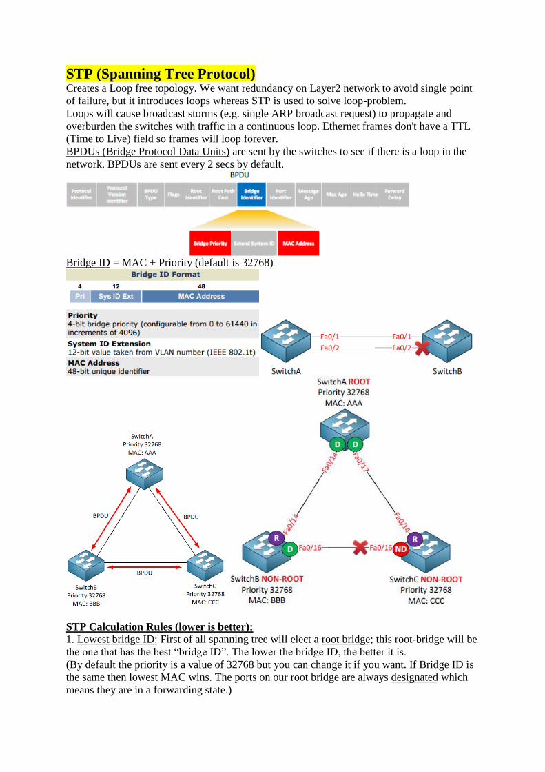
STP (Spanning Tree Protocol) Creates a Loop free topology. We want redundancy on Layer2 network to avoid single point
of failure, but it introduces loops whereas STP is used to solve loop-problem.
Loops will cause broadcast storms (e.g. single ARP broadcast request) to propagate and
overburden the switches with traffic in a continuous loop. Ethernet frames don't have a TTL
(Time to Live) field so frames will loop forever.
BPDUs (Bridge Protocol Data Units) are sent by the switches to see if there is a loop in the
network. BPDUs are sent every 2 secs by default.
Bridge ID = MAC + Priority (default is 32768)
STP Calculation Rules (lower is better):
1. Lowest bridge ID: First of all spanning tree will elect a root bridge; this root-bridge will be
the one that has the best “bridge ID”. The lower the bridge ID, the better it is.
(By default the priority is a value of 32768 but you can change it if you want. If Bridge ID is
the same then lowest MAC wins. The ports on our root bridge are always designated which
means they are in a forwarding state.)

4. Lowest path cost to root bridge: All non-root bridge will find the shortest path (based on
the best BPDU with lowest cost to reach the root bridge) to the root bridge and is called the
root port.
5. Lowest sender bridge ID: when a switch is connected to two switches that it can use to
reach the root bridge and the cost to reach the root bridge is the same, it will select the
interface connecting to the switch with the lowest bridge ID as the root port. Switch C is our
loser (higher Bridge ID) here which means it will have to block its port i.e. non-designated
port (alternate port if using PVST), effectively breaking our loop.
[It is always a good idea to change the priority of the switch for it to become the root bridge
otherwise if it is based on MAC then the oldest/slowest switch will always become the root
bridge]
6. Lowest sender port ID: when the switch has two interfaces connecting to the same switch,
and the cost to reach the root bridge is the same it will use the interface with the lowest
number as the root port.

Keep in mind that switches only make decisions on the BPDUs that they receive. They have
no idea what the topology looks like. The only thing they do know is on which interface they
received the best BPDU. The best BPDU is the one with the shortest path to the root bridge.
This is what happens as soon as you plug in a cable:
1. Listening state: Only a root or designated port will move to the listening state. The non-
designated port will stay in the blocking state. No data transmission occurs at this state for 15
seconds just to make sure the topology doesn’t change in the meantime.
2. Learning state: At this moment the interface will process Ethernet frames by looking at the
source MAC address to fill the mac-address-table. Ethernet frames however are not
forwarded to the destination. It takes 15 seconds to move to the
next state called the forwarding state. 3. Forwarding state: This is the final state of the interface and
finally the interface will forward Ethernet frames so that we
have data transmission.
When a port is not
a designated or
root port it will be
in blocking mode.
This means it
takes 30 seconds
in total to move
from listening to
forwarding.
When an interface is in blocking mode and the topology changes, it’s possible that an
interface that is currently in blocking mode has to move to the forwarding state. When this is
the case, the blocking mode will last for 20 seconds before it moves to the listening state.
This means that it takes 20 (blocking) + 15 (listening) + 15 (learning) = 50 seconds before the
interface is in the forwarding state.
Flavours of STP:
CST: Common (classic) spanning tree (802.1d / single spanning tree for all VLANs)
PVST: Per VLAN spanning tree
RST: Rapid spanning tree (802.1w)
PVRST: Per VLAN rapid spanning tree
MST: Multiple spanning tree

PVST:
There is a big difference between our physical topology and our logical topology because of
our VLANs. We run a separate spanning tree calculation for each VLAN and is called per
VLAN spanning tree. For each VLAN you can have a different root bridge. This way you can
do some load sharing/balancing and utilize all the links i.e. different links for different
VLANs. This is the default one enabled on Cisco switches.
Bridge ID = MAC + Priority (default is 32768 + sys-id-ext(VLAN#) = 32769)
RST and PVRST:
The old spanning tree standard is too slow for a network nowadays which is why there is a
rapid version now.
MST:
Calculating spanning tree for different group of VLANs as a whole.
BPDU default timers:
1. Hello time: every 2 seconds a BPDU is sent.
2. Max Age: If we don’t receive BPDUs for 20 seconds we know something has changed in
the network and we need to re-check the topology. (blocking to listening)

3. Forward Delay: This is the time spent in the “listening” and
“learning” states. By default it’s 15 seconds.
SwitchA(config)#spanning-tree vlan 10 hello-time 1 !(1 sec)
SwitchB(config)#spanning-tree vlan 20 max-age 6 !(6 secs) SwitchC(config)#spanning-tree vlan 30 forward-time 4 !(4 secs)
Change Root Bridge:
SwitchA(config)#spanning-tree vlan 1 root primary !(hard code a root bridge)
!(This is a macro that looks at the current priority of the root bridge and changes your
running-config to lower your own priority. Based on VLAN number)
OR
SwitchA(config)#spanning-tree vlan 1 priority 4096 !(hard code priority. multiple of 4096)
Change Root Port/Non-Designated Port:
SwitchB(config)#interface fa0/14
SwitchB(config-if)#spanning-tree cost 500
!(can be used to change the cost of root port to get a different root port chosen)
SwitchA(config)#interface fa0/14
SwitchA(config-if)#spanning-tree port-priority 16
!(can be used to change the port priority to get a different root port chosen)
[When the cost is equal spanning-tree will look at the port priority (prio.nbr). By default the
port priority is the same for all interfaces which means that the interface number will be the
tie-breaker. The lowest interface number will be chosen]
TCN (topology change notification):
We need the topology change notification to reduce the MAC address table aging timer from
300 seconds to 15 seconds to prevent blackholing traffic.

In a normal situation a non-root switch will receive BPDUs on its root port but will never
send any BPDUs to the root bridge. When a non-root switch detects a topology change it will
generate a topology change notification and send it on its root port towards the root bridge.
When a switch receives the topology change notification it will send a (TCA) topology
change acknowledgement on its designated port towards the downstream switch. It will
create a topology change notification itself and send it on its root port as well. We will work
our way up the tree until we reach the root bridge.
BPDU type field will change to indicate it’s a topology change notification.
Once the topology change notification reaches the root bridge it will set the TC (topology
change) bit in the BPDUs it will send. These BPDUs will be forwarded to all the other
switches in our network so they can reduce their aging time of the MAC address table.
Switches will receives these messages on both forwarding and blocked ports.
The root bridge will send BPDUs and it will set the
flag field to represent the topology change. Portfast:
Each time an interface goes up or down a topology
change notification will be generated and ALL
switches will set their aging time
to 15 seconds. All the MAC
addresses of the devices will be
flushed from the MAC address
table. A host will trigger a
topology change and if you have
a lot of hosts it’s possible that
you end up with a network that is
in a constant state of “topology
changes”.
The switches will quickly re-
learn the MAC address of the
server since its actively sending
traffic to the LAN Backup device. If this LAN Backup device is just silently receiving traffic

and not sending any traffic itself then there’s no way for the switches to re-learn its MAC
address.
Unknown MAC unicast traffic is flooded resuting in network burden until our LAN Backup
device sends an Ethernet Frame and the switches re-learn its MAC address.
Portfast is enabled on access ports to avoid going through all the STP states:
1. Interfaces with portfast enabled that come up will go to forwarding mode immediately. It
will skip the listening and learning state.
2. A switch will never generate a topology change notification for an interface that has
portfast enabled.
Enable portfast on interfaces that are connected to hosts because these interfaces are likely to
go up and down all the time. Don’t enable portfast on an interface to another hub or switch.
Spanning tree is not disabled when portfast is configured. Spanning-tree is still active on
portfast-enabled interfaces, the only thing it does is go straight to the forwarding state.
Whenever the portfast enabled interface receives a BPDU it will switch back to “normal”
spanning-tree operation.
SwitchB(config)interface fa0/2
SwitchB(config-if)#spanning-tree portfast !(configured on access ports)
SwitchB(config)#spanning-tree portfast default !(can be enabled globally for all access mode
ports)
UplinkFast:
Designed to improve the convergence time of spanning-tree. When uplinkfast is enabled a
non-designated port will go to forwarding state immediately if the root port fails. Instead of
50 seconds downtime connectivity is restored immediately. UplinkFast is useful but it will
cause a problem with our MAC address tables because it will take 15 seconds for the
topology change mechanism to age out the MAC address table.
Once SwitchC switches over to use its non-designated port it will create a dummy multicast
frame. The source MAC address of this Ethernet Frame will be all the MAC addresses that it
has in its MAC address table. In my example above this is only the MAC address of
ComputerB. The destination multicast address is a proprietary Cisco MAC address
(000c.29e2.03ba). This multicast frame will be flooded to all other switches so they can
update their MAC address tables right away.
We don’t immediately switch back to interface fa0/14 on SwitchC when it is up again. Even
if we would switch back to interface fa0/14 right away we’d still have to wait because the
fa0/17 interface on SwitchA will have to go through the listening and learning state (which
takes 30 seconds).
BackboneFast:
Is used to recover from an indirect link failure.

Suddenly the link between SwitchA and SwitchB fails. From SwitchC’s perspective this is an
indirect link failure. SwitchC will take 50 secs for fa0/16 to move from blocking to
forwarding. We need backbonefast to speed this up:
1. SwitchB will detect this link failure immediately since it’s a directly connected link. Since
it doesn’t receive any BPDUs from the root anymore it assumes it is now the new root bridge
and will send BPDUs towards SwitchC claiming to be the new root.
2. SwitchC will receive these BPDUs from SwitchB but it will realize that this new BPDU is
inferior compared to the old one it has currently stored on its fa0/16 interface and will ignore
this new BPDU. When a switch receives an
inferior BPDU it means that the neighbor
switch has lost its connection to the root
bridge.
[Using Backbonefast: Without backbone
fast, spanning-tree will discard the inferior
BPDUs that SwitchC receives on its fa0/16
interface and it will have to wait till the max
age timer expires (20 seconds). If we enable
backbone fast it will skip the max age timer
so we can save 20 seconds of time. SwitchA
receives a new packet called a (RLQ) Root
Link Query from SwitchC. As soon as
SwitchC receives an inferior BPDU it will
send a root link query on its root port and
nondesignated ports to check if the root
bridge is still available. SwitchC receives a reply to its root link query on the fa0/14 interface
to SwitchA. Because SwitchC received a response from the root bridge on its fa0/14 interface
it can now skip the max age timer on its f0/16 interface and the interface goes to the listening
and learning state right away. We effectively save 20 seconds (max age timer).]
3. After 20 seconds (default timer) the max age timer will expire for the old BPDU on the
fa0/16 interface of SwitchC. The interface will go from blocking to the listening state and
will send BPDUs towards SwitchB.
4. SwitchB will receive this BPDU from SwitchC and discovers that he isn’t the root bridge
i.e. it now hears the BPDUs from the root bridge through SwitchC and understands that it’s
not the root bridge. It won’t send BPDUs anymore towards SwitchC.
5. The fa0/16 interface on SwitchC will continue from the listening state (15 seconds) to the
learning state (15 seconds) and ends up in the forwarding state.
SwitchA(config)#spanning-tree backbonefast !(enable backbonefast on all the switches)
RST (Rapid Spanning Tree):
Rapid spanning tree is the
same configuration wise
as the original (classic)
spanning tree but
converges quicker.
Discarding is a new port
state. Basically it
combines the blocking and
listening port state.

SwitchC
receives
better BPDUs
on its fa0/16
interface from SwitchB and thus it will be blocked. This is the alternate port and it’s still the
same thing for rapid spanning tree.
The fa0/17 interface of SwitchB is called a backup port and it’s new for rapid spanning tree.
You are very unlikely to see this port on a production network though. Between SwitchB and
SwitchC I’ve added a hub. Normally (without the hub in between) both fa0/16 and fa0/17
would be designated ports. Because of the hub the fa0/16 and fa0/17 interface on SwitchB are
now in the same collision domain. Fa0/16 will be elected as the designated port and fa0/17
will become the backup port for the fa0/16 interface. The reason that SwitchB sees the fa0/17
interface as a backup port is because it receives its own BPDUs on the fa0/16 and fa0/17
interfaces and understands that it has two connections to the same segment.
The BPDU is different for rapid spanning tree. In the classic spanning tree the flags field only
had two bits in use:
1. Topology change.
2. Topology change acknowledgment.
All bits of the flag field are now used:
1. Unknown
2. Alternate / Backup port.
3. Root port.
4. Designated port.
Changes in RST compared to CST (Classic Spanning tree):
1. Transition speed (convergence time) is the most important feature of rapid spanning tree
2. This new BPDU is called a version 2 BPDU. Switches running the old version of spanning
tree will drop this new BPDU version. Rapid spanning tree has a way of dealing with
switches running the older spanning tree version.

3. BPDUs are now sent every hello time. Only the root bridge generated BPDUs in the CST
and those were relayed by the non-root switches if they received it on their root port. In RST
all switches generate BPDUs every two seconds by default (hello time).
4. The CST uses a max age timer (20 seconds) for BPDUs before they are discarded. BPDUs
are now used as a keepalive mechanism similar to what routing protocols like OSPF or
EIGRP use. If a switch misses three BPDUs from a neighbor switch it will assume
connectivity to this switch has been lost and it will remove all MAC addresses immediately.
Rapid spanning tree will accept inferior BPDUs without any config, just like backbonefast in
CST.
RST’s new negotiation mechanism:
The classic spanning tree was based on timers (20 (blocking) + 15 (listening) + 15 (learning)
= 50 secs).
RST doesn’t use timers to decide whether an interface can move to the forwarding state or
not. It will use a sync based negotiation mechanism for this.If we enable portfast while
running the CST it will skip the listening and learning state and put the interface in
forwarding state right away. Besides moving the interface to the forwarding state it will also
not generate topology changes when the interface goes up or down. We still use portfast for
rapid spanning tree but it’s now referred to as an edge port.
RST can only put interfaces in the forwarding state really fast on edge ports (portfast) or
point-to-point interfaces. It will take a look at the
link type and there are only two link types:
1. Point-to-point (full duplex) (p2p)
2. Shared (half duplex) (Shr)
Normally we are using switches and all our
interfaces are configured as full duplex, rapid
spanning tree sees these interfaces as point-to-point. If we introduce a hub to our network
we’ll have half duplex which is seen as a shared interface to rapid spanning-tree.
SwitchA on top is the root bridge. SwitchB, SwitchC and SwitchD are non-root bridges. As
soon as the link between SwitchA and SwitchB comes up their interfaces will be in blocking
mode. SwitchB will receive a BPDU from SwitchA and now a negotiation will take place
called sync.

At this moment SwitchB will figure out that SwitchA is the root bridge because it has the best
BPDU information. The sync mechanism will start because SwitchA will set the proposal bit
in the flag field of the BPDU.
SwitchB receives the proposal from SwitchA and realizes it has to do something. It will block
all its non-edge interfaces and will start the sync towards SwitchC and SwitchD.
Once SwitchB has its interfaces in sync mode it will let SwitchA know about this by sending
an agreement. This agreement is a copy of the proposal BPDU where the proposal bit has
been switched off and the agreement bit is switched on. The fa0/14 interface on SwitchB will
now go into forwarding mode. Once SwitchA receives the agreement from SwitchB it will
put its fa0/14 interface in forwarding mode immediately.
The exact same sync mechanism will take place now on these interfaces. SwitchB will send a
proposal on its fa0/16 and fa0/19 interfaces towards SwitchC and SwitchD.
SwitchC and SwitchD don’t have any other interfaces so they will send an agreement back to
SwitchB. SwitchB will place its fa0/16 and fa0/19 interface in forwarding and we are done.
UplinkFast (RST):
Rapid spanning tree uses UpLinkFast by default, you don’t have to configure it yourself.
When a switch loses its root port it will put its alternate port in forwarding immediately.
We don't need multicast frames to update the MAC address tables of all Switches because of
RST's topology change mechanism.
TCN (Topology Change Notification) (RST):
With the classic spanning tree a link failure would trigger a topology change. Using rapid
spanning tree a link failure is not considered as a topology change. Only non-edge interfaces
(leading to other switches) that move to the forwarding state are considered as a topology
change.
Once a switch detects a topology change this will happen:
1. It will start a topology change while timer with a value that is twice the hello time. This
will be done for all non-edge designated and root ports.
2. It will flush the MAC addresses that are learned on these ports.

3. As long as the topology change while timer is active it
will set the topology change bit on BPDUs that are sent
out these ports. BPDUs will also be sent out of its root
port.
When a neighbor switch receives this BPDU with the
topology change bit set this will happen:
1. It will clear all its MAC addresses on all interfaces
except the one where it received the BPDU with the
topology change on.
2. It will start a topology change while timer itself and
send BPDUs on all designated ports and the root port,
setting the topology change bit.
Instead of sending a topology change all the way up to
the root bridge like the classic spanning tree does, the
topology change is now quickly flooded throughout the
network.
BackboneFast in RST:
A similar mechanism is enabled by default for rapid spanning tree.
PortFast in RST (edge ports):
SwitchB sends a bunch of proposals from the sync mechanism towards the computerA. After
a while they will expire. The port will end up in forwarding state anyway but it takes a while.
You have to tell RST that the interface connecting the computer is an edge port. Enable
portfast and you are ready to go.
RST Compatibility with CST:
RST and CST are compatible. However when a
switch running RST communicates with a switch
running CST all the Speedy features won’t work. Between SwitchA and SwitchB we will run rapid
spanning tree. Between SwitchB and SwitchC we
will fall back to the classic spanning tree.
SwitchB(config)#spanning-tree mode pvst
Change SwitchB to PVST mode. SwitchA and
SwitchC will remain at rapid-PVST.
You can see that SwitchB receives BPDUs from the
root bridge and that the interfaces will have to go
through the listening and learning state. When the switches that are talking RST receive a

BPDU from the CST they will generate CST BPDUs themselves so everything keeps
working. The connected interface will show up as 'Peer (STP)'. All switches still agree on the
port states and everything will function as it should be.
RST Config:
SwitchA(config)#spanning-tree mode rapid-pvst !(to enable rapid spanning-tree protocol)
MST (Multiple Spanning Tree):
If we are running PVST or Rapid PVST this means that we have 199 different calculations
for each VLAN. This requires a lot of CPU power and memory.
SwitchB is the root bridge for VLAN 100 up to VLAN 200 and blocks fa0/17 of SwitchA.
We will have 100 spanning tree calculations but they all look the same for these VLAN. The
same thing applies for VLAN 201 – 300. SwitchC is the root bridge for VLAN 201 up to 300
and blocks fa0/14 interface on SwitchA. Two different
outcomes but I still have 199 different instances of
spanning tree running. MST (Multiple Spanning Tree) will calculate
instances for a group of VLANs, reducing the number
of instances. For example:
1. Instance 1: VLAN 100 – 200.
2. Instance 2: VLAN 201 – 300.
Only two spanning tree calculations (instances) are
required for all these VLANs.
MST works with the concept of regions. Switches that
are configured to use MST need to find out if their
neighbors are running MST. When switches have the same attributes they will be in the same
region. It’s possible to have one or more regions and here are the attributes that need to
match:
1. MST configuration name.
2. MST configuration revision number.
3. MST instance to VLAN
mapping table.
If the attributes are not the same
the switch is seen as being at the
boundary of the region. It can be
connected to another MST
region but also talk to a switch
running another version of
spanning tree. The MST

configuration name is just used to
identify the MST region. The MST
configuration revision number is also
something you can make up and is same
on all switches within the MST region.
VLANs will be mapped to an instance
by using the MST instance to VLAN mapping table. This is
something we have to do ourselves. When you configure MST there is always one default
instance used to calculate the topology within the region.
We call this
the IST
(Internal
Spanning
Tree). By
default Cisco
will use
instance 0 to
run the IST.
It is RST that we run within the MST.
The switch outside the MST region doesn’t see what the MST region
looks like. For this switch it’s like talking to one big switch or a ‘black
box’.
Configuration:
SwitchA(config)#spanning-tree mode mst
SwitchA(config)#interface fa0/14
SwitchA(config-if)#switchport trunk encapsulation dot1q
SwitchA(config-if)#switchport mode trunk
SwitchA(config)#interface fa0/17
SwitchA(config-if)#switchport trunk encapsulation dot1q
SwitchA(config-if)#switchport mode trunk
SwitchA(config)#vlan 10 SwitchA(config-vlan)#vlan 20
SwitchA(config-vlan)#vlan 30
SwitchA(config-vlan)#vlan 40
SwitchA(config-vlan)#vlan 50
SwitchA(config-vlan)#vlan 60
SwitchA(config)#spanning-tree mst configuration
SwitchA(config-mst)#name IceCream !(config name)
SwitchA(config-mst)#revision 1 !(it can be any number)
SwitchA(config-mst)#instance 2 vlan 10,20,30 !(vlans mapped to instance 2)

SwitchA(config-mst)#instance 3 vlan 40,50,60 !(vlans mapped to instance 3)
!(All the other VLANs are still mapped to instance 0)
(Similar/same config on SwitchB anc SwitchC)
SwitchA(config)#spanning-tree mst 0 priority 4096 !(change the priority for the IST
(Internal Spanning Tree) to make SwitchA root bridge for instance 0)
SwitchB(config)#spanning-tree mst 2 priority 4096
SwitchC(config)#spanning-tree mst 3 priority 4096
Switch outside the MST Region:
SwitchD is outside running normal PVST.
SwitchD(config)#spanning-tree mode pvst
SwitchD(config)#interface fa0/16
SwitchD(config-if)#switchport trunk encapsulation dot1q
SwitchD(config-if)#switchport mode trunk
SwitchD(config)#interface fa0/19
SwitchD(config-if)#switchport trunk encapsulation dot1q
SwitchD(config-if)#switchport mode trunk
SwitchD(config)#vlan 10
SwitchD(config-vlan)#vlan 20
SwitchD(config-vlan)#vlan 30
SwitchD(config-vlan)#vlan 40
SwitchD(config-vlan)#vlan 50
SwitchD(config-vlan)#vlan 60
SwitchD sees SwitchA as Root Bridge for VLAN1 (mapped to instance 0). SwitchD also sees
SwitchA as Root Bridge for VLAN10 (mapped to instance 2) because MST will only
advertise BPDUs from the IST to the outside world. We won’t see any information from
instance 2 or instance 3 on SwitchD. VLAN 40 is mapped to instance 3 but you can see that
SwitchD sees SwitchA as the root bridge. SwitchD receives the same BPDU for all VLANS.
UplinkFast and BackboneFast:
UplinkFast and BackboneFast improves convergence time and are not required for rapid
spanning tree because it’s already implemented by default.
BPDUGuard: This will disable
(err-disable) an
interface that has
PortFast configured
if it receives a
BPDU.
PC on the fa0/2
interface of
SwitchB could use
tools to generate BPDUs with a superior bridge ID making other Switches believe that the
root bridge can now be reached through SwitchB. Could even do a man in the middle attack

without anyone knowing if say PC connects between two Switches and becomes a root
bridge. All traffic from SwitchA or SwitchC towards SwitchB will flow through the PC.
BPDUguard will ensure that when Swiitch receives a BPDU on an interface that the interface
will go into err-disable mode.
SwitchB(config)#interface fa0/16
SwitchB(config-if)#spanning-tree bpduguard enable
You should configure this on the interfaces in access mode that connect to PCs.
SwitchB(config-if)#no spanning-tree bpduguard
SwitchB(config-if)#shutdown
SwitchB(config-if)#no shutdown
SwitchB(config)#spanning-tree portfast bpduguard !(enable it globally on portfast enabled
interfaces)
SwitchB(config)#spanning-tree portfast default !(enable portfast globally)
BPDUFilter:
This will suppress BPDUs on interfaces.
1. Enable Globally: if you enable BPDUfilter globally any interface with portfast enabled will
become a standard port.
2. Enable on an Interface: if you enable BPDUfilter on the interface it will ignore incoming
BPDUs and it will not send any BPDUs.
Never configure it on interfaces connected to other switches; if you do you might end up with
a loop.
SwitchB(config)#interface fa0/16
SwitchB(config-if)#spanning-tree portfast trunk
SwitchB(config-if)#spanning-tree bpdufilter enable
Now if you enable BPDU debugging you’ll notice that it doesn’t send any BPDUs anymore.
SwitchB(config)#interface fa0/16
SwitchB(config-if)#no spanning-tree bpdufilter enable
SwitchB(config)#spanning-tree portfast bpdufilter default !(enable it gloablly for all portfast
enabled int)
RootGuard:
This will prevent a neighbor switch from becoming
a root bridge, even if it has the best bridge ID.
BPDUs are sent and processed normally but if a
switch suddenly sends a BPDU with a superior
bridge ID you won’t accept it as the root bridge.
Normally SwitchD would become the root bridge
because it has the best bridge ID, fortunately we
have RootGuard on SwitchC.
SwitchC(config)#interface fa0/16
SwitchC(config-if)#spanning-tree guard root
If SwitchD tries to become Root Bridge it will block the interface for the VLAN it is
becoming Root Bridge.
Unidirectional link failure:
If you ever used fiber cables you might have noticed that there is a different connector to
transmit and receive traffic. If one of the cables (transmit or receive) fails we’ll have a
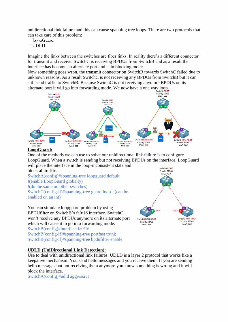
unidirectional link failure and this can cause spanning tree loops. There are two protocols that
can take care of this problem:
Imagine the links between the switches are fiber links. In reality there’s a different connector
for transmit and receive. SwitchC is receiving BPDUs from SwitchB and as a result the
interface has become an alternate port and is in blocking mode.
Now something goes wron, the transmit connector on SwitchB towards SwitchC failed due to
unknown reasons. As a result SwitchC is not receiving any BPDUs from SwitchB but it can
still send traffic to SwitchB. Because SwitchC is not receiving anymore BPDUs on its
alternate port it will go into forwarding mode. We now have a one way loop.
LoopGuard:
One of the methods we can use to solve our unidirectional link failure is to configure
LoopGuard. When a switch is sending but not receiving BPDUs on the interface, LoopGuard
will place the interface in the loop-inconsistent state and
block all traffic.
SwitchA(config)#spanning-tree loopguard default
!(enable LoopGuard globally)
!(do the same on other switches)
SwitchC(config-if)#spanning-tree guard loop !(can be
enabled on an int)
You can simulate loopguard problem by using
BPDUfilter on SwitchB’s fa0/16 interface. SwitchC
won’t receive any BPDUs anymore on its alternate port
which will cause it to go into forwarding mode.
SwitchB(config)#interface fa0/16
SwitchB(config-if)#spanning-tree portfast trunk
SwitchB(config-if)#spanning-tree bpdufilter enable
UDLD (UniDirectional Link Detection):
Use to deal with unidirectional link failures. UDLD is a layer 2 protocol that works like a
keepalive mechanism. You send hello messages and you receive them. If you are sending
hello messages but not receiving them anymore you know something is wrong and it will
block the interface.
SwitchA(config)#udld aggressive

There are a number of methods how you can configure UDLD. You can do it globally with
the udld command but this will only activate UDLD
for fiber links! There are two options for UDLD: (default)
When you set UDLD to normal it will mark the port as
undetermined but it won’t shut the interface when something is wrong. This is only used to
“inform” you but it won’t stop loops.
Aggressive is a better solution, when it loses connectivity to a neighbor it will send a UDLD
frame 8 times in a second. If the neighbor does not respond the interface will be put in
errdisable mode.
SwitchB(config)#interface fa0/16
SwitchB(config-if)#udld port aggressive
UDLD runs its own layer 2 protocol by using the proprietary MAC address 0100.0ccc.cccc so
you can filter this mac to simulate UDLD:
SwitchC(config)#mac access-list extended UDLD-FILTER
SwitchC(config-ext-macl)#deny any host 0100.0ccc.cccc
SwitchC(config-ext-macl)#permit any any
SwitchC(config-ext-macl)#exit
SwitchC(config)#interface fa0/16
SwitchC(config-if)#mac access-group UDLD-FILTER in
FlexLinks:
When you configure FlexLinks you’ll have an active and standby interface. I can configure
this on SwitchC:
nterface.
When you configure interfaces as FlexLinks they will not send BPDUs. There is no way to
detect loops because we don’t run spanning-tree on them. Whenever our active interface fails
the backup interface will take over.
SwitchC(config)#interface fa0/14
SwitchC(config-if)#switchport backup interface fa0/16
!(This is how we make interface fa0/16 a backup of
interface fa0/14 and disable spanning tree for these
interfaces)
Let’s shut the active interface:
SwitchC(config)#interface f0/14
SwitchC(config-if)#shutdown
!(fa0/16 will go active)

Verification and TSHOOT: sh spa !(important)
sh spa | begin int
sh spa summary !(stp mode, portfast, bpdu guard/filter, loopguard, uplink/backbone fast)
sh spa detail !(to see number of topology changes and the int it is happening on)
sh run | inc priority
sh spa vlan 10
sh mac address-table dynamic !(to verify traffic path. Port on which mac was learnt)
sh mac address-table aging-time
sh spa mst config
sh spa mst !(to see if it is root bridge i.e. CIST (Common and Internal Spanning Tree))
sh spa mst 2
sh spa mst 0 | begin Interface
sh spa inconsistentports !(to see when root guard is working)
sh udld fastEthernet 0/16
sh int switchport backup !(to see flexilink)
debug spa
debug spa events !(to see topology change notifications)
debug spa backbonefast detail
debug spa bpdu
debug udld events

Syslog/Logging[Solarwinds Kiwi Syslog Server can be used]If you want your logging messages to be useful you have to make sure that the time and date (timestamp) has been configured correctly on your router.Use a NTP (Network Time Protocol) server to make sure all devices in your network have their clocks synchronized.Router(config)#ntp server pool.ntp.orgRouter(config)#no service timestamps !(you can disable timestamps and use sequence numbers)Router(config)#service sequence-numbers
Router(config)#logging console errors !(severity level 3 and lower)!(This logging information is saved in the RAM of your device. Once you reboot it you will lose this logging history)Router(config)#logging buffered 4096 !(buffer size in bytes)
Router(config)#logging 192.168.1.100 !(all logging sent to the syslog server except level 7)Router(config)#logging trap 7 !(this will sent also the debug info to the syslog server)
The most common method of accessing system messages from networking devices is to use a protocol called syslog. Syslog uses User Datagram Protocol (UDP) port 514 to send event notification messages across IP networks to event message collectors. Cisco routers can be configured to send syslog messages to several different facilities, such as:1. Logging buffer: Messages are stored in router memory (RAM) for a period of time.2. Console: Console logging is turned on by default.3. Terminal lines: Log messages can be sent to the vty lines for viewing during a Telnet or SSH session.4. Syslog server: Log messages can be forwarded to an external device running a syslog daemon.Syslog defines eight severity levels, 0 through 7. The lower the number, the more severe the issue. Syslog also defines standard names to associate with each of the levels.R1(config)# logging host 192.168.1.25R1(config)# logging source-interface Loopback0R1(config)# logging trap notificationsR1(config)# no logging consoleR1 has been configured to sendsyslog to the syslog server at192.168.1.25. Only messages with aseverity level of 5 or lower (i.e.,levels 0–5) will be sent to theserver. Since syslog messages arebeing sent to an external server,logging to the console has beendisabled to save on CPU resources.Use the show logging command toview logging configuration andbuffered syslog messages.
Verification and TSHOOT:sh logging !(to see logging information)sh logging history !(to see the set severity level)sh ntp status !(to see if clock is synchronized)

VLAN Hopping
VLAN hopping is an attack where the attacker will send Ethernet Frames with two 802.1Q tags on it. Send an Ethernet frame that has been tagged for VLAN 10 and VLAN 20. The switch on the left side will strip the VLAN 10 tag and forward the frame to the switch on the right side. The frame still has a tag for VLAN 20 when it arrives at the switch on the right side. The tag will be removed and the Ethernet frame will be forwarded to ComputerB in VLAN 20. The attacker has successfully “hopped” from VLAN 10 to VLAN 20.
You can do a few things to stop it:1. Disable DTP (Dynamic Trunking Protocol). You don’t want interfaces that connect to computers or clients to dynamically become trunk ports.2. Don’t allow all VLANs on trunk ports, prune the ones that are not needed.3. Place interfaces that are not in use in a separate VLAN, don’t leave them in VLAN 1 which is thedefault.4. Shut interfaces that are not in use.

VLANs and VTP:VLAN (Virtual LAN) and VTP (VLANTrunking Protocol) (VLAN replicationprotocol). A VLAN is simply an administrativelydefined subset of switch ports that are inthe same broadcast domain. Ports can begrouped into different VLANs on a singleswitch, and on multiple interconnectedswitches as well. By creating multipleVLANs, the switches create multiple, yetcontained, broadcast domains. By doing so,a broadcast sent by a device in one VLAN isforwarded to the other devices in that sameVLAN; however, the broadcast is notforwarded to devices inthe other VLANs.With VLANs and IP, bestpractices dictate a one-to-one relationship betweenVLANsand IP subnets. Simplyput, the devices in a singleVLAN are typically alsoin the same single IP subnet.Alternately, it is possible toput multiple subnets in oneVLAN, and use secondary IPaddresses on routers to routebetween the VLANs andsubnets. Layer 2 switches forward frames betweendevices in the same VLAN, but they do notforward frames between two devices indifferent VLANs. To forward data betweentwo VLANs, a multilayer switch (MLS) orrouter is needed. VLAN has an operational state:It can either be active , which is the defaultstate, or it can be suspended . A suspendedVLAN is hibernated—while it exists, it doesnot operate. Access ports in a suspendedVLAN are unable to communicate and drop all frames,similar to ports put into a nonexistent VLAN. Putting asuspended VLAN back into the active state also reinstatesnormal communication on all ports in that VLAN.1. A VLAN (switch inside a switch) is a single broadcastdomain. Users are only able to communicate within thesame VLAN unless Inter-VLAN routing is used.2. VLAN=One Broadcast domain=One subnet (0 to 4095available VLANs)3. Like type segmentation: e.g. servers, users, PCs, IP

phones, printers etc.There are two types of trunking protocols: 802.1Q and ISL (Inter-Switch Link)VLAN identifier (12-bits VLAN-ID) hasthe VLAN number. Priority field (3-bitsCoS/802.1p) is used to give differentpriority to different types of traffic inQoS. 1-bit is DE (Discard Eligible)The difference between 802.1Q and ISLis that 802.1 tags the Ethernet framewhile ISL encapsulates the EthernetFrame. 802.1Q will not tag the native VLAN while ISL doestag the native VLAN. [Port Types: Access, Trunk andDynamic]Methods to configure VLANs: 1. Static VLAN: Just configure the VLAN yourself on theinterface (common) 2. Dynamic VLAN: Dynamic VLAN is where you have aVMPS server (VLAN ManagementPolicy Server) which has a database ofMAC address to VLAN information.MAC addresses can be spoofed so not agood idea. 3. Voice VLAN: Configured on a portwhich is connected to an IP phone. Theport acts as a trunk because IP Phone actsas a switch for the PC connected to it. 4. You can use 802.1X and a RADIUS server to authenticate users and dynamically assign users to aVLAN. With NAC (Network Admission Control) enabled PC could end up in a quarantine VLAN unless updated.Deleting VLAN information (decommissioning): VLAN information is not saved in the running-config or startup-config but in a separate file called vlan.dat on your flash memory. So 'delete flash:vlan.dat' to delete VLAN information.Native VLAN (default is VLAN 1) (Used for management traffic): Native VLAN is not tagged. So anythingthat is not tagged will fall under nativeVLAN. (Management frames) CDP,VTP,STP onyour Cisco switch uses the native VLAN,even if it is manually pruned (VLAN1minimization) you will see in packet captureVLAN1 traffic.Native VLAN must be the same on bothswitches otherwise Native VLAN mismatcherror occurs.SW(config)#vlan dot1q tag native !(to tag even the native vlan)Voice VLAN: Implies two VLANs operating on a switchport (Voice and Data VLANs)Uses CDP (if cisco IP phones) and DHCP option-156 (for non cisco phones)

VLAN Creation: this creates mac-address-table and stp instance straight away.Switch(config)# vlan 100Switch(config-vlan)# name Engineering!(This method is the only way to configure extended range VLANs as opposed to database mode)!(Normal VLAN 1-1005. Extended VLAN(1006-4094) transparent mode or V3.Internal 1002-1005)VLAN database mode (is being deprecated): Only normal-range (VLANs 1–1005) VLANs can be configured in this mode, andthe VLAN configuration is stored in a Flash file called vlan.dat. In general, the VLAN database configuration mode should be avoided if possible, and hopefully you will not need to use it anymore; however, there are still switches and even relatively recent routers deployed in networks that do not support the newer way of configuring VLANs in global configuration mode.Switch#vlan databaseSwitch(vlan)#vlan 4 name salesSwitch(vlan)#show current !(shows vlans available in numeric order)Switch(vlan)#show proposedd !(shows tha vlan you have defined)Switch(vlan)#applySwitch(vlan)#exitAccess Port Configuration (Assigning a port to an access VLAN):Switch(config-if)# switchport mode access !(can belong only to one VLAN. Will not send DTP)!(It is good security measure to disable DTP/trunk negotiation on unused ports)Switch(config-if)# switchport access vlan 100 Switch(config-if)# switchport voice vlan 150 !(options: vlan-id | dot1p | untagged | none)!(You can configure the switch port, which is connected to an IP Phone, to use one VLAN for voice traffic and another VLAN for data traffic originating from a device that is connected to the access port of the IP Phone)Modifying the Operational State of VLANs:The state of a VLAN—active or suspended—can be manipulated both in vlan databaseand in configuration mode. A VLAN can be suspended in two ways: globally in theentire VTP domain and locally on a single switch without influencing its state through VTP on otherswitches. The state suspend command, valid both in vlan database and in configuration mode, is used to globally suspend a VLAN. Suspending a VLAN locally, also called “locally shutting down the VLAN,” is accomplished using the shutdown command, and is supported only in the configuration mode in the VLAN context. Do not confuse the shutdown command in the VLAN context with the same command available under interface Vlan mode, which has a different and unrelated meaning (shutting down an SVI without further impairing the operation of the corresponding VLAN itself).Global and local VLAN states can be configured independently, but for a VLAN to be operational on a switch, it must be both globally and locally activated. Switch3# vlan databaseSwitch3(vlan)# vlan 21 state suspend
Switch3(config)# vlan 21Switch3(config-vlan)# state active
Switch3(config)# vlan 21Switch3(config-vlan)# shutdownSwitch3(config)# no shutdown vlan 21VLAN trunking allows switches, routers, and even PCs with the appropriate networkinterface cards (NIC) and/or software drivers to send traffic for multiple VLANs across a single link. To know to which VLAN a frame belongs, the sending switch, router, or PC adds a header to the original Ethernet frame, with that header having a field in which to place the VLAN ID of the

associated VLAN. ISL and 802.1Q differ in how they adda header to the Ethernet frame beforesending it over a trunk. ISL adds a new26-byte header, plus a new trailer (toallow for the new FCS value),encapsulating the entire original frame.This encapsulating header uses thesource address of the device doing the trunking, instead of the source MAC of the original frame. ISL uses a multicast destination address of either 0100.0C00.0000 or 0300.0C00.0000.802.1Q inserts a 4-byte header, called a tag, into the original frame (right after the Source Address field). The original frame’s addresses are left intact. Normally, an Ethernet controller would expect to find either an Ethernet Type field or 802.3 Length field right after the Source Address field. With an 802.1Q tag, the first 2 bytes after the Address fields hold a registered Ethernet type value of 0x8100, which implies that the frame includes an 802.1Q header. Because 802.1Q does not actually encapsulate the original frame, it is often called frame tagging.On trunks, 802.1Q does not tag frames sent inside the native VLAN, and assigns all received untagged frames to the native VLAN. The native VLAN feature allows a switch to attempt to use 802.1Q trunking on an interface, but if the other device does not support trunking, the traffic for thatone native VLAN can still be sent over the link. By default, the native VLAN is VLAN 1, which is also the default access VLAN. It is absolutely necessary that the native VLANs on both ends of a trunk link match; otherwise a native VLAN mismatch occurs, causing the two VLANs to effectivelymerge. To detect and possibly avoid any ill effects of a native VLAN mismatch, Cisco switches implement a proprietary extension to PVST+ and Rapid PVST+ that allows them to detect and block the mismatched native VLANs on the trunk. Also, Cisco Discovery Protocol (CDP) will detect and report a native VLAN mismatch. As a best practice, on each trunk, its native VLAN should be changed from VLAN 1 to a different VLAN, and this VLAN should not be used for any other purpose except being configured as a native VLAN. This prevents users from attempting a VLAN hopping attack by sending double-tagged frames that would be detagged on trunks if the top tag matches the trunk’s native VLAN.Trunk (tagged) Port Configuration: !(Trunk port can be connected to a server, switch or a router)Switch(config-if)# switchport trunk encapsulation dot1q !(do this first before making it a trunk)ORSwitch(config-if)# switchport trunk encapsulation isl !(not all switches support this anymore)Switch(config-if)# switchport mode trunk !(transmits DTP messages as courtesy)Switch(config-if)# switchport nonegotiate !(will not send DTP messages even it is a trunk port)Switch(config-if)# switchport trunk native vlan 10 !(it is a good security measure to change the native vlan to something other than VLAN 1)Allowed VLANs on the trunk:Switch(config-if)# switchport trunk allowed vlan 10,20-30 !(these are the only allowed. Careful!)Switch(config-if)#switchport trunk allowed vlan remove 1- 4094Switch(config-if)#switchport trunk allowed vlan add 1-50 !(adds to the previous ones)Switch(config-if)#switchport trunk allowed vlan none Switch(config-if)#switchport trunk allowed vlan all !(default so won't see in show run)Trunk Negotiation (DTP Negotiation): 1. dynamic auto and dynamic desirable.Switch(config-if)#switchport mode dynamic autoORSwitch(config-if)#switchport mode dynamic desirableDTP (Dynamic Trunking Protocol) (Ciscoproprietary): The negotiation of theswitchport status by using dynamic auto ordynamic desirable is called DTP. It is a good

measure to disable DTP/trunk negotiation on unused ports i.e. nonegotiate command. Security issue: Don't use “dynamic” types. Hard code trunk OR access mode. Default on most switches are 'dynamic auto' or on old ones 'dynamic desirable'. Anyone can connect a laptop and negotiate a trunk. The individual DTP modes are:■ dynamic auto: The port will negotiate the mode automatically; however, it prefers to be an access port.■ dynamic desirable: The port will negotiate the mode automatically; however, it prefers to be a trunk port.Out of these modes, dynamic desirablehas a higher priority—if both ports aredynamic but one is configured as autoand the other as desirable, theresulting operating mode will betrunk. DTP also negotiates the type ofencapsulation on the trunk shouldeither of the two devices support bothISL and 802.1Q. If both devices supportboth trunk types, they will choose ISL.Should the DTP negotiation fail, anyport in dynamic mode, either desirableor auto, will be operating as an accessport.Different types of Cisco switches havedifferent default DTP modes. Forexample, earlier Catalyst 2950 and3550 models default to dynamicdesirable mode. Later Catalyst models,such as 2960, 3560, 3850 or 3750,default to dynamic auto mode. While DTP and VTP are independentprotocols, DTP carries the VTP domainname in its messages. Switches willsuccessfully negotiate the link operatingmode only if the VTP domain name onboth switches is the same, or one switchhas no VTP domain name configured yet (that is, it uses a NULL domain name). The reason behind tying the DTP negotiation to the VTP domain name is that in different VTP domains, there might bedifferent sets of VLANs, and identically numbered VLANs might be used for different purposes (that is why the network was split into several VTP domains in the first place—to keep the VLAN databases separate and independent). As a result, switches should not try to bring up the link as a trunk, as extending VLANs from one VTP domain to another can have undesired consequences.The show interface trunk command lists the VLANs that fall into each category:■ Allowed VLANs: Each trunk allows all VLANs by default. However, VLANs canbe removed or added to the list of allowed VLANs by using the switchport trunkallowed command.■ Allowed and active: To be active, a VLAN must be in the allowed list for the trunk (based on trunk configuration), the VLAN must exist in the VLAN configuration on the switch, and it must bein the active state (not suspended or locally shutdown).With PVST+, an STP instance is actively running on this trunk for the VLANs in this list.■ Active and not pruned: This list is a subset of the “allowed and active” list, with any VTP-pruned VLANs and VLANs for which PVST+ considers the port Blocking removed.

Configuring Trunking on Routers:VLAN trunking can be used on routers and hosts as well as on switches. However, routers do not support DTP, so you must manually configure them to support trunking. Additionally, you must manually configure a switch on the other end of the segment to trunk, because the router does not participate in DTP.The majority of router trunking configurations use subinterfaces, with each subinterface being associated with one VLAN. You can configure 802.1Q native VLANs under a subinterface or under the physical interface on a router. If they are configured under a subinterface, you use the encapsulation dot1q vlan-id native subcommand, with the inclusion of the native keyword meaning that frames exiting this subinterface should not be tagged, and incoming untagged frames shall be processed by this subinterface. As with other router trunking configurations, the associated IP address would be configured on that same subinterface. Alternately, if not configured on a subinterface, the router assumes that the native VLAN is associated with the physical interface. In this case, the encapsulation command is not needed nor supported under the physical interface; the associated IP address, however, would need to be configured under the physical interface. Configuring an (understandably distinct) IP address on both physical interface and a subinterface under the same physical interface using encapsulation dot1q vlan-id native , thereby technically resulting in two different interfaces for the native VLAN, is not supported. All incoming untagged frames will be processed by the subinterface configuration only. A notable exception to this rule canbe seen on ISR G1 routers equipped with 10-Mbps Ethernet built-in interfaces. On these router platforms, settings for the native VLAN shall be configured on the physical Ethernet interface directly. While the router will accept the configuration of a subinterfacewith the encapsulation dot1q vlan-id native command, incoming untagged frameswill be processed by the configuration of the physical interface. This exception applies only to ISR platforms with 10-Mbps Ethernet interfaces, and is not present on platforms with Fast Ethernet or faster interfaces.If the router supports native VLAN configuration on a subinterface, it is recommended to use subinterfaces instead of putting the native VLAN configuration on a physical port. Aside from keeping the configuration more consistent (all configuration being placed on subinterfaces), this configuration allows the router to correctly process frames that, despite being originated in the native VLAN, carry an 802.1Q tag. Tagging such frames is done when using the CoS field inside an802.1Q tag. If the native VLAN configuration was done on a physical interface, the router would not be able to recognize that a frame carrying an 802.1Q tag with a nonzero VLAN ID is really a CoS-marked frame in the native VLAN. When using subinterfaces, the encapsulation dot1q vlan-id native commandallows the router to recognize that both untagged frames and CoS-marked framestagged with the particular vlan-id should be processed as frames in the native VLAN.VTP Configuration(Cisco proprietary)(advertise VLAN attributes to reduce admin overhead)
VTP advertises VLAN configuration information to neighboring switches so that theVLAN configuration can be made on one switch, with all the other switches in the

domain learning the VLAN information dynamically. VTP advertises the VLAN ID,VLAN name, and VLAN type and state for each VLAN. However, VTP does not advertiseany information about which ports (interfaces) should be in each VLAN, so the configuration to associate a switch interface with a particular VLAN (using the switchport access vlan command) must still be configured on each individual switch.The VTP protocol exists in three versions. VTPv1 and VTPv2 are widely supportedacross the CatOS and IOS-based switching platforms. VTPv3 support on IOS-basedswitches is relatively new. On entry-level Catalyst switches, VTPv3 is supported starting with IOS Release 12.2(52)SE.VTPv1 is the default VTP version supported and active on enterprise IOS-based switches. It supports disseminating of normal-range VLANs only.In any VTP version, VTP messages are transmitted and accepted only on trunkports. Access ports neither send nor accept VTP messages. For two switches to communicate in VTP, they must first be interconnected through a working trunk link.
VTPv2 enhancements include the following:■ Support for Token Ring Concentrator Relay Function and Bridge Relay Function(TrCRF and TrBRF) type VLANs: These VLANs were used to segment a TokenRing network into multiple logical rings and interconnecting bridges. There is no use for them in Ethernet-based networks.■ Support for unknown Type-Length-Value (TLV) records: VTP messages can containadditional information elements stored as TLV records. A switch running VTPv1would drop all unrecognized TLVs from received messages, not propagating themfarther to neighboring switches. VTPv2-enabled switches keep all TLVs in propagated messages even if they are not recognized.■ Optimized VLAN database consistency checking: In VTPv1, VLAN databaseconsistency checks are performed whenever the VLAN database is modified, eitherthrough CLI, SNMP, or VTP. In VTPv2, these consistency checks are skipped if thechange was caused by a received VTP message, as the message itself was originatedas a result of a CLI or SNMP action that must already have been sanitized. This is really just an implementation optimization.
There is ongoing confusion regarding the VTP transparent mode. The IOS documentation for earlierCatalyst series appeared to suggest that VTPv1 switches in transparent mode forward VTP messages only if their version and domain match the settings on the transparent switch, while VTPv2 transparent switches allegedly forward VTP messages regardless of their domain and version. Documentation to recent Catalyst switches is less clear, but it states that both VTPv1 and VTPv2 transparent switches check the domain and only forward the message if its domain matches the domain configured on the transparent switch.In reality, experiments performed on multiple Catalyst switch types that supported both VTPv1 and VTPv2 show that, regardless of the activated VTP version, a transparent switch whose VTP domain was NULL (that is, unconfigured) forwarded all VTP messages happily. A transparent switch with a configured domain forwarded VTP messages only if their domain matched.
VTPv3 differs from VTPv2 in the following aspects:■ The server role has been modified:There are two server types in VTPv3:primary and secondary. A primary serveris allowed to modify VTP domaincontents, and there can be at most oneprimary server per VTP domain at anytime. A secondary server (often called just

a server) is not allowed to modify VTP domain contents, but it can be promoted to the role of primary server, retaking the role from the existing primary server if it exists. Ownership of the primary server role is a runtime state that is not stored in the configuration; instead, it is requested in the privileged EXEC mode if necessary. This modification significantly reduces the probability of unintended modification of the VLAN database, as it is not possible to modify the database contents without the concerted effort of making a switch the primary server.■ VTPv3 password storage and usage has been improved: The VTP password can be stored in an encrypted form that cannot be displayed back as plaintext. While this encrypted string can be carried over to a different switch to make it a valid member of the domain, the promotion of a secondary server into the primary server role will require entering the password in its plaintext form.■ VTPv3 is capable of distributing information about the full range of VLANsincluding Private VLANs: With VTPv3, it is not necessary to use Transparent modewhen using extended-range VLANs and Private VLANs. Pruning, however, stillapplies only to normal-range VLANs, even in VTPv3.■ VTPv3 supports the off mode in which the switch does not participate in VTPv3operations and drops all received VTP messages: It is also possible to deactivateVTP on a per-trunk basis.■ VTPv3 is a generalized mechanism for distributing contents of an arbitrarydatabase, and is not limited to synchronizing VLAN information over a set ofswitches: As an example, VTPv3 is also capable of distributing and synchronizingthe MST region configuration among all switches in a VTP domain.VTPv1 and VTPv2 use four types of messages:■ Summary Advertisement: This message is originated by VTP Server and Clientswitches every 5 minutes and, in addition, after each modification to the VLAN database. This message carries information about VTP domain name, revision number, identity of the last updater, time stamp of the last update, MD5 sum computed over the contents of the VLAN database and the VTP password (if configured), and the number of Subset Advertisement messages that optionally follow this Summary Advertisement. Summary Advertisement messages do not carry VLAN database contents.■ Subset Advertisement: This message is originated by VTP Server and Client switches after modifying the VLAN database. Subset Advertisements carry full contents of the VLAN database. One Subset Advertisement can hold multiple VLAN database entries. However, multiple Subset Advertisements might be required if the VLAN database is large.■ Advertisement Request: This message is originated by VTP Server and Clientswitches to request their neighbors send the complete VLAN database or a part ofit. Advertisement requests are sent when a VTP Client switch is restarted, when aswitch enters the Client mode, or when a Server or Client switch receives a Summary dvertisement with a higher revision number than its own.■ Join: This message is originated by each VTP Server and Client switch periodically every 6 seconds if VTP Pruning is active. Join messages contain a bit field that, for each VLAN in the normal range, indicates whether it is active or unused (that is, pruned).VTPv3:VTPv3 addresses the problem of inadvertent (or intentional) rewrite of a VLAN database by introducing the concept of a primary server . A primary server is the only switch in a VTPv3 domain whose VLAN database can be propagated throughout the domain. VTPv3 servers and clients will share their VLAN database only if they agree both on the domain name and on the identity of a primary server (given by its base MAC address). Also, a primary server is the only switch that allows an administrator to perform modifications to the VLAN database.Other VTPv3 switches configured as servers are called secondary servers . UnlikeVTPv1/VTPv2 servers, secondary servers in VTPv3 do not permit an administrator tomodify the VLAN database; rather, they are only eligible to be promoted to the role of a primary

server, taking over this role from the existing primary server if present. Clients in VTPv3 neither allow an administrator to modify the VLAN database nor are eligible to be promoted to the primary server role. Both secondary servers and clients store a copy of the primary server’s VLAN database and will share it with their neighboring servers and clients that agree on the identity of the primary server. This means that even in VTPv3, a secondary server or a client switch with a higher revision number can overwrite a neighbor’s VLAN database, but for this to occur, these switches must first match on thedomain name, primary server’s identity, and VTP password.The state of two or more server or client switches in a VTPv3 domain having different opinions about the identity of a primary server is called a conflict . Conflicting switches do not synchronize their VLAN databases even if all other VTP parameters match. This concept of a conflict is at the core of VTPv3’s improved resiliency againstinadvertent VLAN database overwrites.Because changes to the VLAN database canonly be performed on a primary server,switches that agree on the primary server’sidentity also immediately share the primaryserver’s database. If a switch is disconnectedfrom the network, unless it is the primaryserver itself, its VLAN database can bemodified only if that switch is promoted to a primaryserver while disconnected. After this switch isconnectedback to the network, its idea of the primary server’sidentity does not match itsneighbors’ knowledge about the primary server; thatis, a conflict exists. Therefore, even if its revisionnumber is higher, its VLAN database will not beaccepted by its neighbors. This way, thepossibility of inadvertent VLAN databaseoverwrites is greatly reduced, though notcompletely avoided.There can be at most one primary server in aVTPv3 domain. Only switches configured asVTPv3 servers can be promoted to the role of aprimary server, and the promotion is alwaysperformed in the privileged EXEC mode by invokingthe vtp primary command. The state of a primaryserver is therefore a volatile runtime state that cannotbe permanently stored in the configuration. After aprimary server is reloaded, it comes back only as asecondary server again. A switch newly promoted tothe role of a primary server using the vtp primarycommand will flood its VLAN database to its neighbors, and they will install and flood it further even if the new primary server’s revision number is lower. This way, the new primary server’s database is asserted over the VTP domain.With VTPv3, it is no longer possible to reset the configuration revision number to 0 by setting the switch to the transparent mode and back. The revision number will be reset to 0 only by modifying the VTP domain name or by configuring a VTP password.If a VTPv3 switch detects an older switch running VTPv1 or VTPv2 on its port, it will revert to VTPv2 operation on that port, forcing the older switch to operate in VTPv2 mode. Cooperation between VTPv3 and VTPv1-only switches is not supported.

Normal-Range and Extended-Range VLANs:Because of historical reasons, some VLANnumbers are considered to be normal ,whereas some others are considered to beextended . Normal-range VLANs are VLANs1–1005, and can be advertised through VTPversions 1 and 2. These VLANs can beconfigured both in VLAN database mode andin global configuration mode, with the detailsbeing stored in the vlan.dat file in Flash.Extended-range VLANs range from 1006–4094, inclusive. However, if using VTPv1 orVTPv2, these additional VLANs cannot beconfigured in VLAN database mode, nor stored in the vlan.dat file, nor advertised through VTP. In fact, to configure them, the switch must be in VTP transparent mode. (Also, you should take care to avoid using VLANs 1006–1024 for compatibility with CatOS-based switches.) VTPv3 removes these limitations: Both normal- and extended-range VLANs can be advertised by VTPv3. Also, withVTPv3, information about all VLANs is again stored in the vlan.dat file in Flash. Both ISL and 802.1Q support extended-range VLANs today.Storing VLAN Configuration:Catalyst IOS stores VLAN and VTPconfiguration in one of two places—eitherin a Flash file called vlan.dat or in therunning configuration. (Remember that theterm “Catalyst IOS” refers to a switch thatuses IOS, not the Catalyst OS, which isoften called CatOS.)IOS chooses the storage location in partbased on the VTP version and mode, and inpart based on whether the VLANs arenormal-range VLANs or extended-rangeVLANs. (Note that VTPv1/VTPv2 clients also store the VLAN configuration in vlan.dat, and they do not understand extended-range VLANs.)(When a switch reloads, if the VTP mode or domain name in the vlan.dat file and the startup config file differs, the switch uses only the vlan.dat file’s contents for VLAN configuration)For VTPv3, the situation is greatly simplified: Regardless of the mode (server, client, transparent, oroff), both normal- and extended-range VLANs are stored in the vlan.dat file. If transparent or off mode is selected, VLANs are also present in the running-config.VTP Configuration:1.Every time a vlan is created/modified/deleted therevision number is increased by 1 and the informationgets replicated to other VTP servers and clients. VTPdomain/pass/version must match.Transparent mode only forwards advertisement, whereasserver and client modes synchronizes themselvesalongside forwarding the information. Transparent modedoesn't increment revision number. Off mode in version 3doesn't even pass through advertisements.2. server or a client will change to the learnt domainname only if it was set to a NULL value. Switch(config)# vtp mode server !(options: server | client | transparent)Switch(config)# vtp domain CBTNuggets

Switch(config)# vtp password MyPassword !(must be the same on all the switches)Switch(config)# vtp v2-mode !(options: 1 | 2 | 3)ORSwitch(config)# vtp version 2 !(options: 1 | 2 | 3) !(must be thesame on all the switches)3. Important Note: VTP serveralso acts as a VTP client and canget information from any otherVTP client with higher revisionnumber. So for example if youremove a client SwitchC, convertit into a server, add/removevlans, change it back to a clientand then connect it back to the network, it will create havoc i.e. all theswitches with lower revision than SwitchC will get everything replicated offSwitchC. Measure: If you do want to use VTP Server / Client mode you needto make sure you reset the revision number:1. Changing the domain-name will reset the revision number.2. Deleting the vlan.dat file on your flash memory will reset the revisionnumber.(When you delete a VLAN all interfaces in that VLAN are in 'no-man's land'.They don't return to VLAN 1)In summary, for a newly connected VTP server or client to change another switch’s VTP database, the following must be true:■ The new link connecting the new switch is trunking.■ The new switch has the same VTP domain name as the other switches.■ The new switch’s revision number is higher than that of the existing switches.■ The new switch must have the same password, if configured on the existingswitches.4. Steps to configure VTP version 3 (resolves all the problems with older versions): Differences in running VTPv3 are most visible in the need ofdesignating a selected switch as the primary server using the vtpprimary command before changes to the VLAN database can beperformed on it, and in the way VTP passwords are used.VTPv3 can also be deactivated either globally on the switchusing the vtp mode off command, or on a perinterface basisusing the simple no vtp command It is worth noting that afterchanging the VTP mode from off to any other mode, all existing VLANs except those hardwired into IOS (1, 1002–1005) will be deleted.1.config vtp domain name 2.change mode to vtp version3 3.config one switch as vtp primary4. config vtp password (optional)Switch(config)#vtp domain CBTSwitch(config)# vtp mode server Switch(config)#vtp version 3Switch(config)#vtp primary !(this will be the only one to make changes and advertise)Switch(config)#vtp password cisco hidden !(hashed password, more like service password)Switch(config)#vtp password <32 chars length hash> secretVTP Pruning (Dynamic Pruning) (VLAN 2 - 1001 prune eligible): Only works on VTP servers/clients, but on version3 you have to mention it manually on all. Reduces broadcasts. By enabling VTP pruning we'll make sure there is no unnecessary VLAN

traffic on trunks when there's nobody in a particular VLAN. Depending on your switch model VTP pruning is either turned on or off by default.Switch(config)# vtp pruning !(send VTP prune message and not VTP Join message)Switch(config-if)#switchport trunk pruning vlan remove 4,20-30 !(Removes VLANs 4 and 20-30)Switch(config-if)#switchport trunk pruning vlan except 40-50 !(All VLANs are added to the pruning list except for 40-50)Quarantine VLAN: Switch(config)# vlan 999Switch(config-vlan)#stat suspendedSwitch(config-vlan)#int range fa0/1 – 24Switch(config-if-range)#switchport access vlan 999SVI(Switch Virtual Interface)/Inter-VLAN Routing/L3 Switching/MultiLayer Switch Config:InterVLAN Routing (Router-on-a-stick) (each sub-interface share the same mac address) :
SVI (Using MultiLayer Switch for routing) (each SVI interface has different a mac address) :1. Logical layer3 VLAN interface (Switch routing capabilities. Config SVI for each VLAN and put an IP address on it, used by computers as their default gateway.)
Once you create a SVI and type no shutdown it will normally be “up” since it’s only a virtual interface, there are however a number of requirements or it will show up as “down” (sh vlan):
TSHOOT: The VLAN has to exist in the VLAN database and it should be active. TSHOOT: At least one access or trunk port should use this VLAN actively and it should be in
spanning-tree forwarding mode.SwitchA(config)#interface fa0/2
SwitchA(config-if)#switchport autostate exclude !(won't influence the state of SVI anymore)Routed Ports (Using MultiLayer Switch for routing):By default all interfaces on a switch are switchports (layer 2) but we can change them to routed

ports (layer 3). A routed port is the exact same interface as what we use on a router.
There are two things you should remember about this routed port: It’s no longer a switchport so it’s not associated with any VLAN. It’s a routed port but it doesn’t support sub-interfaces like a router does.
Routing Protocols on MultiLayer Switches:
SVI:SwitchB(config-if)#switchport trunk encapsulation dot1qSwitchB(config-if)#switchport mode trunkSwitchB(config)#vlan 10SwitchB(config)#interface vlan 10SwitchB(config-if)#ip address 192.168.10.1 255.255.255.0SwitchB(config)#ip routingSwitchB(config)#router eigrp 10SwitchB(config-router)#network 192.168.10.0!(same an opposite config on SwitchC)Routed Ports:SwitchB(config)#no interface vlan 10SwitchB(config)#interface fa0/16SwitchB(config-if)#no switchportSwitchB(config-if)#ip address 192.168.10.1 255.255.255.0SwitchB(config)#router ospf 10SwitchB(config-router)#network 192.168.10.0 0.0.0.255 area 0!(same an opposite config on SwitchC)DHCP and DHCP Helper address (DHCP relay) with SVI: Switch(config)# interface vlan 100Switch(config-if)#ip helper-address 10.59.22.9Switch(config)#no ip forward-protocol 37 !(if you don't want to forward some protocols below)

Verification and Troubleshooting commands:1. Make sure the interface is in the correct VLAN. Interface vlan shows Procotol down if there is no
port assigned to that vlan.2. Make sure the interface is in the correct switchport mode (access or trunk).3. Make sure you have checked interfaces (speed/duplex), port-security and VACL.4. Make sure you have the same encapsulation protocol when trunking5. Allowed VLAN mismatch. 6. DTP mismatch (one needs to be desirable instead of both auto) 7. Native VLAN mismatch. (CDP complains about it. So CDP needs to be enabled)8. VTP domain name (Case sensitive), password mismatch. 9. Incorrect IP address/Inactive VLAN/wrong port assignment.10. If you are running pruning and you have a trunk that goes to a switch which is transparent, in a
different domain or not not running pruning (ESXi), it will send all the VLANs so do manual prune.SW2, SW3 and SW4 could think that they all are root because SW1 hasn't got a spanning-tree instance created and is dropping BPDUs.
sh vlan !(only shows interfaces in access mode and no trunk interfaces)sh vlan brish ip int brish vlan bri vlan 10sh int trunk !(shows trunk interfaces in use and allowed vlans)sh int fa0/14 trunk !(shows allowed vlans on a trunk. Also shows native vlan)sh int fa0/1 switchport !(see the operational and admin modes of a port. Also trunk encapsulation)sh vlan id 2sh vlan name salessh int vlan 1sh int status !(shows up/down state and access/trunk state)sh int switchportsh vlan-switch !(used in gns3 )sh dtp !(displays the operating state of DTP globally and on individual ports)sh dtp interface fa0/12sh vtp status !(to see almost everything vtp)sh int fa0/14 pruning !(to see pruned vlans)sh vtp counterssh vtp passworddebug sw-vlan vtp eventsdebug sw-vlan vtp pruningsh spa vlan 10sh internal usage

VPN (Virtual Private Network)
Used to secure the public internet creating a tunnel as an alternative to leased lines. Cheap
compared to leased lines.
It does this by providing the following:
1. Confidentiality
2. Authentication
3. Integrity
4. Anti-Relay
Confidentiality means that nobody will be able to read the data that you are sending; we can
do this by encrypting our traffic.
Authentication means that we make sure that the sender of the data is a legitimate device. A
simple method to do this is password authentication.
Integrity ensures that nobody has altered our data. We can do this with hashing. If you ever
downloaded an ISO file from a website you might have seen some websites specify a MD5
Hash.
Anti-replay prevents attackers to copy certain packets and send them later trying to
impersonate a legitimate user. An attacker might be able to capture and figure out which IP
packet(s) contain the encrypted and/or hashed password. They might be unable to decrypt the
contents of the IP packet(s) but they can try to send them again and fool a network device to
grant access. Normally a sequence number is used to detect if certain IP packets have been
received before or not.
Putting an IP packet into another IP packet is called tunneling.
Site to Site VPN: Router/Firewall (enterprise network) to Router/Firewall (enterpprise
network)
Remote Access VPN: Laptop/PC/Smartphone/Tablet to Router/Firewall (Enterprise network)
IPSec (IP Security) VPN:
Laptop (client software) <-> Router/Firewall OR Router/Firewall <-> Router/Firewall

There are a number of different protocols that we can use to create a VPN. A very common
method to build a VPN is IPSEC. IPSEC is not a protocol but a framework for security on the
network layer. It was created because there is no security on the network layer (layer 3).
When you configure IPSEC you can choose between multiple protocols:
Encryption Protocols: DES, 3DES or AES.
Integrity Protocols: MD5 and SHA
Authentication: password authentication or certificates.
IPSEC is very flexible, throughout the years newer and better protocols have been added and
older protocols might be removed in the future.
SSL (Secure Sockets Layer) VPN:
When you use your web browser to setup a secure connection to a website you are using
HTTPS, which uses SSL. Besides using SSL for secure browsing it can also be used for
secure remote access. One of the differences between using HTTPS and SSL VPN is that
when you browse a website, the SSL encryption is probably done by the webserver, while for
SSL VPN the encryption is done by a dedicated network like a firewall.
VPNS:
A VPN provides security
services to traffic
traversing a relatively
less trustworthy network
between two relatively
more trusted systems or
networks. Most
commonly, the less
trusted network is the
public Internet. A VPN
is virtual in that it carries
information within a private network, but that information is actually transported over a
public network. A VPN is also private in that the traffic is encrypted to keep the data
confidential while it is transported across the public network.
There are four main benefits to using VPNs:
1. Cost savings: Organizations can use VPNs to reduce their connectivity costs.
2. Security: Advanced encryption and authentication protocols protect data.
3. Scalability: Organizations can use the Internet to easily interconnect new offices.
4. Compatibility: VPNs can be implemented across a wide variety of WAN link options.

Site-to-site IPsec VPN:
A site-to-site IPsec VPN is
an extension of a classic
WAN network. Site-to-site
VPNs connect entire
networks to each other. For
example, site-to-site VPNs
can connect a branch office
network to a company
headquarters network.
Transport across a site-to-site
VPN is transparent to the
communicating hosts. The
hosts send and receive normal TCP/IP traffic between each other. VPN gateways provide
security services at the borders between the trusted and non-trusted networks.
Remote-access IPsec VPN:
Remote-access VPN
technology is an evolution of
dialup connections. Remote-
access VPNs can support the
needs of telecommuters,
mobile users, and extranet
consumer-to-business traffic.
Remote-access VPNs connect
individual hosts that must
access their company network
securely over the Internet. In
a remote-access VPN, each
host typically has VPN client
software. Whenever the host tries to send any traffic, the VPN client software encapsulates
and encrypts that traffic before sending it over the Internet to the VPN gateway at the edge of
the target network.
Remote-access SSL VPN:

On the other hand, SSL VPNs provide a suite of security services that are similar to the
security services provided by IPsec. SSL VPN technology has become popular for the
implementation of remote-access VPNs with or without the use of client software. SSL-based
VPNs leverage the SSL protocol. SSL was initially developed by Netscape in the 1990s. The
Internet Engineering Task Force (IETF) later produced a standards-based more secure
alternative called TLS. There are slight differences between SSL and TLS, but the protocols
remain similar. The terms are sometimes used interchangeably, but interestingly, the
protocols are not interoperable. Cisco SSL VPNs are really using TLS behind the scenes.
One of the most popular features of
a clientless SSL VPN is the
capability to launch a browser and
simply connect to the address of the
VPN device, as opposed to running
a separate VPN client program to
establish an IPsec VPN connection.
The most successful application
running on top of SSL is HTTP
because of the huge popularity of
the World Wide Web. All the most
popular web browsers in use today support HTTPS (HTTP over SSL/TLS). Figure shows two
types of SSL VPN connections across the Internet: the noncorporate user connects using a
clientless SSL VPN through a web browser, while the employee connects using a client-
based SSL VPN. Both clients are authenticated using the AAA server in order to access the
internal protected resources.
IPSEC FRAMEWORK:
IPsec is an open standard that defines how a VPN can be secured across IP networks. IPsec
protects and authenticates IP packets between source and destination.
IPsec provides these essential security functions:
1. Confidentiality: IPsec ensures confidentiality by using encryption.
2. Data integrity: IPsec ensures that data arrives unchanged at the destination, meaning that
the data has not been manipulated at any point along the communication path.
3. Origin authentication: Authentication ensures that the connection is made with the desired
communication partner. IPsec uses Internet Key Exchange (IKE) to authenticate users and
devices that can carry out communication
independently. IKE can use the following methods to authenticate the peer system:
1.Pre-shared keys (PSK)
2.Digital certificates

3.RSA-encrypted nonces
4. Anti-replay protection: Anti-replay protection verifies that each packet is unique and is not
duplicated.
5. Key management: Allows for an initial safe exchange of dynamically generated keys
across a non-trusted network and a periodic rekeying process, limiting the maximum amount
of time and data that are protected with any one key.
These security functions define the IPsec framework and spell out the rules for secure
communications. IPsec relies
on existing algorithms to
implement encryption,
authentication, and key
exchange. The framework
allows technologies to be
replaced over time. When
cryptographic technologies
become obsolete, it doesn’t
make the IPsec framework
obsolete. Instead, obsolete
technologies are replaced with
more current versions, keeping
the framework in place.