Original Operating Instructions For authorised specialist ...
76
03/2016 - Art. Nr. 4200 1044 8002A Original Operating Instructions For authorised specialist engineers Fuel-oil/gas dual fuel burner EKEVO 6/N6.2400 / EKEVO 6/N6.2900 GL-E EKEVO 7/N7.3600 / EKEVO 7/N7.4500 GL-E EKEVO 8/N8.5800 / EKEVO 8/N8.7100 GL-E EKEVO 9/N9.8700 / EKEVO 9/N9.10400 GL-E de ................................................... 4200 1044 7602 fr ..................................................... 4200 1044 7702 it ..................................................... 4200 1044 7802 nl .................................................... 4200 1044 7902 EKEVO 6/EKEVO 7 GL-E ............................ 4200 1054 2400 EKEVO 8/EKEVO 9 GL-E ............................ 4200 1071 8500 N6/N7 GL-E .................................................. 4200 1044 7501 N8/N9 GL-E .................................................. 4200 1044 8600 BT300 EKEVO 6/EKEVO 7 GL-E de / en / fr .......... 4201 1017 2700 EKEVO 8/EKEVO 9 GL-E de / en / fr .................................... N6/N7 GL-E de / en / fr ........................................ 14 071 677 N8/N9 GL-E de / en / fr ........................................ 14 071 721 Etamatic ext. EKEVO 6/EKEVO 7 GL-E de / en / fr .......... 4201 1017 2700 EKEVO 8/EKEVO 9 GL-E de / en / fr .................................... N6/N7 GL-E de / en / fr ........................................ 14 071 688 N8/N9 GL-E de / en / fr ........................................ 14 071 732
-
Upload
khangminh22 -
Category
Documents
-
view
0 -
download
0
Transcript of Original Operating Instructions For authorised specialist ...
03/2016 - Art. Nr. 4200 1044 8002A
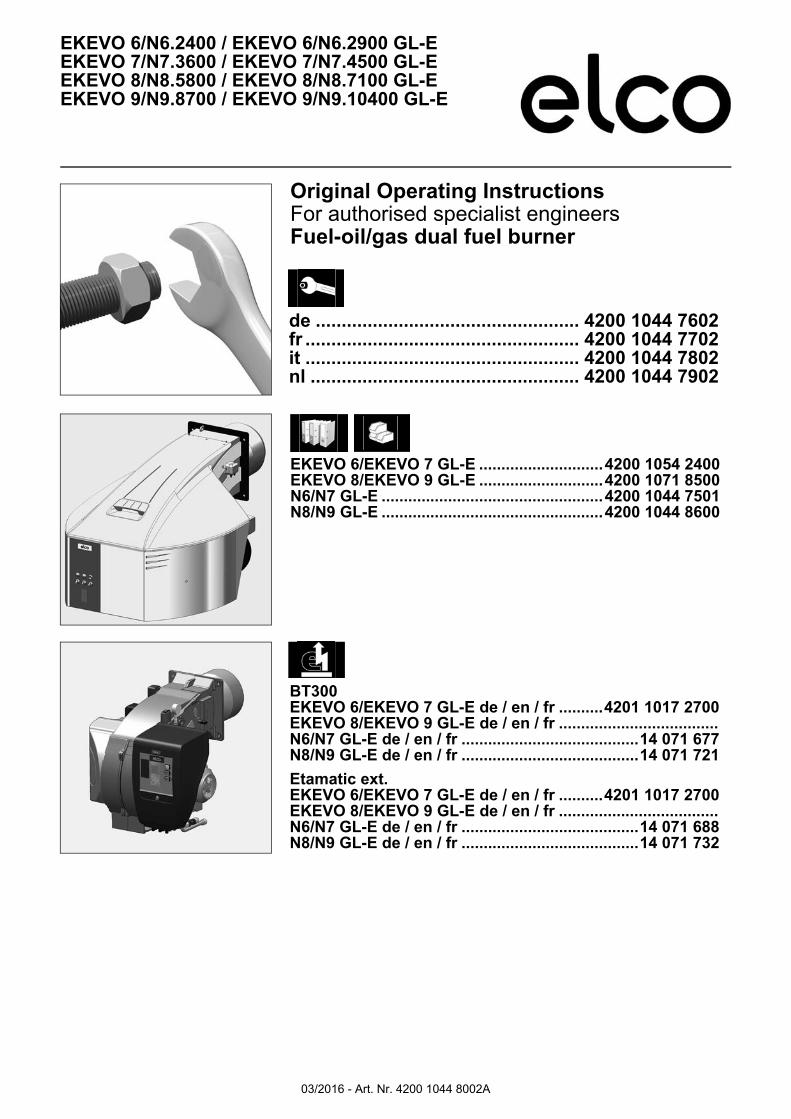
Original Operating InstructionsFor authorised specialist engineersFuel-oil/gas dual fuel burner
EKEVO 6/N6.2400 / EKEVO 6/N6.2900 GL-EEKEVO 7/N7.3600 / EKEVO 7/N7.4500 GL-EEKEVO 8/N8.5800 / EKEVO 8/N8.7100 GL-EEKEVO 9/N9.8700 / EKEVO 9/N9.10400 GL-E
de ................................................... 4200 1044 7602fr ..................................................... 4200 1044 7702it ..................................................... 4200 1044 7802nl .................................................... 4200 1044 7902
EKEVO 6/EKEVO 7 GL-E ............................4200 1054 2400EKEVO 8/EKEVO 9 GL-E ............................4200 1071 8500N6/N7 GL-E ..................................................4200 1044 7501N8/N9 GL-E ..................................................4200 1044 8600
BT300EKEVO 6/EKEVO 7 GL-E de / en / fr ..........4201 1017 2700EKEVO 8/EKEVO 9 GL-E de / en / fr ....................................N6/N7 GL-E de / en / fr ........................................14 071 677N8/N9 GL-E de / en / fr ........................................14 071 721
Etamatic ext.EKEVO 6/EKEVO 7 GL-E de / en / fr ..........4201 1017 2700EKEVO 8/EKEVO 9 GL-E de / en / fr ....................................N6/N7 GL-E de / en / fr ........................................14 071 688N8/N9 GL-E de / en / fr ........................................14 071 732
03/2016 - Art. Nr. 4200 1044 8002A2
General information
Contents
General information Contents ............................................................................................................................ 2Important information......................................................................................................... 3Burner description .......................................................................................................... 4-5
Installation Air duct connection, Rotating air box................................................................................. 6General information regarding burner installation ............................................................. 7Boiler lining for GL-E burner .............................................................................................. 8Burner installation.............................................................................................................. 9Combustion components
Combustion components N6/N7, EKEVO 6/EKEVO 7adjustment data/check ...... 10Combustion components N8/ EKEVO 8 adjustment data/check.......................... 11Combustion components N9/ EKEVO 9 adjustment data/check.......................... 12Gas/fuel-oil ignition electrodes adjustment data/check ................................... 13-14Installation ............................................................................................................ 15
Gas trainDescription of gas train with VGD... ..................................................................... 16Description of gas train with MBC... ..................................................................... 17Basic design......................................................................................................... 18
Gas train componentsDescription of double gas valve VGD... with servomotors SKP ...................................... 19Description of Dungs MBC... double gas valve (gas multiblock) ................................ 20-21General information about electrical connection ............................................................. 21Replacing the MBC-300-700-1200 filter .......................................................................... 22Setting the MBC-300-700-1200-SE pressure regulation component .............................. 22Setting the MBC-1900-7000-SE pressure regulation component ................................... 23Gas filter, test burner ....................................................................................................... 24Gas pressure switch ........................................................................................................ 25
Pressure switch Air pressure switch .......................................................................................................... 26
Hydraulics Fuel-oil system diagram .................................................................................................. 27General information regarding fuel-oil system............................................................ 28-30Fuel-oil hydraulics diagram......................................................................................... 28-30
Commissioning Fuel-oil pressure switch................................................................................................... 31General information regarding fuel-oil system................................................................. 32Pump ........................................................................................................................ 33-34Fuel-oil hydraulic block .................................................................................................... 35Return nozzle rod RDN ................................................................................................... 36Nozzle selection, type W2 - 45°/50° ................................................................................ 37Allocation of nozzle - W2 - 45°/50° .................................................................................. 38Return nozzle rod RDG ................................................................................................... 39Nozzle selection, type Sonic 60° ..................................................................................... 40Allocation of nozzle - Sonic 60° ....................................................................................... 41Nozzle selection, type Sonic 45° ..................................................................................... 42Allocation of nozzle - Sonic 45° ....................................................................................... 43Burner control unit ........................................................................................................... 44Electrical cabinet door construction................................................................................. 45Servomotor STE, servomotor STM 40 ............................................................................ 46Flame sensor.............................................................................................................. 47-48Connecting the gas train, electrical connection, checks to be carried out before commissioning................................................................................................................. 49Gas connection................................................................................................................ 50Fuel-air controller............................................................................................................. 51Burner output adjusting sequence................................................................................... 52Inspection ........................................................................................................................ 53Preventilation................................................................................................................... 54Fuel-oil start-up function, fuel-oil operation function........................................................ 55General safety functions.................................................................................................. 55Gas start-up function, gas operation function.................................................................. 56General safety functions.................................................................................................. 56
Servicing Maintenance ............................................................................................................... 57-60Maintenance, Replacing the control unit ......................................................................... 58Checking / assembling the combustion components ...................................................... 60Rotation procedure of air box EKEVO 6/EKEVO 7 ........................................................ 61Rotation procedure of air box EKEVO 8/EKEVO 9 ................................................... 62-64Air fan setting.............................................................................................................. 65-66Exhaust gas measurement......................................................................................... 67-68Diagnosing and remedying faults ............................................................................... 68-69Faults ............................................................................................................................. 70Conformity declaration................................................................................................ 71-72Manufacturer certificate in accordance with 1. BImschV............................................ 73-75
03/2016 - Art. Nr. 4200 1044 8002A 3
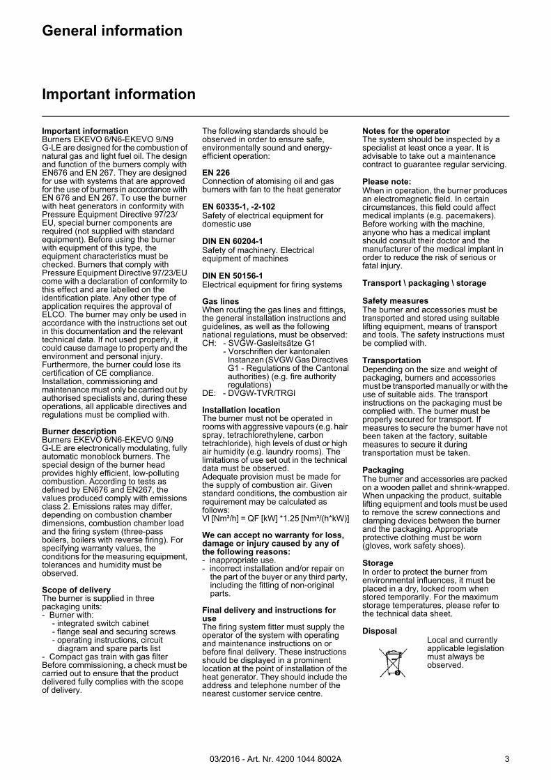
Important informationBurners EKEVO 6/N6-EKEVO 9/N9G-LE are designed for the combustion of natural gas and light fuel oil. The design and function of the burners comply with EN676 and EN 267. They are designed for use with systems that are approved for the use of burners in accordance with EN 676 and EN 267. To use the burner with heat generators in conformity with Pressure Equipment Directive 97/23/EU, special burner components are required (not supplied with standard equipment). Before using the burner with equipment of this type, the equipment characteristics must be checked. Burners that comply with Pressure Equipment Directive 97/23/EU come with a declaration of conformity to this effect and are labelled on the identification plate. Any other type of application requires the approval of ELCO. The burner may only be used in accordance with the instructions set out in this documentation and the relevant technical data. If not used properly, it could cause damage to property and the environment and personal injury. Furthermore, the burner could lose its certification of CE compliance. Installation, commissioning and maintenance must only be carried out by authorised specialists and, during these operations, all applicable directives and regulations must be complied with.
Burner descriptionBurners EKEVO 6/N6-EKEVO 9/N9G-LE are electronically modulating, fully automatic monoblock burners. The special design of the burner head provides highly efficient, low-polluting combustion. According to tests as defined by EN676 and EN267, the values produced comply with emissions class 2. Emissions rates may differ, depending on combustion chamber dimensions, combustion chamber load and the firing system (three-pass boilers, boilers with reverse firing). For specifying warranty values, the conditions for the measuring equipment, tolerances and humidity must be observed.
Scope of deliveryThe burner is supplied in three packaging units:- Burner with:
- integrated switch cabinet - flange seal and securing screws - operating instructions, circuit
diagram and spare parts list- Compact gas train with gas filterBefore commissioning, a check must be carried out to ensure that the product delivered fully complies with the scope of delivery.
The following standards should be observed in order to ensure safe, environmentally sound and energy-efficient operation:
EN 226Connection of atomising oil and gas burners with fan to the heat generator
EN 60335-1, -2-102Safety of electrical equipment for domestic use
DIN EN 60204-1Safety of machinery. Electrical equipment of machines
DIN EN 50156-1Electrical equipment for firing systems
Gas linesWhen routing the gas lines and fittings, the general installation instructions and guidelines, as well as the following national regulations, must be observed:CH: - SVGW-Gasleitsätze G1
- Vorschriften der kantonalenInstanzen (SVGW Gas Directives G1 - Regulations of the Cantonalauthorities) (e.g. fire authority regulations)
DE: - DVGW-TVR/TRGI
Installation locationThe burner must not be operated in rooms with aggressive vapours (e.g. hair spray, tetrachlorethylene, carbon tetrachloride), high levels of dust or high air humidity (e.g. laundry rooms). The limitations of use set out in the technical data must be observed.Adequate provision must be made for the supply of combustion air. Given standard conditions, the combustion air requirement may be calculated as follows:Vl [Nm³/h] = QF [kW] *1.25 [Nm³/(h*kW)]
We can accept no warranty for loss, damage or injury caused by any of the following reasons:- inappropriate use.- incorrect installation and/or repair on
the part of the buyer or any third party, including the fitting of non-original parts.
Final delivery and instructions for useThe firing system fitter must supply the operator of the system with operating and maintenance instructions on or before final delivery. These instructions should be displayed in a prominent location at the point of installation of the heat generator. They should include the address and telephone number of the nearest customer service centre.
Notes for the operatorThe system should be inspected by a specialist at least once a year. It is advisable to take out a maintenance contract to guarantee regular servicing.
Please note:When in operation, the burner produces an electromagnetic field. In certain circumstances, this field could affect medical implants (e.g. pacemakers). Before working with the machine, anyone who has a medical implant should consult their doctor and the manufacturer of the medical implant in order to reduce the risk of serious or fatal injury.
Transport \ packaging \ storage
Safety measuresThe burner and accessories must be transported and stored using suitable lifting equipment, means of transport and tools. The safety instructions must be complied with.
TransportationDepending on the size and weight of packaging, burners and accessories must be transported manually or with the use of suitable aids. The transport instructions on the packaging must be complied with. The burner must be properly secured for transport. If measures to secure the burner have not been taken at the factory, suitable measures to secure it during transportation must be taken.
PackagingThe burner and accessories are packed on a wooden pallet and shrink-wrapped.When unpacking the product, suitable lifting equipment and tools must be used to remove the screw connections and clamping devices between the burner and the packaging. Appropriate protective clothing must be worn (gloves, work safety shoes).
StorageIn order to protect the burner from environmental influences, it must be placed in a dry, locked room when stored temporarily. For the maximum storage temperatures, please refer to the technical data sheet.
DisposalLocal and currently applicable legislation must always be observed.
General information
Important information
03/2016 - Art. Nr. 4200 1044 8002A4
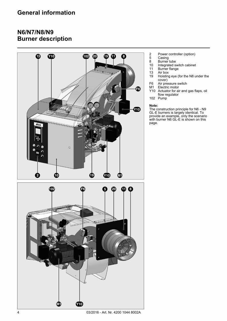
2 Power controller (option)5 Casing8 Burner tube10 Integrated switch cabinet11 Burner flange13 Air box19 Hoisting eye (for the N8 under the
cover)F6 Air pressure switchM1 Electric motorY10 Actuator for air and gas flaps, oil
flow regulator102 Pump
Note:The construction principle for N6 - N9 GL-E burners is largely identical. To provide an example, only the scenario with burner N6 GL-E is shown on this page.
General information
N6/N7/N8/N9Burner description
03/2016 - Art. Nr. 4200 1044 8002A 5
General information
EKEVO 6/EKEVO 7/EKEVO 8/EKEVO 9Burner description
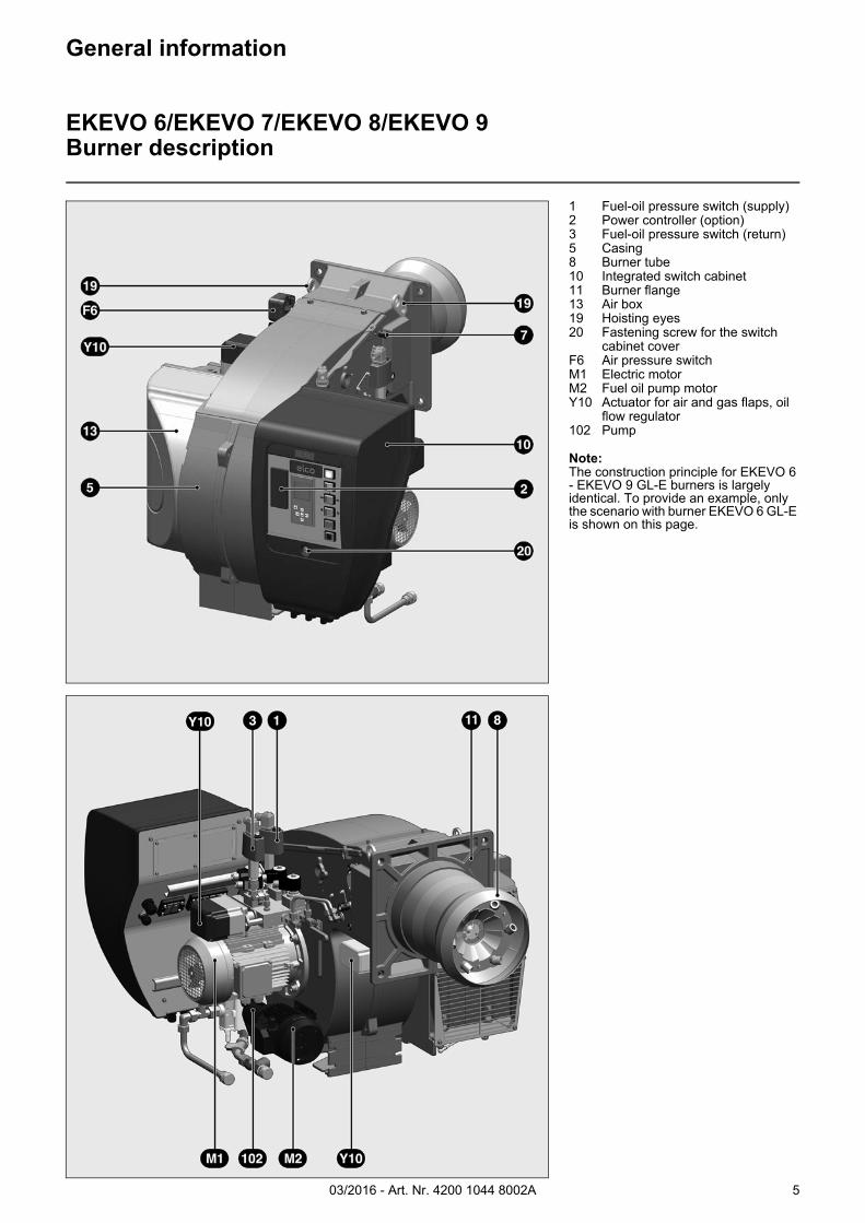
1 Fuel-oil pressure switch (supply)2 Power controller (option)3 Fuel-oil pressure switch (return)5 Casing8 Burner tube10 Integrated switch cabinet11 Burner flange13 Air box19 Hoisting eyes20 Fastening screw for the switch
cabinet coverF6 Air pressure switchM1 Electric motorM2 Fuel oil pump motorY10 Actuator for air and gas flaps, oil
flow regulator102 Pump
Note:The construction principle for EKEVO 6 - EKEVO 9 GL-E burners is largely identical. To provide an example, only the scenario with burner EKEVO 6 GL-E is shown on this page.
03/2016 - Art. Nr. 4200 1044 8002A6
Installation
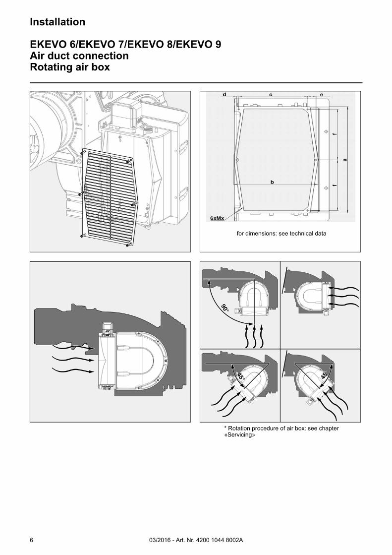
EKEVO 6/EKEVO 7/EKEVO 8/EKEVO 9Air duct connectionRotating air box
* Rotation procedure of air box: see chapter «Servicing»
for dimensions: see technical data
03/2016 - Art. Nr. 4200 1044 8002A 7
Installation
General information regarding burner installation
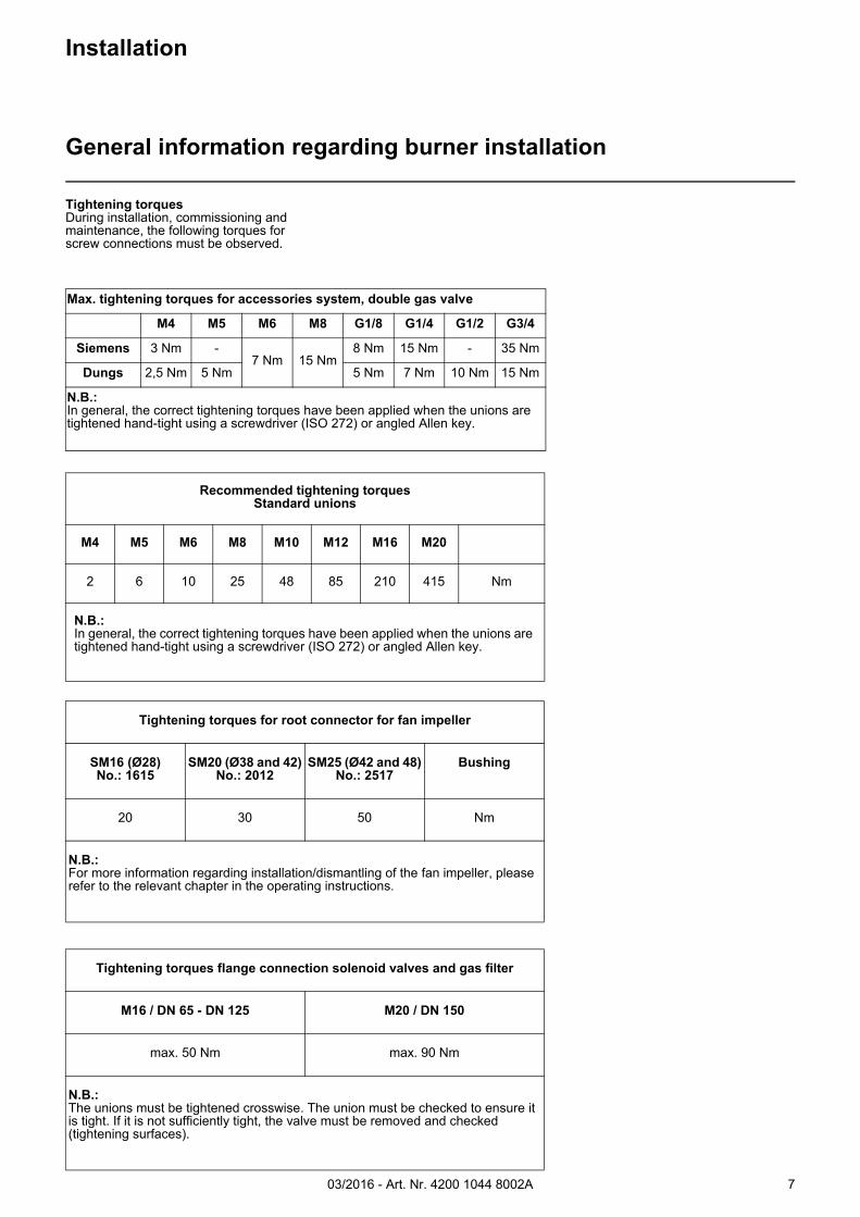
Tightening torquesDuring installation, commissioning and maintenance, the following torques for screw connections must be observed.
Recommended tightening torquesStandard unions
M4 M5 M6 M8 M10 M12 M16 M20
2 6 10 25 48 85 210 415 Nm
N.B.:In general, the correct tightening torques have been applied when the unions are tightened hand-tight using a screwdriver (ISO 272) or angled Allen key.
Tightening torques for root connector for fan impeller
SM16 (Ø28)No.: 1615
SM20 (Ø38 and 42)No.: 2012
SM25 (Ø42 and 48)No.: 2517
Bushing
20 30 50 Nm
N.B.:For more information regarding installation/dismantling of the fan impeller, please refer to the relevant chapter in the operating instructions.
Tightening torques flange connection solenoid valves and gas filter
M16 / DN 65 - DN 125 M20 / DN 150
max. 50 Nm max. 90 Nm
N.B.:The unions must be tightened crosswise. The union must be checked to ensure it is tight. If it is not sufficiently tight, the valve must be removed and checked (tightening surfaces).
Max. tightening torques for accessories system, double gas valve
M4 M5 M6 M8 G1/8 G1/4 G1/2 G3/4
Siemens 3 Nm -7 Nm 15 Nm
8 Nm 15 Nm - 35 Nm
Dungs 2,5 Nm 5 Nm 5 Nm 7 Nm 10 Nm 15 Nm
N.B.:In general, the correct tightening torques have been applied when the unions are tightened hand-tight using a screwdriver (ISO 272) or angled Allen key.
03/2016 - Art. Nr. 4200 1044 8002A8
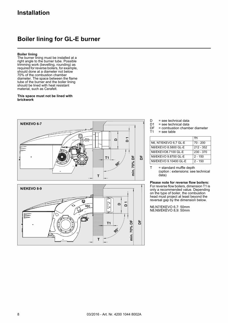
D = see technical dataD1 = see technical dataDF = combustion chamber diameterT1 = see table
T = standard muffle depth (option : extensions: see technical data)
Please note for reverse flow boilers:For reverse flow boilers, dimension T1 is only a recommended value. Depending on the type of boiler, the combustion head must project at least beyond the reversal gap by the dimension below.
N6,N7/EKEVO 6,7: 50mmN8,N9/EKEVO 8,9: 50mm
T1
N6, N7/EKEVO 6,7 GL-E 70 - 200N8/EKEVO 8.5800 GL-E 212 - 352N8/EKEVO8.7100 GL-E 230 - 370N9/EKEVO 9.8700 GL-E 2 - 150N9/EKEVO 9.10400 GL-E 2 - 150
Installation
Boiler lining for GL-E burner
Boiler liningThe burner lining must be installed at a right angle to the burner tube. Possible trimming work (bevelling, rounding) as required for reverse boilers, for example, should done at a diameter not below 70% of the combustion chamber diameter. The space between the flame tube of the burner and the boiler lining should be lined with heat resistant material, such as Cerafelt.
This space must not be lined with brickwork
N/EKEVO 6-7
N/EKEVO 8-9
03/2016 - Art. Nr. 4200 1044 8002A 9
Burner installation
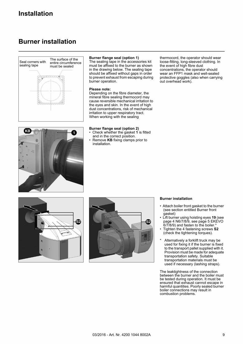
• Attach boiler front gasket to the burner (see section entitled Burner front gasket)
• Lift burner using hoisting eyes 19 (see page 4 N6/7/8/9, see page 5 EKEVO 6/7/8/9) and fasten to the boiler.*
• Tighten the 4 fastening screws S2 (check the tightening torques).
* Alternatively a forklift truck may be used for fixing it if the burner is fixed to the transport pallet supplied with it. Provision must be made for adequate transportation safety. Suitable transportation materials must be used if necessary (lashing straps).
The leaktightness of the connection between the burner and the boiler must be tested during operation. It must be ensured that exhaust cannot escape in harmful quantities. Poorly sealed burner boiler connections may result in combustion problems.
Installation
Burner installation
Burner flange seal (option 1)The sealing tape in the accessories kit must be affixed to the burner as shown in the drawing below. The sealing tape should be affixed without gaps in order to prevent exhaust from escaping during burner operation.
Please note:Depending on the fibre diameter, the mineral fibre sealing thermocord may cause reversible mechanical irritation to the eyes and skin. In the event of high dust concentrations, risk of mechanical irritation to upper respiratory tract.When working with the sealing
thermocord, the operator should wear loose-fitting, long-sleeved clothing. In the event of high fibre dust concentrations, the operator should wear an FFP1 mask and well-sealed protective goggles (also when carrying out overhead work).
Burner flange seal (option 2)• Check whether the gasket 1 is fitted
and in the correct position.• Remove KB fixing clamps prior to
installation.
The surface of the entire circumference must be sealed
Seal corners with sealing tape
03/2016 - Art. Nr. 4200 1044 8002A10
InstallationCombustion components
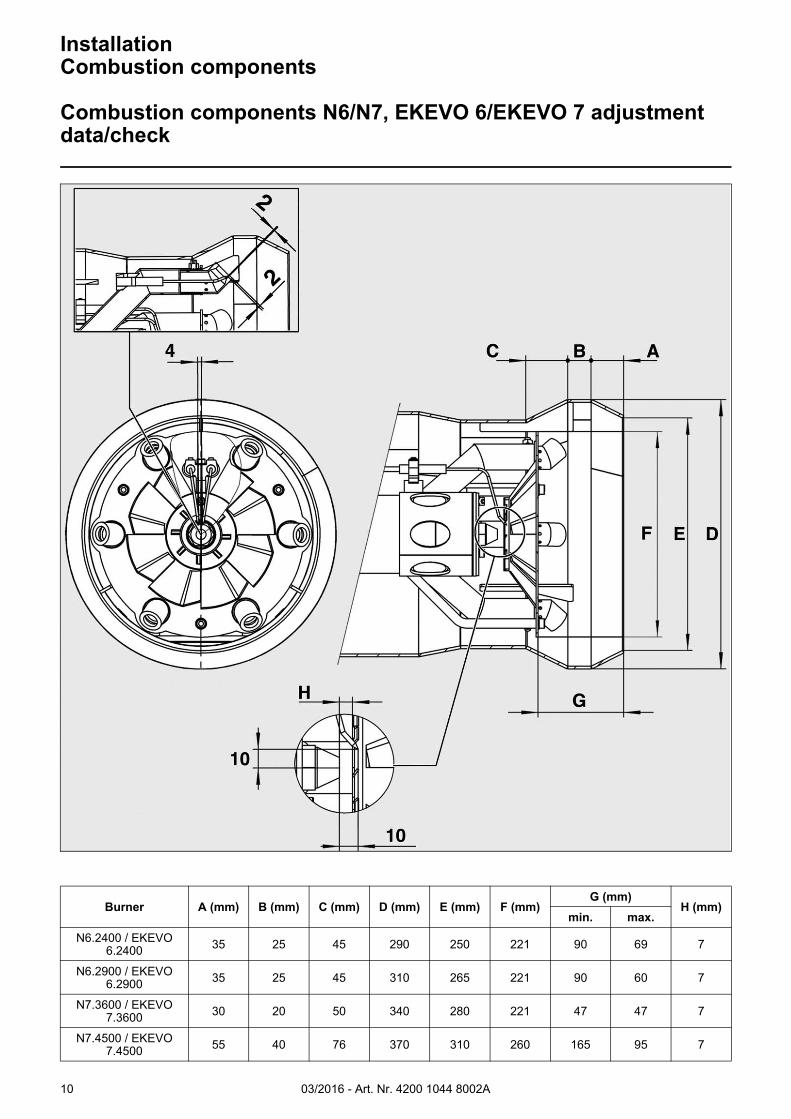
Combustion components N6/N7, EKEVO 6/EKEVO 7 adjustment data/check
Burner A (mm) B (mm) C (mm) D (mm) E (mm) F (mm)G (mm)
H (mm)min. max.
N6.2400 / EKEVO 6.2400 35 25 45 290 250 221 90 69 7
N6.2900 / EKEVO 6.2900 35 25 45 310 265 221 90 60 7
N7.3600 / EKEVO 7.3600 30 20 50 340 280 221 47 47 7
N7.4500 / EKEVO 7.4500 55 40 76 370 310 260 165 95 7
03/2016 - Art. Nr. 4200 1044 8002A 11
InstallationCombustion components
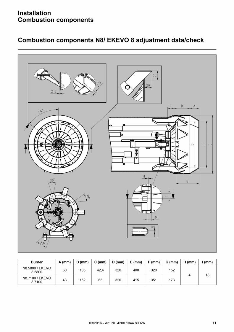
Combustion components N8/ EKEVO 8 adjustment data/check
Burner A (mm) B (mm) C (mm) D (mm) E (mm) F (mm) G (mm) H (mm) I (mm)
N8.5800 / EKEVO 8.5800 60 105 42,4 320 400 320 152
4 18N8.7100 / EKEVO
8.7100 43 152 63 320 415 351 173
03/2016 - Art. Nr. 4200 1044 8002A12
InstallationCombustion components
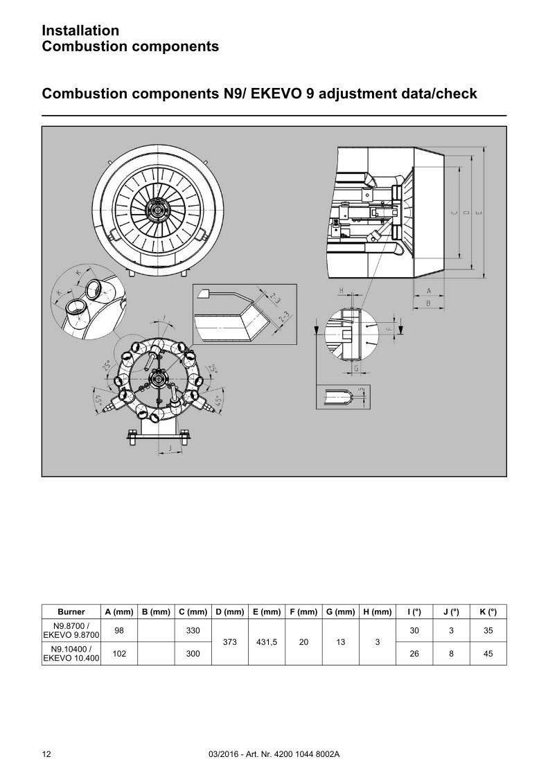
Combustion components N9/ EKEVO 9 adjustment data/check
Burner A (mm) B (mm) C (mm) D (mm) E (mm) F (mm) G (mm) H (mm) I (°) J (°) K (°)
N9.8700 / EKEVO 9.8700 98 330
373 431,5 20 13 330 3 35
N9.10400 / EKEVO 10.400 102 300 26 8 45
03/2016 - Art. Nr. 4200 1044 8002A 13
InstallationCombustion components
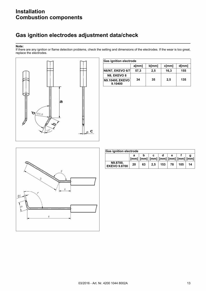
Gas ignition electrodes adjustment data/check
Note:If there are any ignition or flame detection problems, check the setting and dimensions of the electrodes. If the wear is too great,replace the electrodes.
Gas ignition electrode
a[mm] b[mm] c[mm] d[mm]
N6/N7, EKEVO 6/7 57,3 2,5 16,3 155
N8, EKEVO 834 35 2,5 135N9.10400, EKEVO
9.10400
Gas ignition electrodea
[mm]b
[mm]c
[mm]d
[mm]e
[mm]f
[mm]g
[mm]N9.8700,
EKEVO 9.8700 20 63 2,5 153 78 105 14
03/2016 - Art. Nr. 4200 1044 8002A14
InstallationCombustion components
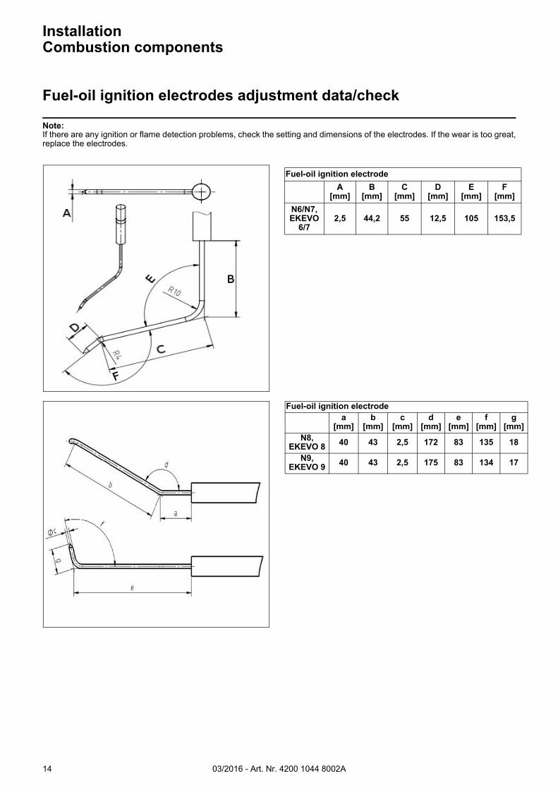
Fuel-oil ignition electrodes adjustment data/check
Note:If there are any ignition or flame detection problems, check the setting and dimensions of the electrodes. If the wear is too great,replace the electrodes.
Fuel-oil ignition electrode
A[mm]
B[mm]
C[mm]
D[mm]
E[mm]
F[mm]
N6/N7, EKEVO
6/72,5 44,2 55 12,5 105 153,5
Fuel-oil ignition electrodea
[mm]b
[mm]c
[mm]d
[mm]e
[mm]f
[mm]g
[mm]N8,
EKEVO 8 40 43 2,5 172 83 135 18
N9, EKEVO 9 40 43 2,5 175 83 134 17
03/2016 - Art. Nr. 4200 1044 8002A 15
InstallationCombustion components
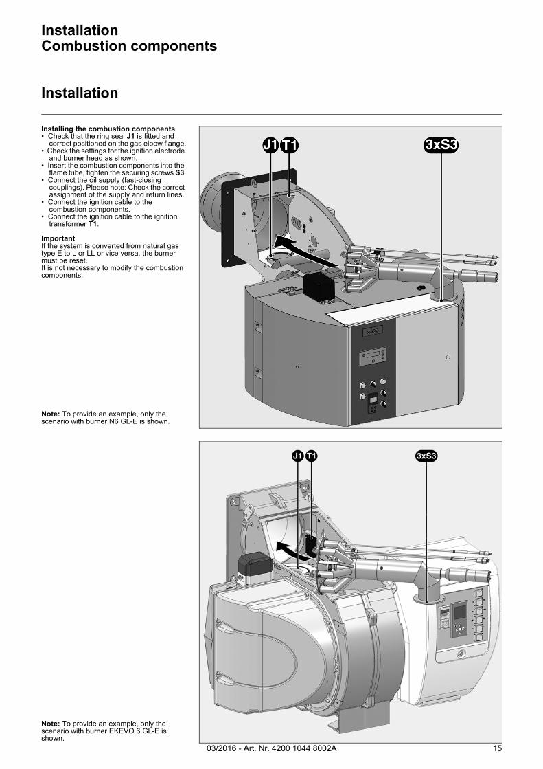
Installation
Installing the combustion components• Check that the ring seal J1 is fitted and
correct positioned on the gas elbow flange.• Check the settings for the ignition electrode
and burner head as shown.• Insert the combustion components into the
flame tube, tighten the securing screws S3.• Connect the oil supply (fast-closing
couplings). Please note: Check the correct assignment of the supply and return lines.
• Connect the ignition cable to the combustion components.
• Connect the ignition cable to the ignition transformer T1.
ImportantIf the system is converted from natural gas type E to L or LL or vice versa, the burner must be reset.It is not necessary to modify the combustion components.
Note: To provide an example, only the scenario with burner N6 GL-E is shown.
Note: To provide an example, only the scenario with burner EKEVO 6 GL-E is shown.
03/2016 - Art. Nr. 4200 1044 8002A16
InstallationGas train
Description of gas train with VGD...
DescriptionGas trains with a Siemens VGD double valve are intended for the supply, main shut-off, filtration, pressure regulation and monitoring of the gas supply. They can be used for all gases in the 1, 2, 3 gas families in accordance with DVGW worksheet G 260/1 and/or EN 437. The design complies with EN 676. All the functional components have been tested individually and awarded the CE mark and number of the Notified Body. The premounted gas valve train is subjected to a leak test at the manufacturer's works.The rules of the DVGW, particularly the DVGW-TRGI and TRF, must be taken into consideration when the gas lines are being installed and commissioned. DIN 4756 and TRD 412 contain stipulations concerning the construction, design and technical safety principles of oil firing in heating systems. DVGW work sheets G 460 and G 461 apply to systems with high operating pressures. The gas lines must comply with the stipulations of DVGW- TRGI for systems with operating pressures of up to or greater than 100 mbar.
Minimum scope of delivery for gas trains in accordance with EN 676:• 1 manual valve (optional)• 1 Gas filter• 1 Gas double valve• 1 SKP15 actuator and 1 SKP25 or
1 SKP75 actuator• 1 min. gas pressure switch• 1 leakage monitoring unit or 1 gas
pressure switch for valve leak test
Options:• Manual valve• Test burner with pushbutton valve• Pressure gauge with pushbutton valve• Compensator• Max. gas pressure switch• Gas meter• Pipe parts and connection parts• Ignition gas device• Installation supports• High-pressure regulator with safety
shut-off valve (SSOV)• Settling section with pulse lines for
high-pressure regulator• Safety relief valve (SRV)• Additional gas safety valve
Low- and high-pressure gas trainsIf the outlet side of the regulator, or individual fittings and devices downstream of the gas pressure regulator, have not been designed for the maximum supply pressure that occurs in the event of a fault, the gas train must be equipped with a safety shut-off valve (SSOV) and a safety relief valve (SRV) in accordance with EN 676. This equipment is generally required for maximum supply pressures of >360 mbar and > 500 mbar respectively. These are known as high-pressure gas trains. If all gas train fittings and devices have been designed/approved for the maximum supply pressure that occurs in the event of a fault, the gas train is known as a low-pressure gas train. This is the case, depending on component selection, for maximum supply pressures of 360 and 500 mbar.
Gas train selectionThe gas train is defined on a system-specific basis.
The following must be taken into consideration:• Burner output• Furnace counterpressure• Gas pressure loss in the burner head• Gas pressure losses in the gas valves
The total drop in gas pressure must always be lower than the available gas flow pressure.
Subject to change without notice due to ongoing technical developments.
Gas train installationTo fit the gas train supplied to the burner, the screw connections and seals provided for this must be used (supplied with the product).
Please note: in order to prevent injury, heavy gas train components should only be fitted using suitable aids and lifting equipment (crane, cable slings, assembly supports). The max. tightening torques must be observed (see chapter on Installation/tightening torques). The screw connections tightened crosswise and evenly. The screw connection must be checked to ensure that it is leaktight. For further information, please refer to the chapter on commissioning the gas connection.
Mechanical supportDuring and after installation of the gas train, mechanical support must be provided using at least one telescopic foot or a similar system (e.g. 1 on the filter and 1 on the valve).
Gas train with VGDTechnical data:Types of gas:
Gas types of gas families 1, 2 and 3 according to DVGW WorksheetG 260/1
Max. inlet pressure:500 mbar
Elect. connection: AC 220-240 V, 50 Hz
Protection level: IP 54
Ambient temperature:-10 °C to +60 °C
Media temperature:-15 °C to +60 °C(Liquid gas 0 °C to +60 °C)
03/2016 - Art. Nr. 4200 1044 8002A 17
Description The gas fitting trains with Dungs MBC ... double gas valves MBC... are used for gas supply, as the main isolation valve, for gas filtering, gas pressure regulation and monitoring of the gas supply. They can be used for all gases in the 1, 2, 3 gas families in accordance with DVGW worksheet G 260/1 and/or EN 437. The design complies with EN 676. All the functional components have been tested individually and awarded the CE mark and number of the Notified Body. The premounted gas fitting train is subjected to a leak test at the manufacturer's works.The rules of the DVGW, particularly the DVGW-TRGI and TRF, must be taken into consideration when the gas lines are being installed and commissioned. DIN 4756 and TRD 412 containstipulations concerning the construction, design and technical safety principles of gas firing in heating systems. DVGW work sheets G 460 and G 461 apply to systems with high operating pressures.The gas lines must comply with the stipulations of DVGW- TRGI in systemswith operating pressures of up to or greater than100 mbar.
Minimum scope of delivery for gas fitting trains in accordance with EN 676:• 1 manual valve (option)• 1 Gas filter• 1 Double gas valve• 1 Min. gas pressure switch• 1 Leakage controller or 1 gas pressure
switch for valve leak test
Options:• Manual valve• Test burner with pushbutton valve• Pressure gauge with pushbutton valve• Compensator• Max. gas pressure switch• Gas meter• Pipe parts and connection parts• Ignition gas device• Installation support• High-pressure regulator with safety
shut-off valve (SSOV)• Settling section with pulse lines for
high-pressure regulator• Safety relief valve (SRV)• Additional gas safety valve
Low- and high-pressure gas trainsIf the outlet side of the regulator, or individual fittings and devices downstream of the gas pressure regulator, have not been designed for the maximum supply pressure that occurs in the event of a fault, the gas train must be equipped with a safety shut-off valve (SSOV) and a safety relief valve (SRV) in accordance with EN 676. This equipment is generally required for maximum supply pressures of >360 mbar and > 500 mbar respectively. These are known as high-pressure gas trains. If all gas train fittings and equipment have been designed and/or approved for the maximum supply pressure that occurs in the event of a fault, the gas train is known as a low-pressure gas train. This is the case, depending on component selection, for maximum supply pressures of 360 and 500 mbar.
Gas train selectionThe gas train is defined on a system-specific basis.
The following must be taken into consideration:• Burner output• Furnace counterpressure• Gas pressure loss in the burner head• Gas pressure losses in the gas valves
The total drop in gas pressure must always be lower than the available gas flow pressure.
Subject to change without notice due to ongoing technical developments.
Gas train installationTo fit the gas train supplied to the burner, the screw connections and seals provided for this must be used (supplied with the product).
Please note: in order to prevent injury, heavy gas train components should only be fitted using suitable aids and lifting equipment (crane, cable slings, assembly supports). The max. tightening torques must be observed (see chapter on Installation/tightening torques). The screw connections must be tightened crosswise and evenly. The screw connection must be checked to ensure that it is leaktight. For further information, please refer to the chapter on commissioning the gas connection.
Mechanical supportDuring and after installation of the gas train, mechanical support must be provided using at least one telescopic foot or a similar system (e.g. 1 on the filter and 1 on the valve).
Gas train with MBCTechnical data:Types of gas:
Gas types of gas families 1, 2 and 3 according to DVGW WorksheetG 260/1
Max. inlet pressure:
MBC300-1200: 360 mbar
MBC1900-7000: 500 mbar
Elect. connection: AC 220-240 V, 50 Hz
Protection level: IP 54
Ambient temperature:-15 °C to +60 °C
InstallationGas train
Description of gas train with MBC...
03/2016 - Art. Nr. 4200 1044 8002A18
InstallationGas train
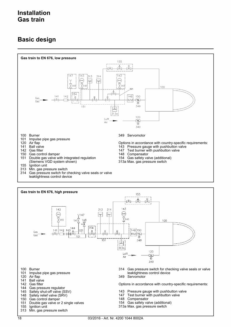
Basic design
100 Burner101 Impulse pipe gas pressure120 Air flap141 Ball valve142 Gas filter150 Gas control damper151 Double gas valve with integrated regulation
(Siemens VGD system shown)155 Ignition unit313 Min. gas pressure switch314 Gas pressure switch for checking valve seals or valve
leaktightness control device
349 Servomotor
Options in accordance with country-specific requirements:143 Pressure gauge with pushbutton valve147 Test burner with pushbutton valve148 Compensator154 Gas safety valve (additional)313a Max. gas pressure switch
100 Burner101 Impulse pipe gas pressure120 Air flap141 Ball valve142 Gas filter144 Gas pressure regulator145 Safety shut-off valve (SSV)148 Safety relief valve (SRV)150 Gas control damper151 Double gas valve or 2 single valves155 Ignition unit313 Min. gas pressure switch
314 Gas pressure switch for checking valve seals or valve leaktightness control device
349 Servomotor
Options in accordance with country-specific requirements:
143 Pressure gauge with pushbutton valve147 Test burner with pushbutton valve148 Compensator154 Gas safety valve (additional)313a Max. gas pressure switch
Gas train to EN 676, low pressure
Gas train to EN 676, high pressure
03/2016 - Art. Nr. 4200 1044 8002A 19
VGD 20
VGD 40
SKP 75
SKP 25
SKP 15
Gas train components
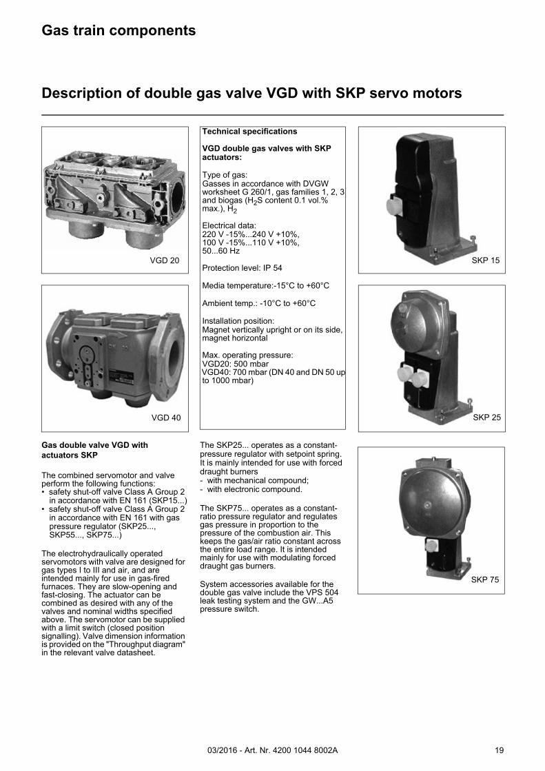
Description of double gas valve VGD with SKP servo motors
Technical specifications
VGD double gas valves with SKP actuators:
Type of gas: Gasses in accordance with DVGW worksheet G 260/1, gas families 1, 2, 3 and biogas (H2S content 0.1 vol.% max.), H2
Electrical data: 220 V -15%...240 V +10%, 100 V -15%...110 V +10%, 50...60 Hz
Protection level: IP 54
Media temperature:-15°C to +60°C
Ambient temp.: -10°C to +60°C
Installation position: Magnet vertically upright or on its side, magnet horizontal
Max. operating pressure: VGD20: 500 mbar VGD40: 700 mbar (DN 40 and DN 50 up to 1000 mbar)
Gas double valve VGD with actuators SKP
The combined servomotor and valve perform the following functions:• safety shut-off valve Class A Group 2
in accordance with EN 161 (SKP15...)• safety shut-off valve Class A Group 2
in accordance with EN 161 with gas pressure regulator (SKP25..., SKP55..., SKP75...)
The electrohydraulically operated servomotors with valve are designed for gas types I to III and air, and are intended mainly for use in gas-fired furnaces. They are slow-opening and fast-closing. The actuator can be combined as desired with any of the valves and nominal widths specified above. The servomotor can be supplied with a limit switch (closed position signalling). Valve dimension information is provided on the "Throughput diagram" in the relevant valve datasheet.
The SKP25... operates as a constant-pressure regulator with setpoint spring. It is mainly intended for use with forced draught burners- with mechanical compound;- with electronic compound.
The SKP75... operates as a constant-ratio pressure regulator and regulates gas pressure in proportion to the pressure of the combustion air. This keeps the gas/air ratio constant across the entire load range. It is intended mainly for use with modulating forced draught gas burners.
System accessories available for the double gas valve include the VPS 504 leak testing system and the GW...A5 pressure switch.
03/2016 - Art. Nr. 4200 1044 8002A20
Gas train components
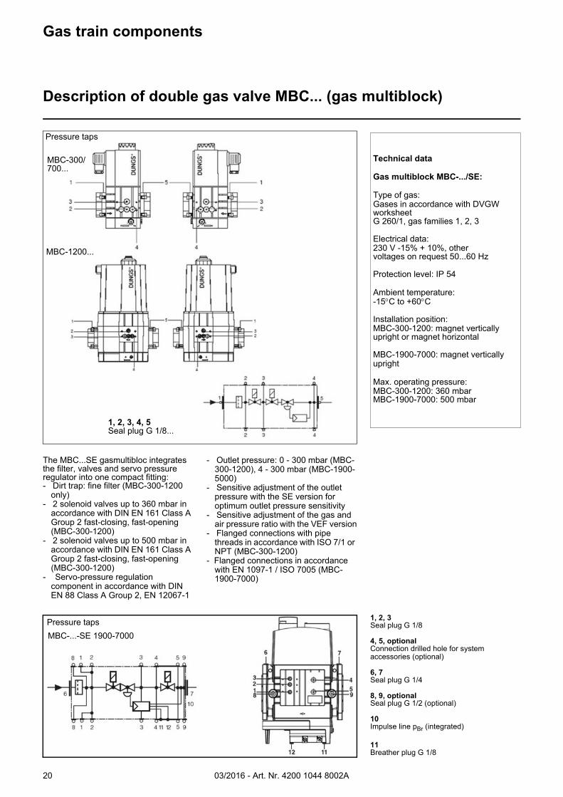
Description of double gas valve MBC... (gas multiblock)
The MBC...SE gasmultibloc integrates the filter, valves and servo pressure regulator into one compact fitting:- Dirt trap: fine filter (MBC-300-1200
only)- 2 solenoid valves up to 360 mbar in
accordance with DIN EN 161 Class A Group 2 fast-closing, fast-opening (MBC-300-1200)
- 2 solenoid valves up to 500 mbar in accordance with DIN EN 161 Class A Group 2 fast-closing, fast-opening (MBC-300-1200)
- Servo-pressure regulation component in accordance with DIN EN 88 Class A Group 2, EN 12067-1
- Outlet pressure: 0 - 300 mbar (MBC-300-1200), 4 - 300 mbar (MBC-1900-5000)
- Sensitive adjustment of the outlet pressure with the SE version for optimum outlet pressure sensitivity
- Sensitive adjustment of the gas and air pressure ratio with the VEF version
- Flanged connections with pipe threads in accordance with ISO 7/1 or NPT (MBC-300-1200)
- Flanged connections in accordance with EN 1097-1 / ISO 7005 (MBC-1900-7000)
1, 2, 3Seal plug G 1/8
4, 5, optionalConnection drilled hole for system accessories (optional)
6, 7Seal plug G 1/4
8, 9, optionalSeal plug G 1/2 (optional)
10Impulse line pBr (integrated)
11Breather plug G 1/8
Technical data
Gas multiblock MBC-.../SE:
Type of gas:Gases in accordance with DVGW worksheet G 260/1, gas families 1, 2, 3
Electrical data:230 V -15% + 10%, othervoltages on request 50...60 Hz
Protection level: IP 54
Ambient temperature:-15C to +60C
Installation position:MBC-300-1200: magnet vertically upright or magnet horizontal
MBC-1900-7000: magnet vertically upright
Max. operating pressure:MBC-300-1200: 360 mbarMBC-1900-7000: 500 mbar
Pressure taps
MBC-300/700...
MBC-1200...
Pressure tapsMBC-...-SE 1900-7000
1, 2, 3, 4, 5Seal plug G 1/8...
03/2016 - Art. Nr. 4200 1044 8002A 21
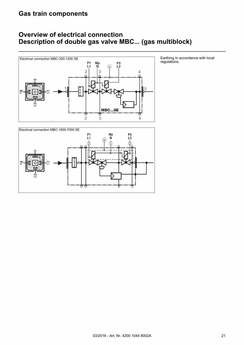
Gas train components
Overview of electrical connectionDescription of double gas valve MBC... (gas multiblock)
Earthing in accordance with local regulations.
Electrical connection MBC-300-1200 SE
Electrical connection MBC-1900-7000 SE
03/2016 - Art. Nr. 4200 1044 8002A22
3
12
1
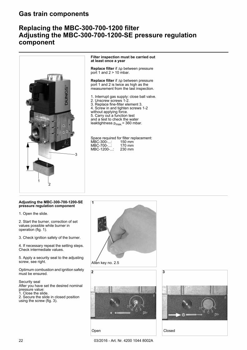
Allen key no. 2.5
Open
2
Closed
3
Filter inspection must be carried out at least once a year
Replace filter if p between pressure port 1 and 2 > 10 mbar.
Replace filter if p between pressure port 1 and 2 is twice as high as the measurement from the last inspection.
1. Interrupt gas supply: close ball valve.2. Unscrew screws 1-2.3. Replace fine-filter element 3.4. Screw in and tighten screws 1-2 without applying force.5. Carry out a function testand a test to check the water leaktightness pmax.= 360 mbar.
Space required for filter replacement:MBC-300-...: 150 mmMBC-700-...: 170 mmMBC-1200-...: 230 mm
Adjusting the MBC-300-700-1200-SE pressure regulation component
1. Open the slide.
2. Start the burner, correction of set values possible while burner in operation (fig. 1).
3. Check ignition safety of the burner.
4. If necessary repeat the setting steps. Check intermediate values.
5. Apply a security seal to the adjusting screw, see right.
Optimum combustion and ignition safety must be ensured.
Security sealAfter you have set the desired nominal pressure value:1. Close the slide.2. Secure the slide in closed position using the screw (fig. 3).
Gas train components
Replacing the MBC-300-700-1200 filterAdjusting the MBC-300-700-1200-SE pressure regulation component
03/2016 - Art. Nr. 4200 1044 8002A 23
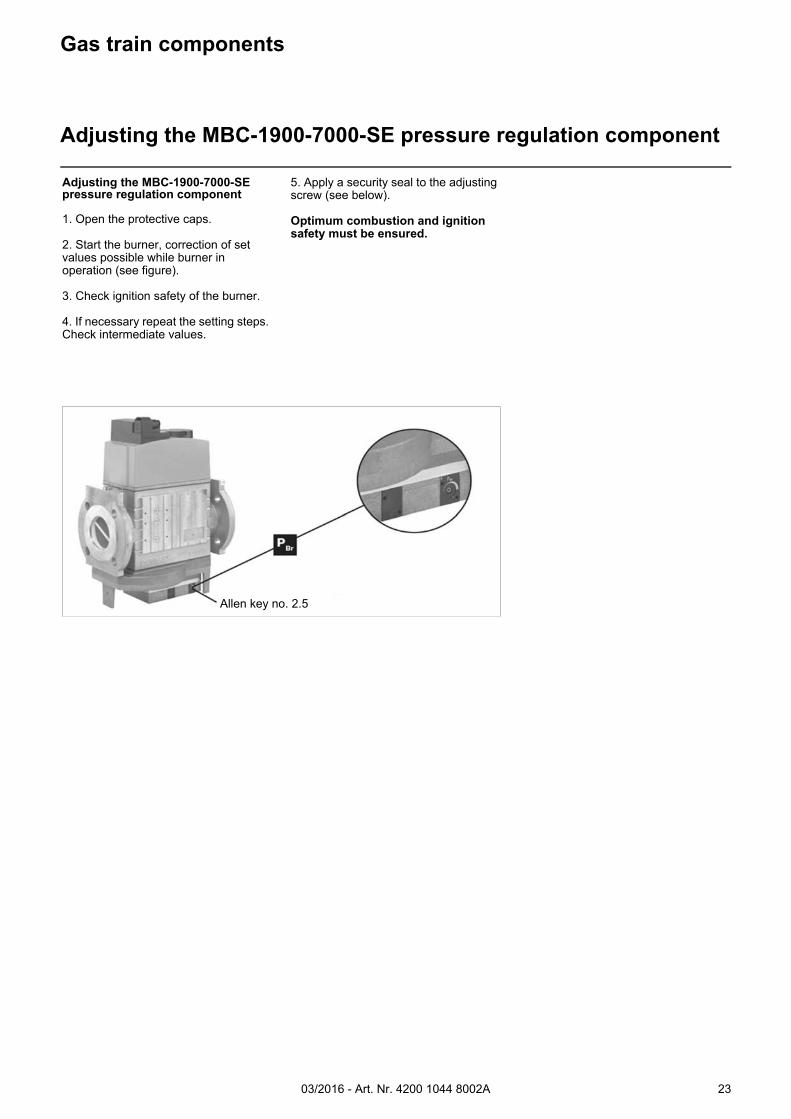
Allen key no. 2.5
Gas train components
Adjusting the MBC-1900-7000-SE pressure regulation component
Adjusting the MBC-1900-7000-SE pressure regulation component
1. Open the protective caps.
2. Start the burner, correction of set values possible while burner in operation (see figure).
3. Check ignition safety of the burner.
4. If necessary repeat the setting steps. Check intermediate values.
5. Apply a security seal to the adjusting screw (see below).
Optimum combustion and ignition safety must be ensured.
03/2016 - Art. Nr. 4200 1044 8002A24
Gas train components
Gas filterTest burner
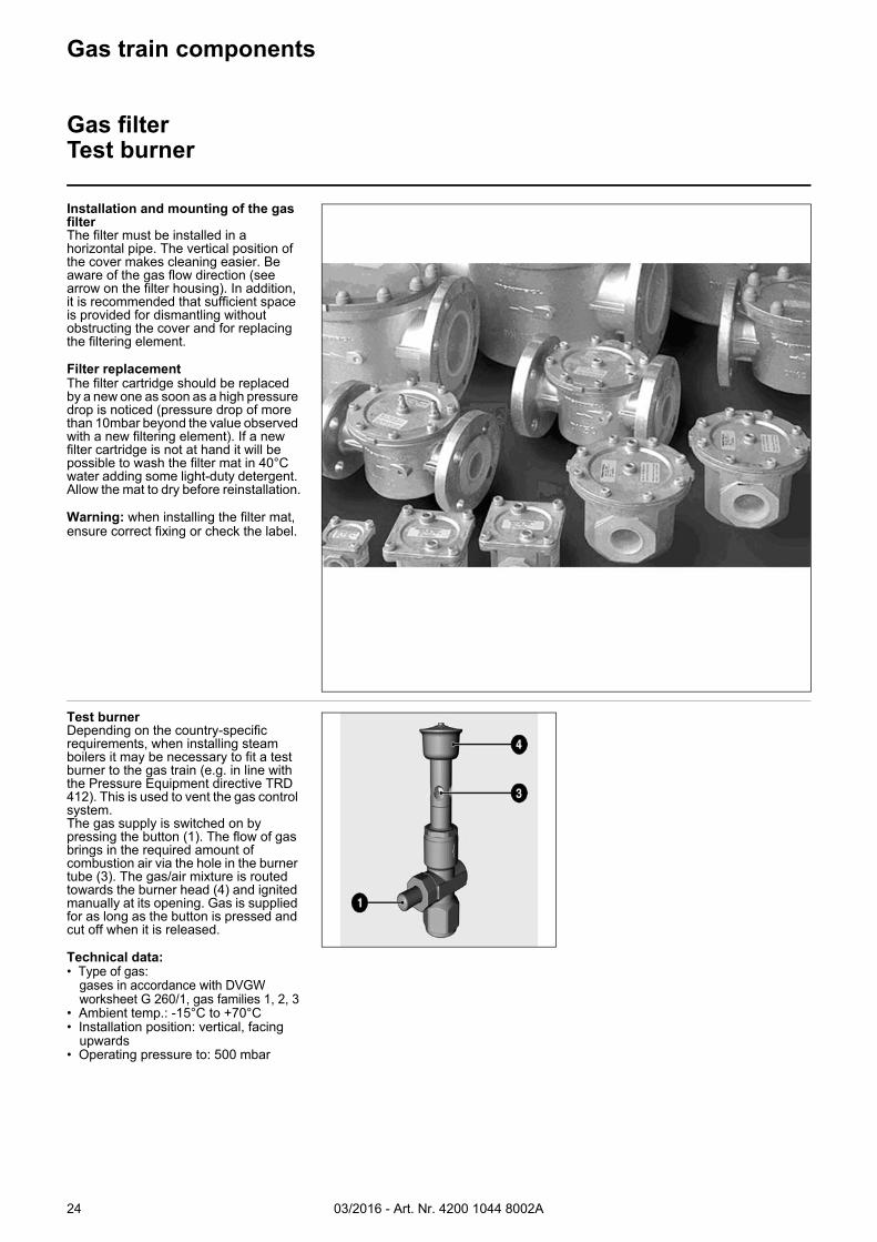
Installation and mounting of the gas filterThe filter must be installed in a horizontal pipe. The vertical position of the cover makes cleaning easier. Be aware of the gas flow direction (see arrow on the filter housing). In addition, it is recommended that sufficient space is provided for dismantling without obstructing the cover and for replacing the filtering element.
Filter replacementThe filter cartridge should be replaced by a new one as soon as a high pressure drop is noticed (pressure drop of more than 10mbar beyond the value observed with a new filtering element). If a new filter cartridge is not at hand it will be possible to wash the filter mat in 40°C water adding some light-duty detergent. Allow the mat to dry before reinstallation.
Warning: when installing the filter mat, ensure correct fixing or check the label.
Test burnerDepending on the country-specific requirements, when installing steam boilers it may be necessary to fit a test burner to the gas train (e.g. in line with the Pressure Equipment directive TRD 412). This is used to vent the gas control system.The gas supply is switched on by pressing the button (1). The flow of gas brings in the required amount of combustion air via the hole in the burner tube (3). The gas/air mixture is routed towards the burner head (4) and ignited manually at its opening. Gas is supplied for as long as the button is pressed and cut off when it is released.
Technical data:• Type of gas:
gases in accordance with DVGW worksheet G 260/1, gas families 1, 2, 3
• Ambient temp.: -15°C to +70°C• Installation position: vertical, facing
upwards• Operating pressure to: 500 mbar
03/2016 - Art. Nr. 4200 1044 8002A 25
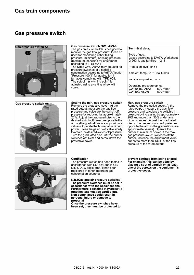
Gas pressure switch A5
Gas pressure switch A6
Gas train components
Gas pressure switch
Technical data:
Type of gas:Gases according to DVGW Worksheet G 260/1, gas families 1, 2, 3
Protection level: IP 54
Ambient temp.: -15°C to +50°C
Installation position: any
Operating pressure up to:GW 50/150 A5A6 500 mbarGW 500/ A5/A6 600 mbar
Gas pressure switch GW...A5/A6The gas pressure switch is designed to monitor the gas flow pressure. It can be used for monitoring either falling pressure (minimum) or rising pressure (maximum, specified for equipment according to TRD 604).The types GW...A5/A6 may be used as pressure switches of a specific construction according to VdTÜV leaflet "Pressure 100/1" for application in furnaces complying with TRD 604. The setpoint (switching point) is adjusted using a setting wheel with scale.
CertificationThe pressure switch has been tested in accordance with EN1854 and is CE/DIN-DVGW-registered. It has been registered in other important gas consumption countries.
N.B.(Gas and air pressure switches)The pressure switches must be set in accordance with the specifications. Furthermore, each time they are set, a function test must be carried out. Non-compliance could result in personal injury or damage to property!Once the pressure switches have been set, they must be protected to
prevent settings from being altered. For example, this can be done by placing a spot of varnish on at least one of the screws on the equipment's protective cover.
Setting the min. gas pressure switchRemove the protective cover. At the rated output, measure the gas flow pressure and calculate the switch-off pressure by reducing by approximately 20%. Adjust the graduated disc to the desired switch-off pressure opposite the arrow (the graduations are approximate values). Operate the burner at minimum power. Close the gas cut-off valve slowly to obtain the desired switch-off pressure. Turn the graduated disc until the burner switches off. Refit and screw down the protective cover.
Max. gas pressure switchRemove the protective cover. At the rated output, measure the gas flow pressure and calculate the switch-off pressure by increasing by approximately 20% (no more than 30% under any circumstances). Adjust the graduated disc to the desired switch-off pressure opposite the arrow (the graduations are approximate values). Operate the burner at minimum power. If the max. gas pressure switch switches off the burner, increase the adjustment value but not to more than 130% of the flow pressure at the rated output.
03/2016 - Art. Nr. 4200 1044 8002A26
Pressure switch
Air pressure switch
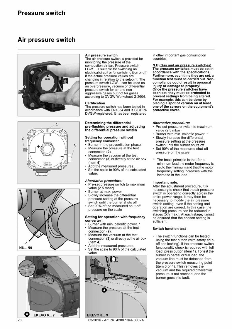
Air pressure switchThe air pressure switch is provided for monitoring the pressure of the combustion air fan. Pressure switch LGW... is suitable for switching an electrical circuit or for switching it on or off if the actual pressure values are changing in relation to the setpoint. The pressure switch LGW... can be used as an overpressure, vacuum or differential pressure switch for air and non-aggressive gases but not for gases according to DVGW Worksheet G 260/l.
CertificationThe pressure switch has been tested in accordance with EN1854 and is CE/DIN-DVGW-registered. It has been registered
in other important gas consumption countries.
N.B.(Gas and air pressure switches)The pressure switches must be set in accordance with the specifications. Furthermore, each time they are set, a function test must be carried out. Non-compliance could result in personal injury or damage to property!Once the pressure switches have been set, they must be protected to prevent settings from being altered. For example, this can be done by placing a spot of varnish on at least one of the screws on the equipment's protective cover.
Determining the differential pre-flushing pressure and adjusting the differential pressure switch
Setting for operation without frequency converter• Burner in the preventilation phase.• Measure the pressure at the test
connection (2).• Measure the vacuum at the test
connection (3) or directly at the air box (item 4)
• Add the measured pressures.• Set the scale to 90% of the calculated
value.
Alternative procedure:• Pre-set pressure switch to maximum
value (2.5 mbar)• Burner at max. power• Slowly increase the differential
pressure setting at the pressure switch until the burner shuts off
• Set 90% of the measured shut-off pressure on the scale
Setting for operation with frequency converter• Burner with min. calorific power. *• Measure the pressure at the test
connection (2).• Measure the vacuum at the test
connection (3) or directly at the air box (item 4)
• Add the measured pressures.• Set the scale to 90% of the calculated
value.
Alternative procedure:• Pre-set pressure switch to maximum
value (2.5 mbar)• Burner with min. calorific power. *• Slowly increase the differential
pressure setting at the pressure switch until the burner shuts off
• Set 90% of the measured shut-off pressure on the scale
* The basic principle is that for a minimum load the motor frequency is set to the minimum and that the motor frequency setting increases with the increase in the load.
Important note:After the adjustment procedure, it is necessary to check that the air pressure switch is operating correctly across the entire power range. It may then be necessary to modify the air pressure switch setting, even if the setting and operation are correct. In this case, the switching pressure can be reduced in stages (5% max.). At each stage, it must be ensured that the chosen setting is sufficient.
Switch function test
• The switch functions can be tested using the test button (with safety shut-off and locking). If the pressure switch functionality check is required with full load, press button (item 1). To test the burner in partial or full load, the vacuum line must be detached from the pressure switch measuring point (item 3 or 4). This removes the vacuum and the required differential pressure is not reached, and the burner goes into fault.
N6... N9
EKEVO 8... 9EKEVO 6... 7
03/2016 - Art. Nr. 4200 1044 8002A 27
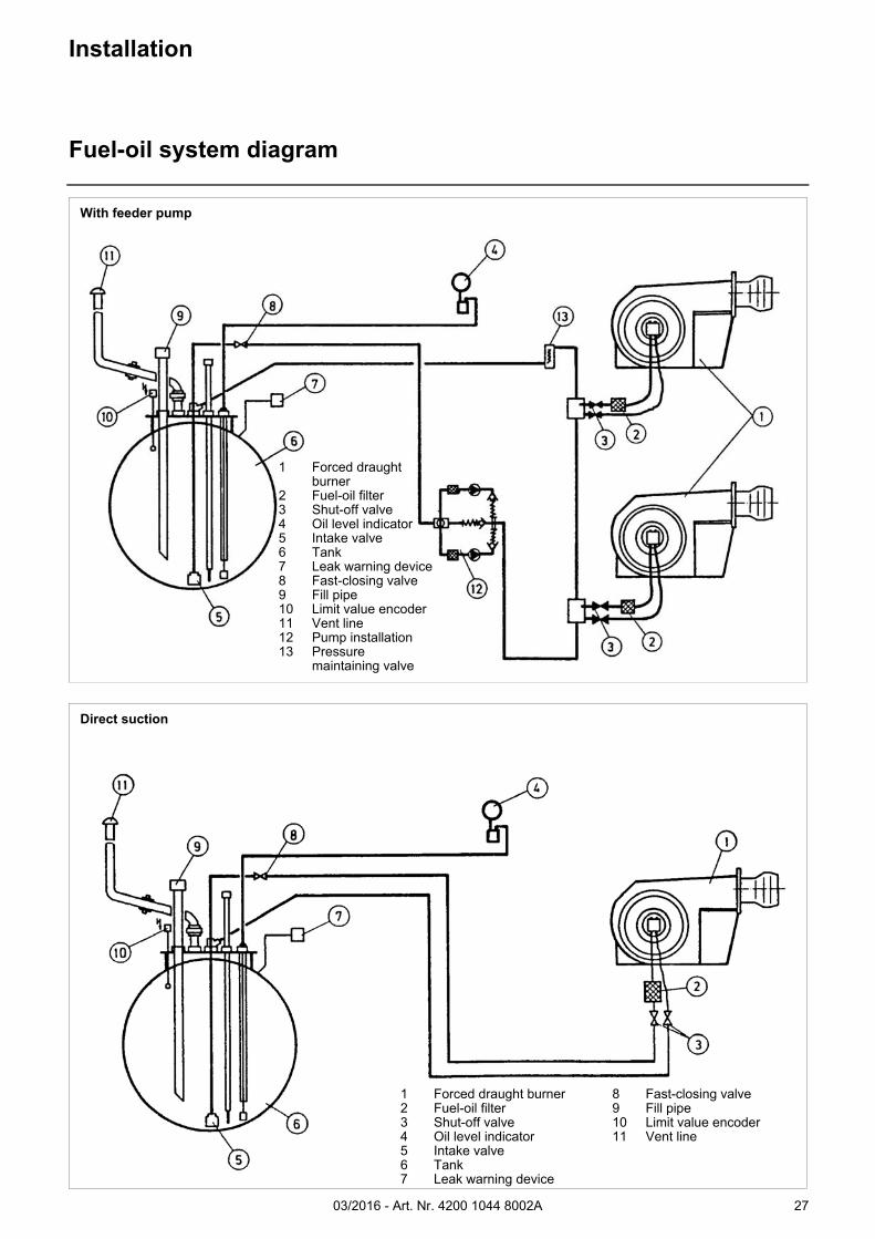
Installation
Fuel-oil system diagram
1 Forced draught burner
2 Fuel-oil filter3 Shut-off valve4 Oil level indicator5 Intake valve6 Tank7 Leak warning device8 Fast-closing valve9 Fill pipe10 Limit value encoder11 Vent line12 Pump installation13 Pressure
maintaining valve
With feeder pump
1 Forced draught burner2 Fuel-oil filter3 Shut-off valve4 Oil level indicator5 Intake valve6 Tank7 Leak warning device
8 Fast-closing valve9 Fill pipe10 Limit value encoder11 Vent line
Direct suction
03/2016 - Art. Nr. 4200 1044 8002A28
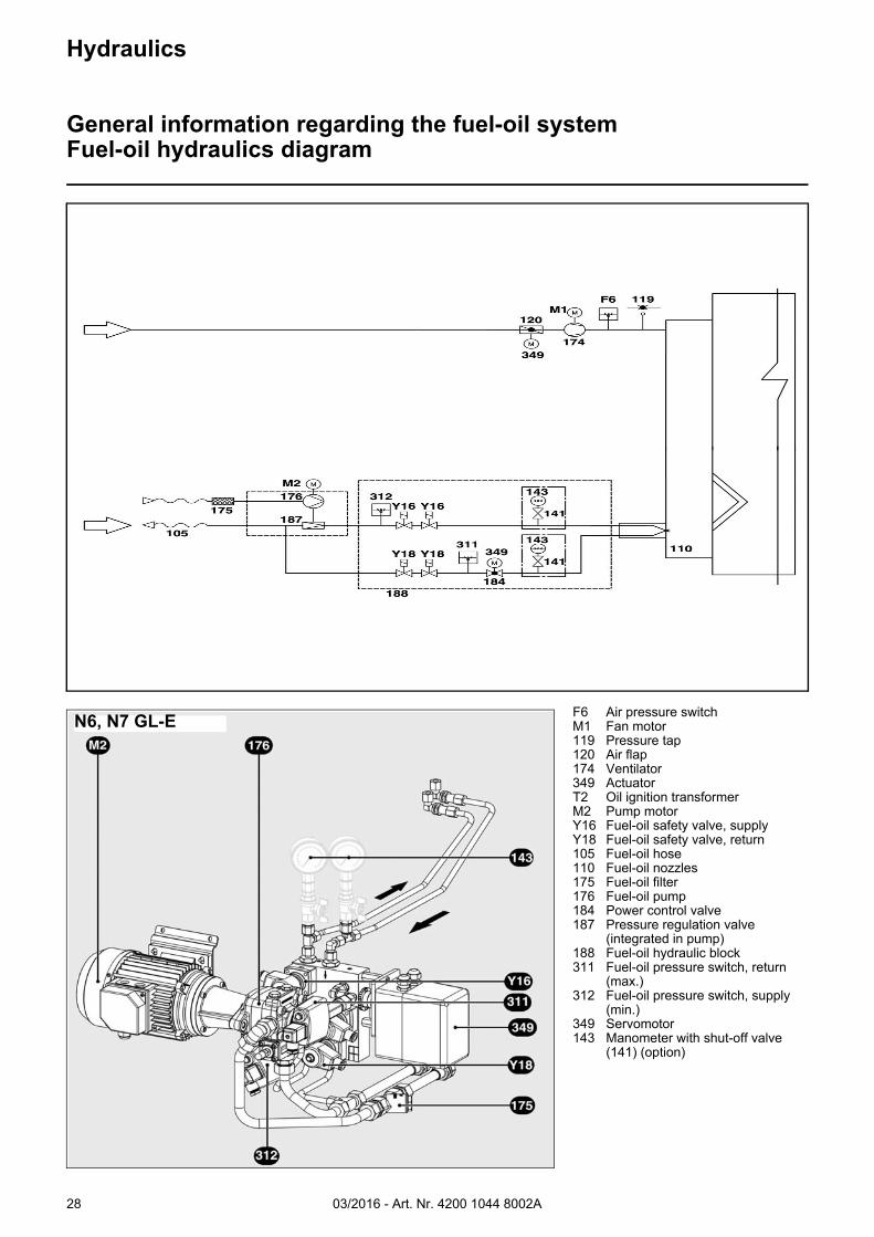
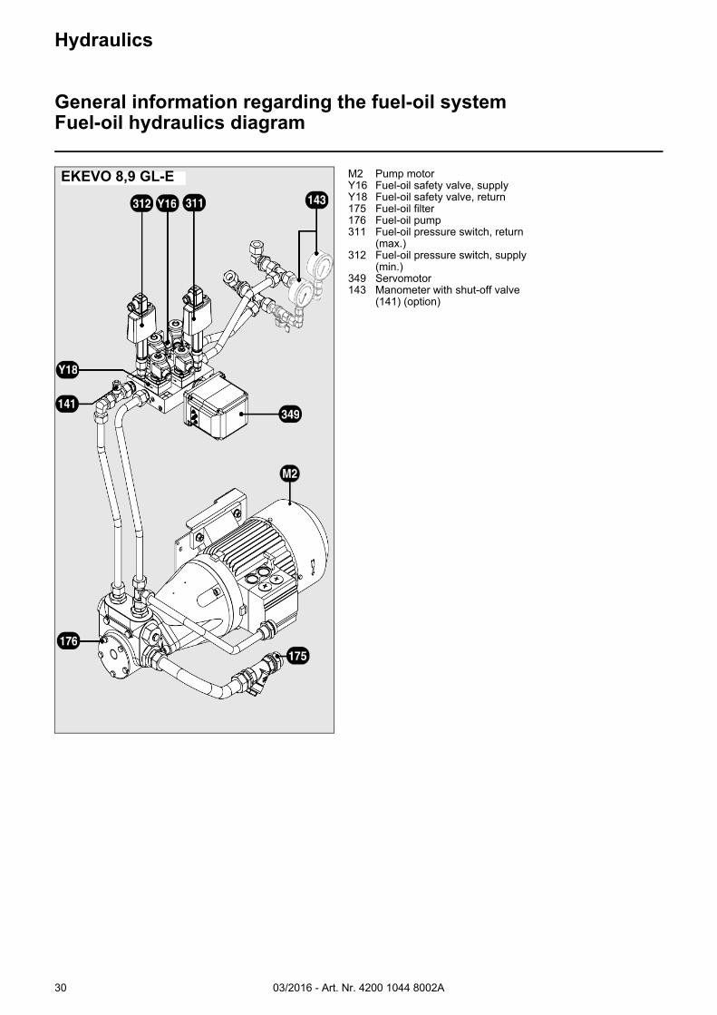
Hydraulics
General information regarding the fuel-oil systemFuel-oil hydraulics diagram
F6 Air pressure switchM1 Fan motor119 Pressure tap120 Air flap174 Ventilator349 ActuatorT2 Oil ignition transformerM2 Pump motorY16 Fuel-oil safety valve, supplyY18 Fuel-oil safety valve, return105 Fuel-oil hose110 Fuel-oil nozzles175 Fuel-oil filter176 Fuel-oil pump184 Power control valve187 Pressure regulation valve
(integrated in pump)188 Fuel-oil hydraulic block311 Fuel-oil pressure switch, return
(max.)312 Fuel-oil pressure switch, supply
(min.)349 Servomotor143 Manometer with shut-off valve
(141) (option)
N6, N7 GL-E
03/2016 - Art. Nr. 4200 1044 8002A 29
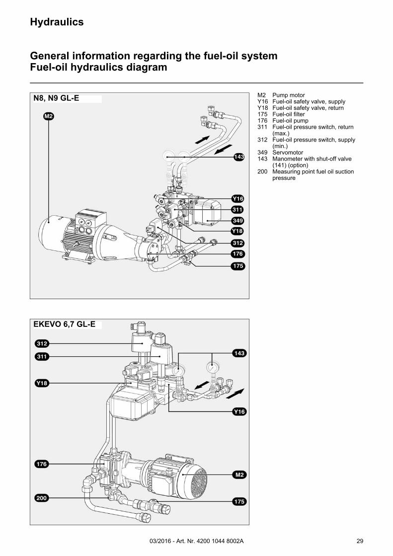
Hydraulics
General information regarding the fuel-oil systemFuel-oil hydraulics diagram
N8, N9 GL-E M2 Pump motorY16 Fuel-oil safety valve, supplyY18 Fuel-oil safety valve, return175 Fuel-oil filter176 Fuel-oil pump311 Fuel-oil pressure switch, return
(max.)312 Fuel-oil pressure switch, supply
(min.)349 Servomotor143 Manometer with shut-off valve
(141) (option)200 Measuring point fuel oil suction
pressure
EKEVO 6,7 GL-E
03/2016 - Art. Nr. 4200 1044 8002A30
Hydraulics
General information regarding the fuel-oil systemFuel-oil hydraulics diagram
M2 Pump motorY16 Fuel-oil safety valve, supplyY18 Fuel-oil safety valve, return175 Fuel-oil filter176 Fuel-oil pump311 Fuel-oil pressure switch, return
(max.)312 Fuel-oil pressure switch, supply
(min.)349 Servomotor143 Manometer with shut-off valve
(141) (option)
EKEVO 8,9 GL-E
03/2016 - Art. Nr. 4200 1044 8002A 31
Installation
Fuel-oil pressure switch
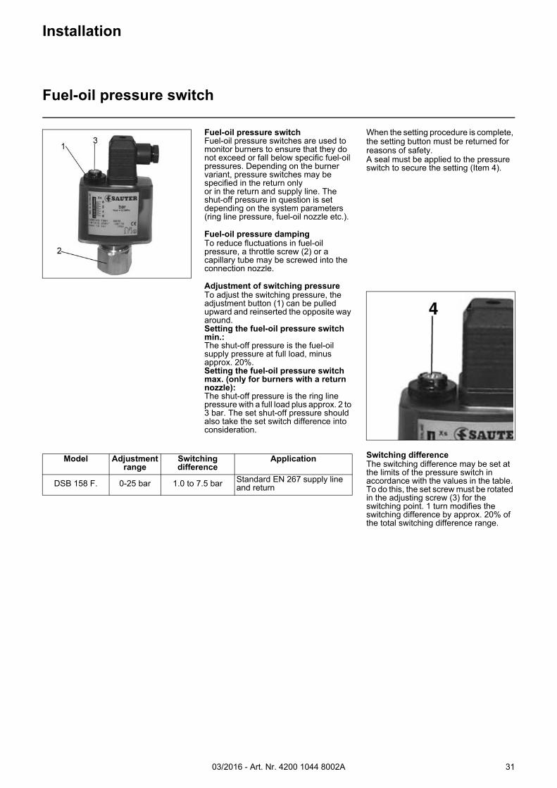
Fuel-oil pressure switchFuel-oil pressure switches are used to monitor burners to ensure that they do not exceed or fall below specific fuel-oil pressures. Depending on the burner variant, pressure switches may be specified in the return onlyor in the return and supply line. The shut-off pressure in question is set depending on the system parameters (ring line pressure, fuel-oil nozzle etc.).
Fuel-oil pressure dampingTo reduce fluctuations in fuel-oil pressure, a throttle screw (2) or a capillary tube may be screwed into the connection nozzle.
Adjustment of switching pressureTo adjust the switching pressure, the adjustment button (1) can be pulled upward and reinserted the opposite way around.Setting the fuel-oil pressure switch min.: The shut-off pressure is the fuel-oil supply pressure at full load, minus approx. 20%.Setting the fuel-oil pressure switch max. (only for burners with a return nozzle):The shut-off pressure is the ring line pressure with a full load plus approx. 2 to 3 bar. The set shut-off pressure should also take the set switch difference into consideration.
When the setting procedure is complete, the setting button must be returned for reasons of safety.A seal must be applied to the pressure switch to secure the setting (Item 4).
Switching differenceThe switching difference may be set at the limits of the pressure switch in accordance with the values in the table. To do this, the set screw must be rotated in the adjusting screw (3) for the switching point. 1 turn modifies the switching difference by approx. 20% of the total switching difference range.
Model Adjustment range
Switching difference
Application
DSB 158 F. 0-25 bar 1.0 to 7.5 bar Standard EN 267 supply line and return
03/2016 - Art. Nr. 4200 1044 8002A32
Connection to the test point
BurnerTest
point for intake
pressure
Test point for pump pressure(at pump)
Test point for pump pressure (bef. 1st safety valve)
N6/EKEVO 6.2400 G1/4 G1/4 Ø10 pipe connector acc. to DIN EN ISO 8434-1*N6/EKEVO 6.2900 G1/4 G1/4 Ø10 pipe connector acc. to DIN EN ISO 8434-1*N7/EKEVO 7.3600 G1/4 G1/4 Ø10 pipe connector acc. to DIN EN ISO 8434-1*N7/EKEVO 7.4500 G1/4 G1/4 Ø10 pipe connector acc. to DIN EN ISO 8434-1*N8/EKEVO 8.5800 G1/8 G1/8 Ø10 pipe connector acc. to DIN EN ISO 8434-1*N8/EKEVO 8.7100 G1/8 G1/8 Ø10 pipe connector acc. to DIN EN ISO 8434-1*N9/EKEVO 9.8700 G1/8 G1/8 Ø10 pipe connector acc. to DIN EN ISO 8434-1*
N9/EKEVO 9.10400 G1/4 G1/4 Ø10 pipe connector acc. to DIN EN ISO 8434-1*
*In order to be able to use the test point, a cutting ring that conforms with DIN EN ISO 8434-1 is required. If the pressure gauge is not left on the burner, a union nut in acc. with DIN EN ISO 8434-1 is also required.
N6/N7
N8/N9
Oil hoses for burner connection
Burner type DN Length [mm]
Connection on bothsides
Minimum bending radii R [mm]
N6/EKEVO 6.2400 20 1500 R 1/2” 145N6/EKEVO 6.2900 20 1500 R 1/2” 145N7/EKEVO 7.3600 20 1500 R 3/4” 145N7/EKEVO 7.4500 20 1500 R 3/4” 145N8/EKEVO 8.5800 20 1500 R 3/4” 145N8/EKEVO 8.7100 20 1500 R 3/4” 145N9/EKEVO 9.8700 20 1500 R 3/4” 145N9/EKEVO 9.10400 25 1500 R 1“ 165
Commissioning
General information regarding the fuel-oil system
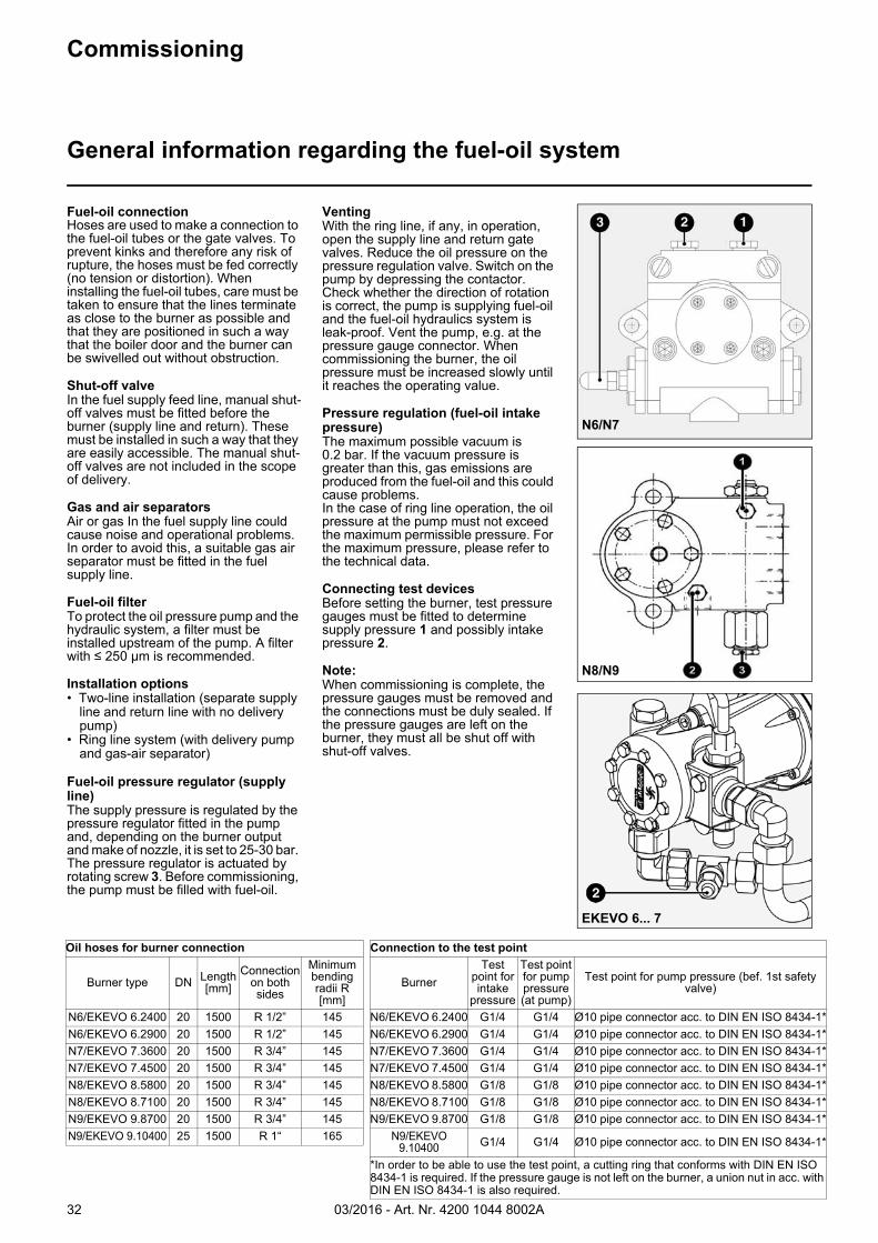
Fuel-oil connectionHoses are used to make a connection to the fuel-oil tubes or the gate valves. To prevent kinks and therefore any risk of rupture, the hoses must be fed correctly (no tension or distortion). When installing the fuel-oil tubes, care must be taken to ensure that the lines terminate as close to the burner as possible and that they are positioned in such a way that the boiler door and the burner can be swivelled out without obstruction.
Shut-off valveIn the fuel supply feed line, manual shut-off valves must be fitted before the burner (supply line and return). These must be installed in such a way that they are easily accessible. The manual shut-off valves are not included in the scope of delivery.
Gas and air separatorsAir or gas In the fuel supply line could cause noise and operational problems. In order to avoid this, a suitable gas air separator must be fitted in the fuel supply line.
Fuel-oil filterTo protect the oil pressure pump and the hydraulic system, a filter must be installed upstream of the pump. A filter with ≤ 250 µm is recommended.
Installation options• Two-line installation (separate supply
line and return line with no delivery pump)
• Ring line system (with delivery pump and gas-air separator)
Fuel-oil pressure regulator (supply line)The supply pressure is regulated by the pressure regulator fitted in the pump and, depending on the burner output and make of nozzle, it is set to 25-30 bar. The pressure regulator is actuated by rotating screw 3. Before commissioning, the pump must be filled with fuel-oil.
VentingWith the ring line, if any, in operation, open the supply line and return gate valves. Reduce the oil pressure on the pressure regulation valve. Switch on the pump by depressing the contactor. Check whether the direction of rotation is correct, the pump is supplying fuel-oil and the fuel-oil hydraulics system is leak-proof. Vent the pump, e.g. at the pressure gauge connector. When commissioning the burner, the oil pressure must be increased slowly until it reaches the operating value.
Pressure regulation (fuel-oil intake pressure)The maximum possible vacuum is 0.2 bar. If the vacuum pressure is greater than this, gas emissions are produced from the fuel-oil and this could cause problems. In the case of ring line operation, the oil pressure at the pump must not exceed the maximum permissible pressure. For the maximum pressure, please refer to the technical data.
Connecting test devicesBefore setting the burner, test pressure gauges must be fitted to determine supply pressure 1 and possibly intake pressure 2.
Note:When commissioning is complete, the pressure gauges must be removed and the connections must be duly sealed. If the pressure gauges are left on the burner, they must all be shut off with shut-off valves.
EKEVO 6... 7
03/2016 - Art. Nr. 4200 1044 8002A 33
Commissioning
Pump type TA
Pression (bar)Viscosité
Pumping capacity
Pump power requirements
Capacity (l/hr)
Power (W)
Pressure (bar)
Pressure (bar)
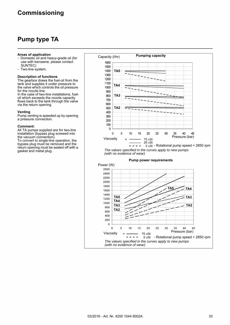
The values specified in the curves apply to new pumps (with no evidence of wear)
Viscosity
Viscosity
- Rotational pump speed = 2850 rpm
Areas of application- Domestic oil and heavy-grade oil (for
use with kerosene, please contact SUNTEC)
- Two-line system.
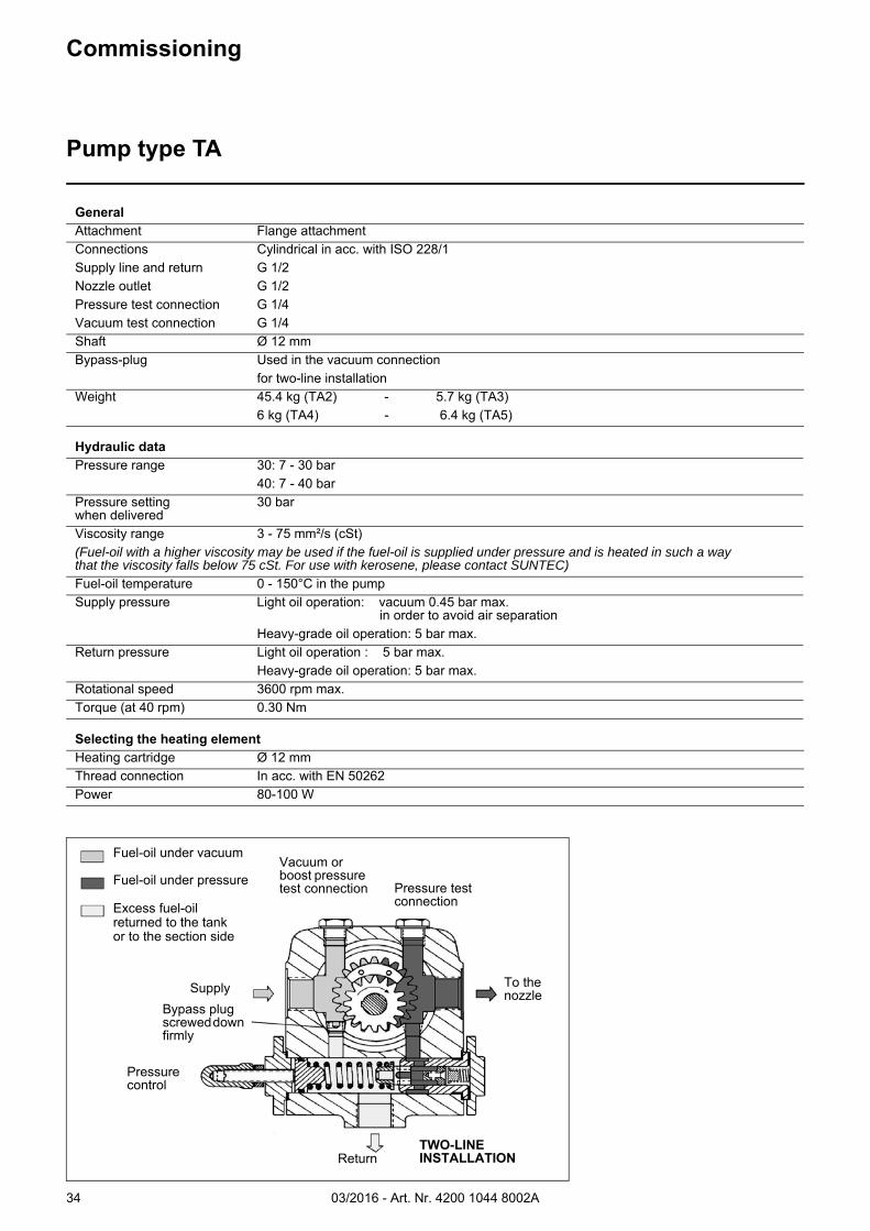
Description of functionsThe gearbox draws the fuel-oil from the tank and supplies it under pressure to the valve which controls the oil pressure for the nozzle line.In the case of two-line installations, fuel-oil which exceeds the nozzle capacity flows back to the tank through the valve via the return opening.
VentingPump venting is speeded up by opening a pressure connection.
Comment:All TA pumps supplied are for two-line installation (bypass plug screwed into the vacuum connection).To convert to single-line operation, the bypass plug must be removed and the return opening must be sealed off with a gasket and metal plug.
The values specified in the curves apply to new pumps (with no evidence of wear)
- Rotational pump speed = 2850 rpm
03/2016 - Art. Nr. 4200 1044 8002A34
Commissioning
Pump type TA
General
Attachment Flange attachmentConnections Cylindrical in acc. with ISO 228/1Supply line and return G 1/2Nozzle outlet G 1/2Pressure test connection G 1/4Vacuum test connection G 1/4Shaft Ø 12 mmBypass-plug Used in the vacuum connection
for two-line installationWeight 45.4 kg (TA2) - 5.7 kg (TA3)
6 kg (TA4) - 6.4 kg (TA5)
Hydraulic data
Pressure range 30: 7 - 30 bar40: 7 - 40 bar
Pressure setting when delivered
30 bar
Viscosity range 3 - 75 mm²/s (cSt)(Fuel-oil with a higher viscosity may be used if the fuel-oil is supplied under pressure and is heated in such a waythat the viscosity falls below 75 cSt. For use with kerosene, please contact SUNTEC)
Fuel-oil temperature 0 - 150°C in the pumpSupply pressure Light oil operation: vacuum 0.45 bar max.
in order to avoid air separationHeavy-grade oil operation: 5 bar max.
Return pressure Light oil operation : 5 bar max.Heavy-grade oil operation: 5 bar max.
Rotational speed 3600 rpm max.Torque (at 40 rpm) 0.30 Nm
Selecting the heating element
Heating cartridge Ø 12 mmThread connection In acc. with EN 50262Power 80-100 W
Fuel-oil under vacuum
Fuel-oil under pressure
Excess fuel-oil returned to the tankor to the section side
Supply
Pressure control
To the nozzle
Bypass plug screwed down firmly
ReturnTWO-LINE INSTALLATION
Vacuum or boost pressure test connection Pressure test
connection
03/2016 - Art. Nr. 4200 1044 8002A 35
Commissioning
Fuel-oil hydraulic block
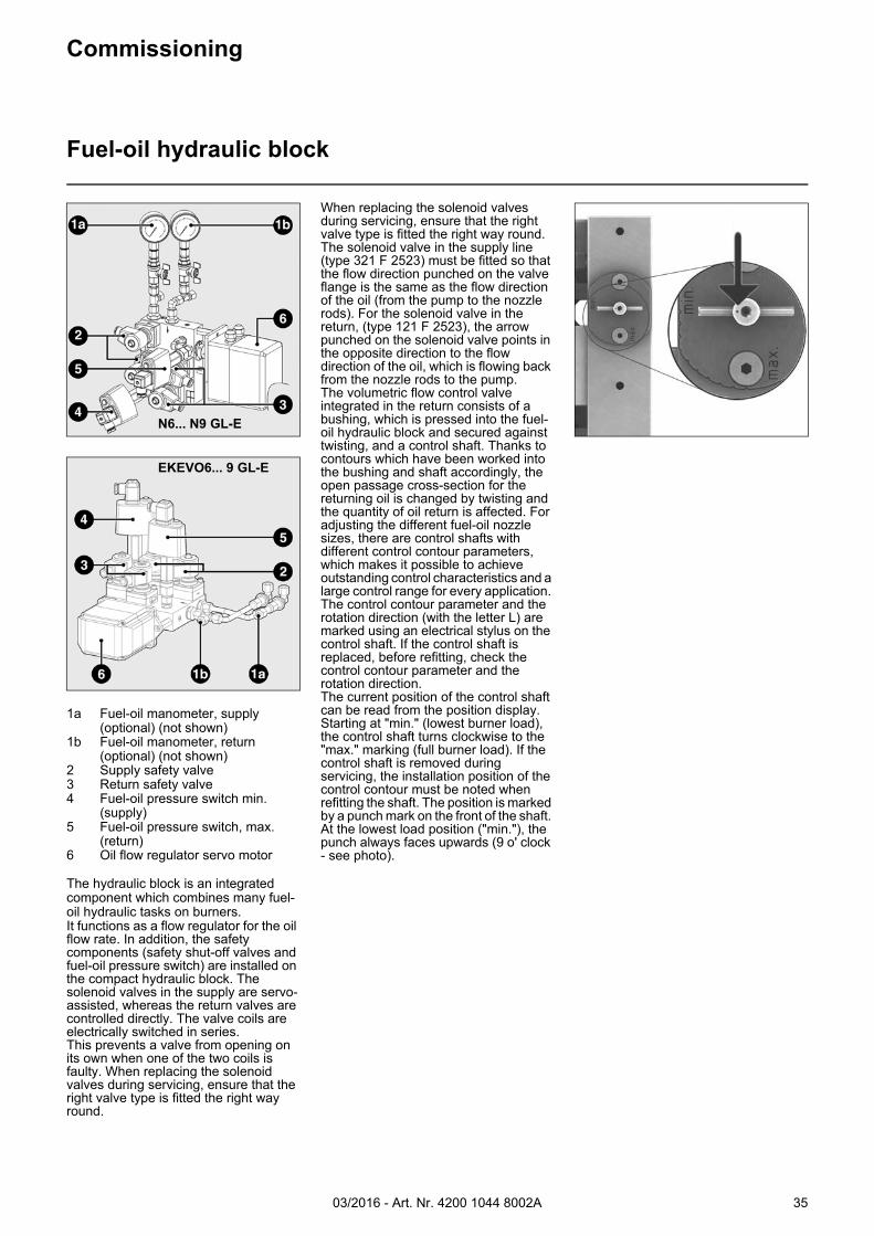
1a Fuel-oil manometer, supply (optional) (not shown)
1b Fuel-oil manometer, return (optional) (not shown)
2 Supply safety valve3 Return safety valve4 Fuel-oil pressure switch min.
(supply)5 Fuel-oil pressure switch, max.
(return)6 Oil flow regulator servo motor
The hydraulic block is an integrated component which combines many fuel-oil hydraulic tasks on burners. It functions as a flow regulator for the oil flow rate. In addition, the safety components (safety shut-off valves and fuel-oil pressure switch) are installed on the compact hydraulic block. The solenoid valves in the supply are servo-assisted, whereas the return valves are controlled directly. The valve coils are electrically switched in series.This prevents a valve from opening on its own when one of the two coils is faulty. When replacing the solenoid valves during servicing, ensure that the right valve type is fitted the right way round.
When replacing the solenoid valves during servicing, ensure that the right valve type is fitted the right way round. The solenoid valve in the supply line (type 321 F 2523) must be fitted so that the flow direction punched on the valve flange is the same as the flow direction of the oil (from the pump to the nozzle rods). For the solenoid valve in the return, (type 121 F 2523), the arrow punched on the solenoid valve points in the opposite direction to the flow direction of the oil, which is flowing back from the nozzle rods to the pump.The volumetric flow control valve integrated in the return consists of a bushing, which is pressed into the fuel-oil hydraulic block and secured against twisting, and a control shaft. Thanks to contours which have been worked into the bushing and shaft accordingly, the open passage cross-section for the returning oil is changed by twisting and the quantity of oil return is affected. For adjusting the different fuel-oil nozzle sizes, there are control shafts with different control contour parameters, which makes it possible to achieve outstanding control characteristics and a large control range for every application. The control contour parameter and the rotation direction (with the letter L) are marked using an electrical stylus on the control shaft. If the control shaft is replaced, before refitting, check the control contour parameter and the rotation direction.The current position of the control shaft can be read from the position display. Starting at "min." (lowest burner load), the control shaft turns clockwise to the "max." marking (full burner load). If the control shaft is removed during servicing, the installation position of the control contour must be noted when refitting the shaft. The position is marked by a punch mark on the front of the shaft. At the lowest load position ("min."), the punch always faces upwards (9 o' clock - see photo).
EKEVO6... 9 GL-E
N6... N9 GL-E
03/2016 - Art. Nr. 4200 1044 8002A36
Nozzle closed
Nozzle open
Commissioning
Return nozzle rod RDN
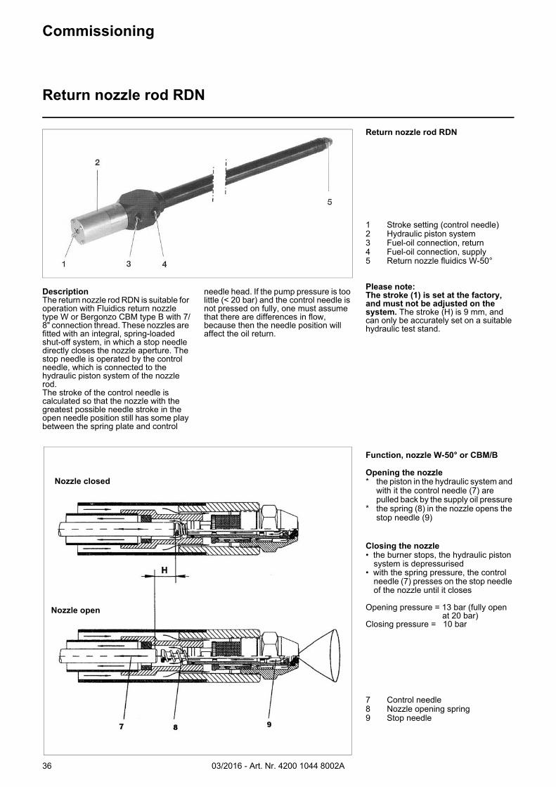
DescriptionThe return nozzle rod RDN is suitable for operation with Fluidics return nozzle type W or Bergonzo CBM type B with 7/8" connection thread. These nozzles are fitted with an integral, spring-loaded shut-off system, in which a stop needle directly closes the nozzle aperture. The stop needle is operated by the control needle, which is connected to the hydraulic piston system of the nozzle rod.The stroke of the control needle is calculated so that the nozzle with the greatest possible needle stroke in the open needle position still has some play between the spring plate and control
needle head. If the pump pressure is too little (< 20 bar) and the control needle is not pressed on fully, one must assume that there are differences in flow, because then the needle position will affect the oil return.
Return nozzle rod RDN
1 Stroke setting (control needle)2 Hydraulic piston system 3 Fuel-oil connection, return 4 Fuel-oil connection, supply 5 Return nozzle fluidics W-50°
Please note: The stroke (1) is set at the factory, and must not be adjusted on the system. The stroke (H) is 9 mm, and can only be accurately set on a suitable hydraulic test stand.
Function, nozzle W-50° or CBM/B
Opening the nozzle * the piston in the hydraulic system and
with it the control needle (7) are pulled back by the supply oil pressure
* the spring (8) in the nozzle opens the stop needle (9)
Closing the nozzle • the burner stops, the hydraulic piston
system is depressurised• with the spring pressure, the control
needle (7) presses on the stop needle of the nozzle until it closes
Opening pressure = 13 bar (fully openat 20 bar)
Closing pressure = 10 bar
7 Control needle8 Nozzle opening spring 9 Stop needle
03/2016 - Art. Nr. 4200 1044 8002A 37
W 100
W 115
W 130
W 145
W 160
W 180
W 200
W 225
W 250
W 275
W 300
0
50
100
150
200
250
300
350
20 21 22 23 24 25 26 27 28 29 30
Vorlauf Öldruck [bar]
Öld
urc
hsa
tz [
kg/h
]O
il th
rou
gh
pu
t [k
g/
Supply oil pressure [bar]
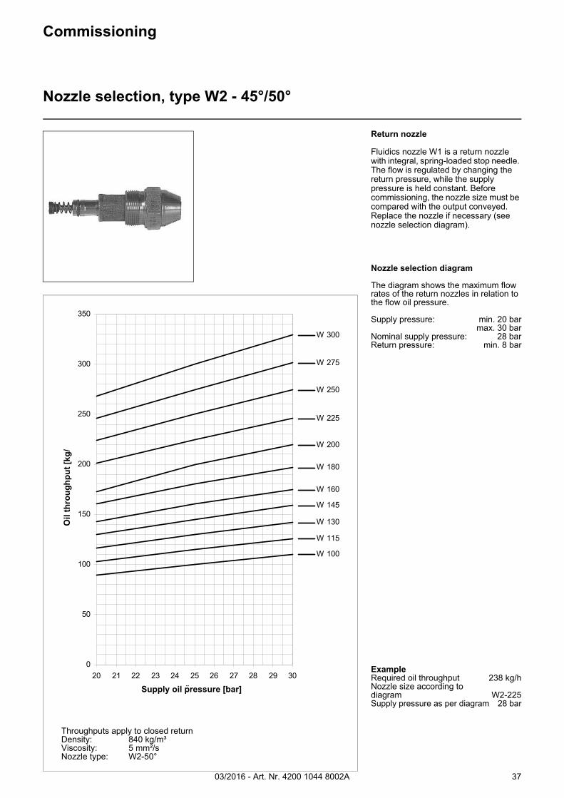
Throughputs apply to closed returnDensity: 840 kg/m³Viscosity: 5 mm²/sNozzle type: W2-50°
Commissioning
Nozzle selection, type W2 - 45°/50°
Return nozzle
Fluidics nozzle W1 is a return nozzle with integral, spring-loaded stop needle. The flow is regulated by changing the return pressure, while the supply pressure is held constant. Before commissioning, the nozzle size must be compared with the output conveyed. Replace the nozzle if necessary (see nozzle selection diagram).
Nozzle selection diagram
The diagram shows the maximum flow rates of the return nozzles in relation to the flow oil pressure.
Supply pressure: min. 20 barmax. 30 bar
Nominal supply pressure: 28 barReturn pressure: min. 8 bar
ExampleRequired oil throughput 238 kg/hNozzle size according to diagram W2-225Supply pressure as per diagram 28 bar
03/2016 - Art. Nr. 4200 1044 8002A38
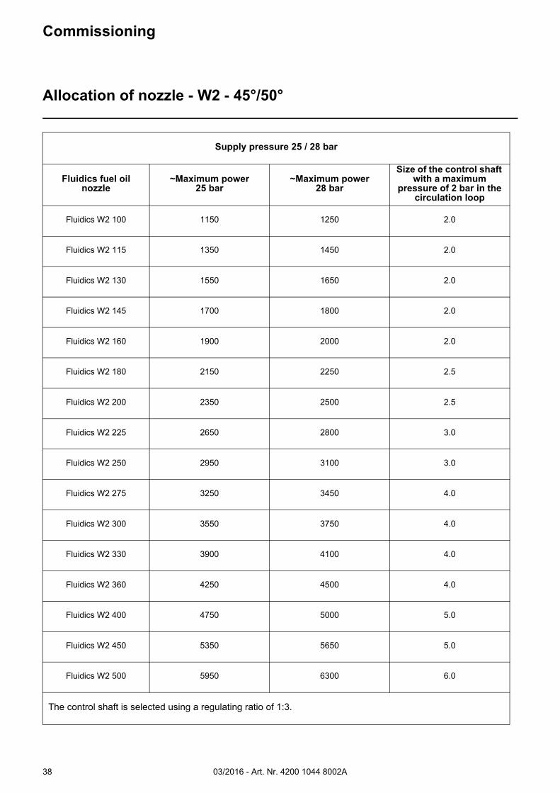
Supply pressure 25 / 28 bar
Fluidics fuel oil nozzle
~Maximum power25 bar
~Maximum power28 bar
Size of the control shaft with a maximum
pressure of 2 bar in the circulation loop
Fluidics W2 100 1150 1250 2.0
Fluidics W2 115 1350 1450 2.0
Fluidics W2 130 1550 1650 2.0
Fluidics W2 145 1700 1800 2.0
Fluidics W2 160 1900 2000 2.0
Fluidics W2 180 2150 2250 2.5
Fluidics W2 200 2350 2500 2.5
Fluidics W2 225 2650 2800 3.0
Fluidics W2 250 2950 3100 3.0
Fluidics W2 275 3250 3450 4.0
Fluidics W2 300 3550 3750 4.0
Fluidics W2 330 3900 4100 4.0
Fluidics W2 360 4250 4500 4.0
Fluidics W2 400 4750 5000 5.0
Fluidics W2 450 5350 5650 5.0
Fluidics W2 500 5950 6300 6.0
The control shaft is selected using a regulating ratio of 1:3.
Commissioning
Allocation of nozzle - W2 - 45°/50°
03/2016 - Art. Nr. 4200 1044 8002A 39
Commissioning
Return nozzle rod RDG
15
3
6
4
7
2
H
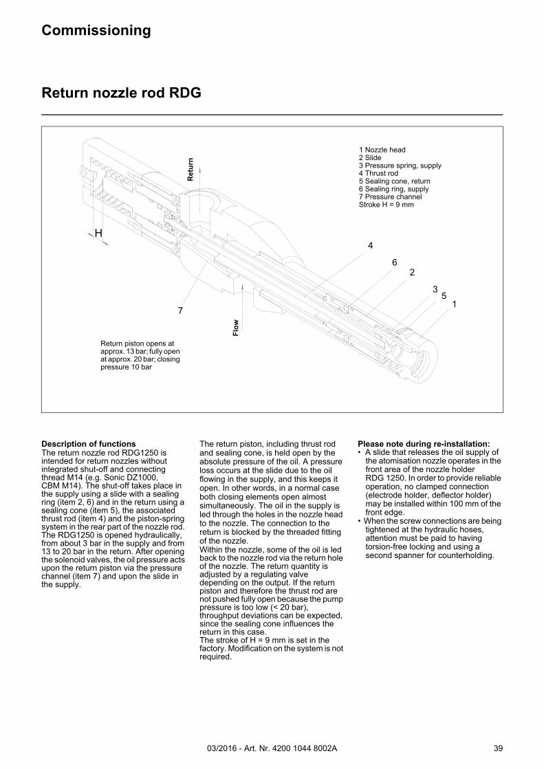
Description of functionsThe return nozzle rod RDG1250 is intended for return nozzles without integrated shut-off and connecting thread M14 (e.g. Sonic DZ1000, CBM M14). The shut-off takes place in the supply using a slide with a sealing ring (item 2, 6) and in the return using a sealing cone (item 5), the associated thrust rod (item 4) and the piston-spring system in the rear part of the nozzle rod. The RDG1250 is opened hydraulically, from about 3 bar in the supply and from 13 to 20 bar in the return. After opening the solenoid valves, the oil pressure acts upon the return piston via the pressure channel (item 7) and upon the slide in the supply.
The return piston, including thrust rod and sealing cone, is held open by the absolute pressure of the oil. A pressure loss occurs at the slide due to the oil flowing in the supply, and this keeps it open. In other words, in a normal case both closing elements open almost simultaneously. The oil in the supply is led through the holes in the nozzle head to the nozzle. The connection to the return is blocked by the threaded fitting of the nozzle. Within the nozzle, some of the oil is led back to the nozzle rod via the return hole of the nozzle. The return quantity is adjusted by a regulating valve depending on the output. If the return piston and therefore the thrust rod are not pushed fully open because the pump pressure is too low (< 20 bar), throughput deviations can be expected, since the sealing cone influences the return in this case.The stroke of H = 9 mm is set in the factory. Modification on the system is not required.
Please note during re-installation:• A slide that releases the oil supply of
the atomisation nozzle operates in the front area of the nozzle holder RDG 1250. In order to provide reliable operation, no clamped connection (electrode holder, deflector holder) may be installed within 100 mm of the front edge.
• When the screw connections are being tightened at the hydraulic hoses, attention must be paid to having torsion-free locking and using a second spanner for counterholding.
1 Nozzle head2 Slide3 Pressure spring, supply4 Thrust rod5 Sealing cone, return6 Sealing ring, supply7 Pressure channelStroke H = 9 mm
Return piston opens at approx. 13 bar; fully open at approx. 20 bar; closing pressure 10 bar
Ret
urn
Flo
w
03/2016 - Art. Nr. 4200 1044 8002A40
Return pressure at the hydraulic block [bar]
No
zzle
oil
flo
w r
ate
[kg
/h]
Commissioning
Nozzle selection, type Sonic 60°
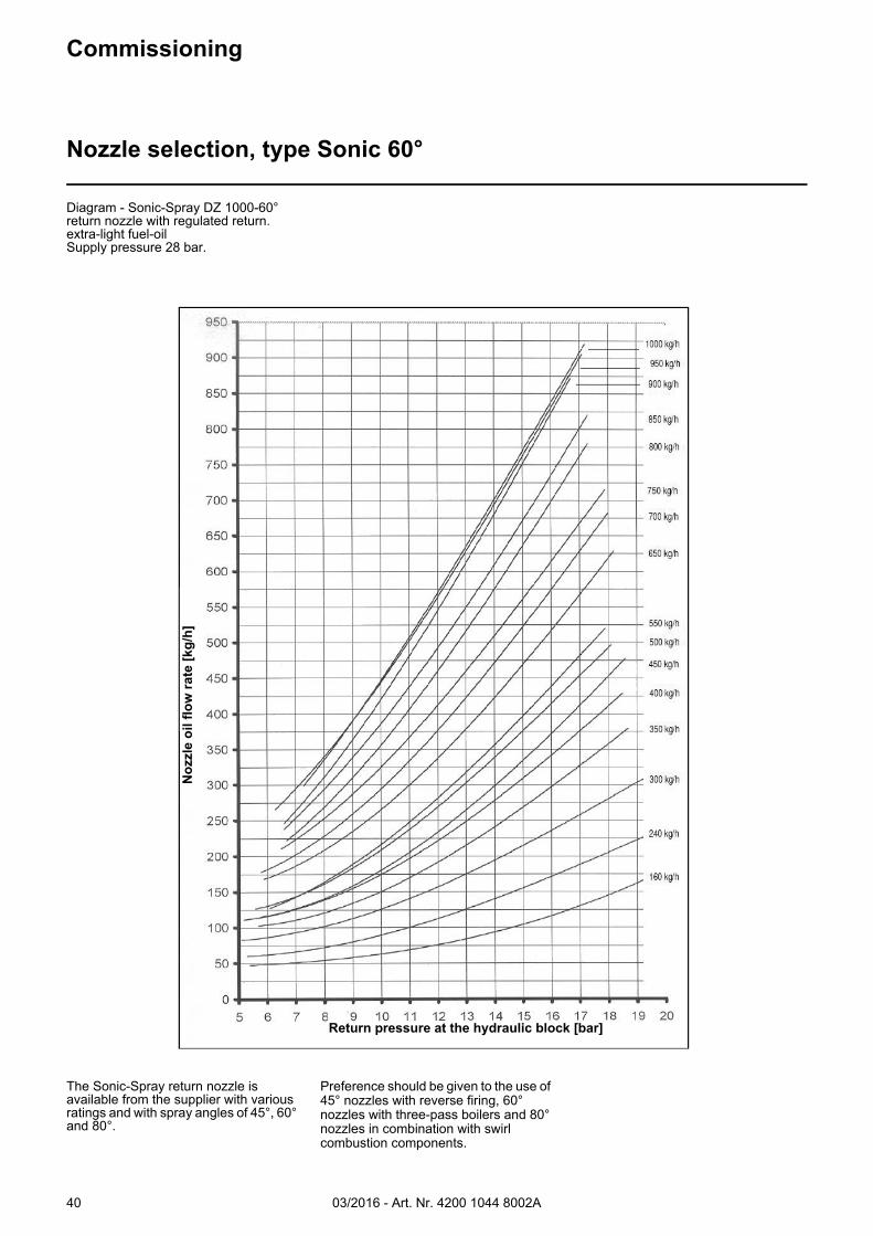
Diagram - Sonic-Spray DZ 1000-60° return nozzle with regulated return.extra-light fuel-oilSupply pressure 28 bar.
The Sonic-Spray return nozzle is available from the supplier with various ratings and with spray angles of 45°, 60° and 80°.
Preference should be given to the use of 45° nozzles with reverse firing, 60° nozzles with three-pass boilers and 80° nozzles in combination with swirl combustion components.
03/2016 - Art. Nr. 4200 1044 8002A 41
Commissioning
Allocation of nozzle - Sonic 60°
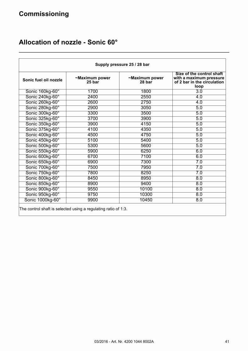
Supply pressure 25 / 28 bar
Sonic fuel oil nozzle ~Maximum power25 bar
~Maximum power28 bar
Size of the control shaft with a maximum pressure of 2 bar in the circulation
loopSonic 160kg-60° 1700 1800 3.0Sonic 240kg-60° 2400 2550 4.0Sonic 260kg-60° 2600 2750 4.0Sonic 280kg-60° 2900 3050 5.0Sonic 300kg-60° 3300 3500 5.0Sonic 325kg-60° 3700 3900 5.0Sonic 350kg-60° 3900 4150 5.0Sonic 375kg-60° 4100 4350 5.0Sonic 400kg-60° 4500 4750 5.0Sonic 450kg-60° 5100 5400 5.0Sonic 500kg-60° 5300 5600 5.0Sonic 550kg-60° 5900 6250 6.0Sonic 600kg-60° 6700 7100 6.0Sonic 650kg-60° 6900 7300 7.0Sonic 700kg-60° 7500 7950 7.0Sonic 750kg-60° 7800 8250 7.0Sonic 800kg-60° 8450 8950 8.0Sonic 850kg-60° 8900 9400 8.0Sonic 900kg-60° 9550 10100 8.0Sonic 950kg-60° 9750 10300 8.0
Sonic 1000kg-60° 9900 10450 8.0
The control shaft is selected using a regulating ratio of 1:3.
03/2016 - Art. Nr. 4200 1044 8002A42
Return pressure at the hydraulic block [bar]
No
zzle
oil
flo
w r
ate
[k
g/h
]
Commissioning
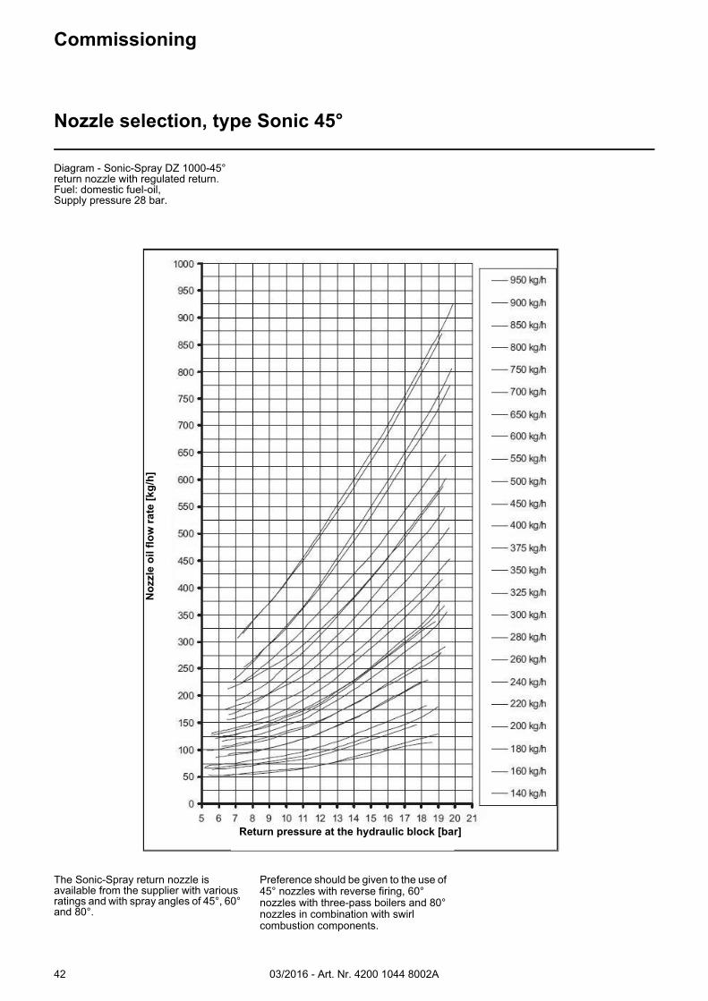
Nozzle selection, type Sonic 45°
Diagram - Sonic-Spray DZ 1000-45° return nozzle with regulated return.Fuel: domestic fuel-oil,Supply pressure 28 bar.
The Sonic-Spray return nozzle is available from the supplier with various ratings and with spray angles of 45°, 60° and 80°.
Preference should be given to the use of 45° nozzles with reverse firing, 60° nozzles with three-pass boilers and 80° nozzles in combination with swirl combustion components.
03/2016 - Art. Nr. 4200 1044 8002A 43
Commissioning
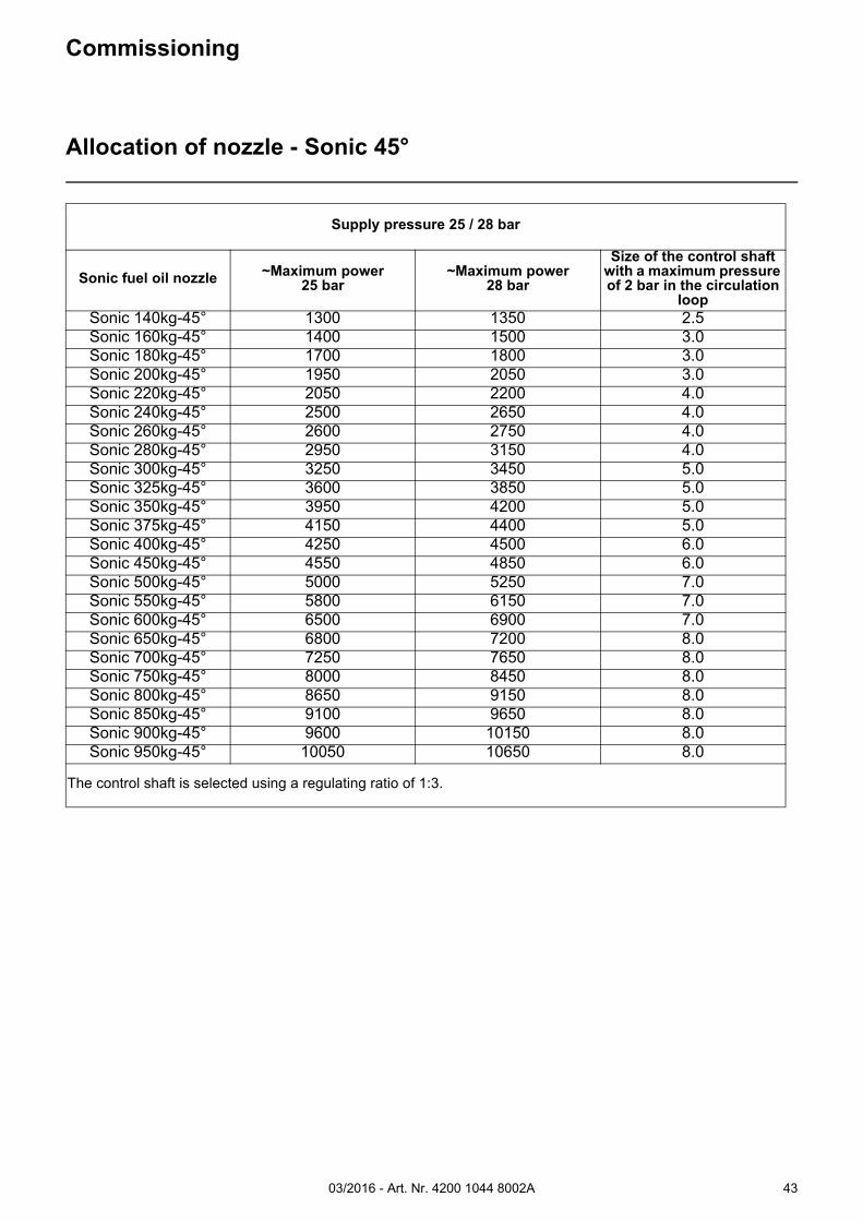
Allocation of nozzle - Sonic 45°
Supply pressure 25 / 28 bar
Sonic fuel oil nozzle ~Maximum power25 bar
~Maximum power28 bar
Size of the control shaft with a maximum pressure of 2 bar in the circulation
loopSonic 140kg-45° 1300 1350 2.5Sonic 160kg-45° 1400 1500 3.0Sonic 180kg-45° 1700 1800 3.0Sonic 200kg-45° 1950 2050 3.0Sonic 220kg-45° 2050 2200 4.0Sonic 240kg-45° 2500 2650 4.0Sonic 260kg-45° 2600 2750 4.0Sonic 280kg-45° 2950 3150 4.0Sonic 300kg-45° 3250 3450 5.0Sonic 325kg-45° 3600 3850 5.0Sonic 350kg-45° 3950 4200 5.0Sonic 375kg-45° 4150 4400 5.0Sonic 400kg-45° 4250 4500 6.0Sonic 450kg-45° 4550 4850 6.0Sonic 500kg-45° 5000 5250 7.0Sonic 550kg-45° 5800 6150 7.0Sonic 600kg-45° 6500 6900 7.0Sonic 650kg-45° 6800 7200 8.0Sonic 700kg-45° 7250 7650 8.0Sonic 750kg-45° 8000 8450 8.0Sonic 800kg-45° 8650 9150 8.0Sonic 850kg-45° 9100 9650 8.0Sonic 900kg-45° 9600 10150 8.0Sonic 950kg-45° 10050 10650 8.0
The control shaft is selected using a regulating ratio of 1:3.
03/2016 - Art. Nr. 4200 1044 8002A44
Commissioning
Burner control unit
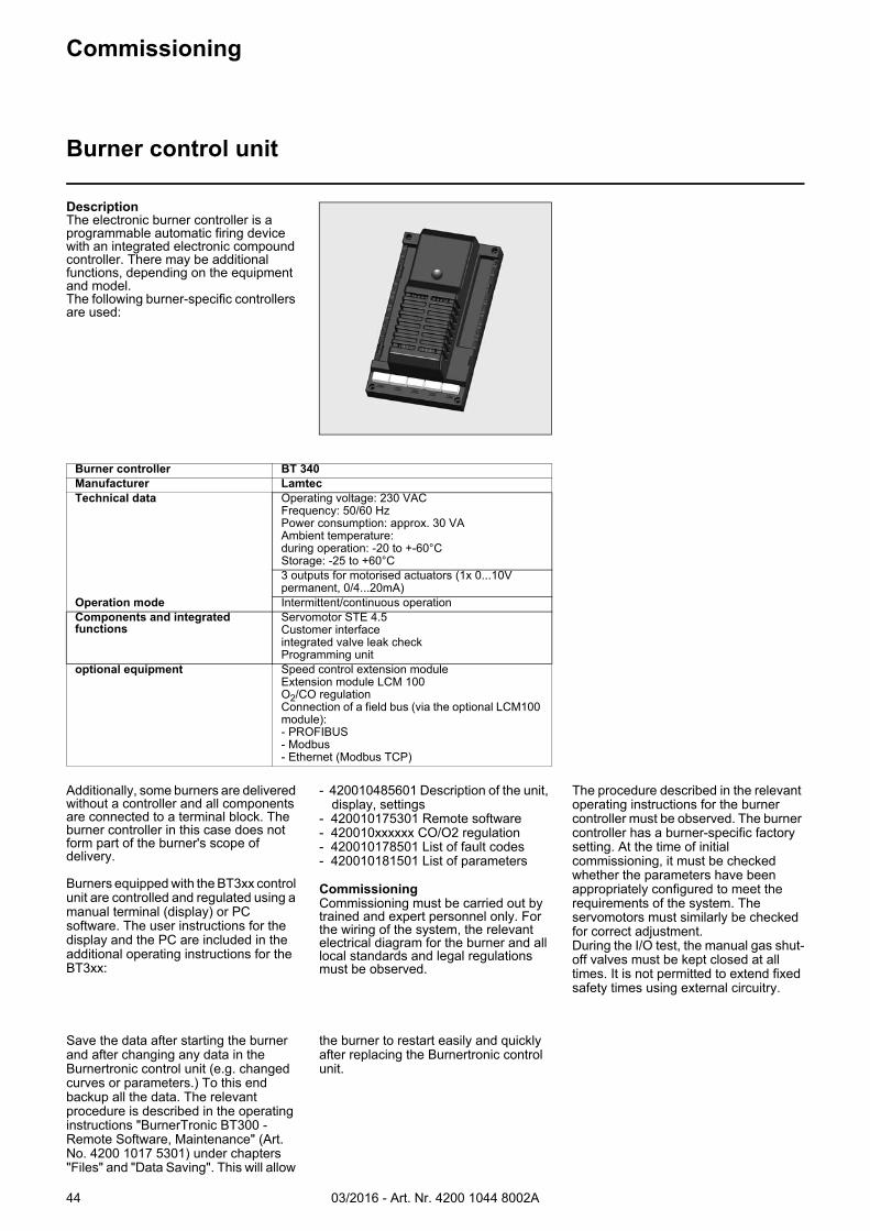
DescriptionThe electronic burner controller is a programmable automatic firing device with an integrated electronic compound controller. There may be additional functions, depending on the equipment and model.The following burner-specific controllers are used:
Burner controller BT 340Manufacturer LamtecTechnical data Operating voltage: 230 VAC
Frequency: 50/60 HzPower consumption: approx. 30 VAAmbient temperature:during operation: -20 to +-60°CStorage: -25 to +60°C3 outputs for motorised actuators (1x 0...10V permanent, 0/4...20mA)
Operation mode Intermittent/continuous operationComponents and integrated functions
Servomotor STE 4.5Customer interfaceintegrated valve leak checkProgramming unit
optional equipment Speed control extension moduleExtension module LCM 100O2/CO regulationConnection of a field bus (via the optional LCM100 module):- PROFIBUS- Modbus- Ethernet (Modbus TCP)
Additionally, some burners are delivered without a controller and all components are connected to a terminal block. The burner controller in this case does not form part of the burner's scope of delivery.
Burners equipped with the BT3xx control unit are controlled and regulated using a manual terminal (display) or PC software. The user instructions for the display and the PC are included in the additional operating instructions for the BT3xx:
- 420010485601 Description of the unit, display, settings
- 420010175301 Remote software- 420010xxxxxx CO/O2 regulation- 420010178501 List of fault codes- 420010181501 List of parameters
CommissioningCommissioning must be carried out by trained and expert personnel only. For the wiring of the system, the relevant electrical diagram for the burner and all local standards and legal regulations must be observed.
The procedure described in the relevant operating instructions for the burner controller must be observed. The burner controller has a burner-specific factory setting. At the time of initial commissioning, it must be checked whether the parameters have been appropriately configured to meet the requirements of the system. The servomotors must similarly be checked for correct adjustment.During the I/O test, the manual gas shut-off valves must be kept closed at all times. It is not permitted to extend fixed safety times using external circuitry.
Save the data after starting the burner and after changing any data in theBurnertronic control unit (e.g. changed curves or parameters.) To this end backup all the data. The relevant procedure is described in the operating instructions "BurnerTronic BT300 - Remote Software, Maintenance" (Art. No. 4200 1017 5301) under chapters "Files" and "Data Saving". This will allow
the burner to restart easily and quickly after replacing the Burnertronic control unit.
03/2016 - Art. Nr. 4200 1044 8002A 45
Commissioning
Electrical cabinet door construction
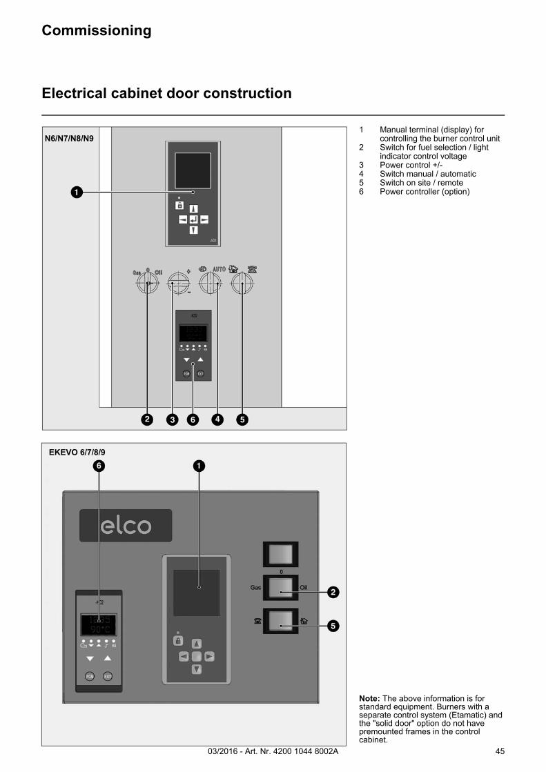
1 Manual terminal (display) for controlling the burner control unit
2 Switch for fuel selection / light indicator control voltage
3 Power control +/-4 Switch manual / automatic5 Switch on site / remote6 Power controller (option)
N6/N7/N8/N9
Note: The above information is for standard equipment. Burners with a separate control system (Etamatic) and the "solid door" option do not have premounted frames in the control cabinet.
EKEVO 6/7/8/9
03/2016 - Art. Nr. 4200 1044 8002A46
Commissioning
Servomotor STEServomotor STM 40
The BT300 electronic control system works with the STE4.5 numerically controlled servomotor. For monitoring the function and direction of rotation, there is a driver with digital feedback via encoder disc.Observe the commissioning procedure for BT300.The connection is documented in the burner wiring diagram.
Note:Before commissioning, the zero position of the servomotors MUST be checked.The servomotor is sealed. Opening the servomotor invalidates the warranty!
The STM 40 servomotor is used in conjunction with various electronic compound control systems. Priority with products supplied by “Lamtec” (Etamatic, Etamatic OEM, VMS, FMS). With some types of burner, the motor is also used as a servomotor for other servo components independently of the compound control system (e.g. nozzle rod safety adjustment). Please refer to the appropriate section of the operating instructions.
The electrical diagram for the burner shows how to establish the servomotor's electrical connection.
Observe the documentation issued by the manufacturer.
Model STE 4.5
Power supply:Power consumption:Angle of rotation:Run time:Nominal torque:static holding moment:Dimensions (WxHxD):
24 VDC ± 20%7.5 W90°5s/90° @ 180 Hz3 Nm2.6 Nm90 x 136 x 116
Technical data
Voltage: 230 V AC
Frequency: 50 Hz
Angle of rotation: 90°
Running time: 40 sec. for 90°
Nominal torque: 15 Nm
Static holding moment: 8 Nm
Dimensions (W x H x D): 93 mm x 144 mm x 149 mm
Potentiometer (fitted): 5 k
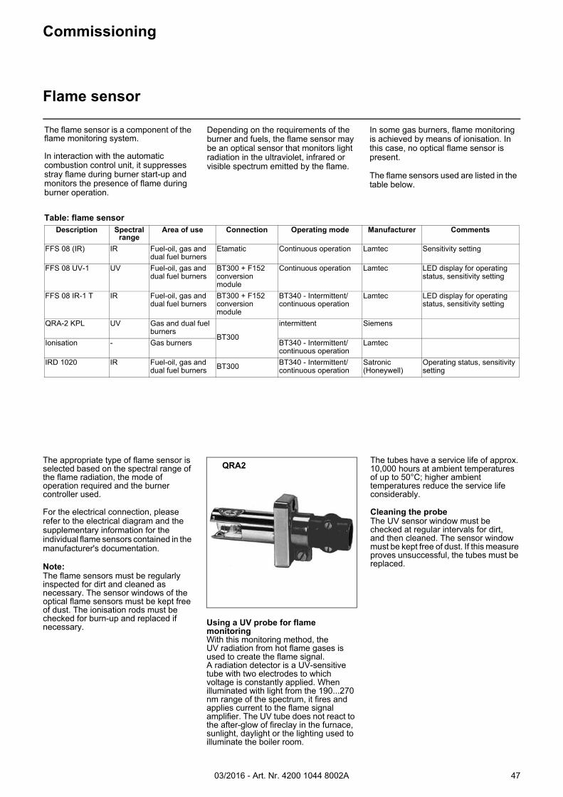
03/2016 - Art. Nr. 4200 1044 8002A 47
Commissioning
Flame sensor
The flame sensor is a component of the flame monitoring system.
In interaction with the automatic combustion control unit, it suppresses stray flame during burner start-up and monitors the presence of flame during burner operation.
Depending on the requirements of the burner and fuels, the flame sensor may be an optical sensor that monitors light radiation in the ultraviolet, infrared or visible spectrum emitted by the flame.
In some gas burners, flame monitoring is achieved by means of ionisation. In this case, no optical flame sensor is present.
The flame sensors used are listed in the table below.
Table: flame sensorDescription Spectral
rangeArea of use Connection Operating mode Manufacturer Comments
FFS 08 (IR) IR Fuel-oil, gas and dual fuel burners
Etamatic Continuous operation Lamtec Sensitivity setting
FFS 08 UV-1 UV Fuel-oil, gas and dual fuel burners
BT300 + F152 conversion module
Continuous operation Lamtec LED display for operating status, sensitivity setting
FFS 08 IR-1 T IR Fuel-oil, gas and dual fuel burners
BT300 + F152 conversion module
BT340 - Intermittent/continuous operation
Lamtec LED display for operating status, sensitivity setting
QRA-2 KPL UV Gas and dual fuel burners
BT300
intermittent Siemens
Ionisation - Gas burners BT340 - Intermittent/continuous operation
Lamtec
IRD 1020 IR Fuel-oil, gas and dual fuel burners BT300 BT340 - Intermittent/
continuous operationSatronic (Honeywell)
Operating status, sensitivity setting
The appropriate type of flame sensor is selected based on the spectral range of the flame radiation, the mode of operation required and the burner controller used.
For the electrical connection, please refer to the electrical diagram and the supplementary information for the individual flame sensors contained in the manufacturer's documentation.
Note:The flame sensors must be regularly inspected for dirt and cleaned as necessary. The sensor windows of the optical flame sensors must be kept free of dust. The ionisation rods must be checked for burn-up and replaced if necessary. Using a UV probe for flame
monitoringWith this monitoring method, theUV radiation from hot flame gases is used to create the flame signal.A radiation detector is a UV-sensitive tube with two electrodes to which voltage is constantly applied. When illuminated with light from the 190...270 nm range of the spectrum, it fires and applies current to the flame signal amplifier. The UV tube does not react to the after-glow of fireclay in the furnace, sunlight, daylight or the lighting used to illuminate the boiler room.
The tubes have a service life of approx. 10,000 hours at ambient temperatures of up to 50°C; higher ambient temperatures reduce the service life considerably.
Cleaning the probeThe UV sensor window must be checked at regular intervals for dirt,and then cleaned. The sensor window must be kept free of dust. If this measure proves unsuccessful, the tubes must be replaced.
QRA2
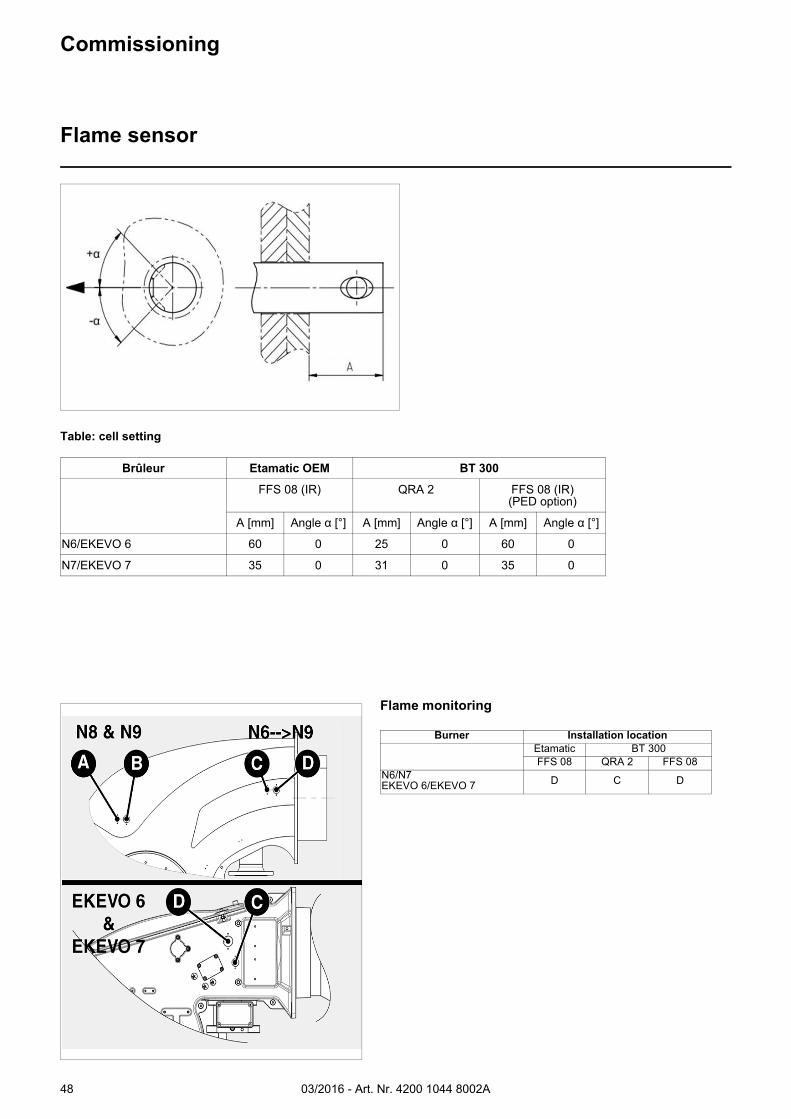
03/2016 - Art. Nr. 4200 1044 8002A48
Commissioning
Flame sensor
Table: cell setting
Brûleur Etamatic OEM BT 300
FFS 08 (IR) QRA 2 FFS 08 (IR)(PED option)
A [mm] Angle α [°] A [mm] Angle α [°] A [mm] Angle α [°]
N6/EKEVO 6 60 0 25 0 60 0
N7/EKEVO 7 35 0 31 0 35 0
Flame monitoring
Burner Installation locationEtamatic BT 300FFS 08 QRA 2 FFS 08
N6/N7EKEVO 6/EKEVO 7 D C D
03/2016 - Art. Nr. 4200 1044 8002A 49
Commissioning
Gas fitting connectionElectrical connectionChecks before commissioning
Checks before commissioningThe following must be checked before initial commissioning:• That the burner is assembled in
accordance with the instructions given here.
• That the burner is pre-set in accordance with the values in the adjustment table.
• Setting the combustion components.• The heat generator must be ready for
operation, and the operating regulations for the heat generator must be observed.
• All electrical connections must be correct.
• The heat generator and heating system must be filled with water and the circulating pumps must be in operation.
• The temperature regulator, pressure regulator, low water detectors and any other safety or limiting devices that might be fitted must be connected and operational.
• The exhaust gas duct must be unobstructed and the secondary air system, if available, must be operational.
• An adequate supply of fresh air must be guaranteed.
• A heat dissipation system must be available.
• Sufficient gas pressure must be available.
• The fuel supply lines must be assembled correctly, checked for leaks and bled.
• A standard-compliant measuring point must be available for measuring the exhaust gas, the exhaust gas duct up to the measuring point must be free of leaks to prevent anomalies in the measurement results.
All electrical installation and connection work must only be carried out by a suitably qualified electrician.
N.B.: The applicable guidelines and directives must be observed, as well as the electrical circuit diagram supplied with the burner.
Before connecting the burner, it is essential to ensure that the entire burner has reached the ambient temperature. Otherwise, there is a risk that condensation will form on electronic components resulting in damage to property and personal injury!
Gas fitting connectionThe connectors on the burner must be used for connecting the gas valve. Cognisance must be taken of the equipment labelling and the electrical circuit diagram.
Electrical connectionThe electrical connections, i.e. the installation materials and all the connectors and earth/ground connections, must be installed in compliance with the specifications.The electrical installation of the burner must be carried out in accordance with the circuit diagram drawn up for the furnace.
The electrical connection of the burner may only be performed by authorised specialists.
Please note:When installing the connection cable, the cable loops selected must be large enough to allow the boiler door to swivel open. When electrical connection work is complete, the wiring for the burner electrics must be checked. This includes checking the direction of rotation of the fan or the fuel-oil pump motor.
03/2016 - Art. Nr. 4200 1044 8002A50
Commissioning
Gas connection
Gas connectionThe gas lines and trains should be installed and taken into operation in accordance with the applicable engineering standards and regulations.
The connection between the gas distribution network and the gas ramp must be performed by authorised persons.
All the gas ramp components must be fitted and installed without bending or distortion or any other form of mechanical stress.
The pipe diameters must be calculated so that the loss of load does not exceed 5% of the distribution pressure.
A quarter turn manual valve (not supplied) must be provided upstream of the gas ramp and the filter.
The max. operating pressure for the shut-off device must be 1.5 times the max. connection pressure. Ease of access must be guaranteed. Precautions must be taken to prevent unintentional actuation. The operating position of the gate valve must be quite obvious. The manually operated valve should have fixed stops in the "OPEN" and "SHUT" positions.
The filter must be installed on a horizontal nozzle with the cover in the vertical position to enable cleaning.
Depending on the current specification, a thermally triggered shut-off valve must be provided on site (not supplied).
All the gas ramp components must be protected against condensation and if necessary, a condensate trap (not supplied) must be provided on site.
The threaded unions used must be in conformity with present standards (tapered male thread, straight female thread with sealing provided in the thread).
Sufficient space must be provided for setting and maintaining the gas ramp components (gas pressure switch, valves, pressure regulator, gas filter, test burner etc.) (see technical data).
Gas propertiesPrior to any installation work make sure to obtain the following data from the gas supply company:1. Type of gas 2. Calorific value Hun = kWh/m3 (kJ/m3)3. Max. CO2 content of exhaust gas4. Gas connection pressure and rest
pressure
Type of gas testPrior to mounting the burner to the gas feed line check the available type of gas and burner type against the data given on the burner nameplate (attached to burner).Be sure the description of the burner and the type of gas are the same as indicated on the nameplate.
Gas connection pressureA minimum connection pressure must be available upstream of the burner gas valve to ensure that the burner operates properly.Take care to observe the mounting instructions supplied by their manufacturers (these are packed with the valves). The gas line installed to the burner must be dimensioned in accordance with the throughput rate and the available pressure.
For selecting the nominal bore "DN" of the gas train care should be taken to observe the flue resistance of the boiler and the gas pressure loss of the burner and train.
Please note:The absence of impurities and foreign bodies must be checked before installation and commissioning of the gas ramp, the lever valves and unions.
Gas trainThe gas train can be connected directly to the gas feed line. Take care to observe the correct order of installation and direction of flow (arrow on housing) of the valves.Check the valves and connection pieces for absence of dirt particles and foreign matter before installation and initial operation. To provide effective conditions for start-up make sure the distance between the burner and the gas stop valve is as short as possible.
Leak testThe fitted gas train must be leak tested on the system in accordance with DVGW worksheets G600 and G490. The gas line upstream of the burner gas train must be installed in accordance with the applicable regulations, leak tested, vented and certified accordingly by the gas installation company. The screw connections and flanged joints must be checked for proper leaktightness (by making a pressure test). The leak test must be made under pressure using approved foaming agents which do not cause corrosion. For steam boiler furnaces the result of the leak test must be duly certified.
VentingPlease note: Prior to putting the burner into operation or after any repair work make sure to vent the complete gas feed line and the gas valve group into the open atmosphere (e.g. by means of a hose) taking care to avoid any hazards.In no case should the gas line be vented into the heating or furnace chambers.Make use of a test burner to check the gas-carrying spaces are free from an inflammable gas mixture.
Support The train must be supported with a telescopic jacking member or similar during and after installation (e.g. on filter and valve).
JointIt is recommended to provide an easy-to-disconnect joint (with planar sealing faces) to facilitate repair work on the boiler (furnace) and allow the boiler door to be swivelled out if required.
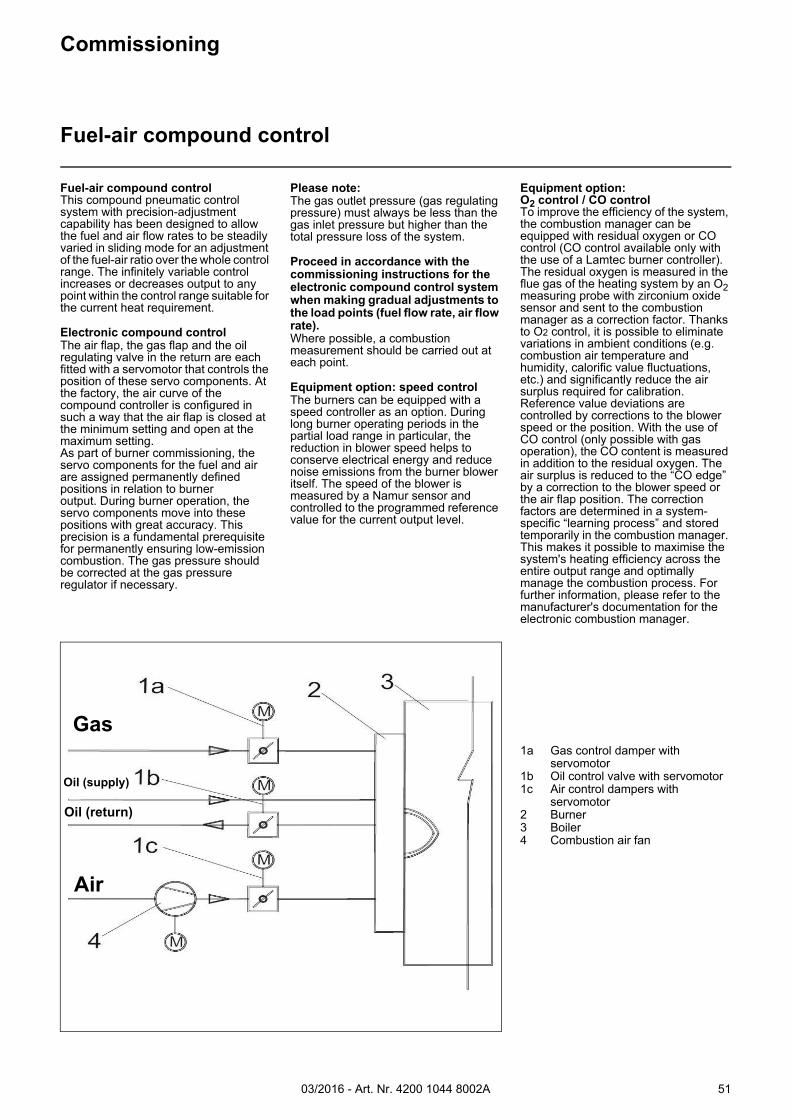
03/2016 - Art. Nr. 4200 1044 8002A 51
Commissioning
Fuel-air compound control
Fuel-air compound controlThis compound pneumatic control system with precision-adjustment capability has been designed to allow the fuel and air flow rates to be steadily varied in sliding mode for an adjustment of the fuel-air ratio over the whole control range. The infinitely variable control increases or decreases output to any point within the control range suitable for the current heat requirement.
Electronic compound controlThe air flap, the gas flap and the oil regulating valve in the return are each fitted with a servomotor that controls the position of these servo components. At the factory, the air curve of the compound controller is configured in such a way that the air flap is closed at the minimum setting and open at the maximum setting.As part of burner commissioning, the servo components for the fuel and air are assigned permanently defined positions in relation to burneroutput. During burner operation, the servo components move into these positions with great accuracy. This precision is a fundamental prerequisite for permanently ensuring low-emission combustion. The gas pressure should be corrected at the gas pressure regulator if necessary.
Please note: The gas outlet pressure (gas regulating pressure) must always be less than the gas inlet pressure but higher than the total pressure loss of the system.
Proceed in accordance with the commissioning instructions for the electronic compound control system when making gradual adjustments to the load points (fuel flow rate, air flow rate).Where possible, a combustion measurement should be carried out at each point.
Equipment option: speed controlThe burners can be equipped with a speed controller as an option. During long burner operating periods in the partial load range in particular, the reduction in blower speed helps to conserve electrical energy and reduce noise emissions from the burner blower itself. The speed of the blower is measured by a Namur sensor and controlled to the programmed reference value for the current output level.
Equipment option:O2 control / CO controlTo improve the efficiency of the system, the combustion manager can be equipped with residual oxygen or CO control (CO control available only with the use of a Lamtec burner controller). The residual oxygen is measured in the flue gas of the heating system by an O2 measuring probe with zirconium oxide sensor and sent to the combustion manager as a correction factor. Thanks to O2 control, it is possible to eliminate variations in ambient conditions (e.g. combustion air temperature and humidity, calorific value fluctuations, etc.) and significantly reduce the air surplus required for calibration. Reference value deviations are controlled by corrections to the blower speed or the position. With the use of CO control (only possible with gas operation), the CO content is measured in addition to the residual oxygen. The air surplus is reduced to the “CO edge” by a correction to the blower speed or the air flap position. The correction factors are determined in a system-specific “learning process” and stored temporarily in the combustion manager. This makes it possible to maximise the system's heating efficiency across the entire output range and optimally manage the combustion process. For further information, please refer to the manufacturer's documentation for the electronic combustion manager.
1a Gas control damper with servomotor
1b Oil control valve with servomotor1c Air control dampers with
servomotor2 Burner3 Boiler4 Combustion air fan
Gas
Oil (supply)
Oil (return)
Air
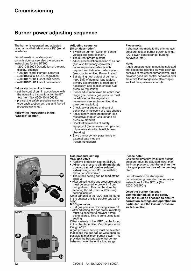
03/2016 - Art. Nr. 4200 1044 8002A52
VGD...
MBC...
Commissioning
Burner power adjusting sequence
Gas pressure settingVGD gas valve• Remove protection cap on SKP25.• Adjust gas pressure pBr (immediately
downstream of double solenoid valve) using screw S1 (beneath lid) and a flat screwdriver
• The stroke setting can be read off the scale X
• After adjusting, the gas pressure setting must be secured to prevent it from being altered. This can be done by securing the lid (cover of S1) using sealing lacquer.
Other variants of the VDG can be found in the chapter entitled Double gas valve VGD.MBC gas valve• Set gas pressure pBr using screw S2• After adjusting, the gas pressure setting
must be secured to prevent it from being altered. This is done using lead sealing.
Other variants of the MBC can be found in the chapter entitled Double gas valve Dungs MBC.A gas pressure setting must be selected that keeps the gas flap as wide open as possible at maximum burner power. This provides the best possible fuel control behaviour over the entire load range.
Please note:Gas output pressure (regulator output pressure) must be adjusted lower than the input pressure, but higher than the total gas pressure loss of the heating plant.
For information on startup and commissioning, see also the separate instructions for the BT3xx (No. 420010485601)
Once the burner has been commissioned, all of the safety devices must be checked to ensure correction settings and operation (in particular, see the Gas/air pressure switch section).
The burner is operated and adjusted using a handheld device or a PC (serial interface).
For information on startup and commissioning, see also the separate instructions for the BT300:- 420010485601 Description of the unit,
display, settings- 420010175301 Remote software- 420010xxxxxx CO/O2 regulation- 420010178501 List of fault codes- 420010181501 List of parameters
Before starting up the burner:• set the control unit in accordance with
the operating instructions for the BT 3xx (Item No.:4200 1048 5601).
• pre-set the safety pressure switches (see each section: air, gas and fuel oil pressure switches).
Follow the instructions in the "Checks" section!
Adjusting sequence(Short description)• Switch on burner (switch on control
voltage and control chain), • The burner program starts• Adjust preventilation position of air flap
(and also frequency converter if necessary) in accordance with required ventilation for boiler system (see chapter entitled Preventilation)
• Set starting heat output of burner to max. 33% of nominal load (adjust primary gas pressure at regulator if necessary, see section entitled Gas pressure regulation)
• Burner adjustment over the entire load range (the primary gas pressure must be adjusted at the regulator if necessary, see section entitled Gas pressure regulation)
• Check power setting and control behaviour in the event of a load change
• Adjust safety pressure monitor (see respective chapter Gas, air and oil pressure monitor)
• Check effectiveness of safety equipment (flame sensor, air, gas and oil pressure monitor, leaktightness checking)
• Save burner control parameters on external data medium (recommendation)
Please note: If changes are made to the primary gas pressure, test all burner power settings. (O2, power, control range, burning behaviour, etc.).
Note:A gas pressure setting must be selected that keeps the gas flap as wide open as possible at maximum burner power. This provides good fuel control behaviour over the entire load range (see also chapter entitled Gas pressure control).
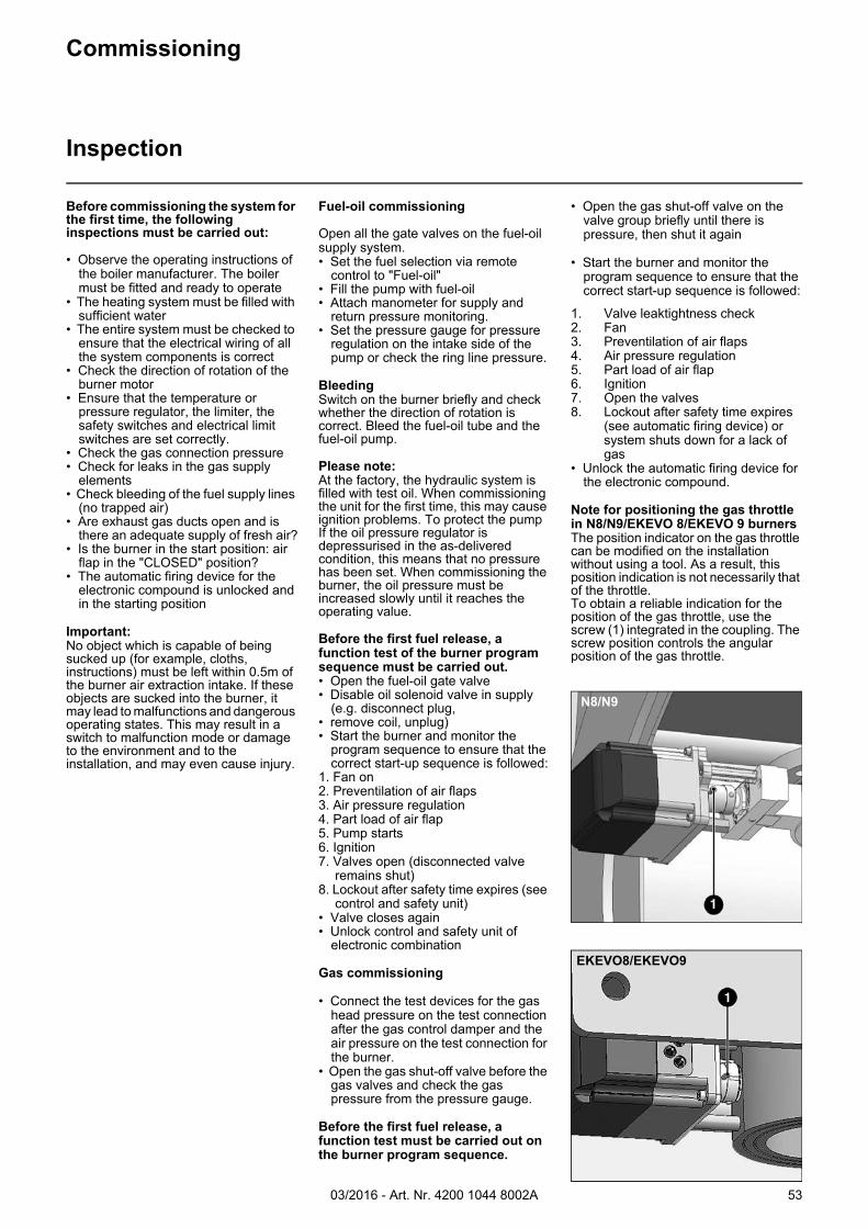
03/2016 - Art. Nr. 4200 1044 8002A 53
Before commissioning the system for the first time, the following inspections must be carried out:
• Observe the operating instructions of the boiler manufacturer. The boiler must be fitted and ready to operate
• The heating system must be filled with sufficient water
• The entire system must be checked to ensure that the electrical wiring of all the system components is correct
• Check the direction of rotation of the burner motor
• Ensure that the temperature or pressure regulator, the limiter, the safety switches and electrical limit switches are set correctly.
• Check the gas connection pressure• Check for leaks in the gas supply
elements• Check bleeding of the fuel supply lines
(no trapped air)• Are exhaust gas ducts open and is
there an adequate supply of fresh air?• Is the burner in the start position: air
flap in the "CLOSED" position?• The automatic firing device for the
electronic compound is unlocked and in the starting position
Important:No object which is capable of being sucked up (for example, cloths, instructions) must be left within 0.5m of the burner air extraction intake. If these objects are sucked into the burner, it may lead to malfunctions and dangerous operating states. This may result in a switch to malfunction mode or damage to the environment and to the installation, and may even cause injury.
Fuel-oil commissioning
Open all the gate valves on the fuel-oil supply system.• Set the fuel selection via remote
control to "Fuel-oil"• Fill the pump with fuel-oil• Attach manometer for supply and
return pressure monitoring.• Set the pressure gauge for pressure
regulation on the intake side of the pump or check the ring line pressure.
BleedingSwitch on the burner briefly and check whether the direction of rotation is correct. Bleed the fuel-oil tube and the fuel-oil pump.
Please note:At the factory, the hydraulic system is filled with test oil. When commissioning the unit for the first time, this may cause ignition problems. To protect the pumpIf the oil pressure regulator is depressurised in the as-delivered condition, this means that no pressure has been set. When commissioning the burner, the oil pressure must be increased slowly until it reaches the operating value.
Before the first fuel release, a function test of the burner program sequence must be carried out.• Open the fuel-oil gate valve• Disable oil solenoid valve in supply
(e.g. disconnect plug,• remove coil, unplug)• Start the burner and monitor the
program sequence to ensure that the correct start-up sequence is followed:
1. Fan on2. Preventilation of air flaps3. Air pressure regulation4. Part load of air flap5. Pump starts6. Ignition7. Valves open (disconnected valve
remains shut)8. Lockout after safety time expires (see
control and safety unit)• Valve closes again• Unlock control and safety unit of
electronic combination
Gas commissioning
• Connect the test devices for the gas head pressure on the test connection after the gas control damper and the air pressure on the test connection for the burner.
• Open the gas shut-off valve before the gas valves and check the gas pressure from the pressure gauge.
Before the first fuel release, a function test must be carried out on the burner program sequence.
• Open the gas shut-off valve on the valve group briefly until there is pressure, then shut it again
• Start the burner and monitor the program sequence to ensure that the correct start-up sequence is followed:
1. Valve leaktightness check2. Fan3. Preventilation of air flaps4. Air pressure regulation5. Part load of air flap6. Ignition7. Open the valves8. Lockout after safety time expires
(see automatic firing device) or system shuts down for a lack of gas
• Unlock the automatic firing device for the electronic compound.
Note for positioning the gas throttle in N8/N9/EKEVO 8/EKEVO 9 burnersThe position indicator on the gas throttle can be modified on the installation without using a tool. As a result, this position indication is not necessarily that of the throttle.To obtain a reliable indication for the position of the gas throttle, use the screw (1) integrated in the coupling. The screw position controls the angular position of the gas throttle.
N8/N9
EKEVO8/EKEVO9
Commissioning
Inspection
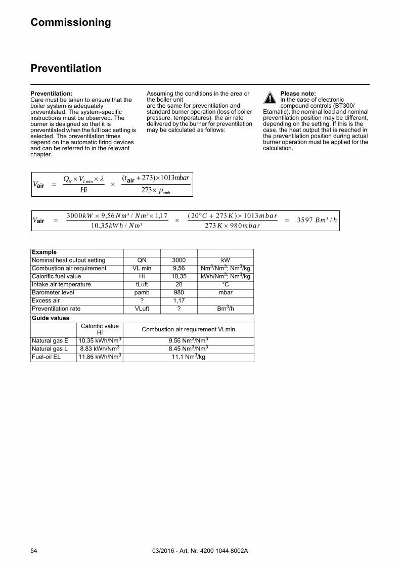
03/2016 - Art. Nr. 4200 1044 8002A54
Commissioning
Preventilation
ExampleNominal heat output setting QN 3000 kWCombustion air requirement VL min 9,56 Nm3/Nm3; Nm3/kgCalorific fuel value Hi 10,35 kWh/Nm3; Nm3/kgIntake air temperature tLuft 20 °CBarometer level pamb 980 mbarExcess air ? 1,17Preventilation rate VLuft ? Bm3/hGuide values
Calorific value Hi Combustion air requirement VLmin
Natural gas E 10.35 kWh/Nm3 9.56 Nm3/Nm3
Natural gas L 8.83 kWh/Nm3 8.45 Nm3/Nm3
Fuel-oil EL 11.86 kWh/Nm3 11.1 Nm3/kg
Preventilation:Care must be taken to ensure that the boiler system is adequately preventilated. The system-specific instructions must be observed. The burner is designed so that it is preventilated when the full load setting is selected. The preventilation times depend on the automatic firing devices and can be referred to in the relevant chapter.
Assuming the conditions in the area or the boiler unitare the same for preventilation and standard burner operation (loss of boiler pressure, temperatures), the air rate delivered by the burner for preventilation may be calculated as follows:
Please note:in the case of electronic compound controls (BT300/
Etamatic), the nominal load and nominal preventilation position may be different, depending on the setting. If this is the case, the heat output that is reached in the preventilation position during actual burner operation must be applied for the calculation.
amb
LuftLNLüft p
mbart
Hi
VQV
273
1013)273(min
airair
hBmm barK
m ba rKC
NmkW h
NmN mkWVL üft /³3597
980273
1013)27320(
³/35,10
17,1³/³56,93000
air
03/2016 - Art. Nr. 4200 1044 8002A 55
Commissioning
Fuel-oil start-up modeFuel-oil operating modeGeneral safety functions
Fuel-oil start-up modeIf heat is required by the furnace, the electronic combustion manager receives an operation request.When the automatic firing device program has come to its end, the burner will be turned on.
The air flap is closed when the burner is out of operation.The automatic firing device controls and monitors start-up. The burner fan starts up and the electrical servomotor opens the air flap to the full load position so the furnace and the exhaust hoods are ventilated at the specified air rate. Shortly after the preventilation process has been started the safety device used to detect an absence of air is switched to the operating position within a certain time, i.e. the minimum air pressure setting must be reached and maintained until the burner is turned off. After the expiry of the preset preventilation time, the air flap is set to partial-load position. Pre-ignition takes place and the fuel-oil is then released.
The solenoid valves open and release the oil, which is under pressure, to the nozzle and return. The fuel-oil is nebulised, mixed with the combustion air and ignited. A normal, steady flame must be formed within the safety time. When the safety time elapses, a flame signal must be sent to the automatic firing device via the flame monitor and must remain in place until the control system is switched off. The start-up programme for the burner is completed.
Fuel-oil operating modeAfter the flame has developed, the output control will be enabled. This brings the burner to its operating position. The output controller will now automatically control the burner between its partial-load and full-load positions.Depending on the heat demand, the electric servomotor will be fed with the open or close command via the regulator and thus increase or decrease the gas and air flow rates.This compound control system will vary the positions of the oil control valve and air valve, and thus regulate the oil flow rate in combination with the air flow rate.The stepless control makes it possible to operate the burner at any desired stage between its partial-load and full-load positions. The burner is shut down from the partial load position. The air flap will
be closed when the burner is in its off position so as to prevent cold air from flowing through the burner, heat generator and chimney. The interior cooling losses will be greatly minimised.
Warning: If gate valves have been installed in the exhaust gas tract, they must be fully opened during the start-up phase, otherwise there is a risk of a low-speed detonation or an explosion! The open-position of the shut-off damper can be assured by the integration of the opening contact of the shut-off damper in the safety chain of the heat generator.
Important:No object which is capable of being sucked up (for example, cloths, instructions) must be left within 0.5m of the burner air extraction intake. If these objects are sucked into the burner, it may lead to malfunctions and dangerous operating states. This may result in a switch to malfunction mode or damage to the environment and to the installation, and may even cause injury.
General safety functionsIn case a flame does not develop when starting the burner (fuel release), the burner controller will shut off at the end of the safety period (fault lock-out). A lockout will also occur in the case of flame failure during operation, air flow failure during the pre-ventilation phase and pressure failure during the whole period of burner operation. Any failure of the flame signal at the end of the safety period and a flame signal during the preventilation phase (external light control) will result in a lockout with the automatic firing device being locked. The fault is indicated by the fault signal lamp lighting up. The automatic firing device can be unlocked immediately after a lockout by pressing the unlocking key.The automatic firing device will return to its starting position and proceed with the restart of the burner. If there is a power failure, the control system is shut down.After voltage recovery, the burner can be automatically restarted unless another interlock is active, e.g. one caused by the safety circuit. In any case, the fuel-oil supply will be immediately stopped upon occurrence of a fault.
When using the burner control system (electronic compound control) all operational and fault messages may be indicated in plain text on an optionally available operating anddisplay module.
03/2016 - Art. Nr. 4200 1044 8002A56
Gas start-up modeAs soon as the furnace is required to supply heat, the burner control circuit will close and the program flow will start. When the program sequence ends, theburner starts up.
An automatic test is made for the leaktightness of the gas valves prior to each burner start.
The air flap is in its closed position when the burner is out of operation.
The electric servomotor will open the closed air flap to its full-load position so that the burner will ventilate the furnace and the exhaust hoods with the specified air rate. Shortly after the preventilation process has been started, the lack-of-air cut-out must change over to the operating position within a certain time, i.e. the minimum air pressure setting must be reached and maintained until the burner is turned off. Once the prescribed preventilation time has elapsed, the air flap and the gas control flap are moved to the partial load position. The ignition transformer is activated.
After the pre-ignition time, the main gas valves are open and the gas comes out from injectors where it is mixed in the combustion head with air coming from the fan. The ignition of the gas air mixture is done directly by a high voltage spark on a gas injector. During the safety time, a stable flame is formed and is monitored by a UV photocell. The ignition is stopped before the end of the safety time and the burner operates at its minimum power. The start-up programme is completed.
Gas operating modeAfter flame formation, the burner will shortly remain in the separately set ignition load and is then run at minimum output. Output regulation will then be enabled. This brings the burner to its operating position. The controller will now automatically control the burner between its partial-load and full-load positions.
Depending on the heat demand, the output controller will actuate the electronic compound controller which in turn will control the actuators of the gas control damper and air control dampers and increase or decrease the flow rates according to a specific program.
The stepless control makes it possible to operate the burner at any desired stage between its partial-load and full-load positions. Burner shutdown occurs regardless of burner load state. It is advisable to program the load controller to have the shutdown occur at low load. The air flap will be closed when the burner is in its off position so as to prevent cold air from flowing through the furnace chamber, heat exchanger and chimney. The interior cooling losses will be greatly minimised.
Warning: If gate valves have been installed in the exhaust gas tract, they must be fully opened during the start-up phase, otherwise there is a risk of a low-speed detonation or an explosion! The open-position of the flue damper can be assured by the integration of the opening contact of the shut-off damper in the safety chain of the heat generator.
Important:No object which is capable of being sucked up (for example, cloths, instructions) must be left within 0.5m of the burner air extraction intake. If these objects are sucked into the burner, it may lead to malfunctions and dangerous operating states. This may result in a switch to malfunction mode or damage to the environment and to the installation, and may even cause injury.
General safety functionsIn case a flame does not develop when starting the burner (fuel release), the burner controller will shut off at the end of the safety period (lockout).. A lockout will also occur in the case of flame failure during operation, air flow failure during the pre-ventilation phase and pressure failure during the whole period of burner operation. Any failure of the flame signal at the end of the safety period and a flame signal during the preventilation phase (external light control) will result in a lockout with the automatic firing device being locked. The fault is indicated by the fault signal lamp lighting up. The automatic firing device can be unlocked
immediately after a lockout by pressing the unlocking key. The automatic firing device will return to its starting position and proceed with the restart of the burner. A voltage failure will result in a regular shut-off of the burner. After voltage recovery, the burner can be automatically restarted unless another interlock is active, e.g. one caused by the safety circuit. In any case, the fuel-oil supply will be immediately stopped upon occurrence of a fault.When using the burner control system (electronic compound control) all operational and fault messages may be indicated in plain text on an optionally available operating and display module.
Commissioning
Gas start-up modeGas operating modeGeneral safety functions
03/2016 - Art. Nr. 4200 1044 8002A 57
Servicing
Maintenance
Burner and boiler servicing must only be carried out by a professionally qualified heating engineer. The system operator is advised to take out a service contract to guarantee regular servicing. Depending on the type of installation, shorter maintenance intervals may be necessary.
Please note:If maintenance is not carried out properly in accordance with these instructions, system malfunctions and dangerous operating conditions could ensue. This may result in a breakdown, damage to property and the environment and personal injury. A log must be kept of all maintenance and servicing work. All wear parts must be replaced in accordance with the specified cycle times (see table below).
For maintenance work, the floor of the work area must be free of dirt and slip-resistant. Provision must be made for
adequate lighting. When maintaining heavy components (e.g. the fan motor), suitable lifting equipment must be used.Before carrying out any maintenance or cleaning work on the burner, the following steps must be followed.1. Turn off the power supply and protect the system from accidental start-up2. Interrupt the supply of fuel3. Check the system for residual power and ensure that steps 1 and 2 have been effective4. Before opening the burner casing, ensure that the fan motor has stopped completely.If the cooling fins of the ventilation motor are motionless, the turbine has stopped.Failure to observe these instructions may result in severe or fatal injuries and/or damage to property.• Use original spare parts.If original spare parts are not used, the system may no longer be CE-compliant.
Warning:Each time maintenance work is carried out, it is essential to ensure that no tools, cleaning cloths or other items are left in the burner housing. Any items left behind could affect the functionality of the burner and could result in damage to property or personal injury (risks of serious or fatal injury).
Work recommended as part of annual burner maintenance:- Burner test run, input measurement in
the boiler room- Clean the combustion components
and replace defective parts if necessary
- Clean the fan wheel and the fan- Clean the gas filter; replace it if
necessary- Check the setting of the combustion
components and check the seal between the gas head and burner
tube for leaks- Check the ignition electrodes and
ignition sparking. Clean and readjust if necessary
- Clean the flame sensor- Clean the air flap and check that it
moves easily- Check whether the fan wheel is
deformed or cracked- Visual inspection of the burner's
electrical components; eliminate malfunctions if necessary
- Check burner start-up (combustion performance, emissions, burner output)
- Leakage test- Function tests on the burner's safety
equipment, the safety chain for the boiler system (air pressure, gas pressure switches, the flame monitor, the leak detection device, the safety valves, the safety chain components). The maintenance and safety specifications for the boiler system must be complied with.
- Check/clean the pressure pipe of the air pressure switch, in particular inside the air box hood (opening in the acoustic insulation.)
- Flame monitor and automatic firing device function check
- Checking the gas circulation pressure upstream and downstream of the gas control system and checking the static gas pressure
- Check the gas flow- Check the gas train for leaks- Check the gas valves for leaks and
cleanliness- Clean the burner inside and out- Correct the adjustment values if
necessary- Draw up a measurement report** The following values must be recorded at a minimum: - Type of fuel, type of gas- Wobbe index (heat value); calorific
value- Volumetric gas flow,- Lowest and highest useful combustion
efficiency; also 1 to 2 intermediate values
- Gas and air pressures (gas connection, gas regulator, burner head, setting pressure, fan pressure, furnace pressure)
- Exhaust gas emissions (NOx, O2, CO, CO2, soot) as a percentage/ ppm
- Temperature and humidity of the combustion air
- Flue gases temperature- Atmospheric air pressure
General checks- Emergency stop button function check- Visual inspection of gas lines in the
boiler room
Warning!Before restarting the burner following maintenance work, make sure that any unions unscrewed during maintenance work are tight and firmly in place. Check the connections of the components
located in the burner (e.g. the parts of the combustion head) before closing the cover. Check the cover too. Incorrectly connected or defective components may cause malfunctioning and hazardous operation. This may result in a switch to malfunction mode or damage to the environment and to the installation, and may even cause injury (risks of serious or fatal injury).
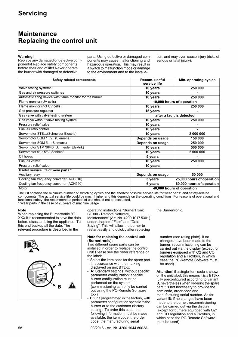
03/2016 - Art. Nr. 4200 1044 8002A58
The list contains the minimum number of switching cycles and the shortest possible service life for wear parts* and safety-related components. The actual service life could be much higher and this depends on the operating conditions. For reasons of operational and functional safety, the recommended periods of use should not be exceeded.* Wear parts in the case of 25 years of machine usage
Safety-related components Recom. useful service life
Min. operating cycles
Valve testing systems 10 years 250 000Gas and air pressure switches 10 years -Automatic firing device with flame monitor for the burner 10 years 250 000Flame monitor (UV cells) 10,000 hours of operationFlame monitor (not UV cells) 10 years 250 000Gas pressure regulator 15 years -Gas valve with valve testing system after a fault is detectedGas valve without valve testing system 10 years 250 000Pressure relief valve 10 years -Fuel-air ratio control 10 years -Servomotor STE…(Schneider Electric) 10 years 2 000 000Servomotor SQM 1../2.. (Siemens) Depends on usage 150 000Servomotor SQM 5... (Siemens) Depends on usage 250 000Servomotor STM 30/40 (Schneider Elektrik) 10 years 500 000Servomotor 01-15/30 Schimpf 10 years 2 000 000Oil hoses 5 years -Fuel-oil valves 10 years 250 000Pressure relief valve 10 years -Useful service life of wear parts *Auxiliary relay Depends on usage 50 000Cooling fan frequency converter (ACS310) 3 years 25,000 hours of operationCooling fan frequency converter (ACH550) 6 years 60,000 hours of operationMotor 40,000 hours of operation
Servicing
MaintenanceReplacing the control unit
Warning!Replace any damaged or defective com-ponents! Replace safety components before their end of life! Never operate the burner with damaged or defective
parts. Using defective or damaged com-ponents may cause malfunctioning and hazardous operation. This may result in a switch to malfunction mode or damage to the environment and to the installa-
tion, and may even cause injury (risks of serious or fatal injury).
Note for replacing the control unit (Burnertronic):Two different spare parts can be installed in order to replace the control unit! Please see the order reference on the label:• Select the item code for the spare part
in accordance with the marking displayed on unit BT3xx:
- A: Standard settings, without specific parameter configuration: specific burner configuration must be performed on the system (commissioning can only be carried out using the PC-Remote Software tool)
- B: unit programmed in the factory, with parameter configuration specific to the burner or to the customer (factory setting). To order this code, the following information must be made available: the item code, the order code, the manufacturing serial
number (see rating plate). If no changes have been made to the burner, recommissioning can be carried out via the display (except for burners equipped with O2 and CO regulation and a Profibus, in which case the PC-Remote Software must be used)
Attention! if a single item code is shown on the unit label, this means it is a BT3xx fully preconfigured according to variant B, nevertheless when ordering the spare part it is not necessary to provide the item code, order code and manufacturing serial number. As for variant B: if no changes have been made to the burner, recommissioning can be carried out via the display (except for burners equipped with O2/ and CO regulation and a Profibus, in which case the PC-Remote Software must be used)
NoteWhen replacing the Burnertronic BT XXX it is recommended to save the data before disassembling the appliance. To this end backup all the date. The relevant procedure is described in the
operating instructions "BurnerTronic BT300 - Remote Software, Maintenance" (Art. No. 4200 1017 5301) under chapters "Files" and "Data Saving". This will allow the burner to restart easily and quickly after replacing
the Burnertronic.
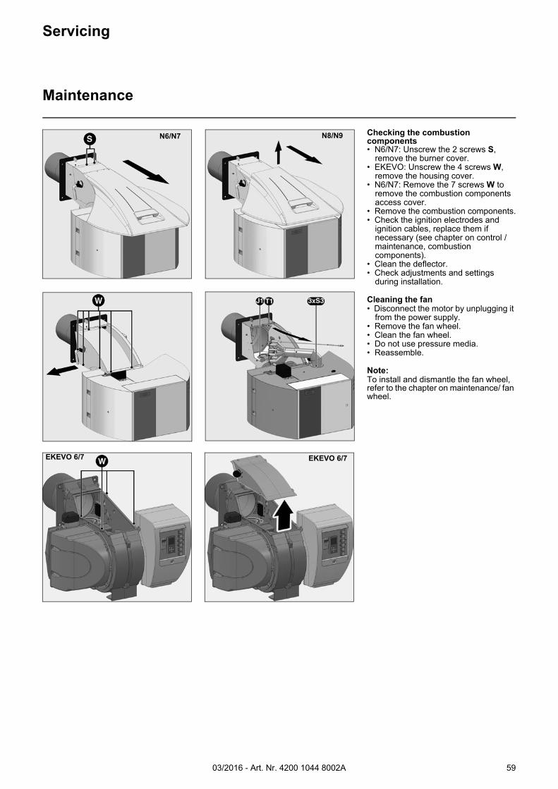
03/2016 - Art. Nr. 4200 1044 8002A 59
N8/N9
Servicing
Maintenance
Checking the combustion components• N6/N7: Unscrew the 2 screws S,
remove the burner cover.• EKEVO: Unscrew the 4 screws W,
remove the housing cover.• N6/N7: Remove the 7 screws W to
remove the combustion components access cover.
• Remove the combustion components.• Check the ignition electrodes and
ignition cables, replace them if necessary (see chapter on control / maintenance, combustion components).
• Clean the deflector.• Check adjustments and settings
during installation.
Cleaning the fan• Disconnect the motor by unplugging it
from the power supply.• Remove the fan wheel.• Clean the fan wheel.• Do not use pressure media.• Reassemble.
Note:To install and dismantle the fan wheel, refer to the chapter on maintenance/ fan wheel.
N6/N7
EKEVO 6/7 EKEVO 6/7
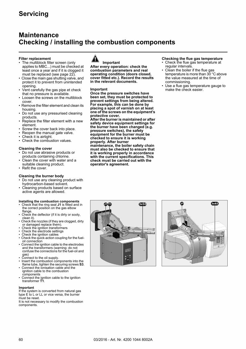
03/2016 - Art. Nr. 4200 1044 8002A60
Installing the combustion components• Check that the ring seal J1 is fitted and in
the correct position on the gas elbow flange.
• Check the deflector (if it is dirty or sooty, clean it).
• Check the nozzles (if they are clogged, dirty or damaged replace them).
• Check the ignition transformers• Check the electrode settings• Check the ignition cables• Check the quick-action coupling for the fuel-
oil connection• Connect the ignition cable to the electrodes
and the transformers (warning: do not confuse the connections for the fuel-oil and gas)
• Connect to the oil supply.• Insert the combustion components into the
flame tube, tighten the securing screws S3.• Connect the ionisation cable and the
ignition cable to the combustion components
• Connect the ignition cable to the ignition transformer T1.
ImportantIf the system is converted from natural gas type E to L or LL or vice versa, the burner must be reset.It is not necessary to modify the combustion components.
Servicing
MaintenanceChecking / installing the combustion components
Filter replacement• The multiblock filter screen (only
applies to MBC...) must be checked at least once a year and if it is clogged it must be replaced (see page 22).
• Close the main gas shutting valve, and protect it to prevent from unintended opening.
• Vent carefully the gas pipe et check that no pressure is available.
• Loosen the screws on the multiblock cover.
• Remove the filter element and clean its housing.
• Do not use any pressurised cleaning products.
• Replace the filter element with a new element.
• Screw the cover back into place.• Reopen the manual gate valve.• Check it is airtight.• Check the combustion values.
Cleaning the cover• Do not use abrasive products or
products containing chlorine.• Clean the cover with water and a
suitable cleaning product.• Refit the cover.
Cleaning the burner body• Do not use any cleaning product with
hydrocarbon-based solvent.• Cleaning products based on surface
active agents are allowed.
Important
After every operation: check the combustion parameters and real operating condition (doors closed, cover fitted etc.). Record the results in the relevant documents.
ImportantOnce the pressure switches have been set, they must be protected to prevent settings from being altered. For example, this can be done by placing a spot of varnish on at least one of the screws on the equipment's protective cover.After the burner is maintained or after safety device equipment settings for the burner have been changed (e.g. pressure switches), the safety equipment for the burner must be checked to ensure it is working properly. After burnermaintenance, the boiler safety chain must also be checked to ensure that it is working properly in accordance with the current specifications. This check must be carried out with the operator's agreement.
Checking the flue gas temperature• Check the flue gas temperature at
regular intervals.• Clean the boiler if the flue gas
temperature is more than 30 °C above the value measured at the time of commissioning.
• Use a flue gas temperature gauge to make the check easier.
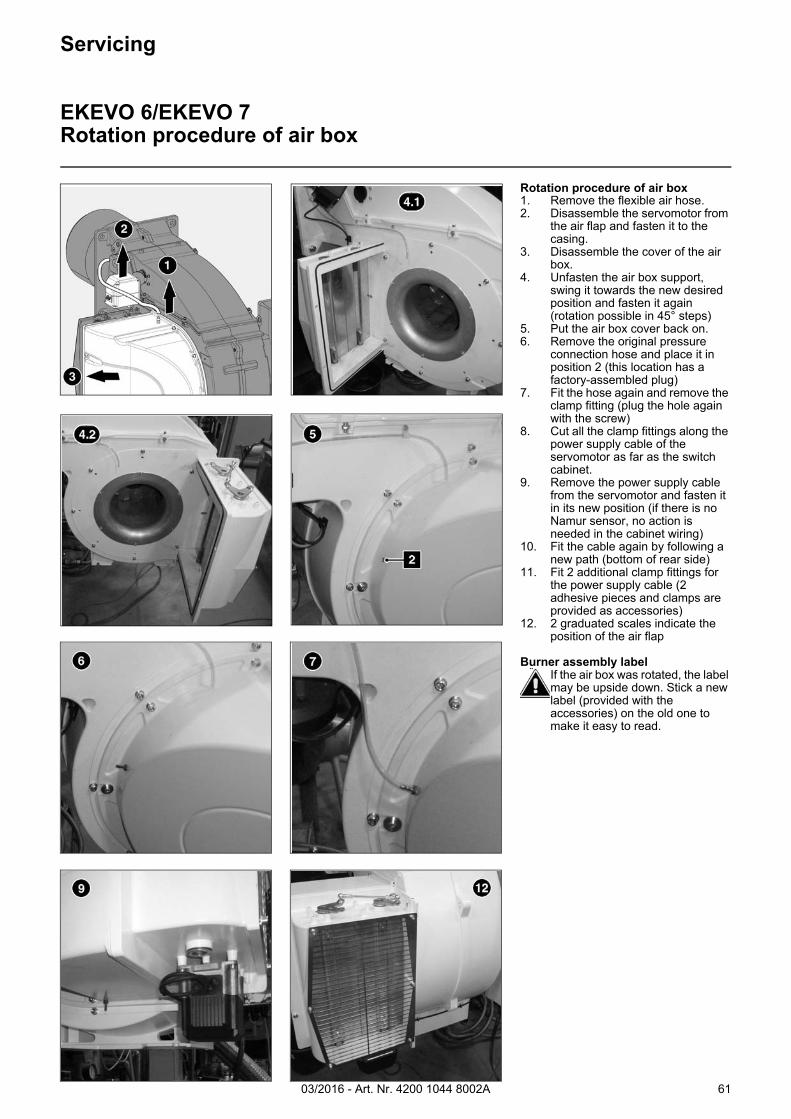
03/2016 - Art. Nr. 4200 1044 8002A 61
Servicing
EKEVO 6/EKEVO 7Rotation procedure of air box
Rotation procedure of air box1. Remove the flexible air hose.2. Disassemble the servomotor from
the air flap and fasten it to the casing.
3. Disassemble the cover of the air box.
4. Unfasten the air box support, swing it towards the new desired position and fasten it again (rotation possible in 45° steps)
5. Put the air box cover back on.6. Remove the original pressure
connection hose and place it in position 2 (this location has a factory-assembled plug)
7. Fit the hose again and remove the clamp fitting (plug the hole again with the screw)
8. Cut all the clamp fittings along the power supply cable of the servomotor as far as the switch cabinet.
9. Remove the power supply cable from the servomotor and fasten it in its new position (if there is no Namur sensor, no action is needed in the cabinet wiring)
10. Fit the cable again by following a new path (bottom of rear side)
11. Fit 2 additional clamp fittings for the power supply cable (2 adhesive pieces and clamps are provided as accessories)
12. 2 graduated scales indicate the position of the air flap
Burner assembly labelIf the air box was rotated, the label may be upside down. Stick a new label (provided with the accessories) on the old one to make it easy to read.
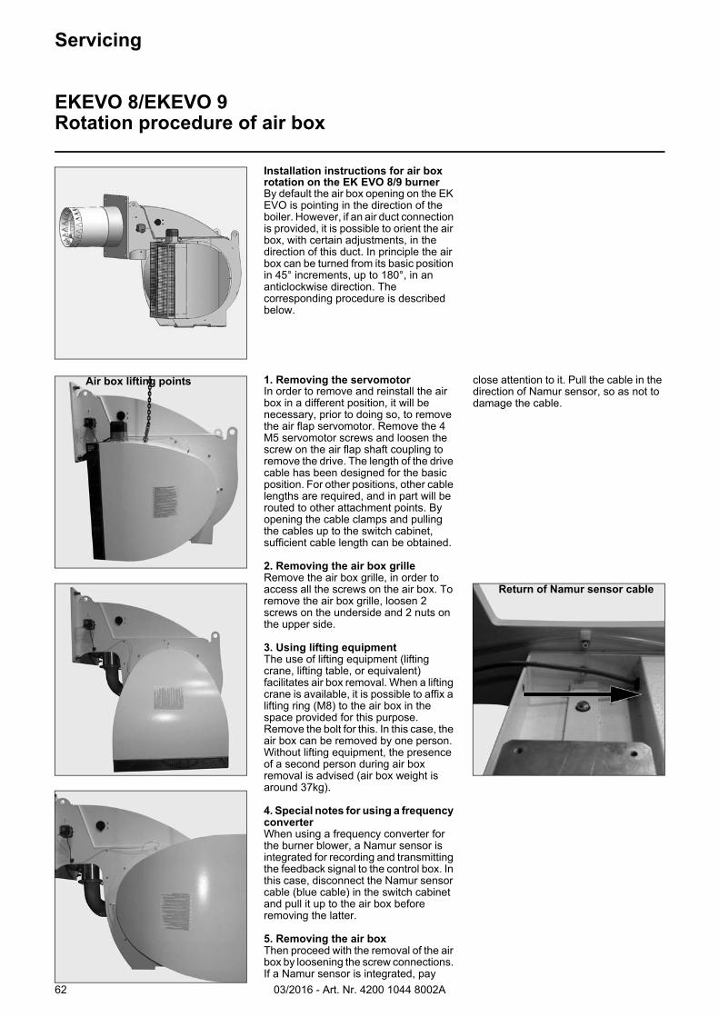
03/2016 - Art. Nr. 4200 1044 8002A62
Installation instructions for air box rotation on the EK EVO 8/9 burnerBy default the air box opening on the EK EVO is pointing in the direction of the boiler. However, if an air duct connection is provided, it is possible to orient the air box, with certain adjustments, in the direction of this duct. In principle the air box can be turned from its basic position in 45° increments, up to 180°, in an anticlockwise direction. The corresponding procedure is described below.
1. Removing the servomotorIn order to remove and reinstall the air box in a different position, it will be necessary, prior to doing so, to remove the air flap servomotor. Remove the 4 M5 servomotor screws and loosen the screw on the air flap shaft coupling to remove the drive. The length of the drive cable has been designed for the basic position. For other positions, other cable lengths are required, and in part will be routed to other attachment points. By opening the cable clamps and pulling the cables up to the switch cabinet, sufficient cable length can be obtained.
2. Removing the air box grilleRemove the air box grille, in order to access all the screws on the air box. To remove the air box grille, loosen 2 screws on the underside and 2 nuts on the upper side.
3. Using lifting equipmentThe use of lifting equipment (lifting crane, lifting table, or equivalent) facilitates air box removal. When a lifting crane is available, it is possible to affix a lifting ring (M8) to the air box in the space provided for this purpose. Remove the bolt for this. In this case, the air box can be removed by one person. Without lifting equipment, the presence of a second person during air box removal is advised (air box weight is around 37kg).
4. Special notes for using a frequency converterWhen using a frequency converter for the burner blower, a Namur sensor is integrated for recording and transmitting the feedback signal to the control box. In this case, disconnect the Namur sensor cable (blue cable) in the switch cabinet and pull it up to the air box before removing the latter.
5. Removing the air boxThen proceed with the removal of the air box by loosening the screw connections. If a Namur sensor is integrated, pay
close attention to it. Pull the cable in the direction of Namur sensor, so as not to damage the cable.
Servicing
EKEVO 8/EKEVO 9Rotation procedure of air box
Air box lifting points
Return of Namur sensor cable
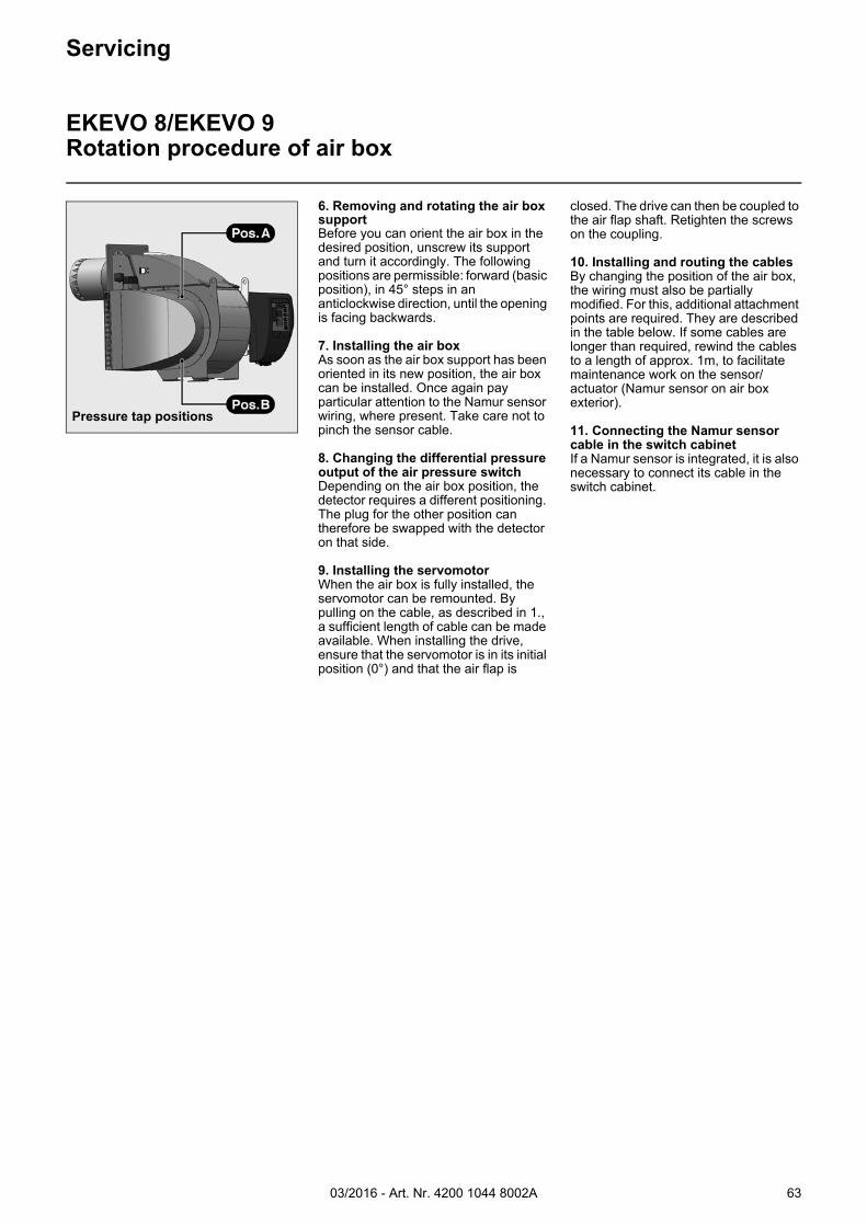
03/2016 - Art. Nr. 4200 1044 8002A 63
Servicing
EKEVO 8/EKEVO 9Rotation procedure of air box
6. Removing and rotating the air box supportBefore you can orient the air box in the desired position, unscrew its support and turn it accordingly. The following positions are permissible: forward (basic position), in 45° steps in an anticlockwise direction, until the opening is facing backwards.
7. Installing the air boxAs soon as the air box support has been oriented in its new position, the air box can be installed. Once again pay particular attention to the Namur sensor wiring, where present. Take care not to pinch the sensor cable.
8. Changing the differential pressure output of the air pressure switch Depending on the air box position, the detector requires a different positioning. The plug for the other position can therefore be swapped with the detector on that side.
9. Installing the servomotorWhen the air box is fully installed, the servomotor can be remounted. By pulling on the cable, as described in 1., a sufficient length of cable can be made available. When installing the drive, ensure that the servomotor is in its initial position (0°) and that the air flap is
closed. The drive can then be coupled to the air flap shaft. Retighten the screws on the coupling.
10. Installing and routing the cablesBy changing the position of the air box, the wiring must also be partially modified. For this, additional attachment points are required. They are described in the table below. If some cables are longer than required, rewind the cables to a length of approx. 1m, to facilitate maintenance work on the sensor/actuator (Namur sensor on air box exterior).
11. Connecting the Namur sensor cable in the switch cabinetIf a Namur sensor is integrated, it is also necessary to connect its cable in the switch cabinet.
Pressure tap positions
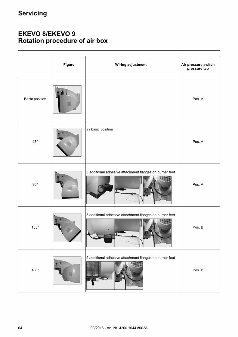
03/2016 - Art. Nr. 4200 1044 8002A64
Servicing
EKEVO 8/EKEVO 9Rotation procedure of air box
Figure Wiring adjustment Air pressure switch pressure tap
Basic position Pos. A
45°
as basic position
Pos. A
90°
3 additional adhesive attachment flanges on burner feet
Pos. A
135°
3 additional adhesive attachment flanges on burner feet
Pos. B
180°
2 additional adhesive attachment flanges on burner feet
Pos. B
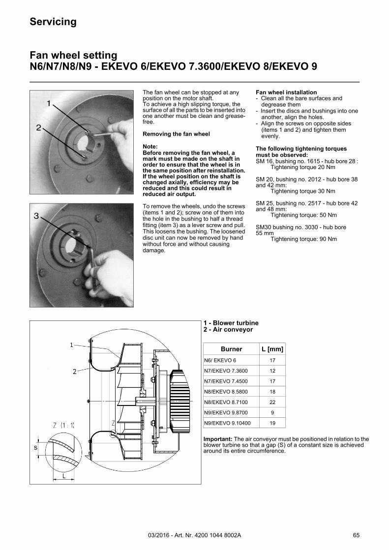
03/2016 - Art. Nr. 4200 1044 8002A 65
1 - Blower turbine2 - Air conveyor
Important: The air conveyor must be positioned in relation to the blower turbine so that a gap (S) of a constant size is achieved around its entire circumference.
Burner L [mm]
N6/ EKEVO 6 17
N7/EKEVO 7.3600 12
N7/EKEVO 7.4500 17
N8/EKEVO 8.5800 18
N8/EKEVO 8.7100 22
N9/EKEVO 9.8700 9
N9/EKEVO 9.10400 19
Servicing
Fan wheel settingN6/N7/N8/N9 - EKEVO 6/EKEVO 7.3600/EKEVO 8/EKEVO 9
The fan wheel can be stopped at any position on the motor shaft.To achieve a high slipping torque, the surface of all the parts to be inserted into one another must be clean and grease-free.
Removing the fan wheel
Note:Before removing the fan wheel, a mark must be made on the shaft in order to ensure that the wheel is in the same position after reinstallation. If the wheel position on the shaft is changed axially, efficiency may be reduced and this could result in reduced air output.
To remove the wheels, undo the screws (items 1 and 2); screw one of them into the hole in the bushing to half a thread fitting (item 3) as a lever screw and pull. This loosens the bushing. The loosened disc unit can now be removed by hand without force and without causing damage.
Fan wheel installation- Clean all the bare surfaces and
degrease them- Insert the discs and bushings into one
another, align the holes.- Align the screws on opposite sides
(items 1 and 2) and tighten them evenly.
The following tightening torques must be observed:SM 16, bushing no. 1615 - hub bore 28 :
Tightening torque 20 Nm
SM 20, bushing no. 2012 - hub bore 38 and 42 mm:
Tightening torque 30 Nm
SM 25, bushing no. 2517 - hub bore 42 and 48 mm:
Tightening torque: 50 Nm
SM30 bushing no. 3030 - hub bore 55 mm
Tightening torque: 90 Nm
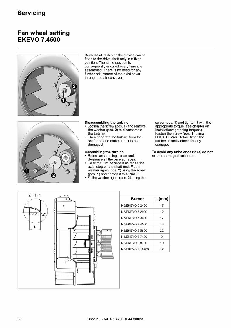
03/2016 - Art. Nr. 4200 1044 8002A66
Servicing
Fan wheel settingEKEVO 7.4500
Because of its design the turbine can be fitted to the drive shaft only in a fixed position. The same position is consequently ensured every time it is assembled. There is no need for any further adjustment of the axial cover through the air conveyor.
Disassembling the turbine• Loosen the screw (pos. 1) and remove
the washer (pos. 2) to disassemble the turbine.
• Then separate the turbine from the shaft end and make sure it is not damaged.
Assembling the turbine• Before assembling, clean and
degrease all the bare surfaces.• To fit the turbine slide it as far as the
axial stop on the shaft end. Fit the washer again (pos. 2) using the screw (pos. 1) and tighten it to 45Nm.
• Fit the washer again (pos. 2) using the
screw (pos. 1) and tighten it with the appropriate torque (see chapter on Installation/tightening torques). Fasten the screw (pos. 1) using LOCTITE 243. Before fitting the turbine, visually check for any damage.
To avoid any unbalance risks, do not re-use damaged turbines!
Burner L [mm]
N6/EKEVO 6.2400 17
N6/EKEVO 6.2900 12
N7/EKEVO 7.3600 17
N7/EKEVO 7.4500 18
N8/EKEVO 8.5800 22
N8/EKEVO 8.7100 9
N9/EKEVO 9.8700 19
N9/EKEVO 9.10400 17
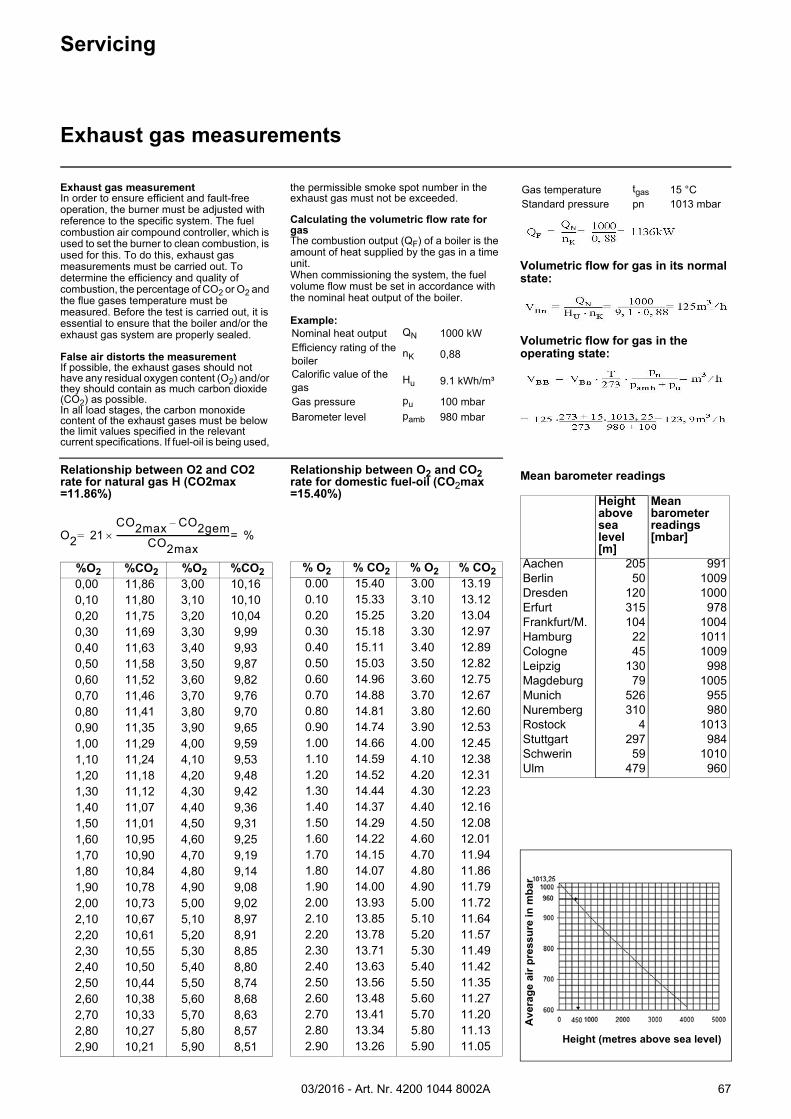
03/2016 - Art. Nr. 4200 1044 8002A 67
Servicing
Exhaust gas measurements
Exhaust gas measurementIn order to ensure efficient and fault-free operation, the burner must be adjusted with reference to the specific system. The fuel combustion air compound controller, which is used to set the burner to clean combustion, is used for this. To do this, exhaust gas measurements must be carried out. To determine the efficiency and quality of combustion, the percentage of CO2 or O2 and the flue gases temperature must be measured. Before the test is carried out, it is essential to ensure that the boiler and/or the exhaust gas system are properly sealed.
False air distorts the measurementIf possible, the exhaust gases should not have any residual oxygen content (O2) and/or they should contain as much carbon dioxide (CO2) as possible.In all load stages, the carbon monoxide content of the exhaust gases must be below the limit values specified in the relevant current specifications. If fuel-oil is being used,
the permissible smoke spot number in the exhaust gas must not be exceeded.
Calculating the volumetric flow rate for gasThe combustion output (QF) of a boiler is the amount of heat supplied by the gas in a time unit. When commissioning the system, the fuel volume flow must be set in accordance with the nominal heat output of the boiler.
Example:
Volumetric flow for gas in its normal state:
Volumetric flow for gas in the operating state:
Nominal heat output QN 1000 kWEfficiency rating of the boiler
nK 0,88
Calorific value of the gas
Hu 9.1 kWh/m³
Gas pressure pu 100 mbarBarometer level pamb 980 mbar
Gas temperature tgas 15 °CStandard pressure pn 1013 mbar
Relationship between O2 and CO2 rate for natural gas H (CO2max =11.86%)
Relationship between O2 and CO2 rate for domestic fuel-oil (CO2max =15.40%)
%O2 %CO2 %O2 %CO2 0,00 11,86 3,00 10,160,10 11,80 3,10 10,100,20 11,75 3,20 10,040,30 11,69 3,30 9,990,40 11,63 3,40 9,930,50 11,58 3,50 9,870,60 11,52 3,60 9,820,70 11,46 3,70 9,760,80 11,41 3,80 9,700,90 11,35 3,90 9,651,00 11,29 4,00 9,591,10 11,24 4,10 9,531,20 11,18 4,20 9,481,30 11,12 4,30 9,421,40 11,07 4,40 9,361,50 11,01 4,50 9,311,60 10,95 4,60 9,251,70 10,90 4,70 9,191,80 10,84 4,80 9,141,90 10,78 4,90 9,082,00 10,73 5,00 9,022,10 10,67 5,10 8,972,20 10,61 5,20 8,912,30 10,55 5,30 8,852,40 10,50 5,40 8,802,50 10,44 5,50 8,742,60 10,38 5,60 8,682,70 10,33 5,70 8,632,80 10,27 5,80 8,572,90 10,21 5,90 8,51
O2 21CO2max CO2gem–
CO2max--------------------------------------------------------- %==
% O2 % CO2 % O2 % CO2 0.00 15.40 3.00 13.190.10 15.33 3.10 13.120.20 15.25 3.20 13.040.30 15.18 3.30 12.970.40 15.11 3.40 12.890.50 15.03 3.50 12.820.60 14.96 3.60 12.750.70 14.88 3.70 12.670.80 14.81 3.80 12.600.90 14.74 3.90 12.531.00 14.66 4.00 12.451.10 14.59 4.10 12.381.20 14.52 4.20 12.311.30 14.44 4.30 12.231.40 14.37 4.40 12.161.50 14.29 4.50 12.081.60 14.22 4.60 12.011.70 14.15 4.70 11.941.80 14.07 4.80 11.861.90 14.00 4.90 11.792.00 13.93 5.00 11.722.10 13.85 5.10 11.642.20 13.78 5.20 11.572.30 13.71 5.30 11.492.40 13.63 5.40 11.422.50 13.56 5.50 11.352.60 13.48 5.60 11.272.70 13.41 5.70 11.202.80 13.34 5.80 11.132.90 13.26 5.90 11.05
Mean barometer readings
Height above sea level[m]
Mean barometer readings [mbar]
Aachen 205 991Berlin 50 1009Dresden 120 1000Erfurt 315 978Frankfurt/M. 104 1004Hamburg 22 1011Cologne 45 1009Leipzig 130 998Magdeburg 79 1005Munich 526 955Nuremberg 310 980Rostock 4 1013Stuttgart 297 984Schwerin 59 1010Ulm 479 960
Height (metres above sea level)
Ave
rag
e ai
r p
ress
ure
in m
bar
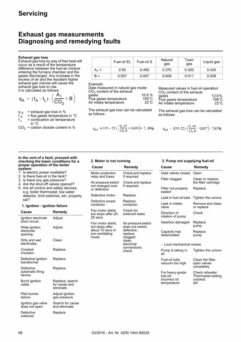
03/2016 - Art. Nr. 4200 1044 8002A68
Example:Data measured in natural gas mode:CO2 content of the exhaust gases 10.8 % Flue gases temperature 195°C Air intake temperature 22°C
The exhaust gas loss can be calculated as follows:
Measured values in fuel-oil operation:CO2 content of the exhaust gases 12.8 % Flue gases temperature 195°C Air intake temperature 22°C
The exhaust gas loss can be calculated as follows:
Fuel-oil EL Fuel-oil S Naturalgas
Towngas Liquid gas
A1 = 0.50 0.490 0.370 0.350 0.420B = 0.007 0.007 0.009 0.011 0.008
Servicing
Exhaust gas measurementsDiagnosing and remedying faults
Exhaust gas lossExhaust gas loss by way of free heat will occur as a result of the temperature difference between the fuel-air mixture entering the furnace chamber and the gases discharged. Any increase in the excess of air and the resultant higher exhaust gas volume will cause the exhaust gas loss to rise. It is calculated as follows:
q A = exhaust gas loss in %t A = flue gases temperature in °Ct L = combustion air temperature
in °CCO2 = carbon dioxide content in %
qA tA tL– A1
CO2------------ B+
=
In the vent of a fault, proceed with checking the basic conditions for a proper operation of the boiler system:1. Is electric power available?2. Is there fuel-oil in the tank?3. Is there any gas pressure?4. Are the shut-off valves opened?5. Are all control and safety devices,
e.g. boiler thermostat, low water detector, limit switches, etc. properly set?
1. Ignition - ignition failure
Cause Remedy
Ignition electrode short circuit.
Adjust.
Wide ignition electrode spacing.
Adjust.
Dirty and wet electrodes.
Clean.
Cracked insulator.
Replace.
Defective ignition transformer.
Replace.
Defective automatic firing device.
Replace.
Burnt ignition cable.
Replace; search for cause and eliminate.
Pilot burner failure.
Adjust ignition gas pressure
Ignition gas valve does not open.
Search for cause and eliminate
Defective solenoid.
Replace
2. Motor is not running
Cause Remedy
Motor protection relay and fuses.
Check and replace if required.
Air pressure switch not changed over or defective.
Check and replace if required.
Defective motor. Replace.
Defective power contactor.
Replace contactor.
Fan motor starts but stops after 20-25 secs.
Check for solenoid leaks
Fan motor starts, but stops after about 10 secs in pre-ventilating mode.
Air pressure switch does not switch, defective : replace, clogged: clean, electrical connections: check
3. Pump not supplying fuel-oil
Cause Remedy
Gate valves closed Open
Filter clogged Clean or replace the filter cartridge
Filter not properly sealed
Replace
Leak in fuel-oil tube Tighten the unions
Leak in intake valve
Remove and clean or replace
Direction of rotation of pump
Check
Gearbox damaged Replace pump
Capacity has deteriorated
Replace pump
- Loud mechanical noises
Pump is taking in air
Tighten the unions
Fuel-oil tube vacuum too high
Clean the filter, open valves completely
For heavy-grade fuel-oil:incorrect oil temperature
Check reheater:Thermostat setting,crackeddirt
03/2016 - Art. Nr. 4200 1044 8002A 69
Servicing
Diagnosing and remedying faults
8. Cleaning and lubricating instructionsDepending on the cleanliness status of the combustion air, the fan impeller, ignition electrodes, flame sensors and air flaps must be cleaned as required.
For burner with mechanical compound controller: lubricate ball heads on the adjusting screws for the compound controller.
The bearing points of the burner moving parts require no maintenance.Damage to ball bearings should be detected and eliminated at an early stage to avoid greater consequential damage. Listen to the motor bearing noise to identify possible irregularities.
4. Nozzle - uneven atomisation
Cause Remedy
Nozzle loose TightenBore partially clogged
Remove and clean or replace
worn as a result of prolonged usage
Replace
- No fuel-oil supply:Nozzle clogged Remove
cleanNozzle leak ReplaceLeak in nozzle line shut-off
Replace
5. No response to flame by Automatic firing device with flame sensor
Cause Remedy
Dirty flame sensor.
Clean.
Burner fails to start.
Check connection with the automatic firing device
Automatic firing device warning light on; flame fault
Unlock and search for cause
Ionisation current too weak.
Check combustion setting
Burner starts without flame formation:
solenoid valve not opening
Coil, detector defective, check connection
Lack of gas or gas pressure too low.
Check gas pressure regulator, gas valve, gas filter. Is the equipment gas cock open?
6. Combustion components - poor combustion values
heavy internal oil deposits or heavy coke deposits
(fuel-oil mode)
Cause Remedy
Incorrectsettings.
Correct settings.
Incorrect burner head
Replace
Nozzle too big or too small
Replace
Incorrect nozzle spray angle
Replace nozzle
High or low combustion air flow rate.
Readjust burner.
Furnace chamber not sufficiently ventilated.
The boiler room must be ventilated through an unlockable opening with a cross section of at least 50 % of all chimney cross sections in the furnace.
7. Solenoid valve fails to open
Cause Remedy
Defective coil. Replace coil or valve
Defective automatic firing device.
Replace automatic firing device.
Will not close properly: dirt on sealing surfaces
Open valve; remove foreign matter; replace valve if required.
03/2016 - Art. Nr. 4200 1044 8002A70
Smell of gas, danger of gas• Shut down the burner• Close the gas shut-off valve• Keep away fire and naked flames• Switch off the emergency switch• Ensure there is adequate ventilation• Notify the gas supplier and customer
services• According to DIN 4788, components
with technical safety-related functions may not be repaired. On the other hand, they may be replaced by original parts or parts of equal quality.
How to proceed in case of hazards• Switch off the emergency switch• Close fuel valves• If there is a smell of gas, notify the gas
supply company.• Use suitable extinguishing equipment,
e.g. fire extinguisher in acc. with DIN 14 406, fire class B,C.
• Servicing work on pressure switches, automatic actuators, limiters and automatic firing devices or other safety devices may only be carried out by the relevant manufacturer or by service engineers authorised to service the individual items of equipment on their behalf.
• If third parties work on the system, our obligations under warranty become void.
If system faults occur, proceed with checking the basic conditions for proper operation of the system.
Make a check for the following:1. Is fuel available, is it flowing through
the lines and is the supply pressure adequate?
2. Is power being supplied to the system?
3. Is all control and safety equipment such as temperature controller, safety limiter, water failure cut-out, electrical limit switches, etc., functioning properly and correctly adjusted? If it is found that none of the above reasons for the fault applies, the burner functions must be thoroughly checked.
Prevailing conditions:The burner will be found to be out of operation and in faulty and interlocked position. Proceed with searching for the cause of the fault and eliminate it. Unlock the automatic firing device by pressing the fault eliminate key and start the burner.
The start-up program will be initiated and should be carefully monitored.The possible cause of the fault may be quickly found by referring to the fault indicator on the automatic firing device and watching the start-up and operating program.
Servicing
Faults
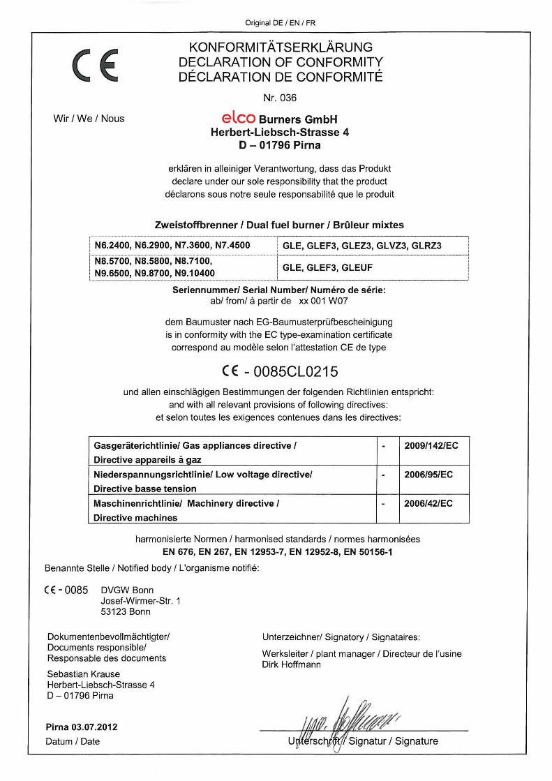
03/2016 - Art. Nr. 4200 1044 8002A 71
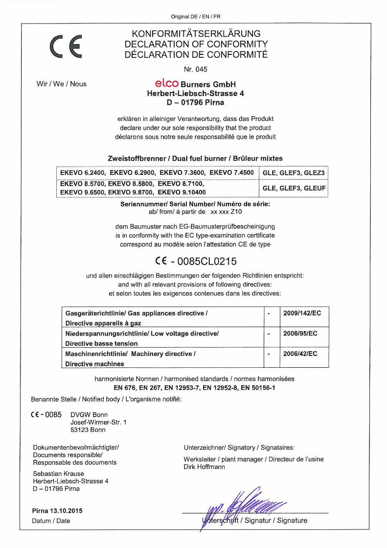
03/2016 - Art. Nr. 4200 1044 8002A72
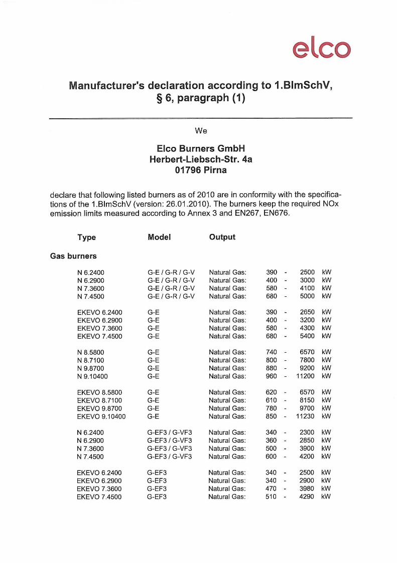
03/2016 - Art. Nr. 4200 1044 8002A 73
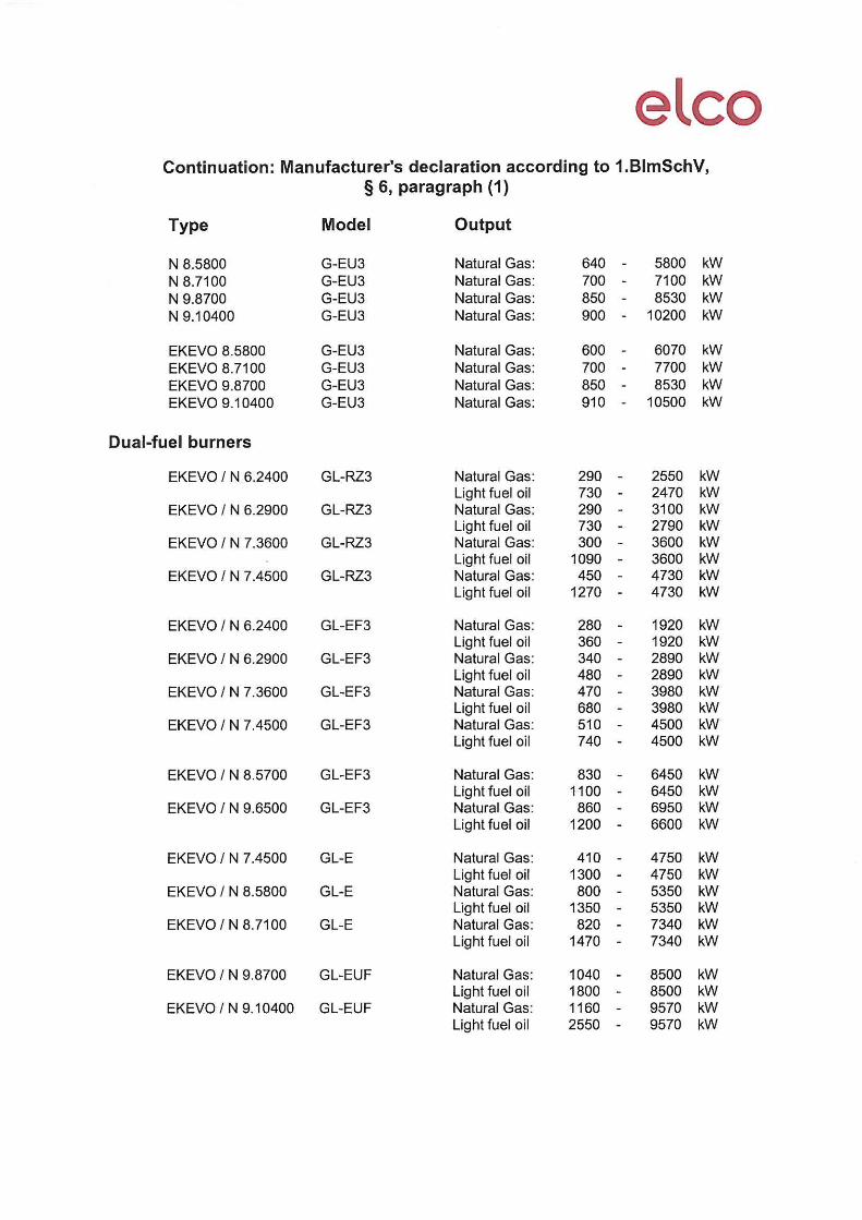
03/2016 - Art. Nr. 4200 1044 8002A74
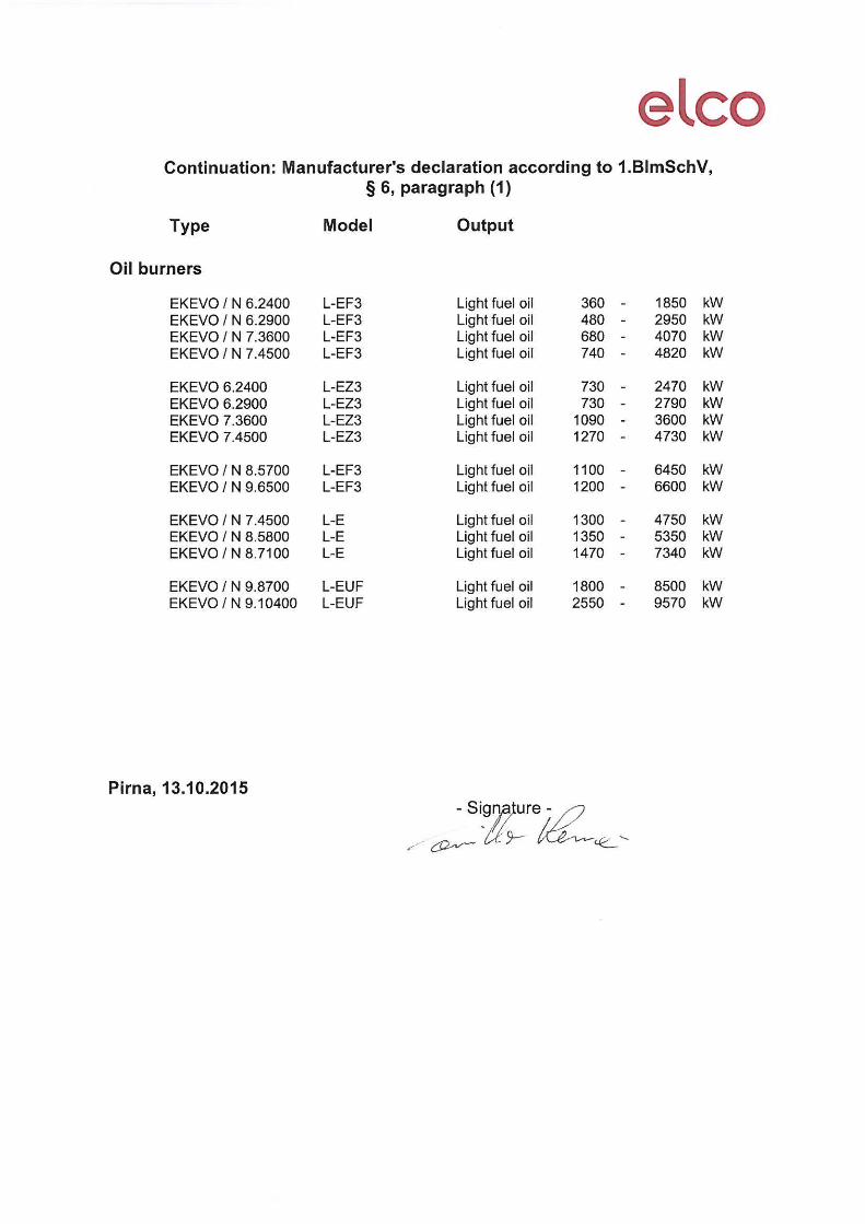
03/2016 - Art. Nr. 4200 1044 8002A 75

03/2016 - Art. Nr. 4200 1044 8002A76
www.elco.netMade in EU.Non contractual document.