Balancing Valves FIG 900XSS and 901XS Butterfly Venturi ...
11
Valve & Actuation Service 4.24 Dimensions The larger sizes of the BOSS TM Venturi consist of a gear operated cast iron butterfly valve fitted with a double regulation feature mounted on a carbon steel tube fitted with the Venturi device. These Venturi valves are available with flanged connections in a long or short pattern. The range covers sizes from 65mm (2½in) to 300mm (12in). This range of valves complement the DZR brass offering of Venturi valves and the long pattern version includes, within the valve, the upstream lengths which are required for accurate commissioning (5 times the valve diameter). The flow is calculated based on the pressure differential across the nozzle. The measurement accuracy is better that +/-3% and this accuracy is maintained over the entire measuring range from 1kPa to 100kPa. The BOSS TM Venturi is available in two variations: • FODRV: Includes regulation, isolation and a flow measurement unit. • DRV: Includes regulation and isolation unit. Benefits • Regulation, Isolation and flow measurement in one single unit • Measurement across a nozzle • Flow measurement better than +/-3% • Same measuring accuracy across the entire measuring area from 1kPa – 100kPa • Regulation setting remains unchanged when isolated C B A D Balancing Valves FIG 900XSS and 901XS Butterfly Venturi Commissioning Valve FODRV & DRV 65mm-300mm (PN16) BOSS TM 900XSS Venturi FODRV DN65-300 BOSS TM 900XSS Weights & Dimensions Standard Butterfly FODRV Venturi DN65 – 300 Size Nominal A B C D Number Weight Product DN Size in mm mm mm mm of bolts kg Code 65 2 1 ⁄ 2 182 185 285 100 4 13.3 32014110 80 3 249 200 295 100 8 16.2 32014121 100 4 325 220 310 160 8 23 32014132 125 5 341 250 325 160 8 30 32014143 150 6 354 285 340 160 8 36 32014154 200 8 378 340 430 200 12 55 32014165 250 10 411 405 465 200 12 78 32014176 300 12 465 460 535 250 12 105 32014187 A C D B BOSS TM 901XS Venturi DRV DN65-300 BOSS TM 901XS Standard Butterfly DRV DN65 - 300 Size Nominal A B C D Number Weight Product DN Size in mm mm mm mm of bolts kg Code 65 2 1 ⁄ 2 45 185 285 100 4 6.1 32014601 80 3 46 200 295 100 8 6.3 32014612 100 4 52 220 310 160 8 10.6 32014623 125 5 55 250 325 160 8 12.6 32014634 150 6 56 285 340 160 8 14.1 32014645 200 8 60 340 430 200 12 14.1 32014656 250 10 68 405 465 200 12 33.7 32014667 300 12 78 460 535 250 12 48.7 32014678
-
Upload
khangminh22 -
Category
Documents
-
view
3 -
download
0
Transcript of Balancing Valves FIG 900XSS and 901XS Butterfly Venturi ...

Valve & Actuation Service
4.24
Dimensions
The larger sizes of the BOSSTM Venturi consist of a gear operated cast iron butterfly valve fitted with a double regulation feature mounted on a carbon steel tube fitted with the Venturi device.
These Venturi valves are available with flanged connections in a long or short pattern. The range covers sizes from 65mm (2½in) to 300mm (12in). This range of valves complement the DZR brass offering of Venturi valves and the long pattern version includes, within the valve, the upstream lengths which are required for accurate commissioning (5 times the valve diameter).
The flow is calculated based on the pressure differential across the nozzle. The measurement accuracy is better that +/-3% and this accuracy is maintained over the entire measuring range from 1kPa to 100kPa.
The BOSSTM Venturi is available in two variations:
• FODRV: Includes regulation, isolation and a flow measurement unit.
• DRV: Includes regulation and isolation unit.
Benefits• Regulation, Isolation and flow measurement in one single unit
• Measurement across a nozzle
• Flow measurement better than +/-3%
• Same measuring accuracy across the entire measuring area from 1kPa – 100kPa
• Regulation setting remains unchanged when isolated
C
BA
D
Balancing Valves FIG 900XSS and 901XS Butterfly Venturi Commissioning Valve FODRV & DRV 65mm-300mm (PN16)
BOSSTM 900XSS Venturi FODRV DN65-300
BOSSTM 900XSS
Weights & Dimensions
Standard Butterfly FODRV Venturi DN65 – 300 Size Nominal A B C D Number Weight Product DN Size in mm mm mm mm of bolts kg Code 65 21⁄2 182 185 285 100 4 13.3 32014110 80 3 249 200 295 100 8 16.2 32014121 100 4 325 220 310 160 8 23 32014132 125 5 341 250 325 160 8 30 32014143 150 6 354 285 340 160 8 36 32014154 200 8 378 340 430 200 12 55 32014165 250 10 411 405 465 200 12 78 32014176 300 12 465 460 535 250 12 105 32014187
A
C
D
B
BOSSTM 901XS Venturi DRV DN65-300
BOSSTM 901XS
Standard Butterfly DRV DN65 - 300 Size Nominal A B C D Number Weight Product DN Size in mm mm mm mm of bolts kg Code 65 21⁄2 45 185 285 100 4 6.1 32014601 80 3 46 200 295 100 8 6.3 32014612 100 4 52 220 310 160 8 10.6 32014623 125 5 55 250 325 160 8 12.6 32014634 150 6 56 285 340 160 8 14.1 32014645 200 8 60 340 430 200 12 14.1 32014656 250 10 68 405 465 200 12 33.7 32014667 300 12 78 460 535 250 12 48.7 32014678

bssindustrial.co.uk4.25
Balancing Valves
SpecificationThe commissioning station incorporates a characterised regulation butterfly valve close coupled to a fixed orifice Venturi flow measuring device with double seal test points. The double regulating feature allows the disc setting to be locked in position using an allen key and return to the exact position after isolation.
Butterfly Venturi DN65 - 300 FODRV DRVPressure & Temperature ClassificationTemperature Max (Max) 105ºC 105ºCPressure Flanged Connection (Max) 16 bar 16 bar
Materials of ConstructionVenturi pipe Carbon Steel ST37Measuring P/T plug DZR Brass CW602N CuZn36Pb2AsRubber in P/T plug EPDMButterfly Valve body Cast Iron, Fully Lugged ASTM A126KL.BDisc Stainless Steel ASTM A351Shaft Stainless Steel ASTM A276Backing ring EPDMDrive pin Stainless Steel ASTM A276 Gr316Shaft seal NBR 1Bearing Lubricated Bronze ASTM B62
Markings on ValvesVenturi pipe PN16, 105ºC, St37Butterfly valve Valve Type, DN & Kvs Value
ConnectionFlanged BS4504 PN16Compression EN1254-2
Pressure Test According to: ISO5208:1993E

Valve & Actuation Service
4.26
Balancing Valves
Flow Range – Butterfly FODRV & DRV DN65 - 300 FODRV DRV Valve Size Kvs Flow Rates* Signal Head Loss Loss Valve Kvs Kvs Factor Size DN Description m3h l/s kPa m3h DN m3h 65 Standard 37.40 3.00 - 7.00 8 - 45 78.20 0.24 65 148 80 Standard 72.90 6.00 - 15.00 9 - 55 169.00 0.19 80 237 100 Standard 129.00 11.00 - 26.00 9 - 53 360.00 0.13 100 603 125 Standard 190.00 17.00 - 40.00 10 - 57 502.00 0.14 125 888 150 Standard 348.00 24.00 - 57.00 6 - 35 1010.00 0.12 150 2341 200 Standard 586.00 42.00 - 100.00 7 - 38 1910.00 0.09 200 2845 250 Standard 861.00 67.00 - 157.00 8 - 43 2540.00 0.11 250 4549 300 Standard 1513.00 94.00 - 226.00 5 - 29 4850.00 0.10 300 7761* The flow rates given in the table are for water flow in steel pipes which provide a pressure loss of
100 to 500 Pa per metre of pipe.
Regulation/OperationThe valve is adjusted by rotating the hand wheel on the gearbox. The water flow increases when the hand wheel is turned anti-clockwise and reduces when turned clockwise. By using a flow meter or other measuring device the flow rate through the BOSSTM Venturi can be measured and adjusted to meet the specific requirements of the system. The gearbox can be locked against the memory stop when the desired setting is achieved. Once locked the valve can be isolated and when re-opened cannot travel past the memory stop.
IsolationThe valve is isolated by turning the hand wheel clockwise up to the “S” position stamped on the gearbox. After isolation the valve is re-opened to the pre-set position when the indicator cam reaches the memory stop.
Flow MeasurementFlow measurements are via the Venturi nozzle. The BOSSTM Venturi has two test points (P/T plugs). The high pressure test point is identified by the RED retaining clip and the low pressure test point is identified by the BLUE retaining clip. The pressure differential measured between these test points can be used to calculate the actual flow through the Venturi. This differential can be measured using a flow meter or other measuring device. This is converted into a flow rate of litres per second (l/s) or metres cubed per hour (m3/h) either electronically or using a calculation formula.
Valve SizingSizing disc available on request via your local BSS branch or the BOSS™ Technical Team on 0116 245 5940.

bssindustrial.co.uk
FIG 900XSS & 900XSL FODRV Venturi Valve DN 65 flange/flange – Flow diagram / Measuring signal diagram
Flowl/s
m3/h
Pressure drop across valve Position
1.8 2 3 4 5 6 7
6.48 7.2 10.8 14.4 18.0 21.6 25.2
kPa100
807060
50
40
30
20
10
876
5
4
3
bar1.0
0.80.70.6
0.5
0.4
0.3
0.2
0.1
0.080.070.06
0.05
0.04
0.03
9.0
3.0
7.0
6.0
5.0
4.0
10.0
8.0
Flowl/s
m 3/h
Pressure drop across valve
1.8 2 3 4 5 6 7
6.48 7.2 10.8 14.4 18.0 21.6 25.2
kPa100
60504030
20
10
5
3
bar1.0
0.60.50.40.3
0.2
0.1
0.05
0.03
DN 65 flange/flange - Flow diagram
DN 65 flange/flange - Measuring signal diagram
4.27

Valve & Actuation Service
4.28
FIG 900XSS & 900XSL FODRV Venturi Valve DN 80 flange/flange – Flow diagram / Measuring signal diagram
DN 80 flange/flange - Flow diagram
DN 80 flange/flange - Measuring signal diagram
Flowl/s
m 3/h
Pressure drop across valve Position
3.5 4 5 6 7 8 9 10 15
12.6 14.4 18.0 21.6 25.2 28.8 32.4 36.0 54.0
kPa100
807060
50
40
30
20
10
876
5
4
3
bar1.0
0.80.70.6
0.5
0.4
0.3
0.2
0.1
0.080.070.06
0.05
0.04
0.03
10.0
3.0
7.0
6.0
5.0
4.0
8.0
9.0
Flowl/s
m 3/h
Pressure drop across valve
3.5 4 5 6 7 8 9 10 15
12.6 14.4 18.0 21.6 25.2 28.8 32.4 36.0 54.0
kPa100
60504030
20
10
5
3
bar1.0
0.60.50.40.3
0.2
0.1
0.05
0.03
bssindustrial.co.uk
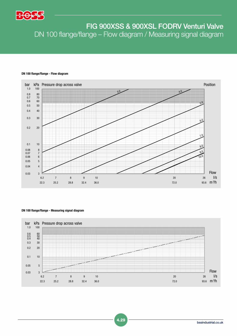
FIG 900XSS & 900XSL FODRV Venturi Valve DN 100 flange/flange – Flow diagram / Measuring signal diagram
Flowl/s
m 3/h
Pressure drop across valve Position
6.2 7 8 9 10 20 26
22.3 25.2 28.8 32.4 36.0 72.0 93.6
kPa100
807060
50
40
30
20
10
876
5
4
3
bar1.0
0.80.70.6
0.5
0.4
0.3
0.2
0.1
0.080.070.06
0.05
0.04
0.03
7.0
3.0 4.0
5.0
6.0
10.09.0
8.0
Flowl/s
m 3/h
Pressure drop across valve
6.2 7 8 9 10 20 26
22.3 25.2 28.8 32.4 36.0 72.0 93.6
kPa100
60504030
20
10
5
3
bar1.0
0.60.50.40.3
0.2
0.1
0.05
0.03
DN 100 flange/flange - Flow diagram
DN 100 flange/flange - Measuring signal diagram
4.29

Valve & Actuation Service
Balancing Valves DN 125 flange/flange – Flow diagram / Measuring signal diagram
Flowl/s
m 3/h
Pressure drop across valve Position
9 10 20 30 40
32.4 36.0 72.0 108.0 144.0
kPa100
807060
50
40
30
20
10
876
5
4
3
bar1.0
0.80.70.6
0.5
0.4
0.3
0.2
0.1
0.080.070.06
0.05
0.04
0.03
7.0
3.0 4.0
5.0
6.0
8.0
9.0
10.0
Flowl/s
m 3/h
Pressure drop across valve
9 10 20 30 40
32.4 36.0 72.0 108.0 144.0
kPa100
60504030
20
10
5
3
bar1.0
0.60.50.40.3
0.2
0.1
0.05
0.03
DN 125 flange/flange - Flow diagram
DN 125 flange/flange - Measuring signal diagram
4.30

bssindustrial.co.uk4.31
FIG 900XSS & 900XSL FODRV Venturi Valve DN 150 flange/flange – Flow diagram / DN 150 flange/flange –
Measuring signal diagram
Flowl/s
m 3/h
Pressure drop across valve Position
16.8 20 30 40 50 57
60.5 72.0 108.0 144.0 180.0 205.0
kPa100
807060
50
40
30
20
10
876
5
4
3
bar1.0
0.80.70.6
0.5
0.4
0.3
0.2
0.1
0.080.070.06
0.05
0.04
0.03
9.0
6.0
7.0
8.0
4.0 5.0
Flowl/s
m 3/h
Pressure drop across valve
16.8 20 30 40 50 57
60.5 72.0 108.0 144.0 180.0 205.0
kPa100
60504030
20
10
5
3
bar1.0
0.60.50.40.3
0.2
0.1
0.05
0.03
DN 150 flange/flange - Flow diagram
DN 150 flange/flange - Measuring signal diagram

Valve & Actuation Service
Balancing Valves DN 200 flange/flange – Flow diagram DN 200 flange/flange – Measuring signal diagram
Flowl/s
m 3/h
Pressure drop across valve Position
28 30 40 50 60 70 80 90 100
101 108 144 180 216 252 288 324 360
kPa100
807060
50
40
30
20
10
876
5
4
3
bar1.0
0.80.70.6
0.5
0.4
0.3
0.2
0.1
0.080.070.06
0.05
0.04
0.03
9.0
4.0
6.0
7.0
8.0
5.0
Flowl/s
m 3/h
Pressure drop across valve
28 30 40 50 60 70 80 90 100
101 108 144 180 216 252 288 324 360
kPa100
60504030
20
10
5
3
bar1.0
0.60.50.40.3
0.2
0.1
0.05
0.03
DN 200 flange/flange - Flow diagram
DN 200 flange/flange - Measuring signal diagram
4.32
bssindustrial.co.uk4.33
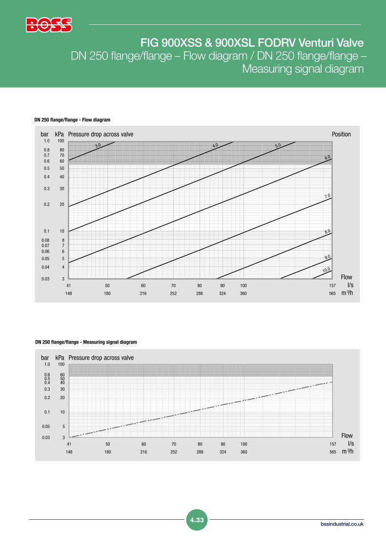
FIG 900XSS & 900XSL FODRV Venturi Valve DN 250 flange/flange – Flow diagram / DN 250 flange/flange –
Measuring signal diagram
Flowl/s
m 3/h
Pressure drop across valve Position
41 50 60 70 80 90 100 157
148 180 216 252 288 324 360 565
kPa100
807060
50
40
30
20
10
876
5
4
3
bar1.0
0.80.70.6
0.5
0.4
0.3
0.2
0.1
0.080.070.06
0.05
0.04
0.03
10.0
5.0
7.0
8.0
9.0
4.0
6.0
3.0
Flowl/s
m 3/h
Pressure drop across valve
41 50 60 70 80 90 100 157
148 180 216 252 288 324 360 565
kPa100
60504030
20
10
5
3
bar1.0
0.60.50.40.3
0.2
0.1
0.05
0.03
DN 250 flange/flange - Flow diagram
DN 250 flange/flange - Measuring signal diagram

Valve & Actuation Service
Flowl/s
m 3/h
Pressure drop across valve Position
72 80 90 100 200 226
259 288 324 360 720 814
kPa100
807060
50
40
30
20
10
876
5
4
3
bar1.0
0.80.70.6
0.5
0.4
0.3
0.2
0.1
0.080.070.06
0.05
0.04
0.03
7.0
8.0
9.0
10.0
6.04.0 5.0
Flowl/s
m 3/h
Pressure drop across valve
72 80 90 100 200 226
259 288 324 360 720 814
kPa100
60504030
20
10
5
3
bar1.0
0.60.50.40.3
0.2
0.1
0.05
0.03
Balancing Valves DN 300 flange/flange – Flow diagram / DN 300 flange/flange – Measuring signal diagram
DN 300 flange/flange - Flow diagram
DN 300 flange/flange - Measuring signal diagram
4.34