
BACHELOR'S THESIS Obstacle alert and collision avoidance ...

Myanmar Maritime University
Department of Naval Architecture and Ocean Engineering
Design of a Pleasure Craft with Catamaran Hull
Htike Aung Kyaw
NA 18
Kaung Zaw Htet
NA 32
Paing Hein Htet Tin
NA 38
Htaik Thu Aung
NA 42
Final Year Project
November 2012
Thanlyin

Myanmar Maritime University
Department of Naval Architecture and Ocean Engineering
Design of a Pleasure Craft with Catamaran Hull
Htike Aung Kyaw
NA 18
Kaung Zaw Htet
NA 32
Paing Hein Htet Tin
NA 38
Htaik Thu Aung
NA 42
Final Year Project
November 2012
Thanlyin

Myanmar Maritime University
Department of Naval Architecture and Ocean Engineering
Design of a Pleasure Craft with Catamaran Hull
Htike Aung Kyaw
NA 18
Kaung Zaw Htet
NA 32
Paing Hein Htet Tin
NA 38
Htaik Thu Aung
NA 42
Final Year Project
November 2012
Thanlyin

Myanmar Maritime University
Department of Naval Architecture and Ocean Engineering
Design of a Pleasure Craft with Catamaran Hull
Htike Aung Kyaw
NA 18
Kaung Zaw Htet
NA 32
Paing Hein Htet Tin
NA 38
Htaik Thu Aung
NA 42
A Paper Submitted to the Department of Naval Architecture and Ocean
Engineering in Partial Fulfillment of the Requirements for the Award of
the Degree of Bachelor of Engineering (Naval Architecture)
November 2012
Thanlyin

Myanmar Maritime University
Department of Naval Architecture and Ocean Engineering
We certify that we have examined, and recommended to the
Department of Naval Architecture and Ocean Engineering for an acceptance
of the paper entitled “Design of a Pleasure Craft with Catamaran Hull”
submitted by Htike Aung Kyaw NA 18, Kaung Zaw Htet NA 32,
Paing Hein Htet Tin NA 38 and Htaik Thu Aung NA 42 in partial fulfillment
of the requirements for the award of the degree of Bachelor of Engineering
(Naval Architecture).
Board of Examiners:
1. Daw Myint Myint Khine
Associate Professor and Head of Department --------------------
Department of Naval Architecture & (Chairman)
Ocean Engineering
2. Daw Khin Khin Moe
Lecturer --------------------
Department of Naval Architecture & (Supervisor)
Ocean Engineering
3. U Tin Tun
Part-time Lecturer --------------------
(Member)
4. U Myint Khin
Chief Engineer --------------------
Myanmar Shipyard (Sinmalike) (External Examiner)
Yangon
5. Lt. Cdr. Tin Tun Aung
Design and Planing Department --------------------
Naval Dockyard Headquarters (External Examiner)

i
Acknowledgements
It took a team of four people and a lot of hard work to create a
complete design of a powered catamaran. We really don’t know how to
express our gratitude to all those who provide assistance, encouragement and
constructive criticism. We totally are indebted to our teachers, professors and
rector of Myanmar Maritime University, friends and family.
We are much obliged to Professor Charlie Than, Rector of
Myanmar Maritime University for all the guidance and references he has
given us. We also want to thank Teacher Daw Myint Myint Khine, Head of
Department of Naval Architecture and Ocean Engineering for her
instructions and suggestions.
We are also very grateful to Teacher Daw Khin Khin Moe, Lecturer of
Naval Architecture and Ocean Engineering Department, Myanmar Maritime
University for giving us guidelines, advices and close supervision.
We are much indebted to Sayar U Tin Tun for his suggestions,
advices, helps and for the time he has given us for this project.
We also thank U Htay Aung and U Sein Win from Dala Dockyard.
We would like to thank Maj. Aung Myo Khant, Sayar U Win Htun,
U Tin Aung Win and all those who have helped us in every ways.
ii
Abstract
This project will include the design of a motor catamaran. This
project approaches the basic design concepts. Using the ideas of new
inventions and technologies and applying them to reality, we may have more
decent designs. For some reasons, those designs may not always be
successful on the market or are not yet in common use. One of those designs
is possibly the catamaran design.
Catamaran is a type of boat, which would be in many ways superior to
old traditional boats. They are still scarcely produced, but the production is
booming in recent years. Although there is an increase in demand, the
technology of making catamaran is still old with slow improvements. Thus it
is still not a tradition of building catamarans.
This design study is about developing a powered catamaran design
and bringing it with new technologies available, more environmental
friendly and increasing the safety of the passengers. It will also bring the
market of catamaran building in Myanmar to a certain level. Design is made
with the most user-friendly, automatic and maintenance-free whilst keeping
the new technical possibilities.
Our project will introduce an easy to construct fiber boat, used as a
pleasure craft, build with a catamaran hull form. The details of designing
concepts will be included in this project.

iii
Table of Contents
Page
Acknowledgements i
Abstract ii
Table of Contents iii
List of Figures vi
List of Tables x
Nomenclature xi
Chapter Title
1 Introduction 1
1.1 Developments 1
1.2 General Definitions 2
1.2.1 Multihulls 2
1.2.2 Pleasure Crafts/Luxury Crafts 2
1.3 Objectives and Scope of Project 3
1.3.1 Objectives 3
1.3.2 Scope of Project 3
2 Types of Pleasure Crafts, Yachts and Catamarans 5
2.1 Yachts 5
2.1.1 Definition 5
2.1.2 History 6
2.2 Motor Yachts Classification 7
2.3 Luxury Crafts or Pleasure Crafts 8
2.4 Types of Hull Forms 8
2.4.1 Displacement Hull 9
2.4.2 Semi-displacement or Semi-Planing Hull 10
2.4.3 Planing Hull 11

iv
2.4.4 Mono-hull and Multi-hulls 12
2.5 Catamarans 12
2.5.1 Definition, History, Advantages and Disadvantages 12
2.5.2 Types of Catamaran Hulls 14
3 Designing Concepts and Detail Design of Pleasure Craft with 27
Catamaran Hull
3. 1 Principal Particulars 27
3.2 Reference Ship Data and Contents 27
3.3 Step-by-Step Designing Procedures 30
3.4 Intended Voyage of the Designed Catamaran 33
3.5 Lines Plan and Bare-Hull Form Generation 34
3.6 General Arrangement Plan 35
3.7 Designed Ship’s 3D Image Renderings Including 38
Superstructure
3.8 Power Prediction by NavCad 42
3.9 Propulsion System with Volvo Penta IPS 600 44
(Inboard Performance System)
3.10 Sewage System 49
4 Rules and Regulations which this Pleasure Craft Complies 52
4.1 SOLAS 52
4.1.1 SOLAS Chapter IV, Part C (Ship’s Requirements) 52
4.1.2 SOLAS V for Pleasure Crafts 53
4.2 Rules and Regulations for the Classification of Yachts 54
and Small Craft, (Lloyd’s Register of Shipping)
4.2.1 Requirements from Part 2 55
4.2.2 Requirements from Part 3 57

v
5 Design Calculations for Pleasure Craft 61
5.1 Stability Calculation 61
5.1.1 Hydrostatic Curve Calculation 61
5.1.2 Cross Curve Calculation 63
5.1.3 Large Angle Stability (GZ Curve) 64
5.1.4 Equilibrium Condition (Still Water) 66
5.1.5 Equilibrium Condition (Sinusoidal Wave) 68
5.1.6 Limiting KG 70
5.1.7 Tank Calibration 71
5.2 Resistance and Powering Calculation 72
5.2.1 Viscous and Wave Interference Effects 72
5.2.2 Insel and Molland (1992) 73
5.2.3 Resistance Test Results of Ship Model, 74
Carried out in Towing Tank
5.2.4 Calculation from Towing Tank Results 75
5.3 Strength Calculation 81
5.3.1 Longitudinal Strength 81
5.3.2 Hull Construction by Glass Reinforced Plastics 83
(GRP/FRP), Requirements by Rules and Regulations
for the Classification of Yachts and Small Crafts,
Lloyd’s Register of Shipping
6 Model Making 89
7 Conclusion and Recommendations 99
7.1 Conclusion 99
7.2 Recommendations 100
References 102
Appendix 103

vi
List of Figures
Figure No Figure Name Page
Fig. 1.1 Typical sailing catamaran 2
Fig. 1.2 Typical racing trimaran 2
Fig. 1.3 Monohull pleasure craft 2
Fig. 2.1 Yacht 5
Fig. 2.2 General hull forms 8
Fig. 2.3 Hull forms 9
Fig. 2.4 General catamaran hull types 14
Fig. 2.5 Type-A catamaran hull 15
Fig. 2.6 Type-B catamaran hull 16
Fig. 2.7 Type-G catamaran hull 17
Fig. 2.8 Type-C catamaran hull 18
Fig. 2.9 Type-D catamaran hull 19
Fig. 2.10 Type-E catamaran hull 20
Fig. 2.11 Type-F catamaran hull 21
Fig. 2.12 Type-H catamaran hull 22
Fig. 2.13 HySuCat working principle 22
Fig. 2.14 Type-I catamaran hull (Bobkat) 24
Fig. 2.15 Type-J catamaran hull (Bobkat with HySuCat) 25
Fig. 3.1 Lines plan of Thidar catamaran 28
Fig. 3.2 Technical layout design of eCAT hybrid catamaran 28
Fig. 3.3 Body plan of designed hull 30
Fig. 3.4 Markers from offset table seen in perspective view of 33
Maxsurf
Fig. 3.5 Lines plan of designed craft 33
Fig. 3.6 Profile view 34
Fig. 3.7 Half-breadth plan 34
Fig. 3.8 Body plan view 35

vii
Figure No Figure Name Page
Fig. 3.9 Bare-hull form generated by Maxsurf, perspective view 35
Fig. 3.10 (a) General arrangement plan (Profile view) 36
Fig. 3.10 (b) General arrangement plan (Tunnel-lower deck) 36
Fig. 3.10 (c) General arrangement plan (Main deck) 36
Fig. 3.11 3D rendering (Starboard view) 38
Fig. 3.12 Internal compartments 38
Fig. 3.13 Wire mesh plan view (Top view) 38
Fig. 3.14 3D rendering (Forward-starboard view) 39
Fig. 3.15 Wire mesh (Profile view) 39
Fig. 3.16 Wire mesh (Forward-bow view) 39
Fig. 3.17 3D rendering (Aft-stern view) 40
Fig. 3.18 3D rendering (Aft-starboard view) 40
Fig. 3.19 Wire mesh (Aft-port view) 40
Fig. 3.20 3D rendering (Forward-port view) 41
Fig. 3.21 3D rendering (Forward-starboard view) 41
Fig. 3.22 Wire mesh (AutoCAD) 41
Fig. 3.23 Speed vs. Resistance graph 44
Fig. 3.24 Speed vs. Power graph 44
Fig. 3.25 Volvo Penta IPS installation layout 45
Fig. 3.26 Volvo Penta IPS propeller advantages 45
Fig. 3.27 System components, Volvo Penta IPS 46
Fig. 3.28 Joystick docking system 46
Fig. 3.29 Section showing U-Joint drive shaft arrangement 47
with counter-rotating propellers
Fig. 3.30 A complete unit of Volvo Penta IPS 48
Fig. 3.31 INCINOLET, The electric incinerating toilet 49
Fig. 3.32 Usage procedures of INCINOLET 49
Fig. 3.33 Assembly of INCINOLET 50

viii
Figure No Figure Name Page
Fig. 4.1 Two-wire insulated electrical distribution systems 59
Fig. 5.1 Hydrostatic curve 62
Fig. 5.2 Cross curve 64
Fig. 5.3 GZ curve 65
Fig. 5.4 Sectional area curve for still-water condition 66
Fig. 5.5 Sinusoidal wave condition 68
Fig. 5.6 Sectional area curve for sinusoidal wave condition 70
Fig. 5.7 Limiting KG vs. Displacement curve 70
Fig. 5.8 Tank calibration 71
Fig. 5.9 Hull form configurations of catamarans 72
Fig. 5.10 Fn4/CF vs. CT/CF curve 76
Fig. 5.11 Speed vs. Resistance curve 80
Fig. 5.12 Speed vs. Effective power curve 80
Fig. 5.13 Longitudinal strength curve 82
Fig. 5.14 Laying-up of keel when moulding hull as 85
semi-completed halves
Fig. 5.15 Laying-up of transom boundary and chine line knuckles 86
Fig. 5.16 Hull laminate for motor craft 87
Fig. 5.17 Hull laminate for motor craft 87
Fig. 5.18 Hull laminate for motor craft 87
Fig. 6.1 Stations cut out using hacksaw 90
Fig. 6.2 Tools used in making wooden mould 91
Fig. 6.3 Assembling stations and plating shells 92
Fig. 6.4 Profile view of wooden mould 92
Fig. 6.5 View from below (Fish view) 93
Fig. 6.6 View from aft (Transom) of wooden mould 93
Fig. 6.7 Profile view of fiber model 95
Fig. 6.8 View from forward-starboard side of fiber model 95

ix
Figure No Figure Name Page
Fig. 6.9 View from aft (Transom) of fiber model 96
Fig. 6.10 Underside of fiber model 96
Fig. 6.11 View from forward-port underside 96
Fig. 6.12 Fiber model placed in towing tank 97
Fig. 6.13 Assembly to towing tank carriage 97
Fig. 6.14 Dynamometer assembled in tunnel 98
Fig. 6.15 Resistance test being carried out 98

x
List of Tables
Table No Table Name Page
Table 2.1 Points score for 10-types of catamaran hull relating to
the given aspects
25
Table 3.1 Offset table of Thidar (I+II) catamaran 29
Table 3.2 Offset table of Geo-Sim 15m catamaran (Limits for our
design)
31
Table3.3 Offset table of designed 15m catamaran 32
Table 3.5 NavCad prediction data 43
Table 4.1 List of radio equipments installed 53
Table 5.1 Intact hydrostatic table 61
Table 5.2 Intact hydrostatic table (Continued) 62
Table 5.3 Cross curve table (KN values in meters) 63
Table 5.4 Load case (Weight distribution) 64
Table 5.5 Equilibrium condition (Still water) 67
Table 5.6 Equilibrium condition particulars (Sinusoidal condition) 68
Table 5.7 Tank data 71
Table 5.8 Resistance test results 74
Table 5.9 Calculation of CT/CF and Fn4/CF 75
Table 5.10 Model particulars by Molland A.F. 76
Table 5.11 Values relating to hull separation to length ratio for
each models
77
Table 5.12 Calculation of CW and 78
Table 5.13 Calculation of total resistance and effective power 79
Table 5.14 Load case (Weight distribution) 81
Table 5.15 Result of longitudinal strength calculation 82

xi
Nomenclature
b Ultimate Flexural Strength
U Ultimate Tensile Strength
Viscous Resistance Interference Factor
Wave Resistance Interference Factor
(1+k) Form Factor
A Summation of Respective Length Times Height of All Erections
above the Weather Deck which have a Length or Breadth
Greater than B/2.
B Breadth of Ship
CB Block Coefficient
Cf Frictional Resistance Coefficient
CG Center of Gravity
Cr Residual Resistance Coefficient
Ct Total Resistance Coefficient
CT CAT Total Resistance Coefficient of Catamaran
Cvol Volume Coefficient
Cw Wave Resistance Coefficient
CWCAT Wave Resistance Coefficient of Catamaran
CWDEMI Wave Resistance Coefficient of Demihull
D Depth of Ship
d Internal Diameter of Bilge
DSC Digital Selective Calling
EPIRB Emergency Position Indicating Radio Beacon
Fn Froude Number
FRP Fiber Reinforced Plastics
GA General Arrangement
GC Glass Content of Laminate (Excluding the Gelcoat

xii
GMDSS Global Maritime Distress and Safety System
GMT Metacentric Height (Transverse)
GRP Glass Reinforced Plastics
GZ Righting Arm
HSC High Speed Crafts
HySuCat Hydrofoil-Supported Catamaran
IMO International Maritime Organization
IOR International Offshore Rule
IPS Inboard Performance Systems
KB Vertical Center of Buoyancy
KG Vertical Center Gravity
KML Distance from Keel to Metacenter (Longitudinal)
KMT Distance from Keel to Metacenter (Transverse)
KN Righting Arm
KW Factor to be Multiplied for Correction of Plate Laminate
KZ Factor to be Multiplied for Correction of Stiffener
L Rule Length of Ship (LWL+LOA)/2
LBP Length Between Perpendicular
LCB Longitudinal Center of Buoyancy
LCF Longitudinal Center of Floatation
LCG Longitudinal Center of Gravity
LED Light Emitting Diode
LM Length of Model
LOA Length Overall
LPP Length Between Perpendiculars
LS Length of Ship
LWL Length on Water Line
m Index Number
MCTC Moment Change Trim One Centimeter

xiii
MSC Maritime Safety Community
NAVTEX Navigational Telex
PE total Total Effective Power
PES Effective Power of Ship
Pt bare Bare-hull Effective Power
Q Capacity of Pump
Rbare Bare-hull Resistance
Rn Reynold Number
Rr Residual Resistance
Rt m Resistance Total of Model
Rtotal Total Resistance
S Separation between Demihulls
S Wetted Surface Area
SART Search and Rescue (Radar) Transponder
SES Surface Effect Ship
SOLAS Safety of Life at Sea
T Draft
TPC Tonne per Centimeter Immersion
VCB Vertical Center of Buoyancy
Vel Velocity
VHF Very High Frequency
Vm Model Speed
VS Ship Speed
W Total Weight of Reinforcement in the Laminate
WPA Water-plane Area
WSA Wetted Surface Area
λ Scaling Factor
Submerged Volume
1
Chapter 1
Introduction
1.1 Developments
Boats are really amazing. While studying Naval Architecture, we
became more and more interested in this field. We found that boats and ships
have much more capabilities than nowadays. Moreover, we were inspired by
the possibilities of multihulls. Multihulls have many superior facts than
similar size of mono-hulls. But why aren’t they very popular in the market?
So, we decided to focus on catamaran design for our graduation project.
This project concentrates on the concept of an easy to handle pleasure
motorboat constructed as a catamaran. We decided that this craft is to be of
easy to use and with a priority in luxury and distinctive design. Seeking the
current market situations, there aren’t any places for catamarans here in
Myanmar. Catamarans are used as luxury crafts mostly in Australia, New
Zealand and can also be found in America. Very few market places can be
found here in Asia.
Another fact is that, there seems to be a gap between the design
qualities and technical superior concepts. Many engineering concepts apply
to boats and they are lacking design, style, grandeur and elegance. This
might probably be the reason why high technological inventions end up as
not practically useful and gradually lost its place for the market. What if we
took those high technological components and tried mixing them into most
stylish package providing luxury, will it fit the definition of a luxury yacht?
Is it even possible for a catamaran to bear these ideas at once?
Boats are designed with a wide diversity; no other means of
transportation is close enough to coming. Speaking of a wide diversity, there
are countless intentions for seagoing vessels. This states clearly that we can
never say any type of a boat without describing its purpose and usage. For

2
example, an oil tanker must have different characteristics from a passenger
ship/liner of the same size. Of course, there are also many sorts of oil tankers
too. Pleasure boats are like sports cars. They must define elegancy, luxury,
joy and most importantly safety.
1.2 General Definitions
1.2.1 Multihulls
Multihulls are crafts with more than one structural body, usually of
two, three or five hulls, namely catamaran for two, trimaran for three,
pentamaran for five hulls. The use of multiple hulls resulted in a vessel with
a lot of space. It is particularly well suited for carrying passengers and low-
density cargos. Multihull design produces a very stable platform, particularly
suitable for the usage in fast ferries.
Fig. 1.1 Typical sailing catamaran Fig. 1.2 Typical racing trimaran
1.2.2 Pleasure Crafts/Luxury Crafts
Pleasure crafts are vessels that are
used only for sports, fishing or
recreational purposes. They do not
operate for any financial gain to the
owner. They are generally owned by
private individuals.
Fig. 1.3 Monohull pleasure craft

3
1.3 Objectives and Scope of Project
1.3.1 Objectives
• To design a whole pleasure craft with the knowledge and the studies
that we’ve learnt.
• To use the ideas of new inventions and technologies and to apply them
into reality and to have more decent designs.
• To bring the construction of catamarans in Myanmar to a certain level.
• To point out the facts that catamarans are far more superior and a lot
better in many ways than most monohull ships.
• To build an eco-friendly, increased passenger safety and most user-
friendly, low maintenance boat.
1.3.2 Scope of the Project
In Chapter 1, the developments, general definition and objectives of
the project are reported. Picture illustrated general definition of multihulls
and luxury crafts are also included.
Chapter 2 comprises of detail definitions and histories of yachts,
luxury crafts/pleasure crafts, catamarans and classification of motor yachts,
as well as the general hull form definition and specific types of catamaran
hulls aided with sketches and figures.
In Chapter 3, creation of hull form is supported with Maxsurf Pro and
AutoCAD Software. Lines Plan, Perspective (3D-View) and General
Arrangement Plans are shown. Components to be included are also listed.
Chapter 4 provides some rules and regulations that pleasure crafts
must apply. In this chapter, SOLAS Chapter-V and Rules and Regulations
for the Classification of Yachts and Small Craft by Lloyd’s Register of
Shipping are focused.
All the designing calculations such as Stability Calculation, Resistance
and Powering Calculations, Strength Calculation by Rules are involved in
4
Chapter 5. The related tables and curves are plotted. The calculations are
done both by hand calculation and the aid of software.
Model making chapter, Chapter 6 consists of step-by-step model
making procedures, material list, photos while making model and the tests
done in towing tank.
In Chapter 7, conclusion and recommendation for the whole project of
designing a pleasure craft with catamaran hull is discussed.

5
Chapter 2
Types of Pleasure Crafts, Yachts and Catamarans
2.1 Yachts
2.1.1 Definition
A yacht (UK /jɒt/, US /jɑːt/) is a recreational boat. The term originated
from the Dutch Jacht meaning "hunt".
In modern use the term designates two rather different classes of
watercraft, sailing and power boats. Yachts are different from working ships
mainly by their leisure purpose, and it was not until the rise of the steamboat
and other types of powerboat that sailing vessels in general came to be
perceived as luxury, or recreational vessels. Later the term came to
encompass motor boats for primarily private pleasure purposes as well.
Yacht lengths generally range from 8 meters (26 ft) up to dozens of
meters (hundreds of feet). A luxury craft, smaller than 12 meters (39 ft), is
more commonly called a cabin cruiser or simply "cruisers." A mega yacht
generally refers to any yacht (sail or power) above 30 m (98 ft) and a super
yacht generally refers to any yacht over 60 meters (197 ft). In addition, there
are terms like “Maxi” and “Giga”.
There also states that above 24 meters yachts can also be called super
yachts. The problem is that these terms are not clearly defined by any size
Fig. 2.1 Yacht

6
requirements and it is even unclear whether a “super yacht” should refer to a
ship smaller or bigger than a “mega yacht”. The term maxi yacht on the
other hand can also refer to the sailing yacht class used for racing under IOR
(International Offshore Rule), around 24.4 meters to 25.6 meters long. There
might also be new yachts in dimensions probably defined as “hyper yachts”
in near future.
The EU guidelines for pleasure boats define a private sports boat with
any kind of propulsion, as between 25m – 24m long. Above 24 meters,
yachts are classified under the same standards as commercial ships.
As this catamaran project is just simply a motor yacht, the size is far
away from the definition of any super yacht.
2.1.2 History
Yachts were used by the Dutch navy to pursue pirates and other
transgressors around and into the shallow waters of the Low Countries. They
were also used for non-military governmental roles such as customs duties
and delivering pilots to waiting ships. The latter use attracted the attention of
wealthy Dutch merchants who began to build private yachts so they could be
taken out to greet their returning ships. Soon wealthy individuals began to
use their 'jachts' for pleasure trips. By the start of the 17th century 'jachts'
came in two broad categories- speel-jachts for sport and oorlog-jachts for
naval duties. By the middle of the century large 'jacht' fleets were found
around the Dutch coast and the Dutch states organized large 'reviews' of
private and war yachts for special occasions, thus putting in place the
groundwork for the modern sport of yachting. Jachts of this period varied
greatly in size, from around 12 m (39 ft) in length to being equal to the lower
classes of the ship of the line. All had a form of fore/aft gaff rig with a flat
bottom and lee boards to allow operations in shallow waters. The gaff rig

7
remained the principal rig found on small European yachts for centuries until
giving way to the 'Bermudan sloop' rig in the 1960s.
Charles II of England spent part of his time in exile during the period
of the Commonwealth of England in the Netherlands and became keen on
sailing. He returned to England in 1660 aboard a Dutch yacht. During his
reign Charles commissioned 24 Royal Yachts on top of the two presented to
him by Dutch states on his restoration. As the fashion for yachting spread
throughout the English aristocracy yacht races began to become common.
Other rich individuals in Europe built yachts as the sport spread. Yachting
therefore became a purely recreational form of sailing with no commercial or
military function (see, for example, the Cox & King yachts at the beginning
of the 20th Century), which still serves a broad definition of both the sport
and of the vessel.
2.2 Motor Yachts Classification
Motor yachts generally fit into the following categories:
Day cruiser yacht (no cabin, sparse amenities such as refrigerator and
plumbing)
Weekender yacht (one or two basic cabins, basic galley appliances and
plumbing)
Cruising yacht (sufficient amenities to allow for living aboard for
extended periods)
Sport fishing yacht (yacht with living amenities and sporting fishing
equipment)
Luxury yacht (similar to the last three types of yachts, with more
luxurious finishing/amenities)

8
2.3 Luxury Crafts or Pleasure Crafts
Pleasure craft includes motor yachts, sailing yachts and dinghies
generally owned by private individuals; few are large enough to be regarded
as ships. They are usually painted white all over but other colors are also
accepted. They provide the maximum safety, comfort and entertainment for
the passengers. Isolation of machinery noise and vibration is of high
importance. Maintaining stability of the hull is even more important. No
extreme of luxury can offset a simple case of sea sickness. Electrical power
is usually of much greater magnitude, but not all crafts require that much.
2.4 Types of Hull Forms
Fig. 2.2 General hull forms
There are almost countless different forms of hulls as boats are build
for many different purposes, different operating environments and different
speed. One way to group boats into categories is by the design of the hull.
This project is about the design of a motor catamaran. Thus, the special type
of hull is basically the starting point and the main element of the whole
concept.
Basically a hull form is the result of compromising different
conflicting properties, like efficiency, payload, stability and maneuverability.
Then these properties must be optimized for the desired size, speed, of use
and operating environment. So it is the evident that the range of possibilities
is huge and there is still development going on in optimizing different hull
concepts. One recent example is the so called “displacement glider” or DG-
hull, which combines to some extend the shape of a slender displacement

9
hull with a flat bottomed gliding hull. The idea of the construction may be
around two hundred years old but could now be optimized using modern
computer aided design and hydrodynamic simulations.
As the type of boat for this design study is defined precisely, I want to
restrict the explanation to the different types of hulls and their characteristics
with focus on catamaran constructions. Basically we can define, between
three differently operating hull forms, these being:
1. Displacement hulls,
2. Semi-displacement or Semi-planing hulls, and
3. Planing hulls.
2.4.1 Displacement Hull
These are ship hulls that float by displacing their own weight in water.
The hull is supported exclusively by buoyancy. Main features of a
displacement design are good efficiency at hull speed, great payload and
good sea-going qualities. This type of hull is the conventional type for most
ships. Although it can only go with a low speed compared to other types of
hulls, it has remarkably good efficiency. Usually of deep round shaped hull
or deep rectangular shaped hull with round bilge.
These types of hull are used in crafts such as tugs and deep sea
trawlers. When viewing in profile, you will notice that the stern rises above
the waterline. The midship section of the hull is very full and is deep in the
water. Approximately, their speeds are 1.34 times the square root of the
Fig. 2.3 Hull forms

10
water line length. The V at the transom is usually fairly flat with anything
from 3 to 7 degrees from baseline.
When this type of hull is over driven, the stern will drag in water and
will create large stern and bow wave. The boat may reach such an extreme
trim angle, where water could come in over the stern and swamp the vessel.
Displacement hulls should not be driver much in excess of their "hull speed".
If higher speed is required, consider Semi-displacement or Planing hulls.
2.4.2 Semi-Displacement or Semi-Planing Hull
As stated in the name, these hulls fit neatly in between the
displacement and the planing hull types. The stern of these Semi-
displacement hulls is lower and designed to be always below the water. This
form of hull is the combine form of good qualities of a displacement hull
design with an increased range of speed. The hull can be round bilge form
but is generally of the "Hard Chine" type.
The chine line runs aft with a small curve from where it enters the
water and on back to the transom. At low speeds, the immersed strait
transom will cause turbulences of the water flow in the aft will result in
increased drag. This increase in drag will be overcome at operating speed
when the water flow at the stern continues uninterrupted. The hull form is
capable of developing a moderate amount of dynamic lift. However, most of
the vessel’s weight is still supported through buoyancy.
Semi-displacement hulls tend to have wide, flat aft sections. Usually
with Moderately-V-shape section forward and goes flat towards the stern.
These hulls are designed to partially climb on top of the bow wave and
separate the transom from the stern wave. Semi-displacement speeds are
usually in the area of 1.5 to 2.5 (square-root LWL (ft)) in knots. The flat wide
stern sections help to provide additional lift in the stern. Semi-displacement
11
hulls speed ranges up to 12 to 18 knots. Same as the displacement hull type,
the stern will tend to dig in at higher speeds.
If you are building a semi-displacement hull, you should try and keep
the weight to reasonable levels. This type of hull is a good weight carrier but
it takes additional power and fuel to get the best out of an overweight boat of
this type. For extended cruising (i.e., cruising that is of distances of over 100
miles from home base), you should plan to choose this type of hull.
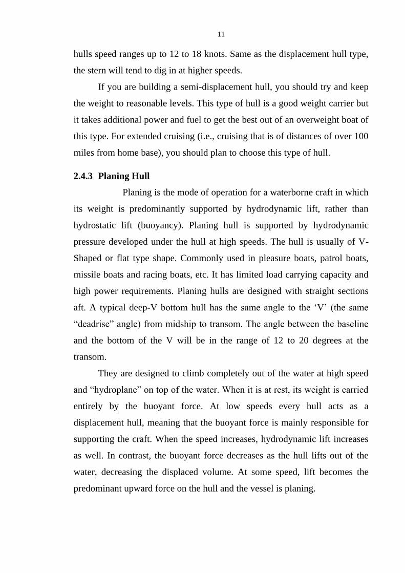
2.4.3 Planing Hull
Planing is the mode of operation for a waterborne craft in which
its weight is predominantly supported by hydrodynamic lift, rather than
hydrostatic lift (buoyancy). Planing hull is supported by hydrodynamic
pressure developed under the hull at high speeds. The hull is usually of V-
Shaped or flat type shape. Commonly used in pleasure boats, patrol boats,
missile boats and racing boats, etc. It has limited load carrying capacity and
high power requirements. Planing hulls are designed with straight sections
aft. A typical deep-V bottom hull has the same angle to the ‘V’ (the same
“deadrise” angle) from midship to transom. The angle between the baseline
and the bottom of the V will be in the range of 12 to 20 degrees at the
transom.
They are designed to climb completely out of the water at high speed
and “hydroplane” on top of the water. When it is at rest, its weight is carried
entirely by the buoyant force. At low speeds every hull acts as a
displacement hull, meaning that the buoyant force is mainly responsible for
supporting the craft. When the speed increases, hydrodynamic lift increases
as well. In contrast, the buoyant force decreases as the hull lifts out of the
water, decreasing the displaced volume. At some speed, lift becomes the
predominant upward force on the hull and the vessel is planing.

12
Due to the hull shape with the characteristic straight cut transom a
hydrodynamic disturbance is created with an effective low pressure at the
stern pulling the vessel against its direction of movement through the water.
This makes the hull shape very energy consuming at speeds below the
planning threshold. At planing speeds, water is breaking cleanly from the
transom and the hull is riding on its straight aft sections. The greatest
resistance at planing speeds is frictional resistance. It takes more power to
climb out of the water over the bow wave than it does to maintain planing
speed once this is achieved.
To plane, the power-to-weight ratio must be high, since the planing
mode of operation is quite inefficient; sailing boats need a good sail area and
powerboats need a high-power engine. They should not be used as long
distance or passage making cruising powerboat. Depending on the particular
design, they can be driven at speeds in excess of 50 knots; however most are
designed to cruise at speeds between 30 to 35 knots. Its disadvantage is
mainly the high cost of operation.
2.4.4 Monohull and Multihulls
The hull types mentioned above are the three basic forms of hull and
they can be constructed in various ways, most commonly being a mono-hull.
A mono-hull is one type of boat having only a single hull, unlike multi-hull
boats: which have two or more individual hulls; most commonly, two, three,
five hulls; namely catamaran, trimaran and pentamaran. There are countless
types and designs of mono-hulls, which is why we will not explain them at
this point, but to go straight ahead to the design of catamarans.
2.5 Catamaran
2.5.1 Definition, History, Advantages and Disadvantages
2.5.1.1 Definition
A catamaran is a type of multihulled boat or ship consisting of two
hulls, joined by some structure, the most basic being a frame. Catamarans
13
can be of sail- or engine-powered. The word “catamaran” comes from the
Polynesian Languages meaning “tied up trees”.
Catamarans are a relatively recent introduction to the design of boats
for both leisure and sport sailing, although they have been used since time
immemorial among the paravas, a fishing community in the southern coast
of Tamil Nadu, India, and independently in Oceania, where Polynesian
catamarans and outrigger canoes allowed seafaring Polynesians to settle the
world's most far-flung islands.
In recreational sailing, catamarans and multihulls in general, had been
met by a degree of skepticism from Western sailors accustomed to more
“traditional” monohull designs, mainly because multihulls were based on, to
them, completely alien and strange concepts, with balance based on
geometry rather than weight distribution. However, the catamaran has
arguably become the best design for fast ferries, because their speed,
stability and large capacity are valuable.
The twin-hulled sailing or motor boat has since become a popular
pleasure craft, largely because of its speed and stability. High-speed
catamaran ferries can exceed 40 knots (74 km/h). Catamarans range typically
from 15 ft to 330 ft in length and are among the world’s fastest sailing and
motor craft.
2.5.1.2 History, Advantages and Disadvantages
Catamarans were developed to perfection and enabled the Polynesians
to spread their civilization over the Pacific Sea. Thus, the approval of the
catamaran hull for seagoing craft was actually established long before our
time.
The design of catamaran remained relatively unknown in the West for
almost 200 years; in the 1870s when the catamaran design first was
introduced in America by Nathanael Herreshoff, they sailed so successfully

14
against mono-hulled boats that they were barred from racing till 1970s. In
1947, the first modern ocean-going catamaran was built and designed in
Hawaii by the surfing legend, Woodbridge "Woody" Brown and Alfred
Kumalae.
As a constructive characteristic, they cannot achieve the high pay load
of mono-hulls with a square-like cross-section. Also the advantage of low
resistance and a higher cruise speed is lost with the growing size of a
catamaran, as the hull-speed increases in proportion to the length of a mono-
hull. At the same time propulsion power needed to use a possible efficiency
benefit of a catamaran grows exponentially.
So there is a size range and boat type where the constructional
advantage of a catamaran comes to best effect. What makes it interesting is
that this range covers well the areas where a mono-hull has its most
drawbacks.
2.5.2 Types of Catamaran Hulls
When talking about catamarans, we are not speaking of just one type
of hull, but merely a whole hull category with many different types of
constructions and optimization for different purposes. As the catamaran hull
is basically the starting point of this study it is necessary to understand the
basic constructional differences and types. Variations of hull forms exist.
Fig. 2.4 General catamaran hull types
15
“Power catamarans come in many shapes, and in different parts of the
world preference is given to specific types.
This is an effort to analyze the 10 hull shapes of medium- and high-
speed existing boats.
Racing boats have deliberately been excluded, because comfort, safety
and a low-cost construction takes a poor second place to outright speed in
that type of boat.”
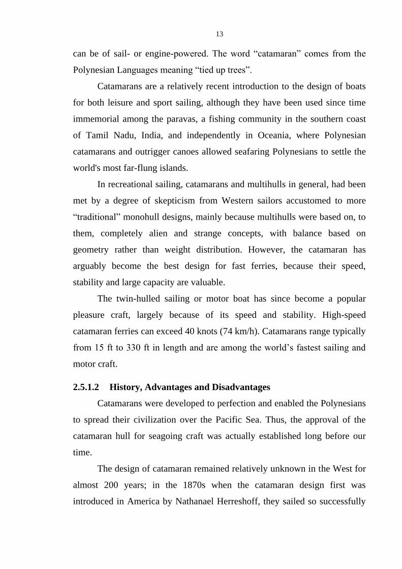
2.5.2.1 Characteristics of Type-A. Australian type with symmetrical
sponsons*, fine entry, medium-square tunnel, low deadrise.
This Type-A catamaran hulls are popular in Australia when it is found
that two identical symmetrical sponsons reduced costs and gave a beamy
boat with lots of deck space. Lateral stability at rest is very good. If wavelet
heights are less than half of the tunnel height, the fine, deep forefoot passes
through without much trouble while giving comfort and economy.
A severely warped bottom, i.e., twisting the bottom from almost
vertical at the bow to almost horizontal at the stern, resistance in calm water
(on rivers and in large harbors) is kept low with a small wetted area & low
wave-making resistance. Problems start when it ventures out to sea where
conditions are not as favorable. Even on calm day, there can be large rollers,
flowing in clear for thousands of miles at 24 knots.
Fig. 2.5 Type-A catamaran hull

16
If the water is deep enough, they have a sinusoidal shape with the
steepest gradient always less than 20° and mostly 10° or less. When Type-A
runs straight into these rollers, it will try to act like a wavepiercer with its
fine, low-lift bows until buoyancy lifts the bows with the help of the tunnel
roof, if necessary. In the process it will slow down a fair amount because of
the increased resistance caused by the extra wetted area and, of course, the
gradient. No vehicle or vessel will go faster up a hill than down. And talking
about the downward run, after cresting a head sea it is usually an exhilarating
feeling, the acceleration and the higher speed.
If the wave length is long enough, say six times the boat’s length then
nothing strange should happen when you arrive at that trough and start up
the next wave. Running beam-on to the big swells, either on top or in the
bottom, is no problem. Quartering the head seas without wind and chop may
make the passengers feel a small uneasiness when the cat leans away from
the higher water, but there is no real chance of overturning.
2.5.2.2 Characteristics of Type-B. Sailing-boat type symmetrical
sponsons*, round-bilge and tunnel, deep forefoot, no strakes.
Type-B Catamaran Hull has symmetrical round bilge sponsons and
wide lowish tunnel. After French proved that a catamaran can out sail any
monohull of the same size, power-boaters started to look at this hull
configuration for medium speed cruisers without sails. This type of hull has
no lift rails and chines, amount of lift at speed is negligible, thus no
Fig. 2.6 Type-B catamaran hull

17
reduction of wetted area. Long, slim sponsons with fine entry have very little
wave-making resistance.
The speed range is approximately between 15 to 25 knots, to give
reasonable economy. This speed is a lot quicker than normal displacement
speed for a hull of same length. Round-bilge shape gives a soft ride and can't
slam but short flat tunnel does that with vengeance when trying to go
directly into a head sea. The fine entry and deep forefoot slice through the
chop nicely, but it lacks the buoyancy or lifting surfaces to save it from some
stuffing into the back of the next wave.
Type-B has a relatively small water plane area so it can carry light
loads and when overloaded to the extent where the tunnel roof stays in
contact with the sea, there will be a large increase in resistance. Type-B can
benefit from some new patented idea such as the HySuCat to lift it at speed
and improve the top speed.
2.5.2.3 Characteristics of Type-G. Kenton Cat type with low round
tunnel and round bottoms, tunnel lifting at bow
Let us skip to Type-G from Type-B as there are some common
features such as round-bilge sponsons and symmetrical bows sections. But
Type-G has a lower, full-length, rounded tunnel and a lot less beam to
change its sea-behavior completely.
That soft entry and landing of the rounded bottom of the sponsons are
completely overshadowed by the bang that occurs when solid water hits that
Fig. 2.7 Type-G catamaran hull

18
low, round-tunnel roof and finds that it has nowhere to go. As a matter of
interest, it is our conviction that the well-known spitting (sneezing) of a
bucketful of water forward, out of the tunnel mouth at speed, is caused by
the speed of sound in the two phase medium being exceeded. This happens
when aerated water is suddenly compressed.
Type-G usually uses chines on the outside and, together with the
tunnel which is submerged at rest, has considerable lift at speed. As a matter
of fact it probably is the best load carrier of all catamarans, providing it can
get over the hump, another big difference from Type-B which has no real
hump in its resistance curve.
2.5.2.4 Characteristics of Type-C. Asymmetrical sponsons with low
deadrise bottoms and no-trip chine, medium height square
tunnel.
This catamaran hull type has good directional stability in head seas
and following seas but, in quartering seas it weaves as the seaward-curved
bow, causes it to "steer". A steering correction to the opposite side gets
worse when the other bow enters the same wave and does the same, resulting
in an uncomfortable yawing motion which is highly encouraging to motion
sickness.
Medium-height tunnel has a limit on wave heights that it can handle at
speed without severe slamming. Depending on the deadrise angles of the
Fig. 2.8 Type-C catamaran hull

19
bottoms, it can have a good ride even in rough seas and will react safely
when sliding sideways off large swells. In following seas, it behaves well
because of the full bows, but at an angle, a broaching action may be felt
when the leading bow hits the bottom of the trough and then veers off.
Lateral stability is excellent and it will need abnormal loads to make it
roll too far. Ride wetness will depend on the detail shape of the forward
chines and the amount of flare in the bows, but it should be much better than
the Type-A. It can carry reasonable loads and its CG is not critical, within
bounds, of course.
2.5.2.5 Characteristics of Type-D. Split monohull with narrow, low
square tunnel with high attack angle at bows.
Strictly speaking, this should not be called a catamaran because its
parent was a monohull that got split down the middle, and the halves were
moved apart by a small amount and the gap covered over.
The result is a hybrid which inherited the worst characteristics of both
monohull and a bad catamaran. It slams and bangs in any kind of head sea or
even chops and does it with a noise like a thunderclap.
The transverse stability has been improved from that of its original
monohull, but not to the extent that would match any decent catamaran.
Load capacity is good and the economy in smooth water is reasonable.
Fig. 2.9 Type-D catamaran hull

20
2.5.2.6 Characteristics of Type-E. Super-slim sponsons with medium-
to-high-tunnel, fine entry, designed to be used on protected
waters.
This type has high aspect-ratio sponsons that have very little wave-
making resistance. At certain speeds, there is an advantage for the super-
slim. However, in doing this, a large area is running wet, and skin friction
resistance has increased over that of a similar sized planing craft. Because of
the minimal bow lift there is no dynamic lift and almost no buoyant lift.
Therefore Type-E is fine in small chop and wave lengths of less than
half the boat length, but it urgently needs a helping hand in the way of a
third sponson or tunnel roof extension to prevent stuffing. Vertical
acceleration from the sponsons is very low, but the tunnel roof will slam if it
is flat and not high enough for the sea state.
Because of the low water plane area, Type-E is sensitive to load shifts
and it becomes important to control people movement and other factors that
can offset the critical center of gravity. Because of its wave penetrating
action, it cannot be used offshore or where large waves and rollers occur.
In other words, this is a protected-water boat similar to Type-A and
Type-G. The narrow sponsons pose problems in installing wide engines and
long cardan-shafts, such as those used in SWATHs and SES may be needed
and that adds to the cost. Lateral stability will depend on aspect ratio, but is
less than on other, more normal types of catamarans. Construction is not
difficult but speeds (for economy) are within a narrow range.
Fig. 2.10 Type-E catamaran hull

21
2.5.2.7 Characteristics of Type-F. SES (Solid Side Skirt) hovercraft
with low tunnel and skirts at bow and stern.
The solid side skirt hovercraft is not considered a catamaran by many,
but it does have two long, slim sponsons almost like Type-E, but with the
addition of flexible skirts fore and aft. The skirts are there to contain the
cushion – air that is pumped into the big empty space between the sponsons,
skirts and tunnel roof to lift the craft up to where it has minimal draft and
wetted area.
The SES was developed by people who were unhappy with the normal
hovercraft where air-propulsion is needed. They thought that these slim
sponsons would allow propulsion by water jet or propeller and so make it
more efficient. Another handicap of a pure hovercraft is its susceptibility to
cross winds and its consequent need to weathercock to counter them. So
don’t be surprised if you see one traveling almost sideways to go along a
certain course. Having slim hulls in the water helps offset this to a
considerable extent but it is costly to build and maintain and its ride
characteristics are not acceptable to many.
It is load-sensitive and the CG has to be dead right. The ride is wet and
becomes hard when the waves hit the relatively low tunnel. On the upside, it
is capable of good speeds in calm conditions. As an afterthought, it is
probably unfair to compare it with normal cats.
Fig. 2.11 Type-F catamaran hull
22
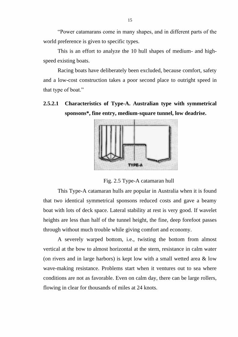
2.5.2.8 Characteristics of Type-H. HySuCat with one main foil and
two trim foils, high deadrise bottoms and medium-high tunnel.
HySuCat means Hydrofoil-Supported-Catamaran. Professor Günther
Hoppe was testing one of the early Bobkat Catamaran models in the
circulating tank at Stellenbosch University when he decided that the
resistance-to-weight ratio was too high and needed improvement. Firstly, he
changed the cross section of the sponsons by introducing a wide, and low-
deadrise bottom with no non-trip chines. This immediately reduced their
resistance, but not enough for Hoppe and he continued experimenting until
he hit on the novel idea of fitting a foil between the sponsons to carry part of
the load and, in so doing, reduced the wetted area.
It is a proven fact that long and narrow wings of aeroplanes produce
more lift at low and medium speeds than short, wide ones. The same goes for
hydrofoils. The Russians developed hydrofoil craft for use on their rivers
where a low wash was needed, together with economy at high speeds. Many
configurations were tried out but all lifted the hull completely clear of the
water which gave them the best speed, but introduced other problems.
Among these were deep draft at rest and wide foils extending beyond
the sides of the boat to make docking difficult, and sometimes downright
Fig. 2.12 Type-H catamaran hull Fig. 2.13 HySuCat working principle

23
dangerous. It was also very expensive to produce, and large shaft angles
made propulsion inefficient.
The Hoppe solution, registered as HySuCat, is a low-cost compromise
that has been developed to give excellent results within its effective speed
range. The foils between the sponsons are positioned to not only lift the boat
when planing speed is reached, but also to adjust the trim for optimal main
foil and sponson attack angles. In the early HySuCat designs the main foil
was placed just forward of the Center of Gravity and small trim foils were
mounted near the transom, all of them above the bottoms of the sponsons.
However, the world patent covers many other possible configurations.
Production models of the HySuCat had a higher deadrise to improve the ride
in rough water and help the vertical tunnel sides for banking less in turns.
Without the non-trips, the lateral stability – in Extreme conditions – could
lead to tripping and flipping if the Center of Gravity is too high.
The sweeping bow with the chine going right up to the gunwales has
poor buoyancy and dynamic lift with all the problems previously mentioned
for asymmetrical hulls. At low speeds the tunnel may slam a bit, but once the
foils come into action at about 14-18 knots, and lift the whole boat a
considerable amount, the tunnel clearance is also increased and very much
larger waves are needed to create an uncomfortable slamming. We have
found that the foils also dampen action such as heaving and pitching, which
improves the ride even further.
The main advantage of the foil system is the dramatic reduction in the
resistance, resulting in a higher top speed and improved economy. Recent
applications of the HySuCat system on other hull shapes such as Type-A
improved the speed and lifted the tunnel a bit but it could not cure the other
inherent bad habits in the basic design.

24
2.5.2.9 Characteristics of Type-I. Bobkat with round, asymmetrical
sponsons*, high tunnel with tunnel-chines and bow steps.
Fig. 2.14 Type-I catamaran hull (Bobkat)
2.5.2.10 Characteristics of Type-J. Bobkat with HySuCat foils.
The registered trademark Bobkat covers a range of power catamarans
from 2.5m-33m that have similar looking hull shapes, but with detailed
changes for different sizes and speeds. The convex shape incorporates the
equally important non-trip below the wide chines to further improve safety
in beam seas and quartering swells in a large following sea.
The rounded section does not slam and gives a comfortable ride in
rough water, even when jumping the large waves at high speed. The 20m
patrol boat, for instance, can take 3m high head seas at 26 knots without
discomfort. The tunnel is also the highest of the boats listed and when the
foils are fitted on the Type-J the effective tunnel height allows high-speed
travel in severe sea states.
The tunnel chines lift up in a flattened S-shape near the stern as does
the tunnel roof, to provide an increased tunnel area for waves to enter when
traveling at speeds below 20 knots in following seas. For the sports
fisherman this feature also allows for backing down at speed when fighting a
large fish without any danger of swamping. The overall aspect ratio of 3:1
with a sponson ratio of 10:1 reduces wave making resistance, especially on
the foil, while giving excellent lateral stability.

25
Fig. 2.15 Type-J catamaran hull (Bobkat with HySuCat foils)
2.5.2.11 Summary and Comparison of the above (10-Types) of Hull
The rest of the world is starting to realize that a tiny country at the
southern tip of Africa is one of the leaders in the design of safe, fast, low-
cost and seaworthy offshore craft with this foil-assisted catamaran concept.
There is also ongoing research we expect to lead to further improvements in
the near future. Points are scored relating to the following aspects and with
the rating of 1 to 9.
Table 2.1 Point score for 10-types of catamaran hull relating to the given
aspects
Aspects A B C D E F G H I J
1. Low Vertical Acceleration (Sponsons) 2 7 5 4 9 9 5 6 7 8
2. Low Vertical Acceleration (Tunnel) 3 3 3 1 5 9 1 6 7 9
3. Inward banking in Turns 1 1 9 7 6 4 5 7 9 9
4. Non-broaching in Following Seas 2 3 6 7 4 6 7 5 8 8
5. Non-weaving in Quartering Seas 8 8 2 3 4 7 7 3 8 8
6. Resistance to Barrel-Rolling 1 5 9 3 7 7 7 5 9 9
7. Load Carrying Ability 5 5 6 7 2 3 8 5 6 7

26
8. Transverse Stability 6 6 7 3 4 3 4 7 7 7
9. Pitching Stability 4 5 6 7 4 3 6 7 7 8
10. Dry Ride in Small Chop 6 6 6 3 7 2 2 7 7 7
11. Economy at Planing Speeds 8 4 7 4 2 9 7 9 6 8
12. Economy of Construction 8 9 8 7 5 1 6 7 9 7
Total Score 54 62 74 56 59 57 65 74 90 95

27
Chapter 3
Designing Concepts and Detail Design of Pleasure Craft with
Catamaran Hull
3.1 Principal Particulars
Maxsurf, AutoCAD and related software are used to create the hull
form. The principal particulars of our ship’s hull form are as follows:
Length overall – 15 m
Breadth (maximum) – 6.75 m
Depth – 2.1 m
Draught, at design waterline – 0.7 m
Speed – 15 knots (Maximum 20 knots)
No. of Passengers – 6
Propulsion – 2xVolvo Penta IPS 600, 2x320kW
(2x435hp)
Fuel & Fresh Water Capacity – 3387.131 liter, 680.045 liter
Classification – Lloyd’s Register of Shipping
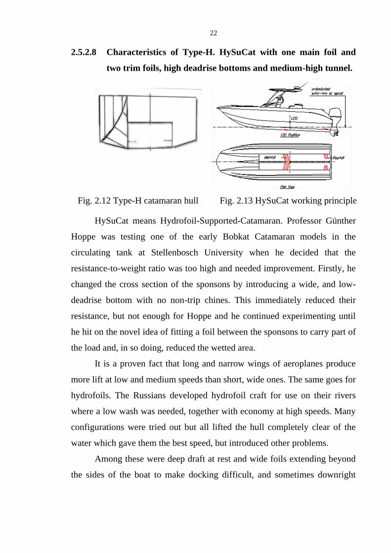
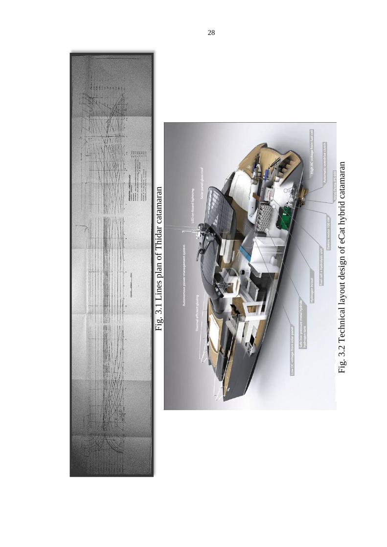
3.2 Reference Ship Data and Contents
The principle dimensions of this design ship are derived from Thidar
Catamaran (a 23.837m Catamaran, the only two catamarans built in
Myanmar as Thidar I & Thidar II) and the general arrangement plan is
adopted from a graduation project by Juri Karinen, Lahti University of
Applied Sciences, Finland, named as eCAT hybrid.
In this chapter, detail lines plan, general arrangement, step-by-step
designing procedures, offset tables, marker data, power prediction by Hull
Speed software, perspective 3-D view, propulsion systems and integrated
equipments will be listed. Both the mothership data and the design ship data
will be included wherever available.
28
Fig
. 3.2
Tec
hnic
al l
ayou
t d
esig
n o
f eC
at h
yb
rid c
atam
aran
Fig
. 3.1
Lin
es p
lan o
f T
hid
ar c
atam
aran

29
Tab
le 3
.1 O
ffse
t ta
ble
of
Thid
ar (
I+II
) ca
tam
aran
s

30
Fig. 3.3 Body plan of designed hull
3.3 Step-by-Step Designing Procedures
From the Lines Plan of Thidar catamaran, we collect data to create the
offset table. (Note that there may be errors up to 20 millimeters in full
scale).From this offset table, we use Geo-Sim Method to create an offset
table for a 15m Catamaran.
You will notice that Thidar catamaran is a round bilge hull and our
design is a chine hull catamaran. We create the chine hull which has the limit
values of the offset table for the 15m Catamaran which we calculated earlier.
In creating a chine hull, first we draw it by hand, adjusting the limits.
Again, we collect offset data from the hand drawing and create a 3D marker
data which will later be imported to Maxsurf Pro software.
Marker data is created using Microsoft Excel Spread Sheet and saved
in a “.txt” format. On markers window in Maxsurf Pro, Open the saved “.txt”
marker data. Prefit software is not used as it will give and undesirable result
while importing catamaran hull marker data.
Create multiple surfaces, bond them and trim them as necessary.
Transverse stiffness is set to 2 as we are creating a chine hull form. After
quite enough fairing is done, the required hull form is obtained in “.msd”
format.

31
To create Lines Plan and GA Plan, we used AutoCAD software. It is
easy to bridge Maxsurf and AutoCAD software. The hull form that we
created in Maxsurf can be exported as a “.dxf” format. This is a data
exchange format that most CAD modeling software knows. The export file
can now be opened in AutoCAD.
Unnecessary lines are deleted and the lines from each view are
arranged in a new file after which it is saved. A Line Plan in “.dwg” format
is achieved. GA Plan is drawn is drawn similar to eCAT hybrid.
The drawn GA Plan is snipped into image file, “.jpg” and is then used
as background image back in Maxsurf Pro. Once the image zero point and
image reference point has been set in Display->Background menu, we are
now ready to fit bulkheads, decks, stairs and superstructures using new
surfaces. After quite a lot of work has been done, the final 3-D Perspective
View of our designed catamaran is obtained.
For Calculations, we will calculate with both hands and with aid of
software where possible. For powering prediction, we will use the resistance
data obtained from Hull Speed for this instance.
Table 3.2 Offset table of Geo-Sim 15m catamaran (Limits for our design)

32
Tab
le 3
.3 O
ffse
t ta
ble
of
des
igned
15m
cat
amar
an

33
Fig. 3.4 Markers from offset table seen in perspective view of Maxsurf
Fig. 3.5 Lines plan of designed craft
3.4 Intended Voyage of the Designed Catamaran
It can be used both in Protected Waters and Sea-going. As it has a low
draft, it has no problems in going shallow water, but it is designed mainly to
go offshore, coastal area around Myanmar.

34
3.5 Lines Plan and Bare-Hull Form Generation
Fig
. 3.6
Pro
file
vie
w
Fig
. 3.7
Hal
f-b
read
th p
lan

35
Fig. 3.8 Body plan view
Fig. 3.9 Bare-hull form generated by Maxsurf, perspective view
3.6 General Arrangement Plan
Below are the pictures of general arrangement plan adopted from eCat
Hybrid. These plans are drawn with AutoCAD software, thus might have a
little difference with the drawings from Maxsurf. Most common errors are
corrected.
In this catamaran, there will be main deck-bridge deck, sundeck, and
tunnel-lower deck. The sun deck is located on forward side of the craft, in
front of the bridge deck windshield. The sun deck is accessible from the
main deck. There are altogether seven emergency exit hatches. The aft part

36
of the main deck is formed by stairs where the passengers can swim, dive or
just simply sit, putting the feet into the pleasant sea.
(c) Main deck
Fig. 3.10 General arrangement plan
(a) Profile view
(b) Tunnel-lower deck

37
The aft part of bridge deck formed a sea view area with luxurious
settees where you can sip a cold drink while enjoying the view of the sea.
The mid portion of the bridge deck forms a small home theatre where you
can spend your time with your family, laughing and smiling while having
surround sounds of a home theatre. In the forward part of the ship, there is a
navigation deck with less complicated but efficient systems which are user
friendly.
The bridge deck then declines to the tunnel deck with the series of
circular stairs. You will arrive to the dining room. The bridge deck
windshield formed a sky light for the dining room. The compartment in front
the dining room is the master bedroom with bathroom attached. The
bathroom is located on the tunnel deck so it kind of needs to go down the
few steps of stairs. The aft part of the tunnel consists of the life boat and two
tanks containing fuel and fresh water.
Lower deck is reachable by the stairs from the dining room. The
forward port side is the galley while the starboard side contains the bathroom
from master bedroom. There is also a small bathroom on the after part of the
port side. Two compartments near the midship section are the bedrooms for
4 persons. The aft-most part of the lower deck is the engine room.
As this catamaran is a six passenger capable pleasure craft, there will
be six beddings. The maximum limit for the no. of passenger boarding this
boat is eleven. If twelve, there will be more rules and regulations that must
be applied and approved. For the same dimension of ship, if used as the ferry
boat, it can carry about 30-50 persons but must be approved by the
authorities. As this is a pleasure craft design, it is only designed for a family
size of 6 persons.
The lifeboat is of rigid inflatable boat type, also called ribs, with a
capacity of 11 passengers just for safety, although only 6 persons is to board
in case of emergency. The outboard motor is mounted in the aft part of the

38
lifeboat. The lifejackets are located below the beds and the extra ones are
located in the stair case cabinet. A total number of eleven lifejackets are
placed on the boat. The lifejackets are to be of approved type.
3.7 Designed Ship’s 3D Image Renderings Including Superstructure
Fig. 3.11 3D rendering (Starboard view)
Fig. 3.12 Internal compartments
Fig. 3.13 Wire mesh plan view (Top view)

39
Fig. 3.14 3D rendering (Forward-starboard view)
Fig. 3.15 Wire mesh (Profile view)
Fig. 3.16 Wire mesh (Forward-bow view)

40
Fig. 3.17 3D rendering (Aft-stern view)
Fig. 3.18 3D rendering (Aft-starboard view)
Fig. 3.19 Wire mesh (Aft-port view)

41
Fig. 3.20 3D rendering (Fwd-port view)
Fig. 3.21 3D rendering (Fwd-starboard view)
Fig. 3.22 Wire mesh (AutoCAD)

42
3.8 Power Prediction by NavCad
It is not easy for the catamaran to predict power and resistance. It can’t
be done directly. It is most complicated as the interference effects of the
waves between the two hulls need to be considered.
To use NavCad, there are certain limitations on the use of methods as
the algorithms are designed for specific hull types. For this craft, Gronslett
Method (Catamaran) is the most appropriate. The limitations of for this
method are:
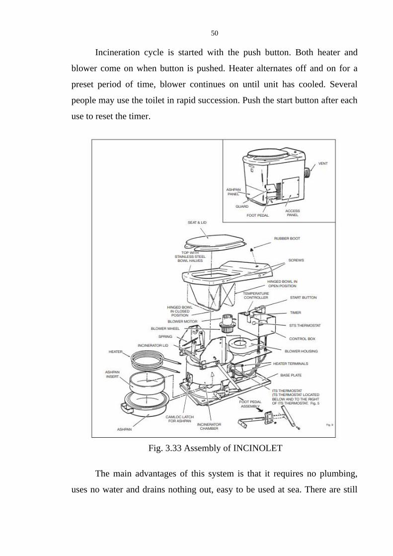
Requirements Design
0.6 < Fn (LWL) < 1.6 0.64
0.6 < Fn-high < 1.6 0.88
7.3 < Cvol (hLpp) < 9.5 7.4
NavCad has one algorithm for catamarans [Gronnslett, 1991]. The
algorithm utilizes a set of curves for residuary resistance. A random
collection of full-scale and model tests of high-speed displacement
catamarans with slender symmetric demi-hulls is the basis of this algorithm.
The method does not take differences in hull separation into account.
Differences in interference drag are averaged to produce a generic result.
This algorithm exhibits surprisingly good accuracy, however. We surmise
that this is due to two characteristics of these types of vessels.
First, the hulls are long and slender operating in a high speed range (Fn
from 0.6 to 1.6). A good portion of this resistance will be frictional, which is
directly calculated. Second, hull spacing has shown to have the most effect
on interference resistance in the lower speed ranges near the principal wave-
making hump speed (Fn from 0.3 to 0.7). Above this speed regime, there is
little difference in added interference drag due to different hull spacing
[Insel, 1991].

43
Using Gronslett Method, we get Table 3.4 corresponding to Fig. 3.23
and Fig. 3.24. Thus we get the predicted power of approximately 336 kW for
the speed of 15knots, 439 kW for the speed of 18 knots and 630 kW for the
speed of 20 knots. Assume 450kW is needed to be on save side, since we are
installing two engines, one on each side of the hull, we will need estimate of
225kW per engine.
So, we chose two Volvo Penta IPS 600 Propulsion Units (Inboard
Performance Systems), which can give propeller shaft power of 307kW
(418hp). Details of Volvo Penta IPS 600 will be stated below and detail
powering calculations will be shown in Chapter-5.
Table 3.4 NavCad prediction data

44
Fig. 3.23 Speed vs. Resistance graph
Fig. 3.24 Speed vs. Power graph
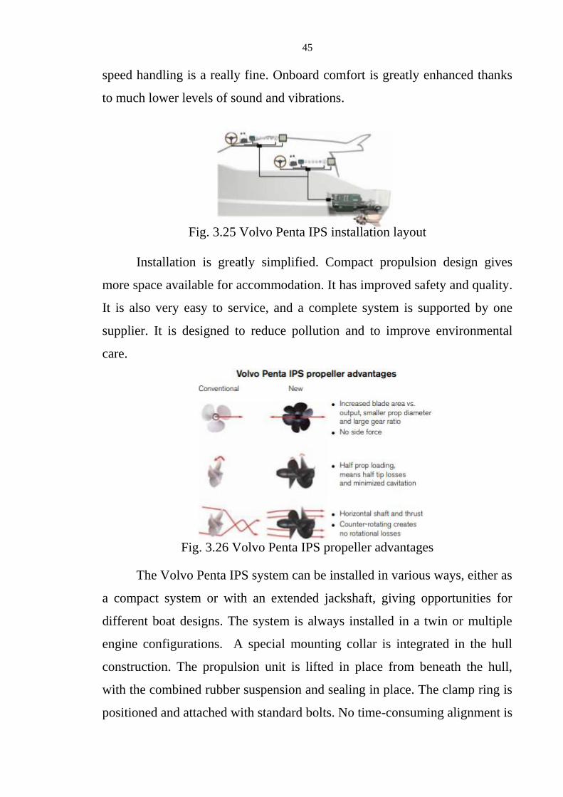
3.9 Propulsion System with Volvo Penta IPS 600 (Inboard
Performance System)
Propulsion is by twin installation of Volvo Penta IPS 600. It has much
improved efficiency, higher top speed, reduced fuel consumption/extended
range, and great acceleration. Low-speed maneuvering is easy, and high
45
speed handling is a really fine. Onboard comfort is greatly enhanced thanks
to much lower levels of sound and vibrations.
Installation is greatly simplified. Compact propulsion design gives
more space available for accommodation. It has improved safety and quality.
It is also very easy to service, and a complete system is supported by one
supplier. It is designed to reduce pollution and to improve environmental
care.
The Volvo Penta IPS system can be installed in various ways, either as
a compact system or with an extended jackshaft, giving opportunities for
different boat designs. The system is always installed in a twin or multiple
engine configurations. A special mounting collar is integrated in the hull
construction. The propulsion unit is lifted in place from beneath the hull,
with the combined rubber suspension and sealing in place. The clamp ring is
positioned and attached with standard bolts. No time-consuming alignment is
Fig. 3.26 Volvo Penta IPS propeller advantages
Fig. 3.25 Volvo Penta IPS installation layout

46
needed. Steering, shift and throttle plus instrumentation are connected in the
simplest way possible.
Volvo Penta IPS systems do not need shaft alignments. With the
Volvo Penta IPS 600 propulsion units placed under the hull, and all
components exposed to seawater made of either nickel-aluminum-bronze or
stainless steel, excellent corrosion resistance is achieved, and marine growth
is minimized.
Volvo Penta IPS patented propellers means increased blade area, half
the load on each propeller, and smaller propeller diameter with minimized
tip losses and cavitation. Furthermore, the propeller system prevents
rotational losses and does not create any side forces. The thrust the
Fig. 3.28 Joystick docking system
Fig. 3.27 System components, Volvo Penta IPS

47
propellers produce is horizontal with all the force driving the boat forward.
The propellers are at the front of the propulsion unit, working in undisturbed
water with a minimum of pressure pulses affecting the hull.
A conventional shaft system loses efficiency with the thrust angled
downward and the propellers working in water disturbed by the propeller
bracket and shaft. Selecting propellers is also very easy, since Volvo Penta
provides optimized gear ratios and a complete and systematic series of
propellers developed for the Volvo Penta IPS system.
Onboard comfort is one of the main factors for a pleasure craft design.
Minimal amounts of sound, vibration and exhaust fumes make life aboard
that much more pleasant. Volvo Penta IPS new technology leads to major
improvements for all comfort enhancing factors. The propulsion forces and
vibrations are absorbed by the combined rubber suspension and sealing.
Engine vibrations are reduced thanks to a U-joint drive shaft, which makes it
possible to have the engine soft suspended.
The propellers are working in undisturbed water with no cavitation,
and have good clearance from the hull. There is an increased number of
propeller blades to distribute the forces. This means that the pressure pulses
created by the propellers have very little effect on the hull. Exhaust fumes
Fig. 3.29 Section showing U-Joint drive shaft arrangement with
counter-rotating propellers

48
are truly minimized. First of all, the new engines have very low exhaust
emissions, and secondly, the exhausts are emitted through the propulsion
unit into the prop-wash and carried well behind the boat.
Crankshaft power, kW (hp)@3500 rpm - 320 (435)
Prop-shaft power, kW (hp)@3500 rpm - 307 (418)
Aspiration - Turbo, after-cooler, compressor
Package weight, kg (lb) - 901 (1986)
Voltage - 12 V or 24V
Application - Twin/multiple engine installation
in planing hulls
Driveshaft - Compact (standard), jackshaft as
option
Fig. 3.30 A complete unit of Volvo Penta IPS system

49
3.10 Sewage System
There is another interesting fact in our designed ship. It is no other
than the sewage system. There are two toilet bowls in our designed ship but
there is neither retention tank nor a sewage treatment plant. This is because
we use INCINOLET, the electric incinerating toilets.
The working principle of INCINOLET toilet is easy.
INCINOLET uses electric heat to reduce human waste (urine, solids, paper)
to a small amount of clean ash, which is dumped periodically into the
garbage. INCINOLET remains clean because waste never touches the bowl
surface. A bowl liner, dropped into the bowl prior to use, captures the waste,
then both liner and its content drop into the incinerator chamber when the
foot pedal is pushed. You can use INCINOLET at any time-even while it is
in cycle.
Fig. 3.32 Usage procedures of INCINOLET
Fig. 3.31 INCINOLET, The electric incinerating toilet.
50
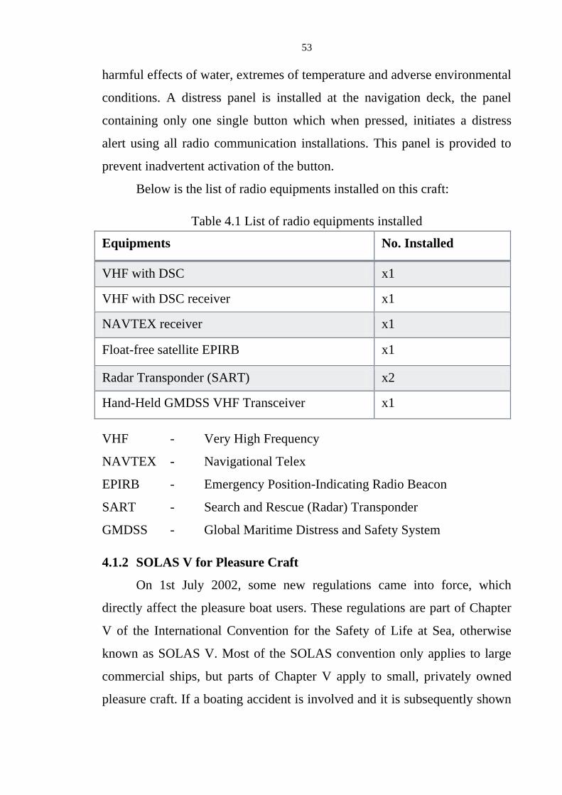
Incineration cycle is started with the push button. Both heater and
blower come on when button is pushed. Heater alternates off and on for a
preset period of time, blower continues on until unit has cooled. Several
people may use the toilet in rapid succession. Push the start button after each
use to reset the timer.
The main advantages of this system is that it requires no plumbing,
uses no water and drains nothing out, easy to be used at sea. There are still
Fig. 3.33 Assembly of INCINOLET

51
many advantages such as cleanliness, odor, residue and low electrical
requirements compare to other conventional composting toilets. Maintenance
has to be done only once a year but the ash pan must be emptied at least once
every week. This can be easily done because our catamaran is only designed
to cruise a week at most.
The price of this product is around $1800. Two units are installed so,
it will cost around $3600. Installing INCINOLET is really easy. All it need
is an electric power and a vent pipe. This appliance uses around 20 amps,
either 120 volts or 240 volts is your choice. Here we will use 240volts unit.
The only disadvantage of this product is the need to use a bowl liner
every time you use toilet and the need to clean the ash pan weekly.

52
Chapter 4
Rules and Regulations which this Pleasure Craft Complies
4.1 SOLAS
The International Convention for the Safety of Life at Sea (SOLAS),
1974, currently in force, was adopted on 1 November 1974 by the
International Conference on Safety of Life at Sea, which was convened by
the International Maritime Organization (IMO), and entered into force on 25
May 1980. It has been amended and consolidated since then.
In SOLAS it is stated that “unless expressly provided otherwise, the
present regulations apply only to ships engaged on international voyages.”
As our catamaran is only designed to go within coastal regions or shallow
water inland, it doesn’t matter whether it comply all the rules but it will be
best if it obeys all.
In this chapter, we will only focus on the fundamental equipments
required by SOLAS. We will emphasize on SOLAS Chapter-4 Part C and
SOLAS Chapter -5. Chapter-4 Part C points out the required Radio
Communication Equipments and Chapter-5 focuses mainly for pleasure craft
users.
Our designed ship will be going in sea area A1. That is “Sea Area A1
is between 30~40 nautical miles from land, i.e., an area within the
radiotelephone coverage of at least one VHF coast station in which
continuous DSC alerting is available.” Where DSC here means “DSC
(Digital Selective Calling) is a technique using digital codes which enables a
radio station to establish contact with and transfer information to another
station or vessels.”
4.1.1 SOLAS Chapter IV, Part C (Ship Requirements)
Radio installation is located away from harmful interference of
mechanical, electrical equipments and systems. It is protected against
53
harmful effects of water, extremes of temperature and adverse environmental
conditions. A distress panel is installed at the navigation deck, the panel
containing only one single button which when pressed, initiates a distress
alert using all radio communication installations. This panel is provided to
prevent inadvertent activation of the button.
Below is the list of radio equipments installed on this craft:
Table 4.1 List of radio equipments installed
Equipments No. Installed
VHF with DSC x1
VHF with DSC receiver x1
NAVTEX receiver x1
Float-free satellite EPIRB x1
Radar Transponder (SART) x2
Hand-Held GMDSS VHF Transceiver x1
VHF - Very High Frequency
NAVTEX - Navigational Telex
EPIRB - Emergency Position-Indicating Radio Beacon
SART - Search and Rescue (Radar) Transponder
GMDSS - Global Maritime Distress and Safety System
4.1.2 SOLAS V for Pleasure Craft
On 1st July 2002, some new regulations came into force, which
directly affect the pleasure boat users. These regulations are part of Chapter
V of the International Convention for the Safety of Life at Sea, otherwise
known as SOLAS V. Most of the SOLAS convention only applies to large
commercial ships, but parts of Chapter V apply to small, privately owned
pleasure craft. If a boating accident is involved and it is subsequently shown
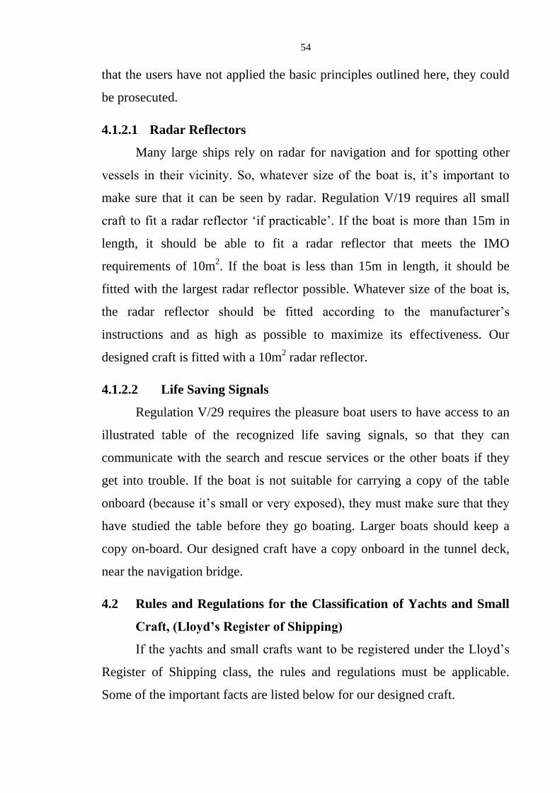
54
that the users have not applied the basic principles outlined here, they could
be prosecuted.
4.1.2.1 Radar Reflectors
Many large ships rely on radar for navigation and for spotting other
vessels in their vicinity. So, whatever size of the boat is, it’s important to
make sure that it can be seen by radar. Regulation V/19 requires all small
craft to fit a radar reflector ‘if practicable’. If the boat is more than 15m in
length, it should be able to fit a radar reflector that meets the IMO
requirements of 10m2. If the boat is less than 15m in length, it should be
fitted with the largest radar reflector possible. Whatever size of the boat is,
the radar reflector should be fitted according to the manufacturer’s
instructions and as high as possible to maximize its effectiveness. Our
designed craft is fitted with a 10m2 radar reflector.
4.1.2.2 Life Saving Signals
Regulation V/29 requires the pleasure boat users to have access to an
illustrated table of the recognized life saving signals, so that they can
communicate with the search and rescue services or the other boats if they
get into trouble. If the boat is not suitable for carrying a copy of the table
onboard (because it’s small or very exposed), they must make sure that they
have studied the table before they go boating. Larger boats should keep a
copy on-board. Our designed craft have a copy onboard in the tunnel deck,
near the navigation bridge.
4.2 Rules and Regulations for the Classification of Yachts and Small
Craft, (Lloyd’s Register of Shipping)
If the yachts and small crafts want to be registered under the Lloyd’s
Register of Shipping class, the rules and regulations must be applicable.
Some of the important facts are listed below for our designed craft.

55
4.2.1 Requirements from Part 2
4.2.1.1 Bulkheads
According to Part 2, Chapter 6, Section 1.2, a watertight collision
bulkhead is to be fitted only if the length of the craft exceeds 15m. As our
craft is 15m, it is on the margin, so we installed a collision bulkhead at the
longitudinal position of 13.25m which is approximately 750mm (0.05L,
Required by the rule) abaft the fore end of the design waterline.
As required, the machinery bulkheads are extended to the upper deck
and the space is made to be gastight, whilst the accommodation spaces are
protected from gas and vapour fumes from machinery, exhaust and fuel
systems.
The doors fitted in watertight bulkheads are capable of being closed
watertight. Both hinged and sliding types are used wherever they suit most.
They are also capable of being operated from both sides of the bulkhead.
4.2.1.2 Hatches and Doors
Hatches and doors have adequate securing arrangements. Hatches on
weather decks are watertight with the cover permanently attached. Where
intended for escape purposes, they are to be operable from both sides. There
are altogether 7 escape hatches in this craft.
Exposed doors in superstructures are weathertight and the sill height is
about 160mm above the deck surface. The rule (Part 2, Chapter 6, Section
1.4) requires a sill height of not less than 150mm.
4.2.1.3 Portlights and Windows
The portlights have a minimum sill height of 500mm above the
waterline and are watertight. All glass installed have a thickness of 12mm.
Storm shutters are required for all windows in the front of the deck house on
the weather deck and the sides. (Part 2, Chapter 6, Section 1.5)

56
4.2.1.4 Guard Rails
Hand rails are installed on exposed decks.
(Part 2, Chapter 6, Section 1.6)
4.2.1.5 Ventilations
Adequate ventilation is provided throughout the craft.
(Part 2, Chapter 6, Section 1.9)
4.2.1.6 Fire Protection
The machinery space is separated from adjacent compartments by
bulkheads. Fire pumps required by the rule (Part 2, Chapter 6, Section 2)
states for a craft of 9m to 21m with less than 150 tons gross, a hand pump is
required and its permanent sea connection is to be situated outside the
machinery space. The minimum nozzle size must be 9.5mm and the
minimum jet throw must be 6m. For this craft, two hand pumps are located
in midship section of the ship embedded in the stair case wall on both sides
of the ship and they are also operable from the main deck.
Fire hoses are made of approved material. The hoses are of 8m length
to project a jet of water to any of the spaces. The rule states the hose length
must not exceed 9m. 5x1.4kg dry powder portable fire extinguishers are
provided. Four extinguishers are of “B” type, i.e., suitable for extinguishing
fires involving flammable liquids, grease, etc., and the remaining are to be of
“C” type, where butane gas installations for cooking or heating. “C” type is
capable of extinguishing fires involving gases.
Two buckets with ropes attached (lanyards) are stowed near the stair
case. A fire blanket is provided and stowed in the store room which is
adjacent to the galley space. A fireman’s axe with insulated handle is an
option. It is only required for craft over 20m overall length. Cooking
appliances are suitable for marine use and secured permanently in position
and must be well ventilated.

57
4.2.1.7 Chains, Anchors and Mooring
The equipment of anchors, chain cables, hawsers and warps required
is based on an “Equipment Number” which can be calculated as:
Equipment Number = 10.76L ((B/L) + D) + 5.38 A
Where,
A= the summation of the respective length times height, in m2, of
all erections above the weather deck which have a length or breadth greater
than B/2.
The equipment number for our designed craft is approximately 885.
The anchors fitted here are stockless. The weights of the anchors are around
45kg. Two anchors are to be fitted. The length of the chain cable must be at
least 95m and the diameter of the short link cable must be at least 10.25mm.
For hawsers and warps they must be 65m long and the breaking loads
required in KN are, for hawsers, 42.2 and for warps, 19.5. These are the
values interpolated from the table given in Part 2, Chapter 6, Section 5.
4.2.2 Requirements from Part 3
4.2.2.1 Engine Seatings
Rigid engine seatings are constructed integral with the hull and permit
easy access to any fitting. Means are provided for removing leakage of oil
fuel or lubricating oil using drip trays fitted around the engine.
A sufficient number of bolts are fitted as required by the engine
manufacturer and are tightened and secured using locking arrangements.
Engine mountings of wood from approved FRP are provided with steel
plates under the engine feet. (Part 3, Chapter 1, Section 4)
4.2.2.2 Pumps and Piping Systems
Pipes are properly secured in position to minimize vibration.
Sufficient joints are provided to enable the pipes to be readily removed. All
sea inlet and overboard discharges are provided with shut off valves located

58
in positions readily accessible at all times. The valves, cocks, inlet chests are
made of corrosion resistance material.
The openings in the shell have suitable pads, which the attached
fittings are spigotted. The fittings are secured with an external ring under the
bolts made of brass.
Bilge pumping system is fitted, arranged that any green water entering
any compartment can be pumped overboard. The diameter of bilge suctions
is to be in accordance with the following formula:
d = (L/1.2) +25mm
Where,
d = internal diameter of the bilge line, in mm,
L = Rule length of the craft, in m.
Thus, the required size of bilge suctions is approximately 3.7cm.
At least two pumps, one power pump and one manual pump is to be
fitted. The capacity of the pump must not be less than 180 l/min for this
craft, which is calculated by the equation:
Q = 25 (d-25) – 112 l/min
Where,
d = the internal diameter of the bilge line
The bilge pumps are connected to a bilge line with a branch
connection to each compartment. Each branch bilge suctions, from the main
bilge line and each separate pump suction is controlled by a non-return
valve.
The power pump is driven by an electric motor. The manual bilge
pump is accessible from the deck, above the waterline. (Part 3, Chapter 3)
4.2.2.3 Electrical Installations
The insulation resistance of the electrical systems, circuits and
apparatus must exceed 100000 ohms. Electrical equipments are located clear

59
of flammable material, in well ventilated spaces in which flammable gases
are not likely to accumulate, and where they are not exposed to risk of
mechanical damage, or damage from water, steam or oil. Where necessarily
exposed to such risks, the equipments are suitably constructed or enclosed.
Equipments are installed in the way that it is easy to access for maintenance.
(Part 3, Chapter 4, Section 1)
4.2.2.4 Electrical Distribution Systems
The electrical distribution system used in this craft is two wire
insulated. 12V system is used. Two wire insulated system is a perfect but a
bit costly. It is best for hulls constructed with FRP too. Earthing connection
in FRP hull (if needed) is made to the generator frame, engine bedplate and
earthing plate (if fitted).
Short circuit protection is fitted wherever necessary. LED lighting
system is used in this craft.
Following points should be noted in the figure.
1. A double pole switch is fitted so that the battery can be completely
isolated from the system (Switch No.1).
2. An ammeter and voltmeter are fitted; the voltmeter (if fitted) is
protected by fuses.
Fig. 4.1 Two-wire insulated electrical distribution systems

60
3. All outgoing circuits from the main switchboard can be isolated
(Switch No.2).
4. Final sub-circuits have single pole switches (Switch No. 3).
5. Each individual circuit is protected by fuses or circuit breakers in each
non-earthed pole (Marked 4). (Part 3, Chapter 4, Section 2)
4.2.2.5 Batteries
Batteries are located in the starboard side compartment which is
adjacent to the engine room. Drip trays are provided, resistant to the effects
of spilled electrolyte. Cable entries to battery compartments and enclosures
are to be effectively sealed. Switches, fuses and other equipment liable to
cause an arc are not located within the compartment.
Battery compartment is well ventilated to remove the hydrogen
evolved during charging and is constructed so that pockets of hydrogen
cannot accumulate. Ventilating systems for battery compartment is made
independent from other spaces. Although mechanical ventilation is used, the
fan motors are kept away from the air stream and it is arranged that the
charging of the battery cannot start unless the ventilation fan is on and
running. Inlet air level is located below the level of the battery and the outlet
vent is at the highest point of the compartment. (Part 3, Chapter 4, Section 4)
4.2.2.6 Lightning Conductors
A copper strip of 150mm2 cross-section is secured to the copper spike
of 12mm diameter is projected 200mm above the top mast. The lower end of
the conductor is earthed to the copper earthing plate. As the hull is
constructed with FRP, a copper earthing plate of 0.2m2 is fitted beneath the
lowest part of the hull, which is always below the waterline, immersed under
all conditions of heel. (Part 3, Chapter 4, Section 5)

61
Chapter 5
Design Calculations for Pleasure Craft
5.1 Stability Calculation
5.1.1 Hydrostatic Curve Calculation
The draft, displacement, wetted surface area, water plane area,
longitudinal center of buoyancy, vertical center of buoyancy, LCF, KMT,
KML, TPC and MCTC are calculated using Hydromax Software and are
checked by hand calculation. The results are as shown in table. The
following results are obtained by using the water density of 1.0252
tonnes/m3.
Table 5.1 Intact hydrostatic table
Draft
(m)
Displacement
(t)
LCB
(m)
VCB, KB
(m)
WPA
(m2)
LCF
(m)
0.1 0.3296 -0.530 0.069 7.464 -0.520
0.2 1.6090 -0.577 0.139 18.192 -0.678
0.3 4.0500 -0.721 0.208 30.395 -0.933
0.4 7.5180 -0.851 0.275 37.422 -1.066
0.5 11.5200 -0.950 0.336 41.692 -1.214
0.6 15.8800 -1.039 0.395 44.306 -1.322
0.7 20.4200 -1.105 0.451 45.362 -1.344
Longitudinal Center of Buoyancy (LCB) and Longitudinal Center of
Floatation (LCF) are measured from midship (¤), taking forward of the
midship as positive (+).

62
Table 5.2 Intact hydrostatic table (Continued)
Draft
(m)
KML
(m)
KMT
(m)
WSA
(m2)
TPC
(t/cm)
MTC
(t-m/cm)
0.1 82.989 45.123 8.864 0.075 0.021
0.2 62.749 32.824 21.786 0.184 0.078
0.3 50.492 30.443 36.431 0.307 0.157
0.4 42.211 21.987 46.870 0.378 0.244
0.5 36.681 16.428 54.973 0.421 0.325
0.6 31.460 12.977 61.960 0.447 0.384
0.7 26.071 10.564 67.691 0.458 0.409
Fig. 5. 1 Hydrostatic curve

63
5.1.2 Cross Curve Calculation
Cross Curve is plotted as displacement versus KN values with various
angles as shown in Fig. 5.2
Table 5.3 Cross curve table (KN values in meters)
Displacement
(t) 0 deg 5 deg 10 deg 15 deg 20 deg 30 deg 40 deg 50 deg
0.300 0 1.517 2.258 2.734 2.797 2.729 2.540 2.267
2.933 0 1.871 2.113 2.271 2.411 2.525 2.459 2.301
5.567 0 1.704 2.112 2.210 2.296 2.424 2.420 2.318
8.200 0 1.526 2.108 2.193 2.257 2.354 2.390 2.331
10.83 0 1.367 2.046 2.190 2.243 2.320 2.365 2.340
13.47 0 1.221 1.955 2.193 2.241 2.306 2.345 2.341
16.10 0 1.088 1.855 2.185 2.246 2.304 2.336 2.334
18.73 0 0.974 1.751 2.152 2.256 2.310 2.337 2.320
21.37 0 0.880 1.648 2.102 2.269 2.322 2.341 2.302
24.00 0 0.802 1.548 2.042 2.272 2.338 2.346 2.284

64
Fig. 5.2 Cross curve
5.1.3 Large Angle Stability (GZ Curve)
As our design ship is small, every single loads acting on it can cause
serious stability issues. Thus, even small loads like chairs and accessories
aren’t neglected. The following load case is used to determine large angle
stability.
Table 5.4 Load case (Weight distribution)

65
The following GZ Curve is obtained. For most vessels, the GZ Curve
must satisfy the criteria stating that the angle where maximum GZ occurs
must be above 30 degrees. But for multihulls which have only small heel
angles, maximum GZ might occur on angles less than 30.
For our design ship, Max GZ of 1.966m occurs at the angle of 20
degrees. HSC Code states that multihulled vessels must have Max GZ at the
angles greater than 10 degree. Thus, our design satisfies this. The following
are the criteria tested and passed.
IMO A.749 (18) 3.1.2.1 Area from 0 to 30, Area from 0 to 40, Area
from 30 to 40 (The area below the GZ curve and above the GZ=0 axis
is integrated between the selected limits and compared with a
minimum required value. The criterion is passed if the area under the
graph is greater than the required value.)
IMO A.749 (18) 3.1.2.4 Initial GMt (Finds the value of GMt at either
a specified heel angle or the equilibrium angle. The criterion is passed
Fig. 5.3 GZ curve

66
if the value of GMt is greater than the required value. GMt is
computed from water-plane inertia and immersed volume.)
MSC.36 (63) HSC Code, Annex 7, Multihulls, HSC multi, Intact. 1.1
Area from 0 to 30 (The area under the GZ curve is integrated
between the specified limits. However the required minimum area
depends on the upper integration limit ( ).The criterion is
passed if the computed area under the graph is greater than the
required value.)
MSC.36 (63) HSC Code, Annex 7, Multihulls, HSC multi, Intact. 1.2
Angle of maximum GZ (Finds the angle at which the value of GZ is
a maximum positive value, heel angle can be limited by first peak in
GZ curve and/or first down-flooding angle. The criterion is passed if
the angle is greater than the required value.)
MSC.36 (63) HSC Code, Annex 7, Multihulls, HSC multi, Intact. 1.5
HTL: Area between GZ and HA (Checks the area under the heel
angle as per “Heel: Area between GZ and heeling arm curves”)
MSC.36 (63) HSC Code, Annex 7, Multihulls, HSC multi, Intact.
3.2.1 HL1: Angle of equilibrium (Checks the equilibrium heel angle
as per “Angle of equilibrium - general heeling arm”)
5.1.4 Equilibrium Condition (Still Water)
max11 /A
Fig. 5.4 Sectional area curve for still water condition

67
The sectional area curve is obtained as shown in figure. This sectional
area curve is for still water condition (flat/no waves). The following
particulars are achieved.
In still water condition, we can see that the boat is trimming by aft.
The draft at AP is 0.06m more than the average draft. Both LCB and LCF
are located aft of the midship. The immersion is 0.468 LT/cm. This is
because the boat is relatively small. The deck has a maximum inclination of
0.6 degree. This isn’t much. This deck inclination is cause by the trim of the
boat, having the same trim angle of 0.6 degree. Trim is by stern.
Table 5.5 Equilibrium condition (Still water)

68
5.1.5 Equilibrium Condition (Sinusoidal Wave)
The sectional area curve is obtained as shown in figure. This sectional
area curve is for sinusoidal water condition. The sinusoidal wave condition
has the following wave characteristics: Wave Length = 13m, Wave Height =
0.986m, Phase Offset = 0.95.
Table 5.6 Equilibrium condition particulars (Sinusoidal condition)
Ph
ase
0.0
0
Ph
ase
0.1
5
Ph
ase
0.3
0
Ph
ase
0.4
5
Ph
ase
0.6
0
Ph
ase
0.7
5
Ph
ase
0.9
0
Ph
ase
0.9
5
Draft
Midship. (m) 0.759 0.702 0.615 0.527 0.593 0.718 0.767 0.766
Displacement
(Long Ton) 21.09 21.09 21.09 21.1 21.1 21.09 21.1 21.1
Heel to
Starboard
(deg)
0 0 0 0 0 0 0 0
Draft at FP
(m) 0.921 0.444 0.012 -0.08 0.579 1.167 1.14 1.049
Draft at AP
(m) 0.597 0.961 1.218 1.138 0.608 0.269 0.394 0.482
Draft at LCF
(m) 0.734 0.755 0.756 0.702 0.596 0.677 0.71 0.725
Trim (+ive by
stern) (m) -0.33 0.517 1.206 1.221 0.03 -0.9 -0.75 -0.57
WL Length
(m) 14.1 13.63 12.48 11.84 13.83 13.02 13.59 13.96
WL Beam
(m) 6.292 6.253 6.352 6.434 6.467 6.434 6.355 6.322
Wetted Area
(m2)
74.46 73.54 68.1 62.44 56.28 66.8 75.08 75.77
Waterpl.
Area (m2)
46.17 48.7 45.52 41.12 35.31 42.09 47.16 47.44
Prismatic
Coeff. 0.553 0.474 0.613 0.518 0.394 0.465 0.531 0.545
Fig. 5.5 Sinusoidal wave condition

69
Block Coeff. 0.304 0.276 0.329 0.423 0.329 0.385 0.303 0.293
Midship Area
Coeff. 0.837 0.618 0.778 0.819 0.836 0.83 0.833 0.834
Waterpl.
Area Coeff. 0.81 0.604 0.638 0.83 0.605 0.772 0.845 0.835
LCB from
Amidsh. (+ve
fwd) (m)
-1.26 -1.25 -1.25 -1.25 -1.26 -1.26 -1.26 -1.27
LCF from
Amidsh. (+ve
fwd) (m)
-1 -1.32 -1.52 -1.86 -1.21 -0.6 -0.99 -0.93
KB (m) 0.579 0.576 0.506 0.504 0.539 0.505 0.538 0.56
KG solid (m) 0.445 0.445 0.445 0.445 0.445 0.445 0.445 0.445
BMT (m) 9.518 9.755 9.601 9.093 7.861 8.891 9.854 9.73
BML (m) 29.47 31.21 24.76 17.66 10.92 21.12 29.91 31.24
GMT
corrected (m) 9.653 9.886 9.663 9.153 7.955 8.951 9.947 9.846
GML
corrected (m) 29.6 31.34 24.82 17.72 11.02 21.18 30 31.36
KMT (m) 10.1 10.33 10.11 9.597 8.4 9.396 10.39 10.29
KML m 30.05 31.79 25.27 18.16 11.46 21.63 30.45 31.8
Immersion
(TPc) (Long
Ton/cm)
0.466 0.491 0.459 0.415 0.356 0.425 0.476 0.479
MTc (Long
Ton.m) 0.48 0.509 0.403 0.287 0.179 0.344 0.487 0.509
RM at 1deg =
GMt.Disp.sin
(1) Long
Ton.m
3.554 3.639 3.557 3.37 2.929 3.295 3.662 3.625
Max deck
inclination
(deg)
1.4 2.3 5.3 5.4 0.1 4 3.3 2.5
Trim angle
(+ve by stern)
(deg)
-1.4 2.3 5.3 5.4 0.1 -4 -3.3 -2.5

70
5.1.6 Limiting KG
The following figure shows the limiting KG values of our design ship.
The Limiting KG analysis may be used to obtain the highest vertical position
of the centre of gravity (maximum KG) for which the selected stability
criteria are just passed. This may be done for a range of vessel
displacements. At each of the specified displacements, Hydromax runs
several large angle stability analyses at different KGs. The selected stability
Fig. 5.6 Sectional area curve for sinusoidal wave condition
Fig. 5.7 Limiting KG vs. Displacement curve

71
criteria are evaluated; the centre of gravity is increased until one of the
criteria fails.
5.1.7 Tank Calibration
The following tank data is used for tank calibration. The result of tank
calibration is shown in the following graph.
Table 5.7 Tank data
Fig. 5.8 Tank calibration

72
5.2 Resistance and Powering Calculation
Resistance Calculation/Prediction in catamarans is more difficult and
complicated than most conventional mono-hulls. Generally saying,
catamaran resistance is twice the individual hull resistance, plus an added
drag due to the interference of the hulls with each other.
Calm water resistance of catamarans is in general attributed to two
major components namely, frictional resistance and calm water wave
resistance. The former has been acceptably determined from ITTC-1957 line
whilst the latter still remains to be a stimulating question to the researchers.
It is understood that the solutions cannot be generalized by one simple
formula but varied in accordance with specific configurations of catamarans.
Fig. 5.9 Hull form configurations of catamarans
5.2.1 Viscous and Wave Interference Effects
When the hulls of a catamaran are widely (infinitely) separated the
total catamaran resistance is equal to the sum of the resistance of the two
single hulls. With reduced hull separation two kinds of interference effects
influence the resistance characteristics:
1. Viscous interference due to asymmetric water flow around each hull:
The decreasing area between the hulls leads to an increase of the water flow
velocity which increases the skin friction.
2. Wave interference due to interaction of the two separate wave systems
in the tunnel between the hulls: Wave interference usually increases the
resistance and in particular at Froude numbers (Fn) about 0.45 - 0.5.

73
However, at lower speeds, when Fn is less than 0.42, the two separate wave
systems may have some cancelling effects on each other, resulting in a
relative decrease of the wave resistance. The total wave energy generated by
a catamaran may be measured behind the hull and is analogous to the wave
resistance. The wave resistance can also be assessed by integrating the
pressure field around the hulls (ideal fluid). The wave interference at
relatively low speed disturbs the pressure field on the hulls, however, at
higher speeds the wave interaction occurs behind the hulls and thus no
pressure field disturbance acts directly on the hulls.
5.2.2 Insel and Molland (1992)
Insel and Molland (1992) proposed that the total resistance of a
catamaran should be expressed as:
CT CAT = (1+ ϕk) σCF + Cw
They also state that for the practical purposes, σ and ϕ can be
combined into a viscous resistance interference factor where (1+ ϕk) σ = (1
+ k). Thus the equation becomes:
Total Resitance Coefficient; CT = CF + CR = (1 + k)CF + Cw
Where,
CF = Frictional Resistance Coefficient can be calculated by the
formula of
2)2(log
075.0
n
FR
C
CR = Residuary Resistance Coefficient (Residuary resistance
coefficient is found by using Froude – CR diagrams)
CW = Wave Resistance Coefficient
= Viscous Resistance Interference Factor
= Wave Resistance Interference Factor

74
It may be noted that for demi-hull in isolation, = 1 and = 1, and for
a catamaran, can be calculated as:
DEMIFT
CATFT
WDEMI
WCAT
CkC
CkC
C
C
])1([
])1([
To be able to determine the form factor (1+k), we plotted Fn4/CF vs.
CT/CF graph with an index of m=4.
5.2.3 Resistance Test Results of Ship Model, Carried Out in Towing
Tank
The resistance test is carried out in the towing tank of Myanmar
Maritime University. The details of model particulars will be shown in
Chapter-6. The calculations from these results are shown in next section. The
results from the towing tank are as follows:
Table 5.8 Resistance test results
Myanmar Maritime University
Marine Hydrodynamics Centre
Lm
1.364
Ls
15
Length Ratio
11
Correspondin
g Speed
Vm=Vs*(Lm/Ls)^
0.5
(Lm/Ls)^0.5 0.301551543
Ship
Speed
(Knots)
Ship Speed
(m/sec)
Corresponding
Speed
of Model (knots)
Corresponding
Speed
of Model (m/sec)
Rtm
6 3.09 1.81 0.93 1.422920
7 3.60 2.11 1.09 2.794620
8 4.12 2.41 1.24 5.095257
9 4.63 2.71 1.40 7.714650
10 5.15 3.02 1.55 13.159010

75
11 5.66 3.32 1.71 19.839000
12 6.18 3.62 1.86 30.511650
13 6.69 3.92 2.02 39.184440
14 7.21 4.22 2.17 39.221220
15 7.72 4.52 2.33 39.553480
5.2.4 Calculation from Towing Tank Results
The following data obtained from the towing tank is used.
Lwl= 1.27272727 m, S = 0.58761157 m2, ν = 8.4305x10
-07 m
2/sec,
ρ = 996.3507 kg/m3, Temperature = 27.59°C
Table 5.9 Calculation of CT/CF and Fn4/CF
v (m/s) RT (N) Rn = vL/ν CT=RT/(0.5
ρSv2)
CF=0.075/
(log Rn -
2)2
Fn=v/(gL)0.5 CT/CF Fn
4/CF
0.931 1.423 1406099.799 0.0056 0.0044 0.264 1.285 1.108
1.087 2.795 1640449.765 0.0081 0.0042 0.308 1.915 2.119
1.242 5.095 1874799.731 0.0113 0.0041 0.351 2.748 3.714
1.397 7.715 2109149.698 0.0135 0.0040 0.395 3.366 6.093
1.552 13.159 2343499.664 0.0187 0.0039 0.439 4.750 9.484
1.708 19.839 2577849.631 0.0232 0.0038 0.483 6.031 14.150
1.863 30.512 2812199.597 0.0300 0.0038 0.527 7.928 20.385
2.018 39.184 3046549.564 0.0328 0.0037 0.571 8.811 28.519
2.173 39.221 3280899.53 0.0284 0.0037 0.615 7.714 38.912
2.328 39.553 3515249.497 0.0249 0.0036 0.659 6.867 51.961

76
Fig. 5.10 Fn4/CF vs. CT/CF curve
From this graph, when x=0, y =(1+k) = 1.1344. Therefore k = 0.1344
can be obtained. The form factor (1+k) = 1.1344.
Comparing the principle particulars of our model to the models tested
by Molland A.F.
Length (m) 1.273
L/1/3
5.110
L/B 6.816
B/T 2.935
CB 0.5108
WSA (m2) 0.588
S/L 0.16
The model 4b shows the most nearest values. So, we will choose the
related values of 4b.
y = 7E-06x4 - 0.0006x3 + 0.0101x2 + 0.3285x + 1.1344
0
1
2
3
4
5
6
7
8
9
10
0 10 20 30 40 50 60
Fn4/CF Vs. CT/CF
Fn4/CF Vs CT/CF
Poly. (Fn4/CF Vs CT/CF)
Table 5.10 Model particulars by Molland
A.F.

77
Table 5.11 -Values relating to hull separation to length ratio for each model
The Value of 4b Model at S/L=0.2 is 1.57 and at S/L=0.3 is 1.43.
Extrapolating the value for S/L=0.16 gives =1.626. Thus the form factor
value (1+k) = 1.219.
Thus the calculation procedures are as follows:
1. The model particulars of LM= 1.2727 m, WSAM = 0.5876 m2,
νM = 8.4305x10-07
m2/sec, ρM = 996.3507 kg/m
3, Temperature =
27.59°C are used.
2. From the towing tank data, RTM with their related VM, the values of
CTM, RnM, CFM are calculated as usual.
2
2
2Relog
075.0
2
1
nM
FM
M
MMnM
M
TMTM
C
LvR
Sv
RC
3. The values (1+k) and are obtained, (1+k) from previous model
test datas and values from the equation.
DEMIFT
CATFT
WDEMI
WCAT
CkC
CkC
C
C
])1([
])1([

78
4. Thus CW is achieved.
FMTM
W
CkCC
1
Table 5.12 Calculation of Cw and
vM (m/s) RTM (N) RnM CTM CFM Cw
0.931 1.423 1406099.80 0.0056 0.0044 0.440 0.0007
1.087 2.795 1640449.77 0.0081 0.0042 0.892 0.0033
1.242 5.095 1874799.73 0.0113 0.0041 0.948 0.0066
1.397 7.715 2109149.70 0.0135 0.0040 0.962 0.0090
1.552 13.159 2343499.66 0.0187 0.0039 0.977 0.0142
1.708 19.839 2577849.63 0.0232 0.0039 0.983 0.0189
1.863 30.512 2812199.60 0.0300 0.0038 0.988 0.0257
2.018 39.184 3046549.56 0.0329 0.0037 0.989 0.0286
2.173 39.221 3280899.53 0.0284 0.0037 0.987 0.0242
2.329 39.554 3515249.50 0.0249 0.0036 0.985 0.0208
The design ship particulars of LS=14m, WSAS=71.101m2, νS = 9.3713x10
-7
m2/sec, ρS = 1023.3873 kg/m
3, Temperature = 25°C are used.
5. Similar to calculation for model, the RnS and CFS are found. CW is
assumed to be the same for both model and design ship.
6. CTS is calculated from the equation, CT = CF + CR = (1 + k)CF + Cw.
Substituting related values, and using (1 + k)=1.219 and
(1+k)=1.1344, the equation becomes:
CTS2 + CTS [ 0.0846 CFS + CW ] = 1.219 CF CW - 1.3828 CF
2
7. Thus the CTS values are acquired.
8. From these values RTS and the PES are established.

79
STE
SSTSTS
vRP
vSCR
2
2
1
We predicted that we could test up to 3.1m/sec model speed in the
towing tank but we only got permission to test up to 2.33 m/sec. Thus the
design ship speed only up to 15 knots can be tested. We designed the ship
speed of 20 knots but only up to 15 knots can be verified. Thus the power
requirement for 20 knots is extrapolated linearly from the graph data. This
value might deviate from the actual power requirement.
Power requirement for 20 knots of ship speed = 631.42 kW
Table 5.13 Calculation of total resistance and effective power
vS
(knots)
vS
(m/s) RnS Cw CFS CTS RTS (N)
PES
(kW)
6 3.089 46142462.43 0.0007 0.0023 0.0033 1148.30 3.55
7 3.604 53832872.83 0.0033 0.0023 0.0059 2780.78 10.02
8 4.118 61523283.24 0.0066 0.0022 0.0092 5655.08 23.29
9 4.633 69213693.64 0.0090 0.0022 0.0167 13006.32 60.26
10 5.148 76904104.05 0.0142 0.0022 0.0167 16057.18 82.66
11 5.663 84594514.45 0.0189 0.0021 0.0213 24839.44 140.66
12 6.177 92284924.86 0.0257 0.0021 0.0281 39054.01 241.25
13 6.692 99975335.26 0.0286 0.0021 0.0312 50877.41 340.48
14 7.207 107665745.67 0.0242 0.0021 0.0265 50140.95 361.36
15 7.722 115356156.07 0.0208 0.0020 0.0231 50151.29 387.25
Thus the effective power for the ship speed of 15 knots is 387.25kW.
In this design, we used Volvo Penta IPS 600, which could deliver the power
PD of 307kW for each engine. Since two units are installed, PD of 614kW is
achieved. Assuming Quasi-Propulsive Efficiency of 65% or more is
obtained, the PE provided by the engines can be above 399.1kW. This power
is enough for our design to archieve the speed of 15 knots or more. Volvo
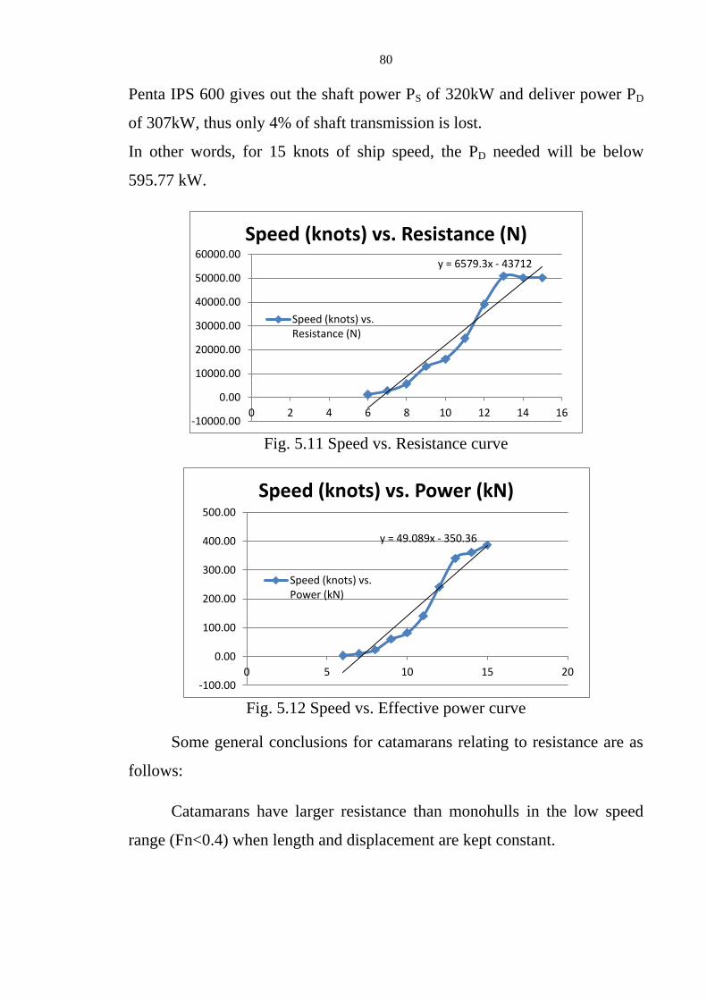
80
Penta IPS 600 gives out the shaft power PS of 320kW and deliver power PD
of 307kW, thus only 4% of shaft transmission is lost.
In other words, for 15 knots of ship speed, the PD needed will be below
595.77 kW.
Fig. 5.11 Speed vs. Resistance curve
Fig. 5.12 Speed vs. Effective power curve
Some general conclusions for catamarans relating to resistance are as
follows:
Catamarans have larger resistance than monohulls in the low speed
range (Fn<0.4) when length and displacement are kept constant.
y = 6579.3x - 43712
-10000.00
0.00
10000.00
20000.00
30000.00
40000.00
50000.00
60000.00
0 2 4 6 8 10 12 14 16
Speed (knots) vs. Resistance (N)
Speed (knots) vs. Resistance (N)
y = 49.089x - 350.36
-100.00
0.00
100.00
200.00
300.00
400.00
500.00
0 5 10 15 20
Speed (knots) vs. Power (kN)
Speed (knots) vs. Power (kN)

81
A catamaran with asymmetric single hulls and conventional hull form
has lower resistance than a catamaran with symmetric single hulls in the
traditional low speed range. (FN<0,36)
A catamaran fishing vessel with a well designed hull form can obtain a
higher speed than a traditional high displacement monohull vessel. In order
to obtain high speed with acceptable power the displacement has to be kept
low.
5.3 Strength Calculation
5.3.1 Longitudinal Strength
Using the load case following load case data shown below, the
longitudinal strength can be calculated in Hydromax.
Table 5.14 Load case (Weight distribution)

82
Table 5.15 Result of longitudinal strength calculation
Fig 5.13 Longitudinal strength curve

83
5.3.2 Hull Construction by Glass Reinforced Plastics (GRP/FRP),
Requirements by Rules and Regulations for the Classification of
Yachts and Small Crafts, Lloyd’s Register of Shipping
Our design ship uses an unsaturated polyester resin system with glass
fibre reinforcement. The polyester resins used are of a type which have been
approved by the Society for marine construction purposes. The type and
amount of the catalyst and accelerator are to be those recommended by the
resin manufacturer for the particular application, so that the resin will cure in
the required time, without the application of local heat.
The amount of colour pigments added does not to exceed 5 percent of
the weight of the resin. No pigments are used in gel coat or laminating resins
used in the underwater portion of the hull laminate or in laminates forming
fuel and water tanks.
Core materials for sandwich construction are of types approved by the
Society. Rigid expanded foam plastics are closed-cell types and are
impervious to water, fuel and oils, and are compatible with the polyester
resin. Balsa wood is end-grain and have a mositure content not exceeding 12
percent. Plywood is of a marine grade manufactured to an ISO or national
standard.
The production of the craft can be either by hand lay-up or spray lay-
up contact moulding techniques, and on the use of either single-skin or
sandwich construction or a combination of both. For the hull construction, it
is recommended that the sandwich construction is to be used and for deck
and other structures, single-skin construction is recommended.
Moulds are constructed of a suitable material and adequately stiffened
to maintain their overall shape and fairness of form. The materials used for
the construction of moulds should not affect the resin cure. Gelcoat resin is
applied to a thoroughly cleaned mould by brush, roller or spraying device to
give a uniform film thickness of between 0.4 and 0.6 mm.

84
Gelcoats are not to be left exposed longer than necessary after
gelation, and in no case overnight, before the application of the first layer of
reinforcement. The hull gel coat is to be backed up by a lightweight
reinforcement, not exceeding 300g/m2 in weight, with a resin-to-glass ratio
of not less than 2.5 to 1.
The scantlings are to be determined by interpolation of the values
given in tables in the Rule Book with respect to the dimensions of the craft.
The interpolated values will be shown later in this section.
The mechanical properties of a laminate, at a glass content by weight
per layer of reinforcement of 0.3 are: Ultimate tensile strength = 85N/mm2,
Tensile modulus = 6350 N/mm2, Ultimate flexural strength = 152 N/mm
2,
Flexural modulus = 5206 N/mm2, Ultimate compressive strength = 117.2
N/mm2, Compressive modulus = 6000 N/mm
2, Ultimate shear strength =
62.0 N/mm2, Shear modulus = 2750 N/mm
2, Interlaminar shear strength =
17.25 N/mm2 and Nominal laminate thickness per weight of reinforcement =
0.7mm per 300 g/m2.
The reinforcements are to be thoroughly impregnated with resin, and
consolidated to give a maximum glass content by weight of reinforcement as
follows: Chopped strand mat or sprayed fibres = 0.34, Woven rovings = 0.5,
Unidirectional rovings = 0.54 and Cloth fabrics = 0.5
The scantling values interpoled from the tables are based on the
mechanical properties and glass content of the laminate mentioned above. If
the properties and glass content differs:
1. For the plate laminates, the corrected weight obtained from the table is
to be multiplied by the factor KW,
36.13072
56.2
16.08.2152
88.1
27.5
W
TG
GKORG
GK
C
CW
bC
C
W

85
Where,
b = ultimate flexural strength, in N/mm2
GC = glass content of laminate (excluding the gel coat)
T = the measured laminate thickness (excluding the
gelcoat)
W = the total weight of reinforcement in the laminate, in
g/m2
2. For the stiffner sections, the corrected section modulus obtained from
the table is to be multiplied by the factor KZ,
45.1615
1)(
852
C
Z
U
ZGG
KORK
C
Where,
U = ultimate tensile strength, in N/mm2
GC = glass content of laminate (excluding the gel coat)
The frame spacing in the design is (350+5L) = 1075 mm, L=14.5m
( .2
WLOA LLL
). The hull laminate is initially moulded as two halves joined
Fig. 5.14 Laying-up of keel when moulding
hull as semi-completed halves

86
together. The outside hulls have gel coat. Where changes in hull form
occurs, such as at the transom boundary or chine, the reinforcement is to be
carried through and past the knuckle, the ends of various layers staggered.
The hull is to be locally increased in thickness in way of fittings for
propulsion units, etc. The increased laminate weight is to be gradually
reduced to the normal laminate weight, and the exposed edges of any
openings in the hull laminate are to be sealed with resin.
The scantling of hull laminate is to be determined by the type of the
craft, length and stiffener spacing. The values required are interpolated with
respect to Length and WLL
v. Thus the required values for our craft are:
Basic Stiffener Spacing = 422.5 mm
Bottom Shell Weight = 4988.7 g/m2
Side Shell Weight = 3756.9 g/m2
Keel Width = 662.5 mm
Keel Shell Weight = 7483.05 g/m2
The bottom shell weight determined is to be maintained throughout
the length of the craft and is to extend to 150mm above the waterline. The
keel is extended from transom to stem head. The side shell weight is to be
Fig. 5.15 Laying-up of transom boundary and chine line knuckles

87
maintained throughout the length of craft. The stern or transom is to be the
same weight as the side shell as our designed craft is not carrying an
outboard propulsion motor.
Fig. 5.17 Hull laminate for motor craft
Fig. 5.18 Hull laminate for motor craft
The hull is to be provided with an efficient system of side and bottom
framing in conjuction with girders, bulkheads or web frames to provide
transverse rigidity. The framing used in this craft is longitudinal framing.
Fig. 5.16 Hull laminate for motor craft

88
The modulus of longitudinals can be obtained by interpolation. For this craft,
we will need a modulus of 172.93 cm3
for the bottom longitudinals and
112.19 cm3 for the side longitudinals. The stiffener spacing is the same as the
scanling required by hull laminate, 422.5 mm.
The longitudinals are to be supported by bulkheads and transverse web
frames, spaced not more than 2 m apart. Additional transverse floors or webs
are to be fitted in way of engine seatings and the bottom of the craft forward,
modulus of floors and frames being 166.8 cm3 and 52.345 cm
3 respectively.
Modulus of web frames at center is 951.25 cm3 and at side is 393.17 cm
3.
Floors and bulkheads are to be connected to adjacent structure by double
angles, where they are manufactured from plywood of 12.5mm thickness,
the weight of laminate forming each angle is 1800g/m2.
The scantlings of the deck of single skin construction are: Basic Beam
Spacing = 422.5 mm, Deck Weight = 2275 g/m2. The openings in the upper
and weather deck for access hatches are properly framed and the coaming is
to be effectively connected to deck structure. Working areas of the weather
deck have an anti-slip surface. The decks are sheathed with wood.
The deck to hull connection is watertight and is constructed by
bonding and mechanical fastenings. Watertight integrity and strength of the
connection is not to be impaired by the attachment of the hull fender.
The laminate weight of deckhouse of single-skin construction in g/m2
is 2275 and the basic stiffener spacing in mm is 422.5. Openings for doors
and windows are to be adequately framed.
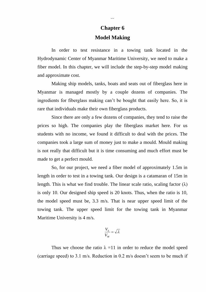
89
Chapter 6
Model Making
In order to test resistance in a towing tank located in the
Hydrodynamic Center of Myanmar Maritime University, we need to make a
fiber model. In this chapter, we will include the step-by-step model making
and approximate cost.
Making ship models, tanks, boats and seats out of fiberglass here in
Myanmar is managed mostly by a couple dozens of companies. The
ingredients for fiberglass making can’t be bought that easily here. So, it is
rare that individuals make their own fiberglass products.
Since there are only a few dozens of companies, they tend to raise the
prices so high. The companies play the fiberglass market here. For us
students with no income, we found it difficult to deal with the prices. The
companies took a large sum of money just to make a mould. Mould making
is not really that difficult but it is time consuming and much effort must be
made to get a perfect mould.
So, for our project, we need a fiber model of approximately 1.5m in
length in order to test in a towing tank. Our design is a catamaran of 15m in
length. This is what we find trouble. The linear scale ratio, scaling factor (λ)
is only 10. Our designed ship speed is 20 knots. Thus, when the ratio is 10,
the model speed must be, 3.3 m/s. That is near upper speed limit of the
towing tank. The upper speed limit for the towing tank in Myanmar
Maritime University is 4 m/s.
M
S
V
V
Thus we choose the ratio λ =11 in order to reduce the model speed
(carriage speed) to 3.1 m/s. Reduction in 0.2 m/s doesn’t seem to be much if

90
you look at the magnitude but what if you look in inches per sec. It would be
about 8 in/sec. But there was more trouble. Only after we made the fiber
model, we did not get permission to test with 3.1m/s. We only got the
permission to test up to 2.33m/s. Thus, the designed ship speed of 15 knots
can only be achieved.
So, the model dimensions and speed were as follows:
LOA = 1.364 m
LBP = 1.812 m
LWL = 1.268 m
B = 0.614 m
T = 0.064 m
D = 0.191 m
VM = 3.106 m/s (expected), 2.33 m/s (reality)
Once we got the main dimensions and the scale factors we needed,
we started making a mould. We needed sheets of 3-plywood and 2"x1"
timber blocks. Firstly, as we have a Maxsurf design file, we printed out the
stations that we’ve created. As the breadth of the model is about 2 feet
maximum, Half-breadth is only around 12 inches. Actually, we needed to
print out the stations with A3, B4 or papers of larger size using a plotter. The
only things we have was legal papers and a printer. So we only printed out
half the stations.
Fig. 6.1 Stations cut out using hacksaw

91
The printed out papers are cut using a small paper knife and are
drawn on the 3-plywood. After which they are sawed out using a hacksaw.
For this model, we used 18 stations. The more stations or frame you include,
the more precise your model will be.
The stations are joined using 2"x1" wooden blocks which are sawed
out according to the station spacing calculated. Just before this, some small
wooden blocks are nailed to the station to enable the shell plating to attach
the stations. All blocks and stations are joined with ½" nails. Following this
you will get a fish-bone like structure, which all the stations are erected and
connected.
Similarly, the shell plating is printed out but as we don’t have a
plotter, we had to redraw on the plywood scaling it to the desired size. Here
we found a huge problem. Maxsurf doesn’t give the shell plating for the
whole structure. It only gives out up to designed waterline. And the
development plan given by Workshop Pro gives us really a hard time. The
shell can’t be plated. We have to redraw nearly everything for the side shell
Fig. 6.2 Tools used in making wooden mould

92
plating. The shell plating of the tunnel and the inner side of the demi-hull
wasn’t of any trouble but the side shell plating really does.
Because of this shell plating error, there were some little gaps
between the plates which we have to fill it up using the general purpose
silicone sealant. We used two tubes of Silicone, each costing 2000 Kyat.
While applying Silicone sealants, we use a masking tape to obtain a smooth
and neat finish. First apply the silicone, then apply the masking tape, wait for
a few seconds and then remove before the sealant cures. Thus, we got a
smooth finish. Silicone is a bit more expensive than other adhesives but it is
really easy to use.
Fig. 6.4 Profile view of wooden mould
Fig. 6.3 Assembling stations and plating shells

93
So, we have finished cutting out the stations, erecting and joining
them, shell plated them and the gaps are filled with sealant. After all these,
the only thing left is to sand the plywood to obtain a smooth finish. First, we
used a No. 3, P: 36 sandpaper, following with a No. 0, P: 120 sandpaper.
Wipe out all the dust and finally, we get a primary male mould made of
plywood.
Fig. 6.6 View from aft (Transom) of wooden mould
Fig. 6.5 View from below (Fish view)

94
For this primary mould, we used 4 sheets of 3'x6' 3-plywood, about 7
feet of 2"x1" wood, 2 tubes of silicone sealant, ½" nails, ¾" nails and some
screws. The tools we used here are a hacksaw, masking tape, pliers, caulking
gun, sand papers, screw drivers, scissors, knife, rulers, pen, pencils,
permanent markers, hand saw, printed out papers, tee and set-squares
(triangular rulers). The estimate cost of this timber mould is about 35,000
Kyat.
For the fiber model, we let Fusion Fiberglass to take care of the job.
Usually, to get the fiber model with the neat outside finish, the female mould
must be made out of the wooden primary mould. This female mould is
usually made of fiberglass having 6 laminates. The primary mould sanded, is
applied with ATM poly putty, which was then again sanded using
sandpapers of number 40, 60, 80, 100, 120, 180 and so on up to 1800. For
the sandpapers of No. 400 and above, the mould surface must be sprayed
with water before rubbing.
Gelcoat is painted or sprayed on this primary mould with putty
applied. Lamination started about 1 hour after. Chopped strand mat and
polyester resin is used for lamination. About 6 layers of lamination are made.
The mat is laid, resin is applied as adhesive solution, rollers are used to coat,
avoid air gaps, release excessive resin, etc. Sheets of mat layers are applied
with unsaturated polyester resin between each other. After 6 layers of
laminate and it had been dried, the female mould is obtained.
The required final male model is made similarly using the female
mould as a base, usually of 3 to 4 layers of laminate. This is the usual way of
making fiberglass models. But the female mould would be an excess if we
made only one model and the female mould could cost extra money. Even
for our model of around 4.5'x 2'x 7" it could cost 220,000 Kyat or more. We
only needed 1 model and we could only spend a few. Thus, it would better if

95
we could get a final male model without making a female mould out of
fiberglass.
Fusion Fiberglass had agreed us to make a final male model which
would cost only around 140,000 Kyat but we would not be able to get back
the wooden primary mould. The way they make the model sounds
interesting. Although we couldn’t see the making with our eyes, they
explained us how they made it. First, they put a tape fully around the primary
mould. They then applied really thick putty around it and let it dry. After
which they destroyed the wooden primary mould, which is lying inside the
putty, taking care not to harm the putty. After peeling of the tapes, the putty
now forms as a female mould. Care must be taken in all stages afterwards.
The male model is made just the same as the steps mentioned above.
Finally, we get the required fiber model as shown below.
Fig. 6.8 View from forward-starboard side of fiber model
Fig. 6.7 Profile view of fiber model

96
Fig. 6.11 View from forward-port underside
Fig. 6.10 Underside of fiber model
Fig. 6.9 View from aft (Transom) of fiber model

97
When Fusion Fiberglass delivered us the model, they said they have
tested that the model is watertight. But we have to see it for ourselves. There
is no lake or tank where we could test the model immediately, so what we
did was we filled up the model with water and see if there were any leaks.
Luckily there were none. So, finally we got our model which we wanted for
just around 175,000 Kyat, saving between 45,000 Kyat to 1 lakh.
To test in a towing tank, we needed to fit wooden pieces on the fiber
model so that the dynamo can be seated properly and the guiding arms be
fitted. The dynamo must be fitted at the center of gravity both longitudinally
and transversely. So it is fitted in the tunnel where CG is located. The design
waterline is drawn around the model. The LCG position is calculated from
Maxsurf and is verified by putting the model, subjected to a tipping point,
most likely to be a chair and is seen whether it is balanced and stabled.
The instruments were fitted and the model was now in place for a
resistance test. The results were shown in Chapter-5.
Fig. 6.12 Fiber model placed in
towing tank Fig. 6.13 Assembly to towing tank
carriage

98
Fig. 6.14 Dynamometer assembled in tunnel
Fig. 6.15 Resistance test being carried out

99
Chapter 7
Conclusion and Recommendations
7.1 Conclusion
In our project, detail definitions relating to catamaran hull forms and
pleasure crafts, designed hull, drawn with Maxsurf and its calculations, rules
and regulations required and model making are included. Our project will
help the development of using catamaran hull forms in ship industry in our
country.
The fact that we chose a chine hull form is because we intended to
design a semi-displacement/semi-planing craft. Thidar Catamaran which we
used as a reference is a round bilge craft, meaning which it is a displacement
hull form. Displacement hull forms are useful for load carrying but they have
very slow speeds. As our design is a pleasure craft, speed is a factor that is
needed to be considered. Planing hulls are designed for speed but they need
more power to plane. So, we chose a semi-displacement/semi-planing hull
form.
Maxsurf software is easy to use and calculations are fast compared
with other types of software. We used Maxsurf Pro Software to initially
create required catamaran hull form, bonding and trimming surfaces as
necessary. From the hull form obtained, we designed general arrangement
plan using AutoCAD and creating complete 3D design back in Maxsurf.
Stability calculations are calculated using Hydromax Software and the
result of curves and table are plotted. Intact Hydrostatics, Large Angle
Stability, KN values, cross curve, Longitudinal Strength, etc. are also
calculated using Hydromax. Freeboard and Tonnage calculations are not
required by this type of craft.
Resistance test is carried out in towing tank located in Myanmar
Maritime University compound. Calculation is done with Insel & Molland

100
Theory. Here we can notice that the viscous resistance interference and wave
resistance interference factors are needed to be considered in calculation of
resistance for catamaran. Strength and Section Modulus required by Rules
and Regulations for the Classification of Yachts and Small Crafts, Lloyd’s
Register of Shipping are interpolated linearly from the given tables with
respect to length and speed to length ratio. Model making chapter will help
understand the basic model making and fiberglass technology.
In Myanmar, FRP boat building is not widely used yet and is not well
developed. Development in this technology is necessary as this will help
production of locally manufactured boats which could be definitely cheaper
than the imported ones. In mass production of the same design, fiber boat
building is more beneficial and less costly compared to conventional boat
building but if built only a few numbers, the cost of making a fiber mould is
expensive and unprofitable.
Catamaran is another technology that our country need to
development. This project states the superior facts of catamarans compared
to monohull. We have Thidar Catamaran, Japanese technology which we
could base on but it is rather old. Further developments are necessary. Fast
ferries should be designed as catamarans. In other countries, the Research
and Development Centers of their universities studies and research for
improvement of catamaran design. We don’t have this in our university, so
this technology could not be studied widely.
If we could study this technology, we can have stable, fast and
profitable catamaran designs. Our project could be a revolution to catamaran
development in our country.
8.2 Recommendations
We used the principle dimensions limiting the boundaries of 15m
catamaran offset derived from Thidar Craft using GEOSIM method. Simply

101
speaking, we could say that our craft does not have a mother ship. It is a new
design with the set of limitations using a similar length catamaran. It would
be better if we have a mother ship of this hull form. Calm water wave
resistance is estimated by using theories and previous test data. It would be
better if all separation to length ratio for specific type of hull form is tested.
In this project, the resistance due to appendages is neglected when
calculating resistance. It will be more accurate, if these data are considered.
Strength calculation is incomplete. More theory and rules must be
studied for strength calculation of FRP boats and crafts. Most people use
AutoCAD software to design a full ship with all superstructures and
appendages but we found using Maxsurf when drawing a 3D design hull is a
bit more easy and less time consuming. But AutoCAD is necessary software
for all engineering students.
From this project, we can change the general arrangement form to
change the design to a ferry boat of same size with the capacity of 30-50
passengers but more rules and regulations would be required. Or we could
head to resistance, verifying the wave resistance with respect to hull
separation. Or fit hydrofoils to form a HySuCat arrangement. Or making use
of this boat and install solar panel to form either electric only or diesel-
electric hybrid system or hydrogen fuel hybrid system. Many new directions
can be made using this project as a base.
“Design of a Pleasure Craft with Catamaran Hull” is just a graduation
project which we approached design aspects with the availability of data and
resources all we could get. It takes a lot of hard work to gather data as there
is no former project to rely on and most data from the internet are incomplete
and costly. We really hope this project could be the start or foundation of
many projects relating this field of study for students in our country.

102
References
1. eCat Hybrid – Power Catamaran Design Study, Juri Karinen, 2011
2. Insel, M. and Molland, A.F (1992), An Investigation into Resistance
Components of High-Speed Displacement Catamarans. Trans. of
Royal Institute of Naval Architects, Vol.134, pp 1-20.
3. International Convention for Safety of Life at Sea, SOLAS, November
2000
4. ITTC-Recommended Procedures, Fresh Water and Seawater
Properties, 7.5-02-01-03, Effective Date – 2011, Revision – 02.
5. Recent Applications of Hydrofoil-Supported-Catamarans, K.G.W
Hoppe, 2001
6. Resistance experiments on a systematic series of high speed
displacement monohull and catamaran forms in shallow water. A.F.
Molland, P.A. Wilson and D.J.Taunton. Ship Science Report No.127
University of Southampton, 2003.
7. Rules and Regulations for the Classification of Yachts and Small Craft
(Lloyd’ Register of Shipping), 1994
8. Ship Resistance and Propulsion, Anthony F. Molland, Stephen R.
Turnock, Dominic A. Hudson, 2011.
9. The Spring 2000 Issue of Power Multihulls Magazine by Prof. Jacob
van Renen van Niekerk
10. Volvo Penta IPS and INCINOLET Manuals
11. http://en.wikipedia.org
12. http://www.thaiboating.com

APPENDIX

103
Chopped Strand Mat Used in Fiber Making
Copyright © 2022 FDOKUMEN