
B-Line series cable ladder support system catalog for the ...
180
Cable ladder CSS-19 Cable support solutions Cable ladder, tray, and supports
-
Upload
khangminh22 -
Category
Documents
-
view
0 -
download
0
Transcript of B-Line series cable ladder support system catalog for the ...
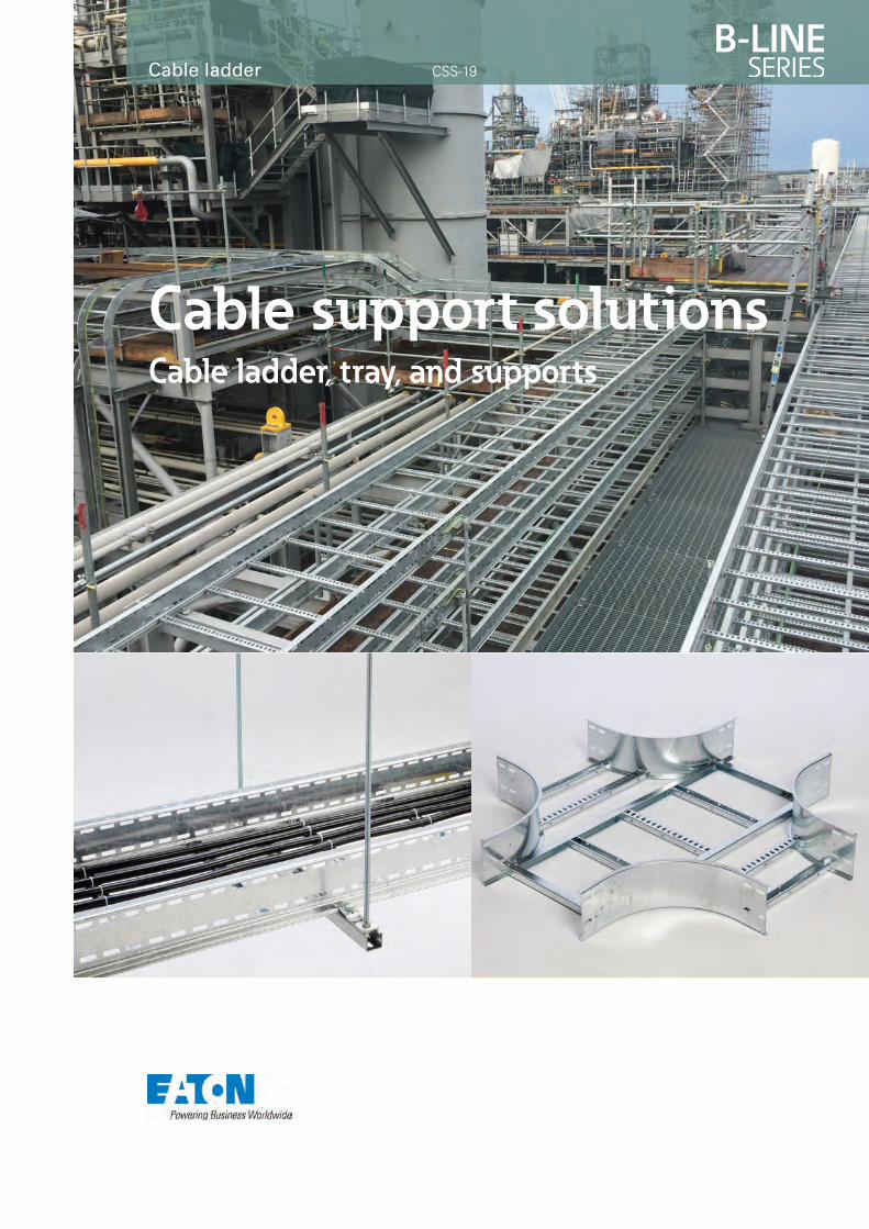
Cable ladder CSS-19
Cable support solutionsCable ladder, tray, and supports

At Eaton, we believe that power is a fundamental part
of just about everything people do. That’s why we’re
dedicated to helping our customers find new ways to
manage electrical, hydraulic and mechanical power
more efficiently, safely and sustainably. To improve
people’s lives, the communities where we live and
work, and the planet our future generations depend
upon. Because this what really matters. And we’re here
to make sure it works.
To learn more go to: Eaton.com/whatmatters
We make what matters work.
We make what matters work.*
** woat phe tveliee b, wnoatt EA t ral patnemadnus a fr ie
.ksrot we irue skao mt
y mllaeat rhs wihe tsuace. Bnopu
e grutur fut oenale phd tn, akrow
eitinmumoe ch, tsevs li’elpoep
sud sny aleaf, syltneicfife erom
nc aliuardy, hlacirtcele eganam
otsur cug oinpleo hd teatcided
e dlpoeg pinhtyrevt euobt asuf jo
e ree hr’ed wn. Asretaty m
d nepes dnoiatrenee g
d ne avie le wrehs we
e vorpmo i. Tylbainats
r ewol pacinahced mn
o s tyaw wed nns firem
e r’ey whs w’ath. Toe d
ake mW
c.nota: Eoo te gron mraeo lTTo l
.kros wretatat me whak
srettamtahw/moc

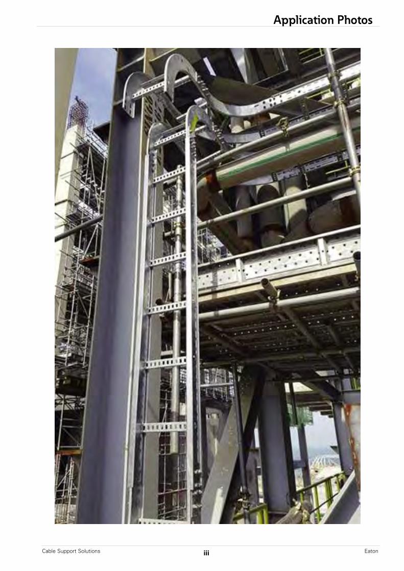
Application Photos
iCable Support Solutions Eaton

Cable Support SolutionsEaton ii
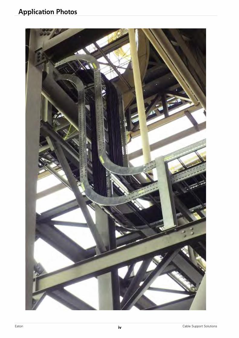
Application Photos
Application Photos
iiiCable Support Solutions Eaton
Cable Support SolutionsEaton iv
Application Photos

Application Photos . . . . . . . . . . . . . . . . . . . . . . . . . . . . . . . . . . . . . . . . . . . . . . . . . . . . . . . . . . . . . . . . . . . . . i - iv
CoSPEC™ Software Tool . . . . . . . . . . . . . . . . . . . . . . . . . . . . . . . . . . . . . . . . . . . . . . . . . . . . . . . . . . . . . . . . . 2
Introduction . . . . . . . . . . . . . . . . . . . . . . . . . . . . . . . . . . . . . . . . . . . . . . . . . . . . . . . . . . . . . . . . . . . . . . . . . . . . . . . . . 3
Product Overview . . . . . . . . . . . . . . . . . . . . . . . . . . . . . . . . . . . . . . . . . . . . . . . . . . . . . . . . . . . . . . . . . . . . . . . . . . 4
Structural Steel Savings . . . . . . . . . . . . . . . . . . . . . . . . . . . . . . . . . . . . . . . . . . . . . . . . . . . . . . . . . . . . 5 - 25
Technical Data . . . . . . . . . . . . . . . . . . . . . . . . . . . . . . . . . . . . . . . . . . . . . . . . . . . . . . . . . . . . . . . . . . . . . . . 26 - 36
Steel Cable LadderLadder Selection Guide (HPL), (SDL), & (HDL) Series . . . . . . . . . . . . . . . . . . . . . . . . . . . . 38 Steel Cable Ladder Construction . . . . . . . . . . . . . . . . . . . . . . . . . . . . . . . . . . . . . . . . . . . . . . . . 39 - 41Steel Cable Ladder Straight Sections . . . . . . . . . . . . . . . . . . . . . . . . . . . . . . . . . . . . . . . . . . . 42 - 43Steel Cable Ladder Covers & Cover Clamps . . . . . . . . . . . . . . . . . . . . . . . . . . . . . . . . . . 44 - 45Steel Cable Ladder Fittings . . . . . . . . . . . . . . . . . . . . . . . . . . . . . . . . . . . . . . . . . . . . . . . . . . . . . . . 46 - 63Steel Cable Ladder Accessories . . . . . . . . . . . . . . . . . . . . . . . . . . . . . . . . . . . . . . . . . . . . . . . . . 64 - 77
Aluminum Metric Cable LadderAluminum Metric Cable Ladder Straight Sections . . . . . . . . . . . . . . . . . . . . . . . . . . . 80 - 85Aluminum Metric Cable Ladder Covers & Cover Clamps . . . . . . . . . . . . . . . . . . . 86 - 87Aluminum Metric Cable Ladder Fittings . . . . . . . . . . . . . . . . . . . . . . . . . . . . . . . . . . . . . . 88 - 110Aluminum Metric Cable Ladder Accessories . . . . . . . . . . . . . . . . . . . . . . . . . . . . . . 111 - 120
Perforated & Solid Bottom Cable TrayStraight Sections . . . . . . . . . . . . . . . . . . . . . . . . . . . . . . . . . . . . . . . . . . . . . . . . . . . . . . . . . . . . . . . . 122 - 123Splice Plates, Cover Clamps, Hold Downs & Hardware . . . . . . . . . . . . . . . . . 124 - 127Fittings . . . . . . . . . . . . . . . . . . . . . . . . . . . . . . . . . . . . . . . . . . . . . . . . . . . . . . . . . . . . . . . . . . . . . . . . . . . . . 128 - 141Covers - Straight Sections & Covers . . . . . . . . . . . . . . . . . . . . . . . . . . . . . . . . . . . . . . . . . 142 - 143
Steel Ship LadderStraight Sections . . . . . . . . . . . . . . . . . . . . . . . . . . . . . . . . . . . . . . . . . . . . . . . . . . . . . . . . . . . . . . . . . . . . . . . . 144Fittings . . . . . . . . . . . . . . . . . . . . . . . . . . . . . . . . . . . . . . . . . . . . . . . . . . . . . . . . . . . . . . . . . . . . . . . . . . . . 145 - 146Accessories . . . . . . . . . . . . . . . . . . . . . . . . . . . . . . . . . . . . . . . . . . . . . . . . . . . . . . . . . . . . . . . . . . . . . . . . . . . . . . 147
Cable CleatsCable Cleats . . . . . . . . . . . . . . . . . . . . . . . . . . . . . . . . . . . . . . . . . . . . . . . . . . . . . . . . . . . . . . . . . . . . . . 149 - 151
Strut SystemsIntroduction & Technical Data . . . . . . . . . . . . . . . . . . . . . . . . . . . . . . . . . . . . . . . . . . . . . . . . . 153 - 160 Channels . . . . . . . . . . . . . . . . . . . . . . . . . . . . . . . . . . . . . . . . . . . . . . . . . . . . . . . . . . . . . . . . . . . . . . . . . . 161 - 165 Hardware . . . . . . . . . . . . . . . . . . . . . . . . . . . . . . . . . . . . . . . . . . . . . . . . . . . . . . . . . . . . . . . . . . . . . . . . . . 166 - 167 Fittings . . . . . . . . . . . . . . . . . . . . . . . . . . . . . . . . . . . . . . . . . . . . . . . . . . . . . . . . . . . . . . . . . . . . . . . . . . . . . 168 - 171
NOTICEEaton’s B-Line Division reserves the right to change the specifications, materials, equipment, prices or the availability of productsat any time without prior notice. While every effort has been made to assure the accuracy of information contained in thiscatalog at the time of publication, Eaton is not responsible for inaccuracies resulting from undetected errors or omissions.
Table of Contents
1Cable Support Solutions Eaton
Cable Support SolutionsEaton 2
CoSPEC™
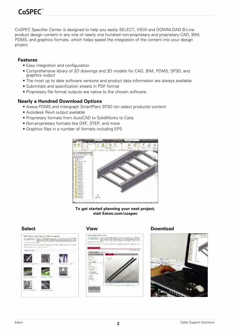
CoSPEC Specifier Center is designed to help you easily SELECT, VIEW and DOWNLOAD B-Line product design content in any one of nearly one hundred non-proprietary and proprietary CAD, BIM,PDMS, and graphics formats, which helps speed the integration of the content into your designproject.
Features• Easy integration and configuration• Comprehensive library of 2D drawings and 3D models for CAD, BIM, PDMS, SP3D, and
graphics output• The most up to date software versions and product data information are always available• Submittals and specification sheets in PDF format• Proprietary file format outputs are native to the chosen software
Nearly a Hundred Download Options• Aveva PDMS and Intergraph SmartPlant SP3D (on select products) content• Autodesk Revit output available • Proprietary formats from AutoCAD to SolidWorks to Catia• Non-proprietary formats like DXF, STEP, and more• Graphics files in a number of formats including EPS
To get started planning your next project,visit Eaton.com/cospec
Select View Download

Introduction
3Cable Support Solutions Eaton
About Eaton’s B-Line Division
Eaton’s B-Line Division is a global provider of innovative, cable management systems andsupport system solutions for engineered facility subsystem applications. With a full range ofcable support solutions, we offer one of the lowest lifetime cost of ownership.
In addition, we offer best-in-class specification engineering services, which provide pre- andpost-sale engineering and technical support. We are dedicated to servicing our global customer base with manufacturing and technical expertise.
Our manufacturing facilities are located in South Korea, China, Malaysia, Kingdom of SaudiArabia, United States of America, and Canada.
HH
HUnitedStates South Korea
H
ChinaH
Malaysia
Kingdom ofSaudi Arabia
Manufacturing Locations
Approvals for products may include (varies by product type):
H
Canada
Product Overview
Cable Support SolutionsEaton 4
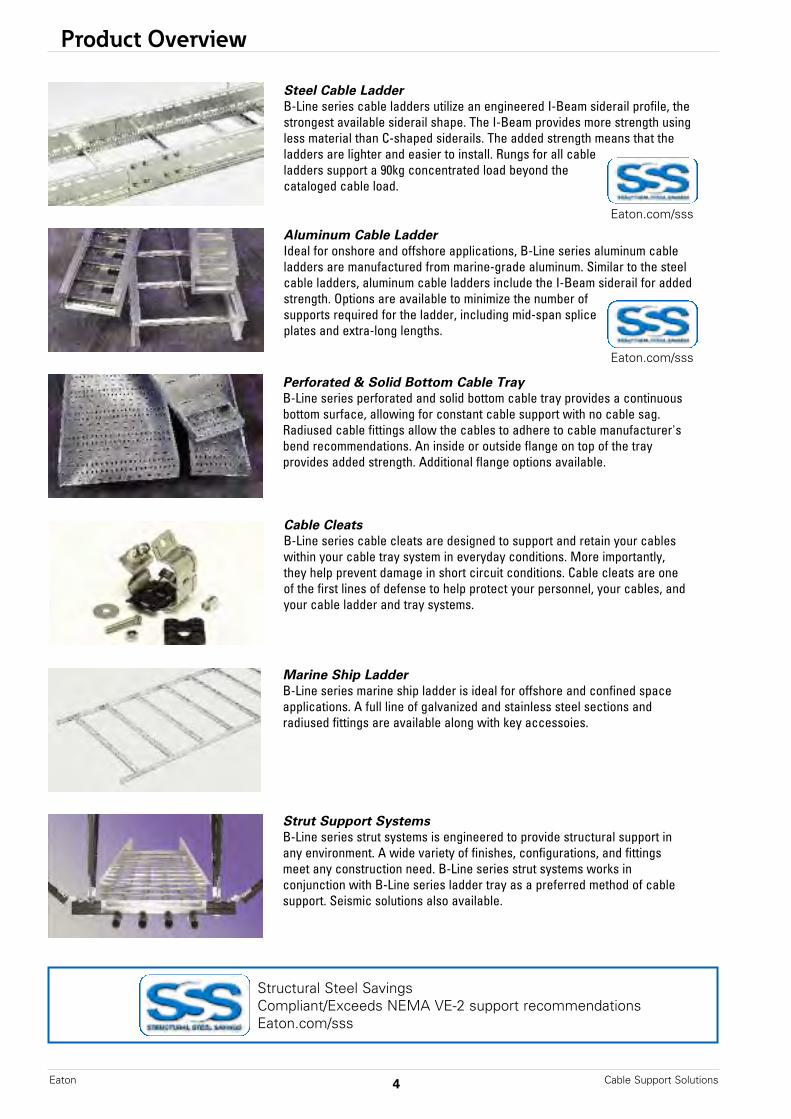
Strut Support SystemsB-Line series strut systems is engineered to provide structural support inany environment. A wide variety of finishes, configurations, and fittingsmeet any construction need. B-Line series strut systems works inconjunction with B-Line series ladder tray as a preferred method of cablesupport. Seismic solutions also available.
Marine Ship LadderB-Line series marine ship ladder is ideal for offshore and confined spaceapplications. A full line of galvanized and stainless steel sections andradiused fittings are available along with key accessoies.
Perforated & Solid Bottom Cable TrayB-Line series perforated and solid bottom cable tray provides a continuousbottom surface, allowing for constant cable support with no cable sag.Radiused cable fittings allow the cables to adhere to cable manufacturer'sbend recommendations. An inside or outside flange on top of the tray provides added strength. Additional flange options available.
Steel Cable LadderB-Line series cable ladders utilize an engineered I-Beam siderail profile, thestrongest available siderail shape. The I-Beam provides more strength usingless material than C-shaped siderails. The added strength means that theladders are lighter and easier to install. Rungs for all cableladders support a 90kg concentrated load beyond thecataloged cable load.
Aluminum Cable LadderIdeal for onshore and offshore applications, B-Line series aluminum cableladders are manufactured from marine-grade aluminum. Similar to the steelcable ladders, aluminum cable ladders include the I-Beam siderail for addedstrength. Options are available to minimize the number ofsupports required for the ladder, including mid-span spliceplates and extra-long lengths.
Cable CleatsB-Line series cable cleats are designed to support and retain your cableswithin your cable tray system in everyday conditions. More importantly,they help prevent damage in short circuit conditions. Cable cleats are oneof the first lines of defense to help protect your personnel, your cables, andyour cable ladder and tray systems.
Structural Steel SavingsCompliant/Exceeds NEMA VE-2 support recommendationsEaton.com/sss
Eaton.com/sss
Eaton.com/sss

Structural Steel Savings
5Cable Support Solutions Eaton
www.eaton.com/sss 3
Lower total install cost solution through reduction of structural steel supportsEaton provides solutions that de-risk by design and drive value to our end customers. With Eaton’s B-Line series cable ladder, Eaton provides support recommendations that meet and exceed NEMA VE-2 requirements. These methods have been applied across the globe on multiple applications and projects, and have saved customers millions of dollars on structural steel.
This brochure provides an overview of Eaton’s recommendations for structural steel supports when utilizing Eaton’s B-Line series cable ladder, !ttings and splice plates. For additional information, and online resources and tools, visit Eaton.com/SSS.
Cable ladder best practiceTo maximize cost savings on any cable ladder project, it is essential that:
Electrical and structural engineers and contractors communicate effectivelySupport plans and layouts are discussed early on within the project life cycle (FEED - Front End Engineering Design) to ensure proper support placement, minimize construction complexity, and reduce budget spend
Support location best practice
1/4 Span - The method of placing supports at 1/4 span away from a splice plate location on continuous runs.
Recommended installation method by NEMA VE 2 and Eaton’s B-Line seriesUp to 50% de"ection reduction over simple beam or mid span installations Eliminates hold down clamp and splice hardware interference issues during thermal expansion and contraction See Fig. 1A and Fig. 1B for visual stress comparison
Mid-Span - The method of placing supports at 1/2 span away from a splice plate location on continuous runs.
Excessive system de"ection and stress experienced compared to 1/4 span support methodologyRequires additional supports to account for proper thermal expansion and contraction Splice plate performance becomes more in"uential on de"ectionSee Fig. 2A and Fig. 2B for visual stress comparison
Simple Beam (Over Support) - The method of placing supports directly under the splice plate locations on continuous runs.
Maximum system de"ection and stress experienced Leads to possible installation issues not allowing for proper thermal expansion and contraction See Fig. 3A and Fig. 3B for visual stress comparison
¼ Span
Fig. 1B
Fig. 1A
Support Location System Stress and De!ection
-Minimum
-Maximum
¼ Span
Mid-Span
Over Support
For b
est p
erfo
rman
ce
Mid-Span
Fig. 2B
Fig. 2A
Simple Beam (Over Support)
Fig. 3B
Fig. 3A
Structural Steel Savings
To maximize cost savings on any cable ladder project,it is essential that:
Support location best practice
Eaton provides solutions that de-risk by design and drive value to our end customers. With Eaton’sB-Line series cable ladder, Eaton provides support recommendations that meet and exceed NEMAVE-2 requirements. These methods have been applied across the globe on multiple applications andprojects, and have saved customers millions of dollars on structural steel.
Structural Steel Savings
Cable Support SolutionsEaton 6
oluvE
n of Piotolu
t Sajecoojecrn of P
ngsivt Sa
ngs
olus B’’ noatE
e ar adile
n of Piotolus eieree sni-Ls Boy f fog the wanadi
t Sajecoojecn of Pad cereenigns e
l itaor tewr loo
ngst Saor sle laddeba*.tsod clletasnl i
ngss niotlu
*
popuSmmecoR
trposniodatnemm
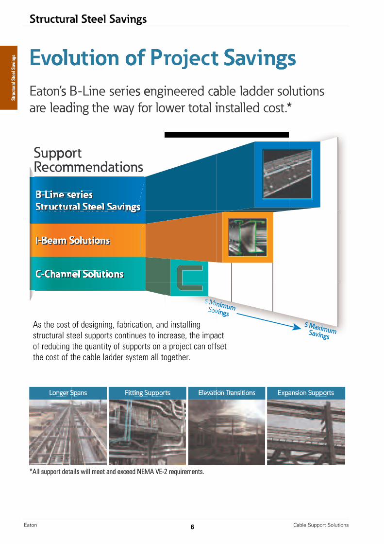
As the cost of structural steel continues to increase, the impact of reducing the quantity of supports on a projects can offset the cost of the cable ladder system all together
As the cost of structural steel continues to increase, the impact of reducing the quantity of supports on a projects can offset the cost of the cable ladder system all together
ntinues to increase, the impact of reducing the quantity of supports on a projects can offset the cost of the cable ladder system all together
r S
the cost of the cable ladder system all together
ngeoL
s
the cost of the cable ladder system all together
anpr S ing StitF
s
.the cost of the cable ladder system all together
trpopuing S ioatvleE
snioitsanrrann T Trio anpEx
strpopun Siosan
*All support details will meet and exceed NEMA VE-2 requirements.
*All support details will meet and exceed NEMA VE-2 requirements.
*All support details will meet and exceed NEMA VE-2 requirements.
Structural Steel Savings
As the cost of designing, fabrication, and installingstructural steel supports continues to increase, the impactof reducing the quantity of supports on a project can offsetthe cost of the cable ladder system all together.

Structural Steel Savings
7Cable Support Solutions Eaton
www.eaton.com/sss8
!"#$%&'()*"+,-."-%/0
!"#$%&'()*"+,-."-%/0
12345"64$78349":;$$2<3"-4-=4<"%83:"%:"9;%>":;$$2<3"?2<"=23@":3<%7A@3":48372&"%&9"?7337&A"B@4&">28%349";&94<&4%3@"3@4":$>784"$>%34C"""
,DE"+F))--."=4&9"<%97;:"-%/C
G?">4::"3@%&"2<4H;%>"32"()*"+,-."-%/C
&2"7&34<-497%34:;$$2<3"7:"<4H;7<49
GIJ4%-":;$$2<3-43@29
K#3<;3":;$$2<3-43@29 G:2-43<78"L74B
Vertical Inside / Outside BendSupport Recommendation
Option 1“½ Span”
1MNO"P482--4&9%372&
#;$$2<3"<482--4&9%372&:"%$$>Q"32"JIR7&4":4<74:"SIT":344>"%&9"%>;-7&;-"8%=>4">%994<U"V6R":4<74:U"%&9"#6R":4<74:":344>"8%=>4">%994<"$<29;83:C
K12345"#;$$2<3"$<2?7>4"-%Q"=4"$>%849"%3""%&Q">28%372&";&94<&4%3@":$>784"$>%34C
#;$$2<3"%&QB@4<4";&94<"?7337&A"2<:$>784"$>%34
M>4L%372&"L74B
Structural Steel Savings
Eaton.com/sss
Structural Steel Savings
Cable Support SolutionsEaton 8
www.eaton.com/sss 9
!"#$%&&#'()*#+,%-.)$#'+#/#&0)*#1234#5678#7)9:;*+#<*'%,7%=<)'%&.00+,'#<&#,%-.<,%=
6>?#5@33778#A%*=#,)=<.)9:
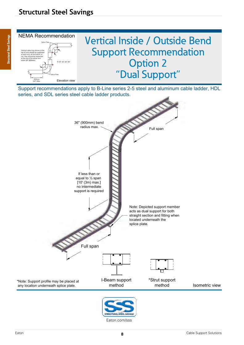
B+'%C#D%0<E'%=#&.00+,'#7%7A%,#)E'&#)&#=.)$#&.00+,'#"+,#A+'(#&',)<F('#&%E'<+*#)*=#"<''<*F#G(%*$+E)'%=#.*=%,*%)'(#'(%#&0$<E%#0$)'%:###
H.$$#&0)*
H.$$#&0)*
!IJ%)7#&.00+,'7%'(+=
KL',.'#&.00+,'7%'(+= !&+7%',<E#M<%G
KB+'%C#L.00+,'#0,+"<$%#7)N#A%#0$)E%=#)'##)*N#$+E)'<+*#.*=%,*%)'(#&0$<E%#0$)'%:
Vertical Inside / Outside BendSupport Recommendation
Option 2“Dual Support”
BOPQ#R%E+77%*=)'<+*
L.00+,'#,%E+77%*=)'<+*&#)00$N#'+#JIS<*%#&%,<%&#TIU#&'%%$#)*=#)$.7<*.7#E)A$%#$)==%,V#WDS#&%,<%&V#)*=#LDS#&%,<%&#&'%%$#E)A$%#$)==%,#0,+=.E'&:
O$%M)'<+*#M<%G
Structural Steel Savings
Eaton.com/sss

Structural Steel Savings
9Cable Support Solutions Eaton
www.eaton.com/sss1
!"#$%&'()**+,-&$-.+/
01-,)-'()**+,-&$-.+/ !(+&$-,23'42$5
Vertical Inside / Outside BendSupport Recommendation
Option 3“Dual Support”
6789':$3+&&$;/%-2+;
6+-$<'=$*23-$/'()**+,-'&$&>$,'%3-('%('/)%?'()**+,-'@+,'>+-.'(-,%2A.-'($3-2+;'%;/'@2--2;A'5.$;'?+3%-$/');/$,;$%-.'-.$'(*?23$'*?%-$B'''
C)??'(*%;
C)??'(*%;
6+-$<'!;-$,&$/2%-$'()**+,-('2;-$,4%?(';+-'-+'$D3$$/'EFG'HI&J'+;'$D-$;/$/'4$,-23%?'/,+*(
K'1*%;LEFG'HI&J'&%DM@,+&')**$,@2--2;A'
½ Span[10' (3m) max]
from lowerfitting
INO'HPFF&&J'>$;/',%/2)('&%DB
1)**+,-',$3+&&$;/%-2+;('%**?Q'-+'#"R2;$'($,2$('S"T'(-$$?'%;/'%?)&2;)&'3%>?$'?%//$,U'V=R'($,2$(U'%;/'1=R'($,2$('(-$$?'3%>?$'?%//$,'*,+/)3-(B
06+-$<'1)**+,-'*,+@2?$'&%Q'>$'*?%3$/'%-''%;Q'?+3%-2+;');/$,;$%-.'(*?23$'*?%-$B
7?$4%-2+;'42$5
Structural Steel Savings
Eaton.com/sss

Structural Steel Savings
Cable Support SolutionsEaton 10
www.eaton.com/sss 1
!"#$%&'()**+,-&$-.+/
0-,)-'()**+,-&$-.+/ !(+&$-,12'31$4
Vertical Inside / Outside BendSupport Recommendation
Option 4“Floating”
5678'9$2+&&$:/%-1+:
0)**+,-',$2+&&$:/%-1+:('%**;<'-+'#"=1:$'($,1$('>"?'(-$$;'%:/'%;)&1:)&'2%@;$';%//$,A'BC='($,1$(A'%:/'0C='($,1$('(-$$;'2%@;$';%//$,'*,+/)2-(D
>E'FGHH&&I'&%J
>E'FGHH&&I'&%J
>E'FGHH&&I'&%J
>E'FGHH&&I'&%J
5+-$K'!:-$,&$/1%-$'()**+,-('1:-$,3%;(':+-'-+'$J2$$/'LHE'FM&I'+:'$J-$:/$/'3$,-12%;'/,+*(
MGN'FOHH&&I'@$:/',%/1)('&%JD
6;$3%-1+:'31$4
Structural Steel Savings
Eaton.com/sss

Structural Steel Savings
11Cable Support Solutions Eaton
www.eaton.com/sss1
!"#$%&'()**+,-&$-.+/
0-,)-'()**+,-&$-.+/ !(+&$-,12'31$4
Horizontal BendSupport Recommendation
Option 1“½ Span”
5678'9$2+&&$:/%-1+:
;<%:'31$4
0)**+,-',$2+&&$:/%-1+:('%**<='-+'#">1:$'($,1$('?"@'(-$$<'%:/'%<)&1:)&'2%A<$'<%//$,B'CD>'($,1$(B'%:/'0D>'($,1$('(-$$<'2%A<$'<%//$,'*,+/)2-(E
'FG'FG ' '
H'(*%:'+,IGJ'KF&L'&%M
H'(*%:'+,IGJ'KF&L'&%M
I?N'"'FON'PFGG"QGG&&RA$:/',%/1)(E
!S'<%,T$,')($'5678'U6"?
Structural Steel Savings
Eaton.com/sss
Structural Steel Savings
Cable Support SolutionsEaton 12
www.eaton.com/sss 1
!"#$%&'()*+(%,
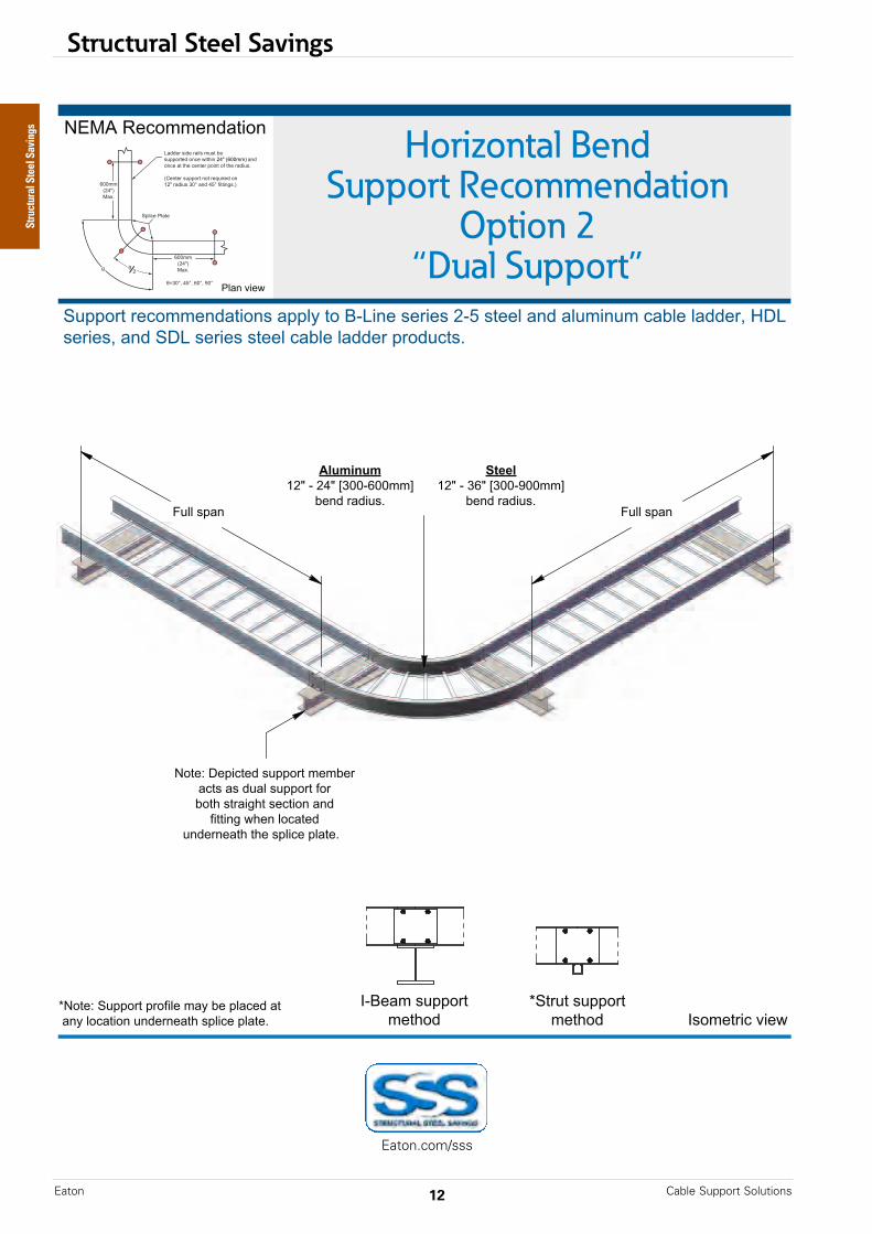
Horizontal BendSupport Recommendation
Option 2“Dual Support”
-./0*1%)#$$%234&(#2
5677#'&*'%)#$$%234&(#2"*47789*&#*:;<(2%*"%'(%"*=;>*"&%%8*423*486$(26$*)4?8%*8433%'@*AB<*"%'(%"@*423*5B<*"%'(%"*"&%%8*)4?8%*8433%'*7'#36)&"C
!;:%4$*"677#'&$%&D#3
E5&'6&*"677#'&$%&D#3
F688*"742
9/)8$")8G=H*;*=IH*JKLL;MLL$$N
?%23*'43(6"C
:+%%/G=H*;*KMH*JKLL;OLL$$N
?%23*'43(6"C
-#&%P*B%7()&%3*"677#'&*$%$?%'*4)&"*4"*3648*"677#'&*Q#'*?#&D*"&'4(RD&*"%)&(#2*423*Q(&&(2R*,D%2*8#)4&%3*
623%'2%4&D*&D%*"78()%*784&%C***
F688*"742
E-#&%P*5677#'&*7'#Q(8%*$49*?%*784)%3*4&**429*8#)4&(#2*623%'2%4&D*"78()%*784&%C
S842*+(%,
Structural Steel Savings
Eaton.com/sss

Structural Steel Savings
13Cable Support Solutions Eaton
www.eaton.com/sss1
!"#$%&'()**+,-&$-.+/
0-,)-'()**+,-&$-.+/ !(+&$-,12'31$4
Horizontal BendSupport Recommendation
Option 3“Floating”
5678'9$2+&&$:/%-1+:
0)**+,-',$2+&&$:/%-1+:('%**;<'-+'#"=1:$'($,1$('>"?'(-$$;'%:/'%;)&1:)&'2%@;$';%//$,A'BC='($,1$(A'%:/'0C='($,1$('(-$$;'2%@;$';%//$,'*,+/)2-(D
9/)8$")8E>F'"'>GF'HIJJ"KJJ&&L
@$:/',%/1)(D
:+%%/E>F'"'IKF'HIJJ"MJJ&&L
@$:/',%/1)(D
>N'OKJJ&&P'&%QD >N'OKJJ&&P'&%QD
R;%:'31$4
Structural Steel Savings
Eaton.com/sss

Structural Steel Savings
Cable Support SolutionsEaton 14
www.eaton.com/sss 1
!"#$%&'()*+(%,
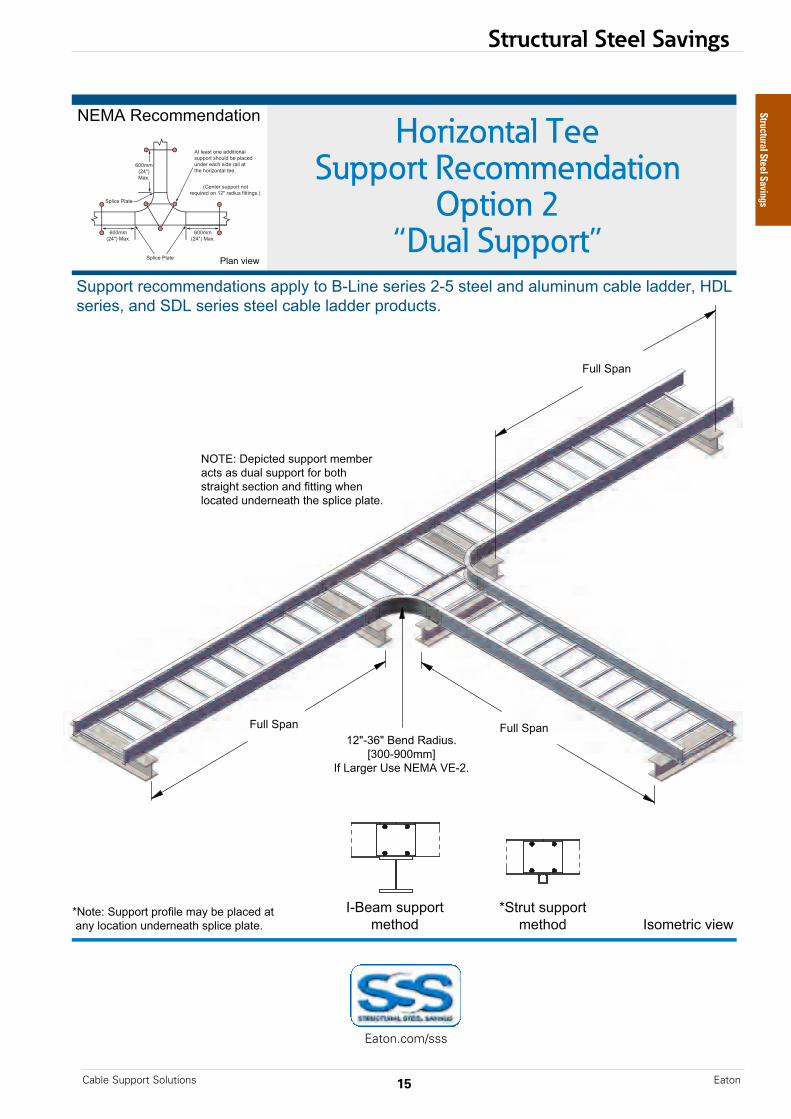
Horizontal TeeSupport Recommendation
Option 1“½ Span”
-./0*1%)#$$%234&(#2
5677#'&*'%)#$$%234&(#2"*47789*&#*:;<(2%*"%'(%"*=;>*"&%%8*423*486$(26$*)4?8%*8433%'@*AB<*"%'(%"@*423*5B<*"%'(%"*"&%%8*)4?8%*8433%'*7'#36)&"C
D*"742*#'*EFG*HI$J*$4KC
E=L;IML*NIFF;OFF$$P*?%23*'43(6"C(Q*84'R%'*6"%*-./0*S.;=C
5677#'&623%'*Q(&&(2RH=*784)%"*&97CJ
!;:%4$*"677#'&$%&T#3
5&'6&*"677#'&$%&T#3
U842*+(%,
Structural Steel Savings
Eaton.com/sss
Structural Steel Savings
15Cable Support Solutions Eaton
www.eaton.com/sss1
!"#$%&'()**+,-&$-.+/
01-,)-'()**+,-&$-.+/ !(+&$-,23'42$5
6)77'1*%8
6)77'1*%86)77'1*%89:;"<=;'#$8/'>%/2)(?
@<AA"BAA&&C!D'E%,F$,'G($'HIJK'LI":?
HMNIO'P$*23-$/'()**+,-'&$&Q$,'%3-('%('/)%7'()**+,-'D+,'Q+-.'(-,%2F.-'($3-2+8'%8/'D2--28F'5.$8'7+3%-$/')8/$,8$%-.'-.$'(*723$'*7%-$?'''
0H+-$O'1)**+,-'*,+D27$'&%R'Q$'*7%3$/'%-''%8R'7+3%-2+8')8/$,8$%-.'(*723$'*7%-$?
Horizontal TeeSupport Recommendation
Option 2“Dual Support”
HIJK'>$3+&&$8/%-2+8
1)**+,-',$3+&&$8/%-2+8('%**7R'-+'#"E28$'($,2$(':"S'(-$$7'%8/'%7)&28)&'3%Q7$'7%//$,T'UPE'($,2$(T'%8/'1PE'($,2$('(-$$7'3%Q7$'7%//$,'*,+/)3-(?
V7%8'42$5
Structural Steel Savings
Eaton.com/sss
Structural Steel Savings
Cable Support SolutionsEaton 16
www.eaton.com/sss 1
!"#$%&'()*+(%,
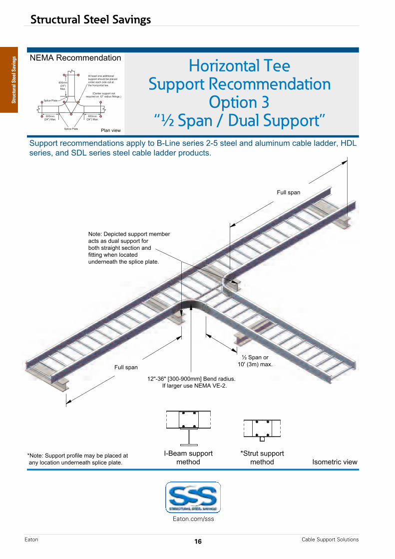
Horizontal TeeSupport Recommendation
Option 3“½ Span / Dual Support”
-./0*1%)#$$%234&(#2
5677#'&*'%)#$$%234&(#2"*47789*&#*:;<(2%*"%'(%"*=;>*"&%%8*423*486$(26$*)4?8%*8433%'@*AB<*"%'(%"@*423*5B<*"%'(%"*"&%%8*)4?8%*8433%'*7'#36)&"C
D-#&%E*5677#'&*7'#F(8%*$49*?%*784)%3*4&**429*8#)4&(#2*623%'2%4&G*"78()%*784&%C
!;:%4$*"677#'&$%&G#3
D5&'6&*"677#'&$%&G#3
H688*"742
H688*"742
I*5742*#'JKL*MN$O*$4PC
J=Q;NRQ*SNKK;TKK$$U*:%23*'43(6"C!F*84'V%'*6"%*-./0*W.;=C
-#&%E*B%7()&%3*"677#'&*$%$?%'*4)&"*4"*3648*"677#'&*F#'*?#&G*"&'4(VG&*"%)&(#2*423*F(&&(2V*,G%2*8#)4&%3*623%'2%4&G*&G%*"78()%*784&%C***
X842*+(%,
Structural Steel Savings
Eaton.com/sss
Structural Steel Savings
17Cable Support Solutions Eaton
!"#$%&'()*+(%,
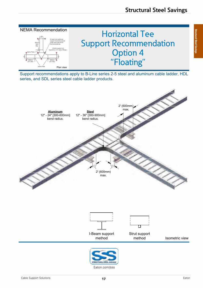
Horizontal TeeSupport Recommendation
Option 4“Floating”
-./0*1%)#$$%234&(#2
( ( ( ( ( ( ( ( ( ( ( CA00000000E—August 2017 www.eaton.com2
5677#'&*'%)#$$%234&(#2"*47789*&#*:;<(2%*"%'(%"*=;>*"&%%8*423*486$(26$*)4?8%*8433%'@*AB<*"%'(%"@*423*5B<*"%'(%"*"&%%8*)4?8%*8433%'*7'#36)&"C
!;:%4$*"677#'&$%&D#3
5&'6&*"677#'&$%&D#3
=E*FGHH$$I$4JC
=E*FGHH$$I$4JC
9/)8$")8K=L*;*=ML*NOHH;GHH$$P
?%23*'43(6"C
:+%%/K=L*;*OGL*NOHH;QHH$$P
?%23*'43(6"C
R842*+(%,
Structural Steel Savings
Eaton.com/sss
Structural Steel Savings
Cable Support SolutionsEaton 18
!"#$%&'()*+(%,
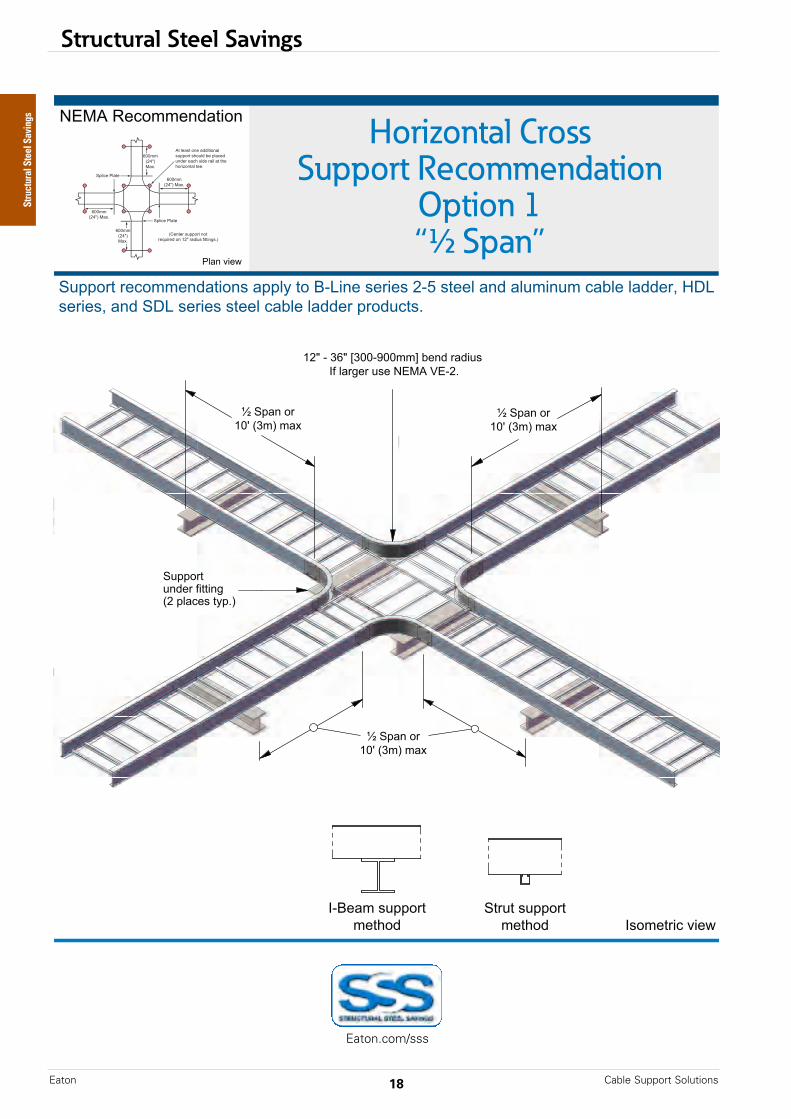
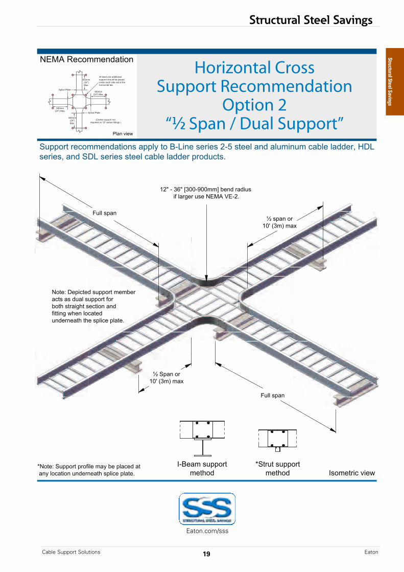
Horizontal CrossSupport Recommendation
Option 1“½ Span”
-./0*1%)#$$%234&(#2
( ( ( ( ( ( ( ( ( ( ( www.eaton.com2
5677#'&*'%)#$$%234&(#2"*47789*&#*:;<(2%*"%'(%"*=;>*"&%%8*423*486$(26$*)4?8%*8433%'@*AB<*"%'(%"@*423*5B<*"%'(%"*"&%%8*)4?8%*8433%'*7'#36)&"C
!;:%4$*"677#'&$%&D#3
5&'6&*"677#'&$%&D#3
E*5742*#'FGH*IJ$K*$4L
E*5742*#'FGH*IJ$K*$4L
F=M*;*JNM*OJGG;PGG$$Q*?%23*'43(6"*!R*84'S%'*6"%*-./0*T.;=C
E*5742*#'FGH*IJ$K*$4L
U842*+(%,
5677#'&623%'*R(&&(2SI=*784)%"*&97CK
Structural Steel Savings
Eaton.com/sss
Structural Steel Savings
19Cable Support Solutions Eaton
!"#$%&'()*+(%,
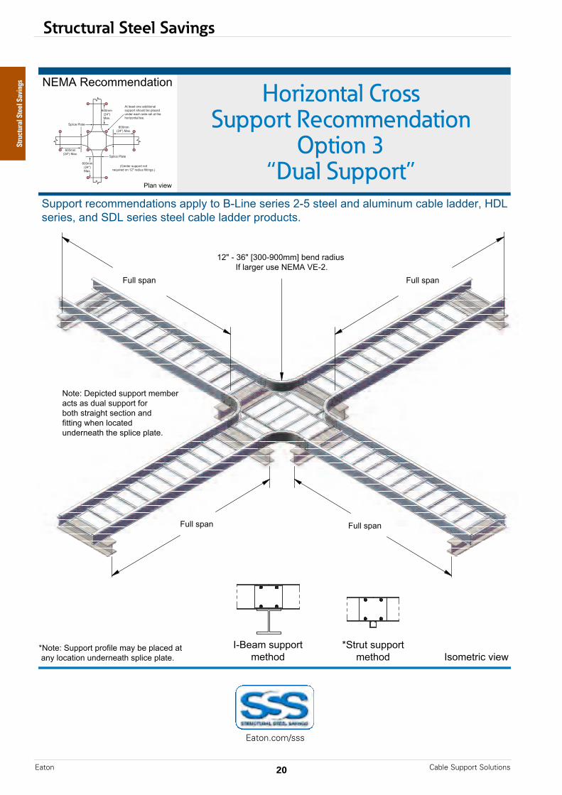
Horizontal CrossSupport Recommendation
Option 2“½ Span / Dual Support”
-./0*1%)#$$%234&(#2
( ( ( ( ( ( ( ( ( ( ( CA00000000E—August 2017 www.eaton.com2
5677#'&*'%)#$$%234&(#2"*47789*&#*:;<(2%*"%'(%"*=;>*"&%%8*423*486$(26$*)4?8%*8433%'@*AB<*"%'(%"@*423*5B<*"%'(%"*"&%%8*)4?8%*8433%'*7'#36)&"C
D-#&%E*5677#'&*7'#F(8%*$49*?%*784)%3*4&**429*8#)4&(#2*623%'2%4&G*"78()%*784&%C
!;:%4$*"677#'&$%&G#3
D5&'6&*"677#'&$%&G#3
H688*"742
H688*"742
I*5742*#'JKL*MN$O*$4P
I*"742*#'JKL*MN$O*$4P
J=Q*;*NRQ*SNKK;TKK$$U*?%23*'43(6"*(F*84'V%'*6"%*-./0*W.;=C
-#&%E*B%7()&%3*"677#'&*$%$?%'*4)&"*4"*3648*"677#'&*F#'*?#&G*"&'4(VG&*"%)&(#2*423*F(&&(2V*,G%2*8#)4&%3*623%'2%4&G*&G%*"78()%*784&%C***
X842*+(%,
Structural Steel Savings
Eaton.com/sss
Structural Steel Savings
Cable Support SolutionsEaton 20
!"#$%&'()*+(%,
Horizontal CrossSupport Recommendation
Option 3“Dual Support”
-./0*1%)#$$%234&(#2
( ( ( ( ( ( ( ( ( ( ( www.eaton.com2
5677#'&*'%)#$$%234&(#2"*47789*&#*:;<(2%*"%'(%"*=;>*"&%%8*423*486$(26$*)4?8%*8433%'@*AB<*"%'(%"@*423*5B<*"%'(%"*"&%%8*)4?8%*8433%'*7'#36)&"C
D-#&%E*5677#'&*7'#F(8%*$49*?%*784)%3*4&**429*8#)4&(#2*623%'2%4&G*"78()%*784&%C
!;:%4$*"677#'&$%&G#3
D5&'6&*"677#'&$%&G#3
H=I*;*JKI*LJMM;NMM$$O*?%23*'43(6"*!F*84'P%'*6"%*-./0*Q.;=C
-#&%E*B%7()&%3*"677#'&*$%$?%'*4)&"*4"*3648*"677#'&*F#'*?#&G*"&'4(PG&*"%)&(#2*423*F(&&(2P*,G%2*8#)4&%3*623%'2%4&G*&G%*"78()%*784&%C***
R688*"742R688*"742
R688*"742R688*"742
S842*+(%,
Structural Steel Savings
Eaton.com/sss

Structural Steel Savings
21Cable Support Solutions Eaton
!"#$%&'()*+(%,
Horizontal CrossSupport Recommendation
Option 4“Floating”
-./0*1%)#$$%234&(#2
( ( ( ( ( ( ( ( ( ( ( CA00000000E—August 2017 www.eaton.com2
5677#'&*'%)#$$%234&(#2"*47789*&#*:;<(2%*"%'(%"*=;>*"&%%8*423*486$(26$*)4?8%*8433%'@*AB<*"%'(%"@*423*5B<*"%'(%"*"&%%8*)4?8%*8433%'*7'#36)&"C
!;:%4$*"677#'&$%&D#3
5&'6&*"677#'&$%&D#3
=E*FGHH$$I*/4JC
=E*FGHH$$I*/4JC
=E*FGHH$$I*/4JC
9/)8$")8K=L*;*=ML*NOHH;GHH$$P
?%23*'43(6"C
:+%%/K=L*;*OGL*NOHH;QHH$$P
?%23*'43(6"C
R842*+(%,
Structural Steel Savings
Eaton.com/sss
Structural Steel Savings
Cable Support SolutionsEaton 22
!"#$%&"'(")*+",-./".%01
!"#$%&"'(")*+",-./".%01
!"#$%&"'(")*+",-./".%01
!"#$%&"'(")*+",-./".%01
!"#$%&"'(")*+",-./".%01
!"#$%&"'(")*+",-./".%01
23'.45(67"8649
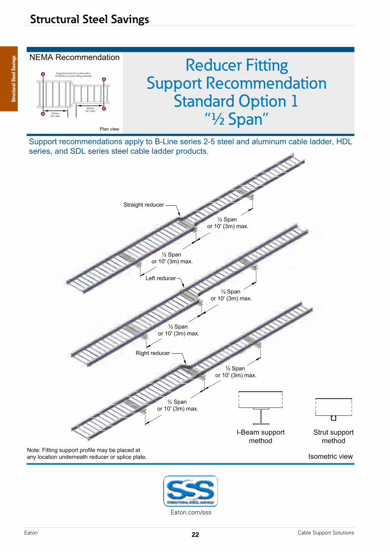
Reducer FittingSupport Recommendation
Standard Option 1“½ Span”
:;<=">47'..4&?%56'&
( ( ( ( ( ( ( ( ( ( ( www.eaton.com2
#@$$'(5"(47'..4&?%56'&3"%$$AB"5'"CDE6&4"34(643"FDG"3544A"%&?"%[email protected]&@."7%HA4"A%??4(I"JKE"34(643I"%&?"#KE"34(643"3544A"7%HA4"A%??4("$('?@7531
:'54L"M6556&N"3@$$'(5"$('O6A4".%B"H4"$A%74?"%5"%&B"A'7%56'&"@&?4(&4%5P"(4?@74("'("3$A674"$A%541
Q**..,FRS/"<%01
Q**..,FRS/"<%01
#@$$'(53"3P'@A?"H4"A'7%54?"965P6&"FRS,Q**../"'O"4%7P"O6556&N"405(4.65B
TA%&"8649
2DC4%."3@$$'(5.45P'?
#5(@5"3@$$'(5.45P'?
#5(%6NP5"(4?@74(
E4O5"(4?@74(
>6NP5"(4?@74(
Structural Steel Savings
Eaton.com/sss

Structural Steel Savings
23Cable Support Solutions Eaton
!"#$%&'()*+(%,
Heavy DutyExpansion Splice
Support Recommendation
NEMA
B-LineSeries
-./0*1%)#$$%234&(#2
.5%+4&(#2*+(%,
( ( ( ( ( ( ( ( ( ( ( CA00000000E—August 2017 www.eaton.com2
6788#'&*'%)#$$%234&(#2"*48859*&#*:;<(2%*"%'(%"*=;>*"&%%5*423*457$(27$*)4?5%*5433%'@*AB<*"%'(%"@*423*6B<*"%'(%"*"&%%5*)4?5%*5433%'*8'#37)&"C
DEE$$F=GHI*/4JC
DEE$$F=GHI*/4JC
6788#'&"*"K#753*?%*5#)4&%3*,(&K(2*=GHFDEE$$I*#L*%4)K*"(3%*#L*&K%*%J842"(#2*"85()%*854&%"
M755*"842
M755*6842
6&4234'3685()%
AB*.J842"(#2685()%
.J842"(#2685()%
=N*FDEE$$I$4J
=N*FDEE$$I$4J
O*6842
O*6842
O*6842
O*6842
!;:%4$*"788#'&$%&K#3
6&'7&*"788#'&$%&K#3
Structural Steel Savings
Eaton.com/sss
NEMA
B-Lineseries
Structural Steel Savings
Cable Support SolutionsEaton 24
!"#$%&'()*+(%,
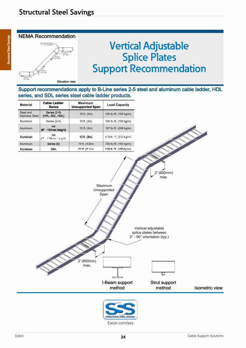
Vertical AdjustableSplice Plates
Support Recommendation
-./0*1%)#$$%234&(#2
.5%+4&(#2*+(%,
( ( ( ( ( ( ( ( ( ( (
6788#'&*'%)#$$%234&(#2"*48859*&#*:;<(2%*"%'(%"*=;>*"&%%5*423*457$(27$*)4?5%*5433%'@*AB<*"%'(%"@*423*6B<*"%'(%"*"&%%5*)4?5%*5433%'*8'#37)&"C
=D*EFGG$$H$4IC
=D*EFGG$$H$4IC
J%'&()45*43K7"&4?5%"85()%*854&%"*?%&,%%2GL*;*MGL*#'(%2&4&(#2*E&98CH
/4I($7$N2"788#'&%3
6842
!;:%4$*"788#'&$%&O#3
6&'7&*"788#'&$%&O#3
-./0*1%)#$$%234&(#2-./0*1%)#$$%234&(#2
Vertical AdjustableVertical Adjustable
.5%+4&(#2*+(%,
Support RecommendationSupport RecommendationSplice Plates
Vertical Adjustable
Support RecommendationSplice Plates
Vertical Adjustable
Support Recommendation
Vertical Adjustable
EFZ*;*S>G$$*O%(XO&HAY*
6%'(%"*057$(27$
PAQ<@*6B<@*AB<R6%'(%"*E=;>H*
6&4(25%""*6&%%5
;%&$%':.6/%(5.**%&(9.+%&$./
6&%%5*423*
057$(27$
"%'(%"@*423*6B<*"%'(%"*"&%%5*)4?5%*5433%'*8'#37)&"C6788#'&*'%)#$$%234&(#2"*48859*&#*:;<(2%*"%'(%"*=;>*"&%%5*423*457$(27$*)4?5%*5433%'@*AB<*
SG*T&C*EU$HEFZ*;*S>G$$*O%(XO&H
SG*T& *EU$H*E=;YH
SG*T&C*EU$HPAQ<@*6B<@*AB<R
="')>>,&+%*(;>."9.<$8)8(
;%&$%':.6/%(5.**%&(
6%'(%"*E=;>H*
AY*
"%'(%"@*423*6B<*"%'(%"*"&%%5*)4?5%*5433%'*8'#37)&"C6788#'&*'%)#$$%234&(#2"*48859*&#*:;<(2%*"%'(%"*=;>*"&%%5*423*457$(27$*)4?5%*5433%'@*AB<*
SGG*5? VT& *ES>G*WXV$H
5,.*(:.>.-$+7="')>>,&+%*(;>."
SGG*5?CVT&C*ES>G*WXV$H
SF[*5?CVT&C*E=Y\*WXV$H
"%'(%"@*423*6B<*"%'(%"*"&%%5*)4?5%*5433%'*8'#37)&"C6788#'&*'%)#$$%234&(#2"*48859*&#*:;<(2%*"%'(%"*=;>*"&%%5*423*457$(27$*)4?5%*5433%'@*AB<*6788#'&*'%)#$$%234&(#2"*48859*&#*:;<(2%*"%'(%"*=;>*"&%%5*423*457$(27$*)4?5%*5433%'@*AB<*6788#'&*'%)#$$%234&(#2"*48859*&#*:;<(2%*"%'(%"*=;>*"&%%5*423*457$(27$*)4?5%*5433%'@*AB<*
6%'(%"*E>H057$(27$
EFZ*;*S>G$$*O%(XO&H
S>*T&C*EYCF$H6%'(%"*E>H
EFZ*;*S>G$$*O%(XO&H
SGG*5?CVT&C*ES>G*WXV$H
( ( ( ( ( ( ( ( ( ( (
$%&O#3!;:%4$*"788#'&
( ( ( ( ( ( ( ( ( ( (
$%&O#36&'7&*"788#'&
( ( ( ( ( ( ( ( ( ( (
!"#$%&'()*+(%,
Structural Steel Savings
Eaton.com/sss

Structural Steel Savings
25Cable Support Solutions Eaton
5 Key Product Attributes
1. I-Beam Side-Rail Design - Can Carry up to 2.3 Times More Load than C-Channel• Maximizes stiffness• Offers positive rung support• Enhances clamping options• Carries load on longer spans, reducing support requirements
2. Application Specific Materials - Maximize Options• Hot-dip galvanized steel• 316 Stainless Steel• Marine-grade, copper-free aluminum• Ensures the best material for the application to carry the load over the longest span
3. Splice Plate Design - Enhance Structural Integrity• Enhances the structural integrity and strength of the system, reducing support requirements• UL Classified as an equipment grounding conductor, eliminating bonding jumpers
4. Application - Specific Specialty Splice Plates - Allow Load Transfer• Patented design• Designed for thermal expansion and contraction • Structural integration maintains load carrying capacity, reducing support requirements
5. Fitting Designs - 75mm or 100mm Tangents• Industry-leading 75mm to 100mm tangents • Maximizes strength and load carrying capacity, reducing support requirements
1
2
3
4 5
Structural Steel Savings
Technical Data
Cable Support SolutionsEaton 26
Metric Cable Ladder Technical Guide
The technical data contained within this guide is intended to provide the engineer with adequate informationto design and specify an efficient and robust cable ladder system. Eaton recommends that the engineerconsiders the following subjects when designing the cable ladder system which are detailed within thecorresponding sections of this guide:
1. Side Rail and Rung Design
2. Materials
3. Finish
4. Corrosion
5. Load Performance Type Tests
6. Environmental Loads
7. Impact
8. Electrical Continuity
9. Free Base Area
10. Thermal Contraction and Expansion
11. Support and Installation Recommendations
12. Cable Restraint
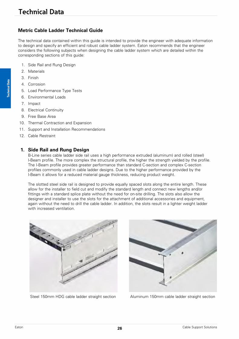
1. Side Rail and Rung DesignB-Line series cable ladder side rail uses a high performance extruded (aluminum) and rolled (steel)I-Beam profile. The more complex the structural profile, the higher the strength yielded by the profile. The I-Beam profile provides greater performance than standard C-section and complex C-sectionprofiles commonly used in cable ladder designs. Due to the higher performance provided by theI-Beam it allows for a reduced material gauge thickness, reducing product weight.
The slotted steel side rail is designed to provide equally spaced slots along the entire length. Theseallow for the installer to field cut and modify the standard length and connect new lengths and/orfittings with a standard splice plate without the need for on-site drilling. The slots also allow thedesigner and installer to use the slots for the attachment of additional accessories and equipment, again without the need to drill the cable ladder. In addition, the slots result in a lighter weight ladder with increased ventilation.
Steel 150mm HDG cable ladder straight section Aluminum 150mm cable ladder straight section
Technical Data
Technical Data
27Cable Support Solutions Eaton
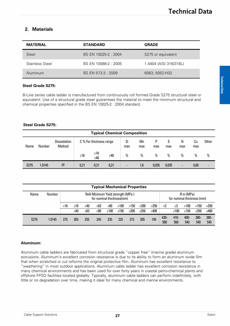
2. Materials
MATERIAL STANDARD GRADE
Steel BS EN 10025-2 : 2004 S275 or equivalent
Stainless Steel BS EN 10088-2 : 2005 1.4404 (AISI 316/316L)
Aluminum BS EN 573-3 : 2009 6063; 5052-H32
Typical Chemical Composition
Deoxidation C % For thickness range Si Mn P S N Cu OtherName Number Method max max max max max max
≤16 >16 >40 % % % % % % %≤40
S275 1.0145 FF 0,21 0,21 0,21 - 1,6 0,035 0,035 - 0,60 -
Steel Grade S275:
Typical Mechanical Properties
Name Number ReH Minimum Yield strength (MPa ) R m (MPa)for nominal thickness(mm) for nominal thickness (mm)
<16 ≥16 >40 >63 >80 >100 >150 >200 >250 <3 ≥3 >100 >150 >250≤40 ≤63 ≤80 ≤100 ≤150 ≤200 ≤250 ≤400 ≤100 ≤150 ≤250 ≤400
S275 1.0145 275 265 255 245 235 225 215 205 195 430- 410- 400- 380- 380-580 560 540 540 540
Steel Grade S275:
B-Line series cable ladder is manufactured from continuously roll formed Grade S275 structural steel or equivalent. Use of a structural grade steel guarantees the material to meet the minimum structural andchemical properties specified in the BS EN 10025-2 : 2004 standard.
Aluminum:
Aluminum cable ladders are fabricated from structural grade “copper free” (marine grade) aluminumextrusions. Aluminum’s excellent corrosion resistance is due to its ability to form an aluminum oxide filmthat when scratched or cut reforms the original protective film. Aluminum has excellent resistance to“weathering” in most outdoor applications. Aluminum cable ladder has excellent corrosion resistance inmany chemical environments and has been used for over forty years in coastal petro-chemical plants andoffshore FPSO facilities located globally. Typically, aluminum cable ladders can perform indefinitely, withlittle or no degradation over time, making it ideal for many chemical and marine environments.
Technical Data
Technical Data
Cable Support SolutionsEaton 28
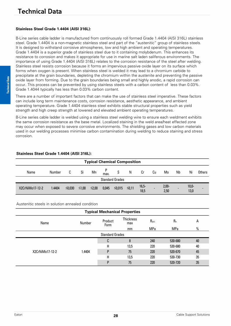
Stainless Steel Grade 1.4404 (AISI 316L):
B-Line series cable ladder is manufactured from continuously roll formed Grade 1.4404 (AISI 316L) stainlesssteel. Grade 1.4404 is a non-magnetic stainless steel and part of the “austenitic” group of stainless steels.It is designed to withstand corrosive atmospheres, low and high ambient and operating temperatures.Grade 1.4404 is a superior grade of stainless steel due to it containing molybdenum. This enhances itsresistance to corrosion and makes it appropriate for use in marine salt laden saliferous environments. Theimportance of using Grade 1.4404 (AISI 316L) relates to the corrosion resistance of the steel after welding.Stainless steel resists corrosion because it forms an impervious passive oxide layer on its surface whichforms when oxygen is present. When stainless steel is welded it may lead to a chromium carbide to precipitate at the grain boundaries, depleting the chromium within the austenite and preventing the passiveoxide layer from forming. Due to the grain boundaries being small and highly anodic, a rapid corrosion canoccur. This process can be prevented by using stainless steels with a carbon content of less than 0.03%.Grade 1.4044 typically has less than 0.03% carbon content.
There are a number of important factors that can make the use of stainless steel imperative. These factorscan include long term maintenance costs, corrosion resistance, aesthetic appearance, and ambient operating temperature. Grade 1.4404 stainless steel exhibits stable structural properties such as yieldstrength and high creep strength at lowered and elevated ambient operating temperatures.
B-Line series cable ladder is welded using a stainless steel welding wire to ensure each weldment exhibitsthe same corrosion resistance as the base metal. Localized staining in the weld area/heat effected zonemay occur when exposed to severe corrosive environments. The shielding gases and low carbon materialsused in our welding processes minimise carbon contamination during welding to reduce staining and stress corrosion.
Typical Chemical Composition
Name Number C Si Mn P S N Cr Cu Mo Nb Ni Othersmax.Standard Grades
X2CrNiMo17-12-2 1.4404 <0,030 <1,00 <2,00 0,045 <0,015 <0,11 16,5- - 2,00- - 10,0- -18,5 2,50 13,0
Stainless Steel Grade 1.4404 (AISI 316L):
Austenitic steels in solution annealed condition
Typical Mechanical Properties
Product Thickness Rp0,2 Rm AName Number Form maxmm MPa MPa %
Standard Grades
C 8 240 530-680 40H 13,5 220 530-680 40
X2CrNiMo17-12-2 1.4404 P 75 220 520-670 45H 13,5 220 530-730 35P 75 220 520-720 35
Technical Data

Technical Data
29Cable Support Solutions Eaton
3. Finish
Zinc Coatings
Zinc protects steel in two ways. First it protects the steelas a coating and second as a sacrificial anode to repairbare areas such as cut edges, scratches, and gouges. Thecorrosion protection of zinc is directly related to itsthickness and the environment. This means a .2 mil coatingwill last twice as long as a .1 mil coating in the sameenvironment.
Zn
FeZnFe
ZnO
Galvanizing also protects cut and drilled edges.
Hot Dip Galvanized After Fabrication(Hot dip galvanized or batch hot dip galvanized)
Hot Dip Galvanized After Fabrication cable ladder products are fabricated from steel and then completelyimmersed in a bath of molten zinc. A metallic bond occurs resulting in a zinc coating that completelycoats all surfaces, including edges and welds.Another advantage of this method is coating thickness. Cable ladders hot dip galvanized after fabricationto provide an average minimum zinc coating thickness in accordance with BS EN ISO 1461.The zinc thickness is controlled by the amount of time each part is immersed in the molten zinc bathas well as the speed at which it is removed. The term "double dipping" refers to parts too large to fitinto the galvanizing kettle and, therefore, must be dipped one end at a time. It does not refer to extracoating thickness.The layer of zinc which bonds to steel provides a dual protection against corrosion. It protects first asan overall barrier coating. If this coating happens to be scratched or gouged, zinc's secondary defenseis called upon to protect the steel by galvanic action.Hot dip galvanizing after fabrication is recommended for prolonged outdoor exposure and will protectsteel for many years in most outdoor environments and in many aggressive industrial environments .
4. Corrosion
IEC 61357 : 2006 section 6.5.2, Table 1 “classification for resistance against corrosion” defines theclassification class of various materials and finishes used in the manufacture and supply of cableladder systems against resistance to corrosion.
In accordance with this classification table, B-Line cable ladder can be supplied as to meet thefollowing classifications:
Steel HDG : Class 6Stainless Steel 1.4404 : Class 9BPassivated Stainless Steel 1.4404 : Class 9D
Stainless Steel
Several important conditions could make the use of stainless steel imperative. These include longterm maintenance costs, corrosion resistance, appearance and locations where product contamination is undesirable. Stainless steel exhibits stable structural properties such as yield strength and high creep strength at elevated temperatures.
Technical Data
Articles & Local Coating Mean CoatingIts Thickness (minimum) (minimum)
g/m2 mm g/m2 mm
Steel > 6mm 505 70 610 85Steel > 3mm to ≤ 6mm 396 55 505 70
Steel > 1.5mm to ≤ 3mm 325 45 396 55
BS EN ISO 1461 : coating minimum thickness on articles not centrifuged
Technical Data
Cable Support SolutionsEaton 30
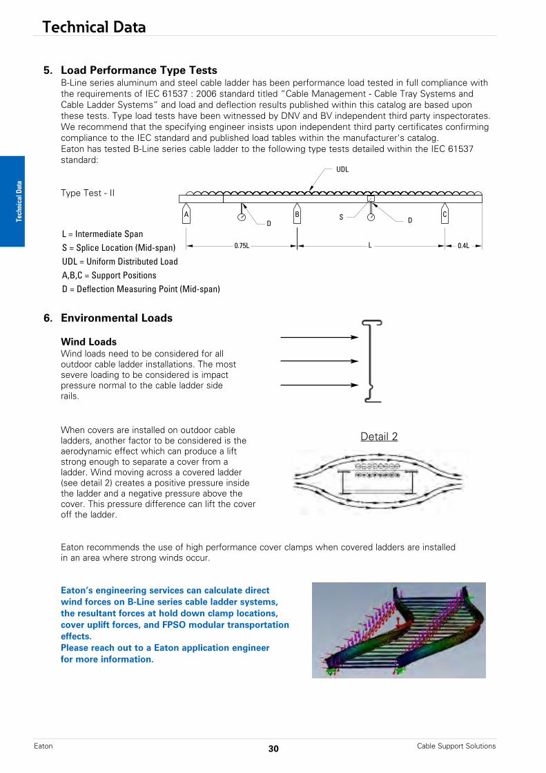
5. Load Performance Type TestsB-Line series aluminum and steel cable ladder has been performance load tested in full compliance withthe requirements of IEC 61537 : 2006 standard titled “Cable Management - Cable Tray Systems andCable Ladder Systems” and load and deflection results published within this catalog are based upon these tests. Type load tests have been witnessed by DNV and BV independent third party inspectorates. We recommend that the specifying engineer insists upon independent third party certificates confirmingcompliance to the IEC standard and published load tables within the manufacturer's catalog.Eaton has tested B-Line series cable ladder to the following type tests detailed within the IEC 61537standard:
Type Test - II
6. Environmental Loads
Wind LoadsWind loads need to be considered for all outdoor cable ladder installations. The most severe loading to be considered is impact pressure normal to the cable ladder side rails.
A BD DS
UDL
0.75L L 0.4L
C
L = Intermediate SpanS = Splice Location (Mid-span)UDL = Uniform Distributed LoadA,B,C = Support PositionsD = Deflection Measuring Point (Mid-span)
Technical Data
When covers are installed on outdoor cable ladders, another factor to be considered is the aerodynamic effect which can produce a lift strong enough to separate a cover from a ladder. Wind moving across a covered ladder (see detail 2) creates a positive pressure inside the ladder and a negative pressure above the cover. This pressure difference can lift the cover off the ladder.
Eaton recommends the use of high performance cover clamps when covered ladders are installedin an area where strong winds occur.
Eaton’s engineering services can calculate direct wind forces on B-Line series cable ladder systems,the resultant forces at hold down clamp locations,cover uplift forces, and FPSO modular transportationeffects.Please reach out to a Eaton application engineerfor more information.
Detail 2
Technical Data
31Cable Support Solutions Eaton
Ice Loads
Glaze ice is the most commonly seen form of ice build-up. It is the result of rain or drizzle freezing on impact with an exposed object. Generally, only the top surface (or the cover) and the windward side of a cable ladder system is significantly coated with ice. The maximum design load to be added due to ice should be calculated as follows:
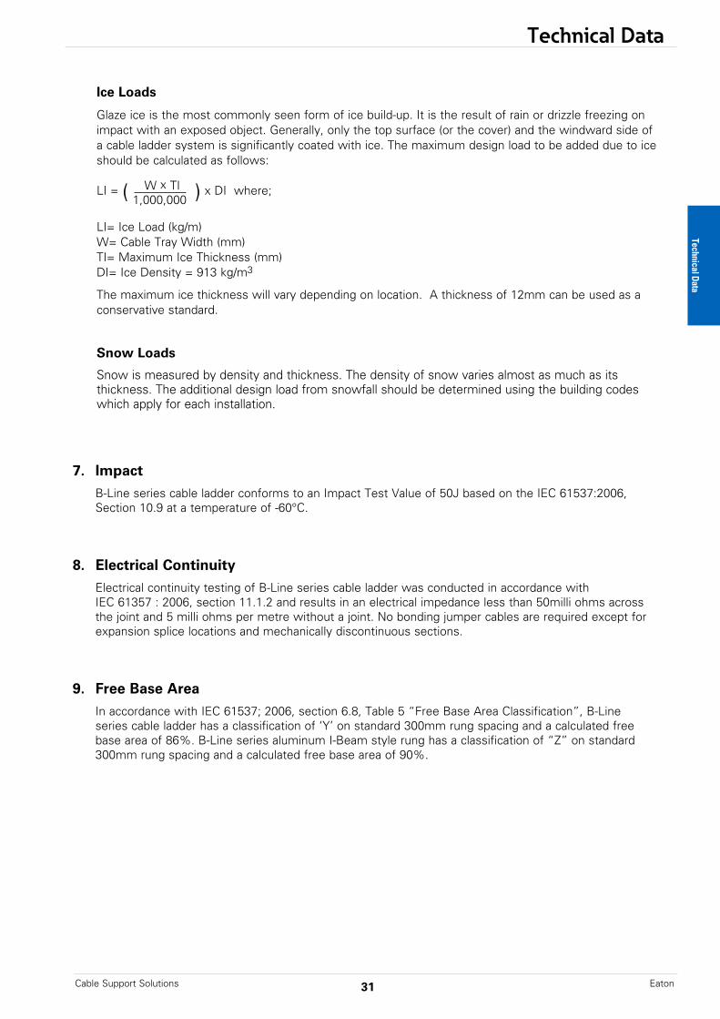
LI = ( W x TI ) x DI where;1,000,000
LI= Ice Load (kg/m)W= Cable Tray Width (mm)TI= Maximum Ice Thickness (mm)DI= Ice Density = 913 kg/m3
The maximum ice thickness will vary depending on location. A thickness of 12mm can be used as a conservative standard.
Snow Loads
Snow is measured by density and thickness. The density of snow varies almost as much as its thickness. The additional design load from snowfall should be determined using the building codes which apply for each installation.
7. Impact
B-Line series cable ladder conforms to an Impact Test Value of 50J based on the IEC 61537:2006,Section 10.9 at a temperature of -60°C.
8. Electrical Continuity
Electrical continuity testing of B-Line series cable ladder was conducted in accordance withIEC 61357 : 2006, section 11.1.2 and results in an electrical impedance less than 50milli ohms acrossthe joint and 5 milli ohms per metre without a joint. No bonding jumper cables are required except for expansion splice locations and mechanically discontinuous sections.
9. Free Base Area
In accordance with IEC 61537; 2006, section 6.8, Table 5 “Free Base Area Classification”, B-Lineseries cable ladder has a classification of ‘Y’ on standard 300mm rung spacing and a calculated freebase area of 86%. B-Line series aluminum I-Beam style rung has a classification of “Z” on standard300mm rung spacing and a calculated free base area of 90%.
Technical Data

Technical Data
Cable Support SolutionsEaton 32
10. Thermal Contraction and Expansion
Maximum Spacing Between Expansion Joints For 25mm Movement
Temperature Aluminum Stainless Steel Stainless SteelDifferential Steel 304 316˚C ˚F m Feet m Feet m Feet m Feet
13.9 25 156.0 512 79.2 260 105.7 347 115.5 379
27.8 50 78.0 256 39.6 130 53.0 174 57.6 189
41.7 75 52.1 171 26.5 87 35.4 116 38.4 126
55.6 100 39.0 128 19.8 65 26.5 87 29.0 95
69.4 125 31.1 102 15.8 52 21.0 69 23.2 76
83.3 150 25.9 85 13.1 43 17.7 58 19.2 63
97.2 175 22.2 73 11.3 37 15.2 50 16.4 54
Note: every pair of expansion splice plates requires two earth continuity connectors for grounding continuity.
1
2
3
4
It is important that thermal contraction and expansion be considered when installing cableladder systems. The length of thestraight cable tray runs and thetemperature differential govern thenumber of expansion splice platesrequired (see Table 2 below).
The cable ladder should beanchored at the support nearest to its midpoint between the expansion splice plates andsecured by expansion guides at all other support locations(see Figure 1). The cable laddershould be permitted longitudinalmovement in both directions fromthat fixed point. When used, covers should be overlapped atexpansion splices.
Accurate gap settings at the timeof installation are necessary for theproper operation of the expansionsplice plates. The following procedure should assist theinstaller in determining the correctgap: (see Figure 2)
Plot the highest expectedmetal temperature on themaximum temperature line.
Plot the lowest expectedmetal temperature on theminimum temperature line.
Draw a line between the maximum and minimumpoints.
Plot the metal temperature atthe time of installation todetermine the gap setting.
C° F° F° C°
Maximum MinimumTemperature Temperature
130
70
50
30
10
-10
-30
90
110
130
110
90
70
50
30
10
-10
-30
50
40
30
20
10
0
-10
-20
-30
-40
50
40
30
20
10
0
-10
-20
-30
-40
3.2(1/8)
6.3(1/4)
9.5(3/8)
12.7(1/2)
15.9(5/8)
19.0(3/4)
22.2(7/8)
0.0(0)
25.4(1)
GAP SETTING mm (Inches)
Met
al T
empe
ratu
re A
t Ti
me
Of
Inst
alla
tion
X -- -- -- -- X -- -- -- -- X
X -- -- -- -- X -- -- -- -- X
X :Denotes hold-down clamp (anchor) at support.
_ : Denotes expansion guide clamp at support.
Expansion Splice Plates(Bonding Jumpers Required
On Each Side of Tray)
Figure 2
Table 2
Figure 1
1
2
3
4
Typical Cable Ladder Installation
Technical Data
Technical Data
33Cable Support Solutions Eaton
11. Support and Installation Recommendations
DeflectionDeflection in a cable ladder system is primarily an aesthetic consideration. When a cable ladder system isinstalled in a prominent location, a maximum simple beam deflection of 1/100 of support span can be usedas a guideline to minimize visual deflection.
There are two typical beam configurations: simple beam and continuous beam.
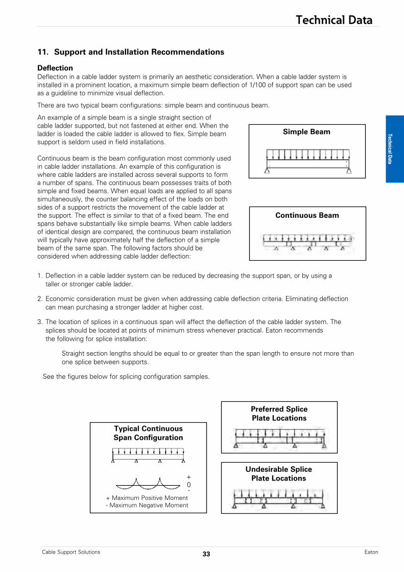
An example of a simple beam is a single straight section ofcable ladder supported, but not fastened at either end. When the ladder is loaded the cable ladder is allowed to flex. Simple beamsupport is seldom used in field installations.
Continuous beam is the beam configuration most commonly usedin cable ladder installations. An example of this configuration iswhere cable ladders are installed across several supports to forma number of spans. The continuous beam possesses traits of bothsimple and fixed beams. When equal loads are applied to all spanssimultaneously, the counter balancing effect of the loads on bothsides of a support restricts the movement of the cable ladder atthe support. The effect is similar to that of a fixed beam. The endspans behave substantially like simple beams. When cable laddersof identical design are compared, the continuous beam installationwill typically have approximately half the deflection of a simplebeam of the same span. The following factors should beconsidered when addressing cable ladder deflection:
1. Deflection in a cable ladder system can be reduced by decreasing the support span, or by using ataller or stronger cable ladder.
2. Economic consideration must be given when addressing cable deflection criteria. Eliminating deflectioncan mean purchasing a stronger ladder at higher cost.
3. The location of splices in a continuous span will affect the deflection of the cable ladder system. Thesplices should be located at points of minimum stress whenever practical. Eaton recommends the following for splice installation:
Straight section lengths should be equal to or greater than the span length to ensure not more than one splice between supports.
See the figures below for splicing configuration samples.
Simple Beam
Continuous Beam
Typical ContinuousSpan Configuration
Preferred SplicePlate Locations
Undesirable Splice Plate Locations
+ Maximum Positive Moment- Maximum Negative Moment
+0-
Technical Data
Technical Data
Cable Support SolutionsEaton 34
Future Expansion RequirementsOne of the many features of cable ladder is the ease of adding cables to an existing system. Futureexpansion should always be considered when selecting a cable ladder, and allowance should be madefor additional fill area and load capacity. A minimum of 50% expansion allowance is recommended.
InstallationShorter cable ladder lengths are typically easier to maneuver on the job site during installation. Twopeople may be needed to manipulate longer cable ladder sections, while shorter sections might behandled by one person. Although longer cable ladder lengths are more difficult to maneuver, theycan reduce installation time due to the fact that there are fewer splice connections. This trade-offshould be evaluated for each set of job site restrictions.
Technical Data
Technical Data
35Cable Support Solutions Eaton
12. Cables and Cable Restraint
Type of CableIn general, small, highly flexible cables should be installed in cable ladders with close rung spacing of 225mm or less. Larger, less flexible cables are typically installed in cable ladders having 300mm rung spacing. Cable ladders having rung spacing greater than 300mm should be used for very large, stiff cables to reduce cost and facilitate cable drop-outs.
Cable ExposureMany cable jackets are manufactured to withstand the environment without additional protection, favoring the use of the cable ladder. Cable jackets should be evaluated during project design for suitability in the project application.
Cable AttachmentA major advantage of cable ladder is the freedom of entry and exit of the cables. Another advantage of cable ladder is the ability to secure cables in the cable ladder. With standard rungs, the cables may be attached with either cable ties or cable clamps. Cable attachment is particularly important on vertical runs or when the ladder is installed on its side. Ladder rung spacing should be chosen to provide adequate cable attachment points while allowing the cables to exit the system.
Cable FlexibilityThe proper bend radius for cable ladder fittings is usually determined by the bend radius and stiffness of the cables to be installed. Typically, the cable manufacturer will recommend a minimum bend allowance for each cable. The fitting radius should be equal to or larger than the minimum bend radius of the largest cable which may ever be installed in the system. When several cables are to be installed in the same cable ladder, a larger bend radius may be desirable to ease cable installation.
Space LimitationsThe overall dimensions for a cable ladder fitting will increase as the bend radius increases. Size and cost make the smallest acceptable fitting radius most desirable. When large radius fittings arerequired, the system layout must be designed to allow adequate space.
Material & Finish • Standards Available• Corrosion• Thermal Contraction and Expansion• Installation Considerations and Electrical
Grounding Capacity
Strength• Environmental Loads• Concentrated Loads• Support Span• Deflection• Rung/Trough Data• Load Capacity• Cable Data
Width & Available Loading Depth• Cable Diameter• Allowable Cable Fill • Barrier Requirements• Future Expansion Requirements• Space Limitations
Length • Lengths Available• Support Spans (Not to exceed the
length of straight sections)• Space Limitations• Installation
Loading Possibilities• Power Application• Data/Communication Cabling• Other Factors to Consider
Bottom Type• Type of Cable• Cost vs. Strength• Cable Exposure• Cable Attachment
Fitting Radius• Cable Flexibility• Space Limitations
The following factors should be considered when determining the appropriatecable ladder system.
Technical Data
Technical Data - Notes
Cable Support SolutionsEaton 36
Side Rail Load Range
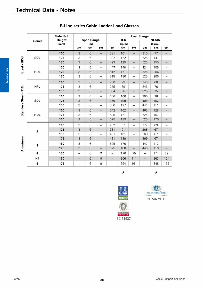
Series Height Span Range IEC NEMA(mm) (m) (kg/m) (kg/m)
3m 6m 9m 3m 6m 9m 3m 6m 9m
100 3 6 -- 381 101 -- 310 77 --SDL 125 3 6 -- 322 122 -- 525 141 --
150 3 6 -- 429 125 -- 525 155 --
100 3 6 -- 447 140 -- 424 106 --HDL 125 3 6 -- 512 171 -- 525 204 --
150 3 6 -- 518 180 -- 525 206 --
100 3 6 -- 250 73 -- 240 60 --HPL 125 3 6 -- 275 89 -- 246 76 --
150 3 6 -- 364 96 -- 225 75 --
100 3 6 -- 386 100 -- 305 76 --SDL 125 3 6 -- 369 199 -- 408 102 --
150 3 6 -- 386 127 -- 444 111 --
100 3 6 -- 542 102 -- 462 128 --HDL 125 3 6 -- 525 171 -- 525 167 --
150 3 6 -- 525 189 -- 525 175 --
100 3 6 -- 282 67 -- 277 69 --
2 125 3 6 -- 381 91 -- 268 67 --150 3 6 -- 431 101 -- 268 67 --175 3 6 -- 431 139 -- 269 67 --
3 150 3 6 -- 525 170 -- 447 112 --175 3 6 -- 525 168 -- 440 110 --
4 150 -- 6 9 -- 170 75 -- 174 62
H4 150 -- 6 9 -- 306 111 -- 263 101
5 175 -- 6 9 -- 394 161 -- 348 155
B-Line series Cable Ladder Load ClassesS
teel
- H
DG
Sta
inle
ss S
teel
- 3
16L
Alu
min
um
IEC 61537
NEMA VE-I
Technical Data
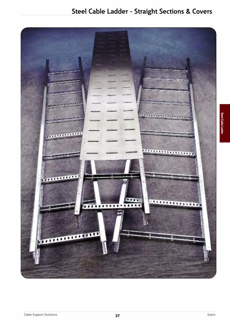
Steel Cable Ladder - Straight Sections & CoversSteel Cable Ladder
37Cable Support Solutions Eaton
Cable Ladder - Straight Sections & Covers
Cable Support SolutionsEaton 38
Cable Ladder Selection Guide
B-Line series hot dip galvanized and stainless steel cable ladder, manufactured and testedto IEC standards, are considered the premier product offering for any industrial cablemanagement application. Three cable ladder series are available to help optimize designand lower total installed cost.
High Performance Ladder (HPL) Series – Designed to reduce overall weight in weightsensitive environments while increasing strength. Ideal for offshore and modular applicationswhere weight reduction is imperative. Visit www.Eaton.com/hpl to learn more.
• Lightweight – design optimized to exceed load requirements while keeping weight to a minimum
• Stainless steel 316 construction• I-Beam side rail - maximizes strength• Rolled components add strength• Slotted side rails help reduce labor by eliminating the need to drill new splice holes
after cutting• Slotted rungs for cable and accessory attachment• ABS Type Approved• BV, DNV, AND CSA Certified load tests• Must support per NEMA VE-2 recommendations
Standard Duty Ladder (SDL) Series – Designed for applications where long spans (3m to 6m)can be utilized to decrease support costs while maintaining load requirements. Ideal for anycable management application where high cable loads are required.
• Long Spans – Available in 3 meter and 6 meter lengths. • Designed for use with 6m spans and still maintain high cable loads, while reducing
support requirements.• Structural Steel Savings support recommendations apply (see pages 5-25)• Available in Stainless steel 316 and Hot-Dip Galvanized• I-Beam side rail - maximizes strength over longer spans• Rolled components add strength• Slotted side rails help reduce labor by eliminating the need to drill new splice holes
after cutting• Slotted rungs for cable and accessory attachment• ABS Type Approved• BV, DNV, AND CSA Certified load tests
Heavy Duty Ladder (HDL) Series – Designed for extreme cable and environmental load conditions where long spans (3m to 6m) can be utilized to decrease support costs. Ideal forheavy industrial applications where environmental conditions such as wind, snow, and iceadd significant load requirements.
• Superior Strength – Maximized material efficiency for maximized loads • Structural Steel Savings support recommendations apply (see page 5-25)• Available in Stainless steel 316 and Hot-Dip Galvanized• I-Beam side rail - maximizes strength over longer spans• Rolled components add strength• Slotted side rails reduce labor by eliminating the need to drill new splice holes after
cutting• Slotted rungs for cable and accessory attachment• ABS Type Approved• BV, DNV, AND CSA Certified load tests
Steel Cable Ladder
Eaton.com/sss
Eaton.com/sss
Steel Cable Ladder Construction
39Cable Support Solutions Eaton
2
1
3
4
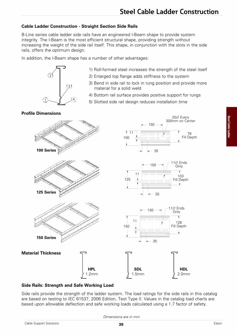
Cable Ladder Construction - Straight Section Side Rails
B-Line series cable ladder side rails have an engineered I-Beam shape to provide systemintegrity. The I-Beam is the most efficient structural shape, providing strength withoutincreasing the weight of the side rail itself. This shape, in conjunction with the slots in the siderails, offers the optimum design.
In addition, the I-Beam shape has a number of other advantages:
Profile Dimensions
Side Rails: Strength and Safe Working Load
Side rails provide the strength of the ladder system. The load ratings for the side rails in this catalogare based on testing to IEC 61537, 2006 Edition, Test Type II. Values in the catalog load charts arebased upon allowable deflection and safe working loads calculated using a 1.7 factor of safety.
Material Thickness
1) Roll-formed steel increases the strength of the steel itself
2) Enlarged top flange adds stiffness to the system
3) Bend in side rail to lock in rung position and provide morematerial for a solid weld
4) Bottom rail surface provides positive support for rungs
5) Slotted side rail design reduces installation time
100 Series
125 Series
HPL1.2mm
SDL1.5mm
HDL2.0mm
150 Series
125
150
35
35
11
11
150
150
103Fill Depth
11∅ EndsOnly
11∅ EndsOnly
128Fill Depth
Dimensions are in mm
150
100
35
11 78Fill Depth
25∅ Every300mm on Center
Steel Cable Ladder
Steel Cable Ladder Construction
Cable Support SolutionsEaton 40
Rung Profile Dimensions
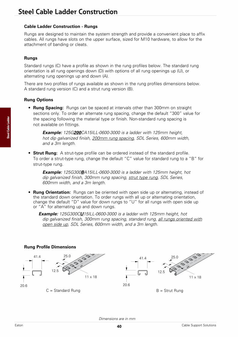
Cable Ladder Construction - Rungs
Rungs are designed to maintain the system strength and provide a convenient place to affixcables. All rungs have slots on the upper surface, sized for M10 hardware, to allow for theattachment of banding or cleats.
Rungs
Standard rungs (C) have a profile as shown in the rung profiles below. The standard rung orientation is all rung openings down (D) with options of all rung openings up (U), oralternating rung openings up and down (A).
There are two profiles of rungs available as shown in the rung profiles dimensions below.A standard rung version (C) and a strut rung version (B).
Rung Options
• Rung Spacing: Rungs can be spaced at intervals other than 300mm on straightsections only. To order an alternate rung spacing, change the default “300” value forthe spacing following the material type or finish. Non-standard rung spacing isnot available on fittings.
Example: 125G200CA15ILL-0600-3000 is a ladder with 125mm height, hot dip galvanized finish, 200mm rung spacing, SDL Series, 600mm width,and a 3m length.
• Strut Rung: A strut-type profile can be ordered instead of the standard profile.To order a strut-type rung, change the default “C” value for standard rung to a “B” forstrut-type rung.
Example: 125G300BA15ILL-0600-3000 is a ladder with 125mm height, hotdip galvanized finish, 300mm rung spacing, strut type rung, SDL Series,600mm width, and a 3m length.
• Rung Orientation: Rungs can be oriented with open side up or alternating, instead ofthe standard down orientation. To order rungs with all up or alternating orientation,change the default “D” value for down rungs to “U” for all rungs with open side upor “A” for alternating up and down rungs.
Example: 125G300CU15ILL-0600-3000 is a ladder with 125mm height, hotdip galvanized finish, 300mm rung spacing, standard rung, all rungs oriented withopen side up, SDL Series, 600mm width, and a 3m length.
C = Standard Rung B = Strut Rung20.6
Dimensions are in mm
25.025.0
20.6
41.441.4
12.512.5
11 x 18 11 x 18
Steel Cable Ladder
Steel Cable Ladder Construction
41Cable Support Solutions Eaton
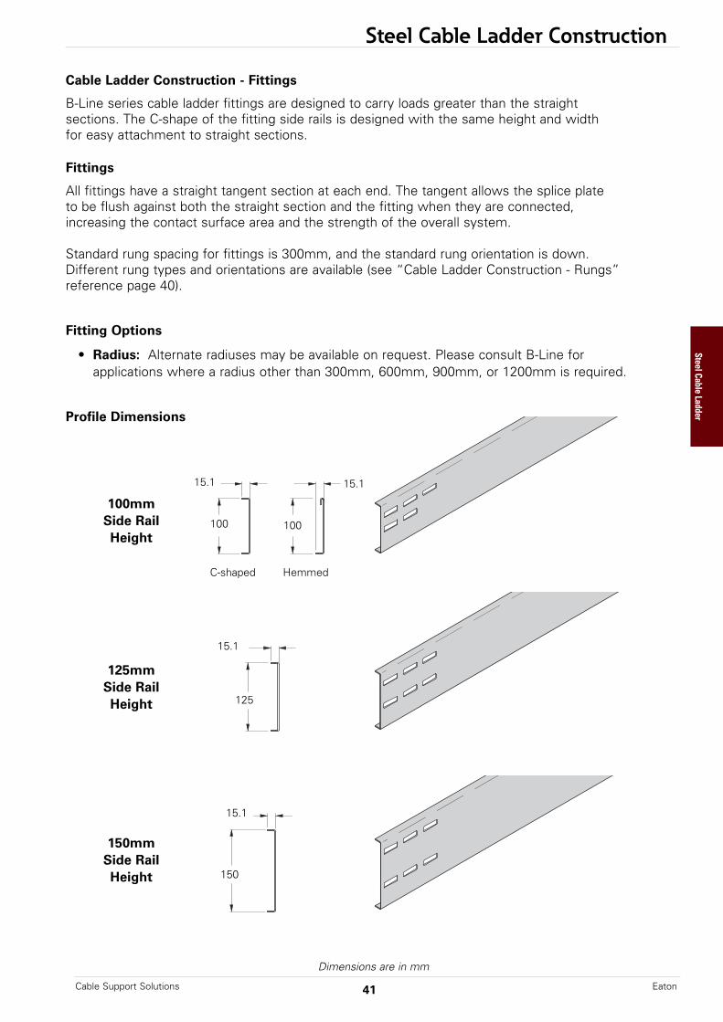
Cable Ladder Construction - Fittings
B-Line series cable ladder fittings are designed to carry loads greater than the straightsections. The C-shape of the fitting side rails is designed with the same height and widthfor easy attachment to straight sections.
Fittings
All fittings have a straight tangent section at each end. The tangent allows the splice plateto be flush against both the straight section and the fitting when they are connected,increasing the contact surface area and the strength of the overall system.
Standard rung spacing for fittings is 300mm, and the standard rung orientation is down.Different rung types and orientations are available (see “Cable Ladder Construction - Rungs”reference page 40).
Fitting Options
• Radius: Alternate radiuses may be available on request. Please consult B-Line forapplications where a radius other than 300mm, 600mm, 900mm, or 1200mm is required.
Profile Dimensions
125mmSide RailHeight
150mmSide RailHeight
125
150
15.1
100mmSide RailHeight
100
15.1
100
15.1
15.1
Dimensions are in mm
C-shaped Hemmed
Steel Cable Ladder

All dimensions are in millimeters unless otherwise specified.
Steel Cable Ladder - Straight Sections
Standard Duty Ladder (SDL) Series, Heavy Duty Ladder (HDL) Series &High Performance Ladder (HPL) Series
Straight Section Part Numbering
Example: 125 G 300 C D 15I LL - 0600 - 3000
* Rung LadderHeight Spacing * Rung * Rung Straight Width Length(mm) Material (mm) Shape Orientation Side Rail Section (mm) (mm)
100 G = 200 C D = 12I ** = 0150 3000125 Galvanized 300 Profile Down HPL Series 0300 6000150 Steel A = 15I = 0450
X = Alternating SDL Series 0600Stainless U = Up 20I = 0750
Steel 316L HDL Series 0900Y =
Passivated * Other Options Available - See “Cable Ladder Construction”Stainless
** Available in SS6 onlySteel 316L
Approval #18-HS1774501-PDA
Splice plates not supplied with straight sections. One (1) pair required to connect to system. See pages 66 & 67.
Cable Support SolutionsEaton 42
RungSpacing
Width(Inside)
Overall Width(Width + 35)
Steel Cable Ladder
All dimensions are in millimeters unless otherwise specified.
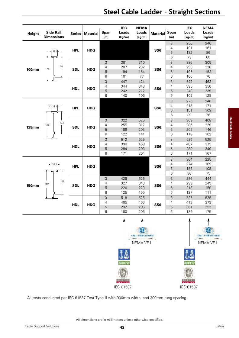
Steel Cable Ladder - Straight Sections
All tests conducted per IEC 61537 Test Type II with 900mm width, and 300mm rung spacing.
IEC 61537 IEC 61537
NEMA VE-I NEMA VE-I
IEC NEMA IEC NEMA
Height Side Rail Series Material Span Loads Loads Material Span Loads LoadsDimensions (m) (kg/m) (kg/m) (m) (kg/m) (kg/m)
3 -- -- 3 250 240
HPL HDG4 -- --
SS64 191 161
5 -- -- 5 132 866 -- -- 6 73 603 381 310 3 386 305
100mm SDL HDG4 287 232
SS64 290 228
5 194 154 5 195 1526 101 77 6 100 763 447 424 3 542 462
HDL HDG4 344 318
SS64 395 350
5 242 212 5 248 2396 140 106 6 102 128
3 -- -- 3 275 246
HPL HDG4 -- --
SS64 213 171
5 -- -- 5 151 1096 -- -- 6 89 763 322 525 3 369 408
125mm SDL HDG4 255 317
SS64 285 229
5 188 203 5 202 1466 122 141 6 119 1023 512 525 3 525 525
HDL HDG4 398 459
SS64 407 375
5 284 293 5 289 2406 171 204 6 171 167
3 -- -- 3 364 225
HPL HDG4 -- --
SS64 274 169
5 -- -- 5 185 1086 -- -- 6 96 753 429 525 3 386 444
150mm SDL HDG4 327 348
SS64 299 249
5 226 223 5 213 1596 125 155 6 127 1113 518 525 3 525 525
HDL HDG4 405 463
SS64 413 373
5 292 296 5 301 2526 180 206 6 189 175
38.1
10078
38.1
150128
43Cable Support Solutions Eaton
38.1
125103
Steel Cable Ladder
All dimensions are in millimeters unless otherwise specified.
Steel Cable Ladder - Straight Section Covers
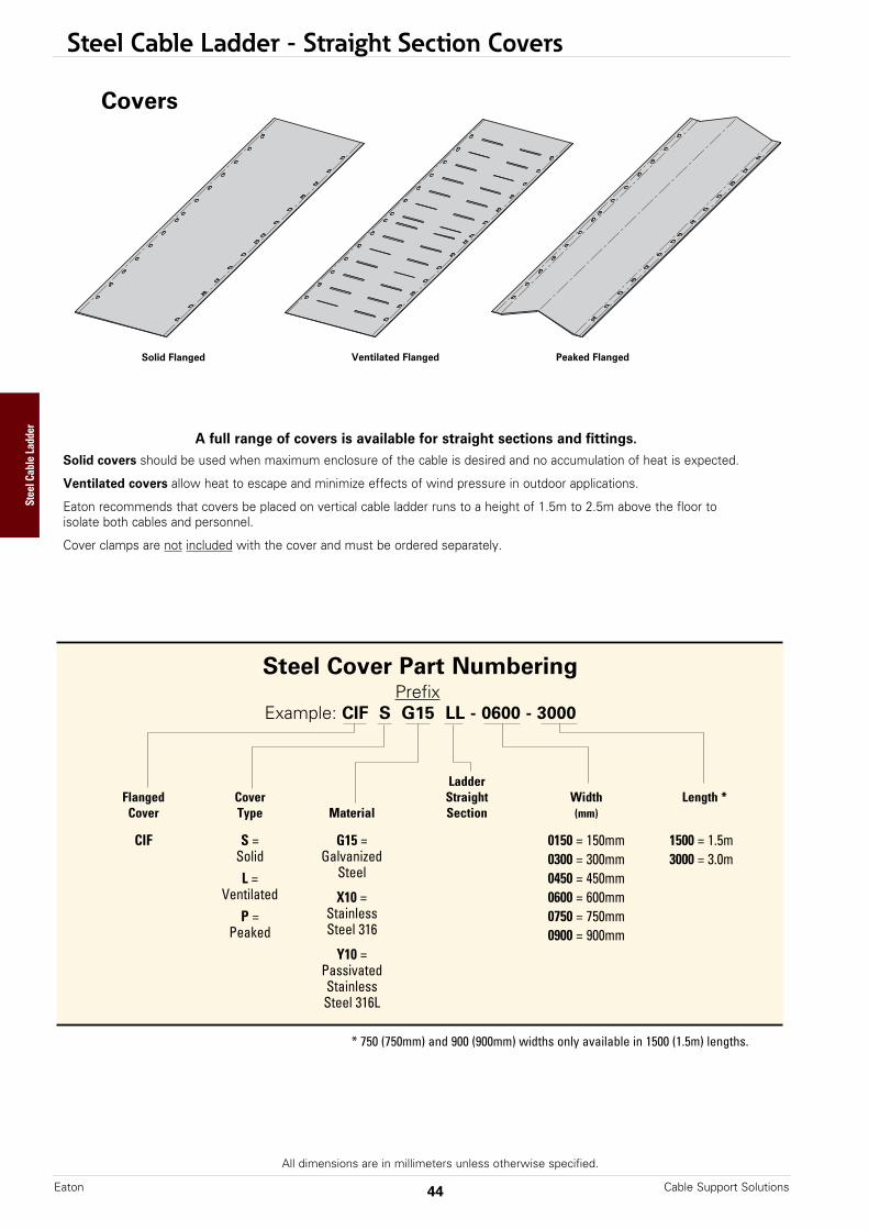
A full range of covers is available for straight sections and fittings.Solid covers should be used when maximum enclosure of the cable is desired and no accumulation of heat is expected.
Ventilated covers allow heat to escape and minimize effects of wind pressure in outdoor applications.
Eaton recommends that covers be placed on vertical cable ladder runs to a height of 1.5m to 2.5m above the floor toisolate both cables and personnel.
Cover clamps are not included with the cover and must be ordered separately.
Solid Flanged Ventilated Flanged Peaked Flanged
Steel Cover Part NumberingPrefix
Example: CIF S G15 LL - 0600 - 3000
LadderFlanged Cover Straight Width Length *Cover Type Material Section (mm)
CIF S = G15 = 0150 = 150mm 1500 = 1.5mSolid Galvanized 0300 = 300mm 3000 = 3.0mL = Steel 0450 = 450mm
Ventilated X10 = 0600 = 600mmP = Stainless 0750 = 750mm
Peaked Steel 316 0900 = 900mmY10 =
PassivatedStainlessSteel 316L
Covers
* 750 (750mm) and 900 (900mm) widths only available in 1500 (1.5m) lengths.
Cable Support SolutionsEaton 44
Steel Cable Ladder

All dimensions are in millimeters unless otherwise specified.
Steel Cable Ladder - Cover Clamps
Heavy Duty Cover Clamp • Recommended for outdoor service • (xx) Insert tray width - 150 to 900 • Includes M10 hardware • (*) Finishes available: G or SS6
High Performance Cover Clamp • Compatible with both flat and
peaked cover options • Sold per piece with hardware • Additional clamps may be necessary
in extreme wind applications (*) Finish: Insert MZ or X for SS6
Number of clamps suggested for assemblies (Additional clamps may be necessary in extreme wind applications.
Please contact [email protected] for more information around wind restraints and project requirements.)
Assembly Cover Size # of Clamps
Straight 1.5m length 4 Section 3.0m length 6
30° - 60° All radii 4 Horizontal Bend
90° 150mm to 600mm radius 4 Horizontal Bend 900mm to 1200mm radius 6
30° - 60° All radii 4 Vertical Bend
90° 150mm to 600mm radius 4 Vertical Bend 900mm to 1200mm radius 6
Horizontal 150mm to 600mm radius 6 Tee 900mm to 1200mm radius 8
Horizontal 150mm to 600mm radius 8 Cross 900mm to 1200mm radius 12
Catalog Description Raised Height
Number mm In. LCCSD(*) Standard Clamp -- --
LCCSDR(*) Raised Clamp 35.5 1.4Visit Eaton.com/ccs for installation instructions
and additional clamp quantities for other fittings.
LCCSD LCCSDR
Ladder Height Catalog No. mm
100 LCH100(*)(xx)
125 LCH125(*)(xx)
150 LCH150(*)(xx)
45Cable Support Solutions Eaton
Steel Cable Ladder
Additional clamps may be necessary in high wind conditions, please contact [email protected]
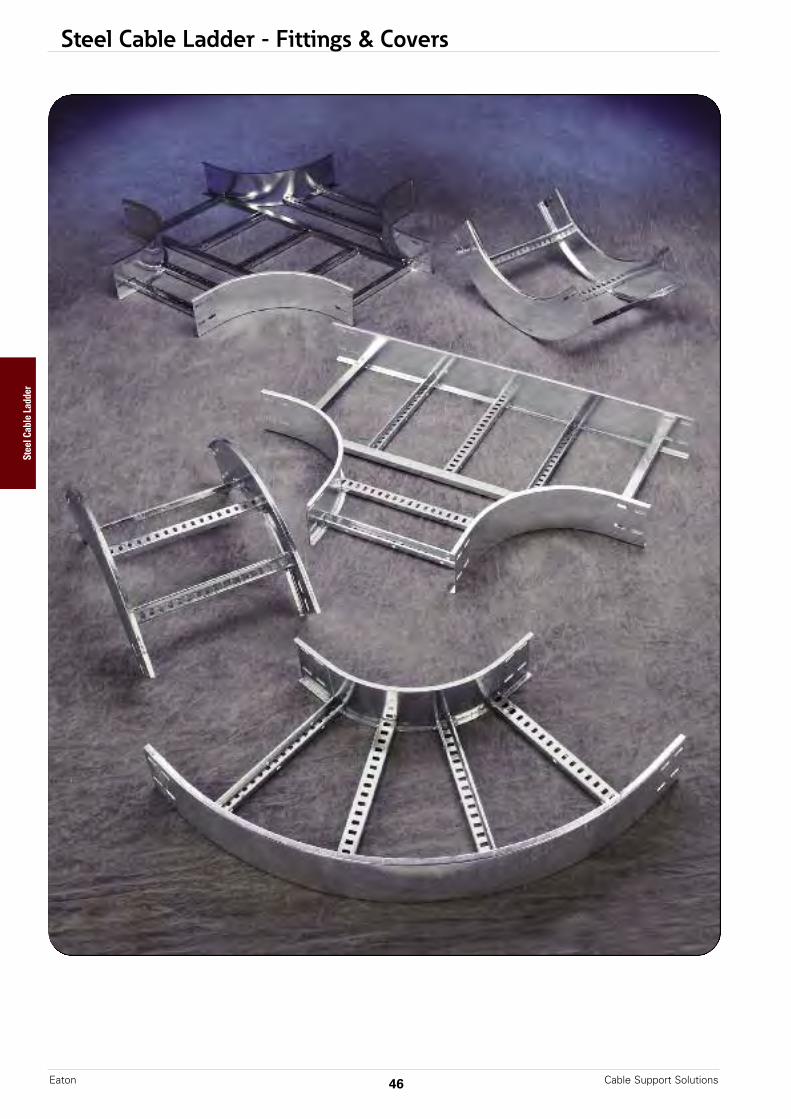
Steel Cable Ladder - Fittings & Covers
Cable Support SolutionsEaton 46
Steel Cable Ladder

Steel Cable Ladder - Fittings
All dimensions are in millimeters unless otherwise specified.
Fittings engineered with 100mm tangentsfor splicing integrity.
B-Line series cable ladder fittings are designed to support cables as they transition directions.Side rails are C-shaped with standard 300mm rung spacing.
Fittings Part Numbering
Example: 125 G 300 C D 20 C LVO - 0600 - 90 R0600
RungHeight Spacing * Rung * Rung Side Side Rail Ladder Fitting Width Angle † Radius(mm) Material (mm) Shape Orientation Rail Type Type (mm) (°) (mm)
100 = ** G = 300 = C = D = 12 = C = LHB = Horiz. Bend 0150 = 30 R0300 =100mm Galvanized 300mm Standard Down HPL C-Shape LVI = Vert.Inside Bend 150mm 45 300mm125 = Steel Profile A = Series LVO = Vert. Outside Bend 0300 = 60 R0600 =
125mm X = Alternating 15 = LHT = Horiz. Tee † 300mm 90 600mm150 = Stainless U = Up SDL LHX = Horiz. Cross † 0450 = R0900 =
150mm Steel 316L Series LVTD = Vert. Tee Down † 450mm 900mmY = 20 = H = LVTU = Vert. Tee Up † 0600 = R1200 =
Passivated HDL Hemmed LCSF = Cable Support 600mm 1200mmStainless Series Fitting † 0750 =Steel 316L * Other Options Available LHYL = LEFT Hand 750mm
See “Cable Ladder Construction” for more detail Horiz. Wye 0900 =LHYR = Right Hand 900mm
** Not Available with HPL Series Horiz. WyeLVR = Vert. Riser †
Prefix
† No angle designation required on these fittings.See fitting page when creating part numbers.
47Cable Support Solutions Eaton
Steel Cable Ladder

Steel Cable Ladder - Fittings
Horizontal Bends 90° (LHB)Splice plates not supplied with fittings.Order standard splice plates separately from page 66.One (1) pair required to connect to system.
Horizontal Bends 60° (LHB)Splice plates not supplied with fittings.Order standard splice plates separately from page 66.One (1) pair required to connect to system.
90˚ Horizontal Bend
A
C
CR
100mm
C
C
B
60˚ Horizontal Bend
90˚LHB
60˚LHB
B
R
A100mm
(Prefix) See page 47 for catalog number prefix.Width dimensions are to inside wall. Manufacturing tolerances apply to all dimensions.
Note: For alternative bend radius dimensions, download submittals atEaton.com/iec
(Prefix) See page 47 for catalog number prefix.Width dimensions are to inside wall. Manufacturing tolerances apply to all dimensions.
Note: For alternative bend radius dimensions, download submittals atEaton.com/iec
All dimensions are in millimeters unless otherwise specified.
Cable Support SolutionsEaton 48
Bend Ladder 90˚ Horizontal BendRadius Width Dimensions
R Catalog No. A B Cmm mm mm mm mm
150 (Pre)LHB-0150-90R0300 475 475 475300 (Pre)LHB-0300-90R0300 550 550 550
300450 (Pre)LHB-0450-90R0300 625 625 625600 (Pre)LHB-0600-90R0300 700 700 700750 (Pre)LHB-0750-90R0300 775 775 775900 (Pre)LHB-0900-90R0300 850 850 850150 (Pre)LHB-0150-90R0600 775 775 775300 (Pre)LHB-0300-90R0600 850 850 850
600450 (Pre)LHB-0450-90R0600 925 925 925600 (Pre)LHB-0600-90R0600 1000 1000 1000750 (Pre)LHB-0750-90R0600 1075 1075 1075900 (Pre)LHB-0900-90R0600 1150 1150 1150
Bend Ladder 60˚ Horizontal BendRadius Width Dimensions
R Catalog No. A B Cmm mm mm mm mm
150 (Pre)LHB-0150-60R0300 476 275 317300 (Pre)LHB-0300-60R0300 541 312 360
300450 (Pre)LHB-0450-60R0300 606 350 404600 (Pre)LHB-0600-60R0300 670 387 447750 (Pre)LHB-0750-60R0300 735 425 490900 (Pre)LHB-0900-60R0300 800 425 534150 (Pre)LHB-0150-60R0600 735 425 490300 (Pre)LHB-0300-60R0600 800 462 534
600450 (Pre)LHB-0450-60R0600 865 500 577600 (Pre)LHB-0600-60R0600 930 537 620750 (Pre)LHB-0750-60R0600 995 575 663900 (Pre)LHB-0900-60R0600 1060 612 707
Steel Cable Ladder
Steel Cable Ladder - Fittings
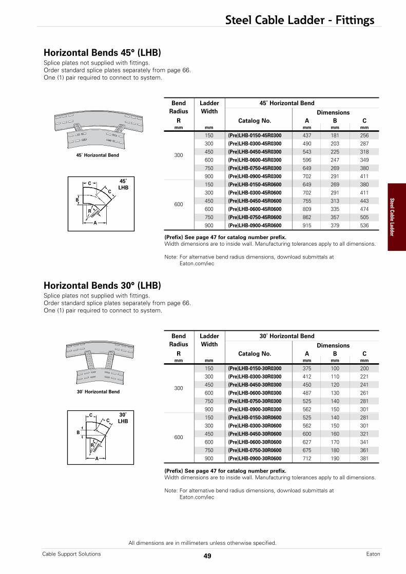
Horizontal Bends 45° (LHB)Splice plates not supplied with fittings.Order standard splice plates separately from page 66.One (1) pair required to connect to system.
Horizontal Bends 30° (LHB)Splice plates not supplied with fittings.Order standard splice plates separately from page 66.One (1) pair required to connect to system.
45˚ Horizontal Bend
CC
B
30˚ Horizontal Bend
30˚LHB
R
A
100m
m
(Prefix) See page 47 for catalog number prefix.Width dimensions are to inside wall. Manufacturing tolerances apply to all dimensions.
Note: For alternative bend radius dimensions, download submittals atEaton.com/iec
(Prefix) See page 47 for catalog number prefix.Width dimensions are to inside wall. Manufacturing tolerances apply to all dimensions.
Note: For alternative bend radius dimensions, download submittals atEaton.com/iec
All dimensions are in millimeters unless otherwise specified.
C
C
B
45˚LHB
R
A10
0mm
Bend Ladder 30˚ Horizontal BendRadius Width Dimensions
R Catalog No. A B Cmm mm mm mm mm
150 (Pre)LHB-0150-30R0300 375 100 200300 (Pre)LHB-0300-30R0300 412 110 221
300450 (Pre)LHB-0450-30R0300 450 120 241600 (Pre)LHB-0600-30R0300 487 130 261750 (Pre)LHB-0750-30R0300 525 140 281900 (Pre)LHB-0900-30R0300 562 150 301150 (Pre)LHB-0150-30R0600 525 140 281300 (Pre)LHB-0300-30R0600 562 150 301
600450 (Pre)LHB-0450-30R0600 600 160 321600 (Pre)LHB-0600-30R0600 627 170 341750 (Pre)LHB-0750-30R0600 675 180 361900 (Pre)LHB-0900-30R0600 712 190 381
49Cable Support Solutions Eaton
Bend Ladder 45˚ Horizontal BendRadius Width Dimensions
R Catalog No. A B Cmm mm mm mm mm
150 (Pre)LHB-0150-45R0300 437 181 256300 (Pre)LHB-0300-45R0300 490 203 287
300450 (Pre)LHB-0450-45R0300 543 225 318600 (Pre)LHB-0600-45R0300 596 247 349750 (Pre)LHB-0750-45R0300 649 269 380900 (Pre)LHB-0900-45R0300 702 291 411150 (Pre)LHB-0150-45R0600 649 269 380300 (Pre)LHB-0300-45R0600 702 291 411
600450 (Pre)LHB-0450-45R0600 755 313 443600 (Pre)LHB-0600-45R0600 809 335 474750 (Pre)LHB-0750-45R0600 862 357 505900 (Pre)LHB-0900-45R0600 915 379 536
Steel Cable Ladder
Steel Cable Ladder - Fittings
All dimensions are in millimeters unless otherwise specified.
90˚ Vertical Outside
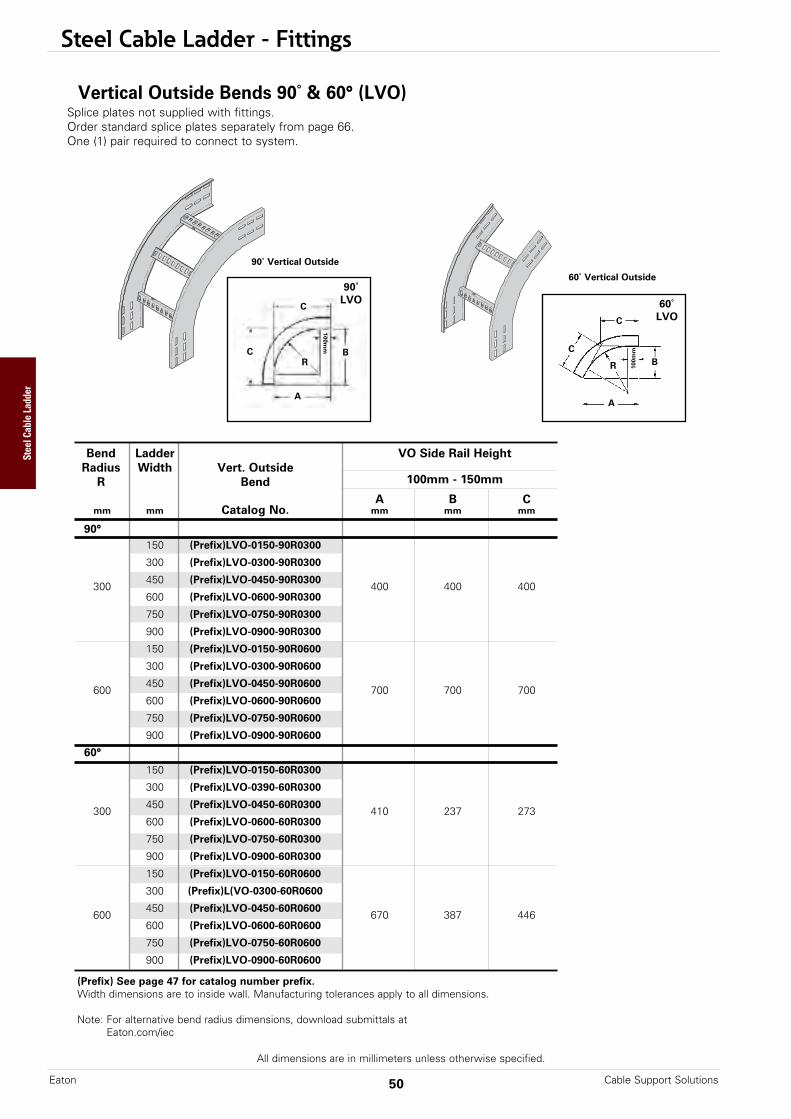
Vertical Outside Bends 90˚ & 60° (LVO) Splice plates not supplied with fittings.Order standard splice plates separately from page 66.One (1) pair required to connect to system.
B
A
C
C
100mm
R
90˚LVO
(Prefix) See page 47 for catalog number prefix.Width dimensions are to inside wall. Manufacturing tolerances apply to all dimensions.
Note: For alternative bend radius dimensions, download submittals atEaton.com/iec
60˚ Vertical Outside
B
A
C
C
100m
m
R
60˚LVO
Cable Support SolutionsEaton 50
Bend Ladder VO Side Rail HeightRadius Width Vert. Outside
R Bend 100mm - 150mm
A B Cmm mm Catalog No. mm mm mm
90°150 (Prefix)LVO-0150-90R0300
300 (Prefix)LVO-0300-90R0300
300450 (Prefix)LVO-0450-90R0300
400 400 400600 (Prefix)LVO-0600-90R0300
750 (Prefix)LVO-0750-90R0300
900 (Prefix)LVO-0900-90R0300
150 (Prefix)LVO-0150-90R0600
300 (Prefix)LVO-0300-90R0600
600450 (Prefix)LVO-0450-90R0600
700 700 700600 (Prefix)LVO-0600-90R0600
750 (Prefix)LVO-0750-90R0600
900 (Prefix)LVO-0900-90R0600
60°
150 (Prefix)LVO-0150-60R0300
300 (Prefix)LVO-0390-60R0300
300450 (Prefix)LVO-0450-60R0300
410 237 273600 (Prefix)LVO-0600-60R0300
750 (Prefix)LVO-0750-60R0300
900 (Prefix)LVO-0900-60R0300
150 (Prefix)LVO-0150-60R0600
300 (Prefix)L(VO-0300-60R0600
600450 (Prefix)LVO-0450-60R0600
670 387 446600 (Prefix)LVO-0600-60R0600
750 (Prefix)LVO-0750-60R0600
900 (Prefix)LVO-0900-60R0600
Steel Cable Ladder
Steel Cable Ladder - Fittings
All dimensions are in millimeters unless otherwise specified.
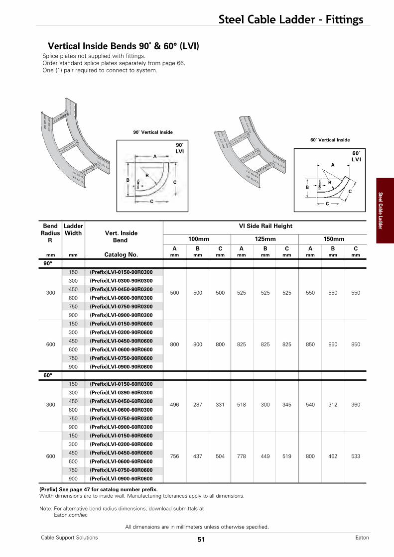
Bend Ladder VI Side Rail HeightRadius Width Vert. Inside
R Bend 100mm 125mm 150mm
A B C A B C A B Cmm mm Catalog No. mm mm mm mm mm mm mm mm mm
90°
150 (Prefix)LVI-0150-90R0300
300 (Prefix)LVI-0300-90R0300
300450 (Prefix)LVI-0450-90R0300
500 500 500 525 525 525 550 550 550600 (Prefix)LVI-0600-90R0300
750 (Prefix)LVI-0750-90R0300
900 (Prefix)LVI-0900-90R0300
150 (Prefix)LVI-0150-90R0600
300 (Prefix)LVI-0300-90R0600
600450 (Prefix)LVI-0450-90R0600
800 800 800 825 825 825 850 850 850600 (Prefix)LVI-0600-90R0600
750 (Prefix)LVI-0750-90R0600
900 (Prefix)LVI-0900-90R0600
60°
150 (Prefix)LVI-0150-60R0300
300 (Prefix)LVI-0390-60R0300
300450 (Prefix)LVI-0450-60R0300
496 287 331 518 300 345 540 312 360600 (Prefix)LVI-0600-60R0300
750 (Prefix)LVI-0750-60R0300
900 (Prefix)LVI-0900-60R0300
150 (Prefix)LVI-0150-60R0600
300 (Prefix)LVI-0300-60R0600
600450 (Prefix)LVI-0450-60R0600
756 437 504 778 449 519 800 462 533600 (Prefix)LVI-0600-60R0600
750 (Prefix)LVI-0750-60R0600
900 (Prefix)LVI-0900-60R0600
90˚ Vertical Inside
Vertical Inside Bends 90˚ & 60° (LVI) Splice plates not supplied with fittings.Order standard splice plates separately from page 66.One (1) pair required to connect to system.
B
A
C
C
100mm
R
90˚LVI
60˚ Vertical Inside
B
A
C
C
100m
m R
60˚LVI
(Prefix) See page 47 for catalog number prefix.Width dimensions are to inside wall. Manufacturing tolerances apply to all dimensions.
Note: For alternative bend radius dimensions, download submittals atEaton.com/iec
51Cable Support Solutions Eaton
Steel Cable Ladder

Steel Cable Ladder - Fittings
All dimensions are in millimeters unless otherwise specified.
45˚ Vertical Outside
Vertical Bends 45˚ & 30° (LVO) Splice plates not supplied with fittings.Order standard splice plates separately from page 66.One (1) pair required to connect to system.
B
A
CC
100mm
R
30˚LVO
(Prefix) See page 47 for catalog number prefix.Width dimensions are to inside wall. Manufacturing tolerances apply to all dimensions.
Note: For alternative bend radius dimensions, download submittals atEaton.com/iec
30˚ Vertical Outside
B
A
C
C10
0mm
R
45˚LVO
Bend Ladder VO Side Rail HeightRadius Width Vert. Outside
R Bend 100mm - 150mm
A B Cmm mm Catalog No. mm mm mm
45°
150 (Prefix)LVO-0150-45R0300
300 (Prefix)LVO-0300-45R0300
300450 (Prefix)LVO-0450-45R0300
383 159 224600 (Prefix)LVO-0600-45R0300
750 (Prefix)LVO-0750-45R0300
900 (Prefix)LVO-0900-45R0300
150 (Prefix)LVO-0150-45R0600
300 (Prefix)LVO-0300-45R0600
600450 (Prefix)LVO-0450-45R0600
595 246 349600 (Prefix)LVO-0600-45R0600
750 (Prefix)LVO-0750-45R0600
900 (Prefix)LVO-0900-45R0600
30°
150 (Prefix)LVO-0150-30R0300
300 (Prefix)LVO-0390-30R0300
300450 (Prefix)LVO-0450-30R0300
337 90 180600 (Prefix)LVO-0600-30R0300
750 (Prefix)LVO-0750-30R0300
900 (Prefix)LVO-0900-30R0300
150 (Prefix)LVO-0150-30R0600
300 (Prefix)L(VO-0300-30R0600
600450 (Prefix)LVO-0450-30R0600
487 130 261600 (Prefix)LVO-0600-30R0600
750 (Prefix)LVO-0750-30R0600
900 (Prefix)LVO-0900-30R0600
Cable Support SolutionsEaton 52
Steel Cable Ladder
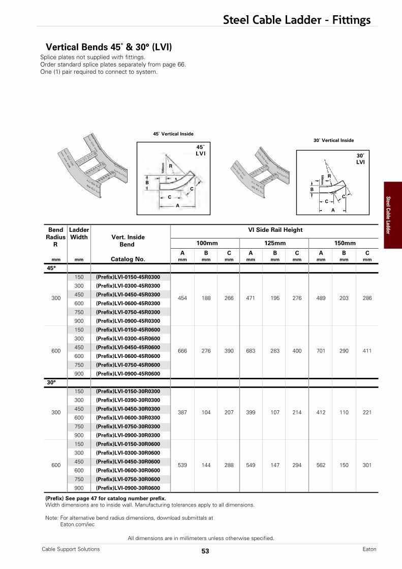
45˚ Vertical Inside
Vertical Bends 45˚ & 30° (LVI) Splice plates not supplied with fittings.Order standard splice plates separately from page 66.One (1) pair required to connect to system.
B
A
CC
100mm
R
30˚LVI
(Prefix) See page 47 for catalog number prefix.Width dimensions are to inside wall. Manufacturing tolerances apply to all dimensions.
Note: For alternative bend radius dimensions, download submittals atEaton.com/iec
30˚ Vertical Inside
B
A
C
C
100m
m R
45˚LVI
Steel Cable Ladder - Fittings
All dimensions are in millimeters unless otherwise specified.
Bend Ladder VI Side Rail HeightRadius Width Vert. Inside
R Bend 100mm 125mm 150mm
A B C A B C A B Cmm mm Catalog No. mm mm mm mm mm mm mm mm mm
45°
150 (Prefix)LVI-0150-45R0300
300 (Prefix)LVI-0300-45R0300
300450 (Prefix)LVI-0450-45R0300
454 188 266 471 195 276 489 203 286600 (Prefix)LVI-0600-45R0300
750 (Prefix)LVI-0750-45R0300
900 (Prefix)LVI-0900-45R0300
150 (Prefix)LVI-0150-45R0600
300 (Prefix)LVI-0300-45R0600
600450 (Prefix)LVI-0450-45R0600
666 276 390 683 283 400 701 290 411600 (Prefix)LVI-0600-45R0600
750 (Prefix)LVI-0750-45R0600
900 (Prefix)LVI-0900-45R0600
30°
150 (Prefix)LVI-0150-30R0300
300 (Prefix)LVI-0390-30R0300
300450 (Prefix)LVI-0450-30R0300
387 104 207 399 107 214 412 110 221600 (Prefix)LVI-0600-30R0300
750 (Prefix)LVI-0750-30R0300
900 (Prefix)LVI-0900-30R0300
150 (Prefix)LVI-0150-30R0600
300 (Prefix)LVI-0300-30R0600
600450 (Prefix)LVI-0450-30R0600
539 144 288 549 147 294 562 150 301600 (Prefix)LVI-0600-30R0600
750 (Prefix)LVI-0750-30R0600
900 (Prefix)LVI-0900-30R0600
53Cable Support Solutions Eaton
Steel Cable Ladder
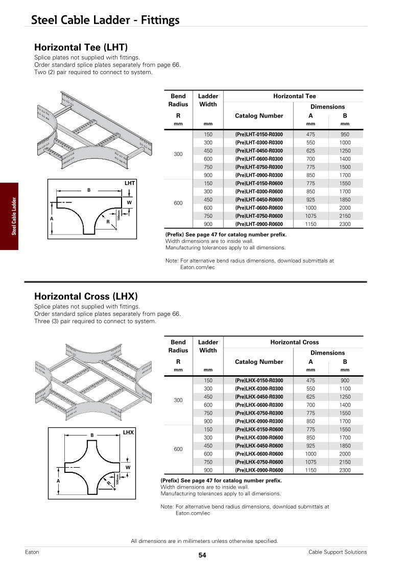
Steel Cable Ladder - Fittings
All dimensions are in millimeters unless otherwise specified.
(Prefix) See page 47 for catalog number prefix.Width dimensions are to inside wall.Manufacturing tolerances apply to all dimensions.
Note: For alternative bend radius dimensions, download submittals atEaton.com/iec
Bend Ladder Horizontal TeeRadius Width Dimensions
R Catalog Number A Bmm mm mm mm
150 (Pre)LHT-0150-R0300 475 950300 (Pre)LHT-0300-R0300 550 1000
300450 (Pre)LHT-0450-R0300 625 1250600 (Pre)LHT-0600-R0300 700 1400750 (Pre)LHT-0750-R0300 775 1500900 (Pre)LHT-0900-R0300 850 1700150 (Pre)LHT-0150-R0600 775 1550300 (Pre)LHT-0300-R0600 850 1700
600450 (Pre)LHT-0450-R0600 925 1850600 (Pre)LHT-0600-R0600 1000 2000750 (Pre)LHT-0750-R0600 1075 2150900 (Pre)LHT-0900-R0600 1150 2300
(Prefix) See page 47 for catalog number prefix.Width dimensions are to inside wall.Manufacturing tolerances apply to all dimensions.
Note: For alternative bend radius dimensions, download submittals atEaton.com/iec
A
B
R 100m
m
Horizontal Tee (LHT)Splice plates not supplied with fittings.Order standard splice plates separately from page 66.Two (2) pair required to connect to system.
LHT
W
AR
B
100m
m
Horizontal Cross (LHX)Splice plates not supplied with fittings.Order standard splice plates separately from page 66.Three (3) pair required to connect to system.
LHX
W
Cable Support SolutionsEaton 54
Bend Ladder Horizontal CrossRadius Width Dimensions
R Catalog Number A Bmm mm mm mm
150 (Pre)LHX-0150-R0300 475 900300 (Pre)LHX-0300-R0300 550 1100
300450 (Pre)LHX-0450-R0300 625 1250600 (Pre)LHX-0600-R0300 700 1400750 (Pre)LHX-0750-R0300 775 1550900 (Pre)LHX-0900-R0300 850 1700150 (Pre)LHX-0150-R0600 775 1550300 (Pre)LHX-0300-R0600 850 1700
600450 (Pre)LHX-0450-R0600 925 1850600 (Pre)LHX-0600-R0600 1000 2000750 (Pre)LHX-0750-R0600 1075 2150900 (Pre)LHX-0900-R0600 1150 2300
Steel Cable Ladder
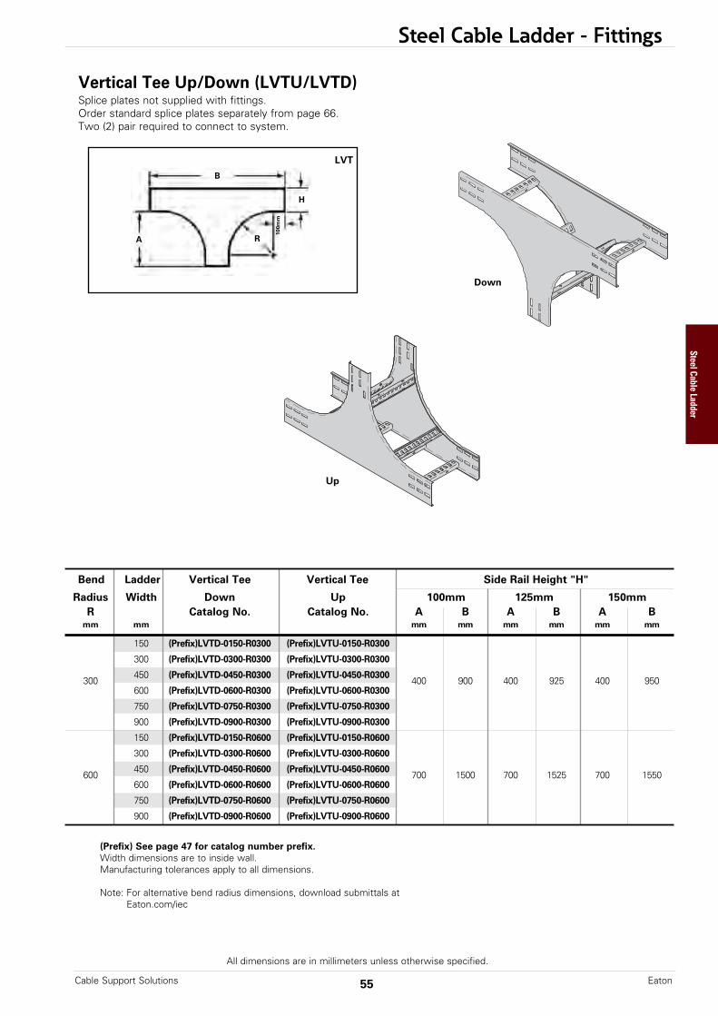
Steel Cable Ladder - Fittings
All dimensions are in millimeters unless otherwise specified.
Bend Ladder Vertical Tee Vertical Tee Side Rail Height "H"
Radius Width Down Up 100mm 125mm 150mmR Catalog No. Catalog No. A B A B A B
mm mm mm mm mm mm mm mm
150 (Prefix)LVTD-0150-R0300 (Prefix)LVTU-0150-R0300
300 (Prefix)LVTD-0300-R0300 (Prefix)LVTU-0300-R0300
300450 (Prefix)LVTD-0450-R0300 (Prefix)LVTU-0450-R0300
400 900 400 925 400 950600 (Prefix)LVTD-0600-R0300 (Prefix)LVTU-0600-R0300
750 (Prefix)LVTD-0750-R0300 (Prefix)LVTU-0750-R0300
900 (Prefix)LVTD-0900-R0300 (Prefix)LVTU-0900-R0300
150 (Prefix)LVTD-0150-R0600 (Prefix)LVTU-0150-R0600
300 (Prefix)LVTD-0300-R0600 (Prefix)LVTU-0300-R0600
600450 (Prefix)LVTD-0450-R0600 (Prefix)LVTU-0450-R0600
700 1500 700 1525 700 1550600 (Prefix)LVTD-0600-R0600 (Prefix)LVTU-0600-R0600
750 (Prefix)LVTD-0750-R0600 (Prefix)LVTU-0750-R0600
900 (Prefix)LVTD-0900-R0600 (Prefix)LVTU-0900-R0600
Up
Down
B
A
H
R
Vertical Tee Up/Down (LVTU/LVTD)Splice plates not supplied with fittings.Order standard splice plates separately from page 66.Two (2) pair required to connect to system.
LVT
(Prefix) See page 47 for catalog number prefix.Width dimensions are to inside wall.Manufacturing tolerances apply to all dimensions.
Note: For alternative bend radius dimensions, download submittals atEaton.com/iec
100m
m
55Cable Support Solutions Eaton
Steel Cable Ladder

Bend Ladder Side Rail Height "H"
Radius Width 100mm 125mm 150mmR Catalog No. A B A B A B
mm mm mm mm mm mm mm mm
150 (Prefix)LCSF-0150-R0300
300 (Prefix)LCSF-0300-R0300
300450 (Prefix)LCSF-0450-R0300
500 400 525 400 550 400600 (Prefix)LCSF-0600-R0300
750 (Prefix)LCSF-0750-R0300
900 (Prefix)LCSF-0900-R0300
150 (Prefix)LCSF-0150-R0600
300 (Prefix)LCSF-0300-R0600
600450 (Prefix)LCSF-0450-R0600
800 700 825 700 850 700600 (Prefix)LCSF-0600-R0600
750 (Prefix)LCSF-0750-R0600
900 (Prefix)LCSF-0900-R0600
(Prefix) See page 47 for catalog number prefix.Width dimensions are to inside wall.Manufacturing tolerances apply to all dimensions.
Note: For alternative bend radius dimensions, download submittals atEaton.com/iec
Steel Cable Ladder - Fittings
All dimensions are in millimeters unless otherwise specified.
This fitting is recommended for useat the top of vertical runs to supportthe weight of the cables. The topcross brace is drilled for installingeye bolts, ordered separately.
B
A
H
100m
m
R
Cable Support Fittings (LCSF)Splice plates not supplied with fittings.Order standard splice plates separately from page 66.One (1) pair required to connect to system.
LCSF
Cable Support SolutionsEaton 56
Steel Cable Ladder
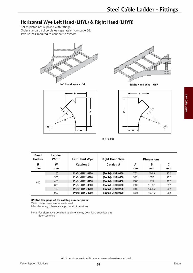
Steel Cable Ladder - Fittings
Horizontal Wye Left Hand (LHYL) & Right Hand (LHYR)Splice plates not supplied with fittings.Order standard splice plates separately from page 66.Two (2) pair required to connect to system.
All dimensions are in millimeters unless otherwise specified.
(Prefix) See page 47 for catalog number prefix.Width dimensions are to inside wall.Manufacturing tolerances apply to all dimensions.
Note: For alternative bend radius dimensions, download submittals atEaton.com/iec
Bend LadderRadius Width Left Hand Wye Right Hand Wye Dimensions
R W Catalog # Catalog # A B Cmm mm mm mm mm
150 (Prefix)-LHYL-0150 (Prefix)-LHYR-0150 761 400.9 102300 (Prefix)-LHYL-0300 (Prefix)-LHYR-0300 973 657 252
600 450 (Prefix)-LHYL-0450 (Prefix)-LHYR-0450 1185 913 402600 (Prefix)-LHYL-0600 (Prefix)-LHYR-0600 1397 1169.1 552750 (Prefix)-LHYL-0750 (Prefix)-LHYR-0750 1609 1425.2 702900 (Prefix)-LHYL-0900 (Prefix)-LHYR-0900 1821 1681.2 852
57Cable Support Solutions Eaton
R = Radius
Left Hand Wye - HYL Right Hand Wye - HYR
B
AC
45˚
R
W
B
A C
45˚
R
W
Steel Cable Ladder
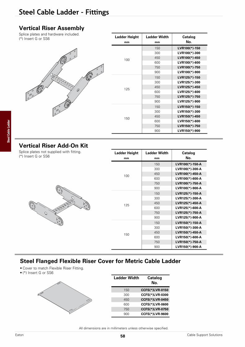
Steel Cable Ladder - Fittings
Vertical Riser AssemblySplice plates and hardware included.(*) Insert G or SS6
All dimensions are in millimeters unless otherwise specified.
Cable Support SolutionsEaton 58
Vertical Riser Add-On KitSplice plates not supplied with fitting.(*) Insert G or SS6
Ladder Height Ladder Width Catalogmm mm No.
150 LVR100(*)-150-A300 LVR100(*)-300-A
100450 LVR100(*)-450-A600 LVR100(*)-600-A750 LVR100(*)-750-A900 LVR100(*)-900-A
150 LVR125(*)-150-A300 LVR125(*)-300-A
125450 LVR125(*)-450-A600 LVR125(*)-600-A750 LVR125(*)-750-A900 LVR125(*)-900-A
150 LVR150(*)-150-A300 LVR150(*)-300-A
150450 LVR150(*)-450-A600 LVR150(*)-600-A750 LVR150(*)-750-A900 LVR150(*)-900-A
Ladder Height Ladder Width Catalogmm mm No.
150 LVR100(*)-150300 LVR100(*)-300
100450 LVR100(*)-450600 LVR100(*)-600750 LVR100(*)-750900 LVR100(*)-900
150 LVR125(*)-150300 LVR125(*)-300
125450 LVR125(*)-450600 LVR125(*)-600750 LVR125(*)-750900 LVR125(*)-900
150 LVR150(*)-150300 LVR150(*)-300
150450 LVR150(*)-450600 LVR150(*)-600750 LVR150(*)-750900 LVR150(*)-900
Ladder Width CatalogNo.
150 CCFS(*)LVR-0150300 CCFS(*)LVR-0300450 CCFS(*)LVR-0450600 CCFS(*)LVR-0600750 CCFS(*)LVR-0750900 CCFS(*)LVR-9600
Steel Flanged Flexible Riser Cover for Metric Cable Ladder• Cover to match Flexible Riser Fitting.• (*) Insert G or SS6
Steel Cable Ladder
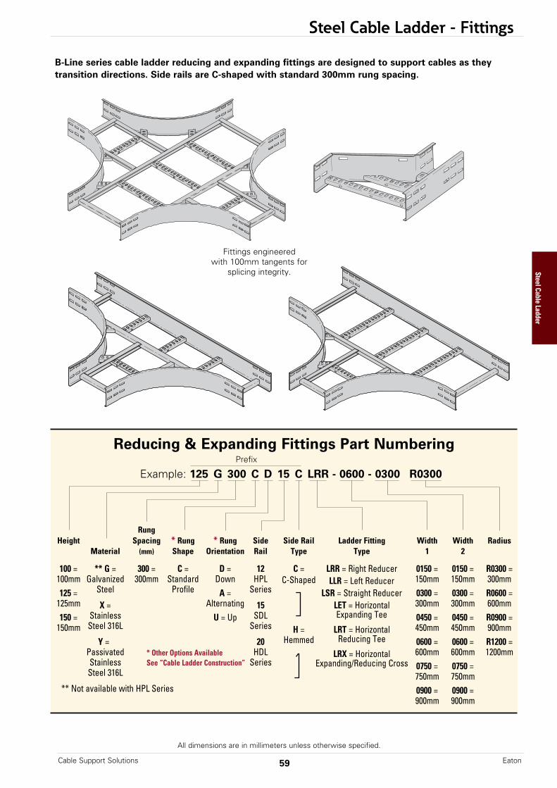
Steel Cable Ladder - Fittings
All dimensions are in millimeters unless otherwise specified.
B-Line series cable ladder reducing and expanding fittings are designed to support cables as theytransition directions. Side rails are C-shaped with standard 300mm rung spacing.
Reducing & Expanding Fittings Part Numbering
Example: 125 G 300 C D 15 C LRR - 0600 - 0300 R0300
RungHeight Spacing * Rung * Rung Side Side Rail Ladder Fitting Width Width Radius
Material (mm) Shape Orientation Rail Type Type 1 2
100 = ** G = 300 = C = D = 12 C = LRR = Right Reducer 0150 = 0150 = R0300 =100mm Galvanized 300mm Standard Down HPL C-Shaped LLR = Left Reducer 150mm 150mm 300mm125 = Steel Profile A = Series LSR = Straight Reducer 0300 = 0300 = R0600 =
125mm X = Alternating 15 LET = Horizontal 300mm 300mm 600mm150 = Stainless U = Up SDL Expanding Tee 0450 = 0450 = R0900 =
150mm Steel 316L Series H = LRT = Horizontal 450mm 450mm 900mmY = 20 Hemmed Reducing Tee 0600 = 0600 = R1200 =
Passivated * Other Options Available HDL LRX = Horizontal 600mm 600mm 1200mmStainless See “Cable Ladder Construction” Series Expanding/Reducing Cross 0750 = 0750 =Steel 316L 750mm 750mm
** Not available with HPL Series 0900 = 0900 =900mm 900mm
Prefix
Fittings engineered with 100mm tangents for
splicing integrity.
59Cable Support Solutions Eaton
Steel Cable Ladder
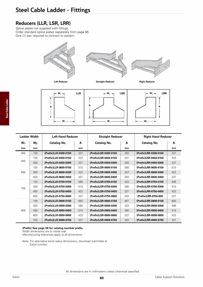
Steel Cable Ladder - Fittings
Ladder Width Left Hand Reducer Straight Reducer Right Hand Reducer
W1 W2 Catalog No. A Catalog No. A Catalog No. A
mm mm mm mm mm
300 150 (Prefix)LLR-0300-0150 337 (Prefix)LSR-0300-0150 293 (Prefix)LRR-0300-0150 337
150 (Prefix)LLR-0450-0150 423 (Prefix)LSR-0450-0150 337 (Prefix)LRR-0450-0150 423 450
300 (Prefix)LLR-0450-0300 337 (Prefix)LSR-0450-0300 293 (Prefix)LRR-0450-0300 337
150 (Prefix)LLR-0600-0150 510 (Prefix)LSR-0600-0150 380 (Prefix)LRR-0600-0150 510
600 300 (Prefix)LLR-0600-0300 423 (Prefix)LSR-0600-0300 337 (Prefix)LRR-0600-0300 423
450 (Prefix)LLR-0600-0450 337 (Prefix)LSR-0600-0450 293 (Prefix)LRR-0600-0450 337
150 (Prefix)LLR-0750-0150 596 (Prefix)LSR-0750-0150 423 (Prefix)LRR-0750-0150 596
750300 (Prefix)LLR-0750-0300 510 (Prefix)LSR-0750-0300 380 (Prefix)LRR-0750-0300 510
450 (Prefix)LLR-0750-0450 423 (Prefix)LSR-0750-0450 337 (Prefix)LRR-0750-0450 423
600 (Prefix)LLR-0750-0600 337 (Prefix)LSR-0750-0600 293 (Prefix)LRR-0750-600 337
150 (Prefix)LLR-0900-0150 683 (Prefix)LSR-0900-0150 467 (Prefix)LRR-0900-0150 683
300 (Prefix)LLR-0900-0300 596 (Prefix)LSR-0900-0300 423 (Prefix)LRR-0900-0300 596
900 450 (Prefix)LLR-0900-0450 510 (Prefix)LSR-0900-0450 380 (Prefix)LRR-0900-0450 510
600 (Prefix)LLR-0900-0600 423 (Prefix)LSR-0900-0600 337 (Prefix)LRR-0900-0600 423
750 (Prefix)LLR-0900-0750 337 (Prefix)LSR-0900-0750 293 (Prefix)LRR-0900-0750 337
Right ReducerStraight ReducerLeft Reducer
Reducers (LLR, LSR, LRR)Splice plates not supplied with fittings.Order standard splice plates separately from page 66.One (1) pair required to connect to system.
A
W2
W1
LLR
A
W2
W1
LSR
A
W2
W1
LRR
(Prefix) See page 59 for catalog number prefix.Width dimensions are to inside wall.Manufacturing tolerances apply to all dimensions.
Note: For alternative bend radius dimensions, download submittals atEaton.com/iec
All dimensions are in millimeters unless otherwise specified.
Cable Support SolutionsEaton 60
Steel Cable Ladder
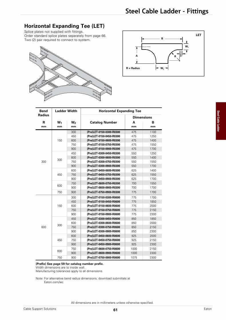
Steel Cable Ladder - Fittings
Bend Ladder Width Horizontal Expanding TeeRadius
DimensionsR W1 W2 Catalog Number A B
mm mm mm mm mm
300 (Pre)LET-0150-0300-R0300 475 1100450 (Pre)LET-0150-0450-R0300 475 1250
150 600 (Pre)LET-0150-0600-R0300 475 1400750 (Pre)LET-0150-0750-R0300 475 1550900 (Pre)LET-0150-0900-R0300 475 1700450 (Pre)LET-0300-0450-R0300 550 1250600 (Pre)LET-0300-0600-R0300 550 1400
300300
750 (Pre)LET-0300-0750-R0300 550 1550900 (Pre)LET-0300-0900-R0300 550 1700600 (Pre)LET-0450-0600-R0300 625 1400
450 750 (Pre)LET-0450-0750-R0300 625 1550900 (Pre)LET-0450-0900-R0300 625 1700750 (Pre)LET-0600-0750-R0300 700 1550
600900 (Pre)LET-0600-0900-R0300 700 1700
750 900 (Pre)LET-0750-0900-R0300 775 1700
300 (Pre)LET-0150-0300-R0600 775 1700450 (Pre)LET-0150-0450-R0600 775 1850
150 600 (Pre)LET-0150-0600-R0600 775 2000750 (Pre)LET-0150-0750-R0600 775 2150900 (Pre)LET-0150-0900-R0600 775 2300450 (Pre)LET-0300-0450-R0600 850 1850600 (Pre)LET-0300-0600-R0600 850 2000
600300
750 (Pre)LET-0300-0750-R0600 850 2150900 (Pre)LET-0300-0900-R0600 850 2300600 (Pre)LET-0450-0600-R0600 925 2000
450 750 (Pre)LET-0450-0750-R0600 925 2150900 (Pre)LET-0450-0900-R0600 925 2300750 (Pre)LET-0600-0750-R0600 1000 2150
600900 (Pre)LET-0600-0900-R0600 1000 2300
750 900 (Pre)LET-0750-0900-R0600 1075 2300
Horizontal Expanding Tee (LET)Splice plates not supplied with fittings.Order standard splice plates separately from page 66.Two (2) pair required to connect to system.
All dimensions are in millimeters unless otherwise specified.
B
A
W2
R
W1
LET
100m
m
R = Radius
(Prefix) See page 59 for catalog number prefix.Width dimensions are to inside wall.Manufacturing tolerances apply to all dimensions.
Note: For alternative bend radius dimensions, download submittals atEaton.com/iec
61Cable Support Solutions Eaton
Steel Cable Ladder

Steel Cable Ladder - Fittings
Horizontal Reducing Tee (LRT)Splice plates not supplied with fittings.Order standard splice plates separately from page 66.Two (2) pair required to connect to system.
All dimensions are in millimeters unless otherwise specified.
R = Radius
B
A
W2
R
W1
LRT
100m
m
(Prefix) See page 59 for catalog number prefix.Width dimensions are to inside wall.Manufacturing tolerances apply to all dimensions.
Note: For alternative bend radius dimensions, download submittals atEaton.com/iec
Bend Ladder Width Horizontal Reducing TeeRadius Dimensions
R W1 W2 Catalog Number A Bmm mm mm mm mm
300 150 (Pre)LRT-0300-0150-R0300 550 950150 (Pre)LRT-0450-0150-R0300 625 950
450300 (Pre)LRT-0450-0300-R0300 625 1100150 (Pre)LRT-0600-0150-R0300 700 950
600 300 (Pre)LRT-0600-0300-R0300 700 1100450 (Pre)LRT-0600-0450-R0300 700 1250150 (Pre)LRT-0750-0150-R0300 775 950
300750
300 (Pre)LRT-0750-0300-R0300 775 1100450 (Pre)LRT-0750-0450-R0300 775 1250600 (Pre)LRT-0750-0600-R0300 775 1400150 (Pre)LRT-0900-0150-R0300 850 950300 (Pre)LRT-0900-0300-R0300 850 1100
900 450 (Pre)LRT-0900-0450-R0300 850 1250600 (Pre)LRT-0900-0600-R0300 850 1400750 (Pre)LRT-0900-0750-R0300 850 1550
300 150 (Pre)LRT-0300-0150-R0600 830 1550150 (Pre)LRT-0450-0150-R0600 925 1550
450300 (Pre)LRT-0450-0300-R0600 925 1700150 (Pre)LRT-0600-0150-R0600 1000 1550
600 300 (Pre)LRT-0600-0300-R0600 1000 1700450 (Pre)LRT-0600-0450-R0600 1000 1850
150 (Pre)LRT-0750-0150-R0600 1075 1550600
750300 (Pre)LRT-0750-0300-R0600 1075 1700450 (Pre)LRT-0750-0450-R0600 1075 1850600 (Pre)LRT-0750-0600-R0600 1075 2000
150 (Pre)LRT-0900-0150-R0600 1150 1550300 (Pre)LRT-0900-0300-R0600 1150 1700
900 450 (Pre)LRT-0900-0450-R0600 1150 1850600 (Pre)LRT-0900-0600-R0600 1150 2000750 (Pre)LRT-0900-0750-R0600 1150 2150
Cable Support SolutionsEaton 62
Steel Cable Ladder

Steel Cable Ladder - Fittings
Horizontal Expanding/Reducing Cross (LRX)Splice plates not supplied with fittings.Order standard splice plates separately from page 66.Three (3) pair required to connect to system.
All dimensions are in millimeters unless otherwise specified.
B
A
W2
100m
m
R
W1
LRX
(Prefix) See page 59 for catalog number prefix.Width dimensions are to inside wall.Manufacturing tolerances apply to all dimensions.
Note: For alternative bend radius dimensions, download submittals atEaton.com/iec
Bend Ladder Width Horizontal Reducing TeeRadius Dimensions
R W1 W2 Catalog Number A Bmm mm mm mm mm
300 150 (Pre)LRX-0300-0150-R0300 1100 950150 (Pre)LRX-0450-0150-R0300 1250 950
450300 (Pre)LRX-0450-0300-R0300 1250 1100150 (Pre)LRX-0600-0150-R0300 1400 950
600 300 (Pre)LRX-0600-0300-R0300 1400 1100450 (Pre)LRX-0600-0450-R0300 1400 1250150 (Pre)LRX-0750-0150-R0300 1550 950
300750
300 (Pre)LRX-0750-0300-R0300 1550 1100450 (Pre)LRX-0750-0450-R0300 1550 1250600 (Pre)LRX-0750-0600-R0300 1550 1400150 (Pre)LRX-0900-0150-R0300 1700 950300 (Pre)LRX-0900-0300-R0300 1700 1100
900 450 (Pre)LRX-0900-0450-R0300 1700 1250600 (Pre)LRX-0900-0600-R0300 1700 1400750 (Pre)LRX-0900-0750-R0300 1700 1550
300 150 (Pre)LRX-0300-0150-R0600 1700 1550150 (Pre)LRX-0450-0150-R0600 1850 1550
450300 (Pre)LRX-0450-0300-R0600 1850 1700150 (Pre)LRX-0600-0150-R0600 2100 1550
600 300 (Pre)LRX-0600-0300-R0600 2100 1700450 (Pre)LRX-0600-0450-R0600 2100 1850150 (Pre)LRX-0750-0150-R0600 2150 1550
600750
300 (Pre)LRX-0750-0300-R0600 2150 1700450 (Pre)LRX-0750-0450-R0600 2150 1850600 (Pre)LRX-0750-0600-R0600 2150 2000150 (Pre)LRX-0900-0150-R0600 2300 1550300 (Pre)LRX-0900-0300-R0600 2300 1700
900 450 (Pre)LRX-0900-0450-R0600 2300 1850600 (Pre)LRX-0900-0600-R0600 2300 2000750 (Pre)LRX-0900-0750-R0600 2300 2150
63Cable Support Solutions Eaton
Steel Cable Ladder
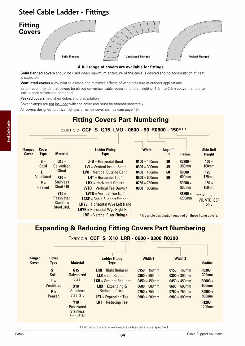
Steel Cable Ladder - Fittings
All dimensions are in millimeters unless otherwise specified.
A full range of covers are available for fittings.Solid flanged covers should be used when maximum enclosure of the cable is desired and no accumulation of heatis expected. Ventilated covers allow heat to escape and minimize effects of wind pressure in outdoor applications.Eaton recommends that covers be placed on vertical cable ladder runs to a height of 1.5m to 2.5m above the floor toisolate both cables and personnel. Peaked covers help shed debris and precipitation.Cover clamps are not included with the cover and must be ordered separately.All covers designed to utilize high performance cover clamps (see page 45).
Solid Flanged Peaked FlangedVentilated Flanged
FittingCovers
Fitting Covers Part NumberingExample: CCF S G15 LVO - 0600 - 90 R0600 - 150***
Flanged Cover Ladder Fitting Width Angle † Side RailCover Type Material Type (°) Radius Height
S = G15 = LHB = Horizontal Bend 0150 = 150mm 30 R0300 = 100 =Solid Galvanized LVI = Vertical Inside Bend 0300 = 300mm 45 300mm 100mmL = Steel LVO = Vertical Outside Bend 0450 = 450mm 60 R0600 = 125 =
Ventilated X10 = LHT = Horizontal Tee † 0600 = 600mm 90 600mm 125mmP = Stainless LHX = Horizontal Cross † 0750 = 750mm R0900 = 150 =
Peaked Steel 316 LVTD = Vertical Tee Down † 0900 = 900mm 900mm 150mmY10 = LVTU = Vertical Tee Up † R1200 = *** Required forPassivated LCSF = Cable Support Fitting † 1200mm VO, VTD, CSFStainless LHYL = Horizontal Wye Left Hand only
Steel 316L LHYR = Horizontal Wye Right HandLVR = Vertical Riser Fitting †
Expanding & Reducing Fitting Covers Part NumberingExample: CCF S X10 LRR - 0600 - 0300 R0300
Flanged Cover Ladder Fitting Width 1 Width 2Cover Type Material Type Radius
S = G15 = LRR = Right Reducer 0150 = 150mm 0150 = 150mm R0300 =Solid Galvanized LLR = Left Reducer 0300 = 300mm 0300 = 300mm 300mmL = Steel LSR = Straight Reducer 0450 = 450mm 0450 = 450mm R0600 =
Ventilated X10 = LRX = Expanding & 0600 = 600mm 0600 = 600mm 600mmP = Stainless Reducing Cross 0750 = 750mm 0750 = 750mm R0900 =
Peaked Steel 316 LET = Expanding Tee 0900 = 900mm 0900 = 900mm 900mmY10 = LRT = Reducing Tee R1200 =
Passivated 1200mmStainlessSteel 316L
† No angle designation required on these fitting covers.
Cable Support SolutionsEaton 64
Steel Cable Ladder

Steel Cable Ladder - Accessories
65Cable Support Solutions Eaton
Steel Cable Ladder
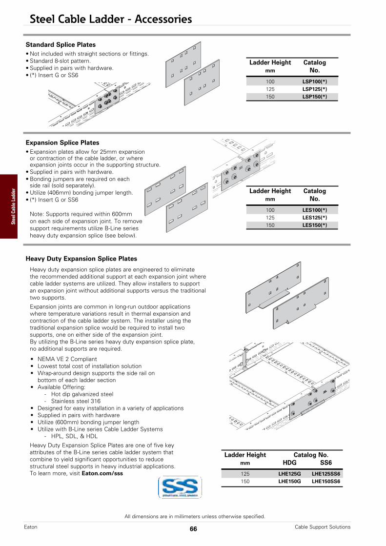
Steel Cable Ladder - Accessories
All dimensions are in millimeters unless otherwise specified.
Expansion Splice Plates• Expansion plates allow for 25mm expansion
or contraction of the cable ladder, or whereexpansion joints occur in the supporting structure.
• Supplied in pairs with hardware.• Bonding jumpers are required on each
side rail (sold separately).• Utilize (406mm) bonding jumper length.• (*) Insert G or SS6
Note: Supports required within 600mmon each side of expansion joint. To removesupport requirements utilize B-Line seriesheavy duty expansion splice (see below).
Standard Splice Plates• Not included with straight sections or fittings.• Standard 8-slot pattern.• Supplied in pairs with hardware.• (*) Insert G or SS6
Ladder Height Catalogmm No.
100 LSP100(*)125 LSP125(*)150 LSP150(*)
Ladder Height Catalogmm No.
100 LES100(*)125 LES125(*)150 LES150(*)
Cable Support SolutionsEaton 66
Steel Cable Ladder
Heavy Duty Expansion Splice Plates
Heavy duty expansion splice plates are engineered to eliminatethe recommended additional support at each expansion joint wherecable ladder systems are utilized. They allow installers to supportan expansion joint without additional supports versus the traditionaltwo supports.
Expansion joints are common in long-run outdoor applicationswhere temperature variations result in thermal expansion andcontraction of the cable ladder system. The installer using thetraditional expansion splice would be required to install twosupports, one on either side of the expansion joint.By utilizing the B-Line series heavy duty expansion splice plate,no additional supports are required.
• NEMA VE 2 Compliant• Lowest total cost of installation solution• Wrap-around design supports the side rail on
bottom of each ladder section• Available Offering:
- Hot dip galvanized steel- Stainless steel 316
• Designed for easy installation in a variety of applications• Supplied in pairs with hardware• Utilize (600mm) bonding jumper length• Utilize with B-Line series Cable Ladder Systems
- HPL, SDL, & HDL
Heavy Duty Expansion Splice Plates are one of five keyattributes of the B-Line series cable ladder system thatcombine to yield significant opportunities to reducestructural steel supports in heavy industrial applications.To learn more, visit Eaton.com/sss
Ladder Height Catalog No.mm HDG SS6
125 LHE125G LHE125SS6150 LHE150G LHE150SS6
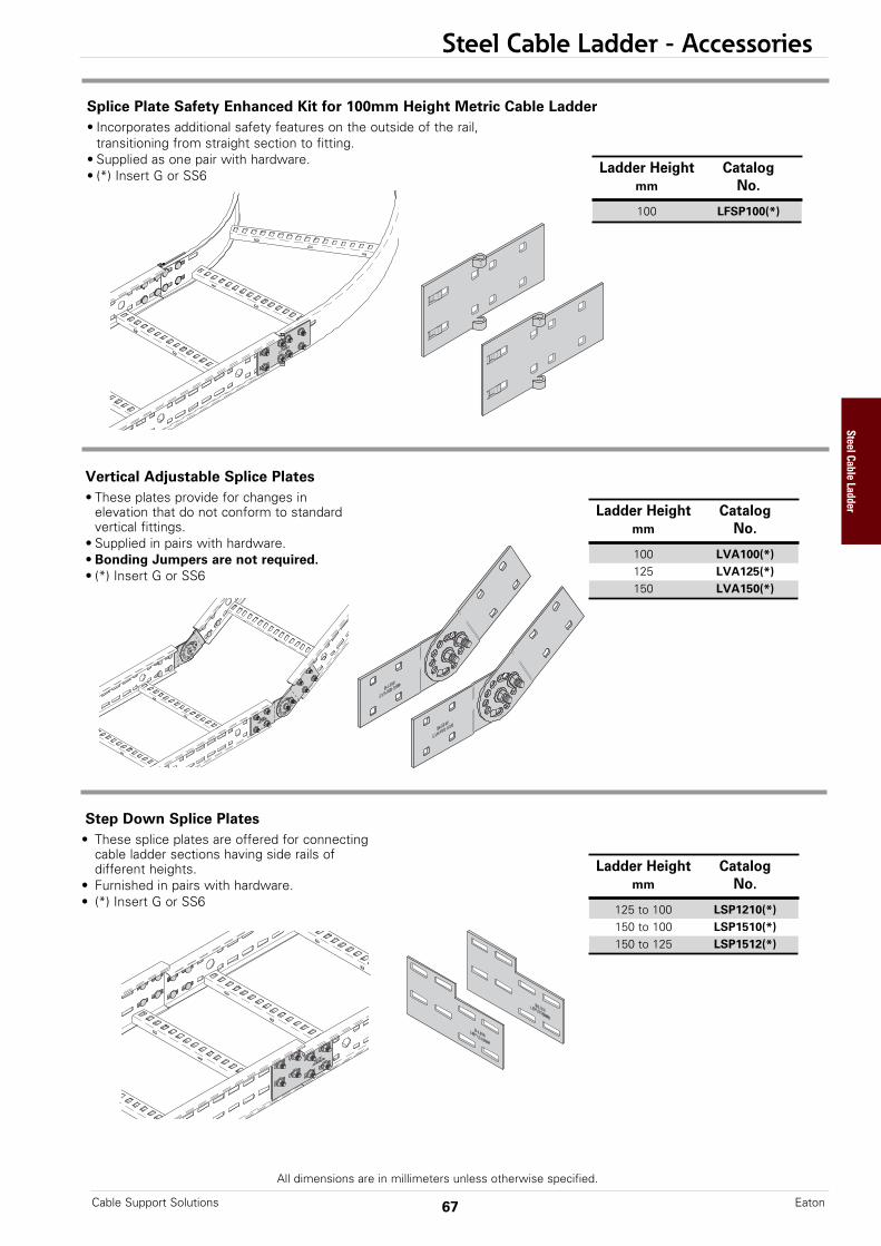
Steel Cable Ladder - Accessories
All dimensions are in millimeters unless otherwise specified.
67Cable Support Solutions Eaton
Step Down Splice Plates• These splice plates are offered for connecting
cable ladder sections having side rails ofdifferent heights.
• Furnished in pairs with hardware. • (*) Insert G or SS6
Ladder Height Catalogmm No.
125 to 100 LSP1210(*)150 to 100 LSP1510(*)150 to 125 LSP1512(*)
Steel Cable Ladder
Vertical Adjustable Splice Plates• These plates provide for changes in
elevation that do not conform to standard vertical fittings.
• Supplied in pairs with hardware.• Bonding Jumpers are not required.• (*) Insert G or SS6
Ladder Height Catalogmm No.
100 LVA100(*)125 LVA125(*)150 LVA150(*)
Splice Plate Safety Enhanced Kit for 100mm Height Metric Cable Ladder• Incorporates additional safety features on the outside of the rail,
transitioning from straight section to fitting.• Supplied as one pair with hardware.• (*) Insert G or SS6 Ladder Height Catalog
mm No.
100 LFSP100(*)
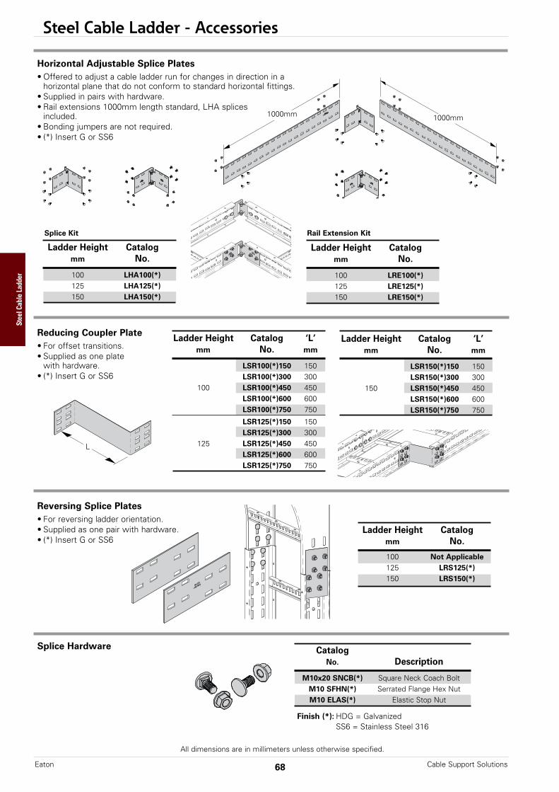
Steel Cable Ladder - Accessories
All dimensions are in millimeters unless otherwise specified.
Cable Support SolutionsEaton 68
Reversing Splice Plates• For reversing ladder orientation.• Supplied as one pair with hardware.• (*) Insert G or SS6
Ladder Height Catalogmm No.
100 Not Applicable125 LRS125(*)150 LRS150(*)
Splice Hardware
Finish (*): HDG = GalvanizedSS6 = Stainless Steel 316
CatalogNo. Description
M10x20 SNCB(*) Square Neck Coach BoltM10 SFHN(*) Serrated Flange Hex NutM10 ELAS(*) Elastic Stop Nut
Steel Cable Ladder
Reducing Coupler Plate• For offset transitions.• Supplied as one plate
with hardware.• (*) Insert G or SS6
L
Ladder Height Catalog ‘L’mm No. mm
LSR100(*)150 150LSR100(*)300 300
100 LSR100(*)450 450LSR100(*)600 600LSR100(*)750 750
LSR125(*)150 150LSR125(*)300 300
125 LSR125(*)450 450LSR125(*)600 600LSR125(*)750 750
Ladder Height Catalog ‘L’mm No. mm
LSR150(*)150 150LSR150(*)300 300
150 LSR150(*)450 450LSR150(*)600 600LSR150(*)750 750
Horizontal Adjustable Splice Plates• Offered to adjust a cable ladder run for changes in direction in a
horizontal plane that do not conform to standard horizontal fittings.• Supplied in pairs with hardware.• Rail extensions 1000mm length standard, LHA splices
included.• Bonding jumpers are not required.• (*) Insert G or SS6
Splice Kit Rail Extension Kit
1000mm1000mm
Ladder Height Catalogmm No.
100 LHA100(*)125 LHA125(*)150 LHA150(*)
Ladder Height Catalogmm No.
100 LRE100(*)125 LRE125(*)150 LRE150(*)

Steel Cable Ladder - Accessories
All dimensions are in millimeters unless otherwise specified.
69Cable Support Solutions Eaton
Tee/Wall Connector• For field connecting ladder to a wall
or to another ladder as a tee.• Supplied in pairs with hardware.• (*) Insert G or SS6
Bonding JumperUse at each expansion splice and where the cable ladder is not mechanically/electrically continuous to ground. • Sold individually. • Hardware included.
Ladder Drop-Out• Specially-designed Ladder Drop-Outs provide a rounded surface with 100mm radius to protect cable as it
exits from the cable ladder, preventing damage to insulation. The drop-out will attach to any desired rung.• Supplied with hardware.• (*) Insert G or SS6 Catalog Ladder Width
No. mm
LDO(*)150 150LDO(*)300 300LDO(*)450 450LDO(*)600 600LDO(*)750 750LDO(*)900 900
Catalog Length Copper Ampacity ExpansionNo. mm Wire Type
99-N1 406 9 Strands #1 600 Standard
99-N1-600 600 9 Strands #1 600 Heavy Duty
Ladder Height Catalogmm No.
100 LTC100(*)125 LTC125(*)150 LTC150(*)
LTC125
LTC150
LTC100
Threaded Rod (ATR) & Rod CouplingLoading based on safety factor 5.
See B-Line series Strut Systems Catalog for other size and finish options.
Catalog No. Threads Recommended Load Wt./30.5m& Size Size kN kg
ATR M6 M6 1.32 6.1
ATR M8 M8 2.42 10.7
ATR M10 M10 3.66 15.3
ATR M12 M12 5.35 24.4
Steel Cable Ladder

Steel Cable Ladder - Accessories
All dimensions are in millimeters unless otherwise specified.
Cable Support SolutionsEaton 70
Cable Ladder Clamp/Guide - SDL & HDL Series• Features a no-twist design.• Has four times the strength of the traditional design. • Each side is labelled to ensure proper installation.• Supplied in pairs without hardware.• (*) Insert G or SS6
Installed asa clamp.
Installed asa guide.
Blind End• For finished look to end of ladder.• Supplied as one plate with hardware.• (*) Insert G or SS6
L
Ladder Ht. Catalog ‘L’mm No. mm
LBE100(*)150 150LBE100(*)300 300
100LBE100(*)450 450LBE100(*)600 600LBE100(*)750 750LBE100(*)900 900
LBE125(*)150 150LBE125(*)300 300
125LBE125(*)450 450LBE125(*)600 600LBE125(*)750 750LBE125(*)900 900LBE150(*)150 150LBE150(*)300 300
150LBE150(*)450 450LBE150(*)600 600LBE150(*)750 750LBE150(*)900 900
Catalog No. Overall HardwareLength Size
9(*)-1204 38mm M6
9(*)-1208 57mm M10
9(*)-1205 57mm M12
End Cap for Metric Cable Ladder• Increased safety features for cable ladder end runs.• Blind end sold separately.• Supplied as one end cap with hardware.• (*) Insert G or SS6 Ladder Height Ladder Width Catalog
mm mm No.
150 LEC(**)(*)150WO(**) 300 LEC(**)(*)300WO100 450 LEC(**)(*)450WO125 600 LEC(**)(*)600WO150 750 LEC(**)(*)750WO
900 LEC(**)(*)900WO
Steel Cable Ladder

Steel Cable Ladder - Accessories
All dimensions are in millimeters unless otherwise specified.
71Cable Support Solutions Eaton
Cable Ladder Clamp/Guide - HPL Series• Improves system performance• Both LHD-121X and LHD-123X are sold in pairs
LHD-121X - requires mounting hardware (not included)LHD-123X includes side rail attachment hardware - requires mounting hardware (not included)
• Material: SS6• Thickness: 6mm• Patent Pending
Catalog No. Description Side Rail Mtg. Hardware Mounting Hardware Side Rail Heights
LHD-121X 1-Hole Hold Down Plate None Required (1) M12 bolt 100, 125, 150
Catalog No, Description Side Rail Mtg. Hardware Mounting Hardware Side Rail Heights
LHD-123X 3-Hole Hold Down Clamp Includes (2) M10 SNCB & SFHN (1) M12 bolt 125, 150
7062 16
13 x 53
125
58.7
90 72.9
11.2 x 11.6
13 x 63
100
90° Hold Down Bracket Kit for 100mm Height Metric Cable Ladder• Supplied as one pair with side rail attachment hardware.• Requires mounting hardware - not included.• (*) Insert G or SS6
Ladder Height Catalogmm No.
100 LHD100(*)
Steel Cable Ladder
LHD-123XNS is also available which excludes bottom rail support tab.
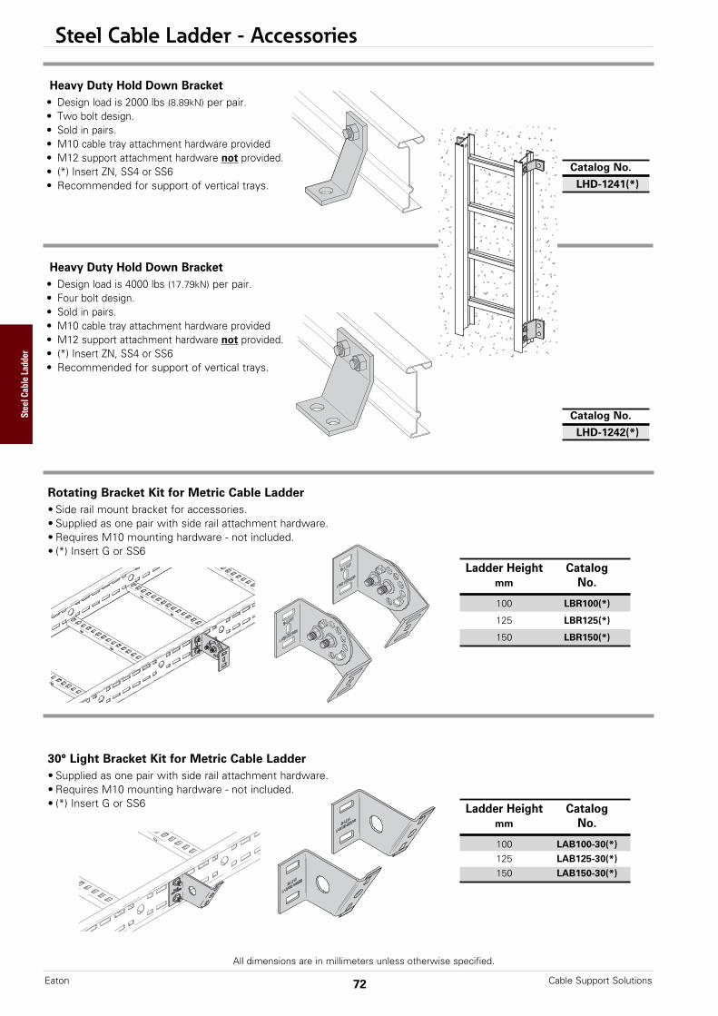
Steel Cable Ladder - Accessories
All dimensions are in millimeters unless otherwise specified.
Cable Support SolutionsEaton 72
Rotating Bracket Kit for Metric Cable Ladder• Side rail mount bracket for accessories.• Supplied as one pair with side rail attachment hardware.• Requires M10 mounting hardware - not included.• (*) Insert G or SS6
Ladder Height Catalogmm No.
100 LBR100(*)
125 LBR125(*)
150 LBR150(*)
30° Light Bracket Kit for Metric Cable Ladder• Supplied as one pair with side rail attachment hardware.• Requires M10 mounting hardware - not included.• (*) Insert G or SS6 Ladder Height Catalog
mm No.
100 LAB100-30(*)
125 LAB125-30(*)
150 LAB150-30(*)
Heavy Duty Hold Down Bracket• Design load is 2000 lbs (8.89kN) per pair.• Two bolt design.• Sold in pairs.• M10 cable tray attachment hardware provided• M12 support attachment hardware not provided.• (*) Insert ZN, SS4 or SS6• Recommended for support of vertical trays.
Catalog No.
LHD-1241(*)
Heavy Duty Hold Down Bracket• Design load is 4000 lbs (17.79kN) per pair.• Four bolt design.• Sold in pairs.• M10 cable tray attachment hardware provided• M12 support attachment hardware not provided.• (*) Insert ZN, SS4 or SS6• Recommended for support of vertical trays.
Catalog No.
LHD-1242(*)
Steel Cable Ladder
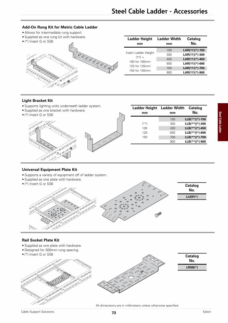
Steel Cable Ladder - Accessories
All dimensions are in millimeters unless otherwise specified.
73Cable Support Solutions Eaton
Universal Equipment Plate Kit• Supports a variety of equipment off of ladder system.• Supplied as one plate with hardware.• (*) Insert G or SS6 Catalog
No.
LUEP(*)
Ladder Height Ladder Width Catalogmm mm No.
150 LLB(**)(*)-150(**) 300 LLB(**)(*)-300100 450 LLB(**)(*)-450125 600 LLB(**)(*)-600150 750 LLB(**)(*)-750
900 LLB(**)(*)-900
Light Bracket Kit• Supports lighting units underneath ladder system.• Supplied as one bracket with hardware.• (*) Insert G or SS6
Add-On Rung Kit for Metric Cable Ladder• Allows for intermediate rung support.• Supplied as one rung kit with hardware.• (*) Insert G or SS6
Ladder Height Ladder Width Catalogmm mm No.
150 LAR(††)(*)-150Insert Ladder Height
300 LAR(††)(*)-300(††) =
450 LAR(††)(*)-450100 for 100mm
600 LAR(††)(*)-600125 for 125mm
750 LAR(††)(*)-750150 for 150mm
900 LAR(††)(*)-900
Rail Socket Plate Kit • Supplied as one plate with hardware.• Designed for 300mm rung spacing.• (*) Insert G or SS6 Catalog
No.
LRSB(*)
Steel Cable Ladder
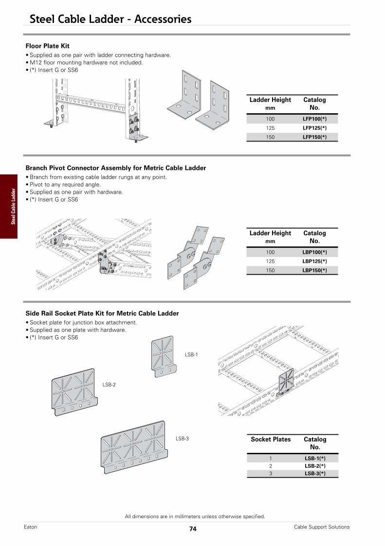
Steel Cable Ladder - Accessories
All dimensions are in millimeters unless otherwise specified.
Cable Support SolutionsEaton 74
Side Rail Socket Plate Kit for Metric Cable Ladder• Socket plate for junction box attachment.• Supplied as one plate with hardware.• (*) Insert G or SS6
Socket Plates CatalogNo.
1 LSB-1(*)2 LSB-2(*)3 LSB-3(*)
Branch Pivot Connector Assembly for Metric Cable Ladder• Branch from existing cable ladder rungs at any point.• Pivot to any required angle.• Supplied as one pair with hardware.• (*) Insert G or SS6
Ladder Height Catalogmm No.
100 LBP100(*)
125 LBP125(*)
150 LBP150(*)
LSB-1
LSB-2
LSB-3
Floor Plate Kit • Supplied as one pair with ladder connecting hardware.• M12 floor mounting hardware not included.• (*) Insert G or SS6
Ladder Height Catalogmm No.
100 LFP100(*)
125 LFP125(*)
150 LFP150(*)
Steel Cable Ladder
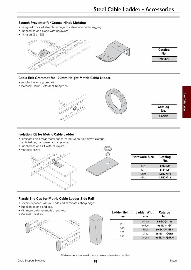
Steel Cable Ladder - Accessories
All dimensions are in millimeters unless otherwise specified.
75Cable Support Solutions Eaton
Hardware Size CatalogNo.
M6 LEIK-M6M8 LEIK-M8M10 LEIK-M10M12 LEIK-M12
Isolation Kit for Metric Cable Ladder• Eliminates dissimilar metal concerns between hold down clamps,
cable ladder, hardware, and supports.• Supplied as one kit with hardware.• Material: HDPE
Stretch Preventer for Crouse Hinds Lighting• Designed to avoid stretch damage to cables and cable sagging.• Supplied as one piece with hardware.• (*) Insert G or SS6
CatalogNo.
SPSS6-CH
Cable Exit Grommet for 100mm Height Metric Cable Ladder• Supplied as one grommet.• Material: Flame Retardent Neoprene
CatalogNo.
99-GEP
Plastic End Cap for Metric Cable Ladder Side Rail• Covers exposed side rail ends and eliminates sharp edges.• Supplied as one end cap.• Minimum order quantities required.• Material: Plastisol Ladder Height Ladder Width Catalog
mm mm No.
White 99-EC-(**)W(**) Yellow 99-EC-(**)Y100 Black 99-EC-(**)BLK125 Gray 99-EC-(**)GRY150 Green 99-EC-(**)GRN
Steel Cable Ladder
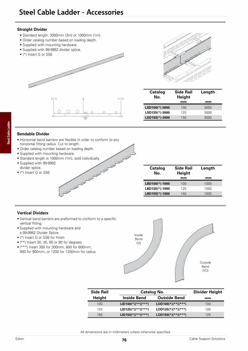
Steel Cable Ladder - Accessories
All dimensions are in millimeters unless otherwise specified.
Cable Support SolutionsEaton 76
Straight Divider• Standard length: 3000mm (3m) or 1000mm (1m).• Order catalog number based on loading depth.• Supplied with mounting hardware.• Supplied with 99-9982 divider splice.• (*) Insert G or SS6
Catalog Side Rail LengthNo. Height
mm mm
LSD100(*)-3000 100 3000LSD125(*)-3000 125 3000LSD150(*)-3000 150 3000
Bendable Divider • Horizontal bend barriers are flexible in order to conform to any
horizontal fitting radius. Cut to length.• Order catalog number based on loading depth.• Supplied with mounting hardware.• Standard length is 1000mm (1m), sold individually.• Supplied with 99-9982
divider splice.• (*) Insert G or SS6
Catalog Side Rail LengthNo. Height
mm mm
LBD100(*)-1000 100 1000LBD125(*)-1000 125 1000LBD150(*)-1000 150 1000
Vertical Dividers• Vertical bend barriers are preformed to conform to a specific
vertical fitting.• Supplied with mounting hardware and
a 99-9982 Divider Splice.• (*) Insert G or SS6 for finish• (**) Insert 30, 45, 60 or 90 for degrees• (***) Insert 300 for 300mm, 600 for 600mm,
900 for 900mm, or 1200 for 1200mm for radius
Outside Bend(VO)
Inside Bend(VI)
Side Rail Catalog No. Divider HeightHeight Inside Bend Outside Bend mm
100 LID100(*)(**)(***) LOD100(*)(**)(***) 100
125 LID125(*)(**)(***) LOD125(*)(**)(***) 100
150 LID150(*)(**)(***) LOD150(*)(**)(***) 125
Steel Cable Ladder
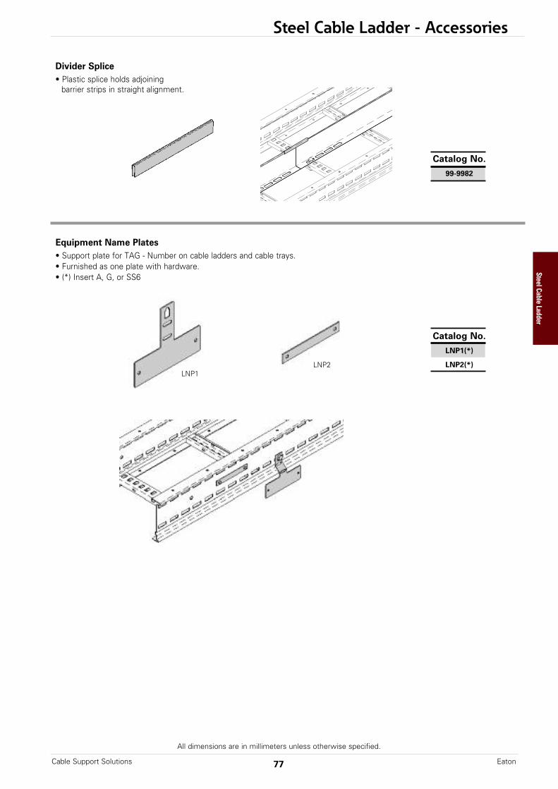
Steel Cable Ladder - Accessories
All dimensions are in millimeters unless otherwise specified.
77Cable Support Solutions Eaton
Divider Splice• Plastic splice holds adjoining
barrier strips in straight alignment.
Catalog No.
99-9982
Equipment Name Plates• Support plate for TAG - Number on cable ladders and cable trays.• Furnished as one plate with hardware.• (*) Insert A, G, or SS6
Catalog No.
LNP1(*)
LNP2(*)LNP2LNP1
Steel Cable Ladder
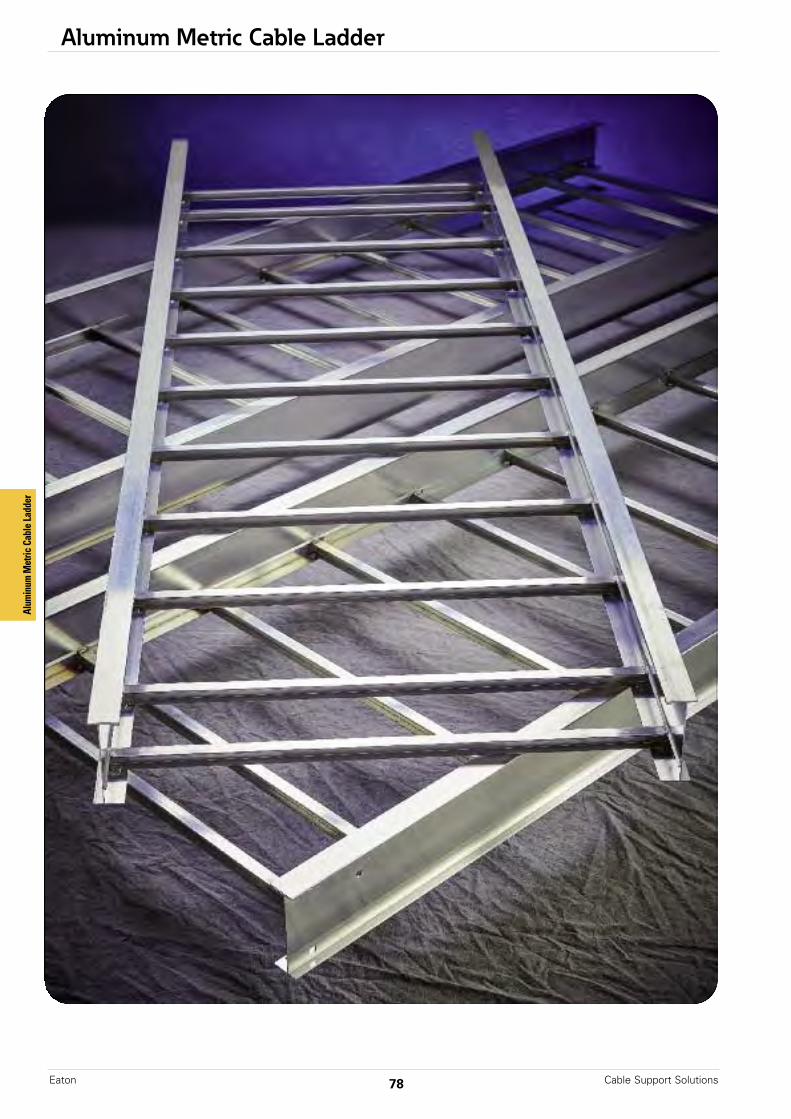
Aluminum Metric Cable Ladder
Cable Support SolutionsEaton 78
Alum
inum
Metric Cable La
dder
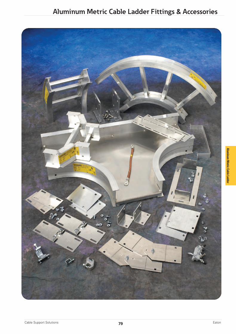
79
Aluminum Metric Cable Ladder Fittings & Accessories
Cable Support Solutions Eaton
Aluminum
Metric Cable Ladder
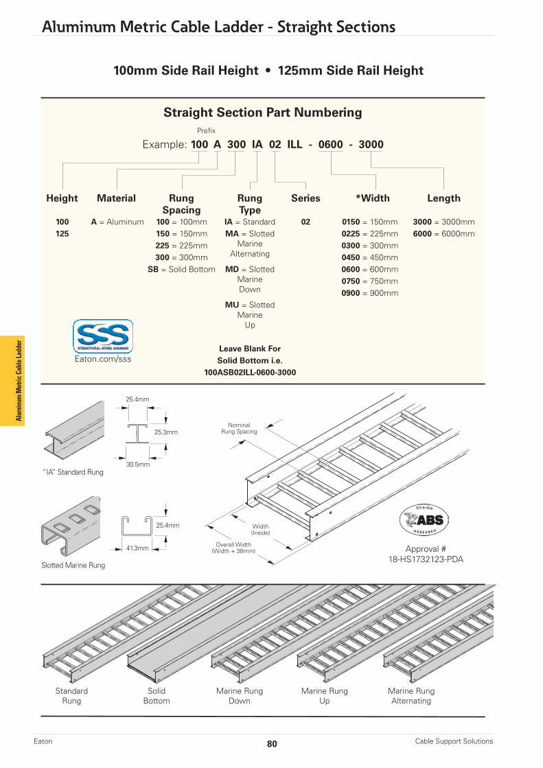
Aluminum Metric Cable Ladder - Straight Sections
Cable Support SolutionsEaton 80
100mm Side Rail Height • 125mm Side Rail Height
StandardRung
SolidBottom
Marine RungDown
Marine RungUp
Marine RungAlternating
Straight Section Part Numbering Prefix
Example: 100 A 300 IA 02 ILL - 0600 - 3000
Height Material Rung Rung Series *Width Length Spacing Type 100 A = Aluminum 100 = 100mm IA = Standard 02 0150 = 150mm 3000 = 3000mm 125 150 = 150mm MA = Slotted 0225 = 225mm 6000 = 6000mm 225 = 225mm Marine 0300 = 300mm 300 = 300mm Alternating 0450 = 450mm SB = Solid Bottom MD = Slotted 0600 = 600mm Marine 0750 = 750mm Down 0900 = 900mm MU = Slotted Marine Up
Leave Blank For Solid Bottom i.e. 100ASB02ILL-0600-3000
NominalRung Spacing
Overall Width(Width + 38mm)
Width(Inside)
Alum
inum
Met
ric C
able
Ladd
er
Approval #18-HS1732123-PDA
“IA” Standard Rung
Slotted Marine Rung
25.4mm
25.4mm
25.3mm
30.5mm
41.3mm
Eaton.com/sss

81
Aluminum Metric Cable Ladder - Straight Sections
Cable Support Solutions Eaton
NEMA values are based on simple beam tests per NEMA VE 1 on 900mm wide cable tray with rungs spaced on 300mm centers. Cable trays will support without collapse a 90.7 kg (200 lb.) concentrated load over and above published loads.Published load safety factor is 1.5. IEC values are based on continuous beam tests per IEC 61537 on 900mm wide cable tray with rungs spaced on 300mm centers. Cable trays will support without collapse a 90.7 kg (200 lb.) concentrated load over and above published loads.Published load safety factor is 1.7.
Individual rungs will support without collapse a 90.7 kg (200 lb.) concentrated load applied at the mid-span of the rung,over and above the NEMA rated cable load with a 1.5 safety factor for highlighted NEMA spans and loads.
100mm Side Rail Height
When trays are used in continuous spans, the deflection of the tray is reduced by as much as 50%. Design factors: Ix = Momentof Inertia, Sx = Section Modulus.
B-Line Side Rail NEMA, CSA & UL Span NEMA Load IEC Load Design Factors Series Dimensions Classifications meters kg/m kg/m for Two Rails
3.0 277 282
NEMA: 16A, 12C 4.0 155 209 Area = 6.77 cm2
UL Cross-Sectional 5.0 99 138 Sx = 21.96 cm3
Area: 1.00 in2 6.0 69 67 Ix = 118.63 cm4
44.5
104.677.502
NEMA values are based on simple beam tests per NEMA VE 1 on 900mm wide cable tray with rungs spaced on 300mm centers. Cable trays will support without collapse a 90.7 kg (200 lb.) concentrated load over and above published loads.Published load safety factor is 1.5. IEC values are based on continuous beam tests per IEC 61537 on 900mm wide cable tray with rungs spaced on 300mm centers. Cable trays will support without collapse a 90.7 kg (200 lb.) concentrated load over and above published loads.Published load safety factor is 1.7.
Individual rungs will support without collapse a 90.7 kg (200 lb.) concentrated load applied at the mid-span of the rung,over and above the NEMA rated cable load with a 1.5 safety factor for highlighted NEMA spans and loads.
125mm Side Rail Height
When trays are used in continuous spans, the deflection of the tray is reduced by as much as 50%. Design factors: Ix = Momentof Inertia, Sx = Section Modulus.
B-Line Side Rail NEMA, CSA & UL Span NEMA Load IEC Load Design Factors Series Dimensions Classifications meters kg/m kg/m for Two Rails
3.0 268 381
NEMA: 20A, 12C 4.0 150 284 Area = 8.00 cm2
UL Cross-Sectional 5.0 96 187 Sx = 29.50 cm3
Area: 1.00 in2 6.0 67 91 Ix = 192.30 cm4
44.5
127.099.802
Aluminum
Metric Cable Ladder
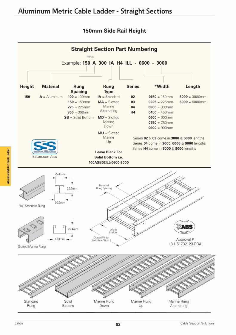
Aluminum Metric Cable Ladder - Straight Sections
Cable Support SolutionsEaton 82
150mm Side Rail Height
Alum
inum
Met
ric C
able
Ladd
er
Straight Section Part Numbering Prefix
Example: 150 A 300 IA H4 ILL - 0600 - 3000
Height Material Rung Rung Series *Width Length Spacing Type 150 A = Aluminum 100 = 100mm IA = Standard 02 0150 = 150mm 3000 = 3000mm 150 = 150mm MA = Slotted 03 0225 = 225mm 6000 = 6000mm 225 = 225mm Marine 04 0300 = 300mm 300 = 300mm Alternating H4 0450 = 450mm SB = Solid Bottom MD = Slotted 0600 = 600mm Marine 0750 = 750mm Down 0900 = 900mm MU = Slotted Marine Series 02 & 03 come in 3000 & 6000 lengths Up Series 04 come in 3000, 6000 & 9000 lengths Series H4 come in 6000 & 9000 lengths Leave Blank For Solid Bottom i.e. 100ASB02ILL-0600-3000
StandardRung
SolidBottom
Marine RungDown
Marine RungUp
Marine RungAlternating
NominalRung Spacing
Overall Width(Width + 38mm)
Width(Inside)
Approval #18-HS1732123-PDA
“IA” Standard Rung
Slotted Marine Rung
25.4mm
25.4mm
25.3mm
30.5mm
41.3mm
Eaton.com/sss

83
Aluminum Metric Cable Ladder - Straight Sections
Cable Support Solutions Eaton
NEMA values are based on simple beam tests per NEMA VE 1 on 900mm wide cable tray with rungs spaced on 300mm centers. Cable trays will support without collapse a 90.7 kg (200 lb.) concentrated load over and above published loads.Published load safety factor is 1.5. IEC values are based on continuous beam tests per IEC 61537 on 900mm wide cable tray with rungs spaced on 300mm centers. Cable trays will support without collapse a 90.7 kg (200 lb.) concentrated load over and above published loads.Published load safety factor is 1.7.
Individual rungs will support without collapse a 90.7 kg (200 lb.) concentrated load applied at the mid-span of the rung,over and above the NEMA rated cable load with a 1.5 safety factor for highlighted NEMA spans and loads.
150mm Side Rail Height
When trays are used in continuous spans, the deflection of the tray is reduced by as much as 50%. Design factors: Ix = Momentof Inertia, Sx = Section Modulus.
B-Line Side Rail NEMA, CSA & UL Span NEMA Load IEC Load Design Factors Series Dimensions Classifications meters kg/m kg/m for Two Rails
3.0 268 431
NEMA: 20A, 16B 4.0 150 321 Area = 9.10 cm2
UL Cross-Sectional 5.0 96 211 Sx = 41.46 cm3
Area: 1.00 in2 6.0 67 101 Ix = 329.45 cm4
50.8
155.4128.002
B-Line Side Rail NEMA, CSA & UL Span NEMA Load IEC Load Design Factors Series Dimensions Classifications meters kg/m kg/m for Two Rails
3.0 447 525
NEMA: 20B, 16C 4.0 252 406 Area = 11.68 cm2
UL Cross-Sectional 5.0 161 288 Sx = 55.06 cm3
Area: 1.50 in2 6.0 112 170 Ix = 451.61 cm4
50.8
156.7128.503
B-Line Side Rail NEMA, CSA & UL Span NEMA Load IEC Load Design Factors Series Dimensions Classifications meters kg/m kg/m for Two Rails
6.0 174 170
NEMA: 20C 7.0 102 138 Area = 13.29 cm2
UL Cross-Sectional 8.0 78 105 Sx = 55.83 cm3
Area: 1.50 in2 9.0 62 75 Ix = 506.97 cm4
50.8
157.2129.004
B-Line Side Rail NEMA, CSA & UL Span NEMA Load IEC Load Design Factors Series Dimensions Classifications meters kg/m kg/m for Two Rails
6.0 263 306
NEMA: 20C+ 7.0 167 241 Area = 19.03 cm2
UL Cross-Sectional 8.0 128 175 Sx = 87.34 cm3
Area: 2.00 in2 9.0 101 111 Ix = 720.08 cm4
50.8
158.5129.3H4
Aluminum
Metric Cable Ladder

Aluminum Metric Cable Ladder - Straight Sections
Cable Support SolutionsEaton 84
175mm Side Rail Height
Alum
inum
Met
ric C
able
Ladd
er
Straight Section Part Numbering Prefix
Example: 175 A 300 IA 05 ILL - 0750 - 3000
Height Material Rung Rung Series *Width Length Spacing Type 175 A = Aluminum 100 = 100mm IA = Standard 02 0150 = 150mm 3000 = 3000mm 150 = 150mm MA = Slotted 03 0225 = 225mm 6000 = 6000mm 225 = 225mm Marine 05 0300 = 300mm 9000 = 9000mm 300 = 300mm Alternating 0450 = 450mm SB = Solid Bottom MD = Slotted 0600 = 600mm Marine 0750 = 750mm Down 0900 = 900mm MU = Slotted Marine Series 02 & 03 come in 3000 & 6000 lengths Up Series 05 come in 6000 & 9000 lengths Leave Blank For Solid Bottom i.e. 100ASB02ILL-0600-3000
StandardRung
SolidBottom
Marine RungDown
Marine RungUp
Marine RungAlternating
NominalRung Spacing
Overall Width(Width + 38mm)
Width(Inside)
Approval #18-HS1732123-PDA
“IA” Standard Rung
Slotted Marine Rung
25.4mm
25.4mm
25.3mm
30.5mm
41.3mm
Eaton.com/sss
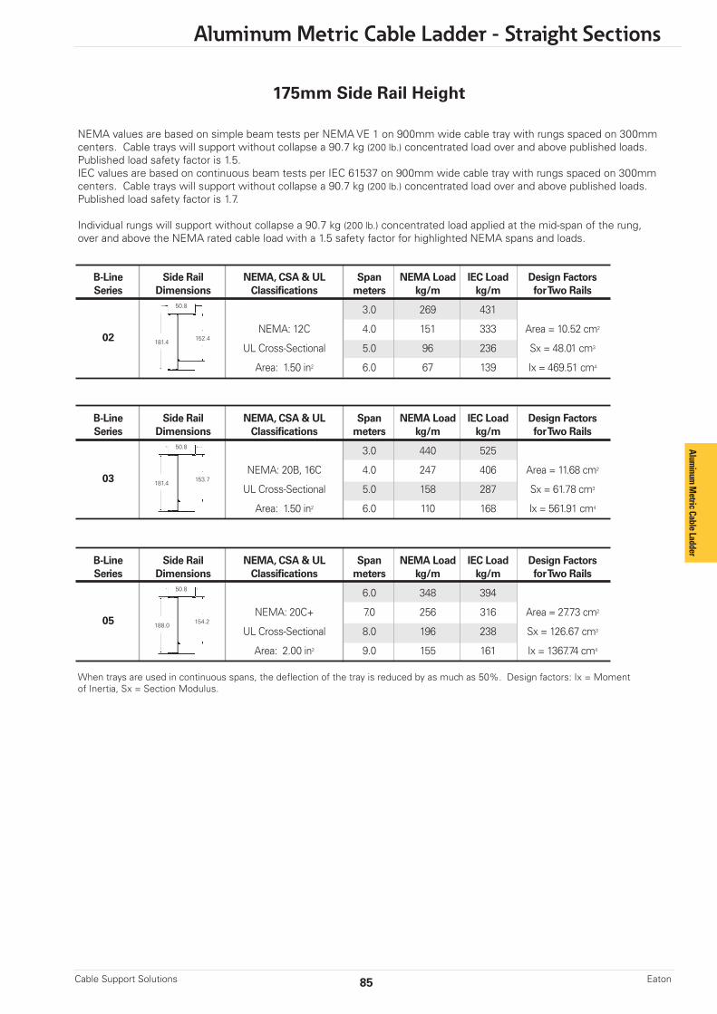
85
Aluminum Metric Cable Ladder - Straight Sections
Cable Support Solutions Eaton
NEMA values are based on simple beam tests per NEMA VE 1 on 900mm wide cable tray with rungs spaced on 300mm centers. Cable trays will support without collapse a 90.7 kg (200 lb.) concentrated load over and above published loads.Published load safety factor is 1.5. IEC values are based on continuous beam tests per IEC 61537 on 900mm wide cable tray with rungs spaced on 300mm centers. Cable trays will support without collapse a 90.7 kg (200 lb.) concentrated load over and above published loads.Published load safety factor is 1.7.
Individual rungs will support without collapse a 90.7 kg (200 lb.) concentrated load applied at the mid-span of the rung,over and above the NEMA rated cable load with a 1.5 safety factor for highlighted NEMA spans and loads.
When trays are used in continuous spans, the deflection of the tray is reduced by as much as 50%. Design factors: Ix = Momentof Inertia, Sx = Section Modulus.
B-Line Side Rail NEMA, CSA & UL Span NEMA Load IEC Load Design Factors Series Dimensions Classifications meters kg/m kg/m for Two Rails
3.0 269 431
NEMA: 12C 4.0 151 333 Area = 10.52 cm2
UL Cross-Sectional 5.0 96 236 Sx = 48.01 cm3
Area: 1.50 in2 6.0 67 139 Ix = 469.51 cm4
50.8
181.4152.402
B-Line Side Rail NEMA, CSA & UL Span NEMA Load IEC Load Design Factors Series Dimensions Classifications meters kg/m kg/m for Two Rails
3.0 440 525
NEMA: 20B, 16C 4.0 247 406 Area = 11.68 cm2
UL Cross-Sectional 5.0 158 287 Sx = 61.78 cm3
Area: 1.50 in2 6.0 110 168 Ix = 561.91 cm4
50.8
181.4153.703
B-Line Side Rail NEMA, CSA & UL Span NEMA Load IEC Load Design Factors Series Dimensions Classifications meters kg/m kg/m for Two Rails
6.0 348 394
NEMA: 20C+ 7.0 256 316 Area = 27.73 cm2
UL Cross-Sectional 8.0 196 238 Sx = 126.67 cm3
Area: 2.00 in2 9.0 155 161 Ix = 1367.74 cm4
50.8
188.0154.205
175mm Side Rail Height
Aluminum
Metric Cable Ladder

Aluminum Metric Cable Ladder - Straight Section Covers
Cable Support SolutionsEaton 86
Aluminum Cover Part Numbering Prefix
Example: CIF S A 15 LL - 0300 - 3000
Ladder Flanged Cover Material Straight Cover Type Material Thickness Section Width Length *
S = Solid A = Aluminum 10 = 10mm 0150 = 150mm 1500 = 1500mm L = Ventilated 15 = 15mm 0225 = 225mm 3000 = 3000mm P = Peaked 20 = 20mm 0300 = 300mm 0450 = 450mm 0600 = 600mm 0750 = 750mm 0900 = 900mm
A full range of covers is available for straight sections and fittings.Solid covers should be used when maximum enclosure of the cable is desired and no accumulation of heat is expected.
Ventilated covers allow heat to escape.
Eaton recommends that covers be placed on vertical cable ladder runs to a height of 1.5m to 2.5m above the floor to isolate both cables and personnel.
Cover clamps are not included with the cover and must be ordered separately.
Solid Flanged Ventilated Flanged Peaked Flanged
Covers
Examples of Catalog Numbers for Fitting Covers:
Vertical Bend Cover Prefix Suffix
CCF S A 15 LVO - 0600 - 90 R0300 - 150*Side Rail* HeightRadiusAngleWidthFittingThicknessMaterialCover TypeCover
Horizontal Bend Cover Prefix Suffix
CCF S A 15 LHB - 0600 - 90 R0300
RadiusAngleWidthFittingThicknessMaterialCover TypeCover
* Required for VO, VTD, & CSF fittings only
Alum
inum
Met
ric C
able
Ladd
er
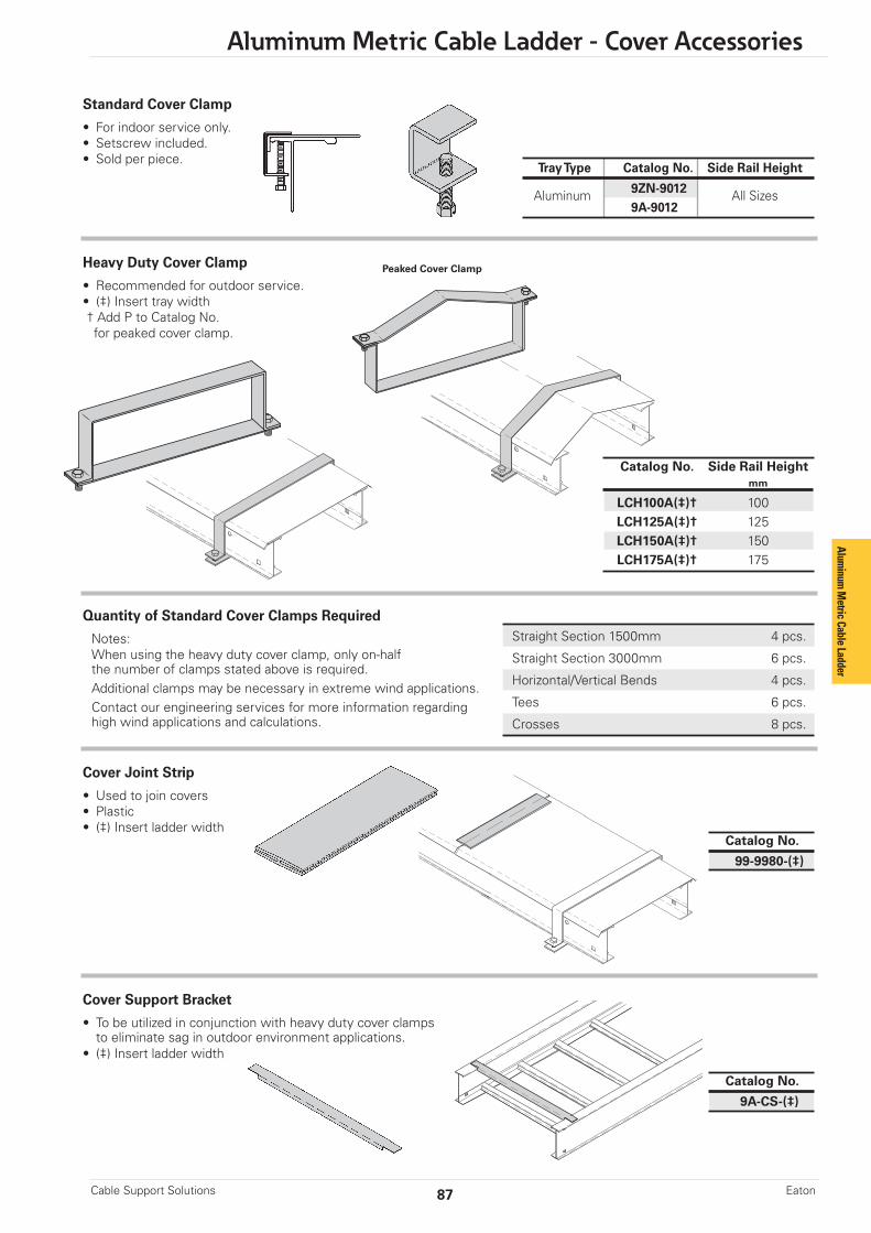
87
Aluminum Metric Cable Ladder - Cover Accessories
Cable Support Solutions Eaton
Straight Section 1500mm 4 pcs.
Straight Section 3000mm 6 pcs.
Horizontal/Vertical Bends 4 pcs.
Tees 6 pcs.
Crosses 8 pcs.
Peaked Cover Clamp
Standard Cover Clamp
• For indoor service only.• Setscrew included.• Sold per piece.
Quantity of Standard Cover Clamps Required
Notes: When using the heavy duty cover clamp, only on-halfthe number of clamps stated above is required.Additional clamps may be necessary in extreme wind applications.Contact our engineering services for more information regardinghigh wind applications and calculations.
Heavy Duty Cover Clamp
• Recommended for outdoor service.• (‡) Insert tray width† Add P to Catalog No.for peaked cover clamp.
Cover Joint Strip
• Used to join covers• Plastic• (‡) Insert ladder width
Tray Type Catalog No. Side Rail Height
Aluminum 9ZN-9012 All Sizes 9A-9012
Catalog No.
99-9980-(‡)
Cover Support Bracket
• To be utilized in conjunction with heavy duty cover clamps to eliminate sag in outdoor environment applications.• (‡) Insert ladder width
Catalog No.
9A-CS-(‡)
Catalog No. Side Rail Height mm
LCH100A(‡)† 100 LCH125A(‡)† 125 LCH150A(‡)† 150 LCH175A(‡)† 175
Aluminum
Metric Cable Ladder
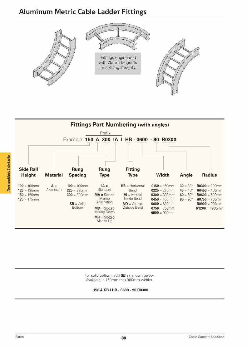
Aluminum Metric Cable Ladder Fittings
Cable Support SolutionsEaton 88
Fittings Part Numbering (with angles)
Prefix
Example: 150 A 300 IA I HB - 0600 - 90 R0300
Side Rail Rung Rung FittingHeight Material Spacing Type Type Width Angle Radius
100 = 100mm A = 100 = 100mm IA = HB = Horizontal 0150 = 150mm 30 = 30° R0300 = 300mm125 = 125mm Aluminum 225 = 225mm Standard Bend 0225 = 225mm 45 = 45° R0450 = 450mm150 = 150mm 300 = 300mm MA = Slotted VI = Vertical 0300 = 300mm 60 = 60° R0600 = 600mm175 = 175mm Marine Inside Bend 0450 = 450mm 90 = 90° R0750 = 750mm
SB = Solid Alternating VO = Vertical 0600 = 600mm R0900 = 900mmBottom MD = Slotted Outside Bend 0750 = 750mm R1200 = 1200mm
Marine Down 0900 = 900mmMU = SlottedMarine Up
For solid bottom, add SB as shown below.Available in 150mm thru 900mm widths.
150 A SB I HB - 0600 - 90 R0300
Fittings engineeredwith 75mm tangentsfor splicing integrity.
Alum
inum
Met
ric C
able
Ladd
er

89
Aluminum Metric Cable Ladder Fittings
Cable Support Solutions Eaton
Bend Tray 90˚ Horizontal Bend 60˚ Horizontal Bend Radius Width Dimensions Dimensions R Catalog No. A B C Catalog No. A B C mm mm mm mm mm mm mm mm
150 (Pre)HB-0150-90R0300 450 450 450 (Pre)HB-0150-60R0300 437 252 292 225 (Pre)HB-0225-90R0300 488 488 488 (Pre)HB-0225-60R0300 470 271 313 300 (Pre)HB-0300-90R0300 525 525 525 (Pre)HB-0300-60R0300 502 290 335 300 450 (Pre)HB-0450-90R0300 600 600 600 (Pre)HB-0450-60R0300 567 327 378 600 (Pre)HB-0600-90R0300 675 675 675 (Pre)HB-0600-60R0300 632 365 421 750 (Pre)HB-0750-90R0300 750 750 750 (Pre)HB-0750-60R0300 697 402 465 900 (Pre)HB-0900-90R0300 825 825 825 (Pre)HB-0900-60R0300 762 440 508 150 (Pre)HB-0150-90R0600 750 750 750 (Pre)HB-0150-60R0600 697 402 465 225 (Pre)HB-0225-90R0600 788 788 788 (Pre)HB-0225-60R0600 730 421 486 300 (Pre)HB-0300-90R0600 825 825 825 (Pre)HB-0300-60R0600 762 440 508 600 450 (Pre)HB-0450-90R0600 900 900 900 (Pre)HB-0450-60R0600 827 477 551 600 (Pre)HB-0600-90R0600 975 975 975 (Pre)HB-0600-60R0600 892 515 595 750 (Pre)HB-0750-90R0600 1050 1050 1050 (Pre)HB-0750-60R0600 957 552 638 900 (Pre)HB-0900-90R0600 1125 1125 1125 (Pre)HB-0900-60R0600 1022 590 681 150 (Pre)HB-0150-90R0900 1050 1050 1050 (Pre)HB-0150-60R0900 957 552 638 225 (Pre)HB-0225-90R0900 1088 1088 1088 (Pre)HB-0225-60R0900 989 571 660 300 (Pre)HB-0300-90R0900 1125 1125 1125 (Pre)HB-0300-60R0900 1022 590 681 900 450 (Pre)HB-0450-90R0900 1200 1200 1200 (Pre)HB-0450-60R0900 1087 627 725 600 (Pre)HB-0600-90R0900 1275 1275 1275 (Pre)HB-0600-60R0900 1152 665 768 750 (Pre)HB-0750-90R0900 1350 1350 1350 (Pre)HB-0750-60R0900 1217 702 811 900 (Pre)HB-0900-90R0900 1425 1425 1425 (Pre)HB-0900-60R0900 1282 740 854 150 (Pre)HB-0150-90R1200 1350 1350 1350 (Pre)HB-0150-60R1200 1217 702 811 225 (Pre)HB-0225-90R1200 1388 1388 1388 (Pre)HB-0225-60R1200 1249 721 833 300 (Pre)HB-0300-90R1200 1425 1425 1425 (Pre)HB-0300-60R1200 1282 740 854 1200 450 (Pre)HB-0450-90R1200 1500 1500 1500 (Pre)HB-0450-60R1200 1347 777 898 600 (Pre)HB-0600-90R1200 1575 1575 1575 (Pre)HB-0600-60R1200 1412 815 941 750 (Pre)HB-0750-90R1200 1650 1650 1650 (Pre)HB-0750-60R1200 1476 852 984 900 (Pre)HB-0900-90R1200 1725 1725 1725 (Pre)HB-0900-60R1200 1541 890 1028
90˚ Horizontal Bend
C C
CR
75mmR
B
60˚ Horizontal Bend
B
Splice plates not supplied with fittings.Order standard splice plates separately from page 111.One (1) pair required to connect to system.
Horizontal Bend 90° 60° (HB)
(Pre) See page 88 for catalog number prefix.Width dimensions are to inside wall. For aluminum fittings add 38mm for total outside width.Manufacturing tolerances apply to all dimensions.
A
75mm
A
C
Aluminum
Metric Cable Ladder
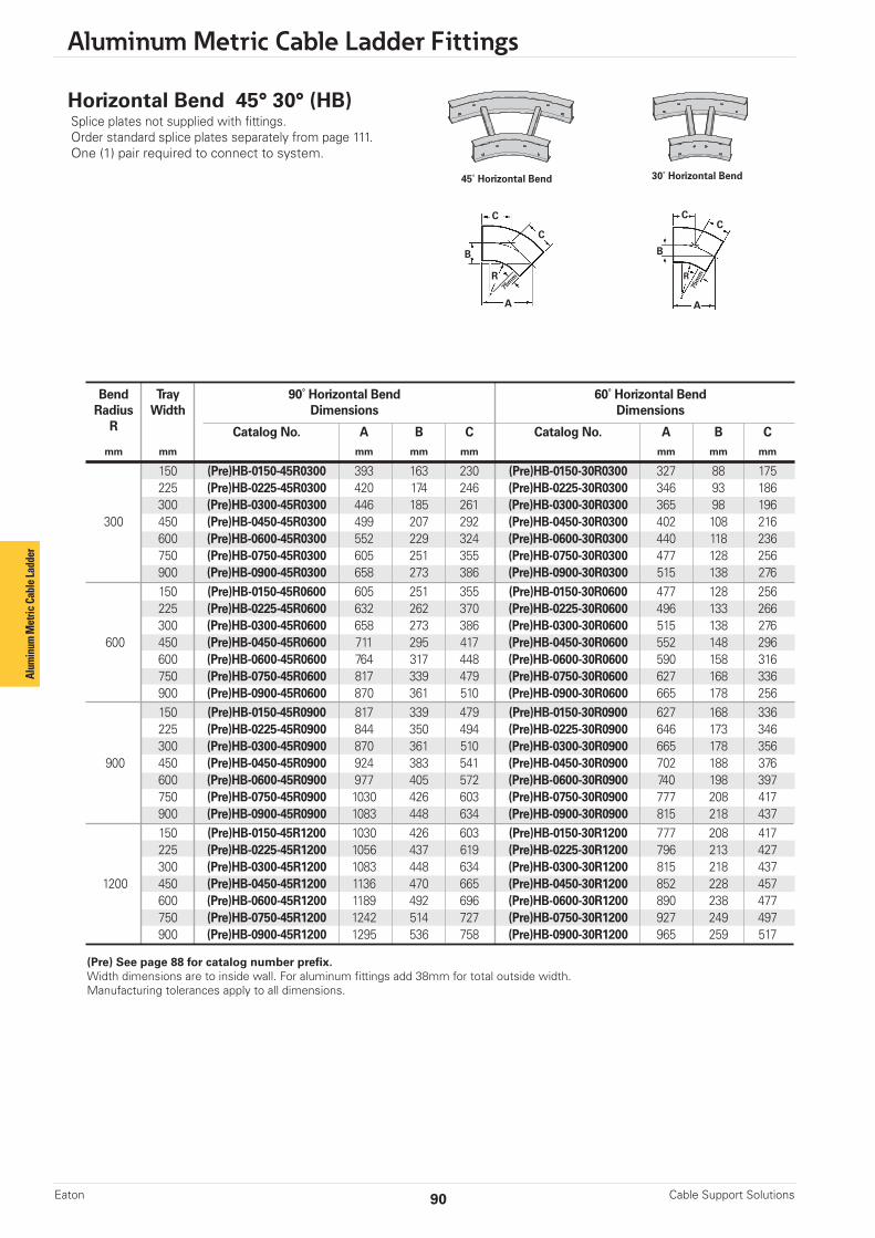
Aluminum Metric Cable Ladder Fittings
Cable Support SolutionsEaton 90
(Pre) See page 88 for catalog number prefix.Width dimensions are to inside wall. For aluminum fittings add 38mm for total outside width.Manufacturing tolerances apply to all dimensions.
45˚ Horizontal Bend
CC
R
75m
m
B
C
C
R
B
30˚ Horizontal Bend
Horizontal Bend 45° 30° (HB)Splice plates not supplied with fittings.Order standard splice plates separately from page 111.One (1) pair required to connect to system.
75m
m
A A
Bend Tray 90˚ Horizontal Bend 60˚ Horizontal Bend Radius Width Dimensions Dimensions R Catalog No. A B C Catalog No. A B C mm mm mm mm mm mm mm mm
150 (Pre)HB-0150-45R0300 393 163 230 (Pre)HB-0150-30R0300 327 88 175 225 (Pre)HB-0225-45R0300 420 174 246 (Pre)HB-0225-30R0300 346 93 186 300 (Pre)HB-0300-45R0300 446 185 261 (Pre)HB-0300-30R0300 365 98 196 300 450 (Pre)HB-0450-45R0300 499 207 292 (Pre)HB-0450-30R0300 402 108 216 600 (Pre)HB-0600-45R0300 552 229 324 (Pre)HB-0600-30R0300 440 118 236 750 (Pre)HB-0750-45R0300 605 251 355 (Pre)HB-0750-30R0300 477 128 256 900 (Pre)HB-0900-45R0300 658 273 386 (Pre)HB-0900-30R0300 515 138 276 150 (Pre)HB-0150-45R0600 605 251 355 (Pre)HB-0150-30R0600 477 128 256 225 (Pre)HB-0225-45R0600 632 262 370 (Pre)HB-0225-30R0600 496 133 266 300 (Pre)HB-0300-45R0600 658 273 386 (Pre)HB-0300-30R0600 515 138 276 600 450 (Pre)HB-0450-45R0600 711 295 417 (Pre)HB-0450-30R0600 552 148 296 600 (Pre)HB-0600-45R0600 764 317 448 (Pre)HB-0600-30R0600 590 158 316 750 (Pre)HB-0750-45R0600 817 339 479 (Pre)HB-0750-30R0600 627 168 336 900 (Pre)HB-0900-45R0600 870 361 510 (Pre)HB-0900-30R0600 665 178 256 150 (Pre)HB-0150-45R0900 817 339 479 (Pre)HB-0150-30R0900 627 168 336 225 (Pre)HB-0225-45R0900 844 350 494 (Pre)HB-0225-30R0900 646 173 346 300 (Pre)HB-0300-45R0900 870 361 510 (Pre)HB-0300-30R0900 665 178 356 900 450 (Pre)HB-0450-45R0900 924 383 541 (Pre)HB-0450-30R0900 702 188 376 600 (Pre)HB-0600-45R0900 977 405 572 (Pre)HB-0600-30R0900 740 198 397 750 (Pre)HB-0750-45R0900 1030 426 603 (Pre)HB-0750-30R0900 777 208 417 900 (Pre)HB-0900-45R0900 1083 448 634 (Pre)HB-0900-30R0900 815 218 437 150 (Pre)HB-0150-45R1200 1030 426 603 (Pre)HB-0150-30R1200 777 208 417 225 (Pre)HB-0225-45R1200 1056 437 619 (Pre)HB-0225-30R1200 796 213 427 300 (Pre)HB-0300-45R1200 1083 448 634 (Pre)HB-0300-30R1200 815 218 437 1200 450 (Pre)HB-0450-45R1200 1136 470 665 (Pre)HB-0450-30R1200 852 228 457 600 (Pre)HB-0600-45R1200 1189 492 696 (Pre)HB-0600-30R1200 890 238 477 750 (Pre)HB-0750-45R1200 1242 514 727 (Pre)HB-0750-30R1200 927 249 497 900 (Pre)HB-0900-45R1200 1295 536 758 (Pre)HB-0900-30R1200 965 259 517
Alum
inum
Met
ric C
able
Ladd
er

(Pre) See page 88 for catalog number prefix.Width dimensions are to inside wall. For aluminum fittings add 38mm for total outside width.Manufacturing tolerances apply to all dimensions.
91
Aluminum Metric Cable Ladder Fittings
Cable Support Solutions Eaton
Bend Tray (*) Insert "VO" for VO Side Rail VI Side Rail HeightRadius Width Vert. Outside Bend Height R Insert "VI" for 100mm - 175mm 100mm 125mm 150mm 175mm Vert. Inside Bend mm mm mm mm mm
Catalog No. A B C A B C A B C A B C A B C00 152 (Pre)(*)-0150-90R0300 225 (Pre)(*)-0225-90R0300 300 (Pre)(*)-0300-90R0300 300 450 (Pre)(*)-0450-90R0300 375 375 375 483 483 483 505 505 505 534 534 534 559 559 559 600 (Pre)(*)-0600-90R0300 750 (Pre)(*)-0750-90R0300 900 (Pre)(*)-0900-90R0300 150 (Pre)(*)-0150-90R0600 225 (Pre)(*)-0225-90R0600 300 (Pre)(*)-0300-90R0600 600 450 (Pre)(*)-0450-90R0600 675 675 675 783 783 783 805 805 805 834 834 834 859 859 859 600 (Pre)(*)-0600-90R0600 750 (Pre)(*)-0750-90R0600 900 (Pre)(*)-0900-90R0600 150 (Pre)(*)-0150-90R0900 225 (Pre)(*)-0225-90R0900 300 (Pre)(*)-0300-90R0900 900 450 (Pre)(*)-0450-90R0900 975 975 975 1083 1083 1083 1105 1105 1105 1134 1134 1134 1159 1159 1159 600 (Pre)(*)-0600-90R0900 750 (Pre)(*)-0750-90R0900 900 (Pre)(*)-0900-90R0900 150 (Pre)(*)-0150-90R1200 225 (Pre)(*)-0225-90R1200 300 (Pre)(*)-0300-90R1200 1200 450 (Pre)(*)-0450-90R1200 1275 1275 1275 1383 1383 1383 1405 1405 1405 1434 1434 1434 1459 1459 1459 600 (Pre)(*)-0600-90R1200 750 (Pre)(*)-0750-90R1200 900 (Pre)(*)-0900-90R1200
90˚ Vertical Inside - VI90˚ Vertical Outside - VO
Vertical Bend 90˚ (VO, VI) Splice plates not supplied with fittings.Order standard splice plates separately from page 111.One (1) pair required to connect to system.
B
A
C
C75m
m
RB
A
C
C
75mm
R
Aluminum
Metric Cable Ladder
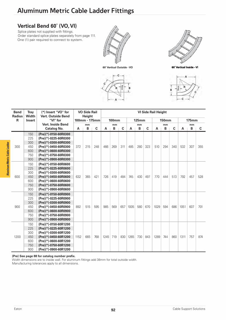
Aluminum Metric Cable Ladder Fittings
Cable Support SolutionsEaton 92
60˚ Vertical Inside - VI60˚ Vertical Outside - VO
A
C
C
75mmR
B
A
C
C
75m
m RB
Vertical Bend 60˚ (VO, VI)Splice plates not supplied with fittings.Order standard splice plates separately from page 111.One (1) pair required to connect to system.
(Pre) See page 88 for catalog number prefix.Width dimensions are to inside wall. For aluminum fittings add 38mm for total outside width.Manufacturing tolerances apply to all dimensions.
Bend Tray (*) Insert "VO" for VO Side Rail VI Side Rail HeightRadius Width Vert. Outside Bend Height R Insert "VI" for 100mm - 175mm 100mm 125mm 150mm 175mm Vert. Inside Bend mm mm mm mm mm
Catalog No. A B C A B C A B C A B C A B C0 150 (Pre)(*)-0150-60R0300 225 (Pre)(*)-0225-60R0300 300 (Pre)(*)-0300-60R0300 300 450 (Pre)(*)-0450-60R0300 372 215 248 466 269 311 485 280 323 510 294 340 532 307 355 600 (Pre)(*)-0600-60R0300 750 (Pre)(*)-0750-60R0300 900 (Pre)(*)-0900-60R0300 150 (Pre)(*)-0150-60R0600 225 (Pre)(*)-0225-60R0600 300 (Pre)(*)-0300-60R0600 600 450 (Pre)(*)-0450-60R0600 632 365 421 726 419 484 745 430 497 770 444 513 792 457 528 600 (Pre)(*)-0600-60R0600 750 (Pre)(*)-0750-60R0600 900 (Pre)(*)-0900-60R0600 150 (Pre)(*)-0150-60R0900 225 (Pre)(*)-0225-60R0900 300 (Pre)(*)-0300-60R0900 900 450 (Pre)(*)-0450-60R0900 892 515 595 985 569 657 1005 580 670 1029 594 686 1051 607 701 600 (Pre)(*)-0600-60R0900 750 (Pre)(*)-0750-60R0900 900 (Pre)(*)-0900-60R0900 150 (Pre)(*)-0150-60R1200 225 (Pre)(*)-0225-60R1200 300 (Pre)(*)-0300-60R1200 1200 450 (Pre)(*)-0450-60R1200 1152 665 768 1245 719 830 1265 730 843 1289 744 860 1311 757 874 600 (Pre)(*)-0600-60R1200 750 (Pre)(*)-0750-60R1200 900 (Pre)(*)-0900-60R1200
Alum
inum
Met
ric C
able
Ladd
er
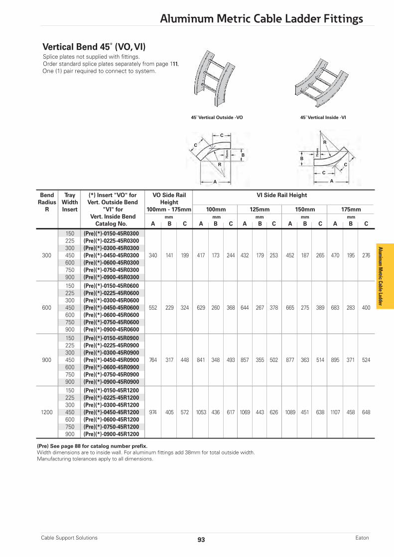
93
Aluminum Metric Cable Ladder Fittings
Cable Support Solutions Eaton
Bend Tray (*) Insert "VO" for VO Side Rail VI Side Rail HeightRadius Width Vert. Outside Bend Height R Insert "VI" for 100mm - 175mm 100mm 125mm 150mm 175mm Vert. Inside Bend mm mm mm mm mm
Catalog No. A B C A B C A B C A B C A B C0 150 (Pre)(*)-0150-45R0300 225 (Pre)(*)-0225-45R0300 300 (Pre)(*)-0300-45R0300 300 450 (Pre)(*)-0450-45R0300 340 141 199 417 173 244 432 179 253 452 187 265 470 195 276 600 (Pre)(*)-0600-45R0300 750 (Pre)(*)-0750-45R0300 900 (Pre)(*)-0900-45R0300 150 (Pre)(*)-0150-45R0600 225 (Pre)(*)-0225-45R0600 300 (Pre)(*)-0300-45R0600 600 450 (Pre)(*)-0450-45R0600 552 229 324 629 260 368 644 267 378 665 275 389 683 283 400 600 (Pre)(*)-0600-45R0600 750 (Pre)(*)-0750-45R0600 900 (Pre)(*)-0900-45R0600 150 (Pre)(*)-0150-45R0900 225 (Pre)(*)-0225-45R0900 300 (Pre)(*)-0300-45R0900 900 450 (Pre)(*)-0450-45R0900 764 317 448 841 348 493 857 355 502 877 363 514 895 371 524 600 (Pre)(*)-0600-45R0900 750 (Pre)(*)-0750-45R0900 900 (Pre)(*)-0900-45R0900 150 (Pre)(*)-0150-45R1200 225 (Pre)(*)-0225-45R1200 300 (Pre)(*)-0300-45R1200 1200 450 (Pre)(*)-0450-45R1200 974 405 572 1053 436 617 1069 443 626 1089 451 638 1107 458 648 600 (Pre)(*)-0600-45R1200 750 (Pre)(*)-0750-45R1200 900 (Pre)(*)-0900-45R1200
45˚ Vertical Inside -VI45˚ Vertical Outside -VO
Vertical Bend 45˚ (VO, VI) Splice plates not supplied with fittings.Order standard splice plates separately from page 111.One (1) pair required to connect to system.
B
A
C
C
75m
m
RB
A
C
C
75m
m
R
(Pre) See page 88 for catalog number prefix.Width dimensions are to inside wall. For aluminum fittings add 38mm for total outside width.Manufacturing tolerances apply to all dimensions.
Aluminum
Metric Cable Ladder

Aluminum Metric Cable Ladder Fittings
Cable Support SolutionsEaton 94
30˚ Vertical Outside -VO 30˚ Vertical Inside -VI
Vertical Bend 30˚ (VO, VI)Splice plates not supplied with fittings.Order standard splice plates separately from page 111.One (1) pair required to connect to system.
B
A
CC
RB
A
CC
75m
m
R
(Pre) See page 88 for catalog number prefix.Width dimensions are to inside wall. For aluminum fittings add 38mm for total outside width.Manufacturing tolerances apply to all dimensions.
75m
m
Bend Tray (*) Insert "VO" for VO Side Rail VI Side Rail HeightRadius Width Vert. Outside Bend Height R Insert "VI" for 100mm - 175mm 100mm 125mm 150mm 175mm Vert. Inside Bend mm mm mm mm mm
Catalog No. A B C A B C A B C A B C A B C0 150 (Pre)(*)-0150-30R0300 225 (Pre)(*)-0225-30R0300 300 (Pre)(*)-0300-30R0300 300 450 (Pre)(*)-0450-30R0300 290 78 155 344 92 184 355 95 190 369 99 198 382 102 205 600 (Pre)(*)-0600-30R0300 750 (Pre)(*)-0750-30R0300 900 (Pre)(*)-0900-30R0300 150 (Pre)(*)-0150-30R0600 225 (Pre)(*)-0225-30R0600 300 (Pre)(*)-0300-30R0600 600 450 (Pre)(*)-0450-30R0600 440 118 236 494 132 265 505 135 271 519 139 278 532 143 285 600 (Pre)(*)-0600-30R0600 750 (Pre)(*)-0750-30R0600 900 (Pre)(*)-0900-30R0600 150 (Pre)(*)-0150-30R0900 225 (Pre)(*)-0225-30R0900 300 (Pre)(*)-0300-30R0900 900 450 (Pre)(*)-0450-30R0900 590 158 316 644 173 345 655 176 351 669 179 359 682 183 366 600 (Pre)(*)-0600-30R0900 750 (Pre)(*)-0750-30R0900 900 (Pre)(*)-0900-30R0900 150 (Pre)(*)-0150-30R1200 225 (Pre)(*)-0225-30R1200 300 (Pre)(*)-0300-30R1200 1200 450 (Pre)(*)-0450-30R1200 740 198 397 794 213 425 805 216 431 819 220 439 832 223 446 600 (Pre)(*)-0600-30R1200 750 (Pre)(*)-0750-30R1200 900 (Pre)(*)-0900-30R1200
Alum
inum
Met
ric C
able
Ladd
er

95
Aluminum Metric Cable Ladder Fittings
Cable Support Solutions Eaton
Fittings Part Numbering (without angles)
Prefix
Example: 150 A 300 IA I HT - 0600 - R0300
Side Rail Rung Rung FittingHeight Material Spacing Type Type Width Radius
100 = 100mm A = 100 = 100mm IA = HT = Horizontal 0150 = 150mm 0300 = 300mm125 = 125mm Aluminum 225 = 225mm Standard Tee 0225 = 225mm 0450 = 450mm150 = 150mm 300 = 300mm MA = Slotted HX = Horizontal 0300 = 300mm 0600 = 600mm175 = 175mm Marine Cross 0450 = 450mm 0750 = 750mm
SB = Alternating VTU = Vertical 0600 = 600mm 0900 = 900mmSolid MD = Slotted Tee - Up 0750 = 750mm 1200 = 1200mmBottom Marine VTD = Vertical 0900 = 900mm
Down Tee - DownMU = Slotted *HYR = Horizontal
Marine Wye, RightUp *HYL = Horizontal
Wye, Left CSF = CableSupport Fitting
For solid bottom, add SB as shown below.Available in 150mm thru 900mm widths
150 A SB I HB - 0600 - 90 R0300
Fittings engineeredwith 75mm tangentsfor splicing integrity.
Aluminum
Metric Cable Ladder
* Available only in 600mm radius

Aluminum Metric Cable Ladder Fittings
Cable Support SolutionsEaton 96
Bend Tray Horizontal Tee Horizontal Cross Radius Width Dimension Dimensions
R Catalog Number A B Catalog Number A B mm mm mm mm mm mm
150 (Pre)HT-0150-R0300 450 900 (Pre)HX-0150-R0300 450 900 225 (Pre)HT-0225-R0300 487.5 975 (Pre)HX-0225-R0300 487.5 975 300 (Pre)HT-0300-R0300 525 1059 (Pre)HX-0300-R0300 525 1059 300 450 (Pre)HT-0450-R0300 600 1200 (Pre)HX-0450-R0300 600 1200 600 (Pre)HT-0600-R0300 675 1350 (Pre)HX-0600-R0300 675 1350 750 (Pre)HT-0750-R0300 750 1500 (Pre)HX-0750-R0300 750 1500 900 (Pre)HT-0900-R0300 825 1650 (Pre)HX-0900-R0300 825 1650 150 (Pre)HT-0150-R0600 750 1500 (Pre)HX-0150-R0600 750 1500 225 (Pre)HT-0225-R0600 787.5 1575 (Pre)HX-0225-R0600 787.5 1575 300 (Pre)HT-0300-R0600 825 1650 (Pre)HX-0300-R0600 825 1650 600 450 (Pre)HT-0450-R0600 900 1800 (Pre)HX-0450-R0600 900 1800 600 (Pre)HT-0600-R0600 975 1950 (Pre)HX-0600-R0600 975 1950 750 (Pre)HT-0750-R0600 1050 2100 (Pre)HX-0750-R0600 1050 2100 900 (Pre)HT-0900-R0600 1125 2250 (Pre)HX-0900-R0600 1125 2250 150 (Pre)HT-0150-R0900 1050 2100 (Pre)HX-0150-R0900 1050 2100 225 (Pre)HT-0225-R0900 1087.5 2175 (Pre)HX-0225-R0900 1087.5 2175 300 (Pre)HT-0300-R0900 1125 2250 (Pre)HX-0300-R0900 1125 2250 900 450 (Pre)HT-0450-R0900 1200 2400 (Pre)HX-0450-R0900 1200 2400 600 (Pre)HT-0600-R0900 1275 2550 (Pre)HX-0600-R0900 1275 2550 750 (Pre)HT-0750-R0900 1350 2700 (Pre)HX-0750-R0900 1350 2700 900 (Pre)HT-0900-R0900 1425 2850 (Pre)HX-0900-R0900 1425 2850 150 (Pre)HT-0150-R1200 1350 2700 (Pre)HX-0150-R1200 1350 2700 225 (Pre)HT-0225-R1200 1387.5 2775 (Pre)HX-0225-R1200 1387.5 2775 300 (Pre)HT-0300-R1200 1425 2850 (Pre)HX-0300-R1200 1425 2850 1200 450 (Pre)HT-0450-R1200 1500 3000 (Pre)HX-0450-R1200 1500 3000 600 (Pre)HT-0600-R1200 1575 3150 (Pre)HX-0600-R1200 1575 3150 750 (Pre)HT-0750-R1200 1650 3300 (Pre)HX-0750-R1200 1650 3300 900 (Pre)HT-0900-R1200 1725 3450 (Pre)HX-0900-R1200 1725 3450
A
B
R A R
B
Splice plates not supplied with fittings.Order standard splice plates separately from page 111.Two (2) pair required to connect to system.
Splice plates not supplied with fittings.Order standard splice plates separately from page 111.Three (3) pair required to connect to system.
75m
m
75m
m
(Pre) See page 95 for catalog number prefix.Width dimensions are to inside wall. For aluminum fittings add 38mm for total outside width.Manufacturing tolerances apply to all dimensions.
Horizontal Tee (HT) Horizontal Cross (HX)
W
Alum
inum
Met
ric C
able
Ladd
er
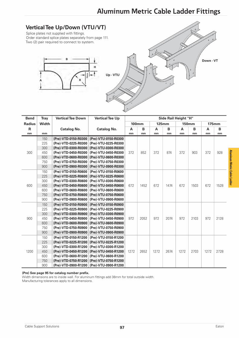
97
Aluminum Metric Cable Ladder Fittings
Cable Support Solutions Eaton
Bend Tray Vertical Tee Down Vertical Tee Up Side Rail Height "H"
Radius Width 100mm 125mm 150mm 175mm R Catalog No. Catalog No. A B A B A B A B mm mm mm mm mm mm mm mm mm mm
150 (Pre)-VTD-0150-R0300 (Pre)-VTU-0150-R0300 225 (Pre)-VTD-0225-R0300 (Pre)-VTU-0225-R0300 300 (Pre)-VTD-0300-R0300 (Pre)-VTU-0300-R0300 300 450 (Pre)-VTD-0450-R0300 (Pre)-VTU-0450-R0300 372 852 372 874 372 903 372 928 600 (Pre)-VTD-0600-R0300 (Pre)-VTU-0600-R0300 750 (Pre)-VTD-0750-R0300 (Pre)-VTU-0750-R0300 900 (Pre)-VTD-0900-R0300 (Pre)-VTU-0900-R0300 150 (Pre)-VTD-0150-R0600 (Pre)-VTU-0150-R0600 225 (Pre)-VTD-0225-R0600 (Pre)-VTU-0225-R0600 300 (Pre)-VTD-0300-R0600 (Pre)-VTU-0300-R0600 600 450 (Pre)-VTD-0450-R0600 (Pre)-VTU-0450-R0600 672 1452 672 1474 672 1503 672 1528 600 (Pre)-VTD-0600-R0600 (Pre)-VTU-0600-R0600 750 (Pre)-VTD-0750-R0600 (Pre)-VTU-0750-R0600 900 (Pre)-VTD-0900-R0600 (Pre)-VTU-0900-R0600 150 (Pre)-VTD-0150-R0900 (Pre)-VTU-0150-R0900 225 (Pre)-VTD-0225-R0900 (Pre)-VTU-0225-R0900 300 (Pre)-VTD-0300-R0900 (Pre)-VTU-0300-R0900 900 450 (Pre)-VTD-0450-R0900 (Pre)-VTU-0450-R0900 972 2052 972 2074 972 2103 972 2128 600 (Pre)-VTD-0600-R0900 (Pre)-VTU-0600-R0900 750 (Pre)-VTD-0750-R0900 (Pre)-VTU-0750-R0900 900 (Pre)-VTD-0900-R0900 (Pre)-VTU-0900-R0900 150 (Pre)-VTD-0150-R1200 (Pre)-VTU-0150-R1200 225 (Pre)-VTD-0225-R1200 (Pre)-VTU-0225-R1200 300 (Pre)-VTD-0300-R1200 (Pre)-VTU-0300-R1200 1200 450 (Pre)-VTD-0450-R1200 (Pre)-VTU-0450-R1200 1272 2652 1272 2674 1272 2703 1272 2728 600 (Pre)-VTD-0600-R1200 (Pre)-VTU-0600-R1200 750 (Pre)-VTD-0750-R1200 (Pre)-VTU-0750-R1200 900 (Pre)-VTD-0900-R1200 (Pre)-VTU-0900-R1200
Down - VTB
A
H
R
Vertical Tee Up/Down (VTU/VT)Splice plates not supplied with fittings.Order standard splice plates separately from page 111.Two (2) pair required to connect to system.
(Pre) See page 95 for catalog number prefix.Width dimensions are to inside wall. For aluminum fittings add 38mm for total outside width.Manufacturing tolerances apply to all dimensions.
75m
m Up - VTU
Aluminum
Metric Cable Ladder
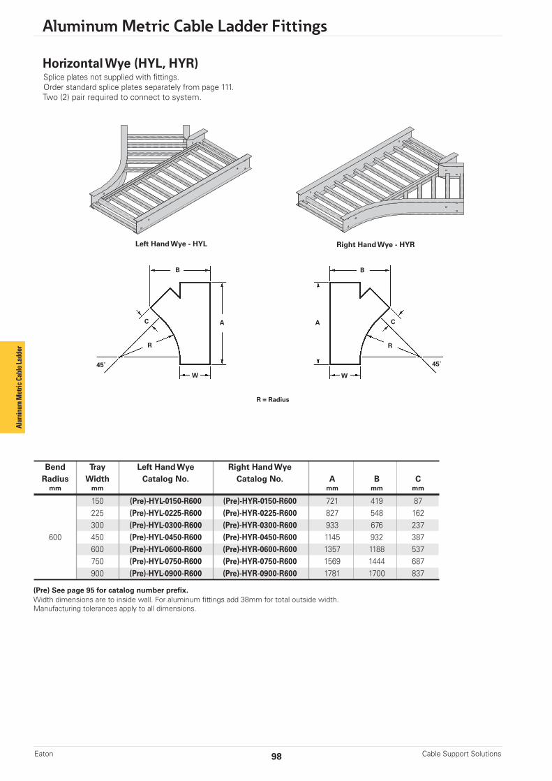
Aluminum Metric Cable Ladder Fittings
Cable Support SolutionsEaton 98
Bend Tray Left Hand Wye Right Hand Wye Radius Width Catalog No. Catalog No. A B C mm mm mm mm mm
150 (Pre)-HYL-0150-R600 (Pre)-HYR-0150-R600 721 419 87 225 (Pre)-HYL-0225-R600 (Pre)-HYR-0225-R600 827 548 162 300 (Pre)-HYL-0300-R600 (Pre)-HYR-0300-R600 933 676 237 600 450 (Pre)-HYL-0450-R600 (Pre)-HYR-0450-R600 1145 932 387 600 (Pre)-HYL-0600-R600 (Pre)-HYR-0600-R600 1357 1188 537 750 (Pre)-HYL-0750-R600 (Pre)-HYR-0750-R600 1569 1444 687 900 (Pre)-HYL-0900-R600 (Pre)-HYR-0900-R600 1781 1700 837
R = Radius
Left Hand Wye - HYL Right Hand Wye - HYR
Horizontal Wye (HYL, HYR)Splice plates not supplied with fittings.Order standard splice plates separately from page 111.Two (2) pair required to connect to system.
B
AC
45˚
R
W
B
A C
45˚
R
W
(Pre) See page 95 for catalog number prefix.Width dimensions are to inside wall. For aluminum fittings add 38mm for total outside width.Manufacturing tolerances apply to all dimensions.
Alum
inum
Met
ric C
able
Ladd
er

99
Aluminum Metric Cable Ladder Fittings
Cable Support Solutions Eaton
Bend Tray Side Rail Height "H"
Radius Width 100mm 125mm 150mm 175mm R Catalog No. A B A B A B A B mm mm mm mm mm mm mm mm mm mm
150 (Pre)-CSF-0150-R0300 225 (Pre)-CSF-0225-R0300 300 (Pre)-CSF-0300-R0300 300 450 (Pre)-CSF-0450-R0300 483 372 505 372 534 372 559 372 600 (Pre)-CSF-0600-R0300 750 (Pre)-CSF-0750-R0300 900 (Pre)-CSF-0900-R0300 150 (Pre)-CSF-0150-R0600 225 (Pre)-CSF-0225-R0600 300 (Pre)-CSF-0300-R0600 600 450 (Pre)-CSF-0450-R0600 783 672 805 672 34 672 859 672 600 (Pre)-CSF-0600-R0600 750 (Pre)-CSF-0750-R0600 900 (Pre)-CSF-0900-R0600 150 (Pre)-CSF-0150-R0900 225 (Pre)-CSF-0225-R0900 300 (Pre)-CSF-0300-R0900 900 450 (Pre)-CSF-0450-R0900 1083 972 1105 972 1134 972 1159 972 600 (Pre)-CSF-0600-R0900 750 (Pre)-CSF-0750-R0900 900 (Pre)-CSF-0900-R0900 150 (Pre)-CSF-0150-R1200 225 (Pre)-CSF-0225-R1200 300 (Pre)-CSF-0300-R1200 1200 450 (Pre)-CSF-0450-R1200 1383 1272 1405 1272 1434 1272 1459 1272 600 (Pre)-CSF-0600-R1200 750 (Pre)-CSF-0750-R1200 900 (Pre)-CSF-0900-R1200
This fitting is recommended for useat the top of vertical runs to supportthe weight of the cables. The topcross brace is drilled for installingeyebolts, ordered separately.B
A
H
75m
mR
Cable Support Fittings (CSF)Splice plates not supplied with fittings.Order standard splice plates separately from page 111.One (1) pair required to connect to system.
(Pre) See page 95 for catalog number prefix.Width dimensions are to inside wall. For aluminum fittings add 38mm for total outside width.Manufacturing tolerances apply to all dimensions.
Aluminum
Metric Cable Ladder
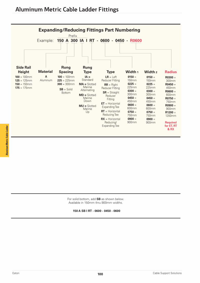
Aluminum Metric Cable Ladder Fittings
Cable Support SolutionsEaton 100
Expanding/Reducing Fittings Part NumberingPrefix
Example: 150 A 300 IA I RT - 0600 - 0450 - R0600
Side RailHeight
100 = 100mm125 = 125mm150 = 150mm175 = 175mm
MaterialA
Aluminum
RungSpacing
100 = 100mm225 = 225mm300 = 300mm
SB = SolidBottom
Width 1
0150 =150mm0225 =225mm0300 =300mm0450 =450mm0600 =600mm0750 =750mm0900 =900mm
Width 2
0150 =150mm0225 =225mm0300 =300mm0450 =450mm0600 =600mm0750 =750mm0900 =900mm
RadiusR0300 =300mm
R0450 =450mm
R0600 =600mm
R0750 =750mm
R0900 =900mm
R1200 =1200mm
Requiredfor ET, RT
& RX
TypeLR = Left
Reducer FittingRR = Right
Reducer FittingSR = StraightReducerFitting
ET = HorizontalExpanding Tee
RT = HorizontalReducing Tee
RX = HorizontalReducing/
Expanding Tee
RungTypeIA =
StandardMA = Slotted
MarineAlternating
MD = SlottedMarineDown
MU = SlottedMarineUp
For solid bottom, add SB as shown below. Available in 150mm thru 900mm widths.
150 A SB I RT - 0600 - 0450 - 0600
Alum
inum
Met
ric C
able
Ladd
er
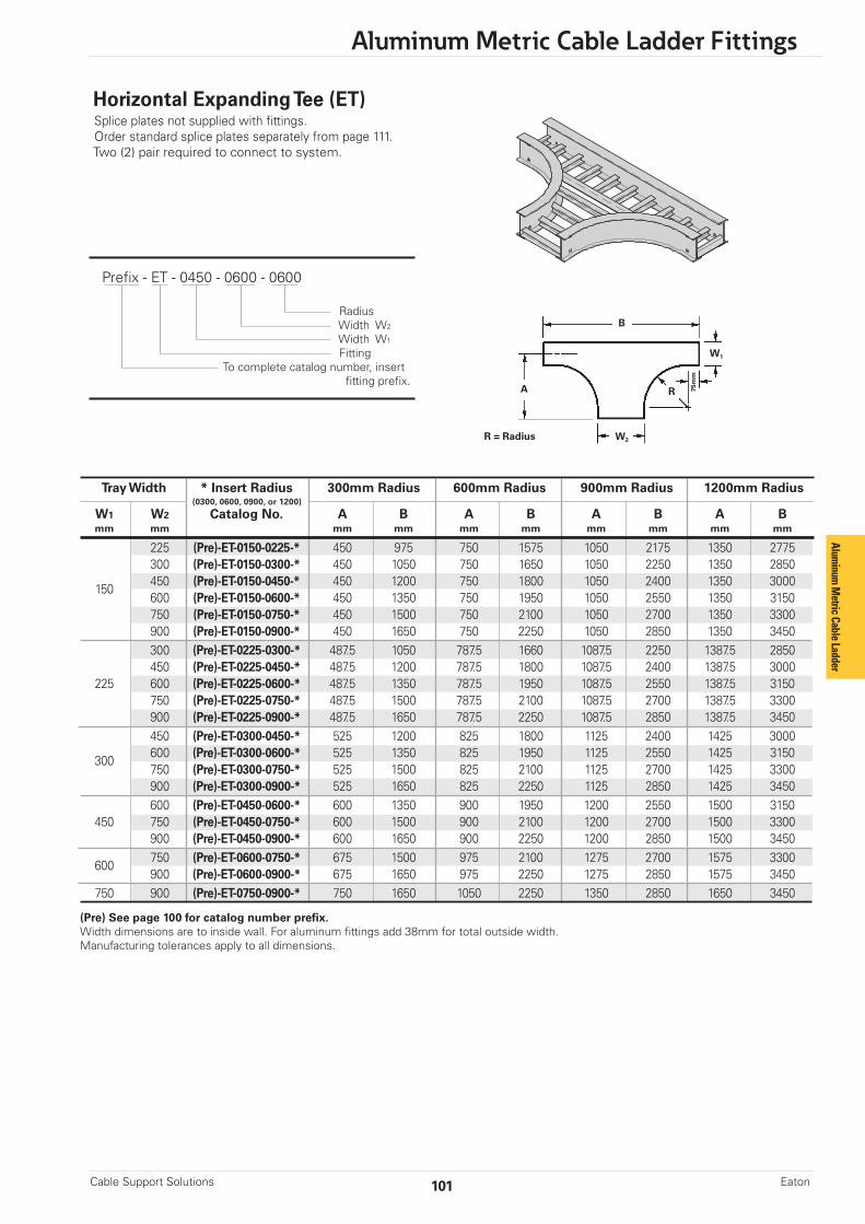
101
Aluminum Metric Cable Ladder Fittings
Cable Support Solutions Eaton
Tray Width * Insert Radius 300mm Radius 600mm Radius 900mm Radius 1200mm Radius (0300, 0600, 0900, or 1200)
W1 W2 Catalog No. A B A B A B A B mm mm mm mm mm mm mm mm mm mm
225 (Pre)-ET-0150-0225-* 450 975 750 1575 1050 2175 1350 2775 300 (Pre)-ET-0150-0300-* 450 1050 750 1650 1050 2250 1350 2850 450 (Pre)-ET-0150-0450-* 450 1200 750 1800 1050 2400 1350 3000
150 600 (Pre)-ET-0150-0600-* 450 1350 750 1950 1050 2550 1350 3150
750 (Pre)-ET-0150-0750-* 450 1500 750 2100 1050 2700 1350 3300 900 (Pre)-ET-0150-0900-* 450 1650 750 2250 1050 2850 1350 3450 300 (Pre)-ET-0225-0300-* 487.5 1050 787.5 1660 1087.5 2250 1387.5 2850 450 (Pre)-ET-0225-0450-* 487.5 1200 787.5 1800 1087.5 2400 1387.5 3000 225 600 (Pre)-ET-0225-0600-* 487.5 1350 787.5 1950 1087.5 2550 1387.5 3150 750 (Pre)-ET-0225-0750-* 487.5 1500 787.5 2100 1087.5 2700 1387.5 3300 900 (Pre)-ET-0225-0900-* 487.5 1650 787.5 2250 1087.5 2850 1387.5 3450 450 (Pre)-ET-0300-0450-* 525 1200 825 1800 1125 2400 1425 3000 600 (Pre)-ET-0300-0600-* 525 1350 825 1950 1125 2550 1425 3150 300
750 (Pre)-ET-0300-0750-* 525 1500 825 2100 1125 2700 1425 3300 900 (Pre)-ET-0300-0900-* 525 1650 825 2250 1125 2850 1425 3450 600 (Pre)-ET-0450-0600-* 600 1350 900 1950 1200 2550 1500 3150
450 750 (Pre)-ET-0450-0750-* 600 1500 900 2100 1200 2700 1500 3300 900 (Pre)-ET-0450-0900-* 600 1650 900 2250 1200 2850 1500 3450 750 (Pre)-ET-0600-0750-* 675 1500 975 2100 1275 2700 1575 3300 600
900 (Pre)-ET-0600-0900-* 675 1650 975 2250 1275 2850 1575 3450 750 900 (Pre)-ET-0750-0900-* 750 1650 1050 2250 1350 2850 1650 3450
Prefix - ET - 0450 - 0600 - 0600
Radius Width W2
Width W1
Fitting To complete catalog number, insert fitting prefix.
Horizontal Expanding Tee (ET)Splice plates not supplied with fittings.Order standard splice plates separately from page 111.Two (2) pair required to connect to system.
B
A
W2
R
W1
(Pre) See page 100 for catalog number prefix.Width dimensions are to inside wall. For aluminum fittings add 38mm for total outside width.Manufacturing tolerances apply to all dimensions.
75m
m
R = Radius
Aluminum
Metric Cable Ladder

Aluminum Metric Cable Ladder Fittings
Cable Support SolutionsEaton 102
Prefix - RT - 0600 - 0450 - 0600
Radius Width W2
Width W1
Fitting To complete catalog number, insert fitting prefix.
R = Radius
Horizontal Reducing Tee (RT)Splice plates not supplied with fittings.Order standard splice plates separately from page 111.Two (2) pair required to connect to system.
B
A
W2
R
W1
(Pre) See page 100 for catalog number prefix.Width dimensions are to inside wall. For aluminum fittings add 38mm for total outside width.Manufacturing tolerances apply to all dimensions.
75m
m
Tray Width * Insert Radius 300mm Radius 600mm Radius 900mm Radius 1200mm Radius (0300, 0600, 0900, or 1200)
W1 W2 Catalog No. A B A B A B A B mm mm mm mm mm mm mm mm mm mm
225 150 (Pre)-RT-0225-0150-* 487.5 900 787.5 1500 1087.5 2100 1387.5 2700 300 150 (Pre)-RT-0300-0150-* 525 900 825 1500 1125 2100 1425 2700 225 (Pre)-RT-0300-0225-* 525 975 825 1575 1125 2175 1425 2775 150 (Pre)-RT-0450-0150-* 600 900 900 1500 1200 2100 1500 2700 450 225 (Pre)-RT-0450-0225-* 600 975 900 1575 1200 2175 1500 2775 300 (Pre)-RT-0450-0300-* 600 1050 900 1650 1200 2250 1500 2850 150 (Pre)-RT-0600-0150-* 675 900 975 1500 1275 2100 1575 2700 600 225 (Pre)-RT-0600-0225-* 675 975 975 1575 1275 2175 1575 2775 300 (Pre)-RT-0600-0300-* 675 1050 975 1650 1275 2250 1575 2850 450 (Pre)-RT-0600-0450-* 675 1200 975 1800 1275 2400 1575 3000 150 (Pre)-RT-0750-0150-* 750 900 1050 1500 1350 2100 1650 2700 225 (Pre)-RT-0750-0225-* 750 975 1050 1575 1350 2175 1650 2775 750 300 (Pre)-RT-0750-0300-* 750 1050 1050 1650 1350 2250 1650 2850 450 (Pre)-RT-0750-0450-* 750 1200 1050 1800 1350 2400 1650 3000 600 (Pre)-RT-0750-0600-* 750 1350 1050 1950 1350 2550 1650 3150 150 (Pre)-RT-0900-0150-* 825 900 1125 1500 1425 2100 1725 2700 225 (Pre)-RT-0900-0225-* 825 975 1125 1575 1425 2175 1725 2775 900 300 (Pre)-RT-0900-0300-* 825 1050 1125 1650 1425 2250 1725 2850 450 (Pre)-RT-0900-0450-* 825 1200 1125 1800 1425 2400 1725 3000 600 (Pre)-RT-0900-0600-* 825 1350 1125 1950 1425 2550 1725 3150 750 (Pre)-RT-0900-0750-* 825 1500 1125 2100 1425 2700 1725 3300
Alum
inum
Met
ric C
able
Ladd
er

103
Aluminum Metric Cable Ladder Fittings
Cable Support Solutions Eaton
B
A
W2
75m
m
R
W1
Horizontal Expanding/Reducing Cross (RX)Splice plates not supplied with fittings.Order standard splice plates separately from page 111.Three (3) pair required to connect to system.
Prefix - RX - 0600 - 0450 - 0600
Radius Width W2
Width W1
Fitting To complete catalog number, insert fitting prefix.
(Pre) See page 100 for catalog number prefix.Width dimensions are to inside wall. For aluminum fittings add 38mm for total outside width.Manufacturing tolerances apply to all dimensions.
Tray Width * Insert Radius 300mm Radius 600mm Radius 900mm Radius 1200mm Radius (0300, 0600, 0900, or 1200)
W1 W2 Catalog No. A B A B A B A B mm mm mm mm mm mm mm mm mm mm
225 150 (Pre)-RX-0225-0150-* 975 900 1575 1500 2175 2100 2775 2700 300 150 (Pre)-RX-0300-0150-* 1050 900 1650 1500 2250 2100 2850 2700 225 (Pre)-RX-0300-0225-* 1050 975 1650 1575 2250 2175 2850 2775 150 (Pre)-RX-0450-0150-* 1200 900 1800 1500 2400 2100 3000 2700
450 225 (Pre)-RX-0450-0225-* 1200 975 1800 1575 2400 2175 3000 2775 300 (Pre)-RX-0450-0300-* 1200 1050 1800 1650 2400 2250 3000 2850 150 (Pre)-RX-0600-0150-* 1350 900 1950 1500 2550 2100 3150 2700 600 225 (Pre)-RX-0600-0225-* 1350 975 1950 1575 2550 2175 3150 2775 300 (Pre)-RX-0600-0300-* 1350 1050 1950 1650 2550 2250 3150 2850 450 (Pre)-RX-0600-0450-* 1350 1200 1950 1800 2550 2400 3150 3000 150 (Pre)-RX-0750-0150-* 1500 900 2100 1500 2700 2100 3300 2700 225 (Pre)-RX-0750-0225-* 1500 975 2100 1575 2700 2175 3300 2775
750 300 (Pre)-RX-0750-0300-* 1500 1050 2100 1650 2700 2250 3300 2850 450 (Pre)-RX-0750-0450-* 1500 1200 2100 1800 2700 2400 3300 3000 600 (Pre)-RX-0750-0600-* 1500 1350 2100 1950 2700 2550 3300 3150 150 (Pre)-RX-0900-0150-* 1650 900 2250 1500 2850 2100 3450 2700 225 (Pre)-RX-0900-0225-* 1650 975 2250 1575 2850 2175 3450 2775 900 300 (Pre)-RX-0900-0300-* 1650 1050 2250 1650 2850 2250 3450 2850 450 (Pre)-RX-0900-0450-* 1650 1200 2250 1800 2850 2400 3450 3000 600 (Pre)-RX-0900-0600-* 1650 1350 2250 1950 2850 2550 3450 3150 750 (Pre)-RX-0900-0750-* 1650 1500 2250 2100 2850 2700 3450 3300
Aluminum
Metric Cable Ladder

Aluminum Metric Cable Ladder Fittings
Cable Support SolutionsEaton 104
Prefix - LR - 0450 - 0300 Width2 Width1 Fitting Prefix
Tray Width Left Hand Reducer Right Hand Reducer Straight Reducer
W1 W2 Catalog No. A Catalog No. A Catalog No. A mm mm mm mm mm
225 150 (Pre)-LR-0225-0150 295 (Pre)-SR-0225-0150 295 (Pre)-RR-0225-0150 273
300
150 (Pre)-LR-0300-0150 338 (Pre)-SR-0300-0150 338 (Pre)-RR-0300-0150 295 225 (Pre)-LR-0300-0225 295 (Pre)-SR-0300-0225 295 (Pre)-RR-0300-0225 273
150 (Pre)-LR-0450-0150 425 (Pre)-SR-0450-0150 425 (Pre)-RR-0450-0150 338 450 225 (Pre)-LR-0450-0225 382 (Pre)-SR-0450-0225 382 (Pre)-RR-0450-0225 317 300 (Pre)-LR-0450-0300 338 (Pre)-SR-0450-0300 338 (Pre)-RR-0450-0300 295
150 (Pre)-LR-0600-0150 512 (Pre)-SR-0600-0150 512 (Pre)-RR-0600-0150 382
600
225 (Pre)-LR-0600-0225 468 (Pre)-SR-0600-0225 468 (Pre)-RR-0600-0225 360 300 (Pre)-LR-0600-0300 425 (Pre)-SR-0600-0300 425 (Pre)-RR-0600-0300 338 450 (Pre)-LR-0600-0450 338 (Pre)-SR-0600-0450 338 (Pre)-RR-0600-0450 295
150 (Pre)-LR-0750-0150 598 (Pre)-SR-0750-0150 598 (Pre)-RR-0750-0150 425 225 (Pre)-LR-0750-0225 555 (Pre)-SR-0750-0225 555 (Pre)-RR-0750-0225 403 750 300 (Pre)-LR-0750-0300 512 (Pre)-SR-0750-0300 512 (Pre)-RR-0750-0300 382 450 (Pre)-LR-0750-0450 425 (Pre)-SR-0750-0450 425 (Pre)-RR-0750-0450 338 600 (Pre)-LR-0750-0600 338 (Pre)-SR-0750-0600 338 (Pre)-RR-0750-0600 295
150 (Pre)-LR-0900-0150 685 (Pre)-SR-0900-0150 685 (Pre)-RR-0900-0150 468 225 (Pre)-LR-0900-0225 641 (Pre)-SR-0900-0225 641 (Pre)-RR-0900-0225 447
900 300 (Pre)-LR-0900-0300 598 (Pre)-SR-0900-0300 598 (Pre)-RR-0900-0300 425
450 (Pre)-LR-0900-0450 512 (Pre)-SR-0900-0450 512 (Pre)-RR-0900-0450 382 600 (Pre)-LR-0900-0600 425 (Pre)-SR-0900-0600 425 (Pre)-RR-0900-0600 338 750 (Pre)-LR-0900-0750 338 (Pre)-SR-0900-0750 338 (Pre)-RR-0900-0750 295
Right Reducer -RR Straight Reducer SRLeft Reducer - LR
Reducers (LR, SR, RR)Splice plates not supplied with fittings.Order standard splice plates separately from page 111.One (1) pair required to connect to system.
A
W2
W1
A
W2
W1
A
W2
W1
(Pre) See page 100 for catalog number prefix.Width dimensions are to inside wall. For aluminum fittings add 38mm for total outside width.Manufacturing tolerances apply to all dimensions.
Reducer Part Numbering
Alum
inum
Met
ric C
able
Ladd
er

105
Aluminum Metric Cable Ladder Square Fittings
Cable Support Solutions Eaton
Square Horizontal Bend, Tee, & CrossFittings Part Numbering
See pages 106 - 107
Prefix
Example: 100 A 300 MD I SQHB - 0600
Side Rail Rung Rung FittingHeight Material Spacing Type Type Width
100 = 100mm A = 300 = 300mm MD = Slotted SQHB = Square 0150 = 150mm
125 = 125mm Aluminum Marine Down Horizontal Bend 0225 = 225mm
150 = 150mm MU = Slotted SQHT = Square 0300 = 300mm
175 = 175mm Marine Up Horizontal Tee 0450 = 450mm
MA = Slotted SQHX = Square 0600 = 600mmMarine Alternating Horizontal Cross 0750 = 750mm
IA = Standard 0900 = 900mm
Square Expanding & ReducingHorizontal Tee & Cross Fittings Part Numbering
See pages 108 - 110
Prefix
Example: 150 A 300 MD I SQRT - 0450 - 0300
Side Rail Rung Rung FittingHeight Material Spacing Type Type Width 1 Width 2
100 = 100mm A = 300 = 300mm MD = Slotted SQET = Square 0225 = 225mm 0150 = 150mm125 = 125mm Aluminum Marine Down Expanding 0300 = 300mm 0225 = 225mm150 = 150mm MU = Slotted Horizontal Tee 0450 = 450mm 0300 = 300mm175 = 175mm Marine Up 0600 = 600mm 0450 = 450mm
MA = Slotted SQRT = Square 0750 = 750mm 0600 = 600mmMarine Alternating Reducing 0900 = 900mm 0750 = 750mm
IA = Standard Horizontal Tee
SQRX = SquareExpanding/ReducingHorizontal Cross
Aluminum
Metric Cable Ladder

Aluminum Metric Cable Ladder Square Fittings
Cable Support SolutionsEaton 106
Tray 90˚ Square Horizontal Bend Width Dimensions Catalog No. A B mm mm mm
150 (Pre)300**ISQHB-0150 338 338
225 (Pre)300**ISQHB-0225 413 413
300 (Pre)300**ISQHB-0300 488 488
450 (Pre)300**ISQHB-0450 638 638
600 (Pre)300**ISQHB-0650 788 788
750 (Pre)300**ISQHB-0750 938 938
900 (Pre)300**ISQHB-0950 1088 1088
** For Rung Style InsertMD = Slotted Marine Down, MU = Slotted Marine Up, MA = Slotted Marine Alternating, IA = Standard
(Pre) See page 105 for catalog number prefix.Width dimensions are to inside wall. For aluminum fittings add 38mm for total outside width.Manufacturing tolerances apply to all dimensions.
Tray Square Horizontal Tee Width Dimensions Catalog No. A B mm mm mm
150 (Pre)300**ISQHT-0150 338 488
225 (Pre)300**ISQHT-0225 413 563
300 (Pre)300**ISQHT-0300 488 638
450 (Pre)300**ISQHT-0450 638 788
600 (Pre)300**ISQHT-0650 788 938
750 (Pre)300**ISQHT-0750 938 1088
900 (Pre)300**ISQHT-0950 1088 1238
** For Rung Style InsertMD = Slotted Marine Down, MU = Slotted Marine Up, MA = Slotted Marine Alternating, IA = Standard
(Pre) See page 105 for catalog number prefix.Width dimensions are to inside wall. For aluminum fittings add 38mm for total outside width.Manufacturing tolerances apply to all dimensions.
Square 90° Horizontal Bend (SQHB)Splice plates not supplied with fittings.Order standard splice plates separately from page 111.One (1) pair required to connect to system.
Square Horizontal Tee (SQHT)Splice plates not supplied with fittings.Order standard splice plates separately from page 111.Two (2) pair required to connect to system.
B
A
Width
Wid
th
B
A
Width
Wid
th
Alum
inum
Met
ric C
able
Ladd
er

107
Aluminum Metric Cable Ladder Square Fittings
Cable Support Solutions Eaton
Tray Square Horizontal Cross Width Dimensions Catalog No. A B mm mm mm
150 (Pre)300**ISQHX-0150 488 488
225 (Pre)300**ISQHX-0225 563 563
300 (Pre)300**ISQHX-0300 638 538
450 (Pre)300**ISQHX-0450 788 788
600 (Pre)300**ISQHX-0650 938 938
750 (Pre)300**ISQHX-0750 1088 1088
900 (Pre)300**ISQHX-0950 1238 1238
** For Rung Style InsertMD = Slotted Marine Down, MU = Slotted Marine Up, MA = Slotted Marine Alternating, IA = Standard
(Pre) See page 105 for catalog number prefix.Width dimensions are to inside wall. For aluminum fittings add 38mm for total outside width.Manufacturing tolerances apply to all dimensions.
Square Horizontal Cross (SQHX)Splice plates not supplied with fittings.Order standard splice plates separately from page 111.Three (3) pair required to connect to system.
B
A
Width
Wid
th
Aluminum
Metric Cable Ladder

Aluminum Metric Cable Ladder Square Fittings
Cable Support SolutionsEaton 108
** For Rung Style InsertMD = Slotted Marine Down, MU = Slotted Marine Up, MA = Slotted Marine Alternating, IA = Standard
(Pre) See page 105 for catalog number prefix.Width dimensions are to inside wall. For aluminum fittings add 38mm for total outside width.Manufacturing tolerances apply to all dimensions.
Square Expanding Horizontal Tee (SQET)Splice plates not supplied with fittings.Order standard splice plates separately from page 111.Two (2) pair required to connect to system.
Tray Width Dimensions
W1 W2 Catalog No. A B mm mm mm mm
225 (Pre)300**ISQET-0150-0225 338 563
300 (Pre)300**ISQET-0150-0300 338 638
450 (Pre)300**ISQET-0150-0450 338 788
150
600 (Pre)300**ISQET-0150-0600 338 938
750 (Pre)300**ISQET-0150-0750 338 1088
900 (Pre)300**ISQET-0150-0900 338 1238
300 (Pre)300**ISQET-0225-0300 413 638
450 (Pre)300**ISQET-0225-0450 413 788
225 600 (Pre)300**ISQET-0225-0600 413 938
750 (Pre)300**ISQET-0225-0750 413 1088
900 (Pre)300**ISQET-0225-0900 413 1238
450 (Pre)300**ISQET-0300-0450 488 788
600 (Pre)300**ISQET-0300-0600 488 938
300
750 (Pre)300**ISQET-0300-0750 488 1088
900 (Pre)300**ISQET-0300-0900 488 1238
600 (Pre)300**ISQET-0450-0600 638 938
450 750 (Pre)300**ISQET-0450-0750 638 1088
900 (Pre)300**ISQET-0450-0900 638 1238
750 (Pre)300**ISQET-0600-0750 788 1088
600
900 (Pre)300**ISQET-0600-0900 788 1238
750 900 (Pre)300**ISQET-0750-0900 938 1238
B
A
W2
W1
Alum
inum
Met
ric C
able
Ladd
er
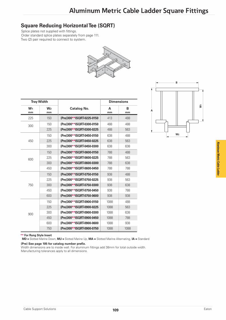
109
Aluminum Metric Cable Ladder Square Fittings
Cable Support Solutions Eaton
** For Rung Style InsertMD = Slotted Marine Down, MU = Slotted Marine Up, MA = Slotted Marine Alternating, IA = Standard
(Pre) See page 105 for catalog number prefix.Width dimensions are to inside wall. For aluminum fittings add 38mm for total outside width.Manufacturing tolerances apply to all dimensions.
Square Reducing Horizontal Tee (SQRT)Splice plates not supplied with fittings.Order standard splice plates separately from page 111.Two (2) pair required to connect to system.
Tray Width Dimensions
W1 W2 Catalog No. A B mm mm mm mm
225 150 (Pre)300**ISQRT-0225-0150 413 488
300 150 (Pre)300**ISQRT-0300-0150 488 488
225 (Pre)300**ISQRT-0300-0225 488 563
150 (Pre)300**ISQRT-0450-0150 638 488
450 225 (Pre)300**ISQRT-0450-0225 638 563
300 (Pre)300**ISQRT-0450-0300 638 638
150 (Pre)300**ISQRT-0600-0150 788 488
600 225 (Pre)300**ISQRT-0600-0225 788 563
300 (Pre)300**ISQRT-0600-0300 788 638
450 (Pre)300**ISQRT-0600-0450 788 788
150 (Pre)300**ISQRT-0750-0150 938 488
225 (Pre)300**ISQRT-0750-0225 938 563
750 300 (Pre)300**ISQRT-0750-0300 938 638
450 (Pre)300**ISQRT-0750-0450 938 788
600 (Pre)300**ISQRT-0750-0600 938 938
150 (Pre)300**ISQRT-0900-0150 1088 488
225 (Pre)300**ISQRT-0900-0225 1088 563
900 300 (Pre)300**ISQRT-0900-0300 1088 638
450 (Pre)300**ISQRT-0900-0450 1088 788
600 (Pre)300**ISQRT-0900-0600 1088 938
750 (Pre)300**ISQRT-0900-0750 1088 1088
B
A
W2
W1
Aluminum
Metric Cable Ladder
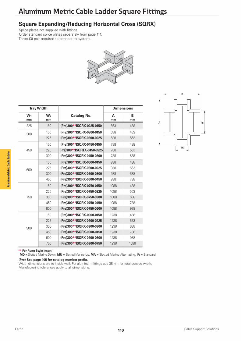
Aluminum Metric Cable Ladder Square Fittings
Cable Support SolutionsEaton 110
Square Expanding/Reducing Horizontal Cross (SQRX)Splice plates not supplied with fittings.Order standard splice plates separately from page 111.Three (3) pair required to connect to system.
** For Rung Style InsertMD = Slotted Marine Down, MU = Slotted Marine Up, MA = Slotted Marine Alternating, IA = Standard
(Pre) See page 105 for catalog number prefix.Width dimensions are to inside wall. For aluminum fittings add 38mm for total outside width.Manufacturing tolerances apply to all dimensions.
Tray Width Dimensions
W1 W2 Catalog No. A B mm mm mm mm
225 150 (Pre)300**ISQRX-0225-0150 563 488
300 150 (Pre)300**ISQRX-0300-0150 638 483
225 (Pre)300**ISQRX-0300-0225 638 563
150 (Pre)300**ISQRX-0450-0150 788 488
450 225 (Pre)300**ISQRTX-0450-0225 788 563
300 (Pre)300**ISQRX-0450-0300 788 638
150 (Pre)300**ISQRX-0600-0150 938 488
600 225 (Pre)300**ISQRX-0600-0225 938 563
300 (Pre)300**ISQRX-0600-0300 938 638
450 (Pre)300**ISQRX-0600-0450 938 788
150 (Pre)300**ISQRX-0750-0150 1088 488
225 (Pre)300**ISQRX-0750-0225 1088 563
750 300 (Pre)300**ISQRX-0750-0300 1088 638
450 (Pre)300**ISQRX-0750-0450 1088 788
600 (Pre)300**ISQRX-0750-0600 1088 938
150 (Pre)300**ISQRX-0900-0150 1238 488
225 (Pre)300**ISQRX-0900-0225 1238 563
900 300 (Pre)300**ISQRX-0900-0300 1238 638
450 (Pre)300**ISQRX-0900-0450 1238 788
600 (Pre)300**ISQRX-0900-0600 1238 938
750 (Pre)300**ISQRX-0900-0750 1238 1088
B
A
W2
W1
Alum
inum
Met
ric C
able
Ladd
er

111
Aluminum Metric Cable Ladder Accessories
Cable Support Solutions Eaton
Catalog No. Height mm
LSP100A 100 LSP125A 125 LSP150A 150 LSP175A 175
Catalog No. Height mm
LES100A 100 LES125A 125 LES150A 150 LES175A 175
Catalog No. Tray Height
LHSP150A 150 LHSP175A 175
Wedge Lock Splice Plates
• Furnished in pairs with M10 galvanized hardware.• SS6 hardware available upon request.• Standard 4-hole pattern.• Boxed in pairs with hardware.
Expansion Splice Plates
• Expansion plates allow for 25mm expansion or contraction of the cable ladder, or where expansion joints occur in the supporting structure. • Supplied in pairs with hardware. • Bonding jumpers are required on each side rail (sold separately). • Utilize (406mm) bonding jumper length.
150-H4 and 175-05 Mid-Span Splice
• Furnished in pairs with M10 galvanized hardware.• SS6 hardware available upon request.• Standard for 150 (Series H4) and 175 (Series 05) straight sections.• Available on ladder bottoms only with 225mm and 300mm rung spacing.
Aluminum
Metric Cable Ladder
Note: Supports required within 600mmof each side of expansion joint.To remove support requirements, utilizeB-Line series heavy duty expansionsplice (page 112)

Aluminum Metric Cable Ladder Square Fittings
Cable Support SolutionsEaton 112
Catalog No. Height mm
LHE150A 150 LHE175A 175
Heavy Duty Expansion Splice Plates
Heavy Duty Expansion Splice Plates are engineered to eliminate the recommendedadditional support at each expansion joint where cable ladder systems are utilized.They allow installers to support an expansion joint without additional supportsversus the traditional two supports.
Expansion joints are common in long-run outdoor applications where temperaturevariations result in thermal expansion and contraction of the cable ladder system.The installer using the traditional expansion splice would be required to install twosupports, one on either side of the expansion joint. By utilizing the B-Line seriesHeavy Duty Expansion Splice Plate, no additional supports are required.
• NEMA VE 2 Compliant• Lowest total cost of installation solution• Wrap-around design supports the side rail on bottom of each ladder section• Available Offering: Aluminum• Designed for easy installation in a variety of applications• Supplied in pairs with hardware• Utilize (600mm) bonding jumper length• Utilize with B-Line series Aluminum Cable Ladder Systems
- 150A04, 150AH4, & 175A05
Heavy Duty Expansion Splice Plates are one of five key attributes of the B-Lineseries cable ladder system that combine to yield significant opportunities to reducestructural steel supports in heavy industrial applications.To learn more, visit Eaton.com/sss.
Catalog No. Height mm
LSDP1210A 125 to 100 LSDP1510A 150 to 100 LSDP1710A 175 to 100 LSDP1512A 150 to 125 LSDP1712A 175 to 125 LSDP1715A 175 to 150
Requires supports within 600mmon both sides, per NEMA VE 2.
Step Down Splice Plates
• These splice plates are offered for connecting cable ladder sections having side rails of different heights.• Furnished in pairs with hardware.
Alum
inum
Met
ric C
able
Ladd
er
Patented
Horizontal Adjustable Splice Plates• Offered to adjust a cable ladder run for changes in direction in a horizontal plane that do not conform to standard horizontal fittings.• Furnished in pairs with hardware.• Bonding jumpers not required.• (X) Insert 100, 125, 150 or 175 for side rail height.
Catalog Cable Tray Thru Tray Width ‘L’ No. End Cut mm mm
LHA(X)A Mitered 900 NALRE(X)A-1000 Not mitered 900 1041
LHA(X)AOn pair splice plates only
LRE(X)A-1000One pair splice plates with extensions.
L
L
Requires supports within 600mmon both sides, per NEMA VE 2.

113
Aluminum Metric Cable Ladder Accessories
Cable Support Solutions Eaton
Catalog No. Height mm
LVA100A 100 LVA125A 125 LVA150A 150 LVA175A 175
Vertical Adjustable Splice Plates
• These plates provide for changes in elevation that do not conform to standard vertical fittings.• Furnished in pairs with hardware.• Bonding jumpers not required.
Branch Pivot Connectors• Branch from existing cable ladder runs at any point.• Pivot to any required angle.• UL Classified for grounding (bonding jumpers not required).• Furnished in pairs with hardware.
Catalog No. Height mm
LBP100A 100 LBP125A 125 LBP150A 150 LBP175A 175
Aluminum
Metric Cable Ladder
Eaton.com/sss
Vertical Riser Assembly
• Splice plates, riser, and hardware included.• Packaged unassembled.
Ladder Height Ladder Width Catalog mm mm No.
150 LVR100A-150 225 LVR100A-225 300 LVR100A-300 100 450 LVR100A-450 600 LVR100A-600 750 LVR100A-750 900 LVR100A-900
150 LVR125A-150 225 LVR125A-225 300 LVR125A-300 125 450 LVR125A-450 600 LVR125A-600 750 LVR125A-750 900 LVR125A-900
150 LVR150A-150 225 LVR150A-225 300 LVR150A-300 150 450 LVR150A-450 600 LVR150A-600 750 LVR150A-750 900 LVR150A-900
150 LVR175A-150 225 LVR1175A-225 300 LVR1175A-300 175 450 LVR1175A-450 600 LVR1175A-600 750 LVR1175A-750 900 LVR1175A-900
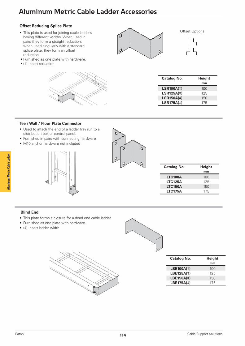
Aluminum Metric Cable Ladder Accessories
Cable Support SolutionsEaton 114
Offset Reducing Splice Plate
• This plate is used for joining cable ladders having different widths. When used in pairs they form a straight reduction; when used singularly with a standard splice plate, they form an offset reduction. • Furnished as one plate with hardware. • (‡) Insert reduction
Tee / Wall / Floor Plate Connector• Used to attach the end of a ladder tray run to a distribution box or control panel.• Furnished in pairs with connecting hardware• M10 anchor hardware not included
Catalog No. Height mm
LTC100A 100 LTC125A 125 LTC150A 150 LTC175A 175
Catalog No. Height mm
LSR100A(‡) 100 LSR125A(‡) 125 LSR150A(‡) 150 LSR175A(‡) 175
Blind End• This plate forms a closure for a dead end cable ladder.• Furnished as one plate with hardware.• (‡) Insert ladder width
Catalog No. Height mm
LBE100A(‡) 100 LBE125A(‡) 125 LBE150A(‡) 150 LBE175A(‡) 175
Alum
inum
Met
ric C
able
Ladd
er
Offset Options
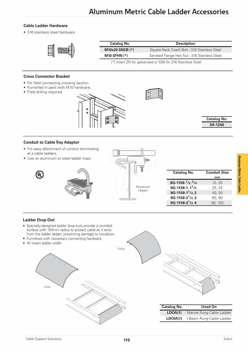
115
Aluminum Metric Cable Ladder Accessories
Cable Support Solutions Eaton
Catalog No. Description
M10x20 SNCB (*) Square Neck Coach Bolt - 316 Stainless Steel
M10 SFHN (*) Serrated Flange Hex Nut - 316 Stainless Steel
Cable Ladder Hardware
• 316 stainless steel hardware
Catalog No.
9A-1240
Catalog No. Conduit Size mm
9G-1158-1/2, 3/4 15, 20 9G-1158-1, 11/4 25, 32 9G-1158-11/2, 2 40, 50 9G-1158-21/2, 3 65, 80 9G-1158-31/2, 4 90, 100
Cross Connector Bracket
• For field connecting crossing section.• Furnished in pairs with M10 hardware.• Field drilling required.
Conduit to Cable Tray Adaptor
• For easy attachment of conduit terminating at a cable ladders.• Use on aluminum or steel ladder trays.
AluminumI-Beam
Ladder Drop-Out• Specially-designed ladder drop-outs provide a rounded surface with 100mm radius to protect cable as it exits from the ladder ladder, preventing damage to insulation.• Furnished with necessary connecting hardware. • (‡) Insert ladder width
Catalog No. Used On
LDOA(‡) Marine Rung Cable Ladder
LDOIA(‡) I-Beam Rung Cable Ladder
LDOA
LDOIA
Aluminum
Metric Cable Ladder
(*) Insert ZN for galvanized or SS6 for 316 Stainless Steel

Aluminum Metric Cable Ladder Accessories
Cable Support SolutionsEaton 116
Cable Tray Clamp/Guide• Features a no-twist design.• Has four times the strength of the traditional design.• Each side is labeled to ensure proper installation.• Furnished in pairs, with or without hardware.• Not recommended for vertical support.
Note: For heavy duty or vertical applications see LHD-1241 or LHD-1242 page 119
Catalog No. Without With Overall Hardware Hardware Hardware Length Size Finish mm
9ZN-1204 9ZN-1204NB 38 M8 G90 9ZN-1208 9ZN-1208NB 57 M10 G90 9A-1205 -- 57 M12 Alum. 9G-1205 -- 57 M12 HDGAF 9SS6-1205 -- 57 M12 316SS 9ZN-1205 -- 57 M12 G90
9ZN-1204 shown.Installed as a guide.
9ZN-1208 shown.Installed as a clamp.
Patent # RE35479
11/2"(39mm)
21/4"(57mm)
Combination Hold Down Guide Clamp
• Concentric hole location for ease of application.• Material: 6063-T6 copper free aluminum• Compatible with aluminum and steel side rails• Allows for predrilled I-Beam locations• Designed for multiple support methods• No twist feature compatible with strut profile• Visual indicators for proper assembly• Hardware sold separately
Catalog No.
9A-1206
Alum
inum
Met
ric C
able
Ladd
er
Guide Application Clamp Application
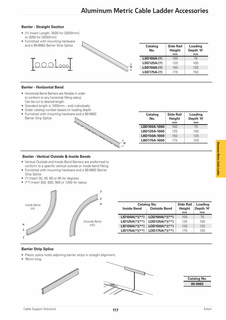
117
Aluminum Metric Cable Ladder Accessories
Cable Support Solutions Eaton
Barrier - Vertical Outside & Inside Bends• Vertical Outside and Inside Bend Barriers are preformed to conform to a specific vertical outside or inside bend fitting.• Furnished with mounting hardware and a 99-9982 Barrier Strip Splice.• (*) Insert 30, 45, 60 or 90 for degrees• (**) Insert 300, 600, 900 or 1200 for radius
Catalog No. Side Rail Loading Inside Bend Outside Bend Height Depth 'H' mm mm
LID100A(*)(**) LOD100A(*)(**) 100 75 LID125A(*)(**) LOD125A(*)(**) 125 100 LID150A(*)(**) LOD150A(*)(**) 150 125
LID175A(*)(**) LOD175A(*)(**) 175 150
Outside Bend(VO)
Inside Bend(VI)
H
H
Catalog No.
99-9982
Barrier Strip Splice
• Plastic splice holds adjoining barrier strips in straight alignment.• 76mm long.
Aluminum
Metric Cable Ladder
Barrier - Horizontal Bend
• Horizontal Bend Barriers are flexible in order to conform to any horizontal fitting radius. Can be cut to desired length.• Standard length is 1000mm - sold individually• Order catalog number based on loading depth.• Furnished with mounting hardware and a 99-9982 Barrier Strip Splice.
H
Catalog Side Rail Loading No. Height Depth 'H' mm mm
LBD100A-1000 100 75LBD125A-1000 125 100LBD150A-1000 150 125LBD175A-1000 175 150
Barrier - Straight Section
• (†) Insert Length: 3000 for [3000mm] or 3050 for [3050mm]• Furnished with mounting hardware and a 99-9982 Barrier Strip Splice. Catalog Side Rail Loading
No. Height Depth 'H' mm mm
LSD100A-(†) 100 75 LSD125A-(†) 125 100 LSD150A-(†) 150 125 LSD175A-(†) 175 150
H
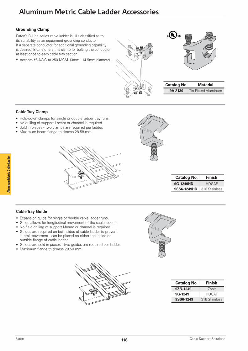
Aluminum Metric Cable Ladder Accessories
Cable Support SolutionsEaton 118
Grounding Clamp
Eaton’s B-Line series cable ladder is UL® classified as toits suitability as an equipment grounding conductor.If a separate conductor for additional grounding capabilityis desired, B-Line offers this clamp for bolting the conductorat least once to each cable tray section.
• Accepts #6 AWG to 250 MCM. (3mm - 14.5mm diameter)
Catalog No. Material 9A-2130 Tin Plated Aluminum
Cable Tray Clamp
• Hold-down clamps for single or double ladder tray runs.• No drilling of support I-beam or channel is required.• Sold in pieces - two clamps are required per ladder.• Maximum beam flange thickness 28.58 mm.
Cable Tray Guide
• Expansion guide for single or double cable ladder runs.• Guide allows for longitudinal movement of the cable ladder.• No field drilling of support I-beam or channel is required.• Guides are required on both sides of cable ladder to prevent lateral movement - can be placed on either the inside or outside flange of cable ladder.• Guides are sold in pieces - two guides are required per ladder.• Maximum flange thickness 28.58 mm.
Catalog No. Finish
9G-1249HD HDGAF9SS6-1249HD 316 Stainless
Catalog No. Finish9ZN-1249 Znplt9G-1249 HDGAF9SS6-1249 316 Stainless
Alum
inum
Met
ric C
able
Ladd
er

119
Aluminum Metric Cable Ladder Accessories
Cable Support Solutions Eaton
Heavy Duty Hold Down Bracket• Design load is 2000 lbs (8.89kN) per pair.• Two bolt design.• Sold in pairs.• M8 cable tray attachment hardware provided• M12 support attachment hardware not provided.• (*) Insert G or SS6• Recommended for support of vertical ladders.
Catalog No.
LHD-1241(*)
Heavy Duty Hold Down Bracket• Design load is 4000 lbs (17.79kN) per pair.• Four bolt design.• Sold in pairs.• M8 cable tray attachment hardware provided• M12 support attachment hardware not provided.• (*) Insert G or SS6• Recommended for support of vertical ladders. Catalog No.
LHD-1242(*)
Hardware Size Catalog No.
M6 LEIK-M6 M8 LEIK-M8 M10 LEIK-M10 M12 LEIK-M12
Isolation Kit for Metric Cable Ladder • Supplied as one kit with hardware. • Material: HDPE
Aluminum
Metric Cable Ladder
3mm
76mm
152mm
Nylon Pad
• Use for friction reduction.• Hardness: Shore D80.• Low friction coefficient.• UV resistant.• Excellent weatherability.• UL - 94HB.
Catalog No.
99-PE36

Aluminum Metric Cable Ladder Accessories
Cable Support SolutionsEaton 120
Catalog No.
LNP1(*)
LNP2(*)
Equipment Name Plates • Support plate for TAG - Number on cable ladders and cable trays. • Furnished as one plate with hardware. • (*) Insert A, G, or SS6
LNP2
LNP1
Alum
inum
Met
ric C
able
Ladd
er
71/2"(190mm)
A
Catalog No. Outside 'A' Cable Tray Ht. mm
LVHS100A 100 97.54LVHS125A 125 120.14LVHS150A 150 148.34LVHS175A 175 173.74
Vertical Hanger Splice Plates• Design load is 1500 lbs (6.67kN) per pair.• Safety Factor of 2.5• Furnished in pairs.• Hole size: 14mm for M12 threaded rod.

Perforated & Solid Bottom Cable Tray
121Cable Support Solutions Eaton
Perf. & Solid Bottom Cable Tray
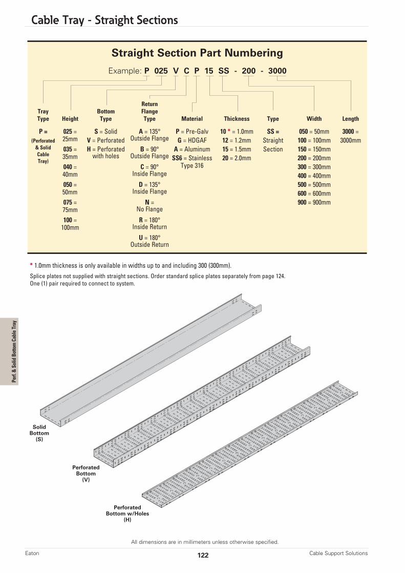
Cable Tray - Straight Sections
All dimensions are in millimeters unless otherwise specified.
Cable Support SolutionsEaton 122
Straight Section Part Numbering
Example: P 025 V C P 15 SS - 200 - 3000
ReturnTray Bottom FlangeType Height Type Type Material Thickness Type Width Length
P = 025 = S = Solid A = 135° P = Pre-Galv 10 * = 1.0mm SS = 050 = 50mm 3000 = (Perforated 25mm V = Perforated Outside Flange G = HDGAF 12 = 1.2mm Straight 100 = 100mm 3000mm& Solid 035 = H = Perforated B = 90° A = Aluminum 15 = 1.5mm Section 150 = 150mmCable 35mm with holes Outside Flange SS6 = Stainless 20 = 2.0mm 200 = 200mmTray)
040 = C = 90° Type 316 300 = 300mm40mm Inside Flange 400 = 400mm050 = D = 135° 500 = 500mm50mm Inside Flange 600 = 600mm075 = N = 900 = 900mm75mm No Flange
100 = R = 180°100mm Inside Return
U = 180°Outside Return
* 1.0mm thickness is only available in widths up to and including 300 (300mm).Splice plates not supplied with straight sections. Order standard splice plates separately from page 124.One (1) pair required to connect to system.
SolidBottom
(S)
PerforatedBottom w/Holes
(H)
PerforatedBottom(V)
Perf. & Solid Bottom Cable Tray

Cable Tray - Straight Sections
All dimensions are in millimeters unless otherwise specified.
123Cable Support Solutions Eaton
A - 135°OutsideFlange
Straight Section Flange Types
Tray Thickness Span Material Load Material LoadHeight mm m kg/m kg/m
25 NA
35 Steel NA
40 1.0 3 & NA
50 Stainless 54.9
75 Steel 71.7
100 80.4
25 NA NA
35 Steel NA NA
40 1.5 3 & NA Aluminum NA
50 Stainless 103.6 33.5
75 Steel 158.5 52.6
100 182.9 73.4
25 NA NA
35 Steel NA NA
40 2.0 3 & NA Aluminum NA
50 Stainless 79.2 46.8
75 Steel 201.2 101.5
100 219.4 115.8
B - 90°OutsideFlange
U - 180°OutsideFlange
D - 135°InsideFlange
C - 90°InsideFlange
R - 180°InsideFlange
N - NoFlange
All tests per NEMA VE-1. 1.0mm thickness to maximum width of 300mm. All others tested to 900mm width.
Published load safety factor is 1.5.
NA = Not available
025 035 040 050 075 100
25mm35mm 40mm
50mm75mm
100mm
Tray Heights Series
Perf. & Solid Bottom Cable Tray
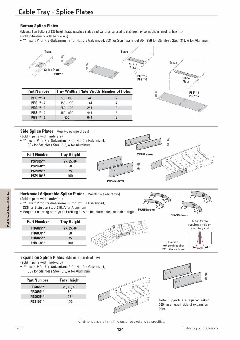
Cable Tray - Splice Plates
All dimensions are in millimeters unless otherwise specified.
Part Number Tray Widths Plate Width Number of Holes
PBS ** -1 50 - 100 44 2PBS ** -2 150 - 200 144 4PBS ** -3 250 - 400 244 4PBS ** -4 450 - 600 444 6PBS ** -5 900 644 6
Part Number Tray Height
PSP025** 25, 35, 40PSP050** 50PSP075** 75PSP100** 100
Part Number Tray Height
PHA025** 25, 35, 40PHA050** 50PHA075** 75PHA100** 100
Bottom Splice Plates (Mounted on bottom of 025 height trays as splice plates and can also be used to stabilize tray connections on other heights)(Sold individually with hardware)• ** Insert P for Pre-Galvanized, G for Hot Dip Galvanized, SS4 for Stainless Steel 304, SS6 for Stainless Steel 316, A for Aluminum
Side Splice Plates (Mounted outside of tray)(Sold in pairs with hardware)• ** Insert P for Pre-Galvanized, G for Hot Dip Galvanized,
SS6 for Stainless Steel 316, A for Aluminum
Horizontal Adjustable Splice Plates (Mounted outside of tray)(Sold in pairs with hardware)• ** Insert P for Pre-Galvanized, G for Hot Dip Galvanized,SS6 for Stainless Steel 316, A for Aluminum• Requires mitering of trays and drilling new splice plate holes on inside angle
Cable Support SolutionsEaton 124
Expansion Splice Plates (Mounted outside of tray)(Sold in pairs with hardware)• ** Insert P for Pre-Galvanized, G for Hot Dip Galvanized,
SS6 for Stainless Steel 316, A for Aluminum
Part Number Tray Height
PES025** 25, 35, 40PES050** 50PES075** 75PES100** 100
Trays
PBS**-1PBS**-2PBS**-3
PBS**-4PBS**-5
Splice Plate
SplicePlate
Trays
SplicePlate
Trays
PSP075 shown
PSP050 shown
Miter 1/2 therequired angle oneach tray end
Example:40° bend requires20° miter each end angle
PHA050 shown
PHA075 shown
Perf. & Solid Bottom Cable Tray
Note: Supports are required within600mm on each side of expansionjoint.
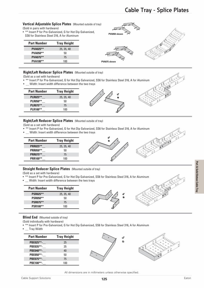
Cable Tray - Splice Plates
All dimensions are in millimeters unless otherwise specified.
Vertical Adjustable Splice Plates (Mounted outside of tray)(Sold in pairs with hardware)• ** Insert P for Pre-Galvanized, G for Hot Dip Galvanized,SS6 for Stainless Steel 316, A for Aluminum
125Cable Support Solutions Eaton
Part Number Tray Height
PVA025** 25, 35, 40PVA050** 50PVA075** 75PVA100** 100
Part Number Tray Height
PLR025**__ 25, 35, 40PLR050**__ 50PLR075**__ 75PLR100**__ 100
Part Number Tray Height
PSR025** 25, 35, 40PSR050** 50PSR075** 75PSR100** 100
Part Number Tray Height
PBE025**-__ 25PBE035**-__ 35PBE040**-__ 40PBE050**-__ 50PBE075**-__ 75PBE100**-__ 100
Part Number Tray Height
PRR025**__ 25, 35, 40PRR050**__ 50PRR075**__ 75PRR100**__ 100
Blind End (Mounted outside of tray)(Sold individually with hardware)• ** Insert P for Pre-Galvanized, G for Hot Dip Galvanized, SS6 for Stainless Steel 316, A for Aluminum• __ Tray Width
Straight Reducer Splice Plates (Mounted outside of tray)(Sold as a set with hardware)• ** Insert P for Pre-Galvanized, G for Hot Dip Galvanized, SS6 for Stainless Steel 316, A for Aluminum• __ Width: Insert width difference between the two trays
Right/Left Reducer Splice Plates (Mounted outside of tray)(Sold as a set with hardware)• ** Insert P for Pre-Galvanized, G for Hot Dip Galvanized, SS6 for Stainless Steel 316, A for Aluminum• __ Width: Insert width difference between the two trays
Right/Left Reducer Splice Plates (Mounted outside of tray)(Sold as a set with hardware)• ** Insert P for Pre-Galvanized, G for Hot Dip Galvanized, SS6 for Stainless Steel 316, A for Aluminum• __ Width: Insert width difference between the two trays
PVA050 shown
PVA075 shown
Perf. & Solid Bottom Cable Tray

Cable Tray - Cover Clamps, Hold Downs, Hardware
All dimensions are in millimeters unless otherwise specified.
Wrap-Around Cover Clamps(Sold individually with hardware)• ** Insert P for Pre-Galvanized, G for Hot Dip Galvanized, SS6 for Stainless Steel 316, A for Aluminum• __ Insert Tray Width of
050 = 50mm, 100 = 100mm, 150 = 150mm, 200 = 200mm, 300 = 300mm, 400 = 400mm,500 = 500mm, 600 = 600mm, 900 = 900mm
C-Shape Cover Clamps(Sold individually with hardware)• ** Insert G for Hot Dip Galvanized, SS6 for Stainless Steel 316, A for Aluminum
* Is not available in 900mm wide tray
Cable Support SolutionsEaton 126
Part Number Tray Height
PWCC025**__ 25 *PWCC035**__ 35PWCC040**__ 40PWCC050**__ 50PWCC075**__ 75PWCC100**__ 100
Part Number Tray Height
PCCC025** 25PCCC035** 35PCCC040** 40PCCC050** 50PCCC075** 75PCCC100** 100
Drop-Out(Sold individually with hardware)• ** Insert P for Pre-Galvanized, G for Hot Dip Galvanized, SS6 for Stainless Steel 316, A for Aluminum
Part Number Tray Width
PDO**-050 50PDO**-100 100PDO**-150 150PDO**-200 200PDO**-300 300PDO**-400 400PDO**-500 500PDO**-600 600PDO**-900 900
Perf. & Solid Bottom Cable Tray
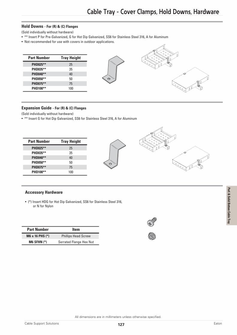
Cable Tray - Cover Clamps, Hold Downs, Hardware
All dimensions are in millimeters unless otherwise specified.
Accessory Hardware
• (*) Insert HDG for Hot Dip Galvanized, SS6 for Stainless Steel 316,or N for Nylon
127Cable Support Solutions Eaton
Perf. & Solid Bottom Cable Tray
Hold Downs - For (R) & (C) Flanges(Sold individually without hardware)• ** Insert P for Pre-Galvanized, G for Hot Dip Galvanized, SS6 for Stainless Steel 316, A for Aluminum• Not recommended for use with covers in outdoor applications.
Part Number Tray Height
PHD025** 25PHD035** 35PHD040** 40PHD050** 50PHD075** 75PHD100** 100
Expansion Guide - For (R) & (C) Flanges(Sold individually without hardware)• ** Insert G for Hot Dip Galvanized, SS6 for Stainless Steel 316, A for Aluminum
Part Number Tray Height
PHD025** 25PHD035** 35PHD040** 40PHD050** 50PHD075** 75PHD100** 100
Part Number Item
M6 x 16 PHS (*) Phillips Head Screw
M6 SFHN (*) Serrated Flange Hex Nut

Cable Tray - Fittings
All dimensions are in millimeters unless otherwise specified.
Cable Tray Fittings are designed to support cables as they transition directions.
Note: Perforated slot dimensions and patterns may vary depending on tray size and type.All fitting bottom are shown as solid bottoms. Perforated bottoms are available.
Fittings Part Numbering
Example: P F 050 V N SS6 10 HB - 200 - 60 R600
ReturnTray Radius Bottom Flange Angle †Type Detail Height Type Type Material Thickness Type Width (°) Radius
P = F = 025 = S = N = P = Pre-Galv 10 * = 1.0mm HB 050 = 50mm 30 R300 =(Perforated Formed 25mm Solid No Flange G = HDGAF 15 = 1.5mm HT † 100 = 100mm 45 300mm& Solid M = 035 = V = R = SS6 = 20 = 2.0mm HX † 150 = 150mm 60 R600 =Cable Mitered 35mm Perforated 180° Return Stainless VO *** 200 = 200mm 90 600mmTray)
040 = C = Type 316 VI *** 300 = 300mm R900 =40mm 90° Inside A = RR † D 400 = 400mm 900mm050 = Aluminum LR † D 500 = 500mm50mm SR † D 600 = 600mm075 = 900 = 900mm75mm100 =100mm
Prefix Suffix
HBHorizontal Bend(C) Formed Shown
HTHorizontal Tee(R) Mitered Shown
HXHorizontal Cross(C) Formed Shown
VOVertical Outside Bend
(C) Formed Only
VIVertical Inside Bend(R) Formed Only
LRRight Reducer(C) Mitered Only
RRLeft Reducer(C) Mitered Only
SRStraight Reducer(R) Mitered Only
* 1.0mm thickness is only available in widths up to and including 300 (300mm).† No angle designation required on these fittings. See fitting page when creating part numbers.*** Not available in mitered styleD Available in mitered style only
Cable Support SolutionsEaton 128
Perf. & Solid Bottom Cable Tray
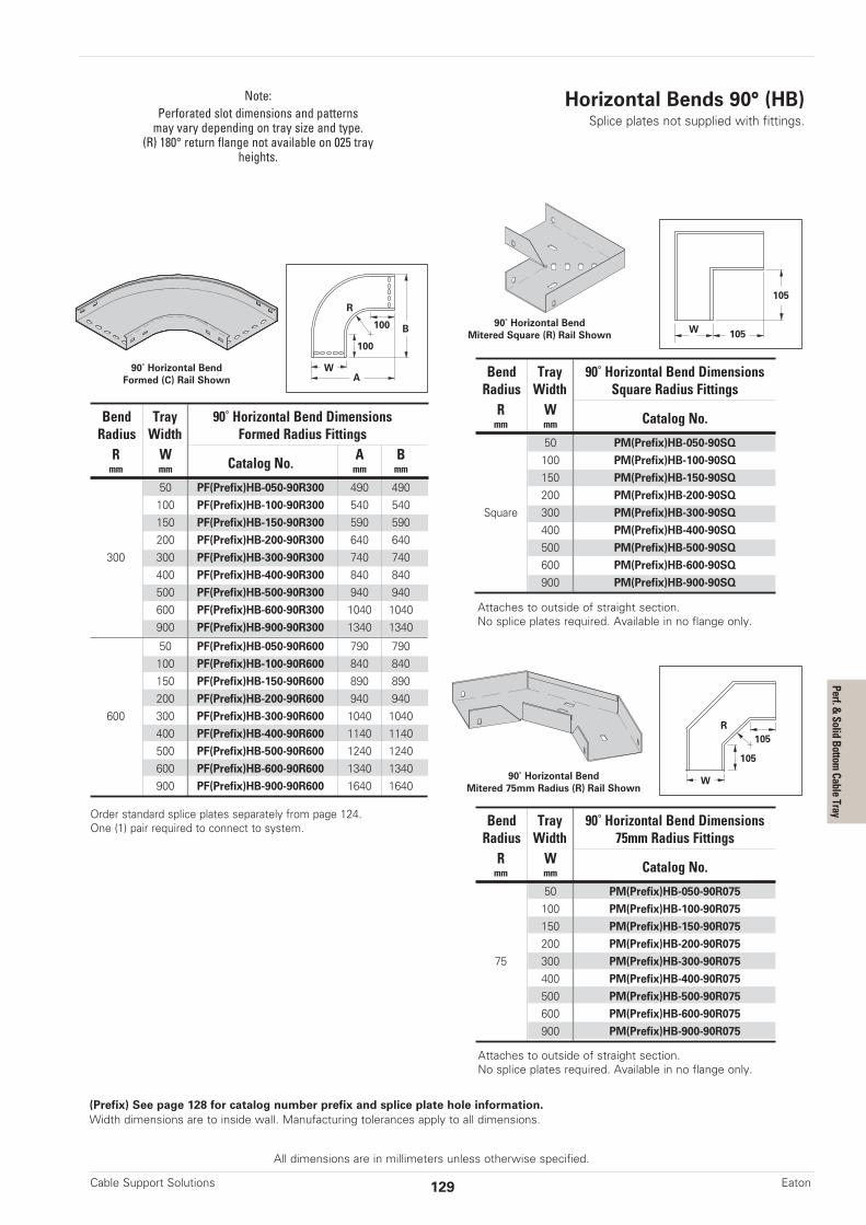
All dimensions are in millimeters unless otherwise specified.
Horizontal Bends 90° (HB)Splice plates not supplied with fittings.
(Prefix) See page 128 for catalog number prefix and splice plate hole information.Width dimensions are to inside wall. Manufacturing tolerances apply to all dimensions.
Note:Perforated slot dimensions and patternsmay vary depending on tray size and type.(R) 180° return flange not available on 025 tray
heights.
129Cable Support Solutions Eaton
Bend Tray 90˚ Horizontal Bend DimensionsRadius Width Formed Radius FittingsR W Catalog No. A Bmm mm mm mm
50 PF(Prefix)HB-050-90R300 490 490100 PF(Prefix)HB-100-90R300 540 540150 PF(Prefix)HB-150-90R300 590 590200 PF(Prefix)HB-200-90R300 640 640
300 300 PF(Prefix)HB-300-90R300 740 740400 PF(Prefix)HB-400-90R300 840 840500 PF(Prefix)HB-500-90R300 940 940600 PF(Prefix)HB-600-90R300 1040 1040900 PF(Prefix)HB-900-90R300 1340 1340
50 PF(Prefix)HB-050-90R600 790 790100 PF(Prefix)HB-100-90R600 840 840150 PF(Prefix)HB-150-90R600 890 890200 PF(Prefix)HB-200-90R600 940 940
600 300 PF(Prefix)HB-300-90R600 1040 1040400 PF(Prefix)HB-400-90R600 1140 1140500 PF(Prefix)HB-500-90R600 1240 1240600 PF(Prefix)HB-600-90R600 1340 1340900 PF(Prefix)HB-900-90R600 1640 1640
Bend Tray 90˚ Horizontal Bend DimensionsRadius Width Square Radius FittingsR W Catalog No.mm mm
50 PM(Prefix)HB-050-90SQ
100 PM(Prefix)HB-100-90SQ
150 PM(Prefix)HB-150-90SQ
200 PM(Prefix)HB-200-90SQ
Square 300 PM(Prefix)HB-300-90SQ
400 PM(Prefix)HB-400-90SQ
500 PM(Prefix)HB-500-90SQ
600 PM(Prefix)HB-600-90SQ
900 PM(Prefix)HB-900-90SQ
Bend Tray 90˚ Horizontal Bend DimensionsRadius Width 75mm Radius FittingsR W Catalog No.mm mm
50 PM(Prefix)HB-050-90R075
100 PM(Prefix)HB-100-90R075
150 PM(Prefix)HB-150-90R075
200 PM(Prefix)HB-200-90R075
75 300 PM(Prefix)HB-300-90R075
400 PM(Prefix)HB-400-90R075
500 PM(Prefix)HB-500-90R075
600 PM(Prefix)HB-600-90R075
900 PM(Prefix)HB-900-90R075
90˚ Horizontal BendFormed (C) Rail Shown
A
100
100
W
R
B
90˚ Horizontal BendMitered 75mm Radius (R) Rail Shown
105
105
W
R
90˚ Horizontal BendMitered Square (R) Rail Shown
105
105W
Order standard splice plates separately from page 124.One (1) pair required to connect to system.
Attaches to outside of straight section.No splice plates required. Available in no flange only.
Attaches to outside of straight section.No splice plates required. Available in no flange only.
Perf. & Solid Bottom Cable Tray

Cable Tray - Fittings
All dimensions are in millimeters unless otherwise specified.
Horizontal Bends 60° (HB)Splice plates not supplied with fittings.
100
100
B
60˚ Horizontal BendFormed (C) Shown
R
A
(Prefix) See page 128 for catalog number prefix and splice plate hole information.Width dimensions are to inside wall. Manufacturing tolerances apply to all dimensions.
Note:Perforated slot dimensions and patternsmay vary depending on tray size and type.
(R) 180° return flange not available on 025 tray heights.
W
Cable Support SolutionsEaton 130
Bend Tray 60˚ Horizontal Bend DimensionsRadius Width Formed Radius FittingsR W Catalog No. A Bmm mm mm mm
50 PF(Prefix)HB-050-60R300 321 513100 PF(Prefix)HB-100-60R300 371 556150 PF(Prefix)HB-150-60R300 421 600200 PF(Prefix)HB-200-60R300 471 643
300 300 PF(Prefix)HB-300-60R300 571 730400 PF(Prefix)HB-400-60R300 671 816500 PF(Prefix)HB-500-60R300 771 903600 PF(Prefix)HB-600-60R300 871 989900 PF(Prefix)HB-900-60R300 1171 124950 PF(Prefix)HB-050-60R600 471 773100 PF(Prefix)HB-100-60R600 521 816150 PF(Prefix)HB-150-60R600 571 850200 PF(Prefix)HB-200-60R600 621 903
600 300 PF(Prefix)HB-300-60R600 721 989400 PF(Prefix)HB-400-60R600 821 1076500 PF(Prefix)HB-500-60R600 921 1163600 PF(Prefix)HB-600-60R600 1021 1249900 PF(Prefix)HB-900-60R600 1321 1509
Order standard splice plates separately from page 124.One (1) pair required to connect to system.
Perf. & Solid Bottom Cable Tray
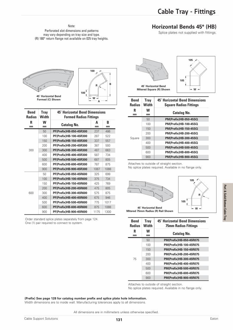
Cable Tray - Fittings
All dimensions are in millimeters unless otherwise specified.
Horizontal Bends 45° (HB)Splice plates not supplied with fittings.
Note:Perforated slot dimensions and patternsmay vary depending on tray size and type.
(R) 180° return flange not available on 025 tray heights.
131Cable Support Solutions Eaton
Bend Tray 45˚ Horizontal Bend DimensionsRadius Width Formed Radius FittingsR W Catalog No. A Bmm mm mm mm
50 PF(Prefix)HB-050-45R300 237 486100 PF(Prefix)HB-100-45R300 287 522150 PF(Prefix)HB-150-45R300 337 557200 PF(Prefix)HB-200-45R300 387 593
300 300 PF(Prefix)HB-300-45R300 487 663400 PF(Prefix)HB-400-45R300 587 734500 PF(Prefix)HB-500-45R300 687 805600 PF(Prefix)HB-600-45R300 787 875900 PF(Prefix)HB-900-45R300 1087 1088
50 PF(Prefix)HB-050-45R600 325 699100 PF(Prefix)HB-100-45R600 375 734150 PF(Prefix)HB-150-45R600 425 769200 PF(Prefix)HB-200-45R600 475 805
600 300 PF(Prefix)HB-300-45R600 575 875400 PF(Prefix)HB-400-45R600 675 946500 PF(Prefix)HB-500-45R600 775 1017600 PF(Prefix)HB-600-45R600 875 1088900 PF(Prefix)HB-900-45R600 1175 1300
Bend Tray 45˚ Horizontal Bend DimensionsRadius Width Square Radius FittingsR W Catalog No.mm mm
50 PM(Prefix)HB-050-45SQ
100 PM(Prefix)HB-100-45SQ
150 PM(Prefix)HB-150-45SQ
200 PM(Prefix)HB-200-45SQ
Square 300 PM(Prefix)HB-300-45SQ
400 PM(Prefix)HB-400-45SQ
500 PM(Prefix)HB-500-45SQ
600 PM(Prefix)HB-600-45SQ
900 PM(Prefix)HB-900-45SQ
Bend Tray 45˚ Horizontal Bend DimensionsRadius Width 75mm Radius FittingsR W Catalog No.mm mm
50 PM(Prefix)HB-050-45R075
100 PM(Prefix)HB-100-45R075
150 PM(Prefix)HB-150-45R075
200 PM(Prefix)HB-200-45R075
75 300 PM(Prefix)HB-300-45R075
400 PM(Prefix)HB-400-45R075
500 PM(Prefix)HB-500-45R075
600 PM(Prefix)HB-600-45R075
900 PM(Prefix)HB-900-45R075
45˚ Horizontal BendFormed (C) Shown
100
100
BR
AW
45˚ Horizontal BendMitered 75mm Radius (R) Rail Shown
105
105
R
W
45˚ Horizontal BendMitered Square (R) Shown
105
105
W
(Prefix) See page 128 for catalog number prefix and splice plate hole information.Width dimensions are to inside wall. Manufacturing tolerances apply to all dimensions.
Order standard splice plates separately from page 124.One (1) pair required to connect to system.
Attaches to outside of straight section.No splice plates required. Available in no flange only.
Attaches to outside of straight section.No splice plates required. Available in no flange only.
Perf. & Solid Bottom Cable Tray
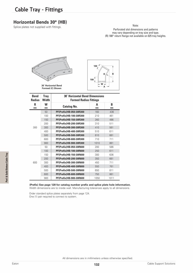
Cable Tray - Fittings
All dimensions are in millimeters unless otherwise specified.
Horizontal Bends 30° (HB)Splice plates not supplied with fittings.
30˚ Horizontal BendFormed (C) Shown
(Prefix) See page 128 for catalog number prefix and splice plate hole information.Width dimensions are to inside wall. Manufacturing tolerances apply to all dimensions.
Note:Perforated slot dimensions and patternsmay vary depending on tray size and type.
(R) 180° return flange not available on 025 tray heights.
100
100
BR
AW
Cable Support SolutionsEaton 132
Bend Tray 30˚ Horizontal Bend DimensionsRadius Width Formed Radius FittingsR W Catalog No. A Bmm mm mm mm
50 PF(Prefix)HB-050-30R300 160 436100 PF(Prefix)HB-100-30R300 210 461150 PF(Prefix)HB-150-30R300 260 486200 PF(Prefix)HB-200-30R300 310 511
300 300 PF(Prefix)HB-300-30R300 410 561400 PF(Prefix)HB-400-30R300 510 611500 PF(Prefix)HB-500-30R300 610 661600 PF(Prefix)HB-600-30R300 710 711900 PF(Prefix)HB-900-30R300 1010 86150 PF(Prefix)HB-050-30R600 200 586100 PF(Prefix)HB-100-30R600 250 611150 PF(Prefix)HB-150-30R600 300 636200 PF(Prefix)HB-200-30R600 350 661
600 300 PF(Prefix)HB-300-30R600 450 711400 PF(Prefix)HB-400-30R600 550 761500 PF(Prefix)HB-500-30R600 650 811600 PF(Prefix)HB-600-30R600 750 861900 PF(Prefix)HB-900-30R600 1050 1011
Order standard splice plates separately from page 124.One (1) pair required to connect to system.
Perf. & Solid Bottom Cable Tray
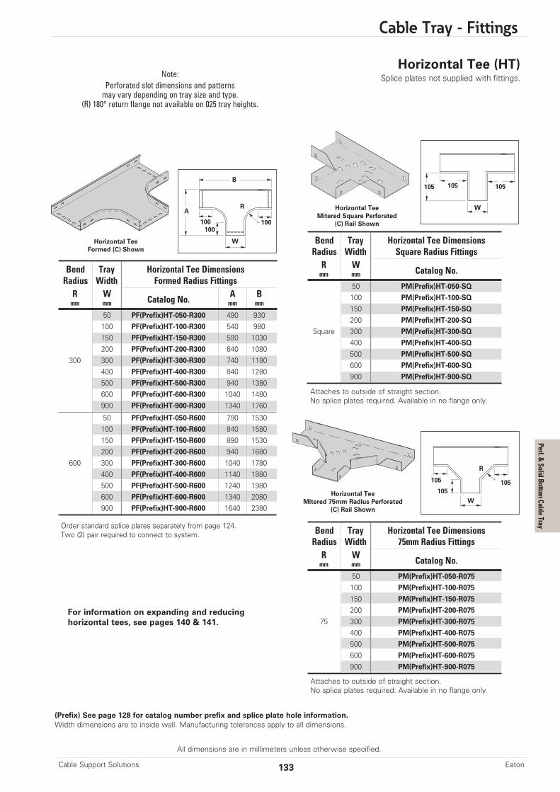
Cable Tray - Fittings
All dimensions are in millimeters unless otherwise specified.
Horizontal Tee (HT)Splice plates not supplied with fittings.
A
B
R
WHorizontal TeeFormed (C) Shown
(Prefix) See page 128 for catalog number prefix and splice plate hole information.Width dimensions are to inside wall. Manufacturing tolerances apply to all dimensions.
100100100
W
105 105 105
Note:Perforated slot dimensions and patternsmay vary depending on tray size and type.
(R) 180° return flange not available on 025 tray heights.
133Cable Support Solutions Eaton
Horizontal TeeMitered Square Perforated
(C) Rail Shown
Horizontal TeeMitered 75mm Radius Perforated
(C) Rail Shown
R
W
105105
105
Bend Tray Horizontal Tee DimensionsRadius Width Formed Radius FittingsR W Catalog No. A Bmm mm mm mm
50 PF(Prefix)HT-050-R300 490 930100 PF(Prefix)HT-100-R300 540 980150 PF(Prefix)HT-150-R300 590 1030200 PF(Prefix)HT-200-R300 640 1080
300 300 PF(Prefix)HT-300-R300 740 1180400 PF(Prefix)HT-400-R300 840 1280500 PF(Prefix)HT-500-R300 940 1380600 PF(Prefix)HT-600-R300 1040 1480900 PF(Prefix)HT-900-R300 1340 1760
50 PF(Prefix)HT-050-R600 790 1530100 PF(Prefix)HT-100-R600 840 1580150 PF(Prefix)HT-150-R600 890 1530200 PF(Prefix)HT-200-R600 940 1680
600 300 PF(Prefix)HT-300-R600 1040 1780400 PF(Prefix)HT-400-R600 1140 1880500 PF(Prefix)HT-500-R600 1240 1980600 PF(Prefix)HT-600-R600 1340 2080900 PF(Prefix)HT-900-R600 1640 2380
Bend Tray Horizontal Tee DimensionsRadius Width Square Radius FittingsR W Catalog No.mm mm
50 PM(Prefix)HT-050-SQ
100 PM(Prefix)HT-100-SQ
150 PM(Prefix)HT-150-SQ
200 PM(Prefix)HT-200-SQ
Square 300 PM(Prefix)HT-300-SQ
400 PM(Prefix)HT-400-SQ
500 PM(Prefix)HT-500-SQ
600 PM(Prefix)HT-600-SQ
900 PM(Prefix)HT-900-SQ
Bend Tray Horizontal Tee DimensionsRadius Width 75mm Radius FittingsR W Catalog No.mm mm
50 PM(Prefix)HT-050-R075
100 PM(Prefix)HT-100-R075
150 PM(Prefix)HT-150-R075
200 PM(Prefix)HT-200-R075
75 300 PM(Prefix)HT-300-R075
400 PM(Prefix)HT-400-R075
500 PM(Prefix)HT-500-R075
600 PM(Prefix)HT-600-R075
900 PM(Prefix)HT-900-R075
Order standard splice plates separately from page 124.Two (2) pair required to connect to system.
Attaches to outside of straight section.No splice plates required. Available in no flange only.
Attaches to outside of straight section.No splice plates required. Available in no flange only.
For information on expanding and reducinghorizontal tees, see pages 140 & 141.
Perf. & Solid Bottom Cable Tray

Cable Tray - Fittings
All dimensions are in millimeters unless otherwise specified.
Horizontal Cross (HX)Splice plates not supplied with fittings. Note:
Perforated slot dimensions and patternsmay vary depending on tray size and type.
Cable Support SolutionsEaton 134
A
R
B
W
(Prefix) See page 128 for catalog number prefix and splice plate hole information.Width dimensions are to inside wall. Manufacturing tolerances apply to all dimensions.
100100100
A
B
W
100100100
A R
B
W
100100100
Horizontal TeeFormed (C) Shown
Horizontal TeeMitered Square Perforated
(C) Rail Shown
Horizontal TeeMitered 75mm Radius Perforated
(C) Rail Shown
Bend Tray Horizontal Tee DimensionsRadius Width Formed Radius FittingsR W Catalog No. A Bmm mm mm mm
50 PF(Prefix)HX-050-R300 490 930100 PF(Prefix)HX-100-R300 540 980150 PF(Prefix)HX-150-R300 590 1030200 PF(Prefix)HX-200-R300 640 1080
300 300 PF(Prefix)HX-300-R300 740 1180400 PF(Prefix)HX-400-R300 840 1280500 PF(Prefix)HX-500-R300 940 1380600 PF(Prefix)HX-600-R300 1040 1480900 PF(Prefix)HX-900-R300 1340 1760
50 PF(Prefix)HX-050-R600 790 1530100 PF(Prefix)HX-100-R600 840 1580150 PF(Prefix)HX-150-R600 890 1530200 PF(Prefix)HX-200-R600 940 1680
600 300 PF(Prefix)HX-300-R600 1040 1780400 PF(Prefix)HX-400-R600 1140 1880500 PF(Prefix)HX-500-R600 1240 1980600 PF(Prefix)HX-600-R600 1340 2080900 PF(Prefix)HX-900-R600 1640 2380
Bend Tray Horizontal Tee DimensionsRadius Width Square Radius FittingsR W Catalog No.mm mm
50 PM(Prefix)HT-050-SQ
100 PM(Prefix)HT-100-SQ
150 PM(Prefix)HT-150-SQ
200 PM(Prefix)HT-200-SQ
Square 300 PM(Prefix)HT-300-SQ
400 PM(Prefix)HT-400-SQ
500 PM(Prefix)HT-500-SQ
600 PM(Prefix)HT-600-SQ
900 PM(Prefix)HT-900-SQ
Bend Tray Horizontal Tee DimensionsRadius Width 75mm Radius FittingsR W Catalog No.mm mm
50 PM(Prefix)HT-050-R075
100 PM(Prefix)HT-100-R075
150 PM(Prefix)HT-150-R075
200 PM(Prefix)HT-200-R075
75 300 PM(Prefix)HT-300-R075
400 PM(Prefix)HT-400-R075
500 PM(Prefix)HT-500-R075
600 PM(Prefix)HT-600-R075
900 PM(Prefix)HT-900-R075
Order standard splice plates separately from page 124.Three (3) pair required to connect to system.
For information on expanding / reducinghorizontal crosses, see pages 140 & 141.
Perf. & Solid Bottom Cable Tray
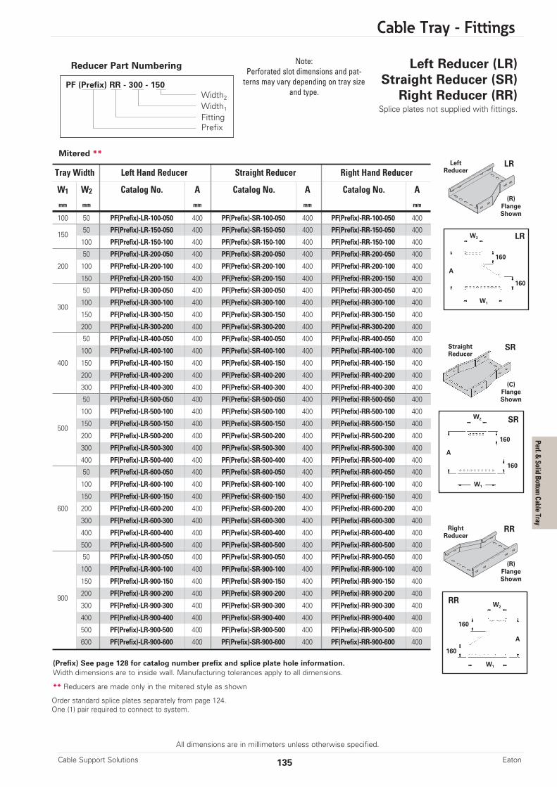
Cable Tray - Fittings
All dimensions are in millimeters unless otherwise specified.
135Cable Support Solutions Eaton
Left Reducer (LR)Straight Reducer (SR)
Right Reducer (RR)Splice plates not supplied with fittings.
PF (Prefix) RR - 300 - 150Width2Width1FittingPrefix
A
160
160
W2
W1
LR
LR
A
W2 SR
SR
Reducer Part Numbering
Tray Width Left Hand Reducer Straight Reducer Right Hand Reducer
W1 W2 Catalog No. A Catalog No. A Catalog No. Amm mm mm mm mm
100 50 PF(Prefix)-LR-100-050 400 PF(Prefix)-SR-100-050 400 PF(Prefix)-RR-100-050 400
15050 PF(Prefix)-LR-150-050 400 PF(Prefix)-SR-150-050 400 PF(Prefix)-RR-150-050 400
100 PF(Prefix)-LR-150-100 400 PF(Prefix)-SR-150-100 400 PF(Prefix)-RR-150-100 400
50 PF(Prefix)-LR-200-050 400 PF(Prefix)-SR-200-050 400 PF(Prefix)-RR-200-050 400
200 100 PF(Prefix)-LR-200-100 400 PF(Prefix)-SR-200-100 400 PF(Prefix)-RR-200-100 400
150 PF(Prefix)-LR-200-150 400 PF(Prefix)-SR-200-150 400 PF(Prefix)-RR-200-150 400
50 PF(Prefix)-LR-300-050 400 PF(Prefix)-SR-300-050 400 PF(Prefix)-RR-300-050 400
300100 PF(Prefix)-LR-300-100 400 PF(Prefix)-SR-300-100 400 PF(Prefix)-RR-300-100 400
150 PF(Prefix)-LR-300-150 400 PF(Prefix)-SR-300-150 400 PF(Prefix)-RR-300-150 400
200 PF(Prefix)-LR-300-200 400 PF(Prefix)-SR-300-200 400 PF(Prefix)-RR-300-200 400
50 PF(Prefix)-LR-400-050 400 PF(Prefix)-SR-400-050 400 PF(Prefix)-RR-400-050 400
100 PF(Prefix)-LR-400-100 400 PF(Prefix)-SR-400-100 400 PF(Prefix)-RR-400-100 400
400 150 PF(Prefix)-LR-400-150 400 PF(Prefix)-SR-400-150 400 PF(Prefix)-RR-400-150 400
200 PF(Prefix)-LR-400-200 400 PF(Prefix)-SR-400-200 400 PF(Prefix)-RR-400-200 400
300 PF(Prefix)-LR-400-300 400 PF(Prefix)-SR-400-300 400 PF(Prefix)-RR-400-300 400
50 PF(Prefix)-LR-500-050 400 PF(Prefix)-SR-500-050 400 PF(Prefix)-RR-500-050 400
100 PF(Prefix)-LR-500-100 400 PF(Prefix)-SR-500-100 400 PF(Prefix)-RR-500-100 400
500150 PF(Prefix)-LR-500-150 400 PF(Prefix)-SR-500-150 400 PF(Prefix)-RR-500-150 400
200 PF(Prefix)-LR-500-200 400 PF(Prefix)-SR-500-200 400 PF(Prefix)-RR-500-200 400
300 PF(Prefix)-LR-500-300 400 PF(Prefix)-SR-500-300 400 PF(Prefix)-RR-500-300 400
400 PF(Prefix)-LR-500-400 400 PF(Prefix)-SR-500-400 400 PF(Prefix)-RR-500-400 400
50 PF(Prefix)-LR-600-050 400 PF(Prefix)-SR-600-050 400 PF(Prefix)-RR-600-050 400
100 PF(Prefix)-LR-600-100 400 PF(Prefix)-SR-600-100 400 PF(Prefix)-RR-600-100 400
150 PF(Prefix)-LR-600-150 400 PF(Prefix)-SR-600-150 400 PF(Prefix)-RR-600-150 400
600 200 PF(Prefix)-LR-600-200 400 PF(Prefix)-SR-600-200 400 PF(Prefix)-RR-600-200 400
300 PF(Prefix)-LR-600-300 400 PF(Prefix)-SR-600-300 400 PF(Prefix)-RR-600-300 400
400 PF(Prefix)-LR-600-400 400 PF(Prefix)-SR-600-400 400 PF(Prefix)-RR-600-400 400
500 PF(Prefix)-LR-600-500 400 PF(Prefix)-SR-600-500 400 PF(Prefix)-RR-600-500 400
50 PF(Prefix)-LR-900-050 400 PF(Prefix)-SR-900-050 400 PF(Prefix)-RR-900-050 400
100 PF(Prefix)-LR-900-100 400 PF(Prefix)-SR-900-100 400 PF(Prefix)-RR-900-100 400
150 PF(Prefix)-LR-900-150 400 PF(Prefix)-SR-900-150 400 PF(Prefix)-RR-900-150 400
900200 PF(Prefix)-LR-900-200 400 PF(Prefix)-SR-900-200 400 PF(Prefix)-RR-900-200 400
300 PF(Prefix)-LR-900-300 400 PF(Prefix)-SR-900-300 400 PF(Prefix)-RR-900-300 400
400 PF(Prefix)-LR-900-400 400 PF(Prefix)-SR-900-400 400 PF(Prefix)-RR-900-400 400
500 PF(Prefix)-LR-900-500 400 PF(Prefix)-SR-900-500 400 PF(Prefix)-RR-900-500 400
600 PF(Prefix)-LR-900-600 400 PF(Prefix)-SR-900-600 400 PF(Prefix)-RR-900-600 400
(Prefix) See page 128 for catalog number prefix and splice plate hole information.Width dimensions are to inside wall. Manufacturing tolerances apply to all dimensions.
** Reducers are made only in the mitered style as shown
LeftReducer
(R)FlangeShown
(C)FlangeShown
StraightReducer
W1
160
160
RRRightReducer
(R)FlangeShown
Note:Perforated slot dimensions and pat-terns may vary depending on tray size
and type.
160
160
A
W2RR
W1
Mitered **
Order standard splice plates separately from page 124.One (1) pair required to connect to system.
Perf. & Solid Bottom Cable Tray
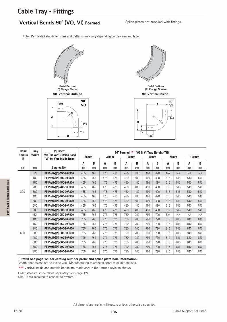
Cable Tray - Fittings
All dimensions are in millimeters unless otherwise specified.
Cable Support SolutionsEaton 136
Vertical Bends 90˚ (VO, VI) Formed Splice plates not supplied with fittings.
90˚ Vertical Outside 90˚ Vertical Inside
90˚VI
90˚VO
(Prefix) See page 128 for catalog number prefix and splice plate hole information.Width dimensions are to inside wall. Manufacturing tolerances apply to all dimensions.
*** Vertical inside and outside bends are made only in the formed style as shown
140
140
BTH
A
R
140
140B
A
R
Note: Perforated slot dimensions and patterns may vary depending on tray size and type.
Solid Bottom(C) Flange Shown
Solid Bottom(R) Flange Shown
TH
Bend Tray (*) Insert 90° Formed *** VO & VI Tray Height (TH)Radius Width “VO” for Vert. Outside Bend 25mm 35mm 40mm 50mm 75mm 100mmR “VI” for Vert. Inside Bend
A B A B A B A B A B A Bmm mm Catalog No. mm mm mm mm mm mm mm mm mm mm mm mm
50 PF(Prefix)(*)-050-90R300 465 465 475 475 480 480 490 490 NA NA NA NA100 PF(Prefix)(*)-100-90R300 465 465 475 475 480 480 490 490 515 515 540 540150 PF(Prefix)(*)-150-90R300 465 465 475 475 480 480 490 490 515 515 540 540200 PF(Prefix)(*)-200-90R300 465 465 475 475 480 480 490 490 515 515 540 540
300 300 PF(Prefix)(*)-300-90R300 465 465 475 475 480 480 490 490 515 515 540 540400 PF(Prefix)(*)-400-90R300 465 465 475 475 480 480 490 490 515 515 540 540500 PF(Prefix)(*)-500-90R300 465 465 475 475 480 480 490 490 515 515 540 540600 PF(Prefix)(*)-600-90R300 465 465 475 475 480 480 490 490 515 515 540 540900 PF(Prefix)(*)-900-90R300 465 465 475 475 480 480 490 490 515 515 540 54050 PF(Prefix)(*)-050-90R600 765 765 775 775 780 780 790 790 NA NA NA NA100 PF(Prefix)(*)-100-90R600 765 765 775 775 780 780 790 790 815 815 840 840150 PF(Prefix)(*)-150-90R600 765 765 775 775 780 780 790 790 815 815 840 840200 PF(Prefix)(*)-200-90R600 765 765 775 775 780 780 790 790 815 815 840 840
600 300 PF(Prefix)(*)-300-90R600 765 765 775 775 780 780 790 790 815 815 840 840400 PF(Prefix)(*)-400-90R600 765 765 775 775 780 780 790 790 815 815 840 840500 PF(Prefix)(*)-500-90R600 765 765 775 775 780 780 790 790 815 815 840 840600 PF(Prefix)(*)-600-90R600 765 765 775 775 780 780 790 790 815 815 840 840900 PF(Prefix)(*)-900-90R600 765 765 775 775 780 780 790 790 815 815 840 840
Order standard splice plates separately from page 124.One (1) pair required to connect to system.
Perf. & Solid Bottom Cable Tray

Cable Tray - Fittings
All dimensions are in millimeters unless otherwise specified.
137Cable Support Solutions Eaton
Vertical Bends 60˚ (VO, VI) Formed Splice plates not supplied with fittings.
60˚ Vertical Outside 60˚ Vertical Inside
(Prefix) See page 128 for catalog number prefix and splice plate hole information.Width dimensions are to inside wall. Manufacturing tolerances apply to all dimensions.
*** Vertical inside and outside bends are made only in the formed style as shown
Note: Perforated slot dimensions and patterns may vary depending on tray size and type.
Solid Bottom(R) Flange Shown
Solid Bottom(R) Flange Shown
Bend Tray (*) Insert 60° Formed *** VO & VI Tray Height (TH)Radius Width “VO” for Vert. Outside Bend 25mm 35mm 40mm 50mm 75mm 100mmR “VI” for Vert. Inside Bend
A B A B A B A B A B A Bmm mm Catalog No. mm mm mm mm mm mm mm mm mm mm mm mm
50 PF(Prefix)(*)-050-60R300 491 296 500 306 504 311 513 321 535 346 556 371100 PF(Prefix)(*)-100-60R300 491 296 500 306 504 311 513 321 535 346 556 371150 PF(Prefix)(*)-150-60R300 491 296 500 306 504 311 513 321 535 346 556 371200 PF(Prefix)(*)-200-60R300 491 296 500 306 504 311 513 321 535 346 556 371
300 300 PF(Prefix)(*)-300-60R300 491 296 500 306 504 311 513 321 535 346 556 371400 PF(Prefix)(*)-400-60R300 491 296 500 306 504 311 513 321 535 346 556 371500 PF(Prefix)(*)-500-60R300 491 296 500 306 504 311 513 321 535 346 556 371600 PF(Prefix)(*)-600-60R300 491 296 500 306 504 311 513 321 535 346 556 371900 PF(Prefix)(*)-900-60R300 491 296 500 306 504 311 513 321 535 346 556 37150 PF(Prefix)(*)-050-60R600 751 446 759 456 764 461 773 471 795 496 816 521100 PF(Prefix)(*)-100-60R600 751 446 759 456 764 461 773 471 795 496 816 521150 PF(Prefix)(*)-150-60R600 751 446 759 456 764 461 773 471 795 496 816 521200 PF(Prefix)(*)-200-60R600 751 446 759 456 764 461 773 471 795 496 816 521
600 300 PF(Prefix)(*)-300-60R600 751 446 759 456 764 461 773 471 795 496 816 521400 PF(Prefix)(*)-400-60R600 751 446 759 456 764 461 773 471 795 496 816 521500 PF(Prefix)(*)-500-60R600 751 446 759 456 764 461 773 471 795 496 816 521600 PF(Prefix)(*)-600-60R600 751 446 759 456 764 461 773 471 795 496 816 521900 PF(Prefix)(*)-900-60R600 751 446 759 456 764 461 773 471 795 496 816 521
60˚VO
140
140
A
B
R
TH
60˚VI
140
140B
A
R
TH
Order standard splice plates separately from page 124.One (1) pair required to connect to system.
Perf. & Solid Bottom Cable Tray

Cable Tray - Fittings
All dimensions are in millimeters unless otherwise specified.
Cable Support SolutionsEaton 138
Vertical Bends 45˚ (VO, VI) Formed Splice plates not supplied with fittings.
45˚ Vertical Outside 45˚ Vertical Inside
(Prefix) See page 128 for catalog number prefix and splice plate hole information.Width dimensions are to inside wall. Manufacturing tolerances apply to all dimensions.
*** Vertical inside and outside bends are made only in the formed style as shown
Note: Perforated slot dimensions and patterns may vary depending on tray size and type.
Solid Bottom(C) Flange Shown
Solid Bottom(R) Flange Shown
Bend Tray (*) Insert 45° Formed *** VO & VI Tray Height (TH)Radius Width “VO” for Vert. Outside Bend 25mm 35mm 40mm 50mm 75mm 100mmR “VI” for Vert. Inside Bend
A B A B A B A B A B A Bmm mm Catalog No. mm mm mm mm mm mm mm mm mm mm mm mm
50 PF(Prefix)(*)-050-45R300 469 212 475 222 479 227 486 237 504 262 522 287100 PF(Prefix)(*)-100-45R300 469 212 475 222 479 227 486 237 504 262 522 287150 PF(Prefix)(*)-150-45R300 469 212 475 222 479 227 486 237 504 262 522 287200 PF(Prefix)(*)-200-45R300 469 212 475 222 479 227 486 237 504 262 522 287
300 300 PF(Prefix)(*)-300-45R300 469 212 475 222 479 227 486 237 504 262 522 287400 PF(Prefix)(*)-400-45R300 469 212 475 222 479 227 486 237 504 262 522 287500 PF(Prefix)(*)-500-45R300 469 212 475 222 479 227 486 237 504 262 522 287600 PF(Prefix)(*)-600-45R300 469 212 475 222 479 227 486 237 504 262 522 287900 PF(Prefix)(*)-900-45R300 469 212 475 222 479 227 486 237 504 262 522 28750 PF(Prefix)(*)-050-45R600 681 300 688 310 692 315 699 325 716 350 734 375100 PF(Prefix)(*)-100-45R600 681 300 688 310 692 315 699 325 716 350 734 375150 PF(Prefix)(*)-150-45R600 681 300 688 310 692 315 699 325 716 350 734 375200 PF(Prefix)(*)-200-45R600 681 300 688 310 692 315 699 325 716 350 734 375
600 300 PF(Prefix)(*)-300-45R600 681 300 688 310 692 315 699 325 716 350 734 375400 PF(Prefix)(*)-400-45R600 681 300 688 310 692 315 699 325 716 350 734 375500 PF(Prefix)(*)-500-45R600 681 300 688 310 692 315 699 325 716 350 734 375600 PF(Prefix)(*)-600-45R600 681 300 688 310 692 315 699 325 716 350 734 375900 PF(Prefix)(*)-900-45R600 681 300 688 310 692 315 699 325 716 350 734 375
45˚VI
45˚VO
140
140
A
B
B
A
R
140
140R
TH TH
Order standard splice plates separately from page 124.One (1) pair required to connect to system.
Perf. & Solid Bottom Cable Tray

Cable Tray - Fittings
All dimensions are in millimeters unless otherwise specified.
139Cable Support Solutions Eaton
Vertical Bends 30˚ (VO, VI) FormedSplice plates not supplied with fittings.
30˚VI
30˚VO
140
140
A
B
B
A
R
140
140
R
THTH
Note: Perforated slot dimensions and patterns may vary depending on tray size and type.
30˚ Vertical Outside 30˚ Vertical Inside
(Prefix) See page 128 for catalog number prefix and splice plate hole information.Width dimensions are to inside wall. Manufacturing tolerances apply to all dimensions.
*** Vertical inside and outside bends are made only in the formed style as shown
Solid Bottom(R) Flange Shown
Solid Bottom(R) Flange Shown
Bend Tray (*) Insert 30° Formed *** VO & VI Tray Height (TH)Radius Width “VO” for Vert. Outside Bend 25mm 35mm 40mm 50mm 75mm 100mmR “VI” for Vert. Inside Bend
A B A B A B A B A B A Bmm mm Catalog No. mm mm mm mm mm mm mm mm mm mm mm mm
50 PF(Prefix)(*)-050-30R300 424 135 429 145 431 150 436 160 449 185 461 210100 PF(Prefix)(*)-100-30R300 424 135 429 145 431 150 436 160 449 185 461 210150 PF(Prefix)(*)-150-30R300 424 135 429 145 431 150 436 160 449 185 461 210200 PF(Prefix)(*)-200-30R300 424 135 429 145 431 150 436 160 449 185 461 210
300 300 PF(Prefix)(*)-300-30R300 424 135 429 145 431 150 436 160 449 185 461 210400 PF(Prefix)(*)-400-30R300 424 135 429 145 431 150 436 160 449 185 461 210500 PF(Prefix)(*)-500-30R300 424 135 429 145 431 150 436 160 449 185 461 210600 PF(Prefix)(*)-600-30R300 424 135 429 145 431 150 436 160 449 185 461 210900 PF(Prefix)(*)-900-30R300 424 135 429 145 431 150 436 160 449 185 461 21050 PF(Prefix)(*)-050-30R600 574 175 579 185 581 190 586 200 599 225 611 250100 PF(Prefix)(*)-100-30R600 574 175 579 185 581 190 586 200 599 225 611 250150 PF(Prefix)(*)-150-30R600 574 175 579 185 581 190 586 200 599 225 611 250200 PF(Prefix)(*)-200-30R600 574 175 579 185 581 190 586 200 599 225 611 250
600 300 PF(Prefix)(*)-300-30R600 574 175 579 185 581 190 586 200 599 225 611 250400 PF(Prefix)(*)-400-30R600 574 175 579 185 581 190 586 200 599 225 611 250500 PF(Prefix)(*)-500-30R600 574 175 579 185 581 190 586 200 599 225 611 250600 PF(Prefix)(*)-600-30R600 574 175 579 185 581 190 586 200 599 225 611 250900 PF(Prefix)(*)-900-30R600 574 175 579 185 581 190 586 200 599 225 611 250
Order standard splice plates separately from page 124.One (1) pair required to connect to system.
Perf. & Solid Bottom Cable Tray

Cable Tray - Fittings
All dimensions are in millimeters unless otherwise specified.
Cable Support SolutionsEaton 140
Expanding Horizontal Tee (ET)Reducing Horizontal Tee (RT)Expanding/Reducing Horizontal Cross (RX)Splice plates not supplied with fittings.
Note: Perforated slot dimensions and patterns may vary depending on tray size and type.
Expanding/Reducing Fittings Part Numbering
Example: P F 050 V N SS6 10 ET - 100 - 200 - R600
ReturnTray Radius Bottom Flange Width WidthType Detail Height Type Type Material Thickness Type 1 2 Radius
P = F = 025 = S = N = P = Pre-Galv 10 * = ET 050 = 050 = R300 =(Perforated Formed 25mm Solid No Flange G = HDGAF 1.0mm RT 50mm 50mm 300mm& Solid 035 = V = R = SS6 = 15 = RX 100 = 100 = R600 =Cable 35mm Perforated 180° Return Stainless 1.5mm 100mm 100mm 600mmTray)
040 = C = Type 316 20 = 150 = 150 =40mm 90° Inside A = 2.0mm 150mm 150mm050 = Aluminum 200 = 200 =50mm 200mm 200mm075 = 300 = 300 =75mm 200mm 300mm100 = 400 = 400 =100mm 400mm 400mm
500 = 500 =500mm 500mm600 = 600 =600mm 600mm900 = 900 =900mm 900mm
Prefix Suffix
* 1.0mm thickness is only available in widths up to and including 300 (300mm).Not available in mitered style
Perf. & Solid Bottom Cable Tray
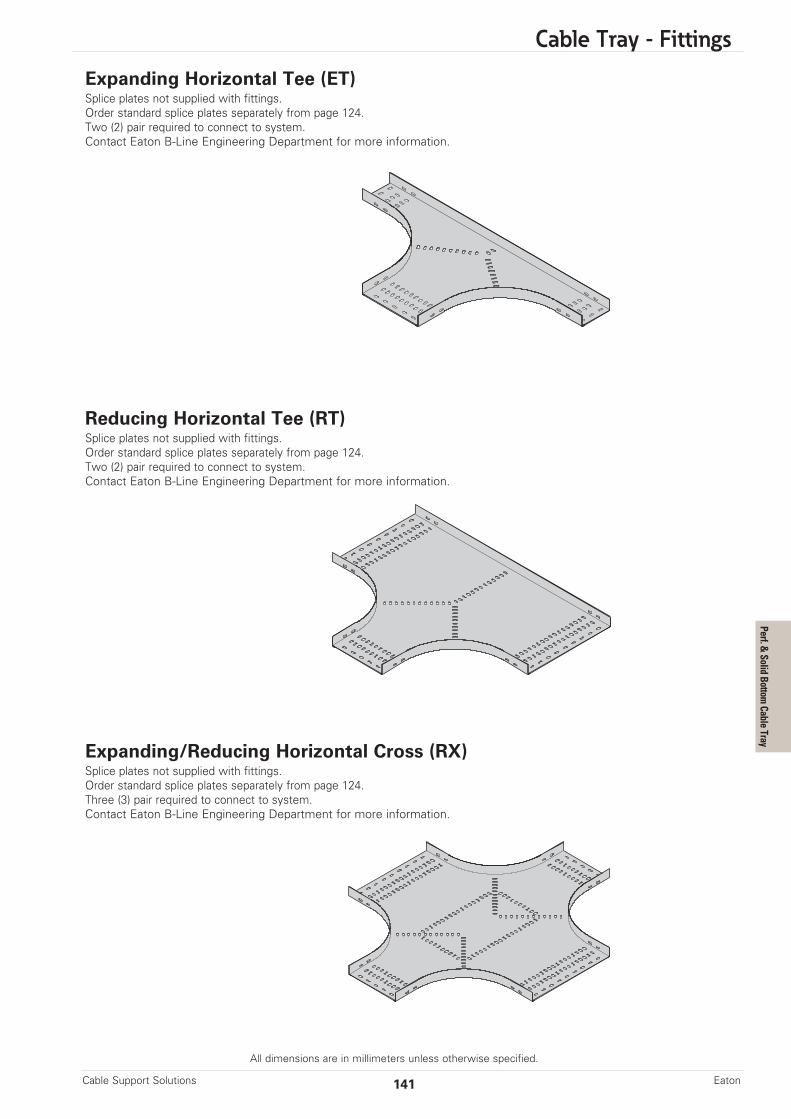
Cable Tray - Fittings
All dimensions are in millimeters unless otherwise specified.
141Cable Support Solutions Eaton
Expanding Horizontal Tee (ET)Splice plates not supplied with fittings.Order standard splice plates separately from page 124.Two (2) pair required to connect to system.Contact Eaton B-Line Engineering Department for more information.
Reducing Horizontal Tee (RT)Splice plates not supplied with fittings.Order standard splice plates separately from page 124.Two (2) pair required to connect to system.Contact Eaton B-Line Engineering Department for more information.
Expanding/Reducing Horizontal Cross (RX)Splice plates not supplied with fittings.Order standard splice plates separately from page 124.Three (3) pair required to connect to system.Contact Eaton B-Line Engineering Department for more information.
Perf. & Solid Bottom Cable Tray
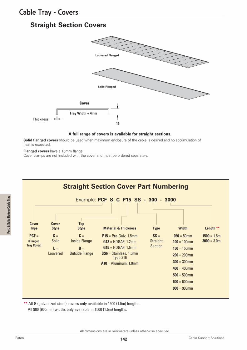
Cable Tray - Covers
All dimensions are in millimeters unless otherwise specified.
A full range of covers is available for straight sections.Solid flanged covers should be used when maximum enclosure of the cable is desired and no accumulation ofheat is expected.
Flanged covers have a 15mm flange. Cover clamps are not included with the cover and must be ordered separately.
Straight Section Covers
Thickness
Tray Width + 4mm
Cover
15
Cable Support SolutionsEaton 142
Straight Section Cover Part Numbering
Example: PCF S C P15 SS - 300 - 3000
Cover Cover TopType Style Style Material & Thickness Type Width Length **
PCF = S = C = P15 = Pre-Galv, 1.5mm SS = 050 = 50mm 1500 = 1.5m(Flanged Solid Inside Flange G12 = HDGAF, 1.2mm Straight 100 = 100mm 3000 = 3.0mTray Cover)
L = B = G15 = HDGAF, 1.5mm Section 150 = 150mmLouvered Outside Flange SS6 = Stainless, 1.5mm 200 = 200mmType 316
300 = 300mmA10 = Aluminum, 1.0mm400 = 400mm
500 = 500mm
600 = 600mm
900 = 900mm
** All G (galvanized steel) covers only available in 1500 (1.5m) lengths. All 900 (900mm) widths only available in 1500 (1.5m) lengths.
Solid Flanged
Louvered Flanged
Perf. & Solid Bottom Cable Tray
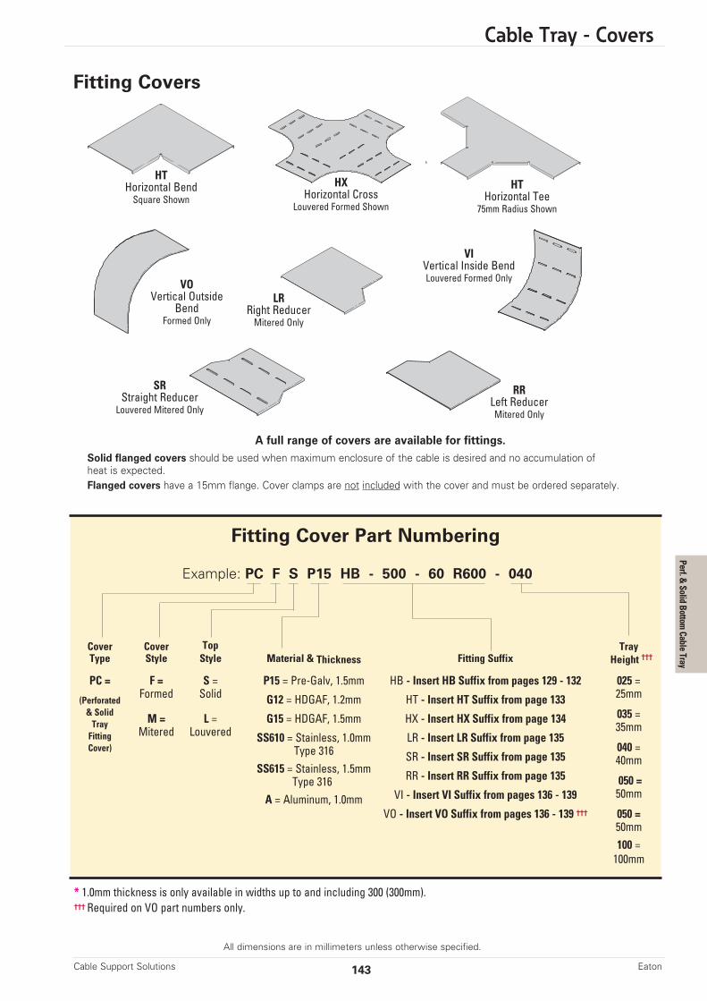
Cable Tray - Covers
All dimensions are in millimeters unless otherwise specified.
Fitting Covers
* 1.0mm thickness is only available in widths up to and including 300 (300mm).††† Required on VO part numbers only.
Fitting Cover Part Numbering
Example: PC F S P15 HB - 500 - 60 R600 - 040
Cover Cover Top TrayType Style Style Material & Thickness Fitting Suffix Height †††
PC = F = S = P15 = Pre-Galv, 1.5mm HB - Insert HB Suffix from pages 129 - 132 025 =
(PerforatedFormed Solid G12 = HDGAF, 1.2mm HT - Insert HT Suffix from page 133 25mm
& Solid M = L = G15 = HDGAF, 1.5mm HX - Insert HX Suffix from page 134 035 =Tray
Mitered Louvered SS610 = Stainless, 1.0mm LR - Insert LR Suffix from page 13535mm
Fitting
Type 316 SR - Insert SR Suffix from page 135040 =Cover)
SS615 = Stainless, 1.5mm RR - Insert RR Suffix from page 13540mm
Type 316VI - Insert VI Suffix from pages 136 - 139
050 =
A = Aluminum, 1.0mmVO - Insert VO Suffix from pages 136 - 139 †††
50mm
050 =50mm100 =100mm
143Cable Support Solutions Eaton
A full range of covers are available for fittings.Solid flanged covers should be used when maximum enclosure of the cable is desired and no accumulation ofheat is expected. Flanged covers have a 15mm flange. Cover clamps are not included with the cover and must be ordered separately.
HTHorizontal BendSquare Shown
HTHorizontal Tee75mm Radius Shown
HXHorizontal Cross
Louvered Formed Shown
VOVertical Outside
BendFormed Only
VIVertical Inside BendLouvered Formed Only
LRRight ReducerMitered Only
RRLeft ReducerMitered Only
SRStraight ReducerLouvered Mitered Only
Perf. & Solid Bottom Cable Tray

Steel Ship Ladder - Straight Sections, Fittings, & Accessories
All dimensions are in millimeters unless otherwise specified.
Cable Support SolutionsEaton 144
ThicknessCatalog No. Width G X
mm mm mm
MR40ST0100-3000(*) 100 4.5 6.0MR40ST0150-3000(*) 150 4.5 6.0MR40ST0200-3000(*) 200 4.5 6.0MR40ST0300-3000(*) 300 4.5 6.0MR40ST0400-3000(*) 400 4.5 6.0MR40ST0500-3000(*) 500 4.5 6.0MR40ST0600-3000(*) 600 4.5 6.0MR40ST0700-3000(*) 700 4.5 6.0MR40ST0800-3000(*) 800 4.5 6.0MR40ST0900-3000(*) 900 4.5 6.0
(*) Insert G for Hot Dipped Galvanized Steel or X for Stainless Steel 316
MR40ST 0100 - 3000 (*)
Marine Rung Width Length MaterialNominal 40mm
Height
Straight Sections• Splice plates sold separately• Material: Hot Dipped Galvanized (HDG) Steel or Stainless Steel 316
300mmRung Spacing
Width
3000mm
Ship Ladder

Steel Ship Ladder - Straight Sections, Fittings, & Accessories
All dimensions are in millimeters unless otherwise specified.
145Cable Support Solutions Eaton
90° Horizontal Bends• Splice plates sold separately• Material: Hot Dipped Galvanized (HDG) Steel orStainless Steel 316
Tee and Cross Bracket • Used to make horizontal ship ladder tees or crosses• Sold per bracket with (4) M10 x 25 coach screws & serrated flange nuts • Requires two (2) brackets for a horizontal tee • Requires four (4) brackets for a horizontal tee • Material: Hot Dipped Galvanized (HDG) Steel or Stainless Steel 316
ThicknessCatalog No. Width G X
mm mm mm
MR40HB0100-90R(xxx)(*) 100 4.5 6.0MR40HB0150-90R(xxx)(*) 150 4.5 6.0MR40HB0200-90R(xxx)(*) 200 4.5 6.0MR40HB0300-90R(xxx)(*) 300 4.5 6.0MR40HB0400-90R(xxx)(*) 400 4.5 6.0MR40HB0500-90R(xxx)(*) 500 4.5 6.0MR40HB0600-90R(xxx)(*) 600 4.5 6.0MR40HB0700-90R(xxx)(*) 700 4.5 6.0MR40HB0800-90R(xxx)(*) 800 4.5 6.0MR40HB0900-90R(xxx)(*) 900 4.5 6.0
(xxx) Radius - Insert 200 for 200mm, 300 for 300mm, 450 for 450mm, or 600 for 600mm(*) Material & Finish - Insert G for Hot Dipped Galvanized Steel or X for Stainless Steel 316
MR40HB 0100 - 90 R200 (*)
Marine Rung Width Angle Radius MaterialNominal 40mm
HeightHorizontal Bend
300mmRung Spacing
40mmWidth
100mm
12mm x 36mmSlots
160mm 160mm
11mm x 18mmSlots
Radius
Ship Ladder
Catalog No.
MTX(*)
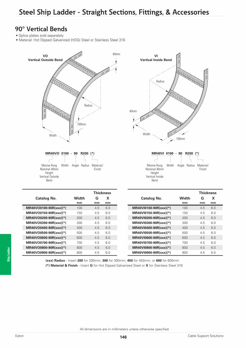
Steel Ship Ladder - Straight Sections, Fittings, & Accessories
All dimensions are in millimeters unless otherwise specified.
Cable Support SolutionsEaton 146
90° Vertical Bends• Splice plates sold separately• Material: Hot Dipped Galvanized (HDG) Steel or Stainless Steel 316
ThicknessCatalog No. Width G X
mm mm mm
MR40VO0100-90R(xxx)(*) 100 4.5 6.0MR40VO0150-90R(xxx)(*) 150 4.5 6.0MR40VO0200-90R(xxx)(*) 200 4.5 6.0MR40VO0300-90R(xxx)(*) 300 4.5 6.0MR40VO0400-90R(xxx)(*) 400 4.5 6.0MR40VO0500-90R(xxx)(*) 500 4.5 6.0MR40VO0600-90R(xxx)(*) 600 4.5 6.0MR40VO0700-90R(xxx)(*) 700 4.5 6.0MR40VO0800-90R(xxx)(*) 800 4.5 6.0MR40VO0900-90R(xxx)(*) 900 4.5 6.0
(xxx) Radius - Insert 200 for 200mm, 300 for 300mm, 450 for 450mm, or 600 for 600mm(*) Material & Finish - Insert G for Hot Dipped Galvanized Steel or X for Stainless Steel 316
MR40VO 0100 - 90 R200 (*)
Marine Rung Width Angle Radius Material/Nominal 40mm Finish
HeightVertical Outside
Bend
ThicknessCatalog No. Width G X
mm mm mm
MR40VI0100-90R(xxx)(*) 100 4.5 6.0MR40VI0150-90R(xxx)(*) 150 4.5 6.0MR40VI0200-90R(xxx)(*) 200 4.5 6.0MR40VI0300-90R(xxx)(*) 300 4.5 6.0MR40VI0400-90R(xxx)(*) 400 4.5 6.0MR40VI0500-90R(xxx)(*) 500 4.5 6.0MR40VI0600-90R(xxx)(*) 600 4.5 6.0MR40VI0700-90R(xxx)(*) 700 4.5 6.0MR40VI0800-90R(xxx)(*) 800 4.5 6.0MR40VI0900-90R(xxx)(*) 900 4.5 6.0
MR40VI 0100 - 90 R200 (*)
Marine Rung Width Angle Radius Material/Nominal 40mm Finish
HeightVertical Inside
Bend
VOVertical Outside Bend
VIVertical Inside Bend
Width
100mm
Radius
Width100mm
Radius
40mm
40mm
Ship Ladder
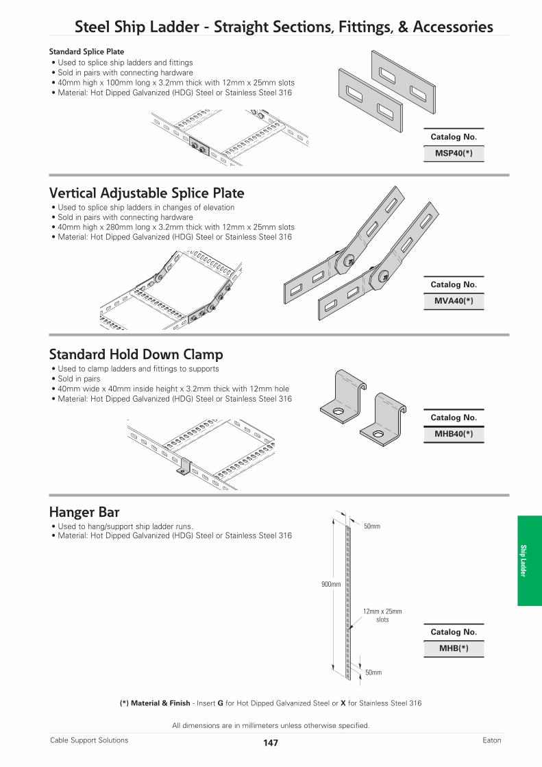
Steel Ship Ladder - Straight Sections, Fittings, & Accessories
All dimensions are in millimeters unless otherwise specified.
147Cable Support Solutions Eaton
Standard Splice Plate• Used to splice ship ladders and fittings• Sold in pairs with connecting hardware • 40mm high x 100mm long x 3.2mm thick with 12mm x 25mm slots• Material: Hot Dipped Galvanized (HDG) Steel or Stainless Steel 316
Vertical Adjustable Splice Plate• Used to splice ship ladders in changes of elevation• Sold in pairs with connecting hardware • 40mm high x 280mm long x 3.2mm thick with 12mm x 25mm slots• Material: Hot Dipped Galvanized (HDG) Steel or Stainless Steel 316
Standard Hold Down Clamp• Used to clamp ladders and fittings to supports• Sold in pairs• 40mm wide x 40mm inside height x 3.2mm thick with 12mm hole• Material: Hot Dipped Galvanized (HDG) Steel or Stainless Steel 316
Hanger Bar• Used to hang/support ship ladder runs.• Material: Hot Dipped Galvanized (HDG) Steel or Stainless Steel 316
Catalog No.
MHB(*)
Catalog No.
MVA40(*)
Catalog No.
MSP40(*)
Catalog No.
MHB40(*)
(*) Material & Finish - Insert G for Hot Dipped Galvanized Steel or X for Stainless Steel 316
50mm
12mm x 25mmslots
900mm
50mm
Ship Ladder

Cable Cleats
Cable Support SolutionsEaton 148
Cable Cleats
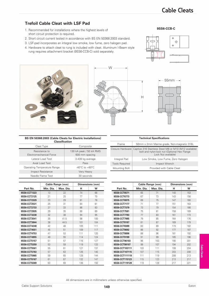
Cable Cleats
All dimensions are in millimeters unless otherwise specified.
Trefoil Cable Cleat with LSF Pad
1. Recommended for installations where the highest levels ofshort circuit protection is required.
2. Short circuit current tested in accordance with BS EN 50368:2003 standard.3. LSF-pad incorporates an integral low smoke, low fume, zero halogen pad.4. Hardware to attach cleat to rung is included with cleat. Aluminum I-Beam style
rung requires attachment bracket (9SS6-CCB-C) sold separately.
W
H
55mm
149Cable Support Solutions Eaton
BS EN 50368:2003 (Cable Cleats for Electric Installations)Classification
Cleat Type Composite
Resistance to 130 kA peak / 50 kA RMSElectromechanical Force 600 mm spacing
Lateral Load Test 3.439 kg average
Axial Load Test Pass
Operating Temperature Range -40°C to +60°C
Impact Resistance Very Heavy
Needle Flame Test 30 seconds
Technical Specifications
Frame 50mm x 2mm Marine grade, Non-magnetic 316L
Closure Hardware Captive 316 Stainless Steel M8 or M10 (M12 available)bolt and nylon-lock nut (Optional Hex Flange
Lock Nut available)
Integral Pad Low Smoke, Low Fume, Zero Halogen
Tools Required Impact Wrench
Mounting Bolt Provided with Cable Cleat
Cable Range (mm) Dimensions (mm)
Part No. Min. Dia. Max. Dia. H W
9SS6-CCT1323 13 22 74 669SS6-CCT2125 21 25 77 709SS6-CCT2329 23 29 81 789SS6-CCT2531 25 31 84 819SS6-CCT2733 27 33 86 839SS6-CCT2935 29 35 90 899SS6-CCT3238 32 38 94 959SS6-CCT3541 35 41.5 98 1009SS6-CCT3844 38 44.5 101 1049SS6-CCT4248 42 48 105 1119SS6-CCT4551 45 51 109 1179SS6-CCT4753 47 53 111 1209SS6-CCT4955 49 55 114 1249SS6-CCT5157 51 57 116 1279SS6-CCT5359 53 59 119 1339SS6-CCT5561 55 61 127 1379SS6-CCT5763 57 63 126 1409SS6-CCT5965 59 65 128 1449SS6-CCT6167 61 67 132 1479SS6-CCT6369 63 69 136 150
Cable Range (mm) Dimensions (mm)
Part No. Min. Dia. Max. Dia. H W
9SS6-CCT6571 65 71 140 1539SS6-CCT6773 67 73 143 1569SS6-CCT6975 69 75 147 1609SS6-CCT7177 71 77 151 1639SS6-CCT7379 73 79 154 1669SS6-CCT7581 75 81 158 1699SS6-CCT7783 77 83 161 1739SS6-CCT7985 79 85 164 1769SS6-CCT8187 81 87 169 1799SS6-CCT8389 83 89 173 1829SS6-CCT8692 86 92 177 1879SS6-CCT8896 88 96 181 1929SS6-CCT9199 91 99 185 1969SS6-CCT96103 96 103 190 2019SS6-CCT99107 99 107 194 2029SS6-CCT103111 103 111 199 2049SS6-CCT107115 107 115 203 2089SS6-CCT111119 111 119 208 2139SS6-CCT115123 115 123 213 2179SS6-CCT119128 119 128 217 221
Cable Cleats
9SS6-CCB-C
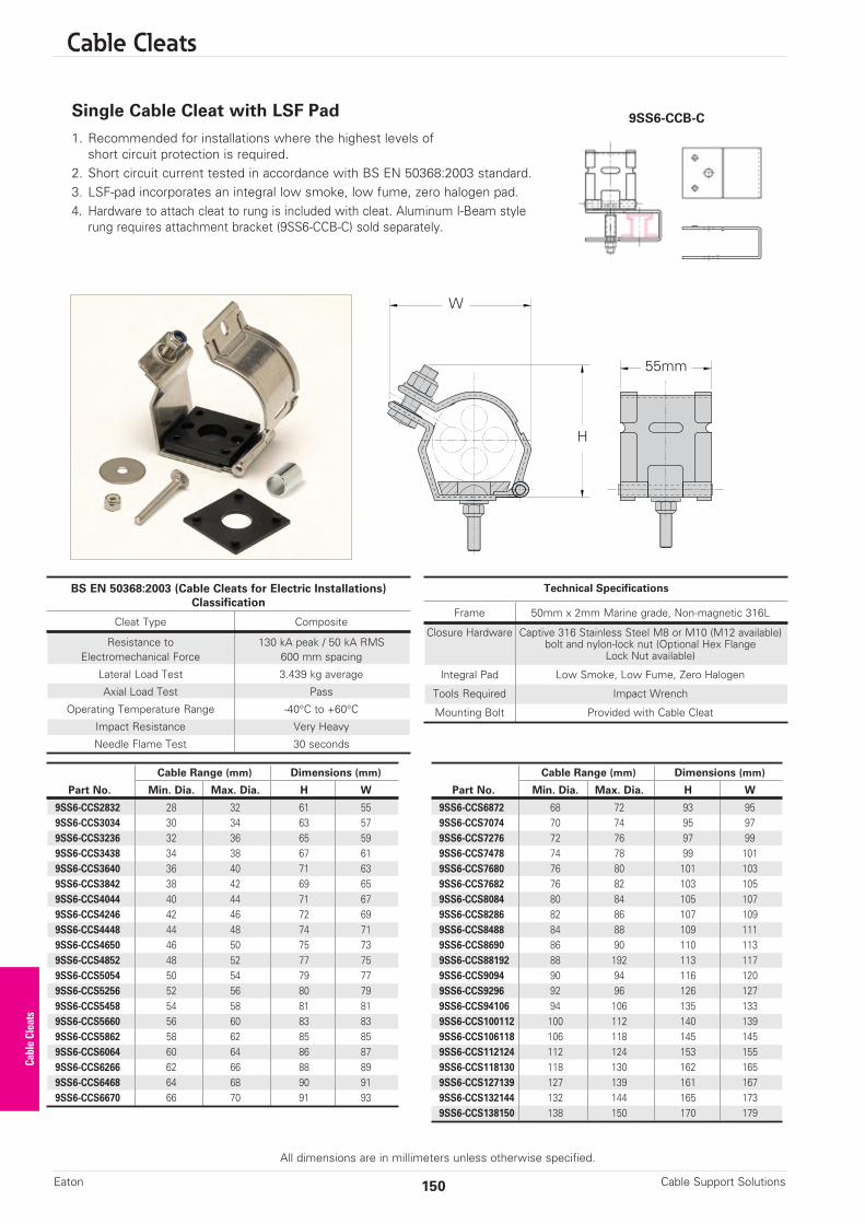
Cable Cleats
All dimensions are in millimeters unless otherwise specified.
Single Cable Cleat with LSF Pad
1. Recommended for installations where the highest levels ofshort circuit protection is required.
2. Short circuit current tested in accordance with BS EN 50368:2003 standard.3. LSF-pad incorporates an integral low smoke, low fume, zero halogen pad.4. Hardware to attach cleat to rung is included with cleat. Aluminum I-Beam style
rung requires attachment bracket (9SS6-CCB-C) sold separately.
W
H
55mm
Cable Support SolutionsEaton 150
BS EN 50368:2003 (Cable Cleats for Electric Installations)Classification
Cleat Type Composite
Resistance to 130 kA peak / 50 kA RMSElectromechanical Force 600 mm spacing
Lateral Load Test 3.439 kg average
Axial Load Test Pass
Operating Temperature Range -40°C to +60°C
Impact Resistance Very Heavy
Needle Flame Test 30 seconds
Technical Specifications
Frame 50mm x 2mm Marine grade, Non-magnetic 316L
Closure Hardware Captive 316 Stainless Steel M8 or M10 (M12 available)bolt and nylon-lock nut (Optional Hex Flange
Lock Nut available)
Integral Pad Low Smoke, Low Fume, Zero Halogen
Tools Required Impact Wrench
Mounting Bolt Provided with Cable Cleat
Cable Range (mm) Dimensions (mm)
Part No. Min. Dia. Max. Dia. H W
9SS6-CCS2832 28 32 61 559SS6-CCS3034 30 34 63 579SS6-CCS3236 32 36 65 599SS6-CCS3438 34 38 67 619SS6-CCS3640 36 40 71 639SS6-CCS3842 38 42 69 659SS6-CCS4044 40 44 71 679SS6-CCS4246 42 46 72 699SS6-CCS4448 44 48 74 719SS6-CCS4650 46 50 75 739SS6-CCS4852 48 52 77 759SS6-CCS5054 50 54 79 779SS6-CCS5256 52 56 80 799SS6-CCS5458 54 58 81 819SS6-CCS5660 56 60 83 839SS6-CCS5862 58 62 85 859SS6-CCS6064 60 64 86 879SS6-CCS6266 62 66 88 899SS6-CCS6468 64 68 90 919SS6-CCS6670 66 70 91 93
Cable Range (mm) Dimensions (mm)
Part No. Min. Dia. Max. Dia. H W
9SS6-CCS6872 68 72 93 959SS6-CCS7074 70 74 95 979SS6-CCS7276 72 76 97 999SS6-CCS7478 74 78 99 1019SS6-CCS7680 76 80 101 1039SS6-CCS7682 76 82 103 1059SS6-CCS8084 80 84 105 1079SS6-CCS8286 82 86 107 1099SS6-CCS8488 84 88 109 1119SS6-CCS8690 86 90 110 1139SS6-CCS88192 88 192 113 1179SS6-CCS9094 90 94 116 1209SS6-CCS9296 92 96 126 1279SS6-CCS94106 94 106 135 1339SS6-CCS100112 100 112 140 1399SS6-CCS106118 106 118 145 1459SS6-CCS112124 112 124 153 1559SS6-CCS118130 118 130 162 1659SS6-CCS127139 127 139 161 1679SS6-CCS132144 132 144 165 1739SS6-CCS138150 138 150 170 179
Cable Cleats
9SS6-CCB-C

Cable Cleats
All dimensions are in millimeters unless otherwise specified.
151Cable Support Solutions Eaton
Step 1: Know Your Cables n What type of cable is being used? Single or Multi-conductorn What is the outside diameter of the cable(s)? n What is the cable arrangement (single conductor cables only)? Flat or Trefoiln If a ground wire will be installed within the cleat, you will need the ground wire
outside diameter.
Step 2: Know Your Systemn What is the available short circuit current (RMS or ip (peak))? n What type of B-Line cable ladder is installed?
Step 3: Select Your Cable Cleatsn See Pages 149 & 150
Step 4: Determine Cleat Spacing for InstallationYour cable diameter is equal to the spacing between conductor centers shown below. Find your cable diameter at the top of the table and look down at the column below it. Find the value equal to or greater than the available short circuit for your system.
Single Conductor Short Circuit Withstand Table
Max. Cable Cleat Spacing Between Conductor Centers (mm)
Spacing (A) 23 25 27 29 31 33 35 37 39 41 43 45
mm In. ip peak (kA)
225 9 179 187 194 203 209 216 220 229 234 240 246 250
300 12 155 163 168 174 181 187 192 198 203 209 214 215
450 18 128 133 137 144 148 152 157 161 165 170 174 178
600 24 110 115 119 124 128 132 135 139 143 148 150 153
675 27 104 108 113 117 121 124 128 132 135 139 143 147
900 36 89 93 97 102 104 108 110 115 117 121 124 127
IMPORTANT: Recommended Installation ProceduresIt is important that the cleats are installed properly to secure your cables:• It is not necessary for every cleat to be attached to the ladder. Every other cleat ( ) must beattached to the ladder system to secure cable. Unattached cleats ( ) provide additional restraintto keep cables bundled.
• The bend radius should be 8 to 12 times the cable diameter.• Cable cleats should always be installed at the beginning, middle and end of a bend ( ), and atno time should the distance between cleats on a bend be more than 0.3M center to center.
Changes of Direction
Trefoil Cables
A A A
0.3M
max(linear)
0.3M
max
(linear)
0.3M
max
(linear)
0.3M
max
(linear)A A A
Cable Cleats

Strut Systems
Cable Support SolutionsEaton 152
Strut Systems
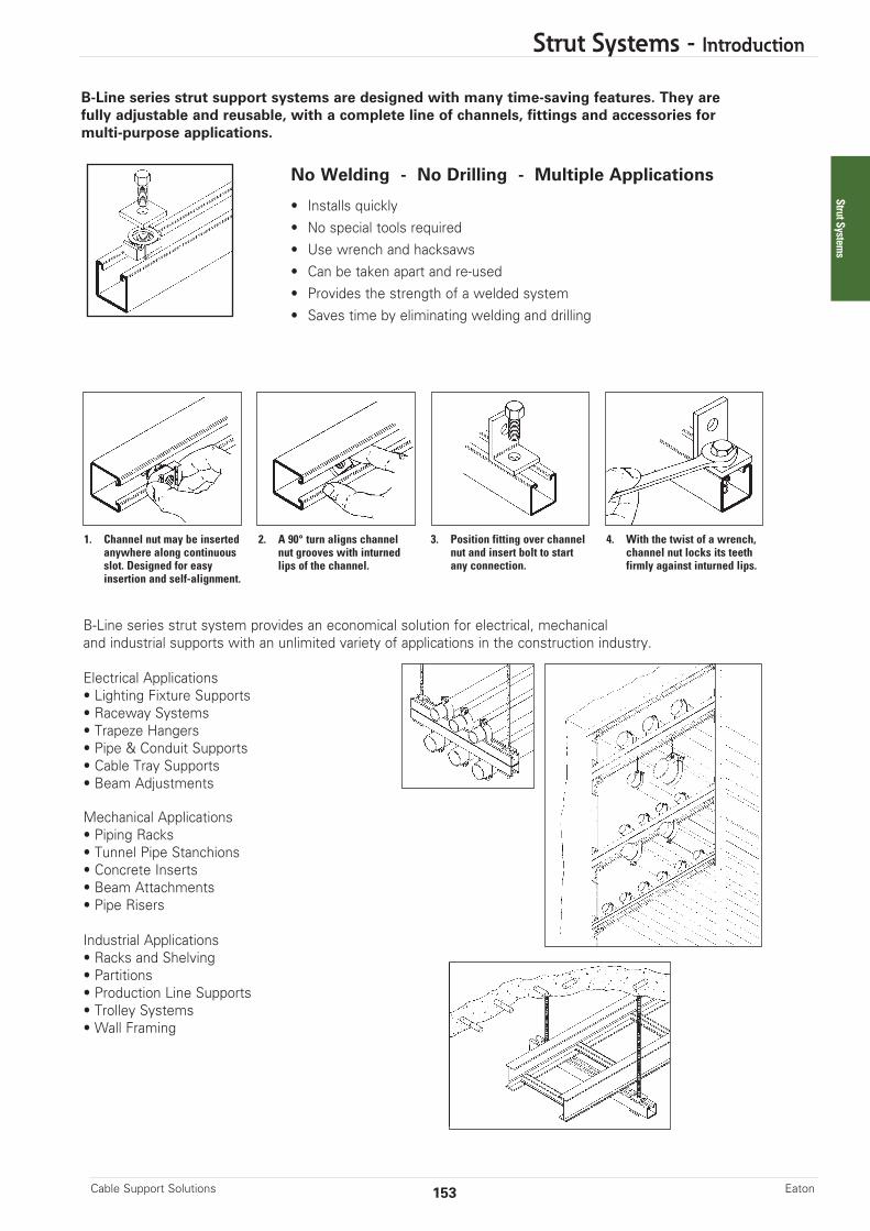
Strut Systems - Introduction
B-Line series strut support systems are designed with many time-saving features. They arefully adjustable and reusable, with a complete line of channels, fittings and accessories formulti-purpose applications.
No Welding - No Drilling - Multiple Applications
• Installs quickly• No special tools required• Use wrench and hacksaws• Can be taken apart and re-used• Provides the strength of a welded system• Saves time by eliminating welding and drilling
1. Channel nut may be insertedanywhere along continuous slot. Designed for easy insertion and self-alignment.
2. A 90° turn aligns channelnut grooves with inturnedlips of the channel.
3. Position fitting over channelnut and insert bolt to startany connection.
4. With the twist of a wrench,channel nut locks its teethfirmly against inturned lips.
B-Line series strut system provides an economical solution for electrical, mechanicaland industrial supports with an unlimited variety of applications in the construction industry.
Electrical Applications• Lighting Fixture Supports• Raceway Systems• Trapeze Hangers• Pipe & Conduit Supports• Cable Tray Supports• Beam Adjustments
Mechanical Applications• Piping Racks• Tunnel Pipe Stanchions• Concrete Inserts• Beam Attachments• Pipe Risers
Industrial Applications• Racks and Shelving• Partitions• Production Line Supports• Trolley Systems• Wall Framing
153Cable Support Solutions Eaton
Strut Systems
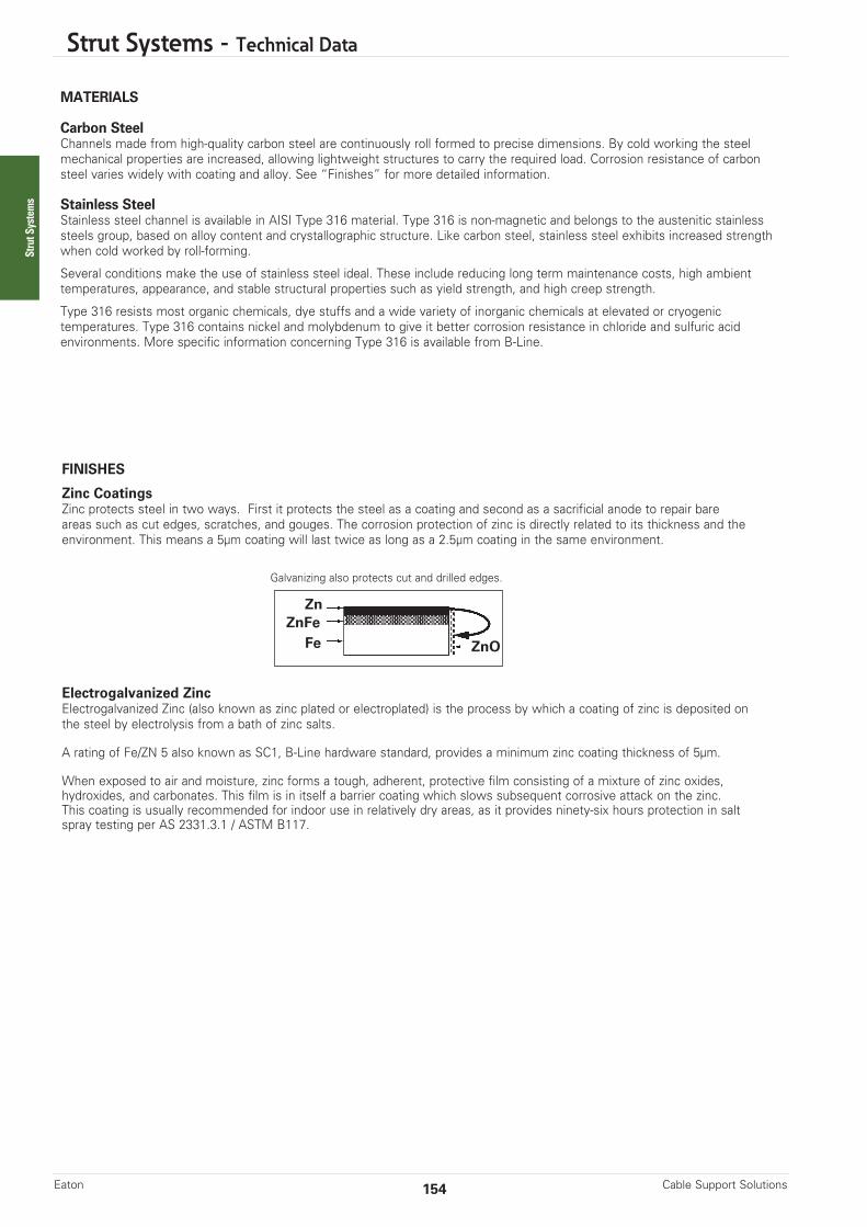
Strut Systems - Technical Data
MATERIALS
Carbon SteelChannels made from high-quality carbon steel are continuously roll formed to precise dimensions. By cold working the steel mechanical properties are increased, allowing lightweight structures to carry the required load. Corrosion resistance of carbonsteel varies widely with coating and alloy. See “Finishes” for more detailed information.
Stainless SteelStainless steel channel is available in AISI Type 316 material. Type 316 is non-magnetic and belongs to the austenitic stainlesssteels group, based on alloy content and crystallographic structure. Like carbon steel, stainless steel exhibits increased strengthwhen cold worked by roll-forming.
Several conditions make the use of stainless steel ideal. These include reducing long term maintenance costs, high ambient temperatures, appearance, and stable structural properties such as yield strength, and high creep strength.
Type 316 resists most organic chemicals, dye stuffs and a wide variety of inorganic chemicals at elevated or cryogenictemperatures. Type 316 contains nickel and molybdenum to give it better corrosion resistance in chloride and sulfuric acidenvironments. More specific information concerning Type 316 is available from B-Line.
Zn
FeZnFe
ZnO
FINISHES
Zinc CoatingsZinc protects steel in two ways. First it protects the steel as a coating and second as a sacrificial anode to repair bare areas such as cut edges, scratches, and gouges. The corrosion protection of zinc is directly related to its thickness and theenvironment. This means a 5µm coating will last twice as long as a 2.5µm coating in the same environment.
Galvanizing also protects cut and drilled edges.
Electrogalvanized ZincElectrogalvanized Zinc (also known as zinc plated or electroplated) is the process by which a coating of zinc is deposited onthe steel by electrolysis from a bath of zinc salts.
A rating of Fe/ZN 5 also known as SC1, B-Line hardware standard, provides a minimum zinc coating thickness of 5µm.
When exposed to air and moisture, zinc forms a tough, adherent, protective film consisting of a mixture of zinc oxides,hydroxides, and carbonates. This film is in itself a barrier coating which slows subsequent corrosive attack on the zinc.This coating is usually recommended for indoor use in relatively dry areas, as it provides ninety-six hours protection in saltspray testing per AS 2331.3.1 / ASTM B117.
Cable Support SolutionsEaton 154
Strut Systems

Strut Systems - Technical Data
WELDING
The welding procedures used in the fabrication of B-Line steel products are in accordance with recognized industry standards.To achieve the highest quality in our manufacturing processes, our welders are 3rd party certified.
MIG WeldingMIG welded, more properly called gas metal arc welded (GMAW) combination channels and fittings, are produced when physical dimensions or certain combinations require a weld process other than automatic spot welding. The same quality control requirements are imposed on MIG welded and spot welded products.
Quality AssuranceOur Quality Assurance Program has been developed and implemented for compliance with ISO 9001:2008. B-Line also complies with various industry standards and specifications.
MIG Weld
Anticipated Life of Zinc Coatings In Various Atmospheric Environments
Hot Dip Galvanized
Pre-Galvanized
= Zinc Coating 460g/m2 (.0026” Thick)
= Zinc Coating 138g/m2 (.00075” Thick)
Rural TropicalMarine
TemperatureMarine
HighlyIndustrial
Lifein
Years
Suburban Urban
10
20
30
40
10
36
8
29
7
25
6
21
5
18
3
11
Hot Dip Galvanized After Fabrication (Hot dip galvanized or batch hot dip galvanized)Hot dip galvanized strut products are fabricated from steel and then completely immersed in a bath of molten zinc. A metallicbond occurs resulting in a zinc coating that completely coats all surfaces, including edges and welds.
Another advantage of this method is coating thickness. Strut products that are hot dip galvanized after fabrication have aminimum thickness of 460g/m2 on each side, or a total 920g/m2, according to AS/NZS 4680 / ASTM A123.
The zinc thickness is controlled by the amount of time each part is immersed in the molten zinc bath as well as the speed atwhich it is removed. The term "double dipping" refers to parts too large to fit into the galvanizing kettle; therefore, must bedipped one end at a time. It does not refer to extra coating thickness.
The layer of zinc which bonds to steel provides a dual protection against corrosion. It protects first as an overall barriercoating. If this coating happens to be scratched or gouged, zinc's secondary defense is called upon to protect the steel by galvanic action.
Hot-Dip Galvanized After Fabrication is recommended for prolonged outdoor exposure and will usually protect steel for20 years or more in most atmospheric environments and in many industrial environments. For best results, a zinc rich paint(available from B-Line) should be applied to field cuts. The zinc rich paint will provide immediate protection for these areas and eliminate the short time period for galvanic action to “heal” the damaged coating.
155Cable Support Solutions Eaton
Strut Systems
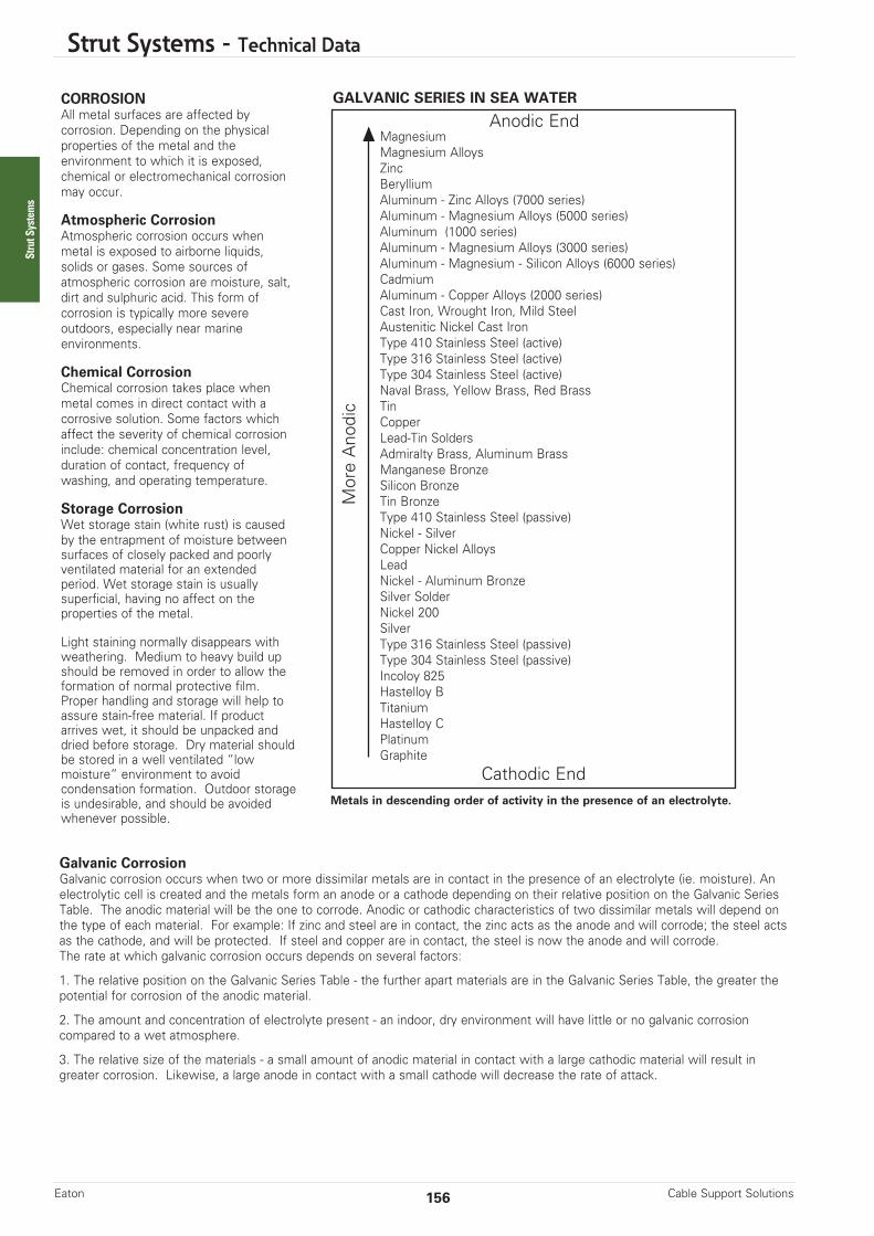
Strut Systems - Technical Data
CORROSIONAll metal surfaces are affected bycorrosion. Depending on the physicalproperties of the metal and theenvironment to which it is exposed,chemical or electromechanical corrosionmay occur.
Atmospheric CorrosionAtmospheric corrosion occurs whenmetal is exposed to airborne liquids,solids or gases. Some sources of atmospheric corrosion are moisture, salt,dirt and sulphuric acid. This form of corrosion is typically more severe outdoors, especially near marine environments.
Chemical CorrosionChemical corrosion takes place whenmetal comes in direct contact with acorrosive solution. Some factors whichaffect the severity of chemical corrosioninclude: chemical concentration level,duration of contact, frequency of washing, and operating temperature.
Storage CorrosionWet storage stain (white rust) is causedby the entrapment of moisture betweensurfaces of closely packed and poorlyventilated material for an extendedperiod. Wet storage stain is usually superficial, having no affect on theproperties of the metal.
Light staining normally disappears withweathering. Medium to heavy build upshould be removed in order to allow theformation of normal protective film.Proper handling and storage will help toassure stain-free material. If productarrives wet, it should be unpacked anddried before storage. Dry material shouldbe stored in a well ventilated “lowmoisture” environment to avoidcondensation formation. Outdoor storageis undesirable, and should be avoidedwhenever possible.
GALVANIC SERIES IN SEA WATER
Metals in descending order of activity in the presence of an electrolyte.
MagnesiumMagnesium AlloysZincBerylliumAluminum - Zinc Alloys (7000 series)Aluminum - Magnesium Alloys (5000 series)Aluminum (1000 series)Aluminum - Magnesium Alloys (3000 series)Aluminum - Magnesium - Silicon Alloys (6000 series)CadmiumAluminum - Copper Alloys (2000 series)Cast Iron, Wrought Iron, Mild SteelAustenitic Nickel Cast IronType 410 Stainless Steel (active)Type 316 Stainless Steel (active)Type 304 Stainless Steel (active)Naval Brass, Yellow Brass, Red BrassTin CopperLead-Tin SoldersAdmiralty Brass, Aluminum BrassManganese BronzeSilicon BronzeTin BronzeType 410 Stainless Steel (passive)Nickel - SilverCopper Nickel AlloysLeadNickel - Aluminum BronzeSilver SolderNickel 200SilverType 316 Stainless Steel (passive)Type 304 Stainless Steel (passive)Incoloy 825Hastelloy BTitaniumHastelloy CPlatinumGraphite
More Anodic
Anodic End
Cathodic End
Galvanic CorrosionGalvanic corrosion occurs when two or more dissimilar metals are in contact in the presence of an electrolyte (ie. moisture). Anelectrolytic cell is created and the metals form an anode or a cathode depending on their relative position on the Galvanic SeriesTable. The anodic material will be the one to corrode. Anodic or cathodic characteristics of two dissimilar metals will depend onthe type of each material. For example: If zinc and steel are in contact, the zinc acts as the anode and will corrode; the steel actsas the cathode, and will be protected. If steel and copper are in contact, the steel is now the anode and will corrode.The rate at which galvanic corrosion occurs depends on several factors:
1. The relative position on the Galvanic Series Table - the further apart materials are in the Galvanic Series Table, the greater thepotential for corrosion of the anodic material.
2. The amount and concentration of electrolyte present - an indoor, dry environment will have little or no galvanic corrosioncompared to a wet atmosphere.
3. The relative size of the materials - a small amount of anodic material in contact with a large cathodic material will result ingreater corrosion. Likewise, a large anode in contact with a small cathode will decrease the rate of attack.
Cable Support SolutionsEaton 156
Strut Systems
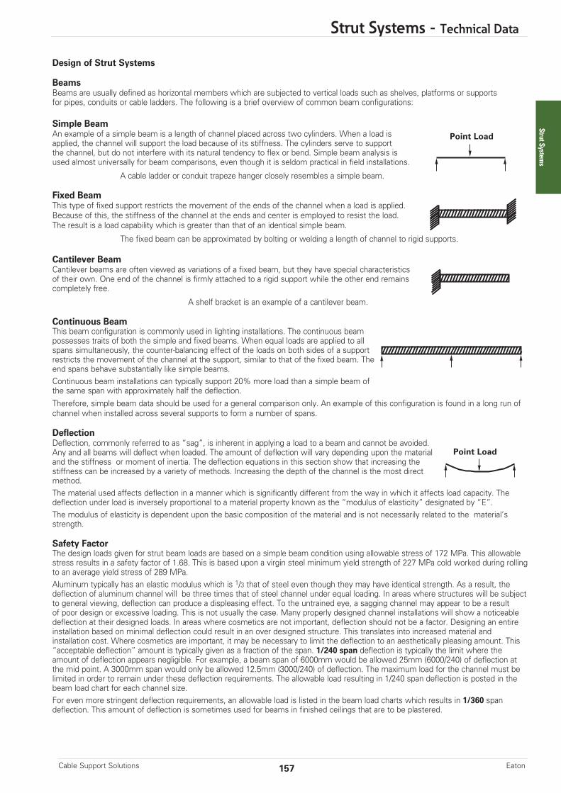
Strut Systems - Technical Data
Design of Strut Systems
BeamsBeams are usually defined as horizontal members which are subjected to vertical loads such as shelves, platforms or supportsfor pipes, conduits or cable ladders. The following is a brief overview of common beam configurations:
Simple BeamAn example of a simple beam is a length of channel placed across two cylinders. When a load isapplied, the channel will support the load because of its stiffness. The cylinders serve to supportthe channel, but do not interfere with its natural tendency to flex or bend. Simple beam analysis isused almost universally for beam comparisons, even though it is seldom practical in field installations.
A cable ladder or conduit trapeze hanger closely resembles a simple beam.
Fixed BeamThis type of fixed support restricts the movement of the ends of the channel when a load is applied.Because of this, the stiffness of the channel at the ends and center is employed to resist the load.The result is a load capability which is greater than that of an identical simple beam.
The fixed beam can be approximated by bolting or welding a length of channel to rigid supports.
Cantilever BeamCantilever beams are often viewed as variations of a fixed beam, but they have special characteristicsof their own. One end of the channel is firmly attached to a rigid support while the other end remainscompletely free.
A shelf bracket is an example of a cantilever beam.
Continuous BeamThis beam configuration is commonly used in lighting installations. The continuous beampossesses traits of both the simple and fixed beams. When equal loads are applied to allspans simultaneously, the counter-balancing effect of the loads on both sides of a supportrestricts the movement of the channel at the support, similar to that of the fixed beam. Theend spans behave substantially like simple beams.Continuous beam installations can typically support 20% more load than a simple beam ofthe same span with approximately half the deflection.Therefore, simple beam data should be used for a general comparison only. An example of this configuration is found in a long run ofchannel when installed across several supports to form a number of spans.
DeflectionDeflection, commonly referred to as “sag”, is inherent in applying a load to a beam and cannot be avoided.Any and all beams will deflect when loaded. The amount of deflection will vary depending upon the materialand the stiffness or moment of inertia. The deflection equations in this section show that increasing the stiffness can be increased by a variety of methods. Increasing the depth of the channel is the most directmethod.The material used affects deflection in a manner which is significantly different from the way in which it affects load capacity. Thedeflection under load is inversely proportional to a material property known as the “modulus of elasticity” designated by “E”.The modulus of elasticity is dependent upon the basic composition of the material and is not necessarily related to the material’sstrength.
Safety FactorThe design loads given for strut beam loads are based on a simple beam condition using allowable stress of 172 MPa. This allowablestress results in a safety factor of 1.68. This is based upon a virgin steel minimum yield strength of 227 MPa cold worked during rollingto an average yield stress of 289 MPa.Aluminum typically has an elastic modulus which is 1/3 that of steel even though they may have identical strength. As a result, thedeflection of aluminum channel will be three times that of steel channel under equal loading. In areas where structures will be subjectto general viewing, deflection can produce a displeasing effect. To the untrained eye, a sagging channel may appear to be a result of poor design or excessive loading. This is not usually the case. Many properly designed channel installations will show a noticeabledeflection at their designed loads. In areas where cosmetics are not important, deflection should not be a factor. Designing an entireinstallation based on minimal deflection could result in an over designed structure. This translates into increased material and installation cost. Where cosmetics are important, it may be necessary to limit the deflection to an aesthetically pleasing amount. This“acceptable deflection” amount is typically given as a fraction of the span. 1/240 span deflection is typically the limit where theamount of deflection appears negligible. For example, a beam span of 6000mm would be allowed 25mm (6000/240) of deflection atthe mid point. A 3000mm span would only be allowed 12.5mm (3000/240) of deflection. The maximum load for the channel must belimited in order to remain under these deflection requirements. The allowable load resulting in 1/240 span deflection is posted in thebeam load chart for each channel size. For even more stringent deflection requirements, an allowable load is listed in the beam load charts which results in 1/360 spandeflection. This amount of deflection is sometimes used for beams in finished ceilings that are to be plastered.
Point Load
Point Load
157Cable Support Solutions Eaton
Strut Systems

Strut Systems - Technical Data
Twisting & Lateral BracingLoading of strut on long spans can cause torsional stress, resulting in the tendency of the strut to twist or bend laterally. Thisphenomenon reduces the allowable beam loads as shown in the beam loading charts. It is recommended that long spans be supported in a manner to prevent twisting (fixed ends), and that the channel have adequate lateral bracing. Many typical strut applications provide this support and bracing inherently. Piping, tubing, cable ladders, or conduits mounted to the strut with straps and clamps prevent twisting or lateral movement. If no such lateral support exists, contact the factory for loading recommendations.
ColumnsColumns are vertical members which carry loads in compression. One common example of a channel column is the verticalmembers of a storage rack.In theory, a column will carry a load equal to its cross sectional area multiplied by the ultimate compressive stress of the materialof which the column is made. In reality, there are many factors affecting the load capacity of a column, such as the tendency tobuckle or twist laterally (torsional-flexural buckling), the type of connection at the top or bottom, the eccentricity of the load application, and material imperfections. Several of these failure modes have been considered in the allowable column load tablesshown in the “Channel” section of this catalog.
B-Line strongly recommends that the engineer perform a detailed study of the many variable conditions before the selectionprocess begins.
Design Factors to be ConsideredThe loading capacity of channel depends primarily on the material, its cross-sectional design, and the beam or column loading configuration. It should be noted that if two lengths of channel have identical designs and configurations, the one made of thestronger base material will support a larger load. Therefore, any comparison of channel should begin by determining whether thematerials are approximately equal in strength.
The column loading chart for each channel lists the allowable load for each channel in compression. This load varies depending onthe support condition or “K-factor”.Several “K-factors” are listed, which correspond to the following support conditions:
K = .8 pinned top - fixed bottomK = .65 fixed top - fixed bottomK = 1.0 pinned top - pinned bottomK = 1.2 free top - fixed bottom
There are a number of physical properties which are important to the complete design of a channel member; the “sectionmodulus” designated as “Sx” or “Sy”, “moment of inertia” designated by “Ix” or “Iy”, and the “radius of gyration” which is givenas “rx” or “ry”.
Every structural material has its own maximum or ultimate stress, which is usually expressed in pascals. Any load which causes a member to fail is referred to as its “ultimate” load. In order to prevent channel from being accidentally loaded up to or beyondits ultimate load, a safety factor is included into the design. The ultimate load is divided by the safety factor to obtain the “recommended” or “allowable” working load.
When evaluating channel under various beam conditions, it is often more convenient to compare in terms of the ultimate orrecommended “bending moment”. Simple equations show the stress is directly proportional to the bending moment.
Therefore, comparing bending moments can save time in repeated calculations. The chart containing Formulas on Common BeamLoadings (following page) shows how to calculate the bending moment for various configurations and load conditions. It should benoted that the bending moment is usually not constant, but varies along the length of the span. However, the channel must bedesigned for a single point, which is the point of maximum bending moment.
For information regarding dynamic or seismic design, contact B-Line’s Home Office.
General Information
TorqueThe torque values given throughout the catalog are to be used as a guide only. The relationship between the applied torque ortorque wrench reading and the actual tension created in the bolt may be substantially different. For example, a dry non-lubricatedbolt with a heavy plating may rate 50% as efficient as a bolt which is lubricated with a mixture of heavy oil and graphite. Otherimportant factors affecting torque-tension relationships include friction under the bolt head or nut, hole tolerances, and torquewrench tolerances. Accuracy of many commercial torque wrenches may vary as much as plus or minus 25%.
Charts and TablesCharts and tables in this section are compiled from information published by nationally recognized organizations and are intendedfor use as a guide only. B-Line recommends that users of this information determine the validity of such information as applied totheir own application.
Cable Support SolutionsEaton 158
Strut Systems

Strut Systems - Technical Data
Brackets [ ] indicate alternative specifications which may be substituted by the project engineer.
PART 1 - GENERAL1.01 WORK INCLUDEDA. Continuous slot, bolted metal framing channels and all associated fittings and hardware.
B. Trapeze type supports for cable ladder, conduit, pipe and other similar systems.
C. Use of bolted metal framing as a surface metal raceway.
1.02 REFERENCESA. AS/NZS 4680 / ASTM A123 - Specification for Zinc (hot-dip galvanized) Coatings on Products Fabricated from Rolled, Pressed, and ForgedSteel Shapes, Plates, Bars and Strips.
B. AS/NZS 1594 / ASTM A1011 - Specification for Steel, Sheet and Strip, Carbon, Hot-Rolled, Structural Quality.
C. AS 1789 / ASTM B633 - Specification for Electrodeposited Coatings of Zinc on Iron and Steel.
D. AS/NZS 1594 / ASTM A1018 - Standard Specification for Steel, Sheet and Strip, Heavy-Thickness Coils, Carbon, Hot-Rolled, Structural Quality.
E. MFMA - Metal Framing Standards Publication, MFMA-4.
1.03 QUALITY ASSURANCEA. Manufacturers : Firms regularly engaged in the manufacture of bolted metal framing of the types required, whose products have been insatisfactory use in similar service for not less than 5 years.
B. For stainless steel items, the part number shall contain a material designator (EXAMPLE: B-Line B22SS6 for type 316 or B22SS4 for type 304),or a separate stamp shall be included to reference the type of material used.
C. MFMA Compliance: comply with the latest revision of MFMA Standard Publication Number MFMA-4, “Metal Framing”.
D. NEC Compliance: Comply with the latest revision NFPA 70 - Article 352 “Surface Metal Raceways and Surface Nonmetallic Raceways”.
1.04 SUBMITTALSA. Submit drawings of strut and accessories including clamps, brackets, hanger rods and fittings.
B. Submit manufacturer’s product data on strut channels including, but not limited to, types, materials, finishes, gauge thickness and hole patterns. For each different strut cross section, submit cross sectional properties including Section Modulus (Sx) and Moment of Inertia (Ix).
1.05 DELIVERY, STORAGE AND HANDLINGA. Deliver strut systems and components carefully to avoid breakage, denting, and scoring finishes. Do not install damaged equipment.
B. Store strut systems and components in original cartons and in clean dry space; protect from weather and construction traffic.
PART 2 - PRODUCTS2.01 ACCEPTABLE MANUFACTURERSA. Manufacturer: Subject to compliance with these specifications, strut systems to be installed shall be as manufactured by B-Line, Inc.[or engineer approved equal.]
2.02 STRUT CHANNELS AND COMPONENTSA. General: Strut shall be 41mm wide in varying heights and welded combinations as required to meet load capacities and designs indicatedon the drawings.
B. Material and Finish: Material and finish specifications for each strut type are as follows:
1. Hot-Dip Galvanized Steel: Strut shall be made from structural quality steel meeting the minimum mechanical properties of AS/NZS 1594 /ASTM A1011 and shall be hot-dip galvanized after fabrication in accordance with AS/NZS 4680 / ASTM A123. Fittings shall be manufactured from steel meeting the minimum requirements of AS/NZS 1594 / ASTM A1018, and hot-dip galvanized after fabrication in accordance with AS/NZS 4680 / ASTM A123.All hardware shall be stainless steel Type 316 or hot-dip galvanized AS 1214 / ASTM A153.
2. Stainless Steel: All strut, fittings and hardware shall be made of stainless steel Type 316 as indicated. Channels must be identified asrequired in previous section 1.03 Quality Assurance.
PART 3 - EXECUTION3.01 INSTALLATIONA. Install strut as indicated; in accordance with equipment manufacturer’s recommendations, and with recognized industry practices.
B. All nuts and bolts shall be tightened to the following values.
RECOMMENDED STRUT SYSTEM SPECIFICATION
Bolt Size Torque (Nm)M6 12M8 17M10 36M12 62
159Cable Support Solutions Eaton
Strut Systems
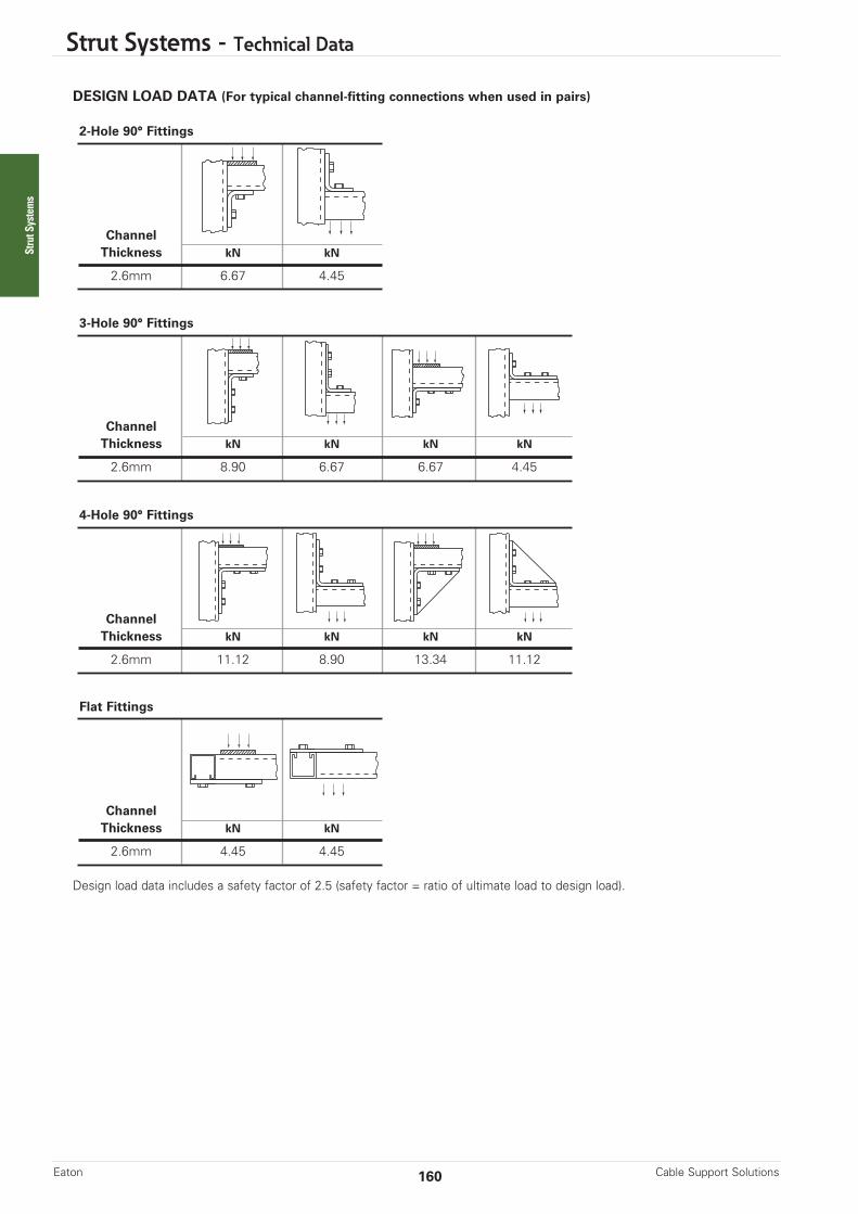
Strut Systems - Technical Data
DESIGN LOAD DATA (For typical channel-fitting connections when used in pairs)
Design load data includes a safety factor of 2.5 (safety factor = ratio of ultimate load to design load).
Cable Support SolutionsEaton 160
2-Hole 90° Fittings
ChannelThickness kN kN
2.6mm 6.67 4.45
Flat Fittings
ChannelThickness kN kN
2.6mm 4.45 4.45
3-Hole 90° Fittings
ChannelThickness kN kN kN kN
2.6mm 8.90 6.67 6.67 4.45
4-Hole 90° Fittings
ChannelThickness kN kN kN kN
2.6mm 11.12 8.90 13.34 11.12
Strut Systems
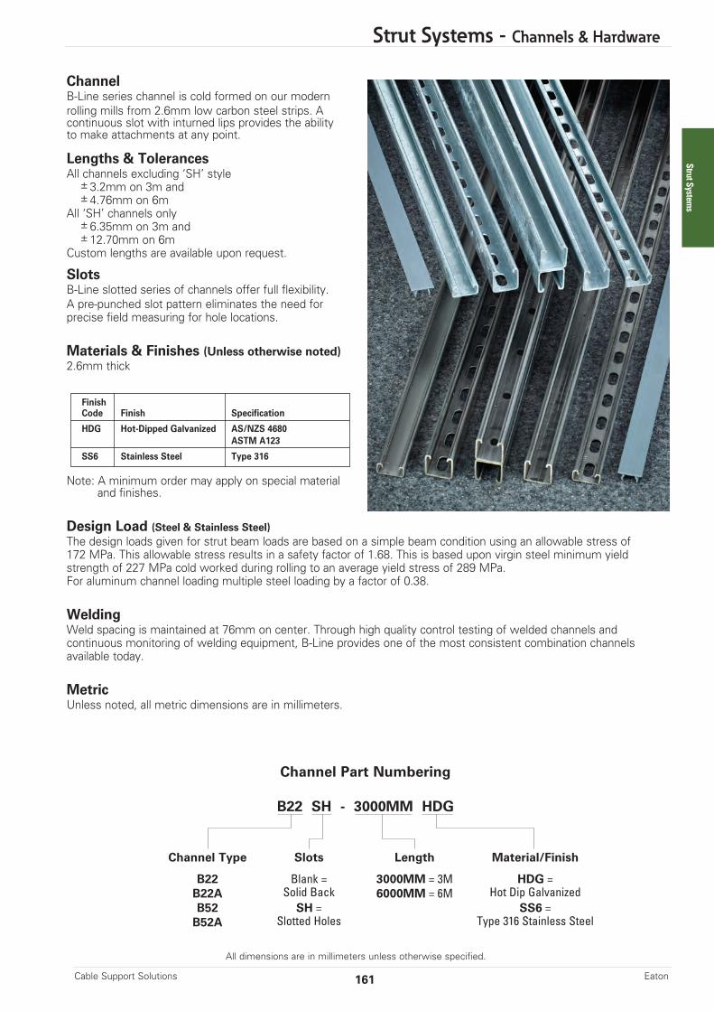
Strut Systems - Channels & Hardware
All dimensions are in millimeters unless otherwise specified.
ChannelB-Line series channel is cold formed on our modernrolling mills from 2.6mm low carbon steel strips. Acontinuous slot with inturned lips provides the abilityto make attachments at any point.
Lengths & TolerancesAll channels excluding ‘SH’ style
±3.2mm on 3m and±4.76mm on 6m
All ‘SH’ channels only±6.35mm on 3m and±12.70mm on 6m
Custom lengths are available upon request.
SlotsB-Line slotted series of channels offer full flexibility.A pre-punched slot pattern eliminates the need for precise field measuring for hole locations.
Materials & Finishes (Unless otherwise noted)2.6mm thick
Note: A minimum order may apply on special materialand finishes.
Design Load (Steel & Stainless Steel)The design loads given for strut beam loads are based on a simple beam condition using an allowable stress of172 MPa. This allowable stress results in a safety factor of 1.68. This is based upon virgin steel minimum yieldstrength of 227 MPa cold worked during rolling to an average yield stress of 289 MPa.For aluminum channel loading multiple steel loading by a factor of 0.38.
WeldingWeld spacing is maintained at 76mm on center. Through high quality control testing of welded channels andcontinuous monitoring of welding equipment, B-Line provides one of the most consistent combination channelsavailable today.
MetricUnless noted, all metric dimensions are in millimeters.
FinishCode Finish Specification
HDG Hot-Dipped Galvanized AS/NZS 4680ASTM A123
SS6 Stainless Steel Type 316
Channel Part Numbering
B22 SH - 3000MM HDG
Channel Type Slots Length Material/Finish
B22 Blank = 3000MM = 3M HDG =B22A Solid Back 6000MM = 6M Hot Dip GalvanizedB52 SH = SS6 =B52A Slotted Holes Type 316 Stainless Steel
161Cable Support Solutions Eaton
Strut Systems

Strut Systems - Channels
All dimensions are in millimeters unless otherwise specified.
Areas of Moment of Section Radius of Moment of Section Radius ofChannel Weight Section Inertia (I) Modulus (S) Gyration (r) Inertia (I) Modulus (S) Gyration (r)
kg/m cm2 cm4 cm3 cm cm4 cm3 cm
B22 2.83 3.62 7.96 3.48 1.48 9.99 4.84 1.66
B22A 5.69 7.25 40.51 9.81 2.36 19.97 9.68 1.66
X - X Axis Y - Y Axis
B22• Thickness: 2.6mm• Standard lengths: 3m & 6m• Standard finishes: Hot-Dipped Galvanized, Stainless Steel Type 316• Weight: 2.83kg/m
Calculations of section properties are based on metal thicknesses as determined by the AISI Cold-Formed Steel Design Manual.
41.3
41.3
41.3
82.5
20.6
20.6
41.3
18.4
9.59.5
7.122.2
X
Y
Y
XX
Y
Y
X
Section Properties
B22A Wt. 5.69kg/m
MIG Weld
Cable Support SolutionsEaton 162
Strut Systems
14.3mm x 28.6mm Slots50.8mm on centers
B22SH Wt. 2.71kg/m
For beam loads use 90% ofBeam Loading charts

Strut Systems - Channels
All dimensions are in millimeters unless otherwise specified.
Beam Loading
Column Loading
Based on simple beam condition using an allowable design stress of 172 MPa in accordance with MFMA, with adequate lateral bracing.Actual yield point of cold rolled steel is 289 MPa. To determine concentrated load capacity at mid span, multiply uniform load by 0.5 and corresponding deflection by 0.8. *Failure determined by weld shear.
**Where the slenderness ratio KL exceeds 200, and K = end fixity factor, L = actual length and r = radius of gyration.r
Uniform Load @ Deflection =Beam Span Channel Uniform Load and Deflection 1/240 Span 1/360 Span
mm Style kN mm kN N
305B22 11.61 .35 11.61 11.61B22A 11.61* .05 11.61* 11.61*
609B22 7.57 1.42 7.57 7.57B22A 11.61* .43 11.61* 11.61*
914B22 5.05 3.20 5.05 4.00B22A 11.61* 1.45 11.61* 11.61*
1219B22 3.78 5.69 3.37 2.24B22A 10.70 3.17 10.70 10.70
1524B22 3.03 8.91 2.16 1.44B22A 8.56 4.95 8.56 7.29
1829B22 2.52 12.83 1.50 1.00B22A 7.13 7.14 7.13 5.06
2133B22 2.16 17.45 1.10 0.73B22A 6.11 9.73 5.58 3.72
2438B22 1.89 22.81 0.84 0.56B22A 5.35 12.70 4.27 2.85
2743B22 1.68 28.85 0.67 0.44B22A 4.75 16.08 3.37 2.25
3048B22 1.51 35.63 0.54 0.36B22A 4.28 19.86 2.73 1.82
Max. Column Loading K = .80 Max. Column Loading (Loaded @ C.G.)Unbraced Channel Loaded@ Loaded@Height Style C.G. Slot Face K = .65 K = 1.0 K = 1.2mm kN kN kN kN kN
305 B22 46.50 19.12 47.14 45.47 44.26B22A 96.19 31.14 96.42 95.81 95.34
609 B22 41.42 17.76 43.60 38.17 34.70B22A 94.14 30.68 95.07 92.61 90.73
914 B22 34.70 15.96 38.59 28.33 23.98B22A 90.73 29.93 92.81 87.27 83.04
1219 B22 27.55 13.87 32.92 20.99 16.86B22A 85.95 28.89 89.66 79.80 72.29
1524 B22 20.99 11.70 27.10 16.08 13.06B22A 79.80 23.75 85.60 70.20 58.45
1829 B22 16.86 10.07 21.66 13.06 10.59B22A 72.29 17.65 80.64 58.45 42.36
2133 B22 14.13 8.82 17.96 10.95 8.81B22A 63.41 13.47 74.78 44.82 31.23
2438 B22 16.58 7.83 15.37 9.34 7.43B22A 53.16 10.49 68.02 34.32 23.83
2743 B22 10.59 7.00 13.44 8.08 68.60**B22A 42.36 8.30 60.35 27.11 18.83
3048 B22 9.34 6.31 11.92 7.04** 5.46**B22A 34.32 6.72 51.78 21.96 15.25**
163Cable Support Solutions Eaton
Strut Systems
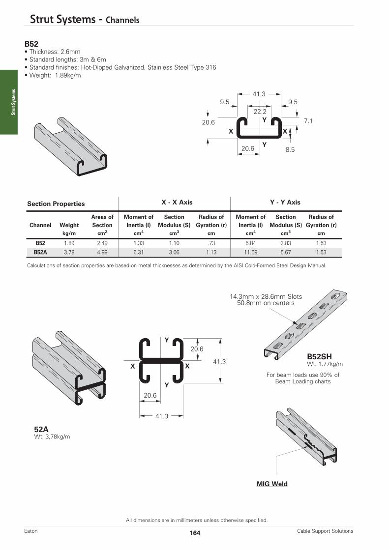
Strut Systems - Channels
All dimensions are in millimeters unless otherwise specified.
Areas of Moment of Section Radius of Moment of Section Radius ofChannel Weight Section Inertia (I) Modulus (S) Gyration (r) Inertia (I) Modulus (S) Gyration (r)
kg/m cm2 cm4 cm3 cm cm4 cm3 cm
B52 1.89 2.49 1.33 1.10 .73 5.84 2.83 1.53
B52A 3.78 4.99 6.31 3.06 1.13 11.69 5.67 1.53
X - X Axis Y - Y Axis
B52• Thickness: 2.6mm• Standard lengths: 3m & 6m• Standard finishes: Hot-Dipped Galvanized, Stainless Steel Type 316• Weight: 1.89kg/m
Calculations of section properties are based on metal thicknesses as determined by the AISI Cold-Formed Steel Design Manual.
41.3
20.6
41.3
41.3
20.6
20.6
20.6
8.5
9.59.5
7.122.2
X
Y
Y
XX
Y
Y
X
Section Properties
52A Wt. 3,78kg/m
Cable Support SolutionsEaton 164
MIG Weld
Strut Systems
14.3mm x 28.6mm Slots50.8mm on centers
B52SH Wt. 1.77kg/m
For beam loads use 90% ofBeam Loading charts
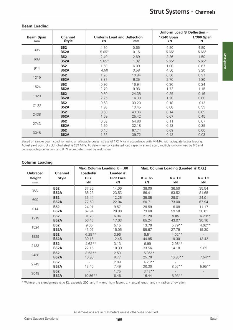
Strut Systems - Channels
All dimensions are in millimeters unless otherwise specified.
Beam Loading
Column Loading
Based on simple beam condition using an allowable design stress of 172 MPa in accordance with MFMA, with adequate lateral bracing. Actual yield point of cold rolled steel is 289 MPa. To determine concentrated load capacity at mid span, multiply uniform load by 0.5 and corresponding deflection by 0.8. *Failure determined by weld shear.
**Where the slenderness ratio KL exceeds 200, and K = end fixity factor, L = actual length and r = radius of gyration.r
Uniform Load @ Deflection =Beam Span Channel Uniform Load and Deflection 1/240 Span 1/360 Span
mm Style kN mm kN N
305B52 4.80 0.66 4.80 4.80B52A 5.65* 0.15 5.65* 5.65*
609B52 2.40 2.69 2.26 1.50B52A 5.65* 1.32 5.65* 5.65*
914B52 1.60 6.09 1.00 0.67B52A 4.50 3.58 4.50 3.20
1219B52 1.20 10.84 0.56 0.37B52A 3.37 6.35 2.70 1.80
1524B52 0.96 16.94 0.36 0.24B52A 2.70 9.93 1.72 1.15
1829B52 0.80 24.38 0.25 0.16B52A 2.25 14.30 1.20 0.80
2133B52 0.68 33.20 0.18 .012B52A 1.93 19.45 0.88 0.59
2438B52 0.60 43.36 0.14 0.09B52A 1.69 25.42 0.67 0.45
2743B52 0.53 54.86 0.11 0.07B52A 1.50 32.18 0.53 0.35
3048B52 0.48 67.74 0.09 0.06B52A 1.35 39.72 0.43 0.03
Max. Column Loading K = .80 Max. Column Loading (Loaded @ C.G.)Unbraced Channel Loaded@ Loaded@Height Style C.G. Slot Face K = .65 K = 1.0 K = 1.2mm kN kN kN kN kN
305 B52 37.36 14.06 38.00 36.50 35.54B52A 85.23 23.53 86.41 83.52 81.68
609 B52 33.44 12.25 35.05 29.01 24.01B52A 77.59 22.04 80.71 73.00 67.94
914 B52 24.01 9.57 29.59 16.08 11.17B52A 67.94 20.00 73.60 59.50 50.01
1219 B52 31.78 6.94 21.28 9.05 6.28**B52A 56.46 17.63 65.24 43.07 30.16
1524 B52 9.05 5.15 13.70 5.79** 4.02**B52A 43.07 15.05 55.67 27.79 19.30
1829 B52 6.28** 3.96 9.51 4.02** -B52A 30.16 12.45 44.85 19.30 13.42
2133 B52 4.62** 3.13 6.99 2.95** -B52A 22.15 10.39 33.56 14.18 9.85
2438 B52 3.53** 2.53 5.35** - -B52A 16.96 8.77 25.70 10.86** 7.54**
2743 B52 - 2.09 4.23** - -B52A 13.40 7.49 20.30 8.57** 5.95**
3048 B52 - 1.75 3.42** - -B52A 10.86** 6.46 16.44 6.95** -
165Cable Support Solutions Eaton
Strut Systems

Strut Systems - Hardware & Fittings
All dimensions are in millimeters unless otherwise specified.
HardwareChannel NutsThe B-Line series channel nut is one of the maincomponents of our bolted metal framing system.It is designed to provide essential gripping powerand ease during installation. Channel nuts arepress formed, machined and hardened from steel.
Recommended Torque
Materials & Finishes*
*Unless otherwise noted.Note: Channel nuts are not available in HDG.
MetricUnless noted, all metric dimensions are in millimeters.
Bolt Size M6 M10 M12
Nm 12 36 62
FinishCode Finish Specification
HDG Hot-Dipped Galvanized AS 1214 / ASTM A153
SS6 Stainless Steel Type 316
Cable Support SolutionsEaton 166
Resistance to Slip kNThread Nut Part 2.6mm ChannelSize Numbers HDG SS6
M6 x 1 BMS-6 1.33 0.65M10 x 1.50 BMS-10 3.56 1.78M12 x 1.75 BMS-12 6.67 3.33
Resistance To Slip• With Safety Factor of 3
Pull-Out Strength kNThread Nut Part 2.6mm ChannelSize Numbers HDG SS6
M6 x 1 BMS-6 2.00 2.00M10 x 1.50 BMS-10 4.89 4.89M12 x 1.75 BMS-12 6.67 6.67
Resistance to Slip of Channel Nut
Pull-Out Strength• With Safety Factor of 3
Pull-Out Strength of Channel Nut
Strut Systems

Strut Systems - Hardware
All dimensions are in millimeters unless otherwise specified.
Part No. Thread Size Fits Channel Sizes Nut Thickness Wt./Cmm kg
BMS-6 M6 x 1 All Sizes 6.3 3.13
BMS-10 M10 x 1.5 All Sizes 9.5 4.35
BMS-12 M12 x 1.75 All Sizes 9.5 4.17
Nut Without Spring
Part No. Thread Size Fits Channel Sizes Nut Thickness Wt./Cmm kg
BMS-6M M6 x 1 B22 6.3 3.13
BMS-6S M6 x 1 B52 6.3 3.13
BMS-10M M10 x 1.5 B22 9.5 4.35
BMS-10S M10 x 1.5 B52 9.5 4.35
BMS-12M M12 x 1.75 B22 9.5 4.17
BMS-12M M12 x 1.75 B52 9.5 4.17
Spring Nut
BMS-_MSeries
BMS-_SSeries
BMS-_Series
Note: See below for resistance toslip and pull-out strength.
• Finish: HDG, SS6
167Cable Support Solutions Eaton
Wt./CPart No. kg
M6x20 HHCS 0.63M16x25 HHCS 0.77M10x25 HHCS 1.90M12x20 HHCS 3.48M12x25 HHCS 3.81M12x30 HHCS 4.17
Wt./CPart No. kg
M6 HN 0.32M10 HN 0.68M12 HN 1.63
HHCS Hex Head Cap Screws• Standard finish:
HDG, Stainless Steel Type 316
HN Hex Nuts• Standard finish:
HDG, Stainless Steel Type 316
O.D. Outside Dia. Wt./CPart No. mm kg
M6 FW 18.7 0.32M10 FW 25.4 0.77M12 FW 34.9 1.77
FW Flat Washers• Standard finish:
HDG, Stainless Steel Type 316
O.D.
Strut Systems

Strut Systems - Fittings
All dimensions are in millimeters unless otherwise specified.
Cable Support SolutionsEaton 168
Fittings A selection of fittings and accessories are available tocomplete the B-Line series bolted strut system.
DimensionsThe following dimensions apply to all fittings except as noted.
Materials & Finishes (Unless otherwise noted)
Note: A minimum order may apply on special materialand finishes.
Load DataThe load data published includes safety factor of 2.5 when used with 2.6mm channel(safety factor = ratio of ultimate load to the design load).
Use M12 x 20 hex head cap screws and BMS-12 channel nuts for the rated results.
Recommended Bolt TorqueMetricAll dimensions are in millimeters unless noted otherwise.
HardwareNuts and bolts are not included with the fittings and must be ordered separately, unless noted.
Hole Size –14mm diameter
Thickness – 6.3mm
Width –38mm
Hole Spacing – 48mmon center
Hole Spacing – 20.6mm from end
FinishCode Finish Specification
HDG Hot-Dipped Galvanized AS/NZS 4680 / ASTM A123
SS6 Stainless Steel Type 316
Bolt Size M6 M10 M12
Nm 12 36 62
Strut Systems

Strut Systems - Fittings
All dimensions are in millimeters unless otherwise specified.
B101 Two-Hole Corner Angle• Standard finishes: HDG, SS6• Wt./C: 16.8kg
B102 Three Hole Corner Angle
• Standard finishes: HDG, SS6• Wt./C: 25.4kg
B105 Three Hole Offset Z-Support for B24• Standard finishes: HDG, SS6• Wt./C: 23.1kg
B280FL Post Base For B24• Standard finishes: HDG, SS6• Wt./C: 141.5kg
B281FL Post Base For B24A• Standard finishes: HDG, SS6• Wt./C: 113.4kg
169Cable Support Solutions Eaton
57
41
B143 Four-Hole Corner Angle
• Standard finishes: HDG, SS6• Wt./C: 34.0kg
89
137
B107 Five Hole U-Support• Standard finishes: HDG, SS6• Wt./C: 38.5kg
134
41
50
20 Dia.2 Holes
159
75
84
203
B172 Four Hole Splice Clevis For B24• Standard finishes: HDG, SS6• Wt./C: 120.6kg
6
184
57
89
89
41
89
43
20 Dia.2 Holes
203159
76
Strut Systems

Strut Systems - Fittings
All dimensions are in millimeters unless otherwise specified.
Cable Support SolutionsEaton 170
B437 SeriesTwo Piece Pipe Clamp• Clamp halves can turn allowing pipe to be fastened to channel at any direction
• Order hardware separately• Standard finish: HDG, SS6
Hole SizeA
Part No. Pipe Size A T Wt./Cmm mm mm kg
B437-1/2 15 7.9 3.4 10.0B437-3/4 20 7.9 3.4 11.8B437-1 25 7.9 3.4 13.6B437-11/4 32 7.9 3.4 15.9B437-11/2 40 7.9 3.4 17.2B437-2 50 11.1 6.3 41.3B437-21/2 65 11.1 6.3 47.2B437-3 80 11.1 6.3 58.9B437-31/2 90 11.1 6.3 67.6B437-4 100 11.1 6.3 71.6B437-5 125 11.1 6.3 86.2B437-6 150 11.1 6.3 98.4B437-8 200 11.1 6.3 133.8
T
Strut Systems
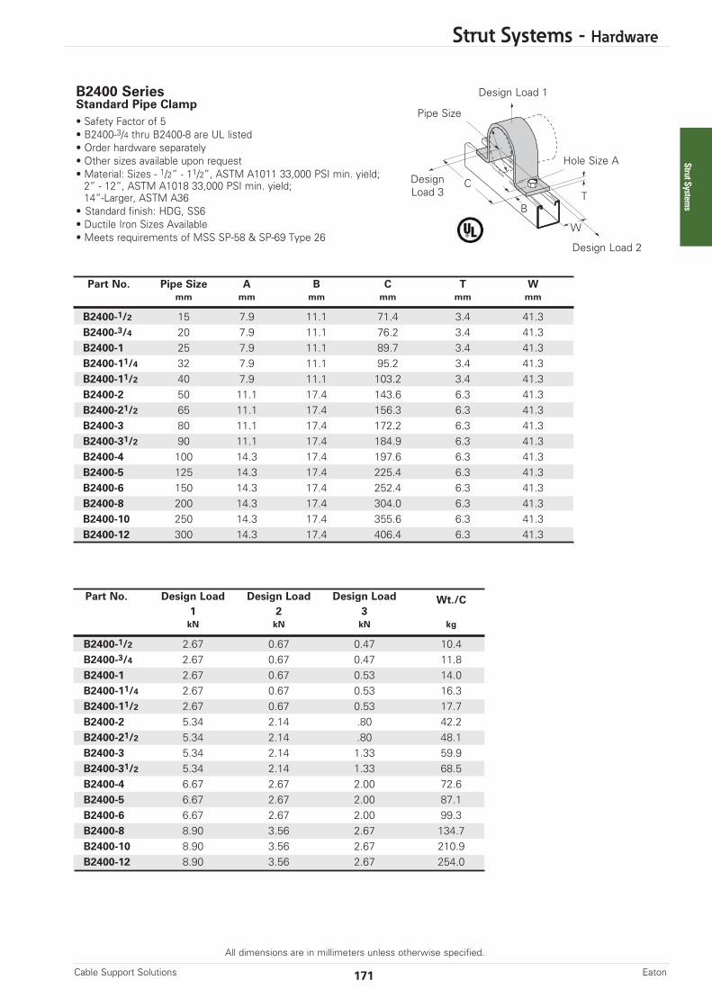
Strut Systems - Hardware
All dimensions are in millimeters unless otherwise specified.
171Cable Support Solutions Eaton
B2400 Series Standard Pipe Clamp• Safety Factor of 5• B2400-3/4 thru B2400-8 are UL listed• Order hardware separately• Other sizes available upon request• Material: Sizes - 1/2” - 11/2”, ASTM A1011 33,000 PSI min. yield; 2” - 12”, ASTM A1018 33,000 PSI min. yield; 14”-Larger, ASTM A36
• Standard finish: HDG, SS6• Ductile Iron Sizes Available• Meets requirements of MSS SP-58 & SP-69 Type 26
Part No. Pipe Size A B C T Wmm mm mm mm mm mm
B2400-1/2 15 7.9 11.1 71.4 3.4 41.3B2400-3/4 20 7.9 11.1 76.2 3.4 41.3B2400-1 25 7.9 11.1 89.7 3.4 41.3B2400-11/4 32 7.9 11.1 95.2 3.4 41.3B2400-11/2 40 7.9 11.1 103.2 3.4 41.3B2400-2 50 11.1 17.4 143.6 6.3 41.3B2400-21/2 65 11.1 17.4 156.3 6.3 41.3B2400-3 80 11.1 17.4 172.2 6.3 41.3B2400-31/2 90 11.1 17.4 184.9 6.3 41.3B2400-4 100 14.3 17.4 197.6 6.3 41.3B2400-5 125 14.3 17.4 225.4 6.3 41.3B2400-6 150 14.3 17.4 252.4 6.3 41.3B2400-8 200 14.3 17.4 304.0 6.3 41.3B2400-10 250 14.3 17.4 355.6 6.3 41.3B2400-12 300 14.3 17.4 406.4 6.3 41.3
Design Load 1
DesignLoad 3
Design Load 2
Pipe Size
Hole Size A
TC
B
Part No. Design Load Design Load Design Load Wt./C1 2 3kN kN kN kg
B2400-1/2 2.67 0.67 0.47 10.4B2400-3/4 2.67 0.67 0.47 11.8B2400-1 2.67 0.67 0.53 14.0B2400-11/4 2.67 0.67 0.53 16.3B2400-11/2 2.67 0.67 0.53 17.7B2400-2 5.34 2.14 .80 42.2B2400-21/2 5.34 2.14 .80 48.1B2400-3 5.34 2.14 1.33 59.9B2400-31/2 5.34 2.14 1.33 68.5B2400-4 6.67 2.67 2.00 72.6B2400-5 6.67 2.67 2.00 87.1B2400-6 6.67 2.67 2.00 99.3B2400-8 8.90 3.56 2.67 134.7B2400-10 8.90 3.56 2.67 210.9B2400-12 8.90 3.56 2.67 254.0
W
Strut Systems

Notes
Cable Support SolutionsEaton 172

Cable Support Solutions Eaton

Eaton Eaton EatonUnited States Canada Europe509 West Monroe Street 5925 McLaughlin Road Building 2, Argosy CourtHighland, IL 62249 Mississauga, ON L5R 1B8 Whitley Business Park, Scimitar WayUnited States Canada Coventry, CV3 4GA Phone: 800-851-7415 Phone: 800-569-3660 United Kingdom Phone: 0 1278 773265
Eaton Eaton’s Cooper Singapore Eaton’s Cooper Korea Co., Ltd.Saudi Arabia No. 2 Serangoon North Ave. 5 5th Fl. Parkland Building, 601 EonJu-ro,PO Box 70160 - Al Khobar - 31952 #06-01 Fu Yu Building, 554911 Gangnam-guKingdom of Saudi Arabia Singapore Seoul, 06109Phone: 00966 3 812 2236 Phone: +65 (0) 62974849 Korea Phone: +82-2-6380-4057
Eaton1000 Eaton BoulevardCleveland, OH 44122United StatesEaton.com
B-Line Business509 West Monroe StreetHighland, IL 62249Phone: 800-851-7415Fax: 618-654-1917www.cooperbline.com
© 2019 Eaton All Rights Reserved Eaton is a registered trademarkPrinted in USA Publication No. CA302005EN All other trademarks are propertyCSS-19 February 2019 of their respective owners.
For more information, visitEaton.com/b-lineseries