B) BOP Packages which include Erection & Commissioning in ...
28
02 19.06.2021 Generally revised as per discussion with projects team. 01 03.06.2021 Revised based on progress in engineering as on date and to include specific requirements for activities during Plant Shutdown period 00 20.03.2021 FIRST SUBMISSION Rev. No. Date Details of Revision PROJECT ENGINEERING & SYSTEMS DIVISION BHEL, RAMACHANDRAPURAM, HYDERABAD- 502032. PREPARED Ch Mahesh CHECKED K Rangamani APPROVED Saroj Kumar DATE 20.03.2021 DOC.NO. IOCL/SRU/EBOM REV.NO. 02 PROJECT STANDYBY SULPHUR RECOVERY UNIT (SRU) AT IOCL PARADIP REFINERY CUSTOMER M/s IOCL PARADIP REFINERY, ODISHA, INDIA CONSULTANT M/s TECHNIP INDIA LIMITED, CHENNAI Erection BOM and Scope Details
-
Upload
khangminh22 -
Category
Documents
-
view
0 -
download
0
Transcript of B) BOP Packages which include Erection & Commissioning in ...

02 19.06.2021 Generally revised as per discussion with projects team.
01 03.06.2021 Revised based on progress in engineering as on date and to include specific requirements for activities during Plant Shutdown period
00 20.03.2021 FIRST SUBMISSION
Rev. No. Date Details of Revision
PROJECT ENGINEERING & SYSTEMS DIVISION
BHEL, RAMACHANDRAPURAM, HYDERABAD- 502032.
PREPARED
Ch Mahesh
CHECKED
K Rangamani
APPROVED
Saroj Kumar
DATE
20.03.2021
DOC.NO.
IOCL/SRU/EBOM
REV.NO.
02
PROJECT STANDYBY SULPHUR RECOVERY UNIT (SRU) AT IOCL PARADIP REFINERY
CUSTOMER M/s IOCL PARADIP REFINERY, ODISHA, INDIA
CONSULTANT M/s TECHNIP INDIA LIMITED, CHENNAI
Erection BOM and Scope Details

Erection Inputs for BOP Equipment / Packages Doc. No.: IOCL/SRU/EBOM Doc Rev: 02
Project: STANDBY SRU PACKAGE, IOCL-PARADIP Date: 19.06.2021
PROJECT ENGINEERING AND SYSTEMS DIVISION Page No. 2 of 28
ERECTION BILL OF MATERIAL: BOP-ELECTRICAL
Definitions:
i) Erection Agency: Contractor
ii) Vendor/ Supplier/ Manufacturer: Supplier of materials/ Equipment/ Systems
iii) Customer: IOCL
iv) Consultant: IOCL consultant (Technip)
I. Intent: This document elaborates the details of Balance of Plant items pertaining to Electrical scope, to be erected and commissioned by Erection
agency for Standby SRU Project, IOCL-Paradip Refinery.
The document contains following Sections and Annexures:
Section-1: Erection BoM for Electrical activities to be carried out during shutdown period. Section-1 contains following Annexures:
Annexure-1: Consists of items that are to be erected, tested and commissioned by Erection agency. These items are supplied by BHEL.
Annexure-2: Consists of items that are to be supplied, erected, tested and commissioned by Erection agency.
Section-2: Erection BoM for Electrical activities to be carried out post-shutdown. Section-2 contains following Annexures:
Annexure-3: Consists of items that are to be erected, tested and commissioned by Erection agency. These items are supplied by, BHEL.
Annexure-4: Consists of items that are to be supplied, erected, tested and commissioned by Erection agency.
II. General Notes for Erection and Commissioning Works (applicable for all Annexures):
1) Erection Agency shall provide all the required services for installation, erection and commissioning of all the Equipment/ Packages/ Systems in
BOP area for successful/ satisfactory operation of the Plant including Receipt, Unloading, Storage & Handling of Material, Erection &
Installation, Commissioning, Calibration & Testing, and Final Painting etc.
2) Manufacturer/ Supplier supervision is envisaged for following packages:
HT Switchgear
LT Switchgear
UPS System

Erection Inputs for BOP Equipment / Packages Doc. No.: IOCL/SRU/EBOM Doc Rev: 02
Project: STANDBY SRU PACKAGE, IOCL-PARADIP Date: 19.06.2021
PROJECT ENGINEERING AND SYSTEMS DIVISION Page No. 3 of 28
PA System
Telephone System
CCTV
3) Erection Agency shall arrange all the tools and facilities required for calibration, erection and testing required for Erection & Commissioning
activities.
4) Obtaining statutory approvals from IBR, PESO, TAC, Electrical Inspector or any other Governing Agencies shall be in Erection Agency’s scope.
5) All lubricants and other consumables (including initial/ first fills) for the equipment / packages / systems (including lube oil etc.) have to be
procured directly by the Erection Agency. All the lubricants and consumables required for Commissioning, Testing for the operation period
specified in customer’s specification/ contract shall be in Erection Agency’s scope.
6) Marked-up “As-Built” documents/ drawings have to be prepared and provided by the Erection Agency to PE&SD after Erection &
Commissioning to enable submission of contractual “As-Built” documentation.
7) Erection Agency shall ensure that Storage and Handling of equipment/ packages is carried out as per the recommendations of OEMs.
8) The Erection/Commissioning work shall be carried out in accordance with the specifications/ drawings furnished during detailed engineering.
9) Some of the items/ parts of the equipment/packages will be supplied loose to site as per OEM’s standard practices. These loose items have to be
assembled at site by Erection Agency as per the guidelines provided.
10) All the necessary procedures and protocols shall be followed by Erection Agency during Erection & Commissioning, Testing, Handing Over, etc.
of equipment as per the procedures finalized with Customer/ Consultant.
11) Only general erection guidelines have been indicated in this document. The Erection & Procedures and requirements specified in the Customer’s
Technical Specifications/ Contract Documents shall be followed by the Erection Agency while executing the project. The responsibility for
adhering to Customer’s Technical Specifications/ Contractual requirements shall be with Erection Agency.
12) Erection agency shall carry out the plant cabling works in line with customer/consultant’s Technical specifications and approved “Notes & Details
for Plant Cable Laying System”.
13) Erection agency shall carry out the plant earthing and lightning protection works in line with customer/consultant’s Technical specifications and
approved “Notes & Details for Plant Earthing & Lightning Protection System”.
14) Erection agency shall carry out the plant illumination works in line with customer approved “Notes & Details for Illumination System”.
15) Actual quantities of the items, that are to be supplied by Erection Agency, shall be as per BHEL instructions.

Erection Inputs for BOP Equipment / Packages Doc. No.: IOCL/SRU/EBOM Doc Rev: 02
Project: STANDBY SRU PACKAGE, IOCL-PARADIP Date: 19.06.2021
PROJECT ENGINEERING AND SYSTEMS DIVISION Page No. 4 of 28
Section-1
Erection BOM for Electrical Activities to be carried out during Shutdown
This section consists of following two Annexures:
Annexure-1:
Consists of items that are to be erected, tested and commissioned by Erection agency. These items are supplied by BHEL.
Annexure-2:
Consists of items that are to be supplied, erected, tested and commissioned by Erection agency.
Annexure-1 (under Section-1)
(Items that are to be erected, tested and commissioned by Erection agency. These items are supplied by BHEL.
Price
bid ref.
Sl. No.
Equipment/ Package Description Unit of Qty. Qty.
Dimension
(Each)
L x B x H (M)
Weight
(Each)
(kg)
Remarks
1.0 HT SWITCHGEAR
MODIFICATION
1.1. Modification of 2 Panels in 6.6kV
Switchgear
Nos. 2 -- 100 1. No new panels are envisaged.
Modification works to be
carried out in 2 Panels as per
contract.
2. These panels are to be interfaced
with existing PMS system.
Please refer Note-3 below.

Erection Inputs for BOP Equipment / Packages Doc. No.: IOCL/SRU/EBOM Doc Rev: 02
Project: STANDBY SRU PACKAGE, IOCL-PARADIP Date: 19.06.2021
PROJECT ENGINEERING AND SYSTEMS DIVISION Page No. 5 of 28
Notes:
1. HT Switchgear vendor scope includes the following:
Supervisory services for erection and commissioning.
Installation of HT Switchgear components, testing of the panel and necessary internal wiring under the supervision of customer and BHEL.
2. Commissioning of HT Switchgear for successful/ satisfactory operation of the plant is in Erection Agency scope.
3. Interface of the HT panels is envisaged with PMS as per contract. Necessary support shall be provided by Erection Agency for completion of
the job.
4. Required testing equipment shall be supplied/ arranged by Erection Agency during testing and commissioning.
Price
bid ref.
Sl. No.
Equipment/ Package Description Unit of Qty. Qty.
Dimension
(Each)
L x B x H (M)
Weight
(Each)
(kg)
Remarks
2.0 LT SWITCHGEAR
2.1 LT Switchgear Extension
2.1.1
Extension Panels in 331S-PMCC-406 Nos. 7 850 x 1000 x 2450 mm 400 7 Panels includes 1 Dummy Panel.
Extension Panels in 331S-MCC-403 Nos. 1 850 x 1000 x 2450 mm 400
Extension Panels in 331S-MCC-401 Nos. 2 850 x 1000 x 2450 mm 400
Extension Panels in 331S-MLDB-3 Nos. 1 750 x 500 x 2450 mm 350
Extension Panels in 331S-ACDB-1 Nos. 1 750 x 500 x 2450 mm 350
2.1.2 Extension Panels in 811-INST-UPS-
002 Nos. 1 -- -- 6 Feeders need to be added.
2.2 LT Switchgear/ UPS DB
Modification
2.2.1 Non DCS Field 110V UPS SUBDB(Wall
Mounted) :1000 x 500 x 1000 mm Nos. 2 -- --
Vacant Module needs to be
modified to required rating feeder.
2.2.2 240V UPS PDB(Wall Mounted) for
CCTV : 1000 x 500 x 1000 mm Nos. 1 For CCTV
2.2.3 240V Non UPS DB/PDB (Wall Mounted)
: 800 x 500 x 1000 mm Nos. 2
2.2.4 Addition of 63A/100A feeder in existing
UPS Nos. 6
2.2.5 STP Serial Communication Cables
within Conduits (Refer Note-3 below) m 1100 -- 80
1. Cable weight indicated in
kg/km

Erection Inputs for BOP Equipment / Packages Doc. No.: IOCL/SRU/EBOM Doc Rev: 02
Project: STANDBY SRU PACKAGE, IOCL-PARADIP Date: 19.06.2021
PROJECT ENGINEERING AND SYSTEMS DIVISION Page No. 6 of 28
2. Quantity of this item is
covered in section 1, D10 of
price bid format
Notes:
1. LT Switchgear vendor scope is limited to following activities:
Modification of modules, installation of components and necessary internal wiring.
Supervisory services for installation, erection, testing and commissioning.
2. Installation and alignment of new panels, joining of new panels with existing panels, inter panel wiring and connections, erection, testing and
commissioning of LT switchgear for successful/satisfactory operation of the plant is in Erection Agency scope.
3. Laying of STP serial communication cables in conduits between above Extension panels and existing Data Concentrator is in Erection Agency
scope. However, services of OEM of Intelligent Motor Controllers (IMCs) are considered for hooking up of IMCs in new feeders in above
Extension Panels with existing Data Concentrator, termination of communication cables, testing, commissioning, modification (if required)
and necessary configuration of Existing Data Concentrator System.
4. Required testing equipment shall be supplied/ arranged by Erection Agency during testing and commissioning.
Price
bid ref.
Sl. No.
Equipment/ Package Description Unit of Qty. Qty.
Dimension
(Each)
L x B x H (M)
Weight
(Each)
(kg)
Remarks
4.0 LT POWER CABLES
4.1 2C x 95 Cu XLPE Meter 1200 -- 2475 Cable weight indicated in kg/km
4.2 1C x 120 Cu XLPE UNARM Meter 500 -- 1400 Cable weight indicated in kg/km
4.3 1C x 35 Cu XLPE UNARM Meter 250 -- 525 Cable weight indicated in kg/km
4.4 1C x 10 Cu XLPE UNARM Meter 250 -- 245 Cable weight indicated in kg/km
4.5 3.5C x 70 Cu XLPE Meter 300 -- 3110 Cable weight indicated in kg/km
Price
bid ref.
Sl. No.
Equipment/ Package Description Unit of Qty. Qty.
Dimension
(Each)
L x B x H (M)
Weight
(Each)
(kg)
Remarks
6.0 PRE-FABRICATED CABLE TRAYS AND ACCESSORIES (GI)
6.1 Ladder type cable tray, W=600mm Sets 50 3.0 x 0.6 x 0.1 45 Each cable tray length 3 meter

Erection Inputs for BOP Equipment / Packages Doc. No.: IOCL/SRU/EBOM Doc Rev: 02
Project: STANDBY SRU PACKAGE, IOCL-PARADIP Date: 19.06.2021
PROJECT ENGINEERING AND SYSTEMS DIVISION Page No. 7 of 28
including coupler plate and nut
bolts.
6.3 300mm(W) Perforated type cable tray Sets 100 2.5 x 0.3 x 0.075 30 Each cable tray length 2.5 meter
including coupler plate and nut
bolts
6.4 150mm (W) Perforated type cable tray Sets 200 2.5 x 0.15 x 0.05 20 Each cable tray length 2.5 meter
including coupler plate and nut
bolts
Notes:
1. Above cable trays are envisaged within SS-331S & SRR-811 only.
Price
bid ref.
Sl. No.
Equipment/ Package Description Unit of Qty. Qty.
Dimension
(Each)
L x B x H (M)
Weight
(Each)
(kg)
Remarks
7.0 PLANT EARTHING AND PLANT LIGHTNING PROTECTION MATERIALS
7.3 50 x 6 mm GI Strip Meter 150 -- 2 kg/m For HT & LT Panel Earthing
7.7 Copper Pipe Electrodes (65mm dia 3
m length) Nos. 4 -- --
For electronics equipment earthing.
Earthing with treated pits. Material
(charcoal & salt etc.) required for
treated earth shall be supplied by
erection agency. 7.8
Copper Pipe Electrodes (65mm dia 6
m length) Nos. 4 -- --
Price
bid ref.
Sl. No.
Equipment/ Package Description Unit of Qty. Qty.
Dimension
(Each)
L x B x H (M)
Weight
(Each)
(kg)
Remarks
14.0 UPS SYSTEM ALONG WITH UPSDB FOR FDA SYSTEM
14.1 UPS System along with UPS DB/
UPS Battery Isolation Boxes
Set/ Nos 1/2 3000 x 750 x 2110 mm,
500 x 500 x 650 mm
200/ 60
14.2 UPS Battery Bank Set 1 4500 x 750 x 1750 mm 500
Notes:
1. Erection agency has to arrange Discharge Resistor bank, if applicable, to carry out discharge test on Battery banks.
Erection Inputs for BOP Equipment / Packages Doc. No.: IOCL/SRU/EBOM Doc Rev: 02
Project: STANDBY SRU PACKAGE, IOCL-PARADIP Date: 19.06.2021
PROJECT ENGINEERING AND SYSTEMS DIVISION Page No. 8 of 28
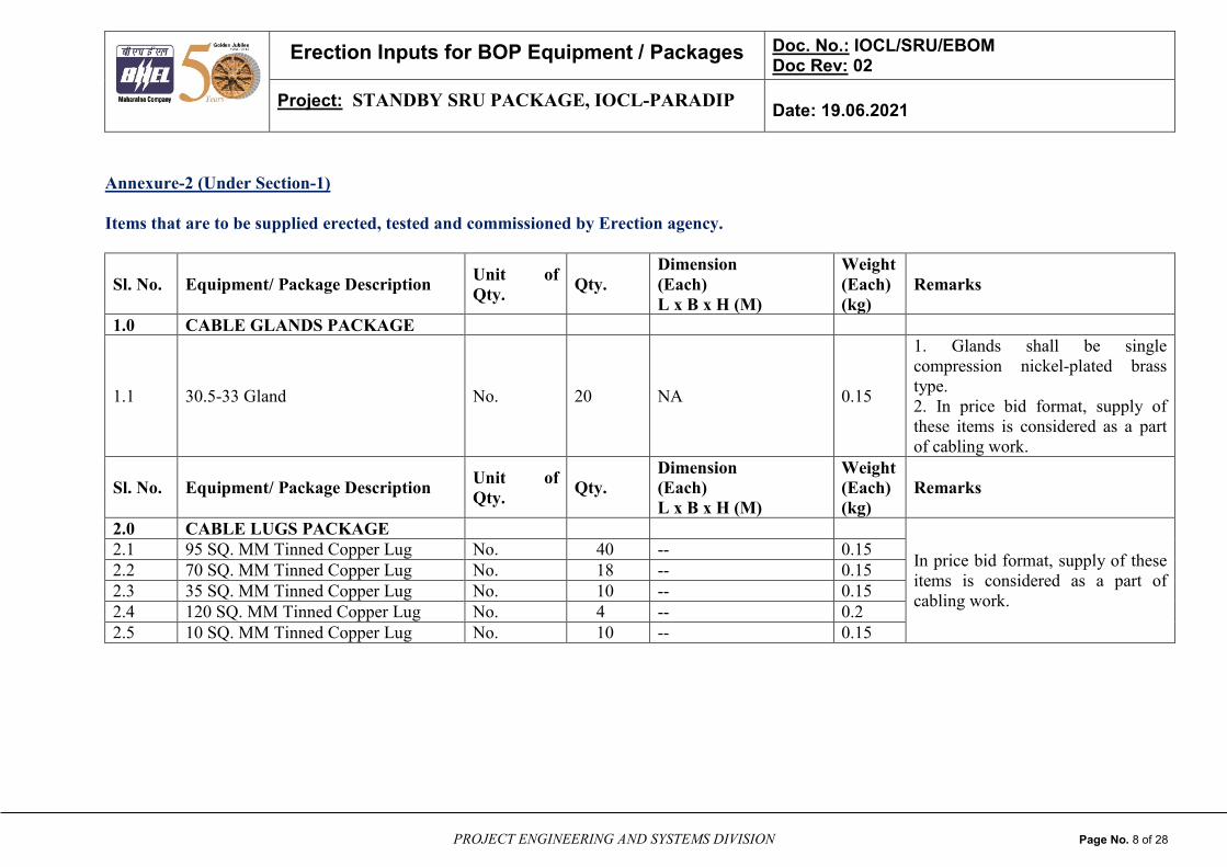
Annexure-2 (Under Section-1)
Items that are to be supplied erected, tested and commissioned by Erection agency.
Sl. No. Equipment/ Package Description Unit of
Qty. Qty.
Dimension
(Each)
L x B x H (M)
Weight
(Each)
(kg)
Remarks
1.0 CABLE GLANDS PACKAGE
1.1 30.5-33 Gland No. 20 NA 0.15
1. Glands shall be single
compression nickel-plated brass
type.
2. In price bid format, supply of
these items is considered as a part
of cabling work.
Sl. No. Equipment/ Package Description Unit of
Qty. Qty.
Dimension
(Each)
L x B x H (M)
Weight
(Each)
(kg)
Remarks
2.0 CABLE LUGS PACKAGE
In price bid format, supply of these
items is considered as a part of
cabling work.
2.1 95 SQ. MM Tinned Copper Lug No. 40 -- 0.15
2.2 70 SQ. MM Tinned Copper Lug No. 18 -- 0.15
2.3 35 SQ. MM Tinned Copper Lug No. 10 -- 0.15
2.4 120 SQ. MM Tinned Copper Lug No. 4 -- 0.2
2.5 10 SQ. MM Tinned Copper Lug No. 10 -- 0.15
Erection Inputs for BOP Equipment / Packages Doc. No.: IOCL/SRU/EBOM Doc Rev: 02
Project: STANDBY SRU PACKAGE, IOCL-PARADIP Date: 19.06.2021
PROJECT ENGINEERING AND SYSTEMS DIVISION Page No. 9 of 28
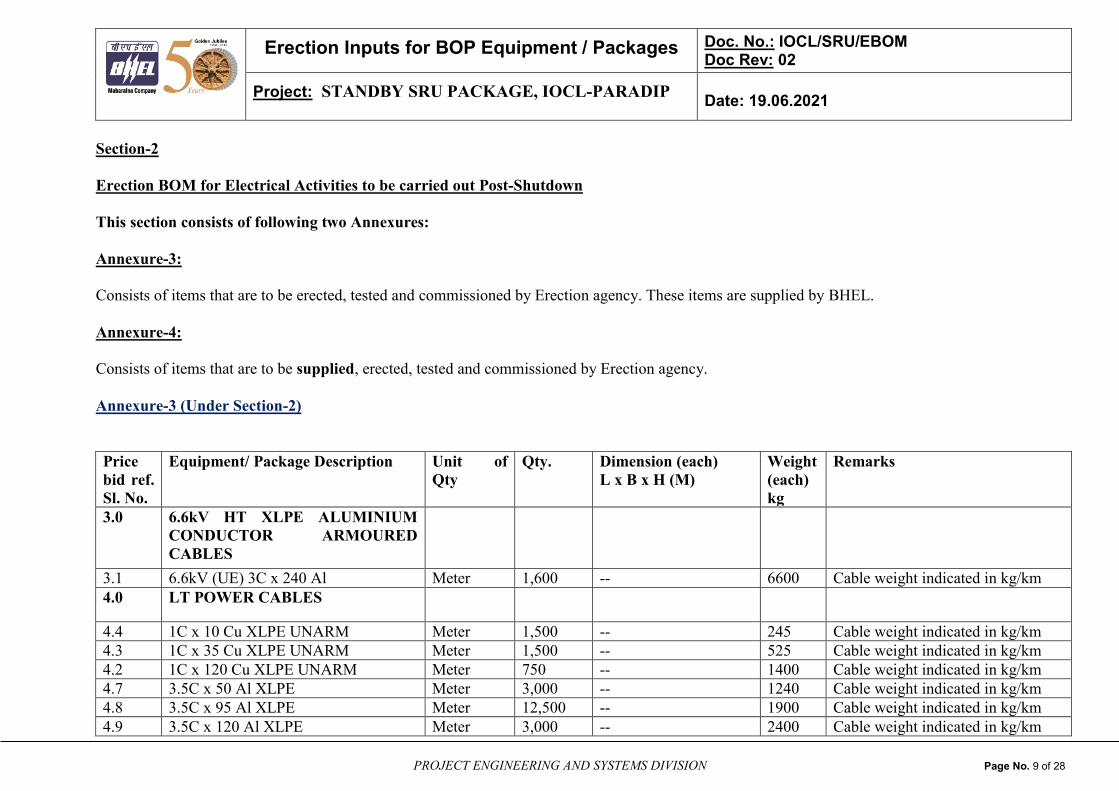
Section-2
Erection BOM for Electrical Activities to be carried out Post-Shutdown
This section consists of following two Annexures:
Annexure-3:
Consists of items that are to be erected, tested and commissioned by Erection agency. These items are supplied by BHEL.
Annexure-4:
Consists of items that are to be supplied, erected, tested and commissioned by Erection agency.
Annexure-3 (Under Section-2)
Price
bid ref.
Sl. No.
Equipment/ Package Description Unit of
Qty
Qty. Dimension (each)
L x B x H (M)
Weight
(each)
kg
Remarks
3.0 6.6kV HT XLPE ALUMINIUM
CONDUCTOR ARMOURED
CABLES
3.1 6.6kV (UE) 3C x 240 Al Meter 1,600 -- 6600 Cable weight indicated in kg/km
4.0 LT POWER CABLES
4.4 1C x 10 Cu XLPE UNARM Meter 1,500 -- 245 Cable weight indicated in kg/km
4.3 1C x 35 Cu XLPE UNARM Meter 1,500 -- 525 Cable weight indicated in kg/km
4.2 1C x 120 Cu XLPE UNARM Meter 750 -- 1400 Cable weight indicated in kg/km
4.7 3.5C x 50 Al XLPE Meter 3,000 -- 1240 Cable weight indicated in kg/km
4.8 3.5C x 95 Al XLPE Meter 12,500 -- 1900 Cable weight indicated in kg/km
4.9 3.5C x 120 Al XLPE Meter 3,000 -- 2400 Cable weight indicated in kg/km

Erection Inputs for BOP Equipment / Packages Doc. No.: IOCL/SRU/EBOM Doc Rev: 02
Project: STANDBY SRU PACKAGE, IOCL-PARADIP Date: 19.06.2021
PROJECT ENGINEERING AND SYSTEMS DIVISION Page No. 10 of 28
4.10 3C x 2.5 Cu XLPE Meter 20,000 -- 460 Cable weight indicated in kg/km
4.11 3C x 4 Cu XLPE Meter 4,000 -- 530 Cable weight indicated in kg/km
4.12 3C x 6 Cu XLPE Meter 4,000 -- 680 Cable weight indicated in kg/km
4.13 3C x 10 Cu XLPE Meter 2,000 -- 865 Cable weight indicated in kg/km
4.14 3C x 16 Cu XLPE Meter 5,500 -- 1040 Cable weight indicated in kg/km
4.15 3C x 35 Al XLPE Meter 2,000 -- 900 Cable weight indicated in kg/km
4.16 3C x 50 Al XLPE Meter 6500 -- 1100 Cable weight indicated in kg/km
4.17 3C x 70 Al XLPE Meter 7,000 -- 1425 Cable weight indicated in kg/km
4.18 3C x 95 Al XLPE Meter 2,000 -- 1750 Cable weight indicated in kg/km
4.19 4C x 50 Cu XLPE Meter 500 -- 2510 Cable weight indicated in kg/km
4.20 4C x 25 Al XLPE Meter 3,200 -- 940 Cable weight indicated in kg/km
4.21 4C x 35 Al XLPE Meter 3,500 -- 1050 Cable weight indicated in kg/km
4.22 4C x 95 Al XLPE Meter 2,000 -- 2100 Cable weight indicated in kg/km
4.23 4C x 120 Al XLPE Meter 1,800 -- 2600 Cable weight indicated in kg/km
4.24 4C x 150 Al XLPE Meter 1,800 -- 3000 Cable weight indicated in kg/km
4.25 4C x 185 Al XLPE Meter 6,000 -- 3650 Cable weight indicated in kg/km
5.0 HT CABLE TERMINATING KITS
5.1 6.6kV (UE) 3C x 240 Terminating Kit No. 4 -- 1
* CABLE GLANDS PACKAGE
1 13-18 Gland No. 600 -- 400
(Total)
*
In price bid format, E&C of these
items is considered as a part of
cabling work.
2 18.5-20 Gland No. 150 --
3 20.5-23 Gland No. 100 --
4 23.5-26 Gland No. 50 --
5 26.5-30 Gland No. 175 --
6 30.5-33 Gland No. 75 --
7 33.5-37 Gland No. 75 --

Erection Inputs for BOP Equipment / Packages Doc. No.: IOCL/SRU/EBOM Doc Rev: 02
Project: STANDBY SRU PACKAGE, IOCL-PARADIP Date: 19.06.2021
PROJECT ENGINEERING AND SYSTEMS DIVISION Page No. 11 of 28
37.5-41 Gland No. 50 --
** CABLE LUGS PACKAGE (Tinned Copper)
1 2.5 sq.mm Tinned Copper Lug No. 20000 -- 300
(Total)
1. Lugs for power cables shall
be of compression type
whereas lugs for control/
signal cables shall be of
crimping type.
Individual termination up to wire
level shall be considered.
**
In price bid format, E&C of these
items is considered as a part of
cabling work.
2 4 sq.mm Tinned Copper Lug No. 500 --
3 6 sq.mm Tinned Copper Lug No. 700 --
4 10 sq.mm Tinned Copper Lug No. 800 --
5 16 sq.mm Tinned Copper Lug No. 600 --
6 25 sq.mm Tinned Copper Lug No. 1200 --
7 35 sq.mm Tinned Copper Lug No. 500 --
8 50 sq.mm Tinned Copper Lug No. 250 --
9 70 sq.mm Tinned Copper Lug No. 100 --
10 95 sq.mm Tinned Copper Lug No. 80 --
11 120 sq.mm Tinned Copper Lug No. 150 --
12 150 sq.mm Tinned Copper Lug No. 50 --
13 180 sq.mm Tinned Copper Lug No. 50 --
14 240 sq.mm Tinned Copper Lug No. 60 --
Price
bid ref.
Sl. No.
CONTROL CABLE (TWISTED
PAIR OVERALL SHIELDED
CABLE)
D 2,
Section
1
8P x 2.5 sq.mm cable Meter 14000 -- 1600 Cable weight indicated in kg/km
D 2,
Section
1
6P x 2.5 sq.mm cable Meter 2000 -- 1400 Cable weight indicated in kg/km
Erection Inputs for BOP Equipment / Packages Doc. No.: IOCL/SRU/EBOM Doc Rev: 02
Project: STANDBY SRU PACKAGE, IOCL-PARADIP Date: 19.06.2021
PROJECT ENGINEERING AND SYSTEMS DIVISION Page No. 12 of 28
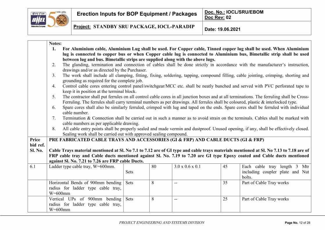
Notes:
1. For Aluminium cable, Aluminium Lug shall be used. For Copper cable, Tinned copper lug shall be used. When Aluminium
lug is connected to copper bus or when Copper cable lug is connected to Aluminium bus, Bimetallic strip shall be used
between lug and bus. Bimetallic strips are supplied along with the above lugs.
2. The glanding, termination and connection of cables shall be done strictly in accordance with the manufacturer’s instruction,
drawings and/or as directed by the Purchaser.
3. The work shall include all clamping, fitting, fixing, soldering, tapping, compound filling, cable jointing, crimping, shorting and
grounding as required for the complete job.
4. Control cable cores entering control panel/switchgear/MCC etc. shall be neatly bunched and served with PVC perforated tape to
keep it in position at the terminal block.
5. The contractor shall put ferrules on all control cable cores in all junction boxes and at all terminations. The ferruling shall be Cross-
Ferruling. The ferrules shall carry terminal numbers as per drawings. All ferrules shall be coloured, plastic & interlocked type.
6. Spare cores shall also be similarly ferruled, crimped with lug and taped on the ends. Spare cores shall be ferruled with individual
cable number.
7. Termination & Connection shall be carried out in such a manner as to avoid strain on the terminals. Cables shall be marked with
cable numbers as per applicable drawing.
8. All cable entry points shall be properly sealed and made vermin and dustproof. Unused opening, if any, shall be effectively closed.
Sealing work shall be carried out with approved sealing compound.
Price
bid ref.
Sl. No.
PRE FABRICATED CABLE TRAYS AND ACCESSORIES (GI & FRP) AND CABLE DUCTS (GI & FRP)
Cable Trays material mentioned at Sl. No 7.1 to 7.12 are of GI type and cable trays materials mentioned at Sl. No 7.13 to 7.18 are of
FRP cable tray and Cable ducts mentioned against Sl. No. 7.19 to 7.20 are GI type Epoxy coated and Cable ducts mentioned
against Sl. No. 7.21 to 7.26 are FRP cable Ducts.
6.1 Ladder type cable tray, W=600mm.
Sets
80 3.0 x 0.6 x 0.1 45 Each cable tray length 3 Mtr
including coupler plate and Nut
bolts.
Horizontal Bends of 900mm bending
radius for ladder type cable tray,
W=600mm
Sets 8
-- 35 Part of Cable Tray works
Vertical UPs of 900mm bending
radius for ladder type cable tray,
W=600mm
Sets 8 -- 25 Part of Cable Tray works
Erection Inputs for BOP Equipment / Packages Doc. No.: IOCL/SRU/EBOM Doc Rev: 02
Project: STANDBY SRU PACKAGE, IOCL-PARADIP Date: 19.06.2021
PROJECT ENGINEERING AND SYSTEMS DIVISION Page No. 13 of 28
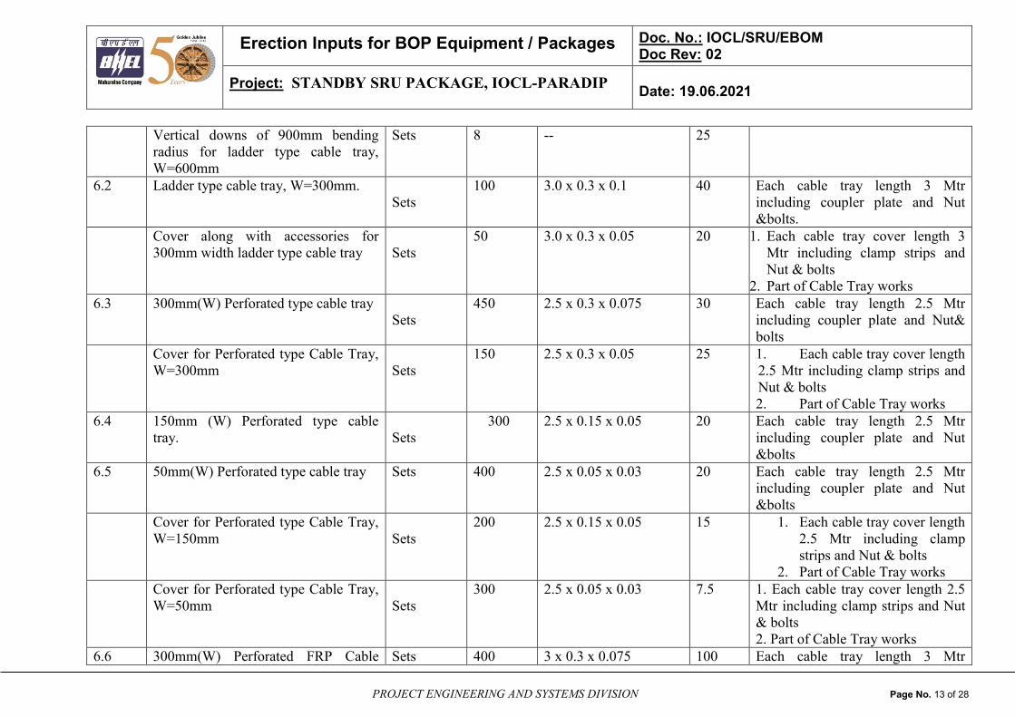
Vertical downs of 900mm bending
radius for ladder type cable tray,
W=600mm
Sets 8 -- 25
6.2 Ladder type cable tray, W=300mm.
Sets
100 3.0 x 0.3 x 0.1 40 Each cable tray length 3 Mtr
including coupler plate and Nut
&bolts.
Cover along with accessories for
300mm width ladder type cable tray
Sets
50 3.0 x 0.3 x 0.05 20 1. Each cable tray cover length 3
Mtr including clamp strips and
Nut & bolts
2. Part of Cable Tray works
6.3 300mm(W) Perforated type cable tray
Sets
450 2.5 x 0.3 x 0.075 30 Each cable tray length 2.5 Mtr
including coupler plate and Nut&
bolts
Cover for Perforated type Cable Tray,
W=300mm
Sets
150 2.5 x 0.3 x 0.05 25 1. Each cable tray cover length
2.5 Mtr including clamp strips and
Nut & bolts
2. Part of Cable Tray works
6.4 150mm (W) Perforated type cable
tray.
Sets
300 2.5 x 0.15 x 0.05 20 Each cable tray length 2.5 Mtr
including coupler plate and Nut
&bolts
6.5 50mm(W) Perforated type cable tray Sets 400 2.5 x 0.05 x 0.03 20 Each cable tray length 2.5 Mtr
including coupler plate and Nut
&bolts
Cover for Perforated type Cable Tray,
W=150mm
Sets
200 2.5 x 0.15 x 0.05 15 1. Each cable tray cover length
2.5 Mtr including clamp
strips and Nut & bolts
2. Part of Cable Tray works
Cover for Perforated type Cable Tray,
W=50mm
Sets
300 2.5 x 0.05 x 0.03 7.5 1. Each cable tray cover length 2.5
Mtr including clamp strips and Nut
& bolts
2. Part of Cable Tray works
6.6 300mm(W) Perforated FRP Cable Sets 400 3 x 0.3 x 0.075 100 Each cable tray length 3 Mtr

Erection Inputs for BOP Equipment / Packages Doc. No.: IOCL/SRU/EBOM Doc Rev: 02
Project: STANDBY SRU PACKAGE, IOCL-PARADIP Date: 19.06.2021
PROJECT ENGINEERING AND SYSTEMS DIVISION Page No. 14 of 28
Tray & Cps including coupler plate and Nut
&bolts.
6.7 150mm(W) Perforated FRP Cable
Tray & Cps
Sets 600 3 x 0.15 x 0.05 40 Each cable tray length 3 Mtr
including coupler plate and Nut
&bolts.
6.8 50mm(W) Perforated FRP Cable Tray
& Cps
Sets 400 3 x 0.05 x 0.04 30 Each cable tray length 3 Mtr
including coupler plate and Nut
&bolts.
6.9 Cover For 300mm(W) Perforated FRP
C.T
Sets 500 -- 50 Each cable tray cover length 3 Mtr
including clamp strips and
Nut&bolts
6.10 Cover For 150mm(W) Perforated FRP
C.T
Sets 600 -- 15 Each cable tray cover length 3 Mtr
including clamp strips and
Nut&bolts
6.11 Cover For 50mm(W) Perforated FRP
C.T
Sets 500 -- 15 Each cable tray cover length 3 Mtr
including clamp strips and
Nut&bolts
6.12 1000 MM WIDTH, 400 MM Height
& 5 mm Thick,2500mm length GI
Cable duct with cover , Jointing plates
and other accessories
Sets 230 2.5 x 1.0 x 0.4 50 Cable ducts are bolted type and
to be assembled at site.
6.13 800 MM WIDTH, 300 MM Height &
5 mm Thick,2500mm length GI Cable
duct with cover , Jointing plates and
other accessories
Sets 280 2.5 x 0.8 x 0.4 40 Cable ducts are bolted type and
to be assembled at site.
6.14 400 MM WIDTH, 200 MM Height &
5 mm Thick,2500mm length FRP
Cable duct with cover , Jointing plates
and other accessories
Sets 1100 2.5 x 0.4 x 0.2 30 Cable ducts are bolted type and
to be assembled at site.
6.15 800 MM WIDTH, 200 MM Height &
5 mm Thick,2500mm length FRP
Cable duct with cover , Jointing plates
Sets 110 2.5 x 0.8 x 0.3 100 Cable ducts are bolted type and
to be assembled at site.

Erection Inputs for BOP Equipment / Packages Doc. No.: IOCL/SRU/EBOM Doc Rev: 02
Project: STANDBY SRU PACKAGE, IOCL-PARADIP Date: 19.06.2021
PROJECT ENGINEERING AND SYSTEMS DIVISION Page No. 15 of 28
and other accessories
6.16 1000 MM WIDTH, 200 MM Height
& 5 mm Thick,2500mm length FRP
Cable duct with cover , Jointing plates
and other accessories
Sets 210 2.5 x 0.1 x 0.2 80 Cable ducts are bolted type and
to be assembled at site.
1000MM width Horizontal Duct
Elbow
Sets 10 -- 30 1. Cable ducts are bolted type
and to be assembled at site.
2. Part of cable tray
800MM width Horizontal Duct Elbow Sets 20 -- 30 1. Cable ducts are bolted type
and to be assembled at site.
2. Part of cable tray
400MM width Horizontal Duct Elbow Sets 25 -- 20 1. Cable ducts are bolted type
and to be assembled at site.
2. Part of cable tray
Notes for Cable Trays:
i) Erection agency shall consider supply of Red Oxide Zinc Chromate Primer for site painting of all Structural Steels (required for cable Tray
Supports) in the Erection contractor’s scope. Final painting shall be done with two coats of approved bituminous aluminium paint & same to be
considered in erection contractor scope.
ii) Cable Trays shall be numbered as per layout drawing before laying of cables. Cabling Shall be done as per Cable Laying Notes & Details.
iii) All cables shall be provided with minimum of 2 mm thick,20mm wide and of enough length Stain less steel as cable identification tags indicating
cable designation in accordance with the cable schedule. The cable tags shall be provided at the ends, every 30mtrs and when the cable changes its
direction/elevation. The tags shall be of stainless steel with the number punched on it and securely attached to the cable by not less than two turns of
16 SWG GI wire.
iv) The cable trays shall be supported in general at a span of 1.5mtrs horizontally and at a distance of 1mtr vertically.
v) Cable Tray covers shall be provided for the top most & bottom most cable trays and outermost trays of vertical droppers in outdoor area.
vi) For buried cable, the marker shall project at least 150mm above ground and shall be spaced at an interval of 30 mtrs and at every change of
direction.
vii) All the cables shall be clamped to the cable trays/support structure with the help of clamps. All power cables shall be clamped individually and
control cables shall be clamped in groups of 3 or 4 cables. Clamps for multicore cables shall be fabricated out of 25x3 mm aluminium/G.I flats. Single
core power cables shall be laid in trefoil formation and suitably clamped with 25mm wide 8 SWG aluminium strips.
ix) All Sharp edges and Burr shall be removed.
x) Cables to be strapped to tray at interval not greater than 300mm.

Erection Inputs for BOP Equipment / Packages Doc. No.: IOCL/SRU/EBOM Doc Rev: 02
Project: STANDBY SRU PACKAGE, IOCL-PARADIP Date: 19.06.2021
PROJECT ENGINEERING AND SYSTEMS DIVISION Page No. 16 of 28
xi) Cable ducts supplied for the project are of G.I & FRP type. Cable ducts shall be laid on the main pipe rack hard chrome plated nuts and bolts.
Accessories such as nuts and bolts for cable ducts is contractor/vendor scope only.
xii) Fire proof shall be done on cable ducts and FRP cable trays using flexible ceramic fibre blanket system (in compliance to OISD STD 164).
7.0 PLANT EARTHING AND PLANT LIGHTNING PROTECTION MATERIALS
7.1 50x10mm GI Strip Below ground m 100 -- -- For risers
7.2 75 x 10 mm GI Strip Below ground m 100 -- -- For risers
7.3 50 x 6 mm GI Strip m 1500 -- 2 kg/m For.earthing.of..LVSwgr/MCC/
Motor above 90kW including HT
Motors/MLDB/Lighting..trafo/
Flood Light masts/T.G.
pedestal/Masts/Stack/MV cable
Boxes/Pipe & cable racks
7.4 35 x 6mm GI Strips m 800 -- 2 kg/m For earthing of Lighting
DB/Structure,Columns/Storage
Tanks/Stair Case/loading
racks/Heat Exchangers/Vessels
7.5 25 x 3mm GI Strips m 500 -- 0.2
kg/m
Down and roof conductors Lighting
fixtures/Single phase Receptacles/
Power & Lighting conduits
7.6 8SWG GI wire ,solid m 3000 -- 1 kg/m For earthing of Motors up to
3.7KW, All push button stations,
small equipments and instrument,
Hand Rails/ Junction Boxes/Limit
Switches
5/8’’ Dia GI Wire rope
m
150 -- -- 1. For earthing of Three Phase
Receptacles, Welding Outlets
,Lighting Transformer Neutral ,
Lighting Transformer, MLDB
2. Part of equipment earthing
3/8’’ Dia GI Wire rope m 150 -- -- 1. For earthing of Motors from

Erection Inputs for BOP Equipment / Packages Doc. No.: IOCL/SRU/EBOM Doc Rev: 02
Project: STANDBY SRU PACKAGE, IOCL-PARADIP Date: 19.06.2021
PROJECT ENGINEERING AND SYSTEMS DIVISION Page No. 17 of 28
5.5KW to 30KW & Welding
Receptacles, Lighting, Power &
Instrument Panels/street lighting
poles , Lighting Fixtures, Single
Phase Receptacles, Power &
Lighting Conduits.
2. Part of equipment earthing
7.7 Copper Pipe Electrodes (65mm dia 3
m length)
Nos. 10 -- -- For electronics equipment
Earthing with treated pits. Material
(charcoal & salt etc.) required for
treated earth shall be supplied by
erection agency
7.8 65MM NB 6 m length GI Pipe
electrode Medium Class-B
Nos. 20 -- -- For Treated earth pits for Machine
Neutral Earthing & Untreated
earth Pits for Machine Body
Earthing. Material (charcoal & salt
etc.) required for treated earth shall
be supplied by erection agency
7.9 Vertical Air Termination Rod for
lightning protection.
Nos. 5 1.2 x 0.3 25 Above ground installation
Notes:
Erection agency/Site shall carry out the plant earthing & lightning protection works in line with customer/consultant’s technical
specifications i.e. “Notes and Details for Plant Earthing & Lightning Protection System”.
8.0 PLANT ILLUMINATION PACKAGE
8.1 Twin cluster LED obstruction light Nos 15 -- 1
8.2 Industrial DC LED Well Glass fixture
(35-45W approx) suitable for DC
Supply
Nos 25 -- 3.5
8.3 Flame proof DC LED Well Glass
fixture (35-45W approx) suitable for
DC Supply
Nos 50 -- 4

Erection Inputs for BOP Equipment / Packages Doc. No.: IOCL/SRU/EBOM Doc Rev: 02
Project: STANDBY SRU PACKAGE, IOCL-PARADIP Date: 19.06.2021
PROJECT ENGINEERING AND SYSTEMS DIVISION Page No. 18 of 28
8.4 LED Well Glass fixture (45W
Approx, 230VAC)
Nos 200 -- 3.5
8.5 Flame proof LED Well Glass fixture
(45WApprox, 230VAC)
Nos 500 -- 4
8.6 LED Flood lighting Fixture (100W
approx)
Nos 2 -- 4
8.7 Flameproof LED Flood lighting
Fixture (100W approx)
Nos 4 -- 7.5
8.8 LED Flood lighting Fixture (200W
approx)
Nos 2 -- 10
8.8 LED Flame proof Flood lighting
Fixture (200W approx)
Nos 10 -- 12
8.9 11meter Steel tubular pole Nos 4 -- 180
8.10 2 meter 50NB GI pole for Platform
lighting
Nos 575 -- 12
Cable clamps Nos 50000 -- .05 Part of Illumination cabling
8.11 4 way 200x150x100mm rectangular
sheet steel weather proof JB (IP55)
Nos 220 -- 2
8.12 Flame proof Cast light alloy JB
(200x150x100mm )
Nos 560 -- 3
8.13 Industrial metal clad type 1Ph, 20A
Socket with 20A interlocked rotary
switch & Plug
Nos 15 -- 1.5
8.14 Flameproof 1ph, 20A Socket with
interlocked rotary switch & Plug
Nos 35 -- 3
8.15 Industrial metal clad type 3Ph, 63A
(5pin) receptacle with interlocked
rotary switch & Plug, weather proof
(IP55) outdoor type
Nos 5 -- 3
8.16 Flameproof 3ph, 63A (5pin)
Receptacle (Indoor type) with
Nos 15 -- 5

Erection Inputs for BOP Equipment / Packages Doc. No.: IOCL/SRU/EBOM Doc Rev: 02
Project: STANDBY SRU PACKAGE, IOCL-PARADIP Date: 19.06.2021
PROJECT ENGINEERING AND SYSTEMS DIVISION Page No. 19 of 28
interlocked rotary switch & Plug
8.17 Flameproof 3-Pph, 250A (5-pin)
Receptacle (Outdoor type) with
interlocked rotary switch & Plug
Nos 1 -- 7
8.18 Weatherproof 3-Ph, 250A (5-pin)
Receptacle (Outdoor type) with
interlocked rotary switch & Plug
Nos 1 -- 2
8.19 24V socket module with FLP Hand
lamp
Nos 4 -- 10
8.20 18 way AC Outdoor Lighting Panel Nos 2 1000 x 200 x 1000 mm 110
8.21 12 way AC Outdoor Lighting Panel Nos 2 1000 x 200 x 1000 mm 100
8.22 6 way DC Outdoor Lighting Panel Nos 2 1000 x 200 x 1000 mm 80
8.23 FLP 12 way AC Lighting/Power Panel Nos 10 800 x 200 x 800 mm 90
8.24 Flameproof 6 way DC Lighting Panel Nos 3 700 x 200 x 700 mm 60
8.25 415V AC Wall Mounted DB Nos 1 650 x 200 x 750 mm 50
8.26 230V AC UPS Wall Mounted DB Nos 2 500 x 200 x 500 mm 50
8.27 110V AC UPS Wall Mounted DB Nos 1 500 x 200 x 500 mm 50

Erection Inputs for BOP Equipment / Packages Doc. No.: IOCL/SRU/EBOM Doc Rev: 02
Project: STANDBY SRU PACKAGE, IOCL-PARADIP Date: 19.06.2021
PROJECT ENGINEERING AND SYSTEMS DIVISION Page No. 20 of 28
Notes:
1) Fixtures, Accessories of lighting panel/JB like cable glands, gland plate etc. will be supplied to site in loose parts as per standard
packing and practice of OEM. Assembly and erection of the fixtures shall be carried out by Erection Agency.
2) In case of non-integral fixtures, control gear box shall be separately mounted (which also acts as JB for looping in and looping out).
However, in case the fixtures are of integral type, separate JB shall be considered for loop in and loop out.
3) Erection of all illumination items (including cutting/ threading/welding etc. of conduit/pipe/ISMC/ISA/Metsec etc.) shall be carried
out at site by Erection Agency as per the installation requirements.
4) All the required erection consumables (like rawl plugs, screws, check nuts, nuts & bolts, locking wire, insulation tape, sealing
compound/plugs, washers etc.) which are not covered in above list but required for successful completion of the work shall be in the
scope of Erection Agency.
5) Pipes & accessories of poles will be supplied in loose condition. Assembling and Erection of these poles shall be carried out by
Erection Agency.
6) All the necessary civil works including foundations etc. as well as structural works required for installation of these poles shall be in
Erection Agency’s scope.
7) Erection agency to ensure the completion of foundations for lighting poles before commencement of paving work in related areas.
9.0 CCTV SYSTEM
9.1 CCTV Cameras (Weatherproof) Nos. 3 -- 5 Network Switches, Media
Converters, LIUs, Adaptors, along
with Patch Cords etc. are part of
CCTV Cabinet.
Refer Notes below for further
details reg. CCTV System.
9.2 CCTV Cameras (Ex-Proof) Nos. 6 -- 7
9.3 CCTV Rack/Cabinet Nos. 1 0.6 x 0.6 x 1.5 200
9.4 Network Switches Nos. 1 -- Part of
CCTV
Cabinet 9.5 Media Converters, LIUs, Adaptors,
along with Patch Cords etc.
Lot 1 --
9.6 Junction Boxes (Weatherproof) Nos. 3 -- 50
9.7 Junction Boxes (Ex-proof) Nos. 6 -- 100
D 9,
Sec 1
FO Cable and HDPE Duct m 6000 --
4.10 Power Cable (3C X 2.5 sq.mm) m 1000 --
D 10,
Sec 1
Cat-6 Cable m 100 --
9.8 Poles Nos. 3 -- 150

Erection Inputs for BOP Equipment / Packages Doc. No.: IOCL/SRU/EBOM Doc Rev: 02
Project: STANDBY SRU PACKAGE, IOCL-PARADIP Date: 19.06.2021
PROJECT ENGINEERING AND SYSTEMS DIVISION Page No. 21 of 28
Erection Agency may note the following:
1. Existing CCTV system is in SS-331-S to which new field telecom equipment like CCTV cameras associated with new SRU & TGTU-
2 shall be interfaced. Additional hardware if any required in existing system shall be provided to interface and integrate new CCTV
System equipment of new SRU & TGTU-2 with existing one. All required hardware and software modification/ upgradation in
existing CCTV system at SS-331S & Main Control Room for interfacing and integration of new cameras inside the battery limit shall
be done by CCTV System Vendor of SRU & TGTU-2 package. Required support shall be extended to CCTV Vendor by Erection
Agency to complete the system in all respects.
2. Supply of Cables mentioned above is by BHEL/ CCTV System vendor. Laying, glanding, ferruling, identification, termination/
splicing of all type of cables required between CCTV cabinet and existing CCTV network, CCTV Cabinet and PDB and for integration
of CCTV cameras inside the battery limit with existing CCTV system are in the scope of Erection Agency.
3. Supply of mounting poles shall be done by BHEL/ CCTV System vendor. Erection and installation of mounting poles including civil
works and provision of permanent water connection near the cameras and hook up with CCTV cameras for cameras inside the battery
limit is by Erection Agency.
4. Engage OEM of CCTV system at site, liaison with existing CCTV System OEM, perform adequacy check and augmentation of CCTV
system, modification/ upgradation of hardware & software of existing CCTV system, interface and integration, testing and
commissioning of augmented CCTV system with CCTV cameras inside the battery limit shall be in CCTV System Vendor of SRU &
TGTU-2 package. Testing & Commissioning of CCTV System by CCTV System vendor.
10.0 PLANT COMMUNICATION SYSTEM (PA SYSTEM & TELEPHONE)
10.1 PA SYSTEM
10.1.1 Modification of Existing PA System
Cabinet for connection New Field Call
Stations (UK0 Adapters, Power
Supply Modules etc.)
Lot 1 -- --
Refer Notes below for further
details regarding PA System.
10.1.2 Flame proof Field call station with
flameproof loudspeakers 25W (Ex
FCS + FLP loudspeaker)
Nos. 15 0.6 x 0.5 x 0.5 50
10.1.3 Flashing Beacon lamps (Ex- proof
type)
Nos. 8 -- 2
10.1.4 Acoustic hood Nos. 15
10.1.5 PA System Junction boxes, Flame Nos. 2 0.4 x 0.37 x 0.165 20
Erection Inputs for BOP Equipment / Packages Doc. No.: IOCL/SRU/EBOM Doc Rev: 02
Project: STANDBY SRU PACKAGE, IOCL-PARADIP Date: 19.06.2021
PROJECT ENGINEERING AND SYSTEMS DIVISION Page No. 22 of 28
proof type
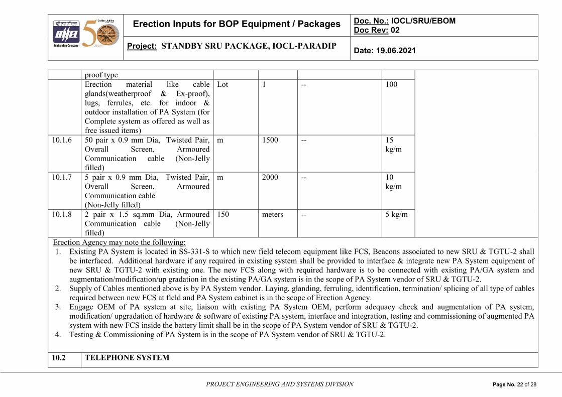
Erection material like cable
glands(weatherproof & Ex-proof),
lugs, ferrules, etc. for indoor &
outdoor installation of PA System (for
Complete system as offered as well as
free issued items)
Lot 1 -- 100
10.1.6 50 pair x 0.9 mm Dia, Twisted Pair,
Overall Screen, Armoured
Communication cable (Non-Jelly
filled)
m 1500 -- 15
kg/m
10.1.7 5 pair x 0.9 mm Dia, Twisted Pair,
Overall Screen, Armoured
Communication cable
(Non-Jelly filled)
m 2000 -- 10
kg/m
10.1.8 2 pair x 1.5 sq.mm Dia, Armoured
Communication cable (Non-Jelly
filled)
150 meters -- 5 kg/m
Erection Agency may note the following:
1. Existing PA System is located in SS-331-S to which new field telecom equipment like FCS, Beacons associated to new SRU & TGTU-2 shall
be interfaced. Additional hardware if any required in existing system shall be provided to interface & integrate new PA System equipment of
new SRU & TGTU-2 with existing one. The new FCS along with required hardware is to be connected with existing PA/GA system and
augmentation/modification/up gradation in the existing PA/GA system is in the scope of PA System vendor of SRU & TGTU-2.
2. Supply of Cables mentioned above is by PA System vendor. Laying, glanding, ferruling, identification, termination/ splicing of all type of cables
required between new FCS at field and PA System cabinet is in the scope of Erection Agency.
3. Engage OEM of PA system at site, liaison with existing PA System OEM, perform adequacy check and augmentation of PA system,
modification/ upgradation of hardware & software of existing PA system, interface and integration, testing and commissioning of augmented PA
system with new FCS inside the battery limit shall be in the scope of PA System vendor of SRU & TGTU-2.
4. Testing & Commissioning of PA System is in the scope of PA System vendor of SRU & TGTU-2.
10.2 TELEPHONE SYSTEM

Erection Inputs for BOP Equipment / Packages Doc. No.: IOCL/SRU/EBOM Doc Rev: 02
Project: STANDBY SRU PACKAGE, IOCL-PARADIP Date: 19.06.2021
PROJECT ENGINEERING AND SYSTEMS DIVISION Page No. 23 of 28
10.2.1 Modification of Existing Telephone
System Exchange (24 Analog media
module, Line Cards etc.)
Lot 1 -- -- 24 Analog media module, Line
Cards etc.
Refer Notes below for further
details
10.2.2 Ex-proof Telephone Equipment Nos. 3 -- 50
10.2.3 Weather proof Telephone, Wall
mounting
Nos. 3 3
10.2.4 Flashing Beacon lamps
(Ex- proof type)
Nos. 2 -- 2
10.2.5 Acoustic Hood/Canopy (FRP) suitable
for Weather proof & Ex-proof
Telephones mounted in outdoor
environment
Nos. 4 -- 10
10.2.6 Telephone System Junction boxes,
Wp-proof type
Nos. 2 0.4 x 0.37 x 0.165 5
Erection material like cable
glands(weatherproof & Ex-proof),
lugs, ferrules, etc. for indoor &
outdoor installation of PA System (for
Complete system as offered as well as
free issued items)
Lot 1 -- 100
10.2.7 10 pair x 0.9 mm Dia, Twisted Pair,
Overall Screen, Armoured
Communication cable (Jelly filled)
m 1500 -- 15
kg/m
10.2.8 2 pair x 0.9 mm Dia, Twisted Pair,
Overall Screen, Armoured
Communication cable
(Jelly filled)
m 500 -- 10
kg/m
10.2.9 Main distribution for connection of
Telephone sets to Main Telephone
System Exchange
1 25

Erection Inputs for BOP Equipment / Packages Doc. No.: IOCL/SRU/EBOM Doc Rev: 02
Project: STANDBY SRU PACKAGE, IOCL-PARADIP Date: 19.06.2021
PROJECT ENGINEERING AND SYSTEMS DIVISION Page No. 24 of 28
Erection Agency may note the following:
1. The new Telephone equipment along with required hardware is to be connected with existing Telephone system and augmentation/ modification/
upgradation in the existing Telephone system is in the scope of Telephone system vendor of SRU & TGTU-2.
2. Required software and hardware modification/ upgradation in existing AVAYA telephone system/ network in SS-331-S for addition of new
telephones shall be done by Telephone System vendor. All necessary power distribution (including UPS power) for new Telephones & associated
additional hardware shall be in scope of Telephone system vendor of SRU & TGTU-2.
3. Supply of Cables mentioned above is by PE&SD/ Telephone System vendor. Laying, glanding, ferruling, identification, termination/ splicing of
all type of cables required between new Telephones and Telephone System cabinet is in the scope of Erection Agency.
4. Engage OEM of Telephone system at site, liaison with existing telephone system OEM, perform adequacy check and augmentation of Telephone
system, modification/ upgradation of hardware & software of existing telephone system, interface and integration, testing and commissioning of
augmented telephone system with new telephones inside the battery limit shall be in the scope of Telephone system vendor of SRU & TGTU-2.
5. Testing & Commissioning of Telephone System is in the scope of Telephone system vendor of SRU & TGTU-2.
STRUCTURAL STEEL
B 5,
Section
1
Structural steel
(MS angle iron- 50x50x6, 75x75x6
mm for panel base frame & its site
fabrication, STR STL 6MM
(1500x5000X6), ISMC MS
CHANNEL (100x50), ISA 65x65x6
mm Runner angles (Mild steel), ISA
50x50x6 mm Runner angles (Mild
steel)
Lot
Lot
Lot
1
1
1
--
--
--
50MT Painting shall be in erection agency
scope and same shall be carried out
as per contract standards.
Notes:
Structural steel is for cable tray supports in the cellar/ trenches/ vertical raceways, cross channels in floor cut outs for supporting panels, for
the field mounted JBs/ PB Stations etc.
11.0 CONVENTIONAL FIRE PROOF SEALING MATERIALS
11.1 Fire Break Coatings for HT/ LT
Power Cables
sq.m 150 -- -- Spray type liquid on cables
11.2 Fire proof materials required for sq.m 80 -- -- Mortar seal

Erection Inputs for BOP Equipment / Packages Doc. No.: IOCL/SRU/EBOM Doc Rev: 02
Project: STANDBY SRU PACKAGE, IOCL-PARADIP Date: 19.06.2021
PROJECT ENGINEERING AND SYSTEMS DIVISION Page No. 25 of 28
sealing of cable entry through
conduits/trenches & through panels
11.3 Ceramic Fibre Mattress GI cable
Ducts
sq.m 2250 -- -- Please refer G.I Cable duct BOQ
item Sl. No. 7.19 & 7.20
11.4 Ceramic Fibre Mattress for below
mentioned FRP cable trays & ducts
sq.m 2000 -- -- P Please refer G.I Cable duct BOQ
item Sl. No. 7.21,7.22 & 7.23
12.0 ELECTRICAL INSULATING MATS
12.1 Insulating Mat for voltage Grade upto
3.3kV (Class-A, Category-III)
Nos. 5 10 x 1 x 0.002 5
13.0 LCS (LOCAL CONTROL STATION) PACKAGE
13.1 Local Control Station (LCS) Nos. 30 400 x 200 x 400 25
Annexure-4 (Under Section-2)
(Items that are to be supplied erected, tested and commissioned by Erection agency.)
Erection and Commissioning Consumables: The consumables required for Electrical Equipment/ Items shall be included in Erection Agency’s scope
(The consumables shall be of Industrial Grade and suitable for use in refineries). The following are typical erection consumables that are envisaged in
this project:
Price
bid ref.
Sl. No.
Equipment/ Package Description Unit of Qty Qty. Dimension (each)
L x B x H (M)
Weight
(each)
kg
Remarks
B 1, Sec
2
6 mm thick chequered plate for
covering cutouts in Switchgear room
sq.m 50 -- -- Refer Switchgear Room Layout.
Support structure for complete
chequered plates shall be erected by
Erection agency.
Erection Inputs for BOP Equipment / Packages Doc. No.: IOCL/SRU/EBOM Doc Rev: 02
Project: STANDBY SRU PACKAGE, IOCL-PARADIP Date: 19.06.2021
PROJECT ENGINEERING AND SYSTEMS DIVISION Page No. 26 of 28
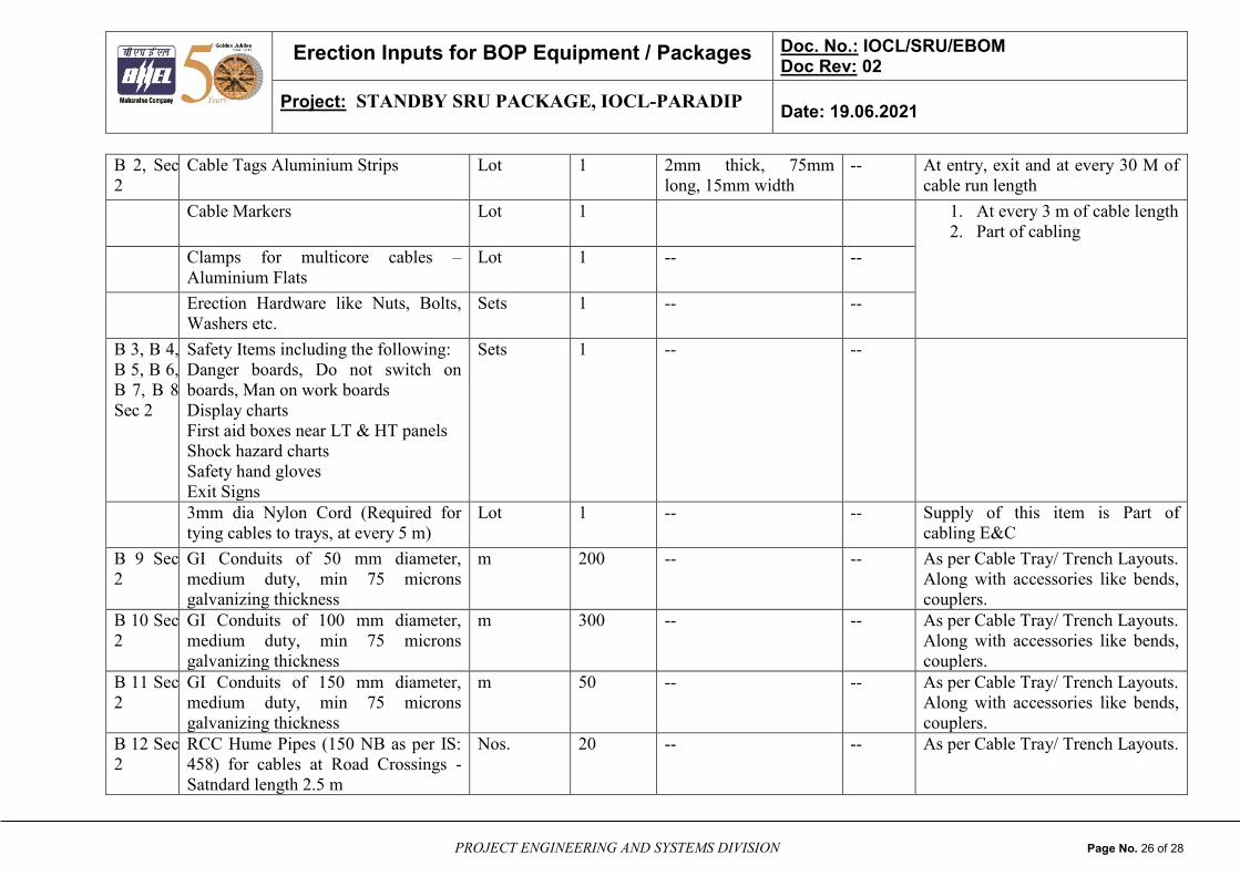
B 2, Sec
2
Cable Tags Aluminium Strips Lot 1 2mm thick, 75mm
long, 15mm width
-- At entry, exit and at every 30 M of
cable run length
Cable Markers Lot 1 1. At every 3 m of cable length
2. Part of cabling
Clamps for multicore cables –
Aluminium Flats
Lot 1 -- --
Erection Hardware like Nuts, Bolts,
Washers etc.
Sets 1 -- --
B 3, B 4,
B 5, B 6,
B 7, B 8
Sec 2
Safety Items including the following:
Danger boards, Do not switch on
boards, Man on work boards
Display charts
First aid boxes near LT & HT panels
Shock hazard charts
Safety hand gloves
Exit Signs
Sets 1 -- --
3mm dia Nylon Cord (Required for
tying cables to trays, at every 5 m)
Lot 1 -- -- Supply of this item is Part of
cabling E&C
B 9 Sec
2
GI Conduits of 50 mm diameter,
medium duty, min 75 microns
galvanizing thickness
m 200 -- -- As per Cable Tray/ Trench Layouts.
Along with accessories like bends,
couplers.
B 10 Sec
2
GI Conduits of 100 mm diameter,
medium duty, min 75 microns
galvanizing thickness
m 300 -- -- As per Cable Tray/ Trench Layouts.
Along with accessories like bends,
couplers.
B 11 Sec
2
GI Conduits of 150 mm diameter,
medium duty, min 75 microns
galvanizing thickness
m 50 -- -- As per Cable Tray/ Trench Layouts.
Along with accessories like bends,
couplers.
B 12 Sec
2
RCC Hume Pipes (150 NB as per IS:
458) for cables at Road Crossings -
Satndard length 2.5 m
Nos. 20 -- -- As per Cable Tray/ Trench Layouts.

Erection Inputs for BOP Equipment / Packages Doc. No.: IOCL/SRU/EBOM Doc Rev: 02
Project: STANDBY SRU PACKAGE, IOCL-PARADIP Date: 19.06.2021
PROJECT ENGINEERING AND SYSTEMS DIVISION Page No. 27 of 28
B 13 Sec
2
RCC Hume Pipes (200 NB as per IS:
458) for cables at Road Crossings -
Satndard length 2.5 m
Nos. 5 -- -- As per Cable Tray/Trench Layouts.
B 14 Sec
2
PVC Conduits Class-3 of 300 mm
diameter
m 10 -- -- As per Cable Tray/ Trench Layouts.
B 15 Sec
2
PVC Conduits Class-3 of 200 mm
diameter
m 100 -- -- As per Cable Tray/ Trench Layouts.
B 16 Sec
2
PVC Conduits Class-3 of 150 mm
diameter
m 50 -- -- As per Cable Tray/ Trench Layouts.
B 17 Sec
2
PVC Conduits Class-3 of 100 mm
diameter
m 50 -- -- As per Cable Tray/ Trench Layouts.
Framed Single Line Diagram Nos. 1 -- -- To be arranged at site
ATTENTION:
Notes regarding Erection of Cables, Cable Trays and Accessories:
a) The termination and connection of cables shall be carried out strictly in accordance with the manufacturer’s instruction, drawings and / or directed
by the Purchaser. The work shall include all clamping, fitting, fixing, soldering, tapping, compound filling, cable jointing, crimping, shorting and
grounding as required for the complete job. Cables shall be checked for insulation resistance before and after jointing. All erection consumables
shall be in Erection Agency’s scope. Termination & Connection shall be carried out in such a manner as to avoid strain on the terminals. Cables
shall be marked with cable numbers as per applicable drawing.
b) Cable Glands and Lugs are being supplied along with corresponding equipment like Motors, LT Switchgear, Junction Boxes, Push Button Stations,
and Transformers etc. However, one lot of Glands and Lugs are being supplied to take care of shortages/mismatches at site.
c) Control cable cores entering panel/switchgear/MCC etc. shall be neatly bunched and served with PVC perforated tape to keep in position at the
terminal block.
Erection Inputs for BOP Equipment / Packages Doc. No.: IOCL/SRU/EBOM Doc Rev: 02
Project: STANDBY SRU PACKAGE, IOCL-PARADIP Date: 19.06.2021
PROJECT ENGINEERING AND SYSTEMS DIVISION Page No. 28 of 28
d) Ferrules shall be installed on all control cable cores in all junction boxes and at all terminations. The ferruling shall be Cross-Ferruling. The ferrules
shall carry terminal numbers as per drawings. All ferrules shall be coloured, plastic & interlocked type. Spare cores shall also be similarly ferruled,
crimped with lug and aped on the ends. Spare cores shall be ferruled with individual cable number.
e) “Structural Steels for support” materials are supplied to make supports for cable trays (in the buried RCC trenches, Overhead tray arrangement on
pipe racks and Cable Tray arrangement in Cellars & other arrangements as applicable for the project. These are also required for making of frames
for PB stations, junction boxes as per the project requirements. Drilling of holes in ISA 65 x 65 x 6 for bolting of cable trays shall be done by
Erection Agency. The holes in the Cable Trays shall be provided by the Cable Tray vendor, however in case of requirement of any additional holes
to be drilled for Cable Trays for the purpose of Cable Tray Erection, same shall be done by the Erection Agency. Erection Agency shall ensure that
all steel structure used for electrical installation shall be painted with one coat of Red Oxide Zinc Chromate Primer of approved shade for indoor
installations. Final painting shall be done with two coats of approved bituminous aluminium paint & same to be considered in erection
contractor scope. Supply of Red Oxide Zinc Chromate Primer for site painting of all Structural Steels (required for cable Tray Supports) shall be in
the Erection contractor’s scope. Erection Agency shall ensure that after welding and drilling (if any) of the steels bracket, above mentioned paint of
approved shade shall be applied. Site shall carry out the structural steel works in line with customer/consultant’s technical specifications “Notes &
Details for Plant cable Laying System”.