AX contactor range Control made simple The performance ...
172
AX contactor range Control made simple The performance you need Main catalog
-
Upload
khangminh22 -
Category
Documents
-
view
5 -
download
0
Transcript of AX contactor range Control made simple The performance ...

AX contactor range Control made simpleThe performance you need
Main catalog
Motor rated operational powers and currents
The currents given below concern standard three-phase four-pole cage motors (1500 r.p.m. at 50 Hz 1800 r.p.m. at 60 Hz).These values are given for guidance and may vary according to the motor manufacturer and depending on the number of poles.
IEC Motor nominal current: standardized values in blue colour(according to IEC 60947-4-1 Annex G)
Motorpower 220 V
230 V 240 V 380 V 400 V 415 V 440 V 500 V 660 V 690 V
kW A A A A A A A A A A0.06 0.37 0.35 0.34 0.21 0.2 0.19 0.18 0.16 0.13 0.120.09 0.54 0.52 0.50 0.32 0.3 0.29 0.26 0.24 0.18 0.170.12 0.73 0.7 0.67 0.46 0.44 0.42 0.39 0.32 0.24 0.230.18 1 1 1 0.63 0.6 0.58 0.53 0.48 0.37 0.350.25 1.6 1.5 1.4 0.9 0.85 0.82 0.74 0.68 0.51 0.490.37 2.0 1.9 1.8 1.2 1.1 1.1 1 0.88 0.67 0.640.55 2.7 2.6 2.5 1.6 1.5 1.4 1.3 1.2 0.91 0.870.75 3.5 3.3 3.2 2.0 1.9 1.8 1.7 1.5 1.15 1.11.1 4.9 4.7 4.5 2.8 2.7 2.6 2.4 2.2 1.7 1.61.5 6.6 6.3 6 3.8 3.6 3.5 3.2 2.9 2.2 2.12.2 8.9 8.5 8.1 5.2 4.9 4.7 4.3 3.9 2.9 2.83 11.8 11.3 10.8 6.8 6.5 6.3 5.7 5.2 4 3.84 15.7 15 14.4 8.9 8.5 8.2 7.4 6.8 5.1 4.95.5 20.9 20 19.2 12.1 11.5 11.1 10.1 9.2 7 6.77.5 28.2 27 25.9 16.3 15.5 14.9 13.6 12.4 9.3 8.911 39.7 38 36.4 23.2 22 21.2 19.3 17.6 13.4 12.815 53.3 51 48.9 30.5 29 28 25.4 23 17.8 1718.5 63.8 61 58.5 36.8 35 33.7 30.7 28 22 2122 75.3 72 69 43.2 41 39.5 35.9 33 25.1 2430 100 96 92 57.9 55 53 48.2 44 33.5 3237 120 115 110 69 66 64 58 53 40.8 3945 146 140 134 84 80 77 70 64 49.1 4755 177 169 162 102 97 93 85 78 59.6 5775 240 230 220 139 132 127 116 106 81 7790 291 278 266 168 160 154 140 128 97 93110 355 340 326 205 195 188 171 156 118 113132 418 400 383 242 230 222 202 184 140 134160 509 487 467 295 280 270 245 224 169 162200 637 609 584 368 350 337 307 280 212 203250 782 748 717 453 430 414 377 344 261 250315 983 940 901 568 540 520 473 432 327 313355 1109 1061 1017 642 610 588 535 488 370 354400 1255 1200 1150 726 690 665 605 552 418 400500 1545 1478 1416 895 850 819 745 680 515 493560 1727 1652 1583 1000 950 916 832 760 576 551630 1928 1844 1767 1116 1060 1022 929 848 643 615710 2164 2070 1984 1253 1190 1147 1043 952 721 690800 2446 2340 2243 1417 1346 1297 1179 1076 815 780900 2760 2640 2530 1598 1518 1463 1330 1214 920 8801000 3042 2910 2789 1761 1673 1613 1466 1339 1014 970
UL/CSA Motor nominal current: single and three phase(according to UL 60947-4-1A)
Motorpower 120 V
1-ph200 V 1-ph
200 V 3-ph
208 V 1-ph
208 V 3-ph
220-240 V 1-ph
220-240 V 3-ph
380- 415 V 3-ph
440- 480 V 3-ph
550- 600 V 3-ph
hp A A A A A A A A A A1/10 3 – – – – 1.5 – – – –1/8 3.8 – – – – 1.9 – – – –1/6 4.4 2.5 – 2.4 – 2.2 – – – –1/4 5.8 3.3 – 3.2 – 2.9 – – – –1/3 7.2 4.1 – 4 – 3.6 – – – –1/2 9.8 5.6 2.5 5.4 2.4 4.9 2.2 1.3 1.1 0.93/4 13.8 7.9 3.7 7.6 3.5 6.9 3.2 1.8 1.6 1.31 16 9.2 4.8 8.8 4.6 8 4.2 2.3 2.1 1.71-1/2 20 11.5 6.9 11 6.6 10 6 3.3 3 2.42 24 13.8 7.8 13.2 7.5 12 6.8 4.3 3.4 2.73 34 19.6 11 18.7 10.6 17 9.6 6.1 4.8 3.95 56 32.2 17.5 30.8 16.7 28 15.2 9.7 7.6 6.17-1/2 80 46 25.3 44 24.2 40 22 14 11 910 100 57.5 32.2 55 30.8 50 28 18 14 1115 135 – 48.3 – 46.2 68 42 27 21 1720 – – 62.1 – 59.4 88 54 34 27 2225 – – 78.2 – 74.8 110 68 44 34 2730 – – 92 – 88 136 80 51 40 3240 – – 120 – 114 176 104 66 52 4150 – – 150 – 143 216 130 83 65 5260 – – 177 – 169 – 154 103 77 6275 – – 221 – 211 – 192 128 96 77100 – – 285 – 273 – 248 165 124 99125 – – 359 – 343 – 312 208 156 125150 – – 414 – 396 – 360 240 180 144200 – – 552 – 528 – 480 320 240 192250 – – – – – – 604 403 302 242300 – – – – – – 722 482 361 289350 – – – – – – 828 560 414 336400 – – – – – – 954 636 477 382450 – – – – – – 1030 – 515 412500 – – – – – – 1180 786 590 472
1SB
C10
158
9S
02
01
ABB | 11SYN829571C0203 - January 2017
AX contactor rangeControl made simple - The performance you need
Overview
Manual motor starters
Contactors
Overload relays
General technical data
Index
11
5
3
2
6
4

2 | ABB
1
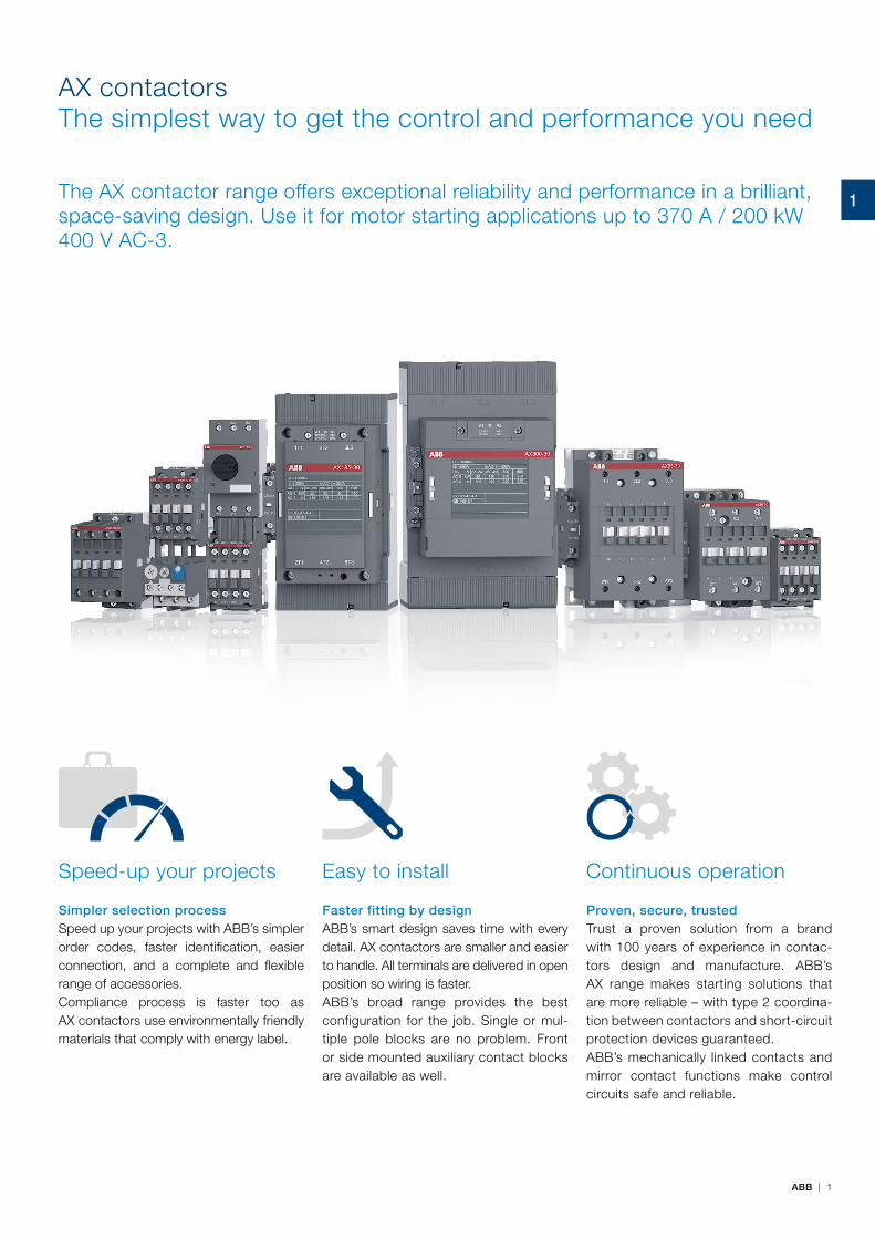
ABB | 1
AX contactorsThe simplest way to get the control and performance you need
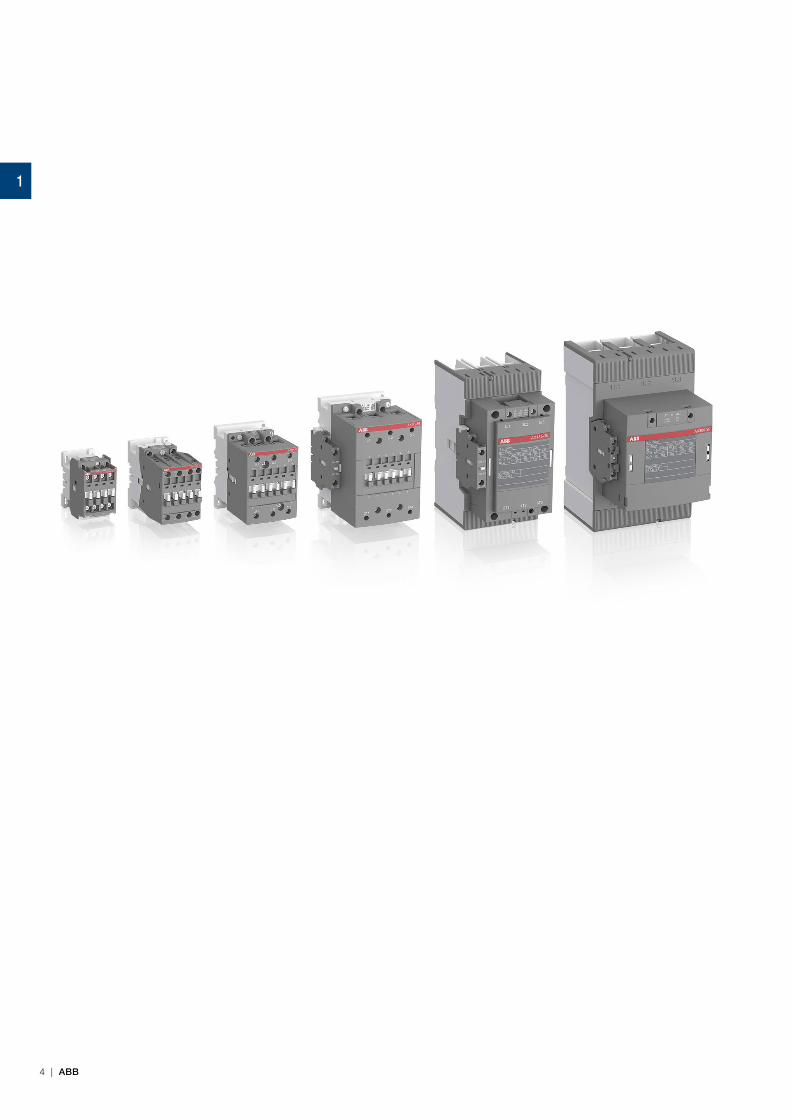
The AX contactor range offers exceptional reliability and performance in a brilliant, space-saving design. Use it for motor starting applications up to 370 A / 200 kW 400 V AC-3.
Simpler selection processSpeed up your projects with ABB’s simpler order codes, faster identification, easier connection, and a complete and flexible range of accessories.Compliance process is faster too as AX contactors use environmentally friendly materials that comply with energy label.
Faster fitting by designABB’s smart design saves time with every detail. AX contactors are smaller and easier to handle. All terminals are delivered in open position so wiring is faster. ABB’s broad range provides the best configuration for the job. Single or mul-tiple pole blocks are no problem. Front or side mounted auxiliary contact blocks are available as well.
Proven, secure, trustedTrust a proven solution from a brand with 100 years of experience in contac-tors design and manufacture. ABB’s AX range makes starting solutions that are more reliable – with type 2 coordina-tion between contactors and short-circuit protection devices guaranteed.ABB’s mechanically linked contacts and mirror contact functions make control circuits safe and reliable.
Speed-up your projects Easy to install Continuous operation
1

1 | ABB
Tested component combinationsUsing ABB's coordination tables gives users a choice of fully tested assemblies and product combinations. It's quicker and easier to build DOL starters, reversing starters or star delta starters using ABB's range of AX contactors, manual motor starters, molded case breakers, fuses and overload relays.
Create smart startersAX contactors look more professional and, together with connection kits, they provide a better finish than cables or bus bars.
Save time when building motor starting solution with AX contactorsComplete range compatible with ABB low voltage solutions
Save timeABB starters come with connection kits to make assembly sim-pler and faster. The kits save time on cable preparation and eliminate fitment and wiring error risks.
1

ABB | 2
Every detail designed for youSmart packaging design makes it simpler to identify the prod-uct you need – the product type, coil voltage, order code and bar code are all clearly displayed. The same goes when the product is unboxed. A quick glance at the front tells you what product, contactor type and coil voltage you have. Terminal markings are also plainly visible. The rated values and main ap-provals are ready to read on the side.
Certified, trusted contactorsABB's AX contactors are designed in compliance with IEC 60947-4-1 and GB 14048-4 requirements. These trusted safety products have CB certification, CE marking as well as CCC and CCS approval.
AX contactorsFeatures and benefits
Easier to connectABB designed its AX contactors so that all screw-heads are accessible from the front. One Pozidriv #2 screwdriver fits every contactor terminal and the complete accessory range. All main and auxiliary terminals can take one or two cables and contac-tors up to AX150 have three coil terminals for connection from the top or the bottom. Right out of the box, all terminals are ready in the open position for wiring.
Environmentally soundThe design and production of ABB's AX contactor range fol-lows ISO 14000 processes. The raw materials are free of red phosphorous, cadmium, mercury, brominated substances (PBB, PBPE) and other pollutants. AX contactors and main ac-cessories also comply with the European directive ROHS 2006.The same goes for the packaging design. The box is fully recyclable and clearly marked to aid correct disposal.
1
3 | ABB
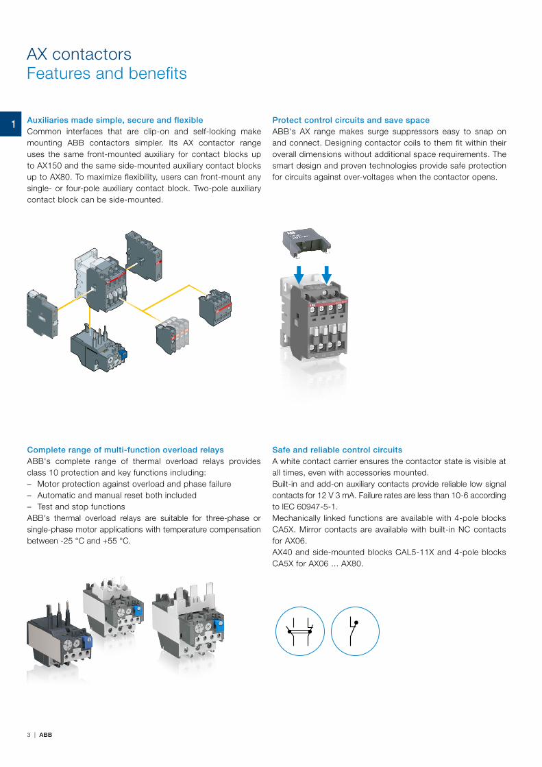
Auxiliaries made simple, secure and flexibleCommon interfaces that are clip-on and self-locking make mounting ABB contactors simpler. Its AX contactor range uses the same front-mounted auxiliary for contact blocks up to AX150 and the same side-mounted auxiliary contact blocks up to AX80. To maximize flexibility, users can front-mount any single- or four-pole auxiliary contact block. Two-pole auxiliary contact block can be side-mounted.
Protect control circuits and save spaceABB's AX range makes surge suppressors easy to snap on and connect. Designing contactor coils to them fit within their overall dimensions without additional space requirements. The smart design and proven technologies provide safe protection for circuits against over-voltages when the contactor opens.
Complete range of multi-function overload relaysABB's complete range of thermal overload relays provides class 10 protection and key functions including: – Motor protection against overload and phase failure – Automatic and manual reset both included – Test and stop functions
ABB's thermal overload relays are suitable for three-phase or single-phase motor applications with temperature compensation between -25 °C and +55 °C.
Safe and reliable control circuitsA white contact carrier ensures the contactor state is visible at all times, even with accessories mounted.Built-in and add-on auxiliary contacts provide reliable low signal contacts for 12 V 3 mA. Failure rates are less than 10-6 according to IEC 60947-5-1.Mechanically linked functions are available with 4-pole blocks CA5X. Mirror contacts are available with built-in NC contacts for AX06. AX40 and side-mounted blocks CAL5-11X and 4-pole blocks CA5X for AX06 ... AX80.
AX contactorsFeatures and benefits
1
4 | ABB
1
5 | ABB
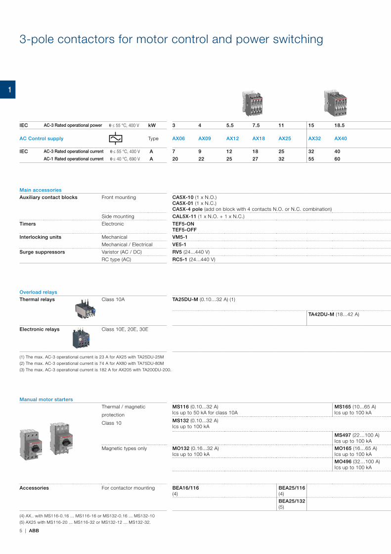
IEC AC-3 Rated operational power θ ≤ 55 °C, 400 V kW 3 4 5.5 7.5 11 15 18.5 22 30 37 45 55 75 90 110 132 160 200
AC Control supply Type AX06 AX09 AX12 AX18 AX25 AX32 AX40 AX50 AX65 AX80 AX95 AX115 AX150 AX185 AX205 AX260 AX300 AX370
IEC AC-3 Rated operational current θ ≤ 55 °C, 400 V A 7 9 12 18 25 32 40 50 65 80 96 115 150 185 205 265 305 370AC-1 Rated operational current θ ≤ 40 °C, 690 V A 20 22 25 27 32 55 60 100 115 125 145 160 190 250 275 400 500 600
Main accessories
Auxiliary contact blocks Front mounting CA5X-10 (1 x N.O.) CA5X-01 (1 x N.C.)CA5X-4 pole (add on block with 4 contacts N.O. or N.C. combination)
Side mounting CAL5X-11 (1 x N.O. + 1 x N.C.) CAL18X-11 (1 x N.O. + 1 x N.C.) CAL19-11 (1 x N.O. + 1 x N.C.)
Timers Electronic TEF5-ON TEF5-OFF
Interlocking units Mechanical VM5-1 VM300H VM19
Mechanical / Electrical VE5-1 VE5-2
Surge suppressors Varistor (AC / DC) RV5 (24...440 V)
RC type (AC) RC5-1 (24...440 V) RC5-2 (24...440 V) RC5-3 (250...440 V)
Overload relays
Thermal relays Class 10A TA25DU-M (0.10…32 A) (1) TA75DU-M (18...80 A) (2) TA80DU (29...80 A) TA200DU (66...200 A) (3)
TA42DU-M (18...42 A) TA110DU (66...110 A)
Electronic relays Class 10E, 20E, 30E E140DU (50…140 A) EF205 (63…210 A) EF370 (115...380 A)
(1) The max. AC-3 operational current is 23 A for AX25 with TA25DU-25M
(2) The max. AC-3 operational current is 74 A for AX80 with TA75DU-80M
(3) The max. AC-3 operational current is 182 A for AX205 with TA200DU-200.
Manual motor starters Short-circuit protection devices
Thermal / magnetic
protection
Class 10
MS116 (0.10...32 A) lcs up to 50 kA for class 10A
MS165 (10...65 A) lcs up to 100 kA
MCCB and switch fuses
MS132 (0.10...32 A) lcs up to 100 kA
MS495 (45…100 A) Ics up to 50 kA
MS497 (22…100 A) Ics up to 100 kA
Magnetic types only MO132 (0.16...32 A) Ics up to 100 kA
MO165 (16…65 A) Ics up to 100 kAMO496 (32…100 A) Ics up to 100 kA
MO495 (63…100 A) Ics up to 50 kA
Accessories For contactor mounting BEA16/116 (4)
BEA25/116 (4)
BEA75/495 For MS495
BEA110/495 For MS495
BEA25/132 (5)
(4) AX.. with MS116-0.16 ... MS116-16 or MS132-0.16 ... MS132-10
(5) AX25 with MS116-20 ... MS116-32 or MS132-12 ... MS132-32.
3-pole contactors for motor control and power switching
1
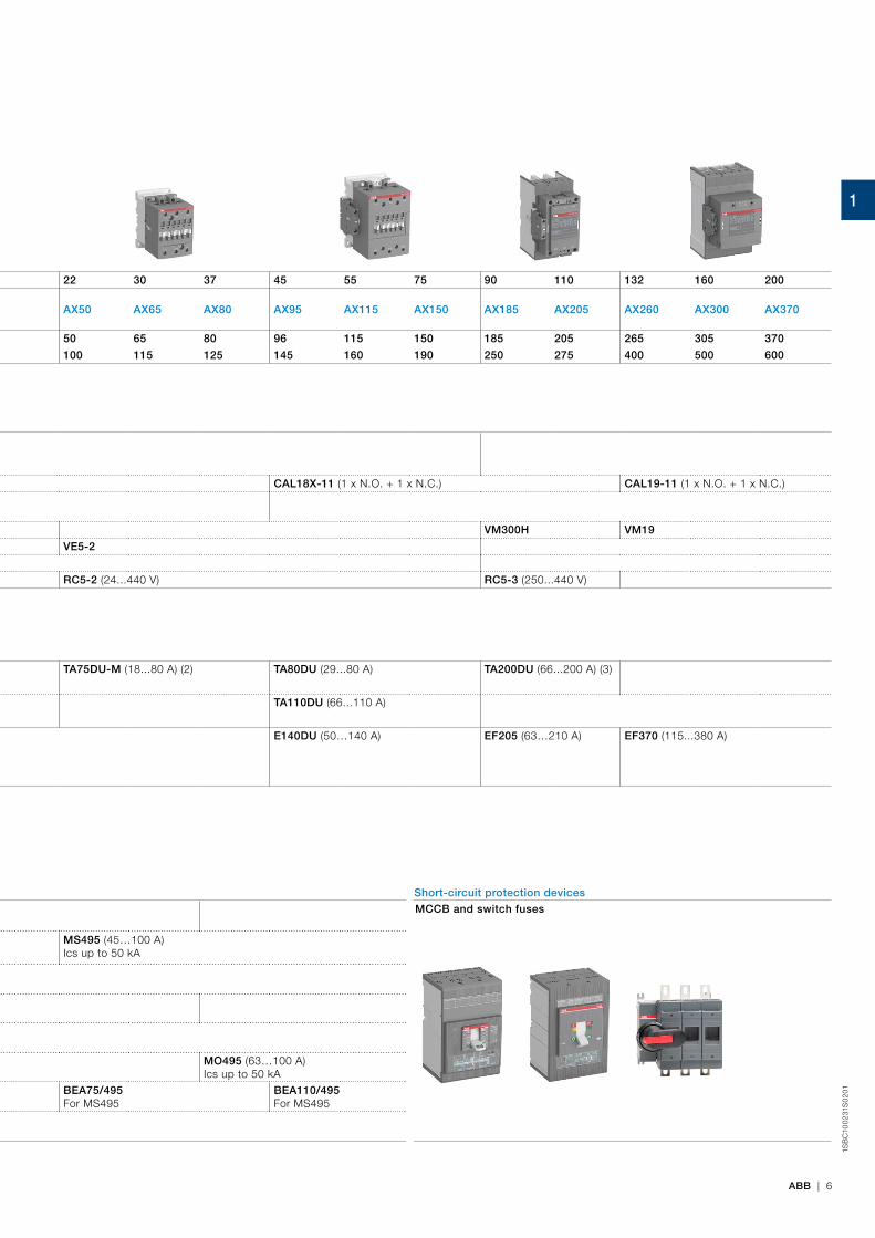
ABB | 6
1SB
C10
02
31S
02
01
IEC AC-3 Rated operational power θ ≤ 55 °C, 400 V kW 3 4 5.5 7.5 11 15 18.5 22 30 37 45 55 75 90 110 132 160 200
AC Control supply Type AX06 AX09 AX12 AX18 AX25 AX32 AX40 AX50 AX65 AX80 AX95 AX115 AX150 AX185 AX205 AX260 AX300 AX370
IEC AC-3 Rated operational current θ ≤ 55 °C, 400 V A 7 9 12 18 25 32 40 50 65 80 96 115 150 185 205 265 305 370AC-1 Rated operational current θ ≤ 40 °C, 690 V A 20 22 25 27 32 55 60 100 115 125 145 160 190 250 275 400 500 600
Main accessories
Auxiliary contact blocks Front mounting CA5X-10 (1 x N.O.) CA5X-01 (1 x N.C.)CA5X-4 pole (add on block with 4 contacts N.O. or N.C. combination)
Side mounting CAL5X-11 (1 x N.O. + 1 x N.C.) CAL18X-11 (1 x N.O. + 1 x N.C.) CAL19-11 (1 x N.O. + 1 x N.C.)
Timers Electronic TEF5-ON TEF5-OFF
Interlocking units Mechanical VM5-1 VM300H VM19
Mechanical / Electrical VE5-1 VE5-2
Surge suppressors Varistor (AC / DC) RV5 (24...440 V)
RC type (AC) RC5-1 (24...440 V) RC5-2 (24...440 V) RC5-3 (250...440 V)
Overload relays
Thermal relays Class 10A TA25DU-M (0.10…32 A) (1) TA75DU-M (18...80 A) (2) TA80DU (29...80 A) TA200DU (66...200 A) (3)
TA42DU-M (18...42 A) TA110DU (66...110 A)
Electronic relays Class 10E, 20E, 30E E140DU (50…140 A) EF205 (63…210 A) EF370 (115...380 A)
(1) The max. AC-3 operational current is 23 A for AX25 with TA25DU-25M
(2) The max. AC-3 operational current is 74 A for AX80 with TA75DU-80M
(3) The max. AC-3 operational current is 182 A for AX205 with TA200DU-200.
Manual motor starters Short-circuit protection devices
Thermal / magnetic
protection
Class 10
MS116 (0.10...32 A) lcs up to 50 kA for class 10A
MS165 (10...65 A) lcs up to 100 kA
MCCB and switch fuses
MS132 (0.10...32 A) lcs up to 100 kA
MS495 (45…100 A) Ics up to 50 kA
MS497 (22…100 A) Ics up to 100 kA
Magnetic types only MO132 (0.16...32 A) Ics up to 100 kA
MO165 (16…65 A) Ics up to 100 kAMO496 (32…100 A) Ics up to 100 kA
MO495 (63…100 A) Ics up to 50 kA
Accessories For contactor mounting BEA16/116 (4)
BEA25/116 (4)
BEA75/495 For MS495
BEA110/495 For MS495
BEA25/132 (5)
(4) AX.. with MS116-0.16 ... MS116-16 or MS132-0.16 ... MS132-10
(5) AX25 with MS116-20 ... MS116-32 or MS132-12 ... MS132-32.
1
2
10 | ABB

Manual motor starters
2CD
C13
106
8C
02
01
2
ABB | 11
Overview
Benefits 12
Features 13
Overview 14
Ordering details – 0.10 to 65 A – with thermal and electromagnetic protection
MS116 manual motor starters 16
MS132 manual motor starters 17
MS165 manual motor starters 18
Ordering details – 0.16 to 65 A – with electromagnetic protection
MO132 manual motor starters magnetic only 19
MO165 manual motor starters magnetic only 20
Ordering details – 0.10 to 25 A – with thermal and electromagnetic protection
MS132-T circuit breakers for transformer protection 21
Technical data 22
Main accessories 32
Ordering details – 22 to 100 A – with thermal and electromagnetic protection
MS495, MS497 manual motor starters 42
Technical data 43
Ordering details – 32 to 100 A – with electromagnetic protection
MO495, MO496 manual motor starters magnetic only 46
Technical data 47
Main accessories 50
General accessories 54
2CD
C13
110
2C0
201
12 | ABB
Manual motor startersBenefits
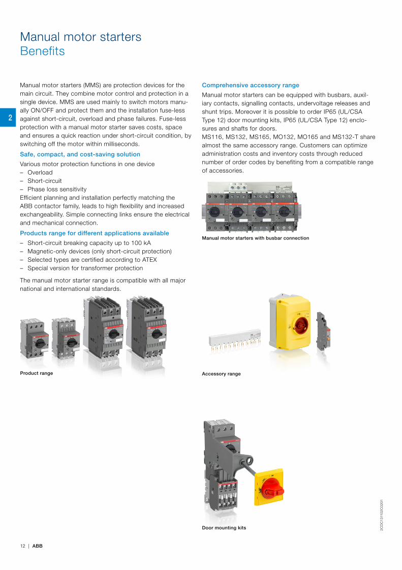
Comprehensive accessory range
Manual motor starters can be equipped with busbars, auxil-iary contacts, signalling contacts, undervoltage releases and shunt trips. Moreover it is possible to order IP65 (UL/CSA Type 12) door mounting kits, IP65 (UL/CSA Type 12) enclo-sures and shafts for doors.MS116, MS132, MS165, MO132, MO165 and MS132-T share almost the same accessory range. Customers can optimize administration costs and inventory costs through reduced number of order codes by benefiting from a compatible range of accessories.
Product range Accessory range
Door mounting kits
Manual motor starters with busbar connection
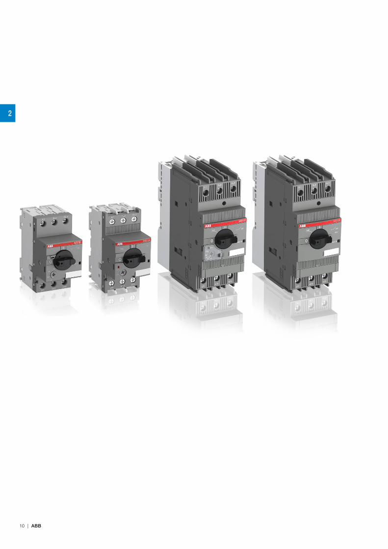
Manual motor starters (MMS) are protection devices for the main circuit. They combine motor control and protection in a single device. MMS are used mainly to switch motors manu-ally ON/OFF and protect them and the installation fuse-less against short-circuit, overload and phase failures. Fuse-less protection with a manual motor starter saves costs, space and ensures a quick reaction under short-circuit condition, by switching off the motor within milliseconds.
Safe, compact, and cost-saving solution
Various motor protection functions in one device – Overload – Short-circuit – Phase loss sensitivity
Efficient planning and installation perfectly matching the ABB contactor family, leads to high flexibility and increased exchangeability. Simple connecting links ensure the electrical and mechanical connection.
Products range for different applications available
– Short-circuit breaking capacity up to 100 kA – Magnetic-only devices (only short-circuit protection) – Selected types are certified according to ATEX – Special version for transformer protection
The manual motor starter range is compatible with all major national and international standards.
2

2CD
C13
110
2C0
201
ABB | 13
Manual motor startersFeatures
Features
– Manual control – Disconnect function – Handle can be locked in the off position – Remote control via undervoltage release or shunt trip – Trip indication – Temperature compensation – Adjustable current setting
– Magnetic trip indication for several types available (MS132, MS165, and MS132-T)
– One product family in 45 mm width (MS116, MS132, MO132, and MS132-T)
– Variants from 0.1 up to 100 A available – Short-circuit service breaking capacity ICS up to 100 kA
2
2
3
4
1
Thermal trippingMagnetic tripping
1 Terminals (1L1, 3L2, 5L3)
2 Switch position TRIP
3 Lockable handle
4 Test function
5 Status indication for short-circuit
6 Current setting range 7 Terminals 2T1, 4T2, 6T3
1 Clear trip indication
2 Handle in TRIP position
3 Optical indication for short-circuit
4 Easy locking
1
2-1
1
2
3
4
7
56
Features of type MS132 TRIP indication
2

14 | ABB
Manual motor startersOverview
Table for short-circuit ratings for 400/415 V
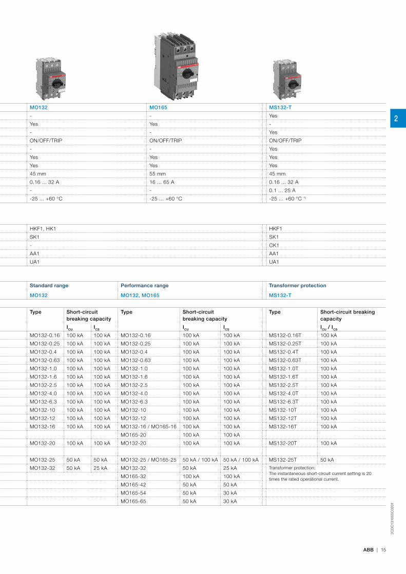
Standard range Performance range Standard range Performance range Transformer protection
MS116 MS132, MS165 MO132 MO132, MO165 MS132-T
Selection parameters
Rated operational power
Setting range for thermal release
Type Short-circuit breaking capacity
Type Short-circuit breaking capacity
Type Short-circuitbreaking capacity
Type Short-circuitbreaking capacity
Type Short-circuit breakingcapacity
ICU ICS ICU ICS ICU ICS ICU ICS ICU / ICS
- 0.1 … 0.16 A MS116-0.16 50 kA 50 kA MS132-0.16 100 kA 100 kA MO132-0.16 100 kA 100 kA MO132-0.16 100 kA 100 kA MS132-0.16T 100 kA
0.06 kW 0.16 … 0.25 A MS116-0.25 50 kA 50 kA MS132-0.25 100 kA 100 kA MO132-0.25 100 kA 100 kA MO132-0.25 100 kA 100 kA MS132-0.25T 100 kA
0.09 kW 0.25 … 0.4 A MS116-0.4 50 kA 50 kA MS132-0.4 100 kA 100 kA MO132-0.4 100 kA 100 kA MO132-0.4 100 kA 100 kA MS132-0.4T 100 kA
0.18 kW 0.4 … 0.63 A MS116-0.63 50 kA 50 kA MS132-0.63 100 kA 100 kA MO132-0.63 100 kA 100 kA MO132-0.63 100 kA 100 kA MS132-0.63T 100 kA
0.25 kW 0.63 … 1.0 A MS116-1.0 50 kA 50 kA MS132-1.0 100 kA 100 kA MO132-1.0 100 kA 100 kA MO132-1.0 100 kA 100 kA MS132-1.0T 100 kA
0.55 kW 1.0…1.6 A MS116-1.6 50 kA 50 kA MS132-1.6 100 kA 100 kA MO132-1.6 100 kA 100 kA MO132-1.6 100 kA 100 kA MS132-1.6T 100 kA
0.75 kW 1.6…2.5 A MS116-2.5 50 kA 50 kA MS132-2.5 100 kA 100 kA MO132-2.5 100 kA 100 kA MO132-2.5 100 kA 100 kA MS132-2.5T 100 kA
1.5 kW 2.5…4.0 A MS116-4.0 50 kA 50 kA MS132-4.0 100 kA 100 kA MO132-4.0 100 kA 100 kA MO132-4.0 100 kA 100 kA MS132-4.0T 100 kA
2.2 kW 4.0…6.3 A MS116-6.3 50 kA 50 kA MS132-6.3 100 kA 100 kA MO132-6.3 100 kA 100 kA MO132-6.3 100 kA 100 kA MS132-6.3T 100 kA
4.0 kW 6.3…10 A MS116-10 50 kA 50 kA MS132-10 100 kA 100 kA MO132-10 100 kA 100 kA MO132-10 100 kA 100 kA MS132-10T 100 kA
5.5 kW 8…12 A MS116-12 25 kA 25 kA MS132-12 100 kA 100 kA MO132-12 100 kA 100 kA MO132-12 100 kA 100 kA MS132-12T 100 kA
7.5 kW 10…16 A MS116-16 16 kA 16 kA MS132-16 / MS165-16 100 kA 100 kA MO132-16 100 kA 100 kA MO132-16 / MO165-16 100 kA 100 kA MS132-16T 100 kA
7.5 kW 14 ... 20 A MS165-20 100 kA 100 kA MO165-20 100 kA 100 kA
7.5 kW 16…20 A MS116-20 15 kA 10 kA MS132-20 100 kA 100 kA MO132-20 100 kA 100 kA MO132-20 100 kA 100 kA MS132-20T 100 kA
11 kW 18 … 25 A MS165-25 100 kA 100 kA
11 kW 20…25 A MS116-25 15 kA 10 kA MS132-25 50 kA 50 kA MO132-25 50 kA 50 kA MO132-25 / MO165-25 50 kA / 100 kA 50 kA / 100 kA MS132-25T 50 kA
15 kW 25…32 A MS116-32 10 kA 10 kA MS132-32 50 kA 25 kA MO132-32 50 kA 25 kA MO132-32 50 kA 25 kA Transformer protection:The instantaneous short-circuit current setting is 20times the rated operational current.15 kW 23 ... 32 A MS165-32 100 kA 100 kA MO165-32 100 kA 100 kA
22 kW 30 ... 42 A MS165-42 50 kA 50 kA MO165-42 50 kA 50 kA
22 kW 40 ... 54 A MS165-54 50 kA 30 kA MO165-54 50 kA 30 kA
30 kW 52 ... 65 A MS165-65 50 kA 30 kA MO165-65 50 kA 30 kA
Type MS116 MS132 MS165 MO132 MO165 MS132-T
Thermal and electromagnetic protection Yes Yes Yes - - Yes
Electromagnetic protection - - - Yes Yes -
Phase loss sensitivity Yes Yes Yes - - Yes
Switch position ON/OFF ON/OFF/TRIP ON/OFF/TRIP ON/OFF/TRIP ON/OFF/TRIP ON/OFF/TRIP
Magnetic trip indication - Yes Yes - - Yes
Lockable handle without accessories - Yes Yes Yes Yes Yes
Disconnecting feature Yes Yes Yes Yes Yes Yes
Width 45 mm 45 mm 55 mm 45 mm 55 mm 45 mm
Rated operational current Ie 0.16 ... 32 A 0.16 ... 32 A 16 ... 65 A 0.16 ... 32 A 16 ... 65 A 0.16 ... 32 A
Setting range 0.1 ... 32 A 0.1 ... 32 A 10 ... 65 A - - 0.1 ... 25 A
Ambient air temperature -25 ... +55 °C 1) -25 ... +60 °C 1) -20 ... +60 °C 1) -25 ... +60 °C -25 ... +60 °C -25 ... +60 °C 1)
1) Compensated2) For motor loads only up to 80 A
Accessories
Auxiliary contact HKF1, HK1 HKF1, HK1 HKF1
Signalling contact
for tripped alarm SK1 SK1 SK1
for short-circuit alarm - CK1 - CK1
Shunt trip AA1 AA1 AA1
Undervoltage release UA1 UA1 UA1
2
2CD
C13
105
5C
02
01
ABB | 15
Table for short-circuit ratings for 400/415 V
Standard range Performance range Standard range Performance range Transformer protection
MS116 MS132, MS165 MO132 MO132, MO165 MS132-T
Selection parameters
Rated operational power
Setting range for thermal release
Type Short-circuit breaking capacity
Type Short-circuit breaking capacity
Type Short-circuit breaking capacity
Type Short-circuit breaking capacity
Type Short-circuit breaking capacity
ICU ICS ICU ICS ICU ICS ICU ICS ICU / ICS
- 0.1 … 0.16 A MS116-0.16 50 kA 50 kA MS132-0.16 100 kA 100 kA MO132-0.16 100 kA 100 kA MO132-0.16 100 kA 100 kA MS132-0.16T 100 kA
0.06 kW 0.16 … 0.25 A MS116-0.25 50 kA 50 kA MS132-0.25 100 kA 100 kA MO132-0.25 100 kA 100 kA MO132-0.25 100 kA 100 kA MS132-0.25T 100 kA
0.09 kW 0.25 … 0.4 A MS116-0.4 50 kA 50 kA MS132-0.4 100 kA 100 kA MO132-0.4 100 kA 100 kA MO132-0.4 100 kA 100 kA MS132-0.4T 100 kA
0.18 kW 0.4 … 0.63 A MS116-0.63 50 kA 50 kA MS132-0.63 100 kA 100 kA MO132-0.63 100 kA 100 kA MO132-0.63 100 kA 100 kA MS132-0.63T 100 kA
0.25 kW 0.63 … 1.0 A MS116-1.0 50 kA 50 kA MS132-1.0 100 kA 100 kA MO132-1.0 100 kA 100 kA MO132-1.0 100 kA 100 kA MS132-1.0T 100 kA
0.55 kW 1.0…1.6 A MS116-1.6 50 kA 50 kA MS132-1.6 100 kA 100 kA MO132-1.6 100 kA 100 kA MO132-1.6 100 kA 100 kA MS132-1.6T 100 kA
0.75 kW 1.6…2.5 A MS116-2.5 50 kA 50 kA MS132-2.5 100 kA 100 kA MO132-2.5 100 kA 100 kA MO132-2.5 100 kA 100 kA MS132-2.5T 100 kA
1.5 kW 2.5…4.0 A MS116-4.0 50 kA 50 kA MS132-4.0 100 kA 100 kA MO132-4.0 100 kA 100 kA MO132-4.0 100 kA 100 kA MS132-4.0T 100 kA
2.2 kW 4.0…6.3 A MS116-6.3 50 kA 50 kA MS132-6.3 100 kA 100 kA MO132-6.3 100 kA 100 kA MO132-6.3 100 kA 100 kA MS132-6.3T 100 kA
4.0 kW 6.3…10 A MS116-10 50 kA 50 kA MS132-10 100 kA 100 kA MO132-10 100 kA 100 kA MO132-10 100 kA 100 kA MS132-10T 100 kA
5.5 kW 8…12 A MS116-12 25 kA 25 kA MS132-12 100 kA 100 kA MO132-12 100 kA 100 kA MO132-12 100 kA 100 kA MS132-12T 100 kA
7.5 kW 10…16 A MS116-16 16 kA 16 kA MS132-16 / MS165-16 100 kA 100 kA MO132-16 100 kA 100 kA MO132-16 / MO165-16 100 kA 100 kA MS132-16T 100 kA
7.5 kW 14 ... 20 A MS165-20 100 kA 100 kA MO165-20 100 kA 100 kA
7.5 kW 16…20 A MS116-20 15 kA 10 kA MS132-20 100 kA 100 kA MO132-20 100 kA 100 kA MO132-20 100 kA 100 kA MS132-20T 100 kA
11 kW 18 … 25 A MS165-25 100 kA 100 kA
11 kW 20…25 A MS116-25 15 kA 10 kA MS132-25 50 kA 50 kA MO132-25 50 kA 50 kA MO132-25 / MO165-25 50 kA / 100 kA 50 kA / 100 kA MS132-25T 50 kA
15 kW 25…32 A MS116-32 10 kA 10 kA MS132-32 50 kA 25 kA MO132-32 50 kA 25 kA MO132-32 50 kA 25 kA Transformer protection: The instantaneous short-circuit current setting is 20 times the rated operational current.15 kW 23 ... 32 A MS165-32 100 kA 100 kA MO165-32 100 kA 100 kA
22 kW 30 ... 42 A MS165-42 50 kA 50 kA MO165-42 50 kA 50 kA
22 kW 40 ... 54 A MS165-54 50 kA 30 kA MO165-54 50 kA 30 kA
30 kW 52 ... 65 A MS165-65 50 kA 30 kA MO165-65 50 kA 30 kA
Type MS116 MS132 MS165 MO132 MO165 MS132-T
Thermal and electromagnetic protection Yes Yes Yes - - Yes
Electromagnetic protection - - - Yes Yes -
Phase loss sensitivity Yes Yes Yes - - Yes
Switch position ON/OFF ON/OFF/TRIP ON/OFF/TRIP ON/OFF/TRIP ON/OFF/TRIP ON/OFF/TRIP
Magnetic trip indication - Yes Yes - - Yes
Lockable handle without accessories - Yes Yes Yes Yes Yes
Disconnecting feature Yes Yes Yes Yes Yes Yes
Width 45 mm 45 mm 55 mm 45 mm 55 mm 45 mm
Rated operational current Ie 0.16 ... 32 A 0.16 ... 32 A 16 ... 65 A 0.16 ... 32 A 16 ... 65 A 0.16 ... 32 A
Setting range 0.1 ... 32 A 0.1 ... 32 A 10 ... 65 A - - 0.1 ... 25 A
Ambient air temperature -25 ... +55 °C 1) -25 ... +60 °C 1) -20 ... +60 °C 1) -25 ... +60 °C -25 ... +60 °C -25 ... +60 °C 1)
1) Compensated2) For motor loads only up to 80 A
Accessories
Auxiliary contact HKF1, HK1 HKF1, HK1 HKF1
Signalling contact
for tripped alarm SK1 SK1 SK1
for short-circuit alarm - CK1 - CK1
Shunt trip AA1 AA1 AA1
Undervoltage release UA1 UA1 UA1
2

2CD
C13
1101
C0
201
16 | ABB
MS116 manual motor starters0.10 to 32 A – with thermal and electromagnetic protection
DescriptionMS116 is a compact and economic range for motor protection up to 15 kW (400 V) / 32 A in width of 45 mm. Further features are the build-in disconnect function, temperature compensation, trip-free mechanism and a rotary handle with a clear switch position indication. The manual motor starter is suitable for three- and single phase applications. Auxiliary contacts, signaling contacts, undervoltage releases, shunt trips, power in-feed blocks and locking devices for protection against unauthorized changes are available as accessory. These are suitable throughout the MS116/MS132/MS165-range.
Ordering details
Rated operational power400 V AC-3
Setting range
Short-circuit breakingcapacity ICS at 400 V AC
Rated instan-taneous short-circuit current setting li
Type Order code Weight(1 pce)
kW A kA A kg- 0.10 ... 0.16 50 2.00 1) MS116-0.16 1SAM250000R1001 0.2250.06 0.16 ... 0.25 50 3.10 1) MS116-0.25 1SAM250000R1002 0.2250.09 0.25 ... 0.40 50 5.00 1) MS116-0.4 1SAM250000R1003 0.2250.18 0.40 ... 0.63 50 7.90 1) MS116-0.63 1SAM250000R1004 0.2250.25 0.63 ... 1.00 50 12.5 1) MS116-1.0 1SAM250000R1005 0.2250.55 1.00 ... 1.60 50 20.0 1) MS116-1.6 1SAM250000R1006 0.2650.75 1.60 ... 2.50 50 31.3 1) MS116-2.5 1SAM250000R1007 0.2651.50 2.50 ... 4.00 50 50.0 MS116-4.0 1SAM250000R1008 0.2652.20 4.00 ... 6.30 50 78.8 MS116-6.3 1SAM250000R1009 0.2654.00 6.30 ... 10.0 50 150 MS116-10 1SAM250000R1010 0.2655.50 8.00 ... 12.0 25 180 MS116-12 1SAM250000R1012 0.2657.50 10.0 ... 16.0 16 240 MS116-16 1SAM250000R1011 0.2657.50 16.0 ... 20.0 10 300 MS116-20 1SAM250000R1013 0.31011.0 20.0 ... 25.0 10 375 MS116-25 1SAM250000R1014 0.31015.0 25.0 ... 32.0 10 480 MS116-32 1SAM250000R1015 0.310- 0.10 ... 0.16 50 2.00 1) MS116-0.16-HKF1-11 1SAM250005R1001 0.2400.06 0.16 ... 0.25 50 3.10 1) MS116-0.25-HKF1-11 1SAM250005R1002 0.2400.09 0.25 ... 0.40 50 5.00 1) MS116-0.4-HKF1-11 1SAM250005R1003 0.2400.18 0.40 ... 0.63 50 7.90 1) MS116-0.63-HKF1-11 1SAM250005R1004 0.2400.25 0.63 ... 1.00 50 12.5 1) MS116-1.0-HKF1-11 1SAM250005R1005 0.2400.55 1.00 ... 1.60 50 20.0 1) MS116-1.6-HKF1-11 1SAM250005R1006 0.2800.75 1.60 ... 2.50 50 31.3 1) MS116-2.5-HKF1-11 1SAM250005R1007 0.2801.50 2.50 ... 4.00 50 50.0 MS116-4.0-HKF1-11 1SAM250005R1008 0.2802.20 4.00 ... 6.30 50 78.8 MS116-6.3-HKF1-11 1SAM250005R1009 0.2804.00 6.30 ... 10.0 50 150 MS116-10.0-HKF1-11 1SAM250005R1010 0.2805.50 8.00 ... 12.0 25 180 MS116-12.0-HKF1-11 1SAM250005R1012 0.2807.50 10.0 ... 16.0 16 240 MS116-16.0-HKF1-11 1SAM250005R1011 0.2807.50 16.0 ... 20.0 10 300 MS116-20-HKF1-11 1SAM250005R1013 0.32611.0 20.0 ... 25.0 10 375 MS116-25-HKF1-11 1SAM250005R1014 0.32615.0 25.0 ... 32.0 10 480 MS116-32-HKF1-11 1SAM250005R1015 0.326
Note: Manual motor starters should always be selected so that the actual motor current is within the setting range.1) The data is valid for products, produced after week 34, 2014.
2CD
C24
1010
F001
1
MS116-16
2CD
C24
1001
F001
1
MS116-25
2CD
C24
1013
F001
1
MS116-0.16-HKF1-11
2CD
C24
1012
F001
1
MS116-32-HKF1-11
Main dimensions mm, inches
0.06"
0.07
"
0.55"
3.54
"
1.77"
0.55"
1.38
"
0.22"
1.77
"
2.3"
2.76"
1.71"
3.15"
1.1"
2.95
"
1.5
1.7
14 14
90
45
35
5.5
45
57.8
70
43.5
80.1
27.5
75
2CD
C24
2002
F001
0
1.77
"
2.3"1.38
"
0.22"
2.75"
1.7"
3.15"
0.55"
2.95
"
3.85
"
1.77"
0.55"
0.06"
0.07
"
1.1" 45
57.8
35
5.5
69.8
43.3
79.9
14 14
75
97.8
45
1.5
1.7
27.5
2CD
C24
2001
F001
1
MS116 ≤ 16 A & MS116-HKF1-11 ≤ 16 A MS116 ≥ 20 A & MS116-HKF1-11 ≥ 20 A
2
2CD
C13
1101
C0
201
ABB | 17
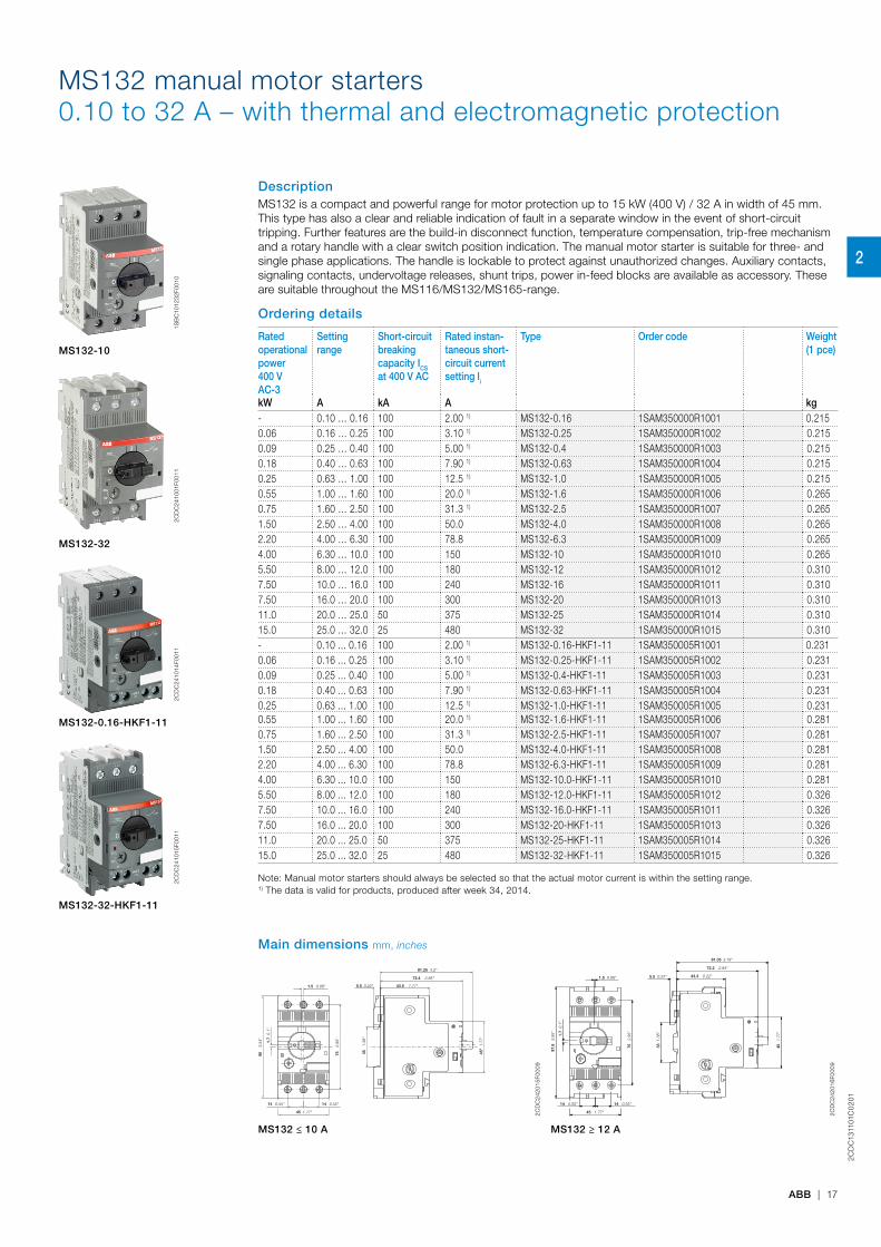
MS132 manual motor starters0.10 to 32 A – with thermal and electromagnetic protection
DescriptionMS132 is a compact and powerful range for motor protection up to 15 kW (400 V) / 32 A in width of 45 mm. This type has also a clear and reliable indication of fault in a separate window in the event of short-circuit tripping. Further features are the build-in disconnect function, temperature compensation, trip-free mechanism and a rotary handle with a clear switch position indication. The manual motor starter is suitable for three- and single phase applications. The handle is lockable to protect against unauthorized changes. Auxiliary contacts, signaling contacts, undervoltage releases, shunt trips, power in-feed blocks are available as accessory. These are suitable throughout the MS116/MS132/MS165-range.
Ordering details
Rated operational power400 V AC-3
Setting range
Short-circuit breaking capacity ICS at 400 V AC
Rated instan-taneous short-circuit current setting li
Type Order code Weight(1 pce)
kW A kA A kg- 0.10 … 0.16 100 2.00 1) MS132-0.16 1SAM350000R1001 0.2150.06 0.16 … 0.25 100 3.10 1) MS132-0.25 1SAM350000R1002 0.2150.09 0.25 … 0.40 100 5.00 1) MS132-0.4 1SAM350000R1003 0.2150.18 0.40 … 0.63 100 7.90 1) MS132-0.63 1SAM350000R1004 0.2150.25 0.63 … 1.00 100 12.5 1) MS132-1.0 1SAM350000R1005 0.2150.55 1.00 … 1.60 100 20.0 1) MS132-1.6 1SAM350000R1006 0.2650.75 1.60 … 2.50 100 31.3 1) MS132-2.5 1SAM350000R1007 0.2651.50 2.50 … 4.00 100 50.0 MS132-4.0 1SAM350000R1008 0.2652.20 4.00 … 6.30 100 78.8 MS132-6.3 1SAM350000R1009 0.2654.00 6.30 … 10.0 100 150 MS132-10 1SAM350000R1010 0.2655.50 8.00 … 12.0 100 180 MS132-12 1SAM350000R1012 0.3107.50 10.0 … 16.0 100 240 MS132-16 1SAM350000R1011 0.3107.50 16.0 … 20.0 100 300 MS132-20 1SAM350000R1013 0.31011.0 20.0 … 25.0 50 375 MS132-25 1SAM350000R1014 0.31015.0 25.0 … 32.0 25 480 MS132-32 1SAM350000R1015 0.310- 0.10 ... 0.16 100 2.00 1) MS132-0.16-HKF1-11 1SAM350005R1001 0.2310.06 0.16 ... 0.25 100 3.10 1) MS132-0.25-HKF1-11 1SAM350005R1002 0.2310.09 0.25 ... 0.40 100 5.00 1) MS132-0.4-HKF1-11 1SAM350005R1003 0.2310.18 0.40 ... 0.63 100 7.90 1) MS132-0.63-HKF1-11 1SAM350005R1004 0.2310.25 0.63 ... 1.00 100 12.5 1) MS132-1.0-HKF1-11 1SAM350005R1005 0.2310.55 1.00 ... 1.60 100 20.0 1) MS132-1.6-HKF1-11 1SAM350005R1006 0.2810.75 1.60 ... 2.50 100 31.3 1) MS132-2.5-HKF1-11 1SAM350005R1007 0.2811.50 2.50 ... 4.00 100 50.0 MS132-4.0-HKF1-11 1SAM350005R1008 0.2812.20 4.00 ... 6.30 100 78.8 MS132-6.3-HKF1-11 1SAM350005R1009 0.2814.00 6.30 ... 10.0 100 150 MS132-10.0-HKF1-11 1SAM350005R1010 0.2815.50 8.00 ... 12.0 100 180 MS132-12.0-HKF1-11 1SAM350005R1012 0.3267.50 10.0 ... 16.0 100 240 MS132-16.0-HKF1-11 1SAM350005R1011 0.3267.50 16.0 ... 20.0 100 300 MS132-20-HKF1-11 1SAM350005R1013 0.32611.0 20.0 ... 25.0 50 375 MS132-25-HKF1-11 1SAM350005R1014 0.32615.0 25.0 ... 32.0 25 480 MS132-32-HKF1-11 1SAM350005R1015 0.326
Note: Manual motor starters should always be selected so that the actual motor current is within the setting range.1) The data is valid for products, produced after week 34, 2014.
1SB
C10
1232
F001
0
MS132-10
2CD
C24
1001
F001
1
MS132-32
2CD
C24
1014
F001
1
MS132-0.16-HKF1-11
2CD
C24
1015
F001
1
MS132-32-HKF1-11
Main dimensions mm, inches
1.3
8"
0.1
"
3.5
4"
2.9
5"
0.22" 0.06"
0.55"
1.77"
0.55"
2.85"
3.2"
1.71"
1.7
7"
35
1.7
90
75
5.51.5
14
45
14
72.4
81.25
43.5
45"
2CD
C24
2015
F000
9
0.06" 0.22" 0.22"
2.84"
3.19"
0.1"
3.85
"
1.77
"
0.55" 0.55"
1.77"
2.95
"
1.38
"
1.5 5.5 43.3
72.2
81.05
1.7
97.8
45
14 14
45
75
35
2CD
C24
2016
F000
9
MS132 ≤ 10 A MS132 ≥ 12 A
2
2CD
C13
1101
C0
201
18 | ABB
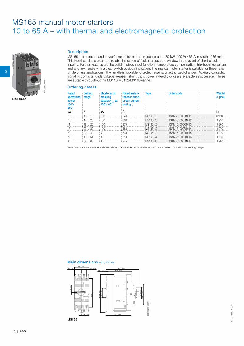
MS165 manual motor starters10 to 65 A – with thermal and electromagnetic protection
DescriptionMS165 is a compact and powerful range for motor protection up to 30 kW (400 V) / 65 A in width of 55 mm. This type has also a clear and reliable indication of fault in a separate window in the event of short-circuit tripping. Further features are the build-in disconnect function, temperature compensation, trip-free mechanism and a rotary handle with a clear switch position indication. The manual motor starter is suitable for three- and single phase applications. The handle is lockable to protect against unauthorized changes. Auxiliary contacts, signaling contacts, undervoltage releases, shunt trips, power in-feed blocks are available as accessory. These are suitable throughout the MS116/MS132/MS165-range.
Ordering details
Rated operational power400 V AC-3
Setting range
Short-circuit breakingcapacity ICS at 400 V AC
Rated instan-taneous short-circuit current setting li
Type Order code Weight(1 pce)
kW A kA A kg7.5 10 ... 16 100 240 MS165-16 1SAM451000R1011 0.9507.5 14 ... 20 100 300 MS165-20 1SAM451000R1012 0.95011 18 ... 25 100 375 MS165-25 1SAM451000R1013 0.96015 23 ... 32 100 480 MS165-32 1SAM451000R1014 0.97022 30 ... 42 50 630 MS165-42 1SAM451000R1015 0.97022 40 ... 54 30 810 MS165-54 1SAM451000R1016 0.97030 52 ... 65 30 975 MS165-65 1SAM451000R1017 0.980
Note: Manual motor starters should always be selected so that the actual motor current is within the setting range.
2CD
C24
1004
V00
15
MS165-65
Main dimensions mm, inches55
17.5 17.5 95.5
122.15.5
93.5
106
1.75
142.
65
35
76.3
544.9
2.05
2.17"0.69" 0.69"
3.76"4.81"
0.22"
3.68"
4.17
"
0.07
"
5.62
"1.
38"
3.0
1" 1.7
7"
0.08" 2CD
C24
2001
F001
4
MS165
2
2CD
C13
1101
C0
201
ABB | 19
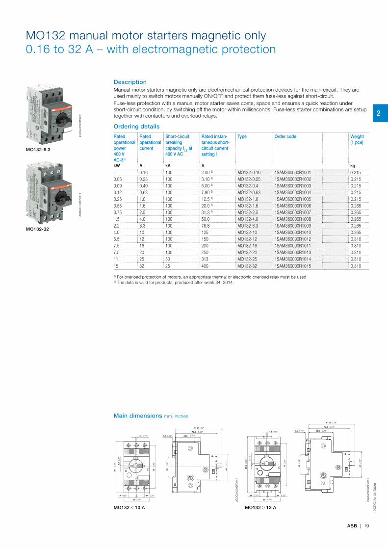
MO132 manual motor starters magnetic only0.16 to 32 A – with electromagnetic protection
DescriptionManual motor starters magnetic only are electromechanical protection devices for the main circuit. They are used mainly to switch motors manually ON/OFF and protect them fuse-less against short-circuit.Fuse-less protection with a manual motor starter saves costs, space and ensures a quick reaction under short-circuit condition, by switching off the motor within milliseconds. Fuse-less starter combinations are setup together with contactors and overload relays.
Ordering details
Rated operational power400 V AC-31)
Rated operationalcurrent
Short-circuit breaking capacity ICS at 400 V AC
Rated instan-taneous short-circuit current setting li
Type Order code Weight(1 pce)
kW A kA A kg- 0.16 100 2.00 2) MO132-0.16 1SAM360000R1001 0.2150.06 0.25 100 3.10 2) MO132-0.25 1SAM360000R1002 0.2150.09 0.40 100 5.00 2) MO132-0.4 1SAM360000R1003 0.2150.12 0.63 100 7.90 2) MO132-0.63 1SAM360000R1004 0.2150.25 1.0 100 12.5 2) MO132-1.0 1SAM360000R1005 0.2150.55 1.6 100 20.0 2) MO132-1.6 1SAM360000R1006 0.2650.75 2.5 100 31.3 2) MO132-2.5 1SAM360000R1007 0.2651.5 4.0 100 50.0 MO132-4.0 1SAM360000R1008 0.2652.2 6.3 100 78.8 MO132-6.3 1SAM360000R1009 0.2654.0 10 100 125 MO132-10 1SAM360000R1010 0.2655.5 12 100 150 MO132-12 1SAM360000R1012 0.3107.5 16 100 200 MO132-16 1SAM360000R1011 0.3107.5 20 100 250 MO132-20 1SAM360000R1013 0.31011 25 50 313 MO132-25 1SAM360000R1014 0.31015 32 25 400 MO132-32 1SAM360000R1015 0.310
1) For overload protection of motors, an appropriate thermal or electronic overload relay must be used2) The data is valid for products, produced after week 34, 2014.
MO132-6.3
2
CD
C24
1009
F001
1
MO132-32
2
CD
C24
1008
F001
1
Main dimensions mm, inches
1.3
8"
0.1
"
3.5
4"
2.9
5"
0.22" 0.06"
0.55"
1.77"
0.55"
2.85"
3.2"
1.71"
1.7
7"
35
1.7
90
75
5.51.5
14
45
14
72.4
81.25
43.5
45"
2CD
C24
2005
F001
1
0.06" 0.22" 0.22"
2.84"
3.19"
0.1"
3.85
"
1.77
"
0.55" 0.55"
1.77"
2.95
"
1.38
"
1.5 5.5 43.3
72.2
81.05
1.7
97.8
45
14 14
45
75
35
2CD
C24
2006
F001
1
MO132 ≤ 10 A MO132 ≥ 12 A
2

2CD
C13
1101
C0
201
20 | ABB
MO165 manual motor starters magnetic only16 to 65 A – with electromagnetic protection
DescriptionManual motor starters magnetic only are electromechanical protection devices for the main circuit. They are used mainly to switch motors manually ON/OFF and protect them fuse-less against short-circuit. Fuse-less protection with a manual motor starter saves costs, space and ensures a quick reaction under short-circuit condition, by switching off the motor within milliseconds. Fuse-less starter combinations are setup together with contactors and overload relays.
Ordering details
Rated operational power400 V AC-3
Rated operational current
Short-circuit breaking capacity ICS at 400 V AC
Rated instan-taneous short-circuit current setting li
Type Order code Weight(1 pce)
kW A kA A kg7.5 16 100 240 MO165-16 1SAM461000R1011 0.9507.5 20 100 300 MO165-20 1SAM461000R1012 0.95011 25 100 375 MO165-25 1SAM461000R1013 0.96015 32 100 480 MO165-32 1SAM461000R1014 0.97022 42 50 630 MO165-42 1SAM461000R1015 0.97022 54 30 810 MO165-54 1SAM461000R1016 0.97030 65 30 975 MO165-65 1SAM461000R1017 0.980
2CD
C24
1005
V00
15
MO165-65
Main dimensions mm, inches55
17.5 17.5 95.5
122.15.5
93.5
106
1.75
142.
65
35
76.3
544.9
2.05
2.17"0.69" 0.69"
3.76"4.81"
0.22"
3.68"
4.17
"
0.07
"
5.62
"1.
38"
3.0
1" 1.7
7"
0.08" 2CD
C24
2002
F001
4
MO165
2
2CD
C13
1101
C0
201
ABB | 21
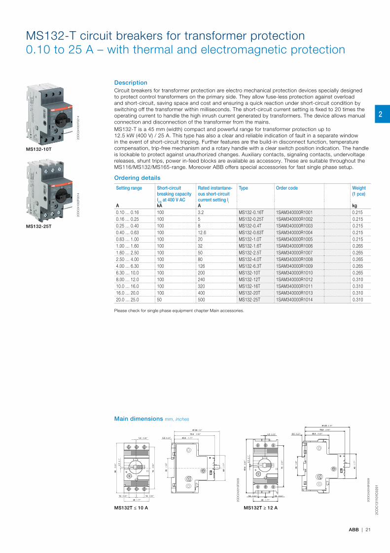
MS132-T circuit breakers for transformer protection0.10 to 25 A – with thermal and electromagnetic protection
DescriptionCircuit breakers for transformer protection are electro mechanical protection devices specially designed to protect control transformers on the primary side. They allow fuse-less protection against overload and short-circuit, saving space and cost and ensuring a quick reaction under short-circuit condition by switching off the transformer within milliseconds. The short-circuit current setting is fixed to 20 times the operating current to handle the high inrush current generated by transformers. The device allows manual connection and disconnection of the transformer from the mains. MS132-T is a 45 mm (width) compact and powerful range for transformer protection up to 12.5 kW (400 V) / 25 A. This type has also a clear and reliable indication of fault in a separate window in the event of short-circuit tripping. Further features are the build-in disconnect function, temperature compensation, trip-free mechanism and a rotary handle with a clear switch position indication. The handle is lockable to protect against unauthorized changes. Auxiliary contacts, signaling contacts, undervoltage releases, shunt trips, power in-feed blocks are available as accessory. These are suitable throughout the MS116/MS132/MS165-range. Moreover ABB offers special accessories for fast single phase setup.
Ordering details
Setting range Short-circuit breaking capacity ICS at 400 V AC
Rated instantane-ous short-circuit current setting li
Type Order code Weight(1 pce)
A kA A kg0.10 … 0.16 100 3.2 MS132-0.16T 1SAM340000R1001 0.2150.16 … 0.25 100 5 MS132-0.25T 1SAM340000R1002 0.2150.25 … 0.40 100 8 MS132-0.4T 1SAM340000R1003 0.2150.40 … 0.63 100 12.6 MS132-0.63T 1SAM340000R1004 0.2150.63 … 1.00 100 20 MS132-1.0T 1SAM340000R1005 0.2151.00 … 1.60 100 32 MS132-1.6T 1SAM340000R1006 0.2651.60 … 2.50 100 50 MS132-2.5T 1SAM340000R1007 0.2652.50 … 4.00 100 80 MS132-4.0T 1SAM340000R1008 0.2654.00 … 6.30 100 126 MS132-6.3T 1SAM340000R1009 0.2656.30 … 10.0 100 200 MS132-10T 1SAM340000R1010 0.2658.00 … 12.0 100 240 MS132-12T 1SAM340000R1012 0.31010.0 … 16.0 100 320 MS132-16T 1SAM340000R1011 0.31016.0 … 20.0 100 400 MS132-20T 1SAM340000R1013 0.31020.0 … 25.0 50 500 MS132-25T 1SAM340000R1014 0.310
Please check for single phase equipment chapter Main accessories.
2CD
C24
1001
F001
4
MS132-10T
2CD
C24
1002
F001
4
MS132-25T
Main dimensions mm, inches
1.3
8"
0.1
"
3.5
4"
2.9
5"
0.22" 0.06"
0.55"
1.77"
0.55"
2.85"
3.2"
1.71"
1.7
7"
35
1.7
90
75
5.51.5
14
45
14
72.4
81.25
43.5
45"
2CD
C24
2015
F000
9
0.06" 0.22" 0.22"
2.84"
3.19"
0.1"
3.85
"
1.77
"
0.55" 0.55"
1.77"
2.95
"
1.38
"
1.5 5.5 43.3
72.2
81.05
1.7
97.8
45
14 14
45
75
35
2CD
C24
2016
F000
9
MS132T ≤ 10 A MS132T ≥ 12 A
2
2CD
C13
1101
C0
201
22 | ABB
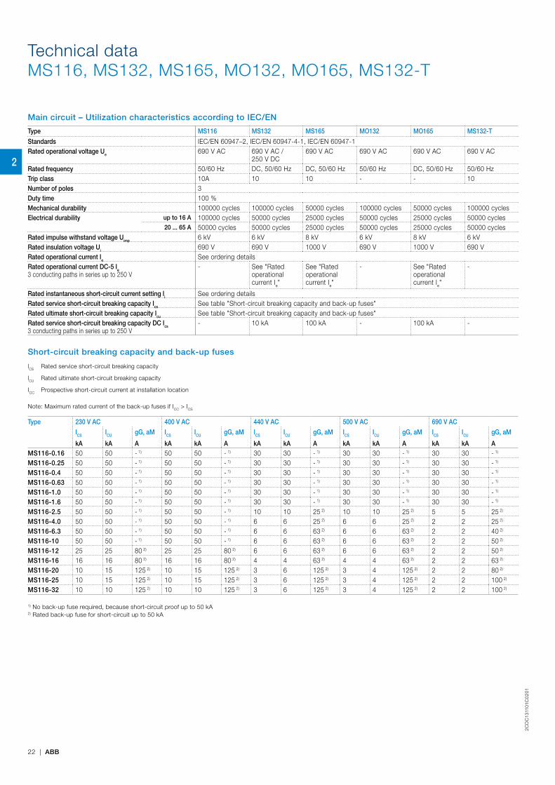
Technical dataMS116, MS132, MS165, MO132, MO165, MS132-T
Main circuit – Utilization characteristics according to IEC/EN
Type MS116 MS132 MS165 MO132 MO165 MS132-T
Standards IEC/EN 60947–2, IEC/EN 60947-4-1, IEC/EN 60947-1Rated operational voltage Ue 690 V AC 690 V AC /
250 V DC690 V AC 690 V AC 690 V AC 690 V AC
Rated frequency 50/60 Hz DC, 50/60 Hz DC, 50/60 Hz 50/60 Hz DC, 50/60 Hz 50/60 HzTrip class 10A 10 10 - - 10Number of poles 3Duty time 100 %Mechanical durability 100000 cycles 100000 cycles 50000 cycles 100000 cycles 50000 cycles 100000 cyclesElectrical durability up to 16 A 100000 cycles 50000 cycles 25000 cycles 50000 cycles 25000 cycles 50000 cycles
20 ... 65 A 50000 cycles 50000 cycles 25000 cycles 50000 cycles 25000 cycles 50000 cyclesRated impulse withstand voltage Uimp 6 kV 6 kV 8 kV 6 kV 8 kV 6 kVRated insulation voltage Ui 690 V 690 V 1000 V 690 V 1000 V 690 VRated operational current Ie See ordering detailsRated operational current DC-5 Ie3 conducting paths in series up to 250 V
- See "Rated operational current Ie"
See "Rated operational current Ie"
- See "Rated operational current Ie"
-
Rated instantaneous short-circuit current setting Ii See ordering detailsRated service short-circuit breaking capacity Ics See table "Short-circuit breaking capacity and back-up fuses"Rated ultimate short-circuit breaking capacity Icu See table "Short-circuit breaking capacity and back-up fuses"Rated service short-circuit breaking capacity DC Ics3 conducting paths in series up to 250 V
- 10 kA 100 kA - 100 kA -
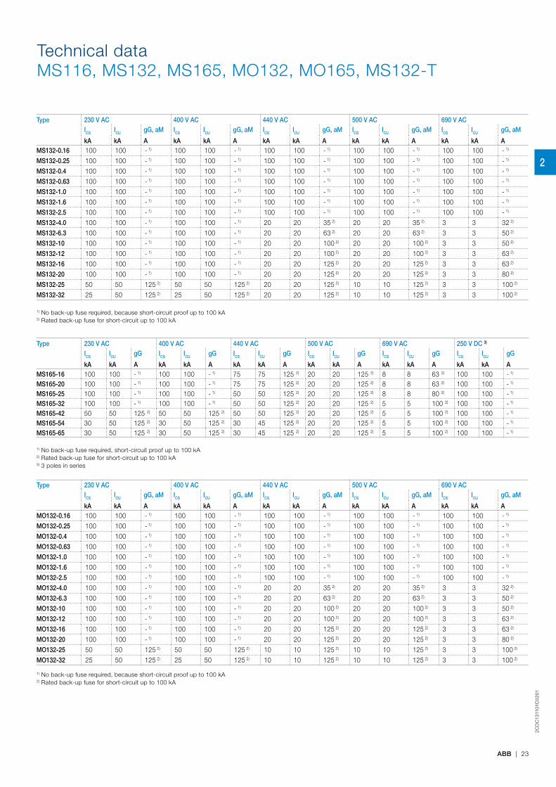
Short-circuit breaking capacity and back-up fuses
lCS Rated service short-circuit breaking capacity
lCU Rated ultimate short-circuit breaking capacity
ICC Prospective short-circuit current at installation location
Note: Maximum rated current of the back-up fuses if ICC > ICS
Type 230 V AC 400 V AC 440 V AC 500 V AC 690 V AC
ICS ICU gG, aM ICS ICU gG, aM ICS ICU gG, aM ICS ICU gG, aM ICS ICU gG, aM
kA kA A kA kA A kA kA A kA kA A kA kA AMS116-0.16 50 50 - 1) 50 50 - 1) 30 30 - 1) 30 30 - 1) 30 30 - 1)
MS116-0.25 50 50 - 1) 50 50 - 1) 30 30 - 1) 30 30 - 1) 30 30 - 1)
MS116-0.4 50 50 - 1) 50 50 - 1) 30 30 - 1) 30 30 - 1) 30 30 - 1)
MS116-0.63 50 50 - 1) 50 50 - 1) 30 30 - 1) 30 30 - 1) 30 30 - 1)
MS116-1.0 50 50 - 1) 50 50 - 1) 30 30 - 1) 30 30 - 1) 30 30 - 1)
MS116-1.6 50 50 - 1) 50 50 - 1) 30 30 - 1) 30 30 - 1) 30 30 - 1)
MS116-2.5 50 50 - 1) 50 50 - 1) 10 10 25 2) 10 10 25 2) 5 5 25 2)
MS116-4.0 50 50 - 1) 50 50 - 1) 6 6 25 2) 6 6 25 2) 2 2 25 2)
MS116-6.3 50 50 - 1) 50 50 - 1) 6 6 63 2) 6 6 63 2) 2 2 40 2)
MS116-10 50 50 - 1) 50 50 - 1) 6 6 63 2) 6 6 63 2) 2 2 50 2)
MS116-12 25 25 80 2) 25 25 80 2) 6 6 63 2) 6 6 63 2) 2 2 50 2)
MS116-16 16 16 80 2) 16 16 80 2) 4 4 63 2) 4 4 63 2) 2 2 63 2)
MS116-20 10 15 125 2) 10 15 125 2) 3 6 125 2) 3 4 125 2) 2 2 80 2)
MS116-25 10 15 125 2) 10 15 125 2) 3 6 125 2) 3 4 125 2) 2 2 100 2)
MS116-32 10 10 125 2) 10 10 125 2) 3 6 125 2) 3 4 125 2) 2 2 100 2)
1) No back-up fuse required, because short-circuit proof up to 50 kA2) Rated back-up fuse for short-circuit up to 50 kA
2
2CD
C13
1101
C0
201
ABB | 23
Technical dataMS116, MS132, MS165, MO132, MO165, MS132-T
Type 230 V AC 400 V AC 440 V AC 500 V AC 690 V ACICS ICU gG, aM ICS ICU gG, aM ICS ICU gG, aM ICS ICU gG, aM ICS ICU gG, aM
kA kA A kA kA A kA kA A kA kA A kA kA AMS132-0.16 100 100 - 1) 100 100 - 1) 100 100 - 1) 100 100 - 1) 100 100 - 1)
MS132-0.25 100 100 - 1) 100 100 - 1) 100 100 - 1) 100 100 - 1) 100 100 - 1)
MS132-0.4 100 100 - 1) 100 100 - 1) 100 100 - 1) 100 100 - 1) 100 100 - 1)
MS132-0.63 100 100 - 1) 100 100 - 1) 100 100 - 1) 100 100 - 1) 100 100 - 1)
MS132-1.0 100 100 - 1) 100 100 - 1) 100 100 - 1) 100 100 - 1) 100 100 - 1)
MS132-1.6 100 100 - 1) 100 100 - 1) 100 100 - 1) 100 100 - 1) 100 100 - 1)
MS132-2.5 100 100 - 1) 100 100 - 1) 100 100 - 1) 100 100 - 1) 100 100 - 1)
MS132-4.0 100 100 - 1) 100 100 - 1) 20 20 35 2) 20 20 35 2) 3 3 32 2)
MS132-6.3 100 100 - 1) 100 100 - 1) 20 20 63 2) 20 20 63 2) 3 3 50 2)
MS132-10 100 100 - 1) 100 100 - 1) 20 20 100 2) 20 20 100 2) 3 3 50 2)
MS132-12 100 100 - 1) 100 100 - 1) 20 20 100 2) 20 20 100 2) 3 3 63 2)
MS132-16 100 100 - 1) 100 100 - 1) 20 20 125 2) 20 20 125 2) 3 3 63 2)
MS132-20 100 100 - 1) 100 100 - 1) 20 20 125 2) 20 20 125 2) 3 3 80 2)
MS132-25 50 50 125 2) 50 50 125 2) 20 20 125 2) 10 10 125 2) 3 3 100 2)
MS132-32 25 50 125 2) 25 50 125 2) 20 20 125 2) 10 10 125 2) 3 3 100 2)
1) No back-up fuse required, because short-circuit proof up to 100 kA2) Rated back-up fuse for short-circuit up to 100 kA
Type 230 V AC 400 V AC 440 V AC 500 V AC 690 V AC 250 V DC 3)
ICS ICU gG ICS ICU gG ICS ICU gG ICS ICU gG ICS ICU gG ICS ICU gG
kA kA A kA kA A kA kA A kA kA A kA kA A kA kA AMS165-16 100 100 - 1) 100 100 - 1) 75 75 125 2) 20 20 125 2) 8 8 63 2) 100 100 - 1)
MS165-20 100 100 - 1) 100 100 - 1) 75 75 125 2) 20 20 125 2) 8 8 63 2) 100 100 - 1)
MS165-25 100 100 - 1) 100 100 - 1) 50 50 125 2) 20 20 125 2) 8 8 80 2) 100 100 - 1)
MS165-32 100 100 - 1) 100 100 - 1) 50 50 125 2) 20 20 125 2) 5 5 100 2) 100 100 - 1)
MS165-42 50 50 125 2) 50 50 125 2) 50 50 125 2) 20 20 125 2) 5 5 100 2) 100 100 - 1)
MS165-54 30 50 125 2) 30 50 125 2) 30 45 125 2) 20 20 125 2) 5 5 100 2) 100 100 - 1)
MS165-65 30 50 125 2) 30 50 125 2) 30 45 125 2) 20 20 125 2) 5 5 100 2) 100 100 - 1)
1) No back-up fuse required, short-circuit proof up to 100 kA2) Rated back-up fuse for short-circuit up to 100 kA3) 3 poles in series
Type 230 V AC 400 V AC 440 V AC 500 V AC 690 V ACICS ICU gG, aM ICS ICU gG, aM ICS ICU gG, aM ICS ICU gG, aM ICS ICU gG, aM
kA kA A kA kA A kA kA A kA kA A kA kA AMO132-0.16 100 100 - 1) 100 100 - 1) 100 100 - 1) 100 100 - 1) 100 100 - 1)
MO132-0.25 100 100 - 1) 100 100 - 1) 100 100 - 1) 100 100 - 1) 100 100 - 1)
MO132-0.4 100 100 - 1) 100 100 - 1) 100 100 - 1) 100 100 - 1) 100 100 - 1)
MO132-0.63 100 100 - 1) 100 100 - 1) 100 100 - 1) 100 100 - 1) 100 100 - 1)
MO132-1.0 100 100 - 1) 100 100 - 1) 100 100 - 1) 100 100 - 1) 100 100 - 1)
MO132-1.6 100 100 - 1) 100 100 - 1) 100 100 - 1) 100 100 - 1) 100 100 - 1)
MO132-2.5 100 100 - 1) 100 100 - 1) 100 100 - 1) 100 100 - 1) 100 100 - 1)
MO132-4.0 100 100 - 1) 100 100 - 1) 20 20 35 2) 20 20 35 2) 3 3 32 2)
MO132-6.3 100 100 - 1) 100 100 - 1) 20 20 63 2) 20 20 63 2) 3 3 50 2)
MO132-10 100 100 - 1) 100 100 - 1) 20 20 100 2) 20 20 100 2) 3 3 50 2)
MO132-12 100 100 - 1) 100 100 - 1) 20 20 100 2) 20 20 100 2) 3 3 63 2)
MO132-16 100 100 - 1) 100 100 - 1) 20 20 125 2) 20 20 125 2) 3 3 63 2)
MO132-20 100 100 - 1) 100 100 - 1) 20 20 125 2) 20 20 125 2) 3 3 80 2)
MO132-25 50 50 125 2) 50 50 125 2) 10 10 125 2) 10 10 125 2) 3 3 100 2)
MO132-32 25 50 125 2) 25 50 125 2) 10 10 125 2) 10 10 125 2) 3 3 100 2)
1) No back-up fuse required, because short-circuit proof up to 100 kA2) Rated back-up fuse for short-circuit up to 100 kA
2

2CD
C13
1101
C0
201
24 | ABB
Technical dataMS116, MS132, MS165, MO132, MO165, MS132-T
Type 230 V AC 400 V AC 440 V AC 500 V AC 690 V AC 250 V DC 3)
ICS ICU gG ICS ICU gG ICS ICU gG ICS ICU gG ICS ICU gG ICS ICU gG
kA kA A kA kA A kA kA A kA kA A kA kA A kA kA AMO165-16 100 100 - 1) 100 100 - 1) 75 75 125 2) 20 20 125 2) 8 8 63 2) 100 100 - 1)
MO165-20 100 100 - 1) 100 100 - 1) 75 75 125 2) 20 20 125 2) 8 8 63 2) 100 100 - 1)
MO165-25 100 100 - 1) 100 100 - 1) 50 50 125 2) 20 20 125 2) 8 8 80 2) 100 100 - 1)
MO165-32 100 100 - 1) 100 100 - 1) 50 50 125 2) 20 20 125 2) 5 5 100 2) 100 100 - 1)
MO165-42 50 50 125 2) 50 50 125 2) 50 50 125 2) 20 20 125 2) 5 5 100 2) 100 100 - 1)
MO165-54 30 50 125 2) 30 50 125 2) 30 45 125 2) 20 20 125 2) 5 5 100 2) 100 100 - 1)
MO165-65 30 50 125 2) 30 50 125 2) 30 45 125 2) 20 20 125 2) 5 5 100 2) 100 100 - 1)
1) No back-up fuse required, short-circuit proof up to 100 kA2) Rated back-up fuse for short-circuit up to 100 kA3) 3 poles in series
Type 230 V AC 400 V AC 440 V AC 500 V AC 690 V ACICS ICU gG, aM ICS ICU gG, aM ICS ICU gG, aM ICS ICU gG, aM ICS ICU gG, aM
kA kA A kA kA A kA kA A kA kA A kA kA AMS132-0.16T 100 100 - 1) 100 100 - 1) 100 100 - 1) 100 100 - 1) 100 100 - 1)
MS132-0.25T 100 100 - 1) 100 100 - 1) 100 100 - 1) 100 100 - 1) 100 100 - 1)
MS132-0.4T 100 100 - 1) 100 100 - 1) 100 100 - 1) 100 100 - 1) 100 100 - 1)
MS132-0.63T 100 100 - 1) 100 100 - 1) 100 100 - 1) 100 100 - 1) 100 100 - 1)
MS132-1.0T 100 100 - 1) 100 100 - 1) 100 100 - 1) 100 100 - 1) 100 100 - 1)
MS132-1.6T 100 100 - 1) 100 100 - 1) 100 100 - 1) 100 100 - 1) 100 100 - 1)
MS132-2.5T 100 100 - 1) 100 100 - 1) 100 100 - 1) 100 100 - 1) 100 100 - 1)
MS132-4.0T 100 100 - 1) 100 100 - 1) 30 30 35 2) 20 20 35 2) 3 3 32 2)
MS132-6.3T 100 100 - 1) 100 100 - 1) 30 30 63 2) 20 20 63 2) 3 3 50 2)
MS132-10T 100 100 - 1) 100 100 - 1) 30 30 100 2) 20 20 100 2) 3 3 50 2)
MS132-12T 100 100 - 1) 100 100 - 1) 30 30 100 2) 20 20 100 2) 3 3 63 2)
MS132-16T 100 100 - 1) 100 100 - 1) 30 30 125 2) 20 20 125 2) 3 3 63 2)
MS132-20T 100 100 - 1) 100 100 - 1) 30 30 125 2) 20 20 125 2) 3 3 80 2)
MS132-25T 50 50 125 2) 50 50 125 2) 30 30 125 2) 10 10 125 2) 3 3 100 2)
1) No back-up fuse required, short-circuit proof up to 100 kA2) Rated back-up fuse for short-circuit up to 100 kA
Main circuit – Utilization characteristics according to UL/CSA
Type MS116 MS132 MS165 MO132 MO165 MS132-TStandards UL 60947-1, UL 60947-4-1 (UL 508), CSA C22.2 No.60947-4-1 (CSA C22.2
No.14)-
Rated operational voltage Ue acc. to UL/CSA 600 V AC 600 V AC 1000 V AC 600 V AC 1000 V AC -Trip class 10A 10 - -Motor ratings1) Horsepower See table "Motor ratings, three phase" -
Full Load Amps (FLA) See table "Motor ratings, three phase" -Locked Rotor Amps (LRA) See table "Motor ratings, three phase" -
1) See product data sheets for UL/CSA single phase motor and general use (AC-1) ratings.
UL/CSA ratings overview
Type MS116 MS132 MS165 MO132 MO165 MS132-TManual Motor Controller x x x x x -Manual Motor Controller, Suitable as Motor Disconnect x x x x x -Manual Motor Controller, Suitable for use in Group Installations x x x x x -Manual Motor Controller, Suitable for Tap Conductor Protection in Group Installations
- x x x x -
Manual self-protected Combination Motor Controller (Type E) - x x - - -
kA
2
2CD
C13
1101
C0
201
ABB | 25
Technical dataMS116, MS132, MS165, MO132, MO165, MS132-T
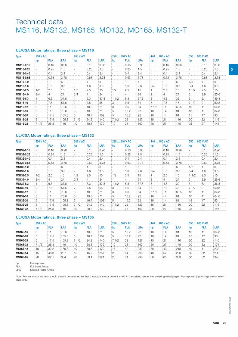
UL/CSA Motor ratings, three phase – MS116
Type 200 V AC 208 V AC 220 … 240 V AC 440 … 480 V AC 550 … 600 V AChp FLA LRA hp FLA LRA hp FLA LRA hp FLA LRA hp FLA LRA
MS116-0.16 - 0.16 0.96 - 0.16 0.96 - 0.16 0.96 - 0.16 0.96 - 0.16 0.96MS116-0.25 - 0.25 1.5 - 0.25 1.5 - 0.25 1.5 - 0.25 1.5 - 0.25 1.5MS116-0.40 - 0.4 2.4 - 0.4 2.4 - 0.4 2.4 - 0.4 2.4 - 0.4 2.4MS116-0.63 - 0.63 3.78 - 0.63 3.78 - 0.63 3.78 - 0.63 3.78 - 0.63 3.78MS116-1.0 - 1 6 - 1 6 - 1 6 - 1 6 1/2 1 6MS116-1.6 - 1.6 9.6 - 1.6 9.6 - 1.6 9.6 3/4 1.6 9.6 3/4 1.6 9.6MS116-2.5 1/2 2.5 15 1/2 2.5 15 1/2 2.5 15 1 2.5 15 1 1/2 2.5 15MS116-4.0 3/4 4 24 3/4 4 24 1 4 24 2 4 24 3 3.9 25.6MS116-6.3 1 6.3 37.8 1 6.3 37.8 1 1/2 6.3 37.8 3 4.8 32 5 6.1 36.8MS116-10 2 7.8 57.5 2 7.5 55 3 9.6 64 5 7.6 46 7 1/2 9 50.8MS116-12 3 11 73.6 3 10.6 71 3 9.6 64 7 1/2 11 63.5 10 11 64.8MS116-16 3 11 73.6 3 10.6 71 5 15.2 92 10 14 81 10 11 64.8MS116-20 5 17.5 105.8 5 16.7 102 5 15.2 92 10 14 81 15 17 93MS116-25 5 17.5 105.8 7 1/2 24.2 140 7 1/2 22 127 15 21 116 20 22 116MS116-32 7 1/2 25.3 146 10 30.8 179 10 28 162 20 27 145 25 27 146
UL/CSA Motor ratings, three phase – MS132
Type 200 V AC 208 V AC 220 … 240 V AC 440 … 480 V AC 550 … 600 V AChp FLA LRA hp FLA LRA hp FLA LRA hp FLA LRA hp FLA LRA
MS132-0.16 - 0.16 0.96 - 0.16 0.96 - 0.16 0.96 - 0.16 0.96 - 0.16 0.96MS132-0.25 - 0.25 1.5 - 0.25 1.5 - 0.25 1.5 - 0.25 1.5 - 0.25 1.5MS132-0.40 - 0.4 2.4 - 0.4 2.4 - 0.4 2.4 - 0.4 2.4 - 0.4 2.4MS132-0.63 - 0.63 3.78 - 0.63 3.78 - 0.63 3.78 - 0.63 3.78 - 0.63 3.78MS132-1.0 - 1 6 - 1 6 - 1 6 - 1 6 1/2 1 6MS132-1.6 - 1.6 9.6 - 1.6 9.6 - 1.6 9.6 3/4 1.6 9.6 3/4 1.6 9.6MS132-2.5 1/2 2.5 15 1/2 2.5 15 1/2 2.5 15 1 2.5 15 1-1/2 2.5 15MS132-4.0 3/4 4 24 3/4 4 24 1 4 24 2 4 24 3 3.9 25.6MS132-6.3 1 6.3 37.8 1 6.3 37.8 1 1/2 6.3 37.8 3 4.8 32 5 6.1 36.8MS132-10 2 7.8 57.5 2 7.5 55 3 9.6 64 5 7.6 46 7 1/2 9 50.8MS132-12 3 11 73.6 3 10.6 71 3 9.6 64 7 1/2 11 63.5 10 11 64.8MS132-16 3 11 73.6 3 10.6 71 5 15.2 92 10 14 81 10 11 64.8MS132-20 5 17.5 105.8 5 16.7 102 5 15.2 92 10 14 81 15 17 93MS132-25 5 17.5 105.8 7 1/2 24.2 140 7 1/2 22 127 15 21 116 20 22 116MS132-32 7 1/2 25.3 146 10 30.8 179 10 28 162 20 27 145 25 27 146
UL/CSA Motor ratings, three phase – MS165
Type 200 V AC 208 V AC 220 … 240 V AC 440 … 480 V AC 550 … 600 V AChp FLA LRA hp FLA LRA hp FLA LRA hp FLA LRA hp FLA LRA
MS165-16 3 11 73.6 3 10.6 71 5 15.2 92 10 14 81 10 11 64.8MS165-20 5 17.5 105.8 5 16.7 102 5 15.2 92 10 14 81 15 17 93MS165-25 5 17.5 105.8 7 1/2 24.2 140 7 1/2 22 127 15 21 116 20 22 116MS165-32 7 1/2 25.3 146 10 30.8 179 10 28 162 20 27 145 30 32 174MS165-42 10 32.2 186.3 10 30.8 179 15 42 232 30 40 218 40 41 232MS165-54 15 48.3 267 15 46.2 257 20 54 290 40 52 290 50 52 290MS165-65 20 62.1 334 20 59.4 321 20 54 290 50 65 363 60 62 348
hp HorsepowerFLA Full Load AmpsLRA Locked Rotor Amps
Note: Manual motor starters should always be selected so that the actual motor current is within the setting range; see ordering detail pages. Horsepower (hp) ratings are for refer-ence only.
2
2CD
C13
1101
C0
201
26 | ABB
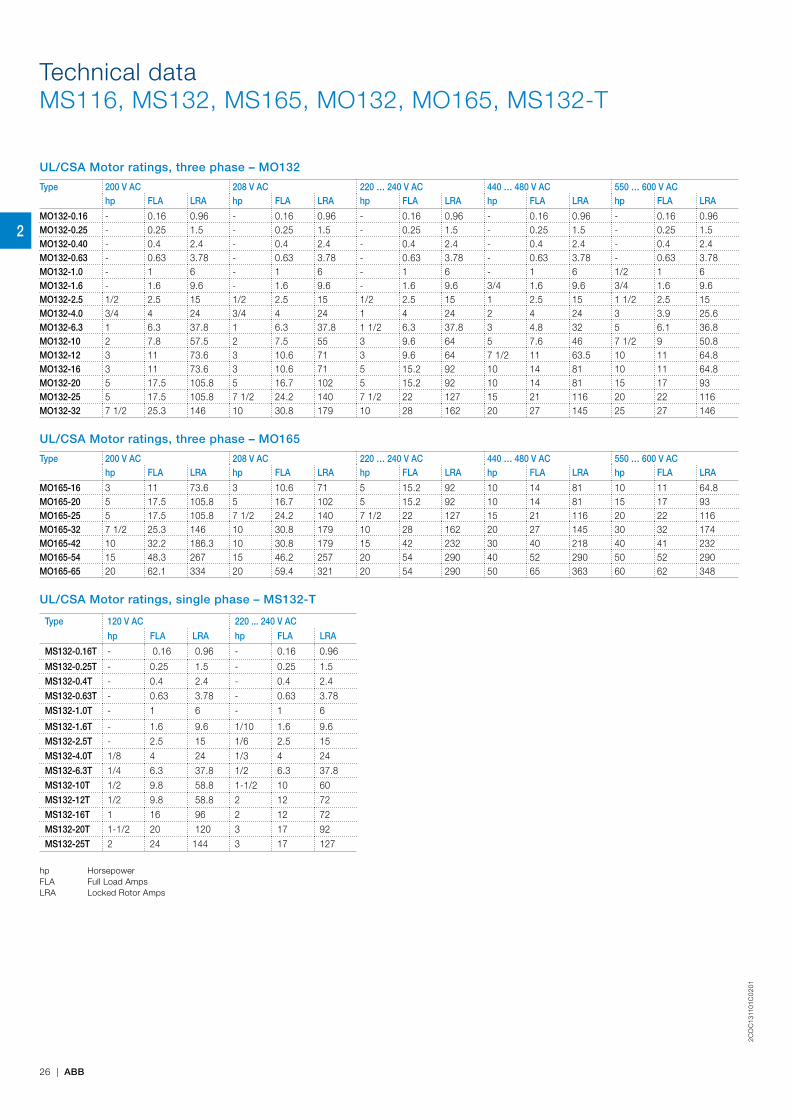
UL/CSA Motor ratings, three phase – MO132
Type 200 V AC 208 V AC 220 … 240 V AC 440 … 480 V AC 550 … 600 V AChp FLA LRA hp FLA LRA hp FLA LRA hp FLA LRA hp FLA LRA
MO132-0.16 - 0.16 0.96 - 0.16 0.96 - 0.16 0.96 - 0.16 0.96 - 0.16 0.96MO132-0.25 - 0.25 1.5 - 0.25 1.5 - 0.25 1.5 - 0.25 1.5 - 0.25 1.5MO132-0.40 - 0.4 2.4 - 0.4 2.4 - 0.4 2.4 - 0.4 2.4 - 0.4 2.4MO132-0.63 - 0.63 3.78 - 0.63 3.78 - 0.63 3.78 - 0.63 3.78 - 0.63 3.78MO132-1.0 - 1 6 - 1 6 - 1 6 - 1 6 1/2 1 6MO132-1.6 - 1.6 9.6 - 1.6 9.6 - 1.6 9.6 3/4 1.6 9.6 3/4 1.6 9.6MO132-2.5 1/2 2.5 15 1/2 2.5 15 1/2 2.5 15 1 2.5 15 1 1/2 2.5 15MO132-4.0 3/4 4 24 3/4 4 24 1 4 24 2 4 24 3 3.9 25.6MO132-6.3 1 6.3 37.8 1 6.3 37.8 1 1/2 6.3 37.8 3 4.8 32 5 6.1 36.8MO132-10 2 7.8 57.5 2 7.5 55 3 9.6 64 5 7.6 46 7 1/2 9 50.8MO132-12 3 11 73.6 3 10.6 71 3 9.6 64 7 1/2 11 63.5 10 11 64.8MO132-16 3 11 73.6 3 10.6 71 5 15.2 92 10 14 81 10 11 64.8MO132-20 5 17.5 105.8 5 16.7 102 5 15.2 92 10 14 81 15 17 93MO132-25 5 17.5 105.8 7 1/2 24.2 140 7 1/2 22 127 15 21 116 20 22 116MO132-32 7 1/2 25.3 146 10 30.8 179 10 28 162 20 27 145 25 27 146
UL/CSA Motor ratings, three phase – MO165
Type 200 V AC 208 V AC 220 … 240 V AC 440 … 480 V AC 550 … 600 V AChp FLA LRA hp FLA LRA hp FLA LRA hp FLA LRA hp FLA LRA
MO165-16 3 11 73.6 3 10.6 71 5 15.2 92 10 14 81 10 11 64.8MO165-20 5 17.5 105.8 5 16.7 102 5 15.2 92 10 14 81 15 17 93MO165-25 5 17.5 105.8 7 1/2 24.2 140 7 1/2 22 127 15 21 116 20 22 116MO165-32 7 1/2 25.3 146 10 30.8 179 10 28 162 20 27 145 30 32 174MO165-42 10 32.2 186.3 10 30.8 179 15 42 232 30 40 218 40 41 232MO165-54 15 48.3 267 15 46.2 257 20 54 290 40 52 290 50 52 290MO165-65 20 62.1 334 20 59.4 321 20 54 290 50 65 363 60 62 348
UL/CSA Motor ratings, single phase – MS132-T
Type 120 V AC 220 ... 240 V AC
hp FLA LRA hp FLA LRA
MS132-0.16T - 0.16 0.96 - 0.16 0.96
MS132-0.25T - 0.25 1.5 - 0.25 1.5 MS132-0.4T - 0.4 2.4 - 0.4 2.4 MS132-0.63T - 0.63 3.78 - 0.63 3.78 MS132-1.0T - 1 6 - 1 6
MS132-1.6T - 1.6 9.6 1/10 1.6 9.6 MS132-2.5T - 2.5 15 1/6 2.5 15 MS132-4.0T 1/8 4 24 1/3 4 24 MS132-6.3T 1/4 6.3 37.8 1/2 6.3 37.8 MS132-10T 1/2 9.8 58.8 1-1/2 10 60 MS132-12T 1/2 9.8 58.8 2 12 72 MS132-16T 1 16 96 2 12 72 MS132-20T 1-1/2 20 120 3 17 92 MS132-25T 2 24 144 3 17 127
hp HorsepowerFLA Full Load AmpsLRA Locked Rotor Amps
Technical dataMS116, MS132, MS165, MO132, MO165, MS132-T
2
2CD
C13
1101
C0
201
ABB | 27
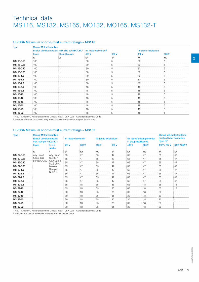
UL/CSA Maximum short-circuit current ratings – MS116
Type Manual Motor ControllersBranch circuit protection, max. size per NEC/CEC1) for motor disconnect2) for group installationsFuses Circuit breaker 480 V 600 V 480 V 600 VA A kA kA kA kA
MS116-0.16 100 - 30 5 30 5MS116-0.25 100 - 30 5 30 5MS116-0.40 100 - 30 5 30 5MS116-0.63 100 - 30 5 30 5MS116-1.0 100 - 30 5 30 5MS116-1.6 100 - 30 5 30 5MS116-2.5 100 - 30 5 30 5MS116-4.0 100 - 18 5 18 5MS116-6.3 100 - 18 5 18 5MS116-10 100 - 18 5 18 5MS116-12 100 - 18 5 18 5MS116-16 100 - 18 5 18 5MS116-20 100 - 18 5 18 5MS116-25 100 - 18 5 18 5MS116-32 100 - 18 5 18 51) NEC: NFPA®70 National Electrical Code®; CEC: CSA C22.1 Canadian Electrical Code.2) Suitable as motor disconnect only when provide with padlock adaptor SA1 or SA3.
UL/CSA Maximum short-circuit current ratings – MS132
Type Manual Motor Controllers Manual self-protected Com-bination Motor Controllers (Type E)2)
Branch circuit protection, max. size per NEC/CEC1)
for motor disconnect for group installations for tap conductor protection in group installations
Fuses Circuit breaker
480 V 600 V 480 V 600 V 480 V 600 V 480Y / 277 V 600Y / 347 V
A A kA kA kA kA kA kA kA kAMS132-0.16 Any Listed
fuses. Size per NEC/CEC
Any Listed UL489 / CSA C22.2 No.5 circuit breaker. Size per NEC/CEC
65 47 65 47 65 47 65 47MS132-0.25 65 47 65 47 65 47 65 47MS132-0.40 65 47 65 47 65 47 65 47MS132-0.63 65 47 65 47 65 47 65 47MS132-1.0 65 47 65 47 65 47 65 47MS132-1.6 65 47 65 47 65 47 65 47MS132-2.5 65 47 65 47 65 47 65 47MS132-4.0 65 47 65 47 65 47 65 47MS132-6.3 65 18 65 35 65 18 65 18MS132-10 65 18 65 35 65 18 65 18MS132-12 30 18 35 35 30 18 30 -MS132-16 30 18 35 35 30 18 30 -MS132-20 30 18 35 35 30 18 30 -MS132-25 30 18 35 35 30 18 30 -MS132-32 30 18 35 35 30 18 30 -1) NEC: NFPA®70 National Electrical Code®; CEC: CSA C22.1 Canadian Electrical Code.2) Requires the use of S1-M3-xx line-side terminal feeder block.
Technical dataMS116, MS132, MS165, MO132, MO165, MS132-T
2

2CD
C13
1101
C0
201
28 | ABB
UL/CSA Maximum short-circuit current ratings – MS165
Type Manual Motor Controllers Manual self-protected Com-bination Motor Controllers (Type E)
Branch circuit protection, max. size per NEC/CEC1)
for motor disconnect for group installations for tap conductor protection in group installations
Fuses Circuit breaker
480 V 600 V 480 V 600 V 480 V 600 V 480Y / 277 V 600Y / 347 V
A A kA kA kA kA kA kA kA kAMS165-16 Any Listed
fuses. Size per NEC/CEC
Any Listed UL489 / CSA C22.2 No.5 circuit breaker. Size per NEC/CEC
65 30 65 30 65 30 65 30MS165-20 65 30 65 30 65 30 65 30MS165-25 65 30 65 30 65 30 65 30MS165-32 65 30 65 30 65 30 65 30MS165-42 65 30 65 30 65 30 65 -MS165-54 65 30 65 30 65 30 65 -MS165-65 65 30 65 30 65 30 65 -1) NEC: NFPA®70 National Electrical Code®; CEC: CSA C22.1 Canadian Electrical Code.
UL/CSA Maximum short-circuit current ratings – MO132
Type Manual Motor ControllersBranch circuit protection, max. size per NEC/CEC1)
for motor disconnect for group installations for tap conductor protection in group installations
Fuses Circuit breaker 480 V 600 V 480 V 600 V 480 V 600 VA A kA kA kA kA kA kA
MS132-0.16 Any Listed fuses. Size per NEC/CEC
Any Listed UL489 / CSA C22.2 No.5 circuit breaker. Size per NEC/CEC
65 47 65 47 65 47MS132-0.25 65 47 65 47 65 47MS132-0.40 65 47 65 47 65 47MS132-0.63 65 47 65 47 65 47MS132-1.0 65 47 65 47 65 47MS132-1.6 65 47 65 47 65 47MS132-2.5 65 47 65 47 65 47MS132-4.0 65 47 65 47 65 47MS132-6.3 65 18 65 35 65 18MS132-10 65 18 65 35 65 18MS132-12 30 18 35 35 30 18MS132-16 30 18 35 35 30 18MS132-20 30 18 35 35 30 18MS132-25 30 18 35 35 30 18MS132-32 30 18 35 35 30 181) NEC: NFPA®70 National Electrical Code®; CEC: CSA C22.1 Canadian Electrical Code.
UL/CSA Maximum short-circuit current ratings – MO165
Type Manual Motor ControllersBranch circuit protection, max. size per NEC/CEC1)
for motor disconnect for group installations for tap conductor protection in group installations
Fuses Circuit breaker 480 V 600 V 480 V 600 V 480 V 600 V
A A kA kA kA kA kA kAMO165-16 Any Listed fuses.
Size per NEC/CEC
Any Listed UL489 / CSA C22.2 No.5 circuit breaker. Size per NEC/CEC
65 30 65 30 65 30MO165-20 65 30 65 30 65 30MO165-25 65 30 65 30 65 30MO165-32 65 30 65 30 65 30MO165-42 65 30 65 30 65 30MO165-54 65 30 65 30 65 30MO165-65 65 30 65 30 65 301) NEC: NFPA®70 National Electrical Code®; CEC: CSA C22.1 Canadian Electrical Code.
Technical dataMS116, MS132, MS165, MO132, MO165, MS132-T
2
2CD
C13
1101
C0
201
ABB | 29
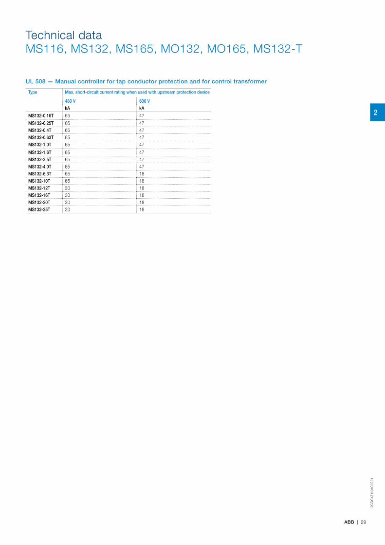
UL 508 — Manual controller for tap conductor protection and for control transformer
Type Max. short-circuit current rating when used with upstream protection device
480 V 600 V
kA kA
MS132-0.16T 65 47
MS132-0.25T 65 47MS132-0.4T 65 47MS132-0.63T 65 47MS132-1.0T 65 47
MS132-1.6T 65 47MS132-2.5T 65 47MS132-4.0T 65 47MS132-6.3T 65 18MS132-10T 65 18MS132-12T 30 18MS132-16T 30 18MS132-20T 30 18MS132-25T 30 18
Technical dataMS116, MS132, MS165, MO132, MO165, MS132-T
2
2CD
C13
1101
C0
201
30 | ABB
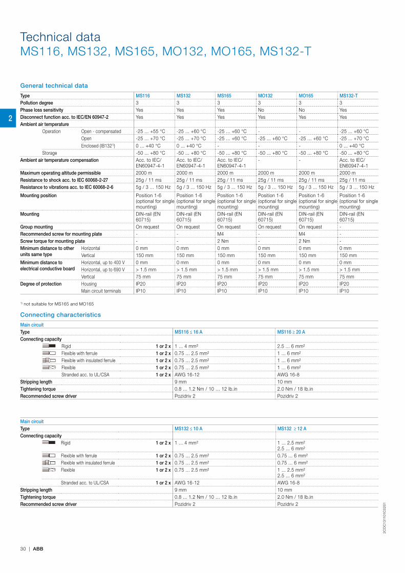
General technical data
Type MS116 MS132 MS165 MO132 MO165 MS132-TPollution degree 3 3 3 3 3 3Phase loss sensitivity Yes Yes Yes No No YesDisconnect function acc. to IEC/EN 60947-2 Yes Yes Yes Yes Yes YesAmbient air temperature
Operation Open - compensated -25 ... +55 °C -25 ... +60 °C -25 ... +60 °C - - -25 ... +60 °COpen -25 ... +70 °C -25 ... +70 °C -25 ... +60 °C -25 ... +60 °C -25 ... +60 °C -25 ... +70 °CEnclosed (IB1321)) 0 ... +40 °C 0 ... +40 °C - - - 0 ... +40 °C
Storage -50 ... +80 °C -50 ... +80 °C -50 ... +80 °C -50 ... +80 °C -50 ... +80 °C -50 ... +80 °CAmbient air temperature compensation Acc. to IEC/
EN60947-4-1Acc. to IEC/EN60947-4-1
Acc. to IEC/EN60947-4-1
- - Acc. to IEC/EN60947-4-1
Maximum operating altitude permissible 2000 m 2000 m 2000 m 2000 m 2000 m 2000 mResistance to shock acc. to IEC 60068-2-27 25g / 11 ms 25g / 11 ms 25g / 11 ms 25g / 11 ms 25g / 11 ms 25g / 11 msResistance to vibrations acc. to IEC 60068-2-6 5g / 3 ... 150 Hz 5g / 3 ... 150 Hz 5g / 3 ... 150 Hz 5g / 3 ... 150 Hz 5g / 3 ... 150 Hz 5g / 3 ... 150 Hz
Mounting position Position 1-6 (optional for single mounting)
Position 1-6 (optional for single mounting)
Position 1-6 (optional for single mounting)
Position 1-6 (optional for single mounting)
Position 1-6 (optional for single mounting)
Position 1-6 (optional for single mounting)
Mounting DIN-rail (EN 60715)
DIN-rail (EN 60715)
DIN-rail (EN 60715)
DIN-rail (EN 60715)
DIN-rail (EN 60715)
DIN-rail (EN 60715)
Group mounting On request On request On request On request On request -Recommended screw for mounting plate - - M4 - M4 -Screw torque for mounting plate - - 2 Nm - 2 Nm -Minimum distance to other units same type
Horizontal 0 mm 0 mm 0 mm 0 mm 0 mm 0 mmVertical 150 mm 150 mm 150 mm 150 mm 150 mm 150 mm
Minimum distance to electrical conductive board
Horizontal, up to 400 V 0 mm 0 mm 0 mm 0 mm 0 mm 0 mmHorizontal, up to 690 V > 1.5 mm > 1.5 mm > 1.5 mm > 1.5 mm > 1.5 mm > 1.5 mmVertical 75 mm 75 mm 75 mm 75 mm 75 mm 75 mm
Degree of protection Housing IP20 IP20 IP20 IP20 IP20 IP20Main circuit terminals IP10 IP10 IP10 IP10 IP10 IP10
1) not suitable for MS165 and MO165
Connecting characteristics
Main circuitType MS116 ≤ 16 A MS116 ≥ 20 AConnecting capacity
Rigid 1 or 2 x 1 ... 4 mm² 2.5 ... 6 mm²Flexible with ferrule 1 or 2 x 0.75 ... 2.5 mm² 1 ... 6 mm²Flexible with insulated ferrule 1 or 2 x 0.75 ... 2.5 mm² 1 ... 6 mm²Flexible 1 or 2 x 0.75 ... 2.5 mm² 1 ... 6 mm²Stranded acc. to UL/CSA 1 or 2 x AWG 16-12 AWG 16-8
Stripping length 9 mm 10 mmTightening torque 0.8 ... 1.2 Nm / 10 … 12 Ib.in 2.0 Nm / 18 Ib.inRecommended screw driver Pozidriv 2 Pozidriv 2
Main circuitType MS132 ≤ 10 A MS132 ≥ 12 AConnecting capacity
Rigid 1 or 2 x 1 ... 4 mm² 1 ... 2.5 mm²2.5 ... 6 mm²
Flexible with ferrule 1 or 2 x 0.75 ... 2.5 mm² 0.75 ... 6 mm²Flexible with insulated ferrule 1 or 2 x 0.75 ... 2.5 mm² 0.75 ... 6 mm²Flexible 1 or 2 x 0.75 ... 2.5 mm² 1 ... 2.5 mm²
2.5 ... 6 mm²Stranded acc. to UL/CSA 1 or 2 x AWG 16-12 AWG 16-8
Stripping length 9 mm 10 mmTightening torque 0.8 ... 1.2 Nm / 10 … 12 Ib.in 2.0 Nm / 18 Ib.inRecommended screw driver Pozidriv 2 Pozidriv 2
Technical dataMS116, MS132, MS165, MO132, MO165, MS132-T
2
2CD
C13
1101
C0
201
ABB | 31
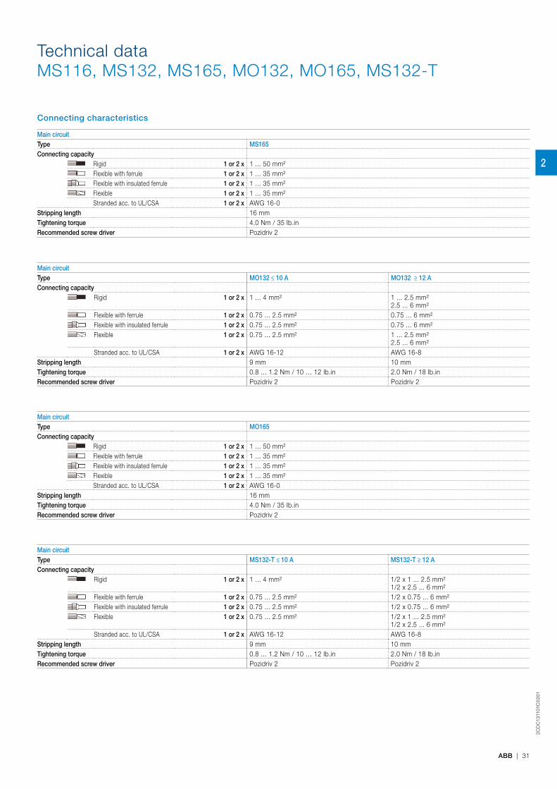
Connecting characteristics
Main circuitType MS165Connecting capacity
Rigid 1 or 2 x 1 ... 50 mm²Flexible with ferrule 1 or 2 x 1 ... 35 mm²Flexible with insulated ferrule 1 or 2 x 1 ... 35 mm²Flexible 1 or 2 x 1 ... 35 mm²Stranded acc. to UL/CSA 1 or 2 x AWG 16-0
Stripping length 16 mmTightening torque 4.0 Nm / 35 Ib.inRecommended screw driver Pozidriv 2
Main circuitType MO132 ≤ 10 A MO132 ≥ 12 AConnecting capacity
Rigid 1 or 2 x 1 ... 4 mm² 1 ... 2.5 mm²2.5 ... 6 mm²
Flexible with ferrule 1 or 2 x 0.75 ... 2.5 mm² 0.75 ... 6 mm²Flexible with insulated ferrule 1 or 2 x 0.75 ... 2.5 mm² 0.75 ... 6 mm²Flexible 1 or 2 x 0.75 ... 2.5 mm² 1 ... 2.5 mm²
2.5 ... 6 mm²Stranded acc. to UL/CSA 1 or 2 x AWG 16-12 AWG 16-8
Stripping length 9 mm 10 mmTightening torque 0.8 ... 1.2 Nm / 10 … 12 Ib.in 2.0 Nm / 18 Ib.inRecommended screw driver Pozidriv 2 Pozidriv 2
Main circuitType MO165Connecting capacity
Rigid 1 or 2 x 1 ... 50 mm²Flexible with ferrule 1 or 2 x 1 ... 35 mm²Flexible with insulated ferrule 1 or 2 x 1 ... 35 mm²Flexible 1 or 2 x 1 ... 35 mm²Stranded acc. to UL/CSA 1 or 2 x AWG 16-0
Stripping length 16 mmTightening torque 4.0 Nm / 35 Ib.inRecommended screw driver Pozidriv 2
Main circuitType MS132-T ≤ 10 A MS132-T ≥ 12 AConnecting capacity
Rigid 1 or 2 x 1 ... 4 mm² 1/2 x 1 ... 2.5 mm²1/2 x 2.5 ... 6 mm²
Flexible with ferrule 1 or 2 x 0.75 ... 2.5 mm² 1/2 x 0.75 ... 6 mm²Flexible with insulated ferrule 1 or 2 x 0.75 ... 2.5 mm² 1/2 x 0.75 ... 6 mm²Flexible 1 or 2 x 0.75 ... 2.5 mm² 1/2 x 1 ... 2.5 mm²
1/2 x 2.5 ... 6 mm²Stranded acc. to UL/CSA 1 or 2 x AWG 16-12 AWG 16-8
Stripping length 9 mm 10 mmTightening torque 0.8 ... 1.2 Nm / 10 … 12 Ib.in 2.0 Nm / 18 Ib.inRecommended screw driver Pozidriv 2 Pozidriv 2
Technical dataMS116, MS132, MS165, MO132, MO165, MS132-T
2
2CD
C13
105
0C
02
01
32 | ABB
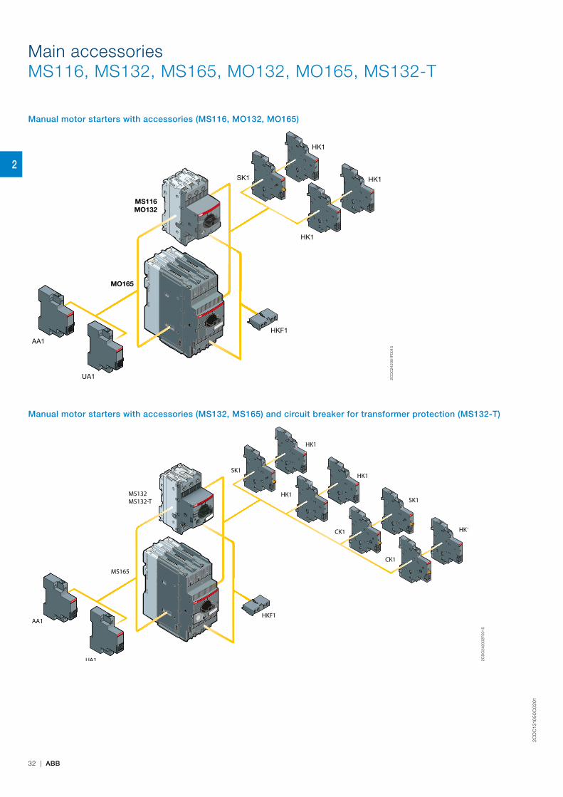
Main accessoriesMS116, MS132, MS165, MO132, MO165, MS132-T
Manual motor starters with accessories (MS116, MO132, MO165)
AA1
UA1
SK1
HK1
HK1
HK1
MO165
MO132MS116
HKF1
2CD
C24
2001
F001
5
Manual motor starters with accessories (MS132, MS165) and circuit breaker for transformer protection (MS132-T)
HK1
SK1
HK1
HK1
HK1CK1
CK1
SK1MS132MS132-T
AA1
UA1
MS165
HKF1
2CD
C24
2002
F001
5
2
2CD
C13
105
0C
02
01
ABB | 33
Main accessoriesMS116, MS132, MS165, MO132, MO165, MS132-T
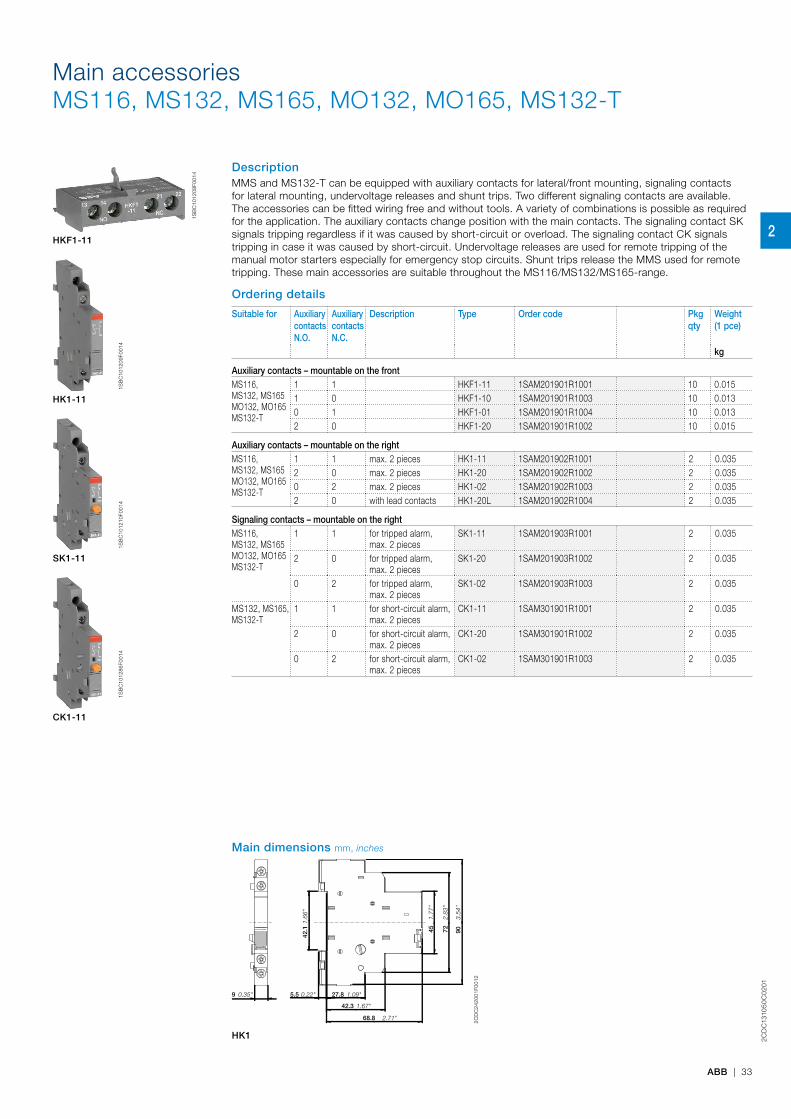
DescriptionMMS and MS132-T can be equipped with auxiliary contacts for lateral/front mounting, signaling contacts for lateral mounting, undervoltage releases and shunt trips. Two different signaling contacts are available. The accessories can be fitted wiring free and without tools. A variety of combinations is possible as required for the application. The auxiliary contacts change position with the main contacts. The signaling contact SK signals tripping regardless if it was caused by short-circuit or overload. The signaling contact CK signals tripping in case it was caused by short-circuit. Undervoltage releases are used for remote tripping of the manual motor starters especially for emergency stop circuits. Shunt trips release the MMS used for remote tripping. These main accessories are suitable throughout the MS116/MS132/MS165-range.
Ordering details
Suitable for Auxiliary contacts N.O.
Auxiliary contacts N.C.
Description Type Order code Pkgqty
Weight (1 pce)
kg
Auxiliary contacts – mountable on the frontMS116, MS132, MS165 MO132, MO165 MS132-T
1 1 HKF1-11 1SAM201901R1001 10 0.0151 0 HKF1-10 1SAM201901R1003 10 0.0130 1 HKF1-01 1SAM201901R1004 10 0.0132 0 HKF1-20 1SAM201901R1002 10 0.015
Auxiliary contacts – mountable on the rightMS116, MS132, MS165 MO132, MO165 MS132-T
1 1 max. 2 pieces HK1-11 1SAM201902R1001 2 0.0352 0 max. 2 pieces HK1-20 1SAM201902R1002 2 0.0350 2 max. 2 pieces HK1-02 1SAM201902R1003 2 0.0352 0 with lead contacts HK1-20L 1SAM201902R1004 2 0.035
Signaling contacts – mountable on the rightMS116, MS132, MS165 MO132, MO165 MS132-T
1 1 for tripped alarm, max. 2 pieces
SK1-11 1SAM201903R1001 2 0.035
2 0 for tripped alarm, max. 2 pieces
SK1-20 1SAM201903R1002 2 0.035
0 2 for tripped alarm, max. 2 pieces
SK1-02 1SAM201903R1003 2 0.035
MS132, MS165, MS132-T
1 1 for short-circuit alarm, max. 2 pieces
CK1-11 1SAM301901R1001 2 0.035
2 0 for short-circuit alarm, max. 2 pieces
CK1-20 1SAM301901R1002 2 0.035
0 2 for short-circuit alarm, max. 2 pieces
CK1-02 1SAM301901R1003 2 0.035
HKF1-11
1S
BC
1012
09F0
014
HK1-11
1S
BC
1012
10F0
014
SK1-11
1SB
C10
1286
F001
4
CK1-11
1SB
C10
1208
F001
4
Main dimensions mm, inches
5.5
42.3
27.8
68.8
9
90
72
45
42.1
3.54
"
0.22"
2.83
"
1.77
"
1.67"
1.09"
2.71"
1.66
"
0.35"
2CD
C24
2001
F001
2
HK1
2
2CD
C13
105
0C
02
01
34 | ABB
Main accessoriesMS116, MS132, MS165, MO132, MO165, MS132-T
Ordering details
Suitable for Rated control supply voltage Type Order code Pkgqty
Weight (1 pce)
50 HzV AC
60 HzV AC kg
Shunt trips – mountable on the leftMS116, MS132, MS165, MO132, MO165, MS132-T
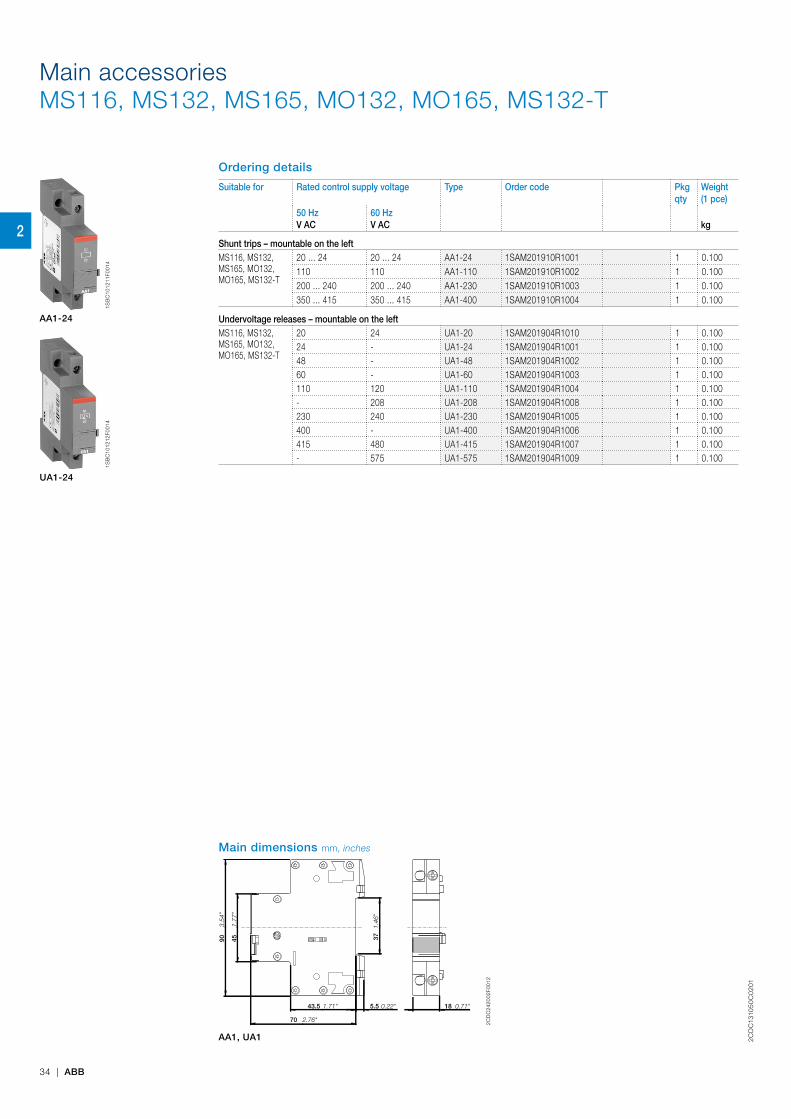
20 ... 24 20 ... 24 AA1-24 1SAM201910R1001 1 0.100110 110 AA1-110 1SAM201910R1002 1 0.100200 ... 240 200 ... 240 AA1-230 1SAM201910R1003 1 0.100350 ... 415 350 ... 415 AA1-400 1SAM201910R1004 1 0.100
Undervoltage releases – mountable on the leftMS116, MS132, MS165, MO132, MO165, MS132-T
20 24 UA1-20 1SAM201904R1010 1 0.10024 - UA1-24 1SAM201904R1001 1 0.10048 - UA1-48 1SAM201904R1002 1 0.10060 - UA1-60 1SAM201904R1003 1 0.100110 120 UA1-110 1SAM201904R1004 1 0.100- 208 UA1-208 1SAM201904R1008 1 0.100230 240 UA1-230 1SAM201904R1005 1 0.100400 - UA1-400 1SAM201904R1006 1 0.100415 480 UA1-415 1SAM201904R1007 1 0.100- 575 UA1-575 1SAM201904R1009 1 0.100
1S
BC
1012
11F0
014
AA1-24
1S
BC
1012
12F0
014
UA1-24
Main dimensions mm, inches
90
45
5.5 43.5
70
37
18
3.54
"
1.77
"
1.71"
2.76"
0.22"
1.46
"
0.71"
2CD
C24
2002
F001
2
AA1, UA1
2
2CD
C13
105
0C
02
01
ABB | 35
General technical data
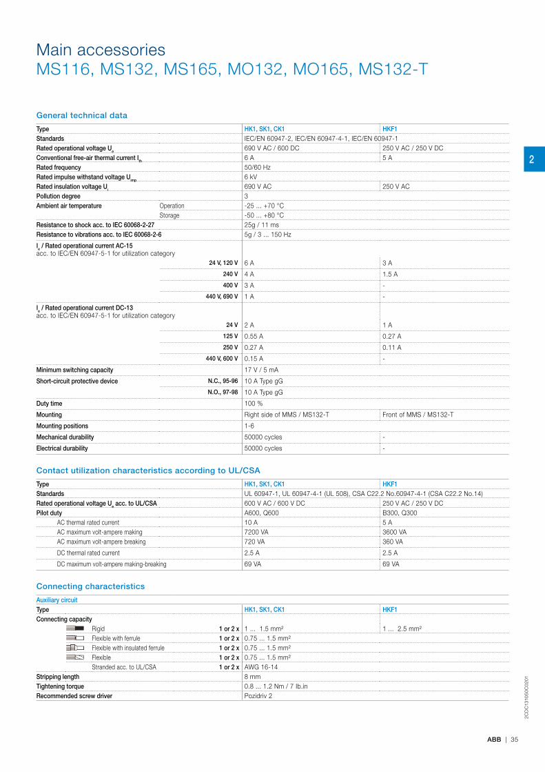
Type HK1, SK1, CK1 HKF1Standards IEC/EN 60947-2, IEC/EN 60947-4-1, IEC/EN 60947-1Rated operational voltage Ue 690 V AC / 600 DC 250 V AC / 250 V DCConventional free-air thermal current Ith 6 A 5 ARated frequency 50/60 HzRated impulse withstand voltage Uimp 6 kVRated insulation voltage Ui 690 V AC 250 V ACPollution degree 3Ambient air temperature Operation -25 ... +70 °C
Storage -50 ... +80 °CResistance to shock acc. to IEC 60068-2-27 25g / 11 msResistance to vibrations acc. to IEC 60068-2-6 5g / 3 ... 150 Hz
Ie / Rated operational current AC-15acc. to IEC/EN 60947-5-1 for utilization category
24 V, 120 V 6 A 3 A
240 V 4 A 1.5 A
400 V 3 A -
440 V, 690 V 1 A -
Ie / Rated operational current DC-13acc. to IEC/EN 60947-5-1 for utilization category
24 V 2 A 1 A
125 V 0.55 A 0.27 A
250 V 0.27 A 0.11 A
440 V, 600 V 0.15 A -
Minimum switching capacity 17 V / 5 mA
Short-circuit protective device N.C., 95-96 10 A Type gG
N.O., 97-98 10 A Type gG
Duty time 100 %
Mounting Right side of MMS / MS132-T Front of MMS / MS132-T
Mounting positions 1-6
Mechanical durability 50000 cycles -
Electrical durability 50000 cycles -
Contact utilization characteristics according to UL/CSA
Type HK1, SK1, CK1 HKF1Standards UL 60947-1, UL 60947-4-1 (UL 508), CSA C22.2 No.60947-4-1 (CSA C22.2 No.14)Rated operational voltage Ue acc. to UL/CSA 600 V AC / 600 V DC 250 V AC / 250 V DCPilot duty A600, Q600 B300, Q300
AC thermal rated current 10 A 5 AAC maximum volt-ampere making 7200 VA 3600 VAAC maximum volt-ampere breaking 720 VA 360 VA
DC thermal rated current 2.5 A 2.5 A
DC maximum volt-ampere making-breaking 69 VA 69 VA
Connecting characteristics
Auxiliary circuitType HK1, SK1, CK1 HKF1Connecting capacity
Rigid 1 or 2 x 1 ... 1.5 mm² 1 ... 2.5 mm² Flexible with ferrule 1 or 2 x 0.75 ... 1.5 mm²Flexible with insulated ferrule 1 or 2 x 0.75 ... 1.5 mm²Flexible 1 or 2 x 0.75 ... 1.5 mm²Stranded acc. to UL/CSA 1 or 2 x AWG 16-14
Stripping length 8 mmTightening torque 0.8 ... 1.2 Nm / 7 Ib.in Recommended screw driver Pozidriv 2
Main accessoriesMS116, MS132, MS165, MO132, MO165, MS132-T
2
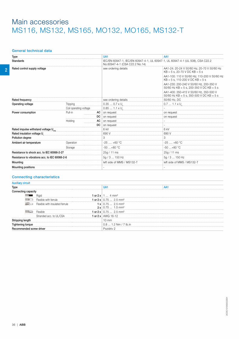
2CD
C13
105
0C
02
01
36 | ABB
General technical data
Type UA1 AA1Standards IEC/EN 60947-1, IEC/EN 60947-4-1, UL 60947-1, UL 60947-4-1 (UL 508), CSA C22.2
No.60947-4-1 (CSA C22.2 No.14)Rated control supply voltage see ordering details AA1-24: 20-24 V 50/60 Hz; 20-70 V 50/60 Hz
KB = 5 s, 20-70 V DC KB = 5 s
AA1-100: 110 V 50/60 Hz; 110-200 V 50/60 Hz KB = 5 s, 110-200 V DC KB = 5 s
AA1-230: 200-240 V 50/60 Hz, 200-350 V 50/60 Hz KB = 5 s, 200-350 V DC KB = 5 s
AA1-400: 350-415 V 50/60 Hz, 350-500 V 50/60 Hz KB = 5 s, 350-500 V DC KB = 5 s
Rated frequency see ordering details 50/60 Hz, DCOperating voltage Tripping 0.35 … 0.7 x Us 0.7 … 1.1 x Us
Coil operating voltage 0.85 … 1.1 x Us -Power consumption Pull-in AC on request on request
DC on request on requestHolding AC on request -
DC on request -Rated impulse withstand voltage Uimp 6 kV 6 kVRated insulation voltage Ui 690 V 690 VPollution degree 3 3
Ambient air temperature Operation -25 …. +60 °C -25 …. +60 °C
Storage -50 …+80 °C -50 …+80 °C
Resistance to shock acc. to IEC 60068-2-27 25g / 11 ms 25g / 11 ms
Resistance to vibrations acc. to IEC 60068-2-6 5g / 3 ... 150 Hz 5g / 3 ... 150 Hz
Mounting left side of MMS / MS132-T left side of MMS / MS132-T
Mounting positions - -
Connecting characteristics
Auxiliary circuitType UA1 AA1Connecting capacity
Rigid 1 or 2 x 1 ... 4 mm² Flexible with ferrule 1 or 2 x 0.75 ... 2.5 mm²Flexible with insulated ferrule 1 x
2 x0.75 ... 2.5 mm²0.75 ... 1.5 mm²
Flexible 1 or 2 x 0.75 ... 2.5 mm²Stranded acc. to UL/CSA 1 or 2 x AWG 16-12
Stripping length 10 mmTightening torque 0.8 ... 1.2 Nm / 7 Ib.in Recommended screw driver Pozidriv 2
Main accessoriesMS116, MS132, MS165, MO132, MO165, MS132-T
2

2CD
C13
105
0C
02
01
ABB | 37
Main accessoriesMS116, MS132, MS165, MO132, MO165
Manual motor starter with three-phase busbar systems (MS116, MS132, MO132)
S1-M1-25
PS1-..-65
PS1-..-65
S1-M2-25
BS1-3
SA1
2CD
C24
2020
F001
3
PS1-..-100
S1-M3-35
2CD
C24
2021
F001
3
Three-phase busbar up to 65 A Three-phase busbar up to 100 A
Manual motor starter with three-phase busbar systems (MS165, MO165)
PS2-4-0-125BS2-3
PS2-2-0-125
2CD
C24
2005
F001
5
PS2-4-0-1252C
DC
2420
06F0
015
Three-phase busbar up to 125 A Three-phase busbar up to 125 A
2
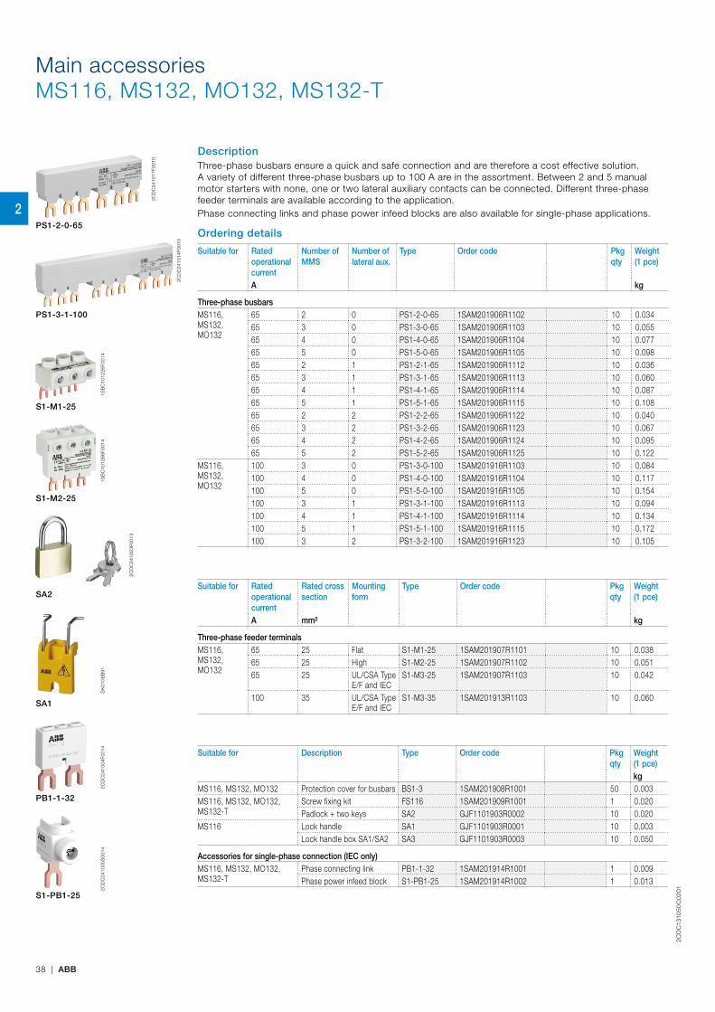
2CD
C13
105
0C
02
01
38 | ABB
DescriptionThree-phase busbars ensure a quick and safe connection and are therefore a cost effective solution. A variety of different three-phase busbars up to 100 A are in the assortment. Between 2 and 5 manual motor starters with none, one or two lateral auxiliary contacts can be connected. Different three-phase feeder terminals are available according to the application.Phase connecting links and phase power infeed blocks are also available for single-phase applications.
Ordering details
Suitable for Rated operational current
Number of MMS
Number of lateral aux.
Type Order code Pkgqty
Weight (1 pce)
A kg
Three-phase busbarsMS116, MS132, MO132
65 2 0 PS1-2-0-65 1SAM201906R1102 10 0.03465 3 0 PS1-3-0-65 1SAM201906R1103 10 0.05565 4 0 PS1-4-0-65 1SAM201906R1104 10 0.07765 5 0 PS1-5-0-65 1SAM201906R1105 10 0.09865 2 1 PS1-2-1-65 1SAM201906R1112 10 0.03665 3 1 PS1-3-1-65 1SAM201906R1113 10 0.06065 4 1 PS1-4-1-65 1SAM201906R1114 10 0.08765 5 1 PS1-5-1-65 1SAM201906R1115 10 0.10865 2 2 PS1-2-2-65 1SAM201906R1122 10 0.04065 3 2 PS1-3-2-65 1SAM201906R1123 10 0.06765 4 2 PS1-4-2-65 1SAM201906R1124 10 0.09565 5 2 PS1-5-2-65 1SAM201906R1125 10 0.122
MS116, MS132, MO132
100 3 0 PS1-3-0-100 1SAM201916R1103 10 0.084100 4 0 PS1-4-0-100 1SAM201916R1104 10 0.117100 5 0 PS1-5-0-100 1SAM201916R1105 10 0.154100 3 1 PS1-3-1-100 1SAM201916R1113 10 0.094100 4 1 PS1-4-1-100 1SAM201916R1114 10 0.134100 5 1 PS1-5-1-100 1SAM201916R1115 10 0.172100 3 2 PS1-3-2-100 1SAM201916R1123 10 0.105
Suitable for Rated operational current
Rated cross section
Mounting form
Type Order code Pkgqty
Weight (1 pce)
A mm² kg
Three-phase feeder terminalsMS116, MS132, MO132
65 25 Flat S1-M1-25 1SAM201907R1101 10 0.03865 25 High S1-M2-25 1SAM201907R1102 10 0.05165 25 UL/CSA Type
E/F and IECS1-M3-25 1SAM201907R1103 10 0.042
100 35 UL/CSA Type E/F and IEC
S1-M3-35 1SAM201913R1103 10 0.060
Suitable for Description Type Order code Pkgqty
Weight (1 pce)kg
MS116, MS132, MO132 Protection cover for busbars BS1-3 1SAM201908R1001 50 0.003MS116, MS132, MO132, MS132-T
Screw fixing kit FS116 1SAM201909R1001 1 0.020Padlock + two keys SA2 GJF1101903R0002 10 0.020
MS116 Lock handle SA1 GJF1101903R0001 10 0.003Lock handle box SA1/SA2 SA3 GJF1101903R0003 10 0.050
Accessories for single-phase connection (IEC only)MS116, MS132, MO132, MS132-T
Phase connecting link PB1-1-32 1SAM201914R1001 1 0.009Phase power infeed block S1-PB1-25 1SAM201914R1002 1 0.013
PS1-2-0-65
PS1-3-1-100
S1-M1-25
S1-M2-25
2CD
C24
1023
F001
3
SA2
SA1
PB1-1-32
S1-PB1-25
2CD
C24
1014
F001
0
1SB
C10
1226
F001
41S
BC
1012
66F0
014
SK
0108
B91
2CD
C24
1017
F001
0
Main accessoriesMS116, MS132, MO132, MS132-T
2CD
C24
1004
F001
42C
DC
2410
05S
0014
2
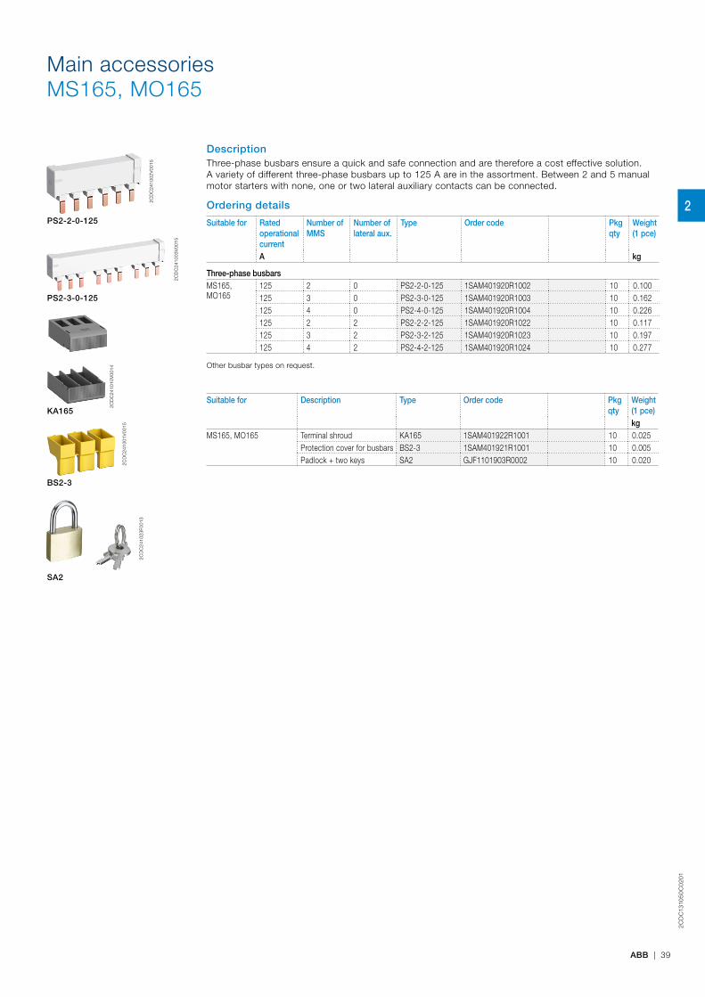
2CD
C13
105
0C
02
01
ABB | 39
DescriptionThree-phase busbars ensure a quick and safe connection and are therefore a cost effective solution. A variety of different three-phase busbars up to 125 A are in the assortment. Between 2 and 5 manual motor starters with none, one or two lateral auxiliary contacts can be connected.
Ordering details
Suitable for Rated operational current
Number of MMS
Number of lateral aux.
Type Order code Pkgqty
Weight (1 pce)
A kg
Three-phase busbarsMS165, MO165
125 2 0 PS2-2-0-125 1SAM401920R1002 10 0.100125 3 0 PS2-3-0-125 1SAM401920R1003 10 0.162125 4 0 PS2-4-0-125 1SAM401920R1004 10 0.226125 2 2 PS2-2-2-125 1SAM401920R1022 10 0.117125 3 2 PS2-3-2-125 1SAM401920R1023 10 0.197125 4 2 PS2-4-2-125 1SAM401920R1024 10 0.277
Other busbar types on request.
Suitable for Description Type Order code Pkgqty
Weight (1 pce)kg
MS165, MO165 Terminal shroud KA165 1SAM401922R1001 10 0.025Protection cover for busbars BS2-3 1SAM401921R1001 10 0.005Padlock + two keys SA2 GJF1101903R0002 10 0.020
PS2-2-0-125
2CD
C24
1003
V00
15
PS2-3-0-125
KA165
BS2-3
2CD
C24
1023
F001
3
SA2
2CD
C24
1010
V00
14
Main accessoriesMS165, MO165
2CD
C24
1002
V00
15
2CD
C24
1001
V00
15
2

2CD
C13
105
0C
02
01
40 | ABB
Main accessoriesMS116, MS132, MS165, MO132, MO165
General technical data
Type PS1-xxx-65 PS1-xxx-100 S1-Mx-25 S1-Mx-35Standards IEC/EN 60947-4-1, IEC/EN 60947-1, UL 60947-1, UL 60947-4-1 (UL 508), CSA C22.2 No.60947-4-1
(CSA C22.2 No.14)Rated operational voltage Ue 690 VRated operational voltage Ue acc. to UL/CSA 600 V ACRated operational current Ie 65 A 100 A 65 A 100 ARated operational current Ie acc. to UL/CSA 65 A 92 A 65 A 92 ARated frequency 50/60 HzRated impulse withstand voltage Uimp 6 kVRated insulation voltage Ui 690 V ACPollution degree 3Cross-section 10 mm² 16 mm² 25 mm² 35 mm²Ambient air temperature Operation -25 ... +70 °C
Storage -50 ... +80 °CResistance to shock acc. to IEC 60068-2-27 25g / 11 msResistance to vibrations acc. to IEC 60068-2-6 5g / 3 ... 150 Hz
Electrical connection
Main circuitType S1-Mx-25 S1-Mx-35Connecting capacity
Rigid 1 x 6 ... 25 mm² 10 ... 35 mm²Flexible with ferrule 1 x 6 ... 16 mm² 10 ... 35 mm²Flexible with insulated ferrule 1 x 6 ... 16 mm² 10 ... 35 mm²Flexible 1 x 6 ... 16 mm² 10 ... 35 mm²Stranded acc. to UL/CSA 1 x AWG 10-4 AWG 8-2
Stripping length 10 mm 12 mmTightening torque 2.5 Nm / 22 Ib.in 4.5 Nm / 40 Ib.in Recommended screw driver Pozidriv 2 Hexagon SW4
Technical data for PS2-xxx on request.
2
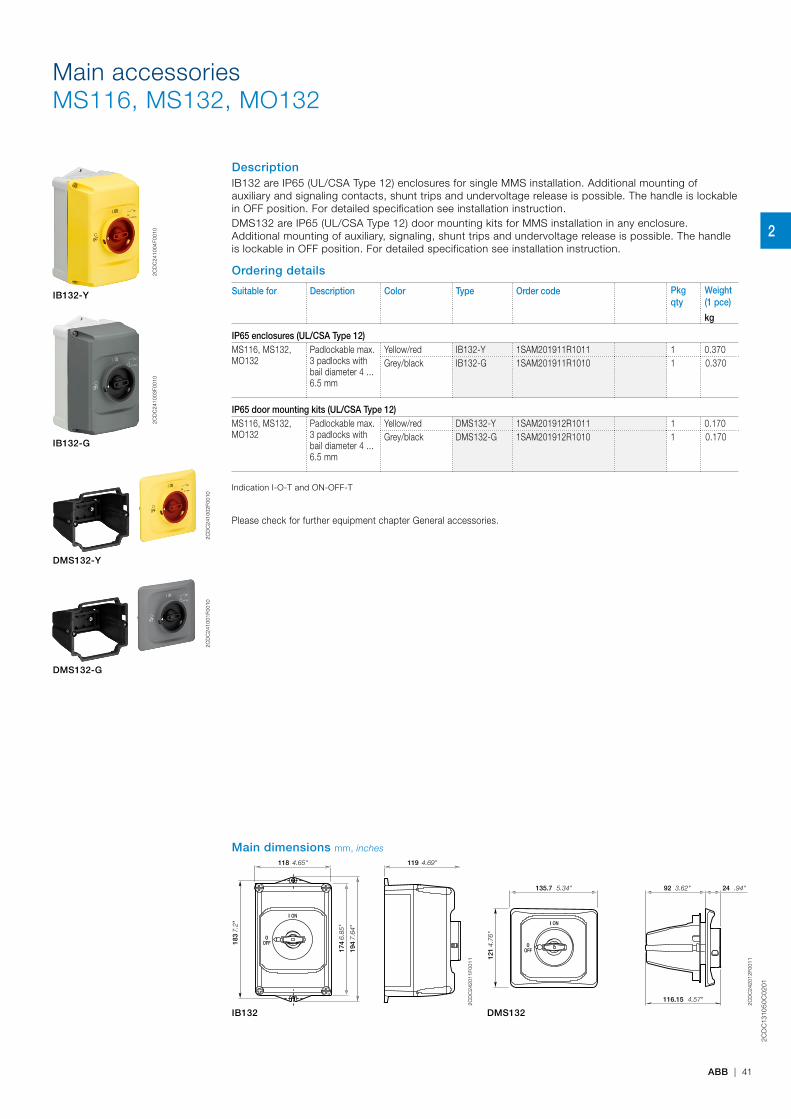
2CD
C13
105
0C
02
01
ABB | 41
DescriptionIB132 are IP65 (UL/CSA Type 12) enclosures for single MMS installation. Additional mounting of auxiliary and signaling contacts, shunt trips and undervoltage release is possible. The handle is lockable in OFF position. For detailed specification see installation instruction. DMS132 are IP65 (UL/CSA Type 12) door mounting kits for MMS installation in any enclosure. Additional mounting of auxiliary, signaling, shunt trips and undervoltage release is possible. The handle is lockable in OFF position. For detailed specification see installation instruction.
Ordering details
Suitable for Description Color Type Order code Pkgqty
Weight (1 pce)
kg
IP65 enclosures (UL/CSA Type 12)MS116, MS132, MO132
Padlockable max. 3 padlocks with bail diameter 4 ... 6.5 mm
Yellow/red IB132-Y 1SAM201911R1011 1 0.370Grey/black IB132-G 1SAM201911R1010 1 0.370
IP65 door mounting kits (UL/CSA Type 12)MS116, MS132, MO132
Padlockable max. 3 padlocks with bail diameter 4 ... 6.5 mm
Yellow/red DMS132-Y 1SAM201912R1011 1 0.170Grey/black DMS132-G 1SAM201912R1010 1 0.170
Indication I-O-T and ON-OFF-T
Please check for further equipment chapter General accessories.
2CD
C24
1004
F001
0
IB132-Y
2CD
C24
1003
F001
0
IB132-G
2C
DC
2410
02F0
010
DMS132-Y
2C
DC
2410
01F0
010
DMS132-G
Main accessoriesMS116, MS132, MO132
Main dimensions mm, inches
I ON
0OFF
119 118
183
174
194
4.69"4.65"
7.2"
6.85
"
7.64
"
2CD
C24
2011
F001
1
I ON
0OFF
135.7 92 24
121
116.15
5.34" 3.62" .94"
4.7
6"
4.57"
2CD
C24
2012
F001
1
IB132 DMS132
2
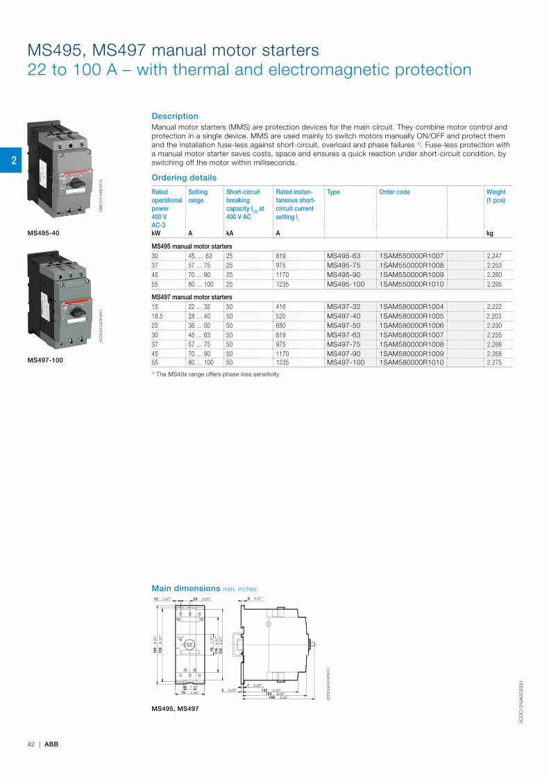
2CD
C13
1042
C0
201
42 | ABB
MS495, MS497 manual motor starters22 to 100 A – with thermal and electromagnetic protection
DescriptionManual motor starters (MMS) are protection devices for the main circuit. They combine motor control and protection in a single device. MMS are used mainly to switch motors manually ON/OFF and protect them and the installation fuse-less against short-circuit, overload and phase failures 1). Fuse-less protection with a manual motor starter saves costs, space and ensures a quick reaction under short-circuit condition, by switching off the motor within milliseconds.
Ordering details
Rated operational power400 V AC-3
Setting range
Short-circuit breakingcapacity ICS at 400 V AC
Rated instan-taneous short-circuit current setting li
Type Order code Weight(1 pce)
kW A kA A kg
MS495 manual motor starters30 45. … 63 25 819 MS495-63 1SAM550000R1007 2.24737 57 … 75 25 975 MS495-75 1SAM550000R1008 2.25345 70 … 90 25 1170 MS495-90 1SAM550000R1009 2.28055 80 … 100 25 1235 MS495-100 1SAM550000R1010 2.295
MS497 manual motor starters15 22 … 32 50 416 MS497-32 1SAM580000R1004 2.22218.5 28 … 40 50 520 MS497-40 1SAM580000R1005 2.20322 36 … 50 50 650 MS497-50 1SAM580000R1006 2.23030 45 … 63 50 819 MS497-63 1SAM580000R1007 2.25537 57 … 75 50 975 MS497-75 1SAM580000R1008 2.26645 70 … 90 50 1170 MS497-90 1SAM580000R1009 2.26855 80 … 100 50 1235 MS497-100 1SAM580000R1010 2.2751) The MS49x range offers phase loss sensitivity
1SB
C10
1184
F001
4
MS495-40
2CD
C24
1020
F001
1
MS497-100
Main dimensions mm, inches
132153
169
155
165
150
116
45
70
8
75
30
12 23
6.10
"
6.50
"
5.91
"4.
57"
1.77
"
0.31"0.47" 0.91"
5.20"6.02"
6.65"2.56"
0.28"0.20"
1.18"
2CD
C24
2014
F001
1
MS495, MS497
2
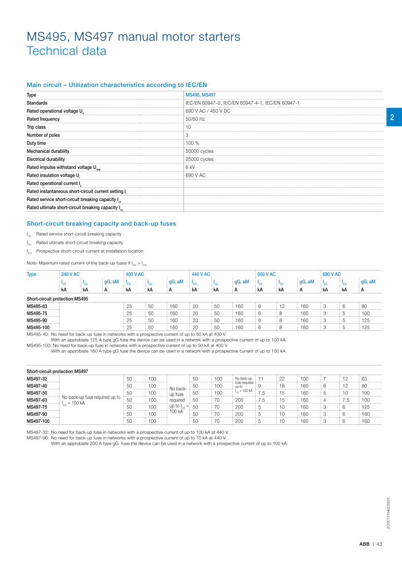
2CD
C13
1042
C0
201
ABB | 43
MS495, MS497 manual motor startersTechnical data
Main circuit – Utilization characteristics according to IEC/EN
Type MS495, MS497
Standards IEC/EN 60947–2, IEC/EN 60947-4-1, IEC/EN 60947-1
Rated operational voltage Ue 690 V AC / 450 V DC
Rated frequency 50/60 Hz
Trip class 10
Number of poles 3
Duty time 100 %
Mechanical durability 50000 cycles
Electrical durability 25000 cycles
Rated impulse withstand voltage Uimp 6 kV
Rated insulation voltage Ui 690 V AC
Rated operational current Ie
Rated instantaneous short-circuit current setting Ii
Rated service short-circuit breaking capacity Ics
Rated ultimate short-circuit breaking capacity Icu
Short-circuit breaking capacity and back-up fuses
lCS Rated service short-circuit breaking capacity
lCU Rated ultimate short-circuit breaking capacity
ICC Prospective short-circuit current at installation location
Note: Maximum rated current of the back-up fuses if ICC > ICS
Type 240 V AC 400 V AC 440 V AC 500 V AC 690 V AC
ICS ICU gG, aM ICS ICU gG, aM ICS ICU gG, aM ICS ICU gG, aM ICS ICU gG, aM
kA kA A kA kA A kA kA A kA kA A kA kA A
Short-circuit protection MS495
MS495-63 25 50 160 20 50 160 6 12 160 3 6 80MS495-75 25 50 160 20 50 160 6 8 160 3 5 100MS495-90 25 50 160 20 50 160 6 8 160 3 5 125MS495-100 25 50 160 20 50 160 6 8 160 3 5 125MS495-40: No need for back-up fuse in networks with a prospective current of up to 50 kA at 400 V. With an approbiate 125 A type gG fuse the device can be used in a network with a prospective current of up to 100 kA.MS495-100: No need for back-up fuse in networks with a prospective current of up to 50 kA at 400 V. With an approbiate 160 A type gG fuse the device can be used in a network with a prospective current of up to 100 kA.
Short-circuit protection MS497
MS497-32
No back-up fuse required up to ICC = 100 kA
50 100
No back-up fuse required up to ICC = 100 kA
50 100 No back-up fuse required up to ICC = 100 kA
11 22 100 7 12 63MS497-40 50 100 50 100 9 18 160 6 12 80MS497-50 50 100 50 100 7.5 15 160 5 10 100MS497-63 50 100 50 70 200 7.5 15 160 4 7.5 100MS497-75 50 100 50 70 200 5 10 160 3 6 125MS497-90 50 100 50 70 200 5 10 160 3 6 160MS497-100 50 100 50 70 200 5 10 160 3 6 160
MS497-32: No need for back-up fuse in networks with a prospective current of up to 100 kA at 440 V. MS497-90: No need for back-up fuse in networks with a prospective current of up to 70 kA at 440 V. With an approbiate 200 A type gG fuse the device can be used in a network with a prospective current of up to 100 kA.
2

2CD
C13
1042
C0
201
44 | ABB
MS495, MS497 manual motor startersTechnical data
Main circuit – Utilization characteristics according to UL/CSA
Type MS495, MS497Standards UL 508, CSA 22.2 No. 14Maximum operational voltage 600 V ACManual motor controller ratings See table "UL 508 – Manual motor controller"Trip rating 125 % FLAMotor ratings Horsepower See table "Motor ratings, three-phase"
Full Load Amps (FLA) See table "Motor ratings, three-phase"
Motor ratings, three-phase
hp Horsepower
FLA Full Load Amps
Type General purpose rating at max. 600 V AC
Full Load Amps 200 - 208 V AC 230 V AC 460 V AC 575 V AC
A FLA hp hp hp hp
MS495-63 63 63 20 25 50 60MS495-75 75 75 25 25 60 75MS495-90 90 90 30 30 75 100MS495-100 100 100 40 40 75 100MS497-32 32 32 10 10 25 30MS497-40 40 40 15 15 30 40MS497-50 50 50 15 20 40 50MS497-63 63 63 20 25 50 60MS497-75 75 75 25 25 60 75MS497-90 90 90 30 30 75 100MS497-100 100 100 30 40 75 100
UL 508 – Manual motor controller
Type Circuit breaker or class R fuse per UL/NEC
Max. circuit breaker or fuse per UL/NEC
Maximum short-circuit current for motor disconnect for group installation for tap
conductorfor protection UL 508
Type E 1) Type E
480/600 VA
480/600 VA
480 VkA
600 VkA
480 VkA
600 VkA
480Y/277VkA
600Y/347VkA
480Y/277VkA
600Y/347VkA
MS495-63 250 500 65 30 65 30 65 30 65 30MS495-75 300 500 65 30 65 30 65 30 65 30MS495-90 350 500 65 10 65 10 65 - 65 -MS495-100 400 500 65 10 65 10 65 - 65 -MS497-32 120 500 65 30 65 30 65 30 65 30MS497-40 160 500 65 30 65 30 65 30 65 30MS497-50 200 500 65 30 65 30 65 30 65 30MS497-63 250 500 65 30 65 30 65 30 65 30MS497-75 300 500 65 30 65 30 65 30 65 30MS497-90 350 500 65 10 65 10 - - 65 -MS497-100 400 500 65 10 65 10 - - 65 -
1) only with use DX495
2
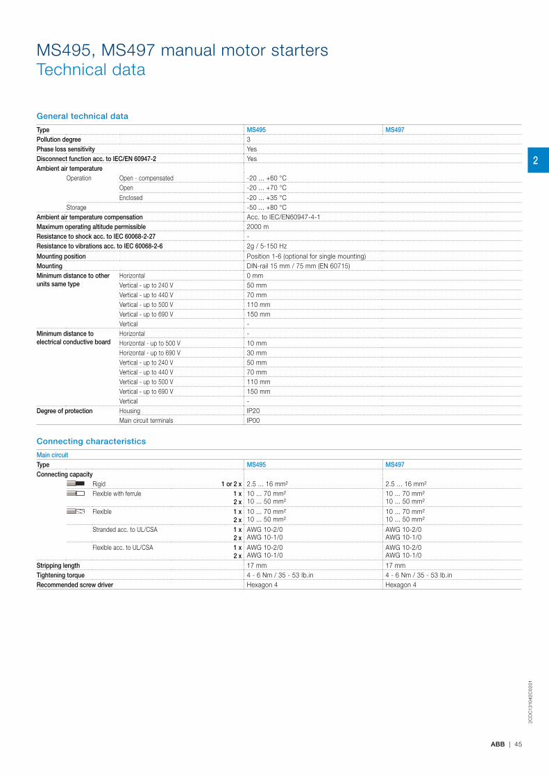
2CD
C13
1042
C0
201
ABB | 45
General technical data
Type MS495 MS497Pollution degree 3Phase loss sensitivity YesDisconnect function acc. to IEC/EN 60947-2 YesAmbient air temperature
Operation Open - compensated -20 ... +60 °COpen -20 ... +70 °CEnclosed -20 ... +35 °C
Storage -50 ... +80 °CAmbient air temperature compensation Acc. to IEC/EN60947-4-1Maximum operating altitude permissible 2000 mResistance to shock acc. to IEC 60068-2-27 -Resistance to vibrations acc. to IEC 60068-2-6 2g / 5-150 Hz
Mounting position Position 1-6 (optional for single mounting)Mounting DIN-rail 15 mm / 75 mm (EN 60715)Minimum distance to other units same type
Horizontal 0 mmVertical - up to 240 V 50 mmVertical - up to 440 V 70 mmVertical - up to 500 V 110 mmVertical - up to 690 V 150 mmVertical -
Minimum distance to electrical conductive board
Horizontal -Horizontal - up to 500 V 10 mmHorizontal - up to 690 V 30 mmVertical - up to 240 V 50 mmVertical - up to 440 V 70 mmVertical - up to 500 V 110 mmVertical - up to 690 V 150 mmVertical -
Degree of protection Housing IP20Main circuit terminals IP00
Connecting characteristics
Main circuitType MS495 MS497Connecting capacity
Rigid 1 or 2 x 2.5 ... 16 mm² 2.5 ... 16 mm²Flexible with ferrule 1 x
2 x10 ... 70 mm²10 ... 50 mm²
10 ... 70 mm²10 ... 50 mm²
Flexible 1 x2 x
10 ... 70 mm²10 ... 50 mm²
10 ... 70 mm²10 ... 50 mm²
Stranded acc. to UL/CSA 1 x2 x
AWG 10-2/0AWG 10-1/0
AWG 10-2/0AWG 10-1/0
Flexible acc. to UL/CSA 1 x2 x
AWG 10-2/0AWG 10-1/0
AWG 10-2/0AWG 10-1/0
Stripping length 17 mm 17 mmTightening torque 4 - 6 Nm / 35 - 53 Ib.in 4 - 6 Nm / 35 - 53 Ib.in Recommended screw driver Hexagon 4 Hexagon 4
MS495, MS497 manual motor startersTechnical data
2

2CD
C13
103
8C
02
01
46 | ABB
MO495, MO496 manual motor starters magnetic only32 to 100 A – with electromagnetic protection
DescriptionThe manual motor starter magnetic only is used to manually switch on and off motors and to protect them reliably and without the need for a fuse from short-circuits.
Ordering details
Rated operational power400 V AC-3 1)
Rated operationalcurrent
Short-circuit breakingcapacity ICS at 400 V AC
Rated instan-taneous short-circuit current setting li
Type Order code Weight(1 pce)
kW A kA A kg
MO495 manual motor starter magnetic only30 63 25 819 MO495-63 1SAM560000R1007 2.24437 75 25 975 MO495-75 1SAM560000R1008 2.24745 90 25 1170 MO495-90 1SAM560000R1009 2.26955 100 25 1235 MO495-100 1SAM560000R1010 2.292
MO496 manual motor starter magnetic only15 32 50 416 MO496-32 1SAM590000R1004 2.20818.5 40 50 520 MO496-40 1SAM590000R1005 2.21822 50 50 650 MO496-50 1SAM590000R1006 2.21830 63 50 819 MO496-63 1SAM590000R1007 2.24837 75 50 975 MO496-75 1SAM590000R1008 2.27845 90 50 1170 MO496-90 1SAM590000R1009 2.26655 100 50 1235 MO496-100 1SAM590000R1010 2.293
1) For overload protection of motors, an appropriate thermal or electronic overload relay must be used2) ICS at 415 V AC
ST0
2601
MO495-75
2CD
C24
1021
F001
1
MO496-100
Main dimensions mm, inches
132153
169
155
165
150
116
45
70
8
75
30
12 23
6.10
"
6.50
"
5.91
"4.
57"
1.77
"
5.20"6.02"
6.65"2.56"
0.31"
0.28"0.20"
1.18"
0.47" 0.91"
2CD
C24
2016
F001
1
MO495, MO496
2
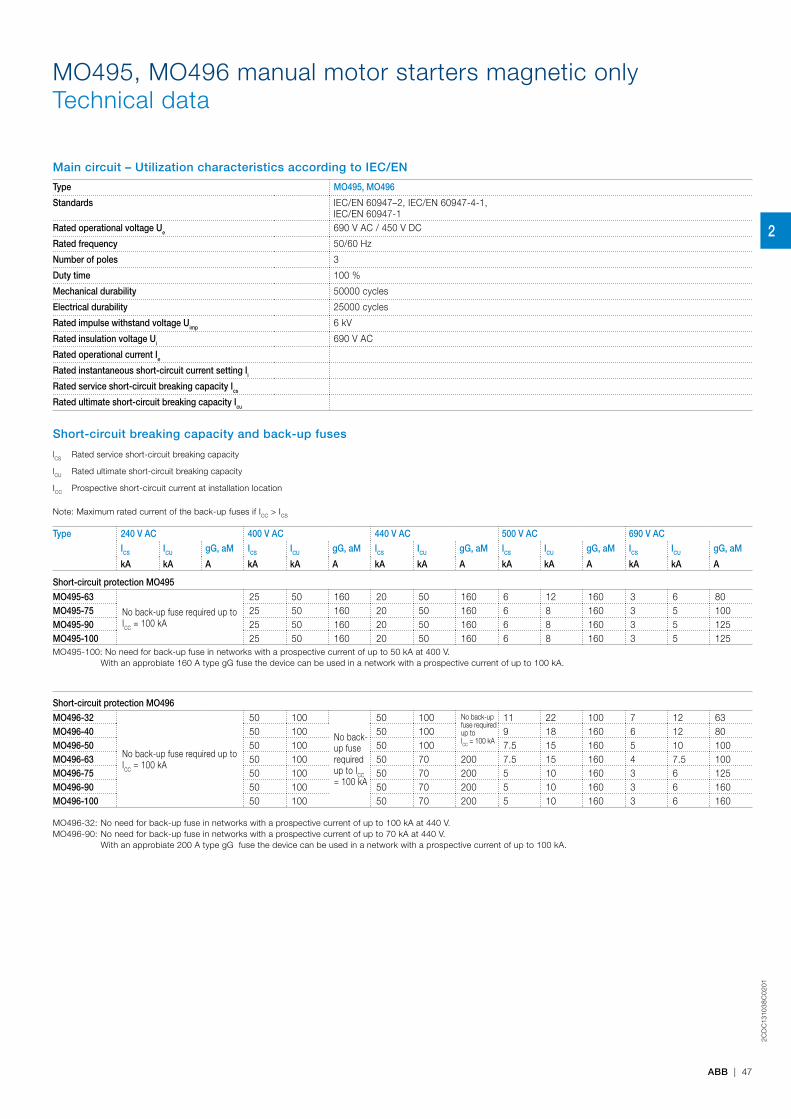
2CD
C13
103
8C
02
01
ABB | 47
MO495, MO496 manual motor starters magnetic onlyTechnical data
Main circuit – Utilization characteristics according to IEC/EN
Type MO495, MO496
Standards IEC/EN 60947–2, IEC/EN 60947-4-1, IEC/EN 60947-1
Rated operational voltage Ue 690 V AC / 450 V DC
Rated frequency 50/60 Hz
Number of poles 3
Duty time 100 %
Mechanical durability 50000 cycles
Electrical durability 25000 cycles
Rated impulse withstand voltage Uimp 6 kV
Rated insulation voltage Ui 690 V AC
Rated operational current Ie
Rated instantaneous short-circuit current setting Ii
Rated service short-circuit breaking capacity Ics
Rated ultimate short-circuit breaking capacity Icu
Short-circuit breaking capacity and back-up fuses
lCS Rated service short-circuit breaking capacity
lCU Rated ultimate short-circuit breaking capacity
ICC Prospective short-circuit current at installation location
Note: Maximum rated current of the back-up fuses if ICC > ICS
Type 240 V AC 400 V AC 440 V AC 500 V AC 690 V AC
ICS ICU gG, aM ICS ICU gG, aM ICS ICU gG, aM ICS ICU gG, aM ICS ICU gG, aM
kA kA A kA kA A kA kA A kA kA A kA kA A
Short-circuit protection MO495
MO495-63
No back-up fuse required up to ICC = 100 kA
25 50 160 20 50 160 6 12 160 3 6 80MO495-75 25 50 160 20 50 160 6 8 160 3 5 100MO495-90 25 50 160 20 50 160 6 8 160 3 5 125MO495-100 25 50 160 20 50 160 6 8 160 3 5 125MO495-100: No need for back-up fuse in networks with a prospective current of up to 50 kA at 400 V. With an approbiate 160 A type gG fuse the device can be used in a network with a prospective current of up to 100 kA.
Short-circuit protection MO496
MO496-32
No back-up fuse required up to ICC = 100 kA
50 100
No back-up fuse required up to ICC = 100 kA
50 100 No back-up fuse required up to ICC = 100 kA
11 22 100 7 12 63MO496-40 50 100 50 100 9 18 160 6 12 80MO496-50 50 100 50 100 7.5 15 160 5 10 100MO496-63 50 100 50 70 200 7.5 15 160 4 7.5 100MO496-75 50 100 50 70 200 5 10 160 3 6 125MO496-90 50 100 50 70 200 5 10 160 3 6 160MO496-100 50 100 50 70 200 5 10 160 3 6 160
MO496-32: No need for back-up fuse in networks with a prospective current of up to 100 kA at 440 V. MO496-90: No need for back-up fuse in networks with a prospective current of up to 70 kA at 440 V. With an approbiate 200 A type gG fuse the device can be used in a network with a prospective current of up to 100 kA.
2
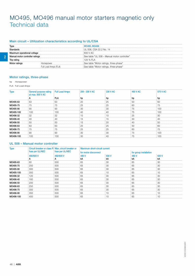
2CD
C13
103
8C
02
01
48 | ABB
Main circuit – Utilization characteristics according to UL/CSA
Type MO495, MO496Standards UL 508, CSA 22.2 No. 14Maximum operational voltage 600 V ACManual motor controller ratings See table "UL 508 – Manual motor controller"Trip rating 125 % FLAMotor ratings Horsepower See table "Motor ratings, three-phase"
Full Load Amps (FLA) See table "Motor ratings, three-phase"
Motor ratings, three-phase
hp Horsepower
FLA Full Load Amps
Type General purpose rating at max. 600 V AC
Full Load Amps 200 - 208 V AC 230 V AC 460 V AC 575 V AC
A FLA hp hp hp hp
MO495-63 63 63 20 25 50 60MO495-75 75 75 25 25 60 75MO495-90 90 90 30 30 75 100MO495-100 100 100 40 40 75 100MO496-32 32 32 10 10 25 30MO496-40 40 40 15 15 30 40MO496-50 50 50 15 20 40 50MO496-63 63 63 20 25 50 60MO496-75 75 75 25 25 60 75MO496-90 90 90 30 30 75 100MO496-100 100 100 30 40 75 100
UL 508 – Manual motor controller
Type Circuit breaker or class R fuse per UL/NEC
Max. circuit breaker or fuse per UL/NEC
Maximum short-circuit current
for motor disconnect for group installation480/600 VA
480/600 VA
480 VkA
600 VkA
480 VkA
600 VkA
MO495-63 60 500 65 30 65 30MO495-75 250 500 65 30 65 30MO495-90 300 500 65 30 65 30MO495-100 350 500 65 10 65 10MO496-32 120 500 65 30 65 30MO496-40 160 500 65 30 65 30MO496-50 200 500 65 30 65 30MO496-63 250 500 65 30 65 30MO496-75 300 500 65 30 65 30MO496-90 350 500 65 10 65 10MO496-100 400 500 65 10 65 10
MO495, MO496 manual motor starters magnetic onlyTechnical data
2
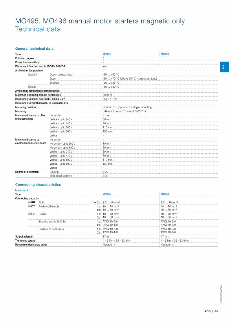
2CD
C13
103
8C
02
01
ABB | 49
General technical data
Type MO495 MO496Pollution degree 3Phase loss sensitivity -Disconnect function acc. to IEC/EN 60947-2 YesAmbient air temperature
Operation Open - compensated -20 ... +60 °COpen -20 ... +70 °C (above 60° C, current derating)Enclosed -20 ... +35 °C
Storage -50 ... +80 °CAmbient air temperature compensation -Maximum operating altitude permissible 2000 mResistance to shock acc. to IEC 60068-2-27 25g / 11 ms Resistance to vibrations acc. to IEC 60068-2-6 -
Mounting position Position 1-6 (optional for single mounting)Mounting DIN-rail 15 mm / 75 mm (EN 60715)Minimum distance to other units same type
Horizontal 0 mmVertical - up to 240 V 50 mmVertical - up to 440 V 70 mmVertical - up to 500 V 110 mmVertical - up to 690 V 150 mmVertical -
Minimum distance to electrical conductive board
Horizontal -Horizontal - up to 500 V 10 mmHorizontal - up to 690 V 30 mmVertical - up to 240 V 50 mmVertical - up to 440 V 70 mmVertical - up to 500 V 110 mmVertical - up to 690 V 150 mmVertical -
Degree of protection Housing IP20Main circuit terminals IP20
Connecting characteristics
Main circuitType MO495 MO496Connecting capacity
Rigid 1 or 2 x 2.5 ... 16 mm² 2.5 ... 16 mm²Flexible with ferrule 1 x
2 x10 ... 70 mm²10 ... 50 mm²
10 ... 70 mm²10 ... 50 mm²
Flexible 1 x2 x
10 ... 70 mm²10 ... 50 mm²
10 ... 70 mm²10 ... 50 mm²
Stranded acc. to UL/CSA 1 x2 x
AWG 10-2/0AWG 10-1/0
AWG 10-2/0AWG 10-1/0
Flexible acc. to UL/CSA 1 x2 x
AWG 10-2/0AWG 10-1/0
AWG 10-2/0AWG 10-1/0
Stripping length 17 mm 17 mmTightening torque 4 - 6 Nm / 35 - 53 Ib.in 4 - 6 Nm / 35 - 53 Ib.in Recommended screw driver Hexagon 4 Hexagon 4
MO495, MO496 manual motor starters magnetic onlyTechnical data
2
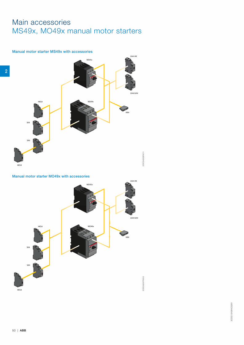
2CD
C13
1051
C0
201
50 | ABB
Main accessoriesMS49x, MO49x manual motor starters
Manual motor starter MS49x with accessoriesUA4-HK
HKS4
HKS4
SK4
SK4
UA4/AA4
HK4
MS45x
MS49x
2CD
C24
2025
F001
1
Manual motor starter MO49x with accessoriesUA4-HK
HKS4
HKS4
SK4
SK4
UA4/AA4
HK4
MO45x
MO49x
2CD
C24
2007
F001
3
2
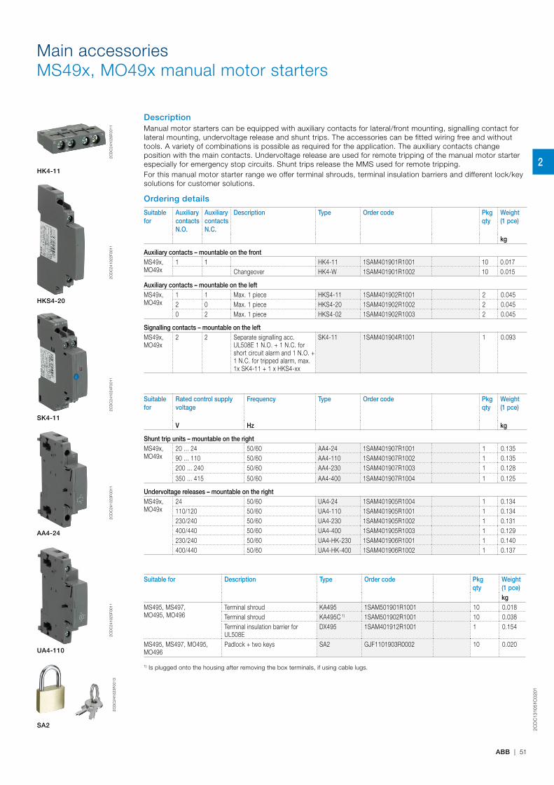
2CD
C13
1051
C0
201
ABB | 51
Main accessoriesMS49x, MO49x manual motor starters
DescriptionManual motor starters can be equipped with auxiliary contacts for lateral/front mounting, signalling contact for lateral mounting, undervoltage release and shunt trips. The accessories can be fitted wiring free and without tools. A variety of combinations is possible as required for the application. The auxiliary contacts change position with the main contacts. Undervoltage release are used for remote tripping of the manual motor starter especially for emergency stop circuits. Shunt trips release the MMS used for remote tripping.For this manual motor starter range we offer terminal shrouds, terminal insulation barriers and different lock/key solutions for customer solutions.
Ordering details
Suitable for
Auxiliary contacts N.O.
Auxiliary contacts N.C.
Description Type Order code Pkgqty
Weight (1 pce)
kg
Auxiliary contacts – mountable on the frontMS49x, MO49x
1 1 HK4-11 1SAM401901R1001 10 0.017Changeover HK4-W 1SAM401901R1002 10 0.015
Auxiliary contacts – mountable on the leftMS49x, MO49x
1 1 Max. 1 piece HKS4-11 1SAM401902R1001 2 0.0452 0 Max. 1 piece HKS4-20 1SAM401902R1002 2 0.0450 2 Max. 1 piece HKS4-02 1SAM401902R1003 2 0.045
Signalling contacts – mountable on the leftMS49x, MO49x
2 2 Separate signalling acc. UL508E 1 N.O. + 1 N.C. for short circuit alarm and 1 N.O. + 1 N.C. for tripped alarm, max. 1x SK4-11 + 1 x HKS4-xx
SK4-11 1SAM401904R1001 1 0.093
Suitable for
Rated control supply voltage
Frequency Type Order code Pkgqty
Weight (1 pce)
V Hz kg
Shunt trip units – mountable on the rightMS49x, MO49x
20 ... 24 50/60 AA4-24 1SAM401907R1001 1 0.13590 ... 110 50/60 AA4-110 1SAM401907R1002 1 0.135200 ... 240 50/60 AA4-230 1SAM401907R1003 1 0.128
350 ... 415 50/60 AA4-400 1SAM401907R1004 1 0.125
Undervoltage releases – mountable on the rightMS49x, MO49x
24 50/60 UA4-24 1SAM401905R1004 1 0.134110/120 50/60 UA4-110 1SAM401905R1001 1 0.134230/240 50/60 UA4-230 1SAM401905R1002 1 0.131400/440 50/60 UA4-400 1SAM401905R1003 1 0.129230/240 50/60 UA4-HK-230 1SAM401906R1001 1 0.140400/440 50/60 UA4-HK-400 1SAM401906R1002 1 0.137
Suitable for Description Type Order code Pkgqty
Weight (1 pce)kg
MS495, MS497,MO495, MO496
Terminal shroud KA495 1SAM501901R1001 10 0.018Terminal shroud KA495C 1) 1SAM501902R1001 10 0.038Terminal insulation barrier for UL508E
DX495 1SAM401912R1001 1 0.154
MS495, MS497, MO495, MO496
Padlock + two keys SA2 GJF1101903R0002 10 0.020
1) Is plugged onto the housing after removing the box terminals, if using cable lugs.
2C
DC
2410
26F0
011
HK4-11
2
CD
C24
1022
F001
1
HKS4-20
2CD
C24
1024
F001
1
SK4-11
2CD
C24
1023
F001
1
AA4-24
2CD
C24
1025
F001
1
UA4-110
2CD
C24
1023
F001
3
SA2
2
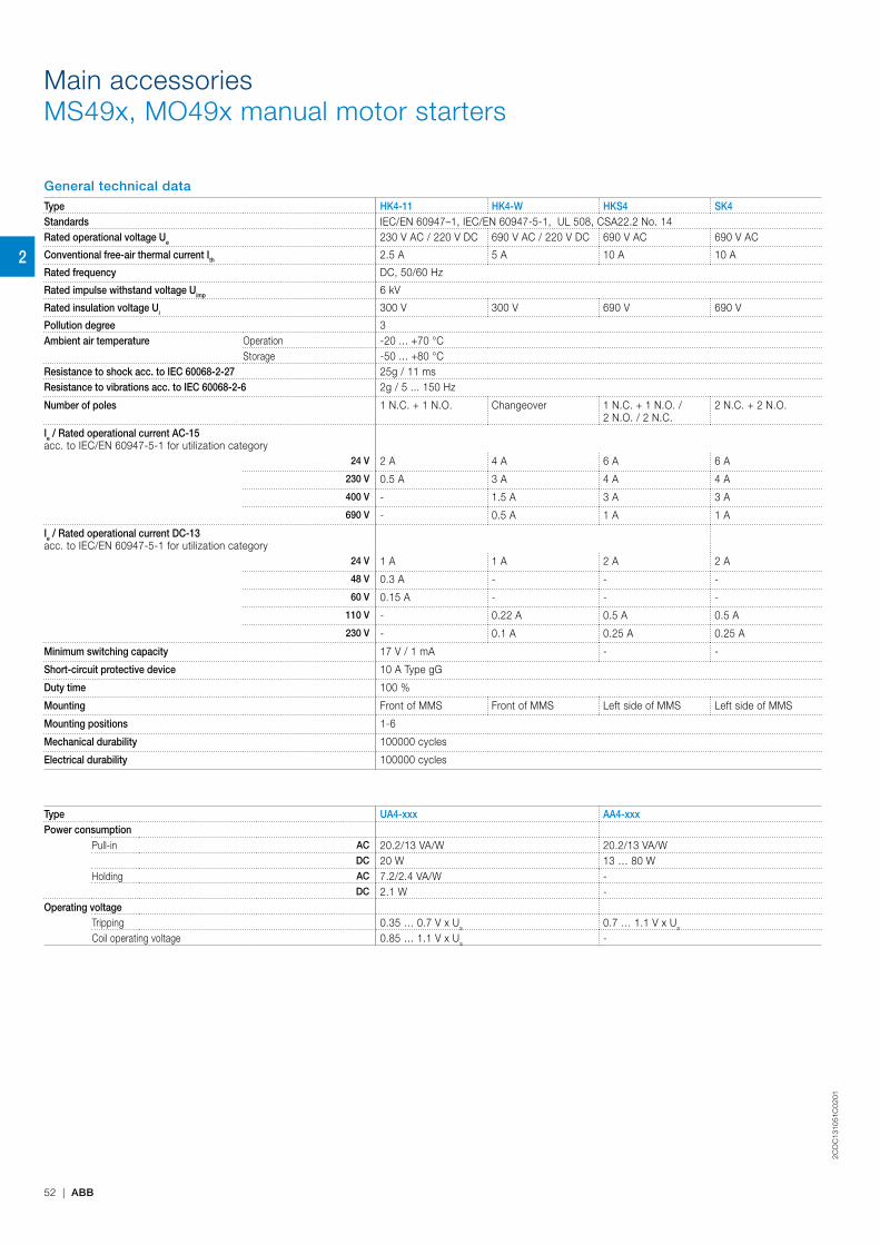
2CD
C13
1051
C0
201
52 | ABB
Main accessoriesMS49x, MO49x manual motor starters
General technical dataType HK4-11 HK4-W HKS4 SK4Standards IEC/EN 60947–1, IEC/EN 60947-5-1, UL 508, CSA22.2 No. 14Rated operational voltage Ue 230 V AC / 220 V DC 690 V AC / 220 V DC 690 V AC 690 V AC
Conventional free-air thermal current Ith 2.5 A 5 A 10 A 10 A
Rated frequency DC, 50/60 Hz
Rated impulse withstand voltage Uimp 6 kV
Rated insulation voltage Ui 300 V 300 V 690 V 690 V
Pollution degree 3Ambient air temperature Operation -20 ... +70 °C
Storage -50 ... +80 °CResistance to shock acc. to IEC 60068-2-27 25g / 11 msResistance to vibrations acc. to IEC 60068-2-6 2g / 5 ... 150 Hz
Number of poles 1 N.C. + 1 N.O. Changeover 1 N.C. + 1 N.O. / 2 N.O. / 2 N.C.
2 N.C. + 2 N.O.
Ie / Rated operational current AC-15acc. to IEC/EN 60947-5-1 for utilization category
24 V 2 A 4 A 6 A 6 A
230 V 0.5 A 3 A 4 A 4 A
400 V - 1.5 A 3 A 3 A
690 V - 0.5 A 1 A 1 A
Ie / Rated operational current DC-13acc. to IEC/EN 60947-5-1 for utilization category
24 V 1 A 1 A 2 A 2 A
48 V 0.3 A - - -
60 V 0.15 A - - -
110 V - 0.22 A 0.5 A 0.5 A
230 V - 0.1 A 0.25 A 0.25 A
Minimum switching capacity 17 V / 1 mA - -
Short-circuit protective device 10 A Type gG
Duty time 100 %
Mounting Front of MMS Front of MMS Left side of MMS Left side of MMS
Mounting positions 1-6
Mechanical durability 100000 cycles
Electrical durability 100000 cycles
Type UA4-xxx AA4-xxxPower consumption
Pull-in AC 20.2/13 VA/W 20.2/13 VA/WDC 20 W 13 … 80 W
Holding AC 7.2/2.4 VA/W -DC 2.1 W -
Operating voltageTripping 0.35 … 0.7 V x Us 0.7 … 1.1 V x Us
Coil operating voltage 0.85 … 1.1 V x Us -
2
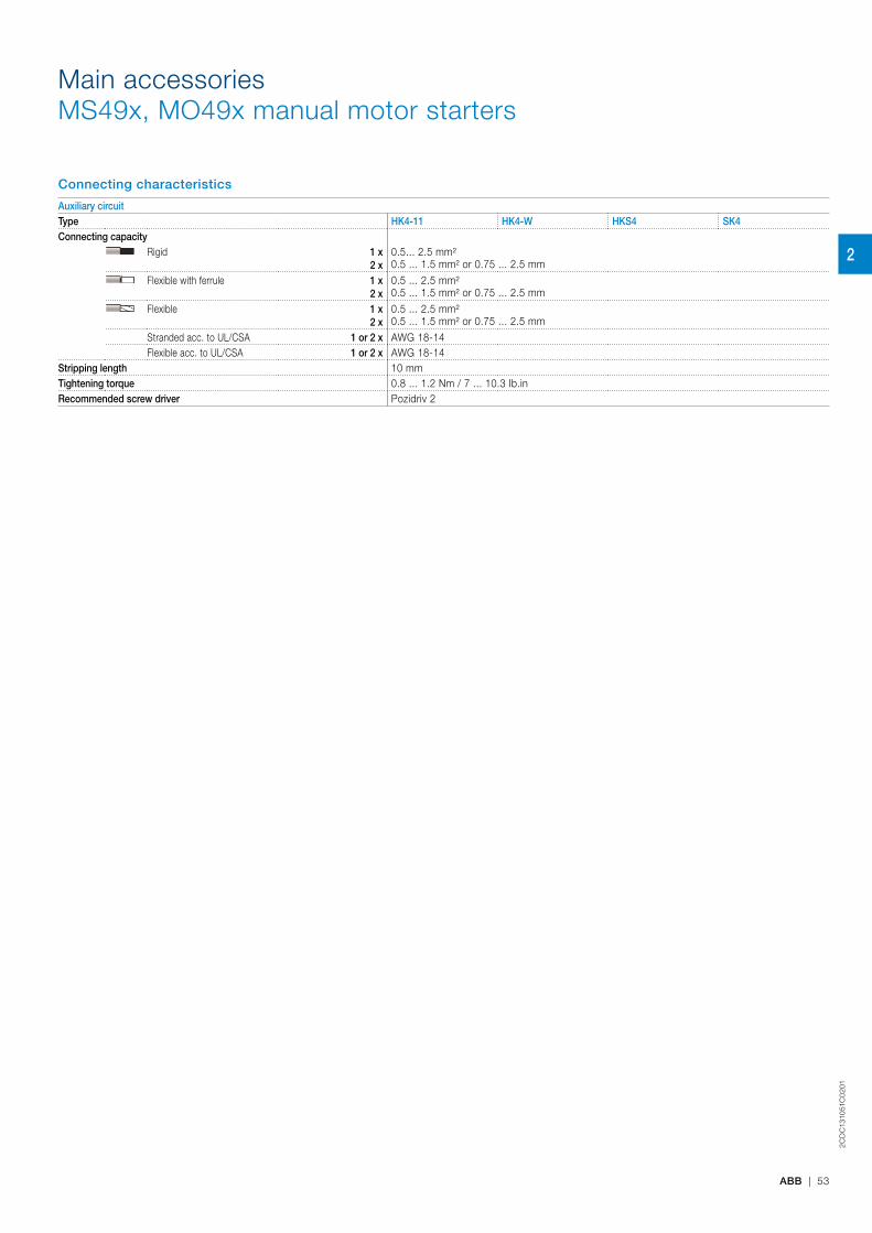
2CD
C13
1051
C0
201
ABB | 53
Connecting characteristics
Auxiliary circuitType HK4-11 HK4-W HKS4 SK4Connecting capacity
Rigid 1 x2 x
0.5... 2.5 mm² 0.5 ... 1.5 mm² or 0.75 ... 2.5 mm
Flexible with ferrule 1 x2 x
0.5 ... 2.5 mm²0.5 ... 1.5 mm² or 0.75 ... 2.5 mm
Flexible 1 x2 x
0.5 ... 2.5 mm²0.5 ... 1.5 mm² or 0.75 ... 2.5 mm
Stranded acc. to UL/CSA 1 or 2 x AWG 18-14Flexible acc. to UL/CSA 1 or 2 x AWG 18-14
Stripping length 10 mmTightening torque 0.8 ... 1.2 Nm / 7 ... 10.3 Ib.in Recommended screw driver Pozidriv 2
Main accessoriesMS49x, MO49x manual motor starters
2
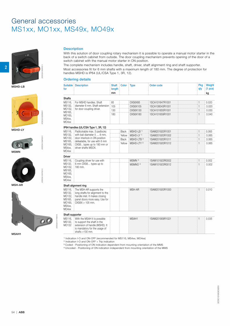
2CD
C13
105
3C
02
01
54 | ABB
General accessoriesMS1xx, MO1xx, MS49x, MO49x
DescriptionWith this solution of door coupling rotary mechanism it is possible to operate a manual motor starter in the back of a switch cabinet from outside. The door coupling mechanism prevents opening of the door of a switch cabinet with the manual motor starter in ON position.The complete mechanism includes handle, shaft, driver, shaft alignment ring and shaft supporter.Most accessories fit for 6 mm shafts with a maximum length of 180 mm. The degree of protection for handles MSHD is IP64 (UL/CSA Type 1, 3R, 12).
Ordering details
Suitable for
Description Shaft length
Color Type Order code Pkgqty
Weight (1 pce)
mm kg
ShaftsMS116, MS132, MO132, MS165, MO165, MS4xx, MO4xx
For MSHD handles. Shaft diameter 6 mm. Shaft extension for door coupling driver.
85 OXS6X85 1SCA101647R1001 1 0.020105 OXS6X105 1SCA108043R1001 1 0.020130 OXS6X130 1SCA101655R1001 1 0.030180 OXS6X180 1SCA101659R1001 1 0.040
IP64 handles (UL/CSA Type 1, 3R, 12)MS116, MS132, MO132, MS165, MO165, MS4xx, MO4xx
Padlockable max. 3 padlocks with bail diameter 5 … 8 mm, door interlock in ON position defeatable, for use with 6 mm OXS6…types up to 180 mm or driver shafts MSOX.
Black MSHD-LB 1) 1SAM201920R1001 1 0.065Yellow MSHD-LY 1) 1SAM201920R1002 1 0.065Black MSHD-LTB 2) 1SAM201920R1011 1 0.065Yellow MSHD-LTY 2) 1SAM201920R1012 1 0.065
DriverMS116, MS132, MO132, MS165, MO165, MS4xx, MO4xx
Coupling driver for use with 6 mm OXS6… types up to 180 mm.
MSMN 3) 1SAM101923R0002 1 0.002MSMNO 4) 1SAM101923R0012 1 0.002
Shaft alignment ringMS116, MS132, MO132, MS165, MO165, MS4xx, MO4xx
The MSH-AR supports the long shafts for alignment to the handle inlet. It makes closing panel doors more easy. Use for OXS6X > 105 mm.
MSH-AR 1SAM201920R1000 1 0.010
Shaft supporterMS116, MS132, MO132
With the MSAH it is possible to support the shaft in the extension of handle (MSHD). It is mandatory for the usage of shafts >130 mm.
MSAH1 1SAM201909R1021 1 0.035
1) Indication I-O and ON-OFF (recommended for MS116, MS4xx, MO4xx)2) Indication I-O and ON-OFF + Trip indication3) Coded - Positioning of ON indication dependent from mounting orientation of the MMS4) Uncoded - Positioning of ON indication independent from mounting orientation of the MMS
2C
DC
2410
03F0
011
MSHD-LB
2CD
C24
1002
S00
11
MSHD-LY
2CD
C24
1004
F001
1
MSMN
2CD
C24
1001
F001
2
MSH-AR
2CD
C24
1017
V00
13
MSAH1
2

2CD
C13
105
3C
02
01
ABB | 55
General accessoriesMS1xx, MO1xx, MS49x, MO49x
OXS6X
MSHD
MSAH1
MSH-AR
MSMNMSMNO
2CD
C24
2022
F001
3
1) MSAH1 fits to MS116,MS132 and MO132
1)
2
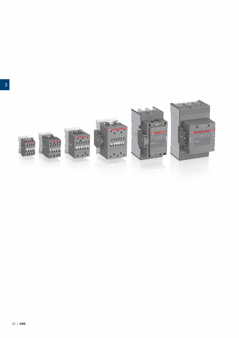
56 | ABB
3

AX contactors and NX contactor relays
AX 3-pole contactors
AX06 ... AX12 AC operated 58
AX18 ... AX25 AC operated 59
AX32, AX40 AC operated 60
AX50 ... AX80 AC operated 61
AX50 ... AX80 AC operated with 1 N.O. + 1 N.C. 62
AX95 ... AX150 AC operated with 1 N.O. + 1 N.C. 63
Main accessories 64
AX185 ... AX205 AC operated with 1 N.O. + 1 N.C. 67
AX260 ... AX370 AC operated with 1 N.O. + 1 N.C. 68
Main accessories 69
Technical data 72
Electrical durability 86
Star-delta starting 90
Terminal marking and positioning 92
Dimensions 93
NX contactor relays
NX AC operated 98
Main accessories 99
Technical data 100
Terminal marking and positioning 102
Accessories for AX06 ... AX80 3-pole contactors and NX contactor relays 103
Voltage code table 126
ABB | 57
3
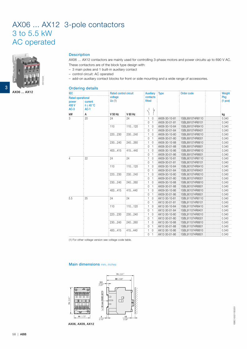
58 | ABB
1SB
C10
021
1S0
201
AX06 ... AX12 3-pole contactors3 to 5.5 kWAC operated
DescriptionAX06 … AX12 contactors are mainly used for controlling 3-phase motors and power circuits up to 690 V AC.
These contactors are of the block type design with: – 3 main poles and 1 built-in auxiliary contact – control circuit: AC operated – add-on auxiliary contact blocks for front or side mounting and a wide range of accessories.
Ordering detailsIEC Rated control circuit
voltageUc (1)
Auxiliary contacts fitted
Type Order code WeightPkg(1 pce)
Rated operationalpower400 VAC-3
currentθ ≤ 40 °CAC-1
kW A V 50 Hz V 60 Hz kg3 20 24 24 1 0 AX06-30-10-81 1SBL891074R8110 0.340
0 1 AX06-30-01-81 1SBL891074R8101 0.340110 110…120 1 0 AX06-30-10-84 1SBL891074R8410 0.340
0 1 AX06-30-01-84 1SBL891074R8401 0.340220…230 230…240 1 0 AX06-30-10-80 1SBL891074R8010 0.340
0 1 AX06-30-01-80 1SBL891074R8001 0.340 230…240 240…260 1 0 AX06-30-10-88 1SBL891074R8810 0.340
0 1 AX06-30-01-88 1SBL891074R8801 0.340400…415 415…440 1 0 AX06-30-10-86 1SBL891074R8610 0.340
0 1 AX06-30-01-86 1SBL891074R8601 0.3404 22 24 24 1 0 AX09-30-10-81 1SBL901074R8110 0.340
0 1 AX09-30-01-81 1SBL901074R8101 0.340110 110…120 1 0 AX09-30-10-84 1SBL901074R8410 0.340
0 1 AX09-30-01-84 1SBL901074R8401 0.340220…230 230…240 1 0 AX09-30-10-80 1SBL901074R8010 0.340
0 1 AX09-30-01-80 1SBL901074R8001 0.340230…240 240…260 1 0 AX09-30-10-88 1SBL901074R8810 0.340
0 1 AX09-30-01-88 1SBL901074R8801 0.340400…415 415...440 1 0 AX09-30-10-86 1SBL901074R8610 0.340
0 1 AX09-30-01-86 1SBL901074R8601 0.3405.5 25 24 24 1 0 AX12-30-10-81 1SBL911074R8110 0.340
0 1 AX12-30-01-81 1SBL911074R8101 0.340110 110…120 1 0 AX12-30-10-84 1SBL911074R8410 0.340
0 1 AX12-30-01-84 1SBL911074R8401 0.340220…230 230…240 1 0 AX12-30-10-80 1SBL911074R8010 0.340
0 1 AX12-30-01-80 1SBL911074R8001 0.340230…240 240…260 1 0 AX12-30-10-88 1SBL911074R8810 0.340
0 1 AX12-30-01-88 1SBL911074R8801 0.340400…415 415...440 1 0 AX12-30-10-86 1SBL911074R8610 0.340
0 1 AX12-30-01-86 1SBL911074R8601 0.340
(1) For other voltage version see voltage code table.
AX
0100
2AX
AX06 ... AX12
AX06, AX09, AX12
35 m
m E
N/IE
C 60
715
74 2
.91"
44 1.73"
5.50.22"
100.39"
40.16"
68 2.68"
74 2.91"
Main dimensions mm, inches
3
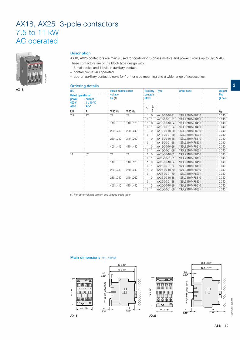
ABB | 59
1SB
C10
021
2S0
201
AX18, AX25 3-pole contactors7.5 to 11 kWAC operated
DescriptionAX18, AX25 contactors are mainly used for controlling 3-phase motors and power circuits up to 690 V AC.
These contactors are of the block type design with: – 3 main poles and 1 built-in auxiliary contact – control circuit: AC operated – add-on auxiliary contact blocks for front or side mounting and a wide range of accessories.
Ordering detailsIEC Rated control circuit
voltageUc (1)
Auxiliary contacts fitted
Type Order code WeightPkg(1 pce)
Rated operationalpower400 VAC-3
currentθ ≤ 40 °CAC-1
kW A V 50 Hz V 60 Hz kg7.5 27 24 24 1 0 AX18-30-10-81 1SBL921074R8110 0.340
0 1 AX18-30-01-81 1SBL921074R8101 0.340110 110…120 1 0 AX18-30-10-84 1SBL921074R8410 0.340
0 1 AX18-30-01-84 1SBL921074R8401 0.340220…230 230…240 1 0 AX18-30-10-80 1SBL921074R8010 0.340
0 1 AX18-30-01-80 1SBL921074R8001 0.340230…240 240…260 1 0 AX18-30-10-88 1SBL921074R8810 0.340
0 1 AX18-30-01-88 1SBL921074R8801 0.340400…415 415…440 1 0 AX18-30-10-86 1SBL921074R8610 0.340
0 1 AX18-30-01-86 1SBL921074R8601 0.34011 32 24 24 1 0 AX25-30-10-81 1SBL931074R8110 0.340
0 1 AX25-30-01-81 1SBL931074R8101 0.340110 110…120 1 0 AX25-30-10-84 1SBL931074R8410 0.340
0 1 AX25-30-01-84 1SBL931074R8401 0.340220…230 230…240 1 0 AX25-30-10-80 1SBL931074R8010 0.340
0 1 AX25-30-01-80 1SBL931074R8001 0.340230…240 240…260 1 0 AX25-30-10-88 1SBL931074R8810 0.340
0 1 AX25-30-01-88 1SBL931074R8801 0.340400…415 415…440 1 0 AX25-30-10-86 1SBL931074R8610 0.340
0 1 AX25-30-01-86 1SBL931074R8601 0.340
(1) For other voltage version see voltage code table.
AX
0100
2AX
AX18
AX18 AX25
35 m
m E
N/IE
C 60
715
74 2
.91"
44 1.73"
5.50.22"
100.39"
40.16"
68 2.68"
74 2.91"
Main dimensions mm, inches
35 m
m E
N/IE
C 60
715
74 2
.91"
44 1.73"
5.50.22"
76.6 3.02"
70.3 2.77"
100.39"
40.16"
3

60 | ABB
1SB
C10
02
32S
02
01
AX32, AX40 3-pole contactors15 to 18.5 kWAC operated
DescriptionAX32, AX40 contactors are mainly used for controlling 3-phase motors and power circuits up to 690 V AC.
These contactors are of the block type design with: – 3 main poles and 1 built-in auxiliary contact – control circuit: AC operated – add-on auxiliary contact blocks for front or side mounting and a wide range of accessories.
Ordering details
IEC Rated control circuit voltageUc (1)
Auxiliary contacts fitted
Type Order code Weight(1 pce)
Rated operationalpower400 VAC-3
currentθ ≤ 40 °CAC-1
kW A V 50 Hz V 60 Hz kg15 55 24 24 1 0 AX32-30-10-81 1SBL281074R8110 0.71
0 1 AX32-30-01-81 1SBL281074R8101 0.71110 110…120 1 0 AX32-30-10-84 1SBL281074R8410 0.71
0 1 AX32-30-01-84 1SBL281074R8401 0.71220…230 230…240 1 0 AX32-30-10-80 1SBL281074R8010 0.71
0 1 AX32-30-01-80 1SBL281074R8001 0.71230…240 240…260 1 0 AX32-30-10-88 1SBL281074R8810 0.71
0 1 AX32-30-01-88 1SBL281074R8801 0.71400…415 415…440 1 0 AX32-30-10-86 1SBL281074R8610 0.71
0 1 AX32-30-01-86 1SBL281074R8601 0.7118.5 60 24 24 1 0 AX40-30-10-81 1SBL321074R8110 0.71
0 1 AX40-30-01-81 1SBL321074R8101 0.71110 110…120 1 0 AX40-30-10-84 1SBL321074R8410 0.71
0 1 AX40-30-01-84 1SBL321074R8401 0.71220…230 230…240 1 0 AX40-30-10-80 1SBL321074R8010 0.71
0 1 AX40-30-01-80 1SBL321074R8001 0.71230…240 240…260 1 0 AX40-30-10-88 1SBL321074R8810 0.71
0 1 AX40-30-01-88 1SBL321074R8801 0.71400…415 415…440 1 0 AX40-30-10-86 1SBL321074R8610 0.71
0 1 AX40-30-01-86 1SBL321074R8601 0.71
(1) For other voltage version see voltage code table.
AX32, AX40
AX
0200
2
AX32, AX40
35 m
m E
N/IE
C 60
715
90 3
.54"
54 2.13" 40.16"
100.39"
6.30.25"
108.3 4.26"
90.35"
Main dimensions mm, inches
3
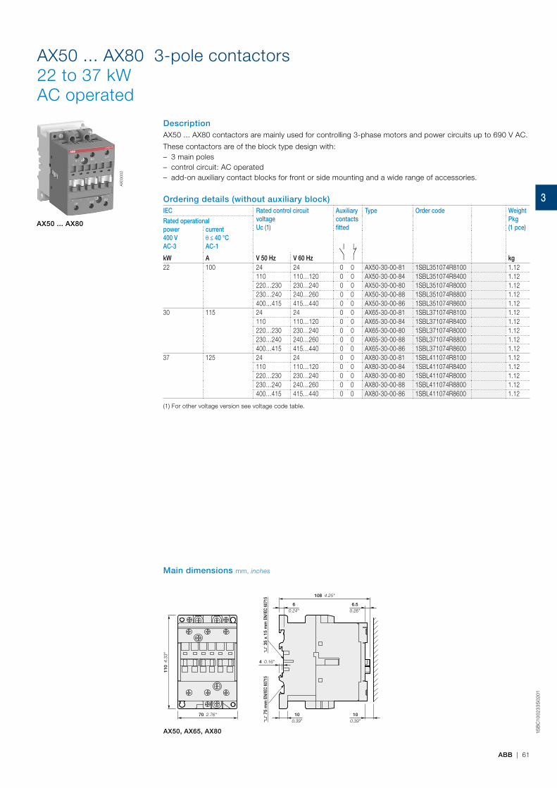
ABB | 61
1SB
C10
02
33
S0
201
AX50 ... AX80 3-pole contactors22 to 37 kWAC operated
DescriptionAX50 ... AX80 contactors are mainly used for controlling 3-phase motors and power circuits up to 690 V AC.
These contactors are of the block type design with: – 3 main poles – control circuit: AC operated – add-on auxiliary contact blocks for front or side mounting and a wide range of accessories.
Ordering details (without auxiliary block)IEC Rated control circuit
voltageUc (1)
Auxiliary contacts fitted
Type Order code WeightPkg(1 pce)
Rated operationalpower400 VAC-3
currentθ ≤ 40 °CAC-1
kW A V 50 Hz V 60 Hz kg22 100 24 24 0 0 AX50-30-00-81 1SBL351074R8100 1.12
110 110…120 0 0 AX50-30-00-84 1SBL351074R8400 1.12220…230 230…240 0 0 AX50-30-00-80 1SBL351074R8000 1.12230…240 240…260 0 0 AX50-30-00-88 1SBL351074R8800 1.12400…415 415…440 0 0 AX50-30-00-86 1SBL351074R8600 1.12
30 115 24 24 0 0 AX65-30-00-81 1SBL371074R8100 1.12110 110…120 0 0 AX65-30-00-84 1SBL371074R8400 1.12220…230 230…240 0 0 AX65-30-00-80 1SBL371074R8000 1.12230…240 240…260 0 0 AX65-30-00-88 1SBL371074R8800 1.12400…415 415…440 0 0 AX65-30-00-86 1SBL371074R8600 1.12
37 125 24 24 0 0 AX80-30-00-81 1SBL411074R8100 1.12110 110…120 0 0 AX80-30-00-84 1SBL411074R8400 1.12220…230 230…240 0 0 AX80-30-00-80 1SBL411074R8000 1.12230…240 240…260 0 0 AX80-30-00-88 1SBL411074R8800 1.12400…415 415…440 0 0 AX80-30-00-86 1SBL411074R8600 1.12
(1) For other voltage version see voltage code table.
AX50 ... AX80
AX
0300
2
AX50, AX65, AX80
35 x
15
mm
EN/
IEC
6071
575
mm
EN/
IEC
6071
5
110
4.3
3"
70 2.76" 100.39"
100.39"
4 0.16"
6.50.26"
60.24"
108 4.25"
Main dimensions mm, inches
3
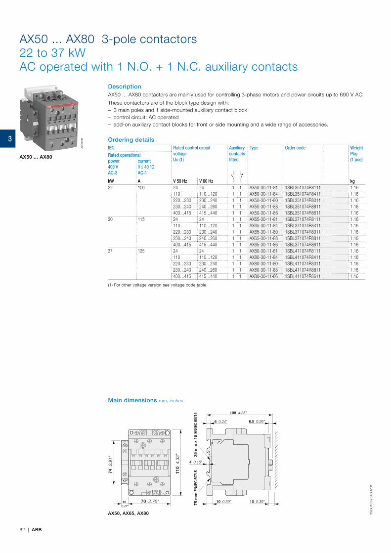
62 | ABB
1SB
C10
02
34
S0
201
AX50 ... AX80 3-pole contactors22 to 37 kWAC operated with 1 N.O. + 1 N.C. auxiliary contacts
DescriptionAX50 ... AX80 contactors are mainly used for controlling 3-phase motors and power circuits up to 690 V AC.
These contactors are of the block type design with: – 3 main poles and 1 side-mounted auxiliary contact block – control circuit: AC operated – add-on auxiliary contact blocks for front or side mounting and a wide range of accessories.
Ordering detailsIEC Rated control circuit
voltageUc (1)
Auxiliary contacts fitted
Type Order code WeightPkg(1 pce)
Rated operationalpower400 VAC-3
currentθ ≤ 40 °CAC-1
kW A V 50 Hz V 60 Hz kg22 100 24 24 1 1 AX50-30-11-81 1SBL351074R8111 1.16
110 110…120 1 1 AX50-30-11-84 1SBL351074R8411 1.16220…230 230…240 1 1 AX50-30-11-80 1SBL351074R8011 1.16230…240 240…260 1 1 AX50-30-11-88 1SBL351074R8811 1.16400…415 415…440 1 1 AX50-30-11-86 1SBL351074R8611 1.16
30 115 24 24 1 1 AX65-30-11-81 1SBL371074R8111 1.16110 110…120 1 1 AX65-30-11-84 1SBL371074R8411 1.16220…230 230…240 1 1 AX65-30-11-80 1SBL371074R8011 1.16230…240 240…260 1 1 AX65-30-11-88 1SBL371074R8811 1.16400…415 415…440 1 1 AX65-30-11-86 1SBL371074R8611 1.16
37 125 24 24 1 1 AX80-30-11-81 1SBL411074R8111 1.16110 110…120 1 1 AX80-30-11-84 1SBL411074R8411 1.16220…230 230…240 1 1 AX80-30-11-80 1SBL411074R8011 1.16230…240 240…260 1 1 AX80-30-11-88 1SBL411074R8811 1.16400…415 415…440 1 1 AX80-30-11-86 1SBL411074R8611 1.16
(1) For other voltage version see voltage code table.
AX50 ... AX80
AX50, AX65, AX80
Main dimensions mm, inches
AX
0303
8
70 2.76"12 0.47"
74 2
.91"
110
4.3
3"
108 4.25"
6.5 0.26"6 0.24"
10 0.39"
4 0.16"
10 0.39"
35 m
m x
15
EN/IE
C 60
715
75 m
m E
N/IE
C 60
715
3
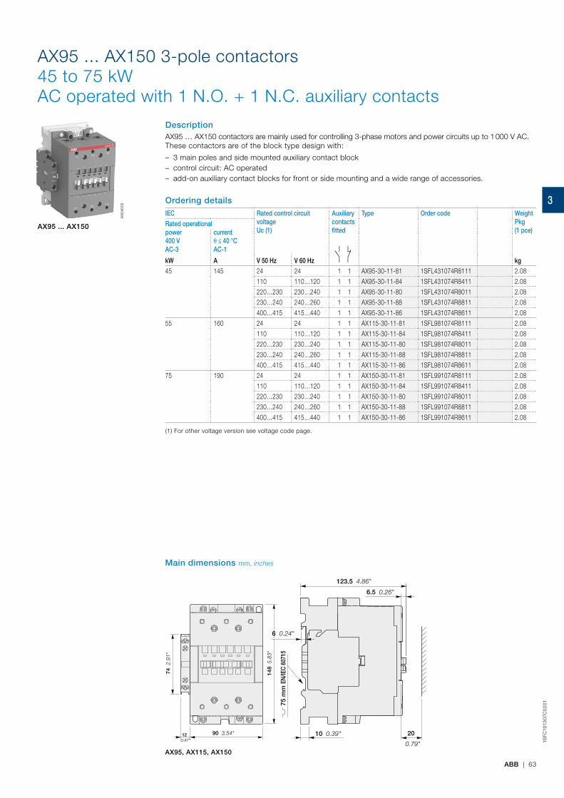
ABB | 63
1SFC
1013
07C
02
01
AX95 ... AX150 3-pole contactors45 to 75 kWAC operated with 1 N.O. + 1 N.C. auxiliary contacts
DescriptionAX95 … AX150 contactors are mainly used for controlling 3-phase motors and power circuits up to 1 000 V AC.These contactors are of the block type design with:
– 3 main poles and side mounted auxiliary contact block – control circuit: AC operated – add-on auxiliary contact blocks for front or side mounting and a wide range of accessories.
Ordering detailsIEC Rated control circuit
voltageUc (1)
Auxiliary contacts fitted
Type Order code WeightPkg(1 pce)
Rated operationalpower400 VAC-3
currentθ ≤ 40 °CAC-1
kW A V 50 Hz V 60 Hz kg
45 145 24 24 1 1 AX95-30-11-81 1SFL431074R8111 2.08110 110…120 1 1 AX95-30-11-84 1SFL431074R8411 2.08220…230 230…240 1 1 AX95-30-11-80 1SFL431074R8011 2.08230…240 240…260 1 1 AX95-30-11-88 1SFL431074R8811 2.08400…415 415…440 1 1 AX95-30-11-86 1SFL431074R8611 2.08
55 160 24 24 1 1 AX115-30-11-81 1SFL981074R8111 2.08110 110…120 1 1 AX115-30-11-84 1SFL981074R8411 2.08220…230 230…240 1 1 AX115-30-11-80 1SFL981074R8011 2.08230…240 240…260 1 1 AX115-30-11-88 1SFL981074R8811 2.08400…415 415…440 1 1 AX115-30-11-86 1SFL981074R8611 2.08
75 190 24 24 1 1 AX150-30-11-81 1SFL991074R8111 2.08110 110…120 1 1 AX150-30-11-84 1SFL991074R8411 2.08220…230 230…240 1 1 AX150-30-11-80 1SFL991074R8011 2.08230…240 240…260 1 1 AX150-30-11-88 1SFL991074R8811 2.08400…415 415…440 1 1 AX150-30-11-86 1SFL991074R8611 2.08
(1) For other voltage version see voltage code page.
AX95 ... AX150
AX
0400
2
AX95, AX115, AX150
Main dimensions mm, inches
148
5.8
3"
74 2
.91"
90 3.54"12 0.47"
75 m
m E
N/IE
C 60
715
123.5 4.86"
6.5 0.26"
6 0.24"
10 0.39" 20
0.79"
3
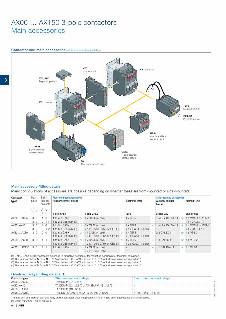
64 | ABB
1SB
C10
021
6S
02
01
AX06 … AX150 3-pole contactorsMain accessories
Contactortypes
Mainpoles
Built-inauxiliarycontacts
Front-mounted accessories Side-mounted accessoriesAuxiliary contact blocks Electronic timer Auxiliary contact
blocksInterlock unit
1-pole CA5X 4-pole CA5X TEF5 2-pole CAL VM5 or VE5
AX06 ... AX25 3 0 1 0 1 to 4 x CA5X or 1 x CA5X (4-pole) or 1 x TEF5 + 1 to 2 x CAL5X-11 or 1 x VM5-1 or VE5-13 0 0 1 (1) 1 to 2 x CE5 max (2) +1 x CAL5X-11
AX32, AX40 3 0 1 0 1 to 5 x CA5X or 1 x CA5X (4-pole) or 1 x TEF5 + 1 to 2 x CAL5X-11 or 1 x VM5-1 or VE5-13 0 0 1 (1) 1 to 3 x CE5 max (3) + 1 x 1-pole CA5X or CE5 (3) + 1 x CA5X (1-pole) +1 x CAL5X-11
AX50 ... AX80 3 0 0 0 1 to 6 x CA5X1 to 5 x CE5 max (4)
or 1 x CA5X (4-pole)+ 2 x 1-pole CA5X or CE5 (4)
or 1 x TEF5+ 2 x CA5X (1-pole)
+ 2 x CAL5X-11 or 1 x VE5-2
AX50 ... AX80 3 0 1 1 1 to 6 x CA5X or 1 x CA5X (4-pole) or 1 x TEF5 + 1 x CAL5X-11 or 1 x VE5-21 to 5 x CE5 max (4) + 2 x 1-pole CA5X or CE5 (4) + 2 x CA5X (1-pole)
AX95 ... AX150 3 0 1 1 1 to 6 x CA5X or 1 x CA5X (4-pole) – + 1 x CAL18X-11 or 1 x VE5-2+ 2 x 1-pole CA5X
(1) 2 N.C. CA5X auxiliary contacts maximum in mounting position 5. for mounting position refer technical data page.(2) The total number of N.O. or N.C. CE5 and other N.C. CA5X is limited to 2. CE5 not allowed in mounting position 5.(3) The total number of N.O. or N.C. CE5 and other N.C. CA5X is limited to 3. CE5 not allowed in mounting position 5.(4) The total number of N.O. or N.C. CE5 and other N.C. CA5X is limited to 5. CE5 not allowed in mounting position 5.
Overload relays fitting details (1)Contactor types Thermal overload relays Electronic overload relaysAX06 ... AX25 TA25DU-M (0.1...32 A) –AX32, AX40 TA25DU-M (0.1...32 A) or TA42DU-M (18...42 A) –AX50 … AX80 TA75DU-M (18...80 A) –AX95 ... AX150 TA80DU (29...80 A) or TA110DU (66...110 A) E140DU (50 ... 140 A)
The addition of a thermal overload relay on the contactor does not prevent fitting of many other accessories as shown above.(1) Direct mounting - No kit required.
Main accessory fitting detailsMany configurations of accessories are possible depending on whether these are front-mounted or side-mounted.
Contactor and main accessories (other accessories available)
A1A2
AX contactor
AX contactor
TEF5Electronic timer
VE5Interlock unit
RV5, RC5Surge suppressor
TAThermal overload relay
BX4-CAProtective cover
CA5X4-pole auxiliary contact block
CA5X1-pole auxiliary contact block
CAL5X2-pole auxiliary contact block
3
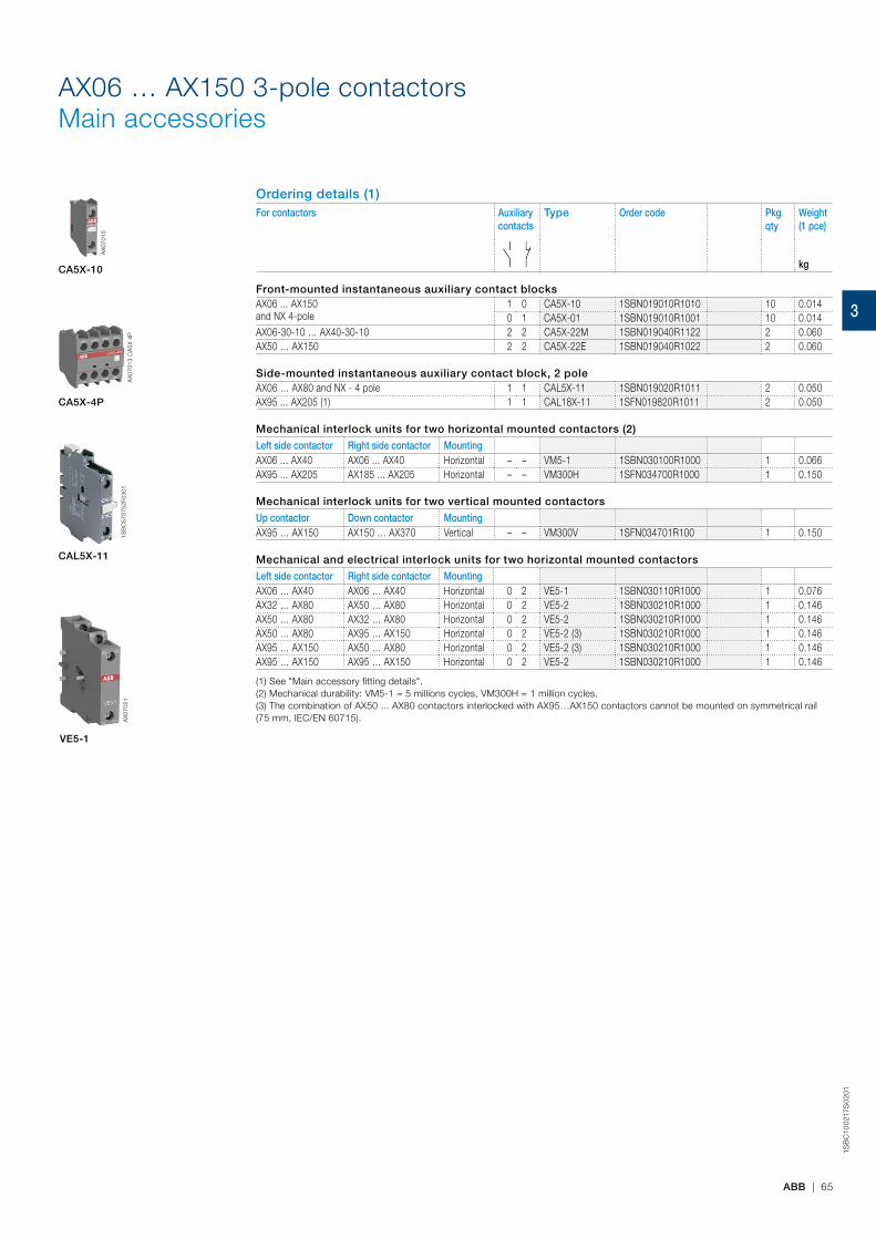
ABB | 65
1SB
C10
021
7S0
201
AX06 … AX150 3-pole contactorsMain accessories
Ordering details (1)For contactors Auxiliary
contactsType Order code Pkg
qtyWeight(1 pce)
kg
Front-mounted instantaneous auxiliary contact blocksAX06 ... AX150 and NX 4-pole
1 0 CA5X-10 1SBN019010R1010 10 0.0140 1 CA5X-01 1SBN019010R1001 10 0.014
AX06-30-10 … AX40-30-10 2 2 CA5X-22M 1SBN019040R1122 2 0.060AX50 … AX150 2 2 CA5X-22E 1SBN019040R1022 2 0.060
Side-mounted instantaneous auxiliary contact block, 2 poleAX06 … AX80 and NX - 4 pole 1 1 CAL5X-11 1SBN019020R1011 2 0.050AX95 ... AX205 (1) 1 1 CAL18X-11 1SFN019820R1011 2 0.050
Mechanical interlock units for two horizontal mounted contactors (2)
Left side contactor Right side contactor MountingAX06 ... AX40 AX06 ... AX40 Horizontal – – VM5-1 1SBN030100R1000 1 0.066AX95 ... AX205 AX185 ... AX205 Horizontal – – VM300H 1SFN034700R1000 1 0.150
Mechanical interlock units for two vertical mounted contactors
Up contactor Down contactor MountingAX95 … AX150 AX150 … AX370 Vertical – – VM300V 1SFN034701R100 1 0.150
Mechanical and electrical interlock units for two horizontal mounted contactors
Left side contactor Right side contactor MountingAX06 … AX40 AX06 … AX40 Horizontal 0 2 VE5-1 1SBN030110R1000 1 0.076AX32 … AX80 AX50 … AX80 Horizontal 0 2 VE5-2 1SBN030210R1000 1 0.146AX50 … AX80 AX32 … AX80 Horizontal 0 2 VE5-2 1SBN030210R1000 1 0.146AX50 … AX80 AX95 … AX150 Horizontal 0 2 VE5-2 (3) 1SBN030210R1000 1 0.146AX95 … AX150 AX50 … AX80 Horizontal 0 2 VE5-2 (3) 1SBN030210R1000 1 0.146AX95 … AX150 AX95 … AX150 Horizontal 0 2 VE5-2 1SBN030210R1000 1 0.146
(1) See "Main accessory fitting details".(2) Mechanical durability: VM5-1 = 5 millions cycles, VM300H = 1 million cycles.(3) The combination of AX50 ... AX80 contactors interlocked with AX95…AX150 contactors cannot be mounted on symmetrical rail (75 mm, IEC/EN 60715).
CA5X-10
AX
0701
5
CAL5X-11
CA5X-4P
1SB
C57
3752
F030
1
VE5-1
AX
0702
1A
X07
013
CA
5X 4
P
3

66 | ABB
1SB
C10
021
8S
02
01
AX06 … AX150 3-pole contactorsMain accessories
Surge suppressors
For contactors Rated control circuit voltageUc
Type Order code Pkg qty
Weight(1 pce)
V AC kgAX06 ... AX150 24...50 RV5/50 1SBN050010R1000 2 0.015
50...133 RV5/133 1SBN050010R1001 2 0.015
110...250 RV5/250 1SBN050010R1002 2 0.015
250...440 RV5/440 1SBN050010R1003 2 0.015
AX06 ... AX40 24...50 RC5-1/50 1SBN050100R1000 2 0.012
50...133 RC5-1/133 1SBN050100R1001 2 0.012
110...250 RC5-1/250 1SBN050100R1002 2 0.012
250...440 RC5-1/440 1SBN050100R1003 2 0.012
AX50 … AX150 24...50 RC5-2/50 1SBN050200R1000 2 0.015
50...133 RC5-2/133 1SBN050200R1001 2 0.015
110...250 RC5-2/250 1SBN050200R1002 2 0.015
250...440 RC5-2/440 1SBN050200R1003 2 0.015
1SB
C57
4001
F030
1
RV5/50
Ordering details (1)For contactors Time delay
rangeselected by switch
Delaytype
Auxiliary contacts
Type Order code Pkgqty
Weight(1 pce)
kg
Electronic timersAX06 ... AX80 NX 4 pole
0.1...1 s1...10 s10...100 s
ON-delay 1 1 TEF5-ON 1SBN020312R1000 1 0.065
OFF-delay 1 1 TEF5-OFF 1SBN020314R1000 1 0.065
Note: Rated control circuit voltage Uc 24...240 V 50/60 Hz or DC.
TEF5-OFF
1SB
C10
1396
F001
4
WB75-A
1SB
C56
5483
F030
1
Mechanical latching units
For contactors Rated control circuitvoltage Uc
Type Order code Pkgqty
Weight(1 pce)
50Hz 60 Hz kgAX06…AX80 24 24...28 WB75-A FPTN372726R1001 1 0.120
220...230 220...255 WB75-A FPTN372726R1006 1 0.120
Connecting links with manual motor starters
BEA
For contactors MMS type Type Order code Pkgqty
Weight(1 pce)
kg
AX06 … AX18 MS116-0.16 ... MS116-16 / MS132-0.16 ... MS132-10
BEA16/116 1SBN081406R1000 10 0.020
AX25 MS116-0.16 ... MS116-16 / MS132-0.16 ... MS132-10
BEA25/116 1SBN089306T1000 10 0.020
AX25 MS116-20 ... MS116-32 / MS132-12 ... MS132-32
BEA25/132 1SBN089306T1001 10 0.020
AX50 ... AX80 MS495 BEA75/495 1SBN084106R1000 1 0.120
AX95 ... AX150 MS495 BEA110/495 1SBN084506R1000 1 0.124
(1) See "Main accessory fitting details".
1SB
C58
2813
F030
1
3
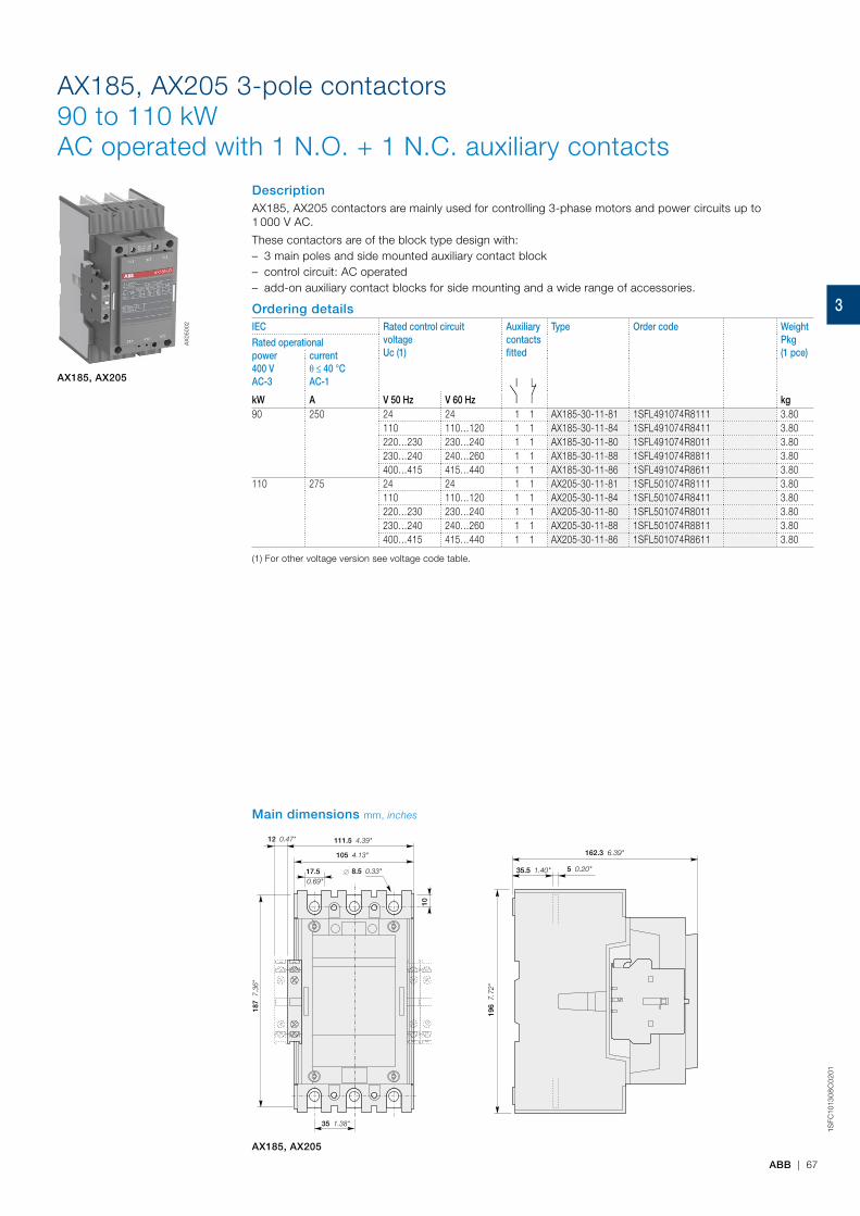
ABB | 67
1SFC
1013
08
C0
201
111.5 4.39"
105 4.13"
12 0.47"
17.5 0.69"
8.5 0.33"
10
0.3
9"
35 1.38"
187
7.3
6"
162.3 6.39"
5 0.20"
196
7.7
2"
35.5 1.40"
AX185, AX205
AX185, AX205 3-pole contactors90 to 110 kWAC operated with 1 N.O. + 1 N.C. auxiliary contacts
DescriptionAX185, AX205 contactors are mainly used for controlling 3-phase motors and power circuits up to 1 000 V AC.
These contactors are of the block type design with: – 3 main poles and side mounted auxiliary contact block – control circuit: AC operated – add-on auxiliary contact blocks for side mounting and a wide range of accessories.
Ordering detailsIEC Rated control circuit
voltageUc (1)
Auxiliary contacts fitted
Type Order code WeightPkg(1 pce)
Rated operationalpower400 VAC-3
currentθ ≤ 40 °CAC-1
kW A V 50 Hz V 60 Hz kg90 250 24 24 1 1 AX185-30-11-81 1SFL491074R8111 3.80
110 110…120 1 1 AX185-30-11-84 1SFL491074R8411 3.80220…230 230…240 1 1 AX185-30-11-80 1SFL491074R8011 3.80230…240 240…260 1 1 AX185-30-11-88 1SFL491074R8811 3.80400…415 415…440 1 1 AX185-30-11-86 1SFL491074R8611 3.80
110 275 24 24 1 1 AX205-30-11-81 1SFL501074R8111 3.80110 110…120 1 1 AX205-30-11-84 1SFL501074R8411 3.80220…230 230…240 1 1 AX205-30-11-80 1SFL501074R8011 3.80230…240 240…260 1 1 AX205-30-11-88 1SFL501074R8811 3.80400…415 415…440 1 1 AX205-30-11-86 1SFL501074R8611 3.80
(1) For other voltage version see voltage code table.
AX185, AX205
AX
0500
2
Main dimensions mm, inches
3

68 | ABB
1SFC
1013
09
C0
201
Main dimensions mm, inches
AX265 AX305 AX370, ,
140 5.51"
19.50 0.77"
43.75 1.72"
10.5 0.41"180 7.09"
94.7
3.7
3"
225
8.8
6"
5 0.20"35.5 1.40"
33.4
1.3
1"
A10 0.39"
187
7.3
6"
43 1.69"75 2.95". 0.00" M5 10 0.39"24 0.94"UNC-4 X
AX260, AX300, AX370
AX260 ... AX370 3-pole contactors132 to 200 kWAC operated with 1 N.O. + 1 N.C. auxiliary contacts
DescriptionAX260 … AX370 contactors are mainly used for controlling 3-phase motors and power circuits up to 1 000 V AC.
These contactors are of the block type design with: – 3 main poles and side mounted auxiliary contact block – control circuit: AC operated – add-on auxiliary contact blocks for side mounting and a wide range of accessories.
Ordering detailsIEC Rated control circuit
voltageUc (1)
Auxiliary contacts fitted
Type Order code WeightPkg(1 pce)
Rated operationalpower400 VAC-3
currentθ ≤ 40 °CAC-1
kW A V 50 Hz V 60 Hz kg132 400 24 24 1 1 AX260-30-11-81 1SFL547074R8111 5.4
110 110…120 1 1 AX260-30-11-84 1SFL547074R8411 5.4220…230 230…240 1 1 AX260-30-11-80 1SFL547074R8011 5.4230…240 240…260 1 1 AX260-30-11-88 1SFL547074R8811 5.4400…415 415…440 1 1 AX260-30-11-86 1SFL547074R8611 5.4
160 500 24 24 1 1 AX300-30-11-81 1SFL587074R8111 5.4110 110…120 1 1 AX300-30-11-84 1SFL587074R8411 5.4220…230 230…240 1 1 AX300-30-11-80 1SFL587074R8011 5.4230…240 240…260 1 1 AX300-30-11-88 1SFL587074R8811 5.4400…415 415…440 1 1 AX300-30-11-86 1SFL587074R8611 5.4
200 600 24 24 1 1 AX370-30-11-81 1SFL607074R8111 5.4110 110…120 1 1 AX370-30-11-84 1SFL607074R8411 5.4220…230 230…240 1 1 AX370-30-11-80 1SFL607074R8011 5.4230…240 240…260 1 1 AX370-30-11-88 1SFL607074R8811 5.4400…415 415…440 1 1 AX370-30-11-86 1SFL607074R8611 5.4
(1) For other voltage version see voltage code table
AX260 ... AX370
AX
0602
2
3

ABB | 69
1SFC
1013
10C
02
01
contact block
AX300-30
AX300-30
Main accessories (other accessories available)
AX contactor
CAL19-112-pole auxiliary
CAL19-112-pole auxiliarycontact block
AX contactor
VMMechanical interlock
LTTerminal shroud
EFElectronic overload relay
CAL19-11B2-pole auxiliarycontact block
contact block
CAL19-11B2-pole auxiliary
AX185 ... AX370 3-pole contactorsMain accessories
Main accessories (other accessories available)
AX185, AX205
AX260 ... AX370
1L1
3L2
5L3
2T1
4T2
6T3
AX185-30
A1A2
Main accessories (other accessories available)
CAL18X-112-pole auxiliarycontact block
CAL18X-11B2-pole auxiliarycontact block
TAThermal overload relay
AX contactor
VMMechanical interlock
LTTerminal shroud
1L1
3L2
5L3
2T1
4T2
6T3
AX185-30
A1A2
CAL18X-112-pole auxiliarycontact block
CAL18X-11B2-pole auxiliarycontact block
AX contactor
3
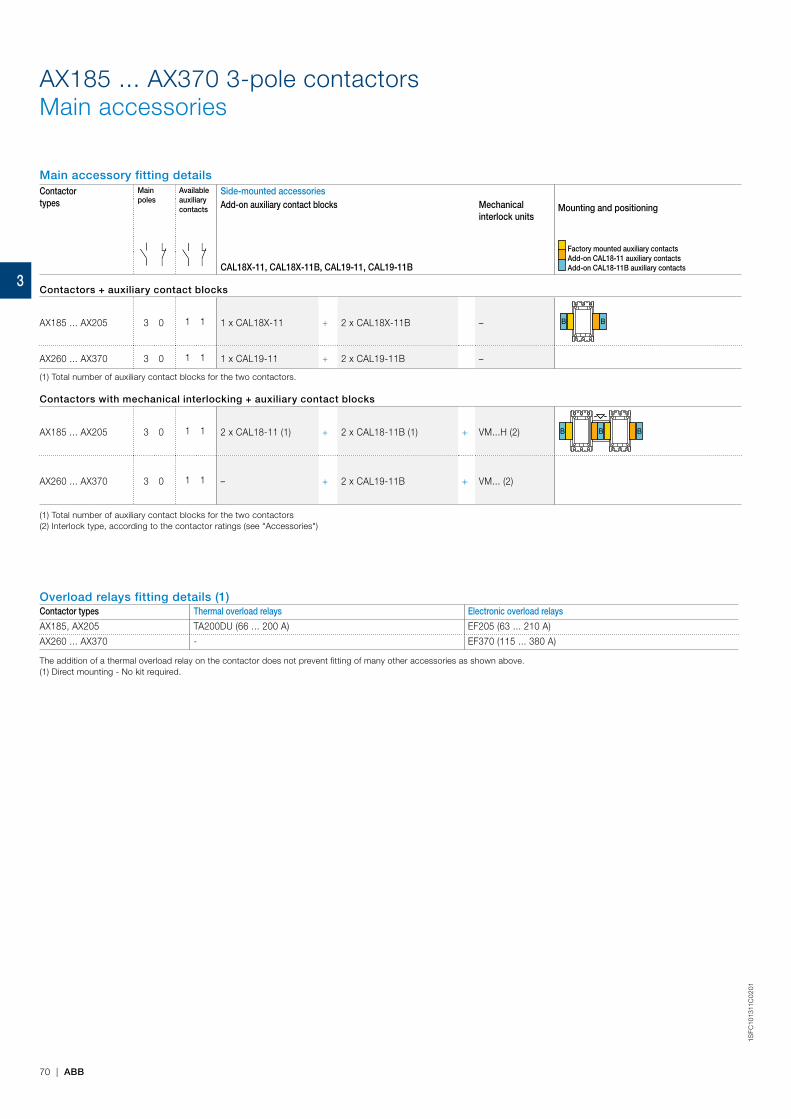
70 | ABB
1SFC
1013
11C
02
01
AX185 ... AX370 3-pole contactorsMain accessories
Main accessory fitting detailsContactortypes
Mainpoles
Availableauxiliarycontacts
Side-mounted accessories Add-on auxiliary contact blocks Mechanical
interlock unitsMounting and positioning
Factory mounted auxiliary contacts Add-on CAL18-11 auxiliary contacts Add-on CAL18-11B auxiliary contactsCAL18X-11, CAL18X-11B, CAL19-11, CAL19-11B
Contactors + auxiliary contact blocks
AX185 ... AX205 3 0 1 1 1 x CAL18X-11 + 2 x CAL18X-11B –
AX260 ... AX370 3 0 1 1 1 x CAL19-11 + 2 x CAL19-11B –
(1) Total number of auxiliary contact blocks for the two contactors.
Contactors with mechanical interlocking + auxiliary contact blocks
AX185 ... AX205 3 0 1 1 2 x CAL18-11 (1) + 2 x CAL18-11B (1) + VM...H (2)
A145 ... A300 3-pole contactorsMain accessories
Main accessory fitting detailsContactortypes
Mainpoles
Availableauxiliarycontacts
Side-mounted accessories Add-on auxiliary contact blocks Mechanical
interlock unitsMounting and positioning
Factory mounted auxiliary contacts
Add-on CAL18-11 auxiliary contacts
Add-on CAL18-11B auxiliary contactsCAL18-11, CAL18-11B
Contactors + auxiliary contact blocks
A145 ... A300 3 0 1 1 1 x CAL18-11 + 2 x CAL18-11B – BB
Contactors with mechanical interlocking + auxiliary contact blocks
A145 ... A185 3 0 1 1 2 x CAL18-11 (1) + 3 x CAL18-11B (1) + VM...H (2) BB B
A210 ... A300 3 0 1 1 2 x CAL18-11 (1) + 4 x CAL18-11B (1) + VM...H (2) B BB B
(1) Total number of auxiliary contact blocks for the two contactors. (2) Interlock type, according to the contactor ratings (see "Accessories").
Main accessories (other accessories available)
Overload relays fitting detailsContactor types Thermal overload relaysA145, A185 TA200DU (66...200 A) (3)A210, A300 TA450DU (130...310 A) (3) or TA450SU (40...310 A) (4)
The addition of a thermal or electronic overload relay on the contactor does not prevent fitting of many other accessories as shown in "Main accessory fitting details" table.(3) Direct mounting - No kit required.(4) Mounting kit required.
LW Terminal enlargement
CAL18-112-pole auxiliarycontact block
CAL18-11B2-pole auxiliarycontact block
TA Thermal overload relay
A contactor
VM Mechanical interlock
LZ Connector terminal
LT Terminal shroud
3/14 | ABB
1SFC
1011
48
C0
201
3
AX260 ... AX370 3 0 1 1 – + 2 x CAL19-11B + VM... (2)
(1) Total number of auxiliary contact blocks for the two contactors(2) Interlock type, according to the contactor ratings (see "Accessories")
Overload relays fitting details (1)Contactor types Thermal overload relays Electronic overload relays
AX185, AX205 TA200DU (66 ... 200 A) EF205 (63 ... 210 A)
AX260 ... AX370 - EF370 (115 ... 380 A)
The addition of a thermal overload relay on the contactor does not prevent fitting of many other accessories as shown above.(1) Direct mounting - No kit required.
A145 ... A300 3-pole contactorsMain accessories
Main accessory fitting detailsContactortypes
Mainpoles
Availableauxiliarycontacts
Side-mounted accessories Add-on auxiliary contact blocks Mechanical
interlock unitsMounting and positioning
Factory mounted auxiliary contacts
Add-on CAL18-11 auxiliary contacts
Add-on CAL18-11B auxiliary contactsCAL18-11, CAL18-11B
Contactors + auxiliary contact blocks
A145 ... A300 3 0 1 1 1 x CAL18-11 + 2 x CAL18-11B – BB
Contactors with mechanical interlocking + auxiliary contact blocks
A145 ... A185 3 0 1 1 2 x CAL18-11 (1) + 3 x CAL18-11B (1) + VM...H (2) BB B
A210 ... A300 3 0 1 1 2 x CAL18-11 (1) + 4 x CAL18-11B (1) + VM...H (2) B BB B
(1) Total number of auxiliary contact blocks for the two contactors. (2) Interlock type, according to the contactor ratings (see "Accessories").
Main accessories (other accessories available)
Overload relays fitting detailsContactor types Thermal overload relaysA145, A185 TA200DU (66...200 A) (3)A210, A300 TA450DU (130...310 A) (3) or TA450SU (40...310 A) (4)
The addition of a thermal or electronic overload relay on the contactor does not prevent fitting of many other accessories as shown in "Main accessory fitting details" table.(3) Direct mounting - No kit required.(4) Mounting kit required.
LW Terminal enlargement
CAL18-112-pole auxiliarycontact block
CAL18-11B2-pole auxiliarycontact block
TA Thermal overload relay
A contactor
VM Mechanical interlock
LZ Connector terminal
LT Terminal shroud
3/14 | ABB
1SFC
1011
48
C0
201
3
3
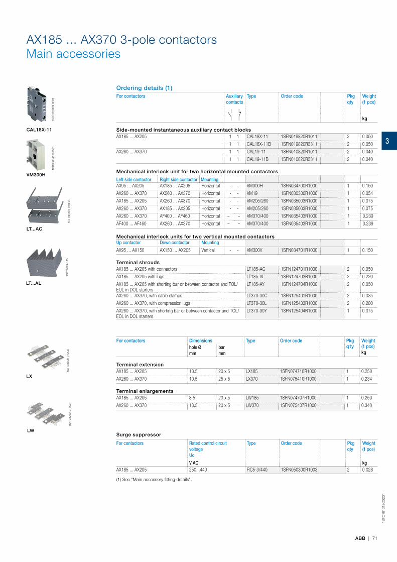
ABB | 71
1SFC
1013
12C
02
01
AX185 ... AX370 3-pole contactorsMain accessories
Ordering details (1)For contactors Auxiliary
contactsType Order code Pkg
qtyWeight(1 pce)
kg
Side-mounted instantaneous auxiliary contact blocksAX185 ... AX205 1 1 CAL18X-11 1SFN019820R1011 2 0.050
1 1 CAL18X-11B 1SFN019820R3311 2 0.050
AX260 ... AX370 1 1 CAL19-11 1SFN010820R1011 2 0.040
1 1 CAL19-11B 1SFN010820R3311 2 0.040
Mechanical interlock unit for two horizontal mounted contactors
Left side contactor Right side contactor MountingAX95 ... AX205 AX185 ... AX205 Horizontal - - VM300H 1SFN034700R1000 1 0.150
AX260 ... AX370 AX260 ... AX370 Horizontal - - VM19 1SFN030300R1000 1 0.054
AX185 ... AX205 AX260 ... AX370 Horizontal - - VM205/260 1SFN035003R1000 1 0.075
AX260 ... AX370 AX185 ... AX205 Horizontal - - VM205/260 1SFN035003R1000 1 0.075
AX260 ... AX370 AF400 ... AF460 Horizontal – – VM370/400 1SFN035403R1000 1 0.239
AF400 ... AF460 AX260 ... AX370 Horizontal – – VM370/400 1SFN035403R1000 1 0.239
Mechanical interlock units for two vertical mounted contactorsUp contactor Down contactor Mounting
AX95 ... AX150 AX150 … AX205 Vertical - - VM300V 1SFN034701R1000 1 0.150
Terminal shroudsAX185 ... AX205 with connectors LT185-AC 1SFN124701R1000 2 0.050
AX185 ... AX205 with lugs LT185-AL 1SFN124703R1000 2 0.220
AX185 ... AX205 with shorting bar or between contactor and TOL/EOL in DOL starters
LT185-AY 1SFN124704R1000 2 0.050
AX260 ... AX370, with cable clamps LT370-30C 1SFN125401R1000 2 0.035
AX260 ... AX370, with compression lugs LT370-30L 1SFN125403R1000 2 0.280
AX260 ... AX370, with shorting bar or between contactor and TOL/EOL in DOL starters
LT370-30Y 1SFN125404R1000 1 0.075
For contactors Dimensions Type Order code Pkg Weight hole Ø mm
bar mm
qty (1 pce)kg
Terminal extensionAX185 ... AX205 10.5 20 x 5 LX185 1SFN074710R1000 1 0.250
AX260 ... AX370 10.5 25 x 5 LX370 1SFN075410R1000 1 0.234
Terminal enlargementsAX185 ... AX205 8.5 20 x 5 LW185 1SFN074707R1000 1 0.250
AX260 ... AX370 10.5 20 x 5 LW370 1SFN075407R1000 1 0.340
Surge suppressor
For contactors Rated control circuit voltage Uc
Type Order code Pkg qty
Weight(1 pce)
V AC kgAX185 ... AX205 250...440 RC5-3/440 1SFN050300R1003 2 0.028
(1) See "Main accessory fitting details".
1SFT
9800
0-01
1C3
LW
1SFT
9800
0-01
2C3
LX
CAL18X-11
VM300H
1SFC
1010
33F0
201
1SB
C58
0411
F030
1
A145 ... A300 3-pole contactorsMain accessories
Ordering details (1)For contactors Auxiliary
contactsType Order code Pkg
qtyWeight(1 pce)
kg
Side-mounted instantaneous auxiliary contact blocksA145 ... A300 1 1 CAL18-11 1SFN010720R1011 2 0.050
1 1 CAL18-11B 1SFN010720R3311 2 0.050
Mechanical interlock unit for two horizontal mounted contactorsA145 ... A300 VM300H 1SFN034700R1000 1 0.150
Terminal shroudsA145 ... A185 with connectors LT185-AC 1SFN124701R1000 2 0.050A145 ... A185 with lugs LT185-AL 1SFN124703R1000 2 0.220A145 ... A185 with short. bar LY185 or between A145 and TA200DU or between A185 and TA200DU
LT185-AY 1SFN124704R1000 1 0.050
A210 ... A300 with connectors LT300-AC 1SFN125101R1000 2 0.070A210 ... A300 with lugs LT300-AL 1SFN125103R1000 2 0.280A210 ... A300 with short bar LY300 LT300-AY 1SFN125104R1000 1 0.075
For contactors Dimensions Type Order code Pkg Weight hole Ø mm
bar mm
qty (1 pce)kg
Terminal enlargementsA145, A185 10.5 20 x 5 LW185 1SFN074707R1000 1 0.250A210 ... A300 10.5 25 x 5 LW300 1SFN075107R1000 1 0.450
Terminal extensionA145, A185 8.5 20 x 5 LX185 1SFN074710R1000 1 0.250A210 ... A300 10.5 20 x 5 LX300 1SFN075110R1000 1 0.350
Cables For contactors Cable cross section Type Order code Pkg qty
Weight(1 pce)
mm² kg
Connector terminalsSingle Cu A145, A185 6...185 – 1SDA023354R0001 3 0.200
A210 ... A300 16...240 – 1SDA023368R0001 3 0.400Single Al & Cu A145, A185 35...95 – 1SDA023356R0001 3 0.100
A145, A185 25...150 – 1SDA023357R0001 3 0.100A210 ... A300 120...240 – 1SDA023370R0001 3 0.200
Double Cu A145, A185 2 x (50...120) LZ185-2C/120 1SFN074709R1000 3 0.300Double Al & Cu A210 ... A300 2 x (95...120) – 1SDA025766R0001 3 0.400
(1) For each contactor type, refer to "Main accessory fitting details" table.
For contactors Rated control circuit voltage Uc
Type Order code Pkg qty
Weight
(1 pce)V AC kg
A145 ... A300 250...440 RC5-3/440 1SFN050300R1003 2 0.028
1SFT
9809
9-01
9C3
LT...AC
1SFC
1010
33F0
201
CAL18-11
1SB
C58
0411
F030
1
VM300H
1SFT
9099
-125
LT...AL
1SFT
9800
0-01
4
LT...AY
1SFT
9800
0-01
1C3
LW
1SFT
9800
0-01
2C3
LX
1SFT
9809
9-01
1C1
LZ
1SFT
9809
9-09
5C2
LZ
1SB
C58
0542
F030
2
LZ
ABB | 3/15
1SFC
1011
49
C0
201
3
A145 ... A
300 3-pole contactors
Main accessoriesO
rderin
g d
etails (1)For contactors
Auxiliary contacts
Type O
rder codePkg qty
Weight
(1 pce) kg
Sid
e-mo
un
ted in
stantan
eou
s auxiliary co
ntact b
locks
A145 ... A3001
1CAL18-11
1SFN010720R10112
0.0501
1CAL18-11B
1SFN010720R33112
0.050
Mech
anical in
terlock u
nit fo
r two
ho
rizon
tal mo
un
ted co
ntacto
rsA145 ... A300
VM300H
1SFN034700R10001
0.150
Termin
al shro
ud
sA145 ... A185 w
ith connectorsLT185-AC
1SFN124701R10002
0.050A145 ... A185 w
ith lugsLT185-AL
1SFN124703R10002
0.220A145 ... A185 w
ith short. bar LY185 or betw
een A145 and TA200DU or betw
een A185 and TA200DU
LT185-AY1SFN124704R1000
10.050
A210 ... A300 with connectors
LT300-AC1SFN125101R1000
20.070
A210 ... A300 with lugs
LT300-AL1SFN125103R1000
20.280
A210 ... A300 with short bar LY300
LT300-AY1SFN125104R1000
10.075
For contactorsD
imensions
TypeO
rder codePkg
Weight
hole Ø
mm
bar m
mqty
(1 pce)kg
Termin
al enlarg
emen
tsA145, A185
10.520 x 5
LW185
1SFN074707R10001
0.250A210 ... A300
10.525 x 5
LW300
1SFN075107R10001
0.450
Termin
al extensio
nA145, A185
8.520 x 5
LX1851SFN074710R1000
10.250
A210 ... A30010.5
20 x 5LX300
1SFN075110R10001
0.350
Cables
For contactorsC
able cross sectionType
Order code
Pkg qty
Weight
(1 pce)m
m²
kg
Co
nn
ector term
inals
Single CuA145, A185
6...185–
1SDA023354R00013
0.200A210 ... A300
16...240–
1SDA023368R00013
0.400Single Al & Cu
A145, A18535...95
–1SDA023356R0001
30.100
A145, A18525...150
–1SDA023357R0001
30.100
A210 ... A300120...240
–1SDA023370R0001
30.200
Double CuA145, A185
2 x (50...120)LZ185-2C/120
1SFN074709R10003
0.300Double Al & Cu
A210 ... A3002 x (95...120)
–1SDA025766R0001
30.400
(1) For each contactor type, refer to "M
ain accessory fitting details" tab
le.
For contactors Rated control circuit voltage Uc
Type O
rder codePkg qty
Weight
(1 pce)V AC
kgA145 ... A300
250...440RC5-3/440
1SFN050300R10032
0.028
1SFT98099-019C3
LT...AC
1SFC101033F0201
CA
L18-11
1SBC580411F0301
VM
300H
1SFT9099-125
LT...AL
1SFT98000-014
LT...AY
1SFT98000-011C3
LW
1SFT98000-012C3
LX
1SFT98099-011C1
LZ
1SFT98099-095C2
LZ
1SBC580542F0302
LZ
AB
B | 3
/15
1SFC101149C0201 3
A145 ... A300 3-pole contactorsMain accessories
Ordering details (1)For contactors Auxiliary
contactsType Order code Pkg
qtyWeight(1 pce)
kg
Side-mounted instantaneous auxiliary contact blocksA145 ... A300 1 1 CAL18-11 1SFN010720R1011 2 0.050
1 1 CAL18-11B 1SFN010720R3311 2 0.050
Mechanical interlock unit for two horizontal mounted contactorsA145 ... A300 VM300H 1SFN034700R1000 1 0.150
Terminal shroudsA145 ... A185 with connectors LT185-AC 1SFN124701R1000 2 0.050A145 ... A185 with lugs LT185-AL 1SFN124703R1000 2 0.220A145 ... A185 with short. bar LY185 or between A145 and TA200DU or between A185 and TA200DU
LT185-AY 1SFN124704R1000 1 0.050
A210 ... A300 with connectors LT300-AC 1SFN125101R1000 2 0.070A210 ... A300 with lugs LT300-AL 1SFN125103R1000 2 0.280A210 ... A300 with short bar LY300 LT300-AY 1SFN125104R1000 1 0.075
For contactors Dimensions Type Order code Pkg Weight hole Ø mm
bar mm
qty (1 pce)kg
Terminal enlargementsA145, A185 10.5 20 x 5 LW185 1SFN074707R1000 1 0.250A210 ... A300 10.5 25 x 5 LW300 1SFN075107R1000 1 0.450
Terminal extensionA145, A185 8.5 20 x 5 LX185 1SFN074710R1000 1 0.250A210 ... A300 10.5 20 x 5 LX300 1SFN075110R1000 1 0.350
Cables For contactors Cable cross section Type Order code Pkg qty
Weight(1 pce)
mm² kg
Connector terminalsSingle Cu A145, A185 6...185 – 1SDA023354R0001 3 0.200
A210 ... A300 16...240 – 1SDA023368R0001 3 0.400Single Al & Cu A145, A185 35...95 – 1SDA023356R0001 3 0.100
A145, A185 25...150 – 1SDA023357R0001 3 0.100A210 ... A300 120...240 – 1SDA023370R0001 3 0.200
Double Cu A145, A185 2 x (50...120) LZ185-2C/120 1SFN074709R1000 3 0.300Double Al & Cu A210 ... A300 2 x (95...120) – 1SDA025766R0001 3 0.400
(1) For each contactor type, refer to "Main accessory fitting details" table.
For contactors Rated control circuit voltage Uc
Type Order code Pkg qty
Weight
(1 pce)V AC kg
A145 ... A300 250...440 RC5-3/440 1SFN050300R1003 2 0.028
1SFT
9809
9-01
9C3
LT...AC
1SFC
1010
33F0
201
CAL18-11
1SB
C58
0411
F030
1
VM300H
1SFT
9099
-125
LT...AL
1SFT
9800
0-01
4
LT...AY
1SFT
9800
0-01
1C3
LW
1SFT
9800
0-01
2C3
LX
1SFT
9809
9-01
1C1
LZ
1SFT
9809
9-09
5C2
LZ
1SB
C58
0542
F030
2
LZ
ABB | 3/15
1SFC
1011
49
C0
201
3A145 ... A
300 3-pole contactors
Main accessoriesO
rderin
g d
etails (1)For contactors
Auxiliary contacts
Type O
rder codePkg qty
Weight
(1 pce) kg
Sid
e-mo
un
ted in
stantan
eou
s auxiliary co
ntact b
locks
A145 ... A3001
1CAL18-11
1SFN010720R10112
0.0501
1CAL18-11B
1SFN010720R33112
0.050
Mech
anical in
terlock u
nit fo
r two
ho
rizon
tal mo
un
ted co
ntacto
rsA145 ... A300
VM300H
1SFN034700R10001
0.150
Termin
al shro
ud
sA145 ... A185 w
ith connectorsLT185-AC
1SFN124701R10002
0.050A145 ... A185 w
ith lugsLT185-AL
1SFN124703R10002
0.220A145 ... A185 w
ith short. bar LY185 or betw
een A145 and TA200DU or betw
een A185 and TA200DU
LT185-AY1SFN124704R1000
10.050
A210 ... A300 with connectors
LT300-AC1SFN125101R1000
20.070
A210 ... A300 with lugs
LT300-AL1SFN125103R1000
20.280
A210 ... A300 with short bar LY300
LT300-AY1SFN125104R1000
10.075
For contactorsD
imensions
TypeO
rder codePkg
Weight
hole Ø
mm
bar m
mqty
(1 pce)kg
Termin
al enlarg
emen
tsA145, A185
10.520 x 5
LW185
1SFN074707R10001
0.250A210 ... A300
10.525 x 5
LW300
1SFN075107R10001
0.450
Termin
al extensio
nA145, A185
8.520 x 5
LX1851SFN074710R1000
10.250
A210 ... A30010.5
20 x 5LX300
1SFN075110R10001
0.350
Cables
For contactorsC
able cross sectionType
Order code
Pkg qty
Weight
(1 pce)m
m²
kg
Co
nn
ector term
inals
Single CuA145, A185
6...185–
1SDA023354R00013
0.200A210 ... A300
16...240–
1SDA023368R00013
0.400Single Al & Cu
A145, A18535...95
–1SDA023356R0001
30.100
A145, A18525...150
–1SDA023357R0001
30.100
A210 ... A300120...240
–1SDA023370R0001
30.200
Double CuA145, A185
2 x (50...120)LZ185-2C/120
1SFN074709R10003
0.300Double Al & Cu
A210 ... A3002 x (95...120)
–1SDA025766R0001
30.400
(1) For each contactor type, refer to "M
ain accessory fitting details" tab
le.
For contactors Rated control circuit voltage Uc
Type O
rder codePkg qty
Weight
(1 pce)V AC
kgA145 ... A300
250...440RC5-3/440
1SFN050300R10032
0.028
1SFT98099-019C3
LT...AC
1SFC101033F0201
CA
L18-11
1SBC580411F0301
VM
300H
1SFT9099-125
LT...AL
1SFT98000-014
LT...AY
1SFT98000-011C3
LW
1SFT98000-012C3
LX
1SFT98099-011C1
LZ
1SFT98099-095C2
LZ
1SBC580542F0302
LZ
AB
B | 3
/15
1SFC101149C0201 3
LT...AC
LT...AL
1SFT
9809
9-01
9C3
1SFT
9099
-125
3

1SB
C10
00
08
S0
201
72 | ABB
Main pole - Utilization characteristics according to IECContactor types AC operated AX06 AX09 AX12 AX18 AX25 AX32 AX40Standards IEC 60947-1 / 60947-4-1 and EN 60947-1 / 60947-4-1Rated operational voltage Ue max. 690 VRated frequency limits 25...400 HzRated frequency (without derating) 50 / 60 HzConventional free-air thermal current Ithacc. to IEC 60947-4-1, open contactors, θ ≤ 40 °C 22 A 24 A 26 A 28 A 32 A 65 A 65 A
With conductor cross-sectional area 4 mm² 4 mm² 4 mm² 4 mm² 6 mm² 16 mm² 16 mm²AC-1 Utilization categoryFor air temperature close to contactor
Ie / Rated operational current AC-1 θ ≤ 40 °C 20 A 22 A 25 A 27 A 32 A 55 A 60 AUe max. ≤ 690 V, 50/60 Hz θ ≤ 55 °C 20 A 22 A 22 A 25 A 27 A 55 A 60 A
θ ≤ 70 °C 16 A 18 A 18 A 20 A 23 A 39 A 42 AWith conductor cross-sectional area 2.5 mm² 2.5 mm² 2.5 mm² 4 mm² 6 mm² 10 mm² 16 mm²
AC-3 Utilization categoryFor air temperature close to contactor θ ≤ 55 °C
Ie / Max. rated operational current AC-3 (1)
M3
3-phase motors
220-230-240 V 7 A 9 A 12 A 18 A 25 A 32 A 40 A380-400 V 7 A 9 A 12 A 18 A 25 A 32 A 40 A
415 V 7 A 9 A 12 A 18 A 25 A 32 A 40 A440 V 7 A 9 A 9 A 12 A 16 A 32 A 37 A500 V 6 A 9 A 9 A 12 A 14 A 28 A 33 A690 V 5 A 7 A 7 A 9 A 10 A 21 A 25 A
Rated operational power AC-3 (1)
M3
1500 r.p.m. 50 Hz1800 r.p.m. 60 Hz3-phase motors
220-230-240 V 1.5 kW 2.2 kW 3 kW 4 kW 6.5 kW 9 kW 11 kW380-400 V 3 kW 4 kW 5.5 kW 7.5 kW 11 kW 15 kW 18.5 kW
415 V 3 kW 4 kW 5.5 kW 9 kW 11 kW 15 kW 18.5 kW440 V 3 kW 4 kW 4 kW 5.5 kW 9 kW 18.5 kW 22 kW500 V 3.5 kW 5.5 kW 5.5 kW 7.5 kW 9 kW 18.5 kW 22 kW690 V 4 kW 5.5 kW 5.5 kW 7.5 kW 9 kW 18.5 kW 22 kW
Rated making capacity AC-3 10 x Ie AC-3 acc. to IEC 60947-4-1Rated breaking capacity AC-3 8 x Ie AC-3 acc. to IEC 60947-4-1AC-8a Utilization category(without thermal overload relay - Ue 400 V 50/60 Hz - θ ≤ 40 °C)
Ie / Rated operational current AC-8a 9 A 12 A 16 A 22 A 30 A 40 A 50 ARated operational power AC-8a 4 kW 5.5 kW 7.5 kW 11 kW 15 kW 20 kW 25 kW
Short-circuit protection device for contactorswithout thermal overload relay - Motor protection excluded (2)Ue ≤ 500 V AC - gG type fuse 25 A 25 A 25 A 32 A 32 A 63 A 63 ARated short-time withstand current Icw 1 s 220 A 250 A 280 A 300 A 300 A 600 A 600 Aat 40 °C ambient temperature, 10 s 80 A 100 A 120 A 145 A 200 A 400 A 400 Ain free air from a cold state 30 s 50 A 60 A 70 A 80 A 105 A 225 A 225 A
1 min 45 A 50 A 55 A 60 A 85 A 150 A 150 A15 min 22 A 26 A 26 A 28 A 32 A 65 A 65 A
Maximum breaking capacitycos φ = 0.45 at 440 V 250 A 250 A 250 A 250 A 250 A 820 A 820 A
at 690 V 90 A 90 A 90 A 90 A 90 A 340 A 340 APower dissipation per pole Ie / AC-1 0.8 W 0.8 W 0.8 W 1 W 1.2 W 2.5 W 3 W
Ie / AC-3 0.1 W 0.1 W 0.1 W 0.2 W 0.35 W 0.9 W 1.3 WMax. electrical switching frequency AC-1 600 cycle/h
AC-3 1200 cycle/hMechanical durability
Number of operating cycles 10 millions operating cyclesMax. switching frequency 3600 cycles/h
(1) For the corresponding kW/A values of 1500 r.p.m, 50 Hz or 1800 r.p.m, 60 Hz, 3-phase motors, see "Motor rated operational powers and currents".(2) For the protection of motor starters against short circuits, see "Coordination with short-circuit protection devices".
AX06 ... AX40 3-pole contactorsTechnical data
3
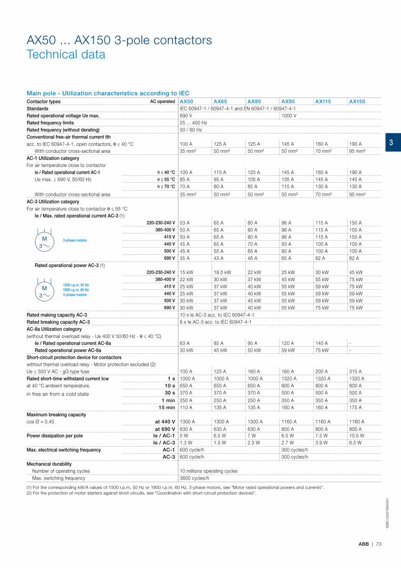
ABB | 73
1SB
C10
021
9S
02
01
AX50 ... AX150 3-pole contactorsTechnical data
Main pole - Utilization characteristics according to IECContactor types AC operated AX50 AX65 AX80 AX95 AX115 AX150Standards IEC 60947-1 / 60947-4-1 and EN 60947-1 / 60947-4-1Rated operational voltage Ue max. 690 V 1000 VRated frequency limits 25 ... 400 HzRated frequency (without derating) 50 / 60 HzConventional free-air thermal current Ithacc. to IEC 60947-4-1, open contactors, θ ≤ 40 °C 100 A 125 A 125 A 145 A 160 A 190 A
With conductor cross-sectional area 35 mm² 50 mm² 50 mm² 50 mm² 70 mm² 95 mm²AC-1 Utilization categoryFor air temperature close to contactor
Ie / Rated operational current AC-1 θ ≤ 40 °C 100 A 115 A 125 A 145 A 160 A 190 AUe max. ≤ 690 V, 50/60 Hz θ ≤ 55 °C 85 A 95 A 105 A 135 A 145 A 145 A
θ ≤ 70 °C 70 A 80 A 85 A 115 A 130 A 130 A
With conductor cross-sectional area 35 mm² 50 mm² 50 mm² 50 mm² 70 mm² 95 mm²AC-3 Utilization categoryFor air temperature close to contactor θ ≤ 55 °C
Ie / Max. rated operational current AC-3 (1)
M3
3-phase motors
220-230-240 V 53 A 65 A 80 A 96 A 115 A 150 A380-400 V 50 A 65 A 80 A 96 A 115 A 150 A
415 V 50 A 65 A 80 A 96 A 115 A 150 A440 V 45 A 65 A 70 A 93 A 100 A 100 A500 V 45 A 55 A 65 A 80 A 100 A 100 A690 V 35 A 43 A 46 A 65 A 82 A 82 A
Rated operational power AC-3 (1)
M3
1500 r.p.m. 50 Hz1800 r.p.m. 60 Hz3-phase motors
220-230-240 V 15 kW 18.5 kW 22 kW 25 kW 30 kW 45 kW380-400 V 22 kW 30 kW 37 kW 45 kW 55 kW 75 kW
415 V 25 kW 37 kW 40 kW 55 kW 59 kW 75 kW440 V 25 kW 37 kW 40 kW 55 kW 59 kW 59 kW500 V 30 kW 37 kW 45 kW 55 kW 59 kW 59 kW690 V 30 kW 37 kW 40 kW 55 kW 75 kW 75 kW
Rated making capacity AC-3 10 x Ie AC-3 acc. to IEC 60947-4-1Rated breaking capacity AC-3 8 x Ie AC-3 acc. to IEC 60947-4-1AC-8a Utilization category(without thermal overload relay - Ue 400 V 50/60 Hz - θ ≤ 40 °C)
Ie / Rated operational current AC-8a 63 A 85 A 95 A 120 A 140 A -Rated operational power AC-8a 30 kW 45 kW 50 kW 59 kW 75 kW -
Short-circuit protection device for contactorswithout thermal overload relay - Motor protection excluded (2)Ue ≤ 500 V AC - gG type fuse 100 A 125 A 160 A 160 A 200 A 315 ARated short-time withstand current Icw 1 s 1000 A 1000 A 1000 A 1320 A 1320 A 1320 Aat 40 °C ambient temperature,
in free air from a cold state
10 s 650 A 650 A 650 A 800 A 800 A 800 A30 s 370 A 370 A 370 A 500 A 500 A 500 A
1 min 250 A 250 A 250 A 350 A 350 A 350 A15 min 110 A 135 A 135 A 160 A 160 A 175 A
Maximum breaking capacitycos Ø = 0.45 at 440 V 1300 A 1300 A 1300 A 1160 A 1160 A 1160 A
at 690 V 630 A 630 A 630 A 800 A 800 A 800 APower dissipation per pole Ie / AC-1 5 W 6.5 W 7 W 6.5 W 7.5 W 10.5 W
Ie / AC-3 1.3 W 1.5 W 2.3 W 2.7 W 3.9 W 6.5 WMax. electrical switching frequency AC-1 600 cycle/h 300 cycles/h
AC-3 600 cycle/h 300 cycles/hMechanical durability Number of operating cycles 10 millions operating cycles Max. switching frequency 3600 cycles/h
(1) For the corresponding kW/A values of 1500 r.p.m, 50 Hz or 1800 r.p.m, 60 Hz, 3-phase motors, see "Motor rated operational powers and currents".(2) For the protection of motor starters against short circuits, see "Coordination with short-circuit protection devices".
3
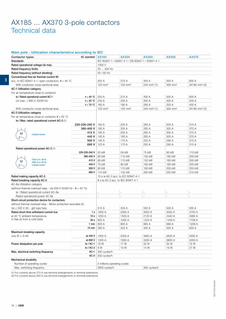
74 | ABB
1SFC
1013
13C
02
01
AX185 ... AX370 3-pole contactorsTechnical data
Main pole - Utilization characteristics according to IECContactor types AC operated AX185 AX205 AX260 AX300 AX370Standards IEC 60947-1 / 60947-4-1 / EN 60947-1 / 60947-4-1Rated operational voltage Ue max. 1000 VRated frequency limits 25 ... 400 HzRated frequency (without derating) 50 / 60 HzConventional free-air thermal current Ithacc. to IEC 60947-4-1, open contactors, θ ≤ 40 °C 250 A 275 A 400 A 500 A 600 A
With conductor cross-sectional area 120 mm² 150 mm² 240 mm² (1) 300 mm² 2X185 mm² (2)AC-1 Utilization categoryFor air temperature close to contactor
Ie / Rated operational current AC-1 θ ≤ 40 °C 250 A 275 A 400 A 500 A 600 AUe max. ≤ 690 V, 50/60 Hz θ ≤ 55 °C 230 A 250 A 350 A 400 A 500 A
θ ≤ 70 °C 180 A 180 A 290 A 325 A 400 AWith conductor cross-sectional area 120 mm² 150 mm² 240 mm² (1) 300 mm² 2X185 mm² (2)
AC-3 Utilization categoryFor air temperature close to contactor θ ≤ 55 °C
Ie / Max. rated operational current AC-3 (1)
M3
3-phase motors
220-230-240 V 185 A 205 A 265 A 305 A 370 A380-400 V 185 A 205 A 265 A 305 A 370 A
415 V 185 A 205 A 265 A 305 A 370 A440 V 145 A 185 A 265 A 305 A 370 A500 V 145 A 170 A 250 A 290 A 315 A690 V 120 A 170 A 250 A 290 A 315 A
Rated operational power AC-3 (1)
M3
1500 r.p.m. 50 Hz1800 r.p.m. 60 Hz3-phase motors
220-230-240 V 55 kW 59 kW 75 kW 90 kW 110 kW380-400 V 90 kW 110 kW 132 kW 160 kW 200 kW
415 V 90 kW 110 kW 132 kW 160 kW 200 kW440 V 75 kW 90 kW 160 kW 160 kW 200 kW500 V 90 kW 110 kW 160 kW 200 kW 250 kW690 V 110 kW 132 kW 200 kW 250 kW 315 kW
Rated making capacity AC-3 10 x Ie AC-3 acc. to IEC 60947-4-1Rated breaking capacity AC-3 8 x Ie AC-3 acc. to IEC 60947-4-1AC-8a Utilization category(without thermal overload relay - Ue 400 V 50/60 Hz - θ ≤ 40 °C)
Ie / Rated operational current AC-8a - - - - -Rated operational power AC-8a - - - - -
Short-circuit protection device for contactorswithout thermal overload relay - Motor protection excluded (2)Ue ≤ 500 V AC - gG type fuse 315 A 355 A 500 A 500 A 630 ARated short-time withstand current Icw 1 s 1800 A 2000 A 2650 A 3050 A 3700 Aat 40 °C ambient temperature,in free air from a cold state
10 s 1200 A 1500 A 2120 A 2440 A 2960 A30 s 800 A 1000 A 1224 A 1409 A 1709 A
1 min 600 A 800 A 865 A 996 A 1208 A15 min 280 A 320 A 400 A 500 A 600 A
Maximum breaking capacitycos Ø = 0.45 at 440 V 1500 A 2000 A 3800 A 4600 A 5000 A
at 690 V 1200 A 1600 A 3300 A 3800 A 4000 APower dissipation per pole Ie / AC-1 16 W 17 W 32 W 50 W 72 W
Ie / AC-3 8 W 10 W 14 W 19 W 27 WMax. electrical switching frequency AC-1 300 cycles/h
AC-3 300 cycles/hMechanical durability Number of operating cycles 5 millions operating cycles Max. switching frequency 3600 cycles/h 300 cycles/h
(1) For currents above 275 A use terminal enlargements or terminal extensions(2) For currents above 450 A use terminal enlargements or terminal extensions
3
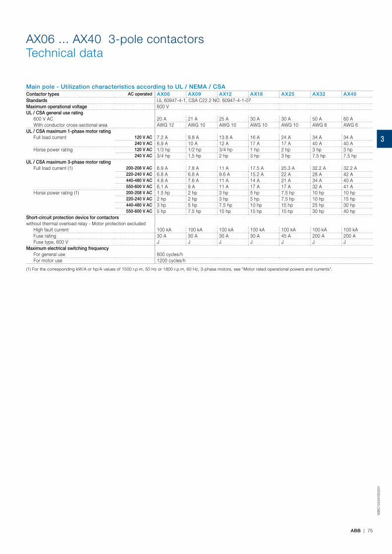
1SB
C10
024
1S0
201
ABB | 75
AX06 ... AX40 3-pole contactors Technical data
Main pole - Utilization characteristics according to UL / NEMA / CSAContactor types AC operated AX06 AX09 AX12 AX18 AX25 AX32 AX40Standards UL 60947-4-1, CSA C22.2 NO. 60947-4-1-07Maximum operational voltage 600 VUL / CSA general use rating
600 V AC 20 A 21 A 25 A 30 A 30 A 50 A 60 AWith conductor cross-sectional area AWG 12 AWG 10 AWG 10 AWG 10 AWG 10 AWG 8 AWG 6
UL / CSA maximum 1-phase motor ratingFull load current 120 V AC 7.2 A 9.8 A 13.8 A 16 A 24 A 34 A 34 A
240 V AC 6.9 A 10 A 12 A 17 A 17 A 40 A 40 AHorse power rating 120 V AC 1/3 hp 1/2 hp 3/4 hp 1 hp 2 hp 3 hp 3 hp
240 V AC 3/4 hp 1.5 hp 2 hp 3 hp 3 hp 7.5 hp 7.5 hpUL / CSA maximum 3-phase motor rating
Full load current (1) 200-208 V AC 6.9 A 7.8 A 11 A 17.5 A 25.3 A 32.2 A 32.2 A220-240 V AC 6.8 A 6.8 A 9.6 A 15.2 A 22 A 28 A 42 A440-480 V AC 4.8 A 7.6 A 11 A 14 A 21 A 34 A 40 A550-600 V AC 6.1 A 9 A 11 A 17 A 17 A 32 A 41 A
Horse power rating (1) 200-208 V AC 1.5 hp 2 hp 3 hp 5 hp 7.5 hp 10 hp 10 hp220-240 V AC 2 hp 2 hp 3 hp 5 hp 7.5 hp 10 hp 15 hp440-480 V AC 3 hp 5 hp 7.5 hp 10 hp 15 hp 25 hp 30 hp550-600 V AC 5 hp 7.5 hp 10 hp 15 hp 15 hp 30 hp 40 hp
Short-circuit protection device for contactorswithout thermal overload relay - Motor protection excluded
High fault current 100 kA 100 kA 100 kA 100 kA 100 kA 100 kA 100 kAFuse rating 30 A 30 A 30 A 30 A 45 A 200 A 200 AFuse type, 600 V J J J J J J J
Maximum electrical switching frequencyFor general use 600 cycles/hFor motor use 1200 cycles/h
(1) For the corresponding kW/A or hp/A values of 1500 r.p.m, 50 Hz or 1800 r.p.m, 60 Hz, 3-phase motors, see "Motor rated operational powers and currents".
3

1SB
C10
024
2S0
201
76 | ABB
AX50 ... AX80 3-pole contactors Technical data
Main pole - Utilization characteristics according to UL / NEMA / CSAContactor types AC operated AX50 AX65 AX80Standards UL 60947-4-1, CSA C22.2 NO. 60947-4-1-07Maximum operational voltage 600 VUL / CSA general use rating
600 V AC 80 A 90 A 105 AWith conductor cross-sectional area AWG 4 AWG 3 AWG 2
UL / CSA maximum 1-phase motor ratingFull load current 120 V AC 34 A 56 A 80 A
240 V AC 50 A 50 A 68 AHorse power rating 120 V AC 3 hp 5 hp 7-1/2 hp
240 V AC 10 hp 10 hp 15 hpUL / CSA maximum 3-phase motor rating
Full load current (1) 200-208 V AC 48.3 A 62.1 A 78.2 A220-240 V AC 54 A 68 A 80 A440-480 V AC 52 A 77 A 77 A550-600 V AC 52 A 77 A 77 A
Horse power rating (1) 200-208 V AC 15 hp 20 hp 25 hp220-240 V AC 20 hp 25 hp 30 hp440-480 V AC 40 hp 60 hp 60 hp550-600 V AC 50 hp 75 hp 75 hp
Short-circuit protection device for contactorswithout thermal overload relay - Motor protection excluded
High fault current 100 kA 100 kA 100 kAFuse rating 100 A 200 A 200 AFuse type, 600 V J J J
Maximum electrical switching frequencyFor general use 600 cycles/hFor motor use 600 cycles/h
(1) For the corresponding kW/A or hp/A values of 1500 r.p.m, 50 Hz or 1800 r.p.m, 60 Hz, 3-phase motors, see "Motor rated operational powers and currents".
3

1SFC
1013
19C
02
01
ABB | 77
AX95 … AX370 3-pole contactors Technical data
Main pole - Utilization characteristics according to UL / NEMA / CSAContactor types AC operated AX95 AX115 AX150 AX185 AX205 AX260 AX300 AX370Standards UL 508, CSA C22.2 N°14, UL 60947-1 / 60947-4-1A and CSA 60947-1 / 60947-4-1AMaximum operational voltage 600 VUL / CSA general use rating
600 V AC 150 150 170 250 260 350 400 520With conductor cross-sectional area AWG 1 AWG 1/0 AWG 2/0 MCM 250 MCM 300 MCM 500 2// AWG 3/0 2//MCM 300
UL / CSA maximum 3-phase motor ratingFull load current (1) 200-208 V AC 92 A 92 A 120 A 150 A 169 A 221 A 285 A 359 A
220-240 V AC 80 A 104 A 130 A 145 A 192 A 248 A 312 A 360 A440-480 V AC 77 A 96 A 124 A 156 A 180 A 240 A 302 A 361 A550-600 V AC 77 A 99 A 125 A 144 A 192 A 242 A 298 A 336 A
Horse power rating (1) 200-208 V AC 30 hp 30 hp 40 hp 50 hp 60 hp 75 hp 100 hp 125 hp220-240 V AC 30 hp 40 hp 50 hp 60 hp 75 hp 100 hp 125 hp 150 hp440-480 V AC 60 hp 75 hp 100 hp 125 hp 150 hp 200 hp 250 hp 300 hp550-600 V AC 75 hp 100 hp 125 hp 150 hp 200 hp 250 hp 300 hp 350 hp
Short-circuit protection device for contactorswithout thermal overload relay - Motor protection excluded
High fault current 100 kA 100 kA 100 kA 100 kA 100 kA 100 kA 100 kA 100 kAFuse rating 200 A 200 A (2) 400 A 400 A 500 A 600 A 800 AFuse type, 600 V J J (2) J J J J J
Maximum electrical switching frequencyFor general use 300 cycles/hFor motor use 300 cycles/h
(1) For the corresponding kW/A or hp/A values of 1500 r.p.m, 50 Hz or 1800 r.p.m, 60 Hz, 3-phase motors, see "Motor rated operational powers and currents".(2) In preparation.
3

1SB
C10
024
3S
02
01
78 | ABB
General technical dataContactor types AC operated AX06 AX09 AX12 AX18 AX25 AX32 AX40Rated insulation voltage Ui
acc. to IS / IEC 60947-4-1 690 Vacc. to UL / CSA 600 V
Rated impulse withstand voltage Uimp. 6 kVAmbient air temperature close to contactor
Operation Fitted with thermal overload relay -25...+55 °C (1)Without thermal overload relay -40...+70 °C
Storage -60...+80 °CClimatic withstand acc. to IEC 60068-2-30 and 60068-2-11 - UTE C 63-100 specification IIMaximum operating altitude (without derating) 3000 mShock withstandacc. to IEC 60068-2-27 and EN 60068-2-27Mounting position 1
Shock direction 1/2 sinusoidal shock for 11 ms: no change in contact position, closed or open positionA 20 g
B1 10 g closed position / 5 g open positionB2 15 gC1 20 gC2 20 g
(1) The max. operational current is 23 A for AX25 with TA25DU-25M.
Magnet system characteristicsContactor types AC operated AX06 AX09 AX12 AX18 AX25 AX32 AX40Coil operating limits AC supply at θ ≤ 55 °C 0.85...1.1 x Ucacc. to IS / IEC 60947-4-1 Please also refer to "Mounting characteristics and conditions for use"AC control voltage 50/60 Hz
Rated control circuit voltage Uc at 50 Hz 24...440 Vat 60 Hz 24...440 V
Coil consumption Average pull-in value 50 Hz 70 VA 120 VA60 Hz 80 VA 140 VA
50/60 Hz (1) 74 VA / 70 VA 125 VA / 120 VAAverage holding value 50 Hz 8 VA / 2 W 12 VA / 3 W
60 Hz 8 VA / 2 W 12 VA / 3 W50/60 Hz (1) 8 VA / 2 W 12 VA / 3 W
Drop-out voltage approx. 40...65 % of UcOperating time
Between coil energization and: N.O. contact closing 10...26 ms 8...21 msN.C. contact opening 7...21 ms 6...18 ms
Between coil de-energization and: N.O. contact opening 4...15 ms 4...11 msN.C. contact closing 9...20 ms 7...14 ms
(1) 50/60 Hz coils: see "Coil voltage code table".
Mounting characteristics and conditions for use
Contactor types AC operated AX06 AX09 AX12 AX18 AX25 AX32 AX40Mounting positions
Max. N.O. or N.C. built-in and add-on N.O. or N.C. auxiliary contacts:see accessory fitting details for 3-pole contactor AX06 ... AX80
Control voltage / Ambient temperatureMounting positions
1, 1±30°, 2, 3, 4, 5 at θ ≤ 55 °C 0.85…1.1 x Ucat 55 °C < θ ≤ 70 °C Uc
6 at θ ≤ 55 °C 0.95…1.1 x Ucat θ > 55 °C Unauthorized
Mounting distances The contactors can be assembled side by sideFixing
On rail according to IEC 60715, EN 60715 35 x 7.5 mm or 35 x 15 mmBy screws (not supplied) 2 x M4 screws placed diagonally
AX06 ... AX40 3-pole contactorsTechnical data
3
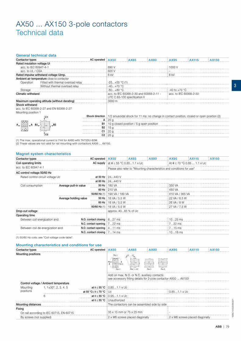
ABB | 79
1SB
C10
02
20
S0
201
General technical dataContactor types AC operated AX50 AX65 AX80 AX95 AX115 AX150Rated insulation voltage Ui
acc. to IEC 60947-4-1 690 V 1000 Vacc. to UL / CSA 600 V –
Rated impulse withstand voltage Uimp. 6 kV 8 kVAmbient air temperature close to contactor
Operation Fitted with thermal overload relay -25...+55 °C (1)Without thermal overload relay -40...+70 °C
Storage -60...+80 °C -40 to +70 °CClimatic withstand acc. to IEC 60068-2-30 and 60068-2-11 -
UTE C 63-100 specification IIacc. to IEC 60068-2-30
Maximum operating altitude (without derating) 3000 mShock withstandacc. to IEC 60068-2-27 and EN 60068-2-27Mounting position 1
Shock direction 1/2 sinusoidal shock for 11 ms: no change in contact position, closed or open position (2)A 20 g
B1 10 g closed position / 5 g open positionB2 15 gC1 20 gC2 20 g
(1) The max. operational current is 74A for AX80 with TA75DU-80M. (2) These values are not valid for rail mounting with contactors AX95 ... AX150.
AX50 ... AX150 3-pole contactorsTechnical data
Mounting characteristics and conditions for useContactor types AC operated AX50 AX65 AX80 AX95 AX115 AX150Mounting positions
Add on max. N.O. or N.C. auxiliary contacts:see accessory fitting details for 3-pole contactor AX50 ... AX150
Control voltage / Ambient temperatureMountingpositions
1, 1±30°, 2, 3, 4, 5 at θ ≤ 55 °C 0.85…1.1 x Ucat 55 °C≤ θ ≤ 70 °C Uc 0.85…1.1 x Uc
6 at θ ≤ 55 °C 0.95…1.1 x Ucat θ ≤ 55 °C Unauthorized
Mounting distances The contactors can be assembled side by sideFixing
35 x 15 mm or 75 x 25 mm -On rail according to IEC 60715, EN 60715By screws (not supplied) 2 x M6 screws placed diagonally 2 x M6 screws placed diagonally
Magnet system characteristicsContactor types AC operated AX50 AX65 AX80 AX95 AX115 AX150Coil operating limits AC supply at θ ≤ 55 °C 0.85...1.1 x Uc At θ ≤ 70 °C 0.85 ... 1.1 x Ucacc. to IEC 60947-4-1 Please also refer to "Mounting characteristics and conditions for use"AC control voltage 50/60 Hz
Rated control circuit voltage Uc at 50 Hz 24...440 Vat 60 Hz 24...440 V
Coil consumption Average pull-in value 50 Hz 180 VA 350 VA60 Hz 210 VA 450 VA
50/60 Hz (1) 190 VA / 180 VA 410 VA / 365 VAAverage holding value 50 Hz 18 VA / 5.5 W 22 VA / 6.5 W
60 Hz 18 VA / 5.5 W 26 VA / 8 W50/60 Hz (1) 18 VA / 5.5 W 27 VA / 7.5 W
Drop-out voltage approx. 40...65 % of UcOperating time
Between coil energization and: N.O. contact closing 8…27 ms 10…25 msN.C. contact opening 7…22 ms 7…22 ms
Between coil de-energization and: N.O. contact opening 4…11 ms 7…15 msN.C. contact closing 7…14 ms 10…18 ms
(1) 50/60 Hz coils: see "Coil voltage code table".
3

80 | ABB
1SFC
1013
14C
02
01
Mounting characteristics and conditions for useContactor types AC operated AX185 AX205 AX260 AX300 AX370Mounting positions
Max. add-on N.O. or N.C. auxiliary contacts:see accessory fitting details for 3-pole contactor AX185 ... AX370
Control voltage / Ambient temperatureMountingpositions
1, 1±30°, 2, 3, 4, 5 at θ ≤ 55 °C 0.85…1.1 x Ucat 55 °C≤ θ ≤ 70 °C 0.85…1.1 x Uc
6 at θ ≤ 55 °C Unauthorized
at θ ≤ 55 °C UnauthorizedMounting distances The contactors can be assembled side by sideFixing
-On rail according to IEC 60715, EN 60715By screws (not supplied) 4 x M5
General technical dataContactor types AC operated AX185 AX205 AX260 AX300 AX370Rated insulation voltage Ui
acc. to IEC 60947-4-1 1000 VRated impulse withstand voltage Uimp. 8 kVAmbient air temperature close to contactor
-25...+55 °C (1)Operation Fitted with thermal overload relay
Without thermal overload relay -40...+70 °CStorage -40 to +70 °C
Climatic withstand Category B according to IEC60947-1 / EN 60947-1 Annex QMaximum operating altitude (without derating) 3000 mShock withstand 1/2 sinusoidal shock for 11 ms: no
change in contact position, closed or open position (2)
1/2 sinusoidal shock for 30 msacc. to IEC 60068-2-27 and EN 60068-2-27Mounting position 1
Shock directionA 5 g 20 g
B1 5 g 15 g closed position / 3 g open positionB2 5 g 15 g closed position / 3 g open positionC1 5 g 20 gC2 5 g 20 g
AX185 ... AX370 3-pole contactorsTechnical data
Magnet system characteristicsContactor types AC operated AX185 AX205 AX260 AX300 AX370Coil operating limits AC supply at θ ≤ 55 °C 0.85...1.1 x Uc At θ ≤ 70 °C 0.85 ... 1.1 x Uc maxacc. to IEC 60947-4-1 Please also refer to "Mounting char-
acteristics and conditions for use"
AC control voltage 50/60 HzRated control circuit voltage Uc at 50 Hz 24...440 V
at 60 Hz 24...440 VCoil consumption Average pull-in value 50 Hz 550 VA -
60 Hz 600 VA -50/60 Hz (1) 700 VA / 650 VA 475 VA
Average holding value 50 Hz 35 VA / 11 W -60 Hz 40 VA / 12 W -
50/60 Hz (1) 44 VA / 13 W 17.5 VADrop-out voltage approx. 40...65 % of Uc 55% of Uc min.Operating time
Between coil energization and: N.O. contact closing 13…27 ms 30…60 ms N.C. contact opening 8…22 ms -
Between coil de-energization and: N.O. contact opening 5…10 ms 45…80 ms N.C. contact closing 9…13 ms -
(1) 50/60 Hz coils: see "Coil voltage code table".
(1) The max. operational current is 182A for AX205 with TA200DU-200(2) These values are not valid for rail mounting with contactors AX95 ... AX150.
3

1SB
C10
001
4S
02
01
ABB | 81
AX06 ... AX40 3-pole contactorsTechnical data
Connecting characteristicsContactor types AC operated AX06 AX09 AX12 AX18 AX25 AX32 AX40Main terminals
Screw terminals with cable clamp Screw terminals with double connector 2 x (5.6 x 6.5 mm)
Connection capacity (min. ... max.)Main conductors (poles)
Rigid Solid (≤ 4 mm²) 1 x 1...4 mm² 1...6 mm² 2.5...16 mm²Stranded (≥ 6 mm²) 2 x 1...4 mm² 1...6 mm² 2.5...16 mm²
Flexible with non insulated ferrule 1 x 0.75...2.5 mm² 0.75...6 mm² 2.5...10 mm²2 x 0.75...2.5 mm² 0.75...6 mm² 2.5...10 mm²
Flexible with insulated ferrule 1 x - 0.75…4 mm² 2.5...10 mm²2 x - 0.75…2.5 mm² 2.5...10 mm²
L6
Bars or lugs L < 7.7 mm 9.6 mm -l > 3.7 mm 3.7 mm -
Connection capacity acc. to UL/CSA 1 or 2 x AWG 18...10 AWG 16...10 AWG 8...4Stripping length 10 mm 14 mmTightening torque 1 Nm / 9 Ib.in 1.5 Nm / 13 Ib.in 2.3 Nm / 20 Ib.inAuxiliary conductors(built-in auxiliary terminals + coil terminals)
Rigid solid 1 x 1...4 mm²2 x 1...4 mm²
Flexible with non insulated ferrule 1 x 0.75...2.5 mm²2 x 0.75...2.5 mm²
L6
Lugs L < 7.7 mm 8 mml > 3.7 mm 3.7 mm
Connection capacity acc. to UL/CSA 1 or 2 x AWG 18...14Stripping length 10 mmTightening torque
Coil terminals 1 Nm / 9 Ib.inBuilt-in auxiliary terminals 1 Nm / 9 Ib.in
Degree of protectionacc. to IEC 60947-1 / EN 60947-1 and IEC 60529
Main terminals IP20 (only front side)Coil terminals IP20 IP20Built-in auxiliary terminals IP20 (only front side) IP20
Screw terminals Delivered in open position, screws of unused terminals must be tightenedMain terminals M3.5 M5
Screwdriver type Flat Ø 5.5 / Pozidriv 2 Flat Ø 6.5 / Pozidriv 2Coil terminals M3.5
Screwdriver type Flat Ø 5.5 / Pozidriv 2Built-in auxiliary terminals M3.5
Screwdriver type Flat Ø 5.5 / Pozidriv 2
3
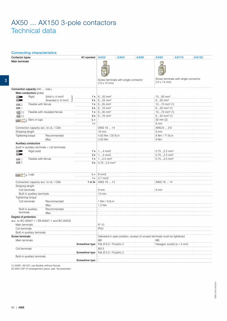
82 | ABB
1SB
C10
021
4S
02
01
AX50 ... AX150 3-pole contactorsTechnical data
Connecting characteristicsContactor types AC operated AX50 AX65 AX80 AX95 AX115 AX150Main terminals
Screw terminals with single connector (13 x 10 mm)
Screw terminals with single connector (14 x 14 mm)
Connection capacity (min. ... max.)Main conductors (poles)
Rigid Solid (≤ 4 mm²) 1 x 6…50 mm² 10…95 mm²Stranded (≥ 6 mm²) 2 x 6…25 mm² 6…35 mm²
Flexible with ferrule 1 x 6...35 mm² 10…70 mm² (1)2 x 6...16 mm² 6…35 mm² (1)
Flexible with insulated ferrule 1 x 6...35 mm² 10…70 mm² (1) 2 x 6...16 mm² 6…35 mm² (1)
Bars or lugs L < - 30 mm (2) l > - 6 mm
Connection capacity acc. to UL / CSA AWG 18 ... 14 AWG 6 ... 2/0Stripping length 16 mm 9 mmTightening torque Recommended 4.00 Nm / 35 lb.in 8 Nm / 71 lb.in
Max. 4.50 Nm 9 Nm Auxiliary conductors(built-in auxiliary terminals + coil terminals)
Rigid solid 1 x 1....4 mm2 0.75…2.5 mm² 2 x 1....4 mm2 0.75…2.5 mm²
Flexible with ferrule 1 x 1…2.5 mm² 0.75…2.5 mm²2 x 0.75...2.5 mm²
Lugs L < 8 mm2l > 3.7 mm2
Connection capacity acc. to UL / CSA 1 or 2x AWG 18 ... 14 AWG 18 ... 14Stripping length
Coil terminals 9 mm 9 mmBuilt-in auxiliary terminals 10 mm
Tightening torqueCoil terminals Recommended 1 Nm / 9 Ib.in
Max. 1.2 NmBuilt-in auxiliary terminals
Recommended -Max. -
Degree of protectionacc. to IEC 60947-1 / EN 60947-1 and IEC 60529
Main terminals IP 10 Coil terminals IP20Built-in auxiliary terminals -
Screw terminals Delivered in open position, screws of unused terminals must be tightenedMain terminals M6 M8
Screwdriver type Flat Ø 6.5 / Pozidriv 2 Hexagon socket (s = 4 mm)
Coil terminals M3.5Screwdriver type Flat Ø 5.5 / Pozidriv 2
Built-in auxiliary terminals -Screwdriver type -
(1) AX95 -AX150: use flexible without ferrule.(2) With LW110 enlargement piece, see "Accessories".
3

ABB | 83
1SFC
1013
15C
02
01
AX185 ... AX205 3-pole contactorsTechnical data
Connecting characteristicsContactor types AC operated AX185 AX205Main terminals Flat type
Connection capacity (min. ... max.)Main conductors (poles)
Rigid with connector
Single for Cu cable 6…185 mm²Single for Al/Cu cable 25…150 mm²Double for Al/Cu cable -
Bars or lugs L < 24 mmØ > 8 mm
Connection capacity acc. to UL / CSA 6 … 250 MCMStripping length 9 mmTightening torque Recommended 18 Nm / 160 Ib.in
Max. 20 NmAuxiliary conductors(built-in auxiliary terminals + coil terminals)
Rigid solid 1 x 1....4 mm22 x 1....4 mm2
Flexible with ferrule 1 x 0.75…2.5 mm²2 x 0.75...2.5 mm²
Lugs L < 8 mm2l > 3.7 mm2
Connection capacity acc. to UL / CSA 1 or 2x AWG 18 ... 14Stripping length 9 mmTightening torque
Coil terminals Recommended 1 Nm / 9 Ib.inMax. 1.2 Nm
Degree of protectionacc. to IEC 60947-1 / EN 60947-1 and IEC 60529
Main terminals IP00 Coil terminals IP20
Screw terminalsMain terminals M8
Screw and boltsCoil terminals (delivered in open position) M3.5
Screwdriver type Flat Ø 5.5 / Pozidriv 2
3
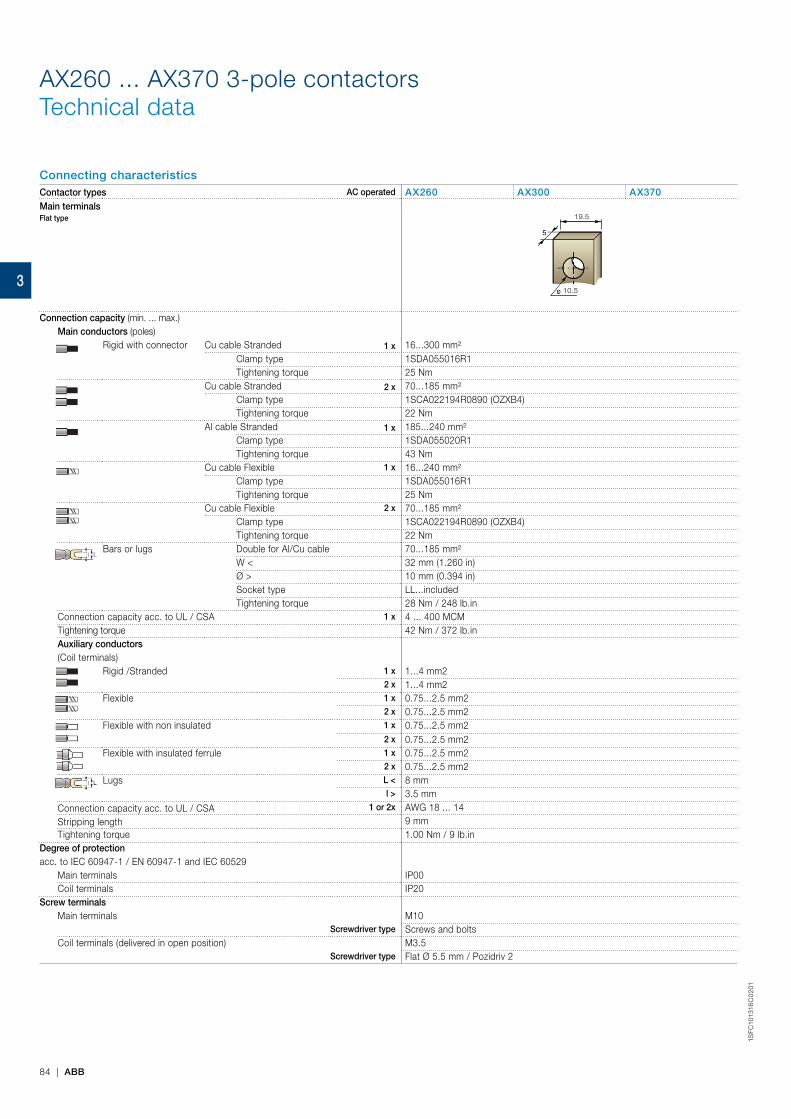
84 | ABB
1SFC
1013
16C
02
01
AX260 ... AX370 3-pole contactorsTechnical data
Connecting characteristicsContactor types AC operated AX260 AX300 AX370Main terminals Flat type
10.5
19.5
Connection capacity (min. ... max.)Main conductors (poles)
Rigid with connector Cu cable Stranded 1 x 16...300 mm² Clamp type 1SDA055016R1Tightening torque 25 Nm
Cu cable Stranded 2 x 70...185 mm² Clamp type 1SCA022194R0890 (OZXB4)Tightening torque 22 Nm
Al cable Stranded 1 x 185...240 mm² Clamp type 1SDA055020R1Tightening torque 43 Nm
Cu cable Flexible 1 x 16...240 mm² Clamp type 1SDA055016R1Tightening torque 25 Nm
Cu cable Flexible 2 x 70...185 mm² Clamp type 1SCA022194R0890 (OZXB4)Tightening torque 22 Nm
Bars or lugs Double for Al/Cu cable 70...185 mm²W < 32 mm (1.260 in)Ø > 10 mm (0.394 in)Socket type LL...includedTightening torque 28 Nm / 248 lb.in
Connection capacity acc. to UL / CSA 1 x 4 ... 400 MCMTightening torque 42 Nm / 372 lb.inAuxiliary conductors(Coil terminals)
Rigid /Stranded 1 x 1...4 mm22 x 1...4 mm2
Flexible 1 x 0.75...2.5 mm22 x 0.75...2.5 mm2
w Flexible with non insulated 1 x 0.75...2.5 mm22 x 0.75...2.5 mm2
Flexible with insulated ferrule 1 x 0.75...2.5 mm22 x 0.75...2.5 mm2
Lugs L < 8 mml > 3.5 mm
Connection capacity acc. to UL / CSA 1 or 2x AWG 18 ... 14Stripping length 9 mmTightening torque 1.00 Nm / 9 lb.in
Degree of protectionacc. to IEC 60947-1 / EN 60947-1 and IEC 60529
Main terminals IP00Coil terminals IP20
Screw terminalsMain terminals M10
Screwdriver type Screws and boltsCoil terminals (delivered in open position) M3.5
Screwdriver type Flat Ø 5.5 mm / Pozidriv 2
3

1SB
C10
001
6S
02
01
ABB | 85
Built-in auxiliary contacts according to IEC - Other auxiliary contacts see "Accessories"
Contactor types AC operated AX06 AX09 AX12 AX18 AX25 AX32 AX40Rated operational voltage Ue max. 690 VRated frequency (without derating) 50 / 60 HzConventional free air thermal current Ith - θ ≤ 40 °C 16 A Ie / Rated operational current AC-15acc. to IEC 60947-5-1 24-127 V 50/60 Hz 6 A
220-240 V 50/60 Hz 4 A380-440 V 50/60 Hz 3 A
500 V 50/60 Hz 2 A690 V 50/60 Hz 2 A
Making capacity AC-15 10 x Ie AC-15 acc. to IEC 60947-5-1Breaking capacity AC-15 10 x Ie AC-15 acc. to IEC 60947-5-1Ie / Rated operational current DC-13acc. to IEC 60947-5-1 24 V DC 6 A / 144 W
48 V DC 2.8 A / 134 W72 V DC 2 A / 144 W
110 V DC 1.1 A / 121 W125 V DC 1.1 A / 138 W220 V DC 0.55 A / 121 W250 V DC 0.55 A / 138 W
Short-circuit protection device gG type fuse 10 ARated short-time withstand current Icw for 1.0 s 100 A
for 0.1 s 140 AMinimum switching capacity 12 V / 3 mAwith failure rate acc. to IEC 60947-5-4Non-overlapping time between N.O. and N.C. contacts ≥ 2 msPower dissipation per pole at 6 A 0.1 WMax. electrical switching frequency AC-15 1200 cycles/h
DC-13 900 cycles/hMechanically linked contacts Built-in N.O. or N.C. auxiliary contacts and additional N.O. or N.C. auxiliary contacts of 4-pole CA5X are
mechanically linked contacts.acc. to annex L of IEC 60947-5-1Mirror contacts Built-in N.C. auxiliary contacts or additional N.C. auxiliary contacts (CA5X, CAL5X-11) are mirror contacts.acc. to annex F of IEC 60947-4-1
Built-in auxiliary contacts according to UL / CSAContactor types AC operated AX06 AX09 AX12 AX18 AX25 AX32 AX40Max. operational voltage 600 V AC, 600 V DCPilot duty A600, P300
AC thermal rated current 10 AAC maximum volt-ampere making 7200 VAAC maximum volt-ampere breaking 720 VADC thermal rated current 5 ADC maximum volt-ampere making-breaking 138 VA
AX06 ... AX40 3-pole contactorsTechnical data
3
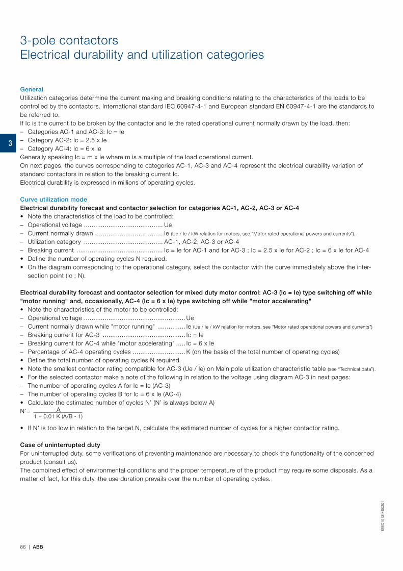
3-pole contactorsElectrical durability and utilization categories
GeneralUtilization categories determine the current making and breaking conditions relating to the characteristics of the loads to be controlled by the contactors. International standard IEC 60947-4-1 and European standard EN 60947-4-1 are the standards to be referred to.If Ic is the current to be broken by the contactor and Ie the rated operational current normally drawn by the load, then: – Categories AC-1 and AC-3: Ic = Ie – Category AC-2: Ic = 2.5 x Ie – Category AC-4: Ic = 6 x Ie
Generally speaking Ic = m x Ie where m is a multiple of the load operational current.On next pages, the curves corresponding to categories AC-1, AC-3 and AC-4 represent the electrical durability variation of standard contactors in relation to the breaking current Ic.Electrical durability is expressed in millions of operating cycles.
Curve utilization modeElectrical durability forecast and contactor selection for categories AC-1, AC-2, AC-3 or AC-4• Note the characteristics of the load to be controlled: – Operational voltage .......................................... Ue – Current normally drawn .................................... Ie (Ue / Ie / kW relation for motors, see "Motor rated operational powers and currents").
– Utilization category .......................................... AC-1, AC-2, AC-3 or AC-4 – Breaking current .............................................. Ic = Ie for AC-1 and for AC-3 ; Ic = 2.5 x Ie for AC-2 ; Ic = 6 x Ie for AC-4
• Define the number of operating cycles N required.• On the diagram corresponding to the operational category, select the contactor with the curve immediately above the inter-
section point (Ic ; N).
Electrical durability forecast and contactor selection for mixed duty motor control: AC-3 (Ic = Ie) type switching off while "motor running" and, occasionally, AC-4 (Ic = 6 x Ie) type switching off while "motor accelerating"• Note the characteristics of the motor to be controlled: – Operational voltage ...................................................... Ue – Current normally drawn while "motor running" ............... Ie (Ue / Ie / kW relation for motors, see "Motor rated operational powers and currents")
– Breaking current for AC-3 ............................................ Ic = Ie – Breaking current for AC-4 while "motor accelerating" ..... Ic = 6 x Ie – Percentage of AC-4 operating cycles ............................ K (on the basis of the total number of operating cycles)
• Define the total number of operating cycles N required.• Note the smallest contactor rating compatible for AC-3 (Ue / Ie) on Main pole utilization characteristic table (see “Technical data”).
• For the selected contactor make a note of the following in relation to the voltage using diagram AC-3 in next pages: – The number of operating cycles A for Ic = Ie (AC-3) – The number of operating cycles B for Ic = 6 x Ie (AC-4)
• Calculate the estimated number of cycles N’ (N’ is always below A)N'= A
1 + 0.01 K (A/B - 1)
• If N' is too low in relation to the target N, calculate the estimated number of cycles for a higher contactor rating.
Case of uninterrupted dutyFor uninterrupted duty, some verifications of preventing maintenance are necessary to check the functionality of the concerned product (consult us). The combined effect of environmental conditions and the proper temperature of the product may require some disposals. As a matter of fact, for this duty, the use duration prevails over the number of operating cycles.
86 | ABB
1SB
C10
1314
S0
201
3
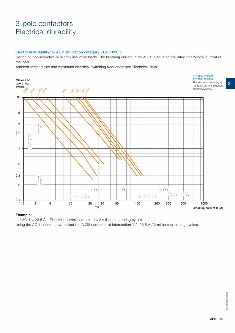
3-pole contactorsElectrical durability
Electrical durability for AC-1 utilization category - Ue ≤ 690 V Switching non-inductive or slightly inductive loads. The breaking current Ic for AC-1 is equal to the rated operational current of the load.Ambient temperature and maximum electrical switching frequency: see "Technical data".
1 3 5 7 9
1 3 5 7 9 1 5 9
1
3
5
79
13579
1 3 5 7 9
1 3 5 7 9
1 3 5 7 9 1 5 9
13579
10
1
0.1
0.2
0.3
0.5
3
5
10 100 10002 3 5 20 30 50 200 300 500
2
26.5
AX09AX12
AX18AX25
AX32AX40
AX50AX65
AX80
Millions of operatingcycles
Breaking current Ic (A)
AF1250, AF1350, AF1650, AF2050:The electrical durability at the rated current is 50000 operating cycles.
Example:Ic / AC-1 = 26.5 A – Electrical durability required = 2 millions operating cycles.Using the AC-1 curves above select the AX32 contactor at intersection " " (26.5 A / 2 millions operating cycles).
ABB | 87
1SFC
1013
20
C0
201
3
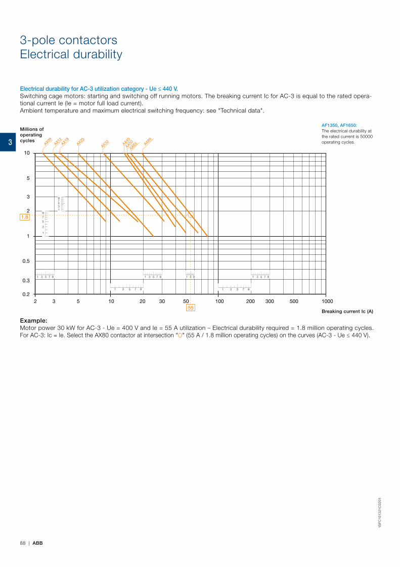
3-pole contactorsElectrical durability
Electrical durability for AC-3 utilization category - Ue ≤ 440 V.Switching cage motors: starting and switching off running motors. The breaking current Ic for AC-3 is equal to the rated opera-tional current Ie (Ie = motor full load current).Ambient temperature and maximum electrical switching frequency: see "Technical data".
10
1
10 100 10002 3 5 20 30 50 200 300 5000.2
0.3
0.5
2
3
5
1 3 5 7 9
13579
1
3
5
79
1 3 5 7 9 1 3 5 7 9 1 5 9
1 3 5 7 9 1 3 5 7 9
1.8
55
AX09AX12
AX18AX25
AX40
AX50
AX65AX32 AX80
Millions of operatingcycles
Breaking current Ic (A)
AF1350, AF1650:The electrical durability at the rated current is 50000 operating cycles.
Example:Motor power 30 kW for AC-3 - Ue = 400 V and Ie = 55 A utilization – Electrical durability required = 1.8 million operating cycles.For AC-3: Ic = Ie. Select the AX80 contactor at intersection " " (55 A / 1.8 million operating cycles) on the curves (AC-3 - Ue ≤ 440 V).
88 | ABB
1SFC
1013
21C
02
01
3
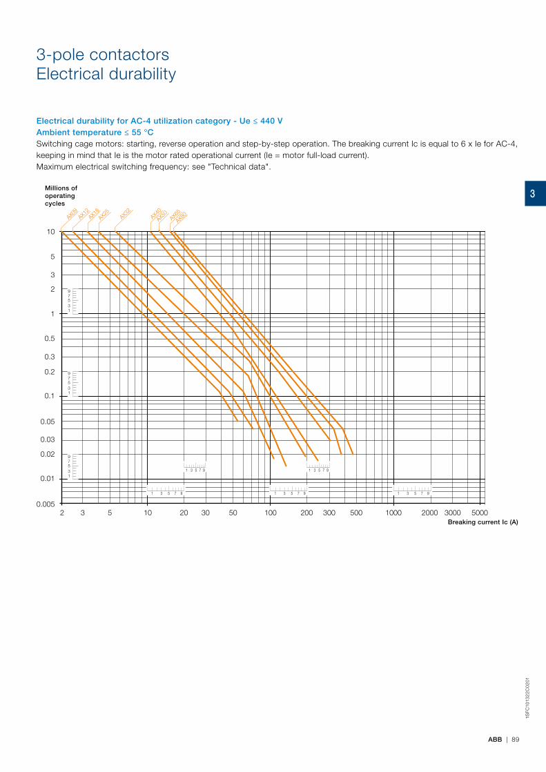
3-pole contactorsElectrical durability
Electrical durability for AC-4 utilization category - Ue ≤ 440 V Ambient temperature ≤ 55 °CSwitching cage motors: starting, reverse operation and step-by-step operation. The breaking current Ic is equal to 6 x Ie for AC-4, keeping in mind that Ie is the motor rated operational current (Ie = motor full-load current).Maximum electrical switching frequency: see "Technical data".
30001000100102 3 5 20 30 50 200 300 500 2000 5000
10
1
0.1
0.005
0.01
0.02
0.03
0.05
0.3
0.2
0.5
2
3
5
1 3 5 7 9
1 3 5 7 9
1 3 5 7 9
1 3 5 7 9 1 3 5 7 9
13579
13579
13579
AX12
AX18
AX09
AX25
AX32
AX40
AX80
AX65
AX50
Millions of operatingcycles
Breaking current Ic (A)
ABB | 89
1SFC
1013
22C
02
01
3

90 | ABB
1SB
C10
02
23
S0
201
Star-delta starting of three-phase asynchronous motorsContactor selection
General
Star-delta starting is the most common method to reduce the starting current of a motor. This system can be used on all the squirrel cage motors, which are normally used in delta connection.In this type of starting, it is recommended to choose motors having high starting torque i.e. much higher than the resistive torque in order to reach sufficient high speed when the motor is connected in star.
Star-delta starting
Technical DataWhen starting:
– inrush current is reduced to a third of direct starting current
– motor torque is reduced to a third or even less of direct starting torque.
Transient current is generated when switching from star to delta connection.
UtilizationDuring the initial starting phase ("star" connection), the resistive torque of the driven load must remain, irrespective of speed, less than the "star" motor torque until "star-delta" switching occurs.This starting mode is therefore ideal for machines having low starting torque such as:
– pumps
– centrifugal compressors
– wood-working machines, etc.
In order to prevent a high current peak, at least 85% of nominal speed must be reached before switching from star to delta.
PrecautionsMotor nominal voltage in delta connection must be equal to that of the mains.Example:A motor for 415 V star-delta starting must be designed for 415 V in "delta" connection. Its usual designation is "415 V / 690 V motor". The motor must be constructed with 6 terminal windings.
SequenceStarting is a three-stage process:1st stage - "Star" connectionPress the "On" button on the control circuit to close the KM2 "star" contactor. The KM1 "line" contactor then closes and the motor starts. Countdown of programmed starting time (normally 6 to 16 s) then begins.2nd stage - "Star" to "Delta" switchingWhen the programmed starting time is over, the KM2 "star" contactor opens.3rd stage - "Delta" connectionFor AX06 ... AX205, A transition time (or dwelling time) of 50 ms is fixed between opening of the "star" contactor and closing of the "delta" contactor by the use of CT-SDS timer. This prevents short circuit between "star" and "delta".For AX260 ... AX370, an on-delay timer without dwelling time (CT-ERS.21S) is enough to countdown the programmed starting time (6 to 10s) during "Star connection". The use of a star-delta timer including dwelling time is not permitted.
Note: An electrical interlock between star and delta is mandatory such as VE 5 or through auxiliary contacts.Furthermore, in open transition, the current interruption may reach up to 95 ms: it shall be checked that this duration is compatible with the application i.e. mainly if the decreasing in rotation speed is acceptable during the starting phase.
3

ABB | 91
1SB
C10
02
24S
02
01
Star-delta starting of three-phase asynchronous motorsContactor selection
Rated operational power - AC-3 Max. starting time from cold state (1)seconds
Linecontactor
Deltacontactor
Starcontactor
Overloadrelay (2)
Timer
220-230 VkW
240 VkW
380 VkW
400 VkW
415 VkW
440 VkW
500 VkW
660 VkW
690 VkW
3 3 5.5 5.5 5.5 5.5 5.5 5.5 5.5 15 AX06 AX06 AX06 TA25DU M CT-SDS.22S4 4 5.5 7.5 7.5 7.5 9 9 9 15 AX09 AX09 AX06 TA25DU M CT-SDS.22S5.5 5.5 9 9 9 9 9 9 9 15 AX12 AX12 AX06 TA25DU M CT-SDS.22S7.5 9 15 15 15 11 11 11 11 15 AX18 AX18 AX12 TA25DU M CT-SDS.22S11 11 22 22 22 15 15 15 15 15 AX25 AX25 AX18 TA25DU M CT-SDS.22S15 15 25 30 30 30 30 30 30 15 AX32 AX32 AX25 TA42DU M CT-SDS.22S18.5 22 37 37 37 37 37 37 37 30 AX40 AX40 AX32 TA42DU M CT-SDS.22S25 30 45 45 45 45 55 55 55 30 AX50 AX50 AX32 TA75DU M CT-SDS.22S30 37 55 55 55 55 55 55 55 30 AX65 AX65 AX40 TA75DU M CT-SDS.22S37 45 55 75 75 75 75 75 75 30 AX80 AX80 AX50 TA75DU M CT-SDS.22S45 55 75 90 90 90 90 90 90 20 AX95 AX95 AX65 TA110DU CT-SDS.22S55 55 90 110 110 110 110 132 132 20 AX115 AX115 AX80 TA110DU / E140DU CT-SDS.22S75 75 132 132 132 110 110 132 132 20 AX150 AX150 AX95 TA110DU / E140DU CT-SDS.22S90 90 160 160 160 160 160 160 200 20 AX185 AX185 AX115 TA200DU CT-SDS.22S110 110 160 200 200 200 200 250 250 20 AX205 AX205 AX185 TA200DU / EF 205 CT-SDS.22S132 132 250 250 250 250 315 400 400 20 AX260 AX260 AX205 EF370 CT-ERS.21S 160 160 250 250 315 315 355 400 500 20 AX300 AX300 AX205 EF370 CT-ERS.21S 200 200 355 355 355 400 355 500 500 20 AX370 AX370 AX260 EF370 CT-ERS.21S
(1) Usual time value = 6...16 s.(2) The setting current value is : nominal motor current x 0.58
AX06 ... AX370 contactors AX06 ... AX205 contactors AX260 ... AX370 contactors
Power circuit diagram Control circuit diagrams - Remote control
0
I
KM3:5/L3Us
UsN KM3:3/L2
.3
KM1
.4
A2
15
16
L Y∆
KM2KM3
.3
KM2
.4
A2 A2
A1KM1
KT1A2
A1
FR1
9596
A1
22
KM2
21
A1
22
KM1
21
2122
2122
23
KM2 A1A2
24
1/L1
3/L2
5/L3
13
2/T1
4/T2
6/T3
14
KM3
A1A2
1/L1
3/L2
5/L3
2/T1
4/T2
6/T3
KM1
A1A2
1/L1
3/L2
5/L3
13
2/T1
4/T2
6/T3
14
TESTSTOP
RESETMA
9897
9695
6/T3
4/T2
2/T1
FR1
W1V1U1
W2V2U2
W1V1U1
W2V2U2
KM2 KM3
A1A2
28 18
17
KT
UsN KM1:3/L2
KM1:5/L3 Us
I
KT
1314
1314
Y
KM1
L
KM2 KM1
23
KM1
24
A1A2
A1A2
A1A2
KM3
2122 22
21
KM2
STOP
RESETMA
9695
FR1
KM2 KM3
A1A2
KM1:5/L3 Us
UsN KM1:3/L2
KM3 KM2 KT
1314
1314
Y
KM1
L
KM2 KM1
28 18
A1A2
A1A2
A1A2
2122 22
21
23
KM1
2417
KT
O
ISTOP
RESET MA
9695
FR1
KM2 KM3
KM3 KM2 KT
1314
1314
Y
KM1
L
KM2 KM1
28 18
A1+
A2-
A1+
A2-
A1+
A2-
A1+
A2-
2122 22
21
23
KM1
2417
KT
O
I
STOP
RESET MA
9695
FR1
KM2 KM3
28 18
17
KT
KM3 KM2 KT
Y
KM1
L
I
1314
1314
KM2 KM1
23
KM1
24
A2-
A2-
A2-
A1+
A1+
A1+
A2-
A1+
2122 22
21
STOP
RESETMA
9695
FR1
t1 = adjusted starting timet2 = transition time (50ms)
Function diagram Electronic Timer
A1-A2
17-18
17-28
green LEDt1 t2
+
-
+
-
Ordering details - Electronic timerTiming function Time ranges Ouput Rated control
supply voltageType Order code Pkg
qtyWeight
(1 pce)kg
Star-delta change-over (3) 7 (0.05 s - 10 min) 2 n/o contacts, 3 LEDs28-48 V DC CT-SDS.22S 1SVR730210R3300 1 0.11424-240 V AC380-440 V AC CT-SDS.23S 1SVR730211R2300 1 0.118
ON-delay (4) 10 (0.05 s - 300h) 2 c/o SPDT contacts 24-240 V AC/DC CT-ERS.21S 1SVR730100R0300 1 0.152
(3) 50 ms transition time(4) No transition time
1SB
C50
0454
F000
0
CT-SDS...
2122
2122
23
KM2 A1A2
24
1/L1
3/L2
5/L3
13
2/T1
4/T2
6/T3
14
KM3
A1A2
1/L1
3/L2
5/L3
2/T1
4/T2
6/T3
KM1
A1A2
1/L1
3/L2
5/L3
13
2/T1
4/T2
6/T3
14
TESTSTOP
RESETMA
9897
9695
6/T3
4/T2
2/T1
FR1
W1V1U1
W2V2U2
W1V1U1
W2V2U2
KM2 KM3
A1A2
28 18
17
KT
UsN KM1:3/L2
KM1:5/L3 Us
I
KT
1314
1314
Y
KM1
L
KM2 KM1
23
KM1
24
A1A2
A1A2
A1A2
KM3
2122 22
21
KM2
STOP
RESETMA
9695
FR1
KM2 KM3
A1A2
KM1:5/L3 Us
UsN KM1:3/L2
KM3 KM2 KT
1314
1314
Y
KM1
L
KM2 KM1
28 18
A1A2
A1A2
A1A2
2122 22
21
23
KM1
2417
KT
O
ISTOP
RESET MA
9695
FR1
KM2 KM3
KM3 KM2 KT
1314
1314
Y
KM1
L
KM2 KM1
28 18
A1+
A2-
A1+
A2-
A1+
A2-
A1+
A2-
2122 22
21
23
KM1
2417
KT
O
I
STOP
RESET MA
9695
FR1
KM2 KM3
28 18
17
KT
KM3 KM2 KT
Y
KM1
L
I
1314
1314
KM2 KM1
23
KM1
24
A2-
A2-
A2-
A1+
A1+
A1+
A2-
A1+
2122 22
21
STOP
RESETMA
9695
FR1
t1 = adjusted starting timet2 = transition time (50ms)
Function diagram Electronic Timer
A1-A2
17-18
17-28
green LEDt1 t2
+
-
+
-
3
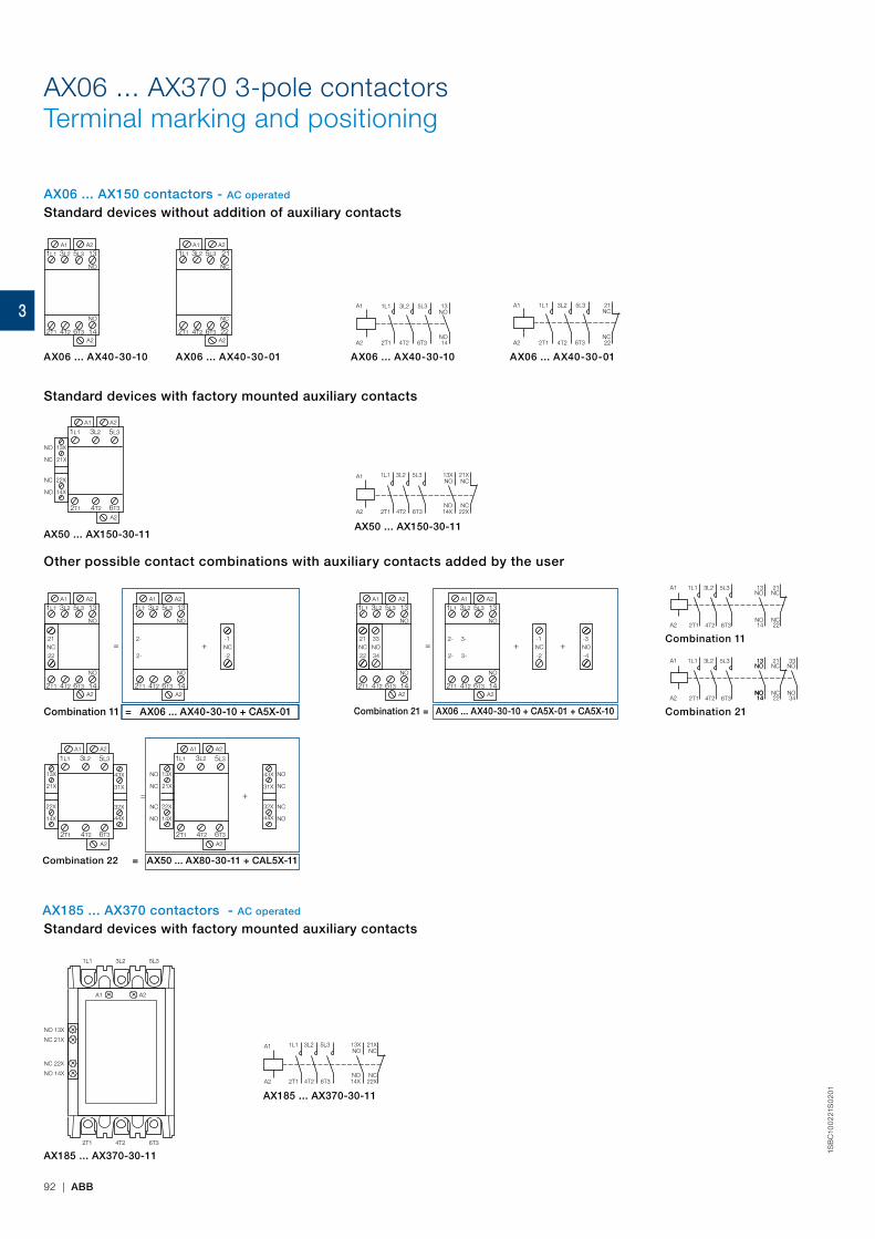
92 | ABB
1SB
C10
02
21S
02
01
AX06 ... AX370 3-pole contactorsTerminal marking and positioning
A1
A2
1L1
2T1
3L2
4T2
5L3
6T3
13NO
NO14
A1
A2
1L1
2T1
3L2
4T2
5L3
6T3
21NC
NC22
1L1 3L2 5L3
2T1 4T2 6T3
A1 A2
A2
21
NC
NC
22
1L1 3L2 5L3
2T1 4T2 6T3
A1 A2
A2
13
NO
NO
14
A1
1L1
2T1
A2
13X
21X
14X
22X
A2
3L2 5L3
4T2 6T3
NC
NO
NO
NCA1
A2
1L1
2T1
3L2
4T2
21XNC
NC22X
5L3
6T3
13XNO
NO14X
= +-1
-2NC
NO
NC
1L1 3L2 5L3
2T1 4T2 6T3
A1 A2
A2
13
NO
14
21
22
NO
1L1 3L2 5L3
2T1 4T2 6T3
A1 A2
A2
13
NO
14
2-
2-
A1
1L1
2T1
A2
13X
21X
14X
22X
A2
3L2 5L3
4T2 6T3
43X
31X
44X
32X
A1
1L1
2T1
A2
A2
3L2 5L3
4T2 6T3
13X
21X
14X
22X
NC
NO
NO
NC
43X
31X
44X
32X
NC
NO
NO
NC
= +
= + +-1
-2NC
-3
-4NO
1L1 3L2 5L3
2T1 4T2 6T3
A1 A2
A2
13
NO
NO
14
21
22
33
34NONC
1L1 3L2 5L3
2T1 4T2 6T3
A1 A2
A2
13
NO
NO
14
2-
2-
3-
3-13
NOA1
A2
5L3
6T3
3L2
4T2
1L1
2T1
21NC
NC22
NO14
33NO
NO34
13NO
NO14
NO14
A1
A2
5L3
6T3
3L2
4T2
1L1
2T1
21NC
NC22
13NO
NO14
A1 A2
NO 13X
NC 21X
NC 22X
NO 14X
1L1 3L2 5L3
2T1 4T2 6T3
A1
A2
1L1
2T1
3L2
4T2
21XNC
NC22X
5L3
6T3
13XNO
NO14X
AX06 ... AX150 contactors - AC operated
AX185 ... AX370 contactors - AC operated
Standard devices without addition of auxiliary contacts
Standard devices with factory mounted auxiliary contacts
Other possible contact combinations with auxiliary contacts added by the user
Standard devices with factory mounted auxiliary contacts
Combination 11 = AX06 ... AX40-30-10 + CA5X-01
AX185 ... AX370-30-11
AX185 ... AX370-30-11
Combination 21 = AX06 ... AX40-30-10 + CA5X-01 + CA5X-10
Combination 22 = AX50 ... AX80-30-11 + CAL5X-11
Combination 11
Combination 21
AX06 ... AX40-30-10
AX50 ... AX150-30-11AX50 ... AX150-30-11
AX06 ... AX40-30-01 AX06 ... AX40-30-10 AX06 ... AX40-30-01
3
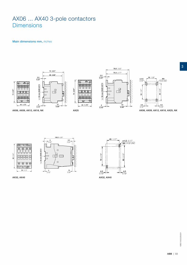
ABB | 93
1SB
C10
02
22S
02
01
AX06 ... AX40 3-pole contactorsDimensions
AX06, AX09, AX12, AX18, NX AX25
Main dimensions mm, inches
AX06, AX09, AX12, AX18, AX25, NX
35 1.38"
60 2
.36"
50 1
.97"
4.50.18"
ø 4.50.18"
M48-32 UNC
4.50.18"
35 m
m E
N/IE
C 60
715
90 3
.54"
54 2.13" 40.16"
100.39"
6.30.25"
108.3 4.26"
90.35"
35 m
m E
N/IE
C 60
715
74 2
.91"
44 1.73"
5.50.22"
100.39"
40.16"
68 2.68"
74 2.91"
35 m
m E
N/IE
C 60
715
74 2
.91"
44 1.73"
5.50.22"
76.6 3.02"
70.3 2.77"
100.39"
40.16"
ø 4.2 0.17"
4.50.18"
4.50.18"
45 1.77"
70 2
.76"
80 3
.15"
M4 8-32 UNC
AX32, AX40 AX32, AX40
3
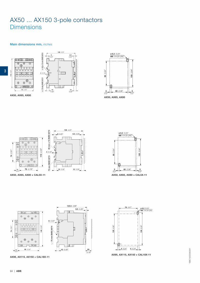
94 | ABB
1SB
C10
02
22S
02
01
AX50 ... AX150 3-pole contactorsDimensions
AX95, AX115, AX150 + CAL18X-11AX95, AX115, AX150 + CAL18X-11
Main dimensions mm, inches
AX50, AX65, AX80 + CAL5X-11 AX50, AX65, AX80 + CAL5X-11
70 2.76"12 0.47"
74 2
.91"
110
4.3
3"
108 4.25"
6.5 0.26"6 0.24"
10 0.39"
4 0.16"
10 0.39"
35 m
m x
15
EN/IE
C 60
715
75 m
m E
N/IE
C 60
715
148
5.8
3"
74 2
.91"
90 3.54"12 0.47"
75 m
m E
N/IE
C 60
715
123.5 4.86"
6.5 0.26"
6 0.24"
10 0.39" 20
0.79"
50.2"
50.2"
60 2.36"
90 3
.54"
ø 6.2 0.24"M6 1/4-20 UNC
100
3.9
4"
126
4.9
6"
78 3.07"ø 6.2 0.24"M6 1/4-20 UNC
136
5.3
5"
6 0.24"6 0.24"
AX50, AX65, AX80
35 x
15
mm
EN/
IEC
6071
575
mm
EN/
IEC
6071
5
110
4.3
3"
70 2.76" 100.39"
100.39"
4 0.16"
6.50.26"
60.24"
108 4.25"
50.2"
50.2"
60 2.36"
90 3
.54"
ø 6.2 0.24"M6 1/4-20 UNC
100
3.9
4"
AX50, AX65, AX80
3
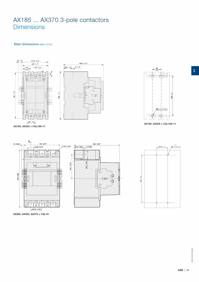
ABB | 95
1SFC
1013
17C
02
01
AX185, AX205 + CAL18X-11AX185, AX205 + CAL18X-11
AX260, AX300, AX370 + CAL19
AX185 ... AX370 3-pole contactorsDimensions
Main dimensions mm, inches
111.5 4.39"
105 4.13"
12 0.47"
17.5 0.69"
8.5 0.33"
10
0.3
9"
35 1.38"
187
7.3
6"
162.3 6.39"
5 0.20"
196
7.7
2"
35.5 1.40"
AX265 AX305 AX370, ,
140 5.51"
19.50 0.77"
43.75 1.72"
10.5 0.41"180 7.09"
94.7
3.7
3"
225
8.8
6"
5 0.20"35.5 1.40"
33.4
1.3
1"
A10 0.39"
187
7.3
6"
43 1.69"75 2.95". 0.00" M5 10 0.39"24 0.94"UNC-4 X
M5 10-24 UNC
351.38"
165
6.5
"
187
7.3
6"
43.75 1.72" M5 10-24 UNC4 X
3

96 | ABB
3
NX contactor relays
NX contactor relays
Ordering details
AC operated 98
Main accessories 99
Technical data 100
Terminal marking and positioning 102
ABB | 97
3
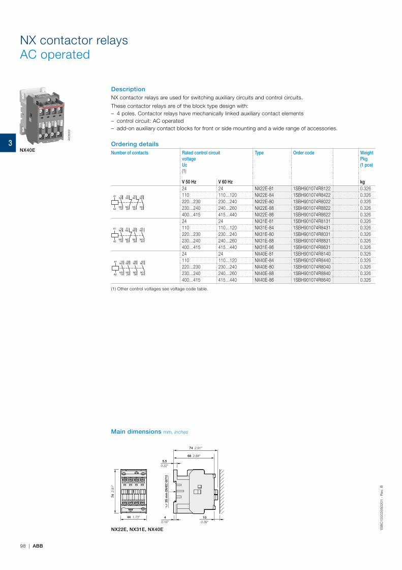
1SB
C10
00
20
S0
201
- R
ev.
B
98 | ABB
DescriptionNX contactor relays are used for switching auxiliary circuits and control circuits.
These contactor relays are of the block type design with: – 4 poles. Contactor relays have mechanically linked auxiliary contact elements – control circuit: AC operated – add-on auxiliary contact blocks for front or side mounting and a wide range of accessories.
Ordering detailsNumber of contacts Rated control circuit
voltageUc(1)
Type Order code WeightPkg(1 pce)
V 50 Hz V 60 Hz kg
43NO
NO44
31NC
NC32
21NC
NC22
13NO
NO14
A1
A2
24 24 NX22E-81 1SBH901074R8122 0.326110 110…120 NX22E-84 1SBH901074R8422 0.326220…230 230…240 NX22E-80 1SBH901074R8022 0.326230…240 240…260 NX22E-88 1SBH901074R8822 0.326400…415 415…440 NX22E-86 1SBH901074R8622 0.326
33NO
NO34
21NC
NC22
13NO
NO14
43NO
NO44
A1
A2
24 24 NX31E-81 1SBH901074R8131 0.326110 110…120 NX31E-84 1SBH901074R8431 0.326220…230 230…240 NX31E-80 1SBH901074R8031 0.326230…240 240…260 NX31E-88 1SBH901074R8831 0.326400…415 415…440 NX31E-86 1SBH901074R8631 0.326
43NO
NO44
33NO
NO34
23NO
NO24
13NO
NO14
A1
A2
24 24 NX40E-81 1SBH901074R8140 0.326110 110…120 NX40E-84 1SBH901074R8440 0.326220…230 230…240 NX40E-80 1SBH901074R8040 0.326230…240 240…260 NX40E-88 1SBH901074R8840 0.326400…415 415…440 NX40E-86 1SBH901074R8640 0.326
(1) Other control voltages see voltage code table.
NX contactor relaysAC operated
AX
0800
2
NX40E
NX22E, NX31E, NX40E
35 m
m E
N/IE
C 60
715
74 2
.91"
44 1.73"
5.50.22"
100.39"
40.16"
68 2.68"
74 2.91"
Main dimensions mm, inches
3
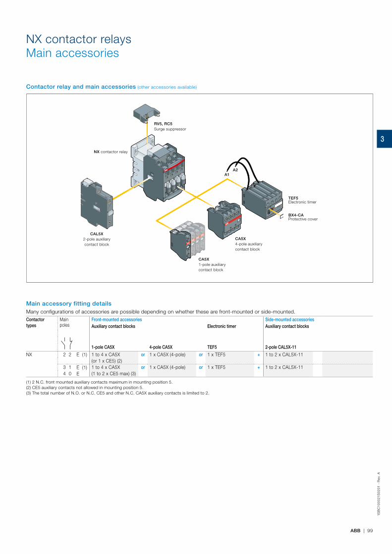
1SB
C10
00
21S
02
01 -
Rev
. A
ABB | 99
NX contactor relaysMain accessories
Main accessory fitting detailsMany configurations of accessories are possible depending on whether these are front-mounted or side-mounted.Contactortypes
Mainpoles
Front-mounted accessories Side-mounted accessoriesAuxiliary contact blocks Electronic timer Auxiliary contact blocks
1-pole CA5X 4-pole CA5X TEF5 2-pole CAL5X-11
NX 2 2 E (1) 1 to 4 x CA5X or 1 x CA5X (4-pole) or 1 x TEF5 + 1 to 2 x CAL5X-11(or 1 x CE5) (2)
3 1 E (1) 1 to 4 x CA5X or 1 x CA5X (4-pole) or 1 x TEF5 + 1 to 2 x CAL5X-114 0 E (1 to 2 x CE5 max) (3)
(1) 2 N.C. front mounted auxiliary contacts maximum in mounting position 5.(2) CE5 auxiliary contacts not allowed in mounting position 5.(3) The total number of N.O. or N.C. CE5 and other N.C. CA5X auxiliary contacts is limited to 2.
Contactor relay and main accessories (other accessories available)
RV5, RC5Surge suppressor
CAL5X2-pole auxiliary contact block
CA5X1-pole auxiliary contact block
CA5X4-pole auxiliary contact block
NX contactor relay
A1A2
TEF5Electronic timer
BX4-CAProtective cover
3
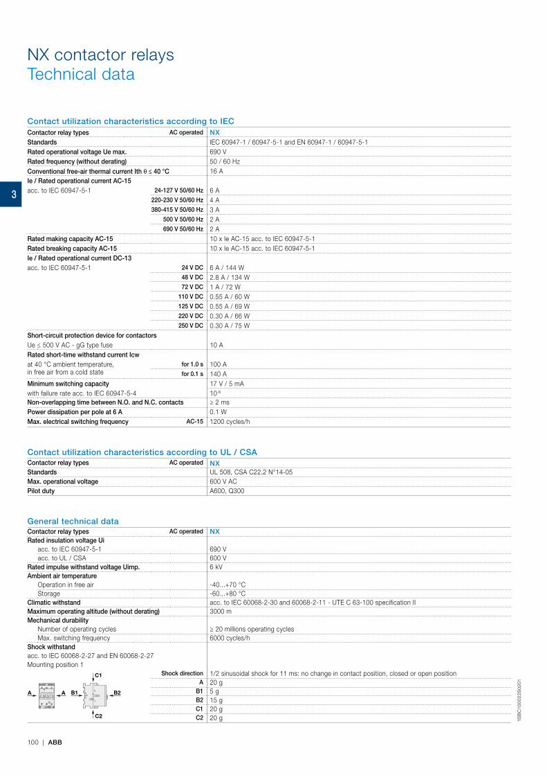
1SB
C10
00
22S
02
01
100 | ABB
NX contactor relaysTechnical data
Contact utilization characteristics according to IECContactor relay types AC operated NXStandards IEC 60947-1 / 60947-5-1 and EN 60947-1 / 60947-5-1Rated operational voltage Ue max. 690 VRated frequency (without derating) 50 / 60 HzConventional free-air thermal current Ith θ ≤ 40 °C 16 AIe / Rated operational current AC-15acc. to IEC 60947-5-1 24-127 V 50/60 Hz 6 A
220-230 V 50/60 Hz 4 A380-415 V 50/60 Hz 3 A
500 V 50/60 Hz 2 A690 V 50/60 Hz 2 A
Rated making capacity AC-15 10 x Ie AC-15 acc. to IEC 60947-5-1Rated breaking capacity AC-15 10 x Ie AC-15 acc. to IEC 60947-5-1Ie / Rated operational current DC-13acc. to IEC 60947-5-1 24 V DC 6 A / 144 W
48 V DC 2.8 A / 134 W72 V DC 1 A / 72 W
110 V DC 0.55 A / 60 W125 V DC 0.55 A / 69 W220 V DC 0.30 A / 66 W250 V DC 0.30 A / 75 W
Short-circuit protection device for contactorsUe ≤ 500 V AC - gG type fuse 10 ARated short-time withstand current Icwat 40 °C ambient temperature,in free air from a cold state
for 1.0 s 100 Afor 0.1 s 140 A
Minimum switching capacity 17 V / 5 mAwith failure rate acc. to IEC 60947-5-4 10-6
Non-overlapping time between N.O. and N.C. contacts ≥ 2 msPower dissipation per pole at 6 A 0.1 WMax. electrical switching frequency AC-15 1200 cycles/h
Contact utilization characteristics according to UL / CSAContactor relay types AC operated NXStandards UL 508, CSA C22.2 N°14-05Max. operational voltage 600 V ACPilot duty A600, Q300
General technical dataContactor relay types AC operated NXRated insulation voltage Ui
acc. to IEC 60947-5-1 690 Vacc. to UL / CSA 600 V
Rated impulse withstand voltage Uimp. 6 kVAmbient air temperature
Operation in free air -40...+70 °CStorage -60...+80 °C
Climatic withstand acc. to IEC 60068-2-30 and 60068-2-11 - UTE C 63-100 specification IIMaximum operating altitude (without derating) 3000 mMechanical durability
Number of operating cycles ≥ 20 millions operating cyclesMax. switching frequency 6000 cycles/h
Shock withstandacc. to IEC 60068-2-27 and EN 60068-2-27Mounting position 1
B2A A B1
C2
C1 Shock direction 1/2 sinusoidal shock for 11 ms: no change in contact position, closed or open positionA 20 g
B1 5 gB2 15 gC1 20 gC2 20 g
3
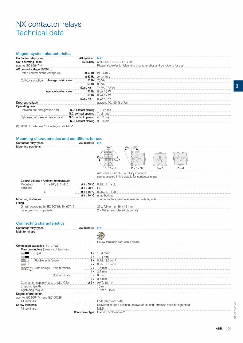
1SB
C10
00
23
S0
201
ABB | 101
NX contactor relaysTechnical data
Magnet system characteristicsContactor relay types AC operated NXCoil operating limits AC supply at θ ≤ 55 °C 0.85...1.1 x Uc
Please also refer to "Mounting characteristics and conditions for use"acc. to IEC 60947-4-1AC control voltage 50/60 Hz
Rated control circuit voltage Uc at 50 Hz 24...440 Vat 60 Hz 24...440 V
Coil consumption Average pull-in value 50 Hz 70 VA60 Hz 80 VA
50/60 Hz (1) 74 VA / 70 VAAverage holding value 50 Hz 8 VA / 2 W
60 Hz 8 VA / 2 W50/60 Hz (1) 8 VA / 2 W
Drop-out voltage approx. 40...65 % of UcOperating time
Between coil energization and: N.O. contact closing 10...26 msN.C. contact opening 7...21 ms
Between coil de-energization and: N.O. contact opening 4...11 msN.C. contact closing 9...16 ms
(1) 50/60 Hz coils: see "Coil voltage code table".
Mounting characteristics and conditions for useContactor relay types AC operated NXMounting positions
Pos. 5 Pos. 6
Pos. 3
Pos. 2
Pos. 1 Pos. 1 ± 30°
+30° -30°
Pos. 4
Add-on N.O. or N.C. auxiliary contacts:see accessory fitting details for contactor relays
Control voltage / Ambient temperatureMountingpositions
1, 1±30°, 2, 3, 4, 5 at θ ≤ 55 °C 0.85…1.1 x Ucat θ ≤ 70 °C Uc
6 at θ ≤ 55 °C 0.95…1.1 x Ucat θ ≤ 70 °C unauthorized
Mounting distances The contactors can be assembled side by sideFixing
On rail according to IEC 60715, EN 60715 35 x 7.5 mm or 35 x 15 mmBy screws (not supplied) 2 x M4 screws placed diagonally
Connecting characteristicsContactor relay types AC operated NXMain terminals
Screw terminals with cable clampConnection capacity (min. ... max.)
Main conductors (poles + coil terminals)Rigid 1 x 1...4 mm²
2 x 1...4 mm²Flexible with ferrule 1 x 0.75...2.5 mm²
2 x 0.75...2.5 mm²Ll Bars or lugs Pole terminals L < 7.7 mm
l < 3.7 mmCoil terminals L < 8 mm
l < 3.7 mmConnection capacity acc. to UL / CSA 1 or 2 x AWG 18...14Stripping length 10 mmTightening torque 1 Nm / 9 Ib.in
Degree of protectionacc. to IEC 60947-1 and IEC 60529
All terminals IP20 (only front side)Screw terminals Delivered in open position, screws of unused terminals must be tightened
All terminals M3.5Screwdriver type Flat Ø 5.5 / Pozidriv 2
3

1SB
C10
00
24S
02
01
102 | ABB
NX22E
43NO
NO44
31NC
NC32
21NC
NC22
13NO
NO14
A1
A2
NX40E
43NO
NO44
33NO
NO34
23NO
NO24
13NO
NO14
A1
A2
NX31E
33NO
NO34
21NC
NC22
13NO
NO14
43NO
NO44
A1
A2
A1
A2
13 21 33 43
NO NC NO NO
54
53NO
NO NC NO NO
14 22 34 44
A213 21 33 43
NO NC NO NO
NO
5-
5-
NC NO NO
14 22 34 44
A1 A2
A2
= + NO-3
-4
= + +
A1
A2
13 23 33 43
NO NO NO NO
51
52
NC61
62
NC
NO NO NO NO
14 24 34 44
A213 23 33 43
NO NO NO NO
NO NO NO
14 24 34 44
5-
5-
6-
6 -
A1 A2
A2
-1
-2
NC-1
-2
NC
NO
= +-3
-4
NO
NO NO NO
A1
A2
13 23 33 43
NO
53
54
NO
NO NO NO NO
14 24 34 44
A213 23 33 43
NO NO NO NO
NO NO NO NO
14 24 34 44
5-
5-
A1 A2
A2
= + +
A1
A2
13 23 33 43
NO NO NO NO
53
54
NO63
64
NO
NO NO NO NO
14 24 34 44
A213 23 33 43
NO NO NO NO
NO NO NO NO
14 24 34 44
5-
5-
6-
6 -
A1 A2
A2
-3
-4
NO-3
-4
NO
NX22E
Combination 41E = NX31E + CA5X-10
33NO
NO34
21NC
NC22
13NO
NO14
A1
A2
43NO
NO44
53NO
NO54
Combination 41E
Combination 42E = NX40E + CA5X-01 + CA5X-01
A1
A2
43NO
NO44
33NO
NO34
23NO
NO24
13NO
NO14
61NC
NC62
51NC
NC52
Combination 42E
Combination 50E = NX40E + CA5X-10
A1
A2
43NO
NO44
53NO
NO54
33NO
NO34
23NO
NO24
13NO
NO14
Combination 50E
Combination 60E = NX40E + CA5X-10 + CA5X-10
A1
A2
43NO
NO44
53NO
NO54
63NO
NO64
33NO
NO34
23NO
NO24
13NO
NO14
Combination 60E
13 21 31 43
NO NC NC NO
NO NC NC NO
14 22 32 44
A1 A2
A2
NX31E
13 21 33 43
NO NC NO NO
NO NC NO NO
14 22 34 44
A1 A2
A2
NX40E
13 23 33 43
NO NO NO NO
NO NO NO NO
14 24 34 44
A1 A2
A2
NX contactor relaysTerminal marking and positioning
NX contactor relays - AC operated
Standard devices without addition of auxiliary contacts
Other possible contact combinations with auxiliary contacts added by the user
3
Accessories for AX06 ... AX370 3-pole contactors and NX contactor relays
Auxiliary contact blocks
Ordering details 104
Technical data 105
Terminal marking and positioning 108
Electronic timers
Ordering details 109
Technical data 110
Mechanical and electrical interlock units
Ordedring details 112
Technical data 113
Interface relays
Ordedring details 114
Technical data 115
Mechanical latching units
Ordering details 116
Technical data 117
Surge suppressors for contactor coils
Ordering details 118
Technical data 119
Additional terminal blocks 120
Function markers - Terminals for control lead connections 121
Terminal shrouds - Terminal enlargements and extension 122
Terminal connecting strips and shorting bars 123
Connection accessories for starting solutions 124
Phase to phase connections - Connection sets for star-delta starters 125
Voltage code table 126
ABB | 103
3
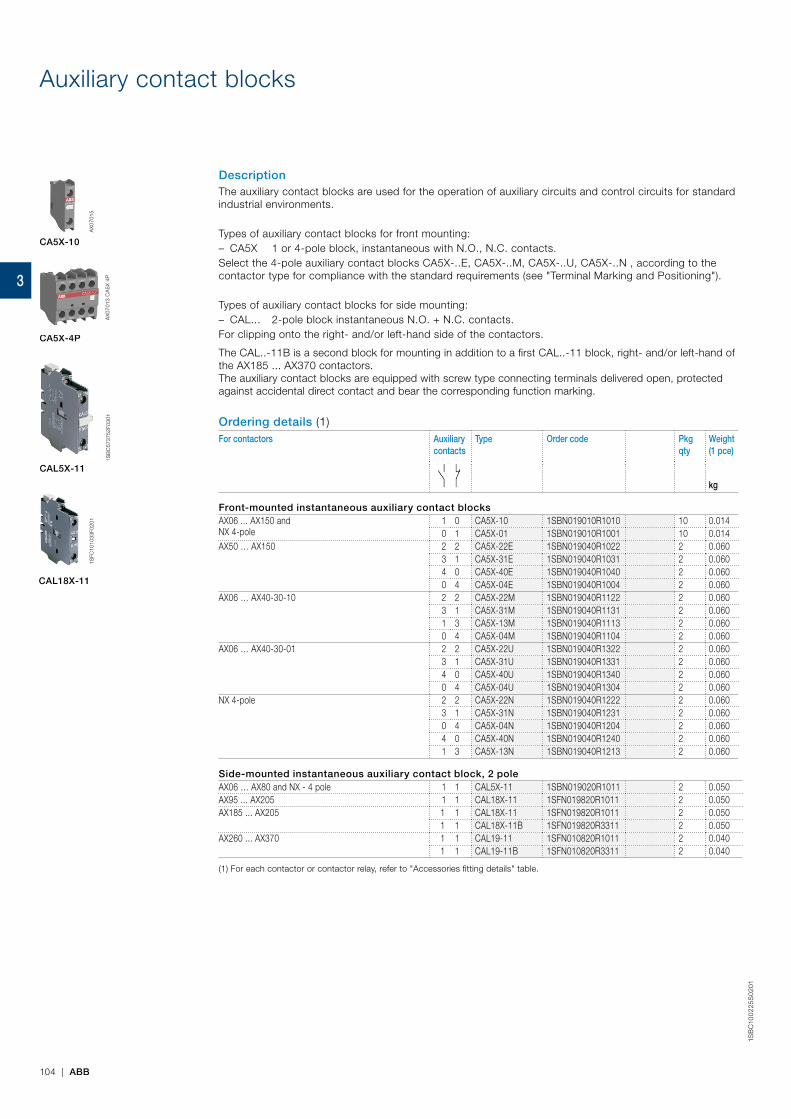
104 | ABB
1SB
C10
02
25S
02
01
Auxiliary contact blocks
DescriptionThe auxiliary contact blocks are used for the operation of auxiliary circuits and control circuits for standard industrial environments.
Types of auxiliary contact blocks for front mounting: – CA5X 1 or 4-pole block, instantaneous with N.O., N.C. contacts.
Select the 4-pole auxiliary contact blocks CA5X-..E, CA5X-..M, CA5X-..U, CA5X-..N , according to the contactor type for compliance with the standard requirements (see "Terminal Marking and Positioning").
Types of auxiliary contact blocks for side mounting: – CAL... 2-pole block instantaneous N.O. + N.C. contacts.
For clipping onto the right- and/or left-hand side of the contactors.
The CAL..-11B is a second block for mounting in addition to a first CAL..-11 block, right- and/or left-hand of the AX185 ... AX370 contactors. The auxiliary contact blocks are equipped with screw type connecting terminals delivered open, protected against accidental direct contact and bear the corresponding function marking.
Ordering details (1)For contactors Auxiliary
contactsType Order code Pkg
qtyWeight(1 pce)
kg
Front-mounted instantaneous auxiliary contact blocksAX06 ... AX150 and NX 4-pole
1 0 CA5X-10 1SBN019010R1010 10 0.0140 1 CA5X-01 1SBN019010R1001 10 0.014
AX50 … AX150 2 2 CA5X-22E 1SBN019040R1022 2 0.0603 1 CA5X-31E 1SBN019040R1031 2 0.0604 0 CA5X-40E 1SBN019040R1040 2 0.0600 4 CA5X-04E 1SBN019040R1004 2 0.060
AX06 … AX40-30-10 2 2 CA5X-22M 1SBN019040R1122 2 0.0603 1 CA5X-31M 1SBN019040R1131 2 0.0601 3 CA5X-13M 1SBN019040R1113 2 0.0600 4 CA5X-04M 1SBN019040R1104 2 0.060
AX06 … AX40-30-01 2 2 CA5X-22U 1SBN019040R1322 2 0.0603 1 CA5X-31U 1SBN019040R1331 2 0.0604 0 CA5X-40U 1SBN019040R1340 2 0.0600 4 CA5X-04U 1SBN019040R1304 2 0.060
NX 4-pole 2 2 CA5X-22N 1SBN019040R1222 2 0.0603 1 CA5X-31N 1SBN019040R1231 2 0.0600 4 CA5X-04N 1SBN019040R1204 2 0.0604 0 CA5X-40N 1SBN019040R1240 2 0.0601 3 CA5X-13N 1SBN019040R1213 2 0.060
Side-mounted instantaneous auxiliary contact block, 2 poleAX06 … AX80 and NX - 4 pole 1 1 CAL5X-11 1SBN019020R1011 2 0.050AX95 ... AX205 1 1 CAL18X-11 1SFN019820R1011 2 0.050AX185 ... AX205 1 1 CAL18X-11 1SFN019820R1011 2 0.050
1 1 CAL18X-11B 1SFN019820R3311 2 0.050AX260 ... AX370 1 1 CAL19-11 1SFN010820R1011 2 0.040
1 1 CAL19-11B 1SFN010820R3311 2 0.040
(1) For each contactor or contactor relay, refer to "Accessories fitting details" table.
CA5X-10
AX
0701
5
CAL5X-11
1SB
C57
3752
F030
1
CA5X-4P
AX
0701
3 C
A5X
4P
CAL18X-11
1SFC
1010
33F0
201
3

ABB | 105
1SB
C10
02
26S
02
01
Auxiliary contact blocksTechnical dataContact utilization characteristics according to IECTypes Front mounted Side mounted
1-pole CA5X, 4-pole CA5X
CAL5X-11 CAL18X-11, CAL18X-11B
CAL19-11, CAL19-11B
Standards IEC 60947-5-1 and EN 60947-5-1Rated insulation voltage Uiacc. to IEC 60947-5-1 690 VRated operational voltage Ue max. 24...690 V ACConventional thermal current Ith - θ ≤ 40 °C 16 AIe / Rated operational current AC-15acc. to IEC 60947-5-1 24-127 V 50/60 Hz 6 A
220-240 V 50/60 Hz 4 A380-440 V 50/60 Hz 3 A500-690 V 50/60 Hz 2 A
Making capacity 10 x Ie AC-15 acc. to IEC 60947-5-1Breaking capacity 10 x Ie AC-15 acc. to IEC 60947-5-1Ie / Rated operational current DC-13acc. to IEC 60947-5-1 24 V DC 6 A / 144 W 3 A / 72 W
48 V DC 2.8 A / 134 W 1.5 A / 72 W72 V DC 1 A / 72 W 1 A / 72 W
110 V DC 0.55 A / 60 W 0.55 A / 60 W125 V DC 0.55 A / 69 W 0.55 A / 69 W220 V DC 0.3 A / 66 W 0.3 A / 69 W250 V DC 0.3 A / 75 W 0.3 A / 75 W
Short-circuit protection device gG type fuse 10 ARated short-time withstand current Icw for 1.0 s 100 Aθ = 40 °C for 0.1 s 140 AMinimum switching capacity
AX06 … AX80 contactors 12 V / 3 mA – –with failure rate acc. to IEC 60947-5-4 ≤ 10-6 – –AX95 … AX150 contactors 24 V / 50 mA – 24 V / 50 mA
(0.5 million of operating cycles)
–
with failure rate acc. to IEC 60947-5-4 – – ≤ 10-6 –AX185 … AX205 contactors – – 24 V / 50 mA
(0.5 million of operating cycles)
–
with failure rate acc. to IEC 60947-5-4 – – ≤ 10-6 –AX260 … AX370 contactors – – – 24 V / 50 mAwith failure rate acc. to IEC 60947-5-4 – – – ≤ 10-6
Power dissipation per pole at 6 A 0.1 W 0.15 WMechanical durability
Number of operating cycles 10 millions (AX06 … AX80) 10 millions 5 millions (AX95 ... AX205)
5 millions3 millions (AX95 … AX150)
Max. switching frequency 3600 cycles/h 300 cycles/hMax. electrical switching frequency AC-15 1200 cycles/h 300 cycles/h
DC-13 900 cycles/h 300 cycles/h
Contact utilization characteristics according to UL / CSAStandards UL 508, CSA C22.2 N°14Max. operational voltage 600 V AC, 250 V DCPilot duty A600, Q300
AC thermal taed current 10 A
Connecting characteristicsConnection capacity (min. ... max.)
Rigid solid 1 x 1...4 mm²2 x 1...4 mm²
Flexible with ferrule 1 x 0.75...2.5 mm²2 x 0.75...2.5 mm²
Lugs L ≤ 7.7 mm 8 mml > 3.7 mm 3.7 mm
Tightening torque 1 Nm / 9 lb.inConnection capacity acc. to UL / CSA 1 or 2 x AWG 18...14 –Stripping length 1-pole: 11 mm 10 mm –
4-pole: 10 mmDegree of protection Terminals IP20acc. to IEC 60947-1 / EN 60947-1 and IEC 60529 / EN 60529Screw terminals Delivered in open position, screws of unused terminals must be tightened
All terminals M3.5Screwdriver type Flat Ø 5.5 / Pozidriv 2
3
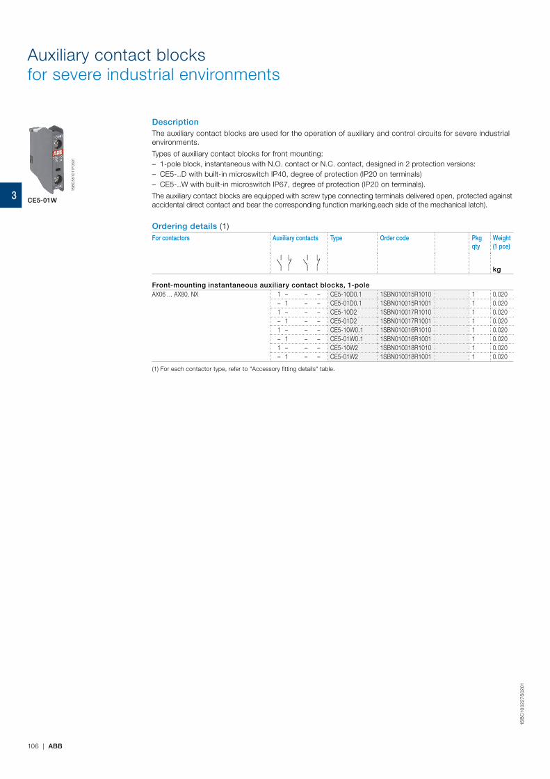
106 | ABB
1SB
C10
02
27S
02
01
Auxiliary contact blocksfor severe industrial environments
DescriptionThe auxiliary contact blocks are used for the operation of auxiliary and control circuits for severe industrial environments.
Types of auxiliary contact blocks for front mounting: – 1-pole block, instantaneous with N.O. contact or N.C. contact, designed in 2 protection versions: – CE5-..D with built-in microswitch IP40, degree of protection (IP20 on terminals) – CE5-..W with built-in microswitch IP67, degree of protection (IP20 on terminals).
The auxiliary contact blocks are equipped with screw type connecting terminals delivered open, protected against accidental direct contact and bear the corresponding function marking.each side of the mechanical latch).
Ordering details (1)For contactors Auxiliary contacts Type Order code Pkg
qtyWeight(1 pce)
kg
Front-mounting instantaneous auxiliary contact blocks, 1-poleAX06 ... AX80, NX 1 – – – CE5-10D0.1 1SBN010015R1010 1 0.020
– 1 – – CE5-01D0.1 1SBN010015R1001 1 0.0201 – – – CE5-10D2 1SBN010017R1010 1 0.020– 1 – – CE5-01D2 1SBN010017R1001 1 0.0201 – – – CE5-10W0.1 1SBN010016R1010 1 0.020– 1 – – CE5-01W0.1 1SBN010016R1001 1 0.0201 – – – CE5-10W2 1SBN010018R1010 1 0.020– 1 – – CE5-01W2 1SBN010018R1001 1 0.020
(1) For each contactor type, refer to "Accessory fitting details" table.
CE5-01W
1SB
C58
1011
F030
1
3
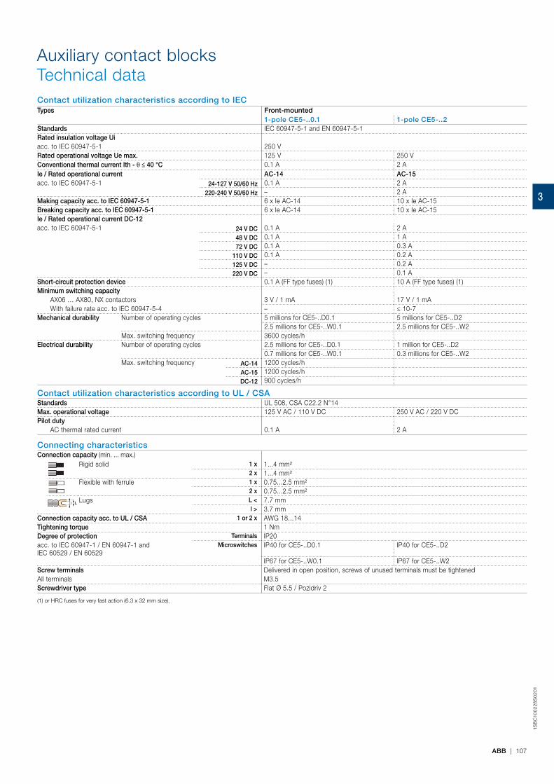
ABB | 107
1SB
C10
02
28S
02
01
Auxiliary contact blocksTechnical dataContact utilization characteristics according to IECTypes Front-mounted
1-pole CE5-..0.1 1-pole CE5-..2Standards IEC 60947-5-1 and EN 60947-5-1Rated insulation voltage Uiacc. to IEC 60947-5-1 250 VRated operational voltage Ue max. 125 V 250 VConventional thermal current Ith - θ ≤ 40 °C 0.1 A 2 AIe / Rated operational current AC-14 AC-15acc. to IEC 60947-5-1 24-127 V 50/60 Hz 0.1 A 2 A
220-240 V 50/60 Hz – 2 AMaking capacity acc. to IEC 60947-5-1 6 x Ie AC-14 10 x Ie AC-15Breaking capacity acc. to IEC 60947-5-1 6 x Ie AC-14 10 x Ie AC-15Ie / Rated operational current DC-12acc. to IEC 60947-5-1 24 V DC 0.1 A 2 A
48 V DC 0.1 A 1 A72 V DC 0.1 A 0.3 A
110 V DC 0.1 A 0.2 A125 V DC – 0.2 A220 V DC – 0.1 A
Short-circuit protection device 0.1 A (FF type fuses) (1) 10 A (FF type fuses) (1)Minimum switching capacity
AX06 … AX80, NX contactors 3 V / 1 mA 17 V / 1 mAWith failure rate acc. to IEC 60947-5-4 – ≤ 10-7
Mechanical durability Number of operating cycles 5 millions for CE5-..D0.1 5 millions for CE5-..D22.5 millions for CE5-..W0.1 2.5 millions for CE5-..W2
Max. switching frequency 3600 cycles/hElectrical durability Number of operating cycles 2.5 millions for CE5-..D0.1 1 million for CE5-..D2
0.7 millions for CE5-..W0.1 0.3 millions for CE5-..W2Max. switching frequency AC-14 1200 cycles/h
AC-15 1200 cycles/hDC-12 900 cycles/h
Contact utilization characteristics according to UL / CSAStandards UL 508, CSA C22.2 N°14Max. operational voltage 125 V AC / 110 V DC 250 V AC / 220 V DCPilot duty
AC thermal rated current 0.1 A 2 A
Connecting characteristicsConnection capacity (min. ... max.)
Rigid solid 1 x 1...4 mm²2 x 1...4 mm²
Flexible with ferrule 1 x 0.75...2.5 mm²2 x 0.75...2.5 mm²
Lugs L < 7.7 mml > 3.7 mm
Connection capacity acc. to UL / CSA 1 or 2 x AWG 18...14Tightening torque 1 NmDegree of protection Terminals IP20acc. to IEC 60947-1 / EN 60947-1 and IEC 60529 / EN 60529
Microswitches IP40 for CE5-..D0.1 IP40 for CE5-..D2
IP67 for CE5-..W0.1 IP67 for CE5-..W2Screw terminals Delivered in open position, screws of unused terminals must be tightenedAll terminals M3.5 Screwdriver type Flat Ø 5.5 / Pozidriv 2
(1) or HRC fuses for very fast action (6.3 x 32 mm size).
3
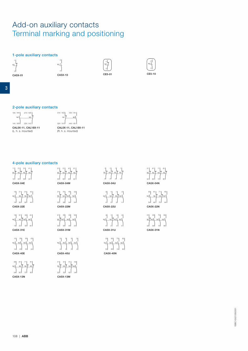
1SB
C10
021
3S
02
01
108 | ABB
-3
-4
NO
CE5-10
-1
-2
NC
CE5-01
Add-on auxiliary contactsTerminal marking and positioning
-1
-2
NC
CA5X-01
-3
-4
NO
CA5X-10
1-pole auxiliary contacts
21X /
22X /
13X /
14X /
NO NC
43X
44X
31X
32X
CAL5X-11, CAL18X-11(L. h. s. mounted)
NC NO
43X /
44X /
31X /
32X /
21X
22X
13X
14X
CAL5X-11, CAL18X-11 (R. h. s. mounted)
2-pole auxiliary contacts
31
32
21
22
51
52
41
42
NCNC NCNC
CA5X-04M
21
22
11
12
41
42
31
32
NCNC NCNC
CA5X-04E
61
62
51
52
81
82
71
72
NCNC NCNC
CA5X-04N
-1
-2
-1
-2
-1
-2
-1
-2
NCNC NCNC
CA5X-04U
21
22
13
14
43
44
31
32
NO NCNC NO
CA5X-22E
21
22
31
32
43
44
53
54
NO NONC NC
CA5X-22M
61
62
53
54
83
84
71
72
NO NCNC NO
CA5X-22N
-1
2
-3
4
-3
4
-1
2
NO NCNC NO
CA5X-22U
21
22
13
14
43
44
33
34
NO NC NONO
CA5X-31E
21
22
33
34
43
44
53
54
NONO NONC
CA5X-31M
51
52
63
64
73
74
83
84
NONO NONC
CA5X-31N
-1
2
-3
4
-3
4
-3
4
NO NC NONO
CA5X-31U
61
62
53
54
81
82
71
72
NO NCNC NC
CA5X-13N
53
54
63
64
73
74
83
84
NO NONO NO
CA5X-40N
3
4
3
4
3
4
3
4
NO NONO NO
CA5X-40U
31
32
41
42
NCNC
53
54
NO
21
22
NC
CA5X-13M
13
14
23
24
33
34
43
44
NO NONO NO
CA5X-40E
4-pole auxiliary contacts
3
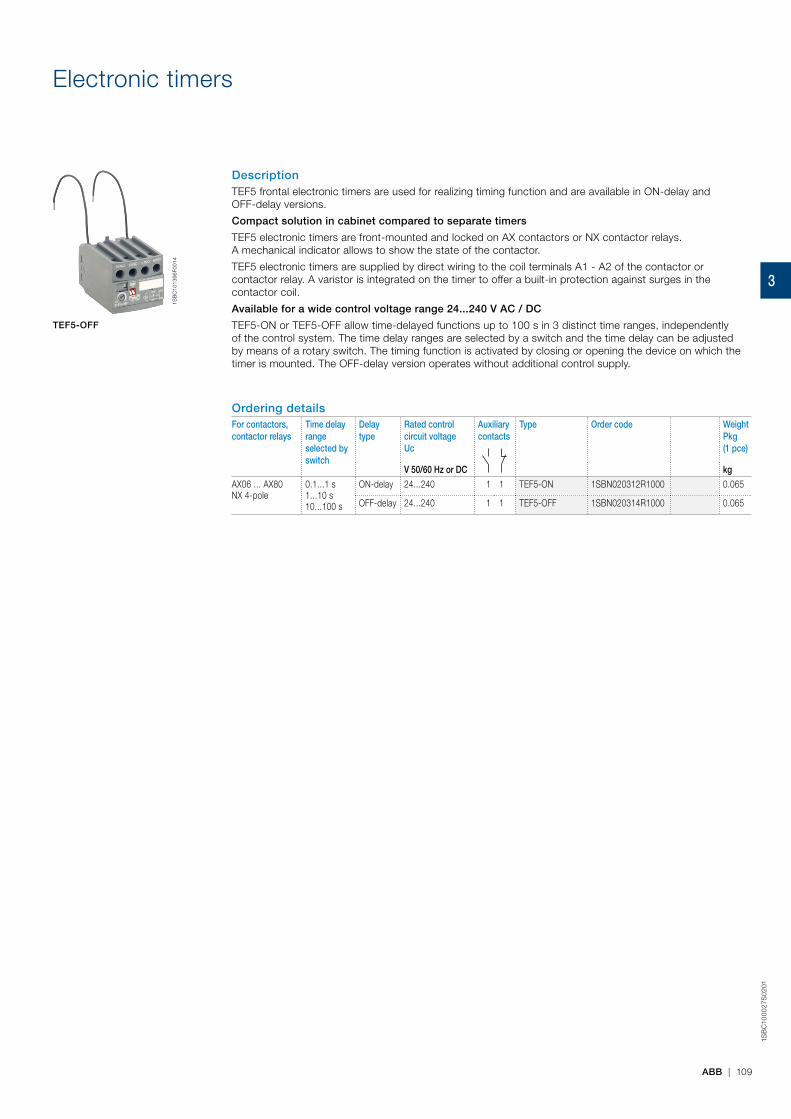
1SB
C10
00
27S
02
01
ABB | 109
Electronic timers
DescriptionTEF5 frontal electronic timers are used for realizing timing function and are available in ON-delay and OFF-delay versions.
Compact solution in cabinet compared to separate timers
TEF5 electronic timers are front-mounted and locked on AX contactors or NX contactor relays. A mechanical indicator allows to show the state of the contactor.
TEF5 electronic timers are supplied by direct wiring to the coil terminals A1 - A2 of the contactor or contactor relay. A varistor is integrated on the timer to offer a built-in protection against surges in the contactor coil.
Available for a wide control voltage range 24...240 V AC / DC
TEF5-ON or TEF5-OFF allow time-delayed functions up to 100 s in 3 distinct time ranges, independently of the control system. The time delay ranges are selected by a switch and the time delay can be adjusted by means of a rotary switch. The timing function is activated by closing or opening the device on which the timer is mounted. The OFF-delay version operates without additional control supply.
Ordering detailsFor contactors,contactor relays
Time delay rangeselected by switch
Delaytype
Rated control circuit voltage Uc
Auxiliary contacts
Type Order code WeightPkg(1 pce)
V 50/60 Hz or DC kg
AX06 ... AX80NX 4-pole
0.1...1 s1...10 s10...100 s
ON-delay 24...240 1 1 TEF5-ON 1SBN020312R1000 0.065
OFF-delay 24...240 1 1 TEF5-OFF 1SBN020314R1000 0.065
TEF5-OFF
1SB
C10
1396
F001
4
3
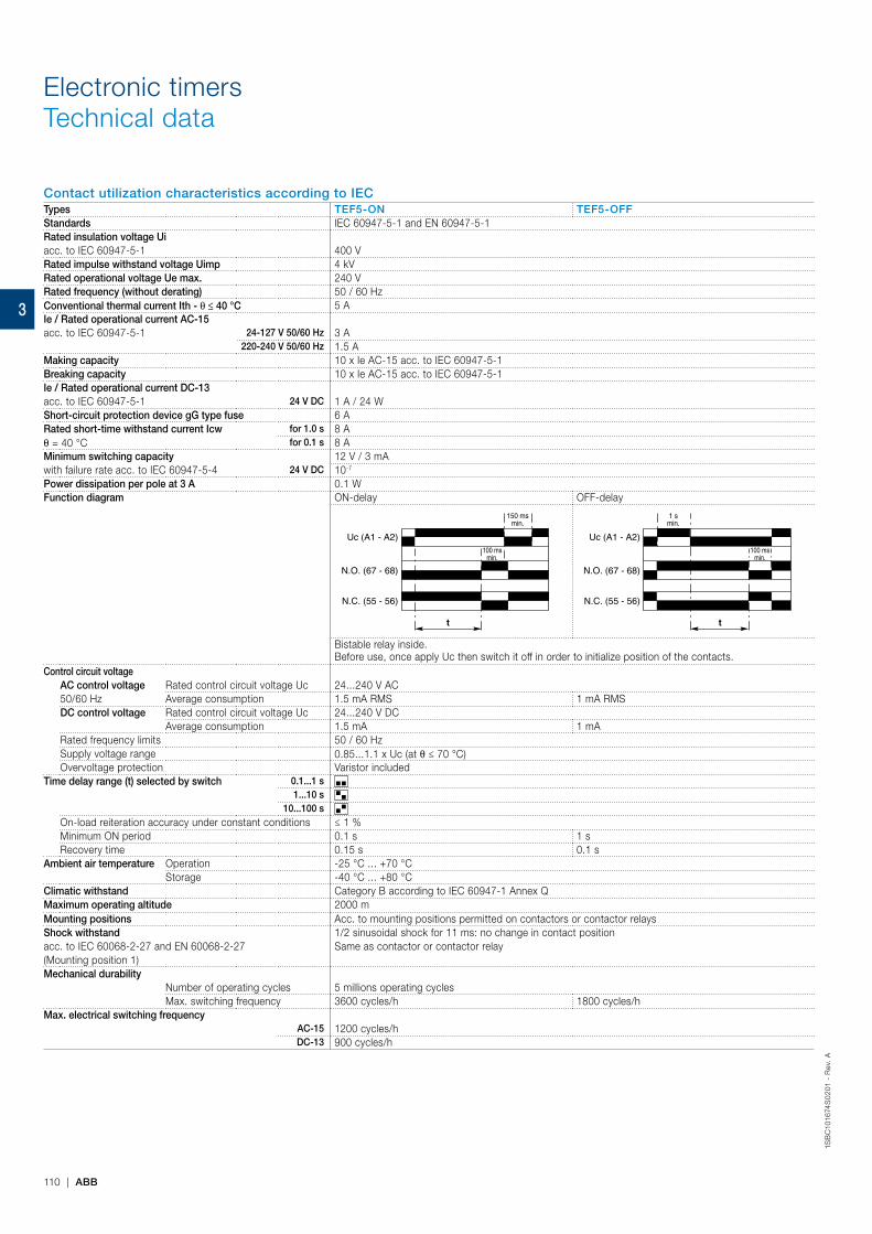
1SB
C10
1674
S0
201
- R
ev.
A
110 | ABB
Electronic timersTechnical data
Contact utilization characteristics according to IECTypes TEF5-ON TEF5-OFFStandards IEC 60947-5-1 and EN 60947-5-1Rated insulation voltage Uiacc. to IEC 60947-5-1 400 VRated impulse withstand voltage Uimp 4 kVRated operational voltage Ue max. 240 VRated frequency (without derating) 50 / 60 HzConventional thermal current Ith - θ ≤ 40 °C 5 AIe / Rated operational current AC-15acc. to IEC 60947-5-1 24-127 V 50/60 Hz 3 A
220-240 V 50/60 Hz 1.5 AMaking capacity 10 x Ie AC-15 acc. to IEC 60947-5-1Breaking capacity 10 x Ie AC-15 acc. to IEC 60947-5-1Ie / Rated operational current DC-13acc. to IEC 60947-5-1 24 V DC 1 A / 24 WShort-circuit protection device gG type fuse 6 ARated short-time withstand current Icw for 1.0 s 8 Aθ = 40 °C for 0.1 s 8 AMinimum switching capacity 12 V / 3 mAwith failure rate acc. to IEC 60947-5-4 24 V DC 10-7
Power dissipation per pole at 3 A 0.1 WFunction diagram ON-delay OFF-delay
Uc (A1 - A2)
N.O. (67 - 68)
t
100 msmin.
150 msmin.
N.C. (55 - 56)
Uc (A1 - A2)
N.O. (67 - 68)
t
100 msmin.
1 smin.
N.C. (55 - 56)
Bistable relay inside. Before use, once apply Uc then switch it off in order to initialize position of the contacts.
Control circuit voltage AC control voltage Rated control circuit voltage Uc 24...240 V AC50/60 Hz Average consumption 1.5 mA RMS 1 mA RMSDC control voltage Rated control circuit voltage Uc 24...240 V DC
Average consumption 1.5 mA 1 mARated frequency limits 50 / 60 HzSupply voltage range 0.85...1.1 x Uc (at θ ≤ 70 °C)Overvoltage protection Varistor included
Time delay range (t) selected by switch 0.1...1 s1...10 s
10...100 sOn-load reiteration accuracy under constant conditions ≤ 1 %Minimum ON period 0.1 s 1 sRecovery time 0.15 s 0.1 s
Ambient air temperature Operation -25 °C ... +70 °CStorage -40 °C ... +80 °C
Climatic withstand Category B according to IEC 60947-1 Annex QMaximum operating altitude 2000 mMounting positions Acc. to mounting positions permitted on contactors or contactor relaysShock withstand 1/2 sinusoidal shock for 11 ms: no change in contact positionacc. to IEC 60068-2-27 and EN 60068-2-27 Same as contactor or contactor relay(Mounting position 1)Mechanical durability
Number of operating cycles 5 millions operating cyclesMax. switching frequency 3600 cycles/h 1800 cycles/h
Max. electrical switching frequencyAC-15 1200 cycles/hDC-13 900 cycles/h
3
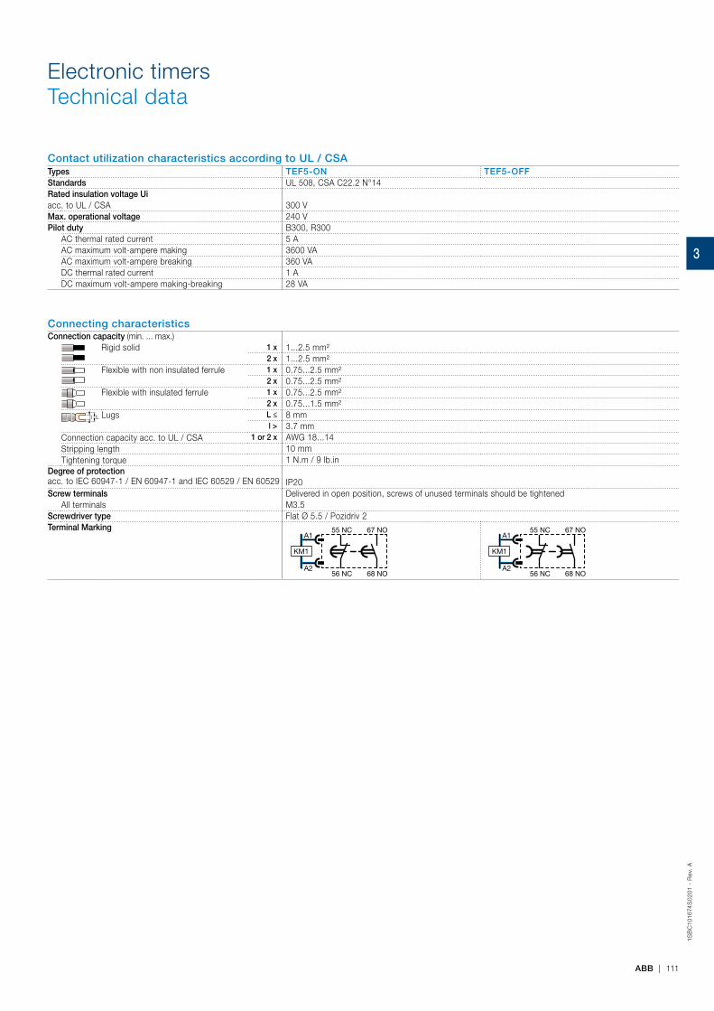
1SB
C10
1674
S0
201
- R
ev.
A
ABB | 111
Electronic timersTechnical data
Contact utilization characteristics according to UL / CSATypes TEF5-ON TEF5-OFFStandards UL 508, CSA C22.2 N°14Rated insulation voltage Uiacc. to UL / CSA 300 VMax. operational voltage 240 VPilot duty B300, R300
AC thermal rated current 5 AAC maximum volt-ampere making 3600 VAAC maximum volt-ampere breaking 360 VADC thermal rated current 1 ADC maximum volt-ampere making-breaking 28 VA
Connecting characteristicsConnection capacity (min. ... max.)
Rigid solid 1 x 1...2.5 mm²2 x 1...2.5 mm²
Flexible with non insulated ferrule 1 x 0.75...2.5 mm²2 x 0.75...2.5 mm²
Flexible with insulated ferrule 1 x 0.75...2.5 mm²2 x 0.75...1.5 mm²
Ll Lugs L ≤ 8 mml > 3.7 mm
Connection capacity acc. to UL / CSA 1 or 2 x AWG 18...14Stripping length 10 mmTightening torque 1 N.m / 9 lb.in
Degree of protection acc. to IEC 60947-1 / EN 60947-1 and IEC 60529 / EN 60529 IP20Screw terminals Delivered in open position, screws of unused terminals should be tightened
All terminals M3.5 Screwdriver type Flat Ø 5.5 / Pozidriv 2Terminal Marking
A1
A256 NC 68 NO
55 NC 67 NO
KM1
A1
A256 NC 68 NO
55 NC 67 NO
KM1
3

1SB
C10
02
29
S0
201
112 | ABB
Mechanical and electrical interlock units
Mechanical interlock unitsDescriptionThe VM mechanical interlock units are designed for the interlocking of two AX contactors. When mounted between two contactors, the VM mechanical interlock unit prevents one of the contactors from closing as long as the other contactor is closed.
Ordering detailsLeft side contactor Right side contactor Mounting Auxiliary
contactsType Order code Pkg
qtyWeight(1 pce)
kg
Mechanical interlock units for two horizontal mounted contactors (1)AX06 ... AX40 AX06 ... AX40 Horizontal – – VM5-1 1SBN030100R1000 1 0.066AX95 ... AX205 AX185 ... AX205 Horizontal – – VM300H 1SFN034700R1000 1 0.150AX260 ... AX370 AX260 ... AX370 Horizontal – – VM19 1SFN030300R1000 1 0.054AX185 ... AX205 AX260 ... AX370 Horizontal – – VM205/260 1SFN035003R1000 1 0.075AX260 ... AX370 AX185 ... AX205 Horizontal – – VM205/260 1SFN035003R1000 1 0.075AX260 ... AX370 AF400 ... AF460 Horizontal – – VM370/400 1SFN035403R1000 1 0.239AF400 ... AF460 AX260 ... AX370 Horizontal – – VM370/400 1SFN035403R1000 1 0.239
Mechanical interlock units for two vertical mounted contactorsUp contactor Down contactor MountingAX95 ... AX150 AX150 … AX205 Vertical – – VM300V 1SFN034701R1000 1 0.150
Mechanical and electrical interlock setsDescriptionThe VM mechanical interlock units are designed for the interlocking of two AX contactors. When mounted between two contactors, the VM mechanical interlock unit prevents one of the contactors from closing as long as the other contactor is closed. The VE units include 2 N.C. contacts for electrical interlocking function.
Ordering detailsLeft side contactor Right side contactor Mounting Auxiliary
contactsType Order code Pkg
qtyWeight(1 pce)
kg
Mechanical interlock units for two horizontal mounted contactors AX06 ... AX40 AX06 ... AX40 Horizontal – 2 VE5-1 1SBN030110R1000 1 0.076AX32 ... AX80 AX50 … AX80 Horizontal – 2 VE5-2 1SBN030210R1000 1 0.146AX50 … AX80 AX32 … AX80 Horizontal – 2 VE5-2 1SBN030210R1000 1 0.146AX50 … AX80 AX95 … AX150 Horizontal – 2 VE5-2 (2) 1SBN030210R1000 1 0.146AX95 … AX150 AX50 … AX80 Horizontal – 2 VE5-2 (2) 1SBN030210R1000 1 0.146AX95 … AX150 AX95 … AX150 Horizontal – 2 VE5-2 1SBN030210R1000 1 0.146
(1) Mechanical durability: VM5-1 = 5 millions cycles, VM300H = 1 million cycles.VM19 = 0,5 million cycles, VM205/260 = 1 million cycles, VM300V = 1 million cycles.(2) The combination of AX50 ... AX80 contactors interlocked with AX95 … AX150 contactors cannot be mounted on symmetrical rail(75 mm, IEC/EN 60715).
VM300H
1SB
C58
0411
F030
1
VE5-1
AX
0702
1
3
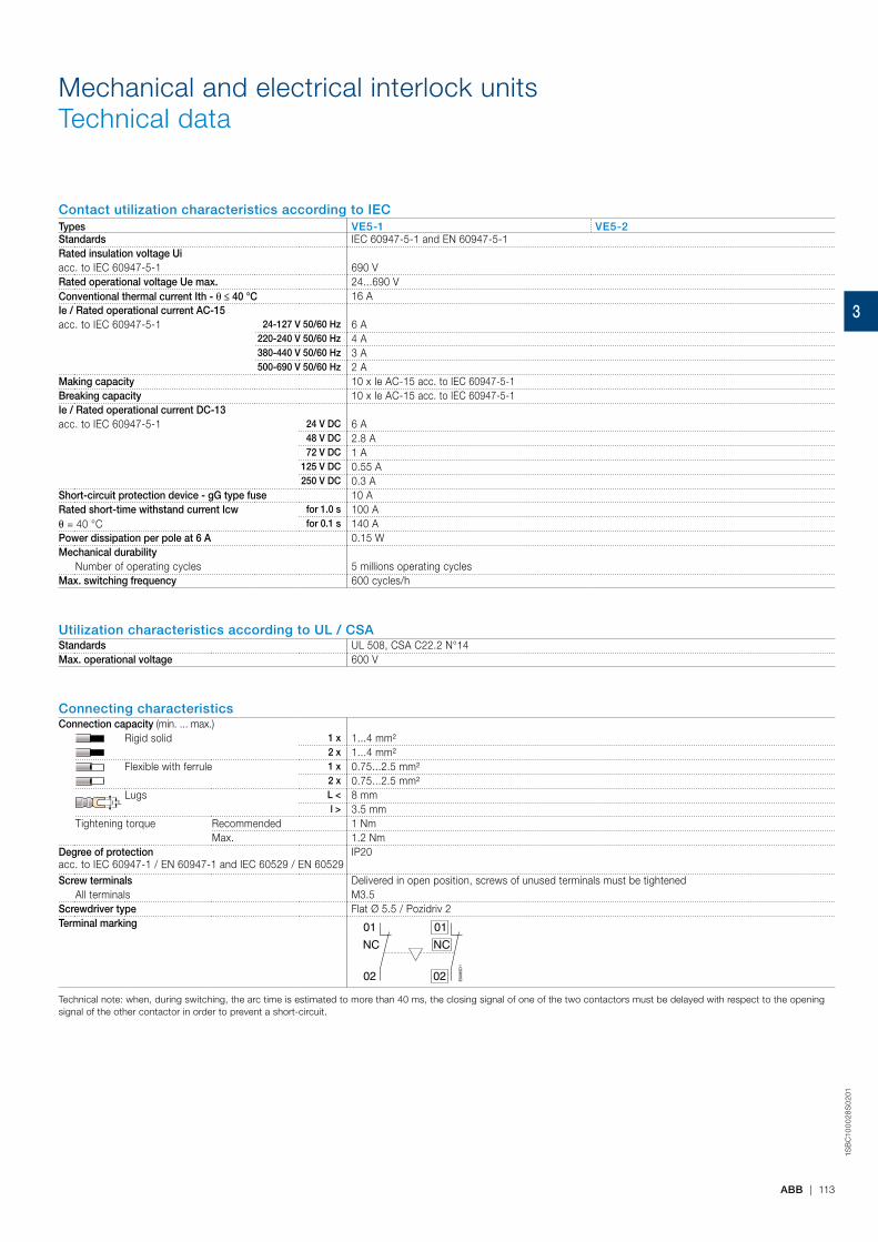
1SB
C10
00
28S
02
01
ABB | 113
Mechanical and electrical interlock unitsTechnical data
Contact utilization characteristics according to IECTypes VE5-1 VE5-2Standards IEC 60947-5-1 and EN 60947-5-1Rated insulation voltage Uiacc. to IEC 60947-5-1 690 VRated operational voltage Ue max. 24...690 VConventional thermal current Ith - θ ≤ 40 °C 16 AIe / Rated operational current AC-15acc. to IEC 60947-5-1 24-127 V 50/60 Hz 6 A
220-240 V 50/60 Hz 4 A380-440 V 50/60 Hz 3 A500-690 V 50/60 Hz 2 A
Making capacity 10 x Ie AC-15 acc. to IEC 60947-5-1Breaking capacity 10 x Ie AC-15 acc. to IEC 60947-5-1Ie / Rated operational current DC-13acc. to IEC 60947-5-1 24 V DC 6 A
48 V DC 2.8 A 72 V DC 1 A
125 V DC 0.55 A250 V DC 0.3 A
Short-circuit protection device - gG type fuse 10 ARated short-time withstand current Icw for 1.0 s 100 Aθ = 40 °C for 0.1 s 140 APower dissipation per pole at 6 A 0.15 WMechanical durability
Number of operating cycles 5 millions operating cyclesMax. switching frequency 600 cycles/h
Utilization characteristics according to UL / CSAStandards UL 508, CSA C22.2 N°14Max. operational voltage 600 V
Connecting characteristicsConnection capacity (min. ... max.)
Rigid solid 1 x 1...4 mm²2 x 1...4 mm²
Flexible with ferrule 1 x 0.75...2.5 mm²2 x 0.75...2.5 mm²
LlLugs L < 8 mm
l > 3.5 mmTightening torque Recommended 1 Nm
Max. 1.2 NmDegree of protection acc. to IEC 60947-1 / EN 60947-1 and IEC 60529 / EN 60529
IP20
Screw terminals Delivered in open position, screws of unused terminals must be tightenedAll terminals M3.5
Screwdriver type Flat Ø 5.5 / Pozidriv 2Terminal marking 01
02
NC
E00
85D
1
01
02
NC
Technical note: when, during switching, the arc time is estimated to more than 40 ms, the closing signal of one of the two contactors must be delayed with respect to the opening signal of the other contactor in order to prevent a short-circuit.
3
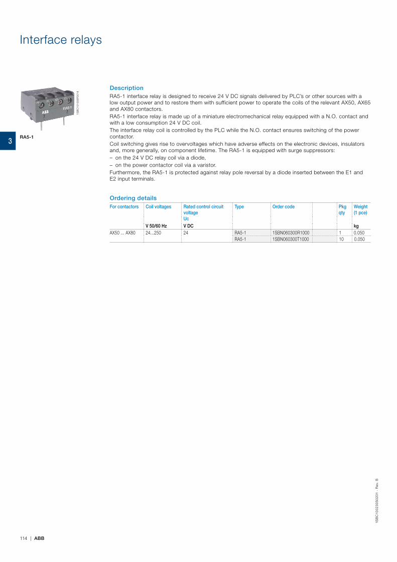
Interface relays
DescriptionRA5-1 interface relay is designed to receive 24 V DC signals delivered by PLC’s or other sources with a low output power and to restore them with sufficient power to operate the coils of the relevant AX50, AX65 and AX80 contactors.RA5-1 interface relay is made up of a miniature electromechanical relay equipped with a N.O. contact and with a low consumption 24 V DC coil.The interface relay coil is controlled by the PLC while the N.O. contact ensures switching of the power contactor.Coil switching gives rise to overvoltages which have adverse effects on the electronic devices, insulators and, more generally, on component lifetime. The RA5-1 is equipped with surge suppressors: – on the 24 V DC relay coil via a diode, – on the power contactor coil via a varistor.
Furthermore, the RA5-1 is protected against relay pole reversal by a diode inserted between the E1 and E2 input terminals.
Ordering detailsFor contactors Coil voltages Rated control circuit
voltage Uc
Type Order code Pkg qty
Weight(1 pce)
V 50/60 Hz V DC kgAX50 ... AX80 24...250 24 RA5-1 1SBN060300R1000 1 0.050
RA5-1 1SBN060300T1000 10 0.050
1SB
C10
1005
F001
4
RA5-1
114 | ABB
1SB
C10
02
30
S0
201
- R
ev.
B
3

1SB
C10
0245
S02
01
ABB | 115
Interface relaysTechnical data
Type RA5-1
Utilization characteristics according to IECStandards IEC 60255-5Rated insulation voltage Ui acc. to IEC 60947-4-1 250 V ACAmbient air temperature
In free air operation at Uc = 24 V DC (between E1 and E2) -25…+70 °Cfrom 0.85 to 1.1 x Uc -25…+55 °C
Storage -40…+70 °CClimatic withstand Complies with that of associated contactorsMaximum operating altitude 3000 mMounting positions No limitationFixing Using the contactor A1 and A2 teminal connecting parts
Connecting characteristicsConnection capacity (min. ... max.)
Rigid solid 1 x 1...4 mm²2 x 1...4 mm²
Flexible with ferrule 1 x 0.75...2.5 mm²2 x 0.75...2.5 mm²
Ll Lugs L < 8 mml > 3.5 mm
Tightening torqueRecommended 1 NmMax. 1.2 Nm
Degree of protection acc. to IEC 60947-1 / EN 60947-1 and IEC 60529 / EN 60529
Protection against direct contact in acc. with EN 50274RA5-1 wired and mounted on the associated contactor
Screw terminals Delivered in open position, screws of unused terminals must be tightenedAll terminals M3.5
Screwdriver type Flat Ø 5.5 / Pozidriv 2
Working dataSurge suppression
For contactor coil VaristorFor interface relay coil Diode
Protection against polarity reversal between terminals E1 and E2 DiodeInterface relay operating time Closing and drop-out ≤ 10 msTotal operating time, interface relay + contactor
Between energization and: N.O. contact closing 20…37 msN.C. contact opening 17…32 ms
Between de-energization and: N.O. contact opening 17…25 msN.C. contact closing 20…28 ms
Electrical input dataControl voltage (E1 and E2 terminals) Uc
Rated value 24 V DCMax. range at ambient temperature 20 °C 19…30 V DC
Max. consumption for Uc = 24 V DC, θ = 20 °C 0.3 W"0" status (relay open) for Uc ≤ 2.4 V DC
for Ic < 1 mA"1" status (relay closed) for Uc ≥ 19 V DCMax. short supply interruption immunity time 2 ms
Electrical output dataSwitching voltage (A0 and A2 terminals) ≤ 250 V ACElectrical durability
Number of operating cycles 2 millions
Connection
Uc ≤ 250 V AC 24 V DC
+–
RA 5-1
A0 E2 – E1 +
KM1
A1
A2
PLCOutput
A2
E07
42D
G
The "E1+" and "E2-" input terminals must be connected, according to their polarity, to the PLC output.The RA5-1 is equipped with two terminal pads for connection to the A1 and the A2 terminals of the contactor coil. This coil is supplied between the A0 and the A2 terminals of the RA 5-1.Mounting: terminals pads clamped inside the contactor coil terminals.
3
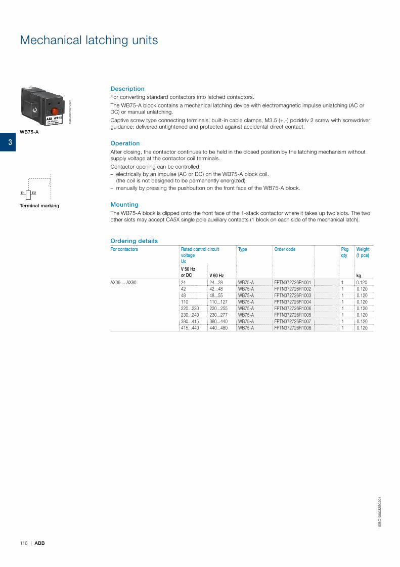
1SB
C10
00
32S
02
01
116 | ABB
Mechanical latching units
DescriptionFor converting standard contactors into latched contactors.
The WB75-A block contains a mechanical latching device with electromagnetic impulse unlatching (AC or DC) or manual unlatching.
Captive screw type connecting terminals, built-in cable clamps, M3.5 (+,-) pozidriv 2 screw with screwdriver guidance; delivered untightened and protected against accidental direct contact.
OperationAfter closing, the contactor continues to be held in the closed position by the latching mechanism without supply voltage at the contactor coil terminals.
Contactor opening can be controlled: – electrically by an impulse (AC or DC) on the WB75-A block coil. (the coil is not designed to be permanently energized)
– manually by pressing the pushbutton on the front face of the WB75-A block.
MountingThe WB75-A block is clipped onto the front face of the 1-stack contactor where it takes up two slots. The two other slots may accept CA5X single pole auxiliary contacts (1 block on each side of the mechanical latch).
Ordering detailsFor contactors Rated control circuit
voltage Uc
Type Order code Pkg qty
Weight(1 pce)
V 50 Hzor DC V 60 Hz kg
AX06 ... AX80 24 24...28 WB75-A FPTN372726R1001 1 0.12042 42...48 WB75-A FPTN372726R1002 1 0.12048 48...55 WB75-A FPTN372726R1003 1 0.120110 110...127 WB75-A FPTN372726R1004 1 0.120220...230 220...255 WB75-A FPTN372726R1006 1 0.120230...240 230...277 WB75-A FPTN372726R1005 1 0.120380...415 380...440 WB75-A FPTN372726R1007 1 0.120415...440 440...480 WB75-A FPTN372726R1008 1 0.120
1SB
C56
5483
F030
1
WB75-A
E1 E2
Terminal marking
3
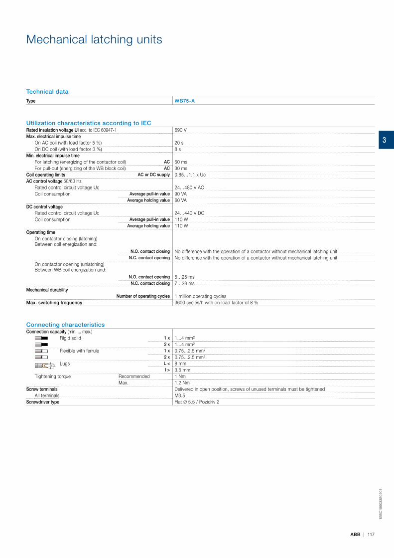
1SB
C10
00
33
S0
201
ABB | 117
Technical data
Type WB75-A
Utilization characteristics according to IECRated insulation voltage Ui acc. to IEC 60947-1 690 VMax. electrical impulse time
On AC coil (with load factor 5 %) 20 sOn DC coil (with load factor 3 %) 8 s
Min. electrical impulse timeFor latching (energizing of the contactor coil) AC 50 msFor pull-out (energizing of the WB block coil) AC 30 ms
Coil operating limits AC or DC supply 0.85…1.1 x UcAC control voltage 50/60 Hz
Rated control circuit voltage Uc 24…480 V ACCoil consumption Average pull-in value 90 VA
Average holding value 60 VADC control voltage
Rated control circuit voltage Uc 24…440 V DCCoil consumption Average pull-in value 110 W
Average holding value 110 WOperating time
On contactor closing (latching)Between coil energization and:
N.O. contact closing No difference with the operation of a contactor without mechanical latching unitN.C. contact opening No difference with the operation of a contactor without mechanical latching unit
On contactor opening (unlatching)Between WB coil energization and:
N.O. contact opening 5…25 msN.C. contact closing 7…28 ms
Mechanical durabilityNumber of operating cycles 1 million operating cycles
Max. switching frequency 3600 cycles/h with on-load factor of 8 %
Connecting characteristicsConnection capacity (min. ... max.)
Rigid solid 1 x 1...4 mm²2 x 1...4 mm²
Flexible with ferrule 1 x 0.75...2.5 mm²2 x 0.75...2.5 mm²
Ll Lugs L < 8 mml > 3.5 mm
Tightening torque Recommended 1 NmMax. 1.2 Nm
Screw terminals Delivered in open position, screws of unused terminals must be tightenedAll terminals M3.5
Screwdriver type Flat Ø 5.5 / Pozidriv 2
Mechanical latching units
3

1SB
C10
024
7S0
201
118 | ABB
Surge suppressors for contactor coils
RV5/50
RC5-1/50
1SB
C57
3891
F030
11S
BC
5740
01F0
301
DescriptionThe operation of inductive circuits causes overvoltages, in particular on opening of the contactor coil.The electromagnetic energy stored in the coil during contactor closing is restored on opening in the form of surges, the slope and amplitude of which may rise to several kilovolts. A number of drawbacks are observed ranging from interference on the electronic devices to breakdown of insulators and even destruction of certain sensitive components. The graph opposite reproduces the oscillogram showing voltage discharges at the terminals of a 42 V / 50 Hz coil without peak clipping. The coil was switched by 8 series-connected poles of a contactor relay.Following a burst of discharges with a very steep slope a damped oscillation emerges with a peak value of 3500 V.Overvoltage Factor The overvoltage factor k is defined as the ratio of the maximum overvoltage peak value Ûs to the peak value Ûc of the coil rated control voltage Uc:
Ûs max.
Ûs max.k = or in AC: k = Ûc Uc√2
3500
For example the following is obtained for the above graph: k = ≈ 60 42 √2
To reduce the harmful effects of these overvoltages, ABB has developed a range of surge suppressors designed to reduce the k factor defined above and to limit or even completely eliminate the high pre-damping voltage frequencies.Each case is different, but the technical data tolerances and the generous sizing of parts have enabled us to reduce the number of variants.We have chosen the following solutions: varistors and RC blocks. Note: A varistor is a resistor whose value decreases to a very large extent when a certain voltage is applied at its terminals.
Ordering detailsFor contactors Rated control circuit
voltage Uc
Type Order code Pkg qty
Weight(1 pce)
V AC kgAX06 ... AX150 24...50 RV5/50 1SBN050010R1000 2 0.015
50...133 RV5/133 1SBN050010R1001 2 0.015
110...250 RV5/250 1SBN050010R1002 2 0.015
250...440 RV5/440 1SBN050010R1003 2 0.015AX06 ... AX40 24...50 RC5-1/50 1SBN050100R1000 2 0.012
50...133 RC5-1/133 1SBN050100R1001 2 0.012110...250 RC5-1/250 1SBN050100R1002 2 0.012250...440 RC5-1/440 1SBN050100R1003 2 0.012
AX50 ... AX150 24...50 RC5-2/50 1SBN050200R1000 2 0.01550...133 RC5-2/133 1SBN050200R1001 2 0.015110...250 RC5-2/250 1SBN050200R1002 2 0.015250...440 RC5-2/440 1SBN050200R1003 2 0.015
AX185 ... AX205 250...440 RC5-3/440 1SFN050300R1003 2 0.028
0
1000
100
(V)
T (µs)
0
1000
100
A 8
84D
3

1SB
C10
024
4S
02
01
ABB | 119
Technical dataVaristor RV5/50 RV5/133 RV5/250 RV5/440Rated control circuit voltage Uc 24...50 V AC 50...133 V AC 110...250 V AC 250...440 V ACResidual overvoltage (clipping voltage) 132 V AC 270 V AC 480 V AC 825 V ACOpening time growth factor 1.1...1.5Operating temperature -20...+70 °CConnection to the coil terminals (parallel mounting) Clip-on for both fixing and connection.Fixing Clipped onto the top part of the contactor base without change in contactor overall dimensions.Advantages High energy absorption: good damping - Unpolarized system.Drawback Clipping as from Uvdr (1), thus voltage front up to this point.
(1) Uvdr = Varistor operating voltage (voltage dependent resistor), tolerance ±10 %.
RC type RC5-1/50 RC5-1/133 RC5-1/250 RC5-1/440
RC5-2/50 RC5-2/133 RC5-2/250 RC5-2/440
– – – RC5-3/440Rated control circuit voltage Uc 24...50 V AC 50...133 V AC 110...250 V AC 250...440 V ACResidual overvoltage (clipping voltage) 2 to 3 x Uc max.Opening time growth factor 1.2...1.3Operating temperature -20...+70 °CConnection to the coil terminals (parallel mounting) Clip-on for both fixing and connection.Fixing Clipped onto the top part of the contactor base without change in contactor overall dimensions.Advantages Very fast clipping - Attenuation of steep fronts and thus of high frequencies. No operating delays.
Wiring diagrams
A1
A2
A1
A2Varistor RC type
Dimensions
RV5, RC5
The add-on block does not increase thecontactor overall dimensions
Surge suppressors for contactor coils
3
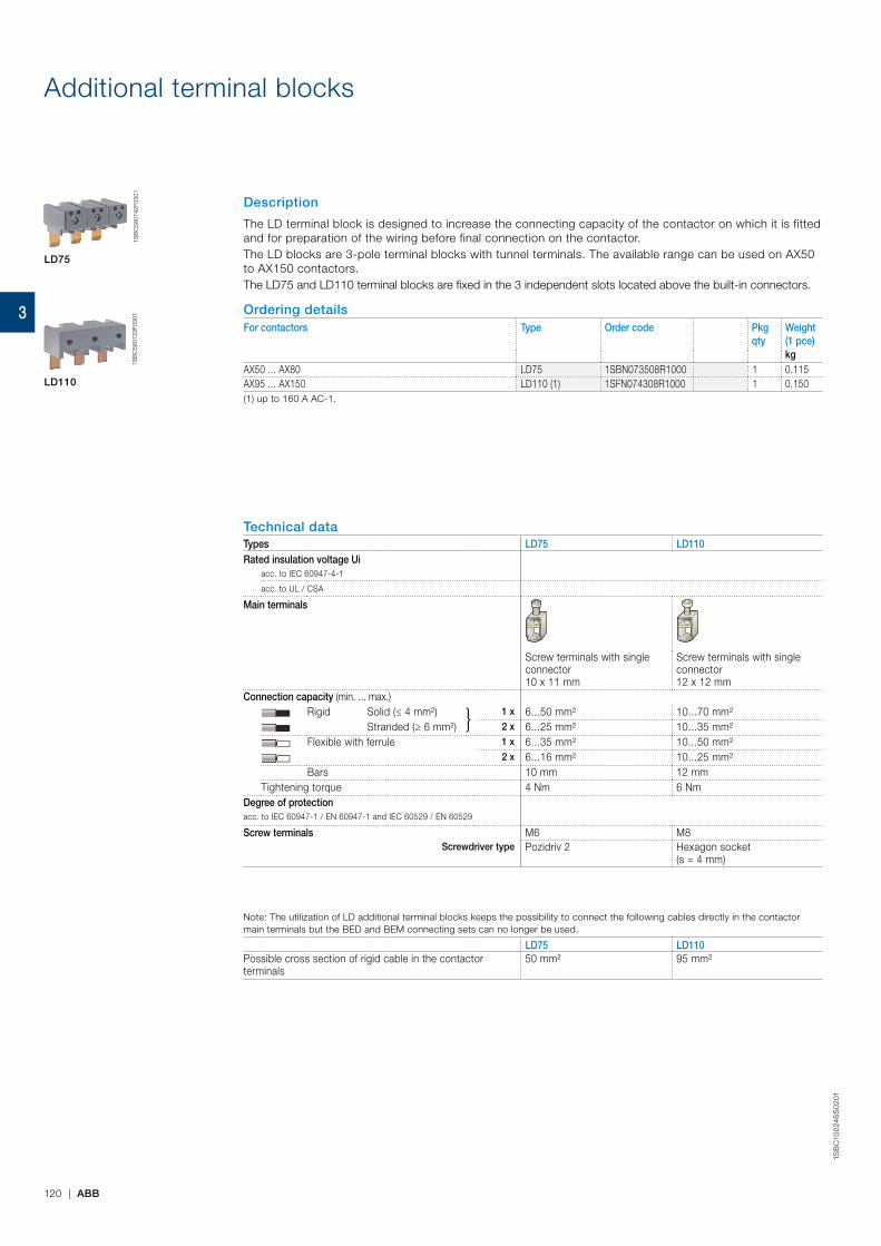
Additional terminal blocks
Description
The LD terminal block is designed to increase the connecting capacity of the contactor on which it is fitted and for preparation of the wiring before final connection on the contactor.The LD blocks are 3-pole terminal blocks with tunnel terminals. The available range can be used on AX50 to AX150 contactors.The LD75 and LD110 terminal blocks are fixed in the 3 independent slots located above the built-in connectors.
Ordering detailsFor contactors Type Order code Pkg
qtyWeight(1 pce)kg
AX50 ... AX80 LD75 1SBN073508R1000 1 0.115AX95 ... AX150 LD110 (1) 1SFN074308R1000 1 0.150(1) up to 160 A AC-1.
LD75
LD110
1SB
C58
0742
F030
11S
BC
5807
23F0
301
Technical dataTypes LD75 LD110Rated insulation voltage Ui
acc. to IEC 60947-4-1
acc. to UL / CSA
Main terminals
Screw terminals with single connector 10 x 11 mm
Screw terminals with single connector 12 x 12 mm
Connection capacity (min. ... max.)Rigid Solid (≤ 4 mm²) 1 x 6...50 mm² 10...70 mm²
Stranded (≥ 6 mm²) 2 x 6...25 mm² 10...35 mm²Flexible with ferrule 1 x 6...35 mm² 10...50 mm²
2 x 6...16 mm² 10...25 mm²Bars 10 mm 12 mm
Tightening torque 4 Nm 6 NmDegree of protectionacc. to IEC 60947-1 / EN 60947-1 and IEC 60529 / EN 60529
Screw terminals M6 M8Screwdriver type Pozidriv 2 Hexagon socket
(s = 4 mm)
Note: The utilization of LD additional terminal blocks keeps the possibility to connect the following cables directly in the contactor main terminals but the BED and BEM connecting sets can no longer be used.
LD75 LD110Possible cross section of rigid cable in the contactor terminals
50 mm² 95 mm²
120 | ABB
1SB
C10
024
6S
02
01
3

Function markersTerminals for control lead connections
Function markers AX06 ... AX205DescriptionSet of 50 function markers designed to be clipped onto the front face of devices. Details can be added to these markers using a ball point pen, indelible felt-tip pen or pentel white.Self-adhesive labels (not supplied) can also be added to them.Marker dimensions: 7 x 19 mm (0.276" x 0.748").
Ordering detailsFor contactors Type Order code Pkg
qtyWeight(1 pce)kg
AX06 ... AX205 and accessories BA5-50 1SBN110000R1000 1 0.017
Function markers AX260 ... AX370DescriptionBox of 16 blank cards (16 markers by card) printable on HTP500 thermal transfer printer and AMS 500 marking table to identify your contactors, overload relays or manual motor starters. Marker dimensions: 7 x 20 mm (.276" x .787").
AX260 ... AX370 contactors, EF electronic overload relays and MS116, MS132, M165 manual motor starters
BA4 1SNA235156R2700 16 0.011
AMS 500 support plate for 8 BA4 SPRC 1 1SNA360010R1500 1 0.220HTP500 support plate HTP500-BA4 1SNA235712R2400 1 0.290
Terminals for control lead connectionsDescriptionTerminals designed to connect the control conductors to the main poles of the AX50 ... AX80 contactors.Accessories clipped into the slots placed above each power terminal connector. The LK75 are fitted with a pin designed to hold them in place until the connector has been fully clamped with its power cable. – Degree of protection IP20 – Connecting terminal delivered in open position: cable clamp and M3.5 (+,-) pozidriv 2 screw. – Cable cross-sectional area:
- 1 or 2 rigid conductors ..........................................1...4 mm² - 1 or 2 flexible conductors with cable end ...............0.75...2.5 mm²
– Tightening torque for the LK screw: - recommended .......................................................1.00 Nm - maxi. .....................................................................1.20 Nm
Ordering detailsFor contactors Type Order code Pkg
qtyWeight(1 pce)kg
AX50 ... AX80 LK75-F 1SBN073552R1002 2 0.006
BA5-50
1SB
C57
5874
F030
1
LK75-F
1SB
C57
5773
F030
1
LK positioning
BA4
1SN
C16
0101
F001
4
Main dimensions mm, inches
LK75-F
13 0.51"
11 0
.43"
19 0.75"
ABB | 121
1SB
C10
02
36
S0
201
3
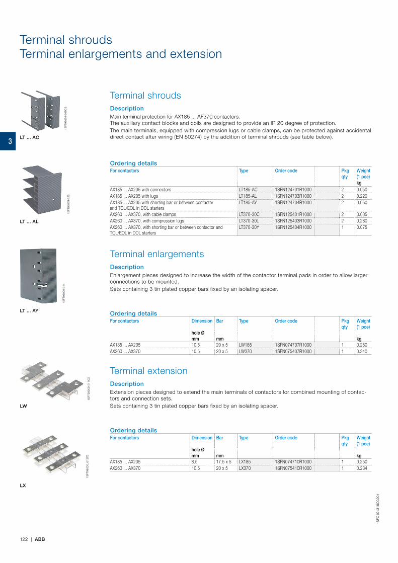
1SFC
1013
18C
0201
122 | ABB
1SFT
9809
9-12
5
Terminal shroudsTerminal enlargements and extension
Terminal shroudsDescriptionMain terminal protection for AX185 ... AF370 contactors.The auxiliary contact blocks and coils are designed to provide an IP 20 degree of protection.The main terminals, equipped with compression lugs or cable clamps, can be protected against accidental direct contact after wiring (EN 50274) by the addition of terminal shrouds (see table below).
Ordering detailsFor contactors Type Order code Pkg
qtyWeight(1 pce)kg
AX185 ... AX205 with connectors LT185-AC 1SFN124701R1000 2 0.050AX185 ... AX205 with lugs LT185-AL 1SFN124703R1000 2 0.220AX185 ... AX205 with shorting bar or between contactor and TOL/EOL in DOL starters
LT185-AY 1SFN124704R1000 2 0.050
AX260 ... AX370, with cable clamps LT370-30C 1SFN125401R1000 2 0.035AX260 ... AX370, with compression lugs LT370-30L 1SFN125403R1000 2 0.280AX260 ... AX370, with shorting bar or between contactor and TOL/EOL in DOL starters
LT370-30Y 1SFN125404R1000 1 0.075
Terminal enlargementsDescriptionEnlargement pieces designed to increase the width of the contactor terminal pads in order to allow larger connections to be mounted.Sets containing 3 tin plated copper bars fixed by an isolating spacer.
Ordering detailsFor contactors Dimension Bar Type Order code Pkg
qtyWeight(1 pce)
hole Ømm mm kg
AX185 ... AX205 10.5 20 x 5 LW185 1SFN074707R1000 1 0.250AX260 ... AX370 10.5 20 x 5 LW370 1SFN075407R1000 1 0.340
Terminal extensionDescriptionExtension pieces designed to extend the main terminals of contactors for combined mounting of contac-tors and connection sets.Sets containing 3 tin plated copper bars fixed by an isolating spacer.
Ordering detailsFor contactors Dimension Bar Type Order code Pkg
qtyWeight(1 pce)
hole Ømm mm kg
AX185 ... AX205 8.5 17.5 x 5 LX185 1SFN074710R1000 1 0.250AX260 ... AX370 10.5 20 x 5 LX370 1SFN075410R1000 1 0.234
1SFT
9809
9-01
9C3
LT ... AC
LT ... AL
LT ... AY
LX
LW
1SFT
9800
0-01
1C3
1SFT
9800
0_01
2C3
1SFT
9800
0-01
4
3

Terminal connecting strips and shorting bars
DescriptionParallel and series connection of 3-pole contactors: – To obtain a star point (3 parallel-connected poles): LY allows 3 phases to be short-circuited. – To connect poles in parallel and thus increase the AC load passing through the flow path made up of the parallel-connected poles: LP (2 poles); LY (3 poles).
– For the maximum permissible current values with parallel-connected poles see "Parallel connection of main poles".
The relevant cable cross-sectional area may limit the maximum permissible current. Consult information in table below. – To connect poles in series and thus increase the DC load controlled by the poles: LP.
Types for connection of "n" poles with terminal insulatedLP n = 2 no yes LY n = 3 no yes
Ordering detailsFor contactors max. nominal continuous
current with "n" polesType Order code Pkg
qtyWeight(1 pce)
A mm² kgAX06 28 6 LP16 FPEP407000R0001 10 0.002AX09 30 6AX12 32 6AX18 34 6NX - 6AX185, AX205 300 - LP185 1SFN074712R1000 2 0.300AX260, AX300, AX370 475 - LP300 1SFN075112R1000 2 0.400AX06 30 6 LY16 FPEP407002R0001 10 0.005AX09 33 6AX12 36 6AX18 39 6AX185, AX205 400 - LY185 1SFN074703R1000 1 0.200AX260, AX300, AX370 670 - LY300 1SFN075103R1000 1 0.300
LP185
LY185
1SFC
1010
88V
0001
1SFT
9800
0-01
0C3
ABB | 123
1SB
C10
02
37S
02
01
3
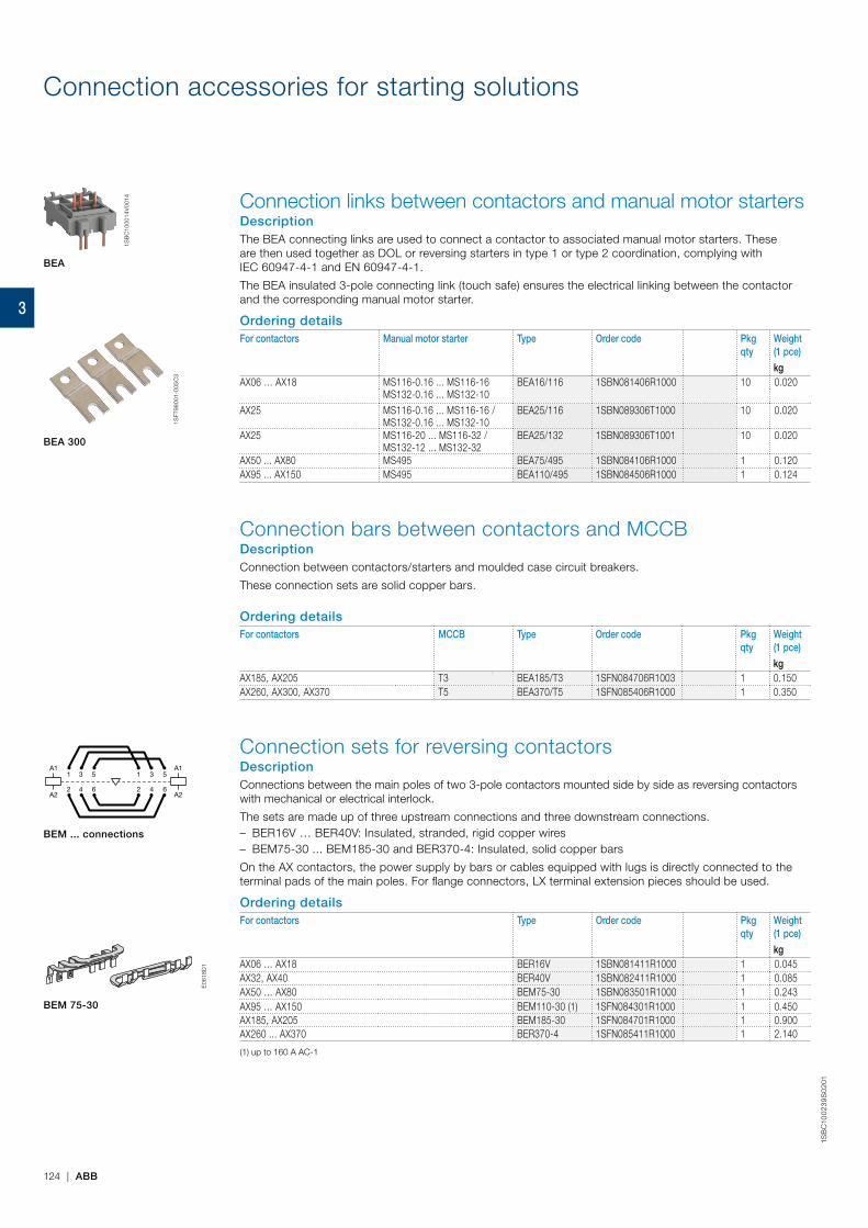
Connection accessories for starting solutions
Connection links between contactors and manual motor startersDescriptionThe BEA connecting links are used to connect a contactor to associated manual motor starters. These are then used together as DOL or reversing starters in type 1 or type 2 coordination, complying with IEC 60947‑4‑1 and EN 60947‑4‑1.
The BEA insulated 3‑pole connecting link (touch safe) ensures the electrical linking between the contactor and the corresponding manual motor starter.
Ordering detailsFor contactors Manual motor starter Type Order code Pkg
qtyWeight(1 pce)
kgAX06 … AX18 MS116‑0.16 ... MS116‑16
MS132‑0.16 ... MS132‑10BEA16/116 1SBN081406R1000 10 0.020
AX25 MS116‑0.16 ... MS116‑16 / MS132‑0.16 ... MS132‑10
BEA25/116 1SBN089306T1000 10 0.020
AX25 MS116‑20 ... MS116‑32 / MS132‑12 ... MS132‑32
BEA25/132 1SBN089306T1001 10 0.020
AX50 ... AX80 MS495 BEA75/495 1SBN084106R1000 1 0.120AX95 ... AX150 MS495 BEA110/495 1SBN084506R1000 1 0.124
Connection bars between contactors and MCCBDescriptionConnection between contactors/starters and moulded case circuit breakers.
These connection sets are solid copper bars.
Ordering detailsFor contactors MCCB Type Order code Pkg
qtyWeight(1 pce)
kgAX185, AX205 T3 BEA185/T3 1SFN084706R1003 1 0.150AX260, AX300, AX370 T5 BEA370/T5 1SFN085406R1000 1 0.350
Connection sets for reversing contactorsDescriptionConnections between the main poles of two 3‑pole contactors mounted side by side as reversing contactors with mechanical or electrical interlock.
The sets are made up of three upstream connections and three downstream connections. – BER16V … BER40V: Insulated, stranded, rigid copper wires – BEM75‑30 ... BEM185‑30 and BER370‑4: Insulated, solid copper bars
On the AX contactors, the power supply by bars or cables equipped with lugs is directly connected to the terminal pads of the main poles. For flange connectors, LX terminal extension pieces should be used.
Ordering detailsFor contactors Type Order code Pkg
qtyWeight(1 pce)
kgAX06 … AX18 BER16V 1SBN081411R1000 1 0.045AX32, AX40 BER40V 1SBN082411R1000 1 0.085AX50 … AX80 BEM75‑30 1SBN083501R1000 1 0.243AX95 … AX150 BEM110‑30 (1) 1SFN084301R1000 1 0.450AX185, AX205 BEM185‑30 1SFN084701R1000 1 0.900AX260 ... AX370 BER370‑4 1SFN085411R1000 1 2.140
(1) up to 160 A AC‑1
A1
A2
A1
A2
31 5 31 5
42 6 42 6
BEM ... connections
1SB
C10
0014
V00
14
BEA
BEA 300
1SFT
9800
1‑00
5C3
BEM 75-30
E06
18D
1E
0618
D1
124 | ABB
1SB
C10
02
39
S0
201
3

Phase to phase connectionsConnection sets for star-delta starters
Phase to phase connectionsDescriptionConnections between the main poles of two 3-pole contactors horizontal mounted.
This set is made up of three downstream or upstream connections.
Ordering detailsFor contactors Type Order code Pkg
qtyWeight(1 pce)
kgAX50 … AX80 BES75-30 1SBN083504R1000 1 0.130AX95 … AX150 BES110 (1) 1SFN084304R1000 1 0.250AX185, AX205 BES185 1SFN084704R1000 1 0.500AX260 ... AX370 BEP370-30 1SFN085414R1000 1 0.926
(1) up to 160 A AC-1.
Connections sets for star-delta startersDescriptionConnections between the main poles of a star-delta starter.
These sets are made up of: – Three line contactor / delta contactor connections, upstream side – Three connections for star and delta contactors, downstream side – The necessary elements to create the star point upstream of the star contactor. – Insulated, solid copper bars.
BED are designed for both star and delta contactors with or without mechanical interlock unit.
Ordering detailsFor line and delta contactors
For star contactors Interlock unit between delta and star contactors
Type Order code Pkg qty
Weight(1 pce)
kgAX150 AX95 VE5-2 BED110 (1) 1SFN084503R1000 1 0.500AX185 AX115 VM300H BED145A 1SFN084703R1000 1 1.300AX205 AX150 VM300H BED185 1SFN084903R1000 1 1.100AX370 AX260 VM19 BEY370-4 1SFN085813R1000 1 2.020
(1) up to 160 A AC-1.
A1
A2
A1
A2
31 5 53
42 6 64
1
2
BEP, BES
BED 110
BED 185
E21
23D
E21
22D
ABB | 125
1SB
C10
024
0S
02
01
3

1SB
C10
00
34
S0
201
- R
ev.
A
126 | ABB
Voltage code table
The below tables indicate the available coil voltages and corresponding digits for order codes. When placing an order, please give the order code. Select a standard contactor from ordering detail pages. Change the coil voltage code in the order code accord-ing to the table below. Example: for contactor AX40-30-10 and coil 80 V 50/60 Hz, the order code is 1SBL321074R8010.
Auxiliary contacts N.O. N.C.
N.O. N.C. Main contacts
Type Order code
Contactor type
Contactor type
AC-3 current rating
AX 40 - 30 - 10 - 80
AX AC operated
NX AC operated
AC coil code
1SBL321074R 80 10
AX contactors
50 Hz 60 Hz81 24 V 24 V82 42 V 42 V83 48 V 48 V84 110 V 110...120 V36 190 V 220 V80 220...230 V 230...240 V88 230...240 V 240...260 V85 380...400 V 400...415 V86 400...415 V 415...440 V51 415 V 480 V
Codes in bold for dual frequency coils.
AC coil code
50 Hz 60 Hz81 24 V 24 V82 42 V 42 V83 48 V 48 V84 110 V 110...120 V36 190 V 220 V80 220...230 V 230...240 V88 230...240 V 240...260 V85 380...400 V 400...415 V86 400...415 V 415...440 V51 415 V 480 V
Codes in bold for dual frequency coils.
3
N.O. N.C. Number contacts
Type Order code
NX 40 E - 80 1SBH901074R 80 40
NX contactor relays

1SB
C10
00
34
S0
201
- R
ev.
A
ABB | 127
3
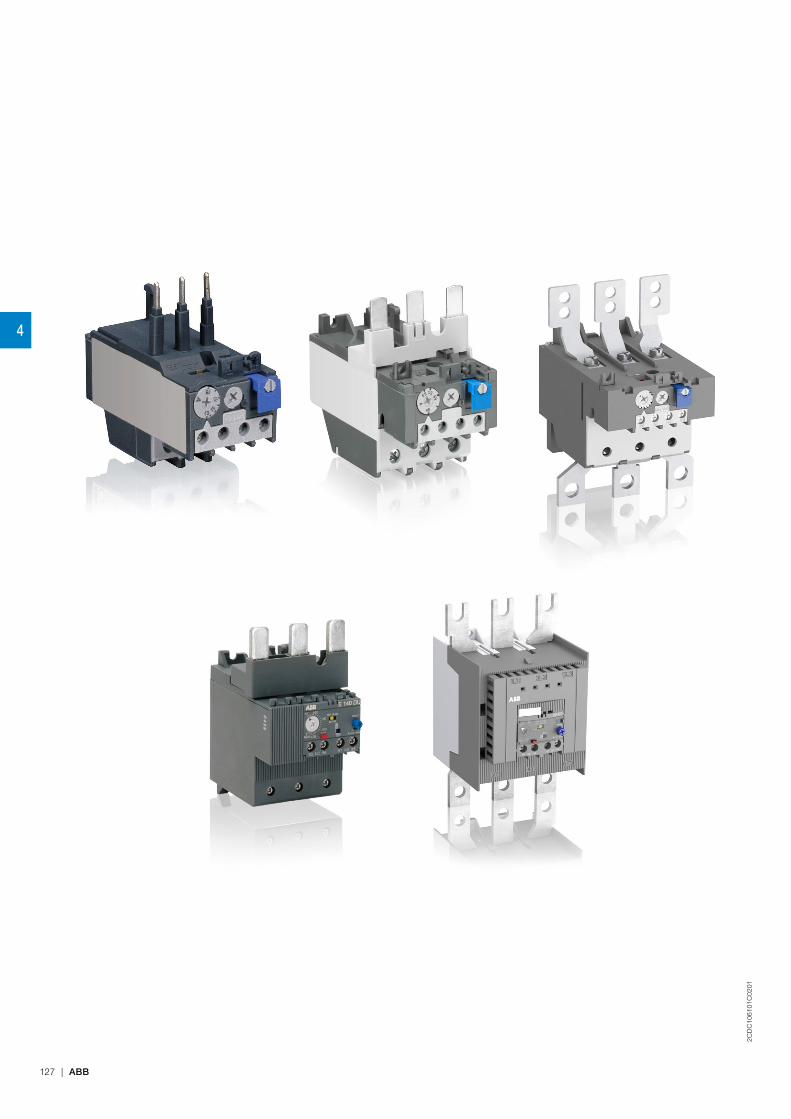
2CD
C10
6101
C02
01
127 | ABB
4

2CD
C10
6101
C02
01
ABB | 128
Overload relays
Overview 130
Thermal overload relays
TA25DU-M / TA42DU-M / TA75DU-M (0.10 … 80 A)
Ordering details 131
Technical data 132
Accessories 135
TA80DU / TA110DU / TA200DU (29 ... 200 A)
Ordering details 136
Technical data 137
Dimensions 140
Electronic overload relays
E140DU (50 ... 140 A)
Ordering details 142
Technical data 143
Accessories 146
EF205, EF370 (63 ... 380 A)
Ordering details 147
Technical data 148
Dimensions 151
4

2CD
C10
6102
C02
01
129 | ABB
4

2CD
C10
6102
C02
01
ABB | 130
Type TA25DU-M TA42DU-M TA75DU-M TA80DU TA110DU TA200DU
Current range 0.10 … 32 A 18 ... 42 A 18 ... 80 A 29 ... 80 A 66 ... 110 A 66 ... 200 A
Trip class 10A 10A 10A 10A 10A 10A
Single mounting kit DB25 DB80 DB80 DB80 DB200 DB200
For contactors AX09 ... AX40 AX32 ... AX40 AX50 ... AX80 AX95 ... AX150 AX95 ... AX150 AX185 ... AX205
Type E140DU EF205 EF370
Current range 50 ... 140 A 63 ... 210 A 115 ... 380 A
Trip class 10E, 20E, 30E selectable
Single mounting kit DB140E - -
For contactors AX95 ... AX150 AX185 ... AX205 AX260 ... AX370
Overload relays
Thermal overload relay
Electronic overload relay
4

2CD
C10
6098
C02
01
131 | ABB
Thermal overload relays TA25DU-M / TA42DU-M / TA75DU-M0.10 to 80 A
DescriptionThe TA25DU-M / TA42DU-M and TA75DU-M thermal overload relays are economic electromechanical protection devices for the main circuit. They offer reliable protection for motors in the event of overload or phase failure. The devices have trip class 10A. The thermal overload relays are three pole relays with bimetal tripping elements. The motor current flows through the bimetal tripping elements and heats them directly and indirectly. In case of an overload (over current), the bimetal elements bent as a result of the heating. This leads to a release of the relay and a change of the contacts switching position (95-96 / 97-98). – Manual or automatic reset selectable – Phase loss sensitive acc. to IEC/EN 60947-4-1 – Two electrically isolated auxiliary contacts – 1 N.O. + 1 N.C. – TEST and STOP function – Trip indication on the front – Temperature compensation – Suitable for three- and single-phase applications
Ordering detailsSetting range Short-circuit
protective device Trip class Type Order code Weight
(1 pce)A kg
TA25DU-M
0.10 ... 0.16 0.50 A, Fuse type F 10A TA25DU-0.16M 1SAZ211201R2005 0.1500.16 ... 0.25 0.63 A, Fuse type F 10A TA25DU-0.25M 1SAZ211201R2009 0.1500.25 ... 0.40 1.25 A, Fuse type F 10A TA25DU-0.4M 1SAZ211201R2013 0.1500.40 ... 0.63 2 A, Fuse type gG / - 10A TA25DU-0.63M 1SAZ211201R2017 0.1500.63 ... 1.00 4 A, Fuse type gG / 2 A aM 10A TA25DU-1.0M 1SAZ211201R2021 0.1501.00 ... 1.40 6 A, Fuse type gG / 2 A aM 10A TA25DU-1.4M 1SAZ211201R2023 0.1501.30 ... 1.80 6 A, Fuse type gG / 4 A aM 10A TA25DU-1.8M 1SAZ211201R2025 0.1501.70 ... 2.40 6 A, Fuse type gG / 4 A aM 10A TA25DU-2.4M 1SAZ211201R2028 0.1502.20 ... 3.10 10 A, Fuse type gG / 6 A aM 10A TA25DU-3.1M 1SAZ211201R2031 0.1502.80 ... 4.00 10 A, Fuse type gG / 6 A aM 10A TA25DU-4.0M 1SAZ211201R2033 0.1503.50 ... 5.00 16 A, Fuse type gG / 10 A aM 10A TA25DU-5.0M 1SAZ211201R2035 0.1504.50 ... 6.50 20 A, Fuse type gG / 16 A aM 10A TA25DU-6.5M 1SAZ211201R2038 0.1506.00 ... 8.50 20 A, Fuse type gG / 20 A aM 10A TA25DU-8.5M 1SAZ211201R2040 0.1507.50 ... 11.00 35 A, Fuse type gG / 25 A aM 10A TA25DU-11M 1SAZ211201R2043 0.15010.00 ... 14.00 35 A, Fuse type gG / 25 A aM 10A TA25DU-14M 1SAZ211201R2045 0.15013.00 ... 19.00 50 A, Fuse type gG / 35 A aM 10A TA25DU-19M 1SAZ211201R2047 0.17018.00 ... 25.00 63 A, Fuse type gG / 50 A aM 10A TA25DU-25M 1SAZ211201R2051 0.17024.00 ... 32.00 80 A, Fuse type gG / 63 A aM 10A TA25DU-32M 1SAZ211201R2053 0.200
TA42DU-M
18 ... 25 63 A, Fuse type gG / 50 A aM 10A TA42DU-25M 1SAZ311201R2001 0.33522 ... 32 80 A, Fuse type gG / 63 A aM 10A TA42DU-32M 1SAZ311201R2002 0.33529 ... 42 100 A, Fuse type gG / 80 A aM 10A TA42DU-42M 1SAZ311201R2003 0.335
TA75DU-M
18 ... 25 63 A, Fuse type gG / 50 A aM 10A TA75DU-25M 1SAZ321201R2001 0.33522 ... 32 80 A, Fuse type gG / 63 A aM 10A TA75DU-32M 1SAZ321201R2002 0.33529 ... 42 100 A, Fuse type gG / 80 A aM 10A TA75DU-42M 1SAZ321201R2003 0.33536 ... 52 125 A, Fuse type gG / 100 A aM 10A TA75DU-52M 1SAZ321201R2004 0.33545 ... 63 160 A, Fuse type gG / 125 A aM 10A TA75DU-63M 1SAZ321201R2005 0.33560 ... 80 200 A, Fuse type gG / 160 A aM 10A TA75DU-80M 1SAZ321201R2006 0.370
TA25DU-M
2CD
C23
1019
F001
3
TA75DU-M
2CD
C23
1022
F001
32C
DC
2310
20F0
013
TA42DU-M
4
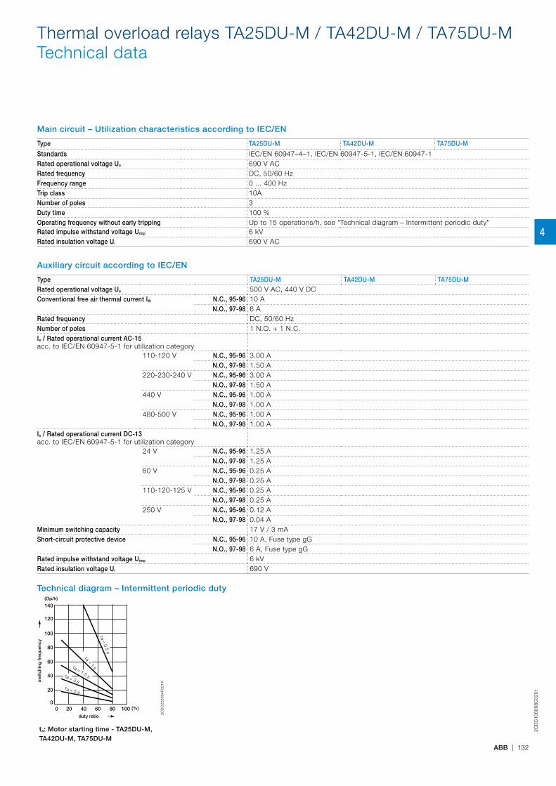
2CD
C10
6098
C02
01
ABB | 132
Main circuit – Utilization characteristics according to IEC/EN
Type TA25DU-M TA42DU-M TA75DU-M
Standards IEC/EN 60947–4–1, IEC/EN 60947-5-1, IEC/EN 60947-1Rated operational voltage Ue 690 V ACRated frequency DC, 50/60 HzFrequency range 0 ... 400 HzTrip class 10ANumber of poles 3Duty time 100 %Operating frequency without early tripping Up to 15 operations/h, see "Technical diagram – Intermittent periodic duty"Rated impulse withstand voltage Uimp 6 kVRated insulation voltage Ui 690 V AC
Auxiliary circuit according to IEC/EN
Type TA25DU-M TA42DU-M TA75DU-MRated operational voltage Ue 500 V AC, 440 V DCConventional free air thermal current Ith N.C., 95-96 10 A
N.O., 97-98 6 ARated frequency DC, 50/60 HzNumber of poles 1 N.O. + 1 N.C.Ie / Rated operational current AC-15acc. to IEC/EN 60947-5-1 for utilization category
110-120 V N.C., 95-96 3.00 AN.O., 97-98 1.50 A
220-230-240 V N.C., 95-96 3.00 AN.O., 97-98 1.50 A
440 V N.C., 95-96 1.00 AN.O., 97-98 1.00 A
480-500 V N.C., 95-96 1.00 AN.O., 97-98 1.00 A
Ie / Rated operational current DC-13acc. to IEC/EN 60947-5-1 for utilization category
24 V N.C., 95-96 1.25 AN.O., 97-98 1.25 A
60 V N.C., 95-96 0.25 AN.O., 97-98 0.25 A
110-120-125 V N.C., 95-96 0.25 AN.O., 97-98 0.25 A
250 V N.C., 95-96 0.12 AN.O., 97-98 0.04 A
Minimum switching capacity 17 V / 3 mAShort-circuit protective device N.C., 95-96 10 A, Fuse type gG
N.O., 97-98 6 A, Fuse type gGRated impulse withstand voltage Uimp 6 kVRated insulation voltage Ui 690 V
Technical diagram – Intermittent periodic duty
duty ratio
switc
hing
fre
que
ncy
(Op/h)
(%)
140
120
0
20
40
60
80
100
0 20 40 60 80 100
t = 1 s
a
t = 1.5 s
a
t = 3 sa
t = 5 sa
t = 0.5 sa
2CD
C23
2004
F021
4
ta: Motor starting time - TA25DU-M, TA42DU-M, TA75DU-M
Thermal overload relays TA25DU-M / TA42DU-M / TA75DU-MTechnical data
4
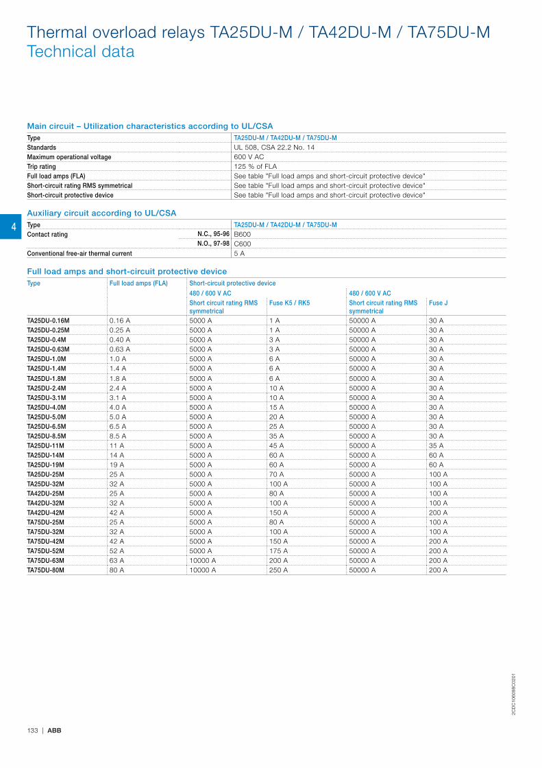
2CD
C10
6098
C02
01
133 | ABB
Main circuit – Utilization characteristics according to UL/CSAType TA25DU-M / TA42DU-M / TA75DU-MStandards UL 508, CSA 22.2 No. 14Maximum operational voltage 600 V ACTrip rating 125 % of FLAFull load amps (FLA) See table "Full load amps and short-circuit protective device"Short-circuit rating RMS symmetrical See table "Full load amps and short-circuit protective device"Short-circuit protective device See table "Full load amps and short-circuit protective device"
Auxiliary circuit according to UL/CSAType TA25DU-M / TA42DU-M / TA75DU-MContact rating N.C., 95-96 B600
N.O., 97-98 C600Conventional free-air thermal current 5 A
Full load amps and short-circuit protective deviceType Full load amps (FLA) Short-circuit protective device
480 / 600 V AC 480 / 600 V ACShort circuit rating RMS symmetrical
Fuse K5 / RK5 Short circuit rating RMS symmetrical
Fuse J
TA25DU-0.16M 0.16 A 5000 A 1 A 50000 A 30 ATA25DU-0.25M 0.25 A 5000 A 1 A 50000 A 30 ATA25DU-0.4M 0.40 A 5000 A 3 A 50000 A 30 ATA25DU-0.63M 0.63 A 5000 A 3 A 50000 A 30 ATA25DU-1.0M 1.0 A 5000 A 6 A 50000 A 30 ATA25DU-1.4M 1.4 A 5000 A 6 A 50000 A 30 A
TA25DU-1.8M 1.8 A 5000 A 6 A 50000 A 30 ATA25DU-2.4M 2.4 A 5000 A 10 A 50000 A 30 ATA25DU-3.1M 3.1 A 5000 A 10 A 50000 A 30 ATA25DU-4.0M 4.0 A 5000 A 15 A 50000 A 30 ATA25DU-5.0M 5.0 A 5000 A 20 A 50000 A 30 ATA25DU-6.5M 6.5 A 5000 A 25 A 50000 A 30 ATA25DU-8.5M 8.5 A 5000 A 35 A 50000 A 30 ATA25DU-11M 11 A 5000 A 45 A 50000 A 35 ATA25DU-14M 14 A 5000 A 60 A 50000 A 60 ATA25DU-19M 19 A 5000 A 60 A 50000 A 60 ATA25DU-25M 25 A 5000 A 70 A 50000 A 100 ATA25DU-32M 32 A 5000 A 100 A 50000 A 100 ATA42DU-25M 25 A 5000 A 80 A 50000 A 100 ATA42DU-32M 32 A 5000 A 100 A 50000 A 100 ATA42DU-42M 42 A 5000 A 150 A 50000 A 200 ATA75DU-25M 25 A 5000 A 80 A 50000 A 100 ATA75DU-32M 32 A 5000 A 100 A 50000 A 100 ATA75DU-42M 42 A 5000 A 150 A 50000 A 200 ATA75DU-52M 52 A 5000 A 175 A 50000 A 200 ATA75DU-63M 63 A 10000 A 200 A 50000 A 200 ATA75DU-80M 80 A 10000 A 250 A 50000 A 200 A
Thermal overload relays TA25DU-M / TA42DU-M / TA75DU-MTechnical data
4
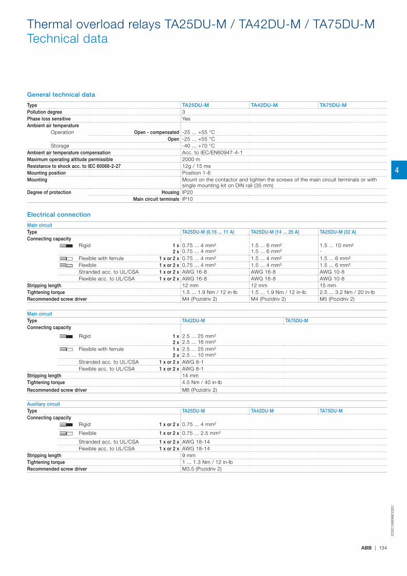
2CD
C10
6098
C02
01
ABB | 134
General technical data
Type TA25DU-M TA42DU-M TA75DU-MPollution degree 3Phase loss sensitive YesAmbient air temperature
Operation Open - compensated -25 ... +55 °COpen -25 ... +55 °C
Storage -40 ... +70 °CAmbient air temperature compensation Acc. to IEC/EN60947-4-1Maximum operating altitude permissible 2000 mResistance to shock acc. to IEC 60068-2-27 12g / 15 msMounting position Position 1-6Mounting Mount on the contactor and tighten the screws of the main circuit terminals or with
single mounting kit on DIN rail (35 mm)Degree of protection Housing IP20
Main circuit terminals IP10
Electrical connection
Main circuitType TA25DU-M (0.16 ... 11 A) TA25DU-M (14 ... 25 A) TA25DU-M (32 A)Connecting capacity Rigid 1 x
2 x0.75 ... 4 mm²0.75 ... 4 mm²
1.5 ... 6 mm²1.5 ... 6 mm²
1.5 ... 10 mm²-
Flexible with ferrule 1 x or 2 x 0.75 ... 4 mm² 1.5 ... 4 mm² 1.5 ... 6 mm²Flexible 1 x or 2 x 0.75 ... 4 mm² 1.5 ... 4 mm² 1.5 ... 6 mm²Stranded acc. to UL/CSA 1 x or 2 x AWG 16-8 AWG 16-8 AWG 10-8Flexible acc. to UL/CSA 1 x or 2 x AWG 16-8 AWG 16-8 AWG 10-8
Stripping length 12 mm 12 mm 15 mmTightening torque 1.5 ... 1.9 Nm / 12 in·lb 1.5 ... 1.9 Nm / 12 in·lb 2.5 ... 3.2 Nm / 20 in·lbRecommended screw driver M4 (Pozidriv 2) M4 (Pozidriv 2) M5 (Pozidriv 2)
Main circuitType TA42DU-M TA75DU-MConnecting capacity
Rigid 1 x2 x
2.5 ... 25 mm² 2.5 ... 16 mm²
Flexible with ferrule 1 x2 x
2.5 ... 25 mm²2.5 ... 10 mm²
Stranded acc. to UL/CSA 1 x or 2 x AWG 8-1Flexible acc. to UL/CSA 1 x or 2 x AWG 8-1
Stripping length 14 mmTightening torque 4.5 Nm / 40 in·lb
Recommended screw driver M6 (Pozidriv 2)
Auxiliary circuitType TA25DU-M TA42DU-M TA75DU-MConnecting capacity
Rigid 1 x or 2 x 0.75 ... 4 mm²
Flexible 1 x or 2 x 0.75 ... 2.5 mm²
Stranded acc. to UL/CSA 1 x or 2 x AWG 18-14Flexible acc. to UL/CSA 1 x or 2 x AWG 18-14
Stripping length 9 mmTightening torque 1 ... 1.3 Nm / 12 in·lbRecommended screw driver M3.5 (Pozidriv 2)
Thermal overload relays TA25DU-M / TA42DU-M / TA75DU-MTechnical data
4
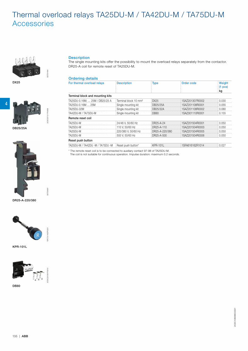
2CD
C10
6099
C02
01
135 | ABB
DescriptionThe single mounting kits offer the possibility to mount the overload relays separately from the contactor.DR25-A coil for remote reset of TA25DU-M.
Ordering detailsFor thermal overload relays Description Type Order code Weight
(1 pce)kg
Terminal block and mounting kits
TA25DU-0.16M; … 25M / DB25/25 A Terminal block 10 mm² DX25 1SAZ201307R0002 0.030TA25DU-0.16M … 25M Single mounting kit DB25/25A 1SAZ201108R0001 0.055TA25DU-32M Single mounting kit DB25/32A 1SAZ201108R0002 0.080TA42DU-M / TA75DU-M Single mounting kit DB80 1SAZ301110R0001 0.155
Remote reset coil
TA25DU-M 24/48 V, 50/60 Hz DR25-A-24 1SAZ201504R0001 0.050TA25DU-M 110 V, 50/60 Hz DR25-A-110 1SAZ201504R0003 0.050TA25DU-M 220/380 V, 50/60 Hz DR25-A-220/380 1SAZ201504R0005 0.050TA25DU-M 500 V, 50/60 Hz DR25-A-500 1SAZ201504R0006 0.050
Reset push button
TA25DU-M / TA42DU -M / TA75DU -M Reset push button* KPR-101L 1SFA616162R1014 0.027
* The remote reset coil is to be connected to auxiliary contact 97-98 of TA25DU-M. The coil is not suitable for continuous operation. Impulse duration: maximum 0.2 seconds.
DX25
DB25/25A
DR25-A-220/380
KPR-101L
DB80
SS
T014
942C
DC
2310
17F0
006
SS
T205
911S
FC15
1402
F000
12C
DC
2310
07F0
010
Thermal overload relays TA25DU-M / TA42DU-M / TA75DU-MAccessories
4
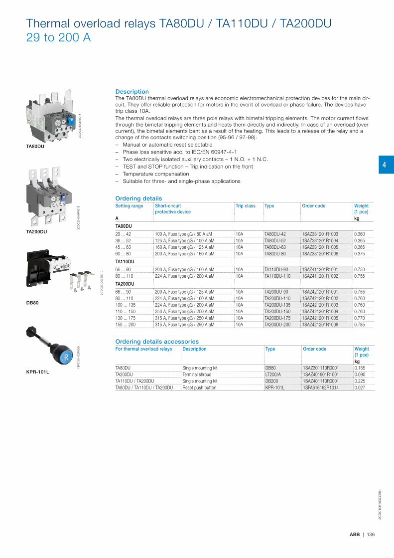
2CD
C10
6103
C02
01
ABB | 136
DescriptionThe TA80DU thermal overload relays are economic electromechanical protection devices for the main cir-cuit. They offer reliable protection for motors in the event of overload or phase failure. The devices have trip class 10A.The thermal overload relays are three pole relays with bimetal tripping elements. The motor current flows through the bimetal tripping elements and heats them directly and indirectly. In case of an overload (over current), the bimetal elements bent as a result of the heating. This leads to a release of the relay and a change of the contacts switching position (95-96 / 97-98). – Manual or automatic reset selectable – Phase loss sensitive acc. to IEC/EN 60947-4-1 – Two electrically isolated auxiliary contacts – 1 N.O. + 1 N.C. – TEST and STOP function – Trip indication on the front – Temperature compensation – Suitable for three- and single-phase applications
Ordering detailsSetting range Short-circuit
protective device Trip class Type Order code Weight
(1 pce)A kg
TA80DU
29 ... 42 100 A, Fuse type gG / 80 A aM 10A TA80DU-42 1SAZ331201R1003 0.36036 ... 52 125 A, Fuse type gG / 100 A aM 10A TA80DU-52 1SAZ331201R1004 0.36545 ... 63 160 A, Fuse type gG / 125 A aM 10A TA80DU-63 1SAZ331201R1005 0.36560 ... 80 200 A, Fuse type gG / 160 A aM 10A TA80DU-80 1SAZ331201R1006 0.375
TA110DU
66 ... 90 200 A, Fuse type gG / 160 A aM 10A TA110DU-90 1SAZ411201R1001 0.75080 ... 110 224 A, Fuse type gG / 200 A aM 10A TA110DU-110 1SAZ411201R1002 0.755
TA200DU
66 ... 90 200 A, Fuse type gG / 125 A aM 10A TA200DU-90 1SAZ421201R1001 0.75580 ... 110 224 A, Fuse type gG / 160 A aM 10A TA200DU-110 1SAZ421201R1002 0.760100 ... 135 224 A, Fuse type gG / 200 A aM 10A TA200DU-135 1SAZ421201R1003 0.760110 ... 150 250 A, Fuse type gG / 200 A aM 10A TA200DU-150 1SAZ421201R1004 0.760130 ... 175 315 A, Fuse type gG / 250 A aM 10A TA200DU-175 1SAZ421201R1005 0.770150 ... 200 315 A, Fuse type gG / 250 A aM 10A TA200DU-200 1SAZ421201R1006 0.785
Ordering details accessoriesFor thermal overload relays Description Type Order code Weight
(1 pce)kg
TA80DU Single mounting kit DB80 1SAZ301110R0001 0.155TA200DU Terminal shroud LT200/A 1SAZ401901R1001 0.090TA110DU / TA200DU Single mounting kit DB200 1SAZ401110R0001 0.225TA80DU / TA110DU / TA200DU Reset push button KPR-101L 1SFA616162R1014 0.027
TA80DU
DB80
KPR-101L
2CD
C23
1008
F001
1
2CD
C23
1007
S00
10
1SFC
1514
02F0
001
TA200DU
2CD
C23
1016
F001
3
Thermal overload relays TA80DU / TA110DU / TA200DU29 to 200 A
4
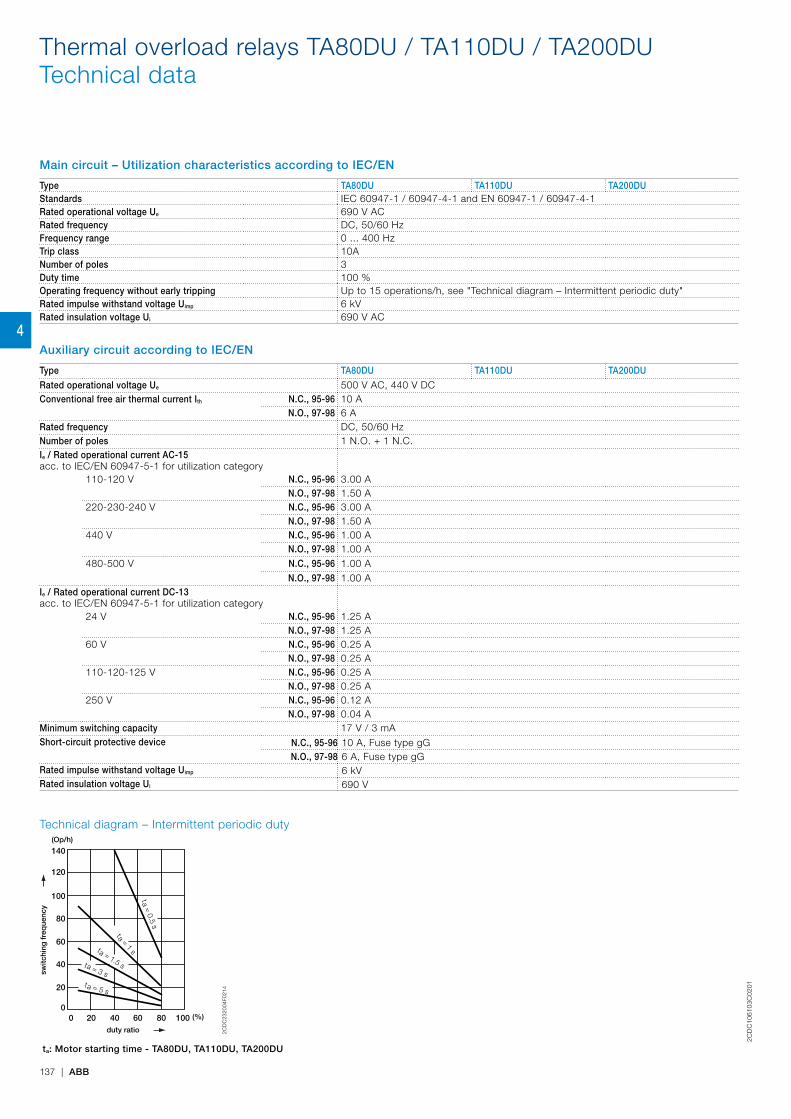
2CD
C10
6103
C02
01
137 | ABB
Main circuit – Utilization characteristics according to IEC/EN
Type TA80DU TA110DU TA200DUStandards IEC 60947-1 / 60947-4-1 and EN 60947-1 / 60947-4-1Rated operational voltage Ue 690 V ACRated frequency DC, 50/60 HzFrequency range 0 ... 400 HzTrip class 10ANumber of poles 3Duty time 100 %Operating frequency without early tripping Up to 15 operations/h, see "Technical diagram – Intermittent periodic duty"Rated impulse withstand voltage Uimp 6 kVRated insulation voltage Ui 690 V AC
Auxiliary circuit according to IEC/EN
Type TA80DU TA110DU TA200DU
Rated operational voltage Ue 500 V AC, 440 V DCConventional free air thermal current Ith N.C., 95-96 10 A
N.O., 97-98 6 ARated frequency DC, 50/60 HzNumber of poles 1 N.O. + 1 N.C.Ie / Rated operational current AC-15acc. to IEC/EN 60947-5-1 for utilization category
110-120 V N.C., 95-96 3.00 AN.O., 97-98 1.50 A
220-230-240 V N.C., 95-96 3.00 AN.O., 97-98 1.50 A
440 V N.C., 95-96 1.00 AN.O., 97-98 1.00 A
480-500 V N.C., 95-96 1.00 AN.O., 97-98 1.00 A
Ie / Rated operational current DC-13acc. to IEC/EN 60947-5-1 for utilization category
24 V N.C., 95-96 1.25 AN.O., 97-98 1.25 A
60 V N.C., 95-96 0.25 AN.O., 97-98 0.25 A
110-120-125 V N.C., 95-96 0.25 AN.O., 97-98 0.25 A
250 V N.C., 95-96 0.12 AN.O., 97-98 0.04 A
Minimum switching capacity 17 V / 3 mAShort-circuit protective device N.C., 95-96 10 A, Fuse type gG
N.O., 97-98 6 A, Fuse type gGRated impulse withstand voltage Uimp 6 kVRated insulation voltage Ui 690 V
Technical diagram – Intermittent periodic duty
duty ratio
switc
hing
fre
que
ncy
(Op/h)
(%)
140
120
0
20
40
60
80
100
0 20 40 60 80 100
t = 1 s
a
t = 1.5 s
a
t = 3 sa
t = 5 sa
t = 0.5 sa
2CD
C23
2004
F021
4
ta: Motor starting time - TA80DU, TA110DU, TA200DU
Thermal overload relays TA80DU / TA110DU / TA200DUTechnical data
4
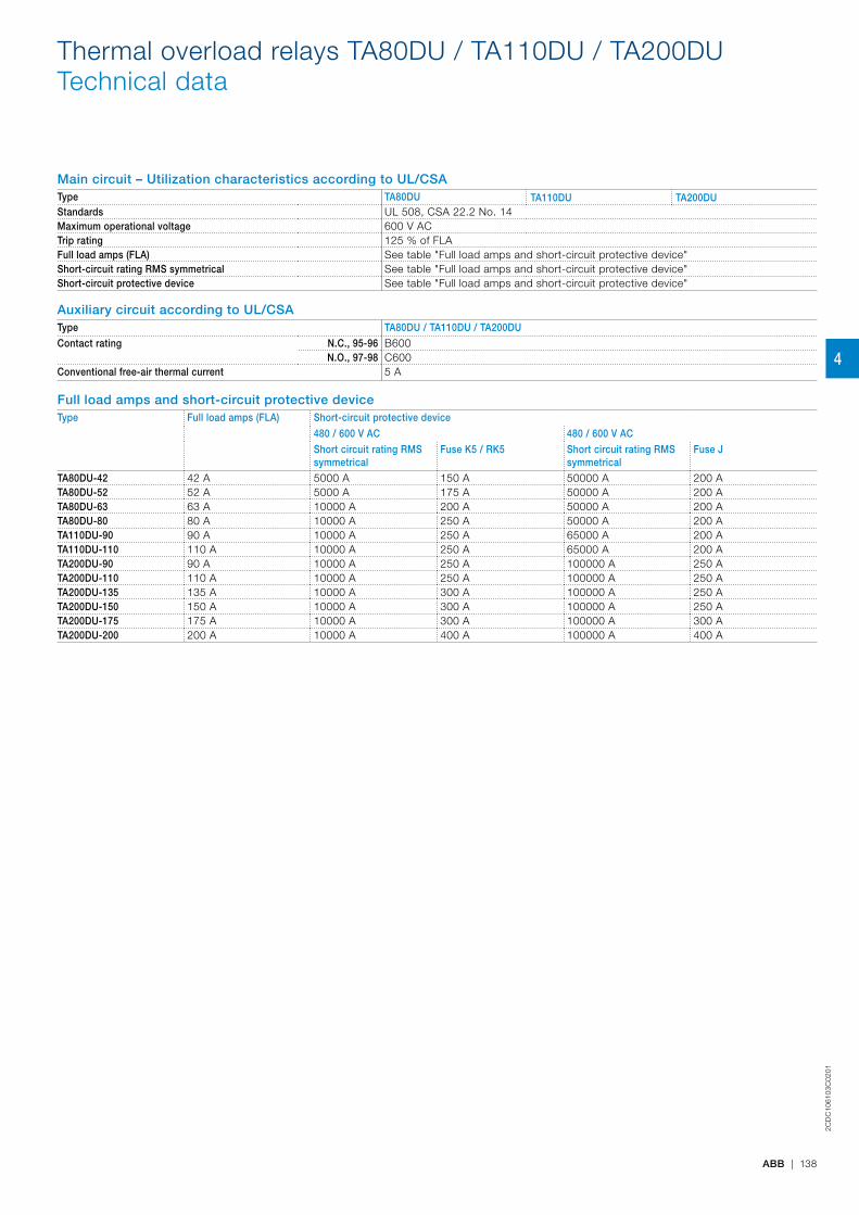
2CD
C10
6103
C02
01
ABB | 138
Main circuit – Utilization characteristics according to UL/CSAType TA80DU TA110DU TA200DUStandards UL 508, CSA 22.2 No. 14Maximum operational voltage 600 V ACTrip rating 125 % of FLAFull load amps (FLA) See table "Full load amps and short-circuit protective device"Short-circuit rating RMS symmetrical See table "Full load amps and short-circuit protective device"Short-circuit protective device See table "Full load amps and short-circuit protective device"
Auxiliary circuit according to UL/CSAType TA80DU / TA110DU / TA200DUContact rating N.C., 95-96 B600
N.O., 97-98 C600Conventional free-air thermal current 5 A
Full load amps and short-circuit protective deviceType Full load amps (FLA) Short-circuit protective device
480 / 600 V AC 480 / 600 V ACShort circuit rating RMS symmetrical
Fuse K5 / RK5 Short circuit rating RMS symmetrical
Fuse J
TA80DU-42 42 A 5000 A 150 A 50000 A 200 ATA80DU-52 52 A 5000 A 175 A 50000 A 200 ATA80DU-63 63 A 10000 A 200 A 50000 A 200 ATA80DU-80 80 A 10000 A 250 A 50000 A 200 ATA110DU-90 90 A 10000 A 250 A 65000 A 200 ATA110DU-110 110 A 10000 A 250 A 65000 A 200 ATA200DU-90 90 A 10000 A 250 A 100000 A 250 ATA200DU-110 110 A 10000 A 250 A 100000 A 250 ATA200DU-135 135 A 10000 A 300 A 100000 A 250 ATA200DU-150 150 A 10000 A 300 A 100000 A 250 ATA200DU-175 175 A 10000 A 300 A 100000 A 300 ATA200DU-200 200 A 10000 A 400 A 100000 A 400 A
Thermal overload relays TA80DU / TA110DU / TA200DUTechnical data
4
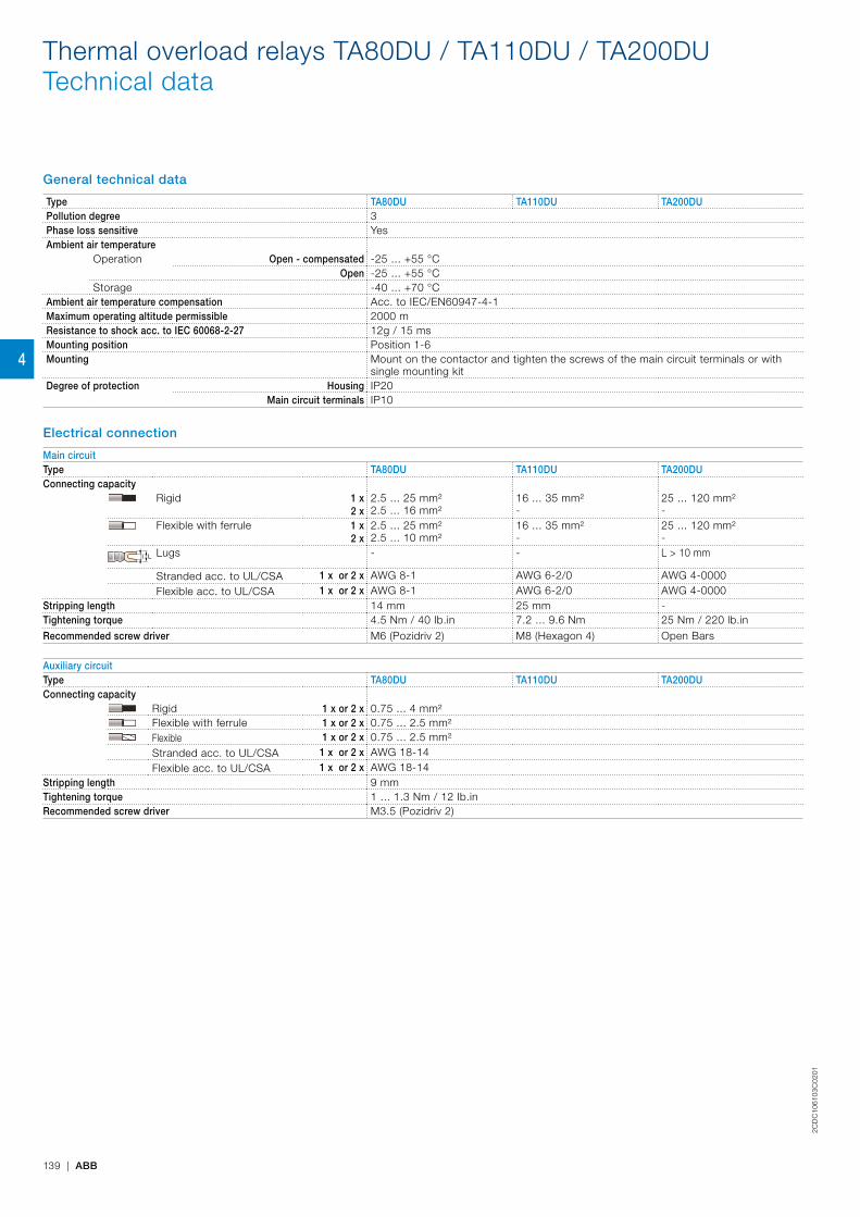
2CD
C10
6103
C02
01
139 | ABB
General technical data
Type TA80DU TA110DU TA200DUPollution degree 3Phase loss sensitive YesAmbient air temperature
Operation Open - compensated -25 ... +55 °COpen -25 ... +55 °C
Storage -40 ... +70 °CAmbient air temperature compensation Acc. to IEC/EN60947-4-1Maximum operating altitude permissible 2000 mResistance to shock acc. to IEC 60068-2-27 12g / 15 msMounting position Position 1-6Mounting Mount on the contactor and tighten the screws of the main circuit terminals or with
single mounting kitDegree of protection Housing IP20
Main circuit terminals IP10
Electrical connection
Main circuitType TA80DU TA110DU TA200DUConnecting capacity
Rigid 1 x2 x
2.5 ... 25 mm²2.5 ... 16 mm²
16 ... 35 mm²-
25 ... 120 mm²-
Flexible with ferrule 1 x 2 x
2.5 ... 25 mm² 2.5 ... 10 mm²
16 ... 35 mm²-
25 ... 120 mm² -
Ll Lugs - - L > 10 mm
Stranded acc. to UL/CSA 1 x or 2 x AWG 8-1 AWG 6-2/0 AWG 4-0000Flexible acc. to UL/CSA 1 x or 2 x AWG 8-1 AWG 6-2/0 AWG 4-0000
Stripping length 14 mm 25 mm -Tightening torque 4.5 Nm / 40 Ib.in 7.2 ... 9.6 Nm 25 Nm / 220 lb.inRecommended screw driver M6 (Pozidriv 2) M8 (Hexagon 4) Open Bars
Auxiliary circuitType TA80DU TA110DU TA200DUConnecting capacity
Rigid 1 x or 2 x 0.75 ... 4 mm²Flexible with ferrule 1 x or 2 x 0.75 ... 2.5 mm²Flexible 1 x or 2 x 0.75 ... 2.5 mm²Stranded acc. to UL/CSA 1 x or 2 x AWG 18-14Flexible acc. to UL/CSA 1 x or 2 x AWG 18-14
Stripping length 9 mmTightening torque 1 ... 1.3 Nm / 12 Ib.inRecommended screw driver M3.5 (Pozidriv 2)
Thermal overload relays TA80DU / TA110DU / TA200DUTechnical data
4

Thermal overload relays TA25DU-M / TA42DU-M / TA75DU-MDimensions
Main dimensions mm, inches
44 1.73"
13.5 0.53"
49.5
1.
95"80
3.
15"
13.5 0.53"
13.5 0.53"
12
0.47
"
73.5 2.89"
94 3.7"
6 0.24"
20
0.79
"14
* 0.
55"*
39 1.54"
52.2 2.06" 2.5 0.1"
2CD
C23
2023
F001
1
5.5
85.8
13.5 13.5
44
14*
14*
49
.5
88
27 6 9
109
35
7.5
48
14.5
4.2
0.22"
3.38"
0.53"0.53"
1.73"
0.55
"
1.95
"
3.46
"
0.55
"
1.06" 0.24"0.35"
4.29"
1.38"
0.3"
1.89
"0.
57"
0.17"
2CD
C23
2009
F001
4
TA25DU-M + DX25 TA25DU-M + DB25 + DX25
10
0.39
" 5 0.
2"
30 1.18"
14.4 0.57" 14.4 0.57"
7.9 0.3"
0.17"4.3 13 0.51"
17.5 0.69" 17.5 0.69"
54 2.13"
61.5 2.42" 1.5 0.06"
5 0.2"
34
1.34
"56
2.
2"
6 0.24"
110.5 4.35"
2CD
C23
2015
F001
1
TA42DU-M
30 1.18"
22 0.87"
57.5 2.26"
22 0.87"
13 0.51"4.3 0.17" 67(65.5*) 2.64"(2.58")
10
0.39
"
5 0.2"
5 0
.2"
17.5 0.69" 17.5 0.69"
54 2.13"
6 0.24"
110.5 4.35"
18
0.71
"
56
2.2"
35.5
1.
4"
1.5 0.06"
(3*) (0.12"*)
2CD
C23
2017
F001
1
19 0.75"19 0.75"
92
3.62
"
60 2.36"
4.7 0.19"
9 0.35" 68 2.68"
86 3.39"
117 4.61"
86
3.39
"
38.5 1.52"
18 0.71"
DIN rail 35 EN60715Hutschiene 35 EN60715 2C
DC
2320
25F0
011
TA75DU-M TA75DU-M + DB80TA42DU-M + DB80
2CD
C10
6100
C02
01
ABB | 140
4

Thermal overload relays TA80DU / TA110DU / TA200DUDimensions
Main dimensions mm, inches
19
0.75
"
56
2.2"
41
1.61
"
6 0.24"
110.5 4.35"
10
0.39
" 5 0
.2"
70 2.76" 2.5 0.1"
5 0.2"
78 3.07"
17.5 0.69" 17.5 0.69"
54 2.13"
30 1.18" 30 1.18"
13 0.51"4.3 0.17"
30 1.18"
2CD
C23
2018
F001
1
19 0.75"19 0.75"
92
3.62
"
60 2.36"
4.7 0.19"
9 0.35" 68 2.68"
86 3.39"
117 4.61"
86
3.39
"
38.5 1.52"
18 0.71"
DIN rail 35 EN60715Hutschiene 35 EN60715
2CD
C23
2025
F001
1
TA80DU TA80DU + DB80
8 0.31"
126 4.96"
6 0.24"
6 0
.24"
32
1.26
"
10
0.39
"
82.3
3.
24"
4 0.16"
70 2.76" 3 0.12"
2 0.
08"
2 0.08"
13 0.51" 26 1.02"
37 1.46"
30 1.18"30 1.4"
70
2.76
"33
1.3
"
83
3.27
"56
2.
2"
Ø 5.3 Ø 0.21"
50 1.97"
68 2.68"
80 3.15" 2CD
C23
2020
F001
1
TA110DU
4 0.16"61 2.4"
8 0.31"
126 4.96"
6 0.24"
4 0.16"
6 0
.24"
32 1.26" 3 0.12"23 0.91" 26 1.02"
37 1.46"
35 1.38"35 1.38"
Ø8.
5 Ø
0.33
"5.5 0.22"
82.3
3.
24"
11
0.43
"
30.9
1.2
2"
49.9
2"
151
5.
94"
10
0.39
"
68
2.68
"
80 3.15"
Ø 11 Ø 0.43"
20 0.79"
22.1
0.
87"
Ø 5.3 Ø 0.21"
42 1.65"42 1.65"
50 1.97"
2CD
C23
2021
F001
1
TA200DU
2CD
C10
6105
C02
01
141 | ABB
4

Electronic overload relay E140DU50 to 140 A
DescriptionThe E140DU are self-supplied electronic overload relays, which means no extra external supply is needed. It offers reliable protection for motors in the event of overload or phase failure. Easy to use like a thermal overload relay and compatible with standard motor applications, the electronic overload relay is convinc-ing, above all, due to its wide setting range, high accuracy, high operational temperature range and the possibility to select a trip class (10E, 20E, 30E). Further features are the temperature compensation, trip contact (N.C.), signal contact (N.O.), automatic or manual reset selectable, trip-free mechanism, STOP and TEST function and a trip indication. The overload relays are connected directly to the contactors. Single mounting kits are available as accessory.
Ordering detailsSetting range Short-circuit
protective device Trip class Type Order code Weight
(1 pce)A kg50.0 ... 140.0 A 400 A 10E, 20E, 30E E140DU-140 1SAX321001R1101 0.915
E140DU
2CD
C23
1004
F000
6
2CD
C10
7054
C02
01
ABB | 142
4
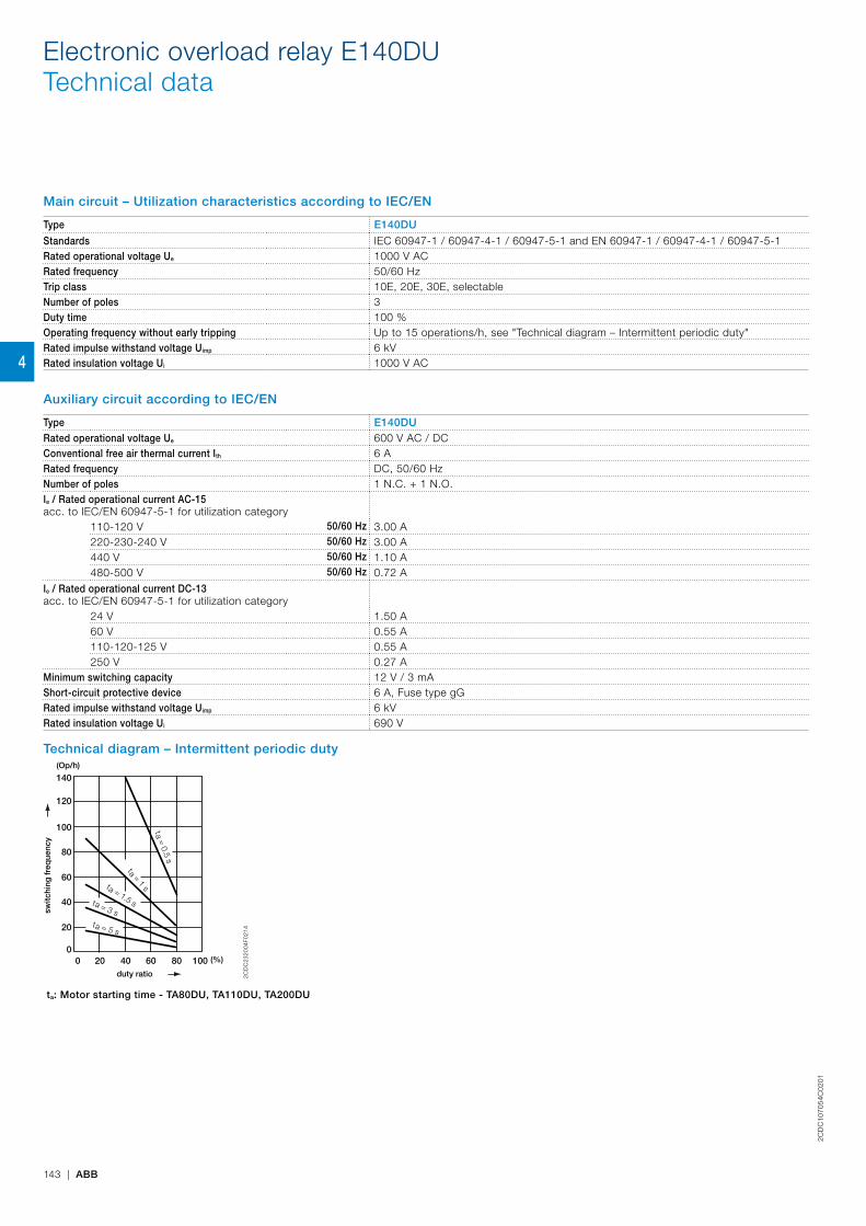
Electronic overload relay E140DUTechnical data
Main circuit – Utilization characteristics according to IEC/EN
Type E140DU
Standards IEC 60947-1 / 60947-4-1 / 60947-5-1 and EN 60947-1 / 60947-4-1 / 60947-5-1Rated operational voltage Ue 1000 V ACRated frequency 50/60 HzTrip class 10E, 20E, 30E, selectableNumber of poles 3Duty time 100 %Operating frequency without early tripping Up to 15 operations/h, see "Technical diagram – Intermittent periodic duty"Rated impulse withstand voltage Uimp 6 kVRated insulation voltage Ui 1000 V AC
Auxiliary circuit according to IEC/EN
Type E140DURated operational voltage Ue 600 V AC / DCConventional free air thermal current Ith 6 ARated frequency DC, 50/60 HzNumber of poles 1 N.C. + 1 N.O.Ie / Rated operational current AC-15acc. to IEC/EN 60947-5-1 for utilization category
110-120 V 50/60 Hz 3.00 A220-230-240 V 50/60 Hz 3.00 A440 V 50/60 Hz 1.10 A480-500 V 50/60 Hz 0.72 A
Ie / Rated operational current DC-13acc. to IEC/EN 60947-5-1 for utilization category
24 V 1.50 A60 V 0.55 A110-120-125 V 0.55 A250 V 0.27 A
Minimum switching capacity 12 V / 3 mAShort-circuit protective device 6 A, Fuse type gGRated impulse withstand voltage Uimp 6 kVRated insulation voltage Ui 690 V
Technical diagram – Intermittent periodic duty
duty ratio
switc
hing
fre
que
ncy
(Op/h)
(%)
140
120
0
20
40
60
80
100
0 20 40 60 80 100
t = 1 s
a
t = 1.5 s
a
t = 3 sa
t = 5 sa
t = 0.5 sa
2CD
C23
2004
F021
4
ta: Motor starting time - TA80DU, TA110DU, TA200DU
2CD
C10
7054
C02
01
143 | ABB
4
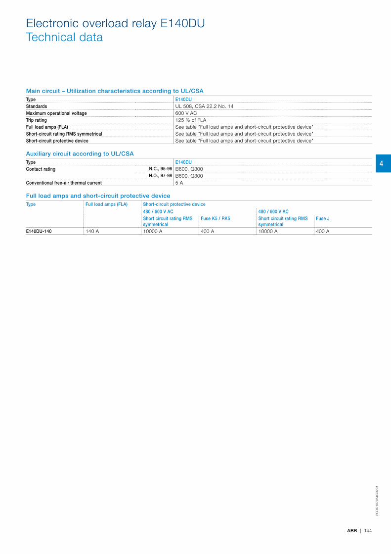
Electronic overload relay E140DUTechnical data
Main circuit – Utilization characteristics according to UL/CSAType E140DUStandards UL 508, CSA 22.2 No. 14Maximum operational voltage 600 V ACTrip rating 125 % of FLAFull load amps (FLA) See table "Full load amps and short-circuit protective device"Short-circuit rating RMS symmetrical See table "Full load amps and short-circuit protective device"Short-circuit protective device See table "Full load amps and short-circuit protective device"
Auxiliary circuit according to UL/CSAType E140DUContact rating N.C., 95-96 B600, Q300
N.O., 97-98 B600, Q300Conventional free-air thermal current 5 A
Full load amps and short-circuit protective deviceType Full load amps (FLA) Short-circuit protective device
480 / 600 V AC 480 / 600 V ACShort circuit rating RMS symmetrical
Fuse K5 / RK5 Short circuit rating RMS symmetrical
Fuse J
E140DU-140 140 A 10000 A 400 A 18000 A 400 A
2CD
C10
7054
C02
01
ABB | 144
4
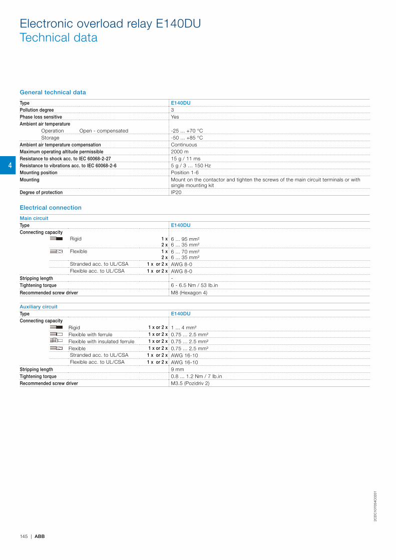
General technical data
Type E140DUPollution degree 3Phase loss sensitive YesAmbient air temperature
Operation Open - compensated -25 ... +70 °CStorage -50 ... +85 °C
Ambient air temperature compensation ContinuousMaximum operating altitude permissible 2000 mResistance to shock acc. to IEC 60068-2-27 15 g / 11 msResistance to vibrations acc. to IEC 60068-2-6 5 g / 3 … 150 HzMounting position Position 1-6Mounting Mount on the contactor and tighten the screws of the main circuit terminals or with
single mounting kitDegree of protection IP20
Electrical connection
Main circuitType E140DUConnecting capacity
Rigid 1 x2 x
6 ... 95 mm² 6 ... 35 mm²
Flexible 1 x2 x
6 ... 70 mm²6 ... 35 mm²
Stranded acc. to UL/CSA 1 x or 2 x AWG 8-0Flexible acc. to UL/CSA 1 x or 2 x AWG 8-0
Stripping length -Tightening torque 6 - 6.5 Nm / 53 Ib.in
Recommended screw driver M8 (Hexagon 4)
Auxiliary circuitType E140DUConnecting capacity
Rigid 1 x or 2 x 1 ... 4 mm²Flexible with ferrule 1 x or 2 x 0.75 ... 2.5 mm²Flexible with insulated ferrule 1 x or 2 x 0.75 ... 2.5 mm²Flexible 1 x or 2 x 0.75 ... 2.5 mm²Stranded acc. to UL/CSA 1 x or 2 x AWG 16-10Flexible acc. to UL/CSA 1 x or 2 x AWG 16-10
Stripping length 9 mmTightening torque 0.8 ... 1.2 Nm / 7 Ib.inRecommended screw driver M3.5 (Pozidriv 2)
Electronic overload relay E140DUTechnical data
2CD
C10
7054
C02
01
145 | ABB
4

Electronic overload relay E140DUAccessories
DescriptionSingle mounting kits are available as accessory for E140DU. The single mounting kits offer the possibility to mount the overload relay separately from the contactor.
Ordering detailsFor thermal overload relays Description Type Order code Weight
(1 pce)kg
E140DU Single mounting kit DB140E 1SAX301110R1002 0.145DB140E
2CD
C23
1006
S00
10
2CD
C10
7055
C02
01
ABB | 146
4
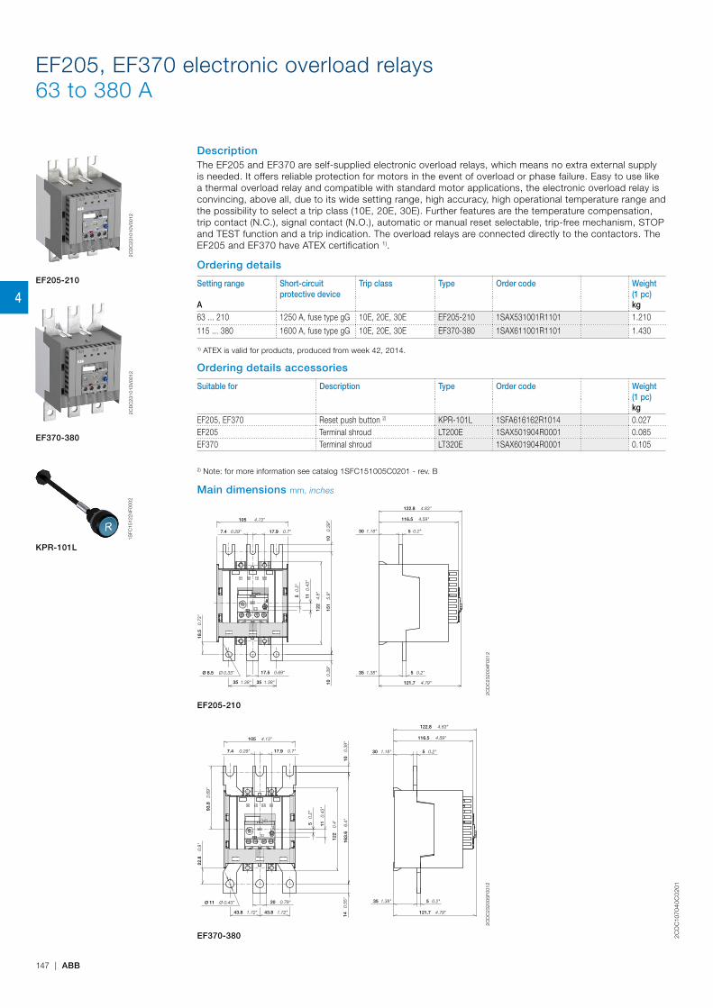
2CD
C10
704
0C
02
01
147 | ABB
EF205, EF370 electronic overload relays63 to 380 A
DescriptionThe EF205 and EF370 are self-supplied electronic overload relays, which means no extra external supply is needed. It offers reliable protection for motors in the event of overload or phase failure. Easy to use like a thermal overload relay and compatible with standard motor applications, the electronic overload relay is convincing, above all, due to its wide setting range, high accuracy, high operational temperature range and the possibility to select a trip class (10E, 20E, 30E). Further features are the temperature compensation, trip contact (N.C.), signal contact (N.O.), automatic or manual reset selectable, trip-free mechanism, STOP and TEST function and a trip indication. The overload relays are connected directly to the contactors. The EF205 and EF370 have ATEX certification 1).
Ordering details
Setting range Short-circuit protective device
Trip class Type Order code Weight(1 pc)
A kg63 ... 210 1250 A, fuse type gG 10E, 20E, 30E EF205-210 1SAX531001R1101 1.210
115 ... 380 1600 A, fuse type gG 10E, 20E, 30E EF370-380 1SAX611001R1101 1.430
1) ATEX is valid for products, produced from week 42, 2014.
Ordering details accessories
Suitable for Description Type Order code Weight(1 pc)kg
EF205, EF370 Reset push button 2) KPR-101L 1SFA616162R1014 0.027EF205 Terminal shroud LT200E 1SAX501904R0001 0.085EF370 Terminal shroud LT320E 1SAX601904R0001 0.105
2) Note: for more information see catalog 1SFC151005C0201 - rev. B
2CD
C23
1010
V00
12
EF205-210
2CD
C23
1013
V00
12
EF370-380
Main dimensions mm, inches
105
7.4 17.9
18.5
5 11
122
151
10
17.5
35
Ø 8.5
10
30 5
116.5
122.8
5 35
121.7 35
4.13"
0.29" 0.7"
0.73
"
0.2"
0.43
"
4.8"
5.9"
0.39
"
1.18" 0.2"
4.59"
4.83"
0.69"
1.38"
Ø 0.33" 0.39
"
1.38"
0.2"1.38"
4.79"
2CD
C23
2004
F001
2
EF205-210
122.8 4.83"
30 1.18"
116.5 4.59"
5 0.2"
35 1.38" 5 0.2"
121.7 4.79"
14
0.55
"16
3.6
6.
4"10
0.
39"
22.8
0.
9"
93.8
3.
69"
7.4 0.29"
105 4.13"
17.9 0.7"
20 0.79"
43.8 1.72"43.8 1.72"
Ø 11 Ø 0.43"
11
0.43
"
122
0.
4'5 0
.2"
2CD
C23
2005
F001
2
EF370-380
1SFC
1512
24F0
002
KPR-101L
4
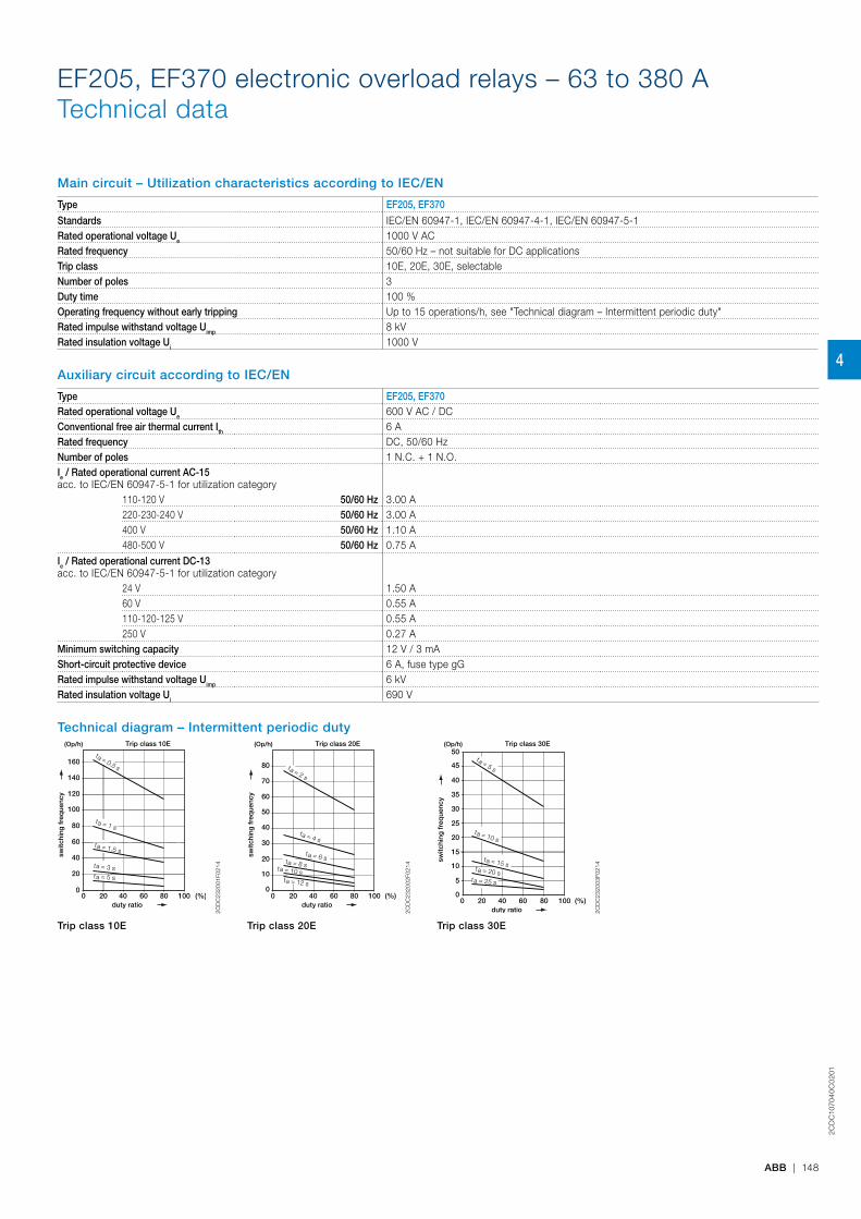
2CD
C10
704
0C
02
01
ABB | 148
Main circuit – Utilization characteristics according to IEC/EN
Type EF205, EF370
Standards IEC/EN 60947-1, IEC/EN 60947-4-1, IEC/EN 60947-5-1Rated operational voltage Ue 1000 V ACRated frequency 50/60 Hz – not suitable for DC applicationsTrip class 10E, 20E, 30E, selectableNumber of poles 3Duty time 100 %Operating frequency without early tripping Up to 15 operations/h, see "Technical diagram – Intermittent periodic duty"Rated impulse withstand voltage Uimp 8 kVRated insulation voltage Ui 1000 V
Auxiliary circuit according to IEC/EN
Type EF205, EF370Rated operational voltage Ue 600 V AC / DCConventional free air thermal current Ith 6 ARated frequency DC, 50/60 HzNumber of poles 1 N.C. + 1 N.O.Ie / Rated operational current AC-15acc. to IEC/EN 60947-5-1 for utilization category
110-120 V 50/60 Hz 3.00 A220-230-240 V 50/60 Hz 3.00 A400 V 50/60 Hz 1.10 A480-500 V 50/60 Hz 0.75 A
Ie / Rated operational current DC-13acc. to IEC/EN 60947-5-1 for utilization category
24 V 1.50 A60 V 0.55 A110-120-125 V 0.55 A250 V 0.27 A
Minimum switching capacity 12 V / 3 mAShort-circuit protective device 6 A, fuse type gGRated impulse withstand voltage Uimp 6 kVRated insulation voltage Ui 690 V
Technical diagram – Intermittent periodic duty
duty ratio
(Op/h)
switc
hing
fre
que
ncy
Trip class 10E
(%)0
20
40
60
80
100
120
140
160
0 20 40 60 80 100
t = 1 sa
t = 1.5 sa
t = 3 sa
t = 5 sa
t = 0.5 s
a
2CD
C23
2001
F021
4
duty ratio
(Op/h)
switc
hing
fre
que
ncy
Trip class 20E
(%)0
10
20
30
40
50
60
70
80
0 20 40 60 80 100
t = 4 sa
t = 8 sat = 10 sa
t = 12 sa
t = 2 sa
t = 6 sa
2CD
C23
2002
F021
4
duty ratio
(Op/h)
switc
hing
fre
que
ncy
Trip class 30E
(%)0
5
10
15
20
25
30
35
45
0 20 40 60 80 100
40
50
t = 10 sa
t = 20 sa
t = 25 sa
t = 5 sa
t = 15 sa
2CD
C23
2003
F021
4
Trip class 10E Trip class 20E Trip class 30E
EF205, EF370 electronic overload relays – 63 to 380 ATechnical data
4

2CD
C10
704
0C
02
01
149 | ABB
Main circuit – Utilization characteristics according to UL/CSA
Type EF205, EF370Standards UL 508, CSA 22.2 No. 14, UL 60947-4-1AMaximum operational voltage 600 V ACTrip rating 125 % of FLAFull load amps (FLA) See table "Full load amps and short-circuit protective device"Short-circuit rating RMS symmetrical See table "Full load amps and short-circuit protective device"Short-circuit protective device See table "Full load amps and short-circuit protective device"
Auxiliary circuit according to UL/CSA
Type EF205, EF370Contact rating N.C., 95-96 B600, Q600
N.O., 97-98 B600, Q600Conventional thermal current 6 A
Full load amps and short-circuit protective device
Type Full load amps (FLA) Short-circuit protective device
480 V AC 600 V ACSCCR Fuse type SCCR Fuse type SCCR Fuse type
EF205-210 210 A 10 kA 400 A, R5/RK5 10kA 400 A, R5/RK5 100 kA 400 A, JEF370-380 380 A 18 kA 800 A, L/T 18kA 800 A, L/T - -
EF205, EF370 electronic overload relays – 63 to 380 ATechnical data
4

2CD
C10
704
0C
02
01
ABB | 150
General data
Type EF205 EF370Pollution degree 3Phase loss sensitive YesAmbient air temperature
Operation Open - compensated -25 ... +70 °CStorage -50 ... +85 °C
Ambient air temperature compensation Acc. to IEC/EN 60947-4-1Maximum operating altitude permissible 2000 mResistance to shock acc. to IEC 60068-2-27 25g / 11 msResistance to vibrations acc. to IEC 60068-2-6 5g / 3 … 150 HzMounting position Position 1-6Mounting Mount on the contactor and tighten the screws
of the main circuit terminalsDegree of protection Housing IP20
Main circuit terminals IP20
Electrical connection
Main circuitType EF205 EF370Connecting capacity
Rigid 1 x2 x
16 ... 185 mm²16 ... 120 mm²
50 ... 240 mm²50 ... 150 mm²
Flexible 1 x2 x
16 ... 185 mm²16 ... 120 mm²
50 ... 240 mm²50 ... 150 mm²
Lugs L ≤ 24 mm 32 mmBars Ø > 8 mm 10 mmStranded acc. to UL/CSA 1 x
2 xAWG 6-0000AWG 6-0000
AWG 1-500 kcmilAWG 1-500 kcmil
Flexible acc. to UL/CSA 1 x2 x
AWG 6-0000AWG 6-0000
AWG 1-500 kcmilAWG 1-500 kcmil
Stripping length - -Tightening torque 18 Nm / 160 lb.in 28 Nm / 247 lb.in
Recommended screw driver M8 M10
Auxiliary circuitType EF205, EF370Connecting capacity
Rigid 1 or 2 x 1 ... 4 mm²Flexible with ferrule 1 or 2 x 0.75 ... 2.5 mm²Flexible with insulated ferrule 1 or 2 x 0.75 ... 2.5 mm²Flexible 1 or 2 x 0.75 ... 2.5 mm²Stranded acc. to UL/CSA 1 or 2 x AWG 18-10Flexible acc. to UL/CSA 1 or 2 x AWG 18-10
Stripping length 9 mmTightening torque 0.8 ... 1.2 Nm / 7 ... 11 Ib.inRecommended screw driver M3.5 (Pozidriv 2)
EF205, EF370 electronic overload relays – 63 to 380 ATechnical data
4

Electronic overload relay E140DUDimensions
Main dimensions mm, inches94
.2
16 5.5 3
58 70
74.2
85.2
215
49 5.5
37 59.7
76
38.4
14
99
104.4
3
8 18
67.6 5
74.5 3
13
27.3
3.7
1“
0.63“ 0.22“ 1.46“
2.28“ 2.76“
2.9
2“
3.3
5“
0.0
8“
0.5
9“
1.93
“
0.21“
1.46“2.35“
2.30“
1.5
1“
0.5
5“
3.90“
4.11“
0.12“
0.1
2“ 0
.71“
2.66“ 0.20“
2.93“0.12“
0.51“
1.07
“
2CD
C23
2008
F001
1
E140DU
81.5 3.21"
29.6 1.17"4.2 0.17"
50.
20"
139.
5
5.50
"
70
2.76"
85.2
3.
35"
99 3.90"
33.7 1.33"
4.3 0.17"
5.5 0.22"
94.2
3.
71"
103 4.06"104.4 4.11"
68.5
2.
70"
21.1
0.
83"
62.5
2.
46"
37 1.46"43.7 1.72"
4.3 0.17"
5.5 0.22"
37 1.46"
2CD
C23
2029
F001
1
E140DU + DB140E 2C
DC
1070
56C
0201
151 | ABB
4
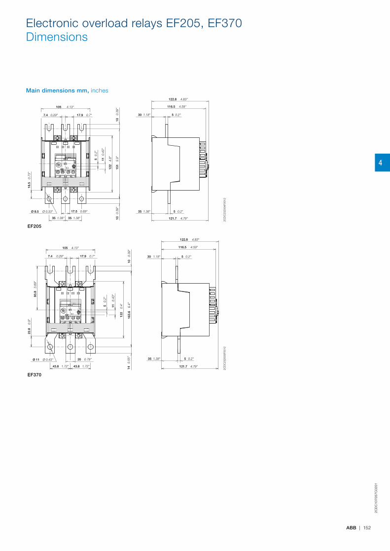
Electronic overload relays EF205, EF370Dimensions
Main dimensions mm, inches
105
7.4 17.9
18.5
5 11
122
151
10
17.5
35
Ø 8.5
10
30 5
116.5
122.8
5 35
121.7 35
4.13"
0.29" 0.7"
0.73
"
0.2"
0.43
"
4.8"
5.9"
0.39
"1.18" 0.2"
4.59"
4.83"
0.69"
1.38"
Ø 0.33" 0.39
"
1.38"
0.2"1.38"
4.79"
2CD
C23
2004
F001
2EF205
122.8 4.83"
30 1.18"
116.5 4.59"
5 0.2"
35 1.38" 5 0.2"
121.7 4.79"
14
0.55
"16
3.6
6.
4"10
0.
39"
22.8
0.
9"
93.8
3.
69"
7.4 0.29"
105 4.13"
17.9 0.7"
20 0.79"
43.8 1.72"43.8 1.72"
Ø 11 Ø 0.43"
11
0.43
"
122
0.
4'5 0
.2"
2CD
C23
2005
F001
2
EF3702C
DC
1070
57C
0201
ABB | 152
4

153 | ABB
1SB
C10
027
9S
02
01
5

ABB | 154
1SB
C10
027
9S
02
01
General technical data
General technical data
Coordination with short-circuit protection devices 155
Terms and technical definitions 156
Standards and utilization categories 158
Degrees of protection 160
5
155 | ABB
1SB
C10
027
9S
02
01
Coordination with short-circuit protection devices
In compliance with standards IEC 60947-4-1, we define for the contactors and starters the type, rating and characteristics of the short-circuit protection devices SCPD which allow selective protection against overloads and ensure protection against short circuits.
Basic functionsAny starter is designed to: – start motors, – ensure continuous functioning of motors, – disconnect motors from the supply line, – guarantee protection of motors against overloads.
The starter is typically made up of a switching device (contactor) and an overload protection device (thermal overload relay or electronic overload relay).These two devices MUST be coordinated with equipment capable of providing protection against short circuit (SCPD: short circuit protective device): typically a circuit breaker with magnetic release only or a switch fuse. These are not necessarily part of the starter.
Applicable standardsIEC 60947-4-1 (EN 60947-4-1) precisely defines the different points to be considered in order to carry out correct coordination.Complete coordination for a combination includes the following points: – Selectivity test between the overload relay and the short-circuit protection device SCPD. – Short-circuit condition tests:
- at prospective "r" currents - These currents depend on the rated operational current of the starter (Ie AC-3) and are given by the standard (Table 13). For example: r = 1kA for Ie AC-3 < 16 A r = 3 kA for 16 A < Ie AC-3 < 63 A r = 5 kA for 63 A < Ie AC-3 < 125 A etc.
- at the rated conditional short-circuit current "Iq" - This is the maximum prospective current that the combination can withstand, for example 50 kA.
Types of coordinationIEC 60947-4-1 (EN 60947-4-1) defines two types of coordination according to the expected level of service continuity. Acceptable extreme damage for the switchgear is divided into two types.Type 1: In short-circuit conditions, the contactor or starter does not endanger persons or installations and will not be able to then operate without being repaired or having parts replaced.Type 2: In short-circuit conditions, the contactor or starter does not endanger persons or installations and will be able to operate afterwards. The risk of contacts light welding is acceptable. In this case, the manufacturer must stipulate the measures to be taken with respect to maintenance of the equipment.
The complete ABB offerABB has acquired years of experience with respect to problems of coordination and is able to make a complete offer based on tests performed in its qualified laboratories. This offer includes 400 V, 500 V, 690 V networks.A complete data base of coordination tables, according to IEC 60947-4-1 (EN 60947-4-1), is available on the ABB Website.In the coordination tables the following short-circuit protection devices are recommended: – Moulded case circuit-breakers (MCCBs) – Miniature circuit-breakers (MCBs) – Switch-disconnector-fuses (aM, gG and BS) – Manual Motor Starters (MMS).
General remarks applicable to all tables – Each table is defined for a maximum ambient temperature of 40 °C. For higher temperatures, apply a derating factor according to the following rules: - Fuses: factor of 0.8 applied to In for an ambient temperature of 70 °C - MCCBs and MCBs: factor of 0.8 applied to In for an ambient temperature of 60 °C - The starter derating factor depends on the operating conditions of thermal overload relays: Factor of 0.9 applied to In for an ambient temperature of 70 °C.
– Each table is defined for motor currents: 3-phase motors, 4-pole – Normal starting means a starting time < 2 s. - Difficult starting means an accelerating time 10 s < ts < 30 s Tripping classes of thermal overload relays according to IEC 60947-4-1 (EN 60947-4-1): 10A and 10 Tripping classes of electronic overload relays according to IEC 60947-4-1 (EN 60947-4-1): 10E, 20E, 30E selectable
– In the tables with MCCBs, these are fitted with the magnetic relay alone. Setting is always carried out at > 12.3 Ie AC-3 so that the transient current peak occurring during starting does not lead to tripping.
5
ABB | 156
1SB
C10
027
9S
02
01
Circuits – auxiliary circuit: All the conductive parts of a contactor designed to be inserted in a different circuit from the main circuit and the contactor control circuits.
– control circuit: All the conductive parts of a contactor (other than the main circuit and the auxiliary circuit) used to control the contactor's closing operation or opening operation or both.
– main circuit: All the conductive parts of a contactor designed to be inserted in the circuit that it controls.
Thermal overload relay tripping classesIEC 60947-4-1 defines tripping classes 10 A, 10, 20 and 30. Types 10 A, 10, etc. correspond to the maximum tripping time for a making current at 7.2 times the setting current.Furthermore, for each class the standard specifies the tripping time for 1.5 times the setting current and sets the non tripping condition at 1.05 times the setting current.All these data are summarized in the table below.
Extract from IEC 60947-4-1:
Tripping class 10 A 10 20 30Max. tripping time for 1.5 times
the setting current (warm state) s 120 240 480 720
Tripping time for 7.2 times
the setting current (cold state) s 2 - 10 4 - 10 6 - 20 9 - 30
For 1.05 times the setting current No tripping
Electromagnetic compatibilityAF... contactors comply with IEC 60947-1, 60947-4-1 and EN 60947-1, 60947-4-1 standards.Definitions:Environment A: "Mainly relates to low-voltage non public or industrial networks/locations/installations (EN 50082-2 article 4) including highly disturbing sources".Environment B: "Mainly relates to low-voltage public networks (EN 50082-1 article 5) such as residential, commercial and light industrial locations/installations. Highly disturbing sources such as arc welders are not covered by this environment".Notice for AF09 ... AF38, AF116 ... AF2650 contactors and NF contactor relays: these products have been designed for environment A. Use of this product in environment B may cause unwanted electromagnetic disturbances in wich case the user may be required to take adequate mitigation measures.AF40 ... AF96 have been designed for environment B.
Definitions according to SEMI F47-0706SEMIF47-0706 defines the voltage sag immunity required for semiconductor processing, metrology and automated test equipment, and on subsystems and components which are used in the construction of semiconductor processing equipment including but not limited to: – Power supplies – Generators – Robots and factory interface – Chillers, pumps, blowers – AC operated contactors and contactor relays – voltage sag: an rms reduction in the AC voltage, at the power frequency, for durations from a half cycle to a few seconds.
The IEC terminology for this phenomenon is voltage dip.voltage sag immunity: the ability of equipment to withstand momentary electrical power interruptions or sags
Coordination of protections against short circuitThe goal here is to protect electromechanical starters and softstarters.Any starter is designed to: – start motors, – ensure continuous functioning of motors, – disconnect motors from the supply line, – guarantee protection of motors against overloads.
The starter is typically made up of a switching device (contactor) and an overload protection device (thermal overload relay or electronic overload relay). These two devices MUST be coordinated with equipment capable of providing protection against short circuit (SCPD: short circuit protective device): typically a circuit breaker with magnetic release only or a switch fuse. These are not necessarily part of the starter.The characteristics of the starter must comply with the international standard IEC 60947-4-1 which defines the above items as follows:contactor: a mechanical switching device having only one position of rest, operated otherwise than by hand, capable of making, carrying and breaking currents under normal circuit conditions including overload conditions.overload release: overload relay or release which operates in the case of overload and also in case of loss of phase.circuit-breaker: defined by IEC 60947-2 as a mechanical switching device, capable of making, carrying and breaking currents under normal circuit conditions and also making, carrying for a specified time and breaking currents under specified abnormal circuit conditions.IEC publication 60947-4-1 defines coordination types "1" and "2": – Type "1" coordination requires that, in the event of a short-circuit, the contactor or starter does not endanger persons or installations and will not then be able to operate without being repaired or parts being replaced.
– Type "2" coordination requires that, in short-circuit conditions, the contactor or starter does not endanger persons or installations and will be able to operate afterwards. The risk of contacts being light welded is acceptable. In this case, the manufacturer must stipulate the measures to be taken with respect to maintenance of the equipment.
Rated operational current Ie.Current rated by the manufacturer. It is mainly based on the rated operational voltage Ue, the rated frequency, the utilization category, the rated duty and the type of protective enclosure, if necessary.
Conventional free air thermal current IthCurrent that the contactor can withstand in free air for a duty time of 8 hours without the temperature rise of its various parts exceeding the maximum values given by the standard.
Operating cycle or cycleIncludes one making operation and one breaking operation.
Cycle timeThis is the sum of the current flow time and the no-current time for given cycle.
Electrical durabilityNumber of on-load operating cycles that the contactor is able to carry out. It depends on the operational current, the operational voltage and the utilization category.
Terms and technical definitions
5
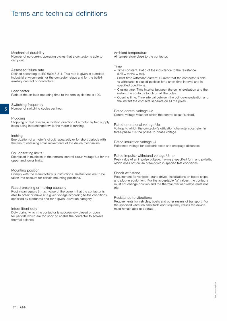
157 | ABB
1SB
C10
027
9S
02
01
Terms and technical definitions
Mechanical durabilityNumber of no-current operating cycles that a contactor is able to carry out.
Assessed failure rateDefined according to IEC 60947-5-4. This rate is given in standard industrial environments for the contactor relays and for the built-in auxiliary contact of contactors.
Load factorRatio of the on-load operating time to the total cycle time x 100.
Switching frequency Number of switching cycles per hour.
PluggingStopping or fast reversal in rotation direction of a motor by two supply leads being interchanged while the motor is running.
InchingEnergization of a motor's circuit repeatedly or for short periods with the aim of obtaining small movements of the driven mechanism.
Coil operating limitsExpressed in multiples of the nominal control circuit voltage Uc for the upper and lower limits.
Mounting positionComply with the manufacturer's instructions. Restrictions are to be taken into account for certain mounting positions.
Rated breaking or making capacityRoot mean square (r.m.s.) value of the current that the contactor is able to break or make at a given voltage according to the conditions specified by standards and for a given utilization category.
Intermittent dutyDuty during which the contactor is successively closed or open for periods which are too short to enable the contactor to achieve thermal balance.
Ambient temperatureAir temperature close to the contactor.
Time – Time constant: Ratio of the inductance to the resistance (L/R = mH/Ω = ms).
– Short-time withstand current: Current that the contactor is able to withstand in closed position for a short time interval and in specified conditions.
– Closing time: Time interval between the coil energization and the instant the contacts touch on all the poles.
– Opening time: Time interval between the coil de-energization and the instant the contacts separate on all the poles.
Rated control voltage UcControl voltage value for which the control circuit is sized.
Rated operational voltage UeVoltage to which the contactor's utilization characteristics refer. In three-phase it is the phase-to-phase voltage.
Rated insulation voltage UiReference voltage for dielectric tests and creepage distances.
Rated impulse withstand voltage UimpPeak value of an impulse voltage, having a specified form and polarity, which does not cause breakdown in specific test conditions.
Shock withstandRequirement for vehicles, crane drives, installations on board ships and plug-in equipment. For the acceptable "g" values, the contacts must not change position and the thermal overload relays must not trip.
Resistance to vibrationsRequirements for vehicles, boats and other means of transport. For the specified vibration amplitude and frequency values the device must remain able to operate.
5
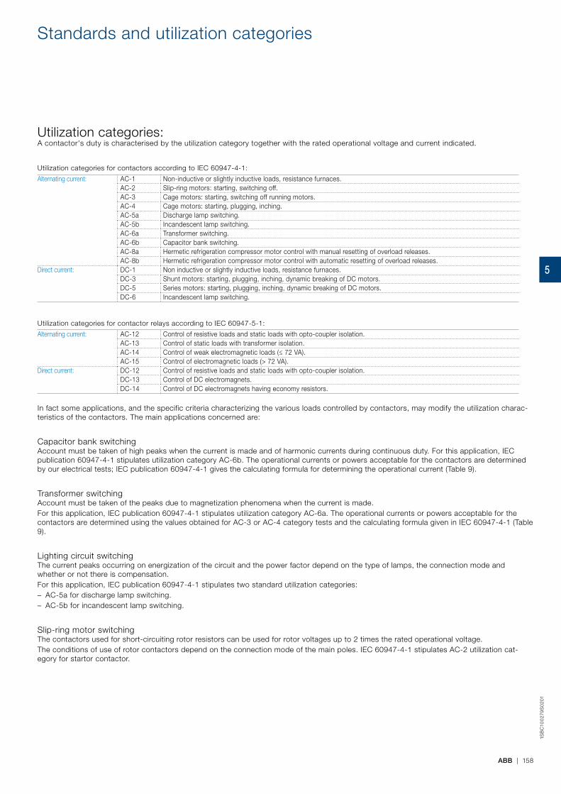
ABB | 158
1SB
C10
027
9S
02
01
Standards and utilization categories
Utilization categories:A contactor's duty is characterised by the utilization category together with the rated operational voltage and current indicated.
Utilization categories for contactors according to IEC 60947-4-1:
Alternating current: AC-1 Non-inductive or slightly inductive loads, resistance furnaces.AC-2 Slip-ring motors: starting, switching off.AC-3 Cage motors: starting, switching off running motors.AC-4 Cage motors: starting, plugging, inching.AC-5a Discharge lamp switching.AC-5b Incandescent lamp switching.AC-6a Transformer switching.AC-6b Capacitor bank switching.AC-8a Hermetic refrigeration compressor motor control with manual resetting of overload releases.AC-8b Hermetic refrigeration compressor motor control with automatic resetting of overload releases.
Direct current: DC-1 Non inductive or slightly inductive loads, resistance furnaces.DC-3 Shunt motors: starting, plugging, inching, dynamic breaking of DC motors.DC-5 Series motors: starting, plugging, inching, dynamic breaking of DC motors.DC-6 Incandescent lamp switching.
Utilization categories for contactor relays according to IEC 60947-5-1:
Alternating current: AC-12 Control of resistive loads and static loads with opto-coupler isolation.AC-13 Control of static loads with transformer isolation.AC-14 Control of weak electromagnetic loads (≤ 72 VA).AC-15 Control of electromagnetic loads (> 72 VA).
Direct current: DC-12 Control of resistive loads and static loads with opto-coupler isolation.DC-13 Control of DC electromagnets.DC-14 Control of DC electromagnets having economy resistors.
In fact some applications, and the specific criteria characterizing the various loads controlled by contactors, may modify the utilization charac-teristics of the contactors. The main applications concerned are:
Capacitor bank switchingAccount must be taken of high peaks when the current is made and of harmonic currents during continuous duty. For this application, IEC publication 60947-4-1 stipulates utilization category AC-6b. The operational currents or powers acceptable for the contactors are determined by our electrical tests; IEC publication 60947-4-1 gives the calculating formula for determining the operational current (Table 9).
Transformer switchingAccount must be taken of the peaks due to magnetization phenomena when the current is made.For this application, IEC publication 60947-4-1 stipulates utilization category AC-6a. The operational currents or powers acceptable for the contactors are determined using the values obtained for AC-3 or AC-4 category tests and the calculating formula given in IEC 60947-4-1 (Table 9).
Lighting circuit switchingThe current peaks occurring on energization of the circuit and the power factor depend on the type of lamps, the connection mode and whether or not there is compensation.For this application, IEC publication 60947-4-1 stipulates two standard utilization categories: – AC-5a for discharge lamp switching. – AC-5b for incandescent lamp switching.
Slip-ring motor switchingThe contactors used for short-circuiting rotor resistors can be used for rotor voltages up to 2 times the rated operational voltage.The conditions of use of rotor contactors depend on the connection mode of the main poles. IEC 60947-4-1 stipulates AC-2 utilization cat-egory for startor contactor.
5

159 | ABB
1SB
C10
027
9S
02
01
Standards and utilization categories
Utilization categories (cont.)DC power circuit switchingArc suppression is more difficult in direct current than in alternating current. Higher the time constant and voltage, heavier the breaking conditions: consequently several poles have to be connected in series.
AC high current circuit switchingPossibility of increasing performances by connecting poles in parallel.
Circuit switching during temporary and intermittent dutyIn these cases higher operational currents are acceptable.
Influence of the length of the conductors used in the contactor control circuitAccording to the operational voltages, the cross-sectional areas, the coil consumption and the control layout, difficulties due to line resistances and capacitances may appear during contactor closing and opening orders.
Making and breaking conditions for utilization categoriesUtilization category Durability test conditions Occasional operation
Making and breaking capacities - 50 operating cyclesMaking conditions Breaking conditions Making conditions Breaking conditionsI/Ie U/Ue Cos. ϕ
or
L/R (ms)
I/Ie U/Ue Cos. ϕ
or
L/R (ms)
Ic/Ie Ur/Ue Cos. ϕ
or
L/R (ms)
Ic/Ie Ur/Ue Cos. ϕ
or
L/R (ms)
Contactors for AC circuit switchingAC-1 1 1 0.95 1 1 0.95 1.5 1.05 0.8 1.5 1.05 0.8AC-2 2.5 1 0.65 2.5 1 0.65 4 1.05 0.65 4 1.05 0.65AC-3 Ie < 17 A 6 1 0.65 1 0.17 0.65 10 1.05 0.45 8 1.05 0.45
17 < Ie < 100 A 6 1 0.35 1 0.17 0.35 10 1.05 0.45 8 1.05 0.45 Ie > 100 A 6 1 0.35 1 0.17 0.35 10 1.05 0.35 8 1.05 0.35
AC-4 Ie < 17 A 6 1 0.65 6 1 0.65 12 1.05 0.45 10 1.05 0.4517 < Ie < 100 A 6 1 0.35 6 1 0.35 12 1.05 0.45 10 1.05 0.45 Ie > 100 A 6 1 0.35 6 1 0.35 12 1.05 0.35 10 1.05 0.35
Contactors for DC circuit switchingDC-1 1 1 1 1 1 1 1.5 1.05 1 1.5 1.05 1DC-3 2.5 1 2 2.5 1 2 4 1.05 2.5 4 1.05 2.5DC-5 2.5 1 7.5 2.5 1 7.5 4 1.05 15 4 1.05 15
Contactor relays for AC circuit switchingAC-14 (≤ 72 VA) – – – – – – 6 1.1 0.7 6 1.1 0.7AC-15 (> 72 VA) 10 1 0.7 1 1 0.4 10 1.1 0.3 10 1.1 0.3
Contactor relays for AC circuit switchingUtilization category Standard operation Occasional operation
Making and breaking capacities - 50 operating cyclesMaking conditions Breaking conditions Making conditions Breaking conditionsI/Ie U/Ue T0.95 I/Ie U/Ue T0.95 Ic/Ie Ur/Ue T0.95 Ic/Ie Ur/Ue T0.95
DC-13 1 1 6 P(1) 1 1 6 P(1) 1.1 1.1 6 P(1) 1.1 1.1 6 P(1)DC-14 – – – – – – 10 1.1 15 ms 10 1.1 15 ms
(1) The value "6 x P" is the result of an empirical relation which is estimated to represent most DC magnetic loads up to the highest limit of P = 50 W (6 x P = 300 ms). It is accepted that loads having drawn energy above 50 W are made up of weaker loads in parallel. As a consequence, the 300 ms value must form the highest limit whatever the value of the power drawn.
Key:U (I) = applied voltage (current)Ur = recovery voltageL/R = test circuit time constantUe (Ie) = rated operational voltage (current)Ic = making and breaking current expressed in DC or in AC like
the r.m.s. value of the symmetrical components
T0.95 = time required to reach 95% of the current in steady-state conditions, expressed in milliseconds
5
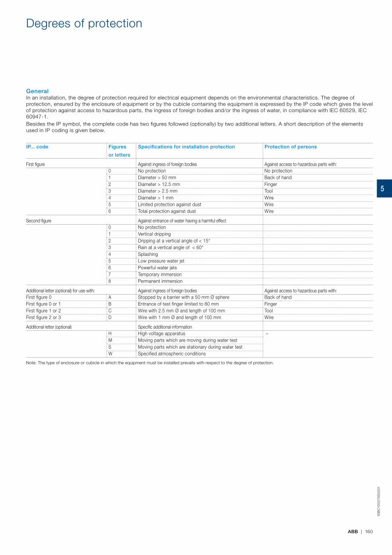
ABB | 160
1SB
C10
027
9S
02
01
Degrees of protection
GeneralIn an installation, the degree of protection required for electrical equipment depends on the environmental characteristics. The degree of protection, ensured by the enclosure of equipment or by the cubicle containing the equipment is expressed by the IP code which gives the level of protection against access to hazardous parts, the ingress of foreign bodies and/or the ingress of water, in compliance with IEC 60529, IEC 60947-1.Besides the IP symbol, the complete code has two figures followed (optionally) by two additional letters. A short description of the elements used in IP coding is given below.
IP... code Figures
or letters
Specifications for installation protection Protection of persons
First figure Against ingress of foreign bodies Against access to hazardous parts with:0 No protection No protection1 Diameter > 50 mm Back of hand2 Diameter > 12.5 mm Finger3 Diameter > 2.5 mm Tool4 Diameter > 1 mm Wire5 Limited protection against dust Wire6 Total protection against dust Wire
Second figure Against entrance of water having a harmful effect0 No protection1 Vertical dripping2 Dripping at a vertical angle of < 15°3 Rain at a vertical angle of < 60° 4 Splashing5 Low pressure water jet6 Powerful water jets7 Temporary immersion8 Permanent immersion
Additional letter (optional) for use with: Against ingress of foreign bodies Against access to hazardous parts with:First figure 0 A Stopped by a barrier with a 50 mm Ø sphere Back of handFirst figure 0 or 1 B Entrance of test finger limited to 80 mm FingerFirst figure 1 or 2 C Wire with 2.5 mm Ø and length of 100 mm ToolFirst figure 2 or 3 D Wire with 1 mm Ø and length of 100 mm Wire
Additional letter (optional) Specific additional informationH High voltage apparatus –M Moving parts which are moving during water testS Moving parts which are stationary during water testW Specified atmospheric conditions
Note: The type of enclosure or cubicle in which the equipment must be installed prevails with respect to the degree of protection.
5
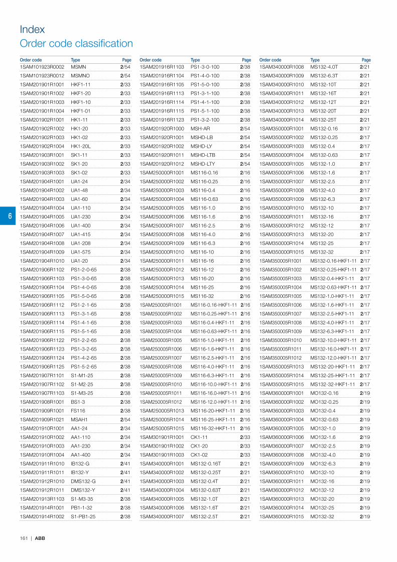
IndexOrder code classificationOrder code Type Page Order code Type Page Order code Type Page
6
161 | ABB
1SAM101923R0002 MSMN 2/54
1SAM101923R0012 MSMNO 2/54
1SAM201901R1001 HKF1-11 2/33
1SAM201901R1002 HKF1-20 2/33
1SAM201901R1003 HKF1-10 2/33
1SAM201901R1004 HKF1-01 2/33
1SAM201902R1001 HK1-11 2/33
1SAM201902R1002 HK1-20 2/33
1SAM201902R1003 HK1-02 2/33
1SAM201902R1004 HK1-20L 2/33
1SAM201903R1001 SK1-11 2/33
1SAM201903R1002 SK1-20 2/33
1SAM201903R1003 SK1-02 2/33
1SAM201904R1001 UA1-24 2/34
1SAM201904R1002 UA1-48 2/34
1SAM201904R1003 UA1-60 2/34
1SAM201904R1004 UA1-110 2/34
1SAM201904R1005 UA1-230 2/34
1SAM201904R1006 UA1-400 2/34
1SAM201904R1007 UA1-415 2/34
1SAM201904R1008 UA1-208 2/34
1SAM201904R1009 UA1-575 2/34
1SAM201904R1010 UA1-20 2/34
1SAM201906R1102 PS1-2-0-65 2/38
1SAM201906R1103 PS1-3-0-65 2/38
1SAM201906R1104 PS1-4-0-65 2/38
1SAM201906R1105 PS1-5-0-65 2/38
1SAM201906R1112 PS1-2-1-65 2/38
1SAM201906R1113 PS1-3-1-65 2/38
1SAM201906R1114 PS1-4-1-65 2/38
1SAM201906R1115 PS1-5-1-65 2/38
1SAM201906R1122 PS1-2-2-65 2/38
1SAM201906R1123 PS1-3-2-65 2/38
1SAM201906R1124 PS1-4-2-65 2/38
1SAM201906R1125 PS1-5-2-65 2/38
1SAM201907R1101 S1-M1-25 2/38
1SAM201907R1102 S1-M2-25 2/38
1SAM201907R1103 S1-M3-25 2/38
1SAM201908R1001 BS1-3 2/38
1SAM201909R1001 FS116 2/38
1SAM201909R1021 MSAH1 2/54
1SAM201910R1001 AA1-24 2/34
1SAM201910R1002 AA1-110 2/34
1SAM201910R1003 AA1-230 2/34
1SAM201910R1004 AA1-400 2/34
1SAM201911R1010 IB132-G 2/41
1SAM201911R1011 IB132-Y 2/41
1SAM201912R1010 DMS132-G 2/41
1SAM201912R1011 DMS132-Y 2/41
1SAM201913R1103 S1-M3-35 2/38
1SAM201914R1001 PB1-1-32 2/38
1SAM201914R1002 S1-PB1-25 2/38
1SAM201916R1103 PS1-3-0-100 2/38
1SAM201916R1104 PS1-4-0-100 2/38
1SAM201916R1105 PS1-5-0-100 2/38
1SAM201916R1113 PS1-3-1-100 2/38
1SAM201916R1114 PS1-4-1-100 2/38
1SAM201916R1115 PS1-5-1-100 2/38
1SAM201916R1123 PS1-3-2-100 2/38
1SAM201920R1000 MSH-AR 2/54
1SAM201920R1001 MSHD-LB 2/54
1SAM201920R1002 MSHD-LY 2/54
1SAM201920R1011 MSHD-LTB 2/54
1SAM201920R1012 MSHD-LTY 2/54
1SAM250000R1001 MS116-0.16 2/16
1SAM250000R1002 MS116-0.25 2/16
1SAM250000R1003 MS116-0.4 2/16
1SAM250000R1004 MS116-0.63 2/16
1SAM250000R1005 MS116-1.0 2/16
1SAM250000R1006 MS116-1.6 2/16
1SAM250000R1007 MS116-2.5 2/16
1SAM250000R1008 MS116-4.0 2/16
1SAM250000R1009 MS116-6.3 2/16
1SAM250000R1010 MS116-10 2/16
1SAM250000R1011 MS116-16 2/16
1SAM250000R1012 MS116-12 2/16
1SAM250000R1013 MS116-20 2/16
1SAM250000R1014 MS116-25 2/16
1SAM250000R1015 MS116-32 2/16
1SAM250005R1001 MS116-0.16-HKF1-11 2/16
1SAM250005R1002 MS116-0.25-HKF1-11 2/16
1SAM250005R1003 MS116-0.4-HKF1-11 2/16
1SAM250005R1004 MS116-0.63-HKF1-11 2/16
1SAM250005R1005 MS116-1.0-HKF1-11 2/16
1SAM250005R1006 MS116-1.6-HKF1-11 2/16
1SAM250005R1007 MS116-2.5-HKF1-11 2/16
1SAM250005R1008 MS116-4.0-HKF1-11 2/16
1SAM250005R1009 MS116-6.3-HKF1-11 2/16
1SAM250005R1010 MS116-10.0-HKF1-11 2/16
1SAM250005R1011 MS116-16.0-HKF1-11 2/16
1SAM250005R1012 MS116-12.0-HKF1-11 2/16
1SAM250005R1013 MS116-20-HKF1-11 2/16
1SAM250005R1014 MS116-25-HKF1-11 2/16
1SAM250005R1015 MS116-32-HKF1-11 2/16
1SAM301901R1001 CK1-11 2/33
1SAM301901R1002 CK1-20 2/33
1SAM301901R1003 CK1-02 2/33
1SAM340000R1001 MS132-0.16T 2/21
1SAM340000R1002 MS132-0.25T 2/21
1SAM340000R1003 MS132-0.4T 2/21
1SAM340000R1004 MS132-0.63T 2/21
1SAM340000R1005 MS132-1.0T 2/21
1SAM340000R1006 MS132-1.6T 2/21
1SAM340000R1007 MS132-2.5T 2/21
1SAM340000R1008 MS132-4.0T 2/21
1SAM340000R1009 MS132-6.3T 2/21
1SAM340000R1010 MS132-10T 2/21
1SAM340000R1011 MS132-16T 2/21
1SAM340000R1012 MS132-12T 2/21
1SAM340000R1013 MS132-20T 2/21
1SAM340000R1014 MS132-25T 2/21
1SAM350000R1001 MS132-0.16 2/17
1SAM350000R1002 MS132-0.25 2/17
1SAM350000R1003 MS132-0.4 2/17
1SAM350000R1004 MS132-0.63 2/17
1SAM350000R1005 MS132-1.0 2/17
1SAM350000R1006 MS132-1.6 2/17
1SAM350000R1007 MS132-2.5 2/17
1SAM350000R1008 MS132-4.0 2/17
1SAM350000R1009 MS132-6.3 2/17
1SAM350000R1010 MS132-10 2/17
1SAM350000R1011 MS132-16 2/17
1SAM350000R1012 MS132-12 2/17
1SAM350000R1013 MS132-20 2/17
1SAM350000R1014 MS132-25 2/17
1SAM350000R1015 MS132-32 2/17
1SAM350005R1001 MS132-0.16-HKF1-11 2/17
1SAM350005R1002 MS132-0.25-HKF1-11 2/17
1SAM350005R1003 MS132-0.4-HKF1-11 2/17
1SAM350005R1004 MS132-0.63-HKF1-11 2/17
1SAM350005R1005 MS132-1.0-HKF1-11 2/17
1SAM350005R1006 MS132-1.6-HKF1-11 2/17
1SAM350005R1007 MS132-2.5-HKF1-11 2/17
1SAM350005R1008 MS132-4.0-HKF1-11 2/17
1SAM350005R1009 MS132-6.3-HKF1-11 2/17
1SAM350005R1010 MS132-10.0-HKF1-11 2/17
1SAM350005R1011 MS132-16.0-HKF1-11 2/17
1SAM350005R1012 MS132-12.0-HKF1-11 2/17
1SAM350005R1013 MS132-20-HKF1-11 2/17
1SAM350005R1014 MS132-25-HKF1-11 2/17
1SAM350005R1015 MS132-32-HKF1-11 2/17
1SAM360000R1001 MO132-0.16 2/19
1SAM360000R1002 MO132-0.25 2/19
1SAM360000R1003 MO132-0.4 2/19
1SAM360000R1004 MO132-0.63 2/19
1SAM360000R1005 MO132-1.0 2/19
1SAM360000R1006 MO132-1.6 2/19
1SAM360000R1007 MO132-2.5 2/19
1SAM360000R1008 MO132-4.0 2/19
1SAM360000R1009 MO132-6.3 2/19
1SAM360000R1010 MO132-10 2/19
1SAM360000R1011 MO132-16 2/19
1SAM360000R1012 MO132-12 2/19
1SAM360000R1013 MO132-20 2/19
1SAM360000R1014 MO132-25 2/19
1SAM360000R1015 MO132-32 2/19
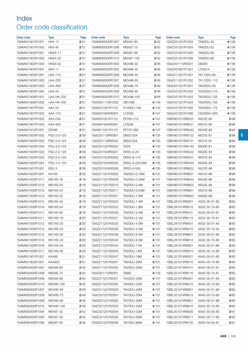
IndexOrder code classificationOrder code Type Page Order code Type Page Order code Type Page
6
ABB | 162
1SAM401901R1001 HK4-11 2/51
1SAM401901R1002 HK4-W 2/51
1SAM401902R1001 HKS4-11 2/51
1SAM401902R1002 HKS4-20 2/51
1SAM401902R1003 HKS4-02 2/51
1SAM401904R1001 SK4-11 2/51
1SAM401905R1001 UA4-110 2/51
1SAM401905R1002 UA4-230 2/51
1SAM401905R1003 UA4-400 2/51
1SAM401905R1004 UA4-24 2/51
1SAM401906R1001 UA4-HK-230 2/51
1SAM401906R1002 UA4-HK-400 2/51
1SAM401907R1001 AA4-24 2/51
1SAM401907R1002 AA4-110 2/51
1SAM401907R1003 AA4-230 2/51
1SAM401907R1004 AA4-400 2/51
1SAM401912R1001 DX495 2/51
1SAM401920R1002 PS2-2-0-125 2/39
1SAM401920R1003 PS2-3-0-125 2/39
1SAM401920R1004 PS2-4-0-125 2/39
1SAM401920R1022 PS2-2-2-125 2/39
1SAM401920R1023 PS2-3-2-125 2/39
1SAM401920R1024 PS2-4-2-125 2/39
1SAM401921R1001 BS2-3 2/39
1SAM401922R1001 KA165 2/39
1SAM451000R1011 MS165-16 2/18
1SAM451000R1012 MS165-20 2/18
1SAM451000R1013 MS165-25 2/18
1SAM451000R1014 MS165-32 2/18
1SAM451000R1015 MS165-42 2/18
1SAM451000R1016 MS165-54 2/18
1SAM451000R1017 MS165-65 2/18
1SAM461000R1011 MO165-16 2/20
1SAM461000R1012 MO165-20 2/20
1SAM461000R1013 MO165-25 2/20
1SAM461000R1014 MO165-32 2/20
1SAM461000R1015 MO165-42 2/20
1SAM461000R1016 MO165-54 2/20
1SAM461000R1017 MO165-65 2/20
1SAM501901R1001 KA495 2/51
1SAM501902R1001 KA495C 2/51
1SAM550000R1007 MS495-63 2/42
1SAM550000R1008 MS495-75 2/42
1SAM550000R1009 MS495-90 2/42
1SAM550000R1010 MS495-100 2/42
1SAM560000R1007 MO495-63 2/46
1SAM560000R1008 MO495-75 2/46
1SAM560000R1009 MO495-90 2/46
1SAM560000R1010 MO495-100 2/46
1SAM580000R1004 MS497-32 2/42
1SAM580000R1005 MS497-40 2/42
1SAM580000R1006 MS497-50 2/42
1SAM580000R1007 MS497-63 2/42
1SAM580000R1008 MS497-75 2/42
1SAM580000R1009 MS497-90 2/42
1SAM580000R1010 MS497-100 2/42
1SAM590000R1004 MO496-32 2/46
1SAM590000R1005 MO496-40 2/46
1SAM590000R1006 MO496-50 2/46
1SAM590000R1007 MO496-63 2/46
1SAM590000R1008 MO496-75 2/46
1SAM590000R1009 MO496-90 2/46
1SAM590000R1010 MO496-100 2/46
1SAX301110R1002 DB140E 4/146
1SAX321001R1101 E140DU-140 4/142
1SAX501904R0001 LT200E 4/147
1SAX531001R1101 EF205-210 4/147
1SAX601904R0001 LT320E 4/147
1SAX611001R1101 EF370-380 4/147
1SAZ201108R0001 DB25/25A 4/135
1SAZ201108R0002 DB25/32A 4/135
1SAZ201307R0002 DX25 4/135
1SAZ201504R0001 DR25-A-24 4/135
1SAZ201504R0003 DR25-A-110 4/135
1SAZ201504R0005 DR25-A-220/380 4/135
1SAZ201504R0006 DR25-A-500 4/135
1SAZ211201R2005 TA25DU-0.16M 4/131
1SAZ211201R2009 TA25DU-0.25M 4/131
1SAZ211201R2013 TA25DU-0.4M 4/131
1SAZ211201R2017 TA25DU-0.63M 4/131
1SAZ211201R2021 TA25DU-1.0M 4/131
1SAZ211201R2023 TA25DU-1.4M 4/131
1SAZ211201R2025 TA25DU-1.8M 4/131
1SAZ211201R2028 TA25DU-2.4M 4/131
1SAZ211201R2031 TA25DU-3.1M 4/131
1SAZ211201R2033 TA25DU-4.0M 4/131
1SAZ211201R2035 TA25DU-5.0M 4/131
1SAZ211201R2038 TA25DU-6.5M 4/131
1SAZ211201R2040 TA25DU-8.5M 4/131
1SAZ211201R2043 TA25DU-11M 4/131
1SAZ211201R2045 TA25DU-14M 4/131
1SAZ211201R2047 TA25DU-19M 4/131
1SAZ211201R2051 TA25DU-25M 4/131
1SAZ211201R2053 TA25DU-32M 4/131
1SAZ301110R0001 DB80 4/135
1SAZ311201R2001 TA42DU-25M 4/131
1SAZ311201R2002 TA42DU-32M 4/131
1SAZ311201R2003 TA42DU-42M 4/131
1SAZ321201R2001 TA75DU-25M 4/131
1SAZ321201R2002 TA75DU-32M 4/131
1SAZ321201R2003 TA75DU-42M 4/131
1SAZ321201R2004 TA75DU-52M 4/131
1SAZ321201R2005 TA75DU-63M 4/131
1SAZ321201R2006 TA75DU-80M 4/131
1SAZ331201R1003 TA80DU-42 4/136
1SAZ331201R1004 TA80DU-52 4/136
1SAZ331201R1005 TA80DU-63 4/136
1SAZ331201R1006 TA80DU-80 4/136
1SAZ401110R0001 DB200 4/136
1SAZ401901R1001 LT200/A 4/136
1SAZ411201R1001 TA110DU-90 4/136
1SAZ411201R1002 TA110DU-110 4/136
1SAZ421201R1001 TA200DU-90 4/136
1SAZ421201R1002 TA200DU-110 4/136
1SAZ421201R1003 TA200DU-135 4/136
1SAZ421201R1004 TA200DU-150 4/136
1SAZ421201R1005 TA200DU-175 4/136
1SAZ421201R1006 TA200DU-200 4/136
1SBH901074R8022 NX22E-80 3/98
1SBH901074R8031 NX31E-80 3/98
1SBH901074R8040 NX40E-80 3/98
1SBH901074R8122 NX22E-81 3/98
1SBH901074R8131 NX31E-81 3/98
1SBH901074R8140 NX40E-81 3/98
1SBH901074R8422 NX22E-84 3/98
1SBH901074R8431 NX31E-84 3/98
1SBH901074R8440 NX40E-84 3/98
1SBH901074R8622 NX22E-86 3/98
1SBH901074R8631 NX31E-86 3/98
1SBH901074R8640 NX40E-86 3/98
1SBH901074R8822 NX22E-88 3/98
1SBH901074R8831 NX31E-88 3/98
1SBH901074R8840 NX40E-88 3/98
1SBL281074R8001 AX32-30-01-80 3/60
1SBL281074R8010 AX32-30-10-80 3/60
1SBL281074R8101 AX32-30-01-81 3/60
1SBL281074R8110 AX32-30-10-81 3/60
1SBL281074R8401 AX32-30-01-84 3/60
1SBL281074R8410 AX32-30-10-84 3/60
1SBL281074R8601 AX32-30-01-86 3/60
1SBL281074R8610 AX32-30-10-86 3/60
1SBL281074R8801 AX32-30-01-88 3/60
1SBL281074R8810 AX32-30-10-88 3/60
1SBL321074R8001 AX40-30-01-80 3/60
1SBL321074R8010 AX40-30-10-80 3/60
1SBL321074R8101 AX40-30-01-81 3/60
1SBL321074R8110 AX40-30-10-81 3/60
1SBL321074R8401 AX40-30-01-84 3/60
1SBL321074R8410 AX40-30-10-84 3/60
1SBL321074R8601 AX40-30-01-86 3/60
1SBL321074R8610 AX40-30-10-86 3/60
1SBL321074R8801 AX40-30-01-88 3/60
1SBL321074R8810 AX40-30-10-88 3/60
1SBL351074R8000 AX50-30-00-80 3/61
1SBL351074R8011 AX50-30-11-80 3/62
1SBL351074R8100 AX50-30-00-81 3/61

IndexOrder code classificationOrder code Type Page Order code Type Page Order code Type Page
6
163 | ABB
1SBL351074R8111 AX50-30-11-81 3/62
1SBL351074R8400 AX50-30-00-84 3/61
1SBL351074R8411 AX50-30-11-84 3/62
1SBL351074R8600 AX50-30-00-86 3/61
1SBL351074R8611 AX50-30-11-86 3/62
1SBL351074R8800 AX50-30-00-88 3/61
1SBL351074R8811 AX50-30-11-88 3/62
1SBL371074R8000 AX65-30-00-80 3/61
1SBL371074R8011 AX65-30-11-80 3/62
1SBL371074R8100 AX65-30-00-81 3/61
1SBL371074R8111 AX65-30-11-81 3/62
1SBL371074R8400 AX65-30-00-84 3/61
1SBL371074R8411 AX65-30-11-84 3/62
1SBL371074R8600 AX65-30-00-86 3/61
1SBL371074R8611 AX65-30-11-86 3/62
1SBL371074R8800 AX65-30-00-88 3/61
1SBL371074R8811 AX65-30-11-88 3/62
1SBL411074R8000 AX80-30-00-80 3/61
1SBL411074R8011 AX80-30-11-80 3/62
1SBL411074R8100 AX80-30-00-81 3/61
1SBL411074R8111 AX80-30-11-81 3/62
1SBL411074R8400 AX80-30-00-84 3/61
1SBL411074R8411 AX80-30-11-84 3/62
1SBL411074R8600 AX80-30-00-86 3/61
1SBL411074R8611 AX80-30-11-86 3/62
1SBL411074R8800 AX80-30-00-88 3/61
1SBL411074R8811 AX80-30-11-88 3/62
1SBL891074R8001 AX06-30-01-80 3/58
1SBL891074R8010 AX06-30-10-80 3/58
1SBL891074R8101 AX06-30-01-81 3/58
1SBL891074R8110 AX06-30-10-81 3/58
1SBL891074R8401 AX06-30-01-84 3/58
1SBL891074R8410 AX06-30-10-84 3/58
1SBL891074R8601 AX06-30-01-86 3/58
1SBL891074R8610 AX06-30-10-86 3/58
1SBL891074R8801 AX06-30-01-88 3/58
1SBL891074R8810 AX06-30-10-88 3/58
1SBL901074R8001 AX09-30-01-80 3/58
1SBL901074R8010 AX09-30-10-80 3/58
1SBL901074R8101 AX09-30-01-81 3/58
1SBL901074R8110 AX09-30-10-81 3/58
1SBL901074R8401 AX09-30-01-84 3/58
1SBL901074R8410 AX09-30-10-84 3/58
1SBL901074R8601 AX09-30-01-86 3/58
1SBL901074R8610 AX09-30-10-86 3/58
1SBL901074R8801 AX09-30-01-88 3/58
1SBL901074R8810 AX09-30-10-88 3/58
1SBL911074R8001 AX12-30-01-80 3/58
1SBL911074R8010 AX12-30-10-80 3/58
1SBL911074R8101 AX12-30-01-81 3/58
1SBL911074R8110 AX12-30-10-81 3/58
1SBL911074R8401 AX12-30-01-84 3/58
1SBL911074R8410 AX12-30-10-84 3/58
1SBL911074R8601 AX12-30-01-86 3/58
1SBL911074R8610 AX12-30-10-86 3/58
1SBL911074R8801 AX12-30-01-88 3/58
1SBL911074R8810 AX12-30-10-88 3/58
1SBL921074R8001 AX18-30-01-80 3/59
1SBL921074R8010 AX18-30-10-80 3/59
1SBL921074R8101 AX18-30-01-81 3/59
1SBL921074R8110 AX18-30-10-81 3/59
1SBL921074R8401 AX18-30-01-84 3/59
1SBL921074R8410 AX18-30-10-84 3/59
1SBL921074R8601 AX18-30-01-86 3/59
1SBL921074R8610 AX18-30-10-86 3/59
1SBL921074R8801 AX18-30-01-88 3/59
1SBL921074R8810 AX18-30-10-88 3/59
1SBL931074R8001 AX25-30-01-80 3/59
1SBL931074R8010 AX25-30-10-80 3/59
1SBL931074R8101 AX25-30-01-81 3/59
1SBL931074R8110 AX25-30-10-81 3/59
1SBL931074R8401 AX25-30-01-84 3/59
1SBL931074R8410 AX25-30-10-84 3/59
1SBL931074R8601 AX25-30-01-86 3/59
1SBL931074R8610 AX25-30-10-86 3/59
1SBL931074R8801 AX25-30-01-88 3/59
1SBL931074R8810 AX25-30-10-88 3/59
1SBN010015R1001 CE5-01D0.1 3/106
1SBN010015R1010 CE5-10D0.1 3/106
1SBN010016R1001 CE5-01W0.1 3/106
1SBN010016R1010 CE5-10W0.1 3/106
1SBN010017R1001 CE5-01D2 3/106
1SBN010017R1010 CE5-10D2 3/106
1SBN010018R1001 CE5-01W2 3/106
1SBN010018R1010 CE5-10W2 3/106
1SBN019010R1001 CA5X-01 3/65
1SBN019010R1010 CA5X-10 3/65
1SBN019020R1011 CAL5X-11 3/65
1SBN019040R1004 CA5X-04E 3/104
1SBN019040R1022 CA5X-22E 3/65
1SBN019040R1031 CA5X-31E 3/104
1SBN019040R1040 CA5X-40E 3/104
1SBN019040R1104 CA5X-04M 3/104
1SBN019040R1113 CA5X-13M 3/104
1SBN019040R1122 CA5X-22M 3/65
1SBN019040R1131 CA5X-31M 3/104
1SBN019040R1204 CA5X-04N 3/104
1SBN019040R1213 CA5X-13N 3/104
1SBN019040R1222 CA5X-22N 3/104
1SBN019040R1231 CA5X-31N 3/104
1SBN019040R1240 CA5X-40N 3/104
1SBN019040R1304 CA5X-04U 3/104
1SBN019040R1322 CA5X-22U 3/104
1SBN019040R1331 CA5X-31U 3/104
1SBN019040R1340 CA5X-40U 3/104
1SBN020312R1000 TEF5-ON 3/66
1SBN020314R1000 TEF5-OFF 3/66
1SBN030100R1000 VM5-1 3/65
1SBN030110R1000 VE5-1 3/65
1SBN030210R1000 VE5-2 3/65
1SBN050010R1000 RV5/50 3/66
1SBN050010R1001 RV5/133 3/66
1SBN050010R1002 RV5/250 3/66
1SBN050010R1003 RV5/440 3/66
1SBN050100R1000 RC5-1/50 3/66
1SBN050100R1001 RC5-1/133 3/66
1SBN050100R1002 RC5-1/250 3/66
1SBN050100R1003 RC5-1/440 3/66
1SBN050200R1000 RC5-2/50 3/66
1SBN050200R1001 RC5-2/133 3/66
1SBN050200R1002 RC5-2/250 3/66
1SBN050200R1003 RC5-2/440 3/66
1SBN060300R1000 RA5-1 3/114
1SBN060300T1000 RA5-1 3/114
1SBN073508R1000 LD75 3/120
1SBN073552R1002 LK75-F 3/121
1SBN081406R1000 BEA16/116 3/66
1SBN081411R1000 BER16V 3/124
1SBN082411R1000 BER40V 3/124
1SBN083501R1000 BEM75-30 3/124
1SBN083504R1000 BES75-30 3/125
1SBN084106R1000 BEA75/495 3/66
1SBN084506R1000 BEA110/495 3/66
1SBN089306T1000 BEA25/116 3/66
1SBN089306T1001 BEA25/132 3/66
1SBN110000R1000 BA5-50 3/121
1SCA101647R1001 OXS6X85 2/54
1SCA101655R1001 OXS6X130 2/54
1SCA101659R1001 OXS6X180 2/54
1SCA108043R1001 OXS6X105 2/54
1SFA616162R1014 KPR-101L 4/135
1SFL431074R8011 AX95-30-11-80 3/63
1SFL431074R8111 AX95-30-11-81 3/63
1SFL431074R8411 AX95-30-11-84 3/63
1SFL431074R8611 AX95-30-11-86 3/63
1SFL431074R8811 AX95-30-11-88 3/63
1SFL491074R8011 AX185-30-11-80 3/67
1SFL491074R8111 AX185-30-11-81 3/67
1SFL491074R8411 AX185-30-11-84 3/67
1SFL491074R8611 AX185-30-11-86 3/67
1SFL491074R8811 AX185-30-11-88 3/67
1SFL501074R8011 AX205-30-11-80 3/67
1SFL501074R8111 AX205-30-11-81 3/67
1SFL501074R8411 AX205-30-11-84 3/67
1SFL501074R8611 AX205-30-11-86 3/67
1SFL501074R8811 AX205-30-11-88 3/67
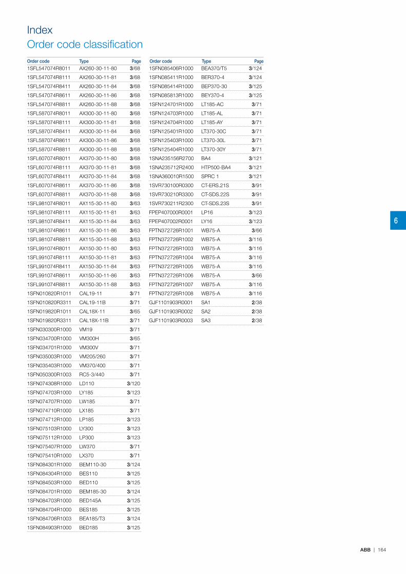
IndexOrder code classificationOrder code Type Page Order code Type Page
6
ABB | 164
1SFL547074R8011 AX260-30-11-80 3/68
1SFL547074R8111 AX260-30-11-81 3/68
1SFL547074R8411 AX260-30-11-84 3/68
1SFL547074R8611 AX260-30-11-86 3/68
1SFL547074R8811 AX260-30-11-88 3/68
1SFL587074R8011 AX300-30-11-80 3/68
1SFL587074R8111 AX300-30-11-81 3/68
1SFL587074R8411 AX300-30-11-84 3/68
1SFL587074R8611 AX300-30-11-86 3/68
1SFL587074R8811 AX300-30-11-88 3/68
1SFL607074R8011 AX370-30-11-80 3/68
1SFL607074R8111 AX370-30-11-81 3/68
1SFL607074R8411 AX370-30-11-84 3/68
1SFL607074R8611 AX370-30-11-86 3/68
1SFL607074R8811 AX370-30-11-88 3/68
1SFL981074R8011 AX115-30-11-80 3/63
1SFL981074R8111 AX115-30-11-81 3/63
1SFL981074R8411 AX115-30-11-84 3/63
1SFL981074R8611 AX115-30-11-86 3/63
1SFL981074R8811 AX115-30-11-88 3/63
1SFL991074R8011 AX150-30-11-80 3/63
1SFL991074R8111 AX150-30-11-81 3/63
1SFL991074R8411 AX150-30-11-84 3/63
1SFL991074R8611 AX150-30-11-86 3/63
1SFL991074R8811 AX150-30-11-88 3/63
1SFN010820R1011 CAL19-11 3/71
1SFN010820R3311 CAL19-11B 3/71
1SFN019820R1011 CAL18X-11 3/65
1SFN019820R3311 CAL18X-11B 3/71
1SFN030300R1000 VM19 3/71
1SFN034700R1000 VM300H 3/65
1SFN034701R1000 VM300V 3/71
1SFN035003R1000 VM205/260 3/71
1SFN035403R1000 VM370/400 3/71
1SFN050300R1003 RC5-3/440 3/71
1SFN074308R1000 LD110 3/120
1SFN074703R1000 LY185 3/123
1SFN074707R1000 LW185 3/71
1SFN074710R1000 LX185 3/71
1SFN074712R1000 LP185 3/123
1SFN075103R1000 LY300 3/123
1SFN075112R1000 LP300 3/123
1SFN075407R1000 LW370 3/71
1SFN075410R1000 LX370 3/71
1SFN084301R1000 BEM110-30 3/124
1SFN084304R1000 BES110 3/125
1SFN084503R1000 BED110 3/125
1SFN084701R1000 BEM185-30 3/124
1SFN084703R1000 BED145A 3/125
1SFN084704R1000 BES185 3/125
1SFN084706R1003 BEA185/T3 3/124
1SFN084903R1000 BED185 3/125
1SFN085406R1000 BEA370/T5 3/124
1SFN085411R1000 BER370-4 3/124
1SFN085414R1000 BEP370-30 3/125
1SFN085813R1000 BEY370-4 3/125
1SFN124701R1000 LT185-AC 3/71
1SFN124703R1000 LT185-AL 3/71
1SFN124704R1000 LT185-AY 3/71
1SFN125401R1000 LT370-30C 3/71
1SFN125403R1000 LT370-30L 3/71
1SFN125404R1000 LT370-30Y 3/71
1SNA235156R2700 BA4 3/121
1SNA235712R2400 HTP500-BA4 3/121
1SNA360010R1500 SPRC 1 3/121
1SVR730100R0300 CT-ERS.21S 3/91
1SVR730210R3300 CT-SDS.22S 3/91
1SVR730211R2300 CT-SDS.23S 3/91
FPEP407000R0001 LP16 3/123
FPEP407002R0001 LY16 3/123
FPTN372726R1001 WB75-A 3/66
FPTN372726R1002 WB75-A 3/116
FPTN372726R1003 WB75-A 3/116
FPTN372726R1004 WB75-A 3/116
FPTN372726R1005 WB75-A 3/116
FPTN372726R1006 WB75-A 3/66
FPTN372726R1007 WB75-A 3/116
FPTN372726R1008 WB75-A 3/116
GJF1101903R0001 SA1 2/38
GJF1101903R0002 SA2 2/38
GJF1101903R0003 SA3 2/38
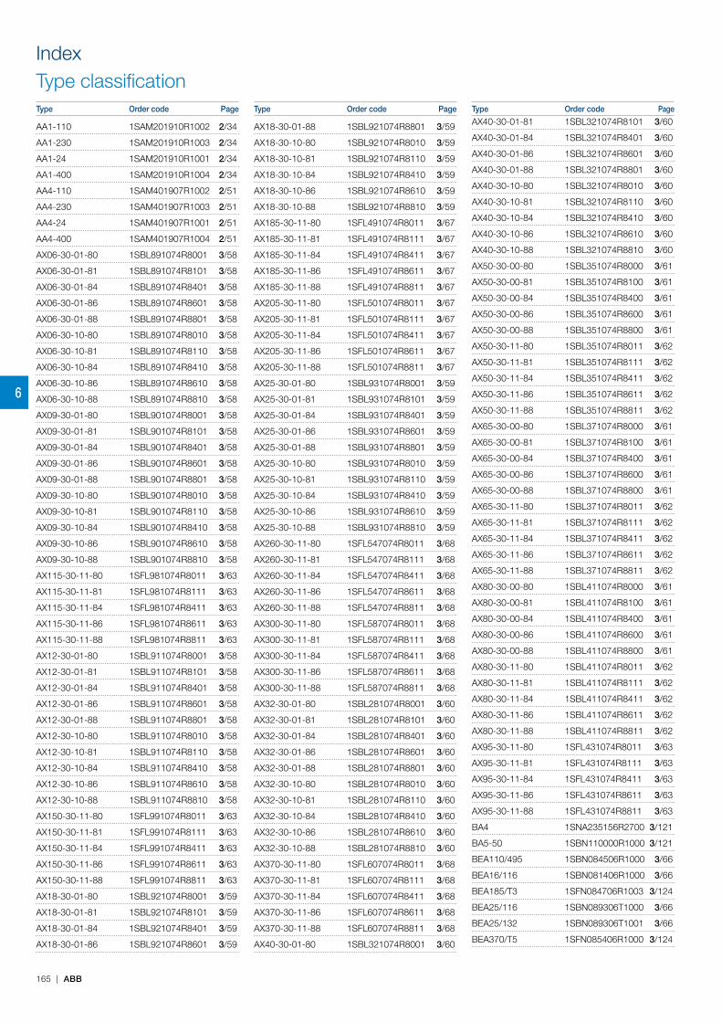
IndexType classificationType Order code Page Type Order code Page Type Order code Page
6
165 | ABB
AA1-110 1SAM201910R1002 2/34
AA1-230 1SAM201910R1003 2/34
AA1-24 1SAM201910R1001 2/34
AA1-400 1SAM201910R1004 2/34
AA4-110 1SAM401907R1002 2/51
AA4-230 1SAM401907R1003 2/51
AA4-24 1SAM401907R1001 2/51
AA4-400 1SAM401907R1004 2/51
AX06-30-01-80 1SBL891074R8001 3/58
AX06-30-01-81 1SBL891074R8101 3/58
AX06-30-01-84 1SBL891074R8401 3/58
AX06-30-01-86 1SBL891074R8601 3/58
AX06-30-01-88 1SBL891074R8801 3/58
AX06-30-10-80 1SBL891074R8010 3/58
AX06-30-10-81 1SBL891074R8110 3/58
AX06-30-10-84 1SBL891074R8410 3/58
AX06-30-10-86 1SBL891074R8610 3/58
AX06-30-10-88 1SBL891074R8810 3/58
AX09-30-01-80 1SBL901074R8001 3/58
AX09-30-01-81 1SBL901074R8101 3/58
AX09-30-01-84 1SBL901074R8401 3/58
AX09-30-01-86 1SBL901074R8601 3/58
AX09-30-01-88 1SBL901074R8801 3/58
AX09-30-10-80 1SBL901074R8010 3/58
AX09-30-10-81 1SBL901074R8110 3/58
AX09-30-10-84 1SBL901074R8410 3/58
AX09-30-10-86 1SBL901074R8610 3/58
AX09-30-10-88 1SBL901074R8810 3/58
AX115-30-11-80 1SFL981074R8011 3/63
AX115-30-11-81 1SFL981074R8111 3/63
AX115-30-11-84 1SFL981074R8411 3/63
AX115-30-11-86 1SFL981074R8611 3/63
AX115-30-11-88 1SFL981074R8811 3/63
AX12-30-01-80 1SBL911074R8001 3/58
AX12-30-01-81 1SBL911074R8101 3/58
AX12-30-01-84 1SBL911074R8401 3/58
AX12-30-01-86 1SBL911074R8601 3/58
AX12-30-01-88 1SBL911074R8801 3/58
AX12-30-10-80 1SBL911074R8010 3/58
AX12-30-10-81 1SBL911074R8110 3/58
AX12-30-10-84 1SBL911074R8410 3/58
AX12-30-10-86 1SBL911074R8610 3/58
AX12-30-10-88 1SBL911074R8810 3/58
AX150-30-11-80 1SFL991074R8011 3/63
AX150-30-11-81 1SFL991074R8111 3/63
AX150-30-11-84 1SFL991074R8411 3/63
AX150-30-11-86 1SFL991074R8611 3/63
AX150-30-11-88 1SFL991074R8811 3/63
AX18-30-01-80 1SBL921074R8001 3/59
AX18-30-01-81 1SBL921074R8101 3/59
AX18-30-01-84 1SBL921074R8401 3/59
AX18-30-01-86 1SBL921074R8601 3/59
AX18-30-01-88 1SBL921074R8801 3/59
AX18-30-10-80 1SBL921074R8010 3/59
AX18-30-10-81 1SBL921074R8110 3/59
AX18-30-10-84 1SBL921074R8410 3/59
AX18-30-10-86 1SBL921074R8610 3/59
AX18-30-10-88 1SBL921074R8810 3/59
AX185-30-11-80 1SFL491074R8011 3/67
AX185-30-11-81 1SFL491074R8111 3/67
AX185-30-11-84 1SFL491074R8411 3/67
AX185-30-11-86 1SFL491074R8611 3/67
AX185-30-11-88 1SFL491074R8811 3/67
AX205-30-11-80 1SFL501074R8011 3/67
AX205-30-11-81 1SFL501074R8111 3/67
AX205-30-11-84 1SFL501074R8411 3/67
AX205-30-11-86 1SFL501074R8611 3/67
AX205-30-11-88 1SFL501074R8811 3/67
AX25-30-01-80 1SBL931074R8001 3/59
AX25-30-01-81 1SBL931074R8101 3/59
AX25-30-01-84 1SBL931074R8401 3/59
AX25-30-01-86 1SBL931074R8601 3/59
AX25-30-01-88 1SBL931074R8801 3/59
AX25-30-10-80 1SBL931074R8010 3/59
AX25-30-10-81 1SBL931074R8110 3/59
AX25-30-10-84 1SBL931074R8410 3/59
AX25-30-10-86 1SBL931074R8610 3/59
AX25-30-10-88 1SBL931074R8810 3/59
AX260-30-11-80 1SFL547074R8011 3/68
AX260-30-11-81 1SFL547074R8111 3/68
AX260-30-11-84 1SFL547074R8411 3/68
AX260-30-11-86 1SFL547074R8611 3/68
AX260-30-11-88 1SFL547074R8811 3/68
AX300-30-11-80 1SFL587074R8011 3/68
AX300-30-11-81 1SFL587074R8111 3/68
AX300-30-11-84 1SFL587074R8411 3/68
AX300-30-11-86 1SFL587074R8611 3/68
AX300-30-11-88 1SFL587074R8811 3/68
AX32-30-01-80 1SBL281074R8001 3/60
AX32-30-01-81 1SBL281074R8101 3/60
AX32-30-01-84 1SBL281074R8401 3/60
AX32-30-01-86 1SBL281074R8601 3/60
AX32-30-01-88 1SBL281074R8801 3/60
AX32-30-10-80 1SBL281074R8010 3/60
AX32-30-10-81 1SBL281074R8110 3/60
AX32-30-10-84 1SBL281074R8410 3/60
AX32-30-10-86 1SBL281074R8610 3/60
AX32-30-10-88 1SBL281074R8810 3/60
AX370-30-11-80 1SFL607074R8011 3/68
AX370-30-11-81 1SFL607074R8111 3/68
AX370-30-11-84 1SFL607074R8411 3/68
AX370-30-11-86 1SFL607074R8611 3/68
AX370-30-11-88 1SFL607074R8811 3/68
AX40-30-01-80 1SBL321074R8001 3/60
AX40-30-01-81 1SBL321074R8101 3/60
AX40-30-01-84 1SBL321074R8401 3/60
AX40-30-01-86 1SBL321074R8601 3/60
AX40-30-01-88 1SBL321074R8801 3/60
AX40-30-10-80 1SBL321074R8010 3/60
AX40-30-10-81 1SBL321074R8110 3/60
AX40-30-10-84 1SBL321074R8410 3/60
AX40-30-10-86 1SBL321074R8610 3/60
AX40-30-10-88 1SBL321074R8810 3/60
AX50-30-00-80 1SBL351074R8000 3/61
AX50-30-00-81 1SBL351074R8100 3/61
AX50-30-00-84 1SBL351074R8400 3/61
AX50-30-00-86 1SBL351074R8600 3/61
AX50-30-00-88 1SBL351074R8800 3/61
AX50-30-11-80 1SBL351074R8011 3/62
AX50-30-11-81 1SBL351074R8111 3/62
AX50-30-11-84 1SBL351074R8411 3/62
AX50-30-11-86 1SBL351074R8611 3/62
AX50-30-11-88 1SBL351074R8811 3/62
AX65-30-00-80 1SBL371074R8000 3/61
AX65-30-00-81 1SBL371074R8100 3/61
AX65-30-00-84 1SBL371074R8400 3/61
AX65-30-00-86 1SBL371074R8600 3/61
AX65-30-00-88 1SBL371074R8800 3/61
AX65-30-11-80 1SBL371074R8011 3/62
AX65-30-11-81 1SBL371074R8111 3/62
AX65-30-11-84 1SBL371074R8411 3/62
AX65-30-11-86 1SBL371074R8611 3/62
AX65-30-11-88 1SBL371074R8811 3/62
AX80-30-00-80 1SBL411074R8000 3/61
AX80-30-00-81 1SBL411074R8100 3/61
AX80-30-00-84 1SBL411074R8400 3/61
AX80-30-00-86 1SBL411074R8600 3/61
AX80-30-00-88 1SBL411074R8800 3/61
AX80-30-11-80 1SBL411074R8011 3/62
AX80-30-11-81 1SBL411074R8111 3/62
AX80-30-11-84 1SBL411074R8411 3/62
AX80-30-11-86 1SBL411074R8611 3/62
AX80-30-11-88 1SBL411074R8811 3/62
AX95-30-11-80 1SFL431074R8011 3/63
AX95-30-11-81 1SFL431074R8111 3/63
AX95-30-11-84 1SFL431074R8411 3/63
AX95-30-11-86 1SFL431074R8611 3/63
AX95-30-11-88 1SFL431074R8811 3/63
BA4 1SNA235156R2700 3/121
BA5-50 1SBN110000R1000 3/121
BEA110/495 1SBN084506R1000 3/66
BEA16/116 1SBN081406R1000 3/66
BEA185/T3 1SFN084706R1003 3/124
BEA25/116 1SBN089306T1000 3/66
BEA25/132 1SBN089306T1001 3/66
BEA370/T5 1SFN085406R1000 3/124
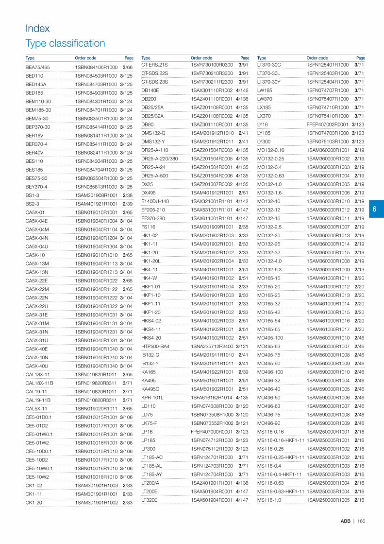
IndexType classificationType Order code Page Type Order code Page Type Order code Page
6
ABB | 166
BEA75/495 1SBN084106R1000 3/66
BED110 1SFN084503R1000 3/125
BED145A 1SFN084703R1000 3/125
BED185 1SFN084903R1000 3/125
BEM110-30 1SFN084301R1000 3/124
BEM185-30 1SFN084701R1000 3/124
BEM75-30 1SBN083501R1000 3/124
BEP370-30 1SFN085414R1000 3/125
BER16V 1SBN081411R1000 3/124
BER370-4 1SFN085411R1000 3/124
BER40V 1SBN082411R1000 3/124
BES110 1SFN084304R1000 3/125
BES185 1SFN084704R1000 3/125
BES75-30 1SBN083504R1000 3/125
BEY370-4 1SFN085813R1000 3/125
BS1-3 1SAM201908R1001 2/38
BS2-3 1SAM401921R1001 2/39
CA5X-01 1SBN019010R1001 3/65
CA5X-04E 1SBN019040R1004 3/104
CA5X-04M 1SBN019040R1104 3/104
CA5X-04N 1SBN019040R1204 3/104
CA5X-04U 1SBN019040R1304 3/104
CA5X-10 1SBN019010R1010 3/65
CA5X-13M 1SBN019040R1113 3/104
CA5X-13N 1SBN019040R1213 3/104
CA5X-22E 1SBN019040R1022 3/65
CA5X-22M 1SBN019040R1122 3/65
CA5X-22N 1SBN019040R1222 3/104
CA5X-22U 1SBN019040R1322 3/104
CA5X-31E 1SBN019040R1031 3/104
CA5X-31M 1SBN019040R1131 3/104
CA5X-31N 1SBN019040R1231 3/104
CA5X-31U 1SBN019040R1331 3/104
CA5X-40E 1SBN019040R1040 3/104
CA5X-40N 1SBN019040R1240 3/104
CA5X-40U 1SBN019040R1340 3/104
CAL18X-11 1SFN019820R1011 3/65
CAL18X-11B 1SFN019820R3311 3/71
CAL19-11 1SFN010820R1011 3/71
CAL19-11B 1SFN010820R3311 3/71
CAL5X-11 1SBN019020R1011 3/65
CE5-01D0.1 1SBN010015R1001 3/106
CE5-01D2 1SBN010017R1001 3/106
CE5-01W0.1 1SBN010016R1001 3/106
CE5-01W2 1SBN010018R1001 3/106
CE5-10D0.1 1SBN010015R1010 3/106
CE5-10D2 1SBN010017R1010 3/106
CE5-10W0.1 1SBN010016R1010 3/106
CE5-10W2 1SBN010018R1010 3/106
CK1-02 1SAM301901R1003 2/33
CK1-11 1SAM301901R1001 2/33
CK1-20 1SAM301901R1002 2/33
CT-ERS.21S 1SVR730100R0300 3/91
CT-SDS.22S 1SVR730210R3300 3/91
CT-SDS.23S 1SVR730211R2300 3/91
DB140E 1SAX301110R1002 4/146
DB200 1SAZ401110R0001 4/136
DB25/25A 1SAZ201108R0001 4/135
DB25/32A 1SAZ201108R0002 4/135
DB80 1SAZ301110R0001 4/135
DMS132-G 1SAM201912R1010 2/41
DMS132-Y 1SAM201912R1011 2/41
DR25-A-110 1SAZ201504R0003 4/135
DR25-A-220/380 1SAZ201504R0005 4/135
DR25-A-24 1SAZ201504R0001 4/135
DR25-A-500 1SAZ201504R0006 4/135
DX25 1SAZ201307R0002 4/135
DX495 1SAM401912R1001 2/51
E140DU-140 1SAX321001R1101 4/142
EF205-210 1SAX531001R1101 4/147
EF370-380 1SAX611001R1101 4/147
FS116 1SAM201909R1001 2/38
HK1-02 1SAM201902R1003 2/33
HK1-11 1SAM201902R1001 2/33
HK1-20 1SAM201902R1002 2/33
HK1-20L 1SAM201902R1004 2/33
HK4-11 1SAM401901R1001 2/51
HK4-W 1SAM401901R1002 2/51
HKF1-01 1SAM201901R1004 2/33
HKF1-10 1SAM201901R1003 2/33
HKF1-11 1SAM201901R1001 2/33
HKF1-20 1SAM201901R1002 2/33
HKS4-02 1SAM401902R1003 2/51
HKS4-11 1SAM401902R1001 2/51
HKS4-20 1SAM401902R1002 2/51
HTP500-BA4 1SNA235712R2400 3/121
IB132-G 1SAM201911R1010 2/41
IB132-Y 1SAM201911R1011 2/41
KA165 1SAM401922R1001 2/39
KA495 1SAM501901R1001 2/51
KA495C 1SAM501902R1001 2/51
KPR-101L 1SFA616162R1014 4/135
LD110 1SFN074308R1000 3/120
LD75 1SBN073508R1000 3/120
LK75-F 1SBN073552R1002 3/121
LP16 FPEP407000R0001 3/123
LP185 1SFN074712R1000 3/123
LP300 1SFN075112R1000 3/123
LT185-AC 1SFN124701R1000 3/71
LT185-AL 1SFN124703R1000 3/71
LT185-AY 1SFN124704R1000 3/71
LT200/A 1SAZ401901R1001 4/136
LT200E 1SAX501904R0001 4/147
LT320E 1SAX601904R0001 4/147
LT370-30C 1SFN125401R1000 3/71
LT370-30L 1SFN125403R1000 3/71
LT370-30Y 1SFN125404R1000 3/71
LW185 1SFN074707R1000 3/71
LW370 1SFN075407R1000 3/71
LX185 1SFN074710R1000 3/71
LX370 1SFN075410R1000 3/71
LY16 FPEP407002R0001 3/123
LY185 1SFN074703R1000 3/123
LY300 1SFN075103R1000 3/123
MO132-0.16 1SAM360000R1001 2/19
MO132-0.25 1SAM360000R1002 2/19
MO132-0.4 1SAM360000R1003 2/19
MO132-0.63 1SAM360000R1004 2/19
MO132-1.0 1SAM360000R1005 2/19
MO132-1.6 1SAM360000R1006 2/19
MO132-10 1SAM360000R1010 2/19
MO132-12 1SAM360000R1012 2/19
MO132-16 1SAM360000R1011 2/19
MO132-2.5 1SAM360000R1007 2/19
MO132-20 1SAM360000R1013 2/19
MO132-25 1SAM360000R1014 2/19
MO132-32 1SAM360000R1015 2/19
MO132-4.0 1SAM360000R1008 2/19
MO132-6.3 1SAM360000R1009 2/19
MO165-16 1SAM461000R1011 2/20
MO165-20 1SAM461000R1012 2/20
MO165-25 1SAM461000R1013 2/20
MO165-32 1SAM461000R1014 2/20
MO165-42 1SAM461000R1015 2/20
MO165-54 1SAM461000R1016 2/20
MO165-65 1SAM461000R1017 2/20
MO495-100 1SAM560000R1010 2/46
MO495-63 1SAM560000R1007 2/46
MO495-75 1SAM560000R1008 2/46
MO495-90 1SAM560000R1009 2/46
MO496-100 1SAM590000R1010 2/46
MO496-32 1SAM590000R1004 2/46
MO496-40 1SAM590000R1005 2/46
MO496-50 1SAM590000R1006 2/46
MO496-63 1SAM590000R1007 2/46
MO496-75 1SAM590000R1008 2/46
MO496-90 1SAM590000R1009 2/46
MS116-0.16 1SAM250000R1001 2/16
MS116-0.16-HKF1-11 1SAM250005R1001 2/16
MS116-0.25 1SAM250000R1002 2/16
MS116-0.25-HKF1-11 1SAM250005R1002 2/16
MS116-0.4 1SAM250000R1003 2/16
MS116-0.4-HKF1-11 1SAM250005R1003 2/16
MS116-0.63 1SAM250000R1004 2/16
MS116-0.63-HKF1-11 1SAM250005R1004 2/16
MS116-1.0 1SAM250000R1005 2/16

IndexType classificationType Order code Page Type Order code Page Type Order code Page
6
167 | ABB
MS116-1.0-HKF1-11 1SAM250005R1005 2/16
MS116-1.6 1SAM250000R1006 2/16
MS116-1.6-HKF1-11 1SAM250005R1006 2/16
MS116-10 1SAM250000R1010 2/16
MS116-10.0-HKF1-11 1SAM250005R1010 2/16
MS116-12 1SAM250000R1012 2/16
MS116-12.0-HKF1-11 1SAM250005R1012 2/16
MS116-16 1SAM250000R1011 2/16
MS116-16.0-HKF1-11 1SAM250005R1011 2/16
MS116-2.5 1SAM250000R1007 2/16
MS116-2.5-HKF1-11 1SAM250005R1007 2/16
MS116-20 1SAM250000R1013 2/16
MS116-20-HKF1-11 1SAM250005R1013 2/16
MS116-25 1SAM250000R1014 2/16
MS116-25-HKF1-11 1SAM250005R1014 2/16
MS116-32 1SAM250000R1015 2/16
MS116-32-HKF1-11 1SAM250005R1015 2/16
MS116-4.0 1SAM250000R1008 2/16
MS116-4.0-HKF1-11 1SAM250005R1008 2/16
MS116-6.3 1SAM250000R1009 2/16
MS116-6.3-HKF1-11 1SAM250005R1009 2/16
MS132-0.16 1SAM350000R1001 2/17
MS132-0.16-HKF1-11 1SAM350005R1001 2/17
MS132-0.16T 1SAM340000R1001 2/21
MS132-0.25 1SAM350000R1002 2/17
MS132-0.25-HKF1-11 1SAM350005R1002 2/17
MS132-0.25T 1SAM340000R1002 2/21
MS132-0.4 1SAM350000R1003 2/17
MS132-0.4-HKF1-11 1SAM350005R1003 2/17
MS132-0.4T 1SAM340000R1003 2/21
MS132-0.63 1SAM350000R1004 2/17
MS132-0.63-HKF1-11 1SAM350005R1004 2/17
MS132-0.63T 1SAM340000R1004 2/21
MS132-1.0 1SAM350000R1005 2/17
MS132-1.0-HKF1-11 1SAM350005R1005 2/17
MS132-1.0T 1SAM340000R1005 2/21
MS132-1.6 1SAM350000R1006 2/17
MS132-1.6-HKF1-11 1SAM350005R1006 2/17
MS132-1.6T 1SAM340000R1006 2/21
MS132-10 1SAM350000R1010 2/17
MS132-10.0-HKF1-11 1SAM350005R1010 2/17
MS132-10T 1SAM340000R1010 2/21
MS132-12 1SAM350000R1012 2/17
MS132-12.0-HKF1-11 1SAM350005R1012 2/17
MS132-12T 1SAM340000R1012 2/21
MS132-16 1SAM350000R1011 2/17
MS132-16.0-HKF1-11 1SAM350005R1011 2/17
MS132-16T 1SAM340000R1011 2/21
MS132-2.5 1SAM350000R1007 2/17
MS132-2.5-HKF1-11 1SAM350005R1007 2/17
MS132-2.5T 1SAM340000R1007 2/21
MS132-20 1SAM350000R1013 2/17
MS132-20-HKF1-11 1SAM350005R1013 2/17
MS132-20T 1SAM340000R1013 2/21
MS132-25 1SAM350000R1014 2/17
MS132-25-HKF1-11 1SAM350005R1014 2/17
MS132-25T 1SAM340000R1014 2/21
MS132-32 1SAM350000R1015 2/17
MS132-32-HKF1-11 1SAM350005R1015 2/17
MS132-4.0 1SAM350000R1008 2/17
MS132-4.0-HKF1-11 1SAM350005R1008 2/17
MS132-4.0T 1SAM340000R1008 2/21
MS132-6.3 1SAM350000R1009 2/17
MS132-6.3-HKF1-11 1SAM350005R1009 2/17
MS132-6.3T 1SAM340000R1009 2/21
MS165-16 1SAM451000R1011 2/18
MS165-20 1SAM451000R1012 2/18
MS165-25 1SAM451000R1013 2/18
MS165-32 1SAM451000R1014 2/18
MS165-42 1SAM451000R1015 2/18
MS165-54 1SAM451000R1016 2/18
MS165-65 1SAM451000R1017 2/18
MS495-100 1SAM550000R1010 2/42
MS495-63 1SAM550000R1007 2/42
MS495-75 1SAM550000R1008 2/42
MS495-90 1SAM550000R1009 2/42
MS497-100 1SAM580000R1010 2/42
MS497-32 1SAM580000R1004 2/42
MS497-40 1SAM580000R1005 2/42
MS497-50 1SAM580000R1006 2/42
MS497-63 1SAM580000R1007 2/42
MS497-75 1SAM580000R1008 2/42
MS497-90 1SAM580000R1009 2/42
MSAH1 1SAM201909R1021 2/54
MSH-AR 1SAM201920R1000 2/54
MSHD-LB 1SAM201920R1001 2/54
MSHD-LTB 1SAM201920R1011 2/54
MSHD-LTY 1SAM201920R1012 2/54
MSHD-LY 1SAM201920R1002 2/54
MSMN 1SAM101923R0002 2/54
MSMNO 1SAM101923R0012 2/54
NX22E-80 1SBH901074R8022 3/98
NX22E-81 1SBH901074R8122 3/98
NX22E-84 1SBH901074R8422 3/98
NX22E-86 1SBH901074R8622 3/98
NX22E-88 1SBH901074R8822 3/98
NX31E-80 1SBH901074R8031 3/98
NX31E-81 1SBH901074R8131 3/98
NX31E-84 1SBH901074R8431 3/98
NX31E-86 1SBH901074R8631 3/98
NX31E-88 1SBH901074R8831 3/98
NX40E-80 1SBH901074R8040 3/98
NX40E-81 1SBH901074R8140 3/98
NX40E-84 1SBH901074R8440 3/98
NX40E-86 1SBH901074R8640 3/98
NX40E-88 1SBH901074R8840 3/98
OXS6X105 1SCA108043R1001 2/54
OXS6X130 1SCA101655R1001 2/54
OXS6X180 1SCA101659R1001 2/54
OXS6X85 1SCA101647R1001 2/54
PB1-1-32 1SAM201914R1001 2/38
PS1-2-0-65 1SAM201906R1102 2/38
PS1-2-1-65 1SAM201906R1112 2/38
PS1-2-2-65 1SAM201906R1122 2/38
PS1-3-0-100 1SAM201916R1103 2/38
PS1-3-0-65 1SAM201906R1103 2/38
PS1-3-1-100 1SAM201916R1113 2/38
PS1-3-1-65 1SAM201906R1113 2/38
PS1-3-2-100 1SAM201916R1123 2/38
PS1-3-2-65 1SAM201906R1123 2/38
PS1-4-0-100 1SAM201916R1104 2/38
PS1-4-0-65 1SAM201906R1104 2/38
PS1-4-1-100 1SAM201916R1114 2/38
PS1-4-1-65 1SAM201906R1114 2/38
PS1-4-2-65 1SAM201906R1124 2/38
PS1-5-0-100 1SAM201916R1105 2/38
PS1-5-0-65 1SAM201906R1105 2/38
PS1-5-1-100 1SAM201916R1115 2/38
PS1-5-1-65 1SAM201906R1115 2/38
PS1-5-2-65 1SAM201906R1125 2/38
PS2-2-0-125 1SAM401920R1002 2/39
PS2-2-2-125 1SAM401920R1022 2/39
PS2-3-0-125 1SAM401920R1003 2/39
PS2-3-2-125 1SAM401920R1023 2/39
PS2-4-0-125 1SAM401920R1004 2/39
PS2-4-2-125 1SAM401920R1024 2/39
RA5-1 1SBN060300R1000 3/114
1SBN060300T1000 3/114
RC5-1/133 1SBN050100R1001 3/66
RC5-1/250 1SBN050100R1002 3/66
RC5-1/440 1SBN050100R1003 3/66
RC5-1/50 1SBN050100R1000 3/66
RC5-2/133 1SBN050200R1001 3/66
RC5-2/250 1SBN050200R1002 3/66
RC5-2/440 1SBN050200R1003 3/66
RC5-2/50 1SBN050200R1000 3/66
RC5-3/440 1SFN050300R1003 3/71
RV5/133 1SBN050010R1001 3/66
RV5/250 1SBN050010R1002 3/66
RV5/440 1SBN050010R1003 3/66
RV5/50 1SBN050010R1000 3/66
S1-M1-25 1SAM201907R1101 2/38
S1-M2-25 1SAM201907R1102 2/38
S1-M3-25 1SAM201907R1103 2/38
S1-M3-35 1SAM201913R1103 2/38
S1-PB1-25 1SAM201914R1002 2/38

IndexType classificationType Order code Page Type Order code Page
6
ABB | 168
SA1 GJF1101903R0001 2/38
SA2 GJF1101903R0002 2/38
SA3 GJF1101903R0003 2/38
SK1-02 1SAM201903R1003 2/33
SK1-11 1SAM201903R1001 2/33
SK1-20 1SAM201903R1002 2/33
SK4-11 1SAM401904R1001 2/51
SPRC 1 1SNA360010R1500 3/121
TA110DU-110 1SAZ411201R1002 4/136
TA110DU-90 1SAZ411201R1001 4/136
TA200DU-110 1SAZ421201R1002 4/136
TA200DU-135 1SAZ421201R1003 4/136
TA200DU-150 1SAZ421201R1004 4/136
TA200DU-175 1SAZ421201R1005 4/136
TA200DU-200 1SAZ421201R1006 4/136
TA200DU-90 1SAZ421201R1001 4/136
TA25DU-0.16M 1SAZ211201R2005 4/131
TA25DU-0.25M 1SAZ211201R2009 4/131
TA25DU-0.4M 1SAZ211201R2013 4/131
TA25DU-0.63M 1SAZ211201R2017 4/131
TA25DU-1.0M 1SAZ211201R2021 4/131
TA25DU-1.4M 1SAZ211201R2023 4/131
TA25DU-1.8M 1SAZ211201R2025 4/131
TA25DU-11M 1SAZ211201R2043 4/131
TA25DU-14M 1SAZ211201R2045 4/131
TA25DU-19M 1SAZ211201R2047 4/131
TA25DU-2.4M 1SAZ211201R2028 4/131
TA25DU-25M 1SAZ211201R2051 4/131
TA25DU-3.1M 1SAZ211201R2031 4/131
TA25DU-32M 1SAZ211201R2053 4/131
TA25DU-4.0M 1SAZ211201R2033 4/131
TA25DU-5.0M 1SAZ211201R2035 4/131
TA25DU-6.5M 1SAZ211201R2038 4/131
TA25DU-8.5M 1SAZ211201R2040 4/131
TA42DU-25M 1SAZ311201R2001 4/131
TA42DU-32M 1SAZ311201R2002 4/131
TA42DU-42M 1SAZ311201R2003 4/131
TA75DU-25M 1SAZ321201R2001 4/131
TA75DU-32M 1SAZ321201R2002 4/131
TA75DU-42M 1SAZ321201R2003 4/131
TA75DU-52M 1SAZ321201R2004 4/131
TA75DU-63M 1SAZ321201R2005 4/131
TA75DU-80M 1SAZ321201R2006 4/131
TA80DU-42 1SAZ331201R1003 4/136
TA80DU-52 1SAZ331201R1004 4/136
TA80DU-63 1SAZ331201R1005 4/136
TA80DU-80 1SAZ331201R1006 4/136
TEF5-OFF 1SBN020314R1000 3/66
TEF5-ON 1SBN020312R1000 3/66
UA1-110 1SAM201904R1004 2/34
UA1-20 1SAM201904R1010 2/34
UA1-208 1SAM201904R1008 2/34
UA1-230 1SAM201904R1005 2/34
UA1-24 1SAM201904R1001 2/34
UA1-400 1SAM201904R1006 2/34
UA1-415 1SAM201904R1007 2/34
UA1-48 1SAM201904R1002 2/34
UA1-575 1SAM201904R1009 2/34
UA1-60 1SAM201904R1003 2/34
UA4-110 1SAM401905R1001 2/51
UA4-230 1SAM401905R1002 2/51
UA4-24 1SAM401905R1004 2/51
UA4-400 1SAM401905R1003 2/51
UA4-HK-230 1SAM401906R1001 2/51
UA4-HK-400 1SAM401906R1002 2/51
VE5-1 1SBN030110R1000 3/65
VE5-2 1SBN030210R1000 3/65
VE5-2 1SBN030210R1000 3/112
VE5-2 1SBN030210R1000 3/65
VM19 1SFN030300R1000 3/71
VM205/260 1SFN035003R1000 3/71
VM300H 1SFN034700R1000 3/65
VM300V 1SFN034701R1000 3/71
VM370/400 1SFN035403R1000 3/71
VM5-1 1SBN030100R1000 3/65
WB75-A FPTN372726R1001 3/66
FPTN372726R1002 3/116
FPTN372726R1003 3/116
FPTN372726R1004 3/116
FPTN372726R1005 3/116
FPTN372726R1006 3/66
FPTN372726R1007 3/116
FPTN372726R1008 3/116
1SY
N82
9571
C02
03 -
Prin
ted
in F
ranc
e (0
1.20
17 P
DF)Note
We reserve the right to make technical changes or modify the contents of this document without prior notice. ABB does not accept any responsibility whatsoever for potential errors or possible lack of information in this document.
We reserve all rights in this document and in the subject matter and illustrations contained therein. Any reproduction, disclosure to third parties or utilization of its contents – in whole or in parts – is forbidden without prior written consent of ABB.
Copyright© 2017 ABB - All rights reserved
Contact us
http://www.abb.com/lowvoltage
You can find the address of your local sales organisation on the ABB home page