AWEA MECHANTRONIC CO. , LTD. - METAVAK
33
AWEA MECHANTRONIC CO. , LTD.
-
Upload
khangminh22 -
Category
Documents
-
view
4 -
download
0
Transcript of AWEA MECHANTRONIC CO. , LTD. - METAVAK

AWEA MECHANTRONIC CO. , LTD.

21
CONTENTS
07 - 16 Core Technology
03 - 06 Company Profile
Operational Advantages17 - 20
21 - 22 AG5 series‧RG5 series
23 - 24 MEGA5 series
25 - 26 FCV-800 series‧FCV-800S series
27 - 28 FCV-620 series‧FV series
29 - 30 EH5 series
31 - 32 MCP series
33 - 34 MVP series‧HVM series
35 - 36 LP-F series
37 - 38 BL series‧JB series
39 - 40 MB series
41 - 42 AHM series
43 - 44 AH series
45 - 46 LG series
47 - 48 HTP series‧HP series
49 - 50 LP series‧EP series
51 - 52 SP series‧HD series
53 - 54 VP-HS series‧VP series
55 - 56 FM series
57 - 58 BM series
59 - 60 AF series‧AE series
61 - 62 The Product Line-up
5-AXIS MACHINING CENTERS
Multi-FACE MACHINING CENTERS
HORIZONTAL MACHINING CENTERS
BRIDGE TYPE MACHINING CENTERS
VERTICAL MACHINING CENTERS
AiLINC
Intelligent Information Control System
New Milestone of multi-face machining centers
New GenerationAWEA Attachment Heads
AHM seriesAll New HMC Release
P.07 P.20 P.12 P.41
Japan
Korea
Thailand
Malaysia
Morocco
Egypt
South Africa
AustraliaIndonesia
Vietnam
India
Israel
Global Sales Network
ASIA AFRICA OCEANIA
Finland
Denmark
Netherlands
Ireland
EUROPE
Belgium
France
Switzerland
Germany
Spain
Portugal
Italy
Poland
Hungary
Czech
Slovenia
Bulgaria
Slovakia
Russia
Lithuania
Turkey
Canada
U.S .A
Mexico
Brazil
Argentina
AMERICA
AWEA OPERATION CENTER
DEALERS
AWEA has been contributing to the development and production of
machining centers for 33 years and sold machines to 38 countries or
regions around the world. The production portfolio includes 5-axis,
multi-face, vertical, horizontal, and other type of machining centers;
especially the large gantry type machining center is well acknowledged
in the global market. The product applications includes aerospace,
automotive, shipbuilding, energy, electronics, communications,
machinery, molds, and other professional manufacturing fields, in
which AWEA machining centers have left a significant presence.
AROUND THE GLOBE

43
Mr. Yang's Management PhilosophyVALUES TO UPHOLD
The book "Persistence : From 100 million to 10 billion", depicts in detail how Mr. Yang, even in a difficult environment, relied on his will to succeed, and accumulating momentum bit by bit to achieve his goals. In the end, we will tell a touching story of the internationally renowned machine tool group. The story will be worth reading for the aspiring person, hoping to find inspiration to follow and achieve their dreams.
At present, the official website has been opened for ordering. The
proceeds from the book sales will be donated to social welfare
organizations and disadvantaged groups. AWEA Mechantronic Co. will
work with you to better the world!
Online order( Traditional Chinese Version )
AWEA Mechantronic Co. is a professional manufacturer of CNC Milling Machines. Our product line includes a variety of integrated processing machines with X-Axis Lengths that range from 500 mm to 20 m. In the past five years, in response to the rapid demand of the market, our product specifications and performance have made breakthroughs in the large-scale, high-speed and compound product markets.
For example, the rapid rise of energy saving vehicles has pushed the original automotive sheet metal mold industry demand to new heights ; the booming information industry has increased the demand for the large prodution chambers required for display panels and semiconductors ; the requirement of larger and lorger parts processing and manufacturing equipment by the aerospace industry and soon on. This is the emerging main market of the Group now and in the future.
Currently, our Taiwan factories and China factories are actively expanding. The Chiayi facility
has completed the first phase of construction and commissioning,vertical machining center has
completed the specification and modularization improvement; the large product line factory has
also developed new models of floor type boring mill, moving cross beam and moving column
bridge type machining centers, as well as actively upgrade the development and application of
5-axis machines. In looking forward to the future development of the Group, we hope to bring
more creative value and services to our customers.
AWEA MECHANTRONIC CO., LTD.EDWARD YANG, PRESIDENT
Company Vision

65
AWEA MECHANTRONIC CO., LTD. was established in Hsinchu County, at capital USD 100,000.
The quality assurance system is ISO 9001 certified by GERMAN TUV RHEINLAND.
Public listed in Taiwan stock market.
C TSP branch factor y is completed and enabled.
‧New Chiayi factory inauguration.
‧Annual revenue soars to a new height.
Taiwan's largest milling machine LG-20070 successful installed.
30th anniversary of AWEA.
I n t ro d u c e d e f f i c i e n t AW E A Production System ( AWPS ).
Suzhou branch is completed and enabled.
1986 1996 2000
2008
2018
2009
2016
2013
2014
Grand Opening of the New Chiayi factory
O nl in e V id e o
C o n t i n u o u s i n v e s t m e n t i n p r o d u c t d e v e l o p m e n t a n d c o n s t r u c t i o n o f p r o d u c t i o n f a c i l i t i e s h a s b e e n o u r consistent pol ic y over a long period of t ime.
After years of planning, land levell ing and
construction, phase one of the new Chiayi
factory was completed at the end of 2018. It will
significantly increase the production capacity
for small and medium sized vertical machining
centers.
The second construction phase of the Suzhou
branch and Chiayi factory will be completed by
the end of 2020. Under the global marketing
strategy and capacity planning, laying the
groundwork for the next golden decade of
AWEA and providing high quality and most
prompt service to our every valued customers.
Chairman Mr. Edward Yang decided personally determined the spirit
of his career early on, and based on this, determined the core values
of the AWEA. He has successfully lead the group's decision making
and development for many years.
Outstanding Innovation &The Pursuit of Excellence
Phase two schematic diagramof the Suzhou branch
VMC production line of the new Chiayi factory
HEADQUARTERS CTSP BRANCH CHIAYI BRANCH SUZHOU BRANCH
Manufacturing of bridge type
machining centers and boring mills
Area : 26,000 m2
HSINCHU‧ TAIWAN TAICHUNG‧TAIWAN CHIAYI‧TAIWAN LOS ANGELES‧CALIFORNIA WUJIANG . SUZHOU
Manufacturing of bridge type and
C-frame VMC
Area : 26,600 m2
Manufacturing of bridge type and
C-frame VMC
Area : 66,800 m2
Manufacturing of VMC
Area : 56,600 m2
YAMA SEIKI USA., INC.
Sales and service
Area : 24,000 m2
M i lestones
Cornerstone at the Suzhou branch
Operation Centers
Business phi losophy

87
AiLINC, the intelligent information control system newly developed and designed by AWEA,
combines three features: convenient operation, intuitive information access and easy
learning. With clear machine information and operation, powerful intelligent functions, and
advanced artificial intelligence technology, your machine can link up with the world in the
of Industry 4.0 era.
2020
Coming
Soon
Machine diagnosis
Machine
i Console intelligent operations
1 NC operation main screen
2 NC tool list
3 NC editor
4 NC maintenance
5 Alarm screen
1 Lighting setting
2 Chip conveyor setting
3 Buzzer setting
4 Automatic lubrication setting
1 Tool loading monitor
2 Spindle thermal compensation
3 Parameter optimization
4 Roughing adaptive feed control
1
1
1
2
2
2
3
3
3
4
4
4
5
i Console intelligent functions
+ AI heat distortion analysis
+ AI machine vibration analysis
+ Automatic neural network adaptation
+ Parameter optimization
+ Rough cutting adaptive feed control
+ Spindle thermal compensation
+ Tool loading monitor
+ Machine vibration
+ Machine temperature
+ Machine diagnosis
+ Production traceability
Artificial Intelligence
Intelligent
System functions
Information
I ntel l igent operat ion
Diagnost ic system
Real t ime information
i Console
1 Spindle system
2 Servo system
3 Tool magazine system
4 Hydraulic system
5 Pneumatic system
6 Track lubrication system
7 Coolant tank system
1 2 3 4
6
5
7
I n te l l i g e n t I n fo r m at i o n Co n t ro l Sys te m

109
Cutting Error
Main screen Circular work-piecemeasurement
Trouble shooting Tools management Counter function
Basic rectangularwork-piece measurement
Advanced rectangularwork-piece measurementMachining parameter GP
It is able to monitor each tool setting and
detec t the tool break age to lower the
possibility of work-piece been damaged.
After manually measuring the tool length, the
controller will automatically calculate the tool
tip position and enter the data into the tool
length o�set table.
Decrease deformation on structure that
c a u s e d by h e a t , I n s t a n t l y m o n i to r i n g
temperature for automatic compensation to
increase machining accuracy. ( Opt. )
This function is di�erent from CNC parameter
optimization, i t a l lows operator to set
parameter by himself, to achieve optimal
machining e�ciency. ( Opt. )
By measuring the A, B, C three points
coordinates the circular work-piece's center
point can be correctly calculated.
Graphical user interface is easy to use, and up
to 12 tool length measurements can be done
in one button, which saves programing time
and lowers operation error. ( Opt. )
Tool length offset Auto. tool length measurementSpindle thermal compensation
By measuring the X+、X-、Y+、Y- four points
coordinates, the rectangular work-piece's
center point can be calculated. Then the center
point coordinate can be entered in the work-
piece coordinate system. ( G54 – G59 )
When the alarm appears, the screen will display
the malfunction message and trouble shooting
procedure enabling the operator to solve
problems to shorten the shutdown time.
Intuitive fast tool set-up, and complete tools
database let operators easy to use and lower
possibility of error caused.
There are 3 sets of counters ready for
individually start, stop and wipe out history,
which is convenient for operator to regularly
maintain machine or gather statistics for
utilization and production.
By measuring the A, B, C, D, and E five points
coordinates, the rectangular work-piece's center
point and slant angle can be calculated. Then
the center point coordinate can be entered in
the work-piece coordinate system.( G54 – G59 )
Slow feed rate brings ultra small cutting error
Fast feed rate brings small cutting error
Super fast feed rate brings large cutting error
From rough cutting to fine finishing, t h e o p e r a t o r c a n s e l e c t v a r i o u s cutting modes based on the working condition, and then set the allowable error and work-piece weight to obtain the optimum parameter.
Spindle load Axial feed
Below setting Feed increase
Above setting Feed decreaseSpindle load = Setting
Adoptive feed control is capable o f r e a l t i m e m o n i t o r i n g t h e spindle load to control the axial f e e d r a t e w h i c h e f f e c t i v e l y e x t e n d s t o o l l i f e , s h o r t e n s rough cutting time, and detects abnormal cutting conditions.
Tooling path
Work-piece
Feed rate
Without AFC
With AFC
Based on feed rate difference for a u t o m a t i c c o r n e r d e c e l e r a t i o n , the smaller the setting value the better the accuracy but the cycle time relatively longer; set different feed rate in ever y axis with this parameter in order to calculate the deceleration at corner.
Adoptive Feed Control ( AFC )
CNC Parameter Opt imizat ion
● CNC parameter optimization● Spindle thermal compensation● Adoptive feed control ( AFC )
OPTION:● Instant messaging system● Tool list● Work-piece measurement● M code● Calculator
Tool loading monitor
We make machine smarter
1211
Mu
lti-
face
Mac
hin
ing
Cen
ters
Ser
ies
Op
tio
n m
ult
i-fa
ce f
un
ctio
ns
seri
es
20,0005,000 10,000 15,000
X-axis ( mm )
LP-F series
EP series
HP series
LG series
HTP series
HVM series
MCP series
MVP series Moving
crossbeam
Movingcolumn
Movingcolumn
Gantry Type
Movingcrossbeam
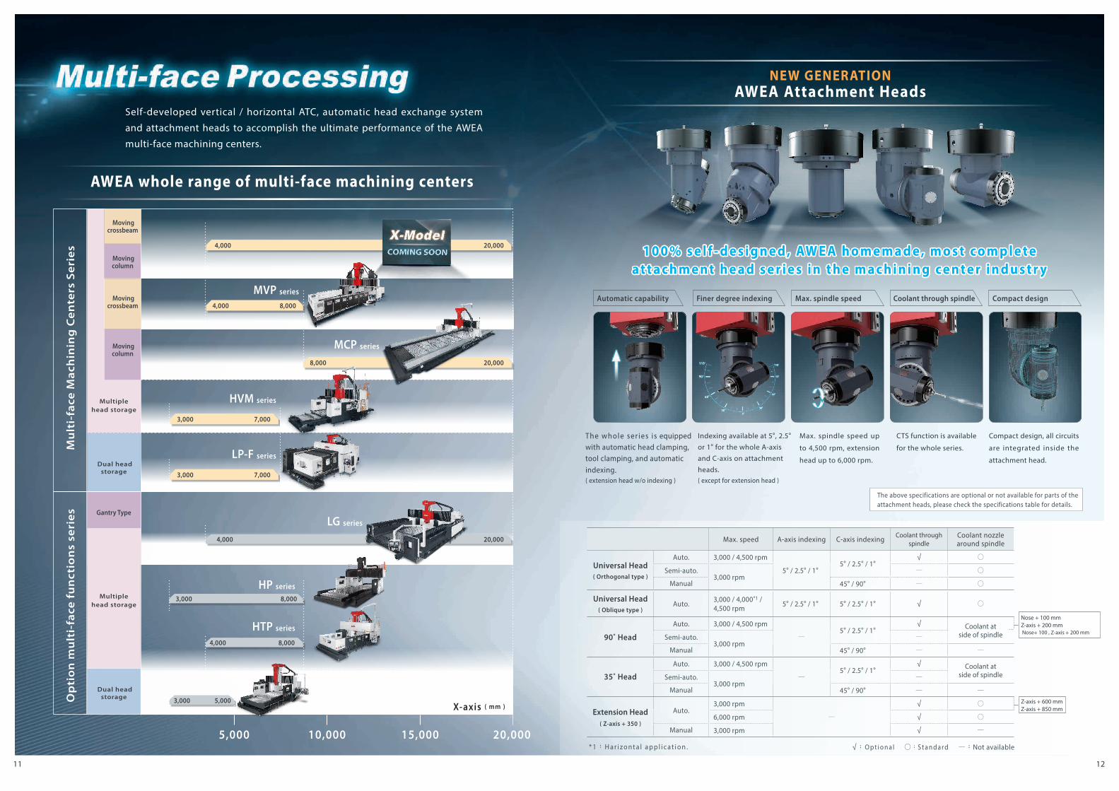
Self-developed vertical / horizontal ATC, automatic head exchange system
and attachment heads to accomplish the ultimate performance of the AWEA
multi-face machining centers.
Nose + 100 mmZ-axis + 200 mm Nose+ 100 , Z-axis + 200 mm
Z-axis + 600 mmZ-axis + 850 mm
Automatic capability Max. spindle speed Coolant through spindle Compact designFiner degree indexing
The whole ser ies is equipped with automatic head clamping, tool clamping, and automatic indexing.( extension head w/o indexing )
Indexing available at 5°, 2.5° or 1° for the whole A-axis and C-axis on attachment heads. ( except for extension head )
Max. spindle speed up
to 4,500 rpm, extension
head up to 6,000 rpm.
CTS function is available
for the whole series.
Compact design, all circuits
are integrated inside the
attachment head.
Max. speed A-axis indexing C-axis indexing Coolant through spindle
Coolant nozzle around spindle
Universal Head
( Orthogonal type )
Auto. 3,000 / 4,500 rpm
5° / 2.5° / 1° 5° / 2.5° / 1°
√ ○
Semi-auto. 3,000 rpm
— ○
Manual 45° / 90° — ○
Universal Head
( Oblique type )Auto. 3,000 / 4,000*1 /
4,500 rpm 5° / 2.5° / 1° 5° / 2.5° / 1° √ ○
90˚ Head
Auto. 3,000 / 4,500 rpm
— 5° / 2.5° / 1°
√ Coolant atside of spindleSemi-auto.
3,000 rpm—
Manual 45° / 90° — —
35˚ Head
Auto. 3,000 / 4,500 rpm
— 5° / 2.5° / 1°
√ Coolant atside of spindleSemi-auto.
3,000 rpm—
Manual 45° / 90° — —
Extension Head( Z-axis + 350 )
Auto. 3,000 rpm
—
√ ○
6,000 rpm √ ○
Manual 3,000 rpm √ —
8,000 20,000
4,000 8,000
3,000
3,000
7,000
7,000
3,000
3,000
4,000 20,000
4,000
5,000
8,000
8,000
20,000 4,000
The above specifications are optional or not available for parts of the attachment heads, please check the specifications table for details.
√:O p t i o n a l ○:S t a n d a r d —:Not available* 1:H a r i z o n t a l a p p l i c a t i o n .
AWEA whole range of multi-face machining centers
NEW GENERATIONAWEA Attachment Heads
1 0 0 % s e l f - d e s i g n e d , AW E A h o m e m a d e , m o s t c o m p l e t ea t t a c h m e n t h e a d s e r i e s i n t h e m a c h i n i n g c e n t e r i n d u s t r y
Dual head storage
Dual head storage
Multiplehead storage
Multiplehead storage

1413
High performance two axes head
Rotaryworking table
Two AxesHead
Gantry Type Gantry Type
Bridge Type
Vertical
Horizontal EH5-500
FV-560 FV-960
MEGA5 P
MEGA5 GRG5
AG5
FCV-800S
FCV-800
FV-620
610 620 960 2,500 3,200560
800 1,000 1,600 4,000 6,000 8,000 10,000400 600
‧ITALIAN made two axes head designed for high performance & high stability.
‧A variety of two axes heads are available optionally - high speed / high torque / compact structure.
Spindle taper HSK-A100
Max. spindle speed 12,000 rpm
Spindle motor 50 kW
B / C axes rotary angle ±110° ±240°
B / C axes max.speed 50 rpm
B / C axes position accuracy ± 3 arc.sec
B / C axes clamping torque 8,000 Nm
Spindle taper HSK-A63 HSK-A100
Max. spindle speed 24,000 rpm 15,000 rpm
Spindle motor 55 kW 65 kW
B / C axes rotary angle ±100° ±240°
B / C axes max. speed 50 rpm
B / C axes position accuracy ± 3 arc.sec
B / C axes clamping torque 4,000 Nm
Spindle taper HSK-A63 HSK-A100
Max. spindle speed 24,000 rpm 15,000 rpm
Spindle motor 55 kW 65 kW
B / C axes rotary angle ±100° ±240°
B / C axes max. speed 50 rpm
B / C axes position accuracy ± 3 arc.sec
B / C axes clamping torque 4,000 Nm
Spindle taper HSK-A100
Max. spindle speed 24,000 rpm
Spindle motor 33 kW
B / C axes rotary angle ±105° ±240°
B / C axes max. speed 50 rpm
B / C axes position accuracy ± 10 arc.sec
B / C axes clamping torque 1,500 Nm
TCH-30F TCH-20F TCH-19F TCH-L13 E VO
Milling and turning complex
Linear motor drive
The professional AWEA 5-axis
service technical team have
h a s b e e n t r a i n e d b y t h e
original Italian manufacturer
firm, could and can provide
the best optimal technical
support and efficient service.
Complete ful l f ive -axis machine series for high speed, high precision
performance, which can easily master complex processing tasks.
X-axis ( mm )

1615
‧X-axis:20,000 mm
‧Y-axis:6,000 mm
‧Z-axis:1,400 mm
‧X-axis:20,000 mm
‧Y-axis:7,000 mm
‧Z-axis:1,400 mm
Max. travel Max. travel Max. travel‧X-axis:10,000 mm
‧Y-axis:3,600 mm
‧Z-axis:450 mm
‧V-axis:2,500 mm
‧W-axis:900 mm
LG seriesGantry Type Machining Centers
MCP seriesMoving Column Machining Centers
JB seriesFloor Type Horizontal Boring Mills
AWEA Attachment Heads
Topology Analysis
CrossbeamAdjustable Mechanism
CrossbeamAdjustable Mechanism
High QualityKey Components
0 mmAfter adjusting, deformation is close to
PAT.NO.: M377276
D e s i g n e d a n d b u i l t b y A W E A fo r s e a m l e s s co m p at i b i l i t y w i t h o u r m a c h i n e s a n d e n h a n c e d , outstanding performance.
Th ro u g h To p o l o g y A n a l ys i s , we design lightweight, but highly rigid structures that guarantee the best dynamic performance.
Key components like ball screws, linear guideways, gears, etc. are made by top quality market leaders to ensure precise accuracy and long term durability of AWEA machines.
T h e p a t e n t e d s t r u c t u r a l design significantly reduces the deformation of the large-span crossbeam and permits ultra-long Y-axis travel.
Our unique PLC control ensures the two servo motors operate in precise synchronization, avoiding tracking errors and providing optimal axial dynamic accuracy.
‧Applicable material : Quartz, Ceramics ... ‧ Installed with specially designed dust collector for tiny and corrosive chips to protect operator against hazard and prolong life of machine.
A rotating FSW tool is plunged between two clamped plates, the fiction between the rotating stir tool and the work-piece material generates heat, causing a plasticized zone to form around the tool and thus a solid-phase joint.
More than 10 years of experience in Turn-key projects; whether automatic loading / unloading systems, automatic and manual work-piece clamping systems, or precision measuring devices, we can tailor it to your specific requirements.
‧Applicable material : Graphite, Carbon fiber... ‧Installed with specially designed dust collector for tiny and scattering chips to protect operator against hazard and prolong life of machine.
Wet Processing
Fric t ion St ir Welding (FSW )
Dr y Processing
Turn-Key Projec tCore Technology
High Pressure Coolant Systems
R series i models SC series SK series
Leader For Large Equipment Application Development Capability
Since the first bridge type machine installation in 1986, AWEA has accumulated experience from
thousands of installations for large machines, refining design, production, and data processing.
We keep improving and this is the difference we make core technology.
AWEA provides comprehensive series of machines to fulfill the demand for processing a
variety of material in an efficient and accurate matter.
Max. Pressure:100 / 70 Bar
Max. Flow Rate:53 / 30 LPM Max. Pressure:140 / 70 Bar
Max. Flow Rate:19 / 12 LPM Max. Pressure:70 Bar
Max. Flow Rate:12 LPM Max. Pressure:70 Bar
Max. Flow Rate:12 LPM Max. Pressure:35 / 20 Bar
Max. Flow Rate:25 / 26 LPM
SU series MB series

1817
All core components are precisely assembled in a constant temperature control led room, which possesses higher assembly quality and higher technology integration of machines than general competitors in the market.
R&D center Assembly of core components
Precis ion machining
M achine assembly
Q ual it y control
Straightness check for linear guide ways
Simultaneously accuracy of 5 axes Laser detection of accuracy Ball bar detection for 3 axes
Measurement of linear axes perpendicularityon 5-axis machine
Parallelism measurement between ball screw and linear guideway
Key components are imported fromworld famous companies
Japan-made YASDA high precision horizontal machining center
Japan-made TOSHIBA bridge type multi-face machining center
Japan-made SUMITOMO high precision vertical grinding machine
Japan-made MITSUI SEIKI horizontal machining center A
B C D
A
B
C
D
‧Monthly maintain and annually inspected by 3D coordinate measuring machine.
‧Platform flatness : 0.005 mm
‧Hand-scraping density : 10 ~ 15 dots / in2
‧Fixed surface hand-scraping density : 10 ~ 15 dots / in2
‧Sliding surface hand-scraping density : 15 ~ 20 dots / in2
Standard Hand Scraping Plat form Hand-Scraping Standard
Production Advantage
All of the key production processes such as design, processing, assembly, and quality control
are constantly improved and performed in house. This ensures the highest quality standards to
achieve the ultimate machining performance and reliability.
Core components are precisely machined by AWEA
in temperature controlled facilities, using world
class equipment to ensure the ultimate accuracy
requirements are met.
U t i l i z i n g a d v a n c e d
inspection equipments to
implement the accuracy
check to ensure the final
performance and quality
of machine.
High precision machine tools come from superb hand scraping skills. AWEA's well trained hand
scraping team makes sure that all contact surfaces are precisely hand scrapped and carefully
inspected to ensure the highest quality of our machines.
Precis ion hand scraping

2019
Happy workplace
Customer commitment
Establish a people-oriented company
Become a close partner to the customers
Committed to contributing to environmental protection
Gain from society, give back to societySocial welfare
Sustainable Environment
· Ac t i ve l y c u l t i vate t a l e nt s , o f fe r learning opportunities.
· Assist in bui lding a healthy and enjoyable outlook on life.
· Provide quality-assured solutions to meet customer demand.
· Devoted to be a reliable partner for customers.
· Develop the product portfolio that helps reduce environmental burdens.
· Reducing the potential negative impact of AWEA's global presence on the environment.
· Carry forward the traditional virtues of filial piety.
· Actively assisting disadvantaged groups.
· Industr y-university cooperation, research program sponsorship.
· AW E A n e w g e n e r a t i o n a t t a c h m e n t h e a d s
· M u l t i p l e h e a d s t o r a g e
· H o r i z o n t a l / v e r t i c a l A T C s y s t e m
AWEA Dale Carnegie Training camp Annual family day AWEA Machine tool academy
Happy and harmonious day camp
Beach clean-up event Tree planting Machine tool improvement competition
Supplier thanking activity Charity fundraising concert
Corporate Social Responsibility

2221
AG5 SERIES RG5 SERIES
X / Y axes driven by linear motor
Specifications are subject to change without notice.
Specifications are subject to change without notice.
RG5-1625 RG5-3225X-axis travel mm 1,600 3,200
Y-axis travel mm 2,500
Z-axis travel mm 1,000
Table size ( X x Y ) mm 1,600 x 2,500 3,200 x 2,500
Table load capacity kg/m2 3,000
X-axis rapid feed rate m/min. 24 20
Y / Z axes rapid feed rate m/min. 24
» B、C axes spec, please refer to P.13
+ The 3 l inear axes are equipped with direc t- dr ive ser vo motors and high resolution linear scales to ensure utmost accuracy.
+ Z-axis is driven by new generation dual ball screws and dual servo motors, to ensure excellent dynamic response.
+ I talian-made high speed two axes mill ing head, designed for flexible and diverse cutting operations.
+ Gantry type, machines use 40 % less floor space than bridge type machines.
+ The 3 linear axes are equipped with high loading roller guide ways, which combine the advantage of highly rigid box guide ways with the agility of linear guide ways.
· THK latest nut cooling technology.
· AWEA hollow ball screw cooling technology.
· AWEA ball screw nut cooling technology.
X / Y axes with cooling technology ( Opt. )
Hollow ball screw cooling technology
AG5-1620 AG5-3220X-axis travel mm 1,600 3,200
Y-axis travel mm 2,000
Z-axis travel mm 1,000
Table size ( X x Y ) mm 1,600 x 2,000 3,200 x 2,000
Table load capacity kg/m2 3,000
X / Y axes rapid feed rate m/min. 60
Z-axis rapids feed rate m/min. 50
Gantry Type 5 axes Machining Centers Gantry Type 5 axes Machining Centers
*1 : S1 / S6 40%
Model TCH-19F TCH-L13 EVO
Spindle Taper HSK-A63 HSK-A63
Spindle Speed 24,000 rpm 24,000 rpm
Spindel Motor *1 42 / 55 kW 27 / 33 kW
RG5 series - ITALIAN Made Two Axes HeadAG5 series - ITALIAN Made Two Axes Head
*1 : S1 / S6 40%
Model TCH-19F TCH-20F TCH-20F-A
Spindle Taper HSK-A63 HSK-A63 HSK-A100
Spindle Speed 24,000 rpm 24,000 rpm 15,000 rpm
Spindel Motor *1 42 / 55 kW 42 / 55 kW 50 / 65 kW
· Wi t h o u t t r a n s m i s s i o n c o m p o n e n t s t h e y o f fe r high acceleration, high reliability, and cause less abrasion, thus enhancing system accurac y and lifetime.
· Motor is directly driven by air gap, non-touch, high efficiency, low noise.
THK nut cooling technology
+ X / Y axes equipped with high speed linear motor provide better dynamic response with high accuracy, zero backlash.
+ Z-axis is driven by new generation dual ball screws and dual ser vo motors, to ensure excellent dynamic response.
+ Italian-made high speed two axes milling head, designed for flexible and diverse cutting operations.
+ U shaped machine base with 4 linear guide ways, designed to evenly disperse the cutting forces.
+ The 3 linear axes are equipped with high loading roller guide ways, which combine the advantage of highly rigid box guide ways with the agility of linear guide ways.

2423
MEGA5 SERIES
MEGA5 PX-axis travel mm 2,500 ~ 6,000
Y-axis travel mm 2,620 / 3,200
Z-axis travel mm 1,000 / 1,200
Table load capacity kg 8,000 ~ 20,000
Max.work-piece
Length ( X ) mm 2,310 ~ 6,000
Width ( Y ) mm 1,500 / 2,400
Height ( Z ) mm 850
MEGA5 GX-axis travel mm 4,000 ~ 10,000
Y-axis travel mm 3,700 / 4,700
Z-axis travel mm 1,200 / 1,400
Table load capacity kg/m2 2,500
Max.work-piece
Length ( X ) mm 4,000 ~ 10,000
Width ( Y ) mm 3,700 / 4,700
Height ( Z ) mm 1,050
Specifications are subject to change without notice. Specifications are subject to change without notice.
Aerospace
Industries
First Choice
MEGA5 P series MEGA5 G series
Model TCH-20F TCH-30F
Spindle Taper HSK-A63 HSK-A100
Spindle Speed 24,000 rpm 12,000 rpm
Spindel Motor *1 55 kW 50 kW
Spindle Torque 87 Nm 314 Nm
*1:S6 40 %
( MEGA5 P 2526 ) ( MEGA5 G 10047 )
· Fixed column bridge type structure
· High rigidity base
· 40 T Chain type tool magazines
· Optional fully enclosed splash guard
· Gantry type structure
· 4 precision linear guide ways on a high rigidity bed
· 20 T / 40 T drum type ATC
· Optional X-axis stainless steel telescopic cover
MEGA5 P series MEGA5 G series
Bridge Type 5 axes Machining Centers
MEGA5 series - ITALIAN Made Two Axes Head
+ Available in a wide range of specifications to satisfy different machining demands.
+ ITALIAN made high speed / high torque output two axes milling head to meet your any difficult cutting need.
+ X, Y, and Z axes are equipped with closed-loop linear scales to ensure ultimate axial positioning accuracy.
Onl ine VideoMEGA5 P cutting display

2625
FCV-800 SERIES
Specifications are subject to change without notice.
FCV-800S
X / Y / Z axes travel mm 800 / 900 / 660
A-axis swiveling range -120° ~ +30°
C-axis rotary range 360°
Table size mm Ø 850
Table load capacityMilling kg ( 0° ) : 1,000 / ( 90° ) : 700
Turning kg ( 0° ) : 800 / ( 90° ) : 600
Spindle speed rpm 18,000
Spindle motor kW 11 / 12 ( cont. / 30 min. )
X / Y / Z rapid feed rate m/min. 48
ATC T 40 ( 80 Opt. )
Specifications are subject to change without notice.
FCV-800X / Y / Z axes travel mm 800 / 900 / 660
A-axis swiveling range -120° ~ +30°
C-axis rotary range 360°
Table size mm Ø 850
Table load capacity kg ( 0° ) : 1,000 / ( 90° ) : 700
Spindle speed rpm 16,000 / 24,000
Spindle motor kW 25 / 29 ( cont. / 30 min. )
Spindle taper BBT40
X / Y / Z rapid feed rate m/min. 48
ATC T 40 ( 80 Opt. )
Highly reliable ATC system
· A-axis is designed with high torque motor and reducer; maximum torque output 12,600 Nm, 250 % stronger than the previous generation.
· C-axis driven by high speed, high torque, and zero backlash torque motor.
· C-axis bearing outside diameter increased by 40 % and axial dynamic stiffness increased by 70 %.
New generation A / C axes trunnion table
C-axis
· Standard ATC with a 40T chain type tool magazine ( 80T optional )
· Tool magazine with high-speed linear guide way
· Automatic tool magazine door to avoid contamination of the tools and the ATC by cutting fluid and chips.
Gantry Type 5 axes Machining Centers
Multi-tasking 5 axes Machining Centers + Stable U shape machine base with Y-axis dual servo control technologies to ensure
excellent dynamic accuracy.
+ 16,000 / 24,000 rpm high speed built-in spindles for ultimate surface finish and accuracy.
+ New generation of A / C axes brake systems substantially increase braking capacity.
+ X / Y / Z axes equipped with roller type linear guide ways; rapid feed rate up to 48 m/min. and cutting feed rate 24 m/min.
+ Side-exit or rear-exit chip conveyors available for best factory space utilization.
+ FCV-800S combines high-speed turning with 5-axis compound milling.
+ Trunnion table ( C-axis ) maximum speed 800 rpm
+ HSK-T63 18,000 rpm high speed built-in spindle
+ New generation A / C axes trunnion table
Multi-tasking
Turning & Milling
FCV-800S SERIES
2827
FCV-620 SERIES
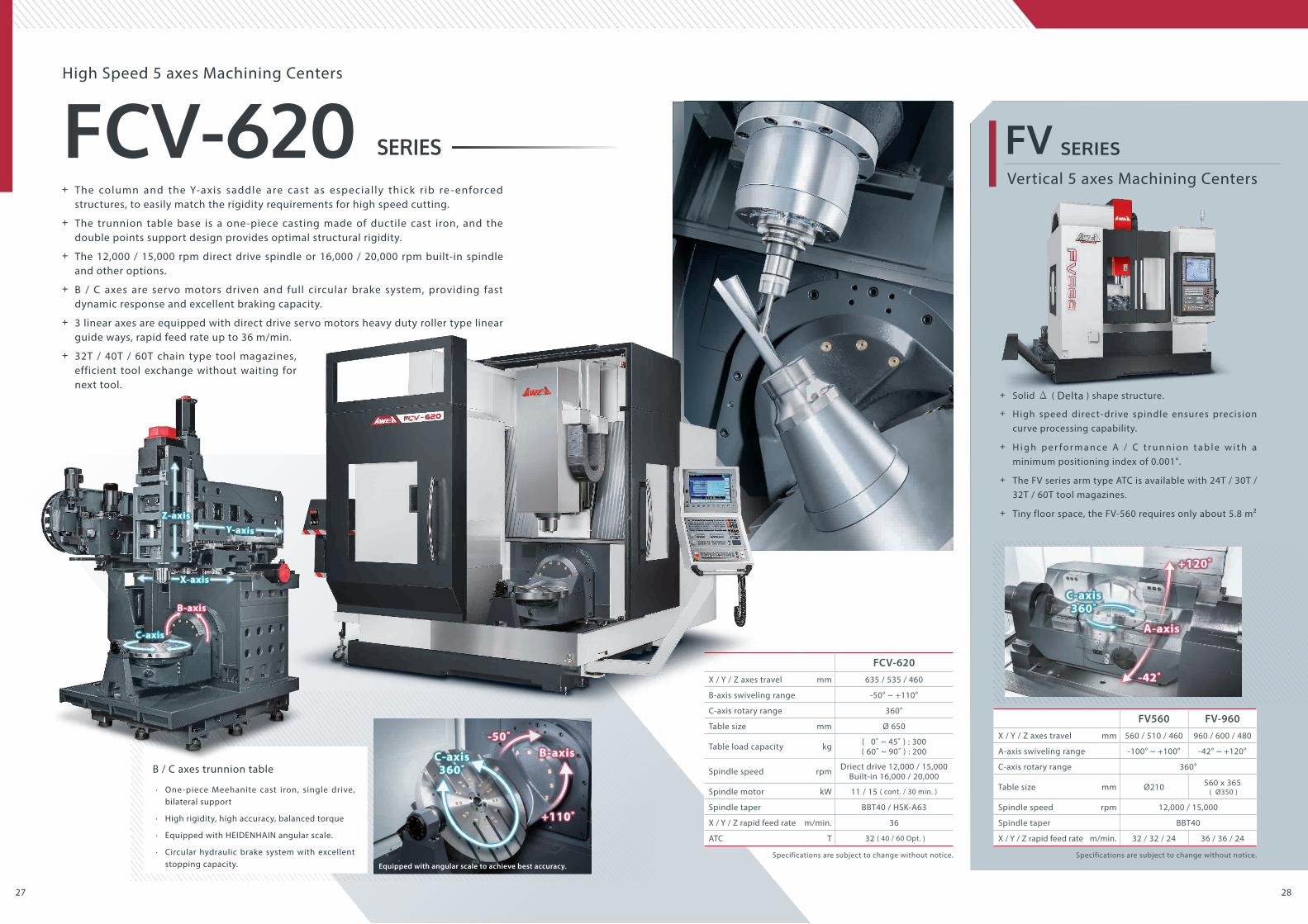
FV560 FV-960X / Y / Z axes travel mm 560 / 510 / 460 960 / 600 / 480
A-axis swiveling range -100° ~ +100° -42° ~ +120°
C-axis rotary range 360°
Table size mm Ø210 560 x 365 ( Ø350 )
Spindle speed rpm 12,000 / 15,000
Spindle taper BBT40
X / Y / Z rapid feed rate m/min. 32 / 32 / 24 36 / 36 / 24
Equipped with angular scale to achieve best accuracy.
Vertical 5 axes Machining Centers
FV SERIES
Specifications are subject to change without notice. Specifications are subject to change without notice.
FCV-620X / Y / Z axes travel mm 635 / 535 / 460
B-axis swiveling range -50° ~ +110°
C-axis rotary range 360°
Table size mm Ø 650
Table load capacity kg ( 0˚ ~ 45˚ ) : 300( 60˚ ~ 90˚ ) : 200
Spindle speed rpm Driect drive 12,000 / 15,000Built-in 16,000 / 20,000
Spindle motor kW 11 / 15 ( cont. / 30 min. )
Spindle taper BBT40 / HSK-A63
X / Y / Z rapid feed rate m/min. 36
ATC T 32 ( 40 / 60 Opt. )
C-axis360˚
+120˚
A-axis
-42˚
C-axis360˚
B-axis-50˚
+110˚
Z-axis
X-axis
C-axis
Y-axis
B-axis
High Speed 5 axes Machining Centers
B / C axes trunnion table
· One-piece Meehanite cast iron, single drive, bilateral support
· High rigidity, high accuracy, balanced torque
· Equipped with HEIDENHAIN angular scale.
· Circular hydraulic brake system with excellent stopping capacity.
+ The column and the Y-axis saddle are cast as especial ly thick r ib re - enforced structures, to easily match the rigidity requirements for high speed cutting.
+ The trunnion table base is a one-piece casting made of ductile cast iron, and the double points support design provides optimal structural rigidity.
+ The 12,000 / 15,000 rpm direct drive spindle or 16,000 / 20,000 rpm built-in spindle and other options.
+ B / C axes are servo motors driven and full circular brake system, providing fast dynamic response and excellent braking capacity.
+ 3 linear axes are equipped with direct drive servo motors heavy duty roller type linear guide ways, rapid feed rate up to 36 m/min.
+ 32T / 40T / 60T chain type tool magazines, efficient tool exchange without waiting for next tool.
+ Solid Δ ( Delta ) shape structure.
+ High speed direct-drive spindle ensures precision curve processing capability.
+ H i g h p e r f o r m a n c e A / C t r u n n i o n t a b l e w i t h a minimum positioning index of 0.001°.
+ The FV series arm type ATC is available with 24T / 30T / 32T / 60T tool magazines.
+ Tiny floor space, the FV-560 requires only about 5.8 m²

3029
EH5 SERIES
Specifications are subject to change without notice.
EH5-500X / Y / Z axes travel mm 610 / 610 / 610
A-axis swiveling range -120° ~ +42°
B-axis rotary range ±360°
Max. work-piece diameter / height mm Ø 600 / 650
Table size mm 620 x 360 mm ( Ø 400 )
Table load capacity kg ( 0˚ ~ 45˚ ) : 200( 45˚ ~ 90˚ ) : 100
Spindle speed rpm Direct drive 12,000 / 15,000 ( Opt. )
Spindle motor kW 7.5 / 11 ( cont. / 30 min. )
Spindle taper BBT40
X / Y / Z rapid feed rate m/min. 60
ATC T 24
Pitch between machines2,400 mm
T h e s h o r t e s t d i s t a n c e b e t w e e n t h e c e n t e r s o f t w o m a c h i n e s i s only about 2,400 mm, allowing to utilize a more compact loading and unloading system.
Rear-exit chip conveyors allow two production lines to share a central chip conveyor, for more convenient chip removal.
A
B
Small foot print makes production line planning more convenient.
A
B
500 x 500 mm 620 x 360 mm 500 x 500 mm 500 x 500 mm
600 kg 300 kg 600 kg 600 kg
Table size ( X x Y )
Table load capacity
Table size ( X x Y )
Table size ( X x Y )
Table size ( X x Y )
Table load capacity
Table load capacity
Table load capacity
B-axis
A-axis
The worm gear contact areas are designed with a low pressure angle, providing higher torque output.
Low PressureAngle <6°
Horizontal 5 axes Machining Centers
A / B axes trunnion table
· The embedded B-axis makes machining more flexible.
· High accuracy and high torque worm gear design.
· Circular hydraulic brake system for heavy cutting.
· Equipped with closed-loop linear scales.
A variety of working table configurations
Fixed table A-axis table B-axis table Auto. pallet change system
+ Compact structural design with very small foot print greatly increases factory space usage flexibility.
+ The unique headstock and saddle design minimizes sagging, even when the Z-axis is fully extended.
+ 12,000 / 15,000 rpm high speed direct drive spindle efficiently separates the heat generated by the motor from the spindle, which reduces deformation and thereby increases machining accuracy.
+ Three axes are equipped with roller type linear ways, rapid feed rate up to 60 m/min.
+ Highly efficient chip removal system. Chips are quickly cleared from the processing area, reliably ensuring continuous processing.
+ Arm type ATC with 24T tool magazine. 32T / 50T tool magazines are optional.
Onl ine VideoEH5 cutting display

3231
MCP SERIES
Specifications are subject to change without notice.
MCP seriesX -axis travel mm 8,000 ~ 20,000
Y -axis travel mm 4,400 / 5,400
Z -axis travel mm 1,200 ( 1,400 Opt. )
Dist. between columns ( X-axis cover ) mm 3,700 ( 3,500 ) / 4,700 ( 4,500 )
Table size ( X x Y ) mm 8,000 ~ 20,000 x 2,800 / 3,800
Table load capacity kg/m2 2,500
Spindle speed rpm 4,000 ( 5,000 / 6,000 Opt. )
Spindle motor kW 22 / 26 ( cont. / 30 min. )
ATC T 40 ( 60 Opt. )
Big opening machining area with low side support makes the loading and unloading of large workpieces more convenient and safe.
Multi-head storage compartment p l a c e d b e h i n d t h e w o r k t a b l e , allows access to different mill ing heads for diverse processing needs.
The vertical / horizontal ATC greatly improves the tool change efficiency.T-T : 5.5 sec. ( V ) / 8 sec. ( H )
Moving Column Bridge Type Multi-face Machining Centers
Super rigid headstock structure
Multi-head storage exchange compartment
Vertical / Horizontal ATC system Convenient operation
High performance X-axis feed rate system
· High rigidity rack and pinion design
· 4 roller type linear guide way structure
· Dual gears driven mechanism – mechanically preloaded to eliminate backlash
· Equipped with high resolution 1µm linear scales
+ Moving Column type structure design provides optimal dynamic accuracy and uses 40% less space than bridge models.
+ Three linear guide ways on the Y-axis and four linear guide ways on the Z-axis provide reliable heavy cutting capability.
+ The optimized design of the two-step continuous variable speed gear-drive spindle combined with a short transmission shaft allows the MCP series to provide extra torque output.
+ The fixed work table provides heavy load capability without wear and tear.
+ The fully enclosed operator cabinet moves along with the X-axis, protecting the operator against hazards while providing ease of use.
+ Two chip augers on each sides of the work table together with the chip conveyor provide efficient chip removal.
High Precision
High Rigidity

3433
MVP SERIES
HVM SERIESHVM series
X-axis travel mm 3,060 ~ 7,000
Y-axis travel mm 2,500 ~ 4,500
Z-axis travel mm 1,000 ( 1,200 / 1,400 Opt. )
Table size ( X x Y ) mm 3,260 ~ 6,020 x 1,500 ~ 2,400
Table load capacity kg 10,000 ~ 20,000
Spindle speed rpm 4,000 ( Vertical ) / 3,000 ( Horizontal )
Spindle motor kW 22 / 26 ( cont. / 30 min. )
ATC T 60 ( 90 / 120 Opt. )
Specifications are subject to change without notice.
Specifications are subject to change without notice.
MVP-4032 MVP-5032 MVP-6032 MVP-7032 MVP-4040 MVP-5040 MVP-6040 MVP-7040X-axis travel mm 4,000 5,000 6,000 7,000 4,000 5,000 6,000 7,000
Y-axis travel mm 3,200 4,000
Z-axis travel mm 1,000 ( 1,200 / 1,400 Opt. )
W-axis travel mm 1,250
Table size ( X x Y ) mm 4,020 x 2,400 5,020 x 2,400 6,020 x 2,400 7,020 x 2,400 4,020 x 3,010 5,020 x 3,010 6,020 x 3,010 7,020 x 3,010
Table load capacity kg 15,000 18,000 20,000 15,000 18,000 20,000
Spindle speed rpm 4,000 ( Vertical ) / 3,000 ( Horizontal )
Spindle motor kW 22 / 26 ( cont. / 30 min. )
ATC T 60 ( 90 / 120 Opt. )
· W-axis adopts twin hydraulic cylinders for counterweight balancing. Rails available for option high efficiency linear guide ways or high rigidity box ways per customer demand.
· The "Synchronized - control led technology" effectively reduces following error from both sides of W-axis movement which ensures the optimal dynamic accuracy.
· The MVP series reduces the overhang of the ram by moving the cross beam t h r o u g h t h e W - a x i s , s h o r t e n i n g t h e distance between the tool and the milling head, and improving the cutting rigidity.
General Structure Moving Cross Beam Structure
Moving Cross Beam Bridge Type Multi-face Machining Centers
Bridge Type Multi-face Machining Centers
High efficiency W-axis
+ The moving cross beam design effectively shortens the overhang of the Z-axis, ensuring excellent cutting rigidity.
+ 4,000 rpm two-step gearbox spindle driven by power ful 26 kW motor, delivering maximum torque of 977 Nm.
+ The cross-section of the column is 30 % larger than the fixed bridge type columns, providing superior structural rigidity for the moving cross beam.
+ 4 high rigidity compound guide ways provide full travel support for the table, effectively enhancing table load capacity and dynamic accuracy.
+ Standardly equipped with automatic two compartments head storage and horizontal / vertical ATC system. Available for options with multiple heads to fulfill various machining demands.
+ The Multi-Face Coordinate Conversion System for automatic coordinate transformation, which saves considerable time in programming.
+ 4,000 rpm 2-step gear spindle, output of torque is up to 827 Nm.
+ 4 high rigidity linear guide ways with full travel support of the table effectively avoid table deflection and guarantee optimal dynamic accuracy.
+ Automatic head storage compartment could store up to 6 heads. ( Opt. )
+ High reliability 60T vertical / horizontal ATC system. ( 90T / 120T Opt. )
+ The overhead swivel pendulum type control panel allows the operator to adjust the control panel to their ergonomic needs, and the freedom to move their position to best observe the current machining process.
Onl ine VideoMVP cutting display

3635
LP-F SERIES
LP-3021YF LP-4021YF LP-5021YF LP-6021YF LP-3025YF LP-4025YF LP-5025YF LP-6025YF LP-4033YF LP-5033YF LP-6033YF LP-7033YFX-axis travel mm 3,000 4,000 5,000 6,000 3,000 4,000 5,000 6,000 4,000 5,000 6,000 7,000
Y-axis travel mm 2,800 3,200 4,000
Z-axis travel mm 760 ( 1,000 / 1,200 / 1,400 Opt. ) 760 ( 1,000 / 1,200 / 1,400 Opt. )
Table size ( X x Y ) mm 3,020 x 2,010 4,020 x 2,400 5,020 x 2,010 6,020 x 2,010 3,020 x 2,400 4,020 x 2,400 5,020 x 2,400 6,020 x 2,400 4,020 x 2,400 5,020 x 2,400 6,020 x 2,400 7,020 x 3,000
Table load capacity kg 10,000 12,000 15,000 18,000 12,000 15,000 18,000 20,000 15,000 18,000 20,000 20,000
Spindle speed rpm 6,000 ( 8,000 / 10,000 Opt. ) Vertical / 3,000 Horizontal
Spindle motor 22 / 26 ( cont. / 30 min. )
ATC T 32 ( 40 / 60 / 90 / 120 Opt. )
Specifications are subject to change without notice.
Dual head storage compar tment is operated independently, linear guide way tracks allow for fast milling heads changing.
32T / 60T / 90T / 120T ver tical / horizontal ATC system with excellent reliability and tool changing efficiency.
Twin hydraulic cylindersfor counter-balance
Hardened way Hardened way
Twin hydraulic cylindersfor counter-balance
Center line of Z-axis
Spindle
Spindle motor
Bridge Type Multi-face Machining Centers
Compound 4 guide ways base
Centro-symmetric Spindle Head Design
· 4 high rigidity linear guide ways with full travel support of the table effectively avoid table deflection and guarantee optimal dynamic accuracy.
· The unique spindle head design, with the main spindle, spindle motor, and ball screw all aligned along the center of the spindle head and the hydraulic counter weight cylinders placed symmetr ical ly, prevents thermal distor t ion and minimizes deflection, thereby providing high accuracy and heavy cutting capability.
Vertical / Horizontal ATC systemDual head storage compartment
+ Most affordable multi-face machining solution.
+ The modular spindle design offers high f lexibi l i ty to execute diverse machining operations.
+ The Multi-face Coordinate Conversion System can automatically convert the coordinates between the faces of the work piece, thus massively saving programming time.
· X- a x i s w i t h s y m m e t r i c a l c e n t e r d r i v e design; the ball screw is at the center of the moving axis and provides of high accuracy, even under heavy load and fast axial feed.

3837
BL SERIES
· The cross section of ram is 480 x 470 mm.
· The maximum travel of W-axis is 600 mm.
· Built-in spindle motor design.
Floor Type Horizontal Boring Mills
JB seriesX-axis travel mm 3,000 ~ 10,000
Y-axis travel mm 1,800 ~ 3,600
Z-axis travel mm 450
V-axis travel mm 1,300 ~ 2,500
W-axis travel mm 900
Specifications are subject to change without notice.
BL seriesX-axis travel mm 2,000 / 3,000 / 4,000
Y-axis travel mm 1,800 / 2,400
Z-axis travel mm 1,300 ( 1,700 Opt. )
W-axis travel mm 600
Table size mm 1,600 x 1,800
Boring spindle size mm Quill Type Ø 120 / Ram Type 480 x 470
Table load capacity kg 15,000
Spindle speed rpm2-step gear box 2,400
Built-in 6,000 ( 8,000 Opt. )
Spindle motor kW 22 / 26 ( cont. / 30 min. )
Specifications are subject to change without notice.
W-axis
Z-axis
A
C
B
D
Rotray table
Rotray tableFixed table
Rotray tableFixed table
Rotray table
1,600 x 1,800 mm
1,600 x 1,800 mm1,600 x 1,200 mm
1,600 x 1,800 mm2,800 x 2,000 mm
2,500 x 2,300 mm
A
B
C
D
( T h e l a r g e a x l e s l e e v e d i a m e t e r e n s u r e s s t r u c t u r a l r i g i d i t y w h e n t h e q u i l l i s e x t e n d e d . )
Heavy Load Horizontal Boring Mills
Quill Type Spindle ( BL-S )
A variety of work table configuration
Ram Type Spindle ( BL-FM )
· H igh precis ion qui l l t ype spindle Ø 120 mm.
· The maximum stroke of the W-axis is 600 mm.
· Two step gear box spindle.
+ X、Y、Z、W、B five axes control with four axes simultaneous processing.
+ Moving column structure with independent X-axis and Z-axis base, providing excellent structural rigidity and axial accuracy.
+ Modular quill or ram type spindle system to meet the processing needs of high precision parts or high chip removal rates.
+ B-axis work table is controllable by CNC and indexed at any angle, one set up the work-piece could be completed on a multi-face processing.
+ The X / Y / Z axes are equipped with high resolution optical scales to provide extreme machining accuracy.
+ 40T / 60T arm type tool magazine. The maximum tool weight is 25 kg, and the tool magazine maximum load capacity is 600 kg.
+ Fully enclosed operator room, to ensure the safety of the operator during heavy cutting or when using high-pressure coolant.
Super Size
Floor Type
+ X、Y、Z、W、B f i ve a xe s c o n t ro l w i t h fo u r a xe s simultaneous processing.
+ 3-step gear- dr ive spindle with a maximum torque output of 3,039 Nm.
+ The quill type spindle diameter Ø 150 mm / Ø 130 mm.
+ 4 high rigidity linear guide ways to optimize support of the table without overhang.
+ Dual compartment head storage, 40T / 60T arm type tool magazine.
JB SERIES

4039
MB SERIES
MB-1512 MB-2012X-axis travel mm 1,500 2,000
Y-axis travel mm 1,200
Z-axis travel mm 900
W-axis travel mm 500
Table size mm 1,250 x 1,150
Boring spindle size mm Ø 110
Table load capacity kg 4,000
Spindle speed rpm 3,200
Spindle motor kW 22 / 26 ( cont. / 30 min. )
Specifications are subject to change without notice.
A
Ø 110 mm high precision quill; W-axis maximum travel: 500 mm.
The Z-axis is designed with four compound guideways to avoid worktable overhang effectively, ensuring optimal support.
B-axis worktable is control lable by CNC and indexing resolution at 1° or 0.001° , one set up the work-piece could be completed on a multi-face processing.
40T / 60T arm type tool magazine. The maximum tool weight is 25 kg, and the tool magazine maximum load capacity is 600 kg.
1° indexing : Positioning by way of three-piece gear coupling mechanism, suitable for heavy cutting.
0.001° indexing : Positioning by way of worm gear mechanism, also suitable for continuous cutting.
A
C
D
B
B
B-axis
C D
High Accuracy Horizontal Boring Mills
MB-1512 Roof enclosure splash guard ( Opt. )
MB-1512 Automatic Pallet Changer ( Opt. )
+ X、Y、Z、W、B five axes control with four axes simultaneous processing.
+ 3 speed gear type spindle with 1,800 Nm torque output at 137 rpm.
+ Fixed column structure; the column and the base contact surfaces are all precision hand scraped, providing a very solid support for the headstock.
+ The X / Y axes are equipped with super rigid box ways that are pre-heated and precision ground, for optimal heavy-duty cutting support.
+ The X / Y / Z / B axes are equipped with high resolution optical scales to ensure ultimate machining accuracy.
+ BBT50 dual surfaces contact spindle taper provide more powerful tool holding force.

4241
AHM SERIES
AHM-800 AHM-1000 AHM-800APCX-axis travel mm 1,700 ( 2,100 Opt. )
Y-axis travel mm 1,350 1,150
Z-axis travel mm 1,200
Table size ( X x Y ) mm 800 x 800 1,000 x 1,000 800 x 800
Table load capacity kg 4,000
Max. work-piece dia. / height mm Ø 1,600 / 1,350 Ø 1,300 / 1,150
Spindle taper BBT50
Spindle speed rpm Gear 6,000
Spindle motor kW 22
A
B
C
C
B
Specifications are subject to change without notice.
Horizontal Machining Centers
+ One-piece T-shaped base cast with high quality Meehanite® to enhance the table rigidity.
+ High torque 2-step gear spindle provides 657 Nm torque output at 320 rpm.
+ BBT50 dual surfaces contact spindle taper provide more powerful tool holding force.
+ High accuracy B-axis indexing work table can be positioned at 1° or 0.001° according to requirements.
+ The base is equipped with 4 Chip augers,chips can be removed from the processing area quickly to guarantee machining accuracy.
+ Front-exit chip conveyors reduce requirements of operating place and ease of maintenance.
The 3 axes are equipped with roller type l i n e a r g u i d e w a y s a n d h i g h r e s o l u t i o n linear scales to ensure optimal rigidity and positioning accuracy for the axial system.
T h e Y- a x i s s u p p o r t s t h e s p i n d l e h e a d with 6 sliding blocks to meet the rigidity requirements of heavy cutting.
40T / 60T chain type tool magazine with arm type ATC, high reliability, can use a variety of large size tools.
High reliability parallel ty exchange pallet design. ( AHM-800 APC )
The column is supported by 6 large sliding blocks in Z-axis to ensure the stationarity and avoid deformation during machining.
A

4443
AH SERIES
B-axis indexing ( 1° ) B-axis indexing ( 0.001° )
Specifications are subject to change without notice.
AH-500 AH-630X-axis travel mm 780 1,020
Y-axis travel mm 670 900
Z-axis travel mm 650 900
Table size mm 500 x 500 630 x 630
Max. work-piece dia. / height mm Ø 700 / 800 Ø 1,020 / 1,000
Table load capacity kg 500 1,200
Spindle taper BBT50
Spindle speed rpm Gear 6,000 / Direct drive 10,000
Spindle motor kW 22 / 26 ( cont. / 30 min. )
· Th e X- a x i s g u i d e ways w i t h o f fs e t design provides strong rigidity for the column and the spindle head.
· The base is cast in one piece f rom Meehanite, a very strong and durable t y p e o f i r o n t h a t h a s v i b r a t i o n absorbing capabilities. The symmetric T- s h a p e d e s i g n f u r t h e r e n h a n c e s the r igidity of the structure, easi ly outperforming competing models.
( AH-630 Super rigidity structure )
A
2 c h i p a u g e r s
B
R e a r - e x i t c o o l a n t t a n k
C
Cooling and Chip Removal System
Fl u s h i n g f r o m t o p
C o o l a n t n o z z l e s a r o u n d s p i n d l e
O p t i o n a l c o o l a n t t h r o u g h s p i n d l e( 20 ~ 140 bar )
H i g h r i g i d i t y c l u t c h t y p e i n d e x i n g , p o s i t i o n i n g accuracy at 8", repeatability at 2", most suitable for heavy-duty machining.
H i g h p r e c i s i o n w o r m g e a r mechanism has contact teeth a n d c o n t a c t a r e a t h a t a r e twice of conventional designs, e n s u r i n g t a b l e r o t a t i o n accuracy and ability to provide complex wor k-piece 4 axes simultaneous machining.
A B C
Horizontal Machining Centers
+ Excellent chip removal capability, particularly suitable for processing tasks such as hollowing out cavities and other tasks that create a lot of chips.
+ BBT50 dual sur faces contact spindle taper, providing more power ful tool holding force to ensure machining accuracy.
+ The APC system is driven by a powerful servo motor; pallet exchanges are reliable and fast.
+ The three axes are equipped with roller type linear guide ways, rapid feed rate up to 48 m/min.*1
+ Servo driven arm-type ATC with 60T tool magazine.
Tool magazines up to 240T optional, T-T is 3.4 seconds.
*1 : Feed rates var y depending on the model.
B-axis

4645
LG SERIES
Specif ications are subject to change without notice.
LG-4030 LG-5030 LG-6030 LG-8030 LG-10030 LG-5040 LG-6040 LG-8040 LG-10040 LG-6050 LG-8050 LG-10050 LG-14050 LG-10070 LG-20070X-axis travel mm 4,000 5,000 6,000 8,000 10,000 5,000 6,000 8,000 10,000 6,000 8,000 10,000 14,000 10,000 20,000
Y-axis travel mm 3,000 4,000 4,000 5,000 7,000
Z-axis travel mm 1,000 ( 1,200 / 1,400 Opt. ) 1,000 ( 1,200 / 1,400 Opt. )
Table load capacity kg/m2 2,500 2,500
Spindle speed rpm 4,000 ( 6,000 / 8,000 / 10,000 / 12,000 Opt. ) 4,000 ( 6,000 / 8,000 / 10,000 / 12,000 Opt. )
ATC T 32 32 ( 60 Opt. ) 32 ( 60 Opt. )
Spindle motor kW 22 / 26 ( cont. / 30 min. ) 22 / 26 ( cont. / 30 min. )
Adjustable Crossbeam Structure Modular design of the X-axis
A B C
4,000 rpm high torque gear type spindle. 6,000 / 8,000 rpm high speed,high accuracy built-in spindle optional.
X / Y axes patented rack & pinion design with 1μm high resolution linear scale to long travel dynamic accuracy ( standard for X-axis 6,000 mm or longer ).
Optional ver t ical / hor izontal ATC system a n d a u t o m a t i c h e a d c h a n g e r ( 2 a n d 3 heads storage ) for upgrading to multi-face machining center.
A
B
C
A W E A p a t e n t e d d e s i g n h a s successfully overcome the physical l imits, minimizing the deformation caused by the weight of the 7,000 mm super wide cross beam, thus ensuring optimal machining accuracy.
Work table and side columns are of modular design, so the X-axis travel can be extended to meet t h e re q u i re m e nt s o f e ve n t h e longest work piece.
Gantry Type Machining Centers
+ Extreme large travel range: X-axis 20,000 mm, Y-axis 7,000 mm, Z-axis 1,400 mm.
+ The gantry type structure design provides optimal stable dynamic accuracy and the space usage 40 % less than bridge models.
+ The fixed working table provides heavy loading capability.
+ The X-axis uti l izes the AWEA "Synchronized- control led technology", which effectively eliminates following errors between two driving systems ( X & U axis ) to ensure machining accuracy.
+ Chip augers on both sides of the work table.
LG-20070
Largest Bridge Type
VMC in Taiwan

4847
HTP SERIES
Specif ications are subject to change without notice.
Specif ications are subject to change without notice.
B
The advanced design of the headstock, four guide ways with ten sliding blocks, combined with the large size, U-shaped saddle and three sets of holders, the headstock rigidity of the HTP series has reached an unprecedented level.
The Y-axis 3 guide ways install on orthogonal planes of the cross beam, counter the distortion moment of the headstock and substantially improve the rigidity for heavy cutting.
4 high rigidity linear guide ways perfectly support the table. Without overhang table deflection is el iminated and optimal dynamic accuracy is ensured.
A
B
C
HP seriesX-axis travel mm 3,200 ~ 8,200
Y-axis travel mm 2,100 / 2,800 / 3,500 / 4,200 / 4,900
Z-axis travel mm 850 ( 1,000 / 1,200 / 1,400 Opt. )
Table size ( X x Y ) mm 3,020 ~ 8,020 x 2,000 ~ 3,600
Table load capacity kg 13,000 ~ 40,000
Spindle speed rpm 6,000
Spindle motor kW 22 / 26 ( cont. / 30 min. )
ATC T 32 ( 40 / 60 / 90 / 120 Opt. )
HTP seriesX-axis travel mm 4,000 ~ 8,000
Y-axis travel mm 3,200 / 4,000 / 4,800
Z-axis travel mm 1,000 ( 1,200 / 1,400 Opt. )
Table size ( X x Y ) mm 4,020 ~ 8,020 x 2,400 / 3,000
Table load capacity kg 15,000 ~ 20,000
Spindle speed rpm Gear 4,000
Spindle motor kW 22 / 26 ( cont. / 30 min. )
ATC T 32 ( 40 / 60 / 90 / 120 Opt. )
A C
HP SERIES
Optional automatic head storage compartment and horizontal/vertical ATC system for upgrading the machine into a multi-face machining center.
High Rigidity Bridge Type Machining Centers
+ Y-axis with three linear guide ways and Z-axis with 4 linear guide ways greatly enhance the machining reliability and heavy cutting capability.
+ The enclosed box structure saddle provides firmly support on both sides of headstock, increasing its rigidity by 40 %, compared to the traditional design.
+ Z-axis has 10 sets of large slides which allow cutting force to be evenly distributed to both sides of headstock. This increases the vibration absorption and significantly enhances accuracy.
+ Optional equipped with high efficiency automatic dual head storage compartments combined with AWEA vertical / horizontal ATC system.
+ Optional multiple head storage compartment for automatic milling heads.
Bridge Type Machining Centers
Heavy Cutting
NO.1
+ Super large bridge structure, the table load capacity is 30% more than similar models.
+ Equipped with a heavy-duty work table, the thickness of the walls and ribbing is enlarged by 20 %, which substantially increases the rigidity by 60 %, compared to similar models.
+ 2-step gear sp indle with the t ransmiss ion shaf t shortened by 20 % to achieve outstanding heavy-duty cutting capability.
+ 4 guide ways with full travel support of the table.

5049
EP SERIES
EP seriesX-axis travel mm 3,000 ~ 5,000
Y-axis travel mm 1,600 ~ 2,500
Z-axis travel mm 760 / 1,000
Table size ( X ) mm 3,020 ~ 5,020
Table size ( Y ) mm 1,500 / 2,010
Table load capacity kg 10,000 ~ 15,000
Spindle speed rpm 6,000 ~ 10,000
Spindle motor kW 22 / 26 ( cont. / 30 min. )
ATC T 32 ( 40 / 60 Opt. )
LP seriesX-axis travel mm 3,000 ~ 7,000
Y-axis travel mm 2,100 ~ 4,800
Z-axis travel mm 760 ~ 1,400
Table size ( X x Y ) mm 3,020~7,020 x 2,010~3,010
Table load capacity kg 10,000 ~ 20,000
Spindle speed rpm 6,000 ~ 12,000
Spindle motor kW 22 / 26 ( cont. / 30 min. )
ATC T 32 ( 40 / 60 / 90 / 120 Opt. )
Y- a x i s e x t e n d e d t r a v e l t o i n c r e a s e t h e p e r m i s s i b l e machining range.
AW E A E P s e r i e s
V S .
C o m p a r a b l e m o d e l s
Standard Y-axis travel. Work-p i e c e s i z e i s l i m i t e d d u e t o i n t e r fe r e n c e f r o m t h e milling head when five face cutting is r e q u i r e d .
LP SERIES
( H i g h r i g i d i t y 4 g u i d e w a y s b a s e )
Bridge Type Machining Centers Bridge Type Machining Centers
+ The width of the work table and the distance between the columns can be adjusted according to actual needs, customizing the perfect bridge type machine for you.
+ High rigidity 4 linear guide ways on bed with full travel support of table, effectively avoids table deflection and guarantees optimal dynamic accuracy.
+ The modular spindle design offers cutting flexibility for various working conditions.
+ High rigidity roller type linear guide ways on the X and Y axes provide heavy-duty cutting, fast movement and low friction capabilities.
+ The Z-axis is equipped with hardened and grounded box ways, which are optimal for heavy-duty cutting conditions.*1
+ Ball screw vibration absorbers reduce the vibration of long ball screws.
+ Super large Y-axis cross beam design, the machining range exceeds comparable models by 20 %.
+ Modular gear / direct-driven spindle designs to meet heavy-duty or precision cutting demands.
+ X / Y axes equipped with roller type linear ways, Z-axis equipped with high rigidity box ways, for both heavy cutting capability and fast movement.
+ 32T ( standard ) / 40T / 60T arm type ATC tool magazine.
+ Vertical / Horizontal ATC and automatic head changer optional to upgrade to multi-face machining center.
*1 : I f Z-axis travel exceeds 1,000 mm, roller type linear guide ways are used instead.
Specif ications are subject to change without notice. Specif ications are subject to change without notice.
Super large Y-axis travel

5251
SP SERIES HD SERIES
Base and column contact area
The maximum table load
Column cross-section
42 %
24 %
22 %
32 cc /kW
720 cc /min.C h i p s r e m o v a l r a t e
Cutting width : 60 mm
Cutting depth : 4 mm
Feed rate : 3,000 mm/min.
Spindle load : 105%
HD-2012 HD-3012X-axis travel mm 2,000 3,000
Y-axis travel mm 1,200
Z-axis travel mm 760
Table size ( X x Y ) mm 2,000 x 1,100 3,000 x 1,100
Table load capacity kg 4,500 5,500
Spindle speed rpm 6,000
Spindle motor kW 22 / 26 ( cont. / 30 min. )
ATC T 32 ( 40 Opt. )
Specif ications are subject to change without notice.
Specif ications are subject to change without notice.
SP seriesX-axis travel mm 2,100 / 3,060 / 4,000
Y-axis travel mm 1,600
Z-axis travel mm 760
Table size ( X x Y ) mm 2,310 / 3,260 / 4,200 x 1,500
Table load capacity kg 8,000 / 10,000 / 12,000
Spindle speed rpm 6,000
Spindle motor kW 22 / 26 ( cont. / 30 min. )
ATC T 32 ( 24 / 40 / 60 Opt. )
The bridge and the base are cast in one piece.
The bridge and the base are cast in one piece each from high quality Meehanite, which has vibration dampening properties and is extremely durable. The heavily ribbed structures effectively resist distortion and guarantee long term precision cutting.
Bridge Type Machining Centers Super Rigid Bridge Type Machining Centers
+ Various gear / direct-driven spindle available to meet heavy-duty or precision cutting requirements.
+ The bridge and the base are cast in one piece each to provide maximum structural integrity. Hand scraped contact surfaces ensure optimum assembly precision, strong mechanical integrity and perfect load distribution.
+ X / Y axes with roller linear guide ways,featuring both heavy cutting capability and fast movement.
+ The Z-axis is equipped with hardened and precision ground super rigid box guide ways, which are optimal for heavy-duty cutting conditions.
+ Major casting structures enforced structural design, overall rigidity of the machine is 30 % higher than comparable models.
+ The high torque gear type spindle with a 26 kW high-power output spindle motor easily meet the processing needs of heavy duty cutting.
+ The X / Y axes are equipped with roller type linear guide ways, and the Z-axis using highly rigid box ways, enabling the machine to perform heavy duty cutting and dynamic movements.
To o l s i z e : Ø 1 0 0 m m N o. o f b l a d e : 7 S p i n d l e s p e e d : 4 7 7 r p m M a t e r i a l : S 5 0 C
Surpassing comparable models with enforced structure HD-2012 cutting test

5453
VP-HS SERIES VP SERIES
VP seriesX-axis travel mm 1,600 ~ 6,000
Y-axis travel mm 1,200
Z-axis travel mm 760
Table size ( X x Y ) mm 1,600 ~ 6,000 x 1,100
Table load capacity kg 3,000 ~ 8,000
Spindle speed rpm 6,000
Spindle motor kW 11 / 15 ( cont. / 30 min. )
ATC T 32 ( 24 / 40 Opt. )
VP-HS seriesX-axis travel mm 1,600 ~ 6,000
Y-axis travel mm 1,200
Z-axis travel mm 760
Table size ( X x Y ) mm 1,600 ~ 6,000 x 1,100
Table load capacity kg 3,000 ~ 8,000
Spindle speed rpm Direct-driven spindle 10,000
Spindle motor kW 22 / 26 ( cont. / 30 min. )
ATC T 32 ( 24 /40 Opt. )
Taper Direct-driven spindle Built-in spindle
BBT50 10,000 / 12,000 rpm 12,000 rpm
BBT40 15,000 rpm 20,000 rpm
Dia. of the Z-axis ball screw
Power of the Z-axis servo motor
15 %
20 %
VP-HS vs. Previous Models
BBT Type Spindle Taper
Long Nose Spindle
( X-axis rack and pinion drive system )
Newmodel
VP-6012
High Speed Bridge Type Machining Centers
+ The modular design allows for either direct drive spindles or built-in motorized spindles to provide flexibility for different working conditions.
+ The Z-axis is directly driven by a high level servo motor employing a large diameter ball screw to achieve excellent accuracy and dynamic motions.
+ New generation high rigidity machine base with special reinforced ribbing, anti-vibration design, and greatly enhanced chip removal capabilities.
+ The one-piece, high rigidity crossbeam casting is made of MEEHANITE, offering abundant rigidity to support the headstock.
+ X / Y / Z roller type linear guide ways offer both, heavy cutting capability, and fast movements.
Brand new Z-axis drive system
High profile spindle configuration
Due to the powerful servo motor and the strengthened ball screw the Z-axis does not require a counter balance system. The design significantly improves the dynamic response and makes the VP-HS Series ideal for high precision mold making.
The VP-HS series features BBT Dual Contact Spindle to meet the needs of long time high speed cutting accuracy. The BBT Dual Contact Spindle ensures both taper and face of the tool holder and spindle are securely coupled to maintain high speed cutting rigidity.
The optional long nose spindle combined with a shorter tool will increase rigidity and accuracy significantly. Recommended for groove milling and boring.
· Increases machining accuracy and reliability · Improves the roundness when boring and drilling
· Ensures tool change accuracy · Extends tool life
Specif ications are subject to change without notice. Specif ications are subject to change without notice.
Bridge Type Machining Centers
+ More than 1,500 units sold worldwide.
+ One-piece casting high rigidity cross beam.
+ One-piece base with vibration dampening capacity.
+ Modular gear / direct-driven spindle designs to meet heavy-duty and precision cutting demands.
+ Roller type linear guide ways : X / Y axes, high rigidity box way : Z-axis
5655
FM SERIES
高速、高精度主軸
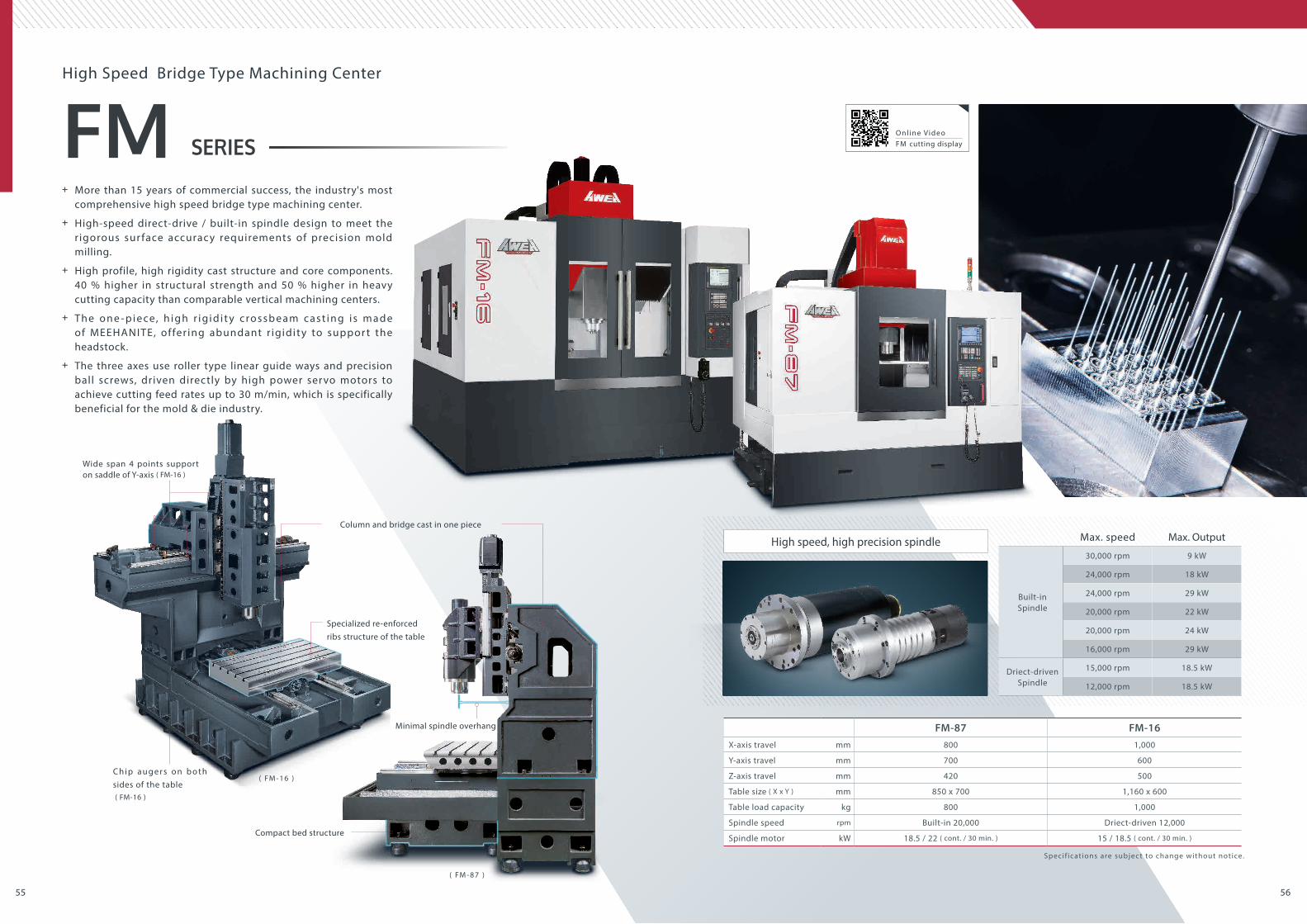
FM-87 FM-16X-axis travel mm 800 1,000
Y-axis travel mm 700 600
Z-axis travel mm 420 500
Table size ( X x Y ) mm 850 x 700 1,160 x 600
Table load capacity kg 800 1,000
Spindle speed rpm Built-in 20,000 Driect-driven 12,000
Spindle motor kW 18.5 / 22 ( cont. / 30 min. ) 15 / 18.5 ( cont. / 30 min. )
Max. speed Max. Output
Built-in Spindle
30,000 rpm 9 kW
24,000 rpm 18 kW
24,000 rpm 29 kW
20,000 rpm 22 kW
20,000 rpm 24 kW
16,000 rpm 29 kW
Driect-driven Spindle
15,000 rpm 18.5 kW
12,000 rpm 18.5 kW
Column and bridge cast in one piece
Minimal spindle overhang
Compact bed structure
( FM - 8 7 )
Specialized re-enforced ribs structure of the table
Wide span 4 points support on saddle of Y-axis ( FM-16 )
C h i p a u g e r s o n b o t h sides of the table ( FM-16 )
( FM - 1 6 )
High Speed Bridge Type Machining Center
+ More than 15 years of commercial success, the industry's most comprehensive high speed bridge type machining center.
+ High-speed direct-drive / built-in spindle design to meet the r igorous sur face accuracy requirements of precision mold milling.
+ High profile, high rigidity cast structure and core components. 40 % higher in structural strength and 50 % higher in heavy cutting capacity than comparable vertical machining centers.
+ Th e o n e - p i e ce, h i g h r i g i d i t y c ro s s b e a m c a s t i n g i s m a d e of MEEHANITE, offer ing abundant r igidity to suppor t the headstock.
+ The three axes use roller type linear guide ways and precision ball screws, driven directly by high power servo motors to achieve cutting feed rates up to 30 m/min, which is specifically beneficial for the mold & die industry.
High speed, high precision spindle
Specif ications are subject to change without notice.
Onl ine VideoFM cutting display

5857
BMSERIES
BM-850 BM-1020 BM-1200 BM-1460 BM-1400 BM-1600 BM-1800 BM-2100 BM-2500X-axis travel mm 850 1,020 1,200 1,400 1,400 1,600 1,800 2,100 2,500
Y-axis travel mm 600 800 1,000
Z-axis travel mm 600 700 800 1,000
Table size ( X x Y ) mm 1,050 x 600 1,120 x 600 1,300 x 600 1,500 x 650 1,500 x 800 1,700 x 800 2,000 x 800 2,300 x 1,000 2,700 x 1,000
Table load capacity kg 850 1,000 1,200 1,400 1,800 2,000 2,200 3,000 4,000
Spindle speed rpm Gear spindle 8,000 Gear spindle 6,000
Spindle taper BBT40 ( BBT50 Opt. ) BBT50 ( BBT40 Opt. ) BBT50
The gear spindle combined with a High-Low 2 step gear box design, provides a large torque output and fulfill to match heavy cutting requirements (optional belt-driven and direct-driven spindles are also available)
Three axes box guide way are precision ground after heat treatment, meeting the rigid requirements for heavy cutting applications.
The contact surfaces of between the machine base and the column, as well as the ball screw holders of table, saddle, and headstock are hand scraped to provide excellent assembly precision and load distribution, ensuring long term accuracy.
The rigid ( Delta ) column structure provides an excellent basis for the distribution of heavy loads and offers superior cutting stability.
Gear spindleA
High rigidity box guide wayB
Hand scraped craftsmanshipC
( Delta ) wide span column structureD
* 1 : A l s o a v a i l a b l e f o r t h e A F s e r i e s .
A
C D
B
+ High torque spindle and box guide way on all 3 axes, provide optimal heavy-duty cutting capabilities.
+ AWEA craftsmanship, evident in precisely hand scraped contact sur faces, ensures best assembly precision and structural strength.
+ Complete product portfolio, spindle taper sizes # 40 and # 50 available.
+ The quantity of chip augers depends on the size of the machine, to provide optimal chip removal solution.
+ 24T (standard) / 30T / 36T / 60T arm type tool magazine. High speed servo ATC is optionally available.
+ Automatic Pallets Changer ( Opt. )*1
High rigidity base with 6 guide ways
The base of the BM-2100/BM-2500 is equipped w i t h 6 g u i d e w a y s , p ro v i d i n g f u l l s u p p o r t w i t h o u t o v e r h a n g f o r t h e t a b l e t o a v o i d eliminate deflection and ensure the enhance table rigidity.
Specif ications are subject to change without notice.
Vertical Machining Centers
6059
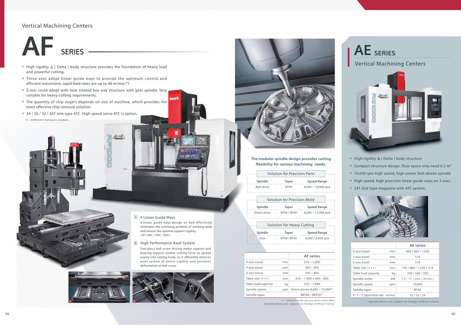
AF seriesX-axis travel mm 510 ~ 1,800
Y-axis travel mm 400 ~ 800
Z-axis travel mm 330 ~ 800
Table size ( X x Y ) mm 610 ~ 1,900 x 400 ~ 800
Table load capacity kg 250 ~ 1,800
Spindle speed rpm Driect-driven 8,000 ~ 15,000*1
Spindle taper BBT40 / BBT50*1
*1:Individual models may vary, please contact AWEA.
AF SERIES
Specif ications are subject to change without notice.
Vertical Machining Centers
AE seriesX-axis travel mm 600 / 800 / 1,020
Y-axis travel mm 510
Z-axis travel mm 510
Table size ( X x Y ) mm 750 / 860 / 1,200 x 510
Table load capacity kg 500 / 500 / 700
Spindle motor kW 7.5 / 11 ( cont. / 30 min. )
Spindle speed rpm 10,000
Spindle taper BT40
X / Y / Z rapid feed rate m/min 32 / 32 / 24
AE SERIES
+ High rigidity ( Delta ) body structure
+ Compact structure design, floor space only need 6.5 m2
+ 10,000 rpm high speed, high power belt-driven spindle
+ High speed, high precision linear guide ways on 3 axes.
+ 24T disk type magazine with ATC system.
Specif ications are subject to change without notice.
Vertical Machining Centers
* 1 : D i f f e r e n t b e t w e e n m o d e l s .
+ High rigidity ( Delta ) body structure provides the foundation of heavy load and powerful cutting.
+ Three axes adopt l inear guide ways to provide the optimum control and efficient movement, rapid feed rates are up to 48 m/min.*1
+ Z-axis could adopt with heat treated box way structure with gear spindle. Very suitable for heavy cutting requirements.
+ The quantity of chip augers depends on size of machine, which provides the most effective chip removal solution.
+ 24 / 30 / 32 / 40T arm type ATC. High speed servo ATC is option.
The modular spindle design provides cutting flexibility for various machining needs.
Spindle Taper Speed Range
Belt-drive BT40 8,000 ~ 10,000 rpm
Spindle Taper Speed Range
Direct-drive BT40 / BT50 8,000 ~ 15,000 rpm
Spindle Taper Speed Range
Gear BT40 / BT50 8,000 / 6,000 rpm
4 l inear guide ways design on bed effectively eliminates the overhang problem of working table and ensure the optimal support rigidity. ( AF-1400 / 1600 / 1800 )
One-piece ball screw driving motor support and bearing support enable cutting force to spread evenly into casting body, so it efficiently ehances a x i a l s ys te m o f e n t i re r i g i d i t y a n d p re ve n t s deformation of ball screw.
4 Linear Guide Ways
High Performance Axial System
A
A B
B
Solution for Precision Parts
Solution for Precision Mold
Solution for Heavy Cutting

6261
VERTICAL MACHINING CENTERS
P57 P59 P60
FCV-800 Series
P25Gantry Type 5-axisMachining Centers
P31
MCP Series
Moving Column Bridge Type Multi-face Machining Centers
BM Series
Super Rigid Vertical Machining Centers
AF Series
High Performance Vertical Machining Centers
AE Series
High Performance Vertical Machining Centers
GF Series
Graphite Milling Machining Centers
P33
MVP Series
Moving Cross Beam BridgeType Multi-face Machining Centers
P34
HVM Series
Bridge Type Multi-faceMachining Centers
LP-F Series
P35Bridge Type Multi-faceMachining Centers
FCV-620 Series
P27High Speed 5-axisMachining Centers
FV Series
P28Vertical 5-axisMachining Centers
AG5 SeriesGantry Type 5-axisMachining Centers
P21 Gantry Type 5-axisMachining Centers
RG5 Series
P22 Gantry Type 5-axisMachining Centers
MEGA5 G Series
P23
High Speed Bridge Type Machining Centers
Bridge Type 5-axisMachining Centers
MEGA5 P Series
P23
X : 1,600 ~ 3,200 mmY : 2,000 mmZ : 1,000 mmB : ±100° C : ±240° ( TCH-19F )
X : 800 mmY : 900 mmZ : 660 mmA : -120° ~ +30° C : ±360°
X : 8,000 ~ 20,000 mmY : 4,400 / 5,400 mmZ : 1,200 mm
X : 850 ~ 2,500 mmY : 600 / 1,000 mmZ : 600 ~ 1,000 mm
X : 510 ~ 1,800 mmY : 400 ~ 800 mmZ : 330 ~ 800 mm
X : 600 / 800 / 1,020 mmY : 510 mmZ : 510 mm
X : 650 ~ 1,400 mmY : 510 ~ 620 mmZ : 510 ~ 620 mm
X : 3,060 ~ 7,000 mmY : 2,500 ~ 4,500 mmZ : 1,000 ~ 1,400 mm
X : 3,000 ~ 7,000 mmY : 2,800 / 3,200 / 4,500 mmZ : 760 ~ 1,400 mm
X : 4,000 ~ 8,000 mmY : 3,200 / 4,000 mmZ : 1,000 ~ 1,400 mmW : 1,250 mm
X : 635 mmY : 535 mmZ : 460 mmB : -50° ~ +110° C : ±360°
X : 610 mmY : 610 mmZ : 610 mmA : -120° ~ +42° B : ±360°
X : 560 / 960 mmY : 510 / 600 mmZ : 460 / 480 mmA : -42° ~ +120° C : ±360° ( FV-960 )
X : 1,600 ~ 3,200 mmY : 2,500 mmZ : 1,000 mmB : ±100° C : ±240° ( TCH-20F )
X : 4,000 ~ 10,000 mmY : 3,700 ~ 4,700 mmZ : 1,200 / 1,400 mmB : ±110° C : ±240° ( TCH-30F )
X : 2,500 ~ 6,000 mmY : 2,620 / 3,200 mmZ : 1,000 / 1,200 mmB : ±110° C : ±240° ( TCH-30F )
X : 4,000 ~ 20,000 mmY : 3,000 ~ 7,000 mmZ : 1,000 ~ 1,400 mm
X : 1,600 ~ 6,000 mmY : 1,200 mmZ : 760 mm
X : 1,500 / 2,000 mmY : 1,200 mmZ : 900 mmW : 500 mm
X : 3,200 ~ 8,200 mmY : 2,100 ~ 4,900 mmZ : 850 ~ 1,400 mm
X : 800 / 1,000 mmY : 700 / 600 mmZ : 420 / 500 mm
X : 780 / 1,020 mmY : 670 / 900 mmZ : 650 / 900 mm
X : 4,000 ~ 8,000 mmY : 3,200 ~ 4,800 mmZ : 1,000 ~ 1,400 mm
X : 3,000 ~ 10,000 mmY : 1,800 ~ 3,600 mmZ : 450 mmV : 1,300 ~ 2,500 mmW : 900 mm
X : 1,700 mmY : 1,350 / 1,150 mmZ : 1,200 mm
X : 510 / 610 mmY : 510 / 610 mmZ : 510 / 610 mm
X : 3,000 ~ 7,000 mmY : 2,100 ~ 4,800 mmZ : 760 ~ 1,400 mm
X : 2,000 ~ 4,000 mmY : 1,800 ~ 2,400 mmZ : 1,300 / 1,700 mmW : 600 mm
Horizontal 5-axis Machining Centers
EH5 Series
P29
5-AXIS MACHINING CENTERS
Multi-FACE MACHINING CENTERS
VP-HS Series
P53 P55High Speed Bridge Type Machining Centers
FM Series
Floor Type HorizontalBoring Mills
P38
JB Series
Heavy LoadHorizontal Boring Mills
BL Series
P37
Horizontal Machining Centers
EH Series
High PrecisionHorizontal Boring Mills
MB Series
P39 Horizontal Machining Centers
AH Series
P43
Gantry Type Machining Center
LG Series
P45 Super RigidBridge Type Machining Center
HP Series
P48 Super RigidBridge Type Machining Center
HTP Series
P47 Bridge Type Machining Centers
LP Series
P49
X : 2,100 ~ 4,000 mmY : 1,600 mmZ : 760 mm
Bridge Type Machining Centers
SP Series
P51
X : 3,000 ~ 5,000 mmY : 1,600 ~ 2,500 mmZ : 760 / 1,000 mm
Bridge Type Machining Centers
EP Series
P50
X : 1,600 ~ 6,000 mmY : 1,200 mmZ : 760 mm
Bridge Type Machining Centers
VP Series
P54
X : 2,000 / 3,000 mmY : 1,200 mmZ : 760 mm
Super Rigid Bridge Type Machining Centers
HD Series
P52
Horizontal Machining Centers
P41
AHM Series
BRIDGE TYPE MACHINING CENTERS
HIGH SPEED BRIDGE TYPE MACHINING CENTERS HORIZONTAL MACHINING CENTERS
HORIZONTAL MACHINING CENTERS

Copyright 2019 by AWEA Mechantronic Co., Ltd. All right reservedA-Journal-EN-201902
AWEA MECHANTRONIC CO., LTD.
HEADQUARTERS
CTSP BRANCH
629, Suezhetou Section, Kwanpu Rd.,Wenshan Li, Xinpu, Hsinchu 305, Taiwan
TEL : +886-3-588-5191FAX : +886-3-588-5194
15, Keyuan 2nd Rd., Central Taiwan Science Park,Taichung 407, Taiwan
TEL : +886-4-2462-9698FAX : +886-4-2462-8002E-mail : [email protected] : www.AWEA.com