avoiso: A ray based program for P-SV synthetic seismogram ...
10
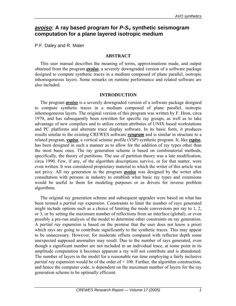
AVO synthetics CREWES Research Report — Volume 17 (2005) 1 avoiso : A ray based program for P-S V synthetic seismogram computation for a plane layered isotropic medium P.F. Daley and R. Maier ABSTRACT This user manual describes the meaning of terms, approximations made, and output obtained from the program avoiso , a severely downgraded version of a software package designed to compute synthetic traces in a medium composed of plane parallel, isotropic inhomogeneous layers. Some remarks on runtime performance and related software are also included. INTRODUCTION The program avoiso is a severely downgraded version of a software package designed to compute synthetic traces in a medium composed of plane parallel, isotropic inhomogeneous layers. The original version of this program was written by F. Hron, circa 1970, and has subsequently been rewritten for specific ray groups, as well as to take advantage of new compilers and to utilize certain attributes of UNIX based workstations and PC platforms and alternate trace display software. In its basic form, it produces results similar to the existing CREWES software syngram and is similar in structure to a related program, vspiso , a vertical seismic profile (VSP) synthetic program. It, like vspiso , has been designed in such a manner as to allow for the addition of ray types other than the most basic ones. The ray generation scheme is based on combinatorial methods, specifically, the theory of partitions. The use of partition theory was a late modification, circa 1990. Few, if any, of the algorithm descriptions survive, or for that matter, were even written. It was considered proprietary material to which the writer of this article was not privy. All ray generation in the program avoiso was designed by the writer after consultation with persons in industry to establish what basic ray types and extensions would be useful to them for modeling purposes or as drivers for inverse problem algorithms. The original ray generation scheme and subsequent upgrades were based on what has been termed a partial ray expansion. Constraints to limit the number of rays generated might include options such as a choice of limiting the mode conversions per ray to 1, 2, or 3, or by setting the maximum number of reflections from an interface (global), or even possibly a pre-run analysis of the model to determine other constraints on ray generation. A partial ray expansion is based on the premise that the user does not know a priori which rays are going to contribute significantly to the synthetic traces. This may appear to be unnecessary. However, for moderate offsets compared with reflector depth some unexpected supposed anomalies may result. Due to the number of rays generated, even though a significant number are not included in an individual trace, at some point in its amplitude computation it becomes apparent a ray will not contribute and is abandoned. The number of layers in the model for a reasonable run time employing a fairly inclusive partial ray expansion would be of the order of < 100. Further, the algorithm construction, and hence the computer code, is dependent on the maximum number of layers for the ray generation scheme to be optimally efficient.
-
Upload
khangminh22 -
Category
Documents
-
view
4 -
download
0
Transcript of avoiso: A ray based program for P-SV synthetic seismogram ...
AVO synthetics
CREWES Research Report — Volume 17 (2005) 1
avoiso: A ray based program for P-SV synthetic seismogram computation for a plane layered isotropic medium
P.F. Daley and R. Maier
ABSTRACT This user manual describes the meaning of terms, approximations made, and output
obtained from the program avoiso, a severely downgraded version of a software package designed to compute synthetic traces in a medium composed of plane parallel, isotropic inhomogeneous layers. Some remarks on runtime performance and related software are also included.
INTRODUCTION The program avoiso is a severely downgraded version of a software package designed
to compute synthetic traces in a medium composed of plane parallel, isotropic inhomogeneous layers. The original version of this program was written by F. Hron, circa 1970, and has subsequently been rewritten for specific ray groups, as well as to take advantage of new compilers and to utilize certain attributes of UNIX based workstations and PC platforms and alternate trace display software. In its basic form, it produces results similar to the existing CREWES software syngram and is similar in structure to a related program, vspiso, a vertical seismic profile (VSP) synthetic program. It, like vspiso, has been designed in such a manner as to allow for the addition of ray types other than the most basic ones. The ray generation scheme is based on combinatorial methods, specifically, the theory of partitions. The use of partition theory was a late modification, circa 1990. Few, if any, of the algorithm descriptions survive, or for that matter, were even written. It was considered proprietary material to which the writer of this article was not privy. All ray generation in the program avoiso was designed by the writer after consultation with persons in industry to establish what basic ray types and extensions would be useful to them for modeling purposes or as drivers for inverse problem algorithms.
The original ray generation scheme and subsequent upgrades were based on what has been termed a partial ray expansion. Constraints to limit the number of rays generated might include options such as a choice of limiting the mode conversions per ray to 1, 2, or 3, or by setting the maximum number of reflections from an interface (global), or even possibly a pre-run analysis of the model to determine other constraints on ray generation. A partial ray expansion is based on the premise that the user does not know a priori which rays are going to contribute significantly to the synthetic traces. This may appear to be unnecessary. However, for moderate offsets compared with reflector depth some unexpected supposed anomalies may result. Due to the number of rays generated, even though a significant number are not included in an individual trace, at some point in its amplitude computation it becomes apparent a ray will not contribute and is abandoned. The number of layers in the model for a reasonable run time employing a fairly inclusive partial ray expansion would be of the order of < 100. Further, the algorithm construction, and hence the computer code, is dependent on the maximum number of layers for the ray generation scheme to be optimally efficient.
Daley and Maier
2 CREWES Research Report — Volume 17 (2005)
Very specific subsets of rays that comprise the partial ray expansion ray set are generated for the medium, over which the user has some moderate control. Amplitudes are computed using zero order Asymptotic Ray Theory (ART). Critically refracted (head) wave computations have been disabled.
The program exists in two versions, one for a UNIX platform with an ANSI C compiler and a SUN FORTRAN77 compiler SC3.0.1 or higher, or on a PC Linux operating system with an ANSI C compiler and a FORTRAN compiler of the Lahey FORTRAN90 variety or equivalent. The actual compiling of the program routines is done at the highest optimization level, with vectorization and parallelization set on where applicable. Parallel processing may be done more efficiently with code abandoned in the mid 1990s but as this process is integrated in the newer generation of compilers this code is semi-obsolete.
The only ray types considered in this program are:
1. P-primary (PP) reflected rays.
2. VPS primary: P down – VS up ( VPS ) reflected rays.
PROGRAM INPUT The program input consists mainly of prompts to the user at run time and is usually
contained in some file, say input, so that the program may be invoked on a UNIX system by issuing the command: " avoiso < input & "
The user is prompted for:
1. A rootname which is particular to that run. A file named rootname.data must exist. A number of files, rootname.files, are created and their contents and use are described below.
a. A file containing the elastic parameters of the layers of the model are contained in the file rootname.data. Each of the mlay+1 lines in the this file contains: P-wave velocity, VS -wave velocity, layer thickness and density in consistent units for each layer in the model together with the underlying halfspace, a total of mlay+1 lines.
b. The file rootname.info contains some information that may be of interest to the user regarding the run of avoiso. If more output is required by the user contact the author with what is desired in this file. It was originally for debug purposes but could contain more information for the user with regard to what occurred during the run and what constituted the input data and some indication of certain quantities which were computed during the run.
AVO synthetics
CREWES Research Report — Volume 17 (2005) 3
c. rootname.vert – output file containing the vertical component of displacement of the synthetic traces computed for the offsets specified and written in SU (Seismic Unix) format.
d. rootname.horz – output file containing the horizontal component of displacement of the synthetic traces computed for the offsets specified and written in SU (Seismic Unix) format.
e. rootname_v.segy – output file containing the vertical component of displacement of the synthetic traces computed for the offsets specified, written in SEGY format.
f. rootname_h.segy – output file containing the horizontal component of displacement of the synthetic traces computed for the offsets specified, written in SEGY format.
2. Number of layers in model, mlay. This number does not include the halfspace.
3. Sampling rate nsi in ms. If nsi is greater than 20 then the sampling rate is assumed to be in sµ .
4. A Gabor wavelet is used. Both the predominant frequency, 0f , and damping factor, γ , are required to specify the wavelet. The dimensionless damping factor, γ , should be in the range 4 5γ≤ ≤ . At a user’s request any of a number of other wavelets could be incorporated, or ideally, become available from a menu. The Gabor wavelet is defined as
( ) [ ]2
00
2sin 2 exp f tf t f t ππγ
⎡ ⎤⎛ ⎞= −⎢ ⎥⎜ ⎟⎝ ⎠⎢ ⎥⎣ ⎦
5. Length of traces in seconds, MAXt .
6. P – primaries to be included: t or f
7. VPS – primaries to be included: t or f
8. (i). Number of traces, (ii). near trace offset and (iii). trace spacing are asked to be input in free format on a single line.
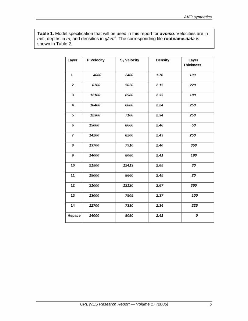
NUMERICAL RESULTS Using the data file in Table 2 and Figure 1, a number of test runs of the program
avoiso were performed. This data file consists of 14 layers over a halfspace. This program has been used for models with 2000 + layers (velocity-density-depth logs). In circumstances such as this only the PP and VPS flags are set . .true as even the number of first order unconverted PP multiples increases run time considerably. This also has little effect on the synthetic as for models with large number of layers a significant
Daley and Maier
4 CREWES Research Report — Volume 17 (2005)
number of the shallow reflectors are not included in the synthetic trace. The rays are traced through these layers to focus on some region of interest at depth. The shallow layers are used in the computation of the ray parameter of a specific ray, but the events from the shallow reflectors are not included in the trace.
In the examples presented here the raw vertical or horizontal component of particle displacement are shown. No processing such as NMO correction is applied and no gain of any type is used. The time window has been purposely cut short so that late arrivals do not appear on the traces, one of the advantages of asymptotic ray theory.
The figure captions contain the necessary information to describe what is being plotted in each panel. Time along the vertical axes is in ms while the offsets are 100m apart. A Gabor wavelet is used with a predominant frequency of 0 60f Hz= and a dimensionless damping factor 4γ = . The time sampling rate for all figures is 1ms .
It is evident from Figures 3 – 5 what the reflections in the vertical and horizontal components of displacement are related to the "region of interest".
CONCLUSIONS AVO synthetic seismograms were produced for plane layered medium for an extremely simple ray generation scheme in that only a fundamental subset of rays comprising a partial ray expansion are considered in the production of the synthetic traces. On a more positive note this program requires a minimum of interaction by the user and can produce at least a gross estimate of the total seismic response in a timely manner. Also, as a result of the fast execution time of this program, even for models with numerous layers and receivers, it may be incorporated into an iterative scheme for a linearized inverse problem.
REFERENCES Červený, V. and Ravindra. R, 1970, Theory of Seismic Head Waves: University of Toronto Press. Červený, V., Molotkov, I.A. and Psencik, I., 1977, Ray Method in Seismology: Charles University Press,
Prague. Červený, V., 2001, Seismic Ray Theory: Cambridge University Press, Cambridge. Daley, P.F., 2003, Asymptotic ray theory programs: CREWES Annual Report. Hron, F., 1971, Criteria for the selection of phases in synthetic seismograms for layered media: Bull.
Seism. Soc. Am., 61, 765-779. Hron, F., 1972, Numerical methods of ray generation in multi-layered media: Methods of Computational
Physics, 12B. Eds.: Adler, S. Fernbach and B.A. Bolt (Editors), Academic Press, New York. Hron, F. and Kanasewich, E.R., 1972, Synthetic seismograms for deep sounding studies using asymptotic
ray theory: Bull. Seism. Soc. Am., 36, 607-625. Hron, F., Kanasewich, E.R. and Alpaslan, T., 1974, Partial ray expansion required to suitably approximate
the exact wave solution: Geophys. J. Roy. astr. Soc., 36, 607-625.
AVO synthetics
CREWES Research Report — Volume 17 (2005) 5
Layer P Velocity SV Velocity Density Layer Thickness
1 4000 2400 1.76 100
2 8700 5020 2.15 220
3 12100 6980 2.33 180
4 10400 6000 2.24 250
5 12300 7100 2.34 250
6 15000 8660 2.46 50
7 14200 8200 2.43 250
8 13700 7910 2.40 350
9 14000 8080 2.41 190
10 21500 12413 2.65 30
11 15000 8660 2.45 20
12 21000 12120 2.67 360
13 13000 7505 2.37 100
14 12700 7330 2.34 225
Hspace 14000 8080 2.41 0
Table 1. Model specification that will be used in this report for avoiso. Velocities are in m/s, depths in m, and densities in g/cm3. The corresponding file rootname.data is shown in Table 2.
Daley and Maier
6 CREWES Research Report — Volume 17 (2005)
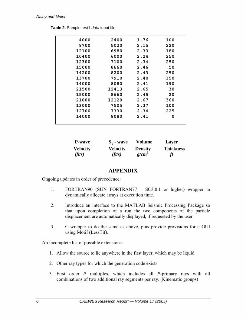
Table 2. Sample test1.data input file.
P-wave VS - wave Volume Layer Velocity Velocity Density Thickness (ft/s) (ft/s) g/cm3 ft
APPENDIX Ongoing updates in order of precedence:
1. FORTRAN90 (SUN FORTRAN77 – SC3.0.1 or higher) wrapper to dynamically allocate arrays at execution time.
2. Introduce an interface to the MATLAB Seismic Processing Package so that upon completion of a run the two components of the particle displacement are automatically displayed, if requested by the user.
3. C wrapper to do the same as above, plus provide provisions for a GUI using Motif (LessTif).
An incomplete list of possible extensions:
1. Allow the source to lie anywhere in the first layer, which may be liquid.
2. Other ray types for which the generation code exists
3. First order P multiples, which includes all P-primary rays with all combinations of two additional ray segments per ray. (Kinematic groups)
4000 2400 1.76 100 8700 5020 2.15 220 12100 6980 2.33 180 10400 6000 2.24 250 12300 7100 2.34 250 15000 8660 2.46 50 14200 8200 2.43 250 13700 7910 2.40 350 14000 8080 2.41 190 21500 12413 2.65 30 15000 8660 2.45 20 21000 12120 2.67 360 13000 7505 2.37 100 12700 7330 2.34 225 14000 8080 2.41 0
AVO synthetics
CREWES Research Report — Volume 17 (2005) 7
4. Second order P multiples which includes all P-primary rays with all combinations of four additional ray segments per ray. (Both kinematic and dynamic groups.)
5. Third order P multiples which includes all P-primary rays with all combinations of six additional ray segments per ray. (Both kinematic and dynamic groups.)
6. P- primaries with all possibilities of one mode conversion to VS type. (A special case of this is included in the synthetic - ( VPS ) reflected rays.)
7. Other ray categories may be added in a plug and play manner or may be user specified in a file.
8. If it is assumed that the source emits VS energy, some or all of the above ray types for a P wave source may be included.
9. Read specific rays from a file.
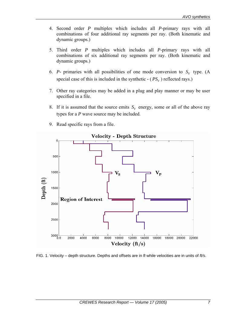
FIG. 1. Velocity – depth structure. Depths and offsets are in ft while velocities are in units of ft/s.
Daley and Maier
8 CREWES Research Report — Volume 17 (2005)
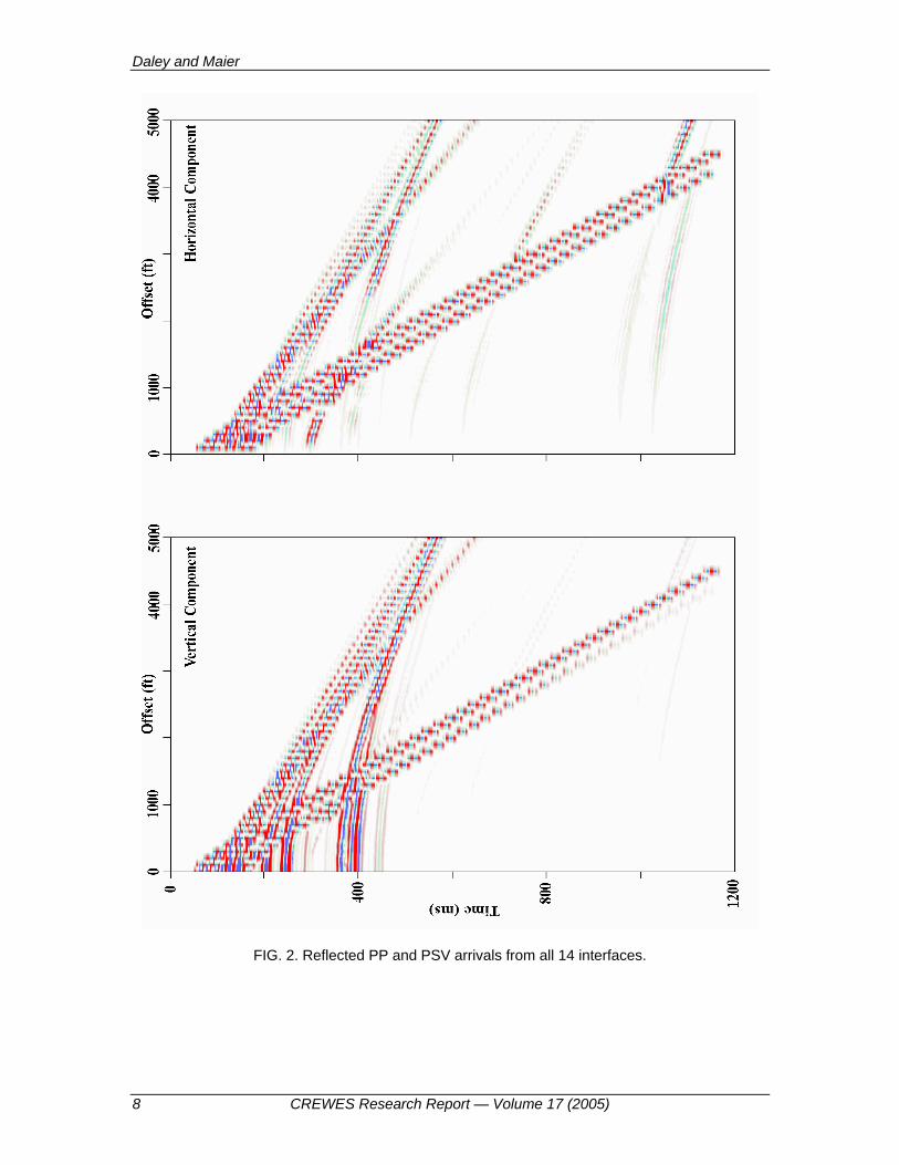
FIG. 2. Reflected PP and PSV arrivals from all 14 interfaces.
AVO synthetics
CREWES Research Report — Volume 17 (2005) 9
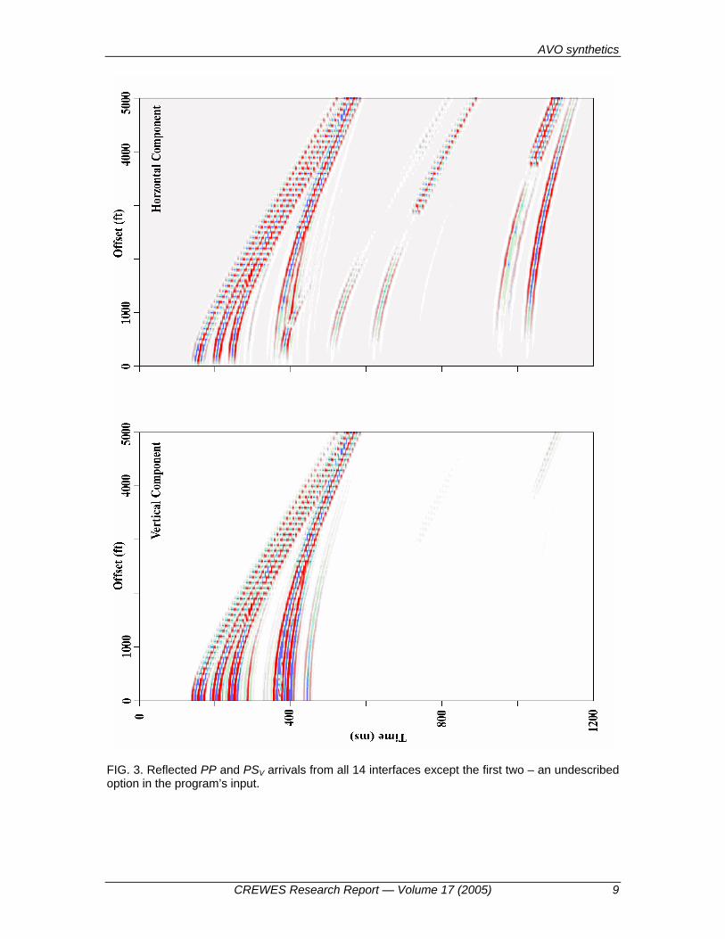
FIG. 3. Reflected PP and PSV arrivals from all 14 interfaces except the first two – an undescribed option in the program’s input.
Daley and Maier
10 CREWES Research Report — Volume 17 (2005)
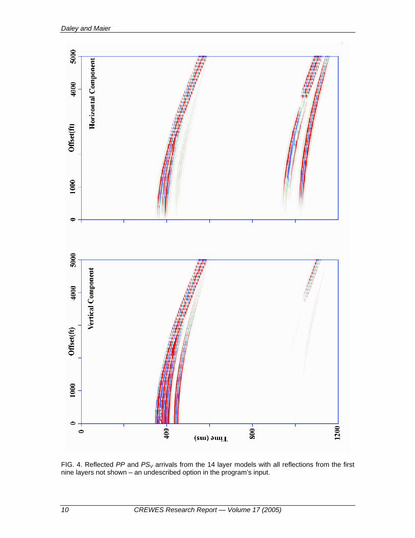
FIG. 4. Reflected PP and PSV arrivals from the 14 layer models with all reflections from the first nine layers not shown – an undescribed option in the program’s input.