Automotive Fuel Tank Sloshing Simulation Using MSC Dytran
34
Fuel Tank Sloshing Simulation Analysis utilizing MSC.Dytran Igor Demin , TI Automotive Edwin Spencer , MSC Software
-
Upload
independent -
Category
Documents
-
view
3 -
download
0
Transcript of Automotive Fuel Tank Sloshing Simulation Using MSC Dytran
Fuel Tank Sloshing Simulation Analysis utilizing MSC.DytranIgor Demin , TI AutomotiveEdwin Spencer , MSC Software
2
Abstract
• Predicting sloshing noise as early as possible during the design process has become an increasingly desired simulation for fuel tank suppliers. It enables suppliers to build products directly to customer specifications, at the minimum cost, in a shorter timeframe. Ideally, it needs to be run during the quote stage to avoid hidden obstacles later. All known solutions take from five to nine days to run the slosh test to completion. The method that has been developed at TI Automotive together with MSC Software is based on utilizing MSC.Dytran as a Hydro code and requires only few hours to run. It allows reasonably quick simulations to study the effects of varying parameters such as the acceleration field, fuel level and internal baffles on the noise generated.
• The results can be presented as an animation of the fuel sloshing in the tank and/or pressures on the surface of the tank. The time histories of points on the tank can be used to help predict sound problems within the tank.
3
TI Automotive Business Profile
• Only global supplier of fully integrated automotive fluid systems.
• The leading supplier of fluid carrying systems applications to automakers worldwide.
• Approximately two-thirds of the world’s vehicles built every year rely on fluid storage, carrying and delivery technology from TI Automotive.– TI Automotive products and technology are present on over eighty
of the top one hundred vehicle platforms.
• Annual sales of $2.5B– Employs over 18,000 people – Has more than 130 facilities – Present on 6 Continents – Operates in 28 countries
4
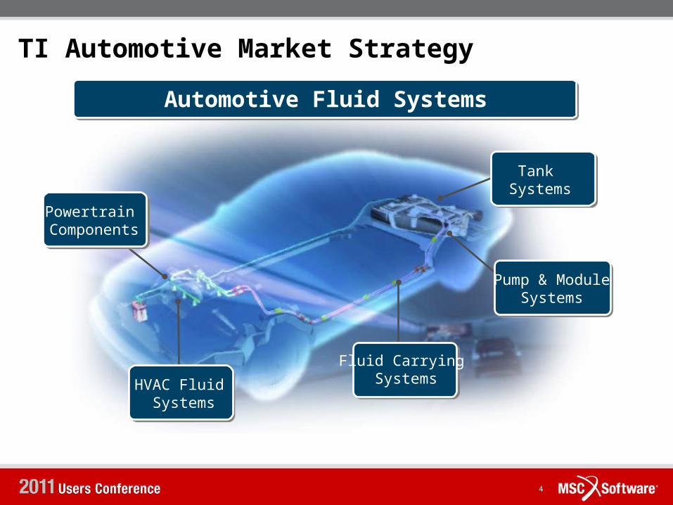
TI Automotive Market StrategyAutomotive Fluid Systems
HVAC Fluid Systems
Powertrain Components
Tank Systems
Fluid Carrying Systems
Pump & ModuleSystems
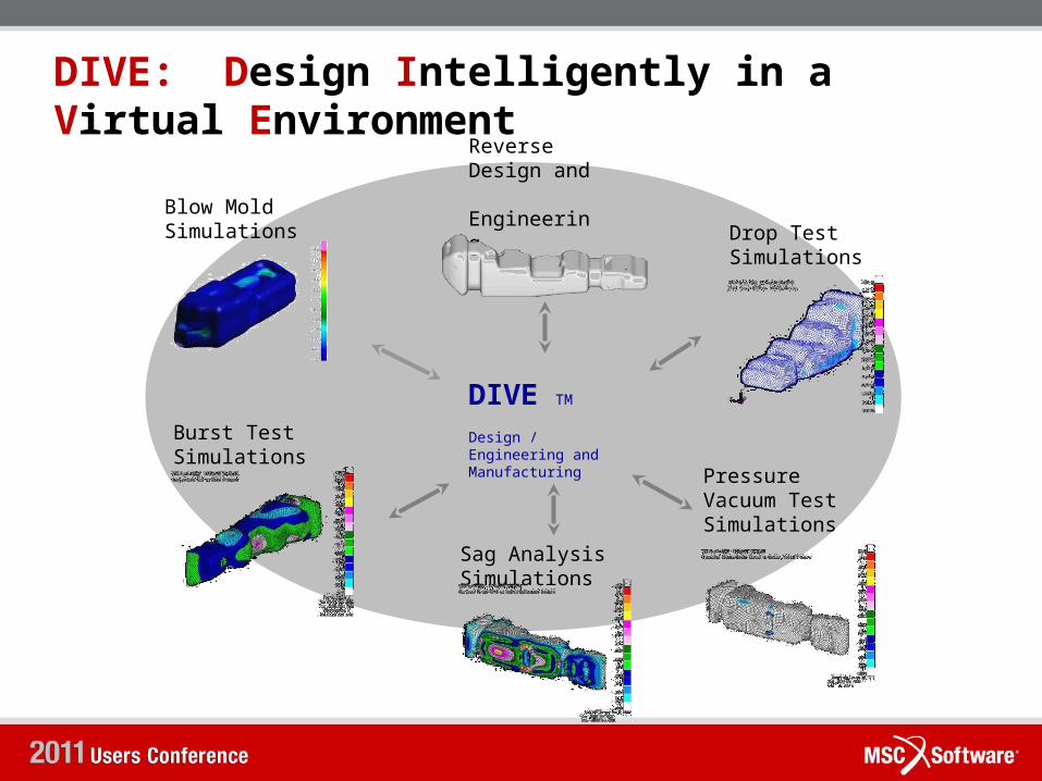
DIVE: Design Intelligently in a Virtual Environment
Blow Mold Simulations
Reverse Design and Engineering Drop Test
Simulations
Sag AnalysisSimulations
Pressure Vacuum Test Simulations
Burst Test Simulations
DIVE TM
Design / Engineering and Manufacturing
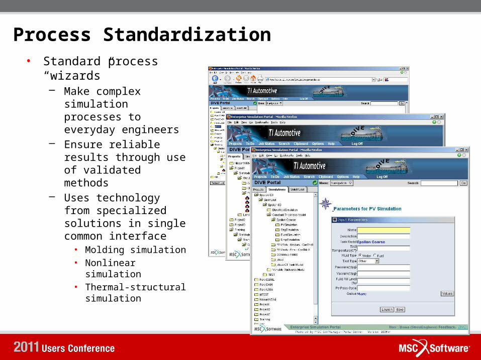
Process Standardization• Standard process
“wizards”– Make complex
simulation processes to everyday engineers
– Ensure reliable results through use of validated methods
– Uses technology from specialized solutions in single common interface• Molding simulation• Nonlinear
simulation• Thermal-structural
simulation

Process Automation• Automatically meshes
CAD geometry• Automatically runs
manufacturing simulation
• Automatically runs standard “tests” to each OEM specs– Static Loads– Drop Test– Sag Test– Burst Test– Pressure-Vacuum Test
• Automatically couples multi-discipline simulations– “as molded” wall
thicknesses– Fluid-structure
interactions– Thermal-structural
interactions• Automatically extracts
results
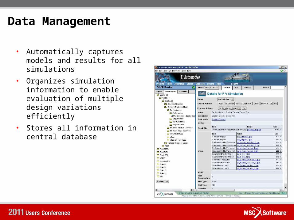
Data Management
• Automatically captures models and results for all simulations
• Organizes simulation information to enable evaluation of multiple design variations efficiently
• Stores all information in central database
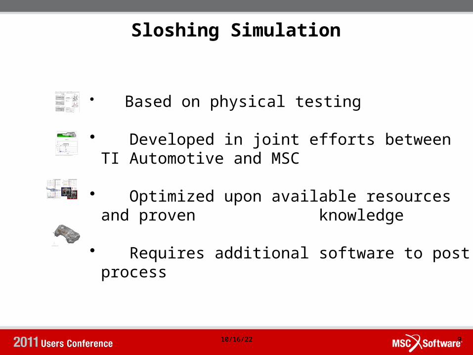
Sloshing Simulation
10/16/22 910/16/22 9
• Based on physical testing
• Developed in joint efforts between TI Automotive and MSC
• Optimized upon available resources and proven knowledge
• Requires additional software to post process
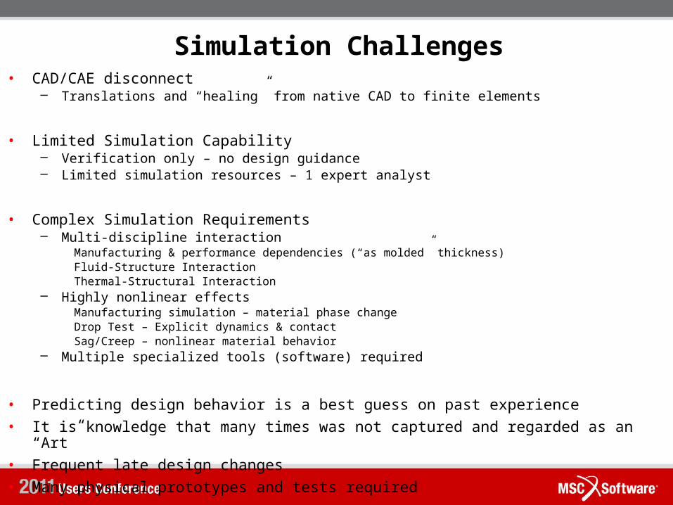
Simulation Challenges• CAD/CAE disconnect
– Translations and “healing” from native CAD to finite elements
• Limited Simulation Capability– Verification only – no design guidance– Limited simulation resources – 1 expert analyst
• Complex Simulation Requirements– Multi-discipline interaction
Manufacturing & performance dependencies (“as molded” thickness)Fluid-Structure InteractionThermal-Structural Interaction
– Highly nonlinear effectsManufacturing simulation – material phase changeDrop Test – Explicit dynamics & contactSag/Creep – nonlinear material behavior
– Multiple specialized tools (software) required
• Predicting design behavior is a best guess on past experience• It is knowledge that many times was not captured and regarded as an
“Art” • Frequent late design changes • Many physical prototypes and tests required
Fuel Tank Sloshing Test
11

Fuel Tank Sloshing – Definition of Sloshing Noise• The acceleration and deceleration of a vehicle causes the
fuel in the tank to slosh producing noise that is transmitted into the passenger compartment. There is an important performance requirement regarding sloshing noise that it should not produce sounds that the vehicle occupants might perceive as being unusual or disturbing.
10/16/22 1210/16/22 12
CAE 11-002
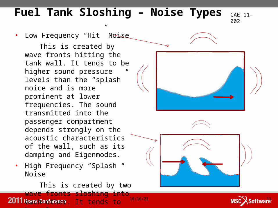
Fuel Tank Sloshing – Noise Types• Low Frequency “Hit” Noise This is created by
wave fronts hitting the tank wall. It tends to be higher sound pressure levels than the “splash” noice and is more prominent at lower frequencies. The sound transmitted into the passenger compartment depends strongly on the acoustic characteristics of the wall, such as its damping and Eigenmodes.
• High Frequency “Splash “ Noise
This is created by two wave fronts sloshing into each other. It tends to have lower sound pressure level than “hit” noise and is more prominent at higher frequencies.
10/16/22 1310/16/22 13
CAE 11-002
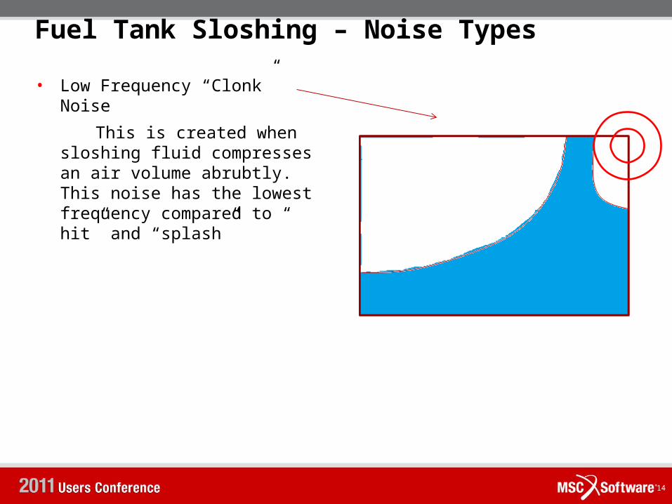
Fuel Tank Sloshing – Noise Types• Low Frequency “Clonk”
Noise This is created when
sloshing fluid compresses an air volume abrubtly. This noise has the lowest frequency compared to “ hit” and “splash”
14
Slosh Test – Customer Specs
10/16/22 1510/16/22 15
CAE 11-002
Slosh Test – Customer Specs
10/16/22 1610/16/22 16
The CAE analysis is performed as per specification below:
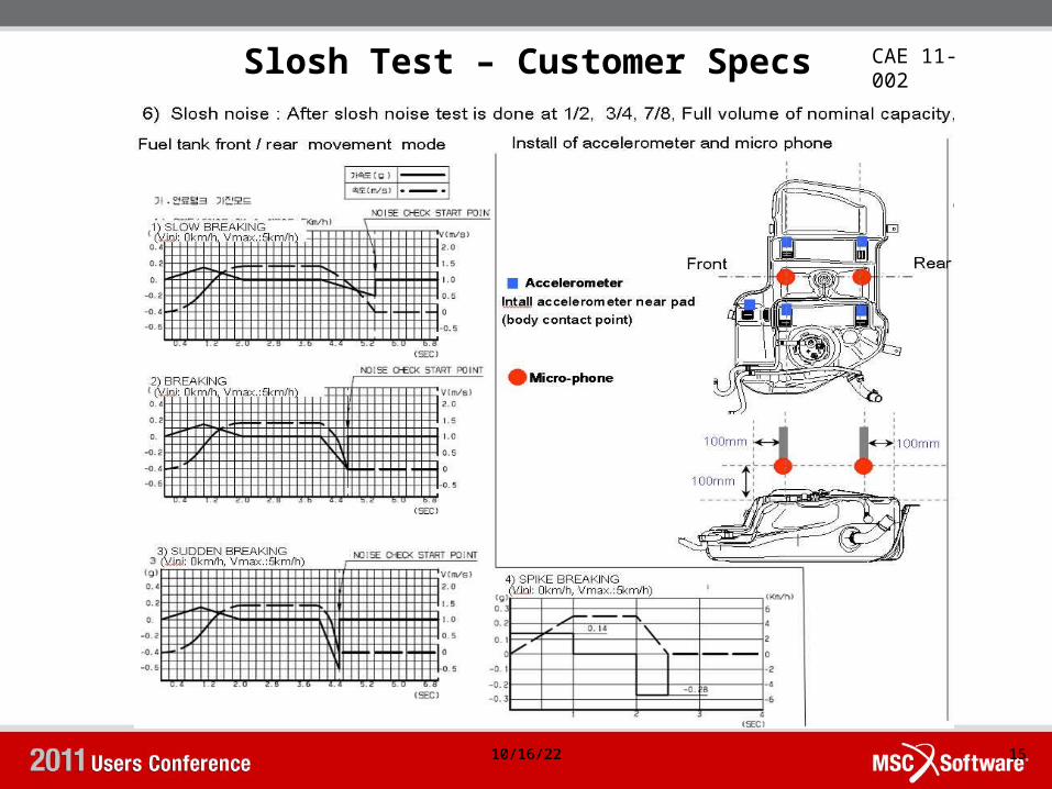
Fuel slosh noise :• At 100%, 80% and 50% of nominal volume, apply fuel tank in the horizontal state the forward/backward acceleration of 0.2g, 0.4g, 0.6g and then forward moving with back incline of 3°and backward moving with front incline of 3° should be maintained at the end of acceleration.
• The pressure gauge should be installed equally spaced at front 3 points, upper 9 points, back 3 points of the upper PNL of fuel tank
• The pressure change (difference between first pressure and peak pressure) at each side should be less than 1000Pa.

Slosh Test – Simulation Workflow
10/16/22 1710/16/22 17
Tank Math Model
Tank Shell Mesh
Slosh Model Prep
Tank FE Model
Slosh_run .dat
Eulerian Mesh Prep
Coupling Surface Prep
Slosh Eulerian Mesh .bdf
Slosh Coupling Faces .bdf
SloshSimulation
slosh_run .out
slosh_run euler .arc
Slosh_run .ths
Slosh .mpg
slosh_run tank .arc
Time graph
included
included
included
ResultsMSC.Patran MSC.DytranCAD MSC.Patran
Slosh Test – Simulation Workflow
10/16/22 1810/16/22 18
CAE 11-002
• Tank Math Model obtained from CAD has to be prepared for meshing.
• The pre-processor used is MSC.Patran and the analysis solver used is MSC.Dytran.
• It takes 14 steps in MSC.Patran from creating of fuel tank mesh to writing out a MSC.Dytran analysis deck.
• If the fuel tank has a baffle it essentially splits the Euler domain in two, therefore the adaptive Euler mesh is defined twice to cover the fluid on either side of the baffle.
• The “ MESH” cards define the adaptive Euler mesh for the fluid domains on either side of the tank which gets generated automatically for each tank location during the analysis.
• The “COUPLE” card defines the coupling surface between each Euler domain and the fuel tank.
• The tank is treated as rigid, therefore tank deformations are not accounted for in this analysis.
• The entire process ( pre-processing , solving, post-processing) takes less than 15hrs
19
Dytran Solver
• Dytran uses the Eulerian FV approach to simulate the fluid flow and Lagrangian FE solver for the Structure.
• Gas Tank or other structure entities functioning as flow boundaries are represented by Lagrangian surface (shell or membrane) elements.
• Dytran adopts a tightly-coupled approach to tie the motion of the structure with the fluid motion.
• This Coupling algorithm does not change Euler mesh connectivity therefore is computationally efficient.
• The Euler mesh adaptively changes based on the motion of the fuel tank. The Euler mesh is created by the solver during run time.
• Dytran allows to model multiple compartments tied to their own fluid domain.
• All the aforementioned traits make Dytran particularly suited for Sloshing Analysis.
20
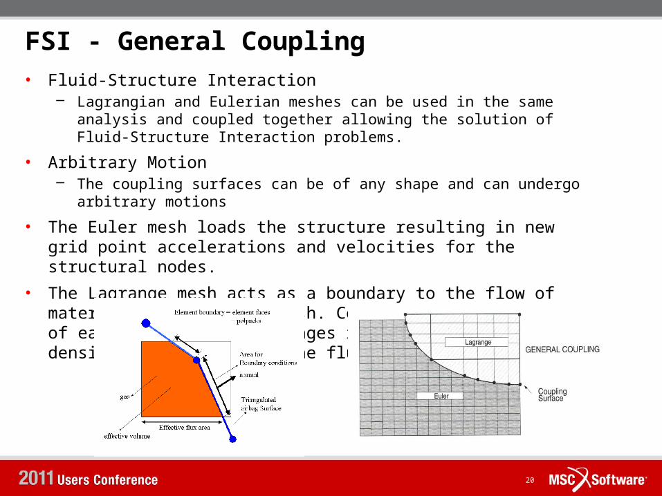
• Fluid-Structure Interaction– Lagrangian and Eulerian meshes can be used in the same
analysis and coupled together allowing the solution of Fluid-Structure Interaction problems.
• Arbitrary Motion– The coupling surfaces can be of any shape and can undergo
arbitrary motions• The Euler mesh loads the structure resulting in new
grid point accelerations and velocities for the structural nodes.
• The Lagrange mesh acts as a boundary to the flow of materials in the Euler mesh. Consequently, the volume of each fluid element changes resulting in change in density and pressure of the fluid element.
FSI - General Coupling
21
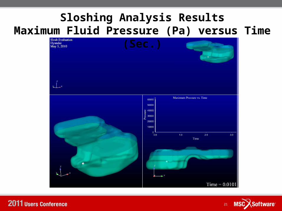
Sloshing Analysis ResultsMaximum Fluid Pressure (Pa) versus Time
(Sec.)
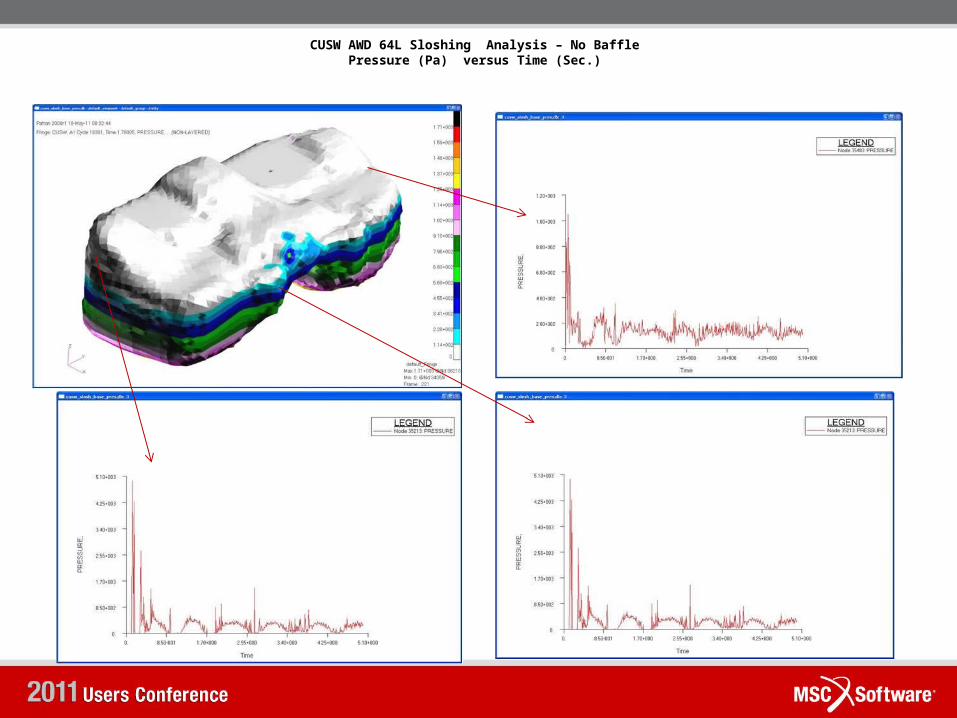
CUSW AWD 64L Sloshing Analysis – No BafflePressure (Pa) versus Time (Sec.)
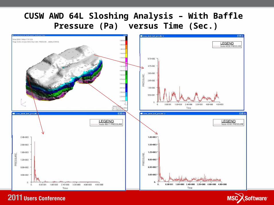
CUSW AWD 64L Sloshing Analysis – With Baffle Pressure (Pa) versus Time (Sec.)
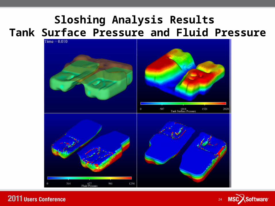
Sloshing Analysis Results Tank Surface Pressure and Fluid Pressure
(Pa)
24
Sloshing Analysis – Conclusions
10/16/22 2510/16/22 25
• MSC Dytran can accurately simulate the Fluid Structure Interaction in a sloshing process.
• Dytran’s automatic Adaptive Fluid Elements creation during run time makes pre-processing easy as the user does not need to create the elements upfront for the entire space in which the structure moves. The entire pre-processing and analysis setup takes less than 2 hrs.
• The Fast coupling FSI algorithm in the Dytran allows faster computation times ( 5 sec simulation computation in less than 12 hrs).
• Future work will involve implementation of this process in DIVE and also taking the current results as input in to an acoustic package to predict the noise outside the tank.
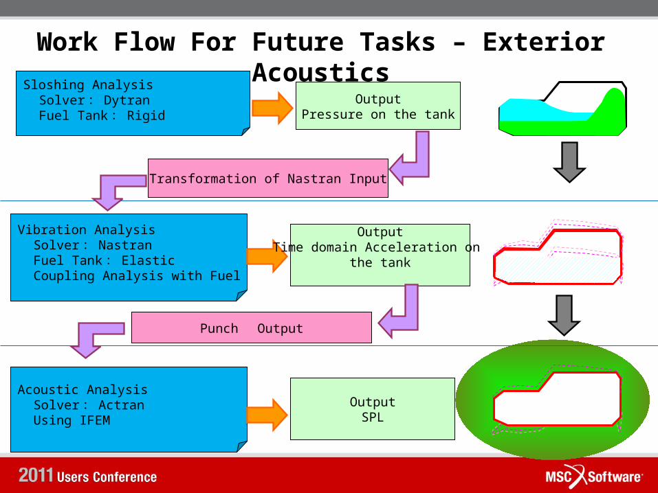
Work Flow For Future Tasks – Exterior AcousticsSloshing Analysis
Solver: Dytran Fuel Tank: Rigid
OutputPressure on the tank
Vibration Analysis Solver: Nastran Fuel Tank: Elastic Coupling Analysis with Fuel
Transformation of Nastran Input
OutputTime domain Acceleration on
the tank
Acoustic Analysis Solver: Actran Using IFEM
OutputSPL
Punch Output
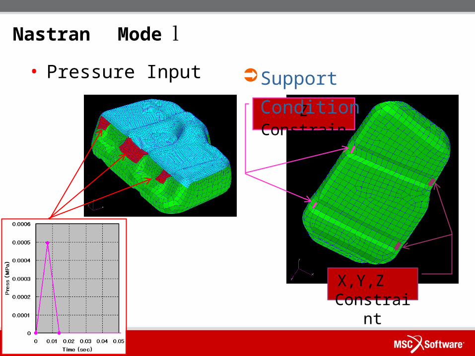
Nastran Model
• Pressure Input
Z Constrain
t
X,Y,Z Constrai
nt
Support Condition
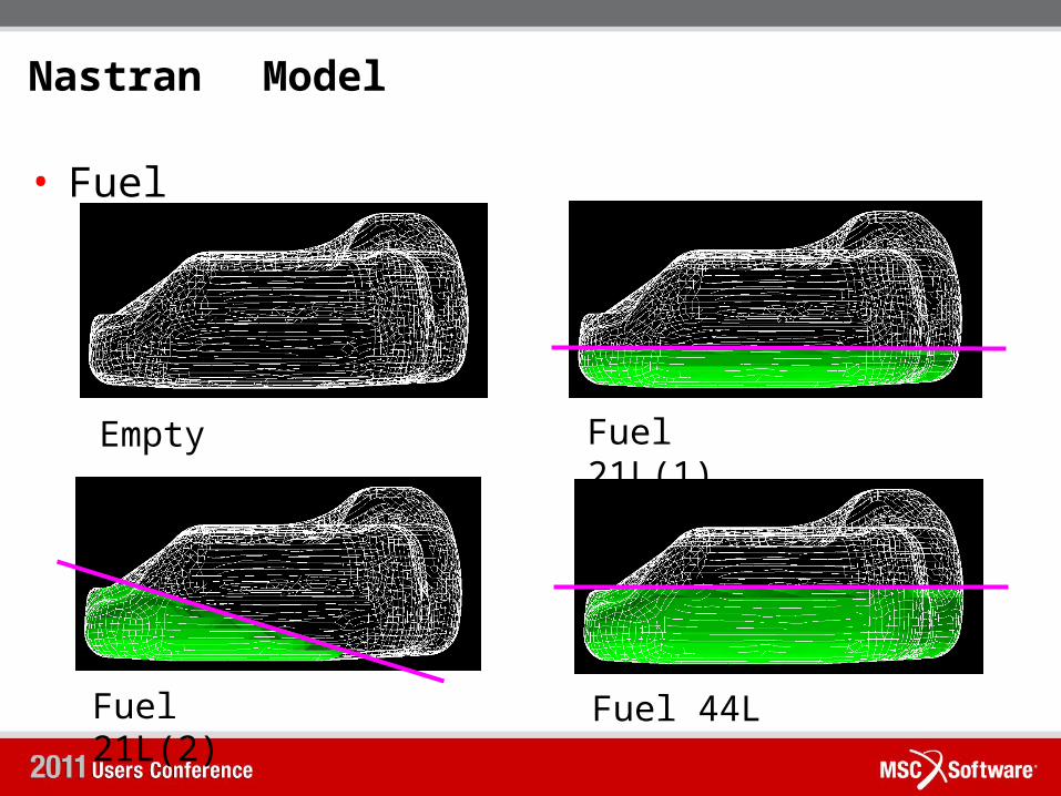
Nastran Model
• Fuel
Empty Fuel 21L(1)
Fuel 21L(2)
Fuel 44L
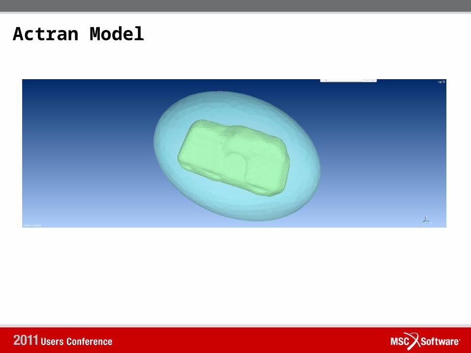
Actran Model
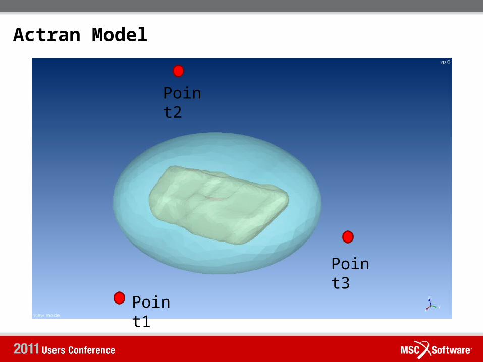
Actran Model
Point1
Point2
Point3
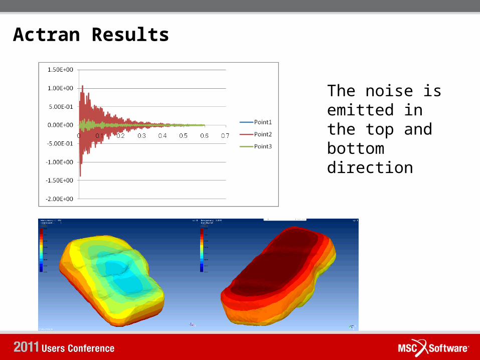
Actran Results
The noise is emitted in the top and bottom direction
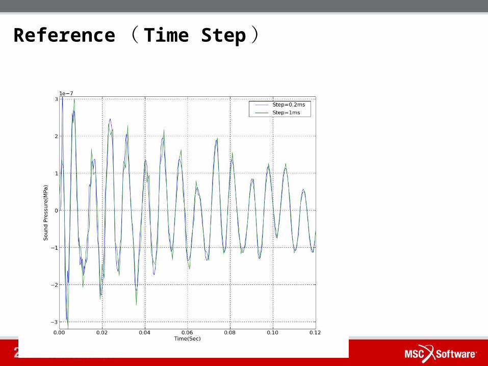
Reference( Time Step)
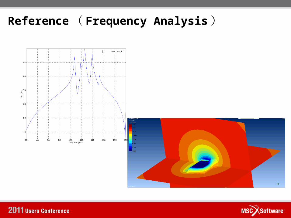
Reference( Frequency Analysis)
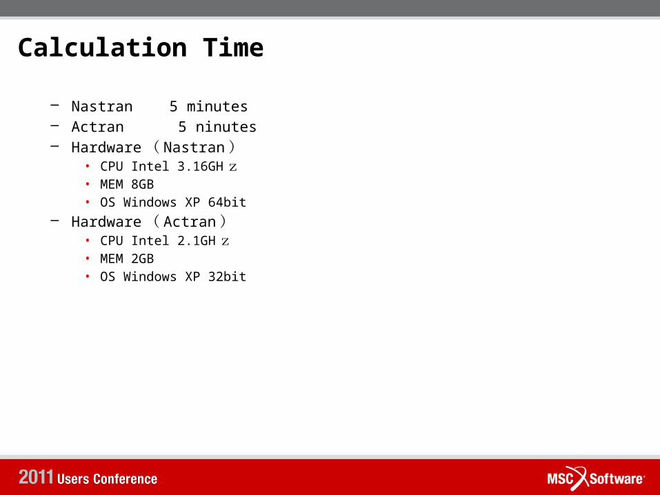
Calculation Time
– Nastran 5 minutes– Actran 5 ninutes– Hardware( Nastran)
• CPU Intel 3.16GHz• MEM 8GB• OS Windows XP 64bit
– Hardware( Actran)• CPU Intel 2.1GHz• MEM 2GB• OS Windows XP 32bit