
Automation Control Environment (ACE) Version 4 User's Manual
685
I633-E-06 Automation Control Environment (ACE) Version 4 User’s Manual
-
Upload
khangminh22 -
Category
Documents
-
view
1 -
download
0
Transcript of Automation Control Environment (ACE) Version 4 User's Manual

I633-E-06
Automation Control Environment (ACE) Version 4
User’s Manual

Copyright Notice
The information contained herein is the property of Omron Robotics and Safety Technologies Inc. andshall not be reproduced in whole or in part without prior written approval of Omron Robotics and SafetyTechnologies Inc. The information herein is subject to change without notice and should not be con-strued as a commitment by Omron Robotics and Safety Technologies Inc. The documentation is peri-odically reviewed and revised.
Copyright 2020 by Omron Robotics and Safety Technologies Inc. All rights reserved.
Any trademarks from other companies used in this publicationare the property of those respective companies.
Created in the United States of America
Table of Contents
Chapter 1: Introduction 111.1 Intended Audience 111.2 Related Manuals 111.3 Software Overview 12Configuration Wizards 12Licenses 16
1.4 Software Features 17Emulation Mode 17Application Samples 20
1.5 Robot Concepts 23Coordinate Systems 23Calibrations 31Basic Robot Motion 36Understanding Belts (Conveyors) 40
Chapter 2: Installation and Uninstallation 432.1 Installing the Software 43System Requirements 43ACE Installation Instructions 43Usage Considerations 45Other Installed Items and Software 46
2.2 Uninstalling the Software 47
Chapter 3: Creating a Project 493.1 Starting and Exiting the ACE Software 49Starting the ACE Software 49Starting Application Manager 51Automatic Project Launch on System Boot Up Procedure 51Clear Application Manager Memory 54Exiting the ACE Software 55
3.2 Creating a Project File 563.3 Saving the Project File 593.4 Saving a Project File Under a Different Name 603.5 Creating a Project from an Online Connection 613.6 Closing a Project and Returning to the Start Page 623.7 Opening a Project File 643.8 Importing a Project File 66Importing from the Start Page 66Importing from the Menu Bar in the Application Window 66Importing an .awp2 ACE Project File 67Importing from Version Control 67
3.9 Exporting a Project File 68Exporting from the Start Page 68Exporting from the Application Window 69
24000-000 Rev. H Automation Control Environment (ACE) Version 4User's Manual
3
Table of Contents
Saving an Exported Project File 703.10 Password Protection for Project Files 71Setting Password Protection for Project Files 71Removing Password Protection for Project Files 72
3.11 Project Version Numbers 72
Chapter 4: Online Connections to SmartControllers 754.1 Going Online with a SmartController 75Going Online from the Start Page 75Detect and Configure Controller 78Going Online from an Open Project 79
4.2 Going Offline with a SmartController 804.3 Memory Comparison 81
Chapter 5: Understanding the ACE User Interface 855.1 The Main Application Window 85Menu Command Structure 86Multiview Explorer 92Filter Pane 96Project Shortcut View 96Status Bar 97Edit Pane 97Multifunction Tabs 99Special Tools 100Other Application Window Functions 100
5.2 Toolbox 1065.3 3D Visualizer 1073D Visualizer Basic Features 108Creating a 3D Workspace 1083D Visualizer Window 108Graphical Collision Detection 114
5.4 Output Tab Page 1155.5 Cross Reference Tab Page 1155.6 Build Tab Page 1155.7 Event Log 116Display Messages by Event Type 116Sorting Messages 116Selecting and Copying Messages 116Clearing the Event Log 116
5.8 V+ Jog Control 117Robot Section 117Current Position Section 118Jog Control Section 119Location Section 120
5.9 Task Status Control 122Online/Offline 122Robot Power Control 122Monitor Speed Setting 123Open the Monitor Window 123Task Manager 123
4 Automation Control Environment (ACE) Version 4User's Manual
24000-000 Rev. H
Table of Contents
IO Watcher 126V+ File Browser 127Virtual Front Panel 129Profiler 131Application Manager Control 133Control Buttons 133
5.10 Vision Window 133Zoom Level 134
5.11 V+ Watch 136Adding Variables to the V+ Watch Window 136
5.12 Search and Replace 137Search Options 138Button Functions 138
5.13 User Management 139Passwords 141
5.14 Project Options 141Color Theme 142Project Settings 143Window 143V+ Programs 144Uninterruptible Power Supply (UPS) 145
Chapter 6: Programming with ACE Software 1556.1 SmartController Programming 155V+ Module and Program Structure 155Creating a New V+ Module 157Save a V+ Module to the PC 157Show Global Variable References 157Show Program Call Commands 157Pull V+ Memory 158V+ Editor 158V+ Program Debugging 166
6.2 V+ Variables 166V+ Variable Types 166
6.3 V+ Variable Editor 167V+ Variable Names 168V+ Variable Properties 168Creating a New V+ Variable 170Editing an Existing V+ Variable 171Filtering by Types and Categories 171Other V+ Variable Editor Function Keywords 171
6.4 Application Manager Programming 173Creating a New C# Program 174C# Program Editor 174
6.5 C# Variable Objects 180C# Variable Object Types 181Creating a New C# Variable Object 181Editing C# Variable Objects 181Other C# Variable Object Function Keywords 181
24000-000 Rev. H Automation Control Environment (ACE) Version 4User's Manual
5
Table of Contents
Chapter 7: SmartController Configuration and Setup 1837.1 Controller Settings 185Configuration 185Parameters 186Control 187Upgrade 190Configure 193Backup/Restore 201Encoders 203
7.2 Save Configuration 204Save Programs and Variables on Controller 205Save Belt Calibrations 205
7.3 Monitor Window 206Using the Monitor Window 206Monitor Command Entry 207Monitor Command Keyword Parameters 207Canceling a Monitor Command 208Executing a Monitor Command 208
7.4 Robot Objects 208Configure Robots 211IO EndEffectors 2123D Visualization 216Configuration 217End-Effector 220Location 221Object 222Configure 222Control 229
Chapter 8: Application Manager Configuration andSetup 2358.1 Remote Application Manager 235Remote Application Manager Set Up 236ACE Server Instance 238ACE Client Instance 240Synchronization 241Remote User Management 243
8.2 3D Visualization 243Adding Shapes 244Adding and Configuring CAD Data 245Update 3D Shapes 249Connection Points 250
8.3 ACE Sight 253Belt Latch Calibration 254Belt Calibration 257Camera Calibration 259Gripper Offset Table 260Vision Sequence 262Overlap Tool 270
6 Automation Control Environment (ACE) Version 4User's Manual
24000-000 Rev. H
Table of Contents
Communication Tool 271Saving and Loading Calibration Data 276
8.4 Camera Objects 276Virtual Cameras 277Emulation Cameras 287Basler and Sentech Cameras 288Custom Devices 290
8.5 Configuration 291Controller Connection Startup 291Data Mapper 294Note Object 296OPC Container 298Program System Startup 303Recipe Overview 305Recipe Manager 306Recipe Editor 309Recipe Manager Script 314
8.6 Feeders 316AnyFeeder Object 316IO Feeder Object 323
8.7 Process Objects 325Part Buffer Object 327Part Target Object 331Part Object 336Belt Object 341Process Manager Object 352Allocation Script Object 406Pallet Object 407Vision Refinement Station Object 413
8.8 Vision Tools 415Adding Vision Tools 418Vision Tool Editor 419Region of Interest 421Color Spaces 424Finder Tools 426Inspection Tools 487Reader Tools 532Calculation Tools 552Image Process Tools 562Custom Tools 584
Chapter 9: Troubleshooting 5919.1 Event Log 591Accessing the Event Log 592
9.2 eV+ Log 592Accessing the eV+ Log 593
9.3 FireWire Event Log 593Accessing and Clearing the FireWire Event Log 594FireWire Configuration Conflicts 595
24000-000 Rev. H Automation Control Environment (ACE) Version 4User's Manual
7

Table of Contents
Appendix A 597A.1 Configuring Basler Cameras 597Camera Connections 597Power and Communication Connections 598Configure Network and Camera Settings 599Add a Basler Camera to the ACE Project 603Position Latch Wiring 604Latch Signal Test 606
A.2 Configuring Sentech Cameras 607Camera Connections 607Sentech Power and Communication Connections 608Configure Network and Camera Settings 609Add a Sentech Camera to the ACE Project 615Position Latch Wiring 615Latch Signal Test 617
A.3 Configuring Photoneo 3D Cameras 6183D Camera Connections 6193D Camera Indicators 6213D Power and Communication Connections 622Add a 3D Camera to the ACE Project 622
A.4 Pack Manager Packaging Application Sample Exercise 630Create a Basic Pack Manager Application Sample 630Jar Packing Application Summary 640Modify the Pack Manager Application Sample Project 641Commissioning on Physical Hardware 671
A.5 Version Control Introduction 673A.6 Git Software Installation 673Installing Git 673Installing TortoiseGit 676
A.7 Version Control Configuration 679A.8 Creating a Shared Folder and Remote Repository 679Create Shared Folder 679Create a Remote Repository 680
A.9 Multiple User Configuration 680Shared Computer Repository 681Dedicated Git Server 681Internet Git Server Service 682
A.10 Exporting ACE Projects 683Save in Shared Directory 683Import a Shared Project 683
8 Automation Control Environment (ACE) Version 4User's Manual
24000-000 Rev. H
Revision History
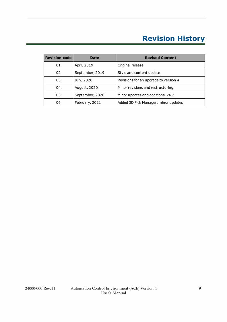
Revision code Date Revised Content
01 April, 2019 Original release
02 September, 2019 Style and content update
03 July, 2020 Revisions for an upgrade to version 4
04 August, 2020 Minor revisions and restructuring
05 September, 2020 Minor updates and additions, v4.2
06 February, 2021 Added 3D Pick Manager, minor updates
24000-000 Rev. H Automation Control Environment (ACE) Version 4User's Manual
9


Chapter 1: Introduction
This manual contains information that is necessary to use Automation Control Environment(ACE) software. Please read this manual and make sure you understand the ACE software fea-tures, functions and concepts before attempting to use it.
Use the information in this section to understand .
1.1 Intended AudienceThis manual is intended for the following personnel.
l Personnel in charge of introducing Factory Automation systems.l Personnel in charge of designing Factory Automation systems.l Personnel in charge of installing and maintaining Factory Automation systems.l Personnel in charge of managing Factory Automation systems and facilities.
1.2 Related ManualsUse the following related manuals for reference.
Manual Description
eV+3 Keyword Reference Manual (Cat. No.I652)
Provides references to eV+ Keyword use andfunctionality.
eV+ Language Reference Guide (Cat. No.I605)
Provides references to eV+language and func-tionality.
Robot Safety Guide (Cat. No. I590) Contains safety information for OMRON indus-trial robots.
S8BA-series Uninterruptible Power Supply(UPS) User’s Manual (Cat. No. U726)
Installation and operating instructions for S8BAUPS.
Sysmac Studio for Robot Integrated SystemBuilding Function with Robot IntegratedCPU Unit Operation Manual (Cat. No. W595)
Contains information that is necessary to usethe robot control function of the NJ-series CPUUnit.
Sysmac Studio for Project Version ControlFunction Operation Manual (Cat. No. W589)
Contains version control information to properlysave, import, export andmanage projects inmulti-user environments.
T20 Pendant User's Manual (Cat. No. I601) Contains information for the setup and use ofthe T20 Pendant.
24000-000 Rev. H Automation Control Environment (ACE) Version 4User's Manual
11
12 Automation Control Environment (ACE) Version 4User's Manual
24000-000 Rev. H
Chapter 1: Introduction
1.3 Software OverviewThe Automation Control Environment (ACE) software allows you to build applications, suchas Pack Manager packaging applications, which can be basic pick-and-place cells or complexcells with multiple cameras, conveyors, and robots. You can create and configure these cellswithout having to write any programming code. For applications that require greater control,you can override the default V+ program code and make changes as needed.
Because the ACE software runs on the PC, the PC must remain connected when the applic-ation is running. The only exception to this rule is when the application does not rely on anyACE functionality at run-time. In this case, ACE software can be used for setup and con-figuration and then removed for the operation of the system.
The ACE software optimizes the cell programming to maximize throughput, handle part flowand robot utilization (line balancing), and other cell parameters based on settings that you spe-cify. This is accomplished by dividing functions between the PC and the SmartController asdescribed below.
PC Functions (Application Manager Devices)
l Vision location / camera managementl Vision result filteringl Hardware / line configuration and balancing scenariosl Tracking part status as parts are processed by the robotsl 3D motion visualization of robot cell objects
Controller Functions (SmartController Devices)
l Queue managing instances that have been passed to the controller for processing. Thisincludes notifying the PC concerning the status of parts being processed and not pro-cessed.
l Robot control
Use the descriptions provided below to have a general understanding of the ACE software ter-minology, concepts, and other functionality needed to create applications. More details forthese items are provided in separate sections of this document.
Configuration Wizards
Many of the ACE software components are configured using wizards. These wizards providea series of screens that guide you through a detailed configuration process.
Selections and steps in the wizards will vary depending on the application and because ofthis, each wizard is not fully detailed in this document. Use the information provided in thewizard steps to understand the selections that are required.
An example robot-to-belt calibration wizard is shown below.
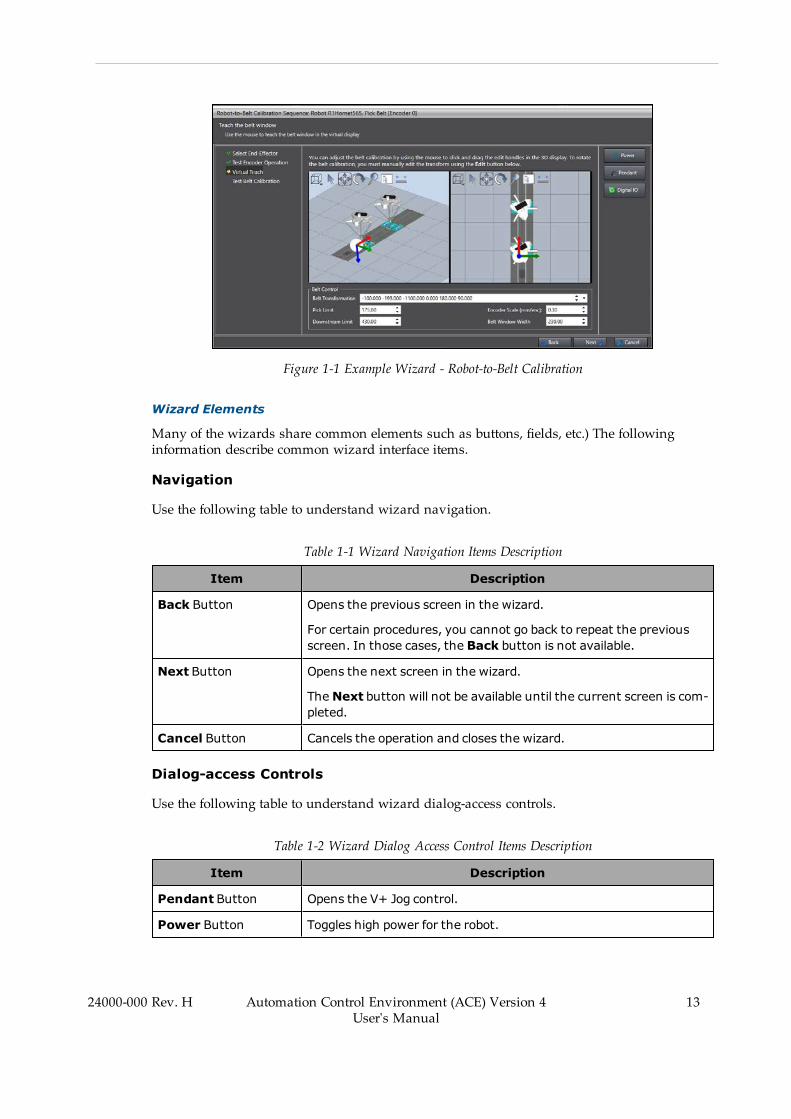
Figure 1-1 Example Wizard - Robot-to-Belt Calibration
Wizard Elements
Many of the wizards share common elements such as buttons, fields, etc.) The followinginformation describe common wizard interface items.
Navigation
Use the following table to understand wizard navigation.
Table 1-1 Wizard Navigation Items Description
Item Description
Back Button Opens the previous screen in the wizard.
For certain procedures, you cannot go back to repeat the previousscreen. In those cases, the Back button is not available.
Next Button Opens the next screen in the wizard.
TheNext button will not be available until the current screen is com-pleted.
Cancel Button Cancels the operation and closes the wizard.
Dialog-access Controls
Use the following table to understand wizard dialog-access controls.
Table 1-2 Wizard Dialog Access Control Items Description
Item Description
Pendant Button Opens the V+ Jog control.
Power Button Toggles high power for the robot.
24000-000 Rev. H Automation Control Environment (ACE) Version 4User's Manual
13
14 Automation Control Environment (ACE) Version 4User's Manual
24000-000 Rev. H
Chapter 1: Introduction
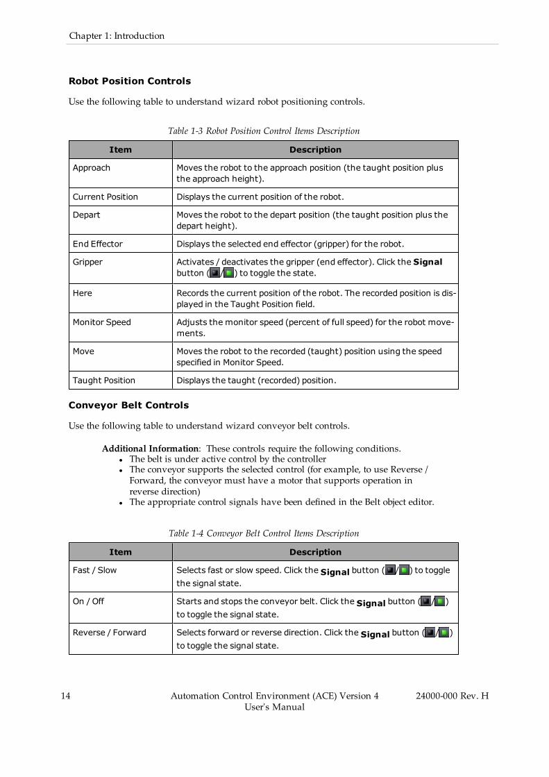
Robot Position Controls
Use the following table to understand wizard robot positioning controls.
Table 1-3 Robot Position Control Items Description
Item Description
Approach Moves the robot to the approach position (the taught position plusthe approach height).
Current Position Displays the current position of the robot.
Depart Moves the robot to the depart position (the taught position plus thedepart height).
End Effector Displays the selected end effector (gripper) for the robot.
Gripper Activates / deactivates the gripper (end effector). Click the Signalbutton ( / ) to toggle the state.
Here Records the current position of the robot. The recorded position is dis-played in the Taught Position field.
Monitor Speed Adjusts the monitor speed (percent of full speed) for the robot move-ments.
Move Moves the robot to the recorded (taught) position using the speedspecified in Monitor Speed.
Taught Position Displays the taught (recorded) position.
Conveyor Belt Controls
Use the following table to understand wizard conveyor belt controls.
Additional Information: These controls require the following conditions.l The belt is under active control by the controllerl The conveyor supports the selected control (for example, to use Reverse /Forward, the conveyor must have a motor that supports operation inreverse direction)
l The appropriate control signals have been defined in the Belt object editor.
Table 1-4 Conveyor Belt Control Items Description
Item Description
Fast / Slow Selects fast or slow speed. Click the Signal button ( / ) to togglethe signal state.
On / Off Starts and stops the conveyor belt. Click the Signal button ( / )to toggle the signal state.
Reverse / Forward Selects forward or reverse direction. Click the Signal button ( / )to toggle the signal state.
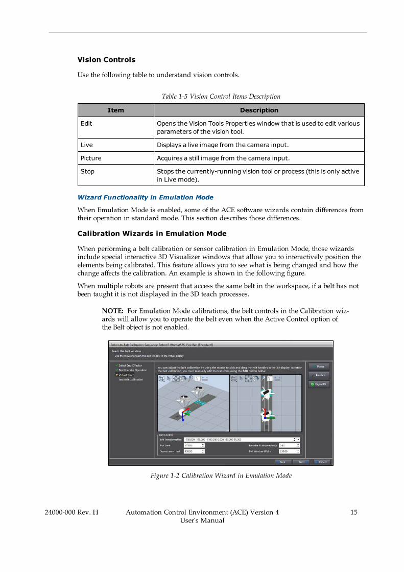
Vision Controls
Use the following table to understand vision controls.
Table 1-5 Vision Control Items Description
Item Description
Edit Opens the Vision Tools Properties window that is used to edit variousparameters of the vision tool.
Live Displays a live image from the camera input.
Picture Acquires a still image from the camera input.
Stop Stops the currently-running vision tool or process (this is only activein Live mode).
Wizard Functionality in Emulation Mode
When Emulation Mode is enabled, some of the ACE software wizards contain differences fromtheir operation in standard mode. This section describes those differences.
Calibration Wizards in Emulation Mode
When performing a belt calibration or sensor calibration in Emulation Mode, those wizardsinclude special interactive 3D Visualizer windows that allow you to interactively position theelements being calibrated. This feature allows you to see what is being changed and how thechange affects the calibration. An example is shown in the following figure.
When multiple robots are present that access the same belt in the workspace, if a belt has notbeen taught it is not displayed in the 3D teach processes.
NOTE: For Emulation Mode calibrations, the belt controls in the Calibration wiz-ards will allow you to operate the belt even when the Active Control option ofthe Belt object is not enabled.
Figure 1-2 Calibration Wizard in Emulation Mode
24000-000 Rev. H Automation Control Environment (ACE) Version 4User's Manual
15

16 Automation Control Environment (ACE) Version 4User's Manual
24000-000 Rev. H
Chapter 1: Introduction
For these wizard pages, there are two ways to change the settings.
1. Use the interactive 3D windows to drag the elements to the desired positions. After pos-itioning the elements, you can see the changes to the values in the fields below the 3Dwindows.
2. Use the fields below the interactive 3D windows to enter the values. After entering thevalues, you can see the changes in the 3D windows.
Licenses
To enable full functionality, the ACE software requires the V+ controller licenses and PClicenses supplied on the USB hardware key (dongle) as described below. For details on obtain-ing these items, please contact your local Omron representative.
To view the licenses installed on the dongle, access the Help menu item and then selectAbout... This will open the About ACE Dialog Box. Choose the PC Licenses tab to view theinstalled licenses.
Figure 1-3 PC Licenses
PC Licenses
The following licenses are available for the PC running ACE software. The PC licenses are sup-plied on the USB hardware key (dongle, sold separately). Contact your local Omron rep-resentative for more information.
l Robot Vision Managerl Pack Manager
The ACE software will still work without licensing in place, but the following restrictions willapply.
Emulation Mode (Not Connected to Physical Devices)
When licensing is not activated, you will have full functionality for two hours while runningin Emulation Mode. After two hours expires, you must restart the ACE software to continue.
While Connected to Physical Devices (Not in Emulation Mode)
Execution of Pack Manager or Robot Vision functionality is restricted.
1.4 Software FeaturesThis section provides details about the following ACE software features.
l Emulation Model Application Samples
Emulation Mode
The ACE software contains an operating mode called Emulation Mode. This mode provides avirtual environment that emulates the physical hardware you have in your application. Thisallows you to program and operate your application with no connection to physical hardware.
Although the Emulation Mode is an optional operating mode, it behaves as though you areworking in the standard operating mode of the ACE software. Once you have enabled Emu-lation Mode, you can create and program an ACE application in the same manner that youwould when connected to physical hardware. This provides a seamless user experience that isnearly identical to running with real, physical hardware.
Emulation Mode can run multiple, simultaneous instances of controllers and robots on thesame PC at the same time. This includes the handling of network ports and multiple file sys-tems. This feature allows you to design, program, and operate a real multi-controller / robotapplication.
This section details the start up, features, and limitations of Emulation Mode.
Emulation Mode Features
Emulation Mode provides the following features and benefits.
NOTE: The term offline implies that no connection to physical hardware ispresent.
l Create applications offline
If no hardware is available, you can still create your application offline. EmulationMode allows you to configure a project with robots, belts, feeders, and other hardware.When the physical hardware becomes available, you can transition from the virtualhardware to the physical hardware easily.
l Program offline
You can open and edit existing ACE projects. You can also edit V+ programs andC# programs.
l Operate applications offline
If you have an existing project, you can open it and run an application without thephysical hardware. The application runs in the Emulation Mode and uses the 3D Visu-alizer feature to simulate the behavior of the system.
l Experimentation with products and hardware
24000-000 Rev. H Automation Control Environment (ACE) Version 4User's Manual
17
18 Automation Control Environment (ACE) Version 4User's Manual
24000-000 Rev. H
Chapter 1: Introduction
Because the Emulation Mode application is created with virtual hardware, you canexperiment with different robot cell designs and layouts before purchasing the physicalhardware.
l Training without products or hardware
The emulated environment provides a convenient and low-risk method for training tech-nicians, operators, and other system users.
Emulation Mode Differences
Emulation Mode has the following differences when compared to operating while connected tophysical hardware.
Additional Information: Other minor Emulation Mode differences not listedbelow exist. These are noted in the related sections of this document.
l Saving data to the emulated controller is not supported.
When Emulation Mode is enabled, ACE software creates a new emulated-controller filesystem in a temporary folder. When ACE software is shut down, that file system isdeleted which means the contents of any user-created folders, files, or data will also bedeleted. You should save your data in a PC folder and/or with the ACE project to avoidloss of data.
l No automatic import of robots when creating a new controller.
When Emulation Mode is enabled, the Create a New Controller wizard does not auto-matically import robots. It prompts you to select the robot(s) connected to the controllerinstead.
l Some controller and robot configuration items are disabled.
When Emulation Mode is enabled, certain Controller Settings and Robot Object con-figuration items are not available. Those items are dimmed or hidden to indicate thatthey are not available. Refer to Controller Settings on page 185 and Robot Objects onpage 208 for more information.
l I/O signals are managed differently.
In Emulation Mode, you can use the Digital I/O window to set input signals. Refer toTask Status Control on page 122 for more information.
l Robot-to-hardware calibrations use the 3D Visualizer.
In Emulation Mode, the robot-to-hardware calibrations and project referencing pro-cedures are different. When Emulation Mode is enabled, these procedures use the 3DVisualizer display to allow for offline calibration and configuration. Refer to ProcessManager Object on page 352 for more information.
l The Belt object control, speed, and latch settings are different.
When Emulation Mode is enabled wizards allow use of belt control signals even if Act-ive Control is disabled, fast and slow speed settings are used, and the Latch Period gen-erates a new latch at each distance interval of belt travel. Refer to Belt Object on page341 for more information.
l The Virtual Camera configuration is different.
When Emulation Mode is enabled, the Virtual Camera object uses an Emulation Con-figuration parameter that is used to specify the operating mode. Refer to Virtual Cam-eras on page 277 for more information.
l Cycle times are not identical.
When Emulation Mode is enabled, the cycle times will not exactly match those obtainedwhen connected to physical hardware.
l Enable power and calibration are managed differently.
When Emulation Mode is enabled, the robot power is enabled and the robot is auto-matically calibrated when loading a project, creating a controller, rebooting a controller,and when changing a Quattro platform.
Enabling and Disabling Emulation Mode
Emulation Mode can be enabled or disabled by clicking the Enable Emulation Mode icon ( )
or the Disable Emulation Mode icon ( ), respectively. Any unsaved data must be savedbefore doing this. Note that the icons are disabled if they do not apply. For example, if Emu-lation Mode is enabled, the Enable Emulation Mode icon cannot be clicked.
Alternatively, Emulation Mode can be enabled when opening a project with the following pro-cedure:.
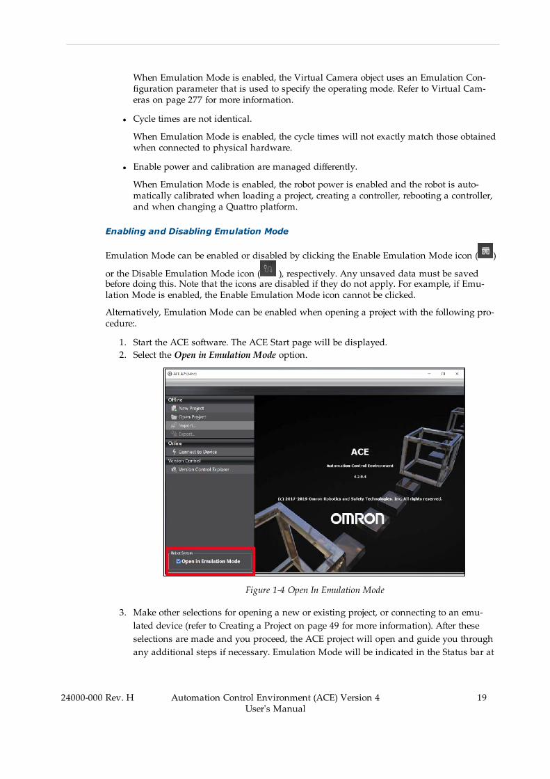
1. Start the ACE software. The ACE Start page will be displayed.2. Select the Open in Emulation Mode option.
Figure 1-4 Open In Emulation Mode
3. Make other selections for opening a new or existing project, or connecting to an emu-lated device (refer to Creating a Project on page 49 for more information). After theseselections are made and you proceed, the ACE project will open and guide you throughany additional steps if necessary. Emulation Mode will be indicated in the Status bar at
24000-000 Rev. H Automation Control Environment (ACE) Version 4User's Manual
19
20 Automation Control Environment (ACE) Version 4User's Manual
24000-000 Rev. H
Chapter 1: Introduction
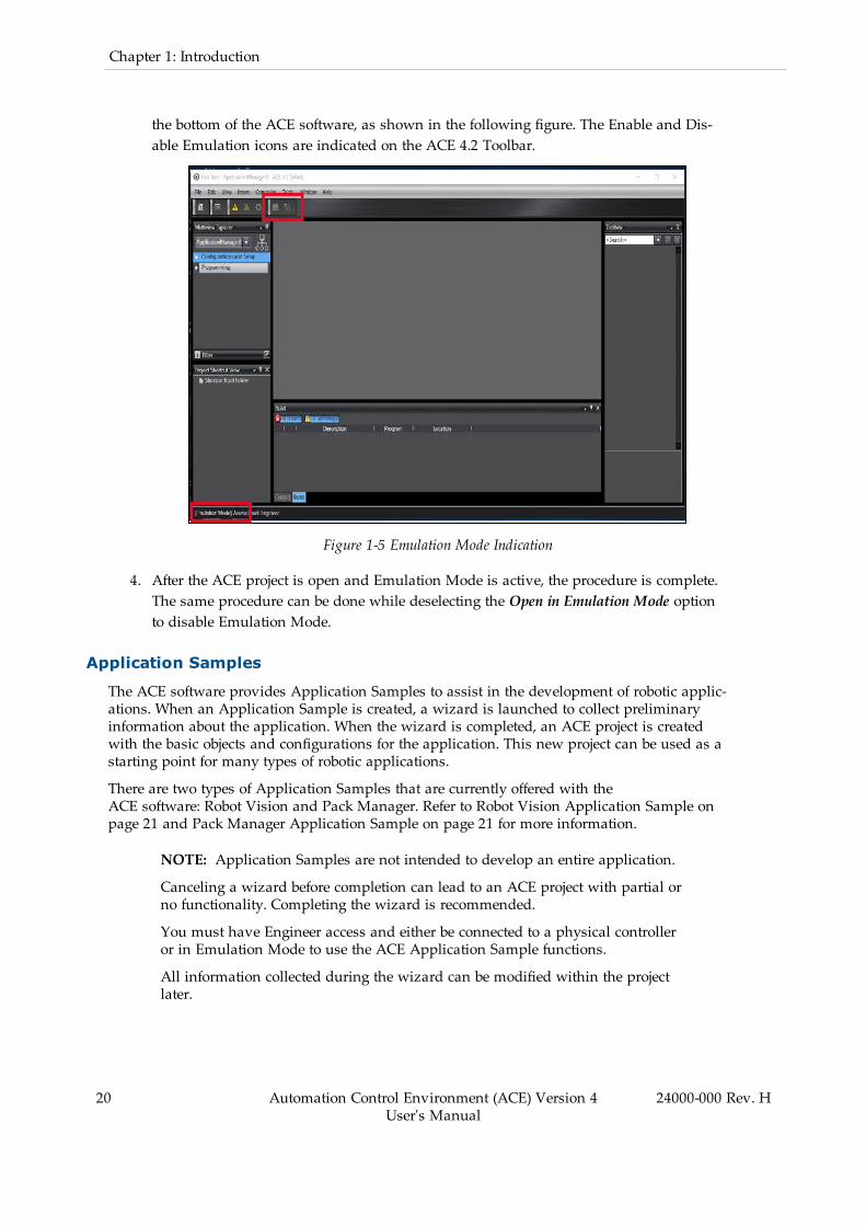
the bottom of the ACE software, as shown in the following figure. The Enable and Dis-able Emulation icons are indicated on the ACE 4.2 Toolbar.
Figure 1-5 Emulation Mode Indication
4. After the ACE project is open and Emulation Mode is active, the procedure is complete.The same procedure can be done while deselecting the Open in Emulation Mode optionto disable Emulation Mode.
Application Samples
The ACE software provides Application Samples to assist in the development of robotic applic-ations. When an Application Sample is created, a wizard is launched to collect preliminaryinformation about the application. When the wizard is completed, an ACE project is createdwith the basic objects and configurations for the application. This new project can be used as astarting point for many types of robotic applications.
There are two types of Application Samples that are currently offered with theACE software: Robot Vision and Pack Manager. Refer to Robot Vision Application Sample onpage 21 and Pack Manager Application Sample on page 21 for more information.
NOTE: Application Samples are not intended to develop an entire application.
Canceling a wizard before completion can lead to an ACE project with partial orno functionality. Completing the wizard is recommended.
You must have Engineer access and either be connected to a physical controlleror in Emulation Mode to use the ACE Application Sample functions.
All information collected during the wizard can be modified within the projectlater.
The Application Sample wizard follows the basic steps listed below. These may vary based onthe Application Sample type and selections made during the wizard, but generally follow thissequence.
1. Select robots to install on the controller (Emulation Mode only).2. Identify the pick and place configuration.3. Teach the pick operation.4. Teach the place operation.5. Specify the robot used in the application sample.6. Specify the end effector configuration.7. Teach the safe robot position.8. Teach the part pick position.9. Teach the part placement position.
Robot Vision Application Sample
Robot Vision Application Samples can be used to create example V+ programs and RobotVision objects for integrating Robot Vision with robots, belts, feeders, and more. When usingRobot Vision with V+ programs you are responsible for writing the V+ programs that driverobot motion and other activity in the robot cell.
NOTE: Robot Vision sample wizards can be used for example application struc-ture, but are not intended to provide all V+ program code required for the applic-ation.
Pack Manager Application Sample
Pack Manager Application Samples can be used to create single-robot packaging applicationprojects with Pack Manager. These single-robot samples can later be expanded for multi-robotapplications. The ACE software provides a point-and-click interface to develop many pack-aging applications without writing V+ programs. If the default behavior does not meet theneeds of the application, V+ programs can be customized. Pack Manager uses a Process Man-ager to manage run-time control of the application including allocation of part and targetinstances in multi-robot packaging lines, visualization of resources, and statistics tracking.
Additional Information: Refer to Process Manager Object on page 352 and theACE Reference Guide for more information.
Creating an Application Sample
There are two methods used to create an Application Sample as described below.
Create an Application Sample from the Start Page
Use the following procedure to create an Application Sample from the Start Page.
1. Start the ACE software.2. Select Connect to Device from the Start Page.
24000-000 Rev. H Automation Control Environment (ACE) Version 4User's Manual
21

22 Automation Control Environment (ACE) Version 4User's Manual
24000-000 Rev. H
Chapter 1: Introduction
Figure 1-6 Connect to Device on the Start Page
3. If you are creating the application while connected to a physical controller, make theappropriate Connect to Device settings. Refer to Online Connections to SmartControllerson page 75 for more information. If you are not connected to a physical controller, selectthe check box for Open in Emulation Mode.
4. Select Create Application Sample and then choose Robot Vision Manager Sample orPack Manager Sample. Then, click the Connect button. This will create a newACE project with the selected Application Sample and launch the Application Samplewizard.
5. Select robots to install on the controller (if running in Emulation Mode) and finish allwizard steps to complete the procedure. A new ACE project will be created according tothe collected wizard information.
Create an Application Sample from an ACE Project
To create an Application Sample from an ACE project, select Insert from the menu bar, selectApplication Sample, and then click Robot Vision Manager Sample or Pack Manager Sample. AnApplication Sample wizard will appear. Finish all wizard steps and then the ApplicationSample will be added to the ACE project.
NOTE: You must select the SmartController device to access the ApplicationSample item from the menu bar. If the Application Manager device is selected,these menu items will not be available.
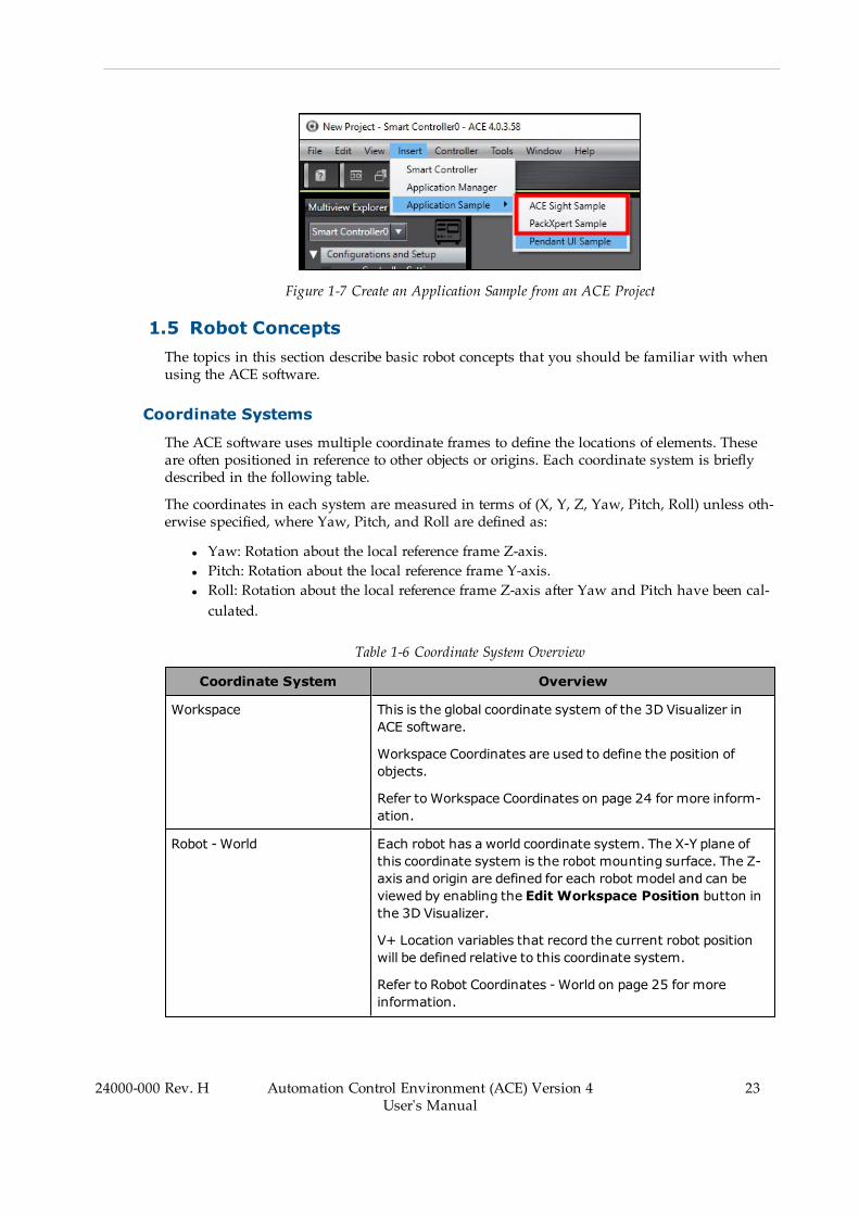
Figure 1-7 Create an Application Sample from an ACE Project
1.5 Robot ConceptsThe topics in this section describe basic robot concepts that you should be familiar with whenusing the ACE software.
Coordinate Systems
The ACE software uses multiple coordinate frames to define the locations of elements. Theseare often positioned in reference to other objects or origins. Each coordinate system is brieflydescribed in the following table.
The coordinates in each system are measured in terms of (X, Y, Z, Yaw, Pitch, Roll) unless oth-erwise specified, where Yaw, Pitch, and Roll are defined as:
l Yaw: Rotation about the local reference frame Z-axis.l Pitch: Rotation about the local reference frame Y-axis.l Roll: Rotation about the local reference frame Z-axis after Yaw and Pitch have been cal-culated.
Table 1-6 Coordinate System Overview
Coordinate System Overview
Workspace This is the global coordinate system of the 3D Visualizer inACE software.
Workspace Coordinates are used to define the position ofobjects.
Refer to Workspace Coordinates on page 24 for more inform-ation.
Robot -World Each robot has a world coordinate system. The X-Y plane ofthis coordinate system is the robot mounting surface. The Z-axis and origin are defined for each robot model and can beviewed by enabling the Edit Workspace Position button inthe 3D Visualizer.
V+ Location variables that record the current robot positionwill be defined relative to this coordinate system.
Refer to Robot Coordinates -World on page 25 for moreinformation.
24000-000 Rev. H Automation Control Environment (ACE) Version 4User's Manual
23

24 Automation Control Environment (ACE) Version 4User's Manual
24000-000 Rev. H
Chapter 1: Introduction
Coordinate System Overview
Robot - Joint Each robot has a joint coordinate system based on the ori-entation of each individual joint. Each element of a coordinateis the angular position of the joint.
V+ Precision Point variables will be defined relative to thiscoordinate system for each robot.
Refer to Robot Coordinates - Joint on page 26 for more inform-ation.
Robot - Tool This is the coordinate system based on the robot tool.
The origin is positioned at the tool flange with the Z-axis ori-ented away from the tool flange when a null tool offset isapplied.
Refer to Robot Coordinates - Tool on page 27 for more inform-ation.
Belt This is the coordinate system describing the direction and ori-entation of a conveyer belt.
Each robot may have a different reference to belt coordinatesfor the same physical conveyor belt.
Refer to Belt Coordinates on page 28 for more information.
Camera This is the coordinate system defining the coordinates withinthe camera field of view.
2D vision primarily uses only the X, Y, and Roll components ofa coordinate.
The origin is located at the center of the field of view.
Refer to Camera Coordinates on page 30 for more inform-ation.
Workspace Coordinates
The workspace coordinate system is a global reference frame for all object positions in the 3DVisualizer. The workspace origin is not visible, but it is positioned at the center of the tile grid,as shown in Figure 1-8 below.
Workspace coordinates are primarily used for positioning robots and other features in theworkspace. Allocation of belt-relative Part and Part Target instances during run time dependson the relative position of robots along a process belt object, therefore robot positions cannot bechanged while a Process Manager is active.
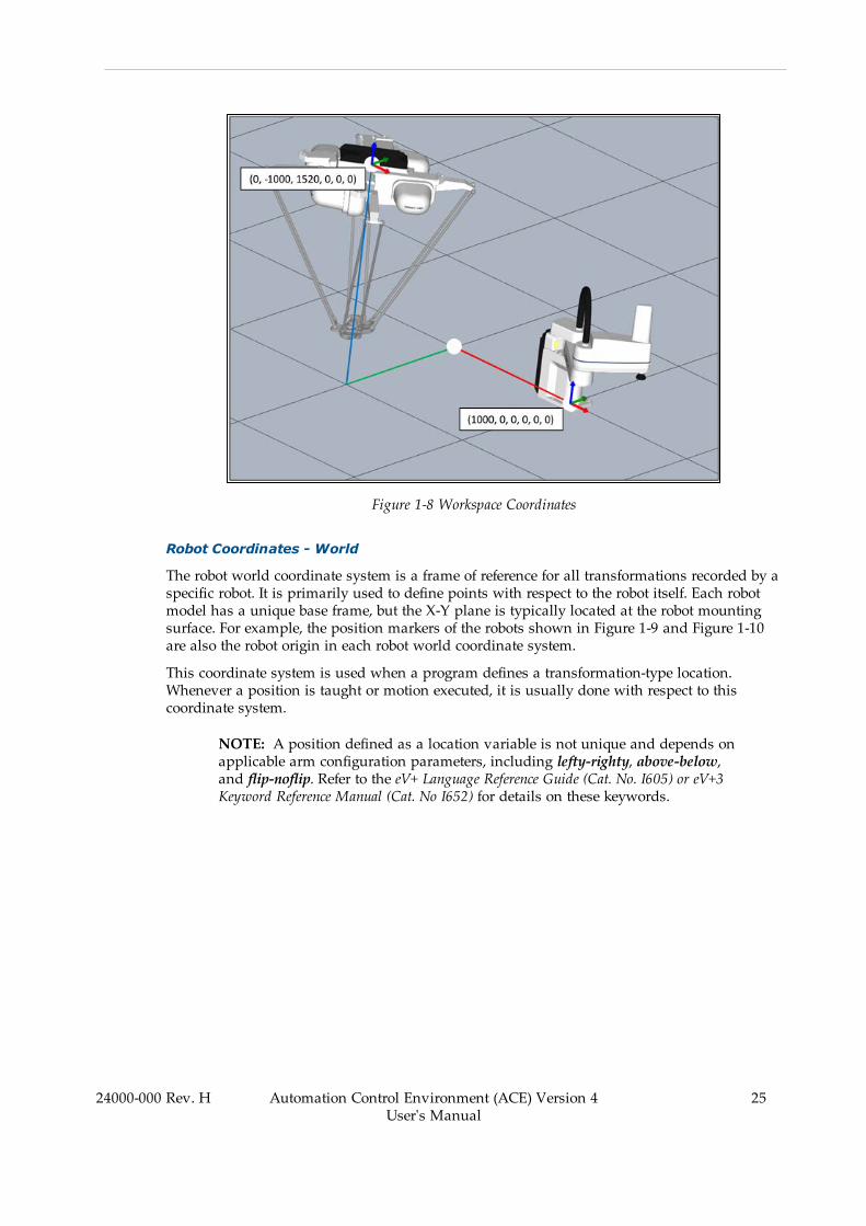
Figure 1-8 Workspace Coordinates
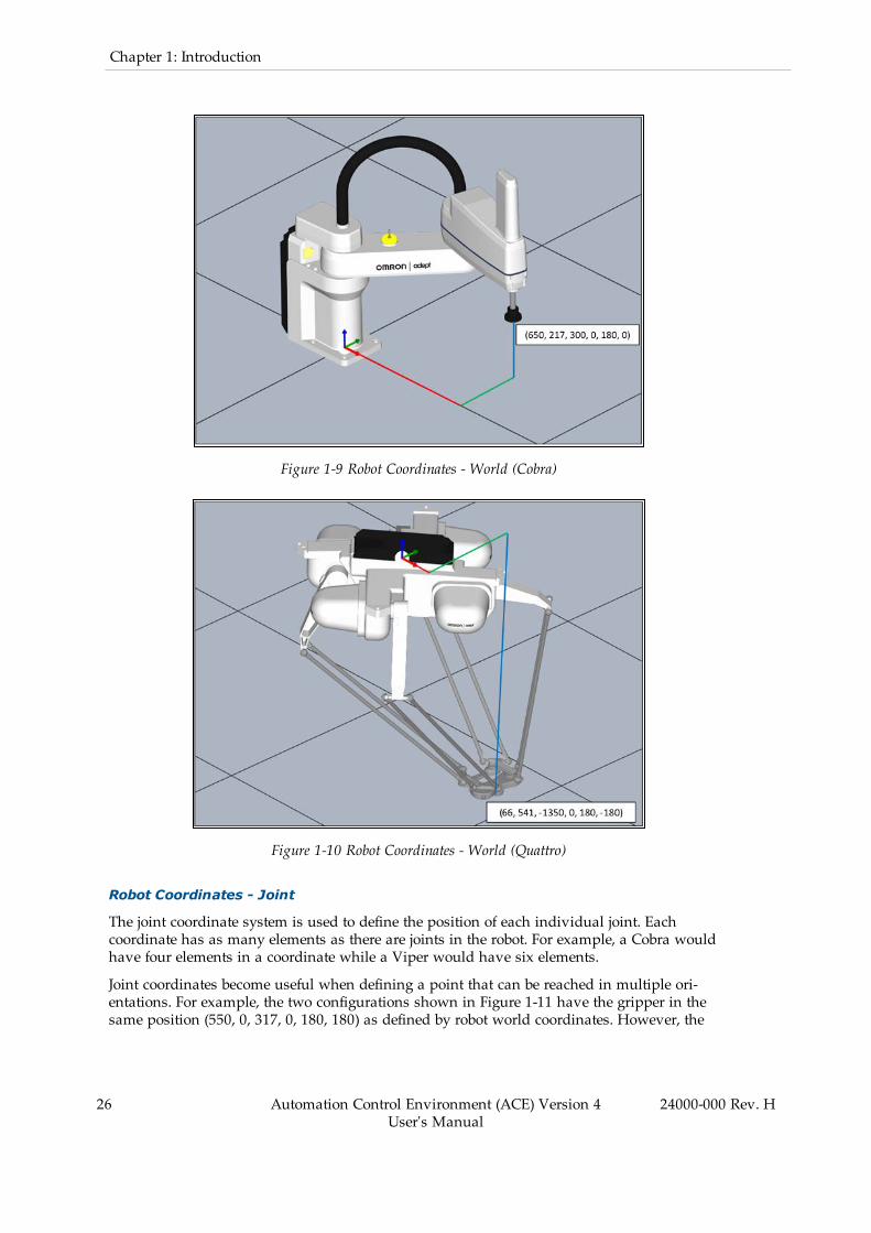
Robot Coordinates - World
The robot world coordinate system is a frame of reference for all transformations recorded by aspecific robot. It is primarily used to define points with respect to the robot itself. Each robotmodel has a unique base frame, but the X-Y plane is typically located at the robot mountingsurface. For example, the position markers of the robots shown in Figure 1-9 and Figure 1-10are also the robot origin in each robot world coordinate system.
This coordinate system is used when a program defines a transformation-type location.Whenever a position is taught or motion executed, it is usually done with respect to thiscoordinate system.
NOTE: A position defined as a location variable is not unique and depends onapplicable arm configuration parameters, including lefty-righty, above-below,and flip-noflip. Refer to the eV+ Language Reference Guide (Cat. No. I605) or eV+3Keyword Reference Manual (Cat. No I652) for details on these keywords.
24000-000 Rev. H Automation Control Environment (ACE) Version 4User's Manual
25
26 Automation Control Environment (ACE) Version 4User's Manual
24000-000 Rev. H
Chapter 1: Introduction
Figure 1-9 Robot Coordinates - World (Cobra)
Figure 1-10 Robot Coordinates - World (Quattro)
Robot Coordinates - Joint
The joint coordinate system is used to define the position of each individual joint. Eachcoordinate has as many elements as there are joints in the robot. For example, a Cobra wouldhave four elements in a coordinate while a Viper would have six elements.
Joint coordinates become useful when defining a point that can be reached in multiple ori-entations. For example, the two configurations shown in Figure 1-11 have the gripper in thesame position (550, 0, 317, 0, 180, 180) as defined by robot world coordinates. However, the
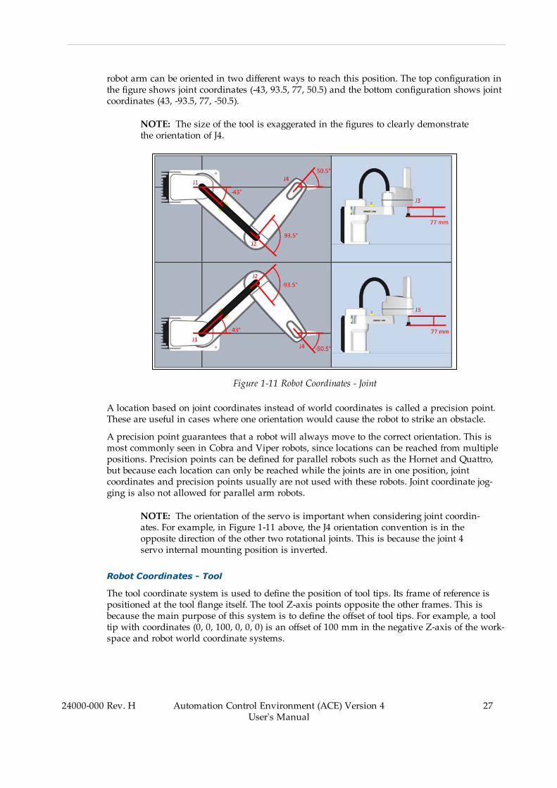
robot arm can be oriented in two different ways to reach this position. The top configuration inthe figure shows joint coordinates (-43, 93.5, 77, 50.5) and the bottom configuration shows jointcoordinates (43, -93.5, 77, -50.5).
NOTE: The size of the tool is exaggerated in the figures to clearly demonstratethe orientation of J4.
Figure 1-11 Robot Coordinates - Joint
A location based on joint coordinates instead of world coordinates is called a precision point.These are useful in cases where one orientation would cause the robot to strike an obstacle.
A precision point guarantees that a robot will always move to the correct orientation. This ismost commonly seen in Cobra and Viper robots, since locations can be reached from multiplepositions. Precision points can be defined for parallel robots such as the Hornet and Quattro,but because each location can only be reached while the joints are in one position, jointcoordinates and precision points usually are not used with these robots. Joint coordinate jog-ging is also not allowed for parallel arm robots.
NOTE: The orientation of the servo is important when considering joint coordin-ates. For example, in Figure 1-11 above, the J4 orientation convention is in theopposite direction of the other two rotational joints. This is because the joint 4servo internal mounting position is inverted.
Robot Coordinates - Tool
The tool coordinate system is used to define the position of tool tips. Its frame of reference ispositioned at the tool flange itself. The tool Z-axis points opposite the other frames. This isbecause the main purpose of this system is to define the offset of tool tips. For example, a tooltip with coordinates (0, 0, 100, 0, 0, 0) is an offset of 100 mm in the negative Z-axis of the work-space and robot world coordinate systems.
24000-000 Rev. H Automation Control Environment (ACE) Version 4User's Manual
27

28 Automation Control Environment (ACE) Version 4User's Manual
24000-000 Rev. H
Chapter 1: Introduction
NOTE: The reversal of the Z-axis does not affect the controls in the V+ Jog Con-trol. The down arrow still moves the tool along the negative Z-axis with respectto the robot world coordinates.
Figure 1-12 Robot Coordinates - Tool
Belt Coordinates
The belt coordinate system is used to define positions on a belt window. Its frame of referenceis at one of the upstream corners of the belt. The axes are oriented so the positive X-axis is inthe direction of the belt vector and the Y-axis is along the belt width. The belt is typically posi-tioned so that the Z-axis of the belt frame aligns with the tool Z-axis, but it can be reversed ifnecessary.
This coordinate system is primarily used to provide part locations on a belt to a robot and toverify that a belt-relative location is within the belt window before commanding a motion tothe location. When an instance is located, the identified belt coordinate is converted to a robotworld coordinate. This means that a belt-to-robot calibration must be done before any beltcoordinates are recorded.
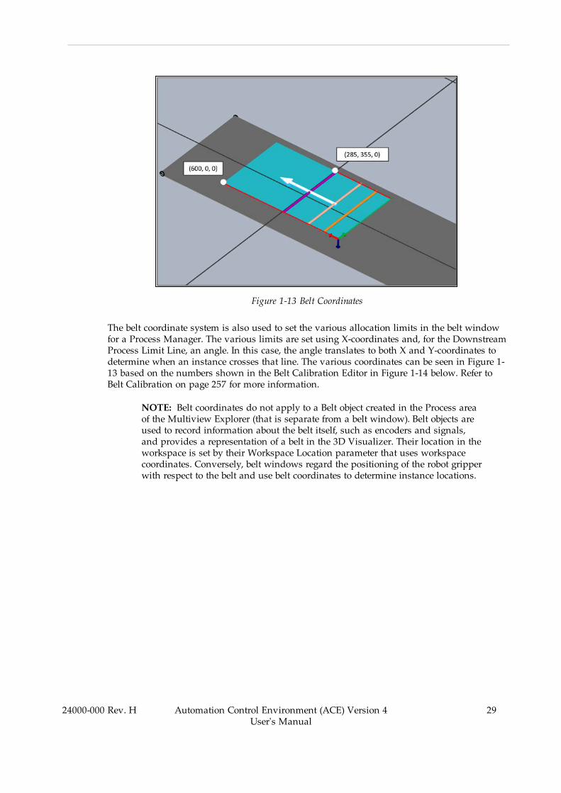
Figure 1-13 Belt Coordinates
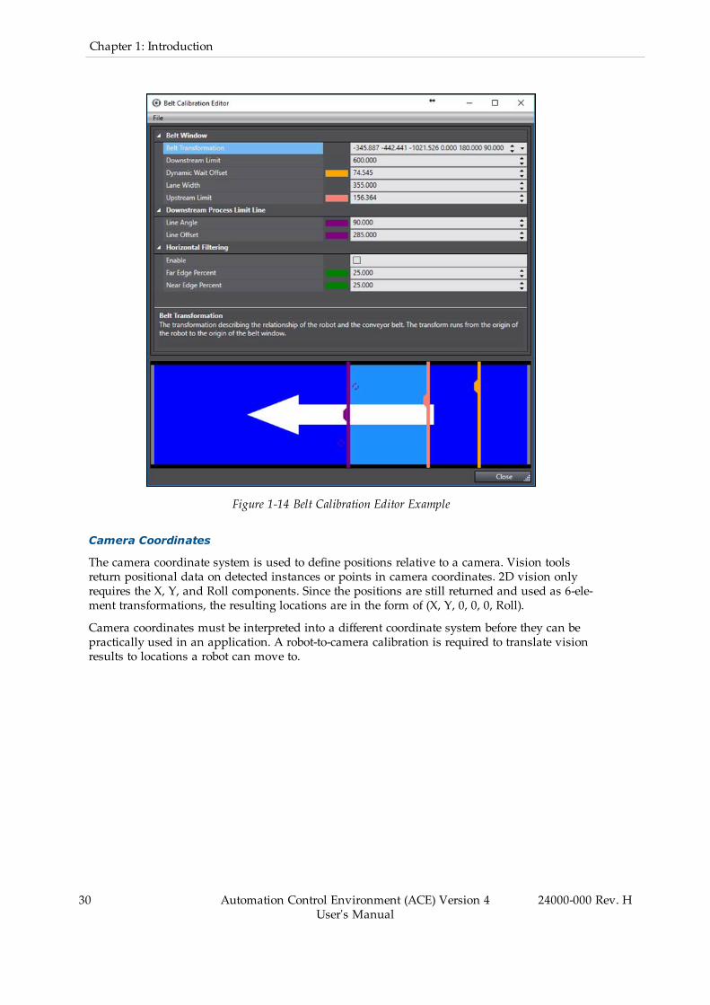
The belt coordinate system is also used to set the various allocation limits in the belt windowfor a Process Manager. The various limits are set using X-coordinates and, for the DownstreamProcess Limit Line, an angle. In this case, the angle translates to both X and Y-coordinates todetermine when an instance crosses that line. The various coordinates can be seen in Figure 1-13 based on the numbers shown in the Belt Calibration Editor in Figure 1-14 below. Refer toBelt Calibration on page 257 for more information.
NOTE: Belt coordinates do not apply to a Belt object created in the Process areaof the Multiview Explorer (that is separate from a belt window). Belt objects areused to record information about the belt itself, such as encoders and signals,and provides a representation of a belt in the 3D Visualizer. Their location in theworkspace is set by their Workspace Location parameter that uses workspacecoordinates. Conversely, belt windows regard the positioning of the robot gripperwith respect to the belt and use belt coordinates to determine instance locations.
24000-000 Rev. H Automation Control Environment (ACE) Version 4User's Manual
29
30 Automation Control Environment (ACE) Version 4User's Manual
24000-000 Rev. H
Chapter 1: Introduction
Figure 1-14 Belt Calibration Editor Example
Camera Coordinates
The camera coordinate system is used to define positions relative to a camera. Vision toolsreturn positional data on detected instances or points in camera coordinates. 2D vision onlyrequires the X, Y, and Roll components. Since the positions are still returned and used as 6-ele-ment transformations, the resulting locations are in the form of (X, Y, 0, 0, 0, Roll).
Camera coordinates must be interpreted into a different coordinate system before they can bepractically used in an application. A robot-to-camera calibration is required to translate visionresults to locations a robot can move to.
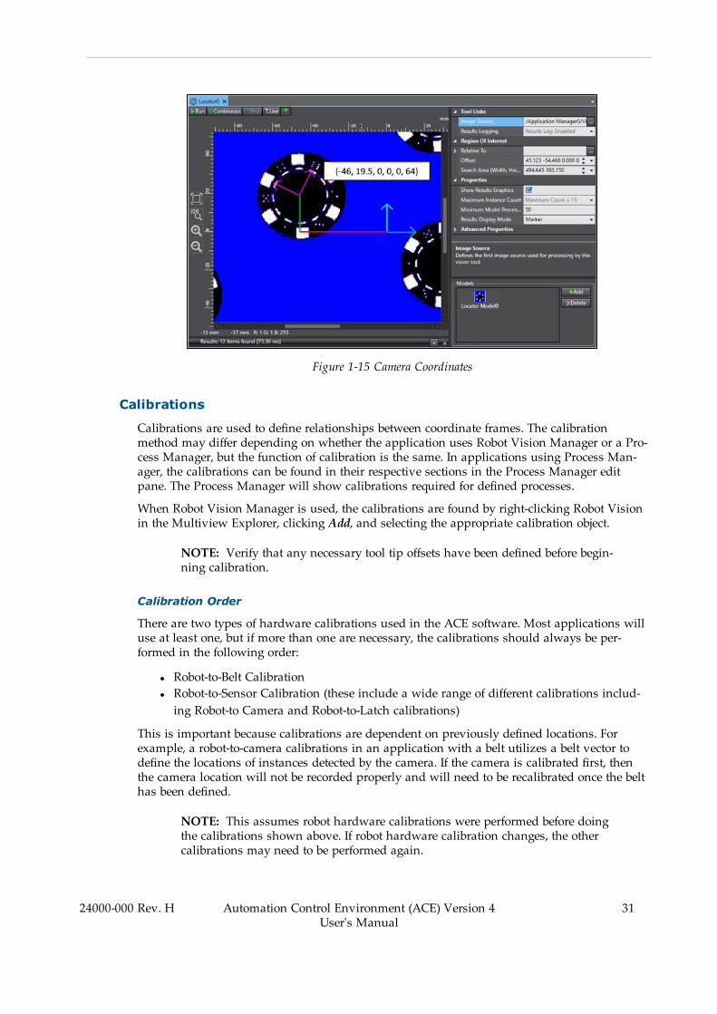
Figure 1-15 Camera Coordinates
Calibrations
Calibrations are used to define relationships between coordinate frames. The calibrationmethod may differ depending on whether the application uses Robot Vision Manager or a Pro-cess Manager, but the function of calibration is the same. In applications using Process Man-ager, the calibrations can be found in their respective sections in the Process Manager editpane. The Process Manager will show calibrations required for defined processes.
When Robot Vision Manager is used, the calibrations are found by right-clicking Robot Visionin the Multiview Explorer, clicking Add, and selecting the appropriate calibration object.
NOTE: Verify that any necessary tool tip offsets have been defined before begin-ning calibration.
Calibration Order
There are two types of hardware calibrations used in the ACE software. Most applications willuse at least one, but if more than one are necessary, the calibrations should always be per-formed in the following order:
l Robot-to-Belt Calibrationl Robot-to-Sensor Calibration (these include a wide range of different calibrations includ-ing Robot-to Camera and Robot-to-Latch calibrations)
This is important because calibrations are dependent on previously defined locations. Forexample, a robot-to-camera calibrations in an application with a belt utilizes a belt vector todefine the locations of instances detected by the camera. If the camera is calibrated first, thenthe camera location will not be recorded properly and will need to be recalibrated once the belthas been defined.
NOTE: This assumes robot hardware calibrations were performed before doingthe calibrations shown above. If robot hardware calibration changes, the othercalibrations may need to be performed again.
24000-000 Rev. H Automation Control Environment (ACE) Version 4User's Manual
31

32 Automation Control Environment (ACE) Version 4User's Manual
24000-000 Rev. H
Chapter 1: Introduction
Robot-to-Belt Calibration
This calibration translates positional information from the belt coordinate system to the robotworld coordinate system. This is required whenever a belt is used in an application. One cal-ibration needs to be performed for each encoder input associated with a robot.
Robot-to-belt calibration will require three points to be defined on the surface of the belt, shownin order in Figure 1-16 below. Use the following procedure to execute a robot-to-belt calibration.
1. Place a calibration target on the belt at the farthest point upstream that the robot canreach. Verify that the robot can reach that belt position across the entire width of thebelt.
2. Position the robot at the calibration target and record the position. This saves the robotlocation and the belt encoder position.
3. Lift the robot and advance the belt to move the calibration target to the farthest down-stream position that the robot can reach. Again, verify the robot can reach across theentire width of the belt to ensure that the entire belt window remains within the workenvelope.
NOTE: It is important to ensure the calibration target does not move rel-ative to the belt while advancing the belt.
4. Reposition the robot at the calibration target and record the position. The combination ofrecorded robot world coordinates and the belt encoder positions of these two pointsdefine the belt vector, which is the X-axis of the belt transformation, and the millimeter-per-count scale factor (mm/count).
5. Remove the calibration target from the belt and reposition on the opposite side of thebelt at the farthest downstream position the robot should pick a part. Record its positionin the same way as the other two points. This defines the belt pitch or Y-axis of the belttransformation. The Z-axis of the belt transformation is defined based on the right-handrule. After completing this step, the robot-to-belt calibration procedure is finished.
NOTE: The three points in this calibration also define other values, such as theupstream and downstream allocation limits, also shown in Figure 1-16 below.However, these do not directly affect the calibration of the belt and can later bechanged to fit the needs of the application. For ACE Sight and V+ programs, thepick limits will be defined in a V+ program. For applications with a ProcessManager, refer to Belt Calibrations on page 370 for more information.

Figure 1-16 Robot-to-Belt Calibration Points
Table 1-7 Robot-to-Belt Calibration Points Description
Item Description
1 Upstream Limit
2 Downstream Limit
3 Downstream Pick Limit
4 Belt Direction
5 Robot Side
6 Far Side
Robot-to-Camera Calibration
This calibration orients a camera frame of reference relative to a robot world coordinate sys-tem. It is used to translate positional information of vision results from the camera coordinatesystem to the robot world coordinate system. One of these is required for each associationbetween a robot and a camera.
To perform this calibration, a grid calibration must be active in the Virtual Camera. If it is not,perform a grid calibration before proceeding. Refer to Grid Calibration Method on page 282 formore information.
The process of calibrating the camera is dependent on the type of pick application in which itis involved. Generally, there are three categories with which the application could be asso-ciated:
l Fixed-mountedl Arm-mountedl Belt-relative
In all cases, the robot tool tip will be used to record various positions on the pick surface toassociate it with the robot world coordinates. At least four points are required to generate thecalibration, but a grid of 3x3 is recommended. The accuracy of the calibration increases withthe distribution of the targets across the field of view (refer to Figure 1-17 below). The con-figuration on the left would result in an accurate calibration while the configuration on theright could yield inaccurate results.
24000-000 Rev. H Automation Control Environment (ACE) Version 4User's Manual
33

34 Automation Control Environment (ACE) Version 4User's Manual
24000-000 Rev. H
Chapter 1: Introduction
Figure 1-17 Correct (Left) and Incorrect (Right) Robot-to-Camera Calibration Target Configurations
When the camera is fixed-mounted, a calibration target is recorded as a Locator Model and thetarget is placed in a defined region of interest of a Locator included in the calibration wizard.The target then must be repositioned in several different points on the pick surface. For eachone, the camera detects the instance and records the position in camera coordinates, and thenthe position is taught to the robot by moving the gripper to the instance. The combination ofthe recorded data teaches the robot where the pick surface and the camera are relative to therobot, thus translating camera data to robot world coordinates.
If the application has a belt, the calibration is effectively the same, but it must be executed intwo phases since the robot cannot reach the camera field of view. In the first phase, the targetsare placed on the belt underneath the camera and their positions are recorded with respect tothe camera. Then, the belt is advanced to where the robot can touch the targets and recordtheir position in the robot world coordinate system. These locations and the associated beltencoder positions are used to define the location of the camera with respect to the robot worldcoordinate system.
Robot-to-Latch Calibration
This calibration positions a latch sensor relative to a belt coordinate system. It is used to trans-late latch detection results to belt coordinate positions. One of these is required for each asso-ciation between a robot and a belt with a latch sensor.
The robot-to-latch calibration is similar to the robot-to-camera calibration when a belt ispresent. However, instead of using a camera to detect the location of the target, the calibrationis used to determine a part detection point, relative to a sensor signal.
The target and the associated object are placed upstream of the latch sensor. When the belt isadvanced past the sensor, the belt encoder position is recorded. Then, the belt is advanced towhere the robot can touch the part. The recorded location combined with the belt encoder pos-ition indicates where the part will be detected by the sensor relative to the latched belt encoderposition. The Figure 1-18 below shows an example using a pallet with slots for six parts.
In the following figure, the blue field represents the belt with the arrows indicating the dir-ection of belt travel. The numbered sections represent the different steps of the calibration,explained as follows.
1. The pallet is positioned upstream of the latch sensor and the belt is not in motion.2. The belt is advanced and the pallet is detected by the latch sensor. The belt encoder pos-ition at this position is recorded.
3. The belt is advanced to a position where the pallet is within the robot range of motion.
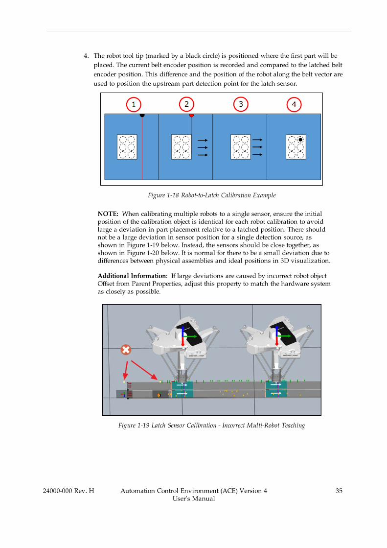
4. The robot tool tip (marked by a black circle) is positioned where the first part will beplaced. The current belt encoder position is recorded and compared to the latched beltencoder position. This difference and the position of the robot along the belt vector areused to position the upstream part detection point for the latch sensor.
Figure 1-18 Robot-to-Latch Calibration Example
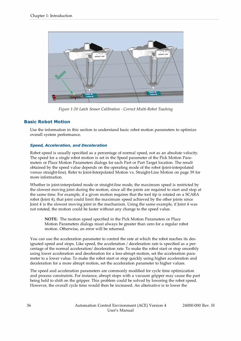
NOTE: When calibrating multiple robots to a single sensor, ensure the initialposition of the calibration object is identical for each robot calibration to avoidlarge a deviation in part placement relative to a latched position. There shouldnot be a large deviation in sensor position for a single detection source, asshown in Figure 1-19 below. Instead, the sensors should be close together, asshown in Figure 1-20 below. It is normal for there to be a small deviation due todifferences between physical assemblies and ideal positions in 3D visualization.
Additional Information: If large deviations are caused by incorrect robot objectOffset from Parent Properties, adjust this property to match the hardware systemas closely as possible.
Figure 1-19 Latch Sensor Calibration - Incorrect Multi-Robot Teaching
24000-000 Rev. H Automation Control Environment (ACE) Version 4User's Manual
35
36 Automation Control Environment (ACE) Version 4User's Manual
24000-000 Rev. H
Chapter 1: Introduction
Figure 1-20 Latch Sensor Calibration - Correct Multi-Robot Teaching
Basic Robot Motion
Use the information in this section to understand basic robot motion parameters to optimizeoverall system performance.
Speed, Acceleration, and Deceleration
Robot speed is usually specified as a percentage of normal speed, not as an absolute velocity.The speed for a single robot motion is set in the Speed parameter of the Pick Motion Para-meters or Place Motion Parameters dialogs for each Part or Part Target location. The resultobtained by the speed value depends on the operating mode of the robot (joint-interpolatedversus straight-line). Refer to Joint-Interpolated Motion vs. Straight-Line Motion on page 39 formore information.
Whether in joint-interpolated mode or straight-line mode, the maximum speed is restricted bythe slowest moving joint during the motion, since all the joints are required to start and stop atthe same time. For example, if a given motion requires that the tool tip is rotated on a SCARArobot (Joint 4), that joint could limit the maximum speed achieved by the other joints sinceJoint 4 is the slowest moving joint in the mechanism. Using the same example, if Joint 4 wasnot rotated, the motion could be faster without any change to the speed value.
NOTE: The motion speed specified in the Pick Motion Parameters or PlaceMotion Parameters dialogs must always be greater than zero for a regular robotmotion. Otherwise, an error will be returned.
You can use the acceleration parameter to control the rate at which the robot reaches its des-ignated speed and stops. Like speed, the acceleration / deceleration rate is specified as a per-centage of the normal acceleration/ deceleration rate. To make the robot start or stop smoothlyusing lower acceleration and deceleration for a less-abrupt motion, set the acceleration para-meter to a lower value. To make the robot start or stop quickly using higher acceleration anddeceleration for a more abrupt motion, set the acceleration parameter to higher values.
The speed and acceleration parameters are commonly modified for cycle time optimizationand process constraints. For instance, abrupt stops with a vacuum gripper may cause the partbeing held to shift on the gripper. This problem could be solved by lowering the robot speed.However, the overall cycle time would then be increased. An alternative is to lower the
acceleration / deceleration rate so the part does not shift on the gripper during motion start orstop. The robot can still move at the maximum designated speed for other movements.Another case would be a relatively high payload and inertia coupled with tight positioning tol-erances. A high deceleration rate may cause overshoot and increase settling time.
NOTE: Higher acceleration / deceleration rates and higher speeds do not alwaysresult in faster cycle times due to positioning overshoot that may occur.
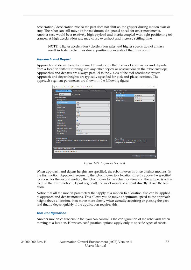
Approach and Depart
Approach and depart heights are used to make sure that the robot approaches and departsfrom a location without running into any other objects or obstructions in the robot envelope.Approaches and departs are always parallel to the Z-axis of the tool coordinate system.Approach and depart heights are typically specified for pick and place locations. Theapproach segment parameters are shown in the following figure.
Figure 1-21 Approach Segment
When approach and depart heights are specified, the robot moves in three distinct motions. Inthe first motion (Approach segment), the robot moves to a location directly above the specifiedlocation. For the second motion, the robot moves to the actual location and the gripper is activ-ated. In the third motion (Depart segment), the robot moves to a point directly above the loc-ation.
Notice that all the motion parameters that apply to a motion to a location also can be appliedto approach and depart motions. This allows you to move at optimum speed to the approachheight above a location, then move more slowly when actually acquiring or placing the part,and finally depart quickly if the application requires this.
Arm Configuration
Another motion characteristic that you can control is the configuration of the robot arm whenmoving to a location. However, configuration options apply only to specific types of robots.
24000-000 Rev. H Automation Control Environment (ACE) Version 4User's Manual
37
38 Automation Control Environment (ACE) Version 4User's Manual
24000-000 Rev. H
Chapter 1: Introduction
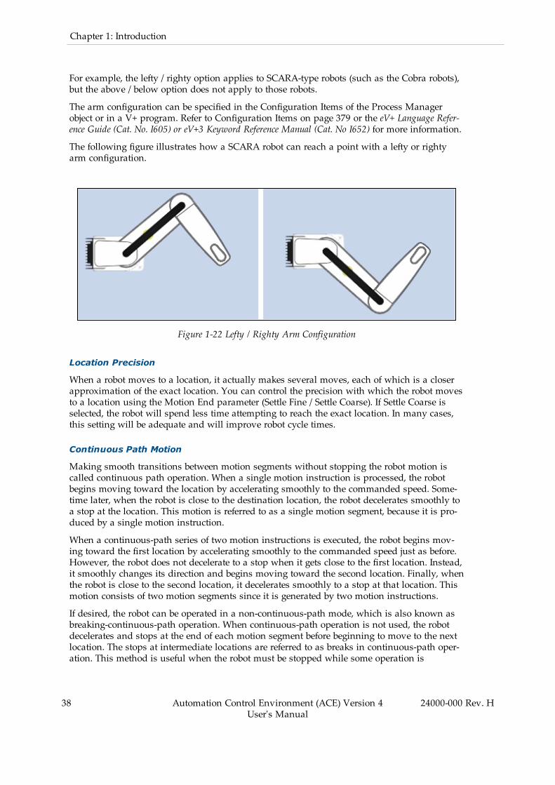
For example, the lefty / righty option applies to SCARA-type robots (such as the Cobra robots),but the above / below option does not apply to those robots.
The arm configuration can be specified in the Configuration Items of the Process Managerobject or in a V+ program. Refer to Configuration Items on page 379 or the eV+ Language Refer-ence Guide (Cat. No. I605) or eV+3 Keyword Reference Manual (Cat. No I652) for more information.
The following figure illustrates how a SCARA robot can reach a point with a lefty or rightyarm configuration.
Figure 1-22 Lefty / Righty Arm Configuration
Location Precision
When a robot moves to a location, it actually makes several moves, each of which is a closerapproximation of the exact location. You can control the precision with which the robot movesto a location using the Motion End parameter (Settle Fine / Settle Coarse). If Settle Coarse isselected, the robot will spend less time attempting to reach the exact location. In many cases,this setting will be adequate and will improve robot cycle times.
Continuous Path Motion
Making smooth transitions between motion segments without stopping the robot motion iscalled continuous path operation. When a single motion instruction is processed, the robotbegins moving toward the location by accelerating smoothly to the commanded speed. Some-time later, when the robot is close to the destination location, the robot decelerates smoothly toa stop at the location. This motion is referred to as a single motion segment, because it is pro-duced by a single motion instruction.
When a continuous-path series of two motion instructions is executed, the robot begins mov-ing toward the first location by accelerating smoothly to the commanded speed just as before.However, the robot does not decelerate to a stop when it gets close to the first location. Instead,it smoothly changes its direction and begins moving toward the second location. Finally, whenthe robot is close to the second location, it decelerates smoothly to a stop at that location. Thismotion consists of two motion segments since it is generated by two motion instructions.
If desired, the robot can be operated in a non-continuous-path mode, which is also known asbreaking-continuous-path operation. When continuous-path operation is not used, the robotdecelerates and stops at the end of each motion segment before beginning to move to the nextlocation. The stops at intermediate locations are referred to as breaks in continuous-path oper-ation. This method is useful when the robot must be stopped while some operation is

performed (for example, closing the gripper or applying a dot of adhesive). The continuous ornon-continuous path motion is set using the Wait Until Motion Done parameter and MotionEnd parameter in the Pick Motion Parameters or Place Motion Parameters dialogs. To enablecontinuous-path operation, you must set both parameters as follows.
l l Wait Until Motion Done = False
l l Motion End = Blend
NOTE: Breaking continuous-path operation affects forward processing (the par-allel operation of robot motion and program execution). Program operation is sus-pended until the robot reaches its destination.
Continuous-path transitions can occur between any combination of straight-line and joint-inter-polated motions. Refer to Joint-Interpolated Motion vs. Straight-Line Motion on page 39 formore information.
Joint-Interpolated Motion vs. Straight-Line Motion
The path a robot takes when moving from one location to another can be either a joint-inter-polated motion or a straight-line motion. A joint-interpolated motion moves each joint at a con-stant speed except during the acceleration / deceleration phases (refer to Speed, Acceleration,and Deceleration on page 36 for more information).
With a rotationally-jointed robot, the robot tool tip typically moves along a curved path duringa joint-interpolated motion. Although such motions can be performed at maximum speed, thenature of the path can be undesirable. Straight-line motions ensure that the robot tool tip tracesa straight line. That is useful for cutting a straight line, or laying a bead of sealant, or any othersituation where a totally predictable path is desired.
NOTE: The joint-interpolated or straight-line motion is set using the Straightparameter in the Pick Motion Parameters or Place Motion Parameters dialogs inthe Process Manager or in V+ programs.
Performance Considerations
Things that may impact performance in most applications include robot mounting, cell layout,part handling, and programming approaches.
Robot Mounting Considerations
The mounting surface should be smooth, flat and rigid. Vibration and flexing of the mountingsurface will degrade performance. Therefore, it is recommended that you carefully follow therobot-mounting procedures described in your robot user's guide.
When positioning a robot in the workcell, take advantage of moving multiple joints for fastermotions. On a SCARA robot, the “Z” and “theta” axes are the slowest, and motion of thesejoints should be minimized whenever possible. This can be accomplished by positioning therobot and setting conveyor heights and pick-and-place locations to minimize Z-axis motion.
Cell Layout Considerations
Regarding cell layout and jointed arms, the same point-to-point distance can result in differentcycle times. Moving multiple joints combines the joint speeds for faster motion. If the same
24000-000 Rev. H Automation Control Environment (ACE) Version 4User's Manual
39
40 Automation Control Environment (ACE) Version 4User's Manual
24000-000 Rev. H
Chapter 1: Introduction
distance is traversed using motion of a single joint, the motion of that joint will be longer, andtherefore will take more time.
Part Handling Considerations
For part handling, settling time while trying to achieve a position can be minimized by cen-tering the payload mass in the gripper. A mass that is offset from the tool rotation point willresult in excess inertia that will take longer to settle. In addition, minimizing gripper mass andtooling weight will improve settling time. This could include using lighter materials andremoving material that is not needed on tooling.
Programming Considerations
The use of joint-interpolated versus straight-line motion has to be evaluated on a case-by-casebasis. In general, joint-interpolated motion is more efficient. Nulling tolerances should be asloose as the application will permit. This has a direct impact on cycle time. Lastly, on jointedarms, changing the arm configuration (for example, lefty versus righty for a SCARA robot) gen-erally requires more time than maintaining the current configuration during a motion.
Understanding Belts (Conveyors)
This section describes basic belt (conveyor) concepts.
Additional Information: Conveyors are referred to as belts in the ACE software.Refer to Belt Calibrations on page 370 for more information.
Indexing versus Tracking Conveyors
There are two basic types of conveyor systems: indexing and tracking. In an indexing conveyorsystem, also referred to as a noncontinuous conveyor system, you specify either control signalsor a time interval for the belt to move between stops. When the conveyor stops, the robotremoves parts from the belt and then it is signaled to move again. The conveyor must beequipped with a device that can use digital output to turn the conveyor ON and OFF.
Indexing Conveyors
Indexing conveyor systems are configured as either non-vision or vision. With a non-visionindexing system, the part must be in the same location each time the belt stops. In a vision-equipped indexing system, a fixed-mount camera takes a picture when the belt stops and therobot accesses any objects found.
Tracking Conveyors
In a tracking conveyor system, the belt moves continuously and the robot tracks parts until thespeed and location of the robot gripper match those of a part on the belt. The robot thenaccesses the part.
Tracking conveyors must be equipped with an encoder that reports the movement of the beltand distance moved to the ACE software. Tracking conveyor systems are configured as eithernon-vision or vision.
With a non-vision tracking conveyor, a sensor signals that a part has passed a known loc-ation. The ACE software tracks the progress of the belt and accesses the part when it comes

into the robot working area (belt window). Parts must always be in the same location withrespect to the center line of the belt.
With a vision-equipped tracking conveyor, the vision system detects parts that are randomlypositioned and oriented on the belt. A fixed-mount camera takes pictures of the moving partsand based on the distance the conveyor travels, returns the location of parts. These part loc-ations are queued and accessed by the robot.
24000-000 Rev. H Automation Control Environment (ACE) Version 4User's Manual
41

Chapter 2: Installation and Uninstallation
This section describes installation and uninstallation details for the ACE software.
2.1 Installing the SoftwareThis section describes the ACE software installation procedure and other software installationdetails.
System Requirements
ACE software has the following system requirements.
l Windows operating system running Windows 10.l Installation and use of the Photoneo 3D camera requires a Windows 10, 64 bit OS.l An external graphics card, supporting OpenGL v 2.0 for operating the Photoneo camera.
l It is recommended to have more than 8 GB of RAM, a minimum 2 GB for the applic-ation and a minimum of 4 GB free disk space.
l Microsoft .NET Framework 4.6.1. The .NET Framework 4.6.1 will be installed auto-matically, if required. This will require a valid network connection to the internet.
l DirectX 11 compatible graphics card.l The SmartController EX or compatible device running eV+ 2.1 B8 or above. The con-troller should also have a CompactFlash card containing up-to-date utility software.
l Ethernet communication between the PC and the controller.
ACE Installation Instructions
NOTE: If there is an existing version of ACE on the computer, it should be unin-stalled prior to installing the latest version.
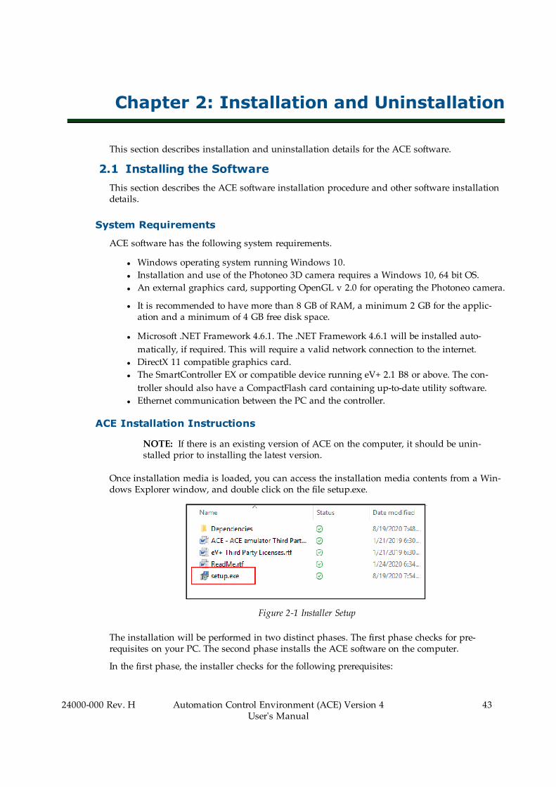
Once installation media is loaded, you can access the installation media contents from a Win-dows Explorer window, and double click on the file setup.exe.
Figure 2-1 Installer Setup
The installation will be performed in two distinct phases. The first phase checks for pre-requisites on your PC. The second phase installs the ACE software on the computer.
In the first phase, the installer checks for the following prerequisites:
24000-000 Rev. H Automation Control Environment (ACE) Version 4User's Manual
43
44 Automation Control Environment (ACE) Version 4User's Manual
24000-000 Rev. H
Chapter 2: Installation and Uninstallation
l Microsoft .NET Framework 4.6.1l Basler Pylonl PhoXi Controll Gitl Sentinel Protection Installerl TortoiseGitl OPC Redistributables
If these required packages are not on the computer, they will be installed. If the Microsoft .NETFramework 4.6.1 is missing, the installer will attempt to download the files from the internet. Ifthe computer does not have internet connectivity, you will need to manually download andinstall the Microsoft .NET Frameworks 4.6.1 from the Microsoft download site.
If any packages are already on the computer, they will be grayed out and not selectable fromthe installation GUI and they will not be installed.
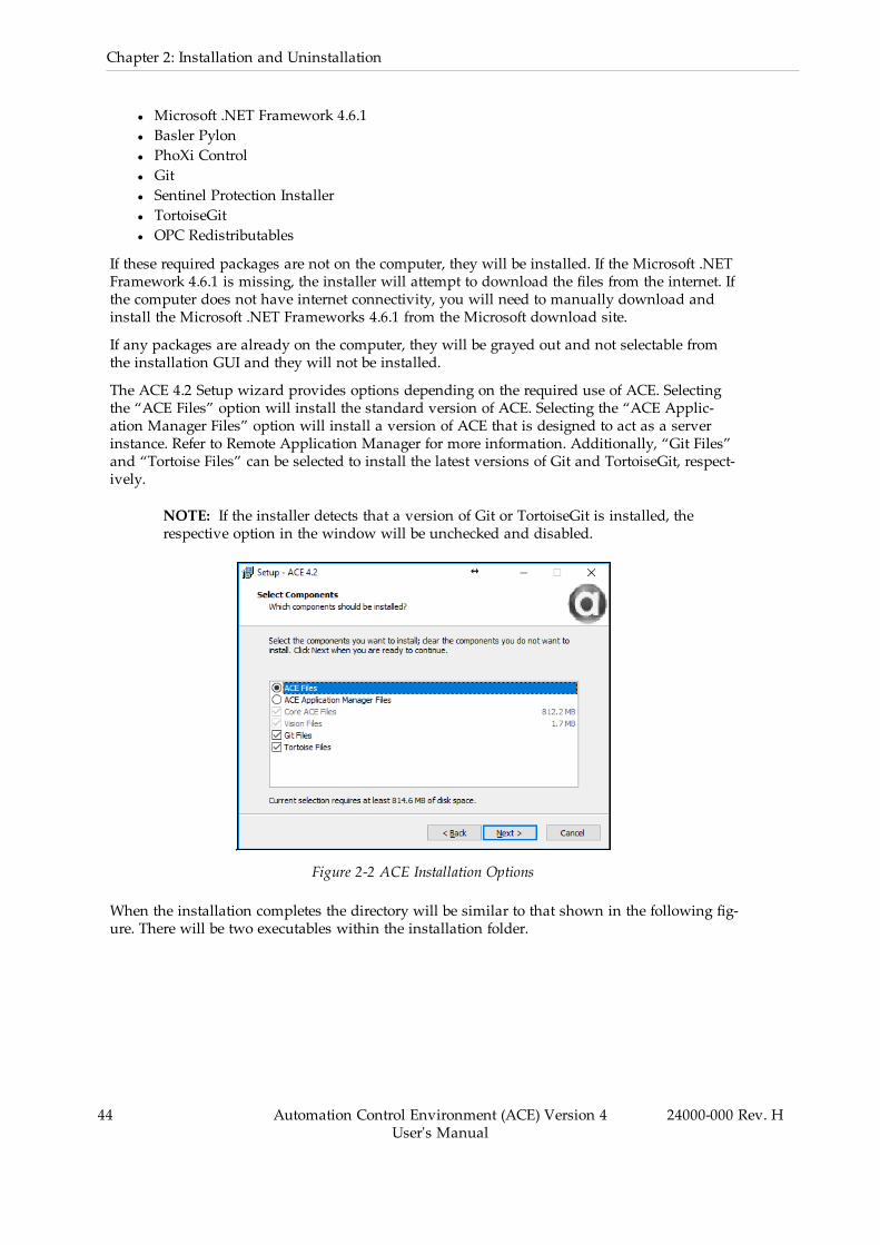
The ACE 4.2 Setup wizard provides options depending on the required use of ACE. Selectingthe “ACE Files” option will install the standard version of ACE. Selecting the “ACE Applic-ation Manager Files” option will install a version of ACE that is designed to act as a serverinstance. Refer to Remote Application Manager for more information. Additionally, “Git Files”and “Tortoise Files” can be selected to install the latest versions of Git and TortoiseGit, respect-ively.
NOTE: If the installer detects that a version of Git or TortoiseGit is installed, therespective option in the window will be unchecked and disabled.
.
Figure 2-2 ACE Installation Options
When the installation completes the directory will be similar to that shown in the following fig-ure. There will be two executables within the installation folder.

Figure 2-3 Installation Directory
Usage Considerations
The following network ports are used by the ACE software.
PC network ports:
l UDP port 69: TFTP file transferl UDP ports 1993: Controller scanl UDP 1994 and 1996: Startup communicationsl TCP port 43434: Remote connections to ACEl UDP port 1990: ACE Sight V+ communications
Controller network ports:
l UDP port 1992: Controller scanl UDP ports 1994-1997: ActiveVl TCP port 1999: AdeptWindowsl TCP port 43234: ACE communication
Controllers must be set to auto-boot when rebooting from ACE; otherwise the connect attemptwill fail.
If other programs are running in the V+ controller while ACE is running, certain operations(such as configuring FireWire or rebooting the controller) will fail.
Do not run the DC_SETUP or SPEC utility programs while ACE is running. They may deletevariables required by ACE for proper operation.
Not all functions work properly if the hardware front-panel keyswitch for the controller is setto Manual mode.
When the ACE software connects to a controller, it will use a certain number of V+ tasks. Itwill use two tasks for general system functions and an additional task for each robot con-figured on the controller. In applications using the Pack Manager module, the process man-ager will allocate additional tasks based on the specific process configuration.
24000-000 Rev. H Automation Control Environment (ACE) Version 4User's Manual
45
46 Automation Control Environment (ACE) Version 4User's Manual
24000-000 Rev. H
Chapter 2: Installation and Uninstallation
Other Installed Items and Software
Other items are installed with ACE software to supplement the application as described below.Access these items in the ACE software installation directory.
Third Party and End User License Agreements
Copies of software license agreements are provided in the installation directory.
Basler Pylon Suite
A Basler Pylon software suite is installed for support and configuration of Basler cameras.
Sentech ST Utilities
The ST Utilities are used from the configuration of the Sentech cameras.
Git/Tortoise Repository Access (Reserved for Future Use)
Git and Tortoise repository resources are installed for use with project version control.
OPC Test Client
An OPC test client is included with the ACE software installation. Refer to OPC Test Client onpage 298 for more information.
Offline Visualizer
Software used for playback of 3D Visualizer recording files (.awp3d). Refer to 3D Visualizer onpage 107 for more information.
Uninterruptible Power Supply Script File Example
Find an uninterruptible power supply script file example in the ACE software installation dir-ectory in the UPS folder. Refer to Uninterruptible Power Supply (UPS) on page 145 for moreinformation.
ACE User's Guide (This Document)
A PDF file of this document is included in the ACE software installation directory.
Dot Pitch Calibration Targets
Two PDF files are included to assist in vision system grid calibrations. Refer to CustomDevices on page 290 for more information.
PhoXi Control
Software resource for defining the operation and target accuracy for 3D imaging sensor.
ACE Software Language Variations
When installing ACE software, the following language variations are included. Access the dif-ferent language variants with the Windows Start Menu group or in the following defaultinstallation directory.

C:\ProgramData\Microsoft\Windows\Start Menu\Programs\Omron\ACE 4.2\LocalizedShortcuts
Language Variants
l Frenchl Germanl Italianl Spanishl Japanesel Koreanl Simplified Chinesel Traditional Chinese
2.2 Uninstalling the SoftwareUse the following procedure to uninstall the ACE software and all associated items and othersoftware.
1. Open the Control Panel from the Windows Start Menu and then select Programs andFeatures (Apps & features). The Uninstall or change a program Dialog Box is displayed.
2. Select ACE 4.2 and then click the Uninstall button.3. Proceed with any confirmation messages to uninstall the software.4. Click the Finish button to complete the uninstallation of the ACE software.
24000-000 Rev. H Automation Control Environment (ACE) Version 4User's Manual
47


Chapter 3: Creating a Project
This section describes how to start and exit the ACE software, create and save projects, and per-form other basic operations.
3.1 Starting and Exiting the ACE SoftwareUse the following precautions when you start the ACE software.
l Exit all applications that are not necessary to use the ACE software. If the ACE softwarestartup or operations are affected by virus checking or other software, take measures toremove ACE software from the scope.
l If any hard disks or printers that are connected to the computer are shared with othercomputers on a network, isolate them so that they are no longer shared.
l With some notebook computers, the default settings do not supply power to the USBport or Ethernet port to save energy. There are energy-saving settings in Windows, andalso sometimes in utilities or the BIOS of the computer. Refer to the user documentationfor your computer and disable all energy-saving features.
Starting the ACE Software
The installation includes ACE Application Manager and ACE, where ACE is the serverinstance that can integrate with clients. Use one of the following methods to start theACE software.
l Double-click the ACE software shortcut icon on your desktop that was created duringthe installation process.
Figure 3-1 ACE Software Shortcut Icon
l From the Windows Start Menu, select Omron - ACE 4.2 in the desired language.
The ACE software starts and the following window is displayed. This window is called theStart page. The language displayed on this page will be the one selected at start up.
24000-000 Rev. H Automation Control Environment (ACE) Version 4User's Manual
49

50 Automation Control Environment (ACE) Version 4User's Manual
24000-000 Rev. H
Chapter 3: Creating a Project
Figure 3-2 ACE Software Start Page
Right clicking the desktop icon and selecting Properties shows the path to the installed applic-ation, as shown in the following figure.
Figure 3-3 Shortcut Properties Panel
The path for this instance is: "C:\Program Files\OMRON\ACE 4.2\bin\Ace.AppMgr.exe".

Starting Application Manager
To change the short cut to start the ACE Application Manager, the properties file needs to beedited. With the Properties panel opened and the Properties line highlighted, add startserver tothe end, so that it now reads: "C:\Program Files\OMRON\ACE 4.2\bin\Ace.AppMgr.exe"startserver. When done, click Apply and then click OK.
An alternative to this is to go to the installation folder, refer to Installation Directory on page45 and create a desktop shortcut from the ACE 4.2_AppMgr file. Using this method allows youto have both an Application Manager and ACE desktop short cut.
Automatic Project Launch on System Boot Up Procedure
The ACE software can be configured to automatically launch and open a specific project whenthe system boots up. The procedure for launching a project on boot up is described below.
NOTE: You may need to disable Windows Login to allow automatic launch ofthe ACE project. Contact your system administrator for more information.
Use the following procedure to configure automatic project launch on system boot up.
NOTE: Depending on the application, it may be necessary to configure itemssuch as an Auto Start program, a Program System Startup object, and aController Connection Startup object. Refer to the following sections for moreinformation.
l Auto Start on page 200l Program System Startup on page 303l Configuration on page 291
The following procedure assumes a default ACE software installation directory.Modify the file paths below accordingly if an alternate path was chosen duringthe ACE software installation.
1. Identify the preferred language variant to use with the ACE project. Take note of the lan-guage code. This will be used later in this procedure.
Table 3-1 ACE Software Language Codes
Language Code
German de-DE
English en-US
Spanish es-ES
French fr-FR
Italian it-IT
Japanese ja-JP
Korean ko-KR
24000-000 Rev. H Automation Control Environment (ACE) Version 4User's Manual
51

52 Automation Control Environment (ACE) Version 4User's Manual
24000-000 Rev. H
Chapter 3: Creating a Project
Language Code
Simplified Chinese zh-CN
Traditional Chinese / Taiwanese zh-TW
2. Locate the ACE software executable file. The default software installation directorywhere the ACE software executable file is normally located can be found here:
C:\Program Files\Omron\ACE 4.2\bin\Ace.AppMgr.exe
3. Create a shortcut to the Ace.AppMgr.exe file in new location that can be accessed in thenext step (on the desktop, for example).
4. Access the new shortcut to the Ace.AppMgr.exe file. Open the shortcut properties byright-clicking the shortcut and selecting Properties. Then, view the shortcut tab of theProperties Dialog Box.
Figure 3-4 File Shortcut Properties
5. Modify the file name at the end of the Target path by replacing \Ace.AppMgr.exe" withthe following.
\Ace.AppMgr.exe" start --culture=xx-XX --project="Project Name"
l Substitute "xx-XX" with the preferred language code from Table 3-1 above.l Substitute "Project Name" with the name of the project to automatically open.
An example Target path would appear as shown below for the Ace.AppMgr.exe short-cut that was created. The example below uses the preferred language of English and theproject name of Part Place 1.
"C:\Program Files\Omron\ACE 4.2\bin\Ace.AppMgr.exe" start -
NOTE: Before assigning the project to the Autostart,
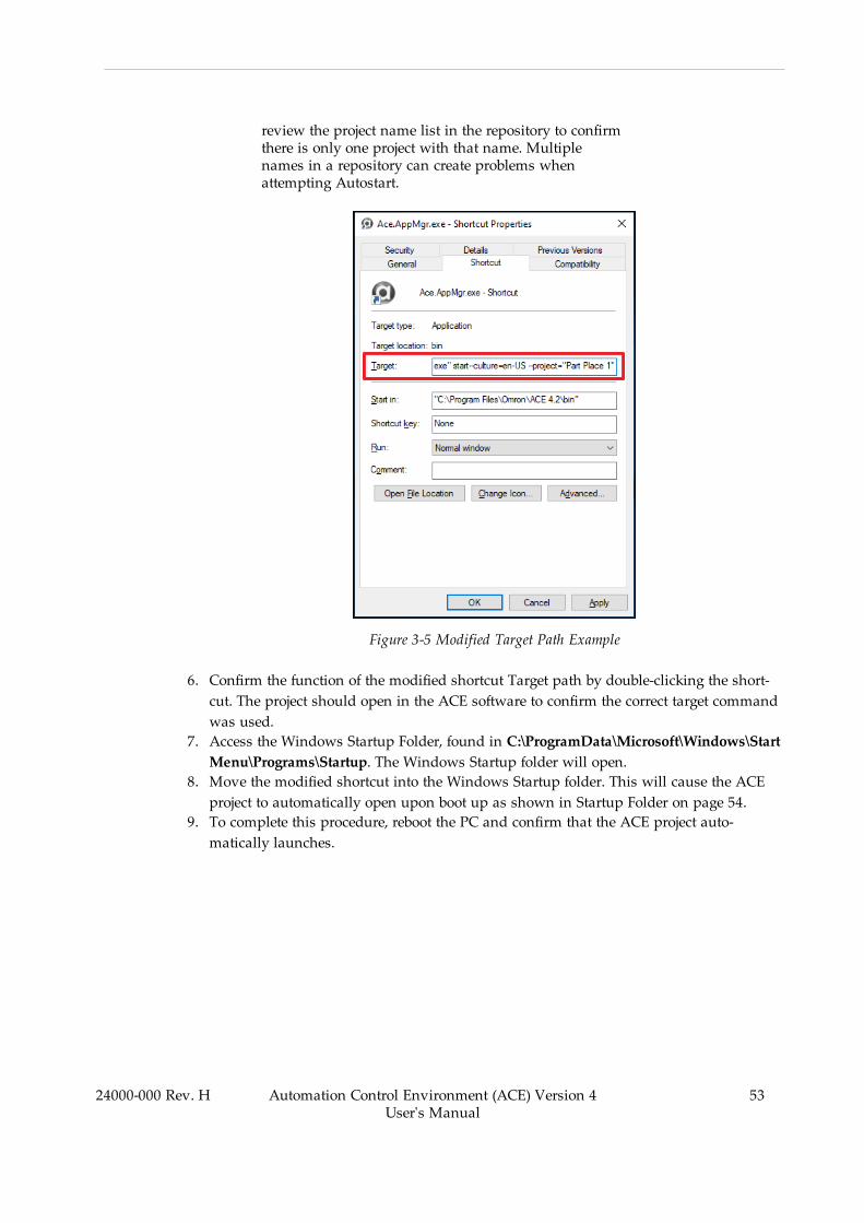
review the project name list in the repository to confirmthere is only one project with that name. Multiplenames in a repository can create problems whenattempting Autostart.
Figure 3-5 Modified Target Path Example
6. Confirm the function of the modified shortcut Target path by double-clicking the short-cut. The project should open in the ACE software to confirm the correct target commandwas used.
7. Access the Windows Startup Folder, found in C:\ProgramData\Microsoft\Windows\StartMenu\Programs\Startup. The Windows Startup folder will open.
8. Move the modified shortcut into the Windows Startup folder. This will cause the ACEproject to automatically open upon boot up as shown in Startup Folder on page 54.
9. To complete this procedure, reboot the PC and confirm that the ACE project auto-matically launches.
24000-000 Rev. H Automation Control Environment (ACE) Version 4User's Manual
53
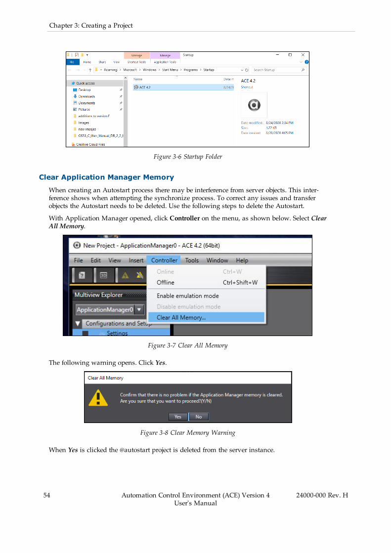
54 Automation Control Environment (ACE) Version 4User's Manual
24000-000 Rev. H
Chapter 3: Creating a Project
Figure 3-6 Startup Folder
Clear Application Manager Memory
When creating an Autostart process there may be interference from server objects. This inter-ference shows when attempting the synchronize process. To correct any issues and transferobjects the Autostart needs to be deleted. Use the following steps to delete the Autostart.
With Application Manager opened, click Controller on the menu, as shown below. Select ClearAll Memory.
Figure 3-7 Clear All Memory
The following warning opens. Click Yes.
Figure 3-8 Clear Memory Warning
When Yes is clicked the @autostart project is deleted from the server instance.
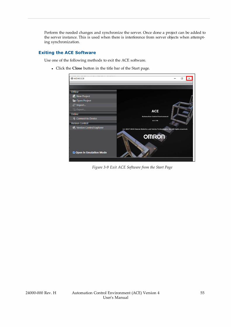
Perform the needed changes and synchronize the server. Once done a project can be added tothe server instance. This is used when there is interference from server objects when attempt-ing synchronization.
Exiting the ACE Software
Use one of the following methods to exit the ACE software.
l Click the Close button in the title bar of the Start page.
Figure 3-9 Exit ACE Software from the Start Page
24000-000 Rev. H Automation Control Environment (ACE) Version 4User's Manual
55

56 Automation Control Environment (ACE) Version 4User's Manual
24000-000 Rev. H
Chapter 3: Creating a Project
l Select Exit from the File Menu when working in an open project.
Figure 3-10 Exit ACE Software from an Open Project
The ACE software will close.
Additional Information: If there is unsaved data when you exit theACE software, a dialog box will appear that asks if you want to save the data.
Figure 3-11 Save Project Dialog Box
Save the data if required. The ACE software will close after this operation.
3.2 Creating a Project FileThe following procedure describes how to create a project file from the start page.
Additional Information: A project file can also be created with the Connect toDevice method when a SmartController is present. Refer to Creating a Projectfrom an Online Connection on page 61 for more information.

1. Click New Project on the Start page.
Figure 3-12 Create a New Project
The Project Properties Screen is displayed.
2. Enter the project name, author, and comment in the Project Properties Screen, select thedevice category and the device to use, and then click the Create button. (Only the pro-ject name is required.)
Figure 3-13 Project Properties Screen
The property settings are listed below.
24000-000 Rev. H Automation Control Environment (ACE) Version 4User's Manual
57

58 Automation Control Environment (ACE) Version 4User's Manual
24000-000 Rev. H
Chapter 3: Creating a Project
Table 3-2 Project Property Descriptions
Property Description
Project name Enter the project name (required)
Author Enter the author name (optional).
If this is the first time you are creating a project after installing theACE software, the user name that you entered when you logged ontoWindows is displayed (see note below).
Comment Enter a comment about the project (optional).
Type Select the project type (required).
l Standard Project
This type is used for a normal project.
l Library Project
This type is used to create a library project (reserved for futureuse).
Category Select the device category for the project (required).
Refer to Device List and Device Icon on page 93 for more information.
Device Specify the device type based on the category selection (required).
Version Specify the device version based on the category selection (required).
The ACE software is compatible with controllers running eV+ version2.1 B8 or above.
Application Manager device AM101-1000 version 2.0 is compatiblewith any Application Manager device in ACE software version 4.2 orhigher. Version 1.0 is compatible with ACE 4.0 or higher.
NOTE: You can change the author name that is displayed when you cre-ate a project in the option settings. Refer to Project Settings on page 143 formore information.
Additional Information: You can change the properties later. Refer toOpening a Project File on page 64 for more information.
3. After entering the project properties, make a selection for Open in Emulation Mode. Referto Emulation Mode on page 17 for more information.
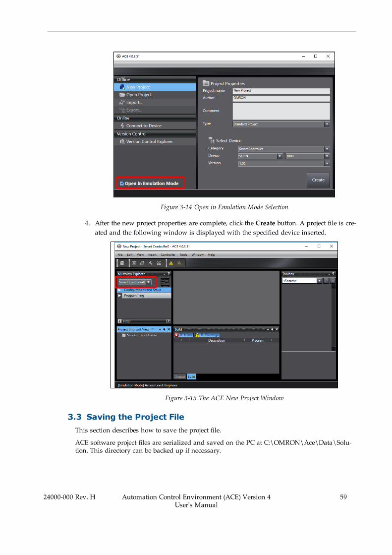
Figure 3-14 Open in Emulation Mode Selection
4. After the new project properties are complete, click the Create button. A project file is cre-ated and the following window is displayed with the specified device inserted.
Figure 3-15 The ACE New Project Window
3.3 Saving the Project FileThis section describes how to save the project file.
ACE software project files are serialized and saved on the PC at C:\OMRON\Ace\Data\Solu-tion. This directory can be backed up if necessary.
24000-000 Rev. H Automation Control Environment (ACE) Version 4User's Manual
59
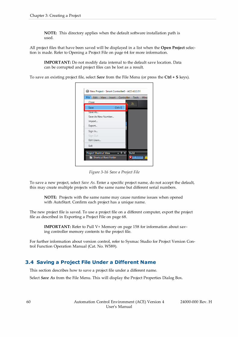
60 Automation Control Environment (ACE) Version 4User's Manual
24000-000 Rev. H
Chapter 3: Creating a Project
NOTE: This directory applies when the default software installation path isused.
All project files that have been saved will be displayed in a list when the Open Project selec-tion is made. Refer to Opening a Project File on page 64 for more information.
IMPORTANT: Do not modify data internal to the default save location. Datacan be corrupted and project files can be lost as a result.
To save an existing project file, select Save from the File Menu (or press the Ctrl + S keys).
Figure 3-16 Save a Project File
To save a new project, select Save As. Enter a specific project name, do not accept the default,this may create multiple projects with the same name but different serial numbers.
NOTE: Projects with the same name may cause runtime issues when openedwith AutoStart. Confirm each project has a unique name.
The new project file is saved. To use a project file on a different computer, export the projectfile as described in Exporting a Project File on page 68.
IMPORTANT: Refer to Pull V+ Memory on page 158 for information about sav-ing controller memory contents to the project file.
For further information about version control, refer to Sysmac Studio for Project Version Con-trol Function Operation Manual (Cat. No. W589).
3.4 Saving a Project File Under a Different NameThis section describes how to save a project file under a different name.
Select Save As from the File Menu. This will display the Project Properties Dialog Box.

Figure 3-17 Save a Project as a Different Name
Change the project file name and any other project property details, and then click theSave button.
Figure 3-18 Change the Project File Name
Additional Information: For information about project file password protection,refer to Password Protection for Project Files on page 71.
3.5 Creating a Project from an Online ConnectionIf you connect to a device without specifying a project, a new project is created automatically.Use the procedure below to connect to a device and create a new project after uploading fromthe SmartController memory.
24000-000 Rev. H Automation Control Environment (ACE) Version 4User's Manual
61

62 Automation Control Environment (ACE) Version 4User's Manual
24000-000 Rev. H
Chapter 3: Creating a Project
1. Click Connect to Device from the Start page. This will open the Connect to Device Dia-log Box.
Figure 3-19 Connect to a Device
2. Make the appropriate connection settings in the Connect to Device Dialog Box and clickthe Connect button (refer to Online Connections to SmartControllers on page 75 formore information).
3. After the connection is established, the Application window will be shown. A new pro-ject has been created from an online connection.
NOTE: This new project gets a default project name. Select Save as... fromthe File Menu to save this project with a different name and adjust projectproperties if necessary.
Additional Information: To capture the V+ memory into the new project,pull V+ memory from the SmartController. Refer to Pull V+ Memory onpage 158 for more information.
3.6 Closing a Project and Returning to the Start PageUse the following procedure to close a project file and return to the Start page.

1. Select Close from the File Menu.
Figure 3-20 Close a Project
2. A dialog box is displayed to ask if you need to save the project. Click the Yes button orNo button for the project saving choice.
Figure 3-21 Save Project Selection
3. The Start page is displayed.
24000-000 Rev. H Automation Control Environment (ACE) Version 4User's Manual
63
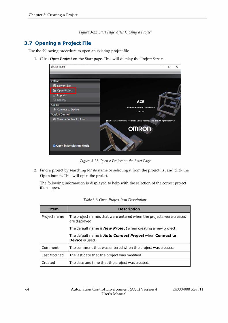
64 Automation Control Environment (ACE) Version 4User's Manual
24000-000 Rev. H
Chapter 3: Creating a Project
Figure 3-22 Start Page After Closing a Project
3.7 Opening a Project FileUse the following procedure to open an existing project file.
1. Click Open Project on the Start page. This will display the Project Screen.
Figure 3-23 Open a Project on the Start Page
2. Find a project by searching for its name or selecting it from the project list and click theOpen button. This will open the project.
The following information is displayed to help with the selection of the correct projectfile to open.
Table 3-3 Open Project Item Descriptions
Item Description
Project name The project names that were entered when the projects were createdare displayed.
The default name isNew Projectwhen creating a new project.
The default name isAuto Connect Projectwhen Connect toDevice is used.
Comment The comment that was entered when the project was created.
Last Modified The last date that the project wasmodified.
Created The date and time that the project was created.
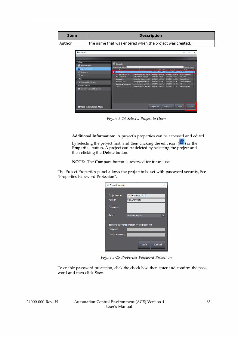
Item Description
Author The name that was entered when the project was created.
Figure 3-24 Select a Project to Open
Additional Information: A project's properties can be accessed and edited
by selecting the project first, and then clicking the edit icon ( ) or theProperties button. A project can be deleted by selecting the project andthen clicking the Delete button.
NOTE: The Compare button is reserved for future use.
The Project Properties panel allows the project to be set with password security, See"Properties Password Protection".
Figure 3-25 Properties Password Protection
To enable password protection, click the check box, then enter and confirm the pass-word and then click Save.
24000-000 Rev. H Automation Control Environment (ACE) Version 4User's Manual
65
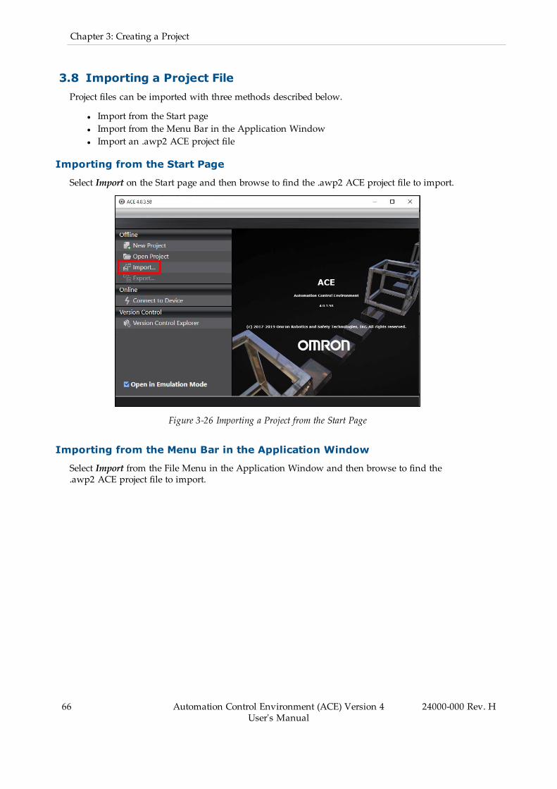
66 Automation Control Environment (ACE) Version 4User's Manual
24000-000 Rev. H
Chapter 3: Creating a Project
3.8 Importing a Project FileProject files can be imported with three methods described below.
l Import from the Start pagel Import from the Menu Bar in the Application Windowl Import an .awp2 ACE project file
Importing from the Start Page
Select Import on the Start page and then browse to find the .awp2 ACE project file to import.
Figure 3-26 Importing a Project from the Start Page
Importing from the Menu Bar in the Application Window
Select Import from the File Menu in the Application Window and then browse to find the.awp2 ACE project file to import.

Figure 3-27 Import a Project from the Application Window
Importing an .awp2 ACE Project File
Browse to an .awp2 ACE project file with a file explorer:
Figure 3-28 ACE Project File / Icon
Opening the ACE project file will automatically launch the ACE software, import a new projectfile, and open the project.
IMPORTANT: Repeated opening of a particular .awp2 ACE project file will res-ult in duplicate copies of the project. This method should be used for projects notpreviously imported.
Importing from Version Control
With ACE opened, click the Version Control Explorer to open the Version Control Projects, See"Version Control Projects".
24000-000 Rev. H Automation Control Environment (ACE) Version 4User's Manual
67
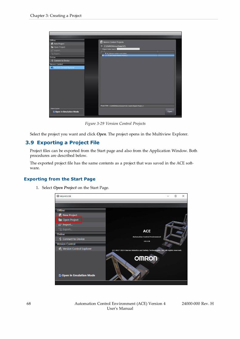
68 Automation Control Environment (ACE) Version 4User's Manual
24000-000 Rev. H
Chapter 3: Creating a Project
Figure 3-29 Version Control Projects
Select the project you want and click Open. The project opens in the Multiview Explorer.
3.9 Exporting a Project FileProject files can be exported from the Start page and also from the Application Window. Bothprocedures are described below.
The exported project file has the same contents as a project that was saved in the ACE soft-ware.
Exporting from the Start Page
1. Select Open Project on the Start Page.

Figure 3-30 Accessing Project List for Exporting
2. Select a project to export from the list of project names and click Export. The Export Pro-ject Dialog Box will be displayed.
Figure 3-31 Select a Project and Click Export
Exporting from the Application Window
Select Export from the File Menu in the Application Window. The Export Project Dialog Boxwill be displayed.
Figure 3-32 Export a Project from the Application Window
When Git is installed onto the computer, or the ACE application is connected to a remote repos-itory, clicking Export opens the repository view, See "Repository View".
24000-000 Rev. H Automation Control Environment (ACE) Version 4User's Manual
69
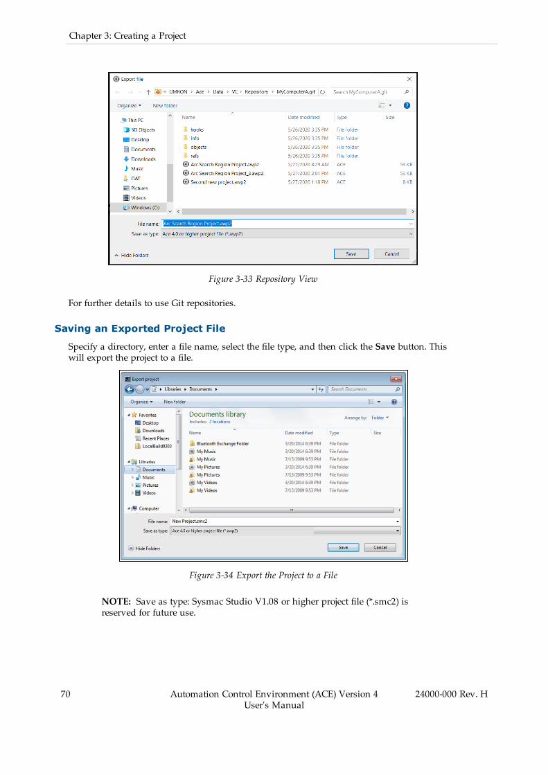
70 Automation Control Environment (ACE) Version 4User's Manual
24000-000 Rev. H
Chapter 3: Creating a Project
Figure 3-33 Repository View
For further details to use Git repositories.
Saving an Exported Project File
Specify a directory, enter a file name, select the file type, and then click the Save button. Thiswill export the project to a file.
Figure 3-34 Export the Project to a File
NOTE: Save as type: Sysmac Studio V1.08 or higher project file (*.smc2) isreserved for future use.

Additional Information: You can export the contents of a project file for whichpassword protection is set. Refer to Password Protection for Project Files on page71 for the procedure to set password protection.
3.10 Password Protection for Project FilesYou can set password protection for project files to protect your assets.
Passwords are case sensitive and must be a string of 8 to 32 alphanumeric characters.
Password protection for project files does not apply to data that is transferred to the SmartCon-troller.
If password protection is set, a password is required for the following operations.
l Opening the project filel Changing the properties of the project filel Importing the contents of the project file
IMPORTANT: If you forget the password, you will no longer be able to open theproject file, change the properties of the project file, or import the contents of theproject file. Be sure to record the password in case you forget it.
Setting Password Protection for Project Files
Use the following procedure to set password protection for project files.
1. Click Open Project on the Start page. Then, click the Properties button or click the Edit
Properties icon ( ). This will display the Properties Dialog Box.2. Select the Enable password protection for the project file Check Box.
Figure 3-35 Enable Password Protection
3. Enter the password, confirm the password (these must match) and then click the Savebutton. The file is saved and password protection is set for this project.
24000-000 Rev. H Automation Control Environment (ACE) Version 4User's Manual
71
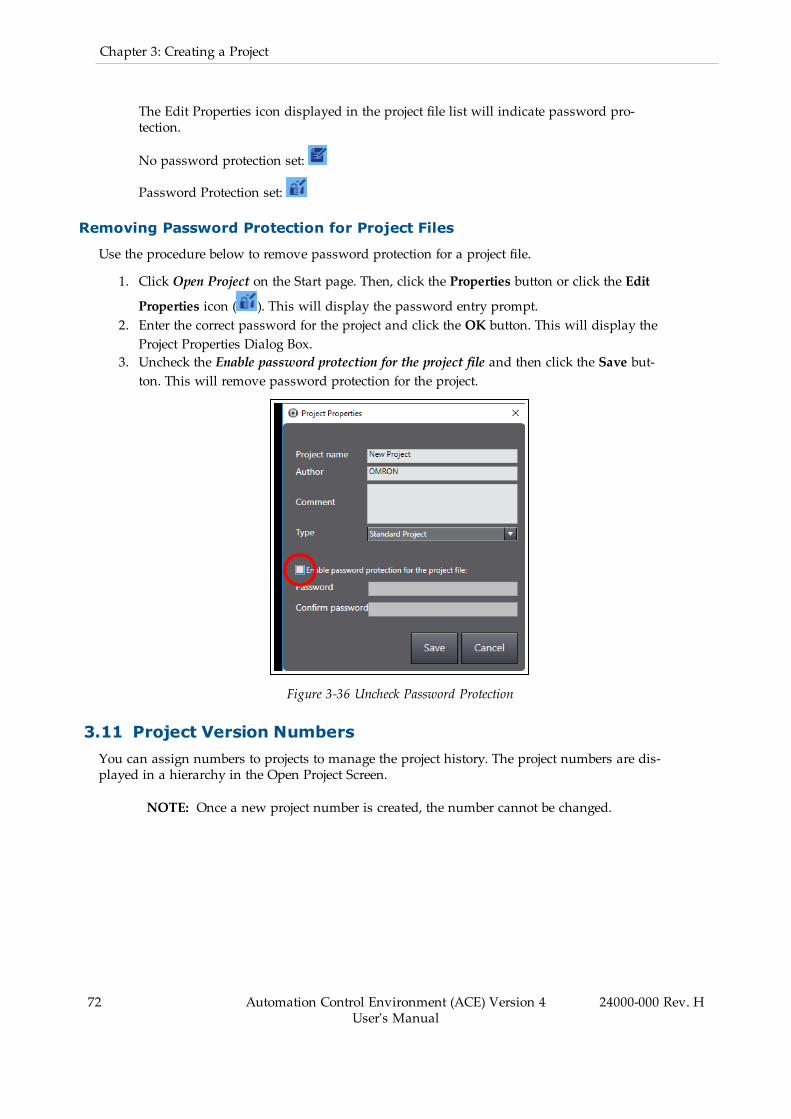
72 Automation Control Environment (ACE) Version 4User's Manual
24000-000 Rev. H
Chapter 3: Creating a Project
The Edit Properties icon displayed in the project file list will indicate password pro-tection.
No password protection set:
Password Protection set:
Removing Password Protection for Project Files
Use the procedure below to remove password protection for a project file.
1. Click Open Project on the Start page. Then, click the Properties button or click the Edit
Properties icon ( ). This will display the password entry prompt.2. Enter the correct password for the project and click the OK button. This will display theProject Properties Dialog Box.
3. Uncheck the Enable password protection for the project file and then click the Save but-ton. This will remove password protection for the project.
Figure 3-36 Uncheck Password Protection
3.11 Project Version NumbersYou can assign numbers to projects to manage the project history. The project numbers are dis-played in a hierarchy in the Open Project Screen.
NOTE: Once a new project number is created, the number cannot be changed.

Figure 3-37 Project Hierarchy
Use the Save As New Number... from the File Menu to assign an incrementing number to anopen project.
Figure 3-38 Save as New Number
A new number is automatically added for the project number.
24000-000 Rev. H Automation Control Environment (ACE) Version 4User's Manual
73
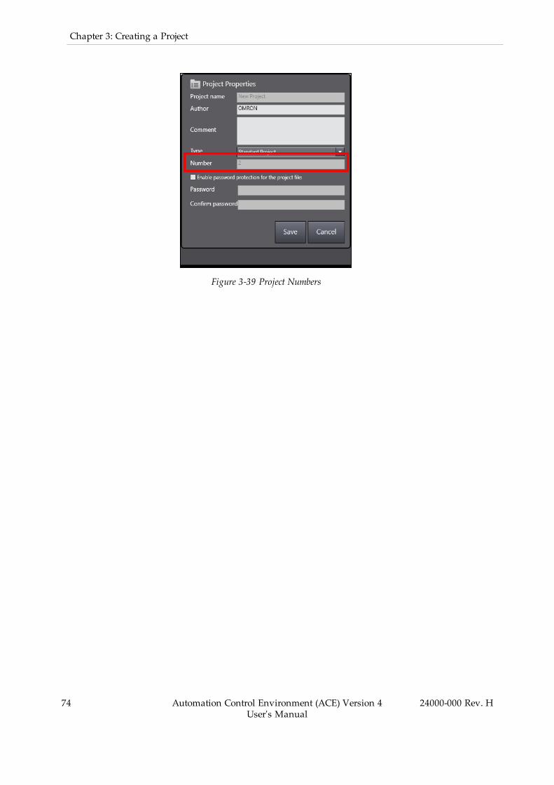
74 Automation Control Environment (ACE) Version 4User's Manual
24000-000 Rev. H
Chapter 3: Creating a Project
Figure 3-39 Project Numbers

Chapter 4: Online Connections to SmartCon-trollers
An online connection must be established to allow communications between the ACE softwareand a SmartController. Online connections are also possible in Emulation Mode (refer toEmulation Mode on page 17 for more information).
NOTE: ACE software version 3.8 (and older) cannot connect to a controller thatACE software version 4.2 (or higher) has connected to previously until a zeromemory or reboot have been executed.
If an online connection has been established, you can perform operations such as:
l Program debugging, transfer, and comparisonl Task managementl I/O monitoringl File transferl Robot joggingl Monitoring system performance
Use the information in this chapter to understand how to use the online connection func-tionality with the ACE software and SmartControllers.
4.1 Going Online with a SmartControllerAn online connection to a SmartController or an emulated controller can be established fromthe ACE software Start page or from within an existing open project.
NOTE: You can simultaneously go online with more than one SmartControllerin a project from the ACE software. The operations that are described in this sec-tion apply to the currently selected SmartController in the Multiview Explorer. Ifthere is more than one SmartController that is registered in the project, select theSmartController in the Multiview Explorer before attempting to go online.
Going Online from the Start Page
Clicking Connect to Device on the Start page will open the Connect to Device Dialog Box. TheConnect to Device screen is used to prepare the online connection to a controller.
NOTE: A successful connection to a controller with this method will auto-matically create a new project with the name "Auto Connect Project". After theproject is open, it is recommended to save the project with a more specific nameusing Save As... from the File menu. Closing without saving may result in anempty project.
24000-000 Rev. H Automation Control Environment (ACE) Version 4User's Manual
75

76 Automation Control Environment (ACE) Version 4User's Manual
24000-000 Rev. H
Chapter 4: Online Connections to SmartControllers
Figure 4-1 Connect to Device on the Start Page
The main areas of the Connect to Device Dialog Box are described below.
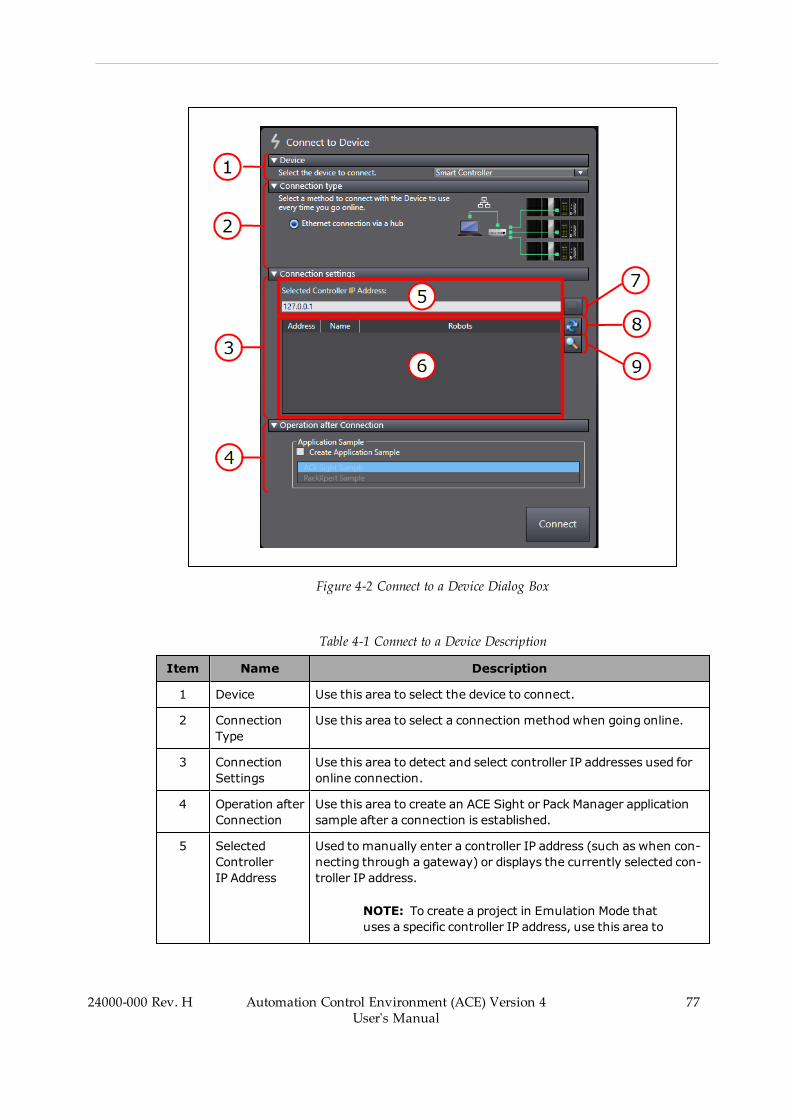
Figure 4-2 Connect to a Device Dialog Box
Table 4-1 Connect to a Device Description
Item Name Description
1 Device Use this area to select the device to connect.
2 ConnectionType
Use this area to select a connection methodwhen going online.
3 ConnectionSettings
Use this area to detect and select controller IP addresses used foronline connection.
4 Operation afterConnection
Use this area to create an ACE Sight or Pack Manager applicationsample after a connection is established.
5 SelectedControllerIP Address
Used tomanually enter a controller IP address (such as when con-necting through a gateway) or displays the currently selected con-troller IP address.
NOTE: To create a project in Emulation Mode thatuses a specific controller IP address, use this area to
24000-000 Rev. H Automation Control Environment (ACE) Version 4User's Manual
77
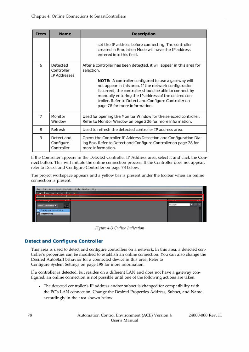
78 Automation Control Environment (ACE) Version 4User's Manual
24000-000 Rev. H
Chapter 4: Online Connections to SmartControllers
Item Name Description
set the IP address before connecting. The controllercreated in Emulation Mode will have the IP addressentered into this field.
6 DetectedControllerIP Addresses
After a controller has been detected, it will appear in this area forselection.
NOTE: A controller configured to use a gateway willnot appear in this area. If the network configurationis correct, the controller should be able to connect bymanually entering the IP address of the desired con-troller. Refer to Detect and Configure Controller onpage 78 for more information.
7 MonitorWindow
Used for opening the Monitor Window for the selected controller.Refer to Monitor Window on page 206 for more information.
8 Refresh Used to refresh the detected controller IP address area.
9 Detect andConfigureController
Opens the Controller IP Address Detection and Configuration Dia-log Box. Refer to Detect and Configure Controller on page 78 formore information.
If the Controller appears in the Detected Controller IP Address area, select it and click the Con-nect button. This will initiate the online connection process. If the Controller does not appear,refer to Detect and Configure Controller on page 78 below.
The project workspace appears and a yellow bar is present under the toolbar when an onlineconnection is present.
Figure 4-3 Online Indication
Detect and Configure Controller
This area is used to detect and configure controllers on a network. In this area, a detected con-troller's properties can be modified to establish an online connection. You can also change theDesired AutoStart behavior for a connected device in this area. Refer toConfigure System Settings on page 198 for more information.
If a controller is detected, but resides on a different LAN and does not have a gateway con-figured, an online connection is not possible until one of the following actions are taken.
l The detected controller's IP address and/or subnet is changed for compatibility withthe PC's LAN connection. Change the Desired Properties Address, Subnet, and Nameaccordingly in the area shown below.

Additional Information: Refer to Configure System Settings on page 198to change the address, subnet, or name of a connected controller.
Figure 4-4 Change the Controller Network Configuration, Name and Autostart Properties
l The PC's IP address and LAN connection are changed to be compatible withthe controller. Adjust the PCs network adapter properties accordingly.
Going Online from an Open Project
There are three methods available for going online from an open project:
1. Use the Online icon ( ) in the toolbar to go online with the controller selected inthe Multiview Explorer.
2. Select Online from the Controller Menu to go online with the controller selected in theMultiview Explorer.
3. Click the Online icon ( ) in the Task Status Control area to go online with the asso-ciated controller. Refer to Task Status Control on page 122 for more information aboutTask Status Control.
Use the Online and Offline buttons to control the online connections to each controller.
24000-000 Rev. H Automation Control Environment (ACE) Version 4User's Manual
79

80 Automation Control Environment (ACE) Version 4User's Manual
24000-000 Rev. H
Chapter 4: Online Connections to SmartControllers
Figure 4-5 Task Status Control for Online Monitoring
These methods rely on a correct IP assignment for the controller. Refer to Controller Settings onpage 185 for more information.
Additional Information: The Controller Connection Startup object allowsthe ACE software to automatically establish an online connection when the pro-ject opens. Refer to Controller Connection Startup on page 291 for more inform-ation.
4.2 Going Offline with a SmartControllerUse the offline function to close an active connection to a controller. Use one of the followingmethods to go offline with a controller.
l Click the Offline button in the toolbar.
Figure 4-6 Offline Button
l Select Offline from the Controller Menu.

Figure 4-7 Offline Toolbar
l Click the Offline icon in the Task Status Control area (refer to Task Status Control onpage 122 for more information).
Figure 4-8 Offline Icon in Task Status Control Area
4.3 Memory ComparisonWhen an online connection is initiated after opening a project, ACE software makes a com-parison between the memory of the controller and the ACE project V+ memory. If a differenceis found after going online, the following dialog box will be displayed.
Figure 4-9 Memory Difference after Online Connection
You have the option of using the controller memory, the ACE project V+ memory, or mergingthe two together.
Controller Memory
Clicking the Controller button ( ) will overwrite the ACE project V+ memory with thecontents of the Controller.
NOTE: If you overwrite the ACE project V+ memory with the contents of the con-troller, there is no way to recover previous project data unless a backup copy has
24000-000 Rev. H Automation Control Environment (ACE) Version 4User's Manual
81
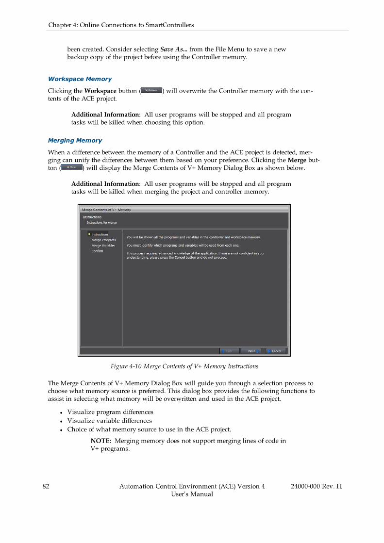
82 Automation Control Environment (ACE) Version 4User's Manual
24000-000 Rev. H
Chapter 4: Online Connections to SmartControllers
been created. Consider selecting Save As... from the File Menu to save a newbackup copy of the project before using the Controller memory.
Workspace Memory
Clicking the Workspace button ( ) will overwrite the Controller memory with the con-tents of the ACE project.
Additional Information: All user programs will be stopped and all programtasks will be killed when choosing this option.
Merging Memory
When a difference between the memory of a Controller and the ACE project is detected, mer-ging can unify the differences between them based on your preference. Clicking theMerge but-ton ( ) will display the Merge Contents of V+ Memory Dialog Box as shown below.
Additional Information: All user programs will be stopped and all programtasks will be killed when merging the project and controller memory.
Figure 4-10 Merge Contents of V+ Memory Instructions
The Merge Contents of V+ Memory Dialog Box will guide you through a selection process tochoose what memory source is preferred. This dialog box provides the following functions toassist in selecting what memory will be overwritten and used in the ACE project.
l Visualize program differencesl Visualize variable differencesl Choice of what memory source to use in the ACE project.
NOTE: Merging memory does not support merging lines of code inV+ programs.

24000-000 Rev. H Automation Control Environment (ACE) Version 4User's Manual
83


Chapter 5: Understanding the ACE User Inter-face
This section provides the names, functions, and basic arrangement of the ACE software userinterface.
5.1 The Main Application WindowThe default application window layout is described below.
Figure 5-1 ACE Main Application Window
Table 5-1 Ace Main Application Window Description
Item Description
1 Menu bar
2 Toolbar
3 Multiview Explorer
4 Filter Pane
5 Project Shortcut View
6 Status Bar
7 Edit Pane
8 Multifunction Tabs
24000-000 Rev. H Automation Control Environment (ACE) Version 4User's Manual
85

86 Automation Control Environment (ACE) Version 4User's Manual
24000-000 Rev. H
Chapter 5: Understanding the ACE User Interface
Item Description
9 Multipurpose Tools
Menu Command Structure
The menu bar contains the following command structure.
Table 5-2 File Menu Bar Item Description
Contents Description
Close Clears all objects and project data and returns to the ACE start screen.
Save Saves the current project to the project library.
Save As... Save the currently opened project with options to adjust project properties.
Save AsNewNumber
Save the currently opened project with an incremented number.
Import... Import an ACE project file.
Refer to Importing a Project File on page 66 for more information.
Export... Export an ACE project to a file.
Refer to Exporting a Project File on page 68 for more information.
Sign In... Sign in with a specific user access level.
Refer to User Management on page 139 for more information.
Sign Out Sign out of a specific user access level.
Refer to User Management on page 139 for more information.
EditUsers...
Edit user access levels.
Refer to User Management on page 139 for more information.
Exit Exit the ACE software.
Table 5-3 Edit Menu Bar Item Description
Contents Description
Undo Undo the last action.
Redo Redo the last action.
Cut Cut the selected item to the clipboard.
Copy Copy the selected item to the clipboard.
Paste Paste an item from the clipboard to the selected area.
Delete Delete the selected item.

Contents Description
Select All Select all items in an area or list.
Searchand Replace
Open the Search and Replace tool.
Refer to Search and Replace on page 137 for more information.
Find Previous Find a previous instance of a search term.
Find Next Find the next instance of a search term.
Jump... Reserved for future use.
Jump toMultiviewExplorer
Display the active item in the expandedMultiview Explorer.
Table 5-4 View Menu Bar Item Description
Contents Description
Multiview Explorer Display the Multiview Explorer.
Refer to Multiview Explorer on page 92 for more information.
Project ShortcutView
Display the Project Shortcut view.
Refer to Project Shortcut View on page 96 for more information.
Toolbox Display the Toolbox in the multipurpose tools area.
Refer to Toolbox on page 106 for more information.
3D Visualizer Display the 3D Visualizer in the multipurpose tools area.
Refer to 3D Visualizer on page 107 for more information.
Output Tab Page Reserved for future use.
Cross Reference TabPage
Reserved for future use.
Build Tab Page Display the Build Tab in the multifunction tabs area.
Refer to Build Tab Page on page 115 for more information.
This is not available when the Application Manager device is selected.
Event Log Display the Event Log in the multifunction tabs area.
Refer to Event Log on page 116 for more information.
Smart Project Search Display the Smart Project Search tool as a pop upwindow.
Refer to Smart Project Search on page 105 for more information.
RecentlyClosed Windows
Display the Recently Closed Windows as a pop upwindow.
Refer to Recently ClosedWindows on page 101 for more information.
Clear Recently ClosedWindows History
Clear the Recently ClosedWindows history.
24000-000 Rev. H Automation Control Environment (ACE) Version 4User's Manual
87
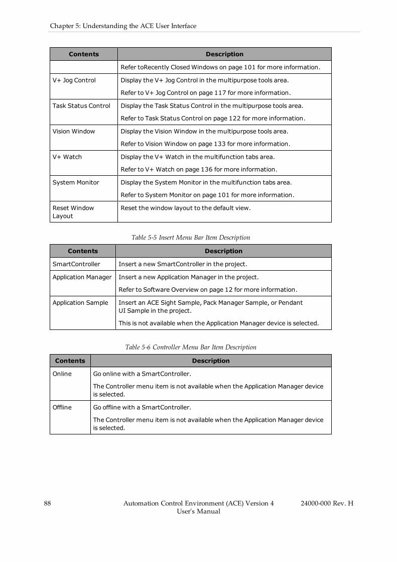
88 Automation Control Environment (ACE) Version 4User's Manual
24000-000 Rev. H
Chapter 5: Understanding the ACE User Interface
Contents Description
Refer toRecently ClosedWindows on page 101 for more information.
V+ Jog Control Display the V+ Jog Control in the multipurpose tools area.
Refer to V+ Jog Control on page 117 for more information.
Task Status Control Display the Task Status Control in the multipurpose tools area.
Refer to Task Status Control on page 122 for more information.
Vision Window Display the Vision Window in the multipurpose tools area.
Refer to Vision Window on page 133 for more information.
V+ Watch Display the V+ Watch in the multifunction tabs area.
Refer to V+ Watch on page 136 for more information.
System Monitor Display the System Monitor in the multifunction tabs area.
Refer to System Monitor on page 101 for more information.
Reset WindowLayout
Reset the window layout to the default view.
Table 5-5 Insert Menu Bar Item Description
Contents Description
SmartController Insert a new SmartController in the project.
Application Manager Insert a new Application Manager in the project.
Refer to Software Overview on page 12 for more information.
Application Sample Insert an ACE Sight Sample, Pack Manager Sample, or PendantUI Sample in the project.
This is not available when the Application Manager device is selected.
Table 5-6 Controller Menu Bar Item Description
Contents Description
Online Go online with a SmartController.
The Controller menu item is not available when the Application Manager deviceis selected.
Offline Go offline with a SmartController.
The Controller menu item is not available when the Application Manager deviceis selected.

Table 5-7 Tools Menu Bar Item Description
Contents Description
CustomizeShortcutKeys...
Display the Shortcut Key Customization pop upwindow.
Option... Display the project Option pop upwindow.
Refer to Project Options on page 141 for more information.
Table 5-8 Window Menu Bar Item Description
Contents Description
Close Close the active window.
Float Float the active window.
Dock Dock the active window.
New HorizontalTab Group
Divide the Edit Pane into upper and lower sections. Only available when theEdit Pane hasmore than one tab open.
NewVertical TabGroup
Divide the Edit Pane into left and right sections. Only available when the EditPane hasmore than one tab open.
Move to NextTab Group
Move the selected tab page to the tab group below or to the right of the cur-rent tab group. Only available when there is a tab group below or to the rightof the current tab group.
Move toPrevious TabGroup
Move the selected tab page to the tab group above or to the left of the cur-rent tab group. Only available when there is a tab group above or to the leftof the current tab group.
Close All ButThis
Close all tab pages and floating Edit Panes, except for the selected tab page.
Close All ExceptActive Device
Close all tab pages and floating Edit Panes for other devices, leaving those forthe selected device.
Close All Close all tab pages and floating Edit Panes, including the selected tab page.
Close Tab Close the active Edit Pane tab.
Open Next Tab Open the next Edit Pane tab. Only available when the Edit Pane hasmorethan one tab open.
Open PreviousTab
Open the previous Edit Pane tab. Only available when the Edit Pane hasmore than one tab open.
24000-000 Rev. H Automation Control Environment (ACE) Version 4User's Manual
89

90 Automation Control Environment (ACE) Version 4User's Manual
24000-000 Rev. H
Chapter 5: Understanding the ACE User Interface
Table 5-9 Help Menu Bar Item Description
Contents Description
ACE Guides Access the ACE User's Guide (this document) or the ACE Reference Guide.
eV+ Guides Access the eV+ Language Reference Guide (Cat. No. I605) or eV+3 KeywordReference Manual (Cat. No I652)
About... Display information about the ACE software.
Table 5-10 Toolbar Icons Description
Icon Name Description
Help Opens ACE User's Guide.
3D Visualizer Opens the 3D Visualizer. For more information, refer to3D Visualizer Basic Features on page 108.
Output Tab Page
Only available when a SmartController device is selected.Shows the Output Tab. If the Output Tab is already dis-played and selected, it will be hidden instead. For moreinformation, refer to Output Tab Page on page 115.
Build Tab Page
Only available when a SmartController device is selected.Shows the Build Tab. If the Build Tab is already displayedand selected, it will be hidden instead. For more inform-ation, refer to Build Tab Page on page 115.
Cross Reference TabPage
Only available when a SmartController device is selected.Shows the Cross Reference Tab. If the Cross ReferenceTab is already displayed and selected, it will be hiddeninstead. For more information, refer to Cross ReferenceTab Page on page 115
Online
Opens communication between the IPC and the specifiedcontroller or between the Application Manager and thespecified server, depending on which type of object isselected. This is disabled if the device is already online.For more information, refer to Going Online with aSmartController on page 75.
Offline
Closes communication between the IPC and the specifiedSmartController or between the Application Manager andthe specified server, depending on which type of object isselected. This is disabled if the device is already offline.For more information, see See "Going Offline with aSmartController".

Icon Name Description
Synchronize
Opens the Synchronize window. If a SmartController isselected, the window will compare ACE and the con-troller. If an Application Manager is selected, the windowwill compare the client with the server. For more inform-ation, refer to Memory Comparison on page 81.
Push V+ Memory
Only available when a SmartController device is selected.Pulls all V+ modules from the controller to ACE. This is dis-abled if there are no detected differences between the V+code in ACE and the controller. For more information,refer to Memory Comparison on page 81.
Pull V+ Memory
Only available when a SmartController device is selected.Pulls all V+ modules from the controller to ACE. This is dis-abled if there are no detected differences between the V+code in ACE and the controller. For more information,refer to Memory Comparison on page 81.
Check V+ Memory
Only available when a SmartController device is selected.Compares the V+ Modules in the project to those in thecontroller. Differences are marked as errors in the Mul-tiview Explorer. This is disabled if the device is not online.For more information, refer to Memory Comparison onpage 81.
Enable EmulationMode
Closes and reopens the project with Emulation Modeenabled. If there is unsaved data, a dialog box will appearasking if the user wants to save before continuing. Formore information, refer to Emulation Mode on page 17.
Disable EmulationMode
Closes and reopens the project with Emulation Modeenabled. If there is unsaved data, a dialog box will appearasking if the user wants to save before continuing. Formore information, refer to Emulation Mode on page 17
NOTE: Float, Dock and Close functions are also accessible with the Optionsmenu.
Figure 5-2 Options Menu
24000-000 Rev. H Automation Control Environment (ACE) Version 4User's Manual
91
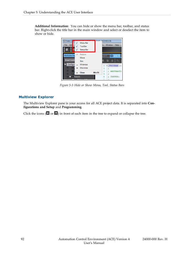
92 Automation Control Environment (ACE) Version 4User's Manual
24000-000 Rev. H
Chapter 5: Understanding the ACE User Interface
Additional Information: You can hide or show the menu bar, toolbar, and statusbar. Right-click the title bar in the main window and select or deselect the item toshow or hide.
Figure 5-3 Hide or Show Menu, Tool, Status Bars
Multiview Explorer
The Multiview Explorer pane is your access for all ACE project data. It is separated into Con-figurations and Setup and Programming.
Click the icons ( or ) in front of each item in the tree to expand or collapse the tree.

Figure 5-4 Multiview Explorer Views
Device List and Device Icon
An ACE project can include SmartController devices or Application Manager devices (or both).
The Device List contains all devices registered in the project. Use the Device List to select theactive device and access the objects associated with that device. The active device and asso-ciated toolbar and menu items can automatically change based on the Edit Pane object that iscurrently selected.
24000-000 Rev. H Automation Control Environment (ACE) Version 4User's Manual
93

94 Automation Control Environment (ACE) Version 4User's Manual
24000-000 Rev. H
Chapter 5: Understanding the ACE User Interface
Figure 5-5 Device List
Right-click the icon ( or ) to add, rename, and delete a device. You can also select SwitchDevice Control Display to switch from a dropdown view (default) to a list view.
Figure 5-6 Device Icon Menu
Color Codes
You can display marks in five colors on the categories and members of the MultiviewExplorer. These colors can be used as filter conditions in the Filter Pane that is described laterin this section.
You can define how you want to use these marks. For example, you may want to indicate asso-ciated objects within a device. The following example uses color codes to indicate which vis-ion tools are used in each Vision Sequence.

Figure 5-7 Multiview Explorer Color Codes
Error Icons
Error icons in the Multiview Explorer indicate an object that is improperly configured or a pro-gram that is not executable.
Figure 5-8 Multiview Explorer Error Icons
24000-000 Rev. H Automation Control Environment (ACE) Version 4User's Manual
95

96 Automation Control Environment (ACE) Version 4User's Manual
24000-000 Rev. H
Chapter 5: Understanding the ACE User Interface
Additional Information: You cannot execute a program with an error present.You cannot execute a Process Manager when an error is present on an asso-ciated object.
Filter Pane
The Filter Pane allows you to search for color codes and for items with an error icon. The res-ults are displayed in a list. Click the Filter Pane Bar to display the Filter Pane. The Filter Paneis hidden automatically if the mouse is not placed in it for more than five seconds at a time.
Automatically hiding the Filter Pane can be canceled by clicking the pin icon ( ).
Figure 5-9 Filter Pane
You can search for only items with a specific color code or items with error icons to display alist with only items that meet the search condition. Click any item in the search result to dis-play the item in the Edit Pane.
Project Shortcut View
The Project Shortcut View provides a convenient location for storing shortcuts to MultiviewExplorer items. Any item placed in this view can be quickly opened with a double-click. Thisarea provides more flexibility than the Multiview Explorer view, allowing you to group short-cuts to objects belonging to multiple devices for quick reference without changing the selecteddevice in the Multiview Explorer.
To add an item to the Project Shortcut View, right-click it in the Multiview Explorer and selectAdd Shortcut. An item can also be added by right-clicking a folder in the Project Shortcut Viewand then clicking Add Shortcut of Selected Item (any item that is currently selected in the Mul-tiview Explorer will be added). A new shortcut to the item will be placed in the Project Short-cut View.
To access functions in the Project Shortcut View, right click the item to open a menu. The func-tions of the Project Shortcut View are described below.
Figure 5-10 Project Shortcut View
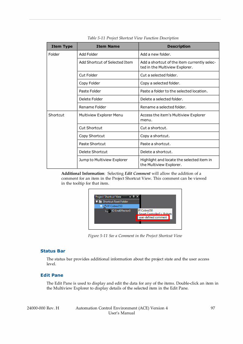
Table 5-11 Project Shortcut View Function Description
Item Type Item Name Description
Folder Add Folder Add a new folder.
Add Shortcut of Selected Item Add a shortcut of the item currently selec-ted in the Multiview Explorer.
Cut Folder Cut a selected folder.
Copy Folder Copy a selected folder.
Paste Folder Paste a folder to the selected location.
Delete Folder Delete a selected folder.
Rename Folder Rename a selected folder.
Shortcut Multiview Explorer Menu Access the item's Multiview Explorermenu.
Cut Shortcut Cut a shortcut.
Copy Shortcut Copy a shortcut.
Paste Shortcut Paste a shortcut.
Delete Shortcut Delete a shortcut.
Jump to Multiview Explorer Highlight and locate the selected item inthe Multiview Explorer.
Additional Information: Selecting Edit Comment will allow the addition of acomment for an item in the Project Shortcut View. This comment can be viewedin the tooltip for that item.
Figure 5-11 See a Comment in the Project Shortcut View
Status Bar
The status bar provides additional information about the project state and the user accesslevel.
Edit Pane
The Edit Pane is used to display and edit the data for any of the items. Double-click an item inthe Multiview Explorer to display details of the selected item in the Edit Pane.
24000-000 Rev. H Automation Control Environment (ACE) Version 4User's Manual
97
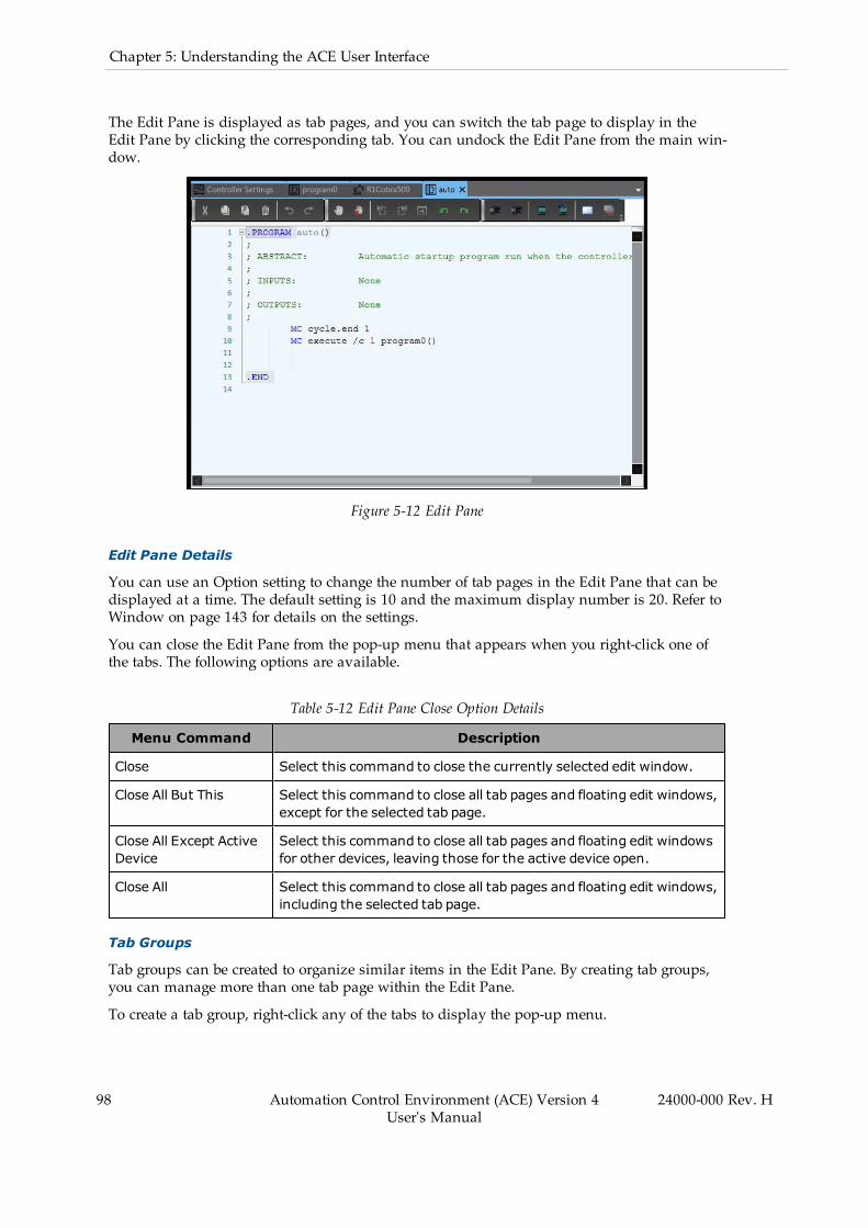
98 Automation Control Environment (ACE) Version 4User's Manual
24000-000 Rev. H
Chapter 5: Understanding the ACE User Interface
The Edit Pane is displayed as tab pages, and you can switch the tab page to display in theEdit Pane by clicking the corresponding tab. You can undock the Edit Pane from the main win-dow.
Figure 5-12 Edit Pane
Edit Pane Details
You can use an Option setting to change the number of tab pages in the Edit Pane that can bedisplayed at a time. The default setting is 10 and the maximum display number is 20. Refer toWindow on page 143 for details on the settings.
You can close the Edit Pane from the pop-up menu that appears when you right-click one ofthe tabs. The following options are available.
Table 5-12 Edit Pane Close Option Details
Menu Command Description
Close Select this command to close the currently selected edit window.
Close All But This Select this command to close all tab pages and floating edit windows,except for the selected tab page.
Close All Except ActiveDevice
Select this command to close all tab pages and floating edit windowsfor other devices, leaving those for the active device open.
Close All Select this command to close all tab pages and floating edit windows,including the selected tab page.
Tab Groups
Tab groups can be created to organize similar items in the Edit Pane. By creating tab groups,you can manage more than one tab page within the Edit Pane.
To create a tab group, right-click any of the tabs to display the pop-up menu.
NOTE: More than one tab must be open in the Edit Pane to use the followingfunctions.
Table 5-13 Tab Group Function Descriptions
Menu Command Description Remarks
New Horizontal Tab Group Select this command to dividethe Edit Pane into upper andlower sections andmove theselected tab page to the tabgroup that is newly created.
You can display the pop-upmenu when the current tabgroup hasmore than one tabpage.
New Vertical Tab Group Select this command to dividethe Edit Pane into left and rightsections andmove the selectedtab page to the newly createdtab group.
You can display the pop-upmenu when the current tabgroup hasmore than one tabpage.
Move to Next Tab Group Select this command tomovethe selected tab page to the tabgroup below or to the right ofthe current tab group.
You can display the pop-upmenu when there is a tabgroup below or to the right ofthe current tab group.
Move to Previous Tab Group Select this command tomovethe selected tab page to the tabgroup above or to the left of thecurrent tab group.
You can display the pop-upmenu when there is a tabgroup above or to the left ofthe current tab group.
Additional Information: You can also move tab pages between tab groups bydragging the mouse.
Multifunction Tabs
The Multifunction Tabs area contains several objects that are described in this chapter.
l Output Tab Page (reserved for future use)l Cross Reference Tab Page (reserved for future use)l Build Tab Page (refer to Build Tab Page on page 115 for more information)l Event Log (refer to Event Log on page 116 for more information)l V+ Watch (refer to V+ Watch on page 136 for more information)
Multiple objects can be open in the Multifunction Tabs area. Use the tab selections to switchbetween active objects.
24000-000 Rev. H Automation Control Environment (ACE) Version 4User's Manual
99

100 Automation Control Environment (ACE) Version 4User's Manual
24000-000 Rev. H
Chapter 5: Understanding the ACE User Interface
Figure 5-13 Multifunction Tab Selection
Special Toolsl Toolbox (refer to Toolbox on page 106 for more information)l 3D Visualizer (refer to 3D Visualizer on page 107 for more information)l V+ Jog Control (refer to V+ Jog Control on page 117 for more information)l Task Status Control (refer to Task Status Control on page 122 for more information)l Vision Window (refer to Vision Window on page 133 for more information)
Multiple objects can be open in the Special Tools area. Use the tab selections to switch betweenactive objects. You can also dock these objects in other areas of the software by dragging anddropping them to different locations.
Figure 5-14 Special Tool Tab Selection
Other Application Window Functions
Other application window functions are described below. These can be accessed in the Viewmenu item.
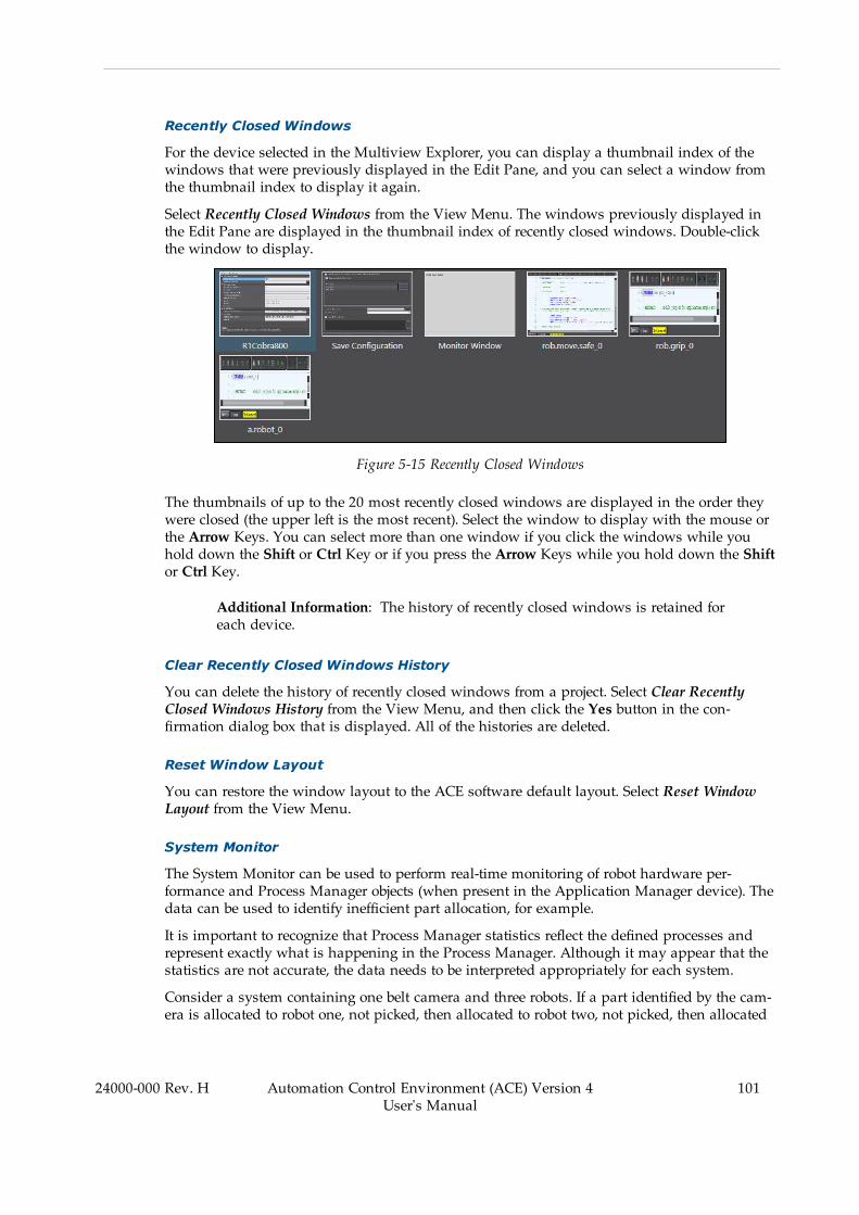
Recently Closed Windows
For the device selected in the Multiview Explorer, you can display a thumbnail index of thewindows that were previously displayed in the Edit Pane, and you can select a window fromthe thumbnail index to display it again.
Select Recently Closed Windows from the View Menu. The windows previously displayed inthe Edit Pane are displayed in the thumbnail index of recently closed windows. Double-clickthe window to display.
Figure 5-15 Recently Closed Windows
The thumbnails of up to the 20 most recently closed windows are displayed in the order theywere closed (the upper left is the most recent). Select the window to display with the mouse orthe Arrow Keys. You can select more than one window if you click the windows while youhold down the Shift or Ctrl Key or if you press the Arrow Keys while you hold down the Shiftor Ctrl Key.
Additional Information: The history of recently closed windows is retained foreach device.
Clear Recently Closed Windows History
You can delete the history of recently closed windows from a project. Select Clear RecentlyClosed Windows History from the View Menu, and then click the Yes button in the con-firmation dialog box that is displayed. All of the histories are deleted.
Reset Window Layout
You can restore the window layout to the ACE software default layout. Select Reset WindowLayout from the View Menu.
System Monitor
The System Monitor can be used to perform real-time monitoring of robot hardware per-formance and Process Manager objects (when present in the Application Manager device). Thedata can be used to identify inefficient part allocation, for example.
It is important to recognize that Process Manager statistics reflect the defined processes andrepresent exactly what is happening in the Process Manager. Although it may appear that thestatistics are not accurate, the data needs to be interpreted appropriately for each system.
Consider a system containing one belt camera and three robots. If a part identified by the cam-era is allocated to robot one, not picked, then allocated to robot two, not picked, then allocated
24000-000 Rev. H Automation Control Environment (ACE) Version 4User's Manual
101

102 Automation Control Environment (ACE) Version 4User's Manual
24000-000 Rev. H
Chapter 5: Understanding the ACE User Interface
to robot three and picked, there would be two parts not processed because the instance wasallocated and not picked by the first two robots. To understand the parts not processed countfor this system, you should examine the Parts Not Processed for Robot 3 (the most down-stream robot).
If a system requires customized statistics processing, this can be achieved using a C# programand the API provided in the StatisticsBin Methods section of the ACE Reference Guide.
NOTE: You must be connected to a physical controller when using the SystemMonitor (Emulation Mode is not supported).
Figure 5-16 System Monitor View
Use the following tables to understand System Monitor data.
Table 5-14 Robot Parameter Descriptions
ParameterName Description
Amplifier busvoltage (V)
The current amplifier bus voltage for the robot. This should operate withinthe specifiedmin/max warning limits (yellow bars), and never reach themin/max error limits (red bars).
If the value drops below the range minimum, this means that the motion istoo hard or the AC input voltage is too low; if the value exceeds the rangemaximum, this means that the motion is too hard or the AC input voltage istoo high. Lowering the motion speed (more than the acceleration) can helpcorrect these issues.
AC input (V) The current AC input voltage (220 VAC) for the robot. This should operatewithin the specifiedmin/max warning limits (yellow bars), and never reachthe min/max error limits (red bars). Running outside or close the limits maycreate envelope errors.
DC input (V) The current DC input voltage (24 VDC) for the robot. This should operate

ParameterName Description
within the specifiedmin/max warning limits (yellow bars), and never reachthe min/max error limits (red bars).
Base boardtemperature(°C)
The current temperature (°C) for the amp-in-base processor board. Thisshould operate within the specifiedmin/max warning limits (yellow bars),and never reach the min/max error limits (red bars).
Encodertemperature(°C)
The current encoder temperature (°C) for the selectedmotor. This shouldoperate within the specifiedmin/max warning limits (yellow bars), and neverreach the min/max error limits (red bars).
Amplifiertemperature(°C)
The current temperature (°C) for the motor amplifier. This should operatewithin the specifiedmin/max warning limits (yellow bars), and never reachthe min/max error limits (red bars).
Duty cycle (%limit)
The current duty cycle value, as a percentage, for the selectedmotor. Thisshould operate below the specifiedmax warning limit (yellow bar), and neverreach the max error limit (red bar).
HarmonicDrive usage(%)
The current usage of the Harmonic Drive, as a percentage of design life, forthe selectedmotor. This should operate below the specifiedmax warninglimit (yellow bar), and never reach the max error limit (red bar).
If the value is less than 100%, the maximum life for the Harmonic Drive willbe extended; if the value exceeds 100%, the maximum life of the HarmonicDrive will be diminished.
Peak torque(%maxtorque)
The peak torque, as a percentage based on maximum torque, for the selectedmotor. If this is frequently exceeded, consider reducing acceleration, decel-eration, or speed parameters or changing s-curve profile to reduce peaktorque required for the motion. This should operate below the specifiedmaxwarning limit (yellow bar), and never reach the max error limit (red bar).
Peak velocity(RPM)
The peak velocity, in rotations per minute, for the selectedmotor. This shouldoperate below the specifiedmax warning limit (yellow bar), and never reachthe max error limit (red bar).
Peak positionerror (% softenvelopeerror)
The peak position error, as a percentage of soft envelope error, for the selec-tedmotor. This should operate below the specifiedmax warning limit (yellowbar), and never reach the max error limit (red bar).
Table 5-15 Process Manager Belt Parameter Descriptions
Parameter Description
Instance Count The number of instances that have been available since the last restart orreset.
Belt Velocity The average velocity of the conveyor belt.
InstantaneousInstances
The instantaneous instances since the last restart or reset. This is cal-culated over the update period selected in the System Diagnostics settings.If the graph is updated 500 ms, it will tell you the instantaneous
24000-000 Rev. H Automation Control Environment (ACE) Version 4User's Manual
103
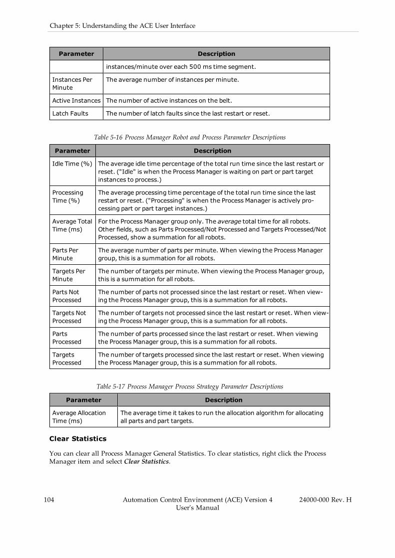
104 Automation Control Environment (ACE) Version 4User's Manual
24000-000 Rev. H
Chapter 5: Understanding the ACE User Interface
Parameter Description
instances/minute over each 500 ms time segment.
Instances PerMinute
The average number of instances per minute.
Active Instances The number of active instances on the belt.
Latch Faults The number of latch faults since the last restart or reset.
Table 5-16 Process Manager Robot and Process Parameter Descriptions
Parameter Description
Idle Time (%) The average idle time percentage of the total run time since the last restart orreset. ("Idle" is when the Process Manager is waiting on part or part targetinstances to process.)
ProcessingTime (%)
The average processing time percentage of the total run time since the lastrestart or reset. ("Processing" is when the Process Manager is actively pro-cessing part or part target instances.)
Average TotalTime (ms)
For the Process Manager group only. The average total time for all robots.Other fields, such as Parts Processed/Not Processed and Targets Processed/NotProcessed, show a summation for all robots.
Parts PerMinute
The average number of parts per minute. When viewing the Process Managergroup, this is a summation for all robots.
Targets PerMinute
The number of targets per minute. When viewing the Process Manager group,this is a summation for all robots.
Parts NotProcessed
The number of parts not processed since the last restart or reset. When view-ing the Process Manager group, this is a summation for all robots.
Targets NotProcessed
The number of targets not processed since the last restart or reset. When view-ing the Process Manager group, this is a summation for all robots.
PartsProcessed
The number of parts processed since the last restart or reset. When viewingthe Process Manager group, this is a summation for all robots.
TargetsProcessed
The number of targets processed since the last restart or reset. When viewingthe Process Manager group, this is a summation for all robots.
Table 5-17 Process Manager Process Strategy Parameter Descriptions
Parameter Description
Average AllocationTime (ms)
The average time it takes to run the allocation algorithm for allocatingall parts and part targets.
Clear Statistics
You can clear all Process Manager General Statistics. To clear statistics, right click the ProcessManager item and select Clear Statistics.
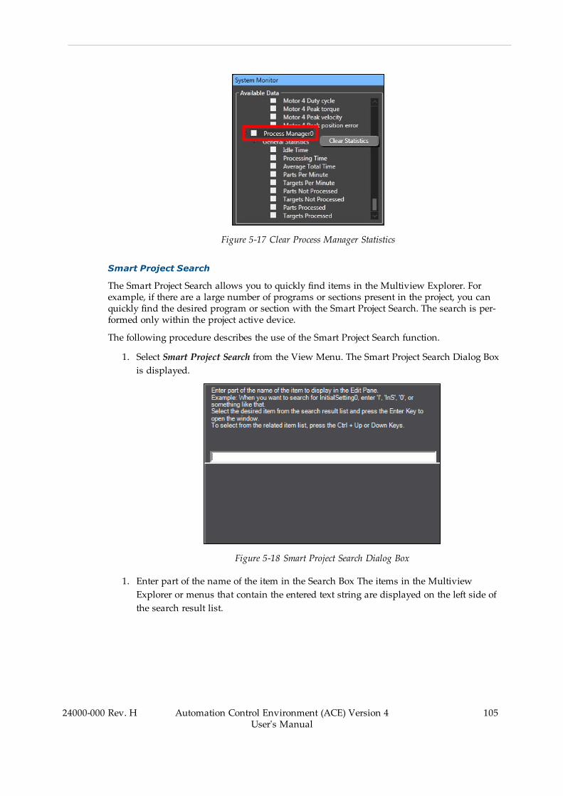
Figure 5-17 Clear Process Manager Statistics
Smart Project Search
The Smart Project Search allows you to quickly find items in the Multiview Explorer. Forexample, if there are a large number of programs or sections present in the project, you canquickly find the desired program or section with the Smart Project Search. The search is per-formed only within the project active device.
The following procedure describes the use of the Smart Project Search function.
1. Select Smart Project Search from the View Menu. The Smart Project Search Dialog Boxis displayed.
Figure 5-18 Smart Project Search Dialog Box
1. Enter part of the name of the item in the Search Box The items in the MultiviewExplorer or menus that contain the entered text string are displayed on the left side ofthe search result list.
24000-000 Rev. H Automation Control Environment (ACE) Version 4User's Manual
105

106 Automation Control Environment (ACE) Version 4User's Manual
24000-000 Rev. H
Chapter 5: Understanding the ACE User Interface
Figure 5-19 Search Box Text String Example
The search results are displayed from the top in the order they are displayed in the Mul-tiview Explorer. On the right side of the search result list, the level that is one higherthan the item that resulted from the search is displayed.
2. Double-click the desired item in the search result list or press the Enter key after makinga selection. The Search Dialog Box is closed and the selected item is displayed in theEdit Pane. To close the Search Dialog Box without selecting an item, click in a paneother than the Search Dialog Box or press the Esc key.
Additional Information: You can enter English characters into the Search Box tosearch for item names that contain words that start with the entered charactersin capitals. Example: If you enter is0 in the Search Box, an item named Ini-tialSetting0 is displayed in the search result list.
5.2 ToolboxThe Toolbox shows the program instructions (Keywords) that you can use to edit and createV+ programs. When a V+ program is open in the Edit Pane, the Toolbox will display a list ofavailable V+ keywords. If you drag a keyword into the V+ program Edit Pane and drop it intothe program, syntax will auto-generate for the chosen V+ keyword, as shown in the figurebelow.
A search tool within the Toolbox can be used to find items with a text string.
You can expand or collapse all categories by right-clicking an item and selecting Expand All orCollapse All from the pop-up menu.

Figure 5-20 Toolbox View
5.3 3D VisualizerThe 3D Visualizer allows you to see simulated and real 3D motion for robots and otherProcess Manager items such as belts and parts. The 3D Visualizer window displays the fol-lowing information.
l Graphical representation of all belts, cameras, robots, fixed objects, and obstacles in theworkspace
l Robot belt windows and allocation limitsl Robot work envelopesl Teach points and other part locationsl Belt lane widthsl Location of latch sensorsl Field of view for camerasl Process Manager objects and Part / Part Target instances
Figure 5-21 3D Visualizer Example View
24000-000 Rev. H Automation Control Environment (ACE) Version 4User's Manual
107
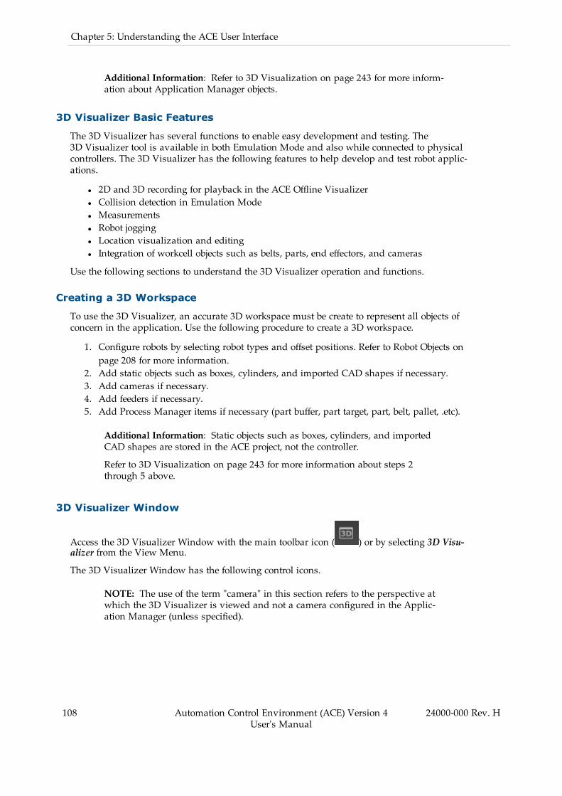
108 Automation Control Environment (ACE) Version 4User's Manual
24000-000 Rev. H
Chapter 5: Understanding the ACE User Interface
Additional Information: Refer to 3D Visualization on page 243 for more inform-ation about Application Manager objects.
3D Visualizer Basic Features
The 3D Visualizer has several functions to enable easy development and testing. The3D Visualizer tool is available in both Emulation Mode and also while connected to physicalcontrollers. The 3D Visualizer has the following features to help develop and test robot applic-ations.
l 2D and 3D recording for playback in the ACE Offline Visualizerl Collision detection in Emulation Model Measurementsl Robot joggingl Location visualization and editingl Integration of workcell objects such as belts, parts, end effectors, and cameras
Use the following sections to understand the 3D Visualizer operation and functions.
Creating a 3D Workspace
To use the 3D Visualizer, an accurate 3D workspace must be create to represent all objects ofconcern in the application. Use the following procedure to create a 3D workspace.
1. Configure robots by selecting robot types and offset positions. Refer to Robot Objects onpage 208 for more information.
2. Add static objects such as boxes, cylinders, and imported CAD shapes if necessary.3. Add cameras if necessary.4. Add feeders if necessary.5. Add Process Manager items if necessary (part buffer, part target, part, belt, pallet, .etc).
Additional Information: Static objects such as boxes, cylinders, and importedCAD shapes are stored in the ACE project, not the controller.
Refer to 3D Visualization on page 243 for more information about steps 2through 5 above.
3D Visualizer Window
Access the 3D Visualizer Window with the main toolbar icon ( ) or by selecting 3D Visu-alizer from the View Menu.
The 3D Visualizer Window has the following control icons.
NOTE: The use of the term "camera" in this section refers to the perspective atwhich the 3D Visualizer is viewed and not a camera configured in the Applic-ation Manager (unless specified).

Figure 5-22 3D Visualizer Window Items
The rectangles marked above (2, refer to Table 5-19 ) and (3 refer to Table 5-20 ) show wherethe control icons appear. The square marked (1) shows the display cube, which can be used toquickly change user perspective of the visualization area to a different orientation by clickingon various faces
Table 5-18 (1) Visualization Orientation
Item Description
1
F (front): the side facing the user.
B (back): the back face.
R (right): the right face.
L (left): the left face.
U (up): the upper face.
D (down): the side opposite to the upper face.
24000-000 Rev. H Automation Control Environment (ACE) Version 4User's Manual
109
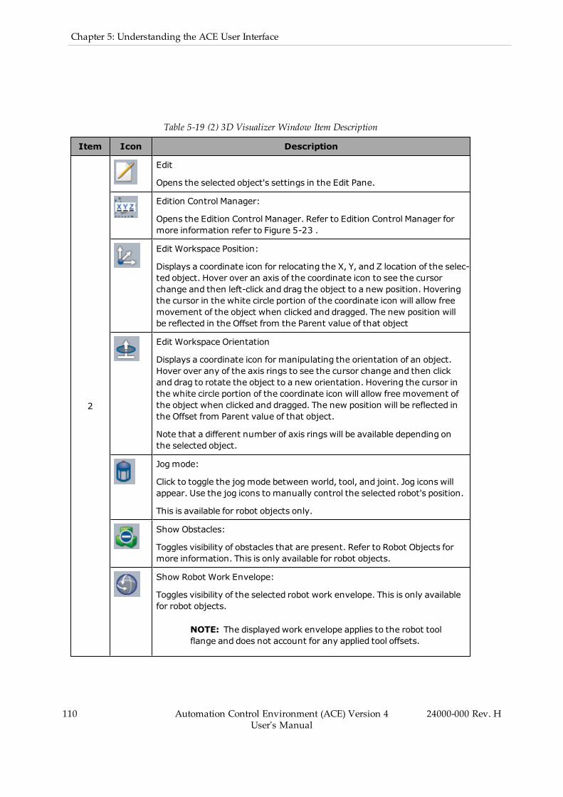
110 Automation Control Environment (ACE) Version 4User's Manual
24000-000 Rev. H
Chapter 5: Understanding the ACE User Interface
Table 5-19 (2) 3D Visualizer Window Item Description
Item Icon Description
2
Edit
Opens the selected object's settings in the Edit Pane.
Edition Control Manager:
Opens the Edition Control Manager. Refer to Edition Control Manager formore information refer to Figure 5-23 .
Edit Workspace Position:
Displays a coordinate icon for relocating the X, Y, and Z location of the selec-ted object. Hover over an axis of the coordinate icon to see the cursorchange and then left-click and drag the object to a new position. Hoveringthe cursor in the white circle portion of the coordinate icon will allow freemovement of the object when clicked and dragged. The new position willbe reflected in the Offset from the Parent value of that object
Edit Workspace Orientation
Displays a coordinate icon for manipulating the orientation of an object.Hover over any of the axis rings to see the cursor change and then clickand drag to rotate the object to a new orientation. Hovering the cursor inthe white circle portion of the coordinate icon will allow free movement ofthe object when clicked and dragged. The new position will be reflected inthe Offset from Parent value of that object.
Note that a different number of axis rings will be available depending onthe selected object.
Jogmode:
Click to toggle the jogmode between world, tool, and joint. Jog icons willappear. Use the jog icons to manually control the selected robot's position.
This is available for robot objects only.
Show Obstacles:
Toggles visibility of obstacles that are present. Refer to Robot Objects formore information. This is only available for robot objects.
Show Robot Work Envelope:
Toggles visibility of the selected robot work envelope. This is only availablefor robot objects.
NOTE: The displayedwork envelope applies to the robot toolflange and does not account for any applied tool offsets.

Item Icon Description
Teach Point:
Adds a new location variable at the robot's current position. This is onlyavailable for robot objects.
Show/Hide Mount Points:
Toggles visibility of mount points on the selected object. This is only avail-able for Box, Cylinder, and CAD Data objects.
Delete:
Delete a selected position from the variables list. This is only availablewhen a point is selected.
Jog To:
Jog to the selected position. This is only available when a point is selected.
Approach Height:
Toggle the approach height for the Jog To command between 0, 10, and25 mm for the selected position. This is only available when a point is selec-ted.
Jog Speed:
Toggle the jog speed between 100%, 50%, 25%, and 5% for the selectedposition. This is only available when a point is selected.
Clear All Instances:
Clear all instances being tracked by the selected Process Manager. This isonly available when a point is selected.
Show Camera Image:
Display camera images for a selected camera configured in the ApplicationManager. This is only available when a point is selected.
NOTE: This is typically used during setup and troubleshoot-ing and keeping this enabled during run time is not recom-mended.
Additional Information: Many of the functions in the previous table can beaccessed by right-clicking an object in the 3D Visualizer view.
Table 5-20 (3) 3D Visualizer Window Item Description
Item Icon Description
3
Split Window:
Click this icon to open a new dialog window that allows splitting the visu-alizer window into multiple views. This allows the user to view the work-space from multiple positions at the same time.
24000-000 Rev. H Automation Control Environment (ACE) Version 4User's Manual
111
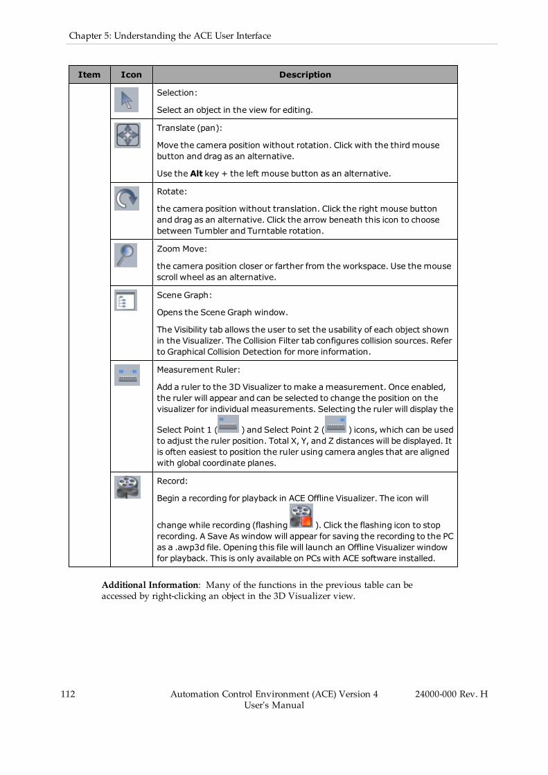
112 Automation Control Environment (ACE) Version 4User's Manual
24000-000 Rev. H
Chapter 5: Understanding the ACE User Interface
Item Icon Description
Selection:
Select an object in the view for editing.
Translate (pan):
Move the camera position without rotation. Click with the thirdmousebutton and drag as an alternative.
Use the Alt key + the left mouse button as an alternative.
Rotate:
the camera position without translation. Click the right mouse buttonand drag as an alternative. Click the arrow beneath this icon to choosebetween Tumbler and Turntable rotation.
Zoom Move:
the camera position closer or farther from the workspace. Use the mousescroll wheel as an alternative.
Scene Graph:
Opens the Scene Graph window.
The Visibility tab allows the user to set the usability of each object shownin the Visualizer. The Collision Filter tab configures collision sources. Referto Graphical Collision Detection for more information.
Measurement Ruler:
Add a ruler to the 3D Visualizer to make ameasurement. Once enabled,the ruler will appear and can be selected to change the position on thevisualizer for individual measurements. Selecting the ruler will display the
Select Point 1 ( ) and Select Point 2 ( ) icons, which can be usedto adjust the ruler position. Total X, Y, and Z distances will be displayed. Itis often easiest to position the ruler using camera angles that are alignedwith global coordinate planes.
Record:
Begin a recording for playback in ACE Offline Visualizer. The icon will
change while recording (flashing ). Click the flashing icon to stoprecording. A Save As window will appear for saving the recording to the PCas a .awp3d file. Opening this file will launch an Offline Visualizer windowfor playback. This is only available on PCs with ACE software installed.
Additional Information: Many of the functions in the previous table can beaccessed by right-clicking an object in the 3D Visualizer view.
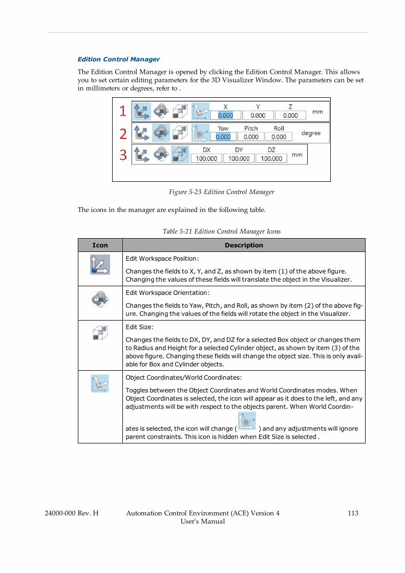
Edition Control Manager
The Edition Control Manager is opened by clicking the Edition Control Manager. This allowsyou to set certain editing parameters for the 3D Visualizer Window. The parameters can be setin millimeters or degrees, refer to .
Figure 5-23 Edition Control Manager
The icons in the manager are explained in the following table.
Table 5-21 Edition Control Manager Icons
Icon Description
Edit Workspace Position:
Changes the fields to X, Y, and Z, as shown by item (1) of the above figure.Changing the values of these fields will translate the object in the Visualizer.
Edit Workspace Orientation:
Changes the fields to Yaw, Pitch, and Roll, as shown by item (2) of the above fig-ure. Changing the values of the fields will rotate the object in the Visualizer.
Edit Size:
Changes the fields to DX, DY, and DZ for a selected Box object or changes themto Radius and Height for a selected Cylinder object, as shown by item (3) of theabove figure. Changing these fields will change the object size. This is only avail-able for Box and Cylinder objects.
Object Coordinates/World Coordinates:
Toggles between the Object Coordinates andWorld Coordinates modes. WhenObject Coordinates is selected, the icon will appear as it does to the left, and anyadjustments will be with respect to the objects parent. When World Coordin-
ates is selected, the icon will change ( ) and any adjustments will ignoreparent constraints. This icon is hidden when Edit Size is selected .
24000-000 Rev. H Automation Control Environment (ACE) Version 4User's Manual
113
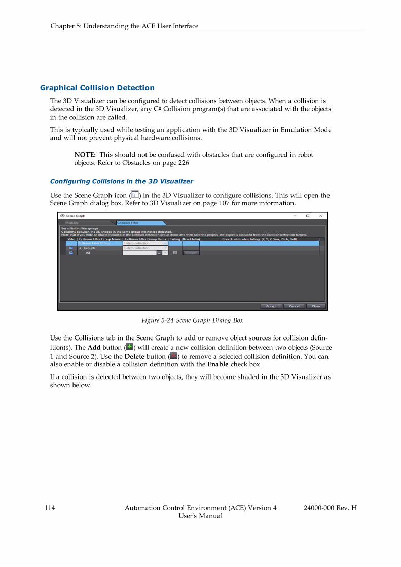
114 Automation Control Environment (ACE) Version 4User's Manual
24000-000 Rev. H
Chapter 5: Understanding the ACE User Interface
Graphical Collision Detection
The 3D Visualizer can be configured to detect collisions between objects. When a collision isdetected in the 3D Visualizer, any C# Collision program(s) that are associated with the objectsin the collision are called.
This is typically used while testing an application with the 3D Visualizer in Emulation Modeand will not prevent physical hardware collisions.
NOTE: This should not be confused with obstacles that are configured in robotobjects. Refer to Obstacles on page 226
Configuring Collisions in the 3D Visualizer
Use the Scene Graph icon ( ) in the 3D Visualizer to configure collisions. This will open theScene Graph dialog box. Refer to 3D Visualizer on page 107 for more information.
Figure 5-24 Scene Graph Dialog Box
Use the Collisions tab in the Scene Graph to add or remove object sources for collision defin-ition(s). The Add button ( ) will create a new collision definition between two objects (Source1 and Source 2). Use the Delete button ( ) to remove a selected collision definition. You canalso enable or disable a collision definition with the Enable check box.
If a collision is detected between two objects, they will become shaded in the 3D Visualizer asshown below.
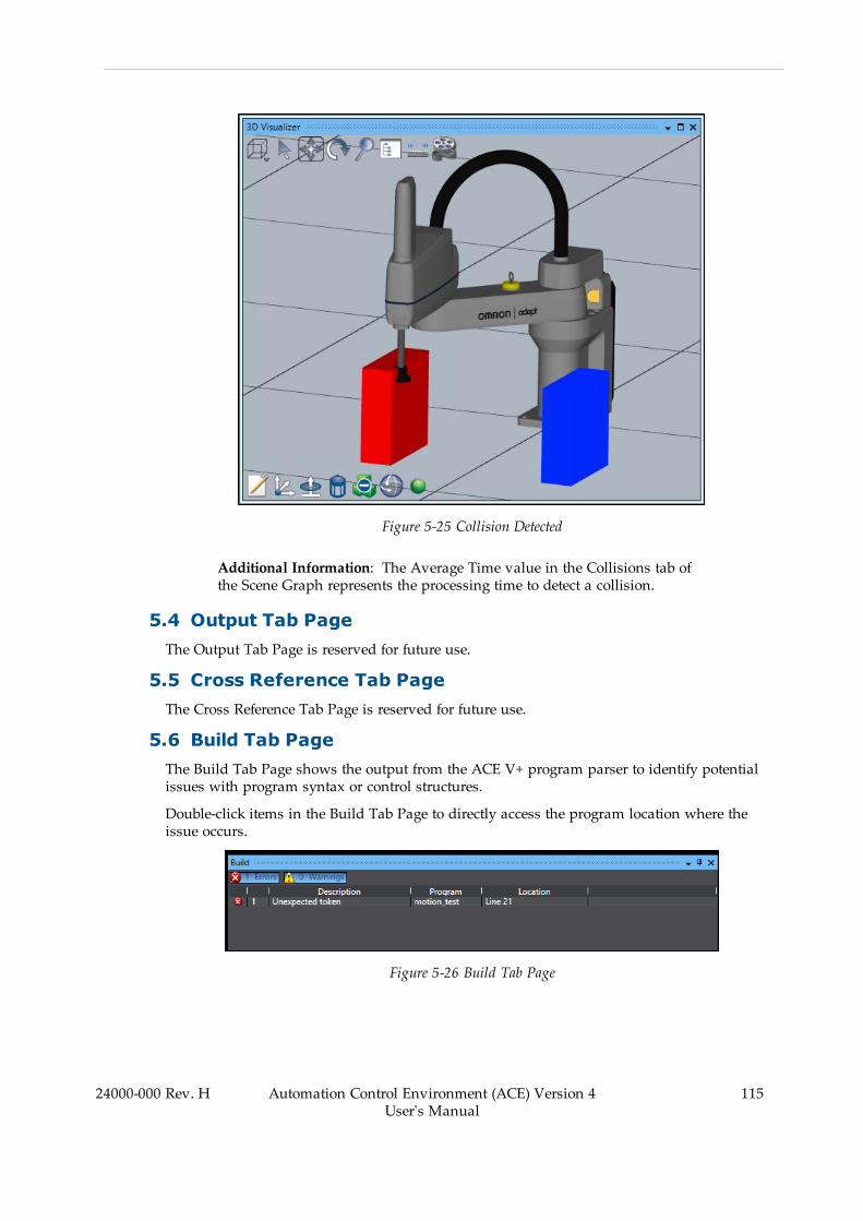
Figure 5-25 Collision Detected
Additional Information: The Average Time value in the Collisions tab ofthe Scene Graph represents the processing time to detect a collision.
5.4 Output Tab PageThe Output Tab Page is reserved for future use.
5.5 Cross Reference Tab PageThe Cross Reference Tab Page is reserved for future use.
5.6 Build Tab PageThe Build Tab Page shows the output from the ACE V+ program parser to identify potentialissues with program syntax or control structures.
Double-click items in the Build Tab Page to directly access the program location where theissue occurs.
Figure 5-26 Build Tab Page
24000-000 Rev. H Automation Control Environment (ACE) Version 4User's Manual
115
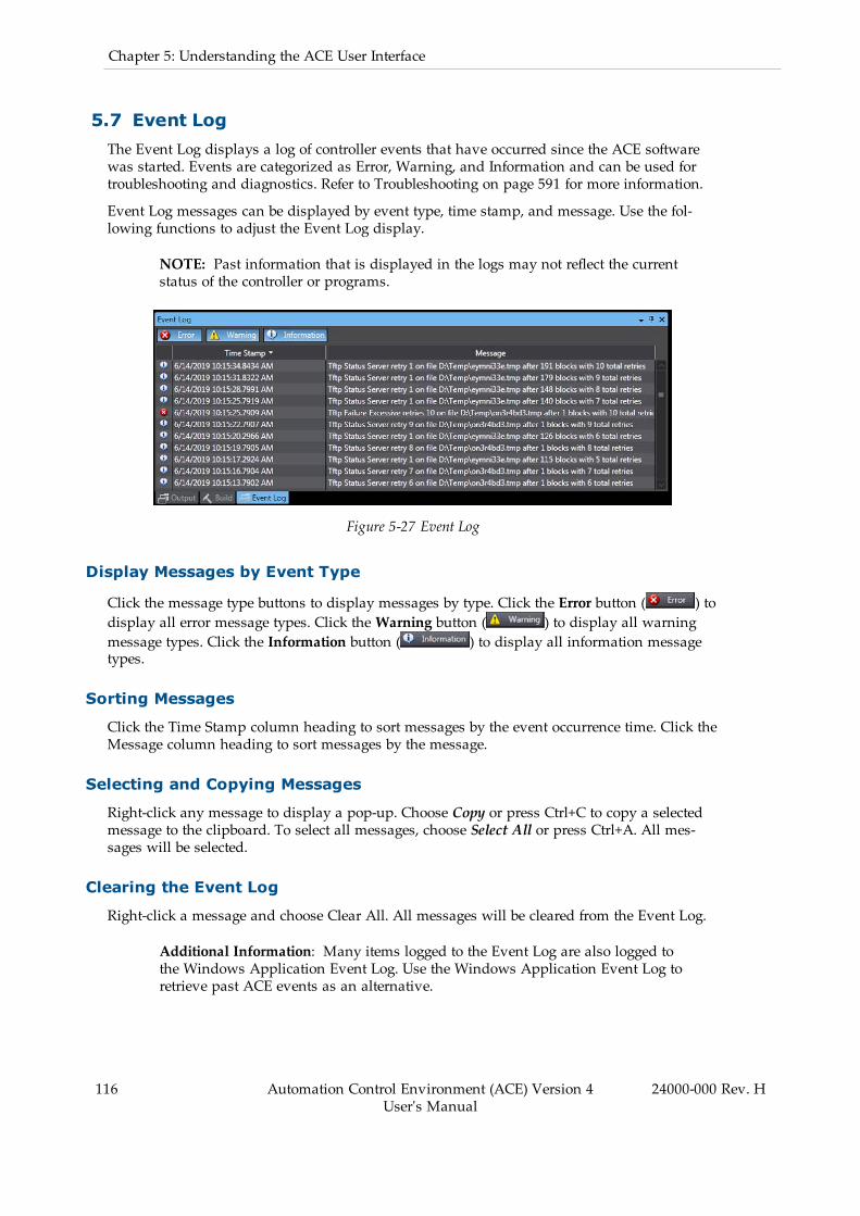
116 Automation Control Environment (ACE) Version 4User's Manual
24000-000 Rev. H
Chapter 5: Understanding the ACE User Interface
5.7 Event LogThe Event Log displays a log of controller events that have occurred since the ACE softwarewas started. Events are categorized as Error, Warning, and Information and can be used fortroubleshooting and diagnostics. Refer to Troubleshooting on page 591 for more information.
Event Log messages can be displayed by event type, time stamp, and message. Use the fol-lowing functions to adjust the Event Log display.
NOTE: Past information that is displayed in the logs may not reflect the currentstatus of the controller or programs.
Figure 5-27 Event Log
Display Messages by Event Type
Click the message type buttons to display messages by type. Click the Error button ( ) todisplay all error message types. Click theWarning button ( ) to display all warningmessage types. Click the Information button ( ) to display all information messagetypes.
Sorting Messages
Click the Time Stamp column heading to sort messages by the event occurrence time. Click theMessage column heading to sort messages by the message.
Selecting and Copying Messages
Right-click any message to display a pop-up. Choose Copy or press Ctrl+C to copy a selectedmessage to the clipboard. To select all messages, choose Select All or press Ctrl+A. All mes-sages will be selected.
Clearing the Event Log
Right-click a message and choose Clear All. All messages will be cleared from the Event Log.
Additional Information: Many items logged to the Event Log are also logged tothe Windows Application Event Log. Use the Windows Application Event Log toretrieve past ACE events as an alternative.
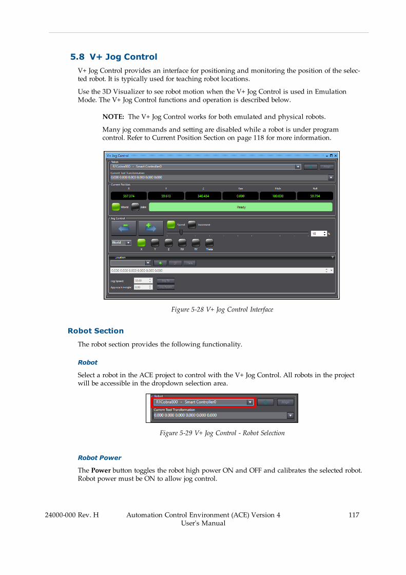
5.8 V+ Jog ControlV+ Jog Control provides an interface for positioning and monitoring the position of the selec-ted robot. It is typically used for teaching robot locations.
Use the 3D Visualizer to see robot motion when the V+ Jog Control is used in EmulationMode. The V+ Jog Control functions and operation is described below.
NOTE: The V+ Jog Control works for both emulated and physical robots.
Many jog commands and setting are disabled while a robot is under programcontrol. Refer to Current Position Section on page 118 for more information.
Figure 5-28 V+ Jog Control Interface
Robot Section
The robot section provides the following functionality.
Robot
Select a robot in the ACE project to control with the V+ Jog Control. All robots in the projectwill be accessible in the dropdown selection area.
Figure 5-29 V+ Jog Control - Robot Selection
Robot Power
The Power button toggles the robot high power ON and OFF and calibrates the selected robot.Robot power must be ON to allow jog control.
24000-000 Rev. H Automation Control Environment (ACE) Version 4User's Manual
117
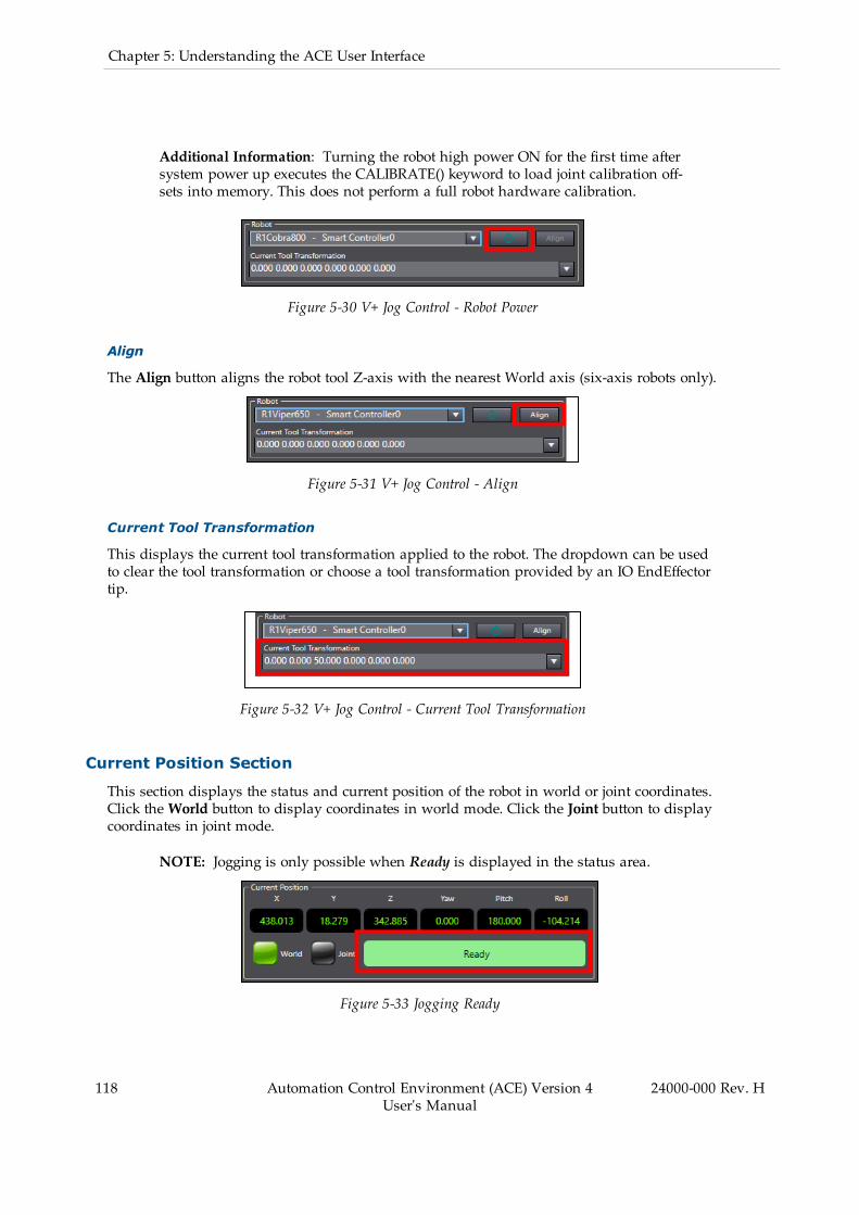
118 Automation Control Environment (ACE) Version 4User's Manual
24000-000 Rev. H
Chapter 5: Understanding the ACE User Interface
Additional Information: Turning the robot high power ON for the first time aftersystem power up executes the CALIBRATE() keyword to load joint calibration off-sets into memory. This does not perform a full robot hardware calibration.
Figure 5-30 V+ Jog Control - Robot Power
Align
The Align button aligns the robot tool Z-axis with the nearest World axis (six-axis robots only).
Figure 5-31 V+ Jog Control - Align
Current Tool Transformation
This displays the current tool transformation applied to the robot. The dropdown can be usedto clear the tool transformation or choose a tool transformation provided by an IO EndEffectortip.
Figure 5-32 V+ Jog Control - Current Tool Transformation
Current Position Section
This section displays the status and current position of the robot in world or joint coordinates.Click theWorld button to display coordinates in world mode. Click the Joint button to displaycoordinates in joint mode.
NOTE: Jogging is only possible when Ready is displayed in the status area.
Figure 5-33 Jogging Ready
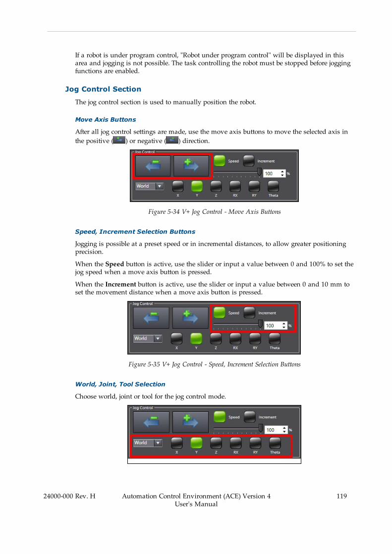
If a robot is under program control, "Robot under program control" will be displayed in thisarea and jogging is not possible. The task controlling the robot must be stopped before joggingfunctions are enabled.
Jog Control Section
The jog control section is used to manually position the robot.
Move Axis Buttons
After all jog control settings are made, use the move axis buttons to move the selected axis inthe positive ( ) or negative ( ) direction.
Figure 5-34 V+ Jog Control - Move Axis Buttons
Speed, Increment Selection Buttons
Jogging is possible at a preset speed or in incremental distances, to allow greater positioningprecision.
When the Speed button is active, use the slider or input a value between 0 and 100% to set thejog speed when a move axis button is pressed.
When the Increment button is active, use the slider or input a value between 0 and 10 mm toset the movement distance when a move axis button is pressed.
Figure 5-35 V+ Jog Control - Speed, Increment Selection Buttons
World, Joint, Tool Selection
Choose world, joint or tool for the jog control mode.
24000-000 Rev. H Automation Control Environment (ACE) Version 4User's Manual
119

120 Automation Control Environment (ACE) Version 4User's Manual
24000-000 Rev. H
Chapter 5: Understanding the ACE User Interface
Figure 5-36 V+ Jog Control - World, Joint, Tool Selection
l World - Enables the jog control to move the robot in the selected direction: X, Y, or Zaxes of the world frame of reference or rotated around the RX, RY, or theta axes in theworld coordinate system.
l Joint - Enables the jog control to move the selected robot joint.l Tool - Enables the jog control to move the robot in the selected direction: X, Y, or Z axesof the tool frame of reference or rotated around the RX, RY, or theta axes in the toolcoordinate system.
Location Section
The Location Section is used to view, teach, remove, and jog to robot locations. Refer to V+Variables on page 166 for more information.
Figure 5-37 V+ Jog Control - Location Section
Jog to a Robot Location
Use the following procedure to jog to a robot location.
NOTE: A robot location must exist and be selected to use this function.
1. Select a location with the dropdown menu.2. Make selections for the Jog Speed and Approach Height fields.3. Click and hold the Jog To button ( ) to make the robot jog to the specified loc-ation
Click and hold the Jog Appro button ( ) to make the robot jog to the specified loc-ation at the approach height specified.
IMPORTANT: Using the Jog Appro button will cause straight-line motionto occur. Monitor the robot during this movement to avoid collisions withobstacles between the starting location and the destination location.
Teach Robot Locations
Before teaching a location, move the robot to the desired location (either by jogging or power-ing OFF and physically moving the robot) and then click the Here button ( ). Clicking theHere button will put the robot's current axis positions into the display field for use in the fol-lowing teach procedure.
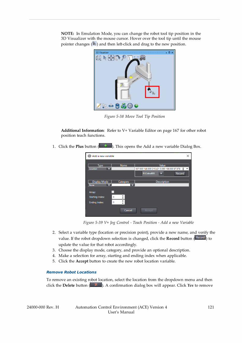
NOTE: In Emulation Mode, you can change the robot tool tip position in the3D Visualizer with the mouse cursor. Hover over the tool tip until the mousepointer changes ( ) and then left-click and drag to the new position.
Figure 5-38 Move Tool Tip Position
Additional Information: Refer to V+ Variable Editor on page 167 for other robotposition teach functions.
1. Click the Plus button ( ). This opens the Add a new variable Dialog Box.
Figure 5-39 V+ Jog Control - Teach Position - Add a new Variable
2. Select a variable type (location or precision point), provide a new name, and verify thevalue. If the robot dropdown selection is changed, click the Record button ( ) toupdate the value for that robot accordingly.
3. Choose the display mode, category, and provide an optional description.4. Make a selection for array, starting and ending index when applicable.5. Click the Accept button to create the new robot location variable.
Remove Robot Locations
To remove an existing robot location, select the location from the dropdown menu and thenclick the Delete button ( ). A confirmation dialog box will appear. Click Yes to remove
24000-000 Rev. H Automation Control Environment (ACE) Version 4User's Manual
121
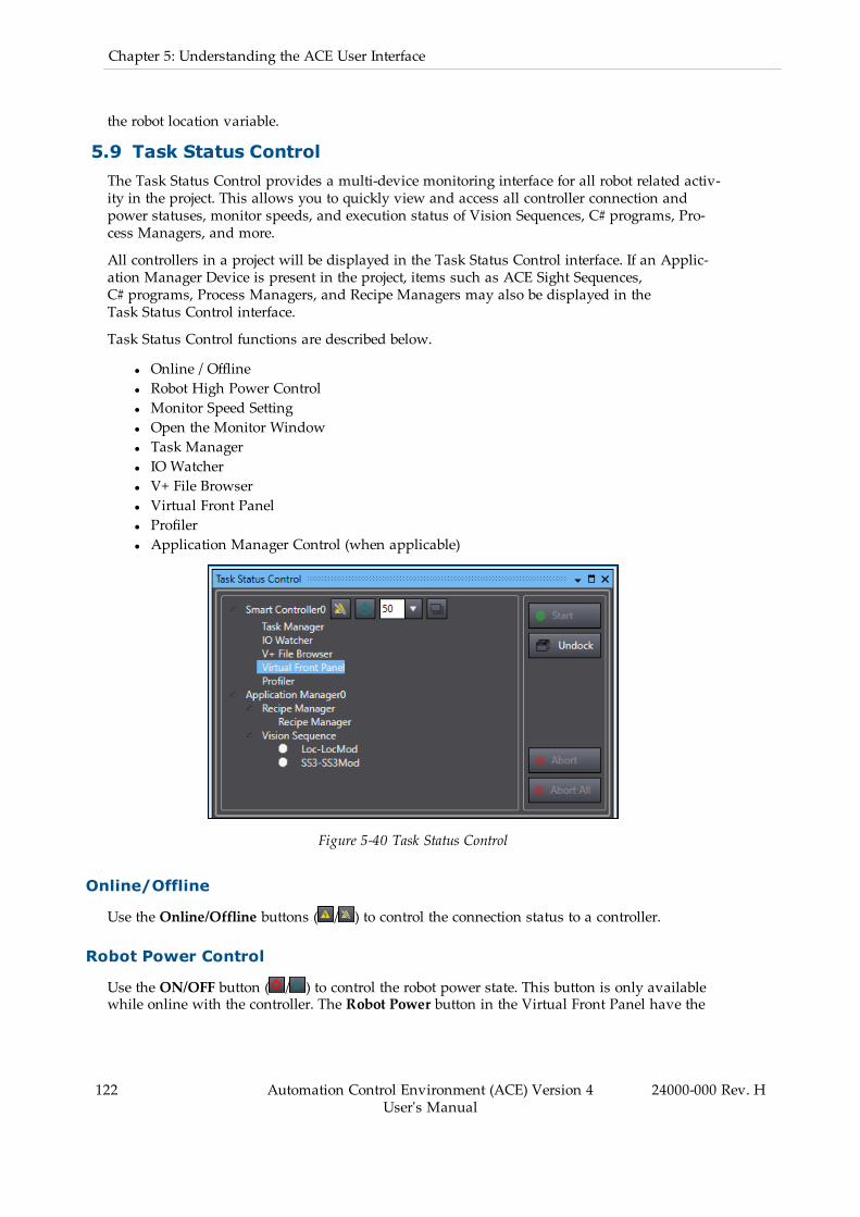
122 Automation Control Environment (ACE) Version 4User's Manual
24000-000 Rev. H
Chapter 5: Understanding the ACE User Interface
the robot location variable.
5.9 Task Status ControlThe Task Status Control provides a multi-device monitoring interface for all robot related activ-ity in the project. This allows you to quickly view and access all controller connection andpower statuses, monitor speeds, and execution status of Vision Sequences, C# programs, Pro-cess Managers, and more.
All controllers in a project will be displayed in the Task Status Control interface. If an Applic-ation Manager Device is present in the project, items such as ACE Sight Sequences,C# programs, Process Managers, and Recipe Managers may also be displayed in theTask Status Control interface.
Task Status Control functions are described below.
l Online / Offlinel Robot High Power Controll Monitor Speed Settingl Open the Monitor Windowl Task Managerl IO Watcherl V+ File Browserl Virtual Front Panell Profilerl Application Manager Control (when applicable)
Figure 5-40 Task Status Control
Online/Offline
Use the Online/Offline buttons ( / ) to control the connection status to a controller.
Robot Power Control
Use the ON/OFF button ( / ) to control the robot power state. This button is only availablewhile online with the controller. The Robot Power button in the Virtual Front Panel have the
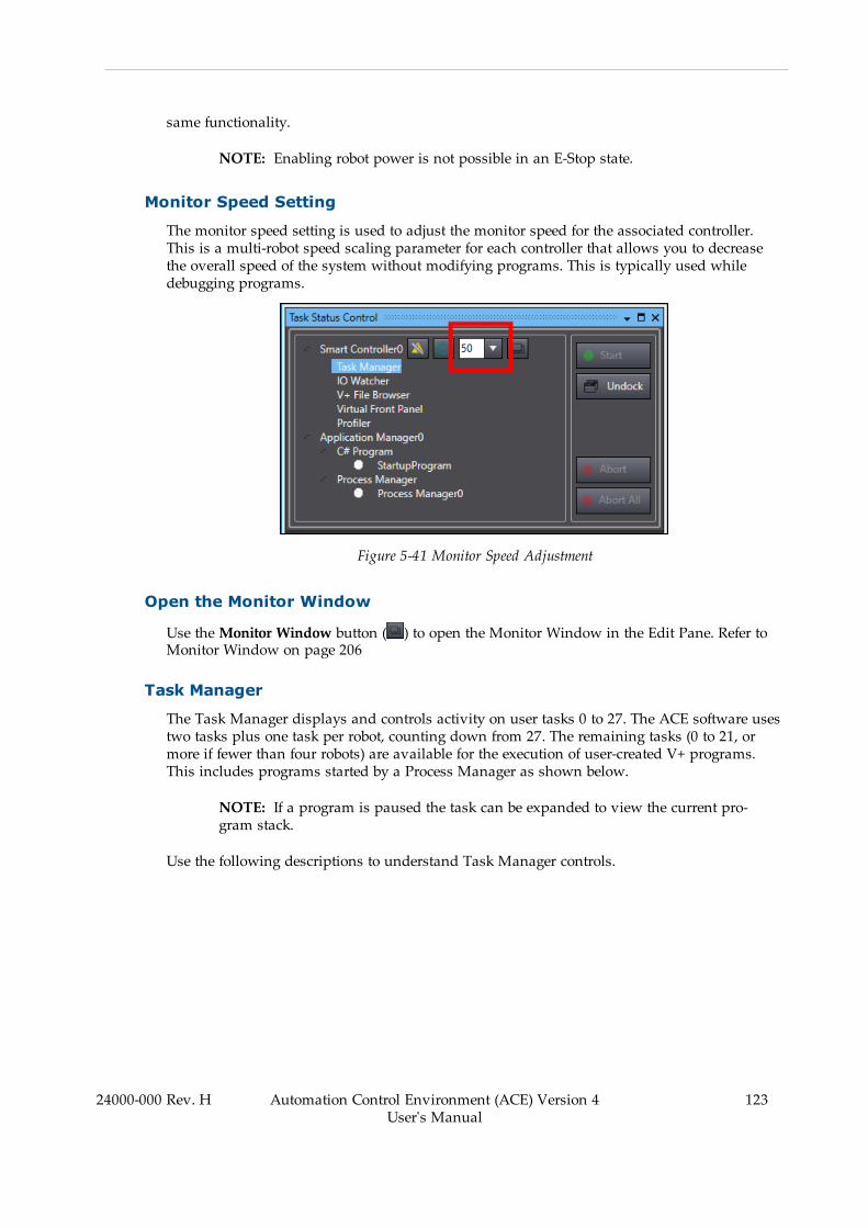
same functionality.
NOTE: Enabling robot power is not possible in an E-Stop state.
Monitor Speed Setting
The monitor speed setting is used to adjust the monitor speed for the associated controller.This is a multi-robot speed scaling parameter for each controller that allows you to decreasethe overall speed of the system without modifying programs. This is typically used whiledebugging programs.
Figure 5-41 Monitor Speed Adjustment
Open the Monitor Window
Use theMonitor Window button ( ) to open the Monitor Window in the Edit Pane. Refer toMonitor Window on page 206
Task Manager
The Task Manager displays and controls activity on user tasks 0 to 27. The ACE software usestwo tasks plus one task per robot, counting down from 27. The remaining tasks (0 to 21, ormore if fewer than four robots) are available for the execution of user-created V+ programs.This includes programs started by a Process Manager as shown below.
NOTE: If a program is paused the task can be expanded to view the current pro-gram stack.
Use the following descriptions to understand Task Manager controls.
24000-000 Rev. H Automation Control Environment (ACE) Version 4User's Manual
123

124 Automation Control Environment (ACE) Version 4User's Manual
24000-000 Rev. H
Chapter 5: Understanding the ACE User Interface
Figure 5-42 Task Status Control - Task Manager
Task Manager Toolbar Items
Table 5-22 Task Manager Toolbar Item Description
Item Icon Description
Execute Task If a stopped program is selected, this button will executethat program on the task.
If a task is selected with no program, this button will opena dialog box for program selection. Selecting a programname and clickingOKwill execute the program on theselected task.
Pause Task The selected task execution is paused at the next com-mand.
Stop All Tasks Stops the execution of all running tasks.
Retry Step If the selected task was paused or stopped due to an error,this button attempts to re-execute the current step andcontinue execution.
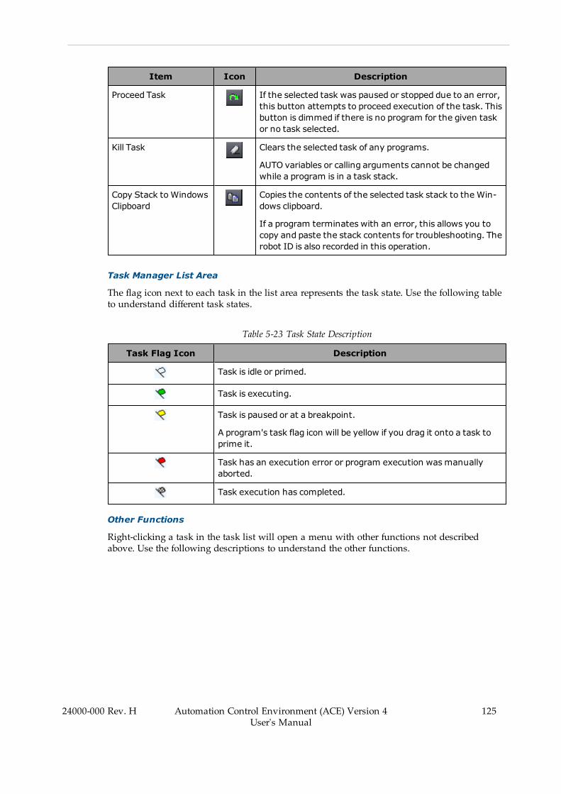
Item Icon Description
Proceed Task If the selected task was paused or stopped due to an error,this button attempts to proceed execution of the task. Thisbutton is dimmed if there is no program for the given taskor no task selected.
Kill Task Clears the selected task of any programs.
AUTO variables or calling arguments cannot be changedwhile a program is in a task stack.
Copy Stack toWindowsClipboard
Copies the contents of the selected task stack to the Win-dows clipboard.
If a program terminates with an error, this allows you tocopy and paste the stack contents for troubleshooting. Therobot ID is also recorded in this operation.
Task Manager List Area
The flag icon next to each task in the list area represents the task state. Use the following tableto understand different task states.
Table 5-23 Task State Description
Task Flag Icon Description
Task is idle or primed.
Task is executing.
Task is paused or at a breakpoint.
A program's task flag icon will be yellow if you drag it onto a task toprime it.
Task has an execution error or program execution wasmanuallyaborted.
Task execution has completed.
Other Functions
Right-clicking a task in the task list will open a menu with other functions not describedabove. Use the following descriptions to understand the other functions.
24000-000 Rev. H Automation Control Environment (ACE) Version 4User's Manual
125
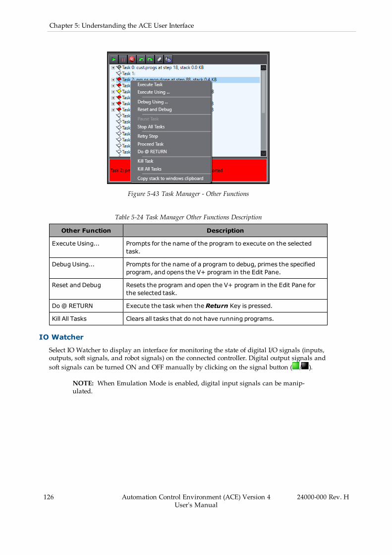
126 Automation Control Environment (ACE) Version 4User's Manual
24000-000 Rev. H
Chapter 5: Understanding the ACE User Interface
Figure 5-43 Task Manager - Other Functions
Table 5-24 Task Manager Other Functions Description
Other Function Description
Execute Using... Prompts for the name of the program to execute on the selectedtask.
Debug Using... Prompts for the name of a program to debug, primes the specifiedprogram, and opens the V+ program in the Edit Pane.
Reset and Debug Resets the program and open the V+ program in the Edit Pane forthe selected task.
Do@ RETURN Execute the task when the Return Key is pressed.
Kill All Tasks Clears all tasks that do not have running programs.
IO Watcher
Select IO Watcher to display an interface for monitoring the state of digital I/O signals (inputs,outputs, soft signals, and robot signals) on the connected controller. Digital output signals andsoft signals can be turned ON and OFF manually by clicking on the signal button ( / ).
NOTE: When Emulation Mode is enabled, digital input signals can be manip-ulated.
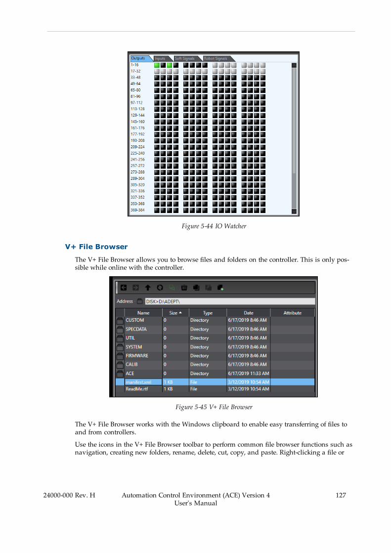
Figure 5-44 IO Watcher
V+ File Browser
The V+ File Browser allows you to browse files and folders on the controller. This is only pos-sible while online with the controller.
Figure 5-45 V+ File Browser
The V+ File Browser works with the Windows clipboard to enable easy transferring of files toand from controllers.
Use the icons in the V+ File Browser toolbar to perform common file browser functions such asnavigation, creating new folders, rename, delete, cut, copy, and paste. Right-clicking a file or
24000-000 Rev. H Automation Control Environment (ACE) Version 4User's Manual
127
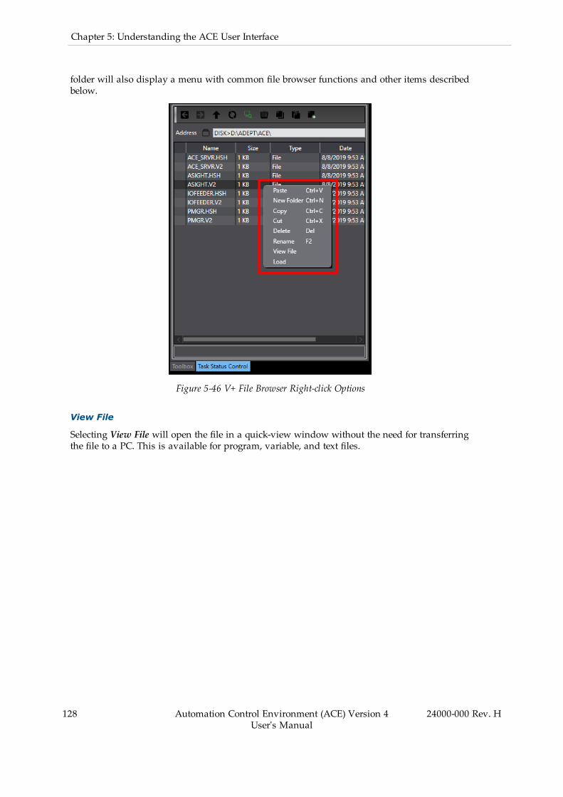
128 Automation Control Environment (ACE) Version 4User's Manual
24000-000 Rev. H
Chapter 5: Understanding the ACE User Interface
folder will also display a menu with common file browser functions and other items describedbelow.
Figure 5-46 V+ File Browser Right-click Options
View File
Selecting View File will open the file in a quick-view window without the need for transferringthe file to a PC. This is available for program, variable, and text files.
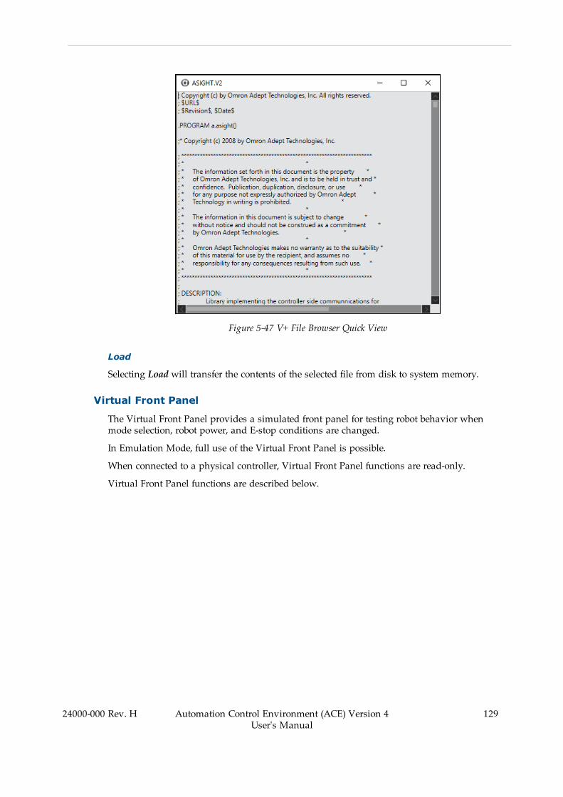
Figure 5-47 V+ File Browser Quick View
Load
Selecting Load will transfer the contents of the selected file from disk to system memory.
Virtual Front Panel
The Virtual Front Panel provides a simulated front panel for testing robot behavior whenmode selection, robot power, and E-stop conditions are changed.
In Emulation Mode, full use of the Virtual Front Panel is possible.
When connected to a physical controller, Virtual Front Panel functions are read-only.
Virtual Front Panel functions are described below.
24000-000 Rev. H Automation Control Environment (ACE) Version 4User's Manual
129

130 Automation Control Environment (ACE) Version 4User's Manual
24000-000 Rev. H
Chapter 5: Understanding the ACE User Interface
Figure 5-48 Virtual Front Panel
Mode Selection
Switches between Manual ( ) and Automatic ( ) mode. In Automatic mode, executing pro-grams control the robot, and the robot can run at full speed. In Manual mode, the system lim-its robot speed and torque so that an operator can safely work in the cell. Manual modeinitiates software restrictions on robot speed, commanding no more than 250 mm/sec. There isno high speed mode in manual mode. Refer to the robot's user's guide for more information.
Robot Power
The Robot Power button enables power to the robot motors. This button has an indicator to dis-play the following robot power states.
l OFF: robot power is not appliedl ON: robot power is appliedl Blinking: robot power will be applied if the Robot Power button is pressed within theSafety Timeout time specified. Refer to Safety Timeout on page 200 for more inform-ation. Robot power must be active for motion to occur.
NOTE: Enabling power to the robot motors is not possible while in an E-Stopstate.
E-Stop
E-Stop behavior can be tested and monitored with the E-Stop button on the Virtual FrontPanel. Use the ESTOP Channel area to simulate various E-Stop system functions.

Figure 5-49 ESTOP Channel Simulation Functions
NOTE: Refer to the eV+ Language Reference Guide (Cat. No. I605) or eV+3 KeywordReference Manual (Cat. No I652) and the robot user's guide for more informationabout E-Stop channel functions.
Profiler
The Profiler is available for each controller in the project. It is used to provide a graphical dis-play of controller processor usage for diagnostic purposes. There are two tabs in the Profilerview as described below.
NOTE: The Profiler function is not available in Emulation Mode.
Current Values Tab
The Current Values tab shows a list of tasks and their respective processor usage. Use the Dis-play and Timing menu items to adjust the listed items and the update rate.
NOTE: Selecting All User Tasks displays all the user tasks available to your sys-tem. If All User Tasks is not selected, only tasks with a program on the executionstack are displayed.
24000-000 Rev. H Automation Control Environment (ACE) Version 4User's Manual
131
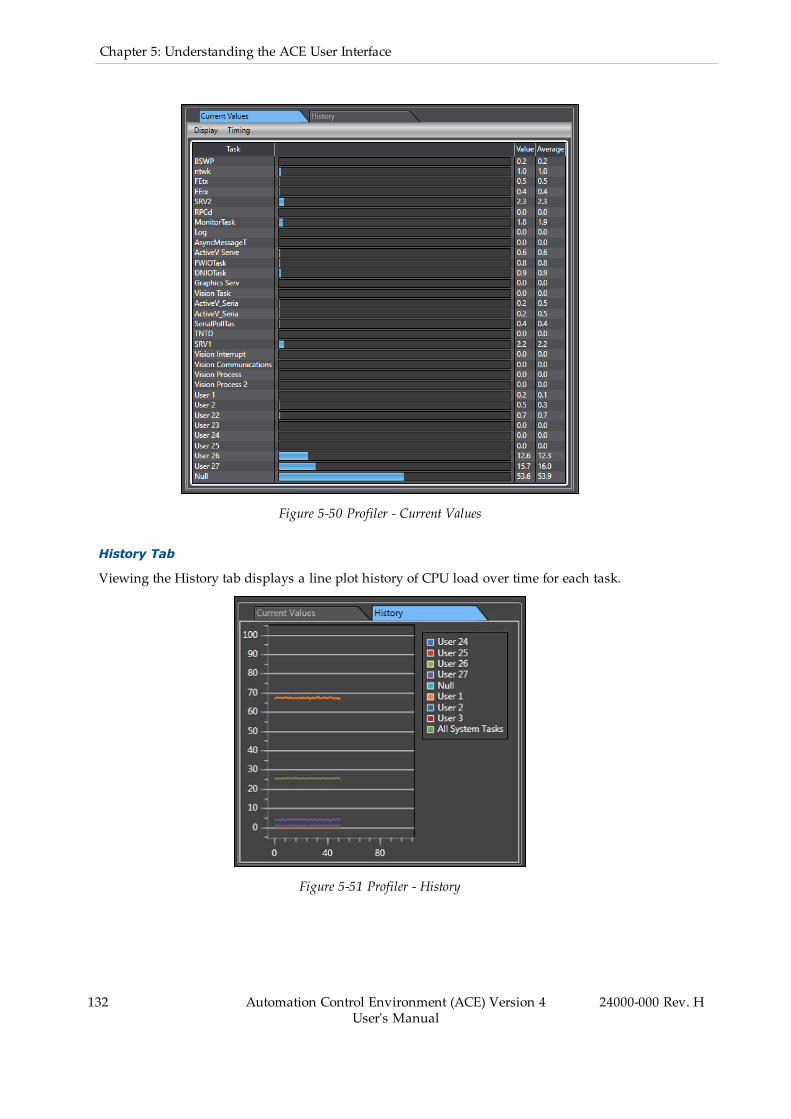
132 Automation Control Environment (ACE) Version 4User's Manual
24000-000 Rev. H
Chapter 5: Understanding the ACE User Interface
Figure 5-50 Profiler - Current Values
History Tab
Viewing the History tab displays a line plot history of CPU load over time for each task.
Figure 5-51 Profiler - History
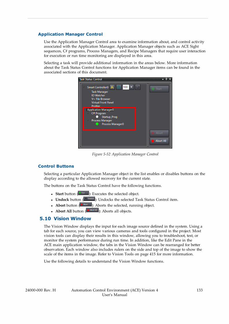
Application Manager Control
Use the Application Manager Control area to examine information about, and control activityassociated with the Application Manager. Application Manager objects such as ACE Sightsequences, C# programs, Process Managers, and Recipe Managers that require user interactionfor execution or run time monitoring are displayed in this area.
Selecting a task will provide additional information in the areas below. More informationabout the Task Status Control functions for Application Manager items can be found in theassociated sections of this document.
Figure 5-52 Application Manager Control
Control Buttons
Selecting a particular Application Manager object in the list enables or disables buttons on thedisplay according to the allowed recovery for the current state.
The buttons on the Task Status Control have the following functions.
l Start button ( ): Executes the selected object.l Undock button ( ): Undocks the selected Task Status Control item.l Abort button ( ): Aborts the selected, running object.l Abort All button ( ): Aborts all objects.
5.10 Vision WindowThe Vision Window displays the input for each image source defined in the system. Using atab for each source, you can view various cameras and tools configured in the project. Mostvision tools can display their results in this window, allowing you to troubleshoot, test, ormonitor the system performance during run time. In addition, like the Edit Pane in theACE main application window, the tabs in the Vision Window can be rearranged for betterobservation. Each window also includes rulers on the side and top of the image to show thescale of the items in the image. Refer to Vision Tools on page 415 for more information.
Use the following details to understand the Vision Window functions.
24000-000 Rev. H Automation Control Environment (ACE) Version 4User's Manual
133
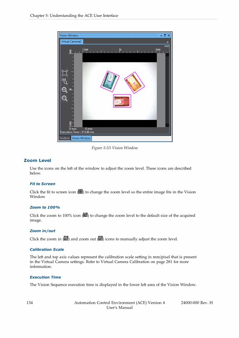
134 Automation Control Environment (ACE) Version 4User's Manual
24000-000 Rev. H
Chapter 5: Understanding the ACE User Interface
Figure 5-53 Vision Window
Zoom Level
Use the icons on the left of the window to adjust the zoom level. These icons are describedbelow.
Fit to Screen
Click the fit to screen icon ( ) to change the zoom level so the entire image fits in the VisionWindow
Zoom to 100%
Click the zoom to 100% icon ( ) to change the zoom level to the default size of the acquiredimage.
Zoom in/out
Click the zoom in ( ) and zoom out ( ) icons to manually adjust the zoom level.
Calibration Scale
The left and top axis values represent the calibration scale setting in mm/pixel that is presentin the Virtual Camera settings. Refer to Virtual Camera Calibration on page 281 for moreinformation.
Execution Time
The Vision Sequence execution time is displayed in the lower left area of the Vision Window.

Camera Selection
Use the dropdown arrow to select from all available Image Sources defined in the system.
Figure 5-54 Virtual Camera Selection
Cursor Information
Moving the cursor in the field of view portion of the Vision Window will reveal additionalinformation about the inspection results.
The X-Y coordinates are displayed at the bottom of the Vision Window for the current cursorposition. Color / gray scale values are also displayed when applicable.
Hover over the coordinate icon in the field of view to display inspection results as shownbelow.
24000-000 Rev. H Automation Control Environment (ACE) Version 4User's Manual
135

136 Automation Control Environment (ACE) Version 4User's Manual
24000-000 Rev. H
Chapter 5: Understanding the ACE User Interface
Figure 5-55 Cursor Information Display
5.11 V+ WatchV+ Watch is used to monitor specified variables while developing or debugging V+ programs.
Variables can be added to the V+ Watch window in several different ways as described below.The V+ Watch window contents will be saved with the project. Refer to V+ Variables on page166 for more information.
Figure 5-56 V+ Watch Window
Adding Variables to the V+ Watch Window
Use one of the following methods to add variables to the V+ Watch window.
l Select one or more variables in the Variable Editor and right-click. Selecting Add toWatch will place these variables in the V+ Watch window.
l Right-click in the V+ Watch window area and select New. Type the name of the variableto add it to the V+ Watch window.
l Right-click the variable name in the V+ Editor. Selecting Add to Watch will place thisvariable in the V+ Watch window.
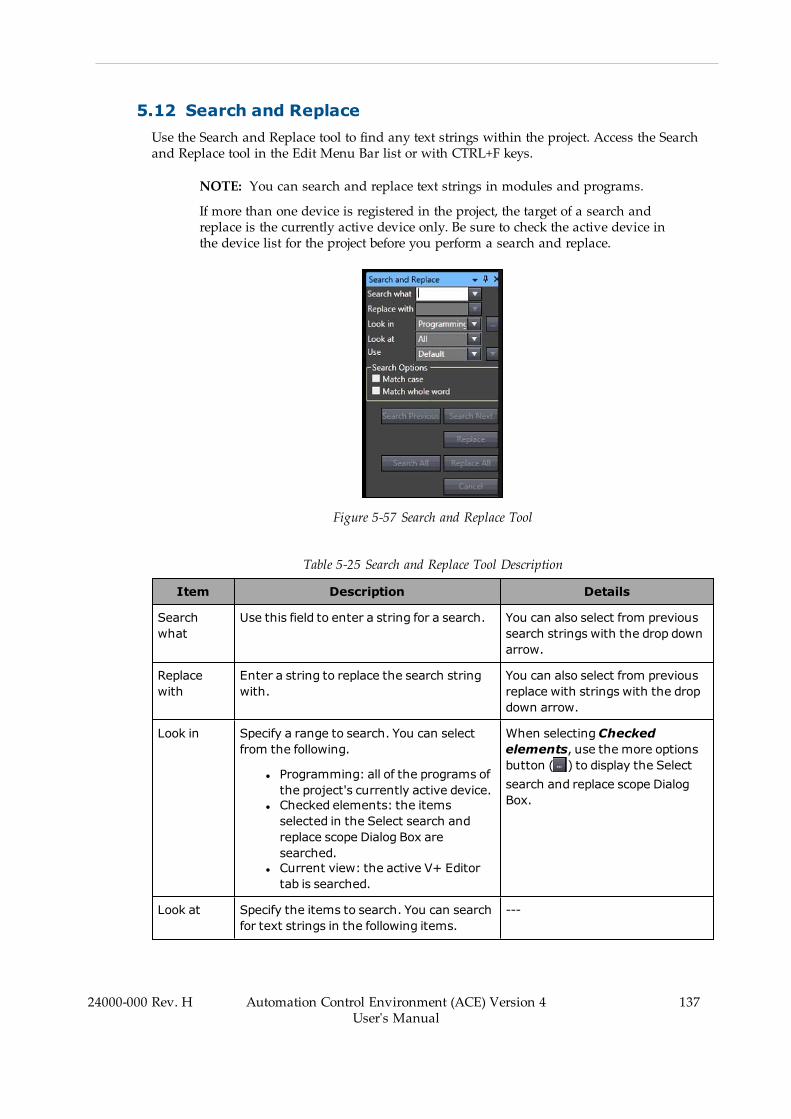
5.12 Search and ReplaceUse the Search and Replace tool to find any text strings within the project. Access the Searchand Replace tool in the Edit Menu Bar list or with CTRL+F keys.
NOTE: You can search and replace text strings in modules and programs.
If more than one device is registered in the project, the target of a search andreplace is the currently active device only. Be sure to check the active device inthe device list for the project before you perform a search and replace.
Figure 5-57 Search and Replace Tool
Table 5-25 Search and Replace Tool Description
Item Description Details
Searchwhat
Use this field to enter a string for a search. You can also select from previoussearch strings with the drop downarrow.
Replacewith
Enter a string to replace the search stringwith.
You can also select from previousreplace with strings with the dropdown arrow.
Look in Specify a range to search. You can selectfrom the following.
l Programming: all of the programs ofthe project's currently active device.
l Checked elements: the itemsselected in the Select search andreplace scope Dialog Box aresearched.
l Current view: the active V+ Editortab is searched.
When selectingCheckedelements, use the more optionsbutton ( ) to display the Selectsearch and replace scope DialogBox.
Look at Specify the items to search. You can searchfor text strings in the following items.
---
24000-000 Rev. H Automation Control Environment (ACE) Version 4User's Manual
137
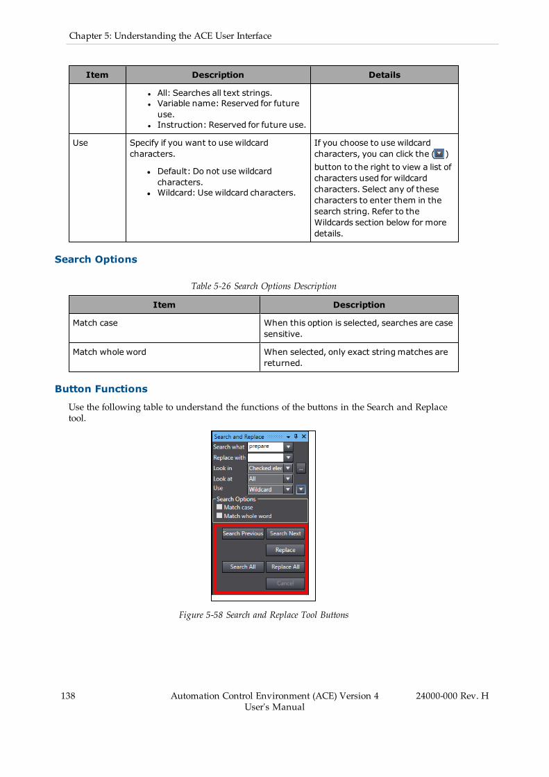
138 Automation Control Environment (ACE) Version 4User's Manual
24000-000 Rev. H
Chapter 5: Understanding the ACE User Interface
Item Description Details
l All: Searches all text strings.l Variable name: Reserved for futureuse.
l Instruction: Reserved for future use.
Use Specify if you want to use wildcardcharacters.
l Default: Do not use wildcardcharacters.
l Wildcard: Use wildcard characters.
If you choose to use wildcardcharacters, you can click the ( )button to the right to view a list ofcharacters used for wildcardcharacters. Select any of thesecharacters to enter them in thesearch string. Refer to theWildcards section below for moredetails.
Search Options
Table 5-26 Search Options Description
Item Description
Match case When this option is selected, searches are casesensitive.
Match whole word When selected, only exact stringmatches arereturned.
Button Functions
Use the following table to understand the functions of the buttons in the Search and Replacetool.
Figure 5-58 Search and Replace Tool Buttons
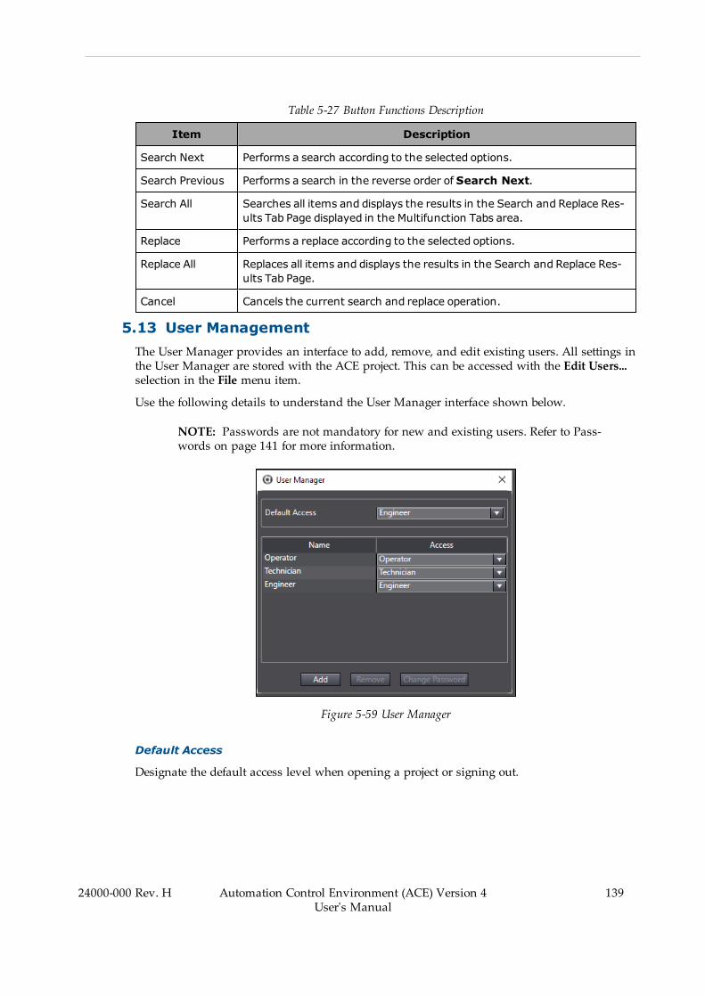
Table 5-27 Button Functions Description
Item Description
Search Next Performs a search according to the selected options.
Search Previous Performs a search in the reverse order of Search Next.
Search All Searches all items and displays the results in the Search and Replace Res-ults Tab Page displayed in the Multifunction Tabs area.
Replace Performs a replace according to the selected options.
Replace All Replaces all items and displays the results in the Search and Replace Res-ults Tab Page.
Cancel Cancels the current search and replace operation.
5.13 User ManagementThe User Manager provides an interface to add, remove, and edit existing users. All settings inthe User Manager are stored with the ACE project. This can be accessed with the Edit Users...selection in the File menu item.
Use the following details to understand the User Manager interface shown below.
NOTE: Passwords are not mandatory for new and existing users. Refer to Pass-words on page 141 for more information.
Figure 5-59 User Manager
Default Access
Designate the default access level when opening a project or signing out.
24000-000 Rev. H Automation Control Environment (ACE) Version 4User's Manual
139
140 Automation Control Environment (ACE) Version 4User's Manual
24000-000 Rev. H
Chapter 5: Understanding the ACE User Interface
Name
This is the User Name when signing in. The Name field can be edited for each user. Defaultnames of Operator, Technician, and Engineer are provided for all new ACE projects.
Access
Designate the access level for each Name in the User Manager list (Operator, Technician, orEngineer).
Add Button
Add a new name with a specific access level to the user list. A new user will be added andsign in will be possible with the User Name and Password (if specified).
Remove Button
Remove a selected name from the User Manager list. The user will be deleted and sign in willnot be possible with the previously stored credentials.
Change Password Button
Create a unique password for each user listed. Clicking this button will open theChange Password Dialog Box. Refer to Passwords on page 141 for more information.
User access levels allow software feature and function access control for designated users foran ACE project. Signing in to each user level can be password protected (optional). This allowsyou to create a list of users and assign a specific access level to each one.
IMPORTANT: The User Manager implements a basic level of user-access secur-ity. For applications that require a higher level of security, you will need to imple-ment a security scheme within a custom user-interface. This could be based onthe network login credentials from Windows or other similar access-control meth-ods.
One of the following three access levels can be assigned to a user.
1. Engineer (highest level): full access to all items2. Technician: limited access to some items3. Operator (lowest level): read-only access
Engineer Accessible Items
All features and functions in the ACE software are accessible to a user with the Engineeraccess level.
NOTE: A user signed in with Technician or Operator access or cannot edit usersor access the User Manager. Only a user with Engineer access can edit userswith the User Manager.
Technician Accessible Items
The following features and functions are accessible to a user with the Technician access level.The Technician access level cannot add any new items to the ACE project and can only view

and edit the following items if they already exist in the workspace.
l Save Controller Configurationl AnyFeeder Objectsl Application Manager Settingsl Pack Manager Belt Objectsl ACE Sight Objectsl 3D / CAD Data Objectsl Data Mapper Objectsl Emulation Camera Imagesl IO EndEffectorl IO Feeder Objectsl OPC Containerl Process Managerl Recipe Managerl System Startupl V+ and C# Variablesl Vision Tools
Operator Accessible Items
The notes function is editable for a user with the Operator access level only when a note wasalready created by another user with Technician or Engineer access. All other features andfunctions are either read-only or inaccessible.
Passwords
Passwords for each User Name can be specified, but are not mandatory. Passwords caninclude symbols, letters, and numbers and are case sensitive.
If a password has not been specified for a user, the following password omissions are present.
l The Old Password field can be left blank when changing a password.l The Password field can be left blank when signing in as this user.
5.14 Project OptionsProject options can be access in the Tools menu item. The following project option settings aredetailed below.
l Color Themel Project Settingsl Windowl V+ programsl UPS
To access the project options, click the Tools menu bar item and then select Option... TheOption window will open.
24000-000 Rev. H Automation Control Environment (ACE) Version 4User's Manual
141
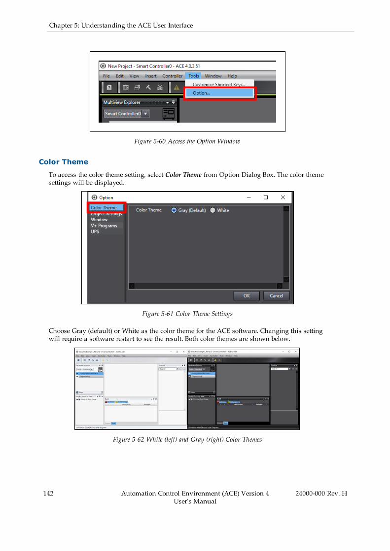
142 Automation Control Environment (ACE) Version 4User's Manual
24000-000 Rev. H
Chapter 5: Understanding the ACE User Interface
Figure 5-60 Access the Option Window
Color Theme
To access the color theme setting, select Color Theme from Option Dialog Box. The color themesettings will be displayed.
Figure 5-61 Color Theme Settings
Choose Gray (default) or White as the color theme for the ACE software. Changing this settingwill require a software restart to see the result. Both color themes are shown below.
Figure 5-62 White (left) and Gray (right) Color Themes

Project Settings
To access the project settings, select Project Settings from Option Dialog Box. The project set-tings will be displayed.
Figure 5-63 Project Settings
The default project author name can be specified in the Project Settings area. The following set-tings are available.
Figure 5-64 Project Settings
Use the Default Author Name
Selecting this will use the name specified when saving or creating a new ACE project. A restartof the ACE software is required to see this change.
If this is not selected, the author field for saving or creating a new ACE project will be blank.
Reset to Default Settings
Clicking the Reset to default settings button will set the project's author name to the Windowsuser name. A restart of the ACE software is required to see this change.
Window
To access the Window settings, selectWindow from Option Dialog Box. The Window settingswill be displayed.
24000-000 Rev. H Automation Control Environment (ACE) Version 4User's Manual
143
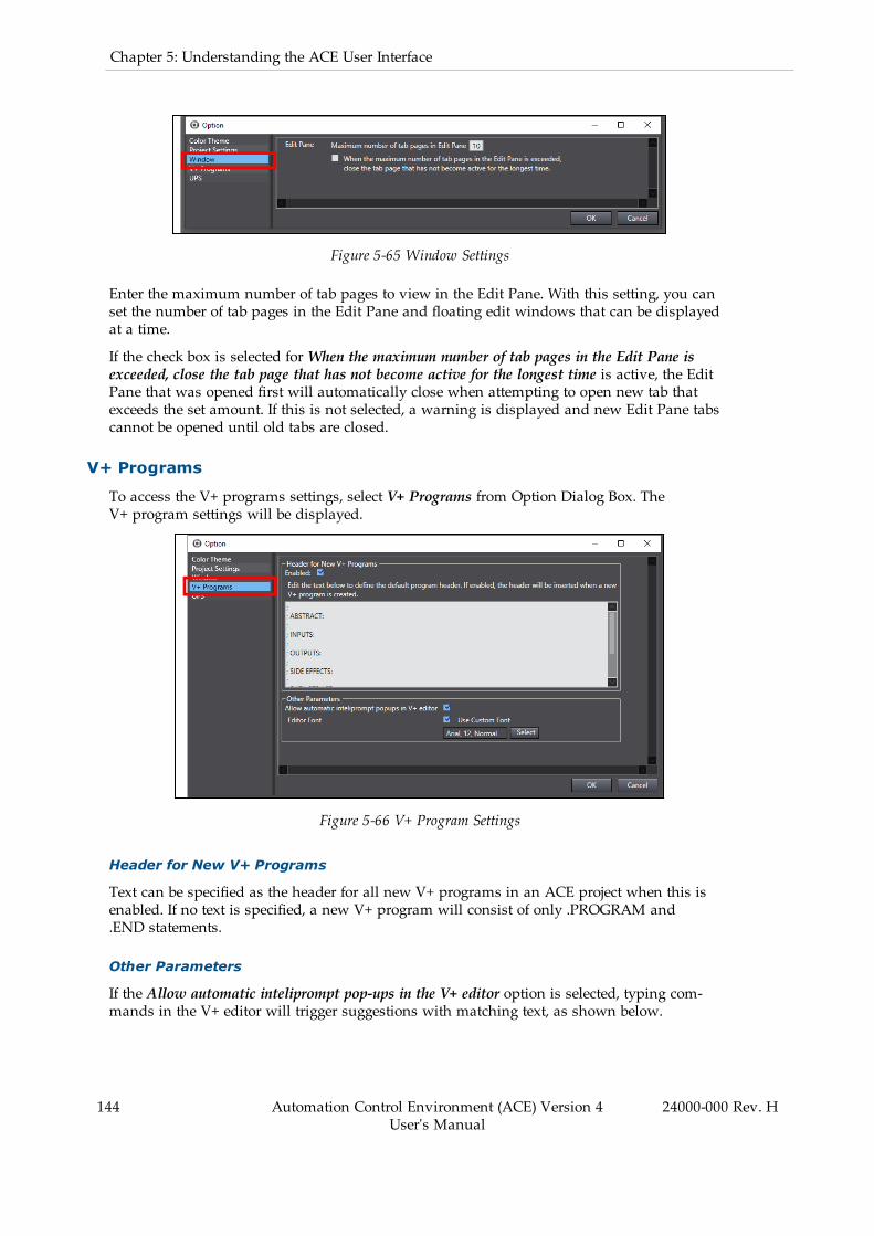
144 Automation Control Environment (ACE) Version 4User's Manual
24000-000 Rev. H
Chapter 5: Understanding the ACE User Interface
Figure 5-65 Window Settings
Enter the maximum number of tab pages to view in the Edit Pane. With this setting, you canset the number of tab pages in the Edit Pane and floating edit windows that can be displayedat a time.
If the check box is selected forWhen the maximum number of tab pages in the Edit Pane isexceeded, close the tab page that has not become active for the longest time is active, the EditPane that was opened first will automatically close when attempting to open new tab thatexceeds the set amount. If this is not selected, a warning is displayed and new Edit Pane tabscannot be opened until old tabs are closed.
V+ Programs
To access the V+ programs settings, select V+ Programs from Option Dialog Box. TheV+ program settings will be displayed.
Figure 5-66 V+ Program Settings
Header for New V+ Programs
Text can be specified as the header for all new V+ programs in an ACE project when this isenabled. If no text is specified, a new V+ program will consist of only .PROGRAM and.END statements.
Other Parameters
If the Allow automatic inteliprompt pop-ups in the V+ editor option is selected, typing com-mands in the V+ editor will trigger suggestions with matching text, as shown below.
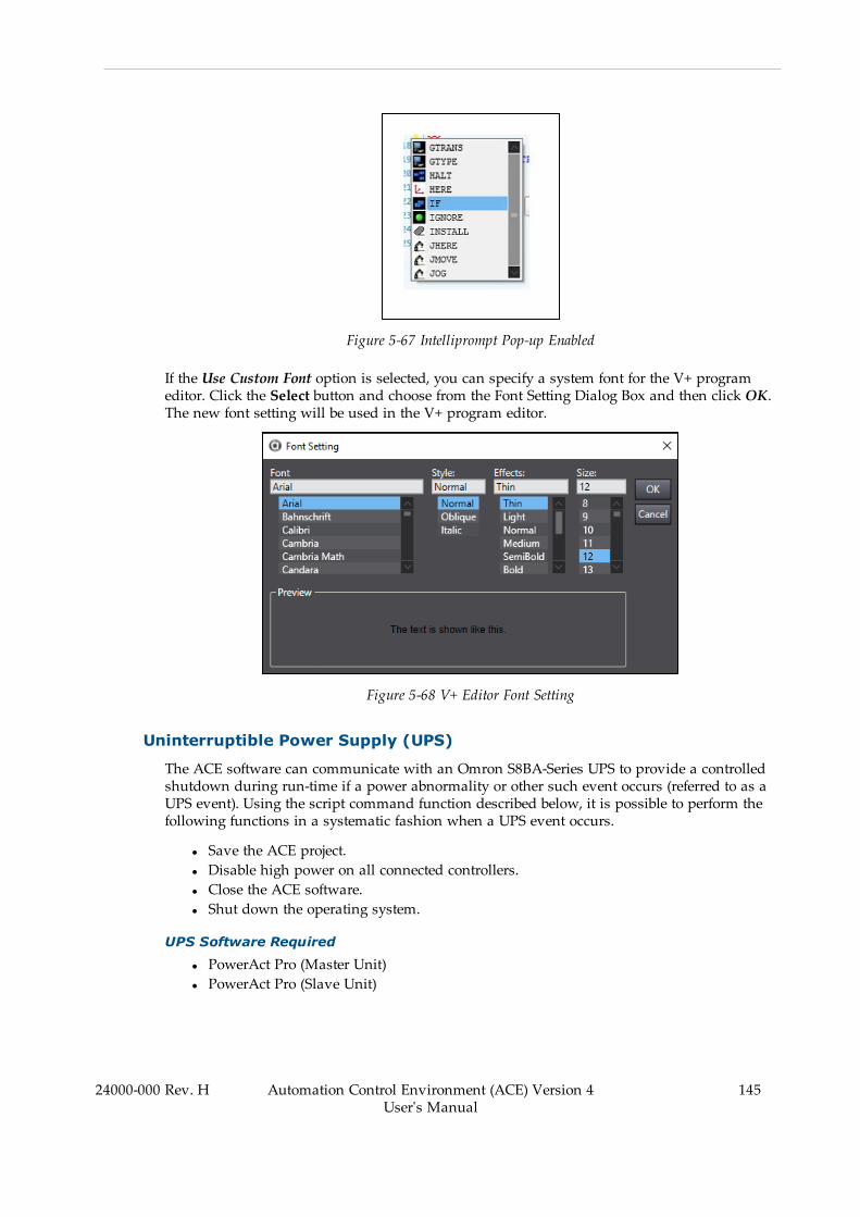
Figure 5-67 Intelliprompt Pop-up Enabled
If the Use Custom Font option is selected, you can specify a system font for the V+ programeditor. Click the Select button and choose from the Font Setting Dialog Box and then click OK.The new font setting will be used in the V+ program editor.
Figure 5-68 V+ Editor Font Setting
Uninterruptible Power Supply (UPS)
The ACE software can communicate with an Omron S8BA-Series UPS to provide a controlledshutdown during run-time if a power abnormality or other such event occurs (referred to as aUPS event). Using the script command function described below, it is possible to perform thefollowing functions in a systematic fashion when a UPS event occurs.
l Save the ACE project.l Disable high power on all connected controllers.l Close the ACE software.l Shut down the operating system.
UPS Software Required
l PowerAct Pro (Master Unit)l PowerAct Pro (Slave Unit)
24000-000 Rev. H Automation Control Environment (ACE) Version 4User's Manual
145

146 Automation Control Environment (ACE) Version 4User's Manual
24000-000 Rev. H
Chapter 5: Understanding the ACE User Interface
The PowerAct Pro software is included with the AC UPS. The Slave Unit needs to be installedon the computer running the ACE software.
Hardware Configuration
The basic hardware needed to use the UPS within a robot installation is: Omron AC UPSBU5002RWL, Omron Web Card SC20G2, Omron S8VKS DC Power Supply, Omron NY Indus-trial PC and an Industrial Robot.
Figure 5-69 UPS Hardware Wiring Diagram
Table 5-28 Hardware Wiring Components
Item Number Description
1 Switching Power Supply 20A/480W S8VKS48024
2 Amplified Power Control Logic
3 Omron Industrial PC
4 Industrial Robot
5 24VDC
6 Ethernet Cable
7 240VAC
8 AC UPS BU5002RWL with SC20G2 Network CardInstalled
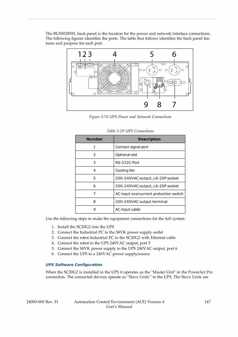
The BU5002RWL back panel is the location for the power and network interface connections.The following figures identifies the ports. The table that follows identifies the back panel fea-tures and purpose for each port.
Figure 5-70 UPS Power and Network Connections
Table 5-29 UPS Connections
Number Description
1 Contact signal port
2 Optional slot
3 RS-232C Port
4 Cooling fan
5 200-240VAC output, L6-20P socket
6 200-240VAC output, L6-20P socket
7 AC input overcurrent protection switch
8 200-240VAC output terminal
9 AC input cable
Use the following steps to make the equipment connections for the full system.
1. Install the SC20G2 into the UPS2. Connect the Industrial PC to the S8VK power supply outlet3. Connect the robot Industrial PC to the SC20G2 with Ethernet cable4. Connect the robot to the UPS 240VAC output, port 55. Connect the S8VK power supply to the UPS 240VAC output, port 66. Connect the UPS to a 240VAC power supply/source
UPS Software Configuration
When the SC20G2 is installed in the UPS it operates as the "Master Unit" in the PowerAct Proconnection. The connected devices operate as "Slave Units'" to the UPS. The Slave Units are
24000-000 Rev. H Automation Control Environment (ACE) Version 4User's Manual
147

148 Automation Control Environment (ACE) Version 4User's Manual
24000-000 Rev. H
Chapter 5: Understanding the ACE User Interface
then configured to initialize .exe or .bat files on the Industrial PC. When these files are executesthe UPS is able to initiate a safe stop to the program upon low battery.
Use the following steps to set up PowerAct Pro.
Install PowerAct Pro onto the Industrial PC
Connect to the AC UPS with the IP, 10.151.24.79, in the browser, opening the UPS Monitor.
Figure 5-71 UPS Monitor Opened in Browser
l Select UPS Management, along the top bar.l Select Shutdown Setting from the options in the left side of the window.l Select the Become Administrator button.l When prompted, the login is OMRON and the password is admin. Then click OK toopen the Shutdown Settings window.
Figure 5-72 Shutdown Setting Window
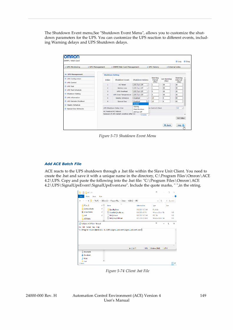
The Shutdown Event menu,See "Shutdown Event Menu", allows you to customize the shut-down parameters for the UPS. You can customize the UPS reaction to different events, includ-ing Warning delays and UPS Shutdown delays.
Figure 5-73 Shutdown Event Menu
Add ACE Batch File
ACE reacts to the UPS shutdown through a .bat file within the Slave Unit Client. You need tocreate the .bat and save it with a unique name in the directory, C:\Program Files\Omron\ACE4.2\UPS. Copy and paste the following into the .bat file: "C:\Program Files\Omron\ACE4.2\UPS\SignalUpsEvent\SignalUpsEvent.exe". Include the quote marks, " ",in the string.
Figure 5-74 Client .bat File
24000-000 Rev. H Automation Control Environment (ACE) Version 4User's Manual
149
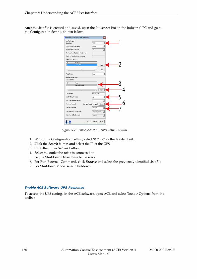
150 Automation Control Environment (ACE) Version 4User's Manual
24000-000 Rev. H
Chapter 5: Understanding the ACE User Interface
After the .bat file is created and saved, open the PowerAct Pro on the Industrial PC and go tothe Configuration Setting, shown below.
Figure 5-75 PowerAct Pro Configuration Setting
1. Within the Configuration Setting, select SC20G2 as the Master Unit.2. Click the Search button and select the IP of the UPS3. Click the upper Submit button4. Select the outlet the robot is connected to5. Set the Shutdown Delay Time to 120(sec)6. For Run External Command, click Browse and select the previously identified .bat file7. For Shutdown Mode, select Shutdown
Enable ACE Software UPS Response
To access the UPS settings in the ACE software, open ACE and select Tools > Options from thetoolbar.
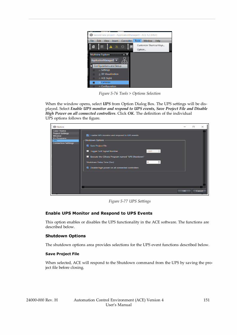
Figure 5-76 Tools > Options Selection
When the window opens, select UPS from Option Dialog Box. The UPS settings will be dis-played. Select Enable UPS monitor and respond to UPS events, Save Project File and DisableHigh Power on all connected controllers. Click OK. The definition of the individualUPS options follows the figure.
Figure 5-77 UPS Settings
Enable UPS Monitor and Respond to UPS Events
This option enables or disables the UPS functionality in the ACE software. The functions aredescribed below.
Shutdown Options
The shutdown options area provides selections for the UPS event functions described below.
Save Project File
When selected, ACE will respond to the Shutdown command from the UPS by saving the pro-ject file before closing.
24000-000 Rev. H Automation Control Environment (ACE) Version 4User's Manual
151
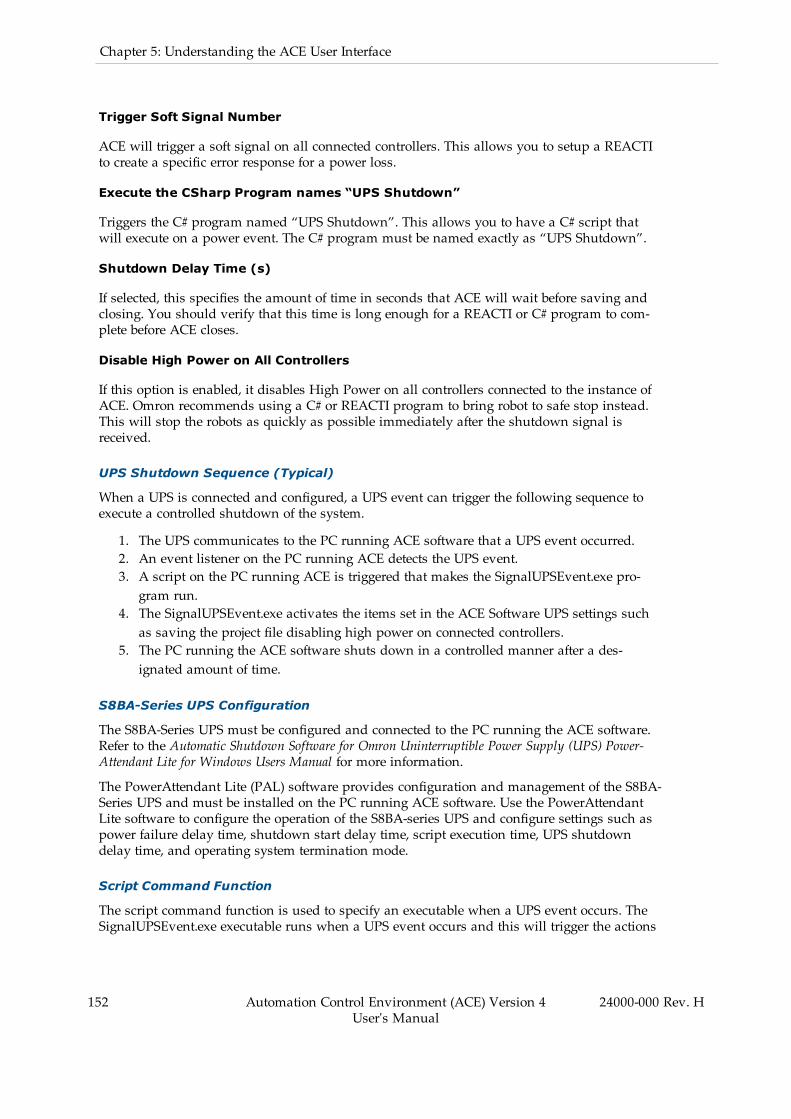
152 Automation Control Environment (ACE) Version 4User's Manual
24000-000 Rev. H
Chapter 5: Understanding the ACE User Interface
Trigger Soft Signal Number
ACE will trigger a soft signal on all connected controllers. This allows you to setup a REACTIto create a specific error response for a power loss.
Execute the CSharp Program names “UPS Shutdown”
Triggers the C# program named “UPS Shutdown”. This allows you to have a C# script thatwill execute on a power event. The C# program must be named exactly as “UPS Shutdown”.
Shutdown Delay Time (s)
If selected, this specifies the amount of time in seconds that ACE will wait before saving andclosing. You should verify that this time is long enough for a REACTI or C# program to com-plete before ACE closes.
Disable High Power on All Controllers
If this option is enabled, it disables High Power on all controllers connected to the instance ofACE. Omron recommends using a C# or REACTI program to bring robot to safe stop instead.This will stop the robots as quickly as possible immediately after the shutdown signal isreceived.
UPS Shutdown Sequence (Typical)
When a UPS is connected and configured, a UPS event can trigger the following sequence toexecute a controlled shutdown of the system.
1. The UPS communicates to the PC running ACE software that a UPS event occurred.2. An event listener on the PC running ACE detects the UPS event.3. A script on the PC running ACE is triggered that makes the SignalUPSEvent.exe pro-gram run.
4. The SignalUPSEvent.exe activates the items set in the ACE Software UPS settings suchas saving the project file disabling high power on connected controllers.
5. The PC running the ACE software shuts down in a controlled manner after a des-ignated amount of time.
S8BA-Series UPS Configuration
The S8BA-Series UPS must be configured and connected to the PC running the ACE software.Refer to the Automatic Shutdown Software for Omron Uninterruptible Power Supply (UPS) Power-Attendant Lite for Windows Users Manual for more information.
The PowerAttendant Lite (PAL) software provides configuration and management of the S8BA-Series UPS and must be installed on the PC running ACE software. Use the PowerAttendantLite software to configure the operation of the S8BA-series UPS and configure settings such aspower failure delay time, shutdown start delay time, script execution time, UPS shutdowndelay time, and operating system termination mode.
Script Command Function
The script command function is used to specify an executable when a UPS event occurs. TheSignalUPSEvent.exe executable runs when a UPS event occurs and this will trigger the actions

set in the ACE Software UPS Settings area described below.
The NotifyAce.usc script file must be placed in a specific directory of the PC runningthe ACE software. This file is included with an ACE software installation and can be found inthe ACE software installation directory in the UPS folder. The default path to find this scriptfile is provided below.
C:\Program Files\Omron\ACE 4.2\UPS
The NotifyAce.usc script must be copied to the following location on the PC running the ACEsoftware.
C:\Users\Public\Documents\OMRON\PAL
IMPORTANT: The PowerAttendant Lite software must be installed onthe PC running the ACE software.
ACE Software UPS Configuration Procedure
Use the following procedure to configure a UPS with the ACE software.
1. Adjust the ACE software UPS settings. Refer to Uninterruptible Power Supply (UPS) onpage 145 for more information.
2. Make all wiring and communication connections between the S8BA-Series UPS andthe PC running the ACE software. Refer to the Automatic Shutdown Software for OmronUninterruptible Power Supply (UPS) PowerAttendant Lite for Windows Users Manual formore information.
3. Install PowerAttendant Lite on the PC running the ACE software.4. Place the provided NotifyAce.usc script in theC:\Users\Public\Documents\OMRON\PAL directory. Refer to Script CommandFunction on page 152 for more information.
5. Set the shutdown parameters using the PowerAttendant Lite software installed onthe PC running the ACE software. Example parameter values are provided below (theseparameters should be adjusted for specific application requirements). After these stepsare finished, the procedure is complete.
l Power Failure Delay Time: 30 secondsl Shutdown Start Delay Time: 0 secondsl Script Execution Time: 60 secondsl UPS Shutdown Delay Time: 180 secondsl OS Termination Mode: Shutdown
24000-000 Rev. H Automation Control Environment (ACE) Version 4User's Manual
153

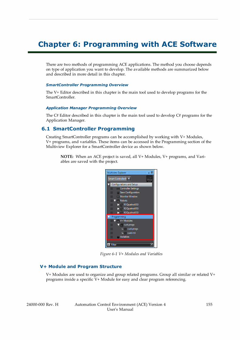
Chapter 6: Programming with ACE Software
There are two methods of programming ACE applications. The method you choose dependson type of application you want to develop. The available methods are summarized belowand described in more detail in this chapter.
SmartController Programming Overview
The V+ Editor described in this chapter is the main tool used to develop programs for theSmartController.
Application Manager Programming Overview
The C# Editor described in this chapter is the main tool used to develop C# programs for theApplication Manager.
6.1 SmartController ProgrammingCreating SmartController programs can be accomplished by working with V+ Modules,V+ programs, and variables. These items can be accessed in the Programming section of theMultiview Explorer for a SmartController device as shown below.
NOTE: When an ACE project is saved, all V+ Modules, V+ programs, and Vari-ables are saved with the project.
Figure 6-1 V+ Modules and Variables
V+ Module and Program Structure
V+ Modules are used to organize and group related programs. Group all similar or related V+programs inside a specific V+ Module for easy and clear program referencing.
24000-000 Rev. H Automation Control Environment (ACE) Version 4User's Manual
155
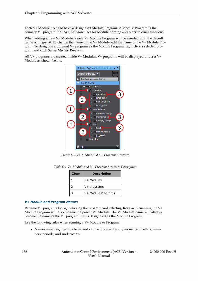
156 Automation Control Environment (ACE) Version 4User's Manual
24000-000 Rev. H
Chapter 6: Programming with ACE Software
Each V+ Module needs to have a designated Module Program. A Module Program is theprimary V+ program that ACE software uses for Module naming and other internal functions.
When adding a new V+ Module, a new V+ Module Program will be inserted with the defaultname of program0. To change the name of the V+ Module, edit the name of the V+ Module Pro-gram. To designate a different V+ program as the Module Program, right click a selected pro-gram and click Set as Module Program.
All V+ programs are created inside V+ Modules. V+ programs will be displayed under a V+Module as shown below.
Figure 6-2 V+ Module and V+ Program Structure
Table 6-1 V+ Module and V+ Program Structure Description
Item Description
1 V+ Modules
2 V+ programs
3 V+ Module Programs
V+ Module and Program Names
Rename V+ programs by right-clicking the program and selecting Rename. Renaming the V+Module Program will also rename the parent V+ Module. The V+ Module name will alwaysbecome the name of the V+ program that is designated as the Module Program.
Use the following rules when naming a V+ Module or Program.
l Names must begin with a letter and can be followed by any sequence of letters, num-bers, periods, and underscores.

l There is a 15 character limit for names.l Names are not case sensitive and always default to lower-case letters.
Creating a New V+ Module
To create a new V+ Module, right-click V+ Modules in the Multiview Explorer and select AddNew Module. A new V+ Module and default V+ program will be created.
Figure 6-3 Add a New Module
Save a V+ Module to the PC
V+ Modules and their programs can be saved to the PC. Right-click a module and select Saveto PC File. A Save As Dialog Box will be displayed for saving a V+ File (*.v2) to the selectedPC file location.
Show Global Variable References
All global V+ variable references can be displayed for a particular V+ Module. Right-click amodule and select Show Global Variables. A Show References Dialog Box will be displayed.This displays all V+ programs and all V+ Variables that are used. Clicking on a V+ Variablein the list will display its use in the program.
Figure 6-4 Show V+ Variable References
Show Program Call Commands
All program CALL commands can be listed for a particular V+ Module. Right-click a moduleand select Show CALLers. A Show CALLers Dialog Box will be displayed to provide a list of
24000-000 Rev. H Automation Control Environment (ACE) Version 4User's Manual
157
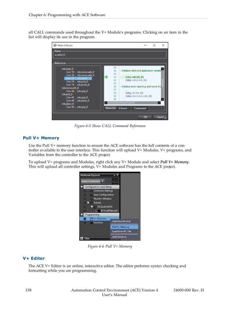
158 Automation Control Environment (ACE) Version 4User's Manual
24000-000 Rev. H
Chapter 6: Programming with ACE Software
all CALL commands used throughout the V+ Module's programs. Clicking on an item in thelist will display its use in the program.
Figure 6-5 Show CALL Command References
Pull V+ Memory
Use the Pull V+ memory function to ensure the ACE software has the full contents of a con-troller available to the user interface. This function will upload V+ Modules, V+ programs, andVariables from the controller to the ACE project.
To upload V+ programs and Modules, right click any V+ Module and select Pull V+ Memory.This will upload all controller settings, V+ Modules and Programs to the ACE project.
Figure 6-6 Pull V+ Memory
V+ Editor
The ACE V+ Editor is an online, interactive editor. The editor performs syntax checking andformatting while you are programming.
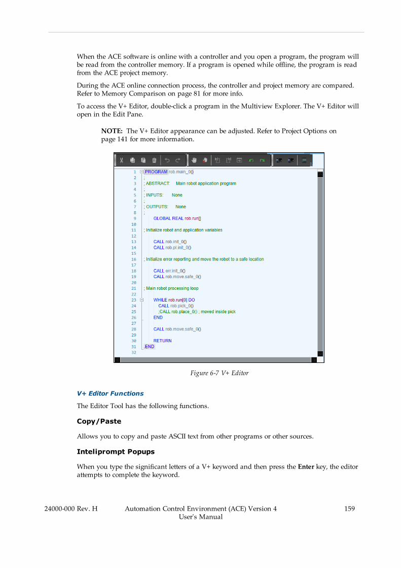
When the ACE software is online with a controller and you open a program, the program willbe read from the controller memory. If a program is opened while offline, the program is readfrom the ACE project memory.
During the ACE online connection process, the controller and project memory are compared.Refer to Memory Comparison on page 81 for more info.
To access the V+ Editor, double-click a program in the Multiview Explorer. The V+ Editor willopen in the Edit Pane.
NOTE: The V+ Editor appearance can be adjusted. Refer to Project Options onpage 141 for more information.
Figure 6-7 V+ Editor
V+ Editor Functions
The Editor Tool has the following functions.
Copy/Paste
Allows you to copy and paste ASCII text from other programs or other sources.
Inteliprompt Popups
When you type the significant letters of a V+ keyword and then press the Enter key, the editorattempts to complete the keyword.
24000-000 Rev. H Automation Control Environment (ACE) Version 4User's Manual
159
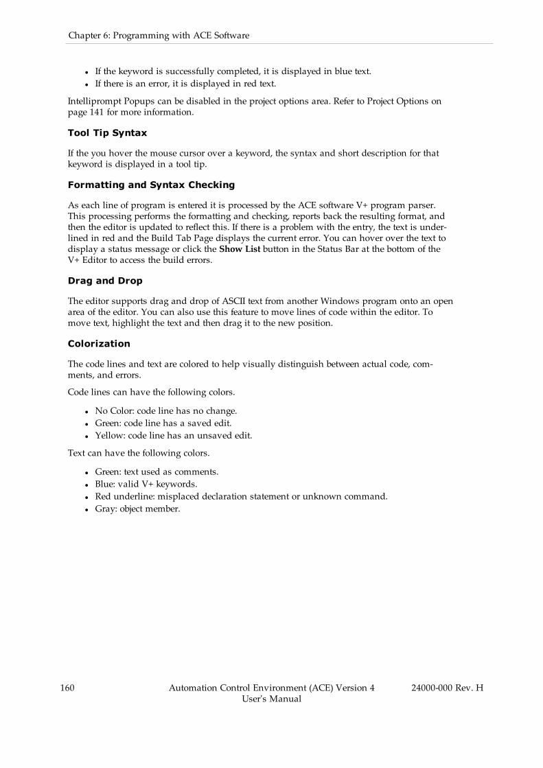
160 Automation Control Environment (ACE) Version 4User's Manual
24000-000 Rev. H
Chapter 6: Programming with ACE Software
l If the keyword is successfully completed, it is displayed in blue text.l If there is an error, it is displayed in red text.
Intelliprompt Popups can be disabled in the project options area. Refer to Project Options onpage 141 for more information.
Tool Tip Syntax
If the you hover the mouse cursor over a keyword, the syntax and short description for thatkeyword is displayed in a tool tip.
Formatting and Syntax Checking
As each line of program is entered it is processed by the ACE software V+ program parser.This processing performs the formatting and checking, reports back the resulting format, andthen the editor is updated to reflect this. If there is a problem with the entry, the text is under-lined in red and the Build Tab Page displays the current error. You can hover over the text todisplay a status message or click the Show List button in the Status Bar at the bottom of theV+ Editor to access the build errors.
Drag and Drop
The editor supports drag and drop of ASCII text from another Windows program onto an openarea of the editor. You can also use this feature to move lines of code within the editor. Tomove text, highlight the text and then drag it to the new position.
Colorization
The code lines and text are colored to help visually distinguish between actual code, com-ments, and errors.
Code lines can have the following colors.
l No Color: code line has no change.l Green: code line has a saved edit.l Yellow: code line has an unsaved edit.
Text can have the following colors.
l Green: text used as comments.l Blue: valid V+ keywords.l Red underline: misplaced declaration statement or unknown command.l Gray: object member.
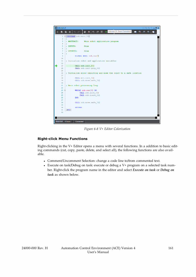
Figure 6-8 V+ Editor Colorization
Right-click Menu Functions
Right-clicking in the V+ Editor opens a menu with several functions. In a addition to basic edit-ing commands (cut, copy, paste, delete, and select all), the following functions are also avail-able.
l Comment/Uncomment Selection: change a code line to/from commented text.l Execute on task/Debug on task: execute or debug a V+ program on a selected task num-ber. Right-click the program name in the editor and select Execute on task or Debug ontask as shown below.
24000-000 Rev. H Automation Control Environment (ACE) Version 4User's Manual
161
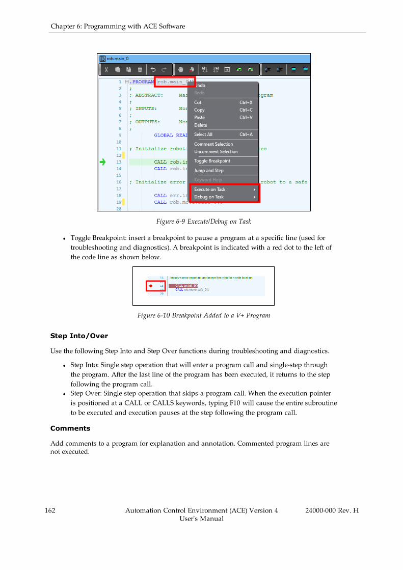
162 Automation Control Environment (ACE) Version 4User's Manual
24000-000 Rev. H
Chapter 6: Programming with ACE Software
Figure 6-9 Execute/Debug on Task
l Toggle Breakpoint: insert a breakpoint to pause a program at a specific line (used fortroubleshooting and diagnostics). A breakpoint is indicated with a red dot to the left ofthe code line as shown below.
Figure 6-10 Breakpoint Added to a V+ Program
Step Into/Over
Use the following Step Into and Step Over functions during troubleshooting and diagnostics.
l Step Into: Single step operation that will enter a program call and single-step throughthe program. After the last line of the program has been executed, it returns to the stepfollowing the program call.
l Step Over: Single step operation that skips a program call. When the execution pointeris positioned at a CALL or CALLS keywords, typing F10 will cause the entire subroutineto be executed and execution pauses at the step following the program call.
Comments
Add comments to a program for explanation and annotation. Commented program lines arenot executed.

Bookmarks
Add bookmarks to a program for quick access to specific program lines. Bookmarks do notaffect program execution. A bookmarked program line will be indicated with the followingsymbol.
Figure 6-11 Bookmarked Program Line
Split Screen View
The V+ Editor can be split into two screens horizontally to allow viewing of multiple sectionsof code in the same editor window.
To split the editor window view, drag the handle down as shown below.
Figure 6-12 V+ Editor Split Screen View
Status Bar
The area below the V+ Editor window has the following functions.
24000-000 Rev. H Automation Control Environment (ACE) Version 4User's Manual
163
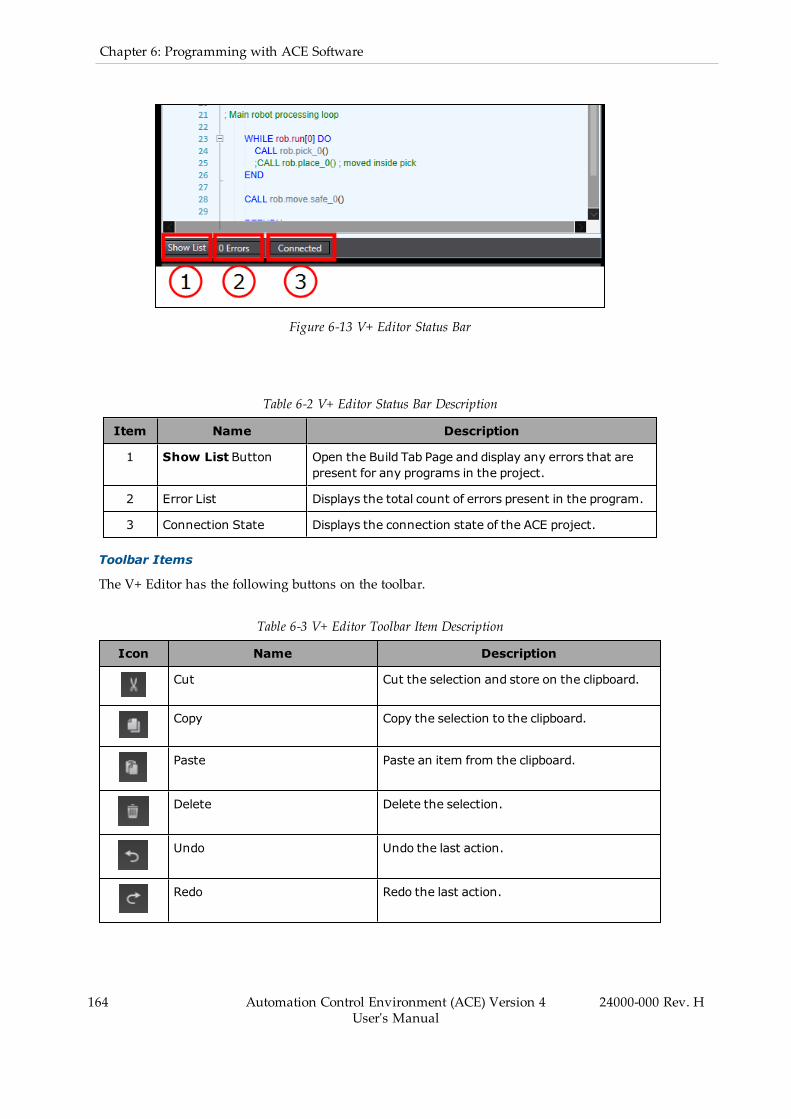
164 Automation Control Environment (ACE) Version 4User's Manual
24000-000 Rev. H
Chapter 6: Programming with ACE Software
Figure 6-13 V+ Editor Status Bar
Table 6-2 V+ Editor Status Bar Description
Item Name Description
1 Show List Button Open the Build Tab Page and display any errors that arepresent for any programs in the project.
2 Error List Displays the total count of errors present in the program.
3 Connection State Displays the connection state of the ACE project.
Toolbar Items
The V+ Editor has the following buttons on the toolbar.
Table 6-3 V+ Editor Toolbar Item Description
Icon Name Description
Cut Cut the selection and store on the clipboard.
Copy Copy the selection to the clipboard.
Paste Paste an item from the clipboard.
Delete Delete the selection.
Undo Undo the last action.
Redo Redo the last action.
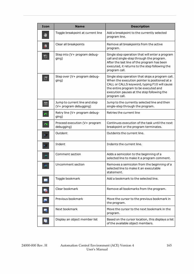
Icon Name Description
Toggle breakpoint at current line Add a breakpoint to the currently selectedprogram line.
Clear all breakpoints Remove all breakpoints from the activeprogram.
Step into (V+ program debug-ging)
Single step operation that will enter a programcall and single-step through the program.After the last line of the program has beenexecuted, it returns to the step following theprogram call.
Step over (V+ program debug-ging)
Single step operation that skips a program call.When the execution pointer is positioned at aCALL or CALLS keyword, typing F10 will causethe entire program to be executed andexecution pauses at the step following theprogram call.
Jump to current line and step(V+ program debugging)
Jump to the currently selected line and thensingle-step through the program.
Retry line (V+ program debug-ging)
Retries the current line
Proceed execution (V+ programdebugging)
Continues execution of the task until the nextbreakpoint or the program terminates.
Outdent Outdents the current line.
Indent Indents the current line.
Comment section Adds a semicolon to the beginning of aselected line to make it a program comment.
Uncomment section Removes a semicolon from the beginning of aselected line to make it an executablestatement.
Toggle bookmark Add a bookmark to the selected line.
Clear bookmark Remove all bookmarks from the program.
Previous bookmark Move the cursor to the previous bookmark inthe program.
Next bookmark Move the cursor to the next bookmark in theprogram.
Display an object member list Based on the cursor location, this displays a listof the available object members.
24000-000 Rev. H Automation Control Environment (ACE) Version 4User's Manual
165
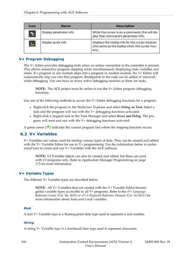
166 Automation Control Environment (ACE) Version 4User's Manual
24000-000 Rev. H
Chapter 6: Programming with ACE Software
Icon Name Description
Display parameter info While the cursor is on a command, this will dis-play that command's parameter info.
Display quick info Displays the tooltip info for the cursor location(the same as the tooltip when the cursor hov-ers).
V+ Program Debugging
The V+ Editor provides debugging tools when an online connection to the controller is present.This allows interactive program stepping while simultaneously displaying code variables andstates. If a program in one module steps into a program in another module, the V+ Editor willautomatically step you into that program. Breakpoints in the code can be added or removedwhile debugging. You can have as many active debugging sessions as there are tasks.
NOTE: The ACE project must be online to use the V+ Editor program debuggingfunctions.
Use one of the following methods to access the V+ Editor debugging functions for a program.
l Right-click the program in the Multiview Explorer and select Debug on Task. Select atask and the program will run with the V+ debugging functions activated.
l Right-click a stopped task in the Task Manager and select Reset and Debug. The pro-gram will reset and run with the V+ debugging functions activated.
A green arrow ( ) indicates the current program line where the stepping function occurs.
6.2 V+ VariablesV+ Variables are values used for storing various types of data. They can be created and editedwith the V+ Variable Editor for use in V+ programming. Use the information below to under-stand how to create and use V+ Variables with the ACE software.
NOTE: C# Variable objects can also be created and edited, but these are usedwith C# programs only. Refer to Application Manager Programming on page173 for more information.
V+ Variable Types
The different V+ Variable types are described below.
NOTE: All V+ Variables that are created with the V+ Variable Editor becomeglobal variable types accessible in all V+ programs. Refer to the eV+ LanguageReference Guide (Cat. No. I605) or eV+3 Keyword Reference Manual (Cat. No I652) formore information about Auto and Local variables.
Real
A real V+ Variable type is a floating-point data type used to represent a real number.
String
A string V+ Variable type is a text-based data type used to represent characters.
Valid string characters include 128 8-bit ASCII characters.
Precision Point
A precision point variable type allows you to define a location by specifying a value for eachrobot joint. These joint values are absolute and cannot be made relative to other locations orcoordinate frames. Precision point locations are useful for jointed-arm applications and withapplications that require full rotation of robot arms with joint 4. They are also helpful wherejoint orientation is critical to the application or when you want to move an individual joint.
Location
A location variable type specifies the position and orientation of the robot tool tip in three-dimensional space. You can define robot locations using Cartesian coordinates (trans-formations).
A transformation is a set of six components that identifies a location in Cartesian space andthe orientation of the robot tool flange (X, Y, Z, Yaw, Pitch, Roll). A transformation can also rep-resent the location of an arbitrary local reference frame (also know as a frame of reference).Refer to Defining a Location on page 167 for more information.
The coordinate offsets are from the origin of the World coordinate system which is located atthe base of the robot by default.
Additional Information: Refer to the following sections for more information.l Coordinate Systems on page 23l 3D Visualizer on page 107l Offset From Parent on page 221
Defining a Location
V+ Variable location values can be manually entered or acquired from the current robot pos-ition. Refer to V+ Jog Control on page 117 for more information.
6.3 V+ Variable EditorThe V+ Variable Editor is used to create and edit different types of V+ Variables. All variabletypes share the following properties but some variables have additional properties (see below).
Access the V+ Variable Editor by double-clicking Variables in the Multiview Explorer (or right-click and select Edit).
24000-000 Rev. H Automation Control Environment (ACE) Version 4User's Manual
167
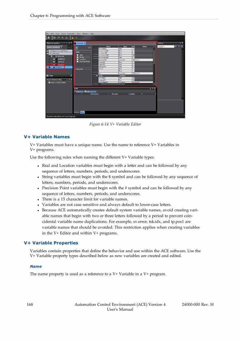
168 Automation Control Environment (ACE) Version 4User's Manual
24000-000 Rev. H
Chapter 6: Programming with ACE Software
Figure 6-14 V+ Variable Editor
V+ Variable Names
V+ Variables must have a unique name. Use the name to reference V+ Variables inV+ programs.
Use the following rules when naming the different V+ Variable types.
l Real and Location variables must begin with a letter and can be followed by anysequence of letters, numbers, periods, and underscores.
l String variables must begin with the $ symbol and can be followed by any sequence ofletters, numbers, periods, and underscores.
l Precision Point variables must begin with the # symbol and can be followed by anysequence of letters, numbers, periods, and underscores.
l There is a 15 character limit for variable names.l Variables are not case sensitive and always default to lower-case letters.l Because ACE automatically creates default system variable names, avoid creating vari-able names that begin with two or three letters followed by a period to prevent coin-cidental variable name duplications. For example, sv.error, tsk.idx, and tp.pos1 arevariable names that should be avoided. This restriction applies when creating variablesin the V+ Editor and within V+ programs.
V+ Variable Properties
Variables contain properties that define the behavior and use within the ACE software. Use theV+ Variable property types described below as new variables are created and edited.
Name
The name property is used as a reference to a V+ Variable in a V+ program.

Type
The type property defines what type of data is stored in the variable.
Initial Value
The initial value property is used to set the variables default value before any program orother function alters it.
Category
A category can be defined for each variable to help classify and organize variables.V+ Variables can be saved by category as well. Refer to Save Configuration on page 204 formore information.
Description
A description can be added to each variable for annotation and clarification purposes.
Robot
A robot in the ACE project can be assigned to a location or precision point variable. This prop-erty does not apply to other variable types. When assigning a robot current position to the loc-ation or precision point variable, a robot must be selected. The robot must be assigned fordisplay purposes and for inclusion in location lists provided by the V+ Jog Control.
Display Mode
The following Display Mode options affect how a location or precision point variable appearsin the 3D Visualizer. This property does not apply to other variable types.
l Do not display: the point will not appear in the 3D Visualizer.l Display as point: the point will appear as a circle ( ).l Display as frame: the point will appear as a coordinate symbol ( ).
Arrays
A variable can be created as a 1D, 2D, or 3D array. Use the array selection options in the Adda new variable Dialog Box to establish the dimensions of the array. Refer to Creating a NewV+ Variable on page 170 for more information.
Figure 6-15 Array Dimension Settings
24000-000 Rev. H Automation Control Environment (ACE) Version 4User's Manual
169

170 Automation Control Environment (ACE) Version 4User's Manual
24000-000 Rev. H
Chapter 6: Programming with ACE Software
Creating a New V+ Variable
Use the following procedure to create a new V+ Variable with the V+ Variable Editor.
NOTE: V+ Variables can also be created from a V+ program. Refer to the eV+Language Reference Guide (Cat. No. I605) or eV+3 Keyword Reference Manual (Cat. NoI652) for more information.
New Precision Point and Location variable types can also be created from theV+ Jog Control. Refer to V+ Jog Control on page 117 for more information.
Additional Information: Once a variable is created, the type and array size can-not be changed.
1. Click the Add button ( ). This will open the Add a new variable Dialog Box.
Figure 6-16 Add a New V+ Variable
2. Input a unique variable name.3. Select a variable type from the dropdown menu.
NOTE: Selecting the variables types of location and precision point willexpose the additional field for robot assignment, the Here button (foracquiring position values from a robot), and the Display mode selection.
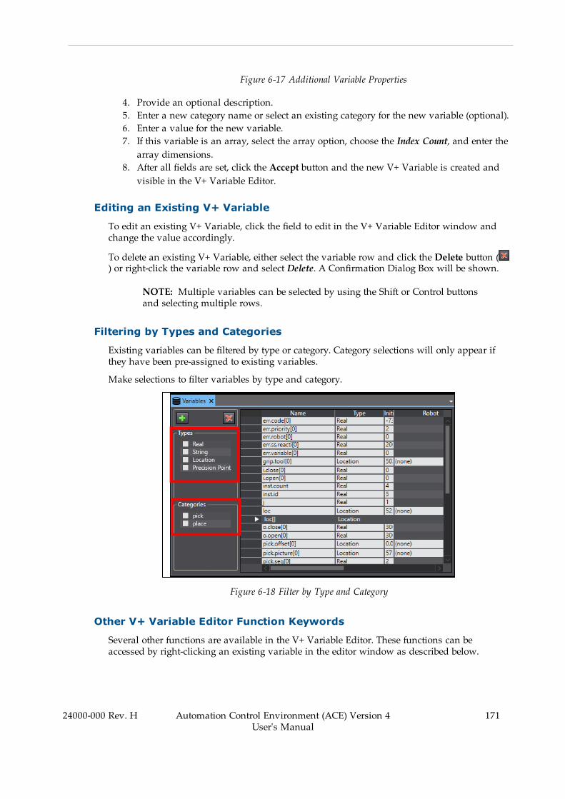
Figure 6-17 Additional Variable Properties
4. Provide an optional description.5. Enter a new category name or select an existing category for the new variable (optional).6. Enter a value for the new variable.7. If this variable is an array, select the array option, choose the Index Count, and enter thearray dimensions.
8. After all fields are set, click the Accept button and the new V+ Variable is created andvisible in the V+ Variable Editor.
Editing an Existing V+ Variable
To edit an existing V+ Variable, click the field to edit in the V+ Variable Editor window andchange the value accordingly.
To delete an existing V+ Variable, either select the variable row and click the Delete button () or right-click the variable row and select Delete. A Confirmation Dialog Box will be shown.
NOTE: Multiple variables can be selected by using the Shift or Control buttonsand selecting multiple rows.
Filtering by Types and Categories
Existing variables can be filtered by type or category. Category selections will only appear ifthey have been pre-assigned to existing variables.
Make selections to filter variables by type and category.
Figure 6-18 Filter by Type and Category
Other V+ Variable Editor Function Keywords
Several other functions are available in the V+ Variable Editor. These functions can beaccessed by right-clicking an existing variable in the editor window as described below.
24000-000 Rev. H Automation Control Environment (ACE) Version 4User's Manual
171
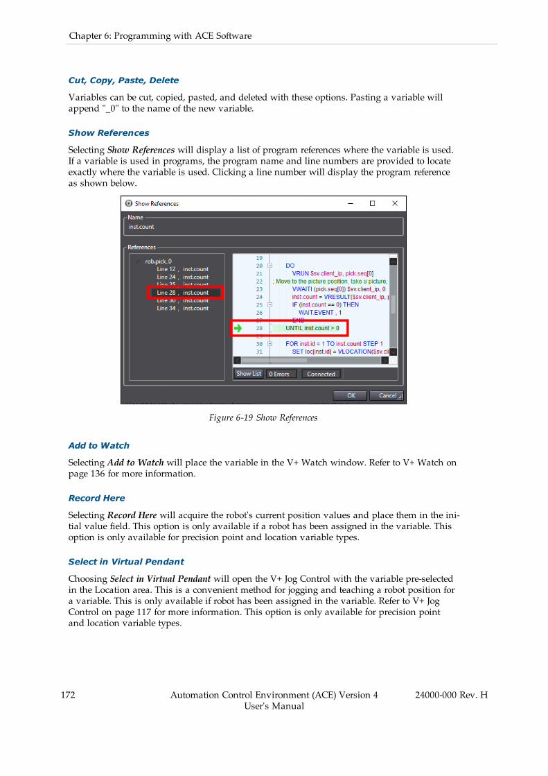
172 Automation Control Environment (ACE) Version 4User's Manual
24000-000 Rev. H
Chapter 6: Programming with ACE Software
Cut, Copy, Paste, Delete
Variables can be cut, copied, pasted, and deleted with these options. Pasting a variable willappend "_0" to the name of the new variable.
Show References
Selecting Show References will display a list of program references where the variable is used.If a variable is used in programs, the program name and line numbers are provided to locateexactly where the variable is used. Clicking a line number will display the program referenceas shown below.
Figure 6-19 Show References
Add to Watch
Selecting Add to Watch will place the variable in the V+ Watch window. Refer to V+ Watch onpage 136 for more information.
Record Here
Selecting Record Here will acquire the robot's current position values and place them in the ini-tial value field. This option is only available if a robot has been assigned in the variable. Thisoption is only available for precision point and location variable types.
Select in Virtual Pendant
Choosing Select in Virtual Pendant will open the V+ Jog Control with the variable pre-selectedin the Location area. This is a convenient method for jogging and teaching a robot position fora variable. This is only available if robot has been assigned in the variable. Refer to V+ JogControl on page 117 for more information. This option is only available for precision pointand location variable types.
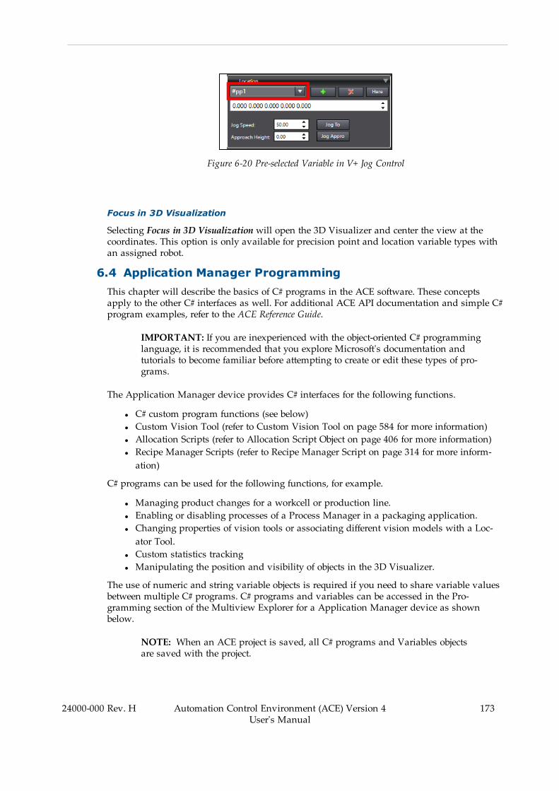
Figure 6-20 Pre-selected Variable in V+ Jog Control
Focus in 3D Visualization
Selecting Focus in 3D Visualization will open the 3D Visualizer and center the view at thecoordinates. This option is only available for precision point and location variable types withan assigned robot.
6.4 Application Manager ProgrammingThis chapter will describe the basics of C# programs in the ACE software. These conceptsapply to the other C# interfaces as well. For additional ACE API documentation and simple C#program examples, refer to the ACE Reference Guide.
IMPORTANT: If you are inexperienced with the object-oriented C# programminglanguage, it is recommended that you explore Microsoft's documentation andtutorials to become familiar before attempting to create or edit these types of pro-grams.
The Application Manager device provides C# interfaces for the following functions.
l C# custom program functions (see below)l Custom Vision Tool (refer to Custom Vision Tool on page 584 for more information)l Allocation Scripts (refer to Allocation Script Object on page 406 for more information)l Recipe Manager Scripts (refer to Recipe Manager Script on page 314 for more inform-ation)
C# programs can be used for the following functions, for example.
l Managing product changes for a workcell or production line.l Enabling or disabling processes of a Process Manager in a packaging application.l Changing properties of vision tools or associating different vision models with a Loc-ator Tool.
l Custom statistics trackingl Manipulating the position and visibility of objects in the 3D Visualizer.
The use of numeric and string variable objects is required if you need to share variable valuesbetween multiple C# programs. C# programs and variables can be accessed in the Pro-gramming section of the Multiview Explorer for a Application Manager device as shownbelow.
NOTE: When an ACE project is saved, all C# programs and Variables objectsare saved with the project.
24000-000 Rev. H Automation Control Environment (ACE) Version 4User's Manual
173
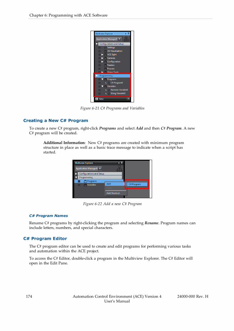
174 Automation Control Environment (ACE) Version 4User's Manual
24000-000 Rev. H
Chapter 6: Programming with ACE Software
Figure 6-21 C# Programs and Variables
Creating a New C# Program
To create a new C# program, right-click Programs and select Add and then C# Program. A newC# program will be created.
Additional Information: New C# programs are created with minimum programstructure in place as well as a basic trace message to indicate when a script hasstarted.
Figure 6-22 Add a new C# Program
C# Program Names
Rename C# programs by right-clicking the program and selecting Rename. Program names caninclude letters, numbers, and special characters.
C# Program Editor
The C# program editor can be used to create and edit programs for performing various tasksand automation within the ACE project.
To access the C# Editor, double-click a program in the Multiview Explorer. The C# Editor willopen in the Edit Pane.
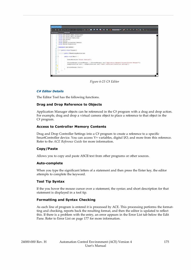
Figure 6-23 C# Editor
C# Editor Details
The Editor Tool has the following functions.
Drag and Drop Reference to Objects
Application Manager objects can be referenced in the C# program with a drag and drop action.For example, drag and drop a virtual camera object to place a reference to that object in theC# program.
Access to Controller Memory Contents
Drag and Drop Controller Settings into a C# program to create a reference to a specificSmartController device. You can access V+ variables, digital I/O, and more from this reference.Refer to the ACE Reference Guide for more information.
Copy/Paste
Allows you to copy and paste ASCII text from other programs or other sources.
Auto-complete
When you type the significant letters of a statement and then press the Enter key, the editorattempts to complete the keyword.
Tool Tip Syntax
If the you hover the mouse cursor over a statement, the syntax and short description for thatstatement is displayed in a tool tip.
Formatting and Syntax Checking
As each line of program is entered it is processed by ACE. This processing performs the format-ting and checking, reports back the resulting format, and then the editor is updated to reflectthis. If there is a problem with the entry, an error appears in the Error List tab below the EditPane. Refer to Error List on page 177 for more information.
24000-000 Rev. H Automation Control Environment (ACE) Version 4User's Manual
175

176 Automation Control Environment (ACE) Version 4User's Manual
24000-000 Rev. H
Chapter 6: Programming with ACE Software
Drag and Drop
The editor supports drag and drop of ASCII text from another Windows program onto an openarea of the editor. You can also use this feature to move lines of code within the editor. Tomove text, highlight the text and then drag it to the new position.
Colorization
The code lines and text are colored to help visually distinguish between actual code, com-ments, and errors. Code lines can have the following colors.
l No Color: code line has no change.l Yellow: code line has an unsaved edit.
Text can have the following colors.
l Green: text used as comments.l Blue: definitionsl Red: Stringsl Black: non-keywords and operators as valid syntax
Right-click Menu Functions
Right-clicking in the C# Editor opens a menu with several functions. In a addition to basic edit-ing commands (cut, copy, paste, delete, and select all), the following functions are also avail-able.
l Toggle All Outlining: collapse/expand all outlining regions of code.l Toggle Outlining Expansion: collapse/expand selected outlined region of code.l Collapse to Definitions: collapse areas for all members.l Comment/Uncomment Lines: change a code line to/from commented text.
Comments
Add comments to a program for explanation and annotation. Commented text is not executed.
Bookmarks
Add bookmarks to a program for quick access to specific program lines. Bookmarks do notaffect program execution. A bookmarked program line will be indicated with the followingsymbol.
Figure 6-24 Bookmarked Program Line

Error List
Program compile errors are shown in the Error List Tab below the C# program Edit Pane.When errors are present in the list, execution is not possible. Use the Error List Line, Char (character), and Description information to resolve program compile errors.
Figure 6-25 C# Error List
Trace Messages
Trace Messages are shown in the Trace Message Tab below the C# program Edit Pane. Thisdisplays messages created from any Trace.WriteLine() call in the program and can be usefulwhen troubleshooting or debugging a program.
Additional Information: Erase all Trace Messages with the ( ) icon in theC# program editor toolbar. This will also clear Trace Messages from theTask Status Control Trace Messages area.
24000-000 Rev. H Automation Control Environment (ACE) Version 4User's Manual
177

178 Automation Control Environment (ACE) Version 4User's Manual
24000-000 Rev. H
Chapter 6: Programming with ACE Software
Figure 6-26 C# Trace Messages
Toolbar Items
The C# Editor has the following buttons on the toolbar.
Table 6-4 C# Editor Toolbar Description
Icon Name Description
Cut Cut the selection and store on the clipboard.
Copy Copy the selection to the clipboard.
Paste Paste an item from the clipboard.
Delete Delete the selection.
Undo Undo the last action.
Redo Redo the last action.
Outdent Outdents the current line.
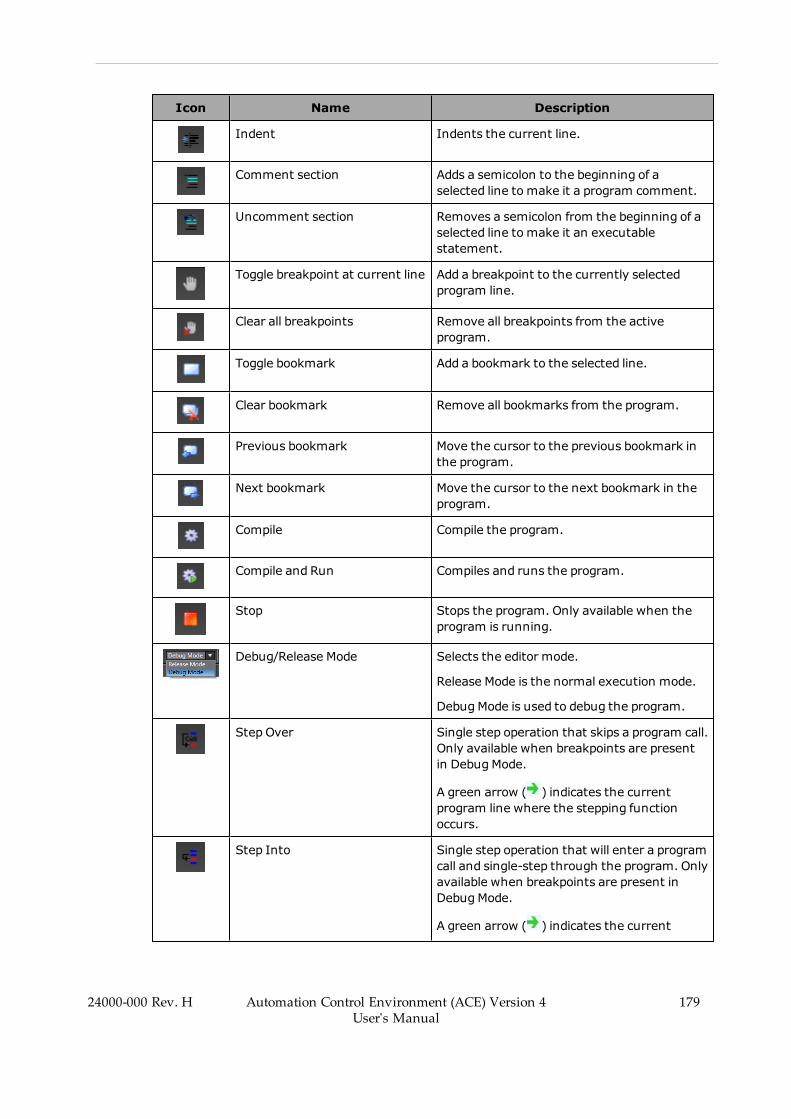
Icon Name Description
Indent Indents the current line.
Comment section Adds a semicolon to the beginning of aselected line to make it a program comment.
Uncomment section Removes a semicolon from the beginning of aselected line to make it an executablestatement.
Toggle breakpoint at current line Add a breakpoint to the currently selectedprogram line.
Clear all breakpoints Remove all breakpoints from the activeprogram.
Toggle bookmark Add a bookmark to the selected line.
Clear bookmark Remove all bookmarks from the program.
Previous bookmark Move the cursor to the previous bookmark inthe program.
Next bookmark Move the cursor to the next bookmark in theprogram.
Compile Compile the program.
Compile and Run Compiles and runs the program.
Stop Stops the program. Only available when theprogram is running.
Debug/Release Mode Selects the editor mode.
Release Mode is the normal execution mode.
DebugMode is used to debug the program.
Step Over Single step operation that skips a program call.Only available when breakpoints are presentin DebugMode.
A green arrow ( ) indicates the currentprogram line where the stepping functionoccurs.
Step Into Single step operation that will enter a programcall and single-step through the program. Onlyavailable when breakpoints are present inDebugMode.
A green arrow ( ) indicates the current
24000-000 Rev. H Automation Control Environment (ACE) Version 4User's Manual
179
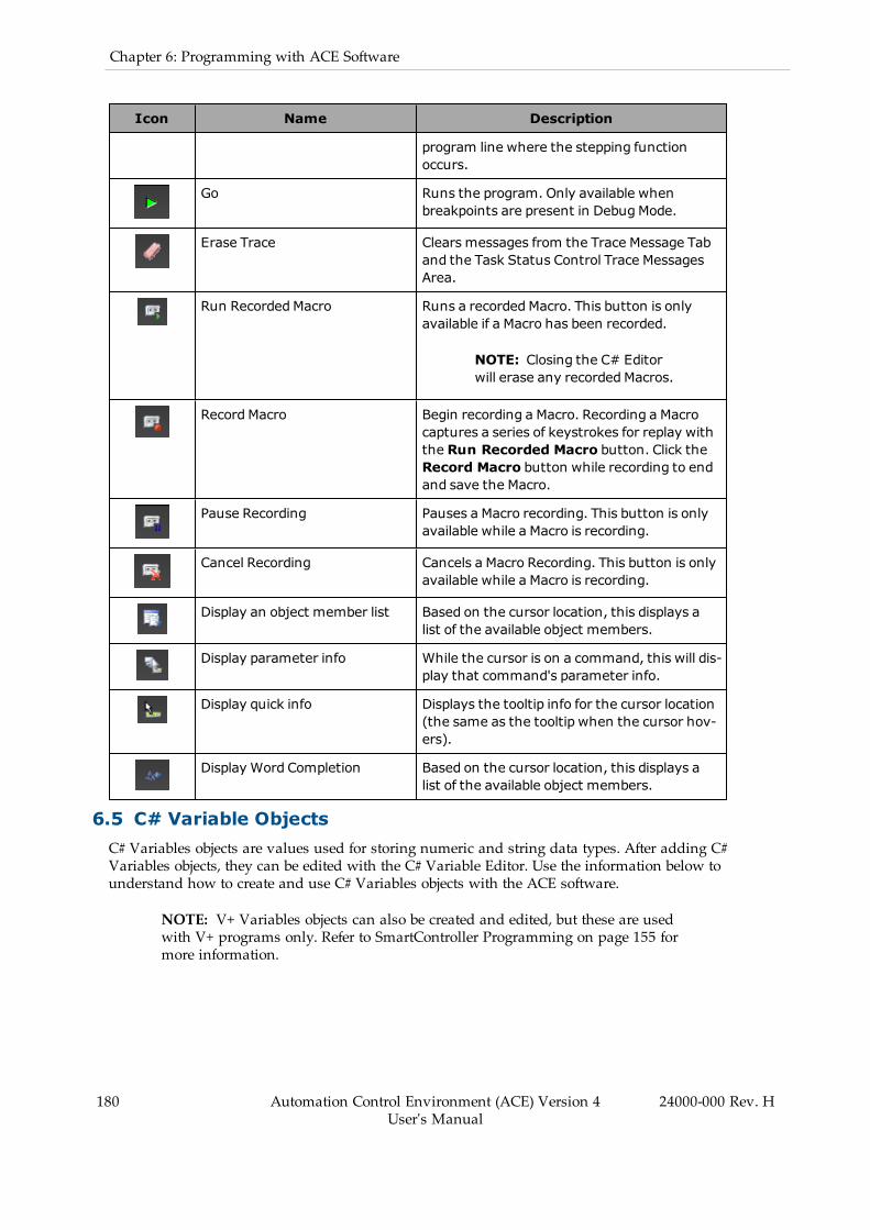
180 Automation Control Environment (ACE) Version 4User's Manual
24000-000 Rev. H
Chapter 6: Programming with ACE Software
Icon Name Description
program line where the stepping functionoccurs.
Go Runs the program. Only available whenbreakpoints are present in DebugMode.
Erase Trace Clears messages from the Trace Message Taband the Task Status Control Trace MessagesArea.
Run Recorded Macro Runs a recordedMacro. This button is onlyavailable if a Macro has been recorded.
NOTE: Closing the C# Editorwill erase any recordedMacros.
RecordMacro Begin recording a Macro. Recording a Macrocaptures a series of keystrokes for replay withthe Run Recorded Macro button. Click theRecord Macro button while recording to endand save the Macro.
Pause Recording Pauses a Macro recording. This button is onlyavailable while a Macro is recording.
Cancel Recording Cancels a Macro Recording. This button is onlyavailable while a Macro is recording.
Display an object member list Based on the cursor location, this displays alist of the available object members.
Display parameter info While the cursor is on a command, this will dis-play that command's parameter info.
Display quick info Displays the tooltip info for the cursor location(the same as the tooltip when the cursor hov-ers).
Display Word Completion Based on the cursor location, this displays alist of the available object members.
6.5 C# Variable ObjectsC# Variables objects are values used for storing numeric and string data types. After adding C#Variables objects, they can be edited with the C# Variable Editor. Use the information below tounderstand how to create and use C# Variables objects with the ACE software.
NOTE: V+ Variables objects can also be created and edited, but these are usedwith V+ programs only. Refer to SmartController Programming on page 155 formore information.
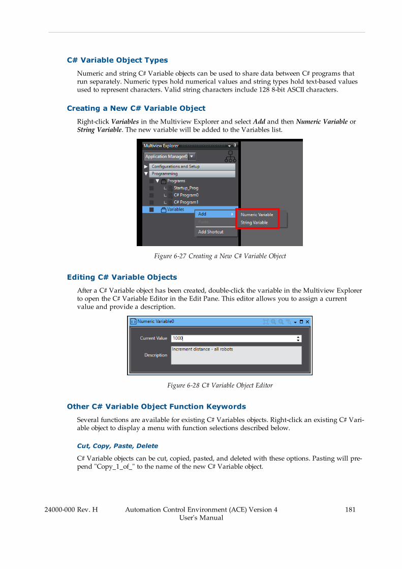
C# Variable Object Types
Numeric and string C# Variable objects can be used to share data between C# programs thatrun separately. Numeric types hold numerical values and string types hold text-based valuesused to represent characters. Valid string characters include 128 8-bit ASCII characters.
Creating a New C# Variable Object
Right-click Variables in the Multiview Explorer and select Add and then Numeric Variable orString Variable. The new variable will be added to the Variables list.
Figure 6-27 Creating a New C# Variable Object
Editing C# Variable Objects
After a C# Variable object has been created, double-click the variable in the Multiview Explorerto open the C# Variable Editor in the Edit Pane. This editor allows you to assign a currentvalue and provide a description.
Figure 6-28 C# Variable Object Editor
Other C# Variable Object Function Keywords
Several functions are available for existing C# Variables objects. Right-click an existing C# Vari-able object to display a menu with function selections described below.
Cut, Copy, Paste, Delete
C# Variable objects can be cut, copied, pasted, and deleted with these options. Pasting will pre-pend "Copy_1_of_" to the name of the new C# Variable object.
24000-000 Rev. H Automation Control Environment (ACE) Version 4User's Manual
181

182 Automation Control Environment (ACE) Version 4User's Manual
24000-000 Rev. H
Chapter 6: Programming with ACE Software
Add to Watch
Selecting Add to Watch will place the C# Variable object in the V+ Watch window. Refer to V+Watch on page 136 for more information.
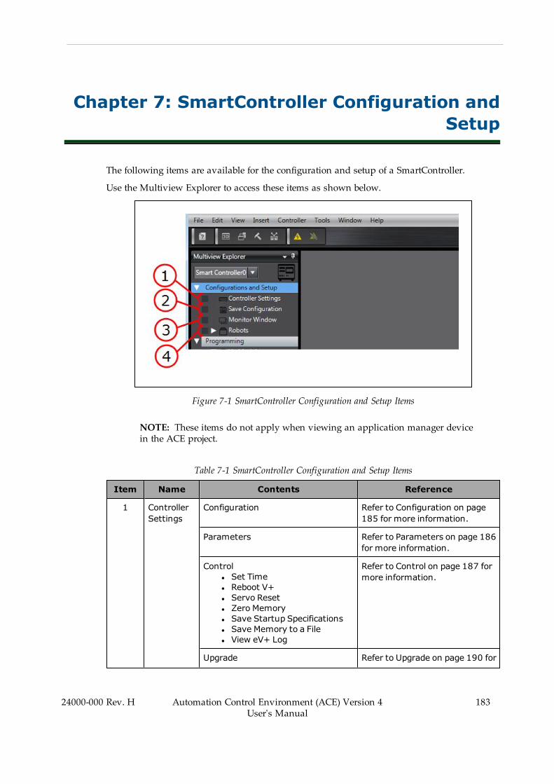
Chapter 7: SmartController Configuration andSetup
The following items are available for the configuration and setup of a SmartController.
Use the Multiview Explorer to access these items as shown below.
Figure 7-1 SmartController Configuration and Setup Items
NOTE: These items do not apply when viewing an application manager devicein the ACE project.
Table 7-1 SmartController Configuration and Setup Items
Item Name Contents Reference
1 ControllerSettings
Configuration Refer to Configuration on page185 for more information.
Parameters Refer to Parameters on page 186for more information.
Controll Set Timel Reboot V+l Servo Resetl Zero Memoryl Save Startup Specificationsl Save Memory to a Filel View eV+ Log
Refer to Control on page 187 formore information.
Upgrade Refer to Upgrade on page 190 for
24000-000 Rev. H Automation Control Environment (ACE) Version 4User's Manual
183

184 Automation Control Environment (ACE) Version 4User's Manual
24000-000 Rev. H
Chapter 7: SmartController Configuration and Setup
Item Name Contents Reference
l Upgrading V+l Upgrading FireWire Firmware
more information.
Configurel Configuring Licensesl Configuring Robotl Configuring FireWire Nodesl Configure I/Ol Configure Belt EncoderLatches
l Configure RobotPosition Latches
l Configure System Settings
Refer to Configure on page 193for more information.
Backup/Restorel Backup V+l Restore V+l Compare V+ to Backup
Refer to Backup/Restore on page201 for more information.
Encoders Refer to Encoders on page 203for more information.
2 Save Configuration Refer to Save Configuration onpage 204 for more information.
3 Monitor Window Refer to Monitor Window on page206 for more information.
4 RobotObjects
3D Visualization Refer to 3D Visualization on page243 for more information.
Configuration Refer to Configuration on page217 for more information.
IO EndEffector Refer to IO EndEffectors on page212 for more information.
Location Refer to Location on page 221for more information.
Object (Menu Item)l Expert Access
Refer to Object on page 222 formore information.
Configure (Menu Item)l Save Startup Specificationsl Load Spec Filel Save Spec Filel Axes, Options and Kinematicsl Obstaclesl S-Curve Profilesl Safety Settings
Refer to Configure on page 222for more information.
Control (Menu Item)l Hardware Diagnosticsl Data Collectionl Motor Tuning
Refer to Control on page 229 formore information.
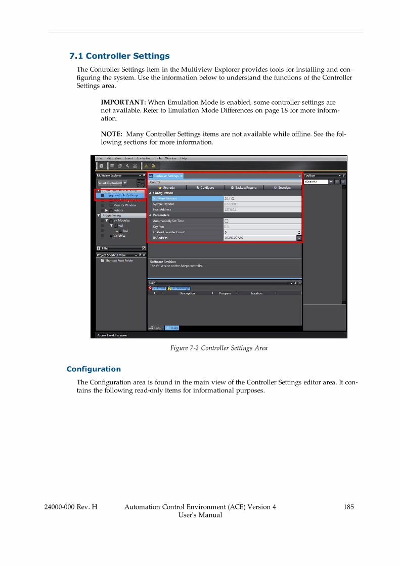
7.1 Controller SettingsThe Controller Settings item in the Multiview Explorer provides tools for installing and con-figuring the system. Use the information below to understand the functions of the ControllerSettings area.
IMPORTANT:When Emulation Mode is enabled, some controller settings arenot available. Refer to Emulation Mode Differences on page 18 for more inform-ation.
NOTE: Many Controller Settings items are not available while offline. See the fol-lowing sections for more information.
Figure 7-2 Controller Settings Area
Configuration
The Configuration area is found in the main view of the Controller Settings editor area. It con-tains the following read-only items for informational purposes.
24000-000 Rev. H Automation Control Environment (ACE) Version 4User's Manual
185

186 Automation Control Environment (ACE) Version 4User's Manual
24000-000 Rev. H
Chapter 7: SmartController Configuration and Setup
Figure 7-3 Controller Settings - Configuration Area
Software Revision
The Software Revision field displays the V+ software revision number installed on theSmartController. This is displayed only while online with the controller.
System Options
The System Options field displays the configuration of the V+ system in a two-word, hexa-decimal format. Refer to the eV+ Language Reference Guide (Cat. No. I605) or eV+3 Keyword Refer-ence Manual (Cat. No I652) for more information. This is displayed only while online with thecontroller.
Host Address
The Host Address field displays the IP address of the connected PC (host). This is displayedonly while online with the controller.
Parameters
The Parameters area is found in the main view of the Controller Settings editor area. It con-tains the following items that are described below.
Figure 7-4 Controller Settings - Parameters Area

Automatically Set Time
Select Automatically Set Time to automatically synchronize the controller to the PC time.
Dry Run
Select Dry Run to test a project without robot motion. This will cause robots to ignore motioncommands. This is selectable only while online with the controller.
Enabled Encoder Count
Enabled Encoder Count displays the number of external encoders used by the system. Thenumber displayed is related to the number of Belt Encoder Channels configured (referto Configure Belt Encoder Latches on page 195 for more information).
IP Address
The IP Address field displays the current IP address of the controller. When offline, it is pos-sible to change or select a controller's IP address by clicking theMore button as shown below.Clicking this button will display the Select a Controller Address Dialog Box.
Figure 7-5 Change or Select a Controller IP Address
NOTE: If the desired controller is not available or the changed IP address willnot allow an online connection, refer to Detect and Configure Controller on page78 for more information.
Additional Information: The controller IP address is also accessible in the con-figuration area. Refer to Configure System Settings on page 198 for more inform-ation.
Control
The Control Menu displays controller-specific setting items described below. These are select-able only while online with the controller.
24000-000 Rev. H Automation Control Environment (ACE) Version 4User's Manual
187

188 Automation Control Environment (ACE) Version 4User's Manual
24000-000 Rev. H
Chapter 7: SmartController Configuration and Setup
Figure 7-6 Control Menu Item
Set Time
In order to use error log time stamps for troubleshooting, the correct time needs to be set in thecontroller(s).
Selecting Set Time will manually synchronize the controller time to match the time detected onthe connected PC. The following confirmation dialog box will be displayed.
NOTE: The Set Time function will not set the time for a robot node. Use theFireWire configuration to set robot node times. Refer to Configure FireWire Nodeson page 194 for more information.
Figure 7-7 Set the Controller Time Confirmation
Reboot V+
Selecting Reboot V+ will reboot the controller. The following confirmation dialog box will bedisplayed.
Figure 7-8 Reboot V+ Confirmation
Servo Reset
Selecting Servo Reset will reset communication with the robot servo nodes.

Zero Memory
Selecting Zero Memory will clear all user programs and variables from the workspace and thecontroller. The following confirmation dialog box will be displayed.
Figure 7-9 Zero Memory Confirmation
Save Startup Specifications
Selecting Save Startup Specifications will save all robot and motor specifications to the V+ bootdisk.
NOTE: This is the same function that is present in the Robot Object - Configuremenu. Refer to Configure on page 222 for more information.
Save Memory to a File
Selecting Save Memory to a File will save all V+ programs to a file in the PC. A Save As win-dow will be displayed.
View eV+ Log
Selecting View eV+ Log will display a list of eV+ event messages for the controller. The fol-lowing View eV+ Log will be displayed. Refer to eV+ Log on page 592 for more information.
Figure 7-10 View eV+ Log Display
Additional Information: View eV+ Log is also accessible by right-clicking Con-troller Settings in the Multiview Explorer.
24000-000 Rev. H Automation Control Environment (ACE) Version 4User's Manual
189

190 Automation Control Environment (ACE) Version 4User's Manual
24000-000 Rev. H
Chapter 7: SmartController Configuration and Setup
Upgrade
Use the Upgrade function to upgrade V+ or the FireWire firmware. Clicking the Upgrade but-ton displays the Upgrade Options Dialog Box. This is selectable only while online with the con-troller.
IMPORTANT: Upgrading the FireWire node firmware is not possible in Emu-lation Mode.
Figure 7-11 Controller Settings - Upgrade Function
Basic Upgrade Procedure
When updates are required, it is recommended to upgrade both V+ and the FireWire NodeFirmware to ensure the entire system has the latest firmware version(s). Use the following pro-cedure to upgrade V+ and the FireWire firmware.
NOTE: The V+ firmware distribution file is supplied as a compressed zip file.Extract this file before beginning the procedure below.
1. Select Upgrade V+ in the Upgrade Options Dialog Box and then click the Finish button.2. Provide the V+ directory where the new V+ distribution is located. Provide a file path tothe \SYSTEM folder located in the distribution file root directory.
3. Select a backup directory to use during the upgrade process.4. Select the Upgrade Controller FPGA option.5. After the V+ directory, backup directory, and FPGA controller upgrade items fields andselections are made, click the Go button to proceed with the upgrade process. The pro-cess can take several minutes to complete. A progress bar is displayed during theupgrade procedure. After the V+ upgrade process is complete, proceed to the next step.
6. Select the Upgrade FireWire Firmware option from the Upgrade Options Dialog Box.7. Select all detected robot amplifier nodes. This process is used to check and update servocode firmware on robot nodes. If a newer version is not provided, an upgrade will notoccur. Alternatively, select only the node you wish to upgrade / downgrade with a spe-cific file from the PC.
8. Select Update FPGA and Update Servo options.
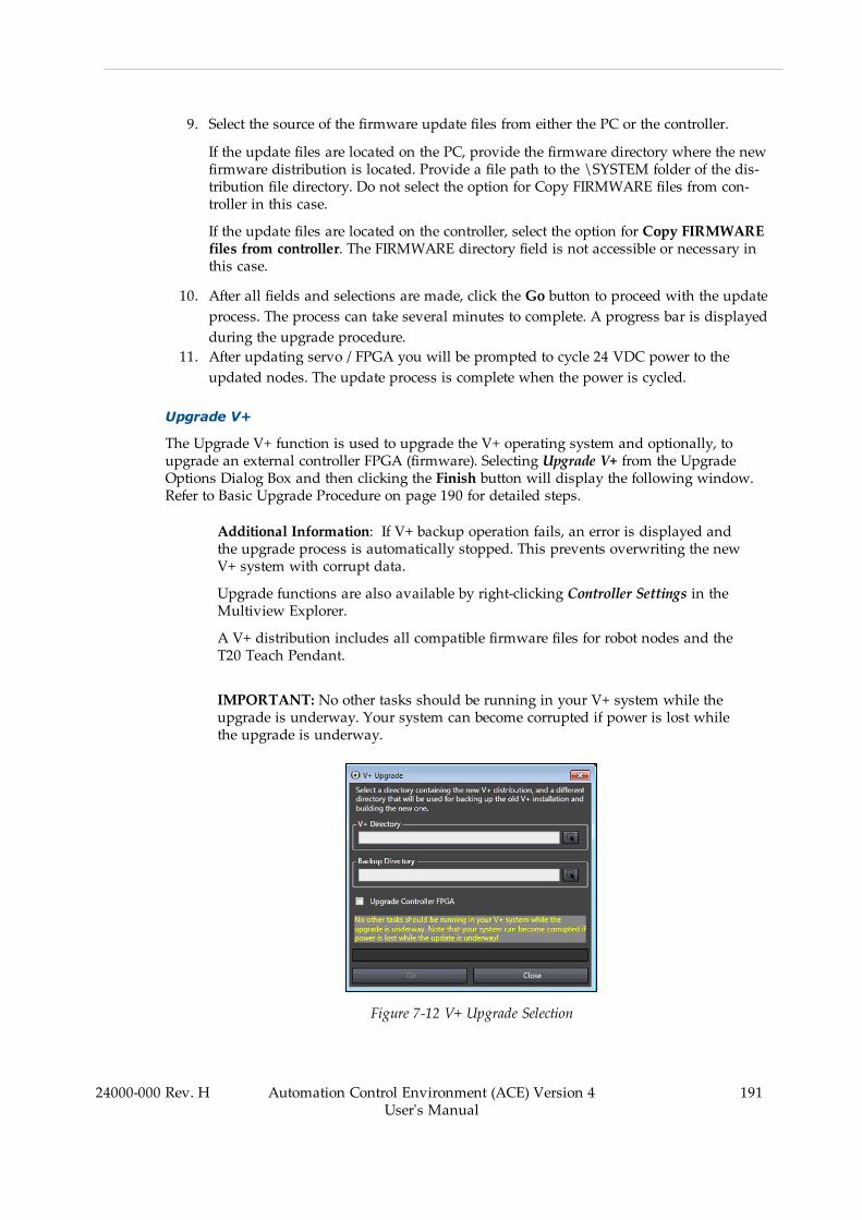
9. Select the source of the firmware update files from either the PC or the controller.
If the update files are located on the PC, provide the firmware directory where the newfirmware distribution is located. Provide a file path to the \SYSTEM folder of the dis-tribution file directory. Do not select the option for Copy FIRMWARE files from con-troller in this case.
If the update files are located on the controller, select the option for Copy FIRMWAREfiles from controller. The FIRMWARE directory field is not accessible or necessary inthis case.
10. After all fields and selections are made, click the Go button to proceed with the updateprocess. The process can take several minutes to complete. A progress bar is displayedduring the upgrade procedure.
11. After updating servo / FPGA you will be prompted to cycle 24 VDC power to theupdated nodes. The update process is complete when the power is cycled.
Upgrade V+
The Upgrade V+ function is used to upgrade the V+ operating system and optionally, toupgrade an external controller FPGA (firmware). Selecting Upgrade V+ from the UpgradeOptions Dialog Box and then clicking the Finish button will display the following window.Refer to Basic Upgrade Procedure on page 190 for detailed steps.
Additional Information: If V+ backup operation fails, an error is displayed andthe upgrade process is automatically stopped. This prevents overwriting the newV+ system with corrupt data.
Upgrade functions are also available by right-clicking Controller Settings in theMultiview Explorer.
A V+ distribution includes all compatible firmware files for robot nodes and theT20 Teach Pendant.
IMPORTANT: No other tasks should be running in your V+ system while theupgrade is underway. Your system can become corrupted if power is lost whilethe upgrade is underway.
Figure 7-12 V+ Upgrade Selection
24000-000 Rev. H Automation Control Environment (ACE) Version 4User's Manual
191

192 Automation Control Environment (ACE) Version 4User's Manual
24000-000 Rev. H
Chapter 7: SmartController Configuration and Setup
Upgrade FireWire Firmware
The Upgrade FireWire Firmware function is used to upgrade a FireWire node's firmware. Select-ing Upgrade FireWire Firmware from the Upgrade Options Dialog Box and then clicking theFinish button will display the following window. Refer to Basic Upgrade Procedure on page190 for detailed steps.
NOTE: The firmware upgrade process will require several minutes for eachnode in the distributed network.
Figure 7-13 FireWire Node Firmware Update
Table 7-2 FireWire Node Firmware Update Description
Item Description Details
1 FireWire Node Identificationand Selection Area
Select nodes to be updated.
2 Update FPGA Updates the firmware for the FireWire node.
3 Update Servo Enable to update the servo binary image stored in theselected node's flash memory. Not performing thisrelies on successful dynamic download from controllerto robot during boot up (see note below). Performingthe servo update eliminates any potential risk ofdynamic download failure during boot up.
4 Firmware Directory Select the PC directory where the new firmware filesare located. Provide a file path to the \SYSTEM folder ofthe distribution file directory.
5 Copy FIRMWARE files fromController
Use firmware files in controller for FireWire nodeupdates.
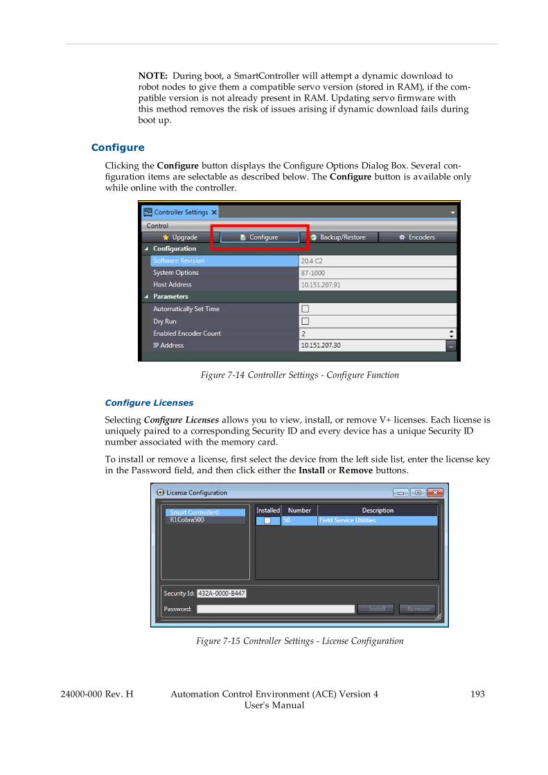
NOTE: During boot, a SmartController will attempt a dynamic download torobot nodes to give them a compatible servo version (stored in RAM), if the com-patible version is not already present in RAM. Updating servo firmware withthis method removes the risk of issues arising if dynamic download fails duringboot up.
Configure
Clicking the Configure button displays the Configure Options Dialog Box. Several con-figuration items are selectable as described below. The Configure button is available onlywhile online with the controller.
Figure 7-14 Controller Settings - Configure Function
Configure Licenses
Selecting Configure Licenses allows you to view, install, or remove V+ licenses. Each license isuniquely paired to a corresponding Security ID and every device has a unique Security IDnumber associated with the memory card.
To install or remove a license, first select the device from the left side list, enter the license keyin the Password field, and then click either the Install or Remove buttons.
Figure 7-15 Controller Settings - License Configuration
24000-000 Rev. H Automation Control Environment (ACE) Version 4User's Manual
193

194 Automation Control Environment (ACE) Version 4User's Manual
24000-000 Rev. H
Chapter 7: SmartController Configuration and Setup
Configure Robots
Select Configure Robots to add or remove robots from the system. Selecting Configure Robotsand clicking the Finish button will display the Configure Robots Dialog Box. Refer toConfigure Robots on page 211 for more information.
Configure FireWire Nodes
Selecting Configure FireWire Nodes allow you to create a valid FireWire network configurationto enable communication with devices such as robots, belt encoders, digital I/O, and forcesensors. Selecting Configure FireWire Nodes and clicking the Finish button will open the dialogbox shown below.
NOTE: Always review the initial FireWire configuration to ensure it is com-patible and appropriate for the application. When connecting to a controller,ACE software will check for FireWire configuration conflicts. If a conflict ispresent, error messages will be displayed. Refer to FireWire Event Log on page593 for more information.
IMPORTANT: Once a network configuration is modified and saved, the phys-ical connections will be identified and restored accordingly on next boot.
Figure 7-16 Configure - Configure FireWire Nodes
Right-click an item in the list to display information and settings for each FireWire node. Thefollowing information and settings are available.
l View and clear FireWire node logs for controllersl Set a robot node clockl View a robot node's informationl Unconfigure or designate a robot's FireWire node numberl Designate encoder FireWire node numbers

l Designate force sensor FireWire node numbersl Configure I/O Block address ranges
Configure I/O
Selecting Configure I/O allows you to map I/O to numerical signal numbers for use in pro-gramming. The Configure I/O function provides DeviceNet scanning, configuration, and map-ping.
NOTE: FireWire nodes must be configured before attempting to map I/O tonumerical signal numbers.
Configure Belt Encoder Latches
Selecting Configure Belt Encoder Latches allows you to view and change latch signals for eachencoder channel of the controller. A Belt Encoder Latch refers to the capture of a conveyor beltencoder position value when an input signal (latch) changes state. Once configured, the sys-tem will monitor and record the latch signal number and corresponding encoder position (oneencoder value) in a first-in-first-out buffer for later access and use in a program. This area canalso be used to check current position and velocity for each encoder channel.
NOTE: Belt encoder latches are not required for conveyor belt tracking but arerecommended for positional accuracy. Pack Manager requires use of latch sig-nals for all belt tracking applications for positional accuracy, as well as cross-con-troller latch handling.
Encoders should be uniquely numbered in the FireWire configuration before con-figuring encoder channels/latches.
Selecting Configure Belt Encoder Latches and clicking the Finish button will display the dialogbox shown below.
24000-000 Rev. H Automation Control Environment (ACE) Version 4User's Manual
195
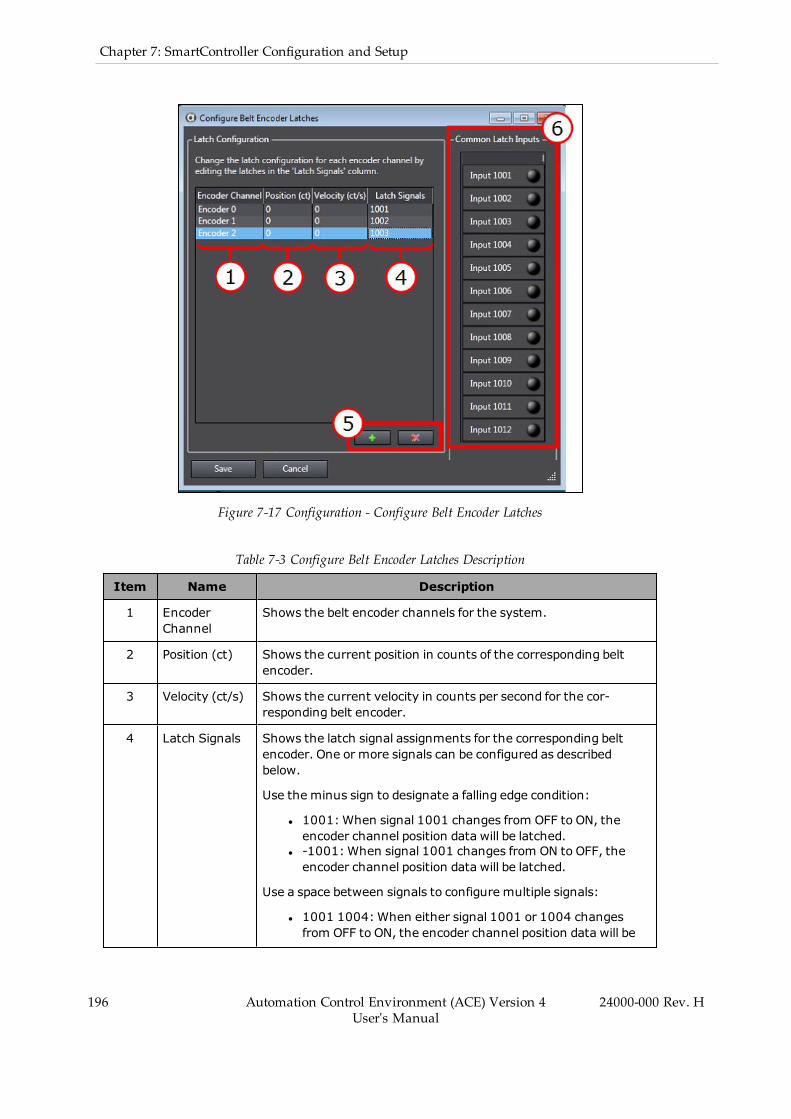
196 Automation Control Environment (ACE) Version 4User's Manual
24000-000 Rev. H
Chapter 7: SmartController Configuration and Setup
Figure 7-17 Configuration - Configure Belt Encoder Latches
Table 7-3 Configure Belt Encoder Latches Description
Item Name Description
1 EncoderChannel
Shows the belt encoder channels for the system.
2 Position (ct) Shows the current position in counts of the corresponding beltencoder.
3 Velocity (ct/s) Shows the current velocity in counts per second for the cor-responding belt encoder.
4 Latch Signals Shows the latch signal assignments for the corresponding beltencoder. One or more signals can be configured as describedbelow.
Use the minus sign to designate a falling edge condition:
l 1001: When signal 1001 changes from OFF to ON, theencoder channel position data will be latched.
l -1001: When signal 1001 changes from ON to OFF, theencoder channel position data will be latched.
Use a space between signals to configure multiple signals:
l 1001 1004:When either signal 1001 or 1004 changesfrom OFF to ON, the encoder channel position data will be
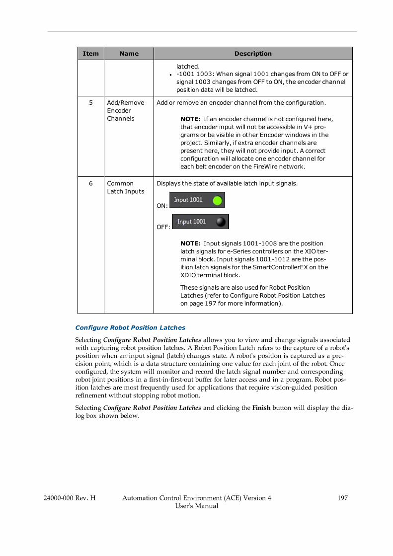
Item Name Description
latched.l -1001 1003: When signal 1001 changes from ON to OFF orsignal 1003 changes from OFF to ON, the encoder channelposition data will be latched.
5 Add/RemoveEncoderChannels
Add or remove an encoder channel from the configuration.
NOTE: If an encoder channel is not configured here,that encoder input will not be accessible in V+ pro-grams or be visible in other Encoder windows in theproject. Similarly, if extra encoder channels arepresent here, they will not provide input. A correctconfiguration will allocate one encoder channel foreach belt encoder on the FireWire network.
6 CommonLatch Inputs
Displays the state of available latch input signals.
ON:
OFF:
NOTE: Input signals 1001-1008 are the positionlatch signals for e-Series controllers on the XIO ter-minal block. Input signals 1001-1012 are the pos-ition latch signals for the SmartControllerEX on theXDIO terminal block.
These signals are also used for Robot PositionLatches (refer to Configure Robot Position Latcheson page 197 for more information).
Configure Robot Position Latches
Selecting Configure Robot Position Latches allows you to view and change signals associatedwith capturing robot position latches. A Robot Position Latch refers to the capture of a robot'sposition when an input signal (latch) changes state. A robot's position is captured as a pre-cision point, which is a data structure containing one value for each joint of the robot. Onceconfigured, the system will monitor and record the latch signal number and correspondingrobot joint positions in a first-in-first-out buffer for later access and in a program. Robot pos-ition latches are most frequently used for applications that require vision-guided positionrefinement without stopping robot motion.
Selecting Configure Robot Position Latches and clicking the Finish button will display the dia-log box shown below.
24000-000 Rev. H Automation Control Environment (ACE) Version 4User's Manual
197

198 Automation Control Environment (ACE) Version 4User's Manual
24000-000 Rev. H
Chapter 7: SmartController Configuration and Setup
Figure 7-18 Configure - Configure Robot Position Latches
Table 7-4 Configure Robot Position Latches Description
Item Name Description
1 Force SensorSelection
Select to enable a Force Sensor.
2 Add LatchesButton
Click the Latches button to display a list of available input signalsto trigger the Robot Position Latch.
3 NegativeEdge Selection
Select to invert the signal. Selecting this will make the latch occurwhen the input signal changes from ON to OFF. If this is not selec-ted, the latch occurs when the input signal changes from OFF toON.
Configure System Settings
Selecting Configure System Settings and clicking the Finish button will display the dialog boxshown below.
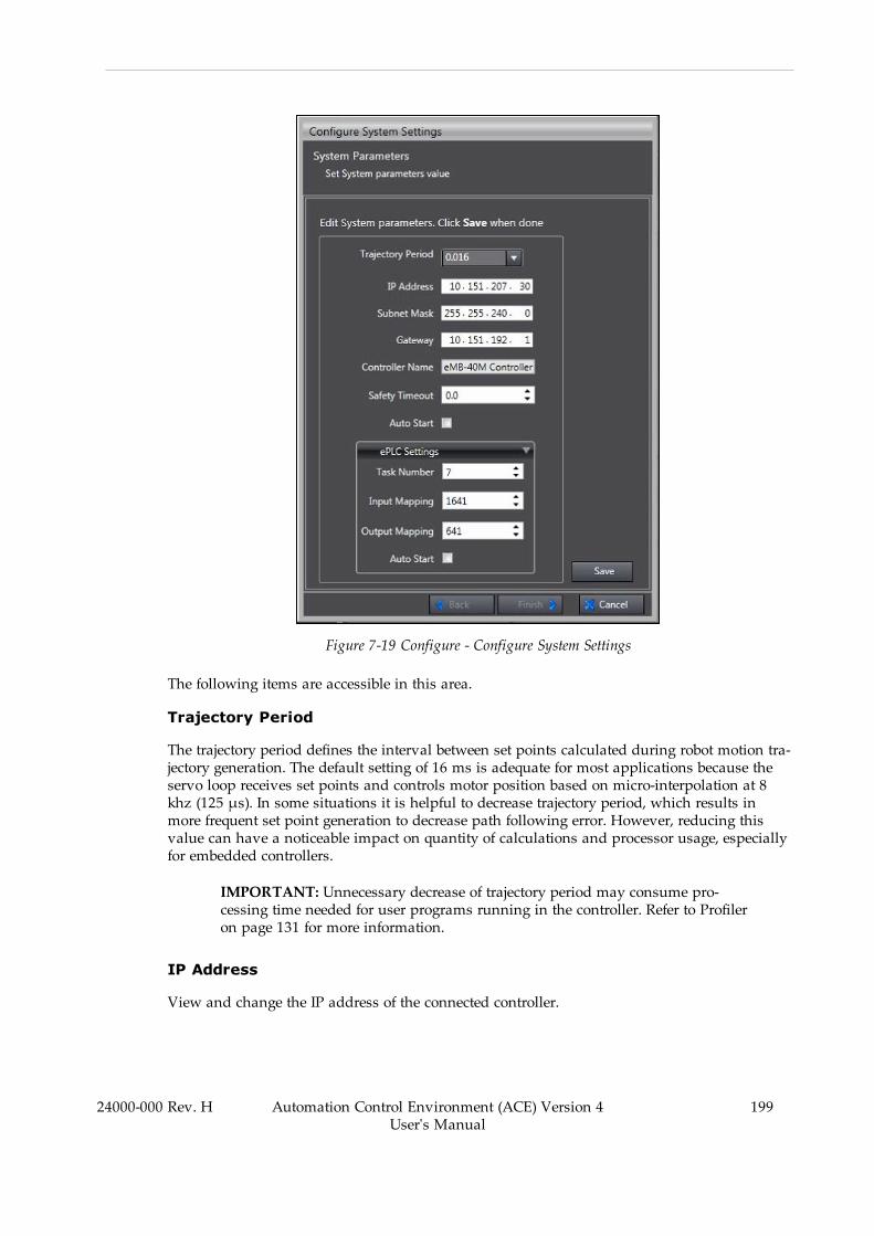
Figure 7-19 Configure - Configure System Settings
The following items are accessible in this area.
Trajectory Period
The trajectory period defines the interval between set points calculated during robot motion tra-jectory generation. The default setting of 16 ms is adequate for most applications because theservo loop receives set points and controls motor position based on micro-interpolation at 8khz (125 μs). In some situations it is helpful to decrease trajectory period, which results inmore frequent set point generation to decrease path following error. However, reducing thisvalue can have a noticeable impact on quantity of calculations and processor usage, especiallyfor embedded controllers.
IMPORTANT: Unnecessary decrease of trajectory period may consume pro-cessing time needed for user programs running in the controller. Refer to Profileron page 131 for more information.
IP Address
View and change the IP address of the connected controller.
24000-000 Rev. H Automation Control Environment (ACE) Version 4User's Manual
199

200 Automation Control Environment (ACE) Version 4User's Manual
24000-000 Rev. H
Chapter 7: SmartController Configuration and Setup
Subnet Mask
View and change the subnet mask of the connected controller.
Gateway
View and change the Gateway of the connected controller
Controller Name
View and change the connected controller's name.
Safety Timeout
View and change the Safety Timeout setting for the connected controller. This controls the beha-vior of the robot high power request sent by a connected PC, executing program, Front PanelHigh Power Enable button, or optional pendant. If a safety timeout is enabled, the robot powerbutton on the front panel will blink for a specified amount of seconds after a high powerrequest is made. If the robot power button is not pressed within the specified time, a safetytimeout occurs and robot power is not applied.
IMPORTANT: Ensure adequate safety measures are taken if the safety timeout isdisabled.
The default setting for the Safety Timeout is 10 seconds. Use the following settings to adjust theSafety Timeout.
l 0 seconds: disables the high power request secondary action and robot power is appliedimmediately.
l 1 to 60 seconds: enables the high power request secondary action and robot power isapplied if the Robot Power button is pressed on the front panel within the specifiedamount of time.
IMPORTANT: Robot maintenance and troubleshooting procedures require thesafety timeout to be enabled. The robot's flashing high power indicator is used toverify that the lamp is not burned out and this should be considered before dis-abling the safety timeout feature.
Auto Start
Enable or disable an Auto Start program. If Auto Start is enabled, as the controller completesboot process it will load and execute D:\AUTO.V2. An AUTO.V2 program has no user-definederror handling and should be kept simple to load modules or variable files and execute a pro-gram that handles system startup. Refer to Save Configuration on page 204 for more inform-ation.
NOTE: Although the Program System Startup function and the Auto Start func-tion share some similarities, the startup file for the Program System Startup func-tion is stored on the PC whereas the Auto Start function files are stored on thecontroller. Refer to Program System Startup on page 303 for more information.

Task Number (ePLC Settings)
View and change the Task Number used for an ePLC configuration. This defines the first taskthat ePLC programs will start executing on when Auto Start is enabled (eplc_autostart). ePLCtask numbers must be between 7 and 15 and will occupy at least 5 tasks when Auto Start isenabled.
NOTE: ePLC settings typically do not need to be changed after Auto Start isenabled.
Input Mapping (ePLC Settings)
View and change the Input Mapping used for an ePLC configuration. This defines the firstinput signal in the range of signals mapped by ePLC programs.
Output Mapping (ePLC Settings)
View and change the Output Mapping for an ePLC configuration. This defines the first outputsignal in the range of signals mapped by ePLC programs.
Auto Start (ePLC Settings)
Select the Auto Start behavior when using the ePLC function. When Auto Start is enabled,D:\ADEPT\UTIL\ePLC3.v2 will be loaded and executed on the designated task number andinitialized with the Input and Output Mapping signal numbers.
Backup/Restore
Use the Backup/Restore function to backup, restore, or compare the V+ operating system filesand directories. Clicking the Backup/Restore button displays the Backup/Restore Options Dia-log Box. This is selectable only while online with the controller.
Figure 7-20 Controller Settings - Backup/Restore Function
24000-000 Rev. H Automation Control Environment (ACE) Version 4User's Manual
201
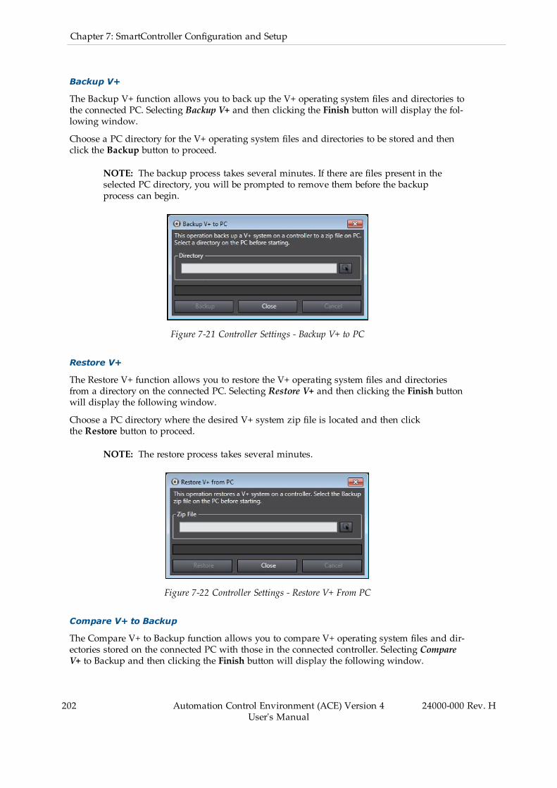
202 Automation Control Environment (ACE) Version 4User's Manual
24000-000 Rev. H
Chapter 7: SmartController Configuration and Setup
Backup V+
The Backup V+ function allows you to back up the V+ operating system files and directories tothe connected PC. Selecting Backup V+ and then clicking the Finish button will display the fol-lowing window.
Choose a PC directory for the V+ operating system files and directories to be stored and thenclick the Backup button to proceed.
NOTE: The backup process takes several minutes. If there are files present in theselected PC directory, you will be prompted to remove them before the backupprocess can begin.
Figure 7-21 Controller Settings - Backup V+ to PC
Restore V+
The Restore V+ function allows you to restore the V+ operating system files and directoriesfrom a directory on the connected PC. Selecting Restore V+ and then clicking the Finish buttonwill display the following window.
Choose a PC directory where the desired V+ system zip file is located and then clickthe Restore button to proceed.
NOTE: The restore process takes several minutes.
Figure 7-22 Controller Settings - Restore V+ From PC
Compare V+ to Backup
The Compare V+ to Backup function allows you to compare V+ operating system files and dir-ectories stored on the connected PC with those in the connected controller. Selecting CompareV+ to Backup and then clicking the Finish button will display the following window.

Select a PC directory where the V+ system zip file for comparison is located and then click theCompare button to proceed.
Figure 7-23 Compare V+ to Backup on PC
NOTE: The compare process takes several minutes.
Encoders
Use the Encoders function to configure and check operating status of devices connected to thecontroller's encoder channels. Clicking the Encoders button displays the Encoders Dialog Box.
Figure 7-24 Controller Settings - Encoders
Figure 7-25 Encoders Dialog Box
The Encoders Dialog Box displays all encoder channels that have been configured. The Con-figure button is reserved for future use.
If an encoder channel that is present does not appear, check the FireWire Configuration andBelt Encoder Latch configuration.
24000-000 Rev. H Automation Control Environment (ACE) Version 4User's Manual
203
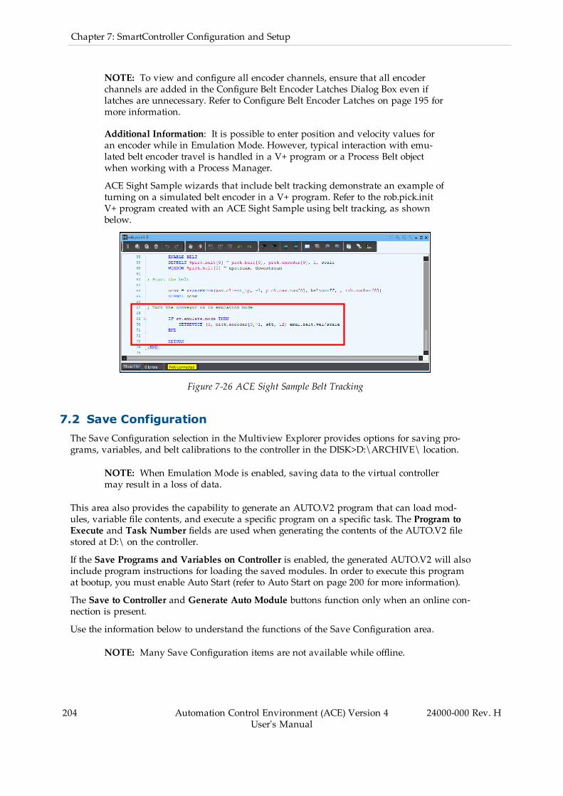
204 Automation Control Environment (ACE) Version 4User's Manual
24000-000 Rev. H
Chapter 7: SmartController Configuration and Setup
NOTE: To view and configure all encoder channels, ensure that all encoderchannels are added in the Configure Belt Encoder Latches Dialog Box even iflatches are unnecessary. Refer to Configure Belt Encoder Latches on page 195 formore information.
Additional Information: It is possible to enter position and velocity values foran encoder while in Emulation Mode. However, typical interaction with emu-lated belt encoder travel is handled in a V+ program or a Process Belt objectwhen working with a Process Manager.
ACE Sight Sample wizards that include belt tracking demonstrate an example ofturning on a simulated belt encoder in a V+ program. Refer to the rob.pick.initV+ program created with an ACE Sight Sample using belt tracking, as shownbelow.
Figure 7-26 ACE Sight Sample Belt Tracking
7.2 Save ConfigurationThe Save Configuration selection in the Multiview Explorer provides options for saving pro-grams, variables, and belt calibrations to the controller in the DISK>D:\ARCHIVE\ location.
NOTE: When Emulation Mode is enabled, saving data to the virtual controllermay result in a loss of data.
This area also provides the capability to generate an AUTO.V2 program that can load mod-ules, variable file contents, and execute a specific program on a specific task. The Program toExecute and Task Number fields are used when generating the contents of the AUTO.V2 filestored at D:\ on the controller.
If the Save Programs and Variables on Controller is enabled, the generated AUTO.V2 will alsoinclude program instructions for loading the saved modules. In order to execute this programat bootup, you must enable Auto Start (refer to Auto Start on page 200 for more information).
The Save to Controller and Generate Auto Module buttons function only when an online con-nection is present.
Use the information below to understand the functions of the Save Configuration area.
NOTE: Many Save Configuration items are not available while offline.
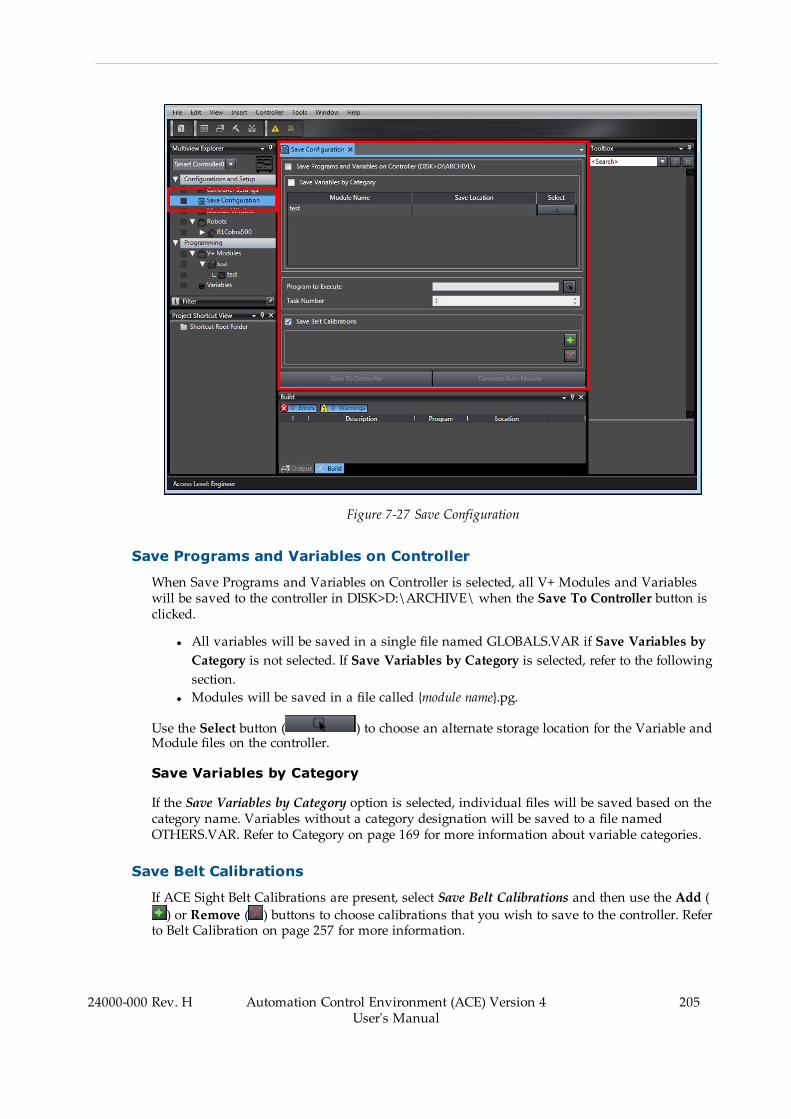
Figure 7-27 Save Configuration
Save Programs and Variables on Controller
When Save Programs and Variables on Controller is selected, all V+ Modules and Variableswill be saved to the controller in DISK>D:\ARCHIVE\ when the Save To Controller button isclicked.
l All variables will be saved in a single file named GLOBALS.VAR if Save Variables byCategory is not selected. If Save Variables by Category is selected, refer to the followingsection.
l Modules will be saved in a file called {module name}.pg.
Use the Select button ( ) to choose an alternate storage location for the Variable andModule files on the controller.
Save Variables by Category
If the Save Variables by Category option is selected, individual files will be saved based on thecategory name. Variables without a category designation will be saved to a file namedOTHERS.VAR. Refer to Category on page 169 for more information about variable categories.
Save Belt Calibrations
If ACE Sight Belt Calibrations are present, select Save Belt Calibrations and then use the Add () or Remove ( ) buttons to choose calibrations that you wish to save to the controller. Refer
to Belt Calibration on page 257 for more information.
24000-000 Rev. H Automation Control Environment (ACE) Version 4User's Manual
205

206 Automation Control Environment (ACE) Version 4User's Manual
24000-000 Rev. H
Chapter 7: SmartController Configuration and Setup
Belt Calibrations will be saved to DISK>D:\ARCHIVE\BELT.DAT when the Save To Con-troller button is clicked.
NOTE: The selection for Save Programs and Variables on Controller must beenabled to save belt calibrations to the controller.
7.3 Monitor WindowThe Monitor Window is used to input V+ Monitor Commands and receive responses from acontroller. When the Monitor Window is open it can also output error information when anerror occurs. User program output from the TYPE keyword can also be displayed within thiswindow.
NOTE: The Monitor Window operates in read-only mode while offline.
Additional Information: For a complete list of V+ Monitor Command Keywords,refer to the eV+ Language Reference Guide (Cat. No. I605) or eV+3 Keyword ReferenceManual (Cat. No I652) (available in the ACE software Help menu).
Figure 7-28 Monitor Window
Using the Monitor Window
When the input prompt cursor is blinking, the system is ready to accept Monitor Commands.Find the input prompt cursor at the bottom of the Monitor Window.

Figure 7-29 Monitor Window Input Cursor
NOTE: Moving the scroll bar away from the bottom will pause auto-scroll.Return the scroll bar to the bottom to resume auto-scroll.
Up and down arrow keys can recall recent Monitor Commands for convenientre-execution. Closing the Monitor Window will clear the recent Monitor Com-mand history.
Monitor Command Entry
Monitor Command do not have to be typed completely. You need to type only enough char-acters to uniquely identify the Monitor Command Keyword. For example, the only MonitorCommand Keyword that begins with "STAT" is STATUS. Therefore, typing "STAT" is sufficientto execute the STATUS Monitor Command. Typing "STA" will result in the AmbiguousName error because it could refer to either the STATUS or STACK command.
Monitor Command Keyword Parameters
Most Monitor Command Keywords require additional information that tells the system exactlyhow you want the command executed. This additional information is specified as parameterson the command line. You specify unique information for each Monitor Command Keywordparameter.
Monitor Command Keyword parameters must be entered in the order they are listed and theymust be separated (delimited) in exactly the fashion shown. A comma is normally used to sep-arate parameters. Occasionally, an equal sign is used. You must always type a space betweena command and its list of parameters.
24000-000 Rev. H Automation Control Environment (ACE) Version 4User's Manual
207
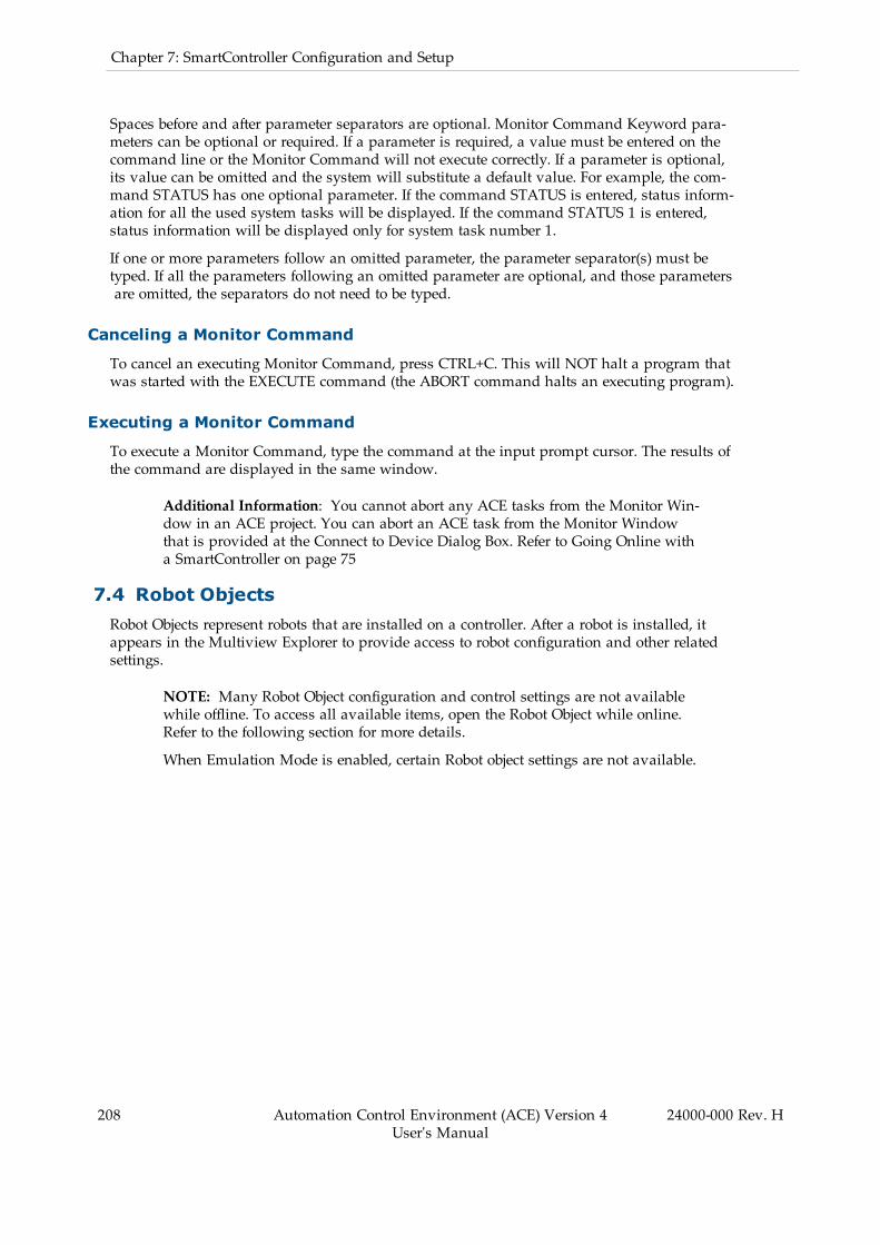
208 Automation Control Environment (ACE) Version 4User's Manual
24000-000 Rev. H
Chapter 7: SmartController Configuration and Setup
Spaces before and after parameter separators are optional. Monitor Command Keyword para-meters can be optional or required. If a parameter is required, a value must be entered on thecommand line or the Monitor Command will not execute correctly. If a parameter is optional,its value can be omitted and the system will substitute a default value. For example, the com-mand STATUS has one optional parameter. If the command STATUS is entered, status inform-ation for all the used system tasks will be displayed. If the command STATUS 1 is entered,status information will be displayed only for system task number 1.
If one or more parameters follow an omitted parameter, the parameter separator(s) must betyped. If all the parameters following an omitted parameter are optional, and those parametersare omitted, the separators do not need to be typed.
Canceling a Monitor Command
To cancel an executing Monitor Command, press CTRL+C. This will NOT halt a program thatwas started with the EXECUTE command (the ABORT command halts an executing program).
Executing a Monitor Command
To execute a Monitor Command, type the command at the input prompt cursor. The results ofthe command are displayed in the same window.
Additional Information: You cannot abort any ACE tasks from the Monitor Win-dow in an ACE project. You can abort an ACE task from the Monitor Windowthat is provided at the Connect to Device Dialog Box. Refer to Going Online witha SmartController on page 75
7.4 Robot ObjectsRobot Objects represent robots that are installed on a controller. After a robot is installed, itappears in the Multiview Explorer to provide access to robot configuration and other relatedsettings.
NOTE: Many Robot Object configuration and control settings are not availablewhile offline. To access all available items, open the Robot Object while online.Refer to the following section for more details.
When Emulation Mode is enabled, certain Robot object settings are not available.

Figure 7-30 Robot Object in the Multiview Explorer
Robot Objects must be added to a new ACE project while online with a controller. Right-click-ing the Robots item in the Multiview Explorer will display the option to Configure Robots.Selecting this option will display the Configure Robots Dialog Box shown below. Use thismethod to add a new robot to an ACE project.
Additional Information: The Configure Robots Dialog Box can also be accessedthrough the Controller Settings area. Refer to Configure on page 193 for moreinformation.
NOTE: When using Emulation Mode, you must manually add robots to the pro-ject. When connecting to a physical controller, robots will be present in the pro-ject after the connection is established.
24000-000 Rev. H Automation Control Environment (ACE) Version 4User's Manual
209

210 Automation Control Environment (ACE) Version 4User's Manual
24000-000 Rev. H
Chapter 7: SmartController Configuration and Setup
Figure 7-31 Install Robots
Depending upon the configuration and robot workspace, a configuration singularity maydevelop. A configuration singularity can be defined as a location in the robot workspace wheretwo or more joints no longer independently control the position and orientation of the tool. Asa robot executes a straight-line motion that moves close to a configuration singularity, therobot joint speeds necessary to achieve that motion become excessive. This speed control andmotion can be controlled through the use of the Singularity Deviation.
When the robot is selected, such as a Viper, the Singularity Deviation can be set to prevent thecondition from occurring thereby preventing excessive joint motor speeds. The addition andtesting of the Singularity Deviation offset should be done in JOG mode.
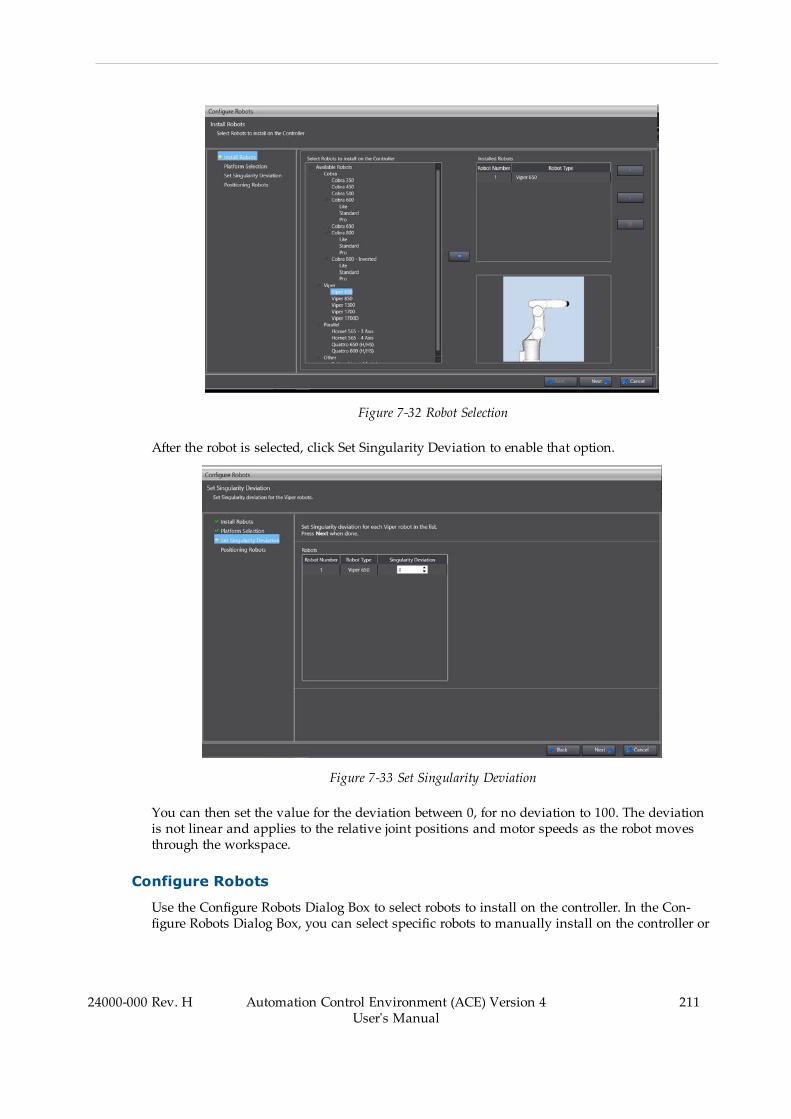
Figure 7-32 Robot Selection
After the robot is selected, click Set Singularity Deviation to enable that option.
Figure 7-33 Set Singularity Deviation
You can then set the value for the deviation between 0, for no deviation to 100. The deviationis not linear and applies to the relative joint positions and motor speeds as the robot movesthrough the workspace.
Configure Robots
Use the Configure Robots Dialog Box to select robots to install on the controller. In the Con-figure Robots Dialog Box, you can select specific robots to manually install on the controller or
24000-000 Rev. H Automation Control Environment (ACE) Version 4User's Manual
211
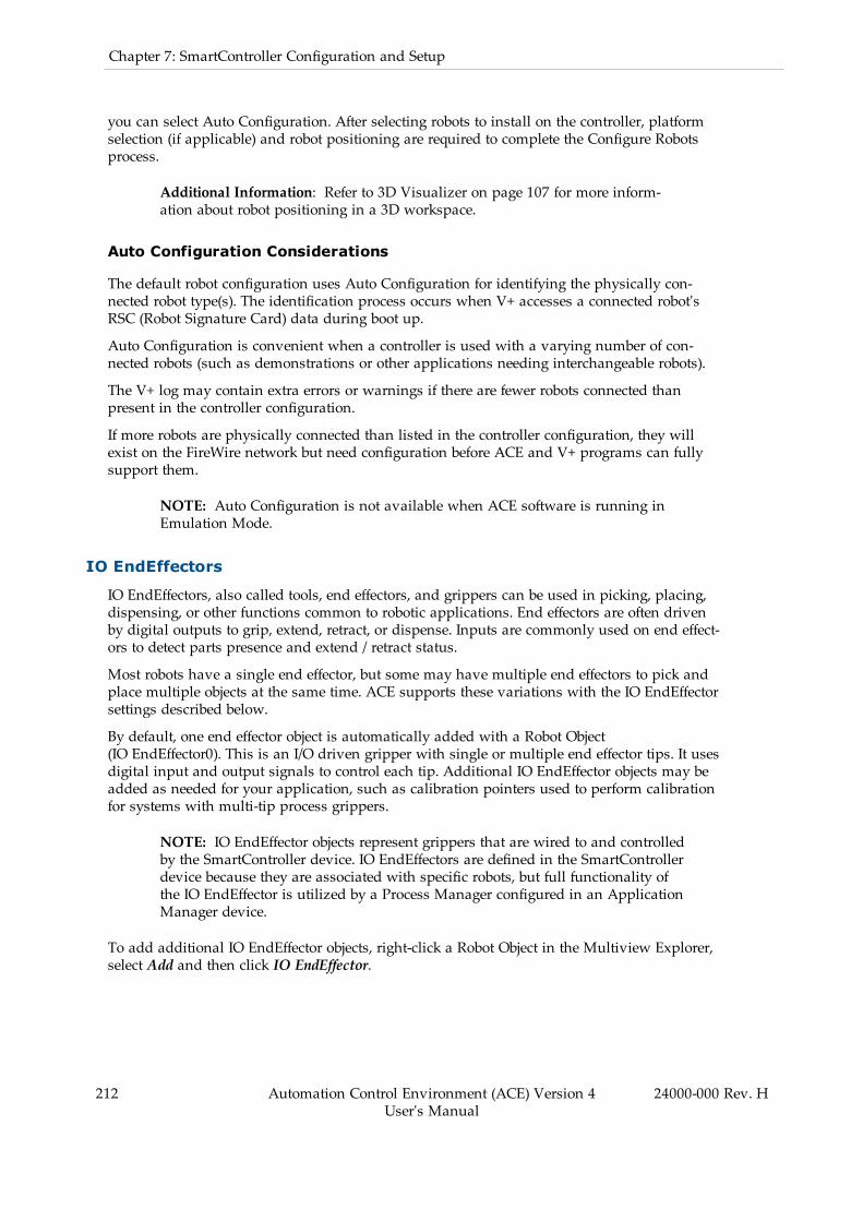
212 Automation Control Environment (ACE) Version 4User's Manual
24000-000 Rev. H
Chapter 7: SmartController Configuration and Setup
you can select Auto Configuration. After selecting robots to install on the controller, platformselection (if applicable) and robot positioning are required to complete the Configure Robotsprocess.
Additional Information: Refer to 3D Visualizer on page 107 for more inform-ation about robot positioning in a 3D workspace.
Auto Configuration Considerations
The default robot configuration uses Auto Configuration for identifying the physically con-nected robot type(s). The identification process occurs when V+ accesses a connected robot'sRSC (Robot Signature Card) data during boot up.
Auto Configuration is convenient when a controller is used with a varying number of con-nected robots (such as demonstrations or other applications needing interchangeable robots).
The V+ log may contain extra errors or warnings if there are fewer robots connected thanpresent in the controller configuration.
If more robots are physically connected than listed in the controller configuration, they willexist on the FireWire network but need configuration before ACE and V+ programs can fullysupport them.
NOTE: Auto Configuration is not available when ACE software is running inEmulation Mode.
IO EndEffectors
IO EndEffectors, also called tools, end effectors, and grippers can be used in picking, placing,dispensing, or other functions common to robotic applications. End effectors are often drivenby digital outputs to grip, extend, retract, or dispense. Inputs are commonly used on end effect-ors to detect parts presence and extend / retract status.
Most robots have a single end effector, but some may have multiple end effectors to pick andplace multiple objects at the same time. ACE supports these variations with the IO EndEffectorsettings described below.
By default, one end effector object is automatically added with a Robot Object(IO EndEffector0). This is an I/O driven gripper with single or multiple end effector tips. It usesdigital input and output signals to control each tip. Additional IO EndEffector objects may beadded as needed for your application, such as calibration pointers used to perform calibrationfor systems with multi-tip process grippers.
NOTE: IO EndEffector objects represent grippers that are wired to and controlledby the SmartController device. IO EndEffectors are defined in the SmartControllerdevice because they are associated with specific robots, but full functionality ofthe IO EndEffector is utilized by a Process Manager configured in an ApplicationManager device.
To add additional IO EndEffector objects, right-click a Robot Object in the Multiview Explorer,select Add and then click IO EndEffector.

Figure 7-34 Add Additional IO EndEffectors
IO EndEffector Settings
ACE software provides an interface for setting various gripper-related parameters, such as endeffector tips, minimum grip time, and maximum grip time. To open the IO EndEffector settingsarea, double-click the IO EndEffector object in the Multiview Explorer.
IO EndEffector Settings are described below.
Additional Information: IO EndEffector properties can be accessed from V+ pro-grams using VPARAMETER and VLOCATION keywords. Refer to the ACE Refer-ence Guide for more details or create an ACE Sight application sample thatincludes vision for V+ program code examples. Using ACE Sight keywordsrequires an online connection between the ACE software and a controller.
IMPORTANT: IO EndEffector settings are not saved on the controller with theSave Configuration function.
24000-000 Rev. H Automation Control Environment (ACE) Version 4User's Manual
213

214 Automation Control Environment (ACE) Version 4User's Manual
24000-000 Rev. H
Chapter 7: SmartController Configuration and Setup
Figure 7-35 IO EndEffector Settings
Table 7-5 IO EndEffector Setting Description
Item Name Description
1 Add/DeleteButtons
Used to add a new gripper tip or to delete an existing gripper tip.
Tip List Displays the list of defined gripper tips.
For robot-to-belt or robot-to-camera calibrations, if a gripperhas multiple tips defined, the entire tool (all tips) will be used topick up and release the part during the calibration procedure.The center line of the gripper will be used as the reference toolin the calibration procedure.

Item Name Description
NOTE: If multiple tips are defined, it can be use-ful to create a second IO EndEffector object thatstores a single tip offset for use when performingcalibrations because the calibration processallows you to choose which IO EndEffector objectto use, regardless if the physical end effectorneeds to be changed. Refer to Process ManagerObject on page 352 for more information.
2 Outputs / Inputs Defines the Open / Close or Extend / Retract activation signalsand Opened / Closed or Extended / Retracted status signals forthe selected tip. You can define multiple signals by entering thesignal numbers separated by a space (for example: 97 98). Ifthe output signals are not valid signals, they are ignored.
When multiple signals are defined, the following icon colorsapply:
ONOFFmultiple signals (not all signals are ON or OFF)
When Emulation Mode is enabled, the input signals areignored, but soft signals can be substituted for testing pur-poses.
Presence Defines an input signal from a part-presence sensor that indic-ates the presence (ON) or absence (OFF) of a part in the grip-per. If specified, the status of the presence sensor is checkedwhen picking or placing a part. Before the robot places a part ata target, the signal must be ON. Before the robot picks a part,the signal must be OFF.
Input signals are ignored in Emulation Mode, but soft signalswill be monitored.
Grip Dwell TimeRelease Dwell Time
The time (in seconds) to wait when gripping or releasing beforecontinuing operation. This should be the actuation time for thegripper.
Open/Close Tab Click this tab to access the Open/Close signal settings for theselected tip.
Extend/Retract Tab Click this tab to access the Extend/Retract signal settings forthe selected tip.
Open Tip/CloseTip buttons
Use the Open Tip and Close Tip buttons to send a open tip ( )
or close tip ( ) signal to the selected tip.
ExtendTip/Retract Tipbuttons
Use the Extend Tip and Retract Tip buttons to send an extendtip ( ) or retract trip ( ) signal to the selected tip.
Extend/Retract The time (in seconds) to wait when extending or retracting,
24000-000 Rev. H Automation Control Environment (ACE) Version 4User's Manual
215
216 Automation Control Environment (ACE) Version 4User's Manual
24000-000 Rev. H
Chapter 7: SmartController Configuration and Setup
Item Name Description
Dwell Time before continuing operation. The value represents the min-imum time to dwell. After the specified dwell time, the input sig-nals are checked.
Tip Offset Shows the current offset for the selected tip in the3D Visualizer. To change the offset, click the Teach Tool Tip
Wizard button ( ), which starts the Tool Offset Wizard.
3 Visible Enables the display of the IO EndEffector tip positions in the 3DVisualizer. Refer to 3D Visualization on page 243 for moreinformation.
Collision Program Select a program that is invokedwhen the 3D Visualizerdetects a collision. Refer to Graphical Collision Detection onpage 114 for more information.
Tip Radius The radius of the tip when drawing the IO EndEffector in the3D Visualizer. Refer to 3D Visualization on page 243 for moreinformation.
4 Payload The weight of the gripper plus the weight of the heaviest partthe robot will carry (in kg). Setting the correct payloadwilllower tracking error and settling time,making the robot motionmore precise and faster at the end of the motion.
A negative value restores the default payload for this robot.
Selected Index The currently selected IO EndEffector tip. Choose Centerlinewhen multiple tips are present.
Max Grip Time Maximum time allowed for the grip to be verified and part pres-ence to be satisfied, in seconds.
5 Use Tip Selection When enabled, the tip selection program will be called when atip is selected.
Tip Selection Task The task usedwhen executing the tip selection program.
Gripper TipSelection Program
The V+ program that is called when a tip is selected.
This is used in the case where the gripper has some additionaloperation required to switch the tips. For example, there mightbe some additional I/O that needs to be set (or a motor moved)to physically move the tips.
3D Visualization
The 3D Visualization setting area is found in the main view of the Robot Object editor area. Itis used to adjust 3D visualization settings for the Robot Object. It contains the following items.
Additional Information: Refer to 3D Visualization on page 243 for more inform-ation about 3D Visualizer.
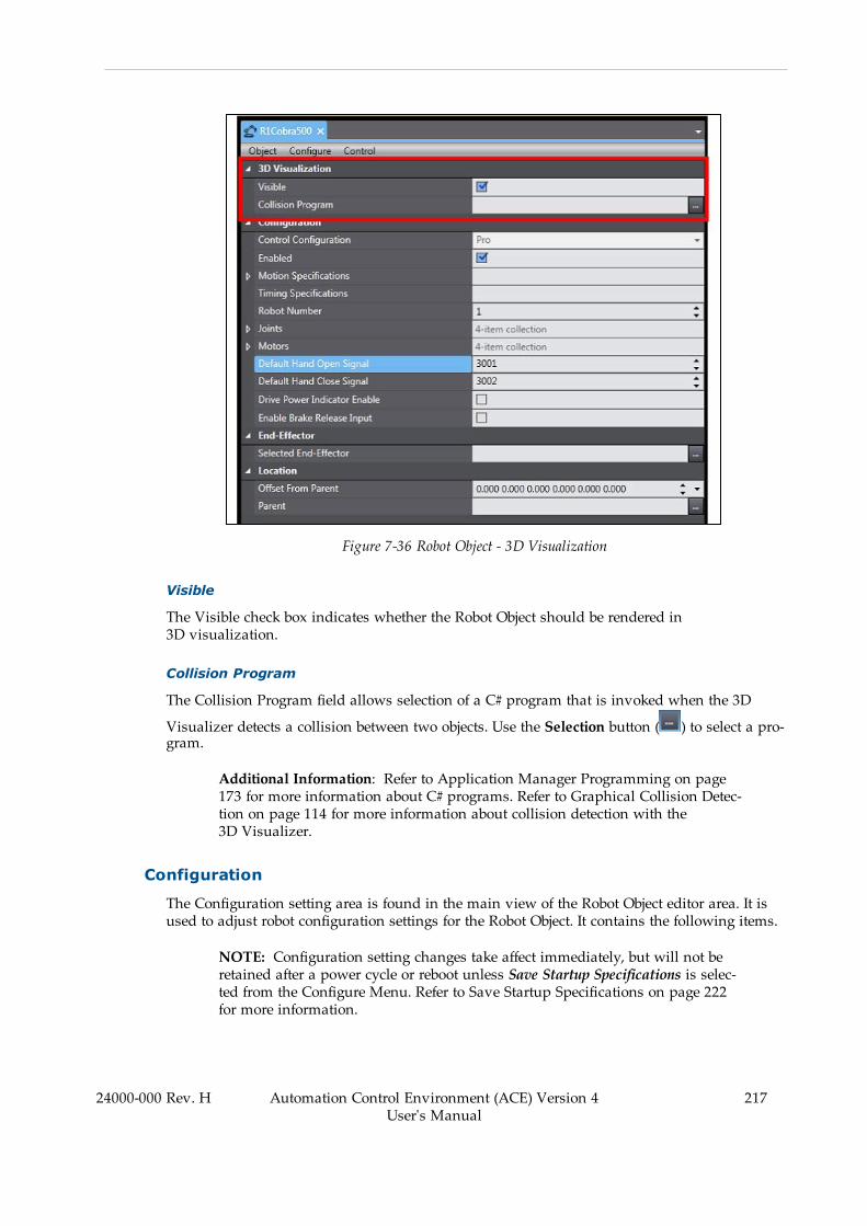
Figure 7-36 Robot Object - 3D Visualization
Visible
The Visible check box indicates whether the Robot Object should be rendered in3D visualization.
Collision Program
The Collision Program field allows selection of a C# program that is invoked when the 3D
Visualizer detects a collision between two objects. Use the Selection button ( ) to select a pro-gram.
Additional Information: Refer to Application Manager Programming on page173 for more information about C# programs. Refer to Graphical Collision Detec-tion on page 114 for more information about collision detection with the3D Visualizer.
Configuration
The Configuration setting area is found in the main view of the Robot Object editor area. It isused to adjust robot configuration settings for the Robot Object. It contains the following items.
NOTE: Configuration setting changes take affect immediately, but will not beretained after a power cycle or reboot unless Save Startup Specifications is selec-ted from the Configure Menu. Refer to Save Startup Specifications on page 222for more information.
24000-000 Rev. H Automation Control Environment (ACE) Version 4User's Manual
217

218 Automation Control Environment (ACE) Version 4User's Manual
24000-000 Rev. H
Chapter 7: SmartController Configuration and Setup
Figure 7-37 Robot Object - Configuration
Control Configuration
The Control Configuration item displays the license status of the Robot Object.
Enabled
The Enabled selection enables or disables control of this robot. This is typically used duringdebugging and troubleshooting.
Motion Specifications
The Motion Specifications item can be expanded to display several settings for robot speedand acceleration as described below.
Table 7-6 Motion Specifications Description
Item Description
Cartesian RotationAcceleration
Specifies the Cartesian rotation acceleration at ACCEL 100(deg/sec2).
Cartesian RotationSpeed
Specifies the Cartesian rotation speed at SPEED 100 (deg/sec).
Cartesian TranslationAcceleration
Specifies the Cartesian translation acceleration at ACCEL 100(mm/sec2).
CartesianTranslation Speed
Specifies the Cartesian translation speed at SPEED 100 (mm/sec).
Item Description
Max PercentAcceleration
Specifies the Maximum allowable percent acceleration from anACCEL command.
Max PercentDeceleration
Specifies the Maximum allowable percent deceleration from anACCEL command.
Max Percent Speed Specifies the Maximum allowable speed from a SPEED command.
SCALE.ACCEL UpperLimit
Specifies the Program speed above which accelerations are sat-urated when SCALE.ACCEL is enabled.
Timing Specifications
Reserved for future use. Timing Specifications are only available with Expert Access.
Robot Number
The Robot Number field specifies the robot's designated number for the FireWire configuration.Use the Configure Options - Configure FireWire Nodes to change this value. Refer to Configureon page 193 for more information.
Robot Number Considerations
l If only one robot is present in the system, it must be configured as Robot Number 1.l If multiple robots are present in the system, they must have unique Robot Numbers.
Joints
The Joints item can be expanded to display settings for range of motion limit, full speed limit,and full acceleration limit of each robot joint.
Motors
The Motors item can be expanded to display settings for motor gain and nulling tolerances foreach servo motor in the robot.
Table 7-7 Motors Adjustment Item Description
Item Description
Motor Gains Only available with Expert Access enabled. Contact your localOmron representative for more information.
Fine Nulling Tolerance Specifies the tolerance for the number of servomotor encoder feed-back counts to consider a move complete when amove is madeafter specifying FINE tolerance (refer to the eV+ Language Refer-ence Guide (Cat. No. I605) or eV+3 Keyword Reference Manual(Cat. No I652) for more information).
Coarse NullingTolerance
Specifies the tolerance for the number of servomotor encoder feed-back counts to consider a move complete when amove is madeafter specifying COARSE tolerance (refer to the eV+ LanguageReference Guide (Cat. No. I605) or eV+3 Keyword ReferenceManual (Cat. No I652) for more information).
24000-000 Rev. H Automation Control Environment (ACE) Version 4User's Manual
219
220 Automation Control Environment (ACE) Version 4User's Manual
24000-000 Rev. H
Chapter 7: SmartController Configuration and Setup
Default Hand Open Signal
The Default Hand Open Signal field specifies the output for the V+ keywords OPEN, OPENI,CLOSE, and CLOSEI. Refer to theeV+ Language Reference Guide (Cat. No. I605) or eV+3 KeywordReference Manual (Cat. No I652) for more information.
Default Hand Close Signal
The Default Hand Close Signal field specifies the output for the V+ keywords OPEN, OPENI,CLOSE, and CLOSEI. Refer to the eV+ Language Reference Guide (Cat. No. I605) or eV+3 KeywordReference Manual (Cat. No I652)for more information.
Drive Power Indicator Enable
The Drive Power Indicator Enable selection is used to enable or disable the signal to indicaterobot power. When enabled, an external indicator can be used to signal when robot power isON. Refer to the appropriate robot user's guide for more information.
IMPORTANT: The user is responsible to connect and install the appropriatevisual indicator(s) as per the requirements of UL 1740. This function is requiredto be enabled to meet UL 1740 requirements.
Enable Brake Release Input
The Enable Brake Release Input selection is used to turn ON or OFF the brake release input sig-nal. Selecting this item will allow an external signal to be used for robot brake control.
End-Effector
The End-Effector setting is used to select an IO EndEffector for the Robot Object. This allows aProcess Manager to reference the number of tips available for that robot when defining multi-pick process, and to control the gripper signals for a specific robot when the Process Manageris active.
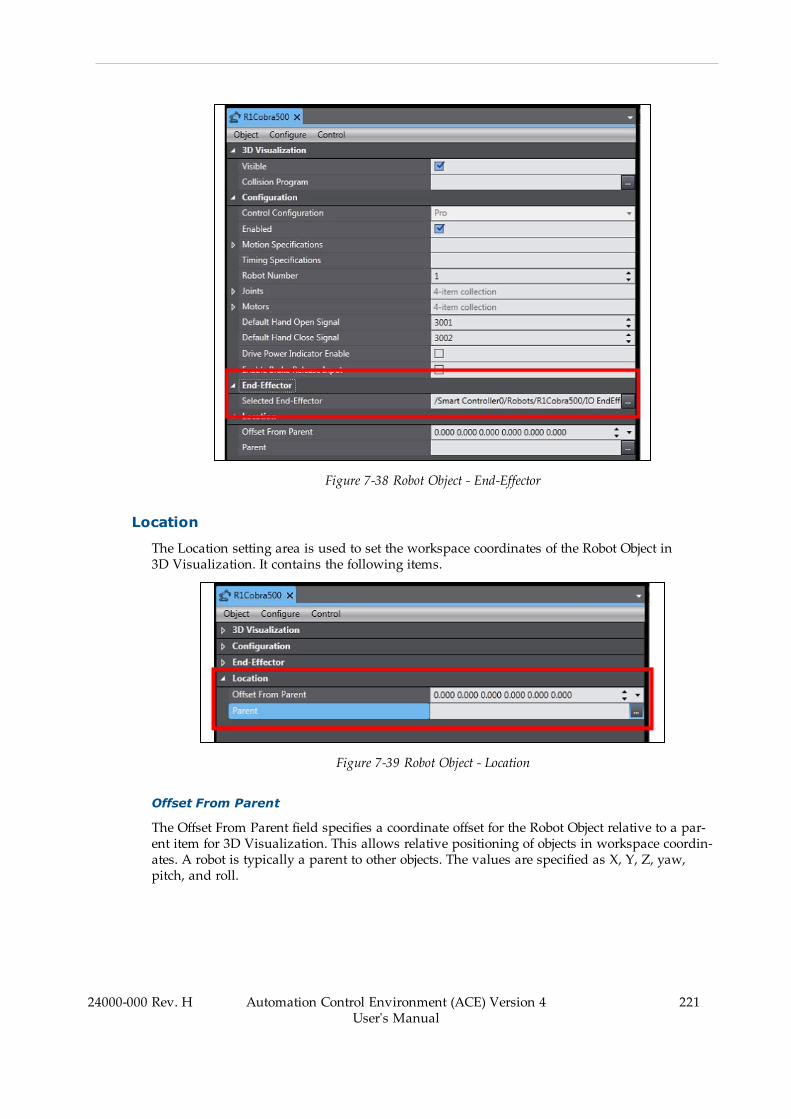
Figure 7-38 Robot Object - End-Effector
Location
The Location setting area is used to set the workspace coordinates of the Robot Object in3D Visualization. It contains the following items.
Figure 7-39 Robot Object - Location
Offset From Parent
The Offset From Parent field specifies a coordinate offset for the Robot Object relative to a par-ent item for 3D Visualization. This allows relative positioning of objects in workspace coordin-ates. A robot is typically a parent to other objects. The values are specified as X, Y, Z, yaw,pitch, and roll.
24000-000 Rev. H Automation Control Environment (ACE) Version 4User's Manual
221

222 Automation Control Environment (ACE) Version 4User's Manual
24000-000 Rev. H
Chapter 7: SmartController Configuration and Setup
Parent
The Parent selection specifies the object this robot will be relative to (using the Offset From Par-ent parameter). Refer to Adding Shapes on page 244 for more information.
Object
The Object Menu displays the Expert Access options described below.
Figure 7-40 Robot Object - Object
Expert Access
Expert Access grants access to all available parameters and settings. Contact your local Omronrepresentative for more information.
Configure
The Configure Menu displays the configuration items described below.
Figure 7-41 Robot Object - Configure Menu Item
Save Startup Specifications
Selecting Save Startup Specifications will save all robot and motor specifications to the V+ bootdisk.
NOTE: This is the same function that is present in the Controller Settings - Con-trol menu. Refer to Control on page 187 for more information.

Load Spec File
A Spec file can be used to restore robot and motor specifications from a saved file. SelectingLoad Spec File will open the Load Spec File Dialog Box. Choose a location where the savedSpec File is stored and then click the Next button to proceed.
Figure 7-42 Robot Object - Load Spec File
Save Spec File
A Spec file can be saved to store robot and motor specifications. Selecting Save Spec File willopen the Save Spec File Dialog Box. Choose a location on the PC to save the Spec File and thenclick the Next button to proceed.
24000-000 Rev. H Automation Control Environment (ACE) Version 4User's Manual
223
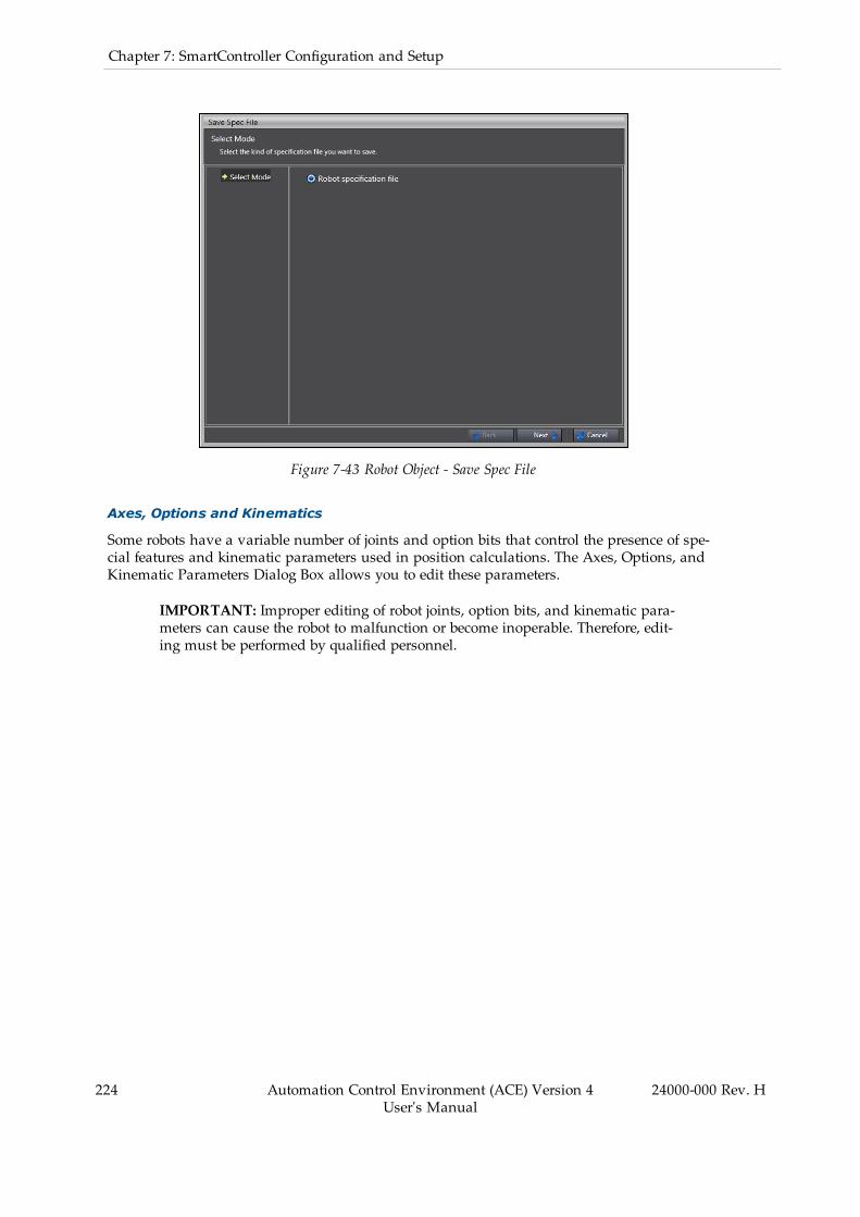
224 Automation Control Environment (ACE) Version 4User's Manual
24000-000 Rev. H
Chapter 7: SmartController Configuration and Setup
Figure 7-43 Robot Object - Save Spec File
Axes, Options and Kinematics
Some robots have a variable number of joints and option bits that control the presence of spe-cial features and kinematic parameters used in position calculations. The Axes, Options, andKinematic Parameters Dialog Box allows you to edit these parameters.
IMPORTANT: Improper editing of robot joints, option bits, and kinematic para-meters can cause the robot to malfunction or become inoperable. Therefore, edit-ing must be performed by qualified personnel.
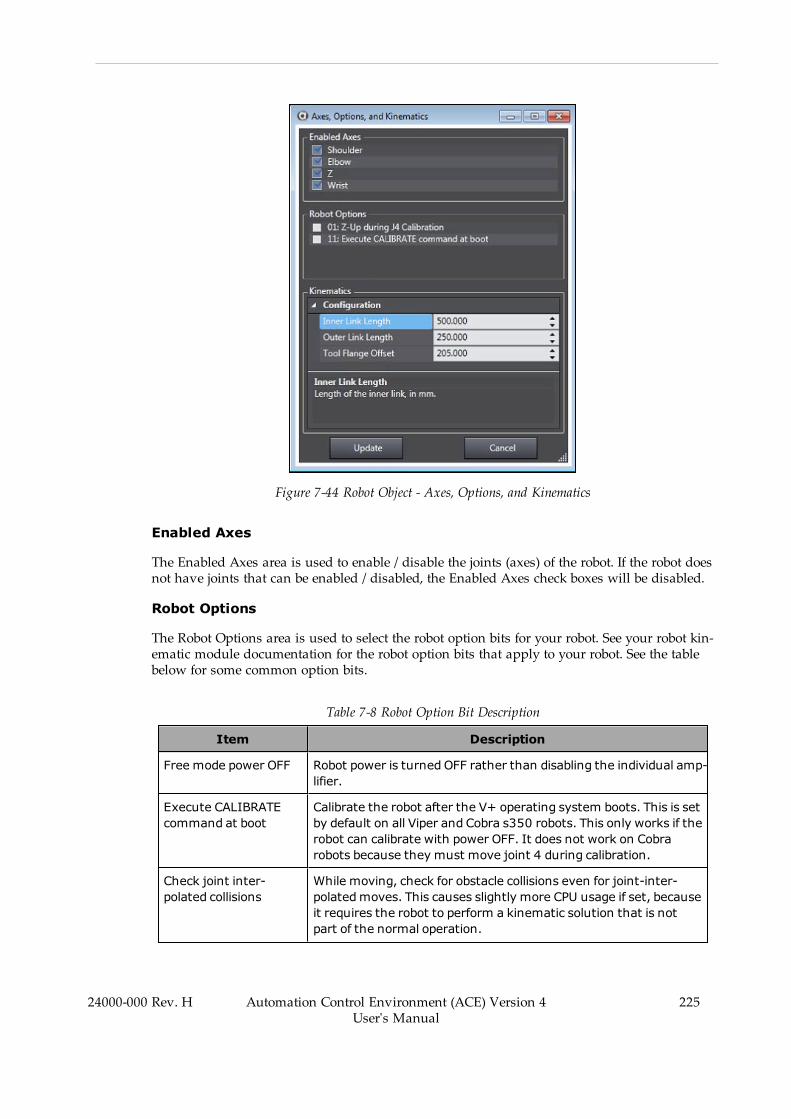
Figure 7-44 Robot Object - Axes, Options, and Kinematics
Enabled Axes
The Enabled Axes area is used to enable / disable the joints (axes) of the robot. If the robot doesnot have joints that can be enabled / disabled, the Enabled Axes check boxes will be disabled.
Robot Options
The Robot Options area is used to select the robot option bits for your robot. See your robot kin-ematic module documentation for the robot option bits that apply to your robot. See the tablebelow for some common option bits.
Table 7-8 Robot Option Bit Description
Item Description
Free mode power OFF Robot power is turned OFF rather than disabling the individual amp-lifier.
Execute CALIBRATEcommand at boot
Calibrate the robot after the V+ operating system boots. This is setby default on all Viper and Cobra s350 robots. This only works if therobot can calibrate with power OFF. It does not work on Cobrarobots because they must move joint 4 during calibration.
Check joint inter-polated collisions
While moving, check for obstacle collisions even for joint-inter-polatedmoves. This causes slightly more CPU usage if set, becauseit requires the robot to perform a kinematic solution that is notpart of the normal operation.
24000-000 Rev. H Automation Control Environment (ACE) Version 4User's Manual
225

226 Automation Control Environment (ACE) Version 4User's Manual
24000-000 Rev. H
Chapter 7: SmartController Configuration and Setup
Item Description
Z-up during J4 cal-ibration
On Cobra robots, J4 must rotate slightly during calibration. Thiscauses J3 to retract before moving J4.
J6 multi-turn This bit allows infinite rotation of J6. Note that individual movesmust be nomore than 360 degrees.
Software motor limits In robot models with multiple motors coupled tomove a singlejoint, the standard joint motion limits may not be adequate to pre-vent the motors from hitting physical limits. In such cases, youmay use software motor limits to restrict motor motion.
Kinematics
The Kinematics area is used to display the kinematic parameters for your robot.
Obstacles
Select Obstacles to add / edit the location, type, and size of workcell obstacles. This will openthe Edit Obstacles Dialog Box. It contains the following items.
IMPORTANT: Obstacles are predefined and evaluated in the controller whencommanding robot motion and should not be confused with Collision Detectionin the 3D Visualizer. Refer to Graphical Collision Detection on page 114 for moreinformation.
Figure 7-45 Robot Objects - Obstacles
Table 7-9 Obstacles Description
Item Description
Protected Obstacles Predefined system obstacles that cannot be edited by the user.

Item Description
User Obstacles Each row provides an entry for a workcell obstacle.
Obstacle Type This drop-down list is used to select the type of obstacle: box, cyl-inder, sphere or frustum. These types are also offered as con-tainment obstacles for applications where you want to keep therobot working within a defined area.
Obstacle Center This text box is used to enter the coordinates of the center of theobstacle.
Obstacle Dimensions Dimensions such as diameter and height are required dependingon the obstacle type chosen.
S-Curve Profiles
The S-Curve Profile Configuration Dialog Box is used to configure the four time valuesrequired to create a new s-curve profile for use in robot motion (also called a trapezoidal accel-eration curve). Selecting S-Curve Profiles will display the S-Curve Profiles Dialog Box.
Refer to the eV+ Language Reference Guide (Cat. No. I605) or eV+3 Keyword Reference Manual (Cat.No I652) for more information about using S-Curve Profiles.
Figure 7-46 Robot Objects - S-Curve Profiles
S-Curve Profile Considerations
An S-Curve Profile is a trajectory that has a trapezoidal acceleration profile, giving an S-shaped velocity profile. The benefit of a trapezoidal acceleration profile is that the rate ofchange of acceleration can be controlled for a smoother motion.
For many mechanisms, controlling the acceleration is significant because high values cancause the mechanical structure of the robot to vibrate. Minimizing structural vibrations is espe-cially important at the end of a motion, since such oscillations can adversely affect the settlingtime of the robot, which can affect the cycle time. However, for stiff, strong mechanisms asquare-wave profile may result in shorter cycle times.
For a general trapezoidal profile, there are four time values that can be specified.
1. Ramp up to maximum acceleration2. Ramp down from maximum acceleration3. Ramp up to maximum deceleration4. Ramp down to zero acceleration.
24000-000 Rev. H Automation Control Environment (ACE) Version 4User's Manual
227

228 Automation Control Environment (ACE) Version 4User's Manual
24000-000 Rev. H
Chapter 7: SmartController Configuration and Setup
Each of these four acceleration values can be individually specified and a set of the four val-ues defines a specific acceleration "profile" for use in programming robot motion routines.
Safety Settings
Safety Settings are used to restore the E-Stop hardware delay and the teach-mode restrictedspeed to the factory settings. Selecting Safety Settings will display the dialog box shown below.It contains the following items.
NOTE: Safety Settings are not available in Emulation mode. This menu item isonly available for robots using eAIB or eMB-40R/60R amplifiers.
Figure 7-47 Robot Object - Safety Settings
Configure Teach Restrict
Selecting Configure Teach Restrict and clicking the Next button will step through the pro-cedure for setting predetermined speed limits for each robot motor.
The objective of the Teach Restrict feature is to comply with safety regulations which requirethe speed to be limited while the robot is in manual mode. This is hardware-based safety func-tionality to prevent rapid robot motion in manual mode even in the unexpected event of soft-ware error attempting to drive a robot faster than allowed. While jogging the robot in manualmode, if any joint exceeds its configured speed limit the system will disable high power.
IMPORTANT: This configuration process is tuning circuitry in the amplifierunits based on characteristics of specific motors. This process should be per-formed any time an amplifier is replaced in an existing system.
Verify Teach Restrict Auto
Selecting Verify Teach Restrict Auto and clicking the Next button will step through a pro-cedure to verify that Teach Restrict is operating properly with a series of automatic com-manded motions.
Verify Tech Restrict Manual
Selecting Verify Teach Restrict Manual and clicking the Next button will step through a pro-cedure to verify Teach Restrict is operating properly with a series of jogging operations per-formed by the user with a T20 pendant. This may also be useful for troubleshooting or testingindividual joints when Teach Restrict commissioning process or automatic verification fails.
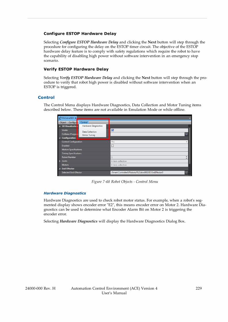
Configure ESTOP Hardware Delay
Selecting Configure ESTOP Hardware Delay and clicking the Next button will step through theprocedure for configuring the delay on the ESTOP timer circuit. The objective of the ESTOPhardware delay feature is to comply with safety regulations which require the robot to havethe capability of disabling high power without software intervention in an emergency stopscenario.
Verify ESTOP Hardware Delay
Selecting Verify ESTOP Hardware Delay and clicking the Next button will step through the pro-cedure to verify that robot high power is disabled without software intervention when anESTOP is triggered.
Control
The Control Menu displays Hardware Diagnostics, Data Collection and Motor Tuning itemsdescribed below. These items are not available in Emulation Mode or while offline.
Figure 7-48 Robot Objects - Control Menu
Hardware Diagnostics
Hardware Diagnostics are used to check robot motor status. For example, when a robot's seg-mented display shows encoder error "E2", this means encoder error on Motor 2. Hardware Dia-gnostics can be used to determine what Encoder Alarm Bit on Motor 2 is triggering theencoder error.
Selecting Hardware Diagnostics will display the Hardware Diagnostics Dialog Box.
24000-000 Rev. H Automation Control Environment (ACE) Version 4User's Manual
229

230 Automation Control Environment (ACE) Version 4User's Manual
24000-000 Rev. H
Chapter 7: SmartController Configuration and Setup
Figure 7-49 Robot Object - Hardware Diagnostics
Table 7-10 Hardware Diagnostics Description
Item Description
Amp Enable Enables / disables the amplifier for the selectedmotor.
Brake Release Enables / disables the brake release for the selectedmotor.
Output Level Specifies a commanded torque, which is used to test the operationof the selectedmotor. The range is from -32767 to 32767, or therange specified by the Max Output Level parameter for that motorin the Robot Editor (restricted Expert Access parameter).
Position Displays the current position in encoder counts of the selectedmotor.
Pos Error Displays the position error in encoder counts of the selectedmotor.
Index Delta Displays the change in encoder counts from the previous latchedzero index and the most recent latched zero index of the selectedmotor. Note that this is only useful with incremental encoders toverify zero index spacing and proper encoder readings.
Error Displays the following error codes for the selectedmotor.
l P - Positive overtravell N - Negative overtravell D - Duty cycle errorl A - Amp faultl R - RSC (Robot Signature Card) power failurel E - Encoder faultl H - Hard envelope errorl S - Soft envelope errorl M -Motor stalled
Status Displays the following status codes for the selectedmotor.
l P - High power onl T - In tolerancel C - Calibratedl H - Home sensor activel V+ control
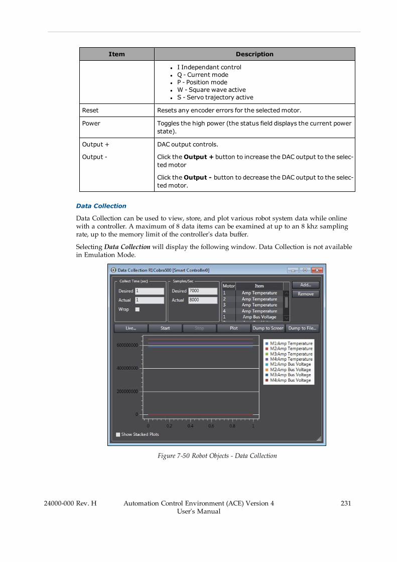
Item Description
l I Independant controll Q - Current model P - Position model W - Square wave activel S - Servo trajectory active
Reset Resets any encoder errors for the selectedmotor.
Power Toggles the high power (the status field displays the current powerstate).
Output +
Output -
DAC output controls.
Click theOutput + button to increase the DAC output to the selec-tedmotor
Click theOutput - button to decrease the DAC output to the selec-tedmotor.
Data Collection
Data Collection can be used to view, store, and plot various robot system data while onlinewith a controller. A maximum of 8 data items can be examined at up to an 8 khz samplingrate, up to the memory limit of the controller's data buffer.
Selecting Data Collection will display the following window. Data Collection is not availablein Emulation Mode.
Figure 7-50 Robot Objects - Data Collection
24000-000 Rev. H Automation Control Environment (ACE) Version 4User's Manual
231

232 Automation Control Environment (ACE) Version 4User's Manual
24000-000 Rev. H
Chapter 7: SmartController Configuration and Setup
Table 7-11 Data Collection Description
Item Description
Collect Time (sec) Specifies the data collection time in seconds. The default value is 1.
Samples/Sec Specifies the data collection rate in samples per second. The defaultvalue is 1000.
Add...
Remove
Add or remove motor items to examine with these buttons.
Clicking the Add button will display the Add Items to Collect Dialog Box.
Figure 7-51 Add Items to Collect
Enter an Absolute Address or select Opcode and choose an availabledata item from the dropdown list. Then select the motor(s) to collectdata from.
Live Displays a window that shows the real-time data being collected.
Start Click to start the data collection. The data collection will continue untileither the Stop button is clicked or the specified collect time is reached.
Stop Click to stop the data collection. If the specified collect time has alreadyexpired, this button is disabled.
Plot Click to plot the collected data. A progress bar displays while the data isprocessed. After the processing has completed, the data is plotted onthe graph located at the lower portion of the Data Collection Dialog Box.
Dump to Screen Displays the collected data in a Data Dumpwindow in text-file format.
Dump to File... Displays a Save As Dialog Box used for saving the collected data to atext file, which can be viewed or processed at a later time.
Motor Tuning
Motor Tuning is used to send a square wave positioning command to the specified motor andobserve the response for servo motor tuning purposes. Observing the response has the samefunctionality as Data Collection (refer to Data Collection on page 231 for more information).

SelectingMotor Tuning will display the following window. Motor Tuning is not available inEmulation Mode.
Figure 7-52 Robot Objects - Motor Tuning
Table 7-12 Motor Tuning Description
Item Description
Motor Specifies the motor that will receive the square wave positioningcommand.
Period (sec) Specifies the length of the square wave in seconds.
Amplitude (cts) Specifies the amplitude of the square wave in servo counts.
Go Turns ON/OFF the square wave positioning command to the spe-cifiedmotor.
24000-000 Rev. H Automation Control Environment (ACE) Version 4User's Manual
233

Chapter 8: Application Manager Configurationand Setup
This section describes the functions, configuration, and setup of Application Manager itemsand objects.
8.1 Remote Application ManagerACE 4.2 introduces the ability to install and run ACE as an Application Manager. This allowstransfer of Application Manager device contents from one IPC to another. This in turn allowsflexibility for users to:
l Maintain one project file for multiple devices on a networkl Manage multiple Application Manager ACE instances from one interfacel Allows for projects to be modified offline and transferred to network connected PCsl Monitor and modify project data over network connection to an IPC
Using a remote Application Manager requires two types of ACE instances. The first is called aserver instance and is primarily used for application control during runtime functionality. Thesecond is called a client instance and is used to create projects and transfer them to the serverinstances. A client instance is virtually identical to a standard ACE instance and is created justby opening ACE. It is called a client instance solely due to its connection to one or more serverinstances.
The client instance is connected to the server instances by using Ethernet connections betweendifferent computers. Typically, the server instances will be opened on IPCs connected to neces-sary cameras and controllers while the client instance will be on a separate computer, calledthe Remote PC in this section. If configured correctly, you can transfer the client instance to theserver instances and interact with the system. When the Application Manager is then con-figured and operating as desired, the Remote PC can go Offline and disconnect from the sys-tem without stopping production.
An example layout is shown, See "Remote Application Manager Connections", where the pro-ject on the client instance, in this example, has three Application Managers that are syn-chronized with a different server instance.
NOTE: All remote Application Manager functionality requires the ApplicationManager device AM101-1000 version 2.0.
24000-000 Rev. H Automation Control Environment (ACE) Version 4User's Manual
235

236 Automation Control Environment (ACE) Version 4User's Manual
24000-000 Rev. H
Chapter 8: Application Manager Configuration and Setup
Figure 8-1 Remote Application Manager Connections
Remote Application Manager Set Up
Establishing a connection between an instance of ACE and an Application Manager serverinstance requires the following:
l One computer (called the Remote PC in this section)l At least one IPC application controller with necessary camerasl One network switch and Ethernet cablesl At least one robot controllerl A recent version of ACE 4.2 installed on all computers
Any cameras need to be connected directly to their respective IPC, but the robot controllersshould be arranged so both the Remote PC and the IPC can go Online with them. See"Example Remote PC to IPC Diagram" for an example of the recommended layout. The sampleIP addresses are shown to illustrate sample networks.
Figure 8-2 Example Remote PC to IPC Diagram
To transfer a project from the remote PC to the IPC, an exception must first be made for theport in the Windows firewall. Continuing without the exception will cause an error message,shown below:
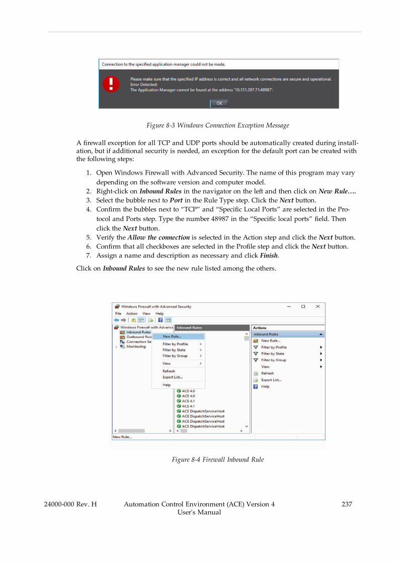
Figure 8-3 Windows Connection Exception Message
A firewall exception for all TCP and UDP ports should be automatically created during install-ation, but if additional security is needed, an exception for the default port can be created withthe following steps:
1. Open Windows Firewall with Advanced Security. The name of this program may varydepending on the software version and computer model.
2. Right-click on Inbound Rules in the navigator on the left and then click on New Rule….3. Select the bubble next to Port in the Rule Type step. Click the Next button.4. Confirm the bubbles next to “TCP” and “Specific Local Ports” are selected in the Pro-tocol and Ports step. Type the number 48987 in the “Specific local ports” field. Thenclick the Next button.
5. Verify the Allow the connection is selected in the Action step and click the Next button.6. Confirm that all checkboxes are selected in the Profile step and click the Next button.7. Assign a name and description as necessary and click Finish.
Click on Inbound Rules to see the new rule listed among the others.
Figure 8-4 Firewall Inbound Rule
24000-000 Rev. H Automation Control Environment (ACE) Version 4User's Manual
237
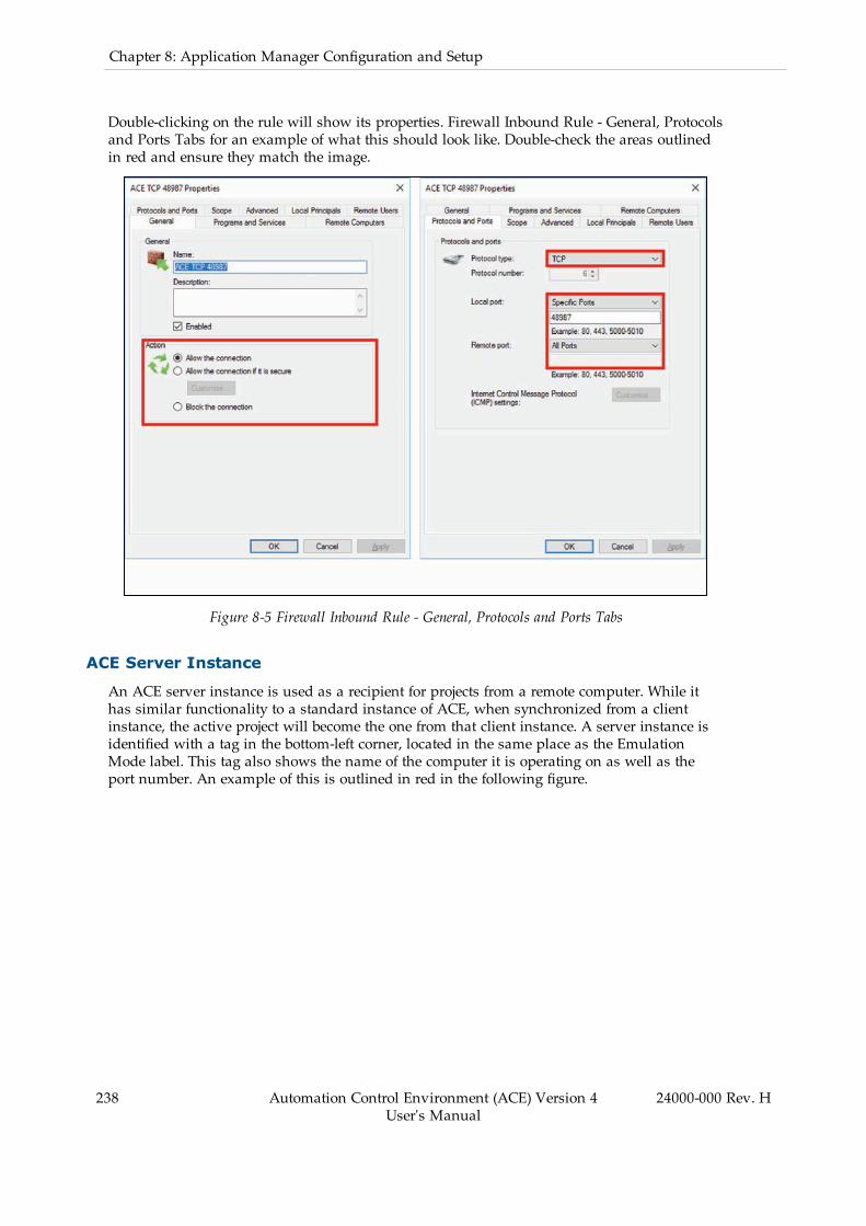
238 Automation Control Environment (ACE) Version 4User's Manual
24000-000 Rev. H
Chapter 8: Application Manager Configuration and Setup
Double-clicking on the rule will show its properties. Firewall Inbound Rule - General, Protocolsand Ports Tabs for an example of what this should look like. Double-check the areas outlinedin red and ensure they match the image.
Figure 8-5 Firewall Inbound Rule - General, Protocols and Ports Tabs
ACE Server Instance
An ACE server instance is used as a recipient for projects from a remote computer. While ithas similar functionality to a standard instance of ACE, when synchronized from a clientinstance, the active project will become the one from that client instance. A server instance isidentified with a tag in the bottom-left corner, located in the same place as the EmulationMode label. This tag also shows the name of the computer it is operating on as well as theport number. An example of this is outlined in red in the following figure.

Figure 8-6 ACE Server in Application Manager
Creating a Server
During the installation of ACE, selecting the Application Manager option allows ACE to openas a server, and installs a desktop short cut for this purpose. Opening an existing installationof ACE as a server requires the use of a keyword. ACE uses utilizes the following keywords inCommand Prompt open ACE for different purposes:
l “startclient” is used to start a client session, which is the same as opening a standardinstance of ACE.
l “startserver” is used to open a server instance.l “start” is used to open a server instance with specified defaultsl “help” displays information about the command and offers options.l “version” displays information about the currently installed version of ACE.
In general, the only one needed for the architecture illustrated above is “startserver.” A clientsession can be created by opening ACE normally or using the “startclient” keyword. However,“startserver” is required to create a server instance using Windows Command Prompt, asshown in the steps below:
1. Open the Windows Command Prompt.2. Change to the directory containing the ACE 4.2 “bin” folder. The command should besimilar to “cd C:\Program Files\Omron\ACE 4.2\bin”. Depending on the computerstorage, the folder may be in a different location.
3. Type the command “Ace.AppMgr.exe startserver”.
Note that Steps 2 and 3 can be done in the same command by including the directory nav-igation in the command.
24000-000 Rev. H Automation Control Environment (ACE) Version 4User's Manual
239
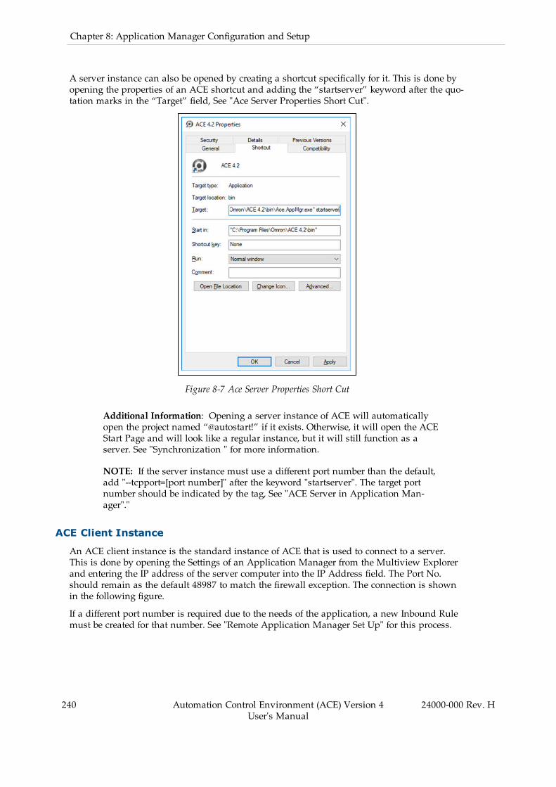
240 Automation Control Environment (ACE) Version 4User's Manual
24000-000 Rev. H
Chapter 8: Application Manager Configuration and Setup
A server instance can also be opened by creating a shortcut specifically for it. This is done byopening the properties of an ACE shortcut and adding the “startserver” keyword after the quo-tation marks in the “Target” field, See "Ace Server Properties Short Cut".
Figure 8-7 Ace Server Properties Short Cut
Additional Information: Opening a server instance of ACE will automaticallyopen the project named “@autostart!” if it exists. Otherwise, it will open the ACEStart Page and will look like a regular instance, but it will still function as aserver. See "Synchronization " for more information.
NOTE: If the server instance must use a different port number than the default,add "--tcpport=[port number]" after the keyword "startserver". The target portnumber should be indicated by the tag, See "ACE Server in Application Man-ager"."
ACE Client Instance
An ACE client instance is the standard instance of ACE that is used to connect to a server.This is done by opening the Settings of an Application Manager from the Multiview Explorerand entering the IP address of the server computer into the IP Address field. The Port No.should remain as the default 48987 to match the firewall exception. The connection is shownin the following figure.
If a different port number is required due to the needs of the application, a new Inbound Rulemust be created for that number. See "Remote Application Manager Set Up" for this process.
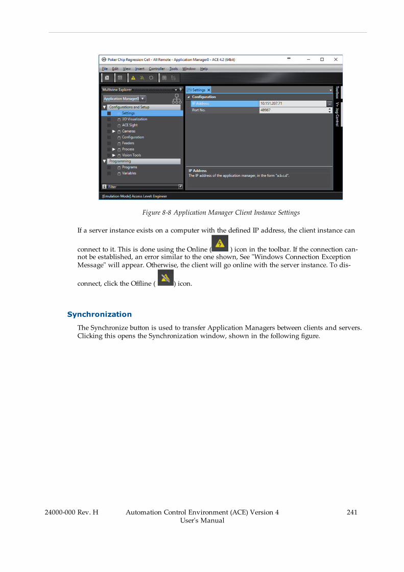
Figure 8-8 Application Manager Client Instance Settings
If a server instance exists on a computer with the defined IP address, the client instance can
connect to it. This is done using the Online ( ) icon in the toolbar. If the connection can-not be established, an error similar to the one shown, See "Windows Connection ExceptionMessage" will appear. Otherwise, the client will go online with the server instance. To dis-
connect, click the Offline ( ) icon.
Synchronization
The Synchronize button is used to transfer Application Managers between clients and servers.Clicking this opens the Synchronization window, shown in the following figure.
24000-000 Rev. H Automation Control Environment (ACE) Version 4User's Manual
241
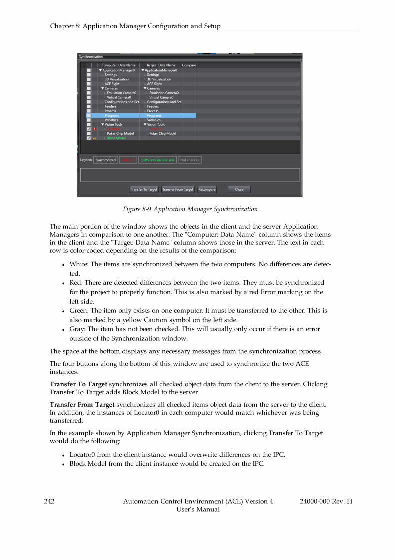
242 Automation Control Environment (ACE) Version 4User's Manual
24000-000 Rev. H
Chapter 8: Application Manager Configuration and Setup
Figure 8-9 Application Manager Synchronization
The main portion of the window shows the objects in the client and the server ApplicationManagers in comparison to one another. The "Computer: Data Name" column shows the itemsin the client and the "Target: Data Name" column shows those in the server. The text in eachrow is color-coded depending on the results of the comparison:
l White: The items are synchronized between the two computers. No differences are detec-ted.
l Red: There are detected differences between the two items. They must be synchronizedfor the project to properly function. This is also marked by a red Error marking on theleft side.
l Green: The item only exists on one computer. It must be transferred to the other. This isalso marked by a yellow Caution symbol on the left side.
l Gray: The item has not been checked. This will usually only occur if there is an erroroutside of the Synchronization window.
The space at the bottom displays any necessary messages from the synchronization process.
The four buttons along the bottom of this window are used to synchronize the two ACEinstances.
Transfer To Target synchronizes all checked object data from the client to the server. ClickingTransfer To Target adds Block Model to the server
Transfer From Target synchronizes all checked items object data from the server to the client.In addition, the instances of Locator0 in each computer would match whichever was beingtransferred.
In the example shown by Application Manager Synchronization, clicking Transfer To Targetwould do the following:
l Locator0 from the client instance would overwrite differences on the IPC.l Block Model from the client instance would be created on the IPC.

Conversely, clicking Transfer From Target would do the following:
l Locator0 from the server instance would overwrite differences in the client instance pro-ject data.
l Block Model would be removed from the client instance project data."
The Recompare button will search for differences between the two Application Managers. Thishappens when the Synchronization window is opened, but the button serves as a way toverify that the items were properly synchronized.
Finally, the Close button closes the window.
Successfully transferring an Application Manager from a client instance to a server instancewill create an ACE project on the IPC with the name “@autostart!”. Transferring a differentApplication Manager to the server instance will replace an existing “@autostart!” project withthe new data.
Additional Information: Synchronization can only occur when the clientinstance is online with the server instance.
Remote User Management
By default, client instances of ACE have Engineer access and, by default, server instances haveOperator access. The Engineer level has the access to make process changes, and because allchanges should be made in the client instance and then transferred to the server instance. Insome cases, however, it may be necessary for changes to be made directly to the server. Thisactivity can be managed and limited by creating users and passwords for the higher accesslevels, such as Engineer.
NOTE: If changes are made directly on the server instance, it is recommendedto immediately transfer the changes to a client instance. The changes will beerased if a new project is transferred to the server instance, so it is best to save iton another system as soon as possible.
The server instance can further be protected by adding additional users with various accesslevels and setting passwords for them. These can be created on the server instance directly orthey can be created on a client instance and then transferred to the server instance using Syn-chronization.
Refer to User Management on page 139 for more information.
8.2 3D VisualizationIn addition to robots, several other objects that are configured in the Application Manager arerepresented in the 3D Visualizer. The location, orientation and dimensions of these items aredefined during the initial configuration of each item and can be adjusted to precisely simulatethe application. The following items will appear in the 3D Visualizer after they are configured.
l Process Belts (Belt Calibrations, Windows, and Allocation Limits)l Latch sensor calibrationsl Camera calibrations and field of viewsl Part and Part Target instancesl Boxes, Cylinders, and imported CAD files
24000-000 Rev. H Automation Control Environment (ACE) Version 4User's Manual
243

244 Automation Control Environment (ACE) Version 4User's Manual
24000-000 Rev. H
Chapter 8: Application Manager Configuration and Setup
Additional Information: After a shape has been added, functions such asrename, cut, copy, paste, delete, and focus in 3D Visualizer can be accessed foreach shape by right clicking the object in the Multiview Explorer and making aselection.
Adding Shapes
Boxes and cylinders can be added to the 3D Visualizer to represent objects in the robot work-space. Use the following procedure to add cylinders and boxes to the 3D Visualizer.
1. Right-click 3D Visualization in the Multiview Explorer and select Add and then chooseBox or Cylinder. A new object will be added to the Multiview Explorer under3D Visualization and it will appear in the 3D Visualizer Window.
2. Access the properties for this object by double-clicking it or right-click and select Edit.This opens the properties editor in the Edit Pane.
Figure 8-10 Shape Properties Editor (Box Shown)
Table 8-1 Shape Properties Editor Item Description
Object Description
3D Visualization
Visible Display or hide the object from the 3D Visualizer.
Collision Program Select a program that is invokedwhen the 3D Visualizerdetects a collision. Refer to Graphical Collision Detectionfor more information.
Color Choose a color for the shape in the 3D Visualizer.
DX/DY/DZ Only available for Box. Defines the dimensions of theshape in the respective direction. DX and DY are bothcentered about the origin while DZ is measured from the
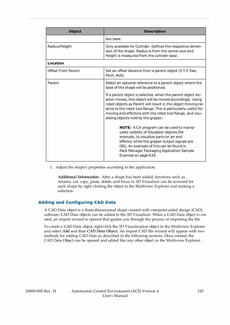
Object Description
box base.
Radius/Height Only available for Cylinder. Defines the respective dimen-sion of the shape. Radius is from the center axis andHeight is measured from the cylinder base.
Location
Offset From Parent Set an offset distance from a parent object (X Y Z Yaw,Pitch, Roll).
Parent Select an optional reference to a parent object where thebase of the shape will be positioned.
If a parent object is selected, when the parent object loc-ation moves, this object will be moved accordingly. Usingrobot objects as Parent will result in the object moving rel-ative to the robot tool flange. This is particularly useful formoving end effectors with the robot tool flange, and visu-alizing objects held by the gripper.
NOTE: A C# program can be used tomanip-ulate visibility of Visualizer objects (forexample, to visualize parts on an endeffector while the gripper output signals areON). An example of this can be found inPack Manager Packaging Application SampleExercise on page 630.
1. Adjust the shape's properties according to the application.
Additional Information: After a shape has been added, functions such asrename, cut, copy, paste, delete, and focus in 3D Visualizer can be accessed foreach shape by right clicking the object in the Multiview Explorer and making aselection.
Adding and Configuring CAD Data
A CAD Data object is a three-dimensional shape created with computer-aided design (CAD)software. CAD Data objects can be added to the 3D Visualizer. When a CAD Data object is cre-ated, an import wizard is opened that guides you through the process of importing the file.
To create a CAD Data object, right-click the 3D Visualization object in the Multiview Explorerand select Add and then CAD Data Object. An import CAD file wizard will appear with twomethods for adding CAD Data as described in the following sections. Once created, theCAD Data Object can be opened and edited like any other object in the Multiview Explorer. .
24000-000 Rev. H Automation Control Environment (ACE) Version 4User's Manual
245
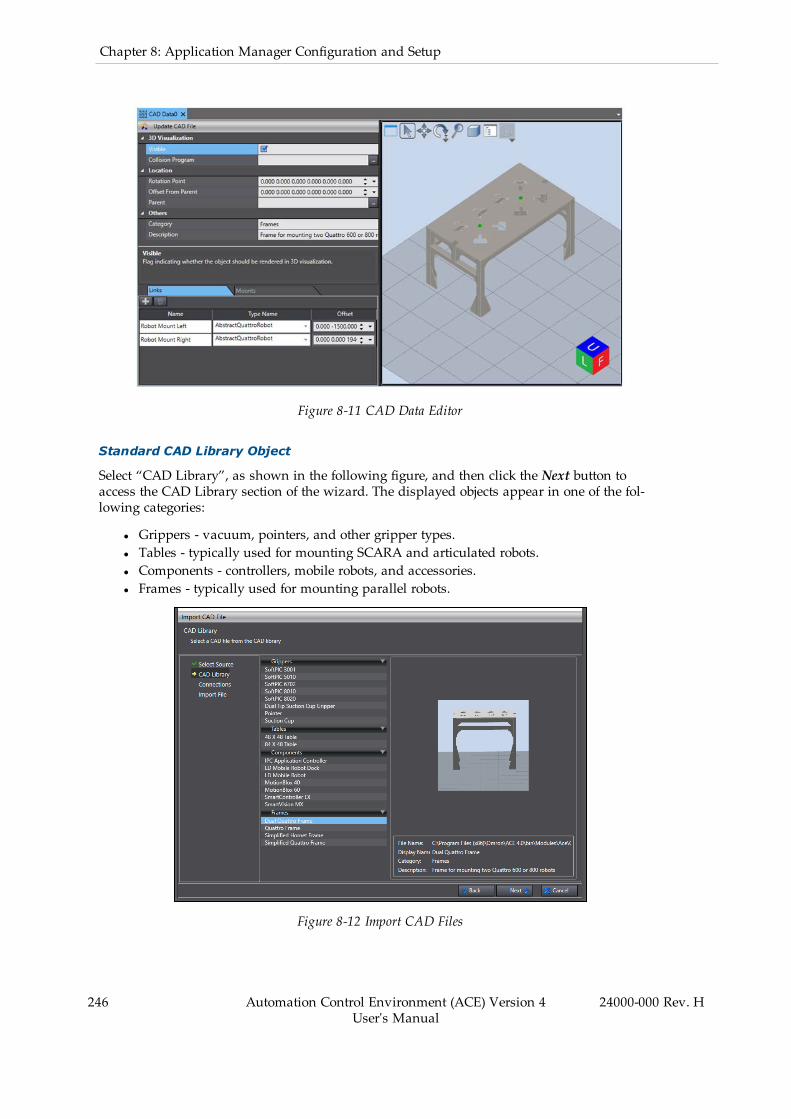
246 Automation Control Environment (ACE) Version 4User's Manual
24000-000 Rev. H
Chapter 8: Application Manager Configuration and Setup
Figure 8-11 CAD Data Editor
Standard CAD Library Object
Select “CAD Library”, as shown in the following figure, and then click the Next button toaccess the CAD Library section of the wizard. The displayed objects appear in one of the fol-lowing categories:
l Grippers - vacuum, pointers, and other gripper types.l Tables - typically used for mounting SCARA and articulated robots.l Components - controllers, mobile robots, and accessories.l Frames - typically used for mounting parallel robots.
Figure 8-12 Import CAD Files
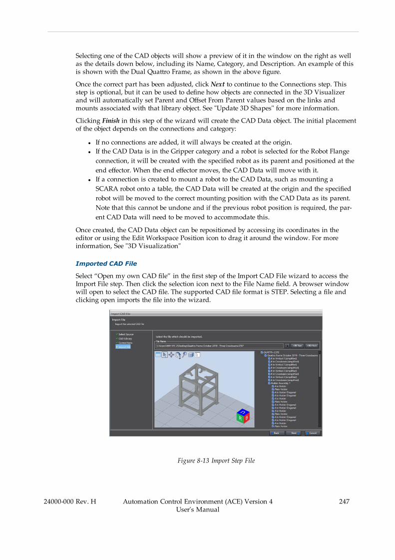
Selecting one of the CAD objects will show a preview of it in the window on the right as wellas the details down below, including its Name, Category, and Description. An example of thisis shown with the Dual Quattro Frame, as shown in the above figure.
Once the correct part has been adjusted, click Next to continue to the Connections step. Thisstep is optional, but it can be used to define how objects are connected in the 3D Visualizerand will automatically set Parent and Offset From Parent values based on the links andmounts associated with that library object. See "Update 3D Shapes" for more information.
Clicking Finish in this step of the wizard will create the CAD Data object. The initial placementof the object depends on the connections and category:
l If no connections are added, it will always be created at the origin.l If the CAD Data is in the Gripper category and a robot is selected for the Robot Flangeconnection, it will be created with the specified robot as its parent and positioned at theend effector. When the end effector moves, the CAD Data will move with it.
l If a connection is created to mount a robot to the CAD Data, such as mounting aSCARA robot onto a table, the CAD Data will be created at the origin and the specifiedrobot will be moved to the correct mounting position with the CAD Data as its parent.Note that this cannot be undone and if the previous robot position is required, the par-ent CAD Data will need to be moved to accommodate this.
Once created, the CAD Data object can be repositioned by accessing its coordinates in theeditor or using the Edit Workspace Position icon to drag it around the window. For moreinformation, See "3D Visualization"
Imported CAD File
Select “Open my own CAD file” in the first step of the Import CAD File wizard to access theImport File step. Then click the selection icon next to the File Name field. A browser windowwill open to select the CAD file. The supported CAD file format is STEP. Selecting a file andclicking open imports the file into the wizard.
Figure 8-13 Import Step File
24000-000 Rev. H Automation Control Environment (ACE) Version 4User's Manual
247

248 Automation Control Environment (ACE) Version 4User's Manual
24000-000 Rev. H
Chapter 8: Application Manager Configuration and Setup
Once imported, the main window of this step shows the CAD Data file as it will be saved inthe project. Some modifications can be made to it here before it is fully integrated. First, the +90Yaw and +90 Pitch rotate the object to control its standard orientation in the 3D Visualizer.This is particularly useful if the file orientation is interpreted differently than ideal. Forexample, custom frames, as in the above figure, should be positioned so their feet are flatagainst the base plane. If they are shown in a different orientation in this window, the buttonscan rotate them into the correct position.
The navigator on the right side shows all of the components in the CAD file. The checkboxesdefine which of the parts are imported. By default, all parts will be selected. Deselecting thesewill omit them from the resulting CAD Data object in the project.
When the necessary adjustments are made, click Next to close the wizard and import the file.
Configuration of CAD Objects
Table 8-2 CAD Properties Editor
Object Description
3D Visualization
Visible Display or hide the object from the 3D Visualizer.
Collision Program Select a program that is invokedwhen the 3D Visualizerdetects a collision. Refer to Graphical Collision Detectionfor more information.
Color Choose a color for the shape in the 3D Visualizer.
Location
Rotation Point Set the offset of the object's center of rotation from theorigin.
Offset From Parent Set an offset distance form a parent object (X Y Z Yaw,Pitch, Roll).
Parent Select an optional reference to a parent object where thebase of the shape will be positioned.
If a parent object is selected, when the parent object loc-ation moves, this object will be moved accordingly. Usingrobot objects as Parent will result in the object moving rel-ative to the robot tool flange. This is particularly useful formoving end effectors with the robot tool flange, and visu-alizing objects held by the gripper.
NOTE: A C# program can be used tomanip-ulate visibility of Visualizer objects (forexample, to visualize parts on an endeffector while the gripper output signals areON). An example of this can be found inPack Manager Packaging Application SampleExercise on page 630.
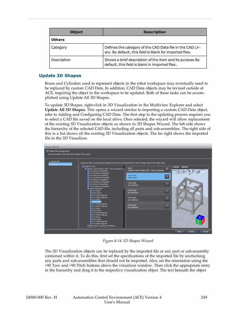
Object Description
Others
Category Defines the category of the CAD Data file in the CAD Lir-ary. By default, this field is blank for imported files.
Description Shows a brief description of the item and its purpose Bydefault, this field is blank in imported files..
Update 3D Shapes
Boxes and Cylinders used to represent objects in the robot workspace may eventually need tobe replaced by custom CAD Data. In addition, CAD Data objects may be revised outside ofACE, requiring the object in the workspace to be updated. Both of these tasks can be accom-plished using Update All 3D Shapes.
To update 3D Shapes, right-click in 3D Visualization in the Multiview Explorer and selectUpdate All 3D Shapes. This opens a wizard similar to importing a custom CAD Data object,refer to Adding and Configuring CAD Data. The first step to the updating process requires youto select a CAD file saved on the local drive. Once selected, the wizard will allow replacementof the existing 3D Visualization objects as shown in 3D Shapes Wizard. The left side showsthe hierarchy of the selected CAD file, including all parts and sub-assemblies. The right side ofthis is a list shows all the existing 3D Visualization objects. The far right shows the importedfile in the 3D Visualizer.
Figure 8-14 3D Shapes Wizard
The 3D Visualization objects can be replaced by the imported file or any part or sub-assemblycontained within it. To do this, first set the specifications of the imported file by uncheckingany parts and sub-assemblies that should not be imported. Also, set the orientation using the+90 Yaw and +90 Pitch buttons above the visualizer window. Then click the appropriate entryin the hierarchy and drag it to the respective visualization object. The text beneath the object
24000-000 Rev. H Automation Control Environment (ACE) Version 4User's Manual
249
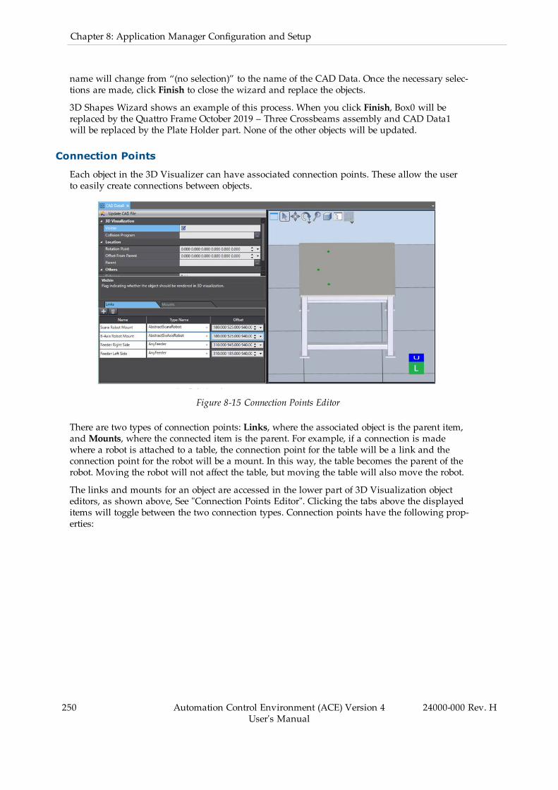
250 Automation Control Environment (ACE) Version 4User's Manual
24000-000 Rev. H
Chapter 8: Application Manager Configuration and Setup
name will change from “(no selection)” to the name of the CAD Data. Once the necessary selec-tions are made, click Finish to close the wizard and replace the objects.
3D Shapes Wizard shows an example of this process. When you click Finish, Box0 will bereplaced by the Quattro Frame October 2019 – Three Crossbeams assembly and CAD Data1will be replaced by the Plate Holder part. None of the other objects will be updated.
Connection Points
Each object in the 3D Visualizer can have associated connection points. These allow the userto easily create connections between objects.
Figure 8-15 Connection Points Editor
There are two types of connection points: Links, where the associated object is the parent item,andMounts, where the connected item is the parent. For example, if a connection is madewhere a robot is attached to a table, the connection point for the table will be a link and theconnection point for the robot will be a mount. In this way, the table becomes the parent of therobot. Moving the robot will not affect the table, but moving the table will also move the robot.
The links and mounts for an object are accessed in the lower part of 3D Visualization objecteditors, as shown above, See "Connection Points Editor". Clicking the tabs above the displayeditems will toggle between the two connection types. Connection points have the following prop-erties:
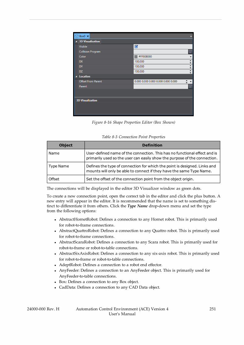
Figure 8-16 Shape Properties Editor (Box Shown)
Table 8-3 Connection Point Properties
Object Definition
Name User-defined name of the connection. This has no functional effect and isprimarily used so the user can easily show the purpose of the connection.
Type Name Defines the type of connection for which the point is designed. Links andmounts will only be able to connect if they have the same Type Name.
Offset Set the offset of the connection point from the object origin.
The connections will be displayed in the editor 3D Visualizer window as green dots.
To create a new connection point, open the correct tab in the editor and click the plus button. Anew entry will appear in the editor. It is recommended that the name is set to something dis-tinct to differentiate it from others. Click the Type Name drop-down menu and set the typefrom the following options:
l AbstractHornetRobot: Defines a connection to any Hornet robot. This is primarily usedfor robot-to-frame connections.
l AbstractQuattroRobot: Defines a connection to any Quattro robot. This is primarily usedfor robot-to-frame connections.
l AbstractScaraRobot: Defines a connection to any Scara robot. This is primarily used forrobot-to-frame or robot-to-table connections.
l AbstractSixAxisRobot: Defines a connection to any six-axis robot. This is primarily usedfor robot-to-frame or robot-to-table connections.
l AdeptRobot: Defines a connection to a robot end effector.l AnyFeeder: Defines a connection to an AnyFeeder object. This is primarily used forAnyFeeder-to-table connections.
l Box: Defines a connection to any Box object.l CadData: Defines a connection to any CAD Data object.
24000-000 Rev. H Automation Control Environment (ACE) Version 4User's Manual
251
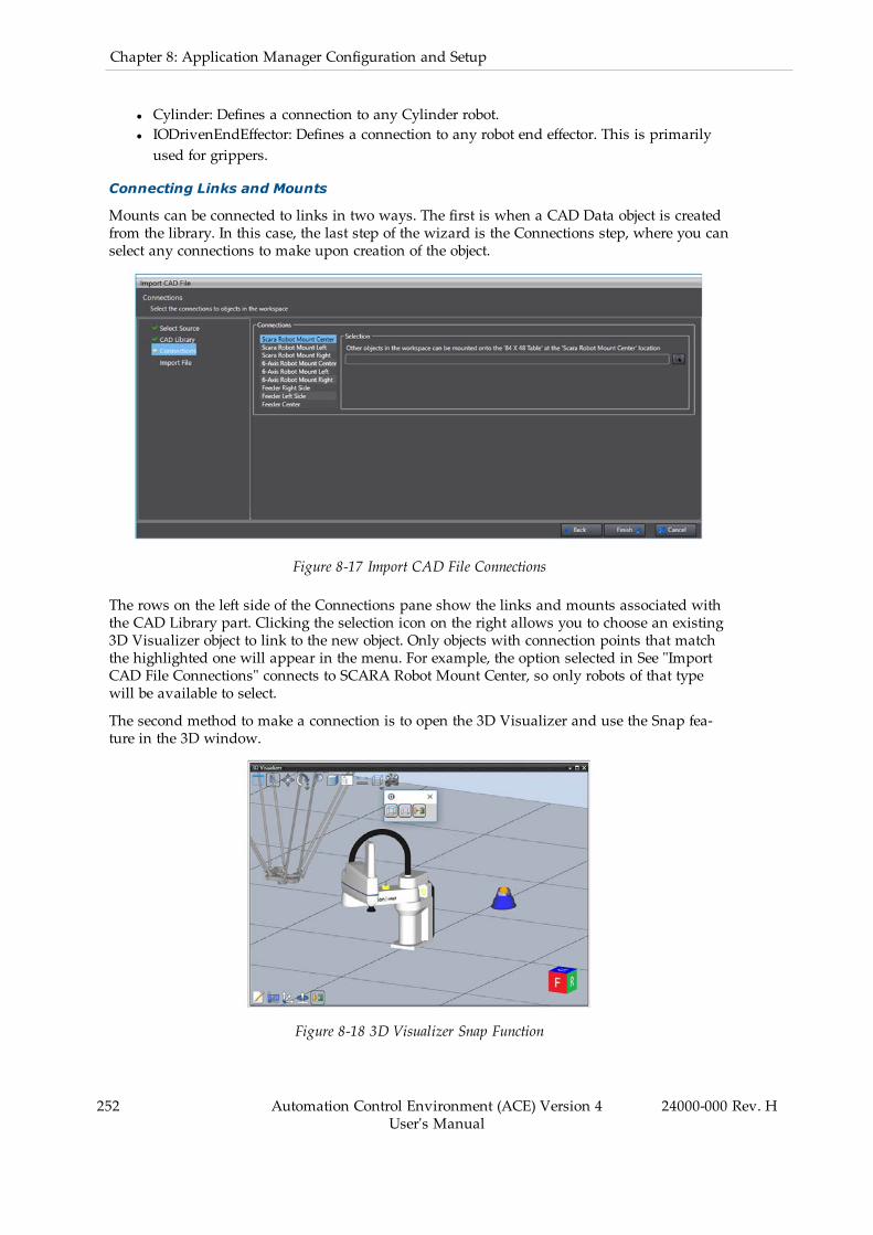
252 Automation Control Environment (ACE) Version 4User's Manual
24000-000 Rev. H
Chapter 8: Application Manager Configuration and Setup
l Cylinder: Defines a connection to any Cylinder robot.l IODrivenEndEffector: Defines a connection to any robot end effector. This is primarilyused for grippers.
Connecting Links and Mounts
Mounts can be connected to links in two ways. The first is when a CAD Data object is createdfrom the library. In this case, the last step of the wizard is the Connections step, where you canselect any connections to make upon creation of the object.
Figure 8-17 Import CAD File Connections
The rows on the left side of the Connections pane show the links and mounts associated withthe CAD Library part. Clicking the selection icon on the right allows you to choose an existing3D Visualizer object to link to the new object. Only objects with connection points that matchthe highlighted one will appear in the menu. For example, the option selected in See "ImportCAD File Connections" connects to SCARA Robot Mount Center, so only robots of that typewill be available to select.
The second method to make a connection is to open the 3D Visualizer and use the Snap fea-ture in the 3D window.
Figure 8-18 3D Visualizer Snap Function
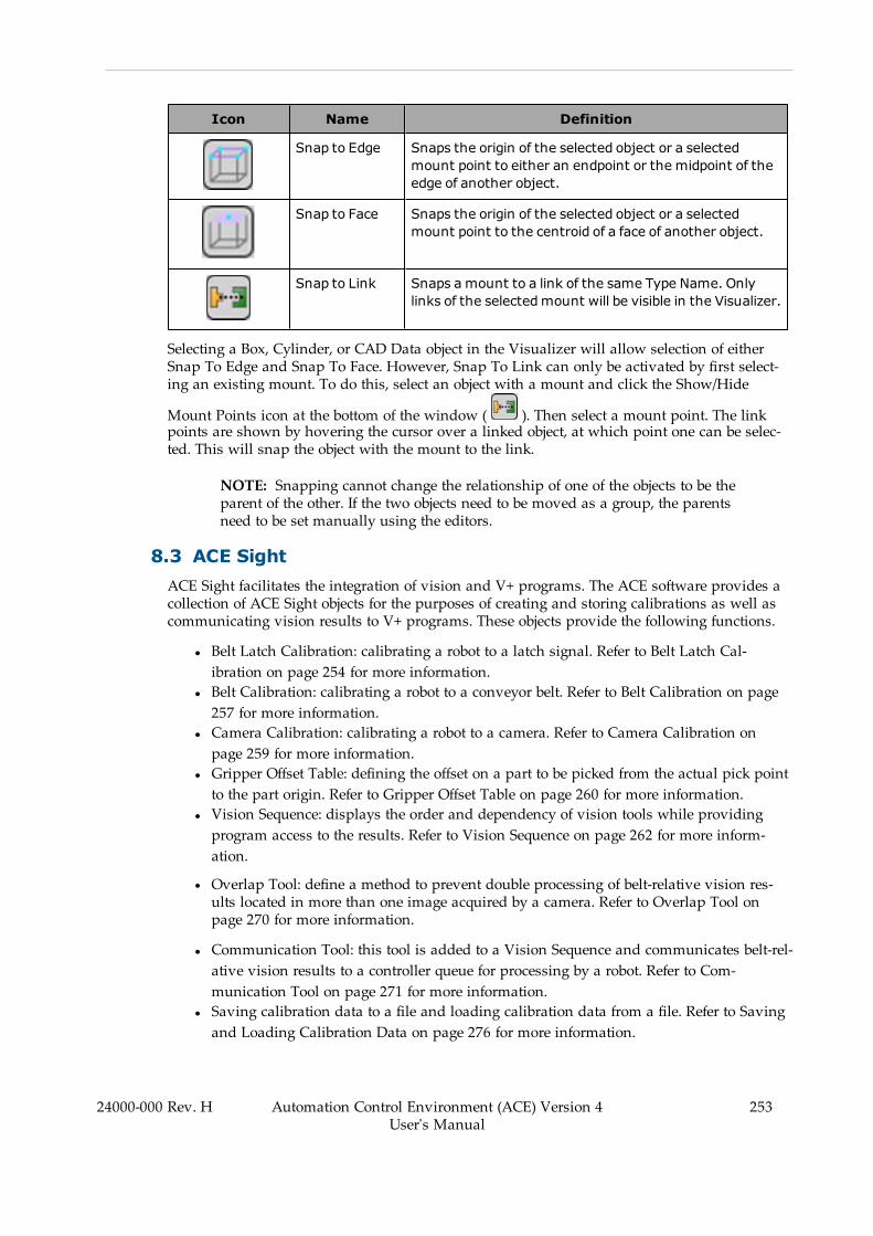
Icon Name Definition
Snap to Edge Snaps the origin of the selected object or a selectedmount point to either an endpoint or the midpoint of theedge of another object.
Snap to Face Snaps the origin of the selected object or a selectedmount point to the centroid of a face of another object.
Snap to Link Snaps amount to a link of the same Type Name. Onlylinks of the selectedmount will be visible in the Visualizer.
Selecting a Box, Cylinder, or CAD Data object in the Visualizer will allow selection of eitherSnap To Edge and Snap To Face. However, Snap To Link can only be activated by first select-ing an existing mount. To do this, select an object with a mount and click the Show/Hide
Mount Points icon at the bottom of the window ( ). Then select a mount point. The linkpoints are shown by hovering the cursor over a linked object, at which point one can be selec-ted. This will snap the object with the mount to the link.
NOTE: Snapping cannot change the relationship of one of the objects to be theparent of the other. If the two objects need to be moved as a group, the parentsneed to be set manually using the editors.
8.3 ACE SightACE Sight facilitates the integration of vision and V+ programs. The ACE software provides acollection of ACE Sight objects for the purposes of creating and storing calibrations as well ascommunicating vision results to V+ programs. These objects provide the following functions.
l Belt Latch Calibration: calibrating a robot to a latch signal. Refer to Belt Latch Cal-ibration on page 254 for more information.
l Belt Calibration: calibrating a robot to a conveyor belt. Refer to Belt Calibration on page257 for more information.
l Camera Calibration: calibrating a robot to a camera. Refer to Camera Calibration onpage 259 for more information.
l Gripper Offset Table: defining the offset on a part to be picked from the actual pick pointto the part origin. Refer to Gripper Offset Table on page 260 for more information.
l Vision Sequence: displays the order and dependency of vision tools while providingprogram access to the results. Refer to Vision Sequence on page 262 for more inform-ation.
l Overlap Tool: define a method to prevent double processing of belt-relative vision res-ults located in more than one image acquired by a camera. Refer to Overlap Tool onpage 270 for more information.
l Communication Tool: this tool is added to a Vision Sequence and communicates belt-rel-ative vision results to a controller queue for processing by a robot. Refer to Com-munication Tool on page 271 for more information.
l Saving calibration data to a file and loading calibration data from a file. Refer to Savingand Loading Calibration Data on page 276 for more information.
24000-000 Rev. H Automation Control Environment (ACE) Version 4User's Manual
253

254 Automation Control Environment (ACE) Version 4User's Manual
24000-000 Rev. H
Chapter 8: Application Manager Configuration and Setup
IMPORTANT: Only one instance of ACE software can run with ACE Sight func-tions. If an additional instance of the ACE software is started on the PC, [ACESight Offline] will be displayed in status bar. In this state, any ACE Sight Key-words may return an error.
Figure 8-19 ACE Sight - Offline Message
ACE Sight Object Configuration
Many ACE Sight objects are dependent on other ACE software objects. When configuring anew ACE Sight object, the editor will provide information about other objects that may need tobe configured or defined. When configuring a new ACE Sight object, the Edit Pane will indicatemissing dependencies as shown below (as an example).
Figure 8-20 ACE Sight Object Configuration - Missing Dependency
Belt Latch Calibration
Belt Latch Calibration calibrates a robot to a latch. This calibration uses a user-supplied sensorto generate a latch signal when an object, such as a pallet, reaches a specific point on a
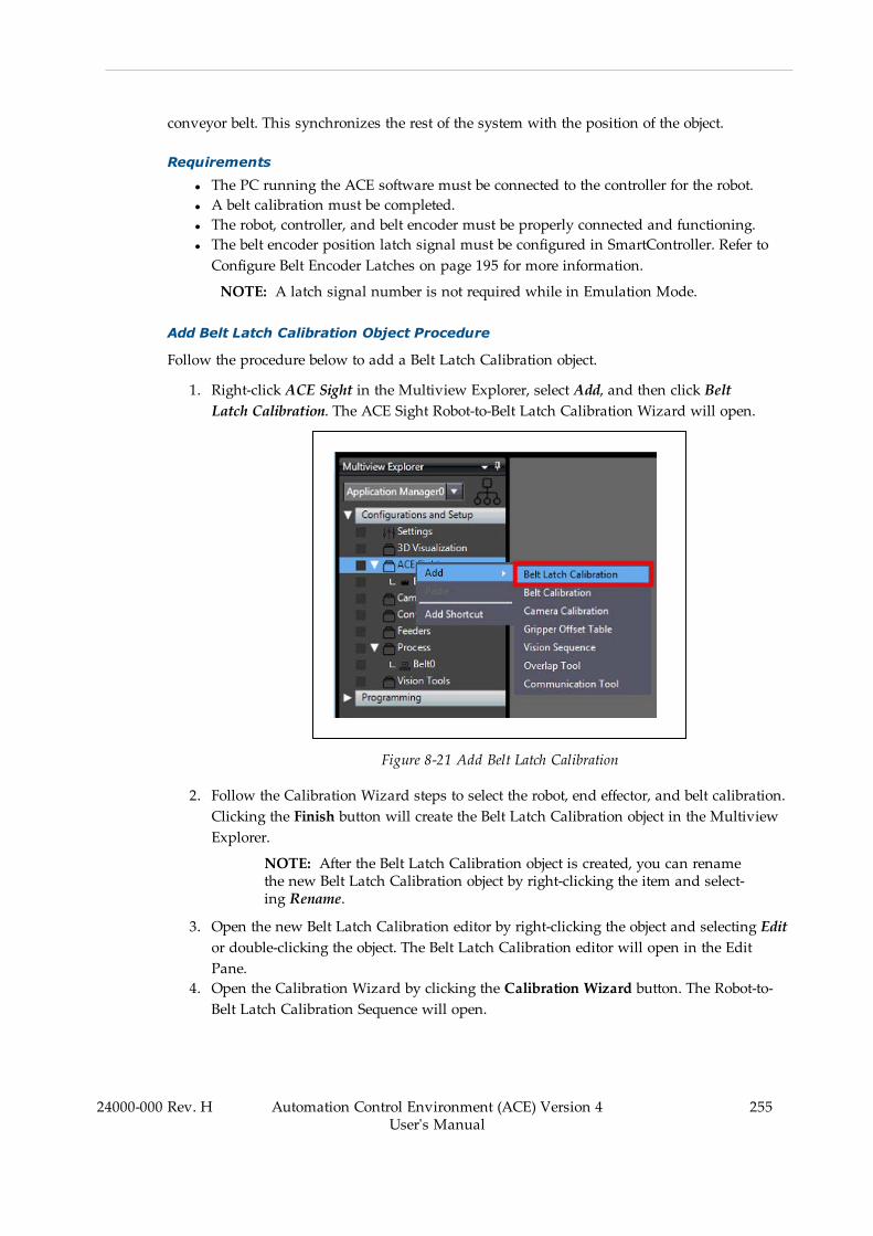
conveyor belt. This synchronizes the rest of the system with the position of the object.
Requirements
l The PC running the ACE software must be connected to the controller for the robot.l A belt calibration must be completed.l The robot, controller, and belt encoder must be properly connected and functioning.l The belt encoder position latch signal must be configured in SmartController. Refer toConfigure Belt Encoder Latches on page 195 for more information.
NOTE: A latch signal number is not required while in Emulation Mode.
Add Belt Latch Calibration Object Procedure
Follow the procedure below to add a Belt Latch Calibration object.
1. Right-click ACE Sight in the Multiview Explorer, select Add, and then click BeltLatch Calibration. The ACE Sight Robot-to-Belt Latch Calibration Wizard will open.
Figure 8-21 Add Belt Latch Calibration
2. Follow the Calibration Wizard steps to select the robot, end effector, and belt calibration.Clicking the Finish button will create the Belt Latch Calibration object in the MultiviewExplorer.
NOTE: After the Belt Latch Calibration object is created, you can renamethe new Belt Latch Calibration object by right-clicking the item and select-ing Rename.
3. Open the new Belt Latch Calibration editor by right-clicking the object and selecting Editor double-clicking the object. The Belt Latch Calibration editor will open in the EditPane.
4. Open the Calibration Wizard by clicking the Calibration Wizard button. The Robot-to-Belt Latch Calibration Sequence will open.
24000-000 Rev. H Automation Control Environment (ACE) Version 4User's Manual
255

256 Automation Control Environment (ACE) Version 4User's Manual
24000-000 Rev. H
Chapter 8: Application Manager Configuration and Setup
Figure 8-22 Calibration Wizard - Belt Latch Calibration
5. Make a selection for the end effector and set the latch sensor offset position. After com-pleting these steps, click the Finish button. This will close the Robot-to-Belt Latch Cal-ibration Sequence.
NOTE: The latch sensor is depicted in the wizard's virtual display asshown below.
Figure 8-23 Teach the Sensor Offset
6. Review the Belt Latch Calibration object properties in the Belt Latch Calibration editor toconfirm the configuration. You can also use the Robot-to-Belt Latch Calibration TestSequence by clicking the Test Calibration button ( ) to confirm the

configuration is correct. If the configuration is correct, the calibration procedure is com-plete.
Belt Calibration
Belt Calibration calibrates a robot to a conveyor belt. Configuring this object will establish arelationship between the belt, its encoder, and the robot. This calibration is necessary when therobot will handle parts that are moving on a conveyor belt. Refer to Robot-to-Belt Calibrationon page 32 for more information.
Requirements
l The robot, controller, and belt must be correctly connected and functioning.l The PC running the ACE software must be connected to the controller for the robot andbelt.
l The robot and gripper must be defined in the ACE software.
Add Belt Calibration Object Procedure
Follow the procedure below to add a Belt Calibration object.
1. Right-click ACE Sight in the Multiview Explorer, select Add, and then click Belt Cal-ibration. The ACE Sight Robot-to-Belt Calibration Wizard will open.
Figure 8-24 Add Belt Calibration
2. Follow the Calibration Wizard steps to select the robot, end effector, and encoder. Click-ing the Finish button will create the Belt Calibration object in the Multiview Explorer.
NOTE: After the Belt Calibration object is created, you can rename thenew Belt Calibration object by right-clicking the item and selectingRename.
3. Open the new Belt Calibration editor by right-clicking the object and selecting Edit ordouble-clicking the object. The Belt Calibration editor will open in the Edit Pane.
24000-000 Rev. H Automation Control Environment (ACE) Version 4User's Manual
257
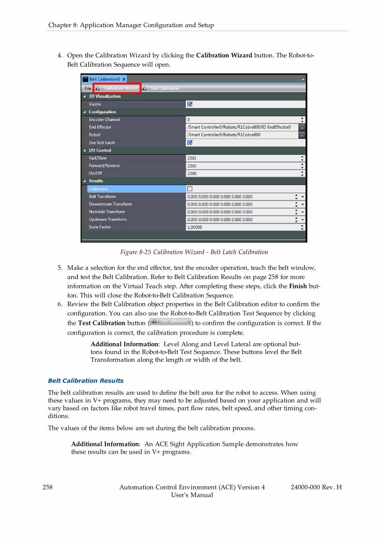
258 Automation Control Environment (ACE) Version 4User's Manual
24000-000 Rev. H
Chapter 8: Application Manager Configuration and Setup
4. Open the Calibration Wizard by clicking the Calibration Wizard button. The Robot-to-Belt Calibration Sequence will open.
Figure 8-25 Calibration Wizard - Belt Latch Calibration
5. Make a selection for the end effector, test the encoder operation, teach the belt window,and test the Belt Calibration. Refer to Belt Calibration Results on page 258 for moreinformation on the Virtual Teach step. After completing these steps, click the Finish but-ton. This will close the Robot-to-Belt Calibration Sequence.
6. Review the Belt Calibration object properties in the Belt Calibration editor to confirm theconfiguration. You can also use the Robot-to-Belt Calibration Test Sequence by clickingthe Test Calibration button ( ) to confirm the configuration is correct. If theconfiguration is correct, the calibration procedure is complete.
Additional Information: Level Along and Level Lateral are optional but-tons found in the Robot-to-Belt Test Sequence. These buttons level the BeltTransformation along the length or width of the belt.
Belt Calibration Results
The belt calibration results are used to define the belt area for the robot to access. When usingthese values in V+ programs, they may need to be adjusted based on your application and willvary based on factors like robot travel times, part flow rates, belt speed, and other timing con-ditions.
The values of the items below are set during the belt calibration process.
Additional Information: An ACE Sight Application Sample demonstrates howthese results can be used in V+ programs.

Belt Transform
The Belt Transform is the frame that is generated from the downstream and upstream trans-form values to define the orientation of the belt window.
Downstream Transform
The Downstream Transform is used to define the downstream belt window limit in a V+ pro-gram. This sets the downstream threshold where the robot is allowed to access an object. If therobot is tracking a part when it reaches this point, a Belt Window Violation will occur.
Nearside Transform
The Nearside Transform is the third point taught in the calibration and is used to define thewidth of the belt window.
Upstream Transform
The Upstream Transform is used to define the upstream belt window limit in a V+ program.
(Encoder) Scale Factor
The belt encoder Scale Factor sets the amount of millimeters per encoder count for the belt'sencoder.
Camera Calibration
Camera Calibration calibrates a robot to a camera. This calibration is necessary if you will beusing a vision system with a robot.
Configuring this object will establish a relationship between the following objects (whereapplicable).
l Cameral Beltl Robotl Robot end effector (robot tool)
Requirements
l The robot, controller, belt (if used), and camera must be correctly connected and func-tioning.
l The Virtual Camera calibration (mm/pixel) must be complete.l The PC running the ACE software must be connected to the controller for the robot (andbelt).
l The Belt Calibration Wizard must have completed successfully if a conveyor belt isused.
Add Camera Calibration Object Procedure
Follow the procedure below to add a Camera Calibration object.
1. Right-click ACE Sight in the Multiview Explorer, select Add, and then click Camera Cal-ibration. The ACE Sight Camera Calibration Wizard will open.
24000-000 Rev. H Automation Control Environment (ACE) Version 4User's Manual
259
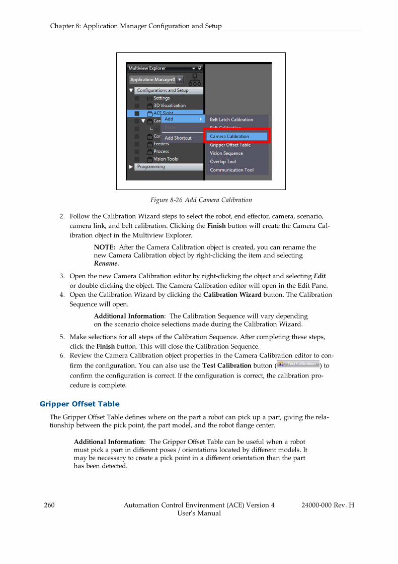
260 Automation Control Environment (ACE) Version 4User's Manual
24000-000 Rev. H
Chapter 8: Application Manager Configuration and Setup
Figure 8-26 Add Camera Calibration
2. Follow the Calibration Wizard steps to select the robot, end effector, camera, scenario,camera link, and belt calibration. Clicking the Finish button will create the Camera Cal-ibration object in the Multiview Explorer.
NOTE: After the Camera Calibration object is created, you can rename thenew Camera Calibration object by right-clicking the item and selectingRename.
3. Open the new Camera Calibration editor by right-clicking the object and selecting Editor double-clicking the object. The Camera Calibration editor will open in the Edit Pane.
4. Open the Calibration Wizard by clicking the Calibration Wizard button. The CalibrationSequence will open.
Additional Information: The Calibration Sequence will vary dependingon the scenario choice selections made during the Calibration Wizard.
5. Make selections for all steps of the Calibration Sequence. After completing these steps,click the Finish button. This will close the Calibration Sequence.
6. Review the Camera Calibration object properties in the Camera Calibration editor to con-firm the configuration. You can also use the Test Calibration button ( ) toconfirm the configuration is correct. If the configuration is correct, the calibration pro-cedure is complete.
Gripper Offset Table
The Gripper Offset Table defines where on the part a robot can pick up a part, giving the rela-tionship between the pick point, the part model, and the robot flange center.
Additional Information: The Gripper Offset Table can be useful when a robotmust pick a part in different poses / orientations located by different models. Itmay be necessary to create a pick point in a different orientation than the parthas been detected.
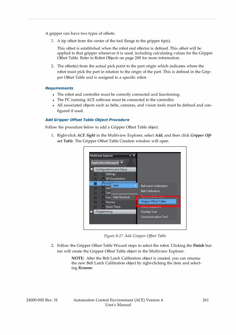
A gripper can have two types of offsets:
1. A tip offset from the center of the tool flange to the gripper tip(s).
This offset is established when the robot end effector is defined. This offset will beapplied to that gripper whenever it is used, including calculating values for the GripperOffset Table. Refer to Robot Objects on page 208 for more information.
2. The offset(s) from the actual pick point to the part origin which indicates where therobot must pick the part in relation to the origin of the part. This is defined in the Grip-per Offset Table and is assigned to a specific robot.
Requirements
l The robot and controller must be correctly connected and functioning.l The PC running ACE software must be connected to the controller.l All associated objects such as belts, cameras, and vision tools must be defined and con-figured if used.
Add Gripper Offset Table Object Procedure
Follow the procedure below to add a Gripper Offset Table object.
1. Right-click ACE Sight in the Multiview Explorer, select Add, and then click Gripper Off-set Table. The Gripper Offset Table Creation window will open.
Figure 8-27 Add Gripper Offset Table
2. Follow the Gripper Offset Table Wizard steps to select the robot. Clicking the Finish but-ton will create the Gripper Offset Table object in the Multiview Explorer.
NOTE: After the Belt Latch Calibration object is created, you can renamethe new Belt Latch Calibration object by right-clicking the item and select-ing Rename.
24000-000 Rev. H Automation Control Environment (ACE) Version 4User's Manual
261
262 Automation Control Environment (ACE) Version 4User's Manual
24000-000 Rev. H
Chapter 8: Application Manager Configuration and Setup
3. Open the new Gripper Offset Table editor by right-clicking the object and selecting Editor double-clicking the object. The Gripper Offset Table editor will open in the Edit Pane.
4. Use the Add button ( ) to create a new Gripper Offset index item. There are twomethods for editing the Offset values:
Direct Value Entry
Change the values directly for the Gripper Offset index. The following items can beentered directly.
l Index: Enter a unique value to reference the Gripper Offset values.l Offset: Enter gripper offset values expressed as (x, y, z, yaw, pitch, roll).l Description: Enter a description for the Gripper Offset index entry.
Teach Button
The Teach button ( ) opens a Gripper Offset Teach Wizard that guides youthrough several steps to teach an Offset value while taking into account other objectsthat may exist in the project such as:
l Specific end effectorsl Cameras and Camera Calibrationsl Vision Toolsl Belts and Belt Calibrations
NOTE: In the Locate Object step of the Gripper Offset Teach Wizard, theNext button will not be available if the selected Vision Tool is not con-figured properly. For example, if a location is not obtained from the VisionTool, you cannot proceed.
Additional Information: Use the Delete button ( ) to remove anexisting Gripper Offset Index entry.
5. When all Gripper Offsets values are set, the configuration procedure is complete.
Vision Sequence
A Vision Sequence lets you see the order and dependency of vision tools that will be executedwhile giving V+ programs a means for retrieving results from vision tools. The VisionSequence object shows the list of tools that will be executed as part of the sequence, the orderin which they will be executed, and the Index associated with each one. The Index is the exe-cution order of each tool.
The sequence cannot be modified from the Sequence Display Window. It shows the order inwhich the tools will be executed, based on the parent tool specified in each tool. The actualorder of a sequence is determined when you specify the Relative To parameter for each of thetools to be included in the sequence.
When you add a Vision Sequence object to the project, the Vision Tool parameter determinesthe Top-Level tool, and all the tools you specified as the Relative To parameter in the chainunder that will automatically show up as members of the sequence, in the order you set.
In a sequence, you specify a robot-to-camera calibration. The calibration is applied to any res-ult accessed by a VLOCATION transformation function.

A Vision Sequence maps a V+ sequence number to the top-level vision tool. Top-level meansthe vision tool with the highest number in the sequence (this will be the last tool executed).This enables you to access an Vision Sequence with the sequence_id parameter from a V+ pro-gram command.
NOTE: V+ programs can access the results of intermediate (not only top-level)tools when a sequence is executed because each tool has an index that can beaccessed.
The Default Calibration is applied to all results, even if they are not the top-leveltool.
Requirements
l The robot and controller must be correctly connected and functioning.l At least one Vision Tool must be configured to define in the sequence.l A camera must be defined in the ACE software.l A Camera Calibration must be completed if a VLOCATION command is used in aV+ program.
Add Vision Sequence Object Procedure
Follow the procedure below to add a Vision Sequence object.
1. Right-click ACE Sight in the Multiview Explorer, select Add, and then clickVision Sequence. A Vision Sequence object will be added to the Multiview Explorer.
Figure 8-28 Add Vision Sequence
NOTE: After the Vision Sequence object is created, you can rename thenew Vision Sequence object by right-clicking the item and selectingRename.
2. Open the new Vision Sequence editor by right-clicking the object and selecting Edit ordouble-clicking the object. The Vision Sequence editor will open in the Edit Pane.
24000-000 Rev. H Automation Control Environment (ACE) Version 4User's Manual
263
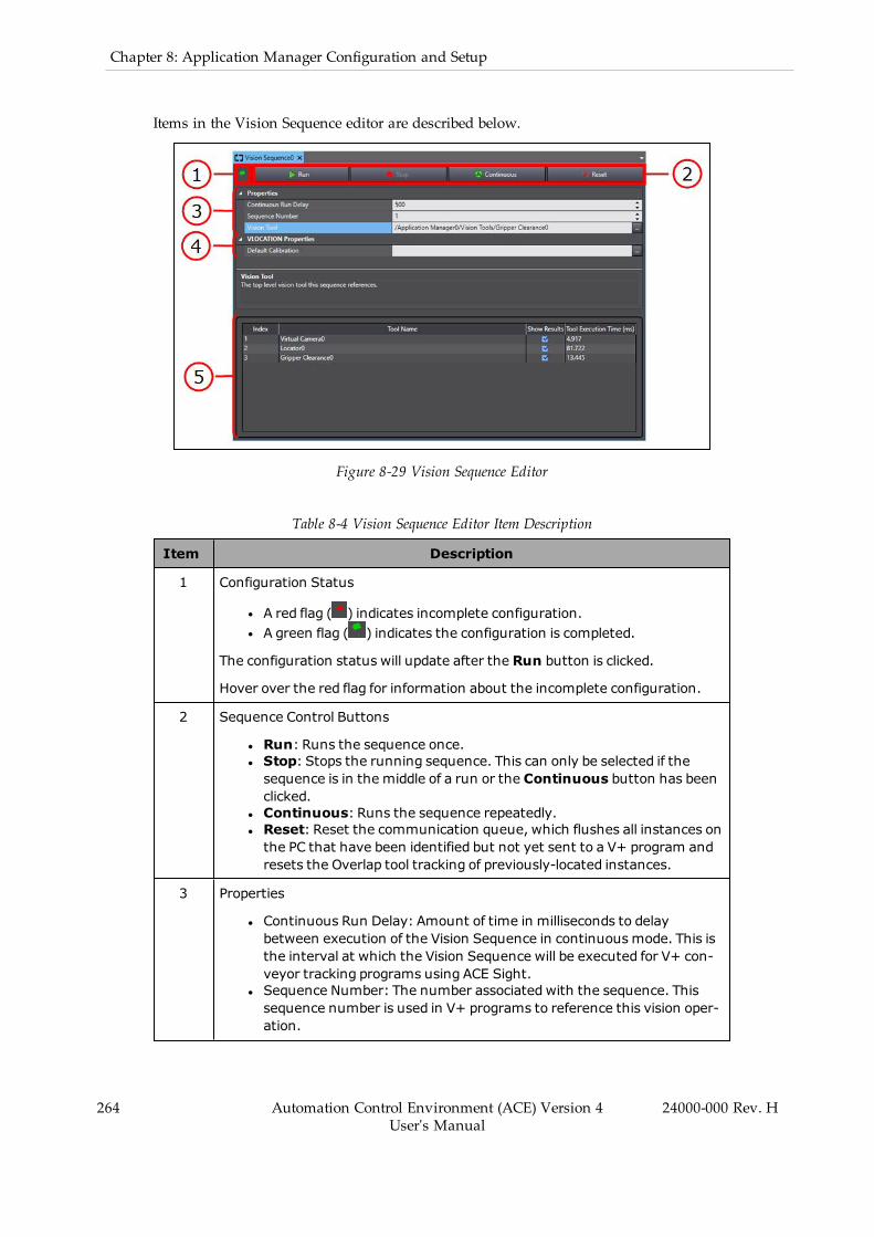
264 Automation Control Environment (ACE) Version 4User's Manual
24000-000 Rev. H
Chapter 8: Application Manager Configuration and Setup
Items in the Vision Sequence editor are described below.
Figure 8-29 Vision Sequence Editor
Table 8-4 Vision Sequence Editor Item Description
Item Description
1 Configuration Status
l A red flag ( ) indicates incomplete configuration.l A green flag ( ) indicates the configuration is completed.
The configuration status will update after the Run button is clicked.
Hover over the red flag for information about the incomplete configuration.
2 Sequence Control Buttons
l Run: Runs the sequence once.l Stop: Stops the running sequence. This can only be selected if thesequence is in the middle of a run or the Continuous button has beenclicked.
l Continuous: Runs the sequence repeatedly.l Reset: Reset the communication queue, which flushes all instances onthe PC that have been identified but not yet sent to a V+ program andresets the Overlap tool tracking of previously-located instances.
3 Properties
l Continuous Run Delay: Amount of time in milliseconds to delaybetween execution of the Vision Sequence in continuousmode. This isthe interval at which the Vision Sequence will be executed for V+ con-veyor tracking programs using ACE Sight.
l Sequence Number: The number associated with the sequence. Thissequence number is used in V+ programs to reference this vision oper-ation.

Item Description
l Vision Tool: Top-level vision tool this sequence references. All toolsrequired to operate the tool selected here will be included in thesequence.
4 VLOCATION Properties
Default Calibration: Default camera calibration used to apply to a VLOCATIONtransformation function from V+ programs. This must reference a Camera Cal-ibration object shown in the Multiview Explorer.
5 Sequence Layout
The Vision Sequence for the specified Vision Tool.
3. Make the necessary configuration settings in the Edit Pane to complete the procedure foradding a Vision Sequence object.
Vision Sequence Configuration
The Vision Sequence editor shows the list of tools that will be executed as part of the sequence,the order in which they will be executed, and the associated index number of each. The toolsare executed in ascending Index value.
The main property of a Vision Sequence is the Vision Tool parameter that defines what toolmarks the end of the sequence. Once it is selected, the Sequence Layout will be populated bythe top-level tool’s dependencies down to the initial image source. For example, the VisionSequence shown in Figure 8-29 is based on a Gripper Clearance tool that has Relative To set toa Locator tool. These are included by starting with the top-level tool and its Image Source andRelative To properties and working through the same properties of subsequent tools. This islaid out in the following figure that shows how the tools are associated and what data ispassed between them.
24000-000 Rev. H Automation Control Environment (ACE) Version 4User's Manual
265
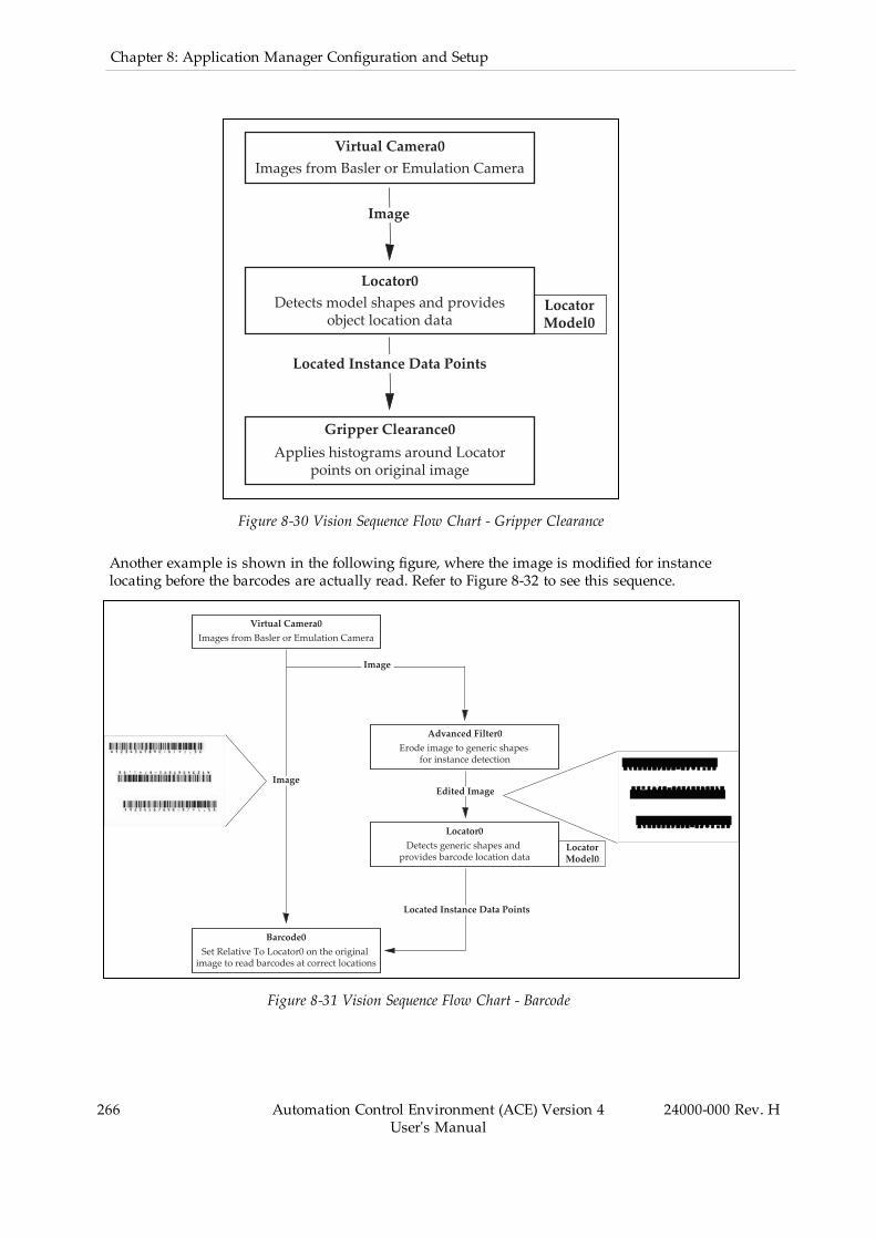
266 Automation Control Environment (ACE) Version 4User's Manual
24000-000 Rev. H
Chapter 8: Application Manager Configuration and Setup
Virtual Camera0Images from Basler or Emulation Camera
Locator0Detects model shapes and provides
object location dataLocator Model0
Gripper Clearance0Applies histograms around Locator
points on original image
Image
Located Instance Data Points
Figure 8-30 Vision Sequence Flow Chart - Gripper Clearance
Another example is shown in the following figure, where the image is modified for instancelocating before the barcodes are actually read. Refer to Figure 8-32 to see this sequence.
Virtual Camera0Images from Basler or Emulation Camera
Image
Advanced Filter0Erode image to generic shapes
for instance detection
Locator0Detects generic shapes and
provides barcode location data
Barcode0Set Relative To Locator0 on the original
image to read barcodes at correct locations
Locator Model0
Image
Edited Image
Located Instance Data Points
Figure 8-31 Vision Sequence Flow Chart - Barcode

Figure 8-32 Vision Sequence - Barcode
NOTE: The sequence itself cannot be changed in the Vision Sequence editor. TheRelative To properties in the tools themselves must be used to do this.
For some applications, it may be beneficial to have multiple sequences whereone sequence is a subset of another.
Vision Sequences also provide a means for V+ programs to obtain information from visiontools using a sequence_id parameter. In addition, the robot-to-camera calibration in the DefaultCalibration property can be accessed using a VLOCATION transformation function. Thereturned values are provided in the following table.
Additional Information: Refer to the ACE Reference Guide for more informationabout VLOCATION.
Table 8-5 Vision Sequence Returned Values
Value Description
Index Tool number within the sequence. The tools are run in ascendingorder.
Tool Name Name of the tool to run.
Show Results Defines if the tool results will be shown in the Vision Window.
This is based on the Show Results Graphics property of the respect-ive tool.
NOTE: This option is not selectable for tools that donot have the Show Results Graphics property.
Tool Execution Time(ms)
Time (in milliseconds) taken for the tool to run in the most recentexecution of the sequence.
Frame and Group Behavior
The Frame / Group result defines the number of the frames referenced in the calculation of thetool. If the tool is not set relative to any other tool, the results for this column will all bereturned as 1. However, when the tool is set relative to a tool with more than one returnedinstance, the Frame / Group value reflects the result instance of the previous tool.
For example, Figure 8-33 and Figure 8-34 show a sequence that is designed to find the starswithin the defined shapes. The Locator tool in Figure 8-33 disambiguates between the shapes
24000-000 Rev. H Automation Control Environment (ACE) Version 4User's Manual
267
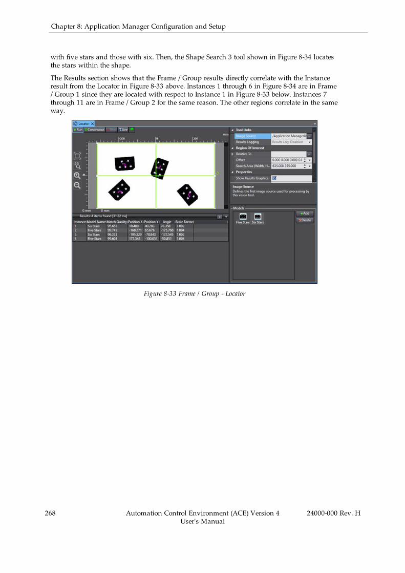
268 Automation Control Environment (ACE) Version 4User's Manual
24000-000 Rev. H
Chapter 8: Application Manager Configuration and Setup
with five stars and those with six. Then, the Shape Search 3 tool shown in Figure 8-34 locatesthe stars within the shape.
The Results section shows that the Frame / Group results directly correlate with the Instanceresult from the Locator in Figure 8-33 above. Instances 1 through 6 in Figure 8-34 are in Frame/ Group 1 since they are located with respect to Instance 1 in Figure 8-33 below. Instances 7through 11 are in Frame / Group 2 for the same reason. The other regions correlate in the sameway.
Figure 8-33 Frame / Group - Locator
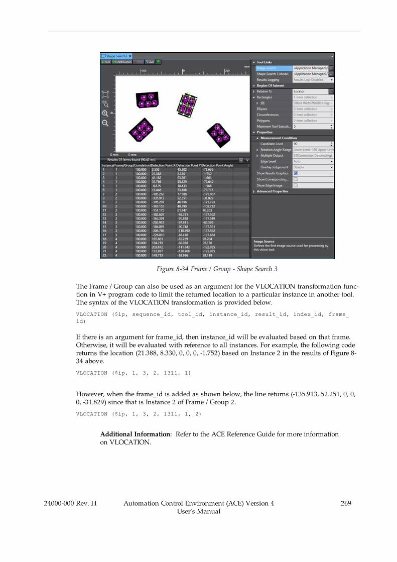
Figure 8-34 Frame / Group - Shape Search 3
The Frame / Group can also be used as an argument for the VLOCATION transformation func-tion in V+ program code to limit the returned location to a particular instance in another tool.The syntax of the VLOCATION transformation is provided below.
VLOCATION ($ip, sequence_id, tool_id, instance_id, result_id, index_id, frame_id)
If there is an argument for frame_id, then instance_id will be evaluated based on that frame.Otherwise, it will be evaluated with reference to all instances. For example, the following codereturns the location (21.388, 8.330, 0, 0, 0, -1.752) based on Instance 2 in the results of Figure 8-34 above.
VLOCATION ($ip, 1, 3, 2, 1311, 1)
However, when the frame_id is added as shown below, the line returns (-135.913, 52.251, 0, 0,0, -31.829) since that is Instance 2 of Frame / Group 2.
VLOCATION ($ip, 1, 3, 2, 1311, 1, 2)
Additional Information: Refer to the ACE Reference Guide for more informationon VLOCATION.
24000-000 Rev. H Automation Control Environment (ACE) Version 4User's Manual
269
270 Automation Control Environment (ACE) Version 4User's Manual
24000-000 Rev. H
Chapter 8: Application Manager Configuration and Setup
Overlap Tool
The Overlap Tool ensures that parts moving on a conveyor belt are processed only once if loc-ated in multiple images. A part found by the Locator Vision Tool (or other input tools) may bepresent in multiple images acquired by the camera and this tool ensures that the robot is notinstructed to pick up or process the same part more than once. The input required by the Over-lap Tool can be provided by any tool that returns a transform instance. This tool is typicallyused in conveyor tracking applications.
Additional Information: It is often desirable to have images taken at an intervalthat is one-half of the field of view of belt travel. This makes it possible to gettwo images of the same part. In this case, the Overlap Tool can be used to filterout duplicates.
If an instance in the image is a new instance (Pass result) it is passed on to the next tool in thesequence. If an instance is already known, it is rejected (Fail result), and is not sent to the nexttool in the sequence. This avoids double-picking or double-processing of the object.
The Overlap Tool should be placed near the beginning of a sequence, just after the input tooland before any inspection tools in the sequence. This ensures that the same instance is not pro-cessed multiple times by the inspection tools. Refer to Vision Sequence on page 262 for moreinformation.
Requirements
l The camera, robot, and conveyor belt are calibrated, connected, and correctly func-tioning.
l The PC running the ACE software must be connected to the controller for the robot andbelt.
l The tool is receiving latched values from the input tool. The belt latch must be wired tothe controller and properly configured.
l A vision input tool is defined and configured.l The conveyor belt and the controller have been correctly assigned to a camera.
Add Overlap Tool Object Procedure
Follow the procedure below to add an Overlap Tool object.
1. Right-click ACE Sight in the Multiview Explorer, select Add, and then click OverlapTool. An Overlap Tool object will be added to the Multiview Explorer.
NOTE: After the Overlap Tool object is created, you can rename the newOverlap Tool object by right-clicking the item and selecting Rename.

Figure 8-35 Add Overlap Tool
2. Open the new Overlap Tool editor by right-clicking the object and selecting Edit ordouble-clicking the object. The Overlap Tool editor will open in the Edit Pane.
3. Make all necessary settings in the Overlap Tool editor. When all settings are completed,the Overlap Tool object configuration procedure is complete.
The Distance Parameter
This specifies how far an instance must be from the expected location of a known instance in adifferent image for it to be considered a new instance. Distance is specified in mm. It should beas small as possible without causing double-picks.
l If Distance is too large, nearby instances will be interpreted as duplicates of a differentinstance, and some will not be picked.
l If Distance is too small, two transforms will be interpreted as different instances, andthe system will try to double-pick the object.
Additional Information: 5 mm is a recommended starting value for the Distanceparameter.
NOTE: Rotation is ignored by the Overlap Tool. Only the difference in X and Yis considered.
Communication Tool
The Communication Tool is a tool for conveyor tracking applications. The purpose of the Com-munication Tool is to transfer belt-relative vision results into a controller queue for processingby a robot.
24000-000 Rev. H Automation Control Environment (ACE) Version 4User's Manual
271
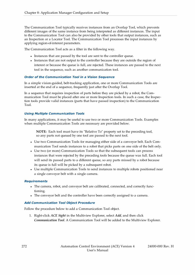
272 Automation Control Environment (ACE) Version 4User's Manual
24000-000 Rev. H
Chapter 8: Application Manager Configuration and Setup
The Communication Tool typically receives instances from an Overlap Tool, which preventsdifferent images of the same instance from being interpreted as different instances. The inputto the Communication Tool can also be provided by other tools that output instances, such asan Inspection or a Locator Tool. The Communication Tool processes the input instances byapplying region-of-interest parameters.
The Communication Tool acts as a filter in the following way.
l Instances that are passed by the tool are sent to the controller queue.l Instances that are not output to the controller because they are outside the region ofinterest or because the queue is full, are rejected. These instances are passed to the nexttool in the sequence, such as another communication tool.
Order of the Communication Tool in a Vision Sequence
In a simple vision-guided, belt-tracking application, one or more Communication Tools areinserted at the end of a sequence, frequently just after the Overlap Tool.
In a sequence that requires inspection of parts before they are picked by a robot, the Com-munication Tool must be placed after one or more Inspection tools. In such a case, the Inspec-tion tools provide valid instances (parts that have passed inspection) to the CommunicationTool.
Using Multiple Communication Tools
In many applications, it may be useful to use two or more Communication Tools. Exampleswhen multiple Communication Tools are necessary are provided below.
NOTE: Each tool must have its "Relative To" property set to the preceding tool,so any parts not queued by one tool are passed to the next tool.
l Use two Communication Tools for managing either side of a conveyor belt. Each Com-munication Tool sends instances to a robot that picks parts on one side of the belt only.
l Use two (or more) Communication Tools so that the subsequent tools can processinstances that were rejected by the preceding tools because the queue was full. Each toolwill send its passed parts to a different queue, so any parts missed by a robot becauseits queue is full will be picked by a subsequent robot.
l Use multiple Communication Tools to send instances to multiple robots positioned neara single conveyor belt with a single camera.
Requirements
l The camera, robot, and conveyor belt are calibrated, connected, and correctly func-tioning.
l The conveyor belt and the controller have been correctly assigned to a camera.
Add Communication Tool Object Procedure
Follow the procedure below to add a Communication Tool object.
1. Right-click ACE Sight in the Multiview Explorer, select Add, and then clickCommunication Tool. A Communication Tool will be added to the Multiview Explorer.
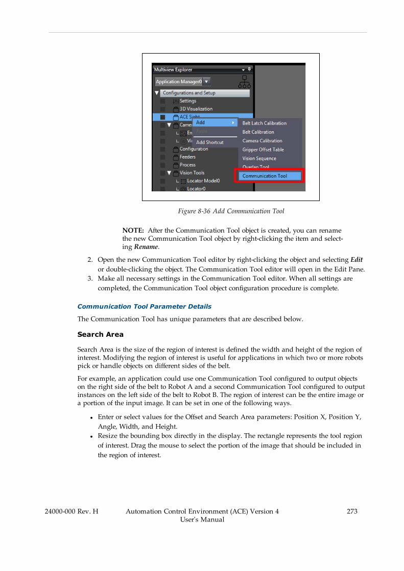
Figure 8-36 Add Communication Tool
NOTE: After the Communication Tool object is created, you can renamethe new Communication Tool object by right-clicking the item and select-ing Rename.
2. Open the new Communication Tool editor by right-clicking the object and selecting Editor double-clicking the object. The Communication Tool editor will open in the Edit Pane.
3. Make all necessary settings in the Communication Tool editor. When all settings arecompleted, the Communication Tool object configuration procedure is complete.
Communication Tool Parameter Details
The Communication Tool has unique parameters that are described below.
Search Area
Search Area is the size of the region of interest is defined the width and height of the region ofinterest. Modifying the region of interest is useful for applications in which two or more robotspick or handle objects on different sides of the belt.
For example, an application could use one Communication Tool configured to output objectson the right side of the belt to Robot A and a second Communication Tool configured to outputinstances on the left side of the belt to Robot B. The region of interest can be the entire image ora portion of the input image. It can be set in one of the following ways.
l Enter or select values for the Offset and Search Area parameters: Position X, Position Y,Angle, Width, and Height.
l Resize the bounding box directly in the display. The rectangle represents the tool regionof interest. Drag the mouse to select the portion of the image that should be included inthe region of interest.
24000-000 Rev. H Automation Control Environment (ACE) Version 4User's Manual
273

274 Automation Control Environment (ACE) Version 4User's Manual
24000-000 Rev. H
Chapter 8: Application Manager Configuration and Setup
Robot
The Robot parameter selects the robot that will handle or pick the instances output by the Com-munication tool.
NOTE: Ensure the selected robot and the robot of the selected camera calibrationare the same. If not, the transformation may be invalid.
Queue Parameters
The Communication Tool sends instances that pass its criteria to its queue, which is con-figured with the following parameters.
Queue Index
The Queue Index identifies the queue to which instances will be sent. Two different Com-munication Tools cannot write to the same queue on a controller. If there are multiple Com-munication Tools, either on the same or different PCs, each tool must be assigned a uniquequeue index. Choose a value from 1 to 100.
In a V+ program, this queue index must be used to access the instances sent to the controllerby the communication tool. For example, in the ACE Sight application sample for belt camerapick to static place, the "rob.pick" program will use "pick.queue" variable to store the queueindex used when obtaining instances. This occurs with the following V+ program call.
CALL getinstance(pick.queue, peek, inst.loc, model.idx, encoder.idx, vision.x,vision.y, vision.rot)
Queue Size
Queue Size specifies the number of instances that can be written to the queue. The ideal queuesize varies greatly and may require some testing to optimize this value for a specific applic-ation and environment. Choose a value from 1 to 100.
Queue Update
Queue Update specifies how often the Communication Tool will write new instance data to thequeue on the controller. The recommended setting is After Every Instance. The Queue Updateoptions are described below.
l After Every Instance: The After Every Instance setting sends each instance to the queueseparately as it becomes available. This minimizes the time until the first instance isavailable for use by the V+ program. If a large number of instances are located, then itcan take longer to push all of the data to the controller.
l After Last Instance: The After Last Instance setting sends multiple instances to thequeue at once. This mode minimizes the total data transfer time, but can increase thetime until the first instance is available for use since the robot is inactive during thetime that the PC is writing to the queue.
NOTE: Both Queue Update settings have the same function when only oneinstance is found.
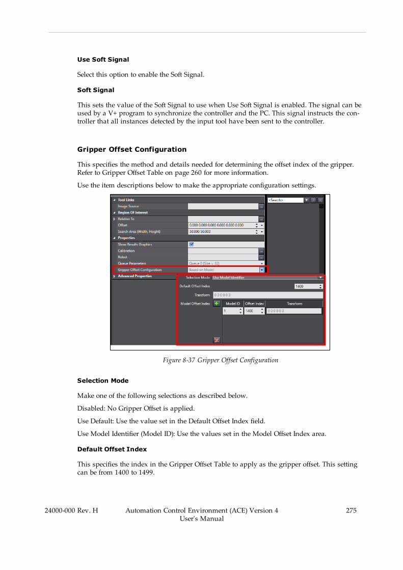
Use Soft Signal
Select this option to enable the Soft Signal.
Soft Signal
This sets the value of the Soft Signal to use when Use Soft Signal is enabled. The signal can beused by a V+ program to synchronize the controller and the PC. This signal instructs the con-troller that all instances detected by the input tool have been sent to the controller.
Gripper Offset Configuration
This specifies the method and details needed for determining the offset index of the gripper.Refer to Gripper Offset Table on page 260 for more information.
Use the item descriptions below to make the appropriate configuration settings.
Figure 8-37 Gripper Offset Configuration
Selection Mode
Make one of the following selections as described below.
Disabled: No Gripper Offset is applied.
Use Default: Use the value set in the Default Offset Index field.
Use Model Identifier (Model ID): Use the values set in the Model Offset Index area.
Default Offset Index
This specifies the index in the Gripper Offset Table to apply as the gripper offset. This settingcan be from 1400 to 1499.
24000-000 Rev. H Automation Control Environment (ACE) Version 4User's Manual
275
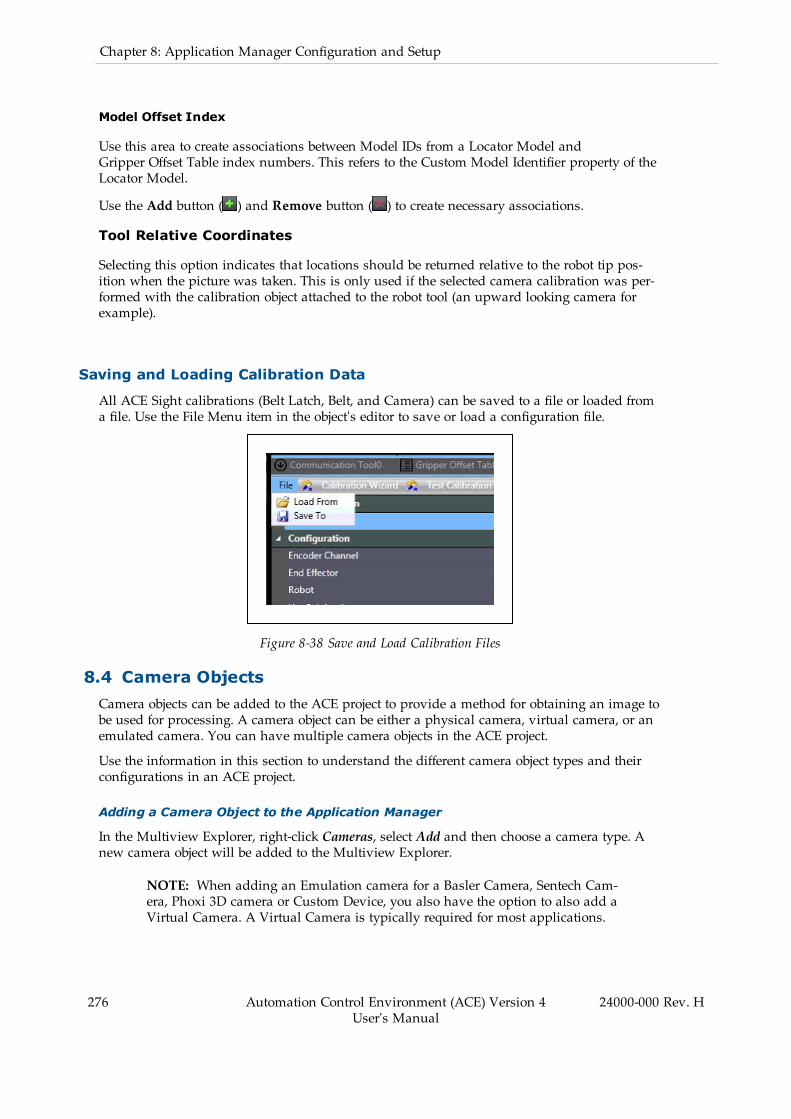
276 Automation Control Environment (ACE) Version 4User's Manual
24000-000 Rev. H
Chapter 8: Application Manager Configuration and Setup
Model Offset Index
Use this area to create associations between Model IDs from a Locator Model andGripper Offset Table index numbers. This refers to the Custom Model Identifier property of theLocator Model.
Use the Add button ( ) and Remove button ( ) to create necessary associations.
Tool Relative Coordinates
Selecting this option indicates that locations should be returned relative to the robot tip pos-ition when the picture was taken. This is only used if the selected camera calibration was per-formed with the calibration object attached to the robot tool (an upward looking camera forexample).
Saving and Loading Calibration Data
All ACE Sight calibrations (Belt Latch, Belt, and Camera) can be saved to a file or loaded froma file. Use the File Menu item in the object's editor to save or load a configuration file.
Figure 8-38 Save and Load Calibration Files
8.4 Camera ObjectsCamera objects can be added to the ACE project to provide a method for obtaining an image tobe used for processing. A camera object can be either a physical camera, virtual camera, or anemulated camera. You can have multiple camera objects in the ACE project.
Use the information in this section to understand the different camera object types and theirconfigurations in an ACE project.
Adding a Camera Object to the Application Manager
In the Multiview Explorer, right-click Cameras, select Add and then choose a camera type. Anew camera object will be added to the Multiview Explorer.
NOTE: When adding an Emulation camera for a Basler Camera, Sentech Cam-era, Phoxi 3D camera or Custom Device, you also have the option to also add aVirtual Camera. A Virtual Camera is typically required for most applications.

Figure 8-39 Adding a Camera Object
Virtual Cameras
The Virtual Camera object provides an interface between a Vision Sequence and the objectused to acquire an image. The Virtual Camera object is typically used as the Image Source ref-erence for vision tools (except when Image Processing tools are used).
The Virtual Camera object editor provides access to pixel-to-millimeter calibration data, acquis-ition settings, image logging, and references for the camera object to use for acquiring animage. The Default Device setting for the Virtual Camera designates the object used to acquirean image. When configured properly, this can provide a seamless transition between a phys-ical camera and an Emulation Camera without changing vision tool settings.
Adding a Virtual Camera
To add a Virtual Camera, right-click Cameras, select Add, and then click Virtual Camera. Anew Virtual Camera will be added to the Multiview Explorer.
Figure 8-40 Add a Virtual Camera
24000-000 Rev. H Automation Control Environment (ACE) Version 4User's Manual
277
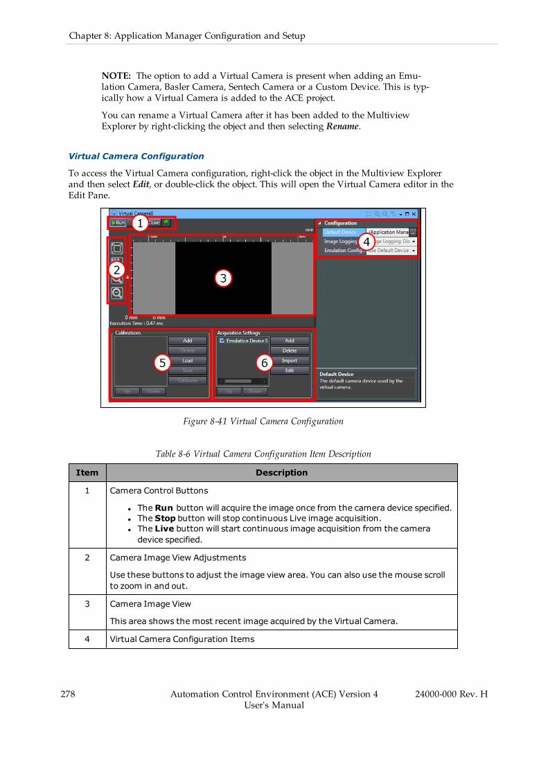
278 Automation Control Environment (ACE) Version 4User's Manual
24000-000 Rev. H
Chapter 8: Application Manager Configuration and Setup
NOTE: The option to add a Virtual Camera is present when adding an Emu-lation Camera, Basler Camera, Sentech Camera or a Custom Device. This is typ-ically how a Virtual Camera is added to the ACE project.
You can rename a Virtual Camera after it has been added to the MultiviewExplorer by right-clicking the object and then selecting Rename.
Virtual Camera Configuration
To access the Virtual Camera configuration, right-click the object in the Multiview Explorerand then select Edit, or double-click the object. This will open the Virtual Camera editor in theEdit Pane.
Figure 8-41 Virtual Camera Configuration
Table 8-6 Virtual Camera Configuration Item Description
Item Description
1 Camera Control Buttons
l The Run button will acquire the image once from the camera device specified.l The Stop button will stop continuous Live image acquisition.l The Live button will start continuous image acquisition from the cameradevice specified.
2 Camera Image View Adjustments
Use these buttons to adjust the image view area. You can also use the mouse scrollto zoom in and out.
3 Camera Image View
This area shows the most recent image acquired by the Virtual Camera.
4 Virtual Camera Configuration Items
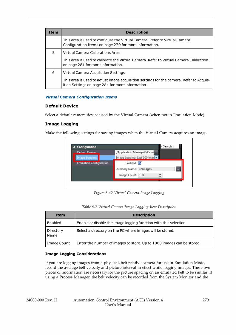
Item Description
This area is used to configure the Virtual Camera. Refer to Virtual CameraConfiguration Items on page 279 for more information.
5 Virtual Camera Calibrations Area
This area is used to calibrate the Virtual Camera. Refer to Virtual Camera Calibrationon page 281 for more information.
6 Virtual Camera Acquisition Settings
This area is used to adjust image acquisition settings for the camera. Refer to Acquis-ition Settings on page 284 for more information.
Virtual Camera Configuration Items
Default Device
Select a default camera device used by the Virtual Camera (when not in Emulation Mode).
Image Logging
Make the following settings for saving images when the Virtual Camera acquires an image.
Figure 8-42 Virtual Camera Image Logging
Table 8-7 Virtual Camera Image Logging Item Description
Item Description
Enabled Enable or disable the image logging function with this selection
DirectoryName
Select a directory on the PC where images will be stored.
Image Count Enter the number of images to store. Up to 1000 images can be stored.
Image Logging Considerations
If you are logging images from a physical, belt-relative camera for use in Emulation Mode,record the average belt velocity and picture interval in effect while logging images. These twopieces of information are necessary for the picture spacing on an emulated belt to be similar. Ifusing a Process Manager, the belt velocity can be recorded from the System Monitor and the
24000-000 Rev. H Automation Control Environment (ACE) Version 4User's Manual
279

280 Automation Control Environment (ACE) Version 4User's Manual
24000-000 Rev. H
Chapter 8: Application Manager Configuration and Setup
picture interval can be recorded from Process Manager in the Control Sources area. If using aV+ program and ACE Sight, the belt velocity can be recorded from the Controller Settings -Encoders area and the picture interval can be recorded from the Robot Vision ManagerSequence, Continuous Run Delay area.
Without recording using this information, the replayed images may be overlapping and partflow may be different than you expect. When using the logged images in emulation, be sure toapply these values in the appropriate fields for the flow of images to match the physical sys-tem.
Emulation Configuration
When Emulation Mode is enabled, the Virtual Camera object editor uses an Emulation Con-figuration parameter that specifies one of the following modes for the image source.
Figure 8-43 Virtual Camera Emulation Configuration Behavior
Use Default Device
This setting will use the camera device specified in the Default Device field.
Random Instances
This setting allows generation of a random quantity of randomly oriented vision results. Youspecify the range of possible instance count with minimum and maximum values, but you donot have control over the random X, Y, and Roll values of the results generated. If this level ofcontrol is required, consider using a Custom Vision tool with user-defined logic.
Additional Information: When using this mode, vision tools will display anerror "There is no image in the buffer.
NOTE: When the Basler Pylon Device is used and Random Instances is selec-ted, the Fixed Pixel calibration will automatically load as the calibration type inthe Basler Pylon Device Virtual Camera object.

Use Alternate Device
This setting allows pictures to be obtained from another vision device that is configured in theproject (typically an Emulation camera object). Select the alternate vision device with this set-ting if required.
Images Replay
This setting allows a set of images to be displayed from a specified directory (.hig files only).
Virtual Camera Calibration
Virtual camera calibration is required before vision tools are created to ensure that accuratemeasurements and locations are acquired. This is a spatial adjustment that corrects for per-spective distortion, lens distortion, and defines the relationship between the camera pixels andreal-world dimensions in millimeters. There are two methods available for virtual camera cal-ibration as described below.
Additional Information: You should calibrate the camera before you create anyvision tools.
NOTE: The offset of the camera from the robot or other equipment is not part ofthis calibration. That information is obtained during the robot-to-camera cal-ibration. Refer to Camera Calibration on page 259 for more information.
Access the camera calibration in the Virtual Camera's editor that is associated with the cameradevice. An example is provided below.
l Click the Add button to begin the calibration procedure. Use the Delete button toremove a previous calibration.
l Click the Load button to load a previously saved calibration. Click the Save button tosave an existing calibration to the PC.
l Click the Calibrate button to adjust an selected calibration.
24000-000 Rev. H Automation Control Environment (ACE) Version 4User's Manual
281
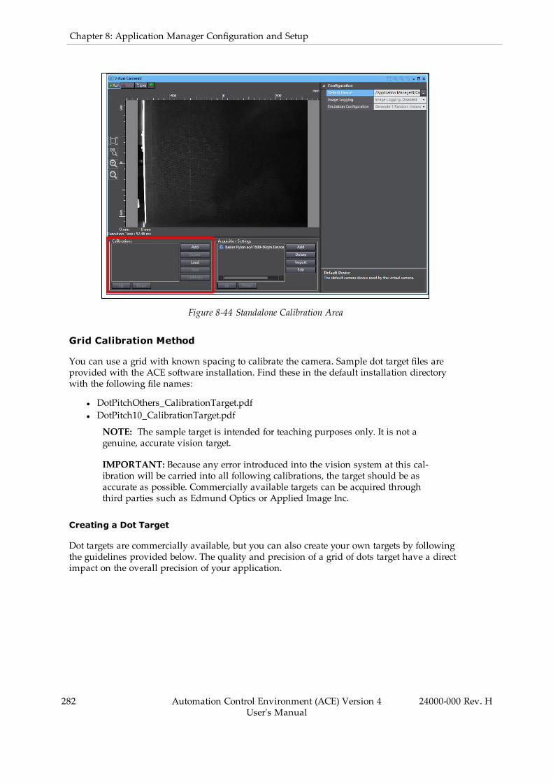
282 Automation Control Environment (ACE) Version 4User's Manual
24000-000 Rev. H
Chapter 8: Application Manager Configuration and Setup
Figure 8-44 Standalone Calibration Area
Grid Calibration Method
You can use a grid with known spacing to calibrate the camera. Sample dot target files areprovided with the ACE software installation. Find these in the default installation directorywith the following file names:
l DotPitchOthers_CalibrationTarget.pdfl DotPitch10_CalibrationTarget.pdf
NOTE: The sample target is intended for teaching purposes only. It is not agenuine, accurate vision target.
IMPORTANT: Because any error introduced into the vision system at this cal-ibration will be carried into all following calibrations, the target should be asaccurate as possible. Commercially available targets can be acquired throughthird parties such as Edmund Optics or Applied Image Inc.
Creating a Dot Target
Dot targets are commercially available, but you can also create your own targets by followingthe guidelines provided below. The quality and precision of a grid of dots target have a directimpact on the overall precision of your application.
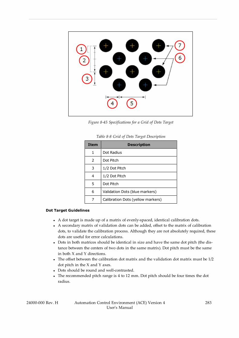
Figure 8-45 Specifications for a Grid of Dots Target
Table 8-8 Grid of Dots Target Description
Item Description
1 Dot Radius
2 Dot Pitch
3 1/2 Dot Pitch
4 1/2 Dot Pitch
5 Dot Pitch
6 Validation Dots (blue markers)
7 Calibration Dots (yellow markers)
Dot Target Guidelines
l A dot target is made up of a matrix of evenly-spaced, identical calibration dots.l A secondary matrix of validation dots can be added, offset to the matrix of calibrationdots, to validate the calibration process. Although they are not absolutely required, thesedots are useful for error calculations.
l Dots in both matrices should be identical in size and have the same dot pitch (the dis-tance between the centers of two dots in the same matrix). Dot pitch must be the samein both X and Y directions.
l The offset between the calibration dot matrix and the validation dot matrix must be 1/2dot pitch in the X and Y axes.
l Dots should be round and well-contrasted.l The recommended pitch range is 4 to 12 mm. Dot pitch should be four times the dotradius.
24000-000 Rev. H Automation Control Environment (ACE) Version 4User's Manual
283
284 Automation Control Environment (ACE) Version 4User's Manual
24000-000 Rev. H
Chapter 8: Application Manager Configuration and Setup
l Dot pitch must be the same in both X and Y axes.l The target should cover the entire field of view.l For best results, targets should be of high photo quality on a stable medium, not printed.
NOTE: You should measure the pitch of your dots after printing a grid toconfirm that your printer did not change the scale of the grid. If the dotsare not exactly the pitch you expect, the camera calibration will be inac-curate.
Additional Information: The dot grid rows and columns must be alignedwith the field of view. Ideally after executing the Calibrate function, thereshould be a uniform distribution of yellow and blue alternating dots. Aregion without blue dots indicates the calibration is not sufficient in thatregion to predict the location of the validation dots.
With the above concepts in mind, you can use the following steps to create specific dottargets.Measure the width or height of your FOV by using a ruler inside the camera image in livemode to obtain the length of the FOV. Using the camera manual, take the matching pixelresolution, Then calculate the resultingmm-to-pixel ratio. With this information you canidentify the optimal dot pitch and dot radius for your target. As an example, with a400mm FOV in the horizontal direction and 1600 pixels in the horizontal direction, cam-era, the calculation for that direction would be:
Dot pitch = (Field of View (mm)/Pixel (count))*36Dot radius = (Field of View (mm)/Pixel (count))*9
Dot pitch = (400mm / 1600)*36 = 9 mmDot radius = (400mm / 1600)*9 = 2.25mm
A standard dot grid with a pitch of 10mm would still be within the scope for accuracy.
Fixed Pixel Calibration Method
Fixed-pixel calibration allows you to specify what physical distance is represented by eachcamera pixel. All camera pixels will be given the same dimension, which is not necessarily thecase with a grid of dots. This method of camera calibration will not correct for lens distortionor perspective.
Acquisition Settings
Acquisition settings are used to view information about the camera and make other imageadjustments for vision devices used by the Virtual Camera.
When configuring a Virtual Camera that uses an Emulation Camera, the settings in this areaare limited to only gray scale conversion and image selection.
When using a Virtual Camera that uses a vision device such as a Basler camera, you canmake several adjustments to the image such as shutter, gain, and exposure along with othercamera related settings as described below.
NOTE: The settings in this area will vary depending on the vision device asso-ciated with the Virtual Camera.

Information
The Information tab displays the Model, Vendor, and Serial Number of the attached camera.These fields are read-only.
Stream Format
The Stream Format tab lets you set the Pixel Format and Timeout value for the data being sentfrom the camera.
The available pixel formats will be displayed in the drop-down box when you click the down-arrow (the default selection is recommended).
The Timeout value sets a time limit in milliseconds, after which the vision tool terminates theprocessing of an image. If the vision tool has not finished processing an image within the allot-ted time, the tool returns all the instances it has located up to the timeout. Although Timeoutcan be disabled, it is recommended that you use a Timeout value. This is useful for time-crit-ical applications in which fast operation is more important than the occasional occurrence ofundetected object instances. This value is only approximate and the actual processing timemay be slightly greater.
Video Format
The Video Format tab lets you set Exposure, Gain, Black Level, and color balance.
Each line displays the minimum allowable value for that property, a bar indicating the currentvalue, the maximum allowable value , and the numeric value of the current level.
Some of the minimum and maximum values, particularly for Gain, will differ depending onthe camera being used.
Exposure Adjustment Considerations
The Exposure time setting determines the time interval during which the sensor is exposed tolight. Choose an exposure time setting that takes into account whether you want to acquireimages of still or moving objects. Adjust Exposure, Gain, and Black Level (in that order) toimprove the quality of acquired images with the following considerations.
l If the object is not moving, you can choose a high exposure time setting (i.e., a longexposure interval).
l High exposure time settings may reduce the camera’s maximum allowed acquisitionframe rate and may cause artifacts to appear in the image.
l If the object is moving, choose a low exposure time setting to prevent motion blur. As ageneral rule, choose a short enough exposure time to make sure that the image of theobject does not move by more than one pixel during exposure. A shorter exposure timesetting may require a higher illumination level.
NOTE: Acquisition parameters are validated before being sent to the camera. Ifyou enter an exposure time that your camera does not support, the time will beadjusted to be valid. If you haven't typed in an invalid exposure time, the leftand right arrows will provide valid times.
24000-000 Rev. H Automation Control Environment (ACE) Version 4User's Manual
285

286 Automation Control Environment (ACE) Version 4User's Manual
24000-000 Rev. H
Chapter 8: Application Manager Configuration and Setup
Gain Adjustment Considerations
Gain is the amplification of the signal being sent from the camera. The readout from each pixelis amplified by the Gain, so both signal and noise are amplified. This means that it is not pos-sible to improve the signal-to-noise ratio by increasing gain. You can increase the contrast inthe image by increasing the camera’s gain setting.
Unless your application requires extreme contrast, make sure that detail remains visible in thebrightest portions of the image when increasing gain. Noise is increased by increasing gain.Increasing gain will increase the image brightness. Set the gain only as high as is necessary.
Black Level Adjustment Considerations
Black Level is an offset, which is used to establish which parts of an image should appearblack. High black level settings will prevent high contrast. Make fine adjustments to the BlackLevel to ensure that detail is still visible in the darkest parts of the acquired images.
White Balance Considerations
Balance Red, Balance Green, and Balance Blue are only available if you have a color cameraconnected. On some Basler color cameras, such as the A601fc-2, the green balance is a fixedvalue that cannot be adjusted. In such cases, only the balance for blue and red will be enabledin this window (Balance Green will be grayed out).
NOTE: It is recommended to consider white balance of the camera when usingcolor camera models. For Basler cameras, this is supported in Pylon Viewer.Refer to Configuring Basler Cameras on page 597 for more information.
Trigger
The Trigger tab lets you enable an external trigger for taking a picture and set parameters thatpertain to that trigger.
Most applications will not use trigger mode and the image is taken when requested by the PC,but some applications need to reduce latency in communication. In this type of situation, a trig-ger signal would be wired directly to a camera input and trigger mode is enabled and con-figured in the Virtual Camera. A V+ program would execute a VRUN command to execute aVision Sequence but instead of acquiring an image, it will create the image buffer and wait toreceive the image from the camera when it is triggered. A camera exposure active signal couldstill be used for position latching if necessary.
Other Acquisition Settings Functions
Use the Add and Delete buttons to add or remove acquisition settings.
The Import button opens a selection window to copy acquisition settings from another VirtualCamera in the ACE project.
The Edit button opens a window for changing acquisition settings for the selected device.
Use the Up and Down buttons to arrange multiple acquisition settings in a specific order.

Emulation Cameras
An Emulation Camera is a stored collection of images, which the ACE software can treat as ifthey were coming from a physical camera. Emulation Cameras are mostly used in EmulationMode when a camera is not available or when viewing images from another application.
Emulation Cameras require imported images to be the same size (pixel X by Pixel Y) andformat (color vs mono). Emulation Cameras should be used with limited quantities of imagesbecause they directly impact the size of projects. If a large quantity of images must be used, itis advisable to use Image Replay and provide a directory of logged images.
Since there are no .hig image file viewers, Emulation Cameras can be used to import logged.hig images and export those images as other common formats for viewing with other software(.jpg, .png, etc).
NOTE: Emulation Camera acquisition settings in the Virtual Camera allowcolor-to-gray scale conversion for convenience.
Add an Emulation Camera
To add an Emulation Camera, right-click Cameras, select Add, and then click Emulation Cam-era. The Create Emulator Device window will open.
Figure 8-46 Add an Emulation Camera
Figure 8-47 Create Emulator Device (Camera)
24000-000 Rev. H Automation Control Environment (ACE) Version 4User's Manual
287
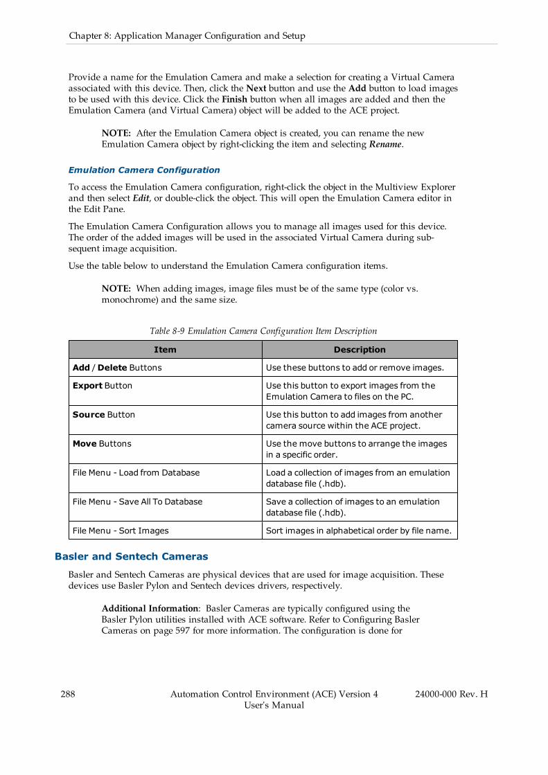
288 Automation Control Environment (ACE) Version 4User's Manual
24000-000 Rev. H
Chapter 8: Application Manager Configuration and Setup
Provide a name for the Emulation Camera and make a selection for creating a Virtual Cameraassociated with this device. Then, click the Next button and use the Add button to load imagesto be used with this device. Click the Finish button when all images are added and then theEmulation Camera (and Virtual Camera) object will be added to the ACE project.
NOTE: After the Emulation Camera object is created, you can rename the newEmulation Camera object by right-clicking the item and selecting Rename.
Emulation Camera Configuration
To access the Emulation Camera configuration, right-click the object in the Multiview Explorerand then select Edit, or double-click the object. This will open the Emulation Camera editor inthe Edit Pane.
The Emulation Camera Configuration allows you to manage all images used for this device.The order of the added images will be used in the associated Virtual Camera during sub-sequent image acquisition.
Use the table below to understand the Emulation Camera configuration items.
NOTE: When adding images, image files must be of the same type (color vs.monochrome) and the same size.
Table 8-9 Emulation Camera Configuration Item Description
Item Description
Add /Delete Buttons Use these buttons to add or remove images.
Export Button Use this button to export images from theEmulation Camera to files on the PC.
Source Button Use this button to add images from anothercamera source within the ACE project.
Move Buttons Use the move buttons to arrange the imagesin a specific order.
File Menu - Load from Database Load a collection of images from an emulationdatabase file (.hdb).
File Menu - Save All To Database Save a collection of images to an emulationdatabase file (.hdb).
File Menu - Sort Images Sort images in alphabetical order by file name.
Basler and Sentech Cameras
Basler and Sentech Cameras are physical devices that are used for image acquisition. Thesedevices use Basler Pylon and Sentech devices drivers, respectively.
Additional Information: Basler Cameras are typically configured using theBasler Pylon utilities installed with ACE software. Refer to Configuring BaslerCameras on page 597 for more information. The configuration is done for
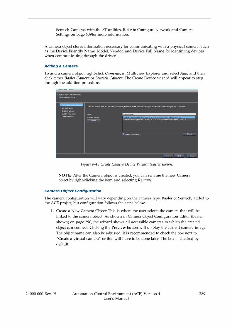
Sentech Cameras with the ST utilities. Refer to Configure Network and CameraSettings on page 609for more information.
A camera object stores information necessary for communicating with a physical camera, suchas the Device Friendly Name, Model, Vendor, and Device Full Name for identifying deviceswhen communicating through the drivers.
Adding a Camera
To add a camera object, right-click Cameras, in Multiview Explorer and select Add, and thenclick either Basler Camera or Sentech Camera. The Create Device wizard will appear to stepthrough the addition procedure.
Figure 8-48 Create Camera Device Wizard (Basler shown)
NOTE: After the Camera object is created, you can rename the new Cameraobject by right-clicking the item and selecting Rename.
Camera Object Configuration
The camera configuration will vary depending on the camera type, Basler or Sentech, added tothe ACE project, but configuration follows the steps below.
1. Create a New Camera Object: This is where the user selects the camera that will belinked to the camera object. As shown in Camera Object Configuration Editor (Baslershown) on page 290, the wizard shows all accessible cameras to which the createdobject can connect. Clicking the Preview button will display the current camera image.The object name can also be adjusted. It is recommended to check the box next to“Create a virtual camera” or this will have to be done later. The box is checked bydefault.
24000-000 Rev. H Automation Control Environment (ACE) Version 4User's Manual
289

290 Automation Control Environment (ACE) Version 4User's Manual
24000-000 Rev. H
Chapter 8: Application Manager Configuration and Setup
Figure 8-49 Camera Object Configuration Editor (Basler shown)
2. Ask Calibration: The wizard will ask the user to choose to calibrate now or later. Choos-ing to calibrate later and clicking the Next button will skip the last three steps and closethe wizard.
3. Grid Instructions: This step displays the instructions for grid calibration. Refer to theGrid Calibration Method for more information.
4. Camera Properties: The image is from the camera is displayed in this. The user canclick the Edit button to modify the camera settings.
5. Grid Calibration: The image is calibrated with the grid. Set the appropriate values in thesettings and click the Finish button to close the wizard.
Once the camera object has been created, it can be opened edited like any other object in theMultiview Explorer.
Custom Devices
The Custom Device object is a C# program that executes at the level of a camera object and canbe used to acquire an image from any camera device or external vision system. It can also beused to manipulate image data from one Virtual Camera’s image buffer before input to asecond Virtual Camera that is linked to a Vision Sequence.
A C# program template will be created when the Custom Device is added to the ACE Project.

Adding a Custom Device
To add a Custom device, right-click Cameras, select Add, and then click Custom Device. A newCustom Device will be added to the Multiview Explorer. Use this object to access theC# program associated with the device.
Figure 8-50 Add a Custom Device
NOTE: After the Custom device object is created, you can rename the new Cus-tom device object by right-clicking the item and selecting Rename.
8.5 ConfigurationVarious configuration objects can be added to the ACE project for different control, setup, andother functions. Use the information in this section to understand the functions ofthe Configuration objects.
Controller Connection Startup
The Controller Connection Startup item is used to establish a connection, monitor, and main-tain the connection to one or more controllers upon the startup of the ACE project. It can alsobe configured to start a V+ program on a specified task number upon startup.
When the Controller Connection Startup object is configured, opening the ACE project will auto-matically initiate a connection to a controller and program execution, once the connection isfully established.
NOTE: Although the Controller Connection Startup function and the Auto Startfunction share some similarities, the startup file for the Controller ConnectionStartup function is stored on the PC whereas the Auto Start function files arestored on the controller. This allows the Auto Start function to provide a head-less (no PC required) operation of the application. Refer to Auto Start on page200 for more information.
24000-000 Rev. H Automation Control Environment (ACE) Version 4User's Manual
291
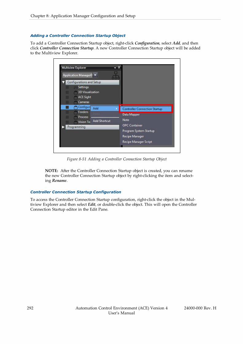
292 Automation Control Environment (ACE) Version 4User's Manual
24000-000 Rev. H
Chapter 8: Application Manager Configuration and Setup
Adding a Controller Connection Startup Object
To add a Controller Connection Startup object, right-click Configuration, select Add, and thenclick Controller Connection Startup. A new Controller Connection Startup object will be addedto the Multiview Explorer.
Figure 8-51 Adding a Controller Connection Startup Object
NOTE: After the Controller Connection Startup object is created, you can renamethe new Controller Connection Startup object by right-clicking the item and select-ing Rename.
Controller Connection Startup Configuration
To access the Controller Connection Startup configuration, right-click the object in the Mul-tiview Explorer and then select Edit, or double-click the object. This will open the ControllerConnection Startup editor in the Edit Pane.
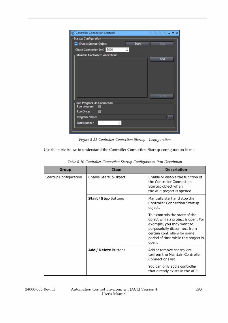
Figure 8-52 Controller Connection Startup - Configuration
Use the table below to understand the Controller Connection Startup configuration items.
Table 8-10 Controller Connection Startup Configuration Item Description
Group Item Description
Startup Configuration Enable Startup Object Enable or disable the function ofthe Controller ConnectionStartup object whenthe ACE project is opened.
Start /Stop Buttons Manually start and stop theController Connection Startupobject.
This controls the state of theobject while a project is open. Forexample, you may want topurposefully disconnect fromcertain controllers for someperiod of time while the project isopen.
Add / Delete Buttons Add or remove controllersto/from the Maintain ControllerConnections list.
You can only add a controllerthat already exists in the ACE
24000-000 Rev. H Automation Control Environment (ACE) Version 4User's Manual
293
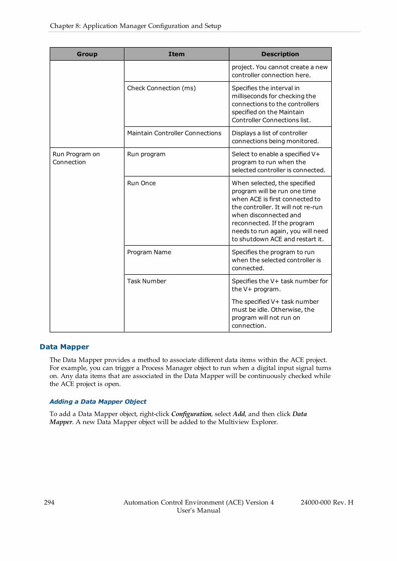
294 Automation Control Environment (ACE) Version 4User's Manual
24000-000 Rev. H
Chapter 8: Application Manager Configuration and Setup
Group Item Description
project. You cannot create a newcontroller connection here.
Check Connection (ms) Specifies the interval inmilliseconds for checking theconnections to the controllersspecified on the MaintainController Connections list.
Maintain Controller Connections Displays a list of controllerconnections beingmonitored.
Run Program onConnection
Run program Select to enable a specified V+program to run when theselected controller is connected.
Run Once When selected, the specifiedprogram will be run one timewhen ACE is first connected tothe controller. It will not re-runwhen disconnected andreconnected. If the programneeds to run again, you will needto shutdown ACE and restart it.
Program Name Specifies the program to runwhen the selected controller isconnected.
Task Number Specifies the V+ task number forthe V+ program.
The specified V+ task numbermust be idle. Otherwise, theprogram will not run onconnection.
Data Mapper
The Data Mapper provides a method to associate different data items within the ACE project.For example, you can trigger a Process Manager object to run when a digital input signal turnson. Any data items that are associated in the Data Mapper will be continuously checked whilethe ACE project is open.
Adding a Data Mapper Object
To add a Data Mapper object, right-click Configuration, select Add, and then click DataMapper. A new Data Mapper object will be added to the Multiview Explorer.

Figure 8-53 Adding a Data Mapper Object
NOTE: After the Data Mapper object is created, you can rename the new DataMapper object by right-clicking the item and selecting Rename.
Data Mapper Configuration
To access the Data Mapper configuration, right-click the object in the Multiview Explorer andthen select Edit, or double-click the object. This will open the Data Mapper editor in the EditPane.
Figure 8-54 Data Mapper Editor
Data Mapper Editor Buttons
Use the Data Mapper Editor buttons to add, delete, and pause/run Data Mapper items.
Pausing a selected Data Mapper item will prevent it from executing. Click the Run button toresume a paused Data Mapper item.
24000-000 Rev. H Automation Control Environment (ACE) Version 4User's Manual
295
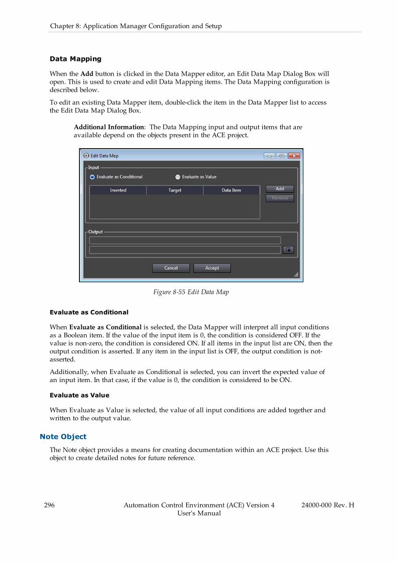
296 Automation Control Environment (ACE) Version 4User's Manual
24000-000 Rev. H
Chapter 8: Application Manager Configuration and Setup
Data Mapping
When the Add button is clicked in the Data Mapper editor, an Edit Data Map Dialog Box willopen. This is used to create and edit Data Mapping items. The Data Mapping configuration isdescribed below.
To edit an existing Data Mapper item, double-click the item in the Data Mapper list to accessthe Edit Data Map Dialog Box.
Additional Information: The Data Mapping input and output items that areavailable depend on the objects present in the ACE project.
Figure 8-55 Edit Data Map
Evaluate as Conditional
When Evaluate as Conditional is selected, the Data Mapper will interpret all input conditionsas a Boolean item. If the value of the input item is 0, the condition is considered OFF. If thevalue is non-zero, the condition is considered ON. If all items in the input list are ON, then theoutput condition is asserted. If any item in the input list is OFF, the output condition is not-asserted.
Additionally, when Evaluate as Conditional is selected, you can invert the expected value ofan input item. In that case, if the value is 0, the condition is considered to be ON.
Evaluate as Value
When Evaluate as Value is selected, the value of all input conditions are added together andwritten to the output value.
Note Object
The Note object provides a means for creating documentation within an ACE project. Use thisobject to create detailed notes for future reference.

Adding a Note Object
To add a Note object, right-click Configuration, select Add, and then click Note. A new Noteobject will be added to the Multiview Explorer.
Figure 8-56 Adding a Note Object
NOTE: After the Note object is created, you can rename the new Note object byright-clicking the item and selecting Rename.
Note Editing
To access the Note object for editing, right-click the object in the Multiview Explorer and thenselect Edit, or double-click the object. This will open the Note editor in the Edit Pane.
Figure 8-57 Note Editor
24000-000 Rev. H Automation Control Environment (ACE) Version 4User's Manual
297
298 Automation Control Environment (ACE) Version 4User's Manual
24000-000 Rev. H
Chapter 8: Application Manager Configuration and Setup
OPC Container
The purpose of an OPC container is to provide a standardized infrastructure for the exchangeof process control data that accommodates different data sources, connections, and operatingsystems.
OPC stands for Object Linking and Embedding (OLE) for Process Control. It uses Microsoft’sComponent Object Model (COM) and Distributed Component Object Model (DCOM) tech-nology to enable applications to exchange data on one or more computers using a client/serverarchitecture.
OPC defines a common set of interfaces which allows various applications to retrieve data inexactly the same format regardless of whether the data source is a PLC, DCS, gauge, analyzer,software application, or anything else with OPC support. The data can be available throughdifferent connections such as serial, Ethernet, or radio transmissions for example. Differentoperating systems such as Windows, UNIX, DOS, and VMS are also used by many processcontrol applications.
The OPC protocol consists of many separate specifications. OPC Data Access (DA) providesaccess to real-time process data. Using OPC DA you can ask an OPC server for the most recentvalues of anything that is being measured, such as flows, pressures, levels, temperatures, dens-ities, and more. OPC support in ACE software is limited to the DA specification.
For more information on OPC, please see the OPC Foundation website at the following URL:
https://www.opcfoundation.org
An OPC container can be configured for the following functions.
l Communicate values of V+ Global Variables and Process Manager statistics.l Start or stop a process within an ACE application.
OPC Test Client
An ACE software installation provides an OPC test client. This is useful for testing the func-tionality of the OPC Container configuration.
The OPC test client can be started by running the SOClient.exe file found in the followingdefault installation directory.
C:\Program Files\OMRON\ACE 4.X\OPC Test Client
Adding an OPC Container
To add an OPC Container object, right-click Configuration, select Add, and then clickOPC Container. A new OPC Container object will be added to the Multiview Explorer.
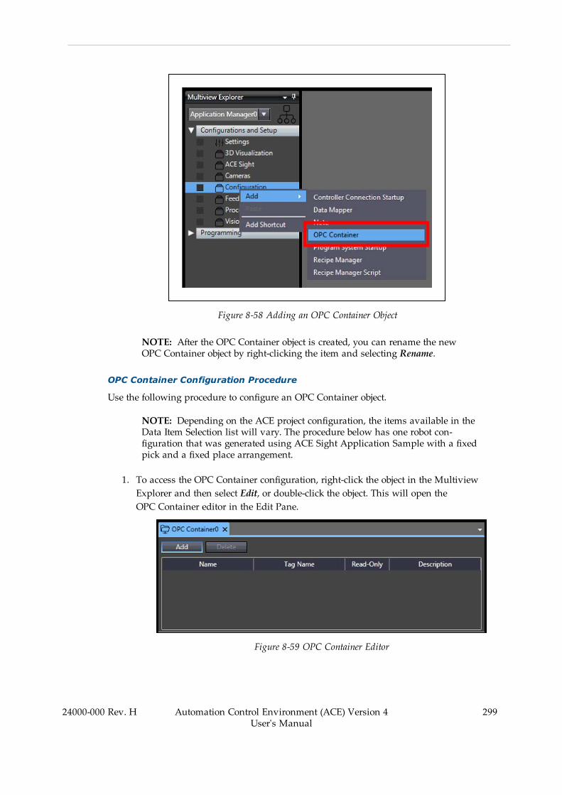
Figure 8-58 Adding an OPC Container Object
NOTE: After the OPC Container object is created, you can rename the newOPC Container object by right-clicking the item and selecting Rename.
OPC Container Configuration Procedure
Use the following procedure to configure an OPC Container object.
NOTE: Depending on the ACE project configuration, the items available in theData Item Selection list will vary. The procedure below has one robot con-figuration that was generated using ACE Sight Application Sample with a fixedpick and a fixed place arrangement.
1. To access the OPC Container configuration, right-click the object in the MultiviewExplorer and then select Edit, or double-click the object. This will open theOPC Container editor in the Edit Pane.
Figure 8-59 OPC Container Editor
24000-000 Rev. H Automation Control Environment (ACE) Version 4User's Manual
299

300 Automation Control Environment (ACE) Version 4User's Manual
24000-000 Rev. H
Chapter 8: Application Manager Configuration and Setup
2. Click the Add button to select a Data Item. The Data Item Selection Dialog Box willappear.
Figure 8-60 Data Item Selection
3. Select an item from the list and then click the Select button. The item will be added tothe OPC Container publish list in the Edit Pane.
Figure 8-61 OPC Container Publish List
4. Make a selection for the Read-Only option. If checked, an external OPC client cannotwrite to the item. If the Read-Only option is not checked, the OPC client has access toread and write the item's value.
5. Once all items have been added to the OPC Container publish list, the OPC client canbe configured as shown in the next steps. Run the SOClient.exe file found in the defaultACE installation directory (C:\Program Files\OMRON\ACE 4.X\OPC Test Client).
6. Select the OPC Server Tab and then expand the Local item to expose all Data Accessitems.
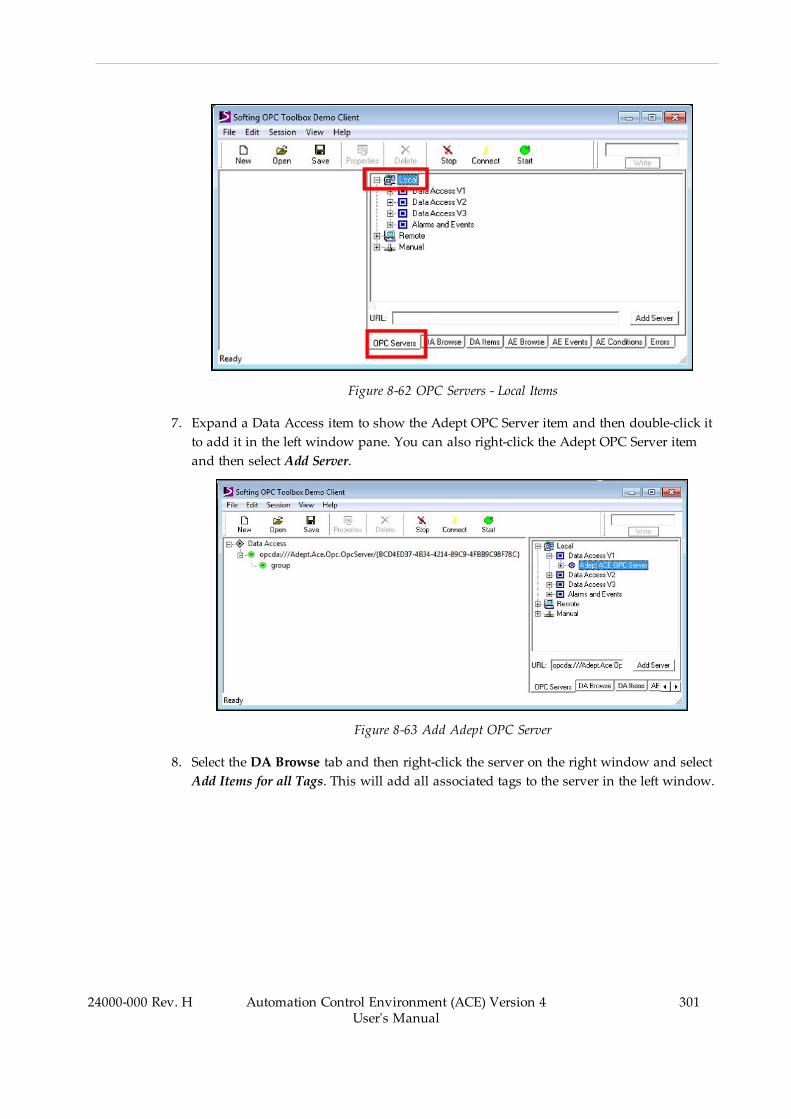
Figure 8-62 OPC Servers - Local Items
7. Expand a Data Access item to show the Adept OPC Server item and then double-click itto add it in the left window pane. You can also right-click the Adept OPC Server itemand then select Add Server.
Figure 8-63 Add Adept OPC Server
8. Select the DA Browse tab and then right-click the server on the right window and selectAdd Items for all Tags. This will add all associated tags to the server in the left window.
24000-000 Rev. H Automation Control Environment (ACE) Version 4User's Manual
301

302 Automation Control Environment (ACE) Version 4User's Manual
24000-000 Rev. H
Chapter 8: Application Manager Configuration and Setup
Figure 8-64 Add Items for all Tags
9. Select the DA Items tab to see the item's value and other related information.
Figure 8-65 DA Items Tab
The Quality column indicates that the communication with the OPC DA server workednormally ("GOOD" indicates successful communications).
The TimeStamp column indicates the last update time of the tag.
10. Tags that were configured with the Read-Only selection unchecked can be modifiedwith the OPC client. To change the value from the OPC client, right click the tag andselectWrite. The dialog box below will appear. Enter a new value and then clickthe Write button to change the value in the ACE application.

Figure 8-66 Write a New Value
11. Values that have been updated from the ACE application can be verified using the readfunction in the OPC client. Right-click the tag and select Read to update values inthe OPC client.
If the values are updating correctly, the configuration procedure is complete.
Add or Delete Items to Publish on OPC DA
Use the Add button to add a new item to publish on OPC DA. Use the Delete button toremove a selected item from the list.
Program System Startup
The Program System Startup object is used to specify a C# program to run when the ACE pro-ject opens.
NOTE: Although the Program System Startup function and the Auto Start func-tion share some similarities, the startup file for the Program System Startup func-tion is stored on the PC whereas the Auto Start function files are stored on thecontroller. This allows the Auto Start function to provide a headless (no PCrequired) operation of the application. Refer to Auto Start on page 200 for moreinformation.
Adding a Program System Startup Object
To add a Program System Startup object, right-click Configuration, select Add, and then clickProgram System Startup. A new Program System Startup object will be added to the MultiviewExplorer.
24000-000 Rev. H Automation Control Environment (ACE) Version 4User's Manual
303
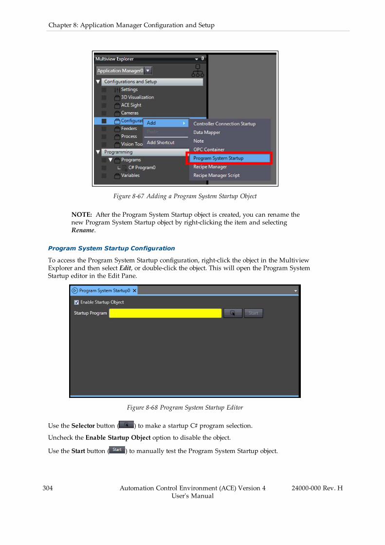
304 Automation Control Environment (ACE) Version 4User's Manual
24000-000 Rev. H
Chapter 8: Application Manager Configuration and Setup
Figure 8-67 Adding a Program System Startup Object
NOTE: After the Program System Startup object is created, you can rename thenew Program System Startup object by right-clicking the item and selectingRename.
Program System Startup Configuration
To access the Program System Startup configuration, right-click the object in the MultiviewExplorer and then select Edit, or double-click the object. This will open the Program SystemStartup editor in the Edit Pane.
Figure 8-68 Program System Startup Editor
Use the Selector button ( ) to make a startup C# program selection.
Uncheck the Enable Startup Object option to disable the object.
Use the Start button ( ) to manually test the Program System Startup object.

Recipe Overview
Manufacturing processes often require frequent product changeover resulting in the need forchanges to variable values, vision models, vision tool parameters, pallet layouts, motion para-meters, process definitions, motion offsets, and more. The ACE software provides a RecipeManager that simplifies the complex process of saving and restoring large amounts of data tominimize downtime during frequent product changeover.
There are three steps for recipe management in the ACE software, as described below.
Recipe Definition
Recipe definition involves selecting which objects will be the Sources of recipe data. Sourcesare similar to ingredients of a traditional cooking recipe. A recipe will contain a copy of thedata for each Source. Recipes can only store data of objects that are defined as Sources in theRecipe Manager edit pane. All other objects will have common parameters for all recipes.When a recipe is created, it will contain a copy of the data that is currently present in theSource objects. This can significantly reduce the number of objects that must be created andmaintained.
For example, consider a situation where a camera is used to locate a product to be packaged.In this example, the system can process five different types of products, but only one producttype at a time. Rather than creating five Locator Models and five Locators, you would createone Locator and one Locator Model, add each as a source, and create five recipes containingthe Model data and Locator parameters optimized for each product type. Alternatively, if twotypes of product must be recognized by the same Locator, you could have two Locator Modelobjects and include both as sources.
Recipe Creation and Modification
After the recipe Sources have been defined in the Recipe Manager Edit Pane, recipes can be cre-ated in the Recipe Manager section of Task Status Control.
NOTE: Typically, a system should be sufficiently optimized for one productbefore creating recipes. This minimizes the amount of parameters in Sourceobjects that need to be individually edited in each recipe. Although this is recom-mended, it is not mandatory.
Task Status Control provides a Recipe Editor that can be used to edit the parameters of allSource types that are commonly modified by operators. When a recipe is selected, the entireACE software interface becomes the editor for the active recipe. The Recipe Editor does notprovide an editor window for all Sources. For example, if a Process Manager is a source for arecipe, it will not be visible in the Recipe Editor, however the Process Manager edit pane canbe used to make modifications to all Process Manager parameters for the selected recipe.
IMPORTANT: It is important to recognize that if changes are made to objectsthat are Sources in a recipe while no recipe is selected, when a recipe is selected,those changes may be lost. Be sure to always use the Recipe Editor or select arecipe before making changes to recipe Source objects.
Refer to Recipe Editor on page 309 for more information regarding creating, modifying, anddeleting recipes.
24000-000 Rev. H Automation Control Environment (ACE) Version 4User's Manual
305
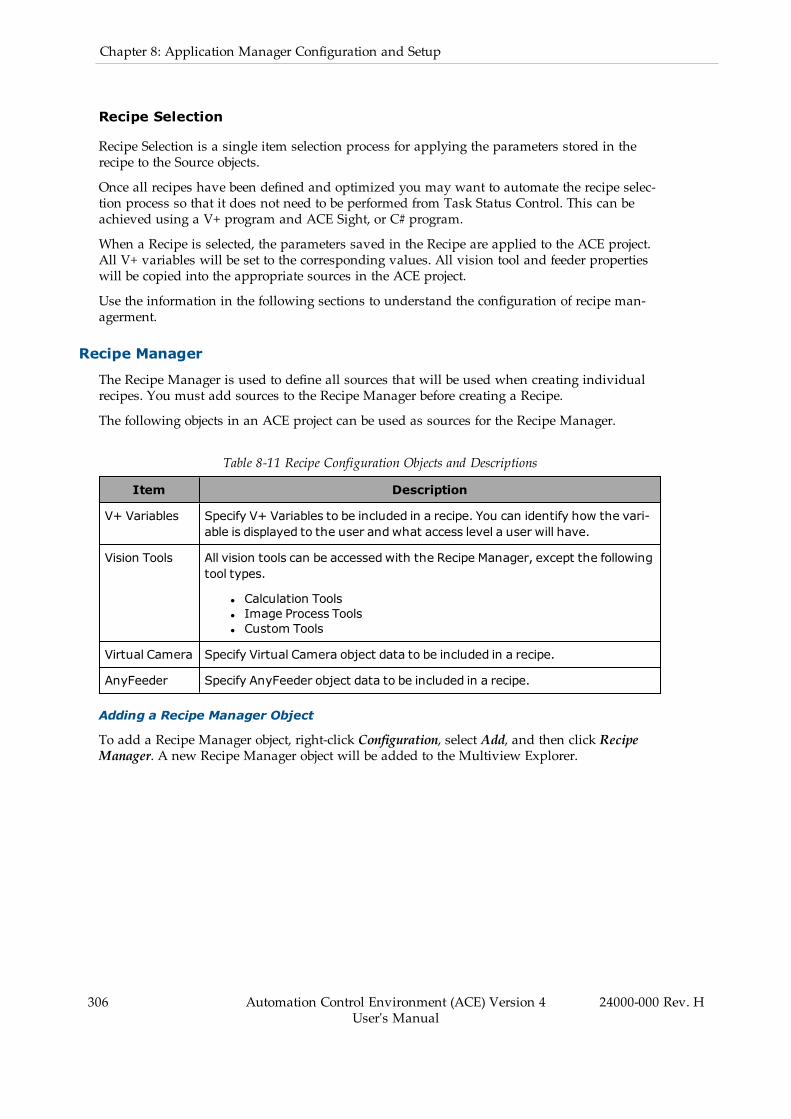
306 Automation Control Environment (ACE) Version 4User's Manual
24000-000 Rev. H
Chapter 8: Application Manager Configuration and Setup
Recipe Selection
Recipe Selection is a single item selection process for applying the parameters stored in therecipe to the Source objects.
Once all recipes have been defined and optimized you may want to automate the recipe selec-tion process so that it does not need to be performed from Task Status Control. This can beachieved using a V+ program and ACE Sight, or C# program.
When a Recipe is selected, the parameters saved in the Recipe are applied to the ACE project.All V+ variables will be set to the corresponding values. All vision tool and feeder propertieswill be copied into the appropriate sources in the ACE project.
Use the information in the following sections to understand the configuration of recipe man-agerment.
Recipe Manager
The Recipe Manager is used to define all sources that will be used when creating individualrecipes. You must add sources to the Recipe Manager before creating a Recipe.
The following objects in an ACE project can be used as sources for the Recipe Manager.
Table 8-11 Recipe Configuration Objects and Descriptions
Item Description
V+ Variables Specify V+ Variables to be included in a recipe. You can identify how the vari-able is displayed to the user andwhat access level a user will have.
Vision Tools All vision tools can be accessedwith the Recipe Manager, except the followingtool types.
l Calculation Toolsl Image Process Toolsl Custom Tools
Virtual Camera Specify Virtual Camera object data to be included in a recipe.
AnyFeeder Specify AnyFeeder object data to be included in a recipe.
Adding a Recipe Manager Object
To add a Recipe Manager object, right-click Configuration, select Add, and then click RecipeManager. A new Recipe Manager object will be added to the Multiview Explorer.

Figure 8-69 Adding a Recipe Manager Object
NOTE: After the Recipe Manager object is created, you can rename the newRecipe Manager object by right-clicking the item and selecting Rename.
Additional Information: You can drag and drop a Recipe Manager object into aC# program. Refer to RecipeManager Topics in the ACE Reference Guide for moreinformation.
Recipe Manager Configuration
To access the Recipe Manager configuration, right-click the object in the Multiview Explorerand then select Edit, or double-click the object. This will open the Recipe Manager editor in theEdit Pane.
Figure 8-70 Recipe Manager Configuration
24000-000 Rev. H Automation Control Environment (ACE) Version 4User's Manual
307
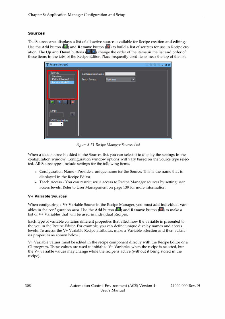
308 Automation Control Environment (ACE) Version 4User's Manual
24000-000 Rev. H
Chapter 8: Application Manager Configuration and Setup
Sources
The Sources area displays a list of all active sources available for Recipe creation and editing.Use the Add button ( ) and Remove button ( ) to build a list of sources for use in Recipe cre-ation. The Up and Down buttons ( ) change the order of the items in the list and order ofthese items in the tabs of the Recipe Editor. Place frequently used items near the top of the list.
Figure 8-71 Recipe Manager Sources List
When a data source is added to the Sources list, you can select it to display the settings in theconfiguration window. Configuration window options will vary based on the Source type selec-ted. All Source types include settings for the following items.
l Configuration Name - Provide a unique name for the Source. This is the name that isdisplayed in the Recipe Editor.
l Teach Access - You can restrict write access to Recipe Manager sources by setting useraccess levels. Refer to User Management on page 139 for more information.
V+ Variable Sources
When configuring a V+ Variable Source in the Recipe Manager, you must add individual vari-ables in the configuration area. Use the Add button ( ) and Remove button ( ) to make alist of V+ Variables that will be used in individual Recipes.
Each type of variable contains different properties that affect how the variable is presented tothe you in the Recipe Editor. For example, you can define unique display names and accesslevels. To access the V+ Variable Recipe attributes, make a Variable selection and then adjustits properties as shown below.
V+ Variable values must be edited in the recipe component directly with the Recipe Editor or aC# program. These values are used to initialize V+ Variables when the recipe is selected, butthe V+ variable values may change while the recipe is active (without it being stored in therecipe).
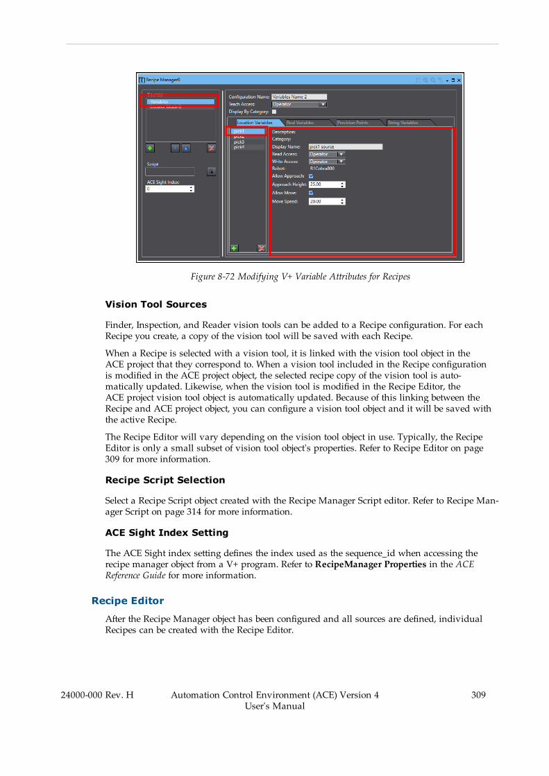
Figure 8-72 Modifying V+ Variable Attributes for Recipes
Vision Tool Sources
Finder, Inspection, and Reader vision tools can be added to a Recipe configuration. For eachRecipe you create, a copy of the vision tool will be saved with each Recipe.
When a Recipe is selected with a vision tool, it is linked with the vision tool object in theACE project that they correspond to. When a vision tool included in the Recipe configurationis modified in the ACE project object, the selected recipe copy of the vision tool is auto-matically updated. Likewise, when the vision tool is modified in the Recipe Editor, theACE project vision tool object is automatically updated. Because of this linking between theRecipe and ACE project object, you can configure a vision tool object and it will be saved withthe active Recipe.
The Recipe Editor will vary depending on the vision tool object in use. Typically, the RecipeEditor is only a small subset of vision tool object's properties. Refer to Recipe Editor on page309 for more information.
Recipe Script Selection
Select a Recipe Script object created with the Recipe Manager Script editor. Refer to Recipe Man-ager Script on page 314 for more information.
ACE Sight Index Setting
The ACE Sight index setting defines the index used as the sequence_id when accessing therecipe manager object from a V+ program. Refer to RecipeManager Properties in the ACEReference Guide for more information.
Recipe Editor
After the Recipe Manager object has been configured and all sources are defined, individualRecipes can be created with the Recipe Editor.
24000-000 Rev. H Automation Control Environment (ACE) Version 4User's Manual
309
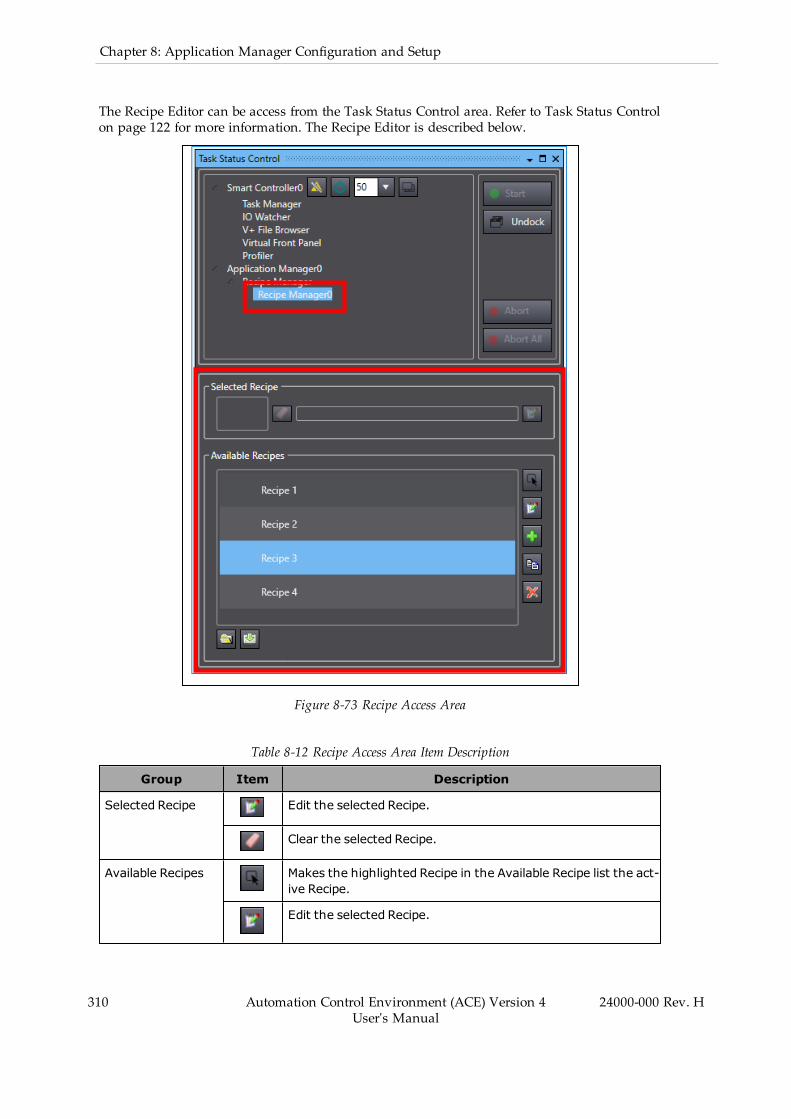
310 Automation Control Environment (ACE) Version 4User's Manual
24000-000 Rev. H
Chapter 8: Application Manager Configuration and Setup
The Recipe Editor can be access from the Task Status Control area. Refer to Task Status Controlon page 122 for more information. The Recipe Editor is described below.
Figure 8-73 Recipe Access Area
Table 8-12 Recipe Access Area Item Description
Group Item Description
Selected Recipe Edit the selected Recipe.
Clear the selected Recipe.
Available Recipes Makes the highlighted Recipe in the Available Recipe list the act-ive Recipe.
Edit the selected Recipe.

Group Item Description
Add a new Recipe.
Create a copy of the selected Recipe.
Delete a selected Recipe.
Open a Recipe from a saved file on the PC.
Save a Recipe to a file on the PC.
Creating a New Recipe
Use the following procedure to create a new Recipe.
1. Add a new recipe with the Add button ( ). A new Recipe will appear in the AvailableRecipes list.
2. Select the recipe and then click the Edit button ( ). This will open the Recipe Editor win-dow.
Figure 8-74 Recipe Editor
3. Select the General item in the Sources list and then input the general information andsettings about the Recipe.
Item Description
Recipe Name Provide a unique name for the Recipe.
Description Provide a description associated with the Recipe.
24000-000 Rev. H Automation Control Environment (ACE) Version 4User's Manual
311
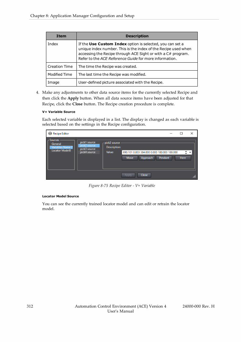
312 Automation Control Environment (ACE) Version 4User's Manual
24000-000 Rev. H
Chapter 8: Application Manager Configuration and Setup
Item Description
Index If theUse Custom Index option is selected, you can set aunique index number. This is the index of the Recipe usedwhenaccessing the Recipe through ACE Sight or with a C# program.Refer to the ACE Reference Guide for more information.
Creation Time The time the Recipe was created.
Modified Time The last time the Recipe wasmodified.
Image User-defined picture associated with the Recipe.
4. Make any adjustments to other data source items for the currently selected Recipe andthen click the Apply button. When all data source items have been adjusted for thatRecipe, click the Close button. The Recipe creation procedure is complete.
V+ Variable Source
Each selected variable is displayed in a list. The display is changed as each variable isselected based on the settings in the Recipe configuration.
Figure 8-75 Recipe Editor - V+ Variable
Locator Model Source
You can see the currently trained locator model and can edit or retrain the locatormodel.

Figure 8-76 Recipe Editor - Locator Model
Virtual Camera Source
The acquisition properties are displayed in a list. You can modify, add, or removeacquisition settings as needed.
Figure 8-77 Recipe Editor - Virtual Camera (Emulation Mode Shown)
Other Vision Tool Sources
Adjust the parameters of the vision tool.
24000-000 Rev. H Automation Control Environment (ACE) Version 4User's Manual
313
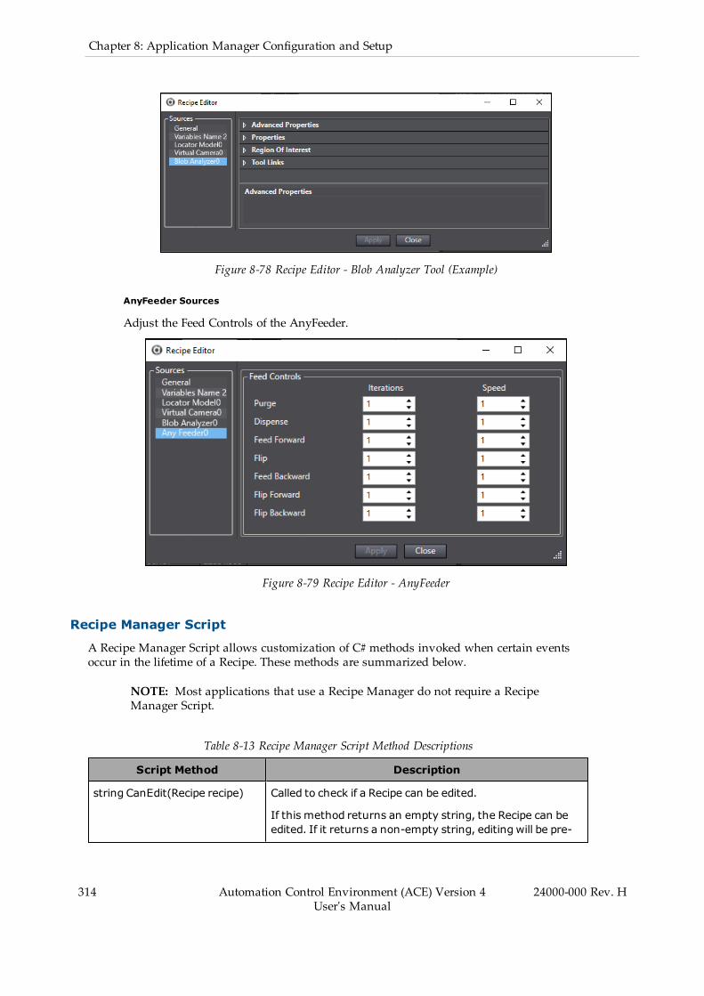
314 Automation Control Environment (ACE) Version 4User's Manual
24000-000 Rev. H
Chapter 8: Application Manager Configuration and Setup
Figure 8-78 Recipe Editor - Blob Analyzer Tool (Example)
AnyFeeder Sources
Adjust the Feed Controls of the AnyFeeder.
Figure 8-79 Recipe Editor - AnyFeeder
Recipe Manager Script
A Recipe Manager Script allows customization of C# methods invoked when certain eventsoccur in the lifetime of a Recipe. These methods are summarized below.
NOTE: Most applications that use a Recipe Manager do not require a RecipeManager Script.
Table 8-13 Recipe Manager Script Method Descriptions
Script Method Description
string CanEdit(Recipe recipe) Called to check if a Recipe can be edited.
If this method returns an empty string, the Recipe can beedited. If it returns a non-empty string, editing will be pre-
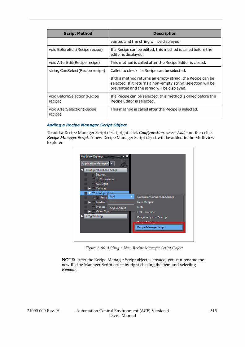
Script Method Description
vented and the string will be displayed.
void BeforeEdit(Recipe recipe) If a Recipe can be edited, this method is called before theeditor is displayed.
void AfterEdit(Recipe recipe) This method is called after the Recipe Editor is closed.
string CanSelect(Recipe recipe) Called to check if a Recipe can be selected.
If this method returns an empty string, the Recipe can beselected. If it returns a non-empty string, selection will beprevented and the string will be displayed.
void BeforeSelection(Reciperecipe)
If a Recipe can be selected, this method is called before theRecipe Editor is selected.
void AfterSelection(Reciperecipe)
This method is called after the Recipe is selected.
Adding a Recipe Manager Script Object
To add a Recipe Manager Script object, right-click Configuration, select Add, and then clickRecipe Manager Script. A new Recipe Manager Script object will be added to the MultiviewExplorer.
Figure 8-80 Adding a New Recipe Manager Script Object
NOTE: After the Recipe Manager Script object is created, you can rename thenew Recipe Manager Script object by right-clicking the item and selectingRename.
24000-000 Rev. H Automation Control Environment (ACE) Version 4User's Manual
315

316 Automation Control Environment (ACE) Version 4User's Manual
24000-000 Rev. H
Chapter 8: Application Manager Configuration and Setup
8.6 FeedersFeeders are objects in an ACE project that represent devices used to dispense and present partsto a robot. There are two different feeder objects that can be added to the ACE project.
l AnyFeeder - a feeder object that uses serial communications with the PC running ACEsoftware for sequence control and feedback purposes. This is typically controlled usingACE Sight from a V+ program or from a Custom Vision tool.
l IO Feeder - a feeder object that uses discrete signals for control and feedback purposes.This is typically used with a Process Manager object to indicate Part and Part Targetavailability and can be associated in Control Sources for static Part and Part Targetsources.
Both types of feeder objects can be configured in the Application Manager device of anACE project as described in the following sections.
AnyFeeder Object
AnyFeeder objects represent an integrated parts feeding system optimized to work togetherwith vision, motion, and robots. AnyFeeder objects can be added to provide control and con-figuration of the parts feeder in the ACE project.
NOTE: When Emulation Mode is enabled, all Feeder Function durations areemulated. Durations for error reset, initialization, operation abort, or firmwarerestart are not emulated because these operations are not intended to be reques-ted during a feed cycle.
Additional Information: More information about AnyFeeder devices is availablein the AnyFeeders User's Guide (P/N 18876-000).
Adding an AnyFeeder Object
To add an AnyFeeder object, right-click Feeders, select Add, and then click AnyFeeder. TheCreate New AnyFeeder wizard will open.
Figure 8-81 Adding an AnyFeeder Object
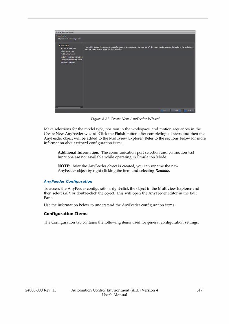
Figure 8-82 Create New AnyFeeder Wizard
Make selections for the model type, position in the workspace, and motion sequences in theCreate New AnyFeeder wizard. Click the Finish button after completing all steps and then theAnyFeeder object will be added to the Multiview Explorer. Refer to the sections below for moreinformation about wizard configuration items.
Additional Information: The communication port selection and connection testfunctions are not available while operating in Emulation Mode.
NOTE: After the AnyFeeder object is created, you can rename the newAnyFeeder object by right-clicking the item and selecting Rename.
AnyFeeder Configuration
To access the AnyFeeder configuration, right-click the object in the Multiview Explorer andthen select Edit, or double-click the object. This will open the AnyFeeder editor in the EditPane.
Use the information below to understand the AnyFeeder configuration items.
Configuration Items
The Configuration tab contains the following items used for general configuration settings.
24000-000 Rev. H Automation Control Environment (ACE) Version 4User's Manual
317

318 Automation Control Environment (ACE) Version 4User's Manual
24000-000 Rev. H
Chapter 8: Application Manager Configuration and Setup
Figure 8-83 AnyFeeder Configuration Tab
Table 8-14 AnyFeeder Configuration Tab Item Description
Group Item Description
Communication COM Port Specifies the PC serial communicationsport that is used to send commands to theAnyFeeder device.
This is not available in Emulation Mode.
Firmware Version Displays the firmware version of the con-nected AnyFeeder device.
This is not available in Emulation Mode
ACE SightConfiguration
ACE Sight Index The ACE Sight Index can be used to ref-erence this configuration from a V+ pro-gram. Specify a unique number between 0to 9999 as the ACE Sight reference.
NOTE: When an AnyFeederdevice configuration and anACE Sight sequence havethe same index value, the PCwill only try to run the ACESight sequence.
3D Display Model Type Select the AnyFeeder Model type from thedropdown selection menu.
Visible Use the Visible selection box display or hidethe device from the 3D Visualizer.
Workspace Position Enter the location of the AnyFeeder devicein the workspace.
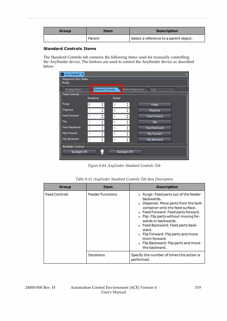
Group Item Description
Parent Select a reference to a parent object.
Standard Controls Items
The Standard Controls tab contains the following items used for manually controllingthe AnyFeeder device. The buttons are used to control the AnyFeeder device as describedbelow.
Figure 8-84 AnyFeeder Standard Controls Tab
Table 8-15 AnyFeeder Standard Controls Tab Item Description
Group Item Description
Feed Controls Feeder Functions l Purge: Feed parts out of the feederbackwards.
l Dispense: Move parts from the bulkcontainer onto the feed surface.
l Feed Forward: Feed parts forward.l Flip: Flip parts without moving for-wards or backwards.
l Feed Backward: Feed parts back-ward.
l Flip Forward: Flip parts andmovethem forward.
l Flip Backward: Flip parts andmovethe backward.
Iterations Specify the number of times this action isperformed.
24000-000 Rev. H Automation Control Environment (ACE) Version 4User's Manual
319
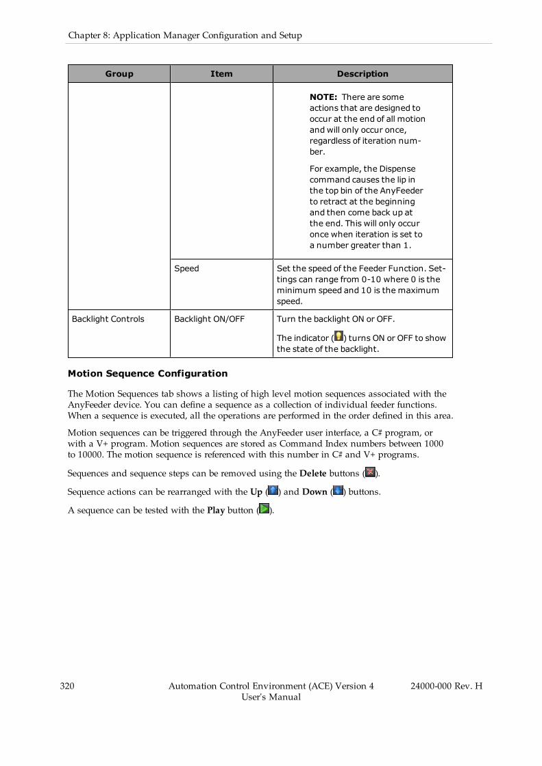
320 Automation Control Environment (ACE) Version 4User's Manual
24000-000 Rev. H
Chapter 8: Application Manager Configuration and Setup
Group Item Description
NOTE: There are someactions that are designed tooccur at the end of all motionandwill only occur once,regardless of iteration num-ber.
For example, the Dispensecommand causes the lip inthe top bin of the AnyFeederto retract at the beginningand then come back up atthe end. This will only occuronce when iteration is set toa number greater than 1.
Speed Set the speed of the Feeder Function. Set-tings can range from 0-10 where 0 is theminimum speed and 10 is the maximumspeed.
Backlight Controls Backlight ON/OFF Turn the backlight ON or OFF.
The indicator ( ) turns ON or OFF to showthe state of the backlight.
Motion Sequence Configuration
The Motion Sequences tab shows a listing of high level motion sequences associated with theAnyFeeder device. You can define a sequence as a collection of individual feeder functions.When a sequence is executed, all the operations are performed in the order defined in this area.
Motion sequences can be triggered through the AnyFeeder user interface, a C# program, orwith a V+ program. Motion sequences are stored as Command Index numbers between 1000to 10000. The motion sequence is referenced with this number in C# and V+ programs.
Sequences and sequence steps can be removed using the Delete buttons ( ).
Sequence actions can be rearranged with the Up ( ) and Down ( ) buttons.
A sequence can be tested with the Play button ( ).
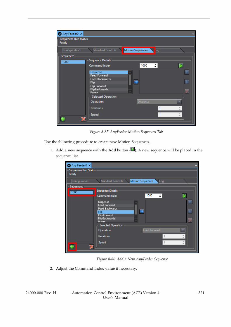
Figure 8-85 AnyFeeder Motion Sequences Tab
Use the following procedure to create new Motion Sequences.
1. Add a new sequence with the Add button ( ). A new sequence will be placed in thesequence list.
Figure 8-86 Add a New AnyFeeder Sequence
2. Adjust the Command Index value if necessary.
24000-000 Rev. H Automation Control Environment (ACE) Version 4User's Manual
321
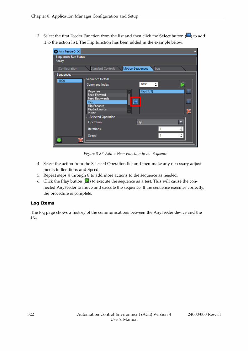
322 Automation Control Environment (ACE) Version 4User's Manual
24000-000 Rev. H
Chapter 8: Application Manager Configuration and Setup
3. Select the first Feeder Function from the list and then click the Select button ( ) to addit to the action list. The Flip function has been added in the example below.
Figure 8-87 Add a New Function to the Sequence
4. Select the action from the Selected Operation list and then make any necessary adjust-ments to Iterations and Speed.
5. Repeat steps 4 through 8 to add more actions to the sequence as needed.6. Click the Play button ( ) to execute the sequence as a test. This will cause the con-nected AnyFeeder to move and execute the sequence. If the sequence executes correctly,the procedure is complete.
Log Items
The log page shows a history of the communications between the AnyFeeder device and thePC.

Figure 8-88 AnyFeeder Configuration
IO Feeder Object
IO Feeder objects represent generic feeder devices that are controlled with input and output sig-nals from a connected SmartController.
Adding an IO Feeder Object
To add an IO Feeder object, right-click Configuration, select Add, and then click IO Feeder. Anew IO Feeder object will be added to the Multiview Explorer.
Figure 8-89 Adding an IO Feeder Object
NOTE: After the IO Feeder object is created, you can rename the new IO Feederobject by right-clicking the item and selecting Rename.
24000-000 Rev. H Automation Control Environment (ACE) Version 4User's Manual
323
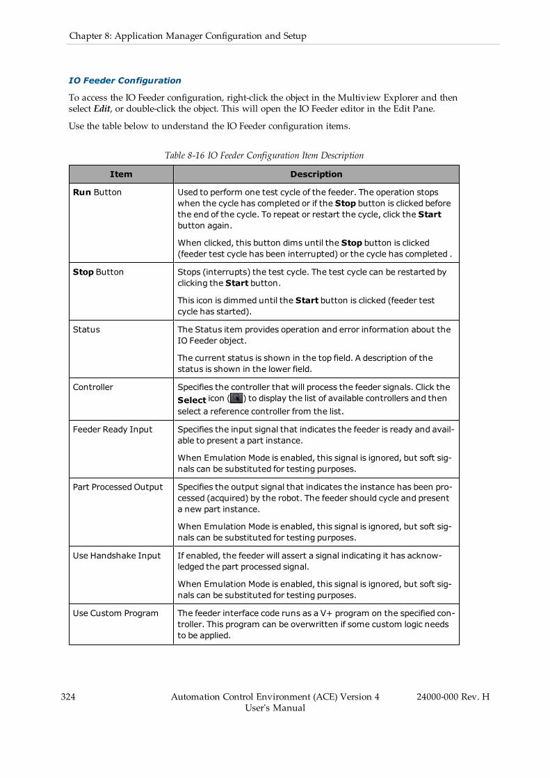
324 Automation Control Environment (ACE) Version 4User's Manual
24000-000 Rev. H
Chapter 8: Application Manager Configuration and Setup
IO Feeder Configuration
To access the IO Feeder configuration, right-click the object in the Multiview Explorer and thenselect Edit, or double-click the object. This will open the IO Feeder editor in the Edit Pane.
Use the table below to understand the IO Feeder configuration items.
Table 8-16 IO Feeder Configuration Item Description
Item Description
Run Button Used to perform one test cycle of the feeder. The operation stopswhen the cycle has completed or if the Stop button is clicked beforethe end of the cycle. To repeat or restart the cycle, click the Startbutton again.
When clicked, this button dims until the Stop button is clicked(feeder test cycle has been interrupted) or the cycle has completed .
Stop Button Stops (interrupts) the test cycle. The test cycle can be restarted byclicking the Start button.
This icon is dimmed until the Start button is clicked (feeder testcycle has started).
Status The Status item provides operation and error information about theIO Feeder object.
The current status is shown in the top field. A description of thestatus is shown in the lower field.
Controller Specifies the controller that will process the feeder signals. Click theSelect icon ( ) to display the list of available controllers and thenselect a reference controller from the list.
Feeder Ready Input Specifies the input signal that indicates the feeder is ready and avail-able to present a part instance.
When Emulation Mode is enabled, this signal is ignored, but soft sig-nals can be substituted for testing purposes.
Part Processed Output Specifies the output signal that indicates the instance has been pro-cessed (acquired) by the robot. The feeder should cycle and presenta new part instance.
When Emulation Mode is enabled, this signal is ignored, but soft sig-nals can be substituted for testing purposes.
Use Handshake Input If enabled, the feeder will assert a signal indicating it has acknow-ledged the part processed signal.
When Emulation Mode is enabled, this signal is ignored, but soft sig-nals can be substituted for testing purposes.
Use Custom Program The feeder interface code runs as a V+ program on the specified con-troller. This program can be overwritten if some custom logic needsto be applied.

Item Description
If you enable this option, you must use the Select icon ( ) toselect the custom program. A custom V+ program selection wizardwill appear to step through the procedure.
Part Processed OutputDwell
Specifies the dwell time (time to wait) in milliseconds after the PartProcessed output signal is turned ON before turning it OFF.
Debounce Time Specifies the amount of time (in milliseconds) that a signal must bedetected in the ON state before it is considered logically ON.
Figure 8-90 IO Feeder Configuration
8.7 Process ObjectsProcess objects are used to define, configure, and manage the process elements of an Pack Man-ager packaging application.
As Process objects are added to the Application Manager device, they can be shown in the 3DVisualizer, if the Visible option or Show in Visualization option is enabled in the object editor.For example, in addition to the robot, the 3D Visualizer shows:
l The robot Belt object windows.l The location of latch sensors.l The location of each camera field of view.l Part and Part Target instances.
Additional Information: Part and Part Target instances are represented in the3D Visualizer with different colors to indicate their current state.
l Yellow: part is allocated.l Orange: part is not allocated.l Light green: part target is allocated.l Green: part target is not allocated.
Process objects listed below are described in detail in the following sections.
24000-000 Rev. H Automation Control Environment (ACE) Version 4User's Manual
325
326 Automation Control Environment (ACE) Version 4User's Manual
24000-000 Rev. H
Chapter 8: Application Manager Configuration and Setup
Part Buffer
The Part Buffer object defines an object that is an overflow area where parts can be temporarilystored when part targets are unavailable to accept more parts.
Refer to Part Buffer Object on page 327 for more information.
Part Target
The Part Target object defines an object that is a possible destination for a part.
Refer to Part Target Object on page 331 for more information.
Part
The Part object defines an object to be picked and processed to an available Part Target.
Refer to Part Object on page 336 for more information.
Belt
The Belt object defines a physical conveyor belt used by the system. The Belt object maintains alist of encoders that are associated with the physical conveyor.
Refer to Belt Object on page 341 for more information.
Process Manager
Process Managers are the central control point for developing packaging applications. A Pro-cess Manager allows you to create complex applications without having to write any pro-gramming code. It provides access to automatically generated V+ and C# programs that allowyou to customize the default behavior to meet the requirements of your application, if neces-sary.
The Process Manager run-time handler is the supervisory control for the entire packaging sys-tem, managing allocation and queuing for multiple controllers, robots, conveyors, parts, andtargets.
Refer to Process Manager Object on page 352 for more information.
Allocation Script
The Allocation Script object is used to create and edit custom part-allocation programs for usewith the Process Manager.
Refer to Allocation Script Object on page 406 for more information.
Pallet
The Pallet object defines the layout of a pallet, which can be used to pick parts from or placeparts to.
Refer to Pallet Object on page 407 for more information.
Vision Refinement Station
The Vision Refinement Station object defines an object that is used to refine the part to gripperorientation for improved placement accuracy.

Refer to Vision Refinement Station Object on page 413 for more information.
Part Buffer Object
The Part Buffer object defines a physical object that is an overflow area where parts can be tem-porarily stored when an output conveyor belt or feeder is unavailable to accept the parts. Thisbuffer can hold a single part, it can be a static pallet, or just a flat surface that acts as a palletthat holds multiple parts.
For pallets, you can also control the access method in the following ways.
l Last In, First Out (LIFO).l First In, First Out (FIFO).
The Pallet object editor is used to specify the pallet parameters and access method. Refer to Pal-let Object on page 407 for more information.
Adding a Part Buffer Object
To add a Part Buffer object, right-click Process, select Add, and then click Part Buffer. A newPart Buffer object will be added to the Multiview Explorer.
Figure 8-91 Adding a Part Buffer Object
NOTE: After the Part Buffer object is created, you can rename the new PartBuffer object by right-clicking the item and selecting Rename.
Part Buffer Configuration
To access the Part Buffer configuration, right-click the object in the Multiview Explorer andthen select Edit, or double-click the object. This will open the Part Buffer editor in the EditPane.
24000-000 Rev. H Automation Control Environment (ACE) Version 4User's Manual
327
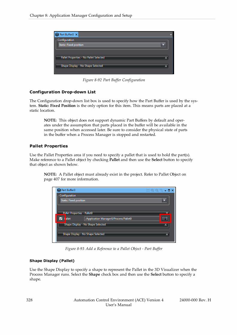
328 Automation Control Environment (ACE) Version 4User's Manual
24000-000 Rev. H
Chapter 8: Application Manager Configuration and Setup
Figure 8-92 Part Buffer Configuration
Configuration Drop-down List
The Configuration drop-down list box is used to specify how the Part Buffer is used by the sys-tem. Static: Fixed Position is the only option for this item. This means parts are placed at astatic location.
NOTE: This object does not support dynamic Part Buffers by default and oper-ates under the assumption that parts placed in the buffer will be available in thesame position when accessed later. Be sure to consider the physical state of partsin the buffer when a Process Manager is stopped and restarted.
Pallet Properties
Use the Pallet Properties area if you need to specify a pallet that is used to hold the part(s).Make reference to a Pallet object by checking Pallet and then use the Select button to specifythat object as shown below.
NOTE: A Pallet object must already exist in the project. Refer to Pallet Object onpage 407 for more information.
Figure 8-93 Add a Reference to a Pallet Object - Part Buffer
Shape Display (Pallet)
Use the Shape Display to specify a shape to represent the Pallet in the 3D Visualizer when theProcess Manager runs. Select the Shape check box and then use the Select button to specify ashape.

Figure 8-94 Pallet Shape Selection - Part Buffer
Shape Display (Part)
Use the Shape Display to specify a shape to represent the Part in the 3D Visualizer when theProcess Manager runs. Select the Shape check box and then use the Select button to specify ashape.
Figure 8-95 Part Shape Selection - Part Buffer
Adding a Part Buffer to a Process
Use the following procedure to add a Part Buffer to a Process after creating and configuringthe Part Buffer object.
NOTE: The default Process Strategy can choose the appropriate process basedon part / target availability.
1. Create a Process that includes a Robot, a Part as the Pick Configuration, and a Part Tar-get as the Place Configuration.
2. Create a second Process that includes the original Robot and Part, and select the PartBuffer as the Place Configuration.
3. Create a third Process that includes the original Robot and Part Target, and select thePart Buffer as the Pick Configuration.
4. Use the Up and Down buttons in the Process Manager Processes area to arrange the pro-cess by priority. The process at the top of the list has the highest priority.
24000-000 Rev. H Automation Control Environment (ACE) Version 4User's Manual
329
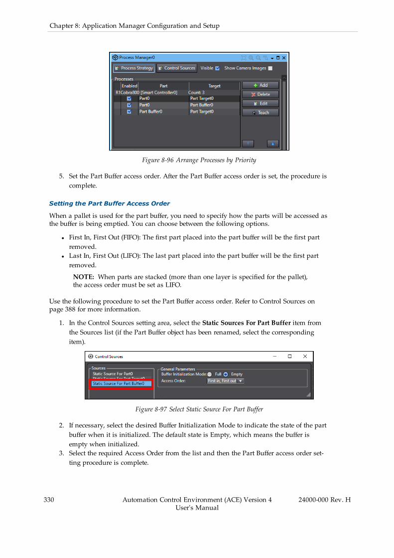
330 Automation Control Environment (ACE) Version 4User's Manual
24000-000 Rev. H
Chapter 8: Application Manager Configuration and Setup
Figure 8-96 Arrange Processes by Priority
5. Set the Part Buffer access order. After the Part Buffer access order is set, the procedure iscomplete.
Setting the Part Buffer Access Order
When a pallet is used for the part buffer, you need to specify how the parts will be accessed asthe buffer is being emptied. You can choose between the following options.
l First In, First Out (FIFO): The first part placed into the part buffer will be the first partremoved.
l Last In, First Out (LIFO): The last part placed into the part buffer will be the first partremoved.
NOTE: When parts are stacked (more than one layer is specified for the pallet),the access order must be set as LIFO.
Use the following procedure to set the Part Buffer access order. Refer to Control Sources onpage 388 for more information.
1. In the Control Sources setting area, select the Static Sources For Part Buffer item fromthe Sources list (if the Part Buffer object has been renamed, select the correspondingitem).
Figure 8-97 Select Static Source For Part Buffer
2. If necessary, select the desired Buffer Initialization Mode to indicate the state of the partbuffer when it is initialized. The default state is Empty, which means the buffer isempty when initialized.
3. Select the required Access Order from the list and then the Part Buffer access order set-ting procedure is complete.
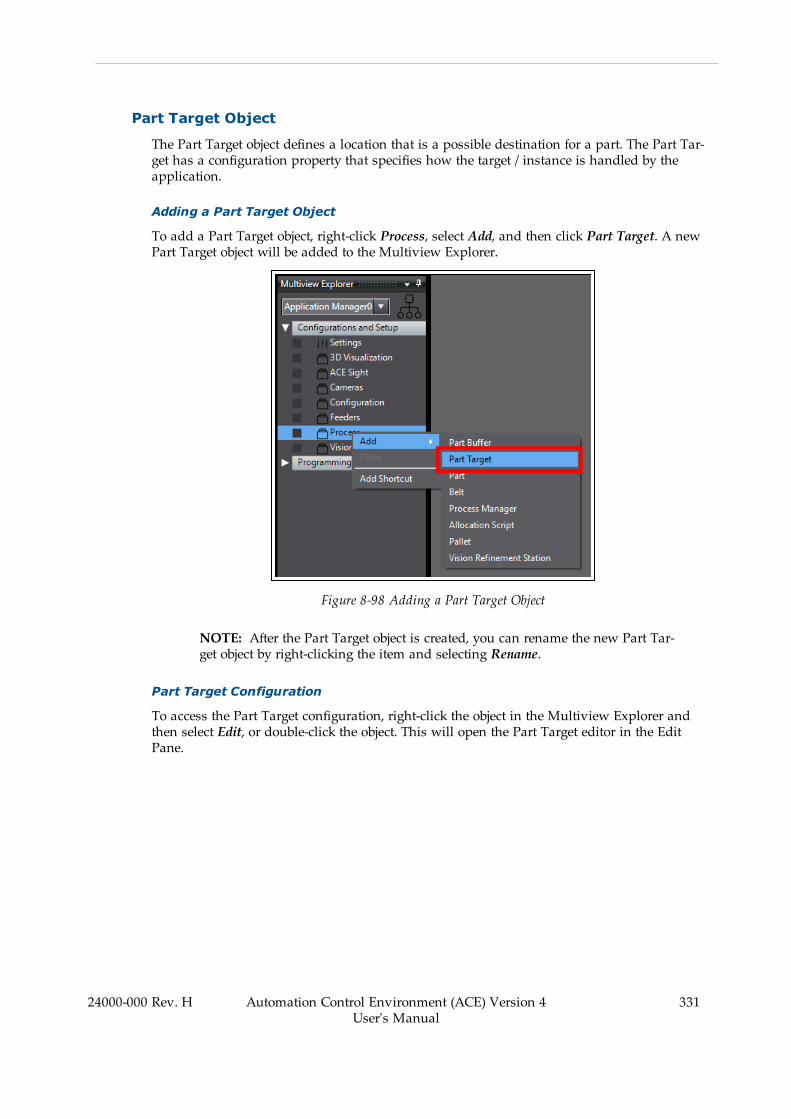
Part Target Object
The Part Target object defines a location that is a possible destination for a part. The Part Tar-get has a configuration property that specifies how the target / instance is handled by theapplication.
Adding a Part Target Object
To add a Part Target object, right-click Process, select Add, and then click Part Target. A newPart Target object will be added to the Multiview Explorer.
Figure 8-98 Adding a Part Target Object
NOTE: After the Part Target object is created, you can rename the new Part Tar-get object by right-clicking the item and selecting Rename.
Part Target Configuration
To access the Part Target configuration, right-click the object in the Multiview Explorer andthen select Edit, or double-click the object. This will open the Part Target editor in the EditPane.
24000-000 Rev. H Automation Control Environment (ACE) Version 4User's Manual
331
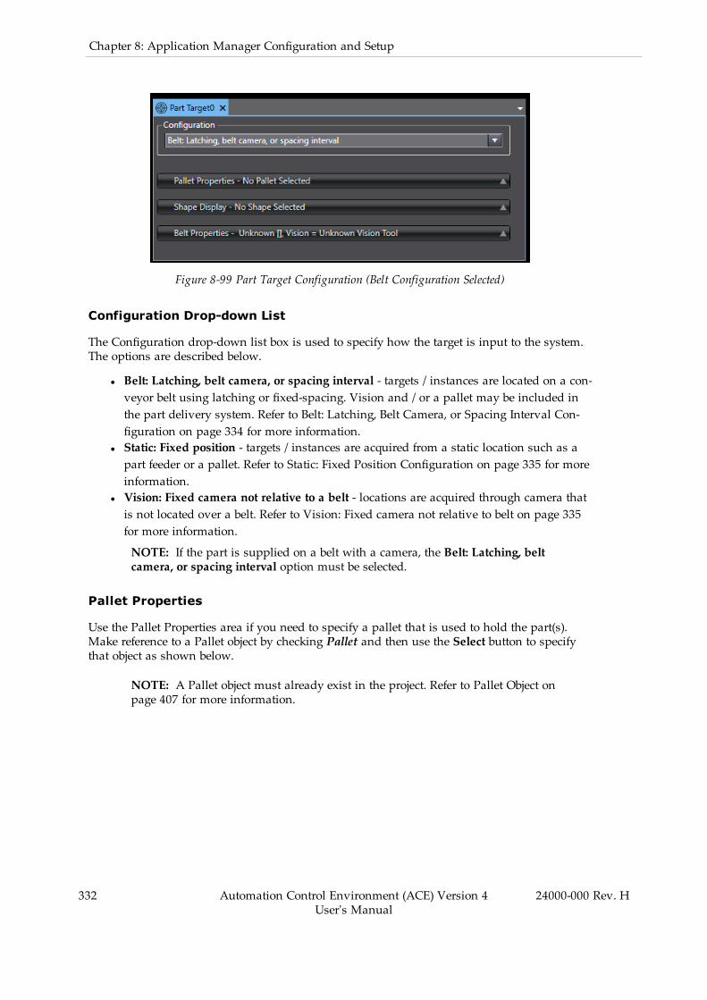
332 Automation Control Environment (ACE) Version 4User's Manual
24000-000 Rev. H
Chapter 8: Application Manager Configuration and Setup
Figure 8-99 Part Target Configuration (Belt Configuration Selected)
Configuration Drop-down List
The Configuration drop-down list box is used to specify how the target is input to the system.The options are described below.
l Belt: Latching, belt camera, or spacing interval - targets / instances are located on a con-veyor belt using latching or fixed-spacing. Vision and / or a pallet may be included inthe part delivery system. Refer to Belt: Latching, Belt Camera, or Spacing Interval Con-figuration on page 334 for more information.
l Static: Fixed position - targets / instances are acquired from a static location such as apart feeder or a pallet. Refer to Static: Fixed Position Configuration on page 335 for moreinformation.
l Vision: Fixed camera not relative to a belt - locations are acquired through camera thatis not located over a belt. Refer to Vision: Fixed camera not relative to belt on page 335for more information.
NOTE: If the part is supplied on a belt with a camera, the Belt: Latching, beltcamera, or spacing interval option must be selected.
Pallet Properties
Use the Pallet Properties area if you need to specify a pallet that is used to hold the part(s).Make reference to a Pallet object by checking Pallet and then use the Select button to specifythat object as shown below.
NOTE: A Pallet object must already exist in the project. Refer to Pallet Object onpage 407 for more information.

Figure 8-100 Add a Reference to a Pallet Object - Part Target
Shape Display (Pallet Properties)
Use the Shape Display to specify a shape to represent the Pallet in the 3D Visualizer when theProcess Manager runs. Select the Shape check box and then use the Select button to specify ashape.
Figure 8-101 Shape Display - Pallet Properties - Part Target Object
Shape Display
Use the Shape Display to specify a shape to represent the Part in the 3D Visualizer when theProcess Manager runs. Select the Shape check box and then use the Select button to specify ashape.
24000-000 Rev. H Automation Control Environment (ACE) Version 4User's Manual
333

334 Automation Control Environment (ACE) Version 4User's Manual
24000-000 Rev. H
Chapter 8: Application Manager Configuration and Setup
Figure 8-102 Part Shape Selection - Part Target
Belt: Latching, Belt Camera, or Spacing Interval Configuration
When Belt is selected for the Part Target configuration, the operation mode can be eitherVision, Latch, or Spacing.
l Vision: a vision tool is used to detect the part on the belt.l Latch: a latch sensor is used to detect the part on the belt.l Spacing: parts are spaced evenly on the belt.
Belt Properties
This area is used to select the mode of the belt that is used to handle the part. You also specifyother details related to the belt mode selection in this area. Use the information below to makeappropriate selections.
Figure 8-103 Belt Configuration - Part Target

Table 8-17 Belt Configuration - Belt Properties Item Description
Item Description
Belt / Encoder Select the encoder from a list of available Process Belt Encoders.This will populate the associated Belt object automatically.
Vision Tool (Vision Mode) Select the vision tool used to detect the part on the belt.
For applications where a custom vision tool is used, this itemwould be used to specify custom names that had been asso-ciated with the different results returned from that tool.
As an option, select Use Named Instance (select Model orenter custom result name) and then use the Select button( ) to reference an existing Locator Model or use the Add but-ton ( ) to add a custom result name.
Spacing (SpacingMode) Specify the spacing in millimeters between targets / instanceson the conveyor belt.
It is important to recognize that there is no physical referencefor where the spacing instances begin when a Process Manageris started.
Spacing is convenient for emulation purposes, but in physicalsystems an upstream or downstream process or conveyor beltgeometry may require that the spacing be synchronized withthe rest of the machine. A latch sensor is recommended in thissituation.
Static: Fixed Position Configuration
When Static is selected for the Part Target configuration, the Part Target is in a fixed position.There are no additional settings to configure with this selection.
Vision: Fixed camera not relative to belt
When Vision is selected for the Part Target configuration, a vision tool must be specified in theVision Properties area.
Vision Properties
This area is used to select the vision tool and optionally, the named instance that is used toacquire the part position.
You can optionally specify a named instance and then select a Model or enter a custom resultname.
24000-000 Rev. H Automation Control Environment (ACE) Version 4User's Manual
335
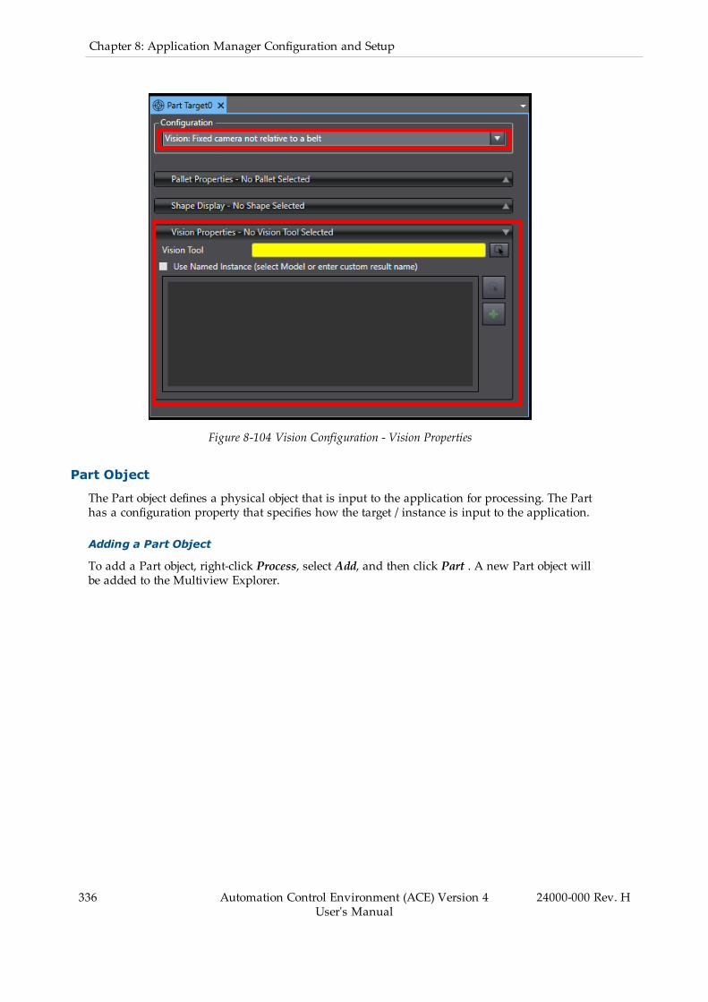
336 Automation Control Environment (ACE) Version 4User's Manual
24000-000 Rev. H
Chapter 8: Application Manager Configuration and Setup
Figure 8-104 Vision Configuration - Vision Properties
Part Object
The Part object defines a physical object that is input to the application for processing. The Parthas a configuration property that specifies how the target / instance is input to the application.
Adding a Part Object
To add a Part object, right-click Process, select Add, and then click Part . A new Part object willbe added to the Multiview Explorer.
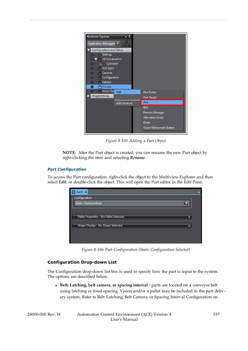
Figure 8-105 Adding a Part Object
NOTE: After the Part object is created, you can rename the new Part object byright-clicking the item and selecting Rename.
Part Configuration
To access the Part configuration, right-click the object in the Multiview Explorer and thenselect Edit, or double-click the object. This will open the Part editor in the Edit Pane.
Figure 8-106 Part Configuration (Static Configuration Selected)
Configuration Drop-down List
The Configuration drop-down list box is used to specify how the part is input to the system.The options are described below.
l Belt: Latching, belt camera, or spacing interval - parts are located on a conveyor beltusing latching or fixed-spacing. Vision and/or a pallet may be included in the part deliv-ery system. Refer to Belt: Latching, Belt Camera, or Spacing Interval Configuration on
24000-000 Rev. H Automation Control Environment (ACE) Version 4User's Manual
337
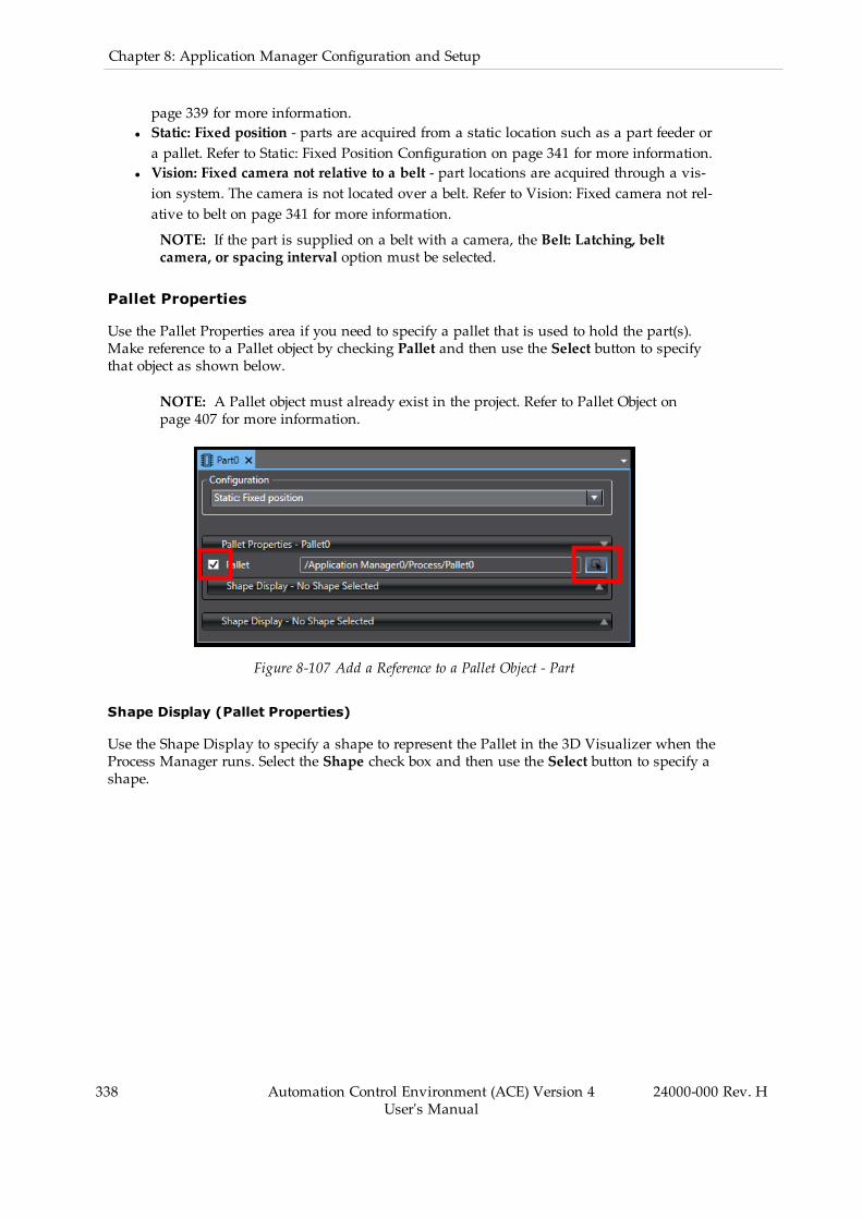
338 Automation Control Environment (ACE) Version 4User's Manual
24000-000 Rev. H
Chapter 8: Application Manager Configuration and Setup
page 339 for more information.l Static: Fixed position - parts are acquired from a static location such as a part feeder ora pallet. Refer to Static: Fixed Position Configuration on page 341 for more information.
l Vision: Fixed camera not relative to a belt - part locations are acquired through a vis-ion system. The camera is not located over a belt. Refer to Vision: Fixed camera not rel-ative to belt on page 341 for more information.
NOTE: If the part is supplied on a belt with a camera, the Belt: Latching, beltcamera, or spacing interval option must be selected.
Pallet Properties
Use the Pallet Properties area if you need to specify a pallet that is used to hold the part(s).Make reference to a Pallet object by checking Pallet and then use the Select button to specifythat object as shown below.
NOTE: A Pallet object must already exist in the project. Refer to Pallet Object onpage 407 for more information.
Figure 8-107 Add a Reference to a Pallet Object - Part
Shape Display (Pallet Properties)
Use the Shape Display to specify a shape to represent the Pallet in the 3D Visualizer when theProcess Manager runs. Select the Shape check box and then use the Select button to specify ashape.
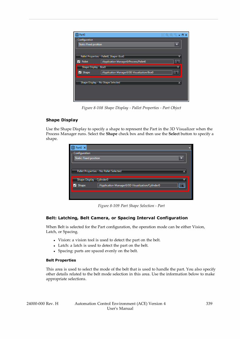
Figure 8-108 Shape Display - Pallet Properties - Part Object
Shape Display
Use the Shape Display to specify a shape to represent the Part in the 3D Visualizer when theProcess Manager runs. Select the Shape check box and then use the Select button to specify ashape.
Figure 8-109 Part Shape Selection - Part
Belt: Latching, Belt Camera, or Spacing Interval Configuration
When Belt is selected for the Part configuration, the operation mode can be either Vision,Latch, or Spacing.
l Vision: a vision tool is used to detect the part on the belt.l Latch: a latch is used to detect the part on the belt.l Spacing: parts are spaced evenly on the belt.
Belt Properties
This area is used to select the mode of the belt that is used to handle the part. You also specifyother details related to the belt mode selection in this area. Use the information below to makeappropriate selections.
24000-000 Rev. H Automation Control Environment (ACE) Version 4User's Manual
339

340 Automation Control Environment (ACE) Version 4User's Manual
24000-000 Rev. H
Chapter 8: Application Manager Configuration and Setup
Figure 8-110 Belt Configuration - Part
Table 8-18 Belt Configuration - Belt Properties Item Description
Item Description
Belt / Encoder Select the encoder from a list of available Process Belt Encoders.This will populate the associated Belt object automatically.
Vision Tool (Vision Mode) Select the vision tool used to detect the part on the belt.
For applications where a custom vision tool is used, this itemwould be used to specify custom names that had been asso-ciated with the different results returned from that tool.
As an option, select Use Named Instance (select Model orenter custom result name) and then use the Select button( ) to reference an existing Locator Model or use the Add but-ton ( ) to add a custom result name.
Spacing (SpacingMode) Specify the spacing in millimeters between parts on the con-veyor belt.
It is important to recognize that there is no physical referencefor where the spacing instances begin when a Process Manageris started.
Spacing is convenient for emulation purposes, but in physicalsystems an upstream or downstream process or conveyor beltgeometry may require that the spacing be synchronized withthe rest of the machine. A latch sensor is recommended in thissituation.

Static: Fixed Position Configuration
When Static is selected for the Part configuration, the Part is in a fixed position. There are noadditional settings to configure with this selection.
Vision: Fixed camera not relative to belt
When Vision is selected for the Part configuration, a vision tool must be specified in the VisionProperties area.
Vision Properties
This area is used to select the vision tool and optionally, the named instance that is used toacquire the part position.
You can optionally specify a named instance and then select a Model or enter a custom resultname.
Figure 8-111 Vision Configuration - Vision Properties
Belt Object
A Belt object represents a physical conveyor belt in the workcell or packaging line. A belt maybe tracked by multiple robots that may be controlled by a single or multiple controllers. Beltsmay also be related to multiple part or part target objects.
The Belt object provides settings for Active Control, Emulation Mode behavior, workspace pos-itioning for 3D visualization and multi-robot allocation order, and a list of associated beltencoder inputs for related controllers. This section will describe how these settings are used.
24000-000 Rev. H Automation Control Environment (ACE) Version 4User's Manual
341
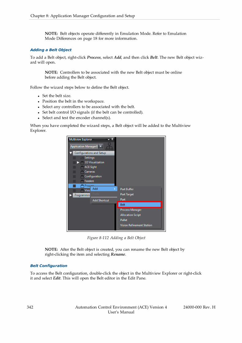
342 Automation Control Environment (ACE) Version 4User's Manual
24000-000 Rev. H
Chapter 8: Application Manager Configuration and Setup
NOTE: Belt objects operate differently in Emulation Mode. Refer to EmulationMode Differences on page 18 for more information.
Adding a Belt Object
To add a Belt object, right-click Process, select Add, and then click Belt. The new Belt object wiz-ard will open.
NOTE: Controllers to be associated with the new Belt object must be onlinebefore adding the Belt object.
Follow the wizard steps below to define the Belt object.
l Set the belt size.l Position the belt in the workspace.l Select any controllers to be associated with the belt.l Set belt control I/O signals (if the belt can be controlled).l Select and test the encoder channel(s).
When you have completed the wizard steps, a Belt object will be added to the MultiviewExplorer.
Figure 8-112 Adding a Belt Object
NOTE: After the Belt object is created, you can rename the new Belt object byright-clicking the item and selecting Rename.
Belt Configuration
To access the Belt configuration, double-click the object in the Multiview Explorer or right-clickit and select Edit. This will open the Belt editor in the Edit Pane.
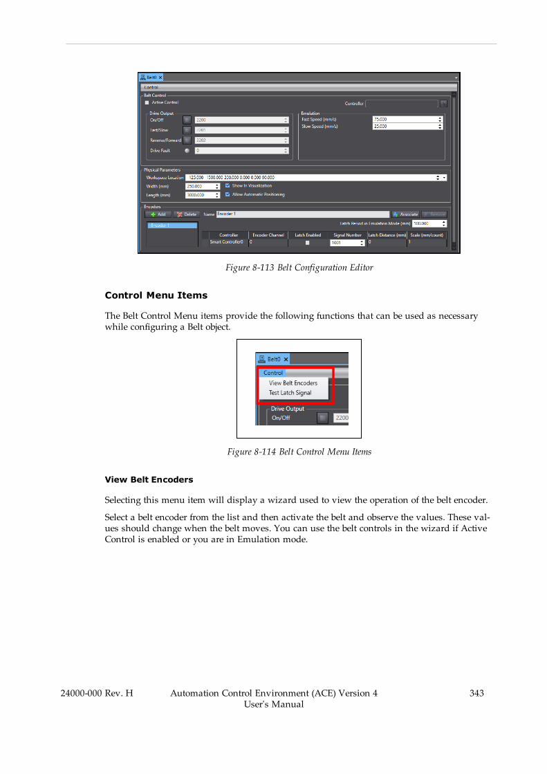
Figure 8-113 Belt Configuration Editor
Control Menu Items
The Belt Control Menu items provide the following functions that can be used as necessarywhile configuring a Belt object.
Figure 8-114 Belt Control Menu Items
View Belt Encoders
Selecting this menu item will display a wizard used to view the operation of the belt encoder.
Select a belt encoder from the list and then activate the belt and observe the values. These val-ues should change when the belt moves. You can use the belt controls in the wizard if ActiveControl is enabled or you are in Emulation mode.
24000-000 Rev. H Automation Control Environment (ACE) Version 4User's Manual
343
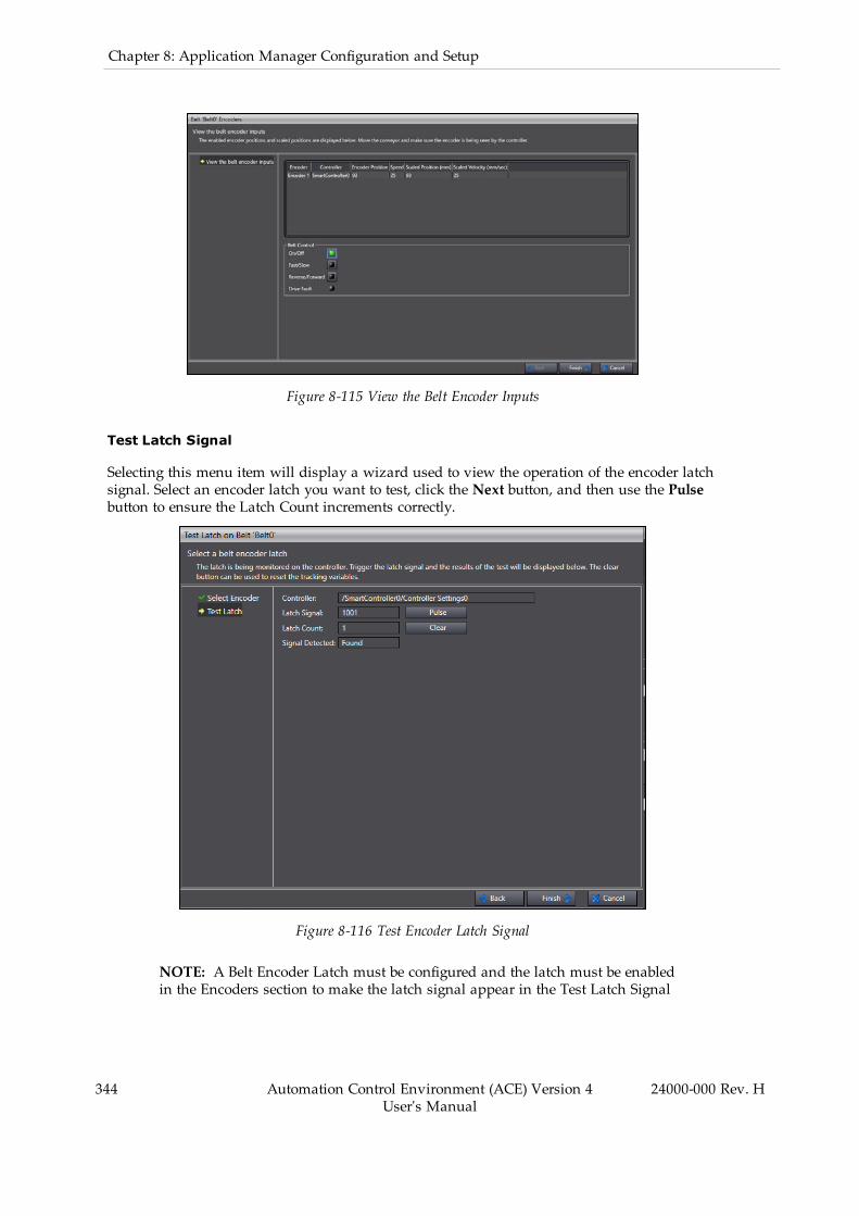
344 Automation Control Environment (ACE) Version 4User's Manual
24000-000 Rev. H
Chapter 8: Application Manager Configuration and Setup
Figure 8-115 View the Belt Encoder Inputs
Test Latch Signal
Selecting this menu item will display a wizard used to view the operation of the encoder latchsignal. Select an encoder latch you want to test, click the Next button, and then use the Pulsebutton to ensure the Latch Count increments correctly.
Figure 8-116 Test Encoder Latch Signal
NOTE: A Belt Encoder Latch must be configured and the latch must be enabledin the Encoders section to make the latch signal appear in the Test Latch Signal
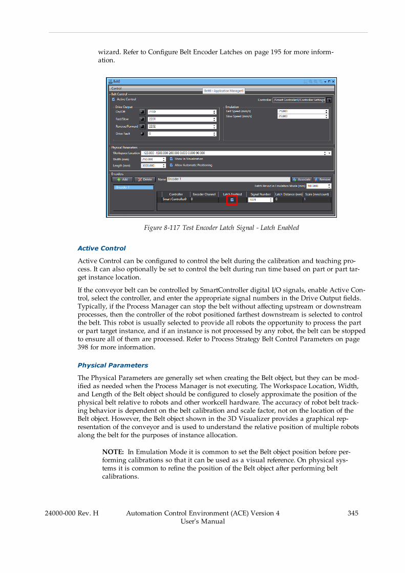
wizard. Refer to Configure Belt Encoder Latches on page 195 for more inform-ation.
Figure 8-117 Test Encoder Latch Signal - Latch Enabled
Active Control
Active Control can be configured to control the belt during the calibration and teaching pro-cess. It can also optionally be set to control the belt during run time based on part or part tar-get instance location.
If the conveyor belt can be controlled by SmartController digital I/O signals, enable Active Con-trol, select the controller, and enter the appropriate signal numbers in the Drive Output fields.Typically, if the Process Manager can stop the belt without affecting upstream or downstreamprocesses, then the controller of the robot positioned farthest downstream is selected to controlthe belt. This robot is usually selected to provide all robots the opportunity to process the partor part target instance, and if an instance is not processed by any robot, the belt can be stoppedto ensure all of them are processed. Refer to Process Strategy Belt Control Parameters on page398 for more information.
Physical Parameters
The Physical Parameters are generally set when creating the Belt object, but they can be mod-ified as needed when the Process Manager is not executing. The Workspace Location, Width,and Length of the Belt object should be configured to closely approximate the position of thephysical belt relative to robots and other workcell hardware. The accuracy of robot belt track-ing behavior is dependent on the belt calibration and scale factor, not on the location of theBelt object. However, the Belt object shown in the 3D Visualizer provides a graphical rep-resentation of the conveyor and is used to understand the relative position of multiple robotsalong the belt for the purposes of instance allocation.
NOTE: In Emulation Mode it is common to set the Belt object position before per-forming calibrations so that it can be used as a visual reference. On physical sys-tems it is common to refine the position of the Belt object after performing beltcalibrations.
24000-000 Rev. H Automation Control Environment (ACE) Version 4User's Manual
345
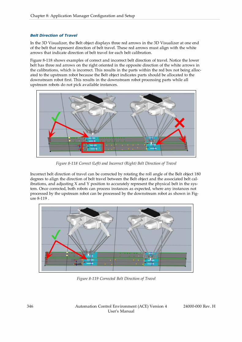
346 Automation Control Environment (ACE) Version 4User's Manual
24000-000 Rev. H
Chapter 8: Application Manager Configuration and Setup
Belt Direction of Travel
In the 3D Visualizer, the Belt object displays three red arrows in the 3D Visualizer at one endof the belt that represent direction of belt travel. These red arrows must align with the whitearrows that indicate direction of belt travel for each belt calibration.
Figure 8-118 shows examples of correct and incorrect belt direction of travel. Notice the lowerbelt has three red arrows on the right oriented in the opposite direction of the white arrows inthe calibrations, which is incorrect. This results in the parts within the red box not being alloc-ated to the upstream robot because the Belt object indicates parts should be allocated to thedownstream robot first. This results in the downstream robot processing parts while allupstream robots do not pick available instances.
Figure 8-118 Correct (Left) and Incorrect (Right) Belt Direction of Travel
Incorrect belt direction of travel can be corrected by rotating the roll angle of the Belt object 180degrees to align the direction of belt travel between the Belt object and the associated belt cal-ibrations, and adjusting X and Y position to accurately represent the physical belt in the sys-tem. Once corrected, both robots can process instances as expected, where any instances notprocessed by the upstream robot can be processed by the downstream robot as shown in Fig-ure 8-119 .
Figure 8-119 Corrected Belt Direction of Travel
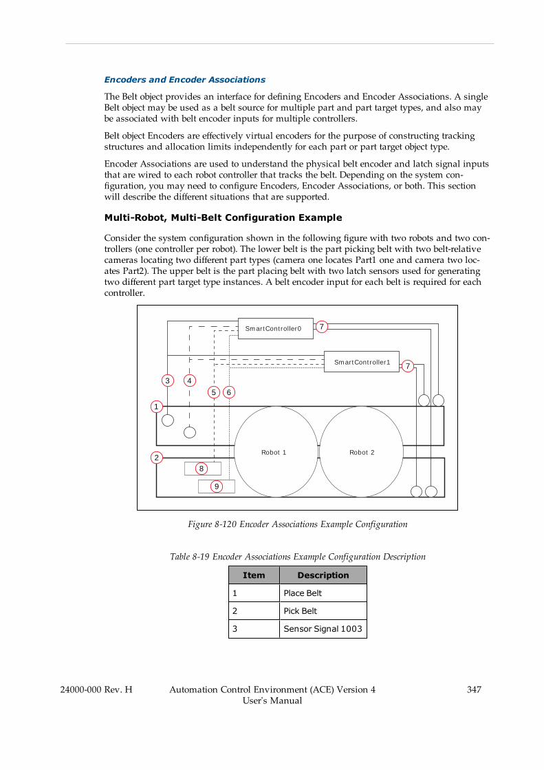
Encoders and Encoder Associations
The Belt object provides an interface for defining Encoders and Encoder Associations. A singleBelt object may be used as a belt source for multiple part and part target types, and also maybe associated with belt encoder inputs for multiple controllers.
Belt object Encoders are effectively virtual encoders for the purpose of constructing trackingstructures and allocation limits independently for each part or part target object type.
Encoder Associations are used to understand the physical belt encoder and latch signal inputsthat are wired to each robot controller that tracks the belt. Depending on the system con-figuration, you may need to configure Encoders, Encoder Associations, or both. This sectionwill describe the different situations that are supported.
Multi-Robot, Multi-Belt Configuration Example
Consider the system configuration shown in the following figure with two robots and two con-trollers (one controller per robot). The lower belt is the part picking belt with two belt-relativecameras locating two different part types (camera one locates Part1 one and camera two loc-ates Part2). The upper belt is the part placing belt with two latch sensors used for generatingtwo different part target type instances. A belt encoder input for each belt is required for eachcontroller.
SmartController0
SmartController1
Robot 1 Robot 2
1
2
3 4
5 6
7
7
8
9
Figure 8-120 Encoder Associations Example Configuration
Table 8-19 Encoder Associations Example Configuration Description
Item Description
1 Place Belt
2 Pick Belt
3 Sensor Signal 1003
24000-000 Rev. H Automation Control Environment (ACE) Version 4User's Manual
347

348 Automation Control Environment (ACE) Version 4User's Manual
24000-000 Rev. H
Chapter 8: Application Manager Configuration and Setup
Item Description
4 Sensor Signal 1004
5 Latch Signal 1002
6 Latch Signal 1001
7 Belt Encoder Inputs
8 Camera 2
9 Camera 1
With the configuration shown in the figure above, Belt Encoder Latches are configured asshown below, assuming a rising edge for each part and part target detection.
Figure 8-121 Belt Encoder Latch Configuration
In the Belt object, a virtual encoder is needed for each part object (Part1 and Part2). Each vir-tual encoder will have an encoder association with the corresponding Belt object EncoderChannel of each controller, and the latch signal of the corresponding camera detecting thatpart object type as shown below in Figure 8-122 and Figure 8-123 below.
Figure 8-122 Part1 Encoder Associations and Latch Signals
Figure 8-123 Part2 Encoder Associations and Latch Signals

Part1 and Part2 configurations include references to their respective virtual encoders and vis-ion tool for location as shown in the figure below.
Figure 8-124 Part1 and Part2 Configurations
The separate virtual encoders are necessary to support independent tracking structures for thedifferent part and part target types, including individual belt calibrations and allocation limits.
The separate encoder associations and latch signals allow Pack Manager applications to man-age capturing and storing latch signals and encoder positions of every instance for each con-troller. When an instance is not processed by the upstream robot and is reallocated to thedownstream robot, the latch position reference is automatically changed from the SmartCon-troller0 encoder latch position to the SmartController1 encoder latch position.
Additional Information: When an instance is allocated to the next controller andthe latch reference changes, an instance can jump in the 3D Visualizer. This isoften due to poor sensor calibrations or incorrect robot locations, as shown in thefigure below. This can cause confusion when instances jump farther upstreamwhen deallocated from the upstream robot. It is highly recommended to keep the3D Visualizer orderly and represent the hardware system as closely as possible.This prevents many issues during commissioning and makes troubleshootingeasier if issues arise.
Figure 8-125 Instances Jumping from Reallocation/Latch Reference Change
24000-000 Rev. H Automation Control Environment (ACE) Version 4User's Manual
349

350 Automation Control Environment (ACE) Version 4User's Manual
24000-000 Rev. H
Chapter 8: Application Manager Configuration and Setup
In this configuration, each camera is relative to independent belt calibrations and allocationlimits as shown in Figure 8-126 and Figure 8-127 below. Notice that there is a Pick Belt cal-ibration for each virtual encoder.
Figure 8-126 Independent Belt Calibrations
Figure 8-127 Pick Belt Calibrations for Each Virtual Encoder
Alternatively, the ACE software supports configurations that require multiple cameras to be rel-ative to a single robot-to-belt calibration and set of allocation limits as shown in Figure 8-128and Figure 8-129 below, where Part1 and Part2 are configured to use a single virtual encoder.This is achieved by defining multiple latch signals for specific encoder associations and con-figuring the corresponding robot-to-sensor belt camera calibrations to use specific latch signalnumbers. This is only valid for belt cameras. For example, multiple latch signals are notallowed if the configuration is for belt-latch configuration, such as locating multiple palletswith different latch signals. For latch and spacing calibrations, use multiple virtual encoders.
Figure 8-128 Part1 and Part2 Configured to Use Single Virtual Encoder

Figure 8-129 Allocation Limit Associations in Belt Calibrations
Multiple Cameras Relative to a Single Robot-to-belt Calibration
Use the following procedure to configure multiple cameras relative to a single robot-to-belt cal-ibration.
1. Open the Belt object and verify that you have associated a controller with the beltencoder.
Figure 8-130 Belt Encoder Association
2. Specify the latch signals used by each camera in the Signal Number field. Multiple sig-nals must be separated by a space, as shown in the following figure.
Figure 8-131 Specify Multiple Latch Signals
24000-000 Rev. H Automation Control Environment (ACE) Version 4User's Manual
351

352 Automation Control Environment (ACE) Version 4User's Manual
24000-000 Rev. H
Chapter 8: Application Manager Configuration and Setup
3. Locate the Robot-to-Sensor belt camera calibrations in the Process Manager. Select aSensor Calibration and click the Edit button.
Figure 8-132 Edit the Sensor Calibration
4. Expand the Belt Latch Configuration parameter group, uncheck Use Default, and thenenter the desired latch signal number associated with that camera.
Figure 8-133 Edit the Belt Camera Calibration
5. Repeat steps 3 and 4 for the other belt camera calibrations and corresponding latch sig-nals. Once all belt camera calibrations and latch signals are accounted for, the pro-cedure is complete.
Process Manager Object
The Process Manager is the central control point for developing a process-managed applic-ation, such as an Pack Manager packaging application. It allows you to create and configurecomplex applications without writing any programming code. For advanced development, itprovides access to V+ programming controls that allow you to modify your application.
NOTE: When Emulation Mode is enabled, robot-to-hardware calibrations andreferencing procedures use 3D Visualization. Refer to Emulation Mode Dif-ferences on page 18 for more information.
Process Components
This section describes the Process components, which are accessed from the Process Managerobject. The other application components, such as robots, grippers (end effectors), controllers,and vision tools are described in other sections of this documentation.
Process Pallets
The Process Pallet object is used to define the layout and location of a pallet. The pallet can bein a static position or it can be located on a conveyor belt. The pallet can use a traditional rowand column part layout or use a radial part layout.
Belts and Belt Encoders
The Belt object defines a conveyor belt used by the system. The Belt object maintains a list ofencoders that are associated with the conveyor. The Belt Encoder defines the mm/count ratio ofthe encoder. The Belt Encoder Controller Connection maintains a list of controllers that theencoder is electrically connected to. The controller connection can also specify controller latch-ing to a particular encoder. The Belt object also contains belt speed and start / stop controls.
Parts and Part Targets
A Part object defines a part that is input for processing. The Part object has a Configurationdrop-down list box that is used to specify how the part is input to the system.
A Part Target object defines a possible destination for a part. The possible configurations for aPart Target object are the same as for a Part object. Depending on the selected configuration,additional information can be defined when configuring the Part / Part Target as describedbelow.
Part / Part Target Con-figuration Vision Properties Belt Properties Pallet
Belt Optional Required Optional
Static Not Used Not Used Optional
Vision Required Not Used Optional
Part and Part Target Configuration Options
The Part and Part Target configuration defines the part pick or place requirements. The fol-lowing options are available.
Table 8-20 Part and Part Target Configuration Option Details
Part and PartTarget
ConfigurationDescription Details
Belt The part is picked from orplaced onto a conveyor belt. Itmay use latching, a camera,or a spacing interval todetermine the position.
A belt and encoder must be specified foruse with the Part / Part Target. Then, aBelt Mode is defined that describes howthe part is related to the belt.
24000-000 Rev. H Automation Control Environment (ACE) Version 4User's Manual
353
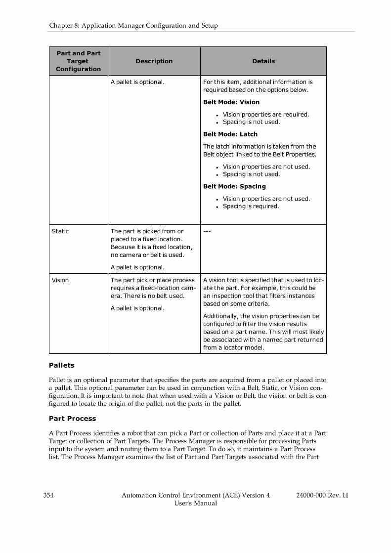
354 Automation Control Environment (ACE) Version 4User's Manual
24000-000 Rev. H
Chapter 8: Application Manager Configuration and Setup
Part and PartTarget
ConfigurationDescription Details
A pallet is optional. For this item, additional information isrequired based on the options below.
Belt Mode: Vision
l Vision properties are required.l Spacing is not used.
Belt Mode: Latch
The latch information is taken from theBelt object linked to the Belt Properties.
l Vision properties are not used.l Spacing is not used.
Belt Mode: Spacing
l Vision properties are not used.l Spacing is required.
Static The part is picked from orplaced to a fixed location.Because it is a fixed location,no camera or belt is used.
A pallet is optional.
---
Vision The part pick or place processrequires a fixed-location cam-era. There is no belt used.
A pallet is optional.
A vision tool is specified that is used to loc-ate the part. For example, this could bean inspection tool that filters instancesbased on some criteria.
Additionally, the vision properties can beconfigured to filter the vision resultsbased on a part name. This will most likelybe associated with a named part returnedfrom a locator model.
Pallets
Pallet is an optional parameter that specifies the parts are acquired from a pallet or placed intoa pallet. This optional parameter can be used in conjunction with a Belt, Static, or Vision con-figuration. It is important to note that when used with a Vision or Belt, the vision or belt is con-figured to locate the origin of the pallet, not the parts in the pallet.
Part Process
A Part Process identifies a robot that can pick a Part or collection of Parts and place it at a PartTarget or collection of Part Targets. The Process Manager is responsible for processing Partsinput to the system and routing them to a Part Target. To do so, it maintains a Part Processlist. The Process Manager examines the list of Part and Part Targets associated with the Part
Processes defined by the user. It will generate a list of Calibration objects, which are displayedto the user, as follows.
l Robot-to-Belt Calibrationl Robot-to-Belt-Camera Calibrationl Robot-to-Belt-Latch-Sensor Calibrationl Robot-to-Fixed-Camera Calibrationl Robot-to-Belt-Spacing-Reference Calibration
Each calibration object relates the robot to another hardware element in the application.
The Part Process defines a possible processing scenario for handling a Part. The ProcessStrategy is responsible for deciding which robots will process which parts. This is done usingthe list of Part Process objects as a guide to the valid combinations.
If a Part or Part Target is a pallet, then the Part Process object allows for a Pallet Exclusion Con-figuration to be defined. The user can limit the pallet positions that can be accessed by therobot in this configuration.
A relative priority can be associated with a given part process. This priority is used by the Pro-cess Manager when allocating parts to robots.
The Part Process defines a gripper pick configuration and where the robot will place the parts.
The Process Manager examines the list of Part and Part Targets associated with the Part Pro-cesses defined by the user. It will generate a list of Calibration objects, which are displayed tothe user, as follows: l Robot-to-Belt Calibration l Robot-to-Belt-Camera Calibration l Robot-to-Belt-Latch-Sensor Calibration l Robot-to-Fixed-Camera Calibration l Robot-to-Belt-Spacing-Refer-ence Calibration Each calibration object relates the robot to another hardware element in theapplication.
Motion Information
After a collection of Part Processes is defined, the Process Manager scans the collection todetermine what additional configuration data is needed to properly drive the process. Someexamples are listed below.
l Each robot will need an idle position.l For each part that is picked, motion parameters describing the approach height, departheight, motion configuration, and offset at the pick location must be defined.
l For each part that is to be delivered to a target, the approach height, depart height,motion configuration, and offset at the place location must be defined.
The Process Manager maintains a list of the required information that must be taught as partof the configuration of the system. The motion information is located in the ConfigurationItems group of the Process Manager editor.
Sources
A Source is an object that interacts with the hardware and discovers Part Instances and PartTarget Instances. The Process Manager analyzes the configuration of Part Processes in order todetermine what Sources are needed to control the hardware. A Source is allocated for each ofthe following conditions
24000-000 Rev. H Automation Control Environment (ACE) Version 4User's Manual
355

356 Automation Control Environment (ACE) Version 4User's Manual
24000-000 Rev. H
Chapter 8: Application Manager Configuration and Setup
l For each Static-defined Part or Part Target, a Source is created.l For each Vision-defined Part or Part Target, one Source is created for each Virtual Cam-era referenced. This Source will process the collection of all Part or Part Targets ref-erenced by the Virtual Camera.
l For each Belt-defined Part or Part Target, one Source is created for each Belt referenced.This Source will process the collection of all Part or Part Targets referenced by the Belt.
For each Source, the Process Manager allows you to modify certain parameters associated withthe Source. As an example, the Vision and Static Source objects can be configured to interfacewith a feeder.
Part and Part Target Instances
When an individual Part is located, it is represented by a Part Instance. When an individualPart Target point is identified, it is represented by a Part Target Instance. These objects identifythe transformation and Part / Part Target information so the complete location can be resolved.If an individual Part Instance must be placed at a specific Part Target Instance, the PartInstance will have a link to the appropriate Part Target Instance.
Part Instance and Part Target Instance objects get allocated to a controller for processing by arobot. The Process Manager uses the Process Strategy to identify that allocation.
NOTE: The Process Manager knows if a Part/Part Target instance was pro-cessed, not processed, or if an error happened during processing because of agrip error. If a grip error occurs, that instance will not be transferred to next robotand will be counted as not processed in the statistics.
Process Handler
When the Process Manager executes a process, it relies on a series of internal objects to man-age the interaction with the hardware. The Process Manager is responsible for organizing andcontaining the information that is going to be processed. The Process Handler is responsiblefor using that information and managing the execution of the process.
In general, the run-time operation of the Process Manager will use the Part Process informationto locate Part Instances and Part Target Instances. Internally, the Process Handler maintains acollection of internal objects that are responsible for interacting with individual elements of thehardware. These objects fall into two categories: objects that generate Part / Part TargetInstances and objects that can process the instances.
Controller Queue
The Controller Queue represents a controller with associated robots that can pick from PartInstances and place to Part Target Instances.
The Controller Queue communicates with the Queue Manager task that manages the collectionof parts to be processed by the robots on a given controller. The Controller Queue receives noti-fication as the controller processes the instance information. The Controller Queue also mon-itors for functionality or capacity issues with the robots connected to the controller. It notifiesthe Process Manager through an event in the case that the controller is unable to process theitems in its queue within a given time-frame.
The time-frame is based on the belt speed and location of the parts on the belt given theupstream / downstream limits of the individual robots. The Controller Queue maintains state

information regarding its ability to accept parts. This information is used by the ProcessStrategy when determining how to allocate parts.
The Controller Queue also maintains statistics that are captured for a certain number of cycles,such as idle time, processing time, and parts / targets processed per minute. This informationis available to you and may be used in the allocation of Part Instances.
Line Balancing
A Process Strategy is invoked to determine how to allocate the Part / Part Target Instances iden-tified by the Process Manager. It uses the list of Part Processes to allocate the instances to spe-cific robots. The output of this process is passed to the Controller Queue object by the ProcessManager.
Each Process Strategy operates under certain assumptions based on the process being mon-itored. Those assumptions determine which algorithms are used to perform the allocation.
Line Balancing and Process Strategy
This process strategy is predicated around certain assumptions on how robots will handleParts and Part Targets. For part processing, the overflow from an upstream robot will bepassed to the next downstream robot on the same controller. In other words, the first robotalong the conveyor will pick all parts it is capable of picking. Any part it cannot pick will bepicked by the next robot in the line. This pattern is repeated for all robots in the line.
For the processing of Part Targets, any targets configured as a latched Pallet will be passedfrom robot to robot, allowing each one to fill the slots with parts as defined by the ProcessStrategy.
There is no logic function that tries to optimize the allocations of parts or targets. The ProcessStrategy simply requests that each robot process as many Parts and Part Targets as possible,and remaining parts are passed to the next robot.
There are user-defined parameters that control this Process Strategy, as described below.
l Robot Parameters: used to specify the queue size for the robot.l Belt Window Parameters: used to set part-processing filters, which help to optimizecycle time.
l Belt Control Parameters: used to set conveyor belt on / off and speed controls, whichcan dynamically adjust the part flow to the robot.
These parameters are available in the Process Strategy editor.
Custom Process Strategy
If required, the system allows you to define your own Process Strategies using C# within theapplication.
Controller Software
The application is split into the following two sections.
1. A series of V+ programs that are responsible for picking and placing an instance.2. A series of V+ programs responsible for managing the queue of parts and com-municating with the PC.
24000-000 Rev. H Automation Control Environment (ACE) Version 4User's Manual
357
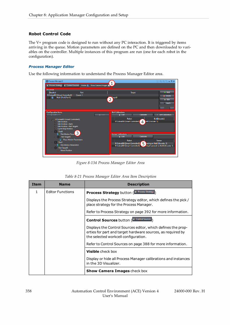
358 Automation Control Environment (ACE) Version 4User's Manual
24000-000 Rev. H
Chapter 8: Application Manager Configuration and Setup
Robot Control Code
The V+ program code is designed to run without any PC interaction. It is triggered by itemsarriving in the queue. Motion parameters are defined on the PC and then downloaded to vari-ables on the controller. Multiple instances of this program are run (one for each robot in theconfiguration).
Process Manager Editor
Use the following information to understand the Process Manager Editor area.
Figure 8-134 Process Manager Editor Area
Table 8-21 Process Manager Editor Area Item Description
Item Name Description
1 Editor Functions Process Strategy button ( )
Displays the Process Strategy editor, which defines the pick /place strategy for the Process Manager.
Refer to Process Strategy on page 392 for more information.
Control Sources button ( )
Displays the Control Sources editor, which defines the prop-erties for part and target hardware sources, as required bythe selected workcell configuration.
Refer to Control Sources on page 388 for more information.
Visible check box
Display or hide all Process Manager calibrations and instancesin the 3D Visualizer.
Show Camera Images check box

Item Name Description
Display or hide the camera image in the camera calibration /field of view shown in the 3D Visualizer.
2 Processes List Displays a list of defined processes.
Refer to Processes in the Process Manager Object on page360 for more information.
3 Configuration ItemsEditors
Provides access to editors for all motion parameters, offsets,and static frames that must be provided for the processesdefined in the Process List.
Refer to Configuration Items on page 379 for more inform-ation.
4 BeltCalibrations Editor
Lists all Robot-to-Belt calibrations required for the defined pro-cesses. Also provides access to edit belt allocation limits.
Refer to Belt Calibrations on page 370 for more information.
5 SensorCalibrations Editor
Lists all Robot-to-Camera, Robot-to-Sensor, and Spacing cal-ibrations required for the defined processes.
Refer to Sensor Calibrations on page 375 for more inform-ation.
Process Manager Configuration Errors
If there is a configuration error, an alert icon ( ) displays in the corresponding item. If youhover the mouse cursor over the icon, a message displays that describes the error as shownbelow.
Figure 8-135 Process Manager Configuration Errors
24000-000 Rev. H Automation Control Environment (ACE) Version 4User's Manual
359
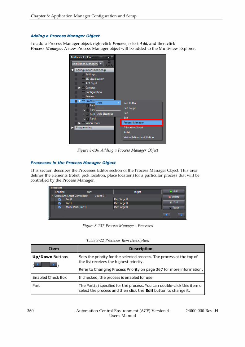
360 Automation Control Environment (ACE) Version 4User's Manual
24000-000 Rev. H
Chapter 8: Application Manager Configuration and Setup
Adding a Process Manager Object
To add a Process Manager object, right-click Process, select Add, and then clickProcess Manager. A new Process Manager object will be added to the Multiview Explorer.
Figure 8-136 Adding a Process Manager Object
Processes in the Process Manager Object
This section describes the Processes Editor section of the Process Manager Object. This areadefines the elements (robot, pick location, place location) for a particular process that will becontrolled by the Process Manager.
Figure 8-137 Process Manager - Processes
Table 8-22 Processes Item Description
Item Description
Up/Down Buttons
( )
Sets the priority for the selected process. The process at the top ofthe list receives the highest priority.
Refer to Changing Process Priority on page 367 for more information.
Enabled Check Box If checked, the process is enabled for use.
Part The Part(s) specified for the process. You can double-click this item orselect the process and then click the Edit button to change it.
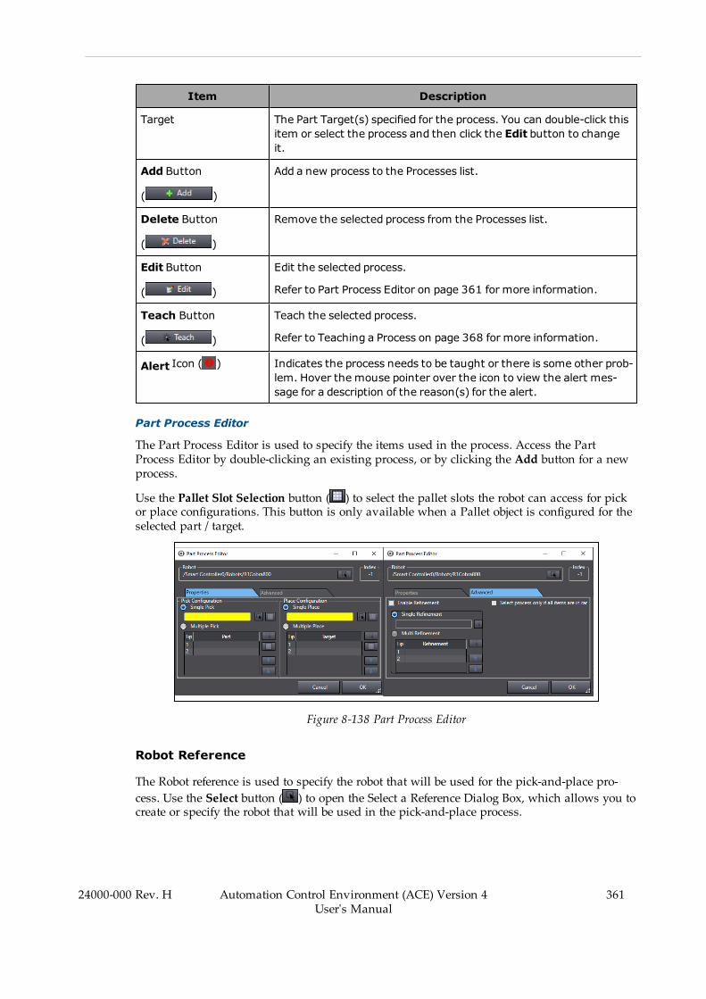
Item Description
Target The Part Target(s) specified for the process. You can double-click thisitem or select the process and then click the Edit button to changeit.
Add Button
( )
Add a new process to the Processes list.
Delete Button
( )
Remove the selected process from the Processes list.
Edit Button
( )
Edit the selected process.
Refer to Part Process Editor on page 361 for more information.
Teach Button
( )
Teach the selected process.
Refer to Teaching a Process on page 368 for more information.
Alert Icon ( ) Indicates the process needs to be taught or there is some other prob-lem. Hover the mouse pointer over the icon to view the alert mes-sage for a description of the reason(s) for the alert.
Part Process Editor
The Part Process Editor is used to specify the items used in the process. Access the PartProcess Editor by double-clicking an existing process, or by clicking the Add button for a newprocess.
Use the Pallet Slot Selection button ( ) to select the pallet slots the robot can access for pickor place configurations. This button is only available when a Pallet object is configured for theselected part / target.
Figure 8-138 Part Process Editor
Robot Reference
The Robot reference is used to specify the robot that will be used for the pick-and-place pro-cess. Use the Select button ( ) to open the Select a Reference Dialog Box, which allows you tocreate or specify the robot that will be used in the pick-and-place process.
24000-000 Rev. H Automation Control Environment (ACE) Version 4User's Manual
361

362 Automation Control Environment (ACE) Version 4User's Manual
24000-000 Rev. H
Chapter 8: Application Manager Configuration and Setup
Index
This item displays the index number of the process, which can be referenced in V+ programsand C# programs.
Properties Tab: Pick Configuration Group
The Pick Configuration group is used to specify the single or multi-pick Part items for the pick-and-place process, as follows.
Single Pick/Place and Multiple Pick/Place can be used together. For example, if you want topick multiple parts individually and then place them all at the same time, you would use Mul-tiple Pick and Single Place.
Single Pick
Select this item for a single-pick application where only one pick motion is performed. Use theSelect icon to browse for the part that will be picked.
NOTE: When Single Pick / Place configuration is used with an IO EndEffectorthat has multiple tips defined, the center line Tip Offset is applied. This is theaverage of all Tip Offsets defined in the IO EndEffector object. Refer toIO EndEffectors on page 212 for more information.
Figure 8-139 Select a Single Pick Object
Multiple Pick
Select this item for a multiple-pick application where multiple parts will be picked before place-ment at a target. When multi-pick is enabled, the available tip indexes will be provided for theselected robot IO EndEffector. Use the Select icon to browse for the part that will be picked byeach tip.
Use the Up/Down buttons to change the order of the tip processing.

NOTE: Multiple Tips must be defined in the robot's IO EndEffector con-figuration. The Process Manager will access the IO EndEffector object specified inthe Selected End-Effector property of the robot object.
Figure 8-140 Select Multiple Pick Objects
Properties Tab: Place Configuration Group
The Place Configuration group is used to specify the single or multi-place Part Target items forthe pick-and-place process as follows.
Single Place
Select this item for a single-place application where only one place-motion is performed. Usethe Select icon to browse for the part target where the part will be placed.
24000-000 Rev. H Automation Control Environment (ACE) Version 4User's Manual
363
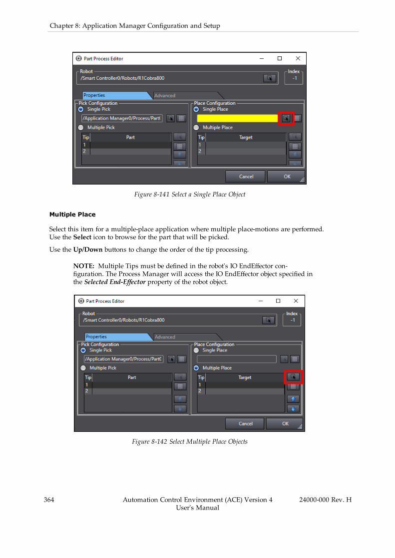
364 Automation Control Environment (ACE) Version 4User's Manual
24000-000 Rev. H
Chapter 8: Application Manager Configuration and Setup
Figure 8-141 Select a Single Place Object
Multiple Place
Select this item for a multiple-place application where multiple place-motions are performed.Use the Select icon to browse for the part that will be picked.
Use the Up/Down buttons to change the order of the tip processing.
NOTE: Multiple Tips must be defined in the robot's IO EndEffector con-figuration. The Process Manager will access the IO EndEffector object specified inthe Selected End-Effector property of the robot object.
Figure 8-142 Select Multiple Place Objects
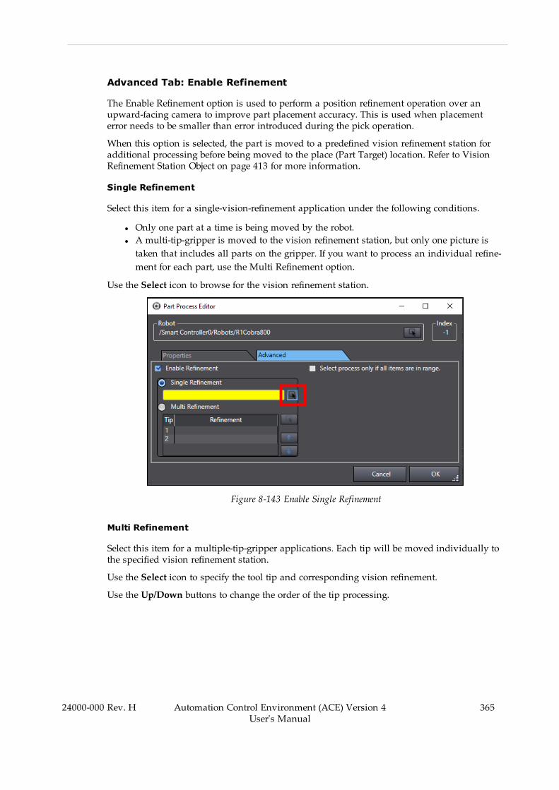
Advanced Tab: Enable Refinement
The Enable Refinement option is used to perform a position refinement operation over anupward-facing camera to improve part placement accuracy. This is used when placementerror needs to be smaller than error introduced during the pick operation.
When this option is selected, the part is moved to a predefined vision refinement station foradditional processing before being moved to the place (Part Target) location. Refer to VisionRefinement Station Object on page 413 for more information.
Single Refinement
Select this item for a single-vision-refinement application under the following conditions.
l Only one part at a time is being moved by the robot.l A multi-tip-gripper is moved to the vision refinement station, but only one picture istaken that includes all parts on the gripper. If you want to process an individual refine-ment for each part, use the Multi Refinement option.
Use the Select icon to browse for the vision refinement station.
Figure 8-143 Enable Single Refinement
Multi Refinement
Select this item for a multiple-tip-gripper applications. Each tip will be moved individually tothe specified vision refinement station.
Use the Select icon to specify the tool tip and corresponding vision refinement.
Use the Up/Down buttons to change the order of the tip processing.
24000-000 Rev. H Automation Control Environment (ACE) Version 4User's Manual
365
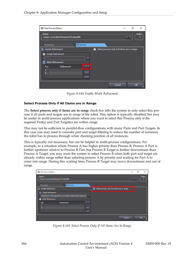
366 Automation Control Environment (ACE) Version 4User's Manual
24000-000 Rev. H
Chapter 8: Application Manager Configuration and Setup
Figure 8-144 Enable Multi Refinement
Select Process Only if All Items are in Range
The Select process only if items are in range check box tells the system to only select this pro-cess if all parts and targets are in range of the robot. This option is typically disabled, but maybe useful in multi-process applications where you want to select this Process only if therequired Part(s) and Part Target(s) are within range.
This may not be sufficient in parallel-flow configurations with many Parts and Part Targets. Inthis case you may need to consider part and target filtering to reduce the number of instancesthe robot has to process through when checking position of all instances.
This is typically not necessary, but can be helpful in multi-process configurations. Forexample, in a situation where Process A has higher priority than Process B, Process A Part isfurther upstream relative to Process B Part, but Process B Target is further downstream thanProcess A Target, you may want the system to select Process B when both part and target arealready within range rather than selecting process A by priority and waiting for Part A tocome into range. During this waiting time, Process B Target may move downstream and out ofrange.
Figure 8-145 Select Process Only If All Items Are In Range

Changing Process Priority
The process priority is used in situations where multiple processes are defined and a givenrobot is capable of doing several of the potential processes. The process at the top of the Pro-cess list receives highest priority.
You can change the priority for a process by using the Up / Down buttons on the Process listeditor, shown in the following figure.
NOTE: In addition to the arrows, you can also affect process priority throughthe Process Selection Mode setting of the Robot Parameters in the ProcessStrategy Editor area. Refer to Process Strategy Robot Parameters on page 394 formore information.
Figure 8-146 Change Process Priority
For example, you have three processes defined in the Process Manager, as follows.
1. Pick from input Part, place to output Part Target.2. Pick from Part Buffer, place to output Part Target.3. Pick from input Part, place to output Part Buffer.
In this case, the Process Manager would always execute the first process if there are parts atthe input, and move them to the output. If no parts are present at the input, it will then checkfor process 2 and 3.
However, if you change the order (the priority), you will get a different behavior as follows.
24000-000 Rev. H Automation Control Environment (ACE) Version 4User's Manual
367

368 Automation Control Environment (ACE) Version 4User's Manual
24000-000 Rev. H
Chapter 8: Application Manager Configuration and Setup
1. Pick from Part Buffer, place to output (Part Target).2. Pick from input (Part), place to output (Part Target).3. Pick from input (Part), place to Part Buffer.
In this case, the Process Manager will always remove parts from the Part Buffer until no partsremain in the Part Buffer, before processing the input (Part).
Teaching a Process
The last step in creating the Process is the teach function. This must be performed after all cal-ibrations are complete. Ideally, all calibrations would be performed as accurately as possiblewith a calibration pointer and disk. After calibrations are complete, the process end effectorcan be installed to teach the process. Every step of the process is performed one at a time tocapture any necessary motion offsets. Select a Process and then click the Teach button (
) to open the Teaching Process wizard.
NOTE: The following process illustrates the steps for a basic pick-and-placeapplication. The steps in your wizard will vary depending on the applicationand types of Parts and Part Targets you have defined for your application.
Additional Information: If a Pallet object is used for a Part or Part Target, youwill see additional screens in the wizard for teaching the pallet frame (the ori-entation of the pallet in the workspace) and the first position in the pallet. Eachof these steps contain an image of the pallet item being taught, which provides avisual reference. Refer to Pallet Object on page 407 for more information.
Figure 8-147 Frame Origin, X-Axis, Y-Axis, and First Pallet Position (left-to-right)
Use the Teaching a Process wizard to make selections for pick, place, and idle robot positions.
IMPORTANT:When the Absolute option is selected, the approach or departheights will be an absolute Z coordinate in robot world coordinates. You mustensure that value is in-range and safe. Otherwise, the robot could move to anunintended location or out of range, which may damage the robot or other equip-ment in the workcell.
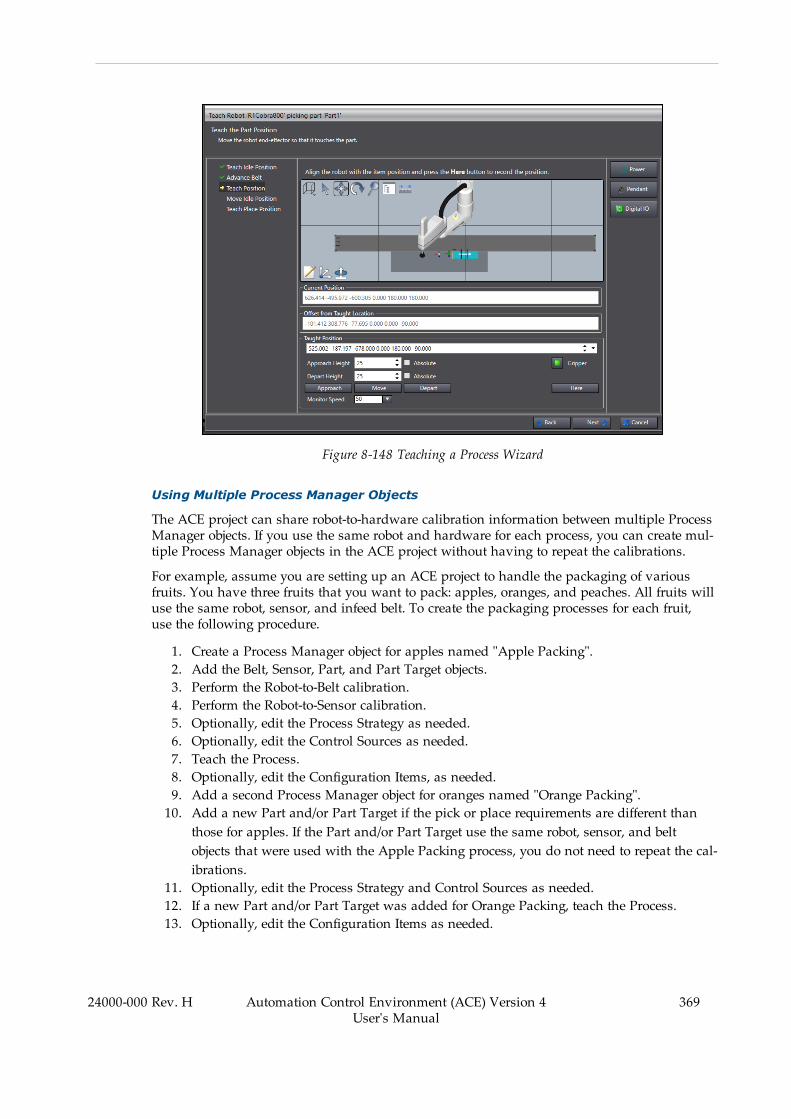
Figure 8-148 Teaching a Process Wizard
Using Multiple Process Manager Objects
The ACE project can share robot-to-hardware calibration information between multiple ProcessManager objects. If you use the same robot and hardware for each process, you can create mul-tiple Process Manager objects in the ACE project without having to repeat the calibrations.
For example, assume you are setting up an ACE project to handle the packaging of variousfruits. You have three fruits that you want to pack: apples, oranges, and peaches. All fruits willuse the same robot, sensor, and infeed belt. To create the packaging processes for each fruit,use the following procedure.
1. Create a Process Manager object for apples named "Apple Packing".2. Add the Belt, Sensor, Part, and Part Target objects.3. Perform the Robot-to-Belt calibration.4. Perform the Robot-to-Sensor calibration.5. Optionally, edit the Process Strategy as needed.6. Optionally, edit the Control Sources as needed.7. Teach the Process.8. Optionally, edit the Configuration Items, as needed.9. Add a second Process Manager object for oranges named "Orange Packing".10. Add a new Part and/or Part Target if the pick or place requirements are different than
those for apples. If the Part and/or Part Target use the same robot, sensor, and beltobjects that were used with the Apple Packing process, you do not need to repeat the cal-ibrations.
11. Optionally, edit the Process Strategy and Control Sources as needed.12. If a new Part and/or Part Target was added for Orange Packing, teach the Process.13. Optionally, edit the Configuration Items as needed.
24000-000 Rev. H Automation Control Environment (ACE) Version 4User's Manual
369
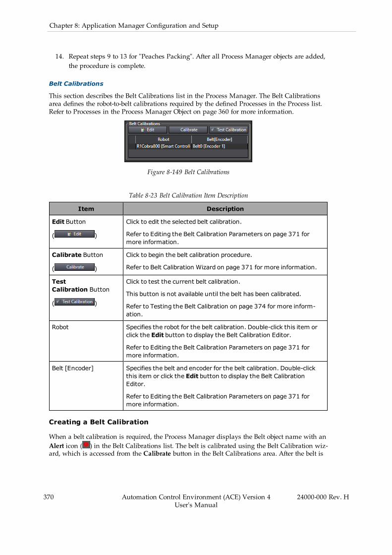
370 Automation Control Environment (ACE) Version 4User's Manual
24000-000 Rev. H
Chapter 8: Application Manager Configuration and Setup
14. Repeat steps 9 to 13 for "Peaches Packing". After all Process Manager objects are added,the procedure is complete.
Belt Calibrations
This section describes the Belt Calibrations list in the Process Manager. The Belt Calibrationsarea defines the robot-to-belt calibrations required by the defined Processes in the Process list.Refer to Processes in the Process Manager Object on page 360 for more information.
Figure 8-149 Belt Calibrations
Table 8-23 Belt Calibration Item Description
Item Description
Edit Button
( )
Click to edit the selected belt calibration.
Refer to Editing the Belt Calibration Parameters on page 371 formore information.
Calibrate Button
( )
Click to begin the belt calibration procedure.
Refer to Belt Calibration Wizard on page 371 for more information.
TestCalibration Button
( )
Click to test the current belt calibration.
This button is not available until the belt has been calibrated.
Refer to Testing the Belt Calibration on page 374 for more inform-ation.
Robot Specifies the robot for the belt calibration. Double-click this item orclick the Edit button to display the Belt Calibration Editor.
Refer to Editing the Belt Calibration Parameters on page 371 formore information.
Belt [Encoder] Specifies the belt and encoder for the belt calibration. Double-clickthis item or click the Edit button to display the Belt CalibrationEditor.
Refer to Editing the Belt Calibration Parameters on page 371 formore information.
Creating a Belt Calibration
When a belt calibration is required, the Process Manager displays the Belt object name with anAlert icon ( ) in the Belt Calibrations list. The belt is calibrated using the Belt Calibration wiz-ard, which is accessed from the Calibrate button in the Belt Calibrations area. After the belt is

calibrated using the wizard, values such as allocation limits, upstream limits, dynamic waitline, process limit, and horizontal filtering limits can be manually edited.
Belt Calibration Wizard
The Robot-to-Belt Calibration wizard provides an interactive series of steps that guide youthrough the calibration process. Each step of the wizard contains graphical aids and text thatdescribe the particular step being performed. As each step of the wizard is completed, theinformation from that step is collected and used to populate the fields in the Belt CalibrationEditor.
Click the Calibrate button to begin the Belt Calibration wizard.
NOTE: This feature operates differently in Emulation Mode. Refer to EmulationMode Differences on page 18 for more information.
Editing the Belt Calibration Parameters
After the belt has been calibrated using the Belt Calibration wizard, you can manually edit thestored belt calibration parameters and allocation limits, such as upstream limit, downstreamlimit, and downstream process limit. These parameters are edited using the Belt CalibrationEditor. The following figure illustrates several of the Belt Calibration Editor items in a typicalworkcell.
NOTE: The belt must be calibrated using the wizard before the values can bemanually edited.
Figure 8-150 Typical Belt Calibration Items
Table 8-24 Typical Belt Calibration Item Description
Item Description
1 Downstream
2 Downstream Limit
3 Process Limit
24000-000 Rev. H Automation Control Environment (ACE) Version 4User's Manual
371
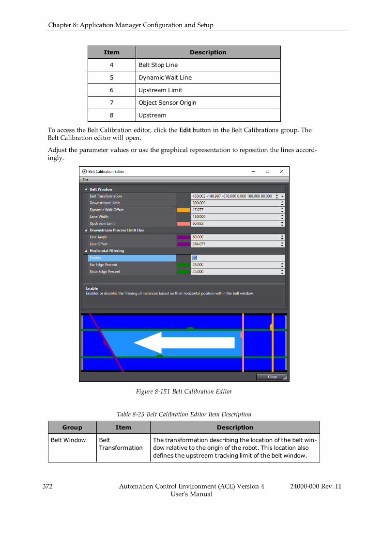
372 Automation Control Environment (ACE) Version 4User's Manual
24000-000 Rev. H
Chapter 8: Application Manager Configuration and Setup
Item Description
4 Belt Stop Line
5 Dynamic Wait Line
6 Upstream Limit
7 Object Sensor Origin
8 Upstream
To access the Belt Calibration editor, click the Edit button in the Belt Calibrations group. TheBelt Calibration editor will open.
Adjust the parameter values or use the graphical representation to reposition the lines accord-ingly.
Figure 8-151 Belt Calibration Editor
Table 8-25 Belt Calibration Editor Item Description
Group Item Description
Belt Window BeltTransformation
The transformation describing the location of the belt win-dow relative to the origin of the robot. This location alsodefines the upstream tracking limit of the belt window.
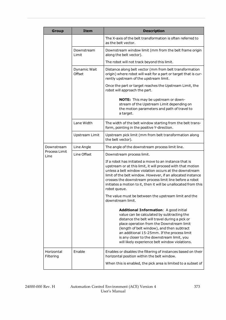
Group Item Description
The X-axis of the belt transformation is often referred toas the belt vector.
DownstreamLimit
Downstream window limit (mm from the belt frame originalong the belt vector).
The robot will not track beyond this limit.
Dynamic WaitOffset
Distance along belt vector (mm from belt transformationorigin) where robot will wait for a part or target that is cur-rently upstream of the upstream limit.
Once the part or target reaches the Upstream Limit, therobot will approach the part.
NOTE: This may be upstream or down-stream of the Upstream Limit depending onthe motion parameters and path of travel toa target.
Lane Width The width of the belt window starting from the belt trans-form, pointing in the positive Y-direction.
Upstream Limit Upstream pick limit (mm from belt transformation alongthe belt vector).
DownstreamProcess LimitLine
Line Angle The angle of the downstream process limit line.
Line Offset Downstream process limit.
If a robot has initiated amove to an instance that isupstream or at this limit, it will proceedwith that motionunless a belt window violation occurs at the downstreamlimit of the belt window. However, if an allocated instancecrosses the downstream process limit line before a robotinitiates a motion to it, then it will be unallocated from thisrobot queue.
The value must be between the upstream limit and thedownstream limit.
Additional Information: A good initialvalue can be calculated by subtracting thedistance the belt will travel during a pick orplace operation from the Downstream limit(length of belt window), and then subtractan additional 15-25mm. If the process limitis any closer to the downstream limit, youwill likely experience belt window violations.
HorizontalFiltering
Enable Enables or disables the filtering of instances based on theirhorizontal position within the belt window.
When this is enabled, the pick area is limited to a subset of
24000-000 Rev. H Automation Control Environment (ACE) Version 4User's Manual
373

374 Automation Control Environment (ACE) Version 4User's Manual
24000-000 Rev. H
Chapter 8: Application Manager Configuration and Setup
Group Item Description
the width of the belt window. You can force differentrobots to pick in different horizontal regions (lanes) of thebelt. For example, if you think of the conveyor belt as athree-lane highway (as shown in the previous figure), youmay have robot one filtered to pick from the near one-third of the belt window, robot two filtered to pick from themiddle one-third of the belt window, and robot threefiltered to pick from the far one-third of the belt window.
Far Edge Percent The distance from the far edge of the conveyor where therobot cannot process.
Near EdgePercent
The distance from the near edge of the conveyor wherethe robot cannot process.
Testing the Belt Calibration
The Test Belt Calibration page allows you to test the current robot-to-belt calibration. Clickthe Test Calibration button to begin the Belt Calibration test.
Figure 8-152 Belt Calibration Test
Use the following procedure to test the robot-to-belt calibration.
1. Make sure the belt is turned OFF so the belt is not moving.
2. Place a part on the belt.
3. Position the robot tool tip so that it is just above the center of the part.
4. On the Test Calibration page, click the Start Tracking button.
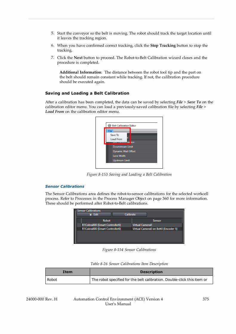
5. Start the conveyor so the belt is moving. The robot should track the target location untilit leaves the tracking region.
6. When you have confirmed correct tracking, click the Stop Tracking button to stop thetracking.
7. Click the Next button to proceed. The Robot-to-Belt Calibration wizard closes and theprocedure is completed.
Additional Information: The distance between the robot tool tip and the part onthe belt should remain constant while tracking. If not, the calibration procedureshould be executed again.
Saving and Loading a Belt Calibration
After a calibration has been completed, the data can be saved by selecting File > Save To on thecalibration editor menu. You can load a previously-saved calibration file by selecting File >Load From on the calibration editor menu.
Figure 8-153 Saving and Loading a Belt Calibration
Sensor Calibrations
The Sensor Calibrations area defines the robot-to-sensor calibrations for the selected workcellprocess. Refer to Processes in the Process Manager Object on page 360 for more information.These should be performed after Robot-to-Belt calibrations.
Figure 8-154 Sensor Calibrations
Table 8-26 Sensor Calibrations Item Description
Item Description
Robot The robot specified for the belt calibration. Double-click this item or
24000-000 Rev. H Automation Control Environment (ACE) Version 4User's Manual
375
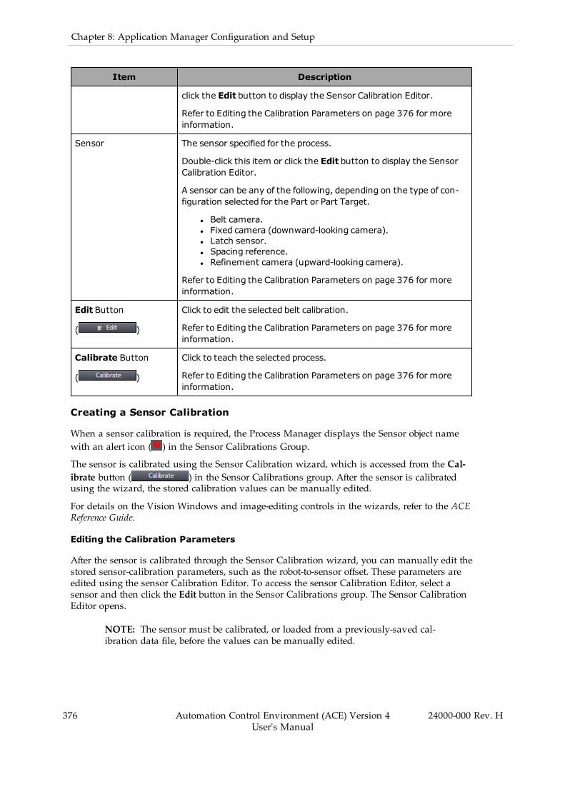
376 Automation Control Environment (ACE) Version 4User's Manual
24000-000 Rev. H
Chapter 8: Application Manager Configuration and Setup
Item Description
click the Edit button to display the Sensor Calibration Editor.
Refer to Editing the Calibration Parameters on page 376 for moreinformation.
Sensor The sensor specified for the process.
Double-click this item or click the Edit button to display the SensorCalibration Editor.
A sensor can be any of the following, depending on the type of con-figuration selected for the Part or Part Target.
l Belt camera.l Fixed camera (downward-looking camera).l Latch sensor.l Spacing reference.l Refinement camera (upward-looking camera).
Refer to Editing the Calibration Parameters on page 376 for moreinformation.
Edit Button
( )
Click to edit the selected belt calibration.
Refer to Editing the Calibration Parameters on page 376 for moreinformation.
Calibrate Button
( )
Click to teach the selected process.
Refer to Editing the Calibration Parameters on page 376 for moreinformation.
Creating a Sensor Calibration
When a sensor calibration is required, the Process Manager displays the Sensor object namewith an alert icon ( ) in the Sensor Calibrations Group.
The sensor is calibrated using the Sensor Calibration wizard, which is accessed from the Cal-ibrate button ( ) in the Sensor Calibrations group. After the sensor is calibratedusing the wizard, the stored calibration values can be manually edited.
For details on the Vision Windows and image-editing controls in the wizards, refer to the ACEReference Guide.
Editing the Calibration Parameters
After the sensor is calibrated through the Sensor Calibration wizard, you can manually edit thestored sensor-calibration parameters, such as the robot-to-sensor offset. These parameters areedited using the sensor Calibration Editor. To access the sensor Calibration Editor, select asensor and then click the Edit button in the Sensor Calibrations group. The Sensor CalibrationEditor opens.
NOTE: The sensor must be calibrated, or loaded from a previously-saved cal-ibration data file, before the values can be manually edited.

The Sensor Calibration Editor contains the sensor properties configuration parameters. Theseare used to configure various settings of the selected sensor.
The following figure shows the Latch Calibration Editor, which has one property for con-trolling the calibration offset.
Figure 8-155 Sensor Calibration Editor - Latch
The following figure shows the Vision Calibration Editor, which contains a calibration offsetalong with additional parameters for controlling the robot motion during the picture-takingand part-pick operations of the automated hardware calibration. These are not used duringrun time when the robot is performing the process (run time motion parameters will be foundin configuration items).
Figure 8-156 Sensor Calibration Editor - Vision
24000-000 Rev. H Automation Control Environment (ACE) Version 4User's Manual
377

378 Automation Control Environment (ACE) Version 4User's Manual
24000-000 Rev. H
Chapter 8: Application Manager Configuration and Setup
Saving and Loading a Sensor Calibration
After a calibration has been completed, the data can be saved by selecting File and then SaveTo on the calibration editor menu.
You can load a previously-saved calibration file by selecting File and then Load From on thecalibration editor menu.
Figure 8-157 Saving and Loading a Calibration
Calibration Wizard - Automatic Versus Manual Calibrations
The calibrations can be performed using either the automatic calibration (preferred method) orthe manual calibration procedure. In the automatic calibration procedure, you teach the initiallocations and then the wizard automatically performs the robot movements to acquire enoughdata points to calibrate the system. In the manual procedure, you have to move the robotthrough each step of the process until enough data points have been acquired. The manualmethod is provided for cases where obstructions in the workcell do not allow for automatedmovement of the robot during the calibration process.
NOTE: It is recommended that you use the calibration wizard, in order to obtainthe optimum performance from your system.
The manual calibration procedure is available for the Fixed Camera and Refine-ment Camera calibrations.
Some calibrations operate differently in Emulation Mode. Refer to EmulationMode Differences on page 18
Using the Sensor Calibration Wizard
The Sensor Calibration wizard provides an interactive series of steps that guide you throughthe calibration process. Each step of the wizard contains graphical aids and text that describethe particular step being performed. As each step of the wizard is completed, the informationfrom that step is collected and used to populate the fields in the Sensor Calibration Editor,which is described in the previous section.
Calibration Types
The Sensor Calibrations area defines all of the calibration types that are used in the project.These calibration types are described below.
Fixed Camera Calibration
The Fixed Camera Calibration wizard configures the positioning of a camera with respect to arobot when both the camera and the surface in the field of view are stationary. The wizard willshow the 3D visualization of the camera vision window at various steps in the process.
Depending on the application, the wizard will end with manual or automatic configuration.Automatic calibration assumes that the pick surface is parallel to the tool plane. If the pick sur-face is not parallel to the tool plane, the parameters should be adjusted so manual calibrationis performed instead.
Refer to Robot-to-Camera Calibration on page 33 for a more detailed explanation of the cal-ibration process.
Belt Camera Calibration
The Belt Camera Calibration wizard configures the positioning of a camera with respect to arobot when a belt object is present. It includes controls for moving the belt, indicators to showif the belt is ON, and fields for speed, position, and direction. Depending on the step in the cal-ibration wizard, it also shows the 3D visualization of the vision window for the associatedcamera.
Refer to Robot-to-Camera Calibration on page 33 for a more detailed explanation of the cal-ibration process.
Belt Latch Calibration
The Belt Latch Calibration wizard configures the positioning of a latch sensor with respect to abelt. Similar to the Belt Camera Calibration wizard, it includes belt controls, indicators, and 3Dvisualization. However, instead of a vision window, this wizard has an additional indicatorshowing that the latch has been triggered.
Refer to Section , Robot-to-Latch Calibration on page 34 for a more detailed explanation of thecalibration process.
Refinement Camera Calibration
The Refinement Camera Calibration wizard is functionally similar to the Fixed Camera Cal-ibration. Refinement Camera Calibrations require the robot to be able to pick up a part. Cal-ibration pointers will not be helpful in this scenario.
Spacing Reference Calibration
The Spacing Reference Calibration wizard configures the positioning of parts along a belt atdefined intervals. This process is performed by setting a stationary point along the belt fromwhich the instances will be generated. This point should be calibrated outside of the belt win-dow to avoid difficulties in allocation. If creating spacing instances for multiple robots, the spa-cing calibrations must reference the same upstream position.
Configuration Items
The Configuration Items area defines the workcell items and the relationships between thoseitems that are associated with a particular workcell configuration. The Configuration Itemsarea also allows quick access to the robot position (location) editors for a particular item, suchas the idle, part pick, or part place location.
24000-000 Rev. H Automation Control Environment (ACE) Version 4User's Manual
379

380 Automation Control Environment (ACE) Version 4User's Manual
24000-000 Rev. H
Chapter 8: Application Manager Configuration and Setup
Creating the Configuration Items
The Configuration Items are created automatically as the workcell process is defined throughthe Part Process editor. As items are added/deleted in the Part Process editor, they areadded/deleted in the Configuration Items area. For example, a basic pick and place applicationwould look like this in the Part Process editor:
Figure 8-158 Part Process Editor - Basic Pick and Place Application
The corresponding Configuration Items area has the following appearance.
Figure 8-159 Configuration Items - Basic Pick and Place Application
Configuration Item Area Structure and Features
The Configuration Items are arranged in a tree structure to show the relationships between theworkcell items. The Configuration Items group contains the following features.
l Expand or collapse a tree branch by clicking the arrow icons next to an item name.l Double-click any of the Position objects (idle or robot) or select the Position object andclick the Edit button to open the location editor that can be used to manually enter theobject location. Refer to the following section for more information.
l Click the Grid button ( ) and use the Motion Sequence Grid Editor to editthe motion parameters and offset locations (a robot must be selected in the list to enable
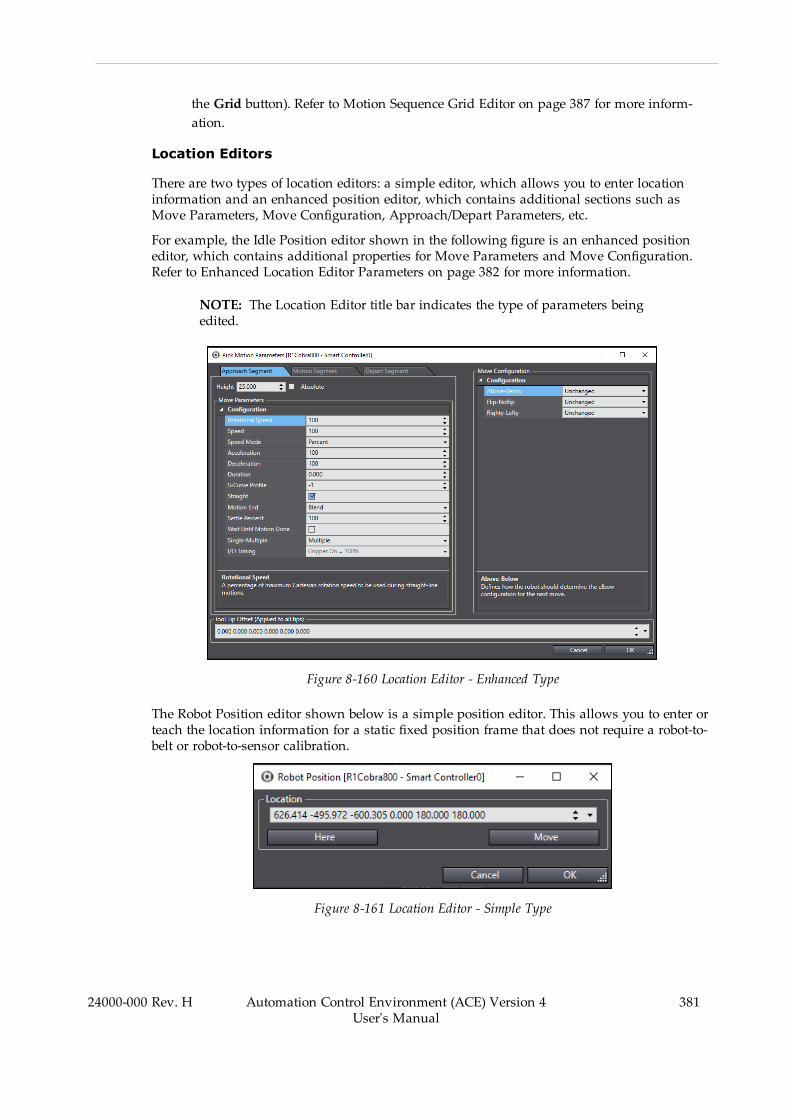
the Grid button). Refer to Motion Sequence Grid Editor on page 387 for more inform-ation.
Location Editors
There are two types of location editors: a simple editor, which allows you to enter locationinformation and an enhanced position editor, which contains additional sections such asMove Parameters, Move Configuration, Approach/Depart Parameters, etc.
For example, the Idle Position editor shown in the following figure is an enhanced positioneditor, which contains additional properties for Move Parameters and Move Configuration.Refer to Enhanced Location Editor Parameters on page 382 for more information.
NOTE: The Location Editor title bar indicates the type of parameters beingedited.
Figure 8-160 Location Editor - Enhanced Type
The Robot Position editor shown below is a simple position editor. This allows you to enter orteach the location information for a static fixed position frame that does not require a robot-to-belt or robot-to-sensor calibration.
Figure 8-161 Location Editor - Simple Type
24000-000 Rev. H Automation Control Environment (ACE) Version 4User's Manual
381
382 Automation Control Environment (ACE) Version 4User's Manual
24000-000 Rev. H
Chapter 8: Application Manager Configuration and Setup
Enhanced Location Editor Parameters
Use the editor's parameter input fields to adjust the Move Parameters and Move Configurationfor the approach, motion, and depart segments. Use the following examples of variousenhanced location editor parameter grids to understand the editor functions.
l Move Configuration Area
These parameters control the configuration of the robot at the selected location. Forexample, if your workcell contains a SCARA robot and you want it to be in a lefty con-figuration, you would set the Righty-Lefty parameter to Lefty.
l Move Parameters for Approach/Motion/Depart Segments
These parameters control how the robot moves to and from the selected Part, VisionRefinement Station, or Part Target location. They allow you to fine-tune the robot'smotion. To optimize the speed of the robot, apply coarser and faster settings for less-pre-cise motions to and from the location. To optimize the precision of the robot, apply finerand slower settings for smoother, more precise motions to and from the location.
l Absolute Check Box and Height
The Height input field allows you to enter a value for the approach and depart seg-ments. The Absolute check box allows you to enter absolute height values for theApproach and/or Depart motion segments. You can enter positive or negative values, asneeded.
IMPORTANT:When the Absolute option is selected, you must ensure theapproach/depart heights are set correctly. Otherwise, the robot could moveto an unintended location or out of range, which may damage the robot orother equipment in the workcell.
l I/O Timing Parameter
An I/O Timing parameter is included which controls the open/close timing of the grip-per during each part of the motion segment. The I/O Timing (Gripper On) can use eithera percent value, a distance value, or a time value as shown in the following figures.
For example, if you set the value to 25 mm, the gripper will activate at 25 mm from thepick position. If you set it at 25%, the gripper will activate at 25% of the distance fromthe approach start to the pick position. The time value allows you to set the gripper tim-ing (in milliseconds).
Additional Information: The distance value is useful when accessing pal-lets with multiple layers and an absolute approach height has been spe-cified.
l Use Custom Program Option (Motion Segment Tab)
The Use Custom Program check box allows you to specify a custom V+ program thatcontrols the motion segment. To use this option, select the check box and then click theSelect ( ) icon to display the Robot Motion Sequence Program wizard.
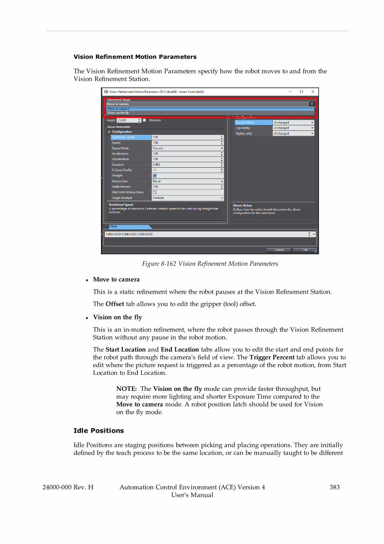
Vision Refinement Motion Parameters
The Vision Refinement Motion Parameters specify how the robot moves to and from theVision Refinement Station.
Figure 8-162 Vision Refinement Motion Parameters
l Move to camera
This is a static refinement where the robot pauses at the Vision Refinement Station.
The Offset tab allows you to edit the gripper (tool) offset.
l Vision on the fly
This is an in-motion refinement, where the robot passes through the Vision RefinementStation without any pause in the robot motion.
The Start Location and End Location tabs allow you to edit the start and end points forthe robot path through the camera's field of view. The Trigger Percent tab allows you toedit where the picture request is triggered as a percentage of the robot motion, from StartLocation to End Location.
NOTE: The Vision on the fly mode can provide faster throughput, butmay require more lighting and shorter Exposure Time compared to theMove to camera mode. A robot position latch should be used for Visionon the fly mode.
Idle Positions
Idle Positions are staging positions between picking and placing operations. They are initiallydefined by the teach process to be the same location, or can be manually taught to be different
24000-000 Rev. H Automation Control Environment (ACE) Version 4User's Manual
383
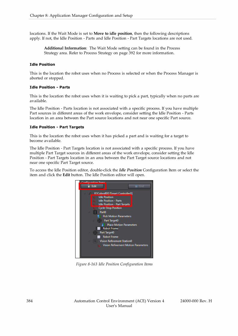
384 Automation Control Environment (ACE) Version 4User's Manual
24000-000 Rev. H
Chapter 8: Application Manager Configuration and Setup
locations. If the Wait Mode is set toMove to idle position, then the following descriptionsapply. If not, the Idle Position - Parts and Idle Position - Part Targets locations are not used.
Additional Information: The Wait Mode setting can be found in the ProcessStrategy area. Refer to Process Strategy on page 392 for more information.
Idle Position
This is the location the robot uses when no Process is selected or when the Process Manager isaborted or stopped.
Idle Position - Parts
This is the location the robot uses when it is waiting to pick a part, typically when no parts areavailable.
The Idle Position - Parts location is not associated with a specific process. If you have multiplePart sources in different areas of the work envelope, consider setting the Idle Position - Partslocation in an area between the Part source locations and not near one specific Part source.
Idle Position - Part Targets
This is the location the robot uses when it has picked a part and is waiting for a target tobecome available.
The Idle Position - Part Targets location is not associated with a specific process. If you havemultiple Part Target sources in different areas of the work envelope, consider setting the IdlePosition - Part Targets location in an area between the Part Target source locations and notnear one specific Part Target source.
To access the Idle Position editor, double-click the Idle Position Configuration Item or select theitem and click the Edit button. The Idle Position editor will open.
Figure 8-163 Idle Position Configuration Items

Cycle-Stop Position
The Cycle-Stop Position is a location that is used when the process Cycle-Stop is requested.The Cycle-Stop can be requested with one of the following methods.
l OPCl Data Mapperl C# programl Clicking the Cycle Stop button in the Task Status Control area
NOTE: Using this method will result in the robot finishing the currentprocess and then waiting for the Cycle-Stop request to be released.
To access the Cycle-Stop Position editor, double-click the Cycle-Stop Configuration Item orselect the item and click the Edit button. The Cycle-Stop Position editor will open.
Figure 8-164 Cycle-Stop Configuration Items
Robot Frames
Robot frames (also known as reference frames) are useful because they allow you to teach loc-ations relative to the frame. If the location of the frame changes in the workcell, you simplyhave to update the frame information to reflect its new location. Then you can use any loc-ations created relative to that frame without further modifications.
A process pallet is typically taught relative to a reference frame. This avoids the problem ofteaching many individual pallet positions and then having to reteach all of those positions ifthe pallet moves for some reason. Instead, the pallet is taught relative to a frame. If the palletmoves in the workcell, the frame position is re-taught and the part positions relative to thatframe remain intact.
The Robot Frame editor is used to teach a reference frame, such as a pallet frame. To accessthe Robot Frame editor, double-click the Robot Frame Configuration Item or select the item andclick the Edit button.
24000-000 Rev. H Automation Control Environment (ACE) Version 4User's Manual
385

386 Automation Control Environment (ACE) Version 4User's Manual
24000-000 Rev. H
Chapter 8: Application Manager Configuration and Setup
Additional Information: Robot Frames are only available when a part or targetobject is configured as Static: Fixed Position and a Pallet object is defined in thatobject.
Figure 8-165 Robot Frame Configuration Items
Figure 8-166 Robot Frame Configuration
Robot Frames will typically be defined during the teach process wizard, but can be manuallydefined as well. Use the following procedure to manually define a Robot Frame.
1. Teach the Origin Location.

Use the V+ Jog Control to position the robot tool tip at the origin (in the case of a rect-angular pallet, this can be the first pocket position) and then click the Here button torecord the position.
2. Teach the +X Location.
Use the V+ Jog Control to position the robot tool tip at a point on the +X axis. In the caseof a rectangular pallet, this can be any pocket position along the +X axis. Optimum res-ults will be obtained by using a point as far away from the origin as possible. Then,click the Here button to record the position.
3. Teach the +Y Location.
Use the V+ Jog Control to position the robot tool tip at a point on the +Y axis. In the caseof a rectangular pallet, this can be any pocket position along the +Y axis. Optimum res-ults will be obtained by using a point as far away from the origin as possible. Then,click the Here button to record the position.
4. Click the Calculate button to calculate the position of the robot frame relative to therobot.
5. Click the OK button to close the Robot Frame editor and complete this procedure.
Motion Sequence Grid Editor
The Moti Sequence Grid Editor provides a grid / table interface that allows you to access andindividually edit the common motion parameters used to optimize cycle time. Also, you canchange multiple speed / acceleration / deceleration parameters at the same time. Click on onone of the necessary fields and drag the cursor across the others, as shown, refer to MultipleParameter Selection. Enter a new value to change all of the selected fields.
l Pick motion parameters.l Place motion parameters.l Vision refinement parameters.l Offset location parameters.
NOTE: If parameters change significantly, I/O timing in the Pick and PlaceMotion Parameter editors may need to be adjusted. Otherwise, faster motionsand blending may lead to missed picks or poor placement.
To access the grid editor, select the robot object in the Configuration Items group and then clickthe Grid button ( ). The Motion Sequence Grid Editor opens.
24000-000 Rev. H Automation Control Environment (ACE) Version 4User's Manual
387

388 Automation Control Environment (ACE) Version 4User's Manual
24000-000 Rev. H
Chapter 8: Application Manager Configuration and Setup
Figure 8-167 Motion Sequence Grid Editor
The left pane is used to select the items you wish to display for editing. The right pane con-tains the editing parameters by group.
Figure 8-168 Multiple Parameter Selection
Control Sources
The Control Sources editor provides access to parameters that affect Part and Part Targetsources for the defined processes. Sources are responsible for providing instances to a process.These are automatically created based on the Part and Part Target object configuration prop-erty. There are three types of Sources that are described in the following sections.
l Belt Control Sources (includes belt-relative cameras)l Static Control Sourcesl Vision Control Sources (not belt-relative)
To access the Control Sources Editor, click the Control Sources button ( ).
Belt Control Sources
This section describes the Control Sources Editor when a Belt source is selected.
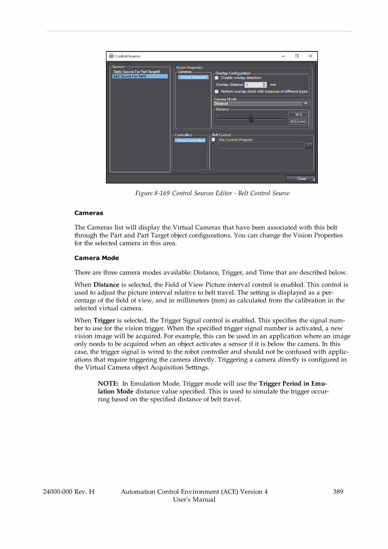
Figure 8-169 Control Sources Editor - Belt Control Source
Cameras
The Cameras list will display the Virtual Cameras that have been associated with this beltthrough the Part and Part Target object configurations. You can change the Vision Propertiesfor the selected camera in this area.
Camera Mode
There are three camera modes available: Distance, Trigger, and Time that are described below.
When Distance is selected, the Field of View Picture interval control is enabled. This control isused to adjust the picture interval relative to belt travel. The setting is displayed as a per-centage of the field of view, and in millimeters (mm) as calculated from the calibration in theselected virtual camera.
When Trigger is selected, the Trigger Signal control is enabled. This specifies the signal num-ber to use for the vision trigger. When the specified trigger signal number is activated, a newvision image will be acquired. For example, this can be used in an application where an imageonly needs to be acquired when an object activates a sensor if it is below the camera. In thiscase, the trigger signal is wired to the robot controller and should not be confused with applic-ations that require triggering the camera directly. Triggering a camera directly is configured inthe Virtual Camera object Acquisition Settings.
NOTE: In Emulation Mode, Trigger mode will use the Trigger Period in Emu-lation Mode distance value specified. This is used to simulate the trigger occur-ring based on the specified distance of belt travel.
24000-000 Rev. H Automation Control Environment (ACE) Version 4User's Manual
389

390 Automation Control Environment (ACE) Version 4User's Manual
24000-000 Rev. H
Chapter 8: Application Manager Configuration and Setup
Figure 8-170 Control Sources Editor - Camera Mode - Trigger
When Time is selected, an image will be requested on the specified time interval.
Overlap Configuration
When a part is located in an image associated with a conveyor, the position of the object iscompared with the position of objects located in previous images that have already beenadded to the queue of instances to process.
If Disable Overlap Check is selected, all overlap checking is disabled. When this option isselected, the remaining Overlap Configuration items are not available. If a part is located inmultiple images, the robot will attempt to pick at the same belt-relative position multipletimes. If this occurs when Overlap Configuration is not disabled, consider increasing the Over-lap distance.
If the newly-located part is within the specified Overlap Distance of a previously located part(accounting for belt travel), it is assumed to be the same part and will not be added as a duplic-ate new instance.
If Perform overlap check with instances of different types is selected, the overlap calculationwill check for overlap of any parts, rather than just parts of the same type.
Use Custom Program
The default belt program (pm.belt.control) is optimized for performance of all default ProcessManager configurations and flexible functionality. The Controllers list will display all con-trollers associated with the selected Belt object. Each controller executes a V+ program for mon-itoring and updating encoder position, belt velocity, image requests, latches, and instanceinformation for all instances allocated to that controller.
Occasionally, applications require customization of this program. For example, you may needto sacrifice available controller processing time to achieve more frequent latch reporting orimage requests. In these cases, select Use Custom Program and then edit the default programaccordingly. You may need to make the same modifications to the belt program on each con-troller depending on application requirements.
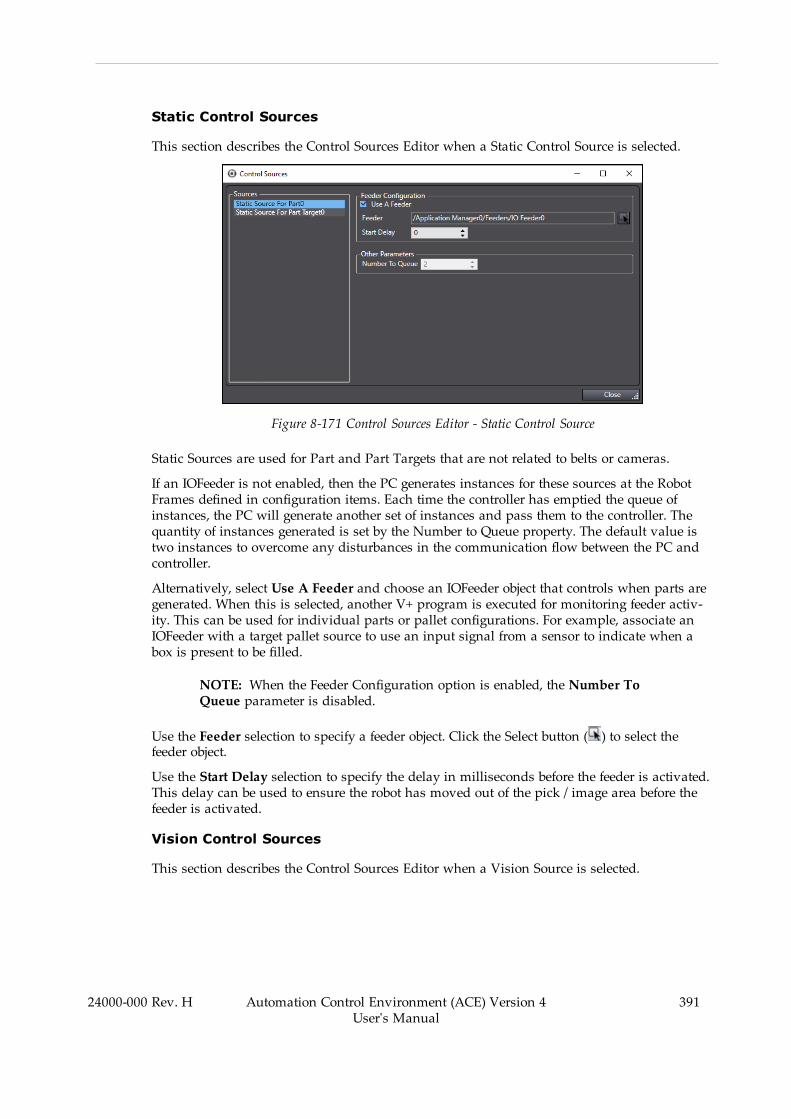
Static Control Sources
This section describes the Control Sources Editor when a Static Control Source is selected.
Figure 8-171 Control Sources Editor - Static Control Source
Static Sources are used for Part and Part Targets that are not related to belts or cameras.
If an IOFeeder is not enabled, then the PC generates instances for these sources at the RobotFrames defined in configuration items. Each time the controller has emptied the queue ofinstances, the PC will generate another set of instances and pass them to the controller. Thequantity of instances generated is set by the Number to Queue property. The default value istwo instances to overcome any disturbances in the communication flow between the PC andcontroller.
Alternatively, select Use A Feeder and choose an IOFeeder object that controls when parts aregenerated. When this is selected, another V+ program is executed for monitoring feeder activ-ity. This can be used for individual parts or pallet configurations. For example, associate anIOFeeder with a target pallet source to use an input signal from a sensor to indicate when abox is present to be filled.
NOTE: When the Feeder Configuration option is enabled, the Number ToQueue parameter is disabled.
Use the Feeder selection to specify a feeder object. Click the Select button ( ) to select thefeeder object.
Use the Start Delay selection to specify the delay in milliseconds before the feeder is activated.This delay can be used to ensure the robot has moved out of the pick / image area before thefeeder is activated.
Vision Control Sources
This section describes the Control Sources Editor when a Vision Source is selected.
24000-000 Rev. H Automation Control Environment (ACE) Version 4User's Manual
391
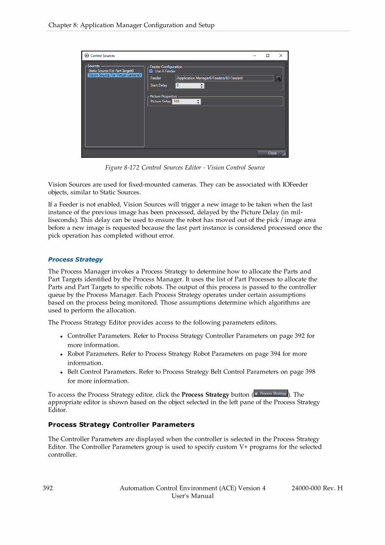
392 Automation Control Environment (ACE) Version 4User's Manual
24000-000 Rev. H
Chapter 8: Application Manager Configuration and Setup
Figure 8-172 Control Sources Editor - Vision Control Source
Vision Sources are used for fixed-mounted cameras. They can be associated with IOFeederobjects, similar to Static Sources.
If a Feeder is not enabled, Vision Sources will trigger a new image to be taken when the lastinstance of the previous image has been processed, delayed by the Picture Delay (in mil-liseconds). This delay can be used to ensure the robot has moved out of the pick / image areabefore a new image is requested because the last part instance is considered processed once thepick operation has completed without error.
Process Strategy
The Process Manager invokes a Process Strategy to determine how to allocate the Parts andPart Targets identified by the Process Manager. It uses the list of Part Processes to allocate theParts and Part Targets to specific robots. The output of this process is passed to the controllerqueue by the Process Manager. Each Process Strategy operates under certain assumptionsbased on the process being monitored. Those assumptions determine which algorithms areused to perform the allocation.
The Process Strategy Editor provides access to the following parameters editors.
l Controller Parameters. Refer to Process Strategy Controller Parameters on page 392 formore information.
l Robot Parameters. Refer to Process Strategy Robot Parameters on page 394 for moreinformation.
l Belt Control Parameters. Refer to Process Strategy Belt Control Parameters on page 398for more information.
To access the Process Strategy editor, click the Process Strategy button ( ). Theappropriate editor is shown based on the object selected in the left pane of the Process StrategyEditor.
Process Strategy Controller Parameters
The Controller Parameters are displayed when the controller is selected in the Process StrategyEditor. The Controller Parameters group is used to specify custom V+ programs for the selectedcontroller.
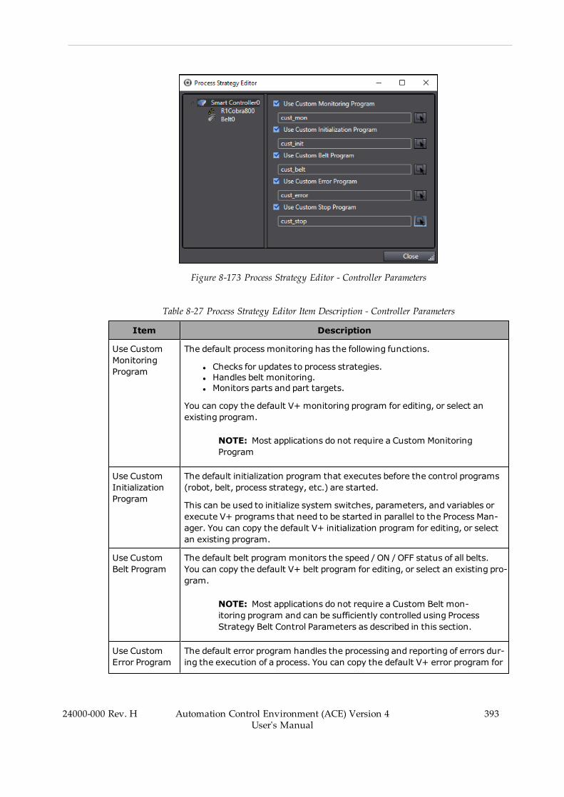
Figure 8-173 Process Strategy Editor - Controller Parameters
Table 8-27 Process Strategy Editor Item Description - Controller Parameters
Item Description
Use CustomMonitoringProgram
The default process monitoring has the following functions.
l Checks for updates to process strategies.l Handles belt monitoring.l Monitors parts and part targets.
You can copy the default V+ monitoring program for editing, or select anexisting program.
NOTE: Most applications do not require a Custom MonitoringProgram
Use CustomInitializationProgram
The default initialization program that executes before the control programs(robot, belt, process strategy, etc.) are started.
This can be used to initialize system switches, parameters, and variables orexecute V+ programs that need to be started in parallel to the Process Man-ager. You can copy the default V+ initialization program for editing, or selectan existing program.
Use CustomBelt Program
The default belt program monitors the speed / ON / OFF status of all belts.You can copy the default V+ belt program for editing, or select an existing pro-gram.
NOTE: Most applications do not require a Custom Belt mon-itoring program and can be sufficiently controlled using ProcessStrategy Belt Control Parameters as described in this section.
Use CustomError Program
The default error program handles the processing and reporting of errors dur-ing the execution of a process. You can copy the default V+ error program for
24000-000 Rev. H Automation Control Environment (ACE) Version 4User's Manual
393

394 Automation Control Environment (ACE) Version 4User's Manual
24000-000 Rev. H
Chapter 8: Application Manager Configuration and Setup
Item Description
editing, or select an existing program. This program can be used to automateerror handling that are reported to the PC by default.
All Process Manager V+ program error handling will lead to this program. Usethis program to automate error handling of errors that are reported to the PCby default. This program will check if any user-defined error responses existin the Process Strategy - Robot parameters.
Use CustomStop Program
The custom stop program can be used to perform certain operations after theapplication has stopped. You can copy the default V+ stop program for edit-ing, or select an existing program.
Process Strategy Robot Parameters
The Robot Parameters are displayed when the robot is selected in the Process Strategy Editor.
There are four tabs of robot parameters: the General Parameters tab, the Allocation tab, theWait Mode Parameters tab, and the Error Response tab that are described below.
Figure 8-174 Process Strategy Editor - Robot Parameters
Table 8-28 Process Strategy Editor Item Description - Robot Parameters
Group Item Description
General Use Custom RobotProgram
Allows you to specify a custom V+ main robot-controlprogram.
For example, this would allow you to customizeexactly when a given robot executes each process.
You can copy the default V+ program for editing, orselect an existing program.
Use Custom Process Allows you to specify a custom V+ process-selection
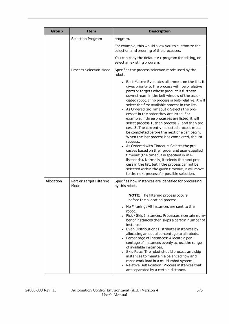
Group Item Description
Selection Program program.
For example, this would allow you to customize theselection and ordering of the processes.
You can copy the default V+ program for editing, orselect an existing program.
Process Selection Mode Specifies the process selection mode used by therobot.
l Best Match: Evaluates all process on the list. Itgives priority to the process with belt-relativeparts or targets whose product is furthestdownstream in the belt window of the asso-ciated robot. If no process is belt-relative, it willselect the first available process in the list.
l As Ordered (no Timeout): Selects the pro-cesses in the order they are listed. Forexample, if three processes are listed, it willselect process 1, then process 2, and then pro-cess 3. The currently- selected process mustbe completed before the next one can begin.When the last process has completed, the listrepeats.
l As Orderedwith Timeout: Selects the pro-cesses based on their order and user-suppliedtimeout (the timeout is specified in mil-liseconds). Normally, it selects the next pro-cess in the list, but if the process cannot beselected within the given timeout, it will moveto the next process for possible selection.
Allocation Part or Target FilteringMode
Specifies how instances are identified for processingby this robot.
NOTE: The filtering process occursbefore the allocation process.
l No Filtering: All instances are sent to therobot.
l Pick / Skip Instances: Processes a certain num-ber of instances then skips a certain number ofinstances.
l Even Distribution: Distributes instances byallocating an equal percentage to all robots.
l Percentage of Instances: Allocate a per-centage of instances evenly across the rangeof available instances.
l Skip Rate: The robot should process and skipinstances to maintain a balanced flow androbot work load in a multi-robot system.
l Relative Belt Position: Process instances thatare separated by a certain distance.
24000-000 Rev. H Automation Control Environment (ACE) Version 4User's Manual
395
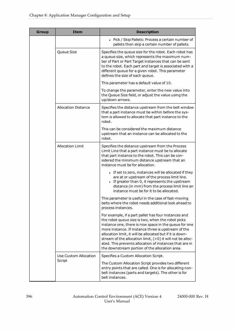
396 Automation Control Environment (ACE) Version 4User's Manual
24000-000 Rev. H
Chapter 8: Application Manager Configuration and Setup
Group Item Description
l Pick / Skip Pallets: Process a certain number ofpallets then skip a certain number of pallets.
Queue Size Specifies the queue size for the robot. Each robot hasa queue size, which represents the maximum num-ber of Part or Part Target instances that can be sentto the robot. Each part and target is associated with adifferent queue for a given robot. This parameterdefines the size of each queue.
This parameter has a default value of 10.
To change the parameter, enter the new value intothe Queue Size field, or adjust the value using theup/down arrows.
Allocation Distance Specifies the distance upstream from the belt windowthat a part instance must be within before the sys-tem is allowed to allocate that part instance to therobot.
This can be considered the maximum distanceupstream that an instance can be allocated to therobot.
Allocation Limit Specifies the distance upstream from the ProcessLimit Line that a part instance must be to allocatethat part instance to the robot. This can be con-sidered the minimum distance upstream that aninstance must be for allocation.
l If set to zero, instances will be allocated if theyare at or upstream of the process limit line.
l If greater than 0, it represents the upstreamdistance (in mm) from the process limit line aninstance must be for it to be allocated.
This parameter is useful in the case of fast-movingbelts where the robot needs additional look ahead toprocess instances.
For example, if a part pallet has four instances andthe robot queue size is two, when the robot picksinstance one, there is now space in the queue for onemore instance. If instance three is upstream of theallocation limit, it will be allocated but if it is down-stream of the allocation limit, (>0) it will not be alloc-ated. This prevents allocation of instances that are inthe downstream portion of the allocation area.
Use Custom AllocationScript
Specifies a Custom Allocation Script.
The Custom Allocation Script provides two differententry points that are called. One is for allocating non-belt instances (parts and targets). The other is forbelt instances.

Group Item Description
The program can manipulate the lists to indicate tothe system what should be allocated to a given robot.This is called by the Process Manager when it needs toallocate parts.
If this option is enabled, click the Select button ( )to select the desired Custom Allocation Script. Referto the ACE Reference Guide - Custom AllocationScripts for more information.
Wait Mode Stay at current position Causes the robot to remain at the current positionwhile waiting for a part or target to process.
Move to Idle Position Causes the robot to move to the idle position afterthe specifiedAfter waiting for time (in mil-liseconds) while waiting for a part or target to pro-cess.
For example, if the After waiting for time is 500ms, when there is a break in the part or part targetprocessing queue, the robot will move to the idle pos-ition after 500 ms.
NOTE: This must be enabled for theIdle Position Parts and Idle Position PartTargets to be used. Refer to Idle Pos-itions on page 383 for more inform-ation.
Use Custom WaitProgram
Allows you to specify a custom V+ wait program. Theprogram would be called when the robot does nothave a part or target available. The program couldcheck to see if the robot needs to be moved to the idlelocation or if it should stay at the current location.
This program starts with the logic specified by one ofthe selections above.
You can copy the default V+ program for editing, orselect an existing program.
Use Signal at CycleStop
When a cycle stop is issued and this option is enabled,the specified I/O signal will be turned ON when therobot has reached the cycle stop state. When thecycle is resumed (cycle stop state is canceled), it willturn the specified signal OFF andwill attempt toenable power, if high power was disabled.
ErrorResponses
Output Signal - OnError
Defines a digital signal to assert when an error isdetected for the selected robot.
Error Listing
(use the Add,Delete,and Up / Down
Specifies how specific error conditions are to behandled.
By default, all errors will be reported to you and the
24000-000 Rev. H Automation Control Environment (ACE) Version 4User's Manual
397

398 Automation Control Environment (ACE) Version 4User's Manual
24000-000 Rev. H
Chapter 8: Application Manager Configuration and Setup
Group Item Description
buttons to arrange thelist).
software will wait until you respond to the error. If anerror condition is defined, it will override this defaulterror handling. It can be used to define automatichandling of the following errors.
l Single Error Code: User-defined error code.l Range of Error Codes: User-defined error coderange.
l Belt Window Access Error: Belt window viol-ations.
l Robot Power Errors: Problems with powerbeing enabled or enabling power.
l Gripper Errors: All gripper actuations.l All Errors: All other errors.
When an error is detected for the robot, it will processthe error listing handlers defined and find the firstone that can handle the condition. If the error cannotbe handled by an item in the list, the error is reportedto Task Status Control. Alternatively, create a Cus-tom Error Program (refer to Process StrategyController Parameters on page 392 for more inform-ation).
Process Strategy Belt Control Parameters
The Belt Control Parameters are displayed when the belt is selected in the Process StrategyEditor.
NOTE: Belt Control Parameters are only available when the following items areconfigured.
l Active Belt Control is enabled in the Belt object configuration.l A controller is selected in the Belt object configuration.l A defined process includes a Part or Part Target that references the BeltObject.
The Belt Control Parameters group as shown in the following figure is used to set the belt con-trol parameters for the selected conveyor belt. These parameters can be set to determine when aconveyor belt is turned ON or OFF. An optional speed control parameter is also provided. Thedecision point for the belt I/O control is based on the selected robot. If objects on the belt in theselected robot queue reach the specified thresholds, the belt will be turned OFF or the beltspeed will be adjusted.

Figure 8-175 Process Strategy Editor - Belt Parameters
Table 8-29 Process Strategy Editor Item Description - Belt Parameters
Item Description
On/OffControl
Specifies the ON / OFF control of the belt. There are three selections available:
l Do not control the belt: Use this option if there are output signals thatcan control the belt, but you do not want the Process Manager to controlthe belt during run time. If the belt control is provided by a PLC and out-put signals are not able to control the belt, disable Active Control in theBelt object.
l Leave the belt always ON: The belt is turned ON when the processstarts and OFF when the Process Manager is stopped.
l Control the belt: (Default) The belt is controlled based on thresholdsdescribed below. The belt is automatically turned OFF when the ProcessManager stops the application.
SpeedControl
If this is selected, you can use the Slow Threshold control to adjust the con-veyor speed threshold based on how full the robot queue is. Otherwise, the con-veyor belt operates at a constant speed.
RobotQueue
Specifies a robot for queue monitoring (the queue size for the robot is set in theRobot Parameters group).
The selected robot will typically be the most downstream robot if multiple robotsservice the same belt. If parts get to the last robot, it needs to slow / stop theconveyor to ensure all Parts or Part Targets are processed.
Slow, Off,and OnThresholds
These thresholds are used to control the belt based on instance position. This isuseful for preventing the belt from feeding the robot faster than the robot canpick the parts, or preventing not-processed Part or Part Targets from passingthe most downstream robot.
Slow Threshold: Specifies the point in the belt window for slowing the con-veyor if parts reach that point. For example, 50%means that if a part reachesthe midpoint of the belt window, the conveyor will be slowed.
Off Threshold: If an instance reaches this threshold, the belt will be turned
24000-000 Rev. H Automation Control Environment (ACE) Version 4User's Manual
399
400 Automation Control Environment (ACE) Version 4User's Manual
24000-000 Rev. H
Chapter 8: Application Manager Configuration and Setup
Item Description
OFF. This is set as a percentage from upstream belt window limit to downstreamprocess limit and is visualized as a black line in the 3D Visualizer (in the belt win-dow for the selected robot).
On Threshold:When a belt is turned OFF by the Off Threshold, the belt willremain OFF until all instances are removed between the Off Threshold point andthe On Threshold point. This can be used tominimize the number of times thebelt is started and stopped. This is set as a percentage from upstream belt win-dow limit to downstream process limit and is visualized as a green line in the3D Visualizer (in the belt window for the selected robot).
ProductFlow
Shows the product flow (belt window) direction of travel in relation to the SlowandOff Threshold slide controls. It is a reference for the thresholds. The bottomof the arrow represents the start of the belt window. The top of the arrow rep-resents the Downstream Process Limit.
Process Manager Control
The Process Manager Control is used to start and stop a process-managed application, such asa Pack Manager packaging application.
Using the Process Manager Control
The Task Status Control interface is used to monitor and control Process Manager objects inthe ACE project. A Process Manager item in the Task Status Control area is used to select theProcess Manager object, start and stop the selected application, and view status and instanceson the application while it is operating.
Process Manager control items are added to the Task Status Control area as shown in the fol-lowing figure. Select a Process Manager control item to view the Hardware and Applicationinformation areas. Refer to Application Manager Control on page 133 for more information.

Figure 8-176 Process Manager in Task Status Control
Process Manager Tasks
Process Manager tasks are displayed under the Application Manager group in a tree view.Tasks are grouped by type (C# program, Process Manager, etc.). When you select a task, the fol-lowing functions become available.
Additional Information: Double-clicking a Process Manager task in theTask Status Control interface will open the item in the Edit Pane.
24000-000 Rev. H Automation Control Environment (ACE) Version 4User's Manual
401
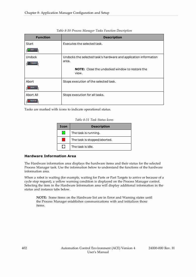
402 Automation Control Environment (ACE) Version 4User's Manual
24000-000 Rev. H
Chapter 8: Application Manager Configuration and Setup
Table 8-30 Process Manager Tasks Function Description
Function Description
Start
( )
Executes the selected task.
Undock
( )
Undocks the selected task's hardware and application informationarea.
NOTE: Close the undockedwindow to restore theview.
Abort
( )
Stops execution of the selected task.
Abort All
( )
Stops execution for all tasks.
Tasks are marked with icons to indicate operational status.
Table 8-31 Task Status Icons
Icon Description
The task is running.
The task is stopped/aborted.
The task is idle.
Hardware Information Area
The Hardware information area displays the hardware items and their status for the selectedProcess Manager task. Use the information below to understand the functions of the hardwareinformation area.
When a robot is waiting (for example, waiting for Parts or Part Targets to arrive or because of acycle stop request), a yellow warning condition is displayed on the Process Manager control.Selecting the item in the Hardware Information area will display additional information in thestatus and instance tabs below.
NOTE: Some items on the Hardware list are in Error and Warning states untilthe Process Manager establishes communications with and initializes thoseitems.
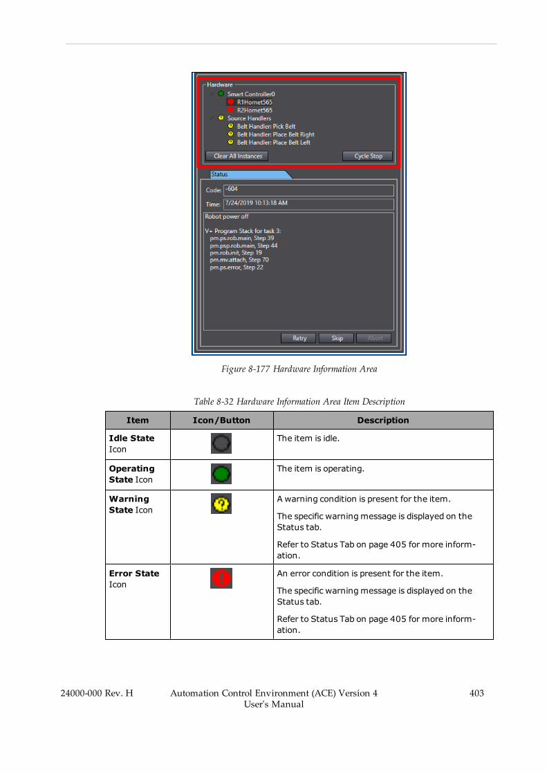
Figure 8-177 Hardware Information Area
Table 8-32 Hardware Information Area Item Description
Item Icon/Button Description
Idle StateIcon
The item is idle.
OperatingState Icon
The item is operating.
WarningState Icon
A warning condition is present for the item.
The specific warningmessage is displayed on theStatus tab.
Refer to Status Tab on page 405 for more inform-ation.
Error StateIcon
An error condition is present for the item.
The specific warningmessage is displayed on theStatus tab.
Refer to Status Tab on page 405 for more inform-ation.
24000-000 Rev. H Automation Control Environment (ACE) Version 4User's Manual
403

404 Automation Control Environment (ACE) Version 4User's Manual
24000-000 Rev. H
Chapter 8: Application Manager Configuration and Setup
Item Icon/Button Description
ClearAllInstancesButton
Clears all Part and Part Target instances from the sys-tem.
Cycle StopButton
Sends a signal to each robot to stop after the currentprocess cycle has completed. Each robot stops afterit reaches the end of its current process, and then"Robot is waiting because of a cycle stop request." isdisplayed in the Status tab.
You can resume the robot(s) and process operationsby clicking the Cycle Stop button.
The Cycle Stop button provides the capability toimplement a variety of situations. For example, youcould click the Cycle Stop button and leave the sys-tem running. When the system is in this state, alltracking is enabled. Therefore, you could either clickthe Abort button which stops everything or youcould simply resume the current cycle by clicking theCycle Stop button again.
Application Information Area
The Application information area displays feedback on the operation of the item selected in theHardware area. The Application information area has a Status tab and an Instances tab whichare described below.

Figure 8-178 Application Information Area
Status Tab
This tab displays information on the status of the control components driving the process. Itshows the hardware in the system and the status of the selected item.
Refer to Section Chapter 9: , Troubleshooting on page 591 for more information about statuscodes and messages.
The Status tab includes the following information.
l Code: displays the error number for the message.l Time: displays the controller time when the error occurred.
24000-000 Rev. H Automation Control Environment (ACE) Version 4User's Manual
405

406 Automation Control Environment (ACE) Version 4User's Manual
24000-000 Rev. H
Chapter 8: Application Manager Configuration and Setup
l Message Information: displays the details of an ACE exception by showing the contentsof the V+ program stack, when available (the exception source must be a V+ error) ordisplays general status and error message text.
l Retry, Skip, Abort buttons: These buttons and their functions are enabled are enabledwhen in error state and return the corresponding response. See Custom Error Programs inthe ACE Reference Guide for more information.
Instances Tab
The Instances tab displays information on the parts and part targets that are associated witheach control source. The Clear button removes all instances from the selected source. Toremove all instances from all sources, use the Clear All Instances button in the Hardware sec-tion of the Process Manager Control area.
Allocation Script Object
The Allocation Script object is used to create and edit custom part allocation programs for usewith the Process Manager.
The Allocation Script object provides two different entry points. One entry point is used forallocating non-belt-relative instances to a robot system. The other entry point is used for alloc-ating belt-relative instances to a robot system. These programs can manipulate the instances toindicate to the system what should be allocated to a given robot. This is called by the ProcessManager when it needs to allocate parts.
Allocation Script objects are edited with the C# program editor. Refer to Application ManagerProgramming on page 173 for more information.
Adding an Allocation Script Object
To add an Allocation Script object, right-click Process, select Add, and then clickAllocation Script. A new Allocation Script object will be added to the Multiview Explorer.
Figure 8-179 Adding an Allocation Script Object
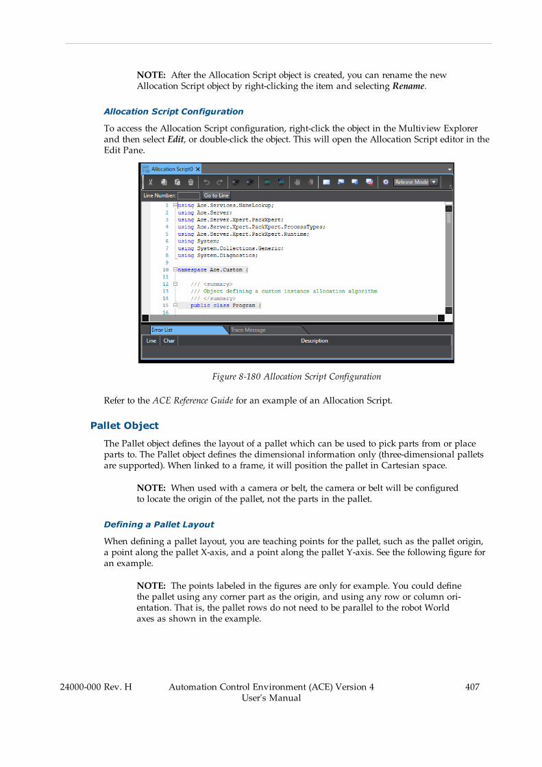
NOTE: After the Allocation Script object is created, you can rename the newAllocation Script object by right-clicking the item and selecting Rename.
Allocation Script Configuration
To access the Allocation Script configuration, right-click the object in the Multiview Explorerand then select Edit, or double-click the object. This will open the Allocation Script editor in theEdit Pane.
Figure 8-180 Allocation Script Configuration
Refer to the ACE Reference Guide for an example of an Allocation Script.
Pallet Object
The Pallet object defines the layout of a pallet which can be used to pick parts from or placeparts to. The Pallet object defines the dimensional information only (three-dimensional palletsare supported). When linked to a frame, it will position the pallet in Cartesian space.
NOTE: When used with a camera or belt, the camera or belt will be configuredto locate the origin of the pallet, not the parts in the pallet.
Defining a Pallet Layout
When defining a pallet layout, you are teaching points for the pallet, such as the pallet origin,a point along the pallet X-axis, and a point along the pallet Y-axis. See the following figure foran example.
NOTE: The points labeled in the figures are only for example. You could definethe pallet using any corner part as the origin, and using any row or column ori-entation. That is, the pallet rows do not need to be parallel to the robot Worldaxes as shown in the example.
24000-000 Rev. H Automation Control Environment (ACE) Version 4User's Manual
407
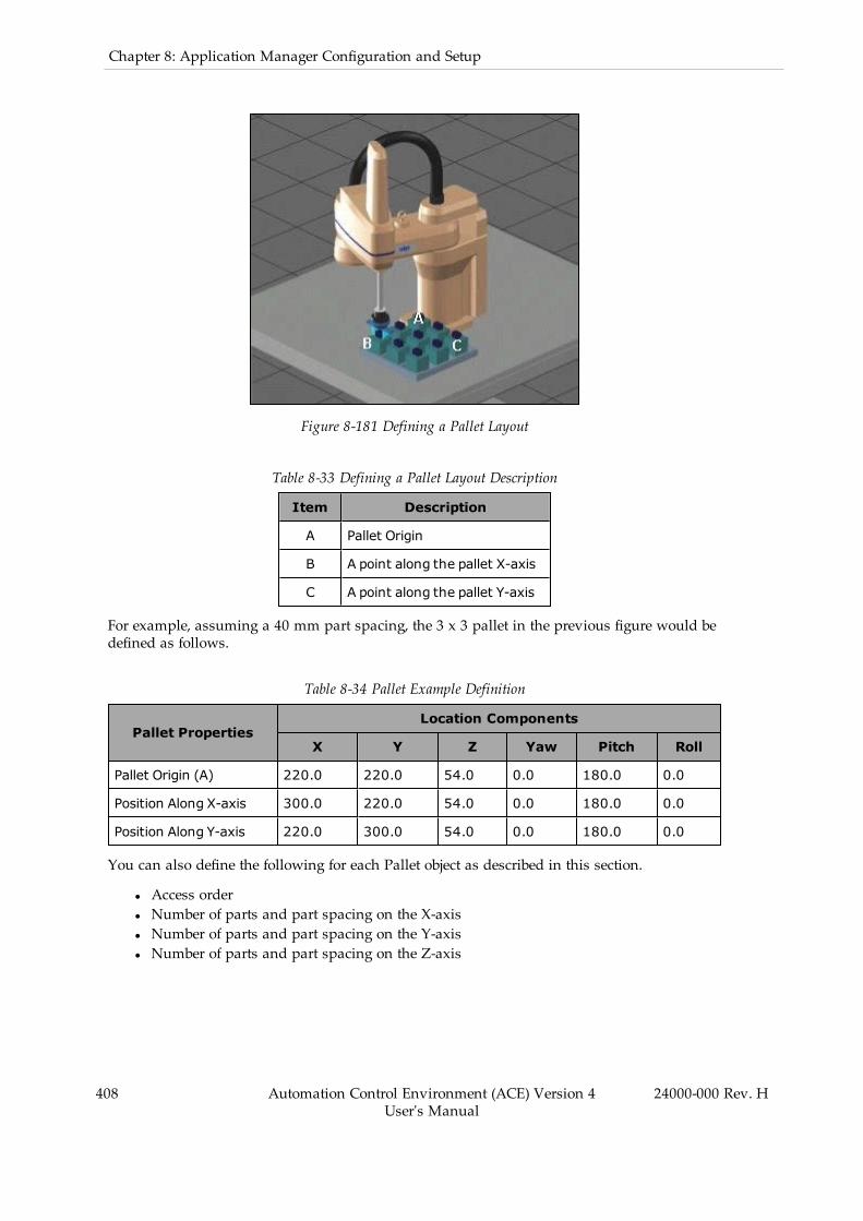
408 Automation Control Environment (ACE) Version 4User's Manual
24000-000 Rev. H
Chapter 8: Application Manager Configuration and Setup
Figure 8-181 Defining a Pallet Layout
Table 8-33 Defining a Pallet Layout Description
Item Description
A Pallet Origin
B A point along the pallet X-axis
C A point along the pallet Y-axis
For example, assuming a 40 mm part spacing, the 3 x 3 pallet in the previous figure would bedefined as follows.
Table 8-34 Pallet Example Definition
Pallet PropertiesLocation Components
X Y Z Yaw Pitch Roll
Pallet Origin (A) 220.0 220.0 54.0 0.0 180.0 0.0
Position Along X-axis 300.0 220.0 54.0 0.0 180.0 0.0
Position Along Y-axis 220.0 300.0 54.0 0.0 180.0 0.0
You can also define the following for each Pallet object as described in this section.
l Access orderl Number of parts and part spacing on the X-axisl Number of parts and part spacing on the Y-axisl Number of parts and part spacing on the Z-axis

Teaching a Pallet
When teaching the pallet using the ACE software wizard, the system automatically computesthe orientation and origin offset of the pallet. Then, the system has all of the information itneeds to pick or place parts from or to positions in the pallet.
The initial pallet teaching process occurs in the Process Manager object configuration duringcalibration or process teaching (depending on the application needs). You can change the val-ues obtained during the teaching process. Refer to Process Manager Object on page 352 formore information.
IMPORTANT:When teaching locations, remember that the gripper orientationrelative to the part is important. As you teach your pallet, you should check thegripper orientation to make sure you have not changed it. This will ensure thatthe parts are picked and placed in the correct orientation.
Adding a Pallet Object
To add a Pallet object, right-click Process, select Add, and then click Pallet. A new Pallet objectwill be added to the Multiview Explorer.
Figure 8-182 Adding a Pallet Object
NOTE: After the Pallet object is created, you can rename the new Pallet object byright-clicking the item and selecting Rename.
Pallet Configuration
To access the Pallet configuration, right-click the object in the Multiview Explorer and thenselect Edit, or double-click the object. This will open the Pallet editor in the Edit Pane.
24000-000 Rev. H Automation Control Environment (ACE) Version 4User's Manual
409
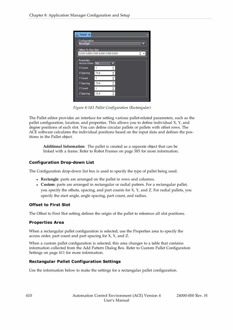
410 Automation Control Environment (ACE) Version 4User's Manual
24000-000 Rev. H
Chapter 8: Application Manager Configuration and Setup
Figure 8-183 Pallet Configuration (Rectangular)
The Pallet editor provides an interface for setting various pallet-related parameters, such as thepallet configuration, location, and properties. This allows you to define individual X, Y, anddegree positions of each slot. You can define circular pallets or pallets with offset rows. TheACE software calculates the individual positions based on the input data and defines the pos-itions in the Pallet object.
Additional Information: The pallet is created as a separate object that can belinked with a frame. Refer to Robot Frames on page 385 for more information.
Configuration Drop-down List
The Configuration drop-down list box is used to specify the type of pallet being used.
l Rectangle: parts are arranged on the pallet in rows and columns.l Custom: parts are arranged in rectangular or radial pattern. For a rectangular pallet,you specify the offsets, spacing, and part counts for X, Y, and Z. For radial pallets, youspecify the start angle, angle spacing, part count, and radius.
Offset to First Slot
The Offset to First Slot setting defines the origin of the pallet to reference all slot positions.
Properties Area
When a rectangular pallet configuration is selected, use the Properties area to specify theaccess order, part count and part spacing for X, Y, and Z.
When a custom pallet configuration is selected, this area changes to a table that containsinformation collected from the Add Pattern Dialog Box. Refer to Custom Pallet ConfigurationSettings on page 411 for more information.
Rectangular Pallet Configuration Settings
Use the information below to make the settings for a rectangular pallet configuration.

Access Order
The Access Order property defines how the robot will access the pallet. For example, if anaccess order of Yxz is selected, the robot will begin accessing the pallet positions with the firstY-row. After the Y row is finished, it will move to the next row in the X-direction. After all X-direction rows are accessed, it will move in the z-direction to access the next row.
X, Y, Z Count
This defines the number of slots on the X, Y, and Z axes.
X, Y, Z Spacing
This defines the slot spacing for the X, Y, and Z axes.
Custom Pallet Configuration Settings
A custom Pallet is typically used for irregular slot arrangements. The custom Pallet con-figuration allows you to define each slot position. For example, if your pallet is 3 x 3 x 2, youwill have 18 slot position items defined in the Properties area of the custom Pallet object asshown below.
You can define individual slot positions manually using the Add button or automaticallyusing the Pattern button as described below.
Additional Information: When the Pallet has no pattern, use the Add button todefine individual slot positions.
24000-000 Rev. H Automation Control Environment (ACE) Version 4User's Manual
411
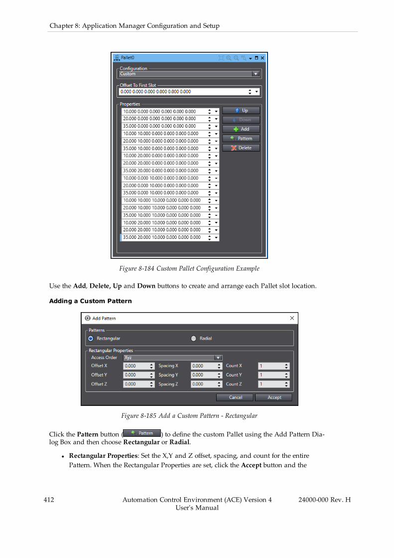
412 Automation Control Environment (ACE) Version 4User's Manual
24000-000 Rev. H
Chapter 8: Application Manager Configuration and Setup
Figure 8-184 Custom Pallet Configuration Example
Use the Add, Delete, Up and Down buttons to create and arrange each Pallet slot location.
Adding a Custom Pattern
Figure 8-185 Add a Custom Pattern - Rectangular
Click the Pattern button ( ) to define the custom Pallet using the Add Pattern Dia-log Box and then choose Rectangular or Radial.
l Rectangular Properties: Set the X,Y and Z offset, spacing, and count for the entirePattern. When the Rectangular Properties are set, click the Accept button and the

Custom Properties list will be populated accordingly.l Radial Properties: Set the Start Angle, Angle Spacing, Count, and Radius for the entirePattern. When the Radial Properties are set, click the Accept button and the CustomProperties list will be populated accordingly.
Pallet Visualization
You can select a shape to represent the pallet in the 3D Visualizer. The shape is specified onthe Part or Part Target object editor. The shape can be selected from a box, cylinder, or Refer toPart Object on page 336, Part Target Object on page 331, and Part Object on page 336 for moreinformation.
Vision Refinement Station Object
The Vision Refinement Station object defines a location with an upward-mounted camera thatis used to improve the part-to-gripper orientation for more accurate placement of the part.
NOTE: The following information assumes you have already installed a phys-ical camera, created a virtual camera, calibrated the camera, and created a visiontool and model.
Adding a Vision Refinement Station Object
To add a Vision Refinement Station object, right-click Process, select Add, and then click VisionRefinement Station. A new Vision Refinement Station object will be added to the MultiviewExplorer.
Figure 8-186 Adding a Vision Refinement Station Object
24000-000 Rev. H Automation Control Environment (ACE) Version 4User's Manual
413

414 Automation Control Environment (ACE) Version 4User's Manual
24000-000 Rev. H
Chapter 8: Application Manager Configuration and Setup
NOTE: After the Vision Refinement Station object is created, you can rename thenew Vision Refinement Station object by right-clicking the item and selectingRename.
Vision Refinement Station Configuration
To access the Vision Refinement Station configuration, right-click the object in the MultiviewExplorer and then select Edit, or double-click the object. This will open the Vision RefinementStation editor in the Edit Pane.
Figure 8-187 Vision Refinement Station Configuration
Vision Properties
The Vision Refinement Station only has a single configuration item. Use the Vision Propertiesdrop-down to specify the vision tool that will be used to locate the part in the gripper.
As an option, select Use Named Instance (select Model or enter custom result name) and thenuse the Select button ( ) to reference an exiting Locator Model or use the Add button ( ) toadd a custom result name. For applications where a custom vision tool is used, this itemwould be used to specify custom names that had been associated with the different resultsreturned from that tool.
Adding the Vision Refinement Station to a Process
After you create the Vision Refinement Station, it must be added to a pick-place process. Thisis done using the Advanced tab of the Part Process Editor, shown in the following figure. Referto Part Process Editor on page 361 for more information.
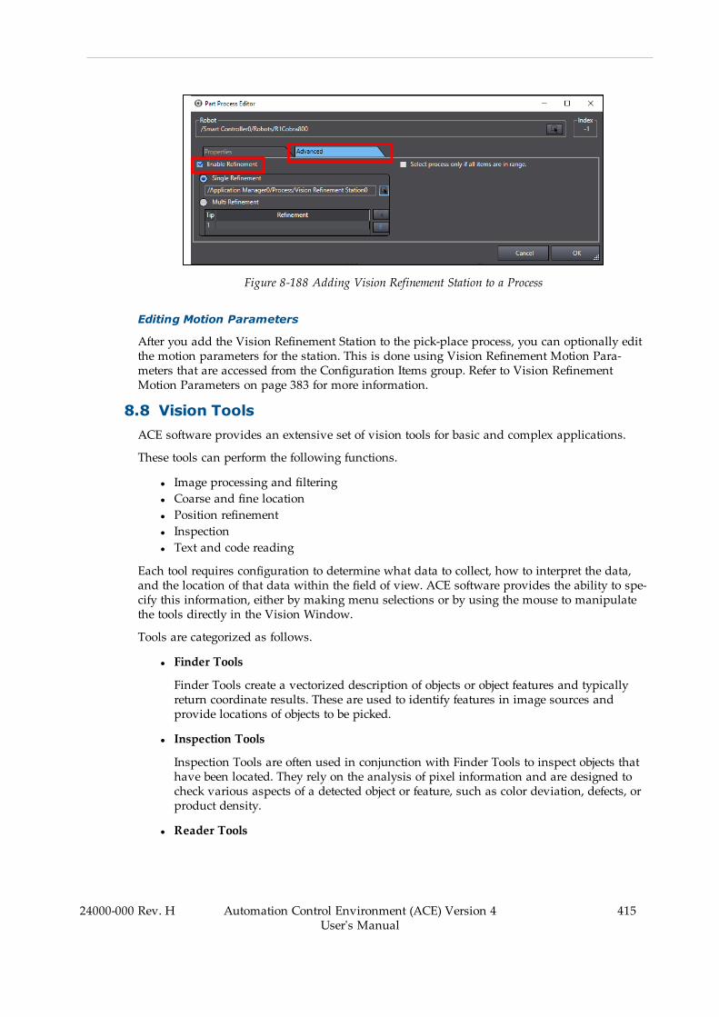
Figure 8-188 Adding Vision Refinement Station to a Process
Editing Motion Parameters
After you add the Vision Refinement Station to the pick-place process, you can optionally editthe motion parameters for the station. This is done using Vision Refinement Motion Para-meters that are accessed from the Configuration Items group. Refer to Vision RefinementMotion Parameters on page 383 for more information.
8.8 Vision ToolsACE software provides an extensive set of vision tools for basic and complex applications.
These tools can perform the following functions.
l Image processing and filteringl Coarse and fine locationl Position refinementl Inspectionl Text and code reading
Each tool requires configuration to determine what data to collect, how to interpret the data,and the location of that data within the field of view. ACE software provides the ability to spe-cify this information, either by making menu selections or by using the mouse to manipulatethe tools directly in the Vision Window.
Tools are categorized as follows.
l Finder Tools
Finder Tools create a vectorized description of objects or object features and typicallyreturn coordinate results. These are used to identify features in image sources andprovide locations of objects to be picked.
l Inspection Tools
Inspection Tools are often used in conjunction with Finder Tools to inspect objects thathave been located. They rely on the analysis of pixel information and are designed tocheck various aspects of a detected object or feature, such as color deviation, defects, orproduct density.
l Reader Tools
24000-000 Rev. H Automation Control Environment (ACE) Version 4User's Manual
415
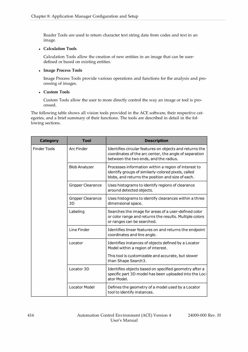
416 Automation Control Environment (ACE) Version 4User's Manual
24000-000 Rev. H
Chapter 8: Application Manager Configuration and Setup
Reader Tools are used to return character text string data from codes and text in animage.
l Calculation Tools
Calculation Tools allow the creation of new entities in an image that can be user-defined or based on existing entities.
l Image Process Tools
Image Process Tools provide various operations and functions for the analysis and pro-cessing of images.
l Custom Tools
Custom Tools allow the user to more directly control the way an image or tool is pro-cessed.
The following table shows all vision tools provided in the ACE software, their respective cat-egories, and a brief summary of their functions. The tools are described in detail in the fol-lowing sections.
Category Tool Description
Finder Tools Arc Finder Identifies circular features on objects and returns thecoordinates of the arc center, the angle of separationbetween the two ends, and the radius.
Blob Analyzer Processes information within a region of interest toidentify groups of similarly-colored pixels, calledblobs, and returns the position and size of each.
Gripper Clearance Uses histograms to identify regions of clearancearound detected objects.
Gripper Clearance3D
Uses histograms to identify clearances within a threedimensional space.
Labeling Searches the image for areas of a user-defined coloror color range and returns the results. Multiple colorsor ranges can be searched.
Line Finder Identifies linear features on and returns the endpointcoordinates and line angle.
Locator Identifies instances of objects defined by a LocatorModel within a region of interest.
This tool is customizable and accurate, but slowerthan Shape Search3.
Locator 3D Identifies objects based on specified geometry after aspecific part 3D model has been uploaded into the Loc-ator Model.
Locator Model Defines the geometry of a model used by a Locatortool to identify instances.
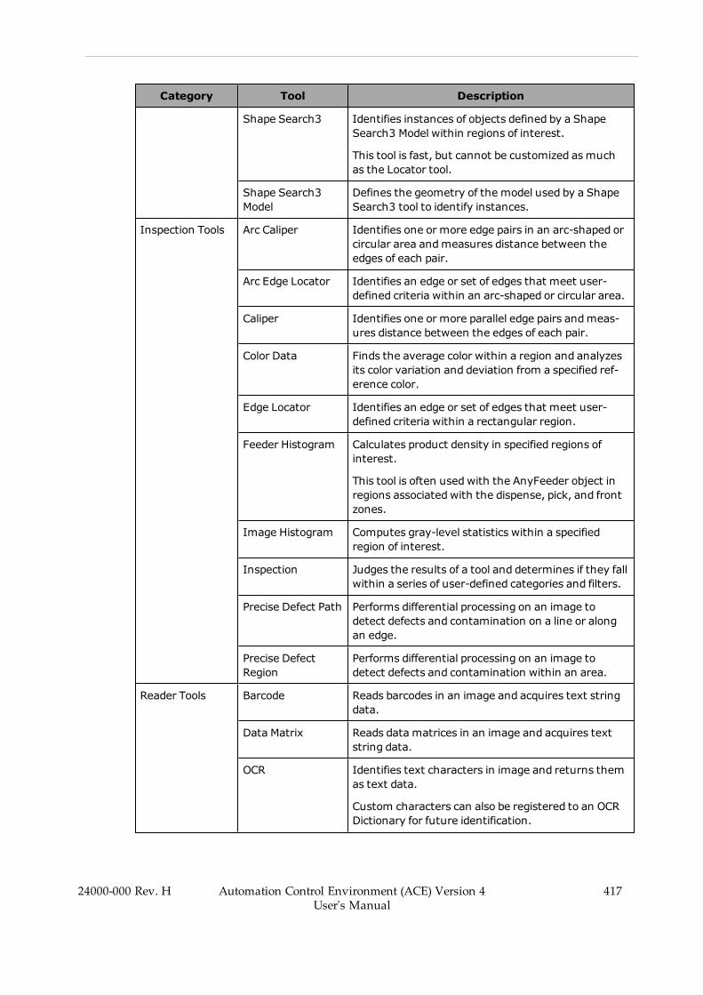
Category Tool Description
Shape Search3 Identifies instances of objects defined by a ShapeSearch3 Model within regions of interest.
This tool is fast, but cannot be customized as muchas the Locator tool.
Shape Search3Model
Defines the geometry of the model used by a ShapeSearch3 tool to identify instances.
Inspection Tools Arc Caliper Identifies one or more edge pairs in an arc-shaped orcircular area andmeasures distance between theedges of each pair.
Arc Edge Locator Identifies an edge or set of edges that meet user-defined criteria within an arc-shaped or circular area.
Caliper Identifies one or more parallel edge pairs andmeas-ures distance between the edges of each pair.
Color Data Finds the average color within a region and analyzesits color variation and deviation from a specified ref-erence color.
Edge Locator Identifies an edge or set of edges that meet user-defined criteria within a rectangular region.
Feeder Histogram Calculates product density in specified regions ofinterest.
This tool is often usedwith the AnyFeeder object inregions associated with the dispense, pick, and frontzones.
Image Histogram Computes gray-level statistics within a specifiedregion of interest.
Inspection Judges the results of a tool and determines if they fallwithin a series of user-defined categories and filters.
Precise Defect Path Performs differential processing on an image todetect defects and contamination on a line or alongan edge.
Precise DefectRegion
Performs differential processing on an image todetect defects and contamination within an area.
Reader Tools Barcode Reads barcodes in an image and acquires text stringdata.
Data Matrix Reads data matrices in an image and acquires textstring data.
OCR Identifies text characters in image and returns themas text data.
Custom characters can also be registered to an OCRDictionary for future identification.
24000-000 Rev. H Automation Control Environment (ACE) Version 4User's Manual
417

418 Automation Control Environment (ACE) Version 4User's Manual
24000-000 Rev. H
Chapter 8: Application Manager Configuration and Setup
Category Tool Description
OCRDictionary Stores dictionary data that OCR can use to identifytext characters.
QR Code Reads QR or Micro QR code in an image and acquirestext string data.
Calculation Tools Calculated Arc Calculates an arc based on a specified calculationmode and returns the encompassing circle.
Calculated Frame Calculates a frame based on a specified calculationmode and returns coordinates and orientation.
Calculated Line Calculates a line based on a specified calculationmode and returns coordinates and dimensions.
Calculated Point Calculates a point based on a specified calculationmode and returns coordinates.
ImageProcess Tools
Advanced Filter Filters or alters an image using one of a variety of fil-ter libraries, such as Background Suppression, Ero-sion / Dilation, and Color Gray Filter.
This tool can be combinedwith other tools (includingother Advanced Filters) to modify an image to thenecessary specifications.
Color Matching Filters and analyzes areas of a specified color or colorrange in images.
Image Processing Filters or alters a gray scale image using one of a vari-ety of filters, including logical and arithmetic cal-culations.
This tool can be combinedwith other tools (includingother Image Processing tools) to modify an image tothe necessary specifications.
Image Sampling Extracts an area of an image and outputs it as a newimage source.
PositionCompensation
Converts all pixels outside a rectangular region toblack and outputs the result as a new image.
Custom Tools Custom Vision Tool Allows you to specify a program to be called whenexecuted.
This tool can execute other tools and return a customset of results.
Remote Vision Tool Enables operation of configured vision tools by cre-ating a vision server instance.
Adding Vision Tools
To add a new vision tool, right-click on the Vision Tools object in the Multiview Explorer,expand one of the categories and then select one of the tools, as shown in the figure below.

Figure 8-189 Adding a New Vision Tool
Vision Tool Editor
Each vision tool is configured using its corresponding object editor in the Edit Pane. In general,most of the tool editors have a similar configuration that can be split into five sections asdescribed below.
Figure 8-190 Vision Tool Editor
24000-000 Rev. H Automation Control Environment (ACE) Version 4User's Manual
419

420 Automation Control Environment (ACE) Version 4User's Manual
24000-000 Rev. H
Chapter 8: Application Manager Configuration and Setup
Table 8-35 Vision Tool Editor Item Description
Item Name Description
1 ExecutionButtons
This area provides direct control of the tool with the following but-tons.
l Run: Run the tool once.
This is available with most vision tools.
l Continuous: Run the tool continuously.
This is available with most vision tools.
l Stop: Stop the tool or live operation. Can only be selected ifLive or Continuous has been activated.
This is available with most vision tools.
l Live: Send images without running the tool.
This is available with most vision tools.
l Auto Tuning: Automatically sets parameters based on pixeldata. This functions differently depending on the tool. Seethose tools for more information.
This is available with the Barcode, Color Data, Data Matrix,OCR, and QR Code tools.
l New Image button: Loads a new image into the tool. Themodel will need to be retrained. This replaces the Run buttonin the respective tools.
This is available with the Locator Model and Shape Search 3Model tools.
l Register to OCR Dictionary button: Registers a characterto the OCR Dictionary.
This is available with the OCR Dictionary tool.
2 Image Display This area displays the current image from the camera.
This will also include any required graphics or controls. For example,the Locator tool shown in Figure 8-190 displays markers for eachidentified instance within the green region of interest, which can bemodified as needed.
3 Results This area displays the output of the tool .
In most cases, this contains returned data organized in columns.The columns can be chosen by clicking the Plus button ( ) whichwill display the Results Column Selection Dialog Box. Use this dialogbox to select and arrange the data displayed in this area.
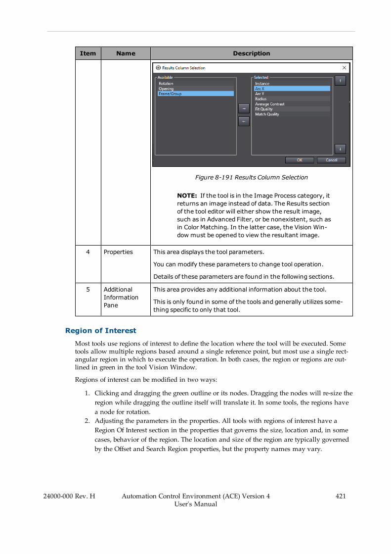
Item Name Description
Figure 8-191 Results Column Selection
NOTE: If the tool is in the Image Process category, itreturns an image instead of data. The Results sectionof the tool editor will either show the result image,such as in Advanced Filter, or be nonexistent, such asin Color Matching. In the latter case, the Vision Win-dow must be opened to view the resultant image.
4 Properties This area displays the tool parameters.
You can modify these parameters to change tool operation.
Details of these parameters are found in the following sections.
5 AdditionalInformationPane
This area provides any additional information about the tool.
This is only found in some of the tools and generally utilizes some-thing specific to only that tool.
Region of Interest
Most tools use regions of interest to define the location where the tool will be executed. Sometools allow multiple regions based around a single reference point, but most use a single rect-angular region in which to execute the operation. In both cases, the region or regions are out-lined in green in the tool Vision Window.
Regions of interest can be modified in two ways:
1. Clicking and dragging the green outline or its nodes. Dragging the nodes will re-size theregion while dragging the outline itself will translate it. In some tools, the regions havea node for rotation.
2. Adjusting the parameters in the properties. All tools with regions of interest have aRegion Of Interest section in the properties that governs the size, location and, in somecases, behavior of the region. The location and size of the region are typically governedby the Offset and Search Region properties, but the property names may vary.
24000-000 Rev. H Automation Control Environment (ACE) Version 4User's Manual
421

422 Automation Control Environment (ACE) Version 4User's Manual
24000-000 Rev. H
Chapter 8: Application Manager Configuration and Setup
NOTE: The region orientation of some tools can only be controlled withthe Offset property.
Tools with Multiple Regions of Interest
Tools with multiple regions of interest can be manipulated to allow different behavior in indi-vidual regions. This is achieved by modifying two properties as described below.
l Overlap
This defines the region as either inclusive or exclusive by setting it to OR or NOT,respectively. An inclusive region returns all detected contours or instances within itsboundaries. An exclusive region hides all detected contours or instances within itsboundaries. Figure 8-192 shows how individual regions are registered in the figure. Theoriginal regions are displayed on the left and the resulting processed region is displayedon the right, where the green area shows what parts are read. For example, in thesecond set of regions, the NOT region eliminates a section of the full region, resulting ina rectangular section that is not read.
Figure 8-192 Overlap - OR Versus NOT
l Z-Order
This defines the order in which regions are processed. Each region has its own propertythat defines its order in the Z-direction of an image. Since the image is two-dimensional,this value is used to determine which regions are processed first. Regions are processedin ascending order. This can be seen in the regions in Figure 8-193 where the regionsare processed according to their written Z-Order. In the first example, the results of allthree regions can be seen, since no region is entirely blocked. However, in the secondexample, the smallest region is hidden because the red region has a higher value than itdoes, according to Z-order.

Figure 8-193 Z-order Layout
Relative To Parameter Details
Most of the tools with regions of interest can be set relative to another tool. A vision tool isordinarily executed with respect to the origin of the image, but when it is set relative to anothertool, it will instead execute with respect to the result values of that tool. This will cause the sec-ondary tool to execute once for every input value, unless it is otherwise constrained.
To create this relationship, set the primary tool as the Relative To property of the secondarytool in the editor of the secondary tool. In this way, the output values of the primary toolbecome the input values of the secondary tool. In the following figure, the Gripper Clearancetool is set relative to a Locator tool and is able to position histograms around all of the objectsby creating new reference points with respect to the Locator results. The input locations areshown under the Current Values section in the properties.
NOTE: Some tools display all instances in the image display. Some only dis-play the region created with respect to the first instance and return the remainderin the Results section. The additional instances can be viewed in the ACE VisionWindow as long as the property Show Results Graphics is enabled. Refer to theVision Window in Figure 8-194 (which is based on the tool in Figure 8-195below).
A tool set relative to another tool can be used to create an Robot Vision Manager Sequence.Refer to Vision Sequence on page 262 for more information.
24000-000 Rev. H Automation Control Environment (ACE) Version 4User's Manual
423
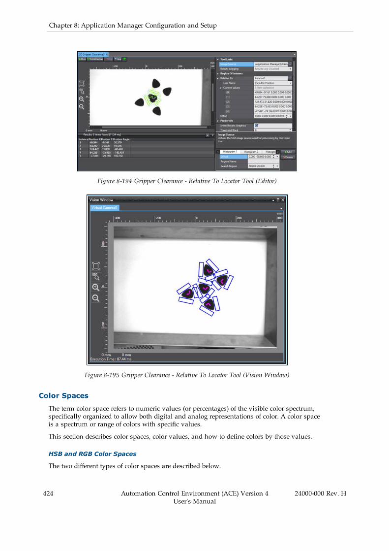
424 Automation Control Environment (ACE) Version 4User's Manual
24000-000 Rev. H
Chapter 8: Application Manager Configuration and Setup
Figure 8-194 Gripper Clearance - Relative To Locator Tool (Editor)
Figure 8-195 Gripper Clearance - Relative To Locator Tool (Vision Window)
Color Spaces
The term color space refers to numeric values (or percentages) of the visible color spectrum,specifically organized to allow both digital and analog representations of color. A color spaceis a spectrum or range of colors with specific values.
This section describes color spaces, color values, and how to define colors by those values.
HSB and RGB Color Spaces
The two different types of color spaces are described below.

Hue, Saturation, and Brightness (HSB) Color Space
The HSB color space arranges colors of each hue radially around a central axis of basic colors,from white at the top to black at the bottom. Hue values are set in degrees from 0 to 360. Sat-uration and brightness are set in percentages from 0 to 100%.
Hue is the quality of color perceived as the color itself. The hue is determined by the perceiveddominant wavelength, or the central tendency combined wavelengths within the visible spec-trum.
Saturation is the purity of the color, or the gray in a color. For example a high saturation valueproduces a very pure, intense color. Reducing the saturation value adds gray to the color.
Brightness is the amount of white contained in the color. As the value increases, the colorbecomes lighter and becomes more white. As the luminance value decreases the color is darkerand becomes more black.
NOTE: HSB is also referenced as HSL (Hue, Saturation, Luminance) and HSV(Hue, Saturation, Value) in the ACE software.
Figure 8-196 HSB Color Space
Red, Green, and Blue (RGB) Color Space
The RGB color space uses combinations of red, green, and blue to create all colors. Red, green,and blue values are expressed with a range of 0 to 255.
24000-000 Rev. H Automation Control Environment (ACE) Version 4User's Manual
425

426 Automation Control Environment (ACE) Version 4User's Manual
24000-000 Rev. H
Chapter 8: Application Manager Configuration and Setup
Figure 8-197 RGB Color Space
NOTE: ACE software also accepts the hexadecimal color value in the colorinput field.
HSB and RGB Color Values
Settings for items such as color filters and reference colors can be adjusted with HSB, RGB, orhexadecimal values. The following table provides example values for common colors.
Table 8-36 Common HSB and RGB Color Values
Color HSB Values RGB Values Hexadecimal Values
White 0, 0, 100 255, 255, 255 #FFFFFF
Black 0, 0, 0 0, 0, 0 #000000
Gray 0, 0, 50 127, 127, 127 #7F7F7F
Red 0, 100, 100 255, 0, 0 #FF0000
Green 120, 100, 100 0, 255, 0 #00FF00
Blue 240, 100, 100 0, 0, 255 #0000FF
Color Tolerances
Color tolerances can be applied to allow for slight color variations. Color tolerances can onlybe set with HSB values.
A color tolerance value is distributed equally above and below the color value to which itapplies. For example, if the color hue value is 50 and the hue tolerance value is 20, the filterwill accept colors within a range of hue values from 30 to 70.
Finder Tools
Finder tools are used to identify objects and create detection points for location guidance.
The following Finder tools are described in this section.
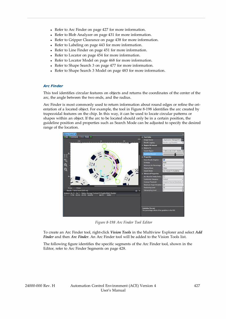
l Refer to Arc Finder on page 427 for more information.l Refer to Blob Analyzer on page 431 for more information.l Refer to Gripper Clearance on page 438 for more information.l Refer to Labeling on page 443 for more information.l Refer to Line Finder on page 451 for more information.l Refer to Locator on page 454 for more information.l Refer to Locator Model on page 468 for more information.l Refer to Shape Search 3 on page 477 for more information.l Refer to Shape Search 3 Model on page 483 for more information.
Arc Finder
This tool identifies circular features on objects and returns the coordinates of the center of thearc, the angle between the two ends, and the radius.
Arc Finder is most commonly used to return information about round edges or refine the ori-entation of a located object. For example, the tool in Figure 8-198 identifies the arc created bytrapezoidal features on the chip. In this way, it can be used to locate circular patterns orshapes within an object. If the arc to be located should only be in a certain position, theguideline position and properties such as Search Mode can be adjusted to specify the desiredrange of the location.
Figure 8-198 Arc Finder Tool Editor
To create an Arc Finder tool, right-click Vision Tools in the Multiview Explorer and select AddFinder and then Arc Finder. An Arc Finder tool will be added to the Vision Tools list.
The following figure identifies the specific segments of the Arc Finder tool, shown in theEditor, refer to Arc Finder Segments on page 428.
24000-000 Rev. H Automation Control Environment (ACE) Version 4User's Manual
427
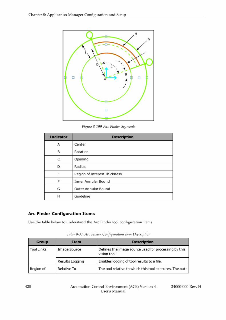
428 Automation Control Environment (ACE) Version 4User's Manual
24000-000 Rev. H
Chapter 8: Application Manager Configuration and Setup
Figure 8-199 Arc Finder Segments
Indicator Description
A Center
B Rotation
C Opening
D Radius
E Region of Interest Thickness
F Inner Annular Bound
G Outer Annular Bound
H Guideline
Arc Finder Configuration Items
Use the table below to understand the Arc Finder tool configuration items.
Table 8-37 Arc Finder Configuration Item Description
Group Item Description
Tool Links Image Source Defines the image source used for processing by thisvision tool.
Results Logging Enables logging of tool results to a file.
Region of Relative To The tool relative to which this tool executes. The out-
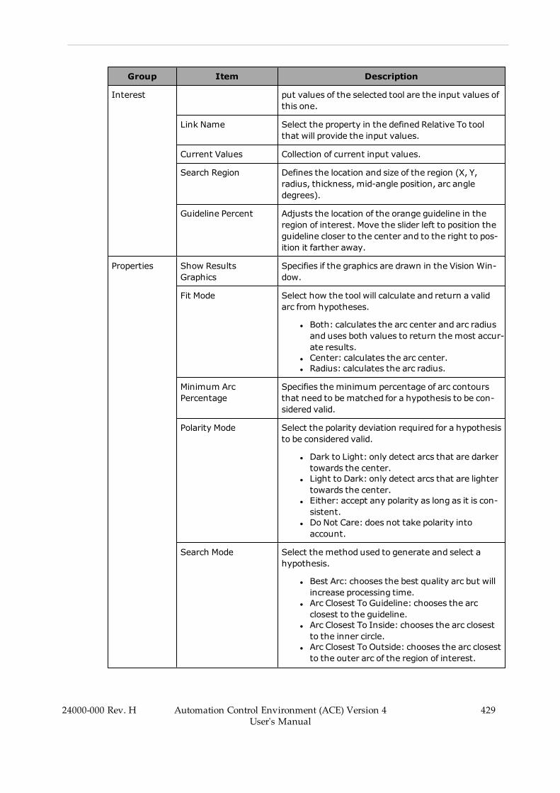
Group Item Description
Interest put values of the selected tool are the input values ofthis one.
Link Name Select the property in the defined Relative To toolthat will provide the input values.
Current Values Collection of current input values.
Search Region Defines the location and size of the region (X, Y,radius, thickness, mid-angle position, arc angledegrees).
Guideline Percent Adjusts the location of the orange guideline in theregion of interest. Move the slider left to position theguideline closer to the center and to the right to pos-ition it farther away.
Properties Show ResultsGraphics
Specifies if the graphics are drawn in the Vision Win-dow.
Fit Mode Select how the tool will calculate and return a validarc from hypotheses.
l Both: calculates the arc center and arc radiusand uses both values to return the most accur-ate results.
l Center: calculates the arc center.l Radius: calculates the arc radius.
Minimum ArcPercentage
Specifies the minimum percentage of arc contoursthat need to be matched for a hypothesis to be con-sidered valid.
Polarity Mode Select the polarity deviation required for a hypothesisto be considered valid.
l Dark to Light: only detect arcs that are darkertowards the center.
l Light to Dark: only detect arcs that are lightertowards the center.
l Either: accept any polarity as long as it is con-sistent.
l Do Not Care: does not take polarity intoaccount.
Search Mode Select the method used to generate and select ahypothesis.
l Best Arc: chooses the best quality arc but willincrease processing time.
l Arc Closest To Guideline: chooses the arcclosest to the guideline.
l Arc Closest To Inside: chooses the arc closestto the inner circle.
l Arc Closest To Outside: chooses the arc closestto the outer arc of the region of interest.
24000-000 Rev. H Automation Control Environment (ACE) Version 4User's Manual
429

430 Automation Control Environment (ACE) Version 4User's Manual
24000-000 Rev. H
Chapter 8: Application Manager Configuration and Setup
Group Item Description
Advanced Prop-erties
Arc Must Be TotallyEnclosed
Specifies if the detected arc can exist outside of theregion of interest. When enabled, the start and endpoints of the arc must be located on the angle bound-ary lines. Otherwise, the arc can enter or exit theregion at any point.
Conformity Tolerance Set the maximum local deviation between the expec-ted arc contours and the arc contours actually detec-ted in the input image.
Contrast Threshold Defines the minimum contrast needed for an edge tobe detected in the input image. This threshold isexpressed in terms of a step in gray level values.Higher values reduce noise but also reduce the num-ber of contours detected.
Maximum AngleDeviation
Defines the maximum angle deviation between thecalculated arc’s tangents and the edge contours.
Positioning Level Set the configurable effort level of the instance pos-itioning process. A value of 10 will provide coarser pos-itioning and lower execution time. Conversely, avalue of 100 will provide high accuracy positioning ofarc entities. The setting range is 10 to 100.
Subsampling Level Set the subsampling level used to detect edges thatare used by the tool to generate hypotheses. High val-ues provide a coarser search and lower executiontime than lower values. The setting range is 1 to 8.
Arc Finder Results
Use the table below to understand the results of the Arc Finder tool.
Table 8-38 Arc Finder Results Description
Item Description
Instance Index of the result instance.
Frame/Group Index of the related result. It is associated with the tool that this tool is setRelative To.
Arc X X-coordinate of the arc center point.
Arc Y Y-coordinate of the arc center point.
Radius Radius of the arc, measured from the center determined by Arc X and Arc Y.
Opening Angle (in degrees)measured between the two arc endpoints.
Rotation Rotation of the region of interest, measured from the positive X-axis.
AverageContrast
Average contrast between light and dark pixels on either side of the arc,expressed in gray level values.
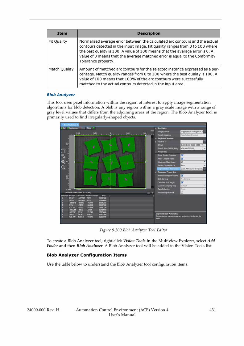
Item Description
Fit Quality Normalized average error between the calculated arc contours and the actualcontours detected in the input image. Fit quality ranges from 0 to 100 wherethe best quality is 100. A value of 100 means that the average error is 0. Avalue of 0 means that the average matched error is equal to the ConformityTolerance property.
Match Quality Amount of matched arc contours for the selected instance expressed as a per-centage. Match quality ranges from 0 to 100 where the best quality is 100. Avalue of 100 means that 100% of the arc contours were successfullymatched to the actual contours detected in the input area.
Blob Analyzer
This tool uses pixel information within the region of interest to apply image segmentationalgorithms for blob detection. A blob is any region within a gray scale image with a range ofgray level values that differs from the adjoining areas of the region. The Blob Analyzer tool isprimarily used to find irregularly-shaped objects.
Figure 8-200 Blob Analyzer Tool Editor
To create a Blob Analyzer tool, right-click Vision Tools in the Multiview Explorer, select AddFinder and then Blob Analyzer. A Blob Analyzer tool will be added to the Vision Tools list.
Blob Analyzer Configuration Items
Use the table below to understand the Blob Analyzer tool configuration items.
24000-000 Rev. H Automation Control Environment (ACE) Version 4User's Manual
431
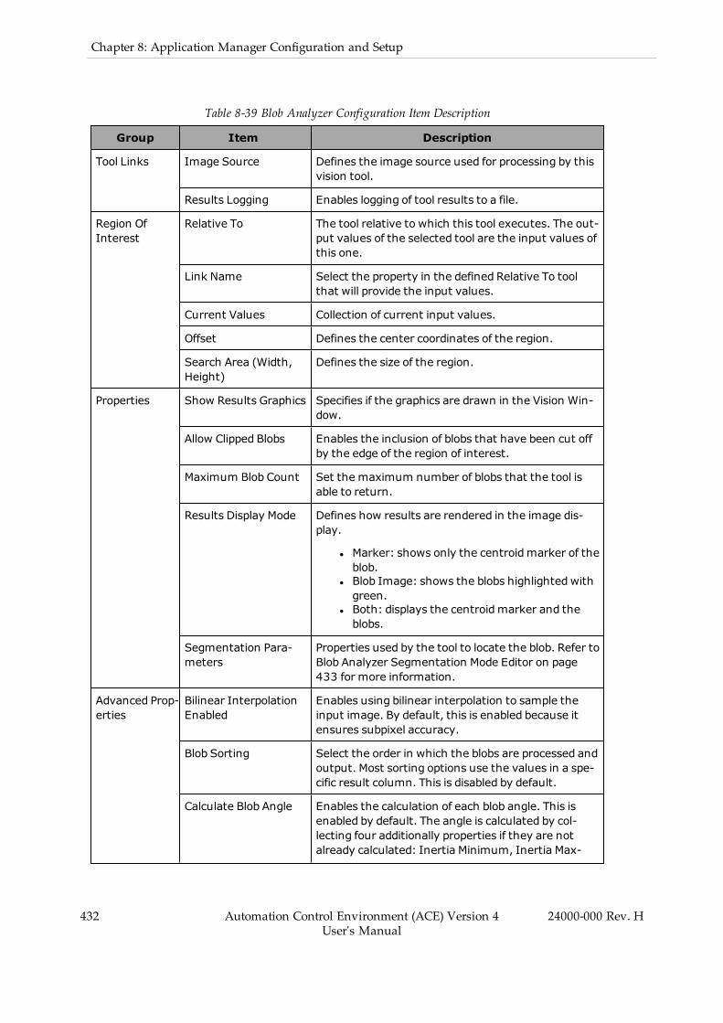
432 Automation Control Environment (ACE) Version 4User's Manual
24000-000 Rev. H
Chapter 8: Application Manager Configuration and Setup
Table 8-39 Blob Analyzer Configuration Item Description
Group Item Description
Tool Links Image Source Defines the image source used for processing by thisvision tool.
Results Logging Enables logging of tool results to a file.
Region OfInterest
Relative To The tool relative to which this tool executes. The out-put values of the selected tool are the input values ofthis one.
Link Name Select the property in the defined Relative To toolthat will provide the input values.
Current Values Collection of current input values.
Offset Defines the center coordinates of the region.
Search Area (Width,Height)
Defines the size of the region.
Properties Show Results Graphics Specifies if the graphics are drawn in the Vision Win-dow.
Allow Clipped Blobs Enables the inclusion of blobs that have been cut offby the edge of the region of interest.
Maximum Blob Count Set the maximum number of blobs that the tool isable to return.
Results Display Mode Defines how results are rendered in the image dis-play.
l Marker: shows only the centroidmarker of theblob.
l Blob Image: shows the blobs highlighted withgreen.
l Both: displays the centroidmarker and theblobs.
Segmentation Para-meters
Properties used by the tool to locate the blob. Refer toBlob Analyzer Segmentation Mode Editor on page433 for more information.
Advanced Prop-erties
Bilinear InterpolationEnabled
Enables using bilinear interpolation to sample theinput image. By default, this is enabled because itensures subpixel accuracy.
Blob Sorting Select the order in which the blobs are processed andoutput. Most sorting options use the values in a spe-cific result column. This is disabled by default.
Calculate Blob Angle Enables the calculation of each blob angle. This isenabled by default. The angle is calculated by col-lecting four additionally properties if they are notalready calculated: Inertia Minimum, Inertia Max-
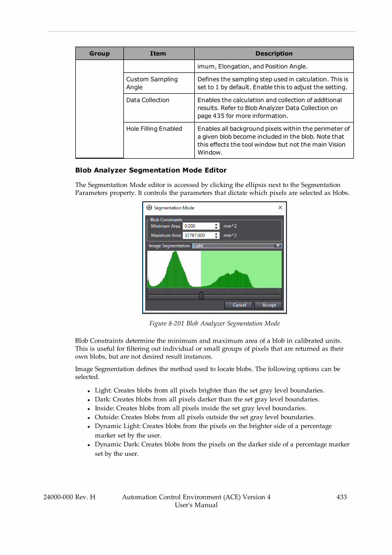
Group Item Description
imum, Elongation, and Position Angle.
Custom SamplingAngle
Defines the sampling step used in calculation. This isset to 1 by default. Enable this to adjust the setting.
Data Collection Enables the calculation and collection of additionalresults. Refer to Blob Analyzer Data Collection onpage 435 for more information.
Hole Filling Enabled Enables all background pixels within the perimeter ofa given blob become included in the blob. Note thatthis effects the tool window but not the main VisionWindow.
Blob Analyzer Segmentation Mode Editor
The Segmentation Mode editor is accessed by clicking the ellipsis next to the SegmentationParameters property. It controls the parameters that dictate which pixels are selected as blobs.
Figure 8-201 Blob Analyzer Segmentation Mode
Blob Constraints determine the minimum and maximum area of a blob in calibrated units.This is useful for filtering out individual or small groups of pixels that are returned as theirown blobs, but are not desired result instances.
Image Segmentation defines the method used to locate blobs. The following options can beselected.
l Light: Creates blobs from all pixels brighter than the set gray level boundaries.l Dark: Creates blobs from all pixels darker than the set gray level boundaries.l Inside: Creates blobs from all pixels inside the set gray level boundaries.l Outside: Creates blobs from all pixels outside the set gray level boundaries.l Dynamic Light: Creates blobs from the pixels on the brighter side of a percentagemarker set by the user.
l Dynamic Dark: Creates blobs from the pixels on the darker side of a percentage markerset by the user.
24000-000 Rev. H Automation Control Environment (ACE) Version 4User's Manual
433

434 Automation Control Environment (ACE) Version 4User's Manual
24000-000 Rev. H
Chapter 8: Application Manager Configuration and Setup
l Dynamic Inside: Creates blobs from the pixels between two percentage bounds set bythe user.
l Dynamic Outside: Creates blobs from the pixels outside of two percentage bounds set bythe user.
l HSL Inside: Creates blobs from all the pixels that fall within an HSL tolerance.l HSL Outside: Creates blobs from all the pixels that fall outside an HSL tolerance.
Image Segmentation settings are made using the slider(s) shown at the bottom of the editor(except for HSL Inside/Outside). The green area indicates which pixels in the histogram will beincluded in the blobs and the white area indicates which ones will not be included as shownin the following figure.
Figure 8-202 Blob Analyzer Image Segmentation Adjustments (Not HSL Inside/Outside)
NOTE: When a Dynamic option is selected in Image Segmentation, the displaywill continue to show the green and white overlay, but the calculation will nottake the histogram into account.
HSL Inside and HSL Outside use a different viewer in the editor since they are based on HSLcolor instead of brightness. Therefore, the histogram has no impact. Instead, the editor appearsas shown below and the histogram is replaced by the following properties. Refer to ColorSpaces on page 424 for more information about color definition.
Figure 8-203 Blob Analyzer Image Segmentation Adjustments for HSL Inside/Outside
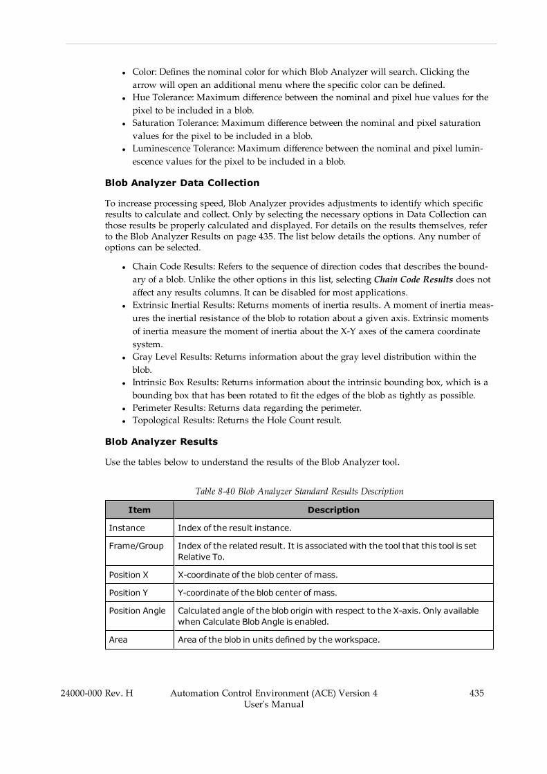
l Color: Defines the nominal color for which Blob Analyzer will search. Clicking thearrow will open an additional menu where the specific color can be defined.
l Hue Tolerance: Maximum difference between the nominal and pixel hue values for thepixel to be included in a blob.
l Saturation Tolerance: Maximum difference between the nominal and pixel saturationvalues for the pixel to be included in a blob.
l Luminescence Tolerance: Maximum difference between the nominal and pixel lumin-escence values for the pixel to be included in a blob.
Blob Analyzer Data Collection
To increase processing speed, Blob Analyzer provides adjustments to identify which specificresults to calculate and collect. Only by selecting the necessary options in Data Collection canthose results be properly calculated and displayed. For details on the results themselves, referto the Blob Analyzer Results on page 435. The list below details the options. Any number ofoptions can be selected.
l Chain Code Results: Refers to the sequence of direction codes that describes the bound-ary of a blob. Unlike the other options in this list, selecting Chain Code Results does notaffect any results columns. It can be disabled for most applications.
l Extrinsic Inertial Results: Returns moments of inertia results. A moment of inertia meas-ures the inertial resistance of the blob to rotation about a given axis. Extrinsic momentsof inertia measure the moment of inertia about the X-Y axes of the camera coordinatesystem.
l Gray Level Results: Returns information about the gray level distribution within theblob.
l Intrinsic Box Results: Returns information about the intrinsic bounding box, which is abounding box that has been rotated to fit the edges of the blob as tightly as possible.
l Perimeter Results: Returns data regarding the perimeter.l Topological Results: Returns the Hole Count result.
Blob Analyzer Results
Use the tables below to understand the results of the Blob Analyzer tool.
Table 8-40 Blob Analyzer Standard Results Description
Item Description
Instance Index of the result instance.
Frame/Group Index of the related result. It is associated with the tool that this tool is setRelative To.
Position X X-coordinate of the blob center of mass.
Position Y Y-coordinate of the blob center of mass.
Position Angle Calculated angle of the blob origin with respect to the X-axis. Only availablewhen Calculate Blob Angle is enabled.
Area Area of the blob in units defined by the workspace.
24000-000 Rev. H Automation Control Environment (ACE) Version 4User's Manual
435
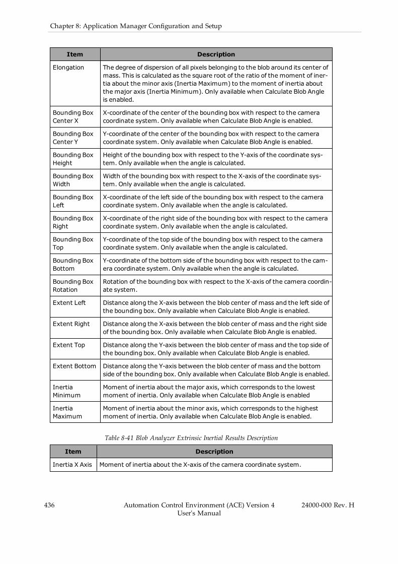
436 Automation Control Environment (ACE) Version 4User's Manual
24000-000 Rev. H
Chapter 8: Application Manager Configuration and Setup
Item Description
Elongation The degree of dispersion of all pixels belonging to the blob around its center ofmass. This is calculated as the square root of the ratio of the moment of iner-tia about the minor axis (Inertia Maximum) to the moment of inertia aboutthe major axis (Inertia Minimum). Only available when Calculate Blob Angleis enabled.
Bounding BoxCenter X
X-coordinate of the center of the bounding box with respect to the cameracoordinate system. Only available when Calculate Blob Angle is enabled.
Bounding BoxCenter Y
Y-coordinate of the center of the bounding box with respect to the cameracoordinate system. Only available when Calculate Blob Angle is enabled.
Bounding BoxHeight
Height of the bounding box with respect to the Y-axis of the coordinate sys-tem. Only available when the angle is calculated.
Bounding BoxWidth
Width of the bounding box with respect to the X-axis of the coordinate sys-tem. Only available when the angle is calculated.
Bounding BoxLeft
X-coordinate of the left side of the bounding box with respect to the cameracoordinate system. Only available when the angle is calculated.
Bounding BoxRight
X-coordinate of the right side of the bounding box with respect to the cameracoordinate system. Only available when the angle is calculated.
Bounding BoxTop
Y-coordinate of the top side of the bounding box with respect to the cameracoordinate system. Only available when the angle is calculated.
Bounding BoxBottom
Y-coordinate of the bottom side of the bounding box with respect to the cam-era coordinate system. Only available when the angle is calculated.
Bounding BoxRotation
Rotation of the bounding box with respect to the X-axis of the camera coordin-ate system.
Extent Left Distance along the X-axis between the blob center of mass and the left side ofthe bounding box. Only available when Calculate Blob Angle is enabled.
Extent Right Distance along the X-axis between the blob center of mass and the right sideof the bounding box. Only available when Calculate Blob Angle is enabled.
Extent Top Distance along the Y-axis between the blob center of mass and the top side ofthe bounding box. Only available when Calculate Blob Angle is enabled.
Extent Bottom Distance along the Y-axis between the blob center of mass and the bottomside of the bounding box. Only available when Calculate Blob Angle is enabled.
InertiaMinimum
Moment of inertia about the major axis, which corresponds to the lowestmoment of inertia. Only available when Calculate Blob Angle is enabled
InertiaMaximum
Moment of inertia about the minor axis, which corresponds to the highestmoment of inertia. Only available when Calculate Blob Angle is enabled.
Table 8-41 Blob Analyzer Extrinsic Inertial Results Description
Item Description
Inertia X Axis Moment of inertia about the X-axis of the camera coordinate system.
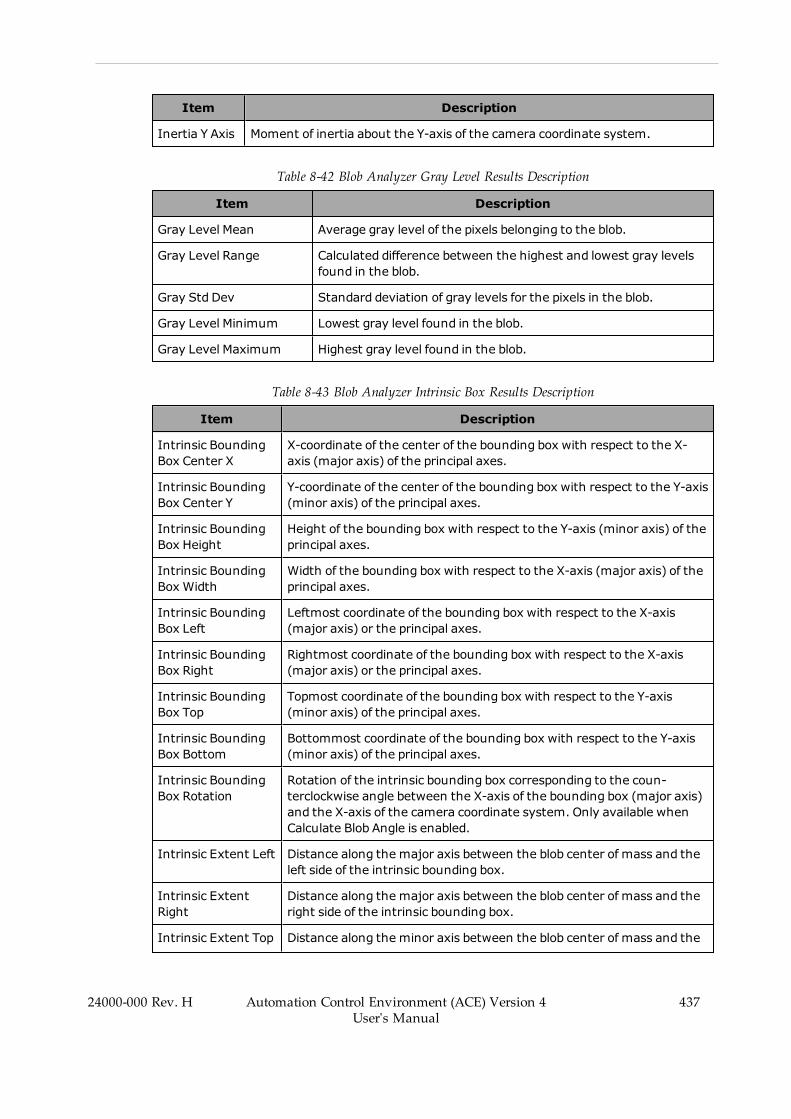
Item Description
Inertia Y Axis Moment of inertia about the Y-axis of the camera coordinate system.
Table 8-42 Blob Analyzer Gray Level Results Description
Item Description
Gray Level Mean Average gray level of the pixels belonging to the blob.
Gray Level Range Calculated difference between the highest and lowest gray levelsfound in the blob.
Gray Std Dev Standard deviation of gray levels for the pixels in the blob.
Gray Level Minimum Lowest gray level found in the blob.
Gray Level Maximum Highest gray level found in the blob.
Table 8-43 Blob Analyzer Intrinsic Box Results Description
Item Description
Intrinsic BoundingBox Center X
X-coordinate of the center of the bounding box with respect to the X-axis (major axis) of the principal axes.
Intrinsic BoundingBox Center Y
Y-coordinate of the center of the bounding box with respect to the Y-axis(minor axis) of the principal axes.
Intrinsic BoundingBox Height
Height of the bounding box with respect to the Y-axis (minor axis) of theprincipal axes.
Intrinsic BoundingBox Width
Width of the bounding box with respect to the X-axis (major axis) of theprincipal axes.
Intrinsic BoundingBox Left
Leftmost coordinate of the bounding box with respect to the X-axis(major axis) or the principal axes.
Intrinsic BoundingBox Right
Rightmost coordinate of the bounding box with respect to the X-axis(major axis) or the principal axes.
Intrinsic BoundingBox Top
Topmost coordinate of the bounding box with respect to the Y-axis(minor axis) of the principal axes.
Intrinsic BoundingBox Bottom
Bottommost coordinate of the bounding box with respect to the Y-axis(minor axis) of the principal axes.
Intrinsic BoundingBox Rotation
Rotation of the intrinsic bounding box corresponding to the coun-terclockwise angle between the X-axis of the bounding box (major axis)and the X-axis of the camera coordinate system. Only available whenCalculate Blob Angle is enabled.
Intrinsic Extent Left Distance along the major axis between the blob center of mass and theleft side of the intrinsic bounding box.
Intrinsic ExtentRight
Distance along the major axis between the blob center of mass and theright side of the intrinsic bounding box.
Intrinsic Extent Top Distance along the minor axis between the blob center of mass and the
24000-000 Rev. H Automation Control Environment (ACE) Version 4User's Manual
437
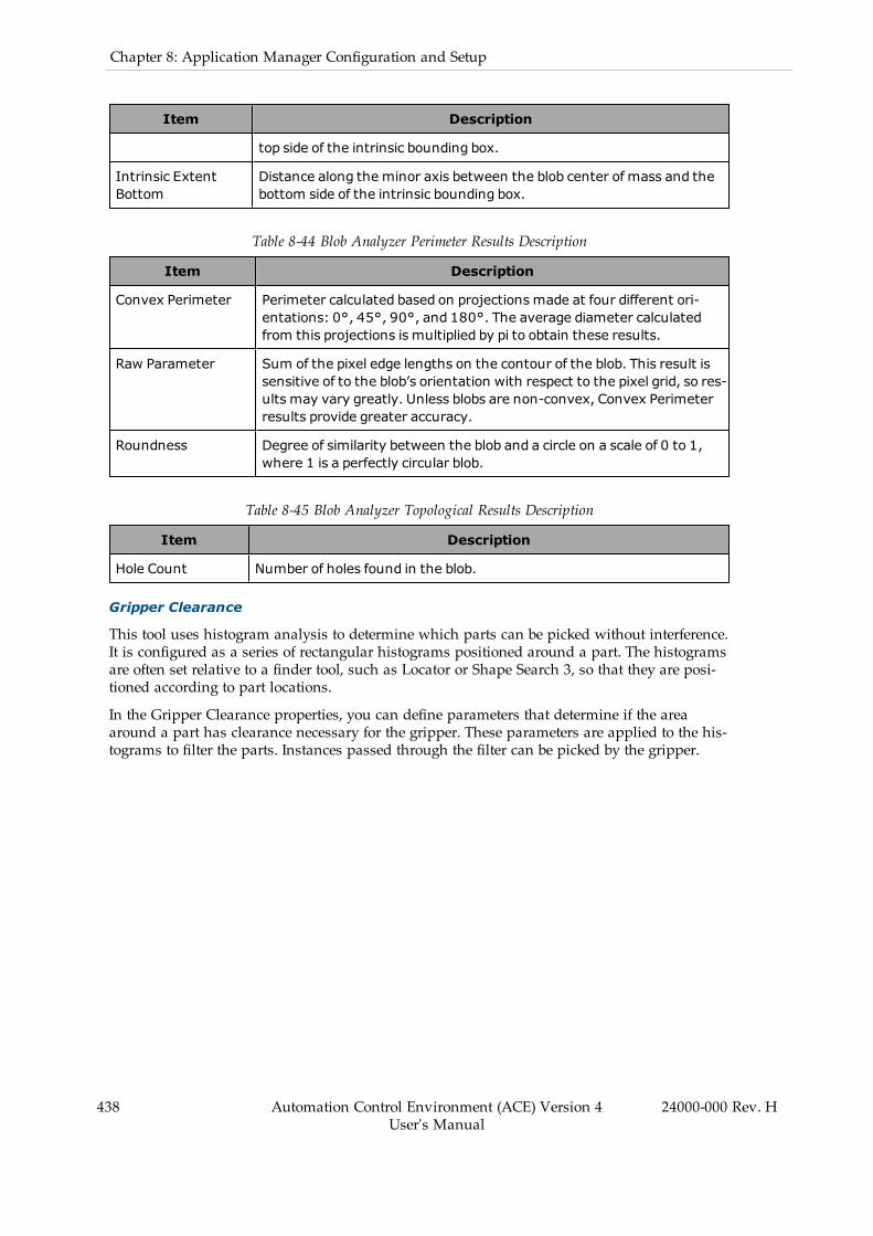
438 Automation Control Environment (ACE) Version 4User's Manual
24000-000 Rev. H
Chapter 8: Application Manager Configuration and Setup
Item Description
top side of the intrinsic bounding box.
Intrinsic ExtentBottom
Distance along the minor axis between the blob center of mass and thebottom side of the intrinsic bounding box.
Table 8-44 Blob Analyzer Perimeter Results Description
Item Description
Convex Perimeter Perimeter calculated based on projections made at four different ori-entations: 0°, 45°, 90°, and 180°. The average diameter calculatedfrom this projections is multiplied by pi to obtain these results.
Raw Parameter Sum of the pixel edge lengths on the contour of the blob. This result issensitive of to the blob’s orientation with respect to the pixel grid, so res-ults may vary greatly. Unless blobs are non-convex, Convex Perimeterresults provide greater accuracy.
Roundness Degree of similarity between the blob and a circle on a scale of 0 to 1,where 1 is a perfectly circular blob.
Table 8-45 Blob Analyzer Topological Results Description
Item Description
Hole Count Number of holes found in the blob.
Gripper Clearance
This tool uses histogram analysis to determine which parts can be picked without interference.It is configured as a series of rectangular histograms positioned around a part. The histogramsare often set relative to a finder tool, such as Locator or Shape Search 3, so that they are posi-tioned according to part locations.
In the Gripper Clearance properties, you can define parameters that determine if the areaaround a part has clearance necessary for the gripper. These parameters are applied to the his-tograms to filter the parts. Instances passed through the filter can be picked by the gripper.
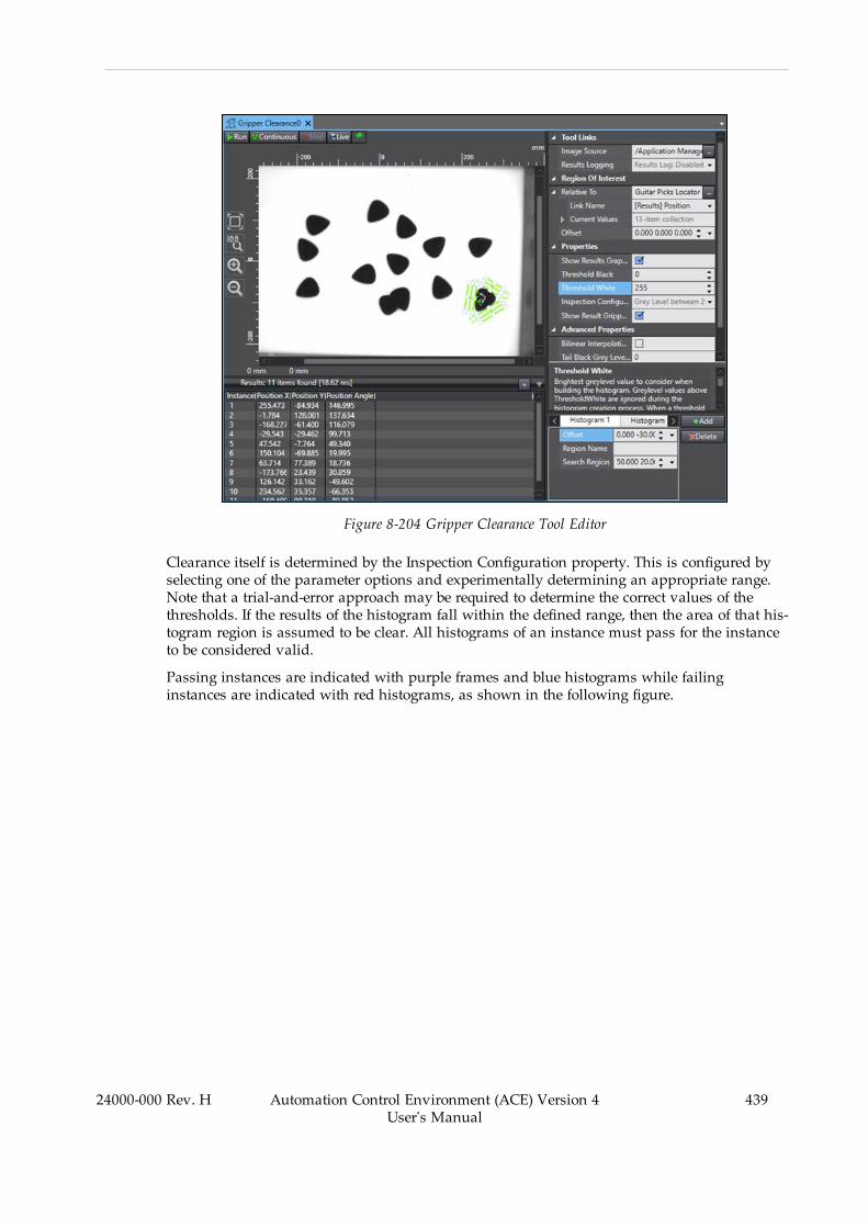
Figure 8-204 Gripper Clearance Tool Editor
Clearance itself is determined by the Inspection Configuration property. This is configured byselecting one of the parameter options and experimentally determining an appropriate range.Note that a trial-and-error approach may be required to determine the correct values of thethresholds. If the results of the histogram fall within the defined range, then the area of that his-togram region is assumed to be clear. All histograms of an instance must pass for the instanceto be considered valid.
Passing instances are indicated with purple frames and blue histograms while failinginstances are indicated with red histograms, as shown in the following figure.
24000-000 Rev. H Automation Control Environment (ACE) Version 4User's Manual
439
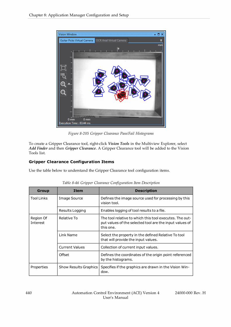
440 Automation Control Environment (ACE) Version 4User's Manual
24000-000 Rev. H
Chapter 8: Application Manager Configuration and Setup
Figure 8-205 Gripper Clearance Pass/Fail Histograms
To create a Gripper Clearance tool, right-click Vision Tools in the Multiview Explorer, selectAdd Finder and then Gripper Clearance. A Gripper Clearance tool will be added to the VisionTools list.
Gripper Clearance Configuration Items
Use the table below to understand the Gripper Clearance tool configuration items.
Table 8-46 Gripper Clearance Configuration Item Description
Group Item Description
Tool Links Image Source Defines the image source used for processing by thisvision tool.
Results Logging Enables logging of tool results to a file.
Region OfInterest
Relative To The tool relative to which this tool executes. The out-put values of the selected tool are the input values ofthis one.
Link Name Select the property in the defined Relative To toolthat will provide the input values.
Current Values Collection of current input values.
Offset Defines the coordinates of the origin point referencedby the histograms.
Properties Show Results Graphics Specifies if the graphics are drawn in the Vision Win-dow.
Group Item Description
Threshold Black Defines the darkest pixels the histogram considerswhen running. Any pixels with gray level lower thanthis value will be ignoredwhile the histogram is build-ing.
ThresholdWhite Defines the brightest pixels the histogram considerswhen running. Any pixels with gray level abovehigher than this value will be ignoredwhile the his-togram is building.
InspectionConfiguration
Set the parameter and range that determines if a his-togram is clear.
l Gray Level: Maximum andminimum allow-able gray level values for pixels within theregion. These are set with a range of 0 to 255.
l Variance: Maximum andminimum allowablevariance of the gray level values within theregion. These values must be greater than 0.
l Histogram Pixel Count: Maximum andmin-imum allowable number of pixels within theregion after applying tails and thresholds.These values must be greater than 0.
l Histogram Pixel Percent: Maximum andmin-imum allowable percentage of pixels that aredetected by the histogram after applying tailsand thresholds. These values must bebetween 0 to 100.
Show Result ImageHistogram Regions
Specifies if the histogram regions are drawn in theACE Vision Window. Show Results Graphics must beenabled for this to work.
Advanced Prop-erties
Bilinear InterpolationEnabled
Enables using bilinear interpolation to sample theinput image. By default, this is enabled because itensures subpixel accuracy.
Tail Black Gray LevelValue
Percentage of pixels to ignore at the dark end of thegray level distribution. This is calculated after thepixels affected by the Threshold Black property havebeen removed.
Tail White Gray LevelValue
Percentage of pixels to ignore at the light end of thegray level distribution. This is calculated after thepixels affected by the ThresholdWhite property havebeen removed.
Gripper Clearance Histogram Pane
The histograms are measured using the Histogram Pane located beneath the properties area.
24000-000 Rev. H Automation Control Environment (ACE) Version 4User's Manual
441

442 Automation Control Environment (ACE) Version 4User's Manual
24000-000 Rev. H
Chapter 8: Application Manager Configuration and Setup
Figure 8-206 Gripper Clearance Histogram Pane
The Add button ( ) and Delete button ( ) are used to create and remove his-tograms from the tool. The Histogram Pane displays the properties for the currently selectedhistogram tab. The properties are described in the following table.
Table 8-47 Histogram Pane Property Description
Item Description
Offset Defines the center coordinates of the histogram region with respect tothe reference point defined by Offset in the main tool properties.
Region Name User-defined name of the histogram. This is displayed in the lower leftcorner of the histogram region in the Vision Window.
Search Region Defines the size (width, height) of the histogram region.
Gripper Clearance Results
Gripper Clearance returns each instance that has passed the all histogram ranges. For theseinstances, the histogram analysis is available in additional columns. These are not shown bydefault and must be added using the Results Column Editor. The numbers of the histogramsare variable and are denoted in the table below as <number> instead of actual values.
NOTE: All results are calculated after applying tails and thresholds.
Use the table below to understand the results of the Gripper Clearance tool.
Table 8-48 Gripper Clearance Results Description
Item Description
Instance Index of the result instance.
Frame/Group Index of the related result. It is associated with the tool that this toolis set Relative To.
Position X X-coordinate of the instance origin.
Position Y Y-coordinate of the instance origin.
Position Angle Angle of the instance origin.
Gray Level Mean<number>
Average gray level within the region of this histogram.
Histogram Pixel Count<number>
Number of pixels within the region of this histogram.
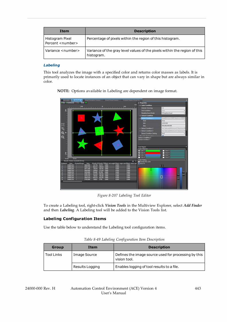
Item Description
Histogram PixelPercent <number>
Percentage of pixels within the region of this histogram.
Variance <number> Variance of the gray level values of the pixels within the region of thishistogram.
Labeling
This tool analyzes the image with a specified color and returns color masses as labels. It isprimarily used to locate instances of an object that can vary in shape but are always similar incolor.
NOTE: Options available in Labeling are dependent on image format.
Figure 8-207 Labeling Tool Editor
To create a Labeling tool, right-click Vision Tools in the Multiview Explorer, select Add Finderand then Labeling. A Labeling tool will be added to the Vision Tools list.
Labeling Configuration Items
Use the table below to understand the Labeling tool configuration items.
Table 8-49 Labeling Configuration Item Description
Group Item Description
Tool Links Image Source Defines the image source used for processing by thisvision tool.
Results Logging Enables logging of tool results to a file.
24000-000 Rev. H Automation Control Environment (ACE) Version 4User's Manual
443

444 Automation Control Environment (ACE) Version 4User's Manual
24000-000 Rev. H
Chapter 8: Application Manager Configuration and Setup
Group Item Description
Region OfInterest
Relative To The tool relative to which this tool executes. The out-put values of the selected tool are the input valuesof this one.
Link Name Select the property in the defined Relative To toolthat will provide the input values.
Current Values Collection of current input values.
Rectangles
Ellipses
Circumferences
Polygons
WideArcs
Sets of regions of interest of a particular shape. Thefield will show how many regions exist ("1-item col-lection","2-item collect', etc.). Click the plus sign inthe field to create additional regions and click thearrow to see all regions.
<region number> Identifies the region of the specified shape. It willappear as [0], [1], [...] within the shape category.Click the minus sign in the field to remove the regionand click the arrow to see its properties.
Name Available in all region types. Sets the user-definedname of the region.
Overlap Available in all region types. Select the behavior ofthe region. OR causes the region to be included inthe search area and NOT excludes it from the searcharea. The behavior of specific regions is furtherdefined in Z-Order.
Refer to Tools with Multiple Regions of Interest onpage 422 for more information.
Z-Order Available in all region types. Sets the order for over-lapping regions of interest. Higher numbers will be infront and resolved first.
Refer to Tools with Multiple Regions of Interest onpage 422 for more information.
Offset Available in all region types except for Polygons.Defines the coordinates of the region’s center.
Search Region (Width,Height)
Sets the height andwidth of the rectangular region.Only available in Rectangles.
Radius X/Y Defines the distance from the center to the exterioralong the X- and Y-axes, respectively. Only availablein Ellipses.
Radius Only available in Ellipses. Defines the distance fromthe center to the exterior along the region X- and Y-axes, respectively.
Thickness Defines the distance between the two visible rings.

Group Item Description
Only available in Circumferences andWideArcs.
Start/End Angle Defines the start and end angle of the Wide Arcbounds. Angles are measured in degrees coun-terclockwise from the positive X-axis. The arc is cre-ated clockwise starting from the Start Angle andending at the End Angle. Only available in WideArcs.
Vertexes Sets of vertexes in a polygon region of interest. Thefield will show how many vertexes exist ("3-item col-lection", "4-item collection", etc). Click the plus linein the field to create additional regions and click thearrow to see all regions. Only available in Polygons.
<vertex number> Identifies a particular vertex in the region. It willappear as [0], [1], [2], and etc. The field defines theX/Y coordinates of the vertex. Click the minus signto remove the vertex, as long as there are not fewerthan three. Only available in Polygons.
Maximum ToolExecution Count
Maximum number of tool executions for Relative Toperformance. If this tool is not set relative toanother tool, the tool will only run once upon exe-cution.
Properties (Label Condition)Outside Condition
Defines the behavior of the area outside the searcharea. When enabled, the entirety of the area outsidethe regions of interest will be returned as the extrac-ted color, connecting all detectedmasses that touchthe edges of the regions.
(Label Condition) SortCondition
Select the order in which the returnedmasses areprocessed and output. The order will be descending(largest to smallest) by default; checking the Ascend-ing box will sort them smallest to largest.
(Label Condition)NeighborhoodMode
Specifies the connection conditions for labeling.Select 4 Neighborhood to process contiguous partsup, down, left, and right of the target pixel as thesame label. Select 8 Neighborhood to add oblique dir-ections.
Extract Condition1/2/3
Defines the type and limitation of conditions thatconstrain the returnedmasses
(Extract Condition1/2/3) Kind
Available under Extract Condition 1/2/3. Select theproperty that will define the constraints on thereturnedmasses.
(Extract Condition1/2/3) Min/Max
Available under Extract Condition 1/2/3. Defines theminimum andmaximum values that are acceptablefor returnedmasses.
Show Results Graphics Specifies if the graphics are drawn in the Vision Win-dow.
24000-000 Rev. H Automation Control Environment (ACE) Version 4User's Manual
445
446 Automation Control Environment (ACE) Version 4User's Manual
24000-000 Rev. H
Chapter 8: Application Manager Configuration and Setup
Group Item Description
Hole Plug Color Defines which color will fill in detected holes in themasses. This is disabled by default.
Advanced Prop-erties
Additional Data Set Allows additional data values to be added to the out-put. Select the types of results based on what isneeded.
l Rectangle Coordinate Results: Upper left,lower right coordinates when enclosing alabel with a circumscribed rectangle.
l Cont Length Results: Length of the entire cir-cumference of the label.
l Circularity Results: Roundness of the label.
l Elliptic Results: Long axis length, minor axislength, and angle when label is ellipticallyapproximated.
l Rotated Rectangle Results: Long side length,short side length, and angle of rotating shortform circumscribing the label.
l Inner Circle Results: Center coordinates andradius of the circle inscribed on the label.
l Outer Circle Results: Center coordinates andradius of circumscribing circle.
l Holes Number Results: Number of holesdetected in the label.
Image Type Set the color scheme of the image to display. All Col-ors shows all extracted colors, Binary outputs allextracted colors as white and everything else asblack, and the rest of the options only extract themasses that match one defined color.
Max Result DisplayCount
Set the number of results to display. The tool will notoutput more instances than this value.
Color Region Pane
This pane shows the color ranges to be extracted from the image. This is imperative whenusing a color image. The color range(s) can be chosen by specifying the minimum and max-imum for hue, saturation, and value. Conversely, the color range(s) can be selected in theimage. Right-click on a pixel to select a specific color or right-click and drag to select a range.The detected colors will be displayed in the Color Setting region and the user can define thelimits based on these data points.

Figure 8-208 Color Region Pane
The Color Region Pane is split into the following three sections.
1. Color Selection
This shows the colors that have been selected. Up to eight different colors can be extrac-ted each time the tool is run. The user can determine which colors are extracted fromamong the selected ones by checking or unchecking the boxes next to them. Forexample, deselecting Colors 2 and 3 in Figure 8-208 will cause only the green regions tobe extracted.
2. Color Setting
This highlights the regions on the color spectrum that are used by the selected colors.They are also defined by the Hue, Saturation, and Value fields down below. The high-lighted regions can be modified by dragging them in the color spectrums or adjustingthe values in the fields down below. The selected color range is shown as a rectanglewith a black and white border. Other ranges defined will have a black border. The col-ors of the pixels in the most recently selected range will appear as gray markers on therectangular field and as red marks in the Value slider on the right.
24000-000 Rev. H Automation Control Environment (ACE) Version 4User's Manual
447
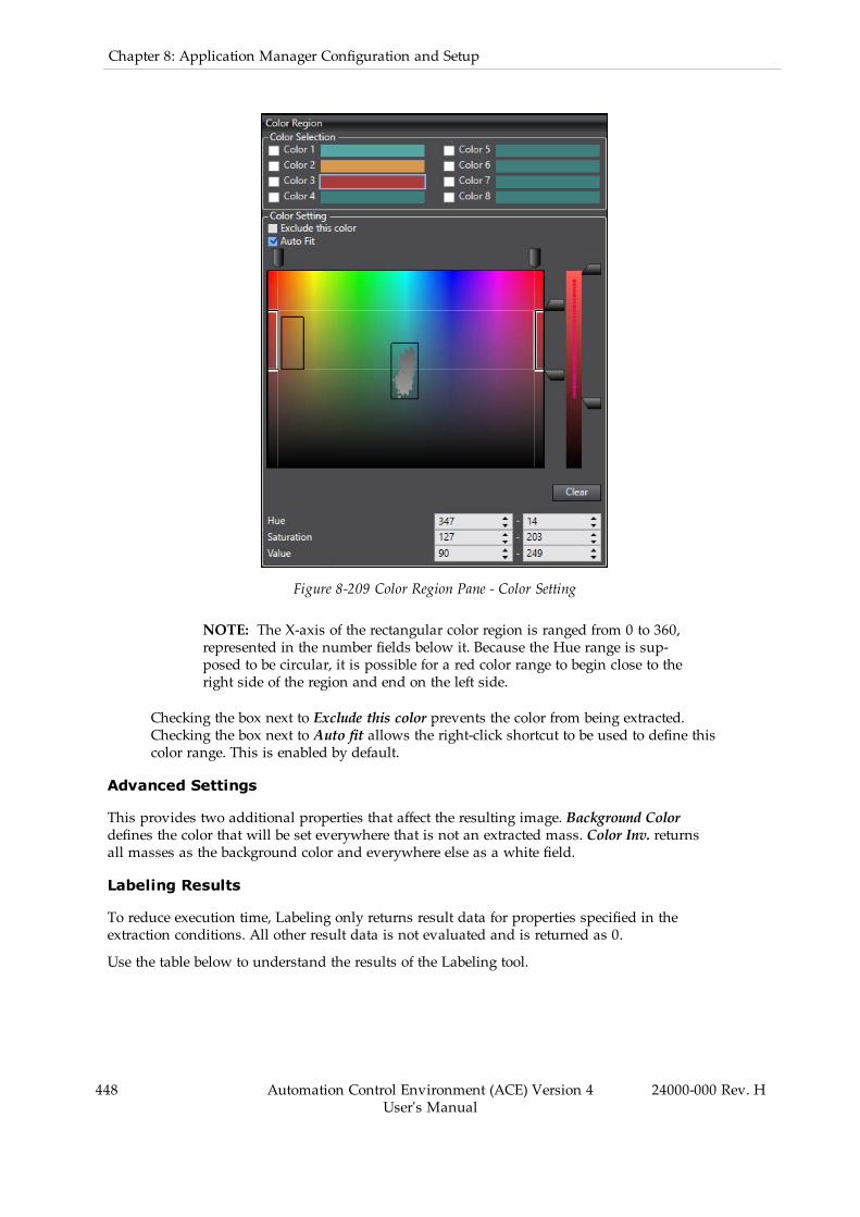
448 Automation Control Environment (ACE) Version 4User's Manual
24000-000 Rev. H
Chapter 8: Application Manager Configuration and Setup
Figure 8-209 Color Region Pane - Color Setting
NOTE: The X-axis of the rectangular color region is ranged from 0 to 360,represented in the number fields below it. Because the Hue range is sup-posed to be circular, it is possible for a red color range to begin close to theright side of the region and end on the left side.
Checking the box next to Exclude this color prevents the color from being extracted.Checking the box next to Auto fit allows the right-click shortcut to be used to define thiscolor range. This is enabled by default.
Advanced Settings
This provides two additional properties that affect the resulting image. Background Colordefines the color that will be set everywhere that is not an extracted mass. Color Inv. returnsall masses as the background color and everywhere else as a white field.
Labeling Results
To reduce execution time, Labeling only returns result data for properties specified in theextraction conditions. All other result data is not evaluated and is returned as 0.
Use the table below to understand the results of the Labeling tool.
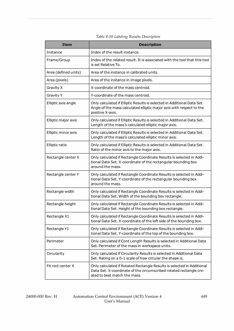
Table 8-50 Labeling Results Description
Item Description
Instance Index of the result instance.
Frame/Group Index of the related result. It is associated with the tool that this toolis set Relative To.
Area (defined units) Area of the instance in calibrated units.
Area (pixels) Area of the instance in image pixels.
Gravity X X-coordinate of the mass centroid.
Gravity Y Y-coordinate of the mass centroid.
Elliptic axis angle Only calculated if Elliptic Results is selected in Additional Data Set.Angle of the mass calculated elliptic major axis with respect to thepositive X-axis.
Elliptic major axis Only calculated if Elliptic Results is selected in Additional Data Set.Length of the mass’s calculated elliptic major axis.
Elliptic minor axis Only calculated if Elliptic Results is selected in Additional Data Set.Length of the mass’s calculated elliptic minor axis.
Elliptic ratio Only calculated if Elliptic Results is selected in Additional Data Set.Ratio of the minor axis to the major axis.
Rectangle center X Only calculated if Rectangle Coordinate Results is selected in Addi-tional Data Set. X-coordinate of the rectangular bounding boxaround the mass.
Rectangle center Y Only calculated if Rectangle Coordinate Results is selected in Addi-tional Data Set. Y-coordinate of the rectangular bounding boxaround the mass.
Rectangle width Only calculated if Rectangle Coordinate Results is selected in Addi-tional Data Set. Width of the bounding box rectangle.
Rectangle height Only calculated if Rectangle Coordinate Results is selected in Addi-tional Data Set. Height of the bounding box rectangle.
Rectangle X1 Only calculated if Rectangle Coordinate Results is selected in Addi-tional Data Set. X-coordinate of the left side of the bounding box.
Rectangle Y1 Only calculated if Rectangle Coordinate Results is selected in Addi-tional Data Set. Y-coordinate of the top of the bounding box.
Perimeter Only calculated if Cont Length Results is selected in Additional DataSet. Perimeter of the mass in workspace units.
Circularity Only calculated if Circularity Results is selected in Additional DataSet. Rating on a 0-1 scale of how circular the shape is.
Fit rect center X Only calculated if Rotated Rectangle Results is selected in AdditionalData Set. X-coordinate of the circumscribed rotated rectangle cre-ated to best match the mass.
24000-000 Rev. H Automation Control Environment (ACE) Version 4User's Manual
449

450 Automation Control Environment (ACE) Version 4User's Manual
24000-000 Rev. H
Chapter 8: Application Manager Configuration and Setup
Item Description
Fit rect center Y Only calculated if Rotated Rectangle Results is selected in AdditionalData Set. Y-coordinate of the circumscribed rotated rectangle cre-ated to best match the mass.
Fit rect major axis Only calculated if Rotated Rectangle Results is selected in AdditionalData Set. Major axis of the circumscribed rotated rectangle.
Fit rect minor axis Only calculated if Rotated Rectangle Results is selected in AdditionalData Set. Minor axis of the circumscribed rotated rectangle.
Fit rect ratio Only calculated if Rotated Rectangle Results is selected in AdditionalData Set. Ratio between the two axes.
Fit rect angle Only calculated if Rotated Rectangle Results is selected in AdditionalData Set. It is the angle of the circumscribed, rotated rectangle. Seethe following figure for details.
Inscribed circle X Only calculated if Inner Circle Results is selected in Additional DataSet. X-coordinate of the mass’s inscribed circle.
Inscribed circle Y Only calculated if Inner Circle Results is selected in Additional DataSet. Y-coordinate of the mass’s inscribed circle.
Inscribed circle R Only calculated if Inner Circle Results is selected in Additional DataSet. Radius of the mass’s inscribed circle.
Circum. circle X Only calculated if Outer Circle Results is selected in Additional DataSet. X-coordinate of the mass’s inscribed circle.
Circum. circle Y Only calculated if Outer Circle Results is selected in Additional DataSet. Y-coordinate of the mass’s inscribed circle.
Circum. circle R Only calculated if Outer Circle Results is selected in Additional DataSet. Radius of the mass’s inscribed circle.
Number of holes Only calculated if Holes Number Results is selected in Additional DataSet.
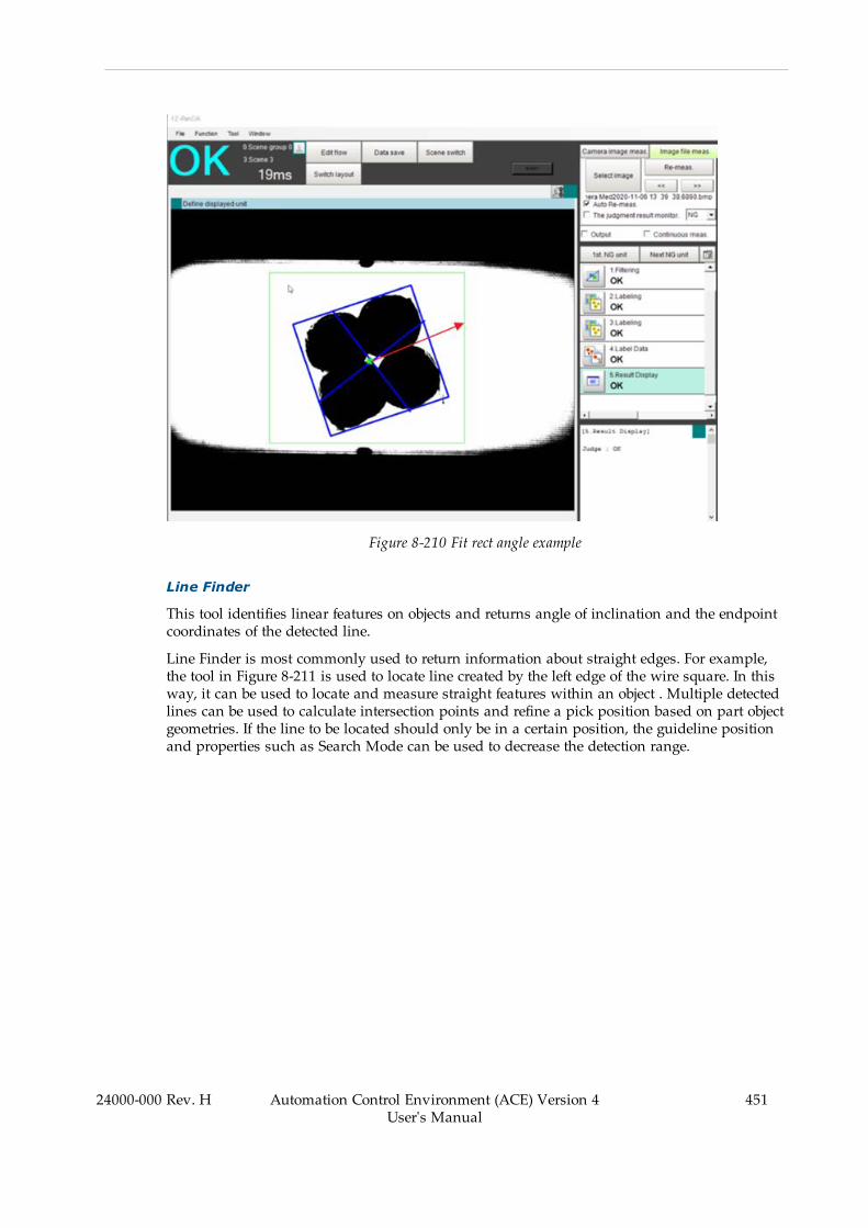
Figure 8-210 Fit rect angle example
Line Finder
This tool identifies linear features on objects and returns angle of inclination and the endpointcoordinates of the detected line.
Line Finder is most commonly used to return information about straight edges. For example,the tool in Figure 8-211 is used to locate line created by the left edge of the wire square. In thisway, it can be used to locate and measure straight features within an object . Multiple detectedlines can be used to calculate intersection points and refine a pick position based on part objectgeometries. If the line to be located should only be in a certain position, the guideline positionand properties such as Search Mode can be used to decrease the detection range.
24000-000 Rev. H Automation Control Environment (ACE) Version 4User's Manual
451

452 Automation Control Environment (ACE) Version 4User's Manual
24000-000 Rev. H
Chapter 8: Application Manager Configuration and Setup
Figure 8-211 Line Finder Tool Editor
To create a Line Finder tool, right-click Vision Tools in the Multiview Explorer, select AddFinder and then Line Finder. A Line Finder tool will be added to the Vision Tools list.
Line Finder Configuration Items
Use the table below to understand the Line Finder tool configuration items.
Table 8-51 Line Finder Configuration Item Description
Group Item Description
Tool Links Image Source Defines the image source used for processing bythis vision tool.
Results Logging Enables logging of tool results to a file.
Region OfInterest
Relative To The tool relative to which this tool executes. Theoutput values of the selected tool are the input val-ues of this one.
Link Name Select the property in the defined Relative To toolthat will provide the input values.
Current Values Collection of current input values.
Offset Defines the center coordinates of the region.
Search Area (Width,Height)
Defines the size of the region.
Guideline Percent Adjusts the location of the orange guideline in theregion of interest. Move the slider left to positionthe guideline farther along positive X-axis of the
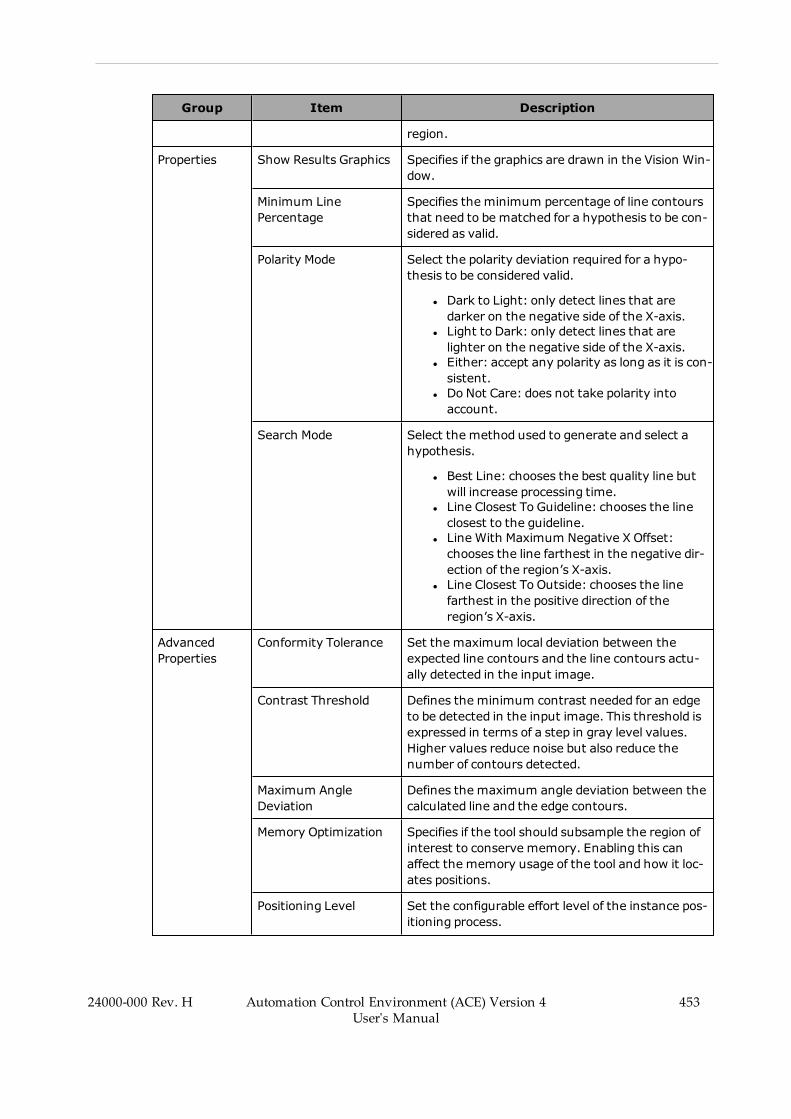
Group Item Description
region.
Properties Show Results Graphics Specifies if the graphics are drawn in the Vision Win-dow.
Minimum LinePercentage
Specifies the minimum percentage of line contoursthat need to be matched for a hypothesis to be con-sidered as valid.
Polarity Mode Select the polarity deviation required for a hypo-thesis to be considered valid.
l Dark to Light: only detect lines that aredarker on the negative side of the X-axis.
l Light to Dark: only detect lines that arelighter on the negative side of the X-axis.
l Either: accept any polarity as long as it is con-sistent.
l Do Not Care: does not take polarity intoaccount.
Search Mode Select the method used to generate and select ahypothesis.
l Best Line: chooses the best quality line butwill increase processing time.
l Line Closest To Guideline: chooses the lineclosest to the guideline.
l Line With Maximum Negative X Offset:chooses the line farthest in the negative dir-ection of the region’s X-axis.
l Line Closest To Outside: chooses the linefarthest in the positive direction of theregion’s X-axis.
AdvancedProperties
Conformity Tolerance Set the maximum local deviation between theexpected line contours and the line contours actu-ally detected in the input image.
Contrast Threshold Defines the minimum contrast needed for an edgeto be detected in the input image. This threshold isexpressed in terms of a step in gray level values.Higher values reduce noise but also reduce thenumber of contours detected.
Maximum AngleDeviation
Defines the maximum angle deviation between thecalculated line and the edge contours.
Memory Optimization Specifies if the tool should subsample the region ofinterest to conserve memory. Enabling this canaffect the memory usage of the tool and how it loc-ates positions.
Positioning Level Set the configurable effort level of the instance pos-itioning process.
24000-000 Rev. H Automation Control Environment (ACE) Version 4User's Manual
453

454 Automation Control Environment (ACE) Version 4User's Manual
24000-000 Rev. H
Chapter 8: Application Manager Configuration and Setup
Group Item Description
Subsampling Level Set the subsampling level used to detect edges thatare used by the tool to generate hypotheses.
Line Finder Results
Use the table below to understand the results of the Line Finder tool.
Table 8-52 Line Finder Results Description
Item Description
Instance Index of the result instance.
Frame/Group Index of the related result. It is associated with the tool that this tool is setRelative To.
Start X X-coordinate of the first endpoint.
Start Y Y-coordinate of the first endpoint.
Center X X-coordinate of the midpoint.
Center Y Y-coordinate of the midpoint.
End X X-coordinate of the second endpoint.
End Y Y-coordinate of the second endpoint.
Angle Angle (in degrees) of the detected line, measured from the positive X-axis ofthe camera frame.
AverageContrast
Average contrast between light and dark pixels on either side of the foundarc, expressed in gray level values.
Fit Quality Normalized average error between the calculated arc contours and the actualcontours detected in the input image. Fit quality ranges from 0 to 100 wherethe best quality is 100. A value of 100 means that the average error is 0. Avalue of 0 means that the average matched error is equal to the ConformityTolerance property.
Match Quality Amount of matched arc contours for the selected instance expressed as a per-centage. Match quality ranges from 0 to 100 where the best quality is 100. Avalue of 100 means that 100% of the arc contours were successfullymatched to the actual contours detected in the input area.
Locator
This tool identifies objects in an image based on geometries defined in one or more LocatorModels. Because of its speed, accuracy, and robustness, the Locator is the ideal frame providerfor ACE Sight inspection tools.
The Locator tool functions by detecting edges in the input images and then using them to gen-erate a vectorized description of the image. The contours are generated on two coarsenesslevels: Outline and Detail. Outline is used to generate hypotheses of potential instances whileDetail is used to confirm the hypotheses and refine the location. The detected contours are thencompared to the model(s) to identify instances of the model(s) within the image.

A Locator can be set relative to other tools, such as another Locator or a Shape Search 3. Thisallows the Locator tool to be used to locate features, sub-features, or sub-parts on a parentobject.
NOTE: The Locator tool will not work until a Locator Model has been created.Refer to Locator Model on page 468 for more information.
Locator provides disambiguation between multiple similar models, but it typ-ically has longer execution times than Shape Search 3. Shape Search 3 is oftenused for simple models while Locator is better when handling multiple modelsor situations where the model training process requires user control.
Figure 8-212 Locator Tool Editor
To create a Line Finder tool, right-click Vision Tools in the Multiview Explorer, select AddFinder and then Locator. A Locator tool will be added to the Vision Tools list.
Locator Configuration Items
Use the table below to understand the Locator tool configuration items.
Table 8-53 Locator Configuration Item Description
Group Item Description
Tool Links Image Source Defines the image source used for processing bythis vision tool.
24000-000 Rev. H Automation Control Environment (ACE) Version 4User's Manual
455
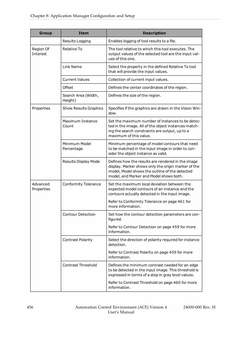
456 Automation Control Environment (ACE) Version 4User's Manual
24000-000 Rev. H
Chapter 8: Application Manager Configuration and Setup
Group Item Description
Results Logging Enables logging of tool results to a file.
Region OfInterest
Relative To The tool relative to which this tool executes. Theoutput values of the selected tool are the input val-ues of this one.
Link Name Select the property in the defined Relative To toolthat will provide the input values.
Current Values Collection of current input values.
Offset Defines the center coordinates of the region.
Search Area (Width,Height)
Defines the size of the region.
Properties Show Results Graphics Specifies if the graphics are drawn in the Vision Win-dow.
Maximum InstanceCount
Set the maximum number of instances to be detec-ted in the image. All of the object instances match-ing the search constraints are output, up to amaximum of this value.
Minimum ModelPercentage
Minimum percentage of model contours that needto be matched in the input image in order to con-sider the object instance as valid.
Results Display Mode Defines how the results are rendered in the imagedisplay. Marker shows only the origin marker of themodel, Model shows the outline of the detectedmodel, andMarker andModel shows both.
AdvancedProperties
Conformity Tolerance Set the maximum local deviation between theexpectedmodel contours of an instance and thecontours actually detected in the input image.
Refer to Conformity Tolerance on page 461 formore information.
Contour Detection Set how the contour detection parameters are con-figured.
Refer to Contour Detection on page 459 for moreinformation.
Contrast Polarity Select the direction of polarity required for instancedetection.
Refer to Contrast Polarity on page 459 for moreinformation.
Contrast Threshold Defines the minimum contrast needed for an edgeto be detected in the input image. This threshold isexpressed in terms of a step in gray level values.
Refer to Contrast Threshold on page 460 for moreinformation.
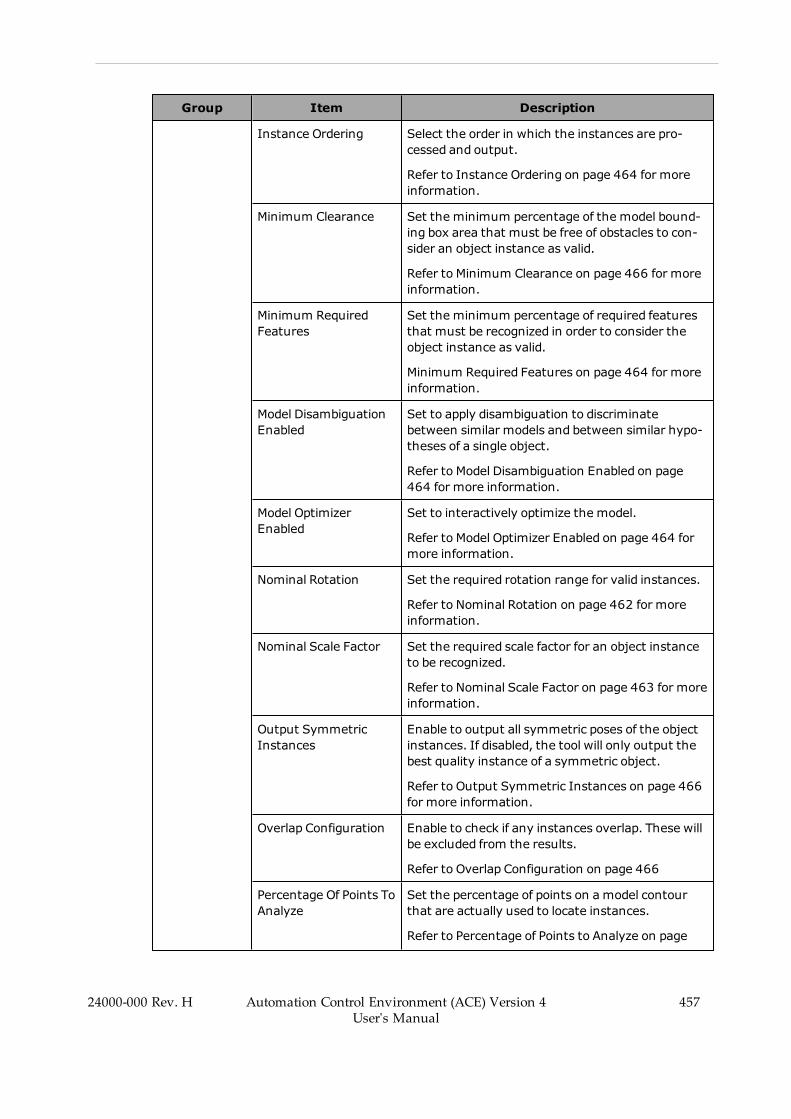
Group Item Description
Instance Ordering Select the order in which the instances are pro-cessed and output.
Refer to Instance Ordering on page 464 for moreinformation.
Minimum Clearance Set the minimum percentage of the model bound-ing box area that must be free of obstacles to con-sider an object instance as valid.
Refer to Minimum Clearance on page 466 for moreinformation.
Minimum RequiredFeatures
Set the minimum percentage of required featuresthat must be recognized in order to consider theobject instance as valid.
Minimum Required Features on page 464 for moreinformation.
Model DisambiguationEnabled
Set to apply disambiguation to discriminatebetween similar models and between similar hypo-theses of a single object.
Refer to Model Disambiguation Enabled on page464 for more information.
Model OptimizerEnabled
Set to interactively optimize the model.
Refer to Model Optimizer Enabled on page 464 formore information.
Nominal Rotation Set the required rotation range for valid instances.
Refer to Nominal Rotation on page 462 for moreinformation.
Nominal Scale Factor Set the required scale factor for an object instanceto be recognized.
Refer to Nominal Scale Factor on page 463 for moreinformation.
Output SymmetricInstances
Enable to output all symmetric poses of the objectinstances. If disabled, the tool will only output thebest quality instance of a symmetric object.
Refer to Output Symmetric Instances on page 466for more information.
Overlap Configuration Enable to check if any instances overlap. These willbe excluded from the results.
Refer to Overlap Configuration on page 466
Percentage Of Points ToAnalyze
Set the percentage of points on amodel contourthat are actually used to locate instances.
Refer to Percentage of Points to Analyze on page
24000-000 Rev. H Automation Control Environment (ACE) Version 4User's Manual
457
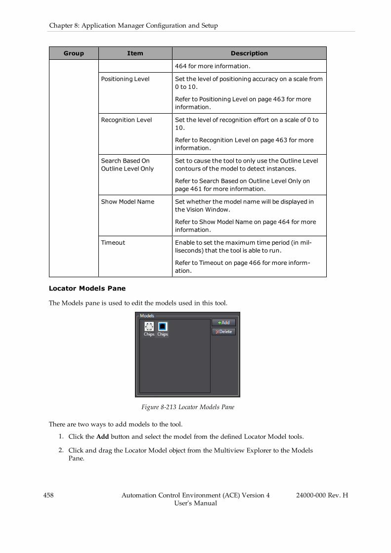
458 Automation Control Environment (ACE) Version 4User's Manual
24000-000 Rev. H
Chapter 8: Application Manager Configuration and Setup
Group Item Description
464 for more information.
Positioning Level Set the level of positioning accuracy on a scale from0 to 10.
Refer to Positioning Level on page 463 for moreinformation.
Recognition Level Set the level of recognition effort on a scale of 0 to10.
Refer to Recognition Level on page 463 for moreinformation.
Search Based OnOutline Level Only
Set to cause the tool to only use the Outline Levelcontours of the model to detect instances.
Refer to Search Based on Outline Level Only onpage 461 for more information.
Show Model Name Set whether the model name will be displayed inthe Vision Window.
Refer to Show Model Name on page 464 for moreinformation.
Timeout Enable to set the maximum time period (in mil-liseconds) that the tool is able to run.
Refer to Timeout on page 466 for more inform-ation.
Locator Models Pane
The Models pane is used to edit the models used in this tool.
Figure 8-213 Locator Models Pane
There are two ways to add models to the tool.
1. Click the Add button and select the model from the defined Locator Model tools.
2. Click and drag the Locator Model object from the Multiview Explorer to the ModelsPane.
Models can be deleted from this pane by selecting them and clicking the Delete button.
NOTE: The order in which models are added defines the Model Index resultvalue. Models cannot be reordered once they have been added to the ModelsPane.
Locator Advanced Properties - Edge Detection Parameters
The properties in this section modify the quality and quantity of contours that are generatedfrom the input image.
Contour Detection
This property sets how the contour detection parameters are configured. For most applications,Contour Detection should be set to All Models, where the contour detection parameters areoptimized by analyzing the parameters that were used to build all the currently active models.
Custom contour detection should only be used when the default values do not work correctly.Setting this to Custom allows the user to specify Outline Level, Detail Level, and Tracking Iner-tia as described below.
l The Outline Level contours are used to rapidly identify potential instances of the object.Coarseness values range from 1 to 16 where 1 is full resolution and all other values arefactors of 1. For example, at level 8, the resolution is 8 times lower than an image at fullresolution. Lower values of Outline Level lead to higher execution times.
l The Detail Level contours are used to confirm recognition and refine the position ofvalid instances. For images that are not in perfect focus, better results will be obtainedwith a higher value of Detail Level. To obtain high-accuracy object location, use imageswith sharp edges and set Detail Level to the lowest coarseness value. Detail Level andOutline Level have the same range, but Detail Level must have a lower value. Lowervalues of Detail Level lead to higher execution times.
l Tracking Inertia defines the longest gap that can be closed to connect two edge elementswhen building the source contours. It is set on a scale of 0 to 1. Higher values can helpclose small gaps and connect contours that would otherwise be broken into smaller sec-tions.
Contrast Polarity
This property defines the polarity change in gray level values between an object and its back-ground, which can be dark to light, light to dark, or a combination of both. The reference polar-ity for an object is defined by its Model with respect to the polarity in the image on which theModel was created. It can be set to the following options.
l Normal searches only for instances that match the polarity of the Model. For example, ifthe Model is a dark object on a light background, the Locator searches only for darkobjects on a light background (refer to the middle image in the following figure).
l Reverse searches only for instances that have opposite polarity from the Model. Forexample, if the Model is a dark object on a light background, the Locator searches onlyfor light objects on a dark background (refer to the right image in the following figure).
24000-000 Rev. H Automation Control Environment (ACE) Version 4User's Manual
459
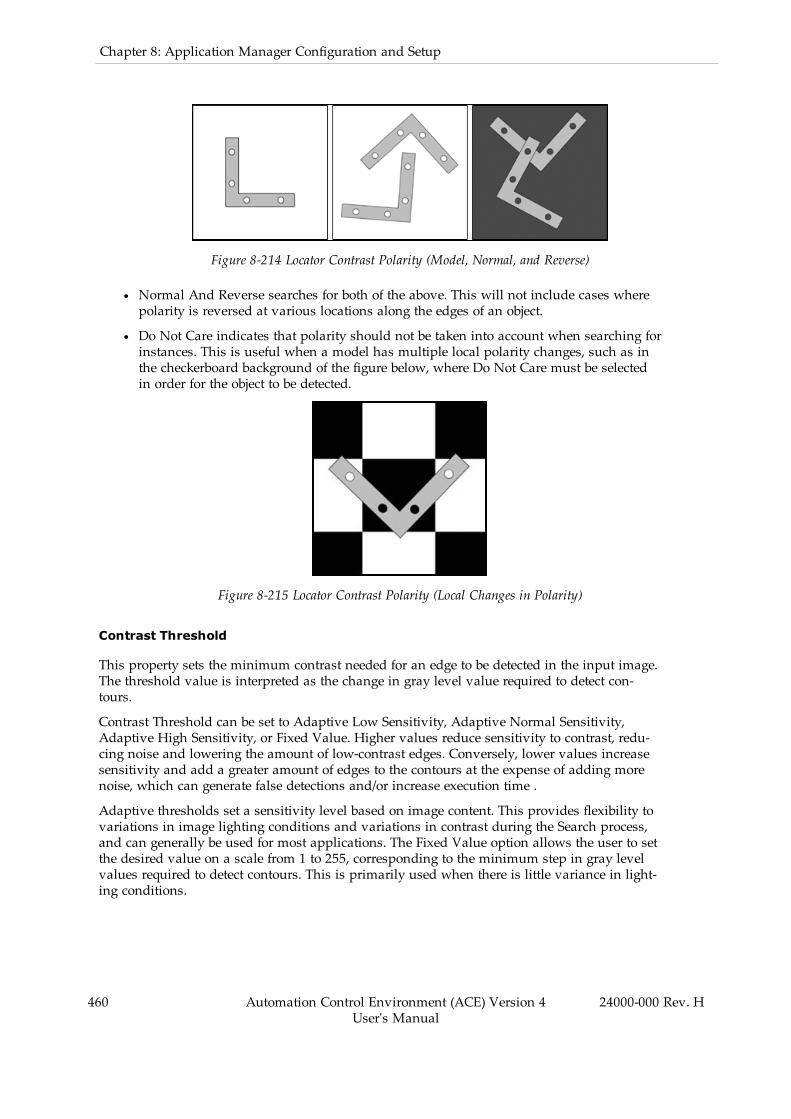
460 Automation Control Environment (ACE) Version 4User's Manual
24000-000 Rev. H
Chapter 8: Application Manager Configuration and Setup
Figure 8-214 Locator Contrast Polarity (Model, Normal, and Reverse)
l Normal And Reverse searches for both of the above. This will not include cases wherepolarity is reversed at various locations along the edges of an object.
l Do Not Care indicates that polarity should not be taken into account when searching forinstances. This is useful when a model has multiple local polarity changes, such as inthe checkerboard background of the figure below, where Do Not Care must be selectedin order for the object to be detected.
Figure 8-215 Locator Contrast Polarity (Local Changes in Polarity)
Contrast Threshold
This property sets the minimum contrast needed for an edge to be detected in the input image.The threshold value is interpreted as the change in gray level value required to detect con-tours.
Contrast Threshold can be set to Adaptive Low Sensitivity, Adaptive Normal Sensitivity,Adaptive High Sensitivity, or Fixed Value. Higher values reduce sensitivity to contrast, redu-cing noise and lowering the amount of low-contrast edges. Conversely, lower values increasesensitivity and add a greater amount of edges to the contours at the expense of adding morenoise, which can generate false detections and/or increase execution time .
Adaptive thresholds set a sensitivity level based on image content. This provides flexibility tovariations in image lighting conditions and variations in contrast during the Search process,and can generally be used for most applications. The Fixed Value option allows the user to setthe desired value on a scale from 1 to 255, corresponding to the minimum step in gray levelvalues required to detect contours. This is primarily used when there is little variance in light-ing conditions.

Search Based on Outline Level Only
This property restricts the search to using only the Outline Level source contours to search,recognize, and position object instances. Detail Level contours are ignored completely.Enabling this can increase speed with possible loss of accuracy and detection of falseinstances.
An Outline-based search is mainly used for time critical applications that do not require ahigh-positioning accuracy or that only need to check for presence/absence of objects. To beeffective, this type of search requires clean run time images that provide high-contrast contourswith little or no noise or clutter.
Locator Advanced Properties - Search Parameters
The properties in this section are constraints that restrict the Locator’s search process.
Conformity Tolerance
This property defines the maximum allowable local deviation of instance contours from theexpected model contours. Its value corresponds to the maximum distance by which a matchedcontour can deviate from either side of its expected position in the model. Portions of theinstance hypothesis that are not within the Conformity Tolerance range are not considered tobe valid. Only the contours within Conformity Tolerance are recognized and calculated for theMinimum Model Recognition search constraint. See the following figure for an example.
Figure 8-216 Locator Conformity Tolerance
Table 8-54 Locator Conformity Tolerance Description
Item Description
1 Model contour (red).
24000-000 Rev. H Automation Control Environment (ACE) Version 4User's Manual
461

462 Automation Control Environment (ACE) Version 4User's Manual
24000-000 Rev. H
Chapter 8: Application Manager Configuration and Setup
Item Description
2 Conformity tolerance (gray).
3 Conformity tolerance (gray) value applies to both sides of model contour (red).
4 Contours of the found object (blue).
Contours outside conformity tolerance are not valid.
5 Portion of object contour outside the conformity tolerance zone.
The Conformity Tolerance options are described below.
l Use Default: Enabling this causes the Locator tool to calculate a default value by ana-lyzing the calibration, contour detection parameters, and search parameters. This boxmust be unchecked if either of the other options are going to be used.
l Range Enabled: Enables the use of the manually-set tolerance value. This is set by Tol-erance, which defines the maximum difference in calibrated units by which a matchedcontour can deviate from either side of its expected position. It can be set on a range of 1to 100.
Nominal Rotation
This property constrains the rotation range within which Locator can detect instances. Anypossible instance must satisfy this property in order to be recognized as instances. By default,the range is set from -180 to 180 degrees. This can be changed depending on the needs of theapplication. The rotation range spans counterclockwise from the minimum to the maximumangle, as shown in .
Figure 8-217 Locator Nominal Rotation Valid Range of Motion
Conversely, Use Nominal can be enabled. This applies the value in the Nominal field to theLocator, which searches for instances within a tolerance of that angle. Any instances foundwithin the tolerance will automatically be set to the angle in the Nominal field. If the actualangle of rotation is required, it is recommended to leave the Use Nominal box disabled andinstead enter a small range, such as 89 to 91 degrees.
NOTE: If the trained Locator Model has rotational symmetry, it is possible thatNominal Rotation will cause an instance to be detected that is not actuallywithin the target angle range. In this case, raising the Minimum Model Per-centage can be used to prevent the symmetric instance from being detected.
Nominal Scale Factor
This property sets the required scale factor for an object to be recognized. Similar to NominalRotation, it can constrain the range of scale factors for which the Locator will search by eithersetting a minimum and maximum value or a fixed nominal value. By default, the range is setfrom 0.9 to 1.1. Any possible instance must lie within this range in order to be output as anidentified instance. Note that the scale factor parameter has one of the most significant impactson search speed and using a large scale factor range can significantly slow down the process.The range should be configured to include only the scale factors that are expected from theapplication.
Conversely, Use Nominal can be enabled to make the Locator search only for the value in theNominal range. However, if objects have a slight variation in scale, the objects may be recog-nized and positioned with reduced quality because their true scale factor will not be measured.In such a case, it is recommended to configure a narrow scale range instead of a nominalvalue.
The Minimum, Maximum, and Nominal values can all be set within a range of 0.1 to 10.
Positioning Level
This property modifies the positioning accuracy. This can be set on a range from 0 to 10,although the default setting of 5 is the optimized and recommended setting for typical applic-ations. Lower values provide coarser positioning with faster execution times while higher val-ues provide high-accuracy positioning at the cost of speed.
Positioning Level does not have a large impact on execution speed. However, in applicationswhere accuracy is not critical, the value can be decreased to lower the processing the time.
Recognition Level
This property slightly modifies the level of recognition effort. This can be set on a range from 0to 10, but the default setting of 5 is the optimized and recommended setting for typical applic-ations. Lower values provides faster searches that may miss partially blocked instances whilehigher values more accurately recognize all objects in cluttered or noisy images at the cost ofspeed.
When adjusting the Recognition Level, it is important to repeatedly test the application to findthe optimum speed at which the process will still find all necessary objects. If the recognitionlevel is too low, some instances may be ignored, but if it is too high, the application may runtoo slowly.
Recognition Level does not affect positioning accuracy.
Locator Advanced Properties - Model Parameters
The properties in this section constrain how the tool interacts with the model.
24000-000 Rev. H Automation Control Environment (ACE) Version 4User's Manual
463
464 Automation Control Environment (ACE) Version 4User's Manual
24000-000 Rev. H
Chapter 8: Application Manager Configuration and Setup
Minimum Required Features
This property defines the percentage of required features that need to be recognized for the Loc-ator to accept a valid instance of an object. In most applications, a feature in the Locator Modelwill be set as Required if it needs to be present in every single instance, but this propertyallows some flexibility. Minimum Required Features is set as a percentage of all required fea-tures on a range from 0.1 to 100. Note that this parameter is expressed in terms of a percentageof the number of required features in a model and does not consider the amount of contoureach required feature represents.
Refer to Locator Model Feature Selection Pane on page 470 for information on how to set a fea-ture as required.
Model Disambiguation Enabled
This property determines if disambiguation is applied to the detected instances to resolve ambi-guity between similar models by analyzing distinguishing features. This is enabled by defaultand should remain enabled in most applications. Disabling this will significantly reduce thetime needed to learn or relearn models, but it prevents the Locator from differentiating betweensimilar models. This should only be done in applications that require many different models.
Model Optimizer Enabled
This property determines if the models can be optimized interactively by building a modelfrom multiple instances of an object. When enabled, the user can build an optimized model bycreating an initial Locator Model and then running the Locator. Each new instance of theobject found by the Locator is analyzed and compiled into the current optimized model. Strongfeatures that recur frequently in the analyzed instances are retained in the optimized model.Once the model is considered satisfactory, the optimized model can be saved.
By default, this property is disabled and can remain disabled for most applications. It may beuseful for applications where the objects have a variable shape.
Percentage of Points to Analyze
This property defines points used to create an optimization model. It is set as a percentage ofthe points on a model contour actually used to locate instances. For example, when it is set tothe default value of 50%, one out of every two points is used. This can be set on a range from0.1 to 100. Higher values can increase the accuracy of the optimized model but incur longeroptimization time while lower values lower the accuracy while improving speed.
Show Model Name
This property determines if the model name is displayed in the Vision Window. Enabling thiswill display the name of the respective Locator Model tool name(s) in the tool window and theVision Window. This is only evaluated if Show Results Graphics is enabled.
Locator Advanced Properties - Instance Output Constraints
The properties in this section constrain how the tool outputs instances.
Instance Ordering
This property sets the order in which object instances are output. In general, it is adjusted byopening the dropdown menu and changing the method. Reference values may also be
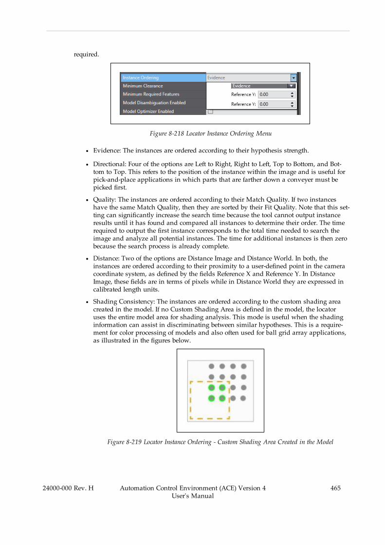
required.
Figure 8-218 Locator Instance Ordering Menu
l Evidence: The instances are ordered according to their hypothesis strength.
l Directional: Four of the options are Left to Right, Right to Left, Top to Bottom, and Bot-tom to Top. This refers to the position of the instance within the image and is useful forpick-and-place applications in which parts that are farther down a conveyer must bepicked first.
l Quality: The instances are ordered according to their Match Quality. If two instanceshave the same Match Quality, then they are sorted by their Fit Quality. Note that this set-ting can significantly increase the search time because the tool cannot output instanceresults until it has found and compared all instances to determine their order. The timerequired to output the first instance corresponds to the total time needed to search theimage and analyze all potential instances. The time for additional instances is then zerobecause the search process is already complete.
l Distance: Two of the options are Distance Image and Distance World. In both, theinstances are ordered according to their proximity to a user-defined point in the cameracoordinate system, as defined by the fields Reference X and Reference Y. In DistanceImage, these fields are in terms of pixels while in Distance World they are expressed incalibrated length units.
l Shading Consistency: The instances are ordered according to the custom shading areacreated in the model. If no Custom Shading Area is defined in the model, the locatoruses the entire model area for shading analysis. This mode is useful when the shadinginformation can assist in discriminating between similar hypotheses. This is a require-ment for color processing of models and also often used for ball grid array applications,as illustrated in the figures below.
Figure 8-219 Locator Instance Ordering - Custom Shading Area Created in the Model
24000-000 Rev. H Automation Control Environment (ACE) Version 4User's Manual
465

466 Automation Control Environment (ACE) Version 4User's Manual
24000-000 Rev. H
Chapter 8: Application Manager Configuration and Setup
Figure 8-220 Locator Instance Ordering - Sorting by Shading Consistency (Hypothesis A RatesHigher Than Hypothesis B With Reference to the Model)
Minimum Clearance
This property sets the minimum percentage of the model bounding box area that must be freeof other instances to consider an object instance as valid. It is disabled by default. Whenenabled, the Locator tool scans the bounding boxes of all instances for obstacles, such as otherinstances. If the amount of obstacle-free space is less than the bounding box percentage listedin the Minimum Clearance field, then the instance is not returned.
Enabling this property may significantly increase the search time. It is primarily intended forpick-and-place applications to confirm that objects have the necessary clearance to be picked.Minimum Clearance also activates the computation of the Clear Quality result for eachinstance.
Output Symmetric Instances
This property defines how the Locator will handle symmetric (or nearly symmetric) objects. Itis disabled by default, causing the search process to output only the best quality instance of asymmetric object. If enabled, all possible symmetries of a symmetric object will be output. Thiscan significantly increase execution time when there are many possible symmetries of anobject, such as when the object is circular.
Overlap Configuration
This property determines if the results of the tool will be checked for overlaps. If any instancesoverlap, they will be excluded from the results. Note that instances will qualify as overlappingif their bounding boxes overlap, even if the models themselves do not. If overlapping bound-ing boxes are acceptable to the application or the objects have unique shapes that cause super-fluous overlap, it is recommended to instead use Minimum Clearance to perform this check.
Timeout
This property controls the elapsed time after which the Locator aborts its search process. Thisperiod does not include the model learning phase. When this value (in milliseconds) isreached, the instances already recognized are output by the Locator and the search is aborted.

Timeout can be set on a range from 1 to 60,000. It can also be disabled by deselecting theEnable box.
Locator Results
Use the table below to understand the results of the Locator tool.
Table 8-55 Locator Results Item Description
Item Description
Instance Index of the result instance.
Frame/Group Index of the related result. It is associated with the tool that this tool is setRelative To. This will only be different if the Locator is set relative to anothertool.
Model Index Index of the model located for each instance. If only one model is used, thiswill be the same for every instance.
Model Name Name of the model located for each instance. Each Model Name is identical tothe associated Locator Model tool name.
Fit Quality Normalized average error between the matchedmodel contours and theactual contours detected in the input image. Fit quality ranges from 0 to 100where the best quality is 100. A value of 100 means that the average error is0. A value of 0 means that the average matched error is equal to the Con-formity Tolerance.
Match Quality Amount of matchedmodel contours for the selected object instanceexpressed as a percentage. Match quality ranges from 0 to 100 where thebest quality is 100. A value of 100 means that 100% of the model contourswere successfully matched to the actual contours detected in the inputimage.
Clear Quality Measurement of the clear area surrounding the specified object instance.Clear quality ranges from 0 to 100 where the best quality is 100. A value of100 means that the instance is completely free of obstacles. If MinimumClearances is Disabled, this value is 100.
Position X X-coordinate of the instance origin.
Position Y Y-coordinate of the instance origin.
Angle Angle of the instance.
Scale Factor Relative size of the instance with respect to its associatedmodel.
Symmetry Index of the instance of which this instance is a symmetry. Output Sym-metric Instances must be enabled.
Time Time in milliseconds needed to recognize and locate the object instance.
NOTE: The result columns Fit Quality, Match Quality, and Clear Quality do notdirectly correlate with the Minimum Model Percentage property. This is becauseMinimum Model Percentage is compared to the initial coarse outline while theseresults are originated from the refined detail search.
24000-000 Rev. H Automation Control Environment (ACE) Version 4User's Manual
467
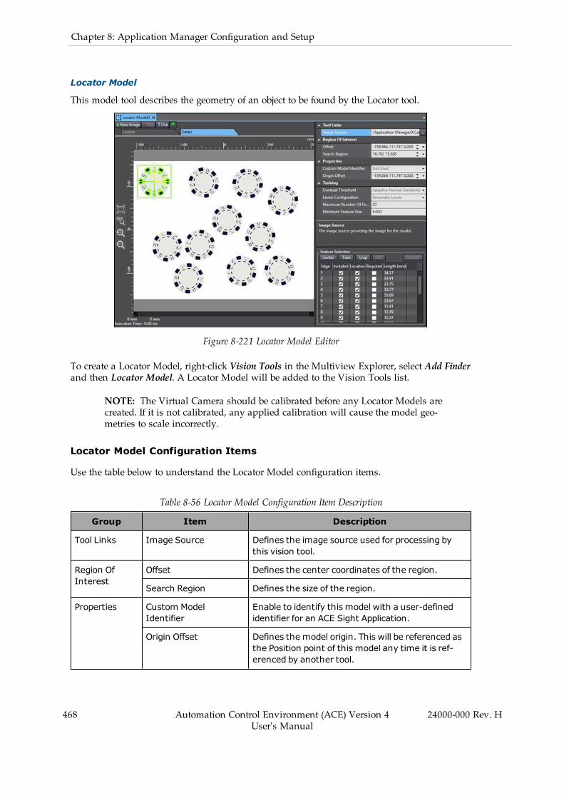
468 Automation Control Environment (ACE) Version 4User's Manual
24000-000 Rev. H
Chapter 8: Application Manager Configuration and Setup
Locator Model
This model tool describes the geometry of an object to be found by the Locator tool.
Figure 8-221 Locator Model Editor
To create a Locator Model, right-click Vision Tools in the Multiview Explorer, select Add Finderand then Locator Model. A Locator Model will be added to the Vision Tools list.
NOTE: The Virtual Camera should be calibrated before any Locator Models arecreated. If it is not calibrated, any applied calibration will cause the model geo-metries to scale incorrectly.
Locator Model Configuration Items
Use the table below to understand the Locator Model configuration items.
Table 8-56 Locator Model Configuration Item Description
Group Item Description
Tool Links Image Source Defines the image source used for processing bythis vision tool.
Region OfInterest
Offset Defines the center coordinates of the region.
Search Region Defines the size of the region.
Properties Custom ModelIdentifier
Enable to identify this model with a user-definedidentifier for an ACE Sight Application.
Origin Offset Defines the model origin. This will be referenced asthe Position point of this model any time it is ref-erenced by another tool.

Group Item Description
Training Contrast Threshold Set the minimum contrast needed for an edge to bedetected in the input image and used for arc com-putation. This threshold is expressed in terms of astep in gray level value.
Levels Configuration Specifies the levels used for contour detection. Inmost cases, Automatic Levels can be enabled. TheOutline value cannot be lower than the Detailvalue. For each level, coarseness values range from1 to 16, where 1 has the best resolution. Everyother value is a factor of the best resolution. Forexample, if one of these is set to 8, then the res-olution is 8 times lower than an image at full res-olution (level 1).
Maximum Number OfFeatures
Set the maximum number of features the modelwill detect.
Minimum Feature Size Set the minimum length of a feature (in mil-limeters) required for it to be selected. This has noimpact on feature detection, only feature selection.
Locator Model Region of Interest
The region of interest defines where Locator Model will look for the contours defined by con-trast changes. Any contours located outside the region will not be detected or considered to bepart of the model. Therefore, it is best to set the region as close to the part as possible so it canbe identified without cropping any part edges.
The Locator Model region of interest can be set by dragging the corners of the green box in thedisplay window or by modifying the numbers in the Offset and Search Region properties. Inthe property fields, the numbers can either be entered manually or changed using the up /down arrows for each value. Note that only the property fields can be used to rotate the region.
Locator Model Origin
The model origin, depicted as a yellow frame, defines the position and orientation of the picklocation. It can be set in the following ways.
l Manually drag the yellow origin indicator to the desired location. Adjust the orientationby clicking and dragging the rotation symbol. This is the best method for irregularly-shaped parts with off-center masses. The coordinates in the property fields will auto-matically adjust to the new position.
l Manually enter a desired location in the Origin Offset field. This is typically used tomake small adjustments on the origin position.
l Click the Center button in the Feature Selection pane without a feature selected. The ori-gin will be centered in the model’s region of interest. This may not be optimal in irreg-ularly-shaped parts and depends entirely on the size of the region of interest. This doesnot affect the origin orientation. If a feature is selected when Center is clicked, the originwill be centered on the feature.
24000-000 Rev. H Automation Control Environment (ACE) Version 4User's Manual
469
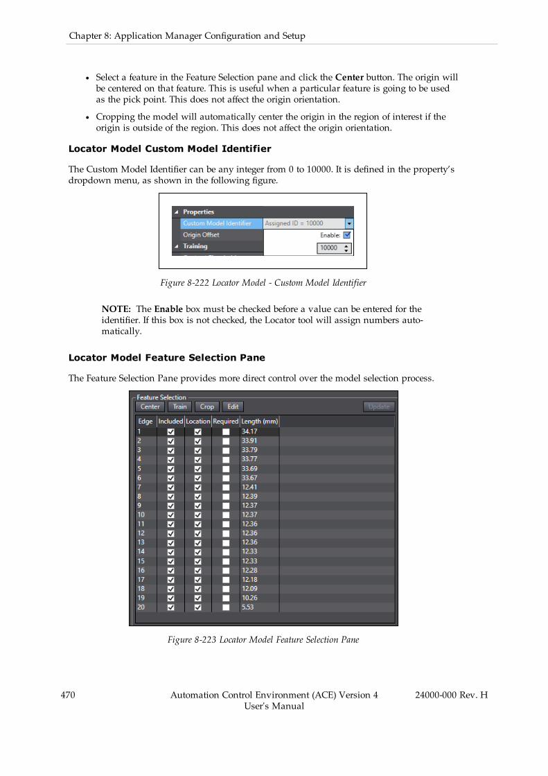
470 Automation Control Environment (ACE) Version 4User's Manual
24000-000 Rev. H
Chapter 8: Application Manager Configuration and Setup
l Select a feature in the Feature Selection pane and click the Center button. The origin willbe centered on that feature. This is useful when a particular feature is going to be usedas the pick point. This does not affect the origin orientation.
l Cropping the model will automatically center the origin in the region of interest if theorigin is outside of the region. This does not affect the origin orientation.
Locator Model Custom Model Identifier
The Custom Model Identifier can be any integer from 0 to 10000. It is defined in the property’sdropdown menu, as shown in the following figure.
Figure 8-222 Locator Model - Custom Model Identifier
NOTE: The Enable box must be checked before a value can be entered for theidentifier. If this box is not checked, the Locator tool will assign numbers auto-matically.
Locator Model Feature Selection Pane
The Feature Selection Pane provides more direct control over the model selection process.
Figure 8-223 Locator Model Feature Selection Pane

This pane lists all features that have been detected in the model within the following columns.
l Included: Select if the feature will be included in the model.
l Location: Select if the feature’s location should be used to define the location of the part.This is enabled by default and should be disabled on unstable features with variable loc-ation. In this way, the feature would be used to recognize the part but not to refine itslocation.
l Required: Select if an instance requires this feature to be a viable candidate. The Min-imum Required Features property in the Locator tool also governs these. If a feature isnot Included, then it cannot be Required.
l Length (mm): The length of the feature in millimeters.
The pane also has five buttons that help to define the model as described below.
l Center: Centers the origin of the model on the region of interest or specific feature,depending on whether or not a feature is selected.
l Train: Trains the model based on the current parameters and region of interest location.This is always enabled, but note that it will eliminate all feature selection changes.
l Crop: Cuts everything from the image except for the area within the region of interest.This is only enabled when the model is trained.
l Edit: Opens the Edge Editor window so you can more directly edit features. Refer to Loc-ator Model Edge Editor on page 472 for more information.
l Update: Update the trained model with the new feature selections in place. This is onlyenabled if feature selection changes have been made.
The features in the tool Vision Window are color-coded based on current selections andoptions as described below.
Figure 8-224 Locator Model Color Coding
l Orange: Currently selected feature.
l Green: Feature is included in this model.
24000-000 Rev. H Automation Control Environment (ACE) Version 4User's Manual
471
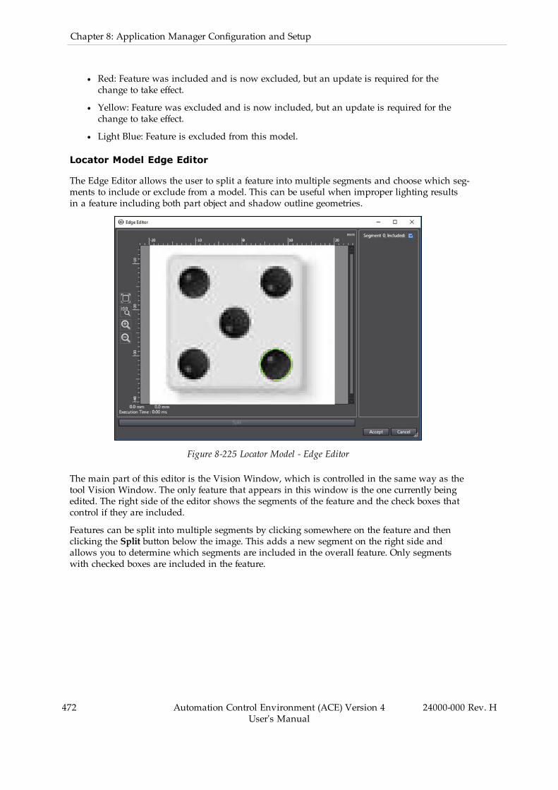
472 Automation Control Environment (ACE) Version 4User's Manual
24000-000 Rev. H
Chapter 8: Application Manager Configuration and Setup
l Red: Feature was included and is now excluded, but an update is required for thechange to take effect.
l Yellow: Feature was excluded and is now included, but an update is required for thechange to take effect.
l Light Blue: Feature is excluded from this model.
Locator Model Edge Editor
The Edge Editor allows the user to split a feature into multiple segments and choose which seg-ments to include or exclude from a model. This can be useful when improper lighting resultsin a feature including both part object and shadow outline geometries.
Figure 8-225 Locator Model - Edge Editor
The main part of this editor is the Vision Window, which is controlled in the same way as thetool Vision Window. The only feature that appears in this window is the one currently beingedited. The right side of the editor shows the segments of the feature and the check boxes thatcontrol if they are included.
Features can be split into multiple segments by clicking somewhere on the feature and thenclicking the Split button below the image. This adds a new segment on the right side andallows you to determine which segments are included in the overall feature. Only segmentswith checked boxes are included in the feature.

Figure 8-226 Locator Model Edge Editor with Split Feature
The feature is color-coded in this Vision Window with the following designations.
l Orange: Currently selected segment.
l Purple: Ends of segments. A purple line that connects to lines at both ends represents asplit between two segments. If it only connects at one end, it is an endpoint of the fea-ture.
l Green: Segment is included in the overall feature.
l Light blue: Segment is excluded from the overall feature.
NOTE: Accepting the changes here will be reflected in the tool Vision Window.See the bottom-right die circle in the figure below. Making any changes to theIncluded property of the feature in the Feature Selection pane will revert allchanges made in the Edge Editor.
24000-000 Rev. H Automation Control Environment (ACE) Version 4User's Manual
473
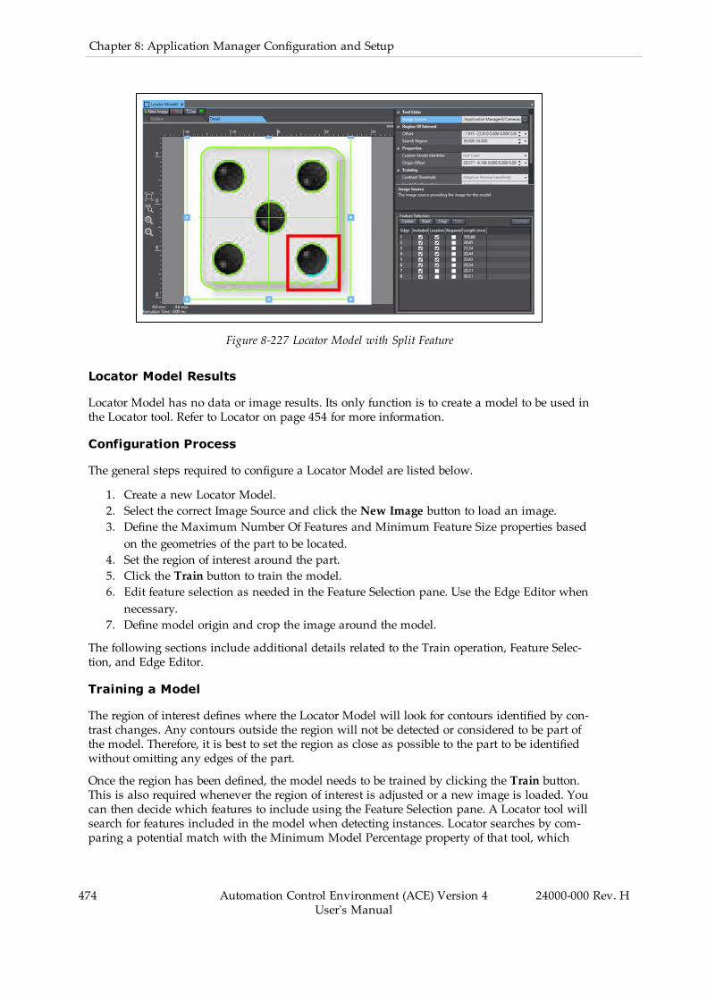
474 Automation Control Environment (ACE) Version 4User's Manual
24000-000 Rev. H
Chapter 8: Application Manager Configuration and Setup
Figure 8-227 Locator Model with Split Feature
Locator Model Results
Locator Model has no data or image results. Its only function is to create a model to be used inthe Locator tool. Refer to Locator on page 454 for more information.
Configuration Process
The general steps required to configure a Locator Model are listed below.
1. Create a new Locator Model.2. Select the correct Image Source and click the New Image button to load an image.3. Define the Maximum Number Of Features and Minimum Feature Size properties basedon the geometries of the part to be located.
4. Set the region of interest around the part.5. Click the Train button to train the model.6. Edit feature selection as needed in the Feature Selection pane. Use the Edge Editor whennecessary.
7. Define model origin and crop the image around the model.
The following sections include additional details related to the Train operation, Feature Selec-tion, and Edge Editor.
Training a Model
The region of interest defines where the Locator Model will look for contours identified by con-trast changes. Any contours outside the region will not be detected or considered to be part ofthe model. Therefore, it is best to set the region as close as possible to the part to be identifiedwithout omitting any edges of the part.
Once the region has been defined, the model needs to be trained by clicking the Train button.This is also required whenever the region of interest is adjusted or a new image is loaded. Youcan then decide which features to include using the Feature Selection pane. A Locator tool willsearch for features included in the model when detecting instances. Locator searches by com-paring a potential match with the Minimum Model Percentage property of that tool, which
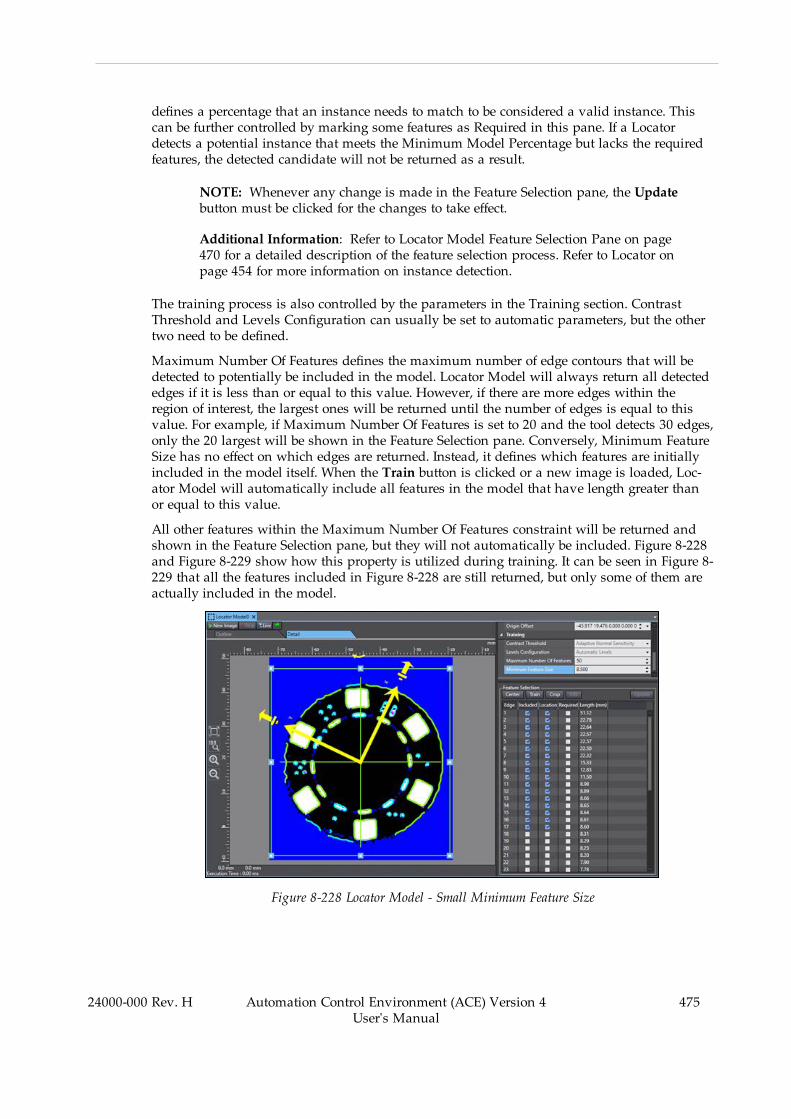
defines a percentage that an instance needs to match to be considered a valid instance. Thiscan be further controlled by marking some features as Required in this pane. If a Locatordetects a potential instance that meets the Minimum Model Percentage but lacks the requiredfeatures, the detected candidate will not be returned as a result.
NOTE: Whenever any change is made in the Feature Selection pane, the Updatebutton must be clicked for the changes to take effect.
Additional Information: Refer to Locator Model Feature Selection Pane on page470 for a detailed description of the feature selection process. Refer to Locator onpage 454 for more information on instance detection.
The training process is also controlled by the parameters in the Training section. ContrastThreshold and Levels Configuration can usually be set to automatic parameters, but the othertwo need to be defined.
Maximum Number Of Features defines the maximum number of edge contours that will bedetected to potentially be included in the model. Locator Model will always return all detectededges if it is less than or equal to this value. However, if there are more edges within theregion of interest, the largest ones will be returned until the number of edges is equal to thisvalue. For example, if Maximum Number Of Features is set to 20 and the tool detects 30 edges,only the 20 largest will be shown in the Feature Selection pane. Conversely, Minimum FeatureSize has no effect on which edges are returned. Instead, it defines which features are initiallyincluded in the model itself. When the Train button is clicked or a new image is loaded, Loc-ator Model will automatically include all features in the model that have length greater thanor equal to this value.
All other features within the Maximum Number Of Features constraint will be returned andshown in the Feature Selection pane, but they will not automatically be included. Figure 8-228and Figure 8-229 show how this property is utilized during training. It can be seen in Figure 8-229 that all the features included in Figure 8-228 are still returned, but only some of them areactually included in the model.
Figure 8-228 Locator Model - Small Minimum Feature Size
24000-000 Rev. H Automation Control Environment (ACE) Version 4User's Manual
475
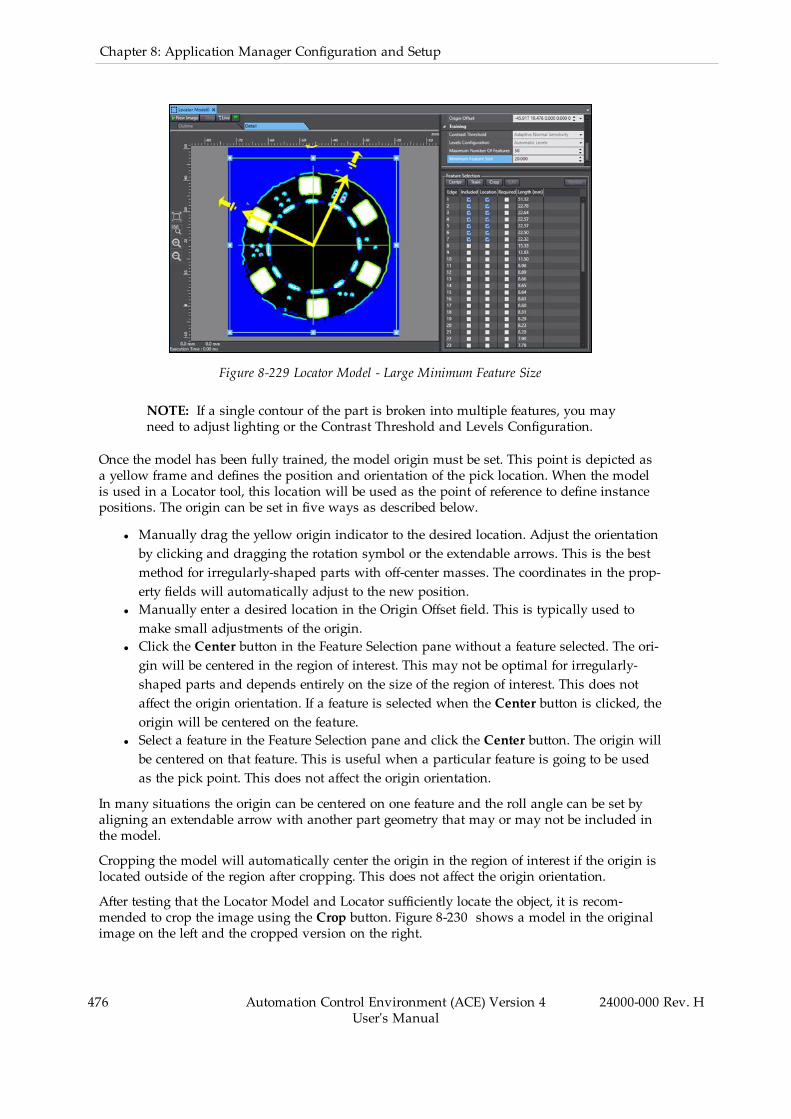
476 Automation Control Environment (ACE) Version 4User's Manual
24000-000 Rev. H
Chapter 8: Application Manager Configuration and Setup
Figure 8-229 Locator Model - Large Minimum Feature Size
NOTE: If a single contour of the part is broken into multiple features, you mayneed to adjust lighting or the Contrast Threshold and Levels Configuration.
Once the model has been fully trained, the model origin must be set. This point is depicted asa yellow frame and defines the position and orientation of the pick location. When the modelis used in a Locator tool, this location will be used as the point of reference to define instancepositions. The origin can be set in five ways as described below.
l Manually drag the yellow origin indicator to the desired location. Adjust the orientationby clicking and dragging the rotation symbol or the extendable arrows. This is the bestmethod for irregularly-shaped parts with off-center masses. The coordinates in the prop-erty fields will automatically adjust to the new position.
l Manually enter a desired location in the Origin Offset field. This is typically used tomake small adjustments of the origin.
l Click the Center button in the Feature Selection pane without a feature selected. The ori-gin will be centered in the region of interest. This may not be optimal for irregularly-shaped parts and depends entirely on the size of the region of interest. This does notaffect the origin orientation. If a feature is selected when the Center button is clicked, theorigin will be centered on the feature.
l Select a feature in the Feature Selection pane and click the Center button. The origin willbe centered on that feature. This is useful when a particular feature is going to be usedas the pick point. This does not affect the origin orientation.
In many situations the origin can be centered on one feature and the roll angle can be set byaligning an extendable arrow with another part geometry that may or may not be included inthe model.
Cropping the model will automatically center the origin in the region of interest if the origin islocated outside of the region after cropping. This does not affect the origin orientation.
After testing that the Locator Model and Locator sufficiently locate the object, it is recom-mended to crop the image using the Crop button. Figure 8-230 shows a model in the originalimage on the left and the cropped version on the right.
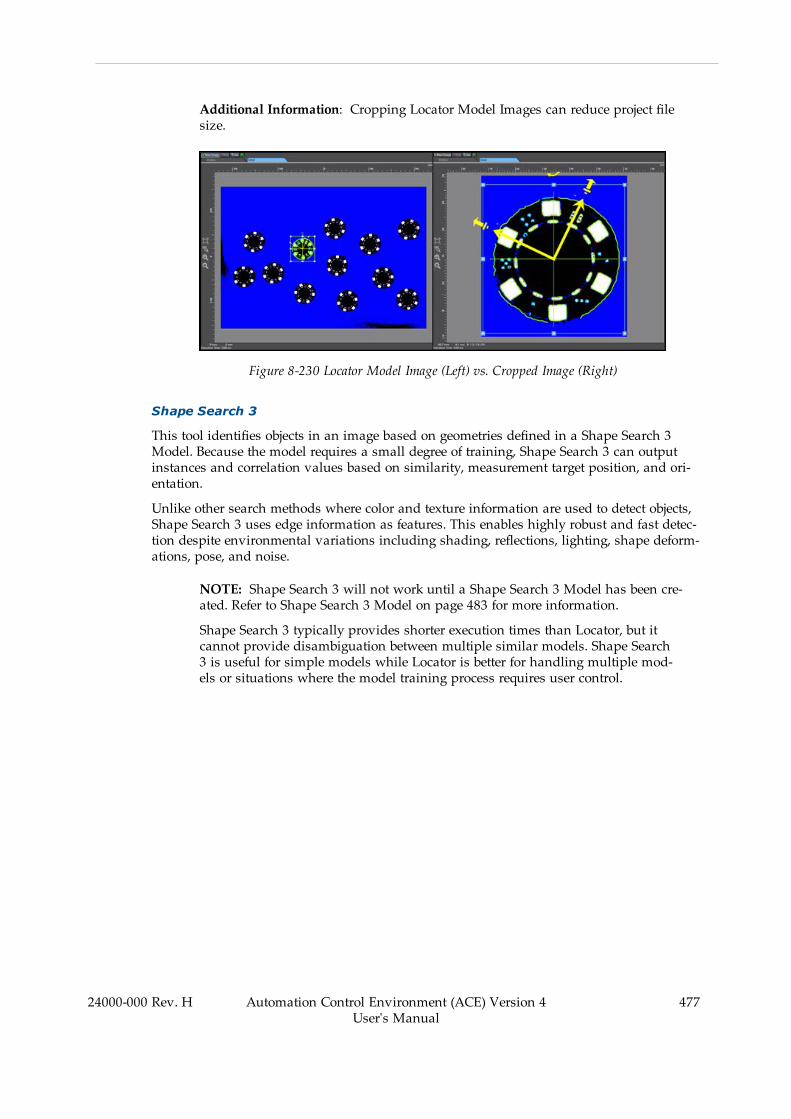
Additional Information: Cropping Locator Model Images can reduce project filesize.
Figure 8-230 Locator Model Image (Left) vs. Cropped Image (Right)
Shape Search 3
This tool identifies objects in an image based on geometries defined in a Shape Search 3Model. Because the model requires a small degree of training, Shape Search 3 can outputinstances and correlation values based on similarity, measurement target position, and ori-entation.
Unlike other search methods where color and texture information are used to detect objects,Shape Search 3 uses edge information as features. This enables highly robust and fast detec-tion despite environmental variations including shading, reflections, lighting, shape deform-ations, pose, and noise.
NOTE: Shape Search 3 will not work until a Shape Search 3 Model has been cre-ated. Refer to Shape Search 3 Model on page 483 for more information.
Shape Search 3 typically provides shorter execution times than Locator, but itcannot provide disambiguation between multiple similar models. Shape Search3 is useful for simple models while Locator is better for handling multiple mod-els or situations where the model training process requires user control.
24000-000 Rev. H Automation Control Environment (ACE) Version 4User's Manual
477

478 Automation Control Environment (ACE) Version 4User's Manual
24000-000 Rev. H
Chapter 8: Application Manager Configuration and Setup
Figure 8-231 Shape Search 3 Tool Editor
To create a Shape Search 3 tool, right-click Vision Tools in the Multiview Explorer, select AddFinder and then Shape Search 3. A Shape Search 3 tool will be added to the Vision Tools list.
Shape Search 3 Configuration Items
Use the table below to understand the Shape Search 3 configuration items.
Table 8-57 Shape Search 3 Configuration Item Description - Tool Links
Group Item Description
Tool Links Image Source Defines the image source used for processing bythis vision tool.
Shape Search 3 Model Select the Shape Search 3 Model that will besearched for in the image.
Results Logging Enables logging of tool results to a file.

Table 8-58 Shape Search 3 Configuration Item Description - Region of Interest
Group Item Description
Region OfInterest
Relative To The tool relative to which this tool executes.The output values of the selected tool are theinput values of this one.
Link Name Select the property in the defined Relative Totool that will provide the input values.
Current Values Collection of current input values.
Rectangles
Ellipses
Circumferences
Polygons
Sets of regions of interest of a particularshape. The field will show how many regionsexist ("1-item collection", "2-item collect,etc.). Click the plus sign in the field to createadditional regions and click the arrow to seeall regions.
<region number> Identifies the region of the specified shape. Itwill appear as [0], [1], [...] within the shapecategory. Click the minus sign in the field toremove the region and click the arrow to seeits properties.
Name Available in all region types. Sets the user-defined name of the region.
Overlap Available in all region types. Select the beha-vior of the region. OR causes the region to beincluded in the search area and NOT excludesit from the search area. The behavior of spe-cific regions is further defined in Z-Order.
Refer to Tools with Multiple Regions ofInterest on page 422 for more information.
Z-Order Available in all region types. Sets the order foroverlapping regions of interest. Higher num-bers will be in front and resolved first.
Refer to Tools with Multiple Regions ofInterest on page 422 for more information.
Offset Available in all region types except for Poly-gons. Defines the coordinates of the region’scenter.
Search Region (Width, Height) Only available in Rectangles. Sets the heightandwidth of the rectangular region.
Radius X/Y Only available in Ellipses. Defines the distancefrom the center to the exterior along the X-and Y-axes in the camera coordinate systemrespectively.
24000-000 Rev. H Automation Control Environment (ACE) Version 4User's Manual
479
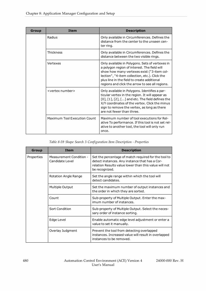
480 Automation Control Environment (ACE) Version 4User's Manual
24000-000 Rev. H
Chapter 8: Application Manager Configuration and Setup
Group Item Description
Radius Only available in Circumferences. Defines thedistance from the center to the unseen cen-ter ring.
Thickness Only available in Circumferences. Defines thedistance between the two visible rings.
Vertexes Only available in Polygons. Sets of vertexes ina polygon region of interest. The field willshow how many vertexes exist ("3-item col-lection", "4-item collection, etc.). Click theplus line in the field to create additionalregions and click the arrow to see all regions.
<vertex number> Only available in Polygons. Identifies a par-ticular vertex in the region. It will appear as[0], [1], [2], [...] and etc. The field defines theX/Y coordinates of the vertex. Click the minussign to remove the vertex, as long as thereare not fewer than three.
Maximum Tool Execution Count Maximum number of tool executions for Rel-ative To performance. If this tool is not set rel-ative to another tool, the tool will only runonce.
Table 8-59 Shape Search 3 Configuration Item Description - Properties
Group Item Description
Properties Measurement Condition -Candidate Level
Set the percentage of match required for the tool todetect instances. Any instance that has a Cor-relation Results value lower than this value will notbe recognized.
Rotation Angle Range Set the angle range within which the tool willdetect candidates.
Multiple Output Set the maximum number of output instances andthe order in which they are sorted.
Count Sub-property of Multiple Output. Enter the max-imum number of instances.
Sort Condition Sub-property of Multiple Output. Select the neces-sary order of instance sorting.
Edge Level Enable automatic edge level adjustment or enter avalue to set it manually.
Overlay Judgment Prevent the tool from detecting overlappedinstances. Increased value will result in overlappedinstances to be removed.
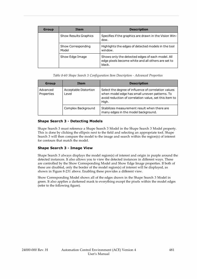
Group Item Description
Show Results Graphics Specifies if the graphics are drawn in the Vision Win-dow.
Show CorrespondingModel
Highlights the edges of detectedmodels in the toolwindow.
Show Edge Image Shows only the detected edges of each model. Alledge pixels become white and all others are set toblack.
Table 8-60 Shape Search 3 Configuration Item Description - Advanced Properties
Group Item Description
AdvancedProperties
Acceptable DistortionLevel
Select the degree of influence of correlation valueswhen model edge has small uneven patterns. Toavoid reduction of correlation value, set this item toHigh.
Complex Background Stabilizes measurement result when there aremany edges in the model background.
Shape Search 3 - Detecting Models
Shape Search 3 must reference a Shape Search 3 Model in the Shape Search 3 Model property.This is done by clicking the ellipsis next to the field and selecting an appropriate tool. ShapeSearch 3 will then compare the model to the image and search within the region(s) of interestfor contours that match the model.
Shape Search 3 - Image View
Shape Search 3 always displays the model region(s) of interest and origin in purple around thedetected instances. It also allows you to view the detected instances in different ways. Theseare controlled by the Show Corresponding Model and Show Edge Image properties. If both ofthese are disabled, only the border of the model region(s) of interest will be displayed, asshown in Figure 8-231 above. Enabling these provides a different view.
Show Corresponding Model shows all of the edges drawn in the Shape Search 3 Model ingreen. It also applies a darkened mask to everything except the pixels within the model edges(refer to the following figure).
24000-000 Rev. H Automation Control Environment (ACE) Version 4User's Manual
481

482 Automation Control Environment (ACE) Version 4User's Manual
24000-000 Rev. H
Chapter 8: Application Manager Configuration and Setup
Figure 8-232 Shape Search 3 - Show Corresponding Model
Show Edge Image changes everything to black except for the edges detected in the image,which become white (refer to the following figure).
Figure 8-233 Shape Search 3 - Show Edge Image
NOTE: These views are overlaid if both are selected.
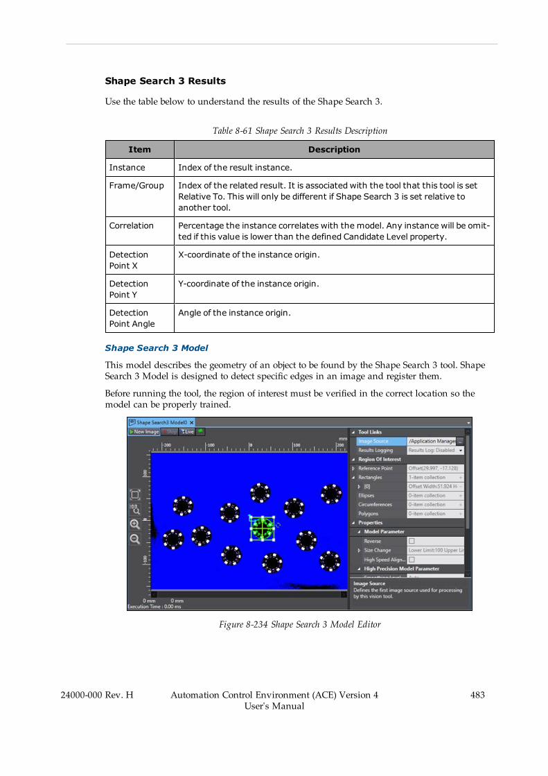
Shape Search 3 Results
Use the table below to understand the results of the Shape Search 3.
Table 8-61 Shape Search 3 Results Description
Item Description
Instance Index of the result instance.
Frame/Group Index of the related result. It is associated with the tool that this tool is setRelative To. This will only be different if Shape Search 3 is set relative toanother tool.
Correlation Percentage the instance correlates with the model. Any instance will be omit-ted if this value is lower than the defined Candidate Level property.
DetectionPoint X
X-coordinate of the instance origin.
DetectionPoint Y
Y-coordinate of the instance origin.
DetectionPoint Angle
Angle of the instance origin.
Shape Search 3 Model
This model describes the geometry of an object to be found by the Shape Search 3 tool. ShapeSearch 3 Model is designed to detect specific edges in an image and register them.
Before running the tool, the region of interest must be verified in the correct location so themodel can be properly trained.
Figure 8-234 Shape Search 3 Model Editor
24000-000 Rev. H Automation Control Environment (ACE) Version 4User's Manual
483
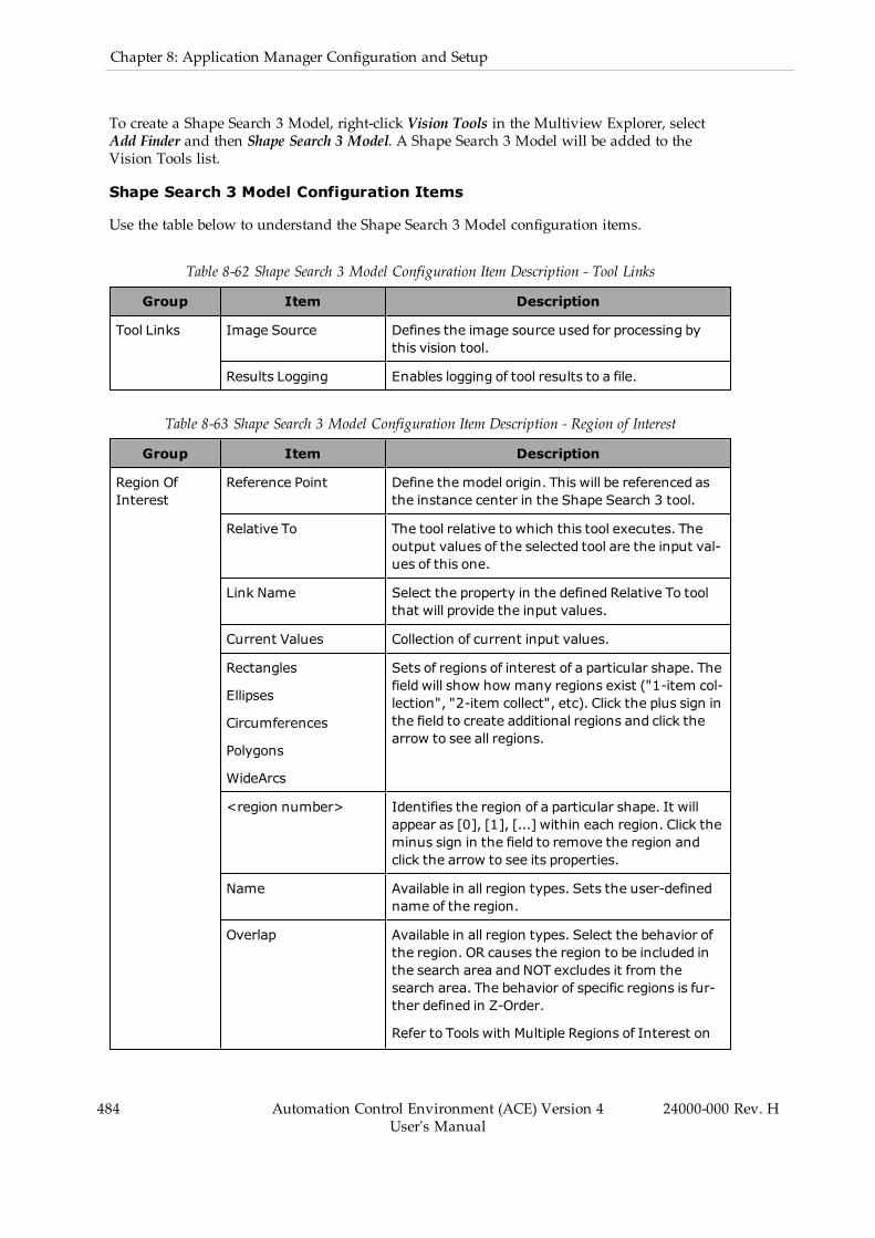
484 Automation Control Environment (ACE) Version 4User's Manual
24000-000 Rev. H
Chapter 8: Application Manager Configuration and Setup
To create a Shape Search 3 Model, right-click Vision Tools in the Multiview Explorer, selectAdd Finder and then Shape Search 3 Model. A Shape Search 3 Model will be added to theVision Tools list.
Shape Search 3 Model Configuration Items
Use the table below to understand the Shape Search 3 Model configuration items.
Table 8-62 Shape Search 3 Model Configuration Item Description - Tool Links
Group Item Description
Tool Links Image Source Defines the image source used for processing bythis vision tool.
Results Logging Enables logging of tool results to a file.
Table 8-63 Shape Search 3 Model Configuration Item Description - Region of Interest
Group Item Description
Region OfInterest
Reference Point Define the model origin. This will be referenced asthe instance center in the Shape Search 3 tool.
Relative To The tool relative to which this tool executes. Theoutput values of the selected tool are the input val-ues of this one.
Link Name Select the property in the defined Relative To toolthat will provide the input values.
Current Values Collection of current input values.
Rectangles
Ellipses
Circumferences
Polygons
WideArcs
Sets of regions of interest of a particular shape. Thefield will show how many regions exist ("1-item col-lection", "2-item collect", etc). Click the plus sign inthe field to create additional regions and click thearrow to see all regions.
<region number> Identifies the region of a particular shape. It willappear as [0], [1], [...] within each region. Click theminus sign in the field to remove the region andclick the arrow to see its properties.
Name Available in all region types. Sets the user-definedname of the region.
Overlap Available in all region types. Select the behavior ofthe region. OR causes the region to be included inthe search area and NOT excludes it from thesearch area. The behavior of specific regions is fur-ther defined in Z-Order.
Refer to Tools with Multiple Regions of Interest on
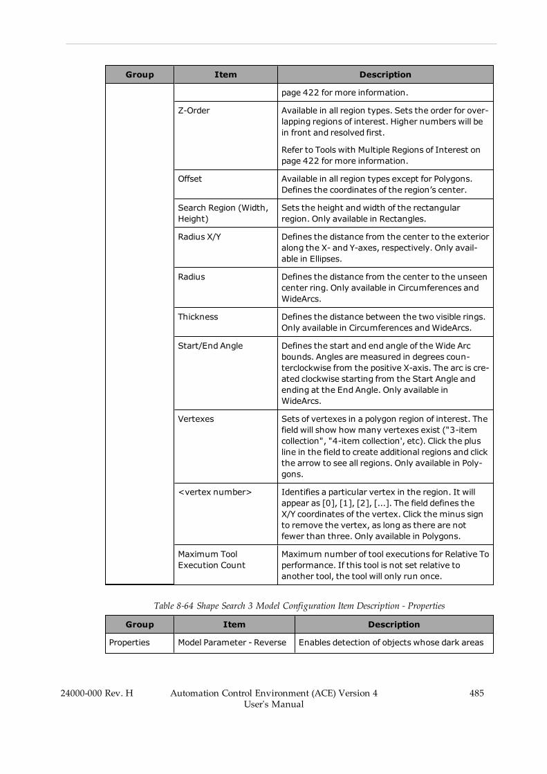
Group Item Description
page 422 for more information.
Z-Order Available in all region types. Sets the order for over-lapping regions of interest. Higher numbers will bein front and resolved first.
Refer to Tools with Multiple Regions of Interest onpage 422 for more information.
Offset Available in all region types except for Polygons.Defines the coordinates of the region’s center.
Search Region (Width,Height)
Sets the height andwidth of the rectangularregion. Only available in Rectangles.
Radius X/Y Defines the distance from the center to the exterioralong the X- and Y-axes, respectively. Only avail-able in Ellipses.
Radius Defines the distance from the center to the unseencenter ring. Only available in Circumferences andWideArcs.
Thickness Defines the distance between the two visible rings.Only available in Circumferences andWideArcs.
Start/End Angle Defines the start and end angle of the Wide Arcbounds. Angles are measured in degrees coun-terclockwise from the positive X-axis. The arc is cre-ated clockwise starting from the Start Angle andending at the End Angle. Only available inWideArcs.
Vertexes Sets of vertexes in a polygon region of interest. Thefield will show how many vertexes exist ("3-itemcollection", "4-item collection', etc). Click the plusline in the field to create additional regions and clickthe arrow to see all regions. Only available in Poly-gons.
<vertex number> Identifies a particular vertex in the region. It willappear as [0], [1], [2], [...]. The field defines theX/Y coordinates of the vertex. Click the minus signto remove the vertex, as long as there are notfewer than three. Only available in Polygons.
Maximum ToolExecution Count
Maximum number of tool executions for Relative Toperformance. If this tool is not set relative toanother tool, the tool will only run once.
Table 8-64 Shape Search 3 Model Configuration Item Description - Properties
Group Item Description
Properties Model Parameter - Reverse Enables detection of objects whose dark areas
24000-000 Rev. H Automation Control Environment (ACE) Version 4User's Manual
485

486 Automation Control Environment (ACE) Version 4User's Manual
24000-000 Rev. H
Chapter 8: Application Manager Configuration and Setup
Group Item Description
and bright areas are fluctuating due to glossi-ness or shine.
Model Parameter - SizeChange
Set the upper and lower limit of model size fluc-tuation.
Model Parameter -High Speed Alignment Mode
Enables detection of simple shapes such asalignment marks. Disable this when detectingcomplex patterns or shapes with thin elementsor lines.
HighPrecision Model Parameter -Smoothing Level
Set the level of smoothing for the High Pre-cision Edge Model. Enabling the Auto boxcauses the tool to automatically set it as neces-sary. Disabling it allows the user to adjust itmanually. Higher values remove more detailsfrom the high precision model.
Edge Settings - Mask Size Select the neighborhood of pixels to use todetect model edges. Higher selections will helpdetection when brightness varies amongpixels.
Edge Settings - Edge Level Set the lower limit of edge level for an edge tobe recognized. Edges with a higher edge levelthan this value will be included in the model.Higher settings will result in fewer edges.
Edge Settings - NoiseRemoval Level
Set the upper limit of noise level to eliminate.Noise with a level below this value will be elim-inated. Higher numbers will lead tomore fea-tures being removed from the model.
Edge Settings - Show EdgeModel
Specifies if the Edge Model is drawn in theVision Window.
Edge Settings - ShowHigh Precision Edge Model
Specifies if the High Precision Edge Model isdrawn in the Vision Window.
Shape Search 3 Model - Training a Model
Shape Search 3 Model automatically runs whenever any change is made to the parameters orregion(s) of interest. Because of this, the training process only requires you to position the ref-erence point and the region(s) of interest in the necessary location(s). As many regions can beadded as necessary to create a custom model shape. The Overlap can further define a custommodel.
When the trained model is used in Shape Search 3, the position result for each detectedinstance will be returned as the position of the model Reference Point property. Therefore,before continuing, the location of the reference point needs to be verified.
Shape Search 3 Model has fewer controlling parameters than Locator Model since the focus ofShape Search 3 is speed. However, several properties provide control over this tool. In par-ticular, the parameters in the Edge Settings section are useful to adjust the model. Mask Size

helps balance brightness issues, Edge Level sets the necessary deviation of edges in order to beincluded, and Noise Removal Level removes unnecessary features.
Shape Search 3 Model Results
Shape Search 3 Model has no data or image results. Its only function is to create a model to beused in the Shape Search 3 tool. Refer to Shape Search 3 on page 477 for more information.
Inspection Tools
Inspection tools are typically used for part inspection purposes.
The following Inspection tools are described in this section.
l Refer to Arc Caliper on page 487 for more information.l Refer to Arc Edge Locator on page 493 for more information.l Refer to Caliper on page 498 for more information.l Refer to Color Data on page 503 for more information.l Refer to Edge Locator on page 507 for more information.l Refer to Feeder Histogram on page 512 for more information.l Refer to Image Histogram on page 515 for more information.l Refer to Inspection on page 518 for more information.l Refer to Precise Defect Path on page 524 for more information.l Refer to Precise Defect Region on page 528 for more information.
Arc Caliper
This tool identifies and measures the gap between one or more edge pairs of arc-shapedobjects. Using pixel gray-level values within regions of interest, Arc Caliper is able to build pro-jections needed for edge detection. Edges can be displayed in a radial or annular position.After detecting potential edges, the tool determines which edge pairs are valid by applying theuser-defined constraints configured for each one. The valid pairs are then scored and meas-ured.
24000-000 Rev. H Automation Control Environment (ACE) Version 4User's Manual
487
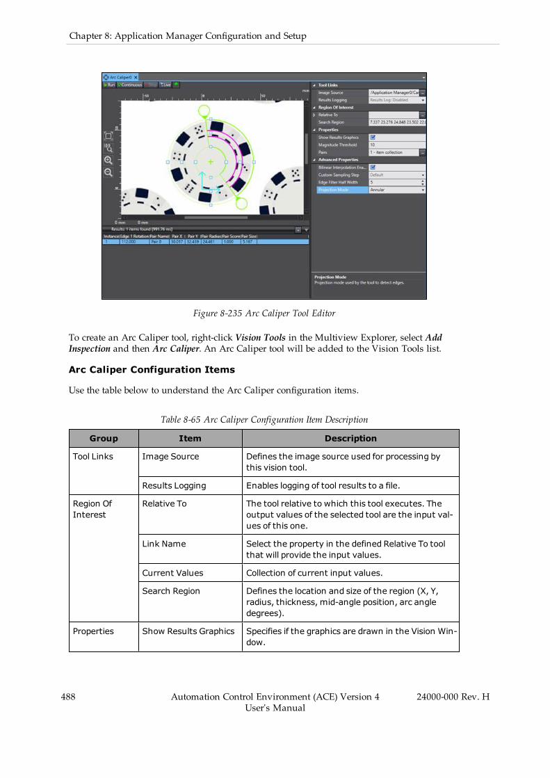
488 Automation Control Environment (ACE) Version 4User's Manual
24000-000 Rev. H
Chapter 8: Application Manager Configuration and Setup
Figure 8-235 Arc Caliper Tool Editor
To create an Arc Caliper tool, right-click Vision Tools in the Multiview Explorer, select AddInspection and then Arc Caliper. An Arc Caliper tool will be added to the Vision Tools list.
Arc Caliper Configuration Items
Use the table below to understand the Arc Caliper configuration items.
Table 8-65 Arc Caliper Configuration Item Description
Group Item Description
Tool Links Image Source Defines the image source used for processing bythis vision tool.
Results Logging Enables logging of tool results to a file.
Region OfInterest
Relative To The tool relative to which this tool executes. Theoutput values of the selected tool are the input val-ues of this one.
Link Name Select the property in the defined Relative To toolthat will provide the input values.
Current Values Collection of current input values.
Search Region Defines the location and size of the region (X, Y,radius, thickness, mid-angle position, arc angledegrees).
Properties Show Results Graphics Specifies if the graphics are drawn in the Vision Win-dow.

Group Item Description
Magnitude Threshold Specifies the minimum gray level deviationrequired to detect an edge. A subpixel peak detec-tion algorithm is applied on the region of every min-imum or maximum of the curve that exceeds thisthreshold in order to locate edges.
Pairs Collection of transition pairs to search for with thecaliper tool. Click the ellipsis to make detailedchanges. Refer to Arc Caliper - Edge ConstraintEditor on page 489 for more information.
AdvancedProperties
Bilinear InterpolationEnabled
Enables using bilinear interpolation to sample theinput image. By default, this is enabled because itensures subpixel accuracy.
Custom Sampling Step Defines the sampling step used in calculation. Thisis set to 1 by default. Enable this to adjust the set-ting. Higher values decrease execution time andsensitivity and can improve processing in high-res-olution images.
Edge Filter Half Width Half width of the convolution filter used to computethe edge magnitude curve, from which actualedges are detected. The filter approximates the firstderivative of the projection curve. The half width ofthe filter should be set in order to match the widthof the edge in the projection curve (the extent ofthe gray scale transition, expressed in number ofpixels).
Projection Mode Defines the direction in which edges are detectedand displayed. Annular detects edges as concentricarcs and Radial displays edges along radii.
Arc Caliper - Edge Constraint Editor
Clicking the ellipsis next to Pairs opens the Edge Constraint Editor. This allows the user to setspecific constraints on the detected pair(s) of edges.
24000-000 Rev. H Automation Control Environment (ACE) Version 4User's Manual
489

490 Automation Control Environment (ACE) Version 4User's Manual
24000-000 Rev. H
Chapter 8: Application Manager Configuration and Setup
Figure 8-236 Arc Caliper - Edge Constraint Editor
The Edge Constraint Editor has the following sections.
Pairs Pane
The area highlighted in the figure below lists the pairs of edges to be detected. By default, ArcCaliper will try to detect only one pair. The Add and Delete buttons at the bottom change thenumber of pairs to be searched for when the tool is run. The name of each pair is adjusted byselecting the associated label in this pane and then changing the Pair Name field to the right.
Figure 8-237 Arc Caliper - Edge Constraint Editor - Pairs Pane
Edges
This section defines the constraints on the detected edges within a pair.

Figure 8-238 Arc Caliper - Edge Constraint Editor - Edges
Each edge is adjusted individually with the following properties.
l Polarity: defines the gray level deviation for which the tool searches. This is performedwith respect to the clockwise direction of the region of interest. For example, in Figure 8-238 Dark to Light is selected for both edges, and in both cases, the left side of the edge isblack.
l Constraints: enables constraining the edge by both Position and Magnitude. When eachis enabled, an associated slider bar appears below the image. The edge position must bebetween the two position sliders and its magnitude must be larger than defined in themagnitude slider.
l Score Threshold: defines the minimum score (quality) an edge must have to pass. Thisvalue is set between 0 and 1.
Region Image
The image beneath the edge constraints shows only the pixels within the region of interest inthe main image window. The image is altered from the region of interest to be rectangularinstead of circular. The positive X-axis in this image is oriented to be aligned with the coun-terclockwise direction in the region of interest.
24000-000 Rev. H Automation Control Environment (ACE) Version 4User's Manual
491

492 Automation Control Environment (ACE) Version 4User's Manual
24000-000 Rev. H
Chapter 8: Application Manager Configuration and Setup
Figure 8-239 Arc Caliper - Edge Constraint Editor - Region Image
Arc Caliper Results
Use the table below to understand the results of the Arc Caliper tool.
Table 8-66 Arc Caliper Results Description
Item Description
Instance Index of the result instance.
Frame/Group Index of the related result. It is associated with the tool that this tool is setRelative To.
Pair Name Name of the edge pair.
Pair X X-coordinate of the center point of the caliper measure at the midpoint of theedge pair.
Pair Y Y-coordinate of the center point of the caliper measure at the midpoint of theedge pair.
Pair Radius Radius of the detected edge. This is only properly measuredwhen ProjectionMode is set to Annular.
Pair Score Score of the resultant pair, which is equal to the mean score of the two edgesin the pair.
Pair Size Distance between the midpoints of the pair edges.
Edge 1 X X-coordinate of the midpoint of the first edge.
Edge 1 Y Y-coordinate of the midpoint of the first edge.

Item Description
Edge 1Magnitude
Magnitude of the first edge.
Edge 1MagnitudeScore
Score between 0 and 1 of the first edge, calculated according to the Mag-nitude Constraint property.
Edge 1 PositionScore
Score between 0 and 1 of the first edge, calculated according to the PositionConstraint property.
Edge 1 RadiusScore
Radius score of the first edge.
Edge 1Rotation
Angle of rotation of the first edge, measured from the positive X-axis. Thisreturns valid results only when Projection Mode is set to Radial.
Edge 1 Score Score of the first edge, computed according to the constraints set by the EdgeConstraints properties.
Edge 2 X X-coordinate of the midpoint of the second edge.
Edge 2 Y Y-coordinate of the midpoint of the second edge.
Edge 2Magnitude
Magnitude of the second edge.
Edge 2MagnitudeScore
Magnitude score of the second edge.
Edge 2 PositionScore
Position score of the second edge.
Edge 2 RadiusScore
Radius score of the second edge.
Edge 2Rotation
Angle of rotation of the second edge, measured from the positive X-axis. Thisreturns valid results only when Projection Mode is set to Radial.
Edge 2 Score Score of the second edge, computed according to the constraints set by theEdge Constraints properties.
Arc Edge Locator
This tool identifies and measures the position of one or more edges on a circular object. Usingpixel gray-level values within regions of interest, Arc Edge Locator is able to build projectionsneeded for edge detection. Edges can be displayed in a radial or annular position. After detect-ing potential edges, the tool determines which edges are valid by applying the user-definedconstraints on the edge candidates. The valid edges are then scored and measured.
Additional Information: While Arc Edge Locator can determine the position ofone or more edges, it cannot measure the length of lines detected in the region ofinterest. To measure arcs and lines on an object, use the Arc Finder or LineFinder tools. Refer to Arc Finder on page 427 and Line Finder on page 451 formore information.
24000-000 Rev. H Automation Control Environment (ACE) Version 4User's Manual
493
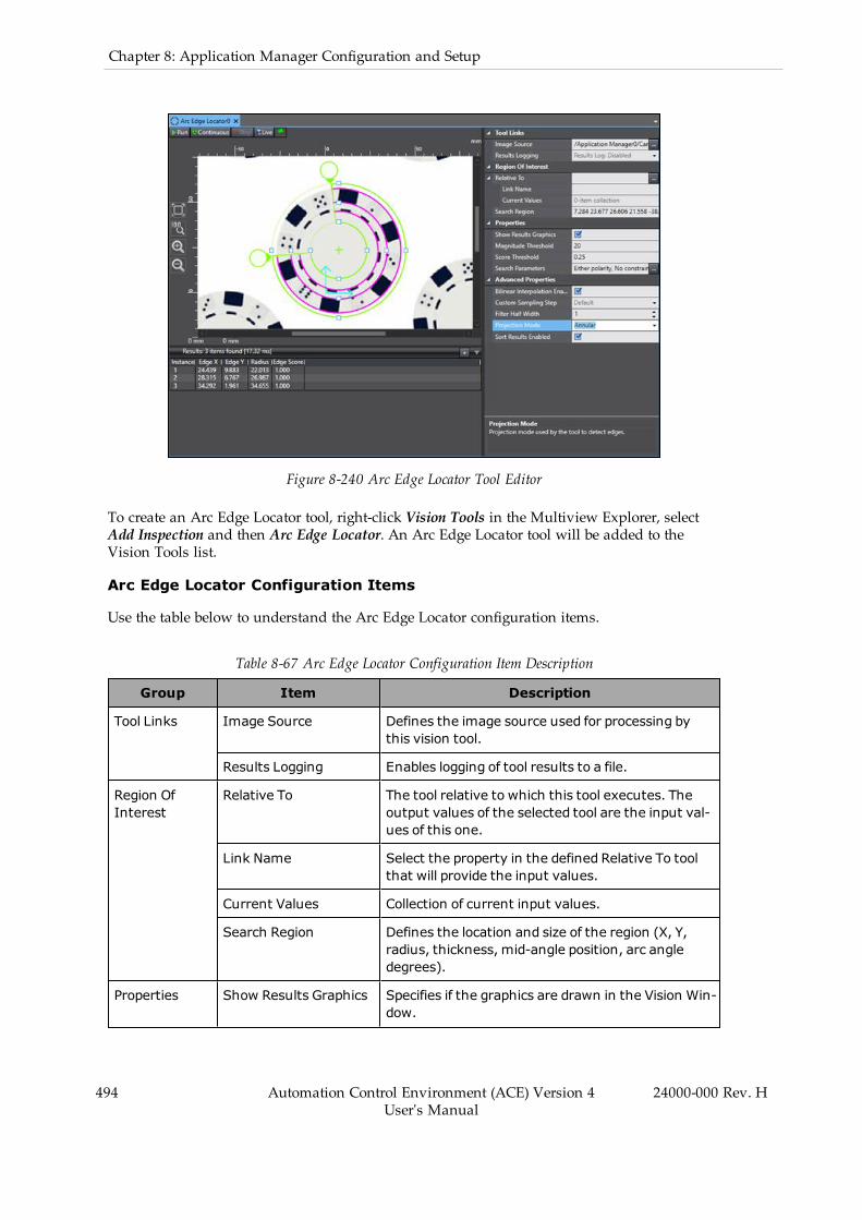
494 Automation Control Environment (ACE) Version 4User's Manual
24000-000 Rev. H
Chapter 8: Application Manager Configuration and Setup
Figure 8-240 Arc Edge Locator Tool Editor
To create an Arc Edge Locator tool, right-click Vision Tools in the Multiview Explorer, selectAdd Inspection and then Arc Edge Locator. An Arc Edge Locator tool will be added to theVision Tools list.
Arc Edge Locator Configuration Items
Use the table below to understand the Arc Edge Locator configuration items.
Table 8-67 Arc Edge Locator Configuration Item Description
Group Item Description
Tool Links Image Source Defines the image source used for processing bythis vision tool.
Results Logging Enables logging of tool results to a file.
Region OfInterest
Relative To The tool relative to which this tool executes. Theoutput values of the selected tool are the input val-ues of this one.
Link Name Select the property in the defined Relative To toolthat will provide the input values.
Current Values Collection of current input values.
Search Region Defines the location and size of the region (X, Y,radius, thickness, mid-angle position, arc angledegrees).
Properties Show Results Graphics Specifies if the graphics are drawn in the Vision Win-dow.
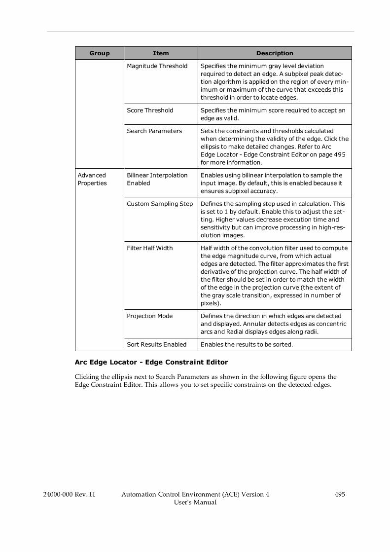
Group Item Description
Magnitude Threshold Specifies the minimum gray level deviationrequired to detect an edge. A subpixel peak detec-tion algorithm is applied on the region of every min-imum or maximum of the curve that exceeds thisthreshold in order to locate edges.
Score Threshold Specifies the minimum score required to accept anedge as valid.
Search Parameters Sets the constraints and thresholds calculatedwhen determining the validity of the edge. Click theellipsis to make detailed changes. Refer to ArcEdge Locator - Edge Constraint Editor on page 495for more information.
AdvancedProperties
Bilinear InterpolationEnabled
Enables using bilinear interpolation to sample theinput image. By default, this is enabled because itensures subpixel accuracy.
Custom Sampling Step Defines the sampling step used in calculation. Thisis set to 1 by default. Enable this to adjust the set-ting. Higher values decrease execution time andsensitivity but can improve processing in high-res-olution images.
Filter Half Width Half width of the convolution filter used to computethe edge magnitude curve, from which actualedges are detected. The filter approximates the firstderivative of the projection curve. The half width ofthe filter should be set in order to match the widthof the edge in the projection curve (the extent ofthe gray scale transition, expressed in number ofpixels).
Projection Mode Defines the direction in which edges are detectedand displayed. Annular detects edges as concentricarcs and Radial displays edges along radii.
Sort Results Enabled Enables the results to be sorted.
Arc Edge Locator - Edge Constraint Editor
Clicking the ellipsis next to Search Parameters as shown in the following figure opens theEdge Constraint Editor. This allows you to set specific constraints on the detected edges.
24000-000 Rev. H Automation Control Environment (ACE) Version 4User's Manual
495

496 Automation Control Environment (ACE) Version 4User's Manual
24000-000 Rev. H
Chapter 8: Application Manager Configuration and Setup
Figure 8-241 Edge Constraint Editor Access (Arc Edge Locator)
The Editor has two different sections named Edges and Region Image as described below.
Edges
This section defines the constraints on the detected edges. Constraints affect all detected edgeswith the following properties.
l Polarity: defines the gray level deviation for which the tool searches. This is performedwith respect to the clockwise direction of the region of interest. For example, in the fol-lowing figure, Either is selected, and dark and light areas can be seen on different sidesof multiple edges.
l Constraints: enables constraining the edge by both Position and Magnitude. A slider barappears below the image in both cases. The edge must be between the two positionsliders and its magnitude must be higher than defined in the magnitude slider (refer tothe following figure for an example).
l Score Threshold: defines the minimum score (quality) an edge must have to be con-sidered valid. The value is set between 0 and 1.
Region Image
The image beneath the edge constraints shows only the pixels within the region of interest inthe main image window. The image is altered from the region of interest to be rectangularinstead of circular. When Projection Mode is set to Radial, the positive X-axis in this image isoriented to be aligned with the clockwise direction of the region of interest. Otherwise, it isaligned with a radius from the inside to the outside.
Figure 8-242 Edge Constraint Editor (Arc Edge Locator)
Arc Edge Locator Results
Use the table below to understand the results of the Arc Edge Locator tool.
Table 8-68 Arc Edge Locator Results Description
Item Description
Instance Index of the result instance.
Frame/Group Index of the related result. It is associated with the tool that this tool is setRelative To.
Edge X X-coordinate of the edge midpoint.
Edge Y Y-coordinate of the edge midpoint.
Radius Radius of the edge. This is only properly measuredwhen Projection Mode isset to Annular.
Edge Score Calculated score (quality) of the edge, computed according to the constraintsset by the Edge Constraints properties.
Magnitude Measurement of how well the region of interest arc or radii matches thefound arc or radii. This will be returned as negative if the found arc is a reflec-tion of the region of interest arc.
Magnitude Score between 0 and 1 calculated according to the Magnitude Constraint prop-
24000-000 Rev. H Automation Control Environment (ACE) Version 4User's Manual
497
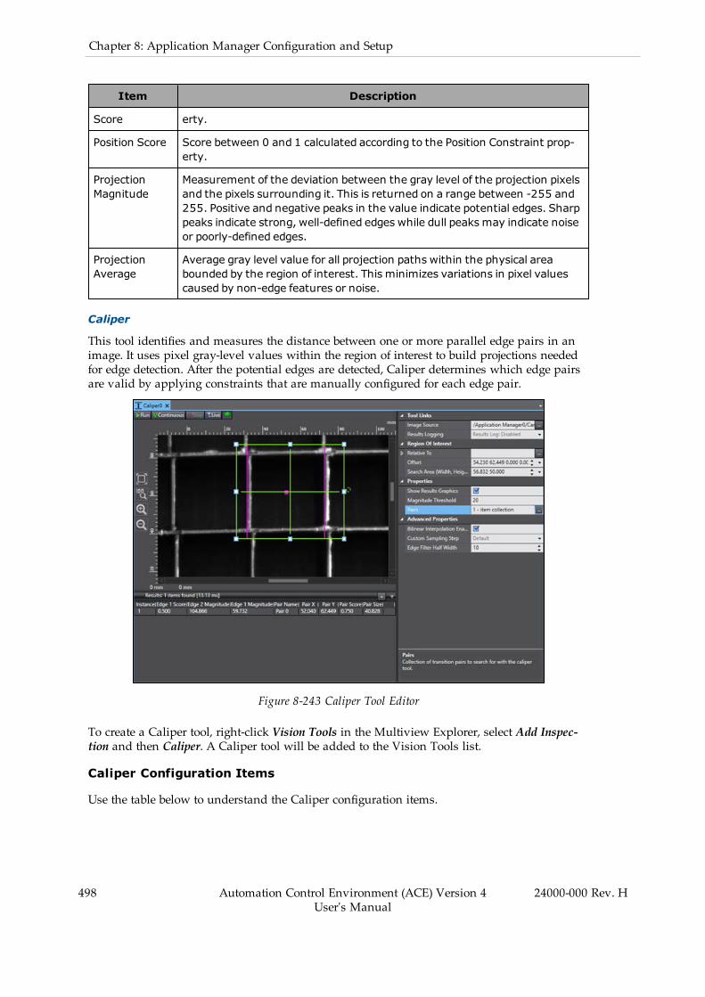
498 Automation Control Environment (ACE) Version 4User's Manual
24000-000 Rev. H
Chapter 8: Application Manager Configuration and Setup
Item Description
Score erty.
Position Score Score between 0 and 1 calculated according to the Position Constraint prop-erty.
ProjectionMagnitude
Measurement of the deviation between the gray level of the projection pixelsand the pixels surrounding it. This is returned on a range between -255 and255. Positive and negative peaks in the value indicate potential edges. Sharppeaks indicate strong, well-defined edges while dull peaks may indicate noiseor poorly-defined edges.
ProjectionAverage
Average gray level value for all projection paths within the physical areabounded by the region of interest. This minimizes variations in pixel valuescaused by non-edge features or noise.
Caliper
This tool identifies and measures the distance between one or more parallel edge pairs in animage. It uses pixel gray-level values within the region of interest to build projections neededfor edge detection. After the potential edges are detected, Caliper determines which edge pairsare valid by applying constraints that are manually configured for each edge pair.
Figure 8-243 Caliper Tool Editor
To create a Caliper tool, right-click Vision Tools in the Multiview Explorer, select Add Inspec-tion and then Caliper. A Caliper tool will be added to the Vision Tools list.
Caliper Configuration Items
Use the table below to understand the Caliper configuration items.
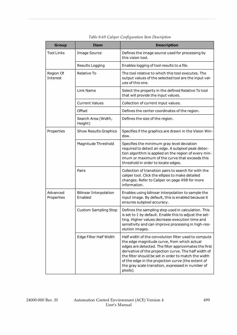
Table 8-69 Caliper Configuration Item Description
Group Item Description
Tool Links Image Source Defines the image source used for processing bythis vision tool.
Results Logging Enables logging of tool results to a file.
Region OfInterest
Relative To The tool relative to which this tool executes. Theoutput values of the selected tool are the input val-ues of this one.
Link Name Select the property in the defined Relative To toolthat will provide the input values.
Current Values Collection of current input values.
Offset Defines the center coordinates of the region.
Search Area (Width,Height)
Defines the size of the region.
Properties Show Results Graphics Specifies if the graphics are drawn in the Vision Win-dow.
Magnitude Threshold Specifies the minimum gray level deviationrequired to detect an edge. A subpixel peak detec-tion algorithm is applied on the region of every min-imum or maximum of the curve that exceeds thisthreshold in order to locate edges.
Pairs Collection of transition pairs to search for with thecaliper tool. Click the ellipsis to make detailedchanges. Refer to Caliper on page 498 for moreinformation.
AdvancedProperties
Bilinear InterpolationEnabled
Enables using bilinear interpolation to sample theinput image. By default, this is enabled because itensures subpixel accuracy.
Custom Sampling Step Defines the sampling step used in calculation. Thisis set to 1 by default. Enable this to adjust the set-ting. Higher values decrease execution time andsensitivity and can improve processing in high-res-olution images.
Edge Filter Half Width Half width of the convolution filter used to computethe edge magnitude curve, from which actualedges are detected. The filter approximates the firstderivative of the projection curve. The half width ofthe filter should be set in order to match the widthof the edge in the projection curve (the extent ofthe gray scale transition, expressed in number ofpixels).
24000-000 Rev. H Automation Control Environment (ACE) Version 4User's Manual
499

500 Automation Control Environment (ACE) Version 4User's Manual
24000-000 Rev. H
Chapter 8: Application Manager Configuration and Setup
Caliper - Edge Constraint Editor
Clicking the ellipsis next to Pairs opens the Edge Constraint Editor. This allows you to set spe-cific constraints on the detected pair(s).
Figure 8-244 Edge Constraint Editor Access (Caliper)
The editor has several different sections that are described below.
Pairs Pane
The area highlighted in the figure below lists the pairs of edges to be detected. By default, Cal-iper will try to detect only one. The Add and Delete buttons at the bottom can change theamount of pairs detected when the tool is run. The name of each pair is adjusted by selectingthe pair in this pane and then changing the Pair Name field.
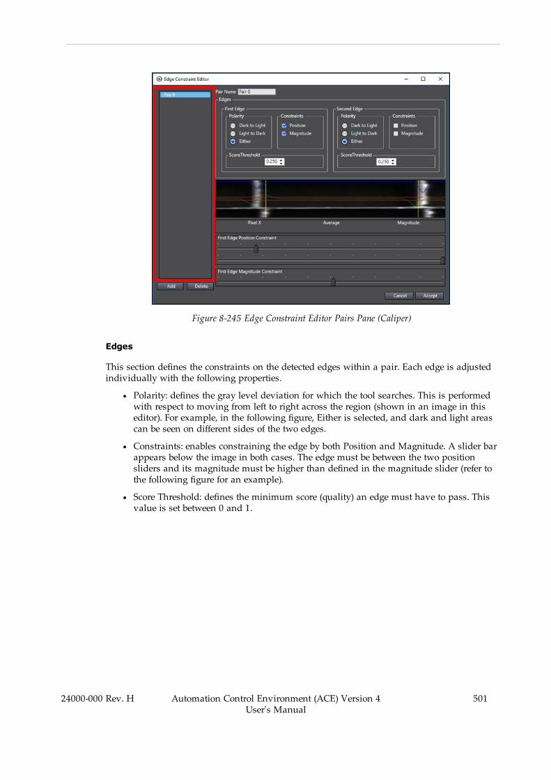
Figure 8-245 Edge Constraint Editor Pairs Pane (Caliper)
Edges
This section defines the constraints on the detected edges within a pair. Each edge is adjustedindividually with the following properties.
l Polarity: defines the gray level deviation for which the tool searches. This is performedwith respect to moving from left to right across the region (shown in an image in thiseditor). For example, in the following figure, Either is selected, and dark and light areascan be seen on different sides of the two edges.
l Constraints: enables constraining the edge by both Position and Magnitude. A slider barappears below the image in both cases. The edge must be between the two positionsliders and its magnitude must be higher than defined in the magnitude slider (refer tothe following figure for an example).
l Score Threshold: defines the minimum score (quality) an edge must have to pass. Thisvalue is set between 0 and 1.
24000-000 Rev. H Automation Control Environment (ACE) Version 4User's Manual
501
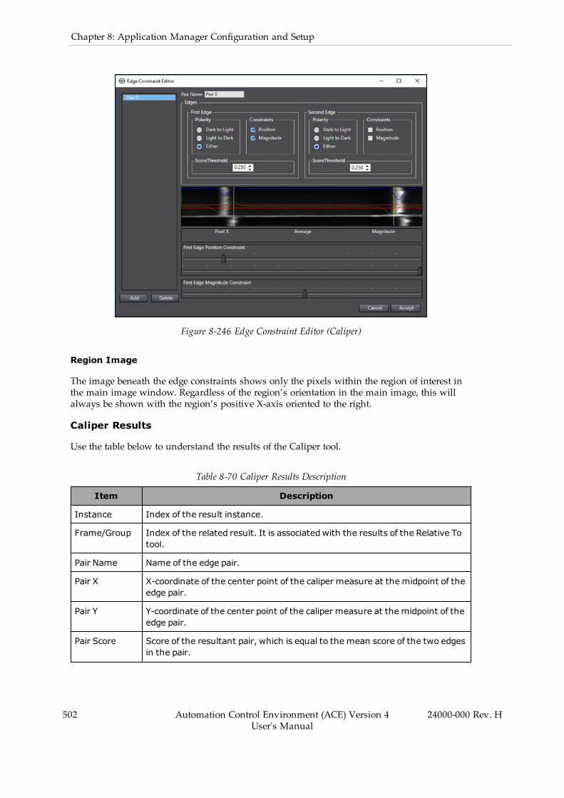
502 Automation Control Environment (ACE) Version 4User's Manual
24000-000 Rev. H
Chapter 8: Application Manager Configuration and Setup
Figure 8-246 Edge Constraint Editor (Caliper)
Region Image
The image beneath the edge constraints shows only the pixels within the region of interest inthe main image window. Regardless of the region’s orientation in the main image, this willalways be shown with the region’s positive X-axis oriented to the right.
Caliper Results
Use the table below to understand the results of the Caliper tool.
Table 8-70 Caliper Results Description
Item Description
Instance Index of the result instance.
Frame/Group Index of the related result. It is associated with the results of the Relative Totool.
Pair Name Name of the edge pair.
Pair X X-coordinate of the center point of the caliper measure at the midpoint of theedge pair.
Pair Y Y-coordinate of the center point of the caliper measure at the midpoint of theedge pair.
Pair Score Score of the resultant pair, which is equal to the mean score of the two edgesin the pair.
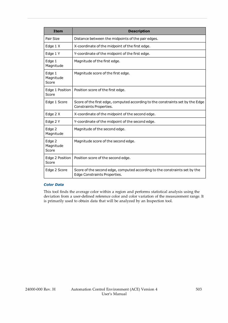
Item Description
Pair Size Distance between the midpoints of the pair edges.
Edge 1 X X-coordinate of the midpoint of the first edge.
Edge 1 Y Y-coordinate of the midpoint of the first edge.
Edge 1Magnitude
Magnitude of the first edge.
Edge 1MagnitudeScore
Magnitude score of the first edge.
Edge 1 PositionScore
Position score of the first edge.
Edge 1 Score Score of the first edge, computed according to the constraints set by the EdgeConstraints Properties.
Edge 2 X X-coordinate of the midpoint of the second edge.
Edge 2 Y Y-coordinate of the midpoint of the second edge.
Edge 2Magnitude
Magnitude of the second edge.
Edge 2MagnitudeScore
Magnitude score of the second edge.
Edge 2 PositionScore
Position score of the second edge.
Edge 2 Score Score of the second edge, computed according to the constraints set by theEdge Constraints Properties.
Color Data
This tool finds the average color within a region and performs statistical analysis using thedeviation from a user-defined reference color and color variation of the measurement range. Itis primarily used to obtain data that will be analyzed by an Inspection tool.
24000-000 Rev. H Automation Control Environment (ACE) Version 4User's Manual
503
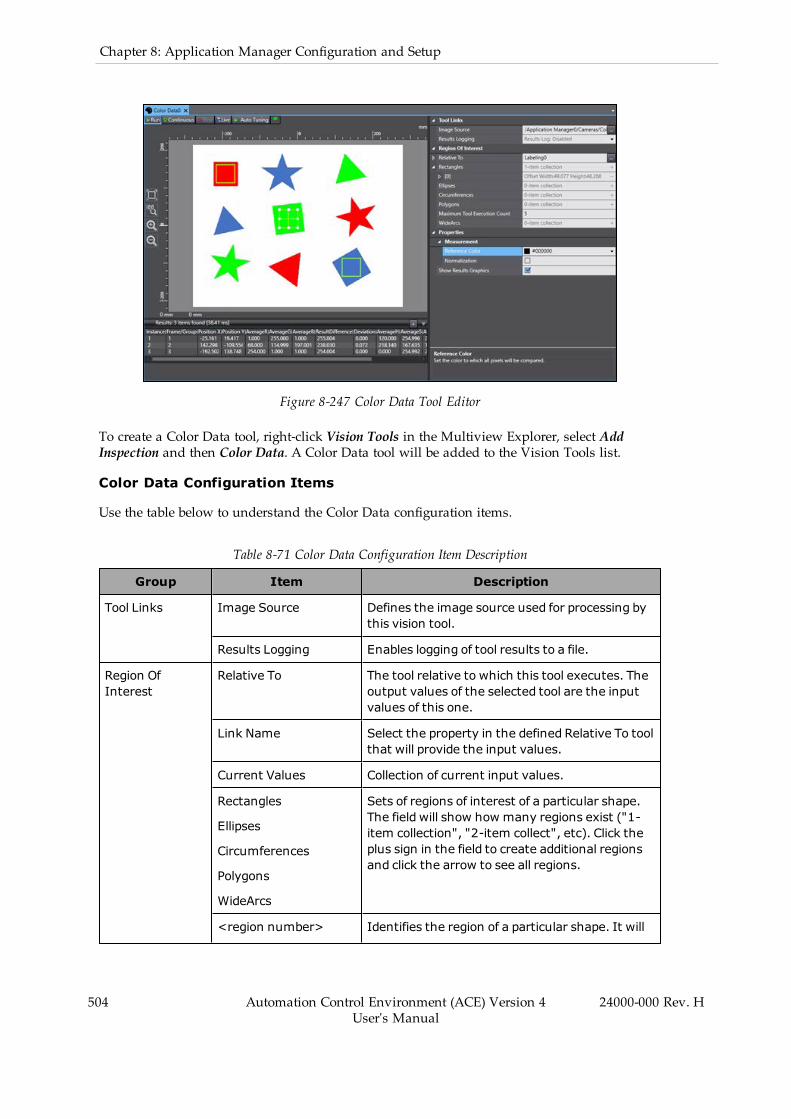
504 Automation Control Environment (ACE) Version 4User's Manual
24000-000 Rev. H
Chapter 8: Application Manager Configuration and Setup
Figure 8-247 Color Data Tool Editor
To create a Color Data tool, right-click Vision Tools in the Multiview Explorer, select AddInspection and then Color Data. A Color Data tool will be added to the Vision Tools list.
Color Data Configuration Items
Use the table below to understand the Color Data configuration items.
Table 8-71 Color Data Configuration Item Description
Group Item Description
Tool Links Image Source Defines the image source used for processing bythis vision tool.
Results Logging Enables logging of tool results to a file.
Region OfInterest
Relative To The tool relative to which this tool executes. Theoutput values of the selected tool are the inputvalues of this one.
Link Name Select the property in the defined Relative To toolthat will provide the input values.
Current Values Collection of current input values.
Rectangles
Ellipses
Circumferences
Polygons
WideArcs
Sets of regions of interest of a particular shape.The field will show how many regions exist ("1-item collection", "2-item collect", etc). Click theplus sign in the field to create additional regionsand click the arrow to see all regions.
<region number> Identifies the region of a particular shape. It will
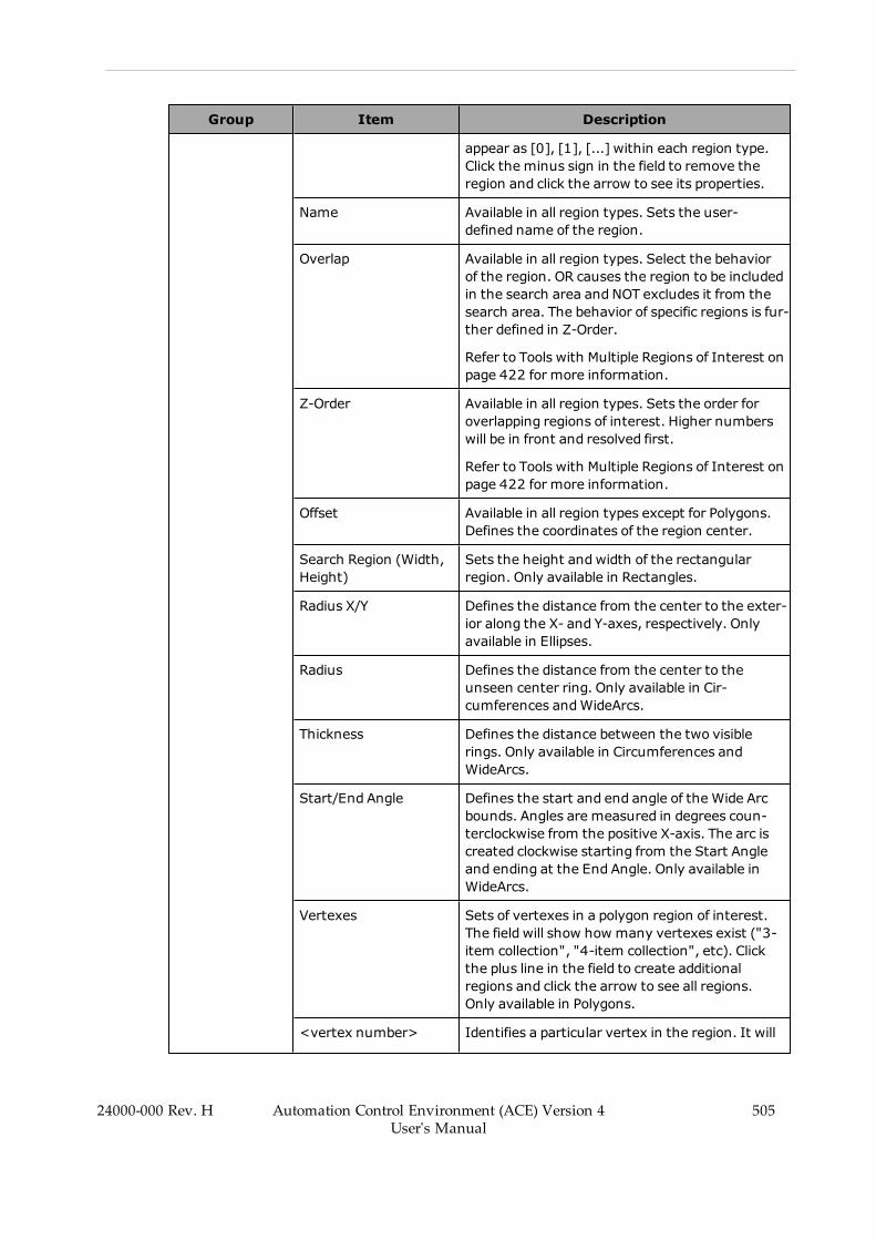
Group Item Description
appear as [0], [1], [...] within each region type.Click the minus sign in the field to remove theregion and click the arrow to see its properties.
Name Available in all region types. Sets the user-defined name of the region.
Overlap Available in all region types. Select the behaviorof the region. OR causes the region to be includedin the search area and NOT excludes it from thesearch area. The behavior of specific regions is fur-ther defined in Z-Order.
Refer to Tools with Multiple Regions of Interest onpage 422 for more information.
Z-Order Available in all region types. Sets the order foroverlapping regions of interest. Higher numberswill be in front and resolved first.
Refer to Tools with Multiple Regions of Interest onpage 422 for more information.
Offset Available in all region types except for Polygons.Defines the coordinates of the region center.
Search Region (Width,Height)
Sets the height andwidth of the rectangularregion. Only available in Rectangles.
Radius X/Y Defines the distance from the center to the exter-ior along the X- and Y-axes, respectively. Onlyavailable in Ellipses.
Radius Defines the distance from the center to theunseen center ring. Only available in Cir-cumferences andWideArcs.
Thickness Defines the distance between the two visiblerings. Only available in Circumferences andWideArcs.
Start/End Angle Defines the start and end angle of the Wide Arcbounds. Angles are measured in degrees coun-terclockwise from the positive X-axis. The arc iscreated clockwise starting from the Start Angleand ending at the End Angle. Only available inWideArcs.
Vertexes Sets of vertexes in a polygon region of interest.The field will show how many vertexes exist ("3-item collection", "4-item collection", etc). Clickthe plus line in the field to create additionalregions and click the arrow to see all regions.Only available in Polygons.
<vertex number> Identifies a particular vertex in the region. It will
24000-000 Rev. H Automation Control Environment (ACE) Version 4User's Manual
505

506 Automation Control Environment (ACE) Version 4User's Manual
24000-000 Rev. H
Chapter 8: Application Manager Configuration and Setup
Group Item Description
appear as [0], [1], [2], [...]. The field defines theX/Y coordinates of the vertex. Click the minussign to remove the vertex, as long as there willnot be fewer than three. Only available in Poly-gons.
Maximum ToolExecution Count
Maximum number of tool executions for RelativeTo performance. If this tool is not set relative toanother tool, the tool will only run once.
Properties(Measurement)
Reference Color Defines the color that will be compared to allpixels in the search area. The Auto Tuning buttonsets this property based on what is currently inthe region of interest.
Normalization Specify whether to normalize the brightness incalculating the color difference. When enabled,the result is not affected by the total brightnessand only the color tone can be detected.
Show Results Graphics Specifies if the graphics are drawn in the VisionWindow.
Color Data - Measuring Color Data
The colors in a region are measured against a reference color, which can be set in two ways. Ifthere is a specific color against which the pixels need to be measured, it can be chosen manu-ally using the Reference Color property. Alternatively, in color images, a particular color can behighlighted within the search area. Clicking the Auto Tuning button will automatically set thisas the Reference Color. All results will then be measured against it.
The ResultDifference result illustrates the difference between the measured color range and theReference Color by using the following formula.
=√((AverageR-Reference R)2+(AverageG-Reference G)2+(AverageB-Reference B)2)
This tool is particularly useful when used in conjunction with Inspection tool. When the ModeOf Operation for an Inspection Filter is set to Color Data, the Inspection tool can determinewhether Color Data tool results fall within a specified range, allowing instances to be cat-egorized by hue. Refer to Inspection on page 518 for more information.
NOTE: Color Data accuracy is dependent on the camera white balance settings,which may need to be modified outside of the ACE software.
Color Data Results
Use the table below to understand the results of the Color Data tool.
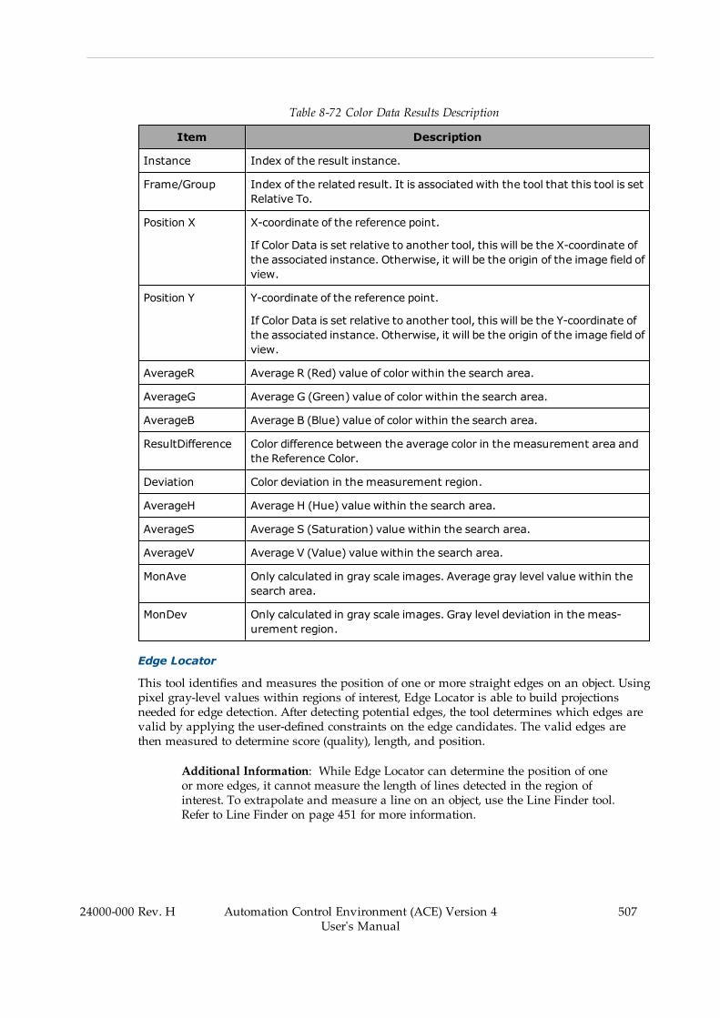
Table 8-72 Color Data Results Description
Item Description
Instance Index of the result instance.
Frame/Group Index of the related result. It is associated with the tool that this tool is setRelative To.
Position X X-coordinate of the reference point.
If Color Data is set relative to another tool, this will be the X-coordinate ofthe associated instance. Otherwise, it will be the origin of the image field ofview.
Position Y Y-coordinate of the reference point.
If Color Data is set relative to another tool, this will be the Y-coordinate ofthe associated instance. Otherwise, it will be the origin of the image field ofview.
AverageR Average R (Red) value of color within the search area.
AverageG Average G (Green) value of color within the search area.
AverageB Average B (Blue) value of color within the search area.
ResultDifference Color difference between the average color in the measurement area andthe Reference Color.
Deviation Color deviation in the measurement region.
AverageH Average H (Hue) value within the search area.
AverageS Average S (Saturation) value within the search area.
AverageV Average V (Value) value within the search area.
MonAve Only calculated in gray scale images. Average gray level value within thesearch area.
MonDev Only calculated in gray scale images. Gray level deviation in the meas-urement region.
Edge Locator
This tool identifies and measures the position of one or more straight edges on an object. Usingpixel gray-level values within regions of interest, Edge Locator is able to build projectionsneeded for edge detection. After detecting potential edges, the tool determines which edges arevalid by applying the user-defined constraints on the edge candidates. The valid edges arethen measured to determine score (quality), length, and position.
Additional Information: While Edge Locator can determine the position of oneor more edges, it cannot measure the length of lines detected in the region ofinterest. To extrapolate and measure a line on an object, use the Line Finder tool.Refer to Line Finder on page 451 for more information.
24000-000 Rev. H Automation Control Environment (ACE) Version 4User's Manual
507
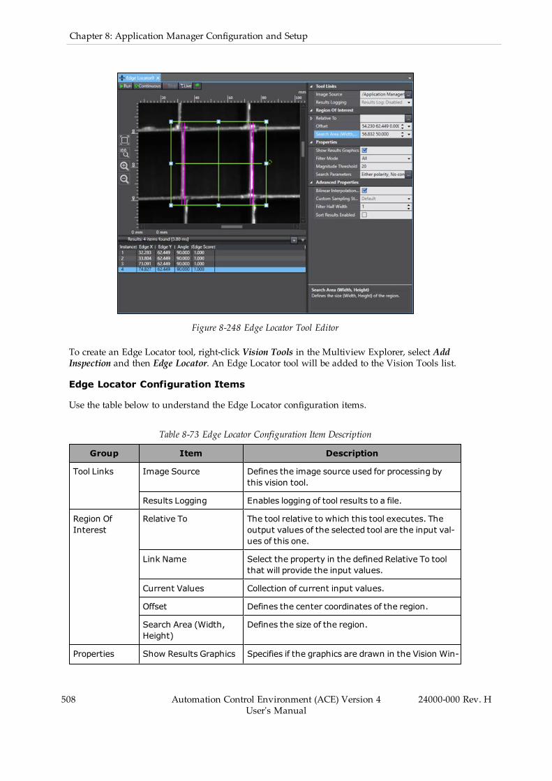
508 Automation Control Environment (ACE) Version 4User's Manual
24000-000 Rev. H
Chapter 8: Application Manager Configuration and Setup
Figure 8-248 Edge Locator Tool Editor
To create an Edge Locator tool, right-click Vision Tools in the Multiview Explorer, select AddInspection and then Edge Locator. An Edge Locator tool will be added to the Vision Tools list.
Edge Locator Configuration Items
Use the table below to understand the Edge Locator configuration items.
Table 8-73 Edge Locator Configuration Item Description
Group Item Description
Tool Links Image Source Defines the image source used for processing bythis vision tool.
Results Logging Enables logging of tool results to a file.
Region OfInterest
Relative To The tool relative to which this tool executes. Theoutput values of the selected tool are the input val-ues of this one.
Link Name Select the property in the defined Relative To toolthat will provide the input values.
Current Values Collection of current input values.
Offset Defines the center coordinates of the region.
Search Area (Width,Height)
Defines the size of the region.
Properties Show Results Graphics Specifies if the graphics are drawn in the Vision Win-
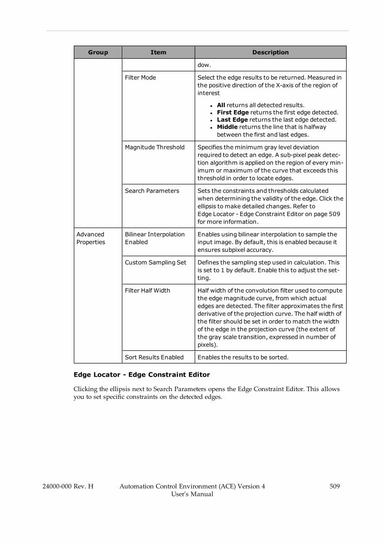
Group Item Description
dow.
Filter Mode Select the edge results to be returned. Measured inthe positive direction of the X-axis of the region ofinterest
l All returns all detected results.l First Edge returns the first edge detected.l Last Edge returns the last edge detected.l Middle returns the line that is halfwaybetween the first and last edges.
Magnitude Threshold Specifies the minimum gray level deviationrequired to detect an edge. A sub-pixel peak detec-tion algorithm is applied on the region of every min-imum or maximum of the curve that exceeds thisthreshold in order to locate edges.
Search Parameters Sets the constraints and thresholds calculatedwhen determining the validity of the edge. Click theellipsis to make detailed changes. Refer toEdge Locator - Edge Constraint Editor on page 509for more information.
AdvancedProperties
Bilinear InterpolationEnabled
Enables using bilinear interpolation to sample theinput image. By default, this is enabled because itensures subpixel accuracy.
Custom Sampling Set Defines the sampling step used in calculation. Thisis set to 1 by default. Enable this to adjust the set-ting.
Filter Half Width Half width of the convolution filter used to computethe edge magnitude curve, from which actualedges are detected. The filter approximates the firstderivative of the projection curve. The half width ofthe filter should be set in order to match the widthof the edge in the projection curve (the extent ofthe gray scale transition, expressed in number ofpixels).
Sort Results Enabled Enables the results to be sorted.
Edge Locator - Edge Constraint Editor
Clicking the ellipsis next to Search Parameters opens the Edge Constraint Editor. This allowsyou to set specific constraints on the detected edges.
24000-000 Rev. H Automation Control Environment (ACE) Version 4User's Manual
509
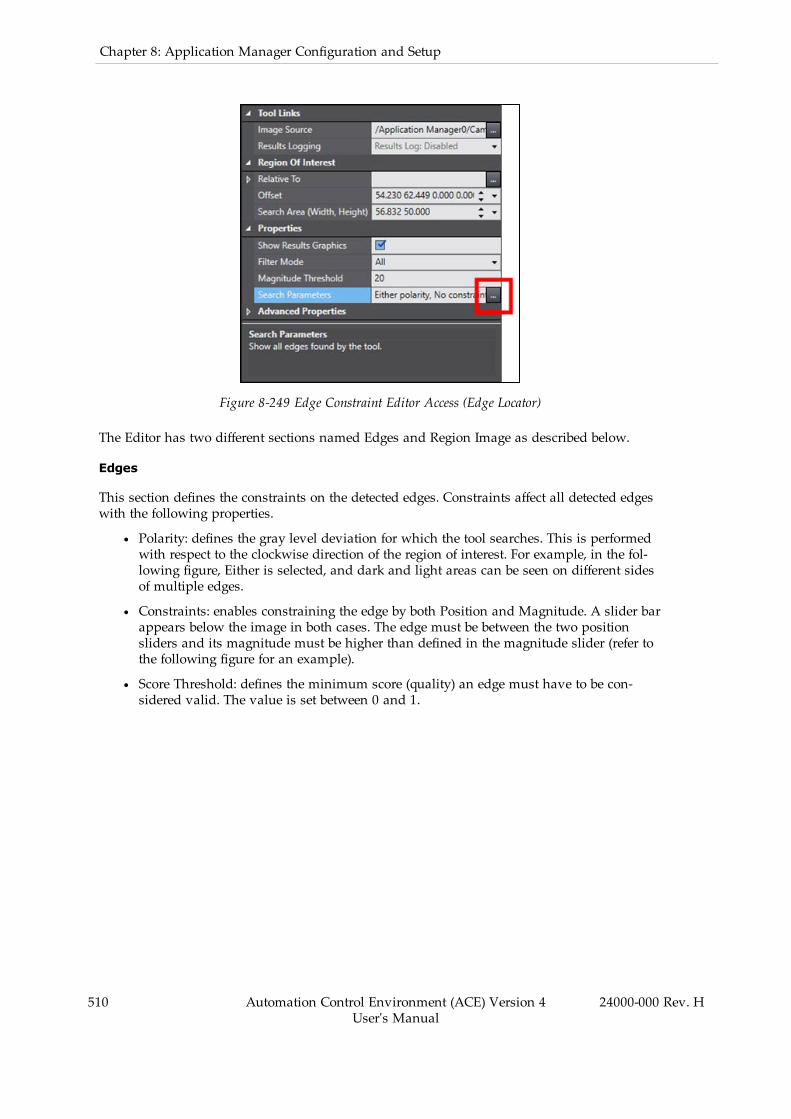
510 Automation Control Environment (ACE) Version 4User's Manual
24000-000 Rev. H
Chapter 8: Application Manager Configuration and Setup
Figure 8-249 Edge Constraint Editor Access (Edge Locator)
The Editor has two different sections named Edges and Region Image as described below.
Edges
This section defines the constraints on the detected edges. Constraints affect all detected edgeswith the following properties.
l Polarity: defines the gray level deviation for which the tool searches. This is performedwith respect to the clockwise direction of the region of interest. For example, in the fol-lowing figure, Either is selected, and dark and light areas can be seen on different sidesof multiple edges.
l Constraints: enables constraining the edge by both Position and Magnitude. A slider barappears below the image in both cases. The edge must be between the two positionsliders and its magnitude must be higher than defined in the magnitude slider (refer tothe following figure for an example).
l Score Threshold: defines the minimum score (quality) an edge must have to be con-sidered valid. The value is set between 0 and 1.

Figure 8-250 Edge Constraint Editor (Edge Locator)
Region Image
The image beneath the edge constraints shows only the pixels within the region of interest inthe main image window. The image is altered from the region of interest so that it appears rect-angular instead of circular. Regardless of the region’s orientation in the main image, this willalways be shown with the region’s positive X-axis oriented to the right.
Edge Locator Results
Use the table below to understand the results of the Edge Locator tool.
Table 8-74 Edge Locator Results Description
Item Description
Instance Index of the result instance.
Frame/Group Index of the related result. It is associated with the tool that this tool is setRelative To.
Edge X X-coordinate of the edge midpoint.
Edge Y Y-coordinate of the edge midpoint.
Angle Angle of the edge segment with respect to the image X-axis.
Edge Score Calculated score (quality) of the edge, computed according to the constraints
24000-000 Rev. H Automation Control Environment (ACE) Version 4User's Manual
511

512 Automation Control Environment (ACE) Version 4User's Manual
24000-000 Rev. H
Chapter 8: Application Manager Configuration and Setup
Item Description
set by the Edge Constraints properties.
Magnitude Peak value of the edge in the magnitude curve. Negative values indicate alight-to-dark transition while positive values indicate the opposite.
MagnitudeScore
Score between 0 and 1 calculated according to the Magnitude Constraint prop-erty.
Position Score Score between 0 and 1 calculated according to the Position Constraint prop-erty.
ProjectionMagnitude
Measurement of the deviation between the gray level of the projection pixelsand the pixels surrounding it. This is returned on a range between -255 and255. Positive and negative peaks in the value indicate potential edges. Sharppeaks indicate strong, well-defined edges while dull peaks may indicate noiseor poorly-defined edges.
ProjectionAverage
Average gray level value for all projection paths within the physical areabounded by the region of interest. This minimizes variations in pixel valuescaused by non-edge features or noise.
Feeder Histogram
This tool is used to calculated product density in user-defined regions of interest. It is designedto function in conjunction with an AnyFeeder to identify the density of products within regionsassociated with the dispense, pick, and front zones. Refer to AnyFeeder Object on page 316 formore information.
Additional Information: Feeder Histogram does not support color images.
Figure 8-251 Feeder Histogram

To create a Feeder Histogram tool, right-click Vision Tools in the Multiview Explorer, selectAdd Finder and then Feeder Histogram. The Feeder Histogram tool will be added to the VisionTools list.
Feeder Histogram Configuration Items
Use the table below to understand the Feeder Histogram configuration items.
Table 8-75 Feeder Histogram Configuration Item Description
Item Description
Tool Links Image Source Defines the image source used for processing by this vis-ion tool.
Results Logging Enables logging of tool results to a file.
Region OfInterest
Relative To The tool relative to which this tool executes. The outputvalues of the selected tool are the input values of thisone.
Link Name Select the property in the relative tool that will providethe input values.
Current Values Collection of current input values.
Offset Defines the coordinates of the reference point that thehistograms reference.
Properties Show ResultsGraphics
Specifies if the graphics are drawn in the Vision Window.
Threshold Black Defines the darkest pixels the histogram considers whenrunning. Any pixels with gray level lower than this valuewill be ignoredwhile the histogram is building.
ThresholdWhite Defines the brightest pixels the histogram considerswhen running. Any pixels with gray level above higherthan this value will be ignoredwhile the histogram isbuilding.
Show Result ImageHistogram Regions
Specifies if the histogram regions are drawn in the ACEVision Window. Show Results Graphics must be enabledfor this to work.
AdvancedProperties
Bilinear InterpolationEnabled
Enables using bilinear interpolation to sample the inputimage. By default, this is enabled because it ensures sub-pixel accuracy.
Tail Black Gray LevelValue
Percentage of pixels to ignore at the dark end of the graylevel distribution. This is calculated after the pixelsaffected by the Threshold Black property have beenremoved.
Tail White Gray LevelValue
Percentage of pixels to ignore at the light end of the graylevel distribution. This is calculated after the pixelsaffected by the ThresholdWhite property have been
24000-000 Rev. H Automation Control Environment (ACE) Version 4User's Manual
513

514 Automation Control Environment (ACE) Version 4User's Manual
24000-000 Rev. H
Chapter 8: Application Manager Configuration and Setup
Item Description
removed.
Feeder Histogram Pane
Feeder Histogram is designed so you can create a series of histograms to measure productdensity in multiple ranges in the image. These histograms are organized using the HistogramPane positioned beneath the properties, as shown in the figure below.
Figure 8-252 Feeder Histogram Pane
The Add and Delete buttons are used to create or remove histograms from the tool. Typically,2 to 4 zones will be configured depending on the complexity of feeding logic required for theapplication.
The pane also shows properties that apply only to the selected histogram. They are shown inthe table below.
Table 8-76 Feeder Histogram Item Description
Item Description
Offset Defines the center coordinates of the histogram region with respect to the ref-erence point defined by Offset in the main tool properties.
Region Name User-defined name of the histogram. This is displayed in the lower left cornerof the histogram region in the region.
Search Region Defines the size (width, height) of the histogram region.
The product density is calculated for each histogram region using the following formula:
Product Density = Histogram Pixel Count / Image Pixel Count
where Histogram Pixel Count is the number of pixels that fall within the defined thresholdsand Image Pixel Count is the number of total pixels in the histogram region.
Feeder Histogram Results
A Feeder Histogram tool will return one result containing the product densities for each his-togram. These are not shown by default and must be added using the Results Column Editor.The numbers of the histograms are variable and are denoted here as <number> instead ofactual values.
NOTE: Results are calculated after applying tails and thresholds.
Table 8-77 Feeder Histogram Results Description
Item Description
Instance Index of the result instance.
Histogram<number> %
Product density percentage of the denoted histogram.
Image Histogram
This tool computes image statistics for all the pixels contained in the region of interest. This isused primarily for identifying product or clutter density, verifying the camera or lightingadjustment during setup of an application, and providing input for the Inspection tool.
NOTE: Image Histogram only functions for gray scale images.
Figure 8-253 Image Histogram Tool Editor
To create an Image Histogram tool, right-click Vision Tools in the Multiview Explorer, selectAdd Inspection and then Image Histogram. An Image Histogram tool will be added to theVision Tools list.
Image Histogram Configuration Items
Use the table below to understand the Image Histogram configuration items.
Table 8-78 Image Histogram Configuration Item Description
Group Item Description
Tool Links Image Source Defines the image source used for processing bythis vision tool.
24000-000 Rev. H Automation Control Environment (ACE) Version 4User's Manual
515
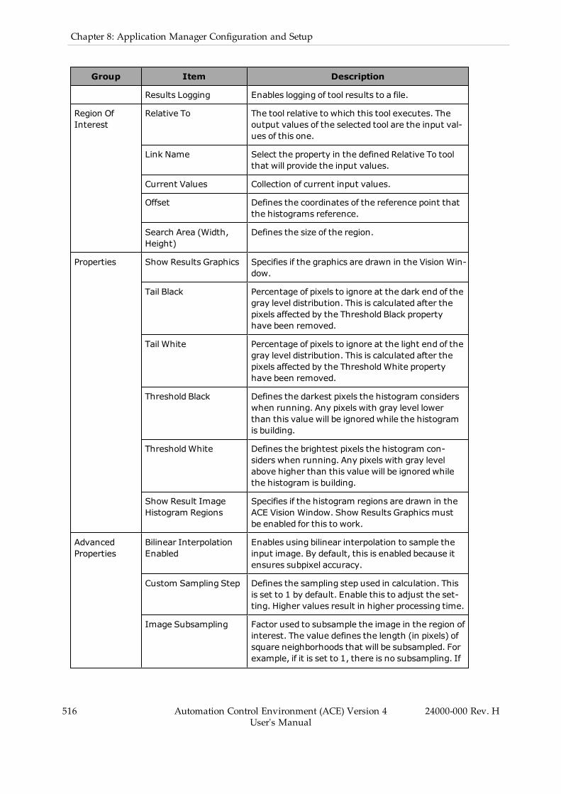
516 Automation Control Environment (ACE) Version 4User's Manual
24000-000 Rev. H
Chapter 8: Application Manager Configuration and Setup
Group Item Description
Results Logging Enables logging of tool results to a file.
Region OfInterest
Relative To The tool relative to which this tool executes. Theoutput values of the selected tool are the input val-ues of this one.
Link Name Select the property in the defined Relative To toolthat will provide the input values.
Current Values Collection of current input values.
Offset Defines the coordinates of the reference point thatthe histograms reference.
Search Area (Width,Height)
Defines the size of the region.
Properties Show Results Graphics Specifies if the graphics are drawn in the Vision Win-dow.
Tail Black Percentage of pixels to ignore at the dark end of thegray level distribution. This is calculated after thepixels affected by the Threshold Black propertyhave been removed.
Tail White Percentage of pixels to ignore at the light end of thegray level distribution. This is calculated after thepixels affected by the ThresholdWhite propertyhave been removed.
Threshold Black Defines the darkest pixels the histogram considerswhen running. Any pixels with gray level lowerthan this value will be ignoredwhile the histogramis building.
ThresholdWhite Defines the brightest pixels the histogram con-siders when running. Any pixels with gray levelabove higher than this value will be ignoredwhilethe histogram is building.
Show Result ImageHistogram Regions
Specifies if the histogram regions are drawn in theACE Vision Window. Show Results Graphics mustbe enabled for this to work.
AdvancedProperties
Bilinear InterpolationEnabled
Enables using bilinear interpolation to sample theinput image. By default, this is enabled because itensures subpixel accuracy.
Custom Sampling Step Defines the sampling step used in calculation. Thisis set to 1 by default. Enable this to adjust the set-ting. Higher values result in higher processing time.
Image Subsampling Factor used to subsample the image in the region ofinterest. The value defines the length (in pixels) ofsquare neighborhoods that will be subsampled. Forexample, if it is set to 1, there is no subsampling. If

Group Item Description
it is set to 2, the image is subsampled in 2x2 tiles.
Image Histogram - Configuration
Image Histogram is designed to return a range of statistics about the pixels within a region ofinterest. The final calculation ignores pixels that have been excluded by thresholds or tails.
These properties provide a way for the user to ignore pixels in the histogram. Threshold Blackand Threshold White set a maximum and minimum gray level to consider when building thehistogram. Tail Black and Tail White remove a percentage of pixels from the ends of the spec-trum within the thresholds. In this way, the user is able to eliminate results from areas that arenot required by the application.
For example, the tool shown in Figure 8-253 can be manipulated to only return results aboutthe pixels within the guitar picks by setting the Threshold White property to 200, as shown inthe figure below. This removes all pixels with a gray level value higher than 200 from ana-lysis.
Figure 8-254 Image Histogram with Threshold White
Image Histogram Results
Use the table below to understand the results of the Image Histogram tool.
NOTE: All results are calculated after applying white and black tails andthresholds.
Table 8-79 Image Histogram Results Description
Item Description
Instance Index of the result instance.
24000-000 Rev. H Automation Control Environment (ACE) Version 4User's Manual
517
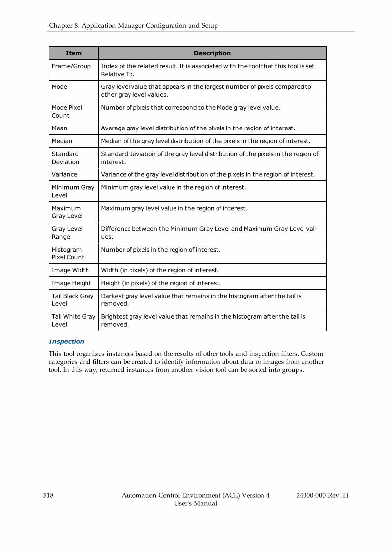
518 Automation Control Environment (ACE) Version 4User's Manual
24000-000 Rev. H
Chapter 8: Application Manager Configuration and Setup
Item Description
Frame/Group Index of the related result. It is associated with the tool that this tool is setRelative To.
Mode Gray level value that appears in the largest number of pixels compared toother gray level values.
Mode PixelCount
Number of pixels that correspond to the Mode gray level value.
Mean Average gray level distribution of the pixels in the region of interest.
Median Median of the gray level distribution of the pixels in the region of interest.
StandardDeviation
Standard deviation of the gray level distribution of the pixels in the region ofinterest.
Variance Variance of the gray level distribution of the pixels in the region of interest.
Minimum GrayLevel
Minimum gray level value in the region of interest.
MaximumGray Level
Maximum gray level value in the region of interest.
Gray LevelRange
Difference between the Minimum Gray Level andMaximum Gray Level val-ues.
HistogramPixel Count
Number of pixels in the region of interest.
ImageWidth Width (in pixels) of the region of interest.
Image Height Height (in pixels) of the region of interest.
Tail Black GrayLevel
Darkest gray level value that remains in the histogram after the tail isremoved.
Tail White GrayLevel
Brightest gray level value that remains in the histogram after the tail isremoved.
Inspection
This tool organizes instances based on the results of other tools and inspection filters. Customcategories and filters can be created to identify information about data or images from anothertool. In this way, returned instances from another vision tool can be sorted into groups.
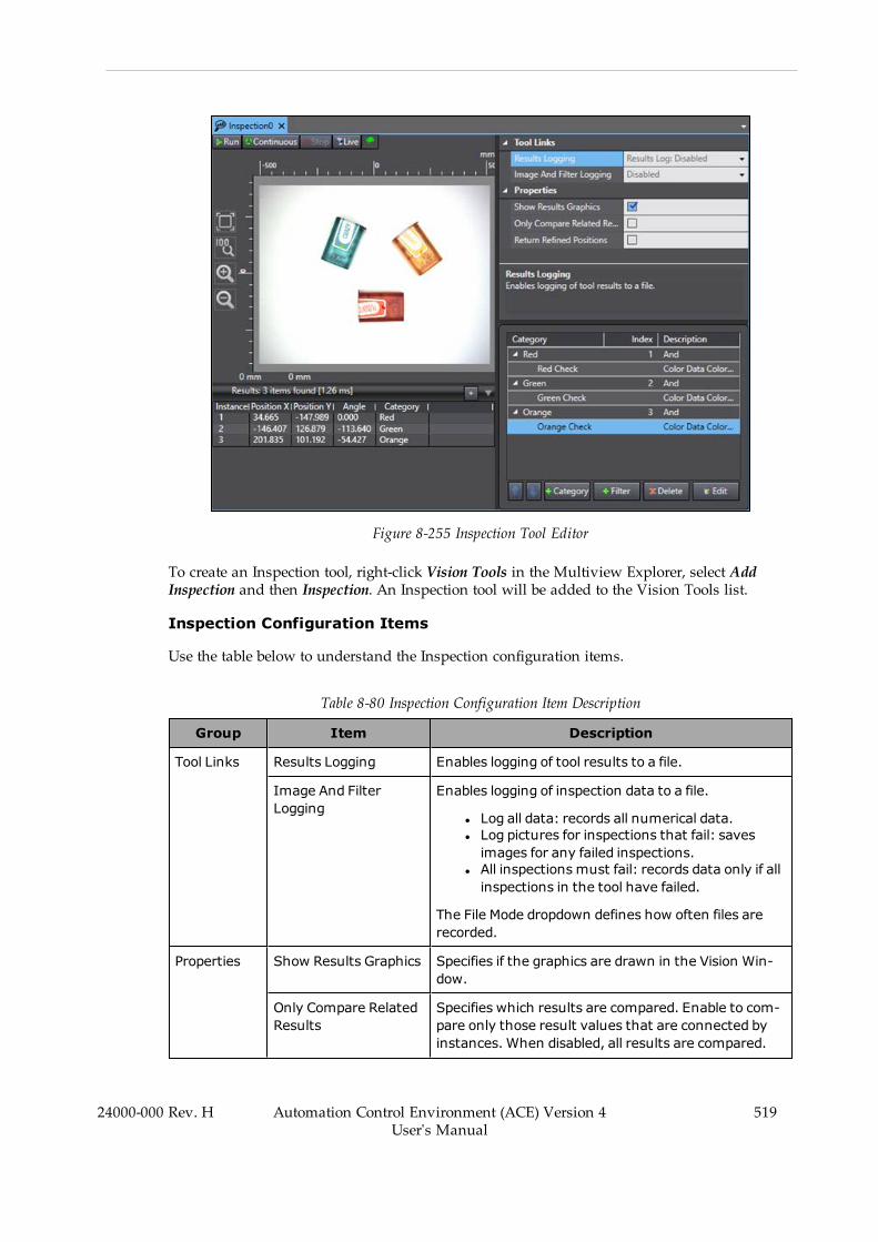
Figure 8-255 Inspection Tool Editor
To create an Inspection tool, right-click Vision Tools in the Multiview Explorer, select AddInspection and then Inspection. An Inspection tool will be added to the Vision Tools list.
Inspection Configuration Items
Use the table below to understand the Inspection configuration items.
Table 8-80 Inspection Configuration Item Description
Group Item Description
Tool Links Results Logging Enables logging of tool results to a file.
Image And FilterLogging
Enables logging of inspection data to a file.
l Log all data: records all numerical data.l Log pictures for inspections that fail: savesimages for any failed inspections.
l All inspections must fail: records data only if allinspections in the tool have failed.
The File Mode dropdown defines how often files arerecorded.
Properties Show Results Graphics Specifies if the graphics are drawn in the Vision Win-dow.
Only Compare RelatedResults
Specifies which results are compared. Enable to com-pare only those result values that are connected byinstances. When disabled, all results are compared.
24000-000 Rev. H Automation Control Environment (ACE) Version 4User's Manual
519
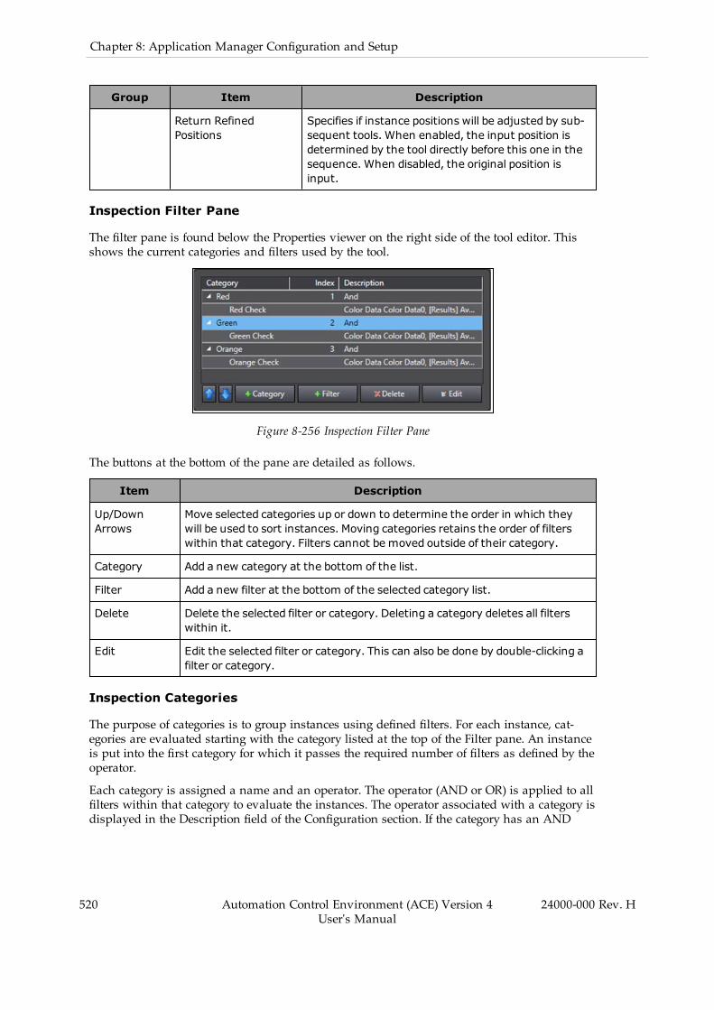
520 Automation Control Environment (ACE) Version 4User's Manual
24000-000 Rev. H
Chapter 8: Application Manager Configuration and Setup
Group Item Description
Return RefinedPositions
Specifies if instance positions will be adjusted by sub-sequent tools. When enabled, the input position isdetermined by the tool directly before this one in thesequence. When disabled, the original position isinput.
Inspection Filter Pane
The filter pane is found below the Properties viewer on the right side of the tool editor. Thisshows the current categories and filters used by the tool.
Figure 8-256 Inspection Filter Pane
The buttons at the bottom of the pane are detailed as follows.
Item Description
Up/DownArrows
Move selected categories up or down to determine the order in which theywill be used to sort instances. Moving categories retains the order of filterswithin that category. Filters cannot be moved outside of their category.
Category Add a new category at the bottom of the list.
Filter Add a new filter at the bottom of the selected category list.
Delete Delete the selected filter or category. Deleting a category deletes all filterswithin it.
Edit Edit the selected filter or category. This can also be done by double-clicking afilter or category.
Inspection Categories
The purpose of categories is to group instances using defined filters. For each instance, cat-egories are evaluated starting with the category listed at the top of the Filter pane. An instanceis put into the first category for which it passes the required number of filters as defined by theoperator.
Each category is assigned a name and an operator. The operator (AND or OR) is applied to allfilters within that category to evaluate the instances. The operator associated with a category isdisplayed in the Description field of the Configuration section. If the category has an AND
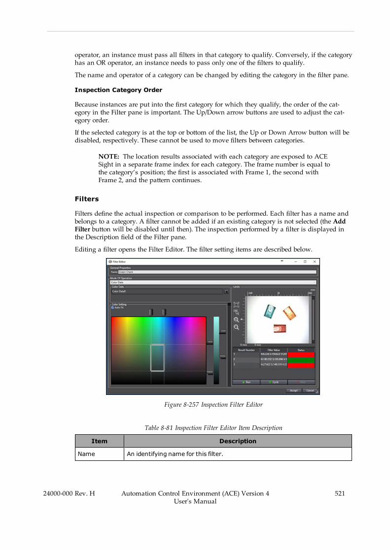
operator, an instance must pass all filters in that category to qualify. Conversely, if the categoryhas an OR operator, an instance needs to pass only one of the filters to qualify.
The name and operator of a category can be changed by editing the category in the filter pane.
Inspection Category Order
Because instances are put into the first category for which they qualify, the order of the cat-egory in the Filter pane is important. The Up/Down arrow buttons are used to adjust the cat-egory order.
If the selected category is at the top or bottom of the list, the Up or Down Arrow button will bedisabled, respectively. These cannot be used to move filters between categories.
NOTE: The location results associated with each category are exposed to ACESight in a separate frame index for each category. The frame number is equal tothe category’s position; the first is associated with Frame 1, the second withFrame 2, and the pattern continues.
Filters
Filters define the actual inspection or comparison to be performed. Each filter has a name andbelongs to a category. A filter cannot be added if an existing category is not selected (the AddFilter button will be disabled until then). The inspection performed by a filter is displayed inthe Description field of the Filter pane.
Editing a filter opens the Filter Editor. The filter setting items are described below.
Figure 8-257 Inspection Filter Editor
Table 8-81 Inspection Filter Editor Item Description
Item Description
Name An identifying name for this filter.
24000-000 Rev. H Automation Control Environment (ACE) Version 4User's Manual
521

522 Automation Control Environment (ACE) Version 4User's Manual
24000-000 Rev. H
Chapter 8: Application Manager Configuration and Setup
Item Description
Mode Of Oper-ation
Defines the type of evaluation this filter performs. The options are:
l Measure Distance Between Two Pointsl Measure The Shortest Distance Between A Point and a Linel Measure The Angle Between Two Linesl Test The Value Of A Vision Result Variablel Vision Tool Transform Resultsl Number of Resultsl Number of Charactersl OCRQualityl Stringl Color Data
Vision Tools The appropriate vision tools and the necessary properties.
This varies depending on the Mode Of Operation.
Limits The bounds of this filter.
If the results of an inspection fall between these values, the instance passesthis filter. Like the Vision Tools, this also varies with the Mode Of Operation,but it is a Minimum andMaximum Value in most cases.
Results Sample results from evaluating this filter on the current image.
This can be used to show whether certain instances pass or fail, allowing theuser to tune the limits. In most cases, there are three result columns in thiseditor:
l Result Number: The instance number.l Filter Value: The evaluated property from the vision tool.l Status: Shows if the instance has satisfied this filter. This field will begreen if the instance passes and red if it fails.
ControlButtons
l Run: Run the tool once.l Cycle: Run the tool continuously.l Stop: Stop the tool or live operation.
Inspection Vision Results Selection
If the Mode Of Operations is set to Test The Value Of A Vision Result Variable, an additionalResult from another Vision Tool will need to be selected. This requires its own window, asdescribed below.
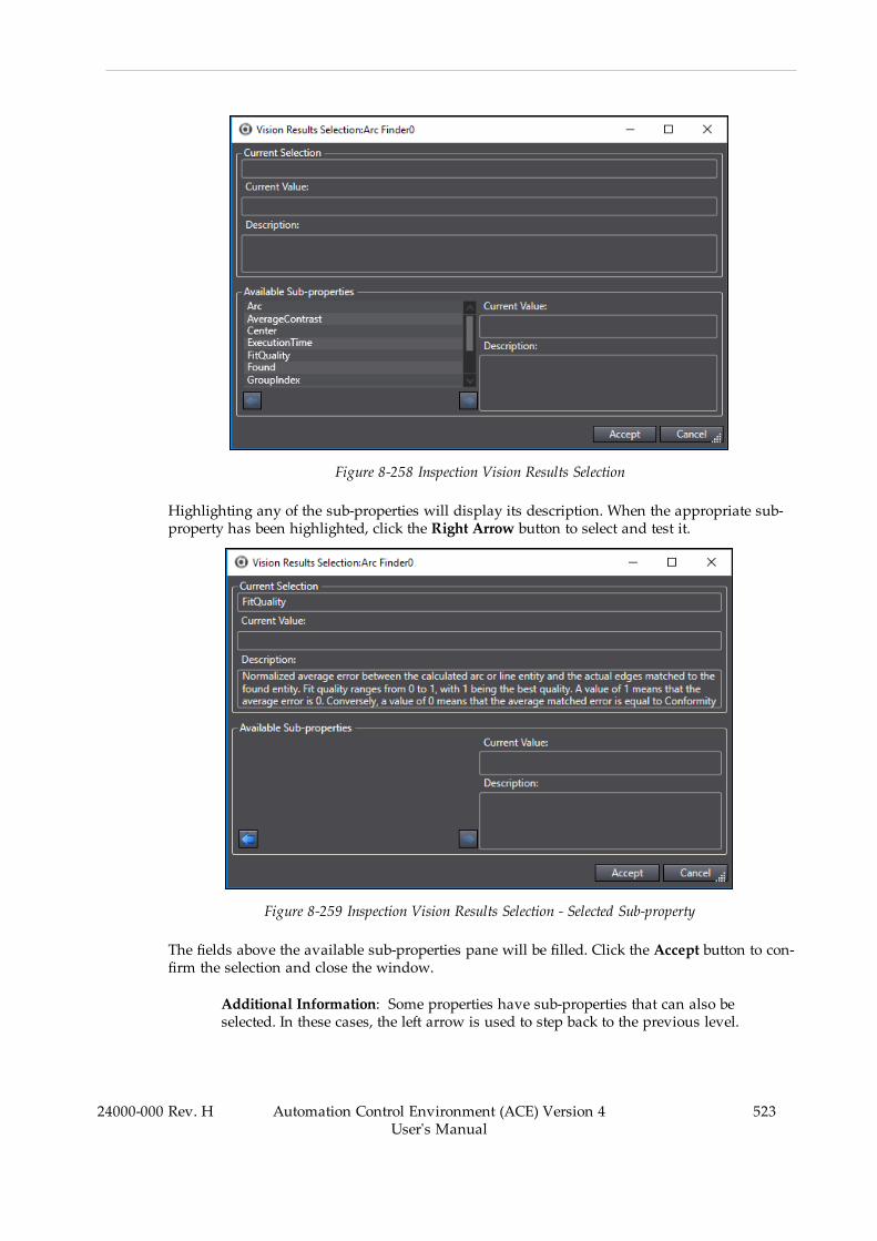
Figure 8-258 Inspection Vision Results Selection
Highlighting any of the sub-properties will display its description. When the appropriate sub-property has been highlighted, click the Right Arrow button to select and test it.
Figure 8-259 Inspection Vision Results Selection - Selected Sub-property
The fields above the available sub-properties pane will be filled. Click the Accept button to con-firm the selection and close the window.
Additional Information: Some properties have sub-properties that can also beselected. In these cases, the left arrow is used to step back to the previous level.
24000-000 Rev. H Automation Control Environment (ACE) Version 4User's Manual
523
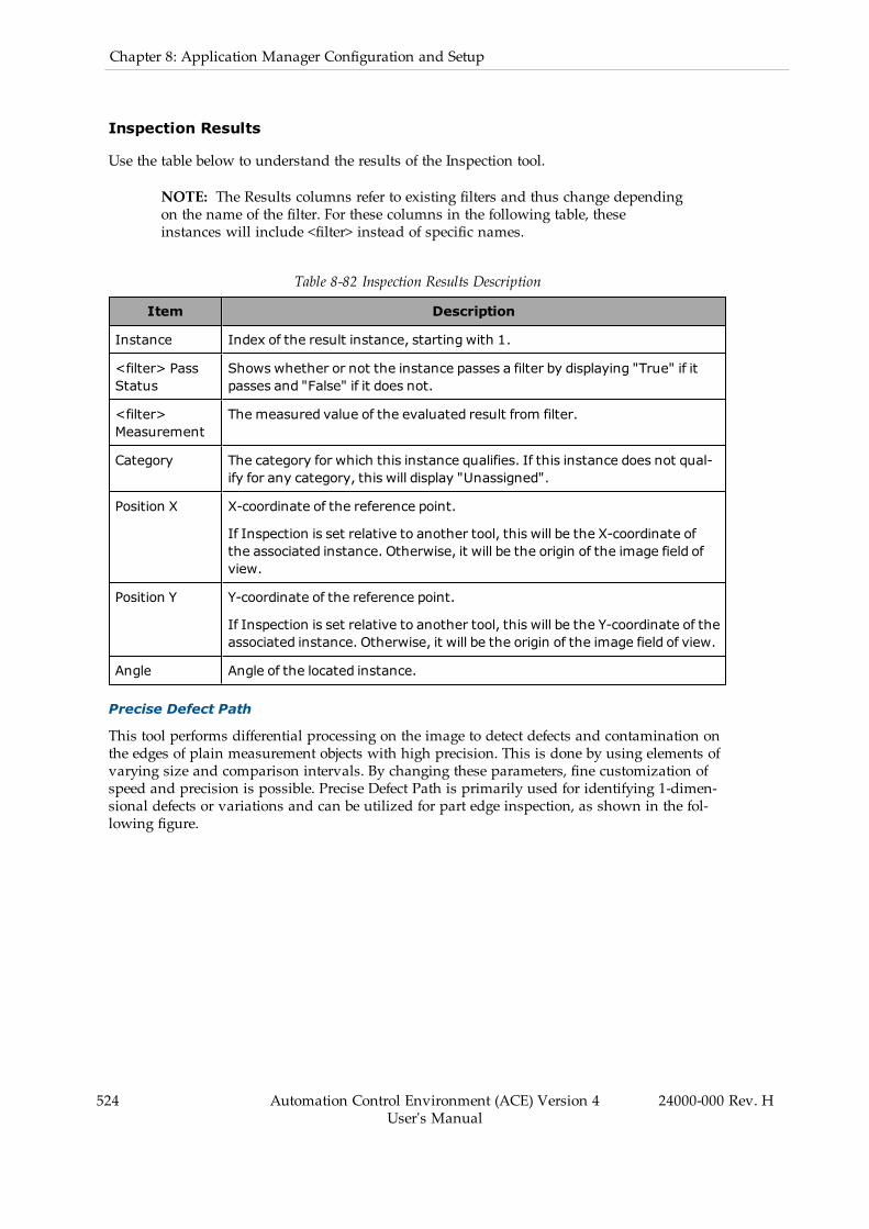
524 Automation Control Environment (ACE) Version 4User's Manual
24000-000 Rev. H
Chapter 8: Application Manager Configuration and Setup
Inspection Results
Use the table below to understand the results of the Inspection tool.
NOTE: The Results columns refer to existing filters and thus change dependingon the name of the filter. For these columns in the following table, theseinstances will include <filter> instead of specific names.
Table 8-82 Inspection Results Description
Item Description
Instance Index of the result instance, starting with 1.
<filter> PassStatus
Shows whether or not the instance passes a filter by displaying "True" if itpasses and "False" if it does not.
<filter>Measurement
The measured value of the evaluated result from filter.
Category The category for which this instance qualifies. If this instance does not qual-ify for any category, this will display "Unassigned".
Position X X-coordinate of the reference point.
If Inspection is set relative to another tool, this will be the X-coordinate ofthe associated instance. Otherwise, it will be the origin of the image field ofview.
Position Y Y-coordinate of the reference point.
If Inspection is set relative to another tool, this will be the Y-coordinate of theassociated instance. Otherwise, it will be the origin of the image field of view.
Angle Angle of the located instance.
Precise Defect Path
This tool performs differential processing on the image to detect defects and contamination onthe edges of plain measurement objects with high precision. This is done by using elements ofvarying size and comparison intervals. By changing these parameters, fine customization ofspeed and precision is possible. Precise Defect Path is primarily used for identifying 1-dimen-sional defects or variations and can be utilized for part edge inspection, as shown in the fol-lowing figure.

Figure 8-260 Precise Defect Path Tool Editor
To create a Precise Defect Path tool, right-click Vision Tools in the Multiview Explorer, selectAdd Inspection and then Precise Defect Path. A Precise Defect Path tool will be added to theVision Tools list.
Precise Defect Path Configuration Items
Use the table below to understand the Precise Defect Path configuration items.
Table 8-83 Precise Defect Path Configuration Item Description
Group Item Description
Tool Links Image Source Defines the image source used for processing bythis vision tool.
Enables logging of toolresults to a file.
Enables logging of tool results to a file.
Region OfInterest
Relative To The tool relative to which this tool executes. Theoutput values of the selected tool are the input val-ues of this one.
Link Name Select the property in the defined Relative To toolthat will provide the input values.
Current Values Collection of current input values.
Maximum ToolExecution Count
Maximum number of tool executions for Relative Toperformance. If this tool is not set relative toanother tool, the tool will only run once.
Path Type Defines the shape and detection method of the
24000-000 Rev. H Automation Control Environment (ACE) Version 4User's Manual
525
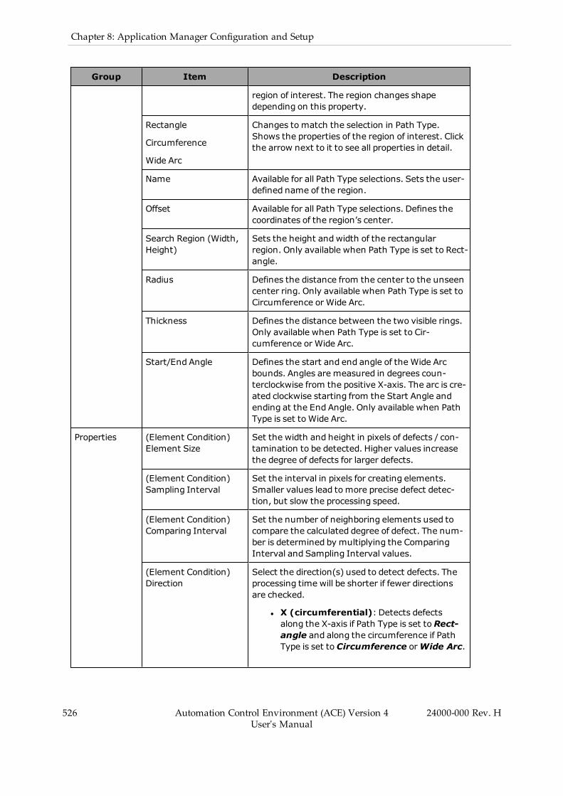
526 Automation Control Environment (ACE) Version 4User's Manual
24000-000 Rev. H
Chapter 8: Application Manager Configuration and Setup
Group Item Description
region of interest. The region changes shapedepending on this property.
Rectangle
Circumference
Wide Arc
Changes to match the selection in Path Type.Shows the properties of the region of interest. Clickthe arrow next to it to see all properties in detail.
Name Available for all Path Type selections. Sets the user-defined name of the region.
Offset Available for all Path Type selections. Defines thecoordinates of the region’s center.
Search Region (Width,Height)
Sets the height andwidth of the rectangularregion. Only available when Path Type is set to Rect-angle.
Radius Defines the distance from the center to the unseencenter ring. Only available when Path Type is set toCircumference or Wide Arc.
Thickness Defines the distance between the two visible rings.Only available when Path Type is set to Cir-cumference or Wide Arc.
Start/End Angle Defines the start and end angle of the Wide Arcbounds. Angles are measured in degrees coun-terclockwise from the positive X-axis. The arc is cre-ated clockwise starting from the Start Angle andending at the End Angle. Only available when PathType is set to Wide Arc.
Properties (Element Condition)Element Size
Set the width and height in pixels of defects / con-tamination to be detected. Higher values increasethe degree of defects for larger defects.
(Element Condition)Sampling Interval
Set the interval in pixels for creating elements.Smaller values lead tomore precise defect detec-tion, but slow the processing speed.
(Element Condition)Comparing Interval
Set the number of neighboring elements used tocompare the calculated degree of defect. The num-ber is determined by multiplying the ComparingInterval and Sampling Interval values.
(Element Condition)Direction
Select the direction(s) used to detect defects. Theprocessing time will be shorter if fewer directionsare checked.
l X (circumferential): Detects defectsalong the X-axis if Path Type is set toRect-angle and along the circumference if PathType is set to Circumference orWide Arc.

Group Item Description
l Y (radial):Detects defects along the Y-axisif Path Type is set toRectangle and alongthe radii if Path Type is set to Cir-cumference orWide Arc.
l Diagonal: Detects defects in diagonal dir-ections.
(MeasurementCondition) Show ResultGraphics
Specifies if the graphics are drawn in the Vision Win-dow.
(MeasurementCondition) ShowComparing ElementsGraphics
Specifies if the comparison elements are drawn inthe Vision Window. Elements are automatically cre-ated duringmeasurement, but they are onlyshown if this is enabled.
Precise Defect Path - Defect Detection
This tool functions by creating elements in the search area and comparing them to determinewhich elements deviate the most from their neighboring elements. The elements to be com-pared are determined by all parameters in the Element Condition section. The size and spa-cing of the created elements is also determined by the properties. This tool focuses primarilyon detecting defects along a path, making it useful for locating scratches or dents in a uniformsurface or edge, as shown in Figure 8-260 above.
When run, Precise Defect Path will return the position of the largest detected defect, shown inthe Vision Window. Only one result will be returned per input instance. For edge inspections,multiple Precise Defect Path tools may be linked to an Inspection tool or used within a CustomVision Tool with logic to filter results as needed.
Precise Defect Path Results
Use the table below to understand the results of the Precise Defect Path tool.
Table 8-84 Precise Defect Path Results Description
Item Description
Instance Index of the result instance.
Frame/Group Index of the related result. It is associated with the tool that this tool is setRelative To.
Position X X-coordinate of the search area origin.
Position Y Y-coordinate of the search area origin.
Defect Level Maximum degree of defect in the search area.
Defect Point X X-coordinate of the element of the largest detected defect.
Defect Point Y Y-coordinate of the element of the largest detected defect.
24000-000 Rev. H Automation Control Environment (ACE) Version 4User's Manual
527

528 Automation Control Environment (ACE) Version 4User's Manual
24000-000 Rev. H
Chapter 8: Application Manager Configuration and Setup
Precise Defect Region
This tool performs differential processing on the image to detect defects and contaminationwithin plain measurement objects with high precision. This is done by using elements of vary-ing size and comparison intervals. By changing these parameters, fine customization of speedand precision is possible. Precise Defect Region is primarily used for identifying 2-dimensionaldefects or variations and can be utilized for inspection of a part area.
Figure 8-261 Precise Defect Region Tool Editor
To create a Precise Defect Region tool, right-click Vision Tools in the Multiview Explorer, selectAdd Inspection and then Precise Defect Region. A Precise Defect Region tool will be added tothe Vision Tools list.
Precise Defect Region Configuration Items
Use the table below to understand the Precise Defect Region configuration items.
Table 8-85 Precise Defect Region Configuration Item Description
Group Item Description
Tool Links Image Source Defines the image source used for processing bythis vision tool.
Results Logging Enables logging of tool results to a file.
Region OfInterest
Relative To The tool relative to which this tool executes. Theoutput values of the selected tool are the input val-ues of this one.
Link Name Select the property in the defined Relative To toolthat will provide the input values.
Current Values Collection of current input values.

Group Item Description
Rectangle
Ellipse
Circumferences
Polygons
WideArcs
Sets of regions of interest of a particular shape. Thefield will show how many regions exist ("1-item col-lection", "2-item collection", etc.). Click the plussign in the field to create additional regions and clickthe arrow to see all regions.
<region number> Identifies the region of the specified shape. It willappear as [0], [1], [...] within the shape category.Click the minus sign in the field to remove theregion and click the arrow to see its properties.
Name Available in all region types. Sets the user-definedname of the region.
Overlap Available in all region types. Select the behavior ofthe region. OR causes the region to be included inthe search area and NOT excludes it from thesearch area. The behavior of specific regions is fur-ther defined in Z-Order.
Refer to Tools with Multiple Regions of Interest onpage 422 for more information.
Z-Order Available in all region types. Sets the order for over-lapping regions of interest. Higher numbers will bein front and resolved first.
Refer to Tools with Multiple Regions of Interest onpage 422 for more information.
Offset Available in all region types except for Polygons.Defines the coordinates of the region center.
Search Region (Width,Height)
Sets the height andwidth of the rectangularregion. Only available in Rectangles.
Radius X/Y Defines the distance from the center to the exterioralong the X- and Y-axes, respectively. Only avail-able in Ellipses.
Radius Defines the distance from the center to the unseencenter ring. Only available in Circumferences andWideArcs.
Thickness Defines the distance between the two visible rings.Only available in Circumferences andWideArcs.
Start/End Angle Defines the start and end angle of the Wide Arcbounds. Angles are measured in degrees coun-terclockwise from the positive X-axis. The arc is cre-ated clockwise starting from the Start Angle andending at the End Angle. Only available inWideArcs.
24000-000 Rev. H Automation Control Environment (ACE) Version 4User's Manual
529

530 Automation Control Environment (ACE) Version 4User's Manual
24000-000 Rev. H
Chapter 8: Application Manager Configuration and Setup
Group Item Description
Vertexes Sets of vertexes in a polygon region of interest. Thefield will show how many vertexes exist ("3-itemcollection", "4-item collection, etc.). Click the plusline in the field to create additional regions and clickthe arrow to see all regions. Only available in Poly-gons.
<vertex number> Identifies a particular vertex in the region. It willappear as [0], [1], [2], [...]. The field defines theX/Y coordinates of the vertex. Click the minus signto remove the vertex, as long as there are notfewer than three. Only available in Polygons.
Maximum ToolExecution Count
Maximum number of tool executions for Relative Toperformance. If this tool is not set relative toanother tool, the tool will only run once.
Properties (Element Condition)Element Size
Set the width and height in pixels of defects / con-tamination to be detected. Higher values increasethe degree of defects for larger defects.
(Element Condition)Sampling Interval
Set the interval in pixels for creating elements.Smaller values lead tomore precise defect detec-tion, but slow the processing speed.
(Element Condition)Comparing Interval
Set the number of neighboring elements used tocompare the calculated degree of defect. The num-ber is determined by multiplying the ComparingInterval and Sampling Interval values.
(Element Condition)Direction
Set the direction for detecting defects. The pro-cessing time will be shorter if fewer directions arechecked.
(MeasurementCondition) AreaMeasurement
Enables measurement of the size of defects, divid-ing the high defect detection regions into groupsand outputting the surface and center of gravitycoordinates of the groupwith the largest area.
(MeasurementCondition) Show ResultGraphics
Specifies if the graphics are drawn in the Vision Win-dow.
(MeasurementCondition) ShowComparing ElementsGraphics
Specifies if the comparison elements are drawn inthe Vision Window. Elements are automatically cre-ated duringmeasurement, but they are onlyshown if this is enabled.
(MeasurementCondition) ResultImage
Sets the display condition of the resulting image.Select None to display the original image, AreaImage to display the image in area measurementmode, and Profile Image to show areas with highdefect levels in bright colors. Note that Area Meas-urement must be enabled for Area image to workproperly.

Precise Defect Region - Defect Detection
This tool functions by creating elements in the search area and comparing them to determinewhich elements deviate the most from their neighboring elements. The elements to be com-pared are determined by all parameters in the Element Condition section. The size and spa-cing of the created elements is also determined by the properties. To see an example of how thevarious parameters affect detection, refer to Figure 8-261 above.
Figure 8-262 Precise Defect Region Size and Spacing
Table 8-86 Precise Defect Region Size and Spacing Description
Item Description
1 Comparing Element
2 Result Element
3 Defect Point
4 Comparing Interval x Sampling Interval
5 Element Size X
6 Element Size Y
When run, Precise Defect Region will return the position of the largest detected defect, shownin the Vision Window. Only one result will be returned per input instance. For example, if Pre-cise Defect Region is set relative to another tool, one result will be returned for each instancecreated by that tool.
If Area Measurement is enabled, the result will include the number of defects on that part inthe Defect Num result. Otherwise, Defect Num will be 0.
24000-000 Rev. H Automation Control Environment (ACE) Version 4User's Manual
531

532 Automation Control Environment (ACE) Version 4User's Manual
24000-000 Rev. H
Chapter 8: Application Manager Configuration and Setup
The tool will display a grid of elements at the location of the largest detected variation. Thisallows the user to gain information on the size and proximity of features being detected asdefects.
Precise Defect Region Results
Use the table below to understand the results of the Precise Defect Region tool.
Table 8-87 Precise Defect Region Results Description
Item Description
Instance Index of the result instance.
Frame/Group Index of the related result. It is associated with the tool that this tool is setRelative To.
Position X X-coordinate of the search area origin.
Position Y Y-coordinate of the search area origin.
Defect Level Maximum degree of defect in the search area.
Defect Point X X-coordinate of the element of the largest detected defect.
Defect Point Y Y-coordinate of the element of the largest detected defect.
Defect Num Number of defects found in the search area.
Min Area Pixel area of the smallest defect in the search area.
Max Area Pixel area of the largest defect in the search area.
Reader Tools
Reader tools are typically used for reading data from located objects and features.
The following Reader tools are described in this section.
l Refer to Barcode on page 532 for more information.l Refer to Data Matrix on page 536 for more information.l Refer to OCR on page 541 for more information.l Refer to OCR Dictionary on page 547 for more information.l Refer to QR Code on page 549 for more information.
Barcode
This tool reads a barcode in a region of interest and returns text string data.

Figure 8-263 Barcode Tool Editor
To create a Barcode tool, right-click Vision Tools in the Multiview Explorer, select Add Readerand then Barcode. A Barcode tool will be added to the Vision Tools list.
Barcode Configuration Items
Use the table below to understand the Barcode configuration items.
Table 8-88 Barcode Configuration Item Description
Group Item Description
Tool Links Image Source Defines the image source used for processing bythis vision tool.
Results Logging Enables logging of tool results to a file.
Region OfInterest
Relative To The tool relative to which this tool executes. Theoutput values of the selected tool are the input val-ues of this one.
Link Name Select the property in the defined Relative To toolthat will provide the input values.
Current Values Collection of current input values.
Offset Defines the center coordinates of the region.
Search Area (Width,Height)
Defines the size of the region.
Maximum ToolExecution Count
Maximum number of tool executions for Relative Toperformance. If this tool is not set relative toanother tool, the tool will only run once.
24000-000 Rev. H Automation Control Environment (ACE) Version 4User's Manual
533
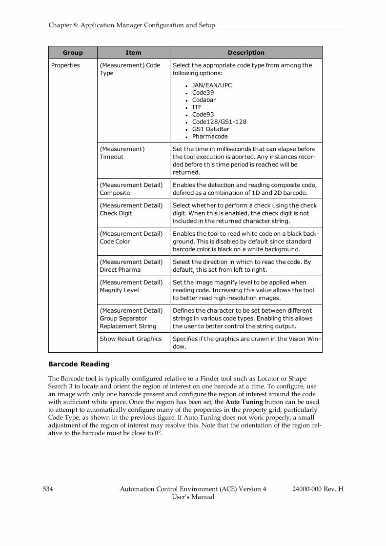
534 Automation Control Environment (ACE) Version 4User's Manual
24000-000 Rev. H
Chapter 8: Application Manager Configuration and Setup
Group Item Description
Properties (Measurement) CodeType
Select the appropriate code type from among thefollowing options:
l JAN/EAN/UPCl Code39l Codabarl ITFl Code93l Code128/GS1-128l GS1 DataBarl Pharmacode
(Measurement)Timeout
Set the time in milliseconds that can elapse beforethe tool execution is aborted. Any instances recor-ded before this time period is reachedwill bereturned.
(Measurement Detail)Composite
Enables the detection and reading composite code,defined as a combination of 1D and 2D barcode.
(Measurement Detail)Check Digit
Select whether to perform a check using the checkdigit. When this is enabled, the check digit is notincluded in the returned character string.
(Measurement Detail)Code Color
Enables the tool to readwhite code on a black back-ground. This is disabled by default since standardbarcode color is black on a white background.
(Measurement Detail)Direct Pharma
Select the direction in which to read the code. Bydefault, this set from left to right.
(Measurement Detail)Magnify Level
Set the image magnify level to be applied whenreading code. Increasing this value allows the toolto better read high-resolution images.
(Measurement Detail)Group SeparatorReplacement String
Defines the character to be set between differentstrings in various code types. Enabling this allowsthe user to better control the string output.
Show Result Graphics Specifies if the graphics are drawn in the Vision Win-dow.
Barcode Reading
The Barcode tool is typically configured relative to a Finder tool such as Locator or ShapeSearch 3 to locate and orient the region of interest on one barcode at a time. To configure, usean image with only one barcode present and configure the region of interest around the codewith sufficient white space. Once the region has been set, the Auto Tuning button can be usedto attempt to automatically configure many of the properties in the property grid, particularlyCode Type, as shown in the previous figure. If Auto Tuning does not work properly, a smalladjustment of the region of interest may resolve this. Note that the orientation of the region rel-ative to the barcode must be close to 0°.
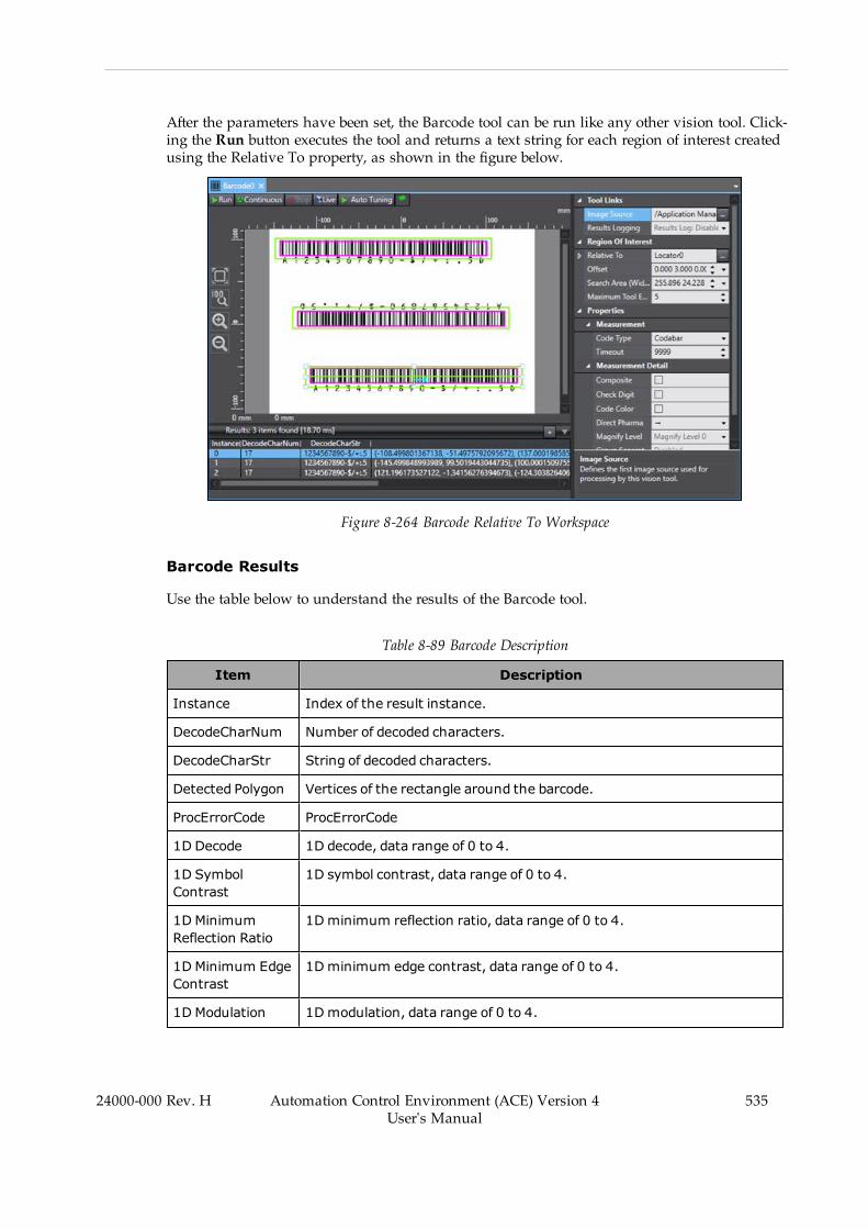
After the parameters have been set, the Barcode tool can be run like any other vision tool. Click-ing the Run button executes the tool and returns a text string for each region of interest createdusing the Relative To property, as shown in the figure below.
Figure 8-264 Barcode Relative To Workspace
Barcode Results
Use the table below to understand the results of the Barcode tool.
Table 8-89 Barcode Description
Item Description
Instance Index of the result instance.
DecodeCharNum Number of decoded characters.
DecodeCharStr String of decoded characters.
Detected Polygon Vertices of the rectangle around the barcode.
ProcErrorCode ProcErrorCode
1D Decode 1D decode, data range of 0 to 4.
1D SymbolContrast
1D symbol contrast, data range of 0 to 4.
1D MinimumReflection Ratio
1Dminimum reflection ratio, data range of 0 to 4.
1D Minimum EdgeContrast
1Dminimum edge contrast, data range of 0 to 4.
1D Modulation 1Dmodulation, data range of 0 to 4.
24000-000 Rev. H Automation Control Environment (ACE) Version 4User's Manual
535
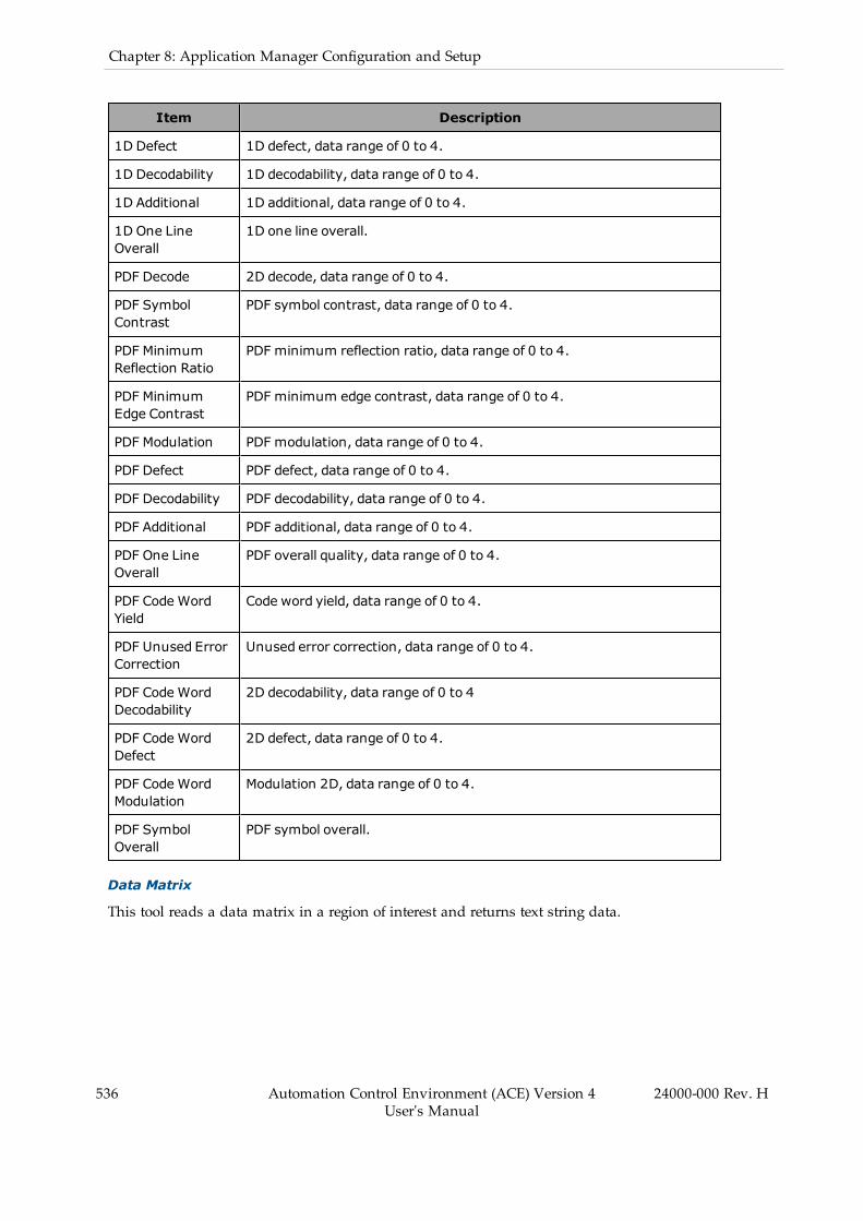
536 Automation Control Environment (ACE) Version 4User's Manual
24000-000 Rev. H
Chapter 8: Application Manager Configuration and Setup
Item Description
1D Defect 1D defect, data range of 0 to 4.
1D Decodability 1D decodability, data range of 0 to 4.
1D Additional 1D additional, data range of 0 to 4.
1D One LineOverall
1D one line overall.
PDF Decode 2D decode, data range of 0 to 4.
PDF SymbolContrast
PDF symbol contrast, data range of 0 to 4.
PDF MinimumReflection Ratio
PDF minimum reflection ratio, data range of 0 to 4.
PDF MinimumEdge Contrast
PDF minimum edge contrast, data range of 0 to 4.
PDF Modulation PDF modulation, data range of 0 to 4.
PDF Defect PDF defect, data range of 0 to 4.
PDF Decodability PDF decodability, data range of 0 to 4.
PDF Additional PDF additional, data range of 0 to 4.
PDF One LineOverall
PDF overall quality, data range of 0 to 4.
PDF CodeWordYield
Code word yield, data range of 0 to 4.
PDF Unused ErrorCorrection
Unused error correction, data range of 0 to 4.
PDF CodeWordDecodability
2D decodability, data range of 0 to 4
PDF CodeWordDefect
2D defect, data range of 0 to 4.
PDF CodeWordModulation
Modulation 2D, data range of 0 to 4.
PDF SymbolOverall
PDF symbol overall.
Data Matrix
This tool reads a data matrix in a region of interest and returns text string data.
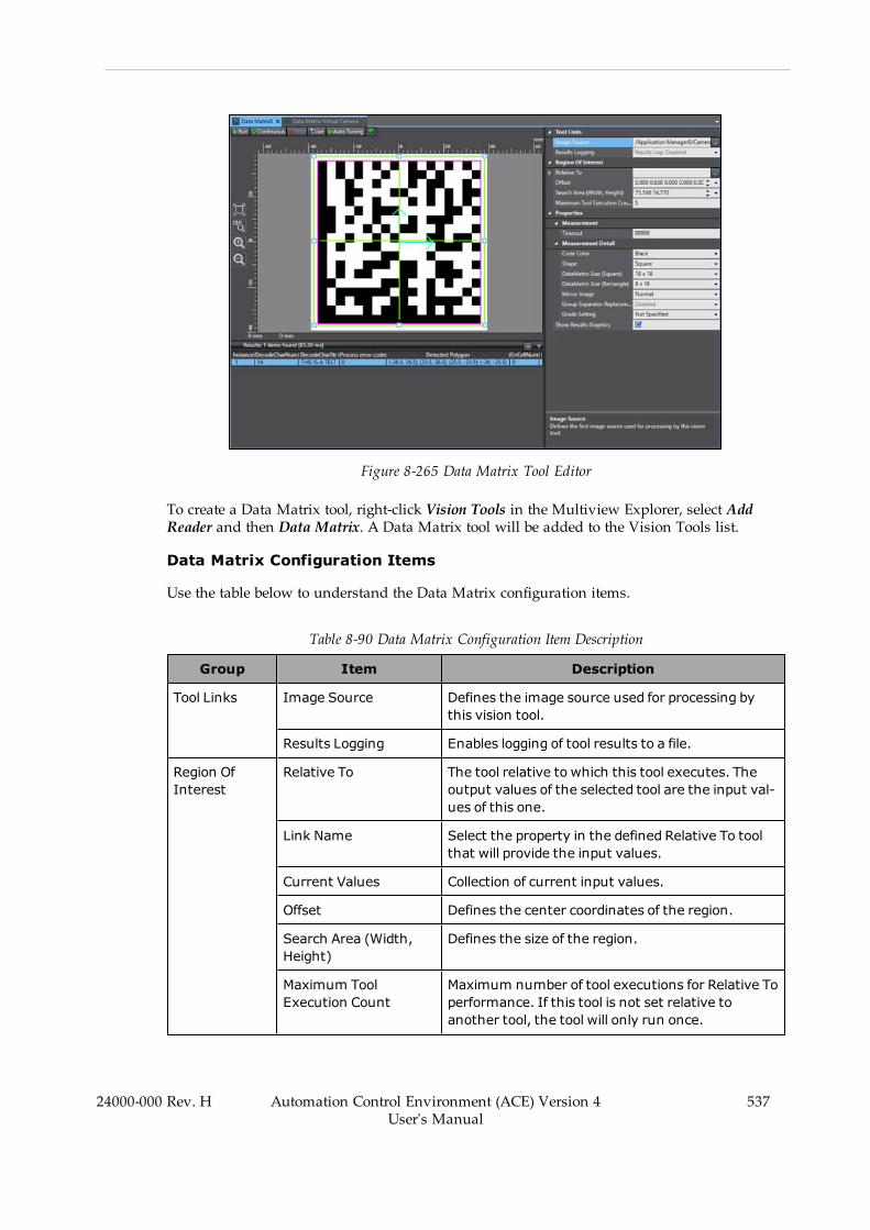
Figure 8-265 Data Matrix Tool Editor
To create a Data Matrix tool, right-click Vision Tools in the Multiview Explorer, select AddReader and then Data Matrix. A Data Matrix tool will be added to the Vision Tools list.
Data Matrix Configuration Items
Use the table below to understand the Data Matrix configuration items.
Table 8-90 Data Matrix Configuration Item Description
Group Item Description
Tool Links Image Source Defines the image source used for processing bythis vision tool.
Results Logging Enables logging of tool results to a file.
Region OfInterest
Relative To The tool relative to which this tool executes. Theoutput values of the selected tool are the input val-ues of this one.
Link Name Select the property in the defined Relative To toolthat will provide the input values.
Current Values Collection of current input values.
Offset Defines the center coordinates of the region.
Search Area (Width,Height)
Defines the size of the region.
Maximum ToolExecution Count
Maximum number of tool executions for Relative Toperformance. If this tool is not set relative toanother tool, the tool will only run once.
24000-000 Rev. H Automation Control Environment (ACE) Version 4User's Manual
537
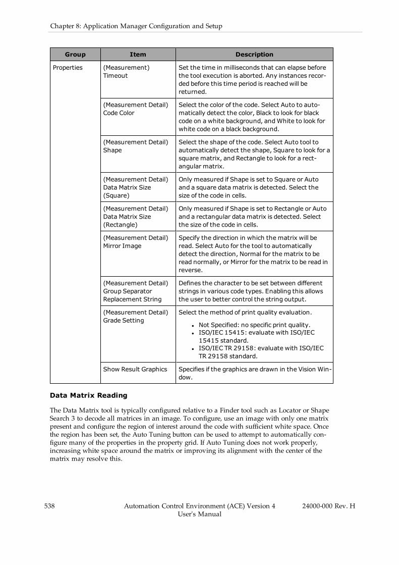
538 Automation Control Environment (ACE) Version 4User's Manual
24000-000 Rev. H
Chapter 8: Application Manager Configuration and Setup
Group Item Description
Properties (Measurement)Timeout
Set the time in milliseconds that can elapse beforethe tool execution is aborted. Any instances recor-ded before this time period is reachedwill bereturned.
(Measurement Detail)Code Color
Select the color of the code. Select Auto to auto-matically detect the color, Black to look for blackcode on a white background, andWhite to look forwhite code on a black background.
(Measurement Detail)Shape
Select the shape of the code. Select Auto tool toautomatically detect the shape, Square to look for asquare matrix, and Rectangle to look for a rect-angular matrix.
(Measurement Detail)Data Matrix Size(Square)
Only measured if Shape is set to Square or Autoand a square data matrix is detected. Select thesize of the code in cells.
(Measurement Detail)Data Matrix Size(Rectangle)
Only measured if Shape is set to Rectangle or Autoand a rectangular data matrix is detected. Selectthe size of the code in cells.
(Measurement Detail)Mirror Image
Specify the direction in which the matrix will beread. Select Auto for the tool to automaticallydetect the direction, Normal for the matrix to beread normally, or Mirror for the matrix to be read inreverse.
(Measurement Detail)Group SeparatorReplacement String
Defines the character to be set between differentstrings in various code types. Enabling this allowsthe user to better control the string output.
(Measurement Detail)Grade Setting
Select the method of print quality evaluation.
l Not Specified: no specific print quality.l ISO/IEC 15415: evaluate with ISO/IEC15415 standard.
l ISO/IEC TR 29158: evaluate with ISO/IECTR 29158 standard.
Show Result Graphics Specifies if the graphics are drawn in the Vision Win-dow.
Data Matrix Reading
The Data Matrix tool is typically configured relative to a Finder tool such as Locator or ShapeSearch 3 to decode all matrices in an image. To configure, use an image with only one matrixpresent and configure the region of interest around the code with sufficient white space. Oncethe region has been set, the Auto Tuning button can be used to attempt to automatically con-figure many of the properties in the property grid. If Auto Tuning does not work properly,increasing white space around the matrix or improving its alignment with the center of thematrix may resolve this.
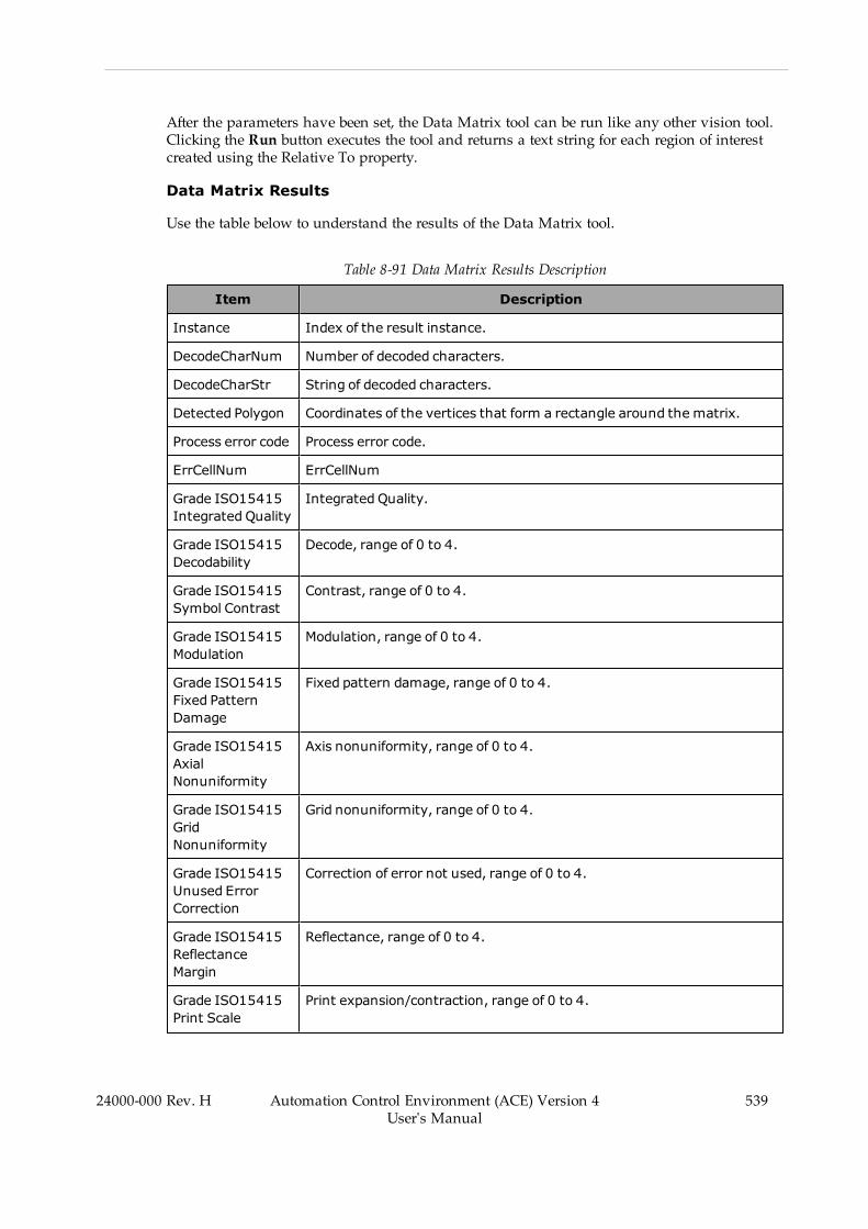
After the parameters have been set, the Data Matrix tool can be run like any other vision tool.Clicking the Run button executes the tool and returns a text string for each region of interestcreated using the Relative To property.
Data Matrix Results
Use the table below to understand the results of the Data Matrix tool.
Table 8-91 Data Matrix Results Description
Item Description
Instance Index of the result instance.
DecodeCharNum Number of decoded characters.
DecodeCharStr String of decoded characters.
Detected Polygon Coordinates of the vertices that form a rectangle around the matrix.
Process error code Process error code.
ErrCellNum ErrCellNum
Grade ISO15415Integrated Quality
Integrated Quality.
Grade ISO15415Decodability
Decode, range of 0 to 4.
Grade ISO15415Symbol Contrast
Contrast, range of 0 to 4.
Grade ISO15415Modulation
Modulation, range of 0 to 4.
Grade ISO15415Fixed PatternDamage
Fixed pattern damage, range of 0 to 4.
Grade ISO15415AxialNonuniformity
Axis nonuniformity, range of 0 to 4.
Grade ISO15415GridNonuniformity
Grid nonuniformity, range of 0 to 4.
Grade ISO15415Unused ErrorCorrection
Correction of error not used, range of 0 to 4.
Grade ISO15415ReflectanceMargin
Reflectance, range of 0 to 4.
Grade ISO15415Print Scale
Print expansion/contraction, range of 0 to 4.
24000-000 Rev. H Automation Control Environment (ACE) Version 4User's Manual
539

540 Automation Control Environment (ACE) Version 4User's Manual
24000-000 Rev. H
Chapter 8: Application Manager Configuration and Setup
Item Description
Grade ISO15415Print Scale X
Print expansion/contraction X, range of 0 to 4.
Grade ISO15415Print Scale Y
Print expansion/contraction Y, range of 0 to 4.
Value ISO15415Symbol Contrast
Symbol contrast, range of 0 to 4.
Value ISO15415AxialNonuniformity
Axis nonuniformity, range of 0 to 4.
Value ISO15415GridNonuniformity
Grid nonuniformity, range of 0 to 4.
Value ISO15415Unused errorCorrection
Correction of error not used, range of 0 to 4.
Value ISO15415Print Scale
Print expansion/contraction, range of 0 to 4.
Value ISO15415Print Scale X
Print expansion/contraction X, range of 0 to 4.
Value ISO15415Print Scale Y
Print expansion/contraction Y, range of 0 to 4.
GradeISOTR29158Integrated Quality
Integrated Quality, range of 0 to 4.
GradeISOTR29158 CellContrast
Contrast, range of 0 to 4.
GradeISOTR29158 SelfModulation
Modulation, range of 0 to 4.
GradeISOTR29158Fixed PatternDamage
Fixed pattern damage, range of 0 to 4.
GradeISOTR29158 AxialNonuniformity
Axis nonuniformity, range of 0 to 4.
GradeISOTR29158 GridNonuniformity
Grid nonuniformity, range of 0 to 4.
GradeISOTR29158
Correction of error not used, range of 0 to 4.
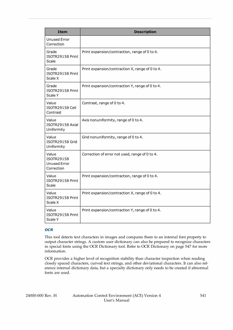
Item Description
Unused ErrorCorrection
GradeISOTR29158 PrintScale
Print expansion/contraction, range of 0 to 4.
GradeISOTR29158 PrintScale X
Print expansion/contraction X, range of 0 to 4.
GradeISOTR29158 PrintScale Y
Print expansion/contraction Y, range of 0 to 4.
ValueISOTR29158 CellContrast
Contrast, range of 0 to 4.
ValueISOTR29158 AxialUniformity
Axis nonuniformity, range of 0 to 4.
ValueISOTR29158 GridUniformity
Grid nonuniformity, range of 0 to 4.
ValueISOTR29158Unused ErrorCorrection
Correction of error not used, range of 0 to 4.
ValueISOTR29158 PrintScale
Print expansion/contraction, range of 0 to 4.
ValueISOTR29158 PrintScale X
Print expansion/contraction X, range of 0 to 4.
ValueISOTR29158 PrintScale Y
Print expansion/contraction Y, range of 0 to 4.
OCR
This tool detects text characters in images and compares them to an internal font property tooutput character strings. A custom user dictionary can also be prepared to recognize charactersin special fonts using the OCR Dictionary tool. Refer to OCR Dictionary on page 547 for moreinformation.
OCR provides a higher level of recognition stability than character inspection when readingclosely spaced characters, curved text strings, and other deviational characters. It can also ref-erence internal dictionary data, but a specialty dictionary only needs to be created if abnormalfonts are used.
24000-000 Rev. H Automation Control Environment (ACE) Version 4User's Manual
541

542 Automation Control Environment (ACE) Version 4User's Manual
24000-000 Rev. H
Chapter 8: Application Manager Configuration and Setup
NOTE: Typical OCR applications use strings of number and capital letters. Ifthe application involves detection of lower case letters, a user-defined OCR Dic-tionary is required.
Figure 8-266 OCR Tool Editor
To create an OCR tool, right-click Vision Tools in the Multiview Explorer, select Add Readerand then OCR. An OCR tool will be added to the Vision Tools list.
OCR Configuration Items
Use the table below to understand the OCR configuration items.
Table 8-92 OCR Configuration Item Description
Group Item Description
Tool Links Image Source Defines the image source used for processing bythis vision tool.
OCR Dictionary Defines which OCR Dictionary tool is used for ref-erence and registering characters.
Results Logging Enables logging of tool results to a file.
Region OfInterest
Relative To The tool relative to which this tool executes. Theoutput values of the selected tool are the input val-ues of this one.
Link Name Select the property in the defined Relative To toolthat will provide the input values.
Current Values Collection of current input values.
Offset Defines the center coordinates of the region.
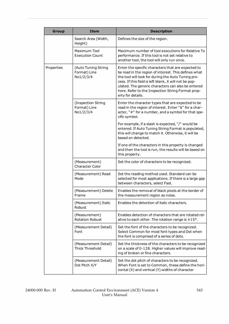
Group Item Description
Search Area (Width,Height)
Defines the size of the region.
Maximum ToolExecution Count
Maximum number of tool executions for Relative Toperformance. If this tool is not set relative toanother tool, the tool will only run once.
Properties (Auto Tuning StringFormat) LineNo1/2/3/4
Enter the specific characters that are expected tobe read in the region of interest. This defines whatthe tool will look for during the Auto Tuning pro-cess. If this field is left blank, it will not be pop-ulated. The generic characters can also be enteredhere. Refer to the Inspection String Format prop-erty for details.
(Inspection StringFormat) LineNo1/2/3/4
Enter the character types that are expected to beread in the region of interest. Enter "$" for a char-acter, "#" for a number, and a symbol for that spe-cific symbol.
For example, if a slash is expected, "/" would beentered. If Auto Tuning String Format is populated,this will change tomatch it. Otherwise, it will bebased on detected.
If one of the characters in this property is changedand then the tool is run, the results will be based onthis property.
(Measurement)Character Color
Set the color of characters to be recognized.
(Measurement) ReadMode
Set the readingmethod used. Standard can beselected for most applications. If there is a large gapbetween characters, select Fast.
(Measurement) DeleteFrame
Enables the removal of black pixels at the border ofthe measurement region as noise.
(Measurement) ItalicRobust
Enables the detection of italic characters.
(Measurement)Rotation Robust
Enables detection of characters that are rotated rel-ative to each other. The rotation range is ±15°.
(Measurement Detail)Font
Set the font of the characters to be recognized.Select Common for most font types and Dot whenthe font is comprised of a series of dots.
(Measurement Detail)Thick Threshold
Set the thickness of the characters to be recognizedon a scale of 0-128. Higher values will improve read-ing of broken or fine characters.
(Measurement Detail)Dot Pitch X/Y
Set the dot pitch of characters to be recognized.When Font is set to Common, these define the hori-zontal (X) and vertical (Y) widths of character
24000-000 Rev. H Automation Control Environment (ACE) Version 4User's Manual
543

544 Automation Control Environment (ACE) Version 4User's Manual
24000-000 Rev. H
Chapter 8: Application Manager Configuration and Setup
Group Item Description
breaks. When Font is set to Dot, these define thehorizontal (X) and vertical (Y) dot intervals.
(Measurement Detail)Max Width
Defines the maximum width (in pixels) of char-acters to be recognized. This is disabled by default.
(Measurement Detail)Max Height
Set the maximum height (in pixels) of characters tobe detected.
(Measurement Detail)Min Height (%)
Set the minimum height of characters to be recog-nized as a percentage of the Max Height property.Characters below this threshold are recognized assymbols.
(Measurement Detail)Max Aspect Ratio
Set the maximum aspect ratio (calculated as heightdivided by width) of characters to be recognized.Characters with an aspect ratio greater than thisvalue are recognized as special characters or sym-bols.
(Measurement Detail)Hyphen Threshold
Set an upper and lower limit as a percentage of theclosest neighboring character
Show Results Graphics Specifies if the graphics are drawn in the Vision Win-dow.
Results Display Select the type of result marker to be displayed.Recognition Markers displays only markers relatedto recognized characters and All Markers displaysmarkers for all characters.
Cut out image display Enables display to show all characters as cutouts.Recognized characters will be isolated on a whitebackground. The gray region displayed in thecutout image display is the region bounded by theDot Pitch X and Dot Pitch Y parameters.
OCR - Acquiring Text Strings
Clicking the Auto Tuning button will attempt to automatically detect the types of characters inthe region. These will be displayed in the Inspection String Format section, as shown the pre-vious figure. If the tool is not correctly tuning to the text, it can be manipulated using this sec-tion and Auto Tuning String Format.
For example the tool will try to find the best numerical matches for all the letters in Line 1 andthe best letter matches for all the numbers in Line 2 if the corresponding lines in the Auto Tun-ing String Format section are set to the number symbol "#" and the character symbol "$",respectively. In this way, characters that are read inaccurately can be corrected to their properform. The specific expected characters can also be entered to further improve the results.
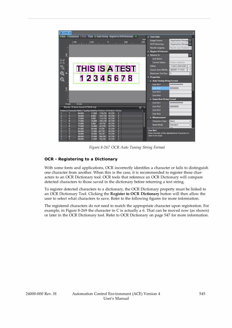
Figure 8-267 OCR Auto Tuning String Format
OCR - Registering to a Dictionary
With some fonts and applications, OCR incorrectly identifies a character or fails to distinguishone character from another. When this is the case, it is recommended to register these char-acters to an OCR Dictionary tool. OCR tools that reference an OCR Dictionary will comparedetected characters to those saved in the dictionary before returning a text string.
To register detected characters to a dictionary, the OCR Dictionary property must be linked toan OCR Dictionary Tool. Clicking the Register to OCR Dictionary button will then allow theuser to select what characters to save. Refer to the following figures for more information.
The registered characters do not need to match the appropriate character upon registration. Forexample, in Figure 8-269 the character in C is actually a 6. That can be moved now (as shown)or later in the OCR Dictionary tool. Refer to OCR Dictionary on page 547 for more information.
24000-000 Rev. H Automation Control Environment (ACE) Version 4User's Manual
545
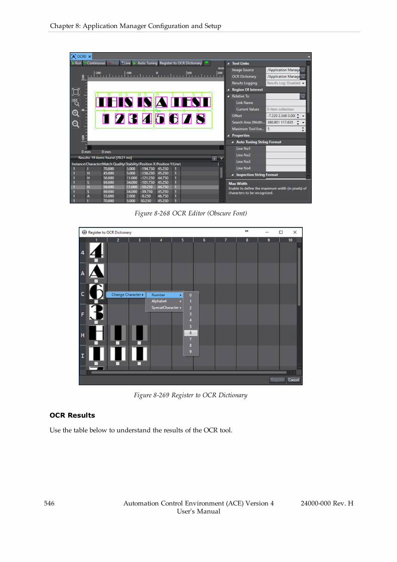
546 Automation Control Environment (ACE) Version 4User's Manual
24000-000 Rev. H
Chapter 8: Application Manager Configuration and Setup
Figure 8-268 OCR Editor (Obscure Font)
Figure 8-269 Register to OCR Dictionary
OCR Results
Use the table below to understand the results of the OCR tool.
Table 8-93 OCR Results Description
Item Description
Instance Index of the result instance, starting with 1.
Frame/Group Index of the related result. It is associated with the tool that this tool is setRelative To. This will only be different if the Locator is set relative to anothertool.
Character Detected character identification.
Match Quality Percentage that the detected character matches the recorded character inthe internal dictionary or OCR Dictionary tool.
Stability Measurement of how likely the character is to be the result that was iden-tified.
Position X X-coordinate of the detected character with respect to the image origin.
Position Y Y-coordinate of the detected character with respect to the image origin.
Line Character’s line of text within the region of interest.
OCR Dictionary
This tool is used only as a reference for OCR tools and can only be configured for and pop-ulated by an OCR tool. It is used to save characters that the OCR identifies incorrectly or failsto identify. An OCR tool will first compare detected characters to an internal dictionary dataand then to a referenced OCR Dictionary. Internal dictionary data cannot be modified. Refer toOCR on page 541 for more information.
Because OCR Dictionary is only a reference, it has no properties or results. It only containsdata about registered characters.
NOTE: The following figure shows the OCR Dictionary with some registeredcharacters. The OCR Dictionary will appear blank if no characters have beenregistered.
24000-000 Rev. H Automation Control Environment (ACE) Version 4User's Manual
547

548 Automation Control Environment (ACE) Version 4User's Manual
24000-000 Rev. H
Chapter 8: Application Manager Configuration and Setup
Figure 8-270 OCR Dictionary Tool Editor
To create an OCR Dictionary tool, right-click Vision Tools in the Multiview Explorer, select AddReader and then OCR Dictionary. An OCR Dictionary tool will be added to the Vision Toolslist.
OCR Dictionary Configuration
Up to ten dictionary entries can be registered for each character. If more than ten characters areregistered, the tool will only save the first ten and remove the others.
The characters can be changed or deleted at any time by right-clicking on the figure. SelectingDelete will remove the entry from the dictionary. Selecting Change Character will allow theentry to be saved to any other character.
If the character to which the entry would be changed already contains ten entries, the entrywill not move. Figure 8-270 shows the OCR Dictionary after all necessary changes have beenmade. The following figure shows one such change in progress.

Figure 8-271 OCR Dictionary Entry Change
QR Code
This tool reads QR Codes and Micro QR Codes in the image and returns text string data.
Figure 8-272 QR Code Tool Editor
To create a QR Code tool, right-click Vision Tools in the Multiview Explorer, select Add Readerand then QR Code. A QR Code tool will be added to the Vision Tools list.
QR Code Configuration Items
Use the table below to understand the QR Code configuration items.
24000-000 Rev. H Automation Control Environment (ACE) Version 4User's Manual
549
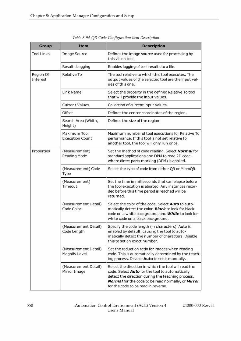
550 Automation Control Environment (ACE) Version 4User's Manual
24000-000 Rev. H
Chapter 8: Application Manager Configuration and Setup
Table 8-94 QR Code Configuration Item Description
Group Item Description
Tool Links Image Source Defines the image source used for processing bythis vision tool.
Results Logging Enables logging of tool results to a file.
Region OfInterest
Relative To The tool relative to which this tool executes. Theoutput values of the selected tool are the input val-ues of this one.
Link Name Select the property in the defined Relative To toolthat will provide the input values.
Current Values Collection of current input values.
Offset Defines the center coordinates of the region.
Search Area (Width,Height)
Defines the size of the region.
Maximum ToolExecution Count
Maximum number of tool executions for Relative Toperformance. If this tool is not set relative toanother tool, the tool will only run once.
Properties (Measurement)ReadingMode
Set the method of code reading. Select Normal forstandard applications and DPM to read 2D codewhere direct parts marking (DPM) is applied.
(Measurement) CodeType
Select the type of code from either QR or MicroQR.
(Measurement)Timeout
Set the time in milliseconds that can elapse beforethe tool execution is aborted. Any instances recor-ded before this time period is reachedwill bereturned.
(Measurement Detail)Code Color
Select the color of the code. Select Auto to auto-matically detect the color,Black to look for blackcode on a white background, andWhite to look forwhite code on a black background.
(Measurement Detail)Code Length
Specify the code length (in characters). Auto isenabled by default, causing the tool to auto-matically detect the number of characters. Disablethis to set an exact number.
(Measurement Detail)Magnify Level
Set the reduction ratio for images when readingcode. This is automatically determined by the teach-ing process. Disable Auto to set it manually.
(Measurement Detail)Mirror Image
Select the direction in which the tool will read thecode. Select Auto for the tool to automaticallydetect the direction during the teaching process,Normal for the code to be read normally, orMirrorfor the code to be read in reverse.
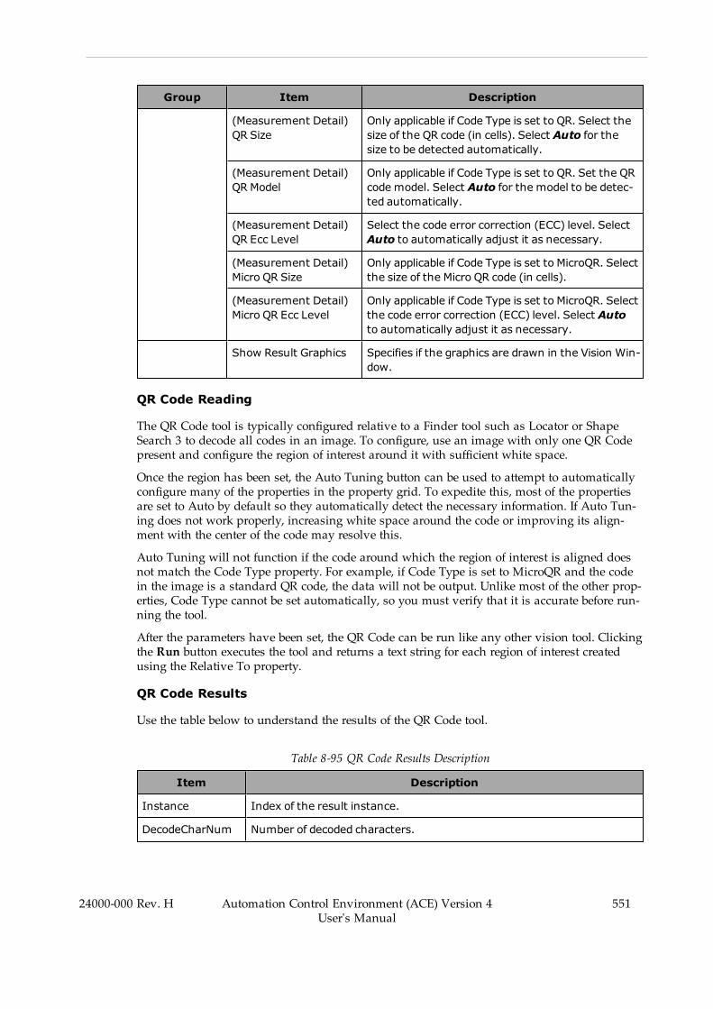
Group Item Description
(Measurement Detail)QR Size
Only applicable if Code Type is set to QR. Select thesize of the QR code (in cells). Select Auto for thesize to be detected automatically.
(Measurement Detail)QRModel
Only applicable if Code Type is set to QR. Set the QRcode model. Select Auto for the model to be detec-ted automatically.
(Measurement Detail)QR Ecc Level
Select the code error correction (ECC) level. SelectAuto to automatically adjust it as necessary.
(Measurement Detail)Micro QR Size
Only applicable if Code Type is set to MicroQR. Selectthe size of the Micro QR code (in cells).
(Measurement Detail)Micro QR Ecc Level
Only applicable if Code Type is set to MicroQR. Selectthe code error correction (ECC) level. Select Autoto automatically adjust it as necessary.
Show Result Graphics Specifies if the graphics are drawn in the Vision Win-dow.
QR Code Reading
The QR Code tool is typically configured relative to a Finder tool such as Locator or ShapeSearch 3 to decode all codes in an image. To configure, use an image with only one QR Codepresent and configure the region of interest around it with sufficient white space.
Once the region has been set, the Auto Tuning button can be used to attempt to automaticallyconfigure many of the properties in the property grid. To expedite this, most of the propertiesare set to Auto by default so they automatically detect the necessary information. If Auto Tun-ing does not work properly, increasing white space around the code or improving its align-ment with the center of the code may resolve this.
Auto Tuning will not function if the code around which the region of interest is aligned doesnot match the Code Type property. For example, if Code Type is set to MicroQR and the codein the image is a standard QR code, the data will not be output. Unlike most of the other prop-erties, Code Type cannot be set automatically, so you must verify that it is accurate before run-ning the tool.
After the parameters have been set, the QR Code can be run like any other vision tool. Clickingthe Run button executes the tool and returns a text string for each region of interest createdusing the Relative To property.
QR Code Results
Use the table below to understand the results of the QR Code tool.
Table 8-95 QR Code Results Description
Item Description
Instance Index of the result instance.
DecodeCharNum Number of decoded characters.
24000-000 Rev. H Automation Control Environment (ACE) Version 4User's Manual
551

552 Automation Control Environment (ACE) Version 4User's Manual
24000-000 Rev. H
Chapter 8: Application Manager Configuration and Setup
Item Description
DecodeCharStr String of decoded characters.
Detected Polygon Coordinates of the vertices that form a rectangle around the code.
Process error code Process error code.
ReadRatio Effective codeword ratio.
Contrast Sharpness of an image on a scale of 0 to 100.
Focus Number of false cell detections in the finder pattern, timing pattern, anddata region.
ErrCellNum ErrCellNum
Position X/Y coordinates of the center of the detected QR code.
Angle Angle of the detected QR code.
Calculation Tools
Calculation tools are used for calculating or refining detection points. The following Cal-culation tools are described in this section.
l Refer to Calculated Arc on page 552 for more information.l Refer to Calculated Frame on page 555 for more information.l Refer to Calculation Line on page 557 for more information.l Refer to Calculated Point on page 560 for more information.
Calculated Arc
This tool is used to create a graphical circle enclosing an arc based on referenced elements. Thecircle can be used for tasks such as better defining a circular part or creating a clearance his-togram. It can also be used to identify the center of a part with corners, as shown in the fol-lowing figure.
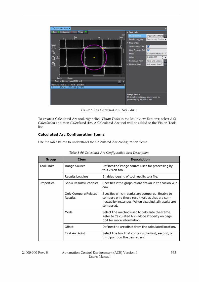
Figure 8-273 Calculated Arc Tool Editor
To create a Calculated Arc tool, right-click Vision Tools in the Multiview Explorer, select AddCalculation and then Calculated Arc. A Calculated Arc tool will be added to the Vision Toolslist.
Calculated Arc Configuration Items
Use the table below to understand the Calculated Arc configuration items.
Table 8-96 Calculated Arc Configuration Item Description
Group Item Description
Tool Links Image Source Defines the image source used for processing bythis vision tool.
Results Logging Enables logging of tool results to a file.
Properties Show Results Graphics Specifies if the graphics are drawn in the Vision Win-dow.
Only Compare RelatedResults
Specifies which results are compared. Enable tocompare only those result values that are con-nected by instances. When disabled, all results arecompared.
Mode Select the method used to calculate the frame.Refer to Calculated Arc - Mode Property on page554 for more information.
Offset Defines the arc offset from the calculated location.
First Arc Point Select the tool that contains the first, second, orthird point on the desired arc.
24000-000 Rev. H Automation Control Environment (ACE) Version 4User's Manual
553
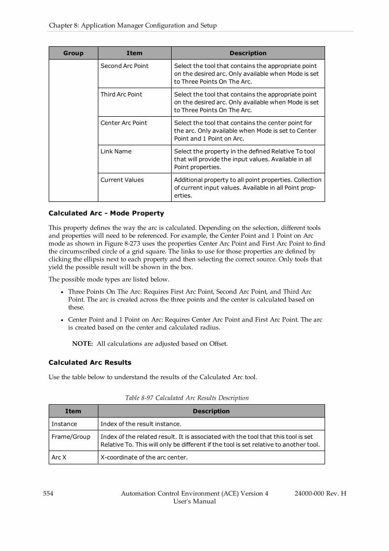
554 Automation Control Environment (ACE) Version 4User's Manual
24000-000 Rev. H
Chapter 8: Application Manager Configuration and Setup
Group Item Description
Second Arc Point Select the tool that contains the appropriate pointon the desired arc. Only available when Mode is setto Three Points On The Arc.
Third Arc Point Select the tool that contains the appropriate pointon the desired arc. Only available when Mode is setto Three Points On The Arc.
Center Arc Point Select the tool that contains the center point forthe arc. Only available when Mode is set to CenterPoint and 1 Point on Arc.
Link Name Select the property in the defined Relative To toolthat will provide the input values. Available in allPoint properties.
Current Values Additional property to all point properties. Collectionof current input values. Available in all Point prop-erties.
Calculated Arc - Mode Property
This property defines the way the arc is calculated. Depending on the selection, different toolsand properties will need to be referenced. For example, the Center Point and 1 Point on Arcmode as shown in Figure 8-273 uses the properties Center Arc Point and First Arc Point to findthe circumscribed circle of a grid square. The links to use for those properties are defined byclicking the ellipsis next to each property and then selecting the correct source. Only tools thatyield the possible result will be shown in the box.
The possible mode types are listed below.
l Three Points On The Arc: Requires First Arc Point, Second Arc Point, and Third ArcPoint. The arc is created across the three points and the center is calculated based onthese.
l Center Point and 1 Point on Arc: Requires Center Arc Point and First Arc Point. The arcis created based on the center and calculated radius.
NOTE: All calculations are adjusted based on Offset.
Calculated Arc Results
Use the table below to understand the results of the Calculated Arc tool.
Table 8-97 Calculated Arc Results Description
Item Description
Instance Index of the result instance.
Frame/Group Index of the related result. It is associated with the tool that this tool is setRelative To. This will only be different if the tool is set relative to another tool.
Arc X X-coordinate of the arc center.
Item Description
Arc Y Y-coordinate of the arc center.
Radius Calculated arc radius.
Opening Opening of the arc in degrees.
Since this tool always generates circles, this is invariably returned as 360.
Rotation Rotation of the arc. This is always returned as 0.
Thickness Thickness of the arc. This is always returned as 0.
Calculated Frame
This tool is used to create a vision frame from referenced elements. Frames allow placement ofvision tools on objects that are not always in the same location or orientation. When a new vis-ion tool is created, it can be specified to be relative to a vision frame. If the object that definesthe vision frame moves, so will the frame and the tools that are relative to that frame.
Additional Information: A fixed frame can also be created using this tool.
Figure 8-274 Calculated Frame Tool Editor
To create a Calculated Frame tool, right-click Vision Tools in the Multiview Explorer, selectAdd Calculation and then Calculated Frame. A Calculated Frame tool will be added to theVision Tools list.
Calculated Frame Configuration Items
Use the table below to understand the Calculated Frame configuration items.
24000-000 Rev. H Automation Control Environment (ACE) Version 4User's Manual
555
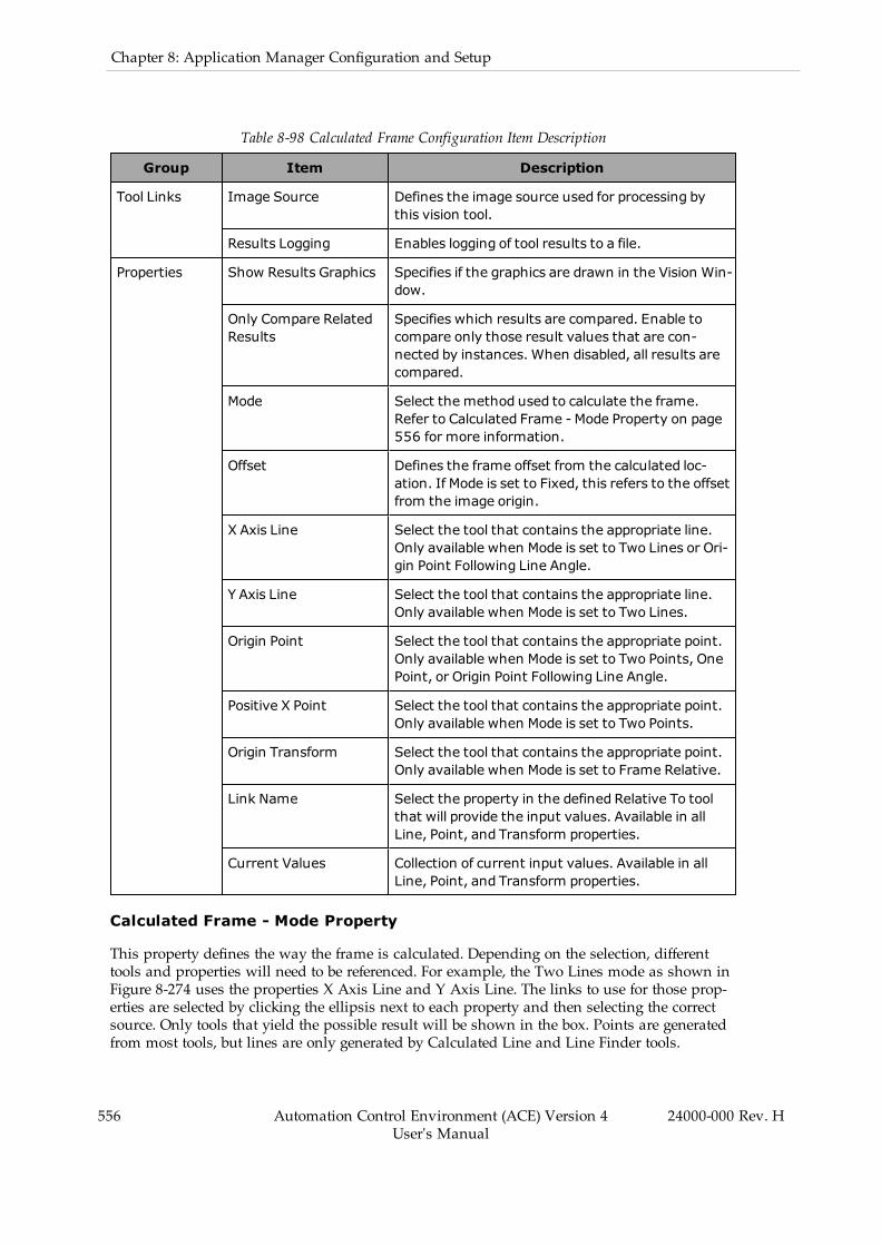
556 Automation Control Environment (ACE) Version 4User's Manual
24000-000 Rev. H
Chapter 8: Application Manager Configuration and Setup
Table 8-98 Calculated Frame Configuration Item Description
Group Item Description
Tool Links Image Source Defines the image source used for processing bythis vision tool.
Results Logging Enables logging of tool results to a file.
Properties Show Results Graphics Specifies if the graphics are drawn in the Vision Win-dow.
Only Compare RelatedResults
Specifies which results are compared. Enable tocompare only those result values that are con-nected by instances. When disabled, all results arecompared.
Mode Select the method used to calculate the frame.Refer to Calculated Frame - Mode Property on page556 for more information.
Offset Defines the frame offset from the calculated loc-ation. If Mode is set to Fixed, this refers to the offsetfrom the image origin.
X Axis Line Select the tool that contains the appropriate line.Only available when Mode is set to Two Lines or Ori-gin Point Following Line Angle.
Y Axis Line Select the tool that contains the appropriate line.Only available when Mode is set to Two Lines.
Origin Point Select the tool that contains the appropriate point.Only available when Mode is set to Two Points, OnePoint, or Origin Point Following Line Angle.
Positive X Point Select the tool that contains the appropriate point.Only available when Mode is set to Two Points.
Origin Transform Select the tool that contains the appropriate point.Only available when Mode is set to Frame Relative.
Link Name Select the property in the defined Relative To toolthat will provide the input values. Available in allLine, Point, and Transform properties.
Current Values Collection of current input values. Available in allLine, Point, and Transform properties.
Calculated Frame - Mode Property
This property defines the way the frame is calculated. Depending on the selection, differenttools and properties will need to be referenced. For example, the Two Lines mode as shown inFigure 8-274 uses the properties X Axis Line and Y Axis Line. The links to use for those prop-erties are selected by clicking the ellipsis next to each property and then selecting the correctsource. Only tools that yield the possible result will be shown in the box. Points are generatedfrom most tools, but lines are only generated by Calculated Line and Line Finder tools.
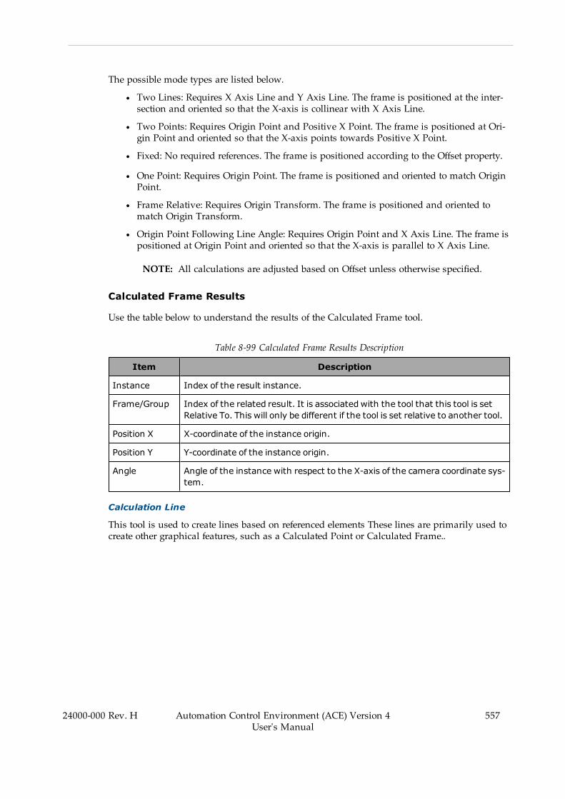
The possible mode types are listed below.
l Two Lines: Requires X Axis Line and Y Axis Line. The frame is positioned at the inter-section and oriented so that the X-axis is collinear with X Axis Line.
l Two Points: Requires Origin Point and Positive X Point. The frame is positioned at Ori-gin Point and oriented so that the X-axis points towards Positive X Point.
l Fixed: No required references. The frame is positioned according to the Offset property.
l One Point: Requires Origin Point. The frame is positioned and oriented to match OriginPoint.
l Frame Relative: Requires Origin Transform. The frame is positioned and oriented tomatch Origin Transform.
l Origin Point Following Line Angle: Requires Origin Point and X Axis Line. The frame ispositioned at Origin Point and oriented so that the X-axis is parallel to X Axis Line.
NOTE: All calculations are adjusted based on Offset unless otherwise specified.
Calculated Frame Results
Use the table below to understand the results of the Calculated Frame tool.
Table 8-99 Calculated Frame Results Description
Item Description
Instance Index of the result instance.
Frame/Group Index of the related result. It is associated with the tool that this tool is setRelative To. This will only be different if the tool is set relative to another tool.
Position X X-coordinate of the instance origin.
Position Y Y-coordinate of the instance origin.
Angle Angle of the instance with respect to the X-axis of the camera coordinate sys-tem.
Calculation Line
This tool is used to create lines based on referenced elements These lines are primarily used tocreate other graphical features, such as a Calculated Point or Calculated Frame..
24000-000 Rev. H Automation Control Environment (ACE) Version 4User's Manual
557

558 Automation Control Environment (ACE) Version 4User's Manual
24000-000 Rev. H
Chapter 8: Application Manager Configuration and Setup
Figure 8-275 Calculated Line Tool Editor
To create a Calculated Line tool, right-click Vision Tools in the Multiview Explorer, select AddCalculation and then Calculated Line. A Calculated Line tool will be added to the Vision Toolslist.
Calculated Line Configuration Items
Use the table below to understand the Calculated Line configuration items.
Table 8-100 Calculated Line Configuration Item Description
Group Item Description
Tool Links Image Source Defines the image source used for processing bythis vision tool.
Results Logging Enables logging of tool results to a file.
Properties Show Results Graphics Specifies if the graphics are drawn in the Vision Win-dow.
Only Compare RelatedResults
Specifies which results are compared. Enable tocompare only those result values that are con-nected by instances. When disabled, all results arecompared.
Mode Select the method used to calculate the line. Referto Calculated Line - Mode Property on page 559 formore information.
Offset Defines the line offset from the calculated location.
Point 1 Select the tool that contains the first endpoint of
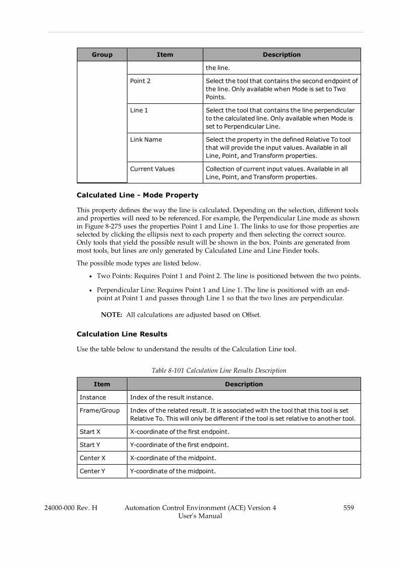
Group Item Description
the line.
Point 2 Select the tool that contains the second endpoint ofthe line. Only available when Mode is set to TwoPoints.
Line 1 Select the tool that contains the line perpendicularto the calculated line. Only available when Mode isset to Perpendicular Line.
Link Name Select the property in the defined Relative To toolthat will provide the input values. Available in allLine, Point, and Transform properties.
Current Values Collection of current input values. Available in allLine, Point, and Transform properties.
Calculated Line - Mode Property
This property defines the way the line is calculated. Depending on the selection, different toolsand properties will need to be referenced. For example, the Perpendicular Line mode as shownin Figure 8-275 uses the properties Point 1 and Line 1. The links to use for those properties areselected by clicking the ellipsis next to each property and then selecting the correct source.Only tools that yield the possible result will be shown in the box. Points are generated frommost tools, but lines are only generated by Calculated Line and Line Finder tools.
The possible mode types are listed below.
l Two Points: Requires Point 1 and Point 2. The line is positioned between the two points.
l Perpendicular Line: Requires Point 1 and Line 1. The line is positioned with an end-point at Point 1 and passes through Line 1 so that the two lines are perpendicular.
NOTE: All calculations are adjusted based on Offset.
Calculation Line Results
Use the table below to understand the results of the Calculation Line tool.
Table 8-101 Calculation Line Results Description
Item Description
Instance Index of the result instance.
Frame/Group Index of the related result. It is associated with the tool that this tool is setRelative To. This will only be different if the tool is set relative to another tool.
Start X X-coordinate of the first endpoint.
Start Y Y-coordinate of the first endpoint.
Center X X-coordinate of the midpoint.
Center Y Y-coordinate of the midpoint.
24000-000 Rev. H Automation Control Environment (ACE) Version 4User's Manual
559

560 Automation Control Environment (ACE) Version 4User's Manual
24000-000 Rev. H
Chapter 8: Application Manager Configuration and Setup
Item Description
End X X-coordinate of the second endpoint.
End Y Y-coordinate of the second endpoint.
Angle Calculated angle of the line with respect to the X-axis of the camera coordin-ate system.
Calculated Point
This tool is used to create points based on referenced elements. These points can be used to cre-ate other graphical features, such as Calculated Arc or Calculated Line, or to act as a referencepoint from which other measurements can be made.
Figure 8-276 Calculated Point Tool Editor
To create a Calculated Point tool, right-click Vision Tools in the Multiview Explorer, select AddCalculation and then Calculated Point. A Calculated Point tool will be added to the VisionTools list.
Calculated Point Configuration Items
Use the table below to understand the Calculated Point configuration items.
Table 8-102 Calculated Point Configuration Item Description
Group Item Description
Tool Links Image Source Defines the image source used for processing bythis vision tool.
Results Logging Enables logging of tool results to a file.
Properties Show Results Graphics Specifies if the graphics are drawn in the Vision Win-
Group Item Description
dow.
Only Compare RelatedResults
Specifies which results are compared. Enable tocompare only those result values that are con-nected by instances. When disabled, all results arecompared.
Mode Select the method used to calculate the point.Refer to Calculated Point - Mode Property on page561.
Offset Defines the point’s offset from the calculated loc-ation.
Point 1 Select the tool that contains the first referencepoint. Only available when Mode is set to Midpoint,Point On A Line Closest To A Point, or Point On AnArc Closest To A Point.
Point 2 Select the tool that contains the second referencepoint. Only available when Mode is set to Midpoint.
Line 1 Select the tool that contains the first reference line.Only available when Mode is set to Point On A LineClosest To A Point, Line – Arc Intersection, or Inter-section Of Two Lines.
Line 2 Select the tool that contains the second referenceline. Only available when Mode is set to IntersectionOf Two Lines.
First Arc Select the tool that contains the first reference arc.Only available when Mode is set to Point On An ArcClosest To A Point, Line – Arc Intersection, or Inter-section of Two Arcs.
Second Arc Select the tool that contains the second referencearc. Only available when Mode is set to Intersectionof Two Arcs.
Link Name Select the property in the defined Relative To toolthat will provide the input values. Available in allLine, Point, and Transform properties.
Current Values Collection of current input values. Available in allLine, Point, and Transform properties.
Calculated Point - Mode Property
This property defines the way the point is calculated. Depending on the selection, differenttools and properties will need to be referenced. For example, the Intersection Of Two Linesmode as shown in Figure 8-276 uses the properties Line 1 and Line 2. The links to use forthose properties are selected by clicking the ellipsis next to each property and then selectingthe correct source. Only tools that yield the correct type of result will be shown in the box.
24000-000 Rev. H Automation Control Environment (ACE) Version 4User's Manual
561
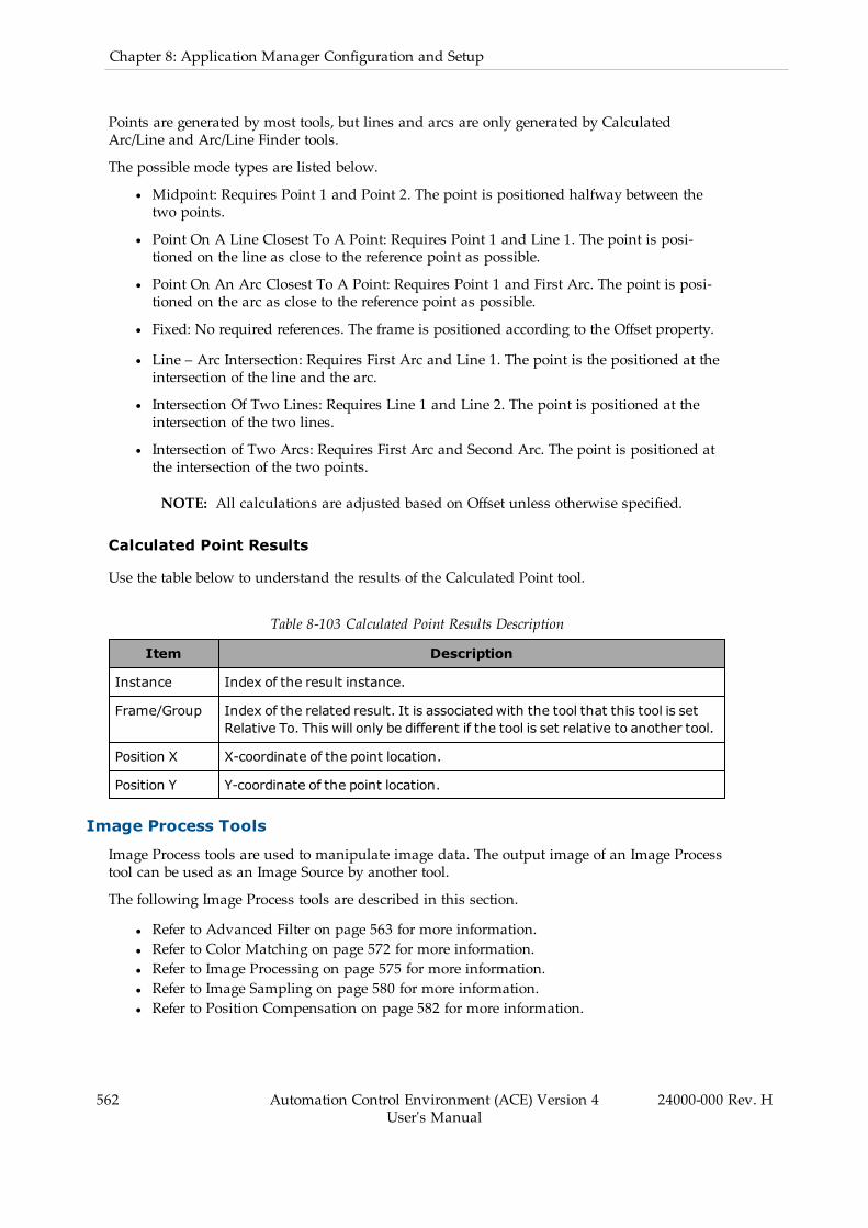
562 Automation Control Environment (ACE) Version 4User's Manual
24000-000 Rev. H
Chapter 8: Application Manager Configuration and Setup
Points are generated by most tools, but lines and arcs are only generated by CalculatedArc/Line and Arc/Line Finder tools.
The possible mode types are listed below.
l Midpoint: Requires Point 1 and Point 2. The point is positioned halfway between thetwo points.
l Point On A Line Closest To A Point: Requires Point 1 and Line 1. The point is posi-tioned on the line as close to the reference point as possible.
l Point On An Arc Closest To A Point: Requires Point 1 and First Arc. The point is posi-tioned on the arc as close to the reference point as possible.
l Fixed: No required references. The frame is positioned according to the Offset property.
l Line – Arc Intersection: Requires First Arc and Line 1. The point is the positioned at theintersection of the line and the arc.
l Intersection Of Two Lines: Requires Line 1 and Line 2. The point is positioned at theintersection of the two lines.
l Intersection of Two Arcs: Requires First Arc and Second Arc. The point is positioned atthe intersection of the two points.
NOTE: All calculations are adjusted based on Offset unless otherwise specified.
Calculated Point Results
Use the table below to understand the results of the Calculated Point tool.
Table 8-103 Calculated Point Results Description
Item Description
Instance Index of the result instance.
Frame/Group Index of the related result. It is associated with the tool that this tool is setRelative To. This will only be different if the tool is set relative to another tool.
Position X X-coordinate of the point location.
Position Y Y-coordinate of the point location.
Image Process Tools
Image Process tools are used to manipulate image data. The output image of an Image Processtool can be used as an Image Source by another tool.
The following Image Process tools are described in this section.
l Refer to Advanced Filter on page 563 for more information.l Refer to Color Matching on page 572 for more information.l Refer to Image Processing on page 575 for more information.l Refer to Image Sampling on page 580 for more information.l Refer to Position Compensation on page 582 for more information.

Advanced Filter
This tool applies a filter or operation to the input image to better facilitate processing by othertools, including additional Advanced Filters. It can be used to perform tasks such as Back-ground Suppression, Color Gray Filter, Erosion/Dilation, and edge extraction. In this way, itcan prepare the image to be used by less versatile tools. For example, the Background Sup-pression filter shown in the following figure can be used by a Locator or Shape Search 3 tool tomore easily detect the poker chips.
Figure 8-277 Advanced Filter Tool Editor
To create an Advanced Filter tool, right-click Vision Tools in the Multiview Explorer, selectAdd Image Process and then Advanced Filter. An Advanced Filter tool will be added to theVision Tools list.
Advanced Filter - Filter Contents Selection
The following filters can be applied by selecting the appropriate option in Filter Contents Selec-tion.
24000-000 Rev. H Automation Control Environment (ACE) Version 4User's Manual
563

564 Automation Control Environment (ACE) Version 4User's Manual
24000-000 Rev. H
Chapter 8: Application Manager Configuration and Setup
Figure 8-278 Advanced Filter - Filter Contents Selection
No Filter
This is the default setting and makes no change to the input image. This setting is typicallyused to temporarily disable Advanced Filter during testing and creation of the application. Ithas no practical use during run time.
Smoothing Weak/Strong
This filter blends each pixel value with the others in its neighborhood to blur the image, a pro-cess used to reduce detail and emphasize deviations. This is used to blur an image to emphas-ize contrast. In particular, it can be used to reduce deviations between individual pixels tomake consistent deviations more distinct, thus improving edge detection. Smoothing Weakand Smoothing Strong filters function by using a Gaussian blur to distribute color / gray levelwithin neighborhoods of pixels. Smoothing Strong does this to a higher degree than SmoothingWeak.
Dilation
This filter changes the value of each pixel to the brightest (highest gray level value) within itsneighborhood. This is used to artificially raise the brightness of an image. Dilation determinesthe highest gray level value within a kernel and then changes all pixels within that kernel tomatch it.
NOTE: Since large sections of pixels are changing each time the tool is run, thequality of the image decreases with each iteration.
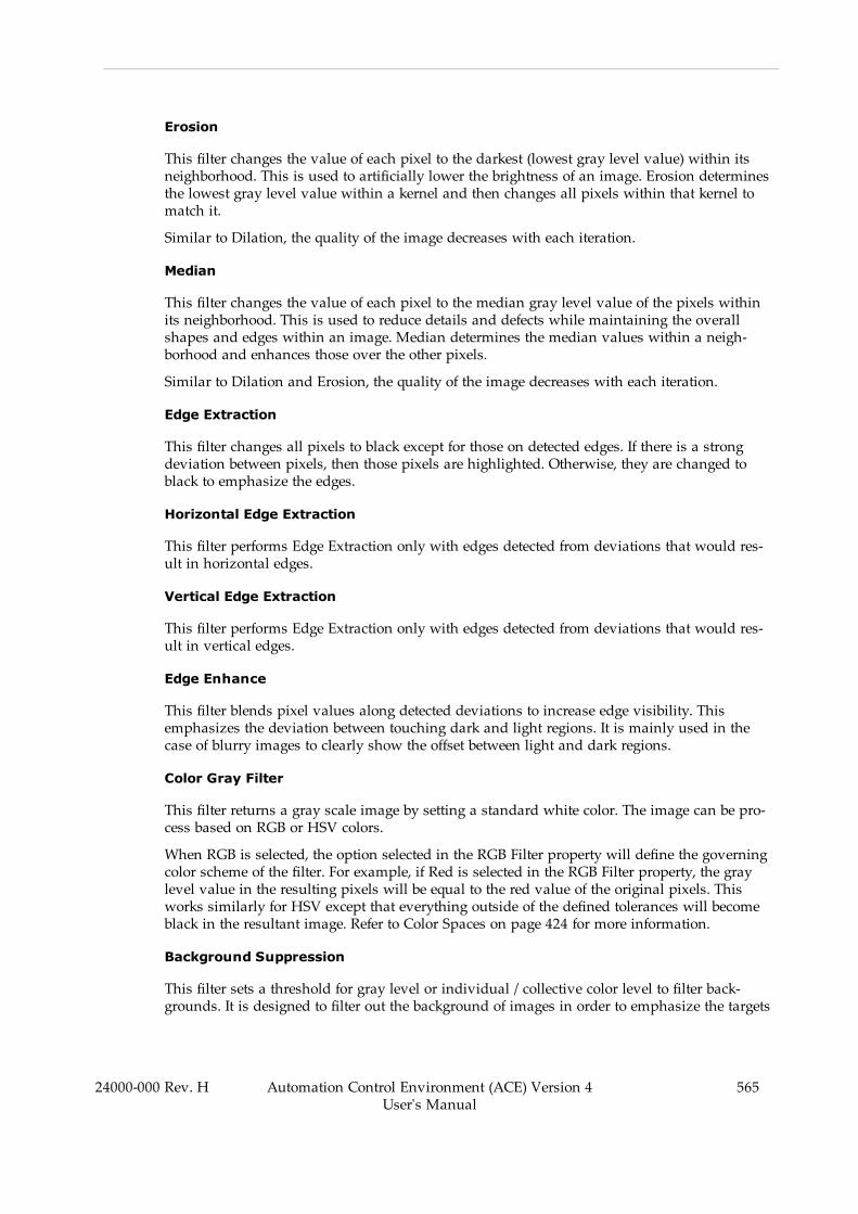
Erosion
This filter changes the value of each pixel to the darkest (lowest gray level value) within itsneighborhood. This is used to artificially lower the brightness of an image. Erosion determinesthe lowest gray level value within a kernel and then changes all pixels within that kernel tomatch it.
Similar to Dilation, the quality of the image decreases with each iteration.
Median
This filter changes the value of each pixel to the median gray level value of the pixels withinits neighborhood. This is used to reduce details and defects while maintaining the overallshapes and edges within an image. Median determines the median values within a neigh-borhood and enhances those over the other pixels.
Similar to Dilation and Erosion, the quality of the image decreases with each iteration.
Edge Extraction
This filter changes all pixels to black except for those on detected edges. If there is a strongdeviation between pixels, then those pixels are highlighted. Otherwise, they are changed toblack to emphasize the edges.
Horizontal Edge Extraction
This filter performs Edge Extraction only with edges detected from deviations that would res-ult in horizontal edges.
Vertical Edge Extraction
This filter performs Edge Extraction only with edges detected from deviations that would res-ult in vertical edges.
Edge Enhance
This filter blends pixel values along detected deviations to increase edge visibility. Thisemphasizes the deviation between touching dark and light regions. It is mainly used in thecase of blurry images to clearly show the offset between light and dark regions.
Color Gray Filter
This filter returns a gray scale image by setting a standard white color. The image can be pro-cess based on RGB or HSV colors.
When RGB is selected, the option selected in the RGB Filter property will define the governingcolor scheme of the filter. For example, if Red is selected in the RGB Filter property, the graylevel value in the resulting pixels will be equal to the red value of the original pixels. Thisworks similarly for HSV except that everything outside of the defined tolerances will becomeblack in the resultant image. Refer to Color Spaces on page 424 for more information.
Background Suppression
This filter sets a threshold for gray level or individual / collective color level to filter back-grounds. It is designed to filter out the background of images in order to emphasize the targets
24000-000 Rev. H Automation Control Environment (ACE) Version 4User's Manual
565
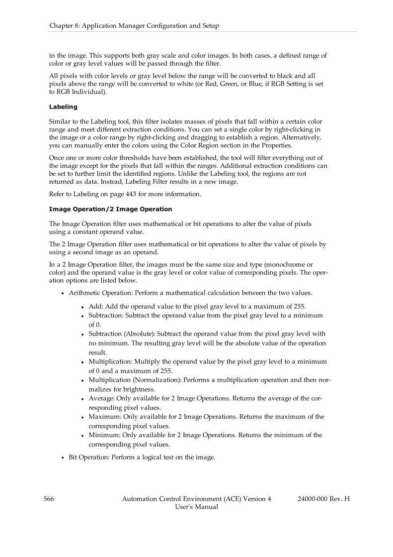
566 Automation Control Environment (ACE) Version 4User's Manual
24000-000 Rev. H
Chapter 8: Application Manager Configuration and Setup
in the image. This supports both gray scale and color images. In both cases, a defined range ofcolor or gray level values will be passed through the filter.
All pixels with color levels or gray level below the range will be converted to black and allpixels above the range will be converted to white (or Red, Green, or Blue, if RGB Setting is setto RGB Individual).
Labeling
Similar to the Labeling tool, this filter isolates masses of pixels that fall within a certain colorrange and meet different extraction conditions. You can set a single color by right-clicking inthe image or a color range by right-clicking and dragging to establish a region. Alternatively,you can manually enter the colors using the Color Region section in the Properties.
Once one or more color thresholds have been established, the tool will filter everything out ofthe image except for the pixels that fall within the ranges. Additional extraction conditions canbe set to further limit the identified regions. Unlike the Labeling tool, the regions are notreturned as data. Instead, Labeling Filter results in a new image.
Refer to Labeling on page 443 for more information.
Image Operation/2 Image Operation
The Image Operation filter uses mathematical or bit operations to alter the value of pixelsusing a constant operand value.
The 2 Image Operation filter uses mathematical or bit operations to alter the value of pixels byusing a second image as an operand.
In a 2 Image Operation filter, the images must be the same size and type (monochrome orcolor) and the operand value is the gray level or color value of corresponding pixels. The oper-ation options are listed below.
l Arithmetic Operation: Perform a mathematical calculation between the two values.
l Add: Add the operand value to the pixel gray level to a maximum of 255.l Subtraction: Subtract the operand value from the pixel gray level to a minimumof 0.
l Subtraction (Absolute): Subtract the operand value from the pixel gray level withno minimum. The resulting gray level will be the absolute value of the operationresult.
l Multiplication: Multiply the operand value by the pixel gray level to a minimumof 0 and a maximum of 255.
l Multiplication (Normalization): Performs a multiplication operation and then nor-malizes for brightness.
l Average: Only available for 2 Image Operations. Returns the average of the cor-responding pixel values.
l Maximum: Only available for 2 Image Operations. Returns the maximum of thecorresponding pixel values.
l Minimum: Only available for 2 Image Operations. Returns the minimum of thecorresponding pixel values.
l Bit Operation: Perform a logical test on the image.

l NOT: Reverses the RGB or gray level polarity of the image, regardless of the oper-and value.
l AND: Performs an AND operation on the pixels by comparing the binary digitsof the two values. It is generally used to compare two images. It can also be usedin masking.
l OR: Performs an OR operation on the pixels by comparing the binary digits ofthe two values. It is generally used to merge two images together.
l XOR: Performs an XOR operation on the pixels by comparing the binary digits ofthe two values. It is generally used to create a binary image (black and white).
l NAND: Performs a NAND operation on the two pixels by comparing the binarydigits of the two values. Like AND, this is used to compare images, but it alsoessentially returns negatives of what the AND result would be.
l NOR: Performs a NOR operation on the pixels by comparing the binary digits ofthe two values. It is generally used to merge two images together and return thenegatives.
l XNOR: Performs an XNOR operation on the pixels by comparing the binarydigits of the two values. It is generally used to create a negative binary (black andwhite) image.
l Bit Shift: Shift the values of the binary digits to the left or right. The bits on the digit thatis shifted away from (first digit in a right shift and last digit in a left shift) becomes 0.This is only available in a single image operation. This is used when Arithmetic Mul-tiplication is too computationally taxing.
l Change Pixel Value: Assign a fixed value to all pixels that fall within a certain graylevel range. Change Pixel Value defines the resulting gray level and the Bounds definethe range to be changed or retained, depending on the Change Pixel Mode.
Advanced Filter Configuration Items
The properties of Advanced Filter change depending on what type of filter is selected in FilterContents Selection. The table below shows all properties.
The Filter Contents Selection column defines those filter(s) for which the property is available.If it is blank, the property is available for all or most of them.
24000-000 Rev. H Automation Control Environment (ACE) Version 4User's Manual
567
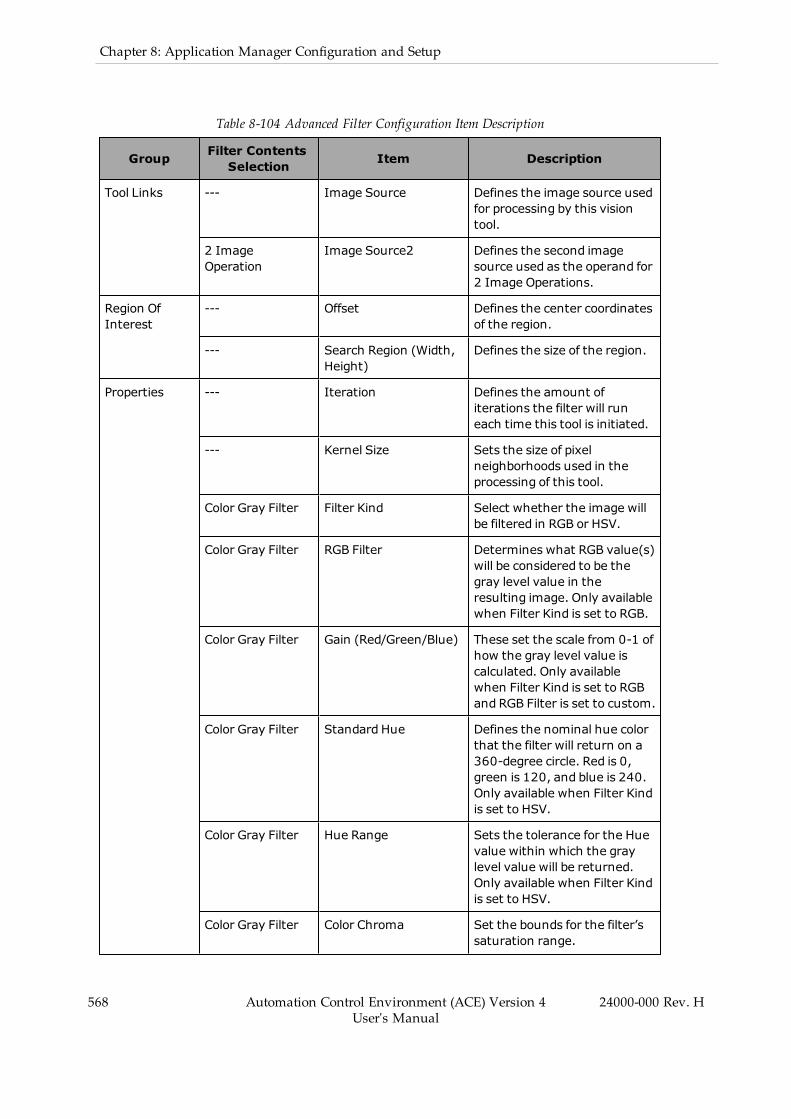
568 Automation Control Environment (ACE) Version 4User's Manual
24000-000 Rev. H
Chapter 8: Application Manager Configuration and Setup
Table 8-104 Advanced Filter Configuration Item Description
Group Filter ContentsSelection Item Description
Tool Links --- Image Source Defines the image source usedfor processing by this visiontool.
2 ImageOperation
Image Source2 Defines the second imagesource used as the operand for2 Image Operations.
Region OfInterest
--- Offset Defines the center coordinatesof the region.
--- Search Region (Width,Height)
Defines the size of the region.
Properties --- Iteration Defines the amount ofiterations the filter will runeach time this tool is initiated.
--- Kernel Size Sets the size of pixelneighborhoods used in theprocessing of this tool.
Color Gray Filter Filter Kind Select whether the image willbe filtered in RGB or HSV.
Color Gray Filter RGB Filter Determines what RGB value(s)will be considered to be thegray level value in theresulting image. Only availablewhen Filter Kind is set to RGB.
Color Gray Filter Gain (Red/Green/Blue) These set the scale from 0-1 ofhow the gray level value iscalculated. Only availablewhen Filter Kind is set to RGBand RGB Filter is set to custom.
Color Gray Filter Standard Hue Defines the nominal hue colorthat the filter will return on a360-degree circle. Red is 0,green is 120, and blue is 240.Only available when Filter Kindis set to HSV.
Color Gray Filter Hue Range Sets the tolerance for the Huevalue within which the graylevel value will be returned.Only available when Filter Kindis set to HSV.
Color Gray Filter Color Chroma Set the bounds for the filter’ssaturation range.

Group Filter ContentsSelection Item Description
BackgroundSuppression
Gray Sets the gray level threshold tobe retained in the results. Onlyavailable with gray scaleimages.
BackgroundSuppression
RGB Setting RGB Common adjusts R, G,and B all together and RGBIndividual adjusts themseparately. Only available withcolor images. Select themethod of color thresholdcreation.
BackgroundSuppression
RGB Common Sets the threshold of color tobe retained in the results. Onlyavailable with color images andwhen RGB Setting is set toRGB Common.
BackgroundSuppression
R/G/B Sets the threshold of eachindividual color setting to beretained in the results. Onlyavailable with color images andwhen RGB Setting is set toRGB Individual.
Labeling Filter Hole Plug Color When enabled, sets the colorthat will fill all holes in thedetectedmasses.
Labeling Filter Outside Trimming When enabled, everythingoutside of the region ofinterest will be returned as theextracted color.
Labeling Filter Labeling Select Allows the selection of a singleextractedmass. The sortcondition and number definewhich one will be selected.
Labeling Filter NeighborhoodMode Defines the ways pixels will beconnected in order to qualify asa single mass. 4 Neighborhoodwill only allow pixels to connectto others that are up, down,left, or right, while 8Neighborhoodwill also connectdiagonal directions.
Labeling Filter Extract Condition 1/2/3 Define the conditions this toolwill consider when extractingmasses from the image.Conditions can be set by the
24000-000 Rev. H Automation Control Environment (ACE) Version 4User's Manual
569
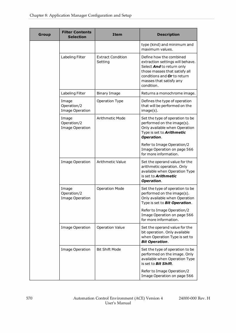
570 Automation Control Environment (ACE) Version 4User's Manual
24000-000 Rev. H
Chapter 8: Application Manager Configuration and Setup
Group Filter ContentsSelection Item Description
type (kind) andminimum andmaximum values.
Labeling Filter Extract ConditionSetting
Define how the combinedextraction settings will behave.Select And to return onlythose masses that satisfy allconditions andOr to returnmasses that satisfy anycondition.
Labeling Filter Binary Image Returns a monochrome image.
ImageOperation/2Image Operation
Operation Type Defines the type of operationthat will be performed on theimage(s).
ImageOperation/2Image Operation
Arithmetic Mode Set the type of operation to beperformed on the image(s).Only available when OperationType is set toArithmeticOperation.
Refer to Image Operation/2Image Operation on page 566for more information.
Image Operation Arithmetic Value Set the operand value for thearithmetic operation. Onlyavailable when Operation Typeis set toArithmeticOperation.
ImageOperation/2Image Operation
Operation Mode Set the type of operation to beperformed on the image(s).Only available when OperationType is set toBit Operation.
Refer to Image Operation/2Image Operation on page 566for more information.
Image Operation Operation Value Set the operand value for thebit operation. Only availablewhen Operation Type is set toBit Operation.
Image Operation Bit Shift Mode Set the type of operation to beperformed on the image. Onlyavailable when Operation Typeis set toBit Shift.
Refer to Image Operation/2Image Operation on page 566

Group Filter ContentsSelection Item Description
for more information.
Image Operation Bit Shift Value Set the operand value for thebit shift. Only available whenOperation Type is set toBitShift.
Image Operation Change Pixel Mode Select whether the pixelsoutside or inside the boundswill be changed. Only availablewhen Operation Type is set toChange Pixel Value.
Image Operation Change Pixel Value Set the gray level value towhich pixels will be changed.Only available when OperationType is set to Change PixelValue.
Image Operation Bounds Set the bounds that definewhat gray level values will bechanged or retained. Onlyavailable when Operation Typeis set to Change Pixel Value.
Configuring the Advanced Filter
The Advanced Filter tool can execute several types of functions on an image, so it is importantthat the appropriate choice is selected from the Filter Contents Selection menu before any otherchanges are made. The Properties will adjust to match the type of filter.
There is no generic way to configure this type of tool because it is designed to perform a mul-titude of different operations. However, in general, the tool is operated by first adjusting theregion of interest to the appropriate location and size. The exception to this is Color Gray Filter,which does not have a region of interest. Any filters or operations performed will take placeonly within the established region.
Most filter types require the Iteration and Kernel Size item. The Iteration value can beincreased for the tool to run multiple times whenever executed. This leads to higher processingtime, but it can be useful to remove detail from an image. Conversely, Kernel Size affects thesize of the pixel neighborhoods. Larger selections lead to fewer calculations and faster pro-cessing time. Modifying these will impact performance and can be used to yield optimumimages.
Several filters use both RGB and HSV color schemes. Refer to Color Spaces on page 424 formore information.
Advanced Filter Results
Advanced Filter returns a modified image that can be used by other vision tools. To do this,set Advanced Filter as the Image Source property of the subsequent tool. The resultant imagecan be viewed in the Result section of the object editor. Refer to Figure 8-278 for an example.
24000-000 Rev. H Automation Control Environment (ACE) Version 4User's Manual
571
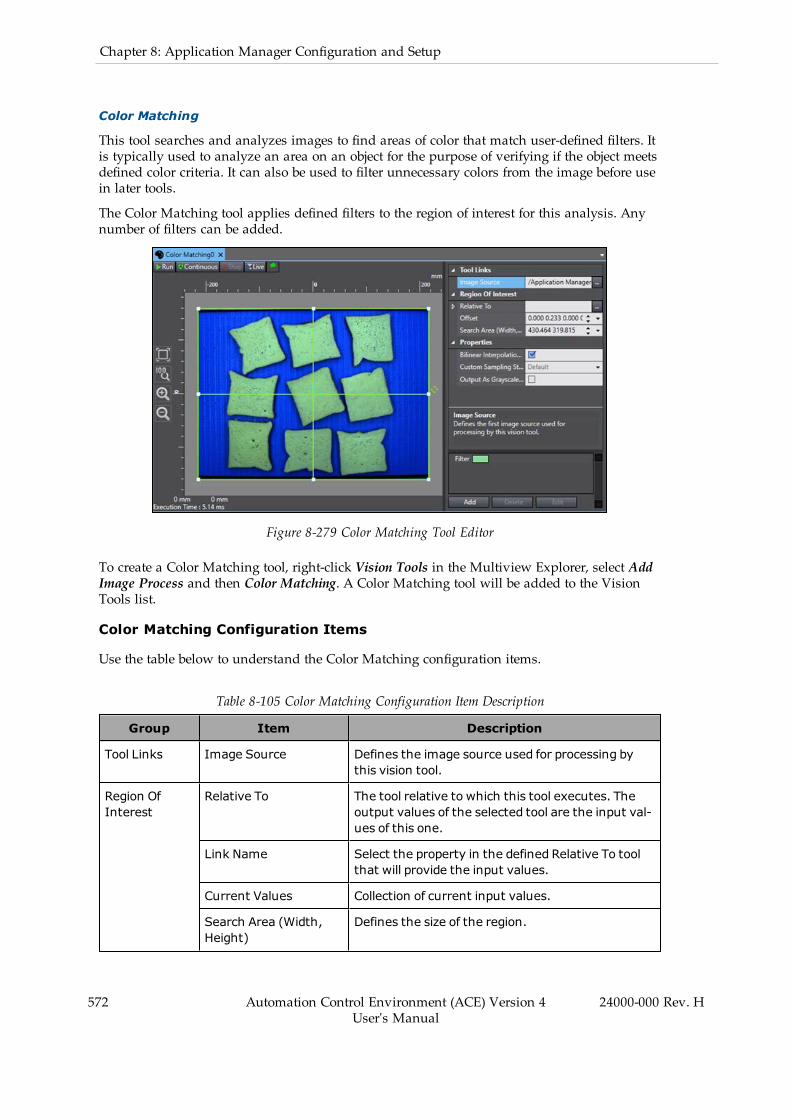
572 Automation Control Environment (ACE) Version 4User's Manual
24000-000 Rev. H
Chapter 8: Application Manager Configuration and Setup
Color Matching
This tool searches and analyzes images to find areas of color that match user-defined filters. Itis typically used to analyze an area on an object for the purpose of verifying if the object meetsdefined color criteria. It can also be used to filter unnecessary colors from the image before usein later tools.
The Color Matching tool applies defined filters to the region of interest for this analysis. Anynumber of filters can be added.
Figure 8-279 Color Matching Tool Editor
To create a Color Matching tool, right-click Vision Tools in the Multiview Explorer, select AddImage Process and then Color Matching. A Color Matching tool will be added to the VisionTools list.
Color Matching Configuration Items
Use the table below to understand the Color Matching configuration items.
Table 8-105 Color Matching Configuration Item Description
Group Item Description
Tool Links Image Source Defines the image source used for processing bythis vision tool.
Region OfInterest
Relative To The tool relative to which this tool executes. Theoutput values of the selected tool are the input val-ues of this one.
Link Name Select the property in the defined Relative To toolthat will provide the input values.
Current Values Collection of current input values.
Search Area (Width,Height)
Defines the size of the region.

Group Item Description
Properties Bilinear InterpolationEnabled
Enables bilinear interpolation to sample the inputimage. By default, this is enabled because itensures subpixel accuracy.
Custom Sampling Set Defines the sampling step used in calculation. Thisis set to 1 by default. Enable this to adjust the set-ting.
Output As Gray scaleImage
Specifies the color scheme of the output image.When enabled, the resultant image is converted togray scale after color filters are applied.
Color Matching Filters Pane
The filters required for Color Matching are organized using the pane located below the prop-erties. Color Matching will output the colors that are included in any filter listed in this pane.All other pixels in the image will be output as black.
Figure 8-280 Color Matching Filters Pane
Any number of filters can be added to the pane. They are managed using the three buttonsdescribed below.
l Add: Creates a new filter and adds it at the end of the current list of filters.l Delete: Removes the currently selected filter. This is only available if a filter is high-lighted.
l Edit: Opens the Color Finder editing window. This is only available if a filter is high-lighted. Refer to the following section for more information.
Color Matching - Color Finder Editor
The Color Finder editor allows modification of specific filters.
The right side of the editor shows the input image. The left side is where the Filter Parametersare adjusted as described below.
24000-000 Rev. H Automation Control Environment (ACE) Version 4User's Manual
573
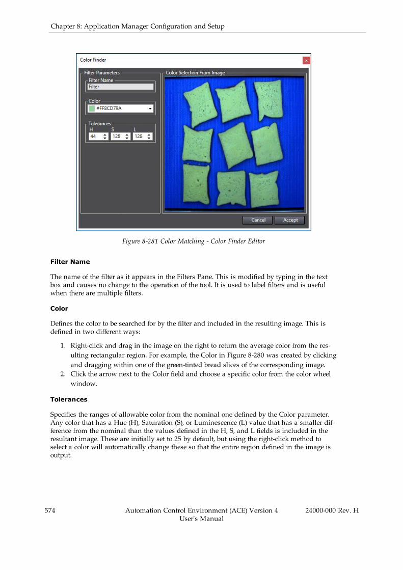
574 Automation Control Environment (ACE) Version 4User's Manual
24000-000 Rev. H
Chapter 8: Application Manager Configuration and Setup
Figure 8-281 Color Matching - Color Finder Editor
Filter Name
The name of the filter as it appears in the Filters Pane. This is modified by typing in the textbox and causes no change to the operation of the tool. It is used to label filters and is usefulwhen there are multiple filters.
Color
Defines the color to be searched for by the filter and included in the resulting image. This isdefined in two different ways:
1. Right-click and drag in the image on the right to return the average color from the res-ulting rectangular region. For example, the Color in Figure 8-280 was created by clickingand dragging within one of the green-tinted bread slices of the corresponding image.
2. Click the arrow next to the Color field and choose a specific color from the color wheelwindow.
Tolerances
Specifies the ranges of allowable color from the nominal one defined by the Color parameter.Any color that has a Hue (H), Saturation (S), or Luminescence (L) value that has a smaller dif-ference from the nominal than the values defined in the H, S, and L fields is included in theresultant image. These are initially set to 25 by default, but using the right-click method toselect a color will automatically change these so that the entire region defined in the image isoutput.

Color Matching Results
Color Matching returns a modified image that can be used by other vision tools. This imagewill only include the colors defined in the filters. All other pixels will be returned as black. Touse this image with another tool, set Color Matching as the Image Source property of the sub-sequent tool.
The resultant image can be viewed in the Vision Window as shown in the following figure.
Figure 8-282 Color Matching Resultant Image
Image Processing
This tool applies a filter to gray scale images to better facilitate processing by other tools,including additional Image Processing tools.
NOTE: Advanced Filter tool provides more capabilities and may offer faster exe-cution times than the Image Processing tool. Refer to Advanced Filter on page563 for more information.
24000-000 Rev. H Automation Control Environment (ACE) Version 4User's Manual
575
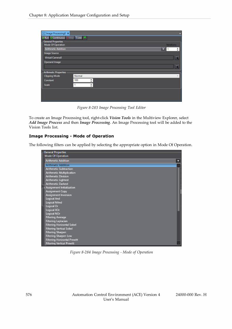
576 Automation Control Environment (ACE) Version 4User's Manual
24000-000 Rev. H
Chapter 8: Application Manager Configuration and Setup
Figure 8-283 Image Processing Tool Editor
To create an Image Processing tool, right-click Vision Tools in the Multiview Explorer, selectAdd Image Process and then Image Processing. An Image Processing tool will be added to theVision Tools list.
Image Processing - Mode of Operation
The following filters can be applied by selecting the appropriate option in Mode Of Operation.
Figure 8-284 Image Processing - Mode of Operation
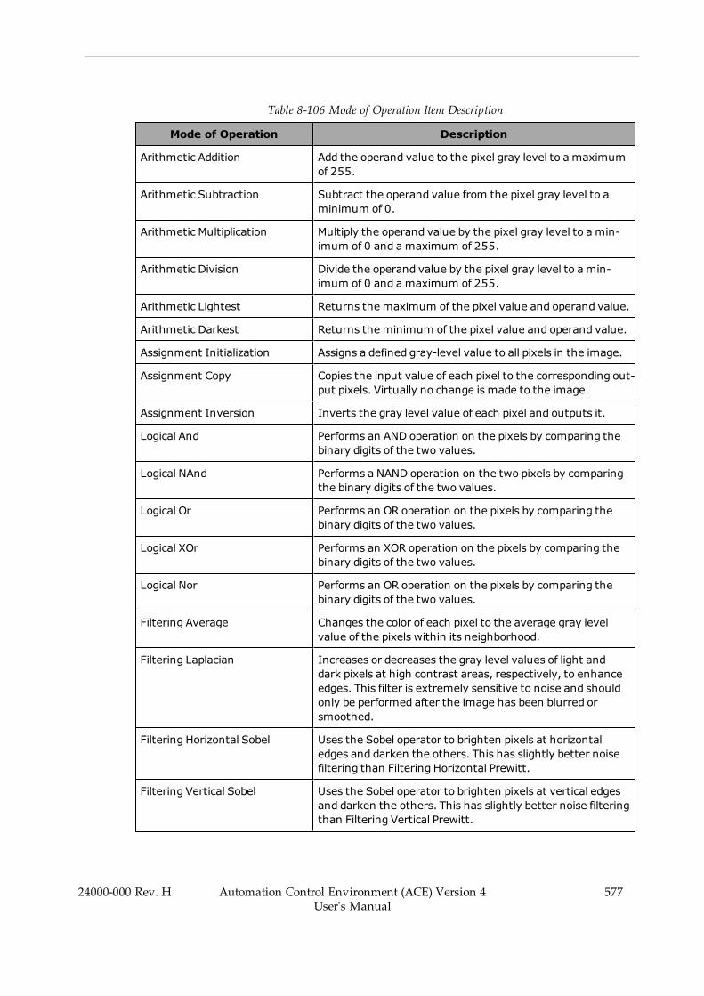
Table 8-106 Mode of Operation Item Description
Mode of Operation Description
Arithmetic Addition Add the operand value to the pixel gray level to a maximumof 255.
Arithmetic Subtraction Subtract the operand value from the pixel gray level to aminimum of 0.
Arithmetic Multiplication Multiply the operand value by the pixel gray level to a min-imum of 0 and amaximum of 255.
Arithmetic Division Divide the operand value by the pixel gray level to a min-imum of 0 and amaximum of 255.
Arithmetic Lightest Returns the maximum of the pixel value and operand value.
Arithmetic Darkest Returns the minimum of the pixel value and operand value.
Assignment Initialization Assigns a defined gray-level value to all pixels in the image.
Assignment Copy Copies the input value of each pixel to the corresponding out-put pixels. Virtually no change is made to the image.
Assignment Inversion Inverts the gray level value of each pixel and outputs it.
Logical And Performs an AND operation on the pixels by comparing thebinary digits of the two values.
Logical NAnd Performs a NAND operation on the two pixels by comparingthe binary digits of the two values.
Logical Or Performs an OR operation on the pixels by comparing thebinary digits of the two values.
Logical XOr Performs an XOR operation on the pixels by comparing thebinary digits of the two values.
Logical Nor Performs an OR operation on the pixels by comparing thebinary digits of the two values.
Filtering Average Changes the color of each pixel to the average gray levelvalue of the pixels within its neighborhood.
Filtering Laplacian Increases or decreases the gray level values of light anddark pixels at high contrast areas, respectively, to enhanceedges. This filter is extremely sensitive to noise and shouldonly be performed after the image has been blurred orsmoothed.
Filtering Horizontal Sobel Uses the Sobel operator to brighten pixels at horizontaledges and darken the others. This has slightly better noisefiltering than Filtering Horizontal Prewitt.
Filtering Vertical Sobel Uses the Sobel operator to brighten pixels at vertical edgesand darken the others. This has slightly better noise filteringthan Filtering Vertical Prewitt.
24000-000 Rev. H Automation Control Environment (ACE) Version 4User's Manual
577

578 Automation Control Environment (ACE) Version 4User's Manual
24000-000 Rev. H
Chapter 8: Application Manager Configuration and Setup
Mode of Operation Description
Filtering Sharpen Increases or decreases the gray level values of light anddark pixels, respectively, to increase contrast.
Filtering Sharpen Low Increases or decreases the gray level values of light anddark pixels, respectively, to increase contrast. This filter per-forms this to a lesser degree than Filtering Sharpen.
Filtering Horizontal Prewitt Uses the Prewitt operator to brighten pixels at horizontaledges and darken the others. This has slightly worse noise fil-tering than Filtering Horizontal Sobel.
Filtering Vertical Prewitt Uses the Prewitt operator to brighten pixels at vertical edgesand darken the others. This has slightly worse noise filteringthan Filtering Vertical Sobel.
Filtering Gaussian Blurs the image to remove contrast between individualpixels, removing noise and enhancing overall contours.
Filtering High Pass Increases or decreases the gray level values of light anddark pixels at high contrast areas, respectively, to enhanceedges. This filter is extremely sensitive to noise and shouldonly be performed after the image has been blurred orsmoothed. It is functionally identical to Filtering Laplacian.
FilteringMedian Changes the color of each pixel to the median gray levelvalue of the pixels within its neighborhood.
Morphological Dilate Changes the color of each pixel to the brightest (highestgray level value) within its neighborhood.
Morphological Erode Changes the color of each pixel to the darkest (lowest graylevel value) within its neighborhood.
Morphological Close Removes small dark particles and holes within an image.
Morphological Open Removes peaks from an image, leaving only the image back-ground.
Histogram Equalization Enhances the input image by flattening the histogram ofthe input image.
Histogram Stretching Increases the contrast in an image by applying a piecewiselinear intensity transformation based on the image his-togram.
Histogram Light Threshold Changes each pixel value depending on whether they areless or greater than the specified threshold. If an input pixelvalue is less than the threshold, the corresponding outputpixel is set to the minimum acceptable value. Otherwise, itis set to the maximum presentable value.
Histogram Dark Threshold Changes each pixel value depending on whether they areless or greater than the specified threshold. If an input pixelvalue is less than the threshold, the corresponding outputpixel is set to the maximum presentable value. Otherwise, itis set to the minimum acceptable value.

Mode of Operation Description
Transform FFT Converts and outputs a frequency description of the inputimage by applying a Fast Fourier Transform (FFT).
Transform DCT Converts and outputs a frequency description of the inputimage by applying a Discrete Cosine Transform (DCT).
Image Processing Configuration
The Image Processing tool is generally configured by selecting a Mode Of Operation and oneor two input images. All of the available Modes can be performed with one image and somecan be performed with two.
The properties in the bottom half of the tool editor will change depending on the selectedMode Of Operation, as shown in the following table. Any mode with a Constant property canbe operated with two images. If an Operand Image is selected, the filter will use the values ofthe corresponding pixels in that image. Otherwise, it will default to the Constant property.
Image Processing Configuration Items
The properties of Image Processing change depending on what type of filter is selected inMode Of Operation. General properties are described below.
l Mode of Operation: Defines the type of operation applied to the image(s).l Iterations: Defines the amount of iterations the filter will run each time this tool is ini-tiated.
l Image Source: Select the source of the input image. This must be gray scale.l Operand Image: Select the source of the operand image. This must be gray scale.
The table below describes all other properties specific to the Mode of Operation selection.
The Mode Of Operation column defines the mode(s) for which the property is available.
Table 8-107 Image Processing Configuration Item Description
Modeof Operation Properties Description
ArithmeticOperations
ClippingMode Select the method by which the calculationhandles resultant values below 0. Normal convertsall of them to 0 while Absolute returns the abso-lute value of any result below 0.
Constant Value used in operation if there is no operandimage.
Scale Defines the initial gray level scale of the imagebefore processing. For example, if this value isequal to 0.5, all gray level values are halved beforethe operation is performed.
AssignmentInitialization
Constant Value used in operation if there is no operandimage.
Logical Constant Value used in operation if there is no operand
24000-000 Rev. H Automation Control Environment (ACE) Version 4User's Manual
579
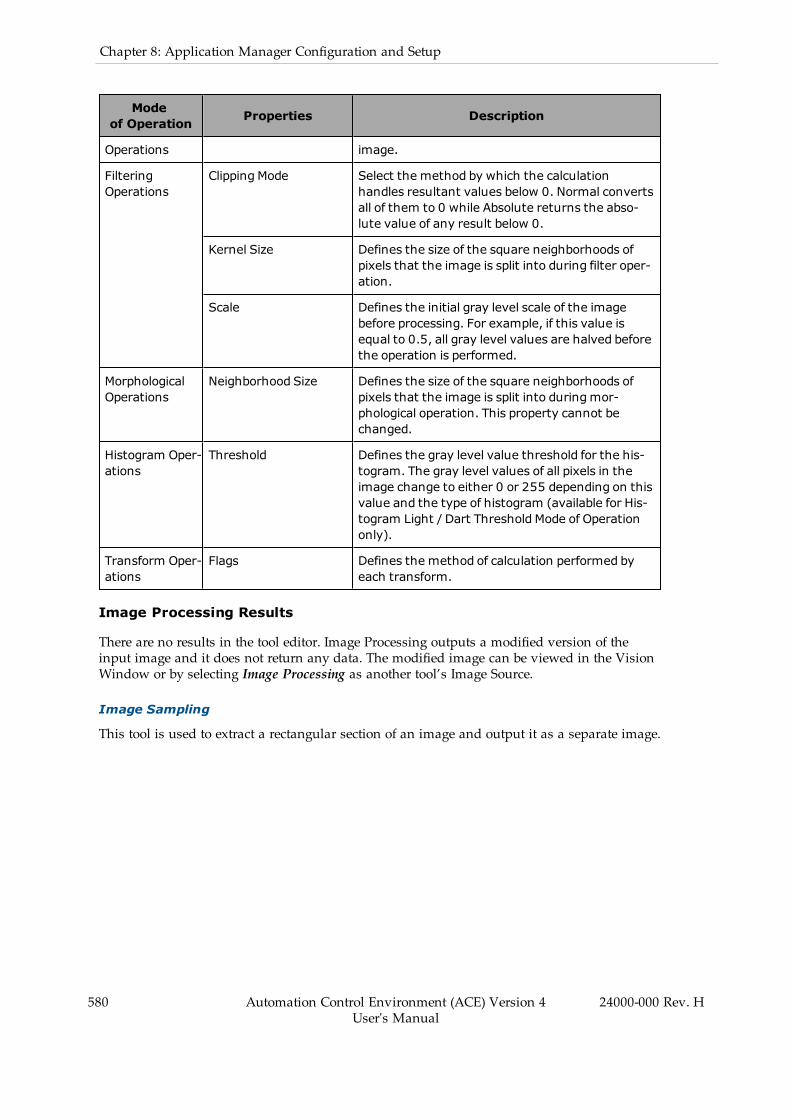
580 Automation Control Environment (ACE) Version 4User's Manual
24000-000 Rev. H
Chapter 8: Application Manager Configuration and Setup
Modeof Operation Properties Description
Operations image.
FilteringOperations
ClippingMode Select the method by which the calculationhandles resultant values below 0. Normal convertsall of them to 0 while Absolute returns the abso-lute value of any result below 0.
Kernel Size Defines the size of the square neighborhoods ofpixels that the image is split into during filter oper-ation.
Scale Defines the initial gray level scale of the imagebefore processing. For example, if this value isequal to 0.5, all gray level values are halved beforethe operation is performed.
MorphologicalOperations
Neighborhood Size Defines the size of the square neighborhoods ofpixels that the image is split into duringmor-phological operation. This property cannot bechanged.
Histogram Oper-ations
Threshold Defines the gray level value threshold for the his-togram. The gray level values of all pixels in theimage change to either 0 or 255 depending on thisvalue and the type of histogram (available for His-togram Light / Dart Threshold Mode of Operationonly).
Transform Oper-ations
Flags Defines the method of calculation performed byeach transform.
Image Processing Results
There are no results in the tool editor. Image Processing outputs a modified version of theinput image and it does not return any data. The modified image can be viewed in the VisionWindow or by selecting Image Processing as another tool’s Image Source.
Image Sampling
This tool is used to extract a rectangular section of an image and output it as a separate image.
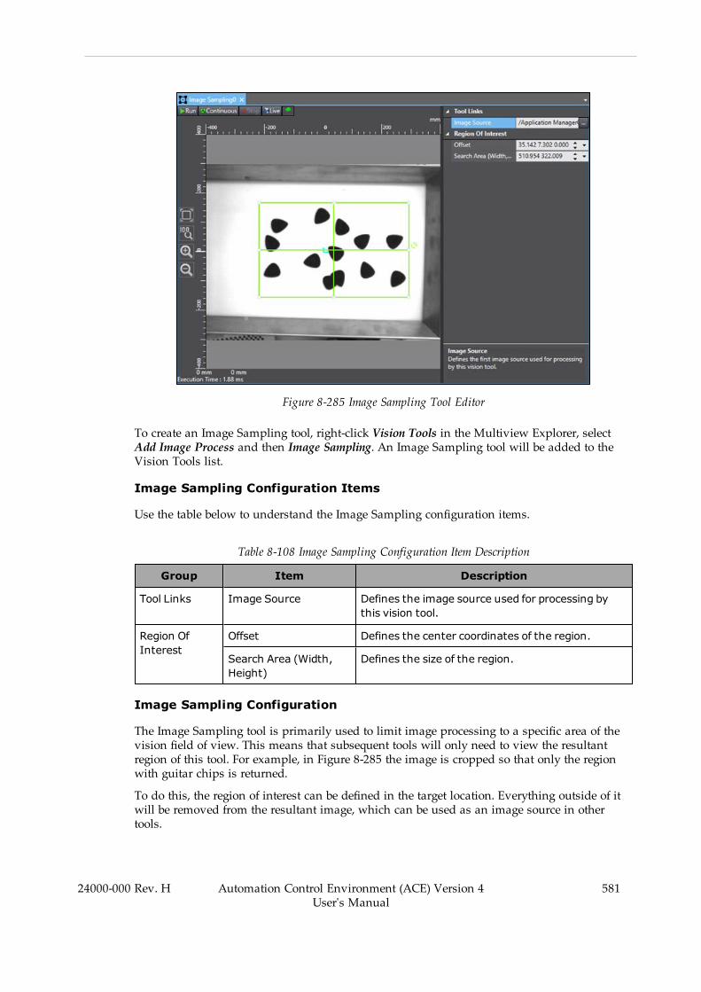
Figure 8-285 Image Sampling Tool Editor
To create an Image Sampling tool, right-click Vision Tools in the Multiview Explorer, selectAdd Image Process and then Image Sampling. An Image Sampling tool will be added to theVision Tools list.
Image Sampling Configuration Items
Use the table below to understand the Image Sampling configuration items.
Table 8-108 Image Sampling Configuration Item Description
Group Item Description
Tool Links Image Source Defines the image source used for processing bythis vision tool.
Region OfInterest
Offset Defines the center coordinates of the region.
Search Area (Width,Height)
Defines the size of the region.
Image Sampling Configuration
The Image Sampling tool is primarily used to limit image processing to a specific area of thevision field of view. This means that subsequent tools will only need to view the resultantregion of this tool. For example, in Figure 8-285 the image is cropped so that only the regionwith guitar chips is returned.
To do this, the region of interest can be defined in the target location. Everything outside of itwill be removed from the resultant image, which can be used as an image source in othertools.
24000-000 Rev. H Automation Control Environment (ACE) Version 4User's Manual
581
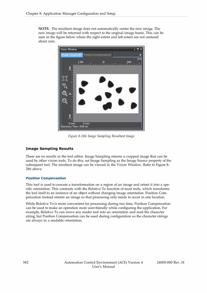
582 Automation Control Environment (ACE) Version 4User's Manual
24000-000 Rev. H
Chapter 8: Application Manager Configuration and Setup
NOTE: The resultant image does not automatically center the new image. Thenew image will be returned with respect to the original image frame. This can beseen in the figure below where the right extent and left extent are not centeredabout zero.
Figure 8-286 Image Sampling Resultant Image
Image Sampling Results
There are no results in the tool editor. Image Sampling returns a cropped image that can beused by other vision tools. To do this, set Image Sampling as the Image Source property of thesubsequent tool. The resultant image can be viewed in the Vision Window. Refer to Figure 8-286 above.
Position Compensation
This tool is used to execute a transformation on a region of an image and orient it into a spe-cific orientation. This contrasts with the Relative To function of most tools, which transformsthe tool itself to an instance of an object without changing image orientation. Position Com-pensation instead orients an image so that processing only needs to occur in one location.
While Relative To is more convenient for processing during run time, Position Compensationcan be used to make an operation more user-friendly while configuring the application. Forexample, Relative To can move any reader tool into an orientation and read the characterstring, but Position Compensation can be used during configuration so the character stringsare always in a readable orientation.
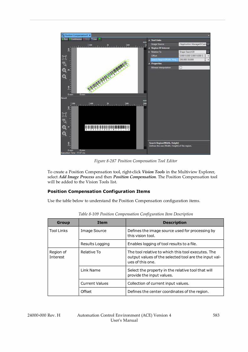
Figure 8-287 Position Compensation Tool Editor
To create a Position Compensation tool, right-click Vision Tools in the Multiview Explorer,select Add Image Process and then Position Compensation. The Position Compensation toolwill be added to the Vision Tools list.
Position Compensation Configuration Items
Use the table below to understand the Position Compensation configuration items.
Table 8-109 Position Compensation Configuration Item Description
Group Item Description
Tool Links Image Source Defines the image source used for processing bythis vision tool.
Results Logging Enables logging of tool results to a file.
Region ofInterest
Relative To The tool relative to which this tool executes. Theoutput values of the selected tool are the input val-ues of this one.
Link Name Select the property in the relative tool that willprovide the input values.
Current Values Collection of current input values.
Offset Defines the center coordinates of the region.
24000-000 Rev. H Automation Control Environment (ACE) Version 4User's Manual
583

584 Automation Control Environment (ACE) Version 4User's Manual
24000-000 Rev. H
Chapter 8: Application Manager Configuration and Setup
Group Item Description
Search Area (Width,Height)
Defines the size of the region.
Properties Bilinear Interpolation Enables using bilinear interpolation to sample theinput image. By default, this is enabled because itensures subpixel accuracy.
Position Compensation Configuration
The Position Compensation tool is primarily used to focus an image on only a specific area ofthe vision field of view. This is useful during configuration to allow the user to develop anapplication while images are in an ideal orientation. For example, Figure 8-287 the barcode isrotated and centered so that a Barcode tool will only need to focus on the center region of theimage.
To do this, Position Compensation can be set in a known orientation to guarantee that theinstance is centered and returned in a target orientation. All pixels outside of the region ofinterest will be returned as black. This may cause interference with reader tools if there is notsufficient white space around the object to be read.
Position Compensation Results
There are no results in the tool editor. Position Compensation returns a modified image thatcan be used by other vision tools. To do this, set Position Compensation as the Image Sourceproperty of the subsequent tool. The resultant image can be viewed in the Result section of theobject editor. Refer to Figure 8-287 for an example.
Custom Tools
Custom tools allow you to specify a program that will be called when the tool is executed. Thefollowing Custom Tools are described in this section.
l Refer to Custom Vision Tool on page 584 below for more information.l Refer to Remote Vision Tool on page 587 for more information.
Custom Vision Tool
This tool is a C# program that can be referenced and executed as a vision tool. Other visiontools and objects can be referenced and used within the program. At the end of the program, acollection of defined vision transform results will be returned.
NOTE: A basic understanding of C# is required to use the Custom Vision Tool.
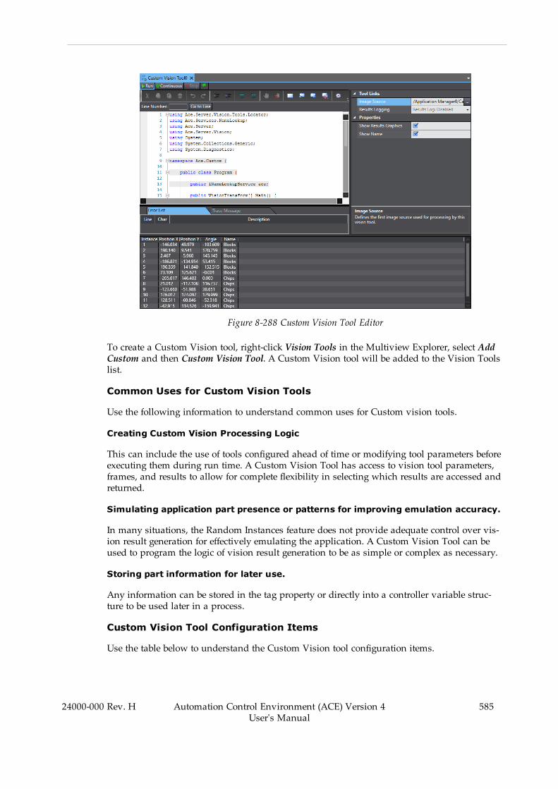
Figure 8-288 Custom Vision Tool Editor
To create a Custom Vision tool, right-click Vision Tools in the Multiview Explorer, select AddCustom and then Custom Vision Tool. A Custom Vision tool will be added to the Vision Toolslist.
Common Uses for Custom Vision Tools
Use the following information to understand common uses for Custom vision tools.
Creating Custom Vision Processing Logic
This can include the use of tools configured ahead of time or modifying tool parameters beforeexecuting them during run time. A Custom Vision Tool has access to vision tool parameters,frames, and results to allow for complete flexibility in selecting which results are accessed andreturned.
Simulating application part presence or patterns for improving emulation accuracy.
In many situations, the Random Instances feature does not provide adequate control over vis-ion result generation for effectively emulating the application. A Custom Vision Tool can beused to program the logic of vision result generation to be as simple or complex as necessary.
Storing part information for later use.
Any information can be stored in the tag property or directly into a controller variable struc-ture to be used later in a process.
Custom Vision Tool Configuration Items
Use the table below to understand the Custom Vision tool configuration items.
24000-000 Rev. H Automation Control Environment (ACE) Version 4User's Manual
585

586 Automation Control Environment (ACE) Version 4User's Manual
24000-000 Rev. H
Chapter 8: Application Manager Configuration and Setup
Table 8-110 Custom Vision Tool Configuration Item Description
Group Item Description
Tool Links Image Source Defines the image source used for processing bythis vision tool.
Results Logging Enables logging of tool results to a file.
Properties Show Results Graphics Specifies if the graphics are drawn in the Vision Win-dow.
Show Name Specifies if the name associated with each instanceis written in the Vision Window.
Custom Vision Tool Customization
Custom Vision Tools can be used to do almost anything with other vision tools in the work-space. For example, the tool shown in Figure 8-288 is a simple example used to returninstances from a Locator. The instances are drawn in the Vision Window as shown in the fig-ure below.
Like other tools, Custom Vision Tool must have a camera or tool selected in the Image Sourceto operate.
Additional Information: Every Custom Vision Tool should end with the line“return results.ToArray();”. This outputs the results to the Results section of thetool editor.
Figure 8-289 Custom Vision Tool Vision Window
Custom Vision Tool Results
Use the table below to understand the results of the Custom Vision tool.
Table 8-111 Custom Vision Tool Results Description
Item Description
Instance Index of the result instance, starting with 1.
Position X X-coordinate of the instance. This is returned using the “x” entry of theVisionTransform list.
Position Y Y-coordinate of the instance. This is returned using the “y” entry of theVisionTransform list.
Angle Angle of the instance. This is returned using the “roll” entry of theVisionTransform list.
Name Name of the instance. This is returned using a VisionTransformResult.Namemethod.
Remote Vision Tool
Some applications require Process Managers to operate several different processes for multiplerobots and cameras. However, these applications sometimes need to operate on a single PC,where the PC hardware can limit available processing power. For example, if a PC is operatingwith multiple robot process and several different vision tools, the operation may produce a lagin response and motion. In this case, it may be useful to offload vision operations to anothercomputer to improve application speed and performance.
This transfer can be accomplished by creating a Remote Vision Tool (RVT), which referencesanother vision tool in a separate Application Manager and returns the results. To distributevision operations, you can create and configure another Application Manager and then movean existing Vision Tool to it using the "Move To" option. Then, an RVT on the original Applic-ation Manager can be configured to reference it and return its VisionTransform results. In thisway, the Vision Tool processing requirements are offloaded to a second PC.
To create a Remote Vision Tool, right-click on Vision Tools in the Multiview Explorer andselect: Add Custom and then Remote Vision Tool, as shown in the following figure.
NOTE: This is not necessary for eV+ applications using ACE Sight objectsbecause eV+ can directly request results from multiple Application Managers.
24000-000 Rev. H Automation Control Environment (ACE) Version 4User's Manual
587
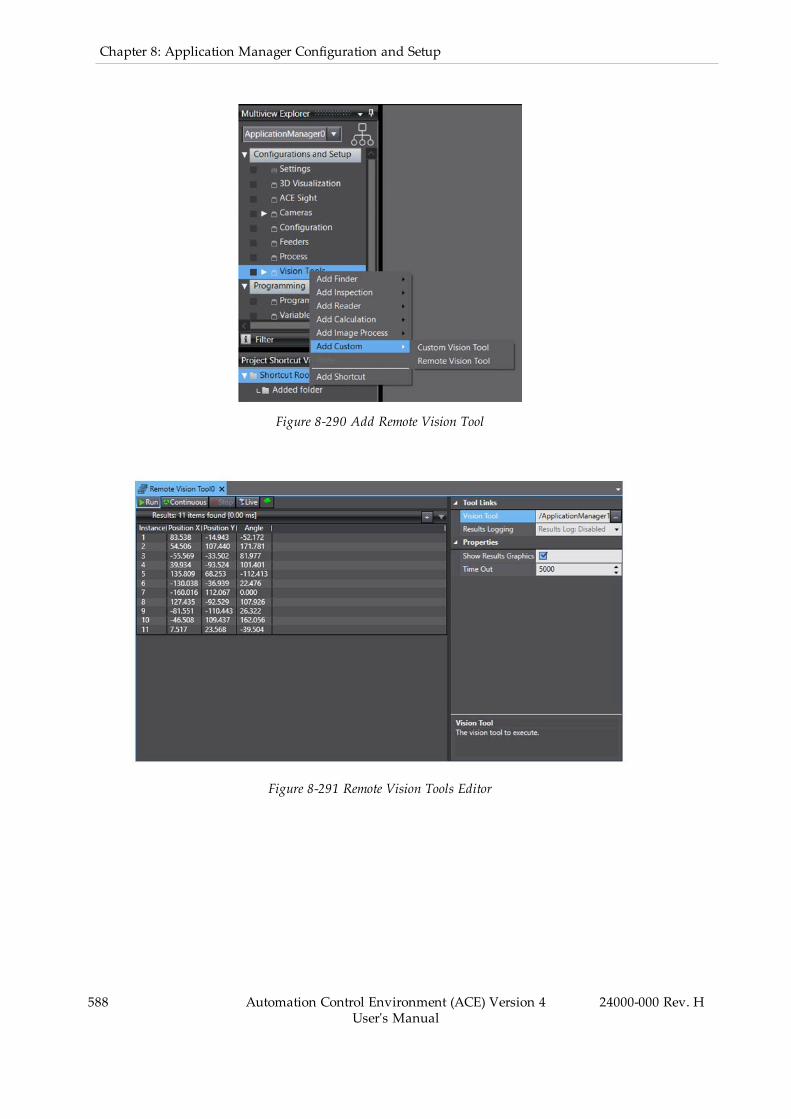
588 Automation Control Environment (ACE) Version 4User's Manual
24000-000 Rev. H
Chapter 8: Application Manager Configuration and Setup
Figure 8-290 Add Remote Vision Tool
Figure 8-291 Remote Vision Tools Editor
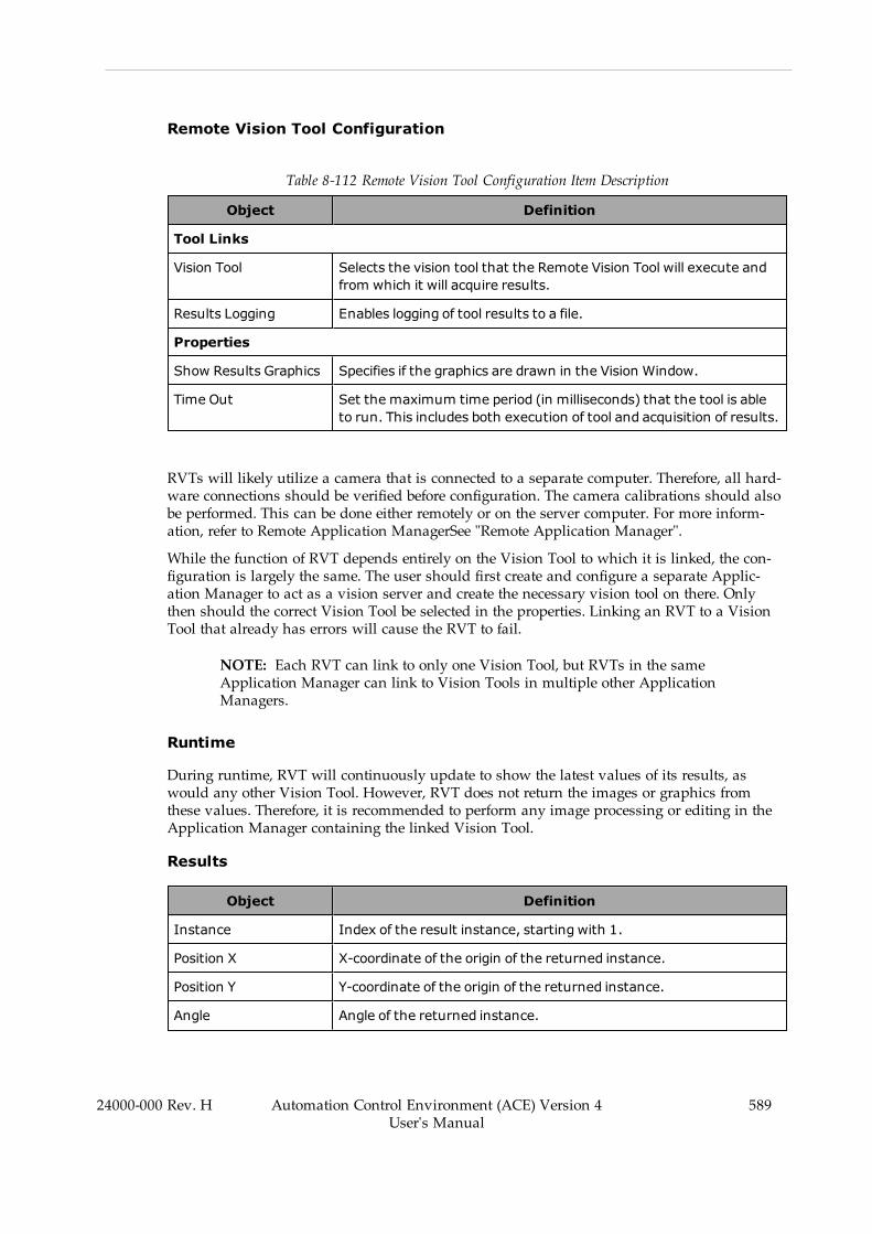
Remote Vision Tool Configuration
Table 8-112 Remote Vision Tool Configuration Item Description
Object Definition
Tool Links
Vision Tool Selects the vision tool that the Remote Vision Tool will execute andfrom which it will acquire results.
Results Logging Enables logging of tool results to a file.
Properties
Show Results Graphics Specifies if the graphics are drawn in the Vision Window.
Time Out Set the maximum time period (in milliseconds) that the tool is ableto run. This includes both execution of tool and acquisition of results.
RVTs will likely utilize a camera that is connected to a separate computer. Therefore, all hard-ware connections should be verified before configuration. The camera calibrations should alsobe performed. This can be done either remotely or on the server computer. For more inform-ation, refer to Remote Application ManagerSee "Remote Application Manager".
While the function of RVT depends entirely on the Vision Tool to which it is linked, the con-figuration is largely the same. The user should first create and configure a separate Applic-ation Manager to act as a vision server and create the necessary vision tool on there. Onlythen should the correct Vision Tool be selected in the properties. Linking an RVT to a VisionTool that already has errors will cause the RVT to fail.
NOTE: Each RVT can link to only one Vision Tool, but RVTs in the sameApplication Manager can link to Vision Tools in multiple other ApplicationManagers.
Runtime
During runtime, RVT will continuously update to show the latest values of its results, aswould any other Vision Tool. However, RVT does not return the images or graphics fromthese values. Therefore, it is recommended to perform any image processing or editing in theApplication Manager containing the linked Vision Tool.
Results
Object Definition
Instance Index of the result instance, starting with 1.
Position X X-coordinate of the origin of the returned instance.
Position Y Y-coordinate of the origin of the returned instance.
Angle Angle of the returned instance.
24000-000 Rev. H Automation Control Environment (ACE) Version 4User's Manual
589

590 Automation Control Environment (ACE) Version 4User's Manual
24000-000 Rev. H
Chapter 8: Application Manager Configuration and Setup
Object Definition
Name Identifies Name of returned vision instance.
Tool Compatibility
RVT is not able to connect to every type of Vision Tool. It is primarily designed to work withFinder Tools so it can return the locations of instances. RVT supports the following VisionTools:
l Blob Analyzerl Labelingl Locatorl Shape Search 3l Custom Vision Tool
In the first four Vision Tools listed, the RVT obtains its results by returning the values for eachinstance that match the Results columns shown, See "Remote Vision Tools Editor". Any otherVision Tool can be supported through a Custom Vision Tool in the Application Manager, act-ing as a vision server. RVT supports VisionTransform object type to give proper values to Pos-ition X, Position Y, and Angle.

Chapter 9: Troubleshooting
This section describes the different messages that are available for troubleshooting purposes.
9.1 Event LogThe Event Log is a tool used to display event messages that have been logged since systemstartup. The Event Log collects the time stamp and details about the particular event messagethat can be used by service personnel to troubleshoot problems.
NOTE: If you have a problem to report to field service, it is helpful to includethe Event Log information in any communication.
Figure 9-1 Event Log
You can sort the events by clicking the Type, Time Stamp, orMessage column headings. Eachclick will toggle the sort between ascending and descending order.
You can filter events by clicking the event type buttons in the Event Log area.
l Click the Error button ( ) to view all error events.l Click theWarning button ( ) to view all warning events.l Click the Information button ( ) to view all information events.
NOTE: In addition to the Event Log, most events are also written to the Win-dows Application Log. Therefore, if the Event Log is no longer available (forexample, it was cleared it or ACE software has been shut down) you can stillview the ACE events in the Windows Application Log file.
You can copy, clear, and select all Event Log entries by right-clicking the list and making aselection.
24000-000 Rev. H Automation Control Environment (ACE) Version 4User's Manual
591

592 Automation Control Environment (ACE) Version 4User's Manual
24000-000 Rev. H
Chapter 9: Troubleshooting
Accessing the Event Log
To access the Event Log, select View from the menu bar and then click Event Log. The EventLog will appear in the Multifunction Tab area.
Figure 9-2 Access the Event Log
9.2 eV+ LogThe eV+ Log displays a history of SmartController events since the controller was powered onfor the first time. The eV+ Log stores the eV+ event type, level, time stamp, and comment foreach entry. Use the eV+ to see a history of SmartController events related to configuration,FieldBus, V+, and System changes. You can also use the eV+ Log for troubleshooting purposes.
The information contained in the eV+ Log is stored in the SmartController at the following loc-ation. Refer to Task Status Control on page 122 for more information.
D:\ADEPT\CUSTOM\LOG.XML
Additional Information: Some errors (such as servo errors) may require access-ing the FireWire event log for additional information. Refer to FireWire Event Logon page 593 for more information.
NOTE: The eV+ Log is available when connected to a SmartController. Access-ing the eV+ Log is not possible in Emulation Mode.

Figure 9-3 View eV+ LogS
Use the Types and Levels selections to filter events. The Copy button will copy all events inthe list to the clipboard.
Accessing the eV+ Log
To access the eV+ Log, open the Controller Settings. Then, click the Control menu item andselect View eV+ Log. The eV+ Log will be displayed.
Refer to Controller Settings on page 185 for more information.
Figure 9-4 Access the eV+ Log
9.3 FireWire Event LogEach FireWire node in the system contains an event log. The FireWire Event Log collects an IDnumber, description, time stamp, occurrence count, and additional information about the last
24000-000 Rev. H Automation Control Environment (ACE) Version 4User's Manual
593
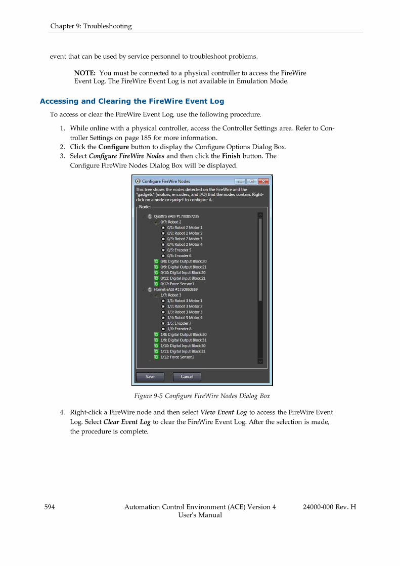
594 Automation Control Environment (ACE) Version 4User's Manual
24000-000 Rev. H
Chapter 9: Troubleshooting
event that can be used by service personnel to troubleshoot problems.
NOTE: You must be connected to a physical controller to access the FireWireEvent Log. The FireWire Event Log is not available in Emulation Mode.
Accessing and Clearing the FireWire Event Log
To access or clear the FireWire Event Log, use the following procedure.
1. While online with a physical controller, access the Controller Settings area. Refer to Con-troller Settings on page 185 for more information.
2. Click the Configure button to display the Configure Options Dialog Box.3. Select Configure FireWire Nodes and then click the Finish button. TheConfigure FireWire Nodes Dialog Box will be displayed.
Figure 9-5 Configure FireWire Nodes Dialog Box
4. Right-click a FireWire node and then select View Event Log to access the FireWire EventLog. Select Clear Event Log to clear the FireWire Event Log. After the selection is made,the procedure is complete.
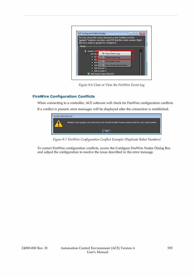
Figure 9-6 Clear or View the FireWire Event Log
FireWire Configuration Conflicts
When connecting to a controller, ACE software will check for FireWire configuration conflicts.
If a conflict is present, error messages will be displayed after the connection is established.
Figure 9-7 FireWire Configuration Conflict Example (Duplicate Robot Numbers)
To correct FireWire configuration conflicts, access the Configure FireWire Nodes Dialog Boxand adjust the configuration to resolve the issue described in the error message.
24000-000 Rev. H Automation Control Environment (ACE) Version 4User's Manual
595

596 Automation Control Environment (ACE) Version 4User's Manual
24000-000 Rev. H
Chapter 9: Troubleshooting

Appendix A
A.1 Configuring Basler CamerasACE Sight vision tools support Basler cameras supplied by Omron. These cameras need to beconfigured before use with the ACE software.
Use the following steps to understand the general Basler camera configuration procedure. Thesteps are detailed in the following sections.
1. Communication and power connections2. Configure network and camera settings3. Add the camera to an ACE project4. Position Latch Wiring (application dependent)5. Latch Signal Test (application dependent)
NOTE: The ACE software installation includes the Basler Pylon Suite that isrequired for the camera configuration.
Camera Connections
The Basler cameras ship with power and data cables. The following identifies the Omron partnumbers.
Basler:Power I/O cable p/n 09454-610Cat6 Camera Cable p/n 18472-000
Use the following information to understand the Basler camera connections. Cameras withGPIO are models: acA60-300, acA800-200, acA1300-75, acA1920-40, acA1920-48, acA1920-50,acA2500-20. All other Basler camera models do not have GPIO capability, use the followingtwo tables as guides for power connections.
1
2
6
5
4 3
8
1
2
3
4
5
6
7
24000-000 Rev. H Automation Control Environment (ACE) Version 4User's Manual
597
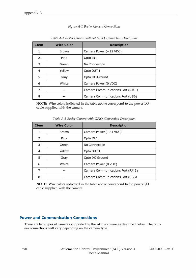
598 Automation Control Environment (ACE) Version 4User's Manual
24000-000 Rev. H
Appendix A
Figure A-1 Basler Camera Connections
Table A-1 Basler Camera without GPIO, Connection Description
Item Wire Color Description
1 Brown Camera Power (+12 VDC)
2 Pink Opto IN 1
3 Green No Connection
4 Yellow Opto OUT 1
5 Gray Opto I/O Ground
6 White Camera Power (0 VDC)
7 -- Camera Communications Port (RJ45)
8 -- Camera Communications Port (USB)
NOTE: Wire colors indicated in the table above correspond to the power I/Ocable supplied with the camera.
Table A-2 Basler Camera with GPIO, Connection Description
Item Wire Color Description
1 Brown Camera Power (+24 VDC)
2 Pink Opto IN 1
3 Green No Connection
4 Yellow Opto OUT 1
5 Gray Opto I/O Ground
6 White Camera Power (0 VDC)
7 -- Camera Communications Port (RJ45)
8 -- Camera Communications Port (USB)
NOTE: Wire colors indicated in the table above correspond to the power I/Ocable supplied with the camera.
Power and Communication Connections
There are two types of cameras supported by the ACE software as described below. The cam-era connections will vary depending on the camera type.

Camera Power Connections
Use the following information to supply power to the camera. Refer to Camera Connections onpage 597 for more information.
NOTE: If using a GigE type camera, external power connections should not beused if the camera is connected to a PoE port. Only the optocoupler needs to beconnected after the Ethernet PoE cable.
Use the following connections to supply external power to the camera if the model uses GPIO.
l Pin 1: + 24 VDCl Pin 6: 0 VDC
Use the following connections to supply external power to the camera if the model doesNOT use GPIO.
l Pin 1: + 12 VDCl Pin 6: 0 VDC
Camera Communication Connections
If using a GigE type camera, connect the RJ45 camera port to the PC or the local area networkusing the supplied cable.
If using a USB camera, connect the provided USB cable to the PC using the supplied cable.
Configure Network and Camera Settings
After connecting the camera to the PC or local area network, configure the network and camerasettings described below.
NOTE: The Pylon tools referenced in this section can be found in the WindowsStart Menu under the Pylon program group. These tools are included with thedefault ACE software installation.
Jumbo Packet Setting
Access the PC network adapter configuration and enable the Jumbo Packet property. Set thevalue to 9014 Bytes.
24000-000 Rev. H Automation Control Environment (ACE) Version 4User's Manual
599
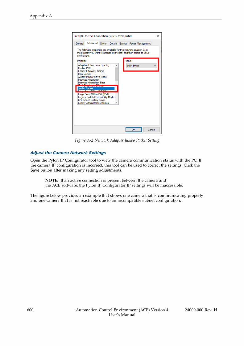
600 Automation Control Environment (ACE) Version 4User's Manual
24000-000 Rev. H
Appendix A
Figure A-2 Network Adapter Jumbo Packet Setting
Adjust the Camera Network Settings
Open the Pylon IP Configurator tool to view the camera communication status with the PC. Ifthe camera IP configuration is incorrect, this tool can be used to correct the settings. Click theSave button after making any setting adjustments.
NOTE: If an active connection is present between the camera andthe ACE software, the Pylon IP Configurator IP settings will be inaccessible.
The figure below provides an example that shows one camera that is communicating properlyand one camera that is not reachable due to an incompatible subnet configuration.
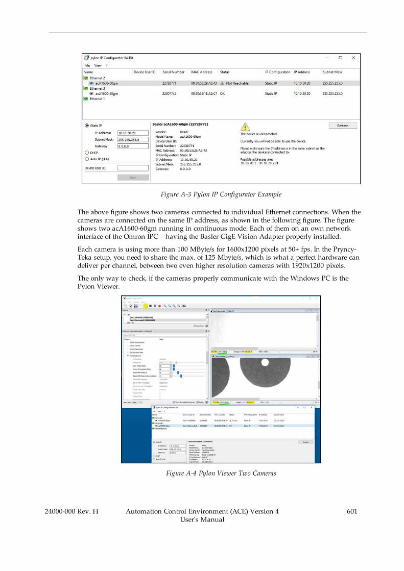
Figure A-3 Pylon IP Configurator Example
The above figure shows two cameras connected to individual Ethernet connections. When thecameras are connected on the same IP address, as shown in the following figure. The figureshows two acA1600-60gm running in continuous mode. Each of them on an own networkinterface of the Omron IPC – having the Basler GigE Vision Adapter properly installed.
Each camera is using more than 100 MByte/s for 1600x1200 pixels at 50+ fps. In the Pryncy-Teka setup, you need to share the max. of 125 Mbyte/s, which is what a perfect hardware candeliver per channel, between two even higher resolution cameras with 1920x1200 pixels.
The only way to check, if the cameras properly communicate with the Windows PC is thePylon Viewer.
Figure A-4 Pylon Viewer Two Cameras
24000-000 Rev. H Automation Control Environment (ACE) Version 4User's Manual
601

602 Automation Control Environment (ACE) Version 4User's Manual
24000-000 Rev. H
Appendix A
An operating issue is that different NICs and switches support different packet sizes. Definingthe correct packet size is system dependent. When the packets are too small the NIC bufferscan become overloaded and packets can be dropped. When packets are too large the NIC maynot support that size and it drops the packet. In either case, when packets are dropped, theACE driver detects the drop and requess the camera to resend.
The typical packet size of ~500 are too small when dealing with large images that naturallyconsist of lots of data. And, not many devices support the full 16000 Byte packets. Starting at1500 Bytes is usually the fail-safe. If you notice your CPU load is higher than you'd like.
You can also enable the "Auto Packet Size" feature in the camera, and the camera will try tonegotiate a working packet size on its own.
Adjust Camera Image Acquisition Settings
The Pylon Viewer is used to adjust the camera image acquisition settings. Use this tool toenable the Exposure Active signal and change any other necessary camera settings beforeadding a camera to the ACE project.
NOTE: If any camera settings are changed with the Pylon Viewer tool after ithas been added to the ACE project, camera functions may be disrupted.
Open the Pylon Viewer tool and select a camera from the Devices list. Then, click the OpenCamera button to access all settings associated with the selected camera.
Figure A-5 Pylon Viewer - Open Camera
Enable the Exposure Active Signal
The Exposure Active signal is an output from the camera to the robot controller that indicatesthe moment when the camera acquired an image. This signal is used by the controller for pos-

ition latching in applications that use vision-guided motion. The Exposure Active signal mustbe enabled for all applications that require robot or belt encoder position latching.
Expand the Digital I/O Controls item and make the following settings.
l Set the Line Selector item to Output Line 1.l Set the Line Source item to Exposure Active.
Figure A-6 Exposure Active Setting
Image Acquisition Check
It may be helpful to use the Pylon Viewer tool to confirm image acquisition before adding thecamera object to the ACE project. Use the Single Shot button to acquire an image and thenmake any necessary adjustments such as exposure or white balance if required.
Add a Basler Camera to the ACE Project
After the camera connections, network settings, and camera settings have been completed, thecamera object can be added to the ACE project. Refer to Basler and Sentech Cameras on page288 for more information.
24000-000 Rev. H Automation Control Environment (ACE) Version 4User's Manual
603

604 Automation Control Environment (ACE) Version 4User's Manual
24000-000 Rev. H
Appendix A
NOTE: The ACE software and Pylon Viewer tool cannot access a camera sim-ultaneously. Always disconnect the Pylon Viewer tool before opening an ACEproject with a Basler camera object present.
Position Latch Wiring
If a camera is used in a vision-guided application with functions such as belt tracking or pos-ition refinement, a position latch signal must be connected from the camera to a robot con-troller input signal. This will allow the robot controller to capture the belt or robot positionwhen the latch condition is met.
Use the information in this section to wire and configure a typical latch position signal from aconnected Basler camera.
Latch Signal Pin Connections
The latch signal pin connections are indicated as follows. Refer to Camera Connections onpage 597 for more information.
l Pin 4: Opto OUT 1 (yellow)l Pin 5: Opto I/O Ground (gray)
SmartController XDIO Terminal Block Connection Example
The following example applies when using the SmartController XDIO terminal block to receivea rising edge latch on input 1001 (+1001 in the latch configuration). Refer to Configure on page193 for more information.

1001
1002
1003
1004
1005
1006
1007
1008
1009
1010
1011
1012
123456789101112131415161718192021222324
+–+–+–+–+–+–+–+–+–+–+–+–
SmartController EX XDIO
41424344454647484950
+24 V (1 A)
GND
Basler Camera
123456
Latch
Figure A-7 SmartController XDIO Latch Wiring Example
e-Series Controller XIO Terminal Block Connection Example
The following example applies when using the e-Series controller XIO terminal block to receivea rising edge latch on input 1001. Refer to Configure on page 193 for more information.
NOTE: Signal numbers may differ than what is shown in the following figure.Refer to the robot User Guide for more information.
Ensure the appropriate XIO Termination Block bank switch is in the LO position.
Additional Information: Refer to the XIO Termination Block Installation Guidefor more information.
24000-000 Rev. H Automation Control Environment (ACE) Version 4User's Manual
605

606 Automation Control Environment (ACE) Version 4User's Manual
24000-000 Rev. H
Appendix A
Basler Camera
123456
Latch
XIO Termination Block
Signal 1001 4
Signal 1002 5
Signal 1003 6
Signal 1004 7
Signal 1005 8
Signal 1006
+24V
GND
9
Bank 1Common
3
2,11
1,10
I1
I2
I3
Inpu
t Ban
k 1 I4
I5
I6
24V
HI
LO
XIO Connector
GND
Figure A-8 XIO Latch Wiring Example
Latch Signal Test
Use the following procedure to test a latch signal. The following settings and configurationsmust be complete before the procedure is followed.
l Camera communication and power supply is present.l Network and camera settings are complete.l The camera object must be present and configured in ACE project.l The position latch signal connections must be present.
Latch Signal Test Procedure
This is a simple test that can be performed for each camera in an application before pro-ceeding with calibrations.
1. Access the Monitor Window. Refer to Monitor Window on page 206 for more inform-ation.
2. Clear the latch FIFO buffer using the program keyword CLEAR.LATCHES.
For belts, use "do@1 clear.latches(-n)" where "n" is the belt object number.
For robots, use "do@1 clear.latches(+n)" where "n" is the robot number.
3. Ensure the latch FIFO buffer is empty by entering "listr latched(-n)" or "listr latched(+n)",where "n" is the same as in step 2. This should return "0" if the FIFO buffer is clear. If
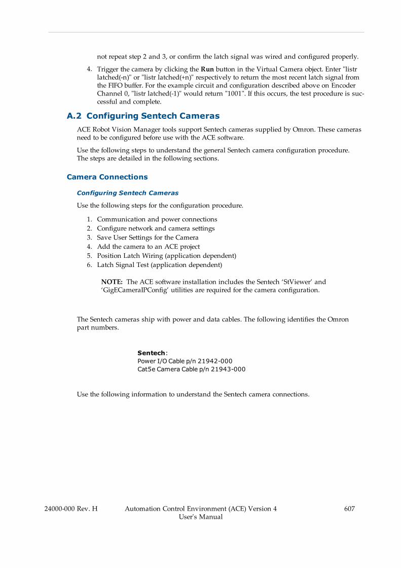
not repeat step 2 and 3, or confirm the latch signal was wired and configured properly.
4. Trigger the camera by clicking the Run button in the Virtual Camera object. Enter "listrlatched(-n)" or "listr latched(+n)" respectively to return the most recent latch signal fromthe FIFO buffer. For the example circuit and configuration described above on EncoderChannel 0, "listr latched(-1)" would return "1001". If this occurs, the test procedure is suc-cessful and complete.
A.2 Configuring Sentech CamerasACE Robot Vision Manager tools support Sentech cameras supplied by Omron. These camerasneed to be configured before use with the ACE software.
Use the following steps to understand the general Sentech camera configuration procedure.The steps are detailed in the following sections.
Camera Connections
Configuring Sentech Cameras
Use the following steps for the configuration procedure.
1. Communication and power connections2. Configure network and camera settings3. Save User Settings for the Camera4. Add the camera to an ACE project5. Position Latch Wiring (application dependent)6. Latch Signal Test (application dependent)
NOTE: The ACE software installation includes the Sentech ‘StViewer’ and‘GigECameraIPConfig’ utilities are required for the camera configuration.
The Sentech cameras ship with power and data cables. The following identifies the Omronpart numbers.
Sentech:Power I/O Cable p/n 21942-000Cat5e Camera Cable p/n 21943-000
Use the following information to understand the Sentech camera connections.
24000-000 Rev. H Automation Control Environment (ACE) Version 4User's Manual
607
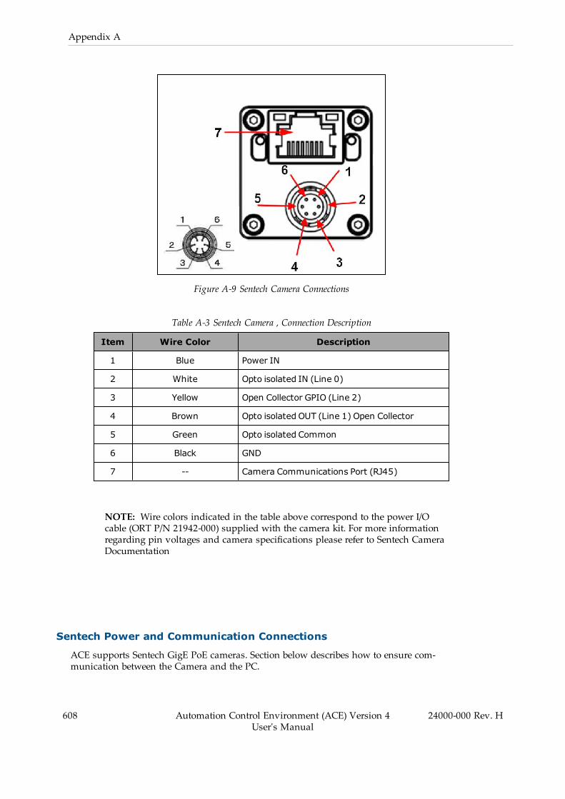
608 Automation Control Environment (ACE) Version 4User's Manual
24000-000 Rev. H
Appendix A
Figure A-9 Sentech Camera Connections
Table A-3 Sentech Camera , Connection Description
Item Wire Color Description
1 Blue Power IN
2 White Opto isolated IN (Line 0)
3 Yellow Open Collector GPIO (Line 2)
4 Brown Opto isolated OUT (Line 1) Open Collector
5 Green Opto isolated Common
6 Black GND
7 -- Camera Communications Port (RJ45)
NOTE: Wire colors indicated in the table above correspond to the power I/Ocable (ORT P/N 21942-000) supplied with the camera kit. For more informationregarding pin voltages and camera specifications please refer to Sentech CameraDocumentation
Sentech Power and Communication Connections
ACE supports Sentech GigE PoE cameras. Section below describes how to ensure com-munication between the Camera and the PC.

Camera Power Connections
Power can be supplied to Sentech PoE cameras in two manners: default PoE, if capable, withPoE Ethernet cable or the Power I/O cable. Use the following information to supply power tothe camera. Refer to Camera Connections on page 607 for more information.
NOTE: When using a GigE type camera, external power connections should notbe used if the camera is connected to a PoE port.
Use the following connections to supply external power to the camera if the model uses GPIO.
l Pin 1: + 24 VDCl Pin 6: 0 VDC
Camera Communication Connections
If using a GigE type camera, connect the RJ45 camera port to the PC or the local area networkusing the supplied cable, ORT P/N 21943-000.
If using a USB camera, connect the provided USB cable to the PC using the supplied cable.
Configure Network and Camera Settings
After connecting the camera to the PC or local area network, configure the network and camerasettings described below.
NOTE: The StViewer tools referenced in this section can be found in the Win-dows Start Menu under the Sentech SDK program group. These tools areincluded with the default ACE software installation.
PC Port Settings
Open the PC Control Panel and then open the Network Connections. Right click the port usedfor the Sentech camera and select Properties. Select Internet Protocol Viewer 4 (TCP/IPv4) andclick Properties, to open that panel, as shown in the following figure.
24000-000 Rev. H Automation Control Environment (ACE) Version 4User's Manual
609

610 Automation Control Environment (ACE) Version 4User's Manual
24000-000 Rev. H
Appendix A
Figure A-10 TCP/IPv4 Network Properties
Use the Network Properties setup the correct compatible IP address for the PC port com-municating with the Sentech Camera. It is recommended to connect one GigE camera per port.When done, click OK on the Properties panel. The Ethernet Properties panel should remainopen.
Jumbo Packet Setting
On the Ethernet Properties panel, click the Configure button. The enables the PC networkadapter configuration and enable the Jumbo Packet property. Set the value to 9014 Bytes. Clickthe Advanced tab and scroll down the Property options and select Jumbo Packet. In the Valueside, use the drop down and select 9014 Bytes, as shown in the following figure. Then click,OK to close the panel.
Figure A-11 Network Adapter Jumbo Packet Setting
Adjust the Camera Network Settings
In the Windows Start Menu, navigate to the Sentech SDK and open the GigECameraIPConfigto view the camera communication status with the PC. If the camera IP configuration is incor-rect, this tool can be used to correct the settings. Click the Apply button after making any set-ting adjustments.
NOTE: If an active connection is present between the camera and the ACE soft-ware, the Sentech StViewer settings may be inaccessible since only one softwaremay access the camera at any time.
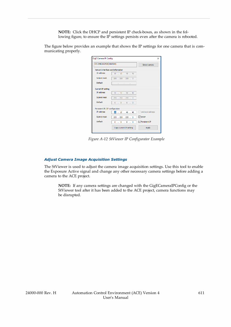
NOTE: Click the DHCP and persistent IP check-boxes, as shown in the fol-lowing figure, to ensure the IP settings persists even after the camera is rebooted.
The figure below provides an example that shows the IP settings for one camera that is com-municating properly.
Figure A-12 StViewer IP Configurator Example
Adjust Camera Image Acquisition Settings
The StViewer is used to adjust the camera image acquisition settings. Use this tool to enablethe Exposure Active signal and change any other necessary camera settings before adding acamera to the ACE project.
NOTE: If any camera settings are changed with the GigECameraIPConfig or theStViewer tool after it has been added to the ACE project, camera functions maybe disrupted.
24000-000 Rev. H Automation Control Environment (ACE) Version 4User's Manual
611
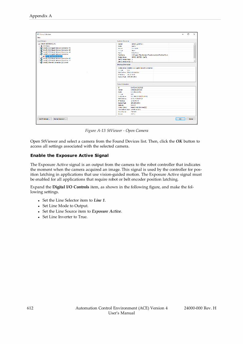
612 Automation Control Environment (ACE) Version 4User's Manual
24000-000 Rev. H
Appendix A
Figure A-13 StViewer - Open Camera
Open StViewer and select a camera from the Found Devices list. Then, click the OK button toaccess all settings associated with the selected camera.
Enable the Exposure Active Signal
The Exposure Active signal is an output from the camera to the robot controller that indicatesthe moment when the camera acquired an image. This signal is used by the controller for pos-ition latching in applications that use vision-guided motion. The Exposure Active signal mustbe enabled for all applications that require robot or belt encoder position latching.
Expand the Digital I/O Controls item, as shown in the following figure, and make the fol-lowing settings.
l Set the Line Selector item to Line 1.l Set Line Mode to Output.l Set the Line Source item to Exposure Active.l Set Line Inverter to True.

Figure A-14 Digital IO Content
Save Camera Settings
Sentech Camera Settings need to be saved to a User Set to ensure the settings are applied whenthe camera loses power or the connected PC is restarted. Before loading or saving User Profiles,the acquisition needs to be turned off by pressing the STOP Acquisition button in the top leftcorner in the tool bar.
To save these settings, for example to User Set 0, “User Set Selector should be changed to“User Set 0”, then execute User Set Save. When “User Set Default” is set to “User Set 0” thecamera will load User Set 0 settings when power is applied. All changes made to the camera’s
24000-000 Rev. H Automation Control Environment (ACE) Version 4User's Manual
613
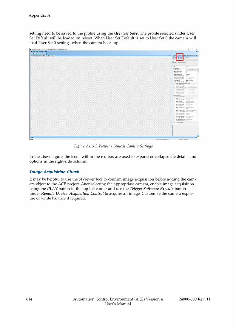
614 Automation Control Environment (ACE) Version 4User's Manual
24000-000 Rev. H
Appendix A
setting need to be saved to the profile using the User Set Save. The profile selected under UserSet Default will be loaded on reboot. When User Set Default is set to User Set 0 the camera willload User Set 0 settings when the camera boots up.
Figure A-15 StViewer - Sentech Camera Settings
In the above figure, the icons within the red box are used to expand or collapse the details andoptions in the right-side oclumn.
Image Acquisition Check
It may be helpful to use the StViewer tool to confirm image acquisition before adding the cam-era object to the ACE project. After selecting the appropriate camera, enable image acquisitionusing the PLAY button in the top left corner and use the Trigger Software Execute buttonunder Remote Device_Acquisition Control to acquire an image. Customize the camera expos-ure or white balance if required.

Figure A-16 Trigger Software Selector
Add a Sentech Camera to the ACE Project
After the camera connections, network settings, and camera settings have been completed, thecamera object can be added to the ACE project. Refer to Basler and Sentech Cameras on page288 for more information.
NOTE: The ACE software and StViewer tool cannot access a camera sim-ultaneously. Always disconnect the StViewer tool before opening an ACE projectwith a Sentech camera object present.
Position Latch Wiring
If a camera is used in a vision-guided application with functions such as belt tracking or pos-ition refinement, a position latch signal must be connected from the camera to a robot con-troller input signal. This will allow the robot controller to capture the belt or robot positionwhen the latch condition is met.
Use the information in this section to wire and configure a typical latch position signal from aconnected Sentech camera.
24000-000 Rev. H Automation Control Environment (ACE) Version 4User's Manual
615

616 Automation Control Environment (ACE) Version 4User's Manual
24000-000 Rev. H
Appendix A
Latch Signal Pin Connections
The latch signal pin connections are indicated as follows. Refer to Camera Connections onpage 607 for more information.
l Pin 4: Opto isolated out line 1 (brown)l Pin 5: Opto isolated common (green)
SmartController XDIO Terminal Block Connection Example
The following example applies when using the SmartController XDIO terminal block to receivea rising edge latch on input 1001 (+1001 in the latch configuration). Refer to Configure on page193 for more information.
1001
1002
1003
1004
1005
1006
1007
1008
1009
1010
1011
1012
123456789101112131415161718192021222324
+–+–+–+–+–+–+–+–+–+–+–+–
SmartController EX XDIO
41424344454647484950
+24 V (1 A)
GND
Sentech Camera
123456
Latch
Figure A-17 SmartController XDIO Latch Wiring Example

e-Series Controller XIO Terminal Block Connection Example
The following example applies when using the e-Series controller XIO terminal block to receivea rising edge latch on input 1001. Refer to Configure on page 193 for more information.
NOTE: Signal numbers may differ than what is shown in the following figure.Refer to the robot User Guide for more information.
Ensure the appropriate XIO Termination Block bank switch is in the LOW pos-ition.
Additional Information: Refer to the XIO Termination Block Installation Guidefor more information.
Figure A-18 XIO Latch Wiring Example
Latch Signal Test
Use the following procedure to test a latch signal. The following settings and configurationsmust be complete before the procedure is followed.
l Camera communication and power supply is present.l Network and camera settings are complete.l The camera object must be present and configured in ACE project.l The position latch signal connections must be present.
24000-000 Rev. H Automation Control Environment (ACE) Version 4User's Manual
617

618 Automation Control Environment (ACE) Version 4User's Manual
24000-000 Rev. H
Appendix A
Latch Signal Test Procedure
This is a simple test that can be performed for each camera in an application before pro-ceeding with calibrations.
1. Access the Monitor Window. Refer to Monitor Window on page 206 for more inform-ation.
2. Clear the latch FIFO buffer using the program keyword CLEAR.LATCHES.
For belts, use "do@1 clear.latches(-n)" where "n" is the belt object number.
For robots, use "do@1 clear.latches(+n)" where "n" is the robot number.
3. Ensure the latch FIFO buffer is empty by entering "listr latched(-n)" or "listr latched(+n)",where "n" is the same as in step 2. This should return "0" if the FIFO buffer is clear. Ifnot repeat step 2 and 3, or confirm the latch signal was wired and configured properly.
4. Trigger the camera by clicking the Run button in the Virtual Camera object. Enter "listrlatched(-n)" or "listr latched(+n)" respectively to return the most recent latch signal fromthe FIFO buffer. For the example circuit and configuration described above on EncoderChannel 0, "listr latched(-1)" would return "1001". If this occurs, the test procedure is suc-cessful and complete.
A.3 Configuring Photoneo 3D CamerasACE Sight vision tools supports 3D Pick Manager and Phoxi cameras supplied by Photoneo.These cameras need to be configured before use with the ACE software.
Use the following steps to understand the general 3D camera configuration procedure. Thesteps are detailed in the following sections.
1. Communication and power connections2. Configure network and camera settings3. Add the camera to an ACE project
NOTE: The ACE software installation includes the PhoXi configuration tool thatis required for the camera configuration.
!WARNING: The PhoXi 3D small scanners are laser class 3R devices. Theseare considered safe when handled properly
!WARNING: The PhoXi 3D medium and large scanners are laser class 3R orlaser class 2 devices. Class 3R lasers are considered safe when handled care-fully. Class 2 lasers are considered safe for normal use.
!WARNING: Do not look directly into the laser beam. This may cause injury toyour retina. Laser protective eyewear is normally not necessary.

3D Camera Connections
The PhoXi 3D cameras are used with Omron Viper 650/850 robots for emptying bins or pal-lets. This means they are used to identify a part, by shape, within a random assortment ofparts. The part is identified, located and then picked and placed onto a stationary fixture or loc-ation. The cameras ship with power and data cables. The following identifies the Omron partnumbers.
3D Camera, p/n 21857-100, -200, -300 include the following::Scanner + PoE injector + cable: 21844-100, -200, -300Programmed License Key: 22869-000Ethernet cable (3 m): 81030-001
WARNING: The surface of the processing unit becomes hot to touch when thedevice is in use. Mount the device on a metal mounting plate that will act as athermal bridge to dissipate the heat and use the camera's carbon body to adjustthe device.
Before connecting cables to the camera, it must be mounted onto the work space. Use the fol-lowing figure to properly mount the 3D camera for your application.
Figure A-19 PhoXi 3D Mounting Dimensions
The suggested mounting method, for heat dissipation, is to use the 4xM4 screws with a metalmounting plate of suitable size. You want to ensure the mounting is rigid, to avoid vibrationsduring scanning. The optimal operating temperature for scanning is 22 °C to 25 °C; while theoperating temperature range is 0 °C to 45 °C.
The following information shows the PhoXi camera connections. The tables that followprovide the details about each pin and any cable requirements. Always use cables of a Cat5ecategory or higher that support Gigabit Ethernet or 10 Gigabit Ethernet standards. Do not useCat5 category cables as their speed is usually 10 - 100 Mbps, which is too low to obtain a goodscanning performance. If you are connecting your Scanner to a switch, make sure it is able torun at 1 Gbps or more.
NOTE: Connect the network cable to the scanner first, followed by the powercable.
24000-000 Rev. H Automation Control Environment (ACE) Version 4User's Manual
619

620 Automation Control Environment (ACE) Version 4User's Manual
24000-000 Rev. H
Appendix A
Figure A-20 3D Camera Connections
Table A-4 3D Camera M12 A 24V and M12-X Pinout
Item Wire Color Pin Out Function
1 White DC IN +24VDC
2 Brown Opto IN2 GND Laser interlock ground
3 Green GND Ground
4 Yellow Opto IN 1
5 Grey Opto IN 1 Ground
6 Pink Opto Out
7 Blue Opto Out GND
8 Red Opto IN 2 Laser interlock signal
NOTE: Wire colors indicated in the table above correspond to the cable suppliedwith the camera.
NOTE: The laser interlock ground and signal functions require special firm-ware.
The M12-X PoE port is the recommended powering option. It has a 1 Gbps connection to thePoE injector IN port. The 24V and GPIO M12-A connector supports desktop and DIN railadapters.
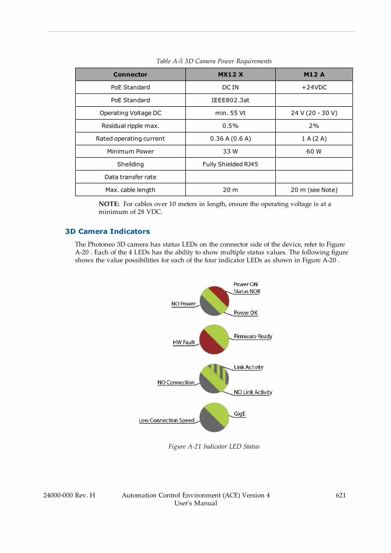
Table A-5 3D Camera Power Requirements
Connector MX12 X M12 A
PoE Standard DC IN +24VDC
PoE Standard IEEE802.3at
Operating Voltage DC min. 55 Vt 24 V (20 - 30 V)
Residual ripple max. 0.5% 2%
Rated operating current 0.36 A (0.6 A) 1 A (2 A)
Minimum Power 33 W 60 W
Sheilding Fully Shielded RJ45
Data transfer rate
Max. cable length 20 m 20 m (see Note)
NOTE: For cables over 10 meters in length, ensure the operating voltage is at aminimum of 28 VDC.
3D Camera Indicators
The Photoneo 3D camera has status LEDs on the connector side of the device, refer to FigureA-20 . Each of the 4 LEDs has the ability to show multiple status values. The following figureshows the value possibilities for each of the four indicator LEDs as shown in Figure A-20 .
Figure A-21 Indicator LED Status
24000-000 Rev. H Automation Control Environment (ACE) Version 4User's Manual
621

622 Automation Control Environment (ACE) Version 4User's Manual
24000-000 Rev. H
Appendix A
3D Power and Communication Connections
There 3D camera connections are the same for the three sizes of PhoXi cameras. .
Camera Power Connections
Use the following information to supply power to the camera. Refer to 3D Camera Connectionson page 619 for more information.
Add a 3D Camera to the ACE Project
After the camera connections, network settings, and camera settings have been completed, thecamera object can be added to the ACE project. Refer to Basler and Sentech Cameras on page288 for more information about the connections and settings.
NOTE: It is possible to simultaneously access the 3D camera through ACE andPhoxi. However, changing camera settings in Phoxi while running ACE may res-ult in unexpected camera and system behavior. For this reason it is recom-mended that you close Phoxi before opening ACE.
Open ACE and select Application Manager in the Multiview Explorer pane, as shown below.
Figure A-22 ACE Multiview Explorer
Click and expand the Configuration and Setup option. Then, right click Cameras, select Addand sequentially add the Photoneo Camera, 3D Virtual camera and Emulation 3D Camera,as shown in the following figure.
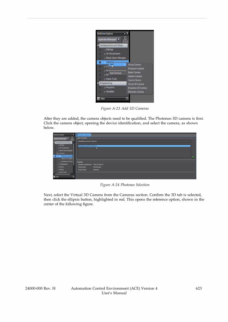
Figure A-23 Add 3D Cameras
After they are added, the camera objects need to be qualified. The Photoneo 3D camera is first.Click the camera object, opening the device identification, and select the camera, as shownbelow.
Figure A-24 Photoneo Selection
Next, select the Virtual 3D Camera from the Cameras section. Confirm the 3D tab is selected,then click the ellipsis button, highlighted in red. This opens the reference option, shown in thecenter of the following figure.
24000-000 Rev. H Automation Control Environment (ACE) Version 4User's Manual
623

624 Automation Control Environment (ACE) Version 4User's Manual
24000-000 Rev. H
Appendix A
Figure A-25 Photoneo Virtual Camera
Select the Photoneo Camera option and then click the Select button. When the center panelcloses, click the Run button shown in the following figure.
Figure A-26 Run Button Selected
The center of the pane populates with an image. The Camera Properties settings then need tobe edited.
Check the camera in the Acquisition Settings box and then click the Edit button. The CameraProperties panel opens, as in the following figure.
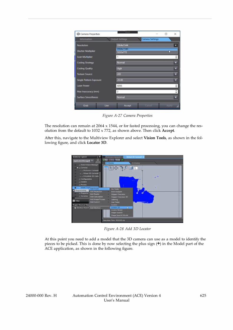
Figure A-27 Camera Properties
The resolution can remain at 2064 x 1544, or for fasted processing, you can change the res-olution from the default to 1032 x 772, as shown above. Then click Accept.
After this, navigate to the Multiview Explorer and select Vision Tools, as shown in the fol-lowing figure, and click Locator 3D.
Figure A-28 Add 3D Locator
At this point you need to add a model that the 3D camera can use as a model to identify thepieces to be picked. This is done by now selecting the plus sign (+) in the Model part of theACE application, as shown in the following figure.
24000-000 Rev. H Automation Control Environment (ACE) Version 4User's Manual
625
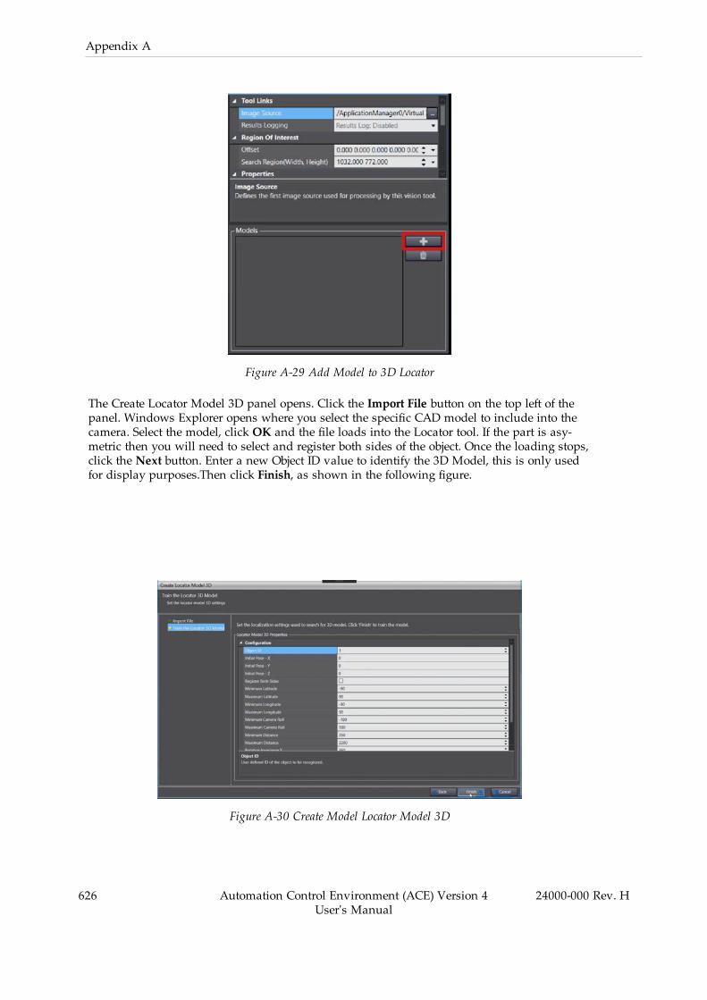
626 Automation Control Environment (ACE) Version 4User's Manual
24000-000 Rev. H
Appendix A
Figure A-29 Add Model to 3D Locator
The Create Locator Model 3D panel opens. Click the Import File button on the top left of thepanel. Windows Explorer opens where you select the specific CAD model to include into thecamera. Select the model, click OK and the file loads into the Locator tool. If the part is asy-metric then you will need to select and register both sides of the object. Once the loading stops,click the Next button. Enter a new Object ID value to identify the 3D Model, this is only usedfor display purposes.Then click Finish, as shown in the following figure.
Figure A-30 Create Model Locator Model 3D
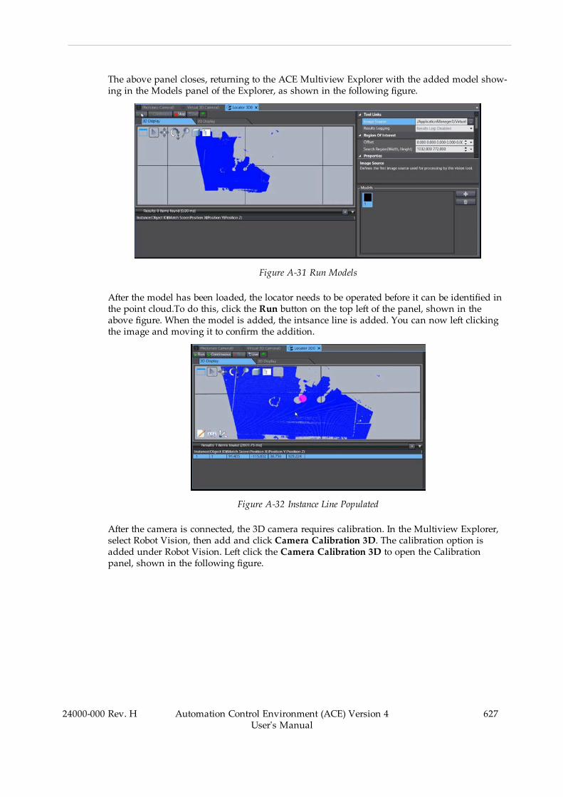
The above panel closes, returning to the ACE Multiview Explorer with the added model show-ing in the Models panel of the Explorer, as shown in the following figure.
Figure A-31 Run Models
After the model has been loaded, the locator needs to be operated before it can be identified inthe point cloud.To do this, click the Run button on the top left of the panel, shown in theabove figure. When the model is added, the intsance line is added. You can now left clickingthe image and moving it to confirm the addition.
Figure A-32 Instance Line Populated
After the camera is connected, the 3D camera requires calibration. In the Multiview Explorer,select Robot Vision, then add and click Camera Calibration 3D. The calibration option isadded under Robot Vision. Left click the Camera Calibration 3D to open the Calibrationpanel, shown in the following figure.
24000-000 Rev. H Automation Control Environment (ACE) Version 4User's Manual
627
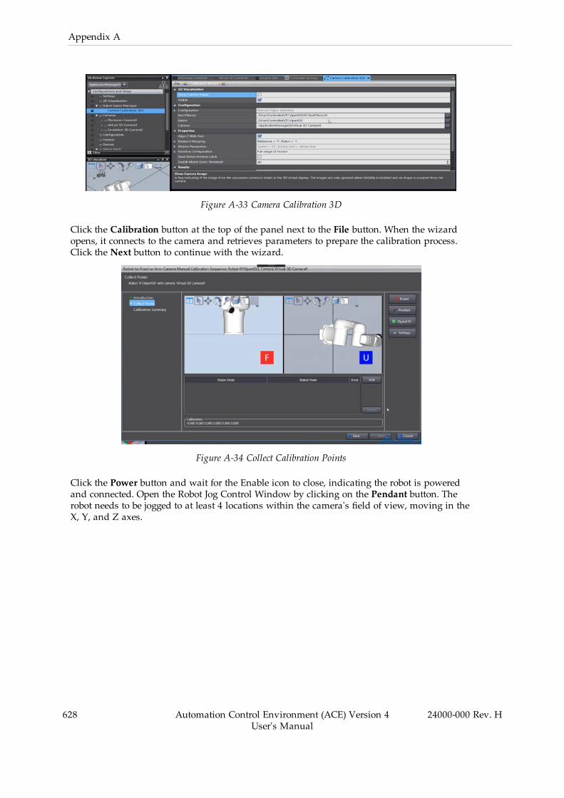
628 Automation Control Environment (ACE) Version 4User's Manual
24000-000 Rev. H
Appendix A
Figure A-33 Camera Calibration 3D
Click the Calibration button at the top of the panel next to the File button. When the wizardopens, it connects to the camera and retrieves parameters to prepare the calibration process.Click the Next button to continue with the wizard.
Figure A-34 Collect Calibration Points
Click the Power button and wait for the Enable icon to close, indicating the robot is poweredand connected. Open the Robot Jog Control Window by clicking on the Pendant button. Therobot needs to be jogged to at least 4 locations within the camera's field of view, moving in theX, Y, and Z axes.

Figure A-35 Jog Control
Use the Jog Control arrow buttons to move the robot arm, viewed through the calibrationpanel. After moving the robot to each new location, click the Add button to take an image andrecord the location. When completed, the panel will populate with each position, as shown inthe following figure. After 4 points, the calibration error will be calculated and displayed nextto each point. This number should be between 0 to 3, with lower the number being more accur-ate.
Figure A-36 Calibration Window with Points.
Once the points are identified, click the Next button, to see the errors, shown in the followingfigure.
24000-000 Rev. H Automation Control Environment (ACE) Version 4User's Manual
629

630 Automation Control Environment (ACE) Version 4User's Manual
24000-000 Rev. H
Appendix A
Figure A-37 Calibration Errors
Click the Next button again. After locating and identifying the object and the end effector of therobot, the calibration process is complete.
A.4 Pack Manager Packaging Application Sample ExerciseThis section will explain the process of building a packaging application with the Pack Man-ager Application Sample. This exercise can help you understand the project development pro-cess and the relationship between various software components and concepts. It will beginwith a Pack Manager Application Sample and include an introduction to V+ programs, 3DVisualization, IO Feeder, Recipes, and more. This will not include multiple robot applicationsor discussion of belt-relative allocation strategies.
The steps for creating a fully functional Pack Manager Packaging Application Sample in Emu-lation Mode are provided in the following sections.
NOTE: Canceling the application sample wizard before completion can lead toan ACE project with partial or no functionality. Completing the wizard is recom-mended.
Create a Basic Pack Manager Application Sample
An Application Sample can be used to generate the basic structure of the application for singlerobot applications. Create the Pack Manager Application Sample in Emulation Mode with thefollowing procedure based on the details provided in the Jar Packing Application Summary onpage 640.
This procedure creates a basic Pack Manager application sample that serves as a foundationfor the application described in the Jar Packing Application Summary on page 640. Use the

information found in Modify the Pack Manager Application Sample Project on page 641 to con-figure the basic Pack Manager application sample to match the application summary require-ments.
1. Launch the ACE software to access the Start Page.2. Select Connect to Device, Open in Emulation Mode, select the Create Application Sampleoption, choose Pack Manager Sample, and then click the Connect button. The projectwill be created and the robot will be selected in the next step.
Figure A-38 Create the Pack Manager Application Sample
3. Add a Cobra 800 Pro robot to the Installed Robots area and then click the Next button.
24000-000 Rev. H Automation Control Environment (ACE) Version 4User's Manual
631
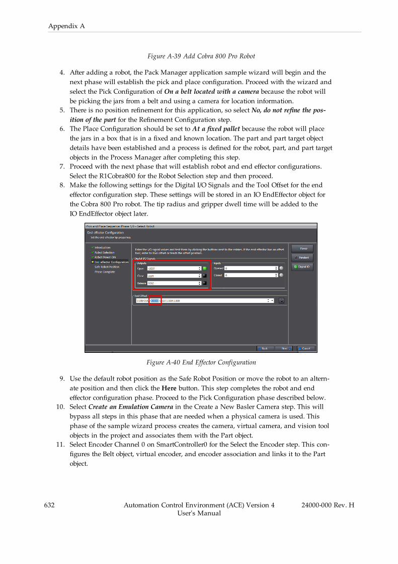
632 Automation Control Environment (ACE) Version 4User's Manual
24000-000 Rev. H
Appendix A
Figure A-39 Add Cobra 800 Pro Robot
4. After adding a robot, the Pack Manager application sample wizard will begin and thenext phase will establish the pick and place configuration. Proceed with the wizard andselect the Pick Configuration of On a belt located with a camera because the robot willbe picking the jars from a belt and using a camera for location information.
5. There is no position refinement for this application, so select No, do not refine the pos-ition of the part for the Refinement Configuration step.
6. The Place Configuration should be set to At a fixed pallet because the robot will placethe jars in a box that is in a fixed and known location. The part and part target objectdetails have been established and a process is defined for the robot, part, and part targetobjects in the Process Manager after completing this step.
7. Proceed with the next phase that will establish robot and end effector configurations.Select the R1Cobra800 for the Robot Selection step and then proceed.
8. Make the following settings for the Digital I/O Signals and the Tool Offset for the endeffector configuration step. These settings will be stored in an IO EndEffector object forthe Cobra 800 Pro robot. The tip radius and gripper dwell time will be added to theIO EndEffector object later.
Figure A-40 End Effector Configuration
9. Use the default robot position as the Safe Robot Position or move the robot to an altern-ate position and then click the Here button. This step completes the robot and endeffector configuration phase. Proceed to the Pick Configuration phase described below.
10. Select Create an Emulation Camera in the Create a New Basler Camera step. This willbypass all steps in this phase that are needed when a physical camera is used. Thisphase of the sample wizard process creates the camera, virtual camera, and vision toolobjects in the project and associates them with the Part object.
11. Select Encoder Channel 0 on SmartController0 for the Select the Encoder step. This con-figures the Belt object, virtual encoder, and encoder association and links it to the Partobject.
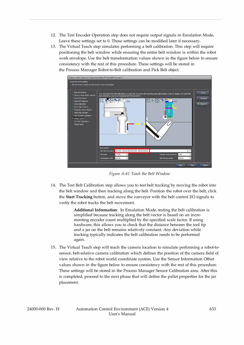
12. The Test Encoder Operation step does not require output signals in Emulation Mode.Leave these settings set to 0. These settings can be modified later if necessary.
13. The Virtual Teach step simulates performing a belt calibration. This step will requirepositioning the belt window while ensuring the entire belt window is within the robotwork envelope. Use the belt transformation values shown in the figure below to ensureconsistency with the rest of this procedure. These settings will be stored inthe Process Manager Robot-to-Belt calibration and Pick Belt object.
Figure A-41 Teach the Belt Window
14. The Test Belt Calibration step allows you to test belt tracking by moving the robot intothe belt window and then tracking along the belt. Position the robot over the belt, clickthe Start Tracking button, and move the conveyor with the belt control I/O signals toverify the robot tracks the belt movement.
Additional Information: In Emulation Mode, testing the belt calibration issimplified because tracking along the belt vector is based on an incre-menting encoder count multiplied by the specified scale factor. If usinghardware, this allows you to check that the distance between the tool tipand a jar on the belt remains relatively constant. Any deviation whiletracking typically indicates the belt calibration needs to be performedagain.
15. The Virtual Teach step will teach the camera location to simulate performing a robot-to-sensor, belt-relative camera calibration which defines the position of the camera field ofview relative to the robot world coordinate system. Use the Sensor Information Offsetvalues shown in the figure below to ensure consistency with the rest of this procedure.These settings will be stored in the Process Manager Sensor Calibration area. After thisis completed, proceed to the next phase that will define the pallet properties for the jarplacement.
24000-000 Rev. H Automation Control Environment (ACE) Version 4User's Manual
633

634 Automation Control Environment (ACE) Version 4User's Manual
24000-000 Rev. H
Appendix A
Figure A-42 Teach the Camera Location
16. The application sample only supports X-Y (2D) arrays, so the Z dimension of the PalletProperties will need to be modified later. Set the X-Y pallet properties as follows to com-plete the Place Configuration phase.
l X Count: 4l X Spacing: 54 mml Y Count: 4l Y Spacing: 54 mm
Figure A-43 Define the Pallet Properties
17. The Teach Robot phase consists of completing the Teach Process wizard to step throughthe sequence of operations the robot will perform for this process. Begin with the TeachIdle Position step that is used when the robot is not picking or placing jars. Move the
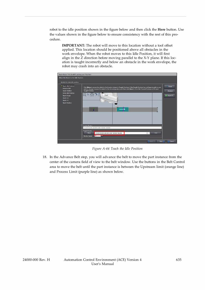
robot to the idle position shown in the figure below and then click the Here button. Usethe values shown in the figure below to ensure consistency with the rest of this pro-cedure.
IMPORTANT: The robot will move to this location without a tool offsetapplied. This location should be positioned above all obstacles in thework envelope. When the robot moves to this Idle Position, it will firstalign in the Z direction before moving parallel to the X-Y plane. If this loc-ation is taught incorrectly and below an obstacle in the work envelope, therobot may crash into an obstacle.
Figure A-44 Teach the Idle Position
18. In the Advance Belt step, you will advance the belt to move the part instance from thecenter of the camera field of view to the belt window. Use the buttons in the Belt Controlarea to move the belt until the part instance is between the Upstream limit (orange line)and Process Limit (purple line) as shown below.
24000-000 Rev. H Automation Control Environment (ACE) Version 4User's Manual
635
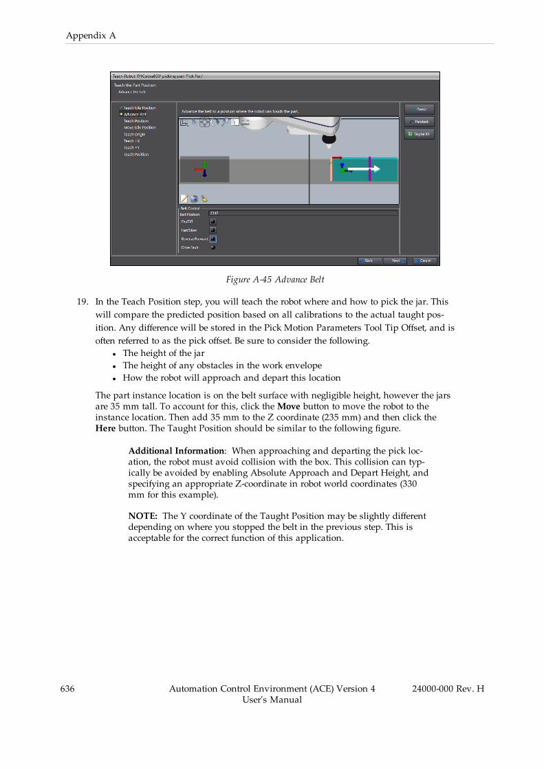
636 Automation Control Environment (ACE) Version 4User's Manual
24000-000 Rev. H
Appendix A
Figure A-45 Advance Belt
19. In the Teach Position step, you will teach the robot where and how to pick the jar. Thiswill compare the predicted position based on all calibrations to the actual taught pos-ition. Any difference will be stored in the Pick Motion Parameters Tool Tip Offset, and isoften referred to as the pick offset. Be sure to consider the following.
l The height of the jarl The height of any obstacles in the work envelopel How the robot will approach and depart this location
The part instance location is on the belt surface with negligible height, however the jarsare 35 mm tall. To account for this, click theMove button to move the robot to theinstance location. Then add 35 mm to the Z coordinate (235 mm) and then click theHere button. The Taught Position should be similar to the following figure.
Additional Information: When approaching and departing the pick loc-ation, the robot must avoid collision with the box. This collision can typ-ically be avoided by enabling Absolute Approach and Depart Height, andspecifying an appropriate Z-coordinate in robot world coordinates (330mm for this example).
NOTE: The Y coordinate of the Taught Position may be slightly differentdepending on where you stopped the belt in the previous step. This isacceptable for the correct function of this application.
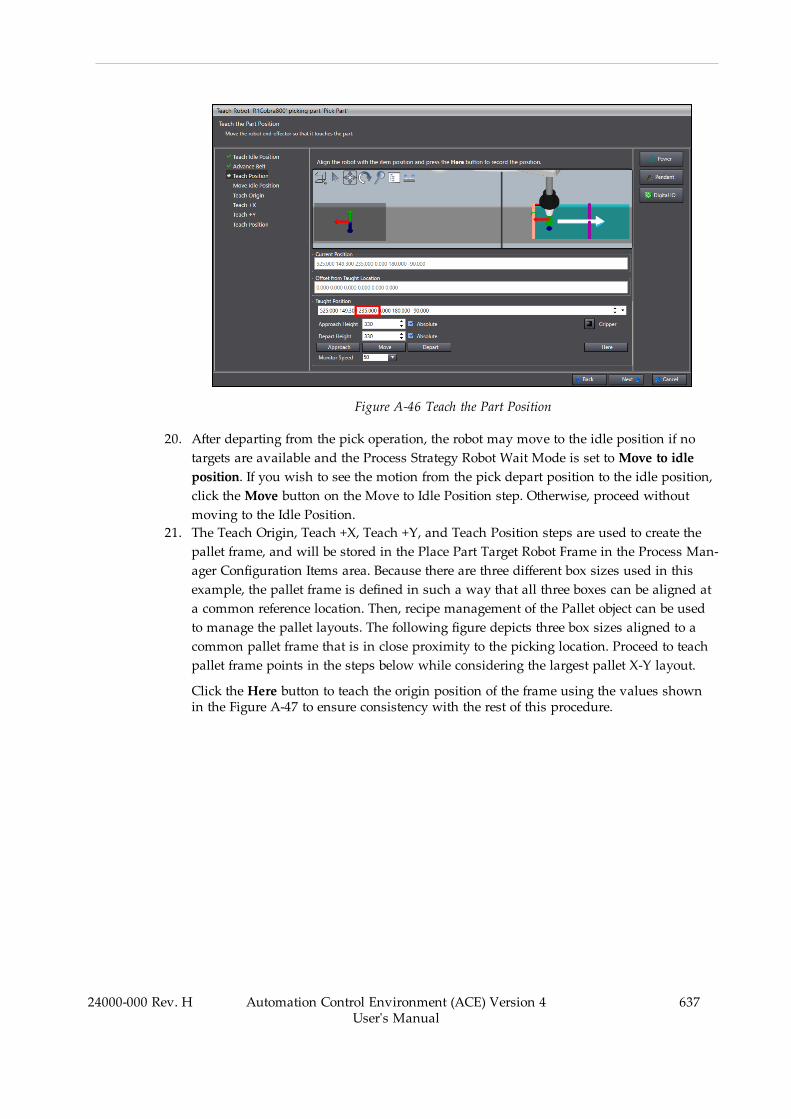
Figure A-46 Teach the Part Position
20. After departing from the pick operation, the robot may move to the idle position if notargets are available and the Process Strategy Robot Wait Mode is set toMove to idleposition. If you wish to see the motion from the pick depart position to the idle position,click theMove button on the Move to Idle Position step. Otherwise, proceed withoutmoving to the Idle Position.
21. The Teach Origin, Teach +X, Teach +Y, and Teach Position steps are used to create thepallet frame, and will be stored in the Place Part Target Robot Frame in the Process Man-ager Configuration Items area. Because there are three different box sizes used in thisexample, the pallet frame is defined in such a way that all three boxes can be aligned ata common reference location. Then, recipe management of the Pallet object can be usedto manage the pallet layouts. The following figure depicts three box sizes aligned to acommon pallet frame that is in close proximity to the picking location. Proceed to teachpallet frame points in the steps below while considering the largest pallet X-Y layout.
Click the Here button to teach the origin position of the frame using the values shownin the Figure A-47 to ensure consistency with the rest of this procedure.
24000-000 Rev. H Automation Control Environment (ACE) Version 4User's Manual
637
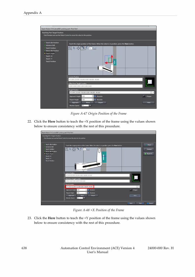
638 Automation Control Environment (ACE) Version 4User's Manual
24000-000 Rev. H
Appendix A
Figure A-47 Origin Position of the Frame
22. Click the Here button to teach the +X position of the frame using the values shownbelow to ensure consistency with the rest of this procedure.
Figure A-48 +X Position of the Frame
23. Click the Here button to teach the +Y position of the frame using the values shownbelow to ensure consistency with the rest of this procedure.

Figure A-49 +Y Position of the Frame
24. Click the Here button to teach the robot the first pallet / slot position as a 35 mm X andY offset from the origin of the frame using the values shown below to ensure con-sistency with the rest of this procedure.
Figure A-50 First Pallet / Slot Position
25. Complete the wizard and then save the project with a new name. The basic Pack Man-ager Application Sample is completed after this step.
Additional Information: Test the application by opening the3D Visualizer, access the Task Status Control, and start the Process
24000-000 Rev. H Automation Control Environment (ACE) Version 4User's Manual
639
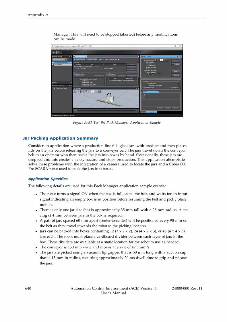
640 Automation Control Environment (ACE) Version 4User's Manual
24000-000 Rev. H
Appendix A
Manager. This will need to be stopped (aborted) before any modificationscan be made.
Figure A-51 Test the Pack Manager Application Sample
Jar Packing Application Summary
Consider an application where a production line fills glass jars with product and then placeslids on the jars before releasing the jars to a conveyor belt. The jars travel down the conveyorbelt to an operator who then packs the jars into boxes by hand. Occasionally, these jars aredropped and this creates a safety hazard and stops production. This application attempts tosolve these problems with the integration of a camera used to locate the jars and a Cobra 800Pro SCARA robot used to pack the jars into boxes.
Application Specifics
The following details are used for this Pack Manager application sample exercise.
l The robot turns a signal ON when the box is full, stops the belt, and waits for an inputsignal indicating an empty box is in position before resuming the belt and pick / placemotion.
l There is only one jar size that is approximately 35 mm tall with a 25 mm radius. A spa-cing of 4 mm between jars in the box is required.
l A pair of jars spaced 60 mm apart (center-to-center) will be positioned every 98 mm onthe belt as they travel towards the robot to the picking location.
l Jars can be packed into boxes containing 12 (3 x 2 x 2), 24 (4 x 2 x 3), or 48 (4 x 4 x 3)jars each. The robot must place a cardboard divider between each layer of jars in thebox. These dividers are available at a static location for the robot to use as needed.
l The conveyor is 150 mm wide and moves at a rate of 42.5 mm/s.l The jars are picked using a vacuum tip gripper that is 50 mm long with a suction cupthat is 15 mm in radius, requiring approximately 20 ms dwell time to grip and releasethe jars.
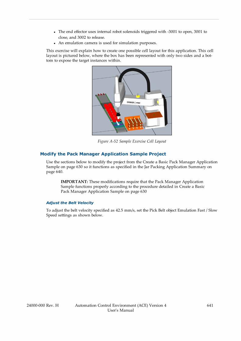
l The end effector uses internal robot solenoids triggered with -3001 to open, 3001 toclose, and 3002 to release.
l An emulation camera is used for simulation purposes.
This exercise will explain how to create one possible cell layout for this application. This celllayout is pictured below, where the box has been represented with only two sides and a bot-tom to expose the target instances within.
Figure A-52 Sample Exercise Cell Layout
Modify the Pack Manager Application Sample Project
Use the sections below to modify the project from the Create a Basic Pack Manager ApplicationSample on page 630 so it functions as specified in the Jar Packing Application Summary onpage 640.
IMPORTANT: These modifications require that the Pack Manager ApplicationSample functions properly according to the procedure detailed in Create a BasicPack Manager Application Sample on page 630
Adjust the Belt Velocity
To adjust the belt velocity specified as 42.5 mm/s, set the Pick Belt object Emulation Fast / SlowSpeed settings as shown below.
24000-000 Rev. H Automation Control Environment (ACE) Version 4User's Manual
641
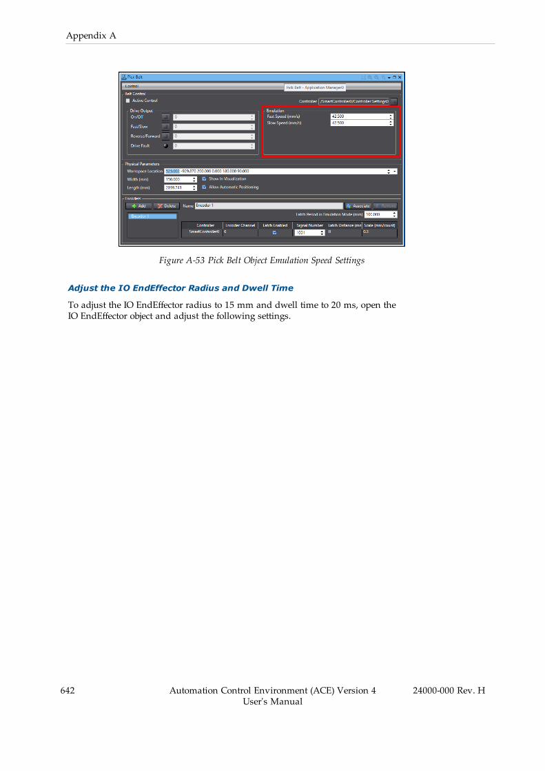
642 Automation Control Environment (ACE) Version 4User's Manual
24000-000 Rev. H
Appendix A
Figure A-53 Pick Belt Object Emulation Speed Settings
Adjust the IO EndEffector Radius and Dwell Time
To adjust the IO EndEffector radius to 15 mm and dwell time to 20 ms, open theIO EndEffector object and adjust the following settings.

Figure A-54 Adjust the IO EndEffector Radius and Dwell Time
Change from Random Jar Belt Locations to Fixed Spacing Locations
The default setting for the Virtual Camera Emulation Configuration Behavior is RandomInstances. To change this so the jars are spaced 60 mm apart (center-to-center) every 98 mm onthe belt to accurately represent the application, you can load images into the Emulation Cam-era and train the Locator Model and Locator tools, or you can use a Custom Vision Tool to gen-erate vision results in specific locations.
The procedure below uses a Custom Vision tool to generate vision results in the desired loc-ations to represent the application accurately when images are not available.
24000-000 Rev. H Automation Control Environment (ACE) Version 4User's Manual
643
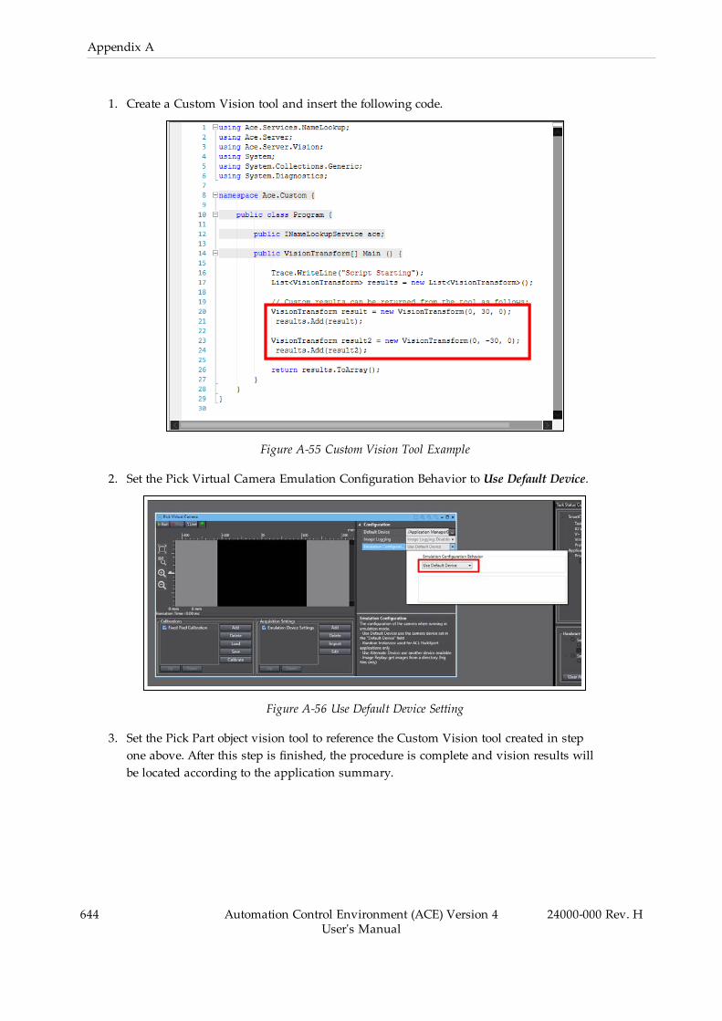
644 Automation Control Environment (ACE) Version 4User's Manual
24000-000 Rev. H
Appendix A
1. Create a Custom Vision tool and insert the following code.
Figure A-55 Custom Vision Tool Example
2. Set the Pick Virtual Camera Emulation Configuration Behavior to Use Default Device.
Figure A-56 Use Default Device Setting
3. Set the Pick Part object vision tool to reference the Custom Vision tool created in stepone above. After this step is finished, the procedure is complete and vision results willbe located according to the application summary.

Figure A-57 Reference the Custom Vision Tool
Adding Cylinder Shapes to Represent the Jars
Use the following procedure to add cylinder objects to accurately represent the jar dimensionsof 35 mm tall with a 25 mm radius.
Additional Information: The color of the objects are changed from the defaultcolor of gray to red to make them easier to see in the 3D Visualizer.
1. Add a new Cylinder object to the 3D Visualization with the following settings. Renamethis object "PartCAD" for reference later.
24000-000 Rev. H Automation Control Environment (ACE) Version 4User's Manual
645

646 Automation Control Environment (ACE) Version 4User's Manual
24000-000 Rev. H
Appendix A
Figure A-58 Create a new 3D Visualization Cylinder Object
2. Set the Pick Part object Shape Display to use the PartCAD object.
Figure A-59 Set the Pick Part Shape Display
3. Copy the PartCAD object created in step 1 and rename the copy to "TargetCAD". Changethe color to differentiate this from the PartCAD object (blue is used in this example).
4. Set the Place Part Target object Shape Display to use the TargetCAD object. After thisstep is finished, the 3D Visualizer will display cylinders that accurately represent the jardimensions for the pick and place instances.
NOTE: Default Pack Manager part and part target instance display col-oration based on allocation status (light / dark yellow for parts, light /dark green for part targets) is not available when part and part targetobject Shape Display is enabled. When Shape Display is enabled, partsand part targets are displayed according to properties of the 3D Visu-alization object.
Create Shapes to Represent the Placement Box
Use the following procedure to create bottom, front, and side box surfaces to show a cutawayview of the box that represents an obstacle that the robot must place the jars inside. These arepositioned using the pallet frame transformation from Process Manager Configuration Itemsand half the length of the box sides applied in X, Y, and Z accordingly.
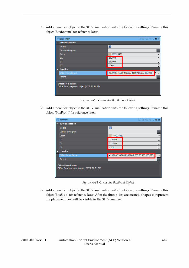
1. Add a new Box object to the 3D Visualization with the following settings. Rename thisobject "BoxBottom" for reference later.
Figure A-60 Create the BoxBottom Object
2. Add a new Box object to the 3D Visualization with the following settings. Rename thisobject "BoxFront" for reference later.
Figure A-61 Create the BoxFront Object
3. Add a new Box object to the 3D Visualization with the following settings. Rename thisobject "BoxSide" for reference later. After the three sides are created, shapes to representthe placement box will be visible in the 3D Visualizer.
24000-000 Rev. H Automation Control Environment (ACE) Version 4User's Manual
647
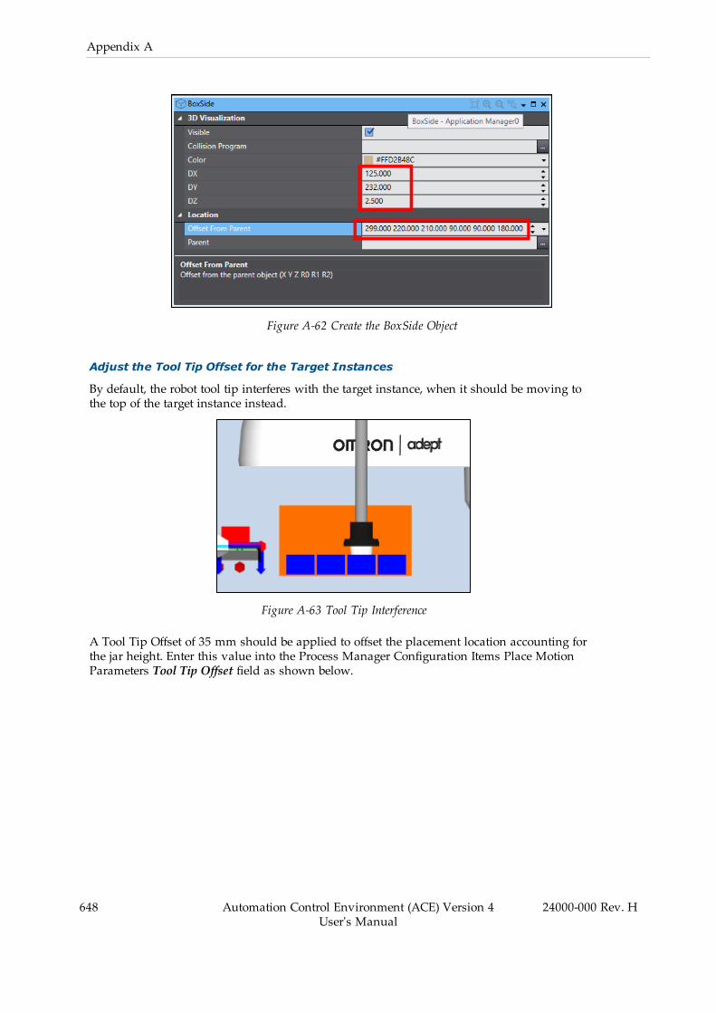
648 Automation Control Environment (ACE) Version 4User's Manual
24000-000 Rev. H
Appendix A
Figure A-62 Create the BoxSide Object
Adjust the Tool Tip Offset for the Target Instances
By default, the robot tool tip interferes with the target instance, when it should be moving tothe top of the target instance instead.
Figure A-63 Tool Tip Interference
A Tool Tip Offset of 35 mm should be applied to offset the placement location accounting forthe jar height. Enter this value into the Process Manager Configuration Items Place MotionParameters Tool Tip Offset field as shown below.
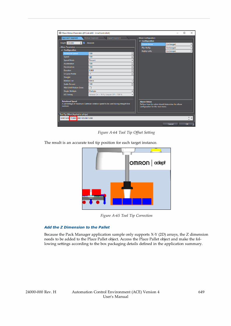
Figure A-64 Tool Tip Offset Setting
The result is an accurate tool tip position for each target instance.
Figure A-65 Tool Tip Correction
Add the Z Dimension to the Pallet
Because the Pack Manager application sample only supports X-Y (2D) arrays, the Z dimensionneeds to be added to the Place Pallet object. Access the Place Pallet object and make the fol-lowing settings according to the box packaging details defined in the application summary.
24000-000 Rev. H Automation Control Environment (ACE) Version 4User's Manual
649
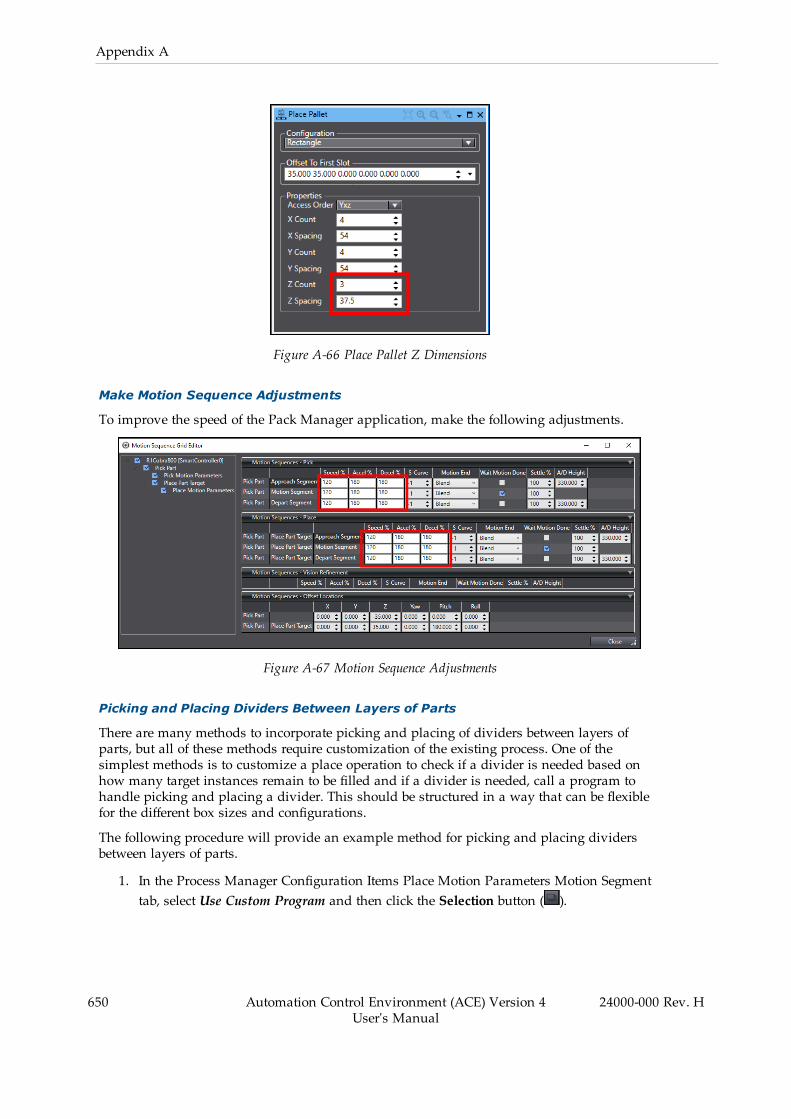
650 Automation Control Environment (ACE) Version 4User's Manual
24000-000 Rev. H
Appendix A
Figure A-66 Place Pallet Z Dimensions
Make Motion Sequence Adjustments
To improve the speed of the Pack Manager application, make the following adjustments.
Figure A-67 Motion Sequence Adjustments
Picking and Placing Dividers Between Layers of Parts
There are many methods to incorporate picking and placing of dividers between layers ofparts, but all of these methods require customization of the existing process. One of thesimplest methods is to customize a place operation to check if a divider is needed based onhow many target instances remain to be filled and if a divider is needed, call a program tohandle picking and placing a divider. This should be structured in a way that can be flexiblefor the different box sizes and configurations.
The following procedure will provide an example method for picking and placing dividersbetween layers of parts.
1. In the Process Manager Configuration Items Place Motion Parameters Motion Segmenttab, select Use Custom Program and then click the Selection button ( ).
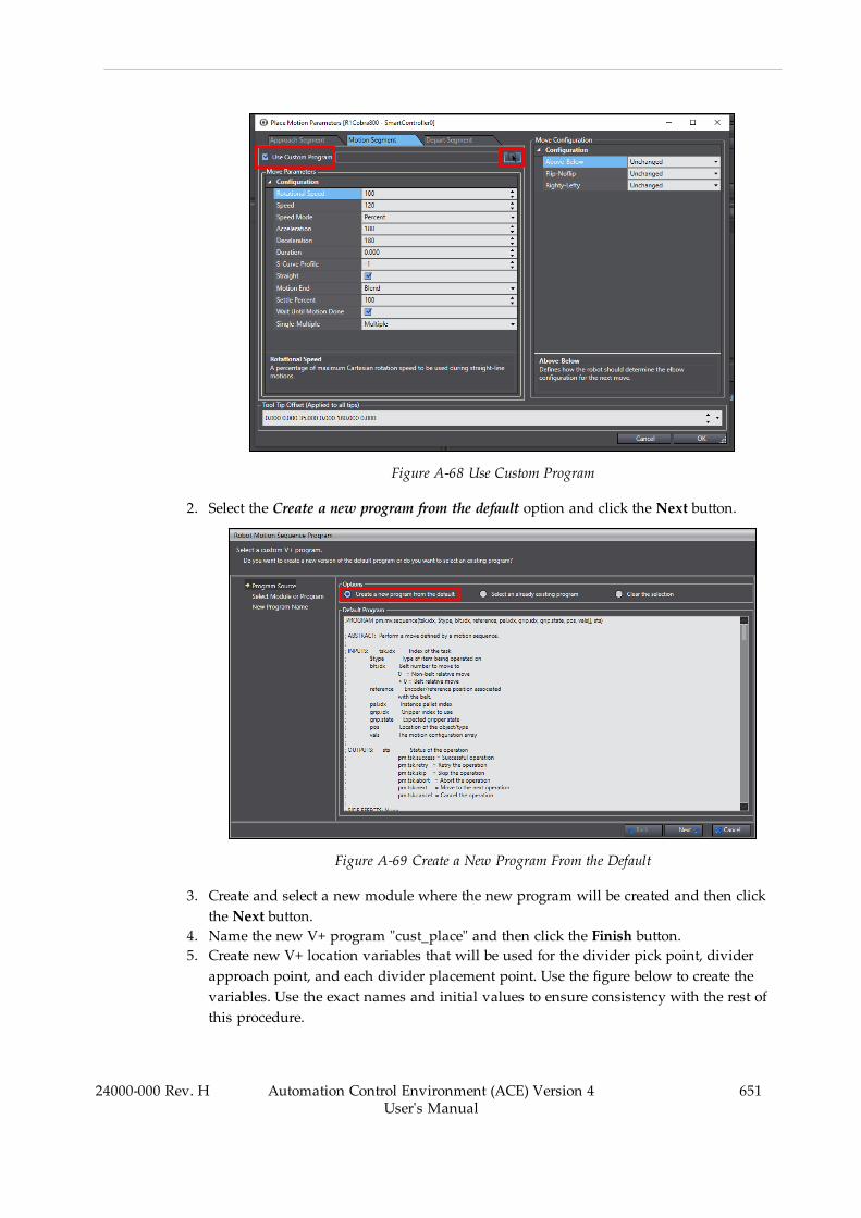
Figure A-68 Use Custom Program
2. Select the Create a new program from the default option and click the Next button.
Figure A-69 Create a New Program From the Default
3. Create and select a new module where the new program will be created and then clickthe Next button.
4. Name the new V+ program "cust_place" and then click the Finish button.5. Create new V+ location variables that will be used for the divider pick point, dividerapproach point, and each divider placement point. Use the figure below to create thevariables. Use the exact names and initial values to ensure consistency with the rest ofthis procedure.
24000-000 Rev. H Automation Control Environment (ACE) Version 4User's Manual
651

652 Automation Control Environment (ACE) Version 4User's Manual
24000-000 Rev. H
Appendix A
NOTE: The purpose of the divider approach point is to ensure that therobot is centered above the box before moving into the box with thedivider.
Figure A-70 Divider V+ Location Variables
6. Create a new V+ program named "place_divider". This will be used to pick and placethe divider at a location passed in as an argument. Add the following code to the newplace_divider V+ program.
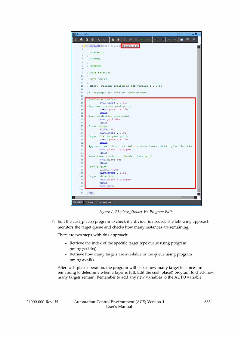
Figure A-71 place_divider V+ Program Edits
7. Edit the cust_place() program to check if a divider is needed. The following approachmonitors the target queue and checks how many instances are remaining.
There are two steps with this approach:
l Retrieve the index of the specific target type queue using programpm.trg.get.idx().
l Retrieve how many targets are available in the queue using programpm.trg.avail().
After each place operation, the program will check how many target instances areremaining to determine when a layer is full. Edit the cust_place() program to check howmany targets remain. Remember to add any new variables to the AUTO variable
24000-000 Rev. H Automation Control Environment (ACE) Version 4User's Manual
653
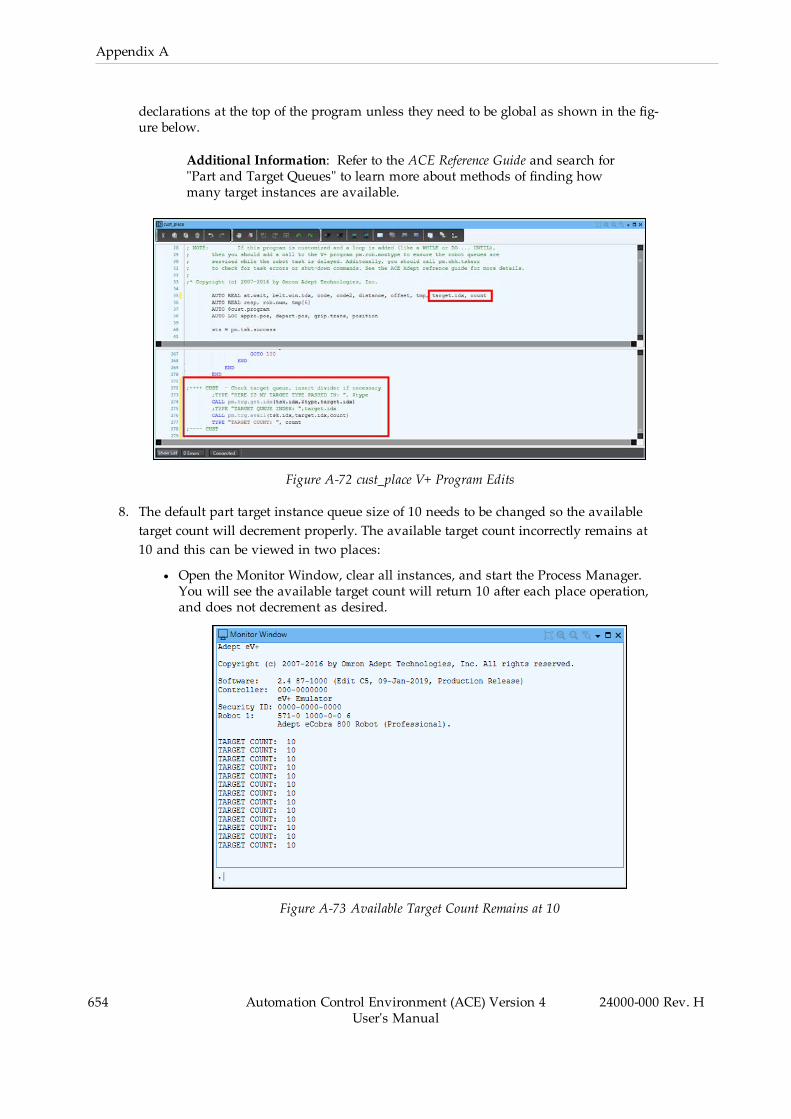
654 Automation Control Environment (ACE) Version 4User's Manual
24000-000 Rev. H
Appendix A
declarations at the top of the program unless they need to be global as shown in the fig-ure below.
Additional Information: Refer to the ACE Reference Guide and search for"Part and Target Queues" to learn more about methods of finding howmany target instances are available.
Figure A-72 cust_place V+ Program Edits
8. The default part target instance queue size of 10 needs to be changed so the availabletarget count will decrement properly. The available target count incorrectly remains at10 and this can be viewed in two places:
l Open the Monitor Window, clear all instances, and start the Process Manager.You will see the available target count will return 10 after each place operation,and does not decrement as desired.
Figure A-73 Available Target Count Remains at 10

l Temporarily disable the Shape Display for the Place Part Target and then startthe Process Manger while viewing the 3D Visualizer. Notice there are only tenpart targets allocated (light green objects).
Figure A-74 Ten Part Targets Allocated
For the customization to work for this application, the entire box of part target instancesmust be allocated to the robot. In Process Strategy Robot Allocation, increase Queue Sizeto the total target count in the largest pallet, which is 48.
Figure A-75 Increase Queue Size
Clear all instances and start the Process Manager while viewing the 3D Visualizer (tem-porarily disable the Shape Display for the Place Part Target) . See that all 48 targetinstances are allocated to the robot as shown in the figure below.
24000-000 Rev. H Automation Control Environment (ACE) Version 4User's Manual
655
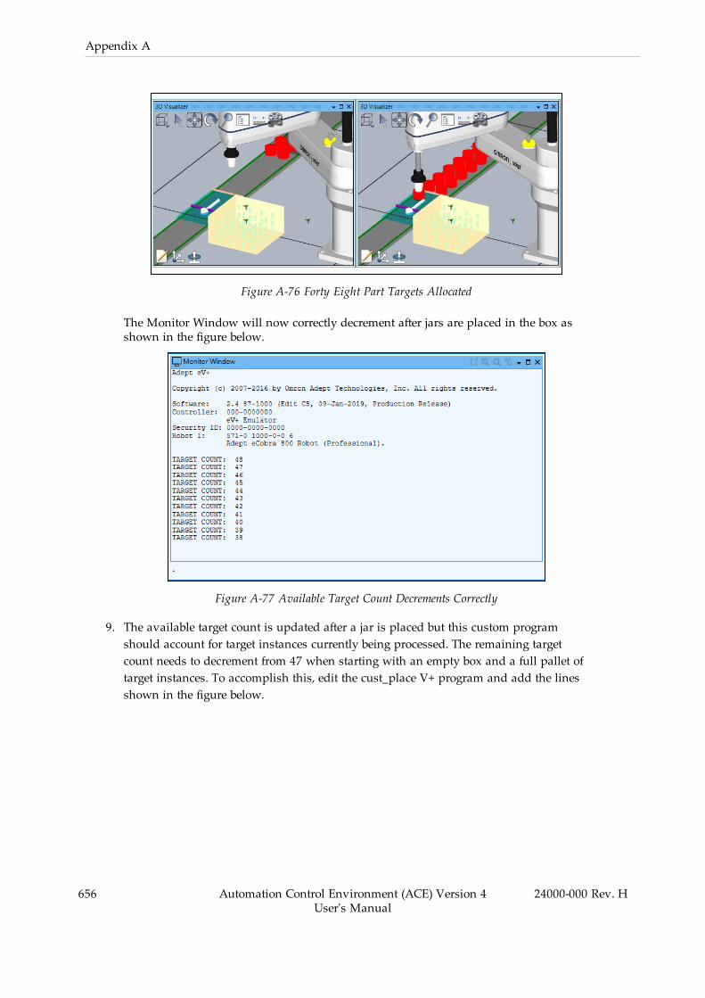
656 Automation Control Environment (ACE) Version 4User's Manual
24000-000 Rev. H
Appendix A
Figure A-76 Forty Eight Part Targets Allocated
The Monitor Window will now correctly decrement after jars are placed in the box asshown in the figure below.
Figure A-77 Available Target Count Decrements Correctly
9. The available target count is updated after a jar is placed but this custom programshould account for target instances currently being processed. The remaining targetcount needs to decrement from 47 when starting with an empty box and a full pallet oftarget instances. To accomplish this, edit the cust_place V+ program and add the linesshown in the figure below.
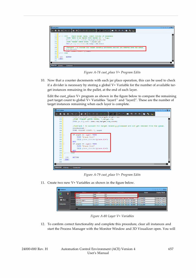
Figure A-78 cust_place V+ Program Edits
10. Now that a counter decrements with each jar place operation, this can be used to checkif a divider is necessary by storing a global V+ Variable for the number of available tar-get instances remaining in the pallet, at the end of each layer.
Edit the cust_place V+ program as shown in the figure below to compare the remainingpart target count to global V+ Variables "layer1" and "layer2". These are the number oftarget instances remaining when each layer is complete.
Figure A-79 cust_place V+ Program Edits
11. Create two new V+ Variables as shown in the figure below.
Figure A-80 Layer V+ Variables
12. To confirm correct functionality and complete this procedure, clear all instances andstart the Process Manager with the Monitor Window and 3D Visualizer open. You will
24000-000 Rev. H Automation Control Environment (ACE) Version 4User's Manual
657
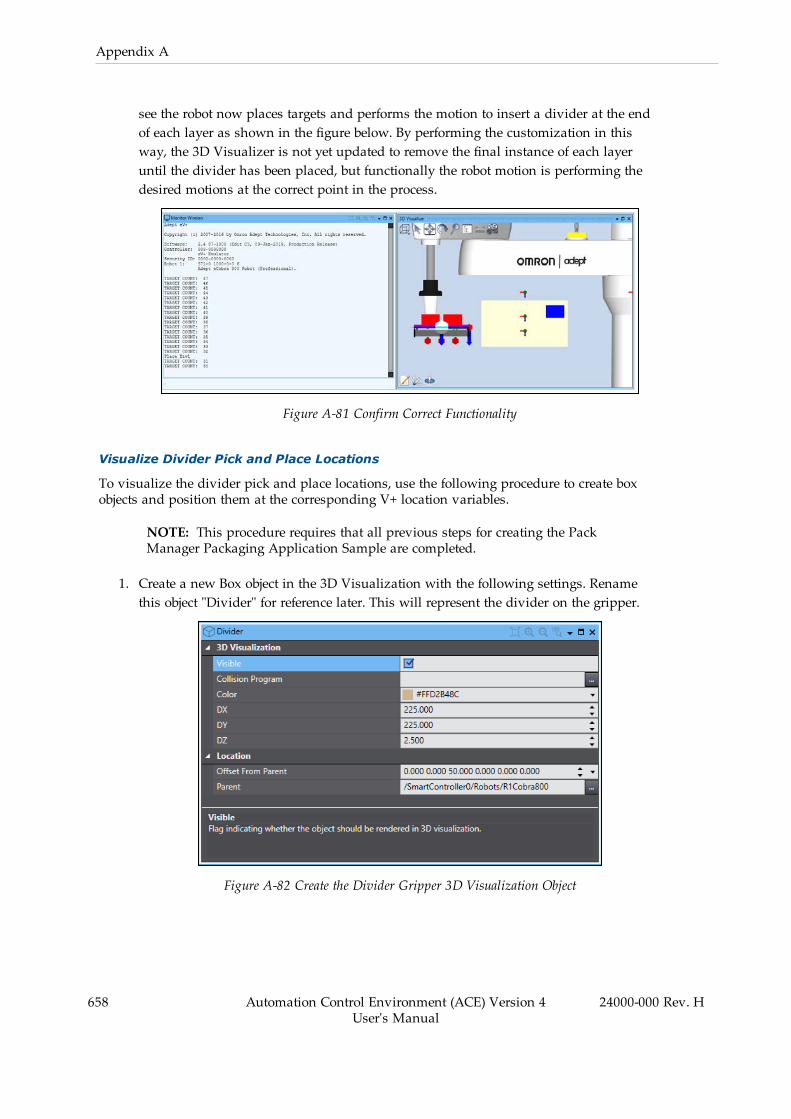
658 Automation Control Environment (ACE) Version 4User's Manual
24000-000 Rev. H
Appendix A
see the robot now places targets and performs the motion to insert a divider at the endof each layer as shown in the figure below. By performing the customization in thisway, the 3D Visualizer is not yet updated to remove the final instance of each layeruntil the divider has been placed, but functionally the robot motion is performing thedesired motions at the correct point in the process.
Figure A-81 Confirm Correct Functionality
Visualize Divider Pick and Place Locations
To visualize the divider pick and place locations, use the following procedure to create boxobjects and position them at the corresponding V+ location variables.
NOTE: This procedure requires that all previous steps for creating the PackManager Packaging Application Sample are completed.
1. Create a new Box object in the 3D Visualization with the following settings. Renamethis object "Divider" for reference later. This will represent the divider on the gripper.
Figure A-82 Create the Divider Gripper 3D Visualization Object

2. Create a new Box object in the 3D Visualization with the following settings. Renamethis object "Divider pick.div" for reference later. This will represent the divider pick loc-ation.
Figure A-83 Create the Divider Pick 3D Visualization Object
3. Create a new Box object in the 3D Visualization with the following settings. Renamethis object "Divider pick.div1" for reference later. This will represent the lower divider inthe place location.
Figure A-84 Create the Divider Place (Lower) 3D Visualization Object
4. Create a new Box object in the 3D Visualization with the following settings. Renamethis object "Divider pick.div2" for reference later. This will represent the upper dividerin the place location.
24000-000 Rev. H Automation Control Environment (ACE) Version 4User's Manual
659

660 Automation Control Environment (ACE) Version 4User's Manual
24000-000 Rev. H
Appendix A
Figure A-85 Create the Divider Place (Upper) 3D Visualization Object
5. To confirm correct functionality and complete this procedure, view the objects in the3D Visualizer to ensure they are accurately represented.
IO Feeder Integration
This section demonstrates how to integrate an IO Feeder into the application to create targetpallet instances only if a box is present. The IO Feeder can use an input signal from a sensor tothe robot controller, a signal from a PLC, or a handshake with another V+ program with softsignals to ensure the next pallet of target instances is not created until a full box is removedand a new empty box is present.
For the purposes of demonstrating how the IO Feeder object is used in this application, we willassume the following.
l A signal is turned ON when a box is available to be filled.l The signal is turned OFF when the Part Processed Output is triggered by the ProcessManager, when the last pallet instance has been processed.
l The signal is turned ON again after an operator has removed the full box and replacedit with an empty box.
The following procedure will provide steps to integrate an IO Feeder.
NOTE: This procedure requires that all previous steps for creating the PackManager Packaging Application Sample are completed.

1. Add an IO Feeder object and select a reference to the controller.
Figure A-86 Add an IO Feeder Object
2. In Control Sources for the Static Source for Place Part Target, enable Use A Feeder andselect the IO Feeder object that was just created.
Figure A-87 Set the Control Sources Feeder Configuration
3. Create a V+ program to simulate IO Feeder signal operation. This is typically done dur-ing development in Emulation Mode to simulate signals that would normally bepresent during run time. This will be executed on another task when the Process Man-ager starts by using a Process Strategy Custom Initialization program as described inthe following steps.
Create a new V+ program named "box_signal" with the code shown in the figure below.
24000-000 Rev. H Automation Control Environment (ACE) Version 4User's Manual
661
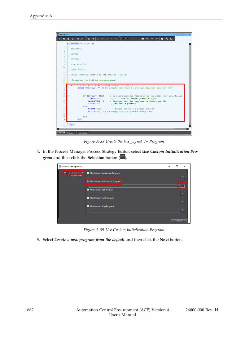
662 Automation Control Environment (ACE) Version 4User's Manual
24000-000 Rev. H
Appendix A
Figure A-88 Create the box_signal V+ Program
4. In the Process Manager Process Strategy Editor, select Use Custom Initialization Pro-gram and then click the Selection button ( ).
Figure A-89 Use Custom Initialization Program
5. Select Create a new program from the default and then click the Next button.
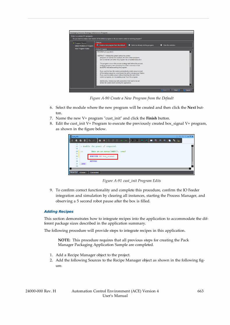
Figure A-90 Create a New Program from the Default
6. Select the module where the new program will be created and then click the Next but-ton.
7. Name the new V+ program "cust_init" and click the Finish button.8. Edit the cust_init V+ Program to execute the previously created box_signal V+ program,as shown in the figure below.
Figure A-91 cust_init Program Edits
9. To confirm correct functionality and complete this procedure, confirm the IO Feederintegration and simulation by clearing all instances, starting the Process Manager, andobserving a 5 second robot pause after the box is filled.
Adding Recipes
This section demonstrates how to integrate recipes into the application to accommodate the dif-ferent package sizes described in the application summary.
The following procedure will provide steps to integrate recipes in this application.
NOTE: This procedure requires that all previous steps for creating the PackManager Packaging Application Sample are completed.
1. Add a Recipe Manager object to the project.2. Add the following Sources to the Recipe Manager object as shown in the following fig-ure.
24000-000 Rev. H Automation Control Environment (ACE) Version 4User's Manual
663
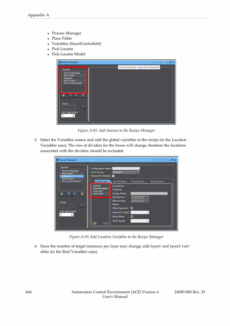
664 Automation Control Environment (ACE) Version 4User's Manual
24000-000 Rev. H
Appendix A
l Process Managerl Place Palletl Variables (SmartController0)l Pick Locatorl Pick Locator Model
Figure A-92 Add Sources to the Recipe Manager
3. Select the Variables source and add the global variables to the recipe (in the LocationVariables area). The size of dividers for the boxes will change, therefore the locationsassociated with the dividers should be included.
Figure A-93 Add Location Variables to the Recipe Manager
4. Since the number of target instances per layer may change, add layer1 and layer2 vari-ables (in the Real Variables area).

Figure A-94 Add Real Variables to the Recipe Manager
5. Open the Recipe Manager in Task Status Control and add new recipes named "48-pack", "24-pack", and "12-pack".
Figure A-95 Add Recipes
24000-000 Rev. H Automation Control Environment (ACE) Version 4User's Manual
665
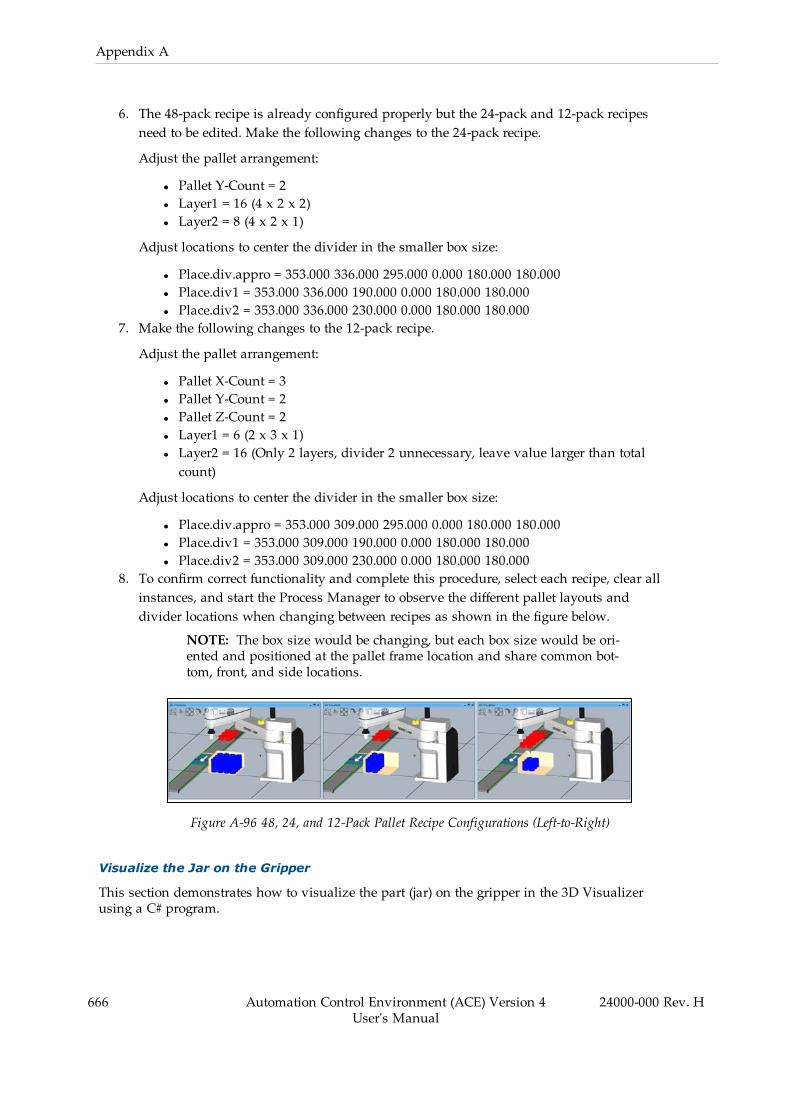
666 Automation Control Environment (ACE) Version 4User's Manual
24000-000 Rev. H
Appendix A
6. The 48-pack recipe is already configured properly but the 24-pack and 12-pack recipesneed to be edited. Make the following changes to the 24-pack recipe.
Adjust the pallet arrangement:
l Pallet Y-Count = 2l Layer1 = 16 (4 x 2 x 2)l Layer2 = 8 (4 x 2 x 1)
Adjust locations to center the divider in the smaller box size:
l Place.div.appro = 353.000 336.000 295.000 0.000 180.000 180.000l Place.div1 = 353.000 336.000 190.000 0.000 180.000 180.000l Place.div2 = 353.000 336.000 230.000 0.000 180.000 180.000
7. Make the following changes to the 12-pack recipe.
Adjust the pallet arrangement:
l Pallet X-Count = 3l Pallet Y-Count = 2l Pallet Z-Count = 2l Layer1 = 6 (2 x 3 x 1)l Layer2 = 16 (Only 2 layers, divider 2 unnecessary, leave value larger than totalcount)
Adjust locations to center the divider in the smaller box size:
l Place.div.appro = 353.000 309.000 295.000 0.000 180.000 180.000l Place.div1 = 353.000 309.000 190.000 0.000 180.000 180.000l Place.div2 = 353.000 309.000 230.000 0.000 180.000 180.000
8. To confirm correct functionality and complete this procedure, select each recipe, clear allinstances, and start the Process Manager to observe the different pallet layouts anddivider locations when changing between recipes as shown in the figure below.
NOTE: The box size would be changing, but each box size would be ori-ented and positioned at the pallet frame location and share common bot-tom, front, and side locations.
Figure A-96 48, 24, and 12-Pack Pallet Recipe Configurations (Left-to-Right)
Visualize the Jar on the Gripper
This section demonstrates how to visualize the part (jar) on the gripper in the 3D Visualizerusing a C# program.
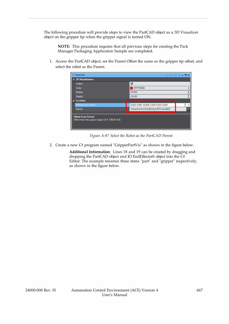
The following procedure will provide steps to view the PartCAD object as a 3D Visualizerobject on the gripper tip when the gripper signal is turned ON.
NOTE: This procedure requires that all previous steps for creating the PackManager Packaging Application Sample are completed.
1. Access the PartCAD object, set the Parent Offset the same as the gripper tip offset, andselect the robot as the Parent.
Figure A-97 Select the Robot as the PartCAD Parent
2. Create a new C# program named "GripperPartVis" as shown in the figure below.
Additional Information: Lines 18 and 19 can be created by dragging anddropping the PartCAD object and IO EndEffector0 object into the C#Editor. The example renames these items "part" and "gripper" respectively,as shown in the figure below.
24000-000 Rev. H Automation Control Environment (ACE) Version 4User's Manual
667
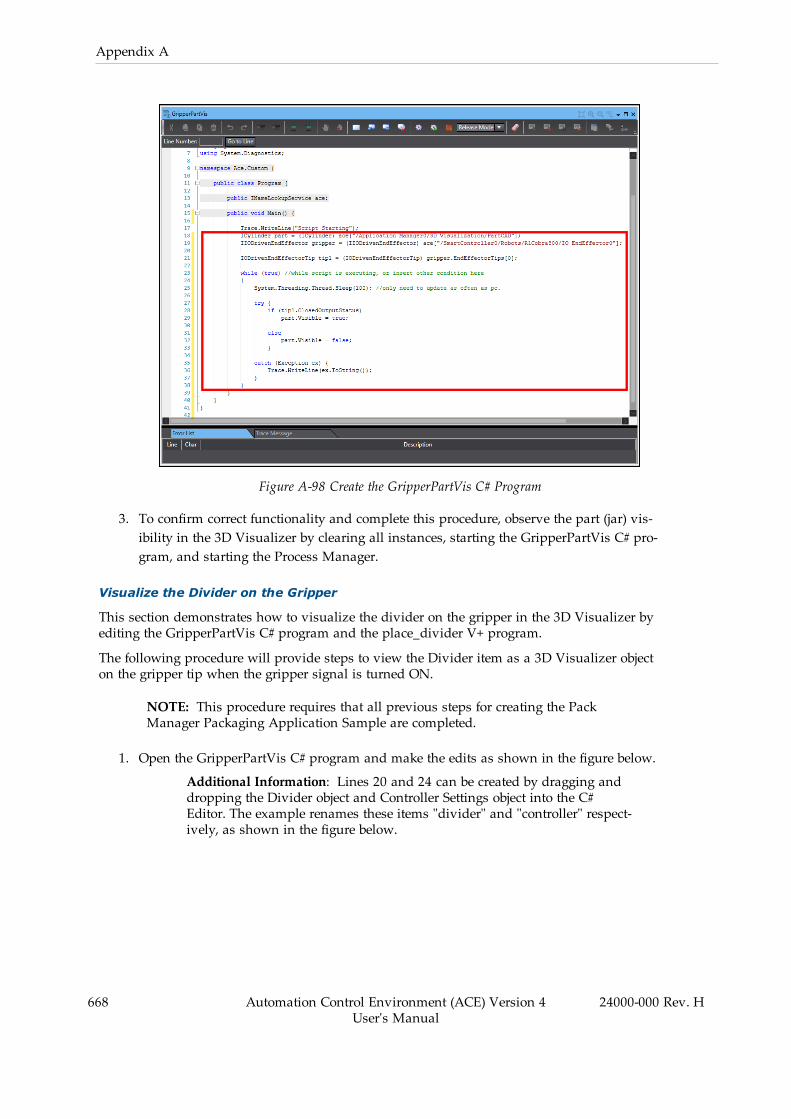
668 Automation Control Environment (ACE) Version 4User's Manual
24000-000 Rev. H
Appendix A
Figure A-98 Create the GripperPartVis C# Program
3. To confirm correct functionality and complete this procedure, observe the part (jar) vis-ibility in the 3D Visualizer by clearing all instances, starting the GripperPartVis C# pro-gram, and starting the Process Manager.
Visualize the Divider on the Gripper
This section demonstrates how to visualize the divider on the gripper in the 3D Visualizer byediting the GripperPartVis C# program and the place_divider V+ program.
The following procedure will provide steps to view the Divider item as a 3D Visualizer objecton the gripper tip when the gripper signal is turned ON.
NOTE: This procedure requires that all previous steps for creating the PackManager Packaging Application Sample are completed.
1. Open the GripperPartVis C# program and make the edits as shown in the figure below.
Additional Information: Lines 20 and 24 can be created by dragging anddropping the Divider object and Controller Settings object into the C#Editor. The example renames these items "divider" and "controller" respect-ively, as shown in the figure below.
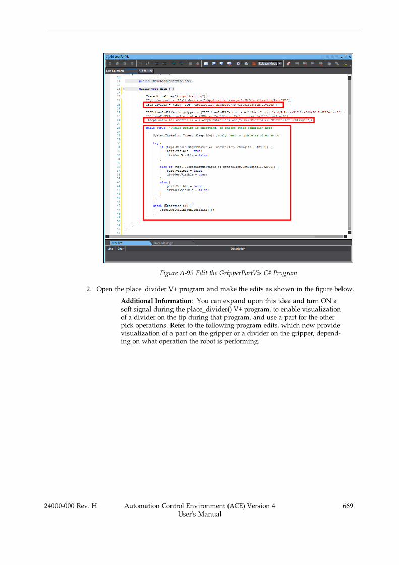
Figure A-99 Edit the GripperPartVis C# Program
2. Open the place_divider V+ program and make the edits as shown in the figure below.
Additional Information: You can expand upon this idea and turn ON asoft signal during the place_divider() V+ program, to enable visualizationof a divider on the tip during that program, and use a part for the otherpick operations. Refer to the following program edits, which now providevisualization of a part on the gripper or a divider on the gripper, depend-ing on what operation the robot is performing.
24000-000 Rev. H Automation Control Environment (ACE) Version 4User's Manual
669

670 Automation Control Environment (ACE) Version 4User's Manual
24000-000 Rev. H
Appendix A
Figure A-100 Edit the place_divider V+ Program
3. To confirm correct functionality and complete this procedure, confirm the divider vis-ibility in the 3D Visualizer by clearing all instances, starting the GripperPartVis C# pro-gram, and starting the Process Manager.
Enable Active Control for the Belt
If the upstream process allows for the conveyor belt to be turned OFF, you can enable ActiveControl in the Pick Belt object. This will allow the robot to turn OFF the belt to prevent any jarscrossing the downstream process limit while the robot is waiting for a new box (per the applic-ation summary requirements).
Use the following procedure to enable Active Control for the belt.
1. Access the Pick Belt object and select Active Control and select the Controller Settings0object as a reference. Set the Drive Output values as shown in the following figure.
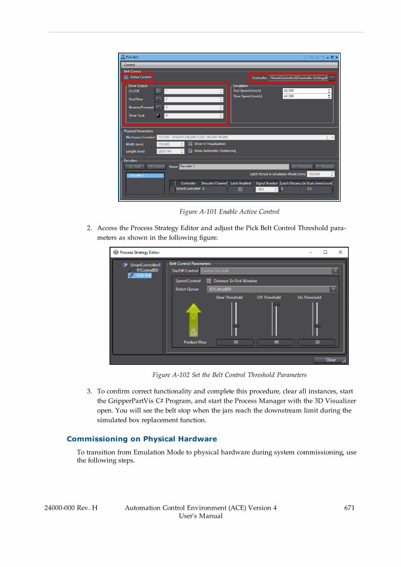
Figure A-101 Enable Active Control
2. Access the Process Strategy Editor and adjust the Pick Belt Control Threshold para-meters as shown in the following figure.
Figure A-102 Set the Belt Control Threshold Parameters
3. To confirm correct functionality and complete this procedure, clear all instances, startthe GripperPartVis C# Program, and start the Process Manager with the 3D Visualizeropen. You will see the belt stop when the jars reach the downstream limit during thesimulated box replacement function.
Commissioning on Physical Hardware
To transition from Emulation Mode to physical hardware during system commissioning, usethe following steps.
24000-000 Rev. H Automation Control Environment (ACE) Version 4User's Manual
671

672 Automation Control Environment (ACE) Version 4User's Manual
24000-000 Rev. H
Appendix A
1. Ensure all hardware is properly installed according to the reference documentation.2. Connect to the controller and configure all necessary network and controller parameters.Test communication with all other devices such as cameras, PLCs, etc.
NOTE: The project created in Emulation Mode cannot transfer its con-figuration to the physical controller.
3. Test any latch signals and latch configurations.4. Open the project with Emulation Mode disabled.5. Set the IP address in the Controller Settings to match the physical controller and verifycommunication with the controller.
6. Perform any necessary Virtual Camera calibrations.7. Perform any necessary Robot-to-Belt calibrations.8. Perform any necessary Robot-to-Sensor calibrations.9. Train any Locator Models and Locator tools to locate parts.10. Link any Part objects to Locator tools (rather than using the Custom Vision tool).11. Teach all processes.12. Teach any global V+ location variables as needed.13. Test, debug, and troubleshoot the application.14. Program system start-up functions as required for the application.
Additional Information: Calibrations are typically performed with calibrationpointers and disks, while Teach Process wizards and teaching V+ locationsshould be performed with the gripper or end of arm tooling used for the process.
A.5 Version Control IntroductionThe ACE project version control function (called version control function hereafter) controls thechange record of an ACE project by recording "who changed what and when."
This function enables various control capabilities by combining the ACE projects with an opensource software version control system that is commonly used in software development. Theversion control function effectively solves problems such as the following, which you mayencounter in large-scale development of production machines.
• The complexity of source code management due to increase in the scale of program devel-opment
• The increase in the workload of change management due to the increased variation of pro-duction machines
• The increase in the complexity of source code management due to the increased oppor-tunities of development by multiple developers
The version control function enables you to leave a change record of a project at any time. Youcan return to the desired project by tracing back the change record and comparing the presentversion with past projects. The version control function provides the capability to check the dif-ference and merge the changes when you apply them to the master project.
When you use the version control function to control projects, you can effectively manage anddevelop programs by multiple developers. This facilitates the management of developingderived machines.
Software
The following software is needed besides the ACE software. Download the latest edition of soft-ware from their official Web sites.
l "Git" (32-bit or 64-bit edition) https://git-scm.com/downloadsl "TortoiseGit" (32-bit or 64-bit edition) https://tortoisegit.org/download/
A.6 Git Software Installation
Installing Git
Download the latest installer from the Git download site and install it as a user with admin-istrator rights. Depending on the operating system installed on the computer, download the32-bit or 64-bit edition of the installer, as defined by the computer. 64 bit is preferred for Win-dows 10.
Follow the instructions in the Git installer wizard. Although the wizard displays several pagesduring the installation, the description below covers the steps requiring your input. The pages
24000-000 Rev. H Automation Control Environment (ACE) Version 4User's Manual
673

674 Automation Control Environment (ACE) Version 4User's Manual
24000-000 Rev. H
Appendix A
on which you must select a specific item are shown with figures. You can leave other pages asdefault.
Locate the downloaded installer and double click it. When the Installer window opens, clickNext and follow the steps below, after accepting the license, default installation destinationand default components.
1. Select Editor, Nano
Figure A-103 Git Editor, Nano Selected
2. Adjust the PATH environment
Figure A-104 PATH Environment, Command Line
3. Click Next and select HTTPS back end transport
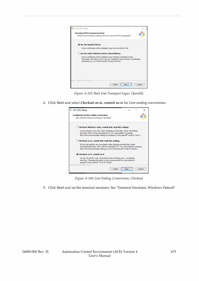
Figure A-105 Back End Transport Layer, OpenSSL
4. Click Next and select Checkout as-is, commit as-is for Line ending conversions
Figure A-106 Line Ending Conversions, Checkout
5. Click Next and set the terminal emulator, See "Terminal Emulator, Windows Default"
24000-000 Rev. H Automation Control Environment (ACE) Version 4User's Manual
675
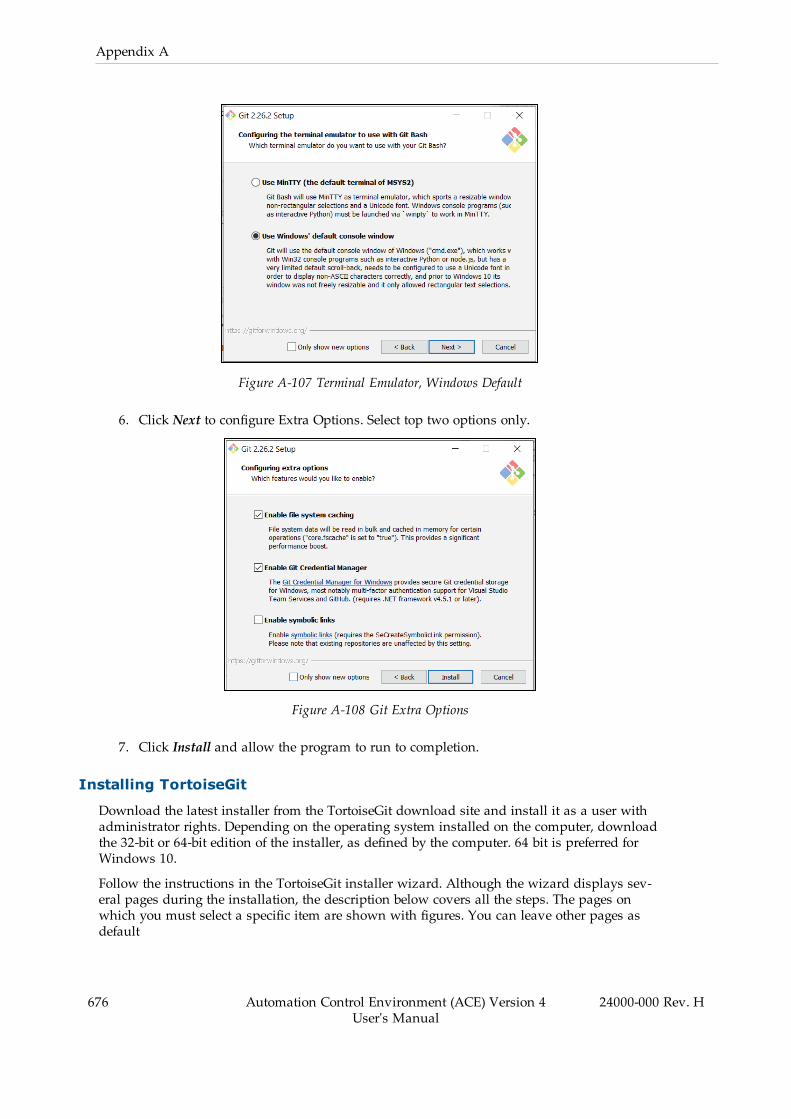
676 Automation Control Environment (ACE) Version 4User's Manual
24000-000 Rev. H
Appendix A
Figure A-107 Terminal Emulator, Windows Default
6. Click Next to configure Extra Options. Select top two options only.
Figure A-108 Git Extra Options
7. Click Install and allow the program to run to completion.
Installing TortoiseGit
Download the latest installer from the TortoiseGit download site and install it as a user withadministrator rights. Depending on the operating system installed on the computer, downloadthe 32-bit or 64-bit edition of the installer, as defined by the computer. 64 bit is preferred forWindows 10.
Follow the instructions in the TortoiseGit installer wizard. Although the wizard displays sev-eral pages during the installation, the description below covers all the steps. The pages onwhich you must select a specific item are shown with figures. You can leave other pages asdefault
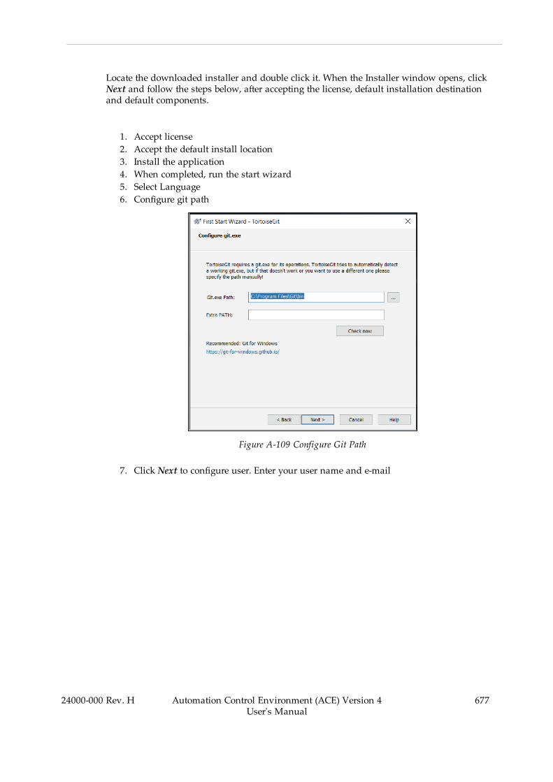
Locate the downloaded installer and double click it. When the Installer window opens, clickNext and follow the steps below, after accepting the license, default installation destinationand default components.
1. Accept license2. Accept the default install location3. Install the application4. When completed, run the start wizard5. Select Language6. Configure git path
Figure A-109 Configure Git Path
7. Click Next to configure user. Enter your user name and e-mail
24000-000 Rev. H Automation Control Environment (ACE) Version 4User's Manual
677
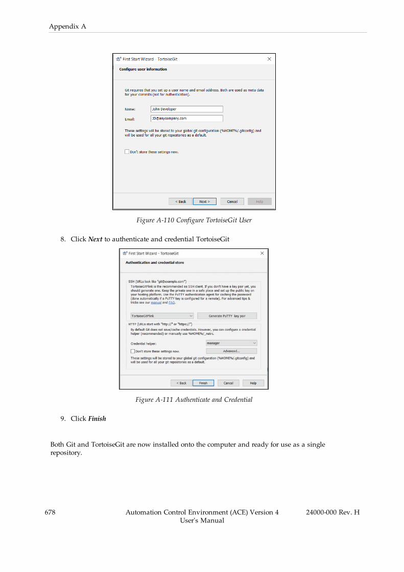
678 Automation Control Environment (ACE) Version 4User's Manual
24000-000 Rev. H
Appendix A
Figure A-110 Configure TortoiseGit User
8. Click Next to authenticate and credential TortoiseGit
Figure A-111 Authenticate and Credential
9. Click Finish
Both Git and TortoiseGit are now installed onto the computer and ready for use as a singlerepository.
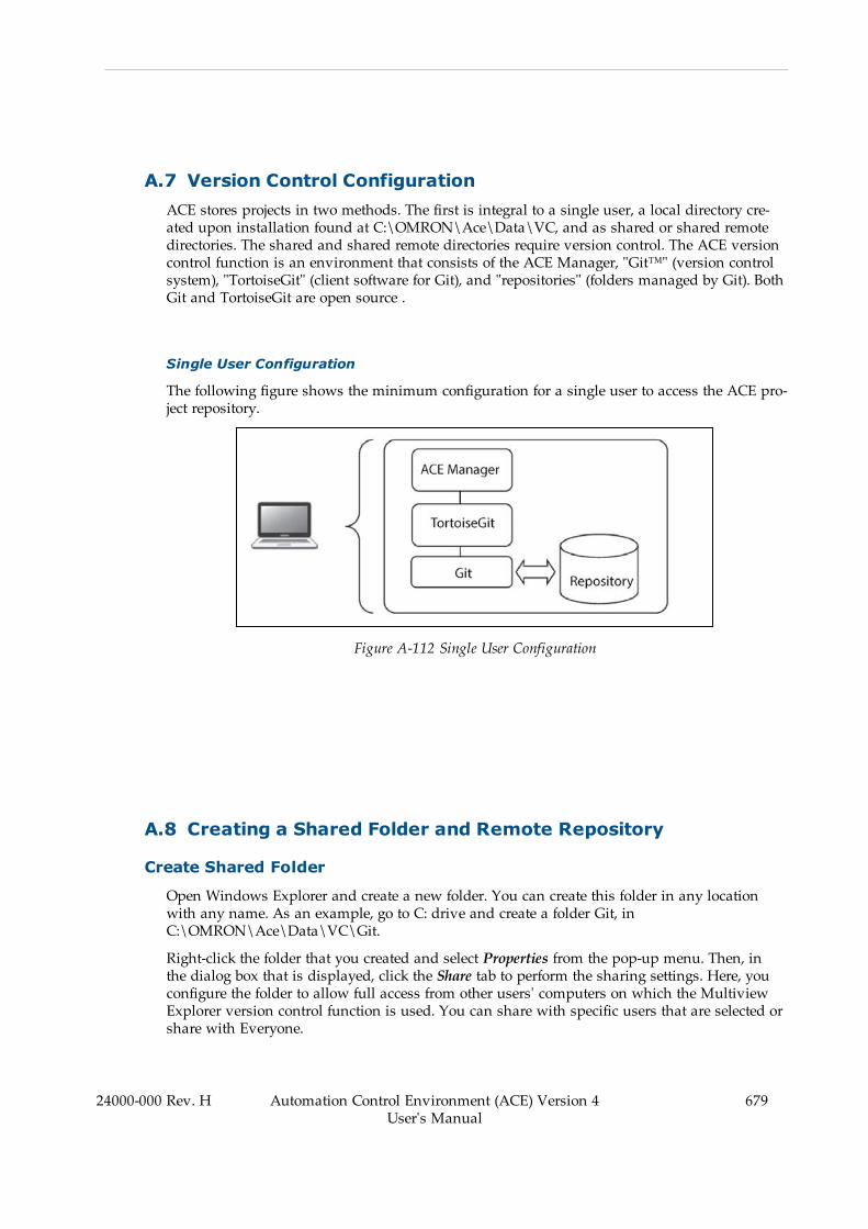
A.7 Version Control ConfigurationACE stores projects in two methods. The first is integral to a single user, a local directory cre-ated upon installation found at C:\OMRON\Ace\Data\VC, and as shared or shared remotedirectories. The shared and shared remote directories require version control. The ACE versioncontrol function is an environment that consists of the ACE Manager, "Git™" (version controlsystem), "TortoiseGit" (client software for Git), and "repositories" (folders managed by Git). BothGit and TortoiseGit are open source .
Single User Configuration
The following figure shows the minimum configuration for a single user to access the ACE pro-ject repository.
Figure A-112 Single User Configuration
A.8 Creating a Shared Folder and Remote Repository
Create Shared Folder
Open Windows Explorer and create a new folder. You can create this folder in any locationwith any name. As an example, go to C: drive and create a folder Git, inC:\OMRON\Ace\Data\VC\Git.
Right-click the folder that you created and select Properties from the pop-up menu. Then, inthe dialog box that is displayed, click the Share tab to perform the sharing settings. Here, youconfigure the folder to allow full access from other users' computers on which the MultiviewExplorer version control function is used. You can share with specific users that are selected orshare with Everyone.
24000-000 Rev. H Automation Control Environment (ACE) Version 4User's Manual
679
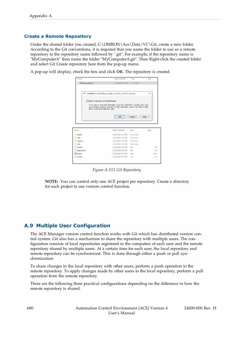
680 Automation Control Environment (ACE) Version 4User's Manual
24000-000 Rev. H
Appendix A
Create a Remote Repository
Under the shared folder you created, C:\OMRON\Ace\Data\VC\Git, create a new folder.According to the Git conventions, it is required that you name the folder to use as a remoterepository to the repository name followed by ".git". For example, if the repository name is"MyComputerA" then name the folder "MyComputerA.git". Then Right-click the created folderand select Git Create repository here from the pop-up menu.
A pop-up will display, check the box and click OK. The repository is created.
Figure A-113 Git Repository
NOTE: You can control only one ACE project per repository. Create a directoryfor each project to use version control function.
A.9 Multiple User ConfigurationThe ACE Manager version control function works with Git which has distributed version con-trol system. Git also has a mechanism to share the repository with multiple users. The con-figuration consists of local repositories registered in the computers of each user and the remoterepository shared by multiple users. At a certain time for each user, the local repository andremote repository can be synchronized. This is done through either a push or pull syn-chronization.
To share changes in the local repository with other users, perform a push operation to theremote repository. To apply changes made by other users to the local repository, perform a pulloperation from the remote repository.
There are the following three practical configurations depending on the difference in how theremote repository is shared.

1. Using a shared repository on the user's computer to share it as the remote repository2. A dedicated Git server to share it as the remote repository3. Utilizing a Git server service on the Internet to share the remote repository
Shared Computer Repository
This is the easiest way to build a remote repository. In this method, you use a Windowsshared folder to publish a remote repository that is synchronized with the local repository tothe local network so that it can be accessed from other computers. In the following See "SharedRepository, Computer Source", you use a remote repository that is built in this way.
Figure A-114 Shared Repository, Computer Source
Dedicated Git Server
You can build a dedicated Git server,See "Repository Server, In Company", to share the remoterepository. This is done using Git server software, Gitbucket (for Windows) or if you are usingLinux; GitLab, Gitbucket, Gitblit, Gogs. Although this configuration has costs for building andmaintaining the server, it has an advantage in reducing the risk of data leakage because thesystem is closed within the company.
24000-000 Rev. H Automation Control Environment (ACE) Version 4User's Manual
681
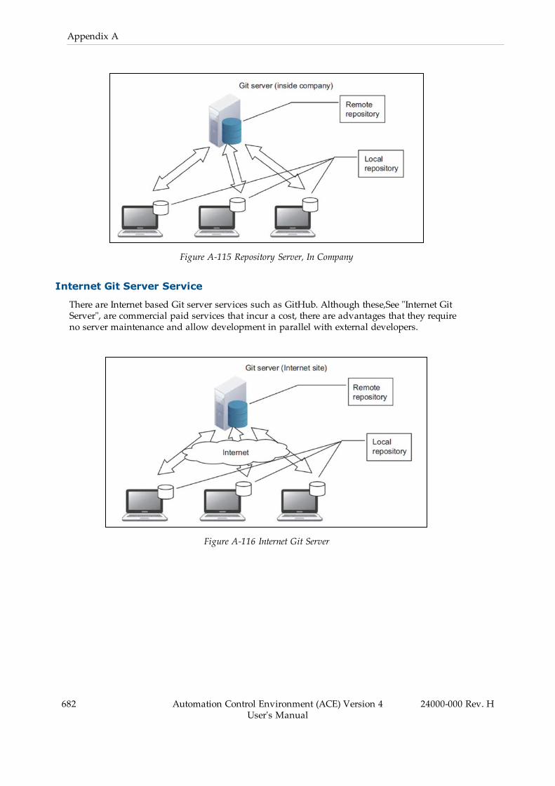
682 Automation Control Environment (ACE) Version 4User's Manual
24000-000 Rev. H
Appendix A
Figure A-115 Repository Server, In Company
Internet Git Server Service
There are Internet based Git server services such as GitHub. Although these,See "Internet GitServer", are commercial paid services that incur a cost, there are advantages that they requireno server maintenance and allow development in parallel with external developers.
Figure A-116 Internet Git Server
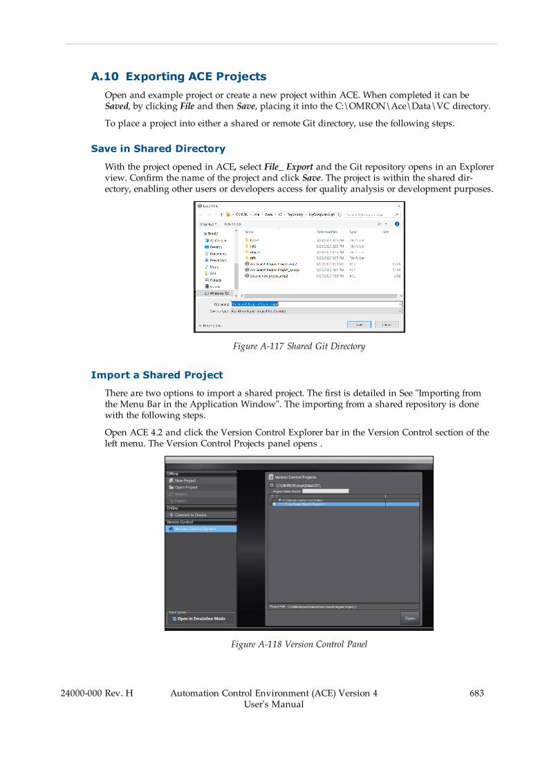
A.10 Exporting ACE ProjectsOpen and example project or create a new project within ACE. When completed it can beSaved, by clicking File and then Save, placing it into the C:\OMRON\Ace\Data\VC directory.
To place a project into either a shared or remote Git directory, use the following steps.
Save in Shared Directory
With the project opened in ACE, select File_ Export and the Git repository opens in an Explorerview. Confirm the name of the project and click Save. The project is within the shared dir-ectory, enabling other users or developers access for quality analysis or development purposes.
Figure A-117 Shared Git Directory
Import a Shared Project
There are two options to import a shared project. The first is detailed in See "Importing fromthe Menu Bar in the Application Window". The importing from a shared repository is donewith the following steps.
Open ACE 4.2 and click the Version Control Explorer bar in the Version Control section of theleft menu. The Version Control Projects panel opens .
Figure A-118 Version Control Panel
24000-000 Rev. H Automation Control Environment (ACE) Version 4User's Manual
683
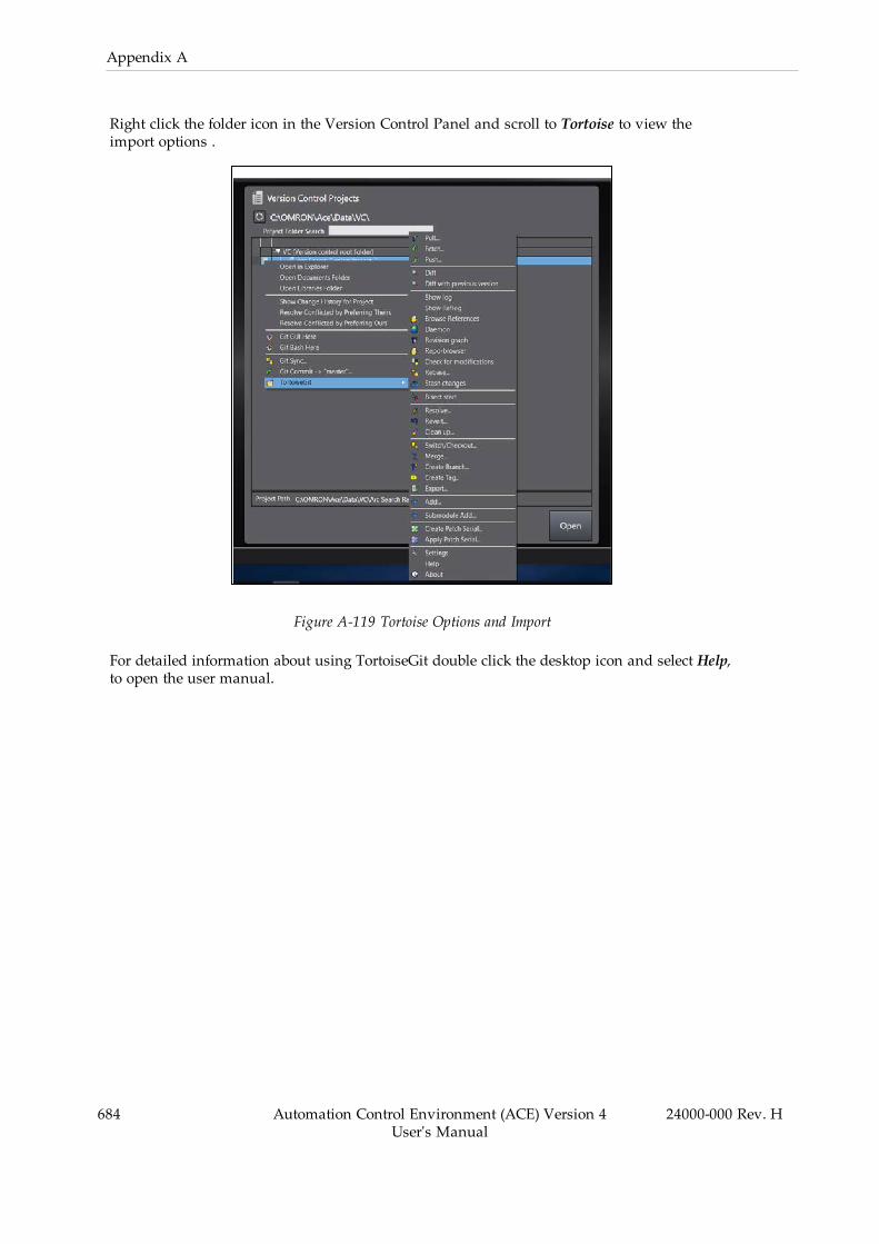
684 Automation Control Environment (ACE) Version 4User's Manual
24000-000 Rev. H
Appendix A
Right click the folder icon in the Version Control Panel and scroll to Tortoise to view theimport options .
Figure A-119 Tortoise Options and Import
For detailed information about using TortoiseGit double click the desktop icon and select Help,to open the user manual.

Authorized Distributor:
Cat. No. I633-E-06 0221
© OMRON Corporation 2016-2021 All Rights Reserved. In the interest of product improvement, specifications are subject to change without notice.
OMRON Corporation Industrial Automation Company
Contact: www.ia.omron.comKyoto, JAPAN
Regional HeadquartersOMRON EUROPE B.V.Wegalaan 67-69, 2132 JD HoofddorpThe NetherlandsTel: (31)2356-81-300/Fax: (31)2356-81-388
OMRON ASIA PACIFIC PTE. LTD.No. 438A Alexandra Road # 05-05/08 (Lobby 2), Alexandra Technopark, Singapore 119967Tel: (65) 6835-3011/Fax: (65) 6835-2711
OMRON ELECTRONICS LLC2895 Greenspoint Parkway, Suite 200 Hoffman Estates, IL 60169 U.S.A.Tel: (1) 847-843-7900/Fax: (1) 847-843-7787
OMRON ROBOTICS AND SAFETY TECHNOLOGIES, INC. 4225 Hacienda Drive, Pleasanton, CA 94588 U.S.A Tel: (1) 925-245-3400/Fax: (1) 925-960-0590
OMRON (CHINA) CO., LTD.Room 2211, Bank of China Tower, 200 Yin Cheng Zhong Road, PuDong New Area, Shanghai, 200120, ChinaTel: (86) 21-5037-2222/Fax: (86) 21-5037-2200
24000-000 H