Automatic Sliding Gate Opener User's Manual - DIGITALas
12
Automatic Sliding Gate Opener User’s Manual Contents 1. Summary········································ (1) 2. Appearance and dimensions··························(1) 3. Parameters········································(1) 4. Features of control board ··························· (2) 5. Installation of mechanical parts························(2) 5.1 Installation of motor base plate ···················· (2) 5.2 Installation of gate opener························· (2) 5.3 Installation of racks······························ (3) 5.4 Installation of limit levers······················· (3) 5.5 Function of clutch································(3) 6.Installation diagram of electrical parts·················· (5) 7.Function Testing····································(7) 8. Maintenance·····································(10) 9. Trouble Shooting··································(10) 10. Important Notes ································· (11)
-
Upload
khangminh22 -
Category
Documents
-
view
1 -
download
0
Transcript of Automatic Sliding Gate Opener User's Manual - DIGITALas

Automatic Sliding Gate Opener
User’s Manual
Contents1. Summary········································ (1)2. Appearance and dimensions··························(1)3. Parameters········································(1)4. Features of control board ···························(2)5. Installation of mechanical parts························(2)5.1 Installation of motor base plate ····················(2)5.2 Installation of gate opener·························(2)5.3 Installation of racks······························(3)5.4 Installation of limit levers······················· (3)5.5 Function of clutch································(3)6.Installation diagram of electrical parts··················(5)7.Function Testing····································(7)8. Maintenance·····································(10)9. Trouble Shooting··································(10)10. Important Notes ································· (11)

1
1. SummaryThis equipment is one of the auto gate openers launched by our company
adopting a new design and integrated control system. Our new sliding gate opener hasmany features such as: low noise, light weight, powerful starting torque, stability,reliability and is compact and stylish. The motor will still work for a short period oftime using lower voltage. The control board has overload protection. When there isa power failure, the motor drive can be separated by the use of the clutch, by using thespecified key the user has the ability to disconnect the clutch enabling the gate to beopened or closed manually. Using the optional infrared photocells the gate willautomatically stop and re-open if an obstacle is sensed.
2. Appearance and dimensions
Fig 1
3. Parameters1. Working temperature of motor:-25°C~ +55°C2. Working humidity:≤85%3. Power supply:220VAC±10%/110VAC±10% 50Hz/60Hz4. Rated power:350W5. Output gear module:M=46. Output gear number:Z=167.Output torque:30.0 N.m8. Open(close) speed:v=12m/min9. Rated speed : 1400RPM10. Maximum pull:1100N11. Maximum load:1300KG

2
12. Net weight:11KG13.Remote control distance : ≤50meter14.Packing : In a standard carton15. Protection Class : B
4. Features of control board1.Totally integrated electrical mechanical system (excludes racks)2.Control board interface for optional impact-proof infrared photocells3.Alarm lamp interface4.Automatic delayed closing5.Adjustable resistance sensitivity6. Gate will auto stop and re-open when an obstacle is encountered7. Wireless remote control or wired remote control are optional
5. Installation of mechanical parts
5.1 Installation of motor base plate1. Depending on the installation size of the motor and mounting height of racks,after determine the installation position of the motor base plate, first let the boltembedded or use expansion bolt to make base plate fixed on watering goodcement foundation. See diagram 2
Fig 2
2. If the rack has been installed on the door, the motor can be fixed on the baseplate.use a Allen key rotation to the clutch "off" position, the motor and the gearrack so as to better determine the position of the motor base plate, then removethe motor and fixed base plate.
5.2 Installation of gate opener1.Let the sliding gate opener put on the base plate.use a random matching hexagonscrew make the motor fixed on the base plate.
2.Unscrew the screws fixed the motors cover,and then remove the motorcover.according to the electrical wiring diagram ,connected the power cord,afteradjust in good position,Then install cover and use screws to fixed it
5.3 Installation of racks1. After the motor is installed,the racks teeth the down ,then put the gear on themotors.and final connected with screws and gate.push the door with hand.so canlet door sliding it and can move it without any problem.after confirmed,fixed theracks.

3
2. Rack is usually unit assembly,in order to avoid gate run jitter or jammed, rackand joint clearance must be corrected.Suggest use this way,see diagram 3.with asmall correction of the rack,after connecting right with racks 1 and racks 2 ,thenfixed racks 1 and 2.
Fig 3
5.4 Installation of limit levers.There are 2 limit levers supplied. Note there is a left hand and a right hand lever.
The levers should be installed one at either end of the rack. See Fig5.To install the levers in the correct position, open the clutch door and press the
‘CLOSE’ button on the remote, the motor will run but will not drive the gate. Closethe gate manually and adjust the limit lever to contact the toggle switch and switch themotor off at the desired gate position. To adjust the stop position of the gate when it isopen, press the ‘OPEN’ button, manually open the gate and adjust the other limit leverto contact the toggle switch and switch the motor off.
When you are satisfied the levers are in the correct positions, tighten the screws inthe levers to clamp them to the rack, close the clutch door and using the remotecontrol check the gate opens and closes to the desired positions. Adjust the limitlevers if necessary.
Fig 4
5.5 Function of clutchWhen the clutch is opened to the open position, you can manually push the door;
when closing the clutch, electric door can run on, off, when touching limiting thebezel will stop automatically.
Fig 5

4
6. Installation diagram of electrical parts (Fig 6)
Fig 66.1. Terminal④ and⑤ it for connecting to 220V power6.2. Connect to sliding gate motor6.2.1.Install the motor on the right of gate.(Please see Fig 7)
Fig 7When the motor being installed to the right of gate , motor wires diagram followsTerminal ① connect the green wire from motor.Terminal ② connect the black wire from motor.Terminal ③ connect the red wire from motor.
6.2.2. Install the motor on the left of gate. (Please see Fig 8)
Please note: Our factory setting is install motor on the right of gate!
5
Fig 8When the motor being installed to the left of gate , motor wires diagram as follows:Terminal ① connect the black wire from motor.Terminal ② connect the green wire from motor.Terminal ③ connect the red wire from motor.
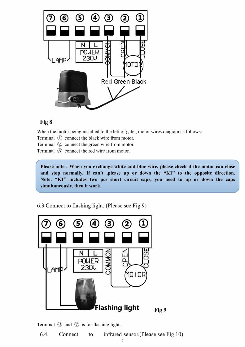
6.3.Connect to flashing light. (Please see Fig 9)
Fig 9
Terminal ⑥ and ⑦ is for flashing light .
6.4. Connect to infrared sensor.(Please see Fig 10)
Please note : When you exchange white and blue wire, please check if the motor can closeand stop normally. If can’t ,please up or down the “K1” to the opposite direction.Note: “K1” includes two pcs short circuit caps, you need to up or down the capssimultaneously, then it work.

6
Fig 10Firstly ,please find a little wire between terminal ⑧ and ⑨,and remove it.Then, connect terminal ⑧ to the “COM “of photocell RX.
connect terminal ⑨ to the “OUT “of photocell RX.Terminal ⑭ and ⑮ is supplying power for external device.
So, connect terminal ⑭ to the “+ “of photocell RX and TX.
connect terminal ⑮ to the “- “of photocell RX and TX.
6.5.Connect to open device. (Please see Fig 11)When you don’t want to use the remote control to control the gate . Terminal ⑩ isfor you connect some external device , such push button, wired keypad, receiver etc.
Fig 11Example for push button;Terminal ⑧ and ⑩ connect to push button. Terminal 14 and 15 to supply powerfor push button
Please note:220VAC sliding gate control board is designed to connect NC modelof photocell, So please keep the jumper on the NC ,as picture Fig 10 shows!
7
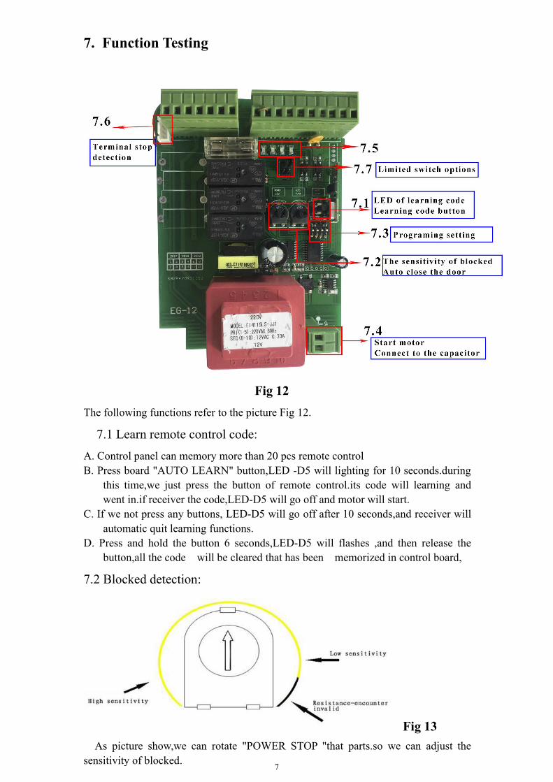
7. Function Testing
Fig 12The following functions refer to the picture Fig 12.
7.1 Learn remote control code:A. Control panel can memory more than 20 pcs remote controlB. Press board "AUTO LEARN" button,LED -D5 will lighting for 10 seconds.during
this time,we just press the button of remote control.its code will learning andwent in.if receiver the code,LED-D5 will go off and motor will start.
C. If we not press any buttons, LED-D5 will go off after 10 seconds,and receiver willautomatic quit learning functions.
D. Press and hold the button 6 seconds,LED-D5 will flashes ,and then release thebutton,all the code will be cleared that has been memorized in control board,
7.2 Blocked detection:
Fig 13As picture show,we can rotate "POWER STOP "that parts.so we can adjust the
sensitivity of blocked.

8
A. High sensitivity : when the motor is rotation,will meet some minorresistance,then control board will send a signal to let motor stop rotating.B. Low sensitivity : when the motor is rotation,will meet greater resistance,thencontrol board will send a signal to let motor stop rotating.Note:when motor is rotation .If LED-D5 flashes,that show system is working now .C. As picture show,when pointer rotate to black part ,the control panel will quit thissystem,and when the motor is working ,LED-D5 will not lighting .
7.3 Auto close the door :
Fig 14
A. When the door is open (as long as there is open ),we rotate the pointer to yellow
part.the control panel will control the motor to auto close the door,this time can beadjusted in 3 seconds to 120 seconds
B. As picture show,we rotate the pointer to black area.control panel will
automatically exits the closed system.
7.4 programming setting:
A. Dial-up 1→off: when motor is working, lamps will always lighting.and motor will
stop and after 1 minutes the lamp is off .Dial-up 1→on:As long as the motor is working,lamp will flashes.the motor is
stop and light is off.
B. Dial-up 2→off:Motor control(Including the use of control and short start),motorworking as followsopen→stop→close→stop→open……
Dial-up 2→on:Motor control(Including the use of control and short start),motorworking as followsopen→stop→close→stop,then automatic open the door ……
C. Dial-up 3→off:when the system is closed state ,there are obstacles to the infraredsensors,the motor will stop it and automatically open the door.
Dial-up 3→ on: when the system is closed state ,there are obstacles to theinfrared sensors,the motor will stop it.
d. Dial-up 4→off:the resistance encounter is set for high sensitivity.Dial-up 4→on:the resistance encounter is set for a lower sensitivity.

9
NOTE: In dial up 4, ‘on’ position, can let you have more choices for the motor power.
7.5 Motor Start Capacitors:Capacitors are connected with control board before use motor, please confirmed theinterface of capacitors is secure. Please see picture Fig 12..
7.6 Led Indicator:D1:The infrared sensors output signal instructions
LED ON:Infrared sensors detection, there is no obstacle.LED OFF: Infrared sensors detection, if there have obstacle when closed thedoor,the motor will stop working.
D2:LED ON:We use a conductor make the START this terminal connected with theright of second terminal.the lamp will lighting it. This will realize samefunction(use the remote control just press one time)LED OFF:show that no operation.
D3:Limit switch of closing the doorLED ON:The door is not completely closedLED OFF:The door has been completely closed
D4:Limit switch of opening the door.LED ON:The door is not completely openedLED OFF:The door is completely opened
7.7 Terminal stop detection interface:Terminal stop detection have 2 type, one is open the door, another is close the door. Ifnormal working. 2 pointer will connect to two positions,when in right position, willbreak it.Our products has set it and connected it before send to our customers.
7.8 Limited switch options (K1):Limit switch is used to switch terminal stop detection interface,that direction of openand close the door
Preparation and testing :Separating clutch, and then use hand push the door, let the door to sliding all
journey, and check the door is flexible or not and check racks happen stuckphenomenon of not ? If have,please readjust motor position or racks position. until letthe door can move flexible.
After installation of sliding gate opener system,please confirmed the direction ofopen and close the door push the door to a sliding door machine, is located near thecenter of the door.then close the clutch.and check electrical lines, to make sure alllines are have connected good.(according to connected electrical diagram 8 to connectit ) .Finally, connected the power,and use remote control to control and move thegate,then trigger an infrared sensors.the gate will stop .show that door action is closed.Or, will delay closing the door,and time will shorter. Use remote control to control andmove the door several seconds, then closed .and waiting for door can automaticmove.if not.use the remote control to control and move the door several secondsagain.and then waiting for door can automatic move.if can automatic move,show thisaction is closed the door. if closing direction do not tally with the actual direction,thatwill show that remote control make the motor stop and please disconnect the power.Please change the motor and control panel connection, means change OPEN and

10
CLOSE these 2 lines.After test direction,please adjust the motor limit switch .Adjust and test limit
switch of opening and closing the door.recognize it and let the motor according toactual open and close the door .when motor open and close,we will use hand to togglelimit switch to simulate the door has been opened or closed in position.If door isstop,that show the limit in the right direction.if not stop,that show the limit in thewrong direction. so have to use remote control to control and stop moving.and thentoggle limit switch(K1 ), make the limit in the right direction.
This gate opener has two type of security protection functions: when meetobstacles have anti-collision function. Infrared sensors anti-collision function.
When meet obstacles have anti-collision function: when gate opener is in theprocess of opening or closing the door.when the door meet resistance, the motor willstop rotating.
Infrared sensors anti-collision function. when the door is in the closed state,if aperson or a car ,just in and out of the door ,the door will stop sliding,and will rebound.
Automatic closing the door:after opening the door,without use remote control tocontrol ,after several time later,the door will automatically closed.
8. Maintenance1. The rack and drive gear should be kept clean. Do not attach any objects to the gatethat may interfere with the rack or drive gear.2. Should frequent clean the sundries on the magnet limit.3. Lubricate all moving parts every 3 months.4. If the control circuit board is fitted with an optional back up battery, check thecondition once a month and replace if necessary.5. Check power cables and conduit have not been damaged.6. During heavy rainfall or light flooding ensure the motor housing has had no ingressof water.
9. Trouble Shooting
Problem Possible causes Repair method
Gate fails tooperate
1. Check the clutch states ,power-driven state or not ?2. Power no indication,and power trip.3. The fuse has broken4. Remote control failure or invalid5. Damaged power cable6. Remote control or motor problem
RecoveryTo restore powerChange the fuseDetection or changeDetection and RepairDetection and Repair
Workingdistance ofremotecontrolreduced
1. Low battery power or damaged2. Interference from equipment using the samefrequency3. The receiver of controller was damaged
Replace batteryWait eliminate interference
Replace the control board
Gate fails tostop at start orend position
1.The terminal stop toggle switch is damaged orobstructed.2. Limit switch of the motor and the limit detectionof the interface PCB board plug off.3. Limit of open and close is in wrong position.
Replace toggle switch orremove obstructionInsert and fixed it
Adjust of limit switch(K1)

11
Press openand close keyof motor, butcant workingand operate
1. Blocked sensitivity is too high(set too big)
2. The gate has lifted off the track and disengaged thedrive gear from the rack
Make blocked sensitivitylowered ,and check gear andracks can operate normally.Maintenance and replace.
10. Important Notes1. When someone or obstructions between the door, do not open or close the door, toensure safety.2. The power supply for the control board should be equipped with a separate switchwith a fuse rated at 10AMP.3. The control section has a strong power, cut off the power before opening the motorcover.4. Motor gear modulus M = 4, number of teeth = 16, use the corresponding racks5. The door should be done straight,after making sure racks fixed good,and the doorcan be in a good position with motor gear.6. Racks and gear should be controlled in good gap.so can make sliding steady.7. Confirm the direction of the gate movement.and magnet limit should fixed in goodposition.to avoid failure causes the motor to run out of control.