Automatic integrated structural design and optimisation in BIM
252
Automatic integrated structural design and optimisation in BIM By Tofigh Hamidavi A Doctoral Thesis submitted in partial fulfilment of the requirements for the award of the degree of Doctor of Philosophy at the University of Portsmouth March 2020
-
Upload
khangminh22 -
Category
Documents
-
view
0 -
download
0
Transcript of Automatic integrated structural design and optimisation in BIM

Automatic integrated structural design and
optimisation in BIM
By
Tofigh Hamidavi
A Doctoral Thesis submitted in partial fulfilment of the requirements for the award
of the degree of Doctor of Philosophy at the University of Portsmouth
March 2020

i
Declaration
The work described in this thesis was carried out in the School of Civil Engineering and
Surveying (SCES) at the University of Portsmouth. The work has not previously been
accepted in substance for any other degree and is not being concurrently submitted in
candidature for any other degree. This thesis is the result of the author’s own work, except
where otherwise stated.

ii
For mom and dad

iii
Acknowledgements
First, I would like to express my deepest gratitude to my first supervisor Dr Sepehr Abrishami that
without his help I would never have had the opportunity to start my PhD at the first stage. I would like
to thank my second and third supervisors Dr Pasquale Ponterosso and Dr David Begg for all the
valuable help and guidance during my PhD.
My sincere and deepest gratitude are due to my parents and brothers whose endless support, love
and belief in me gave me the strength and energy to complete this journey. Without the love and
support of my family, my PhD would never be possible to complete.
Above all, I would like to thank Maria for her love and constant support from the very beginning of my
PhD until the end.
I would like to also acknowledge the support of all the academic staff of the School of Civil Engineering
and Surveying (SCES) of the University of Portsmouth.

iv
Table of Contents
Declaration ......................................................................................................................... i
Acknowledgements .......................................................................................................... iii
Table of Contents ............................................................................................................. iv
List of Tables .................................................................................................................... vii
List of Figures ................................................................................................................. viii
List of abbreviation ........................................................................................................ xiii
Abstract ...........................................................................................................................xiv
Introduction ........................................................................................................ 1
1.1 Background and motivation ............................................................................................ 1
1.2 Aim and objectives .......................................................................................................... 3
1.3 Research methodology ................................................................................................... 5
1.4 Key findings ..................................................................................................................... 7
1.5 Structure of thesis ........................................................................................................... 8
Literature review ............................................................................................... 10
2.1 Structural design ........................................................................................................... 11
2.1.1 The structural design process ............................................................................... 12
2.1.2 Structural optimisation ......................................................................................... 27
2.1.3 Multi-disciplinary Design Optimization (MDO) ..................................................... 32
2.1.4 The iterative structural design process ................................................................. 34
2.2 Building Information Modelling (BIM) .......................................................................... 36
2.2.1 Application of BIM................................................................................................. 37
2.2.2 BIM-enabled structural engineering ..................................................................... 40
2.2.3 Digitalisation ......................................................................................................... 43
2.2.4 Parametrised modelling ........................................................................................ 44

v
2.3 Artificial Intelligence (AI) ............................................................................................... 45
2.3.1 Generative Design (GD) ......................................................................................... 48
2.4 Summary ....................................................................................................................... 57
Methodology ..................................................................................................... 59
3.1 Introduction .................................................................................................................. 59
3.2 Research Application .................................................................................................... 60
3.3 Research Objective ....................................................................................................... 61
3.4 Research World View .................................................................................................... 62
3.5 Research Approach ....................................................................................................... 64
3.6 Research Strategy ......................................................................................................... 65
3.7 Research Methodology ................................................................................................. 66
3.8 Research Methods ........................................................................................................ 69
3.8.1 Questionnaires ...................................................................................................... 70
3.8.2 Interviews and focus group ................................................................................... 79
3.9 Data analysis ................................................................................................................. 85
3.10 Questionnaire Results ................................................................................................... 86
3.10.1 Quantitative data .................................................................................................. 86
3.10.2 Qualitative data ................................................................................................... 103
3.11 Interviews results ........................................................................................................ 113
3.12 Research validity and reliability .................................................................................. 115
3.13 Ethical consideration ................................................................................................... 118
3.14 Summary ..................................................................................................................... 119
Framework and prototype development .......................................................... 121
4.1 CSDO framework development .................................................................................. 121
4.2 SDO framework and prototype development ............................................................ 125
4.2.1 Genetic algorithm (GA) optimisation .................................................................. 149

vi
4.3 Case study ................................................................................................................... 157
4.4 Summary ..................................................................................................................... 164
Conclusion ....................................................................................................... 166
5.1 Theoretical contributions ............................................................................................ 171
5.2 Practical contributions ................................................................................................ 171
5.3 Future work ................................................................................................................. 173
Bibliography ..................................................................................................................... 175
Appendix A ...................................................................................................................... 193
Application for Ethics Review – Staff and Postgraduate Students ..................................... 193
Major Review Confirmation ............................................................................................... 206
Invitation to Questionnaire ................................................................................................ 207
Questionnaire ..................................................................................................................... 209
Interview ............................................................................................................................. 218
Request for interview .................................................................................................... 218
Interview questions: ...................................................................................................... 220
Participation Information Sheet .................................................................................... 221
Consent Form ................................................................................................................ 226
Appendix B ....................................................................................................................... 227
Appendix C ....................................................................................................................... 228
Sample of responses to the questionnaire ......................................................................... 228

vii
List of Tables
Table 1: Overview of eight stages of the RIBA and IStructE plan of work 2020. .......................... 19
Table 2: Extant research on the early stage of the building design.............................................. 27
Table 3: overview of the extant research on different structural optimisation methods and limitation of the researches, which are covered to some extent in this research. .............................. 30
Table 4: Extant research on using generative design ................................................................... 50
Table 5: Reviewed extant researches in Civil Engineering using Genetic Algorithm (GA) ........... 53
Table 6: Extant research in Civil Engineering used VPL in design ................................................. 55
Table 7: Details Deduction, Inductive and Abductive approach in terms of logic generalisability, use of data and theory .......................................................................................................................... 65
Table 8: Different types of questions, which are used in this research to explore the existing challenges at the early stage of the structural design and find potential solutions to solve the challenges. ............................................................................................................................................ 71
Table 9: Number and percentage of each type of question in the questionnaire. ...................... 72
Table 10: Background of the participants in the interview. ......................................................... 84
Table 11: Reliability test for the first Likert scale questions ....................................................... 117
Table 12: Reliability test for the second Likert scale questions.................................................. 117
Table 13: Detailed analysis of two Likert scales ......................................................................... 118

viii
List of Figures
Figure 1: Research development during the three years of research. ........................................... 5
Figure 2: Cross-functional flowchart for a typical structural design process (H. L. Chi, Wang, & Jiao, 2015) ............................................................................................................................................. 13
Figure 3: IStructE Plan of Work 2020 (IStructE, 2020) .................................................................. 20
Figure 4: RIBA Plan of Work 2020 (RIBA, 2020) ............................................................................ 21
Figure 5: a) relationship between available knowledge and level of design stage in the conventional design approach versus an early integration approach from Fabrycky & Blanchard (1991). b) potential effect of the computational design tools at the early stages proposed by Wang et al. (2002). c) Refers to “MacLeamy Curve” in which curve 1 shows the ability to impact costs and functional capabilities, curve 2 shows the cost of design changes, curve 3 shows traditional design process and curve 4 shows IPD design process. ................................................................................... 24
Figure 6: Extant literature on the Multidisciplinary Design and Optimisation (MDO) research in the AEC industry (Díaz et al., 2017). ..................................................................................................... 33
Figure 7: Increasing research in BIM from 2005 until February 2020. The sharp decline of the graph is associated with the timing of the research. ............................................................................ 38
Figure 8 Variations in the number of BIM publications in the area of structural engineering (Vilutiene et al., 2019). .......................................................................................................................... 40
Figure 9: Trend in research publications on the AI in the AEC industry (1974–Aug2019 (Darko et al., 2020) ............................................................................................................................................... 47
Figure 10: generative design process diagram by (Bohnacker et al., 2009). ................................ 49
Figure 11: Introduction to Genetic Algorithm (GA) ...................................................................... 52
Figure 12: Two popular crossover methods in GA: single-point and double point (S. Mirjalili, 2018) .............................................................................................................................................................. 52
Figure 13: Mutation operator alters one or multiple genes in the children solutions after the crossover phase (S. Mirjalili, 2018) ....................................................................................................... 52
Figure 14: Flowchart demonstrates the workflow of the Optimo (Rahmani Asl, Stoupine, et al., 2015) ..................................................................................................................................................... 56
Figure 15: Optimo custom node consists of several nodes in Dynamo (Asl et al., 2015) ............ 57
Figure 16: Methodology classification in three groups of qualitative quantitative and mixed method. ................................................................................................................................................. 67

ix
Figure 17: Sequential exploratory MMR is used to explore the exising challenges at the early stage of the structural design using a comprehensive literature review (A), develop a conceptual structural design framework based on the information achived from the literature review and validate the framework through an online questionnaire (B). Based on the results of the data analysis of the responses to the online questionnaire the extended version of the frame work was developed (C). Thereafter, a proof of concept prototype was developed to show the workability of the extended framework (D). The proposed prototype was validated in different interview (E). ............................. 69
Figure 18: IStructE website was used to approach the members of the institution .................... 74
Figure 19: The sampling strategy, which is used in this research to distribute the questionnaire. .............................................................................................................................................................. 75
Figure 20: Total responses to the questionnaire during the time of the data collection............ 77
Figure 21: Academic education level of the respondents to the online questionnaire ............... 87
Figure 22: Distribution of the respondents to the online questionnaire in different areas ......... 88
Figure 23: Respondents skills in different areas of civil engineering industry ............................. 89
Figure 24: Respondents’ distribution in different institutions of IStructE, ICE, ASCE and other institutions. ........................................................................................................................................... 90
Figure 25: Level of knowledge of the respondents in different areas and tasks .......................... 91
Figure 26: Certain areas that respondents to the questionnaire believe need more improvements .............................................................................................................................................................. 92
Figure 27: Level of knowledge and skills in the use of computer tools at certain stages of structural design and analysis process .................................................................................................................. 93
Figure 28: Cross sectional analysis of two separate questions to evaluate the importance of the proposed framework to the respondents with different level of experience. ..................................... 94
Figure 29: Identification of tools based on the knowledge of the respondents and level of use. Green arrows indicate the tools that respondents have more knowledge and experience to use. .... 96
Figure 30: Identification of tools based on their usability. Green arrows indicate the tools that have more advantages to be used in the prototype. ........................................................................... 97
Figure 31: Level of awareness of the respondents of BIM ........................................................... 98
Figure 32: How BIM supports the early stages of the structural design process ......................... 99
Figure 33: Respondents rate to the question whether automation in structural design would be helpful or not ...................................................................................................................................... 100
Figure 34: results of the cross sectional data analysis of level of skills in GD and response to the question whether GD in BIM could improve the capability of the structural engineers.................... 102

x
Figure 35: word frequency in NVIVO for 50 responses to the first question about the current challenges during the structural design and analysis process. ........................................................... 103
Figure 36: Word cloud of the word frequency results of the response to the first qualitative question about the current issues during the structural design analysis process.............................. 104
Figure 37: Thematic analysis of the response to the first question about the current issues during the structural design process. ............................................................................................................. 105
Figure 38: Word cloud of the word frequency results of the response to the second qualitative question about the potential solutions to solve the current issues during the structural design and analysis process. ................................................................................................................................. 108
Figure 39: Thematic analysis of the response to the second question about the suggested potential solutions to solve the current issues during the structural design process. ....................... 109
Figure 40: Word cloud of the word frequency results of the response to the third qualitative question about considering alternative structural models at the early stages .................................. 111
Figure 41: Thematic analysis of the response to the third question about considering alternative structural models at the early stages.................................................................................................. 112
Figure 42: Years of experience of the respondents to the online questionnaire ....................... 116
Figure 43: Initial idea of the Conceptual Structural Design Optimisation (CSDO) framework ... 121
Figure 44: Conceptual Structural Design and Optimisation (CSDO) framework. ....................... 123
Figure 45: Automatic integration between architectural design and structural design ............ 125
Figure 46: Extended version of the Structural Design and Optimisation (SDO) framework. ..... 127
Figure 47: Load different preferred cross sections to use in the columns and beams design separately. ........................................................................................................................................... 129
Figure 48: Provide design variables for topology design and to generate different alternative structural models ................................................................................................................................ 133
Figure 49: Random combination of the input data to generate lists of input data to generate alternative structural models.............................................................................................................. 135
Figure 50: Ground floor plan of the architectural model used to generate alternative structural models by using SDO prototype. ........................................................................................................ 137
Figure 51: 3D view and elevation views of the building helps the designer to make decisions in defining the mathematical functions and coding to generate structural models for the architectural model. ................................................................................................................................................. 138
Figure 52: SDO Prototype function to use the input data as design variables and constant variables to generate alternative structural models for the proposed architectural model and loading condition. ............................................................................................................................................ 139

xi
Figure 53: Directory path to save the alternative structural models ......................................... 140
Figure 54: Different alternative structural models saved in the predefined directory path file. ............................................................................................................................................................ 141
Figure 55: The first sample of calculating the mass of the steel frame by using the reaction of the self-weight load. .................................................................................................................................. 143
Figure 56 : The second sample of calculating the mass of the steel frame by using the reaction of the self-weight load ............................................................................................................................ 144
Figure 57: Dynamo nodes and scripts used the results of the structural analysis calculation to calculate the mass of the structure. ................................................................................................... 145
Figure 58: Stress strain curve of two different steel grades ....................................................... 147
Figure 59: Data export to excel ................................................................................................... 148
Figure 60: Information of all the structural models in Excel. Units for the self-weight is Kg and for the stress is Kn/m2. ............................................................................................................................. 148
Figure 61: Excel graph to compare alternative structural models. Units for the self-weight is Kg and for the stress is Kn/m2. ................................................................................................................ 149
Figure 62: Generating random initial population by using Genetic Algorithm (GA) in Dynamo 152
Figure 63: Genetic Algorithm (GA) used to generate random initial population and perform the structural optimisation using cross over and mutation. ..................................................................... 153
Figure 64: Using Mass and Smax to calculate the weight score of different design and perform optimisation process. .......................................................................................................................... 155
Figure 65: Python scripts to calculate the weight-score of the alternative structural modelsby using penalty functions for the over design and under design structural models. ........................... 156
Figure 67: Relationship between architectural and structural design criteria ........................... 158
Figure 67: Effect of wind load on the shape of the building ...................................................... 159
Figure 68: Horizontal and vertical transformation and shape of the building ........................... 160
Figure 69: Shape optimisation of the Gherkin tower by using SDO Prototype .......................... 161
Figure 70: Topology optimisation of the Gherkin Tower by using the SDO Prototype .............. 163
Figure 71: The BIM tools used to develop the SDO Prototype. .................................................. 169
Figure 72: An over view of the SDO Prototype process in Dynamo for the residential building design and optimisation in three steps of input design variables, structural design and analysis and results. ................................................................................................................................................. 170

xii
Figure 73: Different design codes in various regions. ................................................................ 172
Figure 76: Research methods and objectives.............................................................................. 223

xiii
List of abbreviation
AEC Architectural Engineering and Construction
AI Artificial Intelligence
ASCE American Society of Civil Engineers
CSDO Conceptual Structural Design and Optimisation
GA Genetic Algorithm
GD Generative Design
ICE Institution of Civil Engineers
IStructE Institution of Structural Engineers
MDO Multidisciplinary Design and Optimisation
MMR Mixed Method Research
RIBA Royal Institute of British Architects
SDO Structural Design and Optimisation

xiv
Abstract
Despite the unprecedented permeation of Building Information Modelling (BIM) and availability
of a wide range of collaboration platforms, architects and structural engineers, for the most part, act
as separate teams. Therefore, linking architectural models with those of structural engineers remains
a labour-dependent and a cumbersome activity. This research proposed potential solutions to
improve the structural design processes at the early stages by integrating architectural and structural
models and generating alternative structural models for the same architectural model automatically. The research proposed a framework and a proof-of-concept prototype, which used the architectural
model and relevant parametric data as input to design and analyse different parametric structural
models through an automatic process. This process helps to reduce the iterative structural design
process and improve the collaboration between the structural engineers and architects through
automation within the BIM platform. The research leveraged the importance of using automation in
the structural design process and the collaboration between structural engineers and other
disciplines, particularly with the architects.
The research started with an exploratory approach, using a comprehensive literature review to
highlight the existing challenges in the structural design, analysis and optimisation processes,
particularly at the early stages. Thereafter, based on the information received from the literature
review a Conceptual Structural Design and Optimisation (CSDO) framework was developed to solve
the identified challenges. In order to justify the research and validate the conceptual framework, an
online questionnaire was distributed between professionally accredited structural engineers of the
Institution of Structural Engineers (IStructE), The Institution of Civil Engineers (ICE) and the American
Society of Civil Engineers (ASCE). The questionnaire uncovered valuable information about the existing
challenges, and potential solutions that justifies the research knowledge gap, and the information

xv
obtained helped to improve the framework. Thereafter, an extended framework was developed and
aimed at improving the integration and interoperability between architectural and structural model
in an automatic process in BIM. Hence, a proof of concept prototype was developed to demonstrate
the workability of the extended framework. Various case studies demonstrated the workability of the
prototype in different areas and type of structures. Finally, the proof of concept prototype was
validated in several semi-structured interviews with the academic staff of the University of
Portsmouth and chartered structural engineers in industry with civil and structural engineering
backgrounds. Furthermore, a focus group was conducted with six domain experts from the Autodesk
research and a development team to validate the prototype and receive feedback for further
development and future work.
This research contributes to the field by presenting a novel solution, capable of automated
generation of structural design, based on architectural models and design requirements (input data).
This research provides a practical demonstration of a fully integrated architectural/structural design
system. Moreover, this research contributes to the field by extending the outcomes of existing
literature that proposed optimisation of structural design, albeit in one dimension, like shape,
topology and size in structural design. The proposed framework and proof of concept prototype
considers all the dimensions of the optimisation simultaneously and provides a valuable source of
reference for future research in this area.

1
Introduction
1.1 Background and motivation
Structural design is one of the main parts of building design, which includes roles and definitions
of safety, economy and performance of buildings (Issa & Olbina, 2015). The general process of
structural design begins with the conceptual design in parallel with design goal requirements including
clients demand, scientific and engineering laws (codes), aesthetic requirements of the architectural
design (Issa & Olbina, 2015). Furthermore, the conceptual design stage has a significant effect on the
project’s life-cycle performance of the building (J. P. Basbagill, Flager, & Lepech, 2014), since very
important decisions are often made at this stage (Cavieres, Gentry, & Al-Haddad, 2011). These
decisions affect the cost, performance, reliability, safety and environmental impact of a product
(Eadie, Browne, Odeyinka, McKeown, & McNiff, 2013). Existing literature stated that design decisions
account for more than 75% of final product costs (Hsu & Liu, 2000; J. Wang, 2001; J. Wang, 2002).
Duffy et al. (2007) argued that 80% of the cost of a product, which is due to poor concept design
decisions, could rarely be compensated at the later stages. On the other hand, Chong et al. (2009)
stated that even detail design of the highest standards is unable to compensate for a poor design
decision made at the conceptual design stage.
Although, Chi et al. (2015) and many other professionals in this area argued the structural design
process lacks in terms of flexibility and requires a new workflow to facilitate the tedious and time-
consuming process and communication with other design aspects (such as architects) (Díaz, Alarcón,
Mourgues, & García, 2017). In this case, the construction industry indicates evidence of the potential
of BIM to transform the design methods and construction (L. Chen & Luo, 2014). Existing literature

2
highlighted that structural design and analysis is one of the most required uses of BIM technology (Y.
Jung & Joo, 2011). BIM-enabled structural design can be coupled with other disciplines such as
architecture and fabrication to facilitate the coordination process (Okakpu et al., 2018). The
relationship between architecture and structure is a fundamental aspect of building design. In this
process, any failure in the structural analysis needs to be solved by modifying the architectural and/or
structural model, redesigning the structural model and reanalysing the model. This repetitive and
time-consuming design and optimisation process helps to improve the structural model. Finally, the
optimum structural design will be sent for detail design to be used for fabrication and construction.
Optimisation can be described as the process of finding the best solution from a collection of
potential alternative solutions. Currently, state of the art technology and optimisation tools equip
engineers to generate new, better and economical solutions. In this process, development of fast
computers not only improved engineers’ performance in the field of design and optimisation but also,
increased the speed of the entire process. Structural optimisation is considered as one of the most
important and challenging fields in engineering optimisation. Structural optimisation alters the
assembly of the structural elements to sustain the applied load in the most efficient arrangement.
Development of the computational tools improved the optimisation techniques by handling large-
scale optimisation problems. This combination has greatly increased the research in this area.
Numerous research investigations have been conducted over the last few decades utilising various
methods to optimise structures in terms of weight, cost and strength.
Structural design requires the designers to consider various factor such as strength, cost and at
the same time aesthetic requirements for the architectural model. Therefore, structural optimisation
includes repetitive and time-consuming process in AEC industry (Allaire, Dapogny, & Frey, 2014; V.
Granadeiro, Duarte, Correia, & Leal, 2013a). To some extent, BIM technology has solved the challenges
of integration amongst different disciplines. However, there are still issues in this area. Therefore, this

3
research proposes a new framework to facilitate the repetitive process of structural design and design
change detection at the early stages. This framework uses automation in the BIM platform to integrate
the structural model with the architectural model and updates the structural models according to the
changes on the architectural model. This automatic synergy reduces significantly the amount of time
and increases the accuracy of structural design. Furthermore, this framework designs and analyses
different alternative structural models for the proposed architectural model. This system enables the
designers to evaluate and compare various structural design alternatives and improves the decision-
making in the optimisation process. Hence, the proposed framework generates conceptual structural
design solutions with high strength and economic in a relatively less time and effort. A proof of concept
prototype has been developed to demonstrate and evaluate the workability of the framework. The
proposed prototype has the potential to be extended and use different methods of optimisations such
as Genetic Algorithms (GA) and improve the optimisation process.
1.2 Aim and objectives
The overall aim of this research is to improve the conceptual structural design process by
developing a new framework to support the automatic integration between the architectural model
and structural model and structural design decision-making at the early stages. The proposed
framework facilitate the integration and coordination between architectural design and structural
design and improve the optimisation and decision-making process of the structural design at the early
stages. To achieve the overall aim, the research objectives have been set as follows:
Objective 1: Identify existing challenges during the structural design process: Ascertain
the challenges associated with the structural design and optimisation processes through
a comprehensive literature review followed by an online questionnaire

4
Objective 2: Identify the potential solutions: Investigates how the use of automation
and BIM technology can address the identified challenges by integrating the architectural
model to the structural model and generate alternative structural solutions for the same
architectural model
Objective 3: Develop a conceptual framework: As a potential solution to the identified
challenges, develop a schematic flowchart to demonstrate the process of the framework
Objective 4: Validate the conceptual framework: Use an online questionnaire to justify
the research and validate the framework. In addition, based on the responses to the
questionnaire, modify the framework and develop an extended version
Objective 5: Develop a proof of concept prototype: Use generative design, visual
programming tools and FEA tools for structural design and analysis in BIM platform to
develop a proof of concept prototype and demonstrate the workability of the proposed
framework
Objective 6: Validate the prototype: Use case studies in different interviews and focus
groups to demonstrate the workability and generalisability of the proposed proof of
concept prototype

5
1.3 Research methodology
Figure 1: Research development during the three years of research.
The focus of this research is on the automatic integration amongst architectural design and
structural design and structural design and optimisation in the BIM platform. Therefore, the research
started with an exploratory objective through a comprehensive literature review regarding structural

6
design and BIM to highlight the existing challenges in the structural design process particularly in the
BIM platform. This resulted in the identification of challenges during the conceptual structural design
process, structural design optimisation and integration amongst architectural models and structural
models. Thereafter, various methods were reviewed to select the potential solutions to the existing
challenges. This helped to produce the Conceptual Structural Design and Optimisation (CSDO)
framework in BIM. In order to justify the research and validate the CSDO framework an online
questionnaire was distributed among 354 professionally accredited structural engineers in the UK. The
questionnaire received 107 responses (32.22% response rate) from IStructE members (61%), ICE
members (17%), ASCE members (7%) and other institutions (15%). The results of the online
questionnaire data analysis showed that time consuming structural design and optimisation processes
and interoperability between architectural and structural models are the most challenging tasks in the
current design process. Furthermore, a considerable number of respondents stated that using
automation at the early stage of the structural design in BIM would be a potential solution to the
highlighted challenges. In addition, data analysis showed that majority of the respondents generate
alternative structural models using trial-and-error methods based on their experience. The majority
of the respondents argued that this iterative and time-consuming process prevented them from
considering alternative models. Therefore, they tend to design according to previous similar projects
or other successful projects. Hence, a considerable number of respondents believed that this is very
important and helpful to have a system to generate alternative structural models at the early stage of
the structural design process. According to the data analysis of the responses to the online
questionnaire the CSDO framework was modified and an extended version was developed. Thereafter,
a proof of concept prototype was developed by using Autodesk Revit, Autodesk Robot Structural
Analysis (RSA) and Dynamo to demonstrate the workability of the framework and the prototype. In
order to validate the workability of the prototype 10 interviews with academic staff and professionally
accredited structural engineers were conducted. Furthermore, a focus group with the Autodesk

7
researchers was conducted to evaluate the prototype and achieve feedbacks for future work and
further developments.
1.4 Key findings
This research conducted an intensive literature review to highlight the existing challenges and
potential solutions to the challenges during the structural design and optimisation processes.
Therefore, the first solution was to establish the main focus of the design at the early stages of the
project development process to guide decisions as progress is made. This way, professional
stakeholders can make changes to the design with less cost and effort at the early stages. The second
solution was automatic integration and synergy between architectural design and structural design in
BIM platform. In this process, parametric data of the BIM-based architectural model is used to
generate and analyse alternative structural model automatically. Therefore, any change in the
architectural model updates in the structural model automatically, which significantly reduces the
time and human errors during coordination amongst different stakeholders. The third solution was to
generate different alternative structural models for the same architectural model. This research
provides an automated procedure and computational details in the form of a proof of concept that:
binds the architectural models with the structural ones; generates and updates alternatives for the
structural model based on input extracted from the architectural model; and provides engineers with
an optimum design that fulfils the set criteria. The prototype is designed based on an initial need
assessment study (questionnaire) to determine the needs and requirements of practitioners. One of
the main needs was an automatic structural optimisation process at the early stages. Therefore,
Genetic Algorithms (GA) was chosen as an optimisation method to be implemented in the prototype.
Furthermore, this research would establish a basis for researchers in this field to have better
understanding of the structural design and optimisation process specifically in BIM and the existing

8
challenges in this area. In addition, this research highlights the importance of automation in the
structural design process and explains how this method can improve the integration between
architects and structural engineers and optimisation process
1.5 Structure of thesis
The thesis consists of five chapters and three appendices as following:
Chapter 1: Introduction
This chapter describes the research background and motivation, the research aim and objectives,
the research methodology, the key findings and the structure of the thesis.
Chapter 2: Literature review
This chapter provides an intensive literature review for the research and highlights the main
existing challenges during the current structural design, analysis and optimisation process. Therefore,
it begins with a general introduction about the transformation of the structural design from traditional
process to the current process. It explains the importance the interoperability between the architects
and structural engineers and details the IStructE plan of work, which is co-ordinated with the RIBA
Plan of Work 2020. Thereafter, it focuses on the existent academic literature on the optimisation at
the conceptual structural design. Thereafter, it explains Building Information Modelling (BIM) and
Artificial Intelligence (AI) as suitable methods to solve the highlighted challenges. Finally, it details the
Generative Design (GD) and Genetic Algorithms (GA) as the methods has been used in the proposed
prototype for automatic design integration, generation and optimisation.

9
Chapter 3: Methodology
This chapter proposes the research philosophy and justifies the methodology adopted
throughout the research before describing the data collection and analysis methods in details.
Thereafter, it describes the data collection and data analysis methods in details and explains validity
and reliability of the research. Finally, this chapter presents a summary of the data collection and
ethical considerations.
Chapter 4: Framework and prototype development
This chapter explains the entire process of the framework and prototype development. It details
how a comprehensive literature review is used to develop the framework and validated through an
online questionnaire. The aim of the questionnaire was to justify the research and validate the CSDO
framework. Therefore, this questionnaire helped to achieve valuable information about the existing
challenges that justify the research knowledge gaps. Furthermore, a considerable number of
responses were received suggesting potential solutions to the existing challenges. This information
helped to improve the framework and develop an extended version of the Structural Design and
Optimisation (SDO) Prototype. This chapter also presents the process of the design and development
of the SDO Prototype. It begins with the prototype development using software prototyping in three
stage of automatic synergy of the input data from Revit to Dynamo, design, optimisation and
evaluation process in Dynamo and design and analysis in Robot Structural Analysis (RSA).
Chapter 6: Discussion, contribution to knowledge and Conclusion
This chapter proposes the main findings of the research and the future application of these
findings. In addition, this chapter highlights the main research contributions to knowledge.

10
Literature review
This chapter provides a comprehensive literature review for the research, aims to highlight the
existing knowledge gaps and challenges in the current structural design process, and provides a
suitable basis to solve the challenges. This chapter is organised based on the recent evolution in the
structural design process and is divided into three main sections including structural design, Building
Information modelling (BIM) and Artificial Intelligence (AI).
This chapter begins with a general introduction about the transformation of the structural design
from the traditional process to the current process, thereafter; it focuses on the existent academic
literature on the conceptual structural design, interoperability and collaboration with architects and
optimisation at the early stages. Hence, the research highlights the existing challenges during the
iterative and time consuming structural design and collaboration between architects and structural
engineers. The focus of the research is on the early stages and provides potential solutions to the
highlighted challenges. The next section explains BIM, as a potential solution and platform to solve
the highlighted challenges. This section explains the BIM-enabled structural design and the recent
development of the integration of BIM and automation for structural design and optimisation. Finally,
the third section details the automation and Generative Design (GD) in structural design and explains
the recent developments in this area, which is used in this research to facilitate the structural design
and interoperability between architects and structural engineers. This section explains tools and
methods such as Dynamo, Optimo and Genetic Algorithms (GA), which are used in this research.

11
2.1 Structural design
Structure has always been one of the main parts of building design, which is ascribed to the roles
and definitions of safety, economy and performance of buildings (Issa & Olbina, 2015). From early
civilization to the current day, they provide shelter, encourage productivity, embody our culture, and
certainly play an important part in life on the planet (Prowler, 2019). At present, buildings provide life
support systems, communication and collaboration terminals, education organisations, justice
institutions, community spaces, and so much more. They are very expensive to build and also to
maintain so that they function effectively during their life cycle (Prowler, 2019).
Structural engineers have a role across the whole life cycle of assets, from project inception and
delivery, to operations and eventual decommissioning (Bartley, 2017). Structural design (engineering)
includes a wide range of skills and capabilities that apply to different types of projects (Vilutiene,
Kalibatiene, Hosseini, Pellicer, & Zavadskas, 2019) from small buildings to large buildings such as high-
rises and bridges (Chin, Yoon, Choi, & Cho, 2008). The main concern of structural engineers during
structural design, analysis and optimisation is to create strong, economic and practical solutions for
material fabrication and actual construction (H.-L. Chi et al., 2015). The general process of structural
design begins with conceptual design in parallel with design goal requirements including client
demands, scientific and engineering laws (codes), aesthetic requirements of the architectural design
(Issa & Olbina, 2015). Although, Chi et al. (2015) and many other professionals in this area argued that
structural design process lacks in terms of flexibility and requires a new workflow to facilitate the
tedious and time-consuming process and communication with other design aspects (such as
architects) (Díaz et al., 2017).

12
2.1.1 The structural design process
According to the definition given by Van Langen & Brazier (2006) the design process provides a
description of a design object which satisfies a certain set of criteria and meets a given set of design
process objectives. The design process of a building includes several stages as following (Mora, Rivard,
& Bédard, 2006):
Project start-up: This stage begins with the purpose of the building and wishes of the client. At
this stage, project stakeholders develop a brief by identifying the requirements of the building design
and construction through consultations (Gervásio, Santos, Martins, & Simões da Silva, 2014).
Concept design: This stage provides initial design concepts for the building and estimates general
schematic drawings and layouts for early project configuration. This stage includes choosing
preliminary materials, deciding on the overall structural form of the building, generating an
approximate dimensional layout, and considering alternative solutions (Soibelman & Pena-Mora,
2000).
Preliminary design: This stage refines the schematic design and estimates the main quantities
for the project (Gervásio et al., 2014).
Detail design (developed design): The schematic design moves to this stage to provide all the
required information for implementation in construction through iterative evaluation (Gervásio et al.,
2014).

13
Figure 2: Cross-functional flowchart for a typical structural design process (H. L. Chi, Wang, & Jiao, 2015)

14
Figure 2 demonstrates a typical structural design process, which begins with the project start-up,
where the client proposes the type and purpose of the building. Taking into consideration the clients’
design requirements and design themes, architects and structural engineers begin to draft design
solutions. After constant collaborations and evaluations between the different stakeholders of the
project, the conceptual structural design will be proposed to be confirmed by all the stakeholders.
Once the conceptual model is proved to be feasible, the preliminary stage begins with a time-
consuming and iterative process design and collaboration between architects and structural
engineers. At this stage, architectural models and drawings are used for the structural design by
converting the architectural model to structural components such as beams, columns, joists, floors
etc. Thereafter, the structural model will be analysed to evaluate the strength of the proposed
structure by using relevant national codes and regulations (British Standards, Euro Codes, ASHTO,
etc.). At this stage, the design can be improved through iterative optimisation processes. The
experience of the structural engineers plays a critical role in the optimisation process and the decision
on the superior design solution. In this process, any failure in the structural elements needs to be
addressed by changing the structural element or adjustment in the architectural and/or structural
model, remodel, reanalyse and redesign the structural model. Often structural design optimisation
processes are iterative and time consuming and once the design objectives are achieved they end (H.-
L. Chi et al., 2015). Finally, the chosen structural design will be sent for detail design and fabrication.
2.1.1.1 Interoperability between structural engineers and architects
According to Issa and Olbina (2015), traditionally, there are three types of design firms: strictly
architectural firms, architectural and engineering firms, and strictly engineering firms. In the
architectural firms, the focus is only on the design of buildings and outsource engineering expertise.
In the architecture and engineering firms’ the focus is on the architectural design, but they also employ

15
structural engineers for their projects to approve the architectural design. The majority of these firms
waste considerable time coordinating information exchanges and collaborating with client, architects,
engineers, fabricator, etc. (Saeed Banihashemi, Tabadkani, & Hosseini, 2017). These fragmented
coordinating information exchanges include sending back and forth 2D or 3D CAD drawings and
reports from early stages to the detail and fabrication stages (Issa & Olbina, 2015). The “National
Institute of Standards and Technology” reported that ‘Cost Analysis of Inadequate Interoperability’ in
the U.S. Capital Facilities Industry, indicates billions of dollars are wasted annually due to these
fragmented coordinating information exchanges (Gallaher, O’connor, Dettbarn, & Gilday, 2004). Many
researchers believe that improving the interoperability amongst different disciplines can provide
efficient progress in the AEC industry (Díaz et al., 2017; V. Granadeiro, Duarte, Correia, & Leal, 2013b;
Shea, Aish, & Gourtovaia, 2005).
The roles of the structures are constantly changing to meet the aesthetic requirements in
addition to the strength. Furthermore, cost and time of the building design has become as complex as
its design (Prowler, 2019). This progressive complexity of the building design requires an efficient
system for different disciplines to collaborate. Gerold (2019) stated that integrative structural design
requires simultaneous collaboration to accomplish the design objectives. Furthermore, Pezeshki and
Ivari (2018), Sarkisian (2012) and W. Charleson (2015) argued that structural designs must be
integrated with the other disciplines like the architects and engineers of different building services.
Therefore, design professionals (such as architects and structural engineers) strive for a balance
between various and often conflicting goals (Beghini et al., 2014). The complexity of the structural
design and the required combination of many disciplines and the variety of communication channels
highlights the need to have a reliable exchange platform (Oraee, Hosseini, Papadonikolaki, Palliyaguru,
& Arashpour, 2017). Buckminster Fuller is one of the architects whose name is most often connected
with architecture, structure and mathematics in the 20th century (Krausse & Lichtenstein, 2000). He

16
believed that ‘synergy’ is the only word in our language that means the behaviour of whole systems is
unpredictable if the behaviour of their parts are taken separately (Edmondson, 2012). To Fuller,
synergy meant two or more things working together to achieve results greater than they could achieve
by themselves (L. Cantor, 2019). Moreover, N. Nawari and Kuenstle (2015) believed that architecture
intermixes with the history of mathematics, philosophy and engineering at different levels and
designers have adopted concepts from various disciplines to improve their own performance.
Therefore, the relationship between architecture and structure is a fundamental aspect of building
design, which requires new methods to solve technical, scientific and artistic challenges (Hurol, 2014;
Issa & Olbina, 2015). There is considerable research in this area such as (Khan, 2004), (William Addis,
2007), (Schueller, 2008), (Billington, Doig, & Guthrie, 2003), (Sandaker, 2007), (N. O. Nawari, 2011)
etc. The common criterion of these researches is that the architecture and structure are inseparable.
According to Nervi (1965) architecture cannot be based only upon aesthetic criteria and the structure
needs to be stable and efficient in terms of achieving maximum results with minimum materials.
2.1.1.2 Plan of work
Collaboration between architects and structural engineers can provide design solutions greater
than the sum of the individual solutions (RIBA, 2019). The IStructE plan of work encourages to use
precisely managed process during the development of a project to promote collaborative working
between different disciplines to provide better solutions (The Structural Plan of Work 2020: Overview
and Guidance, 2020). The IStructE plan of work co-ordinated with the RIBA Plan of Work 2020 and
help clearly explain the role of the structural engineers on building projects, and delivering
proficiencies and precision for clients (IStructE, 2020). IStructE plan of work includes eight primary
stages, representing the full cycle of a building project and purposefully compliment those used in the
RIBA plan of work 2020. Table 1 shows an overview of the eight stages of both plans of work RIBA and

17
IStructE together to demonstrate the close relationship between the architects and structural
engineers. The focus of this research is on the stage 2 (Concept Design) and the stage 3 (spatial
coordination). At stage 2 (Concept Design) architects propose the conceptual design incorporating
strategic engineering requirements and aligned to cost plan project strategies and outline
specifications and confirm with the client (RIBA, 2020). On the other hand, at this stage the structural
engineers prepare the conceptual structural design and define the shape of the structure and
integrated with the architects (IStructE, 2020). This stage represents the start of the design process
and the development of the design to align with the project brief (The Structural Plan of Work 2020:
Overview and Guidance, 2020). At stage 3 (spatial coordination) architectural and engineering
information spatially coordinated to create a single solution aligned to the project brief, cost plan and
project strategy (The Structural Plan of Work 2020: Overview and Guidance, 2020). Therefore, this
research proposed a system, which enables these two disciplines integrate automatically and save
time and effort. In addition, the proposed system generates alternative structural models based on
the information and requirements of the architectural model (input data). Hence, structural engineers
select the most suitable alternative conceptual structural model at the early stages of design before
technical design begins (stage 4).
Stage 0: Strategic Definition
RIBA The best means of achieving the client requirements confirmed
IStructE Client’s main requirements defined
Stage 1: Preparation and Brief
RIBA Project Brief approved by the client and confirmed that it can be accommodated on the
site

18
IStructE Project feasibility confirmed and initial Project Brief defined. Related information collated
and prepared to enable the project to progress
Stage 2: Concept Design
RIBA Architectural Concept approved by the client and aligned to the Project Brief
IStructE Architectural and engineering concept information prepared and developed to meet the
Project Brief
Stage 3: Spatial Coordination
RIBA Architectural and engineering information Spatially Coordinated
IStructE Architectural and engineering information Spatially Coordinated between disciplines into
a single solution aligned to the Project Brief, Cost Plan and Project Strategies
Stage 4: Technical Design
RIBA All design information required to manufacture and construct the project completed
IStructE Architectural and engineering technical design finally coordinated and completed to
assemble and construct the project
Sub-stage 4.5: Production Design
IStructE Engineering information, including specialist sub-contractors' technical information,
prepared to enable the manufacture, assembly and construction to proceed
Stage 5: Manufacturing and Construction

19
RIBA Manufacturing, construction and Commissioning completed
IStructE Manufacturing, assembly and construction completed
Stage 6: Handover
RIBA Building handed over, Aftercare initiated and Building Contract concluded
IStructE Project handed over, defects rectified and initial Aftercare completed
Stage 7: Use
RIBA Building used, operated and maintained efficiently
IStructE Facilities and asset management. Post Occupancy Evaluation of building performance in
use as required
Table 1: Overview of eight stages of the RIBA and IStructE plan of work 2020.

20
Figure 3: IStructE Plan of Work 2020 (IStructE, 2020)

21
Figure 4: RIBA Plan of Work 2020 (RIBA, 2020)

22
2.1.1.3 Conceptual structural design
According to Pahl et al. (2007) conceptual design is the stage in which the requirements and
design objectives (from the start-up stage) are embedded into different conceptual alternative
solutions. Thereafter, all the developed alternatives are evaluated and ranked to select the best
solution for further improvement (Turrin, Von Buelow, & Stouffs, 2011). O’Sullivan (2002) stated that
the conceptual design stage is the product generation process during which designers define certain
constraints and statements to generate many alternative solutions. From the methodological point of
view, Horváth (2005) defines conceptual design as a creative problem solving process, enabled by
human knowledge, intuition, creativity and reasoning.
The conceptual design stage plays a critical role in the project’s life-cycle performance of the
building (J. P. Basbagill et al., 2014) as the most vital decisions are often made at this stage (Cavieres
et al., 2011). These decisions have a significant effect on the cost, performance, reliability, safety
and environmental impact of a product (Eadie et al., 2013). It has been estimated that design
decisions account for more than 75% final product costs (Hsu & Liu, 2000; J. Wang, 2001; J. Wang,
2002). Moreover, Duffy et al. (2007) stated that 80% of the cost of a product which is due to poor
concept design decisions can rarely be compensated at the later stages. Chong et al. (2009) argued
that even the highest standards of the detail design is unable to compensate for a poor design decision
made at the conceptual design stage. It is, therefore, vital that designers have access to the right tools
to support such design activities. Despite the variation amongst design disciplines, there is a common
agreement on the relevant importance of the design stage. Figure 5 indicates an overview proposed
by three different authors assigned to the conceptual design in terms of the need for a redistribution
of the focus knowledge, integration of computational support, and efforts during different stages of
design. In this figure, Fabrycky & Blanchard (1991) focused on the need of fundamental knowledge

23
about economics and lifecycle costs during conceptual stages. Wang et al. (2002) emphasised the
importance of computational support at the conceptual stage. MacLeamy argued the effect of
redistribution of the stakeholders’ efforts to improve the outcome of the design process which is the
basis of an Integrated Project Delivery (IPD) method (Cavieres et al., 2011). The “MacLeamy Curve”
emphasises on the earlier decision making in the design process when there is a high chance of making
positive effect and the cost of the changes is minimized (The American Institute of Architects, 2007).

24
Figure 5: a) relationship between available knowledge and level of design stage in the conventional design approach versus an early integration approach from Fabrycky & Blanchard (1991). b) potential effect of the computational design tools at the early stages proposed by Wang et al. (2002). c) Refers to “MacLeamy Curve” in which curve 1 shows the ability to impact costs and functional capabilities, curve 2 shows the cost of design changes, curve 3 shows traditional design process and curve 4 shows IPD design process.

25
The amount of information available at the early stage affects the required time and quality of
the whole design process (Nour & Beucke, 2019). Gervásio et al. (2014) argued that, the lack of
adequate information at the early stage is the main problem during conceptual design. In conventional
practice, architects and engineers have an estimate of the building design and relevant costs, which
requires constant collaboration and iterative design and amendment to produce the detail design
(Haapio, 2012). According to the American Institute of Architects (2007) the lack of computational
tools at the early stage is the main reason of the unresolved issue of effort redistribution in which BIM
is the potential solution (Hunt, 2013). BIM is capable of reducing 80% of the time taken to generate a
cost estimation and reducing up to 7% in project time (Azhar, 2011). Chi et al. (2015) argued that the
immediate influence of the adoption of computer-aided tools at the early stages would be an increase
in productivity in design documentation.
There is an increasing research in different areas with the focus on the conceptual design. These
areas including ship structural design (Avi, Lillemäe, Romanoff, & Niemelä, 2015) Aircraft Conceptual
Structural Design (Horvath, 2019; Schweiger, Cunningham, Dalenbring, Voß, & Sakarya, 2018),
machine tool structure design (J. Wang et al., 2017), energy performance assessment (Schlueter &
Thesseling, 2009) embodied environmental impacts assessment (J. Basbagill, Flager, Lepech, &
Fischer, 2013) assessment of building sustainability (Gervásio et al., 2014). Table 2 indicates example
of studies at the conceptual design of buildings. Most of these studies proved that integration of
various disciplines at the early stages support the generation of alternatives and/or facilitate the
optimisation process.
Reference Aim Area
Stromberg et al. (2011) proposed a pattern gradation method in order to create repetitive schemes
Structural design/Skyscrapers

26
Dombernowsky and Søndergaard (2009)
Generate topologically optimised building components in pre-stressed concrete
Concrete structures
Beghini et al. (2014) Connecting architectural and structural design
Architecture and structural design
Aage et al. (2015) Advanced Topology Optimisation Methods
for Conceptual Architectural Design
Architecture and structural design
Barg et al. (2018) Aims to quickly and accurately estimate the material, fabrication, and erection cost of steel frames
structural design
Brown and Felipe (2016)
Improve the integration of architectural and structural performance in a parametric multi-objective design tool
Architecture and structural design
Granadeiro (2013) Improve the integration between building envelope shape and energy simulation
Architectural design and energy simulation
Oti & Tizani (2015) Improve sustainability appraisal of conceptual steel design
Steel design
Donn et al. (2012) Provide access to the power of detailed simulation tools to solve the problem of needing real information at the early stages
Structural design-energy efficiency
Eleftheriadis et al. (2015)
Reducing the environmental impacts of structural systems through a more efficient use of materials
Structural design-sustainability
Eleftheriadis et al. (2018)
Automate the specification of steel reinforcement to improve the optimisation of reinforced concrete (RC) flat slabs
Structural design- RC
Lim et al. (2018) Explore the use of BIM and GA to support decision making during building shape optimisation
Architectural design-sustainability
(Donath & Lobos, 2009)
Analyse the problem of the design of envelopes for high-rise isolated residential buildings
Architectural design-High rises
Bianconi et al. (2019) Aim to develop a cross laminated timber (CLT) model for the Architecture, Engineering, and Construction (AEC) industry
Architectural design

27
(Oti, Tizani, & Zada, 2014)
proposes a prototype system for appraising the sustainability of design options at the conceptual design stage
Structural Design-Steel Framed Buildings
Table 2: Extant research on the early stage of the building design.
2.1.2 Structural optimisation
Structural optimisation methods are most frequently applied to the design of automotive
(Großmann, Weis, Clemen, & Mittelstedt, 2020) and aerospace structures (J.-H. Zhu, Zhang, & Xia,
2016) where weight savings are essential. The application of structural optimisation methods in
building design is a more challenging proposition (Tsavdaridis et al., 2015). Structural optimisation is
a mathematical approach towards reducing the amount of material and consequently cost, also
simultaneously, sustaining the applied load and architects’ aesthetic requirements (Belegundu &
Chandrupatla, 2011). In the simplest case, optimisation includes maximising or minimising an
objective function (Delgarm, Sajadi, Delgarm, & Kowsary, 2016). A general structural optimisation
problem can be defined as following: (Christensen & Klarbring, 2009)
{
𝑚𝑖𝑛𝑖𝑚𝑖𝑠𝑒𝑠/𝑚𝑎𝑥𝑖𝑚𝑖𝑠𝑒𝑠 𝑓(𝑥, 𝑦) 𝑤𝑖𝑡ℎ 𝑟𝑒𝑠𝑝𝑒𝑐𝑡 𝑡𝑜 𝑥 𝑎𝑛𝑑 𝑦
𝑠𝑢𝑏𝑗𝑒𝑐𝑡 𝑡𝑜: {
𝑏𝑒ℎ𝑎𝑣𝑖𝑜𝑟𝑎𝑙 𝑐𝑜𝑛𝑠𝑡𝑟𝑎𝑖𝑛𝑡𝑠 𝑜𝑛 𝑦𝑑𝑒𝑠𝑖𝑔𝑛 𝑐𝑜𝑛𝑠𝑡𝑟𝑎𝑖𝑛𝑡𝑠 𝑜𝑛 𝑥𝑒𝑞𝑢𝑖𝑙𝑖𝑏𝑟𝑖𝑢𝑚 𝑐𝑜𝑛𝑠𝑡𝑟𝑎𝑖𝑛𝑡𝑠
Where:
𝑓(𝑥, 𝑦): 𝑂𝑏𝑗𝑒𝑐𝑡𝑖𝑣𝑒 𝑓𝑢𝑛𝑐𝑡𝑖𝑜𝑛, is used to classify the design and aims to either minimise
or maximise the value. According to the aim of designer, this value varies; it can measure
cost, weight, displacement, stress etc. In this process, different design variables can be
used to generate different design options with various objective functions. In the

28
optimisation process, the objective function represents the value of the alternatives in
each generation (Jin & Jeong, 2014).
𝑥: 𝐷𝑒𝑠𝑖𝑔𝑛 𝑣𝑎𝑟𝑖𝑎𝑏𝑙𝑒, represents the geometric properties of design and it can be altered
during the optimisation process. The proposed prototype uses different 𝑥 variables as
design variables to use in the predefined functions and generate different structural
models.
𝑦: 𝑆𝑡𝑎𝑡𝑒 𝑣𝑎𝑟𝑖𝑎𝑏𝑙𝑒, is a function that defines (generates) the result of the structure for
the specific 𝑥 value.
Structural optimisation can be classified into three optimisation methods including shape
optimisation, topology optimisation and size optimisation (Bendsøe & Sigmund, 2003; Christensen &
Klarbring, 2009; Haslinger & Mäkinen, 2015). Table 3 shows similar work on the optimisation of the
structural design. This table highlights the optimisation methods, which have been used in each
research and explains the limits of the research, which is covered in this thesis.
Reference Title Optimisation method
Limitations
Dapogny et al. (2017)
Geometric constraints for shape and topology optimization in architectural design
Shape and topology optimisation
Limited to the conceptual architectural design
Stromberg et al. (2011)
Application of layout and topology optimization using pattern gradation for the conceptual design of buildings
Topology optimisation
Limited to the structural analysis without linking to the architectural model
Stromberg et al. (2012)
Topology optimization for braced frames: Combining continuum and beam/column elements
Topology optimisation
Limited to 2D braced frame and structural analysis without linking to the architectural model
Beghini et al., (2014)
Connecting architecture and engineering through structural topology
Topology optimisation
Limited to the integration process without structural analysis

29
Optimization
Allaire et al. (2014)
Shape optimisation with a level set based mesh evolution method
Shape optimisation
Limited to the structural analysis without linking to the architectural model
Allahdadian et al. (2012)
Towards optimal design of bracing system of multi-story structures under harmonic base excitation through a topology optimization scheme
Topology optimisation
Limited to harmonic structural analysis without link with the architectural model
Tomás and Martí, (2010)
Shape and size optimisation of concrete shells
Shape and size Limited to shape and size optimisation without considering topology optimisation.*
Bogomolny and Amir (2012)
Conceptual design of reinforced concrete structures using topology optimization with elastoplastic material modeling
Topology optimization
Limited to the design optimisation of RC structure.
Besserud et al. (2013)
Structural Emergence: Architectural and Structural Design Collaboration at SOM
Shape and topology optimisation
This research uses FEA to show the effect of loads and stress distribution and helps the architects to design based on the engineering preferences.
Blasques & Stolpe (2012)
Multi-material topology optimization of laminated composite beam cross sections
Topology optimisation
Limited to the laminated composite beam cross section
Tsavdaridis, (2015)
Applications of Topology Optimization in Structural Engineering : High-Rise Buildings and Steel Components
Topology optimisation
Lack of support the current common structural design and architectural process to indicate the location of the structural elements.
Kazakis et al. (2017)
Topology optimization aided structural design: Interpretation, computational aspects and 3D printing
Topology optimisation
Lack of support the current common structural design and architectural process to indicate the location of the structural elements.
Granadeiro et al.(2013)
Building envelope shape design in early stages of the design process: Integrating
Shape optimisation
Limited to the envelope shape optimisation and energy simulation.

30
architectural design systems and energy simulation
Eleftheriadis et al. (2015)
BIM Enabled Optimisation Framework for Environmentally Responsible and Structurally Efficient Design Systems
Size optimisation
No integration with the architectural model
Table 3: overview of the extant research on different structural optimisation methods and limitation of the researches, which are covered to some extent in this research.
The following are the solutions proposed in this research to solve the limitations found in the
reviewed researches and articles:
Flexibility to be used in different stages of structural design from the conceptual design
stage to the detail design stage, although this research focuses on the conceptual stage.
Capability of solving various design problems based on the need of the designer and the
type of the structure such as deflection, stress, bending moment etc.
Automatic integration with the architectural model.
2.1.2.1 Shape design and optimisation
The envelope shape of a structure separates it from the surrounding environment and its shape
has significant effect on different areas such as cost, safety and strength, energy performance etc.
(Ding, Seifi, Dong, & Xie, 2017; Su et al., 2019). Therefore, envelope shape design is considered as the
most salient feature in design (Vasco Granadeiro, Duarte, Correia, & Leal, 2013). Envelope shape is
often defined during the early design stages and includes very limited rule of thumb structural
engineering judgments. Shape optimisation is often performed during architectural design in building
designs or during the structural designs in which structural engineer can contribute to the envelope
shape of the structure. For instance, building shape is a vital factor during the design of high rise

31
towers in which the shape of the building has a significant effect on the behaviour of the structure
against wind load (Beghini et al., 2014; Stromberg et al., 2012).
2.1.2.2 Topology optimisation
Michell (1904) proposed the first solution to a topology optimisation problem in the form of a
simple loading and boundary condition of a truss structure. Afterward, numerous techniques for the
solution of structural topology optimisation have been suggested such as the evolutionary procedure
(von Buelow, Falk, & Turrin, 2011), the bubble method (Eschenauer, Kobelev, & Schumacher, 1994),
the level set method (M. Y. Wang, Wang, & Guo, 2003) and the topological derivative method (Norato,
Bendsøe, Haber, & Tortorelli, 2007). Structural topology optimisation helps the designers to
determine information on the optimum amount of material or number of structural elements
(Tsavdaridis et al., 2015). Jewett and Carstensen (2019) believe that topology optimisation helps to
leverage the new manufacturing possibilities. They argued that this method is a freeform engineering
design that enables the designer to automatically create efficient designs within a design domain by
ascribing the material (elements) to key locations of a structure (Jewett & Carstensen, 2019).
Furthermore, Beghini et al. (2014) argued the potential of the topology optimisation in connecting the
architecture and engineering disciplines. This has made topology optimization a popular design tool
for a wide range of applications, but the examples related to civil structures and components remain
limited. According to Chan and Wong (2008) the potential savings from topology optimisation are
generally more significant than those resulting from element sizing optimisation alone.
2.1.2.3 Size or cross section optimisation
Current structural design processes often separate the design of a building framework into two
steps:

32
1. Defining the structural form (topology) of the building
2. Deciding the size of the elements
However, the behaviour of the structural elements is highly related to the property of the
structural elements. Therefore, the structural efficiency of a building framework varies with changing
element sizes. Therefore, the optimisation process requires a simultaneous topology and elements
sizing design optimisation (Chan & Wong, 2008). Although, most published papers deal with size
optimisation where the shape of the structure and locations of the members (topology) are fixed
(Aldwaik & Adeli, 2016). However, this research proposed a new framework, which enables the
designer to perform all three types of the optimisation simultaneously.
2.1.3 Multi-disciplinary Design Optimization (MDO)
The building design process is a creative and complex process, which includes multiple conflicting
criteria (Díaz et al., 2017). When conflicting goals are required to be achieved simultaneously, a single
objective function is not sufficient to define the problem and multi-objective optimisations arise
(Delgarm et al., 2016). In addition, traditional methods of design optimisations require tedious and
time-consuming manual iterations (W. Wang, Rivard, & Zmeureanu, 2005). Multidisciplinary Design
and Optimisation (MDO) has emerged in the AEC industry to assist designers in generating more
design alternatives in less time (Díaz et al., 2017). MDO is an optimisation method for design of
complex systems. This method attempts to breakdown the problem into smaller sub-problems and
explore the iteration of various disciplines (Ren, Yang, Bouchlaghem, & Anumba, 2011). Researchers
in the aerospace (J.-H. Zhu et al., 2016) and automotive industries (C. J. Chen & Usman, 2004) have
developed methods for MDO to design and analyse design alternatives during the conceptual stage of
a project. However, application of MDO to AEC industry has been comparatively modest (F. Flager &
Haymaker, 2009). AEC professionals often design and analyse very few design alternatives during the

33
conceptual stage of a project due to the limitations in the processes and the software tools used by
the AEC industry (W. Flager et al., 2009). Rahmani Asl, Stoupine, Zarrinmehr, and Yan (2015) argued
that there is a lack of MDO tools to access the rich data stored in BIM to assist designers in exploring
design alternatives across multiple competing design criteria. Application of MDO methods has shown
significant improvements in building performances compared to the traditional design process
(Rahmani Asl, Stoupine, et al., 2015). One of the widely used platforms for MDO is BIM and parametric
modelling and analysis tools such as structural analysis, energy simulation, and cost analysis and so on
(Asl, Stoupine, Zarrinmehr, & Yan, 2015). Díaz et al. (2017) conducted a literature review on the recent
MDO research in the AEC industry, which summarises different disciplines involved in the optimisation
studies (figure 6). According to this figure, energy (34%) and cost (21%) has the highest number of
research investigations in MDO scope, which is followed by architecture (15%) and structure (13%).
According to this figure, despite the lack of application of MDO in AEC, there is a great lack of attention
to the use of MDO in structural design processes.
Figure 6: Extant literature on the Multidisciplinary Design and Optimisation (MDO) research in the AEC industry (Díaz et al., 2017).

34
2.1.4 The iterative structural design process
Even though BIM technology to some extent facilitated the integration between different
disciplines, there are still issues during the iterative design process in AEC industry (Allaire et al., 2014;
V. Granadeiro et al., 2013b). The design process in the AEC industry is complex in nature and includes
much iterative work and design quality changes (Nour & Beucke, 2019). Current structural design and
construction process are becoming increasingly complex because of the introduction of new building
technologies, research and stringent building regulations (N. O. Nawari, 2011). In this complex
process, it is the structural engineers’ responsibility to evaluate the buildings’ strength against gravity
and lateral forces. They are constantly struggling with checking the conformance of the generated
models to various national and international codes (N. Nawari & Kuenstle, 2015). These challenges
highlight the need to a profound collaboration between project stakeholders and an intensive
verification of the building design starting in the conceptual stages (N. O. Nawari, 2011). This research
uses an automated structural analysis system that evaluates the building design according to various
structural design and analysis regulations. This includes evaluating and reviewing the functional
capabilities of the generated structural models and facilitating the optimisation process and decision-
making.
Furthermore, structural design is a multidisciplinary process that can be performed in different
ways including sequentially, concurrently or in parallel (Nour & Beucke, 2019). Therefore, the design
needs to pass through several versions to generate different alternative solutions during the entire
design process and to meet the criteria of each stage (architectural, structural etc.). In this process,
design changes are inevitable due to the iterative and exploratory nature of design (Gheisari &
Esmaeili, 2019). Design changes are common and likely to occur in different disciplines for different
reasons at any time, which can create major delays and disruption, and it is highly accepted by both

35
owners and constructors that change effects are difficult to quantify and frequently lead to clashes
(Motawa, Anumba, Lee, & Peña-Mora, 2007). Therefore, detection of design changes is essential for
collaboration in the design process of buildings (Lin, Zhou, Zhang, & Hu, 2019). More often, various
design solutions are produced as alternative solutions or different development stages that need to
be compared with the original design aims and their conformance to the client and other disciplines
requirements be evaluated (Nour & Beucke, 2019). Woodbury and Burrow (2006) believe evaluation
and comparison are the main benefits of the exploration of various design alternatives. On one hand,
alternative design provides solutions, which the designers may have never considered (C. Lee & Ham,
2018). Therefore, these alternatives suggest innovation and future avenues of exploration. On the
other hand, comparison between different alternative design solutions plays a key role in selecting
the best design among different alternatives (J. P. Basbagill et al., 2014).
This research proposed a new framework that facilitates the iterative process of structural design
and design change detection. This framework uses automation to update the structural models based
on changes in the architectural model. This framework has many advantages for the building process
including; reducing the time of iterative design process by using automatic synergy between architects
and engineers. Moreover, this framework uses parametric data of the architectural model from Revit,
such as location of the elements, to maximise the synergy between two disciplines. This automatic
synergy of the parametric data increases the accuracy of the design process and conformance
between architectural and structural models. Furthermore, this scenario is applied to all the
alternative structural models, which are designed for the same architectural model. This system
enables the designers to evaluate and compare various structural design alternatives and facilitates
the collaboration and data exchange between architects and structural engineers in generating
volume and structural system. Therefore, this system produces economical and high-performance
conceptual structural solutions with less time and effort and with a high accuracy, conformity and

36
quality. Furthermore, the generated alternative solutions respect the space and aesthetic
requirements of the architectural models.
2.2 Building Information Modelling (BIM)
The term “Building Information Modelling” for the first time appeared in an article published in
an automation and construction journal (van Nederveen & Tolman, 1992). However, the first use of
term BIM was in an article by Hoekstra (2003). Van Nederveen and Tolman argued that BIM is a new
method to model building information according to multiple aspects such as spatial design, building
structure, and energy (Santos, Costa, & Grilo, 2017). Since then, the research on BIM has been growing
significantly and new applications were explored such as a data driven concept focused on
coordinating information exchanges (NCS, 2019). The current concept of BIM refers to the
combination of a set of technologies related to the generation of a 3D model and with the handling of
a large amount of data (Sampaio & Berdeja, 2017). BIM technology has been rapidly recognized to
change the process of how construction projects are delivered (Zhang et al., 2015). The construction
industry indicates evidence of the potential of BIM to transform the design methods and construction
(L. Chen & Luo, 2014). Currently, BIM is one of the most promising recent developments in the AEC
industry (Azhar, 2011) which has transcended all disciplines (Issa & Olbina, 2015). The ability to design
and analyse buildings and infrastructures, integrate schedule and cost data with the analysis and
design process in BIM has made it a very popular system in the AEC industry (Issa & Olbina, 2015). It
enables the AEC specialists to visualise the future building in a virtual environment by object-based
modeling (J. C. P. Cheng, Lu, & Deng, 2016), plan the forthcoming construction processes, and identify
any potential design, construction, or operational issues (Vilutiene et al., 2019). The standardisation
of the BIM data is known as an important part of the innovation (van Berlo, 2019). These benefits have
significantly changed the traditional CAD solutions and improved the project delivery process (J. C. P.

37
Cheng et al., 2016) and helps to make BIM technology one of the promising methods for automation
(Pučko, Šuman, & Rebolj, 2018). Civil engineers in general and structural engineers in particular can
benefit from these technologies (Bartley, 2017; Hosseini, Maghrebi, Akbarnezhad, Martek, &
Arashpour, 2018). For instance, BIM has improved the traditional way of presenting design objectives
by adding an intelligent system , which includes detailed information and involving human
interpretation on the drawing (J. C. P. Cheng et al., 2016).
2.2.1 Application of BIM
The application of BIM in the building design and the construction industry is growing rapidly
(Zhang et al., 2015). Many researchers have evaluated the benefits of BIM within different educational
or industrial settings (Barlish & Sullivan, 2012; C. Chen, Dib, & Lasker, 2011; Peterson, Hartmann,
Fruchter, & Fischer, 2011; Sacks, Koskela, Dave, & Owen, 2010; Solnosky, 2013). Azhar (2011) stated
that the construction industry is capable of using BIM in different areas such as visualisation,
fabrication, code review, cost estimating, construction sequencing, conflict, interference, and collision
detection; and forensic analysis and facility management. Many research investigations proved the
advantage of BIM in various fields such as reducing design clashes, increasing productivity, improving
flexibility in design, reducing design time and cost, improving collaboration between different
construction stakeholders, etc. (H.-L. Chi et al., 2015). Therefore, in 2011, the UK Government, which
is the largest client of the construction industry, mandated the use of BIM level 2 in all the public
sector centrally procured construction projects by 2016 (Cabinet Office, 2016; GOV.UK, 2011;
“Standards | BIM Level 2,” 2016). The purpose of this decision was to reduce 33% in costs, 50% in CO2
emissions, and 50% in overall project delivery times during period of 2011-2016 (Cabinet Office, 2016).
Successful BIM implementation on buildings has reaped the rewards of lower cost and higher
productivity, accuracy, communication and efficiency in the building market (J. C. P. Cheng et al.,

38
2016). Existing literature indicates an increasing growth in the use of BIM in AEC industry particularly
after 2012 (Figure 7) (Akintola, Senthilkumar Venkatachalam, & Root, 2017; Hosseini et al., 2018;
Santos et al., 2017; Vilutiene et al., 2019; Yalcinkaya & Singh, 2014). This growth can be associated
with the decision of the Government Construction Strategy of the United Kingdom in 2011 to mandate
the use of BIM Level 2 on all public sector projects by 2016 (GOV.UK, 2011).
Figure 7: Increasing research in BIM from 2005 until February 2020. The sharp decline of the graph is associated with the timing of the research.
Hosseini et al. (2018) and (Santos et al., 2017) performed systematic analysis on the variation of
the total number of BIM related publications during 2003-2017 and 2005-2015 respectively. The
bibliometric analysis indicates that research in the BIM area is dominated by generic tasks of BIM such
as information management; while limited research focused on the technical issues of structural
engineering (Hosseini et al., 2018; Santos et al., 2017). Furthermore, the comparative analysis of BIM
in the AEC industry indicates the use of BIM enhanced the traditional project management and
transformation of project delivery method (Shou, Wang, Wang, & Chong, 2015). In a research
conducted by Vilutiene et al. (2019) demonstrated the recent development and implementation of

39
BIM in the structural engineering by using three dimensional, collaborative and parametric design
tools. Furthermore, literature review demonstrates new researches on automation, decision making,
and optimisation (Olawumi & Chan, 2018). Selçuk Çldlk, Boyd and Thurairajah (2017) believe that BIM
users adopt a certain view of BIM depending on their job and perspective but are not aware about its
innovative capability. Furthermore, they argued that innovation has been elusive because of the
inherent social and organisational complexity of construction. However, with the increasing amount
of BIM adoption in the construction industry, Chi et al. (2015) expected an increase in the BIM-enabled
structural design to shift the structural design by using cutting edge technology. Furthermore, the
success of BIM implementation in industrial projects and the success of BIM case studies in academic
journals inspired BIM research and development in academic area (Hosseini et al., 2018; Shou et al.,
2015; Vilutiene et al., 2019). Vilutiene et al. (2019) performed bibliometric analysis on 369 papers to
create a wide overview of published papers that relate to the structural engineering in BIM platform.
The results of the bibliometric analysis indicated that the research in BIM structural engineering has
increasing popularity particularly after 2012 (Vilutiene et al., 2019). However, the amount of research
on structural engineering and BIM is significantly less than the research on BIM in general. Comparison
between the results of the bibliometric analysis proposed by Vilutiene et al. (2019) (figure 8) with the
research on BIM (figure 7) indicates that almost 7% of research on BIM referred to structural
engineering applications. This highlights the fact that there is a significant lack of attention to the
structural engineering in BIM technology in the existing research and literature (Shou et al., 2015).
Previous researches highlight a similar delay in application of BIM in various areas followed by a
gradual growth (He et al., 2017) and success in industrial application (Shou et al., 2015). BIM has
considerable potential to address complex problems in specialised areas of structural engineering.
Therefore, Vilutiene et al. (2019) believes the delay in research on the application of BIM in structural
engineering reveals a great potential for implementing BIM.

40
Figure 8 Variations in the number of BIM publications in the area of structural engineering (Vilutiene et al., 2019).
2.2.2 BIM-enabled structural engineering
Structural design and analysis is one of the most required uses of BIM technology (Y. Jung & Joo,
2011). Converting an architectural building information model to an engineering analytical model
requires a considerable amount of time and effort. Moreover, extensive amendments are needed to
make the structural model ready for analysis (Ramaji & Memari, 2018).
2.2.2.1 Design and interoperability
The main concept of BIM models are 3D geometric which are encoded, in various proprietary
formats with the capability to adopt time/schedule (4D) and cost (5D) attached to them (Bilal et al.,
2016). This concept provides object-oriented digital information of the design by using data-rich
models and facilitates the simulation for design and analysis process (Sacks, Eastman, Lee, & Teicholz,
2018). Many vendors argued that BIM tools are capable of supporting three main tasks for structural
engineering: geometry design, material property and loading conditions for analysis (Vilutiene et al.,
2019). All the required information can be directly obtained from a BIM model such as Autodesk Revit,

41
edited and sent for structural design and analysis in other BIM software such as Robot Structural
Analysis (Sacks et al., 2018). Moreover, the use of BIM for structural design can be coupled with other
disciplines such as the fabrication and assembly of structural elements and identifying the
coordination issues (Okakpu et al., 2018). This coordination and advanced visualisation can help to
reduce the number of requests for information items from contactor, clients and stakeholders
(Papadonikolaki, Vrijhoef, & Wamelink, 2016). Furthermore, the BIM platform dynamically links design
and construction data which considerably reduces the required time to evaluate more alternative
solutions, execute design changes and generate construction documentations (Ahn, Kim, Park, Kim, &
Lee, 2014; Strafaci, 2008). In this process, structural engineers can keep the model constantly updated
with any change in the design and produce a highly accurate (Hunt, 2013). Yet, interoperability issues
still exist between different BIM technologies (Bynum, Issa, & Olbina, 2013). McGraw Hill stated that
8 in 10 users of BIM technologies in the US struggle with the interoperability (Z.-Z. Hu, Zhang, Wang,
& Kassem, 2016). Muller et al. (2017) stated that efficient use of BIM models for engineering purposes
requires a high level of interoperability among different design and analysis tools. Chi et al. (2015)
argued that systematic modelling and interfaces for data exchange are the future of the structural
design process. There is considerable research on the interoperability between architectural design
and structural design and analysis. For instance P.-H. Chen et al. (2005) adopted Industry Foundation
Class-based (IFC-based) information to enhance an effective collaboration between architects and
structural engineers. Liu and Zhang (2010) developed an algorithm to automatically generate a
structural model from the IFC-based architectural model. Hu and Zhang (2011) proposed an
integration tool to achieve a BIM-based dynamic environment for conversion between structural
information models. Currently, BIM is getting more online and in cloud servers by using technical
standardised interfaces (APIs) which provides the opportunity to innovate the industry with BIM
services for automatic collaboration (van Berlo, 2019). Many researchers believe that BIM is capable
of being an effective part of structural design optimisation (Asl et al., 2015; Díaz et al., 2017).

42
2.2.2.2 Analysis and optimisation
In complex construction projects, several structural analysis methods are adopted to verify the
structural safety and compliance of the proposed design (Z.-Z. Hu et al., 2016). Structural BIM is the
most efficient method for the structural engineers and their immediate supply chain (Robinson, 2007).
CIC research group argued that BIM engineering analysis tools enable the users to perform more
efficiently by using intelligent methods, design specifications and building information model (Kreider
& Messner, 2013). BIM supports structural analysis procedure in various areas such as buildings
(Vitiello et al., 2019), bridge design (McGuire, Atadero, Clevenger, & Ozbek, 2016), and tall buildings
(Robinson, 2007). BIM technology facilitates the engineering analysis process automatically and saves
a considerable amount of time and cost for users (Alwisy, Al-Hussein, & Al-Jibouri, 2012). BIM-based
engineering analysis, including structural analyses, and sustainability evaluation can be performed
automatically and save time and cost, and improve the design quality (Won & Cheng, 2017).
Furthermore, BIM technology is capable of facilitating the optimisation process by quickly resolving
design and constructability issues in the early phases of AEC projects (Anumba et al., 2010). The
required information about the quantity of construction materials for each alternative solution can be
quickly and automatically extracted from BIM models (Won & Cheng, 2017). Existing literature
demonstrated that the important areas for future research include automation of the assembly
sequence, modelling of structural components, planning and optimization of off-site construction, and
dynamic structural health monitoring (Vilutiene et al., 2019). Therefore, BIM is a potential platform
for the future research in automation and optimisation.

43
2.2.3 Digitalisation
The transaction from two-dimensional (2D) to three-dimensional (3D) computer modelling of
building structures has a great effect on the structural engineering design process in many ways such
as: conceptual design, structural analysis, layout, detailing and fabrication (Sacks & Barak, 2008). In
recent years, the main focus of the computer aided tools development was on the quality of the
finished project, flexibility of design modification and error detection (H.-L. Chi et al., 2015). For
structural engineers, the invention of Finite Element Methods (FEM) had a significant contribution to
the analysis and optimisation process (Guo & Cheng, 2010). In this scenario, the increasing demand
on the structural design efficiency and reliability have made structural optimisation and automation a
popular research area (H.-L. Chi et al., 2015; Hosseini et al., 2018). Despite a considerable progress in
technology, computer support for conceptual structural design is still ineffective. This is due, in part,
to the fact that current computer tools do not consider structural design and architectural design as
interdependent processes, particularly at the early stages (Mora, Bédard, & Rivard, 2008). They lack
unified data sources to apply to both architects and engineers. Chi et al. (2015) argued that the existing
modelling tools at the conceptual or detail stages fail to provide various design solutions from
architectural and structural aspects. This lack of performance limits the space to explore superior
design solutions at the early stages. Furthermore, current structural design tools lack in supporting
optimisation and interactive modelling especially at the early stages for conceptual design, simply
because the focus of the numerical methods are on later detail design stages (Gerold, Beucke, Seible,
& Asce, 2012). Although these tools are capable of providing valuable feedback about important
aspects of structural performance, like robustness, redundancy, and ductility (Gerold, 2019).
Therefore, structural engineers still rely on their knowledge, skills and experiences to make decisions
between different alternative conceptual designs (H.-L. Chi et al., 2015). Existing literature indicates

44
an increasing amount of research in the early stages in which, BIM technology plays a critical role and
has already indicated great benefits to the construction industry (Hosseini et al., 2018).
2.2.4 Parametrised modelling
Architectural and structural design projects are growing rapidly and the complexity of these
projects requires more effort during the numerous design steps of the modelling process (Kazakis et
al., 2017). Even with the advantage of computer-aided design, designers still suffer from conflicts and
inconsistency problems (H.-L. Chi et al., 2015). Therefore, many practitioners and researchers from
various design areas believe that concurrency of knowledge and interdisciplinary collaboration during
the design process are critical factors to provide better solutions (Cavieres et al., 2011; Shen, Hao, &
Li, 2008) . Hence, numerous researchers focused on developing computer applications to support
integration during the entire product development process. In this process, Information Technology
(IT) had a great contribution to the growing technology of Building Information Modelling (BIM) to
develop the next generation of the Computer-Aided Design (CAD) for buildings from the conventional
CADD (Computer-Aided Drawing and Design) (G. Lee, Sacks, & Eastman, 2006).
Barrios (2005) described parametric design as the process of designing with parametric models
and information or in a parametric modelling setting. This process enables the designers to change
the shape of model geometry as soon as the dimension value is modified to support the revelation
and comparison performances (Turrin et al., 2011). This process is implemented through the design
computer programming code such as a script to define the dimension and the shape of the model.
The model can be visualized in a 3D view to resemble the features of the real model (Fu, 2018).
Parametric design is the most striking feature of BIM which presents all the building information in
the form of components (Yuan, Sun, & Wang, 2018). Architectural and structural modelling processes
are becoming more flexible due to the progress in parametric design which facilitates geometrical

45
modelling, clash detection, decision making and increases the quality of the project (H.-L. Chi et al.,
2015). Parametric modelling for buildings provides intelligent building objects such as walls, windows
and furniture for architects; columns, beam and bracings for structural engineers and mechanical
objects such as bolts, nuts and pipes and valves for mechanical engineers. Functional intelligence
varies these objects to be distinguished in terms of behaviour and functionality. For instance, in terms
of architectural design, doors and windows can be located in the walls automatically. In addition, in
structural design reinforcement that must be located in the concrete can be performed automatically
(G. Lee et al., 2006). Parametric modelling provides mechanisms to translate and embed domain
expertise as an accurate geometric model that is capable of automating the generation of the building
information particularly geometric information and design (G. Lee et al., 2006). This method provides
a great help in facilitating the design process and generating a rich building model (Shen et al., 2008).
There are numerous research investigations focused on customising the existing CAD systems to
automate the routines through an Application Programming Interface (API) and generate add-ons,
plug-ins, and macros. However, many of the developed tools focus on the late design development
activities, such as detail engineering analysis or simulation and optimisation (Cavieres et al., 2011), but
relatively there is very limited application of the conceptual design stages (L. Wang et al., 2002).
2.3 Artificial Intelligence (AI)
The AEC industry is fraught with complex and difficult problems (Darko et al., 2020). According
to the recognised challenges of exploring alternative solutions of a model, many research
investigations argued that the combination of parametric modelling with other computational
methods including search methods related to the analysis and evaluation of the performance value is
an efficient method to explore better performing solutions (Turrin et al., 2011). Artificial Intelligence
(AI) represents a powerful method to mimic intelligent human behaviour, thus seeking to use human-

46
inspired algorithms for approximating conventional problems (Salehi & Burgueño, 2018) by using
intelligent systems and technology to integrate physical and virtual (digital) worlds (Darko et al., 2020).
Furthermore, AI has a significant influence on the productivity improvements by analysing a large
amount of data quickly and accurately (Patrício & Rieder, 2018). This technology is proving to be an
efficient alternative method to classic modelling techniques (Salehi & Burgueño, 2018).
In the traditional methods of design, once the design is generated any change in the design
parameters, requires the entire process to be repeated. In this process the idea of change, edit and
develop is time consuming and this could iterate until a feasible solution is achieved. In contrast,
parametric design enables the designer to adopt certain tools such as Dynamo or Grasshopper to
efficiently change and improve the design by integrating and coordinating design components
simultaneously (Eltaweel & SU, 2017). Therefore, any change in the design parameters will be
automatically and immediately updated in the model. Hence, the use of AI is significantly increasing
within a wide range of industries (Mellit & Kalogirou, 2008). Darko et al., (2020) conducted a
comprehensive bibliometric analysis on 41,827 relevant publications to demonstrate the trend of
research on AI in the AEC industry from 1974 until august 2019 (Figure 9). According to this figure,
there are many more publications available in the 21st century compared to the 20th century. This
reveals the importance of AI research fields in the 21st century (Oke, 2008). This increasing interest in
AI in AEC industry is in line with the argument by Bilal et al. (2016) that the AEC industry deals with
large amounts of heterogeneous data to extract useful insights for better decisions and state of the
art development on the task. According to Darko et al. (2020) the main focus of the AI research in AEC
industry is on the optimisation process by using Genetic Algorithms (GA). This shows that GA is the
most common AI method for optimisation process in AEC industry (El-Abbasy, Elazouni, & Zayed, 2016;
K. Kim, Walewski, & Cho, 2016; J. Lee & Hyun, 2019).

47
Figure 9: Trend in research publications on the AI in the AEC industry (1974–Aug2019 (Darko et al., 2020)
Powered by AI and the computing technology Autodesk (2018) generative design technology
enabled the designers to simultaneously produce alternative designs according to the manufacturing
and product performance requirements. This technology enables the designers to evaluate, filter and
select the optimum solution between the alternatives. With the ability to explore numerous
alternative valid solutions, designers are no longer limited by personal imaginations and experiences.
Automated modelling has a considerable progress in the recent research in various areas such as:
Modelling of fabricated construction components (Sharif, Nahangi, Haas, & West, 2017)
Construction progress monitoring (Pučko et al., 2018)
Status assessment and quality assessment
Automated planning of concrete joint layouts with 4D-BIM (Sheikhkhoshkar, Pour
Rahimian, Kaveh, Hosseini, & Edwards, 2019)
Automatic light-frame roof construction (H. Liu, Sydora, Altaf, Han, & Al-Hussein, 2019)
BIM-based automated design and planning for boarding of light-frame residential
buildings (Hexu Liu, Singh, Lu, Bouferguene, & Al-Hussein, 2018)

48
Automated systems for the continuous monitoring (Sun, Staszewski, & Swamy, 2010).
However, automatic structural design and engineering still lacks in different areas such as
Automated three-dimensional (3D) modelling (J. Jung, Hong, Yoon, Kim, & Heo, 2016), structural
elements detection and structural optimisation (Rian & Sassone, 2014), automation of the assembly
sequence and Planning off-site construction (Arashpour et al., 2019; Y. Wang, Yuan, & Sun, 2018). This
lack of research calls for more investigation in these areas.
2.3.1 Generative Design (GD)
The generation and exploration of design space is an iterative and time-consuming process and
the system has to generate and compare a variation of models for specific or multi requirement
(Nordin et al., 2013). In this process, designers and engineers would take the client requirements and
try to produce alternative design concepts and evaluate them until they find one that meets the
requirements (Autodesk, 2018). This highlights the need to have a system to explore the space for the
potential feasible solutions because there is not enough time to explore all the possible valid solutions
manually.
Generative design is a design exploration process, which helps to generate high-performing
design alternatives in considerably less time than the conventional manual process. As algorithms and
scripting become more accessible to designers; parametric tools, simulation software, optimisation
and generative algorithms are dominating generative design methods (Agkathidis, 2015). In this
process, the software uses design goals along with performance parameters or special requirements,
materials, costs and strength to quickly explore all the possible solutions (Autodesk, 2020). Bohnacker
et al. (2009) described Generative Design (DG) as a loop process based on an initial idea, which is
applied to a rule or algorithm (figure 10).

49
Figure 10: generative design process diagram by (Bohnacker et al., 2009).
The importance of exploring different design alternatives is known as a great feature of the
conceptual design stage (Y.-C. Liu, Chakrabarti, & Bligh, 2003). Generative design technology has
considerable benefits for the design exploration and production process. The primary benefits are:
Reducing the amount of time to design a product
Providing the designer with design options which the designer might have never
considered
Recently, the increasing complexity of structural engineering applications has revealed the need
for automation (Mobasher, Rashed, & Elhaddad, 2016; Venugopal, Eastman, Sacks, & Teizer, 2012).
Progress in GD can significantly improve the design process, particularly for resource optimisation and
waste reduction (Bilal et al., 2016). These technologies can undoubtedly bring new levels of usability,
accessibility, and democratisation in the design exploration and optimisation (Bilal et al., 2016).
Therefore, there are many underlying challenges to be met before GD is realistically achieved. The
first concern in the generative design of alternative solutions and their performance evaluations with
search algorithms is to find the satisfying parametric configurations among the entire collection of
instances of the parametric model (Turrin et al., 2011). However, it might be practical for relatively
small number to use all the design variables (parameters) to generate alternative designs. This method
would become impractical when the number of independent design variables (parameters) increases
due to the time consuming computational effort of a systematic generation and performance

50
evaluation. Therefore, in the automatic generative design process, the selection of independent
design variables (parameters) plays a critical role for the efficiency of the method (Turrin et al., 2011).
Optimisation algorithms, which control the generation of parametric design alternatives, facilitate the
cumbersome computation process by using stochastic methods (Turrin et al., 2011). This method
helps designers in creative design space exploration and supports decision making by ranking design
alternatives according to multiple design criteria (Rahmani Asl, Stoupine, et al., 2015). In this process,
the computer is responsible for certain tasks including generate a population of solutions, allow the
fittest/ most suitable solution to regenerate and exclude the less fit / suitable solutions (Renner &
Ekárt, 2003). There is an increasing interest in integrating generative design for optimisation in
engineering design and decision making for effective exploration of the solution space (Mourshed,
Shikder, & Price, 2011) (see table 4).
Reference Area Stage Method
(S. Banihashemi, Tabadkani,
& Hosseini, 2018)
Construction waste
reduction workflow
NA Grasshopper
(Eltaweel & SU, 2017) Energy Early stage Grasshopper
(Turrin et al., 2011) Architectural design Early stage GA
(Tuhus-Dubrow & Krarti,
2010)
Architectural design-
building shape and building
envelope features
NA GA
Table 4: Extant research on using generative design

51
2.3.1.1 Genetic Algorithms (GA) combined with parametric modelling
Genetic algorithms (GA) are biologically inspired and represent a new computational model
having its roots in evolutionary sciences (Meyer-Baese & Schmid, 2014). Holland (1992) for the first
time coined the idea of Genetic algorithms optimisation (Yang, 2013). New generations in GA use the
Darwinian principle of reproduction and survival of the fittest of natural occurring genetic operations
(Chalabee, 2013). The concept of Genetic algorithms (GA) has a major difference to other optimisation
methods, including conventional optimisation methods and other stochastic research methods (such
as ant colony systems, particle swarm, shuffled frog leaping, and memetic algorithm) (S. Mirjalili,
2018). The fundamental difference is that while other methods always explore single points in the
search space, GA provides a population of potential solutions (Renner & Ekárt, 2003). In this scenario,
the exploration process is continued until a stopping criteria is satisfied or the number of iterations
exceeds a certain limit (Arora, 2012). Exploring between ranges of solutions is potentially more
efficient in terms of revelation and comparison than following a trajectory based on single solutions
toward a good solution (Turrin et al., 2011). Therefore, population based exploration algorithms are
more efficient (Chalabee, 2013). In this process, genetic operators including Reproduction, Crossover
and Mutation control the generation and evaluation process (S. Mirjalili, 2018):
Reproduction: generates new populations from the existing population
Crossover: swaps two random chromosomes to generate a new solution
Mutation: a small random tweak in the chromosome to maintain the genetic diversity

52
Figure 11: Introduction to Genetic Algorithm (GA)
Figure 12: Two popular crossover methods in GA: single-point and double point (S. Mirjalili, 2018)
Figure 13: Mutation operator alters one or multiple genes in the children solutions after the crossover phase (S. Mirjalili, 2018)

53
Existing literature indicates that GA received more attention than other stochastic methods
(Darko et al., 2020; Shukla, Janmaijaya, Abraham, & Muhuri, 2019). Table 5 provides samples of
research, which used GA for optimisation.
References Area
Merrell et al. (2010) Computer-Generated Residential Building Layouts
Nordin et al. (2013), Duarte (2005) mass customization
(J. Wang & Ghosn, 2005) (Deng, Ghosn, & Shao, 2005)
(Saravanan, Balamurugan, Sivakumar, & Ramabalan, 2014)
Structural reliability
(Hasançebi, 2007)
(Elbehairy, Elbeltagi, Hegazy, & Soudki, 2006) Bridge design
(X. Zhu et al., 2015) Composite truss
(Gandomi, Kashani, Roke, & Mousavi, 2017) Retaining wall
(Senthilkumar, Kannan, & Madesh, 2017) flux-cored arc welding process
(Reed, Minsker, & Goldberg, 2003)
(Erbatur, Hasançebi, Tütüncü, & Kılıç, 2000)
(Toğan & Daloğlu, 2006)
(Rahami, Kaveh, Aslani, & Najian Asl, 2011)
(Khatibinia & Naseralavi, 2014)
(Leandro Fleck Fadel Miguel, Lopez, & Miguel, 2013)
Truss optimisation
Table 5: Reviewed extant researches in Civil Engineering using Genetic Algorithm (GA)

54
2.3.1.2 Visual programming languages (VPL)
Visual programming is a type of computer programming where users graphically interact with
program elements instead of typing lines of text code (Konis, Gamas, & Kensek, 2016). Examples
include GenOpt (Wetter, 2001), Simulink (Mathworks, 2015), Grasshopper (S. Z. Mirjalili, Mirjalili,
Saremi, Faris, & Aljarah, 2018) and Dynamo (Dynamo BIM, 2019). Currently, the use of Grasshopper
in conjunction with Rhino is a leading example of a VPL environment, but Dynamo indicates
considerable promise in becoming a constructive tool to complement BIM, 3D modeling, and analysis
programs (Kensek, 2015). In the visual programming environment, different nodes including numbers,
sliders, operators, functions, list manipulation tools, graphic creators, scripts, notes, customizable
nodes and packages are connected together virtually by wires to perform a specific function (Konis et
al., 2016). Although VPL tools are being widely used in other areas, it has only recently become an
important supplement to 3D geometry modelling tools in AEC industry (Kensek, 2015). This method
helps to design complex geometric shapes in design tools such as Revit and to evaluate their strength
in analysis tools such as Robot Structural Analysis (Kalmykov, Gaponova, Reznik, & Grebenchuk, 2017).
Furthermore, the growing progress in Information Technology (IT) provides new opportunities to use
VPL tools in calculation, analysis, evaluation and consequently structure optimisation. Table 6
indicates examples of using VPL tools in AEC industry.
References Aims VPL tool Area
(Chlosta, 2012) Topology and shape optimisation in
bridges
Grasshopper Bridges
(Briscoe, 2014) Propose a new design proses by
using green wall pilot test
Dynamo Urban infrastructure

55
(Nourbakhsh, 2016) Facilitate optimisation of complex
buildings
Dynamo Bridge, Dome, High-
rises, Trusses,
(Kalmykov et al., 2017) Use of information technologies for
energetic portrait construction of
cylindrical reinforced concrete shells
Dynamo RC shells
(Bortoluzzi et al. (2019) Generate BIM models for energy
simulation and day-to-day building
operations and facility management
Dynamo Buildings
Table 6: Extant research in Civil Engineering used VPL in design
2.3.1.3 Dynamo
Dynamo was developed as a plug-in for Revit and Vasari that displaces graphical interface for
adding and adjusting parametric functions of BIM components (Kensek, 2015). It was developed by
Ian Keough to provide a code playground for building interesting parametric functionality (Soto
Ogueta, 2012). The motivation or user need for developing Dynamo was exploratory nature (Keough,
2020) and there was no particular problem or requirement to solve through the development of the
application (Soto Ogueta, 2012). Dynamo includes parametric geometries and works with Revit, a
leading BIM software program (Kensek, 2015). Dynamo for Revit is an open source visual programming
platform that enables the user to produce 3D geometry in the Dynamo environment called “graph”
(Dynamo, 2020). Moreover, Dynamo enables the user to edit the parameters of a family in Revit and
view the results in the Revit environment simultaneously (Kensek, 2015). This smooth integration
enables designers to generate all forms of complex geometries (Skolan, Arkitektur, &
Samhällsbyggnad, 2016).

56
Optimo
This research used Optimo for the optimisation part of the prototype. Optimo is an open source
Multi-Disciplinary Optimisation (MDO) visual programming interface tool (package) which is
developed by Rahmani Asl (2015). It particularly interacts with Autodesk Revit to generate efficient
design space exploration for achieving high-performance buildings. It is developed as a package that
can be installed in Dynamo and performs based on Non-dominated Sorting Genetic Algorithm-II
(NSGA-II) (Deb, Pratap, Agarwal, & Meyarivan, 2002). Optimo uses variables with lower and upper
domains as design parameters (Rahmani Asl, 2015) to generate alternative solutions within the
required domain. One of the main benefits of Optimo is that the user interface is a visual programming
environment, which considerably facilitates the parametric modelling and simulation process for
architects and engineers who have limited computer programming background (Rahmani Asl,
Zarrinmehr, Bergin, & Yan, 2015).
Figure 14: Flowchart demonstrates the workflow of the Optimo (Rahmani Asl, Stoupine, et al., 2015)

57
Figure 15: Optimo custom node consists of several nodes in Dynamo (Asl et al., 2015)
2.4 Summary
The key output of this literature review is the identification of the existing challenges during the
structural design, analysis and optimisation process and the integration between the structural
engineers and architects. Thereafter, potential solutions to the identified challenges were explored to
develop a Conceptual Structural Design Optimisation (CSDO) framework. Therefore, this chapter was
divided in three sections: 1. Structural Design 2. Building information Modelling (BIM) 3. Artificial
Intelligence (AI). The first section details the structural design and optimisation process, highlight the
recent progress of the structural design process, and explains the existing challenges. The second
section details the BIM technology and application of BIM in the AEC industry and highlights the
advantage of BIM-enabled structural design. This section explains how BIM technology can be used to
solve the existing challenges. The third section provides a comprehensive information about the
Artificial Intelligence (AI), Generative Design (GD), Genetic Algorithms (GA) as a potential solution
proposed in this research to solve the highlighted challenges. According to the extant literature the
integration between structural engineers and architects is a fundamental aspect, which requires new
tools and methods to overcome technical challenges (Issa & Olbina, 2015). To establish the automated

58
synergy needed, the research drew upon the capabilities of visual programming – to create the
technically automated link between architectural and structural design procedures. In parametric
BIM, the visual programming interface can replace the conventional elaborate coding with visual small
blocks, which work independently to perform certain tasks. Visual programming enables designers to
develop computer programs by manipulating visual blocks and linking them graphically rather than
using coding – this is much easier for users with no programming background. Recent developments
in building design technology offer a new opportunity to use visual programming tools for designers.
Chief among all available tools are Grasshopper (Grasshopper, n.d.; S. Z. Mirjalili et al., 2018) and
Dynamo (Dynamo BIM, 2019). This research uses Dynamo as it performs more efficiently with
Autodesk Revit (hereafter referred to as Revit) and extends the power of Revit by readily providing
access to the Revit API (Application Programming Interface). In the design process, Dynamo
synchronises the parametric data of the architectural model into the structural design platform to
design different alternative structural models. The main advantage of this automatic synergy is that
all generated structural models are based on the architectural model’s boundary conditions and any
change in the architectural model will update structural models – automatically.
As discussed, the second need of structural engineers is to reduce the demanding tasks related
to the iterative processing of structural design. The proposed prototype is developed on a BIM-based
platform to facilitate data exchange and create synergy between structural and architectural models.
That is, BIM tools enable designers to use parametric data to model 3D geometric shapes. Hence, the
proposed toolset can generate alternative structural models using geometry parameters (from Revit)
and rules (in Dynamo). This allows designers to automatically update the structural models according
to any change of architectural model parameters.

59
Methodology
This chapter provides an overview of the research philosophy, which guides the methodology,
and justify the methods adopted in this thesis to achieve the research aim and objectives.
This chapter also details the validation of the framework and prototype, which includes the
development and results of the online questionnaire, and interviews. The questionnaire helped to
gather valuable information about the existing challenges, and potential solutions that justified the
research knowledge gap and helped to purposefully develop an extended framework and a proof of
concept prototype. Thereafter, the prototype was validated through an online interview and focus
group to demonstrate the workability of the prototype.
3.1 Introduction
According to Easterby-Smith, Thorpe and Jackson (2012), there are number of fundamental
reasons for considering the philosophical aspects of research. Initially, understanding the philosophy
enables the researcher to find an appropriate research design and distinguish which design will be
more practical. Moreover, it can assist the researcher to produce new research designs. Hence, these
reasons highlight the importance of understanding of the philosophy of the research design to solve
different issues during research process. The essence of this research is to assist structural engineers
at the early stage of design in the BIM platform. In doing so, it is essential to investigate current
structural design and BIM practices, and then demonstrate how the proposed research will improve
it. This chapter provides a detailed description and justification of the methodology employed
throughout the research before describing the data collection and analysis methods in detail. It first
establishes the philosophical position of this research and then, identifies the appropriate

60
methodology and resulting methods for collecting and analysing data. The methodology for the
validity and reliability of the data analysis is then discussed. The chapter also presents a summary of
the data collection’s ethical considerations.
3.2 Research Application
Gratton Jones (2014) argued that according to the context of the research, it can be classified as
pure research or applied research.
Pure research in most cases is driven purely by the curiosity and desire to add knowledge to the
existing literature and expand it (Gratton & Jones, 2014). The main aim of this research application is
specifically to gain information and contribute to the knowledge and existing literature, hence, any
particular beneficial outcomes of the research are a bonus (Goddard & Melville, 2004). Applied
research, is concerned with solving a particular problem or providing a solution to a specific question
(Gratton & Jones, 2014).
This research adopted both pure research and applied research applications to provide
comprehensive information of the existing structural design and optimisation processes and BIM
technology, highlight the existing challenges and provide a framework, which presents potential
solutions to solve the problems. In this process, the research starts as a pure research application by
using the existing literature and similar works with the aim of highlighting the current gaps in the
structural design and optimisation process and interoperability between architects and structural
engineers and designers. The research carried out as an applied research application with an extensive
literature review aiming to provide solutions to the highlighted challenges. Moreover, automatic
design, generative design and BIM technology were investigated as potential solution to the existing
challenges. Consequently, this research proposed a Conceptual Structural Design Optimisation (CSDO)

61
Framework as a potential solution to the highlighted challenges. In addition, this research provides an
extensive literature review regarding optimisation of structural design and Building Information
Modelling/ Management (BIM) technology and interoperability between architects and structural
engineers and designers as a contribution to the existing knowledge. Furthermore, this research used
applied research application through empirical means based upon surveys, measurements and
observations to validate the CSDO framework and develop an extended version of SDO framework
and consequently a proof of concept prototype. Therefore, this research uses applied research
application to provide an automatic system that efficiently facilitates the conceptual structural design
and optimisation process in BIM particularly at the early stage.
3.3 Research Objective
The research objective or the purpose of research is to discover answers to questions and explore
the truth, which are hidden and have not been discovered yet through the application of scientific
procedures (Kothari, 2004). There are different classification criteria for research objectives such as
the process of specifying key features that describes the research aim (Ahmad, 2014), data collection
and data analysis (Gratton & Jones, 2014) falling into a number of following groupings: exploratory,
correlation, descriptive and explanatory.
The focus of this research is the automatic integration between architectural and structural
design and optimisation of the structural design in BIM platform by using automation. This
combination is one of the novelties of this research and the existing literature has limited information
in this area especially automatic interoperability and integration between architects and structural
engineers. Therefore, this research starts with the exploratory objective to achieve familiarity with the
phenomenon of automatic design and interoperability between architects and engineers and gain a
new insight into this area. This research started with very limited preconceived ideas and followed up

62
with more research to scope out the magnitude and extent of the phenomenon of automatic design
and interoperability. As an outcome of the exploratory research objective, a Conceptual Structural
Design Optimisation (CSDO) Framework was developed. Moreover, a comprehensive literature review
regarding using automation in structural design, optimisation process and interoperability between
architects and engineers was conducted that provides a new insight, which contributes to future
research and development. On the top of the exploratory research objective, a correlation research
objective is used to compare the proposed framework with the traditional process of the structural
design and optimisation and the interoperability between architects and engineers.
3.4 Research World View
A number of studies defined the research world view (also called paradigms) as a theoretical
outline or structure that guides how research is viewed and approached by different researchers
(Fellows & Liu, 2015; Lincoln et al., 2011; Mertens, 2014). Existing literature related to the research
methods, highlighted that there are different philosophical worldviews or perspectives such as
positivism, interpretivism, realism, objectivism, constructivism and pragmatism. Although, it is notable
that positivism and interpretivism are two main perspective philosophical traditions. All these
traditions based on different worldview or paradigmatic aspects of Ontology, Epistemology and
Axiology. Therefore, a worldview guides researchers to ask particular questions and use appropriate
methods to systematic inquiry known as methodology (Schwandt, 2001).
Ontological Considerations
Ontology philosophy deals with the nature of reality and it refers to how the research will answer
the questions (Withana-Gamage, 2011). This philosophy answers to the questions: ‘’what is reality?’’

63
(D Byrne, 2017) can be classified into three categories: objective, constructive and pragmatic (K. P.
Kim & Park, 2013).
Epistemological Consideration
Epistemology philosophy is concerned with questions “how the researcher knows the reality”
and ‘’how can I know the reality?’’ (Creswell & Creswell, 2018). Therefore, it is known as the study of
knowledge (D Byrne, 2017). Epistemology and methodology are two intimately related concepts in
research philosophy. Epistemology involves the philosophy of how we come to know the world while
methodology involves the practice to find the reality (William, 2008). Often, epistemology breaks
down to subjectivism, positivism, post-positivism realism and interpretivism (K. P. Kim & Park, 2013).
This research had an axiological consideration to articulate the researcher’s values (beliefs) as a
foundation to make a decision about the research conduction and development. In terms of data
collection, the research started with an ontological consideration to achieve knowledge and
information of different phenomenon related to the research i.e. structural design, optimisation,
Building Information Modelling (BIM), collaboration etc. In this scenario, a constructivism worldview
was adopted for learning and enhancing the overall knowledge in the research area. Because
constructivism is based on the observation and scientific study about people’s experience of a
phenomenon and how they learn and reflect on those experiences (WNET education, 2004). Based on
the obtained knowledge and information, post-positivism worldview was adopted to develop a
framework and proof of concept prototype to demonstrate the concept and workability of the
concept.

64
3.5 Research Approach
Once the research philosophy is determined, the research approaches need to be considered. A
research approach is often classified into two contrasting approaches of deductive and inductive (M.
N. K. Saunders, 2019).
Deductive approach begins with theory, often developed from literature review, and the
research strategy helps to test the theory (M. N. K. Saunders, 2019). In this approach, appropriate data
collection helps the researchers to measure the concepts and analyse them. The inductive approach
begins with data collection to explore a phenomenon and accordingly the researcher generates or
builds a theory (often in the form of a conceptual framework) (M. N. K. Saunders, 2019). The aim of
this approach is to achieve a better understanding of the nature of the problem. In this approach, data
analysis helps to formulate a theory, often proposed as a conceptual framework to make better sense
(M. N. K. Saunders, 2019). The abductive approach is a combination of deductive and inductive
approaches, rather than moving from theory to data (deductive) or data to theory (inductive) (M. N.
K. Saunders, 2019). In this approach, data collection is used to explore a phenomenon, identify themes
and explain a pattern to develop a new or amend the current theory, which is tested through
additional data collections (Ketokivi & Mantere, 2010).
This research uses an abductive approach by using data collection to explore the existing
challenges in the structural design and optimisation process through the existing literature and
provide a potential solution to solve the challenges. Thereafter, it proposes the solution in a form of
a conceptual framework and validate it in subsequent data collection i.e. questionnaire and interview.
Deductive Inductive Abductive

65
Logic In a deductive approach, when the premises are true, the conclusion must be true
In an inductive approach, premises are used to develop untested conclusions
In an abductive approach, premises are used to develop a testable conclusion
Generalisability Generalising from the general to the specific
Generalising from the specific to the general
Generalising from the interactions between the specific and the general
Use of data Data collection is used to test and evaluate premises related to the theory
Data collection is used to explore the phenomenon, identify themes and patterns and generate a framework
Data collection is used to explore a phenomenon, identify themes and patterns, propose it in a conceptual framework and validate it in subsequent data collection
Theory Theory validation Theory generation Theory modification and/or modification.
Table 7: Details Deduction, Inductive and Abductive approach in terms of logic generalisability,
use of data and theory
3.6 Research Strategy
Research strategy is the methodological link between research philosophy and the subsequent
choice of methods to collect and analyse data to answer the research questions (Denzin & Lincoln,
2018). Existing literature demonstrated that there are different classifications available for research
strategies. For example,. Saunders (2019) classified the research strategy into eight different
strategies including experiment, survey, case study, action research, ground theory, and ethnography,
archival and narrative inquiry. Survey research strategy is defined as ‘’the collection of information
from a sample of individuals through their responses to questions’’(Check & Schutt, 2011). This
strategy enables the researcher to use various methods to recruit participants, collect data and
analyse them (Ponto, 2015). Normally, the purpose of a survey is not to consider a particular case in
depth but to gain the main characteristics of the population at any given moment, or to monitor any

66
changes over time (Tan, 2002). Therefore, surveys are suitable for receiving suggestions on possible
reasons for a specific relationship between variables; providing models of these relationships; and
generating the findings that are representative of the whole population (M. N. K. Saunders, 2019).
Survey design can use qualitative methodologies (e.g., using open-ended questions), quantitative
methodologies (e.g., using questionnaires with numerically rated items) or mixed methods (Ponto,
2015). Survey strategy using questionnaires are popular as they allow the data collection from a large
number of the population (M. N. K. Saunders, 2019). Case study research strategy is an in depth inquiry
into a phenomenon within its real life setting (Yin, 2017). The case in a case study may refer to a
person, group, organisation, event or process. Hence, deciding on the case to be studied and relevant
boundaries are the main criteria to perform a case study (M. N. K. Saunders, 2019). R. k. Yin (2017)
stated that case studies can be used in descriptive, exploratory and explanatory research by using
various data collection methods including interview, observations, documentary evidence and
questionnaire (Gerring, 2006; M. N. K. Saunders, 2019).
This research used survey and case study strategies. Survey strategy was used to justify and
validate the research, which includes an online questionnaire and a semi-structured interview. The
aim of the questionnaire survey was to highlight the existing challenges in the industry and provide
potential solutions to help to solve the challenges. Moreover, the interview survey was conducted
between the professionally accredited structural engineers in the UK. The aim of the interview was to
validate the proposed framework and prototype and demonstrate the generalisability of the process
by applying the prototype in a case study.
3.7 Research Methodology
Research methodology is the general plan of how you will go about answering the research
questions. After deciding the right approach to answer the research questions by using research

67
philosophy and research approach, research methodology focuses on the process of research, and
how to turn the research question into a research project (M. N. K. Saunders, 2019). Tan (2002)
described the research methodology as a continuous process for getting from the research questions
to the conclusion. Moreover, a research methodology provides guidelines that connect different
elements of the research. For example, it can link the paradigm to the research strategy and then the
strategy to the methods used for the data collection (Denzin & Lincoln, 2018). Therefore, research
methodology can be described as a process of data collection and data analysis in order to answer the
research questions (Bell, Bryman, & Harley, 2018). The initial methodological decision is to choose
between qualitative, quantitative or mixed method (Creswell & Creswell, 2018).
Figure 16: Methodology classification in three groups of qualitative quantitative and mixed method.
Qualitative research methodology is normally associated with interpretive and constructive
worldviews, because the researcher needs to observe a phenomenon and make sense of the
subjective and socially constructed data (Kawulich & Chilisa, 2015; M. N. K. Saunders, 2019).
Qualitative research uses various data collection methods to collect information from the participants
in the research and uses various data analysis methods to analyse the received data and develop a
conceptual framework and theoretical contribution (M. N. K. Saunders, 2019). Quantitative research
methodology is normally associated with the positivism worldview, especially when the data

68
collection process is highly structured (Kawulich & Chilisa, 2015; M. N. K. Saunders, 2019). Quantitative
research may incorporate with a deductive or inductive approach, where data are collected and
analysed to test a theory or develop a theory (M. N. K. Saunders, 2019). Quantitative research
evaluates relationship between variables, which are measured and analysed numerically using a range
of statistical and graphical methods. Mixed Method Research (MMR) methodology a type of multiple
methods research that uses qualitative and quantitative data collection and data analyses in the same
research (M. N. K. Saunders, 2019). MMR combines qualitative and quantitative methods in different
ways, which lead to the identification of a number of variations of MMR including simple (concurrent)
and complex (sequential) (Creswell & Plano-Clark, 2011). Concurrent MMR uses separate qualitative
and quantitative methods for data collection and data analysis in a single phase, while sequential MMR
includes more than one single phase and it uses the findings of one method to begin other method
and expand the initial findings (M. N. K. Saunders, 2019).
This research used a sequential explanatory mixed method research methodology to highlight
the existing gaps in the structural design process in the current industry and develop a conceptual
framework to solve the gaps (qualitative). Thereafter, the conceptual framework was validated and
an extended framework was developed. Finally, the workability of the extended framework was
demonstrated through a proof of concept prototype (quantitative).

69
Figure 17: Sequential exploratory MMR is used to explore the exising challenges at the early stage of the structural design using a comprehensive literature review (A), develop a conceptual structural design framework based on the information achived from the literature review and validate the framework through an online questionnaire (B). Based on the results of the data analysis of the responses to the online questionnaire the extended version of the frame work was developed (C). Thereafter, a proof of concept prototype was developed to show the workability of the extended framework (D). The proposed prototype was validated in different interview (E).
3.8 Research Methods
Research methods are techniques or procedures used to approach objectives of the research,
collect and analyse data related to a research question(s) or hypothesis (David Byrne, 2017). They may
include a particular instrument for data collection for example, completion of questionnaires,
interviews, observation techniques, analysis of the existing literature and simulations (Withana-
Gamage, 2011). The following subsections detailed all the methods of the data collection and data
analysis which are used in this research.

70
3.8.1 Questionnaires
The literature review highlighted the lack of automation in structural design and optimisation,
and integration between architectural models and structural models. Although, it has emphasised the
requirement for research in this area. As a part of the exploratory research, a questionnaire survey
was adopted for data collection to capture a broad view on the research knowledge gap and provide
potential solutions to the explored gaps. Formulating appropriate questions to explore areas of
interest is key to being successful in surveys. Table 8 explains different types of questions such as open
questions, probing questions, specific and close questions and few relevant examples, which are used
in this research.
Type of question Definition Examples
Open questions
These questions encourage the interviewees to define and describe a phenomenon or topic as they wish and enable the researchers to obtain facts.
What are the existing challenges in industry?
How do engineers tackle the challenges?
How can BIM and automation help to solve the challenges?
Probing questions
These questions help to explore areas with a particular focus on the research topic. In addition, this type of questions can be used when the response is not clear.
How would you solve the challenges?
How would you evaluate the success of this work in the current industry?
That is interesting; would you explain more?
Specific questions
These questions seek information in specific areas to start questioning about a particular topic.
Would you tell me about the use of BIM in the structural design process?
How do you optimise the structural design during the early stages?
Closed questions These questions may be used to confirm a fact or opinion.
Do you think BIM and automation can be helpful in structural design?
Do you think Generative Design (GD) can help the

71
optimisation of the structural design process?
Table 8: Different types of questions, which are used in this research to explore the existing challenges at the early stage of the structural design and find potential solutions to solve the challenges.
3.8.1.1 Questionnaire Design and Development
The questionnaire was divided into five sections and included various types of questions (table
9) starting with quantitative questions (closed-ended questions) and finishing with qualitative
questions (open-ended questions). The first section includes the research information and invitation
letter, followed by demographic information in the second section. The third section focuses on
structural design and analysis, the fourth section is about BIM, and the fifth section thanks the
respondents for participating in the survey (Table 9). This table shows that the questionnaire used
seven different types of questions in two forms of open-ended and closed-ended questions. This
variety of the questions helped to achieve the required information from the respondents and
convince them to complete the questionnaire by preventing the fatigue of response to a long
questionnaire. Moreover, at the end of the questionnaire, the respondents were asked to leave their
email address if they are interested in contributing to the future work and prototype validation.
Question Form Question Type Number of Question %
Closed-ended
Multiple Choice 9
77% Check Box 4
Linear Scale 2

72
Multiple Choice Grid 4
Tick Box Grid 1
Open-ended
Short Answer 1
23%
Long Answer 5
Total 26 100%
Table 9: Number and percentage of each type of question in the questionnaire.
3.8.1.2 Pilot Test
The internal validity and reliability of the data collection and response rate highly depends on the
questionnaire design and the rigour of the pilot study (M. N. K. Saunders, 2019). Therefore, before a
questionnaire is distributed it should be piloted by small scale sample of relevant respondents to
ensure the clarity and validity. The feedback received from the pilot study provides the opportunity
to improve the questionnaire and determine the required time to complete it, and ultimately, this
increases the reliability level of the questionnaire. Thus, a pilot survey was carried out in two stages;
initially, the pilot questionnaire was conducted amongst 14 PhD students and after amendments, the
improved version of the questionnaire was piloted among 10 academic staff of the School of Civil
Engineering and surveying (SCES) at the University of Portsmouth. The latter group was asked to
comment on the suitability of the questions to be distributed between industries. Therefore, a
considerable number of suggestions were received to make necessary amendments on the structure
of the questionnaire, which helped to stablish the content validity of the questionnaire. Consequently,

73
the pilot study demonstrated that the questionnaire took 15-20 minutes to complete. The feedback
received from the pilot respondents showed that the framework procedure (flowchart) was not clear
and required more detailed explanation. Therefore, the flowchart was removed from the online
questionnaire and was added to the interview and focus group with more time for detailed
explanation of the framework process since explanation of the framework would increase the time
required to answer the questionnaire and consequently, reduce the response rate. Therefore, the
flowchart was replaced with more questions targeting different aspects of the framework. Moreover,
the wording of the questionnaire was improved and grammar mistakes were corrected, a few
questions were adjusted to include more details and ensure clarity. Finally, the pilot survey was
revised and the main survey was conducted.
3.8.1.3 Questionnaire Sampling
This research required participants with structural engineering background and/or BIM experts.
Therefore, the research population decided to be the professionally accredited members of the
Institution of Structural Engineers (IStructE), the Institution of Civil Engineers (ICE) and the American
Society of Civil Engineers (ASCE) in the UK and the US. This research has used both non-probability
and probability for the sampling strategy to receive detailed information on the current structural
design process (in BIM), available issues during the structural design process and potential solution to
solve the issues.
Therefore, non-probability sampling, which samples the population in a strategic way in
combination with purposive, quota and snowball strategy, was used to circulate the questionnaire
between people with relevant subjects. The purposive sample was used to distribute this
questionnaire between structural engineers and BIM experts who are known to the researcher and
who are part of a professional network such as IStructE, ICE and ASCE. The quota sample includes

74
structural engineers and BIM experts who were identified as members of professional committees or
groups. This research used quota sampling to distribute the questionnaire between committee
members of the southern region structural engineers of the IStructE and structural engineering groups
in LinkedIn. On the other hand, probability stratified sampling was used to approach the target
samples. In this scenario, the IStructE website was used to approach the most relevant companies in
the southern region (Figure 18). Thereafter, all the companies were asked to circulate the
questionnaire only between structural engineers and BIM coordinators.
Figure 18: IStructE website was used to approach the members of the institution

75
Moreover, snowball sampling is adopted to expand the survey and receive more detailed
information. In this scenario, since the research population (chartered structural engineers with
knowledge of BIM) is not easily accessible also to expand the research sample size, all the respondents
were kindly asked to share the link of the questionnaire with other structural engineers / BIM experts
in their network who might be interested in the survey.
Figure 19: The sampling strategy, which is used in this research to distribute the questionnaire.

76
3.8.1.4 Questionnaire Sample Size
Contact details of the respondents were collected from three main sources including IStructE,
LinkedIn and the similar publications. This research focused on the UK and Ireland regional groups of
the IStructE, which involve 21 regional groups with a committee panel of structural engineers in each
region, which are considered as the main research population. The ‘FindanEngineer’ section of the
website was used as a comprehensive database of structural engineering practices across the UK. This
scheme, only registers firms that have at least one member from the IStructE and demonstrates
available companies in specific areas. Moreover, the ‘Member’s directory’ section was used to search
for specific members of the Institution by entering details of the members. The researcher
purposefully reached these members, as they are experts in the field and their contribution to the
questionnaire provides a great value to the research.
The quota sample were contacted by publishing the link of the questionnaire in professional
groups on LinkedIn such as the BIM community, Revit structural users, BIM Experts, Structural
engineers, etc. Additionally, LinkedIn was used as a method of communication to communicate and
share information with the experts in the field who had relevant experience and could contribute to
the research. A total number of 354 questionnaires were distributed amongst professionally
accredited structural engineers of the IStructE, ICE and ASCE. All the questionnaires were emailed or
sent on LinkedIn. A reminder email or message were sent to all the non-respondents questionnaires
every two weeks for two months. Figure 20 demonstrates the growth of received responses from the
respondents. This figure shows three peaks of 11, 7 and 16 responses after every two weeks, which
shows the effect of the regular reminders for non-respondent questionnaires. In total 107
questionnaire responses were received at the end of second month of data collection.

77
Figure 20: Total responses to the questionnaire during the time of the data collection
1 1 1 1
2
1
3
1 1
11
5
2
3
1
2
1
3 3 3
4
1
7
2
1 1 1
16
5
2 2 2
1
4
2
1
3
2 2
1 2 3 4 6 710101011 12
232323232323232323232328282828283030
333333343636373737404040
434343464646
50505050 51
585858585858586060 6162 63
797979797979797979797979797979798484848484 8686889091
95959595979798101101101 103
107
0
20
40
60
80
100
120
0
2
4
6
8
10
12
14
16
18
Tota
l re
spo
nse
s fr
om
be
gin
ing
Nu
mb
er
of
resp
on
ses
pe
r d
ay
Time map

78
3.8.1.5 Strategies adopted to increase the response rate
According to Fellows & Liu (2015) data collection requires a careful statistical design to obtain
sufficient expected responses to satisfy the validity through sample selection and sizing. Thus, special
attention was given to the questionnaire design and administration process to maximise the response
rate. Therefore, the questionnaire was designed with different types of questions and was limited to
six pages to minimise the response time. Moreover, a pilot study was conducted to ensure the clarity
of the questionnaire. During the distribution of the questionnaire an effort was made to identify the
population by their name and level of expertise to conduct reliable information. Additionally, snowball
sampling helped to approach the more professionals who are relevant to the research area.
Furthermore, the questionnaire was distributed with the University of Portsmouth logo in the heading
as an effective way of attracting respondents by ensuring confidentiality and reliability. According to
Fellows & Liu,(2015) an acceptable conclusion requires a sufficient response rate. According to
equation 1, the active response rate of the questionnaire is 30.22%.
𝐴𝑐𝑡𝑖𝑣𝑒 𝑟𝑒𝑠𝑝𝑜𝑛𝑠𝑒 𝑟𝑎𝑡𝑒 = 𝑇𝑜𝑡𝑎𝑙 𝑛𝑢𝑚𝑏𝑒𝑟 𝑜𝑓 𝑟𝑒𝑠𝑝𝑜𝑛𝑠𝑒𝑠
𝑇𝑜𝑡𝑎𝑙 𝑛𝑢𝑚𝑏𝑒𝑟 𝑖𝑛 𝑠𝑎𝑚𝑝𝑙𝑒 − (𝑖𝑛𝑒𝑙𝑖𝑔𝑖𝑏𝑙𝑒 + 𝑢𝑛𝑟𝑒𝑎𝑐ℎ𝑎𝑏𝑙𝑒)
𝐴𝑐𝑡𝑖𝑣𝑒 𝑟𝑒𝑠𝑝𝑜𝑛𝑠𝑒 𝑟𝑎𝑡𝑒 =107
354= 30.22%
Equation 1 : Active response rate
The result of the data analysis of the response to the online questionnaire provided valuable
information to amend the conceptual framework and provide and extended version of the framework
in a form of a proof of concept prototype.

79
3.8.2 Interviews and focus group
The research interview enable the researchers to collect valid and reliable data from trustful
sources, which are relevant to the research questions and objectives. The objective of the research at
this stage was to validate the workability of the extended framework through a proof of concept
prototype. The following are the main criteria that the prototype presents:
Automatic integrated design between architects and structural engineers
Automatic structural design based on the architectural model
Automatic use of the structural analysis results
Automatic alternative structural design process
Automatic evaluation and comparison between alternative structural designs by using
the extracted information of the structural analysis
Cheng and Atlee (2007) argued that development of a new engineering software requires a
validation process in real world application or industry settings to assess the practicality, scalability
and ease of application of the system. Therefore, the prototype was validated in the real world setting
in BIM platform by using Revit, Dynamo and Robot Structural Analysis (RSA). A pilot interview was
conducted prior to the actual interview to eliminate any misleading questions, ambiguity and any
difficulty in responding. Thereafter, several semi-structured interviews were conducted as a validation
methodology to achieve the research objectives. The purpose of the validation was to assess whether
the prototype reflects the aim of the research and to demonstrate the workability of the framework.
It was intended that comments and feedback from the professionals in the field would provide
efficient information on the appropriateness, suitability, applicability, and ease of use of the
prototype. In this case, an already recorded video of the process of the prototype for a residential
house was demonstrated to the participants show the workability of the prototype. The video started

80
with a brief introduction about the aim and objectives of the research and the features of the
prototype. It was followed by an introduction to the software, which are used in the prototype and
explained that how these tools are linked and performed simultaneously in an automatic process.
After the introduction, a case study of two story residential building was used to demonstrate the
workability of the prototype in a real project. The case study started with an architectural model in
Revit without any structural element to show how the proposed prototype is capable of using the
architectural information and generating different alternative structural models. Thereafter, the
results of the structural analysis were demonstrated to explain how they could be used to compare
different alternative structural models and make a more efficient decision. Finally, a questionnaire
with 10 open questions were given to the respondents to answer and assess the prototype. The
intention of open questions was to achieve important generic factors that interviewees feel may have
been missed-out or ignored in the prototype. Furthermore, these open questions allows the free
expression of opinions that would have been difficult to obtain with quantitative questions. The video
of the prototype was presented to number of structural engineers with strong background and
experiences in this field. An approximately 30 minutes interview was arranged with each of the
interviewees which included 15 minutes video followed by 10-15 minutes questionnaire and
discussion.
In addition to the interviews, a focus group was conducted to further investigate the problem
and evaluate the prototype. This focus group gathered six researchers of Autodesk from USA, UK,
Poland and Netherland. This meeting was organised by product manager of the Autodesk in Zoom
application. The focus group was around 45 minutes. In this meeting after presenting the recorded
video about the prototype, individuals expressed their thoughts and feedback. This information were
considered to modify and improve the prototype. Furthermore, considerable information were
collected to be used for further development and future work. The main drawback of this method of

81
data collection is the direct presentation of the work by the author, which may cause bias. In order to
prevent potential bias due to the one-to- one semi-structured interview, all the respondents were
encouraged to be objective in their respondents. Furthermore, they were asked to provide feedback
about weaknesses of the work and how to improve it. The questionnaire included 10 open questions
started with asking general questions and then narrow down to more technical aspects. The following
are the questions and the reason they have been asked.
Question 1: What do you think about the prototype/framework?
Allows the interviewee to mention the most interesting and attractive part of the
prototype before start asking more detail questions.
Allow the interviewee to ask questions if something was not clear
Allow the interviewee to highlight noticed issues of the work.
Question 2: What did you like more about this prototype/framework?
Assess the strength of the prototype for further development and future work
Assess the potential contribution of the prototype
Assess if the prototype has the potential to addressed the existing challenges
Question 3: Does the prototype/framework facilitate the structural design process?
Assess whether the prototype met the aim of the research
Validate the research
Question 4: Do you think the prototype/framework follow a logical order?
Assess the workability of the prototype
Assess the practicality in the real world projects

82
Question 5: Is the process of evaluating and comparing different models clear?
Assess the prototype in terms of evaluation, decision making and optimisation
Use the feedback to improve the optimisation process
Question 6: Is it practical for decision making at the early stage to select the best design?
Assess the workability of the prototype at the early stage
Assess whether the prototype met the aim of the research
Question 7: Would you like to learn and use it in your projects?
Evaluate the workability of the prototype
Assure if the prototype is practically useable in real world projects
Question 8: What are the barriers to adopt this prototype/framework in industry?
Highlight the practical limitations and try to solve them during future work
Question 9: What would you change in this prototype/framework to improve it?
Highlight the weaknesses of the prototype and try to solve them in the future work
Question 10: In general, does the system create positive impact in structural design process?
Summarise the assessment and validation
Ask if they have anything to share to improve the prototype
3.8.2.1 Sampling
Sample population of the participants in the semi-structured interview was decided to be a
mixture of academic and industry professionals in the field of structural engineering. The purpose of

83
this decision was to achieve feedback from both peer and group review. Moreover, purposive
sampling was used to select interviewees because the interview requires professional structural
engineers with knowledge of BIM. Hence, in total 10 people were invited to participate in the
prototype validation interview. Table 10 provides a brief description of the participants. Seven out of
ten participants had industrial experience as structural engineer. The other three participants are from
academic background with knowledge of structural design and BIM. Although the sample size may not
adequately represent the number of structural engineers in industry, but the responses received from
the participants are the key required information to validate the proof of concept prototype and in
total the framework and research. Furthermore, the feedback and comments received from the
participants is adequate to improve the framework as it is developed at a proof of concept level.

84
Participants Background Qualification Years of experience
P1 Industry Charter – ACSE 17
P2 Industry Charter – IStructE 11
P3 Industry Charter – ICE 20
P4 Industry Senior engineer 20
P5 Industry Senior engineer 15
P6 Industry Head of Digital Services 20
P7 Industry Senior engineer 16
P8 Academia PhD – lecturer 19
P9 Academia PhD – lecturer 6
P10 Academic PhD – lecturer 20
Table 10: Background of the participants in the interview.
3.8.2.2 Response rate
All the participants in the interview and focus group were encouraged to answer to the
questionnaire during the interview to increase the response rate. However, several participants
decided to send back their response to the author. Finally, all the participants answered the
questionnaire after watching the recorded video and the response rate for the validation was 100%.

85
3.9 Data analysis
Once the data are collected and checked for errors, they can be used for data analysis. This
section describes the data analysis process and methods, which are used in this research.
There are many different data analysis tools with various functionalities such as SPSS, SAS,
SYSTAT, STATA, and MINITAB (Kumar, Panwar, Kumar, Shamim, & Mishra, 2018). This research uses
SPSS (Statistical Package for Social Science) for the quantitative data analysis and demonstrates the
reliability and validity of the research. The collected data were analysed based on their type of
measurement (scales, nominal, original) by using quantitative methods. Likert-scale is the most
frequently used rating scale method (M. N. K. Saunders, 2019), which is used in this research for the
Cronbach’s Alpha test in SPSS. Cronbach’s Alpha is one of the most frequently used method to assess
the internal consistency reliability (Gushta & Rupp, 2012). This research used Cronbach’s Alpha to
measure the consistency of responses to a sub-set of questions (scale items) that are combined as a
scale to measure a certain criteria. This method consists of alpha coefficient with a value varies from
0 to 1. Values of 0.7 and above demonstrates an acceptable internal consistency between the
responses to the combined questions (Mitchell, 1996; M. N. K. Saunders, 2019).
Thematic analysis is used for the data analysis of response to the interviews. This method is one
of the most common methods of qualitative data analysis that involves the search for themes or
patterns occurring across a data set (M. N. K. Saunders, 2019). To perform thematic analysis NVIVO is
used to code and categorise the data with similar meanings. Coding involves labelling each unit of data
with a specific code that identifies different themes (M. N. K. Saunders, 2019).

86
3.10 Questionnaire Results
This section details the results of the data analysis of response to the online questionnaire. The
questionnaire includes quantitative and qualitative questions which are analysed separate.
3.10.1 Quantitative data
Quantitative questions started with demographic questions to have a general knowledge of the
background and knowledge of the respondents. Thereafter, the questionnaire started to ask about
the existing issues during the structural design process specifically at the early stages. In addition, they
were asked to provide suggestions as potential solutions to the existing issues. It was followed by
technical questions about the structural design tools, their strength and weaknesses.
3.10.1.1 Demographic information
Respondents were asked to provide information about their highest academic degree, and area
of expertise. Figure 21 demonstrates a considerable number of respondents have high academic
degree qualifications. According to this figure, 80 respondents have postgraduate levels, 18 of them
have undergraduate qualifications, and 6 respondents have some college degrees.

87
Figure 21: Academic education level of the respondents to the online questionnaire
Figure 22, shows that the majority of the respondents are structural engineers (86), it is followed
by architects (11), civil engineers (5) structural design and analysis software technicians (2), project
managers (2) and construction engineers (2). Hence, considerable number of the respondents to the
online questionnaire are structural engineers.

88
Figure 22: Distribution of the respondents to the online questionnaire in different areas
Figure 23, shows the results of the response to a multiple response question, which asked the
respondents about their area of expertise. This question allowed the respondents to select more than
one option to provide comprehensive information about the respondents’ background. According to
this bar chart, residential buildings have the highest rate of response (71), which was followed by high-
rise buildings (43), industrial structures (41), bridge (33) and tunnel (10). Therefore, the case study of
the proof of concept prototype was automatic structural design of a residential building.

89
Figure 23: Respondents skills in different areas of civil engineering industry
Figure 24 demonstrates the respondents’ distribution in different institutions. According to this
figure, the IStructE with 61% of the respondents has the majority of the respondents, which is followed
by the ICE (17%) and the ASCE (7%). Moreover, this figure shows that 15% of the respondents are
registered in other institutions/ organisations such as European Engineer (EUR ING or FEANI), and
there was a Brazilian engineer registered in CREA, Chartered Institution of Highways and
Transportation (CHIT) and Member of the Institution of Engineering and Technology (MIET). However,
this research focused on the respondents who are members of IStructE, ICE and ASCE.

90
Figure 24: Respondents’ distribution in different institutions of IStructE, ICE, ASCE and other institutions.
3.10.1.2 Structural design and analysis
The third part of the questionnaire was dedicated to the questions related to the structural
design and analysis process. The first question of this section asked the respondents to rate their level
of knowledge of different subjects. Figure 25 shows the results of the responses to this question and
in which respondents have a good level of knowledge in Conceptual Structural Design, Detailed
Structural Design and Structural Analysis. Although, the results highlighted a lack of knowledge in the
Structural Optimisation, Structural Design Automation, Generative and/or Parametric Design and
Interoperability with other disciplines.

91
Figure 25: Level of knowledge of the respondents in different areas and tasks
The second question of the structural design and analysis section asked the respondents to select
stages, which require more improvements. Figure 26, shows the results of the response to this
question. According to this figure, interoperability with other disciplines, structural design
automation, structural design optimisation and conceptual structural design require more
improvements. This figure contributes to justifying the research knowledge gap and the focus of the
framework and proof of concept prototype.

92
Figure 26: Certain areas that respondents to the questionnaire believe need more improvements
In order to highlight the main focus of the computer tools for the structural design and analysis
process, the questionnaire asked the respondents to rate their use of computer tools at each stage of
the structural design and analysis process. Figure 27 shows the results of the data analysis of the
responses to this question. According to this figure, participants have the highest level of proficiency
in the use of computer tools during the analysis of the structural design (50) and the detailed structural
design (41) stages. Moreover, this figure indicates that the respondents use computer tools for the
conceptual structural design and optimisation of the structural design much less than the detail
structural design and analysis of the structural design. This figure highlights the need from the industry
to improve the computer tools for the conceptual structural design and optimisation of the structural
design.

93
Figure 27: Level of knowledge and skills in the use of computer tools at certain stages of structural design and analysis process
Figure 28 shows the results of a cross sectional analysis of the responses to the two separate
questions. The first question asked the respondents to rate their level of proficiency in using computer
tools for the structural design and analysis process. The second question asked the respondents to
rate how helpful it would be to have a system, which enabled them to generate alternative conceptual
structural models, which helps to choose the best model between alternatives. In this chart, the value
of 1 on the horizontal axis represents the minimum value and the value of 5 represents the maximum
value. This bar chart demonstrates a similar trend for the responses to the both questions. In this
scenario, people with less skill in using computer tools for structural design thought that generating
alternative models at the early stage of structural designs is not an important task. While respondents
with more experience and skill in using computer tools for the structural design believed that this is
very important and helpful to have a system, which helps to generate alternative structural models at
the early stage of structural design process. In other words, the more experience and skill the

94
respondents have, the more they believed that generating alternative structural models at the early
stage of structural design would help the designers and engineers.
Figure 28: Cross sectional analysis of two separate questions to evaluate the importance of the proposed framework to the respondents with different level of experience.
After justifing the knowledge gap and highlighting the need of the structural engineers to have a
framework which improves the integration between the architectural models and the structural
models and facilitates the structural design process through an automatic process, the questionnaire
explored the most suitable platform to implement the proof of concept prototype. In this scenario,
the respondents were asked to identify the structural design tools based on their level of use and
proficiency. Figure 29 demonstrates the results of the responses data analysis in SPSS. According to
this figure, Revit, ETABS, Sap 2000, Robot, Tekla and STAAD Pro have the highest level of usability in
the current industry. Further questions were used to gather comprehensive information about the
existing tools and to decide on the potential tools to develop the prototype. In this scenario, the
respondents were asked to identify on the provided list, the structural design and analysis tools based
on their usability. Figure 30, shows the results of the data analysis of the responses to this question.
Green arrows in the figure indicate the tools with the highest response rate. According to this figure,

95
Sap 2000 and Robot were reported as having the highest use for the structural analysis process. ETABS
and Robot were reported as the tools with the highest use for the structural optimisation process and
Revit was reported as the most practical tool for the conceptual structural design. However, this
research is based on the BIM platform and aims to improve the collaboration and interoperability
between architectural and structural models. Therefore, two more criteria needed to be considered
during the tool selection for the prototype development; efficient performance in BIM platform, and
a strong link with Revit and Dynamo to perform a smooth integration with architectural models from
Revit and enable automatic dsign performance in Dynamo. Therefore, a combination of Revit, Robot
and Dynamo were decided to be used for the prototype development.

96
Figure 29: Identification of tools based on the knowledge of the respondents and level of use. Green arrows indicate the tools that respondents have more knowledge and experience to use.

97
Figure 30: Identification of tools based on their usability. Green arrows indicate the tools that have more advantages to be used in the prototype.

98
3.10.1.3 Building Information Modelling (BIM)
This research is based on the BIM platform; hence, the third section of the questionnaire is
dedicated to BIM. Therefore, this section begins with a question asking the respondents to identify
their level of awareness and skills proficiency in BIM tools (Figure 31). According to the figure 31,
17.7% of the respondents are experts in BIM, 41.9% are aware of BIM and currently use it in their
projects, 33.3% of the respondents are aware of BIM but do not use it and only 7.6% of the
respondents do not have knowledge and skills in BIM (their responses were excluded in questions
about BIM).
Figure 31: Level of awareness of the respondents of BIM
Following the question about the level of awareness in BIM, the questionnaire asked the
respondents to rate how BIM supports the early stage of the structural design (figure 32). According
to figure 32, data analysis shows that 15% of the respondents believe that BIM is lacking in supporting
the early stages of the structural design and 41% of the respondents believe that BIM supports the

99
early stage of the structural design to some extent. Furthermore, this figure shows that 22% are not
sure about the capability of BIM at the early stage and only 21% believe that BIM supports all the
aspects of the early stages. According to figure 31, almost 75% of the respondents are BIM users and
experts in this area. On the other hand, figure 32 highlighted that 78% of the respondents believe that
BIM lacks to support all the aspects of the early stage. This comparison highlights the fact that BIM
requires further development at the early stage of structural design.
Figure 32: How BIM supports the early stages of the structural design process
3.10.1.4 Generative Design (GD)
The questionnaire narrowed down the questions in more detail about adopting automation in
the structural design process. Therefore, the questionnaire asked the respondents whether
automation in the structural design and analysis could improve the designers’ capabilities during the
early stages. In response to this question 61.3% of the respondents answered ‘Yes’, 32.1% of the
respondents answered ‘Maybe’ and only 6.6% of the respondents answered ‘No’ (Figure 33). This

100
question was followed by another question asking the respondents whether a combination of
automation and BIM technology could improve the designers’ capabilities during the early stages.
Data analysis showed that 69.3% of the respondents answered ‘Yes’, 26.7% of the respondents
answered ‘Maybe’ and 4.0% of the respondents answered ‘No’. Comparison between data analysis of
the responses to these two questions indicates that combination of automation and BIM technology
would be a suitable platform to improve early stages of the structural design process.
Figure 33: Respondents rate to the question whether automation in structural design would be helpful or not
The second and third questions in this section narrowed down the questionnaire in more detail
about GD and using GD in BIM. It was expected that the level of awareness of GD would be limited
especially in industry. Therefore, during the questionnaire design and development, one question was
dedicated to the GD knowledge of the respondents. Interestingly, the results of the respondents
confirmed the expectation and indicated that 40.2 % of the respondents are not aware of GD.
Therefore, a cross sectional data analysis was performed on the results of responses to two separate
questions, and to classify the responses based on the respondents’ knowledge of GD. The first
question asked the respondents to identify their level of awareness of GD, and the second question
asked the respondents whether integration of GD and BIM at the early stage of the structural design

101
could improve designers' capabilities. Figure 34 indicates the results of the cross-sectional data
analysis of these two questions. This figure indicates a relationship between the level of
skills/knowledge in GD and the response to the second question asking whether GD in BIM could
improve the capability of the structural engineers. In this scenario, the majority of the respondents
believe that GD in BIM will improve the capabilities of the structural engineers during the early stage
of structural design.

102
Figure 34: results of the cross sectional data analysis of level of skills in GD and response to the question whether GD in BIM could improve the capability of the structural engineers

103
3.10.2 Qualitative data
This section describes the results of the qualitative data analysis. This questionnaire includes four
qualitative questions, which are used to achieve more information from the respondents. These
questions begin with asking about the current issue(s) during the structural design process. It was
followed by other questions asking whether they are aware of any potential solution(s) to solve the
issue(s). Furthermore, respondents were asked about the method they use to consider alternative
structural models during the early stages. The following subsections describe the results of the
qualitative data analysis, which was performed in NVIVO and EXCEL.
3.10.2.1 Current issues
The first qualitative question asked the respondents to list any specific problem(s) during the
structural design and analysis process. Qualitative data analysis in NVIVO indicated that 50 of 107
participants responded to this question. Word frequency of all the responses were performed in
NVIVO to find the most frequent words in regards to the first question (figure 35).
Figure 35: word frequency in NVIVO for 50 responses to the first question about the current challenges during the structural design and analysis process.
Figure 36 shows the word frequency results of the response to the first question about the
current issues during the structural design. According to this figure “time”, “automation”,
“optimisation”, “concept”, “conceptual”, and “process” are the most frequently used words in

104
responses to the first question. This highlights the fact that time consuming processes are the main
concern of the structural engineers. In addition, automation and optimisation are the potential
solution to reduce iterative design processes at the conceptual stage.
Figure 36: Word cloud of the word frequency results of the response to the first qualitative question about the current issues during the structural design analysis process.
Thematic analysis was performed on the responses to the first question by using NVIVO 12 to
highlight the main issues in the structural design and analysis process. In total, 43 responses were
coded in 5 different themes including; conceptual design (11), interoperability and collaboration (10),
knowledge and experiences (9), optimisation (8) and state of the art technology (5) (figure 37). This
figure indicates that the majority of the respondents believe that there are issues at the conceptual
stages of the structural design.

105
Figure 37: Thematic analysis of the response to the first question about the current issues during the structural design process.
Content analysis was performed on the results of the thematic analysis to achieve more
information about the current issues during the structural design processes and to provide a suitable
framework and proof of concept prototype to solve the issues. “Conceptual stages” was the highest
issue reported by the respondents to the questionnaire. Content analysis of the conceptual stage node
indicated that respondents believe that the conceptual stage lacks in speed and requires fluent
performance. Furthermore, they argued that a practical design analysis at the later stages is unable to
replace flaws in the concepts. Several respondents reported that most of the time, the design changes
in one discipline (such as architecture) pause the design process in other disciplines (such as structure)
and reduces the time for the structural engineers to make changes. They believe that conceptual
design requires more coordination between architects, structural and civil engineers to avoid the
design change at the later stages. Several respondents believe that conceptual design takes a lot of
time to finalise and after finalising the concept, during detail design, they have many clashes with
architects and have to think of something new. Several respondents believe that general involvement
of the engineer from conceptual stage is limited, which can lead to difficulty during the later stages.

106
Interoperability and collaboration is the second highest issue, which is highlighted during
thematic analysis. Several respondents believe that many architects are adopting BIM technology and
it is difficult to work with them in terms of collaboration, communication and interoperability. Many
respondents asserted that sometimes they spend a lot of time amending and changing designs, which
can be difficult, particularly at the end of the process, and often occurs because other disciplines and
contractor/supplier designs are developed out-of-sync with structural designs and it is difficult to
persuade other disciplines to make changes when necessary. Moreover, many respondents believe
that architects consume more time in finalising the initial sketches particularly for complex and very
large development projects while structural engineers are pushed to complete the concept design in
a short period. Several respondents believe that interoperability between design and analysis
packages is still lacking and generally, only the first pass is reasonable (it lacks a back and forth
process).
Knowledge and experience is the third highlighted issue in the thematic analysis. A number of
respondents believe that project related expertise, experience and fundamental knowledge of the
structural design is an important issue. Furthermore, several respondents reported the lack of skills in
automation, optimisation and supervision of computer run models.
Optimisation is another area, which is lacking during the structural design process. In this regard,
respondents believe that structural engineers opt for structural element sizes, which are
overdesigned. They believe that optimisation of a chosen structural design should be straightforward,
but tends not to be. The creative and difficult part is to choose a solution to take forward to the
detailed design. They believe that current structural design processes consume too much time on
repetitive calculations, which result in overdesigned structures with lots of discrepancies and mistakes
in hand calculations and estimations.

107
A lack of creativity and using new technologies and automation is the final issue, which is coded
as state-of-the-art technology. In this case, the majority of the respondents reported a lack of new
methods to facilitate the structural design process in an automatic manner. They believe that the BIM
process is often absent in small organisations that do structural and architectural design. This leads to
delays in the timing and optimisation of the facilities that one might have by having a 3D and 4D view
of the project. Several of the respondents believe that BIM and automation can provide quality
assurance especially in complex designs.
3.10.2.2 Suggested solutions
After asking the respondents about the existing issues during the structural design and analysis
process, they were asked to suggest potential solutions to solve the issues. From 107 participants in
the questionnaire, 47 participants responded to this question. Word frequency was performed on the
whole responses to this question in NVIVO 12. The results of the word frequency indicates that BIM
and automation has the highest number of occurrence amongst responses to the second qualitative
question (figure 38).

108
Figure 38: Word cloud of the word frequency results of the response to the second qualitative question about the potential solutions to solve the current issues during the structural design and analysis process.
Similar to the first question data analysis, thematic analysis was performed on the responses to
the second question to highlight the main potential solution(s) suggested by the respondents. Figure
39 shows that using automation with 23 responses has the highest rate of response, which is followed
by providing training and use of BIM technology with respectively 12 and d 5 responses.

109
Figure 39: Thematic analysis of the response to the second question about the suggested potential solutions to solve the current issues during the structural design process.
Content analysis of the responses to the second question indicates that majority of the
respondents believe that automation is the potential solution to the existing problems and it should
facilitate the engineer to make good choices especially at the early stages. They argued that
automation at the conceptual design stage could always provide the basis for better outcome. They
believe that choosing the best conceptual design should rely on detailed data and may occasionally
need preliminary calculations to avoid major changes throughout design process. Several respondents
believe that adopting automation in the BIM platform could improve the collaboration and
interoperability between different disciplines from the early stages. Other respondents stated that
automation helps to explore creativity without limits. They believe that automation could be used for
complex optimisation and to assure the quality of the optimum model.
Several respondents expressed the need for a new optimisation software, which provides an
economic solution rather than just analysing a proposed solution. They believe that current AEC
industry needs to use data science, machine learning, and uncertainty principles to improve design

110
software's optimisation methods with other available successfully optimised structures. Other
respondents suggested developing a system capable of creating object based modelling which helps
to create conceptual FEM model based on the Revit or Tekla model. However, several respondents
believe that automation without supervision brings out wrong data. Therefore, they suggested
developing systems to prove the effectiveness and to work with reviewers to ensure designs produced
with automation are valid. In this case, many respondents suggested using new visual programming
tools such as Dynamo and Rhino in the structural design and analysis processes. A few respondents
asserted that there are multiple programs with the capability of automatic design but very few of
them interact in the current tools. Therefore, after the automatic performance, engineers need to
remodel the design and then draw it in BIM. Thus, a considerable number of respondents suggested
providing regular training and improving the knowledge about new technology such as automation
and BIM. Data analysis highlighted that after automation, education and training is the highest
suggested solution for the current issues during the structural design and analysis problems. They
believe that developers need to understand the requirements of designers. The majority of the
respondents stated that all design studies need to raise awareness about structural and architectural
BIM design. In addition, the BIM level 2 design is not sufficient to ensure the optimisation of the
process, therefore a great effort must be made to reach shared software platforms where all the
stakeholders can easily see the different aspects of the project (Architectural-Structural- MEP-
Landscape), offering the possibility to have a real time optimisation without loss of time and money.
They believe that having a balanced and well-structured organisation helps to raise the awareness of
the qualified personnel in this area to provide training and to break down the problem into smaller
problems. Finally, many respondents asserted that use of BIM helps to integrate the different
disciplines and increase collaboration and schedule detailed coordination.

111
3.10.2.3 Generation of alternatives
The last qualitative question of the questionnaire is about considering alternative structural
models at the early stages. This question asked the respondents how they generate alternative
structural models at the early stages. From 107 participants in the questionnaire 59 participants
responded to this question. The results of the word frequency indicates that experience and
parametric modelling are the most frequent words used in response to this question (figure 40).
Figure 40: Word cloud of the word frequency results of the response to the third qualitative question about considering alternative structural models at the early stages
Thematic analysis of responses to the third question indicates that majority of the respondents
generate alternative structural models using trial-and-error methods based on their experience.
Moreover, 6 respondents said that they use automation and 2 respondents use brainstorming for this
purpose (Figure 41).

112
Figure 41: Thematic analysis of the response to the third question about considering alternative structural models at the early stages
Content analysis of the response to the third qualitative question indicates that the majority of
the respondents produce the initial sketch of the model and try to improve it using the trial and error
method by considering the various materials available for the construction (RC, Steel etc.), section
sizes and site access. Furthermore, basic engineering principles and design guides plays a key role in
providing an estimate of the structural sizes. In this process, structural engineers use the architectural
drawings or models to overlay structural frames. Therefore, any change in the architectural models
requires remodelling and recalculation of the generated structural model. The majority of the
respondents believe that this iterative and time-consuming process prevents them from considering
alternative models. Therefore, they tend to design according to previous similar projects or other
successful projects.

113
3.11 Interviews results
The results from the interviews showed that majority of the participants stated that this research
is proposing a valuable idea and the prototype includes the potential of further development for
commercial use. One of the chartered structural engineers in IStructE stated; “I think it is really good
and it is definitely something we are exploring and we do need in the future and linking the software
together. So it’s a really useful process and at the right time as well.” Other respondent said: “I thinks
it’s a really interesting work that in the current situation in revolution of digitalization, this system
accelerate the business and facilitate our work. This is one of the main requirements of the current
market”. They stated that converting the architectural model to different alternative structural models
and analyse them is an interesting part of the prototype. They also mentioned that; “the option to
perform optioning, the sliders to change the number of design variables automatically and get quickly
the forces at the elements are very practical and that is sometimes very helpful when you are trying
to come up with a scheme”. One of the responses said: “The idea of making most economic design is
very interesting as its more targeted request from client”. They argued that this prototype is capable
to help the current market in terms of saving time and cost. However, this prototype needs further
development as buildings are becoming more complex. Participants believe that the prototype follow
a logical order for structural design process. One of the charted structural engineers in response to
the question “Do you think the prototype/framework follow a logical order?” said; “I think so, that is
a sort of process I would do to look at the architectural model, decide where to put the columns and
beams and apply loads”. Most of the participants believed that the proposed prototype is useful at
the early stage structural design and decision-making process. One of the chartered structural
engineers in response to the question “Do you think we can use it for decision making at early stage
to select the best design?” answered: “yes, especially when it allows you to create different framing

114
options and allows you to adjust it. It definitely helps to come up with quick schemes that help to
have a better design because in reality you never have an ideal optimum design there is always a
compromise somewhere”. Interestingly, all the respondents showed interest in learning the prototype
and one of the chartered structural engineers said: “it is something definitely I want to learn and in
my lectures I recommend it to the university that automatic deign is something needs to be added to
the curriculum. I do not think anyone would say I do not want to use it because it is something, which
makes the life easy. The only think I can think of is the prototype not being able to cope with big and
complex geometries, which we have, in the reality. This system definitely create positive impact in
structural design process and WSP currently spending on automation design quite a lot. This prototype
is coming up with different schemes but sometimes the most challenging aspect is the coordination
and the design development. If it could be adapted to that point and the technology catches up it
would be really good tool”. This interview also provided great advises for further development and
future work. One of the chartered structural engineers said: “You are working on the early stages, the
other part which is really frustrating for the structural engineers is when the design finished and start
to producing the calculations packs to send to building control to approve it which is very time
consuming and sometimes it takes months”.
Results of the focus group showed that almost all of the participants believe that the proposed
prototype is capable to address a very current need. It was also reported that combination of
integration between architectural design and structural design and optimisation process is a very
interesting part of the research. Majority of the respondents were interested in the automatic
integration of several existing tools using visual programming. They believed that this process makes
it more accessible than coding-based solutions. They also stated that the prototype follows a logical
order and it is capable to facilitate the structural design process. However, it was also raised that
optimisation process requires more development. They stated that at the early stage, cost

115
optimisation is another potential solution to compare alternative models and make a better decision
on the optimal solution. They also suggested to implement more variety in objectives, constraints,
materials and structural systems for the future work.
3.12 Research validity and reliability
According to Creswell & Plano Clark (2017) it is important to have a sound research methodology
for every undertaking that has been made during data collection, data analysis and interpretation.
Therefore, from the beginning of the questionnaire design stage to the data collection and data
analysis stage, different measurements were used to ensure the data validity and reliability. This
research ensured the content validity of the questionnaire through an extensive literature review and
pilot study. As well as validity, it is crucial to consider the reliability of the research. Reliability refers
to replication and consistency (M. N. K. Saunders, 2019) and is about the research methodology being
consistent in various circumstances so the results are consistent (Creswell & Creswell, 2018). Mitchell
(1996) stated three methods to assess the reliability of a research:
Test re-test refers to conducting the same test over time
Internal consistency refers to the connection between responses to the questions of the
questionnaire
Alternative forms refers to comparing responses to equivalent forms of the same
question
In this research test re-test was not utilised, as the questionnaire would have needed to be sent
and completed twice by the potential respondents, which may cause practical problems, as it is
difficult to convince respondents to answer the same questions twice. In addition, the alternative form
reliability test was not adopted in this research, since the respondents may suffer from fatigue owing

116
to answering a long questionnaire and they may spot equivalent questions and repeat the answer to
the previous questions. Therefore, in order to tackle the problem, the positions of the potential
respondents were identified to ensure the data reliability. Figure 42, demonstrates that respondents
had a great level of experience in their skill area. Moreover, this figure demonstrates the diversity of
the respondents from different institutions, which represents evidence of reliability related to the
data sources.
Figure 42: Years of experience of the respondents to the online questionnaire
Internal reliability was used in this research to ensure whether the indicators that make up the
scale or index are consistent. Internal reliability performed by using Cronbach’s Alpha incorporated
into computer software for quantitative data analysis. Two Likert scale questions were analysed in
SPSS separately to assess the internal reliability. The first question asked the participants to rate their
knowledge in different areas including conceptual structural design, detail structural design, structural
analysis, structural optimisation, structural design, automation, generative design/parametric design,
and interoperability with other disciplines. The second question asked the participants to rate their

117
computer tools skills in different stages including conceptual structural design, detail structural design,
structural design analysis, and structural design optimisation. Table 11 and 12, indicates a Cronbach’s
Alpha value of 0.866 and 0.797 for the first and second Likert scale question, which are greater than
0.7 and indicates a high level of internal reliability.
Reliability Statistics
Cronbach's
Alpha
Cronbach's
Alpha Based on
Standardized
Items
N of Items
.866 .868 7
Table 11: Reliability test for the first Likert scale questions
Reliability Statistics
Cronbach's
Alpha
Cronbach's
Alpha Based on
Standardized
Items
N of Items
.797 .803 4
Table 12: Reliability test for the second Likert scale questions
Table 13, demonstrates the detailed analysis of two Likert scales, which provided interesting
results. According to the results related to the first question, if any item of conceptual structural
design, detail structural design, structural analysis, structural automation and generative design/
parametric design was deleted the value of Cronbach’s Alpha would be reduced which shows a good
level of understanding of the respondents in these areas. On the other hand, if the item of
interoperability with other disciplines was deleted, the Cronbach’s Alpha would be increased to .872,

118
which shows a lack of knowledge in this area. The results of the response to the second question
demonstrated that respondents have a good computer tools skills in structural design, detail structural
design, structural design analysis. However, these results demonstrated that the Cronbach’s Alpha
would be increased if the results related to the conceptual structural design deleted, which shows a
lack of computer tools skills at the early stage of the structural design.
First question Second question
Item Cronbach's Alpha if Item Deleted
Item Cronbach's Alpha if Item Deleted
Conceptual structural design .841 Conceptual structural
Design .811
Detail structural design .836 Detail structural design .697
Structural analysis .840 Structural design analysis .714
Structural design
Automation
.825 Structural design .757
Generative design/
parametric design
.841
Interoperability with other
Disciplines
.872
Cronbach's Alpha .866 Cronbach's Alpha .797
Table 13: Detailed analysis of two Likert scales
3.13 Ethical consideration
Ethical concerns are greatest when human participants are involved (M. N. K. Saunders, 2019).
Therefore, the researcher is responsible for acknowledging any ethical issues or risks and following
the required ethical codes and guidelines to ensure participants’ identity is protected at all times

119
(Creswell & Creswell, 2018). The following explain how this research tackled four main ethical
principles in social research:
1. Harm to participants has been solved by maintaining the confidentiality of identities
2. Lack of informed consent has been solved by providing an informed consent form from
the University of Portsmouth (UoP). This form contains the research, aim and objectives,
the purpose of the questionnaire and the contact details of the researcher, in case the
participants require further clarifications.
3. Invasion of privacy has been solved by conducting an anonymous data collection
4. Deception has been solved by sending invitation letter including a consent form from UoP
In order to ensure the primary data collection conducted ethically without any issues and
dilemmas, potential respondents were given the ability to make an informed decision about the
participation. The researcher takes full responsibility and ownership of the research data collection.
All the data is kept on a password protected Google drive and the only person who has access to the
whole data is the researcher. All the data will be kept for the duration of the research and when it is
no longer required, the data will be disposed of securely (e.g. electronic media and paper records /
images) destroyed.
3.14 Summary
This chapter provides details of the research methodology and methods applied within this
research, which was undertaken from a worldview of positivism, an epistemological consideration,
with an abductive approach. This research adopted a Mixed-method Methodology started with
qualitative method to extend the knowledge about the existing challenges during structural design
and optimisation process. In this process, survey strategy was adopted to reach the research

120
population by using online questionnaires. Thereafter, quantitative methods were adopted to validate
the proposed framework and prototype as a potential solution to the existing challenges. In this case,
survey (interview) and case study strategies were used to reach the population and demonstrate the
workability and generalisability of the prototype. According to the type of the data, data analysis was
conducted on the quantitative and qualitative data. SPSS and Excel were used to analyse the
quantitative data received from the online questionnaire. In this process, Cronbach’s Alpha was used
to evaluate the internal reliability of the responses to the online questionnaire. Furthermore, NVIVO
was used to analyse the qualitative data received from the online questionnaire.
The participants in the semi-structured interview were introduced with the idea of the automatic
integration and structural design and analysis in BIM. In addition, they were introduced with the
process of alternative conceptual structural design to facilitate the decision-making and optimisation
process. Almost all the interviewees were optimistic that the research has the potential to successfully
address the proposed issues. They also, suggested to develop the prototype for time-consuming tasks
in structural detail design including RC design and providing reports of the design and calculations.
Interestingly, several interviewees noted the idea that the prototype is capable to save time and effort
during design process. They believed that this prototype needs to be developed to be used in different
areas and provide more details about the design automatically. Furthermore, they suggested to
develop the prototype for structures with different types of materials such as concrete, timber,
aluminium etc. It was also recommended that future development of the design side could be
improvement on consideration of more complex buildings. Although, this prototype has been used to
design different types of buildings with more complex shapes rather than simple cubic buildings.

121
Framework and prototype
development
This chapter consists of two sections of framework development and prototype development.
The first section presents the process of the design, development and validation of the proposed
Structural Design and Optimisation (SDO) framework in BIM. This section explains how the Conceptual
Structural Design (CSDO) framework is developed by using the findings from the literature review
(chapter 2). Thereafter, it details the development of the extended version of the framework, which
is based on the results of the data analysis of the online questionnaire. Finally, a proof of concept
prototype is detailed to demonstrate the workability of the SDO prototype in a real project.
4.1 CSDO framework development
Initially, a comprehensive literature review was conducted to highlight the existing challenges
during the structural design, analysis and optimisation processes. Findings from the literature review
were used in the design and development of the Conceptual Structural Design Optimisation (CSDO)
framework. Figure 43 demonstrates the rationale of the CSDO framework.
Figure 43: Initial idea of the Conceptual Structural Design Optimisation (CSDO) framework
The process CSDO framework started with the information from the architectural model to
generate conceptual structural models. This framework argued that having a system to generate a
range of alternative conceptual structural models at the early stages, increases the designers’

122
capabilities to select the most appropriate model among alternative options. Therefore, the focus of
the research was first automatic integration between the architectural and the structural design and
then automatic structural design and optimisation. In this case, Genetic Algorithms (GA) was
considered a potential optimisation method for the framework, which generates a population of
solutions rather than optimising a single solution (figure 44).

123
Figure 44: Conceptual Structural Design and Optimisation (CSDO) framework.

124
The CSDO framework proposed an automatic process of the structural design at the early stages
in BIM environment. This framework aimed at assisting the engineers by reducing the time and effort
during the iterative structural design at the early stages. This framework involved three stages to make
decisions as following:
Design generation and optimisation: This stage begins with the integration between the
architectural model and structural model and defining a number of criteria for the structural design
process. In this process, the system extracts the required information from the architectural model
for the structural design process. In addition, the designer defines parametric design variables to use
the architectural information and generate alternative structural models. These design variables
including type and number of cross sections, material, loading conditions and supporting systems etc.
More design variables generates more alternative structural models with various criteria and provides
the designers with a wider scope of alternative structural models to select the optimum solution. All
the generated structural models go through the analysis process to evaluate the strength of the
structure. Subsequently, the optimisation process continues until the generated solutions meet a
certain criteria.
Alternative structural design evaluation: This stage evaluates different alternative structural
models and proposes the most optimised structural models in terms of strength and economy. This
stage uses the results of the structural design analysis such as bending moment, maximum stress,
deflection etc. to compare different alternative solutions and select the best solution. Decision on the
type of the analysis result for design evaluation depend on the designers’ requirement.
Shared platform in BIM: After final structural evaluation, the most optimised model will be sent
for further modification in the BIM environment. All the modifications will take place in central BIM
software using the advanced BIM modelling feature.

125
4.2 SDO framework and prototype development
Extended version of the framework is developed based on the results of the data analysis of the
online questionnaire. As discussed in section 3.10.2.1, the current issues during the structural design
process related to the time-consuming tasks at the early stage. Furthermore, thematic analysis
showed that interoperability between structural engineers and architects is one of the most
challenging tasks at the early stages. In order to propose a more specific and practical framework, on
top of the automatic structural design and optimisation, this research focused on the integration and
collaboration between structural engineers and architects. Therefore, it was decided to expand the
framework and improve the efficiency of the integration between structural design and architectural
models. In this case, the question was how to integrate these two disciplines in an automatic process
and use the architectural information for the automatic structural design process.
Figure 45: Automatic integration between architectural design and structural design
A comprehensive literature review in chapter 2 highlighted that there are a considerable number
of studies on the automatic based structural design and optimisation. However, there is a limited
number of research investigations on the integrated structural design, which starts with an
architectural model and generates alternative structural models. Moreover, the results of the online

126
questionnaire data analysis showed that there is a need to have an automatic system for integration
between architectural and structural models. In addition, respondents to the online questionnaire
suggested that BIM technology is the most suitable platform for the framework to improve the
collaboration and interoperability between architectural and structural models. Therefore, the
extended version of the Structural Design and Optimisation (SDO) framework was developed and
aimed at improving the integration and interoperability between the architectural and the structural
model in an automatic process in BIM. In this process, parametric information of the models in BIM
technology was the main method (design variables) to integrate the architectural model to the
structural model. Moreover, this information was used to design and optimise alternative structural
models based on the architectural model. Figure 46 demonstrates a schematic process SDO
framework, focused on solving the existing challenges and addressing the requirements of the
industry – as reflected in the responses submitted to the online questionnaire. Three optimisation
methods of shape, topology and size optimisation of the structural design, were used in a BIM-based
platform to use the parametric data from architectural model in Revit (Autodesk, 2019a); use the data
in the mathematical predefined functions in Dynamo to generate, analyse and optimise different
options of structural models in Robot Structural Analysis (RSA) (Autodesk, 2019b). The procedure
initiates with the structural shape generation and optimisation by defining mathematical functions
and parametric shape variables to create structural geometric entities (see Figure 46). Thereafter,
structural topology and size optimisation begins through a structural performance assessment process
to generate different integrated options of structural designs during the early stage. In this process,
every set of design variables in Dynamo mathematical functions defines a structural model in Robot.
Hence, numerical variables and mathematical functions enable the designer to vary the structural
shape and the structural topology of the building and optimise the structural elements size in an easier
and quicker automatic process.

127
Figure 46: Extended version of the Structural Design and Optimisation (SDO) framework.

128
The extended SDO framework includes four main sections as discussed in the following sub sections.
Input
This section is about the input data that enables the structural designer to decide on the
extracted information from the architectural model and the approach to generate alternative
structural models. For example, the site boundary of the architectural model is a critical information
from the architectural model to position the building in its accurate location and prevent the building
footprint to go beyond the site boundary. Site boundary is utilised in the shape and topology design;
hence, structural design is in the exact location of the architectural model. Therefore, defining site
boundary dictates the location of structural models. Different methods can be used to define the site
boundary such as location of the architectural walls and circumference of different floors. Moreover,
input section of the prototype enable the designers to use a list of various cross-sections to design the
structural models with and optimise the models by varying the cross sections type and sizes. This
section enables the designer to type the name of the cross sections in the relevant node to load the
cross section in RSA and generate the structural model by using the cross section (see Figure 47).
According to figure 47, node 1 and node2 enable the designer to provide lists of the preferred cross
sections to use for the columns and beams in the design respectively. Node 3 and node 4 convert the
text to index (code) and provide lists of indexes of the cross sections. Node 5 combines the lists and
provides a single list of lists for the indexes. Finally, node 6 loads the required cross sections in RSA
according to the input data of the list of lists of cross section names. In this process, changing the text
at the first code will affect the entire process and loads a different cross section in RSA.

129
Figure 47: Load different preferred cross sections to use in the columns and beams design separately.

130
Designers’ preferences, as included among the inputs, play a key role in defining mathematical
functions and the whole process of the structural design and optimisation. These preferences
influence the process of building shape generation, topology optimisation, cross-sections size and the
code of structural analysis (Euro-Codes (EC), British Standards (BS) etc.), for structural evaluation
purposes. According to the type, shape and complexity of the building, designers can define different
mathematical functions to use the input data and design different alternative models by using various
cross sections.
Shape optimisation
At this stage, designers define mathematical functions and codes to design the shape of the
building by using building shape variables based on their preferences and input data, like site
boundary, to generate and optimise the shape of the building parametrically (Figure 59). The visual
programming tool (Dynamo) is used to define the mathematical codes and functions and design the
building shape generation process. This process uses information including site boundary and building
shape design variables to generate different alternative building shapes and optimise the shape of the
building by varying the variables in an automatic process. This method enables designers to generate
different structural shapes within the required site boundary and optimise the shape of the building
by varying building shape variables, which are adjustable, based on designer’s preferences. Normally,
the architects design the shape of the simple and relatively small buildings and the structural
engineers only design the topology of the building and the arrangements of the structural elements.
However, this method enables the designers to make efficient decisions where shape of the structure
is a governing factor for strength and cost such as design of tall and complex structures.

131
Topology and size optimisation
According to Figure 46, structural topology and size optimisation process run after the shape
optimisation process. That is, any change in the shape of the structural model due to the architectural
site boundary will automatically affect the topology arrangements. This link between different stages
of the prototype improves the collaboration and integration between architects and engineers
through an automated process, by using visual programming language tools (Dynamo). Similar to the
shape optimisation stage, topology and size optimisation of structural design are based on structural
design variables. Therefore, changing the structural design variables generates different alternative
structural models with different topology arrangements and various elements cross-sections sizes,
automatically. On the other hand, these structural design alternatives are synchronised to the
architectural model. Therefore, any change and adjustment to the architectural model (boundary
conditions) or engineers’ preferences (topology arrangement and/or elements’ cross-sections size)
automatically updates the structural design and generates new models. Figure 48 demonstrates the
input data nodes for the topology design and arrangement. In this figure node 10 is the main part,
which includes 4 parts including: story height (floor height), number of columns, column section index
(type of cross section for columns) and beam section index (type of cross section for beams). Node 11
demonstrates the results of the floor height, which are between 2.7 m until 3.2 m with the increase
of 0.1m. Node 12 demonstrates the number of columns in the walls, which are between 2 to 6 with
the increase number of 2 columns. According to this figure, the prototype will generate alternative
structural models with 2, 4 and 6 number of columns in the walls. The values all are parametric data
and influenced by the design variables in node 7 and node 10. Node 7 defines the magnitude of
increase in number of columns and height of walls. Node 10 defines the lowest and the highest limits.
Finally, node 13 and 14 demonstrates the indexes of the cross sections for the columns and beams
respectively which explained in figure 47. Any change in the input data for the type, size and number

132
of the cross sections in the previous part affect this section and consequently the results of the
alternative structural models.

133
Figure 48: Provide design variables for topology design and to generate different alternative structural models

134
At the next stage, before defining the structural design generation process, the framework
combines all the parametric input data randomly and provides the database for the alternative
structural design (see figure 49). According to figure 49, node 15 is responsible to combine the
received data randomly and generate lists of combined data for the next stage. Figure 49
demonstrates node 15, which receives 4 number of input data including height of floors, number of
columns, columns cross section and beams cross section. Node 16 is a separate node, which creates
lists for the combined data. Hence, each list presents the data to design a unique structural model.
Figure 49 demonstrates 2 lists of input data for the structural models. However, the results of the
combination is greater but invisible in the view. The following tables explains how this information will
be converted to a structural model:
Model 1:
Height of the floor 2.7 m
Number of columns 2
Columns cross section Index 0, which is UC 152x152x23.
Beam cross section Index 0, which is UB 152x89x16.
Model 2:
Height of the floor 2.7 m
Number of columns 2
Columns cross section Index 0, which is UC 152x152x23.
Beam cross section Index 0, which is UB 178x1022x19.

135
Figure 49: Random combination of the input data to generate lists of input data to generate alternative structural models.

136
The last part of the structural design and optimisation section of the framework is to use the
combined data and additional design variables (𝑥) in a mathematical functions and codes (𝑦) to
generate alternative structural models. 𝑦 , is a function that defines (generates) the result as the
structural models for the specific 𝑥 value. Information of the architectural model are the fundamental
part of the prototype to generate alternative structural models based on the architectural model and
demonstrate the automatic integration between architectural and structural model. Hence, to show
the workability of the prototype in a real setting, an architectural model is provided and this prototype
is used to generate different alternative steel frame structural models. The architectural model is a
10x15m residential house without internal load bearing wall, which confirms the need to a steel frame
to provide adequate strength to the building. However, the only purpose of this case study is to
demonstrate the workability of the prototype in generating alternative structural models for the
architectural model. Traditional conceptual structural design for this project requires a time-
consuming try and error structural design process. This iterative process prevents the structural
engineers from trying various structural models, evaluate them, and select the optimum solution for
the detail stage and construction.

137
Figure 50: Ground floor plan of the architectural model used to generate alternative structural models by using SDO prototype.

138
Figure 51: 3D view and elevation views of the building helps the designer to make decisions in defining the mathematical functions and coding to generate structural models for the architectural model.

139
Figure 52 demonstrates the costume node of SDO Prototype, which is the final stage of the
structural design and optimisation process and consists of several nodes and codes, which generate
different alternative structural steel frames based on the input data. This function uses eight inputs,
of which four of them are design variables (𝑥) that help to generate various designs. As figure 52
demonstrates, these design variables are the lists of combined data from node 15 in figure 49.
Therefore, for every list of data, this function generates a unique structural model and this process
carries for all the lists of data. Hence, the placeholders for the design variables (indicated with 1,2,3,4
in figure 52) in the SDO prototype are without import link because they are included in the lists of
combined data (indicated with star in figure 52). This function uses dead load, live load and type of
support as constant variables to explore the best options of the conceptual structural design for the
proposed situation and architectural model.
Figure 52: SDO Prototype function to use the input data as design variables and constant variables to generate alternative structural models for the proposed architectural model and loading condition.

140
Figure 53: Directory path to save the alternative structural models
Beside the alteration of the input data for the structural design, the SDO prototype uses certain
nodes and codes to access the RSA, run the structural analysis for all the alternative structural models,
and provide the designer with lists of results of structural analysis. These results include reactions,
shear forces, bending moments, stresses and deflections in three axis of x, y and z. Hence, the
multidisciplinary node of Analysis.CalculateWithSave is used in the SDO prototype for this purpose,
which uses three import, including:
1. Elements: this port takes all the structural elements including information such as the
type, size and location of the elements, loading and supporting condition.
2. Parameters: this port help to name different alternative structural models and
distinguish them from each other.
3. Directory path: this port defines the location in which all the structural models are saved.
The output of the Analysis.CalculateWithSave node are analytical bars and nodes. Since from the
beginning of the structural design in the SDO Prototype beams and columns were defined separately,
this node provides separate lists of analytical bars, which represent the columns and beams of the
structure. Therefore, all the information of the structural analysis for the columns and beams can be
obtained separately. This information enables the designer (engineer) to detailed information of the
different alternative structural model and select the best options for detail stage and construction.

141
Furthermore, SDO Prototype saves all the alternative structural models automatically in the directory
path, which has been defined by the designer (figure 53, 54). This enables the designer to open each
alternative solution for further modification and optimisation and select the optimum solution.
Figure 54: Different alternative structural models saved in the predefined directory path file.
Finally, to help the designers (engineers) with decision-making, SDO Prototype provides a
graphical information, which compares and evaluates different alternative structural models. All the
information about each design alternative including the number of bays in each direction, number of
columns and beams, type of columns and beams cross sections and calculation results will be sent to
an already defined Excel file to compare different structural models (figure 55, 56, 57). In the proposed
case study self-weight of the structure and maximum stress (Smax) of all the alternative structural
models were used to compare different alternative structural models. In this case, SDO prototype
generates different alternative steel frame structure in which less self-weight represents the less
material and more economic structure. On the other hand, less magnitude of the maximum stress
(Smax) represents the more strength of the building. According to equation 2, the mass of the structure

142
is calculated as the sum of the reactions due to the self-weight load of the structure divided by 9.81
m/s2 to convert the units from N to Kg (Equation 2 and figure 75).
𝑀𝑎𝑠𝑠 𝑜𝑓 𝑡ℎ𝑒 𝑠𝑡𝑟𝑢𝑐𝑡𝑢𝑟𝑒 = 𝛴𝐹𝑧
9.81
Equation 2: Formula to calculate the mass of the steel frame structure from the reactions of the self-weight loading.
One of the features of the RSA is that it applied the self-weight of the structure automatically.
Therefore, by changing any element of the structural model it updates the self-weight of the structure
according to the mass of the elements. Figure 55 and 56 demonstrate two samples of alternative
structural models used to demonstrate how to calculate the mass of the steel frame structure by using
the reactions of the self-weight loading. By using equation 2, the total mass of the steel frame
structure in the first sample in figure 55 is 3718.65 kg and the total mass of the steel frame of the
second sample in figure 56 is 4130.48. This process applies to all the alternative structural models and
the results in excel helps the designers (engineers) to evaluate the structural models against the self-
weight and to provide an economic conceptual model at the early stage.
𝑀𝑎𝑠𝑠 𝑜𝑓 𝑡ℎ𝑒 𝑓𝑖𝑟𝑠𝑡 𝑠𝑎𝑚𝑝𝑙𝑒 𝑠𝑡𝑟𝑢𝑐𝑡𝑢𝑟𝑒 = 𝛴𝐹𝑧
9.81=
(4 × 5.35) + (2 × 7.54)
9.81=
36.48
9.81= 3718.65 𝑘𝑔
𝑀𝑎𝑠𝑠 𝑜𝑓 𝑡ℎ𝑒 𝑓𝑖𝑟𝑠𝑡 𝑠𝑎𝑚𝑝𝑙𝑒 𝑠𝑡𝑟𝑢𝑐𝑡𝑢𝑟𝑒 = 𝛴𝐹𝑧
9.81=
(4 × 4.55) + (4 × 5.58)
9.81=
40.52
9.81= 4130.48 𝑘𝑔
Figure 58 demonstrates the certain Dynamo nodes and scripts, which extract the data about the
reaction results from RSA and use in Excel. In this process, Dynamo nodes extracted only reactions
due to the self-weight load of the structure in z direction and applied the equation formula to obtain
the whole mass of the structure (figure 58).

143
Figure 55: The first sample of calculating the mass of the steel frame by using the reaction of the self-weight load.

144
Figure 56 : The second sample of calculating the mass of the steel frame by using the reaction of the self-weight load

145
Figure 57: Dynamo nodes and scripts used the results of the structural analysis calculation to calculate the mass of the structure.

146
The second factor of evaluation, which the SDO prototype used in this case study, is to compare and
evaluate different alternative structural models for the maximum stress (Smax) in the structural
elements from the applied load. In terms of maximum stress (Smax), the aim is to use maximum the
capability of the structural elements to be strong, stable and economic. Each structural element has
specific resistance against the applied load, which is relevant to the strength of the steel (Y: yield
strength) and shape of the element (I: second moment of area). Figure 58 demonstrates the yield
strength of the two common steel grades (S355 and S275). The steel elements behave elastically until
yield strength points (y1 and y2). Therefore, the only accepted maximum stress (Smax) should be less
than the yield strength points (y1 and y2). The closer the value of the maximum stress (Smax) to zero
represents stronger but relatively heavier and less economical structure. On the other hand, the closer
the value of the maximum stress (Smax) to the yield strength points (y1 and y2) represents more
conservative design but relatively lighter and more economical design. Hence, the structural designer
(engineer) makes the decision on what structural elements is more efficient for their design.
Therefore, the following formula (ratio) is defined to evaluate whether the designed structural
elements are in the range of acceptable elements or not. In this formula, n and m are parametric
variables, which enables the designer to adjust them and define a domain for their requirements.
𝒏 < 𝑆𝑡𝑟𝑒𝑠𝑠 𝑟𝑎𝑡𝑖𝑜𝑛 =𝑴𝒂𝒙𝒊𝒎𝒖𝒎 𝒔𝒕𝒓𝒆𝒔𝒔
𝑨𝒍𝒍𝒐𝒘𝒂𝒃𝒍𝒆 𝒔𝒕𝒓𝒆𝒔𝒔< 𝑚
Equation 3: A domain to evaluate the maximum stress in the structural elements for the applied load.

147
Figure 58: Stress strain curve of two different steel grades
Figure 59 demonstrates the dynamo nodes and codes used in this case study for the SDO
prototype to combine all the information of the structural design and structural analysis of each model
in a excel file. As figure 59 shows all the information of the excel file is defined in the dynamo
environment. Furthermore, this figure shows that the directory path file is defined to save the
information in the right file. Figure 60 shows the next stage when all the information sent to the excel
file and placed in the right location. According to this figure, row number 7 and 8 in this table are the
self-weight and the maximum stress (Smax) value for all the alternative structural models designed by
SDO Prototype. Therefore, these two rows can be used to demonstrate the results graphically to
evaluate different alternative structural models (see figure 61).

148
Figure 59: Data export to excel
Figure 60: Information of all the structural models in Excel. Units for the self-weight is Kg and for the stress is Kn/m2.

149
Figure 61: Excel graph to compare alternative structural models. Units for the self-weight is Kg and for the stress is Kn/m2.
Figure 61 shows the results of the structural analysis of different alternative structural models
for the same architectural model by using SDO Prototype. This graph shows an increasing trend for
the self-weight of the structure from left to right (blue line). On the other hand, the maximum stress
(Smax) of the structural elements have a decline trend from the left side to the right side. Therefore,
the structural models at the middle present economic and at the same time strong structural steel
frames. Between these options, structural engineers can select the best option based on their
requirements.
4.2.1 Genetic algorithm (GA) optimisation
This research used mathematical functions in Dynamo to generate alternative structural models
in RSA based on the architectural model and engineers’ preferences. This section explains how the

150
SDO Prototype uses other optimisation methods such as Genetic Algorithms (GA). This research uses
the Optimo package in Dynamo to perform Genetic Algorithms (GAs) optimisation on the generated
alternative structural models. This package includes all the required nodes and codes to perform the
GA optimisation. All the process of structural design and analysis are similar to the previous section
and follow the same logic except the data combination and evaluation. As figure 62 shows, this process
begins with defining the lower and upper limits of the design variables to generate alternative models
within the preferred scope. These limits are parametric values and vary from project to project based
on the type of the project and the design process. For example, this case study includes four design
variables as following:
1. 1 < number of bays in X direction < 4: this scope shows that the minimum number of bays
in the X direction is one and the maximum is four. The prototype generates random
numbers between these two numbers to use for the design of alternative structural
models.
2. 1 < number of bays in Y direction < 3: this scope shows that the minimum number of bays
in the Y direction is one and the maximum is three. The prototype generates random
numbers between these two numbers to use for the design of alternative structural
models.
3. 0 < Columns section Index < number of column cross sections – 1: this scope shows that
the first cross section for the columns has the index of zero and the last cross section for
the columns has the index of number of column cross sections – 1. Because the number
of index is always one digit less than the number of items in the list.
4. 0 < Beams section Index < number of Beam cross sections – 1: this scope shows that the
first cross section for the beams has the index of zero and the last cross section for the
beam has the index of number of beam cross sections – 1.

151
In this process, the ‘NSGA_II.InitialSolutionList’ node generates random design variables based
on the population size (in this case study the population size is 10) within the defined scope (lower
and upper limits that explained above). This enables the prototype to generate various designs in a
certain scope and prevent the system from generating unwanted models, which are beyond the
defined scope. In this case study, four design variables have been defined, therefore,
NSGA_II.InitialSolutionList node generates four lists with 10 indexes (population size) plus an extra list
as a placeholder for the weight score of each solution (figure 62). The first and second lists include 10
random numbers for the bays in the X and Y direction respectively. The third and fourth lists include
10 random numbers for the index of the columns and beams cross sections respectively. After this
stage, all the random decimal numbers convert to be natural numbers and the SDO Prototype uses
the numbers as input data to design alternative structural models. Thereafter, the prototype access
the RSA to run the structural analysis for all the alternative structural models and extract the results
of the analysis similar to what explained previously.
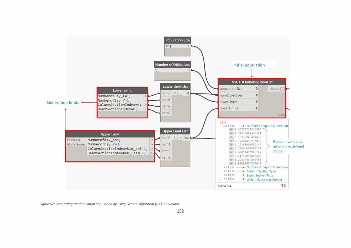
152
Figure 62: Generating random initial population by using Genetic Algorithm (GA) in Dynamo

153
Figure 63: Genetic Algorithm (GA) used to generate random initial population and perform the structural optimisation using cross over and mutation.

154
Figure 63 demonstrates how the SDO Prototype uses the GA to design and optimise alternative
structural models. In this process, GA generates random initial population of the alternative structural
models based on the input data of the design variables. In this population, each model represents a
chromosome, which includes certain types of genes (design variables) and weight score. In this
process, cross over and mutation performs on the generated models (parents) to combine design
variables (genes) and generate new solutions (off springs). For example, model number 1 and model
number 2 in figure 63 with different design variables (genes) combines and generated new model
number 12. Model number 12 includes half of the design variables from model number 1 and the
other half from the model number 2. On the other hand, model number 3 and model number 4
combined and generated new model which is model number 34. In this case, one of the design
variables is from model number 4 and the rest of the design variables are from the model number 3.
SDO Prototype uses codes that performs these variations (cross over and mutation) and generate
various types of alternative structural models. In this process variation in the design variables
generates various types of structural designs with different weight score (fitness values). In this case
study, the objective function of the optimisation was minimum weight score, which is minimum self-
weight or mass and minimum number of elements beyond the allowable stress ration.
As figure 58 indicates, the proposed prototype works on a certain region of the elastic area. Any
design with a maximum stress (Smax) less than n considered as under stress (less than the capability of
the steel) which is not economic but still strong to resist against the applied load. On the other hand,
any design with maximum stress (Smax) more than m considered as over stressed design (more than
the capability of the steel) which is not strong enough and may result in a failure in the structure or
high deflection. Therefore, these two type of structural models receive two different penalty functions
to be excluded from the design loop and only keep the models within the required scope, strong and
economic. Thereafter, GA combination engines (crossover and mutation) combines the fitter design

155
solutions (survivors) which results in close to optimum solutions. In this process, designs with over
stress members, which result in failure, receive a higher penalty function on other hand; designs with
under stressed embers receive lower penalty function. Therefore, the designs, which have all the
members with maximum stress (Smax) within the required range, between n and m, will receive no
penalty function but only the self-weight of the structure as the weight score. On the hand, designs
with elements under stressed receive self-weight of the structure plus the applied maximum stress
(Smax) of the structure to have a higher weigh-score. In addition, those designs, which have elements
over designed, receive the self-weight plus maximum stress (Smax) to the power of two to make a
greater number. Thus, the designs with less weight score will be selected as the optimum solution,
which have less mass and all the members within the allowable maximum stress (Smax). Figure 64
indicates how the penalty function is used to separate the over design and under design structural
models from the optimum designs.
Figure 64: Using Mass and Smax to calculate the weight score of different design and perform optimisation process.

156
Figure 65 shows the Python scripts which use four inputs and to calculate the weight score of the
structural model.
Figure 65: Python scripts to calculate the weight-score of the alternative structural modelsby using penalty functions for the over design and under design structural models.

157
4.3 Case study
In order to assess the practicality and the potential performance of the proposed solution, The
Gherkin Tower is chosen as a case project to demonstrate how architects and engineers can work in
an integrated platform and benefit from the structural optimisation process, as proposed. The Gherkin
Tower is chosen, because of its elongated, curved shaft with a rounded end design that stands out
against the more conservative nature of most of London's buildings. This innovative design is selected
as the case project to demonstrate the workability and efficiency of the proof of concept prototype in
designing complex and creative designs. Furthermore, the tower’s unique shape required ARUP (2020)
structural engineers to work closely with Foster and Partners (2004) architects to achieve an ambitious
curved form for the tower. Therefore, the proposed prototype demonstrates how one can automate
the synergy between architects and structural engineers in a BIM based platform to reduce the design
time. The Gherkin tower has two primary structures comprising the diagrid and the core. The diagrid
is the main part of the structure, which resists the lateral and gravity loads, and transfers it to the core
section of the structure. Cantor Seinuk defines diagrid as a series of triangles that combine gravity and
lateral support into one, making the building stiff, efficient and lighter, compared to a traditional high
rise buildings (Al-Kodmany, 2018; Spray & Ruffle, 2018).

158
Figure 66: Relationship between architectural and structural design criteria

159
Shape optimisation
Building shape can affect the architectural aesthetic integrity, structural safety and strength.
Therefore, the decision on the shape of a building depends on reaching an agreement amongst
architects and structural engineers. The proposed prototype facilitates this by automating the
structural design process based on the architectural model (boundary conditions). For instance, to
improve the safety and serviceability of tall buildings against strong winds, building shape optimisation
at the early architectural design stage is considered as the most efficient method to create a wind-
resistant design (Tang et al., 2014). Therefore, the proposed prototype enables the structural
engineers and architects to work on a synchronised automatic platform and explore the optimum
shape of the building; one that reduces the effect of the wind load on the building and meets the
aesthetic requirements. According to Figure 67, the cylindrical shape of the Gherkin Tower allows the
wind to move around the building and reduces the effect of the wind, while the cubic shape resists
against the wind load.
Figure 67: Effect of wind load on the shape of the building

160
Figure 68: Horizontal and vertical transformation and shape of the building
The proposed prototype enable the designers to modify the building shape parameterisation in
two directions – horizontal and vertical. The horizontal direction represents the shape of the floor plan
and the area of the building; the vertical direction defines the height of the building. Figure 68
demonstrates two types of horizontal and vertical transformations. The left side tower uses floor plan
shapes with a series of squares, where the arrangement of the squares changes along the height of
the tower. On the other hand, the right-side tower uses a circle floor base plan shape, where the radius
of the circle changes along the height of the tower. The solution proposed here uses this method as a
mathematical function in Dynamo to define the shape of the Gherkin Tower by using two variables.
The first parameter is the diameter of the circles and second is the level of the centre point of each
circle (see Figure 68). Hence, providing various series of circle diameters and circle centre point levels
generates different shapes for the tower. Figure 69 demonstrates 4 different options of tower shapes
generated by varying the value of parametric variables. All the design options have the same site
boundary constraints; they all have the same height of 179 m, the same base floor external diameter
of 50 m and the maximum floor external diameter of 56.15 m.

161
Figure 69: Shape optimisation of the Gherkin tower by using SDO Prototype

162
Topology and size optimisation
The optimum option of the tower shape with architectural and structural efficiency is adopted
and the design proceeds to the structural topology design and optimisation. This prototype defined
three different mathematical functions to design the core structure, the diagrid structure and the
façade panelling of the tower. Each approach has specific formulations to solve the design problem;
it uses specific parametric constraints (design variables) to design different topology options. In this
case, the diagrid structure and the architectural façade were designed by using ‘quad.diamond panel’
node from ‘LunchBox Quad by face’ package (Johnson, 2016) in Dynamo to create diamond features.
In addition, the core structure was designed by using a ‘surface panelling’ package to create
rectangular features. By varying the design variables of each function, the corresponding topology
varies. Therefore, different topology design options will be designed and analysed in RSA and the
results will be used for optimisation, to choose the best model between different options. Even though
design alternatives with more diagrid patterns might be preferable from the structural engineers’
point of view, these design alternatives may not be practically and aesthetically desirable for
contractors, architects and clients. The density spaced diamond diagrids may reduce the aesthetic
value of the building and create a less attractive architectural design. Moreover, the more diagrid
diamond pattern may also affect the amount of energy consumption, as it creates blockage for the
sunlight penetrating the building and reduces the natural light of the building. This kind of conflict
requires constant collaboration and communication between architects and engineers during the
design process. Defining an accurate mathematical design function to generate alternative designs
helps to speed up the generation of the conceptual design. Moreover, defining appropriate penalty
functions helps to exclude the unwanted models from the loop and generate suitable designs. Figure
70 demonstrates four different variations of structural topology designs, which are linked to the
architectural façade panelling design.

163
Figure 70: Topology optimisation of the Gherkin Tower by using the SDO Prototype

164
4.4 Summary
This section presents the process of design and development of the framework and prototype. In this
process, based on the findings from the literature review a Conceptual Structural Design and
Optimisation (CSDO) framework was developed as a potential solution to the identified challenges
during the structural design and optimisation process. Thereafter, an online questionnaire was
distributed between professionally accredited structural engineers of IStructE, ICE and ASCE in UK and
US to validate the framework. The aim of the questionnaire was to justify the research knowledge gap
and provide more potential solutions to solve the gap. The objective of the questionnaire was to
explore the existing issues in the conceptual structural design and the optimisation process and to find
how the conventional system with BIM can solve the issues. In order to meet these objectives, the
questionnaire needed to be designed based on some factors including sample size, type of questions,
number of questions, characteristics of the respondents, availability of time, financial implications and
ease of data analysis. According to the results received from the data analysis of the responses to the
questionnaire, the CSDO framework was modified and the extended version of the Structural Design
and Optimisation (SDO) framework was developed. Thereafter, a proof of concept prototype was
developed to demonstrate the workability of the framework.
The outcome of the research provides a much-needed toolset and associated procedures to assist in
integrating various participants across the design procedure of buildings. The proposed framework
and proof of concept prototype offers a workable solution to enhance efficiency and reduce conflicts
and clashes that occur as a result of fragmented and silo-based procedures of structural design. The
study stands out among similar ones, given that it provides a first-of–its-kind toolset that relies on an
automated synergy to use architectural parametric data for the multi-disciplinary optimising of
structural design. In the proposed prototype, the use of precise formulation and functions for the

165
automatic structural design and optimisation is the key to obtain a proper solution. An accurate and
comprehensive problem formulation should propose the design problem and maintain a high level of
accuracy, during the evolutionary design process. In this research, the maximum strength and less
self-weight are considered as the objective functions of the optimisation to explore strong and at the
same time light steel frame structure design. Therefore, mathematical functions are defined in
Dynamo to use different sets of variables to design and analyse different options of the structural
model in the Robot Structural Analysis (RSA), comparing the results in terms of strength against the
applied loads, self-weight, and eventually propose the best option.
166
Conclusion
One of the prevalent challenges facing the design professionals, including architects and
engineers, is maintaining the flow of information among various disciplines and addressing the
competing and frequently conflicting interests (Abrishami et al., 2015; Beghini et al., 2014). This is
because, the traditional supply chain in the construction industry displays a lack of integration of these
two disciplines (architects and engineers); their working procedures are fragmented, segmented and
affected by silo mentality (Durdyev et al., 2019; Mignone et al., 2016). These two groups work in
isolation and recognise responsibility, merely for their own portion of work, hence set different
priorities. That is, traditionally, the focus of architects is on the aesthetic factor of the building (building
shape), while engineers give priority to strength and efficiency of building structures (Hurol, 2014;
Vilutiene et al., 2019). Such mindsets have given rise to serious problems: non-productive activities
with up to 15% of cost and time overruns; many change orders accounting for between 60%–90% of
all variations, and inefficient communications that yield an additional 5%–10% in cost and time
overruns (Durdyev et al., 2019; Kraatz, Sanchez, & Hampson, 2014).
Despite the availability of BIM, IPD – and Common Data Environment (CDE) – the gap among
architects and structural engineers remains a problem to be addressed (Oraee et al., 2017). The
solution, as Merschbrock and Munkvold (2014) and Kassem et al. (2014) argued, relies on developing
data exchange frameworks and tools. Developing new tools is recommended as an effective solution
to facilitate integrating architectural-structural collaboration (Beghini et al., 2014). Therefore, a
comprehensive literature review was conducted to obtain more information about the existing
challenges during the structural design and optimisation process and explore potential solutions to
solve the problems. Based on the finding from the constant literature review a Conceptual Structural
Design and Optimisation (CSDO) framework was conducted. This framework proposed a new process,

167
which uses the architectural data to design alternative structural models. Moreover, Genetic
Algorithm (GA) was proposed as a potential algorithm for the structural optimisation process. In order
to validate the CSDO framework an online questionnaire was distributed between professionally
accredited structural engineers of the IStructE, ICE and ASCE in the UK and US. Data analysis of the
online questionnaire provided a valuable information about the existing challenges and potential
solutions to address the issues. Therefore, based on the results of the online questionnaire the CSDO
framework was amended and the extension version of Structural Design and Optimisation (SDO)
Prototype was developed. In order to demonstrate the workability of the prototype it was validated
through 10 interviews between academic staff and chartered structural engineers. Furthermore, a
focus group was conducted between a research team of Autodesk. The outcome of the research
provides a much-needed toolset and associated procedures to assist in integrating various actors
across the design procedure of buildings. The proposed SDO Prototype offers a workable solution to
enhance efficiency and reduce conflicts and clashes that occur as a result of the fragmented
procedures of structural design. The research stands out among similar ones, given that it provides
the first of its kind toolset that relies on an automated synergy to use architectural parametric data
for multi-faceted optimising of structural design. In this process, software prototyping method was
used to develop the SDO Prototype. In this method, the process of development was divided into
several stages and at each stage; a basic prototype was developed and evaluated to ascertain their
functionality and workability with other stages. As figure 71 and 72 demonstrates, this prototype uses
3 different tools for the design and optimisation processes. The first stage is the integration and
synergy between the architectural and structural design, which starts from the architectural model in
Revit. At this stage, architectural information are used to define the structural model layout and
topology. Structural designs are generated at the second stage, which is performed in Dynamo by
using certain nodes and codes. The second stage is the core part of the prototype, which performs the
structural design and optimisation and exports the data from the first stage to the third stage. The

168
third stage performs the structural design and Finite Element Analysis (FEA) in Robot Structural
Analysis. In this process, RSA designs analyse and save the alternative structural models and results
in an already defined directory path file.

169
Figure 71: The BIM tools used to develop the SDO Prototype.

170
Figure 72: An over view of the SDO Prototype process in Dynamo for the residential building design and optimisation in three steps of input design variables, structural design and analysis and results.

171
5.1 Theoretical contributions
With the above in mind, the research contributes to the field through extending the outcomes
of previous studies that managed to provide optimisation of structural design, albeit in one dimension
like shape, topology (Tsavdaridis et al., 2015; Wu and Tseng, 2010) and size (Jalili and Hosseinzadeh,
2018; Hasançebi et al., 2009) in structural design. That is, the prototype here considers all dimensions
simultaneously. The research also provides a practical demonstration for researchers who
recommended merging architects and structural engineers in one system, making their practices
inseparable, to shift from current practices to a fully integrated architectural/structural design system
(W Addis, 2007; Billington et al., 2003; Khan, 2004; N. O. Nawari, 2011; Sandaker, 2007; Schueller,
2008).
The research also broadens the boundary of application for previous attempts that focused on
structural optimisation of particular structures like truss members (Hasançebi et al., 2009; Kaveh and
Ghazaan, 2015; Kaveh and Mahdavi, 2014; Miguel and Miguel, 2012; Dede et al., 2011; Gholizadeh,
2013; Miguel et al., 2013; Degertekin, 2012). The proposed framework and prototype can be rolled
over to various types of structures including buildings, as well as infrastructure projects like bridges,
trusses high-rise towers, etc.
5.2 Practical contributions
Apart from theoretical contributions, as discussed, the solution provided here would be
appealing to the world of practice, particularly for practitioners active in various fields of structural
design for different type of structures. The solution will be invaluable, as discussed below.

172
This solution enables designers to develop mathematical functions and direct machines to
extract what they need from the architectural models, to be used for structural design,
based on defined parameters that vary and generate alternative structural design solutions.
This gives practitioners great flexibility to customise the system for certain projects, various
clients and different demands. As an example, the solution can easily be adjusted for
different design codes for steel/ aluminium, timber and RC structure in different regions (see
Figure 73).
Figure 73: Different design codes in various regions.
This method provides great efficiency and provides a wide range of alternatives for
structural design. Limitation of time and labour and human error prevent designers from
exploring all available solutions; the proposed system overcomes these and provides
designers with higher efficiency to explore all possibilities within the boundaries of their
demands and requirements.

173
The prototype relies on common tools and software available to most design practitioners.
As such, the solution is cost effective and feasible even for small businesses.
5.3 Future work
Regardless of the contributions to academia and the world of practice, in broad terms, this
research promotes the possibilities of shifting from discipline-based design into integrated design –
among various disciplines, as another step towards making BIM level 3 happen. This provides a fertile
area for research that focuses on improving the idea proposed here through creating user-friendly
platforms that automate the procedure based on a set of variables as inputs and creates efficient
design alternatives for clients, including structural, MEP, etc.
As another area for further exploration, the experience shared here brings to light the
requirements of future design professionals in terms of their knowledge, skills and abilities (KSAs).
Future research must explore the necessity of generating a new generation of designers with
programming capabilities and including coding programs for construction-related curricula at
universities. So too, researchers must target further investigation and development in the RSA API to
expand the workability of the prototype for automatic synergy between architectural and structural
design, analysis, optimisation and evaluation. The proposed prototype enables the designers to define
certain codes to facilitate time consuming and iterative tasks in the structural design process. For
example, defining codes for automatic 3D design of pitched roofs in buildings and defining the
optimum arrangement of the structural elements, which is a time-consuming process and mainly
structural engineers, use their experience and previous successful design in this type of project and
rarely search for new methods or optimum solutions. This prototype can be extended and used to
explore the best arrangement of the structural elements where different factors can affect the design,
and using these factors as design constrain and input data to generate alternative structural design

174
and find the optimum solution. For example, the prototype can be extended to consider the openings
in the design and give penalty function to the generated alternative structural designs, which has an
element in the architectural openings. Furthermore, this prototype can be improved and extended by
using bridge design codes of design and used in iterative structural design tasks in designing bridges.
For example, in the design of suspension bridge, this SDO prototype can be used to generate
alternative structural bridges with different numbers and sizes of cables, evaluate them based on the
most critical factor in the bridge design, and select the optimum solution, which is economic and
stable. In addition, this prototype can be used in the design of warehouses, which is a time consuming
task, and any change in the design requires the designer to change all the arrangement of the
structural elements. SDO prototype is capable to be extended and enable the structural engineers to
define the codes once and use them for different projects by adjusting the parametric input data.

175
Bibliography
Aage, N., Amir, O., Clausen, A., Hadar, L., Maier, D., & Søndergaard, A. (2015). Advanced Topology Optimization Methods for Conceptual Architectural Design. In P. Block, J. Knippers, N. J. Mitra, & W. Wang (Eds.), Advances in Architectural Geometry 2014 (pp. 159–179). Cham: Springer International Publishing.
Abrishami, S., Grenfell-Baines, (, Goulding, J., Pour, F., Grenfell-Baines, R. (, & Ganah, A. (2015). Virtual Generative BIM Workspace for Maximising AEC Conceptual Design Innovation: A Paradigm of Future Opportunities. https://doi.org/10.1108/CI-07-2014-0036
Addis, W. (2007). Building: 3000 years of design engineering and construction. Retrieved from http://www.academia.edu/download/37851373/building-3-000-years-of-design-engineering-and-construction.pdf
Addis, William. (2007). Building: 3000 years of design engineering and construction. Phaidon London/New York.
Agkathidis, A. (2015). Generative Design : Form-Finding Techniques in Architecture. Laurence. Retrieved from search.ebscohost.com/login.aspx?direct=true&db=cat01619a&AN=up.1244674&site=eds-live
Ahmad, A. M. (2014). The use of refurbishment, flexibility, standardisation and BIM to support the design of a change-ready healthcare facility. Retrieved from https://repository.lboro.ac.uk/articles/The_use_of_refurbishment_flexibility_standardisation_and_BIM_to_support_the_design_of_a_change-ready_healthcare_facility/9455693
Ahn, K.-U., Kim, Y.-J., Park, C.-S., Kim, I., & Lee, K. (2014). BIM interface for full vs. semi-automated building energy simulation. Energy and Buildings, 68(PART B), 671–678. https://doi.org/10.1016/j.enbuild.2013.08.063
Akintola, A., Senthilkumar Venkatachalam, ;, & Root, D. (2017). New BIM Roles’ Legitimacy and Changing Power Dynamics on BIM-Enabled Projects. https://doi.org/10.1061/(ASCE)CO.1943-7862.0001366
Al-Kodmany, K. (2018). The vertical city : a sustainable development model. Retrieved from https://books.google.co.uk/books?id=pTlpDwAAQBAJ&pg=PA87&lpg=PA87&dq=Diagrid+is+a+series+of+triangles+that+combine+gravity+and+lateral+supports+into+one,+making+the+building+stiff,+efficient+and+lighter+than+a+traditional+high+rise&source=bl&ots=MfdBk6A2E
Aldwaik, M., & Adeli, H. (2016). Advances in optimization of highrise building structures. Structural and Multidisciplinary Optimization, 50(6), 899–919. https://doi.org/10.1007/s00158-014-1148-1
Allahdadian, S., Boroomand, B., & Barekatein, A. R. (2012). Towards optimal design of bracing system of multi-story structures under harmonic base excitation through a topology optimization scheme. Finite Elements in Analysis and Design, 61, 60–74. https://doi.org/10.1016/j.finel.2012.06.010
Allaire, G., Dapogny, C., & Frey, P. (2014). Shape optimization with a level set based mesh evolution method. Computer Methods in Applied Mechanics and Engineering, 282, 22–53. https://doi.org/10.1016/j.cma.2014.08.028
Alwisy, A., Al-Hussein, M., & Al-Jibouri, S. H. (2012). BIM approach for automated drafting and design for modular construction manufacturing. Congress on Computing in Civil Engineering, Proceedings, 221–228. https://doi.org/10.1061/9780784412343.0028
Anumba, C., Dubler, C., Goodman, S., Kasprzak, C., Kreider, R., Messner, J., … Zikic, N. (2010). Building Information Modeling Execution Planning Guide and Templates - Version 2.0. Retrieved from https://vdcscorecard.stanford.edu/sites/g/files/sbiybj8856/f/bim_project_execution_planning

176
_guide-v2.0.pdf Arashpour, M., Heidarpour, A., Akbar Nezhad, A., Hosseinifard, Z., Chileshe, N., & Hosseini, R. (2019).
Performance-based control of variability and tolerance in off-site manufacture and assembly: optimization of penalty on poor production quality. Construction Management and Economics. https://doi.org/10.1080/01446193.2019.1616789
Arora, J. S. (2012). Chapter 16 - Genetic Algorithms for Optimum Design. In J. S. Arora (Ed.), Introduction to Optimum Design (Third Edition) (Third Edit, pp. 643–655). https://doi.org/https://doi.org/10.1016/B978-0-12-381375-6.00016-4
ARUP. (2020). 3D Modelling for The Gherkin - Arup. Retrieved January 15, 2020, from https://www.arup.com/projects/30-st-mary-axe
Asl, M. R., Stoupine, A., Zarrinmehr, S., & Yan, W. (2015). Optimo: A BIM-based multi-objective optimization tool utilizing visual programming for high performance building design.
Autodesk. (2018). THE NEXT WAVE OF INTELLIGENT DESIGN AUTOMATION. Autodesk. (2019a). Revit. Retrieved from https://www.autodesk.co.uk/products/revit/overview Autodesk. (2019b). Robot Structural Analysis Professional. Retrieved from
https://www.autodesk.com/education/free-software/robot-structural-analysis-professional Autodesk. (2020). What is Generative Design | Tools & Software | Autodesk. Retrieved January 18,
2020, from https://www.autodesk.com/solutions/generative-design Avi, E., Lillemäe, I., Romanoff, J., & Niemelä, A. (2015). Equivalent shell element for ship structural
design. Ships and Offshore Structures, 10(3), 239–255. https://doi.org/10.1080/17445302.2013.819689
Azhar, S. (2011). Building information modeling (BIM): Trends, benefits, risks, and challenges for the AEC industry. Leadership and Management in Engineering, 11(3), 241–252.
Banihashemi, S., Tabadkani, A., & Hosseini, M. R. (2018). Integration of parametric design into modular coordination: A construction waste reduction workflow. Automation in Construction, 88, 1–12. https://doi.org/10.1016/j.autcon.2017.12.026
Banihashemi, Saeed, Tabadkani, A., & Hosseini, M. R. (2017). Modular Coordination-based Generative Algorithm to Optimize Construction Waste. Procedia Engineering, 180, 631–639. https://doi.org/https://doi.org/10.1016/j.proeng.2017.04.222
Barg, S., Flager, F., & Fischer, M. (2018). An analytical method to estimate the total installed cost of structural steel building frames during early design. Journal of Building Engineering, 15, 41–50. https://doi.org/10.1016/j.jobe.2017.10.010
Barlish, K., & Sullivan, K. (2012). How to measure the benefits of BIM — A case study approach. Automation in Construction, 24, 149–159. https://doi.org/https://doi.org/10.1016/j.autcon.2012.02.008
Barrios, C. (2005). Transformations on parametric design models: A case study on the sagrada familia columns. Computer Aided Architectural Design Futures 2005 - Proceedings of the 11th International CAAD Futures Conference, 393–400.
Bartley, T. (2017). BIM for Civil and Structural Engineers. Retrieved from www.digital-built-britain.com Basbagill, J., Flager, F., Lepech, M., & Fischer, M. (2013). Application of life-cycle assessment to early
stage building design for reduced embodied environmental impacts. Building and Environment, 60, 81–92. https://doi.org/10.1016/j.buildenv.2012.11.009
Basbagill, J. P., Flager, F. L., & Lepech, M. (2014). A multi-objective feedback approach for evaluating sequential conceptual building design decisions. Automation in Construction, 45, 136–150. https://doi.org/10.1016/j.autcon.2014.04.015
Beghini, L. L., Beghini, A., Katz, N., Baker, W. F., & Paulino, G. H. (2014). Connecting architecture and engineering through structural topology optimization. Engineering Structures. https://doi.org/10.1016/j.engstruct.2013.10.032
Belegundu, A. D., & Chandrupatla, T. R. (2011). Optimization Concepts and Applications in Engineering.

177
https://doi.org/10.1017/CBO9780511975905 Bell, E., Bryman, A., & Harley, B. (2018). Business research methods. Oxford university press. Bendsøe, M. P., & Sigmund, O. (Ole). (2003). Topology optimization : theory, methods, and
applications. Retrieved from https://orbit.dtu.dk/en/publications/topology-optimization--theory-methods-and-applications(066a1a01-33cb-4c32-8290-773470cc5dcd).html
Besserud, K., Katz, N., & Beghini, A. (2013). Structural Emergence: Architectural and Structural Design Collaboration at SOM. Architectural Design, 83(2), 48–55. https://doi.org/10.1002/ad.1553
Bianconi, F., Filippucci, M., & Buffi, A. (2019). Automated design and modeling for mass-customized housing. A web-based design space catalog for timber structures. Automation in Construction, 103, 13–25. https://doi.org/10.1016/j.autcon.2019.03.002
Bilal, M., Oyedele, L. O., Qadir, J., Munir, K., Ajayi, S. O., Akinade, O. O., … Pasha, M. (2016). Big Data in the construction industry: A review of present status, opportunities, and future trends. Advanced Engineering Informatics, 30(3), 500–521. https://doi.org/10.1016/j.aei.2016.07.001
Billington, D., Doig, J., & Guthrie, J. (2003). The art of structural design: A Swiss legacy. Blasques, J. P., & Stolpe, M. (2012). Multi-material topology optimization of laminated composite
beam cross sections. Composite Structures, 94(11), 3278–3289. https://doi.org/10.1016/j.compstruct.2012.05.002
Bogomolny, M., & Amir, O. (2012). Conceptual design of reinforced concrete structures using topology optimization with elastoplastic material modeling. International Journal for Numerical Methods in Engineering, 90(13), 1578–1597. https://doi.org/10.1002/nme.4253
Bohnacker, H., Gross, B., Laub, J., & Lazzeroni, C. (2009). Generative Gestaltung : entwerfen, programmieren, visualisieren. Schmidt.
Bortoluzzi, B., Efremov, I., Medina, C., Sobieraj, D., & McArthur, J. J. (2019). Automating the creation of building information models for existing buildings. Automation in Construction, 105. https://doi.org/10.1016/j.autcon.2019.102838
Briscoe, D. (2014). Parametric planting green wall system research + design using BIM. ACADIA 2014 - Design Agency: Proceedings of the 34th Annual Conference of the Association for Computer Aided Design in Architecture, 2014-Octob, 333–338.
Brown, N., & Felipe, J. (2016). Early-stage integration of architectural and structural performance in a parametric multi-objective design tool Generative Structural Design Tools View project Mechanics, Assembly, and Optimization of Interlocking Timber Joints View project. Retrieved from https://www.researchgate.net/publication/316093348
Bryman, A. (2016). Social research methods. Oxford university press. Bynum, P., Issa, R. R. A., & Olbina, S. (2013). Building information modeling in support of sustainable
design and construction. Journal of Construction Engineering and Management, 139(1), 24–34. https://doi.org/10.1061/(ASCE)CO.1943-7862.0000560
Byrne, D. (2017). Why do research? https://doi.org/10.4135/9781526408495 Byrne, David. (2017). Research Project Planner. https://doi.org/10.4135/9781526408495 Cabinet Office. (2016). Government Construction Strategy 2016-20. Retrieved from
http://www.nationalarchives.gov.uk/doc/open-government-licence/ Cavieres, A., Gentry, R., & Al-Haddad, T. (2011). Knowledge-based parametric tools for concrete
masonry walls: Conceptual design and preliminary structural analysis. Automation in Construction, 20(6), 716–728. https://doi.org/10.1016/j.autcon.2011.01.003
Chalabee, H. (2013). Performance-based architectural design: Optimisation of building opening generation using generative algorithms. Retrieved from https://www.academia.edu/8217997/Performance-based_architectural_design_Optimisation_of_building_opening_generation_using_generative_algorithms
Chan, C.-M., & Wong, K.-M. (2008). Structural topology and element sizing design optimisation of tall

178
steel frameworks using a hybrid OC-GA method. Structural and Multidisciplinary Optimization, 35(5), 473–488. https://doi.org/10.1007/s00158-007-0151-1
Check, J., & Schutt, R. K. (2011). Research methods in education. Sage Publications. Chen, C., Dib, H. Y., & Lasker, G. C. (2011). Benefits of implementing building information modeling for
healthcare facility commissioning. Congress on Computing in Civil Engineering, Proceedings, 578–585. https://doi.org/10.1061/41182(416)71
Chen, C. J., & Usman, M. (2004). Design optimization for automotive applications. International Journal of Vehicle Design, 25(1-2 SPEC. ISS.), 126–141. https://doi.org/10.1504/ijvd.2001.001912
Chen, L., & Luo, H. (2014). A BIM-based construction quality management model and its applications. Automation in Construction, 46, 64–73. https://doi.org/10.1016/j.autcon.2014.05.009
Chen, P.-H., Cui, L., Wan, C., Yang, Q., Ting, S. K., & Tiong, R. L. K. (2005). Implementation of IFC-based web server for collaborative building design between architects and structural engineers. Automation in Construction, 14(1), 115–128. https://doi.org/https://doi.org/10.1016/j.autcon.2004.08.013
Cheng, B. H. C., & Atlee, J. M. (2007). Research directions in requirements engineering. FoSE 2007: Future of Software Engineering, 285–303. https://doi.org/10.1109/FOSE.2007.17
Cheng, J. C. P., Lu, Q., & Deng, Y. (2016). Analytical review and evaluation of civil information modeling. Automation in Construction, 67, 31–47. https://doi.org/10.1016/j.autcon.2016.02.006
Chi, H.-L., Wang, X., & Jiao, Y. (2015). BIM-Enabled Structural Design: Impacts and Future Developments in Structural Modelling, Analysis and Optimisation Processes. Archives of Computational Methods in Engineering, 22(1), 135–151. https://doi.org/10.1007/s11831-014-9127-7
Chi, H. L., Wang, X., & Jiao, Y. (2015). BIM-Enabled Structural Design: Impacts and Future Developments in Structural Modelling, Analysis and Optimisation Processes. Archives of Computational Methods in Engineering, 22(1), 135–151. https://doi.org/10.1007/s11831-014-9127-7
Chin, S., Yoon, S., Choi, C., & Cho, C. (2008). RFID+4D CAD for progress management of structural steel works in high-rise buildings. Journal of Computing in Civil Engineering, 22(2), 74–89. https://doi.org/10.1061/(ASCE)0887-3801(2008)22:2(74)
Chlosta, M. (2012). Master’s thesis - Literature study: Feasibility study on fiber reinforced polymer cylindrical truss bridges for heavy traffic. Retrieved from www.tudelft.nl
Chong, Y. T., Chen, C.-H., & Leong, K. F. (2009). A heuristic-based approach to conceptual design. Research in Engineering Design, 20(2), 97–116. https://doi.org/10.1007/s00163-008-0059-9
Christensen, P. W., & Klarbring, A. (2009). Examples of Optimization of Discrete Parameter Systems. In An Introduction to Structural Optimization (pp. 9–34). https://doi.org/10.1007/978-1-4020-8666-3_2
Creswell, J. W., & Creswell, J. D. (2017). Research design: Qualitative, quantitative, and mixed methods approaches. Sage publications.
Creswell, J. W., & Creswell, J. D. (2018). Research design : qualitative, quantitative & mixed methods approaches. Retrieved from http://search.ebscohost.com/login.aspx?direct=true&db=cat01619a&AN=up.1276330&site=eds-live
Creswell, J. W., & Plano-Clark, V. L. (2011). Choosing a mixed methods design. Designing and Conducting Mixed Method Research.
Creswell, J. W., & Plano Clark, V. L. (2017). Designing and conducting mixed methods research. Dapogny, C., Faure, A., Georgios Michailidis, ·, Allaire, · Grégoire, Couvelas, A., Rafael Estevez, ·, …
Estevez, R. (2017). Geometric constraints for shape and topology optimization in architectural design. 59, 933–965. https://doi.org/10.1007/s00466-017-1383-6
Darko, A., Chan, A. P. C., Adabre, M. A., Edwards, D. J., Hosseini, M. R., & Ameyaw, E. E. (2020). Artificial

179
intelligence in the AEC industry: Scientometric analysis and visualization of research activities. Automation in Construction, 112, 103081. https://doi.org/https://doi.org/10.1016/j.autcon.2020.103081
Deb, K., Pratap, A., Agarwal, S., & Meyarivan, T. (2002). A fast and elitist multiobjective genetic algorithm: NSGA-II. IEEE Transactions on Evolutionary Computation, 6(2), 182–197. https://doi.org/10.1109/4235.996017
Dede, T., Bekiroğlu, S., & Ayvaz, Y. (2011). Weight minimization of trusses with genetic algorithm. Applied Soft Computing, 11(2), 2565–2575. https://doi.org/https://doi.org/10.1016/j.asoc.2010.10.006
Degertekin, S. O. (2012). Improved harmony search algorithms for sizing optimization of truss structures. Computers & Structures, 92–93, 229–241. https://doi.org/https://doi.org/10.1016/j.compstruc.2011.10.022
Delgarm, N., Sajadi, B., Delgarm, S., & Kowsary, F. (2016). A novel approach for the simulation-based optimization of the buildings energy consumption using NSGA-II: Case study in Iran. Energy and Buildings, 127, 552–560. https://doi.org/10.1016/j.enbuild.2016.05.052
Deng, L., Ghosn, M., & Shao, S. (2005). Development of a shredding genetic algorithm for structural reliability. Structural Safety, 27(2), 113–131. https://doi.org/10.1016/j.strusafe.2004.06.002
Denzin, N. K., & Lincoln, Y. S. (2018). Reframing Rigor in Qualitative Inquiry. In The SAGE Handbook of qualitative Research.
Design Book. (2020). The Gherkin - Famous Buildings and Architecture of London. Retrieved January 15, 2020, from http://www.designbookmag.com/thegerkin.htm
Díaz, H., Alarcón, L. F., Mourgues, C., & García, S. (2017). Multidisciplinary Design Optimization through process integration in the AEC industry: Strategies and challenges. Automation in Construction, 73, 102–119. https://doi.org/10.1016/j.autcon.2016.09.007
Ding, C., Seifi, H., Dong, S., & Xie, Y. M. (2017). A new node-shifting method for shape optimization of reticulated spatial structures. Engineering Structures, 152, 727–735. https://doi.org/https://doi.org/10.1016/j.engstruct.2017.09.051
Dombernowsky, P., & Søndergaard, A. (2009). Three-dimensional topology optimisation in architectural and structural design of concrete structures Evolution and Trends in Design, Analysis and Construction of Shell and Spatial Structures.
Donath, D., & Lobos, D. (2009). Plausibility in Early Stages of Architectural Design: A New Tool for High-Rise Residential Buildings. Tsinghua Science and Technology, 14(3), 327–332. https://doi.org/10.1016/S1007-0214(09)70048-3
Donn, M., Selkowitz, S., & Bordass, B. (2012). The building performance sketch. Building Research and Information, 40(2), 186–208. https://doi.org/10.1080/09613218.2012.655070
Duarte, J. P. (2005). A discursive grammar for customizing mass housing: the case of Siza’s houses at Malagueira. Automation in Construction, 14(2), 265–275. https://doi.org/https://doi.org/10.1016/j.autcon.2004.07.013
Duffy, A. H. B., Andreasen, M. M., MacCallumx, K. J., & Reijers, L. N. (2007). Design Coordination for Concurrent Engineering. Journal of Engineering Design, 4(4), 251–265. https://doi.org/10.1080/09544829308914785
Durdyev, S., Hosseini, M. R., Martek, I., Ismail, S., & Arashpour, M. (2019). Barriers to the use of integrated project delivery (IPD): a quantified model for Malaysia. Engineering, Construction and Architectural Management. https://doi.org/10.1108/ECAM-12-2018-0535
Dynamo. (2020). Download | Dynamo BIM. Retrieved January 28, 2020, from https://dynamobim.org/download/
Dynamo BIM. (2019). Dynamo BIM. Retrieved from https://dynamobim.org/ Eadie, R., Browne, M., Odeyinka, H., McKeown, C., & McNiff, S. (2013). BIM implementation
throughout the UK construction project lifecycle: An analysis. Automation in Construction, 36,

180
145–151. https://doi.org/10.1016/j.autcon.2013.09.001 Easterby-Smith, M., Thorpe, R., & Jackson, P. R. (2012). Management research. Sage. Edmondson, A. (2012). A Fuller explanation: The synergetic geometry of R. Buckminster Fuller.
Retrieved from https://books.google.co.uk/books?hl=en&lr=&id=03fSBwAAQBAJ&oi=fnd&pg=PP12&dq=A+Fuller+Explanation:+The+Synergetic+Geometry+of+R.+Buckminster+Fuller&ots=WX0KJ1hVkt&sig=1ol2bxiM77kzyY3b_ieJzBr89GQ
El-Abbasy, M. S., Elazouni, A., & Zayed, T. (2016). MOSCOPEA: Multi-objective construction scheduling optimization using elitist non-dominated sorting genetic algorithm. Automation in Construction, 71, 153–170. https://doi.org/https://doi.org/10.1016/j.autcon.2016.08.038
Elbehairy, H., Elbeltagi, E., Hegazy, T., & Soudki, K. (2006). Comparison of two evolutionary algorithms for optimization of bridge deck repairs. Computer-Aided Civil and Infrastructure Engineering, 21(8), 561–572. https://doi.org/10.1111/j.1467-8667.2006.00458.x
Eleftheriadis, S., Duffour, P., Stephenson, B., & Mumovic, D. (2018). Automated specification of steel reinforcement to support the optimisation of RC floors. Automation in Construction, 96, 366–377. https://doi.org/10.1016/j.autcon.2018.10.005
Eleftheriadis, S., Mumovic, D., Greening, P., & Chronis, A. (2015). BIM enabled optimisation framework for environmentally responsible and structurally efficient design systems. 32nd International Symposium on Automation and Robotics in Construction and Mining: Connected to the Future, Proceedings.
Eltaweel, A., & SU, Y. (2017). Parametric design and daylighting: A literature review. Renewable and Sustainable Energy Reviews, 73, 1086–1103. https://doi.org/10.1016/j.rser.2017.02.011
Erbatur, F., Hasançebi, O., Tütüncü, İ., & Kılıç, H. (2000). Optimal design of planar and space structures with genetic algorithms. Computers & Structures, 75(2), 209–224. https://doi.org/https://doi.org/10.1016/S0045-7949(99)00084-X
Eschenauer, H. A., Kobelev, V. V., & Schumacher, A. (1994). Bubble method for topology and shape optimization of structures. Structural Optimization, 8(1), 42–51. https://doi.org/10.1007/BF01742933
Fabrycky, W., & Blanchard, B. (1991). Life-cycle cost and economic analysis. Retrieved from https://trove.nla.gov.au/work/6661351
Fellows, R. F., & Liu, A. M. M. (2015). Research methods for construction. John Wiley & Sons. Fenves, S. J., Rivard, H., & Gomez, N. (2000). SEED-Config: A tool for conceptual structural design in a
collaborative building design environment. Artificial Intelligence in Engineering. https://doi.org/10.1016/S0954-1810(00)00018-2
Flager, F., & Haymaker, J. (2009). A COMPARISON OF MULTIDISCIPLINARY DESIGN, ANALYSIS AND OPTIMIZATION PROCESSES IN THE BUILDING CONSTRUCTION AND AEROSPACE INDUSTRIES. Retrieved from http://citeseerx.ist.psu.edu/viewdoc/download?doi=10.1.1.163.945&rep=rep1&type=pdf
Flager, W., Bansal, S., Haymaker ; Flager, F., Welle, B., Bansal, P., Soremekun, G., & Haymaker, J. (2009). Multidisciplinary process integration and design optimization of a classroom building. In Journal of Information Technology in Construction (ITcon) (Vol. 14). Retrieved from http://www.itcon.org/2009/38
Foster and Partners. (2004). 30 St Mary Axe | Offices and Headquarters | Foster + Partners. Retrieved January 15, 2020, from https://www.fosterandpartners.com/projects/30-st-mary-axe/
Fu, F. (2018). Design and Analysis of Tall and Complex Structures. In Design and Analysis of Tall and Complex Structures. https://doi.org/10.1016/b978-0-08-101018-1.00006-x
Gallaher, M. P., O’connor, A. C., Dettbarn, J. L., & Gilday, L. T. (2004). Cost Analysis of Inadequate Interoperability in the U.S. Capital Facilities Industry. https://doi.org/10.6028/NIST.GCR.04-867
Gandomi, A. H., Kashani, A. R., Roke, D. A., & Mousavi, M. (2017). Optimization of retaining wall design

181
using evolutionary algorithms. Structural and Multidisciplinary Optimization, 55(3), 809–825. https://doi.org/10.1007/s00158-016-1521-3
Gerold, F. (2019). Integrative structural design. EG-ICE 2010 - 17th International Workshop on Intelligent Computing in Engineering.
Gerold, F., Beucke, ; K, Seible, F., & Asce, M. (2012). Integrative Structural Design. https://doi.org/10.1061/(ASCE)CP.1943-5487.0000180
Gerring, J. (2006). Case study research: Principles and practices. Cambridge university press. Gervásio, H., Santos, P., Martins, R., & Simões da Silva, L. (2014). A macro-component approach for
the assessment of building sustainability in early stages of design. Building and Environment, 73, 256–270. https://doi.org/10.1016/j.buildenv.2013.12.015
Gheisari, M., & Esmaeili, B. (2019). Applications and requirements of unmanned aerial systems (UASs) for construction safety. Safety Science, 118, 230–240. https://doi.org/10.1016/j.ssci.2019.05.015
Gholizadeh, S. (2013). Layout optimization of truss structures by hybridizing cellular automata and particle swarm optimization. Computers & Structures, 125, 86–99. https://doi.org/https://doi.org/10.1016/j.compstruc.2013.04.024
Goddard, W., & Melville, S. (2004). Research methodology: An introduction. Juta and Company Ltd. GOV.UK. (2011). Government Construction Strategy. Granadeiro, V., Duarte, J. P., Correia, J. R., & Leal, V. M. S. (2013a). Building envelope shape design in
early stages of the design process: Integrating architectural design systems and energy simulation. Automation in Construction, 32, 196–209. https://doi.org/10.1016/j.autcon.2012.12.003
Granadeiro, V., Duarte, J. P., Correia, J. R., & Leal, V. M. S. (2013b). Building envelope shape design in early stages of the design process: Integrating architectural design systems and energy simulation. Automation in Construction, 32, 196–209. https://doi.org/10.1016/j.autcon.2012.12.003
Granadeiro, Vasco, Duarte, J. P., Correia, J. R., & Leal, V. M. S. (2013). Building envelope shape design in early stages of the design process: Integrating architectural design systems and energy simulation. Automation in Construction. https://doi.org/10.1016/j.autcon.2012.12.003
Grasshopper. (n.d.). Grasshopper - algorithmic modeling for Rhino. Retrieved January 10, 2020, from https://www.grasshopper3d.com/
Gratton, C., & Jones, I. (2014). Research methods for sports studies. Retrieved from https://www.taylorfrancis.com/books/9781315796222
Großmann, A., Weis, P., Clemen, C., & Mittelstedt, C. (2020). Optimization and re-design of a metallic riveting tool for additive manufacturing—A case study. Additive Manufacturing, 31. https://doi.org/10.1016/j.addma.2019.100892
Guba, E. G. (1990). The paradigm dialog. Sage publications. Guo, X., & Cheng, G.-D. (2010). Recent development in structural design and optimization. Acta
Mechanica Sinica/Lixue Xuebao, 26(6), 807–823. https://doi.org/10.1007/s10409-010-0395-7 Gushta, M. M., & Rupp, A. A. (2012). Reliability In: Encyclopedia of Research Design.
https://doi.org/10.4135/9781412961288 Haapio, J. (2012). Feature-Based Costing Method for Skeletal Steel Structures based on the Process
Approach. Hasançebi, O. (2007). Optimization of truss bridges within a specified design domain using evolution
strategies. Engineering Optimization, 39(6), 737–756. https://doi.org/10.1080/03052150701335071
Hasançebi, O., Çarbaş, S., Doğan, E., Erdal, F., & Saka, M. P. (2009). Performance evaluation of metaheuristic search techniques in the optimum design of real size pin jointed structures. Computers & Structures, 87(5), 284–302.

182
https://doi.org/https://doi.org/10.1016/j.compstruc.2009.01.002 Haslinger, J., & Mäkinen, R. A. E. (2015). Introduction to Shape Optimization - Theory, Approximation,
and Computation - Knovel. Retrieved from https://app.knovel.com/web/toc.v/cid:kpISOTAC02/viewerType:toc//root_slug:introduction-shape-optimization/url_slug:introduction-shape-optimization?kpromoter=federation%23%3F&kpromoter=federation&hierarchy=kn006BSO14
He, Q., Wang, G., Luo, L., Shi, Q., Xie, J., & Meng, X. (2017). Mapping the managerial areas of Building Information Modeling (BIM) using scientometric analysis. International Journal of Project Management, 35(4), 670–685. https://doi.org/10.1016/j.ijproman.2016.08.001
Hoekstra, J. (2003). TECH/BIG BUZZ FOR BIM-Is the latest approach to A/E/C software a revolutionary one or just repackaged technology at a higher price? , DC: American Institute of Architects ….
Holland, J. H. . (1992). Genetic Algorithms understand Genetic Algorithms. Scientific American, 267(1), 66–73. https://doi.org/10.2307/24939139
Horvath, B. L. (2019). Aircraft conceptual structural design using the ammit structural analysis tool. AIAA Scitech 2019 Forum. https://doi.org/10.2514/6.2019-0549
Horváth, I. (2005). On some crucial issues of computer support of conceptual design what to consider in order to be successful. In Product Engineering: Eco-Design, Technologies and Green Energy. https://doi.org/10.1007/1-4020-2933-0_9
Hosseini, M. R., Maghrebi, M., Akbarnezhad, A., Martek, I., & Arashpour, M. (2018). Analysis of Citation Networks in Building Information Modeling Research. Journal of Construction Engineering and Management, 144(8). https://doi.org/10.1061/(ASCE)CO.1943-7862.0001492
Hsu, W., & Liu, B. (2000). Conceptual design: issues and challenges. Computer-Aided Design, 32(14), 849–850. https://doi.org/10.1016/s0010-4485(00)00074-9
Hu, Z.-Z., Zhang, X.-Y., Wang, H.-W., & Kassem, M. (2016). Improving interoperability between architectural and structural design models: An industry foundation classes-based approach with web-based tools. Automation in Construction, 66, 29–42. https://doi.org/10.1016/j.autcon.2016.02.001
Hu, Z., & Zhang, J. (2011). BIM- and 4D-based integrated solution of analysis and management for conflicts and structural safety problems during construction: 2. Development and site trials. Automation in Construction, 20(2), 167–180. https://doi.org/https://doi.org/10.1016/j.autcon.2010.09.014
Hunt, C. (2013). The Benefits of Using Building Information Modeling in Structural Engineering. All Graduate Plan B and Other Reports. Retrieved from https://digitalcommons.usu.edu/gradreports/319
Hurol, Y. (2014). Ethical Considerations for a Better Collaboration Between Architects and Structural Engineers: Design of Buildings with Reinforced Concrete Frame Systems in Earthquake Zones. Science and Engineering Ethics, 20(2), 597–612. https://doi.org/10.1007/s11948-013-9453-4
Issa, R. R. A., & Olbina, S. (2015). Building information modeling: Applications and practices. In Building Information Modeling: Applications and Practices. https://doi.org/10.1061/9780784413982
IStructE. (2020). The Structural Plan of Work 2020 - The Institution of Structural Engineers. Retrieved December 3, 2020, from IStructE website: https://www.istructe.org/resources/guidance/the-structural-plan-of-work/
Jalili, S., & Hosseinzadeh, Y. (2018). Design optimization of truss structures with continuous anddiscrete variables by hybrid of biogeography‐basedoptimization and differential evolution methods. The Structural Design of Tall and Special Buildings, 27(14), e1495. https://doi.org/10.1002/tal.1495
Jewett, J. L., & Carstensen, J. V. (2019). Topology-optimized design, construction and experimental evaluation of concrete beams. Automation in Construction, 102, 59–67. https://doi.org/https://doi.org/10.1016/j.autcon.2019.02.001

183
Jin, J. T., & Jeong, J. W. (2014). Optimization of a free-form building shape to minimize external thermal load using genetic algorithm. Energy and Buildings, 85, 473–482. https://doi.org/10.1016/j.enbuild.2014.09.080
Johnson, lukes. (2016). Lunchbox – Dynamo Nodes. Retrieved January 10, 2020, from https://dynamonodes.com/category/lunchbox/
Jung, J., Hong, S., Yoon, S., Kim, J., & Heo, J. (2016). Automated 3D wireframe modeling of indoor structures from point clouds using constrained least-squares adjustment for as-built BIM. Journal of Computing in Civil Engineering, 30(4). https://doi.org/10.1061/(ASCE)CP.1943-5487.0000556
Jung, Y., & Joo, M. (2011). Building information modelling (BIM) framework for practical implementation. Automation in Construction, 20(2), 126–133. https://doi.org/https://doi.org/10.1016/j.autcon.2010.09.010
Kalmykov, O., Gaponova, L., Reznik, P., & Grebenchuk, S. (2017). Use of information technologies for energetic portrait construction of cylindrical reinforced concrete shells. MATEC Web of Conferences, 116. https://doi.org/10.1051/matecconf/201711602017
Kaveh, A., & Ghazaan, M. I. (2015). A comparative study of CBO and ECBO for optimal design of skeletal structures. Computers & Structures, 153, 137–147. https://doi.org/https://doi.org/10.1016/j.compstruc.2015.02.028
Kaveh, A., & Mahdavi, V. R. (2014). Colliding Bodies Optimization method for optimum discrete design of truss structures. Computers & Structures, 139, 43–53. https://doi.org/https://doi.org/10.1016/j.compstruc.2014.04.006
Kawulich, B., & Chilisa, B. (2015). Selecting a research approach: paradigm, methodology and methods. Retrieved from https://www.researchgate.net/publication/257944787
Kazakis, G., Kanellopoulos, I., Sotiropoulos, S., & Lagaros, N. D. (2017). Topology optimization aided structural design: Interpretation, computational aspects and 3D printing. Heliyon. https://doi.org/10.1016/j.heliyon.2017.e00431
Kensek, K. (2015). Visual programming for building information modeling: Energy and shading analysis case studies. Journal of Green Building, 10(4), 28–43. https://doi.org/10.3992/jgb.10.4.28
Keough, I. (2020). Ian Keough | CORE studio. Retrieved January 28, 2020, from http://core.thorntontomasetti.com/ian-keough/
Ketokivi, M., & Mantere, S. (2010). Two Strategies for Inductive Reasoning in Organizational Research. Academy of Management Review, 35(2), 315–333. https://doi.org/10.5465/amr.35.2.zok315
Khan, Y. (2004). Engineering architecture: the vision of Fazlur R. Khan. Khatibinia, M., & Naseralavi, S. S. (2014). Truss optimization on shape and sizing with frequency
constraints based on orthogonal multi-gravitational search algorithm. Journal of Sound and Vibration, 333(24), 6349–6369. https://doi.org/https://doi.org/10.1016/j.jsv.2014.07.027
Kilkelly, M. (2018). What Is Dynamo and 5 Reasons You Should be Using It - ArchSmarter -. Retrieved January 10, 2020, from https://archsmarter.com/what-is-dynamo-revit/
Kim, K. P., & Park, K. S. (2013). BIM feasibility study for housing refurbishment projects in the UK. Organization, Technology & Management in Construction: An International Journal, 5(Special), 765–774.
Kim, K., Walewski, J., & Cho, Y. K. (2016). Multiobjective Construction Schedule Optimization Using Modified Niched Pareto Genetic Algorithm. Journal of Management in Engineering, 32(2), 04015038. https://doi.org/10.1061/(ASCE)ME.1943-5479.0000374
Konis, K., Gamas, A., & Kensek, K. (2016). Passive performance and building form: An optimization framework for early-stage design support. Solar Energy, 125, 161–179. https://doi.org/10.1016/j.solener.2015.12.020
Kothari, C. R. (2004). Research methodology: Methods and techniques. New Age International. Kraatz, J. A., Sanchez, A. X., & Hampson, K. D. (2014). Digital Modeling, Integrated Project Delivery and
Industry Transformation: An Australian Case Study. Buildings, 4, 453–466.

184
https://doi.org/10.3390/buildings4030453 Krausse, J., & Lichtenstein, C. (2000). Your Private Sky, R. Buckminster Fuller. Nexus Network Journal,
2. Retrieved from https://scholar.googleusercontent.com/scholar.bib?q=info:R4Bn_KnfTyAJ:scholar.google.com/&output=citation&scisdr=CgUVu6KCEM_WzvPpTSU:AAGBfm0AAAAAXhTsVSXUe5oDW5Tfs_MSuPQrtjKc3Zim&scisig=AAGBfm0AAAAAXhTsVWqscrxRgJTZnZIziZfJEcSd7f6M&scisf=4&ct=citation&cd=-1
Kreider, R. G., & Messner, J. I. (2013). The Uses of BIM Classifying and Selecting BIM Uses. Retrieved from http://bim.psu.edu.
Kumar, S., Panwar, A. S., Kumar, S., Shamim, M., & Mishra, D. (2018). Statistical data analysis tools: Software prospects for crop productivity. In Eco-friendly Agro-biological Techniques for Enhancing Crop Productivity. https://doi.org/10.1007/978-981-10-6934-5_12
L. Cantor, S. (2019). Professional and Practical Considerations for Landscape Design. Retrieved from https://books.google.co.uk/books?hl=en&lr=&id=htnBDwAAQBAJ&oi=fnd&pg=PP1&dq=Professional+and+Practical+Considerations+for+Landscape+Design&ots=QBOqW9RfS7&sig=g2SFr1ZTSMsvK2GJf60G7R6AkIU#v=onepage&q=Professional and Practical Considerations for Landscape D
Lee, C., & Ham, S. (2018). Automated system for form layout to increase the proportion of standard forms and improve work efficiency. Automation in Construction, 87, 273–286. https://doi.org/10.1016/j.autcon.2017.12.028
Lee, G., Sacks, R., & Eastman, C. M. (2006). Specifying parametric building object behavior (BOB) for a building information modeling system. Automation in Construction, 15(6), 758–776. https://doi.org/10.1016/j.autcon.2005.09.009
Lee, J., & Hyun, H. (2019). Multiple Modular Building Construction Project Scheduling Using Genetic Algorithms. Journal of Construction Engineering and Management, 145(1), 04018116. https://doi.org/10.1061/(ASCE)CO.1943-7862.0001585
Lim, Y.-W., Majid, H. A., Samah, A. A., Ahmad, M. H., Ossen, D. R., Harun, M. F., & Shahsavari, F. (2018). Bim and genetic algorithm optimisation for sustainable building envelope design. International Journal of Sustainable Development and Planning, 13(1), 151–159. https://doi.org/10.2495/SDP-V13-N1-151-159
Lin, J. R., Zhou, Y. C., Zhang, J. P., & Hu, Z. Z. (2019). Classification and exemplary BIM models development of design changes. Proceedings of the 36th International Symposium on Automation and Robotics in Construction, ISARC 2019, 122–127.
Lincoln, Y. S., Lynham, S. A., & Guba, E. G. (2011). Paradigmatic controversies, contradictions, and emerging confluences, revisited. The Sage Handbook of Qualitative Research, 4, 97–128.
Liu, H., Sydora, C., Altaf, M. S., Han, S., & Al-Hussein, M. (2019). Towards sustainable construction: BIM-enabled design and planning of roof sheathing installation for prefabricated buildings. Journal of Cleaner Production, 235, 1189–1201. https://doi.org/10.1016/j.jclepro.2019.07.055
Liu, Hexu, Singh, G., Lu, M., Bouferguene, A., & Al-Hussein, M. (2018). BIM-based automated design and planning for boarding of light-frame residential buildings. Automation in Construction, 89, 235–249. https://doi.org/10.1016/j.autcon.2018.02.001
Liu, Y.-C., Chakrabarti, A., & Bligh, T. (2003). Towards an ‘ideal’ approach for concept generation. Design Studies, 24(4), 341–355. https://doi.org/https://doi.org/10.1016/S0142-694X(03)00003-6
Liu, Z.-Q., Li, Y.-G., & Zhang, H.-Y. (2010). IFC-based integration tool for supporting information exchange from architectural model to structural model. J. Cent. South Univ. Technol, 17. https://doi.org/10.1007/s11771−010−0640−z
Mathworks. (2015). Simulink - Simulation and Model-Based Design - MATLAB & Simulink. Retrieved January 18, 2020, from https://uk.mathworks.com/products/simulink.html

185
McGuire, B., Atadero, R., Clevenger, C., & Ozbek, M. (2016). Bridge Information Modeling for Inspection and Evaluation. Journal of Bridge Engineering, 21(4). https://doi.org/10.1061/(ASCE)BE.1943-5592.0000850
Mellit, A., & Kalogirou, S. A. (2008). Artificial intelligence techniques for photovoltaic applications: A review. Progress in Energy and Combustion Science, 34(5), 574–632. https://doi.org/https://doi.org/10.1016/j.pecs.2008.01.001
Merrell, P., Schkufza, E., & Koltun, V. (2010). Computer-Generated Residential Building Layouts. ACM Trans. Graph, 29(181). https://doi.org/10.1145/1866158.1866203
Merschbrock, C., & Munkvold, E. B. (2014). How is building information modeling influenced by project complexity?: A cross-case analysis of e-collaboration performance in building construction. Igi-Global.Com. Retrieved from https://www.igi-global.com/article/how-is-building-information-modeling-influenced-by-project-complexity/114171
Mertens, D. M. (2014). Research and evaluation in education and psychology: Integrating diversity with quantitative, qualitative, and mixed methods. Sage publications.
Meyer-Baese, A., & Schmid, V. (2014). Chapter 5 - Genetic Algorithms. In A. Meyer-Baese & V. Schmid (Eds.), Pattern Recognition and Signal Analysis in Medical Imaging (Second Edition) (Second Edi, pp. 135–149). https://doi.org/https://doi.org/10.1016/B978-0-12-409545-8.00005-4
Michell, A. G. M. (1904). LVIII. The limits of economy of material in frame-structures . The London, Edinburgh, and Dublin Philosophical Magazine and Journal of Science, 8(47), 589–597. https://doi.org/10.1080/14786440409463229
Mignone, G., Hosseini, M. R., Chileshe, N., & Arashpour, M. (2016). Enhancing collaboration in BIM-based construction networks through organisational discontinuity theory: a case study of the new Royal Adelaide Hospital. Architectural Engineering and Design Management, 12(5), 333–352. https://doi.org/10.1080/17452007.2016.1169987
Miguel, Leandro Fleck Fadel, Lopez, R. H., & Miguel, L. F. F. (2013). Multimodal size, shape, and topology optimisation of truss structures using the Firefly algorithm. Advances in Engineering Software, 56, 23–37. https://doi.org/10.1016/j.advengsoft.2012.11.006
Miguel, Letícia Fleck Fadel, & Miguel, L. F. F. (2012). Shape and size optimization of truss structures considering dynamic constraints through modern metaheuristic algorithms. Expert Systems with Applications, 39(10), 9458–9467. https://doi.org/https://doi.org/10.1016/j.eswa.2012.02.113
Mirjalili, S. (2018). Studies in Computational Intelligence 780 Evolutionary Algorithms and Neural Networks Theory and Applications. Retrieved from http://www.springer.com/series/7092
Mirjalili, S. Z., Mirjalili, S., Saremi, S., Faris, H., & Aljarah, I. (2018). Grasshopper optimization algorithm for multi-objective optimization problems. Applied Intelligence, 48(4), 805–820. https://doi.org/10.1007/s10489-017-1019-8
Mitchell, V. (1996). Assessing the reliability and validity of questionnaires: an empirical example. Journal of Applied Management Studies.
Mobasher, M. E., Rashed, Y. F., & Elhaddad, W. (2016). BIM standards for automated BEM structural analysis and design of RC plates. Journal of Computing in Civil Engineering, 30(4). https://doi.org/10.1061/(ASCE)CP.1943-5487.0000531
Mora, R., Bédard, C., & Rivard, H. (2008). A geometric modelling framework for conceptual structural design from early digital architectural models. Advanced Engineering Informatics. https://doi.org/10.1016/j.aei.2007.03.003
Mora, R., Rivard, H., & Bédard, C. (2006). Computer Representation to Support Conceptual Structural Design within a Building Architectural Context. Journal of Computing in Civil Engineering, 20(2), 76–87. https://doi.org/10.1061/(ASCE)0887-3801(2006)20:2(76)
Motawa, I. A., Anumba, C. J., Lee, S., & Peña-Mora, F. (2007). An integrated system for change management in construction. Automation in Construction, 16(3), 368–377. https://doi.org/10.1016/j.autcon.2006.07.005

186
Mourshed, M., Shikder, S., & Price, A. D. F. (2011). Phi-array: A novel method for fitness visualization and decision making in evolutionary design optimization. Advanced Engineering Informatics, 25(4), 676–687. https://doi.org/https://doi.org/10.1016/j.aei.2011.07.005
Muller, M. F., Garbers, A., Esmanioto, F., Huber, N., Loures, E. R., & Canciglieri, O. (2017). Data interoperability assessment though IFC for BIM in structural design–a five-year gap analysis. Journal of Civil Engineering and Management, 23(7), 943–954. https://doi.org/10.3846/13923730.2017.1341850
Nawari, N., & Kuenstle, M. (2015). Building information modeling: Framework for structural design. Retrieved from https://content.taylorfrancis.com/books/download?dac=C2013-0-27324-0&isbn=9780429172083&format=googlePreviewPdf
Nawari, N. O. (2011). Automating codes conformance in structural domain. Congress on Computing in Civil Engineering, Proceedings, 569–577. https://doi.org/10.1061/41182(416)70
NCS. (2019). NCS Content | United States National CAD Standard - V6. Retrieved January 9, 2020, from https://www.nationalcadstandard.org/ncs6/content.php
Nervi, P. (1965). Aesthetics and Technology in Building: Y Pier Luigi Nervi; Translated from the Italian by Robert Einaudi.--.
Norato, J. A., Bendsøe, M. P., Haber, R. B., & Tortorelli, D. A. (2007). A topological derivative method for topology optimization. Structural and Multidisciplinary Optimization, 33(4–5), 375–386. https://doi.org/10.1007/s00158-007-0094-6
Nordin, A., Motte, D., Hopf, A., Bja¨rnemo, R., Bja¨rnemo, B., & Eckhardt, C.-C. (2013). Constraint-handling techniques for generative product design systems in the mass customization context. https://doi.org/10.1017/S0890060413000383
Nour, M., & Beucke, K. (2019). Object Versioning as a basis for design change management within a BIM context. EG-ICE 2010 - 17th International Workshop on Intelligent Computing in Engineering.
Nourbakhsh, M. (2016). GENERALIZABLE SURROGATE MODELS FOR THE IMPROVED EARLY-STAGE EXPLORATION OF STRUCTURAL DESIGN ALTERNATIVES IN BUILDING CONSTRUCTION.
O’Sullivan, B. (2002). Interactive constraint-aided conceptual design. Artificial Intelligence for Engineering Design, Analysis and Manufacturing: AIEDAM, 16(4), 303–328. https://doi.org/10.1017/S0890060402164043
Okakpu, A., GhaffarianHoseini, A., Tookey, J., Haar, J., Ghaffarianhoseini, A., & Rehman, A. (2018). A proposed framework to investigate effective BIM adoption for refurbishment of building projects. Architectural Science Review, 61(6), 467–479. https://doi.org/10.1080/00038628.2018.1522585
Oke, S. A. (2008). A Literature Review on Artificial Intelligence. In International Journal of Information and Management Sciences (Vol. 19).
Olawumi, T. O., & Chan, D. W. M. (2018). Building information modelling and project information management framework for construction projects. Journal of Civil Engineering and Management, 25(1), 53–75. https://doi.org/10.3846/jcem.2019.7841
Oraee, M., Hosseini, M. R., Papadonikolaki, E., Palliyaguru, R., & Arashpour, M. (2017). Collaboration in BIM-based construction networks: A bibliometric-qualitative literature review. International Journal of Project Management, 35(7), 1288–1301. https://doi.org/10.1016/j.ijproman.2017.07.001
Oti, A. H., & Tizani, W. (2015). BIM extension for the sustainability appraisal of conceptual steel design. Advanced Engineering Informatics, 29(1), 28–46. https://doi.org/10.1016/j.aei.2014.09.001
Oti, A. H., Tizani, W., & Zada, A. J. (2014). A BIM extension for sustainability appraisal of conceptual structural design of steel-framed buildings. Computing in Civil and Building Engineering - Proceedings of the 2014 International Conference on Computing in Civil and Building Engineering, 219–226. https://doi.org/10.1061/9780784413616.028
Pahl, G., Beitz, W., Feldhusen, J., & Grote, K.-H. (2007). Engineering design: A systematic approach. In

187
Engineering Design: A Systematic Approach. https://doi.org/10.1007/978-1-84628-319-2 Papadonikolaki, E., Vrijhoef, R., & Wamelink, H. (2016). Architectural Engineering and Design
Management The interdependences of BIM and supply chain partnering: empirical explorations. https://doi.org/10.1080/17452007.2016.1212693
Patrício, D. I., & Rieder, R. (2018). Computer vision and artificial intelligence in precision agriculture for grain crops: A systematic review. Computers and Electronics in Agriculture, 153, 69–81. https://doi.org/10.1016/j.compag.2018.08.001
Peterson, F., Hartmann, T., Fruchter, R., & Fischer, M. (2011). Teaching construction project management with BIM support: Experience and lessons learned. Automation in Construction, 20(2), 115–125. https://doi.org/10.1016/j.autcon.2010.09.009
Pezeshki, Z., & Ivari, S. A. S. (2018). Applications of BIM: A Brief Review and Future Outline. Archives of Computational Methods in Engineering, 25(2), 273–312. https://doi.org/10.1007/s11831-016-9204-1
Ponto, J. (2015). Understanding and evaluating survey research. Journal of the Advanced Practitioner in Oncology, 6(2), 168.
Prowler, D. (2019). Whole Building Design | WBDG - Whole Building Design Guide. Retrieved January 7, 2020, from http://www.wbdg.org/resources/whole-building-design
Pučko, Z., Šuman, N., & Rebolj, D. (2018). Automated continuous construction progress monitoring using multiple workplace real time 3D scans. Advanced Engineering Informatics, 38, 27–40. https://doi.org/10.1016/j.aei.2018.06.001
Rahami, H., Kaveh, A., Aslani, M., & Najian Asl, R. (2011). A HYBRID MODIFIED GENETIC-NELDER MEAD SIMPLEX ALGORITHM FOR LARGE-SCALE TRUSS OPTIMIZATION.
Rahmani Asl, M. (2015). A BUILDING INFORMATION MODEL (BIM) BASED FRAMEWORK FOR PERFORMANCE OPTIMIZATION. Retrieved from https://www.researchgate.net/publication/296879627_A_BUILDING_INFORMATION_MODEL_BIM_BASED_FRAMEWORK_FOR_PERFORMANCE_OPTIMIZATION
Rahmani Asl, M., Bergin, M., Menter, A., & Yan, W. (2014). BIM-based parametric building energy performance multi-objective optimization.
Rahmani Asl, M., Stoupine, A., Zarrinmehr, S., & Yan, W. (2015). Optimo: A BIM-based Multi-Objective Optimization Tool Utilizing Visual Programming for High Performance Building Design. Proceedings of the Conference of Education and Research in Computer Aided Architectural Design in Europe (ECAADe).
Rahmani Asl, M., Zarrinmehr, S., Bergin, M., & Yan, W. (2015). BPOpt: A framework for BIM-based performance optimization. Energy and Buildings. https://doi.org/10.1016/j.enbuild.2015.09.011
Ramaji, I. J., & Memari, A. M. (2018). Interpretation of structural analytical models from the coordination view in building information models. Automation in Construction, 90, 117–133. https://doi.org/10.1016/j.autcon.2018.02.025
Reed, P., Minsker, B., & Goldberg, D. E. (2003). Simplifying Multiobjective Optimization Using Genetic Algorithms. World Water & Environmental Resources Congress 2003, 1–10. https://doi.org/10.1061/40685(2003)135
Ren, Z., Yang, F., Bouchlaghem, N. M., & Anumba, C. J. (2011). Multi-disciplinary collaborative building design—A comparative study between multi-agent systems and multi-disciplinary optimisation approaches. Automation in Construction, 20(5), 537–549. https://doi.org/https://doi.org/10.1016/j.autcon.2010.11.020
Renner, G., & Ekárt, A. (2003). Genetic algorithms in computer aided design. Computer-Aided Design, 35(8), 709–726. https://doi.org/https://doi.org/10.1016/S0010-4485(03)00003-4
Rian, I. M., & Sassone, M. (2014). Fractal-Based Generative Design of Structural Trusses Using Iterated Function System. International Journal of Space Structures, 29(4), 181–203. https://doi.org/10.1260/0266-3511.29.4.181

188
RIBA. (2019). Why buildings are better when architects and engineers collaborate. Retrieved September 13, 2020, from RIBA website: https://www.architecture.com/knowledge-and-resources/knowledge-landing-page/why-buildings-are-better-when-architects-and-engineers-collaborate
RIBA. (2020). RIBA Plan of Work. Retrieved December 4, 2020, from https://www.architecture.com/knowledge-and-resources/resources-landing-page/riba-plan-of-work
Ritchie, J., Lewis, J., Nicholls, C. M., & Ormston, R. (2013). Qualitative research practice: A guide for social science students and researchers. sage.
Robinson, C. (2007). Structural BIM: discussion, case studies and latest developments. The Structural Design of Tall and Special Buildings, 16(4), 519–533. https://doi.org/10.1002/tal.417
Sacks, R., & Barak, R. (2008). Impact of three-dimensional parametric modeling of buildings on productivity in structural engineering practice. Automation in Construction, 17(4), 439–449. https://doi.org/10.1016/j.autcon.2007.08.003
Sacks, R., Eastman, C., Lee, G., & Teicholz, P. (2018). BIM handbook: a guide to building information modeling for owners, designers, engineers, contractors, and facility managers. Retrieved from https://books.google.co.uk/books?hl=en&lr=&id=IU9mDwAAQBAJ&oi=fnd&pg=PR18&dq=%22BIM+for+architects+and+engineers%22&ots=NenwMu1wyI&sig=Co10eek_Pawq0MLqpJlqd0qVj7s
Sacks, R., Koskela, L., Dave, B. A., & Owen, R. (2010). Interaction of lean and building information modeling in construction. Journal of Construction Engineering and Management, 136(9), 968–980. https://doi.org/10.1061/(ASCE)CO.1943-7862.0000203
Salehi, H., & Burgueño, R. (2018, September 15). Emerging artificial intelligence methods in structural engineering. Engineering Structures, Vol. 171, pp. 170–189. https://doi.org/10.1016/j.engstruct.2018.05.084
Sampaio, A. Z., & Berdeja, E. (2017). Collaborative BIM environment as a support to conflict analysis in building design. Proceedings of 2017 4th Experiment at International Conference: Online Experimentation, Exp.at 2017, 77–82. https://doi.org/10.1109/EXPAT.2017.7984348
Sandaker, B. (2007). On span and space: exploring structures in architecture. Retrieved from https://content.taylorfrancis.com/books/download?dac=C2004-0-05701-5&isbn=9780203003947&format=googlePreviewPdf
Santos, R., Costa, A. A., & Grilo, A. (2017). Bibliometric analysis and review of Building Information Modelling literature published between 2005 and 2015. Automation in Construction, 80, 118–136. https://doi.org/10.1016/j.autcon.2017.03.005
Saravanan, A., Balamurugan, C., Sivakumar, K., & Ramabalan, S. (2014). Optimal geometric tolerance design framework for rigid parts with assembly function requirements using evolutionary algorithms. International Journal of Advanced Manufacturing Technology, 73(9–12), 1219–1236. https://doi.org/10.1007/s00170-014-5908-2
Sarkisian, M. (2012). Designing tall buildings: Structure as architecture. In Designing Tall Buildings: Structure as Architecture (Vol. 9780203806). https://doi.org/10.4324/9780203806593
Saunders, M., Lewis, P., & Thornhill, A. (2009). Research methods for business students. Pearson education.
Saunders, M. N. K. (2019). Research Methods for Business Students. Pearson Education. Schlueter, A., & Thesseling, F. (2009). Building information model based energy/exergy performance
assessment in early design stages. Automation in Construction, 18(2), 153–163. https://doi.org/10.1016/j.autcon.2008.07.003
Schueller, W. (2008). Building Support Structures: Analysis and Design Using SAP2000 Software. Schwandt, T. A. (2001). Dictionary of qualitative inquiry. Schweiger, J. M., Cunningham, A. M., Dalenbring, M., Voß, A., & Sakarya, E. (2018). Structural design

189
efforts for the MULDICON configuration. 2018 Applied Aerodynamics Conference. https://doi.org/10.2514/6.2018-3325
Selçuk Çldlk, M., Boyd, D., & Thurairajah, N. (2017). Innovative Capability of Building Information Modeling in Construction Design. Journal of Construction Engineering and Management, 143(8). https://doi.org/10.1061/(ASCE)CO.1943-7862.0001337
Senthilkumar, B., Kannan, T., & Madesh, R. (2017). Optimization of flux-cored arc welding process parameters by using genetic algorithm. International Journal of Advanced Manufacturing Technology, 93(1–4), 35–41. https://doi.org/10.1007/s00170-015-7636-7
Sharif, M.-M., Nahangi, M., Haas, C., & West, J. (2017). Automated Model-Based Finding of 3D Objects in Cluttered Construction Point Cloud Models. Computer-Aided Civil and Infrastructure Engineering, 32(11), 893–908. https://doi.org/10.1111/mice.12306
Shea, K., Aish, R., & Gourtovaia, M. (2005). Towards integrated performance-driven generative design tools. Automation in Construction, 14(2 SPEC. IS), 253–264. https://doi.org/10.1016/j.autcon.2004.07.002
Sheikhkhoshkar, M., Pour Rahimian, F., Kaveh, M. H., Hosseini, M. R., & Edwards, D. J. (2019). Automated planning of concrete joint layouts with 4D-BIM. Automation in Construction, 107. https://doi.org/10.1016/j.autcon.2019.102943
Shen, W., Hao, Q., & Li, W. (2008). Computer supported collaborative design: Retrospective and perspective. Computers in Industry, 59(9), 855–862. https://doi.org/10.1016/j.compind.2008.07.001
Shou, W., Wang, J., Wang, X., & Chong, H. Y. (2015). A Comparative Review of Building Information Modelling Implementation in Building and Infrastructure Industries. Archives of Computational Methods in Engineering, 22(2), 291–308. https://doi.org/10.1007/s11831-014-9125-9
Shukla, A. K., Janmaijaya, M., Abraham, A., & Muhuri, P. K. (2019). Engineering applications of artificial intelligence: A bibliometric analysis of 30 years (1988–2018). Engineering Applications of Artificial Intelligence, 85, 517–532. https://doi.org/https://doi.org/10.1016/j.engappai.2019.06.010
Skolan, K., Arkitektur, F., & Samhällsbyggnad, O. (2016). Parametric BIM: Energy Performance Analysis Using Dynamo for Revit TASSOS MOUSIADIS SINAN MENGANA. Retrieved from www.kth.se
Soibelman, L., & Pena-Mora, F. (2000). Distributed multi-reasoning mechanism to support conceptual structural design. Journal of Structural Engineering, 126(6), 733–742.
Solnosky, R. (2013). Current status of BIM benefits, challenges, and the future potential for the structural discipline. Structures Congress 2013: Bridging Your Passion with Your Profession - Proceedings of the 2013 Structures Congress, 849–859. https://doi.org/10.1061/9780784412848.075
Soto Ogueta, C. M. (2012). User Innovation in Digital Design and Construction: Dialectical Relations between Standard BIM Tools and Specific User Requirements.
Spray, S., & Ruffle, M. (2018). Skyscrapers. Retrieved from https://books.google.co.uk/books?id=yAQ7DwAAQBAJ&pg=PA17&lpg=PA17&dq=Diagrid+is+a+series+of+triangles+that+combine+gravity+and+lateral+supports+into+one,+making+the+building+stiff,+efficient+and+lighter+than+a+traditional+high+rise&source=bl&ots=3JQ0_aMDA
Standards | BIM Level 2. (2016). Retrieved January 28, 2020, from https://bim-level2.org/en/standards/
Strafaci, A. (2008). What does BIM mean for civil engineers? Road and highway projects can benefit from design using building information modeling. Retrieved from www.cenews.com
Stromberg, L. L., Beghini, A., Baker, W. F., & Paulino, G. H. (2011). Application of layout and topology optimization using pattern gradation for the conceptual design of buildings. 43, 165–180. https://doi.org/10.1007/s00158-010-0563-1
Stromberg, L. L., Beghini, A., Baker, W. F., & Paulino, G. H. (2012). Topology optimization for braced

190
frames: Combining continuum and beam/column elements. Engineering Structures. https://doi.org/10.1016/j.engstruct.2011.12.034
Su, Y., Ohsaki, M., Wu, Y., & Zhang, J. (2019). A numerical method for form finding and shape optimization of reciprocal structures. Engineering Structures, 198. https://doi.org/10.1016/j.engstruct.2019.109510
Sun, M., Staszewski, W. J., & Swamy, R. N. (2010). Smart sensing technologies for structural health monitoring of civil engineering structures. Advances in Civil Engineering, 2010. https://doi.org/10.1155/2010/724962
Tan, W. C. K. (2002). Practical research methods. Prentice Hall. Tang, J., Xie, Y. M., & Felicetti, P. (2014). Conceptual design of buildings subjected to wind load by
using topology optimization. Wind and Structures, An International Journal, 18(1), 21–35. https://doi.org/10.12989/was.2014.18.1.021
The American Institute of Architects. (2007). Integrated Project Delivery: A Guide California Council National. Retrieved from http://info.aia.org/siteobjects/files/ipd_guide_2007.pdf
The Structural Plan of Work 2020: Overview and Guidance. (2020). Retrieved from www.istructe.org Toğan, V., & Daloğlu, A. T. (2006). Optimization of 3d trusses with adaptive approach in genetic
algorithms. Engineering Structures, 28(7), 1019–1027. https://doi.org/https://doi.org/10.1016/j.engstruct.2005.11.007
Tomás, A., & Martí, P. (2010). Shape and size optimisation of concrete shells. Engineering Structures, 32(6), 1650–1658. https://doi.org/10.1016/j.engstruct.2010.02.013
Tsavdaridis, K. D. (2015). Applications of topology optimization in structural engineering: High-rise buildings and steel components. Jordan Journal of Civil Engineering, 9(3), 335–357. https://doi.org/10.14525/jjce.9.3.3076
Tsavdaridis, K. D., Kingman, J. J., & Toropov, V. V. (2015). Application of structural topology optimisation to perforated steel beams. Computers and Structures. https://doi.org/10.1016/j.compstruc.2015.05.004
Tuhus-Dubrow, D., & Krarti, M. (2010). Genetic-algorithm based approach to optimize building envelope design for residential buildings. Building and Environment, 45(7), 1574–1581. https://doi.org/https://doi.org/10.1016/j.buildenv.2010.01.005
Turrin, M., Von Buelow, P., & Stouffs, R. (2011). Design explorations of performance driven geometry in architectural design using parametric modeling and genetic algorithms. Advanced Engineering Informatics. https://doi.org/10.1016/j.aei.2011.07.009
van Berlo, L. (2019). BIM Service interface exchange (BIMSie). Retrieved January 9, 2020, from https://www.nibs.org/page/bsa_bimsie?&hhsearchterms=%22bim%22
Van Langen, P. H. G., & Brazier, F. M. T. (2006). Design space exploration revisited. Artificial Intelligence for Engineering Design, Analysis and Manufacturing: AIEDAM, 20(2), 113–119. https://doi.org/10.1017/S0890060406060100
van Nederveen, G. A., & Tolman, F. P. (1992). Modelling multiple views on buildings. Automation in Construction, 1(3), 215–224. https://doi.org/10.1016/0926-5805(92)90014-B
Venugopal, M., Eastman, C. M., Sacks, R., & Teizer, J. (2012). Semantics of model views for information exchanges using the industry foundation class schema. Advanced Engineering Informatics, 26(2), 411–428. https://doi.org/https://doi.org/10.1016/j.aei.2012.01.005
Vilutiene, T., Kalibatiene, D., Hosseini, M. R., Pellicer, E., & Zavadskas, E. K. (2019). Building information modeling (BIM) for structural engineering: A bibliometric analysis of the literature. Advances in Civil Engineering, 2019. https://doi.org/10.1155/2019/5290690
Vitiello, U., Ciotta, V., Salzano, A., Asprone, D., Manfredi, G., & Cosenza, E. (2019). BIM-based approach for the cost-optimization of seismic retrofit strategies on existing buildings. Automation in Construction. https://doi.org/10.1016/j.autcon.2018.10.023
von Buelow, P., Falk, A., & Turrin, M. (2011). Optimization of structural form using a genetic algorithm

191
to search associative parametric geometry. In Structures & Architecture. https://doi.org/10.1201/b10428-93
W. Charleson, A. (2015). STRUCTURE AS ARCHITECTURE. Walliman, N. (2015). Social research methods: The essentials. Sage. Wang, J. (2001). Ranking engineering design concepts using a fuzzy outranking preference model.
Fuzzy Sets and Systems, 119(1), 161–170. https://doi.org/10.1016/S0165-0114(99)00104-9 Wang, J. (2002). Improved engineering design concept selection using fuzzy sets. International Journal
of Computer Integrated Manufacturing, 15(1), 18–27. https://doi.org/10.1080/09511920110034996
Wang, J., & Ghosn, M. (2005). Linkage-shredding genetic algorithm for reliability assessment of structural systems. Structural Safety, 27(1), 49–72. https://doi.org/10.1016/j.strusafe.2004.06.001
Wang, J., Niu, W., Ma, Y., Xue, L., Cun, H., Nie, Y., & Zhang, D. (2017). A CAD/CAE-integrated structural design framework for machine tools. International Journal of Advanced Manufacturing Technology, 91(1–4), 545–568. https://doi.org/10.1007/s00170-016-9721-y
Wang, L., Shen, W., Xie, H., Neelamkavil, J., & Pardasani, A. (2002). Collaborative conceptual design - State of the art and future trends. CAD Computer Aided Design, 34(13), 981–996. https://doi.org/10.1016/S0010-4485(01)00157-9
Wang, M. Y., Wang, X., & Guo, D. (2003). A level set method for structural topology optimization. Computer Methods in Applied Mechanics and Engineering, 192(1), 227–246. https://doi.org/https://doi.org/10.1016/S0045-7825(02)00559-5
Wang, W., Rivard, H., & Zmeureanu, R. (2005). An object-oriented framework for simulation-based green building design optimization with genetic algorithms. Advanced Engineering Informatics, 19(1), 5–23. https://doi.org/https://doi.org/10.1016/j.aei.2005.03.002
Wang, Y., Yuan, Z., & Sun, C. (2018). Research on assembly sequence planning and optimization of precast concrete buildings. Journal of Civil Engineering and Management, 24(2), 106–115. https://doi.org/10.3846/jcem.2018.458
Wetter, M. (2001). GenOpt®-A Generic Optimization Program GenOpt Ö-A Generic Optimization Program. Retrieved from http://simulationresearch.lbl.gov.
William, M. K. (2008). Positivism & Post-Positivism. Retrieved from https://socialresearchmethods.net/kb/positvsm.php
Withana-Gamage, I. S. (2011). A waste minimisation framework for the procurement of design and build construction projects. © Inoka Shyamal Withana Gamage.
WNET education. (2004). Constructivism as a Paradigm for Teaching and Learning. Retrieved October 8, 2019, from https://www.thirteen.org/edonline/concept2class/constructivism/index.html
Won, J., & Cheng, J. C. P. (2017). Identifying potential opportunities of building information modeling for construction and demolition waste management and minimization. Automation in Construction, 79, 3–18. https://doi.org/10.1016/j.autcon.2017.02.002
Woodbury, R. F., & Burrow, A. L. (2006). Whither design space? Artificial Intelligence for Engineering Design, Analysis and Manufacturing: AIEDAM, 20(2), 63–82. https://doi.org/10.1017/S0890060406060057
Wu, C.-Y., & Tseng, K.-Y. (2010). Topology optimization of structures using modified binary differential evolution. Structural and Multidisciplinary Optimization, 42(6), 939–953. https://doi.org/10.1007/s00158-010-0523-9
Xie, J. (2014). Aerodynamic optimization of super-tall buildings and its effectiveness assessment. Journal of Wind Engineering and Industrial Aerodynamics, 130, 88–98. https://doi.org/10.1016/j.jweia.2014.04.004
Yalcinkaya, M., & Singh, V. (2014). Building Information Modeling (BIM) for Facilities Management -- Literature Review and Future Needs. In S. Fukuda, A. Bernard, B. Gurumoorthy, & A. Bouras

192
(Eds.), Product Lifecycle Management for a Global Market (pp. 1–10). Berlin, Heidelberg: Springer Berlin Heidelberg.
Yang, X.-S. (2013). 1 - Optimization and Metaheuristic Algorithms in Engineering. In X.-S. Yang, A. H. Gandomi, S. Talatahari, & A. H. Alavi (Eds.), Metaheuristics in Water, Geotechnical and Transport Engineering (pp. 1–23). https://doi.org/https://doi.org/10.1016/B978-0-12-398296-4.00001-5
Yin, R. k. (2017). Case Study Research and Applications: Design and Methods, Sixth Edition. Yuan, Z., Sun, C., & Wang, Y. (2018). Design for Manufacture and Assembly-oriented parametric design
of prefabricated buildings. Automation in Construction, 88, 13–22. https://doi.org/10.1016/j.autcon.2017.12.021
Zhang, S., Sulankivi, K., Kiviniemi, M., Romo, I., Eastman, C. M., & Teizer, J. (2015). BIM-based fall hazard identification and prevention in construction safety planning. Safety Science, 72, 31–45. https://doi.org/10.1016/j.ssci.2014.08.001
Zhu, J.-H., Zhang, W.-H., & Xia, L. (2016). Topology Optimization in Aircraft and Aerospace Structures Design. Archives of Computational Methods in Engineering, 23(4), 595–622. https://doi.org/10.1007/s11831-015-9151-2
Zhu, X., He, R., Lu, X., Ling, X., Zhu, L., & Liu, B. (2015). A optimization technique for the composite strut using genetic algorithms. Materials and Design, 65, 482–488. https://doi.org/10.1016/j.matdes.2014.09.039

193
Appendix A
Application for Ethics Review – Staff and Postgraduate
Students
1. Study Title and Key Dates
1.1 Title
Optimisation of the conceptual structural design in BIM
1.2 Key Dates
Date of original submission to ethics committee:
Version number of original submission: version 2
Ethics Committee Reference Number: TECH 2019 - T.H – 02
Intended Start Date of Data Collection: 10/11/2019
Expected Finish Date of Data Collection: 30/11/2019
When resubmitting an updated application (e.g. in response to ethical review, or an application for
substantial amendment):
Date of resubmission to ethics committee: 25/10/2019
Version number of resubmitted documents: 2
2. Applicant Details
2.1 Principal Investigator
Name: Tofigh Hamidavi Title /Role /Course of study: Mr/ Student/ PhD
Department: School of Civil Engineering and Surveying Faculty: Technology
Telephone: 07507266112 Email: [email protected]

194
Has the principal investigator attended the graduate school (for students) or
researcher development programme (for staff) research ethics training session?
Yes
20/10/2017
2.2 Supervisor (if Principal Investigator is a student)
Name: Sepehr Abrishami Title /Role: Dr/ first Supervisor
Department: School of Civil Engineering and Surveying Faculty: Technology
Telephone: 02392842905 Email: [email protected]
Names and email of any other supervisors:
Name: David Begg Title /Role: Dr/ 2nd Supervisor
Department: School of Civil Engineering and Surveying Faculty: Technology
Telephone: 02392842476 Email: [email protected]
Name: Pasquale Ponterosso Title /Role: Dr/ 3rd Supervisor
Department: School of Civil Engineering and Surveying Faculty: Technology
Telephone: 02392842932 Email: [email protected]
Has the supervisor attended the researcher development programme
research ethics training session?
Yes
2.3 Others involved in the work/research including students and/or external collaborators (name,
organisation/course, role in the project)
The data will be collected from the chartered and associate members of the Institution of the Structural
Engineers in the UK. The data will be used to validate the Structural Design Optimisation (SDO) framework
by using proof of concept prototype.
3. Details of Peer Review

195
This research has been successfully passed the major review exam. Please find attached confirmation of
approval of my Major Review and therefore registration for the degree of Doctor of Philosophy/Medicine
(PhD/MD).
4. Funding Details
Self-funded project.
5. Sites/Locations
The work will take place at the University of Portsmouth. An online interview will be conducted with the
people who participated in the previous online questionnaire and showed interest to participate in an online
interview. Data will be recorded by taking notes. The results of the data received from the interview will be
analysed to validate the framework and prototype. Before the real interview takes place a pilot test will be
conducted between BIM and structural engineering lecturer and PhD students at the University of
Portsmouth.
6. Insurance/indemnity Arrangements
This research includes normal educational research and doesn’t involve any certain kind of activity.
7. Aims and Objectives/Hypothesis
7.1 Aims
This research is aiming to optimise the conceptual structural design process in BIM and improve the synergy
between architects and engineers through an automated process of structural design exploration and
optimisation. The Structural Design Optimisation (SDO) framework is prepared at this stage of the research,
which contain BIM platform, and represent a unique approach to automatically redesign conceptual
structural design alternatives and optimise them based on the designers’ preferences. The interview aims
to validate the SDO framework through a proof of concept prototype.
7.2 Primary Objective
Develop a framework/prototype to improve the conceptual stage of the structural design and synergy
between architects and engineers through an automated optimisation process.
7.3 Secondary Objective(s)

196
- A summary of the early stage structural design process
- Develop conceptual framework based on findings from extant literature review
- Justify and validate the conceptual framework
- Develop the extended framework
- Develop a proof of concept prototype
- Validate the extended framework through the proof of concept prototype in the real settings interviews
and focus groups by using case studies
8. Study Summary
8.1 Justification/Summary of Study (no more than one side)
Structural design and analysis is an important and time-consuming process, particularly at the conceptual
design stage (Fenves, Rivard, & Gomez, 2000). Decisions made at this stage can have an enormous effect on
the entire project, as it becomes ever more costly and difficult to alter the choices made early on in the
construction (Larsen & Tyas, 2003; Neale et al., 2016). Hence, optimisation of the early stages of structural
design can provide important efficiencies in terms of cost and time. This research suggests a structural
design optimization (SDO) framework which automatically generates and optimises alternative structural
designs during the early stages. This framework has the potential to leverage conceptual structural design
innovation in Architecture, Engineering and Construction (AEC) projects. Moreover, this framework
improves the synergy between the architectural stage and the structural stage. It is shown that this SDO
framework can make this achievable by generating alternative integrated architectural and structural
models based on the extracted parametric BIM data from the architectural model. The proposed SDO
framework is justified and validated through online questionnaire. According to the data received from the
questionnaire respondents an extended version of the questionnaire and proof of concept prototype are
developed. This prototype will be used in interview by using case studies to validate the extended version
of the framework and show the workability of the prototype. The target population is the chartered IStructE
engineers in the UK who has participated in the past questionnaire and showed interest to participate in the
interview. This study uses the advantage of Building Information Modelling/Management (BIM) data, which
is one of the promising recent developments in the AEC industry. BIM represents a new paradigm within
AEC, one that encourages collaboration of the different AEC roles on the same model, or Common Data
Environment (Azhar, 2011).
8.2 Anticipated Ethical Issues
1. Confidentiality of participants will be ensured and information collected will be used for the
purpose of this study only. No personal details will be collected at any stages of this research.
There are no direct benefits to participants or coming from the research. The participants will be

197
informed that the participation is voluntary and they may withdraw at any stage of data collection.
There will be no harms to participants as they will be contacted through emails electronically.
2. Wasting people’s time: participants will be informed of the time commitment to contribute in the
interview or to complete the questionnaire before proceeding.
3. Personally sensitive information: It is not expected that any part of the interview or the
questionnaire effect personally sensitive information. Moreover, respondents will be informed
that they may leave the interview or the questionnaire at any stage.
4. Raising expectation: It might be possible that respondents expect to receive benefit from
contributing to the interview or the questionnaire. In order to avoid such situation, the
respondents will be aware from the beginning of the interview or the questionnaire that they
wouldn’t receive any benefit for their contribution.
5. Potential for sharing confidential information: The respondents will be informed from the
beginning that the data and information they share during their contribution will not be shared
with others and they will be permitted to opt-out of any enquiries they feel uncomfortable with.
6. Participants will receive an information sheet explaining the use of their information, data storage,
how we maintain anonymity.
8.3 Anticipated other Risks or Concerns
Risks to participants: The only risk to participants is that the research will take some of their time to
participate in the interview or the questionnaire.
Risks to researchers/ university staff/students: The research does not require lab, chemical staff and
equipment, also the research doesn’t need travelling to any new place for the purpose of data collection.
Reputational risks: This research does not have any reputation risks. In the worst situation if the research
wouldn’t be able to provide an efficient framework, it would be useful and comprehensive source
contributes to knowledge in terms of conceptual structural design optimisation process in BIM.
Security risks: None
Other: None
8.4 Medical Cover (if applicable)
N/A
9. Description of Method/ Protocol
In order to have a better understanding of the gap and related factors, along with the literature review,
semi-structured interview and questionnaire will be provided. Questionnaire would be one of the methods
to evaluate the conceptual framework. Semi-structured interview is another useful method will be used to

198
explain the conceptual SDO framework in details to the participants and validate the framework based on
the responses.
Interview can help to collect the fresh, new and primary information as needed. Sufficient information can
be collected through the interview process. Any misunderstanding and mistake can be corrected easily in
an interview. Because the interviewer can ask any question to the interviewee. To explore more or to find
out the actual reasons behind the research gap interview method can be efficient method. In this scenario,
semi-structured interview will be used because this approach provides several key questions which help to
define the areas to be explored, but also allow the researcher the flexibility to pursue the research in more
detail. The main disadvantage of the interview is the cost of this method, therefore, online interview format
will be used through skype or any other application which is more convenient for the participants.
Questionnaire is a quick way to collect various data from many people at once which is easy to classify and
analyse. The questionnaire will be delivered electronically by using Google forms. Before distributing the
questionnaire, it will be tested through pilot studies. For the pilot test, the questionnaire will be sent to the
civil engineering lecturers at the University of Portsmouth. Thereafter, the questionnaire will be
troubleshoot and improved based on the feedbacks received from the participants.
The interview includes two sections as explained below:
Section 1: About the interview
This section provides brief explanation about the research, purpose of the interview and confidentiality to
the interviewees.
Section 2: Interview questions
This section is the main part of the interview, which includes the interview questions. The type of the
questions are semi-structured questions starts with quantitative questions and finishes with the validation
of the framework through qualitative questions (please see the PDF version of the interview at the end of
this document). This section begins with explaining how the framework solve the current challenges in the
structural design and optimisation process and synergy between architects and engineers through an
automatic process. Thereafter, the prototype shows the workability of the framework through a proof of
concept prototype by using case studies. Thereafter, the respondents will be asked about their views of the
proposed prototype. This section helps to justify the knowledge gap and validate the framework and prototype.
(Please see the link to the online questionnaire or PDF version file at the end of this document).
10. Compliance with Laws, Codes, Guidance, Policies and Procedures
The researcher will comply with the following documents:
The University of Portsmouth Ethics Policy.
The University of Portsmouth Research Data Management Policy and associated retention
schedules.
Guidance on conducting research in your own place of work.

199
The Research Councils UK Policy and Guidelines on Governance of Good Research Conduct.
The Research Councils UK Concordat for Engaging the Public with Research
The UK Research Integrity Office Code of Practice for Research
11. Recruitment of Participants
11.1 Who are the Research/ Participant Population?
The population size are the professionally accredited structural engineers in the Institution of Structural
Engineers (IStructE) in the UK, who participated in the previous online questionnaire and showed interest
to participate in an online interview.
11.2 Inclusion/Exclusion Criteria
Inclusion Criteria: Participant would be chartered engineers registered in the IStructE.
Exclusion Criteria: Participants who are not IStructE members.
11.3 Number of participants (include rationale for sample size)
The size of the sample is limited to the size of your interviewing staff, the area in which the interviews are
conducted, and the number of qualified respondents within that area (DeFranzo, 2014). The number of
participants in the previous online questionnaire who showed interest to participate in the interview are 58
people. The interview will continue until almost the same results will be received from the participants, but
the number of the interviews will not be more than 15.
For the questionnaire, the confidence level of 95% is assumed. Additionally, considering time and accuracy
of results margin of error 10% is assumed. Therefore, having the population size of 6908 gives a sample size
of 364. This number means at least 364 surveys need to be sent out to have a representative sample for this
research.
11.4 Recruitment Strategy (including details of any anticipated use of a gatekeeper in host organizations
to arrange/distribute participant invitations)
The researcher will uses professional Architecture, Engineering and Construction (AEC) networks, such as
CNBR, ARCOM, IStructE, and LinkedIn. In order to assure that the respondents are meeting the research
criteria, they will be asked to identify their formal recognition of professional status as a member of
IStructE within the questionnaire, and non-member responses will be excluded. A similar recruitment
strategy to the questionnaire will be used to arrange semi-structured interviews and approach the
targeted population. Also, respondents to the questionnaires will be asked if they are interested to be
involved in the semi-structured interview.
11.5 Payments, rewards, reimbursements or compensation to participants

200
Participants will be informed that contribution to the research is voluntary and without recompense.
Participants will be thanked for the time they provide to answer the survey.
11.6 What is the process for gaining consent from participants?
The consent form will be sent along with the questionnaire through email to the participants (who are
chartered members in the IStructE). Regarding the interviews, the consent will be taken from the
participant by using the prepared consent form which has been attached to this application. Therefore, a
completed and returned survey questionnaire can be considered as implied consent, and also a formal
written consent is provided.
11.7 Has or will consent be gained from other organisations involved (if applicable)?
N/A
11.8 Arrangements for translation of any documentation into another language (if applicable)?
N/A
11.9 Outline how participants can withdraw consent (if applicable), and how data collected up to this
point will be handled. Also stop criteria for specific tests (if applicable)?
The interview and the questionnaire will be started by informing the participants that they are free to
withdraw from the study at any time if they decide not to continue. If the participant does withdraw from
the survey after some information have been collected, then the participant will be asked if he/ she is
content with the information collected so far to be retained and included in the study. If the participant
prefers the data collected can be destroyed and not included in the study. However, once the research has
been completed and the data analysed, it will not be possible for the participants to withdraw their
information from the study.
11.10 Outline details of re-consent or debrief (if applicable)?
N/A
12. Data Management
12.1 Description of data analysis
This research will have quantitative and qualitative data which needs to be analysed. The qualitative data will be analysed by using NVIVO, and quantitative data will be analysed using SPSS software. Regarding the questionnaire, the data from the questionnaire will be imported to SPSS for analysing the category of participants such as number of year experience, number of BIM participated projects. However, the responses of participants will be analysed as Qualitative Content Analysis through coding, Conceptualisation, classifying, categorising, identifying themes, and Interpretation, creating explanatory

201
accounts. And the result of this analysis will be articulated as intensive literature review in order to justify the research and modify the conceptual SDO framework. Regarding the Interview, the conceptual SDO framework will be evaluated. The data from the interview will be analysed in NVIVO. The analyzing process should be organized to avoid missing the data. The analyzing process begins by organizing the data by coding through two stages, first, gather the similar data meaning in one unit, second arrange and code the organized data. After that, check the validation of these data and the relevance of the main questions. The type of the questions are semi-structured questions starts with quantitative questions and finishes with the validation of the framework through qualitative questions.
12.2 Where and how will data be stored?
For the data storage, Google form, Nvivo and N-drive at the University of Portsmouth system will be used.
12.3 Destruction, Retention and Reuse of Data
This process will follow university regulations regarding reuse the collected data, as well as, the consent
form which will be signed by the participants includes specific clauses to manage how the collected data
can be used in other research purposes. The UoP will be responsible for managing and retaining the data
after the researcher leaves the university, the period is ten years in accordance with UoP regulations. In
terms of the consent forms, the researcher will retain them for ten years after collecting them, after that,
the researcher will destroy them.
12.4 Personal Data – How will confidentiality be ensured (for instance will anonymisation be used)?
No personal data of the participants will be required in this research. Additionally, the collected data will anonymously be saved in the University of Portsmouth system and will be accessible only to authorised personnel of the University.
12.5 How will organisational data (publically unavailable data) be handled (if applicable)?
The study does not include organizational data.
12.6 How will security sensitive data be handled (if applicable)?
N/A
13. Publication / Impact / Dissemination Plans
No publication plans yet. In the case of publishing, research publications will be Open Access (OA).
14. References
Azhar, S. (2011). Building information modeling (BIM): Trends, benefits, risks, and challenges for the AEC
industry. Leadership and management in engineering, 11(3), 241-252.

202
Fenves, S. J., Rivard, H., & Gomez, N. (2000). SEED-Config: a tool for conceptual structural design in a
collaborative building design environment. Artificial Intelligence in Engineering, 14(3), 233-247.
Larsen, O. P., & Tyas, A. (2003). Conceptual structural design: bridging the gap between architects and
engineers: Thomas Telford.
Neale, M. C., Hunter, M. D., Pritikin, J. N., Zahery, M., Brick, T. R., Kirkpatrick, R. M., . . . Boker, S. M.
(2016). OpenMx 2.0: Extended structural equation and statistical modeling. Psychometrika, 81(2), 535-549.
Azhar, S. (2011). Building information modeling (BIM): Trends, benefits, risks, and challenges for the AEC
industry. Leadership and management in engineering, 11(3), 241-252.
Communication, T. B. (2013). Advantage and disadvantage of interview. from
https://thebusinesscommunication.com/advantage-and-disadvantage-of-interview/
Fenves, S. J., Rivard, H., & Gomez, N. (2000). SEED-Config: a tool for conceptual structural design in a
collaborative building design environment. Artificial Intelligence in Engineering, 14(3), 233-247.
Larsen, O. P., & Tyas, A. (2003). Conceptual structural design: bridging the gap between architects and
engineers: Thomas Telford.
Neale, M. C., Hunter, M. D., Pritikin, J. N., Zahery, M., Brick, T. R., Kirkpatrick, R. M., . . . Boker, S. M.
(2016). OpenMx 2.0: Extended structural equation and statistical modeling. Psychometrika, 81(2),
535-549.
Triangle, T. A. (2016). TYPES OF INTERVIEWS FOR DATA COLLECTION. from
https://researcholic.wordpress.com/2016/02/18/types_of_interviews/
The Institution of Structural Engineers. (2018). Southern - Contacts. from https://www.istructe.org/near-
you/europe/united-kingdom/southern/contacts
Triangle, T. A. (2016). TYPES OF INTERVIEWS FOR DATA COLLECTION. from
https://researcholic.wordpress.com/2016/02/18/types_of_interviews/
15. Appendices
Put N/A in version Number column if necessary
Document Date Version No.
Application Form 29/08/2019 3

203
Invitation Letter 25/04/2018 1
Participant Information Sheet(s) (list if necessary) 29/03/2018 1
Consent Form(s) (list if necessary) 29/03/2018 1
Supervisor Email Confirming Application 14/05/2018 1
Questionnaire 01/02/2018 1
Interview Questions / Topic List 05/09/2019 1
16. Declaration by Principal Investigator and Supervisor (if applicable)

204

205

206
Major Review Confirmation

207
Invitation to Questionnaire

208
Study Title: Optimisation of the conceptual structural design in BIM
FEC Ref No: (if applicable)...........................
Name of researcher and supervisor: Mr Tofigh Hamidavi, Dr Sepehr
Abrishami
Contact details: Refer to the letter head which includes necessary
information.
Invitation
Thank you for reading this. I would like to invite you to take part in my
research study by completing this questionnaire. My research focuses on
developing a framework for the automation/optimisation of the conceptual
structural design at the early stages of the structural design process. This
framework uses Building Information Modelling/Management (BIM)
technologies as the central conduit. So far, a conceptual Structural Design
Optimisation (SDO) framework has been developed which requires validation,
troubleshoot and improvement to develop the extended version of the SDO
framework, followed by the working prototype.
Please be assured that no personal information will be collected, I neither
need your name nor any identifying details; the questionnaire can be
completed anonymously and all reasonable steps will be taken to ensure
confidentiality. I will ask you for some biographical details [e.g. highest
degree, subject area, expertise field, years of experience] to help us produce
summary statistics, but these will not be used in any attempt to reveal your
identity. Responses from completed questionnaires will be collated for
analysis; once this is complete the original questionnaires will be retained
until completion of the research.
University of Portsmouth
School of Civil Engineering and Surveying
Portland Building
Portland Street
Portsmouth
PO1 3AH
+44 (0)23 9284 2918
Researcher: Mr Tofigh Hamidavi
Supervisor: Dr Sepehr Abrishami
Survey Questionnaire

209
Questionnaire
Link to the questionnaire

210

211

212

213

214

215

216

217

218
Interview
Request for interview
Title: Automatic prototype for the optimisation of the structural design at the early stage by
using BIM
Dear ………….,
My Name is Tofigh Hamidavi; I am a PhD Candidate at the School of Civil Engineering and Surveying at the University of Portsmouth.
I am conducting research to develop a new prototype on Building Information Modelling (BIM) to use the architectural model, extract the required information such as boundary conditions and design and analysis different structural models automatically based on the structural engineers' requirements such as type of cross-sections and potential location of the structural elements. My prototype helps to reduce the time, cost and effort during the iterative process of the structural design and improve the collaboration between architects and engineers during the early stage. Moreover, this prototype provides different potential structural models based on the single architectural model that helps the engineers to optimise the structural model.
As a recognised structural engineer, I would like to invite you to participate in my research and evaluate my prototype. It starts with a short interview about the attached video, which demonstrates the workability of the developed prototype. The interview can be either face-to-face or via Skype and will take approximately 15 minutes. In this interview, I will explain the prototype in details and you will be asked a few questions about it.
Your views on structural design and collaboration of the prototype with architectural models are highly important for this study and are very important for this research so your help will be greatly appreciated.
Your opinion will be anonymised for reporting and will only be used for academic research. Your participation is voluntary but I would be grateful if you could participate.
Looking forward to hearing from you.
Sincerely yours,
Tofigh Hamidavi
Email: [email protected]

219
Skype: Tofigh.h91
Supervisors: Dr Sepehr Abrishami

220
Interview questions:
Title: Optimisation of the structural design prototype evaluation questionnaire
In-depth questions
1. What do you think about the prototype/framework?
2. What did you like more about this prototype/framework?
3. Does the prototype/framework facilitate the structural design process?
4. Do you think the prototype/framework follow a logical order?
5. Is the process of evaluating and comparing different models clear?
6. Do you think we can use it for decision making at early stage to select the best design?
7. Would you like to learn and use it in your projects?
8. What are the barriers to adopt this prototype/framework in industry?
9. What would you change in this prototype/framework to improve it?
10. In general, does the system create positive impact in structural design process?
11. Do you have any further information than you would like to share to improve my
prototype?
12. Do you have any questions?
13. Do you like to participate in my future work related to the framework development in
automatic design and Optimisation?

221
Participation Information Sheet
PARTICIPANT INFORMATION SHEET
Title of Project: Optimisation of the conceptual structural design in BIM environment
Name and Contact Details of Researcher(s): Tofigh Hamidavi ([email protected])
Name and Contact Details of Supervisor (if relevant): Dr Sepehr Abrishami ([email protected])
Ethics Committee Reference Number: ...
1. Invitation
I would like to invite you to take part in my research study. Joining the study is entirely voluntarily. Before you
decide, I would like you to understand why the research is being conducted and what would it be expected from
you. I will go through this information sheet with you, to help you decide whether or not you would like to take
part and answer any queries you may have. I would suggest this should take about 10 minutes. Please feel free
to talk to others about the study if you wish. Do ask if anything is unclear.
I am second year PhD student working on the optimisation of the conceptual structural design in BIM. This
research is a part of my PhD thesis.
2. Study Summary
Structural design and analysis is an important and time-consuming process, particularly at the conceptual design
stage. Decisions made at this stage can have an enormous effect on the entire project, as it becomes ever more
costly and difficult to alter the choices made early on in the construction process. Hence, optimisation of the
early stages of structural design can provide important efficiencies in terms of cost and time. This paper suggests
a structural design optimization (SDO) framework in which Genetic Algorithms (GAs) may be used to semi-
automate the production and optimisation of early structural design alternatives.
This study is concerned with the structural design process in BIM environment, which is important because this
process has vital effect on the whole process of the construction.
We are seeking participants who should be able to identify the barriers and benefits of the SDO framework.
Participation in the research would require you to take part in the questionnaire and take approximately 7
minutes of your time.
3. What is the purpose of the study?

222
The main aim of this research is to improve the early stage of conceptual structural design process in BIM
environment. Therefore, conceptual SDO framework has been developed and will be validated through
questionnaires in order to develop extended SDO framework based on the data received from the questionnaire.
4. Why have I been invited?
You have been invited to take part in this questionnaire based on your formal IStructE membership title
(Chartered/ Associate member of the institution).
5. Do I have to take part?
No, taking part in this research is entirely voluntary. It is up to you to decide if you want to volunteer for the
study. We will describe the study in this information sheet. If you agree to take part, we will then ask you to
sign the attached consent form, dated May 2018, version number, 1.0.
6. What will happen to me if I take part?
Completion of questionnaires which should take approximately 10 minutes, the total duration of the research is
3 years, and total duration of the data collection is 2 months. Generally participants will be asked to answer a
series of questions.
The questionnaire includes three sections as explained below:
Section 1: Demographic Information
This section asks personal information for example: what is your highest degree or years of experience. This
information is necessary to analyse the data. In this section respondents will be assured that the data they
share with us will not be passed on to anyone else and will not be used for any other reason. Additionally, they
will be asked to feel free to leave any question blank if they are not comfortable answering them.
Section 2: Structural Design and Analysis and BIM
This section asks questions about structural design and analysis and BIM. This section helps to classify the
respondents’ proficiency.
Section 3: Conceptual Structural Design Optimisation (SDO) framework
This section introduces the proposed conceptual SDO framework with a brief description of the whole process.
Thereafter, the respondents will be asked about their views of the proposed framework.
No publication plans yet. In the case of publishing, research publications will be Open Access (OA).
The following flowchart demonstrates the methods will be used in the research to meet the objectives

223
Figure 74: Research methods and objectives

224
7. Expenses and payments
Contribution to the research is voluntary and without recompense
8. Anything else I will have to do?
This research doesn’t have further requirement.
9. What data will be collected and / or measurements taken?
The research will classify the entire questionnaire responses if the participants agreed. Thereafter, the responses
will be used as validation data (qualitative and quantitative) to validate the conceptual SDO framework and
develop an extended version of the SDO framework and further analysis.
10. What are the possible disadvantages, burdens and risks of taking part?
There is no known risks or disadvantages of talking part, as we strive to protect your confidentiality.
11. What are the possible advantages or benefits of taking part?
You will not receive any direct personal benefits from participating but society of the structural design and BIM
may benefit from the results of this work by developing a new framework to facilitate and accelerate the
process of the structural design through a semi-automatic process.
12. Will my taking part in the study be kept confidential?
Yes, your participation in the study will be kept confidential. All the information received from the participants
will be anonymised, therefore those reading reports from the research will not know who has contributed to it.
Moreover, except the researcher nobody else will have access to the data, which will be saved securely on
password-protected laptop and stored securely for 10 years.
The data, when made anonymous, may be presented to others at academic conferences, or published as a
project report, academic dissertation or in academic journals or book. It could also be made available to any
commissioner or funder of the research. Anonymous data, which does not identify you, may be used in future
research studies approved by an appropriate research ethics committee.
The raw data, which would identify you, will not be passed to anyone outside the study team without your
express written permission. The exception to this will be any regulatory authority which has the legal right to
access the data for the purposes of conducting an audit or enquiry, in exceptional cases. These agencies treat
your personal data in confidence.
The raw data will be retained for up to 10 years. When it is no longer required, the data will be disposed of
securely (e.g. electronic media and paper records / images) destroyed.
13. What will happen if I don’t want to carry on with the study?
As a volunteer you can stop any participation in the questionnaire at any time, or withdraw from the study at
any time before it completes, without giving a reason if you do not wish to. If you do withdraw from a study
after some data have been collected you will be asked if you are content for the data collected thus far to be
retained and included in the study. If you prefer, the data collected can be destroyed and not included in the
study. Once the research has been completed, and the data analysed, it will not be possible for you to withdraw
your data from the study.
225
14. What if there is a problem?
If you have a query, concern or complaint about any aspect of this study, in the first instance you should contact
the researcher(s) if appropriate. If the researcher is a student, there will also be an academic member of staff
listed as the supervisor whom you can contact. If there is a complaint and there is a supervisor listed, please
contact the Supervisor with details of the complaint. The contact details for both the researcher and any
supervisor are detailed on page 1.
If your concern or complaint is not resolved by the researcher or their supervisor, you should contact the Head
of Department:
The Head of Department Mr Andrew Packer
Department / School of….. 023 9284 2918
University of Portsmouth [email protected]
Portland Building
Portland Street
Portsmouth
PO1 3AH
If the complaint remains unresolved, please contact:
The University Complaints Officer
023 9284 3642 [email protected]
15. Who is funding the research?
This research is being self-funded by the researcher.
16. Who has reviewed the study?
Research involving human participants is reviewed by an ethics committee to ensure that the dignity and well-
being of participants is respected. This study has been reviewed by the xxxxx Faculty Ethics Committee and
been given favourable ethical opinion. (to be added after approval)
Thank you
Thank you for taking time to read this information sheet and for considering volunteering for this research. If
you do agree to participate your consent will be sought; please see the accompanying consent form. You will
then be given a copy of this information sheet and your signed consent form, to keep.

226
Consent Form
CONSENT FORM
Title of Project: Optimisation of the conceptual structural design in BIM environment
Name and Contact Details of Researcher(s): Tofigh Hamidavi ([email protected])
Name and Contact Details of Supervisor (if relevant): Dr Sepehr Abrishami ([email protected])
University Data Protection Officer: Samantha Hill, 023 9284 3642 or [email protected]
Ethics Committee Reference Number: (this may not be available at the time the form is submitted for review)
1. I confirm that I have read and understood the information sheet dated April 2018 (version 1.0)
for the above study. I have had the opportunity to consider the information, ask questions and have
had these answered satisfactorily.
2. I understand that my participation is voluntary and that I am free to withdraw at any time without giving any
reason.
3. I understand that data collected during this study will be retained in accordance with the University’s data
retention policy and could also be requested by UK regulatory authorities.
4. I understand that the results of this study may be published and / or presented at meetings or academic
conferences, and may be provided to research commissioners or funders. I give my permission for my
anonymous data, which does not identify me, to be disseminated in this way.
5. I agree to the data I contribute being retained for any future research that has been given a favourable
opinion by a Research Ethics Committee.
6. I agree to take part in the above study.
Name of Participant: Date: Signature:
Name of Person taking Consent: Date: Signature:
Note: When completed, one copy to be given to the participant, one copy to be retained in the study
file
Plea
se initial
box

227
Appendix B

228
Appendix C
Sample of responses to the questionnaire

229

230

231

232
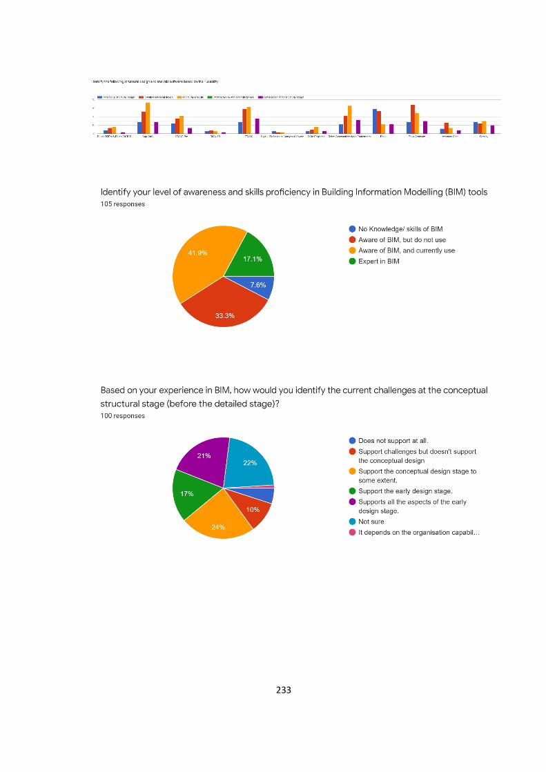
233

234

235

236
End