Automatic Generation of LEGO As- sembly Manual from 3D ...
7
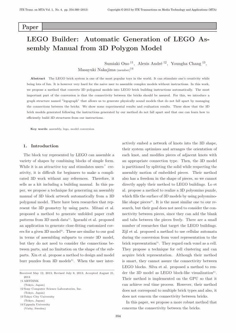
LEGO Builder: Automatic Generation of LEGO As- sembly Manual from 3D Polygon Model Sumiaki Ono †1 , Alexis Andr´ e †2 , Youngha Chang †3 , Masayuki Nakajima (member) †4 Abstract The LEGO brick system is one of the most popular toys in the world. It can stimulate one’s creativity while being lots of fun. It is however very hard for the naive user to assemble complex models without instructions. In this work, we propose a method that converts 3D polygonal models into LEGO brick building instructions automatically. The most important part of the conversion is that the connectivity between the bricks should be assured. For this, we introduce a graph structure named ”legograph” that allows us to generate physically sound models that do not fall apart by managing the connections between the bricks. We show some experimental results and evaluation results. These show that the 3D brick models generated following the instructions generated by our method do not fall apart and that one can learn how to efficiently build 3D structures from our instructions. Key words: assembly, lego, model conversion 1. Introduction The block toy represented by LEGO can assemble a variety of shapes by combining blocks of simple form. While it is an attractive toy and stimulates users ’cre- ativity, it is difficult for beginners to make a compli- cated 3D work without any references. Therefore, it sells as a kit including a building manual. In this pa- per, we propose a technique for generating an assembly manual of 3D block artwork automatically from a 3D polygonal model. There have been researches that rep- resent the 3D geometry by using parts. Mitani et al. proposed a method to generate unfolded paper craft patterns from 3D mesh data 1) . Igarashi et al. proposed an application to generate close-fitting customized cov- ers for a given 3D model 2) . These are similar to our goal in terms of assembling subparts to create 3D model, but they do not need to consider the connections be- tween parts, and no limitation on the shape of the sub- parts. Xin et al. propose a method to design and model burr puzzles from 3D models 3) . When the user inter- Received May 12, 2013; Revised July 8, 2013; Accepted August 21, 2013 †1 ARTDINK (Tokyo, Japan) †2 Sony Computer Science Laboratories, Inc. (Tokyo, Japan) †3 Tokyo City University (Tokyo, Japan) †4 Uppsala University (Visby, Sweden) actively embed a network of knots into the 3D shape, their system optimizes and arranges the orientation of each knot, and modifies pieces of adjacent knots with an appropriate connection type. Then, the 3D model is partitioned by splitting the solid while respecting the assembly motion of embedded pieces. Their method also has a freedom in the shape of pieces, so we cannot directly apply their method to LEGO buildings. Lo et al. propose a method to realize a 3D polyomino puzzle, which fills the surface of 3D models by using polyomino- like shape pieces 4) . It is the most similar one to our re- search, but their goal does not need to consider the con- nectivity between pieces, since they can add the blank and tabs between the pieces freely. There are a small number of researches that target the LEGO buildings. Zijl et al. proposed a method to use cellular automata during the conversion from voxel representation to the brick representation 5) . They regard each voxel as a cell. They propose a technique for cell clustering and can acquire brick representation. Although their method is smart, they cannot assure the connectivity between LEGO blocks. Silva et al. proposed a method to ren- der the 3D model as LEGO block-like visualization 6) . Their method is implemented on the GPU so that it can achieve real time process. However, their method does not correspond to multiple brick types and also, it does not concern the connectivity between bricks. In this paper, we propose a more robust method that concerns the connectivity between the bricks. ITE Trans. on MTA Vol. 1, No. 4, pp. 354-360 (2013) 354 Copyright © 2013 by ITE Transactions on Media Technology and Applications (MTA)
-
Upload
khangminh22 -
Category
Documents
-
view
2 -
download
0
Transcript of Automatic Generation of LEGO As- sembly Manual from 3D ...
Paper
LEGO Builder: Automatic Generation of LEGO As-
sembly Manual from 3D Polygon Model
Sumiaki Ono †1, Alexis Andre †2, Youngha Chang †3,Masayuki Nakajima (member)†4
Abstract The LEGO brick system is one of the most popular toys in the world. It can stimulate one’s creativity while
being lots of fun. It is however very hard for the naive user to assemble complex models without instructions. In this work,
we propose a method that converts 3D polygonal models into LEGO brick building instructions automatically. The most
important part of the conversion is that the connectivity between the bricks should be assured. For this, we introduce a
graph structure named ”legograph” that allows us to generate physically sound models that do not fall apart by managing
the connections between the bricks. We show some experimental results and evaluation results. These show that the 3D
brick models generated following the instructions generated by our method do not fall apart and that one can learn how to
efficiently build 3D structures from our instructions.
Key words: assembly, lego, model conversion
1. Introduction
The block toy represented by LEGO can assemble avariety of shapes by combining blocks of simple form.While it is an attractive toy and stimulates users’cre-ativity, it is difficult for beginners to make a compli-cated 3D work without any references. Therefore, itsells as a kit including a building manual. In this pa-per, we propose a technique for generating an assemblymanual of 3D block artwork automatically from a 3Dpolygonal model. There have been researches that rep-resent the 3D geometry by using parts. Mitani et al.proposed a method to generate unfolded paper craftpatterns from 3D mesh data1). Igarashi et al. proposedan application to generate close-fitting customized cov-ers for a given 3D model2). These are similar to our goalin terms of assembling subparts to create 3D model,but they do not need to consider the connections be-tween parts, and no limitation on the shape of the sub-parts. Xin et al. propose a method to design and modelburr puzzles from 3D models3). When the user inter-
Received May 12, 2013; Revised July 8, 2013; Accepted August 21,
2013
†1ARTDINK
(Tokyo, Japan)
†2 Sony Computer Science Laboratories, Inc.
(Tokyo, Japan)
†3Tokyo City University
(Tokyo, Japan)
†4Uppsala University
(Visby, Sweden)
actively embed a network of knots into the 3D shape,their system optimizes and arranges the orientation ofeach knot, and modifies pieces of adjacent knots withan appropriate connection type. Then, the 3D modelis partitioned by splitting the solid while respecting theassembly motion of embedded pieces. Their methodalso has a freedom in the shape of pieces, so we cannotdirectly apply their method to LEGO buildings. Lo etal. propose a method to realize a 3D polyomino puzzle,which fills the surface of 3D models by using polyomino-like shape pieces4). It is the most similar one to our re-search, but their goal does not need to consider the con-nectivity between pieces, since they can add the blankand tabs between the pieces freely. There are a smallnumber of researches that target the LEGO buildings.Zijl et al. proposed a method to use cellular automataduring the conversion from voxel representation to thebrick representation5). They regard each voxel as a cell.They propose a technique for cell clustering and canacquire brick representation. Although their methodis smart, they cannot assure the connectivity betweenLEGO blocks. Silva et al. proposed a method to ren-der the 3D model as LEGO block-like visualization6).Their method is implemented on the GPU so that itcan achieve real time process. However, their methoddoes not correspond to multiple brick types and also, itdoes not concern the connectivity between bricks.
In this paper, we propose a more robust method thatconcerns the connectivity between the bricks.
ITE Trans. on MTA Vol. 1, No. 4, pp. 354-360 (2013)
354
Copyright © 2013 by ITE Transactions on Media Technology and Applications (MTA)
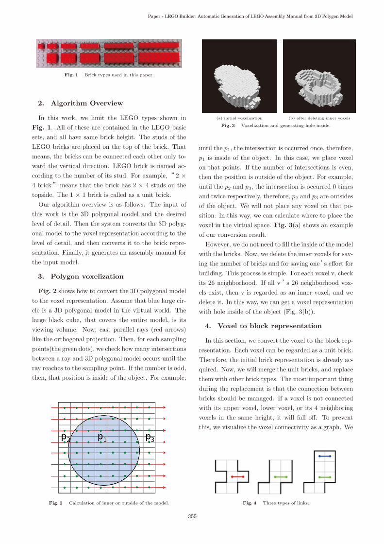
Fig. 1 Brick types used in this paper.
2. Algorithm Overview
In this work, we limit the LEGO types shown inFig. 1. All of these are contained in the LEGO basicsets, and all have same brick height. The studs of theLEGO bricks are placed on the top of the brick. Thatmeans, the bricks can be connected each other only to-ward the vertical direction. LEGO brick is named ac-cording to the number of its stud. For example,“ 2 ×4 brick”means that the brick has 2 × 4 studs on thetopside. The 1 × 1 brick is called as a unit brick.
Our algorithm overview is as follows. The input ofthis work is the 3D polygonal model and the desiredlevel of detail. Then the system converts the 3D polyg-onal model to the voxel representation according to thelevel of detail, and then converts it to the brick repre-sentation. Finally, it generates an assembly manual forthe input model.
3. Polygon voxelization
Fig. 2 shows how to convert the 3D polygonal modelto the voxel representation. Assume that blue large cir-cle is a 3D polygonal model in the virtual world. Thelarge black cube, that covers the entire model, is itsviewing volume. Now, cast parallel rays (red arrows)like the orthogonal projection. Then, for each samplingpoints(the green dots), we check how many intersectionsbetween a ray and 3D polygonal model occurs until theray reaches to the sampling point. If the number is odd,then, that position is inside of the object. For example,
Fig. 2 Calculation of inner or outside of the model.
(a) initial voxelization (b) after deleting inner voxels
Fig. 3 Voxelization and generating hole inside.
until the p1, the intersection is occurred once, therefore,p1 is inside of the object. In this case, we place voxelon that points. If the number of intersections is even,then the position is outside of the object. For example,until the p2 and p3, the intersection is occurred 0 timesand twice respectively, therefore, p2 and p3 are outsidesof the object. We will not place any voxel on that po-sition. In this way, we can calculate where to place thevoxel in the virtual space. Fig. 3(a) shows an exampleof our conversion result.
However, we do not need to fill the inside of the modelwith the bricks. Now, we delete the inner voxels for sav-ing the number of bricks and for saving one’s effort forbuilding. This process is simple. For each voxel v, checkits 26 neighborhood. If all v ’s 26 neighborhood vox-els exist, then v is regarded as an inner voxel, and wedelete it. In this way, we can get a voxel representationwith hole inside of the object (Fig. 3(b)).
4. Voxel to block representation
In this section, we convert the voxel to the block rep-resentation. Each voxel can be regarded as a unit brick.Therefore, the initial brick representation is already ac-quired. Now, we will merge the unit bricks, and replacethem with other brick types. The most important thingduring the replacement is that the connection betweenbricks should be managed. If a voxel is not connectedwith its upper voxel, lower voxel, or its 4 neighboringvoxels in the same height, it will fall off. To preventthis, we visualize the voxel connectivity as a graph. We
Fig. 4 Three types of links.
355
Paper » LEGO Builder: Automatic Generation of LEGO Assembly Manual from 3D Polygon Model
call this as legograph. In the legograph, we save threetypes of links between voxels: priority 1 link, priority 2link, and endnote link. An example of priority 1 classlink is shown in Fig. 4, left (red line). Priority 1 linkis that there exists one voxel that sticks out sideways,and it should be merged with its neighbor in the secondlayer (otherwise, it will be fall off).
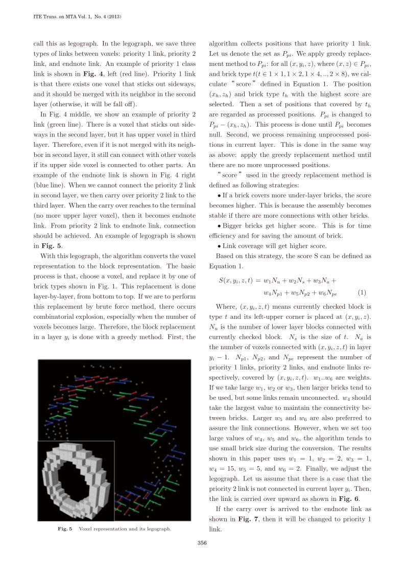
In Fig. 4 middle, we show an example of priority 2link (green line). There is a voxel that sticks out side-ways in the second layer, but it has upper voxel in thirdlayer. Therefore, even if it is not merged with its neigh-bor in second layer, it still can connect with other voxelsif its upper side voxel is connected to other parts. Anexample of the endnote link is shown in Fig. 4 right(blue line). When we cannot connect the priority 2 linkin second layer, we then carry over priority 2 link to thethird layer. When the carry over reaches to the terminal(no more upper layer voxel), then it becomes endnotelink. From priority 2 link to endnote link, connectionshould be achieved. An example of legograph is shownin Fig. 5.
With this legograph, the algorithm converts the voxelrepresentation to the block representation. The basicprocess is that, choose a voxel, and replace it by one ofbrick types shown in Fig. 1. This replacement is donelayer-by-layer, from bottom to top. If we are to performthis replacement by brute force method, there occurscombinatorial explosion, especially when the number ofvoxels becomes large. Therefore, the block replacementin a layer yi is done with a greedy method. First, the
Fig. 5 Voxel representation and its legograph.
algorithm collects positions that have priority 1 link.Let us denote the set as Ppi. We apply greedy replace-ment method to Ppi: for all (x, yi, z), where (x, z) ∈ Ppi,and brick type t(t ∈ 1 × 1, 1 × 2, 1 × 4, .., 2 × 8), we cal-culate“ score” defined in Equation 1. The position(xh, zh) and brick type th with the highest score areselected. Then a set of positions that covered by th
are regarded as processed positions. Ppi is changed toPpi − (xh, zh). This process is done until Ppi becomesnull. Second, we process remaining unprocessed posi-tions in current layer. This is done in the same wayas above: apply the greedy replacement method untilthere are no more unprocessed positions.“ score”used in the greedy replacement method is
defined as following strategies:• If a brick covers more under-layer bricks, the score
becomes higher. This is because the assembly becomesstable if there are more connections with other bricks.
• Bigger bricks get higher score. This is for timeefficiency and for saving the amount of brick.
• Link coverage will get higher score.Based on this strategy, the score S can be defined as
Equation 1.
S(x, yi, z, t) = w1Nu + w2Ns + w3Na +
w4Np1 + w5Np2 + w6Npe (1)
Where, (x, yi, z, t) means currently checked block istype t and its left-upper corner is placed at (x, yi, z).Nu is the number of lower layer blocks connected withcurrently checked block. Ns is the size of t. Na isthe number of voxels connected with (x, yi, z, t) in layeryi − 1. Np1, Np2, and Npe represent the number ofpriority 1 links, priority 2 links, and endnote links re-spectively, covered by (x, yi, z, t). w1..w6 are weights.If we take large w1, w2 or w3, then larger bricks tend tobe used, but some links remain unconnected. w4 shouldtake the largest value to maintain the connectivity be-tween bricks. Larger w5 and w6 are also preferred toassure the link connections. However, when we set toolarge values of w4, w5 and w6, the algorithm tends touse small brick size during the conversion. The resultsshown in this paper uses w1 = 1, w2 = 2, w3 = 1,w4 = 15, w5 = 5, and w6 = 2. Finally, we adjust thelegograph. Let us assume that there is a case that thepriority 2 link is not connected in current layer yi. Then,the link is carried over upward as shown in Fig. 6.
If the carry over is arrived to the endnote link asshown in Fig. 7, then it will be changed to priority 1link.
ITE Trans. on MTA Vol. 1, No. 4 (2013)
356
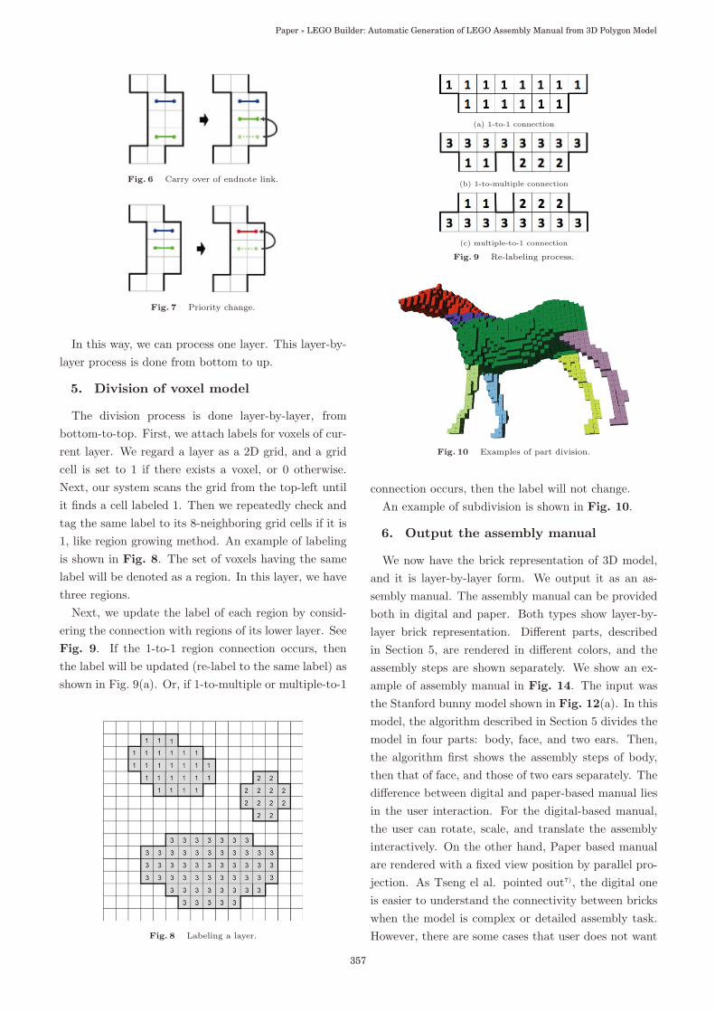
Fig. 6 Carry over of endnote link.
Fig. 7 Priority change.
In this way, we can process one layer. This layer-by-layer process is done from bottom to up.
5. Division of voxel model
The division process is done layer-by-layer, frombottom-to-top. First, we attach labels for voxels of cur-rent layer. We regard a layer as a 2D grid, and a gridcell is set to 1 if there exists a voxel, or 0 otherwise.Next, our system scans the grid from the top-left untilit finds a cell labeled 1. Then we repeatedly check andtag the same label to its 8-neighboring grid cells if it is1, like region growing method. An example of labelingis shown in Fig. 8. The set of voxels having the samelabel will be denoted as a region. In this layer, we havethree regions.
Next, we update the label of each region by consid-ering the connection with regions of its lower layer. SeeFig. 9. If the 1-to-1 region connection occurs, thenthe label will be updated (re-label to the same label) asshown in Fig. 9(a). Or, if 1-to-multiple or multiple-to-1
Fig. 8 Labeling a layer.
(a) 1-to-1 connection
(b) 1-to-multiple connection
(c) multiple-to-1 connection
Fig. 9 Re-labeling process.
Fig. 10 Examples of part division.
connection occurs, then the label will not change.An example of subdivision is shown in Fig. 10.
6. Output the assembly manual
We now have the brick representation of 3D model,and it is layer-by-layer form. We output it as an as-sembly manual. The assembly manual can be providedboth in digital and paper. Both types show layer-by-layer brick representation. Different parts, describedin Section 5, are rendered in different colors, and theassembly steps are shown separately. We show an ex-ample of assembly manual in Fig. 14. The input wasthe Stanford bunny model shown in Fig. 12(a). In thismodel, the algorithm described in Section 5 divides themodel in four parts: body, face, and two ears. Then,the algorithm first shows the assembly steps of body,then that of face, and those of two ears separately. Thedifference between digital and paper-based manual liesin the user interaction. For the digital-based manual,the user can rotate, scale, and translate the assemblyinteractively. On the other hand, Paper based manualare rendered with a fixed view position by parallel pro-jection. As Tseng el al. pointed out7), the digital oneis easier to understand the connectivity between brickswhen the model is complex or detailed assembly task.However, there are some cases that user does not want
357
Paper » LEGO Builder: Automatic Generation of LEGO Assembly Manual from 3D Polygon Model
interactions or the user wants portability of the man-ual. Therefore, we prepare both methods, and open thechoices available to the users.
7. Results and Discussion
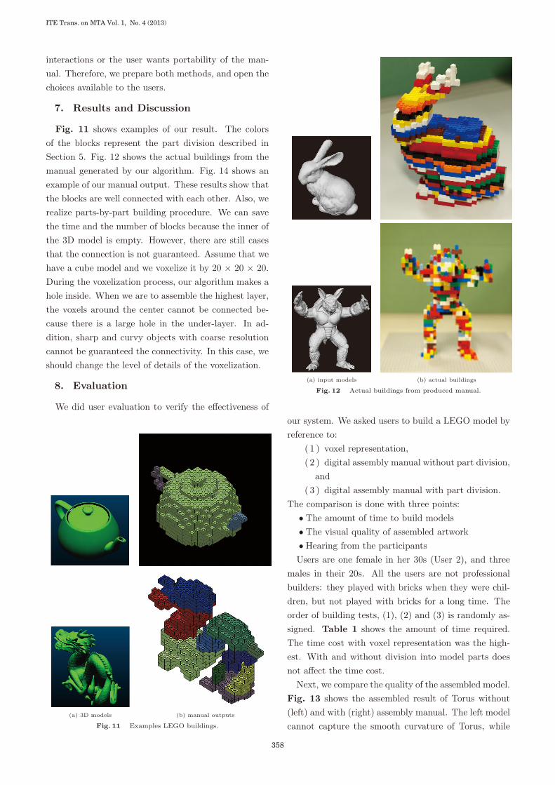
Fig. 11 shows examples of our result. The colorsof the blocks represent the part division described inSection 5. Fig. 12 shows the actual buildings from themanual generated by our algorithm. Fig. 14 shows anexample of our manual output. These results show thatthe blocks are well connected with each other. Also, werealize parts-by-part building procedure. We can savethe time and the number of blocks because the inner ofthe 3D model is empty. However, there are still casesthat the connection is not guaranteed. Assume that wehave a cube model and we voxelize it by 20 × 20 × 20.During the voxelization process, our algorithm makes ahole inside. When we are to assemble the highest layer,the voxels around the center cannot be connected be-cause there is a large hole in the under-layer. In ad-dition, sharp and curvy objects with coarse resolutioncannot be guaranteed the connectivity. In this case, weshould change the level of details of the voxelization.
8. Evaluation
We did user evaluation to verify the effectiveness of
(a) 3D models (b) manual outputs
Fig. 11 Examples LEGO buildings.
(a) input models (b) actual buildings
Fig. 12 Actual buildings from produced manual.
our system. We asked users to build a LEGO model byreference to:
( 1 ) voxel representation,( 2 ) digital assembly manual without part division,
and( 3 ) digital assembly manual with part division.
The comparison is done with three points:• The amount of time to build models• The visual quality of assembled artwork• Hearing from the participantsUsers are one female in her 30s (User 2), and three
males in their 20s. All the users are not professionalbuilders: they played with bricks when they were chil-dren, but not played with bricks for a long time. Theorder of building tests, (1), (2) and (3) is randomly as-signed. Table 1 shows the amount of time required.The time cost with voxel representation was the high-est. With and without division into model parts doesnot affect the time cost.
Next, we compare the quality of the assembled model.Fig. 13 shows the assembled result of Torus without(left) and with (right) assembly manual. The left modelcannot capture the smooth curvature of Torus, while
ITE Trans. on MTA Vol. 1, No. 4 (2013)
358
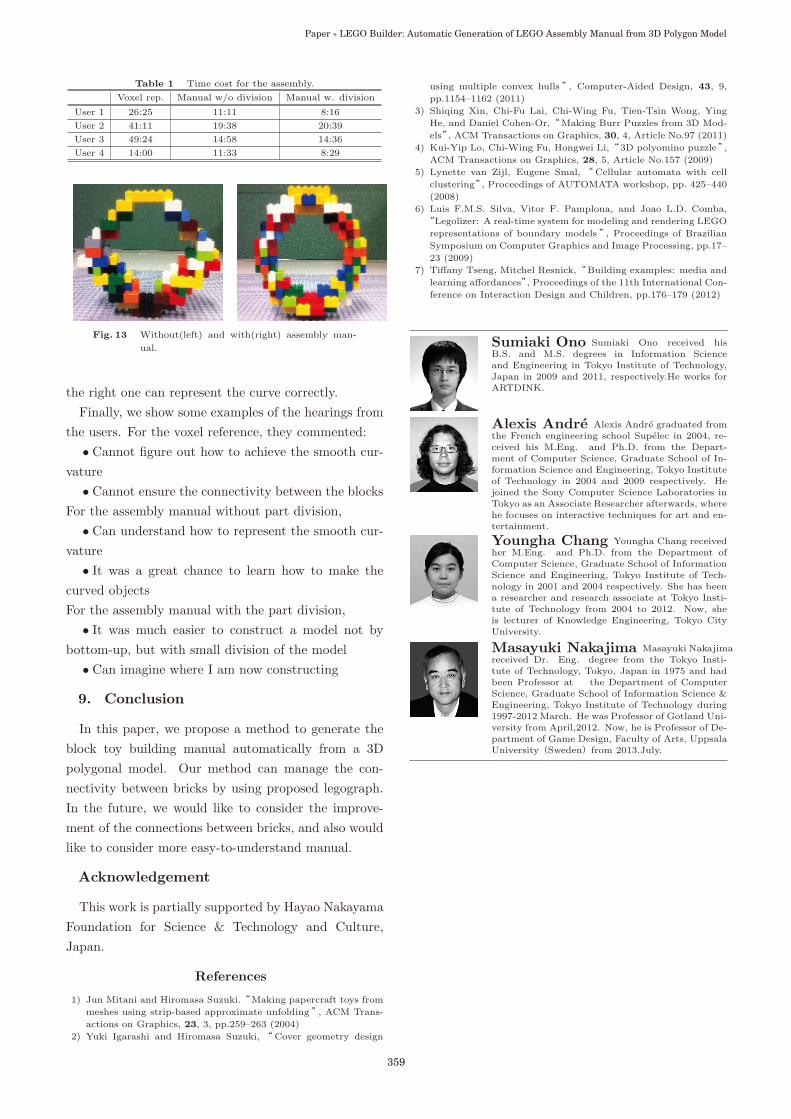
Table 1 Time cost for the assembly.
Voxel rep. Manual w/o division Manual w. division
User 1 26:25 11:11 8:16
User 2 41:11 19:38 20:39
User 3 49:24 14:58 14:36
User 4 14:00 11:33 8:29
Fig. 13 Without(left) and with(right) assembly man-
ual.
the right one can represent the curve correctly.Finally, we show some examples of the hearings from
the users. For the voxel reference, they commented:• Cannot figure out how to achieve the smooth cur-
vature• Cannot ensure the connectivity between the blocks
For the assembly manual without part division,• Can understand how to represent the smooth cur-
vature• It was a great chance to learn how to make the
curved objectsFor the assembly manual with the part division,
• It was much easier to construct a model not bybottom-up, but with small division of the model
• Can imagine where I am now constructing
9. Conclusion
In this paper, we propose a method to generate theblock toy building manual automatically from a 3Dpolygonal model. Our method can manage the con-nectivity between bricks by using proposed legograph.In the future, we would like to consider the improve-ment of the connections between bricks, and also wouldlike to consider more easy-to-understand manual.
Acknowledgement
This work is partially supported by Hayao NakayamaFoundation for Science & Technology and Culture,Japan.
References
1) Jun Mitani and Hiromasa Suzuki.“Making papercraft toys from
meshes using strip-based approximate unfolding”, ACM Trans-
actions on Graphics, 23, 3, pp.259–263 (2004)
2) Yuki Igarashi and Hiromasa Suzuki, “Cover geometry design
using multiple convex hulls”, Computer-Aided Design, 43, 9,
pp.1154–1162 (2011)
3) Shiqing Xin, Chi-Fu Lai, Chi-Wing Fu, Tien-Tsin Wong, Ying
He, and Daniel Cohen-Or,“Making Burr Puzzles from 3D Mod-
els”, ACM Transactions on Graphics, 30, 4, Article No.97 (2011)
4) Kui-Yip Lo, Chi-Wing Fu, Hongwei Li,“3D polyomino puzzle”,ACM Transactions on Graphics, 28, 5, Article No.157 (2009)
5) Lynette van Zijl, Eugene Smal, “Cellular automata with cell
clustering”, Proceedings of AUTOMATA workshop, pp. 425–440
(2008)
6) Luis F.M.S. Silva, Vitor F. Pamplona, and Joao L.D. Comba,
“Legolizer: A real-time system for modeling and rendering LEGO
representations of boundary models”, Proceedings of Brazilian
Symposium on Computer Graphics and Image Processing, pp.17–
23 (2009)
7) Tiffany Tseng, Mitchel Resnick,“Building examples: media and
learning affordances”, Proceedings of the 11th International Con-
ference on Interaction Design and Children, pp.176–179 (2012)
Sumiaki Ono Sumiaki Ono received hisB.S. and M.S. degrees in Information Scienceand Engineering in Tokyo Institute of Technology,Japan in 2009 and 2011, respectively.He works forARTDINK.
Alexis Andre Alexis Andre graduated fromthe French engineering school Supelec in 2004, re-ceived his M.Eng. and Ph.D. from the Depart-ment of Computer Science, Graduate School of In-formation Science and Engineering, Tokyo Instituteof Technology in 2004 and 2009 respectively. Hejoined the Sony Computer Science Laboratories inTokyo as an Associate Researcher afterwards, wherehe focuses on interactive techniques for art and en-tertainment.
Youngha Chang Youngha Chang receivedher M.Eng. and Ph.D. from the Department ofComputer Science, Graduate School of InformationScience and Engineering, Tokyo Institute of Tech-nology in 2001 and 2004 respectively. She has beena researcher and research associate at Tokyo Insti-tute of Technology from 2004 to 2012. Now, sheis lecturer of Knowledge Engineering, Tokyo CityUniversity.
Masayuki Nakajima Masayuki Nakajimareceived Dr. Eng. degree from the Tokyo Insti-tute of Technology, Tokyo, Japan in 1975 and hadbeen Professor at the Department of ComputerScience, Graduate School of Information Science &Engineering, Tokyo Institute of Technology during1997-2012 March. He was Professor of Gotland Uni-versity from April,2012. Now, he is Professor of De-partment of Game Design, Faculty of Arts, UppsalaUniversity(Sweden)from 2013.July.
359
Paper » LEGO Builder: Automatic Generation of LEGO Assembly Manual from 3D Polygon Model
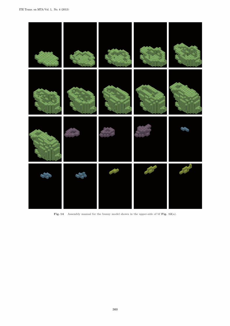
Fig. 14 Assembly manual for the bunny model shown in the upper-side of bf Fig. 12(a).
ITE Trans. on MTA Vol. 1, No. 4 (2013)
360