
Automated Real–Time Targeting and Guidance (ARTGUID) for Lunar Descent and Precision Landing
18
AAS 10-035 Automated Real–Time Targeting and Guidance (ARTGUID) for Lunar Descent and Precision Landing Brent W. Barbee and David E. Gaylor Emergent Space Technologies, Inc. !∀∀ #!# ∃ %& ∋ ∀ ((%
Transcript of Automated Real–Time Targeting and Guidance (ARTGUID) for Lunar Descent and Precision Landing
AAS 10-035
Automated Real–Time Targeting and Guidance
(ARTGUID) for Lunar Descent and Precision
Landing
Brent W. Barbee and David E. Gaylor
Emergent Space Technologies, Inc.
���������������������������������������������������������������������������������������������������������������������������������������������
�������������������� ������ ������� ������� �
���������������������������������������������������������������������������������������������������������������������������������������������
���������������������� ����� ������������������������ ��������� ����������������������
���� ������������!∀∀��� � #!#���∃��%�&�������∋���� �����∀������(��(%
AAS 10-035
AUTOMATED REAL–TIME TARGETING AND GUIDANCE
(ARTGUID) FOR LUNAR DESCENT AND PRECISION LANDING
Brent W. Barbee∗ and David E. Gaylor†
The guidance algorithms and software utilized during the Apollo missions for lunar descentand landing had fundamental limitations that precluded real–time guidance and autonomousHazard Detection and Avoidance (HDA). This was partially due to the lack of closed formguidance solutions for the major portion of the descent braking phase. Emergent SpaceTechnologies, Inc. has designed and developed prototype automated real–time targeting andguidance (ARTGUID) software for precision lunar landing and descent. Optimal control the-ory was successfully applied to produce closed form guidance solutions for the major portionof the descent braking phase. Improvements were also made to the quartic closed form so-lutions used (from Apollo) for the remainder of descent. Formulations for vehicle attitudewere also developed and implemented, allowing the evolution of the vehicle attitude to bemodeled and understood. The closed form constant thrust solutions and the improved quar-tics enabled real–time landing site re–targeting, which was demonstrated in simulation. Thisreal–time re–targeting capability will be a key technology for autonomous Hazard Detectionand Avoidance (HDA) during any future lunar landing mission.
INTRODUCTION
The guidance algorithms and software utilized during the Apollo missions for lunar descent and landing
had fundamental limitations that precluded real–time guidance and autonomous Hazard Detection and Avoid-
ance (HDA). This was partially due to the lack of closed form guidance solutions for the major portion of the
descent braking phase. HDA and the ability to target a new landing site on the fly will be key areas of interest
in the development of any future lunar landing program (be it crewed, robotic, or both).
Emergent Space Technologies, Inc. has designed and developed prototype automated real–time targeting
and guidance (ARTGUID) software for precision lunar landing and descent. The software was designed to
meet or exceed the challenging mission requirements of NASA’s ALHAT and Altair Lunar Lander projects.
Optimal control theory was successfully applied to produce closed form guidance solutions for the major
portion of the descent braking phase. This, in combination with improvements to the quartic closed form
solutions used (from Apollo) for the remainder of descent, enabled demonstrations of real–time lunar landing
site re–targeting in simulation.
Apollo-era lunar descent targeting and guidance algorithms were successfully re–validated and integrated
into ARTGUID, in conjunction with closed form, constant thrust arc solutions for the first portion of the
descent trajectory. Simulation results show that the performance of ARTGUID meets ALHAT requirements,
offering fuel-efficient and accurate lunar descent trajectory guidance.
Formulations for vehicle attitude were also developed and implemented, allowing the evolution of the
vehicle attitude to be modeled and understood. The closed form constant thrust solutions and the improved
quartics enabled real–time landing site re–targeting, which was demonstrated in simulation.
MISSION PROFILE
The mission profile considered in this work begins with the lunar lander in an initial circular orbit around
the Moon. From here, the lander transfers to an elliptical entry orbit, performing a short duration injection
∗Aerospace Engineer, Emergent Space Technologies, Inc., 6301 Ivy Lane, Suite 720, Greenbelt, MD 20770, USA.†Vice President, Emergent Space Technologies, Inc., 6301 Ivy Lane, Suite 720, Greenbelt, MD 20770, USA.
1
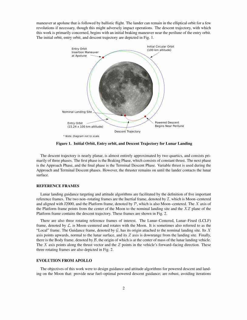
maneuver at apolune that is followed by ballistic flight. The lander can remain in the elliptical orbit for a few
revolutions if necessary, though this might adversely impact operations. The descent trajectory, with which
this work is primarily concerned, begins with an initial braking maneuver near the perilune of the entry orbit.
The initial orbit, entry orbit, and descent trajectory are depicted in Fig. 1.
Figure 1. Initial Orbit, Entry orbit, and Descent Trajectory for Lunar Landing
The descent trajectory is nearly planar, is almost entirely approximated by two quartics, and consists pri-
marily of three phases. The first phase is the Braking Phase, which consists of constant thrust. The next phase
is the Approach Phase, and the final phase is the Terminal Descent Phase. Variable thrust is used during the
Approach and Terminal Descent phases. However, the thruster remains on until the lander contacts the lunar
surface.
REFERENCE FRAMES
Lunar landing guidance targeting and attitude algorithms are facilitated by the definition of five important
reference frames. The two non–rotating frames are the Inertial frame, denoted by I, which is Moon–centered
and aligned with J2000, and the Platform frame, denoted by P , which is also Moon–centered. The X axis of
the Platform frame points from the center of the Moon to the nominal landing site and the XZ plane of the
Platform frame contains the descent trajectory. These frames are shown in Fig. 2.
There are also three rotating reference frames of interest. The Lunar–Centered, Lunar–Fixed (LCLF)
frame, denoted by L, is Moon–centered and rotates with the Moon. It is sometimes also referred to as the
“Local” frame. The Guidance frame, denoted by G, has its origin attached to the nominal landing site. Its Xaxis points upwards, normal to the lunar surface, and its Z axis is downrange from the landing site. Finally,
there is the Body frame, denoted by B, the origin of which is at the center of mass of the lunar landing vehicle.
The X axis points along the thrust vector and the Z points in the vehicle’s forward–facing direction. These
three rotating frames are also depicted in Fig. 2.
EVOLUTION FROM APOLLO
The objectives of this work were to design guidance and attitude algorithms for powered descent and land-
ing on the Moon that: provide near fuel–optimal powered descent guidance; are robust, avoiding iterations
2
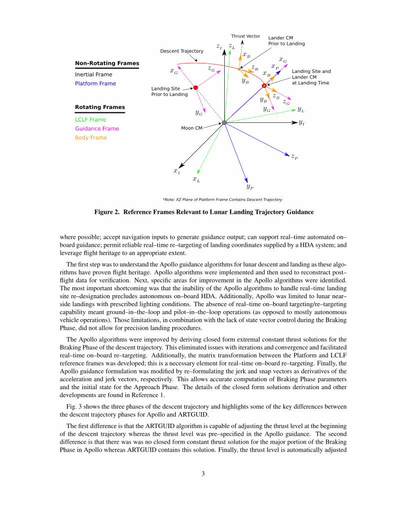
Figure 2. Reference Frames Relevant to Lunar Landing Trajectory Guidance
where possible; accept navigation inputs to generate guidance output; can support real–time automated on–
board guidance; permit reliable real–time re–targeting of landing coordinates supplied by a HDA system; and
leverage flight heritage to an appropriate extent.
The first step was to understand the Apollo guidance algorithms for lunar descent and landing as these algo-
rithms have proven flight heritage. Apollo algorithms were implemented and then used to reconstruct post–
flight data for verification. Next, specific areas for improvement in the Apollo algorithms were identified.
The most important shortcoming was that the inability of the Apollo algorithms to handle real–time landing
site re–designation precludes autonomous on–board HDA. Additionally, Apollo was limited to lunar near–
side landings with prescribed lighting conditions. The absence of real–time on–board targeting/re–targeting
capability meant ground–in–the–loop and pilot–in–the–loop operations (as opposed to mostly autonomous
vehicle operations). Those limitations, in combination with the lack of state vector control during the Braking
Phase, did not allow for precision landing procedures.
The Apollo algorithms were improved by deriving closed form extremal constant thrust solutions for the
Braking Phase of the descent trajectory. This eliminated issues with iterations and convergence and facilitated
real–time on–board re–targeting. Additionally, the matrix transformation between the Platform and LCLF
reference frames was developed; this is a necessary element for real–time on–board re–targeting. Finally, the
Apollo guidance formulation was modified by re–formulating the jerk and snap vectors as derivatives of the
acceleration and jerk vectors, respectively. This allows accurate computation of Braking Phase parameters
and the initial state for the Approach Phase. The details of the closed form solutions derivation and other
developments are found in Reference 1.
Fig. 3 shows the three phases of the descent trajectory and highlights some of the key differences between
the descent trajectory phases for Apollo and ARTGUID.
The first difference is that the ARTGUID algorithm is capable of adjusting the thrust level at the beginning
of the descent trajectory whereas the thrust level was pre–specified in the Apollo guidance. The second
difference is that there was was no closed form constant thrust solution for the major portion of the Braking
Phase in Apollo whereas ARTGUID contains this solution. Finally, the thrust level is automatically adjusted
3
Figure 3. Comparison of ARTGUID and Apollo Trajectory Profiles
by the algorithm for the remainder of the Braking Phase in ARTGUID whereas it was pre–specified in Apollo.
VEHICLE ATTITUDE
In this section we develop the algorithm that computes the commanded attitude of the lunar lander resulting
from the outputs of the descent trajectory guidance algorithm. Relevant reference frames are defined, along
with the representations of the lander attitude, which include Euler angles and quaternions. The structure and
features of the attitude algorithm are discussed throughout.
Attitude Nomenclature
Quaternions are represented by a boldface, italicized, lowercase letter q that is superscripted with the
symbol denoting the frame from which the quaternion transforms and subscripted with the symbol denoting
the frame to which the quaternion transforms. For example, qAB transforms from the A frame to the B frame.
Similarly, transformation matrices are represented by the uppercase letter T and are superscripted with the
symbol denoting the frame from which the matrix transforms and subscripted with the symbol denoting the
frame to which the matrix transforms. For example, TAB transforms from the A frame to the B frame.
Angular velocity vectors are denoted by ~ω and are superscripted to indicate what they represent. For
instance, ~ωA/B is the angular velocity vector of the A frame with respect to the B frame.
Attitude Reference Frames
Fig. 4 shows the guidance frame, G, with basis vectors gx, gy , and gz along with the body frame, B, in its
zero orientation at the time of landing. The B frame has basis vectors bx, by , and bz . The 0 superscripts on
the B frame basis vectors indicate that the B frame is shown in its zero orientation.
4
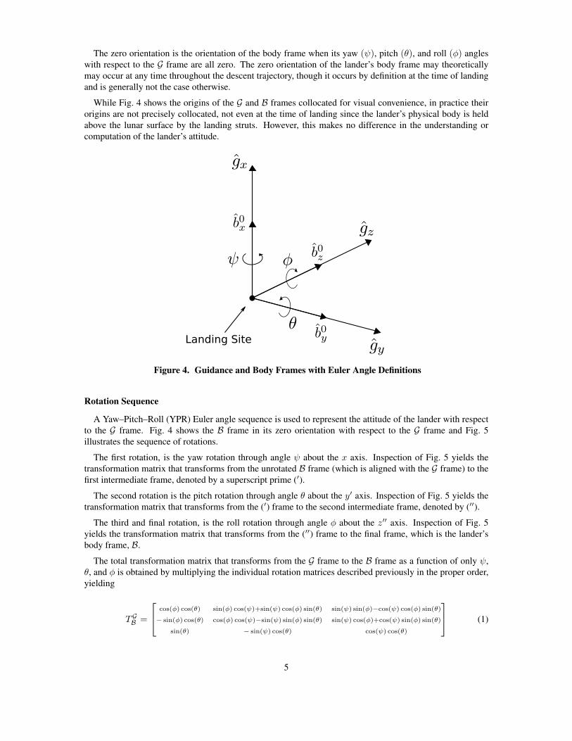
The zero orientation is the orientation of the body frame when its yaw (ψ), pitch (θ), and roll (φ) angles
with respect to the G frame are all zero. The zero orientation of the lander’s body frame may theoretically
may occur at any time throughout the descent trajectory, though it occurs by definition at the time of landing
and is generally not the case otherwise.
While Fig. 4 shows the origins of the G and B frames collocated for visual convenience, in practice their
origins are not precisely collocated, not even at the time of landing since the lander’s physical body is held
above the lunar surface by the landing struts. However, this makes no difference in the understanding or
computation of the lander’s attitude.
Figure 4. Guidance and Body Frames with Euler Angle Definitions
Rotation Sequence
A Yaw–Pitch–Roll (YPR) Euler angle sequence is used to represent the attitude of the lander with respect
to the G frame. Fig. 4 shows the B frame in its zero orientation with respect to the G frame and Fig. 5
illustrates the sequence of rotations.
The first rotation, is the yaw rotation through angle ψ about the x axis. Inspection of Fig. 5 yields the
transformation matrix that transforms from the unrotated B frame (which is aligned with the G frame) to the
first intermediate frame, denoted by a superscript prime (′).
The second rotation is the pitch rotation through angle θ about the y′ axis. Inspection of Fig. 5 yields the
transformation matrix that transforms from the (′) frame to the second intermediate frame, denoted by (′′).
The third and final rotation, is the roll rotation through angle φ about the z′′ axis. Inspection of Fig. 5
yields the transformation matrix that transforms from the (′′) frame to the final frame, which is the lander’s
body frame, B.
The total transformation matrix that transforms from the G frame to the B frame as a function of only ψ,
θ, and φ is obtained by multiplying the individual rotation matrices described previously in the proper order,
yielding
TGB =
cos(φ) cos(θ) sin(φ) cos(ψ)+sin(ψ) cos(φ) sin(θ) sin(ψ) sin(φ)−cos(ψ) cos(φ) sin(θ)
− sin(φ) cos(θ) cos(φ) cos(ψ)−sin(ψ) sin(φ) sin(θ) sin(ψ) cos(φ)+cos(ψ) sin(φ) sin(θ)
sin(θ) − sin(ψ) cos(θ) cos(ψ) cos(θ)
(1)
5
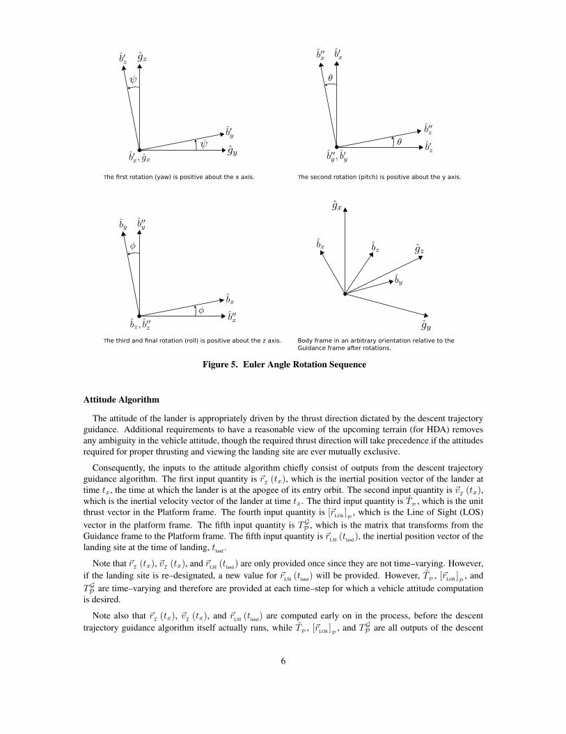
Figure 5. Euler Angle Rotation Sequence
Attitude Algorithm
The attitude of the lander is appropriately driven by the thrust direction dictated by the descent trajectory
guidance. Additional requirements to have a reasonable view of the upcoming terrain (for HDA) removes
any ambiguity in the vehicle attitude, though the required thrust direction will take precedence if the attitudes
required for proper thrusting and viewing the landing site are ever mutually exclusive.
Consequently, the inputs to the attitude algorithm chiefly consist of outputs from the descent trajectory
guidance algorithm. The first input quantity is ~rI
(tx), which is the inertial position vector of the lander at
time tx, the time at which the lander is at the apogee of its entry orbit. The second input quantity is ~vI
(tx),which is the inertial velocity vector of the lander at time tx. The third input quantity is T
P, which is the unit
thrust vector in the Platform frame. The fourth input quantity is [~rLOS
]P
, which is the Line of Sight (LOS)
vector in the platform frame. The fifth input quantity is TGP , which is the matrix that transforms from the
Guidance frame to the Platform frame. The fifth input quantity is ~rLSI
(tland
), the inertial position vector of the
landing site at the time of landing, tland
.
Note that ~rI
(tx), ~vI(tx), and ~r
LSI(t
land) are only provided once since they are not time–varying. However,
if the landing site is re–designated, a new value for ~rLSI
(tland
) will be provided. However, TP
, [~rLOS
]P
, and
TGP are time–varying and therefore are provided at each time–step for which a vehicle attitude computation
is desired.
Note also that ~rI
(tx), ~vI(tx), and ~r
LSI(t
land) are computed early on in the process, before the descent
trajectory guidance algorithm itself actually runs, while TP
, [~rLOS
]P
, and TGP are all outputs of the descent
6

trajectory guidance algorithm itself.
The complete attitude calculation algorithm is presented as a flowchart in Fig. 6 and each step in the process
is developed and discussed in turn.
Figure 6. Attitude Algorithm Flowchart
Platform to Inertial Transformation
The matrix that transforms from the Platform frame to the Inertial frame, TPI , is only computed once in
the beginning since it is constant. However, if re–designation of the landing site occurs this matrix must be
recomputed. TPI is computed as follows1
ux =~r
LSI(t
land)
‖~rLSI
(tland
)‖(2)
uz =(~r
I(tx) × ~v
I(tx)) × ux
‖(~rI
(tx) × ~vI
(tx)) × ux‖(3)
uy = uz × ux (4)
TPI =
(ux)T
(uy)T
(uz)T
(5)
Unit Window Vector
The unit window vector, W , is defined such that its usage in the construction of the lander body frame
vectors will cause the lander to be oriented so that its thruster is pointing in the direction specified by the
7
guidance algorithm and the lander will be viewing the landing site. If those two conditions are ever mutually
exclusive, the thrust direction takes precedence and the unit window vector acts to keep the lander in a
“forward–facing” attitude with respect to the landing site.
This is necessary because the dominant constraint on the lander’s attitude is the orientation of the thrust
vector, as commanded by the guidance algorithm. Once the lander has adjusted its attitude such that the
thrust vector is properly aligned, the lander may then spin about the thrust axis in an arbitrary fashion unless
an additional constraint is imposed to disambiguate the spin angle about the thrust axis.
The unit window vector was defined by Klumpp for the Apollo program.2 In practice, a particular lander
attitude profile design for any future lunar exploration program will require careful consideration of the
specific design of the lander vehicle in terms of the body frame locations and orientations, and fields of view,
of sensors and crew view–ports. However, for now the unit window vector is useful as a placeholder to
facilitate preliminary attitude analysis. The unit window vector is computed as follows.2
(
TBP
)
xis the first row of the matrix that transforms from the body frame to the platform frame, P , and is
equal to the unit thrust vector in the platform frame, TP
, by definition. Let(
TGP
)
ybe the second row of the
matrix that transforms from the guidance frame, G to the platform frame. Then,
F =T
P×(
(
TGP
)
y
)T
||TP×(
(
TGP
)
y
)T
||
(6)
where F is the “forward” vector. Next, the projection, p, of the cross product of the line of sight vector and
the unit thrust vector onto the second row of the guidance to platform transformation matrix is computed as
p =(
[rLOS
]P× T
P
)
·(
TGP
)
y(7)
Finally, the unit window vector is computed as a linear combination of the LOS vector and the “forward”
vector, depending on the magnitude of the projection, p, as follows
W = max (p− cos (65◦) , 0) [rLOS
]P
+ max (cos (75◦) − p, 0) F (8)
The result ensures that when W is used to construct the commanded body frame, along with the unit
thrust vector, TP
, the lander will be in a forward–facing posture with respect to the landing site to the extent
possible. Note that the LOS vector is unitized in the above calculations. The relevant geometry for the unit
window vector is shown in Fig. 7.
Body to Platform Transformation
Let the unit basis vectors of the vehicle body frame, B, be specified as bx, by , and bz . These basis vectors
are computed as follows1
bx = T (9)
by = W × bx (10)
bz = bx × by (11)
where T is the unit thrust vector in the platform frame and W is the unit window vector.
Next, these basis vectors become the rows of the matrix that transforms from the platform frame, P , to the
body frame.
8
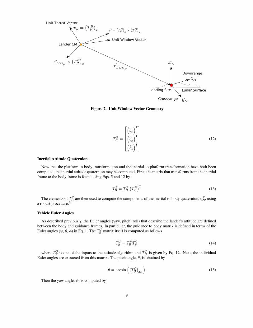
Figure 7. Unit Window Vector Geometry
TPB =
(
bx
)T
(
by
)T
(
bz
)T
(12)
Inertial Attitude Quaternion
Now that the platform to body transformation and the inertial to platform transformation have both been
computed, the inertial attitude quaternion may be computed. First, the matrix that transforms from the inertial
frame to the body frame is found using Eqs. 5 and 12 by
T IB = TP
B
(
TPI
)T(13)
The elements of T IB are then used to compute the components of the inertial to body quaternion, qI
B, using
a robust procedure.3
Vehicle Euler Angles
As described previously, the Euler angles (yaw, pitch, roll) that describe the lander’s attitude are defined
between the body and guidance frames. In particular, the guidance to body matrix is defined in terms of the
Euler angles (ψ, θ, φ) in Eq. 1. The TGB matrix itself is computed as follows
TGB = TP
B TGP (14)
where TGP is one of the inputs to the attitude algorithm and TP
B is given by Eq. 12. Next, the individual
Euler angles are extracted from this matrix. The pitch angle, θ, is obtained by
θ = arcsin(
(
TGB
)
3,1
)
(15)
Then the yaw angle, ψ, is computed by
9

ψ = atan2
(
−
(
TGB
)
3,2
cos (θ),
(
TGB
)
3,3
cos (θ)
)
(16)
Finally, the roll angle, φ, is given by
φ = atan2
(
−
(
TGB
)
2,1
cos (θ),
(
TGB
)
1,1
cos (θ)
)
(17)
However, for the non–degenerate case of cos (θ) 6= 0, there are always two equivalent sets of Euler angles
that specify a given attitude∗. Therefore a consistency check is necessary in order to avoid false discontinuities
in the time histories of the Euler angles. This consistency check is performed as follows.
If
∣
∣
∣|θ| −
∣
∣
∣atan2
(
cos (ψ)(
TGB
)
3,1,(
TGB
)
3,3
)∣
∣
∣
∣
∣
∣> cos (θ), then the second solution for pitch, equal to π−θ,
is used and the ψ and φ angles are recomputed, using this new value of θ in Eqs. 16 and 17.
This consistency check compares the difference between two methods of computing the pitch angle to the
cosine of the first method of pitch angle computation, Eq. 15, because the numerical accuracy required to
discriminate between the two pitch angle values should be about the same order of magnitude as the gimbal
lock condition itself, i.e., cos (θ). Note that yaw and roll are corrected to vary between 0◦ and 360◦ as a
convention since the output of the atan2 function is between −π and π radians.
Attitude Rates
Attitude rates are computed in three forms: quaternion rates, angular velocity vector, and Euler angle rates.
The quaternion rates and Euler angle rates are computed by differencing and the angular velocity vector is
computed using the quaternion and its rates. For quaternion rates and the angular velocity vector, the rates
represent the rate of rotational motion of the B frame with respect to the I frame. The Euler angle rates
describe the time rate of change of the Euler angles, which represent the orientation of the B frame with
respect to the G frame. However, it is important to note that these Euler angle rates do not directly equate to
the angular velocity of the B frame with respect to the G frame.
Quaternion Rates The time rate of change of the inertial attitude quaternion is determined by computing
the first time derivative of each of the four quaternion components via forward finite differences according to
qi (tn) =d
dt(qi)
∣
∣
∣
∣
t=tn
=∆qi∆t
=qin+1
− qintn+1 − tn
(18)
where i = 1, 2, 3, 4 and n = 1, 2, ..., (N − 1) if there are N elements in the data series. ∆qi is the change
occurring in the ith quaternion component during the data series time step, ∆t. Note that ∆t is not assumed
constant and is instead computed individually between each two consecutive time values.
Angular Velocity The quaternion components and their rates are then utilized to compute the angular ve-
locity vector of the body frame with respect to the inertial frame as follows4
ωB/Ix = 2 (q1q4 + q2q3 − q3q2 − q4q1) (19)
ωB/Iy = 2 (q2q4 + q3q1 − q1q3 − q4q2) (20)
ωB/Iz = 2 (q3q4 + q1q2 − q2q1 − q4q3) (21)
where
∗Slabaugh, G., “Computing Euler Angles From a Rotation Matrix,” http://home.comcast.net/˜greg_slabaugh/
publications/euler.pdf, August 1999.
10

~ωB/I =
ωB/Ix
ωB/Iy
ωB/Iz
(22)
Since the quaternion components and their rates are computed at each time step, the components of the
angular velocity vector are also computed at each time step.
Euler Angle Rates Just as with the quaternion rates described above, the time rates of change of the Euler
angles are determined by computing the first time derivative of each of the three Euler angles via forward
finite differences according to
ψ (tn) =d
dt(ψ)
∣
∣
∣
∣
t=tn
=∆ψ
∆t=ψn+1 − ψntn+1 − tn
(23)
θ (tn) =d
dt(θ)
∣
∣
∣
∣
t=tn
=∆θ
∆t=θn+1 − θntn+1 − tn
(24)
φ (tn) =d
dt(φ)
∣
∣
∣
∣
t=tn
=∆φ
∆t=φn+1 − φntn+1 − tn
(25)
Logic has been included in the Euler angle rate calculations to exclude non–existent rates due to wrap–
around between 0◦ and 360◦.
HAZARD DETECTION AND AVOIDANCE (HDA)
The capability to have real–time on–board landing site re–targeting within the descent trajectory guidance
algorithms is essential for the “avoidance” portion of Hazard Detection and Avoidance (HDA) and can be
executed in an autonomous, semi–autonomous, or largely piloted (with the ground still in the loop) manner.
The goal of HDA is to detect features of the landing site terrain (e.g., uneven terrain, boulders, etc.) that
might pose a risk of damage to the vehicle upon landing.5
An HDA system, separate from guidance, is responsible detecting any hazards or anomalies and for re–
designating the landing site in the event that a hazard or anomaly is detected. The guidance system has two
key complimentary responsibilities.
Firstly, guidance is responsible for ensuring that the HDA sensors have an adequate view of the terrain
at and near the landing site. This is accomplished by keeping the thruster pointed in the proper direction
to bring the lander to the designated landing coordinates while simultaneously ensuring that the landing
vehicle’s attitude provides a favorable look angle to the landing site, the geometry for which is shown in
Fig. 8. This will keep the landing site and surrounding terrain within the fields of view of the HDA sensors.
Secondly, guidance is responsible for executing re–targeting whenever the landing site is re–designated by
the HDA system. As shown in Fig. 9, this process of re–targeting a re–designated landing site might occur
multiple times during the descent if multiple landing hazards are detected. Unless a given re–designated
landing site is identically downrange of the previously designated landing site, the trajectory that takes the
landing vehicle from its current position to the new landing site will generally lie in a different plane than the
plane of the previous landing trajectory up to the point of landing site re–designation and re–targeting.
11
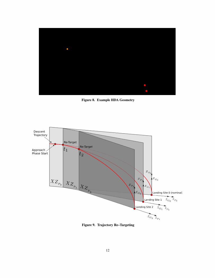
Figure 8. Example HDA Geometry
Figure 9. Trajectory Re–Targeting
12
RESULTS
The ARTGUID descent trajectory guidance and attitude algorithms were applied to a representative lunar
landing scenario, and the landing site was re–targeted at several points throughout the descent to demonstrate
this capability in support of HDA. It is assumed that the HDA system is handling the detection of hazards and
the selection of alternate landing sites; ARTGUID is simply re–targeting the descent trajectory each time the
landing site coordinates change.
Guidance Simulation Results
The lander begins in a 100 km circular orbit about the Moon and injects into a 100 × 15.24 km entry
orbit at apolune. The injection maneuver is modeled as impulsive and the rocket equation is used for the
mass evolution. The lander’s mass prior to the entry orbit injection maneuver is 33, 300 kg and the lander’s
Descent Propulsion System (DPS) thruster is assumed to be capable of providing up to 83, 000 N of thrust;
the minimum thrust is assumed to be 11% of the maximum thrust. The DPS thruster is assumed to have a
specific impulse of 446.9 seconds.
The time of entry orbit insertion is March 18th, 2024 at 15:385:17.674 UTC and the nominal landing site is
in the vicinity of Shackleton crater, near the Moon’s south pole. The coordinates of the landing site are −89◦
selenocentric latitude, 0◦ selenocentric longitude, and the altitude of the landing site is −2000 m.
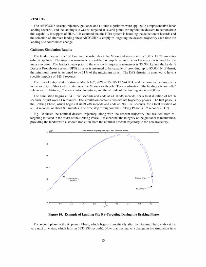
The simulation begins at 3419.738 seconds and ends at 4110.338 seconds, for a total duration of 690.6seconds, or just over 11.5 minutes. The simulation contains two distinct trajectory phases. The first phase is
the Braking Phase, which begins at 3419.738 seconds and ends at 3933.138 seconds, for a total duration of
513.4 seconds, or about 8.5 minutes. The time step throughout the Braking Phase is 0.2 seconds (5 Hz).
Fig. 10 shows the nominal descent trajectory, along with the descent trajectory that resulted from re–
targeting initiated in the midst of the Braking Phase. It is clear that the integrity of the guidance is maintained,
providing the lander with a smooth transition from the nominal descent trajectory to the new trajectory.
−2 −1.8 −1.6 −1.4 −1.2 −1 −0.8 −0.6 −0.4 −0.2
x 10
1.738
1.74
1.742
1.744
1.746
1.748
1.75x 10
6
Zp, m.
Real−time re−targeting on BP (MT arc). Platform frame.
New target
Original targetRe−targetinginitiation
Figure 10. Example of Landing Site Re–Targeting During the Braking Phase
The second phase is the Approach Phase, which begins immediately after the Braking Phase ends (at the
very next time step, which falls on 3933.238 seconds). Note that this marks a change in the simulation time
13
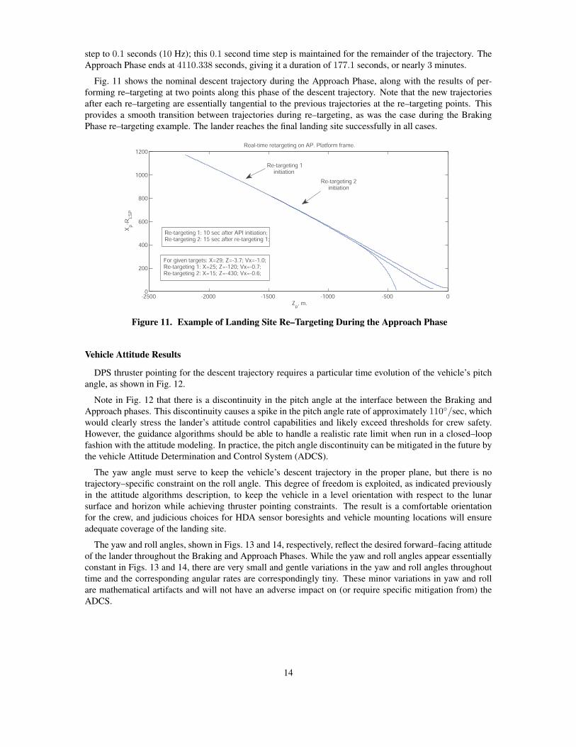
step to 0.1 seconds (10 Hz); this 0.1 second time step is maintained for the remainder of the trajectory. The
Approach Phase ends at 4110.338 seconds, giving it a duration of 177.1 seconds, or nearly 3 minutes.
Fig. 11 shows the nominal descent trajectory during the Approach Phase, along with the results of per-
forming re–targeting at two points along this phase of the descent trajectory. Note that the new trajectories
after each re–targeting are essentially tangential to the previous trajectories at the re–targeting points. This
provides a smooth transition between trajectories during re–targeting, as was the case during the Braking
Phase re–targeting example. The lander reaches the final landing site successfully in all cases.
-2500 -2000 -1500 -1000 -500 00
200
400
600
800
1000
1200
Zp, m.
Xp-R
LS
P
Real-time retargeting on AP. Platform frame.
Re-targeting 1initiation
Re-targeting 2initiation
Re-targeting 1: 10 sec after API initiation;Re-targeting 2: 15 sec after re-targeting 1;
For given targets: X=29; Z=-3.7; Vx=-1.0; Re-targeting 1: X=25; Z=-120; Vx=-0.7;Re-targeting 2: X=15; Z=-430; Vx=-0.6;
Figure 11. Example of Landing Site Re–Targeting During the Approach Phase
Vehicle Attitude Results
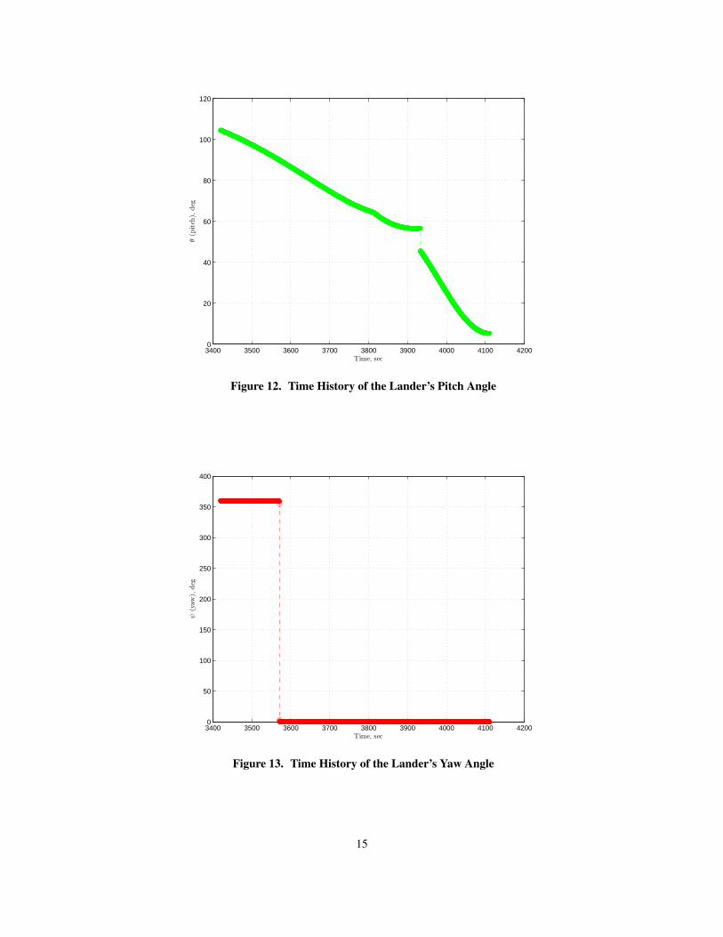
DPS thruster pointing for the descent trajectory requires a particular time evolution of the vehicle’s pitch
angle, as shown in Fig. 12.
Note in Fig. 12 that there is a discontinuity in the pitch angle at the interface between the Braking and
Approach phases. This discontinuity causes a spike in the pitch angle rate of approximately 110◦/sec, which
would clearly stress the lander’s attitude control capabilities and likely exceed thresholds for crew safety.
However, the guidance algorithms should be able to handle a realistic rate limit when run in a closed–loop
fashion with the attitude modeling. In practice, the pitch angle discontinuity can be mitigated in the future by
the vehicle Attitude Determination and Control System (ADCS).
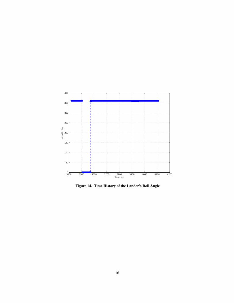
The yaw angle must serve to keep the vehicle’s descent trajectory in the proper plane, but there is no
trajectory–specific constraint on the roll angle. This degree of freedom is exploited, as indicated previously
in the attitude algorithms description, to keep the vehicle in a level orientation with respect to the lunar
surface and horizon while achieving thruster pointing constraints. The result is a comfortable orientation
for the crew, and judicious choices for HDA sensor boresights and vehicle mounting locations will ensure
adequate coverage of the landing site.
The yaw and roll angles, shown in Figs. 13 and 14, respectively, reflect the desired forward–facing attitude
of the lander throughout the Braking and Approach Phases. While the yaw and roll angles appear essentially
constant in Figs. 13 and 14, there are very small and gentle variations in the yaw and roll angles throughout
time and the corresponding angular rates are correspondingly tiny. These minor variations in yaw and roll
are mathematical artifacts and will not have an adverse impact on (or require specific mitigation from) the
ADCS.
14
3400 3500 3600 3700 3800 3900 4000 4100 42000
20
40
60
80
100
120
Time, sec
θ(p
itch
),deg
Figure 12. Time History of the Lander’s Pitch Angle
3400 3500 3600 3700 3800 3900 4000 4100 42000
50
100
150
200
250
300
350
400
Time, sec
ψ(y
aw),
deg
Figure 13. Time History of the Lander’s Yaw Angle
15
3400 3500 3600 3700 3800 3900 4000 4100 42000
50
100
150
200
250
300
350
400
Time, sec
φ(r
oll)
,deg
Figure 14. Time History of the Lander’s Roll Angle
16
CONCLUSION
The lunar landing guidance algorithms have been understood and improved upon by combining new closed
form solutions with upgraded quartic formulations. This advancement avoids iterative convergence issues
and allows for real–time re–targeting, which enables autonomous on–board Hazard Detection and Avoidance
(HDA). Furthermore, attitude routines have been developed and integrated into the descent trajectory com-
putation flow. This also serves to facilitate HDA by enabling the descent guidance system to ensure that
the vehicle attitude provides all relevant sensors (and crew viewports) with a proper view of the landing site
whilst satisfying thruster pointing requirements.
Future Work
Future work for this project includes: robustness studies to assess the relationship between how far a new
target landing site can be from the original target when re–targeting is initiated; integration of ARTGUID into
a high–fidelity closed–loop 6–DOF GNC simulation environment); investigations of ARTGUID algorithm
robustness to dispersions from navigation and control; modeling of HDA in action; comparison of results to
other lunar landing descent guidance algorithms such as Powered Explicit Guidance (PEG); assessment of
the feasibility and benefits of closed form solutions for the Approach Phase; and trade studies to determine
sensitivity of ARTGUID performance to variations in key parameters.
ACKNOWLEDGMENT
The work presented in this paper was performed under NASA Phase 1 Small Business Innovative Research
(SBIR) contract NNX09CE29P. The authors would like to acknowledge the support of the NASA Johnson
Space Center and especially Ron Sostaric for making it possible for us to work on this challenging problem.
REFERENCES
[1] R. Bishop and D. Azimov, “Enhanced Apollo Targeting and Guidance for Pin–Point Landing,” NewTrends in Astrodynamics and Applications V, Milan, Italia, June 2008.
[2] A. Klumpp, “Apollo Lunar-Descent Guidance,” Tech. Rep. R-695, Massachusetts Institute of Technol-ogy, Cambridge, MA, June 1971.
[3] J. Wertz, ed., Spacecraft Attitude Determination and Control, p. 415. Boston: Kluwer Academic Pub-lishers, 1978.
[4] B. Wie, Space Vehicle Dynamics and Control. Reston, VA: American Institute of Aeronautics and As-tronautics, 1998.
[5] S. Paschall, T. Brady, T. Fill, and R. Sostaric, “Lunar Landing Trajectory Design for Onboard Hazard De-
tection & Avoidance,” 32nd Annual AAS Guidance and Control Conference, Breckenridge, CO, February2009.
17