
Automated analysis of feature models 20 years later: A literature review
24
Automated Analysis of Feature Models 20 Years Later: A Literature Review ✩ David Benavides, Sergio Segura and Antonio Ruiz-Cort´ es Dpto. de Lenguajes y Sistemas Inform ´ aticos, University of Seville Av. Reina Mercedes s/n, 41012, Seville - Spain Abstract Software product line engineering is about producing a set of related products that share more commonalities than variabilities. Feature models are widely used for variability and commonality management in software product lines. Feature models are information models where a set of products are represented as a set of features in a single model. The automated analysis of feature models deals with the computer–aided extraction of information from feature models. The literature on this topic has contributed with a set of operations, techniques, tools and empirical results which have not been surveyed until now. This paper provides a comprehensive literature review on the automated analysis of feature models 20 years after of their invention. This paper contributes by bringing together previously-disparate streams of work to help shed light on this thriving area. We also present a conceptual framework to understand the different proposals as well as categorise future contributions. We finally discuss the different studies and propose some challenges to be faced in the future. Key words: Feature models, automated analyses, software product lines, literature review 1. Introduction Mass production is defined as the production of a large amount of standardized products using stan- dardized processes that produce a large volume of the same product in a reduced time to market. Gener- ally, the customers’ requirements are the same and no customization is performed (think of Japanese watches of the nineties). After the industrial revolu- tion, large companies started to organise –and are still organising– their production in a mass production en- vironment. However, in this highly competitive and segmented market, mass production is not enough anymore and mass customization is due to become a must for mar- ket success. According to Tseng and Jiao [83], mass customization is about “producing goods and services to meet individual customer’s needs with near mass production efficiency”. There are two key parts in this definition. Firstly, mass customization aims to meet as many individual customer’s needs as possible (imag- ine current mobile phones). Secondly, this has to be done while maintaining the highest mass production efficiency as possible. To achieve this efficiency, prac- ✩ A very preliminay version of this paper was published in Jor- nadas de Ingenier´ ıa del Software y Bases de Datos (JISBD’06) Email address: {benavides,sergiosegura,aruiz}@us.es (David Benavides, Sergio Segura and Antonio Ruiz-Cort´ es) titioners propose building products from existing as- sets that share more commonalities than singularities. The information systems market is a peculiar branch of industry compared to more traditional branches. Making the parallelism with the history of traditional industries, the industrialization of informa- tion systems started with artisanal methods, evolved to mass production and is now pursuing mass cus- tomization to succeed in the market. In the software engineering literature, the mass customization of soft- ware products is known as software product lines [24] or software product families [62]. In order to achieve customer’s personalization, software product line en- gineering promotes the production of a family of soft- ware products from common features instead of pro- ducing them one by one from scratch. This is the key change: software product line engineering is about producing families of similar systems rather than the production of individual systems. Software product lines have found a broad adop- tion in several branches of software production such as embedded systems for mobile devices, car embed- ded software and avionics [85]. However, adopting other types of software and systems applications such as desktop, web or data–intensive applications is a cur- rent challenge. An organisation decides to set up a software product line and faces the following issues, How is a particu- Preprint submitted to Information Systems February 3, 2010
-
Upload
independent -
Category
Documents
-
view
0 -
download
0
Transcript of Automated analysis of feature models 20 years later: A literature review
Automated Analysis of Feature Models 20 Years Later: A Literature Review✩
David Benavides, Sergio Segura and Antonio Ruiz-Cortes
Dpto. de Lenguajes y Sistemas Informaticos, University ofSevilleAv. Reina Mercedes s/n, 41012, Seville - Spain
Abstract
Software product line engineering is about producing a set of related products that share more commonalities thanvariabilities. Feature models are widely used for variability and commonality management in software productlines. Feature models are information models where a set of products are represented as a set of features in asingle model. The automated analysis of feature models deals with the computer–aided extraction of informationfrom feature models. The literature on this topic has contributed with a set of operations, techniques, tools andempirical results which have not been surveyed until now. This paper provides a comprehensive literature reviewon the automated analysis of feature models 20 years after oftheir invention. This paper contributes by bringingtogether previously-disparate streams of work to help shedlight on this thriving area. We also present a conceptualframework to understand the different proposals as well as categorise future contributions. We finally discuss thedifferent studies and propose some challenges to be faced in the future.
Key words: Feature models, automated analyses, software product lines, literature review
1. Introduction
Mass productionis defined as the production ofa large amount of standardized products using stan-dardized processes that produce a large volume of thesame product in a reduced time to market. Gener-ally, the customers’ requirements are the same andno customization is performed (think of Japanesewatches of the nineties). After the industrial revolu-tion, large companies started to organise –and are stillorganising– their production in a mass production en-vironment.
However, in this highly competitive and segmentedmarket, mass production is not enough anymore andmass customizationis due to become a must for mar-ket success. According to Tseng and Jiao [83], masscustomization is about “producing goods and servicesto meet individual customer’s needs with near massproduction efficiency”. There are two key parts in thisdefinition. Firstly, mass customization aims to meet asmany individual customer’s needs as possible (imag-ine current mobile phones). Secondly, this has to bedone while maintaining the highest mass productionefficiency as possible. To achieve this efficiency, prac-
✩A very preliminay version of this paper was published in Jor-nadas de Ingenierıa del Software y Bases de Datos (JISBD’06)
Email address:{benavides,sergiosegura,aruiz}@us.es(David Benavides, Sergio Segura and Antonio Ruiz-Cortes)
titioners propose building products from existing as-sets that share more commonalities than singularities.
The information systems market is a peculiarbranch of industry compared to more traditionalbranches. Making the parallelism with the history oftraditional industries, the industrialization of informa-tion systems started with artisanal methods, evolvedto mass production and is now pursuing mass cus-tomization to succeed in the market. In the softwareengineering literature, the mass customization of soft-ware products is known assoftware product lines[24]or software product families[62]. In order to achievecustomer’s personalization,software product line en-gineeringpromotes the production of a family of soft-ware products from common features instead of pro-ducing them one by one from scratch. This is the keychange: software product line engineering is aboutproducing families of similar systems rather than theproduction of individual systems.
Software product lines have found a broad adop-tion in several branches of software production suchas embedded systems for mobile devices, car embed-ded software and avionics [85]. However, adoptingother types of software and systems applications suchas desktop, web or data–intensive applications is a cur-rent challenge.
An organisation decides to set up a software productline and faces the following issues, How is a particu-
Preprint submitted to Information Systems February 3, 2010
lar product specified?, and How is the software prod-uct line itself specified? When this question was firstposed, there was ample evidence for a solution: inother industries product lines are specified in terms offeatures. Products in a software product line are differ-entiated by their features, where a feature is an incre-ment in program functionality [7]. Individual productsare specified using features, software product lines arespecified usingfeature models.
Feature model languages are a common family ofvisual languages to represent software product lines[69]. The first formulation of a feature model lan-guage is due by Kang et al. in 1990 [43]. A fea-ture model captures software product line informationabout common and variant features of the softwareproduct line at different levels of abstraction. A fea-ture model is represented as a hierarchically arrangedset of features with different relationships among thosefeatures. It models all possible products of a softwareproduct line in a given context. Unlike traditional in-formation models, feature models not only represent asingle product but a family of them in the same model.
The automated analysis of feature models is aboutextracting information from feature models using au-tomated mechanisms [7]. Analysing feature modelsis an error–prone and tedious task, and it is infeasibleto do manually with large–scale feature models. It isan active area of research and is gaining importancein both practitioners and researchers in the softwareproduct line community [7, 9]. Since the introductionof feature models, the literature has contributed witha number of operations of analysis, tools, paradigmsand algorithms to support the analysis process.
In this article, we present a structured literature re-view [46, 94] of the existing proposals for the auto-mated analysis of feature models. The main contri-bution of this article is to bring together previously–scattered studies to set the basis for future research aswell as introduce new researchers and practitioners inthis thriving area. We present a conceptual frameworkto understand the different proposals and classify newcontributions in the future. 53 primary studies wereanalysed from where we report 30 operations of anal-ysis and 4 different groups of proposals to automatethose operations. As a result of our literature review,we also report some challenges that remain open toresearch.
The main target audience of this literature revieware researchers in the field of automated analysis, tooldevelopers or practitioners who are interested in analy-sis of feature models as well as researchers and profes-sionals of information systems interested in softwareproduct lines, their models and analyses.
The remainder of the paper is structured as follows:
Section 2 presents feature models in a nutshell. Sec-tion 3 presents the method used in the literature re-view. Section 4 describes the conceptual frameworkthat we use to classify primary studies and define re-curring concepts in the paper. Section 5 presents thedifferent analysis operations. Section 6 presents theautomated techniques used for analysis. Section 7 dis-cusses the results of performance analysis of featuremodels. Section 8 discusses the results obtained anddescribes some challenges to be faced in the future.Finally, Section 9 presents some conclusions.
2. Feature Models
A feature model represents the information of allpossible products of a software product line in termsof features and relationships among them. Featuremodels are a special type of information model widelyused in software product line engineering. A featuremodel is represented as a hierarchically arranged setof features composed by:
1. relationships between a parent (or compound)feature and its child features (or subfeatures).
2. cross–tree (or cross–hierarchy) constraints thatare typically inclusion or exclusion statements inthe form: if feature F is included, then features Aand B must also be included (or excluded).
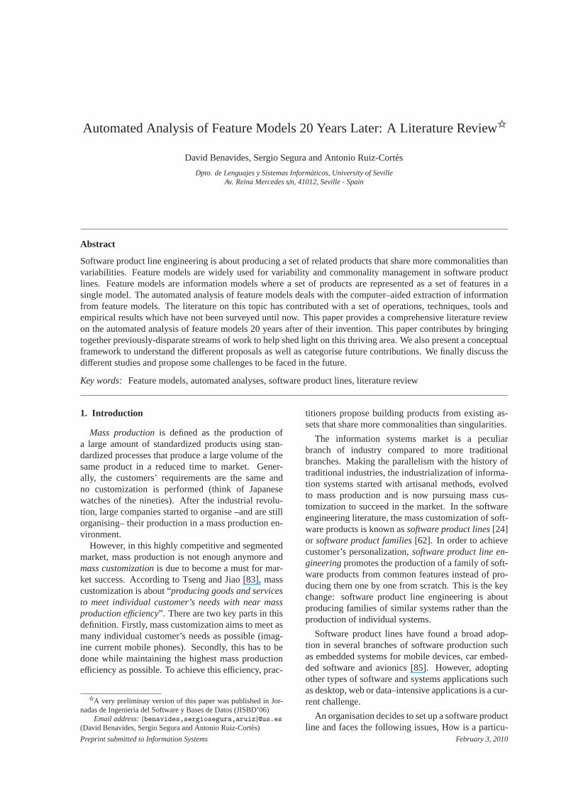
Figure 1 depicts a simplified feature model inspiredby the mobile phone industry. The model illustrateshow features are used to specify and build software formobile phones. The software loaded in the phone isdetermined by the features that it supports. Accordingto the model, all phones must include support forcalls,and displaying information in either abasic, colouror high resolutionscreen. Furthermore, the softwarefor mobile phones may optionally include support forGPS and multimedia devices such ascamera, MP3player or both of them.
Feature models are used in different scenarios ofsoftware production ranging from model driven devel-opment [81], feature oriented programming [6], soft-ware factories [40] or generative programming [27],all of them around software product line development.Although feature models are studied in software prod-uct line engineering, these information models can beused in different contexts ranging from requirementsgathering [23] to data model structures, hence the po-tential importance of feature models in the informationsystems domain.
The termfeature modelwas coined by Kang et al.in the FODA report back in 1990 [43] and has beenone of the main topics of research in software product
2
Mobile Phone
Calls GPS
ColourBasic
Screen Media
Camera MP3
Mandatory
Optional
Alternative
Or
Requires
Excludes
High resolution
Figure 1: A sample feature model
lines since then. There are different feature model lan-guages. We refer the reader to [69] for a detailed sur-vey on the different feature model languages. Below,we review the most well known notations for thoselanguages.
2.1. Basic feature models
We group as basic feature models those allowing thefollowing relationships among features:
• Mandatory. A child feature has a mandatory re-lationships with its parent when the child is in-cluded in all products in which its parent fea-ture appears. For instance, every mobile phonesystem in our example must provide support forcalls.
• Optional. A child feature has an optional rela-tionship with its parent when the child can beoptionally included in all products in which itsparent feature appears. In the example, softwarefor mobile phones may optionally include sup-port forGPS.
• Alternative. A set of child features have an al-ternative relationship with their parent when onlyone feature of the children can be selected whenits parent feature is part of the product. In the ex-ample, mobile phones may include support for abasic, colour or high resolutionscreen but onlyone of them.
• Or. A set of child features have an or-relationshipwith their parent when one or more of them canbe included in the products in which its parentfeature appears. In Figure 1, wheneverMedia isselected,Camera, MP3or both can be selected.
Notice that a child feature can only appear in a prod-uct if its parent feature does. The root feature is a partof all the products within the software product line. In
addition to the parental relationships between features,a feature model can also contain cross-tree constraintsbetween features. These are typically in the form:
• Requires. If a feature A requires a feature B, theinclusion of A in a product implies the inclusionof B in such product. Mobile phones includinga cameramust include support for ahigh resolu-tion screen.
• Excludes. If a feature A excludes a feature B,both features cannot be part of the same product.GPSandbasicscreen are incompatible features.
More complex cross-tree relationships have beenproposed later in the literature [5] allowing constraintsin the form of generic propositional formulas, e.g. “Aand B implies not C”.
2.2. Cardinality–based feature models
Some authors propose extending FODA featuremodels with UML-like multiplicities (so-calledcar-dinalities) [28, 65]. Their main motivation was drivenby practical applications [26] and “conceptual com-pleteness”. The new relationships introduced in thisnotation are defined as follows:
• Feature cardinality. A feature cardinality is asequence of intervals denoted [n..m] with n aslower bound andm as upper bound. These in-tervals determine the number of instances of thefeature that can be part of a product. This rela-tionship may be used as a generalization of theoriginal mandatory ([1,1]) and optional ([0,1])relationships defined in FODA.
• Group cardinality. A group cardinality is an in-terval denoted〈n..m〉, with n as lower bound andm as upper bound limiting the number of childfeatures that can be part of a product when its
3
Connectivity
WifiBluetooth
USB
Name: CostDomain: RealValue: 85.5
Name: MaxSpeedDomain: RealValue: 3.6
Name: MemoryDomain: RealValue: 725
Name: MemoryDomain: RealValue: 425
Name: CostDomain: RealValue: 50
Name: MaxSpeedDomain: RealValue: 2.1
Name: CostDomain: RealValue: 35.50
Name: MaxSpeedDomain: RealValue: 12
Name: MemoryDomain: RealValue: 179
Figure 2: A sample extended feature model
parent feature is selected. Thus, an alternative re-lationship is equivalent to a〈1..1〉 group cardinal-ity and an or–relationship is equivalent to〈1..N〉,being N the number of features in the relation-ship.
2.3. Extended feature models
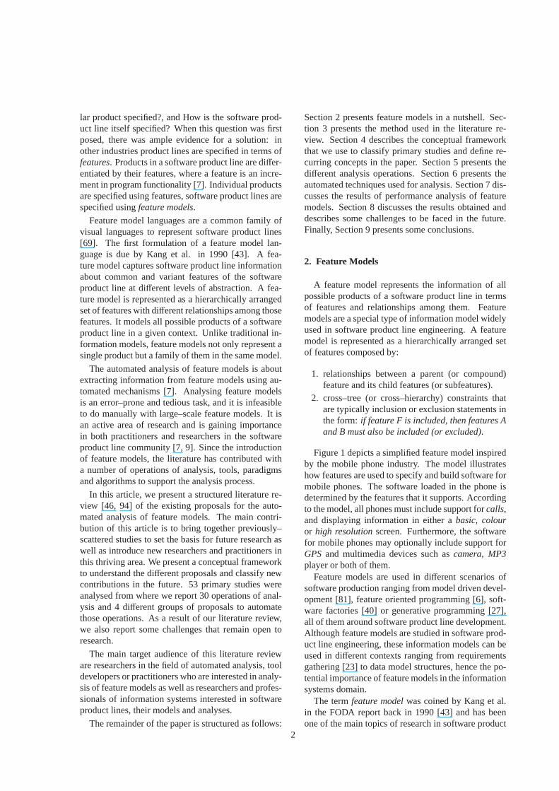
Sometimes it is necessary to extend feature mod-els to include more information about features. Thisinformation is added in terms of so–calledfeature at-tributes. This type of models where additional infor-mation is included are calledextended, advanced orattributed feature models.
FODA [43], the seminal report on feature models,already contemplated the inclusion of some additionalinformation in feature models. For instance, relation-ships between features and feature attributes were in-troduced. Later, Kang et al. [44] make an explicit ref-erence to what they call “non–functional” features re-lated to feature attributes. In addition, other groups ofauthors have also proposed the inclusion of attributesin feature models [5, 7, 11, 12, 29, 30, 73, 96]. Thereis no consensus on a notation to define attributes.However, most proposals agree that an attribute shouldconsist at least of aname, adomainand avalue. Fig-ure 2 depicts a sample feature model including at-tributes using the notation proposed by Benavides etal. in [11]. As illustrated, attributes can be usedto specify extra-functional information such as cost,speed or RAM memory required to support the fea-ture.
Extended feature models can also include complexconstraints among attributes and features like: “If at-tribute A of feature F is lower than a value X, thenfeature T can not be part of the product”.
3. Review method
We have carried out a literature review in orderto examine studies proposing automated analysis offeature models. To perform this review we followed
a systematic and structured method inspired by theguidelines of Kitchenham [46] and Webster et al. [94].Below, we detail the main data regarding the reviewprocess and its structure. For further details on themethod followed we refer the reader to [13].
3.1. Research questionsThe aim of this review is to answer the following
research questions:
• RQ1: What operations of analysis on featuremodels have been proposed?This question moti-vates the following sub-questions:
– What operations have been formally de-scribed?
• RQ2: What kind of automated support has beenproposed and how is it performed?This questionmotivates the following sub-questions:
– Which techniques have been proposed toautomate the analysis?
– What is the feature modelling notation sup-ported by each approach?
– Which analysis operations have been auto-mated?
– Which proposals present a performanceevaluation of their results?
After reviewing all this information we also want toanswer a more general question:
• RQ3: What are the challenges to be faced in thefuture?
3.2. Source materialAs recommended by Webster et al. [94], we used
both manual and automated methods to make a selec-tion of candidate papers in leading journals and con-ferences and other related events. We reviewed 72 pa-pers, 19 were discarded resulting in a total of53 pa-pers that were in the scope of this review. These 53papers are referred asprimary studies[46].
4
[43]
[88][51] [20,52,90] [86,102]
[10,89] [30,92]
[7,101][35,68]
[14,37,78][15]
[69,93][4,34,87]
[16]
[38,42,55,76][57,99,103][41,59,70,98]
[96]
[60,66,80,84][1�36�56�75�97�100][5,11,12,74,91]
Figure 3: Classification of papers per year and type of publication
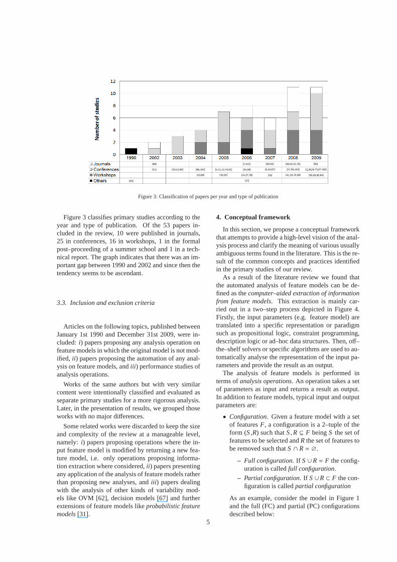
Figure 3 classifies primary studies according to theyear and type of publication. Of the 53 papers in-cluded in the review, 10 were published in journals,25 in conferences, 16 in workshops, 1 in the formalpost–proceeding of a summer school and 1 in a tech-nical report. The graph indicates that there was an im-portant gap between 1990 and 2002 and since then thetendency seems to be ascendant.
3.3. Inclusion and exclusion criteria
Articles on the following topics, published betweenJanuary 1st 1990 and December 31st 2009, were in-cluded: i) papers proposing any analysis operation onfeature models in which the original model is not mod-ified, ii ) papers proposing the automation of any anal-ysis on feature models, andiii ) performance studies ofanalysis operations.
Works of the same authors but with very similarcontent were intentionally classified and evaluated asseparate primary studies for a more rigorous analysis.Later, in the presentation of results, we grouped thoseworks with no major differences.
Some related works were discarded to keep the sizeand complexity of the review at a manageable level,namely: i) papers proposing operations where the in-put feature model is modified by returning a new fea-ture model, i.e. only operations proposing informa-tion extraction where considered,ii ) papers presentingany application of the analysis of feature models ratherthan proposing new analyses, andiii ) papers dealingwith the analysis of other kinds of variability mod-els like OVM [62], decision models [67] and furtherextensions of feature models likeprobabilistic featuremodels[31].
4. Conceptual framework
In this section, we propose a conceptual frameworkthat attempts to provide a high-level vision of the anal-ysis process and clarify the meaning of various usuallyambiguous terms found in the literature. This is the re-sult of the common concepts and practices identifiedin the primary studies of our review.
As a result of the literature review we found thatthe automated analysis of feature models can be de-fined as thecomputer–aided extraction of informationfrom feature models. This extraction is mainly car-ried out in a two–step process depicted in Figure 4.Firstly, the input parameters (e.g. feature model) aretranslated into a specific representation or paradigmsuch as propositional logic, constraint programming,description logic or ad–hoc data structures. Then, off–the–shelf solvers or specific algorithms are used to au-tomatically analyse the representation of the input pa-rameters and provide the result as an output.
The analysis of feature models is performed interms ofanalysis operations. An operation takes a setof parameters as input and returns a result as output.In addition to feature models, typical input and outputparameters are:
• Configuration. Given a feature model with a setof featuresF, a configuration is a 2–tuple of theform (S,R) such thatS,R ⊆ F beingS the set offeatures to be selected andR the set of features tobe removed such thatS ∩ R= ∅.
– Full configuration. If S∪R= F the config-uration is calledfull configuration.
– Partial configuration. If S∪R⊂ F the con-figuration is calledpartial configuration
As an example, consider the model in Figure 1and the full (FC) and partial (PC) configurationsdescribed below:
5
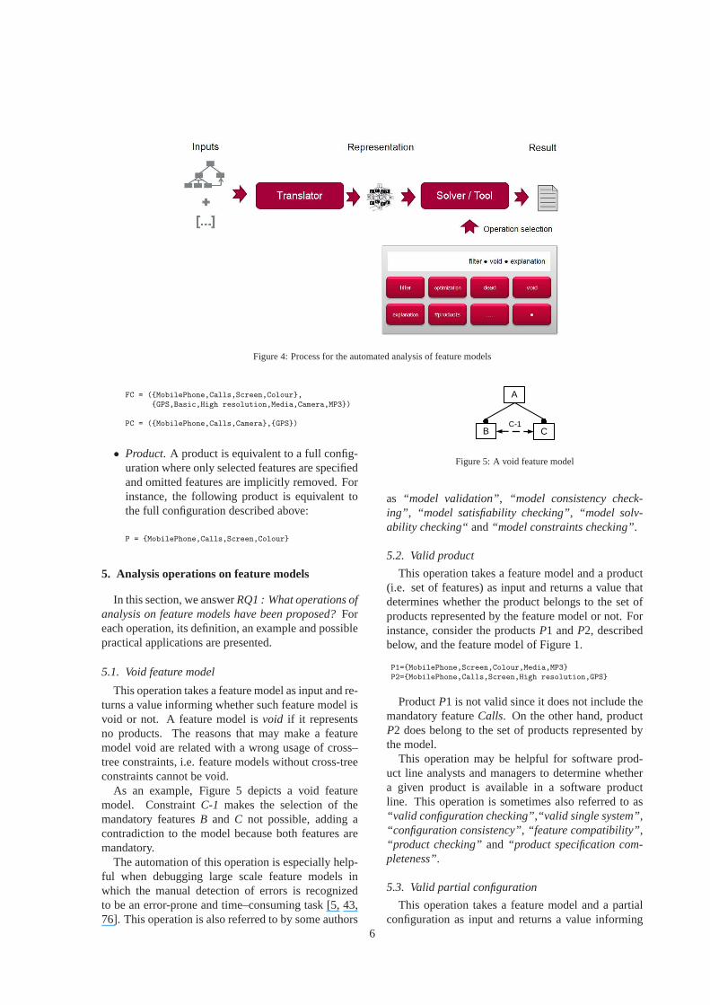
Figure 4: Process for the automated analysis of feature models
FC = ({MobilePhone,Calls,Screen,Colour},{GPS,Basic,High resolution,Media,Camera,MP3})
PC = ({MobilePhone,Calls,Camera},{GPS})
• Product. A product is equivalent to a full config-uration where only selected features are specifiedand omitted features are implicitly removed. Forinstance, the following product is equivalent tothe full configuration described above:
P = {MobilePhone,Calls,Screen,Colour}
5. Analysis operations on feature models
In this section, we answerRQ1 : What operations ofanalysis on feature models have been proposed?Foreach operation, its definition, an example and possiblepractical applications are presented.
5.1. Void feature model
This operation takes a feature model as input and re-turns a value informing whether such feature model isvoid or not. A feature model isvoid if it representsno products. The reasons that may make a featuremodel void are related with a wrong usage of cross–tree constraints, i.e. feature models without cross-treeconstraints cannot be void.
As an example, Figure 5 depicts a void featuremodel. ConstraintC-1 makes the selection of themandatory featuresB and C not possible, adding acontradiction to the model because both features aremandatory.
The automation of this operation is especially help-ful when debugging large scale feature models inwhich the manual detection of errors is recognizedto be an error-prone and time–consuming task [5, 43,76]. This operation is also referred to by some authors
A
B CC-1
Figure 5: A void feature model
as “model validation”, “model consistency check-ing” , “model satisfiability checking”, “model solv-ability checking“and“model constraints checking”.
5.2. Valid product
This operation takes a feature model and a product(i.e. set of features) as input and returns a value thatdetermines whether the product belongs to the set ofproducts represented by the feature model or not. Forinstance, consider the productsP1 andP2, describedbelow, and the feature model of Figure 1.
P1={MobilePhone,Screen,Colour,Media,MP3}P2={MobilePhone,Calls,Screen,High resolution,GPS}
ProductP1 is not valid since it does not include themandatory featureCalls. On the other hand, productP2 does belong to the set of products represented bythe model.
This operation may be helpful for software prod-uct line analysts and managers to determine whethera given product is available in a software productline. This operation is sometimes also referred to as“valid configuration checking”,“valid single system”,“configuration consistency”, “feature compatibility”,“product checking” and “product specification com-pleteness”.
5.3. Valid partial configuration
This operation takes a feature model and a partialconfiguration as input and returns a value informing
6
whether the configuration is valid or not, i.e. a partialconfiguration is valid if it does not include any con-tradiction. Consider as an example the partial config-urationsC1 andC2, described below, and the featuremodel of Figure 1.
C1 = ({MobilePhone,Calls,Camera}, {GPS,High resolution})C2 = ({MobilePhone,Calls,Camera}, {GPS})
C1 is not a valid partial configuration since it selectssupport for the camera and removes the high resolu-tion screen that is explicitly required by the softwareproduct line. C2 does not include any contradictionand therefore could still be extended to a valid fullconfiguration.
This operation results helpful during the productderivation stage to give the user an idea about theprogress of the configuration. A tool implementingthis operation could inform the user as soon as a con-figuration becomes invalid, thus saving time and ef-fort.
5.4. All products
This operation takes a feature model as input andreturns all the products represented by the model.For instance, the set of all the products of the featuremodel presented in Figure 1 is detailed below:
P1 = {MobilePhone,Calls,Screen,Basic}
P2 = {MobilePhone,Calls,Screen,Basic,Media,MP3}
P3 = {MobilePhone,Calls,Screen,Colour}
P4 = {MobilePhone,Calls,Screen,Colour,GPS}
P5 = {MobilePhone,Calls,Screen,Colour,Media,MP3}
P6 = {MobilePhone,Calls,Screen,Colour,Media,MP3,GPS}
P7 = {MobilePhone,Calls,Screen,High resolution}
P8 = {MobilePhone,Calls,Screen,High resolution,Media,MP3}
P9 = {MobilePhone,Calls,Screen,High resolution,Media,MP3,Camera}
P10 = {MobilePhone,Calls,Screen,High resolution,Media,Camera}
P11 = {MobilePhone,Calls,Screen,High resolution,GPS}
P12 = {MobilePhone,Calls,Screen,High resolution,Media,MP3,GPS}
P13 = {MobilePhone,Calls,Screen,High resolution,Media,Camera,GPS}
P14 = {MobilePhone,Calls,Screen,High resolution,Media,Camera,MP3,GPS}
This operation may be helpful to identify new validrequirement combinations not considered in the initialscope of the product line. The set of products of afeature model is also referred to in the literature as“allvalid configurations”and“list of products”.
5.5. Number of products
This operation returns the number of products rep-resented by the feature model received as input. Notethat a feature model is void iff the number of productsrepresented by the model is zero. As an example, thenumber of products of the feature model presented inFigure 1 is14.
This operation provides information about the flex-ibility and complexity of the software product line[11, 30, 88]. A big number of potential products mayreveal a more flexible as well as more complex prod-uct line. The number of products of a feature model isalso referred to in the literature as“variation degree”.
5.6. Filter
This operation takes as input a feature model and aconfiguration (potentially partial) and returns the set ofproducts including the input configuration that can bederived from the model. Note that this operation doesnot modify the feature model but filters the featuresthat are considered.
For instance, the set of products of the featuremodel in Figure 1 applying the partial configuration(S,R) = ({Calls,GPS}, {Colour,Camera}), being Sthe set of features to be selected andR the set of fea-tures to be removed, is:
P1 = {MobilePhone,Calls,Screen,High resolution,GPS}
P2 = {MobilePhone,Calls,Screen,High resolution,Media,MP3,GPS}
Filtering may be helpful to assist users during theconfiguration process. Firstly, users can filter the setof products according to their key requirements. Then,the list of resultant products can be inspected to selectthe desired solution [30].
5.7. Anomalies detection
A number of analysis operations address thedetection of anomalies in feature models i.e. unde-sirable properties such as redundant or contradictoryinformation. These operations take a feature modelas input and return information about the anomaliesdetected. We identified five main types of anomaliesin feature models reported in the literature. These are:
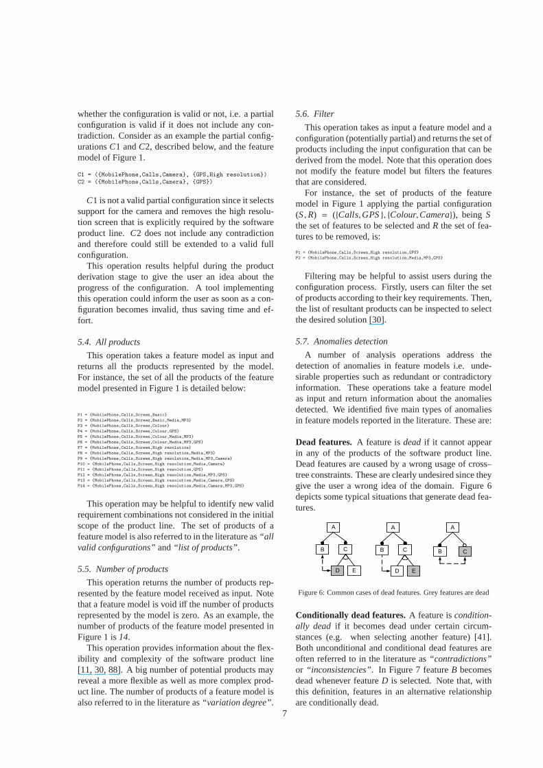
Dead features. A feature isdeadif it cannot appearin any of the products of the software product line.Dead features are caused by a wrong usage of cross–tree constraints. These are clearly undesired since theygive the user a wrong idea of the domain. Figure 6depicts some typical situations that generate dead fea-tures.
A
B C
D E
A
B C
D E
A
B C
Figure 6: Common cases of dead features. Grey features are dead
Conditionally dead features.A feature iscondition-ally dead if it becomes dead under certain circum-stances (e.g. when selecting another feature) [41].Both unconditional and conditional dead features areoften referred to in the literature as“contradictions”or “inconsistencies”. In Figure 7 featureB becomesdead whenever featureD is selected. Note that, withthis definition, features in an alternative relationshipare conditionally dead.
7
A
B C D E
(B and D) implies CC implies not B
Figure 7: An example of a conditionally dead feature
False optional features. A feature isfalse optionalif it is included in all the products of the product linedespite not being modelled as mandatory. Figure 8depicts some examples of false optional features.
A
B C
D E
A
B C
D E
A
B C
Figure 8: Some examples of false optional features. Grey featuresare false optional
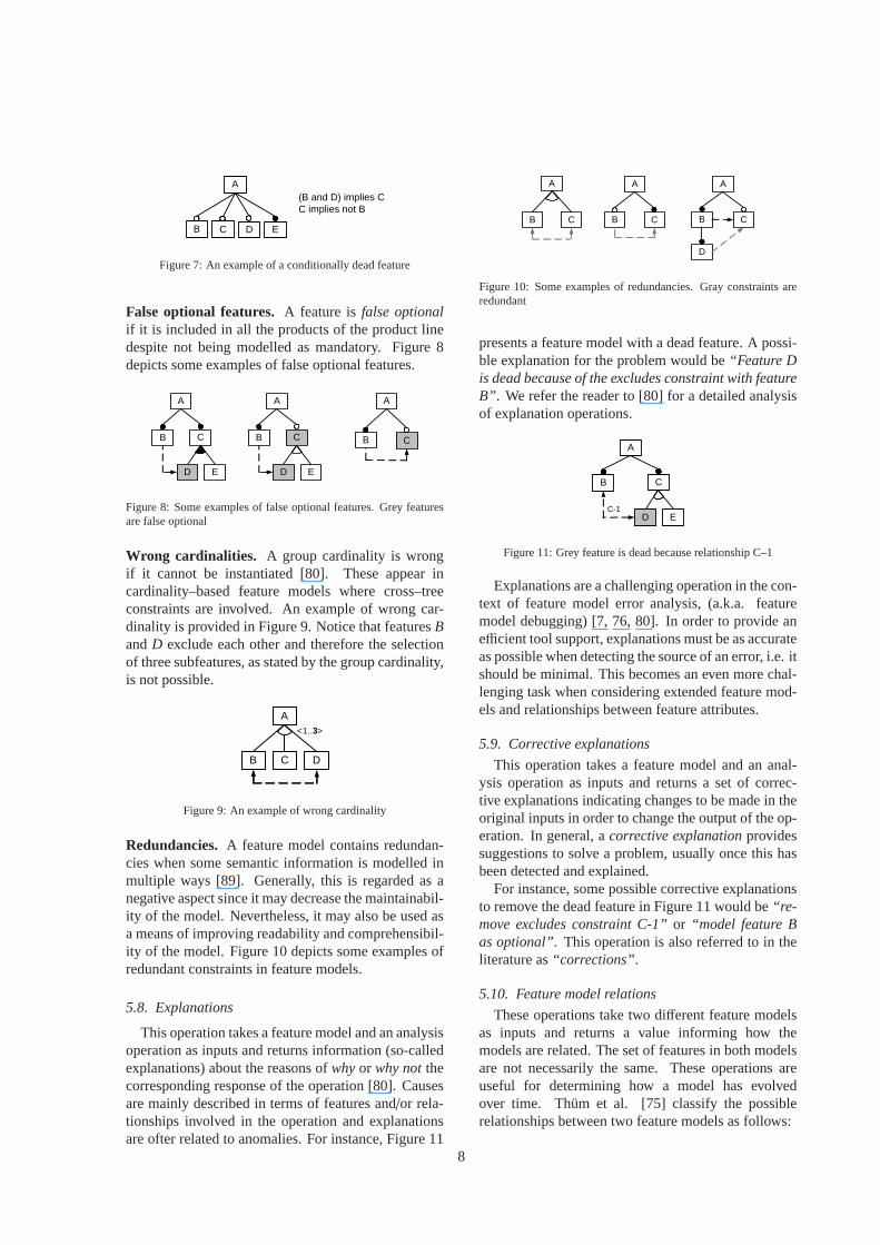
Wrong cardinalities. A group cardinality is wrongif it cannot be instantiated [80]. These appear incardinality–based feature models where cross–treeconstraints are involved. An example of wrong car-dinality is provided in Figure 9. Notice that featuresBandD exclude each other and therefore the selectionof three subfeatures, as stated by the group cardinality,is not possible.
A
B C D
<1..3>
Figure 9: An example of wrong cardinality
Redundancies. A feature model contains redundan-cies when some semantic information is modelled inmultiple ways [89]. Generally, this is regarded as anegative aspect since it may decrease the maintainabil-ity of the model. Nevertheless, it may also be used asa means of improving readability and comprehensibil-ity of the model. Figure 10 depicts some examples ofredundant constraints in feature models.
5.8. Explanations
This operation takes a feature model and an analysisoperation as inputs and returns information (so-calledexplanations) about the reasons ofwhyor why notthecorresponding response of the operation [80]. Causesare mainly described in terms of features and/or rela-tionships involved in the operation and explanationsare ofter related to anomalies. For instance, Figure 11
A
B C
D
A
B C
A
B C
Figure 10: Some examples of redundancies. Gray constraints areredundant
presents a feature model with a dead feature. A possi-ble explanation for the problem would be“Feature Dis dead because of the excludes constraint with featureB” . We refer the reader to [80] for a detailed analysisof explanation operations.
A
B C
D EC-1
Figure 11: Grey feature is dead because relationship C–1
Explanations are a challenging operation in the con-text of feature model error analysis, (a.k.a. featuremodel debugging) [7, 76, 80]. In order to provide anefficient tool support, explanations must be as accurateas possible when detecting the source of an error, i.e. itshould be minimal. This becomes an even more chal-lenging task when considering extended feature mod-els and relationships between feature attributes.
5.9. Corrective explanations
This operation takes a feature model and an anal-ysis operation as inputs and returns a set of correc-tive explanations indicating changes to be made in theoriginal inputs in order to change the output of the op-eration. In general, acorrective explanationprovidessuggestions to solve a problem, usually once this hasbeen detected and explained.
For instance, some possible corrective explanationsto remove the dead feature in Figure 11 would be“re-move excludes constraint C-1”or “model feature Bas optional”. This operation is also referred to in theliterature as“corrections” .
5.10. Feature model relations
These operations take two different feature modelsas inputs and returns a value informing how themodels are related. The set of features in both modelsare not necessarily the same. These operations areuseful for determining how a model has evolvedover time. Thum et al. [75] classify the possiblerelationships between two feature models as follows:
8
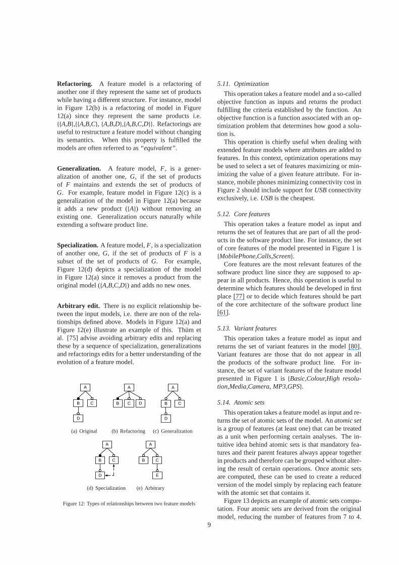
Refactoring. A feature model is a refactoring ofanother one if they represent the same set of productswhile having a different structure. For instance, modelin Figure 12(b) is a refactoring of model in Figure12(a) since they represent the same products i.e.{{A,B},{{A,B,C}, {A,B,D},{A,B,C,D}}. Refactorings areuseful to restructure a feature model without changingits semantics. When this property is fulfilled themodels are often referred to as“equivalent”.
Generalization. A feature model,F, is a gener-alization of another one,G, if the set of productsof F maintains and extends the set of products ofG. For example, feature model in Figure 12(c) is ageneralization of the model in Figure 12(a) becauseit adds a new product ({A}) without removing anexisting one. Generalization occurs naturally whileextending a software product line.
Specialization.A feature model,F, is a specializationof another one,G, if the set of products ofF is asubset of the set of products ofG. For example,Figure 12(d) depicts a specialization of the modelin Figure 12(a) since it removes a product from theoriginal model ({A,B,C,D}) and adds no new ones.
Arbitrary edit. There is no explicit relationship be-tween the input models, i.e. there are non of the rela-tionships defined above. Models in Figure 12(a) andFigure 12(e) illustrate an example of this. Thum etal. [75] advise avoiding arbitrary edits and replacingthese by a sequence of specialization, generalizationsand refactorings edits for a better understanding of theevolution of a feature model.
A
B C
D
(a) Original
A
B C D
(b) Refactoring
A
B C
D
(c) Generalization
A
B C
D
(d) Specialization
A
B C
E
(e) Arbitrary
Figure 12: Types of relationships between two feature models
5.11. Optimization
This operation takes a feature model and a so-calledobjective function as inputs and returns the productfulfilling the criteria established by the function. Anobjective function is a function associated with an op-timization problem that determines how good a solu-tion is.
This operation is chiefly useful when dealing withextended feature models where attributes are added tofeatures. In this context, optimization operations maybe used to select a set of features maximizing or min-imizing the value of a given feature attribute. For in-stance, mobile phones minimizing connectivity cost inFigure 2 should include support forUSBconnectivityexclusively, i.e.USBis the cheapest.
5.12. Core features
This operation takes a feature model as input andreturns the set of features that are part of all the prod-ucts in the software product line. For instance, the setof core features of the model presented in Figure 1 is{MobilePhone,Calls,Screen}.
Core features are the most relevant features of thesoftware product line since they are supposed to ap-pear in all products. Hence, this operation is useful todetermine which features should be developed in firstplace [77] or to decide which features should be partof the core architecture of the software product line[61].
5.13. Variant features
This operation takes a feature model as input andreturns the set of variant features in the model [80].Variant features are those that do not appear in allthe products of the software product line. For in-stance, the set of variant features of the feature modelpresented in Figure 1 is{Basic,Colour,High resolu-tion,Media,Camera, MP3,GPS}.
5.14. Atomic sets
This operation takes a feature model as input and re-turns the set of atomic sets of the model. Anatomic setis a group of features (at least one) that can be treatedas a unit when performing certain analyses. The in-tuitive idea behind atomic sets is that mandatory fea-tures and their parent features always appear togetherin products and therefore can be grouped without alter-ing the result of certain operations. Once atomic setsare computed, these can be used to create a reducedversion of the model simply by replacing each featurewith the atomic set that contains it.
Figure 13 depicts an example of atomic sets compu-tation. Four atomic sets are derived from the originalmodel, reducing the number of features from 7 to 4.
9
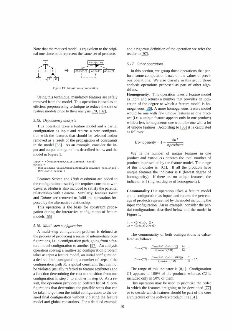
Note that the reduced model is equivalent to the origi-nal one since both represent the same set of products.
A
B D
F GE
C
AS-1={A,C,D}
AS-2={B,E} AS-3={F} AS-4={G}
Figure 13: Atomic sets computation
Using this technique, mandatory features are safelyremoved from the model. This operation is used as anefficient preprocessing technique to reduce the size offeature models prior to their analysis [70, 102].
5.15. Dependency analysis
This operation takes a feature model and a partialconfiguration as input and returns a new configura-tion with the features that should be selected and/orremoved as a result of the propagation of constraintsin the model [55]. As an example, consider the in-put and output configurations described below and themodel in Figure 1.
Input = ({MobilePhone,Calls,Camera}, {MP3})Output =
({MobilePhone,Calls,Camera,Media,Screen,High resolution},{MP3,Basic,Colour})
FeaturesScreenand High resolutionare added tothe configuration to satisfy the requires constraint withCamera. Media is also included to satisfy the parentalrelationship withCamera. Similarly, featuresBasicand Colour are removed to fulfil the constraints im-posed by the alternative relationship.
This operation is the basis for constraint propa-gation during the interactive configuration of featuremodels [55]
5.16. Multi–step configuration
A multi–step configuration problem is defined asthe process of producing a series of intermediate con-figurations, i.e. a configuration path, going from a fea-ture model configuration to another [97]. An analysisoperation solving a multi–step configuration problemtakes as input a feature model, an initial configuration,a desired final configuration, a number of steps in theconfiguration pathK, a global constraint that can notbe violated (usually referred to feature attributes) anda function determining the cost to transition from oneconfiguration in stepT to another in stepU. As a re-sult, the operation provides an ordered list ofK con-figurations that determines the possible steps that canbe taken to go from the initial configuration to the de-sired final configuration without violating the featuremodel and global constraints. For a detailed example
and a rigorous definition of the operation we refer thereader to [97].
5.17. Other operations
In this section, we group those operations that per-form some computation based on the values of previ-ous operations. We also classify in this group thoseanalysis operations proposed as part of other algo-rithms.Homogeneity. This operation takes a feature modelas input and returns a number that provides an indi-cation of the degree to which a feature model is ho-mogeneous [36]. A more homogeneous feature modelwould be one with few unique features in one prod-uct (i.e. a unique feature appears only in one product)while a less homogeneous one would be one with a lotof unique features. According to [36] it is calculatedas follows:
Homogeneity= 1−#u f
#products
#u f is the number of unique features in oneproduct and #productsdenotes the total number ofproducts represented by the feature model. The rangeof this indicator is [0,1]. If all the products haveunique features the indicator is 0 (lowest degree ofhomogeneity). If there are no unique features, theindicator is 1 (highest degree of homogeneity).
Commonality.This operation takes a feature modeland a configuration as inputs and returns the percent-age of products represented by the model including theinput configuration. An as example, consider the par-tial configurations described below and the model inFigure 1:
C1 = {{Calls}, {}}C2 = {{Calls},{MP3}}
The commonality of both configurations is calcu-lated as follows:
Comm(C1) =| f ilter(FM, {{Calls}, {}})|
#products(FM)=
1414= 1
Comm(C2) =| f ilter(FM, {{Calls}, {MP3}})|
#products(FM)=
714= 0.5
The range of this indicator is [0,1]. ConfigurationC1 appears in 100% of the products whereasC2 isincluded only in 50% of them.
This operation may be used to prioritize the orderin which the features are going to be developed [77]or to decide which features should be part of the corearchitecture of the software product line [61].
10
Variability factor. This operation takes a featuremodel as input and returns the ratio between the num-ber of products and 2n where n is the number of fea-tures considered. In particular, 2n is the potential num-ber of products represented by a feature model assum-ing that any combination of features is allowed. Theroot and non-leaf features are often not considered. Asan example, the variability of the feature model pre-sented in Figure 1 taking into account only leaf fea-tures is:
N.Products2n
=1427= 0.0625
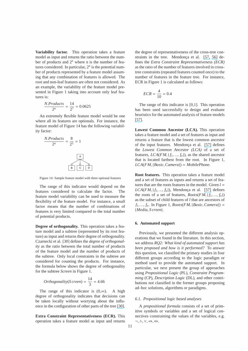
An extremely flexible feature model would be onewhere all its features are optionals. For instance, thefeature model of Figure 14 has the following variabil-ity factor:
N.Products2n
=823= 1
A
B DC
Figure 14: Sample feature model with three optional features
The range of this indicator would depend on thefeatures considered to calculate the factor. Thefeature model variability can be used to measure theflexibility of the feature model. For instance, a smallfactor means that the number of combinations offeatures is very limited compared to the total numberof potential products.
Degree of orthogonality. This operation takes a fea-ture model and a subtree (represented by its root fea-ture) as input and returns their degree of orthogonality.Czarnecki et al. [30] defines thedegree of orthogonal-ity as the ratio between the total number of productsof the feature model and the number of products ofthe subtree. Only local constraints in the subtree areconsidered for counting the products. For instance,the formula below shows the degree of orthogonalityfor the subtreeScreenin Figure 1.
Orthogonality(S creen) =143= 4.66
The range of this indicator is (0,∞). A highdegree of orthogonality indicates that decisions canbe taken locally without worrying about the influ-ence in the configuration of other parts of the tree [30].
Extra Constraint Representativeness (ECR).Thisoperation takes a feature model as input and returns
the degree of representativeness of the cross-tree con-straints in the tree. Mendonca et al. [57, 56] de-fines theExtra Constraint Representativeness (ECR)as the ratio of the number of features involved in cross-tree constraints (repeated features counted once) to thenumber of features in the feature tree. For instance,ECR in Figure 1 is calculated as follows:
ECR=410= 0.4
The range of this indicator is [0,1]. This operationhas been used successfully to design and evaluateheuristics for the automated analysis of feature models[57].
Lowest Common Ancestor (LCA). This operationtakes a feature model and a set of features as input andreturns a feature that is the lowest common ancestorof the input features. Mendonca et al. [57] definesthe Lowest Common Ancestor (LCA)of a set offeatures,LCA(FM, { f1, ..., fn}), as the shared ancestorthat is located farthest from the root. In Figure 1,LCA(FM, {Basic,Camera}) = MobilePhone.
Root features. This operation takes a feature modeland a set of features as inputs and returns a set of fea-tures that are therootsfeatures in the model. Givenl =LCA(FM, { f1, ..., fn}), Mendonca et al. [57] definesthe roots of a set of features,Roots(FM, { f1, ..., fn})as the subset of child features ofl that are ancestors off1, ..., fn. In Figure 1,Roots(FM, {Basic,Camera}) ={Media,S creen}.
6. Automated support
Previously, we presented the different analysis op-erations that we found in the literature. In this section,we addressRQ2: What kind of automated support hasbeen proposed and how is it performed?To answerthis question, we classified the primary studies in fourdifferent groups according to the logic paradigm ormethod used to provide the automated support. Inparticular, we next present the group of approachesusingPropositional Logic(PL), Constraint Program-ming (CP),Description Logic(DL), and other contri-butions not classified in the former groups proposingad–hoc solutions, algorithms or paradigms.
6.1. Propositional logic based analyses
A propositional formulaconsists of a set of prim-itive symbols or variables and a set of logical con-nectives constraining the values of the variables, e.g.¬,∧,∨,⇒,⇔.
11
A SAT solveris a software package that takes as in-put a propositional formula and determines if the for-mula is satisfiable, i.e. there is a variable assignmentthat makes the formula evaluate to true. Input formu-las are usually specified inConjunctive Normal Form(CNF). CNF is a standard form to represent proposi-tional formulas that is used by most of SAT solverswhere only three connectives are allowed:¬,∧,∨. Ithas been proved that every propositional formula canbe converted into an equivalent CNF formula [25].SAT solving is a well known NP-complete problem[25], however, current SAT solvers can deal with bigproblems where in most of the cases the performanceis not an issue [53].
Similarly, a Binary Decision Diagram (BDD)solver is a software package that takes a propositionalformula as input (not necessarily in CNF) and trans-lates it into a graph representation (the BDD itself)which allows determining if the formula is satisfi-able and providing efficient algorithms for countingthe number of possible solutions [19]. The size ofthe BDD is crucial because it can be exponential inthe worst case. Although it is possible to find a goodvariable ordering that reduces the size of the BDD, theproblem of finding the best variable ordering remainsNP-complete [18].
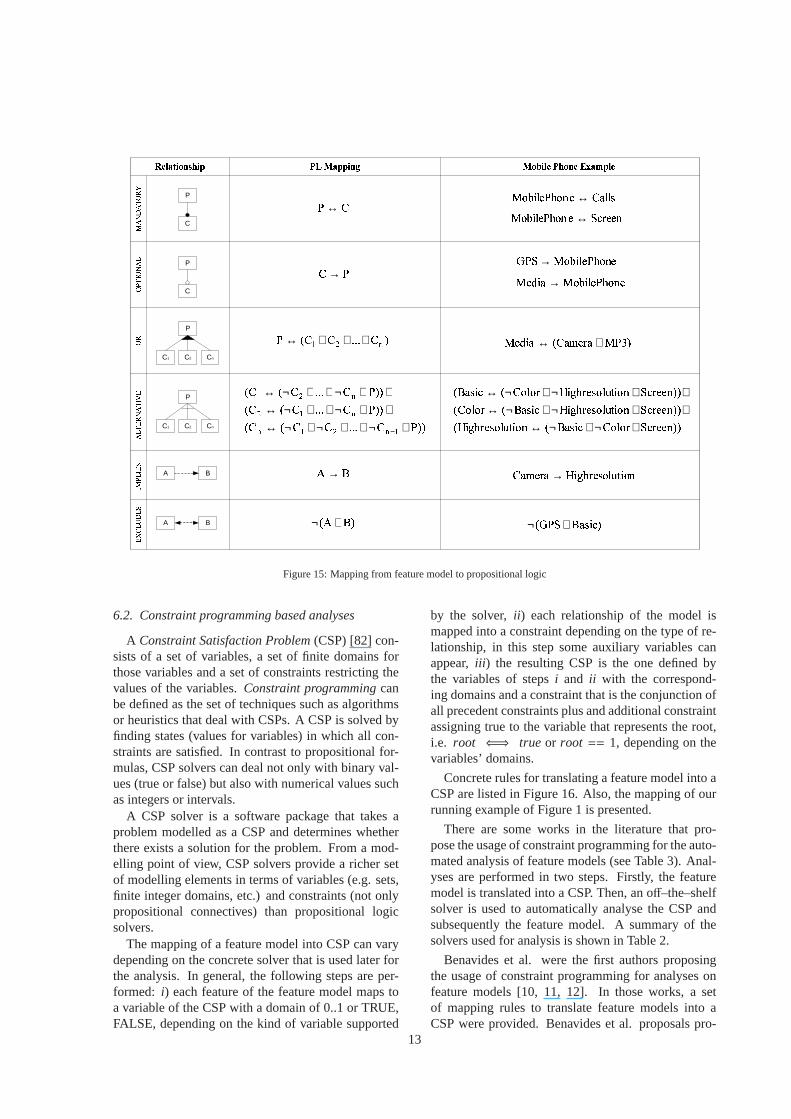
The mapping of a feature model into a propositionalformula can change depending on the solver that isused later for analysis. In general, the following stepsare performed:i) each feature of the feature modelmaps to a variable of the propositional formula,ii )each relationship of the model is mapped into one ormore small formulas depending on the type of rela-tionship, in this step some auxiliary variables can ap-pear, iii ) the resulting formula is the conjunction ofall the resulting formulas of stepii plus and additionalconstraint assigning true to the variable that representsthe root, i.e.root ⇐⇒ true.
Concrete rules for translating a feature model intoa propositional formula are listed in Figure 15. Also,the mapping of our running example of Figure 1 ispresented. We may mention that the mapping of thepropositional formulas listed in Figure 15 into CNF isstraightforward (see [25]).
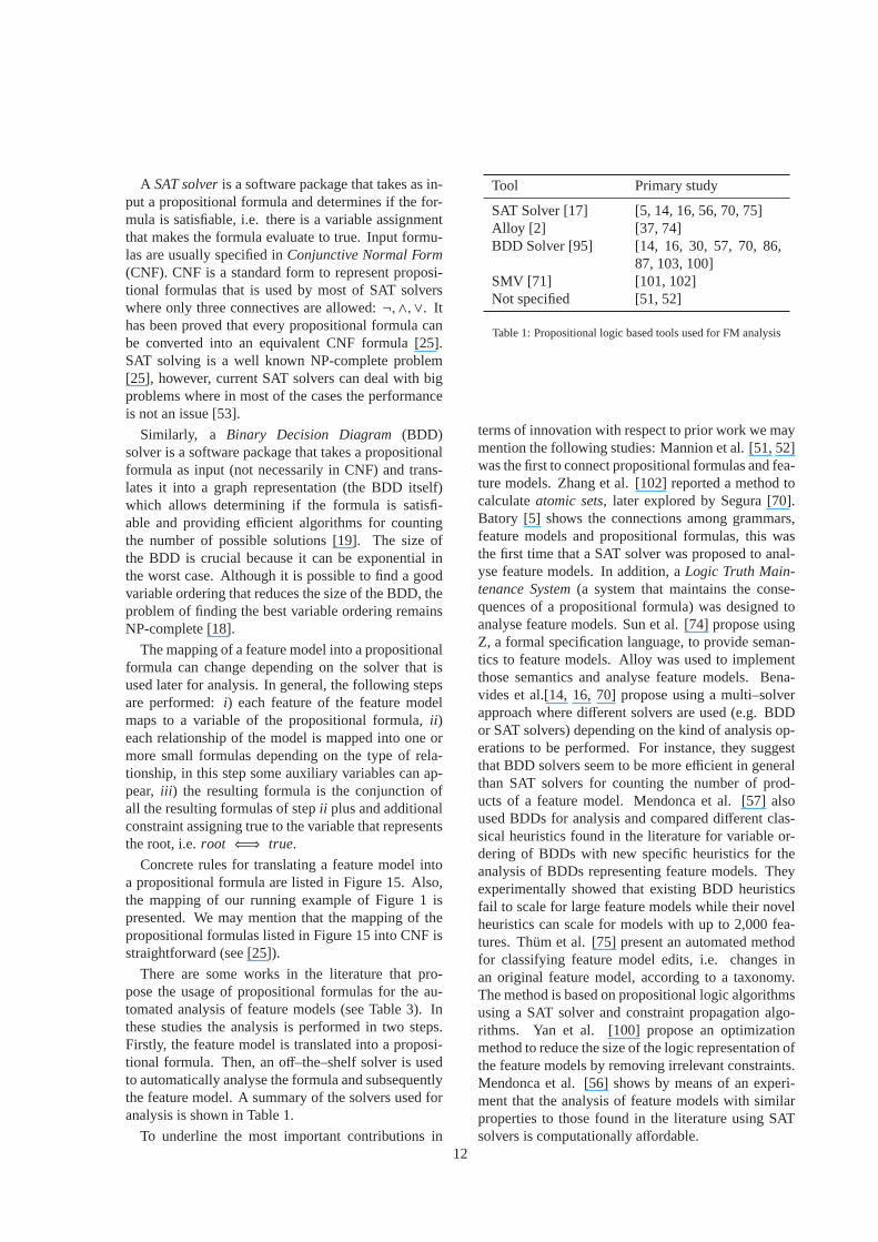
There are some works in the literature that pro-pose the usage of propositional formulas for the au-tomated analysis of feature models (see Table 3). Inthese studies the analysis is performed in two steps.Firstly, the feature model is translated into a proposi-tional formula. Then, an off–the–shelf solver is usedto automatically analyse the formula and subsequentlythe feature model. A summary of the solvers used foranalysis is shown in Table 1.
To underline the most important contributions in
Tool Primary study
SAT Solver [17] [5, 14, 16, 56, 70, 75]Alloy [2] [37, 74]BDD Solver [95] [14, 16, 30, 57, 70, 86,
87, 103, 100]SMV [71] [101, 102]Not specified [51, 52]
Table 1: Propositional logic based tools used for FM analysis
terms of innovation with respect to prior work we maymention the following studies: Mannion et al. [51, 52]was the first to connect propositional formulas and fea-ture models. Zhang et al. [102] reported a method tocalculateatomic sets, later explored by Segura [70].Batory [5] shows the connections among grammars,feature models and propositional formulas, this wasthe first time that a SAT solver was proposed to anal-yse feature models. In addition, aLogic Truth Main-tenance System(a system that maintains the conse-quences of a propositional formula) was designed toanalyse feature models. Sun et al. [74] propose usingZ, a formal specification language, to provide seman-tics to feature models. Alloy was used to implementthose semantics and analyse feature models. Bena-vides et al.[14, 16, 70] propose using a multi–solverapproach where different solvers are used (e.g. BDDor SAT solvers) depending on the kind of analysis op-erations to be performed. For instance, they suggestthat BDD solvers seem to be more efficient in generalthan SAT solvers for counting the number of prod-ucts of a feature model. Mendonca et al. [57] alsoused BDDs for analysis and compared different clas-sical heuristics found in the literature for variable or-dering of BDDs with new specific heuristics for theanalysis of BDDs representing feature models. Theyexperimentally showed that existing BDD heuristicsfail to scale for large feature models while their novelheuristics can scale for models with up to 2,000 fea-tures. Thum et al. [75] present an automated methodfor classifying feature model edits, i.e. changes inan original feature model, according to a taxonomy.The method is based on propositional logic algorithmsusing a SAT solver and constraint propagation algo-rithms. Yan et al. [100] propose an optimizationmethod to reduce the size of the logic representation ofthe feature models by removing irrelevant constraints.Mendonca et al. [56] shows by means of an experi-ment that the analysis of feature models with similarproperties to those found in the literature using SATsolvers is computationally affordable.
12
���������� � ������� ������ ���� ����������������������������������� �������!�"#�$��! A B
A B
%&↔ &%→ '()))((*+ ,-. ∨∨∨↔
/0→ 1/02
∧¬
''+()))((*(* ''+()))(*(* ''+()))(*(* .,-., ,.- ,-.∧¬∧∧¬∧¬↔
∧∧¬∧∧¬↔∧∧¬∧∧¬↔
−
P
C
P
C
P
C1 C2 Cn
P
C1 C2 Cn
%34456789:46&;8< ↔ =>?66<6789:46&;8< ↔ 6789:46&;8<@&=→ 6789:46&;8<76A:3 → 'BC+(DEFGD*CFHID ∨↔
JKGFFL''(MNMGODPIK*QRIML*SITUGFPMN JKGFFL''RIMLSITUGFPMNQODPIK**(MNMG JKGFFL''RIMLSITUGFPMNQ(MNMG**ODPIK∧¬∧¬↔
∧∧¬∧¬↔∧∧¬∧¬↔
V:8<W:X;?6584Y%3Z6?3 → 'ODPIK[+J*∧¬
Figure 15: Mapping from feature model to propositional logic
6.2. Constraint programming based analyses
A Constraint Satisfaction Problem(CSP) [82] con-sists of a set of variables, a set of finite domains forthose variables and a set of constraints restricting thevalues of the variables.Constraint programmingcanbe defined as the set of techniques such as algorithmsor heuristics that deal with CSPs. A CSP is solved byfinding states (values for variables) in which all con-straints are satisfied. In contrast to propositional for-mulas, CSP solvers can deal not only with binary val-ues (true or false) but also with numerical values suchas integers or intervals.
A CSP solver is a software package that takes aproblem modelled as a CSP and determines whetherthere exists a solution for the problem. From a mod-elling point of view, CSP solvers provide a richer setof modelling elements in terms of variables (e.g. sets,finite integer domains, etc.) and constraints (not onlypropositional connectives) than propositional logicsolvers.
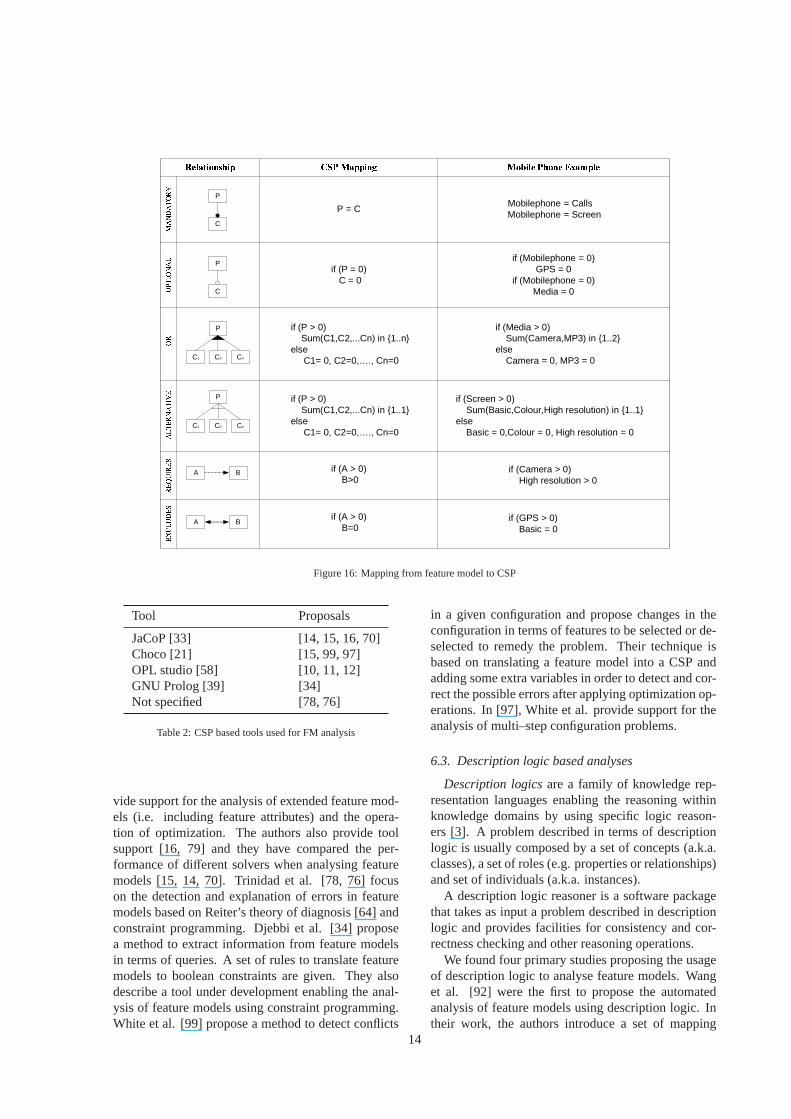
The mapping of a feature model into CSP can varydepending on the concrete solver that is used later forthe analysis. In general, the following steps are per-formed: i) each feature of the feature model maps toa variable of the CSP with a domain of 0..1 or TRUE,FALSE, depending on the kind of variable supported
by the solver,ii ) each relationship of the model ismapped into a constraint depending on the type of re-lationship, in this step some auxiliary variables canappear,iii ) the resulting CSP is the one defined bythe variables of stepsi and ii with the correspond-ing domains and a constraint that is the conjunction ofall precedent constraints plus and additional constraintassigning true to the variable that represents the root,i.e. root ⇐⇒ true or root == 1, depending on thevariables’ domains.
Concrete rules for translating a feature model into aCSP are listed in Figure 16. Also, the mapping of ourrunning example of Figure 1 is presented.
There are some works in the literature that pro-pose the usage of constraint programming for the auto-mated analysis of feature models (see Table 3). Anal-yses are performed in two steps. Firstly, the featuremodel is translated into a CSP. Then, an off–the–shelfsolver is used to automatically analyse the CSP andsubsequently the feature model. A summary of thesolvers used for analysis is shown in Table 2.
Benavides et al. were the first authors proposingthe usage of constraint programming for analyses onfeature models [10, 11, 12]. In those works, a setof mapping rules to translate feature models into aCSP were provided. Benavides et al. proposals pro-
13
\]^_`abcdeaf ghi j_ffack jbla^] iebc] mn_of^]pqrsqtuvwuxtyurqzuvqzt{vrqty|{v{}~yv{�{��z~s{� A B
A B
P
C
P
C
P
C1 C2 Cn
P
C1 C2 Cn
P = C
if (P = 0) C = 0
if (P > 0) Sum(C1,C2,...Cn) in {1..n}else C1= 0, C2=0,…., Cn=0
if (P > 0) Sum(C1,C2,...Cn) in {1..1}else C1= 0, C2=0,…., Cn=0
if (A > 0) B>0
if (A > 0) B=0
Mobilephone = Calls Mobilephone = Screen
if (Mobilephone = 0) GPS = 0
if (Mobilephone = 0) Media = 0
if (Media > 0) Sum(Camera,MP3) in {1..2}else Camera = 0, MP3 = 0
if (Screen > 0) Sum(Basic,Colour,High resolution) in {1..1}else Basic = 0,Colour = 0, High resolution = 0
if (Camera > 0) High resolution > 0
if (GPS > 0) Basic = 0
Figure 16: Mapping from feature model to CSP
Tool Proposals
JaCoP [33] [14, 15, 16, 70]Choco [21] [15, 99, 97]OPL studio [58] [10, 11, 12]GNU Prolog [39] [34]Not specified [78, 76]
Table 2: CSP based tools used for FM analysis
vide support for the analysis of extended feature mod-els (i.e. including feature attributes) and the opera-tion of optimization. The authors also provide toolsupport [16, 79] and they have compared the per-formance of different solvers when analysing featuremodels [15, 14, 70]. Trinidad et al. [78, 76] focuson the detection and explanation of errors in featuremodels based on Reiter’s theory of diagnosis [64] andconstraint programming. Djebbi et al. [34] proposea method to extract information from feature modelsin terms of queries. A set of rules to translate featuremodels to boolean constraints are given. They alsodescribe a tool under development enabling the anal-ysis of feature models using constraint programming.White et al. [99] propose a method to detect conflicts
in a given configuration and propose changes in theconfiguration in terms of features to be selected or de-selected to remedy the problem. Their technique isbased on translating a feature model into a CSP andadding some extra variables in order to detect and cor-rect the possible errors after applying optimization op-erations. In [97], White et al. provide support for theanalysis of multi–step configuration problems.
6.3. Description logic based analyses
Description logicsare a family of knowledge rep-resentation languages enabling the reasoning withinknowledge domains by using specific logic reason-ers [3]. A problem described in terms of descriptionlogic is usually composed by a set of concepts (a.k.a.classes), a set of roles (e.g. properties or relationships)and set of individuals (a.k.a. instances).
A description logic reasoner is a software packagethat takes as input a problem described in descriptionlogic and provides facilities for consistency and cor-rectness checking and other reasoning operations.
We found four primary studies proposing the usageof description logic to analyse feature models. Wanget al. [92] were the first to propose the automatedanalysis of feature models using description logic. Intheir work, the authors introduce a set of mapping
14
rules to translate feature models into OWL-DL on-tologies [32]. OWL-DL is an expressive yet decidablesub language of OWL [32]. Then, the authors sug-gest using description logic reasoning engines such asRACER[63] to perform automated analysis over theOWL representations of the models. In [93], the au-thors extend their previous proposal [92] with supportfor explanations by means of an OWL debugging tool.Fan et al. [35] also propose translating feature mod-els into description logic and using reasoners such asRACER to perform their analyses. In [1], Abo Zaidet al. propose using semantic web technologies to en-able the analyses. They use OWL for modelling andthe Pellet [22] reasoner for the analysis.
6.4. Other studies
There are some primary studies that are not classi-fied in the former groups, namely:i) studies in whichthe conceptual logic used is not clearly exposed andii )studies using ad–hoc algorithms, paradigms or toolsfor analysis.
Kang et al. mentioned explicitly the automatedanalysis of feature models in the original FODA re-port [43, pag. 70]. A prolog–based prototype isalso reported. However, no detailed information isprovided to replicate their prolog coding. After theFODA report, Deursen et al. [88] were the first au-thors proposing some kind of automated support forthe automated analysis of feature models. In theirwork, they propose a textual feature diagram algebratogether with a prototype implementation using theASF+SDF Meta-Environment [47]. Von der Massenet al. [90] present Requiline, a requirement engi-neering tool for software product lines. The tool ismainly implemented by using a relational data baseand ad–hoc algorithms. Later, Von der Massen et al.[91] propose a method to calculate a rough approxi-mation of the number of products of a feature model,which they callvariation degree. The technique is de-scribed using mathematical expressions. In [4], Bach-meyer et al. presentconceptual graph feature models.Conceptual graphs are a formalism to express knowl-edge. Using this transformation, they provide an al-gorithm that is used to compute analysis. Hemaku-mar [41] proposes a method to statically detect condi-tional dead features. The method is based on modelchecking techniques and incremental consistency al-gorithms. Mendonca et al. [54, 55] study dependen-cies among feature models and cross–tree constraintsusing different techniques obtaining a noticeable im-provement in efficiency. Gheyi et al. [38] present aset of algebraic laws in feature models to check con-figurability of feature model refactorings. They usethe PVS tool to do some analysis although this is
not the main focus of the paper. White et al. [96]present an extension of their previous work [98]. Thesame method is presented but giving enough details tomake it reproducible since some details were missedin their previous work. The method is calledFilteredCartesian Flatteringwhich maps the problem of op-timally selecting a set of features according to sev-eral constraints to aMulti–dimensional Multi–choiceKnapsack Problemand then they apply several ex-isting algorithms to this problem that perform muchfaster while offering an approximate answer. Van denBroek et al. [84] propose transforming feature mod-els into generalised feature trees and computing someof their properties. Ageneralised feature treeis a fea-ture model in which cross-tree constraints are removedand features can have multiple occurrences. Some al-gorithms and an executable specification in the func-tional programming language Miranda are provided.The strength of their proposal lies in the efficiency ofthe analysis operation. Fernandez et al. [36] proposean algorithm to compute the total number of productson what they callNeutral Feature Trees, trees that al-low complex cross-tree constraints. Computing the to-tal number of products the authors are also able to cal-culate thehomogeneityof a feature tree as well as thecommonalityof a given feature. They finally comparethe computational complexity of their approach withrespect to previous work.
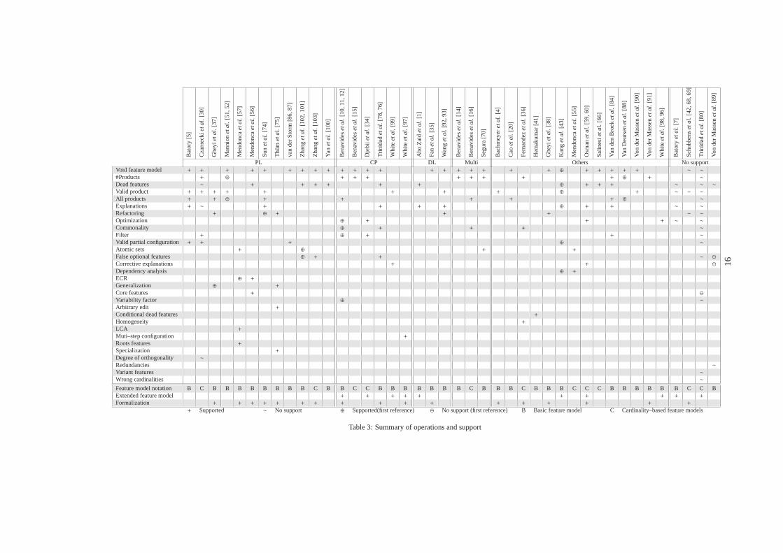
6.5. Summary and analysis of operations and supportA summary of the analysis operations (RQ1) and
automated support (RQ2) identified in the literature isshown in Table 3. Operations are listed horizontallyand ordered by the total number of papers mentioningit. Primary studies are listed vertically. Related worksof the same author are grouped in a single column. Pri-mary studies are grouped according to the paradigmthey use for the analyses as follows:i) PropositionalLogic (PL), ii ). Constraint Programming (CP)iii ) De-scription Logic (DL), iv) works that integrate morethan one paradigm and/or solver (Multi), v) studiesthat use their own tools not categorized in the formergroups (Others), andvi) proposals that present differ-ent operations but do not provide automated supportfor them (No support).
The cells of the matrix indicate the informationabout a primary study in terms of operations sup-ported. Cells marked with ‘+’ indicate that the pro-posal of the column provides explicit support for theoperation of the row. We use the symbol ‘∼’ for pro-posals with no automated support for the correspond-ing operation but explicit definition of it. We alsohighlight the primary study that first proposed an op-eration using the symbols ‘⊕’ (when support is pro-vided) and ‘⊖’ (when no support is provided). To fully
15
Bat
ory
[5]
Cza
rnec
kie
tal.
[30]
Ghe
yie
tal.
[37]
Man
nion
eta
l.[5
1,52
]
Men
donc
aeta
l.[5
7]
Men
donc
aeta
l.[5
6]
Sun
eta
l.[7
4]
Thu
me
tal.
[75]
van
der
Sto
rm[8
6,87
]
Zha
nge
tal.
[102
,101
]
Zha
nge
tal.
[103
]
Yan
eta
l.[1
00]
Ben
avid
ese
tal.
[10,
11,1
2]
Ben
avid
ese
tal.
[15]
Dje
biie
tal.
[34]
Trin
idad
eta
l.[7
8,76
]
Whi
tee
tal.
[99]
Whi
tee
tal.
[97]
Abo
Zai
de
tal.
[1]
Fan
eta
l.[3
5]
Wan
ge
tal.
[92,
93]
Ben
avid
ese
tal.
[14]
Ben
avid
ese
tal.
[16]
Seg
ura
[70]
Bac
hmey
ere
tal.
[4]
Cao
eta
l.[2
0]
Fer
nand
eze
tal.
[36]
Hem
akum
ar[4
1]
Ghe
yie
tal.
[38]
Kan
ge
tal.
[43]
Men
donc
aeta
l.[5
5]
Osm
ane
tal.
[59,
60]
Sal
ines
ieta
l.[6
6]
Van
den
Bro
eke
tal.
[84]
Van
Deu
rsen
eta
l.[8
8]
Von
der
Mas
sene
tal.
[90]
Von
der
Mas
sene
tal.
[91]
Whi
tee
tal.
[98,
96]
Bat
ory
eta
l.[7
]
Sch
obbe
nse
tal.
[42,
68,6
9]
Trin
idad
eta
l.[8
0]
Von
der
Mas
sene
tal.
[89]
PL CP DL Multi Others No supportVoid feature model + + + + + + + + + + + + + + + + + + + + ⊕ + + + + + ∼ ∼
#Products + ⊕ + + + + + + + + ⊕ + ∼
Dead features ∼ + + + + + + ⊕ + + + ∼ ∼ ∼
Valid product + + + + + + + + ⊕ + ∼ ∼ ∼
All products + + ⊕ + + + + + ⊕ ∼
Explanations + ∼ + + + + ⊕ + + ∼ ∼
Refactoring + ⊕ + + + ∼ ∼
Optimization ⊕ + + + ∼ ∼
Commonality ⊕ + + + ∼
Filter + ⊕ + + ∼
Valid partial configuration + + + ⊕ ∼
Atomic sets + ⊕ + +
False optional features ⊕ + + ∼ ⊖
Corrective explanations + + ⊖
Dependency analysis ⊕ +
ECR ⊕ +
Generalization ⊕ +
Core features + ⊖
Variability factor ⊕ ∼
Arbitrary edit +
Conditional dead features +
Homogeneity +
LCA +
Muti–step configuration +
Roots features +
Specialization +
Degree of orthogonality ∼
Redundancies ∼
Variant features ∼
Wrong cardinalities ∼
Feature model notation B C B B B B B B B B C B B C C B B B B B B B C B B B C B B B C C C B B B B B B C C BExtended feature model + + + + + + + + + +
Formalization + + + + + + + + + + + + + + + + +
+ Supported ∼ No support ⊕ Supported(first reference) ⊖ No support (first reference) B Basic feature model C Cardinality–based feature models
Table 3: Summary of operations and support
16
answer the research questions we also extracted someadditional information about different aspects of theprimary studies, namely:i) feature model notationssupported: ‘B’ (basic feature model), ‘C’ (cardinality–based feature model)ii ) whether the approach supportextended feature models or not, andiii ) whether theapproach is described formally. This information isalso reported in the final rows of Table 3.
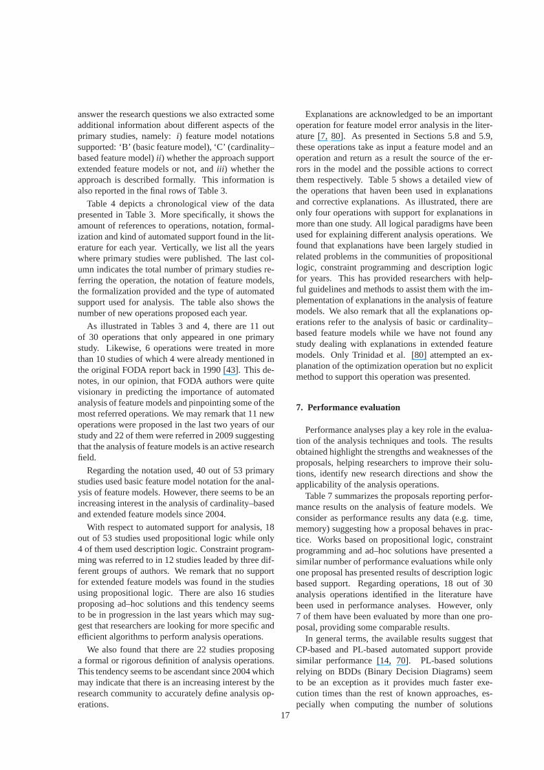
Table 4 depicts a chronological view of the datapresented in Table 3. More specifically, it shows theamount of references to operations, notation, formal-ization and kind of automated support found in the lit-erature for each year. Vertically, we list all the yearswhere primary studies were published. The last col-umn indicates the total number of primary studies re-ferring the operation, the notation of feature models,the formalization provided and the type of automatedsupport used for analysis. The table also shows thenumber of new operations proposed each year.
As illustrated in Tables 3 and 4, there are 11 outof 30 operations that only appeared in one primarystudy. Likewise, 6 operations were treated in morethan 10 studies of which 4 were already mentioned inthe original FODA report back in 1990 [43]. This de-notes, in our opinion, that FODA authors were quitevisionary in predicting the importance of automatedanalysis of feature models and pinpointing some of themost referred operations. We may remark that 11 newoperations were proposed in the last two years of ourstudy and 22 of them were referred in 2009 suggestingthat the analysis of feature models is an active researchfield.
Regarding the notation used, 40 out of 53 primarystudies used basic feature model notation for the anal-ysis of feature models. However, there seems to be anincreasing interest in the analysis of cardinality–basedand extended feature models since 2004.
With respect to automated support for analysis, 18out of 53 studies used propositional logic while only4 of them used description logic. Constraint program-ming was referred to in 12 studies leaded by three dif-ferent groups of authors. We remark that no supportfor extended feature models was found in the studiesusing propositional logic. There are also 16 studiesproposing ad–hoc solutions and this tendency seemsto be in progression in the last years which may sug-gest that researchers are looking for more specific andefficient algorithms to perform analysis operations.
We also found that there are 22 studies proposinga formal or rigorous definition of analysis operations.This tendency seems to be ascendant since 2004 whichmay indicate that there is an increasing interest by theresearch community to accurately define analysis op-erations.
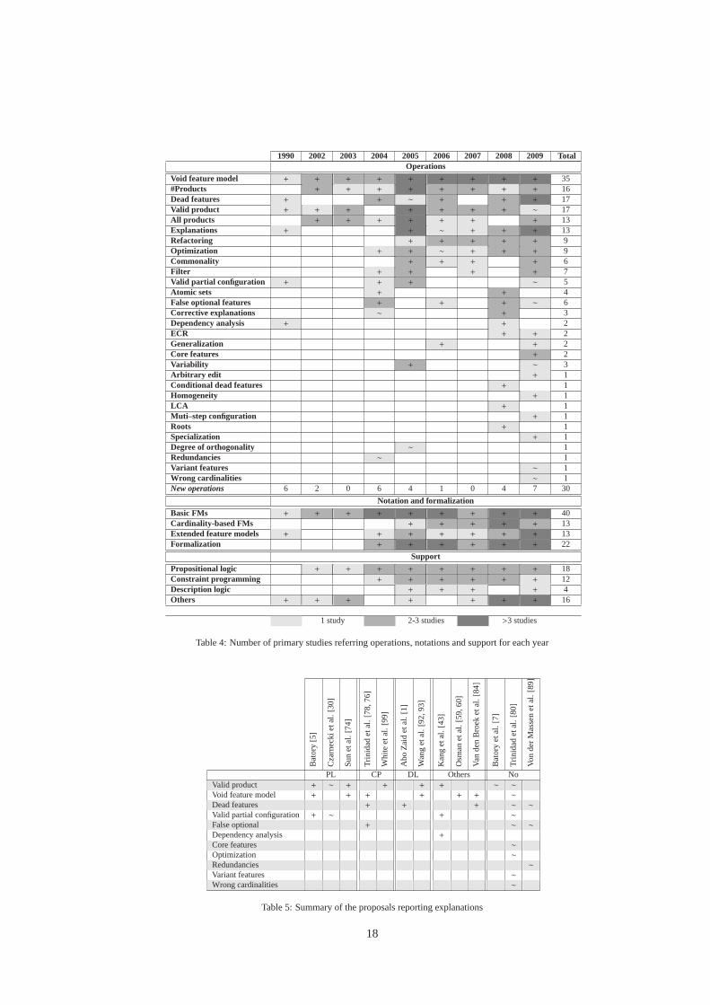
Explanations are acknowledged to be an importantoperation for feature model error analysis in the liter-ature [7, 80]. As presented in Sections 5.8 and 5.9,these operations take as input a feature model and anoperation and return as a result the source of the er-rors in the model and the possible actions to correctthem respectively. Table 5 shows a detailed view ofthe operations that haven been used in explanationsand corrective explanations. As illustrated, there areonly four operations with support for explanations inmore than one study. All logical paradigms have beenused for explaining different analysis operations. Wefound that explanations have been largely studied inrelated problems in the communities of propositionallogic, constraint programming and description logicfor years. This has provided researchers with help-ful guidelines and methods to assist them with the im-plementation of explanations in the analysis of featuremodels. We also remark that all the explanations op-erations refer to the analysis of basic or cardinality–based feature models while we have not found anystudy dealing with explanations in extended featuremodels. Only Trinidad et al. [80] attempted an ex-planation of the optimization operation but no explicitmethod to support this operation was presented.
7. Performance evaluation
Performance analyses play a key role in the evalua-tion of the analysis techniques and tools. The resultsobtained highlight the strengths and weaknesses of theproposals, helping researchers to improve their solu-tions, identify new research directions and show theapplicability of the analysis operations.
Table 7 summarizes the proposals reporting perfor-mance results on the analysis of feature models. Weconsider as performance results any data (e.g. time,memory) suggesting how a proposal behaves in prac-tice. Works based on propositional logic, constraintprogramming and ad–hoc solutions have presented asimilar number of performance evaluations while onlyone proposal has presented results of description logicbased support. Regarding operations, 18 out of 30analysis operations identified in the literature havebeen used in performance analyses. However, only7 of them have been evaluated by more than one pro-posal, providing some comparable results.
In general terms, the available results suggest thatCP-based and PL-based automated support providesimilar performance [14, 70]. PL-based solutionsrelying on BDDs (Binary Decision Diagrams) seemto be an exception as it provides much faster exe-cution times than the rest of known approaches, es-pecially when computing the number of solutions
17
1990 2002 2003 2004 2005 2006 2007 2008 2009 TotalOperations
Void feature model + + + + + + + + + 35#Products + + + + + + + + 16Dead features + + ∼ + + + 17Valid product + + + + + + + ∼ 17All products + + + + + + + 13Explanations + + ∼ + + + 13Refactoring + + + + + 9Optimization + + ∼ + + + 9Commonality + + + + 6Filter + + + + 7Valid partial configuration + + + ∼ 5Atomic sets + + 4False optional features + + + ∼ 6Corrective explanations ∼ + 3Dependency analysis + + 2ECR + + 2Generalization + + 2Core features + 2Variability + ∼ 3Arbitrary edit + 1Conditional dead features + 1Homogeneity + 1LCA + 1Muti–step configuration + 1Roots + 1Specialization + 1Degree of orthogonality ∼ 1Redundancies ∼ 1Variant features ∼ 1Wrong cardinalities ∼ 1New operations 6 2 0 6 4 1 0 4 7 30
Notation and formalization
Basic FMs + + + + + + + + + 40Cardinality-based FMs + + + + + 13Extended feature models + + + + + + + 13Formalization + + + + + + 22
Support
Propositional logic + + + + + + + + 18Constraint programming + + + + + + 12Description logic + + + + 4Others + + + + + + + 16
1 study 2-3 studies >3 studies
Table 4: Number of primary studies referring operations, notations and support for each year
Bat
ory
[5]
Cza
rnec
kiet
al.
[30]
Sun
etal
.[7
4]
Trin
idad
etal
.[7
8,76
]
Whi
teet
al.
[99]
Abo
Zai
det
al.
[1]
Wan
get
al.
[92,
93]
Kan
get
al.
[43]
Osm
anet
al.
[59,
60]
Van
den
Bro
eket
al.
[84]
Bat
ory
etal
.[7
]
Trin
idad
etal
.[8
0]
Von
der
Mas
sen
etal
.[8
9]
PL CP DL Others NoValid product + ∼ + + + + ∼ ∼
Void feature model + + + + + + ∼
Dead features + + + ∼ ∼
Valid partial configuration + ∼ + ∼
False optional + ∼ ∼
Dependency analysis +
Core features ∼
Optimization ∼
Redundancies ∼
Variant features ∼
Wrong cardinalities ∼
Table 5: Summary of the proposals reporting explanations
18
[14, 57, 70, 103]. The major drawback of this tech-nique is the size of the BDD representing the featuremodel that can be exponential in the worst case. Sev-eral authors have worked in the development of newheuristics and techniques to reduce the size of theBDDs used in the analysis of feature models [57, 103].Others focus on providing automated support usingdifferent paradigms in order to combine the best of allof them in terms of performance [14, 16].
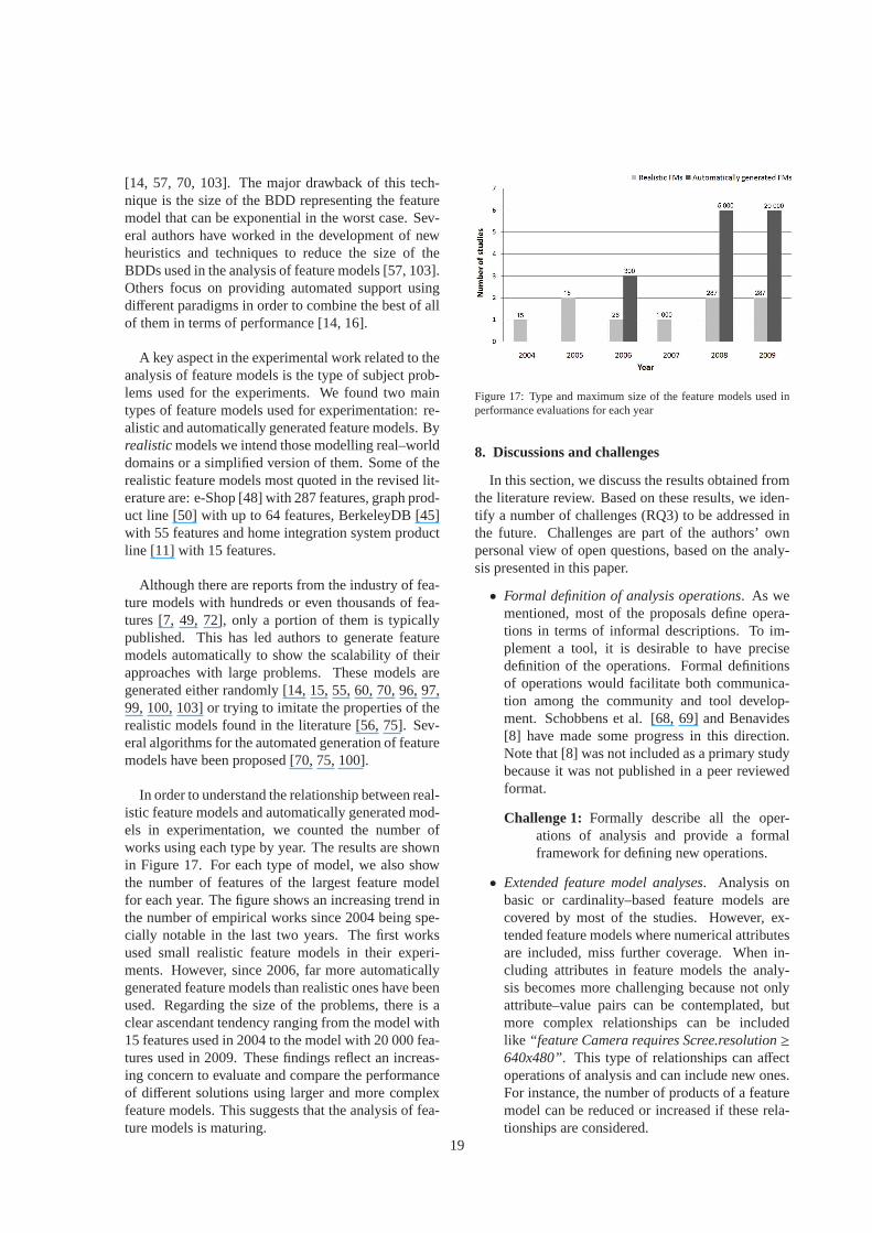
A key aspect in the experimental work related to theanalysis of feature models is the type of subject prob-lems used for the experiments. We found two maintypes of feature models used for experimentation: re-alistic and automatically generated feature models. Byrealisticmodels we intend those modelling real–worlddomains or a simplified version of them. Some of therealistic feature models most quoted in the revised lit-erature are: e-Shop [48] with 287 features, graph prod-uct line [50] with up to 64 features, BerkeleyDB [45]with 55 features and home integration system productline [11] with 15 features.
Although there are reports from the industry of fea-ture models with hundreds or even thousands of fea-tures [7, 49, 72], only a portion of them is typicallypublished. This has led authors to generate featuremodels automatically to show the scalability of theirapproaches with large problems. These models aregenerated either randomly [14, 15, 55, 60, 70, 96, 97,99, 100, 103] or trying to imitate the properties of therealistic models found in the literature [56, 75]. Sev-eral algorithms for the automated generation of featuremodels have been proposed [70, 75, 100].
In order to understand the relationship between real-istic feature models and automatically generated mod-els in experimentation, we counted the number ofworks using each type by year. The results are shownin Figure 17. For each type of model, we also showthe number of features of the largest feature modelfor each year. The figure shows an increasing trend inthe number of empirical works since 2004 being spe-cially notable in the last two years. The first worksused small realistic feature models in their experi-ments. However, since 2006, far more automaticallygenerated feature models than realistic ones have beenused. Regarding the size of the problems, there is aclear ascendant tendency ranging from the model with15 features used in 2004 to the model with 20 000 fea-tures used in 2009. These findings reflect an increas-ing concern to evaluate and compare the performanceof different solutions using larger and more complexfeature models. This suggests that the analysis of fea-ture models is maturing.
Figure 17: Type and maximum size of the feature models used inperformance evaluations for each year
8. Discussions and challenges
In this section, we discuss the results obtained fromthe literature review. Based on these results, we iden-tify a number of challenges (RQ3) to be addressed inthe future. Challenges are part of the authors’ ownpersonal view of open questions, based on the analy-sis presented in this paper.
• Formal definition of analysis operations. As wementioned, most of the proposals define opera-tions in terms of informal descriptions. To im-plement a tool, it is desirable to have precisedefinition of the operations. Formal definitionsof operations would facilitate both communica-tion among the community and tool develop-ment. Schobbens et al. [68, 69] and Benavides[8] have made some progress in this direction.Note that [8] was not included as a primary studybecause it was not published in a peer reviewedformat.
Challenge 1: Formally describe all the oper-ations of analysis and provide a formalframework for defining new operations.
• Extended feature model analyses. Analysis onbasic or cardinality–based feature models arecovered by most of the studies. However, ex-tended feature models where numerical attributesare included, miss further coverage. When in-cluding attributes in feature models the analy-sis becomes more challenging because not onlyattribute–value pairs can be contemplated, butmore complex relationships can be includedlike “feature Camera requires Scree.resolution≥640x480”. This type of relationships can affectoperations of analysis and can include new ones.For instance, the number of products of a featuremodel can be reduced or increased if these rela-tionships are considered.
19
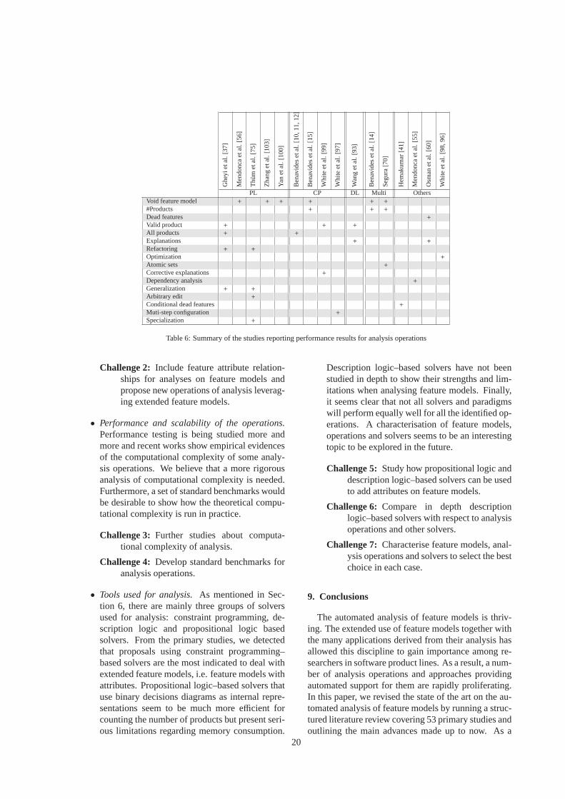
Ghe
yiet
al.
[37]
Men
donc
aet
al.
[56]
Thu
met
al.
[75]
Zha
nget
al.
[103
]
Yan
etal
.[1
00]
Ben
avid
eset
al.
[10,
11,1
2]
Ben
avid
eset
al.
[15]
Whi
teet
al.
[99]
Whi
teet
al.
[97]
Wan
get
al.
[93]
Ben
avid
eset
al.
[14]
Seg
ura
[70]
Hem
akum
ar[4
1]
Men
donc
aet
al.
[55]
Osm
anet
al.
[60]
Whi
teet
al.
[98,
96]
PL CP DL Multi OthersVoid feature model + + + + + +
#Products + + +
Dead features +
Valid product + + +
All products + +
Explanations + +
Refactoring + +
Optimization +
Atomic sets +
Corrective explanations +
Dependency analysis +
Generalization + +
Arbitrary edit +
Conditional dead features +
Muti-step configuration +
Specialization +
Table 6: Summary of the studies reporting performance results for analysis operations
Challenge 2: Include feature attribute relation-ships for analyses on feature models andpropose new operations of analysis leverag-ing extended feature models.
• Performance and scalability of the operations.Performance testing is being studied more andmore and recent works show empirical evidencesof the computational complexity of some analy-sis operations. We believe that a more rigorousanalysis of computational complexity is needed.Furthermore, a set of standard benchmarks wouldbe desirable to show how the theoretical compu-tational complexity is run in practice.
Challenge 3: Further studies about computa-tional complexity of analysis.
Challenge 4: Develop standard benchmarks foranalysis operations.
• Tools used for analysis.As mentioned in Sec-tion 6, there are mainly three groups of solversused for analysis: constraint programming, de-scription logic and propositional logic basedsolvers. From the primary studies, we detectedthat proposals using constraint programming–based solvers are the most indicated to deal withextended feature models, i.e. feature models withattributes. Propositional logic–based solvers thatuse binary decisions diagrams as internal repre-sentations seem to be much more efficient forcounting the number of products but present seri-ous limitations regarding memory consumption.
Description logic–based solvers have not beenstudied in depth to show their strengths and lim-itations when analysing feature models. Finally,it seems clear that not all solvers and paradigmswill perform equally well for all the identified op-erations. A characterisation of feature models,operations and solvers seems to be an interestingtopic to be explored in the future.
Challenge 5: Study how propositional logic anddescription logic–based solvers can be usedto add attributes on feature models.
Challenge 6: Compare in depth descriptionlogic–based solvers with respect to analysisoperations and other solvers.
Challenge 7: Characterise feature models, anal-ysis operations and solvers to select the bestchoice in each case.
9. Conclusions
The automated analysis of feature models is thriv-ing. The extended use of feature models together withthe many applications derived from their analysis hasallowed this discipline to gain importance among re-searchers in software product lines. As a result, a num-ber of analysis operations and approaches providingautomated support for them are rapidly proliferating.In this paper, we revised the state of the art on the au-tomated analysis of feature models by running a struc-tured literature review covering 53 primary studies andoutlining the main advances made up to now. As a
20
main result, we presented a catalogue with 30 analy-sis operations identified in the literature and classifiedthe existing proposal providing automated support forthem according to their underlying logical paradigm.We also provided information about the tools used toperform the analyses and the results and trends re-lated to the performance evaluation of the publishedproposals. From the analysis of current solutions, weconclude that the analysis of feature models is matur-ing with an increasing number of contributions, oper-ations, tools and empirical works. We also identifieda number of challenges for future research mainly re-lated to the formalization and computational complex-ity of the operations, performance comparison of theapproaches and the support of extended feature mod-els.
Acknowledments
We would like to thank Lamia Abo Zaid, Don Ba-tory, Deepak Dhungana, David Fernandez-Amoros,Jose Galindo, Ruben Heradio, Christian Kastner, Ab-delrahman Osman Elfaki, Anna Queralt, Fabricia C.Roos, Ernest Teniente, Thomas Thum, Pablo Trinidad,Pim Van den Broek and Wei Zhang for their helpfulcommments in earlier versions of this article.
This work has been partially supported by the Eu-ropean Commission (FEDER) and Spanish Govern-ment under CICYT projects SETI (TIN2009-07366)and WebFactories(TIN2006-00472) and by the An-dalusian Government under ISABEL project (TIC-2533)
References
[1] L. Abo, F. Kleinermann, and O. De Troyer. Applying se-mantic web technology to feature modeling. InSAC ’09:Proceedings of the 2009 ACM symposium on Applied Com-puting, pages 1252–1256, New York, NY, USA, 2009. ACM.
[2] Alloy analyzer,http://alloy.mit.edu/. accessed Jan-uary 2010.
[3] F. Baader, D. Calvanese, D.L. McGuinness, D. Nardi, andP.F. Patel-Schneider, editors.The description logic hand-book: theory, implementation, and applications. CambridgeUniversity Press, New York, NY, USA, 2003.
[4] R. Bachmeyer and H. Delugach. A conceptual graph ap-proach to feature modeling. InConceptual Structures:Knowledge Architectures for Smart Applications, 15th Inter-national Conference on Conceptual Structures, ICCS, pages179–191, 2007.
[5] D. Batory. Feature models, grammars, and propositionalformulas. InSoftware Product Lines Conference, volume3714 of Lecture Notes in Computer Sciences, pages 7–20.Springer–Verlag, 2005.
[6] D. Batory. A tutorial on feature oriented programming andthe ahead tool suite. InSummer school on Generative andTransformation Techniques in Software Engineering, 2005.
[7] D. Batory, D. Benavides, and A. Ruiz-Cortes. Automatedanalysis of feature models: Challenges ahead.Communica-tions of the ACM, December:45–47, 2006.
[8] D. Benavides.On the Automated Analyisis of Software Prod-uct Lines using Feature Models. A Framework for Devel-oping Automated Tool Support.PhD thesis, University ofSeville, 2007.
[9] D. Benavides, D. Batory, P. Heymans, and A. Ruiz-Cortes,editors. First Workshop on Analyses of Software ProductLines, September 2008.
[10] D. Benavides, A. Ruiz-Cortes, and P. Trinidad. Coping withautomatic reasoning on software product lines. InProceed-ings of the 2nd Groningen Workshop on Software VariabilityManagement, November 2004.
[11] D. Benavides, A. Ruiz-Cortes, and P. Trinidad. Automatedreasoning on feature models. InAdvanced Information Sys-tems Engineering: 17th International Conference, CAiSE,volume 3520 ofLecture Notes in Computer Sciences, pages491–503. Springer–Verlag, 2005.
[12] D. Benavides, A. Ruiz-Cortes, and P. Trinidad. Using con-straint programming to reason on feature models. InThe Sev-enteenth International Conference on Software Engineeringand Knowledge Engineering, SEKE 2005, pages 677–682,2005.
[13] D. Benavides, S. Segura, and A. Ruiz-Cortes. Automatedanalysis of feature models: A detailed literature review.Technical Report ISA-09-TR-04, ISA research group, 2009.Available athttp://www.isa.us.es/.
[14] D. Benavides, S. Segura, P. Trinidad, and A. Ruiz-Cortes. Afirst step towards a framework for the automated analysis offeature models. InManaging Variability for Software Prod-uct Lines: Working With Variability Mechanisms, 2006.
[15] D. Benavides, S. Segura, P. Trinidad, and A. Ruiz-Cortes.Using java CSP solvers in the automated analyses of featuremodels.LNCS, 4143:389–398, 2006.
[16] D. Benavides, S. Segura, P. Trinidad, and A. Ruiz-Cortes.FAMA: Tooling a framework for the automated analysis offeature models. InProceeding of the First InternationalWorkshop on Variability Modelling of Software-intensiveSystems (VAMOS), pages 129–134, 2007.
[17] D. Le Berre. SAT4J solver,http://www.sat4j.org. ac-cessed January 2010.
[18] B. Bollig and I. Wegener. Improving the variable ordering ofOBDDs is NP-complete.IEEE Transactions on Computers,45(9):993–1002, 1996.
[19] R. Bryant. Graph-based algorithms for boolean functionma-nipulation. IEEE Transactions on Computers, 35(8):677–691, 1986.
[20] F. Cao, B. Bryant, C. Burt, Z. Huang, R. Raje, A. Olson, andM. Auguston. Automating feature-oriented domain analysis.In International Conference on Software Engineering Re-search and Practice (SERP’03), pages 944–949, June 2003.
[21] CHOCO solver,http://choco.emn.fr/. accessed Jan-uary 2010.
[22] Clark and Parsia. Pellet: the open source owl reasoner,http://clarkparsia.com/pellet/. published on line.
[23] A. Classen, P. Heymans, and P.Y. Schobbens. What’s in afeature: A requirements engineering perspective. InFunda-mental Approaches to Software Engineering, volume 4961,pages 16–30. Springer, 2008.
[24] P. Clements and L. Northrop.Software Product Lines: Prac-tices and Patterns. SEI Series in Software Engineering.Addison–Wesley, August 2001.
[25] S. Cook. The complexity of theorem-proving procedures.In Conference Record of Third Annual ACM Symposium onTheory of Computing, pages 151–158, 1971.
[26] K. Czarnecki, T. Bednasch, P. Unger, and U. Eisenecker.Generative programming for embedded software: An in-dustrial experience report. InGenerative Programming andComponent Engineering, ACM SIGPLAN/SIGSOFT Confer-ence, GPCE, pages 156–172, 2002.
[27] K. Czarnecki and U.W. Eisenecker.Generative Program-
21
ming: Methods, Techniques, and Applications. Addison–Wesley, may 2000. ISBN 0–201–30977–7.
[28] K. Czarnecki, S. Helsen, and U. Eisenecker. Formaliz-ing cardinality-based feature models and their specialization.Software Process: Improvement and Practice, 10(1):7–29,2005.
[29] K. Czarnecki, S. Helsen, and U. Eisenecker. Staged configu-ration through specialization and multilevel configurationoffeature models.Software Process: Improvement and Prac-tice, 10(2):143–169, 2005.
[30] K. Czarnecki and P. Kim. Cardinality-based feature model-ing and constraints: A progress report. InProceedings of theInternational Workshop on Software Factories At OOPSLA2005, 2005.
[31] K. Czarnecki, S. She, and A. Wasowski. Sample spaces andfeature models: There and back again. Inproceedings ofthe Software Product Line Conference (SPLC), pages 22–31,2008.
[32] M. Dean and G. Schreiber. OWL web ontology languagereference. W3C recommendation, W3C, February 2004.
[33] JaCoP development team. accessed January 2010.[34] O. Djebbi, C. Salinesi, and D. Diaz. Deriving product line
requirements: the red-pl guidance approach. In14th Asia-Pacific Software Engineering Conference (APSEC), pages494–501, Los Alamitos, CA, USA, 2007. IEEE ComputerSociety.
[35] S. Fan and N. Zhang. Feature model based on descriptionlogics. InKnowledge-Based Intelligent Information and En-gineering Systems, 10th International Conference, KES, PartII , volume 4252 ofLecture Notes in Computer Sciences.Springer–Verlag, 2006.
[36] D. Fernandez-Amoros, R. Heradio, and J. Cerrada. Inferringinformation from feature diagrams to product line economicmodels. InProceedings of the Sofware Product Line Confer-ence, 2009.
[37] R. Gheyi, T. Massoni, and P. Borba. A theory for featuremodels in alloy. InProceedings of the ACM SIGSOFY FirstAlloy Workshop, pages 71–80, Portland, United States, nov2006.
[38] R. Gheyi, T. Massoni, and P. Borba. Algebraic laws forfeature models. Journal of Universal Computer Science,14(21):3573–3591, 2008.
[39] GNU prolog, http://www.gprolog.org. accessed Jan-uary 2010.
[40] J. Greenfield, K. Short, S. Cook, and S. Kent.SoftwareFactories: Assembling Applications with Patterns, Models,Frameworks, and Tools. Wiley, August 2004.
[41] A. Hemakumar. Finding contradictions in feature models. InFirst International Workshop on Analyses of Software Prod-uct Lines (ASPL’08), pages 183–190, 2008.
[42] P. Heymans, P.Y. Schobbens, J.C. Trigaux, Y. Bontemps,R. Matulevicius, and A. Classen. Evaluating formal prop-erties of feature diagram languages.Software IET, 2(3):281–302, 2008.
[43] K. Kang, S. Cohen, J. Hess, W. Novak, and S. Peter-son. Feature–Oriented Domain Analysis (FODA) FeasibilityStudy. Technical Report CMU/SEI-90-TR-21, Software En-gineering Institute, Carnegie Mellon University, November1990.
[44] K. Kang, S. Kim, J. Lee, K. Kim, E. Shin, and M. Huh.FORM: A feature–oriented reuse method with domain–specific reference architectures.Annals of Software Engi-neering, 5:143–168, 1998.
[45] C. Kastner, S. Apel, and D. Batory. A case study implement-ing features using aspectj. InSPLC ’07: Proceedings of the11th International Software Product Line Conference, pages223–232, Washington, DC, USA, 2007. IEEE Computer So-ciety.
[46] B. Kitchenham. Procedures for performing systematic re-
views. Technical report, Keele University and NICTA, 2004.[47] P. Klint. A meta-environment for generating programming
environments.ACM Trans. Softw. Eng. Methodol., 2(2):176–201, April 1993.
[48] S.Q. Lau. Domain analysis of e-commerce systems usingfeature–based model templates. master’s thesis. Dept. ofECE, University of Waterloo, Canada, 2006.
[49] F. Loesch and E. Ploedereder. Optimization of variability insoftware product lines. InProceedings of the 11th Interna-tional Software Product Line Conference, SPLC, pages 151–162, Washington, DC, USA, 2007. IEEE Computer Society.
[50] R.E Lopez-Herrejon and D. Batory. A standard problem forevaluating product-line methodologies. InGCSE ’01: Pro-ceedings of the Third International Conference on Genera-tive and Component-Based Software Engineering, pages 10–24, London, UK, 2001. Springer-Verlag.
[51] M. Mannion. Using first-order logic for product line modelvalidation. InProceedings of the Second Software ProductLine Conference (SPLC’02), volume 2379 ofLecture Notesin Computer Sciences, pages 176–187, San Diego, CA, 2002.Springer–Verlag.
[52] M. Mannion and J. Camara. Theorem proving for productline model verification. InSoftware Product-Family Engi-neering (PFE), volume 3014 ofLecture Notes in ComputerScience, pages 211–224. Springer–Verlag, 2003.
[53] F. Maric. Formalization and implementation of modern satsolvers. Journal of Automated Reasoning, 43(1):81–119,June 2009.
[54] M. Mendonca, T.T. Bartolomei, and D. Cowan. Decision-making coordination in collaborative product configuration.In Proceedings of the 2008 ACM symposium on Applied com-puting (SAC ’08), pages 108–113, New York, NY, USA,2008. ACM.
[55] M. Mendonca, D.D. Cowan, W. Malyk, and T. Oliveira. Col-laborative product configuration: Formalization and efficientalgorithms for dependency analysis.Journal of Software,3(2):69–82, 2008.
[56] M. Mendonca, A. Wasowski, and K. Czarnecki. SAT–basedanalysis of feature models is easy. InProceedings of theSofware Product Line Conference, 2009.
[57] M. Mendonca, A. Wasowski, K. Czarnecki, and D. Cowan.Efficient compilation techniques for large scale feature mod-els. In Generative Programming and Component Engi-neering, 7th International Conference, GPCE , Proceedings,pages 13–22, 2008.
[58] OPL studio,http://www.ilog.com/products/oplstudio/.accessed January 2010.
[59] A. Osman, S. Phon-Amnuaisuk, and C.K. Ho. Knowledgebased method to validate feature models. InFirst Inter-national Workshop on Analyses of Software Product Lines,pages 217–225, 2008.
[60] A. Osman, S. Phon-Amnuaisuk, and C.K. Ho. Using first or-der logic to validate feature model. InThird InternationalWorkshop on Variability Modelling in Software-intensiveSystems (VaMoS), pages 169–172, 2009.
[61] J. Pena, M. Hinchey, A. Ruiz-Cortes, and P. Trinidad. Build-ing the core architecture of a multiagent system product line:With an example from a future nasa mission. In7th Inter-national Workshop on Agent Oriented Software Engineering,Lecture Notes in Computer Sciences. Springer–Verlag, 2006.
[62] K. Pohl, G. Bockle, , and F. van der Linden.Software Prod-uct Line Engineering: Foundations, Principles, and Tech-niques. Springer–Verlag, 2005.
[63] Racer Systems GmbH Co. KG. RACER,http://www.racer-systems.com/. accessed Jan-uary 2010.
[64] R Reiter. A theory of diagnosis from first principles.Artifi-cial Intelligence, 32(1):57–95, 1987.
[65] M. Riebisch, K. Bollert, D. Streitferdt, and I. Philippow. Ex-
22
tending feature diagrams with UML multiplicities. In6thWorld Conference on Integrated Design& Process Technol-ogy (IDPT2002), June 2002.
[66] C. Salinesi, C. Rolland, and R. Mazo. Vmware: Tool supportfor automatic verification of structural and semantic correct-ness in product line models. InThird International Work-shop on Variability Modelling of Software-intensive Systems,pages 173–176, 2009.
[67] K. Schmid and I. John. A customizable approach to fulllifecycle variability management.Science of Computer Pro-gramming, 53(3):259–284, 2004.
[68] P. Schobbens, P. Heymans, J. Trigaux, and Y. Bontemps. Fea-ture Diagrams: A Survey and A Formal Semantics. InPro-ceedings of the 14th IEEE International Requirements Engi-neering Conference (RE’06), Minneapolis, Minnesota, USA,September 2006.
[69] P. Schobbens, J.C. Trigaux P. Heymans, and Y. Bontemps.Generic semantics of feature diagrams.Computer Networks,51(2):456–479, Feb 2007.
[70] S. Segura. Automated analysis of feature models usingatomic sets. InFirst Workshop on Analyses of Software Prod-uct Lines (ASPL 2008). SPLC’08, pages 201–207, Limerick,Ireland, September 2008.
[71] SMV system ,http://www.cs.cmu.edu/~modelcheck.accessed January 2010.
[72] M. Steger, C. Tischer, B. Boss, A. Muller, O. Pertler,W. Stolz, and S. Ferber. Introducing pla at bosch gasolinesystems: Experiences and practices. InSPLC, pages 34–50,2004.
[73] D. Streitferdt, M. Riebisch, and I. Philippow. Detailsof for-malized relations in feature models using OCL. InProceed-ings of 10th IEEE International Conference on Engineeringof Computer–Based Systems (ECBS 2003), Huntsville, USA.IEEE Computer Society, pages 45–54, 2003.
[74] J. Sun, H. Zhang, Y.F. Li, and H. Wang. Formal semanticsand verification for feature modeling. InProceedings of the10th IEEE International Conference on Engineering of Com-plex Computer Systems (ICECCS), 2005.
[75] T. Thum, D. Batory, and C. Kastner. Reasoning about editsto feature models. InInternational Conference on SoftwareEngineering, pages 254–264, 2009.
[76] P. Trinidad, D. Benavides, A. Duran, A. Ruiz-Cortes, andM. Toro. Automated error analysis for the agilization of fea-ture modeling.Journal of Systems and Software, 81(6):883–896, 2008.
[77] P. Trinidad, D. Benavides, and A. Ruiz-Cortes. Improv-ing decision making in software product lines product planmanagement. InProceedings of the V ADIS 2004 Workshopon Decision Support in Software Engineering, volume 120.CEUR Workshop Proceedings (CEUR-WS.org), 2004.
[78] P. Trinidad, D. Benavides, and A. Ruiz-Cortes. A first stepdetecting inconsistencies in feature models. InCAiSE ShortPaper Proceedings, 2006.
[79] P. Trinidad, D. Benavides, A. Ruiz-Cortes, S. Segura, andA.Jimenez. FaMa framework. In12th Software ProductLines Conference (SPLC), 2008.
[80] P. Trinidad and A. Ruiz Cortes. Abductive reasoning andautomated analysis of feature models: How are they con-nected? InThird International Workshop on Variabil-ity Modelling of Software-Intensive Systems. Proceedings,pages 145–153, 2009.
[81] S. Trujillo, D. Batory, and O. Dıaz. Feature oriented modeldriven development: A case study for portlets. InInterna-tional Conference on Software Engineering, pages 44–53,2007.
[82] E. Tsang.Foundations of Constraint Satisfaction. AcademicPress, 1995.
[83] M. Tseng and J. Jiao.Handbook of Industrial Engineering:Technology and Operations Management, chapter Mass Cus-
tomization, page 685. Wiley, 2001.[84] P. van den Broek and I. Galvao. Analysis of feature models
using generalised feature trees. InThird International Work-shop on Variability Modelling of Software-intensive Systems,number 29 in ICB-Research Report, pages 29–35, Essen,Germany, January 2009. Universitat Duisburg-Essen.
[85] F. van der Linden, K. Schmid, and E. Rommes.SoftwareProduct Lines in Action: The Best Industrial Practice inProduct Line Engineering. Springer-Verlag New York, Inc.,Secaucus, NJ, USA, 2007.
[86] T. van der Storm. Variability and component composition.In Software Reuse: Methods, Techniques and Tools: 8thInternational Conference, ICSR 2004. Proceedings, volume3107 ofLecutre Notes in Computer Sciences, pages 157–166.Springer, July 2004.
[87] T. van der Storm. Generic feature-based software compo-sition. In Software Composition, volume 4829 ofLectureNotes in Computer Sciences, pages 66–80. Springer–Verlag,2007.
[88] A. van Deursen and P. Klint. Domain–specific language de-sign requires feature descriptions.Journal of Computing andInformation Technology, 10(1):1–17, 2002.
[89] T. von der Massen and H. H. Lichter. Deficiencies in featuremodels. In Tomi Mannisto and Jan Bosch, editors,Workshopon Software Variability Management for Product Derivation- Towards Tool Support, 2004.
[90] T. von der Massen and H. Lichter. Requiline: A requirementsengineering tool for software product lines. In F. van derLinden, editor,Proceedings of the Fifth International Work-shop on Product Family Engineering (PFE), volume 3014of Lecture Notes in Computer Sciences, Siena, Italy, 2003.Springer–Verlag.
[91] T. von der Massen and H. Litcher. Determining the variationdegree of feature models. InSoftware Product Lines Confer-ence, volume 3714 ofLecture Notes in Computer Sciences,pages 82–88. Springer–Verlag, 2005.
[92] H. Wang, Y. Li, J. Sun, H. Zhang, and J. Pan. A seman-tic web approach to feature modeling and verification. InWorkshop on Semantic Web Enabled Software Engineering(SWESE’05), November 2005.
[93] H. Wang, Y.F. Li, J. un, H. Zhang, and J. Pan. Verifying Fea-ture Models using OWL.Journal of Web Semantics, 5:117–129, June 2007.
[94] J. Webster and R. Watson. Analyzing the past to preparefor the future: Writing a literature review.MIS Quarterly,26(2):xiii–xxiii, 2002.
[95] J. Whaley. JavaBDD,http://javabdd.sourceforge.net/. accessed January2010.
[96] J. White, B. Doughtery, and D. Schmidt. Selecting highlyoptimal architectural feature sets with filtered cartesian flat-tening. Journal of Systems and Software, 82(8):1268–1284,2009.
[97] J. White, B. Doughtery, D. Schmidt, and D. Benavides. Au-tomated reasoning for multi-step software product-line con-figuration problems. InProceedings of the Sofware ProductLine Conference, pages 11–20, 2009.
[98] J. White and D. Schmidt. Filtered cartesian flattening: Anap-proximation technique for optimally selecting features whileadhering to resource constraints. InFirst International Work-shop on Analyses of Software Product Lines (ASPL), pages209–216, 2008.
[99] J. White, D. Schmidt, D. Benavides P. Trinidad, and A. Ruiz-Cortes. Automated diagnosis of product-line configurationerrors in feature models. InProceedings of the Sofware Prod-uct Line Conference, 2008.
[100] H. Yan, W. Zhang, H. Zhao, and H. Mei. An optimiza-tion strategy to feature models’ verification by eliminatingverification-irrelevant features and constraints. InICSR,
23

pages 65–75, 2009.[101] W. Zhang, H. Mei, and H. Zhao. Feature-driven require-
ment dependency analysis and high-level software design.Requirements Engineering, 11(3):205–220, June 2006.
[102] W. Zhang, H. Zhao, and H. Mei. A propositional logic-basedmethod for verification of feature models. In J. Davies, ed-itor, ICFEM 2004, volume 3308 ofLecture Notes in Com-puter Sciences, pages 115–130. Springer–Verlag, 2004.
[103] Wei Zhang, Hua Yan, Haiyan Zhao, and Zhi Jin. A bdd–based approach to verifying clone-enabled feature models’constraints and customization. InHigh Confidence SoftwareReuse in Large Systems, 10th International Conference onSoftware Reuse, ICSR, Proceedings, volume 5030 ofLec-ture Notes in Computer Sciences, pages 186–199. Springer–Verlag, 2008.
24