Aug. 14, 1956 T. M. DEAKIN 2,758,513
10
: Aug. 14, 1956 T. M. DEAKIN 2,758,513 MACHINE FOR FORMING OR MEASURING BEVEL GEAR TEETH Filed April 14, 1950 5 Sheets-Sheet
-
Upload
khangminh22 -
Category
Documents
-
view
0 -
download
0
Transcript of Aug. 14, 1956 T. M. DEAKIN 2,758,513

:
Aug. 14, 1956 T. M. DEAKIN 2,758,513 MACHINE FOR FORMING OR MEASURING BEVEL GEAR TEETH
Filed April 14, 1950 5 Sheets-Sheet
Aug. 14, 1956 T. M. DEAKN 2,758,513 MACHINE FOR FORMING OR MEASURING BEVEL GEAR TEETH
Filed April 14, 1950 5 Sheets-Sheet 2
Šá2ZZN 46. €2a3S O
e ze 23 N 22
FC, 4

Aug. 14, 1956 T. M. DEAKN 2,758,513 MACHINE FOR FORMING OR MEASURING BEWEL GEAR TEETH
Filed April 14, 1950 5 Sheets-Sheet 3
Suula. towashupak L.
by R.A.

Aug. 14, 1956 T. M. DEAKN 2,758,513 MACHINE FOR FORMING OR MEASURING BEVEL GEAR TEETH
Filed April 14, l950. 5 Sheets-Sheet 4
ZA SN 7 C N M 8.

Aug. 14, 1956 T. M. DEAKN 2,758,513 MACHINE FOR FORMING OR MEASURING BEWEL GEAR TEETH
Filed April 14, 1950 5 Sheets-Sheet 5

2,758,513 MACHINE FOR FORMING OR MEASURING
BiVEL GEARTEETH Thomas Meyrick Deakin, Worcester, England Application April 14, 1950, Serial No. 155,876
Claims priority, application Great Britain April 14, 1949 13 Claims. (C. 90-3)
This invention concerns machines for forming or meas uring bevel gear teeth and has for an object to provide a simple mechanism for forming true involute profiles on the teeth of bevel gears. In the manufacture of Spur-gears it is known practice to form the flanks of the gear teeth to an involute curve so that, during intermeshing of the gears, the tooth flanks which transmit the load at any given time always make contact with one another along the line of action which is tangential to both involute base circles whereby the ratio between the Speeds of the two gears always remains constant. in addition, the use of the involute curve enables the distance between centres of shafts coupled together with the intermeshing gears to be varied within the limits for intermeshing of the gear teeth without affecting the constancy of the Speed ratio. It also provides a system of gearing whereby gears having the same diametral or circular pitch may mesh with each other, irrespective of the number. of teeth.
In the practice relating to the manufacture of bevel
United States Patent Office
O
2,758,513 Patented Aug. 14, 1956 2.
truncated "involute base cones' (hereinafter referred to for brevity. as the base cone) whose axes intersect at a point known in the art as the “apex" and constituting the centre of a circumscribing sphere, whilst the plane which is rolled from one cone to the other is of annular form. The circumference of this annular plane constitutes a great circle of the said sphere the circumferences of the bases of the base cones lying on the surface of the sphere. The profile of a tooth generated on this principle has
a true involute shape which can only be seen on a spheri cal surface of section, and whilst the advantages of the shape (termed herein the "spherical involute" shape) as mentioned above, have long been known, it has always been regarded as too complicated for commercial pur 15
20
poses, and an approximation has been preferred. This approximate profile, which is specified by the British Standards Institution, in Specification No. BSS.545/1949 "Bevel Gears (Machine Cut)"--is that which is produced by a cutting tool having a profile which is a counterpart of a single flank and root fillet of a basic rack. The latter is defined as the developed section of the teeth of the crown gear on the back cone, and this section has
25
straight sided flanks having a pressure angle of 20. When two bevel gears having their teeth, cut to this
standard profile are in mesh, the point of contact between any one pair of contacting tooth flanks does not follow a Straight line (the "line of action' of a true involute pro file). but a curve known in the art as an “octoid.” This
30
gears, although it is known that the involute shape of tooth flank produces the same advantageous results, dif: ficulty has been experienced in generating this shape accu rately owing to the more complicated geometric construc tion involved. It has therefore been the practice to manu facture bevel gear teeth having a flank profile which approximates to a true involute. Such gears, however, must generally be manufactured in pairs which match with each other and this involves considerable. additional ex pense. Moreover, if one gear of a pair becomes damaged and has to be replaced, it is necessary, to remove also the other gear so that the new gear to be made can be matched therewith, or both gears must be replaced. This is a considerable drawback since it may involve dismantling much of the machine concerned and its withdrawal from useful work for the period required for making the new gear. Much time and expense would be saved if it were possible to manufacture bevel gears which are universally interchangeable with the certainty that: they would accu rately mesh with any other gear. having the same dia metral, or circular pitch and the same cone, distance, i.e. the teeth interengage at the same distance from the com naOn cone apex. In the generation of an involute profile for spur gear
teeth a line or "involute generator' is regarded as fixed on a plane which is rolled from the circumference of a first disc, having a diameter equal to the involute base circle of the teeth of one gear, and a width equal to the flank width of the gear teeth, on to the circumference of a second involute base circle disc for the other gear. The surface traced out in space by the said fixed line or gen erator relative to the base circle disc as the plane is rolled from the one disc to the other is a true involute profile, and if the gear teeth are formed to this profile, contact between each tooth flank will take place along the line of action and therefore the profile will transmit constant anguiar velocity ratio. A similar consideration obtains in connection with bevel.
gears except that the involute, base. circle, discs become
35
40
45
50
55
60
65
results in greater noise and wear due to friction which Teaches serious proportions where the bevel gears are run at high Speeds. The working life: of standard bevel gears under these conditions is undesirably short. A further disadvantage of the said standard profile is
that the above-mentioned drawbacks are enhanced if there is any deviation from its true position of the axis of either shaft of a pair connected by standard bevel gears.
It is a principal object of the present. invention to pro vide a machine for generating. (or for testing) the teeth of a bevel gear to a true spherical involute profile. Another object of the present invention is to provide a
machine for generating the teeth of a bevel gear to a true Spherical involute profile, which can be operated on a quantity production basis. The present invention resides in the utilisation of this
geometric construction by providing that the gear on which the teeth are to be formed or measured, is rotated about its own axis and about the centre of the great circle representing the said annular plane in a manner equiva lent to the motion derived by rolling the piane around the base cone of the gear, and a forming or measuring tool is located or reciprocated along the involute generator, dur ing the said rotation of the bevel gear. The present invention accordingly provides a machine
for forming or measuring a true involute profile on a bevel gear tooth which comprises, a fixed frame part in which is mounted a first or great circle disc representing the ar nular plane which is rolled from one base cone to the other, a rigid straight-edged slide which is mounted in a carrier pivoted about the axis, of the great circle disc and is connected in non-slipping relation to the circum ference of the said disc, a second discrepresenting the base cone of the gear rotatably mounted on the carrier and con- . nected in non-slipping relation to the straight edged slide means for Securing the gear to beformed or measured co-axially to the base cone: disc, and a forming or meas uring tool mounted to be traversed, along the involute generator. The forming tool may be of the single or multiple point.
type or it may be constituted by a hone or griding wheel. 0 in the latter-case, it may be preferred to reciprocate the
wheel in a direction normal to, the plane containing the involute generator, so, that the point of contact, between

2,758,518 3
the flank of the tooth being generated and the grinding surface moves with respect thereto, thus preventing ex cessive local wear of the wheel. A similar consideration applies in the case where the tool has a cutting edge ex tending in the direction of the iheight of the tooth or is constituted by a measuring member or "feeler.' - Where the teeth of the bavel gear are straight and dis
posed radially with respect to the sphere on which the bases of the base cones lie, the first or great circle disc is locked in the frame of the device. Where, however, the teeth are disposed at an angle to the radius of the grit circle, or are curved along their length, the great circle disc may be rotatable about its axis under the control of suitable mechanism. Furthermore, the path of the tool may be modified in accordance with the shape of the tooth, as, for example, when the teeth are curved length wise as in spiral bevel gears. - Examples of ways of carrying the invention into effect will now be described with reference to the accompanying drawings in which: Fig. 1 illustrates the geometrical construction of a spherical involute focth profile for a bevel gear;
Fig. 2 illustrates the geometry of two intermeshing bevel gears having teeth whose profiles are true spherical in volutes: Fig. 3 is a partial axial cross-sectional view of a sche
0.
20
25
matic arrangement of machine embodying the principle of the invention; Fig. 4 is a fragmentary sectional elevation seen in the direction of the arrow IV of Fig. 3; Fig. 5 is a fragmentary plan view of Fig. 3, the teeth being shown in section on the surface of the base cone of the gear; Fig. 6 is a view similar to Fig. 5 illustrating the ma chining of a skew gear;
Fig. 7 illustrates the way in which the mechanism of Fig. 3 may be modified to enable a standard profile to be machined if desired; Fig. 8 is a fragmentary view similar to Fig. 4 of the arrangement shown in Fig. 7.
Fig. 9 illustrates a modification of the machine of Fig. 3; Fig. 10 is a diagram illustrating the displacement of
the tool in the direction of the height of the tooth to avoid excessive wear at one point of the tool, and Fig. 1 is a fragmentary section showing a method of machining the curved teeth of a spiral bevel gear.
In Fig. 1 of the drawings, thc base cone, i. of a bevel gear is in contact with a plane 2 (shown bounded by a circle of radius equal to the slant height of the cone ), the piane being assumed to roll against the cone. The curve 3 represents the locus of a point A on the plane 2 at the point where it touches the base AQ. The curve 3 is an involute, and lies on the surface of a sphere having its centre at O which is the apex of the cone .
Ef the come 1 rolls to the position 1, the involute 3 will always be normal to the base AQ, and at each suc cessive position of the cone a straight line may be draw:1 from the apex O to meet the curve in the point A. A family of such lines is shown at OA, Oa, OA'. These lines, by definition, always lie in the plane 2 as the latter rolls around the cone i, and define a surface which is a true or spherical involute, the profile of which can only be accurately represented on a spherical surface of section. The lines Oa are involute generators.
Referring now to Fig. 2 of the drawings, two meshing bevel gears are represented by their respective base cones a, B. Their corresponding pitch cones are shown at ip, iq, and are tangential at the point P. in this figure, the point P, sometimes referred to as the pitch point, is coincident with the apex. O, although it will be understood that in fact the point O is distant from the point P by the slant height of the pitch cones p, 1 g in a direction normal to the planeof the figure. The base cones sa, b are tangential to the plane 2 which cuts the sphere S in a great circle. The plane 2 contains both the apex. O and the
30
35
40
50
4. pitch point P, and also the line of action APB which is perpendicular to the line MPN. This latter line makes an angle with the line KPL drawn through the centres of the bases of the cones p, q, this angle being termed the "pressure angle.' The pressure angle is usually of the order of 20, and serves to determine the flank profile of the gear teeth. The circumscribing sphere on the Surface of which all the lines of the above construction are to be understood as drawn is represented by the circle S. The profiles 1 and 2 of a pair of mating gear teeth T.,
Ta are both tangential to the pressure angle line MPN, the curves corresponding to the curve 3 of Fig. 1. Since each of these curves represents the locus of a point cin the plane 2 as the plane is rolled past the respective base cone Aa or b, they are spherical involute curves, and lie on spherical involute surfaces whose generators are radii of the sphere S. One particular generator position is represented by the line OP which is common to both tocti profiles i and I2, and since both these profiles are spherical involute curves, they intersect thc line APB so that the tangent at the point of intersection is perpen dicular to the said line. From this it follows that the locus of the point of contact between the profiles of any pair of mating teeth such as T1 and T2 as the gears rotate is the straight line APB. Also, as the gears rotate, a gein. erator of each spherical involute tooth flank lies in the plane 2. The foregoing analysis rcfers specifically to straight bevel gears-that is, gears having teeth winose axes are radial with respect to the axis of the bevel gear. It will be understood, however, that similar considerations apply to spiral bevel gears, whether the teeth are straight-i. e. their axes are tangential to a circle concentric with centre O of the circumscribing sphere-or are curved. By an ex tension of the geomctry set out above, it can be shown that the generator of a spherical involute tooth flank for a spiral bevel gear is a line which lies in the plane 2. The common feature of the three types of gear mentioned above is, therefore, that the generators of the flanks cf the teeth whose profiles are spherical involute curves will al ways lie in the plane 2. The present inventic in accordingly seeks to embody this principle in a machine for the manu facture of bevel gears. Figs. 3, 4 and 5 are schematic fraginentary illustra tions of a basic mechanism for carrying the invention into effect. Referring again to Fig. 2, and assuming that the blank for a bevel gear whose teeth are to be formed with spherical involute profiles is made of a plastic substance of a putty-like consistency, then the desired profile would be generated by rotating the blank about its cone axis and at the same time traversing relatively thereto a rigid wire representing the involute generator in the plane 2 from a position outside the blank-say, beyond the point B with
60
5
respect to the gear represented by the cone a-up to the point (A) where the piane 2 is tangential to the base cone. Thus, the basic mechanism provides a fool and means for traversing the blank relatively thereto with such motion that the tool always makes contact with the flank of a tooth along a spherical involute generator. The machine comprises a rigid frame it containing a
fixed vertical axis OX. On the frame is mounted a fixed or 'great circle' disc 55 which is concentric with the said fixed vertical axis. Adjacent to this disc 2 and above it is mounted a sub-frame 2 which is oscillatable about the fixed axis OX by means of the shaft 12a, and has rigidly connected thereto a horizontal guideway 3 on which is mounted a straight rigid slide ; ; which is con nected at a rectilinear edge 14a in non-slipping relation to the circumference of the great circle disc it, the air rangement being such that on oscillation of the sy frame 2 about the fixed vertical axis OX, the slide 5: is reciprocated along the guideway 3 on the sub-frane. The sub-frame 12 supports a carrier 15 for the gear 6.
the teeth 17 of which are to be formed or measured. This carrier is provided with a bearing 18, the axis OG of
2,758,518 5 which is located so as to intersect the fixed vertical axis in a point O which represents the geometrical apex O. of Figs. 1. and 2. Hence, the point Q is the centre of the imaginary sphere. Son the surface of which lies both the circumference AQ of the base of the base cone OAQ for the teeth 17 to be formed or measured on the gear, and the circumference of the great circle representing the geo metrical plane 2 which, in the construction of Figs. 1 and 2, is regarded as containing the involute generator OA, and on which the base cone OAQ is assumed to roll to form the involute profile of a gear tooth 17. The carrier bearing 18 receives a stub shaft i9 on
which is secured the gear 16. The stub shaft 19 also has fixed thereto a disc 20 which represents the base cone OAQ of the gearié and has a diameter equal to the di ameter of the base. AQ. This base.cone disc 20 is, con nected in non-slipping relation to a rectilinear edge, 14b on the slide 14, so that it is constrained to rotate about the axis OG of the stub shaft 19 when the slide 14 is reciprocated in the sub-frame 12. . . . . . . m .
in the construction so far described, the gear on which teeth having true involute profiles are to be formed or measured is mounted on an axis which always passes through the apex. The circumference of the base cone of the teeth on this gear must therefore always lie on the surface of an imaginary sphere having its centre at the said apex. In the geometrical construction shown. in Figs. 1 and 2, the great circle plane 2 conta :ontaining the involute generator, OA, and which is tangenti OAQ, is regarded as having an outer radius equal to the radius of the sphere S. containing, the circumference of the base AQ of the base cone. In order to allow for the necessary clearances between the several working parts of the machine, it is ady - to rega • OAQ of the gear 16, as being extended outer end or base of the gear 16 by a convenient amount extended beyond the actual
derived from the great circle, disc 11, through the inter mediary of the slide 14, A forming tool, represented as a grinding wheel 21,
is mounted on a slide 22 for reciprocation on a guideway 23 carried on the machine frame 10. The tool, slide 22 is, reciprocated by suitable driving mechanism (not shown) in a generally radial direction so that t ol. 21. mounted thereon is traversed past the gear 16, in such a way that the point of contact at any given instant be tween the tool 21, and the flank of a gear tooth 17, lies on the involute generator OA for that tooth,
In order to impartfeed to the tool 21, the guideway 23 is mounted so as to pivot about an axis perpendicular, the fixed axis OX. The tool 21, shown in Figs. 3 and 4 as a grinding wheel, is thus able to be displaced towards, and away from the tooth flank, it being understood that the extent of such feed motion would normally be small sufficient to remove the excess metal from the teeth of a rough-formed gear blank,
It will be understood from the above description that oscillation of the sub-frame 12 about the fixed axis OX as by oscillation of the shaft 12a-causes oscillation of the gear 16 both about its own axis OG and about the fixed axis OX in such a way that the flank of a tooth 17 having a true involute profile is always tangential to a fixed vertical plane containing the involute generator OA
0.
15.
20
6 which also always lies in a horizontal plane 2 containing . the apex. O. The necessary geometrical relationships between the gear 16 and the forming or measuring tool 21 are thus always maintained. Furthermore, the fact that the flank of a tooth being formed is always tangen tial to a given vertical plane (containing the line MAN, Fig. 2) enables a single point tool to be moved vertically in this plane as the gear 16 rotates so that a vertically elongated cutting edge may be employed, thus avoiding tool wear at one point only and prolonging the life of the cutting edge. For the same reason a grinding wheel 21, having a flat vertical grinding face can be used and similarly moved. This vertical movement of the tool 21 relatively to the plane 2 is illustrated in Fig. 10 which shows three separate relative positions of the tool 21, and a tooth 17. As the tooth 17 rolls against the tool. 2. from an initial position 171 through an intermediate posi tion 172 to a final position 173, the point of contact J between the tool and the tooth remains in the plane 2-2. The tool. 21, however, may be moved downwards from the initial position 211 to the final position 213, it being apparent that the point J then moves along the tool 21,
25
30.
35
50
55
60
65
70
and it will be seen from Fig. 10 that the basic geometry of the method is not changed by this arrangement. The forming tool may be of the usual single point type
or it may be constituted by a grinding wheel. In the former case, the mechanism for reciprocating the tool slide 22 on the guideway 23 is arranged to give a high speed of traverse of the tool 21 across the tooth flank whilst the mechanism for oscillating the sub-frame 12 is of an intermittently operating nature. Thus, the gear 16 is held stationary during the cutting stroke of the forming tool 21, and the frame 12 is then moved through a pre-determined angle to rotate the gear. 16 by the de sired amount before the tool 23 makes the next cut. Where the forming tool 21 is constituted by a grinding
wheel, the mechanism for oscillating the tool slide 22 is arranged to give a slow speed of traverse whilst the mechanism for oscillating the sub-frame 12 is of a con tinuous nature to give the gear 16 a relatively high-speed of rotation about its axis OG. - A second tool 21a (Fig. 5) may be provided, the
mounting for which is in all respects similar to that of the tool. 21 except that the tool 21a is located on the op posite side of a tooth so that the tool forms or measures an oppositely directed flank. Whilst this latter flank may in some cases be the opposite flank of the same tooth 17-as that which is being-formed or measured by the first tool 21, it will in general be on another tooth.
In the above described form of machine, it has been assumed that the teeth 17 to be formed or measured are straight and directed radially with respect to the apex O. It will, however, be understood that in certain circum stances gear teeth of other forms may be required. For example, the teeth may be required to be straight but skewed with respect to a radius passing - through the apex O. In such a case, the tool 2i is mounted so. as to move along an involute generator O2A2 (Fig. 6) which is tangential to a circle concentric with the apex O. and to which the directions of the skewed teeth are also tangential. The mechanism illustrated in Figs. 3-5 can be readily
modified to machine a standard tooth profile. This is a 7 valuable feature of the invention, since it renders the mechanism of universal utility. Figs. 7 and 8 illustrate the modifications. The standard tooth profile is based on the pitch cone
1p or 1 g of Fig. 2. The gear 16 must, therefore, be reset in the machine so that its pitch cone OApGp lies tangen tial to the plane 2-2. This resetting is achieved by mounting the carrier 15 and its bearing 18 as a unit on an arcuate seating 24 struck about the apex O. This seating 24 is formed on a cross-slide 25 whereby the gear
5 16 may be bodily displaced so that its axis OG intersects the plane 2-in a point O2 (Fig. 6), lying on the diameter.

2,758,513 7
of the sphere S which is perpendicular to the line OA. The tool or wheel 21 is moved in the same direction through the distance OO2 so as to be traversible along the involute generator O2A2 parallel to the line OA. Clamp ing bolts 26 retain the carrier 15 in the desired position of adjustment. The former cone base AQ which determined the size
of the base cone disc 20 has now become extended to ApOp, so that a larger base cone disc 2.0a is required. The edge 14b is replaced by a bail 27 pivoted to the slide 14 about an axis in the plane 2 and containing the point Ap. The bail 27 has a surface. 27a, which is radial with respect to its pivotal axis, and suitable means is provided for clamping the bail 27 at the desired angle so as to engage tangentially the circumference of the pitch cone disc 20a. The guideway 23, is supported-as by the bracket 23a-on a trunnion 28 whose axis passes through the apex O so that the said guideway may be tilted to the same inclination as the root cone generator OA. The trunnion 28 is carried in a bearing 29 which is slung from a slide 30 working in an arcuate guide 31 on the machine frame 10. The guide 31 is curved about the line. OAp as axis. This enables the tool or wheel 21 to be set over to the pressure angle, as seen in Fig. 8. The mechanism thus generates the standard profile when the sub-frame 12 is oscillated and the tool or wheel 21 reciprocated along the guideway 23. Where teeth of arcuate shape are to be generated, it is preferred to employ a horizontally disposed cup-shaped grinding wheel (Fig. 11) which is rotated about a ver tical axis and the outer periphery 21b of which is in con tact with the flank of the tooth 17a. The radius of the said outer periphery 21b of this wheel may be equal to the radius of the tooth 17a, or alternatively, it may be less than this radius and the centre of the wheel may be swung about the centre of curvature of the tooth 17a. This latter arrangement is preferably adopted to allow for truing of the grinding wheel at the necessary intervals.
Although in the above description reference has been made to great circle and base cone "discs,' it is to be understood that these discs 11, 20 or 20a are of finite thickness, and are preferably, although not necessarily, of relatively great thickness so as to form in effect short cylinders. They may also be of any desired form other than solid. Each disc 1, 20 or 20a may be replaced by a sector having an angle not less than the angle through which relative movement between the inter-engageable parts takes place. Any alternative form of driving engagement between the discs 11, 20 or 20a and the slide 14 may be adopted as preferred. For example, the slide 14 may be pro vided with rack teeth in place of the surfaces 14a, 14b, and the periphery of each disc 11, 20 or 20a may be correspondingly toothed.
In the alternative construction, shown in Fig. 9, a great circle member-for example a rigid arcuate mem ber 32-is mounted in the true geometrical plane 2 con taining the involute generator OA to engage directly, in non-slipping relation, a base cone disc 20b mounted on the stub shaft i9 and having the same pitch circle AQ as the base cone, disc 20. Although in Fig. 9 the mem bers 20b and 32 are shown toothed, any convenient means may be used to ensure a non-slipping relation between them. In the examples of machine according to the invention which have been described above, the axis OG of the gear 6 to be formed has been assumed to intersect the axis of the gear with which it is to mesh. Where, how ever, it is desired to form a hyperboloidal gear (fre quently termed a "hypoid' bevel gear) the axis OG of the gear 16 to be formed is offset with respect to the fixed axis OX. It then intersects the plane 2 contain ing the apex. O and the involute generator OA at a point lying on the circumference of a circle contained in the
5
0.
15
20
25
30
0
5 .5
60
O
8 plane 2. As before, the tool 21 is caused to move along the line of the involute generator OA. Throughout the specification, the term "forming' is to be understood as including both generating a tooth pro file from a plain gear blank or finishing a roughly formed blank. The forming operation may be a cutting, broaching, grinding, lapping or like operation as desired. The drive to the machine is preferably applied to the
oscillatable sub-frame 12, although if preferred this frame may be fixed and the necessary motions imparted to the other parts of the machine. Alternatively, the Sub-frame 12 may carry a driving motor which recipro cates the slide 14 through any convenient known form of mechanism. Where the terms "vertical' and "horizontal' have been used in the foregoing specification, they are to be under stood as having relative rather than absolute significance. Although the machine has been described primarily
for the purpose of generating true involute tooth profiles on bevel gear teeth, it will be understood that it may be used, if desired, for the generation of modified tooth pro files by providing for the necessary modifications of the rotary feed motion of the gear being cut, or by any other convenient method. In this specification the term “tooth flank” is to be understood as referring to that zone of the tooth which may make driving contact with a corresponding tooth on the intermeshing gear wheel and which is comprised between the involute base circle and the tip of the tooth. This zone is sometimes referred to as the tooth "surface.” What I claim is: 1. A machine for generating the profile of a bevel
gear tooth flank comprising a first rigid member having an arcuate peripheral portion of a radius equal to the radius of a preselected imaginary circumscribing sphere drawn on the gear apex as centre, a second rigid member fixedly coupled to the gear blank and having an arcuate peripheral portion of a radius equal to the radius of the base cone of the gear blank where it intersects the said circumscribing sphere, a single rigid rectilinear slide assembly having two straight parallel operative portions respectively engaged in non-slip relationship with the arcuate portions of the first and second rigid members, a guideway for supporting the rectilinear slide for recip rocation in the direction of length of its straight parallel portions and for bodily angular displacement around the axis of the arcuate portion of the first rigid member, and a tool traversible across the gear blank in a plane nor mal to the generating plane to generate the tooth flank profile.
2. A machine as claimed in claim 1 wherein the tool is further reciprocable in the plane of traverse thereof and in a direction perpendicular to its direction of traverse relative to the gear blank. 3. A machine for forming the teeth of a bevel gear comprising a first and fixed rigid member representing a reference plane and having an operative portion of its periphery formed as an arc of a circle, a carrier for rotatably supporting the gear in a position relative to the plane such that the plane is tangential to the involute base cone of the gear, a second and circular rigid mem ber having an effective diameter equal to that of the geometrical base of the said base cone, the said opera tive portion of the periphery of the first rigid member having a diameter equal to that of the circumscribing sphere which can be drawn about the cone apex of the gear and at whose surface lies the said geometrical base of the involute base cone of the gear, a rigid coaxial connection between the gear and the second rigid mem ber, a non-slip connection between the operative portion of the periphery of the first rigid member and the effec tive periphery of the second rigid member, means for rotating the said carrier and first rigid member relatively to each other about an axis normal to the reference plane and containing the centre of the said circumscribing
2.
2,758,513 sphere, a tool mounted so as to make contact with a tooth flank of the gear only along a spherical involute surface generator contained in the said plane, and means for traversing the tool relatively to the tooth flank along the said involute generator and in a plane normal to the generating plane.
4. A machine as claimed in claim 3 having means for reciprocating the tool relatively to the tooth flank in a direction normal to the reference plane.
5. A machine as claimed in claim 3 wherein the first and second rigid members are constituted by discs the radius of the said first member being equal to the radius of the circumscribing sphere and the diameter of the said second member being equal to the diameter of the geo metrical base of the base cone.
6. A machine as claimed in claim 5 wherein the two discs are interconnected in non-slipping relationship by means of a straight rigid member slidably supported on the gear carrier and having two parallel edges, each being in non-slipping engagement with a respective one of the two discs.
7. A machine as claimed in claim 3 wherein the gear carrier supports the gear in a position such that the axis of the gear intersects the reference plane at the centre of the circumscribing sphere.
8. A machine as claimed in claim 3 wherein the gear carrier is adjustable in a direction parallel to the refer ence plane and perpendicular to the direction of traverse of the tool.
9. A machine for forming the flank of a bevel gear tooth to a true involute profile comprising a first disc representing the generating plane which is tangential to both involute base cones of the said gear and another gear with which it is to mesh, a carrier for the said gear, means for supporting the gear on the carrier for rotation about its own axis and in a position such that the said axis makes an angle with the said plane equal to half the cone angle of the involute base cone, a second disc rigidly connected to the said gear and coaxial therewith, the diameter of said second disc being equal to the diam eter of the geometrical base of the base cone, means for rotating the gear carrier relatively to the first disc about the axis of the latter, means for interconnecting the pe
O ripheries of the discs in non-slipping relationship, a tool mounted with its operating portion lying in a plane normal to the generating plane so as to make contact with a tooth flank of the said gear on an involute generator lying
5 in the said generating plane, and means for traversing the tool in the direction of the said involute generator.
10. A machine as claimed in claim 9 having means for reciprocating the tool in a direction normal to the said generating plane.
11. A machine as claimed in claim 3 having means for adjusting the position of the gear relative to the reference plane so that the latter is tangential to the pitch cone of the gear, means for adjusting the second and circular rigid member so that its effective diameter is
15 equal to that of the geometrical base of the said pitch cone, and means for adjusting the tool mounting so as to present the tool to the tooth flank at an angle to the normal to the reference plane equal to the pressure angle of the tooth profile.
12. A machine as claimed in claim 3 wherein the first rigid member comprises a crown gear having its pitch surface lying in the reference plane and the second rigid member comprises a bevel gear meshing with the crown gear and having a pitch circle diameter equal to the
25 diameter of the geometrical base of the base cone of the gear. 13. A machine as claimed in claim 3 having means
for displacing the tool perpendicular to its path of trav erse and parallel to the generating plane in a direction
30 towards the tooth flank in engagement therewith when the tool engages the tip of the tooth by an amount suffi cient to impart a desired tip relief to the tooth.
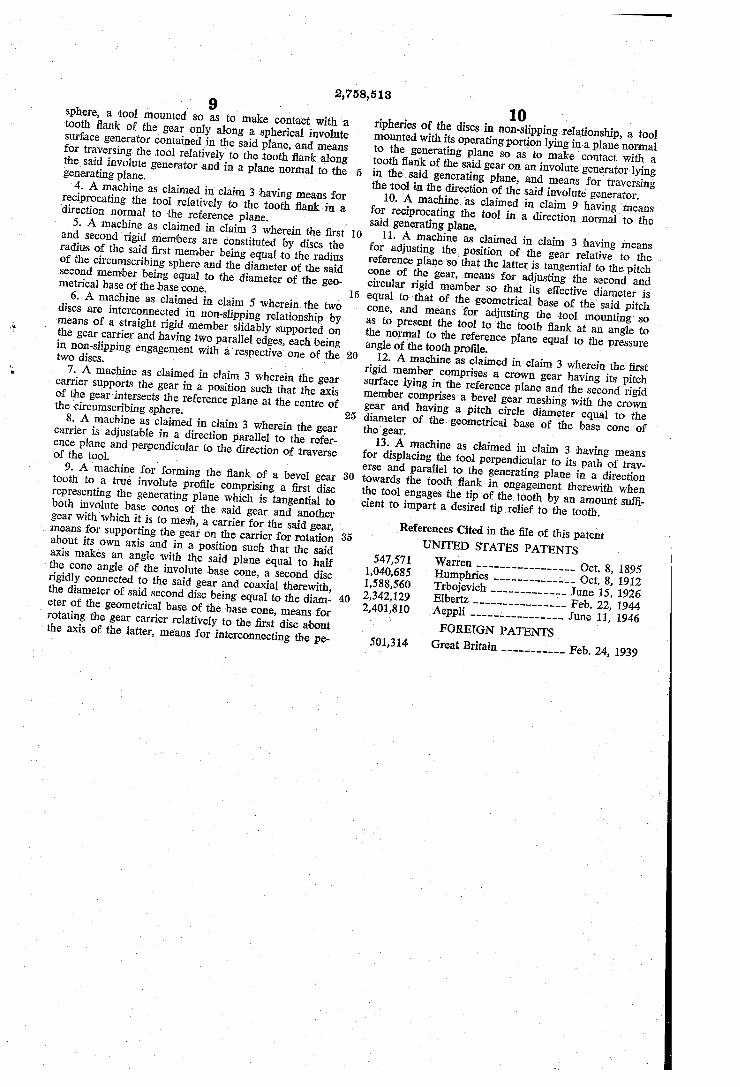
References Cited in the file of this patent UNITED STATES PATENTS
547,571 Warren ----------------- Oct. 8, 1895 1,040,685 Humphries -------------- Oct. 8, 1912 1,588,560 Trbojevich ------------- June 15, 1926
40 2,342,129 Elbertz ---------------- Feb. 22, 1944 2,401,810 Aeppli---------------- June 11, 1946
FOREIGN PATENTS 501,314 Great Britain -----Fun was or mon Feb. 24, 1939


![arXiv:2008.07486v1 [stat.AP] 17 Aug 2020](https://static.fdokumen.com/doc/165x107/631ce10276d2a4450503bd91/arxiv200807486v1-statap-17-aug-2020.jpg)