auburn university student launch - Wisconsin Space Grant ...
115
AUBURN UNIVERSITY STUDENT LAUNCH Project Tigris 211 Davis Hall AUBURN, AL 36849 Proposal September 14, 2018
-
Upload
khangminh22 -
Category
Documents
-
view
1 -
download
0
Transcript of auburn university student launch - Wisconsin Space Grant ...

AUBURN UNIVERSITY STUDENT LAUNCH
Project Tigris
211 Davis Hall
AUBURN, AL 36849
Proposal
September 14, 2018
AUBURN UNIVERSITY STUDENT LAUNCH | PROPOSAL 2
Contents
List of Tables ..................................................................................................................................6
List of Figures .................................................................................................................................7
1. General Information ................................................................................................9
1.1: Team summary ...................................................................................................9
1.2: Adult Educators ..................................................................................................9
1.3: Team Mentor ....................................................................................................10
1.4: Student Team Leader ........................................................................................11
1.5: Student Safety Officer ......................................................................................11
1.6: Project Organization .........................................................................................12
1.7: NAR/TRA Sections ..........................................................................................12
2. Facilities ..................................................................................................................14
2.1: Aerospace Computational Lab .........................................................................14
2.2: Aerodynamics Laboratory ................................................................................14
2.3: Advanced Laser Diagnostics Laboratory .........................................................15
2.4: Composites and UAV Laboratory ....................................................................16
2.5: Design and Manufacturing Laboratory .............................................................17
2.6: Flow Visualization Laboratory .........................................................................18
2.7: GKN Aerospace Tallassee, Alabama ...............................................................19
2.8: Machine Tool Laboratory and the Aerospace Wood Shop ..............................20
2.9: Structures Laboratory .......................................................................................20
3. Safety .......................................................................................................................21
3.1: Personnel and Responsibilities .........................................................................21

AUBURN UNIVERSITY STUDENT LAUNCH | PROPOSAL 3
3.2: Hazard Analyses ...............................................................................................22
3.3: Checklists..........................................................................................................25
3.4: Team Briefings and Checks ..............................................................................25
3.5: Energetic Device Handling ...............................................................................26
3.6: Law Compliance ...............................................................................................27
3.6.1: FAA Regulations: ........................................................................................................27
3.6.2: Alabama, Tennessee, and NFPA Codes: .....................................................................28
3.7: NAR/TRA Safety Codes ..................................................................................31
3.8: Caution Statements ...........................................................................................33
3.9: Team Safety Statement .....................................................................................35
3.10: Risk Assessments .............................................................................................35
4. Technical Design ....................................................................................................36
4.1: Vehicle Design .................................................................................................36
4.2: Projected Altitude .............................................................................................40
4.3: Recovery System Design ..................................................................................41
4.3.1: Structural Elements ......................................................................................................41
4.3.2: Materials ......................................................................................................................43
4.3.3: Ejection System ...........................................................................................................44
4.3.4: Parachutes ....................................................................................................................45
4.3.5: Parachute Construction ................................................................................................49
4.3.6: Drift ..............................................................................................................................50
4.3.7: Electronics ...................................................................................................................51
4.4: Motor Selection ................................................................................................56

AUBURN UNIVERSITY STUDENT LAUNCH | PROPOSAL 4
4.5: Payload Design (Rover)....................................................................................57
4.5.1: Rover Orientation System (ROS) ................................................................................57
4.5.2: Rover ............................................................................................................................57
4.5.3: Electronics ...................................................................................................................58
4.6: Altitude Control ................................................................................................59
4.6.1: Structure .......................................................................................................................62
4.6.2: Electronics ...................................................................................................................62
4.7: Requirements Verification ................................................................................66
4.7.1: General Requirements ..................................................................................................66
4.7.2: Vehicle Requirements ..................................................................................................69
4.7.3: Vehicle Prohibitions ....................................................................................................76
4.7.4: Recovery Requirements ...............................................................................................77
4.7.5: Rover Requirements ....................................................................................................80
4.7.6: Safety Requirements ....................................................................................................81
4.8: Major Technical Challenges and Solutions ......................................................82
5. STEM Engagement ................................................................................................84
5.1: General Statement.............................................................................................84
5.2: Drake Middle School 6th Grade Rocket Week ................................................84
5.2.1: Rocket Week Plan of Action .......................................................................................85
5.3: Samuel Ginn College of Engineering E-Day ...................................................86
5.4: Boy Scouts of America: Space Exploration Badge ..........................................87
5.5: Girl Scouts of America .....................................................................................88
5.6: GRAND Engineering Showcase ......................................................................89
AUBURN UNIVERSITY STUDENT LAUNCH | PROPOSAL 5
5.7: Auburn Junior High School Engineering Day ..................................................89
6. Project Plan ............................................................................................................90
6.1: Systems Engineering ........................................................................................90
6.1.1: CFD ..............................................................................................................................90
6.1.2: Rover ............................................................................................................................90
6.1.3: Embedded ....................................................................................................................91
6.1.4: Recovery ......................................................................................................................92
6.1.5: Vehicle Body ...............................................................................................................93
6.2: Development Timeline .....................................................................................94
6.3: Budget ...............................................................................................................95
6.3.1: Budget Summary .......................................................................................................100
6.4: Funding Plan ...................................................................................................101
6.5: Sustainability ..................................................................................................102
6.5.1: Aeropalooza ...............................................................................................................102
6.5.2: Organization Week ....................................................................................................103
6.5.3: Auburn University Rocketry Association ..................................................................104
Appendix A. Risk Assessment Tables .......................................................................................105

AUBURN UNIVERSITY STUDENT LAUNCH | PROPOSAL 6
List of Tables
Table 1: Severity Levels ............................................................................................................... 23
Table 2: Probability Levels ........................................................................................................... 24
Table 3: Risk Assessment Matrix ................................................................................................. 24
Table 4: Fin Dimensions and Fin .................................................................................................. 39
Table 5: Parachute Size Pugh Chart .............................................................................................. 46
Table 6: Parachute Sizing Details ................................................................................................. 49
Table 7: Altimeter Specifications ................................................................................................. 55
Table 8: Motor Specifications ....................................................................................................... 56
Table 9: Microcontroller Trade Study .......................................................................................... 63
Table 10: DC Motor Trade Study ................................................................................................. 64
Table 11: Vehicle Expected Costs ................................................................................................ 95
Table 12: Recovery Expected Budget ........................................................................................... 96
Table 13: Rover Expense Summary ............................................................................................. 97
Table 14: Research and Development Projected Expenses .......................................................... 98
Table 15: Altitude Control Expense Summary ............................................................................. 98
Table 16: Outreach Expenses ........................................................................................................ 99
Table 17: Budget Summary ........................................................................................................ 100
Table 18: Funding Sources ......................................................................................................... 101

AUBURN UNIVERSITY STUDENT LAUNCH | PROPOSAL 7
List of Figures
Figure 1: Organizational Chart ..................................................................................................... 13
Figure 2: Organizational chart ...................................................................................................... 13
Figure 3: Subsonic Wind Tunnel .................................................................................................. 15
Figure 4: Advanced Laser Diagnostics Laboratory ...................................................................... 16
Figure 5: Composites and UAV Laboratory ................................................................................. 17
Figure 6: Flow Visualization Laboratory ...................................................................................... 18
Figure 7: Autoclave at GKN ......................................................................................................... 19
Figure 8: Vehicle Rendering ......................................................................................................... 36
Figure 9: Open Rocket Model ....................................................................................................... 36
Figure 10: Braided Section Sample .............................................................................................. 37
Figure 11: Projected Altitude ........................................................................................................ 40
Figure 12: BAE 3D Printed Housing ............................................................................................ 42
Figure 13: Nosecone Diagram ...................................................................................................... 45
Figure 14: 6 Gore Template .......................................................................................................... 47
Figure 15: 8 Gore Template .......................................................................................................... 47
Figure 16: Hemispherical Parachute ............................................................................................. 48
Figure 17: TeleMega ..................................................................................................................... 52
Figure 18: TeleMetrum ................................................................................................................. 52
Figure 19: PerfectFlite StratoLogger ............................................................................................ 53
Figure 20: Adafruit Trinket ........................................................................................................... 54
Figure 21: Nosecone Wiring Diagram .......................................................................................... 54

AUBURN UNIVERSITY STUDENT LAUNCH | PROPOSAL 8
Figure 22: Motor Thrust Curve ..................................................................................................... 57
Figure 23: Left: Rover in closed, transport configuration. Right: Rover in extended, working
configuation. ................................................................................................................................. 58
Figure 24: Controller Block Diagram ........................................................................................... 61
Figure 25: Rocket with drag plates extended ................................................................................ 61
Figure 26: Conceptual Rendering ................................................................................................. 62
Figure 27: STM32F103C8 (“Blue Pill”)....................................................................................... 63
Figure 28: Planetary Gear Motor with Encoder. The 26 RPM model is depicted; however, the 280
RPM has the same dimensions. .................................................................................................... 64
Figure 29: Picture of sixth graders on Launch day for Rocket Week for spring 2018. ................ 85
Figure 30: USLI team members talking to E-Day visitors of spring 2018. .................................. 86
Figure 31: AUSL members setting up rockets for the Boy Scouts to launch for the Boy Scout event
in spring 2018. .............................................................................................................................. 87
Figure 32: AUSL pose with Girl Scouts and their rockets after launching in spring 2018 .......... 88
Figure 33: Gannt Chart ................................................................................................................. 94
Figure 34: The USLI team at Aeropalooza 2018 talking to Aerospace Department faculty and
recruiting new members. ............................................................................................................. 103
Figure 35: An AURA build group in Fall 2017 preparing their rocket engines for launching to
attempt their Level 1 certifications. ............................................................................................ 104

AUBURN UNIVERSITY STUDENT LAUNCH | PROPOSAL 9
1. General Information
1.1: Team summary
General Team Information
University Affiliation Auburn University
Mailing Address 211 Davis Hall Auburn, AL 36849
Title of Project Tigris
Date of Proposal September 12, 2018
Experiment Option 2: Deployable Rover
1.2: Adult Educators
Adult Educator
Name Dr. Brian Thurow
Title Aerospace Engineering Department Chair
Email [email protected]
Phone 344-844-6827
Address 211 Davis Hall Auburn, AL 36849

AUBURN UNIVERSITY STUDENT LAUNCH | PROPOSAL 10
Adult Educator
Name Robert Kulick
Title Aerospace Engineering Faculty Advisor
Email [email protected]
Phone 344-844-6869
Address 220 Davis Hall Auburn, AL 36849
1.3: Team Mentor
Mentor
Name Dr. Eldon Triggs
Title Lecturer, Aerospace Engineering, Mentor
Certification Tripoli Rocketry Association Level 2
Email [email protected]
Phone 344-844-6809
Address 336 Davis Hall Auburn, AL 36849

AUBURN UNIVERSITY STUDENT LAUNCH | PROPOSAL 11
1.4: Student Team Leader
Student Project Lead
Name Bryce Gardner
Title Senior in Aerospace Engineering
Email [email protected]
Phone 719-930-1445
Address 215 South Gay St Apt. 106 Auburn, AL 36830
1.5: Student Safety Officer
Student Safety Officer
Name Jackson Treese
Title Junior in Aerospace Engineering
Email [email protected]
Phone 334-275-6378
Address 2260 E University Dr. Apt 8D Auburn, AL 36830

AUBURN UNIVERSITY STUDENT LAUNCH | PROPOSAL 12
1.6: Project Organization
This year, the team will have four technical development teams and four operations support teams.
All students that are not in a leadership position are a member of a technical team. The technical
teams are vehicle body, recovery, payload, and altitude control. They are responsible for the
design and fabrication of major sections of the rocket. The support teams are systems engineering,
educational engagement, safety, and paper editing. Members of the support teams are embedded
in the other teams. This is essential for the systems engineering and safety teams to perform their
roles by engaging them at the lowest level of organization. This arrangement also provides
additional experience for members of support teams, especially educational engagement and paper
editing, which may otherwise not have the opportunity to work in a technical role. During
educational events, members of the outreach team organize and coordinate while members of all
teams volunteer. An organizational chart of the team can be seen in Figure 1.
1.7: NAR/TRA Sections
The Auburn Student Launch team is planning to attend launches hosted by Phoenix Missile Works
(PMW) and the South Eastern Alabama Rocket Society (SEARS). PMW (Tripoli Section #81)
will be hosting a new launch event called Bama Blastoff in Aliceville, Alabama on October 27-
28. SEARS (NAR Section #572) will host a launch on the first Saturday of every month during
the competition season in Samson, Alabama. In addition to providing the majority of the team’s
launch opportunities, the team will be partnering with Christopher Short of SEARS, who will
provide further technical expertise and serve as a rocketry vendor.

AUBURN UNIVERSITY STUDENT LAUNCH | PROPOSAL 13
Figure 1: Organizational Chart

AUBURN UNIVERSITY STUDENT LAUNCH | PROPOSAL 14
2. Facilities
2.1: Aerospace Computational Lab
The Aerospace Computational Lab, located in Davis 330, provides sixteen Windows PC
workstations for students to use while on campus. Software packages such as MATLAB,
NASTRAN, PATRAN, ANSYS, etc., are available and will be used to analyze the technical
aspects of the launch vehicle, such as drag data and altitude projections. Student also have access
to a variety of CAD programs such as Solid Edge, AutoCAD, Autodesk Inventor, SmartDraw, and
SolidWorks, which will aid in the design of various launch vehicle components. Team members
also have access to the CES EDU Pack, a materials database which provides a comprehensive
database of materials and process information and can be used to perform various parametric trade
studies with materials.
2.2: Aerodynamics Laboratory
The aerodynamics laboratory is located near campus in the Auburn Research Park. It includes two
subsonic and three supersonic wind tunnels, as well as a low-speed smoke tunnel for flow
visualization. An open-circuit, low-speed wind tunnel with a 2-ft by 2-ft test section is available
for testing (see Figure 3). The flow speed may be varied from 0 to approximately 120 mph.
Different types of mounting hardware and balances are available, including a six degree-of-
freedom floor mounted balance and angle of attack control along with a three degree-of-freedom
sting-mounted balance. This represents the primary wind tunnel that will be used for the project’s
parachute testing. The aerodynamics lab is also equipped with a 4 in. by 4 in. supersonic wind
tunnel which is capable of flow testing at Mach numbers from 1.5 to 3.5. A Schlieren system is
used to detect shock waves optically. Recently, a new converging and test section were designed
and fabricated to provide transonic flow in this tunnel. The wind tunnel may be used to study the
effects on the launch vehicle as it approaches supersonic speeds. Furthermore, inserts can be used
to change the geometry of the inlet of the test section of the 7-inch by 7-inch in-draft supersonic
wind tunnel and produce discrete test section Mach numbers between 1.4 and 3.28. This wind

AUBURN UNIVERSITY STUDENT LAUNCH | PROPOSAL 15
tunnel can be used for additional data collection on the proposed launch vehicle configuration at
supersonic speeds if needed.
2.3: Advanced Laser Diagnostics Laboratory
The Advanced Laser Diagnostics Laboratory (ALDL) located in the Woltosz Engineering
Research Laboratory specializes in the development and application of laser diagnostics for
aerodynamic measurements (see Figure 2.2). The laboratory is equipped with the following
advanced instrumentation:
• MHz rate Nd:YAG pulse burst laser system.
• Ultra-high speed intensified camera capable of imaging at up to 500,000 fps.
• Galvanometric scanning mirrors.
• High QE CCD cameras.
Figure 3: Subsonic Wind Tunnel

AUBURN UNIVERSITY STUDENT LAUNCH | PROPOSAL 16
Areas of specialization include high-
repetition rate flow visualization and
high-speed three-dimensional imaging.
The centerpiece of the laboratory is a
custom-built pulse burst laser system
with the ability to produce a burst of
high-energy laser pulses at repetition
rates up to 10 MHz and an ultra-high
speed camera capable of imaging at up to 500,000 frames per second. The laser is an Nd:YAG
base laser system and has been used in the past to make high-repetition rate planar flow
visualization, particle image velocimetry (PIV), and planar Doppler velocimetry (PDV)
measurements in supersonic flow fields. This laboratory may be used for flow visualization
purposes in order to accurately characterize the flow around the launch vehicle including the hot
plume trailing behind the motor.
2.4: Composites and UAV Laboratory
The Composites Laboratory located in Davis Hall 222 serves as the main lab space for the Auburn
Student Launch team. This lab provides equipment and workspace for the construction of adaptive
aerospace structures using composite materials and additive manufacturing. The Auburn Student
Launch team primarily uses this lab for design prototyping construction of the main vehicle body.
The laboratory houses a CNC Router, 3D printer, filament winder, composites oven, and many
additional pieces of equipment utilized in the construction of the main vehicle body. The Rockler
CNC Shark brand CNC router has a 25-in by 25-in by 7-in work area and is capable of accurately
machining wood, composite materials, plastics, and soft metals. This machine can produce high
quality, precision milled components and is typically used by the vehicle body team to produce
fins, bulkheads, and other flat components of the launch vehicle. The LulzBot TAZ 4 3D printer
is used in the production of a wide range of launch vehicle elements, ranging from custom ribbed
nosecones to single-use black powder charge caps. The printer has an 11.7-in by 10.8-in by 9.8-in
print bed with a print tolerance of 0.003 in. This printer has the capability to make components out
of ABS, PLA, HIPS, PVA and wood filaments. The team is expanding its additive manufacturing
Figure 4: Advanced Laser Diagnostics Laboratory

AUBURN UNIVERSITY STUDENT LAUNCH | PROPOSAL 17
capabilities by printing structures and overlaying composite materials for more control over the
shape and strength. To accompany the 3D printer, the lab is equipped with a material reclaimer
that allows the manufacturing of custom 1.75 mm to 3 mm diameter ABS, PLA and HIPS
filaments. As part of the composites capabilities of the lab, a microprocessor-controlled, floor
model, Blue-M convection oven is employed to cure composite parts. The oven has internal
dimensions of 48-in by 48-in by 36-in. Cold storage equipment is available in the lab for long-
term, thermoset prepreg carbon fiber storage.
2.5: Design and Manufacturing Laboratory
The Auburn University Design and Manufacturing Laboratory (DML) aids in the manufacturing
of large metal parts required for the fabrication process. The DML is a machine shop that provides
various work areas for machining metal. The machine shop tools include lathes, mills, drill presses,
saws, a CNC milling machine, a metrology section, and various sanders. The DML specializes in
making high precision metal parts that can be machined with tolerances as low as 0.001 in.
Figure 5: Composites and UAV Laboratory

AUBURN UNIVERSITY STUDENT LAUNCH | PROPOSAL 18
2.6: Flow Visualization Laboratory
The Flow Visualization Laboratory utilizes a 45-cm by 45-cm test section water tunnel for flow
visualization, shown in Figure 6: Flow Visualization Laboratory. The water tunnel has a maximum
speed of 1.2 meters per second and is equipped with the latest instrumentation for visualization
and flow measurements. This includes a planar and stereoscopic particle image velocimeter, hot
film anemometer, high speed imager, pulsed and continuous wave front lasers for laser-induced
fluorescence, and a multiple color dye injection system. Specially designed flow tanks and
channels are also available to study the evolution of vortex dominated flows and vortex filaments.
This facility will be extensively used for visualizing the flow field around the launch vehicle
structure.
Figure 6: Flow Visualization Laboratory

AUBURN UNIVERSITY STUDENT LAUNCH | PROPOSAL 19
2.7: GKN Aerospace Tallassee, Alabama
GKN Aerospace’s facility in Tallassee, Alabama has 380,000 sq. ft. of manufacturing space. Their
facility includes clean rooms and laser ply projections for composite assembly, Gerber cutting
systems for precision fabrication, and autoclaves for curing and consolidation of composite
materials. Their largest autoclave is 15-ft by 50-ft (shown in Figure 2.4). Additionally, GKN has
CNC milling capabilities for a wide range of part sizes as well as Honeycomb machining. For
composite curing and consolidation of the airframe, GKN has kindly allowed the use of their
facilities.
Figure 7: Autoclave at GKN

AUBURN UNIVERSITY STUDENT LAUNCH | PROPOSAL 20
2.8: Machine Tool Laboratory and the Aerospace Wood Shop
The Machine Tool Laboratory and the Aerospace Wood Shop will both be used for the fabrication
of the internal components of the launch vehicle. The Machine Lab has a CNC milling machine
that may be used to fabricate precision parts. The Wood Shop has multiple tools such as drill
presses, lathes, belt sanders, band saws, and pneumatic rotary tools for the fabrication of parts,
especially the cutting of composites.
2.9: Structures Laboratory
Auburn’s Structures Laboratory, located in Woltosz 1568, is equipped with a variety of testing
equipment suitable for materials testing on launch vehicle components. These include a pair of
screw-driven universal testing machines for tensile, compression, and 3-point bend testing.
Additional facilities can measure dynamic loadings as well. Structural test data may be obtained
from the manufactured composite specimens in the Composites Laboratory by using the servo-
hydraulic testing machine and the data acquisition equipment that are available in the Structures
Laboratory (Figure 2.5). Two new pieces of equipment in the Structures Laboratory that will be
useful for the team this year are a Universal Testing Machine and a Split Hopkinson Pressure Bar
Apparatus. The Universal testing machine can perform a wide variety of quasi-static loading
configurations, such as tension, compression, and three-point bend testing. The Split Hopkinson
Bar can provide high strain rate testing on materials samples, similar to what would be experienced
during impacts with the ground or other rapid changes in acceleration.

AUBURN UNIVERSITY STUDENT LAUNCH | PROPOSAL 21
3. Safety
3.1: Personnel and Responsibilities
The Auburn Student Launch organization has a team in place to ensure that all activities and
property of the organization is prepared, handled, and operated in a safe manner while still
achieving the organization’s goals. The role of safety officer will be fulfilled by Jackson Treese.
Jackson is a sophomore in aerospace engineering and is entering his second year working with
Auburn Student Launch. He was previously a member of the recovery team. He will oversee a
safety team consisting of liaisons from each Auburn Student Launch team. This group will
facilitate frequent interaction, communication, and documentation of safety practices for every
aspect of Auburn Student Launch. This organizational strategy will improve every member’s
awareness and knowledge of safety procedures and allow quick access to a safety expert for each
team.
In accordance with the NASA Student Launch handbook, the Safety team will:
1. Monitor team activities with an emphasis on Safety during:
a. Design of the vehicle and payload
b. Construction of the vehicle and payload
c. Assembly of the vehicle and payload
d. Ground testing of the vehicle and payload
e. Sub-scale launch test(s)
f. Full-scale launch test(s)
g. Launch Day
h. Recovery activities
i. STEM Engagement Activities
2. Implement procedures developed by the team for construction, assembly, launch, and recovery
activities.

AUBURN UNIVERSITY STUDENT LAUNCH | PROPOSAL 22
3. Manage and maintain current revisions of the team’s hazard analyses, failure mode analyses,
procedures, and MSDS/chemical inventory data.
4. Assist in the writing and development of the team’s hazard analyses, failure mode analyses, and
procedures.
The Auburn Student Launch organization will adhere strictly to all NAR and TRA regulations.
The team’s mentor is Dr. Eldon Triggs, a professor at Auburn University who holds a Level 2 high
power rocket certification. This certification allows him to handle up to class L rocket motors,
which is sufficient for this project. Dr. Eldon Triggs will be primarily responsible for overseeing
the transportation and handling of rocket motors and of launch procedures. He will review the
design of the rocket at each stage of the design process and ensure that it is within the safety
requirements set by NAR and TRA. He will travel with the team on launch day and collaborate
with the safety officer to produce a launch checklist that the safety officer will be responsible for
adhering to and ensuring other members adhere to. This checklist will include ensuring safe
weather conditions, clearing and preparing the launch area, locating observers a safe distance from
the launch pad, and meeting all NAR and TRA launch safety requirements. The handling of any
hazardous material will be the responsibility of the mentor, the safety officer, or another certified
member of the team with permission from either the mentor or the safety officer.
The team website will serve as an online archive for safety materials. In addition, physical copies
of MSDS sheets, hazard analyses, risk mitigation procedures, and NAR and TRA regulations will
be printed and available in the lab where construction will take place.
3.2: Hazard Analyses
The safety team’s responsibilities will include the identification and analysis of the hazards
involved with every step of the project. This will include hazards to personnel, hazards to the
rocket, and hazards to the environment.
A risk assessment matrix has been prepared to unambiguously categorize hazards that the team
identifies. The matrix can be found below in Table 3.3: Risk Assessment Matrix.

AUBURN UNIVERSITY STUDENT LAUNCH | PROPOSAL 23
Severity levels ranging from 1 (Catastrophic) to 4 (Negligible) and Probability levels ranging from
A (Frequent) to E (Improbable) will be utilized. These quantities have been provided with a
qualifying descriptor to help classify hazards as they are determined.
Severity Level Descriptor Example
1
Catastrophic: Immediate loss of mission or loss of rocket or significant safety risk to one or multiple personnel or the
environment.
A rocket motor is improperly constructed or assembled in
such a way to cause a misfire.
2
Critical: Immediate threat to mission completion or likely harm to personnel or environmental
destruction.
The rocket must be recovered from power lines, an active roadway, or another active
hazard.
3
Marginal: Immediate or delayed threat to
partial or total mission completion or moderate threat to personnel or environmental concerns requiring
attention.
Sparks or exhaust from the rocket motor ignite a small
brush fire on launch.
4
Negligible: Delayed threat to partial mission
completion or minor environmental concerns; Minor or no threat to
personnel.
One nylon screw on the nose cone requires replacement.
Table 1: Severity Levels

AUBURN UNIVERSITY STUDENT LAUNCH | PROPOSAL 24
Probability Level Descriptor Likelihood
A Frequent >85% chance of occurring.
B Probable 50% to 85% chance of
occurring.
C Occasional 15% to 50% chance of occurring.
D Remote 1% to 15% chance of occurring.
E Improbable <1% chance of occurring. Table 2: Probability Levels
Probability
Level
Severity Level
1 2 3 4
A 1A 2A 3A 4A
B 1B 2B 3B 4B
C 1C 2C 3C 4C
D 1D 2D 3D 4D
E 1E 2E 3E 4E Table 3: Risk Assessment Matrix

AUBURN UNIVERSITY STUDENT LAUNCH | PROPOSAL 25
3.3: Checklists
The safety officer will work closely with the other team leads and safety liaisons to compose a
thorough list of procedures that team members will follow prior to the launch of any sub-scale or
full-scale rocket as well as safety lists for the construction process and day-to-day lab work. The
purpose of these checklists is to centralize the preparation process and unambiguously detail the
actions the team should take and in what order they should be taken.
Checklists will be created for each of the rocket’s subsystems, final assembly, and for launch.
Team leads will be responsible for checklists that cover the subsystem they have authority over
and will see to it that they are followed closely. Upon completion of the subsystem checklists, they
will sign the checklist and report the checklist to the safety officer. The safety officer will have the
authority over the final signature for the overall assembly checklist, and the team mentor will have
authority to sign off on the final launch time checklist. In the event that a team member deviates
from the checklist, the team lead or safety officer will immediately determine what actions were
taken and what actions can be further taken to return to following the checklist as closely as
possible.
3.4: Team Briefings and Checks
Before lab work begins on the project, a meeting will be held with the entire membership of
Auburn Student Launch to inform members of the risks and responsibilities they will encounter in
the lab, during testing, and on launch day. The material used in these briefings will be made
available online, and the safety liaisons for each team will be available to team leads and team
members during general construction and testing for questions. The briefing will include machine
and tool hazards, chemical and material handling procedures, and instruction regarding the use of
personal protection equipment (PPE). Team members will be required to attend this meeting and
to acknowledge they understand this information and will comply with it at all times by signing a
waiver that will be available at the briefing and kept on file.
Materials and chemicals in the laboratory will be stored properly per their hazard level. Flammable
and toxic chemicals will be stored in specifically labeled flammable cabinets to protect them from
AUBURN UNIVERSITY STUDENT LAUNCH | PROPOSAL 26
accidentally being released. One of the major roles of the safety team is to keep an accurate and
complete inventory of all materials and chemicals in the laboratory areas. Clear and readable labels
will be in place to identify hazard levels and make them easier to locate. Team members will be
briefed on the proper disposal of materials and chemicals per the hazard level of each material and
chemical.
All machinery must be used exclusively by properly trained and briefed members. Before using a
machine, team members must demonstrate to the safety officer or another member of the safety
team that he or she can properly and safely use the equipment. Members will be briefed on different
hazards that could occur and what to be aware of while operating machines to avoid accidents.
Team members will keep a safe distance from a machine making sure that hands and bodies are
clear before starting the machine to avoid accidents. Machines will not be operated alone; there
will always be at least two people present when machinery is being used. Before operating a
machine, team members will check to make sure that safety shields are in place and secure (if
applicable). Team members will be briefed on the use of proper personal protective equipment
(PPE) to wear when operating machines.
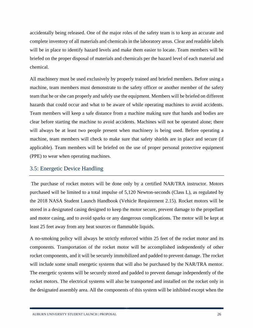
3.5: Energetic Device Handling
The purchase of rocket motors will be done only by a certified NAR/TRA instructor. Motors
purchased will be limited to a total impulse of 5,120 Newton-seconds (Class L), as regulated by
the 2018 NASA Student Launch Handbook (Vehicle Requirement 2.15). Rocket motors will be
stored in a designated casing designed to keep the motor secure, prevent damage to the propellant
and motor casing, and to avoid sparks or any dangerous complications. The motor will be kept at
least 25 feet away from any heat sources or flammable liquids.
A no-smoking policy will always be strictly enforced within 25 feet of the rocket motor and its
components. Transportation of the rocket motor will be accomplished independently of other
rocket components, and it will be securely immobilized and padded to prevent damage. The rocket
will include some small energetic systems that will also be purchased by the NAR/TRA mentor.
The energetic systems will be securely stored and padded to prevent damage independently of the
rocket motors. The electrical systems will also be transported and installed on the rocket only in
the designated assembly area. All the components of this system will be inhibited except when the

AUBURN UNIVERSITY STUDENT LAUNCH | PROPOSAL 27
rocket will be in the launching position and all personnel are at the minimum safe distance and the
NRA/TRA mentor can confirm so. During the use of the rocket motors and energetic devices,
specific requirements will be followed per the regulations set forth by NAR. Also per team
requirements, specific guidelines and documentation will be followed to ensure the safety of all
team members and observers present at either the launches or tests for specific systems.
3.6: Law Compliance
The regulations imposed nationally by the FAA and within the state of Alabama, due to the
adoption of the National Fire Protection Agency (NFPA) codes, are relevant and will be complied
with for the purposes of this project.
3.6.1: FAA Regulations:
FAA Regulation Compliance
No member shall operate an unmanned rocket in a manner that creates a collision hazard with other aircraft.
The team will ensure that the immediate airspace is clear of all aircraft before launching. If an aircraft is in the airspace, the team will not launch the rocket.
No member shall operate an unmanned rocket in controlled airspace.
The team will work with the RSO to ensure that the launch site is within uncontrolled airspace.
No member shall operate an unmanned rocket within five miles of the boundary of any airport.
The team will review a map of the launch site to guarantee that no airports are within five miles.
No member shall operate an unmanned rocket at any altitude where clouds or obscuring phenomena of more than five-tenths coverage prevails.
The team will delay the launch of the rocket until the appropriate weather conditions are active.
No member shall operate an unmanned rocket at any altitude where the horizontal visibility is less than five miles.
The team will review the launch site to ensure no objects obscure horizontal visibility out to five miles.
No member shall operate an unmanned rocket into any cloud.
The team will delay the launch until the immediate skies are clear.
No member shall operate an unmanned rocket within 1,500 feet of any person or property that is not associated with the operations or between sunset and sunrise.
The team will only use launch sites that have been approved with the owner of the property and will not launch the rocket between sunset and sunrise.
AUBURN UNIVERSITY STUDENT LAUNCH | PROPOSAL 28
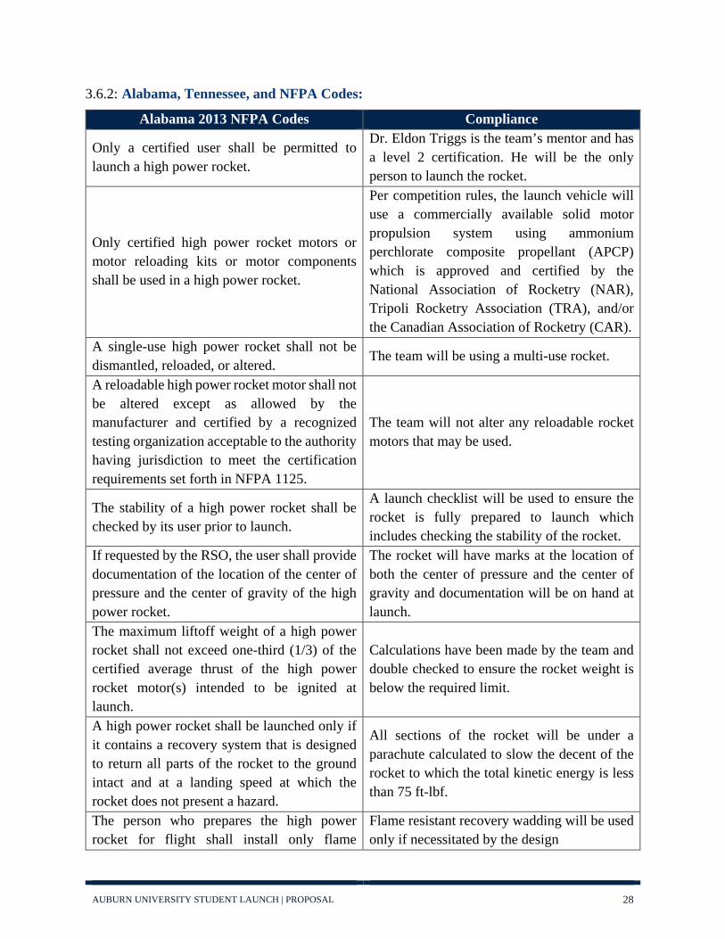
3.6.2: Alabama, Tennessee, and NFPA Codes:
Alabama 2013 NFPA Codes Compliance
Only a certified user shall be permitted to launch a high power rocket.
Dr. Eldon Triggs is the team’s mentor and has a level 2 certification. He will be the only person to launch the rocket.
Only certified high power rocket motors or motor reloading kits or motor components shall be used in a high power rocket.
Per competition rules, the launch vehicle will use a commercially available solid motor propulsion system using ammonium perchlorate composite propellant (APCP) which is approved and certified by the National Association of Rocketry (NAR), Tripoli Rocketry Association (TRA), and/or the Canadian Association of Rocketry (CAR).
A single-use high power rocket shall not be dismantled, reloaded, or altered.
The team will be using a multi-use rocket.
A reloadable high power rocket motor shall not be altered except as allowed by the manufacturer and certified by a recognized testing organization acceptable to the authority having jurisdiction to meet the certification requirements set forth in NFPA 1125.
The team will not alter any reloadable rocket motors that may be used.
The stability of a high power rocket shall be checked by its user prior to launch.
A launch checklist will be used to ensure the rocket is fully prepared to launch which includes checking the stability of the rocket.
If requested by the RSO, the user shall provide documentation of the location of the center of pressure and the center of gravity of the high power rocket.
The rocket will have marks at the location of both the center of pressure and the center of gravity and documentation will be on hand at launch.
The maximum liftoff weight of a high power rocket shall not exceed one-third (1/3) of the certified average thrust of the high power rocket motor(s) intended to be ignited at launch.
Calculations have been made by the team and double checked to ensure the rocket weight is below the required limit.
A high power rocket shall be launched only if it contains a recovery system that is designed to return all parts of the rocket to the ground intact and at a landing speed at which the rocket does not present a hazard.
All sections of the rocket will be under a parachute calculated to slow the decent of the rocket to which the total kinetic energy is less than 75 ft-lbf.
The person who prepares the high power rocket for flight shall install only flame
Flame resistant recovery wadding will be used only if necessitated by the design

AUBURN UNIVERSITY STUDENT LAUNCH | PROPOSAL 29
resistant recovery wadding if the design of the rocket necessitates the use of wadding.
No attempt shall be made to catch a high power rocket as it approaches the ground.
All personnel will be made to stand a safe distance away from the launch pad and will not leave this area until the rocket has touched down.
No attempt shall be made to retrieve a high power rocket from a power line or other life-threatening area.
If a rocket lands on a power line or other life-threatening area, all team members will be instructed to stay clear and the appropriate authorities will be contacted.
A high power rocket shall be launched using an ignition system that is remotely controlled, is electrically operated, and contains a launching switch that returns to the “off” position when released.
The RSO will be consulted to ensure the ignition system is within regulation standards.
The ignition system shall contain a removable safety interlock device in series with the launch switch.
The RSO will be consulted to ensure the ignition system is within regulation standards.
The launch system and igniter combination shall be designed, installed, and operated so that liftoff of the rocket occurs within 3 seconds of actuation of the launch system.
The RSO will be consulted to ensure the launch system and igniter combination is within regulation standards.
An ignition device shall be installed in a high power rocket motor only at the launcher or within the prepping area.
An ignition device will only be installed at the launcher by the RSO.
A high power rocket shall be pointed away from the spectator area and other groups of people during and after the installation of the ignition device.
The rocket will be pointed away from all personnel once the ignition device is installed and will only be taken down after the ignition device has been removed.
A high power rocket shall be launched in an outdoor area where tall trees, power lines, buildings, and persons not involved in the rocket launch do not present a hazard.
The launch site will be surveyed beforehand to ensure no obstacles are in the immediate vicinity.
Fire suppression devices and first aid kits shall be located at the launch site during the launch of a high power rocket.
The appropriate safety equipment will be brought to every launch and will be included on a pre-launch to ensure they are present at launch.
No person shall ignite and launch a high power rocket horizontally, at a target, or so that a rocket’s flightpath during ascent phase is
The team will consider the predicted flight path of the rocket to ensure it does not leave
AUBURN UNIVERSITY STUDENT LAUNCH | PROPOSAL 30
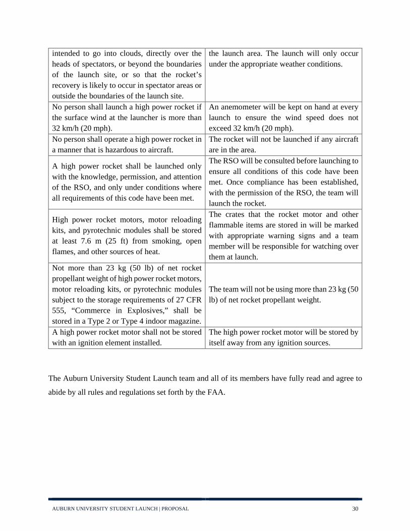
intended to go into clouds, directly over the heads of spectators, or beyond the boundaries of the launch site, or so that the rocket’s recovery is likely to occur in spectator areas or outside the boundaries of the launch site.
the launch area. The launch will only occur under the appropriate weather conditions.
No person shall launch a high power rocket if the surface wind at the launcher is more than 32 km/h (20 mph).
An anemometer will be kept on hand at every launch to ensure the wind speed does not exceed 32 km/h (20 mph).
No person shall operate a high power rocket in a manner that is hazardous to aircraft.
The rocket will not be launched if any aircraft are in the area.
A high power rocket shall be launched only with the knowledge, permission, and attention of the RSO, and only under conditions where all requirements of this code have been met.
The RSO will be consulted before launching to ensure all conditions of this code have been met. Once compliance has been established, with the permission of the RSO, the team will launch the rocket.
High power rocket motors, motor reloading kits, and pyrotechnic modules shall be stored at least 7.6 m (25 ft) from smoking, open flames, and other sources of heat.
The crates that the rocket motor and other flammable items are stored in will be marked with appropriate warning signs and a team member will be responsible for watching over them at launch.
Not more than 23 kg (50 lb) of net rocket propellant weight of high power rocket motors, motor reloading kits, or pyrotechnic modules subject to the storage requirements of 27 CFR 555, “Commerce in Explosives,” shall be stored in a Type 2 or Type 4 indoor magazine.
The team will not be using more than 23 kg (50 lb) of net rocket propellant weight.
A high power rocket motor shall not be stored with an ignition element installed.
The high power rocket motor will be stored by itself away from any ignition sources.
The Auburn University Student Launch team and all of its members have fully read and agree to
abide by all rules and regulations set forth by the FAA.

AUBURN UNIVERSITY STUDENT LAUNCH | PROPOSAL 31
3.7: NAR/TRA Safety Codes
NRA/TRA Code Topic Details Additional Information or
Precautions
Materials I will use only lightweight, non-metal parts for the nose, body,
and fins of my rocket.
Carbon fiber and fiberglass will be used for the body and flight
stabilization systems of the rocket. 3D printed plastics will be used for
the nose. These materials are nonmetal, extremely lightweight,
and very durable.
Motors
I will use only certified, commercially-made model rocket motors, and will not
tamper with these motors or use them for any purposes except
those recommended by the manufacturer.
We will stay within the limitation of the motors and inspect the
quality of the motor before use.
Ignition System
I will launch my rockets with an electrical launch system and electrical motor igniters. My
launch system will have a safety interlock in series with the
launch switch and will use a launch switch that returns to the
“off” position when released.
After following these guidelines, A Range Safety Officer certified by NAR or the TRA will have ultimate authority regarding
launches and will be the person to launch the rocket.
Misfires
If my rocket does not launch when I press the button of my electrical launch system, I will remove the launcher’s safety
interlock or disconnect its battery and will wait 60 seconds
after the last launch attempt before allowing anyone to
approach the rocket.
Following the 60 second period of inactivity, the rocket will be
approached by either the safety officer or the team mentor and all other team members will remain a
safe distance from the rocket. Safety devices will be on hand for
any circumstance.
Launch Safety
I will use a countdown before launch, and will ensure that
everyone is paying attention and is a safe distance of at least 15
feet away when I launch rockets
A highly visible object will be used to mark the minimum
distance team members should be away from the rocket. The visible
object will be in the form of a

AUBURN UNIVERSITY STUDENT LAUNCH | PROPOSAL 32
with D motors or smaller, and 30 feet when I launch larger
rockets. If I am uncertain about the safety or stability of an
untested rocket, I will check the stability before flight and will fly it only after warning spectators
and clearing them away to a safe distance. When conducting a simultaneous launch of more
than ten. rockets I will observe a safe distance of 1.5 times the
maximum expected altitude of any launched rocket.
bright line on the ground created by tape or paint and a vertical
object that the safety officer will hold. All team members and
observers will remain soundly behind this line.
Launcher
I will launch my rocket from a launch rod, tower, or rail that is pointed to within 30 degrees of the vertical to ensure that the rocket flies nearly straight up,
and I will use a blast deflector to prevent the motor’s exhaust from
hitting the ground. To prevent accidental eye injury, I will place launchers so that the end of the launch rod is above eye level or will cap the end of the rod when
it is not in use.
Beyond this guideline, only safety personnel, team leads, and the team mentor will be allowed to approach the launch rod and to
prep the rocket for launch. This is to minimize the number of people
around the rocket immediately prior to launch, helping to prevent accidents to either personnel or the
launch system.
Size
My model rocket will not weigh more than 1,500 grams (53
ounces) at liftoff and will not contain more than 125 grams
(4.4 ounces) of propellant or 320 N-sec (71.9 pound-seconds) of
total impulse.
Each system of the rocket and section of the body will be
weighed independently before transportation and directly prior to assembly. The assembled weight
will be known prior to launch.
Flight Safety
I will not launch my rocket at targets, into clouds, or near aircraft, and will not put any
flammable or explosive payload in my rocket.
During a rocket launch and prior to launch, all team members will
be required to remain together and be vigilant of impeding objects as well as a recovery failure in case

AUBURN UNIVERSITY STUDENT LAUNCH | PROPOSAL 33
the rocket returns at a dangerous speed in the direction of personnel.
Launch Site
I will launch my rocket outdoors, in an open area at least as large as shown in the accompanying
table, and in safe weather conditions with wind speeds no greater than 20 miles per hour. I will ensure that there is no dry grass close to the launch pad,
and that the launch site does not present risk of grass fires.
All launches will take place at certified NAR or TRA events and
locations. Currently, our only launch site is the SEARS launch
site in Samson, AL.
Recovery System
I will use a recovery system such as a streamer or parachute in my
rocket so that it returns safely and undamaged and can be
flown again, and I will use only flame-resistant or fireproof
recovery system wadding in my rocket.
The team will calculate the optimum heights at which to deploy the drogue and main
parachutes to maximize drag and minimize drift. This will aid in a
safe and undamaged recovery. The parachutes will also be made of flame resistant material to avoid
heat related failures of the system.
Recovery Safety I will not attempt to recover my
rocket from power lines, tall trees, or other dangerous places.
In the event that the rocket does land in a dangerous place,
appropriate help will be consulted immediately to avoid danger to
any other peoples or infrastructure. 3.8: Caution Statements
Safety is of the highest importance in all aspects of the competition and critical to the design
philosophy of Auburn Student Launch. To ensure that this is kept as the first priority of all the
team members, before any procedures are undertaken there will be a safety briefing led by the
safety officer and safety liaisons of each team lead. The briefing will cover all the important
procedural and safety acknowledgements necessary to construction, assembly, and launch day
activities. The safety liaison members will be responsible for reporting back changes to the design
that affect safety considerations and providing an accessible and knowledgeable voice for safety
concerns.
AUBURN UNIVERSITY STUDENT LAUNCH | PROPOSAL 34
Team members will be briefed on the proper personal protection equipment (PPE) to wear while
working in the laboratory. This includes hand, foot, ear, eye, and respiratory protection. Loose
clothing must be secure, and jewelry must be removed before operating machinery. Members will
be required to wear long pants, closed toed shoes, safety glasses, and gloves while working in the
laboratory. Respiratory protection will also be used when toxic chemicals or small particle forming
machines are in use. Team members will be required to wear lab coats when handling chemicals
along with proper skin protection and respiratory protection as appropriate.
To avoid accidents, listening to music with earbuds or headphones will be prohibited while
operating machines. Team members will look over machines before operating to ensure the
machine is in proper condition. Ventilation systems will be checked prior to work to make sure
they are also in proper working condition. An inventory of all materials and chemicals in the
laboratory will be maintained along with labels to identify the hazard levels and what precautions
to take with each of them. A waiver has been created for all team members to sign prior to entry
to the lab that states their knowledge and understanding of these statements, the hazards they may
encounter and their responsibilities to keep a safe work environment, and their intent to follow
them closely.

AUBURN UNIVERSITY STUDENT LAUNCH | PROPOSAL 35
3.9: Team Safety Statement
All members of the Auburn University Student Launch team have read and will abide by all of the
rules as set forth by NASA. Before each flight a safety inspection will be completed by the Range
Safety Officer (RSO). If any changes need to be made as per request of the RSO, they will be
completed immediately. Auburn University Student Launch will comply with the safety decisions
of the RSO to ensure the flight capability of the rocket and continued participation in the
competition. The team members of Auburn University Student Launch understand that the RSO
has ultimate authority of the flight readiness of any rocket to be flown by the team. Members of
the team understand that this means the RSO has the authority to deny the launch of a rocket for
any safety issue that is determined to be risky or of concern. The team will comply with all safety
requirements of the competition, NASA, NAR, local and federal agencies, and the RSO in order
to ensure the safety of all persons at the launch event.
All team members present at assembly and launch will sign a safety waiver that acknowledges
their complete understanding of these safety statements and their intent to comply.
3.10: Risk Assessments
The risk assessment tables are located in Appendix A: Risk Assessment Tables.

AUBURN UNIVERSITY STUDENT LAUNCH | PROPOSAL 36
4. Technical Design
4.1: Vehicle Design
Figure 8: Vehicle Rendering
The launch vehicle body will be composed of six major structural elements: the nose cone, the
rover bay, the avionics section, the main parachute compartment, the drogue chute compartment,
and the booster section. The preliminary model in Figure 9 shows the general layout of the rocket.
The outer diameter of our rocket will be 6.25 inches, while the inner diameter will be 6 inches.
This will give a wall thickness of 0.25 inches. Finite element analysis will be performed to ensure
that the wall thickness will be adequate for a successful and safe flight. The inner diameter was chosen
to maximize the amount of usable space without increasing the weight too much. Work will also be
done to limit the lengths of each section to further decrease the weight.
Figure 9: Open Rocket Model

AUBURN UNIVERSITY STUDENT LAUNCH | PROPOSAL 37
The main body of the rocket will be constructed using composite materials. The body tubes will
be constructed using two methods: carbon fiber braiding and filament winding. The carbon fiber
braiding process weaves cords of carbon fiber into a braid which is then turned into an open-
architecture composite isogrid structure using filament winding. Isogrid structures are a lighter
alternative when compared to solid tubes. Using current samples of the isogrid structure, the body
tube will potentially be 20 to 30 percent lighter than using a solid carbon fiber structure. In previous
years, there was initial success using this method, so the team has a high level of confidence in
incorporating this unique structure into the airframe. A sample of the isogrid structure is displayed
in Figure 10.
A thin sheet of fiberglass will be secured inside the structure to create a smooth surface to allow
for incorporation of the subsystem components. Additionally, the outside will be covered in a thin
layer of filament wound carbon fiber to create a smooth surface to decrease aerodynamic drag. The
thickness of these sections will be minimal, as they are not going to be carrying the structural load
during launch. The team also has access to a filament winder which will be used for manufacturing
carbon fiber tubes. Filament winding is a fabrication technique used mainly for manufacturing a
cylindrical hollow product. Filament winding is highly beneficial because it is automated and
precise, creating lightweight, strong composite parts, with minimal labor required. The different
variables when winding are fiber type, resin content, wind angle, tow, and thickness of the fiber
bundle. The filament winder will use a 6-inch diameter aluminum mandrel. Using an aluminum
mandrel allows the team to produce very accurate body tubes. As filament winding is highly
Figure 10: Braided Section Sample

AUBURN UNIVERSITY STUDENT LAUNCH | PROPOSAL 38
repeatable and has a high degree of accuracy, several spare body tubes could be created and tested
to help the team eliminate undesirable configurations before proceeding to full-scale testing.
Finally, the last few primary pieces of the rocket will be constructed by utilizing a much different
form of composite layup. Since bulk-plates and fins require very little special geometric variance
from a flat plate, several plates of varying thickness composites will be made using a compaction
method. This approach will significantly reduce the cost and difficulty of composites
manufacturing, since vacuum bagging is not required in a compaction method. An added benefit
will be the ability to achieve effective ply consolidation while remaining relatively easy to layup.
Once post-cured the flat plates of cured composites will be milled and machined into the final
shape required.
The stability of the rocket will be controlled by the fins. The fin’s primary purpose is to locate the
center of pressure aft of the center of gravity. The greater drag on the fins will keep them behind
the upper segments of the vehicle, allowing the rocket to fly straight along the intended flight path
while minimizing the chances of weather-cocking. A trapezoidal planform has been selected for
the fins. Trapezoidal fins provide an easily machinable avenue for achieving a large section of
wetted surface area. In addition, the trapezoidal design produces a large, easily machinable surface
area to bond and secure the fin to the structural assembly beneath it. Four trapezoidal fins will be
machined from .25-inch-thick carbon fiber plates. The trailing edge of the fins will be located one
inch forward of the end of the body tube. This design feature will provide some impact protection
for the fins when the rocket hits the ground. Carbon fiber of 1.03 oz./in3 density has been selected
due to its stiffness, strength, and light weight. Each fin will have a surface area of 56.88 in2
respectively (summing both sides), making the fin surface area total to 227.52 in2. These
dimensions provide the vehicle with a projected stability of 2.53 calibers. This level of stability is
ideal, as it is well above stable but below over-stable. Detailed dimensions of the fins are provided
in Table 4: Fin Dimensions.

AUBURN UNIVERSITY STUDENT LAUNCH | PROPOSAL 39
Section Lengths
Nose Cone 20 in
Rover Bay 24 in
Avionics Section 12 in(2 in externally)
Main Parachute Section 18 in
Drogue Chute Section 14 in
Booster Section 25 in
Total Length 103 in
Trapezoidal Fin Dimensions
Root Chord 6.25 in
Tip Chord 2.5 in
Height 6.5 in
Sweep 3.677 in
Sweep Angle 29.5° Table 4: Fin Dimensions and Fin

AUBURN UNIVERSITY STUDENT LAUNCH | PROPOSAL 40
4.2: Projected Altitude
In order to create an initial, fairly accurate projection of the altitude, the team used OpenRocket, a
freeware program designed to calculate various parameters in rocket flight. Given the team’s
experience with this software in the previous years, the team is confident in the ability of OpenRocket
to produce accurate estimates of the altitude. With the current motor selection, discussed in section
4.4: Motor Selection, the current projected apogee for the vehicle is 5111 ft. In addition, a chart of the
altitude over time is provided in Figure 11: Projected Altitude.
Figure 11: Projected Altitude

AUBURN UNIVERSITY STUDENT LAUNCH | PROPOSAL 41
4.3: Recovery System Design
The 2018-2019 Auburn Student Launch team is planning on employing a dual-stage, dual-system
recovery approach this year. The lower recovery system will consist of two parachutes, a drogue
and a main, contained within their own separate housings. The housing for the drogue chute will
be placed just above the embedded systems portion of the rocket with the main parachute housing
and BAE respectively being stacked on top of that. The drogue chute will be deployed at apogee
at a height of 5111 ft. followed by a main parachute deployment at 600 ft. Both parachutes will be
deployed from their own individual compartments with redundant black powder charges and shear
pins. These black powder charges will be ignited by electronic matches connected to redundant
altimeters housed within the Barometric Avionics Enclosure (BAE).
The upper recovery system will be housed in the nosecone and will consist of a single parachute,
two altimeters, a microcontroller, and a servo. These components will be assembled in such a
manner as to create a redundant mechanical release. At 700 ft., the altimeters will send a signal to
the microcontroller causing it to turn the servo, retracting the tabs holding the nosecone in place.
A spring system will be in place to push the nosecone and parachute out of the rocket once the
mechanical release is activated. The nosecone will then drift the rest of the way to the ground
separately with its own parachute.
4.3.1: Structural Elements
The centerpiece of Auburn's lower recovery system will be the BAE. The BAE will be formed by an
8-inch-long cylindrical fiberglass coupler. Within the coupler, there will be a 3D printed housing for
both the altimeters and their bulk plates to make efficient use of the space as seen in Figure 12. There
will be three holes through the length of the housing to run charge wires and threaded rods. The hole
for the wires will be in the center of the housing and half an inch in diameter. The holes for the two
threaded rods will be half an inch in diameter and two inches away from either side of the hole for the
wires. The coupler forming the outside of the BAE will be sealed off with bulk plate caps on both ends.
The aforementioned rod holes will continue through both bulk plate caps. Rods will be fitted through
these holes and secured with lock nuts on either side to hold the BAE together for the duration of the
flight. The hole for the charge wires will continue down through the bottom bulk plate cap exclusively.
After the wires have been pulled through it, this hole will be sealed with epoxy to help eliminate the

AUBURN UNIVERSITY STUDENT LAUNCH | PROPOSAL 42
chance of back pressure causing damage to the altimeters or forces from parachute deployment pulling
on the charge wires and damaging altimeter terminals. The BAE will serve as the coupler between the
lower parachute housings and the payload section. Neither of these sections will separate once the
rocket is assembled.
Figure 12: BAE 3D Printed Housing
Two additional holes will be drilled in the bottom bulk plate cap of the BAE for a U-bolt. This U-bolt
will be the anchor point for the main parachute and will be attached with lock nuts on either side of the
bulk plate to keep it from moving during parachute deployment.
Centered on the outside of the BAE there will be a two-inch-wide ring of fiberglass that is the same
diameter as the outside of the rocket. The switches and pressure holes for the altimeters will be located
on this ring. The key switches located on the ring will allow the team to externally arm the altimeters
while the rocket is assembled. This will be done so the tube connections between the payload section,
the BAE, and the main parachute housing are continuous and smooth, minimizing the impact on the
aerodynamic performance of the rocket due to these connections.
In between the drogue and main parachute housings will be a 12-inch fiberglass coupler with a bulk
plate fixed inside to separate the two compartments. The bulk plate will be fixed six inches from either
end of the coupler to separate the two sections evenly and give both separation points a 6-inch shoulder.
In this bulk plate there will be five holes, four of which will be used for U-bolts on either side of the
plate secured in the same fashion as the one below the BAE. The fifth hole will be used for the e-match

AUBURN UNIVERSITY STUDENT LAUNCH | PROPOSAL 43
wire for the drogue charge. Separation points on both sides of the coupler will use three shear pins
each.
Located in the nosecone will be a second altimeter bay to control the mechanical release of the
nosecone. A housing similar to the one seen in Figure 12: BAE 3D Printed Housing will be used to
secure the altimeters, microcontroller, servo and batteries. The top of the housing will be tapered to
reflect the taper of the nosecone, and an additional hole will be placed in the bottom of the housing to
secure the servo. The servo will be placed radially in the center of the rocket with three arms attached
to it. This single servo approach is being used because it eliminates the possibility of asymmetrical
actuation and creating a loosely attached nosecone. There will be three slots drilled in the nose cone
and outer body of the rocket for the arms to slide into in order to lock the nosecone to the body. The
arms, when locked into place, will be flushed with the outer surface of the rocket as to not to create
unnecessary drag during ascent. The arms will have a ring of support structure around them to reduce
the moment on the arms themselves and strain on the servo. On the bottom of the nosecone shoulder
there will be a bulk plate with U-bolt for the parachute to attach to. Three threaded rods will pass
through the bulk plate, arm support structure, bottom level and middle level of the altimeter housing
with lock nuts on either side of each piece, totaling six lock nuts per rod. This will be done to ensure
that each of these components stay in the same relative position to each other throughout the duration
of the flight. The entire assembly will be fixed to the nosecone via four machine screws. These four
screws will be screwed into the middle level of the altimeter housing through the top of the shoulder
of the nosecone. In order to keep the screws from causing part of the nosecone shoulder to be exposed,
the end of the airframe tube will be notched. This will be done to allow the screws, switches, and
pressure holes to slide down to where the nosecone is fully seated against the top of the rocket. This is
also done to relieve any undue stress from boost on the locking arms by transferring those forces
directly to the airframe.
4.3.2: Materials
The materials chosen to create the team's recovery subsystems are of the utmost importance. They must
work properly for the team’s payload, a rover that cannot be damaged when it returns to Earth. The
materials must be both strong and lightweight in order to be effective, as well as not adding unnecessary
weight to the rocket. The parachutes will be made from ripstop nylon. Ripstop nylon is an ideal material
for this application; the fabric is thin and lightweight, but its reinforced woven composition makes it
resistant to tearing. The 70 denier ripstop nylon fabric has been chosen for the parachutes because it
AUBURN UNIVERSITY STUDENT LAUNCH | PROPOSAL 44
has a tensile strength of 1500 psi, which is more than sufficient for the needs of this project. The drogue
and nosecone shroud lines will be made of paracord, unlike the main parachutes shroud lines, which
will both be made of tubular nylon. Tubular nylon was chosen for the main parachute due to its high
strength and ability to stretch slightly, absorbing some of the shock from deployment without failing.
Tubular nylon will be used for the shock cord connecting the shroud lines to the rocket for the same
reasons, with sections being reinforced with tubular Kevlar as needed as determined after testing.
Kevlar was chosen for the reinforcing material because it is even stronger and able to withstand more
impact than tubular nylon. Nylon shear pins will be used to attach both the main parachute housing
and drogue parachute housing to the parachute coupler section of the rocket to prevent drag separation.
In the proposed configuration, #4-40 nylon screws will be used to secure these sections together. These
machine screws each have a double shear strength of 50 lbs. This shear strength will be verified via
ground testing to ensure safety. For all 3-D printed materials, the team will be using a Markforged 3-
D printer and their patented material, Onyx. Onyx is a product consisting of nylon and chopped carbon
fiber that is 1.4 times stronger than traditional ABS. This product offers high strength and low weight
which will help ensure that the rockets overall weight stays low while not sacrificing safety. U-bolts
will be used for all parachute anchor points in the rocket. All bulk plates used in both recovery sections
will be made out of 1/8th inch perpendicularly layered carbon fiber.
4.3.3: Ejection System
The Auburn University Student Launch team will be using two different recovery systems within this
year’s rocket. The lower recovery system will be using black powder charges for separation and lower
parachute deployment. Prior to each separation, the drogue and main parachutes will both be stored in
their own compartments with two black powder charges with their own independent altimeter. Two
charges are included in each compartment to make the system doubly redundant. The exact amount of
black powder per charge will be determined once components have been assembled and testing can be
performed. The drogue charge will deploy at apogee and the main charge will deploy at 600 ft. Both
redundant charges will have a one-second delay on ignition so as not to over pressurize a section and
compromise the structural integrity of the airframe. The separation points for the lower recovery system
will be above and below the parachute coupler. The black powder charges for the drogue parachute
will be located directly aft of the parachute coupler bulk plate and the main parachute black powder
charges will be located directly aft of the BAE bottom bulk plate cap.

AUBURN UNIVERSITY STUDENT LAUNCH | PROPOSAL 45
The upper recovery system will be using a mechanical release to separate the nosecone at 700 ft in a
non-energetic event. The team elected to use a mechanical release for the nosecone due to the
pressurizing nature of a black powder event. The embedded payload section is located directly below
the nosecone and a pressurizing event would damage the sensitive electronics of the rover payload.
The mechanical release will consist of two altimeters, a microcontroller and a servo motor. Each
altimeter will be connected to its own microcontroller. The two microcontrollers will be wired in
tandem in an open circuit containing the servo and a power source. When the altimeters reach the target
altitude, they will send a pulse of electricity to the microcontrollers and prompt them to close the circuit
for a predetermined amount of time to fully retract the locking arms. A spring positioned between the
payload and nosecone parachute will then push the parachute and nosecone out of the rocket allowing
it to drift the rest of the way to the ground. A diagram detailing the nosecone recovery system can be
seen below in Figure 13: Nosecone Diagram.
Figure 13: Nosecone Diagram
4.3.4: Parachutes
Auburn’s double system recovery approach will make use of three separate parachutes designed and
constructed in house by the Auburn Student Launch team. The team has been making its own
parachutes for six years and has refined its manufacturing process to produce quality, custom
parachutes that produce the desired drag and drift for all sections of the rocket. The drogue parachute
will be a small, circular parachute constructed of ripstop nylon with paracord shroud lines. Following
the first event at apogee, the drogue will be deployed from the middle of the rocket with both halves

AUBURN UNIVERSITY STUDENT LAUNCH | PROPOSAL 46
still connected. This will stabilize descent until main deployment at the second event at 600 feet.
Slightly prior to this event the mechanical release will activate, and the nose cone parachute will
deploy. When the rocket reaches 600 feet in altitude, a second charge will push off the coupler to
release the main parachute. A spill hole will be added to the main parachute. In accordance with the
general rule of thumb, the spill holes will be close to 20% of the total base diameters of the chutes. The
20% diameters of the spill holes are chosen because it only reduces the areas of the parachutes by about
4%, allowing enough air to go through the spill hole to stabilize the rocket without drastically altering
the descent rate.
A drogue parachute size can be estimated by the following calculation based on the length and diameter
of the rocket body.
𝐷𝐷𝐷𝐷𝐷𝐷𝐷𝐷𝐷𝐷𝐷𝐷𝐷𝐷 = �4 × 𝐿𝐿𝑇𝑇𝐷𝐷𝑇𝑇𝐷𝐷 × 𝐷𝐷𝑇𝑇𝐷𝐷𝑇𝑇𝐷𝐷𝜋𝜋
The team’s rocket will have a length of approximately 106 in and a diameter of 6 in, yielding a drogue
chute diameter of 28.5 in. The recovery system will have two main parachutes constructed of ripstop
nylon with 0.5-inch tubular nylon shroud lines. The main parachute and nosecone parachute will be
hemispherical in shape. The hemispherical design can be more difficult to manufacture, but will
produce the most drag, allowing the rocket to have maximum drag with minimum weight. A Pugh
chart can be seen below comparing different parachute shapes. The shape of the main parachutes and
their gores for both 8 and 6 gore configurations can be seen in Figure 14: 6 Gore Template, Figure 15: 8
Gore Template, and Figure 16: Hemispherical Parachute.
Baseline Square Circular Hemispherical
Drag Produced 3 1 1 2
Ease of Manufacturing 2 1 2 1
Stability 1 2 1 1
Total 7 8 9
Table 5: Parachute Size Pugh Chart

AUBURN UNIVERSITY STUDENT LAUNCH | PROPOSAL 47
Figure 14: 6 Gore Template
Figure 15: 8 Gore Template

AUBURN UNIVERSITY STUDENT LAUNCH | PROPOSAL 48
Figure 16: Hemispherical Parachute
The kinetic energy for the rocket upon impact can be calculated using the following formula:
𝐾𝐾𝐾𝐾 =12𝑚𝑚 × 𝑉𝑉2
Where m is mass and V is descent velocity. The team will use this equation to solve for descent
velocity to determine the size of the parachute. Solving the above equation for V yields:
𝑉𝑉 = �2 × 𝐾𝐾𝐾𝐾𝑚𝑚
Auburn Student Launch will apply a factor of safety of 1.5 to the competition kinetic energy
requirement of 75 ft-lbs of force upon impact for a target kinetic energy of 50 ft-lbs upon landing.
Using this value and an initial mass estimate of 29.7 lbm for the rocket body, the equation above yields:
𝑉𝑉 = �2 × 50𝑓𝑓𝑓𝑓 ∙ 𝑙𝑙𝑙𝑙 × 32.2𝑓𝑓𝑓𝑓𝑠𝑠229.7𝑙𝑙𝑙𝑙𝑚𝑚
= 10.4𝑓𝑓𝑓𝑓𝑠𝑠
Applying the same technique to the nosecone with an initial mass estimate of 8 lbm, the descent
velocity equation shows:
𝑉𝑉 = �2 × 50𝑓𝑓𝑓𝑓 ∙ 𝑙𝑙𝑙𝑙 × 32.2𝑓𝑓𝑓𝑓𝑠𝑠28𝑙𝑙𝑙𝑙𝑚𝑚
= 20.0𝑓𝑓𝑓𝑓𝑠𝑠

AUBURN UNIVERSITY STUDENT LAUNCH | PROPOSAL 49
Parachute areas for hemispherical shaped chutes are determined using the following equation:
𝐴𝐴 =2 × 𝐹𝐹
𝜌𝜌 × 𝐶𝐶𝐷𝐷 × 𝑉𝑉2
Where F is force, ρ is density of the air, CD is the drag coefficient and V is descent velocity. The team
will use this equation to calculate an appropriate area for the main parachute so that the kinetic energy
of the rocket does not exceed 75 ft-lbs during recovery and remains within safe limits. Testing on
hemispherical parachutes done in prior years by Auburn Student Launch has concluded that
hemispherical parachutes have a drag coefficient of 1.31. Using this data, estimated mass of 37.3 lbs
after burnout with 8 lbs of that being in the nosecone, and descent velocities of 10.4 and 20.0 ft/s
calculated above, the team has used the following formula to determine the initial estimate of the size
of the main and nosecone parachutes.
𝐴𝐴𝑀𝑀𝑀𝑀𝑀𝑀𝑀𝑀 =2 × 29.7𝑙𝑙𝑇𝑇𝑚𝑚 × 32.2 𝑓𝑓𝑓𝑓𝑠𝑠2
0.076474 𝑙𝑙𝑙𝑙𝑚𝑚𝑓𝑓𝑓𝑓3 × 1.31 × �10.4𝑓𝑓𝑓𝑓𝑠𝑠 �2 = 176.52 𝑓𝑓𝑓𝑓2
𝐴𝐴𝑁𝑁𝐷𝐷𝑁𝑁𝐷𝐷𝑁𝑁𝐷𝐷𝑀𝑀𝐷𝐷 =2 × 8.0𝑙𝑙𝑇𝑇𝑚𝑚 × 32.2𝑓𝑓𝑓𝑓𝑠𝑠2
0.076474 𝑙𝑙𝑙𝑙𝑚𝑚𝑓𝑓𝑓𝑓3 × 1.31 × �20.0 𝑓𝑓𝑓𝑓𝑠𝑠 �2 = 12.86 𝑓𝑓𝑓𝑓2
Main Chute Nosecone Chute Area 176.5 ft^2 12.9 ft^2 Diameter 127.2 in 17.2 in Diameter of Spill hole 25.4 in 3.4 in Number of Gore 8 6 Width of Each Gore at Base 50.0 in 9.0 in Height of Each Gore 99.9 in 13.5 in Circumference at Base 33.3 ft 4.5 ft
Table 6: Parachute Sizing Details
4.3.5: Parachute Construction
The parachutes will be manufactured at Auburn University by the Auburn Student Launch team
members. The drogue parachute will be created by cutting an appropriately sized circle out of orange
ripstop nylon. Sizing for the drogue can be seen in Table 6: Parachute Sizing Details. Orange ripstop

AUBURN UNIVERSITY STUDENT LAUNCH | PROPOSAL 50
nylon will be chosen because it is easier to see whether or not the drogue has deployed when compared
to blue ripstop nylon. Shroud lines will be attached in four evenly spaced intervals around the drogue
with four inches of the paracord being sewn on at each point. Once they are designed, 1:1 gore
templates will be made for the main parachutes using SolidWorks. These templates will include an
extra inch around the perimeter of the gore for sewing and hemming purposes. Once they are cut out,
templates will be lain over the team's stock of orange and blue ripstop nylon and will be used for cutting
out all of the gores from the team's stock of orange and blue ripstop nylon. The main and nosecone
parachute for the 2018-2019 rocket will consist of 8 and 6 gores respectively. The gores will be sewn
together with a butterfly stitch; wherein, the gores will be pinned along the edges and sewn together
using strong nylon thread and a straight stitch. These seams will then be inverted and a new seam will
be added to encase the first seam. This process will be repeated for all the gores until the parachute is
fully assembled and reinforced to ensure safety. After the assembly is completed, the spill-hole will be
traced onto the top of the parachute and the excess fabric will be removed. Next the spill-hole edges
and the outer circumference of the parachute will be hemmed utilizing a straight stitch. Finally, the
shroud lines will be added around the circumference of the parachute. Due to the thickness of the
shroud lines, two parallel zigzag stitches – one on each edge of the shroud lines – will be used to attach
them firmly to the parachute. Once the parachute is completed, it will be inspected for any flaws in the
workmanship or materials that could lead to failure in the recovery system.
4.3.6: Drift
The distance the rocket will drift during descent can be estimated with the following equation.
𝐷𝐷𝐷𝐷𝐷𝐷𝑓𝑓𝑓𝑓 = 𝑊𝑊𝐷𝐷𝑊𝑊𝑊𝑊 𝑆𝑆𝑆𝑆𝑆𝑆𝑆𝑆𝑊𝑊 ×𝐴𝐴𝑙𝑙𝑓𝑓𝐷𝐷𝑓𝑓𝐴𝐴𝑊𝑊𝑆𝑆 𝐶𝐶ℎ𝑎𝑎𝑊𝑊𝑎𝑎𝑆𝑆𝐷𝐷𝑆𝑆𝑠𝑠𝐷𝐷𝑆𝑆𝑊𝑊𝑓𝑓 𝑉𝑉𝑆𝑆𝑙𝑙𝑉𝑉𝐷𝐷𝐷𝐷𝑓𝑓𝑉𝑉
However, this drift estimation assumes wind speed and descent velocity are constant and does not
account for the horizontal distance the rocket travels during ascent. There will be two stages of descent.
First, the rocket will descend under the drogue parachute from an altitude of 5111 ft. to 700 ft. At 700
ft. the second event will occur, and the nose cone will separate from the rocket body, continuing the
rest of the way to the ground under a separate main parachute. A third event will occur at 600 ft. when
a charge will separate the parachute coupler and push the main parachute out. The rate of descent under
drogue can be calculated with the following equation:

AUBURN UNIVERSITY STUDENT LAUNCH | PROPOSAL 51
𝐷𝐷𝑆𝑆𝑠𝑠𝐷𝐷𝑆𝑆𝑊𝑊𝑓𝑓 𝑉𝑉𝑆𝑆𝑙𝑙𝑉𝑉𝐷𝐷𝐷𝐷𝑓𝑓𝑉𝑉 = �2 × 𝐹𝐹𝑉𝑉𝐷𝐷𝐷𝐷𝑆𝑆
𝐴𝐴𝐷𝐷𝐷𝐷 𝐷𝐷𝑆𝑆𝑊𝑊𝑠𝑠𝐷𝐷𝑓𝑓𝑉𝑉 × 𝐷𝐷𝐷𝐷𝑎𝑎𝑎𝑎 𝐶𝐶𝑉𝑉𝑆𝑆𝑓𝑓𝑓𝑓𝐷𝐷𝐷𝐷𝐷𝐷𝑆𝑆𝑊𝑊𝑓𝑓 × 𝑃𝑃𝑎𝑎𝐷𝐷𝑎𝑎𝐷𝐷ℎ𝐴𝐴𝑓𝑓𝑆𝑆 𝐴𝐴𝐷𝐷𝑆𝑆𝑎𝑎
Using this information and weight of the rocket, the team will be able to calculate an estimated descent
velocity. This descent velocity will then be used to ensure drift is kept to a maximum of 2,500 feet
away from the launch pad.
4.3.7: Electronics
The lower recovery system BAE will house two altimeters to satisfy redundant system requirements.
Both altimeters will fire an initial charge at apogee (target altitude: 5111 feet) to separate the rocket at
the drogue section and eject the drogue parachute. Then both altimeters will fire main deployment
charges at an altitude of 600 ft, separating the parachute coupler from the upper rocket body and
releasing the main parachute. At both of these separation points, the separated pieces will still remain
attached to one another via shock cord. The altimeters will have a one second firing delay at both
apogee and main deployment to avoid compromising the structural integrity of the airframe while still
providing redundancy.
The team will use an Altus Metrum TeleMega (Figure 17: TeleMega) as the primary altimeter and an
Altus Metrum TeleMetrum (Figure 18: TeleMetrum) as the secondary altimeter in the BAE. Both Altus
Metrum altimeters gather flight data via a barometric pressure sensor and an onboard accelerometer.
The TeleMega has an advanced accelerometer for more detailed flight data acquisition. Additionally,
using two Altus Metrum altimeters will make programming quicker and easier, as they share an
interface program. This will ensure that any last minute or on-site changes are more efficient and less
prone to error. Altus Metrum altimeters are capable of tracking in flight data, apogee and main ignition,
GPS tracking, and accurate altitude measurement up to a maximum of 25,000 feet. This height is much
higher than the team's anticipated maximum altitude of 5111 feet. They are also capable of being armed
from outside the rocket using a key switch, which is their intended purpose.

AUBURN UNIVERSITY STUDENT LAUNCH | PROPOSAL 52
Figure 17: TeleMega
Figure 18: TeleMetrum Another reason that the Altus Metrum altimeters are preferred are their radio frequency (RF)
communication capabilities. Both TeleMega and TeleMetrum are capable of communicating with a
Yagi-Uda antenna operated by the team at a safe distance during the launch. It can be monitored while
idle on the ground or while in flight. While on the ground, referred to as “idle mode,” the team can use
the computer interface to ensure that all ejection charges are making proper connections. The main and
apogee charges can be fired via the RF link to verify functionality, which will be used to perform
ground testing. The voltage level of the battery can also be monitored, and, should the battery dip
below 3.8V, the launch can be aborted in order to charge the battery to a safer level. Additionally, the
apogee delay, main deploy height, and other pyro events can be configured to almost any custom
configuration. The altimeter can even be rebooted remotely. Furthermore, while in flight, referred to
as “flight mode,” the team can be constantly updated on the status of the rocket via the RF transceiver.
It reports altitude, battery voltage, igniter status, and GPS status. However, in flight mode, settings
cannot be configured and the communication is one way from the altimeter to the RF receiver. Both
Altus Metrum altimeters transmit on one of ten channels with frequencies ranging from 434.550 MHz
to 435.450 MHz.
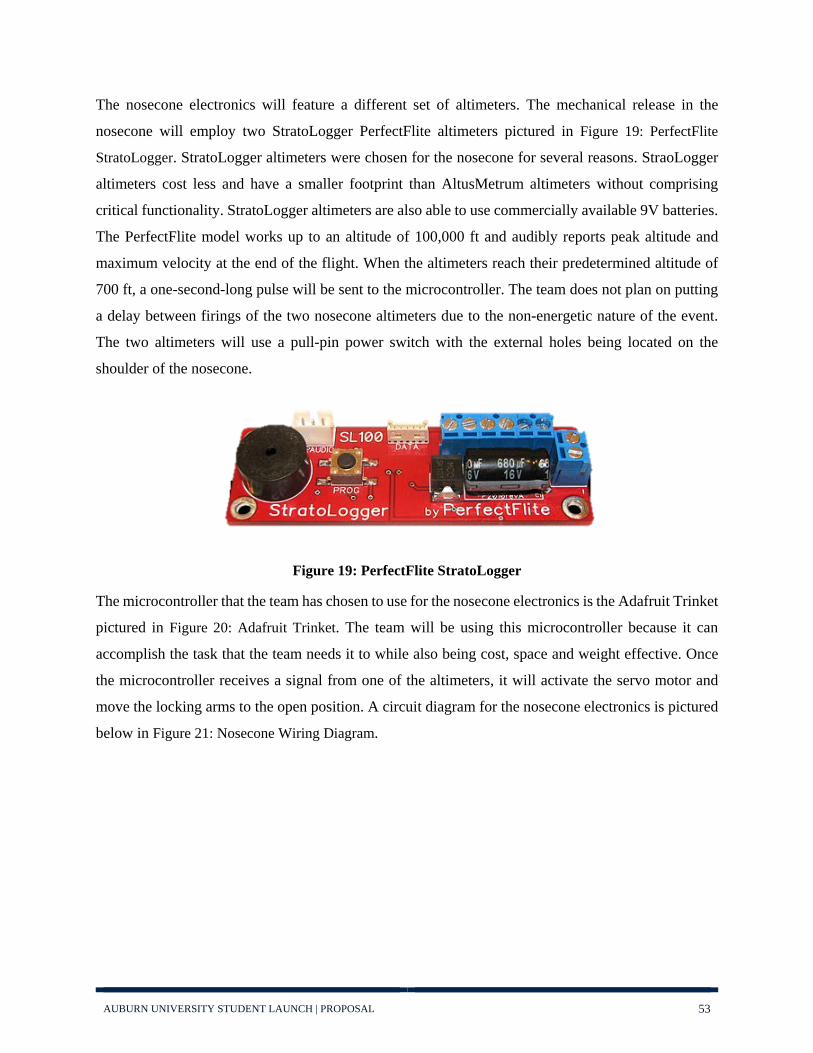
AUBURN UNIVERSITY STUDENT LAUNCH | PROPOSAL 53
The nosecone electronics will feature a different set of altimeters. The mechanical release in the
nosecone will employ two StratoLogger PerfectFlite altimeters pictured in Figure 19: PerfectFlite
StratoLogger. StratoLogger altimeters were chosen for the nosecone for several reasons. StraoLogger
altimeters cost less and have a smaller footprint than AltusMetrum altimeters without comprising
critical functionality. StratoLogger altimeters are also able to use commercially available 9V batteries.
The PerfectFlite model works up to an altitude of 100,000 ft and audibly reports peak altitude and
maximum velocity at the end of the flight. When the altimeters reach their predetermined altitude of
700 ft, a one-second-long pulse will be sent to the microcontroller. The team does not plan on putting
a delay between firings of the two nosecone altimeters due to the non-energetic nature of the event.
The two altimeters will use a pull-pin power switch with the external holes being located on the
shoulder of the nosecone.
Figure 19: PerfectFlite StratoLogger The microcontroller that the team has chosen to use for the nosecone electronics is the Adafruit Trinket
pictured in Figure 20: Adafruit Trinket. The team will be using this microcontroller because it can
accomplish the task that the team needs it to while also being cost, space and weight effective. Once
the microcontroller receives a signal from one of the altimeters, it will activate the servo motor and
move the locking arms to the open position. A circuit diagram for the nosecone electronics is pictured
below in Figure 21: Nosecone Wiring Diagram.

AUBURN UNIVERSITY STUDENT LAUNCH | PROPOSAL 54
Figure 20: Adafruit Trinket
Figure 21: Nosecone Wiring Diagram
In past years, this radio frequency communication has caused trouble due to signal strength.
Communication could intermittently be established with the rocket while on the ground, and settings
could be configured. Once launched however, connection with the onboard altimeters was soon lost
due to weak signal strength. This is likely due to several causes such as the antenna not being straight
inside the rocket, the conductive carbon fiber body blocking the signal, or low power output of the
altimeter’s whip antenna. To prevent these issues, the team will replace the altimeters' default antennae
with new antennae. Isolating one altimeter system (altimeter, battery, and wires) from the other will
help prevent any form of coupling or cross-talk of signals. Isolation will be realized via distancing the
two systems, avoiding parallel wires, and twisting wires within the same circuit. Additionally, the most
apparent form of radio-frequency interference (the antennae) will resonate on wires any multiple of ¼
λ (1/4 of ~70cm). Avoiding resonant lengths of wire will be done wherever possible. Within the BAE,

AUBURN UNIVERSITY STUDENT LAUNCH | PROPOSAL 55
the altimeters and batteries will be mounted on opposing sides of the carbon fiber avionics board, with
one battery and altimeter per side. Since carbon fiber is an effective shielding material (50dB
attenuation), this board will act as shielding between the two altimeters and will minimize cross-talk
as well as nearfield coupling. This board will also be easily removable for connecting the altimeters to
computers for configuration and for charging the altimeters’ batteries. A table comparing the different
altimeters and detailing the specifications within the two recovery systems can be seen below in Table
7: Altimeter Specifications
Model Altus Metrum
TeleMega Altus Metrum TeleMetrum Stratologger
Dual Deployment Yes Yes No
Telemetry Downlink 70cm ham-band transceiver
70cm ham-band transceiver -
Barometric Pressure Sensor Good to 100k ft. MSL Good to 100k ft. MSL Good to 100k ft. MSL
Accelerometer
1-axis, 105g, motor characterization/3-
axis, 16g, gyro calibration
1-axis, 105g, motor characterization -
Gyro 3-axis, 200dps, No No On-board GPS Yes Yes No
On-board nonvolatile memory for flight
storage data Yes Yes Yes (31 flights)
Power, configuration, data recovery interface USB USB USB
Board size 3.25" x 1.25" 2.75" x 1" 2.75" x 0.9" x 0.5" Weight - - 12.8 grams
Microcontroller STM32L151 ARM Cortex M3
STM32L151 ARM Cortex M3 -
Regulator STM32L151 ARM Cortex M3
STM32L151 ARM Cortex M3 -
Range 120kPa to 1kPa 120kPa to 1kPa - Precision 2.4Pa 2.4Pa +/- 0.1%
Inertial Sensor SPI Interface, +- 105g,
on-chip 12-bit digitizer
SPI Interface, +- 105g, on-chip 12-bit
digitizer None
Magnetometer 3-axis None None Table 7: Altimeter Specifications

AUBURN UNIVERSITY STUDENT LAUNCH | PROPOSAL 56
4.4: Motor Selection
The rocket motor initially selected for the competition is the Aerotech L1420R. The L1420’s
specifications are listed below in Table 8: Motor Specifications. Additionally, the thrust curve for this
motor is shown in Figure 22: Motor Thrust Curve below:
Motor Specifications
Manufacturer AeroTech
Motor Designation L1420R
Diameter 2.95 in
Length 17.44 in
Impulse 4616.31 N-s
Total Motor Weight 160.92 oz
Propellant Weight 90.30 oz
Propellant Type APCP
Average Thrust 320.31 lbf
Maximum Thrust 373.76 lbf
Burn Time 3.24 s Table 8: Motor Specifications

AUBURN UNIVERSITY STUDENT LAUNCH | PROPOSAL 57
Figure 22: Motor Thrust Curve
4.5: Payload Design (Rover)
4.5.1: Rover Orientation System (ROS)
The orientation of the rover upon its departure from the launch vehicle was a driving factor in its
design. A trade study was conducted to decide between a rover that could operate on both sides
and one that required an orientation system to deploy the rover in the correct orientation. This
Rover Orientation System was decided to be the best option.
The ROS will utilize a turntable bearing at the rear and three press fit type ball transfer units to
support the front end of the sled used to carry the rover. The ROS will correct the rover’s position
using a passive weight driven orientation correction. The sled will be kept from rotating during
ascent by a pin tethered to the nose cone. The pin will be released when the nose cone falls away
during descent, allowing the ROS to freely spin upon landing.
4.5.2: Rover
The rover will deploy 3D printed tracks to facilitate movement. Tracked vehicles have
continuously proven that they provide the most traction across all possible terrains that our rover
may encounter. The rover will be powered by two contained motors, one for each track to allow

AUBURN UNIVERSITY STUDENT LAUNCH | PROPOSAL 58
for possible navigation. All the required electronics will be contained between these tracks in a 3D
printed body in a low lying configuration. A retention system that anchors the rover to the ROS
will be housed in the rear of the rover. This device will use a motor that raises an arm to unhook
the rover from the ROS after the signal has been sent to begin operations. To complete the
experiment of collecting a 10 mL soil sample, an arm will deploy from the inside of the rover once
it has reached its final destination. This arm will consist of an inch wide belt with multiple buckets
placed at equal intervals. This belt will rotate for a predetermined time along the length of the arm
scooping up soil at the far end of the rover and depositing the sample into a container within the
rover. The sample will then be covered by a sliding cover to contain it safely. The arm will utilize
a servomotor to deploy and keep the arm at a constant force against the ground. A separate stepper
motor will rotate the belt.
Figure 23: Left: Rover in closed, transport configuration. Right: Rover in extended, working configuation.
4.5.3: Electronics
The rover requires 6 motors. Four “1000:1 12V Pololu Micro Metal Gearmotors” will be used to
turn the tracks, turn the soil collection belt, and close the soil containment system. This motor
proved to provide the required torque to move the rover in a small package. The rover retention
system will use an “Adafruit TowerPro SG-501” servomotor to hold the rover in place during
launch until landing. The final motor will pivot the soil collection belt. A servomotor with a control
area up to 270 degrees was required and a “LewanSoul LD-3015MG“ servomotor fulfills this
requirement. For controlling the rover, the team has decided to use an Arduino Uno as they are
simple to code and the team has previous experience with them. An Adafruit 10-DOF IMU
Breakout will be used to calculate the acceleration and orientation of the rover. The IMU Breakout
consists of a 3-DOF accelerometer, a 3-DOF gyroscopic sensor, a 3-DOF compass and barometric
pressure/temperature gauge. To activate the rover, an SMS text message will be sent to an Arduino

AUBURN UNIVERSITY STUDENT LAUNCH | PROPOSAL 59
GSM Shield attached to the rover body. The accelerometer will be used to ensure the rover moves
more than 10 feet from the launch vehicle. When this requirement is met, the rover will be at its
final destination and deploy the soil collection device.
4.6: Altitude Control
To ensure the vehicle reaches its target altitude, a drag system will be utilized again this year. This
year’s design will be similar to last year’s system. Drag plates will be embedded inside the body
of the vehicle and will be actuated out by a single motor, perpendicular to the airflow. The team
prefers to use a single motor to reduce the complexity of the system while increasing safety.
However, two plates will be used instead of three, since this allows more effective surface area
due to the size constraints of the vehicle. Rudimentary CFD analysis showed that two plates with
an effective frontal surface area of 6.5 in2 each increases the total drag force of the vehicle by
roughly 80%, providing sufficient stopping power. A PID controller will be used to control the
position of the drag plates. The projected altitude of the vehicle is calculated and compared with
the target altitude to determine the position the plates should be set to. The projected equation can
be calculated by using the following equation:
𝑉𝑉𝑚𝑚𝑀𝑀𝑚𝑚 = 𝑣𝑣𝑡𝑡2
2𝐷𝐷𝑙𝑙𝑊𝑊(𝑣𝑣0
2+𝑣𝑣𝑡𝑡2
𝑣𝑣𝑡𝑡2),
where,
𝑣𝑣𝑡𝑡 = �2𝑚𝑚𝑎𝑎𝐶𝐶𝑑𝑑𝐴𝐴𝜌𝜌
𝐶𝐶𝑑𝑑 is not a known quantity, however, we also have the following equation:
𝑎𝑎 = −𝑎𝑎 −𝐶𝐶𝑑𝑑𝐴𝐴𝜌𝜌𝑣𝑣2
2𝑚𝑚

AUBURN UNIVERSITY STUDENT LAUNCH | PROPOSAL 60
Solving for 𝐶𝐶𝑑𝑑 results in:
𝐶𝐶𝑑𝑑 = −2𝑚𝑚𝐴𝐴𝜌𝜌𝑣𝑣2
(𝑎𝑎 + 𝑎𝑎)
Plugging this back into the equation for 𝑣𝑣𝑡𝑡 and simplifying gives us the following equation:
𝑣𝑣𝑡𝑡 = �𝑣𝑣2𝑎𝑎
−(𝑎𝑎 + 𝑎𝑎)
This eliminates the need for 𝐶𝐶𝑑𝑑, as well as 𝜌𝜌. We now have an equation for 𝑣𝑣𝑡𝑡 as a function of
acceleration and velocity, which can be calculated using sensors. Plugging this new equation for
𝑣𝑣𝑡𝑡 into the equation for 𝑉𝑉𝑚𝑚𝑀𝑀𝑚𝑚 and simplifying results in the following equation:
𝑉𝑉𝑚𝑚𝑀𝑀𝑚𝑚 = −𝑣𝑣2
2(𝑎𝑎 + 𝑎𝑎) ln �−𝑎𝑎𝑎𝑎�
The projected altitude can then be calculated using this equation and adding it to the current
altitude of the vehicle. In addition, a Kalman filter will be applied to each sensor’s signal to filter
the output, yielding a more accurate projected altitude calculation. The block diagram in Figure
20: Controller Block Diagram outlines the current setup of the controller.

AUBURN UNIVERSITY STUDENT LAUNCH | PROPOSAL 61
Figure 24: Controller Block Diagram
Figure 25: Rocket with drag plates extended
Since the position of the plates affects the drag of the vehiclewe are using the acceleration as the "output" of the PID controller.
Dividing the change inaltitude to find velocity
Subtracting the altitude from the laststep from the current altitude
AccelerationVelocityAltitude
Projected Altitude
Plant
Error Control
Controller
a
Accelerometer
5280
Target Altitude in Feet
a out
Kalman Filter for AccelerometerAccelerometer Noise
Current Altitude
Altimeter Noise
alt out
Altimiter Filter
Velocity
Step Time
altitude
Saves the current altitude so it can be usedin the next time step to find the change in altitude
Subtract
Projected Altitude
error Drag Plate Positionreference

AUBURN UNIVERSITY STUDENT LAUNCH | PROPOSAL 62
4.6.1: Structure
The drag plates and the internal structure of the drag plate assembly will primarily be 3D printed
with onyx, a mixture of carbon fiber and nylon. The entire structure will be attached to a coupler
that sits between the booster section and the recovery section, which will allow the team to have
its own section while optimizing space. The drag plates will be mounted to aluminum rods and
will be actuated by the motor via a rack and pinion. The electrical components will be attached to
printed trays, which can be taken out separate from the rest of the assembly. This gives the team
the ability to work on the electrical components separately.
Figure 26: Conceptual Rendering
4.6.2: Electronics
This year the team will be using a STM32F103C8 microcontroller (commonly known as “Blue
Pill”) instead of an Arduino Uno. Last year the team had issues with the Uno as there was not
enough memory to handle the size of the code. A quick trade study was done to weigh the pros
and cons of each microcontroller, which can be seen in Table 9: Microcontroller Trade Study.

AUBURN UNIVERSITY STUDENT LAUNCH | PROPOSAL 63
The Blue Pill has more RAM as well as increased computational power. It consists of a 32-bit
processor running at 72 MHz with 64 KB of flash memory and 20 KB of RAM. This is opposed
to the Uno’s 8-bit processor running at 16 MHz, with 32 KB of memory and 2 KB of ram. In
addition, the Blue Pill is much smaller than the Uno, which gives the team more space to work
with inside the vehicle. However, the Blue Pill is not as easy to use as the Uno and requires
additional setup and configuration to work with other electrical devices.
Microcontroller Trade Study
Categories STM32F103C8 Arduino Uno
Processing Power 5 2
Memory 4 1
Size 4 2
Integration 1 5
Total 14 10 Table 9: Microcontroller Trade Study
Figure 27: STM32F103C8 (“Blue Pill”)
The team also plans to use a different DC motor. Last year the team used a NeveRest 40 Gear
motor, which was very heavy and large. The team decided that the NeveRest was overkill for the
current assembly and opted for a smaller motor. The team is currently looking at the 280 RPM

AUBURN UNIVERSITY STUDENT LAUNCH | PROPOSAL 64
gear motor offered by ServoCity, outlined in the trade study in Table 10: DC Motor Trade Study.
An image of the ServoCity motor can be seen in Figure 24.
DC Motor Trade Study
Categories NeveRest 40 Gear Motor Robotzone 280 RPM
Planetary Gear Motor
Weight 2 5
Power 4 2
Size 2 4
Total 8 11 Table 10: DC Motor Trade Study
The projected altitude calculation requires knowing the acceleration and velocity of the vehicle.
The acceleration can be calculated by simply using an accelerometer. However, the velocity of the
vehicle cannot be calculated accurately using the accelerometer alone. A real time clock module
will be used to measure the velocity of the vehicle by dividing the change in altitude per unit time.
Figure 28: Planetary Gear Motor with Encoder. The 26 RPM model is depicted; however, the 280 RPM has the same dimensions.

AUBURN UNIVERSITY STUDENT LAUNCH | PROPOSAL 65
The team has decided to use the DS3231 module from Adafruit to measure time accurately. The
rest of the components the team plans to use is provided as components listed in Table 15: Altitude
Control Expense Summary.

AUBURN UNIVERSITY STUDENT LAUNCH | PROPOSAL 66
4.7: Requirements Verification
4.7.1: General Requirements Requirement Number Description Verification Method
1.1
Students on the team will do 100% of the project, including design, construction, written reports, presentations, and flight preparation with the exception of assembling the motors and handling black powder or any variant of ejection charges, or preparing and installing electric matches (to be done by the team’s mentor).
Demonstration: During the course of the competition, the team’s mentor will only assemble the motor and handle the ejection charges and electronic matches, with all other tasks performed by students on the team.
1.2
The team will provide and maintain a project plan to include, but not limited to the following items: project milestones, budget and community support, checklists, personnel assignments, STEM engagement events, and risks and mitigations.
Inspection: The team will include a detailed project timeline, educational engagement plan, and safety risk and mitigations with proposal, and release additional documentation as early as possible.
1.3
Foreign National (FN) team members must be identified by the Preliminary Design Review (PDR) and may or may not have access to certain activities during launch week due to security restrictions. In addition, FN’s may be separated from their team during certain activities.
Demonstration: Foreign National team members will be identified by PDR and will understand that they may be separated from the team during certain launch week activities.
1.4
The team must identify all team members attending launch week activities by the Critical Design Review (CDR). Team members will include: 1.4.1. Students actively engaged in the project throughout the entire year. 1.4.2. One mentor (see requirement 1.13). 1.4.3. No more than two adult educators.
Demonstration: The team will identify all team members attending launch week activities by CDR. Members attending launch week will be students, one mentor, and two adult educators
1.5 The team will engage a minimum of 200 participants in educational, hands-on science, technology, engineering,
Demonstration: The team will engage far more than 200 participants in educational STEM activities prior to FRR. All events

AUBURN UNIVERSITY STUDENT LAUNCH | PROPOSAL 67
and mathematics (STEM) activities, as defined in the STEM Engagement Activity Report, by FRR. To satisfy this requirement, all events must occur between project acceptance and the FRR due date and the STEM Engagement Activity Report must be submitted via email within two weeks of the completion of the event.
will have their Educational Activity Report submitted via email within two weeks of the event.
1.6 The team will establish a social media presence to inform the public about team activities.
Demonstration/ Inspection: The team has an Instagram and Facebook account and will update both regularly.
1.7
Teams will email all deliverables to the NASA project management team by the deadline specified in the handbook for each milestone. In the event that a deliverable is too large to attach to an email, inclusion of a link to download the file will be sufficient.
Demonstration: The team will email all deliverables to the NASA project team prior to the specified deadlines, utilizing a link to download if the deliverable is too large.
1.8 All deliverables must be in PDF format.
Demonstration: All deliverables will be in PDF format.
1.9
In every report, teams will provide a table of contents including major sections and their respective sub-sections.
Demonstration: All reports will include a table of contents.
1.10 In every report, the team will include the page number at the bottom of the page.
Demonstration: All reports will include a page number at the bottom of the page.
1.11
The team will provide any computer equipment necessary to perform a video teleconference with the review panel. This includes, but is not limited to, a computer system, video camera, speaker telephone, and a sufficient Internet connection. Cellular phones should be used for speakerphone capability only as a last resort.
Demonstration: The team will utilize a conference room within the Aerospace Engineering building that will provide a video camera, speaker telephone and internet connection, while a team member will provide the computer.
1.12
All teams will be required to use the launch pads provided by Student Launch’s launch services provider. No custom pads will be permitted on the launch field. Eight foot 1010 rails and 12 foot 1515 rails will be provided. The launch rails will be canted 5 to 10 degrees away from the crowd on launch day. The exact cant will depend on launch day wind conditions
Test: The rocket will be designed to fit on either 1010 or 1515 launch rails. During construction it will be verified to fit on the planned type of launch rails using a test segment of the same type of launch rail.

AUBURN UNIVERSITY STUDENT LAUNCH | PROPOSAL 68
1.13
Each team must identify a “mentor.” A mentor is defined as an adult who is included as a team member, who will be supporting the team (or multiple teams) throughout the project year, and may or may not be affiliated with the school, institution, or organization. The mentor must maintain a current certification, and be in good standing, through the National Association of Rocketry (NAR) or Tripoli Rocketry Association (TRA) for the motor impulse of the launch vehicle and must have flown and successfully recovered (using electronic, staged recovery) a minimum of 2 flights in this or a higher impulse class, prior to PDR. The mentor is designated as the individual owner of the rocket for liability purposes and must travel with the team to launch week. One travel stipend will be provided per mentor regardless of the number of teams he or she supports. The stipend will only be provided if the team passes FRR and the team and mentor attend launch week in April.
Demonstration: The team has already identified its mentor as Dr. Eldon Triggs. Dr. Triggs has a current level 2 certification from the Tripoli Rocketry Association and is in good standing.
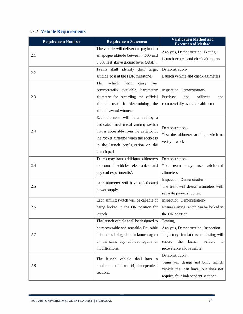
AUBURN UNIVERSITY STUDENT LAUNCH | PROPOSAL 69
4.7.2: Vehicle Requirements
Requirement Number Requirement Statement Verification Method and Execution of Method
2.1
The vehicle will deliver the payload to
an apogee altitude between 4,000 and
5,500 feet above ground level (AGL).
Analysis, Demonstration, Testing -
Launch vehicle and check altimeters
2.2 Teams shall identify their target
altitude goal at the PDR milestone.
Demonstration-
Launch vehicle and check altimeters
2.3
The vehicle shall carry one
commercially available, barometric
altimeter for recording the official
altitude used in determining the
altitude award winner.
Inspection, Demonstration-
Purchase and calibrate one
commercially available altimeter.
2.4
Each altimeter will be armed by a
dedicated mechanical arming switch
that is accessible from the exterior of
the rocket airframe when the rocket is
in the launch configuration on the
launch pad.
Demonstration -
Test the altimeter arming switch to
verify it works
2.4
Teams may have additional altimeters
to control vehicles electronics and
payload experiment(s).
Demonstration-
The team may use additional
altimeters
2.5 Each altimeter will have a dedicated
power supply.
Inspection, Demonstration-
The team will design altimeters with
separate power supplies.
2.6
Each arming switch will be capable of
being locked in the ON position for
launch
Inspection, Demonstration-
Ensure arming switch can be locked in
the ON position.
2.7
The launch vehicle shall be designed to
be recoverable and reusable. Reusable
defined as being able to launch again
on the same day without repairs or
modifications.
Testing,
Analysis, Demonstration, Inspection -
Trajectory simulations and testing will
ensure the launch vehicle is
recoverable and reusable
2.8
The launch vehicle shall have a
maximum of four (4) independent
sections.
Demonstration -
Team will design and build launch
vehicle that can have, but does not
require, four independent sections

AUBURN UNIVERSITY STUDENT LAUNCH | PROPOSAL 70
2.8.1
The official, marked altimeter is
damaged and/or does not report an
altitude via a series of beeps after the
team’s competition flight.
Inspection, Analysis, Testing -
Design the electronics housing to
prevent damage to altimeter
2.8.2
The team does not report to the NASA
official designated to record the
altitude with their official, marked
altimeter on the day of the launch.
Demonstration -
The team is timely and organized in
gathering data and reporting to NASA
official
2.9 The launch vehicle shall be limited to
a single stage.
Demonstration -
Team will design and build a single-
stage launch vehicle
2.10
The launch vehicle shall be capable of
being prepared for flight at the launch
site within 4 hours, from the time the
Federal Aviation Administration flight
waiver opens.
Demonstration -
Team will be timely and organized to
ensure vehicle is prepared on time
2.11
The launch vehicle shall be capable of
remaining in launch-ready
configuration at the pad for a minimum
of 2 hours without losing the
functionality of any critical on-board
component.
Demonstration -
Team will design vehicle with ability
to remain launch-ready for at least one
hour.
2.12
The launch vehicle shall be capable of
being launched by a standard 12 volt
direct current firing system. The firing
system will be provided by the NASA-
designated Range Services Provider.
Testing -
Batteries shall be tested with full
electronics to verify their life
2.13
The launch vehicle shall require no
external circuitry or special ground
support equipment to initiate launch
(other than what is provided by launch
services provider).
Demonstration -
The team will design a vehicle
requiring no external circuitry or
special ground support equipment
2.14
The launch vehicle will use a
commercially available solid motor
propulsion system using ammonium
perchlorate composite propellant
(APCP) which is approved and
Demonstration
Vehicle will be designed around
commercially available, certified
motors

AUBURN UNIVERSITY STUDENT LAUNCH | PROPOSAL 71
certified by the National Association
of Rocketry (NAR), Tripoli Rocketry
Association (TRA), and/or the
Canadian Association of Rocketry
(CAR).
2.14.1
Final motor choices must be made by
the
Critical Design Review (CDR).
Demonstration -
CDR will determine which motor the
team will use for competition
2.14.2
Any motor changes after CDR must be
approved by the NASA Range Safety
Officer (RSO) and will only be
approved if the change is for the sole
purpose of increasing the safety
margin.
Demonstration -
If the change is made to increase safety
margin, NASA RSO will allow the
change
2.15
Pressure vessels on the vehicle shall be
approved by the RSO and shall meet
the following criteria:
Analysis, Testing -
Inspection of pressure vessel by RSO
standards by testing.
2.15.1
The minimum factor of safety (Burst
or Ultimate pressure versus Max
Expected Operating Pressure) shall be
4:1 with supporting design
documentation included in all
milestone reviews.
Inspection, Analysis, Testing-
Team will design the pressure vessels
to have a factor of safety of 4:1.
2.15.2
Each pressure vessel will include a
pressure relief valve that sees the full
pressure of the tank and is capable of
withstanding the maximum pressure
and flow rate of the tank.
Inspection, Analysis, Testing -
Inspection of each pressure vessel and
testing of the pressure relief valve to
see that it works correctly
2.15.3
Full pedigree of the tank shall be
described, including the application
for which the tank was designed, and
the history of the tank, including the
number of pressure cycles put on the
tank, by whom, and when.
Inspection, Demonstration-
The team will inspect the tank along
with documentation of testing and
history
2.16 The total impulse provided by a
College and/or University launch Demonstration, Analysis-

AUBURN UNIVERSITY STUDENT LAUNCH | PROPOSAL 72
vehicle shall not exceed 5,120
Newton-seconds (L-class).
The team will choose a motor with a
total impulse that does not exceed
5,120 Newton-seconds (L-class).
2.17
The launch vehicle shall have a
minimum static stability margin of 2.0
at the point of rail exit.
Testing, Demonstration, Analysis-
The team will design and test the
vehicle to ensure that it has a stability
margin of 2.0 at the point of rail exit
2.18
The launch vehicle shall accelerate to
a minimum velocity of 52 fps at rail
exit.
Demonstration, Analysis, Testing -
The team will design the and test the
vehicle to ensure that it’s minimum
velocity at rail exit is at least 52 fps.
2.19
All teams shall successfully launch
and recover a subscale model of their
rocket prior to CDR.
Demonstration, Testing -
A demonstration of the launch will be
exhibited through testing.
2.19.1
The subscale model should resemble
and perform as similarly as possible to
the full-scale model, however, the full-
scale shall not be used at the subscale
model.
Demonstration -
The subscale model will be designed to
resemble and perform similarly to the
full-scale model.
2.19.2
The subscale model will carry an
altimeter capable of reporting the
model’s apogee altitude.
Demonstration -
An altimeter capable of reporting the
model’s apogee altitude will be
implemented on the subscale model.
2.19.3
The subscale rocket must be a newly
constructed rocket, designed and built
specifically for this year’s project.
Demonstration -
The team will construct a subscale
specifically for this year’s vehicle.
2.19.4 Proof of a successful flight shall be
supplied in the CDR report.
Testing, Demonstration -
The team will send use altimeter data
to proof a successful flight.
2.20 All teams will complete demonstration flights as outlined below.
2.20.1
All teams shall successfully launch
and recover their full-scale rocket prior
to FRR in its final flight configuration.
The rocket flown at FRR must be the
same rocket
Testing, Demonstration, Analysis -
A test of the rocket will be exhibited,
demonstrating all hardware functions
properly.

AUBURN UNIVERSITY STUDENT LAUNCH | PROPOSAL 73
flown of launch day. The following
criteria must be met during the full-
scale demonstration flight:
2.20.1.1 The vehicle and recovery system shall
have functioned as designed
Testing -
Testing of vehicle will show how
recovery system functions.
2.20.1.2
The full-scale rocket must be a newly
constructed rocket, designed and built
specifically for this year’s project.
Demonstration -
The team will build a vehicle
specifically for this year’s
competition.
2.20.1.3 The payload does not have to be flown during the full-scale test flight.
The following requirements still apply:
2.20.1.3.1
If the payload is not flown, mass
simulators shall be used to simulate the
payload mass.
Testing, Demonstration, Analysis-
Payload will be flown
2.20.1.3.2
The mass simulators shall be located in
the same approximate location on the
rocket as the missing payload mass.
Inspection-
Inspection of the rocket payload will
be done by the team to ensure it is
properly placed.
2.20.1.4
If the payload changes the external
surfaces of the rocket (such as with
camera housings or external probes) or
manages the total energy of the
vehicle, those systems shall be
activated during the full-scale
demonstration of flight
Demonstration, Testing-
Demonstration of the adaptability of
the systems notice to payload changes
of the external surfaces through
testing.
2.20.1.5 Teams shall fly the launch day motor
for the Vehicle Demonstration Flight.
Inspection-
The team will ensure that the motor
will be the one used on launch day.
2.20.1.6
The vehicle shall be flown in its fully
ballasted configuration during the full-
scale test flight.
Testing, Demonstration-
Testing of the ballast systems to ensure
proper mass locations.
2.20.1.7
After successfully completing the full-
scale demonstration flight, the launch
vehicle or any of its components will
not be modified without the
Demonstration-
The team will demonstrate that it did
not alter any components or vehicle
after demonstration flight.

AUBURN UNIVERSITY STUDENT LAUNCH | PROPOSAL 74
concurrence of the NASA Range
Safety Officer (RSO).
2.20.1.8 Proof of a successful flight shall be
supplied in the FRR report.
Demonstration, Testing- The team will
use altimeters to verify a successful
flight
2.20.1.9
Vehicle Demonstration flights must be
completed by the FRR submission
deadline (March 4, 2019).
Demonstration-
The full-scale flight will be completed
by March 4th, 2019,
2.20.2
Payload Demonstration Flight - All
teams will successfully launch and
recover their full-scale rocket
containing the completed payload
prior to the Payload Demonstration
Flight deadline (March 25, 2019).
Demonstration -
The payload demonstration flight will
be completed by the FRR submission
(March 4th, 2019).
2.20.2.1
The payload must be fully retained
throughout the entirety of the flight, all
retention mechanisms must function as
designed, and the retention mechanism
must not sustain damage requiring
repair.
Demonstration, Testing-
The team will demonstrate the payload
being fully secured during flight.
2.20.2.2 The payload flown must be the final,
active version.
Demonstration, Testing-
The team will use the final active
payload during flight.
2.20.2.3
If the above criteria is met during the
original Vehicle Demonstration Flight,
occurring prior to the FRR deadline
and the information is included in the
FRR package, the additional flight and
FRR Addendum are not required.
Demonstration-
The additional flight will not be flown,
if the above criteria is met.
2.20.2.4
Payload Demonstration Flights must
be completed by the FRR Addendum
deadline.
Demonstration-
The payload demonstration flight will
be completed by March 25th, 2019.
2.21 An FRR Addendum will be required
for any team completing a Payload
Analysis- The FRR Addendum will be
finished if a re-flight is required.
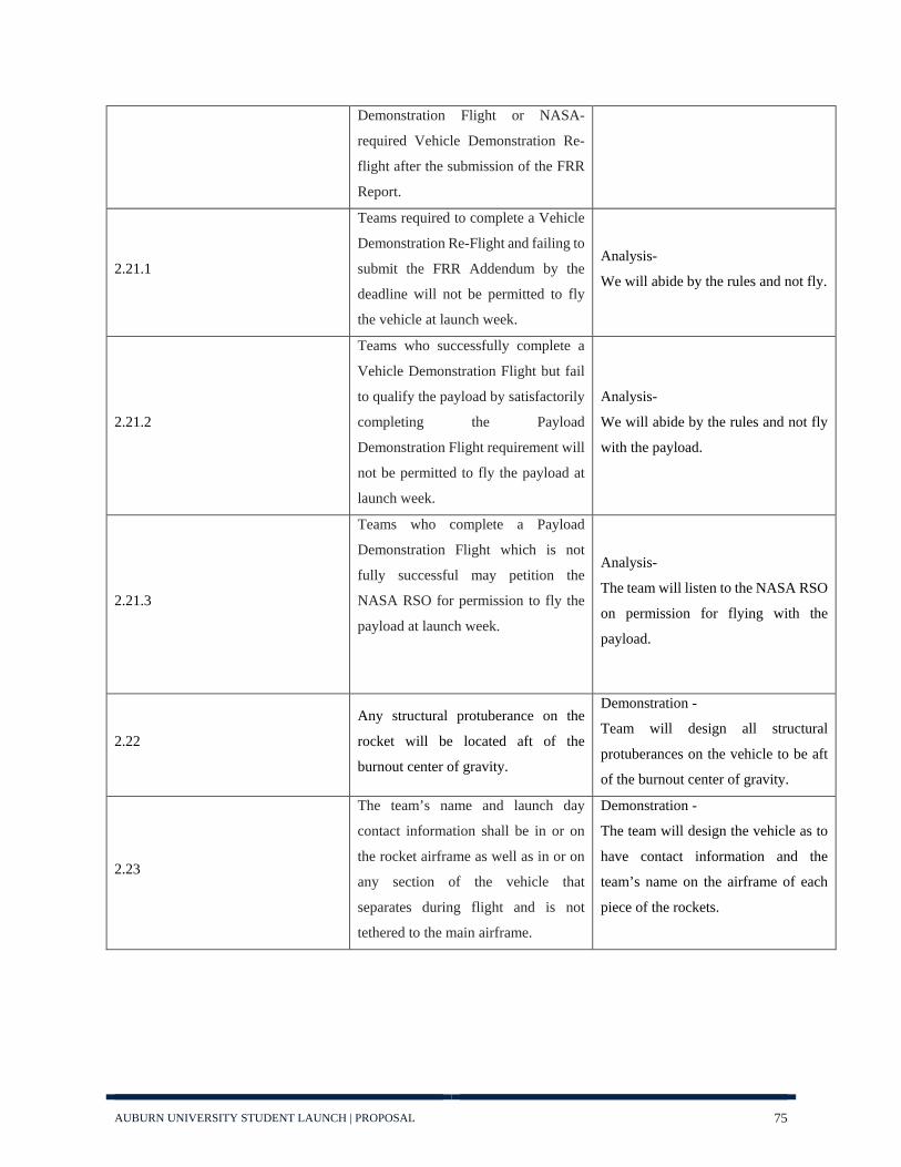
AUBURN UNIVERSITY STUDENT LAUNCH | PROPOSAL 75
Demonstration Flight or NASA-
required Vehicle Demonstration Re-
flight after the submission of the FRR
Report.
2.21.1
Teams required to complete a Vehicle
Demonstration Re-Flight and failing to
submit the FRR Addendum by the
deadline will not be permitted to fly
the vehicle at launch week.
Analysis-
We will abide by the rules and not fly.
2.21.2
Teams who successfully complete a
Vehicle Demonstration Flight but fail
to qualify the payload by satisfactorily
completing the Payload
Demonstration Flight requirement will
not be permitted to fly the payload at
launch week.
Analysis-
We will abide by the rules and not fly
with the payload.
2.21.3
Teams who complete a Payload
Demonstration Flight which is not
fully successful may petition the
NASA RSO for permission to fly the
payload at launch week.
Analysis-
The team will listen to the NASA RSO
on permission for flying with the
payload.
2.22
Any structural protuberance on the
rocket will be located aft of the
burnout center of gravity.
Demonstration -
Team will design all structural
protuberances on the vehicle to be aft
of the burnout center of gravity.
2.23
The team’s name and launch day
contact information shall be in or on
the rocket airframe as well as in or on
any section of the vehicle that
separates during flight and is not
tethered to the main airframe.
Demonstration -
The team will design the vehicle as to
have contact information and the
team’s name on the airframe of each
piece of the rockets.

AUBURN UNIVERSITY STUDENT LAUNCH | PROPOSAL 76
4.7.3: Vehicle Prohibitions Requirement
Number Requirement Statement Verification Method and
Execution of Method
2.24.1 The launch vehicles shall not utilize forward canards.
Demonstration - The team will demonstrate how the launch vehicle does not utilize canards.
2.24.2 The launch vehicle shall not utilize forward firing motors.
Demonstration - The team will design the vehicle so that it does not utilize forward firing motors.
2.24.3 The launch vehicle shall not utilize motors that expel titanium sponges (Sparky, Skidmark, MetalStorm, etc.)
Demonstration- The team will not utilize a motor that expels titanium sponges.
2.24.4 The launch vehicle shall not utilize hybrid motors.
Demonstration - The team will not utilize a hybrid motor.
2.24.5 The launch vehicles shall not utilize a cluster of motors.
Demonstration - A demonstration and inspection of the launch vehicle shall be carried out to validate it does not use a cluster of motors.
2.24.6 The launch vehicle shall not utilize friction fitting for motors.
Demonstration - The team will design the vehicle so that it does not utilize friction fitting for the motor.
2.24.7 The launch vehicle shall not exceed Mach 1 at any point during flight.
Demonstration ,Testing, Analysis - The team will test and demonstrate to ensure that the vehicle does not exceed Mach 1 at any point during the flight.
2.24.8 Vehicle Ballast shall not exceed 10% of the total weight of the rocket.
Demonstration, Testing ,Analysis- The team will design ballast so that it does not exceed 10% of the total weight of the rocket.
2.24.9 Transmissions from onboard transmitters will not exceed 250 mW of power.
Demonstration, Testing- The team will design transmitters that will not exceed 250 mW of power.
2.24.10
Excessive and/or dense metal will not be utilized in the construction of the vehicle. Use of lightweight metal will be permitted but limited to the amount necessary to ensure structural integrity of the airframe under the expected operating stresses.
Demonstration- The team will design the vehicle to ensure it does not use dense metals.

AUBURN UNIVERSITY STUDENT LAUNCH | PROPOSAL 77
4.7.4: Recovery Requirements
Requirement Number Description Verification Method
3.1
The launch vehicle will stage the
deployment of its recovery devices,
where a drogue parachute is deployed
at apogee and a main parachute is
deployed at a lower altitude. Tumble or
streamer recovery from apogee to main
parachute deployment is also
permissible, provided that kinetic
energy during drogue-stage descent is
reasonable, as deemed by the RSO.
The team will stage the deployment of
our recovery devices with a drogue
parachute deployed at apogee, currently
specified at 5111 ft. before altitude
control.
3.1.1 The main parachute shall be deployed
no lower than 500 feet.
The team will stage the deployment of
our recovery devices with the main
parachute at 600 ft.
3.1.2 The apogee event may contain a delay
of no more than 2 seconds.
A redundant altimeter will be in place
with an apogee delay of 1 second.
3.2
Each team must perform a successful
ground ejection test for both the drogue
and main parachutes. This must be
done prior to the initial subscale and
full-scale launches.
Prior to the initial subscale and full scale
launches the team will perform a ground
ejection test for both the drogue and main
parachute.
3.3
At landing, each independent section
of the launch vehicle will have a
maximum kinetic energy of 75 ft-lbf.
The team will calculate and test both
sections of our launch vehicle to ensure
that a maximum kinetic energy of 75 ft-
lbf at landing is not exceeded.
3.4
The recovery system electrical circuits
will be completely independent of any
payload electrical circuits.
The team will create independent circuits
for our recovery system so that they are
independent of any payload electrical
circuits.

AUBURN UNIVERSITY STUDENT LAUNCH | PROPOSAL 78
3.5
All recovery electronics will be
powered by commercially available
batteries.
All recovery electronics included in the
recovery systems will be powered by
commercially available batteries.
3.6
The recovery system will contain
redundant, commercially available
altimeters. The term “altimeters”
includes both simple and more
sophisticated flight computers.
The recovery systems will contain
TeleMetrum and TeleMega altimeters for
the BAE, and two Stratologger altimeters
for the nose cone.
3.7
Motor ejection is not a permissible
form of primary or secondary
deployment.
The recovery system will not use motor
ejection as a form of primary or
secondary deployment.
3.8
Removable shear pins will be used for
both the main parachute compartment
and the drogue parachute
compartment.
Removable shear pins will be used for
both the main parachute and drogue
parachute compartments.
3.9 Recovery area will be limited to a
2,500 ft. radius from the launch pads.
The team will ensure recovery area will
be less than a 2,500 ft. radius from the
launch pads.
3.10 Descent time will be limited to 90
seconds (apogee to touch down).
The team will limit the descent time to
under 90 seconds.
3.11
An electronic tracking device will be
installed in the launch vehicle and will
transmit the position of the tethered
vehicle or any independent section to a
ground receiver.
The team will install an electronic
tracking device in the launch vehicle that
will transmit the position of both
independent sections to a ground
receiver.
3.11.1
Any rocket section or payload
component which lands untethered to
the launch vehicle will contain an
active electronic tracking device.
Both independent sections of the launch
vehicle will contain and active electronic
tracking device.
3.11.2
The electronic tracking device(s) will
be fully functional during the official
flight on launch day.
The team will test the electronic tracking
devices to ensure their functionality for
the official flight on launch day.

AUBURN UNIVERSITY STUDENT LAUNCH | PROPOSAL 79
3.12
The recovery system electronic will
not be adversely affected by any other
on-board electronic devices during
flight (from launch until landing).
The team will test the recovery system
electronic to ensure it is not affected by
any other on-board electronic devices.
3.12.1
The recovery system altimeters will be
physically located in a separate
compartment within the vehicle from
any other radio frequency transmitting
device and/or magnetic wave
producing device.
The recovery system altimeters will be
located in separate compartments within
the vehicle from any other radio
frequency transmitting device and/or
magnetic wave producing device.
3.12.2
The recovery system electronics will
be shielded from all onboard
transmitting devices to avoid
inadvertent excitation of the recovery
system electronics.
The team will ensure that the recovery
system electronics will be shielded from
any and all transmitting devices to avoid
any excitation of said electronics.
3.12.3
The recovery system electronics will
be shielded from all onboard devices
which may generate magnetic waves
(such as generators, solenoid valves,
and Tesla coils) to avoid inadvertent
excitation of the recovery system.
The recovery electronics will be sealed in
their own separate compartment separate
from all other magnetic wave including
devices in the rocket.
3.12.4
The recovery system electronics will
be shielded from any other onboard
devices which may adversely affect the
proper operation of the recovery
system electronics.
The recovery electronics will be sealed in
their own separate compartment from all
other magnetic wave inducing devices in
the rocket.

AUBURN UNIVERSITY STUDENT LAUNCH | PROPOSAL 80
4.7.5: Rover Requirements
Requirement Number Description Verification Method
4.3.1 Teams will design a custom rover that will deploy from the internal structure of the launch vehicle.
Design: Tracked rover and orientation system will be completely housed inside the body of the rocket.
4.3.2
The rover will be retained within the vehicle utilizing a fail-safe active retention system. The retention system will be robust enough to retain the rover if atypical flight forces are experienced.
Testing: A servomotor held within the rover will hold onto an anchor point.
4.3.3
At landing, and under the supervision of the Remote Deployment Officer, the team will remotely activate a trigger to deploy the rover from the rocket.
Testing: Communicate via SMS message to rover to activate deployment.
4.3.4
After deployment, the rover will autonomously move at least 10 ft. (in any direction) from the launch vehicle. Once the rover has reached its final destination, it will recover a soil sample.
Testing: A 3-axis accelerometer will be used to determine distance from launch vehicle. At final destination soil recovery device will activate.
4.3.5 The soil sample will be a minimum of 10 milliliters (mL).
Testing: Soil recovery device will run for a designated amount of time.
4.3.6
The soil sample will be contained in an onboard container or compartment. The container or compartment will be closed or sealed to protect the sample after collection.
Testing: An integrated container will hold the sample, and a motor will extend a cover to contain the sample.
4.3.7 Teams will ensure the rover’s batteries are sufficiently protected from impact with the ground.
Testing: A slot for the batteries will be a priority when designing the rover so they will be integrated seamlessly in a safe, padded location.
4.3.8
The batteries powering the rover will be brightly colored, clearly marked as a fire hazard, and easily distinguishable from other rover parts
Design: All hazardous elements of the rover will be marked with a bright red color and be visible from the outside without moving parts to access them.

AUBURN UNIVERSITY STUDENT LAUNCH | PROPOSAL 81
4.7.6: Safety Requirements
Requirement
Number Description Verification
5.1
Each team will use a launch and safety checklist. The final checklists will be included in the FRR report and used during the Launch Readiness Review (LRR) and any launch day operations.
Demonstration - The team will develop and utilize their launch and safety checklists at all flights (testing and at competition) and at LRR
5.2 Each team must identify a student safety officer who will be responsible for all items in section 5.3.
The team has identified Jackson Treese as the student safety officer
5.3.1
Monitor team activities with an emphasis on Safety during: 1. Design of the vehicle and payload 2. Construction of the vehicle and payload 3. Assembly of the vehicle and payload 4. Ground testing of the vehicle and payload 5. Sub-scale launch test(s) 6. Full-scale launch test(s) 7. Launch Day 8. Recovery activities 9. STEM Engagement Activities
Demonstration- The Safety team will be present during all activities by virtue of being embedded within every team, and will monitor all activities to ensure that they are performed safely
5.3.2 Implement procedures developed by the team for construction, assembly, launch and recovery activities
Demonstration – During their duties while embedded in the other teams, safety liaisons will record the procedures that their teams follow, recording best practices and ensuring that safety checks are implemented.
5.3.3 Manage and maintain current revisions of the team’s hazard analysis, failure analysis, and procedures and MSDS/inventory data
Demonstration – The safety team will maintain current revisions of all required documents
5.3.4 Assist in the writing and development of the team’s hazard analyses, failure modes analyses, and procedures.
Demonstration – The safety team will assist in writing all required documents
5.4
During test flights, teams will abide by the rules and guidance of the local rocketry club’s RSO. The allowance of certain vehicle configurations and/or payloads at the NASA Student Launch does not give explicit or implicit authority for teams to fly those vehicle configurations and/or payloads at other club launches. Teams should communicate their intentions to the local club’s President or Prefect and RSO before attending any NAR or TRA launch.
Analysis, Demonstration – During test flights and design, the team will ensure that all aspects of the rocket are compliant with launch site requirements.
5.5 Teams will abide by all rules set forth by the FAA. Demonstration – The team will abide by all rules set forth by the FAA

AUBURN UNIVERSITY STUDENT LAUNCH | PROPOSAL 82
4.8: Major Technical Challenges and Solutions
As the Auburn team continues to mature its design, it has identified the major technical challenges
ahead and potential solutions to them.
Team Design Challenges Faced Potential Solutions
Vehicle Body
Need to create a smooth surface
around the iso-grid for aerodynamic
efficiency
Wrapping a single layer of pre-preg carbon fiber around the
isogrid structure could provide a relatively low weight and
easily applicable outer coating to the main body tube
Filling the iso-grid tube with a dissolvable foam and sanding
the foam such that it was flush with the outer edge of the iso-
grid would provide a relatively smooth and level surface for
filament winding
Recovery
Nose cone release cannot use a black
powder charge
Some form of mechanical ejection system could be designed to more effectively and safely separate the nose cone from the rest of the launch vehicle, as described in 4.3.3: Ejection System
Need a more reliable altimeter system
A trade study into different altimeter bay layouts could be
conducted in order to determine a more efficient and reliable
system
Ensure the black powder charges used
in main separation generate sufficient
pressure
Ensure the amount of black powder used for successful
separation test is documented and used for all further vehicle
launches
Ensure the main parachute is always
loaded properly
Establish a procedure for packing both the drogue and main
parachute, and ensure it is followed during all launches
Phase out Jolly Logic parachute
release system
The parachute release could be paired with the main separation
programming
Embedded
Systems
Instruments create too much data
noise for the altitude control system to
sort through
The PID controller could be set to accept the average value of
small data sets rather than every piece of data in order to
streamline the flow of data being analyzed
Rover Need to increase effective battery life
A more robust power system needs to be designed in order to
ensure the rover can stay powered on the launch pad for the
required two hours and still remain effective. A trade study into

AUBURN UNIVERSITY STUDENT LAUNCH | PROPOSAL 83
different batteries and power sources could be conducted to
determine the most effective and efficient option
Rover will require new motors for
propulsion
A trade study into various motors will need to be conducted in
order to select a motor capable of propelling the rover over any
terrain it might encounter
Rover bay design was not robust
enough to successfully deliver the
rover
Rover bay will be redesigned with a new release mechanism, a
new deployment system, and a new method of ensuring the
rover remains right way up

AUBURN UNIVERSITY STUDENT LAUNCH | PROPOSAL 84
5. STEM Engagement
5.1: General Statement
The Auburn University Student Launch (AUSL) team is entering an exciting new era of growth,
influence and leadership, as devotion for the future advancement of aeronautical and astronautical
engineering swells throughout the department. The team truly aspires to instill a passion for
science, technology, engineering, mathematics (STEM) and rocketry in young students here on the
Plains.
There are many middle school, high school, and college students that possess talents in math and
science, and they may aspire to pursue STEM careers in the future. Auburn University students
have great influence in the Auburn community. AUSL plans to use its influence to enrich the
minds of young students in Auburn and enable them to realize their full potential for STEM
careers.
5.2: Drake Middle School 6th Grade Rocket Week
Date: Spring 2019, exact week TBD
This year, the team’s primary plans begin with its venture in engaging young students by bringing
a hands-on learning experience for the sixth-grade class of J.F. Drake Middle School (DMS). The
program is entitled DMS 6th Grade Rocket Week, and the goal of the program is to encourage
interests in STEM and rocketry through an interactive three-day teaching curriculum that will
reach approximately 700 middle school students.
The sixth-grade science curriculum at DMS has a space unit during the school year. Therefore,
the rocketry unit curriculum will include lessons about rocketry and the forces that cause a rocket
to fly. Then, students will be divided into teams of 2-3 and provided a small alpha rocket to
construct and launch under the supervision of AUSL and certified professionals. This program
was successfully implemented during the 2013-2014 school year, and we have continued our
relationship every year since then.

AUBURN UNIVERSITY STUDENT LAUNCH | PROPOSAL 85
5.2.1: Rocket Week Plan of Action
Day 1: AUSL members will come to each sixth-grade science classroom and present a
presentation on rocketry and how it works. The members will engage the students during the
presentations with questions and answering their questions. If the presentation finishes before the
end of class, the students will begin on their rockets.
Day 2: The students will be split into teams of 2-3 and given a small alpha rocket assembly kit and
the required materials to build and decorate the rocket. AUSL members and the teachers will lead
the students in building and answers any questions that occur from the rocket building. All the
rocket building should finish on this day.
Day 3: All science classes will head to the P.E. field on DMS’s campus during each period
throughout the day. Students will also be informed of all safety and launch procedures for the
event when they first arrive on the field. A summary of what will take place at the launch and a
launching order will be announced on this day.
The launch day will be held on the DMS P.E. field on the third and final day of the program. Each
period of the school day, four or five science classes will proceed to the launch field. There will
be multiple launch rails set up in sanctioned safe zones in different parts of the field, meeting all
Figure 29: Picture of sixth graders on Launch day for Rocket Week for spring 2018.
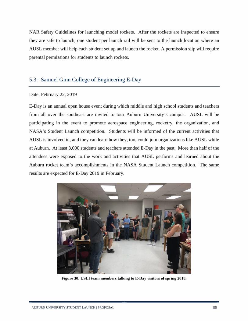
AUBURN UNIVERSITY STUDENT LAUNCH | PROPOSAL 86
NAR Safety Guidelines for launching model rockets. After the rockets are inspected to ensure
they are safe to launch, one student per launch rail will be sent to the launch location where an
AUSL member will help each student set up and launch the rocket. A permission slip will require
parental permissions for students to launch rockets.
5.3: Samuel Ginn College of Engineering E-Day
Date: February 22, 2019
E-Day is an annual open house event during which middle and high school students and teachers
from all over the southeast are invited to tour Auburn University’s campus. AUSL will be
participating in the event to promote aerospace engineering, rocketry, the organization, and
NASA’s Student Launch competition. Students will be informed of the current activities that
AUSL is involved in, and they can learn how they, too, could join organizations like AUSL while
at Auburn. At least 3,000 students and teachers attended E-Day in the past. More than half of the
attendees were exposed to the work and activities that AUSL performs and learned about the
Auburn rocket team’s accomplishments in the NASA Student Launch competition. The same
results are expected for E-Day 2019 in February.
Figure 30: USLI team members talking to E-Day visitors of spring 2018.

AUBURN UNIVERSITY STUDENT LAUNCH | PROPOSAL 87
5.4: Boy Scouts of America: Space Exploration Badge
Date: TBD
Through AUSL, scouts from Boy Scouts of America can receive the Space Exploration Badge.
The Space Exploration Badge is meant to persuade young scouts to explore the mysteries of the
universe and build rockets. The boy scouts will be led by students in AUSL to learn about rocketry
and build rockets. After the rocketry are inspected, they will be launched at the small rocket launch
fields south of Auburn University’s campus. This event began in 2016, and AUSL plans on
continuing working with the Boy Scouts this year. There is a Boy Scouts Engineering event during
the school year that scouts come to earn many badges, such as the Space Exploration Badge. AUSL
plans on coordinating with this event to set up a day to lead scouts in earning this Badge with
rocketry.
This event is planned to take up a single day on a weekend. The scouts will arrive to the Davis
Aerospace Engineering Building on Auburn University’s Campus where they will learn about
rocketry. Afterwards, they will be lead in building model rockets by AUSL members. AUSL
members will inspect the rockets for checking the integrity of the build. Then the scouts and AUSL
members will travel to the launch fields south of campus to help the scouts launch the rockets.
Figure 31: AUSL members setting up rockets for the Boy Scouts to launch for the Boy Scout event in spring 2018.

AUBURN UNIVERSITY STUDENT LAUNCH | PROPOSAL 88
5.5: Girl Scouts of America
Date: TBD
AUSL worked with other organizations in Auburn last spring to host an Engineering Day with the
Girl Scouts. AUSL plans on participating with the Girl Scout Engineering Day this year. The team
will present on aerospace concepts to the scouts. AUSL has two experiments members will run.
One experiment floats a ping pong ball that represents lift and the balance of forces on an object
in space. The second experiment launches straw rockets to show the dynamic forces in ballistic
trajectories. The AUSL team also plans on incorporating rocket builds and launches with the
scouts, as has been done in the past.
Figure 32: AUSL pose with Girl Scouts and their rockets after launching in spring 2018

AUBURN UNIVERSITY STUDENT LAUNCH | PROPOSAL 89
5.6: GRAND Engineering Showcase
Date: September 11th, 2018
This is an outreach event for 4-8th graders which has demonstrations about different areas of
Engineering. This is the first year AUSL participated in this event. AUSL presented on aerospace
concepts with two experiments. One experiment floats a ping pong ball that represents lift and the
balance of forces on an object in space. The second experiment launches straw rockets to show the
dynamic forces in ballistic trajectories. Members interacted with the children and answered any
questions they may have. This allows the team to continue its ongoing engagement with the local
community.
5.7: Auburn Junior High School Engineering Day
Date: Fall 2018
The Auburn Junior High School Engineering Day was created to encourage student interest in
engineering and to create an opportunity for students to gain firsthand experience as to what it is
like to be an engineer. AUSL will participate in the event to promote aerospace engineering,
rocketry, and the AUSL Competition. The team will bring example rockets and rocket components
to present to the students so that they can get an up close and hands on view of what AUSL does.
Last year the team presented to 1,000 students, many of whom expressed interest in engineering
and rocketry, and the team hopes to reach similar numbers this year.

AUBURN UNIVERSITY STUDENT LAUNCH | PROPOSAL 90
6. Project Plan
6.1: Systems Engineering
This year, the Auburn University Student Launch testing team is being reformatted into a Systems
Engineering team. This shift will serve to expand the team’s responsibilities from assisting the
more traditional design teams with verification and testing of launch vehicle components to
ensuring each team’s work is compatible with every other teams. It is crucial that communication
and co-operation be constantly maintained between the teams. Proper inter-team communication
can prevent last minute inconsistencies in dimensions or general designs, leading to a much higher
rate of success at launch. This team’s new responsibilities are designed to ensure consistency in
all aspects of the launch vehicle. The team will still maintain its original purpose of assisting in
all testing activities and will be responsible for ensuring all components on the launch vehicle
function properly and meet or exceed design requirement criteria. The combination of these two
duties should ensure quality control in all aspects of the design and construction process and
contribute to a safer and more consistent launch vehicle.
6.1.1: CFD
The team will be using computational fluid dynamics (CFD) to analyze this year’s launch vehicle.
CFD is a process which uses finite element analysis to model how fluid flow will interact with a
solid body. The team will insert a CAD model of the launch vehicle into the simulated flow field
to test the total drag of the rocket body and the effectiveness of the altitude control system. This
data will allow the team to more accurately predict the final altitude of the launch vehicle and to
calibrate the altitude control system more precisely.
6.1.2: Rover
The rover team will be using a revolving rover bay with gravity-based stabilization in order to
ensure the rover can deploy right side up upon vehicle landing. This system will receive extensive
drop, vibration and rotation testing in order to ensure proper function when mounted on the launch
vehicle. The rover capsule will have two locking mechanisms, one that is released by a pin with

AUBURN UNIVERSITY STUDENT LAUNCH | PROPOSAL 91
the parachute when it deploys, and one released by remote control. The first system will allow the
gravity-based system of the capsule to activate and keep the rover upright. The second system will
detach the rover after confirmed touchdown. Only after these mechanisms both are unlocked will
the rover be able to exit the rocket body. Both systems will be tested to ensure they only function
when needed for the safety of both the payload and potential bystanders. After the rover deploys,
it will use its tracked drive system to drive up to ten feet away from the vehicle body. Subsequently,
it will use a trenching mechanism to collect a large sample of soil into its soil bay. Thorough testing
will be done to ensure the rover is well engineered to do its task and that there are no soil conditions
on which the rover cannot complete its mission. Electronic systems will be tested for battery life
and capability from long distances. All systems mentioned above will undergo vibration and
centrifuge testing, to ensure they are ready for the forces of flight and deployment.
6.1.3: Embedded
One of the primary performance requirements for this year’s competition is for the rocket to be
able to reach a predetermined altitude. To ensure the rocket does not over shoot this target, variable
flat plates on the rocket will need to be able to generate controllable drag force. The team will
conduct both CFD simulation and wind tunnel testing to determine how much drag is produced by
the plates. This data will be fed into a PID controller on the rocket which will constantly determine
the projected altitude. When that value is determined, the rocket will be able to adjust position of
the plates and therefore drag accordingly. Determining how much drag this system produces and
how it will affect the final altitude of the rocket will be an essential part of testing.
The rocket will have multiple electrical components such as batteries, controllers, and their
respective circuitry. These devices will have to be verified to be able to function after being left
on for over two hours on the launch pad. Additionally, the altimeter(s) and accelerometers used
will have to be verified to be accurate, since they are managing the energy of the rocket. These
will be tested by the team to ensure they are safe and will accomplish their designed function.
Additionally, they will be tested ensure the forces applied by launch and main chute deployment
do not disrupt their function. Another concern for the electrical and software components will be
environmental challenges – the main concern being humidity. The electrical and software

AUBURN UNIVERSITY STUDENT LAUNCH | PROPOSAL 92
components will be tested to ensure there are no potential hazards which could result from
humidity damage or other environmental causes.
6.1.4: Recovery
The Recovery system will have to undergo intensive testing to ensure the successful final recovery
of the rocket. Testing will follow similar, however slightly augmented, methods as previous years.
The team will be manufacturing both the drogue and main parachutes in house. In order to test the
parachutes, the team will construct a scaled hemispherical main parachute, which will then be
tested in the Auburn University wind tunnels in similar flow conditions to what the full sized
parachute will experience at launch. Drag data from the tests will be averaged and used to compute
a coefficient of drag for the hemispherical parachute with a spill hole. The data will be compared
to the coefficients of drag obtained via research and last year’s data to confirm accurate sizing and
performance of the team's parachutes. With this data, the team will be able to more accurately size
the parachute to ensure a safe descent for the vehicle. Finally, when the parachutes are completed,
the team will analytically determine an efficient packing style for the parachute and conduct drop
tests to ensure the recovery system deploys properly. The team will be conducting extensive
ground testing of the black powder ejection system, as proper deployment is essential and in need
of optimization from previous years. Brainstorming and testing of a mechanical release for the
nosecone separation will be conducted to determine whether the mechanical release is more
reliable than black powder. These tests will be performed by assembling the avionics bay along
with the sections of the rocket that separate; the sections will be fixed in a testing rig oriented
horizontally. The nose cone will be aimed at a backstop so as to prevent injury and damage. The
altimeters will be connected to a ground computer, from which the charges are triggered. Safety
equipment will be on site, including fire extinguishers. For the black powder system, testing will
begin with the smallest black powder charge from a calculated range. The testing will iterate with
increasing black powder charges until the minimum charge is reached that safely separates each
rocket section.

AUBURN UNIVERSITY STUDENT LAUNCH | PROPOSAL 93
6.1.5: Vehicle Body
The body team will be conducting various material, structural, and aerodynamic tests to ensure the
launch vehicle can withstand the forces of launch and maintain a controlled and predictable ascent.
Material and structural testing of the body will consist of electronic simulation, followed by
physical testing to verify models and highlight necessary changes. Finite element analysis within
computer aided design software will be used to model the effects of launch forces on individual
components of the vehicle to ensure they are robust enough to support the launch vehicle.
Additionally, material samples of carbon fiber, 3D-printed Onyx, and fiberglass will be tested to
ensure these models provide accurate data. The entire launch vehicle will also be modelled in
CFD software to gather expected drag data and determine a maximum altitude prediction. As
construction progresses, complete flat plates and sections of the open architecture structure will be
tested to ensure their structural properties are still sufficient. Wind and water tunnel testing of the
body and fins will be performed to gather real world data on drag characteristics.

AUBURN UNIVERSITY STUDENT LAUNCH | PROPOSAL 94
6.2: Development Timeline
This year, the Auburn team plans to pursue an aggressive testing and construction schedule in
order to ensure that our timeline can absorb delays. A high level overview of team activities that
contribute to the mission can be seen in Figure 33: Gannt Chart. Dates for team educational
engagement events and specific launches that will be attended are not yet available, and will be
added to the timeline as they become known.
Figure 33: Gannt Chart

AUBURN UNIVERSITY STUDENT LAUNCH | PROPOSAL 95
6.3: Budget
The projected budget for the 2018-2019 competition can be seen in the tables that follow. Since
this is the planning stage of the competition, specific component costs were used when available,
but otherwise intentionally over estimated when not available. For example, the price of the
planned full scale motor (an Aerotech L1520T) is already known to be $259.99, but the exact
quantity of Onyx printer material that will be used over the course of the competition is not, so
each section is assumed to use an entire roll on their own. Of course, in actual manufacturing this
resource will be shared between teams and should not exceed that level, especially with material
left over from previous years. Similarly, costs for all sections of the project are greatly reduced
through the team’s built up stockpile of extra attachment hardware, parachute and structural
material, electronics and tooling.
Vehicle (Full Scale and Subscale) Item Cost Per Unit Unit Quantity Total
Prepreg Carbon Fiber
$0 (Donated by GKN
Aerospace) Per square yard 9 $0
Aerotech L1520T $199.99 Per unit 1 $199.99 RMS 75/3840 Motor Case and Associated Hardware
$385 Per unit 1 $385
Aerotech L1420R $259.99 Per unit 1 $259.99 RMS 75/5120 Motor Case and Associated Hardware
$390 Per unit 1 $390
Fiberglass Coupler $69 Per unit 6 $414
Rail Buttons $3 Per unit 4 $12 Total $1,661
Table 11: Vehicle Expected Costs

AUBURN UNIVERSITY STUDENT LAUNCH | PROPOSAL 96
Recovery (Full Scale and Subscale)
Item Cost Per Unit Unit Quantity Total
Ripstop Nylon $8 Per yard 25 $200
Nylon Thread $8 Per spool 3 $24
Tubular Nylon $1 Per foot 50 $50
Paracord $5 Per roll 1 $5
Telemetrum $200 Per unit 1 $200
Telemega $400 Per unit 1 $400
Adafruit Trinket $14 Per unit 1 $14
Total $893 Table 12: Recovery Expected Budget
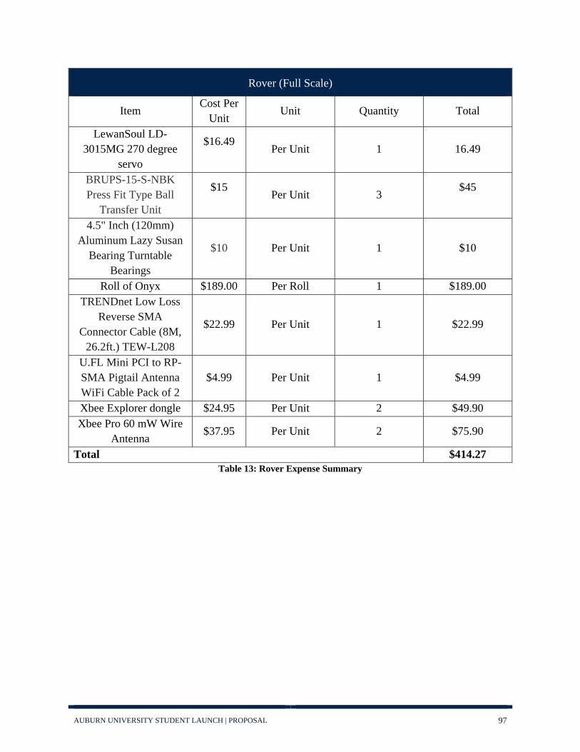
AUBURN UNIVERSITY STUDENT LAUNCH | PROPOSAL 97
Rover (Full Scale)
Item Cost Per Unit Unit Quantity Total
LewanSoul LD-3015MG 270 degree
servo
$16.49 Per Unit 1 16.49
BRUPS-15-S-NBK Press Fit Type Ball
Transfer Unit
$15 Per Unit 3
$45
4.5" Inch (120mm) Aluminum Lazy Susan
Bearing Turntable Bearings
$10 Per Unit 1 $10
Roll of Onyx $189.00 Per Roll 1 $189.00 TRENDnet Low Loss
Reverse SMA Connector Cable (8M,
26.2ft.) TEW-L208
$22.99 Per Unit 1 $22.99
U.FL Mini PCI to RP-SMA Pigtail Antenna WiFi Cable Pack of 2
$4.99 Per Unit 1 $4.99
Xbee Explorer dongle $24.95 Per Unit 2 $49.90 Xbee Pro 60 mW Wire
Antenna $37.95 Per Unit 2 $75.90
Total $414.27 Table 13: Rover Expense Summary

AUBURN UNIVERSITY STUDENT LAUNCH | PROPOSAL 98
Research and Development Costs
Item Cost Per Unit Unit Quantity Total
Carbon fiber and resin for open weave structure.
$284 Per tube 2 $568
Fiber glass sleeve $33 Per tube 2 $66
Pre-preg Carbon Fiber
$118 Per yard 3 $354
Stratologger CF $55 Per unit 2 $110
Roll of Onyx $189.00 Per Roll 2 $189.00
Total $1,287 Table 14: Research and Development Projected Expenses
Altitude Control
Items Name Price
Accelerometer ADXL345 $17.50
SD Card Datalogger MicroSD card breakout board+ $7.50
Premium Planetary Gear Motor w/Encoder
280 RPM Premium $49.99
Altimeter/Pressure Sensor MPL3115A2 $9.95
Display 2x16 Character Display $4.95
RTC DS3231 $13.95
Motor Driver Adafruit DRV8833 $4.95
2 9V Batteries Duracell $10.00
Onyx Structure (one roll of material) MarkForged $189.00
Microcontroller STM32F103C8T6 “Blue Pill” $2.50
Total $310.29 Table 15: Altitude Control Expense Summary

AUBURN UNIVERSITY STUDENT LAUNCH | PROPOSAL 99
Education Outreach
Item Cost
Estes Educator Rockets $ 2040
Glue for Rockets $ 50
Estes A8-3 Motors $ 805
Straw Rockets $ 20
Launch Controller Batteries $ 30
Rocket Building Supplies (X-acto Knives, Sandpaper) $ 20
Total Cost $ 2965 Table 16: Outreach Expenses

AUBURN UNIVERSITY STUDENT LAUNCH | PROPOSAL 100
6.3.1: Budget Summary
The total costs for each segment of the team can be seen below in Table 17: Budget Summary, in
addition to the total cost for the year based on current projections. To provide further robustness
and ensure that unforeseen expenses are accounted for, the total projected costs were multiplied
by twenty percent. This second number is the one that the team feels is a more accurate prediction
of the final project cost based off of previous experience.
Budget Summary
Vehicle $1661
Recovery $893
Rover $414.27
Research and Development $1287
Altitude Control $310.29
Education/ Outreach $2965
Hotel and Travel $2500
Promotional Materials $1250
Total $11,280.56
Total plus 20% growth $13,536.67 Table 17: Budget Summary

AUBURN UNIVERSITY STUDENT LAUNCH | PROPOSAL 101
6.4: Funding Plan
The teams current expected funding level is in Table 18: Funding Sources. For our corporate
sponsors, these numbers are based off of last year’s contributions, and are expected to remain
constant. The team must also thank GKN Aerospace in Tallassee, Alabama for their support.
Instead of providing monetary support, GKN donates surplus composites to Auburn University,
which the team is in turn able to use to manufacture our airframe. Additionally, over the previous
year the Auburn team was able to maintain a budget surplus, and these funds have been rolled over
to the current year’s resources as well. As already mentioned in Section 6.3: Budget, the current
costs are all conservative overestimations for materials quantities when not related to specific new
components that will be ordered. Even with a hefty twenty percent further increase in expenses,
the team’s current projections expect a budget surplus of almost two thousand dollars.
Source Amount
Alabama Space Consortium $12,000
Dynetics $2,500
Team Savings $1003.02
Total Funding $15,503.02
Total plus 20% growth $13,536.67
Expected Savings $1966.35 Table 18: Funding Sources

AUBURN UNIVERSITY STUDENT LAUNCH | PROPOSAL 102
6.5: Sustainability
In order to maintain the AUSL team, AUSL must recruit every year to train and maintain the
technical skills needed for running the team. Multiple events in the fall semester of school are used
to outreach to college students to introduce them to AUSL. These new members are brought into
the teams and taught the technical skills so that the level of quality rocket production is kept the
same. All members are required to participate in Education outreach activities to not only train
them in outreach, but also to maintain the relationships created for outreach events in the area. The
coordinators that work with AUSL gain familiarity with members they see each year, developing
a relationship between the team and the educational opportunities.
As far as the community presence, the team has now been in regular contact with many local
organizations and businesses for over two years. The team has established programs for
educational engagement that it can improve every year with experience and the addition of a larger,
better trained workforce. The team’s partnerships with Drake Middle School, Auburn Junior High
School, and Auburn High School are well developed and it hopes to maintain its relationship
through the continuation of successful educational engagement events.
As for financial stability, both of the primary sources of funding, the Alabama Space Consortium
and Auburn University College of Engineering, are renewable in that the team does not foresee
issues obtaining relatively similar amounts of money for future years assuming the continued
success of the organization. If for any reason the team receives reduced funding from either source,
budget gaps can be made up with department funding, club dues, and other smaller fundraising
opportunities.
6.5.1: Aeropalooza
Date: August 28, 2018
Aeropalooza is a yearly gathering at the beginning of the fall semester that seeks to bring together
the entirety of the Auburn Aerospace community. One of the main purposes of the event is to
help students find a student organization that occupies their interests. To this end, AUSL set up a
table and several rockets from previous years. As students came by members explained the
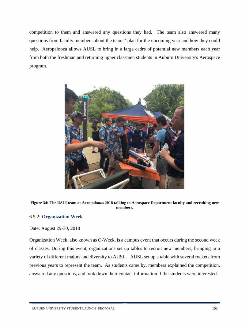
AUBURN UNIVERSITY STUDENT LAUNCH | PROPOSAL 103
competition to them and answered any questions they had. The team also answered many
questions from faculty members about the teams’ plan for the upcoming year and how they could
help. Aeropalooza allows AUSL to bring in a large cadre of potential new members each year
from both the freshman and returning upper classmen students in Auburn University's Aerospace
program.
Figure 34: The USLI team at Aeropalooza 2018 talking to Aerospace Department faculty and recruiting new members.
6.5.2: Organization Week
Date: August 29-30, 2018
Organization Week, also known as O-Week, is a campus event that occurs during the second week
of classes. During this event, organizations set up tables to recruit new members, bringing in a
variety of different majors and diversity to AUSL. AUSL set up a table with several rockets from
previous years to represent the team. As students came by, members explained the competition,
answered any questions, and took down their contact information if the students were interested.

AUBURN UNIVERSITY STUDENT LAUNCH | PROPOSAL 104
6.5.3: Auburn University Rocketry Association
The Auburn University Rocket Association (AURA) is a sister organization parallel to AUSL and
operates with the Education Outreach team. The goal of AURA is simple: it instructs students in
how to construct a rocket with which they can secure their Tripoli level one certification. To
achieve this, students are first taught how to model their rockets in the OpenRocket design
software, and some of the strengths and limitations of that program. Next, members construct their
rockets in the lab, gaining familiarity with the machines and tools within and the techniques
involved. Finally, the students’ rockets are launched at the same launch day as a AUSL subscale
or full-scale launch, to allow for sharing rides and save time. AURA serves a dual purpose for
AUSL. First, it allows current-but-newer AUSL members to gain experience and appreciation for
the design of an entire rocket and valuable hands-on lab experience. Secondly, it provides a
gateway in rocketry for those initially daunted by the scale of the AUSL competition, who after
developing their skills feel confident enough to take the plunge and join AUSL
Figure 35: An AURA build group in Fall 2017 preparing their rocket engines for launching to attempt their Level 1 certifications.
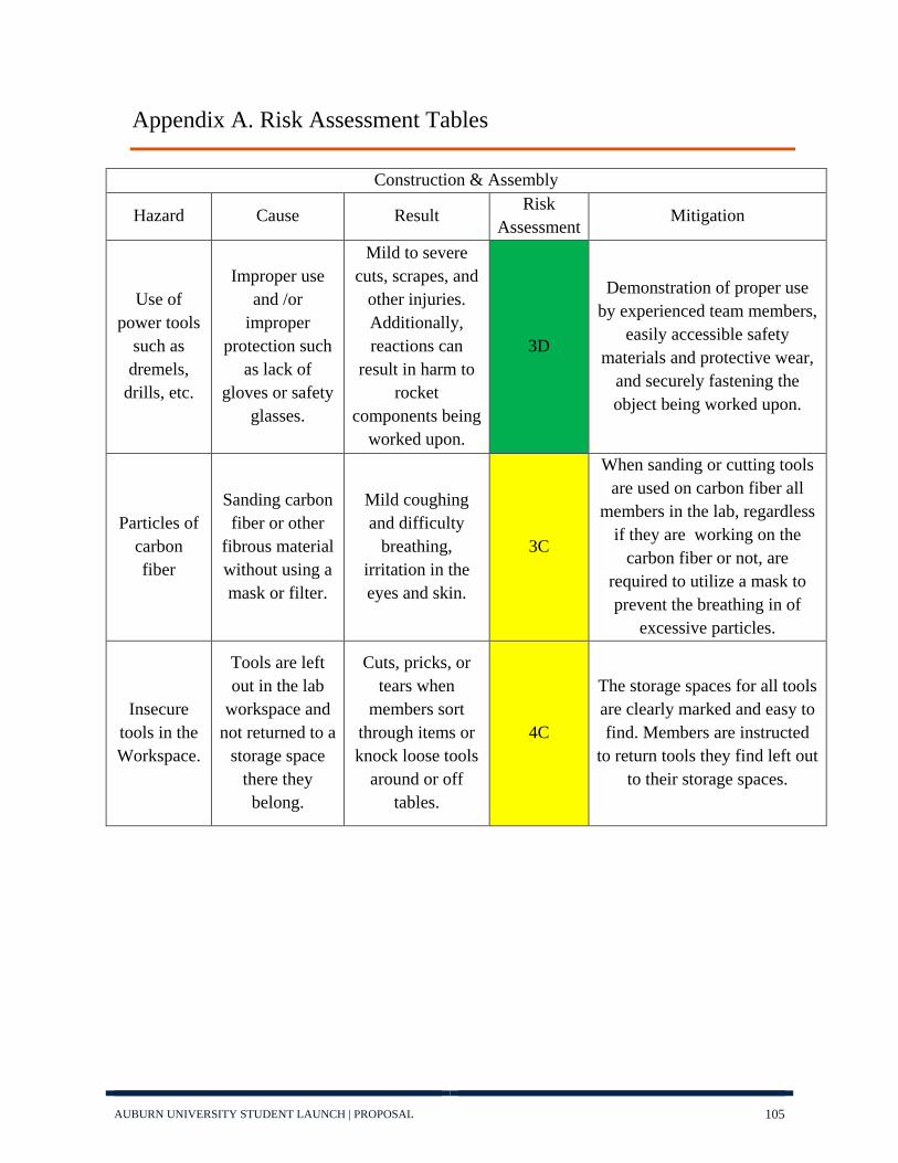
AUBURN UNIVERSITY STUDENT LAUNCH | PROPOSAL 105
Appendix A. Risk Assessment Tables
Construction & Assembly
Hazard Cause Result Risk
Assessment Mitigation
Use of power tools
such as dremels,
drills, etc.
Improper use and /or
improper protection such
as lack of gloves or safety
glasses.
Mild to severe cuts, scrapes, and
other injuries. Additionally, reactions can
result in harm to rocket
components being worked upon.
3D
Demonstration of proper use by experienced team members,
easily accessible safety materials and protective wear,
and securely fastening the object being worked upon.
Particles of carbon fiber
Sanding carbon fiber or other
fibrous material without using a mask or filter.
Mild coughing and difficulty
breathing, irritation in the eyes and skin.
3C
When sanding or cutting tools are used on carbon fiber all
members in the lab, regardless if they are working on the
carbon fiber or not, are required to utilize a mask to prevent the breathing in of
excessive particles.
Insecure tools in the Workspace.
Tools are left out in the lab
workspace and not returned to a
storage space there they
belong.
Cuts, pricks, or tears when
members sort through items or knock loose tools
around or off tables.
4C
The storage spaces for all tools are clearly marked and easy to find. Members are instructed
to return tools they find left out to their storage spaces.

AUBURN UNIVERSITY STUDENT LAUNCH | PROPOSAL 106
Construction & Assembly
Hazard Cause Result Risk
Assessment Mitigation
Use of soldering
tool
Failure to pay proper attention to the soldering
tool.
Mild to severe burns on the
fingers or hands of the team
member using it. Additionally, could result in excessive heat
and damage to the component being
worked on.
3D
Members that use the soldering iron are required to give it their full attention for the duration of their work. They must turn off and stow the tool somewhere away from the object being
worked on if they must attend to something else before work
is finished.
Fumes from soldering
Tool.
Improper ventilation of
the workstation where soldering is taking place.
Excessive exposure to toxic fumes results in
nausea and irritation.
Reactions could potentially damage the
component(s) being worked
upon.
3D
The workstation will be properly vented and members
using it are required to confirm ventilation is functioning
periodically. Additionally, team members will not be allowed to
continue soldering for an extended period of time and must take a break to let any buildup of fumes disperse.
Use of the belt sander, band saw,
or drill press.
Failure to pay attention,
aggressive use of the tools,
lack of proper protective equipment
Severe cuts, burns, rashes,
bruises, or other harm to fingers, hands, and/or
arms.
2D
Experienced team members will instruct inexperienced team
members before they are allowed to use the tools,
protective equipment will be easily accessible.

AUBURN UNIVERSITY STUDENT LAUNCH | PROPOSAL 107
Construction & Assembly
Hazard Cause Result Risk
Assessment Mitigation
Use of tools.
Improper maintenance of tools used in the
lab and workspace.
Damage to sections of the
rocket or to team members, or delays to the project to get replacement
parts.
3E
All tools are maintained regularly. Any tools deemed beyond repair are disposed of
and replaced immediately.
Use of electrical
Equipment.
a) Improperly maintained equipment.
b) Improper use of equipment.
Electric shocks could occur to team members handling the equipment.
1E
Electrical equipment will be maintained regularly. Electrical equipment will only be plugged
in when ready for immediate use and will be promptly
unplugged afterward.
Carbon fiber splinters.
Handling of carbon fiber components
with bare hands.
Slivers of carbon fiber break off
and become stuck in the skin of
fingers and hands handling it.
4B
Members are encouraged to handle carbon fiber components
with gloves. In the event that gloves are unavailable, gentle handling is enough to avoid
splinters.
Structural integrity of the rocket is
compromised by buckling
during flight.
Excessive aerodynamic
loading on the airframe of the
rocket.
The mission is lost, the rocket
becomes unstable during flight and may be a danger to personnel or
the environment.
1E
Extensive testing of the materials and structural
architecture of the rocket body will be done before subscale and
full-scale launches to confirm that the design will withstand forces that it will encounter.
Sections of the rocket are
poorly coupled together.
The use of weak bolts or
poorly designed couplers between sections.
Sections of the rocket may
wobble and the trajectory of the rocket could be affected during ascent or during
recovery.
2D
Extensive testing of the coupler will be done prior to subscale and full-scale launches. The
coupler will be visually inspected before and after
assembly.

AUBURN UNIVERSITY STUDENT LAUNCH | PROPOSAL 108
Vehicle Structure
Hazard Cause Result Risk
Assessment Mitigation
The airframe is dropped or hits against a hard surface
during construction, assembly, or in transport.
Distracted or clumsy handlers
that are not aware of their surroundings.
The body or nose cone may be
damaged by the impact and may
require replacement.
3D
Great care will be taken when working on components under
all conditions. During transportation multiple
personnel will carry the rocket slowly and carefully while an
additional team member removes obstacles or opens
doors as necessary. Replaceable parts such as pins, screws, and
the nose cone will have duplicate parts available during
assembly.
Holes in the airframe
leading to the inside of the rocket body.
Insufficient communication in addition to
excessive drilling or work on components
or failure to notice missing pins or screws
The hole could result in an
improper reading of air pressure by the altimeter and
result in premature
activation of the recovery system.
1D
All sections of the rocket will be visually inspected immediately
after construction, before transport to the launch site, and
on assembly. Duplicates of objects such as pins, screws, etc. will be available to replace any
missing ones.
Cracks in the airframe.
Excessive physical or
thermal loading to the rocket body during storage or transport.
The rocket body fractures on launch or on
ascent releasing debris in the
immediate area.
1E
Sections of the rocket body will be kept in a dry location at room
temperature. The rocket body will be visually inspected before
and after transport, during assembly, and immediately
prior to launch to confirm that there are no cracks.

AUBURN UNIVERSITY STUDENT LAUNCH | PROPOSAL 109
Vehicle Structure
Hazard Cause Result Risk
Assessment Mitigation
A segment of the airframe is misplaced
or lost.
A messy or disorganized
work environment leads to poor tracking and storage of
pertinent rocket segments.
An incomplete rocket body is transported or
ready for assembly on launch day.
Segments may need to be
remanufactured if they cannot be
located.
2E
Once segments of the rocket body are completed they will be immediately stored in a location
exclusively for launch-ready components. For subscale
launches, some components will be manufactured twice so
that one may serve as a backup.
Stability and Propulsion
Hazard Cause Result Risk
Assessment Mitigation
Motor explodes on
Launch.
Manufacturing defect from
supplier
The rocket is destroyed on the
launch pad or shortly after
launch.
1E
Rocket motors will only be purchased from a certified
source and will be handled with extreme care exclusively by the
team mentor or by someone with permission of the team
mentor.
The rocket exceeds
Mach 1 on ascent.
The rocket motor utilized in the design is
too powerful for the mass of the
rocket.
Vehicle requirement
1.19.7 is violated, compromising the
validity of the mission.
2E
Team members will analytically evaluate the expected speed of the rocket prior to testing and will confirm these results in
sub-scale and full-scale testing. In the event that the mass of the
rocket is too low, additional mass will be added to the inside of the rocket to ensure it does
not exceed Mach 1.

AUBURN UNIVERSITY STUDENT LAUNCH | PROPOSAL 110
Stability and Propulsion
Hazard Cause Result Risk
Assessment Mitigation
Motor fails to ignite.
a) Defect in Manufacturing
b) Failure of the ignition system.
c) Delayed ignition.
a) and b) The motor will not
fire and the rocket will not launch. c)
The motor will fire and the rocket
will launch an unknown amount of time after the
button is pressed.
3D
In accordance with the NAR Safety Code, the safety
interlock will be removed or the battery will be disconnected and no team member will approach the rocket for 60 seconds. After 60 seconds without activity the safety officer will approach and check the ignition systems. In
the event that the ignition systems are not at fault the motor will be removed and
replaced with a spare. A second launch will be attempted if there
is time to do so.
Motor is physically Damaged.
Motor was damaged during
handling or transport.
The motor will be primarily handled
by the team mentor or another member certified to do so with the permission of the mentor or safety
officer.
2E
The mentor will oversee the design of a carrying case for the motors that they will be safely stored in during transport and
will be the one to stow and remove them from this case.
Epoxy used is
insufficient to stabilize
fins on rocket body.
a) The epoxy was mixed or
cured improperly.
b) The epoxy used was not
strong enough to withstand
forces encounter in
flight.
Fins may vibrate and cause
unexpected or erratic changes to the course of the
rocket. This could endanger
personnel on ascent or recovery.
2D
Proper procedures regarding the mixing and curing of epoxy will
be strictly followed during construction of the rocket.
During assembly team members will apply pressure to the fins to confirm they do not move and
will not during flight.

AUBURN UNIVERSITY STUDENT LAUNCH | PROPOSAL 111
Stability and Propulsion
Hazard Cause Result Risk
Assessment Mitigation
Rocket center of
gravity and center of
pressure are improperly
placed.
Rocket property calculations were made incorrectly.
The rocket's ascent will be unstable and potentially dangerous.
1E
Calculations will be checked multiple times prior to launch. Subscale launches will provide an opportunity to confirm these calculations prior to full scale
launch. Additionally, the center of gravity will be physically
checked prior to launch.
Scientific Payload
Hazard Cause Result Risk
Assessment Mitigation
Improper soldering.
Too much or too little solder is used when
constructing the electrical
equipment to control the
science payload.
Electrical malfunctions and a loss of system
integrity.
2D
The electrical equipment will be visually inspected by multiple team members and tests run to ensure that it carries electrical
signals as intended.
Improper wiring.
Electrical signals are transmitted improperly resulting in unexpected behavior.
The science payload does not
behave as expected or does
not function at all.
2D
Wires will be color-coded to communicate their function and
a specific checklist will be created to ensure the system is
wired correctly. Extensive ground testing will confirm
payload functionality

AUBURN UNIVERSITY STUDENT LAUNCH | PROPOSAL 112
Scientific Payload
Hazard Cause Result Risk
Assessment Mitigation
The servos utilized by the science
payload jitter or do not actuate
smoothly.
a) Internal electrical failure.
b) Worn or malfunctioning
gears.
The science payload may not
respond as accurately as
expected.
3D
The servos that will be used for flight will be purchased at the beginning of the project and
will be stored in a space away from any chemicals or
excessive humidity. The servos will be tested before transport, before and after assembly to
confirm that they actuate properly.
Recovery
Hazard Cause Result Risk
Assessment Mitigation
Parachute failure on
deployment.
The parachute is not packed
properly.
The parachute becomes tangled
on descent resulting in an erratic and fast
moving projectile that endangers personnel and
property below.
1C
Packing of the parachute will be performed by dedicated
members of the recovery team who will have practiced
previously.
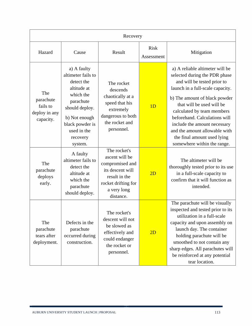
AUBURN UNIVERSITY STUDENT LAUNCH | PROPOSAL 113
Recovery
Hazard Cause Result Risk
Assessment Mitigation
The parachute
fails to deploy in any
capacity.
a) A faulty altimeter fails to
detect the altitude at which the parachute
should deploy.
b) Not enough black powder is
used in the recovery system.
The rocket descends
chaotically at a speed that his
extremely dangerous to both
the rocket and personnel.
1D
a) A reliable altimeter will be selected during the PDR phase
and will be tested prior to launch in a full-scale capacity.
b) The amount of black powder that will be used will be
calculated by team members beforehand. Calculations will include the amount necessary
and the amount allowable with the final amount used lying
somewhere within the range.
The parachute deploys early.
A faulty altimeter fails to
detect the altitude at which the parachute
should deploy.
The rocket's ascent will be
compromised and its descent will
result in the rocket drifting for
a very long distance.
2D
The altimeter will be thoroughly tested prior to its use
in a full-scale capacity to confirm that it will function as
intended.
The parachute tears after
deployment.
Defects in the parachute
occurred during construction.
The rocket's descent will not
be slowed as effectively and could endanger
the rocket or personnel.
2D
The parachute will be visually inspected and tested prior to its
utilization in a full-scale capacity and upon assembly on
launch day. The container holding parachute will be
smoothed to not contain any sharp edges. All parachutes will
be reinforced at any potential tear location.

AUBURN UNIVERSITY STUDENT LAUNCH | PROPOSAL 114
Recovery
Hazard Cause Result Risk
Assessment Mitigation
The rocket falls too quickly.
Design oversight causes the rocket to fall
faster than desired.
The body of the rocket will be damaged and potentially the
internal components
damaged as well. This could violate
vehicle requirement 1.4 and jeopardize
mission success.
2C
The exact size of the parachute needed to slow down the
descent of the rocket and the timing of its release will be
calculated and sufficient leeway given to ensure that recovery will not threaten the rocket or
personnel.
Wind blows the rocket off
course.
a) Strong winds on the day of
the launch affect descent
more than expected.
b) A premature parachute
deployment causes the
rocket to be subject to more
drift.
Rocket could become lost, damaged, or
could endanger observers.
3C
The rocket will not be launched if weather conditions are
considered dangerous by either the team or the range safety
officer. All parts of the rocket will have a GPS locater device securely attached to facilitate
tracking during and after descent.

AUBURN UNIVERSITY STUDENT LAUNCH | PROPOSAL 115
Recovery
Hazard Cause Result Risk
Assessment Mitigation
The parachute or chords catch
fire upon deployment.
Excessive black powder and insufficient
flame retardant wadding.
The descent of the rocket is
accelerated and the external and internal structure of the rocket is
jeopardized. Upon landing, a
flaming parachute or chords could
ignite brush.
2C
Testing will be done to determine the exact amount of
black powder and wadding needed to safely deploy the parachute. No more than is needed will be used. A fire
extinguisher will be available to combat any fires that may occur once the rocket lands. If the fire spreads or is significantly large,
authorities will be contacted.