ATTERBERG LIMITS (CASAGRANDE)
26
Casagrande Test Presented by: Basil P. Quinto Pedro Lalata Presented to: Engr. Dorothy Jade Rosario
Transcript of ATTERBERG LIMITS (CASAGRANDE)

Casagrande Test
Presented by: Basil P. Quinto Pedro Lalata
Presented to: Engr. Dorothy Jade
Rosario

What is Liquid Limit (LL)? Liquid limit (LL)
-is defined as the moisture content , in percent, at which the cohesive soil will pass from a plastic state to a liquid state, required to close a distance of 12.7 mm along the bottom of the groove after 25 blows.

Determining the Liquid Limit of SoilOne of the methods used to determine the liquid limit of soil is by Casagrande Test.
This test was standardized by Arthur Casagrande,the “right hand” of Terzaghi for several years, and made, or contributed to making the fundamentaldevelopments of Soil Mechanics. Used with permission from
John Wiley & sons, New York

How is Casagrande Test Performed?Equipment used in this test are:
Casagrande Liquid Limit Device -consist of brass cup that can be raised and dropped
through a distance of 10 mm on a hard rubber base by a cam operated by a crank

Grooving Tool

Moisture Cans Porcelain Evaporating Dish

Spatula Oven
Balance sensitive up to 0.01g Plastic squeeze bottle
Paper Towels

Test Procedure:
1) Determine the mass of three moisture cans (W1).
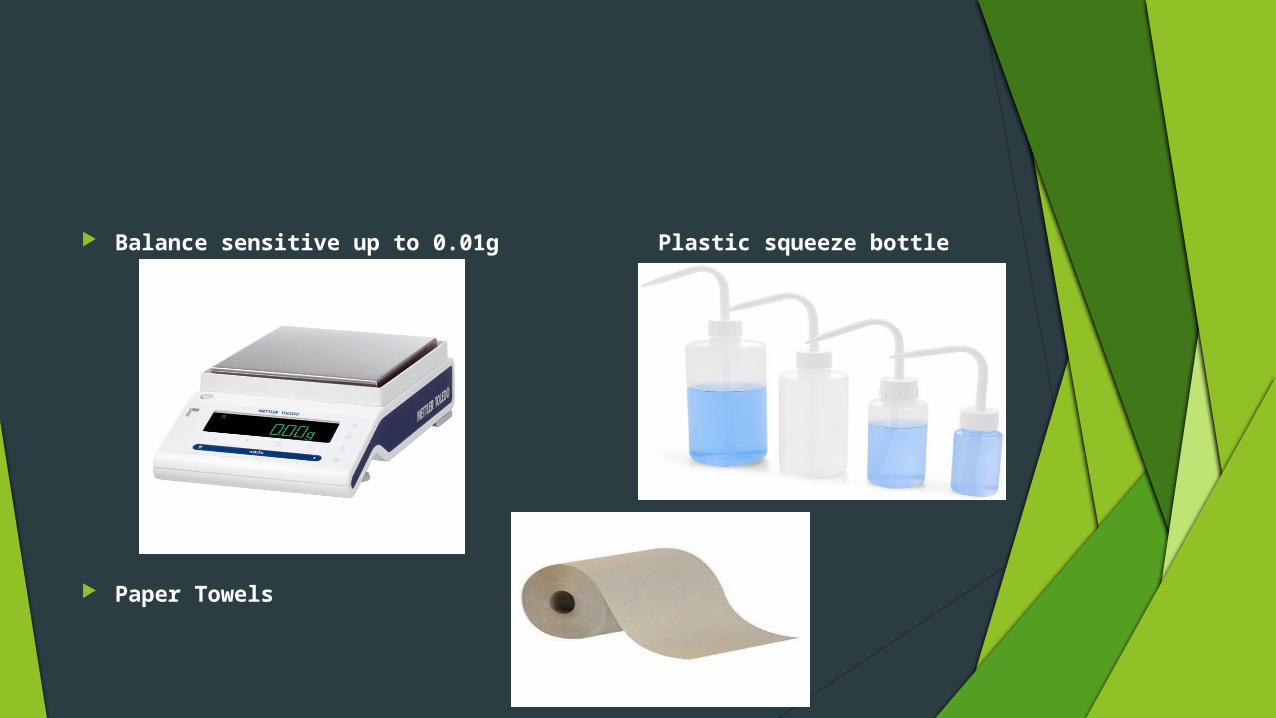
2. Put about 250 g of soil. Assume that the soil was previously passed through a No. 40 sieve, air-dried, and then pulverized. Thoroughly mix the soil with a small amount of distilled water until it appears as a smooth uniform paste.

3. Adjust the liquid limit apparatus by checking the height of drop of the cup. The point on the cup that comes in contact with the base should rise to a height of 10 mm. The block on the end of the grooving tool is 10 mm high and should be used as a gage. Practice using the cup and determine the correct rate to rotate the crank so that the cup drops approximately two times per second.
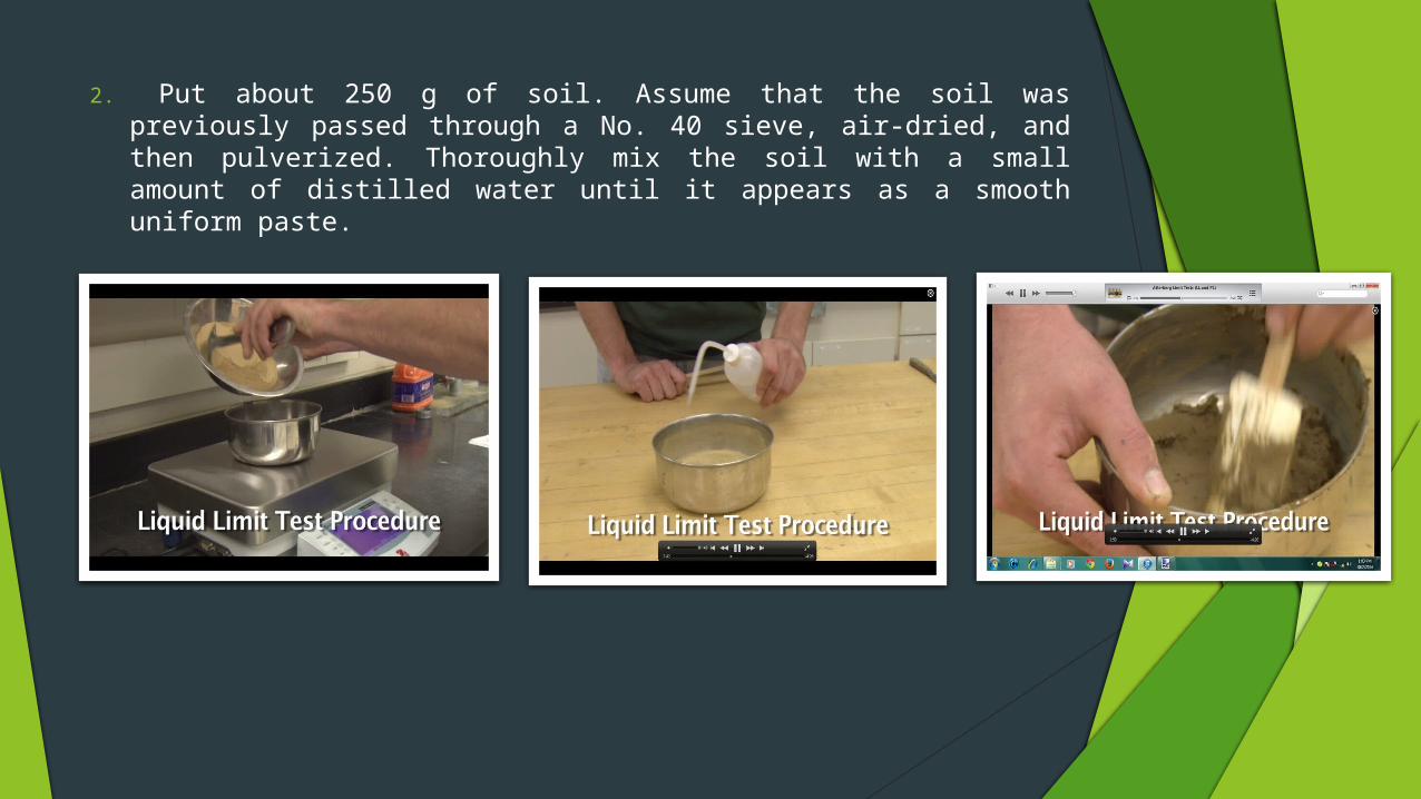
4. Place a portion of the previously mixed soil into the cup of the liquid limit apparatus at the point where the cup rests on the base. Squeeze the soil down to eliminate air pockets and spread it into the cup to a depth of about 10 mm at its deepest point. The soil pat should form an approximately horizontal surface (See Photo B).

5. Use the grooving tool carefully cut a clean straight groove down the center of the cup. The tool should remain perpendicular to the surface of the cup as groove is being made. Use extreme care to prevent sliding the soil relative to the surface of the cup (See Photo C).

6. Make sure that the base of the apparatus below the cup and the underside of the cup is clean of soil. Turn the crank of the apparatus at a rate of approximately two drops per second and count the number of drops, N, it takes to make the two halves of the soil pat come into contact at the bottom of the groove along a distance of 13 mm (1/2 in.) (See Photo D). If the number of drops exceeds 50, then go directly to step eight and do not record the number of drops, otherwise, record the number of drops on the data sheet.

7. Take a sample, using the spatula, from edge to edge of the soil pat. The sample should include the soil on both sides of where the groove came into contact. Place the soil into a moisture can cover it. Immediately weigh the moisture can containing the soil, record its mass, remove the lid, and place the can into the oven.

8. Leave the moisture can in the oven for at least 16 hours. Place the soil remaining in the cup into the porcelain dish. Clean and dry the cup on the apparatus and the grooving tool.
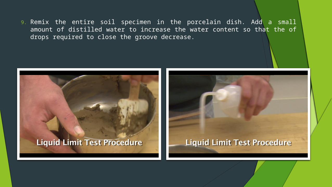
9. Remix the entire soil specimen in the porcelain dish. Add a small amount of distilled water to increase the water content so that the of drops required to close the groove decrease.

10. Repeat steps six, seven, and eight for at least two additional trials producing successively lower numbers of drops to close the groove. One of the trials shall be for a closure requiring 25 to 35 drops, one for closure between 20 and 30 drops, and one trial for a closure requiring 15 to 25 drops. Determine the water content from each trial by using the same method used in the first laboratory. Remember to use the same balance for all weighing.

The graph is approximated by the best fit straight line, usually called the flow line or flow curve and sometimes called liquid state line. The moisture content that corresponds to 25 blows is the liquid limit of the soil.

The slope of the flow line is called flow index and may be written as:
Flow Index,
where w1 and w2 are the water content (in percent) corresponding to number of blows N1 and N2, respectively.
𝐹𝐼=𝑤1−𝑤2
log (𝑁 2/𝑁 1)

Sample Problem


Based on the liquid limit tests on several soils, the U.S. Army Waterways Experiment Station (1949) observed that the liquid limit (LL) of a soil can be approximately given by
where = moisture content, in percent, for 12.7 mm groove closure in the liquid limit device at
N number of blows

ASTM also recommends this equation in determining the liquid limit of soils (ASTM designation D-4318). However, the value of should correspond to an N value between 20 and 30. following are the values of for various values of N.

Several variables that affect the Casagrande test are as follows:
Size of soil pat in brass cup (thickness and quantity) Rate of blows (crank rate should be 120 rpm) Length of time soil is in cup prior to beginning test
blow count and cleanliness of cup before soil is added for the test
Laboratory humidity and speed of performing the test Type of material used for this test (commonly Micarta or
hard rubber) Accuracy of height-of-fall calibration (should be exactly
1 cm) Type of grooving tool Condition of liquid-limit device (worn pins, loose
connections, etc,)
References:1. Joseph E. Bowles, Engineering Properties of Soils and
Their Measurement.2. David E. McCarthy, Essentials of Soil Mechanics and
Foundatios.3. http://www.mathalino.com/reviewer/geotechnical-engineerin
g/consistency-soil-atterberg-limits4. http://www.engineeringcivil.com/determine-the-liquid-limi
t-of-soil.html5. http://en.wikipedia.org/wiki/Atterberg_limits
Video:http://www.youtube.com/watch?v=bxh3kMGt9h0&hd=1
**end**