Attenuator and Digital Logic - World Radio History
128
$2.50 APRIL 1978 VOLUME 9 - NUMBER 2 Page 74 ... A Programmable Parametric Attenuator and Digital Logic Control System RELATING RECORDING SCIE( www.americanradiohistory.com
-
Upload
khangminh22 -
Category
Documents
-
view
2 -
download
0
Transcript of Attenuator and Digital Logic - World Radio History

$2.50 APRIL 1978
VOLUME 9 - NUMBER 2
Page 74 ... A Programmable Parametric Attenuator and Digital Logic
Control System
RELATING RECORDING SCIE( www.americanradiohistory.com

rtm *P4
tioto.
indicc agocsgg
o hghding a ao5p2plete st of
Odilw detailed acoustic 9 eUectrtcal, air,
and fhbß goff Vphti
5.a.10 /gOo uaTEDE 4
drawings - ,80,0 square foot
room complex - need be any more tl n
;$-,,000.00
for absolutely everything you will need to either call on your own constru_ ction talents -
or those of your ownñtractors - or ours, if you like.
Please accept our invitation to contact us for a discussion of your studio requirements.
studio owner /constructor David Porter with
construction foreman Earl Thomas at
Music Annex, Menlo Park, California
Call Brian Cornfield at
(213) 982 -6200
7037 Laurel Canyon Blvd., North Hot 1, California 91605 í 982 -6200
www.americanradiohistory.com

;
AMEK SYSTEMS AND CONTROLS LIMITED
6®8g _..- f Cdl; Ì
g Ir! .
- -T!'! - t w
.__ _.;
3
. ..---..-. ,T=r ,.
. e __ - or -- Imo ,.: .. . . _
_. 11.
. .
.`. 0
-b
tl
,,,;
e
< ,
Sr," ,-°".
O . a
WHERE AMEK HAS BEEN: Village Way Studio, England Regents Park Recording Company, England Berry Street Studios, England Utopia Studios, England Slater Sound Studio, Australia Castle Sound. England Wembley Conference Center, England
WHERE AMEK IS GOING: Sierra Pacific Recording Studios, California Don Costa Productions, California Music Annex Recording Studios, California Sun Sound Studios, Connecticut ABC Records, California Everything Audio, California
WHAT AMEK HAS: Main frames in sizes from 20 -28 inputs 16 buss outputs 19 -27 VU meters 8 direct buss assign 4 addressable group controls Penny & Giles faders
4 auxiliary sends Stereo solo -in -place in both input and monitor sections 4 band equalizer with 2 additional filters
One microphone and 2 line positions per input channel Pan control between live busses
Stereo panning on each module Stereo panning on monitor section Phantom power supply All metal cabinet construction Frame stand with 19" rack included 100 position tip, ring, sleeve patch bay with expansion provided Test oscillator Talkback Dim and complete control room and studio control.
WHAT AMEK COSTS: $17,000 to $25,000
WHAT AMEK SHIPS FROM: STOCK
Distributed throughout the United States by
M9' - T,73 OII®A
Accept our invitation to contact us and discuss your studio needs. 7037 Laurel Canyon Blvd., North Hollywood, California 91605 / 982 -6200
for additional information circle no. 2 R-e/p 3
{
www.americanradiohistory.com

letra Audio Builds More Than Studios We've built a reputation unparallelled in the history of acoustic design.
A list of over 185 clients reads like a Who's Who of the recording industry... All of them still in business.
We've assembled an experienced staff to take charge of construction, finance, and equipment interface. Together znith acoustic design by Tom Hidley and project coordination by Kent Duncan, both accomplished recording engineers, they can answer instinctively any questions that arise - and some you may never have thought of
We've developed a systems approach to studio design and construction encompassing guaranteed acoustic design, thorough site analysis, realistic market assessment, computer generated financial forecasts arrd business planning, comprehensive'sta ff training, equipment selection and interface design to accomnwdate not only today's needs, hut also tonrorrozu's innovations.
We should build one for you.
SIERRA AUDIO CORPORATION 621 South Glenwood Place Burbank, California 91506
(213) 843 -8115 Telex: 691138
R-e/p 5
www.americanradiohistory.com
N engineer /producer
I
- the magazine to exclusively serve the
Recording Studio market . . . all those
whose work involves the recording of commercially marketable sound.
- the magazine produced to relate .. .
Recording ART to Recording SCIENCE to Recording EQUIPMENT.
Editor /Publisher .. .
Associate Editor .. Consulting Editor Assistant Editor .. Business Manager
Circulation Manager
. MARTIN GALLAY GARY KLEINMAN
PETER BUTT D. KEITH LARKIN
V. L. GAFFNEY TRICI VENOLA
"RECORDING engineer /producer" is pub- lished six times a year by RECORDING & BROADCASTING PUBLICATIONS, 1850 Whitley Avenue, Hollywood, California 90028, and is sent to qualified recipients in the United States. One year (six issues) sub- scriptions for other than qualified individ- uals or companies may be purchased at the following rates:
United States (surface mail) . . $9.00 United States (air mail) . . . $17.00 Foreign (surface mail) ... $9.50 Foreign (air mail) . . . $19.00
0
RECORDING engineer /producer is not responsible for any claim made by any person based on the publication by RE- CORDING engineer /producer of material submitted for publication.
Material . appearing in RECORDING engineer /producer may not be reproduced without written permission of the publisher.
I
Controlled Circulation Postage paid at
Los Angeles, California
Postmaster: Send form 3579 for address correction to:
RECORDING engineer /producer P.O. Box 2449
Hollywood, California 90028 (213) 467.1111
R-e/p 6
page 18
page 38
page 44
page 58
page 64
page 74
page 82
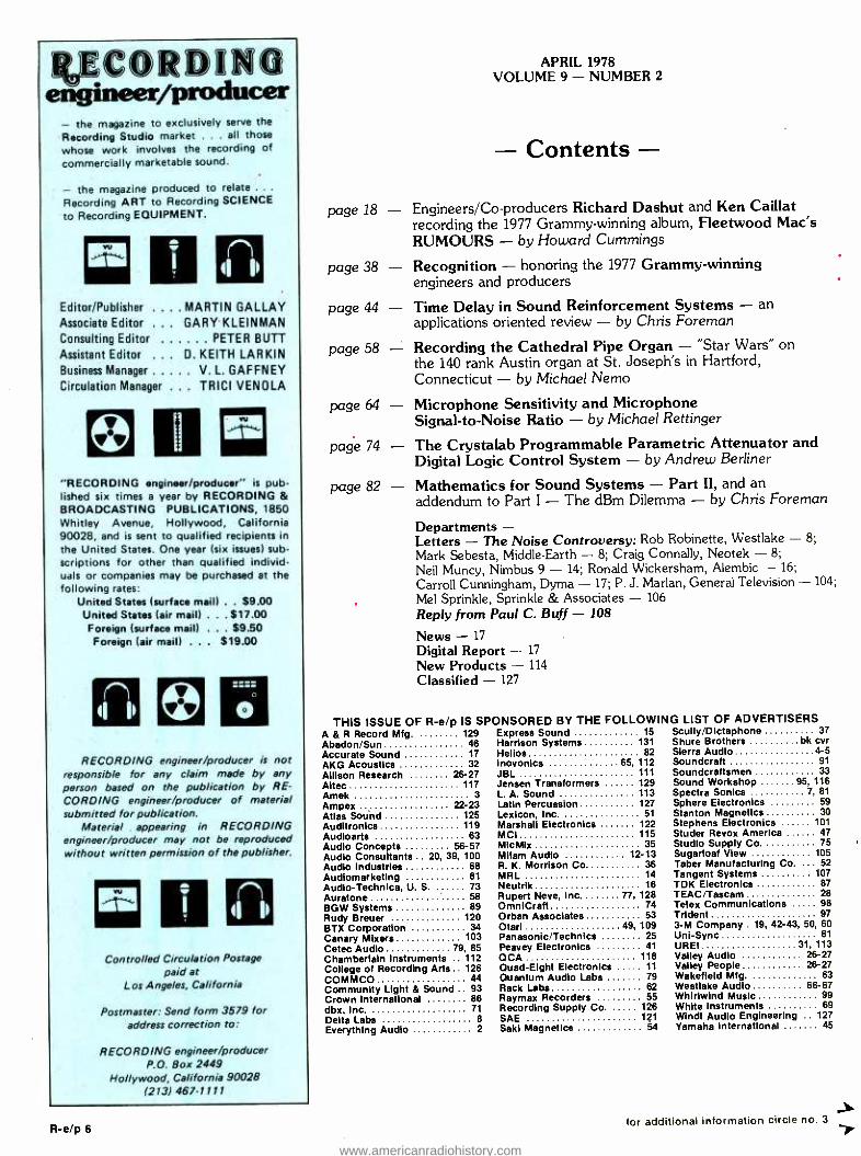
APRIL 1978 VOLUME 9 - NUMBER 2
- Contents - - Engineers /Co- producers Richard Dashut and Ken Caillat
recording the 1977 Grammy- winning album, Fleetwood Mac's RUMOURS - by Howard Cummings
Recognition - honoring the 1977 Grammy -winning engineers and producers
- Time Delay in Sound Reinforcement Systems - an applications oriented review - by Chris Foreman
Recording the Cathedral Pipe Organ - "Star Wars" on the 140 rank Austin organ at St. Joseph's in Hartford, Connecticut - by Michael Nemo
- Microphone Sensitivity and Microphone Signal -to -Noise Ratio - by Michael Rettinger
- The Crystalab Programmable Parametric Attenuator and Digital Logic Control System - by Andrew Berliner
Mathematics for Sound Systems - Part II, and an addendum to Part I - The dBm Dilemma - by Chris Foreman
Departments - Letters - The Noise Controversy: Rob Robinette, Westlake - 8;
Mark Sebesta, Middle -Earth - 8; Craig Connally, Neotek - 8;
Neil Muncy, Nimbus 9 - 14; Ronald Wickersham, Alembic - 16;
Carroll Cunningham, Dyma - 17; P. J. Marian, General Television - 104;
Mel Sprinkle, Sprinkle & Associates - 106
Reply from Paul C. Buff - 108
News - 17
Digital Report - 17
New Products - 114
Classified - 127
THIS ISSUE OF R -e /p IS SPONSORED A & R Record Mfg. 129 Express Sound Abadon /Sun 46 Harrison Systems Accurate Sound 17 Helios AKG Acoustics 32 Inovonics Allison Research 26-27 JBL Altec 117 Jensen Transformers Amek 3 L. A. Sound Ampex 22 -23 Latin Percussion Atlas Sound 125 Lexicon, Inc. Auditronics 119 Marshall Electronics Audioarts 63 MCI Audio Concepts 56-57 MicMix Audio Consultants .. 20, 39, 100 Milam Audio Audio Industries 68 R. K. Morrison Co Audiomarketing 81 MRL Audio- Technica, U. S. 73 Neutrik Auratone 58 Rupert Neve, Inc BGW Systems 89 OmniCraft Rudy Breuer 120 Orban Associates BTX Corporation 34 Otani Canary Mixers 103 Panasonic /Technics Cetec Audio 79, 85 Peavey Electronics Chamberlain Instruments .. 112 OCA College of Recording Arts.. 126 Quad-Eight Electronics COMMCO 44 Quantum Audio Labs Community Light & Sound .. 93 Rack Labs Crown International 86 Raymax Recorders dbx, Inc. 71 Recording Supply Co. Delta Labs 8 SAE Everything Audio 2 Saki Magnetics
BY THE FOLLOWING LIST OF ADVERTISERS 15 Scully /Dictaphone 37
131 Shure Brothers bk cvr 82 Sierra Audio 4-5
65, 112 Soundcraft 91
111 Soundcraftsmen 33 129 Sound Workshop 95, 116 113 Spectra Sonics 7, 81
127 Sphere Electronics 59 51 Stanton Magnetics 30
122 Stephens Electronics 101 115 Studer Revox America 47
35 Studio Supply Co 75 12 -13 Sugarloaf View 105
36 Taber Manufacturing Co. ... 52 14 Tangent Systems 107 16 TDK Electronics 87
77, 128 TEAC/Tascam 28 74 Telex Communications 98 53 Trident 97
49, 109 3 -M Company . 19, 42 -43, 50, 60 25 Uni -Sync 61
41 UREI 31, 113 118 Valley Audio 26 -27
11 Valley People 26 -27 79 Wakefield Mfg. 63 62 Westlake Audio 66-67 55 Whirlwind Music 99
126 White Instruments 69 121 Windt Audio Engineering .. 127
54 Yamaha International 45
for additional information circle no. 3 7 www.americanradiohistory.com

SPECTRA SONICS Model 1024 -24 Audio Control Console at United Audio Recording, San Antonio, Robert Bruce, General Manager.
Quality: SPECTRA SONICS audio control consoles show the care and attention to detail that are the mark of the skilled American craftsman. The internal wiring, module construction, console housing, and the control display reflect the precision and distinctive craftsmanship that is characteristic of SPECTRA SONICS.
Capability: SPECTRA SONICS audio control consoles provide an immediate initial capability that may be increased to 32 inputs and 32 outputs, at minimum cost. The flexibility of the system will provide line /microphone selection, attenuation, equalization and, through assignment controls, various other combinations for the most sophisticated signal processing now required in today's studio.
Reliability: SPECTRA SONICS audio control consoles have an established reputation of superior reliability. Through creative design, the circuitry is developed to function well below operating
limits to enhance an extendec life for the components. Through empirical data on SPECTRA SONICS audio amplifiers, a reliability rate of 99.9% has been deriied. These amplifiers are used in SPECTRA SONICS audio control conso.es and materially contribute to system reliability.
Performance: SPECTRA SONICS audio control consoles are guaranteed to outperform any ether console in the world in noise, frequency response, distortion, and peak overload. All consoles are provided with documented data acquired in tests of the complete system. Guaranteed performance specifications are Frequency Response, ± 1/4dB 20HZ- 20kHZ, Signal /Noise Ratio ( microphone input), not less tfan 82 5d below +4dBM, output for a -50 input (50 ohms source); Signal /Noise Ratio (line input), not less than 87dB below + 4dBM output for + 4dBM input; Harmonic Distortion, less thar .019ó at + 18dBM (1kHz); Inter - modulation Distortion, less that 02% at +4dBM; Crosstalk, not less than 60dB at 20kHZ (typically 80dB).
Dealer Inquiries Invited
P[CIHU BONICS L E A D E R I N A O V A N C E D T E C H N O L G Y
3750 Airport Road Ogden, Utah 84403 (801) 392 -7531
www.americanradiohistory.com

tr5 from: A. Clegg
Assistant General Manager Product Engineering Div. Technics by Panasonic Secaucus, NJ
After reviewing the article by Chris Foreman from Altec Corporation on "Mathematics For Sound Systems ", I
have concluded that he did a fine job. My compliments to him. Having taught such subjects myself at the college level, I can testify that Mr. Foreman has a good understanding of the theoretical and the practical side of applied electronics as his terminology and examples show.
My recommendation to your readers is to study Part 1 carefully and learn each topic well if they want to become a bone fide "Engineer ".
Ed: The following is only a represent- ative sampling of the many letters received in response to Paul Buff's articles on NOISE in both the December 1977, and the February 1978 issues. Space limitations forbid inclusion of all the excellent comments received.
Corrections: J. McKnight has informed us of two
typographical errors in his letter on Noise Index Measurements, in the February 1978 issue of R -e /p, pp 14 and 16: In the Noise Index Formula at the end of Sec. 3, the terms should be
added (Rs + Req), not subtracted as shown. And toward the end of Sec. 4, the temperature conversion from T =
300 K should be 27 °C, not 37 °C as shown.
from: Robert Robinett Chief Design Engineer
Westlake Audio, Inc. Los Angeles, CA
In regards to the above (February Issue - Reply from Paul C. Buff):
In defining dBme, Mr. Buff neglected dByou. What he really defined was a dBuff.
from: Mark E. Sebesta Middle -Earth Sound
Recording Houston, TX
I have just finished reading your article in December's issue and I must say I was shocked! I'm sure most of us realized that some manufacturers don't test their equipment with the same methods as others, but I think few of us realized the problem was so wide- spread. Now that we know the problem is real, we need to take action. We are the ones who buy this equipment. We must demand that equipment manufac- turers clean up their act.
Manufacturers will claim they can't sell their products any other way. Wrong! If the products they're selling are as good as they say they are it could only help sell them. With so many
industry standards in the world why can't we have standardized equipment testing? This could only lead to better quality equipment for everyone.
from: Craig Connally, President NEOTEK Chicago, IL
Congratulations on your publication of the articles by Paul Buff concerning console noise specification and microphone preamp design. It will certainly be interesting to see which console manufacturers, if any, now publish more honest noise specifica- tions. The dilemma, of course, is who shall be the first to admit culpability.
There are a few points raised by the articles which need amplifying. Firstly, it is not only the mike preamp which determines a console's noise and sound quality. Manufacturers must offer noise, distortion, and bandwidth data from inputs to outputs in order that the customer be able to make an informed judgement. Secondly, there is no mystery or magic in designing preamps with specifications such as Mr. Buff describes. Instrumentation amplifiers have been in the electronics designer's repertoire many years and the techni- ques for obtaining optimum noise performance from low impedance sources are also well known, including paralleling of input devices or use of power transistors, cascode or common base topology, and so forth. Designers
The flew Leader in DIGITAL DELAY For natural, unobtrusive sound reinforcement in any church, theater, or hall.
For chorus, doubling, and echo effects in recording or broadcast. WHO IS DELTALAB? In digital audio, experience counts. DeltaLab is a new consortium of engineers and scientists with a combined experience of over 50 years in aerospace, digital electronics, and high quality audio. Our previous designs (under other brand names) include some of the most respected products in audio today.
For more information, including the name of your nearest distributor, write or call: DeltaLab Research
Inc., Att. Peter Tribeman (617) 458 -2545.
DeltaLabitesearch, Inc. 25 DRUM HA ROAD, L CHELMSFORD,MASS. 01824.,.
THE PROBLEM: Digital delay lines (DDLs) are the established standard for time delay, due to their high S /N, low distortion, long delays and wide bandwidth at all delay lengths. But DDLs have been too expensive for many applications.
Analog delay lines have been accepted as a
substitute because they provide some useful effects at a modest price. But their performance and flexi- bility are severely limited; frequency response and dynamic range deteriorate as delay length is
increased.
THE SOLUTION... DELTALAB DIGITAL DELAY DeltaLab introduces the Problem-Solver a new high - performance DDL at a price comparable to ordinary analog units. It features:
Three outputs with independently selectable delays. Delay lengths from 5 mS to 160 mS.
Frequency response 30-15K Hz at all delay lengths, all outputs. No audible noise. (Dynamic range > 90 dB.) No audible distortion. (THD < 0.2 %, mostly pure second harmonic.) No audible side effects -hum, whistles, birdies, quantizing noise, or compander noise -pumping. Input and output levels adjustable from 0 to +24 dBm. Price: approx. $1200.
DeltaLab Available at Quality Dealers
- DIGITAL DELAY InODULE -
R-e/p 8 for additional information circle no. 4
www.americanradiohistory.com

40 tifir,ff, .01bm Cotmoi,ey
Comfrunkr, III
5r t/, .itetisG Soezy- S.ri.zee,-
Quad /Eight Electronics Quad /Eight International
11929 Vose Street, North Hollywood, California 91605 (213) 764 -1516 Telex: 662 -446
11 111111 111111111 mIl Ì 1 1111 I IE1111 1 on on u ud www.americanradiohistory.com

JERRYM I ß-ìM DELIVERS THE
SOUND
"When I decided to build a studio at the Playboy Resort, the first person I turned to was Jerry Milam because of his knowledge and experience in studio engineering.
Well, Jerry provided more than sophisticated equipment. He con- sulted with me on every detail of the recording business. Planning, financing, construction, installation and training. Together we developed a `state -of- the -art' studio that delivers great sounds.
That's why I owe him a lot more than he charged me."
Andy Watermann, Owner SHADE TREE STUDIO, Lake Geneva, WI
tor additional information circle no 6
www.americanradiohistory.com

FULLY AUTOMATED 24 TRACK SHADE TREE STUDIO PLUGS INTO LAKE GENEVA RESORT.
Jerry Milam and Andy Watermann behind the MCI -528 console.
erry introduced me to his friend, Rudi Breuer, who's gj probably the top studio builder in the business. He's
really the craftsman who made the acoustics and sound- proofing become so comfortable and beautiful.
In fact, Rudi added a soundproof window that can either be fitted with sound and light absorbent panels or left open for a fantastic view of the woods and rolling countryside.
Rudi and his own crew controlled the quality and costs, then finished on schedule. It's no wonder that
Jerry collaborates with him on all the big jobs."
Jerry erry started in this business as a musician and his heart
is always in the music. That aware- ness makes a tremendous difference
in the completed studio."
ilL 401t4II '4 is'
The view outside can inspire a performance inside
Jerry owned and operated his own 24 -track studio and he's engineered
over 1000 sessions. So, he knows what a studio must be able to do.
And, because Milam Audio has sold and serviced more than 50 major installations in the past five years alone, he really knows the equipment that can do the job. So he sells only the best and services what he sells. It's that kind of personal commitment that helps keep his customers operating profitably.
You know, Jerry's client list reads like 'Who's Who' in the music business, and they all swear by him. That's because his installations are equal to anything available in Los Angeles, New York, Nashville or anywhere else."
SHADE TREE's main studio features exposed sound absorbent ceilneg beams and acoustic surfaces framed in rich redwood.
"terry flies his own company plane and covers the Midwest like his
own backyard. So, before you talk to anyone else about a studio, I'd suggest you talk it over with Jerry Milam. He'll deliver the sound."
MILAMo&o 1504 NORTH 8th STREET / PEKIN, ILLINOIS 61554 / 309-346-3161 EXCLUSIVE MCI REPRESENTATIVE IN THE MIDWEST. Also representing more than 50 other professi.nal product hn.s including. DOLBY. DBX. AUDITRONICS. NEUMAN UREI. EVENTIDE, PARASOUND. CROWN LEXICON, BOW. ALLISON. AKG, BEYER and MRL. Ash the professionals about Jerry Milam. A complete list of clients and previous installations is available upon request.
www.americanradiohistory.com

of strain guage preamps and moving coil cartridge preamps have left well - worn paths. Lastly, many people will find that a clean and clear mike preamp will not give them the sound quality they desire, just as no engineer would use a clean, jazz -style guitar sound on every occasion. My company has manufac- tured completely transformerless consoles for several years and we have encountered many circumstances where engineers discover that they do not like to hear precisely what the mike hears. Consoles, like microphones and guitars, may be preferred because of particular colorations. We, on the other hand, have perservered in the belief that the engineer best achieves his desired sound through artful use of the many variables at his command, such as mike selection and placement, equalization, and external processing equipment, and that he should be able to depend on the console always accurately to reflect his choices. Other designers may disagree, for various reasons.
The advent of digital processing has brought to audio many new improve- ments, ideas, and standards of quality. It is certainly time for analog designers to discard outdated notions and to offer the best our art can produce. I believe that anyone who listens critically or measures the differences will conclude that transformers, especially micro- phone input transformers, are best left as historical curiosities.
from: Carroll Cunningham DYMA Corporation Taos, NM
Paul Buff, writing about "Console
Specifications" in your December issue, demonstrated remarkable brav- ery. Armed with nothing more than sure and certain knowledge, he set out to drain a very treacherous swamp.
Several years ago, we went through the same exercise and came to exactly the same conclusions he did. Apparent- ly we lacked his bravery - we have in the intervening period failed to stand our ground on the subject.
Console buyers themselves are responsible for their present plight. Their ignorance has led console manufacturers into a numbers game with no meaning or substance behind the numbers.
This is particularly true of our area of the specialty, the broadcast industry. We often encounter what we have come to call the "instant wizard ". This wizard is a peach- faced, unrecognized genius. Starting flat -footed, unburden- ed by anything as limiting as matheme- tics, he has , in two years, learned more than Mr. Paul Buff has learned in his decades. He is the guy when you tell him that minus 129 dBm is less noise than God makes, he points proudly to your competitors spec of minus 131 dBm. He is the one that believes that a microphone preamplifier with a gain of 60 dB also has a voltage gain of 1,000. He is not interested in being troubled by fine points about differences in impedance levels. He is the one that believes that the octave between 20 Hz and 40 Hz is somehow easier than the octave between 20 kHz and 40 kHz. He is the one that likes lots of output level, not realizing that +30 dBm RMS is one watt. (He usually adds 4 dB to his maximum output spec as soon as you
tell him this.) So, we took what we considered to
be a very sensible step. We started defining our test conditions: input source impedance, output source impedance, load, and over -all voltage gain, and then stated how far the noise would be below zero dBm. Almost anyone can run that test.
from: Neil A. Muncy Consultant to Numbus 9
and Umbrella Records Toronto, Canada
I have just finished reading the article by Paul Buff on Console Noise Specifications which appeared in the December, 1977 issue. While I certainly agree with Mr. Buff on the issue of specification writing and the deplorable condition which exists today as far as uniformity in specsmanship is concern- ed, I must disagree with his method of calculating equivalent input noise.
The formula quoted by Mr. Buff which describes Thermal Noise Voltage appears to me to be correct. However, the voltage which is decribed by this formula is the open circuit generator voltage, and exists only when the circuit is open, i.e., no load. Now the concept of Equivalent Input Noise as originally developed back some 30 or 40 years ago expresses the noise power available. In order to calculate the power available from a generator of any impedance, it is necessary to connect a load to the generator whose impedance equals that of the generator. The resulting voltage across the load is then measured, and the power calculated according to the formula E2 /R, where E is the voltage across the load resistor,
What is what e yu
get... Foi a catalog and a lost of over 60 dealers in the USA and Canada, contact J. G. (Jay) McKnight at:
Magnetic Reference Laboratory, Inc. 229 Polaris Ave., Suite 4 Mountain View, CA 94043 (415) 965 -8187
The MRL Calibration Graph is your proof of the quality control that goes into every MRL Reproducer Calibration Tape. We guarantee each one to exceed the performance requirements of IEC, NAB, AES, and EIA Standards.
MRL Calibration Tapes are designed and supported by experts in magnetic recording .
and audio standardization ... we helped write the standards. Each tape comes with detailed instructions and application notes.
The MRL catalog includes tapes for all studio applications. In addition to the usual spot -
frequency tapes, we make single -tone tapes, rapid -swept frequency tapes, wideband or 1 /3rd octave -band pink random noise tapes, and difference -method azimuth -setup tapes. Most are available from stock.
T aPe
Exclusive Export Agent: Gotham Export Corp, o New York, NY t
R-e/p 14
FtuxlvitV t-e`let
for additional information circle no. 7
www.americanradiohistory.com

Another full- service custom studio by Express Sound Co., Inc.
Over_and Recording Studios, Costa Mesa, CA. (714) 957 -0633
Helping you with your business is our business.
From ground zero, we can help you sell your banker with the necessary pro forma facts and figures, blueprints, equipment specifications, and total costs.
If you want to up- grade, we'll show you exactly what your options are.
We've designed, constructed, equipped, interfaced, and fine -tuned professional sound rooms by the score for recording studios, discos, clubs and homes.
We'll do it all - or any part - on time, within budget.
And when you're operational our service contract delivers 24 -hour back -up.
Now - how can we help you?
Express Sound Co., Inc. 1833 Newport Blvd., Costa Mesa, CA 92627 (714) 645 -8501
t; ,f)M8f1) R-e/p 15
for additional information circle no. 8
www.americanradiohistory.com
and R is the value of load resistance. As will be found in any basic
electronics text, when a generator is
terminated with a load impedance equal to its own, the voltage across the load will be exactly 1/2 the open circuit generator voltage. It is this voltage across the load which is incorporated in the concept of E.I.N. as expressed in dBm.
It is my belief that the correct usage of the concept of E.I.N. expressed in dBm, is as follows:
Thermal Noise Power (in watts) = E2/4R = KTB
Thermal Noise Power (dBm) = 10 login (E2 /4R x 1000)
where E is the open circuit noise voltage calculated according
to the formula:
E = \/4KTRB, and R is the load resistance in ohms.
Thermal Noise Power expressed according to the above procedure describes the power available, and will result in a number of approximately -130.8 dBm for a 20 kHz bandwidth at room temperature at 150 ohms.
I am somewhat disturbed by several other things in the article. dBm is a
Ay O/A S
Macee 9c 9 4/0/O
ksOdh4
S0,930
qfS r20, ) 9,ó
`?800
R-e/p 16 for additional information circle no. 9
measurement of power referred to one milliwatt, regardless of impedance, and not a referred to 600 ohms. dBme is apparently a new concept which no one in the engineering field that I can locate has ever heard of. And with reference to figure 2 on page 26, I have never met an audio oscillator that would drive a
one ohm load! Enough nit -picking. Mr. Buff has
stirred up a pot which has been on my back burner for years. Back in the old days when every stage of a console was impedance matched to everything it related to, the description of system performance in terms of power levels was certainly justified. However, things have changed. Microphone preampli- fiers rarely present a terminating impedance to a microphone, and most of the preamps I have measured in the last ten years or so possess an input impedance of 8 to 10 or more times the "nominal" 150 ohm impedance of a typical microphone. When a micro- phone is connected to such a preamp, very little power changes hands.
When the operator of a console typical of the "state -of- the -art" (whatever that is) grabs a handful of patch cords and gets creative amongst a patch bay, he doesn't want to know (nor should he haue to know) about milliwatts, or impedance matching for that matter. What is going to be of concern to him (her) as an operator is the resulting level in the system after the patch is made.
The point I am trying to make is that in view of the fact that virtually all of the studio equipment being built today can be characterized as having very low output impedances, and very high input impedances, and therefore when it is
- Letters continue on page 104.. .
e e S
DIGITAL AUDIO REPORT
Digital Standards Committee News
The AES Digital Audio Standards Committee held its second meeting on February 1 and 2, in Atlanta. Thirty four members attended, from the United States, Japan, and Europe. The meeting was chaired by John G. McKnight, of Magnetic Reference Laboratory.
The Chairman reported that an informal meeting of representatives of the AES and the JCIC in New York on December 27, 1977 had agreed that the
www.americanradiohistory.com

AES is the appropriate body to undertake the establishment of Digital Audio Standards.
The report "A Review of Digital Audio Techniques" by Willcocks was received.
The discussion of sampling frequency (begun at the meeting in Salt Lake City) was continued. Several reports were presented proposing the use of a 44.05594 kHz sampling frequency for all consumer and professional applications. The committee agreed that 44.05594 kHz is an appropriate sampling frequency for use with low- bandwidth rotary -head type video recorders. Those whose reports were presented were: M. Kosaka's "Sampling Frequency Considerations "; T. Doi et al "On Several Standards of Forms for Converting PCM Signals into Video Signals "; K. Tanaka and Y. Ishidá s "Sampling- frequency Considerations "; and H Kawada "Sampling- frequency Considerations in the Digital Audio Standard ".
Heaslett's report "Some Criteria for the Selection for Sampling Rates in Digital Audio Systems ", and Youngquist's report "Sampling Frequency Considerations" were discussed. After consideration of the requirements for variable -speed . recording, and for international interchange between all media, the committee agreed that a second sampling frequency (in addition to 44.05594 kHz) such as 50 kHz or 54 kHz, would be necessary.
After further discussion, the committee agreed that 50 kHz appeared to be more desirable from the digital signal processing point of view. Further studies will be presented at the next committee meeting.
The discussion of "source encoding" (A /D conversion) begun at Salt Lake City was continued. Certain principles were generally agreed: For main channel applications in professional equipment, the digital word should be a 16 -bit linear, 2's compliment, format. Pre- or de- emphasis should not be used. The aperture correction (sin x /x) should be at the D/A side. Positive internal digital numbers should represent positive analog quantities. The polarity of analog input signals should be preserved through the digital system to the analog output.The equipment may be designed such that it does not set or detect least significant bits in the digital words. Unused bits
-Late News continues on page 70.. .
The Possible Dream. All dreams are possible. To make them reality
requires skill, integrity and commitment. That's our business ... taking your dreams - or needs - and turning them into an effective
hardware system, designed to do what you want done at a price you can afford.
We did it for the Society of Authors and Composers of Music, in Mexico City. Their dream was to create three 24 -track studios, each with the ability to function both independently and jointly with the other two; and all of this "under one roof."
As their consultants and equipment supplier, we created the hardware systems for each studio as well as the equipment interface. Everything "from microphone to record" was involved - disk mastering and record pressing, film re- mixing, high -speed duplicating. Everything.
We did it because we have the skills required to convert an idea into a system; the integrity to select the proper equipment, whether it be our own brand or someone else's; and the commitment to meeting the client's every need, without exception.
We've done it for numerous clients. And we can do it for you too, no matter how small or large your dream may be.
We'd like to show you why our name is "Accurate." Contact Eric Price for details.
AAccurate Sound Corporation 114 Fifth Avenue / Redwood City, California 94063 / (415) 365 -2843 / TELEX: ASCO 34 -8327
"Because Sound Comes From A System"
for additional information circle no. 10 R-e/p 17
www.americanradiohistory.com

engineers /co- producers RICHARD DASH UT and KEN CAILLAT
recording the GRAMMY WINNING
rr
ecordt a.é'Fleet- wood s Gram - my- winrsng Album of the Yecr with en- gineers and co -pro- ducers Richard Da- shut and Ken Cail- lat.
Fleetwood .`'ac known pr a British at their ince 1967, evolvéd more of a roc during its s phase in 197 ter various c of vocalists tarists. Ph saw the de ment of a m low pop sou the additi vocalist Nicks and g
Previousl album FLEE through to th 1977 saw the cess: #1 for > ver Grammy nomma'tio 8.2 million in the U.
Richard Dashut b, gan h ' . e in Hollywood and later mo d to assisting engineer Ken Olsen. Aft engineer, he joined Fleetwood around the time vocalist Stevie Ni
rith of
vie 'st Li
ate O lic
by How. otos by Ho
000 range, the, roup 's break-
), and February ven bigger suc-
4 hit singles, les of mor
ich. ashut: Bes cial thing we work on ngle mix for RHIANN en Caillat: Still at tha ETWOOD MAC albu LEETWOOD MAC continuously. And
S (Jan. '76), there the different mem orking at The Rec told me the albu
ne week to mix.
R-e/p 18
gham joined roup.
en Caillat (Cal- ) started as a gui - rist in the San se area of Califor-
a. When the po- ntial of that area pired, he moved Los Angeles in
ate 1970 and began engineering work t Wally Heider's n sessions and on remotes. Ken met Richard and the rest of the Fleet- wood Mac during the broadcast of a "King Biscuit Flower Hour" radio broadcast being recorded from Heider's in Nov- ember, 1975.
io mix -down, the first for Fleetwood Mac was
o one knew how well the oing with sales. To break he group had been on the started working on RU-
the personal problems be- f the group. Also, while we
ant in Sausalito, Mick (Fleet - take five weeks of recording
continued overleaf .. .
www.americanradiohistory.com

Last year we introduced a recorder more advanced than our Series 79.
But there's still a strong reason tobuy this one.
a e e
IA .11
0
w. e e, « - - -- - `pr;Rm.tr.°,.,°°
It costs a heck of a lot less. Like all new technology, digital
recording is very expensive. So, most studios will probably choose
the world's second most advanced recorder. The 3M Series 79.
The 3M Series 79 is used by leading recording studios around the world. Whether you choose 24, 16, 8, 4 or 2 -track models, you get the steadiest capstan drive in the business, as well as the most up -to -date electronics. The unique patented 3M Isoloop drive gives you smooth tape flow, easy threading and editing, and precise tape handling. It also achieves excellent head -to-
tape contact and incredibly low wow and flutter by reducing unsupported tape length to 31/2."
Our Selectake II Cue Locator uses an exclusive micro processor to program and locate cues.
So, as you can see, there are still a lot of reasons to buy a Series 79. Not the least of which is money.
See us at AES Exhibit Booths [in #11, 12 & 13 or Suites 527 -529. COMPANY
for additional information circle no. 11
www.americanradiohistory.com

11111111M111111
Concept I: A major breakthrough inprice
and perforance! Last year at the Los Angeles
A.E.S. Show we introduced a new concept in console design: Value. We built a console that combined the most wanted fea- tures with professional perfor- mance and rugged high -quality construction. And all at a remarkably low price! The con-
sole is the Concept I, and even though the price has gone up a little since then, we still think you'll find it to be an exceptional value in a studio console.
Concept I, the best combina- tion of features and performance at a suprisingly affordable price, $14,500.
Stop by and see us at
booths 49 & 50.
AIDIO CONBoulevard EPT INC. ) C3L L oc L >> MS Santa is 90046 (2131 8S1-7172 R -e /p 20 The Professional Sound People
for additional information circle no. 12 www.americanradiohistory.com

Richard Dashut: That was the original plan.
Ken Caillat: When we got up there we asked who had the songs for the album. Lindsey, Christine, and Stevie each had a few ideas, but no one had anything definite. At that point we realized the album would take longer than we thought. Also at that point, the FLEETWOOD MAC album started taking off and we found we had a hot product and had to follow up with something. Then we started paying attention to what we were doing.
Richard Dashut: We started feeling the pressure of the prior album. We knew we had to make a good follow -up - in addition to meeting the deadlines of the record company and trying to stick to the budget.
Ken Caillat: The prior album didn't go gold until about the the third month we were working on RUMOURS. That's how slow the building process was. The more we started to see it sell, the more we started to see we could take more time. John(McVie) started taking a special interest in how his bass would sound.
Richard Dashut: Again it should be mentioned that Ken and I had just started working together. We had just known each other through two mix - downs from the previous album.
Howard Cummings: Why were you guys producing RUMOURS instead of Keith Olsen who had produced the prior album?
RD: Toward the end of the last album, there was kind of a falling out between him and the group. Conseq- uently they decided they wanted to get someone new, of which we were not the first choice. Deke Richards was scheduled to do the next album. Apparently he wanted to do full production of the album and that wasn't what the group was looking for. The next step was a guy named Kelly Coteras from the Record Plant, but that didn't work out after he tried to do some mixes on RHIANNON.
Ken Caillat: On a Thursday and Friday we mixed the "King Biscuit Flower Hour" and Saturday and
Sunday were scheduled for the RHIANNON mix.
RD: By this time when we left the Record Plant, Mick turned to me and said, "You're doing the album." At that point I really didn't have the confidence to do it on my own and didn't want to take on a project of that magnitude, since the only thing I had done with them prior to that was their sound on the road. So it flashed in my mind right there that Ken and I had gotten along great with the band, so I suggested to Mick, "Why don't both of us do it ?"
Howard Cummings: You guys were credited with being co- producers of the album. Was that decided from the outset or was it decided that the group would take care of production and you would take care of engineering?
KC: Basically, engineering. When we started to get into production, the group asked us to tell them when they were out of tune and also to make suggestions. I think the group was starting to feel the lack of presence of a producer, which they had had before.
Howard Cummings: That sense of direction?
RD: Exactly. That's more or less how we got involved in the production aspect.
Howard Cummings: Approximately three months had elapsed between the time you started working on RUMOURS and the time FLEET- WOOD MAC went gold. Did you end up scrapping any tracks that you had recorded when you saw how big the MAC album would be?
KC: We finished all the basic tracks except for NEVER GOING BACK AGAIN.
RD: Also THE CHAIN and I DON'T WANT TO KNOW.
KC: We originally had cut 10 or 11
tracks, some of which were not used on the album. After three months in Sausalito, we came to L.A. with the basic tracks and some overdubs. On DONT STOP, after we had gotten everything on but the master lead vocal, Christine and Lindsey decided it was in the wrong key, so we ended up having to erase the piano track, bass
track - any track in that key. All we kept was percussion.
RD: A few songs we did that. We ended up taking it right down to the drums. I want to re- emphasize that the Sausalito thing was a big psychological thing because we had been working 18
hours a day, seven days a week for 21/2
straight months without one break - unless we were sick. So we were worn pretty thin. And after Sausalito, we went on the road for six weeks and then came back and took a good listen to what we had recorded and started stripping down a lot of tracks - right down to the drums - and re -doing a lot of stuff for production reasons.
KC: If we wanted to get a drum sound, we had the extra time. While the group would be rehearsing in the studio, we would be working on our sounds. We could try to "package" a sound together to make it feel good and make it express a certain emotional direction.
HC: Was it a hard album to do technically or production -wise?
KC: Engineering wise, everything was a challenge, but I think it was a challenge we brought upon ourselves. We had the time to experiment - the desire to experiment to try and make everything as right as possible.
Not that there's anything wrong with it, but antyime you start to stretch a project over a period of time, the more you'll grow and the more changes you'll hear in something. In a lot of ways it's important to do an album in a shorter period of time because you'll be able to capture a more emotional viewpoint - but I'm not sure. Maybe that's why the album stayed #1 so long. We were able to change things so we could listen to it longer and endure it without becoming tired of it. Maybe the ideas we had at first would change or we saw some things that would be better.
For example, the nice thing about the Record Plant was that they had two large ambient vocal booths, one on either side of the control room. On SECOND HAND NEWS, we tuned the snare high, put a speaker in the other room, miked it, and added that sound to the snare sound to get a more unusual snare sound. In the case of OH
R-e/p 21
www.americanradiohistory.com

Sometime before the sun comes up, you'll learn
to love your MM- 1200. Ampex gives you a lot of reasons to buy an MM -1200 multichannel audio recorder: capacity, fidelity, flexibility and reliability. The performance specifications alone have made this the best seller among professional multitrack recorders.
But you'll find your own reasons for loving the MM -1200 you buy.
Some morning, after a long session that dragged through the wee hours, you're going to realize just how many MM -1200 features you used to keep things moving. How you used the electronic tape timer, plus search -to -cue, to save precious minutes of time. How you used the quick- change
head feature to switch back and forth between 8,16 and 24 track work. The ease with which you employed the optional accessories such as the pure video layback head, synchronizer and variable speed oscillator to finish the audio portion of a video production.
The same professional drive for perfec- tion that kept you going, kept our engineers working to refine an already -respected design.
That's why you see so many MM -1200s in professional recording studios. Sooner or later, before the sun comes up, every- body learns to love an MM -1200.
AMPEX
Ampex Corporation, Audio-Video Systems Division, 401 Broadway, Redwood City, California 94063, 415/367 -2011.
R -e /p 23 fnr intnrrratinn circle no. 13 www.americanradiohistory.com

DADDY, we used a Leslie feeding through a guitar with a volume pedal. By the time they had finished rehearsing the song and we had worked out the sound, the potential of the song changed.
We might work out a sound on an acoustic guitar and feel that was very nice. We added in some instances, five and six guitars, getting rid of the first one after we made sure the fifth one was better.
RD: From the outset, we all decided that we didn't want every song to sound the same. For us it was very important that every song sound different.
KC: Like separate paintings. RD: Exactly. If you have a separate
song, why should the sound be the same? The sound should follow the music. We purposely got different drum sounds for different songs. To me, that makes for a stronger album but it also led to some technical problems.
For one; Mick's kick drum. We spent about 18 hours just trying to get a kick drum on the first song.
KC: Richard would spend about 21/2
hours before each session, sitting down and tuning each drum separately.
RD: I think that's important. If you want a good drum sound, you go out there and make the drums sound good
because you can only do so much with the board. So we spent a tremendous amount of time, at the cost of a lot of studio time.
HC: How about the drum variations that existed between something like DREAMS vs GO YOUR OWN WAY, for example?
RD: Again, let me emphasize that Ken and myself were not locked into anything. We used whatever mike sounds good.
HC: On Mick's drums, it seems like he uses a rather large bass drum - like a 24 -inch?
RD: He's got a 28 -inch drum now, but in the studio he uses his old road kit which had a 24 -inch kick, I believe. But it's an old kit and the lugs were loose. So I'd go out into the studio for 21/2 hours to tune them while Ken would be at the board. Now Mick would come in and beat on the drums for five hours, running through the song, and the drums would go out of tune again. We'd be two takes away from a master take and the energy is there, but the drums would go bad on us.
HC: Did you put any of the rehearsals on tape?
"DREAMS" Drums and Vocal recorded at RECORD PLANT, Sausalito
Gudar and Rhodes recorded at CRITERIA, Miami Acoustic Guitar recorded at HEIDER, Hollywood
Background Vocal recorded at RECORD PLANT, Los Angeles
LESLIE
U -47 TUBE Orl
RHODES (direct through FAT BOX)
O Work Vocal STEVIE NICKS
E -V RE -20
BASS in CONTROL ROOM - Direct
CONTROL ROOM
I i
451 Overhead
U -87 r
R-e/p 24
KC: Intermittently. We did about thirty takes on GOLD DUST, but went back to one of the first takes, editing a piece in the second chorus and one near the end. We used over 110 reels of 2 -inch tape. On a lot of songs, we had thirty or forty takes and might have edited parts of five different takes to get a master take.
RD: There's not one track on there that is original. The whole album is put together from different tracks and different tapes.
HC: Did you use a drum booth for Mick?
RD: That's a good question. Why don't you take that one Ken.
KC: We started out with a drum booth and failed miserably.(laughs) ... .
RD: (Laughter) Went down in flames
KC: (Laughter) We went as far, on the kick drum sound, of taking Mick's old kick drum and taping them together so it was two kick drums deep.
RD: We were desperate men Howard! (laughter)
HC: One in front of the other with no skins on the front bass drum and one skin on the rear bass drum?
KC: Right. One skin for all.
HC: So it was a tunnel - the Holland tunnel.
RD: Exactly. Needless to say, that was lousy too! (Laughter all around)
The one thing with Mick, and I love his drumming, is he has a foot like a feather and we simply couldn't get the punch out of the kick drum.
KC: We had so much leakage that we would pick up the cymbals. We had to Kepex the drums because we had to raise the gain of the kick mike.
HC: So did you put him in the middle of the studio or off to one side with an umbrella?
KC: Off against the wall. We had a wooden wall.
RD: We decided that on GO YOUR OWN WAY, and others, we wanted more of a live drum sound. We ended up putting plywood on the floor and using plywood walls with the hard backing wall to simulate what it might
. continued on page 29 - www.americanradiohistory.com

.11
How to geta three-rnotoç direct- drive, isolated -loop deck. And save $5,500
"Ingenuity of design can be fasdnating fo- its own sake, out when it -esu is in a product of ce.monstrab e
excellence, as wit, this tape recorde ; one icon on °y
applaud... "
The review is from Moderr Recordir;. The tape deck is Technics RS- 15000S. And the inc?ncity of design that Modem Recording a-d Audio hale pra sec
in recen- issues is Technics' adv aced 'Isolated Loop" tape transport wi-n a quartz -locked, pass -control, di-ect -drive capstmn.
6y isolating the tope from external influences, Techn cs has minimized tape ter! on to an urpre_edented 80gml. Elimira-ing v -tuc ly all sigral dropout While reducing modula-ion and wow and flutter to a point where conventional abo otory measurement is serioLsly challenged. A ccnsiderabl achie "ement when you realize -ethnics RS- 1500U3 is
priced substantial y below its profess_ ono ccunterFart. $5,500 below.
circle ro. 14
E ectronicolly, too, Technics hcs providec the
LItima-e in pro-essioral ccntrol arc performonce. A
separcte microphone amalifier. Record amol fier. Mixing amcliFer. Arc Three -way bias equalization. While. IC
full- cgic furction cortrols permit apsolute freedom in
swittn ng modes. Zompare specifications and o -ices. Tien you'll
real ze there's no comparison TRACK SYSTEM 2- track, 2- channel recording, playaac< and erase. 4- tack, 2- channel p cyback. RESPCNSE: 30- 3C,000Hz,
3c3 ( -10dE rec. lave ) at 15ips WOW & FLUTTER:
0 013% WFM3 at 15ips. S %N RA-I0 60d3 :NAE
weighed) a- 15ips. EEPARATION: Greater tFan .50dB.
PISE -IME: 0 7 secs. `PEED DEVIATION: 0.1% with
0 cr 1.5rril lape a- 15ips. SPEED FLUCTUATKON
0.05 % with 1.0 or 1 .5mil tape 15ips. 'ITCH
CONROL: 5 %. SJGG_STED R =-AIL PRICE: $1,500. Technics FS- 15COUS. A rare :ombinat en of audip
teci-rology. A new stondard of aucio excellence. r ecornrretrd d price, but uduol etal arce will be sr.t d=tilers.
'ChniCS Prcaessional Series by Panasonic
www.americanradiohistory.com

TECHNOLOGY statu... THE PERFECTIONISTS: A new company with but one product to offer. We call it TRANS- AMPtmLZ, and it's taking off like a bullet. Just how does a new company, with a new product, gain international fame in a few short weeks? By applying bold new con- cepts to not so new problems. TRANS-AMP' LZ eliminates the need for microphone in- put transformers. But we weren't satisfied to simply obsolete transformer inputs ... we decided to walk all over them, in terms of audible performance.
Experienced professionals, listening to A -B comparisons between TRANS-AMP' LZ and transformer preamps in actual ses- sion, have been blown away by the audible difference. Yes, Virginia, there IS an aud- ible difference.
Here's what it does in numbers:
Noise - within IA dB of theoretical limits, when direct coupled to a 150 SZ micro- phone. (Noise Voltage - .5 771/\/1-1Z)
Bandwidth - .3 Hz to .5 MHz (@ 60 dB gain)
Slew Rate - 26V /µsec. (Differential output)
Distortion - .005% typical, any gain and any input level (IM or THD)
CMRR - Well in excess of 100 dB
Cost - $30 (1 to 10), $15 (3001 & up) (Evaluation Kit - $35)
Listen to TRANS -AMP" LZ preamps on the latest Direct Disc album by "The New Dave Brubeck Quartet" entitled "A Cut Above."
Complete TRANS-AMP' LZ mic preamp retrofit kits for your MCI 400 and 500 series consoles; Available late May 1978.
Valley People, Inc. P. O. Box 40306 2821 Erica Place Nashville, Tennessee 37204 615- 383 -4737
TRANS -AMP is a trademark of Valley People, Inc. Patents are pending on circuit configuration.
THE INNOVATORS We deal in ideas. Bock in 1969 we conceived a method of modifying the dynamic envelope of music (and non -music); We called it KEPEX® Today, o studio without KEPEX® is as rare as a rabbit with- out a tail.
In 1971, we recognized the invalidity of con - venticnol peck limiting, in the production of music ... enter GAIN BRAIN, M the producers limiter.
The thought of automated mixdown tickled our fancy around 1972. Allison Automation, circa first generation, ruled the world.
E allison ,
f, ,a i
In spite of heavy promotion from the band- wagon jumpers, Allison still rules the Automation world, by a vast margin; thanks to our second generation 65K series programmers. Why? They work.
A new wave of Allison innovations is on the horizon. Keep your eyes open, for they will prob- ably appear in your studio.
research, inc. 2817 Erica Place P.O. Box 40288 Nashville, Tennessee 37204 / Dial (615) "ALLISON" or (615) 385 -1760
www.americanradiohistory.com

flashvîllB,Tennu!SSEE
Bee Jay Re :ording - Orlando, Fla.
Complete 2 studio facility by Valley Audio
Building Reality From Dreams. Valley Audio -A unique combination of acoustical artistry and dramatic room de- sign: coupling time proven methods with fresh "state of the ear" results.
A small group of individually talented people, combining their energies to pro- duce one thing -Great Studios!
Pioneers in practical developments: "Coherent" grounding techniques which maximize system signal to noise. An Active Cue system eliminating crosstalk and poor transient response inherent in
multi -passive systems.
Power amp rack switching logic for fool- proof monitor protection. Unsurpassed custom electronics for special requirements.
If you're determined to make your dreams a reality, Call Us!
VALLEY AU7i0 P.O. Box 40743 2821 Erica Pace
Nashville, Tenn. 37204 615-383-4732
MAS1ERS OF AURAL GRAIIFICA1iON
fo-r it'íonal information circle no. 15
www.americanradiohistory.com

You can pay for someone else's studio or you can invest in your own. Our new Studio 8000 give3 you that choice. And you won't have to sell your soul to get it.*
The eight tracks give you room to spread out your mus:c, and your own stud:o gives you the option of turning on the equipment whenever you turn on to a good idea.. .
24 hours a day.
Herds what you get. The TASCAM Series 80 -8: half -_nch, 15 ips. One speed, one format saves you money but gives
you a final product: professional master tapes, faster and easier than any recorder /reproducer you ever sat behind. Add the DX -8 for up to 30dB of noise reduction.
The Model SA Mixing Console gives you 8 -in and 4 -out, and has been studio proven in both mobile and fixed installations. In short, it's uncomplicated and tough. Add the 5EX for 12 inputs and even greater flexibility. The Model -1
(8 -in, 2 -out) gives you those necessary sub - mixes, without affecting your primary mix.
And for absolute quality stereo mastering, plug in the 25 -2. DBX is built in, and so are speed, simplicity and accurate final editing capability.
So why go on paying for time in a studio that someone else owns? Especially when the total dollars involved wouldn't buy much more than a new car at today's prices.
See the Studio 8000 at your authorized TASCAM dealer.
ifîi /''j.f"'f/". =.;/, -4 v 111 it
t:11 'S S it It it it
TASCAM SERIES BY T E ACS A new generation of recording instruments for a new generation of recording artists.
'$10,460 suggested retail price as shown. Rolling consoles shown are optional.
Prices subject to dealer preparation charges where applicable.
TEAC Corporation of America 7733 Telegraph Road Montebello, California 90640 In Canada TEAC is distributed by White Electronic Development Corporation (1966) Ltd.
R-e/p 28 for additional information circle no. 16
www.americanradiohistory.com

sound like on stage. KC: We had a mike for each tom -
two bass toms, two floor toms. We tried different mikes, depending on the sound - 87's, 47 fets, tube 47's, 67's, 56's,451's with one mike on the high - hat, one on the kick, snare, two overheads, always one tube condenser about 7' over the kit - usually a tube 47. We rented a lot of mikes.
RD: Now we didn't necessarily use the overhead on every track, but we had it on an extra track if we wanted it. We gave ourselves that option.
KC: Usually on the drums, we ended up sending something to that vocal booth too.
RD: I have to credit Ken with this idea. They had a juke box at Sausalito with a track by the Meters which had a
snare sound that was like a trash can. We didn't try to copy it, but we decided on SECOND HAND NEWS we wanted more than a rockish sounding snare. Ken came up with the idea where we had the drum kit miked as normal, but then in one of the vocal isolation rooms, we had a Marshall cabinet. We went from the board and fed the EQed snare into the isolation booth, then recorded that sound from the Marshall back into the board onto a separate track.
KC: The isolation booths, by the
way, were made of plaster and the other booth was mirrored and totally live. In some cases we had six tracks fo drums plus separate tracks for the overhead, and one for the vocal booth.
HC: How bad was the high -hat leakage into the original snare mike and how extensive was the EQ?
KC: With the Kepex, there was no problem. As far as EQ - it was extensive - maybe +8.
RD: Another thing is that Ken and I
aren't afraid of leakage, in fact I think a
lot of times you can use leakage to enhance your sound and make it work for you. For me, you're going to have leakage anyway. A lot of engineers will take great pains to separate and put things across the room and try to isolate them, but from my experience, the distance doesn't stop sound.
HC: It delays it.
RD: Right. So if you're going to have leakage, put them together and make the delay time shorter. Ken and I would use a tight set -up for a lot of things. We'd put the bass next to the drums, we'd put the guitar next to the drums. You can't do an album with musicians with just a technical point of view. The main thing is the music. The musicians
"GO YOUR OWN WAY" Recorded at the RECORD PLANT. SAUSALITO
iaQ
0 BASS LESLIE
Beyer M -88 U -87
Direct
CC
451
SM-56
Work Vocal Shure SM -56
CONTROL ROOM
BOOTH m Marshall
Amp
need to have the feel - the eye contact. So to me, the delay of leakage is the worst enemy, not the leakage itself.
I'm somewhat of a drum perfection ist A drummer hears his drums as he would in a concert experience, but when you're in the studio there's only so much you can do at the board. The toms are always the hardest to record. I
prefer top and bottom skins. They're harder to work with, but I think you get a sound that has more character. Like in GO YOUR OWN WAY, those toms ring. We didn't go to any great pain to stop them from ringing because we wanted to have that overall tone surrounding the kit. To me it enhances the sound and gives it dimension and size, whereas in DREAMS, I think we were in a little deader area and we didn't have it surrounded with wood. We had a plywood floor, but I don't think we used any hardwood siding. On WAY,the drums were up against a hard wall which we built to make it even liver - sounding and to keep all the ring.
DREAMS had a much tighter set -up. It was very dead. Ken went for a more "punchy" sound because it would fit the track better. the kick drum was probably miked a little bit closer.
HC: What did you use? RD: For overheads, we were using
451's, on snare a 451, on the kick drum a Beyer 88, which Ken turned me on to. You go through them real fast on kick drums.
HC: Because of the overload? KC: Yes. In an album you can count
on, at least, losing one, but they're only $70.00 or $100.00 mikes.
RD: The thing is, it gets a real deep bottom end, very tight. Some other mikes might sound muddy, but with this one the bottom is very firm. It also has good attack, which is something I
always look for in a kick drum. I've never liked too "pillowy" a kick drum.
HC: Were the floor toms and high -hat miked separately?
KC: Yes. The high -hat was a KM 84.
The floor toms were varied a lot. I think they were 87's most of the time.
RD: We tried RE20's, 451's. KC: If you use 87's, you have to rely
R-e/p 29
www.americanradiohistory.com

Better stereo records are the result of better playback pick -ups
Scanning Electron Beam Microscope photo of Stereohedron Stylus, 2000 times magnification.
Enter the New Professional Calib- ration Standard, Stanton's 881S
The recording engineer can only produce a product as good as his abil- ity to aialyze it. Such analysis is best accomplished through the use of a playback pick -up. Hence, better rec- ords are the result of better playback pick -up. Naturally, a calibrated pick- up is essential.
There is an additional dimension to Stanton's new Professional Calibration Standard cartridges. They are designed for maximum record protection. This requires a brand new tip shape, the Stereohedron®, which was developed for not only better sound characteristics but also the gentlest possible treatment of the record groove. This cartridge possesses a revolutionary new magnet made of an exotic rare earth compound which, because of its enormous power, is far smaller than ordinary magnets.
Mike Reese of the famous Mastering Lab in Los Angeles says: "While main- taining the Calibration Standard, the 881S sets new levels for tracking and high frequency response. It's an audi- ble improvement. We use the 881S ex- clusively for calibration and evaluation in our operation ".
Stanton guarantees each 881S to meet the specifications within exacting limits. The most meaningful warranty possible, individual calibration test re- sults, come packed with each unit.
For further information write to Stanton Magnetics, Terminal Drive,
Plainview, New York 11803.
R-e/p 30
S~raNTOn
on the overheads a lot, to open them up, otherwise they don't seem to give you the actual depth of the kit.
RD: We had to rely on those overheads a lot, picking up the toms and snare, rather than just relying on the tom mikes.
KC: Fifty percent. RD: Without it, they sound very dry
and unapparent. You can only do that through time delays, really. Especially for drum sounds, it's important for that extra dimension.
HC: How extensive was the album EQ in general?
KC: At the same time we said we wanted to try for a Grammy, we also said we didn't want to use any EQ. That lasted about eight hours.
RD: (Laughs) Yeah. KC: We used everything we could
use if that's what we had to do. We didn't like to use outboard EQ if we didn't have to. We mixed on parametric and tracked on API and I think it's a good combination.
Richard and I, on the very first day we got to Sausalito, looked at each other and told the assistant engineer, Cris Morris, that we were out to get a Grammy for the best sound. To me, the album lost a lot because we had a lot of
hours on the tape. We have rough mixes that are totally
incredible.
HC: As far as dynamic range, frequency response, transparency?
KC: All of the above. After we had done all the transfers, we felt we probably wouldn't get the Grammy. We felt we had a chance at the beginning. The drums were so clear, you could see the drum key sitting on the side of one of the drums.
But we wore out our original 24 -track master. We figured we had 3,000 hours on it and were losing high -end, transients, and much of the clarity.
RD: Ken and I were losing our mind because it's like Chinese water torture - it's a very slow thing - the high -end goes a little at a time and we'd go in feeling a little more insecure.
HC: So you start boosting and boosting (EQ)?
RD: Exactly. We originally had a lot of high -end, and yet we didn't have the same sounds we started out with.
HC: What did you end up using if you wore out your master?
KC: We made a safety master, but much of the safety master wasn't valid
REMOTE TRUCK with AUDITRONICS Console feeding 2 3M M -79's
\ SONY ECM -50
and Direct
ACOUSTIC GUITAR (Not used on final track)
C
"SONGBIRD" recorded at U.C. Berkley
www.americanradiohistory.com

anymore because we had overdubbed new parts onto it. The drums were valid and maybe a couple of guitar parts. We ended up using 24- tracks, and transfering all the overdubs on the original master to the safety master - in sync.
RD: Now, keep in mind, there's no one to ask about high -end loss that takes place over the course of a year.
KC: People suggested that we "wash" the tape.
RD: People said we should clean the tape off, (laughter) use Drano. So, Ken came up with the brilliant idea of taking the safety and bouncing the master overdubs, which we'd done two months after we'd done the safety, onto the safety. Now we had no sync -pulse to lock the two machines together. So we're talking about something that's really hard to do.
KC: On ten tracks. RD: Ten tracks, by ear, using head-
phones during I2 -hour sessions, and manually syncing the two machines.
HC: You didn't have any click tracks or pop tracks?
RD: Nothing. We ended up listening to the snare and two overheads and when the phasing would start to develop between the two, you'd have to turn the VSO - by hand - to match the two together. I had never heard of anyone doing this before.
KC: And I wished we weren't doing it.
RD: People thought we were crazy. (laughter) But it turned out really good. We saved our bass sounds and our drum sounds.
KC: We did it at ABC, a guy named Jerry. He thought of using headphones and putting snare on one ear and overheads on the other ear and listening and using the VSO. He gets the credit for doing it. Nimble fingers Jerry.
HC: How many studios did you use in Sausalito?
RD: We used two studios at the Record Plant. I think we started out in "B ", then decided we didn't like the sound of the room that much.
KC: The problem with it was the pianos. We used seven pianos.
The first Time AlignedTM Control Room Speaker System
Unbdlleob' Clean.. .from a whisper, to the threshold of pain. The UREI 813 Monitor Loudspeaker System brings impressive new realism and clarity to recording control room listening. This first Time AlignedTM professional monitor employs the efficient Altec 6048 -G duplex 15" driver with a UREI custom horn for extended and more uniform H.F. response, plus an added 15" direct radiating driver for extended L.F. response and higher power handling. Add to this the UREI 3 -way
` TATM. network in a unique pressure controlled enclosure and you have unbelievably clean reproduction from low levels to the threshold of
k pain! Bring your aspirin and hear it at your UREI ' dealer.
8460 San Fernando Road Sun Valley, California 91352 (213) 767 -1000
Exclusive export agent: Gotham Export Corporation, New York
(71.) Time -Align and its derivatives are trademarks of and licensed by E. M. Long Associates
for additional information circle no. 18 R-e/p 31
www.americanradiohistory.com

RD: Seven pianos and four or five piano tuners. We couldn't keep the pianos in tune. We couldn't get a piano that would stay in tune and couldn't figure out why, although it may have been because of the temperature within the studio itself.. .
KC: And the chords that Christine likes to play, which are strange - chords that people don't tend to play a lot which show more of the upper harmonics. Once we got a piano tuner that tuned by ear instead of using a scope, she was happy and we were happy, but by that time we had moved to studio "A ".
RD: That's one of the advantages of using different studios. Certain studios are good for tracking, certain studios are good for overdubbing because of the monitoring system of the board, and some are good for mixing. Why not take advantage of the good points of each studio?
HC: Did you use condensers on keyboards?
KC: Three 451's, left, center, right.
HC: No phasing problems? KC: Some, but it sounds good. We
had a scope, and adjusted. I used to use two mikes, but went to three for a center -fill, placed back further.
When we went to Sausalito I
requested that they build us a piano box which actually sat on top of the piano with the lid off. Later when we had the piano problems, that was the first thing to go, but it still didn't make any difference. We thought it might be a humidity trap between top and bottom.
RD: We really didn't use the piano box for any final tracks.
KC: Except for the drum sound. We left one of the piano mikes open because no one was playing the piano, and the sound of the drums bouncing
Meet AKG's"ctiew Jrofessional" AKG is a research, development and manu- facturing organization specializing in electro- acoustic technology. Our designs have been awarded over 600 transducer related pa- tents, and our products have earned the highest degree of user respect for quality and dependability.
The AKG line of various microphone models is considered to be the most sophis- ticated available for applications ranging through the spectrum of professional uses. From studio, to in- concert recording and re- inforcement, to location film sound...our products can be called on to solve the most difficult situations you may en- counter. AKG has developed a broad range of products to meet your varying creative re- quirements and, as new audio frontiers evolve, our engineers will lead the technological pioneering.
We set our goals rather high
R-e/p 32
and turn every stone to live up to, and im- prove upon, self- imposed challenges. We constantly strive to advance beyond state - of- the -art developments. Some of these ad- vancements you see illustrated below. Loaded with practical, innovative features, AKG's "New Professional" microphones are intended to further build upon the remark- able results achievable with the other AKG "Professionals," Ask your dealer or write:
'! AKG
AKG acoustics
PHILIPS AUDIO VIDEO SYSTEMS CORP
91 McKee Dnve, Mahwah, N J 07430 (201 ) 529 -3800
The Mark of Professional Quality.. in microphones, headphones, phonocartridges, reverb units.
for additional information circle no. 19
off the walls going into the piano box was amaaazing!
RD: So we used that to enhance the drum sound.
HC: The acoustic guitar in the chorus of DREAMS seems like it was added as an afterthought.
RD: It was. Lindsey thought it needed that "color" in the chorus, something more in the high -end range to make it "roll" a little more. DREAMS is a very "open" track and that guitar adds more continuity to the chorus which adds that edge to separate it from the verse. It worked out real well.
KC: As far as guitars go, we and Lindsey would discuss what guitar parts might happen while we were in the studio. We had three or four different amps there - we had Marshalls, we had Hi- Watts, Fenders, Magnatones, direct boxes.
RD: It was important to have everything available to try different things so we wouldn't have to spend time setting up. KC We had another amp in a separate room so Lindsey could be in the studio while we had another amp in the vocal booth that could be miked 20' away.
HC: Direct on the guitars? KC: We generally took a direct,
sometimes with a mike on a split track. We usually uséd two or three mikes; usually a 56 up close, a 451 a foot away, and another mike back ten feet. We also used Leslies.
HC: How about the guitar sound on DREAMS?
RD: One of his finest hours. KC: That was Wally Heiders.
Lindseÿ s original idea was to play his Strat through a volume pedal and an amp. We took an ECM -50 on the bridge of the guitar, fed it to the volume pedal, fed that to the direct -box, and fed that to a Leslie in an isolation booth. So Lindsey would pick the guitar and the first thing you'd hear was the harmonics or the string vibrations off the ECM -50.
RD: Which was panned off to one side . . .
KC: Then out of that you'd hear the volume pedal come up. We had the harmonics in the center, the Leslie on
www.americanradiohistory.com

the left and the direct on the right, and the whole thing was in echo.
RD: To me, it's not just important to have a good sound, but to have some movement within the sound - some dimension.
KC: That's what we tried to do when we got any sound. I'm proud of the sounds we got on a lot of things, and not because we're technical wizards, but because we had a lot of patience. It took a little patience on the musician's part, which you can't always do in sessions, to let us try different things to see what we could come up with.
HC: Let's go into your approach on acoustic guitars like when Lindsey did the chorus work on DREAMS. Did you put him in the center of the studio and use stereo miking?
KC: Almost always stereo with two or three mikes; one ECM -50 in the hole, or taped on the front, and two 451's - maybe one on the twelfth fret to pick up the highs. Sometimes we'd let him sit close to the glass or use hardwood floors then use a +6 at 10 k shelving and +4 at 3, 5, or 7 k while we recorded.
HC: Why while you recorded? KC: To create as much of a "feeling"
as we could get right then because it gives you too many variables later on. We even printed delay echo on DADDY right away. We try to set up a situation that will create the concept we were trying to get, instead of having to listen to a playback and imagining what it's going to sound like. If we have to go back and change it or re- print, that's fine.
HC: Did John use any stand -up bass? RD: No.
HC: How did you handle the electric? KC: Direct and through an amp. We
ended up using the direct only. He had an SAE stereo equalizer with his Alembic bass which fed a separate Mac pre -amp and amp, which fed an Ampeg B15 on the bottom, and stereo direct boxes.
HC: Is that where Larry Comara's Fat Boxes came in?
KC:Those are superb boxes. That
was the best thing about it.
HC: To add to the sound or to maintain the sound?
KC: It doesn't detract from it. They go out flat to 105 k. It's ridiculous!
RD: They ran a check when we were
at Criteria. The maintenance guy came out of the shop with his mouth wide open, "You guys were right."
KC: That, along with John's great playing, was great. The bass, along with everything else, was about half of what we started out with. There was a lot of
equalizers The new high- performance "State -of -the -Art" Equalizers that set un- equalled Industry Standards!
SOUNOCRAFTSMEN HRSTS:
sTto invent low -noise home equalizers to invent the 10- octave pre -amp /equalizer to invent the CLASS H amplifier to invent the high performance 114 dB SIN,
44 dB range, home equalizer
EQUALIZERS are used everywhere in the music -
making chain: by live performers, recording studios,
mixing consoles. AM and FM stations. and so on.
In every step. each of the engineers use EQUALIZERS
to make the music sound the way they think It should
sound. So after everyone else makes the music
sound the way they like It, Its up to you to use that
some Instrument -THE EQUALIZER -to make the final
adjustment, and moire the music sound the way you
Ilke it to sound in your own home.
THE EQUALIZER YOU BUY IN 1978 SHOULD HAVE THESE FEATURES:
We include all the accessories and features that are
a most to make EQUALIZING easy. os well os an
amazingly rewording new experience ... An
ENVIRONMENTAL DO -IT- YOURSELF TEST RECORD
edited and announced by Soundcraftsmen espe- cially for use with the Soundcraftsmen equalizer ... COMPUTONE CHARTS for making a record or, and
resetting In seconds, any desired EQ curve ... o
Full -Channel FREQUENCY SPECTRUM LEVEL CONTROL
on each channel for instont "no distortion' in /out balancing ... LIGHT -EMITTING -DIODES for precise
visual signal level balancing ... A GRAPHIC DISPLAY
of each EQ curve ...
FREE BROCHURE
equalizers ' re-amplifiers 4i-2-r' p amplifiers
Includes TEST REPORTS, comp,', specMcallons Class 'H' ompnnei ENGINEERING REPORT. Ea COM-
PARISON CHART. and me "WHY S
e HOw eal equalllafpn - an
easyLo-anaerslona e,plononee of
Ine rrmnonsmp of mamma ro
Your ment Alm conms many e IDEAS On e
So acrmmmen Eou0locr con rneasurab4, annonce yoolnsmnina pleasures How WC. rap", prOOlerrIS con be e by
Eauaor00 anon ana o (o.rall POINT
"DO0n.YOURSELF' EOmaluauon cnecelisl so You can FIND OUT FOR
YOURSELF WHAT FO CAN DO FOR YOU,
GUARANTEED TO IMPROVE YOUR SYSTEM MORE THAN ANY OTHER ADD-ON COMPONENT
RP2215 -R SPECIFICATIONS
IN -OUT MONITORING: Continuous Visual L.E.D. input -to- output level.
HARMONIC DISTORTION: Less than .01% at 2 V.
IM DISTORTION: Less than .01% at 2 V.
SIGNAL -TO- NOISE: a. 114 dB at 10 V output. b. 100 dB at 2 V output.
INDIVIDUAL OCTAVE CONTROLS: (44 dB total adjustment range) a. - 22 dB -each octave (all other octaves set at max )
b. -15 OB -each octave (all other octoves set of zero) EQUALIZER GAIN /CUT CAPABILITY: 32 dB- 38 dB (all controls max.) "FREQUENCY SPECTRUM LEVEL" zero -gain controls tor each channel.
FILTER TYPE: Precision -tuned passive wire -wound inductors PRICE: $370.00 (including cabinet)
ßP2201 -R SPECIFICATIONS
SIGNAL -TO- NOISE: 105 dB below full output INDIVIDUAL OCTAVE CONTROLS: (32 dB total adjustment range)
a. ±16 aB -each octave (all other octaves set at max) b. ±12 dB -each octave (all other octaves set at zero)
EQUALIZER GAIN /CUT CAPABILITY: * 22 dB 28 dB (all controls max.) FILTER TYPE: Op- Amp -Synthesized inductors PRICE: $299.00 (including cabinet).
;;'át#tLI:N
1
RP2204-3329.50
other Soundcraftsmen High -Performance Products
ßP2212- 5369.50
1440+tt' tltltf}tH
W2217-5529 50
Manufactured in California, U.S.A. by Soundcraftsmen, 1721 Newport Circle, Santa Ana, CA 92705
Enter No. on Reader Service Card
for additional information circle no. 20 R-e/p 33
www.americanradiohistory.com

sound degradation.
HC: Any particular problem in recording vocals?
RD: Mainly finding the right areas to record them in.
KC: Getting the type of sound, be it ambient room sound or a real dry sound. Most of the tracks we used 400 Hz on to bring out the bottom. We also found out we couldn't use one mike for three people and have it be as effective against the track. We did a lot of real close miking and had to find out which mikes would work well for each song and see which ones felt best for the way they were singing or for the range the person was singing in.
RD: We also tried different areas of the room, sometimes putting them closer to the glass for more ambience, sometimes looking for a dead area. It's always hard to tell until you put the vocal with the track in order to
conceptualize the sound. KC: Sometimes the group would
catch on to something while they were singing and ask that we record it. So we'd have to make a decision pretty quick at that point on how to record it.
RD: But most of the time we were able to get the sound we wanted.
HC: What did you do with Christine on DON'T STOP? It sounds like some filtering and being put through a delay system.
KC: I was just going to go into that. Up at the Record Plant - Sausalito, we put Christine and Lindsey in the mirrored vocal booth using two tube 47's or 87's. I think they were standing about 31/2 feet apart from each other. We put her through a digital.
That track suffered most. Without looking at the faders you could not tell the difference between the kick and the snare.
SMPTE synchronizer Interfaces all recorders Reads code to -12 dBm Tracks within 50µs Inaudible lip -sync adjust Programmable offset Studio quality performance Broadcast reliability
The BTX Corporation, 438 Boston Post Road Weston, Massachusetts 02193 617-891-1239
R-e/p 34 for additional information circle no. 21
HC: So the EQ might haue been pretty severe?
KC: Very extensive. We might have had some +20's or used two equalizers hooked up together.We tried to use the right kind of EQ to avoid tape hiss.
When we did the vocal for DREAMS, the work vocal ended up being the final take for the song. We and Stevie could never get one that was better.
RD: We also ended up punching -in a few lines.
KC: She did about ten tracks of lead vocal.
RD: She was singing while the drums were playing. Just the way the drums worked around the vocals. The vocal just wove around what was happening. We were never able to recapture that again.
HC: How did you take care of the matching for the punch -ins?
RD We had to try to match the live sounds and ended up opening some drum mikes, then Ken mixed that with the actual mike of the vocal track.
KC: So while she was doing her overdub, she sang with the speaker.
RD: I don't even remember where the punch -ins are now.
HC: What say do each of the members have in their own tracks?
KC: Everybody has as much say as they want. Everyone that participated had something to say. Everything was tried more or less.
RD: One of our favorite phrases was "As the writer of the song, I think ..." (laughter) - which was probably the strongest statement.
HC: Could you go into your screening of studios, because you went through about five of them.
RD: We started out in Sausalito. We got some really good things but Ken and I wondered about the Hidley monitor system. I wasn't that used to them. I'm more used to an Augsburger system like at Sound City, and Ken is used to 604E's. We knew we'd have a lot of high -end, probably a lot more than it sounded like we needed on the Hidleys'.
KC: We went through a lot of tests at Sausalito. We played a lot of records
www.americanradiohistory.com

and tapes. They had a glass plate over the ceiling. We had a bunch of baffles put in front of the console between it and the window.
RD: They had that redwood dropped ceiling that comes toward your head. When you're sitting at the board it sounds like you're sitting in an ambient chamber.
KC: The top -end seemed like it was a lot more splashy.
RD They had a stained -glass window and we put a moving blanket over that and baffled it to keep the sound from bouncing around.
KC: I liked the Criteria a lot. RD: We overdubbed some guitar
parts there which included the guitar on DREAMS.
KC: We liked the sound of the machines. We had some speaker problems.
HC: What were they using?
RD: I think it was Gauss. They had so much high -end that we just shut off the tweeters, then they were fine.
KC: Most of the guitar parts and some of the vocals were done at Heiders.
RD: I think personally, that that is where we went through the most tape wear. We were using an Ampex 1100 or 1200, and to me, Ampex machines seem to be very rough on tape.
KC: While the rest of the group were on vacation in Hawaii, we had a lot of guitars to catch up on. We had to go over and over and over the parts and started to lose some high -end with the tape wear.
RD: Another problem came when we were trying to find a studio to mix down, and couldn't really find a studio where we were happy with the monitor system. Then I heard about this place called Producer's Workshop. I went down with a tape and played with it and
it sounded great! The sound just seemed to open up. It sounded really, really clear. The first thing to catch my ear was the bass. The kick drum and the bass were dead center. Our previous experience was that the kick drum would come from all around the room. I went back to Ken saying, "You're going to love it." The sound seems to be very musical - nothing severe, because the board doesn't have any transformers and their 3M's are also modified without transformers. They also have a Stephens machine.
The inside of the room is angled like a fun -house - the walls and the ceiling. It's very dis- orienting at first - even the door is angled.
HC: It sounds like they're anti - "standing waves."
RD: Exactly. That's why you get such good definition. You don't get anything coming back at you.
ns no wn
Equalized Natural Sound Ambience ... `SUPER C' MASTER -ROO
True Natural Sound Ambience characteristics have made Master -Room the chamber preferred by "Masters of the Recording Art" throughout the world. Go east or west, from Memphis to Mosco you will find Master -Room in the finest of studios and with the best of groups on the road.
'Super C' models combine this exceptional performance with effective equalization controls.
Each fully independent stereo channel features variable decay, separate reverb /direct (dry signal)
mix controls, and provides the typical smooth response (without the necessity for limiting) that has
made Master -Room the number one choice in performance.
Originators of the Natural Sound
Reverberation Chamber. MICMIX Audio Products, Inc. 2995 Ladybird, Dallas, TX 75220 {214) 352 -3814
for additional information circle no. 22 R-e'p 35
www.americanradiohistory.com
KC: For mixing, we also brought the top -end of the machine up about 1/2 dB to help us.
RD: At about 10 or 12 k. KC: We'd also hit the Dolbys harder
by 1/2 dB. We hoped that would compensate.
RD: A lot of times the EQ out of the machine sounds better - it's a more gentle slope and it's much softer. You can enhance the sound of everything, especially if you're subject to tape wear.
HC: O.K., now you're down to the lacquers. Did you specify anything special?
KC: Hold on. We even did one thing before that. We mixed simultaneously to two 2 -track machines set up identically. After assembly of two first - generation albums, we designated them Master # 1 and Master # 2. Number 1
was never played back except for the first thirty seconds for verification.Then
we put that aside to use for masters. Number 2 we used for copies. Number 1 was used for about the first million albums then we switched back to Number 2, which had been used for studio playbacks.
HC: If someone were to go out and buy an album from the first million and one from the second million onwards, would they hear a difference?
KC: Yes, absolutely. You wouldn't hear as much top -end.
RD: Cutting is one of the most important processes. You have to follow through and keep control.
KC: You can sweat your ass off.
HC: How did you go about screening on where to haue it cut?
KC: Ken Perry had cut the lacquers for RHIANNON and SAY YOU LOVE ME and we had had good experiences with those. He'd install a new tool
STAf1DARD TAPE fnAAUAI... A NEW AND VALUABLE DATA BOOK FOR THE AUDIO TAPE RECORDIST, ENGINEER OR DESIGNER
Limited edition on heavy stock in laboratory binder. Charts, nomographs, diagrams, and "How to" tips of interest to those familiar with the fundamentals of magnetic recording. Data supplied relative to: Head losses, flux levels, azimuth, reproducer amplifier response and its relation to induction loop plus head and amplifier curve, wavelength charts. Techniques of measure- ment: Induction loop, constant current, track widths, losses to recorded signals, distortion, magnetized components and fields related to erasure and noise, head resonance, static problems and wear patterns.
Available postpaid for $45.00 each. California residents add sales tax.
Order from:
ROBERT K. MORRISON ILLUSTRATIVE MATERIALS 819 Coventry Road Kensington, CA 94707
or ROBERT K. MORRISON
Standard Tape Laboratory 26120 Eden Landing Road #5 Hayward, CA 94545
R-e/p 36 for additional information circle no. 23
everytime we came in instead of on his regular schedule.
RD: He's got a very good attitude. KC: After the lacquers were cut,
we'd take them down to AFM for the plating. We made 50 extra mothers and stocked them at Capitol and when the pressing plants would run out of parts, we already had the parts made in advance and stored so we could send out the metal parts . . .
RD: rather than cutting and then letting them sit a day. Enough mothers were made initially for a few million albums.
While we were at Producer's, we found out that there was the possibility of vinyl "moving" and would therefore suffer. That's why we cut at Capitol and took them to the plater ourselves 15 minutes after they were cut.
We heard about AFM from the Mastering Lab, because they process all the Direct -to -Disc material. We had a few hassles with the label because the procedure was not part of their policy. But we were very adamant about it. We had a number of meetings with Warner Brothers, and finally we were allowed to do it because we were very persistent.
KC: We just presented the logical facts to them.
RD: We told them we had taken so much time mixing and cutting that we didn't want to lose anything - however subtle. They were very understanding and let us do it. They had no idea that every pressing plant around the country would be pressing RUMOURS because of the demand.
We'd be running down to AFM every hour as the lacquers would come off the lathe. I'd get there and Ken would be leaving.
HC: How many sides would you cut a day?
RD: That's a new record for Ken Perry. I think it was 17 or 19.
KC: We were doing about three an hour going down there.
RD: Even Lindsey made a couple of runs. AFM would be waiting for us with gloves on their hands and put them right in the bath. It was amazing. Again, the first records sounded really good. We saved a lot of the high -end. The big problem is the pressing plants. We
www.americanradiohistory.com

listened to copies from different plants and told them which ones we liked best and turned the others down. We had a lot of skips and pops.
KC: We were having meetings with Warner Brothers a couple of times a week, "Listen to this, listen to that." I
guess that we found out that a lot of the screw -ups came because they were taking them off the machines and jamming them into the paper sleeves while they were still hot.
RD: At this point, I want to mention what we did for the eight- tracks and cassettes. What they usually do is make a sub -master from an EQed tape copy.
KC: Down a few more generations. RD: When Ken and I heard this, we
were a little freaked about it. As they were running a tape for lacquers, we ran a feed to the duplicator and made a sub -master right away. It's a little thing but it's worth taking for the quality.
KC: We even programmed the eight - tracks because we didn't want any songs interrupted with fade -outs. We even added the last 25 seconds of GOLD DUST, which is not on the record.
RD: Things like that are usually left to the record company, but you can ruin the vibe if someone's not sensitive to what you want to do.
HC: How did you like having two guys on the board at the same time?
RD: Ken and I are pretty much perfectionists and we know what we want to hear. If I would be satisfied with a sound, Ken would push it a little bit further and say it needs a little bit more of this or vice -versa. Sometimes I would want to hear something and we'd keep working and working to get exactly what we wanted to hear.
KC: It worked out very well. I might get a sound and he would say, "Let me try just one thing. Listen to this." And I'd go, "Yeahh, I like that!!"
HC: So there was no butting of heads between you two?
RD: I would have to say for the eleven months we did the album, we may have had one disagreement. We worked very well together. It was like a family project and I think that's why it turned out so good. -END-
There are few things in life as well respected as a Scully Take our 284B-8 for instance... Most Recording Studios have. The Scully reputation always commands respect. Look to the standard DC Servo -Drive and Constant Tension for high value and dependability.
The 284B -8... another classic performance by Scully. For complete details, write or call Scully Recording In-
struments, Division of Dictaphone Corp., 475 Ellis Street, Mountain View, California 94043 (415) 968 -8389.
Recording Instruments For classic performance.
for additional information circle no. 24 R-e/p 37
www.americanradiohistory.com

Honoring .. .
the ENGINEERS .. .
the PRODUCERS ... for the parts they played in making the recordings which won 1977's GRAMMYS .. .
RECOGNITION 1977
Engineers
Producer Studios
BEST ENGINEERED RECORDING (Non - Classical)
Disc -Mastering
Engineer Producer Studios Disc -Mastering
Roger Nichols, Elliot Scheiner, Bill Schnee, and Al Schmitt, assisted by Lenise Bent, Ken Klinger, Linda Tyler, Ed Rack, Joe Bellamy & Ron Pangaliman. Gary Katz L.A. - Village Recorders, Producer's Workshop, Warner Brothers, ABC, Sound Labs. N.Y.C. -A & R Studios Bernie Grundman at A & M, Hollywood A JA *
BEST ENGINEERED RECORDING (Classical)
Kenneth Wilkinson Ray Minshull Medinah Temple, Chicago England RAVEL: BOLERO Solt! conducting Chicago Symphony
BEST ENGINEERED ALBUM NOMINATIONS
Engineer Producer Studios Disc- Mastering
Engineers
Producer
Studios Studios
Disc- Mastering
Bill Schnee Doug Sax & Lincoln Mayorga Producer's Workshop Direct -to -Disc
DISCOVERED AGAIN
Ken Caillat & Richard Dashut assisted by Cris Morris Fleetwood Mac, Richard Dashut, and Ken Caillat S.F. - Record Plant; U.C. Berkeley - The Sound Factory, Hollywood L.A. - Record Plant, Wally Heider, Davlen, Sound City. Miami - Criteria Ken Perry, at Capitol, Hollywood
RUMOURS
Engineer Producer Studios Disc- Mastering
Engineer
Producer
Val Garay Peter Asher The Sound Factory, Hollywood Doug Sax at The Mastering Lab, Hollywood JT
Val Garay
Peter Asher
Disc -Mastering - Doug Sax, at The Mastering Lab, Hollywood - SIMPLE DREAMS
Compiled by Howard Cummings www.americanradiohistory.com

AUDI OflITOA A bLUf rKInT for .ACCUKATf. AOnI TOIIIC1
DESIEthI GC I Tf.R I A á
U56fD 5TKUCTUICAL CA%fh-ETRY 1VHICff ago 00KIKf.ItT CONTROI, KoD/A 51//lPLifYllIä fKA//\Ih0 AIED IIN1RIrftt It15TALLATIDtI CO)T. Zo ttltifi tftICrfNCY TO CDrisERVE POtVfR AAPLIFIEK (6N. AND UT(LIZt /itORf DnTDICTIOt1 DtrSIEtNSo 3. FLAT TUNED FKfQU1rNGY KfSPONSf o o> Z5 ttZ TO 2o Kitz. AT ALL
LtVELS fñD/n 51°L TO 'fib A, SPLo t. I/AMDVirD CDRItE.R L.40b01 -FOR f`ATfNDfD L01VefUQUENCf KfbPDHSfo
5o fQUAL TICANSItNT ñf.SPDtt:>L AT ALL fREQtlfliCSo 6. ttlâtl Lf.VEL CAPI6ILITY 11vJ6 5pL A7 (0 Z5 tfZ TO ZOKNZ,
7, ULTIU1a HiEaf1 Rf_L.IAP,OILITY-
NOTirs f,tiGI.OSUKfS Tilt OF GJLL.AP.aOICATIOIi \VITtI ,t)Ottl1 STORYt
THE Nf.\UYOtCK bA;>LD STUC10 CONSULTANT AND PRf51DFSIT OF
SUEtp,ICI-DA VIf.1V _.
tiOT.; t=oR I/A//I-MI ATt I riST A LLATION ATo
/M51fR5out10 Rf.CORDiHä STUDIOS
ATLANTA,F,tA.
fA/Af. RfEC.oROIt{ci STUDIGS
/A If SC E 50A l, 5, AL.
/AALACO áOUND ñfCOIRDIt1s JACK50N, /Alo
/AUúLf, SftOAI-5 52UND IAfJSCLE SftOALS, ALo
5outIQ5l1OP, I{ASHvILt-f,Tt{o
146 n5
NOT-Es AUDIcoN /r10NITORS Aßt ON D15PLAY AT Tilt //ICI DE/MttSTRATION RO/A AT Pit LO5 AHaELES A.r^5, RITf -F01 CO/APLfTE SPfG1flcATIOtIa
Audio ConsuItonti Inc. 1200 Beechwood Avenue
Nashville, Tennessee 37212 615.256.6900 0 15 30 60 120
R-e/p 39 for additional information circle no. 25
www.americanradiohistory.com

RECOGNITION 1977
RECORD OF THE Engineer - Producer
Studios
YEAR Bill Szymczyk, Alan Blazek, Ed Mashal & Bruce Hensal Bill Szymczyk
Criteria, Miami, and Record Plant, Los Angeles
Disc -Mastering - Sterling Sound, New York City - HOTEL CALIFORNIA - Eagles
POP VOCAL - FEMALE Engineers Producer Studio Disc -Mastering
POP VOCAL - MALE Engineer Producer Studio Disc -Mastering
ALBUM OF THE YEAR Engineers - Ken Caillat & Richard Dashut
assisted by Cris Morris Producers Fleetwood Mac, Richard Dashut,
& Ken Caillat Studios S.F. - Record Plant; U.C. Berkeley
L.A. - Record Plant, Wally Heider, Davlen, Sound City. Criteria, Miami.
Disc -Mastering Ken Perry at Capitol, Hollywood RUMOURS - Fleetwood Mac
PRODUCER OF THE YEAR - PETER ASHER
Phil Ramone, Tommy Vicar! & Dan Wallin Barbra Streisand & Phil Ramone A & M, Hollywood Mike Reese, Mastering Lab, Hollywood LOVE THEME FROM A STAR IS BORN - Barbra Streisand
Val Garay, - Peter Asher The Sound Factory, Hollywood Doug Sax, Mastering Lab, Hollywood HANDY MAN - James Taylor
POP VOCAL - DUO, GROUP OR CHORUS Engineers - Karl Richardson, assisted by Midhel Marré- Producers - The Bee Gees, Karl Richardson
& Albhy Galuten Studios Chateau D'Herouville, France,
& Criteria, Miami Disc -Mastering - Sterling Sound, New York City
HOW DEEP IS YOUR LOVE - Bee Gees
R & B VOCAL - FEMALE Engineers - Sye Mitchell, Art Stewart & Russ Terrana Producer Hal Davis Studio - Motown, Hollywood Disc- Mastering - Jack Andrews, Motown, Hollywood
7%,*,.,, - DON'T LEAVE ME THIS WAY - Thelma Houston
COUNTRY VOCAL. gin
u *0- DrsC s
- FEMALE Garth Fundis Allen Reynolds Jack's Tracks, Nashville Master Control, Nashville DON'T IT MAKE MY BROWN EYES BLUE - Crystal Gayle
POP INSTRUMENTAL Engineers - Producer - Studios -
R & B VOCAL - MALE Engineers
Produ cers
Studio Disc- Mastering
JAZZ BIG BAND Engineer Producer Studio
AL - MALE - Billy Sherrill & Harold Lee Larry Butler American, Nashville Master Control, Nashville LUCILLE - Kenny Rogers
Eric Tomlin, U.K., John Neal L.A. George Lucas Anvil Studios, Denhim, England The Burbank Studios, Burbank STAR WARS - John Williams Conducting the London Symphony
Jay Mark, Joe Tarsia & Carl Paroulo assisted by Paul Humphreys, Dirk Devlan & Jim Dougherty - Ken Gamble, Leon Huff, Bobby Martin, Jack Faith, & Dexter Wansel - Sigma, Philadelphia - Frankford -Wayne Labs, Philadelphia UNMISTAKABLY LOU - Lou Rawls
- Angel Balestler - Norman Granz - SunWest, Los Angeles PRIME TIME - Count Basie & His Orchestra
JAZZ SOLOIST Producer Studio
JAZZ GROUP Engineers
Producer Studio
Disc -Mastering
- Norman Granz' - MGM (1974) -- THE GIANTS - Oscar Peterson
Keith Grant, Dale & Bill Ashby, assisted by Frank Koenig Norman Schwartz assisted by Jill Goodwin Live from Showboat Lounge, Silver Spring Maryland, with Dale Ashby & Father's Remote facility. Bob Ludwig at Masterdisk, New York City THE PHIL WOODS SIX - LIVE FROM THE SHOWBOAT - Phil Woods
BEST COMEDY RECORDING Engineer - William E. McEuen Producer - William E. McEuen Studio - Live at the Boarding House, San Francisco Disc -Mastering - Rick Collins, at Kendun, Burbank - LET'S GET SMALL - Steve Martin
R-e/p 40
www.americanradiohistory.com

Last year, under the direction of the U.S. State Department, the Nitty Gritty Dirt Band made history by being the first American band to do a tour of the Soviet Union.
From a diplomatic stand point, it would prove to be the most significant series óf concerts an American group had ever played.
The prerequisites for such a tour were obvious. Only the most reliable, high performance sound equipment should be used. Maximum efficiency, versatility, and compactness would be absolute necessities.
The choice was Peavey. SP -1 en- closures bi -amped with CS -800 power amplifiers would create the backbone of the system. Artist and LTD instrument amps would make up the on stage gear along with Peavey monitor enclosures and a 1200 Stereo Mixing Console.
May 2, 1977 the tour began through five cities and twenty - three performances in every imaginable condition from large auditoriums to out- door bicycle tracks.
Dirt Band sound man Gary Mullen recalls, "One of the problems we faced was severe drops in
The sound system that raised the
Iron Curtain!
"The system was set up with FH -1 bass cabinets .9 stacked two high with two MF1 -X horns on top of each stack and two stacks on each
side of the stage. It looked pretty small but the system totally covered the area with
no dead spots and enough acoustic power to make it loud enough to
wake the dead! Gary Mullen
Dirt Band sound man
for additiloral information circle no. 26
voltage. At times we were running on voltages as low as 80 volts. I can't tell you how or why, but the equipment kept on working. Not only was it loud, but through the wonders of bi- amping, it was crystal clear. In the five shows at the bicycle track, the system was left on the stage each night and two nights brought enough rain to float a barge. Each time we uncovered it for a show it worked great,...the tour was a
total success!" The folks at Peavey
appreciate the Dirt Band's confidence in our equipment. We're proud to have had a
part in bringing a
piece of the U.S.A. to the U.S.S.R.
Peavey Electronics Corp. 711 A Street Meridian, Mississippi 39301
©4.78
r I I'd like to know '
Imore about the Peavey line of ' advanced sound gear. Send me a
free catalog.
Name '
Address '
City ' State
'Zip
L J R-e/p 41
www.americanradiohistory.com

"FOR THE FiRST TIME RECORD PEOPLE AND MOVIE PEOPLE HAVE REALLY PULLED IT TOGETHER."
Quincy Jones
www.americanradiohistory.com

It's not surprising that Quincy Jones sometimes feels like he was born in a studio. He's performed on, composed for, or producedovera thousand albums. Right now he's finishing his first musical, Sidney Lumet's version of The Wizard of Oz, The Wiz, starring Diana Ross.
While Quincy is one Jones that's impossible to keep up with, we were able to catch him briefly to find out his views on the current recording scene, his latest work, and "Scotch" 250 Mastering Tape.
The only thing Dizzy Gillespie, Andy Williams, Peggy Lee, and Ringo Starr have in common is that they've all worked with you. How can you work in so many musical styles?
"I don't get hung up in any bags. When I was studying in Paris, a teacher told me once, there were only twelve notes, so you should find out what everybody's done with them, because they're the same twelve notes that Palestrina was scuffling with. So I can live with the best of all different areas. I like that, you know. The menu is broad, man -eat everything:"
There are a lot of movie scores that have turned into some pretty hot albums lately, Saturday Night Fever, for example...
"You know why I think it's happening? It's just a guess... for the first time record people and film people are basically the same people and they've really pulled it together.
"Of all the films I did, the thing that bugged me the most was that we'd be in the studio and the music would boom down at you, and when you got to the theatre it was almost like a rumor, all the bottom end and the top end falls off. Then Dolby came along and they got A Star is Born, Star Wars, Close Encounters, and Saturday Night Fever.
"Those are successful record -wise because for the first time people actually hear the music in the track, really hear it. We've got a new kind of sound system now with Dolby. Emotionally it hits you from a place you're not even aware of'
Is it technically harder to achieve what you want in a musical as opposed to doing a score for a dramatic film?
"Oh yeah, in The Wiz we've got choral things that go up to 80 and 120 voices, so to get a good lip sync we decided to use just two voices for guide tracks, almost like a Polaroid. Aftertheir mouths are moving in the right way, then we sit down and put the sweetening on the dance and singing numbers:"
So the music is composed simultaneously with the filming?
"They've been sending me out dailies on videotape from New York because the color really turns me on. You get it at 2 o'clock in the morning and look at the reel about ten times. You have to eat it. That's the best homework you can do for a film:'
You're a big user of "Scotch" 250. Do you find that it has a clean sound? That's one of the things we've been selling the tape on.
"That's right. "It's like with film stock,
you know. When you've got 800 people out there on a set, I don't care what happens on that performance, if it isn't recorded on camera, it's all over. And it's the same in the recording studio; everything else is superfluous.
"No matter how great a song we get, or performance or balance or anything else, if that same thing isn't reproduced and captured on that tape, nothing we do means a thing,
"That's why we stay with 'Scotch:"
"SCOTCH" 250 MASTERING TAPE. The tape the masters use.
3 m COMPANY
for additional information circle no. 27 R-e/p 43
www.americanradiohistory.com

MEASURE
REVERB TIME
IN REAL TIME.
Instantly!
RT-60. This easy -to -use
instrument delivers pre- cise reverb time measurement in Instant real time digital read- out. No more chart recorder or time- consuming chart re- corder analysis. The RT -60's integrated circuitry incorpor- ates a one -third octave band pass filter system with fre- quency centers on 250,500,1000,2,000, and 4,000 Hz. It operates on self- contained ni -cad batteries. Mounted in a rugged carrying case, the RT -60 weighs only 3.5 pounds. The dealer net cost, FOB San Diego, is just $A 60 Write for your free technical 'T V bulletin on the RT -60 - tututlyl
communicnTions comPnnY= 3490 Noell Street t I".
San TelephoneD(171g4) 297-3261 ,.a, For quick, precise,
and economical audio frequency
analysis...
...use the versatile new ARA -412 -27 -G
With an ARA- 412 -27 -G you can analyze and measure all frequencies in real time within the audio bandwidth. Use it to test microphones, isolate cross -talk, balance crossovers, check speaker deficiencies, test tone controls, adjust equalization, and many other purposes. $2,950. Write for your free technical (FOB San Diego) bulletin on the ARA 412 27 -G
communicATions comPnnY gripE;
Inc. .IP I 3490 Noell Street ,,f
San Diego, CA 92110 , I' Telephone: (714) 297 -3261 ,UIUIP
R-e/p 44
TIME DELAY in SOUND REINFORCEMENT SYSTEMS
by Chris Foreman Altec Corporation
an Applications Oriented Review
Those of us who have designed and installed successful sound reinforce- ment systems know that there is a great deal of personal satisfaction in the finished product. When we finally throw the switch and realize that the system does work, it produces intelligible, natural sound with no objectional noises and it doesn't feedback we experience a feeling that must be similar to what an accomplished composer feels upon hearing his music performed, or what a painter feels at an exhibition of his works. This satisfaction can result just as easily from a successful permanent church sound system as from a successful portable concert sound system.
Even as artists tend to paint better pictures when they understand how to select a canvas, choose a brush and mix the paints, we, as sound system designers, need to understand and know how to use tools such as time delay in designing a sound reinforce- ment. In speech reinforcement, an echo delayed more than 30 milliseconds from the original sound is generally undesir- able. Even though we will not hear a distinct echo until it is delayed about 65 milliseconds (or more) from the original sound, even a 30 millisecond delayed echo detracts from the intelligibility of the original sound. That is, the echo detracts from our ability to understand what is being said.
The intelligibility of a sound, as affected by echos, depends on the time between the echos, the relative sound pressure level of the echos compared to the source sound, and a number of other factors. These relationships have
been studied by Peutz and Klein who developed the concept of "articulation loss of consonents "1. They developed a formula which attempts to predict the scores of a random group of listeners in understanding random syllables spoken in a room with known acoustic parameters. These parameters include the reverberation time of the room and the Q of the loudspeaker cluster *. In the following formula, AL.9 is the articulation loss of consonents in per cent, RT60 is the room's measured reverberation time in seconds, D2 is the distance between the loudspeaker cluster and the farthest listener in feet, ment system. Besides knowing when to use a time delay device, we need to understand how to select a compatible loudspeaker system, how to choose the time delay device, and how to apply it to enhance our overall system design.
PSYCHOACOUSTIC AND ARCHITECTURAL EFFECTS In the real world, we seldom hear just
the source of a sound. There are almost always reflected sounds, from nearby walls or other surfaces. In most cases, there will be many such reflections. If the reflections are closely spaced in time, they blend into what we call reverberation. If the time spacing (time delay) between the source sound and the first reflection, or between any two reflections, is more than about 30 milliseconds, the second sound will muddy or garble the overall sound. This effect is often called "masking ".
Intelligibility In music, controlled echo and
reverberation can add to our enjoy-
www.americanradiohistory.com

*aimal-144. PA I SwdeA.. 7 4 mit&eA,/,0 ma/zit ,eawkit 444.
AIo matter what the application, or how tough the job, there's a Yamaha PM Series professional sound mixer that can handle it.
Think of the Yamaha PM mixers as business machines that insure your sound.The PM -170 and PM- 180 are ideal as prime mixers for small clubs, discos, schools and the like. Or they're excellent submixers to extend the capability of larger consoles.
The Yamaha PM -430 and PM -700 are the portable heavyweights.They have the specs, power and flexibility to mix well in moderate to major events and concerts, broadcast production and recording studio applications.
Each PM mixer can be used as a complete sound system controller. Or they can be combined to solve your most complex reinforcement and production problems.
And all your mixes are well under control with balanced, transformer -isolated inputs* and +24dBm (12.3 volts RMS) stereo outputs for no -hum sound over long distances. Precision Yamaha engineered and manu- factured long- throw, smooth -flow, dB- calibrated faders respond to your most subtle adjustments. And foldback and monitor functions that help you precisely feed the right mix to the right performer or technician.
Send six dollars, and we'll rush you an operating manual complete with schematics on our PM Series. (Please, certified check or money order only. No cash or personal checks.) Or better yet, see your Yamaha dealer and match a Yamaha PM mixer to your job. *PM -170 uses unbalanced inputs, ideal as a keyboard mixer.
Yamaha International Corporation, Musical Instrument/ Combo Division, 6600 Orangethorpe Avenue, Buena Park, CA 90620. Write: P.O. Box 6600, Buena Park, CA 90622.
for additioral information circle no. 30
GYAMAHA R-e/p 45
www.americanradiohistory.com

V is the volume of the room in cubic feet, and Q is the "Q" of the loudspeaker cluster.*
AL-con s in % = 641 .81 (Dz) (RT 260)/VQ
It is generally agreed that this formula is most accurate in rooms with a measured RT60 equal to or greater than 1.6 seconds. As with any formula that attempts to predict human behavior, this formula should be treated as a useful tool, but not necessarily as "set in stone ". The actual intelligibility of sound also depends on the following:
1) The nature of the talker: People who speak professionally tend to enunciate clearly and pace themselves
* To review, Q is a dimensionless number that represents a ratio of the on -axis sound pressure level from a loudspeaker (or loudspeaker cluster) to what that sound pressure level would be if the loudspeaker were radiating all of its energy omnidirectionally. Thus, Q is a measure of the directivity of the loudspeaker, the ability of the loud- speaker to control the dispersion of its sound. A person talking can be considered to be a "loudspeaker " with a Q of 2 to 2.5.
WE'RE KNOWN BY THE COMPANIES
WE KEEP. AKG
AMBER AMPEX
AUDITRONICS BEYER
COUNTRYMAN CROWN
DBX
EVENTIDE CLOCKWORKS JBL
LEXICON MARSHALL
ORBAN PARASOUND OTARI
SOUNDCRAFT SOUND WORKSHOP
TASCAM
FOR INFORMATION ON
PRODUCTS OF THESE
11:
COMPANIES
101 call toll free
800 -531 -7392 RBRDON SUN, INC. P n Box 6520. San Antonio Texas 78209
R-e/p 46
according to room acoustics. 2) The nature of the listener: There
are uninterested as well as interested listeners. Also, in general, older people do not hear as well as younger people.
3) Speech level and noise: Random room noise affects our ability to hear and understand speech. The signal -to- noise ratio required for intelligibility depends on the absolute speech level as well as the relative speech and room noise levels.
4) The frequency response and distortion levels of any sound reinfor- cement system being used.
5) Other similar factors.
Naturalness Besides affecting our ability to
understand speech, the echos and reverberation in a room affect the "naturalness" of the sound that we hear. This is especially true with respect to reinforced sound. If we are in a room with an overhead loudspeaker cluster and we are seated in a front row so that we can hear both the loudspeaker cluster and the talker, we will hear the talker first and then hear the loudspeak- er cluster (assuming that we are closer to the talker than the cluster). Even if
the sound from the loudspeaker cluster is louder than the sound directly from the talker, we will probably hear the sound as if it were all coming from the talker.
This psychoacoustic phenomenon is know as the "Haas" or precedence effect. In general, if there are two or more sources for the same sound (as in the example above) and the sounds from these two sources reach our ears at slightly different times, our ears and our computer brain will lead us to believe that the apparent (and only) source of the sound is the first source we hear. In the above example, we heard the talker first, and then the loudspeaker cluster and thus, our computer brain decided that the talker was the apparent (and only) source of the sound.
The precedence effect depends on the time delay between the sounds reaching our ears. The two sounds must be more than about 5 milliseconds apart but less than about 30 millisec- onds apart. The precedence effect also depends on the relative level of the two sounds. If the sound pressure level of the first sound we hear is no more than 10 dB or so below the sound pressure level of the secdnd sound, our brain will decide that the first sound is the apparent source. Another way to say this is that we will "localize" on the first sound.
APPLICATIONS OF THESE PSYCHOACOUSTIC
EFFECTS TO SOUND REINFORCEMENT SYSTEMS
Naturalness With the aid of an electronic time
delay device, we can take advantage of this precedence effect to make many sound systems "sound" more natural. In the preceding example we sat in the front row. If we had been farther back in the room the distance to the loudspeak- er cluster would have been more nearly equal to the distance to the talker. Thus, the sound from the loudspeaker cluster would have arrived at nearly the same time as the sound from the talker. Since the sound from the loudspeaker cluster would most likely be louder than the sound from the talker, we would probably "localize" on the loudspeaker cluster as the apparent souce. This could degrade the naturalness of the sound somewhat. By delaying the sound from the loudspeaker cluster with an electronic time delay device, we can help restore the illusion that the sound is coming from the talker. The delay time must be long enough to restore the desired illusion for any listeners near the middle or back of the room, yet must not be long enough to cause the listener near the front of the room to perceive a masking effect or to hear a distinct echo.
In practice, this example is not typical. In most cases, the sound from the loudspeaker cluster will be enough louder than the direct sound from the talker that the application of a time delay device will not cause any improvement in localization. In addition, our ears are on the sides of our head and thus we are able to localize sounds that are to our right or to our left must more accurately than we can localize sounds that are above or below us. Thus, the central cluster that is directly above the talker will usually maintain the illusion that the sound is coming directly from the talker without the need for a time delay device. Nevertheless, a time delay device can be employed in many other systems to significantly improve the naturalness of the system. Several of the example systems later in this discussion illustrate this procedure.
Intelligibility We can also use an electronic time
delay device to improve the intelligibility of a sound reinforcement system. The standard methods for sound reinforce- ment system design l' 3 usually refer to a term known as "Critical Distance" or
www.americanradiohistory.com

Studer introduces the A80 /RC
the quality defies comparison ... the price invites it
From now on you don't have to pay more money to get Studer quality. The new Studer A80 /RC two -channel recorder costs the same as or less than two of the other three popular names.
It sounds unbelievable. And it is the most perfect machine you can buy for any two- channel
application you can think of. Because nothing but a machine created by Willi Studer records, plays, handles, and lasts like a
machine created by Willi Studer. Now you have a choice: you can pay less for an A80/RC and get more tape recorder, or pay more
for another brand and get less tape recorder. Visit Studer for a hands -on experience with the A80 /RC or for full information, call:
R EVOX Studer Revox America, Inc., 1819 Broadway, Nashville, Tennessee 37203 / (615) 329 -9576 In Canada: Studer Revox Canada, Ltd. / (416) 423 -2831
for additional information circle no. 32 R-e/p 47
www.americanradiohistory.com

D,. Briefly, D, is that distance from the loudspeaker cluster where the level of the direct sound (from the cluster) and the reverberant (reflected) sound are equal. Dc will depend on the Q of the loudspeaker cluster and the so- called "room constant" R, a factor related to the reverberation time and size of the room.
In order to understand what a talker is saying, the listener must not be farther than about four times D, from the loudspeaker cluster. This rule of thumb for designing loudspeaker clustrers is derived from the ALc0ns formula discussed earlier. If the listener is no more than about 4D, from the loudspeaker cluster, he will usually experience an acceptable ALc °n5. If there is no apparent method of designing a loudspeaker cluster that can meet this criteria for listeners near the back of a room, it may be necessary to place a second cluster some distance farther back in the room. In this situation, as diagrammed in Figure 1, a time delay device must be connected to the second cluster. Without the time delay device a listener at postion L1, near the back of the room, would hear the second cluster, and some time later he would hear the first cluster. In most cases, the two clusters would be spaced far enough apart that the listener would hear a distinct echo. This echo would
degrade the intelligibility of the sound. By using a time delay device, the sound from the second cluster arrives at listener L l's ears at about the same time as the sound from the first cluster and intelligibility is improved. Note that for listener L1, the sound from the first cluster might be low in level and might not even be intelligible by itself, yet it can still degrade the sound from the second cluster unless the time delay device is applied to the second cluster.
By delaying the sound to the second cluster slightly more than necessary to maintain intelligibility, we can improve the naturalness of the sound. In this case, the sound from the first cluster will arrive at listener L1's ears slightly before the sound from the second cluster, and thus, because of the precedence effect, listener L will localize on the first cluster as the apparent source.
PUTTING SOME NUMBERS ON ALL THIS
We need to be able to calculate the exact amount of time delay to apply to the second cluster in the previous example to maintain intelligibility. We also need to know how much extra time delay to apply to preserve naturalness and allow listener L1 to localize on the first cluster. Sound travels about 1,130 feet per second (at 68° F and 20% R.H.). Thus, in one millisecond, sound travels
Figure 1
40'
First Cluster
Talker
73'
73'
Second Cluster
Listener L2
100'
Listener L1
127'
Listener L3
R-e/p 48
about 1.13 feet. Or we could say that it takes about 0.885 milliseconds for sound to travel one foot. We often round off both of these values and say that for sound in air, "one millisecond equals one foot ". While in many cases, this approximation is accurate enough, for the examples in the rest of this article, we will use 1.13 foot per millisecond and 0.885 milliseconds per foot for our calculations.
We can now determine the amount of time delay required in this first example system to bring the sound from both clusters to listener L1 at the same instant. First, we must calculate the distance from each cluster to listener L1. By trigonometry, the first cluster is 106 feet from listener L1 and the second cluster is 45 feet from the listener L1. The second cluster is 61 feet closer to listener L1 than the first cluster. Since sound takes 54 milliseconds to travel 61 feet, we need to delay the second cluster 54 milliseconds to allow the sound from both clusters to reach listener L1 at the same instant. In equation form this can be stated: Time delay required = 0.885 msec /foot x 61 feet
(in milliseconds)
Answer: 54 milliseconds
In order to help preserve naturalness, we could add somewhere between 5 and 15 milliseconds of delay to the amount necessary to preserve intelligi- bility. The exact amount needed for naturalness varies with the system and the room. If possible, experiment with different amounts for each system. Sometimes, the amount added will correspond, by necessity, with the next increment of delay available on the time delay device!
In practice, we need to do the above calculations'for several listener positions to be certain that by improving the intelligibility for one listener, we have not degraded the intelligibility for another listener. In the above example, we'll do these calcula- tions for listener L2, directly below the second cluster, and for listener L3, at the very back of the room. Assuming that 6 milliseconds of extra time delay was added to the second cluster for a total of 60 milliseconds of delay, we find that listener L3 hears the second cluster 0.62 milliseconds after he hears the first cluster. Thus, listener L3 will have no problem with intelligibility and will probably localize on the first cluster as the apparent source. Listener L2 will hear the second cluster 20 milliseconds after he hears the first cluster. This means that listener L2 will also experience a nearly ideal situation from a time delay viewpoint.
www.americanradiohistory.com

first full -.unctiom
one-inch 8-track? MOVE ON UP to the one -inch scene with the world's very first full- function one -inch eight track: the Otari MX -7800. If you've been holding back because you couldn't find a
one -inch eight -track that could cut it, then check out the MX -7800.
It's got it all. And, it sells at a price you can afford.
Constant tension for improved tape handling and tighter timing, plus dynamic braking for reduced tape shock.
Full remote synchronous reproduce for overdubbing on all eight tracks, plus record punch -in without clicks or pops.
Automatic monitor switching matches input or tape to proper mode: record, reproduce, or sync. No knob -throwing or switch flipping.
30/15 ips dc capstan servo and varispeed playback, with coarse and fine controls on transport and remote control.
Remote tape timer with LED readout (minutes, seconds, tenths) for precise time location.
Remote return -to -zero saves time in
mix down.
Rapid access to electronics and transport, plus built -in oscillator for fast set up.
Improved reliability with FET switching and rugged construction.
Write or telephone for price, delivery, and literature.
Otari Corporation 981 Industrial Road, San Carlos, Calif. 94070 (415) 593 -1648 TWX: 910 -376 -4890
MANUFACTURED BY OTARI ELECTRIC CO. TOKYO, JAPAN
R-e/p 49
www.americanradiohistory.com

Figure 2
t s
R-e/p 50
The job called for a smooth operator. ASV people needed a high quality mastering cassette that would also stand up to high speed use. At 3M, we designed Scotch Brand AVM Mastering Cassettes to fill the bill.
A tough polyester backing reduces the chances of tape jamming while a specially designed oxide improves high frequency output and signal - to- noise.
We packed it in a sturdy cassette with a five screw design for easy access to the tape pack.
And we have it -the smoothest operator around -the Scotch AVM Mastering Cassette for special high -speed mastering.
See your Scotch Brand dealer today.
SMOOTH OPERATOR.
"Scotch" is a registered trademark of 3M Company
for additional information circle no. 34
While for this example system, the initial time delay application worked, it is important to make such calculations on a case by case basis. Occasionally, intelligibility and naturalness may seem to conflict in a speech reinforcement system design. If this happend, it's probably best to choose intelligibility over naturalness; most customers will be happier if they can understand what is being said.
MORE EXAMPLES OF SYSTEMS USING TIME DELAY DEVICES
EXAMPLE #2: Central Cluster System with Under -Balcony Distributed Speakers (See Figure 2)
The central cluster loudspeaker system is generally the first choice for any room which allows its installation. The central cluster, as explained earlier, allows us to preserve localization of the talker as the apparent source. In addition, a central cluster often has better fidelity than a column loudspeak- er system or a ceiling distributed loudspeaker system. The actual choice of a loudspeaker system, however, depends on a large number of factors. References 1 and 3 at the end of this article detail methods for making this decision. For the following examples, we will assume that careful judgements have already been made as to the choice of loudspeaker system and we will concentrate on whether to use time delay, how much time delay to use, and how to apply it properly.
In this system, the central cluster cannot reach the listeners under the balcony. A distributed loudspeaker system covers these rear listeners. Yet, even though the central cluster alone would not allow the under - balcony listeners to hear and understand, they will still be able to hear some of the sound from the cluster, even when the under -balcony distributed system is turned on. Thus, we will apply a time delay device to the under - balcony loudspeakers to preserve intelligibility. If time delay were not added, the listeners would first hear the under - balcony loudspeakers, then the central cluster. The central cluster is 119 feet farther away from the listeners than the under -balcony loudspeakers. Thus, the under -balcony listeners would hear the central cluster 114 milliseconds after they heard the under -balcony loud- speakers. Since this is more than 30 milliseconds, there would be a masking effect, and it is clear that a time delay device is needed. For this system, we will apply 114 milliseconds of time delay
www.americanradiohistory.com

to cancel the unwanted echo and we will apply 6 milliseconds of additional time delay for a total delay time of 120 milliseconds. This should allow the under - balcony listeners to hear intelligible sound and to localize on the central cluster (and therefore to localize on the area near the talker).
EXAMPLE #3: Outdoor Concert Sound System with Distributed Clusters (See Figure 3)
This could be a typical rock festival system, or, on a smaller scale, it could be an outdoor reinforcement system for a school commencement or for some other use. The distributed cluster approach is useful in any situation where a central cluster would have to be of enormous size to allow coverage of an entire listening area. In an indoor situation with a high reverberation time and a high ceiling that will not allow a traditional distributed speaker system, a distributed cluster arrangement can allow the room to be adequately covered with intelligible sound. In some cases where room aesthetics will not allow a large central cluster, a series of smaller distributed clusters can provide good results. In most cases, however, a distributed cluster system will cost considerably more than a single, central cluster.
FIGURE 3
STAGE 125
O
For this system, the distributed clusters are arranged along lines drawn away from the stage like the spokes of a wheel. In this arrangement, each of the distributed clusters is the same distance from the stage and therefore requires the same amount of time delay. For this system, we calculate that 111 millisec- onds of time delay is needed to preserve intelligibility (to prevent a distinct echo) and we will add another 9 milliseconds to help maintain naturalness, and allow the listeners to localize on the stage clusters.
Note that after the application of time delay to this system, a listener at
When you want a really clean, sweet -sounding delay for your lead vocals and instrumentals ... and professional quality equipment that works reliably month after month and gig after gig ...call us.
Our stereo 102 -S is both versatile and exciting to use. Two independent delay lines in a
single chassis. Couple them with ourVCO module and you get special effects like you never had be- fore. Vibrato, doubling with time delay and pitch shift time delay panning, doppler shift and a whole lot more.
Oursingle- channel, two- output Model 92 is superb for multi- tracking, ambience en-
hancement and echo send with sound just as clean as the 102 -S. Its low cost, reliability and portability makes it ideal
both for studios and entertainers.
Write on your letterhead for AN -3, our 24 -page application note and demo record on a wide array of audio effects achievable by delay processing.
e xîconWaltham, MA Turner Street
891-6790
Export Gotham Export Corporation, New York, New York
for additional information circle no. 35 R-e/p 51
www.americanradiohistory.com

position L1 will hear the sound from the stage left cluster first, then he will hear the sound from the stage right cluster, and finally he will hear the sound from the distributed cluster near his position. If the delay between the sound from the stage left cluster and the stage right cluster is more than 30 milliseconds, listener L1 will hear a masking effect. We could apply time delay to the stage left cluster to prevent this masking but that would aggravate the same problem for a listener at position L2. This situation points out one of the real problems with the common practice of splitting the cluster for concert sound systems. One partial solution is to keep the distance between the stage left and stage right clusters at no more than 30 feet or so. This will insure that there is a minimal amount of time delay heard at any listener position. In practice, this 30 feet distance is usually unrealizable; however, it is still a good idea to minimize the distance between clusters.
EXAMPLE #4: Ceiling -Type High- Density Distributed System with Time Delay (See Figure 4)
For this system, we will mark out areas as portions of circles. The
FIGURE 4
no delay
40 msec area
60 msec area
80 msec area
o
40'
o
o
o
23'
-----_
23'
o
location
distrance between these areas will be somewhere between 20 to 30 feet, and we will apply an increasing amount of time delay in increments of 20 to 30 milliseconds as we move outward from the stage area. We will calculate the exact amount of time delay needed for each area and then add an additional 5 to 15 milliseconds to each area to help maintain naturalness. Finally, we will apply a "frontal localizer" loudspeaker. A small frontal localizer loudspeaker, located near the talker can help establish an effective localization on the talker as the source of the sound.
The first section of time delay is
ForTape Heads Head for TABER
At Taber you get precision work, quality results and low price ... unmatched by any other audio head manufacturer.
We will install three new heads in your full track Ampex assembly for only $97.50... Scully at $186.00. Or, wear permitting, an Ampex or Scully three head reconditioned assembly for only $45.00.
VTR audio is priced at only $310.00 for four new heads installed, or $100.00 for four reconditioned heads. (Add $25.00 if monitor post needs lapping).
Loaner assemblies are available.
For heads, head for Taber ... the best source available.
Send for free brochure.
R-e/p 52
TABERManufacturing & Engineering Company 2081 Edison Ave. ..in Leandro, Ca. 94577' (415) 635 -3831
Nvag
for additional information circle no. 37
added in an area which is 40 feet away from the stage. At this distance, the ceiling loudspeakers are 6 feet from the listener. Thus, without a time delay device, the listener would hear the sound from the loudspeakers about 30 milliseconds before he heard the sound from the source (the talker). This is just about enough delay to cause the listener to localize on the ceiling loudspeakers as being the apparent source of sound. We will add 30 milliseconds of time delay to the loudspeakers. This will match and thus counteract the original delay between the sound from the talker and the sound from the loudspeakers. Then we will add another 10 milliseconds to reverse the localization effect so that the listener hears the talker as the apparent souce of sound.
We place the next increment of time delay at about 23 feet farther (approxi- mately 20 milliseconds of delay) from the source than the first time delay area. We could have chosen an increment of distance greater than about 30 feet, and delayed the loudspeakers in the second area an appropriate additional amount from the first delay area. However, in this case, the listeners in the second area would have heard the sound from the loudspeakers in the second area some time after they heard the (reduced level) sound from the loudspeakers in the first area. If this time delay was more than about 30 milliseconds, these listeners would have experienced an undesirable masking effect. We might also have chosen a distance less than 20 feet as less likely to cause this masking effect. In practice, since each time delay area requires another section of time delay and another power amplifier, we usually attempt to minimize the number of time delay areas. Thus, a distance of 20 to 30 feet between time delay areas is a good choice for a system of this type.
EXAMPLE #5: A Distributed Column System (See Figure 5)
A distributed column system may be chosen for a church or other building where aesthetics discourage a central or distributed cluster. A distributed column system may also be chosen when large support pillars would prevent some listeners from hearing line -of -sight sound from a central cluster. A distributed column system is another good place to apply a frontal localizer loudspeaker.
The time delay for a distributed column system is designed much like the time delay for the ceiling distributed system. In most cases, however, we will
www.americanradiohistory.com

be forced to hang the column loud- speakers on existing pillars in the room. The distance between these pillars, therefore, dictates the exact amount of time delay used.
Near the center of the room, the listener will hear sound from at least two
columns at one time. Unless the listener is at the exact center (left to right) of the room, there will be phasing cancella- tions between the sound coming from the two sides. This same problem happens in any split cluster system and is one of the primary reasons that the
" one -column -speaker -on- each -side -of- the- stage" system often lacks intelligibil- ity. In order to minimize this problem in the distributed column system, the distance across the room should be less than about 45 feet. If the distance is much greater than 45 feet, a different type of loudspeaker system, such as a pew -back system, should be consider- ed.
EXAMPLE #6: A "Pew- Back" System
This system is chosen primarily in large churches with high reverberation times and lots of rich members. When designed properly, a pew -back system can work very well for speech reinfor- cement, but because of the large number of loudspeakers, and the resulting large number of amplifiers, the cost can be very high.
A pew -back system usually has one loudspeaker for every two or three listeners. These loudspeakers are actually located on the backs of the pews, facing the listeners in the next pew. The time delay for this type of system is designed in a similar manner to the time delay for the ceiling type distributed system. Note that a listener at the very front of one time delay area will only be one pew away from the
The Reverb Price /Performance Leader The Orban dual -channel 111B combines solid, industrial - quality construction with unique signal processing and an unmatched pedigree. Since the first Orban Reverb was introduced in 1970, the line has been acclaimed for its
outstanding cost /performance ratio. Standard are built -in bass and "quasi- parametric" mid-
range equalizers, our exclusive "floating threshold limiter" that minimizes spring twang and eliminates overload dis- tortion, dual outputs (use the 111B regardless of whether your mixer has echo send /return facilities), and 115/230 volt AC power supply. Standard also are the sophisticated electronics that provide bright, super -clean sound with extraordinarily low noise. We reduce "flutter" to the van- ishing point by using four (not just two) springs per channel. Special mu -metal shields eliminate the hum that usually plagues a low -cost spring reverb.
L
As always, you can count on Orban's r2liability and prompt service.
Although the 111B interfaces perfectly with "home - studio mixers," its quality makes it equally at home in pro- fessional studios, radio stations, and travelling shows. Its rugged construction stands up to the rigors of the road, and many top acts carry the Orban Reverberation with them on tour.
If yoi're serious about sound and quality, and if your cheaper consumer -quality reverb doesn't qu-te cut it any more, now is the time to step up to Orban's professional performance.
Your Orban Dealer has all the details. Write us for his name and a brochure with the complete 111B story.
ge
INOCMIVOC
niVerri
ORBALA /PARASOUNO aDUAL. REVER®ERATION
Orban Associates Inc.
Oft
orlon 645 Bryant St., San Francisco, CA 94107 (4 =5) 957 -1067
for additional information circle no. 38 R-e/p 53
www.americanradiohistory.com
preceding time delay area. This listener will hear the sound from the loudspeak- ers in his area several milliseconds after he hears the sound from the loudspeak- ers in the pew directly in front of him. Because of this close proximity between delayed areas, it may be wise to choose smaller increments of time delay than for the ceiling distributed system.
Other Audio Applications of Time Delay
Several other audio applications for time delay devices are worth mention- ing:
1) Time delay devices are used extensively in musical performances and in recording studios for enhance- ment of the musical sound. Christopher Mooré s excellent excellent discussion in the June 1977 issue of Recording Engineer /Producer is a good source for understanding these applications.4
2) Some sophisticated audiophiles are now using a special type of time delay device to enhance the acoustics of their hi -fi listening rooms. These devices usually have purposely limited frequen- cy response and multiple outputs. Each output is connected to a separate power amplifier and a separate set of loudspeakers. The delayed loudspeak-
ers then simulate the reflections in a much larger room.
3) Time delay devices are often used to enhance artificial reverberation devices both in recording studios and in electronically variable room acoustics systems.
4) Time delay devices of one type or another are often quite useful in audio measurements. Bruel and Kjaer offer a system for measuring the response of a loudspeaker system in a non -anechoic environment by using a pulsed signal to the loudspeaker and a delayed gated signal from the measuring microphone. In addition, Cecil Cables has described a method of investigating the acoustics of a room using a type of time delay device in conjunction with other equipment.
Choosing a Time Delay Device for Sound Reinforcement
Solid state time delay devices can be divided into analog and digital types. The analog types, which may cost less than digital devices of similar delay time, are used primarily for musical enhance- ment where frequency response or dynamic range may not be critical. The digital devices, on the other hand, are used in more critical studio applications and for sound reinforcement systems.
Increased Performance for your Mincom Think Ferrite 10 Times Life All Track Formats 100's in Service Unconditional Warranty. Ferrite Heads Available for all Professional Recorders.
R-e/p 54
1649 12th Street Santa Monica, California 90404. (213) 450 -1551
for additional information circle no. 39
There are a number of possible designs for digital delay devices. Probably the most popular design uses an "analog to digital" (AD) converter at the input and a "digital to analog" (DA) converter at the output. In between are a series of computer type random access memories (RAM's) and the necessary processing logic. This type of design is capable of extremely high performance and versatility with the primary limitation being moderate to high cost. The Altec Model 1660/1661 time delays are examples of this type of design.
Another design, recently Adopted by Altec in the Model 1640 time delay, uses a "delta modulator" as the input and the output device and a "shift register" as the delay line. This design has slightly reduced dynamic range and frequency response from the DA /AD /RAM type of delay device, but is also significantly lower in cost.
There are other methods of achieving a "digital" delay device, all of which have some advantages and some disadvan- tages. Yet rather than choose a digital delay device on the basis of its design, it may be wiser to choose the device on the basis of its features, its versatility, its performance and your budget.
Features For sound reinforcement, many of
the features found on time delay devices used for musical enhancement are not needed. Continuously variable delay time, for example, may be undesirable for sound reinforcement. A better choice would be accurate steps of time delay available at one or more outputs. As another example, some enhance- ment type delays allow the output to be fed back to the input for a type of regeneration or feedback similar to artificial reverberation. This would seem to be unnecessary for a sound reinforcement system.
Other features may be highly desirable for sound reinforcement. One of these features, useful in all of the examples show, would be multiple outputs with selectable delay times for each output. A lower cost alternative might be several outputs with increas- ing amounts of fixed delay time. If delay time is selectable, it may be in large or small increments. The chances are that the smaller the increment of selectable delay, the larger the cost.
Balanced or floating inputs and outputs are desirable for proper grounding and shielding in a reinforce- ment system. Input and output gain and level matching are useful for a time delay device that may be used at
www.americanradiohistory.com

different points in a system, or with other equipment from several different manufacturers. A lower cost alternative might be a delay device with balanced inputs and outputs but with a fixed gain of xl (0 dB) and an input and output fixed at standard line level with no controls.
Total delay time available could be considered a feature. Some delay units have a fixed amount of delay with selectable outputs. Others may have plug -in memories that increase the amount of total delay. These, if available as accessories, can reduce the initial cost of the delay device while allowing future expansion. Still other delay devices may allow chaining between several units. If the chaining is done in the digital stages, there should be no degradation of sound quality as extra delay is added. If two delay lines not equipped for this type of chaining are connected in series, the sound quality may suffer audibly.
Possibly the most important thing to remember about features is that the presence or absense of a particular feature does not necessarily indicate quality, but it probably affects the device's cost. Thus the choice of features must be dictated by both the needs of the system and the budget.
Performance The performance specifications for a
digital delay device will usually read similar to those for most other types of sound system components. One exception is the "dynamic range" specification found on a digital delay that is not usually found on specifica- tions for other devices. This dynamic range specification can be interpreted as a signal -to -noise ratio specification in most cases.
The types of noises and distortions produced in a digital delay device are different from the noises and distortions produced in an analog device such as a mixer or equalizer. Other limitations of a digital delay, such as headroom at high frequencies are not apparent on most analog devices. Thus, while the specifications for one digital delay may help you compare it with another digital delay, these specifications should not be interpreted as being an exact match for the same specifications on an analog device. Thus, if you are not familiar with the subjective sound of a digital delay device, it is probably a good idea to audition several devices before purchasing. Be certain that impedances and levels are carefully matched for each device in order to make a fair judgement. Some digital delays may
have an "overload" or "peak" indicator to help in this setup. And
In once sense, the digital delay device has opened up a market area for many consultants, dealers and installers.. There are many existing systems that have always needed a delay device. In some cases, the budget would not allow one, or the time delay may be an older type which has become unreliable with age. As the cost of digital delay devices comes down due to the advances in computer technology, this older /re- placement market will continue to expand. Thus, the digital delay device
has helped both the dealer and the user to receive the benefits of time delay.
Bibliograph 1) Sound System Engineering by Don and
Carolyn Davis; published by Howard W. Sams & Company.
2) Technical Letter #234 by Mark E. Engebretson; published by Altec Lansing.
3) Training Manual #5 "Indoor Reinforce- ment Systems "; published by Altec Lansing.
4) Articles by Christopher Moore in the June, 1977 issue of R -e /p.
5) Time Delay Spectrometry Investigation of Regenerative Sound Systems by Cecil Cable; pre -print #1237 of the Audio Engineering Society's 57th Convention in May, 1977.
6) Application Note AN -2 by David Klepper of KMK Associates; published by Lexicon.
How can you call a recording studio like this
a truck? oH°
4
,,,,. ._..... rJ © !1eettt r,.gtrottI.;,ttat. ;
rrrrrifi«5a°rrarr
,ex
For SALE or LEASE by
RAYMAX RECORDERS A new concept in mobile recording.
Custom Systems and Studios The finest sound available. Anywhere.
(213) 273-3894 Telex 686130
for additional information circle no. 40 R-e/p 55
www.americanradiohistory.com

STOPPER
4, IS! 6. iss
_
.d.. Ns
THE MONITOR MIX (2) JBL #4311 STUDIO MONITORS, OR ELECTRO -VOICE
# SENTRY V MONITORS, PLUS A CROWN #D -150A STEREO POWER AMPLIFIER.
REGULAR $1,200. SPECIAL $995.
OTARI 1/2" 8 TRACK THE BEST OF THE 1/2" 8 TRACKS, THE OTARI
#MX- 5050 -8. THIS IS A SPECIAL PURCHASE AND QUANTITIES ARE LIMITED.
REGULAR $4,850. SPECIAL $3,995.
THE MIC MIX (2) NEUMANN #KM -84 CONDENSERS WITH A NEUMANN #N -80 G POWER SUPPLY, (2) ELECTRO-
VOICE #RE -10 DYNAMICS, (2) AKG #D -202E CO -AXIAL DYNAMICS, (2) SENHEISER #MD -421 DYNAMICS, (2) BEYER #M -500 RIBBONS, (1) UNI -SYNC
#DB -1104 DIRECT BOX (10) AKG #KM- 201A/2 STANDS
WITH #KM11 /2 BOOMS AND (10) NEUMANN
#IC -325 CABLES.
REGULAR $2,980. SPECIAL $2,195.
www.americanradiohistory.com

SHOW SPECIALS!
(Good through June 30, 1978)
"SEMI -PRO" STATE OF THE ART CLEARLY ONE OF THE MOST OUTSTANDING 8 TRACK REGULAR $8,200. SPECIAL $6,900. STUDIO PACKAGES EVER OFFERED. FEATURING THE OPTIONAL WHEN ORDERED WITH ABOVE SYSTEM: POPULAR SOUND WORKSHOP #1280 B MIXING
CONSOLE (12 IN -8 OUT) AND THE TASCAM #80 -8 SOUND WORKSHOP 15 FREQUENCY EQ. (8 CH.) $685.
MULTI -TRACK RECORDER WITH THE NEW TECHNICS TASCAM #CX -8 NOISE REDUCTION $995.
#RS-1500U FOR STEREO MIXDOWN. INCREDIBLE!
AIUDIO CONCEPTS, INC. /( B LE =i1=f ß0o J II I) 1118 Santa Monica Boulevard Hollywood. California 90046 12131 8f1 -7172
THE PROFESSIONAL SOUND PEOPLE
for additional information circle no. 41 R-e/p 57
www.americanradiohistory.com

Quirky Jones...
demands duality
Photographed at RECORD PLANT, Los Angeles, CA
"...I mix with AURATONE® 5C Super - Sound- Cubes© the little powerhouse speakers. They tell me exactly what will be in the grooves. You hear it all with AURATONE"'!"
Join "Q" and other seasoned music world pros, top record company executives, engineers, producers, and art- ists who lay it on the line with AU RATON E®.
Durability, flat full -range re- sponse, amazing power han-
dling, and portability
have made AURATONE®
5C's the Record Industry's
favorite "mixdown monitors, "...for
comparison and final mixes, au- ditioning, remotes, and reference standard speakers. See your Dealer or order Factory Direct (30 -day return privilege, one year guarantee). $59.95 per pair. Shipping and handling add: U.S.: $3.00 pair; Foreign: $7.50 pair. Calif. res. add sales tax.
Mail to: AURATONE P.O. Box 698 -C15, Coronado, CA 92118
Ship _...pair 5 C's. Amount Enclosed $
Name (Please print) Job Title Date
Shipping Address
City State Please send additional information.
Zip
magnitude of the St. Joseph's organ is illustrated by two parishioners seated at the lower right of the picture -
RECORDING a CATHEDRAL PIPE ORGAN ... "Star Wars "on the 140 rank Austin organ at Saint Joseph's, in Hartford,
by Michael Nemo London Symphony Orchestra is a tough act to follow; so in a number of sections, most notably The Last Battle, the orchestral score was not mimicked, and wholly new protions were composed for the organ.
Connecticut John Williams' score for STAR
WARS is in the tradition of 19th century romantic symphonic literature. It was the broad, moving chordal progressions and lush harmonies that suggested a comparison with the grandiose and majestic sound of a cathedral pipe organ.
The concept of recording an organ transcription of Star Wars was proposed to organist JOHN ROSE, a brilliant 28 year old virtuoso concert recitalist. The Star Wars project was met with guarded enthusiasm. After lengthy discussion it was decided that there was musical merit to the idea, and composer /arranger Robert Edward Smith was contacted to begin the mammoth task of transcribing 100 pages of orchestral score. Smith is, himself, a published composer of works for classical pipe organ. The original sountrack score, performed by the
The next consideration was the choice of instrument to record. Many cathedrals were considered, and the one that seemed most appropriate was the Cathedral of Saint Joseph in Hartford, Connecticut. The cathedral has a spectacular 140 rank Austin organ, containing over 8,000 pipes. An organ of this size has fundamentals beginning at 16 Hz of a 32 foot CCCC, to over 8,000 Hz from the top C of a one foot flute stop. the latter having harmonics that extend beyond 25 kHz. (An organ "stop" is a set of pipes representing a single voice or sound; so named because the wind supply is
www.americanradiohistory.com

the I]LIF!TI 3 RELIABILITY Sphere is known for hard working, low maintenance console systems. The White House, the United States Senate, the Dorothy Chandler Pavilion are Sphere consoles .. .
they have to work and -hey do!
SOUND Sphere consoles have no built -in sound .. .
they're "like a piece of wire you shape ". "Transparent ... clear . . musical ..." punch, with no "edgyness" common to IC consoles. We use discrEte circuit amps at critical signal points - mike pre -amp, summing amps and output amps.
AUTOMATION Sphere automation is designed to keep you on the air, not making excuses. We use the only proven system in the world ... the Allison 65K. All others are hypothetical.
VERSATILITY On each and every input we have three parable stereo sends and four mono sends (for Echo, cue, effects . . whatever you need 'em for;, 9 VCA groups, 3 programmable mutes, 4
interchangeable equalizers (2 three -knobs, 2
nine- octave graphics and a four -knob true parametric available soon).
PRICE you've heard about electronics that pass "DC to daylight' ... well Sphere rods off at the color green and puts it in your pocket. The Eol pse C is the finest console in the world for your dollar. It may be the finest console in the wo-ld for any number of dollars (or pounds or marks or yen). You re going tc be very pleasantly surprised ... we are priced very cbse to some of the mass -produced consoles p-esently available.
,,,,,,,,,,,,, r t+ . tr 1, :. NN.NNNNN efers,pir**wti0wswyryrts +r ...,i,I1PÌ'!'. "'
+ .: . +ll' 2i+rvw+tsr+NAr44& rtrat+NNr It St %,+'04,4IMM~
QUALITY The Eclipse C is perhaps the most beautiful console you have ever seen. A truly elegant statement of the console maker's craftsman- ship. Penny & Giles faders, Bournes rotary pots and the finest components available go into the 'C' ... and a Ict of T. L. C. as well.
David Holmes Factory Sales
West & International (213) 349 -4747
fphsie ECTRONICS. INC.
"THE CONSOLE COMPANY"
20201 A Prairie Chatsworth, California 91311
'C' us on stage at the L :s Angeles AES
Wally Wilscn Sphere Audio Sales
Midwest & Sou-heast (615) 794 -0155
photograph taken at Bee Jay Stutioà, Orlando, Florida. tor additional intormatioì circle no. 43
Ted Bennett Sphere Associates
Northeast (703) 471 -1230
R-e/p 59
www.americanradiohistory.com

stopped from entering the pipes when the stop is off.)
The Saint Joseph Cathedral organ has a frequency range of 10 octaves, and a dynamic range exceeding 100 dB - a greater frequency and dynamic range than a 95 piece symphony orchestra.
The Recording Environment: Recording in a five million cubic foot
cathedral presents some very special problems. The immense scale of the building required some dizzying steeplejack work to suspend microphones. 1,850 feet of microphone extensions were used for fivemikes. The microphones were suspended through light well openings in the vaulted ceiling (a false ceiling) 110 feet above the floor of the cathedral. The huge 4 manual organ console, viewed from that height, looked rather like a home spinet (Photo).
Microphone Placement and Choice:
Microphone placement for recording a large pipe organ is a tedious process, because no two organs are alike! The physical placement of the pipes; dynamic and harmonic balances within a given stop as well as between stops
and ensembles all vary considerably. The geometry of microphone placement is scaled to the overall layout of the organ pipes. The pipes of the Saint Joseph Cathedral instrument presented a sound source of over 4,000 square feet!
Choosing positions for the 2 prime microphones (Neumann M- 249's) was accomplished by moving the mikes in approximately 5 foot increments, then logging and recording the results of each position change and evaluating the frequency and dynamic balances between divisions of the organ. One stop, the Trompette Harmonique, produced an ear -splitting 122 dB SPL at 10 feet when a four note major chord was held. We took care to avoid microphone and human proximity to it.
Earliest predecessor to the Neumann M -249C was the original M -49 and M -50 series. These microphones were designed in the 1950's by Neumann in cooperation with the Bavarian Radio for single microphone pickup of symphony orchestras. Long a favorite of mine in studio use, the Saint Joseph Cathedral remote found the 249C's particularly at home, owing to the original design intention for pickup of large scale, wide dynamic sources. Unfortunately, Neumann discontinued
R-e/p 60
Scotch Brand's Standard A/V Cassette is a loveable tough guy -an old friend who'll be there when things get rough. Like when there's high speed dubbing to be done. Or when the job calls for day -in, day -out wear and tear.
High energy oxides, a rugged polyester base material, and a high impact plastic cassette give this tough guy character and durability.
The Standard Cassette is available in 20, 30, 45, 60, 90 and 120 minute lengths. Ask for the popular AV File System, (96 cassettes) or the standard package of 40 cassettes.
See your Scotch Brand dealer today.
LOVEABLE TOUGH GUY.
3 c rnpAra
"Scotch" is a registered trademark of 3M Company
for additional information circle no 44
manufacture of the series about 4 years ago.
The acoustic environment surround- ing a pipe organ is to the organ what a sounding board is to piano strings; an integral part of the overall sound of the instrument. The reverberant decay of a building housing an organ may range from less than one second, as in a carpeted theater or small church, to the 71/2 second Tbo decay of the Cathedral of Saint Joseph. A coherent XY pair of AKG 414's were used to balance the reverberation with the prime pickup.
Michael Nemo's career in the recording industry began in the early 60's on the staff at United /Western in Hollywood. There, he began in the electronic maintenance department, where he was night supervisor for one year. At the time, the United /Western complex had six live studios, four mastering rooms, two mixdown rooms, and 19 engineers on staff. At United /Western he became a staff mixer and worked with artists such as Rick Nelson, The Association, Linda Ronstadt, and Frank Sinatra. He recalls the variety of opportunity in his work - from stereo disc mastering to maintenance, to every sort of live session. Because of his knowledge of symphonic music, he was also called on to do many film scoring sessions with orchestras up to 70 musicians.
In 1969 Michael went independent. At that time he also formed a multi- track machine rental company; first with 8- track, then 16- track, and in 1971 he had the first operational 24- track on the west coast. It was a custom MCI machine, assembled in Tom Hidley's garage in Westlake. One of the first uses of the 24 -track was put to, was an unusual live session with 54 -piece orchestra and rhythm section performing an arrangement of Handel's Messiah. The session also featured the Pasedena First Baptist pipe organ, 22 miles away, live on 2- tracks of the 24, via equalized Dolby processed phone lines.
Michael finds time to attend many orchestral concerts. He says, "It's important for me to maintain contact with subtleties of timbre and balance before the interjection of microphone and electronics. Live music provides a frame of reference."
www.americanradiohistory.com

Two FOR THE LOAD
THE UNI -SYNC DUAL PROFESSIONAL
POWER AMPLIFIER MODEL 100
The Trouper Series met the challenge of combining roadability with top performance, on the road or off, UNI -SYNC delivers sound. Designed in the same tradition, comes the MODEL 100 Professional Power Amplifier with these exclusive features:
Two Amplifiers: Not just a stereo amplifier, but actually two amplifiers in one chassis, which means accurate bass response, greater dynamics and elimination of the crosstalk distortion phenomenon.
Design: Greater efficiency due to technically superior transformer and heat sink designs.
Size: Smallest dual lOO watt professional power amplifier on the market - a 31 inch package.
True modular construction: road tested inter- locking PC board assemblies eliminate incon- sistencies in performance, and serviceability problems found in hand -wired products.
Connections: Balanced bridging XLR and 1/4
inch phone inputs; both may be used bal-
anced or unbalanced. Outputs are 5 -way Banana Binding Posts. Mono operation switch.
Specifications: 8 ohm power outputs; lOO watts average continuous power per channel; power band 20Hz to 20kHz. Total Harmonic Distortion: .02 %. Intermodulation Distortion: Less than .004% @ rated output. Frequency Response: -3Db 1Hz and 100kHz. Fully complimentary output.
Protection Features: On /off transient speaker protection circuitry for DC offset; SOA limiting circuitry; Independent Thermal Shutdown; and Available Power Monitor, provides accurate LED indication of amplifier status.
UNI -SYNC has made significant strides in the design and packaging of the MODEL 100 and companion power amplifiers. We invite you to take an inside look at the UNI-SYNC MODEL 100, see your local dealer or write for a free brochure. A BSR COMPANY
DESIGN ERS & MANUF ACTURERS OF PROFESSIONAL AUDIO SYSTEMS& EQUIPMENT
742 HAMPSHIRE ROAD /WESTLAKE VILLAGE, CALIFORNIA 91361/(805) 497 -0766
for additional information circle no. 45 R -e /p 61
www.americanradiohistory.com

sweu Division
-- Uf1uu1t1r -\ 0 o
ó 0 o
a
o
o
o a o o o o
ói
Ceiling Height 110'
28{'
/ Approximate Cubic Volume: /:/h --/ 5,000,000 cubic feet
Choir, Bombarde Divisions p
CATHEDRAL OF SAINT JOSEPH Hartford, Connecticut
The placement of the 414's was also critical because of low frequency acoustic nodes in the building. The full wavelength of 32 foot CCCC is 96 feet; giant null areas for some pedal notes were the result. Similar tests for the reverb microphones as for the prime mikes solved the problem. An additional microphone (a Neumann U87) was used for a few segments of the recording when an extreme amount of ambient sound was called for. It was positioned more than 200 feet from the organ.
Choosing the microphone type for a given pickup is important. However, the audible differences between
microphones are often quite subtle within a particular type group (ie: large diaphragm capacitor microphones). In this project, positioning the mikes at their optimum was certainly more important to us than to be using any so called pet microphones. Had the choice been between other similar micro- phones instead, or not having had the time to do the placement tests, the pet mikes would have lost. Happily, that wasn't the choice that had to be made.
Three days of tests yielded a microphone placement that satisfied the requirements of good sonic definition and source imaging from the 80 foot wide and 50 foot high organ
facade, while retaining a convincing impression of the vast acoustic space.
Remote recording is often punctuat- ed with strange technical glitches, and sometimes human ones, as well. On a blustery afternoon during the time we were doing our mike placement tests, I
was in the ceiling vaulting calling down instructions to an assistant in the choir gallery, some eight stories below, when an inebriated man stumbled into the cathedral. He began to carry on a bizarre conversation with me, perhaps thinking I was the Holy Spirit ... or at least George Burns?
The control room for our project was set up in the radio broadcast room adjacent to the gallery, about 50 feet from the organ console. Several dozen funiture pads served to attenuate the acoustic wrinkles of the monitoring area. An Ampex ATR -100 2 -track with dbx noise reduction was used, fed directly by an AM -10 mixer. No equalization was used in the recording. Spectral balancing was acheived entirely with microphone placement.
High Level, Low Frequency Problem:
One problem indigenous to the organ, very large organs in particular, is the great amount of sustained high level, very low frequency energy. Unusual demands are placed on any portion of the recording/reproducing chain prone to overload or IM distortion. Such basso profundo will surely grey some hairs in disc mastering. A sustained pedal note with a fundamental of 20 Hz or below has a voracious appetite for disc land area. Couple the low frequency with a high
RCAF:" Et -32 variable crossover line
sfsne.o crossover
re quency lo
channel
hi frequency
channel
low high
We hand wire all connections, use discrete transistor supply regulation, high quality Allen Bradley pots, an 18 guage steel case, a grounded a.c. cord and the latest quad I.C.'s for high reliability.
Specs: slopes 12 db per octave - unity gain - T.H.D. below .05 percent - wideband response- frequency continuously variable from 250 Hz to 7 KHz - individually buffered outputs.
2217it SIRS 'S 136 Park St. New Haven, Ct. 06511 (203) 787 -4880
www.americanradiohistory.com

ratio of incoherent to coherent phase content, and even the Neumann Vari- pitch /depth computer can cry uncle. On the Star Wars record it was necessary to manually expand the pitch drive in places to make room for the very obese grooves. The cutting problems were handled beautifully by Terry Moore,at Kendun in Burbank.
Cutting, Pressing Relationship The anticipated quality of pressings is
a special consideration when cutting masters from ultra -wide dynamic range source material. Delos Records selected Wakefield Manufacturing in Phoenix to handle the pressing and processing. Wakefield has exceptional- ly high standards of quality control. Based on prior experience with Wakefield's virgin vinyl pressings it was decided to take what would ordinarily be a risky approach to mastering. The soft passages, as much as 60 dB below full organ (below the loudest peak) were not boosted. If it had been decided to have the project done in one of the huge production pop pressing plants, the quiet sections would have ordinarily been raised 10 dB, or so, to overcome the expected surface noise. The soft passages without heavy bass were filtered at 30- 40 Hz to reduce rumble from distant traffic noise, and from the organ blower in an adjacent room. (The wind supply for the organ is a large set
-of tubine fans powered by a 50 hp motor). In the louder portions of the record the organ masked any ambient noise; these sections were cut flat.
Conclusion As this piece is being written, by
contrast, I am recording an album for Elektra of singer /songwriter Karen Alexander, Bob Morin producing. The album runs the sonic gamut from rock rhythm section and synthesizers to live 40 piece orchestra sessions. Multi - trackery galore. The cathedral recording, with microphone distances up to 200 feet and no EQ; quite a contrast to the Karen Alexander project - mike distances to 5 inches and considerable signal processing. Thus, the music directs the choice of recording permutations, and the conception of a sonic perspective.
Music from STAR WARS JOHN ROSE
playing the great pipe organ at the Cathedral of Saint Joseph
Hartford, Connecticut produced and engineered by
MICHAEL NEMO DELOS RECORDS #25450
IMPORT QUALITY WITHOUT THE HASSLES
The Europeans and Japanese consistently produce high
quality pressings. So do we. So, if you demand a
superior product, you only have three choices. Economics
dictates Phoenix.
NEUMANN COMPUTERIZED MASTERING
36 POSITION PROCESSING
OFFSET, LETTERPRESS LABEL PRINTING
20 COMPRESSION MOLDING PRESSES
COMPLETE JACKET SERVICES
SHRINK WRAP
Dedicated to improving the quality of the
phonograph record.
WAKEFIELD MANUFACTURING, INC. Custom Record Pressing
602- 252 -5644 P.O. BOX 6037 PHOENIX, AZ 85005
Q AUDIOARTS ENGINEERING pit
300 ,OX
240 350 -9 -6
ON , . /
170
20 580 -12 -3 120 580
1 1500 Tuneable Notch Finer - Feedback Suppressor
300 fox
240 360
170 ,00tr 3.//
700
730 QUENCY
0 «eTt1 Oh
-9 360
QUENCY IUNNCY en- issss GOT FEEDBACK?
The MODEL 1500 was engineered to solve the problems of feedback where conventional filters fail: (1) TUNEABLE - meaning you tune the filters exactly to the offending frequency, while leaving adjacent frequencies unaffected; (2) NARROW BAND - 1/6 octave; much narrower than any graphic equalizer, so you remove only feedback, without disturbing tonal balance in program material; (3) SPECIALIZED DESIGN - The Model 1500 has five identical filter sections, each covering 52 Hz to 7.3 KHz, thus eliminat- ing the "low- mid- high" band restrictions imposed by other general purpose equalizers. This insures plenty of control, no matter what frequencies you need to process.
- five identical tuneable full range filters 52 Hz to 7.3 KHz; 0 to -16 db notch depth
- front panel gain control
- overload LED
- In /Out switch
- separate color -coded controls (no concentrics or sliders)
- balanced input (accepts unbal. sources)
- 7 pushbutton switches (each w /LED indicator)
- direct rack mount
- +20 dbm output ( +26 dbm w /transformer balanced output option)
- no test equipment required
- professional industrial construction
- two -year warranty for parts and labor
- under $340
lAUDIOARTS ENGINEERING® 286 DOWNS ROAD, BETHANY, CT 06525.203393 -0887
R-e/p 63
www.americanradiohistory.com

Microphone Sensitivity and Microphone Signal -To -Noise Ratio
Before discussing the titled subjects it appears desirable to establish some term definitions. There are essentially three:
dBm -A measure of electric power referred to .001 watts. A secondary reference is a given voltage squared divided by a given resistance, namely (.77452/600) = .001 watts.
dBv -A measure of voltage referred to .7745 volts rms.
dBV -A measure of voltage referred to 1 volt rms. Considering that most microphone preamplifiers
have an input impedance which is much higher than the output impedance of the associated microphone it appears reasonable to measure the microphone sensitivity in terms of its open- circuited output voltage for a given sound pressure at the transducer. To load a microphone with a resistance equal to its impedance reduces the signal -to -noise ratio at the preamplifier output, because of the lower input voltage. Such a resistance termination, or even the introduction of an attenuative network between microphone and preamplifier, is desirable only when substantial advantages are gained in other directions, such as avoiding overload in the amplifier, reducing distortion, flattening the frequency response of the system, etc.
The introduction of the MKS system of measurement has led to some confusion on the part of customers not well familiar with microphone sensitivity ratings(there are several such systems). A lay person might have assumed that all microphones would be tested at the same sound pressure level, SPL, at the microphone, standardized by, say, the U. S. Bureau of Standards. Unfortunately this is not so. Not only does the U. S. Bureau of Standards not furnish standards in acoustics and electroacoustics, but there are several standardizing bodies in the country, like ANSI (American National Standards Institute), EIA (Electrical Industries Association) and the SMPTE (Society of Motion Picture and Television Engineers).
In the older CGS system a microphone reference sound pressure (not reference sound pressure level) of 1 dyne /cm2 was used, which corresponds to an SPL of 74 dB referred to a minimum sound pressure at 1,000 hertz (this minimum pressure is the same whether expressed in the old or the new system of metrication). In the same MKS system, the reference sound pressure was chosen as 1 newton/m2, which corresponds to an SPL of 94 dB. Hence the sensitivity of a microphone measured presently appears to be 20 dB higher than in the older days, but only so because the SPL at the transducer is 20 dB higher. So much for the "standard" sound pressure at the microphone.
In regard to the voltage generated by the
R-e/p 64
by Michael Rettinger Consultant in Acoustics
microphone, it also requires a reference voltage if the rating is to be expressed in decibels. Here we have essentially two: 1 volt and .7745 volt, with corresponding decibels subscripts, respectively dbV and dBv.
In the EIA scheme of rating microphone sensitivity, which also employs the decibel unit, it is unimportant what the sound pressure is at the microphone. This is because in the term 201og E /P, the argument E/P remains constant: as the sound pressure P at the microphone increases, so does the microphone voltage E.
As an example of how to calculate the sensitivity of a microphone by the various proposed schemes, consider a small, low- priced unit, like a lapel microphone worn by TV announcers. At an SPL of 74 dB at the unit, the open- circuited voltage is .0001 volts at its unterminated 150 -ohm output terminal and .0002 volts at its 600 -ohm unterminated terminal. For
1,000
loo
lo
MV
.01
.001
.0001
-20
mlomPRIEPP r...... INW.ININIA..4141 _ %I//%I/ ....... /IIINNIIIII=VI=VA_
MFAIW%WWWI/W1111/ ---Í 66_= .. . :...::mor. MWMAIIINI41/MWMMENIIMINI AINII/FAI/%MMINI AIMMIN IEM MIEM. .. 41=ral.IMIW.NIIF.IU. ANIIIIIIINI111/A1111=11 -MPFAIMI/ MIIMINIMM=MIN ..W-a-ii .r 4MIWrAIWIIIIMOMIIII=111MMENNI
0 10 20 30 40 50 60 70 SPL
Variation of microphone open- circuit voltage in millivolts, MV, with sound pressure level, SPL, for various microphone sensitivity levels in dBV, referred to 1 volt output for an MKS reference pressure of 1 N /m'.
... continued on page 68 -
dBV
30
-40
50
-60
70
-80
80 90 100 110 120 dB
www.americanradiohistory.com
Heres everything you need for one-third-octave sound- level and reverberation-time analysis in one easy-to-use package... |nnvnn|cs'Modo| sOOAznust|cAna|yznc
in the real-time mode, Model 500 shows you wideband or weighted SPL readings in each one-third-octave band from 25 Hz to 20 kHz. You set the reference level you
want, or Model 500 will seek the proper level automati- cally over a 100 dB range in 1 dB steps. The built-in pink- noise generator suppUes you with wideband or octave-band test signals.
Then, touch a button for the RT60 mode. The digital dis- play shows reverberation time up to 10 seconds with 10 ms resolution, while the LED matrix plots the decay characteristic.
Rear-panel connectors pro- vide an external oscilloscope output, an auxiliary tes signal input, and digital I/O interface. The Inovonics 500 is ready for peripherals.
This rugged, lightweight, precision instrument goes wherever you go. From the freeway interchange to the auditorium, concert hall,
and laboratory. The Model 500 is completely self- contained, and comes to you with an internally charged battery.
For accurate dependable level response and reverber- aÓonunu|ys|s.thesnunÚ choice is inovonics' Model 500 Acoustic Analyzer. Its part of every great perform- ance.[aUorwritetoÓuyfor all the details. Model 5OO- $275O.
Inovonics Inc. 503-B Vandell Way Campbell, CA 95008
Telephone (408) 374-8300
www.americanradiohistory.com

A world of new ideas are found in Westlake Audio's second generation studios
t a._..._
a...___-. .....-...,...
www.americanradiohistory.com

. SCALE
1LERANCES. X -
x - 'X -
ES.
DWG. NO
Irua rrlga ot cf .:\li di:l
11417 MIIIIPHY A!'ENIIE IflVINI CAl If JliYlA 97114
from acoustic design to down beat...
//ç ° (273i 655-0103 + ' Tele 698645
111111 I `112. îI+ www.americanradiohistory.com

an SPL of 94 dB, the voltages are respectively .001 and .002 volts.
1. For a 1 volt reference, the microphone output levels are:
S = 201og (E) = 201og (.0001) =
= 201og (.0002) =
= 20log (.001) =
= 201og (.002) =
SPL
74 74 94 94
TERMINAL (OHMS) 150 600
-80 dBV
-60 dBV -74 dBV
-54 dBV
2. For the electrical power level relative to .001 watts delivered by the microphone into a resistance equal to its own impedance we get:
TERMINAL (OHMS) SPL 150 600
S' = 101og (E/2)'/0.001 R
S' = 101og (E'/R) + 24 = 101og ([0.0001f/150) + 24 = 74 -77 76 dBm = 101og ([0.0002]'/600) + 24 = 74 -77.76 dBm = 101og ([0.001f/150) + 24 = 94 -57.76 dBm = 101og ([0.0021'/600) + 24 = 94 -57 76 dBm
3. As noted previously, by the EIA system of rating microphone sensitivity it is unimportant what the sound pressure is at the microphone, because a higher sound pressure will result in a higher open- circuited microphone voltage, so that the ratio of E/P remains constant; the rating varies, however, with the microphone output impedance.
For our sample microphone we get:
Gm = 20log (E /P) - 10log R -50 = 20log (.0001)/1 - 10log 1 50 - 50 = -154.76 dB at 150 ohms
= 20log (.0001)/1 - 10log 600 - 50 = -151.76 dB at 600 ohms
When the open- circuited output voltage of the microphone at its 150 -ohm terminal is -80 dB in reference to 1 volt for a SPL of 74 dB, then when SPL is zero, the open- circuited output voltage becomes -80 +
( -74) = -154 dB in reference to 1 volt. This is equivalent to a voltage x of 20log x = -154, or x = 2x10 " volts. At the 600 -ohm terminal x = 4x10
-' volts when SPL is
zero, corresponding to an output level of -151 dB. Note that these level values practically equal the EIA ratings, since they also pertain to the sound pressure threshold at 1,000 hertz, according to EIA standard SE -105.
Closely associated with the sensitivity of a microphone is the signal -to -noise ratio which exists at the input to the associated preamplifier as well as at its output. The overall microphone noise voltage should preferably lie below the lowest noise voltage generated by an equivalent resistor.
The thermal noise voltage produced bythe electrical resistance of a sound source is dependent on the frequency bandwidth under consideration, the magnitude of the resistance, and the temperature existing at the time of the measurement. This voltage is:
E, = N/4kTRW
where k = Boltzmann's constant
= 1.38x10 -2' joules /degree K
T = absolute temperature
SAY WHEN... audio industries corporation knows that in today's competitive studio business, client requirements demand immediate action ... your clients won't wait ... you shouldn't have to - that's why -
audio industries delivers from stock! Now ! AIC has all models of the widely ac- claimed MCI Multi -track Recorders and MCI Consoles in stock and available today.
They are on our floor now, made session - ready by AIC's factory trained team of MCI specialists ... ready today to start producing platinum.
*"SESSION- READY" ... did you know, that all MCI recorders and consoles are first as- sembled, tested, QC'd and operated at the factory before shipment . . . then re -cali- brated, re -QC'd, and test operated again, be- fore delivery to the customer. ... SESSION -READY !
R-e/p 68
1,11.1111/111 1 ?1(.l.
We are great people to do business with - just one call will convince you.
(213) 851 -4111
audio industries corporation 1419 N. La Brea Ave. Hollywood, CA 90028 (213) 851 -4111
Telex 67 -7363
for additional information circle no. 50
www.americanradiohistory.com

mon TH
iroa EQUALIZER!
ALSO: SERIES 4200 ACTIVE CUT ONLY EQUALIZER
SERIES 4100 STEREO OCTAVE BAND EQUALIZER
ANALYZERS
MODEL 1401/3 OCTAVE ANALYZER FOR ROOM EQ
MODEL 142 A SIGNAL MONITOR
MODEL 150 OCTAVE BAND ANALYZER
instruments, incorporated
P.O. Box 698 AUSTIN TEXAS 78767 PHONE AREA 512/892 -0752
4
= 273° + room temperature, both in degrees Celsius.
R = resistance, ohms
W = bandwidth in hertz
When R = 600 ohms, W = 20,000 hertz, T = 300 degree Kelvin, the white noise voltage across the source resistance turns out to be En = 4.48x10 -7 volts according to the above equation.
For a reference voltage of .7745 volts rms across 600 ohms, the noise voltage level equals:
SOUND PRESSURE LEVEL VERSUS SOUND PRESSURE
SPL dB dynes @cm'
microbers newton /m'
pascals micropa sca Is
0 0.0002 0.00002 20.0 10 0.000631 0.0000631 63.1 14 0.001 0.0001 100.0 20 0.002 0.0002 200.0 30 0.00631 0- 000631 631.0 34 0.01 0.001 10000 40 0.02 0.002 2000 0 50 0.0631 0.00631 6310.0 54 0.1 0.01 10,000.0 60 0.2 0.02 20,000.0 70 0.631 0.0631 63,100.0 74 1.0 0.1 100,000.0 80 2.0 0 2 200,000.0 90 6.31 0.631 631,000.0 94 10.0 1.0 1.000,000.0
100 20.0 2.0 2,000,000 0 110 63.1 6.31 6,310,000.0 114 100.0 10.0 10,000,000.0 120 200.0 20.0 20,000,000.0 130 631.0 63.1 63,100,000.0 134 1,000.0 100.0 100,000,000.0 140 2,000.0 200.0 200,000,000.0 150 6,310.0 631.0 631,000,000.0 154 10,000.0 1,000.0 1,000,000,000.0 160 20,000.0 2,000.0 2.000,000,000.0 170 63,100.0 6,310.0 6,310,000,000.0 174 100, 000.0 10, 000.0 10,000,000,000.0 180 200,000.0 20,000.0 20,000,000,000.0 190 631,000.0 63,000.0 63,100,000.000 .0 194 1,000,000.0 100,000.0 100,000,000,000.0
E;, = 20log (4.48x10 -7/.7745) _ -1 24.8 dBv
When the microphone output voltage is .0002 volts across its unterminated 600 -ohm terminal for an SPL of 74 dB, the corresponding voltage level referred to .7745 volts is:
SI' = 20log .0002/.7745 = -71.76 dBv
The signal -to -noise ratio for this case becomes:
S/N = -124.8 + 71.76 = 53 dB
This means that the lowest SPL at 1,000 hertz which the unit can measure is 74 - 53 = 21 dB. When no overload occurs in either the microphone or the amplifier, the signal -to -noise ratio for the microphone is greater for higher signal levels. For an SPL of 121 dB at the microphone, the signal -to -noise ratio becomes 100 dB.
In 1965 this writer developed the RCA MI- 10006A microphone which has an open- circuited output voltage of .002 volts at its 600 -ohm terminal for an SPL of 74 dB, which makes it 26 dB more sensitive than the small commercial unit discussed above. Its corresponding signal -to -noise ratio, is 79 dB, and it is capable of measuring acoustic noise levels 5 dB below the 1,000 hertz threshold value of zero dB.
It should be noted, however, that the electrical resistance of a microphone may not be the highest disturbance which limits the signal -to -noise ratio for a
microphone of given sensitivity. This is particularly true for condenser microphones which may emit a
"frying" noise when water vapor is able to collect between the diaphragm and the back electrode.
L
SERIES 4000 ACTIVE EQUALIZER
FEATURES: 27 1/3 octave bands on ISO centers rom 40 Hz through 16 kHz. 10 dB boost or cut on continuous ìontrol. Equal Q in both boost and cut onditions. Jariable high -pass filter from 20 Hz to 160 Hz with 12 dB /octave roll -off. =liter Q optimized for best summation Nith adjacent bands.
Noise guaranteed to be -90 dBm or better. Sealed Mil -Spec pots. EQ IN /EQ OUT switch on front panel
PLUS OPTIONAL CROSSOVERS FOR BI- AMPING!
Dual buffered outputs for bi -amp operation. Accessory socket to permit insertion of 12 dB /oct. or 18 dB /oct. low level
crossover for bi -amp outputs.
for additional information circle no. 51 R-e/p 69
www.americanradiohistory.com

continued from page 17 .. .
DIGITAL AUDIO REPORT
should be fixed. The exact method for converting the words from and to analog signals should be at the discretion of the designer.
P.K. Burkowitz presented a report "Users' Note on Digital Audio ", on operational requirements for digital recorders. This brought up the need for measurement techniques for quantization noise, headroom, distortion of the signal, and distortion caused by out -of -band 'signals. It also led to a discussion of requirements for editing (particularly the punch -in mode), and questions about whether the data needs to be in block form in order not to loose data on "punch -in" and "punch- out ". Reports on these subjects are to be prepared for the meeting in April.
SOUNDSTREAM DIGITALLY RECORDS TWO
MAJOR RELEASE PROJECTS Using their most recently updated
system, now 22 kHz, 4 channels as contrasted to the earlier 15 kHz, 2 channel system the Salt Lake City digital system developer has recently recorded two major projects scheduled for early commercial release.
The first of these projects was done for Orinda Recording and features Diahann Carroll with the Duke Ellington Orchestra.
Orinda is a recently formed label headed by Michael Phillips, who has been one of the pioneers in direct -to- disc recordings. The label's first release was a direct -to -disc recording of Robert Goulet.
In commissioning Soundstream to record the current project Phillips explained that digital recording ought to be the next natural step in releasing the highest quality disc material.
Both Phillips and Soundstream founder, Dr. Thomas Stockham, described the advantages of digital recording as a step beyond direct -to- disc for that part of the record buying market who demand the ultimate in recorded quality. Among the advantages available when recording digitally are most of those used in the post production process of any multi- track recording; editing and assembling the album, programming and optimizing disc cutting to use more of the record surface, the ability to use the quality advantages of half speed cutting, the ability to cut an unlimited number of masters from digital tapes that can be duplicated without generation loss.
R-e/p 70
The second project will be done for TELARC RECORDS, Cleveland, and will involve The Cleveland Symphonic Winds conducted by Frederick Fennell, at Severance Hall.
According to Telarc president Jack Renner, "While there have been other digital recordings made of symphonic organizations, this will be the first to be released as a record. I feel this is very significant in this day of proliferating direct -to -disc releases, since the digital system, because of its editing capabilities, will enable side lengths on the finished records to be closer to that of conventionally produced records. This is important for the record buyer since he can now buy full length LP's with quality which equals, and in some ways exceeds that of direct -to -disc.
"Plans are to cut at half -speed by Stan Ricker at JVC, where Soundsream's preview facility can also be utilized to insure precise control of pitch and depth."
The album will be distributed to the audiophile market by Audio -Technica, U.S., Inc.
BIGGEST SOUND SYSTEM EVER DESIGNED POWERS
CAL JAM II Said to be the biggest sound
reinforcement system ever designed was recently installed at the Ontario Motor Speedway for Cal Jam II, according to TFA Electrosound, sound contractors for the event. A crowd estimated at well over 250,000 persons attended the twelve hour concert on March 18, which featured performan- ces by Heart, Aerosmith, Santana, Ted Nugent, Dave Mason, Foreigner, Bob Welch, Rubicon and Mahogany Rush.
TFA Electrosound, based in Los Angeles, makes exclusive use of JBL
power amplifier and loudspeaker components. The company spent a month designing the Cal Jam II system, valued at nearly $2 million, and consisting of 150 JBL 6233 professional power amplifiers (The Ice Cube), hundreds of JBL loudspeakers, compression drivers and horns loaded in custom -built enclosures and two 32- channel mixing boards.
Peak power levels delivered by the all -JBL system were in excess of 100,000 watts, according to Jack Ingram, TFA Electrosound spokes- man. "Listening quality was excellent throughout the entire program and in every location," said Ingram.
Two main towers positioned on either side of the stage and measuring forty feet by forty -eight feet provided seventy -five per cent of the total sound. This primary system was electronically synchronized by digital delay lines with two rear towers, erected six hundred fifty feet into the audience. A crew of thirty TFA Electrosound personnel spent one week setting up the equip- ment, and four semi trucks were used to transport it.
The colossal Cal Jam II all -JBL sound system is being registered this year in the Guinness Book of World Records.
ORBAN REORGANIZES MARKETING STRUCTURE
Orban Associates, Inc., has an- nounced an organizational change concerning the marketing and sales of the popular Orban /Parasound line of audio processing products.
For the past several years, the marketing and sales of Orban /Para- sound products has been handled by Parasound, Inc., an independent Marketing and Sales Agent.
Due to the continuing growth of Orban Associates, all marketing and sales functions previously performed by Parasound, Inc., will be integrated into the Orban Associates Marketing organization.
Shortly, the company will be appointing a sales manager for their well -known line of Orban products. He will work under Frank Santucci, the marketing manager for all products. This includes the Orban line of Broadcast products, OPTIMOD -AM and OPTIMOD -FM.
ADDITIONAL DATES FOR JILL WORKSHOP SET
The three day long workshops are describes by Ewald Cornsen, Field Service Manager for James B. Lansing
continued overleaf.
www.americanradiohistory.com

HUSH UP YOU R4 TRACK.
4 CHANNEL TAPE NOISE REDUCTION
SYSTEM
CH 1 CH 2 CH 3
BYP
PLAY
REC
BYP
PLAY
Introducing dbx professional four -track tape noise reduction for under $500.
You've just settled on a TEAC, Tascam, Otari or Dokorder four -track tape deck for that studio you always wanted to have. You've chosen the mikes, the carpenter is almost finished (or maybe you even built it yourself). Your console's ready to be wired into place.
But... haven't you forgotten just one important item?
Noise reduction. Because every time you (or
your group) want to bounce a track, you're adding at least three dB of tape noise (see chart). So the great artistic result you plan to end up with, might end up sounding like a rainstorm.
Fear not. Help is at hand. It's the new dbx 155 four - channel tape noise reduction system. You can add it for far less money than you ever imagined possible. Here, on one compact chassis, is
a complete dbx noise reduction
Additive Noise Chart +15
+3
0 1 2 4 8 16 32
Number of tracks or generations
system. But the best part is, it will give your tape deck an extra 10 dB of headroom, and reduce tape noise by 30 dB. That means no audible noise whatsoever will be added to your tracks. And, because dbx tape noise reduction operates by linear compression /expansion, you
won't have to get involved with tedious level calibration, either.
All you need do is press the playback buttons to hear noise -free, full dynamic range reproduction of your music.
The new dbx 155 also has user -changeable modular circuit boards, so in the unlikely event that one processor fails, the other channels remain operational. You can even keep a spare on hand.
Visit your dbx professional dealer now, for a demonstra- tion of our new 155 tape noise reduction system. Discover how you can put an end to tape hiss, without putting an end to your bankroll.
for additional information circle no. 52
Xdbx Incorporated 71" Chapel Street Newton, MA 02195 617/964 -3210
R-e/p 71
www.americanradiohistory.com

Goldstein, Parasound
Sound, Inc.'s Professional Division, as a "unified and rational approach to the installation and layout of sound reinforcement systems." The topic areas to be covered are practical acoustics (i.e., sound in free space, sound in enclosed space, wavelength - dependent phenomena, etc.) and how to predict the gain of a sound reinforce- ment system (i.e., acoustic feedback and potential system gain, criteria for optimum sound system geometry, etc.). Several hours will also be set aside for discussion of specific jobs or problems encountered by attendees.
Workshops are now scheduled as follows: July 10, 11, 12 in Montreal; August 14, 15, 16 in Kansas City; September 11, 12, 13 in Vancouver; October 16, 17, 18 in Chicago. Attendance is limited to 40.
For further information on this course, interested readers should contact Mr. Consen at JBL, (213) 893- 8411.
PARASOUND AND ORANGE COUNTY ANNOUNCE
AFFILIATION Parasound, Inc., San Francisco,
California, announces the acquisition of the Orange County Electronics product line. Orange County Electron- ics is located in Winnipeg, Manitoba, Canada, and manufactures a highly sophisticated, innovative line of signal processing equipment which includes compressor, limiter, equalizer, noise gate, and expander functions all in one unit and integrated to work together.
Parasound and Sid Goldstein will be responsible for all sales and marketing of the Orange County products to the professional audio industry. Parasound has previously worked as sales and marketing agency for Orban Associat- es for the past ten years. That relationship has now been terminated.
In addition to the affiliation with Orange County, Parasound will be offering consultation services to the professional audio industry. This will include sales and marketing functions, R -e /p 72
Silsby, Electro - Voice
new product development, advertising design and placement, and market research. These services will be available on a project -to- project basis.
Orange County will continue to sell its products to the broadcast industry directly from its Winnipeg offices. Bob Patrick will become the new Broadcast Products Manager.
JIM BRAWLEY APPOINTED PROFESSIONAL APPLICATIONS
ENGINEER IN JBL's PROFESSIONAL DIVISION
Jim Brawley has been appointed Applications Engineer for the Profess- ional Division of James B. Lansing Sound, Inc., it was announced by Peter Horsman, division manager.
As announced by Peter Horsman, "In his new position, Brawley will assist JBL professional sound contractors in backup system design and will provide technical information on JBL products to the public. Additionally, Brawley will serve as an instructor in JBL's Sound Workshop Seminars to be held throughout the 1978 in selected cities nationwide.
"He has an extensive background both in commercial sales and in sound engineering," commented Horsman. "He'll be a definite asset to our department."
LEXICON, INC. OPENS WESTERN REGIONAL OFFICE; APPOINTS KEITH WORSLEY REGIONAL SALES MANAGER Lexicon, leading manufacturer of
digital audio delay and speech com- pression equipment, has announced the opening of a western regional office, located at 24 Greenbank Avenue, Piedmont, California 94611, (415) 654- 2371.
Keith Worsley has been appointed Regional Sales Manager with additional responsibilities in national marketing of Lexicon's professional audio products.
Worsley, with over 15 years experi- ence in professional audio, has held key positions in sound contracting as well
Lazarus, LBS
as in the supply of professional audio equipment to recording studios and entertainers.
Ron Noonan, President of Lexicon, stated, "The opening of Lexicon West and the appointment of Worsley will provide the support for the expansion of Lexicon's dealer organization and will enable the company to better serve the needs of existing and future users of Lexicon products in the West."
SILSBY JOINS E -V AS PROFESSIONAL SALES
MANAGER As announced by Lawrence LeKash-
man, V. P. Marketing, Greg Silsby joins Electro- Voice, Inc., in the position of Product Sales Manager for Professional Markets. Silsby will be responsible for national sales of E -V's professional microphone plus recording and broadcast studio monitors.
Silsby comes to Electro -Voice from TAPCO, a Seattle, Washington, company specializing in professional sound reinforcement equipment.
LAZERUS APPOINTED MANAGER OF RECORD
RECORDING AT TBS Gary Paster, President of The
Burbank Studios, announced that Bill Lazerus has been named Manager of Record Recording.
Lazerus moves to TBS with more than 27 years experience in the music industry. For the majority of his career he has been involved in the technical aspects of record making thus giving him total communication with artists and staff.
Among the recording studios he has been associated with are Sunset Sound, Paramount, Motown, Cadet Records, Sun West and T. T. G. Studios.
Lazerus has been guest lecturer on numerous occasions for A. E. S. and C. B. C.
Lazerus welcomes calls from the record industry regarding information on record recording at TBS.
www.americanradiohistory.com

Audio-Techuica introduces Ike new IUiCIOI)hOHeS... and u pleasani surprise.
w AT813 Electret Condenser Cardioid
q. AT811
Electret Condenser
Cardioid
AT8O1 Electret Condenser Omnidirectional
AT812 Moving Coil
Dynamic Cardioid
Take a close look at these new Audio -Technica microphones. Three electret condensers and two dynamics. Plus two clip -on miniature electrets (not shown). All are superbly finished. Care- fully thought out in every detail. With the right "heft" and feel. Professional A3M Switchcraft output connectors, of course.
Then listen in your studio. Full - range, peak -free, clean and crisp. With
no distortion even when used close -up to high -level performers. And the balanced, phased Lo -Z (600 Ohm) out- put matches pro and semi -pro mixers alike.
Now for the surprise. The price. Both omnis are nationally advertised at just $60, for either dynamic or electret condenser element. The two basic car - dioids are just $80, while the AT813
AT802 Moving Coil Dynamic Omnidirectional
electret condenser with integral wind- screen is pegged at $95. All complete with full one -year warranty.
Once you've seen and tried these new Audio -Technica microphones we think you'll welcome them. Not just because they cost so little...but because they do so much. Available now from your Audio -Technica Professional Products dealer.
audio-technica (:rent sound. right from the start! AUDIO -TECHNICA U.S., INC., Dept. 38RE, 33 Shiawassee Avenue, Fairlawn, Ohio 44313 In Canada: Superior Electronics, Inc.
for additional information circle no. 53 R-e/p 73
www.americanradiohistory.com

SLIDE PULSERS
MODEL SP -I
Two internal oscillators -50Hz and 1k Hz.
Soft switching - No clicks. Duration adjustable from 20ms to 2sec. Trigger input for repulsing. External oscillator input. $ 300.
MODEL SP -2
Same features as SP -1 plus: Zero cross switching and envelope control. Four digit counter displays frequency, duration, and events. Up to five internal plug in oscillators. $600. with one oscillator. Additional oscillators $35. ea.
Call or write for additional information:
OMNI CRAFT INC.
14319 HIGH ROAD RT.4 BOX4O LOCKPORT ILLINOIS 00441 815 838 -1285
R-e/p 74
',Jog mnduiv ,hou 111, a. si,bme. ter selection sanN hrs. neun , , ra,
A PROGRAMMABLE PARAMETRIC ATTENUATOR AND A DIGITAL LOGIC CONTROL SYSTEM
by ANDREW BERLINER Crystal Recording Studios
As high quality audio systems increase in complexity, super -human demands are being made on the operators of these systems. It is natural for the designer of large recording systems to employ computer techniques to aid the operator in his quest for control as well as to provide more flexibility in operation. The Crystalab system currently under development and in use at Crystal Sound Recording Studios has combined a 40 input channel, 4 output channel mixer with a digital logic system and 300 megabyte disc storage memory into a high performance, super reliable creative tool.
Modern electronic attenuators are primarily of the voltage control type, i.e., attenuation is a function of control voltage. Such attenuators, utilizing pulse width modulation or analog transconductance methods, are well known, as are their limitations; namely noise, slew related distortion and temperature instability.
The cornerstone of the Crystalab approach is the development of the Programmable Parametric Attenuator.
Parametric attenuators have been with us as long as electronics. A simple potentiometer is a parametric attenuator. The attenuation being a function of shaft rotation; the ratio of the resistances between the series and shunt legs. Essentially an "L" pad. The Crystalab Parametric Attenuator incorporates and expands this basic concept. Twelve separate "L" pads are connected in series and isolated by an input buffer amplifier and output driver amplifier. Each pad section contains
two switches which insert or bypass it into the audio signal flow. The values (dB attenuation) of each pad section are chosen in a sequential binary and Grey coded progression. After considerable experimentation, the selected pad values are:
1/16 dB, 1/8 dB, 1/4 dB, 1/2 dB, 1 dB, 2 dB, 4 dB, 7 dB, 12 dB, 20 dB, 33 dB, Off.
An electronic attenuator when full on may be considered a unity gain device. The change in gain is expressed as "dB attenuation ". Careful circuit design insures the accuracy of each pad section individually as well as the additive combinations of any and all. Each of the twelve pad sections are addressed by one bit in a twelve bit word. 1,280 different combinations of the twelve bit word provide a gain range from uinity to -79 15/16 dB before off in exact 1/16 dB steps. Pad trim pots mean "step size error" can be made arbitrarily small.
Field effect transistors were an obvious choice for the switching elements. Their advantages of high speed, linearity and low "on" resistance, are, however, offset by the charge coupled noise as it changes state (on to off and off to on).
A major design effort was directed toward designing a floating FET switch with minimal gate /channel capacity effect and high signal level handling capability.
In 1975, after almost three years of research and development, a patent, describing a circuit, embodying isolated gate pull -up and constant current pinch -off techniques was issued to
www.americanradiohistory.com

.01111.. ,. ,,
1,. ""'I, Ild I L ;Inl1 anl
III
1011 ' .,11 a c1;;,!1¡111
,,y
M
'1.1.ï
p1h111,
IIllr, '111111.
I il@^';IIIl141 ,
IIIIII"
10 ,1.,IIIpI 1.!1I !;1111i1 II
1.
', 1.T I
PII 1.:,1III1'' dP1 1. ..
11i11 Ar '';11.'
1.1.10
11 !..
1111
1 111111
1'll r 1 I,' .,,11Pld;lll, Ilmu0
,W11Lli ,
1.1
Ii!I 1.1!I
Tom Irby itStudio Supply Company
13 Music Square East Nashville, TN 37203 (615) 327 -3075
Just completed:
Sumet - Bernet - Dallas, TX Mach One - Central City, KY Experience -Montreal, Canada
r ation c cl o www.americanradiohistory.com

The complete system in Crystal's Studio B
Crystal Industries, Inc. Singularly the most important
ingredient in making this attenuator work, the Crystal -FET driver, switches signal levels up to ±12 volts from DC to 100 kHz in 2 microseconds. Charge coupled noise < 90 dBv (relative to input) while linearity is primarily dependent on the FET, 0.01% in "on" mode is about average.
Each new version of the attenuator solved some problems and created others. For example; in spite of the care taken to provide minimum charge on the gate, the finite noise generated increases with switching speed. When the attenuator slews, the least significant bit (1/16 dB) has the highest switching speed. Organizing the pad values such that the highest switching rate occurs at the front of the pad chain allows the noise, so generated, to be attenuated by an amount equal to the total dB attenuation of the subsequent pad sections.
Zipper noise is produced by a discrete step size change in amplitude and is exaggerated by the finite time discrepancies of one pad energizing and another de- energizing. It is completely undetectable on complex wave forms such as program, however, on sine wave, well ... By incorporating a zero crossing detector to limit the switching of pad sections into or out of the audio path, only to the time when the amplitude of the wave form approaches 0 volts all zipper noise vanished.
The Programmable Parametric Attenuator as the variable gain element in a professional recording console offers many unique advantages. In its static mode, the audio signal passes
R-e/p 76
through no non -linear or noisy elements. Fifty or more attenuators will track within 1/16 dB over the entire 80 dB range. Slew rates of 125 dB /second with 1 kHz signal to 2,500 dB /second with 20 kHz signal are inherent in its design.
Another intriguing application of the Programmable Parametric Attenuator is as the control element of a program - controlled gain circuit (limiter - compressor- expander). Such a circuit could peak limit, maintain a constant average level, or expand the dynamic range of an input signal, or any combination. Since 80 dB of control range is not needed, resolution of 1/32 dB or 1/64 dB may be more desirable. The Programmable Parametric
1
SIX SUEMASTER SELECTORS
FADER
Attenuators make it the ideal tool for radio and TV broadcast applications.
The revolutionary significance of the Programmable Parametric Attenuator is that it provides the missing link between analog and digital. It is the catalyst that integrates the vast resources of applied digital technology into the creative analog music systems of modern recording studios.
This is a data acquisition and management system. In contrast to current automated or automation ready consoles, the "Computer" is an integral part of the system. Technically, it's "dumb" because the program is hard wired, but its internal 14.2 mHz clock and command time of 70 ns mean the performance and sophistication of a lunar landing.
Its operation is easily understood by examining the function of it's four main sub systems: Input, Processing and Control, Storage and Output. - The input system translates the commands of the operator into its internal language. - In Processing and Control the words of this language are then organized and processed. - When memory is used, groups of words can be stored and recalled on demand. - The output system routes these processed words to a specific location where they perform their specific function.
The block diagram of the digital system components and the flow of data between them illustrates the entire system concept; the simultaneous
SAARY TO DECIMAL CONVERTER
FADER MODULE XSE
COxVERTER
MAISASTES FMORY
CONSOLE SCAN
CLOCK
CULL OCKL:TOR
ADDER EXPONENTIAL
MEMORY
XUPIO PROOSAMMrnLE
ATTENAT
01011,4
tr
EMCOMP TIME CODE READER
00 AUDIO TAPE
PROM OAC
OU
onC
DISC
BLOCK DIAGRAM OF SYSTEM COMPONENTS and DATA FLOW
CONTROL
www.americanradiohistory.com

The Best. New 40 ín132 track 8078 Console
Updated 805818068 Mk. II Consoles NECAM Computer Mixing
VCA Grouping/Automation Ready LYREC Multitrack Recorders Custom Designed Consoles
Leasing/Financing Assistance You know our consoles are the best in the world.
Used by leading recording studios, studios not willing to compromise on sound or reliability. What
you may not realize is the economy of a Neve console. Neve is not expensive. Give us a chance
and we'll show you.
We give you more than 20 standard consoles to choose from, and we modify and customize facilities. You owe it to yourself to check us out. Let us know what you need and we'll build it for you!
A Rupert Neve Incorporated, Berkshire Industrial Park, Bethel, Connecticut 06801 Tel: (203) 744 -6230, Telex: 969638
Rupert Neve Incorporated, Suite 609, 6255 Sunset B vd., Hollywood, California 90028 Tel: (213) 465- 22 Rupert Neve of Canada, Ltd., 2717 Rena ad,
Malton, Ontario L4T 3K1, Canada Tel: (416) 677= 11
Rupert Neve & Company Ltd., Cambridge H use, Melbourn, Royston, Hertfordshire,
SG8 6AU England, Tel: (0763) 69776 Rupert Neve GmbH, 6100 Darmstadt Bismarckstrasse 114
West Germany, Tel: (06151) 81764
for additional information circle no. 56
www.americanradiohistory.com

ORGANIZATION OF DATA
A. A word is the digitized representative of the number of dB attenuation from unity gain of one audio signal channel for one time period.
1/16 dB 1/8 dB 1/4 dB 1/2 dB 1 dB 2 dB 4 dB 7 dB 12 dB 20 dB 33 dB OFF
o01111ó 0 ó = 30.75 dB Attenuation
B. 44 words in sequence, equal one console scan = 1 ms.
Channel 1
Channel 2 jI
Channel 44
I I I I I
C. 250 scans equals 1 time zone = 250 ms.
\Scan 1
. Scan 2 Scan 250
D. 2400 time zones on the time code reference disc equals 2400 block locations on each disc = 10 minutes 6 discs = 6 files, 10 minutes each.
Time Zone 2400
Time zone 1
Time zone 50
i
0 o
r
I / r
i /J
Time code
File 1
File 2
File 3
File 4
File 5
File 6
control of volume of 44 audio signal channels in time increments of 1
ms.
A PLAY -BY -PLAY DESCRIPTION FOR ONE SCAN OF THE CONSOLE
The twelve bit Analog /Digital converter using high speed multiplexing techniques, samples and digitizes the control voltage of each of the six submaster faders, 40 input faders and four line control faders in order. The sequential sampling of the faders produces a flow of words. A word is the digitized representation for the number of dB attenuation from unity gain for one time period.
First, the six words representing the value (dB attenuation) of the six submasters are stored in the six submaster memories.
Then, channel 1 fader word is entered into the adder. If any of the six submaster selector switches are selected, the values of those submasters are recalled from the submaster memory, and also entered into the adder. A word equal to the sum of the values (dB attenuation) of the channel fader, and all of the selected submasters results. Each channel is sequentially processed so that one console scan results in the flow of 44 data words from the adder.
The flow is then processed by the exponential memory. Here, on this
I
.,._
II
II
1 '" i ; ..,
111111 tt*tc,q I
7`
111111 A ;
-v 111111 i'l _ '-.4
.r"-s' -T°
..,, ° j'l -f°i =- 'T-" t ,u
114%-_-1;'H.F' -°-j - i¡;)21 -r-) °.. LJ i j .. va^ i " i -t-- -` ... r. ---1 l
.,,.
000000000000
,r
0.111. CONSSO)
.- ... I
rl--s.
I MM I y uYY
r --- - -,o-,..,lf I .- :.-,,,,.,",-- I II =.-, '; °-"^"' II >-
¡Ma S.
...,,., O -.,°. ío
eq,
p e°...EW°°
R-e/p 78
II ;I 1_
r>D=,, !
° 6 11_>1?-°J
I
' 1,,,. ° s,
74.0yrtil',.__, ,------ _J
----°'-L////^ I Ì------_ _
I
,.-..,°..
i
.°. .,.. .,?
I u.
ANALOG SIGNAL FLOW
)--p-- ó° ...
41'Á
,,.{b.j >-+F.
,-p ,. r ,
Su, °o., q.,9
www.americanradiohistory.com
plug -in circuit board the 12 ROM's scale the fader taper. The ability to adjust the dB per inch of travel of all faders while a fringe benefit of digital processing is one unique feature of the Crystalab system.
The function of the Data Multiplexor circuitry is the heart of this high speed data management system. It is the power of the Read /Write switch. The Data Multiplexor has two data inputs. One from the console faders and the other the "from disc" buffer. The 44 word scans are exactly synchronized such that the Read /Write switch on each channel selects between the two "word l's ", two "word 2's ", two "word 3's ", and so on, until one of all 44 pairs of words have been selected. This composite data is directed to the output circuitry and to the input of the "to disc" buffer.
The output circuitry takes the flow of composite data and directs the 44 words to the 44 Programmable Parametric Attenuators as well as to fader displays.
The update power of this system effectively allows the operator to alter any of the 44 channels for a period as short as one thousandth of a second without affecting or changing any other channels. The selective Read /Write of each channel on each scan is to provide a powerful tool.
The buffer memory consists of two 11,000 word Random Access Memories. Each RAM has 250 locations of 44 words. The "to disc" RAM receives data from the output of the Data Multiplexor. At the start of a time zone, say T200, the 44 words of each console scan are sequentially stored, in
order, at each location. Each successive console scan addresses the next location. Each time zone is 250 ms. At the end of the 250th console scan the "to disc" RAM is full and all information is shifted to disc in lump and stored in the time zone related block, in this case T200. When T201 starts, the "to disc" RAM is empty and again begins to fill
up. This sequence is repeated for each 250 ms time zone. In this way data is entered into RAM in real time but shifted to disc as one block. Meanwhile, just before the start of T200, the block of data at disc location T200 is shifted to the "from disc" RAM in lump. When T200 starts, each location is sequentially emptied exactly as it had been entered. The first location that had been filled is also the first to empty. The 44 words of each scan are directed to the "from disc" buffer input of the Data Multiplexor.
At any given instant both RAMs are
THE DIG TURN ON COMES IN YOUR
Bliaini....*0 SIZE. 11111411141ii1l 1tiLL1t41 \tt. 21/2', 4', 5' & 6'.
1. We make a console that firs your space. From 21/2
to 6 feet in length. 2. Modular construction means you can arrange the
consoles your way. 3. A single button activates all inputs.
For complete information, call your Cetec Audio dealer, or, Cetec Audio. Cetec audio
13035 Saticoy Street
North Hollywood, CA. 91605 (213) 875 -1900 TWX: 910 -499 -2669
Dealers: ARIZ: Phoenix, American Electronics (602) 275 -5496 CALIF: Culver Ciry,
Acromedio (213) 390 -4407; Fresno, Engineered Sound (209) 229 -2224; Los Angeles, Hannon Engineering, Inc. (213) 936 -5176 COLO: Englewood, Speaker For The House (303) 761 -7191 ILL: Elk Grove Village, Swiderski Electronics, Inc. (312) 364 -1900 KY
Louisville, Sonic Services, Inc (502) 367 -2823 MASS: Allston, Lebow Lobs, Inc. (617) 782 -0600 MINN: Sr. Paul, Electronics Design Co. (612) 636 -3550 OHIO: Asron, Electronic Engineering (216) 762 -9771 TENN: Memphis, Communications Systems, Inc.
(901) 396 -0930 CANADA: Downsview ONT, Noresco (416) 661 -0541; Vancouver, B.C.,
Pacificom (604) 294 -1881
The QA -201 Stereo Reverb Like two live chambers in a rack mount module
10 - WaT
NC
STEREO REVERB T1
tffvea QA -201 ..........
Compressor /Limiter plus 3 -stage Overload Detection keeps the sound natural by avoiding "spring noise."
Individual Channel High Frequency Equalization useful for modifying the sound of the chamber.
XLR and phone jack connections, and a wide range of input and output levels for full compatibility with professional and semi -pro equipment.
Balanced inputs are standard; balanced outputs optional. Suggested retail price: $450
uAnium AUDIO LABS, INC.
1909 Riverside Drive /Glendale, California 91201 /Phone (213) 841 -0970
R-e/p 79
www.americanradiohistory.com

TUTE CODE READER CJs. QOL¢S CLEAN 146. A FcFAN r A rw ,
RFA, nNrF rwrF Q
TIAE G oE020 COME /N, CNCN NWr CRAAL LA..
NERf COMES refE ZONE ZOO
DIGITAL ATTEM.
4iim49f?1L9A ._;....,-_..; 1111)llllli1111
-=--°° --.,.. REPO MR-MTERR06ATOR
CANTA CTS : ' /NNY "+AUNA LOG S.H." + SAME/10N'
R.ld" TpDGEDMA
RyFR J0,4NS Rlfr
,-+-'^L
Irog" 4 _i`_ ?,./J/
ANNA 'S rATroo fl9ifLOR
lfAhtlY ANDY'S ANT Off Cuff
If rNL t.h. WTERRoG-ArOR r«LJAfe, rCiANf<NDYDNT fACSLM,Ca aoVN M1 rNR ADAJR
Te 9D e eiitQ:
Mcfr Calf WE 6+ TvuL[i'
40 44 410'
ADDEiY TECH-- S/NC£ /775)
I CRANNE4 (ODER
4- ALL SELECréD SU8 HASTEBS
pAril LO.tOS
<,O .r,,, 7,n.,,,.0 SWLLWL6 wsCs
11/GJ
R^/ i:ALL Of1%/SC/PL/NE
1..¿RrER.tYO.ATOt rAYS 02 IS ifEAO"
SaRRY rauwE /ge TD.
A! /64MENT FOYER LR/rER3 FROM CONSOLO ANO READERS FROM 'fR0/7 DISC'
BL/S SrA,LON /AIRED HERE
® e ® ito SCSI-LNG CL/NIG ....
DR. E.X. PoNENr4AL
!R /MeLT A cOAW
suml1gi '2.44
,..-0--710iv
WE Gar 4000E0 CNFOT/DW/ (ROVE j
0
CN Rory
ALL our., GET UP ro rRf RATA
MOLT //LI aR StARO AND ref THE
ALL FACSIMILES OFT OM THE Sus. NEEF w 600ER.
EOFJ Of AWN.. . 250 SEAr,, YY WMOS no' SOAP..
A'ELR NEXT COW /S Monte L NSC.
WL MAUL ¿r! WE'RL ArAC LAWS.
www.americanradiohistory.com

processing the same time zone. The "from disc" RAM is emptying into the Data Multiplexor input while the "to disc" RAM is filling up from the Data Multiplexor output.
The Crystalab proprietary Time Code System allows the synchroniza- tion of the master audio tape, console and disc memory systems.
The time code signal generated in the encoder is recorded on the audio tape. As the tape is replayed, each time code reading is interpreted by the time code reader and is translated into a four digit number. The four digit numbers are successively incremental such that 0000 is followed by 0001, 0002, and so on. There are four time zones each second, 2,400 time zones for a 10-
minute period. The time code signal itself is a
modulated 20 kHz sine wave, recorded at a level as much as 35 dB below reference.
The problem of existing time code systems is the interference between it
and the audio information on adjacent tracks. The unique feature of the Crystalab Time Code System is that it
does not require a separate track. Its supersonic frequency and low recorded level make it inconspicuous on the bass or bass drum track. The time code readings are insensitive to dropouts, bias frequencies, spurious pops or clicks and tape speed variations.
The gap between sophisticated electronics and user ease of operation has been narrowed. No longer is "state - of- the -art" a synonym for complicated and difficult to use because the digital control of audio offers the creative engineer a chance to control his equipment and not be controlled by it; it's the mixer's musical instrument which is easily played with understanding and feeling.
Designed as an integral element of a complete 24 -track mixing studio, Crystalab's new and unique circuits, fabricated with only military grade components and gold contacts on all switches and connectors, underscore the handcrafted quality. Machined aluminum framework and engraved panels, as well as burl woodwork, add strength and beauty to a system where high performance and super- reliability are the first design specifications.
The purpose of Crystal is to create and enhance the artistry and technology of music recording systems. The tremendous design effort invested in this project is representative of the creativity that is the essence of the music business.
NEW!
Model 1100 Line /Microphone Audio Mixer
Six Line /Microphone Inputs Phono Preamplifier, RIAA Equalization Monaural Output Monitor Output
Rack Mountable Transformer Isolation Equalization VU Meter
OUTSTANDING GUARANTEED PERFORMANCE IMMEDIATE DELIVERY - ECONOMICALLY PRICED
Specifications may be obtained from
$rcïou $ONICS LEADER IN ADVANCE D TECHNOLOGY
3750 Airport Road Ogden, Utah 84403 (801) 392 -7531
NEW LITTLE RED STUDIO .MONITORS
BIG RED SOUND FOR ONLY $440 A PAIR... The standard reference monitor for many recording studios across the country is the Mastering Lab /Big Red and Super Red System. This same standard is now available in a small size ... Little Red Studio Monitors. This system is ideal for listening rooms, A & R
departments, small mix rooms and even the home listener who wishes to hear music exactly as it was originally recorded. Only $440 a pair. Visit your audio dealer or send for specifications.
audiomarketing ltd. 142 Hamilton Ave., Stamford, CT 06902 TEL: 203 359 2315 TELEX: 99 6519
DEALER INQUIRIES INVITED
R-e/p 81
www.americanradiohistory.com

What takes 3 -5 months to build, costs less than you think,
is owned by some of the biggest international names
in the industry, has the highest technical specification, and is
built to your own precise ergonomic requirements?
hellos hellos real custom built consoles
Helios Electronics Ltd., Brcwells Lane, Feitham, Middx, TW13 7ER England Telephone No 01 -890 O:E7 Telex No 8814265
CANADA SALES AND SERVI47-E REPRESENTATIVES
RADIO SERVICE INC. EVERYTHING AUDIO 2500 Bates Road, Montreal, Canada H3S 1A6 7037 Laurel Canyon Boulevard, North Hollywood, Cd,Aornia 91605 Telephone: 15141 342 -4503 Telex: )55 -60070 Telephone: (213) 982 -5200 Telex: 651 485
for , `d1ti n frr tptir. nt .el.. no. 61 www.americanradiohistory.com
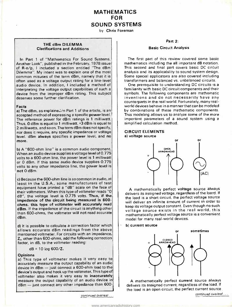
MATHEMATICS FOR
SOUND SYSTEMS by Chris Foreman
THE dBm DILEMMA Clarifications and Additions
In Part 1 of "Mathematics For Sound Systems, Another Look ", published in the February, 1978 issue of R -e /p, I included a section entitled "The dBm Dilemma ". My intent was to explain one of the most common misuses of the term dBm, namely that it is
often used as a voltage output rating for a line -level audio device. In addition, I included a method of interpreting the voltage output capabilities of such a
device from the improper dBm rating. This subject deserves some further clarification.
Facts a) The dBm, as explaine,:,'n Part 1 of the article, is an accepted method of expressing a specific power level. The reference power for dBm ratings is 1 milliwatt. Thus, 0 dBm is equal to 1 milliwatt, +3 dBm is equal to 2 milliwatts, and so on. The term dBm does not specify, nor does it require, any specific impedance or voltage level. dBm always specifies a power level, and no more.
b) A "600 -ohm line" is a common audio component. When an audio device supplies a voltage level of 0.775 volts to a 600 -ohm line, the power level is 1 milliwatt or 0 dBm. If this same audio device supplies 0.775 volts to any other impedance line, the power level is
not 0 dBm.
c) Because the 600 -ohm line is so common in audio, at least in the U.S.A., some manufacturers of test equipment have printed a "dB" scale on the face of their voltmeters. When this type of voltmeter reads "0 dB ", the voltage level is 0.775 volts. Thus, if the impedance of the circuit being measured is 600 - ohms, this type of voltmeter will accurately read dBm. If the impedance of the circuit is anything other than 600 -ohms, the voltmeter will not read accurate dBm.
d) It is possible to calculate a correction factor which allows accurate dBm readings from the above mentioned voltmeter. For circuits with an impedance, Zx, other than 600 -ohms, add the following correction factor, in dB, to the voltmeter reading:
dB = 10 log 600 /Z,
Opinions a) This type of voltmeter makes it very easy to accurately measure the output capability of an audio device in dBm - just connect a 600 -ohm load to the device's output and hook up the voltmeter. This type of voltmeter also makes it very easy to inaccurately measure the output capability of an audio device in
dBm - just connect any other impedance than 600-
continued overleaf .
Part 2:
Basic Circuit Analysis
The first part of this review covered some basic mathematics including the all important dB notation. This second and final part covers basic DC circuit analysis and its applicability to sound system design. Some special applicatons are also covered including transformers and balanced vs. unbalanced circuits.
One prerequisite to understanding DC circuits is a
familiarity with basic DC circuit components and their symbols. The following components are mathematic inventions and do not necessarily have any counterparts in the real world. Fortunately, many real- world devices behave in a manner that can be modeled by combinations of these mathematic components. This modeling allows us to analyze some of the more important parameters of a sound system using a
simplified calculation method.
CIRCUIT ELEMENTS a) voltage source
OPEN ARROWHEAD
or or
A mathematically perfect voltage source always delivers its assigned voltage, regardless of the loard. If
the load is a short circuit, the perfect voltage source will deliver an infinite amount of current in order to keep its voltage output constant. Even though no such voltage source exists in the real world, this mathematically perfect voltage source is a convenient model for many real -world devices.
b) current source
CLOSED ARROWHEAD
or sometimes
A mathematically perfect current source always delivers its assigned current, regardless of the load. If
the load is an open circuit, the perfect current source continued overleaf .
www.americanradiohistory.com

will deliver an infinite voltage in order to keep its current output constant. Even though no such current source exists in the real world, this mathematically perfect current source, like its counterpart, the mathematically perfect voltage source, is a convenient model for many real -world devices.
c) resistor
s or
A mathematically perfect resistor always obeys ohm's law, regardless of the voltage or current applied to it. This means that the mathematically perfect resistor has absolutely no inductance or capacitance and will absorb an infinte amount of power. Again, there is no such device in the real world, but we often use this mathematically perfect resistor as a model for real -world devices.
d) the passive sign convention Whenever a circuit element, such as a voltage
source, is delivering power to a circuit, its current and voltage arrows point in the same direction. You can
think of this as the voltage pushing the current around the circuit. Whenever a circuit element, such as a resistor, is absorbing power from the circuit, its current and voltage arrows point in opposite directions. You can think of this as the resistor trying to resist current flow by setting up an opposing voltage.
Source Vsdelivers \ power to resistor R
which absorbs power
OHM'S LAW a) Ohm's law relates voltage, current and resistance in a DC circuit by the following formula:
1) V =IxR (Where V is voltage, I is current, and R is resistance.)
Other forms of Ohm's law, derived by algebraic manipulation are:
2) l =V /R 3) R = V/I
continued on page 88 .
THE dBm DILEMMA ohms to the device's output and neglect to use the correction factor.
b) This type of error is not uncommon, even among equipment manufacturers. As an example. consider the following imaginary specification (not from any manufacturers's specification sheet, but typical of some I hàve seen):
Maximum Output Level: +18 dBm into 5,000 -ohms or
higher load, +14 dBm into 600 -ohm load.
c) If the output level were truly +18 dBm into a 5,000 - ohm load, the voltage output from the device would have to be 17.8 volts. While this is plausible, it is not likely. The chance are that the device is delivering 6.16 volts to the 5,000 -ohm load and 3.88 volts to the 600 - ohm load. Since 6.16 volts into a 600 -ohm load is equal to +18 dBm, it seems likely that a voltmeter with a dB scale was used to rate the output of this device, and that the technician making the measurements did not apply the needed correction factor for impedances other than 600 -ohms.
d) Fortunately, few manufacturers have made this mistake in the past, and even fewer make this mistake in current literature - consumers are becoming more and more aware of the accuracy of specifications, and any manufacturer making this particular mistake would probably soon hear from a high -school audio buff with an HP or T! calculator!
Further Opinion a) I believe that the term dBm, used as an audio signal level specification, is probably not very useful, even
when it is presented accurately.
b) I also believe that audio signal levels, given as voltages with the appropriate impedances specified, could be very useful.
c) I further believe that some sort of dB notation is needed to specify audio voltage levels.
Let me explain the reasoning behind these opinions.
a) For the purpose of determining signal levels and voltage gain (to be accurate, I should say voltage amplification, not gain), almost every modern audio electronics device can be modeled with an input and output impedance and a dependent or independent voltage source. This modeling method is covered in Part 2 of my mathematics review article, published in this issue of R -e /p.
A theoretically perfect voltage amplifier would have an infinite input impedance, a zero output impedance, and its voltage output would not vary with load impedance. With few exceptions, most modern audio electronics devices have high input impedances, low output impedances and, provided they are not overloaded, their output voltage varies only slightly with changing load impedance. Thus, I believe that the modeling method presented is basically accurate for calculating signal levels and voltage amplification.
b) Since these devices seem to be voltage- oriented devices, it seems reasonable to specify voltage - oriented parameters when rating their performance. These parameters might include input (load) impedance, output (source) impedance, maximum output voltage level, maximum input voltage (input
R-e/p 84 continued overleaf ..
www.americanradiohistory.com

"THE GAUSS HIGH SPEED TAPE DUPLICATING EQUIPMENT
WE PUT TO WORK IN 1960 IS
STILL WORKING, THREE SHIFTS."
"Gauss high speed rape duplicating technology was originally developed right in this department or Capitol in the late 60's. And, the first ten machines are still in full operation or our Jackson- ville, Illinois facility. In fact, they're work- ing three shifts a day. They're even bet- ter machines thon they were in 1968... because we've continually up- graded them with new innovations from Gauss and our own engineers. To-
day, they're performing at the leading edge of the technology. If they weren't, Capitol would find something better."
At Gauss, we engineer the quality in. Modularly. Solid state.
That way, as we improve the technology, you can upgrade your equipment. Were engineers building for engineers.
Richard P. Blinn, Director, Studio Operations & Electronic Development
Capitol Records
engineering reproduction
means
Gauss 10 MHz Bias System assures you lower noise and distortion. Wow /flutter is
less than 0.05% RMS. And that's just the beginning of our engineering story.
Nome your format. 2- track, 4- track,
8- track, cassette, or, reel -to -reel. Gauss
delivers. And, you can change formats in less than 10 minutes. What's more, you can choose between 32:1 or 64:1
duplicating with the flip of o switch.
Here's the acid test: Ask anyone who owns a Gauss high speed tape repro-
duction system what they think of their
system. They'll tell you that Gauss high productivity, highest -quality sound
and maximum reliability. If those are your
criterio, we think you'll choose Gauss.
aus by Cetec audio
CETEC AUDIO 13035 Saticoy Street North Hollywood, CA 91605 (213) 875 -1900 TWX: 910- 499 -2669
CETEC INTERNATIONAL LTD. 16 Uxbridge Rood Ealing, London W5 2ßp. England C1-579-9145 TLX: 935847 Divisions of Cetec Corporation
for additional information circle no. 62 R-e/p 85
www.americanradiohistory.com

Are you sure what the crossover point for
your next installation should be?
If not... you might think
about including a Crown VFX -2 in your tool kit.
This unique, dual -channel unit has continuously variable filters. With
it you can "fine- tune" the crossover point in any sound reinforcement system.
As a temporary test rig, the VFX -2 in- stalls quickly. You can diagnose crossover problems in existing systems, no matter how old or new, and prescribe a solution.
For permanent installation, you'll find that the VFX -2 costs less than many fixed filters, and provides other advantages. For one, a 15dB gain that eliminates the need for input transformers. An 18dB per octave rolloff that's sharp by any standard. Cross- over points can easily be changed to suit different performances. The VFX -2 also works as a bandpass filter, or for tri- amping a mono system.
Hum and noise 113dB below rated out- put (IHF), IM distortion less than 0.01%, 19 inch rack mount.
Try a VFX -2 on your next installation. Be sure.
When listening becomes an art, crown
Box 1000, Elkhart IN 46514
R-e/p 86 for additional information circle no. 63
THE dBm DILEMMA clipping) level and voltage amplification.
c) Because of the logarithmic nature of human hearing, it seems reasonable to rate these voltage - oriented parameters with sort of dB notation. I
recommend the following for signal level specifica- tions:
dB = 20 log voltage level /0.775 volts The 0.775 volt reference was chosen so that, for a
600 -ohm line, the voltage rating in dB corresponds numerically to the familiar dBm rating.
Since, to my knowledge, no standards organization has adopted a dB notation for voltage levels with a 0.775 volt reference, I recommend that the actual voltage level be included in parenthesis after the dB rating to avoid confusion. Alternately, the notation "re: 0.775 volts" may be included in parenthesis. Examples for a device with maximum 6.1 6 volts output level:
Maximum Output Level: +18 dB (6.16 volts)
or Maximum Output Level: +18 dB (re: 0.775 volts)
d) For "gain" specifications, the notation could be similar to the following:
Voltage Amplification: +87 dB maximum
e) One example of the usefulness of a voltage- oriented signal level specification is a sound system "gain /loss chart ". These charts are often included with a system, and are also often given as part of the specifications for a multi- section audio mixing console. For a sound system, the gain /loss chart helps the designer to optimize signal -to -noise ratios and system headroom.
Examine a portion of a typical system as diagrammed below:
POWER AMP MIXER MIKE LOUDSPEAKER
PAD
The maximum output level of the mixer is rated at +28 dB (19.5 volts). The mixer's output impedance is rated at 120 ohms. The input clipping level for the power amplifier is rated at +4 dB (1.23 volts). The power amplifier's input impedance is rated at 15,000 ohms. In order to optimize the signal -to -noise ratio and to maintain at least a 10 dB headroom factor, we will operate the mixer at a nominal +18 dB output level, allowing it to peak to +28 dB (19.5 volts). Since this level would severely overdrive the power amplifier, we will insert a 24 dB pad. This can be a 15,000 -ohm pad allowing the power amplifier's input impedance to properly terminate the pad. A 24 dB pad drops the peak level to +4 dB (1.23 volts) which is just equal to the input clipping level of the power amplifier. Since we are opertating the mixer at a nominal +18 dB (6.16 volts) output level, the 24 dB pad will drop the nominal level to -6 dB (0.388 volts) which maintains the 10 dB headroom factor for the power amplifier. Notice that the pad value was calculated simply by subtracting the input clipping level of the power amplifier (in dB) from the maximum output level (in dB) of the mixer.
Now suppose that the input clipping level of the power amplifier had been rated in true dBm. We know
continued overleaf . . .
www.americanradiohistory.com
duality and reliability all the way down the line.
No matter what TDK tape you use, and no matter what application you use it for, you get the same superior performance and reliability. That's what you'd expect from a world leader in ferromagnetic technology.
TDK SA, AD and D cassettes set new standards for cassette sound and performance - they're ideal for stereo dubs from master tapes for discriminating music clients, for instance. TDK "Y" Series duplicator cassettes give you superb performance in an economical package for extra -long runs -even at speeds up to 120 ips.
Or, you can have the same quality in 1 /a" pancake. TDK Audua open reels and pancakes provide the ultimate in 1/4" lab quality tape formulations. And our selection of A -V, Endless, Dictation (leaderless) and Data Cassettes, is complete. Each is designed to TDK's stringent quality controls. Finally, our ultra -reliable test cassette series offers long -lasting service for laboratory measurements, quality control evaluation, production line assembly testing and precision servicing.
Get the TDK full line story from your professional products supplier, or write us direct. Let us show you how TDK products can upgrade the quality of your operation.
BP&P 42
4TDK® World leader in recording tape technology.
TDK Electronics Corp., 755 Eastgate Blvd., Garden City, NY 11530 2906 W. Peterson Ave., Chicago, IL 60645; 2041 Rosecrans Ave., Suite 365, El Segundo, CA 90245.
for additional information circle no. 64 R-e/p 87
www.americanradiohistory.com

. continued from page 84:
Example 1: In the circuit below, the current source is delivering
2 amperes to the 10 -ohm resistor. What is the voltage across the resistor?
2A
Answer: V = I x R; therefore, VR = 2 x 10 = 20 volts
Example 2: In the circuit below, the voltage source is delivering
25 volts to the 5 -ohm resistor. What is the current delivered to the resistor?
25v
Answer. IR = V/R = 25/5 = 5 amperes
Example 3: In the circuit below, the resistor value in ohms is the
unknown. If the voltage source is delivering 15 volts to the resistor, and the current flowing through the resistor is 3 amperes, what is the resistor value in ohms?
15v
Answer: R = V/I = 15/3 = 5 ohms
POWER a) In a DC circuit, the power absorbed by a resistor is given by the following formula:
4) P =VxI (Where V and I are the voltage and current through the resistor, and P is the power absorbed by the resistor.)
b) By using Ohm's law and some algebraic manipulation again, we come up with two alternate forms of the power equation.
5) P = V:-/R
6) P =12xR
c) Find the power delivered to the resistor in each of these three examples under OHM'S LAW.
Example 4: We know the resistor value and the current through
the resistor, so we use formula 6:
P =12xR= 2'x10 =40 watts
Example 5: We know the resistor value and the voltage
delivered to the resistor, so we use formula 5:
P = V' /R = 252/5 = 125 watts Example 6:
We know the current through the resistor and the voltage delivered to the resistor, so we use formula 4:
P =VxI= 15x3 =45 watts
VOLTAGE AND CURRENT DIVISION Voltage Division
When two or more resistors are connected in series across a voltage source, they share the voltage among themselves according to the following formulas, where N is the number of resistors:
a) For two resistors:
7) VR I = x R, /(R, + R2)
b) For any Number, N, of resistors:
THE dBm DILEMMA that t' .oltage level for clipping was 1.23 volts. We also know that the input impedance was 15,000 ohms. Therefcre the input power level needed for clipping is 0.10 m Iliwatts or -10 dBm. Since the output of this mixer Kvas planned for a 600 -ohm (minimum load impeda -Ice) line, its maximum output level in dBm is +28 dBm, the same numerical value as the rating of +28 dBm (19.5 volts). If we now attempt to calculate the app -opriate pad value for optimum signal -to -noise ratio and headroom, we can no longer simply subtract the two values but must go through an extended series of mathematical gyrations.
f) There are numerous other reasons for using voltage level specifications. If we know the maximum voltage output of a power amplifier, for example, it's easy to calculate the power the amplifier will deliver into an odd load impedance. Just square the voltage and divide by the load impedance. Because of the power
supply limitations of a power amplifier, this may not be perfectly accurate, but its a pretty good "ball park ".
g) If we know the voltage amplification of this power amplifier, we can calculate the power output of the amplifier into any load impedance, for any input level (provided the amplifer is not overloaded). This is illustrated as an example in Part 2 of the mathematics review article.
h) I am not recommending dropping the dBm notation for all audio specifications. I am only recommending that a dB (voltage) rating be used for signal level specifications and that a dB voltage amplification rating be used for "gain" specifications. It is perfectly valid to include standard dBm or dB gain specifications along with the voltage specifications.
i) Does any of this make sense?
R-e/p 88
www.americanradiohistory.com

alliHia T30 aoi AMA WO .
CCU BITT/ SYSTEMS NC. 13130 YUKON AVE HAWMCIFIE. CA SOPSO
4.4 12138138080
RiGHT
GROUND
FOR MONAOPAL OPERATION. SWITCH TO MONO, CONNECT NFUT TO LEFT CHANNEL. CONNECT LOAO BETWEEN RED BINONG POSTS. LEFT CHANNEL OUTPUT LS
LEFT
MONO
Over the past seven years BGW has turned a lot of professional heads around. We came
out of nowhere to successfully challenge the stand -pat technology of the aging monarch of professional amplifiers. The most demanding buyers in the music business now rely on BGW: Studio owners. Recording engineers. Serious musicians. Everyone who makes his living from recorded or live sound. Performers and technicians alike have gotten behind BGW's legendary power, impeccable performance and workhorse reputation.
Here's what's made BGW the most imitated product in the pro sound business:
A full professional line starting with the MODEL 100:30 watts per channel into 8
4 iIHMS
MITES CALIBSATION
MODEL IMISERIAL N9=11 THIS UNIT IS WIRED FOR THE VOLTAGE AND CURRENT INDICATED BELOW. TO CHANGE VOLTAGE REFER TO OWNERS MANUAL. VOLTAGE CURRENT 100 VOLTS= 3 AMPS= 120 VOLTS. 5 AMPS - 200 VOLTS= 6 AMPS im 220 VOLTS. 7 5 AMPS MI 240 VOLTS= 10 AMPS.
15 AMPS.
ohms, 20 Hz to 20 kHz, at less than 0.1% THD (80 watts mono);
The MODEL 250 C: 100 watts per channel into 8 ohrñs, 20 Hz to 20 kHz, at less than 0.1% THD (251 watts mono);
The new MODELS 750B and 750C: 225 watts per channel into 8 ohms, 20 Hz to 20 kHz, at less than 0.1% THD (720 watts mono).
Fo' the true sound professional, quality isn't a luxury. It's a necessity and something we build into every BGW amp.
Ccntact our home office for complete technical specs. You'll understand why so
many of your professional peers get behind BGW. And why the competition stays behind.
BGW Systems, Inc., 13130 S. Yukon Ave., Hawthorne, CA 90250. Telex: 66 -4494
In Canada: Omnimedia Corp., 9653 Cote de Liesse, Dorval, Quebec H9P 1A3 International Inquiries please contact the factory.
for additional information circle no. 65
SYSTEMS
Get Behind Us R -e /p 89
www.americanradiohistory.com

8) VRI =VsX RI /(R1 +R2 +R3 +... +RN)
c) If the ohmic value of all the resistors is the same, they share the voltage equally:
9) VR1 = Vs /N d) When two or more resistors are connected in parallel across a voltage source, they each receive the same voltage regardless of their ohmic value: 1 0) VRI = VR2 = VR3
Current Division When two or more resistors are connected in
parallel across a current source, they share the current among them according to the following formulas, where N is the number of resistors: a) For two resistors:
...=VRN=Vs
11) IR, = Is x R2 /(R, + R2)
b) For any number, N, of resistors: 1 2 ) IRI = Is x (R2 + R3 + ... + RN) /(R1 + R2 + R3 + ... RN)
c) If the ohmic value of all the resistors is the same, they share the current equally:
13) IR1 = Is /N d) When two or more resistors are connected in series across a current source, they each receive the same current, regardless of their ohmic value: 14) IR,= IR2=IR3 =. ..= IRN= Is
Example 7: In the circuit shown, find the voltage delivered to
each of the two resistors:
From formula 7:
VRI = 10 X 5/(5 + 15) = 2.5 volts
VR2 = 10 X 15/(5 + 15) = 7.5 volts Example 8:
In the circuit shown, find the voltage delivered to each of the three resistors.
28.3v
2.7f2
VR1 = ?
13f2
VR2 =
47.5f2
VR3=?
Since the resistors are in parallel (formu a 10), they all receive the same voltage which is equal to the source voltage of 28.3 volts.
Example 9: In the circuit below, find the current delivered to
each of the two resistors:
R-e/p 90
104
From formula 11:
IRI= 1 0 x 15/(15 +5) =7.5 amperes IR, = 10 x 5/(15 + 5) = 2.5 amperes
Example 10: In the circuit below, find the current delivered to
each of the three resistors.
Ak 28.34
Since the resistors are in series, they all receive the same current which is equal to the source current of 28.3 amperes.
SERIES AND PARALLEL COMBINATIONS The following diagram shows resistors connected in
series and in parallel.
SERIES SERIES PARALLEL PARALLEL
Series Resistor Combinations To find the total resistance of a set of series
connected resistors, simply add their ohmic values. 15) Rr= T1 +R2= R3 +... +RN
Parallel Resistor Combinations a) To find the total resistance of a set of parallel connected resistors, use the following formula: 16) R, = 1/(1/R1+ 1 /R2 + 1/R3+ ... + 1/RN)
Where N is the number of resistors. b) When there are only two resistors in parallel, the formula can be simplified as follows: 1 7 ) Rr = R1 x R2 /(R1 + R2)
c) For any number of resistors with the same ohmic value which are in parallel, the formula further simplifies:
18) R1 = R/N
Where R is the resistor value and N is the number of resistors.
Series /Parallel Resistor Combinations The following diagrams show resistors in several
possible series /parallel combinations.
www.americanradiohistory.com

The Series IS, based on the world famous industry standard Series L
Unequalled features,technical sophistication and a modest price.
Input channels (12 16 or 20 ' Transformer a once mic input with a 20dB pad. Variab -e gain mic
amp. Insert send /return (line input).120hz high pass filter. Four band EQ, with the two mid band frequencies sweepable. Two monitor sends (post -EQ) and one echo send (post- fade). Automatic pre -fade Solo. LED peak indicator whose delay time indicates the relative size of the transient. Five outputs
Left and right main, monitors A and B and master echo, each with two band EQ, solo and insert. Each output may be balanced by a plug -in transformer.
Encore.
Meters Two studio quality VU's and peak reading LED's display the main
stereo output or any function soloed. Communication
There's both talkback and intercom. The talkback mic can speak into the main output, monitors A or B, or into a ClearCom (or compatible) intercom system. Specifications
Excellent, ie l'Incredibly quiet and dhstortion -free. Finally
Two echo returns, conductive plastic potentiometers throughout, socket for Share lamp and, of course, the Soundcraft comprehensive 2 -year warranty.
Début.
The new EX4S studio quality 2,3 or 4 -way stereo electronic crossover. Internal switching
The facilities for changing the crossover points, and for converting the unit to a 2, 3 or 4 -way ore inside, to provide maximum protection for P.A. systems, by avoiding accidental switching. Front panel controls
Eight band- attenuators, eight LED peak indicators, and LED's to indicate 2, 3 or 4 -way mode. Circuitry
Bessel function filters (superior to Butterworth filters in other crossovers) give an ultimate slope of 2GdB/octave, the most linear phase response and the best transient response. The result is, quite simply, a better sound. And the rest
EX4S is built into an all extruded black anodised 19" case, tough enough to stand up to all the wear and tear of the road. XLR and multipin connectors on the back. Inputs are electronically balanced while outputs may be balanced by plug -in transformers. Of course, it's also covered by Soundcraft's comprehensive 2 -year warranty.
Soundcraft Electronics Ltd., 5 -8 Great Sutton Street, London EC1V OBX. Telephone 01 -251 3631. Telex 21198.
Soundcraft North America, PO Box 883, JFK Station, Jamaica, New York 11430, USA. Telephone (212) 5288158.Telex0! -2203.
SDURRDE Rfi 1A
Y
for additional information circle no. 66 R-e/p 91
www.americanradiohistory.com
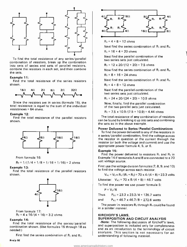
l
To find the total resistance of any series /parallel combination of resistors, break up the combination into sets of series and sets of parallel resistors, combine the resistors in each set, and then combine the sets.
Example 11: Find the total resistance of the series resistors
shown.
1652 412 211 812 211 3211
Since the resistors are in series (formula 15), the total resistance is equal to the sum of the individual resistances = 64 ohms.
Example 12: Find the total resistance of the parallel resistors
shown.
From formula 16:
R, = 1/(1/4+ 1/8 + 1/16 + 1/16) = 2 ohms
Example 13: Find the total resistance of the parallel resistors
shown.
412
1611
From formula 17: R1 = 4 x 16/(4+ 16) =3.2 ohms
Example 14: Find the total resistance of the series /parallel
combination shown. (Use formulas 15 through 18 as needed.)
First find the series combination of R, and R2.
R-e/p 92
Rr =4 +8= 12 ohms
Next find the series combination of R, and R4.
R1 = 16 + 4 = 20 ohms
Next find the parallel combination of the two series sets just calculated.
R1 = 12 x 20/(12 + 20) = 7.5 ohms
Now find the series combination of RS and R6.
Rr= 8 +16 =24 ohms
Next find the series combination of R, and R6.
R, =4 +8= 12 ohms
Next find the parallel combination of the two series sets just calculated.
R, = 24 x 20/(24 + 20) = 10.9 ohms
Now, finally, find the parallel combination of the two parallel sets just calculated.
R,= 7.5x10.9/(7.5 +10.9) =4.44 ohms
The total resistance of any combination of resistors can be found by breaking it up into sets and combining the sets as in the above example.
Power Delivered to Series /Parallel Combinations To find the power delivered to any of the resistors in
a series /parallel combination, find the voltage across the resistor in question or the current through the resistor (or both the voltage and current) and use the appropriate power formula 4, 5, or 6.
Example 15: Find the power delivered to resistors R, and R2 in
Example 14 if terminals A and B are connected to a 70 volt voltage source.
First use the voltage division formulas (7, 8, 9, and 10) to find the voltage across each resistor.
VR1 = Vs x R, /(R, + R2) = 70 x 4/(4 + 8) = 23.3 volts
Likewise: VR: = 70 x 8/(4 + 8) = 46.7 volts
To find the power we use power formula 5:
P = V2/R
Thus PRI = 23.3 x 23.3/4 = 135.7 watts
and PR, = 46.7 x 46.7/8 = 272.6 watts
The power in resistors RI through R8 could be found in a similar manner.
KIRCHOFF'S LAWS, SUPERPOSITION AND CIRCUIT ANALYSIS .Note: The following discussion of Kirchoff's laws,
and superposition is included only for completeness and as an introduction to the terminology of circuit analysis. This section is not necessary for an understanding of following material.
www.americanradiohistory.com

RH60 RADIAL HORNS
Meet the Community sixty degree radials, the horns for high definition, understandable sound. The horn pic- tured is our RH60, the midrange main- stay of the large system. We've recently added two new sixty degree horns to our line for HF and VHF projection, the SRH60 and the SQ60.
Some people still think that our horns and cabinets look a little strange, perhaps not realizing that at Com- munity shape and construction are determined by the laws of physics, not marketing, packaging or the almighty
dollar. For instance, you can see that the mouth of the RH60 is considerably taller than that of comparable sixty degree horns. Why? Well, if a horn is to act as a wave guide at its lower operative frequencies (which it is) it must have a tall mouth to support the larger wave forms generated near crossover. The idea of a thin, wide - mouthed radial may be pleasing in terms of packaging and handling, but it is a convenience that does not pay off in operation. Some conveniences that do pay off in operation are one -piece
RESPONSE AND SPL
construction, low resonance, high strength -to- weight ratios and the meticulously executed design that characterizes a Community horn.
Would you like more information? We recently published a catalog which details the performance of all Com- munity products. Already it has been called a must for anyone wishing to design a sound system on a profes- sional level. Please write or call to order.
RH60 -A DRIVER: GAUSS HF4000
1 Watt cr 1 Meter 107.24 dB -SPL
BANDWIDTH PINKNOISE: 250Hz -16KHz
1 Watt co 4 Feet 107.28 dB -SPL
-12 -7 -6 -4 -3 -1 0 +1 -1 -2 -1 -3 -5 -5 -9 -9 -9 -13 -17
Hz 40 50 63 80 100 125 160 200 250 315 400 500 630 800 i6 1.25 1.6 Z.0 2.5 3.15 4.0 5.0 6.3 8.0 10.0 12.5 16.0 RHz
SRH60 -B DRIVER: ALTEC 288.16G BANDWIDTH PINKNOISE: 350HZ -16Hz
1 Watt @ 1 Meter 108.99 db -SPL 1 Watt Ca 4 Feet 105.52 dB -SPL
-10 -6 -4 -2 0 0 0 0 0 -2 -2 -4 -8 -8 -6 -10 -12
Hz 40 50 63 80 100 125 160 200 250 315 400 500 630 800 18 1.25 1.6 Z.0 2.5 3.15 4.0 5.0 6.3 8.0 10.0 12.5 16.0 RHz
SQ60 -C DRIVER: EMILAR EA. 175.16
1 Watt Oa 1 Meter 103.85 dB -SPL
BANDWIDTH PINKNOISE: 800Hz -16KHz
1 Watt 2i 4 Feet 102.14 dB -SPL
-6 -2 -2 0 0 +2 0 0 0 -2 -2 -5 -12 -16
Ih 40 50 63 80 100 125 160 200 250 315 400 500 630 800 111 1.25 1.6 2.0 2.5 3.15 4.0
C ommunry 5.0 6.3 8.0 10.0 12.5 16.0 8112
Community Light & Sound, Inc. 5701 Grays Avenue Philadelphia, PA 19143 (215) 727 -0900
for additional information circle no. 67 R-e/p 93
www.americanradiohistory.com

Kirchoff's laws are two of the basic laws of circuit analysis. Using Kirchoff's laws, the law of superposition, and the rules for voltage and current division and series and parallel resistor combinations, we can analyze almost any DC electrical circuit. These same laws combined with AC impedance, complex frequency and other concepts also form the basis for AC circuit analysis.
Definitions: Nodes and Branches A node is any point where two or more circuit
elements join. A branch is a single path in a circuit which contains one simple element and connects one node to another node:
Kirchoff's Current Law Kirchoff's current law states that the algebraic sum
of all the currents entering any node is zero. Another way to state this would be that whatever current enters a node must be balanced by an equal current leaving that node. This seems reasonable. A node is
just a junction between circuit elements. If the current entering the node were not balanced by current leaving the node, then the node would have to store some current which is impossible. The current division formulas 11 through 14 illustrate Kirchoff's current law.
Kirchoff's Voltage Law Kirchoff's voltage law states that the algebraic sum
of the voltages around any closed path in a circuit is zero. Another way to state this would be that for any voltage source V, in a closed circuit path, the algebraic sum of all the other voltages in that same path must be equal to -V. This also seems reasonable. A closed circuit path will not allowanyvoltage to "escape ", so it seems logical that all the voltage (and no more) from the voltage source must be applied across the various other components in the circuit. The voltage division formulas 7 through 10 illustrate Kirchoff's voltage law.
Superposition The law of superposition allows us to calculate
voltages and currents in a circuit containing several voltage and current sources. The circuit must be linear (must contain only mathematically perfect resistors and sources). To calculate the voltage across any resistor, we calculate the voltage across that resistor caused by one of the sources acting alone. We replace all the other voltage sources with short circuits and all the other current sources with open circuits. Then we find the voltage across the same resistor caused by the second source acting alone, and continue until the voltages across this one resistor caused by all the sources have been calculated. The total voltage across this resistor is simply the algebraic sum of all the voltages just calculated. The current through the resistor is calculated in a similar manner.
Impedance and AC Circuit Analysis An impedance is made of a pure resistance
combined with a reactance. The reactance consists of a capacitance or an inductance or some combination of capacitance and inductance. A pure resistance maintains the same value, in ohms, whether the voltage or current changes from a DC source to an AC source at any frequency. On the other hand, the value of an impedance, in ohms, changes with frequency, making it more challenging to manipulate R -e /p 94
mathematically. Thus, we often assume that the impedances we work with in audio can be treated like pure resistances over the audio frequency range. In most cases, this is a good assumption. When the occasional exception shows up, we treat it separately. If we always had to deal with an actual impedance value, made up of a pure resistance and a reactance, most of the formulas we have developed so far would be similar, but they would contain complex numbers with a real and imaginary part. This would complicate the solutions without greatly improving the accuracy. Some audio components, on the other hand, must be analyzed by AC methods. Crossover networks and equalizers, which are AC filter circuits, are examples of devices that must be analyzed using AC techniques.
TRANSFORMERS A transformer changes electrical energy at its input
(its primary winding) into magnetic energy in its core. This magnetic energy is transformed back into electrical energy at the transformer's output (its secondary winding). If the transformer is wound with a
greater number of turns on its primary side than on its secondary side, the voltage level at the secondary will be lower than on the primary, and the current level on the secondary will be higher than on the primary. Since the impedance of a circuit is equal to the ratio of that circuit's voltage level divided by its current level (ohm's law), a transformer can transform impedances as well as voltages and currents. These actions take place in a precise, mathematical way described by the following formulas:
Notes: N, is the number of turns on the primary side of the
transformer, N2 is the number of turns on the secondary side of the transformer.
VI is the voltage level on the primary side of the transformer, V2 is the voltage level on the secondary side of the transformer.
I, is the current level on the primary side of the transformer, 12 is the current level on the secondary side of the transformer.
Z, is the impedance of the circuit seen at the primary side of the transformer, Z2 is the impedance seen at the secondary side of the transformer.
The transformer formulas:
19)
20)
21)
VI/V2 = NI/N2
11/I2 = N2/NI
Z,/Z2 = N;/N3
b) Formula 19 shows that the voltage ratio between the primary and secondary windings of a transformer is directly proportional to the transformer's turns ratio. This equation is applicable to voltage level matching between two circuits.
Formula 20 shows that the current ratio between the two windings of the transformer is inversely proportional to the turns ratio.
Formula 21 describes the impedance matching action of a transformer. Note that the impedance ratio between the primary and secondary of the transformer is directly proportional to the square of the turns ratio.
c) Often, the transformer spec sheet gives its impedance ratio, but not its turns ratio. A simple
www.americanradiohistory.com

So d Workshop introduces its a
un un rm S.
w
The Auto-Recall Mixdown System brings computerized
mixing to the Sound Workshop Series 1600.
The Series 1600 is a high- perfor- mance, automation -ready audio
recording console available in several mainframe sizes, all fully
expandable to a maximum config- uration of 36 x 32, and all ready for direct interface with both the VCA input sub -group package and the
ARMS Automation Processor.
arm AUTO- RECALL MIXDOWN SYSTEM
l i rr1-1-!! rrr! i! r! I.w kk
During mixdown, ARMS stores fader levels which can be recalled for track by track update of the mix.
The Sound Workshop Series 1600 Recording Console. A new philosophy in console design. Now with arms.
Tapes processed with ARMS are compatible with MCI's JH -50 Automation System.
Sound Workshop Bringing the technology within everyone's reach. PROFESSIONAL AUDIO PRODUCTS 1324 Motor Parkway, Hauppauge, New York 11787 516 - 582 -6210
R -e /p 95 for additional information circle no. 68
www.americanradiohistory.com

manipulation of formula 21 solves this problem:
22) N, /N2 = \/ Z, /Z2
Example 16: A transformer has a primary impedance of 15k
ohms, and a secondary impedance of 600 ohms. If the input (primary) voltage is -16 dB (0.123 volts), what is the output voltage?
From formula 22: NI/N2= \/ 15,000/600 Thus, the turns ratio NI/N2= -/ 25 = 5
Since N1/N2 = V, /V2 (formula 19), then:
5 = (0.123 volts) /V2 or V2 = (0.123 volts) /5 Thus, V2 = -30 dB (24.5 mV)
From this example, we see two transformer actions at once. The source impedance of 15k ohms was "transformed" to 600 ohms and the source voltage of -16 dB (0.123 volts) was "transformed" to -30 dB (24.5 mV).
One other significant use of audio transformers is to isolate the ground wire of one circuit from the ground wire of another circuit to prevent ground loops and reduce hum.
Other Transformer Considerations A transformer doesn't have any impedance of its
own. It merely transforms an impedance at its primary to a corresponding impedance at its secondary as described in formula 21. Thus, the transformer in the above example has an impedance ratio of 15,000:600 which equals 25:1. If a 150k ohm circuit is connected to its primary, the impedance seen at the secondary will be 150,000/25 = 6,000 ohms. Since this impedance transformation works in both directions, a
6,000 -ohm circuit connected to the secondary of the transformer, will be transformed to a primary impedance of 150,000 ohms. Voltage and current matching also work in both directions.
However, a transformer that is specified as having an impedance ratio of 15,000 ohms to 600 ohms has been manufactured specifically to operate at those impedances. If it is used with circuits having considerably greater or smaller impedances, its frequency response may be degraded, or it may "ring" (resonate). One way to avoid these problems is to terminate the transformer or to use it in a circuit where the impedances are proper.
It is also important to use a transformer at the voltage and power level for which it was planned. For example, a mike level transformer will probably saturate (distort) if it is used for line level circuit matching. Also, a line level transformer will not perform properly if it is used for mike level circuit matching. The magnetic fields are so weak that non - linearity occurs.
It's a good rule to always choose transformers according to the voltage levels, power levels, and the impedances of the circuits under consideration.
BALANCED, UNBALANCED AND FLOATING CIRCUITS a) Balanced, unbalanced and floating circuits may all be transformer isolated or direct coupled. The distinction beween them lies in the way the circuits are referenced to ground (audio common). A floating
R-e/p 96
circuit has no ground reference. The mike inputs of most "balanced" input mixers are actually floating. A balanced circuit requires either a center tapped transformer, or resistors from each side of the transformer to ground; either condition places both sides of the transformer at equa I potential with respect to ground. In other words, the circuit is balanced with respect to ground. Electronic balancing, done with "differential" input or output circuits can replace transformers with similar results. For example, the bridged output of two of Altec's Model 2275 Incremental Power amplifiers is balanced electronically. The diagrams below show transformer coupled balanced, floating and unbalanced lines.
Unbalanced Balanced Floating Unbalanced Source Shielded Shielded Load
Shielded Line Line Shielded
b) One of the advantages of a balanced circuit is that, in most cases, it can reject hum and noise better than an unbalanced circuit. Consider what happens if an interference source such as a radio station, CB radio, SCR dimmer, etc., causes a noise current in the wires of a balanced circuit. Provided that the source is physically distant from the circuit compared to the distance between the two wires, the interference will cut across both wires creating equal noise currents in both wires. However, since the signal currents (wanted signal) in the two wires a re headed in opposite directions, but the noise current (unwanted signal) travels in the same direction in both wires, the noise current is out -of -phase with itself and is cancelled.
c) A balanced line may or may not have a shield. If it does have a shield, the shield is usually at the same voltage potential as the common or ground wire. Since the phase cancellation of noise currents in a balanced line is never perfect in the real world, most low level balanced circuits, mike or line level, are shielded. Twisting the two wires of a floating circuit also helps cancel noise. Because the twd wires of a floating circuit are also at equal voltage potential from ground, noise currents that enter a floating circuit are effectively canceled, too.
The Advantages of Low Impedance Lines Because low impedance lines and balanced lines
are often used together, it may be useful to review the advantages of low impedance lines for microphones and for line level signals.
Any two -wire cable can be modeled by a group of resistors and capacitors as shown below.
T T T - Cable Group of Resistors and Capacitors RC Lowpass
These resistors and capacitors form a simple low - pass filter, (a low -pass filter may also be called a high-
www.americanradiohistory.com

E S.E.E. I.T. A.T.
T.H. E . LA A. ITSivi SERIES BY TRIDENT
.S.
Ob
Trident Audio Developments' new TSM Series
desk will be on display for the first time in America in booths 120/121 in L.A.'s
giant A.E.S. Convention.
Two and one -half years of applied research backed by
more than ten years of direct experience in professional
recording have produced the TSM. Designed by engineers
for engineers, the TSM is the ultimate recording console. In addition
to the TSM, Trident's Fleximix system, Parametric Equalizer, Low Distortion
Audio Oscillator and Stereo Limiter Compressor will be cn display.
See and operate the entire Trident pine at A.E.S.
TRI DENT Crossing the frontiers of sound
Trident Audio Developments Ltd., Sales Office: 112 -114 Wardour St. London W1'V3AW Tel: 01 -734 !901/6 Telex: Tridisc 27782
for additional information circle no. 49 R -eip 97
www.americanradiohistory.com

cut filter). A larger capacitor or a larger resistor makes this filter more effective, that is, it will cut more low frequency energy from the signal. This high -cut action is the reason why a cable can degrade the high - frequency performance of a device. Now connect a source to this cable model and examine the effects of the source's output impedance.
When the source's output impedance is high, it adds to the resistor in the low -pass filter, increasing the amount of high frequencies that are cut from the signal.
Vs Rs 1\ Output
Impedance of Source.
R
If the source's output impedance is low, it adds very little to the effectiveness of the low -pass filter. Thus, the high frequencies in the signal are not attenuated as much.
RELATING CIRCUIT ANALYSIS TECHNIQUES TO SOUND SYSTEM DESIGN
Many of the devices we use to build sound systems can be modeled with the mathematically perfect components we defined earlier. This way we can use the circuit analysis formulas to analyze the gain of a system, the voltage and power output and any impedance matching that may be needed.
Devices That Can be Modeled by Voltage Sources a) Microphones, contact pickups, microphone substitution devices and the output of most tape machines, phonographs and other "sources" can be modeled as perfect voltage sources which have a resistor in series with them. The resistor is equal to the output impedance of the device.
15052
Microphone Balanced
Low -Z
Gnd
15k52
Tape Deck Unbalanced
High -Z
b) Mixers, equalizers, power amplifiers and other "signal processing" devices can be modeled as dependent voltage sources. That is they can be modeled as voltage sources whose output depends on the input voltage to the device. The output voltage is
J
11 Split Second Time Machine
an revolut` . This seises, <trïd cc
vo driv e 4000 times Del secon e - ijflat Weather and the Environmental
ervices selected Teiéx /t lagnecord I4f) II others to record meteorological display ata
Of course, broadcasters also favor the 1400 for she rugged stability of the die cast main frame,
TL logic and exceptionally clean electronics, ompare our speed, specs, and price. We invite ou to make a split second decision.
*At 7 ips, adjustable t 7% to compensate for tape thicknesses and mechanical wear.
PRODUCTS OF SOUND RESEARCH
TELEX, COMMUNICATIONS, INC.
9600ALDRICH AVE. SO.MINNEAPOLIS, MINN. 55420 U.S.A. Europe: 22 rue da la Legion -d'honneur, 93200 St. Denis. France
Canada: Telak Electronics, Ltd., Scarborough, Ontario
R-e/p 98 for additional information circle no. 69
www.americanradiohistory.com

equal to the input voltage times some amplification factor. This amplification factor is the voltage gain. Av, or more accurately, the voltage amplification of the device. A resistor in series with the output models the device's output impedance.
Devices that Can be Modeled with Resistors a) Loudspeakers can often be modeled as perfect resistors. Note the word "often ". A loudspeaker's impedance does vary with frequency, and when we are designing a loudspeaker system we must sometimes take this into account. However, the perfect resistor is a useful model, and if the impedance change with frequency must be considered, we can always substitute another perfect resistor of a different value.
b) The input impedance of most mixers, equalizers, power amplifiers and other signal processing devices can be modeled as a perfect resistor.
Example 17: A 250 -ohm microphone is rated at -56 dB (1.23 mV)
output for an SPL level of 10 dynes per square centimeter (94 dB SPL) at its diaphragm. If 10 dynes per square centimeter reaches this microphone and it is connected to a mixer with a 1,500 -ohm input impedance, what voltage will the mixer receive? If this same microphone is connected to a mixer with a 250 - ohm input impedance, what voltage will the mixer receive?
First draw the circuit:
Now find the voltage loss in dB caused by the voltage
-56 dB 1,500 or 25011
division between the microphone impedance and the input impedance of the mixer. From formula 7:
V; = V, x R; /(R; + R)
and V, = V, x 1500/(1500 + 250) x = 0.857 V,
To convert this to a dB loss we use a dB formula from Part 1 of this review:
dB loss = 20 log 0.857 = -1.34 dB
(a 20 log formula since we are considering voltage loss)
Thus, for a microphone output voltage of -56 dB (1.23 mV), the mixer sees -57.34 dB (1 .05 mV).
For R, = 250 ohms, the equation becomes:
V, = V, x 250/(250 + 250) = 0.5 V,
dB loss =20log 0.5 = -6dB Thus, for a microphone output voltage of -56 dB (1.23 mV), the mixer sees -62 dB (0.616 mV).
Example 18: A power amplifier is rated at 50 watts into an 8 -ohm
load. Its input sensitivity (input level needed for full output power) is rated as +4 dB (1 .23 V).
W h UP With Medusa.
Specifically designed to bring simplicity to everything from the most complex of PA and
recording systems to the simplest six input set -up. Medusa is a rugged, road -tested
option -loaded system that flexibly handles all of your multiple hook -up needs; brought to
you by Whirlwind, the people who wire up the pros.
To get one of the eight standard Medusas, or have one custom -built to your specs, all you
have to do is visit your local Whirlwind music dealer (if you don't have a dealer near you,
write us). So the next time you go on the road, let Medusa handle the headaches.
You can handle the applause.
whirlwind P.O. Box 1075 Rochester, N.Y. 14603 (716) 663 -8820
for additional information circle no. 70 R-e/p 99
www.americanradiohistory.com

a) Find the maximum output power in a 12 -ohm load.
b) Find the output power into this same 12 -ohm load if the input level is -2 dB (616 mV).
c) Find the voltage amplification (voltage gain) of the amplifier in dB.
First draw the equivalent circuit:
V = +4 dB (1.23v) or -2 dB (616 mV)
_
Note that the input impedance of the amplifier will not enter into any of our calculations because the actual voltage reaching the amplifier input is specified. In the microphone example, on the other hand, we had to calculate the actual voltage reaching the mixer input. In addition, the output impedance of the power amplifier is so small that we will neglect it in our calculations.
a) Since we have modeled that amplifier as a
dependent voltage source, we first must find out the voltage output with the known voltage input of +4 dB (1 .23 V). However, we only know the power output for an input level of +4 dB (1.23 V). Therefore, we go back to formula 4 to find the voltage output.
P = V2/R
manipulating this equation: V2 = P x R or V= \/ P x R
Thus, Vo = '/ 50 x 8 = 20 volts
Now put the power equation back in its original form to find the power into a 12 -ohm load:
P = V2/R = 20 x 20/12 = 33.3 watts
b) For this part of the example, we notice that the level has dropped exactly 6 dB at the input. Since the voltage output of the power amplifier is dependent on the
RL = IL Ri 812
or 12f2
voltage input, the output must also drop exactly 6 dB. Thus, the output power must also drop 6 dB, and remembering our memorized dB equivalents for power (from Part 1 of this review), we know that this means that the power output is now equal to one -fourth of the original power:
P = 33.3/4 = 8.33 watts
c) To find the voltage amplification, we must know the ratio of the output voltage to the input voltage. We know the input voltage and the output voltage. However, the input is specified in dB, and the output was calculated in volts. We could find the input rating in volts, perform the indicated division, and convert to dB. However, it will be quicker to convert the output voltage to a dB value and then simply subtract the input level (remembering that to divide two numbers which are expressed in dB, we merely subtract their dB values).
dB = 20 log (20 volts /0.775 volts) _ +28.2 dB (20.0 volts)
Therefore, voltage amplification:
( +28 dB) - (+4 dB) = 24 dB
Faults in This Analysis Method This method may be used for entire sound systems
or for individual components. Unfortunately, there are several things that can degrade the accuracy of this type of analysis.
1) Volume Controls. The voltage amplification of any device with a volume control depends on the setting of that control! The manufacturer's rated voltage amplification assumes that the control is fully up for minimum attenuation, but this seldom reflects actual usage. Thus, unless the control is accurately calibrated in dB, we are reduced to guessing the overall gain of the device with nominal control settings. If we do know the actual loss of the control setting, we simply subtract this value from the rated gain in dB. A good guess in many cases is that the volume controls will all be set at about "12 o'clock ". For a standard logarithmic taper audio volume control,
R-e/p 100
NOBODY HOES IT B
ConsuItonta Inc. 00 Beech}uood Avenue NMrvillq Tennessee 3728
615.456.6900 Nclrhvill, Tnnff 37212
6152566900
for additional information circle no. 71
www.americanradiohistory.com

this will approximate 20 dB of loss in the circuit.
2) Manufacturer's Specifications. The analysis method presented above depends on knowledge of the voltage output of any source device such as a microphone. Often, microphone outputs are rated in dBm, a power output rating. If the rated load impedance (not output impedance)for the microphone is also given, the dBm rating can be converted into a voltage output (in dB re: 0.775 volts) by formula 5 and two dB formulas from Part 1 of this review:
Power Output in watts = 0.001 x 10(ddm 10j
Voltage output = Power Output x Rated Load Impedance in dB (re: 0.775 volts) = 20 log (Voltage Output /0.775 volts)
The so- called "gain" of an electronic device is another questionable specification. At one time, most manufacturers rated the "insertion gain" or the "transmission gain" of the device. These ratings were developed by the telephone industry and are primarily useful in circuits where impedance matching is critical. The "gain" specification of many current audio devices is actually a voltage amplification figure. Unfortunately, few manufacturers tell us what type of "gain" specification method they are following. Thus, the actual voltage amplification number, in dB, mayor may not be available.
Let's do one final example for a complete, if simple, sound system. We will assume that, from the manufacturer's specification sheets, or by actual measurements in our own labs, that we are able to find
the voltage output from the microphone, and the voltage amplification (voltage gain) of the electronic devices.
Example 19: For the system shown, assume an SPL of 100 dB at
the microphone diaphragm. Find the SPL level heard by the listener at 100 feet from the loudspeaker.
100 dB SPL et Mic
Diaphragm
Power Amp
ñE m tg i;
ñE
>
Equipment Specifications: Microphone:
Sensitivity: -54 dB (1 .55 mV) /10 dynes /cm' Impedance: 230 ohms
Mixer: Voltage Amplification: 87 dB Input Impedance: 1,500 ohms Output Impedance: 120 ohms
Power Amplifier: Sensitivity: +4 dB (1 .23 volts) for 200 watts
into 8 ohms Input Impedance: 15k ohms Output Impedance: Less than 0.1 ohm
Listener
ìC.
N O CAPSTAN /PINCH ROLLER FIRST PASS QUALITY Pass After Pass After Pass
Mastering Recorders To 40 Tracks By Stephens Electronics Inc.
[Ft
1
STEPHENS ELECTRONICS, INC. 3513 Pacific Avenue Burbank, Calif. 91505 Phone: (213) 842 -5116
EXCLUSIVE EASTERN REPRESENTATION:
Va/"09udio Xew1ca DIVISION OF TODRANK TECHNICAL SYSTEMS, INC.
P.O. Box 40743 2821 Erica Place Nashville, Tenn. 37204 (615) 383 -4732
for additional information circle no. 72 R-e/p 101
www.americanradiohistory.com

Loudspeaker: Sensitivity: 104 dB SPL @ 4'/1 watt Impedance: 8 ohms
Step 1: Find the voltage output of the microphone for 100 dB SPL at the diaphragm.
We know that the microphone output is -54 dB (1 .55 mV) at 10 dynes /cm' (94 dB SPL). Therefore at 100dB SPL, the microphone output must be 6 dB higher or -48 dB. Note that, during these calculations, it is not necessary to calculate the actual value in volts represented by the -48 dB figure. We will simply remember that our dB values are referenced to 0.775 volts and convert at the appropriate point in the example.
Step 2: Find the voltage delivered to the mixer input.
First draw the equivalent circuit:
-48 dB
Next, find the ratio between the voltage delivered to the mixer and the voltage output of the voltage source in the microphone's equivalent circuit. Then convert this ratio to a dB loss value. This loss is caused by the voltage division between the microphone's output impedance and the mixer's input impedance. From formula 7:
loss = 1500/(1500 + 230) = 0.867
since this is a voltage loss, the dB value is:
dB loss = 20 log 0.867 = -1.24 dB
Thus, the mixer's input sees a voltage that is -1 .24 dB below the calculated output of the microphone at the 100 dB SPL. That is, the voltage input to the mixer is ( -4 dB) - ( -1 .24 dB) = ( -49.24 dB).
Step 3: Find the voltage output of the mixer:
First, draw the equivalent circuit:
120:12
1,500i2
Vo = -49. 24 d B AvVi ( +87 dB gain)
We have just calculated the voltage delivered to the mixer's input impedance. The dependent voltage source must be delivering an output that is equal to the input voltage in dB, plus the indicated voltage amplification in dB. Thus, the dependent voltage source output is:
dB output = -49.24 dB + 87 dB = +37.76 dB
Step 4: Include the effects of an input volume control and a master volume control, both set at -20 dB (12 o'clock).
R-e/p 102
Add the two volume control loss values to the voltage source output calculated in Step 3:
dB output = +37.76 dB + ( -20 dB) + ( -20 dB) - 2.24 dB
This is the actual output of the dependent voltage source.
Step 5: Find the ratio between the voltage delivered to the power amplifier's input and the voltage output of the dependent voltage source in the mixer. Then convert this ratio to a dB loss value. This loss is caused by the voltage division between the mixer's output impedance and the power amplifier's input impedance.
First, draw the equivalent circuit:
12012
1,500f1 15kí2
From formula 7:
loss = 15,000/(15,000 + 120) = 0.992
This means that better than 99% of the voltage developed by the dependent voltage source in the mixer is actually delivered to the power amplifier's input impedance. Thus, we will ignore the small loss.
Step 6: Find the voltage output of the power amplifier. Assume the power amplifier's volume control is at the 0 dB position (full up).
We need the voltage amplification of the power amplifier, but are given only the input sensitivity of the power amplifier, not its voltage amplification. This is a
common practice in amplifier specification sheets. To find the voltage amplification, we need to convert the rated power output of the amplifier into a voltage figure in dB (re: 0.775 volts) and subtract the input voltage given in the sensitivity rating.
From formula 5:
Voltage output = J/ 200 watts x 8 ohms = 40 volts in dB (re: 0.775 volts) = 20 log (40/0.775) = +34.26 dB
Now subtract the input voltage value given in the sensitivity rating: (This will be the power amplifier's voltage amplification rating in dB.)
dB = +34.26 dB - +4 dB = +30.26 dB
Next, add this voltage amplification value to the voltage delivered by the mixer:
dB = ( -2.24 dB) + ( +30.26 dB) = +28.02 dB
At this point, we will round off the dB value to +28 dB.
Step 7: Find the actual power level delivered to the loudspeaker system:
First, draw the equivalent circuit:
Note that there is a voltage division in this circuit, but that the value of the power amplifier's output impedance is so small compared to the loudspeaker
www.americanradiohistory.com

impedance that the loss will be negligible as was the loss between the mixer output and the power ampli fier input.
Next, convert the power amplifier's output voltage from a dB value to a value in volts: (from Part 1 of this review)
voltage = 0.775 x 10'2',20' = 19.47 volts
From formula 5:
power = 19.47'/8 = 47.37 watts
Step 8: Find the output from the loudspeaker system at 100 feet with the calculated power input. Assume free field conditions (inverse square law is valid).
We know the loudspeaker's output at 4 feet with one watt input. Thus, we must calculate the additional output at 4 feet with 47.37 watts input. From Part 1 of this review:
additional dB SPL = 10 log (47.37/1) = +16.76 dB
Thus, the output of the loudspeaker system at 4 feet from 47.37 watts is 104 dB SPL+ 16.76 dB= 120.76 dB SPL.
Next, we find the loss from 4 feet to 100 feet caused by inverse square law.
dB loss = 20 log (100/4) = -27.96 dB
Thus, the output of the loudspeaker system at 100 feet from 47.37 watts is 120.76 dB SPL -27.96 dB - 92.8 dB SPL.
The answer to this example system problem is that the listener hears 92.8 dB SPL at 100 feet from the loudspeaker when the microphone receives 100 dB SPL at its diaphragm.
While the may seem a long method of finding a single number answer, it is straightforward and, up to the loudspeaker system, requires only voltage division calculations and dB gain and loss calculations. It could be a very useful tool for designing a system with unfamiliar components. By assuming all volume controls to be at -20 dB (12 o'clock), we can easilyfind out whether the system will have enough electrical gain to give us the required output. The same method can be adapted to gain /loss matching between electronic devices, and other simple gain or input /output level calculations.
The formulas and examples presented in these two articles are ones that I work with on almost a daily basis. I have most of them memòrized to the point where they are simply a series of button -pushing operations on my HP21. Still, this review was good for me. It helps me to review the original formulas and their derivations, both of which are useful when I run into unfamiliar problems. I hope the review has been as useful for you.
DO YOU NEED A 20 CHANNEL MIXER WITH MORE THAN AVERAGE FACILITIES?
CANARY have a new 20 channel desk with just about everything: Penny and Giles faders; 4 band variable equalisation; 4 stereo sub groups; foldback sends; 2 treatment sends per channel with pre -post switches; tone controls on master foldback and treatment sends or returns; stereo headphone monitoring with AFL on each channel; foldback and 3 way stereo crossover. If by chance anything else is needed modifications can be made. CANARY make other fine mixers too, 16/2 - 10/4 - 10/2 as well as many other accessories, Crossovers, Graphics, Power Amps.
CANARY FLIES TO CHICAGO NAMM SHOW STAND No.5101K See you there June 24.27
CANARY Dept B, 17 West Hill, Wandsworth, London SW18 1R B, England 01 -870 7722
for additional information circle no. 73
www.americanradiohistory.com

-continued from page 16.. .
tern interconnected very little power changes hands, why is it that the specification procedures always refer to power? The only reason I can find is that it is a carryover from the past when power transfer maximization was required in order to maintain accept- able frequency response and distortion numbers in vacuum tube equipment.
If I were in the position of being an operator of the kind of equipment available in a typical studio today, and I
didn't have the greatest technical background in the world, I would be one hell of a lot happier to read a spec that told me how many things I could connect to the output of my console without affecting the level, than I would be to read about milliwatts. Most line level equipment I know of will deliver a lot of milliwatts into a dead short, but you can't make hit records with the resulting level in the circuit under those conditions.
I wholeheartedly agree with Mr. Buff that it is about time that the industry got together and adopted some sort of standardization in the area of specs - manship. Whether the theoretical limit of E.I.N. is -124 or -130 or whatever is academic. It has been evident to me for a long time that the prime requirements for spec writing in this industry are a typewriter and a blank piece of paper. If this industry is as sophisticated and advanced as everyone thinks it is, it's about time we started being honest about the way things really work. I
would like to cast a vote for developing a method of spec writing which relates to the way equipment is used, rather than to a theory which is not very applicable to the situation as it now exists.
I hope that Mr. Buff's offer (to head up an effort to clean up the act) is not refused. I would certainly be willing to participate.
from: P. J. Marian Vice President /Engineering
General Television Corp. Richmond, Vic., Australia
Congratulations! You are a brave man to venture into the quicksands of audio noise specs and definitions, as in R -e /p of December, 1977.
I also have been much involved with this matter over the past 25 years or so; hence your paper was of more than passing interest. R -e /p 104
I will come right out and say that you have done an excellent job of adding to the confusion which so concerns you.
Fighting words? Let's take a look. First, for a definitive treatise on this subject, I refer you to "Design Considerations of Low -Noise Audio Input Circuitry for a Professional Microphone Mixer" by A. Douglas Smith and Paul H. Wittman, Journal of the A.E.S., April 1970, Volume 18, No. 2, pp 140 -155.
I wouldn't attempt to embellish this paper in any way and urge you to thoroughly digest it.
As a positive critique of your paper in R -e /p, please consider the following:
It is not possible to achieve noise performance beyond the basic limita- tion imposed by thermal agitation of the molecules of a component. On that we are agreed.
The basic flaw in your argument is a trap fallen into countless times previously. We can agree that:
Thermal Noise Voltage EN = 4kTRB'2
where k = Boltzmanns Constant, 1 .38 x 10 -23 joules / °C
T = temperature in ° K
R = resistance in ohms B = noise bandwidth in hertz
Now stop and think! It is not valid to say (in this case)
Power = E' /R and therefore Thermal Noise Power
= 4kTRB /R = 4kTB
_ -124.8 dBm
Why? Power involves energy trans- fer, i.e., current flow, in an electrical sense. The Nyquist equation for noise voltage produces the open circuit noise voltage across any conductor resulting from thermal agitation of its molecules. No current flows. There is no energy transfer. If you insist in thinking about E.I.N. in power terms, you are likely to get into trouble.
To determine E.I.N. expressed in power units, gain must be (appropriate- ly) measured, output noise power measured and then referred to the input. The E.I.N. obtained (in terms of power) in compared with the available noise power from the terminating source resistance. This is not 4kTB = -124.8 dBm.
For a generator - of noise or otherwise - to deliver maximum power to a load, it must be loaded by a resistance equal to the source resist- ance. The loaded terminal voltage is
then one -half the open circuit terminal voltage and the power avilable to the load is also 6 dB lower than that incorrectly assumed and arrived by P =
4kTB. The available power is actually kTB,
which is -130.8 dBm for any ohmic value and 293 K and an equivalent noise bandwidth of 20 kHz.
Could this be the answer to your quandry when discussing Transducer Gain Theory on page 24 of the paper in R -e /p?
I hope you can agree that your quite positive contention that 'anything better than -124.8 dBm is fantasy - absolutely impossible' requires a re- think ... ?
Your definitions: dBm: This is not a measurement of
power referred to 1 milliwatt in 600 ohms. It is a measurement of power referred to 1 mW.
Why bring impedance into it? Sure, 0 dBm, i.e., 1 mW, being
dissipated in 600 ohms results from a voltage across 600 ohms = 0.774 Vrms. But 0 dBm, or any other number of dBm, can be generated by, or dissipat- ed in, a source or load respectively of any impedance.
dame: Where did you get this one from?
Noise Figure: I fully agree with your general remarks about the use of Noise Figure and about the factors involved in accurately arriving at the N.F. for each particular case.
Putting it all together: I am in complete agreement with you up to and including Step 9. Steps 10, 11 and 12 are, in my opinion, wrong due to the previously discussed misuse of the Nyquist equation to obtain noise power.
You will arrive at the correct Noise Figure if you compare the E.I.N. of the amplifier under test (obtained at Step 9) with the open circuit noise voltage of the terminating source resistance given by:
VN = 4kTRB1 2
Having got over a mental block regarding power, all this is very obvious.
We simply determine the true voltage gain of the amplifier, use this amplifier to 'amplify' the noise voltage generated by thermal agitation of the molecules of a terminating resistor and (effectively) compare the noise voltage obtained with what would have been obtained if
the amplifier were perfectly noise free. In conclusion, it seems to me that the
noise performance of an amplifier expressed as follows shows that the
www.americanradiohistory.com

"Togetherness" - Sometimes you want it. The STUDIO with a view tr rough the vocal booth and control room at H &L's new 24 track facility in Englewood Cliffs, New Jersey
SU q ARIO Ar New Offices:
\/IE\v 31 UNION SQUARE WEST
NEW YORK, N. Y. 10003 NC. (212) 675 -1166
Complete ARCHITECTURAL ... ACOUSTICAL ...LIGHTING design for Recording, Video, and Entertainment facilities.
We've been pleased to work with:
Agora Theatre Columbus, OH Gold Coast Recording La Grange, IL O.D.O. Recording New York, NY A & R Recording New York, NY Isaac Hayes Studios Memphis, TN Philo Recording Studios Ferrisburg, VT Atlantic Recording New York, NY Hljooriti Recording Studio Hafnarfiroi, Iceland Plaza Sound New York, NY Audiotechniques, Inc. Stamford. CT H & L Records Corporation Englewood Cliffs. NJ P & P Studios Stamford. CT Aura Recording New York, NY The Hit Factory New York, NY Quad 5 Studios Merrick, LI, NY
Bearsville Recording Studio Bearsville, NY Isley Brothers Studio Mt. Kisco, NY Record Plant -B Los Angeles. CA Bearsville Theatre Complex Bearsville, NY Katy Reocrding Studio Belgium Willis A. Ramsey Studios Austin, TX
Bedford -Stuyvesant Restoration Brooklyn, NY KBK -Earth City Sound Studio St. _nuis, MO Roadshow Records Corporation New York, NY Blue Rock Recording Studio New York, NY King Biscuit Flower Hour New York. NY Todd Rundgren Studio Woodstock, NY
Broadway Recording Studio New York, NY Rod Kinder Music Group Atlanta, GA Leon Russell Studio Tulsa, OK Century Ill Recording Boston, MS Eddie Kramer Studio Katonah, NY Howard M. Schwartz Recording New York, NY Chipping Norton Recording Studio England Landmark Media Center New York, NY Sharc Productions Trinidad, West Indies Corporate Entertainment Baton Rouge, LA Mannberly Studios Pars, France Shelter Church Studio Tulsa, OK CTI Recording New York, NY Master Disc New York, NY Sigma Sound New York, NY
Earmark Sound Recording Philadelphia, PA Margouleff, Cecil Synthesizer Los Angeles, CA Sound Market Chicago. IL
Electric Lady Studios New York, NY Bob Marley Kingston, Jamaica Sound Mixers New York, NY Fifth Floor Recording Cincinnati, OH MCI, Inc. Ft. !_auderdale, FL The Sound Shop Nashville, TN Forum Productions Covington. KY Medress & Appell New York, NY Susquehanna Sound Pennsylvania Fredonia College Fredonia, NY James Morris Editing Dublin, Ireland Trackmaster Audio Buffalo, NY
GTE Stamford, CT National Government Studio Libreville, Gabon,Africa WGUC -FM 90.9 Radio Cincinnati. OH Generation Studios New York, NY National Recording Studios New York, NY Yorkville Palace New York, NY
Ochos Recording Studios Sar Juan, PR
for additional information circle no. 74 R-e/p 105
www.americanradiohistory.com

designer really knows what he is doing: "Noise: At maximum sensitivity the
Noise Figure is typically 2.5 dB (above theoretical noise in source resistance). At minimum sensitivity the output noise is typically -84 dB w.r.t. +8 dBm. At average sensitivity for a condenser microphone ( -40 dB) output noise is typically -83 dB w.r.t +8 dBm. These figures are r.m.s. and measured over a noise bandwidth of 20 Hz to 20 kHz unweighted."
It is valid to specify output noise in terms of dBm because of measurement convenience. Noise meters calibrated for dBm in 600 ohms are common and most studio equipment is designed to feed 600 ohm loads. It is equally valid to specify output noise in dBV or dBu (dB referred to 0.775 Vr.m.s.), but the specification must then mention the load impedance.
I hope you accept these comments in the spirit in which they are written. This really is a little understood subject -a complete mystery to most and a problem to many workers in this field.
I am sure you will get a big response to your invitation for comments. After you have recovered some composure, I
hope you will let me know whether or not you agree with my position.
from: Melvin C. Sprinkle, P. E. Sprinkle & Associates Kensington, MD
I have just received my copy of the December 1977 issue of R -e /p and have been impelled to raise my voice in protest over the inaccuracies, mis- takes, and errors in the article entitled "Console Specifications - Fact or Fiction ", by Paul Buff.
Now I have nothing personal against Mr. Buff; I have never met him, but I
cannot help but think that his education in audio engineering is very weak in the basics of system engineering. He may be a good circuit designer, but there is a vast difference between a circuit designer and a system engineer.
The problem you have in publishing such articles with technical inaccurac- ies, lies not with Mr. Buff, who can persist in his errors, but with the tyros who read your magazine as an audio textbook and believe every word. That makes you personally responsible for leading the innocent into errors which are sometimes difficult or impossible to correct.
First of all, let me say that I am a Registered Engineer with background in professional systems engineering that goes back to the 1930's - probably
R-e/p 106
before Mr. Buff was born. My training includes a Bachelor's degree plus specialized academic work in college level electronic engineering using Terman's Radio Engineering as a text as well as Everitt's Communications Engineering. Although I have never written any papers in your magazine, I
have written extensively in other magazines in the audio and acoustical field. My paper in Consulting Engineer magazine on sound system design was so well thought of by Don Davis (who was still with Altec at the time) that he had 10,000 re- prints made with my picture on the cover for distribution to Altec sound dealers. I was also selected to prepare the material on sound systems for Time Sauer Standards, and architect's Handbook published by McGraw -Hill. Don Davis has requested re- prints of my papers and articles for inclusion in his "Syn -Aud -Con" audio system design course. He is especially proud of a paper I wrote some years ago entitled "The Ultimate Noise" which appeared in dB magazine and which deals with the same subject as Mr. Buff's article. It is, however, more in agreement with basic engineering principles than Buff's article.
The statements and postulates advanced by Buff are in violent disagreement with every authoritative writer and paper on the subject since the initial paper on thermal noise by Johnson in the Bell System Technical Journal, about 1934, and Johnson's original article in the Physical Review, July 1928. Since that time there have been a whole series of papers on noise as a limit to amplification by the scientists and distinguished scholars of the electronics industry. The bibliogra- phy on the subject would cover many pages and therefore is too lengthy to include herein. Sufficient to say that the subject of input noise has been treated by not only the great in the scientific community, but also our colleagues in the radio -frequency field, where the noise figure of a radio receiver is a very important property; by the writers in QST magazine (see Byron Goodman, W1DX, in QST, September 1947) on "How Sensitive Is Your Amateur Receiver ? "; by the father of the discipline of radio engineering, F. E. Terman in his several texts (see Radio Engineer's Handbook, pages 476 -77); by engineers at RCA (see E. W. Herold, Proceeding of IRE, September, 1943); by the engineers and scientists at ITT (see Reference Data for Radio Engine- ers, 4th edition, pages 768 ey seq.); by Australians (see Langford- Smith, Radiotron Designer's Handbook, page
829 on noise in audio amplifiers); by the engineers and staff of Hewlett- Packard (see H -P Application Note 57 - Noise Figure Primer); by the staff of Bell Telephone Laboratories (see Chapter 7
in the reference text, "Transmission Systems for Communications "); by the British (see Wireless -World, March 1975); ad nauseam.
The classic paper which created the term "Noise Figure" was written by H. T. Friis, a Fellow of the IRE and on the staff of the Bell Telephone Laborator- ies. This paper appears in the Proceed- ings of the IRE (now IEEE), July 1944. Friss also recognized and used the term "Available Power" about which more will be said later. Another feature of the Friis paper is that while his research was directed to noise in radio receivers (those used by the telephone company for international telephony), he recognized that the same theory applied equally well to four- terminal networks (two port devices they are now called!) which includes audio amplifiers with two input and two output terminals. A corollary paper, also a landmark, was written by Harold Goldberg, of the National Bureau of Standards. Goldberg's paper appeared in Proceedings of IRE for October 1948. There is also a small book on the subject, "Noise Performance Factors in Communications Systems" by Mum - ford and Scheibe. This book may be more pertinent to audio than many young people realize, for an audio system is a communications system just like a radio system (which also includes audio).
Audio engineers appear to have lagged behind their radio frequency colleagues in the application of thermal noise theory to their activities. Perhaps this was because the early electron or "radio" tubes were in themselves noisy and it was only recently that wide -band audio systems and better loudspeakers made the thermal noise more impor- tant.
The first reference to thermal noise in audio, to the best of the writer's knowledge, was made by Howard Chinn, Chief Audio Engineer for CBS. This was in an article, "Audio System Design Fundamentals ", which appear- ed in Audio magazine, November 1948. In this paper, Chinn quoted the Johnson equation (which Buff also quoted) and stated, "Assuming a bandwidth of 15,000 cps and carrying through the calculation, the thermal noise level in a circuit having matched, pure resistance source and load impedances is found to be equivalent to -129 VU." This number is not inconsis-
www.americanradiohistory.com
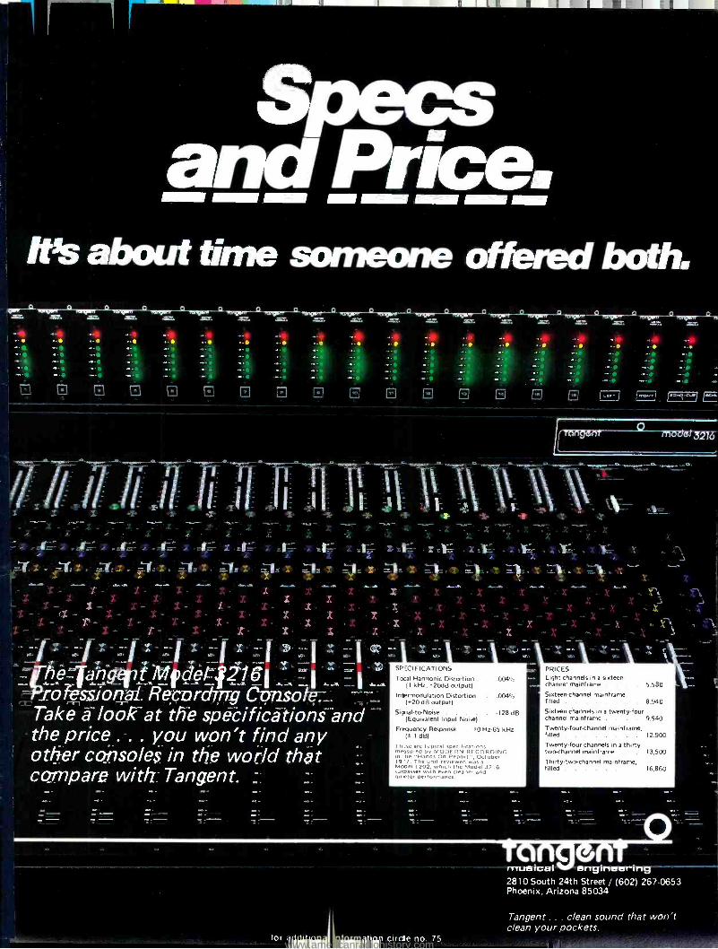
-.
Specs and Price. It's about time someone offered both.
tiiiver---aTiangerm--CLnIpmr--CLmsniodwr-CL ,anu tvg)ner--J'Lleicuanr---CLratierigwv ° minxtrm ° Ait% zaZ. =7. x47.. =T. zVr. AC.
a 1:1 a 1:1
-
-1
-
-X- -sw-
. , . - . , , -S , , , , , , , x x 42:'- , . 4-L7-, , _ Ari--- , .. et.; , ..r=7 , ..V. , ,:a.:.:;:. , =..11;". , A:41 dr,27 x .v.,. ,v- -::,.--,.. . x -,b,- , -.--.. , ,
4'.
r..y. ,.. zcl zr.,:. orp.x. .-,;-.:u x . -...3,.... x ...-.-1. x -..--". x --.4. x ..-.4r, x -4, x -....--.-.1.. x 4. X' ..s.A. x r f . 1 ,. A A A 1 AL..... J11..... y......, ....... 411....IIM .111a111. All...111l ....a AM ........ 41..... ......116 41....i. Am,.
r71 L-J O E
o
..
x -X X
x x x
X.
1--;' -I F7-
1( fangen? mo e 3216 -
1 3
- x - - x x - - x x - -\
- - Y.
x x - X - - - X
fhe_fla:nfivf1;Ififfet4216A ---_ .1
_rofessional Rucording .
Take alook.at the spec. ifications and the price . you won't find any other consoles in the world that compare with Tangent
SPECIFICATIONS
Taal Harmonic Distortion . .004% (I kHz, +20dB output)
I ntermodulation Distortion (+20 dB output)
Signal-to-Noise . . . . -128 dB (Equivalent Input Noise)
Frequency Response . 10 Hz-65 kHz (t 1 dB)
Those are typical specifications rnEssured by MODERN RECORDING In he "Hands-On Report", October 19 7. The unit reviewed was a Model 1202, which the Model 3216 surdasses with even cleaner and nu eter performance.
PRICES Eight channels in a sixteen- channel mainframe . . . 5,580
Sixteen-channel mainframe, filled 8,940 Sixteen channels in a twenty-four channel mainframe . . . . 9,540
Twenty-four-channel mainframe, filled 12 900 Twenty-four channels in a thirty- two-channel mainframe . . 13,500
Thirty-two-channel mainframe, filled 16 860
o angen musicat engineering 2810 South 24th Street / (602) 267-0653 Phoenix, Arizona 85034
Tangent . . clean sound that won't clean your pockets.
tot lb '1 " 7 I circle no 75 www.americanradiohistory.com

tent with similar values quoted by this writer and others in their writings.
To enlighten Mr. Buff on some elementary circuit theory, we com- mend him to Thevenin's Theorem, which he will find well explained in
Terman's Handbook on page 198, and to the maximum power transfer Theorem - also in Terman. If he has a miniature H -P or T.I. calculator he may check our work.
If we consider a resistor (value in ohms is not important), the random noise voltage across its ends is given by the Johnson equation:
1) e= N/KTB4R Plugging in values for K (1.38 x
10 -2') and 290 K (17° C or 63° F as suggested by Friis as a "standard" temperature) we have:
2) KT = 4.002 x 10 -2' watts per cycle bandwidth
Returning to the original equation:
e= /4.002x10- ̀ 2!x4xBxR If B = 15,000 Hz and we square and
divide by R, we have:
3) e2 /R = 2.401 x 10⁻¹⁶ watts
Equation 3 represents the power in watts developed in a resistor of any value by Johnson (thermal) noise in a bandwidth of 15,000 Hz.
Before proceeding further, I must straighten out Mr. Buff on another piece of fundamental engineering. There is scarcely anything (save perhaps noise) that is more misunder- stood and misused than the common decibel. The definition of the decibel (as it was in the beginning, is now, and ever shall be) is: A unit for expressing the ratio of two amounts of power, equal to 10 times the common logarithm of this ratio. Thus the plain old dB is always expressing a ratio of two values of power and never anything else.
If we now assign the value of 1
milliwatt (0.001 watt) to one of the values of power in the dB ratio, we now have a new unit of absolute power in logarithmic form. When one says +30 dBm he is saying the identical thing to 1.0 watt; +47 dBm is identical to 50 watts; +46 dBm is identical to 40 watts, etc., ad nauseam.
Here is where Mr. Buff really leaves the straight and narrow path and gets lost in the briars. He says that dBm only applies when the resistance in which the power is dissipated is 600 ohms and then he invents a new unit called "dBme" when the resistance is any value except 600 ohms. How can this be so? I submit that by fundamental R-e/p 108
definitions that have been in use since about 1940 that this is sheer nonsense. The dBm was brought into being by the committee from NBC, CBS, Bell Labs and others who developed and specified the VU meter. It was a simplified and improvement over the previous hodge -podge of reference powers including the 0.006 watts value. There is no magic about 600 ohms except that if one uses a Hewlett -
Packard voltmeter, he can read directly absolute power in dBm, if and only if he is measuring across 600 ohms. But power is power just like pigs is pigs, and one may have +30 dBm (which is identical to one watt) in any value of resistance from 0.000001 ohm to 1014
ohms. As for dBme - forget that and fast! Get rid of it and never come back!
If we take equation (3) above and multiply by 1,000 we can concert to milliwatts and this it becomes:
4) e2 /R = 2.401 x 10 -" milliwatts (We multiplied by 10' which is the same as dividing by 101
5) Converting to dBm: 10 log10(2.401 x 10-H) _ -126.1961
This is the number of milliwatts, expressed as dBm, which are generat- ed in a resistor of any value and in a bandwidth of 15,000 Hz. But - note Chinn s words that he connects this "generator" to a matched (equal value) load resistance. Under these circum- stances, half the power is dissipated in the "load" (assuming it is not a generator of noise in itself), then the "load" power would be half that of the system of -126.1961 - 3.0103 =
- 129.2064 a figure which agrees with Chinn.
The mathematics of the situation is
considerably simplified by converting the Johnson equation to the "available power" form in this manner:
6) e2 = KTB4R same as equation (1)
7) e2 /4R = KTB watts or KTB x 10' milliwatts
The expression e2 /4R indicates the available noise power from a generator of any resistance in a bandwidth of "B" Hz.
The term "available power" derives from the fact that this is the power which a Thevenin generator (previously referred to and the form to which any active transducer may be reduced) will
deliver to a matched load resistance. Now if if the load is not matched to the generator's internal source impedance, then the load power will be less, but this fact does not alter in any way the
capability of the generator of energy. It
is the capability of power delivery which Friis and I call available power.
By way of a slight diversion, the "dBm rating" of microphones is the available power which the mike will deliver. But that's another story.
If we take equation (7) and assign the value (1) to "B" and convert to dBm:
e2 /4R = -173.977 dBm per cycle of bandwidth.
We can now come up with the available noise power by simply adding 10 log (bandwidth). Thus, if our bandwidth is 20,000 Hz we add 43 "dB" thus:
e2 /4R = -173.977 + 43 = -130.9772 dBm which is the available noise power from any resistor or generator - including microphones.
Now if one matches the amplifier input to the generator, then this noise power will be amplified by the gain of the amplifier and appear in the output. On the other hand, as Friis suggested in 1944 (and people are re- discovering in
1978!) if one carefully mismatches the amplifier input, then the noise transfer- red will be less and the signal -to -noise ratio will be improved. But - this mismatching does not in any way change the value of the noise capability or available noise power from the generator.
Unfortunately, Mr. Buff did not show how he derived his so- called "limit" of -124.8 dBm. Why he did not was not stated.
In actual practice, every amplifier makes a contribution to the system's noise, but it can be shown that only the first stage has any significant effect on the system noise, unless the signal is attenuated so that its level becomes comparable with the thermal noise levels.
The correct method of finding the Equivalent Input Noise (E.I.N.) or Noise Figure is to measure the noise level in the output of the amplifier, and subtract the transducer gain of the amplifier. This gives the E.I.N. and the difference between the E.I.N. and the theoretical value of -131 dBm for 20,000 Hz bandwidth is the Noise Figure.
F'r instance: Transducer Gain = 60 dB Output signal = +4 dBm Signal /Noise Ratio = 70 dB Noise level in output = 4
- 70 = -66 dBm E.I.N. = -66 - 60 = -126 dBm Noise Figure = -131 - ( -126) = 5 dB
On one thing I am in complete agreement with Mr. Buff -that there is much "hanky-panky" and "specsman- ship" in our industry. But that is
www.americanradiohistory.com

The unusual masterpiece : half-inch, eight- track. Otari MX5050.8SD for discriminating recordists.
If you have been thinking eight - track machines are bulky and costly, this unusual one will change your
idea. It's exceptionally compact, yet comes with every feature critical pro- fessional applications require. DC -servo capstan motor for less than 0.05% wow /flutter, with ± 7% pitch control. 63 dB S/N and greater - than -50 dB crosstalk. Selective reproduce on all eight tracks. Motion sensing control logic, front panel edit and adjustable cueing control for fast -mode monitor- ing. Front adjustable bias, record equalization and output level. 600 ohm
+ 4dBm fixed output with XLR con- nectors. And it comes with the latest plug -in card electronics. The compact- ness and performance make it ideal for live recording.
In short, the MX5050 -8SD is an ex- ception of eight -track professional re- corders with performance, reliability and economy internationally proven in hundreds of applications producing high quality 15 and 7-1/2 ips masters. For the full story of this unique model, get in contact with your nearest Otani distributor.
Please send me details on MX5050 -8SD Name
Company
Address
Japan: Otani Electric Co., Ltd., 4-29 -18 Minami Ogfkubo, Suginami -ku, Tokyo 167, Japan U.S.A.: Otani Corporation, 981 Industrial Road, San Carlos, California 94070 Curada: Noresco Manufacturing Co., Ltd., 100 Floral Parkway, Toronto, Ontario M6L 2C5
for additional information circle no. 76
RE/P
R-e/p 109 www.americanradiohistory.com

scarcely a new pheonomenon since the Romans had a word for it: Caveat Emptor - Let the buyer beware. My approach to such things is to under- stand the fundamentals of the situation as I have partially covered in this diatribe, and to go over the mathema- tics of the specifications to see if they check. If something is amiss or an important parameter is missing, then one might write the manufacturer asking for his measurement technique or for the missing parameter, etc. If one does not receive a proper reply - then run, do not walk away from that merchandise. It is a job for the Standards Committee of the Audio Engineering Society to revise the procedures and methodology for measuring audio system performance. At present there is EIA Standard RS- 219 which is rigorous but in need of revision.
Another area of slight agreement is that people get very confused with this "dBv" stuff. As previously stated, dB always refers to power in watts or milliwatts or microwatts or gigawatts or something. dB can never be applied to voltage unless it is specifically stated that the resistance stays the same, or unless the resistance ratio is also stated. The fellow who invented this "dBv" ought to be tarred and feathered and run out of town on a rail as we used to say in West Virginia. It causes nothing but confusion and grief and wrong answers.
One final area of violent disagree- ment with Mr. Buff - I'd hate to measure the performance of a mike preamp with the setup of Figure 2 on page 26. You see, most audio oscilla- tors are not balanced and with the setup shown he is trying to feed a balanced mike input with a network which is only 75 ohms from ground. More troubles! Also wrong answers.
This diatribe has gone on long enough, and is time to stop. Maybe you would be interested in a series of articles on some of the points mention- ed but not amplified, such as micro- phone ratings and what they mean, what gain is and what it isn't; more on noise figure and E.I.N.; more on Thevenin's theorem, etc. I teach at Eastman School of Music every summer during their Recording Seminar and we cover all this in my classes.
In reviewing Mr. Buff's assertions, I
cannot believe that this is a "Christo- pher Columbus" situation where everybody believed that the earth was flat (even though the moon and sun were seen to be round) - all except
R-e/p 110
Christopher Columbus. We live in an age of scientific enlightenment where one scientist's work is and should be reviewed by others. The theory of noise and its ultimate value have been studied by people of eminence since 1928 or so and no faults yet have been found. Rather Mr. Buff appears to me to be like the character who says: "All the world's mad (crazy) except me and thee, and I
have my doubts about thee!" Since Mr. Buff asked for comments,
you may and should forward a copy of this to him for comments. Also, if you so elect, you may publish this in your next issue.
I hope that this straightens him out on some fundamentals.
from: Ronald J. Wickersham Chief Engineer
Alembic, Inc. Sebastapol, CA
By now I am sure that many readers have pointed out the error in the constant "4" in the Thermal Noise Power equation on the first page of the article by Paul C. Buff "Console Noise Specifications ". Don Davis of Syn -Aud- Con pointed out the error to me and in referencing the Amplifier Handbook, Richard F. Shea, Editor -In- Chief, McGraw -Hill, Inc., 1966 Chapter 7, "Amplifier Noise ", by Edward G. Nielsen, on two terminal networks, the noise power indeed does equal kTB, not 4kTB as stated by Buff. Other authorities in the field, notably Van der Ziel in his book Noise, Prentice -Hall, 1954, and the recently published Low Noise Electronic Design, by C. D. Motchenbacher and F. C. Fitchen, John Wiley & Sons, Inc., 1973, agree. And thus the correct number for 0 dB noise figure is -130.8 dBm, agreeing with Buff's method "A" - Transducer Gain Theory.
Also I suggest, that if uniform measurement techniques be adopted for microphone amplifier specifications we keep in line with internationally accepted symbology, and not further create equivalent symbols. I suggest that there is no need for the term defined by Buff as dBme, as he clearly intends the true meaning of the term dBm which he defines incorrectly as being applicable only to measurements made at 600 ohms. Let's let 0 dBm mean power referenced to one milliwatt, period - at any impedance. Also it is confusing to introduce dBme since it is already a Siemens (Germany) sobriquet based on 0.775 volts across a low impedance.
dBv or dBV are both used interna-
tionally as Decibels relative to 1.0 volt with standards people prefering dBV. This reference was first adopted in
Europe but the practice is rapidly spreading to this country, and the latest equipment practice is to make the meter read in dBV only or switchable between dBV (ref. 1.0 Volt) or dBm (ref. 0.775 Volts). Besides, there are a number of commonly used terms for a voltmeter reading of 0 dB = 0.775 volts -- the most accepted U. S. term being dBc standing for "dB Collins ". Siemens (Germany) uses variously, dBe, and dBer for 0.775 volts across a low impedance, and dBu and dBur refer- ence to 0.775 volts (independant of impedance), and in addition to the term dBeff is a Rhode and Schwartz (Germany) epithet referenced to 0.7 volts RMS.
But all of this is just a lot of practice without standardization, and therefore I suggest that uniform terminology with specific debated procedures be gathered into an AES standard, submitted to ANSI and through them to the IEC for an international standard measurement specification to which all microphone preamplifier manufactur- ers could refer. We have achieved such a standard for the weighted flutter measurement and this has reduced the confusion in specifications of this perameter of performance for tape machines.
I thank you and Mr. Buff for addressing this important topic and I
encourage you to keep it alive until the demand for international standardiza- tion results in adoption of a method by which the user can meaningly compare various pieces of equipment.
REPLY TO ALL COMMENTS
by Paul C. Buff
In reading over the numerous letters directed to me, with respect to my article, "Console Noise Specs - Fact or Fiction ?" (December 1977, R -e /p), I
find a rather curious pattern. The console manufacturers (to whom the original article was addressed) have been conspicuously absent in their comment. In fact, the only comments which were received from this group all tended to agree with my conclusions.
On the other hand, I have a stack of letters from people outside the manufacturing community, who criticize my remarks, in no uncertain terms.
At this point, I suppose it comes down to a simple Who's right and Who's wrong situation, with the reader
www.americanradiohistory.com

A JBL MONITOR KNOWS ITS PLACE. A studio monitor is only a tool. It is not
supposed to enhance, add to, subtract from, or in any way modify sound.
That's your job. What a studio monitor is supposed to do
is tell you precisely what's on tape. Because you have to know everything that's there. And everything that isn't. Before it's too late.
That's why JBL monitors are in thousands
of recording and broadcast studios around the world. In fact, according to a national survey by Billboard Magazine, JBL's are in more recording studios than any other brand.
A JBL monitor plays what it's told. Nothing more. Nothing less. If that sounds good to you, contact your nearest JBL Professional Products Studio Equipment Supplier.
And put a JBL monitor in your place.
The 4301: Our newest 2 -way monitor. Com- pact and efficient, for small broadcast control rooms and home studios. $168. The 4311: The most popular monitor going. A compact, full -range 3 -way. $333.
The 4315: An ultra -shallow 4 -way, for maximum sound in minimum space. $783. JBL studio monitors come in three other models, too. All fully compatible for accurate cross referencing.
GET IT ALL.
James L. Lansing S1101-Inc. ' me essional Division. 8500 Balboa Bouleverd, cRfiridgle. Calif
for add tional informal on circle no. 77
www.americanradiohistory.com
Switch to a better idea
Constant tension front-WARNttvc one end of the tape CIRCUITRY AT t
to the other. Elimi- -'-rNSUIT MANUAL BEFf
nate pitch changer D
improve tape handling, extend head life. Fits most profes- sional SET OP
recorders a
and duplicator transperts.
lnovonics' TENTROL Tension Control Kit Series 400 -$300 and up
Inovonics Inc. 503 -8 Vandell Way Campbell, CA 95008 (408) 374 -8300
THE
LambefzLix_ Reproduces the true sounds of
violins, flutes, cello, banjo, bas- soon, and many other instru-
ments, using best quality tapes. Instruments can
be played in single tones or chords.
Uses stereo heads under each key - two Instruments can be
blended together Vol-
urne control; On-off switch Fourteen different instru-
ment combinations with a quick - change selector New patented tape handling mechanism - The Chamberlin can be moved from place to place with no
tape fouling Dependable, easy to service Hard-finish Formica; walnut grain finish.
964 West Ninth Street Upland, California 91786
Phone: 714/985-3017
R-e/p 112
(the customer and ultimate judge) making the decision.
Out of fairness to the authors whose letters appear in this issue, I should point out that their comments were made before publication of my second article on the subject. (February 1978,
R -e /p.) I believe that article offered considerable clarification of the reasons for the differences of opinion.
Before going on to the real meat of the situation, allow me to stand corrected on the proper definition of the term dBm. As several have pointed out, the term, properly defined, is
simply a statement of power relative in decibels to 1 mW at any impedance.
I would, however, take issue with those who state that impedance level need not be specified when the term dBm is used. Without a statement of impedance, the term gives the user no clue as to what the voltage level is, and it is voltage levels which we are really dealing with, in bridging amplifiers.
As for the term dBme, or as Bob Robinette so humorously paraphrased "dBuff ", I cannot take the credit for inventing it. I was given the term by Mr. Tom Hay, so it must, in all fairness, be re -named "dBmci ". In any event, although the term has the potential of having meaningful application, the textbooks don't agree, so forget it.
In order to clean up a couple of minor points, I must support the oscillator circuit which I suggested for testing console inputs. With respect to Mr. Muncy, most commercial oscillators will drive a one ohm load. (Not to full output, of course, but, indeed, to the -50 dBv level required for the job.)
With respect to Mr. Sprinkle, the circuit will properly drive a console mike input, because: A. The circuit shown indicated a Floating oscillator output, not an unbalanced output as he
erroneously stated. B. Even if the oscillator did have an unbalanced output, it would still work, since console mike inputs are not, as he mis- assumed, truly balanced. They are, in fact, effectively Floating inputs, referenced to ground only by the relatively high value phantom powering resistors.
Enough for the minor points. What about the real topic? The authors who expressed varying degrees of rage over my formula Pt = 4KTB, and my subsequent statement that the Theoretical Minimum Noise Level is -124.8 dBm, all talked about "Available Noise Power ", the formula Pt = KTB, and the resultant -130.8 dBm number.
As I pointed out in my second article, it's a lovely formula, and perfectly
applicable when specifying imaginary systems.
For those who may have missed my second article, I will reiterate the requirements which are requisite to use of the formula Pt = KTB:
1. The system must contain equal value, pure resistive source and load resistances. (A Power Matched System.)
2. The load resistor must be noiseless, and held at absolute zero temperature. (An Imaginary Power Matched System.)
The term "Available Power ", while perfectly appropriate in defining signal levels (in a power matched system), is a
completely false misnomer when applied to thermal noise in Real Systems. This is so because the Second Law of Thermodynamics specifically precludes the unilateral transferance, or "dissipation ", or "availability" of thermally induced power, in equal temperature (Real) systems. Indeed, the available power from thermal noise sources in real systems is zero.
In tracing the roots of "Available Power" theory, one must look backward some 30 to 40 years, when most all audio systems were Power Matched - that is to say, each source was terminated with an equal value load. In such systems, a 6 dB drop of potential signal voltage was a necessary evil, when the load was connected. It was, I suppose, logical in those days to assume that the noise voltage would also drop by 6 dB when the source was loaded. This assumption was essentially valid, since the source of the noise, in primitive systems, was not thermal in nature, but was, typically, atmospheric static, carbon mike noise, hum, etc. - sources not subject to reincarnation in the load resistor, and sources which do, indeed, exhibit available power.
In attempting to define what minimum noise levels might be achieved in later systems, devoid of non -thermal noise effects, the "available noise power" theory, together with the formula Pt = KTB, was born. Now, these scientists were not stupid. They obviously were fully aware of the nature of thermal noise. I'm quite certain that they were also fully aware that, in defining the term "Available Thermal Noise Power ", they were, indeed, defining an illusionary, cryogenic load system. No, I'm not concerned with these peoples mentality. My concern is with those who attempt to recite it, and re -apply it, without comprehending it.
I believe that Chinn comprehended
www.americanradiohistory.com

the illusionary nature of the KTB formula, and the basic incredibility of the "Available Noise" theory, as applied to real systems. He showed that, in power matched systems, the load resistor must be an equal contributor of thermal noise to the source resistance. He came up with a minimum EIN of -129 dBm (15 kHz bandwidth). If one translates to a 19,980 Hz bandwidth, his answer becomes -127.8 dBm, and relates to the formula Pt = 2KTB (for real, power matched systems). This 3 dB increase in noise over the illusionary KTB example is due, simply, to the fact that the two noise powers (source and load) bilaterally combine to form a noise power equal to 2KTB in each source and load. The noise of the source /load combination total 4KTB ( -124.8 dBm), as does the true noise power generated thermally within any resistor, be it source, load, heat engine or what -have -you. When two, or more,
Paul C. Buff Paul Buff was born in Los Angeles,
California, on April 24, 1936. Be considers himself fundamentally a self- educated man, and is a strong proponent of the concept of education as a continuing process, rather than an incremental step in the chronology of life.
Paul's formal education consists of the U.S. Marine Corps equivalent of a B.S. Degree in communications electronics, together with two semesters of civilian college electronics.
Since his Marine Corps discharge in 1957, he has had 21 years of self - employed experience as: a musician of sorts, producer, BMI writer, recording engineer, inventor, analog and digital circuit engineer, audio systems engineer and corporate director. He has been self- taught in each of these areas, and has enjoyed commercial success in each distinct field mentioned. - Paul is credited with some five Gold Records, and the engineering and marketing of numerous pieces of professional audio equipment. He is, in many circles, recognized as the father of commercially successful automated mixdown systems.
Paul's most recent interests include ultra low noise transducer amplifiers, and the generation of electricity from solar sources via mechanical heat engines.
Paul is currently founder and director of téchnology for two Nashville based corporations; Allison Research, Inc., and Valley People, Inc. He has been chosen for inclusion in the forthcoming McGraw -Hill publication, Who's Who in Electron- ics.
resistors are joined, the thermal noise power does not change. It simply distributes itself throughout the network. It is always equal to 4KTB as applied to the whole network.
The rules of power match theory, however, ignore the noise of the source, and address only the noise evident in the load. (2KTB = -127.8 dBm.) The physics of power match, on the other hand, necessarily reduce the signal level by 6 dB. Thus, the power match approach imposes a 3 dB reduction of signal -to -noise ratio over what is optimally available from the signal source.
When it was realized that power matching was an ineffective method of achieving optimum S/N ratios, audio systems almost universally adopted the bridging input. In such systems, as typified by today's microphone pre - amps, the source is left as unterminated as possible, in order to allow it to produce its full potential output voltage swing.
As the load is increased from a value equal to the source resistance (power matched) upward to infinity (ideal bridging) the signal rises by 6 dB. The noise voltage, though, rises only 3 dB, thereby improving the S/N ratio by 3 dB. In both cases, as in all cases, the total noise power located at the input terminals is the same, and is equal to 4KTB, or -124.8 dBm.
In the generic classification of "power match", the rules apply, justifyably, to that signal power and noise power appearing in the load, with no regard to what's going on in the source. Thus, the properly stated minimum thermal noise power can be said to be one -half of the total source /load noise, or -127.8 dBm, or 2KTB, for real systems.
In an ideal bridging amplifier, however, the situation is different. Here there is but one circuit element in which thermal noise power exists. The source resistance. As usual, and as always will be, the magnitude of this noise power is equal to 4KTB, or -124.8 dBm. It is, then, totally illogical to refer to anything else when making a statement of equivalent input noise power.
With due respect to Mr. Marlan's statement that "no current flows" (in an unterminated source resistance) I must disagree. While his statement is absolutely true, with respect to signal current, it is not true, with respect to thermal noise currents. From a signal standpoint, the source appears as a true Thevenin generator, (a voltage generator in series with a resistance). As I showed in my second article, the source, from a thermal noise
... concluded on page 130 -
Our New 539 Room Equalizer Blows away BQ hang ups. Our Model 539 is a new advanced -performance version of our popular 529 attenuate only room equalizer. Using the most current filter technology and integrated circuitry, it is now the most quiet, most powerful, smoothest com- bining equalizer of its kind today. The new 539 is also surprisingly low priced (under $700.00). Each of its 27'/2- octave filters provides 15 dB of attenuation to adjust for the desired response curve. Filters combine smoothly for minimum ripple and phase shift. Continuously tunable "band end" cut -off filters attenuate 12 dB per octave, with the hi -cut filter switchable to 6 dB octave. Internal amplifiers furnish up to 20 dB of make -up gain. Completely self contained with built -in power supply. Security cover optional. So, up and away with EQ hang ups. See your UREI dealer today.
8460 San Fernando Road Sun Valley, California 91352 (213) 767 -1000 Exclusive export agent: Gotham Export Corporation, New York
AMPEX440 SLOW GETTING UP TO SPEED?
TRANS TAPE INTERNATIONAL INTRODUCES THE TTI 10440 TORQUE BOOSTER FOR THE
AMPEX 440 SERIES TAPE DECK!
FULL TORQUE IN 100 MS., "ON SPEED" AND TAPERING OUT OF
THE CIRCUIT IN 750 MS.!
A SIGNIFICANT IMPROVEMENT IN
TAPE HANDLING -AND START -UP!
SPECIAL INTRODUCTORY OFFER: $24.95 !
EXCLUSIVELY FROM: L A SOUND Po BOX 1576 SANTA MONICA, CA. 90406 (CALIF. RESIDENTS ADD Gala SALES TAX.)
[213] 473-9756
R-e/p 113 www.americanradiohistory.com

U NEW MICMIX
DYNAFLANGERTM MicMix Audio Products has intro-
duced its new audio effects unit called the Dynaflanger which provides dramatic improvements in the popular comb filter effect known as flanging. Unlike previous equipment of this type, Dynaflanger has the unique capability to dynamically control its effects in response to the program material.
One of the dynamic effects is called Freq -E- Flanging because the resultant notch spacings are frequency enabled. In this mode, Dynaflanger performs a frequency analysis on an incoming program signal and continuously varies the control voltage on its delay line in accordance with the program and the panel control settings. A dynamics tracking switch determines whether the control voltage increases or decreases with an increase in frequency of the program, while another switch sets a CV decay rate to suit the program material. A CV Dynamics control allows setting of the delay time range to correspond to user desires for the program material being processed.
are continuously indicated on a quad - LED display to assure the user of maximum performance.
Both balanced and un- balanced input /output connections are provided, along with provisions for an externally supplied control voltage and a flange defeat or bypass switch. In addition, the unit will furnish a control voltage output in any of its dynamic operating modes. XLR -type connectors are utilized for the balanced lines and 1 /4' phone jacks for all others.
Dynaflanger offers extremely quiet operation and a wide dynamic range. Residual noise is typically -78 dBm for the delayed signal and below -90 dBm for the direct signal. Maximum output level into 600 ohms is +18 dBm, with a distortion figure at that level of 0.03% on direct and a THD of less than 0.8% on a delayed signal at 1 kHz and delay midpoint operation. Comb filter notch depth exceeds 40 dB and frequency mode amplitude rejection is more than 30 dB typically.
Packaged in a standard 1%" x 19" rack panel envelope and only 51/4" deep, the unit operates on 120/240 volts, 50-
Dynaflanger will also operate dynamically in the envelope follower mode, with its control voltages responding to peak amplitudes and the tracking switch selecting a following or inverse response to signal amplitude increases. A quad -LED display indicates the instantaneous value of control voltage being supplied in any operating mode.
The new unit can also be used for standard or non -dynamic type flanging. One control permits the user to manually set or vary the control voltage while a modulator having both rate and depth adjustment allows the input signal to be swept continuously at varying rates and amounts. Flange phasing/depth is fully variable in all operating modes.
Dynaflanger will accept input levels from +18 dB above to 40 dB below a reference of 0.775 volts, making the unit usable with instruments as well as consoles. Peak internal operating levels R -e /p 114
60 Hz. Dynaflanger is said to be the most versatile tool of its type and has a number of applications such a doubling and synthesizer control as well as normal dynamic and standard flanging operation. The unit is priced at $895.00.
MICMIX AUDIO PRODUCTS 2995 LADYBIRD LANE
DALLAS, TX 75220 (214) 352 -3811
for additional information circle no. 82
TROUPER 1 LIVE MUSIC MIXING SYSTEM
Like its bigger brothers, the Trouper 1 is a modular system. The Output Control Module ($749.00 suggested retail value) has eight inputs and the Expander Module has ten for $698.00 (suggested retail value).
Each input contains the following features which separate the Trouper 1
from other mixing systems: low level balanced input, high Z input, in /out jack, 20 dB of mike attenutation,
MCI DEALERS ARE LOCATED THROUGHOUT THE UNITED STATES AND THE ENTIRE WORLD ... AUDIO CONSULTANTS, INC.
Nashville, TN 37212; (615) 256 -6900 Florence, AL 35630; (205) 766 -6624 (Muscle Shoals office)
AUDIO INDUSTRIES CORP. Hollywood, CA 90028; (213) 851 -4111
AUDIO TECHNIQUES, INC. Stamford, CT 06902; (203) 359 -2312
AUSTIN PROFESSIONAL AUDIO, INC. Austin, TX 78701; (512) 477 -3706
MILAM AUDIO CORPORATION Pekin, IL 61554; (309) 346 -3161
PACIFIC RECORDERS and ENGINEERING CORPORATION
San Diego, CA 92121; (714) 453 -3255 SOUND 80, INC.
Minneapolis, MN 55406; (612) 721 -6341 RECORDING STUDIO EQUIPMENT CO. (formerly World Electronics)
N. Miami Beach, FL 33160; (305) 949 -8918
I N T E R N A T I O N A L GERMANY (WEST) -R. BARTH KG,
Hamburg; (011- 49 -40) 229 -8883 HOLLAND -PIETER BOLLEN
Eindhoven; 040-512777 BELGIUM -DELTA EQUIPMENT S.A.
Brussels; (011 -32 -2) 376 -6034 ENGLAND -MCI (Professional Studio Equipment) LTD.
London; (011 -44 -1) 388 -7887 FRANCE -STUDIO EQUIPMENT S.A.
Paris; (011 -33 -1) 647 -6401 SPAIN -SINGLETON PRODUCTIONS
Barcelona; (011 -34 -3) 228 -3800 SWEDEN- TAL OCH TON A.B.
Goteborg; 031 -13 02 05, 13 02 16 CANADA -CHROMACORD CORP.
Lachine, Quebec; (514) 636 -8183 MEXICO -AUDIO Y CONSULTORIA
Mexico 11, D.F.; (905) 584 -2713 ARGENTINA -PLATTEN S.R.L.
Buenos Aires; 31 -7286 COLOMBIA -INGESON LTDA.
Bogota; 43 -60 -44 REMAINING SOUTH and CENTRAL AMERICAN COUNTRIES -H.O. Schleusner Estemac Peruana, S.A.
Lima, Peru; 45 -55 -30 AUSTRALIA -KLARION ENTERPRISES PTY. LTD
South Melbourne; (011 -61 -3) 61 -3801 NEW ZEALAND -CEPAK AUTOMATION LTD.
Wellington; (011 -64) 736 -898 JAPAN -CONTINENTAL FAR EAST, INC.
Tokyo; (011 -81 -3) 583 -8451 KOREA -AUDIO SUPPLY COMPANY
Seoul, PO Box 46, Ma -Po Post Office REPUBLIC of SOUTH AFRICA -VITAPHONE (PTY) LTD.
Johannesburg; 22- 2067/22 -0665 WEST INDIES -PROFESSIONAL SOUND EQUIPMENT LTD.
Kingston 11, Jamaica; 93 -39138 PUERTO RICO -HOPE, BENNETT, BLACKBURN, INC.
Old San Juan; (809) 725 -8668 ITALY -ROJE TELECOMUNICAZIONI S.P.I.
20147 Milano, Italy; (39 -2) 4154141 /2/3 MALAYSIA -DAGANG TEKNIK SDN. BHD.
Kuala Lumpur, Malaysia; 462629
Professional Recording Equipment 4007 Northeast 6th Avenue, Fort Lauderdale, Florida, USA 33334 Phone (305) 566 -2853 / Telex 514362
www.americanradiohistory.com

MCI has sold more than 50 automated consoles in one year - many times more than any other manufacturer.
Plastic Writing Strip
Mute Button Fully illuminated button not a small LED. Custom built by MCI to provide sharp snap action with only .050" travel. This mute button can also function as a "Quad in place" solo.
MCI VCA Fader Custom conductive plastic fader gives optimum dB scale for easy control.
Direction Indicator Tells which direction to move the fader for "Null ".
Write Button
Update Button
Master Select This button tells the automation you would like to make this fader a group master. When made a group master the channel VCA value is held and added to the group value. If you revert this fader from group master to local the group value is held while you correct the channel value. When the fader is a group master fader the automation controls act as group master controls.
Group Selection
v4
LWRITE T o 0
(1 A T
I
j -MASTER
V 4
A
Selects group buses 1 thru 8 and local.
rofessional Recording Equipment. \%\« %\E STANDARD OF THE INDUSTRY.
4007 NE 6th Avenue, Ft. Lauderdale, FL USA 33334 Telephone (305) 566 -2853 /Telex 514362
for additional information circle no. 83
Ask yourself: `WHY ?' MCI's JH -50 automation package, the most usable automation available anywhere today, has already been proven on the JH -500 series - in fact, more than 50 consoles since its introduction in January 1977.
JH -50 automation is now also incorporated in the JH -400B series consoles.
Sophisticated processor logic eliminates controls and complex operation procedures still inherent to many automation systems. Level nulling between modes is controlled by the JH -50 automation, creating operating procedures human -engineered to free the operator of time - consuming setup and null routines.
Why is MCI outdistancing all other manufacturers? Because MCI simplicity, reliability and commitment to ergonomics results in a functional system, and makes MCI the standard of the industry.
SEE MCI'S DISPLAY AT THE L.A. AES SHOW, BOOTHS 83 -87 AND A DEMONSTRATION OF THE JH -50 SYSTEM IN THE ASSEMBLY ROOM CENTER.
R-e/p 115
www.americanradiohistory.com

monitor send, echo send, three band graphic equalizers, solo switch for individual channel monitoring by the operator (incidentally the VU meter follows the solo system giving you a visual as well as audible indication of each input and output), and the input mix control.
The Output Control Module, besides having eight inputs with the same features as above, include: house and monitor outputs, echo /send receive jacks, headphone jack, solid state LED VU meter, echo send master to the built -in reverb, headphone level control, house /monitor echo receive, high/low cut filters, and house /monitor level controls.
The Trouper 1 Expander and Control Module couple together simply
by console interconnection and the supplied umbilical cable. It gives 18 inputs of quiet, heavy duty mixing ability. It is rack mountable and available in heavy duty carrying cases built for the road. Choose between two models holding one unit each or holding both expander and output control module.
UNI -SYNC, INC. 742 HAMPSHIRE ROAD
WESTLAKE VILLAGE, CA 91361 (805) 497 -0766
for additional information circle no. 84
NEW WHITE SERIES 4300 ONE -SIXTH OCTAVE
EQUALIZERS AND REAL TIME ANALYZERS
Features of the new equalizers include one -sixth octave resolution from 40 Hz through 894 Hz and one - third octave resolution from 1,000 Hz through 16 kHz. The adjustment range is ±10 dB using Mil -Spec rotary controls. Optional plug -in low -level crossover networks facilitate either bi- amp or tri -amp outputs to the power amplifiers.
Preliminary field testing in Nashville, Los Angeles and Austin has shown a marked "smoothing" or "tightening" of
BRINGING TH
E TECH NOLOG
Y WITHIN EVE
RYONE'S REA
CH. Sound Workshop PROFESSIONAL AUDIO PRODUCTS
Sound Workshop Professional Audio Products, Inc. 1324 Motor Parkway, Hauppauge, New York 11787 (516) 582 -6210
R -e /p 116
the low frequency response of the rooms tested. These rooms had been tuned previously with one -third octave equalizers.
White Instruments, Inc., also offers one -sixth octave real time analyzers to be used in conjunction with the new one -sixth octave equalizers.
WHITE INSTRUMENTS, INC. P. O. BOX 698
AUSTIN, TX 78767 (512) 892 -0752
for additional information circle no. 85
PEAVEY KM -4 KEYBOARD MIXER
The new Peavey KM -4 Keyboard Mixer has been designed to answer the requirement for a versatile mixer for use with keyboard instruments.
The KM -4's unique packaging allows the unit to be used, on top, or sandwiched between the cabinets of the various keyboard instruments in use.
Channel one of the KM -4 features a complete 5 -band Equalizer allowing adjustment of the five critical bands of frequencies and associated overtones produced by the piano. Channels two, three, and four feature 3 -band active equalization circuits for synthesizers, organs, and keyboard instruments other than the piano. Other KM -4 features include: wide dynamic range input circuitry, buffered transformer coupled high level line outputs, high and low level inputs on each channel, pre - amp send and return from each channel, effects send each channel, reverb, three line outputs, and stereo headphone out.
Suggested retail price of the KM -4 is $349.50. PEAVEY ELECTRONICS CORP.
MERIDIAN, MS 39301 for additional information circle no. 86
NEUTRIK INTRODUCES THE AD -4 ANALOG AUDIO DELAY
Available at an attractive price point, suggested professional user net of
www.americanradiohistory.com
Some people buy us for our fader
because ours is better than any you can buy elsewhere. Ours has all the features you need, like smooth action, accurate tracking, long life and low noise, plus a full 85 dB attenuation. And ours is coffee proof. It's just one more reason an Auditronics mixer is a better investment for the long haul. To learn more, circle reader service number or write to us for complete information.
Lt's coffee proof a f, auditronic ince
3750 Old Getwell Road, Memphis, Tennessee 38118 / (901) 362 -1350
for additional information circle no 87 R-e/p 117
www.americanradiohistory.com

$795.00, the AD -4 is said to be extremely useful for establishing a virtual sound source and improving speed and /or music articulation in distributed- speaker sound- reinforce- ment installations, as well as for generating special effects and ambience (or enhancing reverb delay) in record- ing applications.
AD -4 "bucket brigade" design, employing charge- coupled devices and steep Butterworth filters offers four discrete, time -incremented, delayed outputs - all commonly and continu- ously adjustable over a 4:1 range (12.5 -
50 msec, 25 - 100 msec, 37.5 - 50 msec and 50 - 200 msec) and each indepen- dently adjustable in output level.
The unit features a low- distortion input- limiting amplifier with three position Time -Constant /Defeat switch (Slow, Fast, Off) to suit music and speech characteristics, plus LED Overload /Limiter indicator and continuously adjustable sensitivity (10 mV to 10 volts for +18 dBm output). Unbalanced inputs and outputs use professional XLR -type connectors. Toroidal dual- voltage power transfor- mer and regulated power supply for stable, low -noise operation on either 110 or 220 volts.
The compact rack -mount unit is 1.75 inches high x 19.0 inches wide x 8.5 inches deep. Supplied complete with three -conductor power cable and three -pole grounding plug.
PHILIPS AUDIO VIDEO SYSTEMS CORPORATION
91 MCKEE DRIVE MAHWAH, NJ 07430
(212) 697 -3600 for additional information circle no. 88
A NEW 1024 -STAGE BBD JOINS PANASONIC
BBD FAMILY A new wide- range, low noise BBD
(Bucket Brigade Device) is now avail- able from Panasonic Company. Desig- nated as "BBD3007 ", it comes in a DIP (dual -in -line) 8 -lead plastic package offering a variable delay time of 5.12 msec to 51.2 msec, low insertion loss (0 dB), wide dynamic range (S /N of 82 dB), wide frequency response (up to 40 kHz), clock frequency up to 100 kHz, low noise (250 pVrms), and very low harmonic distortion (0.5% max.).
According to Bill Bottari, Panasonic Product Manager: "The new BBD3007
SAVE 10% ON YOUR NEXT RECORD PRESSING ORDER!!! QCA Custom Pressing has gained the reputation of being one of the finest pressing facilities in the country, offering every stage of record manufacturing "Under One Roof," mastering, plating, typesetting, color separations, printing, pressing, and packaging.
As an introductory offer, we are allowing a 10% discount with the initial order from any customer All you need to do is fill out the coupon below and send it in with your order.
, ; i`
'
; :
7 :. ï i N"7 ft .J. -
ÿ'- á --
1' ..,
-_.
. , . .
; .
>
' i .
U.7.
.,_ \`-, r '..:114 . 1. . h r, .L' ,.::,-.:,. . , ,
10% DISCOUNT With this coupon Expires 6/31/78 This is my first order. QI have ordered before. °Send more info.
NAME ADDRESS CITY ZIP
STATE PHONE
Qca QCA CUSTOM PRESSING, INC. 2832 Spring Grove Ave. Cincinnati, Ohio 45225 PHONE: (513) 681 -8400
R-e/p 118
represents a 10 dB improvement over previously attainable state -of- the -art. This, coupled with its low noise figure, makes the BBD3007 ideally suited for obtaining tremolo, vibrato, and /or chorus effects in electronic musical in- struments; variable or fixed delays of analog signals; telephone time com- pression and voice scrambling in com- munication systems. With seven BBDs in Panasonic's BBD family (BBD3001 through BBD3007), electronic equip- ment designers should be able to select the right BBD for their cost /perfor- mance requirements.
The new BBD3007 is available on 6- week delivery. OEM prices are avail- able on request.
PANASONIC COMPANY ONE PANASONIC WAY SECAUCUS, NJ 07094
(201) 348 -7276
for additional information circle no. 89
NEW E -V SERIES OF STAGE SPEAKER SYSTEMS
The S12-2 is a two -way system; the S15 -3 is a three -way. Both systems claim to be exceedingly accurate with the S15 -3 being virtually flat down to 50 Hz. The S12 -2 uses the EVM12L while the 515 -3 uses the EVM15L for low - frequency reproduction. The upper limits of both systems is 16,000 Hz. By using the ST350A tweeter, a driver also, found in E -V's studio monitor speakers, these systems are able to project high frequencies uniformly over an extraor- dinarily wide 120° angle. Power handling capability is 100 watts RMS for each system.
The S15-3 applies the design theories of A. N. Thiele and R. H. Small, theories previously restricted to low frequency reproduction, and developed a vented mid -range cone speaker. This design, it is said, makes it possible to achieve high sound pressure levels (up to 116 dB) without resorting to a horn mid -range driver. An accurate horn would have
www.americanradiohistory.com

listening is your profession ...
........11Iiiiimomp' \ we've got som ros should meet If you spend long, strenuous hours listening to high -level sound, you can't afford to be fatigued by distortion or distracted by poor
4 quality audio. You've got to have the best low- distortion monitors with top power capacity and extended bandwidth that money can buy.
The answer -the professionals from Altec.
Recording studios worldwide rely on Altec studio monitors to deliver tight, crisp, accurate playback in the most crucial of professional audio environments.
As standards in the recording industry for over
NW .4' a quarter century, Altec monitors offer high efficiency, wide dynamic range and the distortion -free power required to help you make the right listening judgments.
For further information on Altec's line of studio monitors, including the Models 620/604 and 9ß49 shown above, please write to Altec Sound Products Division, Commercial Sales Department,`
ALTEC 1515 So Manchester Ave., Anaheim, Calif. 92803 714/774 29(10 Z/lsolrind of expefìeov._ AI EC CORPORATION
tor additional information circle no 90 R-e/p 119
www.americanradiohistory.com

¡For the very best Studio Construction available .. .
usually wears nail bags -
carries hammer and tape - drives crew very hard
':) h and smiles all the while ! !
Occasionally, he's caught looking at plans. Is also known for doing work all
l' over North America, giving firm estimates, exacting dates of completion and
f' No BULL ! !
ik -.
$;,
He pleads guilty of con- structing the following studios :
Century 21, Winnipeg, Canada, new studio
Sound Interchange, Toronto, Canada, new studio Superscope, San Fernando, California, new studio
Chicago Recording Company, Chicago, Illinois, Studios 1, 2 and 3
Bill Szymczyk's Bayshore Recording Studios, Inc., Coconut Grove, Florida, new studio The Shade Tree Playboy Club Lake Geneva, Wisconsin new studio Group Four, Hollywood, Calif.
é KBK Earth City Studios St. Louis, Missouri
Village Recorders new studio under construction
He leaves a trail of 'Happy Customers', and is easy to follow ... and his prices are fantastic ! ! !
Call for information and details
RUDOLF A. BREUER
ä 805 / 273 -3792 Lic. No. 238315
R-e/p 120
been far too large for the desired small enclosure, and the use of the vented mid -range cone driver eliminates the pinched, "honky" sound normally associated with small horns. The result - mid -ranges with a warm, robust quality from a driver with modest size and high output capability.
Both systems are surprising small considering the amount and quality of the sound they produce. This should be a real boon to the touring band that is strapped for equipment space. The grille cloth is actually a metal mesh designed to protect the drivers against various kinds of abuse. Fail -safe tweeter protection is provided by Electro- Voice's high- frequency auto limiting circuit.
Suggested prices for the two systems are $350.00 for the S 12 -2 and $550.00 for the S15 -3. (Prices slightly higher in the Western states.)
ELECTRO- VOICE, INC. 600 CECIL STREET
BUCHANAN, MI 49107 (616) 695 -6831
for additional information circle no. 92
LEXICON ANNOUNCES "PRIME TIME" DIGITAL
DELAY PROCESSOR Prime Time combines digital audio
delays, VCO time base processing and complete mixing facilities in a single package with self- contained power supply.
The mixer section allows use with an outboard reverb unit or other signal processor. An echo return mix is achieved by a combination of the two internal delays, input, and an auxiliary return allowing highly flexible and convenient echo sub -mix processing, thus freeing channels on the master console. In addition, delays can be recirculated via a second mixing bus for the creation of reverb effects.
Several special effects are provided such as Doppler pitch shift, natural double and triple tracking, flanging and vibrato via the VCO time base modulator. A delay multiplier control provides extended delays up to two
seconds, which with a Repeat /Hold control, allows a rhythm track to be repeated indefinitely with no degrada- tion of the original audio signal. For concert use, the major dynamic functions are remoteable to the entertainer's foot pedal controls.
Features include two independently adjustable delay outputs with separate digital displays. Delays may be smoothly and continously varied to 50% of the selected value. The standard configuration contains full band -pass delays to 128 ms which may be field expanded to 256 ms by a plug -in memory extension option. Both inputs are balanced and the output mix is balanced/transformer coupled.
Prime Time is designed having a dynamic range in excess of 90 dB and THD of less than 0.1% at all delay settings. The system occupies 31/2" of panel space and weighs 9 lbs. It is designed for reliable operation under the rigors of road use in sound systems.
The standard unit is priced at $1,485.00, and the optional memory extension option is $175.00. According to Keith Worsley, Lexicon's Pro Audio Sales Manager, "Prime Time will provide a flexible, easy -to -use delay processing sub - system of full profess- ional quality that will be within economic reach of most studios and professional entertainers."
LEXICON, INC. 60 TURNER STREET WALTHAM, MS 02154
(617) 891 -6790
for additional information circle no. 93
COMMUNITY LIGHT & SOUND INTRODUCES 'ZOIDS
Community Light & Sound will ex- hibit its entire line of fiberglass horns and introduce a new line called the 'Zoids - a new concept in packaged radial horns. 'Zoids eliminate the nec- essity of building wooden boxes to en- close horns used in touring sound sys- tems. Community's 'Zoids include the horn and outer stackable enclosure formed in one piece with foam sand- wiched solidly between to eliminate un- wanted resonances. The mainstay of the 'Zoid line is a new mid -range radial horn in a sixty degree configuration that accepts either a 10" or 12" loudspeaker, is usable as low as 150 Hz, and produces a dramatic increase in mid -range trans-
www.americanradiohistory.com

the (w)hole story For years, SAE has been producing "state -of- the -art" separate components that offer value, quality and performance. That experience has now been applied to a line of integrated amplifiers. But what's the hole for? The answer is, ultimate performance!
Unlike others, our integrateds are identical to our separates with the same designs and component parts already proven in SAE preamps and amps. But that's not all - in each of our integrateds the preamp and amp section is entirely separated (even the power supply !). The preamp section, which is
. identical to our 2900 (or 3000, depending on the model) has its inputs and outputs near the front (hence the need for the hole), while the amp section (2200 or 3100) is at the rear. The only common parts are the chassis and the power switch. This unusual "U" shape design provides isolation of low and high level circuits, while retaining easy access to inputs and outputs (now only 3.5" behind the front panel).
These new units are so unique we don't consider them integrateds. Instead, we call them preamp/ amps. They meet all the goals of an ideal integrated; (1) Convenience of an integrated design; (2) Excellent value due to reduced packaging costs; 3) The performance of separate components. Na matter which of SAE's preamp /amps you choose - the 2922 with parametric EQ and 100 watts* per channel, 3022 with tone controls and 100 watts* per channel or the 3031 with tone controls and 50 watts* per channel , you are assured of SAE performance, quality and value. The preamp /amps are truly integrated separates. And that's the whole story.
*Per FTC Rating @ 8 ohms
For Complete Information Write:
Scientific Audio Electronics, Inc. P.O. Box 60271 Terminal Annex, Los Angeles, CA 90060
r---A1IAMETw/C [CUAtRE11 ... . ............ .. -- .,._:. irM SE1111Ett ,. M.S M I/ 414 Ottt t
LEVEL
M 1.M RM Rta tpt
TAPS - -_ EItECT011 -- ap. 2 owe ...p, w i1tl.P l
maue. .o t gawp, 1-2 Me
a r.ApOWOTÑ In, l II i 111 i 'v.uieiE
for additional information circle no. 94
2922 Pre -amp /Amp
R-e/p 121
www.americanradiohistory.com

ient accuracy and SPL. All 'Zoids are stackable, exhibit far less resonance than box -enclosed horns and weigh less than half as much. COMMUNITY LIGHT & SOUND
5701 GRAYS AVENUE PHILADELPHIA, PA 19143
(215) 727 -0900 for additional information circle no. 96
dbx INTRODUCES FOUR -TRACK PRO -FORMAT
TAPE NOISE REDUCTION FOR UNDER $500.00
Identified as the Model 155, dbx, Inc., has added a new professional- format four -track tape noise reduction system to its product line. The system's nationally- advertised value of under $500.00 places pro -type noise reduction within economic reach of almost any small studio or semi -professional
recordist. "Until now," dbx national marketing
manager Larry Blakely noted, "record- ists might invest in a sophisticated four - track tape recorder, and find that outboard noise reduction cost as much or more than the machine. Too often, this has meant leaving noise reduction out of the studio budget altogether. But it's important to realize that when you bounce tracks and combine tracks in mixdown, the noise level builds up sharply. With professional noise reduction available at this price, no one who is seriously involved in tape recording has to tolerate this excessive noise."
The Model 155 tape noise reduction system, like other dbx professional and consumer systems, eliminates audible tape hiss, thereby permitting multiple track bouncing and mixing without audible noise build up. It does so by
providing 30 dB of noise reduction over the entire audio spectrum, at all levels. It also permits an extra 10 dB of recording level headroom, dbx claims. The 155 accomplishes this feat through retrievable compression - halving music's dynamic range at the input, then expanding it by a mirror -image ratio of 1:2 at the output.
In playback, the 155 completely restores the music's dynamic range so it is indistinguishable from the original, with no audible tape noise added by the tape recording process.
The dbx proprietary system of RMS detection /voltage -controlled amplifica- tion eliminates any need for level matching procedures, since compress- ion /expansion is linear.
Each channel of the 155 is completely switchable from the front panel to record (encode), play (decode) and bypass functions, permitting either four channel switchable or two channel simultaneous operation. Record and play level adjustments are provided on the front panel. It also features user - changeable circuit boards for each channel. The user may order spares to keep on hand. Rack mount kits to accommodate either a single or pair of 155's are also available.
Ir
ifiARSHALL ELECTROflIC IS PLEASED TO ANNOUNCE THE UNVEILING OF SEVERAL RATHER INTERESTING NEW DEVICES
MARSHALL ifiARSHALL LINIE 7 N B=JAg QONlE000
MARSHALL ELECTRONIC IS A DIVISION OF UNITED STATES AUDIO, INC., BOX 177, JOPPA, MD 21085 (301) 679 -4837
R-e/p 122 for additional information circle no. 95
www.americanradiohistory.com

The dbx 155 four channel tape noise reduction system is fully compatible with dbx models 152, 154, 157, 158, 177, 187, and 216, as well a TEAC /Tascam DX -4, DX -8 and other on -board dbx pro- format tape noise reduction systems.
dbx, Inc. 71 CHAPEL STREET NEWTON, MS 02195
(617) 964 -3210 for additional information circle no. 97
NEW MXR EQUALIZERS The two new product additions to the
MXR group of professional products are identified as the Dual Fifteen Band Equalizer and the Thirty One Band Equalizer.
different time -related effects. The DN36 is available from Klark-
Teknik distributors and has a suggest- ed price of $1,499.00.00. HAMMOND INDUSTRIES, INC.
155 MICHAEL DRIVE SYOSSET, NY 11791
(516) 364 -1900 Gor additional information circle no. 99
NEW SOUND APPLICATIONS COLOR CODED CABLE
ASSEMBLIES The SA -191 professional lines of pre -
assembled audio cable is available in a choice of seven colors and two
thicknesses. The cable jacket
polyurethane which is a modified combines the
Both units feature level controls; front panel bypass and power switches; standard 19 -inch (483 mm) rack mount; 12 dB boost and cut on all controls; and active balanced inputs.
The Dual Fifteen Band Equalizer is priced at $325.00. The Thirty One Band Equalizer at $350.00.
MXR INNOVATIONS, INC. 247 N. GOODMAN STREET
ROCHESTER, NY 14607 (716) 442 -5320
for additional information circle no. 98
KLARK -TEKNIK DN36 ANALOG -TIME PROCESSOR Primarily designed for studio use, the
DN36 A. T. P. is a 19" dual -channel multi- effect device with a frequency response of 20 - 15 kHz and distortion less than .2 %.
The DN36 A. T. P. gives a multitude
of effects such as phasing, flanging, reverb, doppler shift, and using an external ramp generator, can also provide harmonizing. The unit is supplied complete with an applications manual and cassette demonstration tape describing how to achieve many
Professional performers for stage and studc'...f om ATLAS SOUND, the world's leading manufacturer of microphone stands and booms.
- Take these Porta -Stand headliners, for ex- aiid, `o _roir o stud os the mobile model
ample. For today's artist there's Model PS -C, SE 100W 3acrn, 9°t. long, with its unique flex -
America's first floor stand with spring- action ibl drive telance- contrcl and 350° micro -
telescoping legs, most practical where mobil- ity or transportation costs are a consideration.
For acts that have their ups and downs, Model PS -S features our exclusive touch - control clutch that makes height adjustment so easy, you can raise and lower the micro- phone with one hand tied behind your back.
There is Model PB -1, one of a series of new easy- adjustment microphone boom attachments which fit all ATLAS SOUND microphone floor stands.
phole- cl cam. There are even two new desk -top micro -
phone stands - one of decorative Carrara marble, the other with a vibration -isolating base for sound- absorption no matter how strong the beat.
For details on these and other microphone stands accessories headliners, Contact:
ATLAS SOUND. Division of American 4.01L011111° Trading anc Production Corporation,
10 Pomeroy Road, Parsippany, NJ 07054; Tel. (201) 887 -7800.
for additional information circle no. 100
76
R-e/p 125
www.americanradiohistory.com

4icidio Ta for professionals
REEL TO HEEL TAPE Ampex, 3M. All grades. On reels or hubs.
CASSETTES, C- 10 -C -90, With Agfa, Ampex, 3M tape.
LEADER & SPLICING TAPE
EMPTY REELS & BOXES All widths, sizes. - it RI. FRO\1 SIOCK -
For your catalog, call or write: Jim Worth
Recording Supply Co. 1233 Rand Road Des Plaines, IL 60016 1
Div of Poivline Corp
1HE SVUDIO CO4G4 DR c rib
TheLP conga has been neerbs
ed as a recording en
and with good reason well.
dream conga records as w No other No
other conga is as
R-e, p 126
advantages of both rubber and vinyl making it resistant to abrasions and solvents. The inner conductors are made up of 45 strands of tinned cadmium bronze for an optimum combination of strength and flexibility. The shielding is a combination of braided tinned copper wire and a conductive fabric tape wrap providing 100% shielding while also improving the cables' flexibility, flex life and mechani- cal strength.
The SA -191 series cable assemblies are available in many configurations including microphone cables, guitar cords, patch cords, headphone cables and adaptors. All assemblies are complemented by Switchcraft connec- tors.
There are also available speaker cable and multi -cable assemblies of high quality.
SOUND APPLICATIONS, LTD. 342 LEXINGTON AVENUE MOUNT KISCO, NY 10549
(914) 241 -0034 for additional information circle no. 103
ATLAS SOUND INTRODUCES PORTA SERIES MICROPHONE
BOOM ATTACHMENTS The new booms are said to offer
maximum functional flexibility and convenience in operation, and make it possible to maintain close proximity between the microphone and its sound source. They are designer -styled for use on stage or in studio, by perform- ers, musicians or vocalists, and with sound reinforcement systems or recording activities.
Each of the booms is supplied with a die -cast zinc swivel equipped with oversized hardware for operational convenience. The chrome -plated steel tubing terminates in 5/8 -inch - 27 male thread or adaptor for use with all standard microphone holders.
Model PB -1 is 31- inches long. Model PB -1X, particularly suited for use by choirs or for application in conjunction with percussion and keyboard instru- ment- miking, is adjustable in length from 31- inches to 50- inches. Both of
f
these new boom attachments include a tapered counterweight to allow variable and precise positioning for optimum balance.
Lightweight model PB -2X telescopes from 21- inches to 40- inches, and is recommended for portable use in conjunction with audience-participa - tion or, as preferred by many contem- porary performers, as a short horizon- tal extension of any microphone floor stand.
ATLAS SOUND 10 POMEROY ROAD
PARSIPPANY, NJ 07054 (201) 887 -7800
for additional information circle no. 104
ROLAND DC -10 ANALOG ECHO UNIT
The lightweight (2.8 kg) Model DC -10 Analog Echo Unit features stereo output and allows remote control of echo effect through an optional
footswitch. Single delays, acoustic echo effects, sustained echos and chorus effects similar to those achieved by a phase shifter can be achieved, but all of them can be bypassed by the foot - switch, which changes the effects instantly to direct, unaffected sound. A three -position input selector ( -20, -35, -50 dB) makes it easy to accept nearly any kind of input.
Tom Beckman, president of Roland - Corp, U. S., said the DC -10 carries a suggested retail of $390.00 and is available for immediate delivery.
ROLAND CORP., U. S. 2401 SAYBROOK AVENUE LOS ANGELES, CA 90040
(213) 685 -5141 for additional information circle no. 105
MODULE INTERFACES VOICE AND INSTRUMENTS TO
SYNTHESIZERS The Aries AR -333 Pitch and Enve-
lope Follower is an electronic module that lets the user interface external signal sources, such as voice, single note instruments, and tape recorders, to most syntheiszers. A one octave change of input signal produces a one volt change in pitch control output for controlling V. C. oscillator frequency, filter frequency, and so on. Linear and logarithmic envelope follower outputs allow you to control synthesizer
www.americanradiohistory.com

functions, such as V. C. filter frequen- cy, pulse width, and filter resonance, by the amplitude of the input signal.
On the Aries AR -333 front panel, a trim -pot allows adjustment of the tracking sensitivity of the pitch control output, and permits use of the module with different synthesizers without re- trimming oscillators. The front panel also provides a tuning control for
PITCH FOLLOWER
LIME LEVEL
TRIG SEMS
GRING
.R -333
adjusting oscillator frequency which allows tuning to the pitch of other instruments, and a re- triggering sensitivity control for picking up accents. A low -distortion compressor output is also provided. The module's 36 dB, low -noise mike pre -amp accepts 1/4" phone plugs.
The Aries -333 sells for $349.00 (kit) and $499.00 (assembled). An assemb- led AR -333 with case and power supply (Model GE -101) sells for $550.00.
ARIES MUSIC, INC. SHETLAND INDUSTRIAL PARK
BOX 3065 SALEM, MA 01790
(617) 744 -2400 for additional information circle no. 106
ALTEC 604 E -2 SPEAKERS FROM AUDIOMARKETING
Audiomarketing, Ltd., introduces the new 604 E -2 speakers by Altec for use in the Big Red and Super Red monitoring systems. The 604 E -2 has been re- designed to handle 140 watts of power which will provide an increase in sound pressure level of 6 dB. This technological advance greatly reduces the costly problem of speaker blow -up caused by the high sound pressure levels in recording studios.
The Big Red and Super Red systems are the standard reference monitors for hundreds of studios throughout the
country. The 604 E -2 speaker will enable these sytems to have four times the power handling capability without changing their sound quality or appearance.
AUDIOMARKETING, LTD. 142 HAMILTON AVENUE
STAMFORD, CT 06902 (203) 359 -2315
for additional information circle no. 107
CLASSIFIED ADVERTISING RATES
- $40.00 Per Column Inch - (2r%i" x 1 ")
One inch minimum, four inches max- imum. Space over four inches will be charged for at regular display advertising rates.
BOOKS
SOUND SYSTEM ENGINEERING by Don d Carolyn Davis
296 pages 81401 Hardbound $19.95
R -e /p BOOKS P.O. Box 2449
HOLLYWOOD, CA 90028
SOUND RECORDING by John Eargle JME Associates
"The best book on the technical side of recording . . .
thoroughly recommended." -Studio Sound
338 Pages, illustrated with 232 tables,
curves, schematic diagrams, photographs
and cutaway views of equipment. $16.95 each
R -e /p BOOKS P. O. BOX 2449
HOLLYWOOD, CA 90028
MICROPHONES: DESIGN and APPLICATION
by Lou Burroughs A practical, non -theoretical reference
manual for those involved in the application of microphones for recording,
TV, motion pictures, sound reinforcement.
Hardcover - $20.00 R -e /p Books
P.O. Box 2449 Hollywood, CA 90028
. theory and working information with emphasis on practical uses . . .
"MICROPHONES - HOW THEY WORK AND HOW
TO USE THEM" by Martin Clifford
224 Pages - 97 Illustrations $8.95 Hardbound; $5.95 Paperback
Postpaid R-s /p Books
P.O. Box 2449 Hollywood, CA 90028
Direct Box Professionally Built for
Studio & Road Use
Switchable Ground (DB -3) or Unique Automatic Grounding System (DB -2)
Jensen Transformer
Accepts all levels, pickup to 400 -W amp
Switchable filter for "miked speaker" sound
Won't change the sound of your instrument
Diecast, engraved box; shock -mounted switches
0ne year warranty
DB -2 $74.95 DB -3 $84.95 for Studio Use for S. R. Use
Ask about our snakes, cables and
other "goodies in little black boxes."
Windt Audio Inc. 1207 N. Western Ave. Los Angeles, CA 90029 (213) 466 -1271
IF YOU WANT TO LEARN RECORDING ENGINEERING
AND THE MUSIC BUSINESS - AND YOU UNDERSTAND THAT
SUCCESS IS A RESULT OF HARD WORK AND DEDICATION
. . . Then you owe it to yourself to investigate the only school of its kind that is an ACCREDITED member of NATTS, and is APPROVED by the California Superintendent of Public Instruction to teach these courses. We have been teaching Music Law, Recording, Business, Engineering, Production, Disc Mastering and other allied courses in a three semester Diploma Program that is so effective more than two- thirds of our gradu- ates are working in the Industry. Before wasting your money and time by attending an unlicensed school, call for an appointment to visit our studio, sit in on a class and receive our catalog.
College for Recording Arts 665 Harrison Street San Francisco, California 94107 (415) 781 -6306
SEMESTER BEGINS JUNE 12TH
R-e/p 127
www.americanradiohistory.com

BOOKS
HANDBOOK OF MULTICHANNEL
RECORDING by F. A /ton Everest
320 pages - 201 illustrations The book that covers it all ...
a comprehensive guide to all facets of multi -track recording ... acoustics ...
construction ... studio design ... equipment ... techniques ... and
much, much more. Hardbound $10.95 Paperback $7.95
R -e /p Books P.O. Box 2449 Hollywood, CA 90028
EDUCATION
Intensive Summer Workshops in Recording Techniques, Electronics, Electronic Music, Jazz Improvisation, Instrumental Master Classes. Write Frank Stachow,
LEBANON VALLEY COLLEGE ANNVILLE, PA 17003
OPPORTUNITIES
WANTED: Partner, young, ambitious man or woman interested in a part- nership in a recording studio in Nashville, L.A., or elsewhere. Write:
Randy Carter 317 Liberty St. Steele, MO 63877
The following used Neve Consoles are available fully refurbished and with 12 months factory warranty, subject to prior sale.
CUSTOM 28 in /24 track Extensive EQ, separate monitor mix - down section on right hand side of console. Built -in patch. 4 years old, but in excellent refurbished condit- ion. Available June. $52,000 FOB N.Y.
MODEL 8036 24 in /16 track Very extensive EQ (1081), separate monitor mixdown section on right hand side of console. Built -in patch. 3 years old, but in excellent refurbished condition. Available June. $45,000 FOB N.Y.
FINANCING AVAILABLE Subject to our terms, financing is available on the above used consoles. $20,000 cash, balance over 24 months. Sales taxes not included. Please call.
Bethel, Conn. - (203) 744 -6230 Malton, Ontario - (416) 677 -6611
A/ Neve R-e/p 128
EQUIPMENT
FREE CATALOG & AUDIO APPLICATIONS CONSOLES
KITS L WIRED AMPLIFIERS
MIC., Ea,ACN,LINE, TAPE, DISC, POWER
OSCILLATORS AUDIO, TAPE BIAS
POWER SUPPLIES 1033 N. SYCAMORE AVE. LOS ANGELES, CA. 9003E (2131 434-3566
for additional information circle no. 110
ONE STOP FOR ALL YOUR PROFESSIONAL AUDIO REQUIREMENTS
BOTTOM LINE ORIENTED F. T. C. BREWER COMPANY
P.O.Box 8057 Pensacola, Florida 32505
FOR SALE: (1) Series 70 Tascam 1/2"
8 -track deck in console. (1) 242 Sound Workshop reverb unit. (1) 8- channel dbx model 154 noise reduction system.
JESTER SOUND STUDIO 423 Kuhlman Dr. Billings, MT 59101
(406) 245 -2174
WANTED: Want used MCI JH -416 Modules in good condition.
(612) 521 -7631
MCI JH 416 Recording Console w /mid -range cut; MCI JH 16 Record- er w /16 channels of noise gating; 2 Countryman 968a Phasors w /stereo panner and oscillator.
WEST MINST'R SOUND Box 220 Otho, IA 50569
(515) 972 -4475
Give ,
T ,'"
Heart' Fund American Heart Association
WANTED TO PURCHASE Console with 16 -24 inputs no wider than 70" for 8 -track mobile studio. Contact:
Mr. Frost (303) 443 -2372
TRACKS! Total recording systems, specializing in the semi -pro studio. Tascam, TEAC, Neotek, BGW, dbx, MicMix, Sennheiser, TAPCO, MXR, Shure, S.A.E., and many others.
COMPLETE STUDIO PACKAGES AVAILABLE
TRACKS 9520 - 47th Street
Brookfield, I L 60513 (312) 485 -0020
RACK LABS Continuously Variable Stereo
Electronic Crossovers Built for the Road
136 Park Street New Haven, CT 06511 (203) 787 -4880
WISCONSIN'S RECORDING STUDIO, P.A. AND SHOW STAGE BUYERS
ONE STOP SHOPPING for
Tascam, JBL, Altec, S.A.E., Maxell Tape, Scotch Tape, Quad 8, Strong Altman,
Capitol Lighting TURNKEY -TECH SUPPORT FOR THE LINES WE SELL
HARRY MELCHER ENTERPRISES (414) 442 -5020
Tascam, TEAC, Sound Workshop, Otani, dbx, Nakamichi, MXR, Dynaco, ADS, E -V, Eventide, Shure, Maxell, Ampex, AKG Pro, Beyer, Urei, Stax, Sennheiser, Tapco, BGW, and more!
SEND FOR PRICE QUOTES ZIMET PRO AUDIO
Dept. REP 1038 Northern Blvd. Roslyn, NY 11576
TASCAM 80 -8 w /dbx, Neumann U -87, TEAC 7300 2 -tk., AKG BX10E, AKG BX20, Fisher Reverb units. Call:
(303) 988 -2156 after 6:00
WISCONSIN'S PRO AUDIO CENTER
Featuring equipment from TASCAM, KLARK -TEKNIK, dbx, TAPCO, CROWN, AKG, REVOX, BEYER, EV, SHURE, AND MANY MORE! Corn - plete professional consulting avail- able. Large display in- store. In stock for immediate delivery, TASCAM SERIES 70 1/2" 4 -track with 701 electronics and sync module, $1,995 - new, factory sealed.
FLANNER & HAFSOOS 2500 N. Mayfair Rd. Milwaukee, WI 53226
Call (414) 476 -9560 Ask for Terry DeRouin, John Loeper,
or Tom Luell.
SPECTRA SONICS Custom Console 16 x 16, rotary pots. Good, quiet board. $8,000.00. + 16 Track Scully 100. Perfect condition. Remote and custom meter panel. $11,500.00. $17,500.00 takes both. Eventide Phaser. Make offer.
5TH FLOOR RECORDING 513/651 -1871
FOR SALE: Scully 16 -tk. Model 100 complete with index master /digital readout and sync - master /remote. $14,000.00.
(612) 521-7631
OTARI, TECHNICS, REVOX Reel -Reel Professional feature recorders. 2, 4, and 8track, 1/4" to 1 "tape models from $695. Ex- stock, with all other equipment (including Lamb Laboratories and Tri- dent- Fleximixers) to complete mini-studio systems. Visit our demonstration show- room or write for details.
ENTERTAINMENT SOUND SERVICES, INC.
78 N. Franklin St. Hempstead, NY 11550 (516) 538 -2220
-JACK PANELS
AUDIO CONNECTORS
7.wp.r _.""
MULTI -SWITCH
SWITCHES
Send for FREE catalog A Complete Line of Audio Accessories
Immediate Delivery
CALIFORNIA SWITCH & SIGNAL 13717 S. Normandie Ave., Gardena, California 90249 1213) 770 -2330
PIEZO SUPER TWEETERS Super clean, High end. For stereo, PA, and studio monitors. Specifications if regyested. $4.62 -$9.50 depending on quantity.
MUSIMATIC, INC. 4187 Glenwood Road
Decatur, GA 30032 (404) 289-5159
www.americanradiohistory.com

FOR SALE: MCI JH -16 late model with locator -heads in mint condi- tion. $15,500.00. Scully 280 -B with console and remote, $3,000.00. Mastering Lab monitors, $1,200.00. Pandora Time Line, $1,500.00. UREI 527 -A, $525.00.
AUDIO -TRAK RECORDING 623 Bruce St. Rockford, IL 61103
(815) 968 -2902
MCI JH -416 console, 24 -in, 16/24 - out. Also, identical 16-in/16-out wired for 24. 8 Input modules available for unit sale. All in very good condition.
Call DATACOPE (501) 666 -8588
Did you have trouble on last remote? We have best mastering service and equip- ment in middle west that can handle it, using state -of- the -art Neumann Lathe. We also can give you complete finished product, records, artwork, covers and fabricated jackets in any quantity. Write or phone for details and rates.
AUDIO LABS 323 East 23rd St. Chicago, IL 60616
(312) 225 -2110 - Ask for Ralph
FOR SALE: Ampex AG -440C, 8 -track w /dbx, used used 12 hours. Sound - craft Series II, 24 -in /8 -out, with all sweepable EQ, w /Carlo case.
C. B. GALLOWAY P.O. Box 45486 Tulsa, OK 74145
(918) 664 -1151
STAGE /STUDIO /BROADCAST AUDIO SYSTEMS
AKG, Allison Research, Amber, AMCO, API, Auditronics, Beyer, Cannon, dbx, E -V Edit -All, El -Tech, Eventide Clockworks, IVIE, JBL, Lexicon, MicMix, MRL, MXR, Nagra, Neotek, Neumann, Nortronics, Orban /Parasound, Orange County Otari, Pultec, Ramko, Robins, Russco, Scully, Sennheiser, Sescom, Shure, Sony, Soundcraft, Speck, Switchcraft, Spectra Sonics, 3-M, Tascam, Technics, White,
and UREI. Plus many more. FOR FURTHER INFORMATION ON
THESE AND OTHER SPECIALTY ITEMS FROM OUR FACTORY OPERATIONS
CONTACT: MIDWEST SOUND COMPANY
4346 West 63rd Street Chicago, IL 60629 0312/767 -7272
ASSETS of Bankrupt Recording Studio for sale: 16 Track Console, tape recdrs., electrs., spkrs., mixers, cabinets, van epps disc cutting lathe w /Grampian Head and 200 watt amp., FM tuners, etc., and misc. office equipment.
DIMENSIONAL SOUND 301 West 54th St. New York, NY 10019
(212) 247 -6010
FOR SALE: (1) Quantum Audio Labs QM -8 Mixer (8 x 4). Factory certified to meet specs. Excellent condition. Best offer over $1,300.00. (1) Ampex AM -10 Mixer. Best offer over $275.00. (1) Ampex AG440 -B 4 -track recorder. $200.00. New parts installed. MRL align- ment tape included. Meets or exceeds new specs. Excellent condition. Best offer over $3,400 00.
CONTACT: VANGUARD SOUND
RECORDING STUDIO P.O. Box 308 Charleston, SC 29402
(803) 577 -7398
PRO AUDIO EQUIPMENT AND SERVICES
P.A. and custom touring sound systems, studio equipment and turn -key install- ations, theatre and disco sound. Repre- senting over 100 audio lines including: AKG, Allen & Heath, Alembic, Altec, Ampex, B &W, Beyer, BGW, Cetec, Cerwin -Vega, Celestion, Community Light & Sound, dbx, Denon, Dokorder, Dynaco, Emilar, ESS -Pro, E -V, For- sythe Audio, Fons, Furman, Gallien - Kruger, Gale, Gauss, Goldring, Grace, J &H Formula 4, Kelsey, Koss, Lamb, Langevin, 3M, 3A, Marantz, Meteor, Mitsubishi, Maxell, Malatchy, MXR- Pro, Otari, Russound, Revox, SAEC, Sennheiser, Scotch, Shure, Sonab, Sound Craftsman, Soundcraft, Sound Workshop, Sony, Switchcraft, Sescom, Stax, Supex, Tapco, TDK, Tascam, Technics, TEAC, Thorens, Uher, West Penn. ALL EQUIPMENT ON DISPLAY IN A WORKING ENVIRONMENT. COMPETI- TIVE PRICING & COMPREHENSIVE
SER VICE. K & L SOUND
75 N. Beacon St. Watertown, MASS 02172 (617) 926 .6100 (Attn: Ken Berger)
EMPLOYMENT
INDEPENDENT ENGINEER Desires to establish a production and mixing association with an indepen- dent producer in the Los Angeles area. Engineer has 8 years of ex- perience in multi- track, video pro- duction and post production, on both East and West coasts. Currently involved with multi -track mixing in L. A., and custom digital design for audio applications. Resume and ref- erences available upon request. All inquiries will be held in strict confidence.
Engineer 20211 Sherman Way, #215
Canoga Park, CA 91306 (213) 998 -7541
MAINTENANCE ENGINEER A music and commercial production studio with excellent reputation seeks an experienced maintenance engineer who wants a future. We need a self- starting individual with extremely high standards to maintain and repair the electronic systems. Located in the Pacific North- west area with 3 studios, to 16 track. We will be building a new facility with 5 studios, to 24 track, within 18 months. Salary commensurate with qualifications. Reply with resume and letter of intro- duction to:
Box S.S.I. c/o R -e /p P.O. Box 2449
Hollywood, CA 90028
OPPORTUNITY FOR CHIEF ENGINEER
Well- equipped (Neve /Studer) and grow- ing 24 track studio in secondary (Western) market needs well -qualified engineer. Looking for stable individual with fol- lowing, some maintenance abilities and good album credits. Please send letter with complete resume and salary require- ments.
BOX A.S.C. c/o R -e /p P.O. Box 2449
Hollywood, CA 90028
jensenHEtránsförmers By
Wide Bandwidth Minimum Transient Distortion
Low Noise
Years of transformer manu- facturing and design experi- ence, combined with computer assisted technology, have en- abled us to make a significantly audible improvement in the performance of audio trans- formers.
Write or call for information 1617 NORTH FULLER AVENUE
HOLLYWOOD, CA 90046 (2131 876 -0059
(Visitors by appointment only.)
i
o r presents...
"THE PACKAGE"
1000 Pure Vinyl 45 RPM Records.
Labels)OneColor)
All Metal Parts & Processing.
Mastering by Dick McGrew using Neumann VMS 70 Lathe and SX
74 Cutter.
COMPLETE PACKAGE.. 249.00
(FOB DALLAS)
The Package" consists of 1 -step processing. Re- orders are not possible without re- mastering
Call Toll Free for more Information. 800- 527 -3260
cl "rriecord manufacturing corp. 902 N. Industrial Blvd. Dallas, Texas 75207 (214) 741 -2027
R-e/p 129
www.americanradiohistory.com

LETTERS . . . continued from page 113 - standpoint, acts as an infinite number of Thevenin generators connected in a series /parallel lattuce network. A random and non -coherent noise power, complete with current flow, is bilaterally exchanged between the physical particles of resistance, and is bilaterally dissipated and re- absorbed, as heat, from the environment surrounding the physical source mechanism. All of the parameters exist for the definition of power. It is definable, measureable and audible.
If one chooses to deny the existance of power in the source resistance of an ideal bridging amplifier, then there is no technical foundation for showing the existance of any power whatsoever, and a bridging amplifier would have to be stated as having a theoretical EIN of -infinity.
What About -130.8 dBm? O.K., you're probably saying, if the
real theoretical minimum is -124.8 dBm, why do certain people so violently disagree and say -130.8 dBm?
Look at it this way. In the days of power match, it was shown that an EIN of -127.8 dBm was theoretically achievable in real systems, as governed by the specification method used for power matched systems.
When bridging amps became vogue, signals went up 6 dB and noise went up 3 dB. What were they to do? Publish noise specs 3 dB worse than before, hoping that their customers would understand that signals were up 6 dB?
Of course not! Much too scientific. Instead, they chose to devise a method which would make it appear as if signals did not change, while noise went down by 3 dB.
I'll say one thing, there must have been some good politicians on the I.E.E.E. staff in those days (and these, for that matter).
Here's what Mr. Sprinkle, Mr. Davis and others are trying to sell:
1. Measure the EIN of a bridging amplifier.
2. Imagine loading the source with an illusionary resistor housed in a cryogenic chamber.
3. Imagine the noise power transferred to this illusionary load.
4. Publish it. 5. Don't publish the imaginary 6 dB
signal drop. Like I said, very good politicians,
these theorists. Here's what I propose: 1. Measure it. 2. Publish it. There you have it, with the exception
of this one extremely important point R -e /p 130
- a point which was the crux of my original article:
Our predecessors have, in an attempt to keep power match theory alive, laid down such a technically ridiculous set of rules, that today's manufacturers, bar a few old timers, cannot comprehend what it's all about. Up until my completing this series of papers, I would have to admit to being included in that group of manufactur- ers. My research into the subject, in recent months, has been long, and sometimes frustrating. I have had to try to unravel some logic out of a thermodynamically inaccurate synopsis of the behavior of a thermodynamic mechanism. I have come upon case after case of chief engineers who, either unwilling or unable to decipher the situation, have gone ahead and used whatever method of specification they could think of to make their product look good in the marketplace. In retrospect, I feel I owe a general apology to America's console industry, for I believe I came down too hard.
With people like Mel Sprinkle around, it's amazing that our young people don't throw up their hands and get a job at MacDonald's.
By the way, Mel, your paper lost any credibility when you made the statement that the outcome of your beloved KTB formula agreed with the work of Chinn. You see, Mr. Chinn's outcome of " -129.2 dBm, for a 15 kHz bandwidth @ 290 degrees Kelvin" precisely indicates that the thermal power, in a real power matched system, equals 2KTB.
Whenever I plug your KTB formula (with Chinn's bandwidth) into my miniature T.I. Calculator, I come up with -132.2 dBm. If you have trouble figuring out the difference, you might try asking one of the "amateurs" (tyros) who you claim read this magazine, or possibly the "irresponsible" editor. As for many of your other sadistic, and oft erroneous comments, I don't feel my time would be justified in replying.
As for the other correspondents, namely Mr. Rettinger, Muncy, Cunningham, Wickersham, McKnight, Connally, Marlan and Robinette, I
extend a cordial thank you for your constructive and helpful comments. I
hope that I have offered some degree of understanding.
May we now forget the dBm specification of the EIN of bridging amplifiers, and get on with something our customers, and our future engineers, can handle? Like Noise Figure?
HARRISON consoles are available world -wide from the following select organizations:
AUSTRIA, SWITZERLAND and EASTERN EUROPE
B ENELUX (BELGIUM, THE NETHERLANDS and LUXEMBOURG): B RAZIL:
CANADA:
COLUMBIA, EOUADOR, PARAGUAY, VENEZUELA and CUBA:
DENMARK:
FAR EAST (Except Japan):
FINLAND:
FRANCE:
GERMANY:
GREECE:
ITALY:
JAPAN:
MEXICO:
SPAIN:
SWEDEN:
UNITED KINGDOM:
EXPORT AGENT:
UNITED STATES:
FACTORY:
Studer International AG Althardstrasae 150 CH -8105 Regenadorf, Switzerland
Heijnen B. V.
Steendalerstraat 58 NL -8940 Gennep, Netherlands
Larex Eletronica LTDA Avenida Princesa Isabel, 7 grupos 915 Rio de Janeiro 20.000 Brasil
J -MAR Electronics Limited 6 Banigan Drive Toronto, Ontario M4H 1E9 Canada
Division Internacional Spice CA Avenida Sanz -Edificio Escar Local B -El Marques Caracas 107, Venezuela
Ouali -fi A/S Strandvejen 730 DK -2930 Klampenborg, Denmark
Studer -Revox Hong Kong Limited 108 Asian House 1 Hennessy Road Wanchai, Hong Kong, B.C.C.
Into OY Lepolantie 16
SF -00680 Helsinki 68, Finland
Studer France 12 -14 rue Desnouettes 75015 Paris, France
Franz Vertriebsgesellschaft mbH (EMT) Elektronik, Mess -und Tonatudiotechnik Postfach 1520 D -763 Lahr 1, West Germany
Electronica O. E.
9 Valaoritou Street Athens 134, Greece
Audio Products International Via Gaspare Spontini 3
20131 Milan, Italy a
Shindenshi Manufacturing Corp. 1 -47 Sasazuka, Shibuya -Ku Tokyo, Japan
Accurate Sound Corporation 114 5th Avenue Redwood City, California 94063
Neotecnica, s.a.e. Marques de Urquijo. 44 Madrid 8, Spain
ELFA Radio & Television AB Industrivaegen 23 S -171 17 Solna, Sweden
Scenic Sounds Equipment 97/99 Dean Street Soho. London WI, England
Audio Systems International 146 North Orange Drive Los Angeles, California 90036 Tel. (213) 933 -2210. Telex 686101
PRO Sound, Inc. Seven Wynnewood Road Wynnewood, Pennsylvania 19096 Tel: (215) 642 -2744
Studio Supply Company P. O. Box 280 Nashville, Tennessee 37202 Tel. (615) 327 -3075
Electro -Media Systems P. O. Box 480394 Los Angeles, California 90048 Tel (213) 653 -4931
Sierra Audio 619 S. Glenwood Place Burbank, California 91506 Tel. (213) 843 -8115
Westlake Audio 6311 Wilshire Boulevard Los Angeles, California 90048 Tel (213) 655 -0303. Telex 698645
Soundesigno 313 W 57th Street New York, New York 10019 Tel. (212) 765 -7790
Willi Studer America, Inc. 1819 Broadway Nashville, Tennessee 37203
Harrison Systems, Inc. P. O. Box 22964 Nashville, Tennessee 37202 Tel. (615) 834 -1184. Telex 555133
Harrison
www.americanradiohistory.com

WHAT IS AUTO -SET? AUTO -SET is not a single piece of equipment. Rather it is a
system of process control micro -computers designed for the entertainment industry, and manufactured by Harrison Systems.
The first implementation of the AUTO -SET system is the 864 AUTO -SET version 1.0. This version of AUTO-SET is currently available from Harrison Systems and is for use with the Harrison 24 series, 32 series and 32B series consoles.
Additionally, the 864 AUTO -SET V1.0 can be used in any application where control signals must be stored and recalled with data management capabilities. This includes, but is not limited to audio, video, lighting and special effects.
WHAT MAKES AUTO -SET DIFFERENT?
There are four basic differences be- tween AUTO -SET and previous automa- tion "programmers ". They are
Physical Presentation Data Management Software Control Open -ended System
Physical Presentation AUTO -SET's obvious difference is the
physical presentation of the system to the operator. The physical package appears to be a small computer terminal. Data Management
Data management is the not so obvious difference between AUTO -SET and most previous au- tomation systems.
Data management, in simple
terms, is the ability to manipulate the data. This includes the ability to merge or separately use individual components of various data sets.
Data management in the 864 AUTO -SET V1.0 is extensive but is presented in such a way that even a novice operator can beneficially use the system with a few minutes ins:ruction.
The data management capability includes the ability to store up to four independent mixes or dynamic sets of data on one track of an audio recorder.
Data management also includes the ability to store "Snapshot mixes" or static sets of data on a data cartridge machine included in AUTO -SET. Up to 630 individual sets of data can be
stored on each cartridge. Software Control
Internally AUTO -SET is a software or more correctly, a firmware driven machine. This means that there are many features and refinements of operation that could not economically be offered with a traditional "hard logic" design. Open -ended System
AUTO -SET is modular. Future hardware and software modules will be available to perform many new functions.
AUTOSE Ì Part of the
NO COMPROMISE philosophy at
Harrison NI
..,T -e-
Haniümk
,r . :..
12-,
o n E
-© w u L g. IS- 5.
,D kl L 2. C III
((
- .
HARRISON SYSTEMS, INC. P.O. Box 22964, Nashville, Tennessee 37202 (615) 834- 1184, TELEX 555133
,.":;;:° , ,.=M,. . www.americanradiohistory.com

1 fact: 1 you can choose your
microphone to enhance your sound system.
Shure makes microphones for every imaginable use. Like musical instruments, each different type of Shure microphone has a distinctive "sound," or physical characteristic that optimizes it for particular applications, voices, or effects. Take, for example, the Shure SM58 and SM59 microphones:
SM59 SM58 Mellow, smooth,
silent... The SM59 is a relatively new,
dynamic cardioid microphone. Yet it is already widely accepted as a standard for distinguished studio
productions. In fact, you'll often see it on TV ... especially on mus-
ical shows where perfection of sound quality is a major considera-
tion. This revolutionary cardioid microphone has an exceptionally flat frequency response and neu-
tral sound that reproduces exactly what it hears. It's designed to give good bass
response when miking at a distance. Re- markably rugged - it's built to shrug off rough handling. And, it is superb in reject- ing mechanical stand noise such as floor and desk vibrations because of a unique, patented built -in shock mount. It also fea-
tures a special hum -bucking coil for superior noise reduction!
Some like it essentially flat...
III iiril
Ì
.00 20 000
FREQUENCY IN HERTZ
Crisp, bright "abuse proof" Probably the most widely used on- stage, hand -held cardioid dynamic microphone. The SM58 dynamic microphone is preferred for its punch in live vocal applications ... espe- cially where close -up miking is important. It is THE world - standard professional stage mi- crophone with the distinctive Shure upper mid -range presence peak for an intelligible, lively sound. World - renowned for its ability to withstand the kind of abuse that would destroy many other microphones. Designed to minimize the boominess you'd ex- pect from close miking. Rugged, effi- cient spherical windscreen eliminates pops. Lightweight (15 ounces!) hand -sized. The first choice among rock, pop, R & B, country, gospel, and jazz vocalists.
:474.4040.
i'ri.4.'4. t141411. 'lA rlVÌffrf 1yl4s t){1 `yMRC`.,
...some like a "presence" peak.
FREQUENCY IN HERTZ
professional microphones...by
PIA SHURE Shure Brothers Inc., 222 Hartrey Ave., Evanston, IL 60204, In Canada: A. C. Simmonds & Son Limited
Manufacturers of high fidelity components, microphones, sound systems and related circuitry.
for additional information circle no. 114
k www.americanradiohistory.com