Innovation and inertia: the emerging dislocation of imperatives ...

Atom probe informed simulations of dislocation–precipitate interactionsreveal the importance of local interface curvature
A. Prakash,a J. Guenole,a J. Wang,a J. Muller,b E. Spiecker,b M.J. Mills,c I. Povstugar,d P. Choi,d
D. Raabed and E. Bitzeka,⇑
aDepartment of Materials Science and Engineering, Institute I, Friedrich-Alexander-Universitat Erlangen-Nurnberg (FAU),
91058 Erlangen, GermanybDepartment of Materials Science and Engineering, Institute IX, Friedrich-Alexander-Universitat Erlangen-Nurnberg (FAU),
91058 Erlangen, GermanycDepartment of Materials Science and Engineering, The Ohio State University, Columbus, OH 43210, USA
dDepartment of Microstructure Physics and Alloy Design, Max-Planck-Institut fur Eisenforschung, 40237 Dusseldorf, Germany
Received 19 January 2015; revised 18 March 2015; accepted 28 March 2015
Abstract—The interaction of dislocations with precipitates is an essential strengthening mechanism in metals, as exemplified by the superior high-temperature strength of Ni-base superalloys. Here we use atomistic simulation samples generated from atom probe tomography data of a single crys-tal superalloy to study the interactions of matrix dislocations with a c0 precipitate in molecular dynamics simulations. It is shown that the precipitatemorphology, in particular its local curvature, and the local chemical composition significantly alter both, the misfit dislocation network which formsat the precipitate interface, and the core structure of the misfit dislocations. Simulated tensile tests reveal the atomic scale details of many experi-mentally observed dislocation–precipitate interaction mechanisms, which cannot be reproduced by idealized simulation setups with planar interfaces.We thus demonstrate the need to include interface curvature in the study of semicoherent precipitates and introduce as an enabling method atomprobe tomography-informed atomistic simulations.Ó 2015 Acta Materialia Inc. Published by Elsevier Ltd. All rights reserved.
Keywords: Ni-base superalloys; Precipitation hardening; Misfit dislocation network; Atomistic simulation; Atom probe tomography (APT)
1. Introduction
Ni-base superalloys are key materials for single crystalturbine blades in gas turbines of aero-engines and powerplants [1,2]. Their ability to withstand mechanical loadsat high temperatures is mostly due to their c=c0 microstruc-ture, consisting of about 70 vol.% cuboidal precipitates ofthe ordered L12 c
0 phase embedded in a face-centered cubic(fcc) solid solution matrix. The increased strength of thesetwo-phase superalloys, compared to the individual phases,is a direct result of the coherent c=c0 interfaces [3]. Duringthe initial stages of high temperature, low stress creep, thelattice misfit between the two phases is relieved by thedeposition of dislocation segments at the f100g-c=c0
interfaces by dislocations gliding in the c-channels betweenthe precipitates [4–6]. These dislocation segments react witheach other and locally rearrange to form an interfacialmisfit dislocation network [7–10]. This process is usually
accompanied by a change of the precipitate shape fromcuboidal to a lamellar structure (rafting) [11,12]. This raftedmicrostructure determines the creep of single crystallinesuperalloys by effectively hindering the annihilation ofdislocations of opposite sign by climb processes [13,14].The interfacial dislocation network plays a key role in pro-tecting the c0 precipitate by preventing dislocations fromthe c channels to cut into the c0 phase [15,10].
The present knowledge of dislocation–precipitate inter-actions is based almost exclusively on post-mortem trans-mission electron microscopy (TEM) studies of dislocation“relics” from which the underling formation processescan only be inferred. These critical dynamic interactionprocesses can on the other hand be directly exploredthrough large-scale atomistic simulations, which can cap-ture the interaction mechanisms at the dislocation corelevel. However, only very few such simulations have beenreported in the literature [16–22], and almost all of themmake use of highly idealized simulation setups with per-fectly planar interphase boundaries (IPB) and periodicboundary conditions (PBC) [17–22]. In particular, the
http://dx.doi.org/10.1016/j.actamat.2015.03.050
1359-6462/Ó 2015 Acta Materialia Inc. Published by Elsevier Ltd. All rights reserved.
⇑Corresponding author; e-mail: [email protected]
Available online at www.sciencedirect.com
ScienceDirectActa Materialia 92 (2015) 33–45
www.elsevier.com/locate/actamat

interaction of matrix dislocations with the interfacialdislocation network only recently became the focus of anatomistic study: Zhu et al. [22] studied the interaction ofinfinite, straight screw dislocations with a misfit dislocationnetwork on a planar IPB in a quasi-2D setup at 0 K.
The use of highly idealized, quasi-2D simulation scenar-ios is typical for atomistic simulations. While simplified,highly controlled setups are often necessary to quan-titatively determine material properties, overly simplifiedsetups might artificially suppress important mechanisms.Examples include the use of PBC along the crack front innearly all studies on fracture which suppresses kink forma-tion and crack front curvature effects [23,24], neglectingsurface roughness in the study of nanowires where it wasshown to significantly influence dislocation nucleationand the overall deformation behavior [25], and the nearlyubiquitous use of Voronoi tessellation in simulations ofnanocrystalline metals resulting in perfectly planar grainboundaries (GBs) which fail to represent the GB networktopology of real materials [26].
Ideally, one would like to be able to perform simulationson samples which are atom-by-atom reproductions of theexperimental specimens. Atom probe tomography (APT),which combines time of flight spectroscopy on individualions that are sequentially evaporated from a sharp tip witha position-sensitive detector [27,28] (Fig. 1a), could provideexactly this kind of 3D information on the position andchemical species of atoms within a needle-shaped specimen.APT measurements are therefore increasingly used in con-junction with atomistic simulations. APT data were used toconstruct representative idealized models, e.g. for (kinetic)Monte Carlo [29,30] and Molecular Dynamics (MD) [31]simulations, or density functional theory (DFT) cal-culations [32–35]. The simulation results were subsequentlyeither compared to experiments or used to evaluate theexperimental findings. Only rarely, APT data have beendirectly used for constructing the actual atomistic sim-ulation samples [35]. This is due to the partial loss of evapo-rated ions (detection efficiency is 37–80% depending on theequipment) and field evaporation artefacts affecting theaccuracy of reconstructed atomic positions. Recently, newapproaches were proposed to create complete atomisticsamples based on APT data [35–37]. Here, a key elementis the reconstruction of the lattice configuration of theoriginal sample (lattice rectification), which requires real-space spatial distribution maps [37] or the use of Fouriertransformations [36]. The lattice rectification replaces themissing atoms, but without reproducing the correct short-range order (SRO). Statistical analysis of the originalAPT data in combination with a Monte Carlo algorithmto interchange atoms can then be used to match the realSRO [35,38].
In the present work, we suggest a simpler alternativeapproach to generate APT-informed atomistic simulationsamples and use it to obtain a real c=c0 microstructuredirectly from a reconstructed APT sample of the alloyERBO/1 [39]. By comparing the simulation results usingthis microstructure with the results of simulations on typi-cal idealized simulation setups with planar IPBs, we showthat the misfit dislocation network, and in particular thecore structure of the misfit dislocations, depend on the pre-cipitate morphology and play a crucial role in determiningthe possible interaction mechanisms between matrixdislocations and the misfit dislocation network.
2. Methods
2.1. Experiments
The key idea of the present study lies in conductingAPT-informed atomistic simulations. For this purpose, asa first step APT characterization was conducted on a singlecrystal Ni-base superalloy ERBO/1 with a compositionclose to the commercial CMSX-4 alloy [39]. In a secondstep atomistic starting configurations for subsequent MDsimulations were generated from the APT data set as out-lined in the ensuing section. The master melt was providedby Cannon-Muskegon and cast into a single crystal platewith h001i orientation along the solidification directionby Doncasters Precision Casting, Bochum. The cast platewas homogenized at 1300 °C for 6 h to minimize elementalsegregation at the dendrite scale. The homogenized platewas then aged in two steps, 1140 °C for 4 h and subse-quently at 870 °C for 16 h, to form a common c=c0 superal-loy microstructure. The alloy was cooled in air after eachstep of heat treatment process. The actual chemicalcomposition of the alloy after heat treatment was deter-mined by inductive-coupled plasma atomic emission spec-troscopy (ICP-AES) and is presented in Table 1.
Specimens for APT analyses were prepared with theirh001i crystallographic orientation parallel to the specimenaxis using a dual-beam focused-ion-beam (FIB) system(FEI Helios Nanolab 600). A conventional lift-out methoddescribed in [40] was applied. To eliminate the subvolumedamaged by Ga ions during preparation, final shaping ofthe APT tips was performed using low-energy (5 keV) ions.APT measurements were performed using a reflectron-equipped local electrode atom probe (LEAP 3000X HR,Cameca Instruments) in pulsed voltage mode with pulserate of 200 kHz and pulse fraction of 15%. The specimenbase temperature of 60 K and detection rate of 0.005 ionsper pulse were maintained throughout the analysis.Reconstruction, visualization and analysis of APT data setswere performed using the commercial software IVAS 3.6.6(Cameca Instruments). From the initial APT data setobtained from the experiment about 1 million ions werediscarded to eliminate the outer Ga contaminated regions.
2.2. Atomistic sample generation from APT data
To construct APT-informed atomistic simulation sam-ples we suggest here a simpler alternative to the approachescurrently found in the literature [35–37]. The fundamentalstep is to obtain information on the IPB from the APTdata. The c and c0 phases have different chemical composi-tions, and hence the IPB position can be defined by the iso-density surfaces of any ion which partitions strongly intoeither c matrix or the c0 precipitate, see Figs. 1(b) and (c).Once the precipitate shape is determined, it can be filledwith atoms arranged according to the crystallographicstructure and orientation of the lattice of the precipitatephase which – in case it cannot be determined from theAPT dataset itself – has to be determined by complemen-tary experiments, e.g. by correlative TEM, electron back-scatter diffraction (EBSD) or X-ray diffraction [41]. Theremainder of the sample is filled with atoms on lattice posi-tions of the matrix phase. The approach of using comple-mentary information on the crystallography renders thelattice rectification step [36,37] in the sample reconstruction
34 A. Prakash et al. / Acta Materialia 92 (2015) 33–45

unnecessary. Atoms of both phases can be furthermorereplaced in a stochastic manner according to the local ele-mental concentrations of Ni and Al as determined fromAPT (Fig. 1e). The resulting structures can in principle befurther refined by MC calculations to reproduce the localSRO [35,38]. In the current work, Re and Al ions were usedto define the IPB location since they are mostly found in thecmatrix and c0 particles, respectively (Fig. 1b). The iso-den-sity surfaces were constructed by means of a marchingcubes algorithm [42,43] as implemented in the R statisticalsoftware [44]. The number of grid lines to compute the iso-density surfaces was chosen so as to obtain a smooth facet-ing of the computed surfaces. Fig. 1(c) shows the iso-den-sity surfaces for Re and Al, defined by the location of70% of all Re ions and 22.5% of all Al ions, respectively.The chosen iso-levels for the two ions provide nearly iden-tical surface topology at the interface. The iso-density sur-face of Al was used merely to verify the correctness of theinterface predicted by the iso-density surface of Re. Forthe construction of the atomistic simulation samples fromthe APT data sets, however, only the iso-density surfaceof Re was used so as to have a unique definition of theinterface. It must be pointed out that the iso-density surfaceof Re shows negligible differences for iso-levels between70% and 90%. Following the generation of the iso-densitysurfaces, a cuboidal box that represents the desired
simulation sample was cut out (Fig. 1c). Care was takento avoid boundary artifacts while preserving topologicallyrelevant features of the APT sample. The atomistic sample(Fig. 1d) was then generated using nanoSCULPT [45,46].This tool uses a point in polyhedron test [47] to determineif an atom is inside or outside a volume bounded by anarbitrary surface. In our case the bounded volume corre-sponds to the c matrix and is defined by the iso-density sur-face of Re and the sides of the cuboidal box. In the firststage only the region pertaining to c channel is filled withNi atoms in a fcc structure, and in the second step, theregions corresponding to the c0 phase are filled withNi3Al in a L12 structure. The lattice orientation corre-sponds to that of the original single crystal from whichthe APT-sample was extracted, and the lattice parametersof the two phases were obtained from the embedded atommethod (EAM) potentials of Mishin [48]. For pairs ofatoms across the curved IPB which were spaced less than0:45 � a0 apart, where a0 is the lattice constant, one atomat a time was removed in an iterative procedure followingthe approach described in [49,26].
A second APT-informed sample (Fig. 1e) was generatedby stochastically replacing atoms in the original atomisticsimulation sample, so as to match the local concentrationsof Al and Ni as observed in the actual APT data set. Thelocal concentrations were obtained by a voxelized dis-cretization of the APT data. A voxel size of 1.2 nm waschosen so as to avoid large fluctuations between neighbor-ing voxels. The simulation box has dimensions of45� 45� 75 nm3, and contains approximately 14 millionatoms. As the focus of this study is on fundamental disloca-tion processes rather than on short-range order effects, weforgo further refinement of the atomic distribution byMC calculations.
Fig. 1. Schematics of the APT setup and of the generation of atomistic simulation samples from APT data. (a) Illustration of the working principle of
APT. (b) Reconstructed APT specimen showing only Ni (black), Al (gray), and Re (red) ions. (c) Iso-density surfaces of Al (gray) and Re (black)
determined from the reconstructed APT specimen. The superposed white lines indicate the desired cuboidal box for atomistic simulations. (d) APT-
informed sample with stoichiometric chemical composition (pure Ni/Ni3Al). (e) Non-stoichiometric APT-informed atomistic sample obtained by
stochastically replacing atoms in the configuration shown in (d) so as to match the local distributions of Ni and Al in the APT-specimen. (For
interpretation of the references to color in this figure legend, the reader is referred to the web version of this article.)
Table 1. Chemical composition of the alloy ERBO/1 as measured by
ICP-AES.
Element Al Co Cr Hf Mo Re Ta Ti W Ni
wt.% 5.6 9.6 6.5 0.1 0.6 2.9 6.1 1.0 6.6 Bal.
A. Prakash et al. / Acta Materialia 92 (2015) 33–45 35

2.3. Molecular dynamics simulations
Atomistic simulations of the c=c0 microstructure wereperformed using the Embedded Atom Method (EAM)potential developed by Mishin [48], which has been shownto represent well the equilibrium properties and defects ofboth the c and c0 phases. In addition to the samples gener-ated from the APT data (Fig. 2a and b), two typical idea-lized samples were used. The setup in Fig. 2(c) has thesame dimensions as the APT-informed sample, albeit witha flat ð100Þ IPB instead of the curved precipitate. Thegeometry and crystallographic orientation match the onesused to study misfit dislocation networks in [17,19,21].However, we use fixed boundary conditions instead ofPBC to mimic the situation in the APT-informed sampleand to allow for the insertion of matrix dislocations. Thefourth scenario, Fig. 2(d), is similar to the one suggestedby Zhu et al. [22]. Here, PBCs are used along the ½011�and ½21�1� directions while applying 2D boundary condi-tions on the surfaces parallel to the glide plane, seeFig. 2(e). In contrast to the approach used by Zhu et al.[22], this setup allows to study the interactions of infinitestraight screw as well as 60° dislocations with a planarð100Þ-IPB in a controlled shear stress state.
Dislocations were inserted in the simulation boxes fol-lowing the procedure described in [50]. All structures wereoptimized using the FIRE algorithm [51]. The lattice is thenexpanded according to the average lattice constant of thec=c0 microstructure at 1250 K, and equilibrated at 1250 Kfor at least 80 ps while maintaining zero stresses using aNose-Hoover-type thermo- and barostat [52]. The cuboidalsimulation boxes with fixed boundary conditions areloaded by homogeneously scaling the atomic positionsaccording to a uniaxial strain rate of _� ¼ 108 sÿ1 alongthe ½001� direction, while maintaining constant temperatureand zero stress in the orthogonal directions.
The dislocation in the slab sample was loaded by forceboundary conditions on the surfaces parallel to the glideplane and in Burgers vector direction, at a shear stress rate_s ¼ 4 � 109 GPa sÿ1 equivalent to the strain rate in the other
samples. To eliminate thermal fluctuations, snapshots wereobtained by averaging atomic positions over 300 fs. Defectstructures were identified using AtomViewer [53,54] andvisualized with OVITO [55].
3. Results
3.1. Interphase boundary and misfit dislocation network
Due to the positive lattice misfit d between Ni (latticeconstant a0ðNiÞ ¼ 0:352 nm) and Ni3Al (a0(Ni3Al) =
0.3571 nm) [48] of d ¼ 2 a0ðNi3AlÞÿa0ðNiÞa0ðNi3AlÞþa0ðNiÞ
� 100% ¼ 1:45%, a
misfit dislocation network is automatically formed uponenergy minimization. The structure of the resulting misfitdislocation network in the different samples at 1250 K isshown in Fig. 3(a–d). A perfectly rectangular network(Fig. 3d) is formed in the quasi-2D sample with constricted
edge dislocations with Burgers vector ~b ¼ a0=2h011i lyingalong the ½011� and ½01�1� directions. The fixed boundaryconditions used in the 3D sample with planar IPB lead tosome deviations from the rectangular network (Fig. 3c),but overall the same dislocation line directions andBurgers vectors are maintained as in the 2D sample.At some of the intersections between the misfit disloca-tions, short segments with h001i line direction and~b ¼ a0=2h010i are formed. The misfit dislocations in theAPT-informed simulation samples, Figs. 3(a) and (b),however, show clear deviations from the rectangular net-work structure, and include dislocation segments withBurgers vectors along ½1�10� and ½101� directions pointingout of the mostly ð100Þ-oriented IPB. These dislocationsalso form square like structures at the intersection betweendislocations with Burgers vectors ½011� and ½0�11�. Themisfit dislocation network mimics the interfacial disloca-tion network formed during the initial stages of hightemperature, low stress creep under h001i loading, seee.g. [8,56–58], and contains the same Burgers vectors andline directions.
Fig. 2. Simulation setups including one 60� matrix dislocation. (a) and (b) APT-informed simulation samples. Only atoms belonging to the c0 phase
or defects are shown. (a) sample with stoichiometric Ni/Ni3Al composition, (b) distribution of Ni and Al according to the local chemical composition
as determined by APT. (c) Atomistic sample with same orientation, size and boundary conditions as (a) & (b), however with a planar c=c0 boundary.(d) Quasi-2D slab geometry for force-controlled studies with PBC in dislocation line and propagation direction. The gray atoms belong to the c0
phase, the red and white atoms, respectively, denote stacking fault and other defect atoms in the c phase, including atoms in dislocation cores or next
to vacancies. The loading directions are indicated by gray arrows. (For interpretation of the references to color in this figure legend, the reader is
referred to the web version of this article.)
36 A. Prakash et al. / Acta Materialia 92 (2015) 33–45
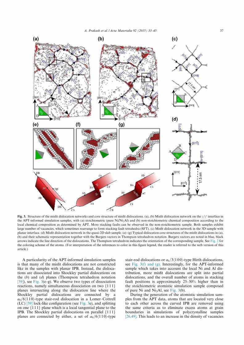
A particularity of the APT-informed simulation samplesis that many of the misfit dislocations are not constrictedlike in the samples with planar IPB. Instead, the disloca-tions are dissociated into Shockley partial dislocations onthe (b) and (d) planes (Thompson tetrahedron notation[59]), see Fig. 3(e–g). We observe two types of dissociationreactions, namely simultaneous dissociation on two f111gplanes intersecting along the dislocation line where theShockley partial dislocations are connected by aa0=6h110i-type stair-rod dislocation in a Lomer–Cottrell(LC) [59] lock-like configuration (see Fig. 3e), and splittingon one f111g plane which is a local tangential plane to theIPB. The Shockley partial dislocations on parallel f111gplanes are connected by either, a set of a0=6h110i-type
stair-rod dislocations or a0=3h100i-type Hirth dislocations,see Fig. 3(f) and (g). Interestingly, for the APT-informedsample which takes into account the local Ni and Al dis-tribution, more misfit dislocations are split into partialdislocations, and the overall number of atoms in stackingfault positions is approximately 25–30% higher than inthe stoichiometric atomistic simulation sample composedof pure Ni and Ni3Al, see Fig. 3(b).
During the generation of the atomistic simulation sam-ples from the APT data, atoms that are located very closeto each other across the curved IPB are removed usingthe same criteria as to eliminate excess atoms at grainboundaries in simulations of polycrystalline samples[26,49]. This leads to an increase in the density of vacancies
Fig. 3. Structure of the misfit dislocation networks and core structure of misfit dislocations. (a), (b) Misfit dislocation network on the c=c0 interface inthe APT-informed simulation samples, with (a) stoichiometric (pure Ni/Ni3Al) and (b) non-stoichiometric chemical composition according to the
local chemical composition as determined by APT. More stacking faults can be observed in the non-stoichiometric sample. Both samples exhibit
large number of vacancies, which sometimes rearrange to form stacking fault tetrahedra (SFT). (c) Misfit dislocation network in the 3D sample with
planar interface. (d) Misfit dislocation network in the quasi-2D slab sample. (e)–(g) Typical dislocation core structures of the misfit dislocations in (a),
(b) and their schematic representation together with the Burgers vectors in Thompson tetrahedron notation. Burgers vectors are noted in blue, black
arrows indicate the line direction of the dislocations. The Thompson tetrahedron indicates the orientation of the corresponding sample. See Fig. 2 for
the coloring scheme of the atoms. (For interpretation of the references to color in this figure legend, the reader is referred to the web version of this
article.)
A. Prakash et al. / Acta Materialia 92 (2015) 33–45 37

near the interface, which can rearrange into stacking faulttetrahedra (SFT), see Fig. 3(a) and (b).
3.2. Interactions between a single matrix dislocation and themisfit dislocation network
Under a tensile load in ½001� direction, typical of turbineblade applications, only 60� and screw dislocation segments
are deposited along the f100g IPB. Dislocations whichwould deposit segments of other character at the IPBs donot experience any resolved shear stress. The interactionof infinite screw dislocations with the misfit dislocation net-work was recently studied by Zhu et al. [22] in a 2D setup at0 K. They found that screw dislocations are absorbed in themisfit dislocation network, and a dislocation segment isonly deposited when the screw dislocation intersects the
Fig. 4. Interaction of one 60° matrix dislocation d1 with the misfit dislocation network in the APT-informed sample. (a) Deposition of dislocation
segments at the interface during tensile loading in ½001� direction. (b)–(d) Details of specific dislocation processes which are highlighted by gray
rectangles in (a). (b) Intersection of an orthogonal misfit dislocation by the deposited d1. (c) Local climb of d1 by absorption of vacancies at the
interface. (d) collinear reaction of d1 with a misfit dislocation of identical Burgers vector leaving a gap along the line of the deposited dislocation. (e)
Knitting-out of a misfit dislocation by d1. Defects as identified by AtomViewer [53,54]: red – stacking fault (lighter shade used to denote complex
stacking fault (CSF) in c0 phase), white – other defects. To improve clarity, undercoordinated atoms next to vacancies were removed from the pictures
in (b), (d), (e). The c=c0 interface is indicated by a semi-transparent surface. (For interpretation of the references to color in this figure legend, the
reader is referred to the web version of this article.)
38 A. Prakash et al. / Acta Materialia 92 (2015) 33–45

misfit dislocation network exactly at the location of a misfitdislocation, with which it reacts [22]. Our results on screwdislocations in the 2D setup agree qualitatively with theirobservations, see Supplementary Fig. 1, and we hence focuson the interaction of 60� dislocations with the misfitdislocation network at a constant temperature of 1250 K.In the following, the interactions of matrix dislocationswith the misfit dislocation network are presented only forthe samples with stoichiometric Ni/Ni3Al composition.The APT-informed simulation sample with adjusted localelemental concentration shows the same mechanisms.
A 60� dislocation with ~b ¼ a0=2½�101� (or CBðaÞ inThompson tetrahedron notation [59]) is initially insertedas a straight line in ½011� direction in the APT-informedsamples and the 3D sample with planar IPB. This disloca-tion will in the following be referred to as d1. The disloca-tion d1 is pinned at the fixed surfaces of the sample andstarts to bow out towards the c0 phase once the sample isdeformed under uniaxial tension along the ½001� direction.The deposition process of d1 at the IPB of the APT-in-formed sample is shown in Fig. 1, and SupplementaryMovie M1. While during the deposition process d1 justintersects the orthogonal misfit dislocations with Burgersvector DC, see Fig. 4(b) and Supplementary Fig. 2, it reactswith the orthogonal misfit dislocation CB. The details ofthis process are shown in Fig. 4(d). Both dislocations havethe same Burgers vector, and d1 is joined to the misfitdislocation on one side, while the threading part of d1becomes connected to the misfit dislocation on the otherside, leaving a gap between the deposited dislocation seg-ments (see also Supplementary Fig. 3). In single-phase fccmetals, this type of interaction among dislocations of sameBurgers vectors on intersecting glide planes is referred to asa collinear interaction [60]. This kind of interaction is notobserved in the 3D sample with planar IPB, as there areno misfit dislocation segments that have the same Burgersvector as d1; only the intersection process is observed,which is described in more detail in Supplementary Fig. 4and Movie M2.
Compared to the 3D samples, the interaction of astraight infinite 60� dislocation CBðdÞ (which is crys-tallographically equivalent to d1 used in the 3D samples)with the misfit dislocation network is completely differentin the quasi-2D setup. Here, the misfit dislocations are com-pletely free to move within the IPB plane. The misfitdislocation BD parallel to d1 and below its glide planemoves upwards and reacts with d1 at its intersection pointwith the network. The reaction leads to a dislocation DCthat is dissociated on the (b) plane, see SupplementaryFig. 5 and Movie M3. By contrast, no significant glide ofthe misfit dislocations along the IPB can be observed inthe 3D samples. This can be attributed to the fixed bound-ary conditions in the 3D samples, and the fact that a largernetwork is simulated rather than just a periodically repeat-ing unit.
When d1 in the APT-informed simulation sampleapproaches the edge of the precipitate, a second collinearinteraction with an orthogonal misfit dislocation takesplace, see Fig. 4(e). However, as d1 can no longer depositsegments at the IPB, it is no longer connected to the pre-cipitate. The misfit dislocation to which d1 is connected istherefore knitted-out from the misfit dislocation network.Furthermore, it is interesting to note that during thedeposition of d1 at the IPB between two misfit dislocations,
the dislocation absorbs vacancies, leading to local climb ofd1, see Fig. 4(e) and Supplementary Movie M4.
3.3. Cutting of the c0 phase by a pair of matrix dislocations
To study the cutting of the c0 precipitate by a pair of 60�
dislocations, two straight dislocations with identicalBurgers vector CBðaÞ are inserted on the same glide plane6 nm apart. During relaxation and thermalization, the firstand leading dislocation, d1, reacts to the stress field of thesecond dislocation (d2) by gliding towards the precipitateand depositing dislocation segments at the IPB similar tothe deposition of the single d1 described in the previous sec-tion. The resulting configuration at zero applied strain isshown in Fig. 5(a).
The overall evolution under uniaxial strain is shown inFig. 5(a) and Supplementary Movie M5. With increasingstrain, d1 proceeds to deposit itself on the IPB; d2 followsd1 and bows out towards the IPB, see Fig. 5(a). With addi-tional strain the parts of d1 between the misfit dislocationscut into the c0 phase. Cutting of the c0 phase by the leadingpartial dislocation Ca of d1 results in a complex stackingfault (CSF), which is transformed into an antiphase bound-ary (APB) by the trailing partial dislocation aB of d1, seeFig. 5(b). Where d2 glides on the identical plane as d1, italso cuts the c0 phase where the leading partial dislocationof d2 forms another CSF while the trailing partial disloca-tion restores the ordered L12 crystal structure of the c0
phase. Arranged jointly on the same glide plane, the twoinserted dislocations form a classical superdislocation, seeFig. 5(b). Superpartial dislocations in c0 are in the followingdenoted by d
0.Where d1 intersects the misfit dislocation network, two
characteristic processes occur. The intersected orthogonalmisfit dislocations are dissociated into partial dislocationson the (b) and (d) planes linked by the stair-rod disloca-tion db, as described in Fig. 3(e). The partial dislocationBd of the misfit dislocation is connected to d1 (Burgersvector CBðaÞ) together with a second partial dislocationCd which was generated during the intersection process,see Supplementary Fig. 6(a–d). Under the stress field ofthe approaching d2, this dislocation CBðdÞ enters the c0
phase together with d1; however, on the cross-slip plane.In other words, the intersection of the misfit dislocationnetwork by the 60° dislocation can activate dislocationson a second glide plane within c0, as shown schematicallyin Fig. 5(e). The created superpartial dislocation is stillconnected to the orthogonal misfit dislocation at theIPB. This process is also observed in the 3D sample withplanar IPB, but only at high strains, where the initiallyconstricted misfit dislocations dissociate into the LC-lockstructure described in Fig. 3(e), see SupplementaryFig. 7 and Movie M6.
When d2 arrives at the intersection of d01 with the misfit
dislocation network, the interaction of d2 with the intersec-tion of d0
1 and the misfit dislocation network leads to thedepinning of d0
1 after a series of intermediate reactionsand the pinning of d2 at the misfit dislocation (seeSupplementary Fig. 6 and Movie M7 for more details).Alternatively, d0
1, which is pinned at a misfit dislocation,can bow out on both sides of this misfit dislocation anddepin in an Orowan-type mechanism, see Fig. 5(c). Thisprocess is also observed in the 3D sample with planarIPB, see Supplementary Movie M8.
A. Prakash et al. / Acta Materialia 92 (2015) 33–45 39

Fig. 5. Interaction of two 60° matrix dislocations, d1 and d2, with the misfit dislocation network in the APT-informed sample. (a) Deposition of
dislocation segments at the interface during tensile loading in ½001� direction. (b) Details of the last configuration of (a), showing the formation of a
superdislocation in the c0 phase. The white arrow indicates where, due to the jogged d01, a stacking fault is produced by d0
2 on a plane adjacent to the
existing APB. The black arrow indicates steps in the APB and prismatic loops left behind by the motion of a jogged segment d01, as described in more
detail in the text and in Supplementary Fig. 10. (c–f) Idealized sketches of the different processes which lead to the configuration in (b). The gray plane
represents the c=c0 interface, the black line the misfit dislocations, red represents stacking faults, blue represents the antiphase boundary. See text as well
as Supplementary Figs. 6, 8 andMovies M5,M7–M9 for more details. (c) Depinning of a superdislocation from a misfit dislocation by an Orowan-like
process. (d) The collinear interaction described in Fig. 4(d) left a gap in the deposited dislocation line. The secondmatrix dislocation d2 can thus not cut
into the c0 phase, but can unpin the leading superpartial dislocation d01 from the misfit dislocation by a collinear reaction during which d2 merges with
d01. (e) Reaction of d0
1 with a partial dislocation of the LC-lock like structure, leading to a superpartial dislocation on the cross-slip plane. (f) Similar
mechanism like (e), however for d02. Defects as identified by AtomViewer [53,54]: red – stacking fault (lighter shade used to denote complex stacking
fault (CSF) in c0 phase), blue – antiphase boundary, green – other 12-neighbors defects, white – other defects. The c=c0 interface is indicated by a semi-
transparent surface. (For interpretation of the references to color in this figure legend, the reader is referred to the web version of this article.)
40 A. Prakash et al. / Acta Materialia 92 (2015) 33–45

The situation is different where the collinear reaction ofd1 with the misfit dislocation led to a gap along the depos-ited dislocation line. Here, d0
1 remains pinned at the IPBwhere it is connected to the orthogonal misfit dislocation,see the illustration in Fig. 5(d). The threading dislocationd2 interacts with this dislocation arrangement resulting ina series of collinear reactions similar to that observed inthe case of d1. In the process d0
1 unpins from the misfitdislocation and becomes connected to the threading secondmatrix dislocation in the c phase, d2. The segment of d2deposited along the IPB cuts into the c0 phase formingthe trailing superpartial dislocation d0
2, which is now pinnedat the misfit dislocation. Fig. 5(b) shows this configurationwhere d2 has become connected to d0
1. The process isdescribed in more detail in the Supplementary Fig. 8 andMovie M9.
In contrast to the situation considered above, in the 2Dsetup, the stress field of d2 leads to the emission of thedislocation DCðbÞ – result of the reaction of d1 with the par-allel misfit dislocation – back into the c phase, seeSupplementary Fig. 9.
It is interesting to note that the local climb due to theabsorption of vacancies by d1 in the APT-informed samplesleads to jogs in d0
1. In the c0 phase these jogs lead to steps inthe APB. The jog segments of d0
1 which are on differentplanes can merge together leaving behind prismatic loopsthat collapse into vacancy clusters at the end of the steps,see the black arrow in Fig. 5(b). This mechanism, whicheffectively reverses the climb process, is described in moredetail in Supplementary Fig. 10. Where d1 has absorbedvacancies, the glide planes of d1 and d2 are locally no longeridentical. Therefore, d2 can enter the c0 particle on slipplanes adjacent to the one of d0
1, which leads to the situa-tion where stacking faults are created on neighboringplanes, as indicated by the white arrow in Fig. 5(b).
4. Discussion
Two key observations can be made from the simulationsof matrix dislocations interacting with a semi-coherent pre-cipitate in the four different computational setups: (a) themisfit dislocation network and the core structure of misfitdislocations are critically influenced by the simulationsetup, and in particular by the local curvature of the IPB;(b) the nature of the misfit dislocations significantly affectsthe interaction of matrix dislocations with the misfitdislocation network.
The differences in the topology of the misfit dislocationnetwork in the APT-informed samples compared to theperfectly rectangular network in the quasi-2D sample andthe nearly perfectly rectangular network in the 3D samplewith planar IPB, Figs. 3(a–d), are caused by several factors.On the curved IPB of the APT-informed samples thedislocations can rearrange to shorten their line length.This is impossible in the quasi-2D sample with PBC, andin the 3D sample with planar IPB only observed near thefixed borders, see Fig. 3(c). Furthermore, the misfit disloca-tion network in the APT-informed sample contains edgedislocations with Burgers vectors of the type ½�10� 1�which point into or out of the ð100Þ plane. Although theð100Þ plane is the average IPB plane along most of the pre-cipitate, locally the IPB intersects ð100Þ lattice planes. Heremisfit dislocations can form with a Burgers vector compo-nent according to the misfit in the ½100� direction (Fig. 6a).
In addition to the misfit dislocation network topology,the core structure of the misfit dislocations in the APT-in-formed simulation sample also differs significantly fromthe misfit dislocations in the samples with planar IPB. Ingeneral, perfect a=2h110i-type dislocations in fcc structuresdissociate into Shockley partial dislocations with a=6h112iBurgers vectors to lower their strain energy according toFrank’s rule [59]. However, this is only possible on f111gglide planes where the generalized stacking fault energy sur-face has a local minimum at the intrinsic stacking fault con-figuration. The dislocations on the planar ð100Þ IPBs in theFigs. 3(c) and (d) can therefore not dissociate. In the APT-informed samples the local curvature of the IPB causes mis-fit dislocation segments to lie on tangential f111g planes,where they can dissociate, see Fig. 6(b). Stair-rod orHirth dislocations then connect the dissociated dislocations
Fig. 6. Effect of interface curvature on misfit dislocations. (a) Misfit
dislocation with Burgers vector of ½�101� type (yellow arrow). The local
interface plane intersects both the ð100Þ and ð001Þ planes, which
allows the additional ð001Þ and ð100Þ half planes (blue lines) due to
the different lattice constants to combine into one misfit dislocation.
The red line shows the Burgers circuit. (b) Where the interface can be
approximated by local ð111Þ tangential planes, the misfit dislocation
can dissociate into Shockley partial dislocations on these planes. Color
code: green – fcc structure in the c phase, gray – L12 structure in c0
phase, red – stacking-fault, white – other defects. (For interpretation of
the references to color in this figure legend, the reader is referred to the
web version of this article.)
A. Prakash et al. / Acta Materialia 92 (2015) 33–45 41

on the adjacent tangential planes, see Figs. 3(f) and (g).Misfit dislocations which are oriented along a h110i direc-tion can, furthermore, dissociate simultaneously on twof111g planes connected by a stair rod dislocation, forminga LC-lock, see Fig. 3(e). According to Frank’s rule, thisconfiguration has still about 30% lower strain energy thana perfect dislocation. This is, however, only possible if themisfit dislocation has a certain standoff to the local IPBplane – otherwise the partial dislocations would cut intothe c0 phase creating a CSF. This is why this dissociationis observed in simulations with planar IPBs only at highstresses. The overall increase in stacking fault area in theAPT-informed sample with adjusted local Ni and Al con-centrations compared to the stoichiometric sample,Fig. 3(b), can be related to the decrease of the stable stack-ing fault energy in the c phase with increasing Al concentra-tion, see Supplementary Fig. 11.
A LC-lock like core structure is also seen in theHRSTEM micrograph Fig. 7(b) of a misfit dislocation ina high-temperature crept sample of LEK94 [61] (seeSupplementary Information for details on the materialand sample preparation). Like all technical Ni-base super-alloys, this alloy has a negative lattice misfit resulting inmismatch-accommodating dislocations of oppositeBurgers vectors compared to the misfit dislocations in thepresent simulation study on pure Ni/Ni3Al, which has apositive misfit. In order to arrange the Shockley partialdislocations in such a way that an intrinsic stacking faultis formed between them and the stair-rod dislocation, theglide planes on which the dislocations dissociate have tobe interchanged [59]. In other words, instead of the dis-sociation of DB shown in Fig. 3(e), the dislocation of oppo-site sign, BD, would be dissociated in bBðbÞ on the left andBdðdÞ on the right. LC-lock like dissociation of mismatch-accommodating dislocations on planes towards the c0 phasesimilar to the one observed in Fig. 7(a) could however beexpected in Co-base superalloys, which have a positive lat-tice misfit [62,63]. LC-lock like core structures of interfacialdislocations were recently also reported for the alloy DD6[64] crept under loading conditions different from [61].The dissociation of misfit dislocations into LC-locks wasalso observed in atomistic simulations of fcc metal
multilayers [65]. Hence we speculate that this type of corestructure is rather typical for mismatch-accommodatingdislocations in fcc crystals in general, and for the c=c0
microstructure of superalloys in particular.While purely rectangular interfacial dislocation networks
like in Figs. 3(c) and (d) are rarely reported in experiments,the misfit dislocation network in the APT-informed samples,Figs. 3(a) and (b), bears striking resemblance to the mis-match network developed during the initial stages of hightemperature creep of Ni-base superalloys loaded in ½001�direction [8,56–58,66,64]. The dislocation line directionsand Burgers vectors in the misfit dislocation network areof the same type as in the experiments, including Burgersvectors of h001i-type [8,56,64], Burgers vectors with compo-nents normal to the IPB plane and the formation of littlesquare loops between larger structures, see e.g. [8,57].
The evolution of the dislocation network of depositedglide dislocations during high temperature, low stress creepinto a mismatch-accommodating interfacial dislocation net-work has been studied by many groups [5,8,9,56,58,67–69].The formation of a mismatch-accommodating interfacialdislocation network is believed to involve [5,8,9,56]: (a)the reaction between deposited glide dislocations on differ-ent activated glide systems, (b) the splitting of the nodesformed during the aforementioned reactions, (c) the re-ori-entation of dislocation lines in edge orientation, (d) the reac-tion of the so formed secondary dislocations with furtherprimary glide dislocations. Additionally, local diffusion pro-cesses and local climb, but without long-range glide or climbalong the interface, also play a role.
Given that the processes by which the mismatch-ac-commodating interfacial dislocation networks form inexperiments are completely different from the automaticformation of a misfit dislocation network by energy mini-mization of a two-phase structure with different lattice con-stants, the resemblances between experiments and atomisticsimulations on the APT-informed samples might be fortui-tous. However, the driving force in both cases is the mini-mization of strain energy. During high temperature, lowstress creep the deposited channel dislocations effectivelyreduce the misfit strain by increasingly forming edgedislocations with Burgers vectors which are parallel to the
Fig. 7. Lomer–Cottrell lock-like dislocation core structure in a Ni-base superalloy. (a) cut through the misfit dislocation in the APT-informed sample
shown in Fig. 3(a). See Fig. 6 for the color code. (b) STEM micrograph of a misfit dislocation at an interface groove in a LEK94 single crystal crept
along h110i at high-temperature. The Burgers circuit is indicated by the red line, the Burgers vector by the yellow arrow. The blue lines are added to
highlight the stacking faults of the respective partial dislocations. Due to the negative lattice misfit in the LEK94 alloy, the Burgers vector of the
misfit dislocation is opposite to the one in (a), leading to a LC lock-like core structure where the Shockley partial dislocations are oriented towards
the c phase. (For interpretation of the references to color in this figure legend, the reader is referred to the web version of this article.)
42 A. Prakash et al. / Acta Materialia 92 (2015) 33–45

IPB plane, see e.g. [58]. By not artificially constraining themisfit dislocation network formation in the simulations to aplanar interface with PBCs, other energy minima becomeaccessible during energy minimization, leading, e.g., to dif-ferent dislocation core structures compared to typical sim-ulation setups. The resulting network structures in theexperiments as well as in simulations with realistic IPBsshould therefore in both cases be close to an energetic mini-mum. The misfit dislocation network in the APT-informedsample and the misfit-accommodating interfacial networkin experiments can thus be expected to share similar fea-tures. This has important consequences for atomistic mod-eling: in contrast to the typically used overly idealizedsimulation scenarios, APT-informed atomistic samplesindeed provide a more realistic model for interfacialdislocation networks. Furthermore, it is to be expected thatalso under experimental conditions, the local IPB curvatureinfluences the topology, core structure and formation ofmisfit-accommodating interfacial dislocation networks.
The interfacial dislocation network plays a decisive rolein the stationary creep properties of superalloys. Finespaced dislocation networks can protect the c0 phase frombeing sheared by pairs of matrix dislocations [10,15].However, if the dislocation network contains many long,straight dislocation segments, these can actually serve aspartners for gliding matrix dislocations to penetrate the c0
phase [10,66]. The interaction of d1 with the orthogonalmisfit dislocation is a special case of such a process wherethe matrix dislocation and the misfit dislocation togethercut into the c0 precipitate. In this case the dislocation pene-trates the c0 phase on the initial glide plane of the matrixdislocation and on the cross-slip plane of the dissociatedmisfit dislocation. This is a clear example of how the corestructure of interfacial dislocations can influence the inter-action with channel dislocations. Due to the dependence ofthe misfit dislocation core structure on the Burgers vectorsign, such a simultaneous cutting in on two glide planescould, however, only be expected for Co-base superalloyswith positive lattice misfit.
When the dislocation d1 arrives at the interface, it inter-sects with the orthogonal misfit dislocations and getspinned locally. Between the intersection nodes, d1 is, how-ever, free to move and penetrates the c0 phase as leadingsuperpartial dislocation d0
1. The dislocation can, addition-ally, relatively easily depin from the misfit dislocations,either by a reaction with d2, or by bowing out in a processsimilar to the Orowan mechanism (see Fig. 5, andSupplementary Movie M8 where this process is revealedin the 3D sample with planar IPB). Similar to the interac-tion of dislocations with forest dislocations which do notlead to the formation of strong locks [59], the intersectionof the 60� dislocation with the edge misfit dislocation doesnot act as a strong obstacle.
The situation is different where d1 interacted with a mis-fit dislocation of the same Burgers vector in a collinearreaction. This reaction changed the topology of the disloca-tion arrangement, leading to a gap in the deposited matrixdislocation. The first superpartial dislocation d0
1 is effec-tively pinned by its connection to the orthogonal misfitdislocation. The second matrix dislocation d2 can unpind01 in a second collinear interaction. As a result, however,
d2 merges with d01, and d0
2 is connected to the misfit disloca-tion, i.e., to unpin d0
2 from the misfit dislocation, a third lat-tice dislocation with same Burgers vector and glide planewould be necessary. Similar to the situation in single
crystals where collinear interactions were shown to signifi-cantly contribute to work hardening [60], collinear interac-tions with the misfit dislocation network seem to formstrong obstacles to further cutting of the c0 phase, whichcannot be overcome by unzipping or Orowan bowing.
So far, the focus has been on a qualitative analysis of themechanisms of dislocation-precipitate interaction. Thesemechanisms are governed by crystallography and are onlyminimally influenced by the local chemical composition.Simulations conducted on the present non-stoichiometricAPT-informed atomistic sample show, however, clear dif-ferences to the effects governing deformation of such anidealized stoichiometric sample in terms of the strain atwhich the mechanisms take place. These quantitative differ-ences are mainly caused by an increased Young’s modulusdue to the increased Al contents, and due to the decreasedlocal misfit stresses in the non-stoichiometric sample.Furthermore, the chemical composition will affect the linetension of the dislocations due to its effect on the elasticconstants, and the local chemical composition will alsoinfluence the APB energy and thereby the critical resolvedstress required for matrix dislocations to cut into the pre-cipitate. A detailed quantitative study of these effects willbe presented elsewhere.
As with all atomistic simulations, the results of the MDstudies cannot be directly compared to experiments andneed to be critically discussed. The usual size limitationsof simulation boxes require large strains, and the typicalatomistic time scales lead to strain rates which are manyorders of magnitude higher than in experiments.Thermally activated processes can thus not be capturedby MD simulations. Furthermore, the EAM potentialmight not exactly represent the interatomic bonding in allsituations, and the Ni-Al-system does not adequately cap-ture the chemical complexity of contemporary superalloys.However, the described processes are very robust, i.e., theyare observed under significantly different simulation condi-tions, including different strain rates, temperatures andlocal chemical compositions. They can all, furthermore,be explained using arguments solely based on crystal-lography and dislocation theory. Consequently, we suggestthat observations such as the role of the local IPB curvaturefor the misfit dislocation network and the importance ofcollinear interactions for protecting c0 precipitates can begeneralized to the experimental situation.
Our study has implications not only for understandingthe mechanical properties of superalloys, but also for mod-eling and simulation in general. By using different setups,the simulations clearly demonstrated that the usual, idea-lized sample geometries fail to reproduce key experimentalobservations such as the specific core structure of interfacialdislocations. Atom probe tomography informed samplesfor atomistic or mesoscale simulations help circumventthe need for overly simplified setups by providing a uniquepossibility to study dislocation processes directly in morerealistic, complex microstructures.
5. Conclusions
We presented a novel approach to construct atom probetomography informed atomistic simulation samples whichavoids the lattice rectification step by using complementaryinformation on the crystallographic structure of the speci-men. Molecular dynamics simulations on real and idealized
A. Prakash et al. / Acta Materialia 92 (2015) 33–45 43

c=c0 microstructures of a Ni-base superalloy showed thatthe local interface curvature and the local chemicalcomposition critically influence the misfit dislocation net-work which forms on top of the c0 precipitate and the corestructure of the misfit dislocations. In particular, misfitdislocations with Burgers vectors that are not an elementof the f100g interface plane and Lomer–Cottrell lock-likedislocation core structures could be observed, in agreementwith TEM observations. The nature of the misfit disloca-tions in turn determines the interactions of matrix disloca-tions with the misfit dislocation network. Simulations oftensile tests at 1250 K with one or two 60� matrix disloca-tions revealed the atomic scale details of many experimen-tally observed dislocation–precipitate interactionmechanisms like the cutting of precipitates by a pair ofsuperpartial dislocations, the pinning of threading disloca-tions and the knitting out of misfit dislocations, which can-not be reproduced by typically used, highly idealizedsimulation setups with planar interfaces. Notably, the sim-ulations provided direct evidence for the importance of col-linear dislocation interactions in protecting the c0
precipitates against dislocation cutting.
Acknowledgments
We thank J.J. Moller for the calculation of the concentration-dependent stacking fault energies and helpful discussions. Theauthors acknowledge support by the DeutscheForschungsgemeinschaft (DFG) through projects C3 (atomisticsimulations), A4 (APT) and A7 (HRTEM) of SFB/Transregio103 (Single Crystal Superalloys).
Appendix A. Supplementary data
Supplementary data associated with this article can befound, in the online version, at http://dx.doi.org/10.1016/j.actamat.2015.03.050.
References
[1] M. Durand-Charre, The Microstructure of Superalloys, CRCPress, 1998.
[2] R.C. Reed, The Superalloys: Fundamentals and Applications,Cambridge University Press, 2006.
[3] T. Murakumo, T. Kobayashi, Y. Koizumi, H. Harada, ActaMater. 52 (2004) 3737–3744.
[4] C. Carry, J. Strudel, Acta Metall. 25 (1977) 767–777.[5] M. Kolbe, A. Dlouhy, G. Eggeler, Mater. Sci. Eng.: A 246
(1998) 133–142.[6] Z. Zhu, H. Basoalto, N. Warnken, R. Reed, Acta Mater. 60
(2012) 4888–4900.[7] T. Gabb, S. Draper, D. Hull, Mater. Sci. Eng., A 118 (1989)
59–69.[8] R.D. Field, T.M. Pollock, W.H. Murphy, The development
of c=c0 interfacial dislocation networks during creep in Ni-base superalloys, in: S.D. Antolovich, R.W. Stusrud, R.A.MacKay, D.L. Anton, T. Khan, R.D. Kissinger, D.L.Klarstrom (Eds.), Superalloys, The Minerals, Metals &Materials Society, 1992.
[9] C. Mayr, G. Eggeler, A. Dlouhy, Mater. Sci. Eng.: A 207(1996) 51–63.
[10] L. Carroll, Q. Feng, T. Pollock, Metall. Mater. Trans. A 39(2008) 1290–1307.
[11] F. Nabarro, Metall. Mater. Trans. A 27 (1996) 513–530.[12] R. Reed, D. Cox, C. Rae, Mater. Sci. Technol. 23 (2007) 893–
902.
[13] R. Srinivasan, G.F. Eggeler, M.J. Mills, Acta Mater. 48(2000) 4867–4878.
[14] M. Kamaraj, Sadhana 28 (2003) 115–128.[15] J.X. Zhang, T. Murakumo, Y. Koizumi, T. Kobayashi, H.
Harada, S. Masaki, Metall. Mater. Trans. A 33 (2002) 3741–3746.
[16] K. Yashiro, M. Naito, Y. Tomita, Int. J. Mech. Sci. 44 (2002)1845–1860.
[17] T. Zhu, C.-Y. Wang, Phys. Rev. B 72 (2005) 014111.[18] J.R. Djuansjah, K. Yashiro, Y. Tomita, Mater. Trans. 49
(2008) 2507–2514.[19] H.X. Xie, C.Y. Wang, T. Yu, Modell. Simul. Mater. Sci. Eng.
17 (2009).[20] W. Wu, Y. Guo, Y. Wang, Philos. Mag. 91 (2011) 357–372.[21] J.P. Du, C.Y. Wang, T. Yu, Modell. Simul. Mater. Sci. Eng.
21 (2013) 015007.[22] Y. Zhu, Z. Li, M. Huang, Comput. Mater. Sci. 70 (2013) 178–
186.[23] E. Bitzek, J.R. Kermode, P. Gumbsch, Int. J. Fract. 191
(2015) 13–30.[24] J.J. Moller, E. Bitzek, Eng. Fract. Mech. (2015), http://
dx.doi.org/10.1016/j.engfracmech.2015.03.028, in press.[25] A. Sedlmayr, E. Bitzek, D.S. Gianola, G. Richter, R. Monig,
O. Kraft, Acta Mater. 60 (2012) 3985–3993.[26] T. Xu, M. Li, Philos. Mag. 90 (2010) 2191–2222.[27] T.F. Kelly, M.K. Miller, Rev. Sci. Instrum. 78 (2007) 031101.[28] D.N. Seidman, Annu. Rev. Mater. Res. 37 (2007) 127–
158.[29] C. Pareige, F. Soisson, G. Martin, D. Blavette, Acta Mater.
47 (1999) 1889–1899.[30] Z. Mao, C.K. Sudbrack, K.E. Yoon, G. Martin, D.N.
Seidman, Nat. Mater. 6 (2007) 210–216.[31] X. Zhou, H. Wadley, R. Johnson, Acta Mater. 49 (2001)
4005–4015.[32] W. Geng, D. Ping, Y. Gu, C. Cui, H. Harada, Phys. Rev. B 76
(2007) 224102.[33] Y. Amouyal, Z. Mao, C. Booth-Morrison, D.N. Seidman,
Appl. Phys. Lett. 94 (2009) 041917.[34] B. Gault, X.Y. Cui, M.P. Moody, F. De Geuser, C. Sigli, S.P.
Ringer, A. Deschamps, Scr. Mater. 66 (2012) 903–906.[35] M.P. Moody, A.V. Ceguerra, A.J. Breen, X.Y. Cui, B. Gault,
L.T. Stephenson, R.K.W. Marceau, R.C. Powles, S.P. Ringer,Nat. Commun. 5 (2014) 5501.
[36] F. Vurpillot, L. Renaud, D. Blavette, Ultramicroscopy 95(2003) 223–229.
[37] M.P. Moody, B. Gault, L.T. Stephenson, R.K.W. Marceau,R.C. Powles, A.V. Ceguerra, A.J. Breen, S.P. Ringer,Microsc. Microanal. 17 (2011) 226–239.
[38] A.V. Ceguerra, M.P. Moody, R.C. Powles, T.C. Petersen,R.K.W. Marceau, S.P. Ringer, Acta Crystallogr., Sect. A 68(2012) 547–560.
[39] A.B. Parsa, P. Wollgramm, H. Buck, C. Somsen, A. Kostka,I. Povstugar, P.-P. Choi, D. Raabe, A. Dlouhy, J. Muller, E.Spiecker, K. Demtroder, J. Schreuer, K. Neuking, G. Eggeler,Adv. Eng. Mater. (2014) 1–15.
[40] D.J. Larson, T.J. Prosa, R.M. Ulfig, B.P. Geiser, T.F. Kelly,Local Electrode Atom Probe Tomography, Springer NewYork, New York, NY, 2013.
[41] M. Herbig, D. Raabe, Y.J. Li, P. Choi, S. Zaefferer, S. Goto,Phys. Rev. Lett. 112 (2014) 126103.
[42] E.V. Chernyaev, Marching Cubes 33: Construction ofTopologically Correct Isosurfaces, Technical Report, CN/95-17, CERN, Institute for High Energy Physics, 1995.
[43] W.E. Lorensen, H.E. Cline, Comput. Graphics 21 (1987) 163–169.
[44] D. Feng, L. Tierney, J. Stat. Software 28 (2008).[45] A. Prakash, M. Hummel, S. Schmauder, E. Bitzek,
Nanosculpt: a tool to generate atomistic samples of arbitraryenclosed volumes, 2015. http://www.gmp.ww.uni-erlangen.de/nanoSCULPT.php.
[46] A. Prakash, M. Hummel, S. Schmauder, E. Bitzek,Unpublished results, 2015.
44 A. Prakash et al. / Acta Materialia 92 (2015) 33–45

[47] J. O’Rourke, Computational Geometry in C, 2nd ed.,Cambridge University Press, 1998.
[48] Y. Mishin, Acta Mater. 52 (2004) 1451–1467.[49] P.M. Derlet, H. Van Swygenhoven, Phys. Rev. B 67 (2003)
014202.[50] E. Bitzek, P. Gumbsch, Mater. Sci. Eng. A 387–389 (2004)
11–15.[51] E. Bitzek, P. Koskinen, F. Gahler, M. Moseler, P. Gumbsch,
Phys. Rev. Lett. 97 (2006).[52] W. Hoover, Phys. Rev. A 31 (1985) 1695–1697.[53] C. Begau, A. Hartmaier, E. George, G. Pharr, Acta Mater. 59
(2011) 934–942.[54] J. Amodeo, C. Begau, E. Bitzek, Mater. Res. Lett. 2 (2014)
140–145.[55] A. Stukowski, Modell. Simul. Mater. Sci. Eng. 18 (2010)
015012.[56] T. Link, A. Epishin, M. Klaus, U. Bruckner, A. Reznicek,
Mater. Sci. Eng.: A 405 (2005) 254–265.[57] A. Epishin, T. Link, G. Nolze, J. Microsc. 228 (2007) 110–117.[58] L. Agudo Jacome, P. Nortershauser, J.-K. Heyer, A. Lahni, J.
Frenzel, A. Dlouhy, C. Somsen, G. Eggeler, Acta Mater. 61(2013) 2926–2943.
[59] J. Hirth, J. Lothe, Theory of Dislocations, 2 ed., KriegerPublishing Company, 1982.
[60] R. Madec, B. Devincre, L. Kubin, T. Hoc, D. Rodney,Science 301 (2003) 1879–1882.
[61] G. Malzer, R. Hayes, T. Mack, G. Eggeler, Metall. Mater.Trans. A 38 (2007) 314–327.
[62] J. Sato, T. Omori, K. Oikawa, I. Ohnuma, Science 312 (2006)90–91.
[63] A. Bauer, S. Neumeier, F. Pyczak, M. Goken, Scr. Mater. 63(2010) 1197–1200.
[64] M. Huang, Z. Cheng, J. Xiong, J. Li, J. Hu, Z. Liu, J. Zhu,Acta Mater. 76 (2014) 294–305.
[65] R.G. Hoagland, T.E. Mitchell, J.P. Hirth, H. Kung, Philos.Mag. A 82 (2002) 643–664.
[66] L. Agudo Jacome, P. Nortershauser, C. Somsen, A. Dlouhy,G. Eggeler, Acta Mater. 69 (2014) 246–264.
[67] K. Yashiro, F. Kurose, Y. Nakashima, K. Kubo, Y. Tomita,H. Zbib, Int. J. Plast. 22 (2006) 713–723.
[68] K. Yashiro, M. Konishi, Y. Tomita, Comput. Mater. Sci. 43(2008) 481–488.
[69] B. Liu, D. Raabe, F. Roters, A. Arsenlis, Acta Mater. 79(2014) 216–233.
A. Prakash et al. / Acta Materialia 92 (2015) 33–45 45
Copyright © 2022 FDOKUMEN