ATLAS Phase-II Upgrade: Run-4 Luminosity Task Force Report
64
DRAFT Run-4 Luminosity Task Force Report ATLAS Doc.: None EDMS Id: None 1 ATLAS Phase-II Upgrade Project 2 ATLAS Phase-II Upgrade: 3 Run-4 Luminosity Task Force Report 4 Abstract 5 This report summarises the findings of the Run-4 Luminosity Task Force, as part of the ATLAS Phase-II 6 Upgrade Project. 7 Run-4 Luminosity Task Force Report ATLAS Doc: None EDMS Id: None EDMS Url: Version: 0.1 Created: December 9, 2019 Last modified: March 29, 2020 Prepared by: Checked by: Approved by: Martin Aleksa Kevin Einsweiler Benedetto Giacobbe Andrej Gorisek Simone Pagan Griso Richard Hawkings Vincent Hedberg Ilya Korolkov Witold Kozanecki Brian Petersen Alessandro Polini Jonas Strandberg Eric Torrence Manuella Vincter No need for checking Task force members 8 c 2020 CERN for the benefit of the ATLAS Collaboration. Reproduction of this article or parts of it is allowed As specified in the CC-BY-4.0 license. 9 10
-
Upload
khangminh22 -
Category
Documents
-
view
0 -
download
0
Transcript of ATLAS Phase-II Upgrade: Run-4 Luminosity Task Force Report

DRAFT
Run-4 Luminosity Task Force Report ATLAS Doc.: None EDMS Id: None
1
ATLAS Phase-II Upgrade Project2
ATLAS Phase-II Upgrade:3
Run-4 Luminosity Task Force Report4
Abstract5
This report summarises the findings of the Run-4 Luminosity Task Force, as part of the ATLAS Phase-II6
Upgrade Project.7
Run-4 Luminosity Task Force ReportATLAS Doc: NoneEDMS Id: NoneEDMS Url:Version: 0.1Created: December 9, 2019Last modified: March 29, 2020
Prepared by: Checked by: Approved by:
Martin AleksaKevin EinsweilerBenedetto GiacobbeAndrej GorisekSimone Pagan GrisoRichard HawkingsVincent HedbergIlya KorolkovWitold KozaneckiBrian PetersenAlessandro PoliniJonas StrandbergEric TorrenceManuella Vincter
No need for checking Task force members
8
c© 2020 CERN for the benefit of the ATLAS Collaboration.Reproduction of this article or parts of it is allowed As specified in the CC-BY-4.0 license.9
10

DRAFT[INTENTIONALLY BLANK PAGE]11

DRAFT
Run-4 Luminosity Task Force Report March 29, 2020 - Version 0.1
REVISION HISTORY12
Revision Date Description0.1 09/12/1970 Begin writing the report for the Run-4 Luminosity Task Force
Revision History iii

DRAFT
Run-4 Luminosity Task Force Report March 29, 2020 - Version 0.1
TABLE OF CONTENTS13
Revision History . . . . . . . . . . . . . . . . . . . . . . . . . . . iii14
Table of Contents . . . . . . . . . . . . . . . . . . . . . . . . . . . iv15
1 Introduction . . . . . . . . . . . . . . . . . . . . . . . . . . 116
2 Lessons from Run 1 and Run 2 . . . . . . . . . . . . . . . . 217
3 Expected Run-4 Running Conditions . . . . . . . . . . . . . 418
4 Luminosity-Calibration Strategy . . . . . . . . . . . . . . . . 519
4.1 Overview of the ATLAS luminosity-determination workflow . . . . . . 520
4.2 Absolute luminosity calibration by the van der Meer method . . . . . 621
4.3 Detector requirements for vdM calibrations and calibration transfer . . 722
4.3.1 Bunch-by-bunch capability . . . . . . . . . . . . . . . . . . . . . . . 723
4.3.2 Geometrical coverage . . . . . . . . . . . . . . . . . . . . . . . . 724
4.3.3 Short-term stability of luminometer response . . . . . . . . . . . . . . . . 825
4.3.4 On-detector gain- or efficiency-calibrations . . . . . . . . . . . . . . . . . 826
4.3.5 Linearity and dynamic-range requirements . . . . . . . . . . . . . . . . . 827
4.3.5.1 Head-on pp collisions . . . . . . . . . . . . . . . . . . . . . . . 828
4.3.5.2 pp vdM scans . . . . . . . . . . . . . . . . . . . . . . . . . 929
4.3.5.3 Heavy-ion collisions . . . . . . . . . . . . . . . . . . . . . . . 930
4.3.6 Calibration transfer from the vdM- to the physics-luminosity regime . . . . . . . . . 931
5 Requirements for Luminosity Measurements in Run 4 . . . . 1132
5.1 Global Requirements for Luminosity Instrumentation at HL-LHC . . . . 1133
5.2 Offline Luminosity Determination . . . . . . . . . . . . . . . . . 1234
5.3 Online Luminosity Monitoring . . . . . . . . . . . . . . . . . . . 1235
6 Assessment of Proposed Luminometer Upgrades . . . . . . 1436
6.1 BCM′ . . . . . . . . . . . . . . . . . . . . . . . . . . . . . . 1537
6.1.1 BCM Luminosity Performance in LHC Runs 1 and 2 . . . . . . . . . . . . . . 1538
6.1.1.1 Overall assessment . . . . . . . . . . . . . . . . . . . . . . . 1539
6.1.1.2 Limitations of the existing BCM system . . . . . . . . . . . . . . . . . 1540
6.1.1.2.1 Calibration shifts . . . . . . . . . . . . . . . . . . . . . . . . . . . . 1541
6.1.1.2.2 Long-term aging of the efficiency over an LHC year . . . . . . . . . 1642
6.1.1.2.3 µ dependence with both isolated bunches and trains . . . . . . . . 1643
6.1.1.2.4 Bunch-position dependent non-linearity . . . . . . . . . . . . . . . 1844
6.1.1.2.5 Dynamic range in µ . . . . . . . . . . . . . . . . . . . . . . . . . . 1845
6.1.2 Progress in CVD diamond-sensor technology . . . . . . . . . . . . . . . . 1846
6.1.3 Overview of the BCM′ design . . . . . . . . . . . . . . . . . . . . . . 2047
6.1.4 BCM′ risk assessment . . . . . . . . . . . . . . . . . . . . . . . . 2048
Table of Contents iv

DRAFT
Run-4 Luminosity Task Force Report March 29, 2020 - Version 0.1
6.2 A BCM′ with Silicon Sensors . . . . . . . . . . . . . . . . . . . 2249
6.3 LUCID . . . . . . . . . . . . . . . . . . . . . . . . . . . . . 2350
6.3.1 A MOD-PMT detector for Run-4 . . . . . . . . . . . . . . . . . . . . . 2351
6.3.2 A FIBER detector for Run-4 . . . . . . . . . . . . . . . . . . . . . . 2552
6.3.3 Activity for Run-3 towards the Run-4 upgrade . . . . . . . . . . . . . . . . 2653
6.3.4 Proposal of LUCID for Run-4 and Recommendations . . . . . . . . . . . . . . 2754
6.3.5 Online and Offline Requirements . . . . . . . . . . . . . . . . . . . . . 2855
6.4 Tile Calorimeter . . . . . . . . . . . . . . . . . . . . . . . . . 2956
6.5 LAr Calorimeter . . . . . . . . . . . . . . . . . . . . . . . . . 3057
6.5.1 Experience in Run-2 and Outlook for the HL-LHC for the LAr-gap Current Measurements . 3058
6.5.2 Possible Bunch-by-Bunch Luminosity Measurement Using LTDBs (Phase I) or LASPs (Phase59
II) . . . . . . . . . . . . . . . . . . . . . . . . . . . . . . . . 3160
6.6 HGTD . . . . . . . . . . . . . . . . . . . . . . . . . . . . . . 3261
6.6.1 HGTD as a luminometer . . . . . . . . . . . . . . . . . . . . . . . . 3262
6.6.2 Review of the detector . . . . . . . . . . . . . . . . . . . . . . . . 3463
6.6.3 Activity towards Run-4 . . . . . . . . . . . . . . . . . . . . . . . . 3464
6.7 ITk . . . . . . . . . . . . . . . . . . . . . . . . . . . . . . . 3665
6.7.1 Present experience . . . . . . . . . . . . . . . . . . . . . . . . . 3666
6.7.2 ITk opportunities . . . . . . . . . . . . . . . . . . . . . . . . . . 3767
6.7.2.1 Parasitic resources . . . . . . . . . . . . . . . . . . . . . . . . 3768
6.7.2.2 Opportunistic resources . . . . . . . . . . . . . . . . . . . . . . 3769
6.7.2.3 Dedicated resources . . . . . . . . . . . . . . . . . . . . . . . 3870
6.7.3 PixLumi rings . . . . . . . . . . . . . . . . . . . . . . . . . . . 3871
6.7.4 Action Items . . . . . . . . . . . . . . . . . . . . . . . . . . . . 3972
6.8 Muon System . . . . . . . . . . . . . . . . . . . . . . . . . . 4073
6.9 TPX System . . . . . . . . . . . . . . . . . . . . . . . . . . . 4274
6.10 Summary of the Detector Upgrades . . . . . . . . . . . . . . . . 4375
6.10.1 Table Headings . . . . . . . . . . . . . . . . . . . . . . . . . . . 4376
7 Recommendations . . . . . . . . . . . . . . . . . . . . . . . 4677
7.1 Introduction . . . . . . . . . . . . . . . . . . . . . . . . . . . 4678
7.2 Assessment of the Instrumental Upgrades Proposed for Run-4 . . . . 4679
7.2.1 Overall Upgrade Strategy . . . . . . . . . . . . . . . . . . . . . . . 4680
7.2.2 Already Ongoing Upgrades: Bunch-by-Bunch Luminometers . . . . . . . . . . . 4881
7.2.2.1 LUCID-3 . . . . . . . . . . . . . . . . . . . . . . . . . . . 4882
7.2.2.2 HGTD . . . . . . . . . . . . . . . . . . . . . . . . . . . . 4883
7.2.2.3 BCM′ . . . . . . . . . . . . . . . . . . . . . . . . . . . . 4984
7.2.3 Already Ongoing Upgrades: Auxiliary Luminometers . . . . . . . . . . . . . . 4985
7.2.3.1 LAr-gap currents . . . . . . . . . . . . . . . . . . . . . . . . 5086
7.2.3.2 TILE PMT currents . . . . . . . . . . . . . . . . . . . . . . . . 5087
7.2.3.3 Track counting . . . . . . . . . . . . . . . . . . . . . . . . . 5088
7.2.4 New Stand-Alone Bunch-by-bunch Luminometers . . . . . . . . . . . . . . . 5189
7.2.4.1 Pixel Luminosity Rings . . . . . . . . . . . . . . . . . . . . . . 5190
7.2.4.2 Si-BCM′ . . . . . . . . . . . . . . . . . . . . . . . . . . . 5191
Table of Contents v
DRAFT
Run-4 Luminosity Task Force Report March 29, 2020 - Version 0.1
7.2.5 New Auxiliary Luminometers . . . . . . . . . . . . . . . . . . . . . . 5292
7.2.5.1 Pixel-cluster counting . . . . . . . . . . . . . . . . . . . . . . . 5293
7.2.5.2 Bunch-by-Bunch Luminosity Measurement using the Main Readout (FEB2 + LASP) . 5294
7.2.5.3 Trigger-rate monitoring . . . . . . . . . . . . . . . . . . . . . . 5295
7.3 Recommendations for Run-3 . . . . . . . . . . . . . . . . . . . 5296
7.4 Person-power and organization . . . . . . . . . . . . . . . . . . 5497
References . . . . . . . . . . . . . . . . . . . . . . . . . . . . . . 5698
Table of Contents vi

DRAFT
Run-4 Luminosity Task Force Report March 29, 2020 - Version 0.1
199
INTRODUCTION100
A Phase-II Luminosity Task Force (Phase2LTF hereafter) was created in June 2019 with the mandate to101
develop a strategy for a robust and precise ATLAS luminosity measurement during Phase-II (also referred to102
as Run-4 hereafter), taking into account the following items:103
• identification of conditions and detector requirements needed for a robust and precise luminosity mea-104
surement under HL-LHC conditions, including complementary measurements and the necessary trig-105
gers for van der Meer calibration scans;106
• evaluation of existing detector projects (including HGTD, ITk) suitable for luminosity measurement dur-107
ing Phase-II in view of these requirements, and of a possible reuse of the present detector concepts108
and methods under Phase-II conditions;109
• evaluation of the need to develop additional detector projects for luminosity measurement during Phase-110
II.111
The work of the Phase2LTF was organized in regular meetings each dedicated to one or more specific112
items, namely:113
• review of the lessons from the luminosity measurement in Run-1 and Run-2 (Sec. 2);114
• review of the expected LHC conditions in Run-4 (Sec. 3);115
• definition of the requirements for a reliable measurement both online and offline (Sec. 5);116
• review of the absolute calibration strategy (Sec. 4);117
• review of the upgrade projects of the detectors already contributing to the luminosity measurement dur-118
ing Run-1 and Run-2 and evaluation of the need and role of additional detectors, both already foreseen119
and newly proposed (Sec. 6). A full-day workshop was devoted to this item, which included the presence120
of experts of all detectors, also external to the Phase2LTF: the agenda and contributions can be found121
in https://indico.cern.ch/event/844318/ and https://indico.cern.ch/event/844322/;122
• formulation of recommendations for the luminosity measurement in Run-4 (Sec. 7). Recommendations123
about actions to be taken in Run-3 in preparation for Run-4 and about person-power and organization124
issues are also provided;125
This document is the final report of the work of the Phase2LTF.126
1. Introduction Page 1 of 58

DRAFT
Run-4 Luminosity Task Force Report March 29, 2020 - Version 0.1
2127
LESSONS FROM RUN 1 AND RUN 2128
The preliminary ATLAS Run-2 luminosity measurement is described in Ref. [1], building on the Run-1 strat-129
egy documented in Refs. [2, 3]. The measurement is based on continuous luminosity measurements from the130
LUCID Cherenkov detectors in the forward regions of ATLAS, complemented by multiple independent mea-131
surements from other detectors. These include counting the multiplicity of reconstructed tracks per bunch132
crossing in a dedicated data stream from an unbiased trigger (track counting), LAr gap currents measured by133
the HV power supplies of the endcap electromagnetic (EMEC) and forward (FCal) calorimeters, currents in134
the photomultiplier readout of selected Tile calorimeter scintillators, and measurements from the beam con-135
ditions monitor (BCM) in the ATLAS inner detector volume. Each of these measurement techniques has its136
own strengths and limitations, and the overall luminosity measurement with its uncertainty of 1.7 % relies on137
the complementarity of the different measurements, and comparisons between them.138
The absolute luminosity scale of LUCID is calibrated using the van der Meer (vdM) beam separation scans139
in dedicated low-luminosity runs with up to O(100) isolated bunches and larger transverse beam sizes giving140
peak µ values around 0.5. These conditions allow the absolute scale to be determined with a precision of141
1–1.5 %, but at an instantaneous luminosity 2000 times less than that typical of Run 2 physics conditions. The142
LUCID response is known to be non-linear, leading to an overestimation the luminosity by O(10 %) in physics143
running. This is corrected using a ‘calibration transfer’ procedure using the track-counting luminosity measure-144
ment, assuming the latter to have no significant µ dependence. This assumption is checked by comparing the145
relative response of track-counting and TILE luminosity measurements made using the E-cell scintillators in146
the barrel/end-cap calorimeter gap; any difference between the two is interpreted as a systematic uncertainty147
on the calibration transfer correction applied to LUCID, typically 1.3–1.6 % during Run 2. This procedure leads148
to a calibrated LUCID measurement in physics conditions. The final step is to assess the long-term stability of149
LUCID measurements throughout the year, by comparing per-run integrated luminosity measurements from150
LUCID with those from track-counting, EMEC, FCal and TILE D-cells, after normalising all measurements to151
agree with LUCID in a single reference physics run close in time to the vdM scan. These comparisons lead to152
additional uncertainties of O(1 %) on the absolute stability of the LUCID calibration throughout the year. The153
full breakdown of systematic uncertainties on the luminosity measurement is shown in Table 2 of Ref. [1]. The154
total uncertainties amount to 2.1–2.4 % in each data-taking year, but are not fully correlated between years,155
leading to a final uncertainty of 1.7 % on the full Run-2√
s = 13 TeV data sample. The corresponding values156
for Run 1 are similar; 1.9 % for 2011 data at√
s = 7 TeV , and 1.8 % for 2012 data at√
s = 8 TeV .157
Several weaknesses are present in the Run-2 luminosity calibration, which could potentially be addressed158
with improved instrumentation in Run 4. The most important is the large non-linearity of LUCID between159
the vdM calibration and physics regime, leading to an O(10 %) calibration transfer correction that has to be160
determined with a relative uncertainty of 10 % of the correction, yet still dominates the overall luminosity uncer-161
tainty. This correction relies on very delicate measurements with the TILE E-cells, at the limit of what can be162
achieved. These problems will become even worse in Run 4, with µ up to 200 in physics conditions. Reducing163
the µ dependence of the primary vdM-calibrated luminosity measurements is therefore essential if the Run-4164
2. Lessons from Run 1 and Run 2 Page 2 of 58

DRAFT
Run-4 Luminosity Task Force Report March 29, 2020 - Version 0.1
luminosity precision goals are to be met. Secondly, it would be desirable to have at least three independent,165
bunch-by-bunch luminosity detectors which can be calibrated with vdM scans and be reliably used in physics166
conditions; this would allow vital consistency checks of both the vdM calibration and the calibration transfer.1167
In Run 1, LUCID and BCM provided such a pair, but BCM was not usable in standard pp physics conditions168
during Run 2, primarily due to the 25 ns bunch spacing. Track-counting measurements have proven to be an169
essential part of the calibration strategy in particular because of their small µ-dependence, robustness and170
long-term stability, but are presently only available offline, and are statistics-limited, making bunch-by-bunch171
measurements impossible except during special run periods when the bulk of the ATLAS readout bandwidth172
is devoted to the dedicated datastream. Implementing track-counting online (e.g. in the HLT) would poten-173
tially overcome many of these limitations. Finally, the calorimeter measurements show excellent long-term174
stability (for the TILE calorimeter, only after painstaking corrections using e.g. laser-based response mea-175
surements), but are affected by activation-induced biases with time constants of a few minutes to a few days.176
These complicate the analysis, particularly when high-luminosity is followed by low-luminosity running, and177
make the relative sequencing of vdM and calibration transfer data-taking very complex, particularly when178
other experiments have conflicting requirements.179
Experience from Run 1 and Run 2, in particular the issues discussed above, suggest broad requirements180
for the luminosity instrumentation in Run 4: these are presented in Sec. 5.1.181
1The three-fold offline redundancy is required to resolve the inconsistencies, and resulting systematic uncertainties, that would likelyarise if only two independent bunch-by-bunch luminometers were available.
2. Lessons from Run 1 and Run 2 Page 3 of 58
DRAFT
Run-4 Luminosity Task Force Report March 29, 2020 - Version 0.1
3182
EXPECTED RUN-4 RUNNING CONDITIONS183
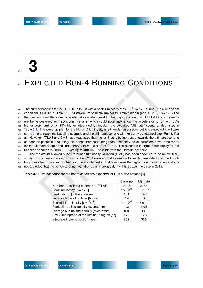
The current baseline for the HL-LHC is to run with a peak luminosity of 5×1034 cm−2s−1 during Run 4 with beam184
conditions as listed in Table 3.1. The maximum possible luminosity is much higher (about 2×1035 cm−2s−1) and185
the luminosity will therefore be leveled at a constant level for the majority of each fill. All HL-LHC components186
are being designed with additional margins, which could potentially allow the accelerator to run with 50%187
higher peak luminosity (25% higher integrated luminosity), the so-called "Ultimate" scenario, also listed in188
Table 3.1. The ramp-up plan for the HL-LHC luminosity is still under discussion, but it is expected it will take189
some time to reach the baseline scenario and the ultimate scenario will likely only be reached after Run 4, if at190
all. However, ATLAS and CMS have requested that the luminosity be increased towards the ultimate scenario191
as soon as possible, assuming this brings increased integrated luminosity, so all detectors have to be ready192
for the ultimate beam conditions already from the start of Run 4. The expected integrated luminosity for the193
baseline scenario is 3000 fb−1, with up to 4000 fb−1 possible with the ultimate scenario.194
The maximum allowed bunch-to-bunch luminosity variation (RMS) has been specified to be below 10%,195
similar to the performance in most of Run 2. However, it still remains to be demonstrated that the bunch196
brightness from the injector chain can be maintained at that level given the higher bunch intensities and it is197
not excluded that the bunch-to-bunch variations can increase during fills as was the case in 2018.198
Table 3.1: Two scenarios for the beam conditions expected for Run 4 and beyond.[4].
Baseline UltimateNumber of colliding bunches in ATLAS 2748 2748Peak luminosity [cm−2s−1] 5 × 1034 7.5 × 1034
Peak pile-up [collisions/event] 131 197Luminosity levelling time [hours] 7.4 3.6End-of-fill luminosity [cm−2s−1] 3 × 1034 4.5 × 1034
Peak pile-up line-density [events/mm] 1.3 1.95Average pile-up line-density [events/mm] 0.8 1.2RMS time spread of the luminous region [ps] 178 178Integrated luminosity [fb−1/year] 262 326
3. Expected Run-4 Running Conditions Page 4 of 58

DRAFT
Run-4 Luminosity Task Force Report March 29, 2020 - Version 0.1
4199
LUMINOSITY-CALIBRATION STRATEGY200
The absolute-luminosity calibration strategy at HL-LHC is expected to follow closely that developed during201
Run 1 [2, 3] and Run 2 [1]. In the context of the present Task Force, an extensive discussion of the Run-4202
strategy can be found in Ref. [5]. The experience documented there underpins many of the luminosity-detector203
requirements at HL-LHC; it also motivates the overarching emphasis, in the present report, on the importance204
of instrumental redundancy to reach the 1% luminosity-accuracy target suggested by the physics program.205
This Chapter offers a terse summary of Ref. [5]. It is organized as follows. The luminosity-determination206
workflow at HL-LHC (Sec. 4.1) is expected to remain largely unchanged compared to that used in Run 2.207
The determination of the absolute luminosity scale will continue to rely on van der Meer (vdM) scans carried208
out under dedicated experimental conditions (Sec. 4.2). These procedures drive the detector requirements209
associated not only with the vdM calibration proper, but also with the transfer of those calibrations to the210
high-luminosity regime typical of physics data-taking (Sec. 4.3).211
4.1 OVERVIEW OF THE ATLAS LUMINOSITY-DETERMINATION212
WORKFLOW213
The absolute-luminosity determination methodology that was followed in LHC Runs 1 and 2 and is described214
in Chapter 2, remains applicable at HL-LHC. It consists of three main steps.215
1. Calibrate the absolute luminosity scale by the vdM method, under carefully tailored beam conditions.216
In this so-called “vdM regime”, the luminosity must be reliably measured bunch-by-bunch, up to a217
bunch-integrated luminosity of L ≈ 1031 cm−2 s−1, and for pile-up parameter values spanning the range218
2 − 4 × 10⁻⁵ < µ < 0.5. The vdM calibration requires a minimum of two, and preferably three indepen-219
dent bunch-by-bunch luminometers2, based on different technologies, to estimate (and minimize) the220
absolute-scale uncertainties.221
2. For each luminosity detector and algorithm separately, transfer this absolute, vdM-based calibration222
from the vdM regime to the high-luminosity regime typical of physics running (L ∼ 5− 7× 1034 cm−2 s−1,223
µ ∼ 130 − 200). The associated calibration-transfer uncertainty has been dominating the total ATLAS224
luminosity uncertainty since the 8 TeV run in 2012, fundamentally because no luminometer could be225
demonstrated to remain sufficiently linear over the full range of µ and L encountered during Run 2.226
Most luminometers are expected to suffer, to some degree, from µ, total-rate, crossing-angle or bunch-227
pattern dependent non-linearities. In view of the more demanding precision requirements at HL-LHC,228
and of the fact that the µ span will be four times wider than in Run 2, the calibration-transfer procedure is229
2Three detectors are needed to resolve ambiguities when the first two disagree.
4. Luminosity-Calibration Strategy Page 5 of 58

DRAFT
Run-4 Luminosity Task Force Report: 4.1 Overview of the ATLAS luminosity-determination workflowMarch 29, 2020 - Version 0.1
expected to require a minimum of three independent bunch-by-bunch luminometers, based on different230
technologies, to disentangle intertwined biases. This three-fold redundancy is required to resolve the231
inconsistencies, and the resulting systematic uncertainties, that would arise if only two independent232
bunch-by-bunch luminometers were available.233
3. Characterize and correct instrumental drifts over the running year, and quantify the relative long-term234
consistency and stability of all the available independent luminosity measurements. Experience to date235
demonstrates that in practice, step 3 requires a minimum of four independent luminometers (only some236
of which need to measure bunch-by-bunch) to bring the corresponding uncertainties under control.237
The total uncertainty budget of 1% on the delivered integrated luminosity implies an error budget well238
below that limit for each of the vdM-calibration, calibration-transfer and long-term stability contributions, which239
can be assumed to be uncorrelated.240
4.2 ABSOLUTE LUMINOSITY CALIBRATION BY THE VAN DER241
MEER METHOD242
The principle of the van der Meer calibration is to infer the absolute luminosity from direct measurements of the243
parameters of the colliding bunches. This known luminosity is then combined with the interaction rate reported244
by each luminosity algorithm to compute the proportionality constant3 between these two quantities. Because245
the intensity and the transverse emittance vary from bunch to bunch, this calibration must imperatively be246
carried out on a bunch-by-bunch basis.4247
The scanning protocols and beam conditions are detailed in Refs. [1, 3]. In brief, the absolute luminosity248
is computed from the precisely measured particle populations in the two colliding bunches, and from the249
convolved horizontal and vertical beam sizes. The latter are measured by scanning the beams across each250
other first in the horizontal and then in the vertical direction. This procedure assumes that the factorization251
hypothesis holds, i.e. that the transverse particle density distributions [or more precisely the dependence of252
the luminosity on the beam separation in the x-y plane] can be factorized into a product of uncorrelated x and253
y components.254
These “on-axis” beam-separation scans, where the beams are centered on each other in the non-scanning255
plane, are complemented by “off-axis” scans, during which the beams are partially separated in the vertical256
(horizontal) plane during a horizontal (vertical) beam-separation scan; as a consequence, the luminosity is257
smaller than in on-axis scans by a factor of 20 to 30. A generalization of this procedure to two-dimensional258
“x-y grid” scans will be tested during Run 3. Information about possible non-linear x-y correlations in the259
transverse density distributions of the colliding bunches that could result in a so-called “non-factorization260
bias”, is extracted from a combined fit of the single-beam parameters to the beam-separation dependence,261
in both the on-axis and the off-axis scans, of the measured interaction rate and of the position, size, shape262
and orientation of the luminous region. In this context, a minimum-bias trigger based on some or all of the263
HGTD, LUCID-3 and BCM′ (see Sec. 6) will be needed, as in Run 2, in order to collect enough tracking data264
to reconstruct the beamspot all the way to large beam separations.265
The experimental conditions, which over the years have been optimized to minimize both instrumental and266
accelerator-related systematic uncertainties, can be summarized as follows.267
• Interaction-region (IR) configuration: optics de-squeezed to β∗ ∼ 19 m, zero crossing angle.268
• Beam parameters: approximately 140 isolated colliding-bunch pairs (∆t > 500 ns), with moderate bunch269
currents (n ∼ 0.8 × 10¹¹ p/bunch), relatively large transverse emittances (εN ∼ 3 µm-radians), and270
“phase-space tailored” in the injector chain [6].271
3also known as the visible cross-section associated with the luminometer and algorithm considered.4Bunch-integrating luminometers such as TILE (PMT currents) or EMEC and FCal (LAr-gap currents) cannot be calibrated bunch-
by-bunch, and neither can they contribute to the evaluation of vdM-related systematic uncertainties. Instead, they are cross-calibratedto the baseline bunch-by-bunch luminometer (LUCID in Run 2), either in a reference high-luminosity fill, or if their sensitivity permits, inquiescent-beam periods during the vdM fill.
4. Luminosity-Calibration Strategy Page 6 of 58

DRAFT
Run-4 Luminosity Task Force Report: 4.2 Absolute luminosity calibration by the van der Meer methodMarch 29, 2020 - Version 0.1
• The configuration above results in a peak bunch-integrated luminosity of L ≈ 1031 cm−2 s−1, and in pile-272
up parameter values ranging from µ ∼ 0.5 at the peak of the on-axis scans to µ ∼ 2 − 4 × 10⁻⁵ in the273
tails of the off-axis scans.274
The instrumental considerations, the accelerator physics issues and the operational constraints that led to275
the above-described vdM-calibration strategy are sufficiently fundamental in character, for the associated scan276
protocols and beam conditions to remain largely unchanged in Run 4 (up to eventual incremental improve-277
ments during LHC Run 3). No difficulties are expected in transferring these configurations and procedures to278
the HL-LHC environment.279
4.3 DETECTOR REQUIREMENTS FOR VDM CALIBRATIONS AND280
CALIBRATION TRANSFER281
4.3.1 BUNCH-BY-BUNCH CAPABILITY282
At least three of the luminometers should be bunch-by-bunch capable, and:283
• preferably sample the entire bunch string, i.e. all 3564 BCIDs (including non-colliding bunches and284
unfilled bunch slots);285
• if sampling all BCIDs is impractical (as may be the case for track or pixel-cluster counting in the ITk,286
which relies on recording events randomly triggered on colliding-bunch pairs), one should sample as287
many paired BCIDs as technically feasible, as well as a sufficient number of unpaired BCIDs, so as to288
provide unbiased and statistically meaningful measurements of the luminosity signal and of the associ-289
ated single-beam backgrounds. In addition, a set of well chosen unfilled bunch slots should be sampled290
for afterglow characterization. This is particularly important during vdM scans, in order to minimize the291
background- and afterglow-related uncertainties;292
• during vdM scans, accumulate the collision-rate data on every single orbit if technically possible, i.e. at293
11 kHz per BCID (40 MHz for the entire bunch string), otherwise at the highest possible rate, so as to294
minimize the per-bunch statistical error. The combination of a limited number of colliding bunches and295
of the low interaction rate determine the statistical precision of the visible cross-section, as well as the296
ability to untangle statistical fluctuations from systematic biases;297
• preferably operate independently of the event-driven ATLAS TDAQ infrastructure, so as to bypass dead-298
time or data-flow related rate limitations, as well as temporary interruptions in data taking.299
These requirements are best served by stand-alone, deadtime-less DAQ chains such as those used by the300
present LUCID and BCM. In the case of trigger-driven luminometry, dedicated, high-bandwidth partial-event301
streams such as the existing PixelBeam- and vdM-streams must be available during vdM-calibration sessions.302
4.3.2 GEOMETRICAL COVERAGE303
The luminometer coverage should be:304
• azimuthally symmetric, to cancel, or at least mitigate, the azimuthal dependence of the detector re-305
sponse associated with the transverse boost induced by the crossing angle. This issue is more impor-306
tant for detectors with partial (rather than continuous) azimuthal coverage, such as the present LUCID307
and BCM;308
• longitudinally symmetric with respect to the IP, to cancel the dependence of the detector response on the309
luminous length and on the longitudinal position of the luminous centroid. The closer the luminometer310
lies to the IP, the more sensitive its acceptance to longitudinal parameters. Current examples include311
single-arm BCM algorithms and pixel-cluster counting in the 3D modules of the IBL.312
4. Luminosity-Calibration Strategy Page 7 of 58

DRAFT
Run-4 Luminosity Task Force Report: 4.3 Detector requirements for vdM calibrations and calibration transferMarch 29, 2020 - Version 0.1
4.3.3 SHORT-TERM STABILITY OF LUMINOMETER RESPONSE313
The short-term, or scan-to-scan, variability of the absolute vdM calibrations is one of the sources of uncertainty314
that affect the absolute luminosity scale. In Run-2, it has occasionally been seen to dominate the overall vdM-315
calibration uncertainty (1.2% out of an overall 1.5% in 2017). The primary causes are poorly understood,316
but believed to be mostly associated with beam conditions (e.g. orbit drifts, non-factorization), and perhaps317
also with hysteresis effects in steering correctors. Instrumental contributions from the ATLAS luminometers,318
however, are not always negligible.319
LUCID-2 has typically been stable at the 0.5%-level or better from one vdM-scan pair to the next. For the320
BCM, however, drifts at the ∼ 1% level were observed during the 2011 session (see Sec. 6.1.1 and Fig. 6.1a).321
By the June 2018 calibration session, these drifts had grown to 4-5%, making it impossible to use the BCM for322
validating the LUCID-2 vdM calibrations. In a similar vein, the scheduling of the CMS 2018 vdM session was323
severely constrained by the need to have one of their silicon-based luminometers properly conditioned after a324
Technical Stop, i.e. exposed to high-luminosity conditions up to at most a few hours before the vdM session.325
It is essential, therefore, that at least two of the bunch-by-bunch luminometers remain demonstrably stable326
at the permil level on the time scale of a vdM session, otherwise the HL-LHC precision goals will be difficult327
to meet. A comparable stability must also be ensured on the time scale of a few LHC fills, which is typical of328
the delay separating a vdM fill from the calibration-transfer fill at high luminosity.329
4.3.4 ON-DETECTOR GAIN- OR EFFICIENCY-CALIBRATIONS330
The lack of any (adequate) on-detector calibration capability made the LUCID-1 long-term drifts uncorrectable331
in the latter half of Run 1, and is one of the reasons why BCM could not be used as a luminometer during most332
of Run-2. Another example is that of the track-reconstruction efficiency, which in 2016 was seen to vary on the333
time scale of months and had to be corrected using Z→ µµ decays in which the muon efficiency can be mon-334
itored by a tag-and-probe method. In a similar vein, PMT-current (and therefore luminosity) -dependent TILE335
non-linearities are one of two dominant contributions to the Run-2 calibration-transfer uncertainty, because of336
the limited precision of the present laser-in-gap monitoring system.337
In contrast, the successful operation of LUCID-2 since 2015 is in no small part due to the performance of338
its Bi-calibration system.339
At HL-LHC, where the dose rate and the particle flux (and therefore the aging rate of some detector340
components) will be considerably larger than experienced so far, an in-situ, sub-percent level calibration341
and long-term monitoring capability should be built-in from the start if at all possible. It should preferably342
be available both in the absence of beam (e.g. based on test pulses or radioactive sources) and during343
physics operation (as the TILE laser system). It is possible – up to a point – to resort instead to beam-based344
monitoring methods, such as comparing luminosity estimates from multiple luminometers. However their use345
as primary correction tools has proven cumbersome and subject to ambiguity; they are better brought to bear346
as final-validation tools.347
Such an efficiency-monitoring capability is not, strictly speaking, a requirement associated with the vdM-348
calibration strategy. However, the ability to quickly monitor changes in detector response is critical to ensure349
the portability of vdM calibrations on the time scale of one LHC year. A beam-independent, built-in calibration350
system may also contribute to satisfying the short-term stability requirements outlined in Sec. 4.3.3 above.351
4.3.5 LINEARITY AND DYNAMIC-RANGE REQUIREMENTS352
4.3.5.1 HEAD-ON pp COLLISIONS353
The toughest challenge is to achieve sub-percent accuracy (and therefore linearity) from the vdM regime to354
the high-luminosity physics regime. This corresponds to:355
• maintaining the corresponding single-bunch performance over three orders of magnitude in pile-up356
(10−1 < µ < 200) during head-on collisions (scan tails will be discussed below);357
• controlling train effects and total-rate dependent biases over three orders of magnitude in the number358
of bunches (1 < nb < 2700).359
4. Luminosity-Calibration Strategy Page 8 of 58

DRAFT
Run-4 Luminosity Task Force Report: 4.3 Detector requirements for vdM calibrations and calibration transferMarch 29, 2020 - Version 0.1
The combination of these requirements amounts to controlling the calibration-transfer uncertainty to sig-360
nificantly better than 1% over six orders of magnitude in head-on, bunch-integrated luminosity (from L ∼361
7 × 1028 cm−2 s−1 for a single bunch at µ = 0.5 in a vdM scan, to L ∼ 7 × 1034 cm−2 s−1 for the ultimate LHC362
performance during physics running). Not all luminometers will be able to satisfy these specifications, but363
ATLAS needs three that plausibly can.364
4.3.5.2 pp VDM SCANS365
During on-axis scans, the luminosity signal (and, if applicable, the random-trigger rate per bunch) should be366
large enough, and the instrumental noise and afterglow small enough, to provide:367
• a per-bunch signal-to-noise noise ratio close to 10000 at the peak of the scan, where µ ∼ 0.5 (see Fig.368
1 of Ref. [1]);369
• a statistically usable bunch-by-bunch signal (after background subtraction) all the way to a separation5370
of 6σ, i.e. in the tails of the scan, where µ ∼ 2 − 4 × 10⁻⁵. This is important for non-factorization371
corrections, especially those that exploit only the luminosity (but not the luminous-region) information.372
The main issue here is instrumental noise (sensor, electronics, Bi source, etc): in LHC Runs 1 and 2,373
single-beam backgrounds at top energy have been a problem neither for the luminosity calibration nor374
for the luminosity measurements, and there is no reason to expect this will be different at HL-LHC.375
During off-axis scans, the luminosity signal (and, if applicable, the per-bunch trigger rate) should be large376
enough, and the instrumental noise small enough, to provide a statistically usable bunch-by bunch signal377
(after background subtraction) into the scan tails out to about 5σ separation, where µ is comparable to that378
at 6σ separation during an on-axis scan. It may be that not all bunch-by-bunch luminometers satisfy these379
specifications, but ATLAS needs a minimum of two that plausibly can.380
4.3.5.3 HEAVY-ION COLLISIONS381
The luminosity-precision goals for heavy-ion physics are looser than for high-luminosity pp physics, and the382
performance achieved during Run 2 is likely to remain adequate. The main issue here is the statistical383
sensitivity of the luminometers. The single-bunch, head-on luminosity in PbPb collisions is LPbPb ∼ 1 − 2 ×384
1024 cm−2 s−1, but the visible cross-section is a thousand times larger than in pp. The pp-equivalent inelastic-385
collision rate therefore corresponds to Lpp ∼ 1− 2× 1027 cm−2 s−1, comparable to that at 4σ separation during386
an on-axis pp vdM scan, and therefore covered by the pp requirements listed above.387
Since the precision goals are looser and luminometer non-linearity is not an issue, heavy-ion vdM scans388
are typically performed under physics conditions. The large number of bunches partially compensates the389
loss in statistical power. Absolute-calibration uncertainties typically end up slightly larger than in pp mode,390
but since there is no need for a calibration-transfer correction the overall luminosity uncertainty has remained391
moderate compared to that associated with the physics analysis proper.392
There is, however, one HI-specific issue that needs to be addressed. During PbPb operation, all of MBTS,393
BCM, and to a lesser extent LUCID-2, have exhibited “echo” signals, whereby genuine collisions in one bunch394
slot induce an “afterpulse” up to 10 BCIDs later, with in the BCM case a probability of several percent [7].395
This effect, which significantly complicates the analysis, is attributed to very high multiplicity events that re-396
sult in anomalously large pulses, which in turn cause the front-end circuitry to“ring” for tens to hundreds of397
nanoseconds.398
4.3.6 CALIBRATION TRANSFER FROM THE VDM- TO THE PHYSICS-LUMINOSITY399
REGIME400
The uncertainty budget allotted to the combination of the independent luminometers that will be needed to401
achieve the targeted sub-percent calibration-transfer uncertainty (Sec. 4.1) must encompass not only the402
short-term stability and linearity requirements specified in Secs. 4.3.3 and 4.3.5, but in some cases also the403
following contributions:404
5Following the LHC convention, the beam separation is always expressed in terms of the single-beam RMS width σ. Since theconvolved width Σ ∼
√2σ, a “6σ” separation corresponds to probing the luminosity-scan curve out to about 4.2 times its RMS width.
4. Luminosity-Calibration Strategy Page 9 of 58

DRAFT
Run-4 Luminosity Task Force Report: 4.3 Detector requirements for vdM calibrations and calibration transferMarch 29, 2020 - Version 0.1
• if applicable, the uncertainty associated with the cross-calibration, in the vdM regime, of the luminome-405
ter(s) used for calibration transfer with respect to the vdM-calibrated baseline luminometer. This implies406
even smaller contributions from pedestals, activation, gain drifts during the vdM fill, etc;407
• the uncertainty associated with the relative non-linearity between luminometers, from the vdM regime408
to the physics regime. Combining the Run-2 calibration-transfer uncertainty [1] of 1.3% (which was409
derived from the TILE/track luminosity ratio at µ ∼ 50) with the fact that the µ span will be 3-4 times410
wider at HL-LHC, the residual relative non-linearity between luminometers (or the absolute linearity of411
at least one of them) will have to be about ten times stricter than achieved to date;412
• the uncertainties associated with train- and total–rate-related biases.413
4. Luminosity-Calibration Strategy Page 10 of 58

DRAFT
Run-4 Luminosity Task Force Report March 29, 2020 - Version 0.1
5414
REQUIREMENTS FOR LUMINOSITY415
MEASUREMENTS IN RUN 4416
5.1 GLOBAL REQUIREMENTS FOR LUMINOSITY INSTRUMEN-417
TATION AT HL-LHC418
The Run-2 experience summarized in Chapter 2, combined with the experimental environment expected at419
HL-LHC (Chapter 3) and with the luminosity-calibration strategy developed in Chapter 4, lead to the following420
broad requirements for the luminosity instrumentation in Run 4.421
1. At least three independent luminosity detectors with bunch-by-bunch capability; read out independently422
of the ATLAS DAQ; with enough statistical precision and dynamic range to be calibrated in vdM scans423
and used at the highest foreseen physics luminosity; with small intrinsic non-linearity over the full µ424
range, and excellent long-term stability on a six- to nine-months time scale; maintained/monitored with425
external calibration systems if possible. At least two of these measurements (with reduced calibration426
precision) should also be available online.427
2. Multiple auxiliary luminosity measurements (some possibly without bunch-by-bunch capability) with ex-428
cellent linearity (well below 1 %) between the vdM and physics regimes, and corresponding short-term429
stability (over a few days) to link the vdM and calibration transfer datasets.430
3. Multiple auxiliary luminosity measurements usable in physics conditions, with excellent intrinsic long-431
term stability (well below 1 %), or external calibration systems enabling this precision, but without the432
need for bunch-by-bunch capability.433
These requirements do not have to be satisfied by disjoint sets of detectors; some luminometers may fall into434
more than one category. However, it is highly recommended that there exist at least one bunch-by-bunch435
luminosity detector with fully standalone capability, i.e. that can simultaneously:436
• be absolutely calibrated by the vdM method (rather than cross-calibrated to another luminometer), and437
• remain intrinsically linear all the way from the vdM regime to the high-luminosity conditions of routine438
physics running, without having to rely to a separate luminometer for any linearity or other correction.439
In addition, the importance of internal redundancy or segmentation within a single luminosity detector440
should be stressed. This provides the opportunity for internal consistency checks and systematic studies441
before comparison with other detectors, as well as for operational redundancy in the online environment.442
Examples from Run 2 include the multiple LUCID algorithms enabled by different combinations of PMTs in443
5. Requirements for Luminosity Measurements in Run 4 Page 11 of 58

DRAFT
Run-4 Luminosity Task Force Report: 5.1 Global Requirements for Luminosity Instrumentation at HL-LHCMarch 29, 2020 - Version 0.1
various OR or AND configurations, the different track-counting working points using different track selections444
and |η| regions, or the different cell families and detector sides of the calorimeter algorithms. Segmentation445
also implies robustness against isolated detector problems: for example, LUCID still provided the primary446
online and offline luminosity determination in 2018 despite more than half of the PMTs failing during the447
course of the year.448
The instrumental requirements listed below are meant to apply to individual luminometers, either in the449
context of offline luminosity determination (Sec. 5.2), or in that of online luminosity monitoring (Sec. 5.3) where450
some performance requirements are looser. Not all luminometers considered individually will be able to meet451
all the requirements: some of the more demanding accuracy or stability goals may only be met by combining452
two or more luminometers. A tentative summary of how well each luminometer technology is projected to453
perform is offered in tabular form in Sec. 6.10.454
5.2 OFFLINE LUMINOSITY DETERMINATION455
The requirements listed in the present Section are driven by the ultimate luminosity accuracy required by the456
ATLAS physics program [8, 9, 10]. Precision, systematics-limited physics measurements at HL-LHC call for457
an overall uncertainty on the absolute integrated luminosity of 1 % (ideally separately for each year of data458
taking), clearly limiting each major contribution to the sub-percent level.459
1. The absolute calibration by the vdM method (Sec. 4.2), or if impractical the cross-calibration to another460
luminometer in the vdM regime, has been allotted an uncertainty budget well below 1 % (Sec. 4.1). At461
least two, and preferably three bunch-by-bunch luminometers must be vdM-calibratable. If only two are462
available, an additional, highly linear luminometer must be (cross-)calibratable in the vdM regime for463
calibration-transfer purposes.464
Subdetectors used for long-term relative-luminosity monitoring, and that lack sensitivity in the vdM465
regime, must be cross-calibratable at high luminosity (Sec. 4.1).466
2. The calibration-transfer uncertainty has been allotted a budget well below 1 % (Sec. 4.1). This gives467
rise to two distinct requirements, that together must fit within this tight error budget:468
• the residual non-linearity with respect to the pile-up parameter µ must satisfy the above require-469
ment all the way from the vdM to the physics regime (Sec. 4.3.5);470
• the luminometer response must remain insensitive to the bunch pattern, i.e. to the total number of471
bunches and to the train structure.472
If these goals cannot be met by a given luminometer on a standalone basis, it must be possible to correct473
the detector response to the specified level of accuracy by resorting to an independent, intrinsically more474
linear device. This strategy was followed for the Run-2 luminosity measurement, where the non-linearity475
of LUCID-2 was corrected using the much more linear track-counting measurements.476
3. The long-term stability of the luminometer response, as quantified by the relative consistency of inde-477
pendent subdetectors, has also been allotted an uncertainty budget well below 1 %.478
5.3 ONLINE LUMINOSITY MONITORING479
The requirements below are crucial to ensure optimal LHC operation (from the viewpoints of, for instance,480
collision optimization, luminosity leveling, and long-term characterization of accelerator performance), as well481
as to maximize the ATLAS data-taking efficiency (e.g. by informing trigger-prescale adjustments during a fill).482
These specifications fall in two categories.483
1. Operational requirements (see Sec. 4.3.1 for a detailed justification):484
• measure the luminosity on a bunch-by-bunch basis;485
• (preferably) sample the entire bunch string (3564 BCIDs);486
5. Requirements for Luminosity Measurements in Run 4 Page 12 of 58
DRAFT
Run-4 Luminosity Task Force Report: 5.3 Online Luminosity Monitoring March 29, 2020 - Version 0.1
• (preferably) accumulate luminosity data at the full revolution frequency (11 kHz/BCID), otherwise at487
the highest possible rate, to provide adequate sensitivity in the low-luminosity regime (vdM scans,488
special diagnostic runs, heavy-ion physics, pp physics at high β);489
• (preferably) rely on a stand-alone, deadtime-free data-acquisition system, decoupled from the490
event-driven ATLAS TDAQ infrastructure;491
• report the instantaneous luminosity at a frequency of approximately 1 Hz, not only in bunch-492
integrated for luminosity optimization and leveling purposes, but preferably also on a bunch-by-493
bunch basis as an accelerator diagnostic tool;494
• report the instantaneous luminosity on a lumiblock by lumiblock basis, both bunch-integrated and495
bunch-by-bunch (as available since the start of LHC operation). In addition, and based on Run-2496
experience, the luminometer-specific DAQ infrastructure must be able to accommodate luminosity497
blocks as short as 5 to 10 seconds for use during some of the “special runs” (vdM scans, emittance498
scans, µ scans, etc);499
• (preferably) operate safely in all beam modes, and in particular outside STABLE BEAMS;500
• operational redundancy (at least two independent bunch-by-bunch luminometers available by de-501
fault), and flexibility in segmentation (to allow on-the-fly changes in detector coverage in case502
of serious malfunction) are of paramount importance to maintain the highest possible operational503
efficiency not only of ATLAS, but also of the LHC complex as a whole, since accelerator instrumen-504
tation cannot provide sufficiently accurate luminosity measurements. Such operational flexibility505
should also be built-in from the start into the ATLAS online luminosity software.506
2. Performance requirements:507
• absolute luminosity scale accurate to 2 − 3%, independently of the bunch configuration and of the508
number of colliding bunches;509
• residual µ- (or total-rate-) dependence below 2 − 3% (or non-linearity correctable to this level), at510
least under standard high-luminosity conditions. This is crucial for luminosity leveling. Note that a511
reliable online non-linearity correction can be implemented only if at least two different reference512
luminometers yield consistent offline-luminosity estimates;513
• long-term stability at the 2 − 3% level or better. Detector-aging- or beam-conditions related drifts,514
as well as anomalies in luminometer response or effective coverage must be spotted promptly by515
continuous monitoring, and corrected for on a time scale short enough (hours rather than days or516
weeks) to keep the overall online stability within the imposed limit.517
5. Requirements for Luminosity Measurements in Run 4 Page 13 of 58

DRAFT
Run-4 Luminosity Task Force Report March 29, 2020 - Version 0.1
6518
ASSESSMENT OF PROPOSED519
LUMINOMETER UPGRADES520
In this Section a review is given of the various ATLAS luminosity detectors upgrades, as well as the proposal521
of two new detectors in the ITk volume that the Phase2LTF recommends to be developed and deployed.522
The reasons for such proposals is explained in details in Section 7. In Section 6.10 two summary tables are523
presented with the expected capability of each of the detectors to comply with the offline and online Run-4524
requirements discussed in Section 5.525
6. Assessment of Proposed Luminometer Upgrades Page 14 of 58

DRAFT
Run-4 Luminosity Task Force Report March 29, 2020 - Version 0.1
6.1 BCM′526
6.1.1 BCM LUMINOSITY PERFORMANCE IN LHC RUNS 1 AND 2527
6.1.1.1 OVERALL ASSESSMENT528
The primary goal of the existing ATLAS Beam Conditions Monitor (BCM) is the protection of the ATLAS Inner529
Detector, and in particular of the IBL, Pixel and SCT, against potentially harmful beam losses. The device530
measures the instantaneous flux of charged particles traversing small (≈ 1cm2) pCVD diamond sensors, with531
sub-nanosecond-level (σ ≈ 0.5 ns) time resolution so as to distinguish beam-halo from pp-collision induced532
signals. The particle flux above which one of the sensors registers a hit that is subsequently used as input to533
the beam-abort decision, is determined by a tunable discriminator threshold.534
Due to its excellent time resolution and single-MIP (minimum-ionizing particle) sensitivity, the BCM has535
also been exploited as a luminosity monitor, using the so-called event-counting method, also known as zero536
counting. This is achieved by splitting the analog signal from each of the eight diamond sensors into a low-537
gain, high-threshold branch for beam-abort purposes, and a high-gain, low-threshold channel for luminosity538
monitoring. In this latter mode, the luminosity is determined by counting the fraction of bunch crossings in539
which no signal is detected in one (or a combination of) sensor(s) [2]. The signal-to-noise ratio lies in the540
∼6-8 range, and the threshold setting of the luminosity channel is a compromise between minimizing the541
instrumental noise and maximizing the signal efficiency.542
The BCM was the primary ATLAS luminometer from 2011 to 2013, providing dead-time free, bunch-by-543
bunch luminosity measurements at 40 MHz for online and offline purposes during both pp and heavy-ion (HI)544
runs. While the overall performance was adequate for the beam conditions typical of late Run 1 (pp collisions545
with 10 < 〈µ〉peak < 35, Lpeak ∼ 5 − 8 × 1033 cm−2s−1, 50 ns bunch spacing), the BCM could not be relied546
upon as a stand-alone absolute luminometer. Rapid calibration shifts attributed to charge pumping [2], as547
well as total-rate dependent non-linearities and long-term radiation-aging effects [3] were already apparent.548
These biases could be corrected for because they were still moderate, but only by resorting to independent549
luminosity monitors, such as track-counting and bunch-integrated TileCal PMT currents.550
In Run 2, the BCM continued to provide protection against accidental beam losses, as well as beam-551
background monitoring data. For luminosity purposes however, the combination of the significantly higher pile-552
up regime, of halving the bunch spacing to 25 ns, and of the considerably larger yearly radiation dose resulted553
in much more substantial instrumental biases (from a few % to 40% depending on beam conditions), making554
the existing diamond BCM unreliable for vdM-calibration purposes, as well as unusable as a luminometer555
during routine pp physics running. From 2015 onwards, the luminosity functionalities of the BCM could be556
called upon only for occasional consistency checks under very special beam conditions, such as HI or pp557
running at extremely low µ and with bunch spacing larger than 50 ns.558
The most critical instrumental issues that affect the existing BCM system are tersely documented in559
Sec. 6.1.1.2 below. Their impact should be assessed in the light of (i) the overall luminosity performance560
(σL/L = 1.7%) achieved for Run 2 at 13 TeV with LUCID as the primary luminometer, and (ii) the absolute-561
luminosity accuracy goal of 1% up to 〈µ〉 ∼ 200 at HL-LHC. These observations provide guidance to the562
ATLAS luminosity-upgrade strategy, not only for the BCM′ upgrade outlined in Secs. 6.1 to 6.1.4, but also for563
the Run-4 luminosity infrastructure as a whole (Chapter 7).564
6.1.1.2 LIMITATIONS OF THE EXISTING BCM SYSTEM565
6.1.1.2.1 CALIBRATION SHIFTS The BCM sensors are solid-state devices constructed from chemical vapour-566
deposition diamonds to provide tolerance to high radiation levels. A well-known feature of such detectors is567
a tendency for the gain to increase under moderate irradiation levels up to a stable asymptotic value at high568
dose rates. This so-called “charge pumping” is generally ascribed to the filling of charge traps in the diamond569
sensors with continued irradiation until enough charge has been sent through the device to fill essentially all570
the traps.571
In the 2011 vdM-scan data, recorded at µ < 0.5 using isolated colliding-bunch pairs, it was observed572
that the luminosity scale of different BCM sensors tends to vary by about 1% immediately after an extended573
period with no beam in the LHC. This effect, illustrated in Fig. 6.1a and discussed more extensively in Ref.[2],574
6. Assessment of Proposed Luminometer Upgrades Page 15 of 58

DRAFT
Run-4 Luminosity Task Force Report: 6.1 BCM′ March 29, 2020 - Version 0.1
0 2 4 6 8
1
[%
]T
ile / L
alg
orith
mL
2
1.5
1
0.5
0
0.5
1
1.5
2
21.6 21.8 62 63 64
Time since center of vdM scan [hours]
106 108 110 112
BCMH_EventOR
BCMV_EventOR
ATLAS
Day in 2012
Mar 01 May 01 Jul 01 Aug 31 Oct 31 Dec 31
1 [
%]
Tile
Ca
l/L
Alg
oL
3−
2−
1−
0
1
2
3
4
BCMH_EventOR
BCMV_EventOR
Track Counting
ATLAS
=8 TeVs
Figure 6.1: (a) Fractional deviation of BCMH_EventOR and BCMV_EventOR luminosity values with respectto TileCal as a function of time since the May 2011 vdM scan. The TileCal luminosity scale is calibrated toLUCID_EventOR at the time of the vdM scan. The vdM session took place immediately following an LHCtechnical stop, when there had been no collisions for about two weeks. (b) History of the luminosity per run,compared to the value measured by TileCal, for BCM and track-counting during routine physics operation athigh luminosity during 2012. Each point shows for a single run the mean deviation from a reference run takenon November 25, 2012 (LHC fill 3323). The vertical arrow indicates the time of the November 2012 vdM-scansession.
was later also observed in Run-2 pp vdM scans with isolated bunches and in some PbPb runs with trains.575
It exhibited a peak-to-peak amplitude of 3% in the 2017 pp vdM scans at√
s = 5 TeV (see Fig.2 of [11],576
and reached 4% in the 2018 pp vdM scans at√
s = 13 TeV (see Pag. 7 of [12]), suggesting a progressive577
and presumably radiation-induced degradation of the diamond sensors. The calibration shift is sensor- and578
time-dependent, not reproducible, subject to partial but unpredictable annealing during no-beam periods,579
and sensitive to both the short-term (minutes) and the long-term (days) irradiation history. It also manifests580
itself during µ scans under high pile-up conditions, where the sensor exhibits a hysteresis-like difference in581
response between the ascending and descending branches of the scan (see pag. 4-7 of [13]). Overall, these582
calibration shifts prevented the use of BCM during Run-2 vdM or µ scans.583
6.1.1.2.2 LONG-TERM AGING OF THE EFFICIENCY OVER AN LHC YEAR Over the course of 2012, the BCM584
system exhibited significant variations in response, that were different from channel to channel and possibly585
caused by radiation-induced defects. These long-term drifts, illustrated in Fig. 6.1b and extensively discussed586
in Ref.[3], were large enough (∼ 2%) to warrant a time-dependent response correction based on more stable587
relative-luminosity monitors, such as TileCal or track counting.588
Carrying out the same study on Run-2 data revealed a much more severe degradation of the BCM per-589
formance during physics running, dominated by the large µ- and bunch-pattern-dependent non-linearities590
described below.591
6.1.1.2.3 µ DEPENDENCE WITH BOTH ISOLATED BUNCHES AND TRAINS Several µ scans were carried out592
during Run 2, during which the horizontal beam separation at the ATLAS IP was varied in steps so as to span593
the full pile-up range from physics conditions (µ ∼ 50) to vdM conditions (µ ∼ 0.5) and vice-versa. The BCM594
non-linearity is quantified in terms of the bunch-by-bunch µ-dependence of the BCM/track-counting luminosity595
ratio (the chosen track-counting algorithm has been demonstrated to exhibit a very small non-linearity, if any).596
The results are illustrated in Figs. 6.2a and Fig. 6.2b and detailed at pages 8-11 of [13]. They reveal a +5%597
(resp. -40%) variation in BCM efficiency for isolated bunches (resp. 25 ns bunch trains), when µ increases598
from ∼ 0.5 to ∼ 60. The non-linearity is of opposite sign for isolated and for train bunches, suggesting599
two different mechanisms. Its amplitude, already large for isolated bunches, not only is bunch-separation-600
dependent, it also varies somewhat across ATLAS runs over the course of a running year.601
6. Assessment of Proposed Luminometer Upgrades Page 16 of 58

DRAFT
Run-4 Luminosity Task Force Report: 6.1 BCM′ March 29, 2020 - Version 0.1
run 355446µ
0 10 20 30 40 50 60
Tra
cks_
Tig
htM
/LB
CM
_A
ve
L
0.9
0.92
0.94
0.96
0.98
1
1.02
1.04
1.06
1.08
1.1µ
1 + p
0R = p
0.0006± = 0.9505 0
p3
10× 0.02) ± = ( 0.62 1
p
isolated
run 354309µ
0 10 20 30 40 50 60 70
Tra
cks_
Tig
htM
/LB
CM
_A
ve
L
0.5
0.6
0.7
0.8
0.9
1
1.1
1.2
1.3
1.4
1.5µ
1 + p
0R = p
0.0005± = 0.9145 0
p3
10× 0.02) ± = ( 4.83 1
p
train
Figure 6.2: (a) Ratio of the bunch luminosity reported by the BCM to that from the track-counting algorithm forisolated bunches, as a function of the track-counting based pile-up parameter µ, during the µ scan performedin LHC fill 6913 (ATLAS Run 355446, 12 July 2018). The BCM luminosity is computed, bunch-by-bunch,as the average of the online-luminosity values from the 8 diamond sensors; the track counting uses theTracks_TightModLumi working point. The bunch string contained 10 isolated colliding bunches and no trains.(b) Ratio of the bunch luminosity reported by the BCM to that from the track-counting algorithm for bunchesin 25 ns trains, as a function of the track-counting based pile-up parameter µ, during the µ scan performedin LHC fill 6854 (ATLAS Run 354309, 28 June 2018). The bunch string contained 1212 colliding-bunch pairsdistributed in 26 bunch trains, plus 2 isolated colliding bunches which were ignored when computing theluminosity ratios. For both (a) and (b), the red lines are linear fits to the data, the parameters of which aredisplayed in the legend.
6. Assessment of Proposed Luminometer Upgrades Page 17 of 58

DRAFT
Run-4 Luminosity Task Force Report: 6.1 BCM′ March 29, 2020 - Version 0.1
6.1.1.2.4 BUNCH-POSITION DEPENDENT NON-LINEARITY The BCM non-linearity has also been charac-602
terized in terms of its dependence on the position of the bunch along the train (Fig. 6.3). At the head of the603
train, the BCM- and track-based luminosity ratio is close to 1, as should be; it then drops by 30% (in the604
example considered) over the next 5 bunch slots, then progressively recovers in part, and finally stabilizes at605
about -25% after about 20 bunch slots. The deviation of the ratio from unity in the first bunch of the train, the606
depth and width of the dip, and the asymptotic value of the plateau, all depend on µ in a non-trivial and poorly607
reproducible manner.
train position, run 355273
0 20 40 60 80 100 120 140
Tra
cks_T
ightM
/LB
CM
_H
EvtO
RL
0.6
0.7
0.8
0.9
1
1.1
1.2
1.3
1.4
Figure 6.3: Ratio of the bunch luminosity reported by the BCM to that from the track-counting algorithm forbunches in 25 ns trains, as a function of the bunch position along the train. The data are averaged over lumi-nosity blocks 400-450 of ATLAS Run 355273 (LHC fill 6904, 8 July 2018). The bunch string contained 2448colliding-bunch pairs distributed over 51 bunch trains. The bunch-averaged pile-up parameter 〈µ〉 decayedfrom 39 to 36 over the period considered.
608
6.1.1.2.5 DYNAMIC RANGE IN µ The dynamic range of the existing BCM system extends from a minimum609
pile-up parameter µ of about 10−5 in the tails of vdM scans, up to µ ∼ 130, as determined in accelerator-610
development sessions with high-brightness bunches in 2016 and 2017. While more than adequate for LHC611
Run 1, this implies that during routine HL-LHC operation, where the peak bunch-averaged pile-up parameter612
〈µ〉 will lie in the 130-200 range, the present device would saturate by zero starvation. This limitation by itself613
requires upgrading the BCM system so it can cover the full range of pile-up parameter values expected during614
Run 4.615
6.1.2 PROGRESS IN CVD DIAMOND-SENSOR TECHNOLOGY616
Since the production of the original BCM pad sensors in 2005, there have been significant improvements to617
the manufacturing of diamond sensors for charged-particle detectors.618
First, dramatic progress has been achieved in the electric properties of diamond material. Radiation-619
damage studies show that the degradation of pCVD diamond sensors follows a simple damage curve, with a620
damage constant around 1 × 10⁻¹⁸ cm2/(µm-p) for 800 MeV protons [14, 15]. After 2/ab, i.e. halfway through621
the nominal HL-LHC period, and for the fluences expected at the location of BCM′, the signal is expected to622
decrease to about 50% of its initial value. Modern sensors of the same thickness have 30-50% fewer traps623
than the material used in the present BCM, thereby improving the charge-collection efficiency.624
Very important progress has also been made in the processing of the surface of diamond sensors, where625
it has been proven that mechanical polishing can damage the surface to depths of over 10 µm. The modern626
process use much gentler procedures, as well as RIE/ICP6 for the final step of plasma etching: this removes627
the polarisation effect to a great extent. The process has been shown [16] to be effective (Fig. 6.4) in repairing628
the sensor in the ∼ 10% of cases where it exhibits large polarisation effects. The RIE/ICP procedure “repairs”629
the surface and increases the charge. There is no apparent rate-induced polarisation up to the rate that630
6RIE stands for reactive-ion etching; ICP refers to inductively coupled plasma RIE.
6. Assessment of Proposed Luminometer Upgrades Page 18 of 58

DRAFT
Run-4 Luminosity Task Force Report: 6.1 BCM′ March 29, 2020 - Version 0.1
could be attained in a PSI beam test (≈ 10 MHz), which roughly corresponds to a quarter of the nominal LHC631
bunch-crossing frequency. Prior laboratory tests with 90Sr sources could cover only the first couple of points632
in Fig. 6.4 (left), between which the degradation of the signal is around 5%.633
The leakage current, which was always very low for diamond sensors, is even smaller for modern material,634
by several orders of magnitude: this lowers the electronic noise. In recent years it has been demonstrated635
that slower diamond growth reduces the bulk trap density drastically: this leads to less charge trapping and636
larger signals.637
]2Flux [kHz/cm1 10 210 310 410
Sig
nal P
ulse
Hei
ght [
mV
]
0
20
40
60
80
100
120
140
160
]2Flux [kHz/cm1 10 210 310 410
Sig
nal P
ulse
Hei
ght [
mV
]
0
20
40
60
80
100
120
140
160
Figure 6.4: Demonstration of the effectiveness of new RIE/ICP plasma processing of the diamond surface.The plots illustrate the rate dependence of the response of the same diamond before (left) and after (right)novel surface processing.
Modern pCVD diamond sensors have been tested extensively at high rate in a PSI beam, where it was638
shown that the rate dependence is small for particle fluxes from 10 kHz/cm2 to 20 MHz/cm2. This was ob-639
served for both no-irradiated material, and for material irradiated up to fluences of 8 × 10¹⁵ neq/cm2 (Figs. 6.4640
and 6.5).641
Figure 6.5: Analog signal from a pCVD diamond sensor measured at high rate in a PSI beam test. Severalthousand signal waveforms are overlaid. If one requires that there be no signal in the bunch slot immediatelypreceding the trigger bunch (at Time ≈ 70 ns), the rate in the subsequent bunch slots exhibits no systematictime dependence.
6. Assessment of Proposed Luminometer Upgrades Page 19 of 58

DRAFT
Run-4 Luminosity Task Force Report: 6.1 BCM′ March 29, 2020 - Version 0.1
6.1.3 OVERVIEW OF THE BCM′ DESIGN642
The upgraded Beam Conditions Monitor (BCM Prime or BCM′) will measure fast signals induced by charged643
particles (MIPs) traversing pCVD diamond sensors. The µ dynamic range is expanded by segmenting each644
sensor into a few smaller pads of different sizes, ranging from approximately 1 mm2 to 50 mm2.645
The signal from each pad will be processed in the Calypso chip, a dedicated ASIC that features a fast646
front-end amplifier and a constant-fraction discriminator with settable discriminating and arming levels. Ca-647
lypso handles two types of channels in the same enclosure: the abort channels and the luminosity channels.648
They were implemented in the same chip to reduce the cost of submissions, but effectively the Calypso ASIC649
functions as two independent chips. The luminosity pads in dedicated pCVD diamond sensors will be con-650
nected to the low-noise, luminosity-type channels in the Calypso chip. The first preliminary tests show a651
signal-to-noise ratio of about 30-40. This drastically improves the BCM′ performance compared to that of652
BCM, where single diamond sensors are read out by discrete front-end electronics. There, the luminosity-653
abort separation is realised only at the discriminator level, and the signal-to-noise ratio is about 6-8 [16].654
There have been two submissions of the Calypso chip in 65 nm technology so far; the third one is foreseen655
for the May submission at TSMC. A typical signal in a Calypso luminosity channel has a rise time shorter than656
≈ 1.5 ns. The baseline restoration of the luminosity signal is fast enough to have only a percent or so of the657
analog signal left after a 25 ns interval. As such, the BCM′ will be able to count events with zero or more hits in658
its pads and monitor in real time the luminosity delivered to ATLAS. The Calypso chip features a fast-discharge659
capability that can be optionally enabled, and that offers the benefit of an even quicker baseline restoration,660
at the expense of gain. When simulating seven consecutive signals, each of ≈ 5-MIP amplitude, the baseline661
shift after the seventh signal was 2.2% without, and 0.3% with, the fast-discharge feature, at the expense of a662
gain loss of about 25% [16].663
The Calypso preamplifier was tuned for the low capacitance of diamond sensors of ≈ 2 pF; the specifica-664
tions are still met for ≈ 5 pF. The output of the preamplifier is directly coupled to the on-chip constant-fraction665
discriminator. The time walk of single-MIP signals for irradiated detectors (≈ 3600e) is still below 250 ps [16].666
Readout channels from the Calypso chip will be connected to a PicoTDC ASIC, a chip developed at CERN667
in 65 nm technology by following all the recommendations to make it radiation hard. The PicoTDC will measure668
the times of both the leading and the trailing edge of the signal from the Calypso chip, thereby providing also669
a measurement of the signal amplitude. Signals will be serialised and converted into optical with the lpGBT670
ASIC and VTRx+ module, both of which were qualified to approximately 200 MRad and 2 × 10¹⁵ neq/cm2. The671
optical signals will be collected in a dedicated server PC with the FELIX readout card.672
In contrast to the current BCM, which lacks such a feature, the Calypso ASIC includes a built-in pulser that673
will allow monitoring of the degradation of the electronics. The ToT (time over threshold) measurement of dis-674
criminated signals coming from the Calypso to the PicoTDC will make it possible to monitor the analog signal675
from the pCVD diamond sensor themselves. Quantifying the characteristics of the signal (mean amplitude676
of a MIP signal, spread of signal amplitudes) will help in evaluating the sensor degradation due to radia-677
tion damage, while the constant and precise monitoring of the amplitude will help diagnose diamond-sensor678
conditioning effects such as charge pumping.679
The BCM′ modules will be installed on a dedicated ring inside the Inner Support Tube of the ITk Pixel680
detector, on both sides of the interaction point at z = ±2 m and r = 10 cm (Fig. 6.6). The z position will681
be similar to that of the current detector; it was chosen such as to maximise the time separation between682
particles originating at the interaction point, and those produced by beam scattering off the beam-aperture or683
the residual gas in the LHC beam pipe (the latter hit the sensors on the incoming-beam side early compared to684
collision products). The main luminosity algorithms will be based on event counting in different combinations685
of the eight stations of the BCM′ modules, similar to what is used in the existing BCM system.686
6.1.4 BCM′ RISK ASSESSMENT687
The ATLAS BCM group has invested a large effort into diamond R&D, electronics development and system688
design. The separated-function BCM′ architecture, combined with:689
• the improvements in diamond-fabrication and surface-treatment techniques (Sec. 6.1.2),690
• the associated test-beam results, which appear promising (within the range of particle fluxes attainable691
at PSI), and692
6. Assessment of Proposed Luminometer Upgrades Page 20 of 58

DRAFT
Run-4 Luminosity Task Force Report: 6.1 BCM′ March 29, 2020 - Version 0.1
Figure 6.6: Schematic view of a BCM′ module on a ITk Pixel ring.
• the progress in on-detector electronics, including the implementation of hardware-diagnostic and -693
calibration capabilities, as well as the attention devoted to fast baseline restoration (Sec. 6.1.3),694
are all aimed at remedying known shortcomings of the present ATLAS BCM.695
The biggest challenges of a diamond-based BCM upgrade are (i) to control both the fast and the slow696
calibration drifts, and (ii) to understand and mitigate the large µ-, bunch-pattern- and total–rate-dependent697
biases observed during LHC Runs 1 and 2. Although these problems did not affect the radiation-protection698
and background-monitoring functionalities of the existing BCM, they made it unusable as a luminometer dur-699
ing Run-2 pp-physics running. Qualitatively similar non-linearities and instabilities in response have been700
reported by CMS [17, 18, 19] on their pCVD-BCM1F installed as recently as early 2017. None of these issues701
is understood, and the lack of personpower together with the inaccessibility of the detector all but preclude702
further investigations of the ATLAS BCM problems during Run 3.703
It remains, therefore, that the source(s) of the severe luminosity-related problems that affect the existing704
BCM have not been fully identified, let alone convincingly mitigated, and that some of them may be intrinsic705
to diamond. CMS reached similar conclusions: although less robust against radiation damage, silicon was706
chosen as the sensor material for their Run-3 BCM1F upgrade, as well as for a new, still-to-be-designed707
stand-alone BCM1F-like luminometer considered for Run 4.708
The consensus of the luminosity-upgrade task force is that although the amount of overall progress is709
impressive and the test results encouraging, the luminosity performance of the BCM′ remains, on the scale710
of the exacting requirements detailed in the preceding chapters, significantly at risk.7 In order to ensure that711
these requirements are met by the ATLAS Run-4 luminosity infrastructure as a whole, two complementary712
approaches inside the ITk volume, with technical risks partially or totally orthogonal to those affecting BCM′,713
have been considered in the context of this Task Force. These proposed bunch-by-bunch luminometers,714
dubbed Si-BCM′ and Pixel-Luminosity Rings, are presented in Secs. 6.2 and 6.7 respectively.715
7It should be stressed that the use of diamond technology for the radiation-protection and background-monitoring functionalities ofthe BCM’ have never been put in question.
6. Assessment of Proposed Luminometer Upgrades Page 21 of 58

DRAFT
Run-4 Luminosity Task Force Report: 6.1 BCM′ March 29, 2020 - Version 0.1
6.2 A BCM′ WITH SILICON SENSORS716
An additional bunch-by-bunch, deadtime-free, 40 MHz luminometer, that builds on the operational efficiency717
and early success of the existing diamond-BCM and on several aspects of the diamond-BCM′ strategy is718
proposed. This addition, referred to as the Si-BCM′, uses AC-coupled silicon sensors with complementary719
risks, while leveraging off as much of the diamond-BCM′ electronics design as possible. It is considered720
necessary to ensure that the ATLAS luminosity infrastructure reaches the HL-LHC luminosity-performance721
goals. This can be considered as an extension of the luminosity component of the present diamond-BCM′722
proposal.723
The use of AC-coupled silicon sensors minimizes the impact of the large leakage currents expected from724
silicon sensors when exposed to the fluences expected at the location of the BCM′. The present Silicon Strip725
upgrade for phase-II is based on 320 µ thick AC-coupled sensors from Hamamatsu, with an active thickness726
in the range of 270-290 µ. Note that in comparing 500 µ diamond sensors and 300 µ silicon sensors of a727
given area, that the capacitance is 3.5 times larger for the silicon sensors. The Hamamatsu process is very728
mature, and has been extensively characterized by the Strip community in ATLAS over many years, up to729
fluences almost identical to those required for the proposed BCM′ location. Furthermore, the pre-production730
Strip sensor wafer design is already in production, and includes a large selection of test structures. The731
most relevant structures for building Si-BCM′ are the so-called "minis", which are small silicon strip sensors of732
roughly 8x8 mm2, containing 104 8 mm long strips (the barrel strip sensors use a strip pitch of 75 µ). These733
mini-strip sensors have been characterized in detail under irradiation and in testbeams, as well as in the lab.734
It is then possible to connect multiple mini-strips together to assemble sensitive regions of varying sizes, to735
extend the dynamic range of the Si-BCM′. The largest such multi-strip region consistent with the current736
specifications of the CALYPSO ASIC (max sensor capacitance to meet specifications is 5 fF) would consist737
of 16 mini-strips covering a total sensitive area of 10 mm2. To achieve a larger dynamic range, to improve738
the statistics available during the vdM scans (both on-axis and 0ff-axis), it would be necessary to use multiple739
independent CALYPSO channels (e.g. four channels to give a 40 mm2 sensitive region, similar to the largest740
region available on the diamond BCM-′). The current CALYPSO ASIC includes four channels (each channel741
includes both Abort and Luminosity functionality, but the Si-BCM′ would only use the Luminosity functionality),742
so a possible layout might include one ASIC with four 10 mm2 16-strip regions, and a second ASIC with two743
2.5 mm2 4-strip regions, and two 0.6 mm2 1-strip regions.744
Initial discussions are taking place with the CALYPSO design team to understand whether any optimization745
(perhaps controlled by external wire-bonds) could further optimize the performance for silicon detectors. There746
is already a fast return-to-baseline option that decreases the gain by about 25 while significantly reducing747
the tails of the pulse. This is likely to be critical for the slower pulses produced by the silicon strip sensors748
in order to operate the Si-BCM′ as a 40 MHz luminometer. The next steps would require bench-testing the749
current CALYPSO ASIC with mini-strip sensor test structures (these test structures are diced out as so-called750
"half-moons" from the pre-production sensor wafers) and a beta source, and characterizing the performance.751
Simulations of the expected CALYPSO performance with electrical models of the mini-strip sensors would752
also be very useful. More generally, this new addition to the scope of the present BCM′ project will require753
additional expert manpower to match the ASIC and sensor performances and simulate the combination as a754
luminometer. It should be possible to use essentially identical back-end electronics to that proposed for the755
diamond-BCM′.756
6. Assessment of Proposed Luminometer Upgrades Page 22 of 58

DRAFT
Run-4 Luminosity Task Force Report: 6.2 A BCM′ with Silicon Sensors March 29, 2020 - Version 0.1
6.3 LUCID757
LUCID-2 [20][21] has been the official luminometer of the ATLAS experiment in part of LHC Run 1 and the758
whole of Run 2. It is divided into two conceptually different sub-detectors located around the beam-pipe at a759
radius of about 10 cm symmetrically at both sides of the IP at about 17 meters from it. Each detectors side is760
composed of:761
• A PMT detector, composed of 16 Hamamatsu R760 PMTs whose quartz window acts as a Cherenkov762
radiator. 12 of them (called in the following Standard-PMTs or simply PMTs) have a 10 mm diameter763
window, while 4 of them (called MOD-PMTs) have the effective diameter reduced to 7 mm due to764
a deposition of an aluminum layer between the quartz window and the cathode which reduces their765
acceptance (custom production by Hamamatsu for LUCID).766
• A FIBER detector composed of 4 quartz fiber bundles with 37 fibers each that acts both as Cherenkov767
radiator and light-guides, read-out by R760 PMTs located in a low radiation zone about 1 meter from768
the beam-pipe.769
Thanks to its RO electronics LUCID can measure luminosity with two different types of per-bunch algorithms:770
HIT-counting, counting the number of HITs above a pre-set threshold, and Charge-integrating algorithms,771
measuring the integral of the pulses produced by the PMTs at each bunch-crossing. Despite being able to772
provide an excellent measurement of the luminosity in Run-2, several limitations put in question the ability to773
fully comply with the online and offline requirements described in Section 5. Both detector-types and both774
algorithm-types have advantages and disadvantages, which will be described in the following sub-sections,775
but since both technologies and algorithms are orthogonal with each other, this implies that the concept of a776
combined, modular solution similar to the one of Run-2 is suggested for HL-LHC, as discussed at the end of777
this section.778
6.3.1 A MOD-PMT DETECTOR FOR RUN-4779
The major reason why the present LUCID-2 Standard-PMT detector cannot be used alone in Run-4 is that it780
will saturate, i.e., the photomultipliers will have hits in almost all bunch crossings. The acceptance of a single781
photomultiplier is with other words too large for the particle density in the very forward region where LUCID782
is located. The solution to this problem is either to move the detector to another location or to use smaller783
PMTs. The photomultipliers cannot be located in a strong magnetic field and so the inner detector volume is784
ruled out. The front-end electronics has also to be located close to the detector in order not to spoil the pulse785
width which has to be shorter than 25 ns. For these reasons an alternate location with low particle density786
has not so far been found.787
The LUCID group has evaluated an alternative PMT from Hamamatsu with a smaller diameter. The788
result of the tests was not promising because this PMT had a curved window that was thicker at the edges.789
Edge effects cause small signals below the threshold of the hit-definition and when several of these signals790
from particles from different pp-interaction add up to a pulse above the hit-threshold, another problem called791
migration occur. The origin of this problem is due to the fact that the logarithmic formula used to calculate792
luminosity from the number of hits has been derived using Poisson statistics under the assumption that the793
different pp-collisions during a bunch crossing are fully independent. If this is not the case and small signals794
below the threshold combine to migrate above the threshold then the measured luminosity shows a mu-795
dependent deviation from the true luminosity that has to be corrected for. In LHC Run-2 the luminosity from796
track-counting measured in one run was used to evaluate a mu-dependent correction function that is then797
applied to all runs.798
Since Hamamatsu does not have PMTs with smaller windows that are flat, the LUCID group has developed799
a new type of PMTs together with this company as mentioned above. These so-called MOD-PMTs have800
already been used and evaluated in LHC Run-2. If the hole in the Al ring has 7 mm diameter, then the (MOD-801
)PMT effective area is half of the original (Standard-)PMT (with a 10 mm window diameter). Unfortunately802
these MOD-PMTs also suffer from edge effects since Cherenkov radiation has an angle of about 45 degrees803
and particles that goes into the aluminium ring can therefore still produce light that reaches the photocathode804
and produce small pulses. In the 2018 data it was observed that a larger mu-correction is needed for MOD-805
PMTs compared to standard PMTs. Figure 6.7 shows that at a mu ∼50 the MOD-PMT overestimates the806
6. Assessment of Proposed Luminometer Upgrades Page 23 of 58
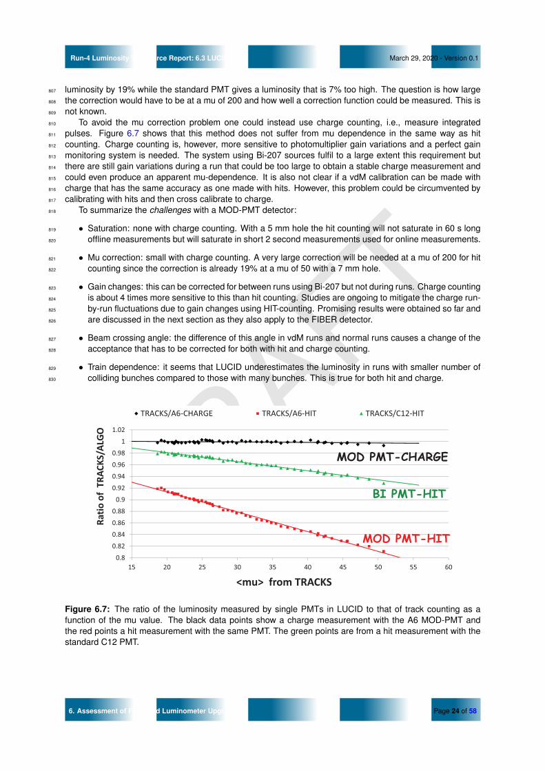
DRAFT
Run-4 Luminosity Task Force Report: 6.3 LUCID March 29, 2020 - Version 0.1
luminosity by 19% while the standard PMT gives a luminosity that is 7% too high. The question is how large807
the correction would have to be at a mu of 200 and how well a correction function could be measured. This is808
not known.809
To avoid the mu correction problem one could instead use charge counting, i.e., measure integrated810
pulses. Figure 6.7 shows that this method does not suffer from mu dependence in the same way as hit811
counting. Charge counting is, however, more sensitive to photomultiplier gain variations and a perfect gain812
monitoring system is needed. The system using Bi-207 sources fulfil to a large extent this requirement but813
there are still gain variations during a run that could be too large to obtain a stable charge measurement and814
could even produce an apparent mu-dependence. It is also not clear if a vdM calibration can be made with815
charge that has the same accuracy as one made with hits. However, this problem could be circumvented by816
calibrating with hits and then cross calibrate to charge.817
To summarize the challenges with a MOD-PMT detector:818
• Saturation: none with charge counting. With a 5 mm hole the hit counting will not saturate in 60 s long819
offline measurements but will saturate in short 2 second measurements used for online measurements.820
• Mu correction: small with charge counting. A very large correction will be needed at a mu of 200 for hit821
counting since the correction is already 19% at a mu of 50 with a 7 mm hole.822
• Gain changes: this can be corrected for between runs using Bi-207 but not during runs. Charge counting823
is about 4 times more sensitive to this than hit counting. Studies are ongoing to mitigate the charge run-824
by-run fluctuations due to gain changes using HIT-counting. Promising results were obtained so far and825
are discussed in the next section as they also apply to the FIBER detector.826
• Beam crossing angle: the difference of this angle in vdM runs and normal runs causes a change of the827
acceptance that has to be corrected for both with hit and charge counting.828
• Train dependence: it seems that LUCID underestimates the luminosity in runs with smaller number of829
colliding bunches compared to those with many bunches. This is true for both hit and charge.830
0.8
0.82
0.84
0.86
0.88
0.9
0.92
0.94
0.96
0.98
1
1.02
15 20 25 30 35 40 45 50 55 60
Ratio%of%%TRACKS/ALGO
<mu>%%from%TRACKS
TRACKS/A61CHARGE TRACKS/A61HIT TRACKS/C121HIT
Run 350184
MOD PMT-HIT
BI PMT-HIT
MOD PMT-CHARGE
Figure 6.7: The ratio of the luminosity measured by single PMTs in LUCID to that of track counting as afunction of the mu value. The black data points show a charge measurement with the A6 MOD-PMT andthe red points a hit measurement with the same PMT. The green points are from a hit measurement with thestandard C12 PMT.
6. Assessment of Proposed Luminometer Upgrades Page 24 of 58

DRAFT
Run-4 Luminosity Task Force Report: 6.3 LUCID March 29, 2020 - Version 0.1
6.3.2 A FIBER DETECTOR FOR RUN-4831
During Run-2 the FIBER detector did not contribute to the luminosity measurement but was studied as a832
prototype for Run-3 and Run-4. Hereafter the main advantages and limitations observed are described with833
reference to the requirements for Run-4.834
• Gain monitoring system and impact on long-term stability: differently from the PMT detector which835
uses a Bi-207 radioactive source to monitor (and therefore correct) the gain-losses of the PMTs, the836
fibers PMTs were monitored through LED light directly injected on their window. The control of the LED837
stability, performed with a PIN-diode, proved not to be adequate. The LED light injected has moreover838
a different wavelength with respect to the Cherenkov photons. Finally the LED is injected into the PMTs839
and not at the fibers-end which prevents from monitoring possible fibers degradation due to radiation.840
Overall the inability to fully understand the gain monitoring system is considered at least a part of the841
poorer long-term stability of the FIBER detector (at the level of up to 10% during one year) as compared842
to the PMT detector (which proved to be stable at the % level). A system based on radioactive sources843
similar to the one of the PMT detector is under study, to at least provide a good control of the PMT gain844
stability.845
• Linearity (and calibration transfer): HIT-counting algorithms are affected by very large non-linearities846
(mu-dependence) and therefore, in order to be used, they would need to rely on very large and probably847
not precise enough offline corrections. The HIT-counting algorithms are therefore affected by large848
calibration transfer (and related uncertainty) and will most probably not be usable. On the other hand the849
Charge-Integrating algorithm proved to be linear (as compared to track-counting and/or calorimeters)850
over the whole luminosity range of Run-2. There are no evident reasons why this should not apply to851
larger values of pile-up. The FIBER detector can therefore only rely on Charge-integrating algorithms.852
• Short-term stability: The FIBER detector has shown a poor stability over time. This is mostly attributed853
to the not-effective LED-based monitoring system. In addition, the charge-integrating algorithm, the854
only one usable for the FIBER detector, is intrinsically more dependent on PMT gain-variations with855
respect to HIT-counting, both in the long-term (which is supposed to be compensated for by high voltage856
changes) and on the Run-by-Run timescale, where gain losses up to 2-3% are observed. This results857
into Run-to-Run fluctuations of this order of magnitude, not incompatible with the online requirements,858
but certainly with the offline ones. It is envisageable and under study to correct offline these fluctuations859
by using the standard PMT HIT-Counting algorithms. The preliminary results are very encouraging as860
can be seen in Figure 6.8 where the stability of the charge algorithm for one FIBER channel is shown861
both without (top) and after (bottom) a run-by-run correction using the HIT algorithm of one standard862
PMT channel (before this is corrected using track-counting, i.e. as it is measured by LUCID). To do this863
it is imposed that the CHARGE-to-HIT ratio in a single luminosity block with µHIT = 30 to be constant864
for all runs. In this way, exploiting the linearity of the charge algorithm and the lower sensitivity of the865
HITS algorithm to the PMT gain-losses, the charge algorithm is made more stable (both in the short-866
and long-term) and at the same time independent of any external detector, apart from the calibration867
transfer. Similar results are also obtained for the charge algorithm of the MOD PMTs.868
• van der Meer absolute calibration: in vdM (vdM-like) conditions, the observed signal/noise ratio is poorer869
with respect to the PMT detector in Run-2. This is partially due to instabilities of the readout electronic,870
which are under investigation and which are not supposed to be a limitation in Run-4 once understood871
and solved (they do reside in the electronics and are not principle reasons related to fibers and/or to the872
algorithms used), but the precision of the vdM calibration with fibers has still to be assessed. In beam-873
offset scans the signal is marginal. A different location of the FIBER detector might help to increase the874
signal but studies in this respect have not yet started.875
• Dependence on bunch-configuration and beam-parameters: a dependence at the level of a few percent876
on the LHC crossing-angle has been observed (common to all LUCID sensors simply due to their877
geometrical position) and, in addition, a dependence still to be understood on the bunch-configuration878
(number of colliding bunches). This last effect must be understood, and data from Run-3 will be used879
for this purpose.880
6. Assessment of Proposed Luminometer Upgrades Page 25 of 58

DRAFT
Run-4 Luminosity Task Force Report: 6.3 LUCID March 29, 2020 - Version 0.1
• Saturation: charge-integrating algorithms are not expected to saturate (as HIT-counting) due to large881
values of pile-up parameters in Run-4 due to the absence of zero-starvation issues. This is a very strong882
advantage for its use in both the FIBER, PMT and MOD-PMT detectors.883
• Location of the detector: the place where LUCID sits now will be most probably not available (or less884
available) due to the LHC instrumentation. This is a common problem for the whole LUCID detector and885
must be addressed and solved as soon as possible.886
Overall, the FIBER detector is expected to fulfil most of the ONLINE requirements, provided that a proper887
gain-monitoring system will make it possible to keep the PMT gain constant at a few-% level as was the888
case in Run-2 for the PMT-detector. As for the OFFLINE requirements, it is expected from todays experience889
that it will most probably not comply with the requirements. In particular in terms of short-term stability and890
dependence on the bunch-configuration, at least without any external recalibration and/or correction, which891
are expected to be possible but will prevent the FIBER detector from being a fully independent detector (which892
was also the case for LUCID already in Run-2). Its strong points concerning expected linearity and absence893
of saturation (additional to other features common to the whole LUCID detector) are however strong points894
suggesting the importance of dedicated efforts and studies of Run-2 and Run-3 data for its full qualification895
and a strong reason for including it in the Run-4 LUCID design.896
Figure 6.8: Ratio between the luminosity measured by a LUCID FIBER channel (C-17) and track-counting forall runs in 2018, before (top) and after (bottom) the correction to the HIT luminosity of a single PMT channel(C-12). The ratio is normalized to 1 in a single run.
6.3.3 ACTIVITY FOR RUN-3 TOWARDS THE RUN-4 UPGRADE897
The detector which will run in Run-3 will basically be the same as the one which provided the ATLAS lumi-898
nosity in Run-2. Minor modifications are being implemented in order to make the system suitable for Run-3899
conditions and in view of Run-4. These include:900
• PMTs and bases will now be both replaceable during the winter shutdowns, which was not the case so901
far when only PMTs could be changed if malfunctioning were observed. Indeed at the end of Run-2 an902
increasing number of such malfunctioning channels were observed and were initially attributed either903
to PMT or bases being damaged due to either radiation or the charge produced. These problems were904
only observed in the PMT detector but not in the FIBER detector, whose readout PMTs draw smaller905
6. Assessment of Proposed Luminometer Upgrades Page 26 of 58

DRAFT
Run-4 Luminosity Task Force Report: 6.3 LUCID March 29, 2020 - Version 0.1
current and are in a lower radiation area. Measurements performed in the lab with the dismantled LUCID906
unambiguously pointed to a problem neither in the sensors nor in the bases but in the contacts between907
the two. Work has therefore been done in order to ensure that both components can be replaced908
during the winter access. This has been possible by adding radiation hard connectors between both909
the signal and the HV cables and the bases, which was not the case before. Radiation hardness910
measurements performed with gammas at the Calliope Facility of ENEA (Rome, Italy) have shown that911
such connectors are resistant up to the doses expected for the full Run-3. Also the HV and signal cables912
show no degradation. Neutron irradiation is expected to take place before summer 2020. Note that the913
full Run-3 will correspond to about one year of Run-4 in terms both of radiation and produced charge.914
Based on the irradiation measurements it is therefore expected that no issues will affect the base-cable915
connectors in a one year period in Run-4, but the problem of the PMT-base contact problem could show916
up in timescales smaller than that. Solutions for this problem are therefore necessary to allow the single917
channels to survive for at least one year in Run-4, before they can be replaced during the winter breaks.918
• Work is ongoing to design and install before Run-3 one FIBER channel read-out by a PMT capable to919
host a Bi-207 on the its window. The PMT has to be of larger diameter to allow both the insertion of920
the quartz fiber and host the source. A candidate has been identified with 25 mm window and work921
is ongoing to design the connector ensuring that no radioactive source can leak. Such a channel will922
be fundamental to understanding whether the responsibility for the long term drift of the luminosity923
measurement with fibers is due to the LED calibration and is therefore of the highest importance for the924
FIBER detector in Run-4.925
• Measurements are starting in the lab in order to understand if simpler (and less space-consuming)926
systems can replace the FIBER detector as it is now. These measurements include quartz rods of927
different diameter (from 2.5 to 10 mm) which could be placed perpendicular to the beam-pipe avoiding928
the present longitudinal section. This would both shorten the path the light should go through before929
reaching the PMT and limit the space occupancy of the detector in view of the limitations due to the LHC930
upgrade in Run-4. The main question to be answered though is how the signals produced in the rods931
compare to the ones presently produced in the fibers (with main focus on the capability to be calibrated932
in vdM conditions). One adavantage of this system would be the possibility to equip the rods with Bi-207933
in one end so to monitor both PMT gain and rod degradation.934
• During Run-3 (but not at the beginning) it is foreseen to insert a few MOD-PMTs with the custom mod-935
ification of the aluminum layer between window and cathode further reducing the effective active area936
of the PMT (down to 5 mm diameter). Studies of the produced charge (compared to the present PMTs)937
and of the physics performances (in particular in terms of mu-dependence) are crucial to understand if938
such devices are effectively a viable solution for Run-4.939
From the above discussion it is clear that many answers about the performances of the proposed LUCID940
detector for Run-4 will come from Run-3. It is therefore crucial that this program can be carried out during Run-941
3 and data are analyzed and understood. This requires sufficient personpower, additional to what is needed942
for the daily operation of the detector which, as happened in Run-2, will be the only one able to measure943
luminosity online in all conditions and therefore will be subject to a high demand both from LHC and ATLAS.944
The present person-power in the LUCID community is critical if not underestimated to face both the running of945
the detector, the design and installation of the prototypes and the data analysis both for performance studies946
and for luminosity measurement.947
6.3.4 PROPOSAL OF LUCID FOR RUN-4 AND RECOMMENDATIONS948
An advantage of the LUCID detector is that the detector technology and its luminosity methods have been949
extensively tested. The limitations, problems and corrections are well known and have been studied during950
several years. Data exists and can be used to predict the performance at the HL-LHC. Moreover the detector951
will be operating during Run-3 with improvements towards Run-4 and performance studies can be further952
done in realistic conditions. Finally, due to the existing experience and to the relative simplicity of the detector,953
LUCID is expected to be installed and active from the beginning of Run-4, when some of the newly proposed954
detectors will be either incomplete or not yet fully understood. In particular on the online side, the limited955
6. Assessment of Proposed Luminometer Upgrades Page 27 of 58

DRAFT
Run-4 Luminosity Task Force Report: 6.3 LUCID March 29, 2020 - Version 0.1
ATLAS redundancy present today and expected at least in the beginning of Run-4, calls for a detector based956
on a known technology to be present. On the other hand for this to happen, crucial technical issues must be957
solved: as an example, the new LHC vacuum equipment that ATLAS has agreed to install at the location of958
the present LUCID-2 detector will make it difficult to find space and install new LUCID-3 detectors around the959
VJ beampipe. It will be crucial to have technical support from the ATLAS technical coordination to ensure that960
a new detector can be installed. This should include the possibility of modifying the forward shielding to give961
space for LUCID and its services.962
At present it is not clear if a FIBER detector or a MOD-PMT detector is the best way to go, as the arguments963
explained in the previous section highlight pro and cons to each of the two. More tests and developing work964
are needed to determine this in detail (as described in the previous section).965
According to the present understanding, a combination of the two technologies (PMT and FIBER detec-966
tors) might be desirable. A MOD-PMT detector should also incorporate standard PMTs (i.e. with no reduction967
of the active area) to be used in VDM scans (and up to µ ∼130), to ensure both a solid absolute calibration968
and help understanding the non-linearity corrections. Ideas of correcting the charge measurement by hit mea-969
surements will perhaps make it possible to make the MOD-PMT detector charge measurements more stable.970
New MOD-PMTs with a hole of 5 mm will be purchased and tested during Run-3 (as discussed above). The971
MOD-PMT charge measurements can also be tested for online measurements during Run-3. The FIBER972
detector can be considered a useful back-up, should the problem of the calibration be solved in Run-3.973
The present LUCID-2 detector was designed and built in a little more than one year and this is a big974
advantage over more complex detectors that needs many years to go from ideas to finished detector. There975
is therefore ample time to study the different ideas that has emerged for a LUCID-3 detector before a final976
design has to be chosen.977
6.3.5 ONLINE AND OFFLINE REQUIREMENTS978
Referring to the list of online and offline requirements listed in Section5, LUCID-3, independent of the final979
design but under the general scheme proposed, is expected to:980
• comply with the online operational requirements;981
• comply with the online performance requirements;982
• comply with the first of the offline requirements namely it will be possible to calibrate in vdM conditions983
with a precision determined by LHC-beam parameters. As for the others (linearity or linearity correction,984
bunch-configuration independence and long-term stability) the present experience suggests that a sub-985
% precision will NOT be reached, unless a better understanding will be obtained in Run-3;986
• comply with the requirement to be a modular and flexible detector, operationally solid against malfunc-987
tioning of single components and able to perform to a certain extent internal consistency checks;988
• most probably LUCID will not have stand-alone capability at least if using the HIT-counting algorithms989
due to the needed non-linearity corrections.990
6. Assessment of Proposed Luminometer Upgrades Page 28 of 58

DRAFT
Run-4 Luminosity Task Force Report: 6.3 LUCID March 29, 2020 - Version 0.1
6.4 TILE CALORIMETER991
During Run 2, the TILE calorimeter has stably provided luminosity measurements based on PMT anode992
currents. Two main groups of cells were used with different impact on the luminosity measurement:993
• E Cells (in particular E3 and E4): these are the most exposed to radiation and therefore the ones994
with the largest degradation of response, i.e. ageing, as a function of time (or integrated luminosity).995
Due to their larger sensitivity at low luminosity, these cells can be cross-calibrated to LUCID in the996
vdM regime; their response in high-luminosity runs immediately following the vdM run (therefore with997
minimal degradation) is crucial to assess the calibration-transfer uncertainty (which typically dominates998
the overall luminosity uncertainty) by comparison with the track-counting algorithm. On the other hand,999
E cells cannot be used for long-term stability studies, due to scintillator radiation damage;1000
• D Cells (in particular D5 and D6): these are remarkably stable as a function of time provided the1001
PMT gain is monitored, and corrected for, based on a laser calibrations, while the radiation-induced1002
degradation of the Tile scintillators can be accounted for offline, with the dedicated calibration based on1003
Cesium sources. The D cells are therefore used to study the long-term stability of LUCID; however they1004
cannot be used for calibration-transfer studies, due to their poor sensitivity in the vdM regime, which1005
prevents them from being cross-calibrated in the vdM calibration runs.1006
The main features of the TILE measurement are: a good linearity (at the sub-percent level) as a function1007
of the bunch-integrated instantaneous luminosity; the excellent long-term stability of the D Cells, also in this1008
case at the sub-percent level; the sufficient sensitivity of E-Cells at low luminosity to study calibration-transfer1009
systematics; the reliability and stability of the system which made the luminosity measurement by TILE smooth1010
during the whole of Run 2. On the other hand, TILE cannot provide bunch-by-bunch measurements and1011
moreover cannot provide the 40 MHz sampling rate needed for online purposes; however the publication of1012
the online luminosity at the Hz level is possible. It is therefore a crucial detector to complement the dedicated1013
luminosity detectors and to provide the crucial information to assess the dominant systematic uncertainties of1014
the luminosity measurement, but it cannot fulfill most of the online requirements. The main upgrade actions1015
towards Run-4 (some of which already taking place for Run-3) can be summarized as follows:1016
• E-Cell scintillators will be replaced before Run 3 by more radiation-resistant ones. We consider it crucial1017
that E-Cells be kept (and possibly replaced again after Run 3 if needed) also in Run 4 to ensure the1018
possibility to study the calibration transfer;1019
• if it turns out to be needed at the end of Run-3, PMTs must be replaced with new ones;1020
• HV-dividers will replaced with active ones everywhere in order to ensure an even better linearity;1021
• every channel will be equipped with individual ADCs with increased dynamic range to mitigate single-1022
point failures;1023
• every channel will be read out at 100 Hz via optical links through PPR;1024
• the existing laser calibration system will be maintained as well as the Cs-based system.1025
A demonstrator with such improvements was tested in an SPS test beam and it would be highly important1026
that it can stay during Run-3 to evaluate the performance and the improvements with respect to the Run-21027
configuration. To summarize: there are no apparent showstoppers for the TILE upgrade to ensure even better1028
performance with respect to Run 2. The main concerns/recommendations are:1029
• the person-power to be dedicated to the luminosity measurement within the TILE community should be1030
expanded to ensure offline analysis and maintain the calibration files and dead-channel list needed to1031
ensure optimal online performance;1032
• the demonstrator should be running during Run 3 to study the performance in view of Run 4;1033
• the E-Cells should be kept during Run-4 as a crucial ingredient for the assessment of the calibration-1034
transfer uncertainty.1035
6. Assessment of Proposed Luminometer Upgrades Page 29 of 58

DRAFT
Run-4 Luminosity Task Force Report: 6.4 Tile Calorimeter March 29, 2020 - Version 0.1
6.5 LAR CALORIMETER1036
6.5.1 EXPERIENCE IN RUN-2 AND OUTLOOK FOR THE HL-LHC FOR THE1037
LAR-GAP CURRENT MEASUREMENTS1038
The following description is based on a text written by J. Carter (Toronto).1039
The ATLAS liquid argon (LAr) calorimeters provide bunch-integrated luminosity measurements using the1040
LAr-gap currents in the electromagnetic endcap calorimeter (EMEC) and the forward calorimeter (FCal). This1041
method serves as an independent, complementary luminosity measurement and is important for both online1042
monitoring and evaluating the long-term stability of the ATLAS baseline luminosity algorithm. One limitation of1043
this method is that it is not sensitive enough in the low-luminosity regime and cannot therefore be calibrated1044
in vdM-scans (a cross-calibration to the main ATLAS luminometer, LUCID-2, is therefore performed in the1045
high-luminosity regime to set the absolute luminosity scale). The LAr gap currents are measured in a set of1046
high-voltage (HV) lines supplying the drift voltage to the EMEC and FCal. The current drawn by the calorimeter1047
is proportional to the instantaneous luminosity, therefore a linear fit of the gap current as a function of a known1048
reference luminosity provides a means to calibrate the luminosity measurement of an individual HV line. A1049
single measurement for each detector subsystem is achieved by averaging over HV lines.1050
Run-2 saw exceptionally smooth operation of the HV-based LAr luminosity system and online infrastruc-1051
ture, with no major issues occurring and only minimal intervention from experts. Several improvements to the1052
offline measurement were made throughout Run-2, which can be adapted for the online system in the future.1053
First, a more robust pedestal subtraction method was developed. This method estimates the baseline LAr-1054
gap current for each ATLAS run during a 10 minute period immediately before the LHC beams are brought1055
into collision. In the online system, since the time at which stable beams are declared is not known a priori, a1056
single pedestal value per channel was used throughout Run-2. An alternative approach could be developed to1057
more closely resemble the offline pedestal method. For example, a buffered sliding window could be employed1058
to record the gap currents over a 10 minute period and retrieve the pedestal at the point immediately before1059
stable beams are declared.1060
Second, a correction to the offline FCal luminosity was developed to account for a non-linear intensity1061
dependence, where the FCal tended to overestimate the luminosity relative to the other luminosity algorithms1062
by several percent at low total (i.e. bunch-integrated) luminosity. The correction parameters were obtained by1063
anchoring the FCal luminosity to the primary track-counting luminosity algorithm in a single physics run and1064
then applied to all subsequent runs. A similar correction could be employed for the online FCal luminosity.1065
Additionally, the correction parameters, as well as the channel-by-channel calibration parameters, would need1066
to be re-evaluated for the higher luminosity conditions at the HL-LHC.1067
Another potential improvement to both the online and offline LAr luminosity measurements is to increase1068
the HV line sampling rate. In Run-2, the sampling rate was set to 20 samples/min for all FCal channels and to1069
12 samples/min for all EMEC channels. Increasing the EMEC sampling rate would improve the precision in1070
low-luminosity conditions where the signal to background ratio is small, and in special runs that require better1071
timing resolution, such as µ-scans. However, increasing the sampling rate comes at the cost of greater disk1072
usage and strain on the Detector Control System (DCS), which manages the data flow and I/O of the HV line1073
current measurements, therefore this option should only be used if the necessary computing resources are1074
available.1075
Finally, further corrections to the offline LAr luminosity measurement are currently being examined. For1076
example, there is evidence of activation effects in both the EMEC and FCal measurements where there is a1077
residual current in the HV lines immediately after the beams are brought out of collision, which then decays1078
exponentially over time. Studies based on detector simulation are underway to estimate and subtract this1079
residual “activation luminosity” given the response of the detector and the ATLAS luminosity history. Another1080
correction under investigation is to account for HV-sagging due to protection resistors and filter box resistors,1081
which reduces the LAr gap currents at high luminosity. Based on results from simulation, this effect is on the1082
order of 1 % in the FCal (and negligible in the EMEC) at luminosities of 2 × 1034 cm−2s−1 and is predicted to1083
increase at the luminosities reached at the HL-LHC. It may therefore be necessary to include this correction1084
in future LAr luminosity measurements.1085
The operation of the HV-based LAr luminosity system is expected to continue roughly as-is into Run-31086
and the HL-LHC with no major issues foreseen. No major changes to the online computing infrastructure or1087
6. Assessment of Proposed Luminometer Upgrades Page 30 of 58

DRAFT
Run-4 Luminosity Task Force Report: 6.5 LAr Calorimeter March 29, 2020 - Version 0.1
the offline analysis tools, other than those already mentioned, will be required for continued operation at the1088
HL-LHC.1089
6.5.2 POSSIBLE BUNCH-BY-BUNCH LUMINOSITY MEASUREMENT USING1090
LTDBS (PHASE I) OR LASPS (PHASE II)1091
The following description is based on a text written by P. Schwemling (CEA).1092
The triangular Liquid Argon ionization current pulse is shaped by a CR − RC2 filter, whose time constants1093
have been optimized to minimize the total contribution from electronics noise and from pile-up noise. Nev-1094
ertheless, the dispersion of the measurements around the pedestal obviously is sensitive to the amount of1095
pile-up, and hence to the instantaneous luminosity.1096
The LAr calorimeter Phase-I upgraded electronics continuously digitizes the analog signal from the Su-1097
percells. The Phase-II main-readout electronics will do the same on the individual cells. This continuous1098
digitization opens up the possibility to measure in an unbiased way the dispersion of the samples around the1099
pedestal and thereby extract luminosity information.1100
Preliminary studies have been made offline on physics data taken with LTDB pre-series boards at the end1101
of Run 2, during several fills of proton-proton collisions. This has shown that a luminosity measurement with1102
a statistical error of a few per mille is easily reachable using all the 64 EMB LTDBs, analyzing the sample1103
dispersion over 32 sample time frames, for a few hundred events per lumi block. A first estimate of the1104
associated total systematics is 1.2 %. This has been obtained by comparing the measured dispersion of the1105
luminosity estimation with a purely statistical estimation of this dispersion. This is very conservative since no1106
study has been made yet to reduce this number.1107
In addition to the dispersion of the samples, other luminosity estimators have been evaluated, like the1108
shape of the autocorrelation function. If the statistical power of this estimator is about 30 % worse than the1109
statistical power of the dispersion of the samples, the systematics are at a similar level. In addition, there is1110
some evidence that the origin of the systematics is not the same for both estimators, so combining them can1111
potentially reduce the global systematics.1112
The CR − RC2 shaping has also the consequence that the integral of the shaped pulse is equal to zero.1113
So, for infinite bunch trains with constant luminosity, the position of the pedestal will stay on average constant.1114
The CR − RC2 shaping does however not cancel the sensitivity of the pedestal to the derivative of the1115
bunch by bunch luminosity. This opens up the possibility of measuring the bunch by bunch luminosity from1116
an instantaneous bunch by bunch measurement of the pedestal level. The feasibility of this measurement1117
has also been demonstrated on LTDB physics collision data. The reachable precision has to be evaluated1118
carefully.1119
In the case of the Phase-I electronics, it is planned to use the monitoring channel output of the back-end1120
LAr-data processing board (LDPB). This monitoring channel has the capability to output digitized data at a1121
rate of a few Hz. The LDPB will also measure in real time the pedestal position, bunch crossing by bunch1122
crossing. Reading this information out at a rate of a few times per minute will provide the required information1123
for a bunch by bunch luminosity measurement.1124
In the case of the Phase-II electronics, the required information is the same as for Phase-I. Both the1125
LDPB and the LAr signal processor (LASP), the Phase-II main readout systems, can be combined for this1126
measurement.1127
One major strength of the Liquid Argon calorimeter is its excellent intrinsic linearity and time stability.1128
During Phase-II, the linearity may however be limited by the high voltage drop accross the charge drift gap,1129
induced by the high current and the accumulated space charge due to the many consecutive collisions. If1130
this effect is anticipated to be serious in the most forward regions of the detectors, it should remain negligible1131
in the barrel (|η| ≤ 1.5). It should be noted that since this luminosity measurement effectively relies on a1132
measurement of pile-up, it will not be applicable to low-µ running or vdM scans.1133
6. Assessment of Proposed Luminometer Upgrades Page 31 of 58

DRAFT
Run-4 Luminosity Task Force Report: 6.5 LAr Calorimeter March 29, 2020 - Version 0.1
6.6 HGTD1134
The High Granularity Timing Detector (HGTD) is a new detector planned for the ATLAS Phase-II upgrade. It1135
will augment the ITk in the forward region, with the capability to measure charged particle trajectories in time1136
as well as space. The target average time resolution per track for a minimum-ionising particle is 30 ps at the1137
beginning of the HL-LHC, increasing to 50 ps per track at the end of the HL-LHC. The HGTD will also provide a1138
precise, real-time luminosity measurement for ATLAS’s Phase-II physics programme. The full documentation1139
of the detector can be found in the TDR, which is in its final stages of preparation at the same time this report1140
is being prepared.1141
The HGTD will be located in the gap region between the barrel and the end-cap calorimeters, at a distance1142
in z of ±3.5 m from the nominal interaction point. This region lies outside the ITk volume and in front of the1143
end-cap and forward calorimeters in the volume currently occupied by the Minimum-Bias Trigger Scintillators1144
(MBTS), which will be removed. Each endcap consist of two disks (cooling plates) with sensors mounted and1145
the front and backside of each disk. The active area extend from an inner radius of 120 mm to an outer radius1146
of 640 mm. The position of the two vessels for the HGTD within the ATLAS detector is shown in Fig. 6.9.1147
Figure 6.9: Position of the HGTD within the ATLAS Detector. The active area (blue in the figure) extend from120 < r < 640 mm.
The detector elements will consist of silicon Low Gain Avalanche Detector (LGAD), with pads of 1.3 times1148
1.3 mm and with an active thickness of 50 µm. This pad size ensures occupancies below 10% at the highest1149
expected levels of pile-up, small dead areas between pads, and low sensor capacitance, which is important for1150
the time resolution. A custom ASIC (ALTIROC) which will be bump-bonded to the sensors is being developed1151
to meet the requirements on time resolution and radiation hardness. The ASIC will also provide functionality1152
to count the number of hits registered in the sensor and transmit this at 40 MHz to allow unbiased, bunch-1153
by-bunch measurements of the luminosity using the Pixel Cluster Counting method. All ASICs of the HGTD1154
are of the same type, thus all are capable of providing occupancy data at 40 MHz. The limiting factor for how1155
much of the detector is read out for luminosity purposes is foremost the space needed for the optical links, and1156
to a smaller extent the cost of the backend electronics FELIX boards. As low occupancy is desirable for the1157
luminosity measurement, only sensors in the outermost regions (430 < r < 640 mm) will be used to measure1158
the luminosity. In total this corresponds to 4,256 LGAD sensors (and 8,512 ASICs).1159
6.6.1 HGTD AS A LUMINOMETER1160
The HGTD has been designed to meet as many of the requirements for the HL-LHC luminosity program as1161
possible. As a detector that will be possible to calibrate in vdM scans, read out every bunch crossing, and1162
operate at all expected µ values, it is meant to fill the hole in the luminosity program in ATLAS that was evident1163
in Run-2 when only LUCID could fulfill these requirements.1164
6. Assessment of Proposed Luminometer Upgrades Page 32 of 58

DRAFT
Run-4 Luminosity Task Force Report: 6.6 HGTD March 29, 2020 - Version 0.1
The high granularity gives a low occupancy, and should therefore provide excellent linearity between1165
the average number of hits and the average number of simultaneous pp interactions over the full range of1166
luminosity expected at the HL-LHC. With detector signal durations in the few-ns range, the charged particle1167
multiplicities within the acceptance can be determined accurately for each individual bunch crossing. With1168
the occupancy information sent at 40MHz, the HGTD will be able to provide both online and offline per-BCID1169
luminosity measurements.1170
The pixel cluster counting will be done over two time windows, one centred at the bunch crossing and with1171
a width of 3.125 ns, the other (a sideband time window) with both width and relative position tunable with a1172
step of 3.125 ns. Fig. 6.10 illustrates the two time windows used for the luminosity measurement.1173
Figure 6.10: Illustration of the time windows used for counting hits for the luminosity data. The smaller window(W1, in red) is 3.125 ns wide and is centred at the bunch crossing time. The width and relative location of thelarger window (W2, in blue) can be set in steps of 3.125 ns through the control parameters.
This double-sideband window will be programmable. Here it has been chosen symmetric, such that its1174
occupancy provides, after appropriate scaling, an estimate of the noise and afterglow contributions as interpo-1175
lated under the luminosity signal in the central time window, separately for each BCID. This ability to perform1176
an in-situ measurement of the noise and afterglow level for each bunch crossing, using data from empty RF1177
buckets just before and after the filled bucket within the same nominally filled 25-ns bunch slot, is a unique1178
capability of the HGTD compared to other luminometers.1179
To facilitate the luminosity measurement, the ASICs will be grouped together into regions (where each1180
region can be calibrated independently). The definition of the regions can be made in software residing on1181
the FELIX host or in a Data Handler instance and can thus be tuned with operational experience. A possible1182
outline for 16 regions per disk is shown in Fig. 6.11.1183
1
2
3
4
5
6
7
8
9 10 11 12 13 14 15 16
Figure 6.11: Sketch of the partitioning of the sensors into 16 regions for the luminosity determination. Each ofthe regions can be used to determine the luminosity independently of the others. Regions at different radiuswill be subject to different levels of radiation over time.
Considering the requirements for the luminosity program at the HL-LHC outlined in Chapt. 5, the HGTD:1184
• Will have the capability to be calibrated in vdM scans.1185
• Will be able measure the luminosity per-bunch, independent of TDAQ and with sampling at 40 MHz.1186
• Provide online luminosity updates at the needed frequency.1187
6. Assessment of Proposed Luminometer Upgrades Page 33 of 58
DRAFT
Run-4 Luminosity Task Force Report: 6.6 HGTD March 29, 2020 - Version 0.1
• Will not be able to operate in non-stable beam modes, unless a safe configuration is found with a subset1188
of the full detector at a reduced high voltage compared to nominal operations.1189
• Ideally conform with the performance requirements of being linear with the instantaneous luminosity1190
and have good long-term stability.1191
6.6.2 REVIEW OF THE DETECTOR1192
The HGTD was reviewed by the Phase2LTF in a meeting on October 21, 2019, with follow-up discussions in1193
subsequent meetings. In this review, some of the key issues that were raised were:1194
• The ability to cope with individual detector elements going noisy or dead, which has implications1195
for the long-term stability of the detector. The large area instrumented for the luminosity implies that1196
the chance of a few detector elements malfunction increases, while at the same time the large area1197
partially alliviates the problem as the impact of these elements are reduced. For the Run-2 measure-1198
ments using the silicon detectors (Pixel and SCT) a data quality analysis is necessary to remove such1199
elements, the same will be true for the HGTD. If HGTD is to be used as one of the main luminometers,1200
such analysis has to be both detailed and prompt. This is a challange for the HGTD community, but sim-1201
ilar to what any silicon detector has to cope with. The occupancy counts in the sideband time window1202
gives some possibilities of implementing fast "stopless removal" actions online for better online luminos-1203
ity stability. One possibility is that the luminosity backend electronics automatically removes data from1204
an ASIC if the counts in the sideband time window is saturated in a large number of consecutive bunch1205
crossings.1206
• The ability to remove data from individual ASICs for the offline analysis, to reach the best pos-1207
sible precision of the measurement. When the data is aggregated in the backend luminosity elec-1208
tronics, the information from individual ASICs are lost. For the best precision of the offline analysis, one1209
would like to store final occupancy counts for each of the ASICs for every Luminosity Block (LB), so that1210
counts from regions can be updated by removing individual elements that does not fullfil the long-term1211
stability requirements. The possibility of storing such per-LB data offline has been studied, and found to1212
be within the specifications of the luminosity backend capabilities. The new baseline for the HGTD, as1213
documented in the TDR, includes the functionality to store per-ASIC, per-LB information offline, either1214
directly into a database or written out in a dedicated data format.1215
• The uncertainty regarding the performance of a new type of detector, and the availability of the1216
detector at the start of Run-4. The timeline for the production of the HGTD and its installation in LS31217
is very compact. The baseline is to install the full detector before the start of Run-4, but there is a1218
fallback option of only installing the detector on one side of the interaction point. In addition, there are1219
uncertainties regarding which precision can be achieved with the detector, that can only be answered1220
once operational experience has been gained. The pixel cluster counting method is well established,1221
it is used as the default method by CMS in Run-2, and should be intrinsically linear with the instan-1222
taneous luminosity. The experience from CMS is that the largest uncertainties come from subtracting1223
the contributions from noise and afterglow. While the HGTD will have unique capabilities for estimating1224
these contributions using the sideband time window, it is still impossible to know what precision can be1225
achieved using these tools without having some operational experience with the detector.1226
6.6.3 ACTIVITY TOWARDS RUN-41227
The two main components that are needed for the luminosity functionality of the HGTD are the ASICs and the1228
backend electronics which will handle the data from the ASICs. The current status of these components are:1229
• The first iteration of the ASIC which will have the digital blocks for sending occupancy information1230
will be submitted at the end of 2020. Tests of this capability will occur during 2021, and integrated1231
tests (sending data over optical fibres to FELIX units) will happen during 2022 together with testbeam1232
measurements.1233
6. Assessment of Proposed Luminometer Upgrades Page 34 of 58

DRAFT
Run-4 Luminosity Task Force Report: 6.6 HGTD March 29, 2020 - Version 0.1
• A phase-I FELIX will be delivered during Q1 of 2020 which will be the starting point for implementing1234
and testing the data handling in the backend electronics. This includes both firmware and software1235
developments. Initial tests will be using signal generators coded in FPGAs, whereas subsequent tests1236
will be using communication over optical fibres.1237
More detailed plans regarding the activities towards Run-4, including cost and personpower considerations,1238
can be found in the TDR. In addition, the HGTD luminosity effort would be greatly helped by having a pixel1239
cluster counting analysis in ATLAS in Run-3 to gain the necessary experience with this algorithm.1240
6. Assessment of Proposed Luminometer Upgrades Page 35 of 58

DRAFT
Run-4 Luminosity Task Force Report: 6.6 HGTD March 29, 2020 - Version 0.1
6.7 ITK1241
6.7.1 PRESENT EXPERIENCE1242
The current Inner Detector [ref:itk:innerdetector] has been extensively used for luminosity determination dur-1243
ing both Run 1 and Run 2. Such detector has provided offline luminosity measurement, either self-calibrated1244
using vdM scans or cross-calibrated to other detectors to test long-term stability and extrapolations from1245
vdM-like conditions to regular data-taking conditions.1246
The current Inner Detector will be completely replaced by the Inner Tracker (ITk) [ref:itk:itkpix, ref:itk:itkstrips]1247
during the Phase-II upgrade. Nevertheless, the experience acquired so far offers invaluable insight on the1248
strenghts and weaknesses of the existing approach based on the ATLAS inner tracking system and has been1249
used to foresee how to provide a more flexible approach for HL-LHC luminosity determination.1250
Three main classes of algorithms have been explored to-date utilizing information from the Inner Detector1251
as their primary observable:1252
• Vertex counting (VC);1253
• Track counting (TC);1254
• Pixel Cluster Counting (PCC)1255
Vertex counting has been successfully employed in Run 1, from vdM calibration to long-term stability1256
studies [22, 23]. It relies on counting the number of primary vertices reconstructed from Inner Detector tracks.1257
Corrections due to masking of nearby interactions are evaluated in a data-driven way. The main advantage of1258
such algorithm is to be very robust against variations of data-taking conditions. However, the large corrections1259
needed to unfold pile-up effects introduce uncertainties that increase substantially with higher pile-up and1260
make the algorithm impractical to be used in high pile-up environments.1261
Track counting was introduced to overcome the large pile-up corrections needed in vertex counting algo-1262
rithms [24]. It relies on counting the number of tracks that are loosly consistent with coming from primary1263
proton-proton interactions and that pass relatively tight quality criteria to reduce fake contamination. It has the1264
big advantage of being a good compromise between stability against data-taking conditions and robustness1265
against pile-up effects. Such algorithm has been a back-bone of the luminosity measurement in Run 2. It1266
provides pile-up corrections to the LUCID detector and unique probes on both long-term stability as well as1267
calibration transfer from vdM to physics runs. It is usually not self-calibrated during vdM scan runs due to1268
limited statistics available. Overall the algorithm is able to be stable within about 1-2% throughout a full year.1269
Pixel cluster counting has been developmed with the idea to provide very large statistics for luminosity1270
measurement [25]. It relies on counting the number of pixel clusters reconstructed and relating this quantity1271
to the number of proton-proton interactions. Among these three algorithms, it is the one that is more sensitive1272
to changes in data-taking conditions and the only one seriously affected by non-collision backgrounds. In the1273
current setup, only clusters in the 3D pixel module of IBL were considered; the longitudinal length of such1274
clusters offer a large separation power between clusters originating from primary particle near the luminous1275
region and backgrounds from either secondaries or beam-induced backgrounds. Corrections for movement1276
of the beamspot over time and outlier removal strategies to increase the robustness have been developed1277
and tested. Severe Single-Event-Upset problems with the current IBL chip [26] have prevented this algorithm1278
to be deployed over the full Run 2 dataset, but specific test runs have shown that such problems can be1279
mitigated successfully and a stability of the order of 1-3% can be achieved. A pixel-cluster based algorithm1280
has been also used by CMS for luminosity determination, using a similarly dedicated data-taking stream that1281
also collect information about empty bunch crossing to perform beam-background subtraction [27, 28].1282
All of these algorithms require an unbiased dataset and benefit from as large of a dataset as possible. To1283
address these problems, a special data stream was setup in Run 1, called PixelBeam. It consists of a partial-1284
event build trigger that relies on zero-bias L1 (and L2 in Run 1) triggers on nominally-filled bunch crossings,1285
where only information on the trigger and the silicon detectors is passed through HLT and saved to the output1286
data stream. Data from a selected subset of non-colliding BCIDs is also stored for background studies. Such1287
dedicated data stream has been running with a collected rate ranging from 100 Hz to 200 Hz throughout the1288
second part of Run 1 and all of Run 2. Thanks to the reduced information to be stored, this is equivalent to1289
just few Hz of a regular trigger. Additionally, a similarly configured stream, so-called Calibration_vdM is setup1290
6. Assessment of Proposed Luminometer Upgrades Page 36 of 58

DRAFT
Run-4 Luminosity Task Force Report: 6.7 ITk March 29, 2020 - Version 0.1
in special runs, as in vdM runs, to collect data for all the above algorithms using the same technique, just at a1291
much higher rate.1292
A dedicated reconstruction setup is used to process data from the PixelBeam (and Calibration_vdM) data1293
stream. The reason is two-fold. First, only partial information on the event is available and this require special1294
care on what algorithms can be run. Secondly, a dedicated track reconstruction algorithm, called VtxLumi1295
was developed to provide a fast and robust track reconstruction at the expenses of a slightly lower track1296
reconstruction efficiency. Such reconstruction setup has to be much faster than regular track reconstruction1297
due to the large amount of data collected in this stream and its robustness is a key for a successful usage1298
in luminosity measurements. The output of such setup was used for both track counting and vertex counting1299
algorithms and it is currently run automatically at T0 on the collected data by the PixelBeam data stream, as1300
well as on-demand for special runs, including all the data collected in the Calibration_vdM data stream for1301
vdM and luminosity scan runs.1302
Common short-comings of all the current approaches based on Inner Detector are the lack of a very large1303
statistics sample that allows a per-BCID luminosity measurement throughout the year - only partially mitigated1304
in the case of PCC - and dead-time effects coming from the global TDAQ data-taking chain.1305
6.7.2 ITK OPPORTUNITIES1306
Following the experience gathered with the current Inner Detector and the similarity in detector technology1307
foreseen for the Phase-II ITk, the most viable algorithms identified as promising for HL-LHC luminosity mea-1308
surement using the ITk are track counting and pixel cluster counting.1309
In terms of the dataset that can be used for luminosity measurement using such algorithms, three cate-1310
gories can be roughly defined, depending on the usage of parasitic, opportunistic, or dedicated resources.1311
A detailed plan of CMS strategy for luminosity measurement for HL-LHC is available in Ref. [29] and relies1312
heavily on the use of a PCC algorithm on data collected by dedicated hardware.1313
6.7.2.1 PARASITIC RESOURCES1314
Using existing triggers, both a TC and PCC algorithms can in principle estimate the luminosity if the bias due1315
to the trigger can be unfolded and partially limited restricting to triggers whose rate is less sensitive to pile-up1316
effects.1317
The advantage of such methods is that they require no dedicated resources, however the accuracy of a1318
potential correction for pile-up effects of such sample would require new studies and significant person-power1319
investment, with unclear results at this time.1320
For this reason, such strategy is deemed risky to rely on and is foreseen as complementary to the other1321
approaches described below.1322
6.7.2.2 OPPORTUNISTIC RESOURCES1323
Using foreseen ITk and trigger capabilities it is possible to have a more powerful dataset for luminosity mea-1324
surement using either PCC or TC algorithms. Three strategies are described briefly below, in increasing order1325
of complexity.1326
As done for the current data taking, the usage of a dedicated partial-event build stream is the most straight-1327
forward way to collect an unbiased dataset, based on random triggers, for an offline luminosity analysis. A1328
collection of filled and unpaired/empty BCIDs will have to be collected with different prescales, depending on1329
the details of the offline algorithm used. The typical expected event size for pixel and strips detector raw data1330
is about 1.1MB per event for µ = 200; the typical raw data size for a typical 2018 data-taking run for pixel1331
and strips has been estimated to be of the order of 200KB per event, i.e. about a factor 5.5 smaller. The1332
available trigger bandwidth for HL-LHC at HLT will be about 10 kHz, or a factor 10 larger than for the 20181333
data-taking. It is therefore expected that, with a similar commitment of total trigger bandwidth, a rate of about1334
300 to 400 Hz of unbiased events can be collected during HL-LHC. Such events will need to be processed1335
with a fast track reconstruction algorithm that fits in the CPU budget allocated and likely may need some initial1336
processing to fit in the disk space constraints dictated by the computing model. An offline analysis of this1337
dataset, either based on TC and/or PCC algorithms, will be able to provide a solid reference for calibration1338
transfer, long-term stability and ultimately for the total integrated luminosity. Such dataset is therefore of the1339
6. Assessment of Proposed Luminometer Upgrades Page 37 of 58

DRAFT
Run-4 Luminosity Task Force Report: 6.7 ITk March 29, 2020 - Version 0.1
uttermost importance to be foreseen for HL-LHC data taking and R&D should be pursued to ensure data can1340
be efficiently processed and analyzed.1341
Another approach that can be foreseen is using the the HLT farm to perform a real-time TC and/or PCC1342
analysis based on the reconstructed objects. The available bandwidth after L1 and the resources available1343
to dedicate to its reconstruction and analysis are the main variables that will set the ultimate rate of events1344
that can be analyzed. More R&D and a better understanding of both the L1 menu as well as the full-scan1345
tracking capabilities of HLT are needed to understand how large such maximum rate would be. Ideally, more1346
events can be processed in this scenario than the ones written on disk in the case of a dedicated partial-1347
event build stream. In addition, no offline resources (CPU and disk space) would be needed. Based on the1348
current expectation of full-scan tracking capabilities outlined in the TDAQ Phase-II TDR [30], it is reasonable1349
to expect that as much 10kHz of data could be processed with reasonable stress on both L1 bandwidth as well1350
dedicated resources for track reconstruction. Such luminosity determination could potentially overcome the1351
low statistics limitations that have been encountered in a per-BCID analysis using the dedicated data stream.1352
An even more extreme scenario would use the L1-Track trigger capabilities in the evolved trigger scenario1353
to do a TC analysis. Again, a dedicated bandwidth of unbiased events passing L0 is required but it is rea-1354
sonable to estimate that this method has the potential to access of the order of up to 100kHz of dedicated1355
data. Such analysis would certainly allow to have a per-BCID luminosity determination real-time. Additional1356
resources for such processing need however to be allocated for such approach to be viable, and dedicated1357
development pursued. With significant more resources and dedicated R&D, the idea could be expanded to1358
include a PCC algorithm based on the hits received as input to the system. It has to be noted that at this1359
level only part of the ITk will be accessible, and remains to be proven if this is enough for a reliable luminosity1360
determination.1361
It is worth to note that all the above approaches will need to deal with the expected dead-time of the1362
ATLAS TDAQ system. Additionally, for the last two methods, robustness against data-taking conditions will be1363
a significantly bigger challenge than for the offline analysis.1364
6.7.2.3 DEDICATED RESOURCES1365
The usage of a dedicated hardware for luminosity measurement has the big advantage that allows potentially1366
dead-time free and well-controlled data to be collected for luminosity measurement purposes. Additionally,1367
operation in non-stable beam conditions could be considered. The use of dedicated hardware has been also1368
foreseen by the CMS Collaboration in Ref. [29].1369
A dedicated ring in the ITk inner system based on the existing ITk pixel module technology has been1370
identified as the most promising route to have a dedicated hardware resource for luminosity measurement.1371
Such approach naturally fits the PCC algorithm usage and has the potential of providing dead-time free1372
and high rate data - as high as 1 MHz or more - for real-time or offline luminosity determination. In addition,1373
the hardware can be freely customized to be optimal for this scope. A more detailed description of such1374
approach is given in Section 6.7.3.1375
6.7.3 PIXLUMI RINGS1376
Intro: advantages of dedicated hw over existing. PCC only.1377
Design considerations:1378
• as similar as possible to existing structures1379
• calibration in-situ with tracks -> constraints on position1380
• bkg discrimination -> tilt angle1381
• dead-time free and high-rate -> dedicated readout chain1382
• dynamic range -> rate control through masking1383
• Others: pix geometry, TFM (3D sensors), rad damage1384
6. Assessment of Proposed Luminometer Upgrades Page 38 of 58

DRAFT
Run-4 Luminosity Task Force Report: 6.7 ITk March 29, 2020 - Version 0.1
6.7.4 ACTION ITEMS1385
Intro: critical steps that need to be taken well in advance (most asap)1386
PCC data for Run 3 (triggers)1387
Encourage PixLumi ring1388
• sim studies for position/tilt(/dynamic-range/...)1389
• services allocation, integration, module production1390
• organization1391
6. Assessment of Proposed Luminometer Upgrades Page 39 of 58

DRAFT
Run-4 Luminosity Task Force Report: 6.7 ITk March 29, 2020 - Version 0.1
Figure 6.12: Left: a) An example of the ATLAS instantaneous luminosity (red, [1030cm−2s−1]) along withthe average gap current (blue, [µA/m2]) for LHC fill 7083, 24-08-2018. The green curve ([Volts]) shows asample HV channel which is moved from STANDBY to READY at begin of fill and back to STANDBY afterthe calibration is done.Right: b) DAQ system of the BIS78 RPC PHASE-I system. A triplet of RPC strip data,(η, φ,×3m2) are available to the trigger PAD for computation and to the flexible FELIX DAQ chain. The Greenboxed components can be easily adapted to provide useful data for luminosity determination.
6.8 MUON SYSTEM1392
Similarly to other sub-detectors in ATLAS, the Muon Spectrometer can be used to provide an estimate of the1393
instantaneous luminosity by means of the hit counts in the detector, the trigger rates or the currents originated1394
from the gas avalanche processes.1395
This last aspect has been studied in some detail in particular for the Resistive Plate Chambers (RPC),1396
which, in the barrel region of ATLAS, provide the muon trigger and the two-coordinate measurement.1397
The ATLAS RPC system is organized in 3 concentric shells of chambers, each with a doublet of gas-gaps,1398
covering a surface of about 3600 m2 with about 3800 gas volumes individually monitored by the Detector1399
Control System. The gas-gap current of the single volumes can be used to extract precise cavern background1400
map, predict running conditions at higher luminosity or, if properly calibrated, provide an independent esti-1401
mate of the instantaneous luminosity. This has been done in particular during Run-1 in preparation for the1402
high luminosity period and in Run-2 to provide built-in tools for online monitoring of the detector status and1403
performance[31].1404
Figure 6.12-a shows the profile of a standard LHC Physics Lumi fill with the ATLAS instantaneous lumi-1405
nosity along with the average current extracted online by summing up the gas gap currents, normalized to the1406
detector surface and pedestal subtracted (Linst = 0). The pedestal is automatically re-calibrated 20 minutes1407
after a physics fill is dumped to remove any offset in preparation of the next fill. The delay allows for taking into1408
account the residual detector activation which after 20 minutes appears negligible. The plot already shows1409
as this information which is generated online by the DCS from all the gas-gap current applying only a simple1410
mask to remove those chambers known to have an unreliable measurement. The plot illustrates well how a1411
simple pedestal subtraction to the detector currents can provide with little effort an online luminosity estimate1412
during a pp fill with a precision normally better than 10%. The redundancy coming from the several thousand1413
independent channels allows also, in case of failure of a sub-part of the system, to provide a measurement1414
or recover the data offline. As part of the Detector Control System, the data on the detector currents can1415
naturally be used only to extract a bunch-averaged measurement.1416
Although these results appear very encouraging, when trying to move to a more accurate (at the percent1417
level) measurement, several difficulties requiring additional studies, have so far prevented this measurement1418
from actively contributing to the final luminosity tags releases. The main ones were:1419
• The detector currents strongly depend on the environmental conditions in the experimental hall, in1420
particular the detector temperature and the gas pressure which is linked to the atmospheric pressure.1421
An automatic adjustment of the HV is performed by the DCS but additional corrections might be needed.1422
• A constant and precise monitoring is required to identify instabilities coming from glitches to the detector1423
infrastructure or chambers developing new gas leaks.1424
6. Assessment of Proposed Luminometer Upgrades Page 40 of 58

DRAFT
Run-4 Luminosity Task Force Report: 6.8 Muon System March 29, 2020 - Version 0.1
• When running with few bunches in the machine or at low pileup as in some of the standard calibration1425
runs (the VdM head-on and in particular offset scan) the gap-currents have a limited sensitivity. Similarly,1426
heavy ion runs at the nominal LHC luminosity also provide a very tiny measurement.1427
• The µ dependence along with activation effects need to be accounted for and might have also impact1428
on the long term stability of the system.1429
• The large amount of DCS data requires an important machinery is not directly stored in COOL or directly1430
available to the offline analysis.1431
• Finally, as shown in Fig. 6.12-a, it’s worth mentioning that the RPC system is operated with two differ-1432
ent working points: Nominal High Voltage (READY) during physics data taking for PHYSICS/STABLE1433
BEAMS operation (typically 9600Veff) and STANDBY (typically 9000Veff) during beam optimization or no1434
data taking and is therefore not available during optimization at begin of a Luminosity fill.1435
These considerations show that several studies and dedicated person power would be needed to bring1436
the RPC DCS data to a level required to contribute to the overall luminosity measurement. More information1437
on these studies can be found in [31].1438
New perspective and opportunities might arise anyhow arise from the new RPC detectors which are being1439
installed for Run-3 and beyond. This new generation of RPCs [32] with thinner gas gap (triplets of 1mm gap1440
vs doublets of 2mm for the legacy RPCs) and lower working point is not expected to measure the luminosity1441
via DCS but, thanks to the new data acquisition architecture, might have the potential of providing counts and1442
luminosity with little extra effort. During the Long Shutdown 2, a new set of RPC+MDT assemblies, the BIS781443
stations, will be installed to reduce the fake rate in the transition region (1.05 < |η| < 1.25) as a pilot for the1444
Phase-II project of a full RPC Barrel Inner layer of RPCs. Figure 6.12-b shows a simplified scheme of the RPC1445
BIS78 Data Acquisition system. Data from each RPC BIS78 station (∼ 500 channels, η, φ,×3m2) is computed,1446
formatted and sent by the trigger Pad which is an FPGA based device and from there to the FELIX system.1447
The FPGA and the FELIX as main building block of the upgrade projects (PHASEI and II) of ATLAS have the1448
potential for providing an extra stream for diagnostic and luminosity information. The interesting aspect is that1449
the optimization as counting device should have a relatively small impact on the overall commissioning and1450
running effort of the new detector and depending on the detector occupancy this information could be either1451
bunch averaged or even organized per-bunch. Run-3 will allow to study these new detectors and test also the1452
possibility of using them as counting devices from which possibly obtain an independent luminosity estimate1453
in view also of Run-4 when a full layer of RPC BI chambers will be installed.1454
In conclusions the muon system with the RPC in particular are already providing an online luminosity1455
estimate. A large amount of data is saved in the DCS system but in order to possibly bring this information1456
to a level to be comparable to the other systems several studies are still needed and the result might be1457
uncertain. New opportunities might arise from the upgrade projects which are being installed for Run-3 and1458
which might be able to provide luminosity data with, relatively small extra effort, at least in the setup process,1459
and which could be of use in the later years. More information can be found in [33] .1460
6. Assessment of Proposed Luminometer Upgrades Page 41 of 58

DRAFT
Run-4 Luminosity Task Force Report: 6.8 Muon System March 29, 2020 - Version 0.1
Figure 6.13: Left: a) Example of the instantaneous luminosity measurement by a Timepix3 detector duringRun-2. The luminosity is obtained by normalizing the measured track rate to LUCID.Right: b) Example oftrack counts as a function of time in the LHC orbit as measured by a Timepix3 detector during ATLAS run350479 (17th May 2018). The Number of tracks is integrated over the full run. In both cases data refer to asensor located in ATLAS at x = −3.58, y = 0.97, z = 2.83 meters from the interaction point.
6.9 TPX SYSTEM1461
The Atlas TPX system consists of a network of 17 pixel detectors originally designed for radiation monitoring1462
which has also been used to measure relative luminosity and provide an independent input for long term1463
stability studies. It is based on two types of pixel readout chips designed by the Medipix Collaboration at1464
CERN: Timepix [34], used for 15 detectors, and the more recent Timepix3 [35], used for 2 detectors, each1465
chip being bonded to a silicon sensor.1466
Detectors equipped with the first chip generation (Timepix) record images of incident radiation, called1467
frames, during which each particle interaction in the silicon sensor leave a distinct pixelated track. The num-1468
ber of tracks per unit time can be related to instantaneous luminosity by normalization to the LUCID signal. As1469
the minimum frame duration is about 1 ms, Timepix can only measure bunch-integrated luminosity. However,1470
the possibility to recognize each particle interacting in the sensor results in a clean signal and allows filtering1471
background, activation or detector noise, resulting in a stable signal too. In particular, it is possible to distin-1472
guish minimum-ionizing-particles originating from the interaction point [36]. Moreover, being a track-counting1473
methodology, the dependence of the signal to pile-up might be small, which is under investigation.1474
The more recent Timepix3 chip allows the measurement of luminosity on a bunch-by-bunch basis thanks to1475
its data-driven mode and improved time resolution. In this case, each pixel triggered by a particle interaction1476
in the sensor is read-out instantly (as opposed to the frame-based readout of Timepix) with a precision of1477
1.6 ns. A hit rate of up to 40 Mhit/s/cm2 (i.e. 80 Mhit/s for the entire sensor) can be achieved. An example of1478
instantaneous Timepix3 luminosity measurement is shown in Fig. 6.13-a [37]. In 2018, the synchronization of1479
two Timepix3 detectors readout with the LHC orbit clock allowed the measurement of track rates as a function1480
of time in the LHC orbit [38]. This is illustrated in Fig. 6.13-b. Here, track counts are integrated over a full run,1481
in nominal physics conditions.1482
For Run 3, the network upgrade proposal involves 16 Timepix3 telescopes, with some close to the beam1483
pipe for high statistics (R 1.1m, Z 3.5m) and others further away for a more stable signal (less noise and1484
radiation damage). Covering a wide dynamic range (from low luminosity runs to the highest instantaneous1485
luminosity peaks), the proposed Timepix3 network might further complement the luminosity determination1486
using a track-counting methodology.1487
6. Assessment of Proposed Luminometer Upgrades Page 42 of 58

DRAFT
Run-4 Luminosity Task Force Report: 6.9 TPX System March 29, 2020 - Version 0.1
6.10 SUMMARY OF THE DETECTOR UPGRADES1488
Table 6.2 attempts to summarise the capabilities of the reviewed detector proposals to fulfill the requirements1489
of the luminosity program, together with the risk (or degree of confidence) the Phase2LTF attributes to each1490
detector capability (indicated by the background colour of the cells in the table). Table 6.1 contains similar1491
information for the offline luminosity capabilities of the luminometer upgrades. While these tables can help1492
to give a quick overview of the strengths and weaknesses of detectors in various categories, they have to1493
be used with extreme caution and with proper explanation if shown elsewhere as they also hide details of1494
what the difference is between the various detectors. Nevertheless, the Phase2LTF believe that the tables are1495
useful to have, at least as part of this document where the necessary background information can be found.1496
6.10.1 TABLE HEADINGS1497
• B-by-B: Can resolve individual bunches.1498
• DT Free: Deadtime free, using a readout chain that is independent of the ATLAS TDAQ chain.1499
• 40 MHz: Capability to read out every bunch crossing.1500
• 1 Hz Update: Capability to update the luminosity at approximately 1 Hz, needed for the control of the1501
LHC.1502
• All Beam Modes: Capability to operate in non-Stable Beam modes, which is required at the start of1503
every run and during machine development.1504
• Bunch Pattern Insensitive: No bunch–position- nor bunch-pattern-dependent bias on the reported1505
luminosity, within the specifications listed in Sec. 5.3 or 5.2.1506
• Linear: No µ-dependent bias on the reported luminosity, i.e. linear from the vdM to the physics regime1507
within the specifications listed in Sec. 5.3 or 5.2.1508
• Non-Lin. Correctable: For a non-linear detector, the capability to correct the non-linearity using other1509
detectors, to the level specified in Sec. 5.3 or 5.2.1510
• Segmented: Capability to measure the luminosity using independent channels or azimutal/pseudorapidity1511
ranges such that the internal consistency can be monitored.1512
• Stability: Maintaining a stable efficiency for the detector both within single runs, and over longer time1513
periods spanning up to a year.1514
• Trigger: Capability to deliver a trigger for low-µ running, which could replace the MBTS trigger used in1515
Phase-I.1516
• vdM Calibratable: Having the capability to be independently calibrated in a vdM scan.1517
• Cross-Calib Low-L: Possible to cross-calibrate to another detector during the head-on periods in a1518
vdM session.1519
• Cross-Calib High-L: Only possible to cross-calibrate to another detector in high-µ running.1520
6. Assessment of Proposed Luminometer Upgrades Page 43 of 58

DRAFT
Run-4 Luminosity Task Force Report: 6.10 Summary of the Detector Upgrades March 29, 2020 - Version 0.1
Offl
ine
Sum
mar
yTa
ble
Det
ecto
rB
-by-
Bvd
MC
alib
rata
ble
Cro
ss-C
alib
Low
-LC
ross
-Cal
ibH
igh-
LB
unch
Pat
tern
Line
arN
on-L
in.
Sta
bilit
yIn
sens
itive
Cor
rect
able
LUC
ID_P
MT_
HIT
YE
SY
ES
-N
Oa
YE
Sa
NO
YE
Sa
-a
LUC
ID_P
MT_
CH
AR
GE
YE
SY
ES
b-
YE
SY
ES
bY
ES
c-
YE
Sd
LUC
ID_M
OD
_HIT
YE
SY
ES
-Y
ES
YE
SN
OY
ES
cY
ES
LUC
ID_M
OD
_CH
AR
GE
YE
SY
ES
b-
YE
SY
ES
YE
Sc
-Y
ES
d
LUC
ID_F
IBR
E_C
HA
RG
EY
ES
YE
Sb
-Y
ES
YE
Se
YE
Sc
-Y
ES
d
BC
M’
YE
SY
ES
e-
-Y
ES
eY
ES
eY
ES
eY
ES
e
Sili
con-
BC
M’
YE
SY
ES
--
YE
Sf
YE
S-
YE
Sf
Pix
elLu
min
osity
Rin
gsY
ES
YE
S-
-Y
ES
fY
ES
-Y
ES
f
HG
TDY
ES
YE
S-
-Y
ES
fY
ES
-Y
ES
f
Tile
PM
TC
urre
nts
NO
NO
E-C
ELL
SD
-CE
LLS
YE
SY
ES
-D
-CE
LLS
LArG
apC
urre
nts
NO
NO
NO
YE
SY
ES
YE
Sg
-Y
ES
LArw
.R
OU
pgra
deY
ES
NO
YE
SY
ES
YE
SY
ES
-Y
ES
ITk
Trac
kC
ount
ing
YE
Sh
YE
Sh
YE
S-
YE
SY
ES
-Y
ES
ITk
PC
CY
ES
hY
ES
hY
ES
-Y
ES
YE
S-
YE
S
RP
CG
apC
urre
nts
NO
NO
YE
SY
ES
YE
SY
ES
YE
SY
ES
Tabl
e6.
1:S
umm
ary
tabl
eof
dete
ctor
capa
bilit
ies
for
offli
nelu
min
osity
mea
sure
men
t.D
ono
tuse
this
tabl
ew
ithou
tthe
prop
erco
ntex
t.Th
ete
xtin
each
cell
deno
tes
whe
ther
the
dete
ctor
nom
inal
lyha
sth
eca
pabi
lity
tofu
lfill
the
requ
irem
ents
,w
here
asth
eba
ckgr
ound
colo
urde
note
sth
ede
gree
ofun
cert
aint
y.A
gree
nba
ckgr
ound
colo
ursi
gnifi
esa
high
leve
lofc
onfid
ence
that
the
dete
ctor
will
perfo
rmac
cord
ing
toth
ete
xtin
the
cell,
aye
llow
back
grou
ndco
lour
mea
nsth
atth
ere
are
unkn
owns
orris
ksre
late
dto
the
stat
emen
tin
the
text
,and
are
dba
ckgr
ound
colo
urm
eans
that
thes
eun
know
nsor
risks
are
seve
re.
The
grey
back
grou
ndis
used
for
dete
ctor
sw
hich
dono
tful
filla
cert
ain
requ
irem
ento
rth
atit
isno
tapp
licab
le.
The
requ
irem
ents
for
e.g.
Sta
bilit
yan
dB
unch
Pat
tern
Inde
pend
ence
are
stric
tert
han
the
corr
espo
ndin
gon
line
requ
irem
ents
.
aS
atur
ates
atµ∼
130.
bR
un-2
anal
ysis
still
tobe
final
ised
.c U
ncer
tain
ties
forb
ehav
iour
athi
ghµ
.dC
orre
ctio
nto
HIT
-cou
ntin
gco
uld
mak
ech
arge
algo
rithm
equi
vale
ntto
HIT
-cou
ntin
g.eB
ased
onex
perie
nce
inR
un-1
and/
orR
un-2
.f B
ased
onC
MS
expe
rienc
e.gLi
near
inR
un-2
,but
pote
ntia
liss
ues
with
e.g.
HV-
sagg
ing
coul
dbe
pres
enta
tthe
high
estµ
valu
es.
hB
unch
-by-
bunc
han
alys
isst
atis
tical
lylim
ited
(res
p.po
ssib
lyre
stric
ted
toa
subs
etof
the
bunc
hes)
durin
gph
ysic
sru
nnin
g(r
esp.
vdM
scan
s).
6. Assessment of Proposed Luminometer Upgrades Page 44 of 58

DRAFT
Run-4 Luminosity Task Force Report: 6.10 Summary of the Detector Upgrades March 29, 2020 - Version 0.1
Onl
ine
Sum
mar
yTa
ble
Det
ecto
rB
-by-
BD
TFr
ee40
MH
z1
Hz
Upd
ate
All
Bea
mB
unch
Pat
tern
Line
arN
on-L
in.
Seg
men
ted
Sta
bilit
yTr
igge
rM
odes
Inse
nsiti
veC
orre
ctab
le
LUC
ID_P
MT_
HIT
YE
SY
ES
YE
SY
ES
YE
SY
ES
aN
OY
ES
aY
ES
YE
SY
ES
b
LUC
ID_P
MT_
CH
AR
GE
YE
SY
ES
YE
SY
ES
YE
SY
ES
YE
S-
YE
SY
ES
NO
c
LUC
ID_M
OD
_HIT
YE
SY
ES
YE
SY
ES
YE
SY
ES
NO
YE
Sd
YE
SY
ES
YE
Sb
LUC
ID_M
OD
_CH
AR
GE
YE
SY
ES
YE
SY
ES
YE
SY
ES
YE
S-
YE
SY
ES
NO
c
LUC
ID_F
IBR
E_C
HA
RG
EY
ES
YE
SY
ES
YE
SY
ES
YE
Se
YE
S-
YE
SY
ES
eN
Oc
BC
M’
YE
SY
ES
YE
SY
ES
YE
SY
ES
eY
ES
eY
ES
eY
ES
YE
Se
YE
Sb
Sili
con-
BC
M’
YE
SY
ES
YE
SY
ES
YE
SY
ES
fY
ES
-Y
ES
YE
Sf
YE
Sb
Pix
elLu
min
osity
Rin
gsY
ES
YE
SN
Og
YE
SY
ES
YE
Sf
YE
S-
YE
SY
ES
fN
O
HG
TDY
ES
YE
SY
ES
YE
SY
ES
YE
Sf
YE
S-
YE
SY
ES
fY
ES
Tile
PM
TC
urre
nts
NO
YE
SN
OY
ES
YE
SY
ES
YE
S-
YE
SD
-CE
LLS
NO
LArG
apC
urre
nts
NO
YE
SN
OY
ES
YE
SY
ES
YE
Sh
YE
SY
ES
YE
SN
O
LArw
.R
OU
pgra
deY
ES
YE
SY
ES
iY
ES
YE
SY
ES
YE
SY
ES
YE
SY
ES
NO
j
Trac
ksat
L1Y
ES
kN
ON
OY
ES
NO
YE
SY
ES
YE
SY
ES
kY
ES
NO
PC
Cat
L1Y
ES
kN
ON
OY
ES
NO
YE
SY
ES
-Y
ES
YE
SN
O
Trac
ksat
HLT
YE
Sk
NO
NO
YE
SN
OY
ES
YE
SY
ES
YE
Sk
YE
SN
O
PC
Cat
HLT
YE
Sk
NO
NO
YE
SN
OY
ES
YE
SY
ES
YE
Sk
YE
SN
O
RP
CG
apC
urre
nts
NO
YE
SN
ON
ON
OY
ES
YE
SY
ES
YE
SY
ES
NO
Tabl
e6.
2:S
umm
ary
tabl
eof
dete
ctor
capa
bilit
ies
for
onlin
elu
min
osity
mea
sure
men
t.D
ono
tuse
this
tabl
ew
ithou
tthe
prop
erco
ntex
t.Th
ete
xtin
each
cell
deno
tes
whe
ther
the
dete
ctor
nom
inal
lyha
sth
eca
pabi
lity
tofu
lfill
the
requ
irem
ents
,w
here
asth
eba
ckgr
ound
colo
urde
note
sth
ede
gree
ofun
cert
aint
y.A
gree
nba
ckgr
ound
colo
ursi
gnifi
esa
high
leve
lofc
onfid
ence
that
the
dete
ctor
will
perfo
rmac
cord
ing
toth
ete
xtin
the
cell,
aye
llow
back
grou
ndco
lour
mea
nsth
atth
ere
are
unkn
owns
orris
ksre
late
dto
the
stat
emen
tin
the
text
,and
are
dba
ckgr
ound
colo
urm
eans
that
thes
eun
know
nsor
risks
are
seve
re.
The
grey
back
grou
ndis
used
ford
etec
tors
whi
chdo
notf
ulfil
lace
rtai
nre
quire
men
tort
hati
tis
nota
pplic
able
.
aS
atur
ates
atµ∼
130.
bH
assi
gnifi
cant
lylo
wer
acce
ptan
ceco
mpa
red
toM
BTS
.c N
otpo
ssib
lew
ithcu
rren
tele
ctro
nics
.dU
ncer
tain
ties
forb
ehav
iour
athi
ghµ
.eB
ased
onex
perie
nce
inR
un-1
and/
orR
un-2
.f B
ased
onC
MS
expe
rienc
e.gR
eado
utw
illbe
inde
pend
ento
fTD
AQ
,and
coul
dbe
high
erth
an1
MH
zbu
tnot
40M
Hz.
hLi
near
inR
un-2
,but
pote
ntia
liss
ues
with
e.g.
HV-
sagg
ing
coul
dbe
pres
enta
tthe
high
estµ
valu
es.
i Nee
dde
dica
ted
firm
war
eim
plem
enta
tion
tobe
real
ised
.j It
ispo
ssib
lea
low
-thre
shol
dLA
rtrig
gerc
anbe
used
form
inim
umbi
asev
ents
,but
that
isse
para
tefro
mth
eR
Oup
grad
e.k Po
ssib
lyst
atis
tical
lylim
ited,
tova
rious
degr
ees.
6. Assessment of Proposed Luminometer Upgrades Page 45 of 58

DRAFT
Run-4 Luminosity Task Force Report March 29, 2020 - Version 0.1
71521
RECOMMENDATIONS1522
7.1 INTRODUCTION1523
The existing Run-2 ATLAS luminosity infrastructure is adequate in view of the operating conditions and physics1524
goals of Run 3, however it is unable to meet the requirements of Run 4. Firstly, the present bunch-by-1525
bunch luminometers (LUCID and BCM) saturate at µ ∼ 130. Secondly, and more fundamentally, the Phase-1526
II luminosity-performance requirements are much more demanding that those in Phase 1. The absolute1527
accuracy achieved on the Run-2 integrated luminosity is 1.7% for a mean, bunch-averaged, pile-up parameter1528
〈µ〉 around 40; this systematic uncertainty is already dominated by contributions that are correlated from year1529
to year. In contrast, the goal at HL-LHC is 1% for 〈µ〉 up to 200. This precision target, which is dictated by the1530
physics goals [8, 9, 10], is extremely challenging on its own: it can be achieved only if the critical weaknesses1531
present in Runs 1-2 are convincingly addressed, and if the ATLAS luminosity instrumentation is considerably1532
strengthened compared to its Phase-I capabilities.1533
This Chapter is organized as follows. The technical assessment of the luminometer-upgrade strategy de-1534
tailed in Chapter 6 is summarized in Sec. 7.2, accompanied by both global and subdetector-specific recom-1535
mendations. Since some of these instrumentation upgrades still carry significant performance risks, validation1536
of some of the technical choices and new analysis techniques during Run 3 is essential to put the Run-4 lu-1537
minosity strategy on firmer ground (Sec. 7.3). These upgrade-related activities, combined with the need to1538
strengthen the support of the routine luminosity-operations and -analysis activities during Run 3, require a sig-1539
nificant increase in luminosity-dedicated human resources: the associated organizational recommendations1540
are presented in Sec. 7.4.1541
7.2 ASSESSMENT OF THE INSTRUMENTAL UPGRADES PRO-1542
POSED FOR RUN-41543
7.2.1 OVERALL UPGRADE STRATEGY1544
The requirements for luminosity determination at HL-LHC have been detailed in Chapter 5. In this context,1545
the ATLAS Phase-I luminosity infrastructure suffers from three main weaknesses.1546
• LUCID-2 is the one and only bunch-by-bunch luminometer that can be calibrated by the van der Meer1547
(vdM) method, and that simultaneously possesses the stability, the statistical sensitivity and the dynamic1548
range to span the full range of µ and total-luminosity values encountered in Runs 2 and 3.1549
• LUCID-2, however, suffers from large, channel-dependent non-linearities (5-10% at 〈µ〉 ≈ 50) that re-1550
quire relying on two additional luminometers (track counting and TILE PMT currents) to transfer the1551
7. Recommendations Page 46 of 58

DRAFT
Run-4 Luminosity Task Force Report: 7.2 Assessment of the Instrumental Upgrades Proposed for Run-4March 29, 2020 - Version 0.1
LUCID absolute calibration from the vdM- to the physics-luminosity regime.1552
• The auxiliary luminometers used to quantify and ensure the long-term stability and consistency of the1553
reported luminosity have either no (LAr-gap currents, TILE PMTs) or statistically marginal (track count-1554
ing) bunch-by-bunch capability. In addition, they are affected by detector-specific biases (activation,1555
rate-dependent PMT non-linearities, fake tracks, sensitivity to ID conditions) that are comparable to1556
(resp. significantly larger than) the Phase-I (resp. Phase-II) precision requirements.1557
The following recommendations are strongly inspired by Run-2 experience, and in particular by the lack1558
of redundancy that affects the existing ATLAS luminosity infrastructure. They should be considered in the1559
context of the projected performance of the proposed luminometer upgrades, as summarized in Tables 6.11560
and 6.2 of Sec. 6.101561
1. Build a minimum of three dedicated, bunch-by-bunch luminometers, based on different technologies,1562
that can be calibrated by the vdM method, and that provide enough statistical sensitivity and dynamic1563
range to span 7 orders of magnitude in µ (i.e. from the calibration to the physics regime). Each of these1564
three devices must remain adequately linear over the corresponding range of single-bunch and bunch-1565
integrated luminosities, possibly after a calibration-transfer correction based on an independent (and1566
preferably bunch-by-bunch) luminometer. At least two of them must be able to provide online luminosity1567
measurements, safely and reliably in all beam modes (and in particular outside STABLE BEAMS).1568
The three-fold offline redundancy is required to resolve the inconsistencies, and resulting systematic1569
uncertainties, that would likely arise if only two independent bunch-by-bunch luminometers were avail-1570
able; the two-fold online redundancy is needed to ensure the availability of an operational backup, as1571
well as online-diagnostic capabilities to ensure efficient operation of both ATLAS and LHC as a whole.1572
Of the already planned upgrades discussed in Sec. 7.2.2 below, the combination of LUCID-3, HGTD1573
and BCM′ offers the potential, but not the guarantee, to satisfy the above requirements.1574
2. Ensure the availability of multiple auxiliary luminometers to provide independent estimates of1575
the needed non-linearity corrections, as well as a robust assessment of the calibration-transfer1576
uncertainty. These devices must be linear to much better than 1% over the full range of pile-up and1577
bunch-integrated luminosity values, as well as stable to much better than 1% over the period of a few1578
LHC fills that typically separate the vdM-calibration session from the nearest high-luminosity physics fill1579
in which the calibration transfer is performed.1580
3. Ensure the availability of multiple auxiliary luminometers (most of which overlap with those in item1581
2 above) to assess the long-term stability and the mutual consistency of independent relative-1582
luminosity measurements. This requires detectors with intrinsic sub-percent long-term stability, and1583
the development of monitoring- and/or correction-tools in either hardware or software.1584
Among the already planned upgrades discussed in Sec. 7.2.3, the combination of track counting, LAr-1585
gap currents, and TILE PMT currents offers the potential to approach, but probably not fully meet, the1586
precision goals of recommendations 2 and 3.1587
4. The already ongoing upgrades of both bunch-by-bunch and auxiliary luminometers are assessed in1588
Secs. 7.2.2 and 7.2.3 respectively, accompanied by subdetector-specific recommendations.1589
5. In view of the technical, actual performance and/or schedule uncertainties that affect BCM’, LUCID1590
and HGTD, there exists a significant risk that ATLAS ends up with less than the minimum of three1591
independent bunch-by-bunch luminometers with adequate performance. The Phase2LTF therefore1592
unanimously recommends the development and deployment of at least one, and preferably two,1593
additional bunch-by-bunch, high-rate luminometers to ensure the redundancy and complemen-1594
tarity needed to achieve the HL-LHC luminosity-precision goal. This recommendation is developed1595
in Sec. 7.2.4.1596
6. For the auxiliary luminometers, additional developments are required to fulfill recommendations 2 and1597
3 above. These are outlined in Secs. 7.2.3, 7.2.5 and 7.3.1598
7. Recommendations Page 47 of 58

DRAFT
Run-4 Luminosity Task Force Report: 7.2 Assessment of the Instrumental Upgrades Proposed for Run-4March 29, 2020 - Version 0.1
7.2.2 ALREADY ONGOING UPGRADES: BUNCH-BY-BUNCH LUMINOMETERS1599
LUCID-3, the HGTD8 and BCM′ are designed as dedicated bunch-by-bunch luminometers that:1600
• can be calibrated in vdM scans,1601
• are equipped with a 40 MHz, deadtime-free readout;1602
• provide the statistical sensitivity and the dynamic range necessary to span the full range in µ and in1603
bunch-integrated rate from the calibration to the physics regime, while remaining adequately linear (or at1604
least, in the case of LUCID and BCM′, adequately correctable by an independent reference luminometer1605
such as HGTD or offline track counting);1606
• are expected to provide a stable response over several years of HL-LHC operation.1607
7.2.2.1 LUCID-31608
The LUCID upgrade strategy is built on the successful operation of LUCID-2 from 2015 to 2018, and will1609
further benefit from Run-3 experience. While the Run-4 challenges listed in Sec 6.3 are far from trivial, the1610
multiprong approach (standard-aperture PMTs in vdM and medium pile-up conditions; reduced-acceptance1611
PMTs to avoid saturation at the largest µ values, possibly complemented by a fiber-based device; use of1612
complementary hit and charge algorithms), together with the use of Run-3 for improving the understanding1613
of the detector and refining the calibration techniques, lend credence to LUCID-3 as a stand-alone bunch-by-1614
bunch luminometer, operating at 40 MHz and available in all beam modes.1615
The main technical issues that remain open are:1616
• where in ATLAS the device will be installed. The Phase-1 location is no longer available because it1617
conflicts with new vacuum components;1618
• the precision of the calibration-transfer procedure, in particular for the reduced-acceptance PMTs and1619
the fibers. How well the non-linearity correction will perform at µ ≈ 200 remains uncertain;1620
• the radiation resilience of key hardware components (PMTs, bases, connectors, fibers, cables). Here1621
valuable experience can be gained from Run 3.1622
Recommendations concerning LUCID-3:1623
1. Compared to the HGTD and to BCM′, LUCID-3 represents the smallest extrapolation in performance1624
requirements and risk. It is of utmost importance that it be installed by the start of Run 4.1625
2. Since the detector itself can be built in less than two years, some time remains to finalize its design.1626
However, the exact location of LUCID-3 in the ATLAS cavern needs to be decided within the next1627
few months.1628
3. The LUCID group should be significantly reinforced, because the available person-power is in-1629
sufficient to simultaneously re-install and re-commission LUCID-2, operate it during Run-3, all while1630
designing and constructing LUCID-3.1631
7.2.2.2 HGTD1632
The High-granularity Timing Detector, which employs the novel LGAD technology, has been designed from1633
the start with the luminosity use-case in mind (Sec. 6.6). It addresses the two main limitations of existing1634
pixel-cluster counting (PCC) luminosity algorithms.1635
The design performance of the HGTD, if and when realized in full, would potentially make it the most pow-1636
erful ATLAS luminometer. Not only would the HGTD perform on par with LUCID-3 in the online environment:1637
it would also provide LUCID-3 with completely stand-alone non-linearity corrections, as well as contribute1638
both online and offline luminosity determinations that are fully independent of other luminometers, thereby1639
contributing significantly to the control of systematic uncertainties. The technical risks have been analyzed in1640
detail in the HGTD TDR. In the context of the present report, the main concerns are:1641
8The HGTD is considered here as a dedicated luminometer because of its autonomous 40 MHz luminosity-readout functionality.
7. Recommendations Page 48 of 58

DRAFT
Run-4 Luminosity Task Force Report: 7.2 Assessment of the Instrumental Upgrades Proposed for Run-4March 29, 2020 - Version 0.1
• the lack of experience with LGAD technology on such a large scale and in the complex LHC environ-1642
ment,1643
• the time it will take to commission this completely new detector and readout chain, and1644
• potential schedule slippages that would endanger the availability of the full luminosity capability of the1645
HGTD for the first year of Run 4.1646
Recommendation concerning the HGTD:1647
• The HGTD is a crucial component of the ATLAS luminosity strategy at HL-LHC. All effort should1648
be made to have at least part of its luminosity functionality installed and ready for commission-1649
ing at the start of Run 4.1650
7.2.2.3 BCM′1651
The BCM′ (Sec. 6.1) is a diamond-based detector intended to provide both protection against beam acci-1652
dents, and luminosity measurements by the well-understood “event-counting” method. To ensure statistically1653
adequate coverage of the full µ range, the luminosity sensors are segmented in pads of different sizes, the1654
larger of which can be calibrated by the vdM method, while the smaller ones ensure saturation-free luminosity1655
determination at the highest luminosities. The occupancy is read out at 40 MHz on a pad-by-pad basis, and1656
the device can safely operate in all beam modes.1657
The biggest challenges facing the luminosity part of the BCM′ project are (i) to control the radiation-related1658
calibration drifts, and (ii) to understand and mitigate the µ-, bunch–pattern- and total–rate-dependent biases,1659
described in Sec. 6.1.1.2, that affect the existing ATLAS BCM.1660
Over several years, intense work has been invested by the BCM team into improving the manufacturing1661
of diamond sensors, as well as the sensitivity and the diagnostic capabilities of the front-end electronics.1662
The goal is to provide a state-of-the-art diamond detector that would overcome the deficiencies that made the1663
original ATLAS device essentially unusable as a luminometer during Run-2. The Phase2LTF is encouraged by1664
the progress of these developments: compared to the existing BCM system, the BCM′ does represent a major1665
leap in design sophistication and potential performance, and it does address some of the shortcomings of the1666
original device. Nevertheless, there remains significant uncertainty as to whether, in the harsh environment1667
of the HL-LHC, BCM′ will be able to perform as a stand-alone luminometer with the necessary absolute1668
accuracy, linearity, and stability.1669
Recommendations concerning BCM′:1670
1. The BCM′ should be built. If it performs as hoped for, it will provide bunch-by-bunch, deadtime-free1671
luminosity measurements at 40 MHz, that build on the operational efficiency and early success of the1672
existing diamond-BCM and complement the luminosity measurements from LUCID-3 and the HGTD.1673
2. To ensure that the experience from the Run-1 and Run-2 luminosity analyses is taken advantage of, the1674
ATLAS luminosity group should be directly involved in all the reviews of sensors and electronics1675
associated with the BCM′ project.1676
3. As recently suggested in the context of the “BCM′ forum”, the possibility of installing a BCM′ prototype1677
in the ATLAS cavern in time for Run-3 (or part thereof) should be explored very actively.1678
4. The BCM′ project is carried by a very small community, which, like LUCID. would benefit if additional1679
human resources (with appropriately matched talents) could be identified.1680
7.2.3 ALREADY ONGOING UPGRADES: AUXILIARY LUMINOMETERS1681
During LHC Runs 1 and 2, three auxiliary luminometers were used to build redundancy into the luminosity-1682
monitoring strategy: the current flowing through the LAr gaps of the EMEC and the FCal, the current drawn1683
by the PMTs of the TILE calorimeters, and the number of charged-particle tracks per bunch crossing recon-1684
structed using random triggers on colliding-bunch pairs. All three of these luminometers have proven essential1685
to control uncertainties associated with calibration transfer and long-term stability. The TILE PMTs and the1686
7. Recommendations Page 49 of 58

DRAFT
Run-4 Luminosity Task Force Report: 7.2 Assessment of the Instrumental Upgrades Proposed for Run-4March 29, 2020 - Version 0.1
LAr-gap currents cannot be calibrated by the vdM method, but must instead rely on cross-calibration to LU-1687
CID. Track-counting can be calibrated directly in a vdM scan on a subset of colliding-bunch pairs, providing1688
enough bandwidth (around 11 kHz per bunch-pair) can be devoted to the readout. This was achieved in 2012,1689
but not in Run 2 where track-counting was cross-calibrated to the results of the LUCID vdM calibration.1690
7.2.3.1 LAR-GAP CURRENTS1691
The LAr-based luminosity-monitoring technique is outlined in Sec. 6.5.1. The system encountered no sig-1692
nificant problems during Run 2, and has exhibited remarkable operational stability throughout. Both EMEC1693
and FCal proved essential for controlling the long-term reproducibility of the LUCID response during physics1694
running.1695
The main limitation of the technique is that it integrates over all bunches, and therefore remains blind1696
to pattern- or brightness-dependent biases in the bunch-by-bunch luminometer. In addition, some difficul-1697
ties appear in the low-luminosity regime (L < 1032 cm−2 s−1): marginal signal-to-noise ratio (mainly EMEC),1698
luminosity-dependent non-linearity (mainly FCal), activation-related biases that depend on the luminosity his-1699
tory (both). Dedicated corrections were developed in Run 2 and are believed to remain adaptable to Run-41700
conditions. Recommendations are the same as for the Tile calorimeter, as detailed below.1701
7.2.3.2 TILE PMT CURRENTS1702
The bunch-integrated luminosity inferred from the TILE PMT currents proved an essential ingredient to con-1703
strain both the calibration-transfer uncertainty and the long-term stability. The data for the former are supplied1704
by the higher-sensitivity E3 and E4 cells, which provide a usable signal down to the vdM regime but suffer1705
from noticeable radiation aging on the time scale of a a few LHC fills; the long-term stability is better monitored1706
by the D5 and D6 cells, which age much more slowly. The main limitations arise from activation effects in the1707
E-cells, and from rate-dependent non-linearities in the corresponding PMTs.1708
The Phase2LTF recommends that:1709
• the planned upgrade of the HV dividers be carried out, since active dividers have been demonstrated1710
to reduce the PMT non-linearities;1711
• the E-cell scintillators remain available in both Run 3 and Run 4 to continue providing a handle on1712
the calibration-transfer uncertainty;1713
• the demonstrator be installed and running during Run 3 to study its performance in view of Run 4;1714
• the upgrade of the Cs source system must be completed and the Tile community should have1715
the opportunity to carry out multiple Cs scans each year in order to maintain the calibration1716
uniformity as aging and radiation-damage effects increase.1717
More broadly, the Phase2LTF notes that:1718
• the LAr (gap currents) and TILE (PMT currents) upgrades will continue to play an essential role in the1719
luminosity-monitoring strategy. As such, the corresponding upgrades must be supported ;1720
• the luminosity communities for these detectors need to be strengthened to ensure the continuity1721
of the effort and the transfer of experience. The present situation, where either only one student, or1722
one student and one part-time postdoc carry the entirety of the workload, is sub-critical.1723
7.2.3.3 TRACK COUNTING1724
Track counting has been the primary ingredient underlying the calibration-transfer and non-linearity correction1725
procedures, as well as the characterization of the long-term stability of the luminometer response. Track1726
counting can also perform bunch-by-bunch luminosity measurements in special diagnostic runs where most1727
of the trigger bandwidth is dedicated to luminosity studies; such runs have provided deep insight into the µ-1728
and bunch-pattern dependent biases that affect the LUCID, track-counting and BCM response.1729
7. Recommendations Page 50 of 58

DRAFT
Run-4 Luminosity Task Force Report: 7.2 Assessment of the Instrumental Upgrades Proposed for Run-4March 29, 2020 - Version 0.1
The use of ITk for Track Counting measurements, as described in Sec. 6.7.2, is essential to the HL-LHC1730
luminosity program. An adequate fraction of the bandwidth during physics runs must be routinely ded-1731
icated to the track-counting (and PCC) partial-event stream(s). To set the scale, in Run 2 the PixelBeam1732
stream used for such purposes was triggered at ∼ 200 Hz during routine physics running. This provided1733
enough statistical precision to monitor the bunch-integrated luminosity on the time scale of a few lumiblocks,1734
but was inadequate for bunch-by-bunch diagnostics on time scales significantly shorter than an entire run1735
(10–15 hours).1736
7.2.4 NEW STAND-ALONE BUNCH-BY-BUNCH LUMINOMETERS1737
These dedicated, stand-alone, detectors are needed to mitigate the technical risks attached to the luminome-1738
ters discussed in Sec. 7.2.2.1739
7.2.4.1 PIXEL LUMINOSITY RINGS1740
The lowest-risk option is dubbed Pixel Luminosity Rings (PLR), an additional pair of rings on either side of the1741
IP and outfitted with luminosity-dedicated ITk-pixel modules that shall provide bunch-by-bunch, PCC-based1742
luminosity measurements (Sec. 6.7). The device shall rely on a dedicated readout chain to ensure deadtime-1743
free, high-rate (but not 40 MHz) data taking. Given that these modules would not be used for tracking,1744
operating them outside STABLE BEAMS (thereby allowing online luminosity monitoring in all beam modes) is1745
considered an acceptable risk.1746
No R&D is required, neither on the sensor technology nor on the readout electronics. However, space1747
needs to be reserved for routing the services, and the TDAQ implications of the associated data volume1748
remain to be clarified. Construction of the detector poses no significant technical challenges. Considerations1749
and concerns about the needed person-power for construction, commissioning, operation and data analysis1750
are detailed below.1751
Recommendations concerning PLR:1752
1. Given there is no redundancy in, as well as non-negligible risks attached to, the already planned set1753
of vdM-calibratable bunch-by-bunch luminometers (Sec. 7.2.2), the Phase2LTF strongly recommends1754
that ATLAS support the PLR detector.1755
2. Immediate action is needed to integrate PLR in the ITk layout and to insert it in the construction1756
schedule.1757
3. Effort for construction should (and most likely can) presumably be found within the ITk commu-1758
nity, with a small increase in the ITk cost. On the other hand, human resources for the commission-1759
ing and the operation of this luminosity-dedicated device (including data analysis) needs to be1760
identified, most likely not within the ITk community alone.1761
7.2.4.2 SI-BCM′1762
The so-called Si-BCM′ (Sec. 6.2) is a BCM′-like detector based on AC-coupled Si sensors, and intended to1763
provide luminosity measurements by the same methods as BCM’. The Si sensors would be located on the1764
same ITk ring as the BCM′ diamonds; their segmentation in pads of different sizes, the front-end electronics1765
and the data chain would be either very similar, or identical, to those of BCM′. The occupancy would be read1766
out at 40 MHz on a pad-by-pad basis, and the device is intended to be operated in all beam modes.1767
The technical risks affecting Si-BCM′ are dominated by how well the front-end electronics can handle the1768
smaller signal-to-noise ratio associated with AC-coupled, albeit relatively large, silicon pads, as well as by the1769
potential difficulties associated with the progressive, radiation-induced degradation in signal strength. These1770
risks are orthogonal to the problems associated with the more delicate fabrication of diamond sensors, and1771
with the imperfectly understood solid-state physics that impact the stability of their response.1772
The current BCM′ community is very open to collaborate with institutes that want to pursue the Si-BCM′1773
detector, but it does not have the resources, neither human nor financial, to take responsibility for it. It should1774
be noted here that CMS BRIL group is building a Si-BCM1F for Run-3, and is reportedly leaning towards a1775
7. Recommendations Page 51 of 58

DRAFT
Run-4 Luminosity Task Force Report: 7.2 Assessment of the Instrumental Upgrades Proposed for Run-4March 29, 2020 - Version 0.1
similar device as one of their stand-alone bunch-by-bunch luminometers at HL-LHC. Informal conversations1776
with CMS colleagues suggest that multiple synergies exist, and that they are eager to share the effort.1777
Recommendations concerning Si-BCM′:1778
1. The Phase2LTF considers the Si-BCM′ detector as a highly valuable addition to the ATLAS luminos-1779
ity infrastructure. Its potential performance appears on par with that of BCM′, with the combination of1780
the two sensor technologies significantly reducing the overall technical risk.1781
2. Immediate action is needed if the Si-BCM′ is to be inserted into the ITk layout and fit in the con-1782
struction schedule.1783
3. The ATLAS management is encouraged to help identify a community interested in taking on the1784
construction and operation of this potentially important addition the the ATLAS luminosity capabilities in1785
Run-4.1786
7.2.5 NEW AUXILIARY LUMINOMETERS1787
Additional opportunities for bunch-by-bunch relative-luminosity monitoring have recently resurfaced: pixel-1788
cluster counting, pile-up related signatures in the upgraded LAr front-end electronics, and trigger-rate moni-1789
toring. These should be tested during Run 3, and fully developed in Run 4.1790
7.2.5.1 PIXEL-CLUSTER COUNTING1791
Since 2011, PCC-based luminosity determination based on randomly triggered inner-tracker data has been1792
relied upon by CMS as one of the primary, and most reliable, offline luminosity-determination methods.1793
At HL-LHC, the luminosity determination in both HGTD and PLR will be entirely based on PCC. In addition,1794
PCC in the ITk will also be used offline as a precision algorithm, to complement track-counting with largely1795
independent biases and systematic uncertainties. The partial-event streams of ITk data planned for track1796
counting (Sec. 6.7.2) provide the needed raw data at no extra cost in bandwidth.1797
It is essential that the PCC method be developed on existing Run-2 and upcoming Run-3 data, as1798
well as ported to the ITk configuration in time for the beginning of Run-4. The development of PCC1799
algorithms must be significantly strengthened without delay.1800
7.2.5.2 BUNCH-BY-BUNCH LUMINOSITY MEASUREMENT USING THE MAIN READOUT (FEB21801
+ LASP)1802
The Phase-I and Phase II upgrades of the LAr readout chain offer several opportunities for measuring the1803
bunch-by-bunch luminosity via its impact on the turn-to-turn energy fluctuations in a given bunch slot, or1804
through pedestal shifts monitored in the front-end electronics . The exploratory analysis of demonstrator data1805
recorded in 2018 appears very promising (Sec. 6.5.2). It is important that such studies continue during1806
Run-3 on routinely collected physics data in view of an eventual, full-scale implementation for Run 4.1807
7.2.5.3 TRIGGER-RATE MONITORING1808
Exploratory Run-2 studies using the ATLAS TDAQ infrastructure, for example rates of low-threshold EM trig-1809
gers, have shown encouraging preliminary results. As detailed in Sec. 7.3 below, such studies should be1810
encouraged, at a higher level of effort than available so far.1811
7.3 RECOMMENDATIONS FOR RUN-31812
In this section, a list of recommendations is provided for analyses that should be developed during Run 3.1813
The aim is to gain experience with these analyses and lay the groundwork for techniques that will be needed1814
during Run 4. While the action items listed below are in preparations for Run 4, it may well be that some of1815
these analyses prove useful for the luminosity determination already during Run 3.1816
7. Recommendations Page 52 of 58

DRAFT
Run-4 Luminosity Task Force Report: 7.3 Recommendations for Run-3 March 29, 2020 - Version 0.1
• Pixel Cluster Counting.1817
– An analysis to use Pixel Cluster Counting (PCC) to perform a BCID-sensitive luminosity measure-1818
ment should be developed. Even though the ITk will not be available in Run 3, it is important to start1819
developing the analysis with the existing pixel detector to gain experience with the overall method1820
and better understand the data samples, data rates, and workflow needed to achieve per-BCID1821
luminosity measurements with this technique. This work can start with the samples of random trig-1822
gers available in the PixelBeam- and vdM streams recorded during special luminosity-dedicated1823
runs in 2017 and 2018.1824
– In order to acquire useful data in Run-3 for PCC studies, randomly triggered bunch groups must be1825
foreseen which include not only nominally filled bunch slots, but also a set of well chosen unfilled1826
bunch slots for afterglow characterization. (Sec. 4.3.1).1827
• Online luminosity software. During the whole of Run 2 the online luminosity software underwent sev-1828
eral developments to improve its performance and reliability, include quick and automatic diagnostics1829
(overview and monitoring tools, shifter assistant utilities), flexibility and on-the-fly operation, allowing1830
for smooth algorithm change in case of detector failures (as happened with the Lucid PMTs) and the1831
addition of many more luminosity algorithms. 2018 coincided also with the introduction of emittance1832
scan during physics runs and the synchronization of ATLAS luminosity blocks with LHC scanning steps1833
during calibration runs. For Run 3 further improvements are in front of us in preparation for the HL-LHC.1834
It is clear that the online luminosity software, and its core, the OLC partition, will have to interact with1835
an increasing number of subsystems and their available segmentation, further improve the monitoring1836
and write raw and calibrated instantaneous as luminosity block averaged, bunch integrated and bunch-1837
by-bunch luminosities from the available subsystems. The collected data in Run 3 will help highlighting1838
those systems which might contribute improving the luminosity uncertainty in Run-4 and beyond.1839
• Bunch-by-bunch Luminosity determination in the LAr front-end electronics. An analysis should be devel-1840
oped to measure luminosity using the supercell information available from the Phase I LAr electronics1841
upgrade. Even though the Phase II upgrade available in Run-4 will provide continuous digitization for1842
each LAr cell, developing this technique in Run-3 using supercells will be a critical to understand the1843
systematic limitations of this technique, and better understand how to achieve the desired performance1844
in Run-4.1845
• New algorithms exploiting the ATLAS Central TDAQ infrastructure (EM12, TE5 etc.). In 2018, to over-1846
come and be prepared against the progressive failures of the LUCID PMTs, optional algorithms capable1847
of per-bunch measurement were looked for. The LAr LVL1 algorithm EM-12 (electromagnetic energy1848
above 12 GeV) was included in the online luminosity software and showed, since its implementation,1849
a remarkable accuracy and stability which might have also a positive impact on the offline-luminosity1850
performance. This exercise also proved the ATLAS LVL1 Central Trigger Processor to be able, with1851
small additional effort, of providing unbiased averaged and per-bunch information for any of the avail-1852
able triggers. Further studies in this direction should be encouraged along with the validation for offline1853
purposes of the already taken data.1854
• Phase I subsystems. The Data Acquisition System of the new Phase I sub-systems, with their modular1855
Felix based architecture, might be well suited for providing data into an extra stream which could be1856
used for the determination both of bunch-averaged and per-bunch luminosity. These developments, in1857
particular when requiring small overhead to the actual commissioning effort, should be overall encour-1858
aged. This applies in particular for those systems like the RPC BIS-78 which as pilot for the larger BI1859
project in Phase II should be studied and could provide additional handles and independent luminosity1860
estimates.1861
• The TPX system has not been reviewed by the task force, but has the potential to be useful for the1862
luminosity program. An attempt should be made to integrate the operation of the detector, which for Run1863
2 was detached from ATLAS, into the operations, the DAQ and DCS infrastructure and the luminosity1864
online software. The system fully upgraded to TimePix3 will provide high data rates for detectors close1865
to the beam-pipe, potentially allowing for fast luminosity estimations using the raw signals.1866
7. Recommendations Page 53 of 58

DRAFT
Run-4 Luminosity Task Force Report: 7.4 Person-power and organization March 29, 2020 - Version 0.1
7.4 PERSON-POWER AND ORGANIZATION1867
After careful evaluation of the strength of the groups involved in the existing upgrade projects, the recommen-1868
dations of building additional detectors for luminosity purposes and the historical situation of the Luminosity1869
Working Group, the Phase2LTF concludes, as a general remark, that there is a very large risk from the1870
fact that the luminosity program in ATLAS is understaffed to face Run-4. A failure to realise any of the1871
planned upgrades will be extremely detrimental to the luminosity determination as there is only the ab-1872
solute minimal redundancy in the program. Detector-specific person-power considerations have already been1873
given in the previous sections, but a summary is given here together with more general recommendations on1874
the resources and organization of the ATLAS luminosity program.1875
• Detector-specific recommendations:1876
– LUCID and BCM historically suffer from under-critical person-power, which makes it difficult to1877
operate the detector on a daily basis for the online and offline luminosity measurement, study the1878
detectors performance in view of Run-4, define the upgrade projects and build the new detectors.1879
A reinforcement of both communities is needed.1880
– Within the HGTD community, a sufficiently large and stable-in-time group must be ensured1881
which will be dedicated to the luminosity measurement, both for the commissioning of the1882
detector and for the data analysis.1883
– PLR can be built with a reasonably limited effort and person-power to be found within the ITk1884
community. Still a clear responsibility from individual groups must be identified both for the1885
construction and for the running of the detector, as well as for data analysis.1886
– A new community must be urgently identified with expertise both in silicon detectors and1887
related electronics in order that the proposed Silicon BCM-like detector be designed, built1888
and operated. Such group will certainly benefit from collaboration with the BCM’ community and1889
with CMS.1890
– The crucial contribution to the luminosity from the calorimeters historically had to rely on single per-1891
sons within the respective detectors communities, which could not ensure a long-term contribution,1892
with limited possibility to discuss the issues related to their own detectors. It is therefore manda-1893
tory that, as happened so far for example in LUCID, stable expert figures are dedicated to1894
the luminosity effort within each of such detector communities on the long-term, additional1895
to short-term person-power who can benefit both from learning the existing experience and1896
be able to interact and discuss with experts.1897
• General recommendations:1898
– The analysis effort of the present Luminosity Working Group (LWG) had to rely so far on a small,1899
although motivated, group of persons coming mainly from the detectors communities. The present1900
person-power is clearly understaffed to face all aspects (online operation, offline analysis, vdM1901
analysis, detectors performances) and some crucial areas could not be covered (as the study of1902
the PCC algorithms). Additional to the historical luminosity activities (i.e the ones related to Run-1903
2 analysis and Run-3 preparation), the luminosity upgrade activities are now entering a critical1904
phase and many, although not all, of the contributors to the LWG are also involved in the luminosity1905
upgrade effort, further hardening the ability of the LWG to face all areas.1906
– The Phase2LTF considers crucial that the luminosity upgrade communities profit from the expe-1907
rience of the LWG and, viceversa, that the LWG is kept informed about the detectors upgrades1908
projects, plans and status. Therefore the luminosity upgrade activities must be reported and1909
discussed on a regular basis within the LWG. Nevertheless the responsibility of the coordi-1910
nation of the luminosity detectors upgrades cannot be carried out by the LWG, especially1911
in view of the limited forces discussed above.1912
– The Phase2LTF therefore recommends that the ATLAS management, in consultation with1913
all the relevant players, promptly put in place a body, headed ideally by two coordina-1914
tors/conveners with sufficient seniority and demonstrated organizational and leadership1915
7. Recommendations Page 54 of 58

DRAFT
Run-4 Luminosity Task Force Report: 7.4 Person-power and organization March 29, 2020 - Version 0.1
skills and the possibility to dedicate a significant fraction of time to this project, to co-1916
ordinate the luminosity-upgrade activities and facilitate the information flow between the1917
luminosity-detector communities, the LWG and the Upgrade Steering Committee (USC).1918
Defining the responsibilities of this coordinating body, the mandate of its chairperson(s),1919
as well as the choice of said chairperson(s), should be undertaken by the ATLAS manage-1920
ment in close consultation with the USC, the present LWG and the relevant sub-detector1921
communities.1922
– A longer term possibility discussed within the Phase2LTF is to evolve the LWG and the pro-1923
posed luminosity-upgrade group, into a coherent and structured ATLAS activity/project1924
with own resources (both financial and in terms of person-power). This is the direction taken1925
by the CMS experiment with the BRILL project. We understand that this involves major changes1926
in the ATLAS structure, also in view of the advanced status of the Upgrades MoU’s, that it must1927
be further studied and could only happen gradually. The advantage is that such an organization1928
could reinforce the strength of the luminosity-dedicated community, ensure visibility and reward1929
of the work of the people and ensure stable and organized financial resources and person-power1930
allocation. Moreover it would be the natural location for detectors entirely dedicated to the luminos-1931
ity measurement. On the other hand, the way to incorporate into such a structure the luminosity1932
effort of detectors which do belong to other systems (as calorimeters, ITk, etc.) would have to1933
be identified. The Phase2LTF therefore recommends the ATLAS management to further discuss1934
this possibility and evaluate the feasibility and the pro’s and con’s of such a large scale1935
re-organization of the luminosity community structure.1936
7. Recommendations Page 55 of 58

DRAFT
Run-4 Luminosity Task Force Report March 29, 2020 - Version 0.1
REFERENCES1937
[1] ATLAS Collaboration. “Luminosity Determination in pp Collisions at√
s = 13 TeV using the ATLAS1938
Detector at the LHC”. ATLAS-CONF-2019-021. 2019. URL: https://atlas.web.cern.ch/Atlas/1939
GROUPS/PHYSICS/CONFNOTES/ATLAS-CONF-2019-021/ (cit. on pp. 2, 5, 6, 9, 10).1940
[2] ATLAS Collaboration. “Improved luminosity determination in pp collisions at√
s = 7 TeV using the1941
ATLAS detector at the LHC”. In: Eur. Phys. J. C 73 (2013), p. 2518. DOI: 10.1140/epjc/s10052-013-1942
2518-3. arXiv: 1302.4393 [hep-ex] (cit. on pp. 2, 5, 15).1943
[3] ATLAS Collaboration. “Luminosity determination in pp collisions at√
s = 8 TeV using the ATLAS detector1944
at the LHC”. In: Eur. Phys. J. C 76 (2016), p. 653. DOI: 10.1140/epjc/s10052-016-4466-1. arXiv:1945
1608.03953 [hep-ex] (cit. on pp. 2, 5, 6, 15, 16).1946
[4] L. Medina et al. “Assessment of the performance of High-Luminosity LHC operational scenarios: in-1947
tegrated luminosity and effective pile-up density”. In: Can. J. Phys. 97.5 (2019), pp. 498–508. DOI:1948
10.1139/cjp-2018-0291 (cit. on p. 4).1949
[5] W. Kozanecki. “Absolute-luminosity calibrations at HL-LHC: procedure overview and detector require-1950
ments”. Presentation to the ATLAS Luminosity-Upgrade Task Force meeting of 26 August 2019. URL:1951
https://indico.cern.ch/event/842770/contributions/3537629/attachments/1897162/1952
3130338/vdMCalibRqmts_WK_26Aug19.pptx (cit. on p. 5).1953
[6] H. Bartosik et al. “Beam preparation for vdM scans in the injectors”. Proc. Lumi Days 2019, CERN1954
(2019). URL: https://indico.cern.ch/event/813285/contributions/3406093/attachments/1955
1855848/3048210/2019.06.04_vdM_bunches_from_injectors.pdf (cit. on p. 6).1956
[7] B. Cole et al. “Luminosity calibration for December 2015√
(s) = 5.02 TeV PbPb measurements”. ATL-1957
COM-DAPR-2019-022. 2019. URL: https://cds.cern.ch/record/2703472/ (cit. on p. 9).1958
[8] Andrea Dainese et al. Report on the Physics at the HL-LHC, and Perspectives for the HE-LHC. Tech.1959
rep. CERN-2019-007. Geneva, Switzerland, 2019. DOI: 10.23731/CYRM- 2019- 007. URL: https:1960
//cds.cern.ch/record/2703572 (cit. on pp. 12, 46).1961
[9] The ATLAS and CMS Collaborations. Addendum to the report on the physics at the HL-LHC, and1962
perspectives for the HE-LHC: Collection of notes from ATLAS and CMS. Tech. rep. arXiv:1902.10229.1963
Geneva: CERN, 2019. DOI: 10.23731/CYRM-2019-007.Addendum. URL: https://cds.cern.ch/1964
record/2651134 (cit. on pp. 12, 46).1965
[10] Expected performance of the ATLAS detector at the High-Luminosity LHC. Tech. rep. ATL-PHYS-PUB-1966
2019-005. Geneva: CERN, 2019. URL: http://cds.cern.ch/record/2655304 (cit. on pp. 12, 46).1967
[11] ATLAS Collaboration. “Luminosity calibration for the 2017√
s = 5 TeV pp ATLAS dataset”. ATLAS-1968
COM-DAPR-2019-020. 2019. URL: https://cds.cern.ch/record/2697452 (cit. on p. 16).1969
[12] R. Hawkings. “BCM response in isolated bunches”. Presentation to the Luminosity WG meeting of 251970
July 2019. 2019. URL: https://indico.cern.ch/event/837331/contributions/3510825/1971
attachments/1886318/3109658/BCMIsol_20190725.pdf (cit. on p. 16).1972
[13] R. Hawkings. “BCM response in Run-2 µ-scans”. Presentation to the Luminosity WG meeting of 191973
September 2019. 2019. URL: https://indico.cern.ch/event/849481/contributions/3569791/1974
attachments/1911411/3162079/BCMIsol_20190919.pdf (cit. on p. 16).1975
[14] L. Bani et al., in: J. Phys. D: Appl. Phys. 52 (2019), p. 465103 (cit. on p. 18).1976
[15] L. Bani et al. “Latest Results on the Radiation Tolerance of Diamond Detectors”. In: Proc. Science1977
(Lepton-Photon 2019) 367 (2019), p. 79. DOI: 10.22323/1.367.0079. URL: https://pos.sissa.it/1978
367/079 (cit. on p. 18).1979
[16] Presentations to the BCM′ Sensor-Specifications Review of 7 February 2020. URL: https://indico.1980
cern.ch/event/885082/ (cit. on pp. 18, 20).1981
[17] M. Guthoff for the CMS Collaboration. “The new Fast Beam Condition Monitor using poly-crystalline1982
diamond sensors for luminosity measurement at CMS”. In: Nucl. Instr. Meth. A 936 (2019), pp. 717–1983
718 (cit. on p. 21).1984
References References Page 56 of 58

DRAFT
Run-4 Luminosity Task Force Report March 29, 2020 - Version 0.1
[18] CMS Collaboration. “CMS luminosity measurement for the 2018 data-taking period at√
s = 13 TeV”.1985
CMS-LUM-18-002-PAS. 2019 (cit. on p. 21).1986
[19] O. Karacheban for the CMS Collaboration. “Long-term Monitoring of Delivered Luminosity and Cal-1987
ibration Stability in the CMS Experiment”. Proc. Lumi Days 2019, CERN (2019). URL: https : / /1988
indico.cern.ch/event/813285/contributions/3406108/attachments/1856464/3211052/1989
Proceedings_Long_term_monitoring_and_calibration_stability_v3.pdf (cit. on p. 21).1990
[20] G.Avoni et al., “The new LUCID-2 detector for luminosity measurement and monitoring in ATLAS”. In:1991
JINST 13 (2018), p. 07017 (cit. on p. 23).1992
[21] G.Alberghi et al., “Choice and characterization of photomultipliers for the new ATLAS LUCID detector”.1993
In: JINST 11 (2016), p. 05014 (cit. on p. 23).1994
[22] D Yu, S Pagan Griso, and B Heinemann. Luminosity Measurement in pp Collisions at√
s = 7 TeV1995
using Vertex Counting with the ATLAS Detector in 2011. Tech. rep. ATL-COM-LUM-2013-016. Geneva:1996
CERN, 2013. URL: https://cds.cern.ch/record/1559846 (cit. on p. 36).1997
[23] Julia Mariana Iturbe Ponce and Terry Richard Wyatt. Using Vertex Counting as a Luminosity Measure-1998
ment at ATLAS during pp collisions at√
s = 8 TeV in 2012. Tech. rep. ATL-COM-DAPR-2016-002.1999
Geneva: CERN, 2016. URL: https://cds.cern.ch/record/2138073 (cit. on p. 36).2000
[24] Robert Michael Hutchinson et al. Luminosity from track counting in 8 TeV proton-proton data. Tech. rep.2001
ATL-COM-DAPR-2015-008. Geneva: CERN, 2015. URL: https://cds.cern.ch/record/20183952002
(cit. on p. 36).2003
[25] Peilian Liu. Novel technique for luminosity measurement using 3D pixel modules in the ATLAS detector.2004
Tech. rep. ATL-COM-DAPR-2017-010. Geneva: CERN, 2017. URL: https://cds.cern.ch/record/2005
2284010 (cit. on p. 36).2006
[26] Marcello Bindi et al. Measurements of Single Event Upset in ATLAS IBL. Tech. rep. ATL-COM-INDET-2007
2019-016. To be submitted to: Journal of Instrumentation. Geneva: CERN, 2019. URL: https://cds.2008
cern.ch/record/2674322 (cit. on p. 36).2009
[27] CMS Luminosity Based on Pixel Cluster Counting - Summer 2013 Update. Tech. rep. CMS-PAS-LUM-2010
13-001. Geneva: CERN, 2013. URL: https://cds.cern.ch/record/1598864 (cit. on p. 36).2011
[28] CMS Luminosity Based on Pixel Cluster Counting - Summer 2012 Update. Tech. rep. CMS-PAS-LUM-2012
12-001. Geneva: CERN, 2012. URL: https://cds.cern.ch/record/1482193 (cit. on p. 36).2013
[29] The CMS Collaboration. The Phase-2 Upgrade of the CMS Beam Radiation, Instrumentation, and Lumi-2014
nosity Detectors: Conceptual Design. Tech. rep. CMS-NOTE-2019-008. CERN-CMS-NOTE-2019-008.2015
Geneva: CERN, 2020. URL: https://cds.cern.ch/record/2706512 (cit. on pp. 37, 38).2016
[30] ATLAS Collaboration. Technical Design Report for the Phase-II Upgrade of the ATLAS TDAQ System.2017
Tech. rep. CERN-LHCC-2017-020. ATLAS-TDR-029. Geneva: CERN, Sept. 2017. URL: https://cds.2018
cern.ch/record/2285584 (cit. on p. 38).2019
[31] G. Aielli, M. Bindi, and A. Polini. “Performance, Operation and Detector Studies with the ATLAS Resistive2020
Plate Chambers”. In: 2012. URL: http://cdsweb.cern.ch/record/1477764/files/rpcall14.pdf2021
(cit. on pp. 40, 41).2022
[32] ATLAS Collaboration. Technical Design Report for the Phase-II Upgrade of the ATLAS Muon Spec-2023
trometer. Tech. rep. CERN-LHCC-2017-017. ATLAS-TDR-026. Geneva: CERN, 2017. URL: https:2024
//cds.cern.ch/record/2285580 (cit. on p. 41).2025
[33] F. Lasagni A. Polini. Internal presentation at the Run-4 Taskforce. URL: https://indico.cern.ch/2026
event/864711/ (cit. on p. 41).2027
[34] X. Llopart et al. “Timepix, a 65k programmable pixel readout chip for arrival time, energy and/or photon2028
counting measurements”. In: Nucl. Instrum. Meth. A 581 (2007). [Erratum: Nucl.Instrum.Meth.A 585,2029
106–108 (2008)], pp. 485–494. DOI: 10.1016/j.nima.2007.08.079 (cit. on p. 42).2030
[35] T Poikela et al. “Timepix3: a 65K channel hybrid pixel readout chip with simultaneous ToA/ToT and2031
sparse readout”. In: Journal of Instrumentation 9.05 (2014), pp. C05013–C05013. DOI: 10.1088/1748-2032
0221/9/05/c05013. URL: https://doi.org/10.1088%2F1748-0221%2F9%2F05%2Fc05013 (cit. on2033
p. 42).2034
References References Page 57 of 58

DRAFT
Run-4 Luminosity Task Force Report March 29, 2020 - Version 0.1
[36] Benedikt Bergmann et al. “Characterization of the Radiation Field in the ATLAS Experiment With2035
Timepix Detectors”. In: IEEE Transactions on Nuclear Science PP (May 2019), pp. 1–1. DOI: 10.1109/2036
TNS.2019.2918365 (cit. on p. 42).2037
[37] B. Bergmann et al. “Relative luminosity measurement with Timepix3 in ATLAS”. In: Journal of Instru-2038
mentation 15.01 (2020), pp. C01039–C01039. DOI: 10 . 1088 / 1748 - 0221 / 15 / 01 / c01039. URL:2039
https://doi.org/10.1088%2F1748-0221%2F15%2F01%2Fc01039 (cit. on p. 42).2040
[38] P. Burian et al. “Timepix3 detector network at ATLAS experiment”. In: Journal of Instrumentation 13.112041
(2018), pp. C11024–C11024. DOI: 10.1088/1748-0221/13/11/c11024. URL: https://doi.org/10.2042
1088%2F1748-0221%2F13%2F11%2Fc11024 (cit. on p. 42).2043
References References Page 58 of 58