AT THE FOREFRONT!
19
2 a brand of Hommel+Keller 3 Tools used in knurling technology always have special requirements with respect to quality, precision, stability and especially technological know-how. For your benefit we are relaunching the time-proven QUICK brand: since 2018 the high-end brand of Hommel+Keller Präzisionswerkzeuge GmbH for exceptionally precise knurling tools. Because here, design is combined with functionality and innovation with experience. QUICK develops, produces and markets knurling tools of first-rate quality and is therefore your specialist for solutions with a profile. FORMING AND CUTTING: The QUICK product spectrum offers innovative solutions for diverse knurling technology applications. For both form knurling and cut knurling tools, QUICK fulfils the most stringent quality standards and masters even difficult tasks with ease. TOOLS IN ACTION: QUICK is used wherever absolute precision and first-rate surface quality are needed. In the automotive sector, for example, in mechanical engineering, in the manufacture of timepieces and in many other industries. Our selection of knurling profiles will impress you – and your customers, too. CONVINCING QUALITY: Precision and premium quality – that is our passion and what motivates us to deliver maximum performance every day. And simultaneously a promise to our customers. Because you are good only if we are. We think ahead, to continuously develop customer-oriented innovations and to find new solutions. Our goal: joint success. ANYWHERE IN THE WORLD: Take advantage of our services: A global sales network and customer proximity, excellent on-site technical support, as well as fast spare parts availability and tool maintenance. COMMUNITY: What makes us special: We not only have excellent technological competence, but also know the needs of our customers very well. For you, that means: Whether in production or processing – at Hommel+Keller you will receive professional service at all times. And you will always find your personal contact person, who will respond to your concerns in a flexible and customer- oriented manner. AT THE FOREFRONT!
-
Upload
khangminh22 -
Category
Documents
-
view
5 -
download
0
Transcript of AT THE FOREFRONT!
2
a b r a n d o f H o m m e l + K e l l e r
3
Tools used in knurling technology always have special requirements with respect to quality, precision,
stability and especially technological know-how. For your benefit we are relaunching the time-proven
QUICK brand: since 2018 the high-end brand of Hommel+Keller Präzisionswerkzeuge GmbH for
exceptionally precise knurling tools. Because here, design is combined with functionality and
innovation with experience. QUICK develops, produces and markets knurling tools of first-rate quality
and is therefore your specialist for solutions with a profile.
FORMING AND CUTTING: The QUICK product spectrum offers innovative solutions for diverse
knurling technology applications. For both form knurling and cut knurling tools, QUICK fulfils the most
stringent quality standards and masters even difficult tasks with ease.
TOOLS IN ACTION: QUICK is used wherever absolute precision and first-rate surface quality are
needed. In the automotive sector, for example, in mechanical engineering, in the manufacture of
timepieces and in many other industries. Our selection of knurling profiles will impress you – and
your customers, too.
CONVINCING QUALITY: Precision and premium quality – that is our passion and what motivates
us to deliver maximum performance every day. And simultaneously a promise to our customers.
Because you are good only if we are. We think ahead, to continuously develop customer-oriented
innovations and to find new solutions. Our goal: joint success.
ANYWHERE IN THE WORLD: Take advantage of our services: A global sales network and
customer proximity, excellent on-site technical support, as well as fast spare parts availability
and tool maintenance.
COMMUNITY: What makes us special: We not only have excellent technological competence, but
also know the needs of our customers very well. For you, that means: Whether in production or
processing – at Hommel+Keller you will receive professional service at all times. And you will always
find your personal contact person, who will respond to your concerns in a flexible and customer-
oriented manner.
AT THE FOREFRONT!
4 5
Cut knurling 6
Overview of cut knurling tools 8
Cut knurling tool C601 10
Cut knurling tool C602 11
Cut knurling tool C611 12
Cut knurling tool C612 13
Cut knurling tool C621 14
Cut knurling tool C622 15
Cut knurling tool C693 16
Cut knurling tool set C610 17
Form knurling 18
Overview of form knurling tools 20
Form knurling tool F711 22
Form knurling tool F712 23
Form knurling tool F751 24
Form knurling tool F761 25
Form knurling tool F791 26
Form knurling tool F792 27
Knurling wheels 28
Cut knurling process 29
Form knurling process 29
Profiles and pitches 29
Knurling wheels for cutting 30
Knurling wheels for forming 31
Technology 32
Important information 33
Knurling profiles 33
Dovetail guide 33
Explanation of model designations 33
Influencing factors 34
Optimisation of knurling 35
Material displacement in form knurling 36
Guidelines for cutting speed and feed rate 38
CONTENTS
As a global leader in knurling technology
Hommel+Keller manufactures products
of superior quality based on decades of
experience, always with the incentive of
continuous improvement. Our premium
brand, which can look back on a long and
proud history, is custom tailored to the re-
quirements of our customers.
6
RAA RBR30° RBL30° RBR45° RBL45°
RGE30° RGE45°
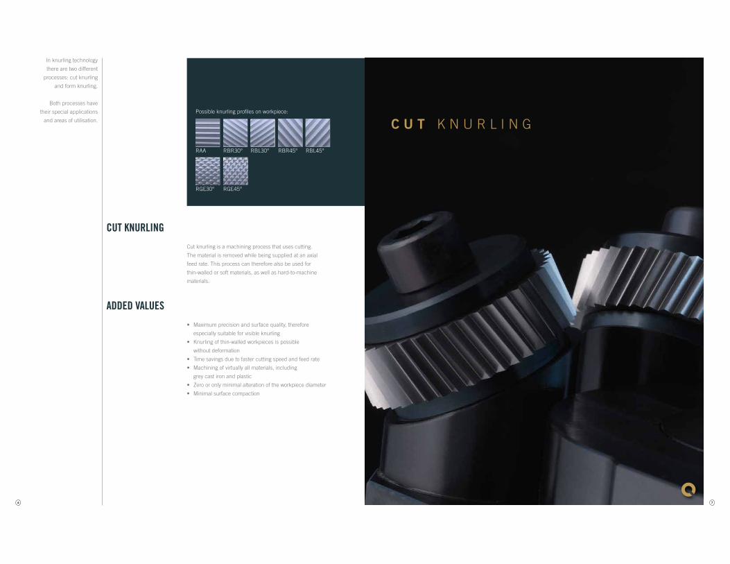
CUT KNURLING
Cut knurling is a machining process that uses cutting.
The material is removed while being supplied at an axial
feed rate. This process can therefore also be used for
thin-walled or soft materials, as well as hard-to-machine
materials.
ADDED VALUES
• Maximum precision and surface quality, therefore
especially suitable for visible knurling
• Knurling of thin-walled workpieces is possible
without deformation
• Time savings due to faster cutting speed and feed rate
• Machining of virtually all materials, including
grey cast iron and plastic
• Zero or only minimal alteration of the workpiece diameter
• Minimal surface compaction
In knurling technology
there are two different
processes: cut knurling
and form knurling.
Both processes have
their special applications
and areas of utilisation.
Possible knurling profiles on workpiece:
7
C U T K N U R L I N G
8
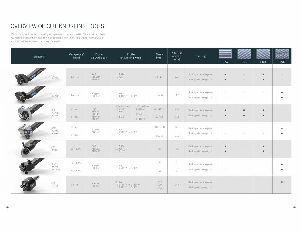
OVERVIEW OF CUT KNURLING TOOLS
Tool seriesWorkpiece Ø
[mm]Profile
on workpieceProfile
on knurling wheelShank[mm]
Knurling wheel Ø[mm]
Knurling
RAA RBL RBR RGE
C601(LA/FL)
1.5 – 12RAARBR30°RBR45°
1 x BR30°1 x AA 1 x BL15°
10 / 12 8.9Starting at the workpiece
Starting after plunge cut
••
–
–
••
–
–
C602(LA/KF)
1.5 – 12 RGE30°RGE45°
2 x AA1 x BR15° / 1 x BL15°
10 / 12 8.9Starting at the workpiece
Starting after plunge cut
–
–
–
–
–
–
••
C611(A1/FL)(A2/FL)
3 – 50
5 – 250
RAARBR30°RBL30°RBR45°RBL45°
Right-hand use:1 x BR30°1 x AA
1 x BL15°
Left-hand use:1 x BL30°
1 x AA
1 x BR15°
10 / 12 / 16
20 / 25
14.5
21.5
Starting at the workpiece
Starting after plunge cut
••
••
••
–
–
C612(A1/KF)(A2/KF)
3 – 50
5 – 250
RGE30°RGE45°
2 x AA1 x BR15° / 1 x BL15°
10 / 12 / 16
20 / 25
14.5
21.5
Starting at the workpiece
Starting after plunge cut
–
–
–
–
–
–
••
C621(M/FL)
20 – 3000RAARBR30°RBR45°
1 x BR30°1 x AA1 x BL15°
27 42Starting at the workpiece
Starting after plunge cut
••
–
–
••
–
–
C622(MI/KF)(MII /KF)
20 – 1000
30 – 3000
RGE30°RGE45°
2 x AA1 x BR15° / 1 x BL15°
40
57
32
42
Starting at the workpiece
Starting after plunge cut
–
–
–
–
–
–
••
C693(STR-A)
3.5 – 20 RGE30°RGE45°
3 x AA1 x BR15° / 2 x BL15° or2 x BR15° / 1 x BL15°
Ø15
Ø20
Ø25
14.5Starting at the workpiece
Starting after plunge cut
–
–
–
–
–
–
•–
With the product finder for cut knurling tools you can find your desired QUICK product even faster.
You receive all relevant tool data, as well as possible profiles, the corresponding knurling wheels
and the possible direction of machining at a glance.
9
Tool seriesWorkpiece Ø
[mm]Profile
on workpieceProfile
on knurling wheelShank[mm]
Knurling wheel Ø[mm]
Knurling
RAA RBL RBR RGE
C601(LA/FL)
1.5 – 12RAARBR30°RBR45°
1 x BR30°1 x AA 1 x BL15°
10 / 12 8.9Starting at the workpiece
Starting after plunge cut
••
–
–
••
–
–
C602(LA/KF)
1.5 – 12 RGE30°RGE45°
2 x AA1 x BR15° / 1 x BL15°
10 / 12 8.9Starting at the workpiece
Starting after plunge cut
–
–
–
–
–
–
••
C611(A1/FL)(A2/FL)
3 – 50
5 – 250
RAARBR30°RBL30°RBR45°RBL45°
Right-hand use:1 x BR30°1 x AA
1 x BL15°
Left-hand use:1 x BL30°
1 x AA
1 x BR15°
10 / 12 / 16
20 / 25
14.5
21.5
Starting at the workpiece
Starting after plunge cut
••
••
••
–
–
C612(A1/KF)(A2/KF)
3 – 50
5 – 250
RGE30°RGE45°
2 x AA1 x BR15° / 1 x BL15°
10 / 12 / 16
20 / 25
14.5
21.5
Starting at the workpiece
Starting after plunge cut
–
–
–
–
–
–
••
C621(M/FL)
20 – 3000RAARBR30°RBR45°
1 x BR30°1 x AA1 x BL15°
27 42Starting at the workpiece
Starting after plunge cut
••
–
–
••
–
–
C622(MI/KF)(MII /KF)
20 – 1000
30 – 3000
RGE30°RGE45°
2 x AA1 x BR15° / 1 x BL15°
40
57
32
42
Starting at the workpiece
Starting after plunge cut
–
–
–
–
–
–
••
C693(STR-A)
3.5 – 20 RGE30°RGE45°
3 x AA1 x BR15° / 2 x BL15° or2 x BR15° / 1 x BL15°
Ø15
Ø20
Ø25
14.5Starting at the workpiece
Starting after plunge cut
–
–
–
–
–
–
•–
10
RBR30° RBR45°RAA
MaßtabelleBuchstabe Abmaß in mm
a 10 / 12b 10 / 12c 108d 23,5e 20f 20,3 / 22x 0,9
ab
c
e
fd
MaßtabelleBuchstabe Abmaß in mm
a 10 / 12b 10 / 12c 108d 23,5e 20f 20,3 / 22x 0,9
ab
c
e
fd
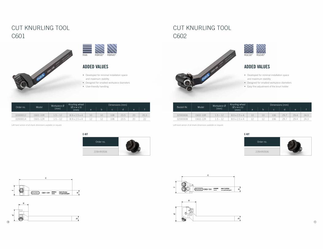
ADDED VALUES
• Developed for minimal installation space
and maximum stability
• Designed for smallest workpiece diameters
• User-friendly handling
CUT KNURLING TOOLC601
Order no. Model Workpiece Ø[mm]
Knurling wheel(Ø x w x b)
[mm]
Dimensions [mm]
a b c d e f
32000012 C601-10R 1.5 – 12 8.9 x 2.5 x 4 10 10 108 23.5 20 20,3
32000014 C601-12R 1.5 – 12 8.9 x 2.5 x 4 12 12 108 23.5 20 22
Left-hand version of all shank dimensions available on request.
Order no.
22BHR0506
E-KIT
11
RGE45°RGE30°
MaßtabelleBuchstabe Abmaß in mm
a 10 / 12b 10 / 12c 106d 29,7e 29,4f 24,3x 2
ab
cf
d
e
MaßtabelleBuchstabe Abmaß in mm
a 10 / 12b 10 / 12c 106d 29,7e 29,4f 24,3x 2
ab
c
fd
e
ADDED VALUES
• Developed for minimal installation space
and maximum stability
• Designed for smallest workpiece diameters
• Easy fine adjustment of the knurl holder
CUT KNURLING TOOLC602
Bestell-Nr. Model Workpiece Ø[mm]
Knurling wheel(Ø x w x b)
[mm]
Dimensions [mm]
a b c d e f
32000006 C602-10R 1.5 – 12 8.9 x 2.5 x 4 10 10 106 29.7 29.4 24.3
32000008 C602-12R 1.5 – 12 8.9 x 2.5 x 4 12 12 106 29.7 29.4 24.3
Left-hand version of all shank dimensions available on request.
Order no.
22BHR0506
E-KIT
12
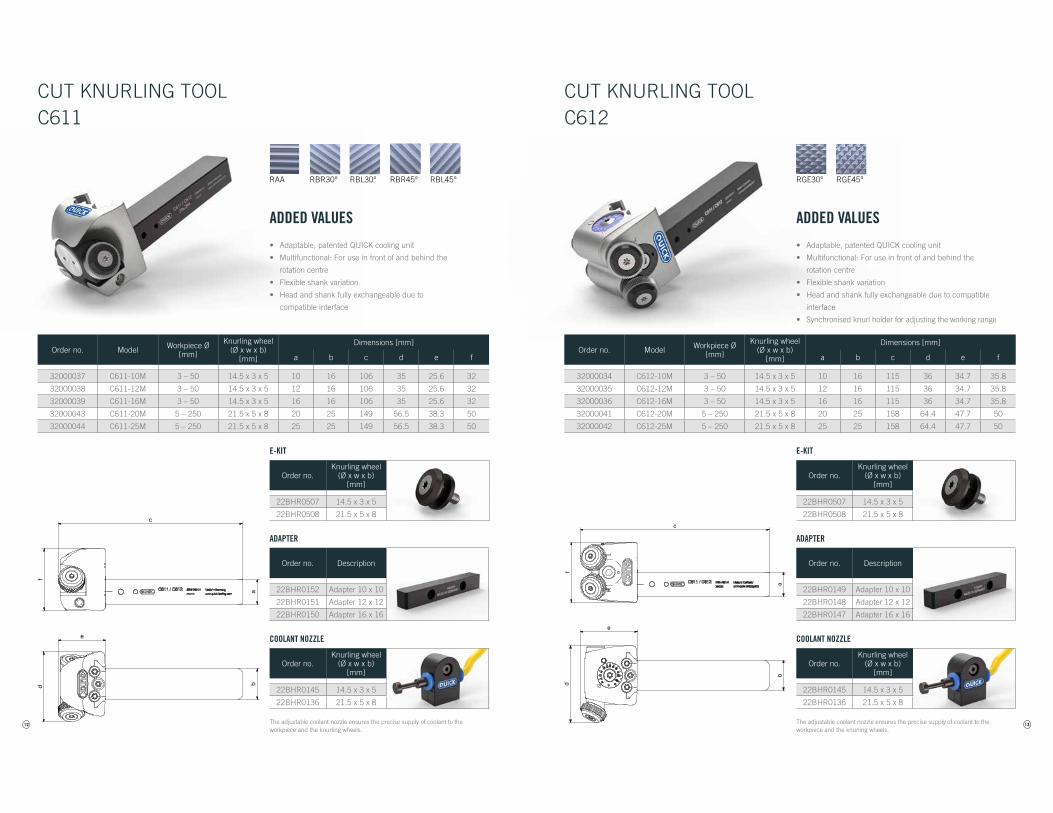
RBR30° RBL30° RBR45° RBL45°RAA
MaßtabelleBuchstabe Abmaß in mm
a 10 / 12 / 16 / 20 / 25b 16 / 25c 106 / 149d 35 / 56,5e 25,6 / 38,3f 32 / 50x 1
ab
c
e
fd
ADDED VALUES
• Adaptable, patented QUICK cooling unit
• Multifunctional: For use in front of and behind the
rotation centre
• Flexible shank variation
• Head and shank fully exchangeable due to
compatible interface
CUT KNURLING TOOLC611
Order no. Model Workpiece Ø[mm]
Knurling wheel(Ø x w x b)
[mm]
Dimensions [mm]
a b c d e f
32000037 C611-10M 3 – 50 14.5 x 3 x 5 10 16 106 35 25.6 32
32000038 C611-12M 3 – 50 14.5 x 3 x 5 12 16 106 35 25.6 32
32000039 C611-16M 3 – 50 14.5 x 3 x 5 16 16 106 35 25.6 32
32000043 C611-20M 5 – 250 21.5 x 5 x 8 20 25 149 56.5 38.3 50
32000044 C611-25M 5 – 250 21.5 x 5 x 8 25 25 149 56.5 38.3 50
Order no.Knurling wheel
(Ø x w x b)[mm]
22BHR0507 14.5 x 3 x 5
22BHR0508 21.5 x 5 x 8
E-KIT
Order no. Description
22BHR0152 Adapter 10 x 10
22BHR0151 Adapter 12 x 12
22BHR0150 Adapter 16 x 16
ADAPTER
Order no.Knurling wheel
(Ø x w x b)[mm]
22BHR0145 14.5 x 3 x 5
22BHR0136 21.5 x 5 x 8
COOLANT NOZZLE
The adjustable coolant nozzle ensures the precise supply of coolant to the workpiece and the knurling wheels.
13
MaßtabelleBuchstabe Abmaß in mm
a 10 / 12 / 16 / 20 / 25b 16 / 25c 115 / 158d 36 / 64,4e 34,7 / 47,7f 35,8 / 50
ab
c
e
fd
RGE45°RGE30°
ADDED VALUES
• Adaptable, patented QUICK cooling unit
• Multifunctional: For use in front of and behind the
rotation centre
• Flexible shank variation
• Head and shank fully exchangeable due to compatible
interface
• Synchronised knurl holder for adjusting the working range
CUT KNURLING TOOLC612
Order no. Model Workpiece Ø[mm]
Knurling wheel(Ø x w x b)
[mm]
Dimensions [mm]
a b c d e f
32000034 C612-10M 3 – 50 14.5 x 3 x 5 10 16 115 36 34.7 35.8
32000035 C612-12M 3 – 50 14.5 x 3 x 5 12 16 115 36 34.7 35.8
32000036 C612-16M 3 – 50 14.5 x 3 x 5 16 16 115 36 34.7 35.8
32000041 C612-20M 5 – 250 21.5 x 5 x 8 20 25 158 64.4 47.7 50
32000042 C612-25M 5 – 250 21.5 x 5 x 8 25 25 158 64.4 47.7 50
Order no.Knurling wheel
(Ø x w x b)[mm]
22BHR0507 14.5 x 3 x 5
22BHR0508 21.5 x 5 x 8
E-KIT
Order no. Description
22BHR0149 Adapter 10 x 10
22BHR0148 Adapter 12 x 12
22BHR0147 Adapter 16 x 16
ADAPTER
Order no.Knurling wheel
(Ø x w x b)[mm]
22BHR0145 14.5 x 3 x 5
22BHR0136 21.5 x 5 x 8
COOLANT NOZZLE
The adjustable coolant nozzle ensures the precise supply of coolant to the workpiece and the knurling wheels.
14
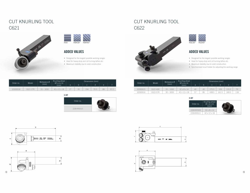
RBR30° RBR45°RAA
MaßtabelleBuchstabe Abmaß in mm
a 27b 35c 194d 70,5e 89f 57,2x 5,5
ab
c
e
df
MaßtabelleBuchstabe Abmaß in mm
a 27b 35c 194d 70,5e 89f 57,2x 5,5
ab
c
e
df
ADDED VALUES
• Designed for the largest possible working ranges
• Ideal for heavy-duty and roll turning lathes etc.
• Maximum stability due to solid construction
CUT KNURLING TOOLC621
Order no. Model Workpiece Ø[mm]
Knurling wheel(Ø x w x b)
[mm]
Dimensions [mm]
a b c d e f
32000018 C621-27R 20 – 3000 42 x 12 x 18 27 35 194 70.5 89 57.2
Order no.
22BHR0510
E-KIT
15
RGE45°RGE30°
MaßtabelleBuchstabe Abmaß in mm
a 40 / 57b 45 / 85c 275,5 / 438,5d 109 / 161,5e 115,5 / 169,5f 79 / 118x 8
ab
c
e
fd
MaßtabelleBuchstabe Abmaß in mm
a 40 / 57b 45 / 85c 275,5 / 438,5d 109 / 161,5e 115,5 / 169,5f 79 / 118x 8
ab
c
e
fd
ADDED VALUES
• Designed for the largest possible working ranges
• Ideal for heavy-duty and roll turning lathes etc.
• Maximum stability due to solid construction
• Synchronised knurl holder for adjusting the working range
CUT KNURLING TOOLC622
Order no. Model Workpiece Ø[mm]
Knurling wheel(Ø x w x b)
[mm]
Dimensions [mm]
a b c d e f
32000015 C622-40R 20 – 1000 32 x 8 x 14 40 45 275.5 109 115.5 79
32000016 C622-57R 30 – 3000 42 x 12 x 18 57 85 438.5 161.5 169.5 118
Order no.Knurling wheel
(Ø x w x b)[mm]
22BHR0509 32 x 8 x 14
22BHR0511 42 x 12 x 18
E-KIT
16
RGE45°RGE30°
d max
n max
j k
e
Maßtabelle C691 - mit SchaftBuchstabe Abmaß in mm
Arbeitsbeitsbereich 3,5 - 20a 15 / 20 / 25d max 75e 57h 50i 9 / 10 / 15j 20k 54l 20n max 38x 1,7
l
a
i
h d max
n max
j k
e
Maßtabelle C691 - mit SchaftBuchstabe Abmaß in mm
Arbeitsbeitsbereich 3,5 - 20a 15 / 20 / 25d max 75e 57h 50i 9 / 10 / 15j 20k 54l 20n max 38x 1,7
l
a
i
h
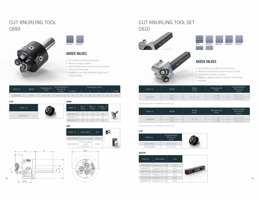
ADDED VALUES
• Knurl holders individually adjustable
• Maximum process stability
• All knurling processes can be used by conversion
of the knurl holder jaws
• Suitable for very small installation spaces due to
compact design
CUT KNURLING TOOLC693
Order no. Model Workpiece Ø[mm]
Knurling wheel(Ø x w x b)
[mm]
Dimensions [mm]
d max. e j k l n max.
32000030 C693 3.5 – 20 14.5 x 3 x 5 75 57 20 54 20 38
Order no. Ø „a“[mm]
Bore „i“[mm]
Length „h“[mm]
22BHR0119 15 9 50
22BHR0121 20 10 50
22BHR0122 25 15 50
SHANK
Order no. Description Tool
22BHR0490 Form knurling F791
22BHR0537Form knurling
up to a shoulder
F792
JAWS
Order no.
22BHR0507
E-KIT
17
RBR30° RBL30° RBR45° RBL45°RAA
RGE45°RGE30°
ADDED VALUES
• All common knurl profiles can be produced
• Maximum user flexibility due to numerous possible
combinations of head and shank
• Additional, patented QUICK cooling unit for optimised
chip flow
CUT KNURLING TOOL SETC610
Order no.Knurling wheel
(Ø x w x b)[mm]
22BHR0507 14.5 x 3 x 5
22BHR0508 21.5 x 5 x 8
E-KIT
Order no. Description Tool
22BHR0152 Adapter 10 x 10 C611
22BHR0151 Adapter 12 x 12 C611
22BHR0150 Adapter 16 x 16 C611
22BHR0149 Adapter 10 x 10 C612
22BHR0148 Adapter 12 x 12 C612
22BHR0147 Adapter 16 x 16 C612
ADAPTER
Order no. Model Shank [mm]
Workpiece Ø[mm]
Knurling wheel(Ø x w x b)
[mm]
32000040C611
10 / 12 / 163 – 50 14.5 x 3 x 5
C612 3 – 50 14.5 x 3 x 5
Order no. Model Shank [mm]
Workpiece Ø[mm]
Knurling wheel(Ø x w x b)
[mm]
32000045C611
20 / 255 – 250 21.5 x 5 x 8
C612 5 – 250 21.5 x 5 x 8
Coolant nozzle (order no. 22BHR0145) included in set.
Coolant nozzle (order no. 22BHR0145) included in set.
18
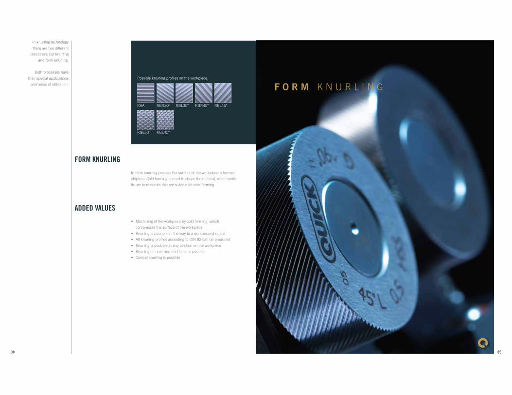
RAA RBR30° RBL30° RBR45° RBL45°
RGE30° RGE45°
FORM KNURLING
In form knurling process the surface of the workpiece is formed
chipless. Cold forming is used to shape the material, which limits
its use to materials that are suitable for cold forming.
ADDED VALUES
• Machining of the workpiece by cold forming, which
compresses the surface of the workpiece
• Knurling is possible all the way to a workpiece shoulder
• All knurling profiles according to DIN 82 can be produced
• Knurling is possible at any position on the workpiece
• Knurling of inner and end faces is possible
• Conical knurling is possible
Possible knurling profiles on the workpiece:
In knurling technology
there are two different
processes: cut knurling
and form knurling.
Both processes have
their special applications
and areas of utilisation.
19
F O R M K N U R L I N G
20
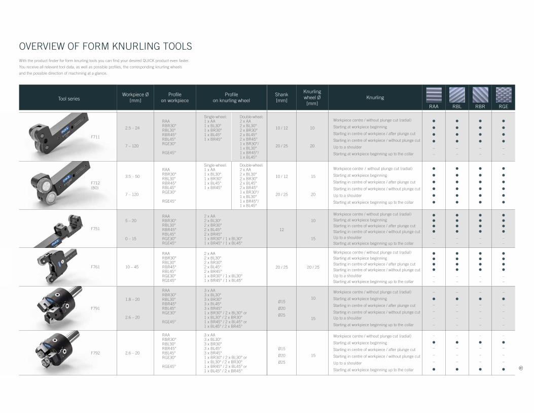
OVERVIEW OF FORM KNURLING TOOLS
Tool seriesWorkpiece Ø
[mm]Profile
on workpieceProfile
on knurling wheelShank[mm]
Knurling wheel Ø[mm]
Knurling
RAA RBL RBR RGE
F711
2.5 – 24
7 – 120
RAARBR30°RBL30°RBR45°RBL45°RGE30°
RGE45°
Single-wheel:1 x AA1 x BL30°1 x BR30°1 x BL45°1 x BR45°
Double-wheel:2 x AA2 x BL30°2 x BR30°2 x BL45°2 x BR45°1 x BR30°/ 1 x BL30°1 x BR45°/ 1 x BL45°
10 / 12
20 / 25
10
20
Workpiece centre / without plunge cut (radial)
Starting at workpiece beginning
Starting in centre of workpiece / after plunge cut
Starting in centre of workpiece / without plunge cut
Up to a shoulder
Starting at workpiece beginning up to the collar
••••––
••••––
••••––
••••––
F712(B0)
3.5 – 50
7 – 120
RAARBR30°RBL30°RBR45°RBL45°RGE30°
RGE45°
Single-wheel:1 x AA1 x BL30°1 x BR30°1 x BL45°1 x BR45°
Double-wheel:2 x AA2 x BL30°2 x BR30°2 x BL45°2 x BR45°1 x BR30°/ 1 x BL30°1 x BR45°/ 1 x BL45°
10 / 12
20 / 25
15
20
Workpiece centre / without plunge cut (radial)
Starting at workpiece beginning
Starting in centre of workpiece / after plunge cut
Starting in centre of workpiece / without plunge cut
Up to a shoulder
Starting at workpiece beginning up to the collar
••••••
••••••
••••••
••••••
F751
5 – 20
0 – 15
RAARBR30°RBL30°RBR45°RBL45°RGE30°RGE45°
2 x AA2 x BL30°2 x BR30°2 x BL45°2 x BR45°1 x BR30° / 1 x BL30°1 x BR45° / 1 x BL45°
12
10
15
Workpiece centre / without plunge cut (radial)Starting at workpiece beginningStarting in centre of workpiece / after plunge cutStarting in centre of workpiece / without plunge cutUp to a shoulderStarting at workpiece beginning up to the collar
••••––
••••––
••••––
••••––
F761 10 – 45
RAARBR30°RBL30°RBR45°RBL45°RGE30°RGE45°
2 x AA2 x BL30°2 x BR30°2 x BL45°2 x BR45°1 x BR30° / 1 x BL30°1 x BR45° / 1 x BL45°
20 / 25 20 / 25
Workpiece centre / without plunge cut (radial)Starting at workpiece beginningStarting in centre of workpiece / after plunge cutStarting in centre of workpiece / without plunge cutUp to a shoulderStarting at workpiece beginning up to the collar
••••––
••••––
••••––
••••––
F791
1.8 – 20
2.6 – 20
RAARBR30°RBL30°RBR45°RBL45°RGE30°
RGE45°
3 x AA3 x BL30°3 x BR30°3 x BL45°3 x BR45°1 x BR30° / 2 x BL30° or 1 x BL30° / 2 x BR30°1 x BR45° / 2 x BL45° or 1 x BL45° / 2 x BR45°
Ø15
Ø20
Ø25
10
15
Workpiece centre / without plunge cut (radial)
Starting at workpiece beginning
Starting in centre of workpiece / after plunge cut
Starting in centre of workpiece / without plunge cutUp to a shoulder
Starting at workpiece beginning up to the collar
–
•–
–
–
–
–
•–
–
–
–
–
•–
–
–
–
–
•–
–
–
–
F792 2.6 – 20
RAARBR30°RBL30°RBR45°RBL45°RGE30°
RGE45°
3 x AA3 x BL30°3 x BR30°3 x BL45°3 x BR45°1 x BR30° / 2 x BL30° or 1 x BL30° / 2 x BR30°1 x BR45° / 2 x BL45° or 1 x BL45° / 2 x BR45°
Ø15
Ø20
Ø25
15
Workpiece centre / without plunge cut (radial)
Starting at workpiece beginning
Starting in centre of workpiece / after plunge cut
Starting in centre of workpiece / without plunge cut
Up to a shoulder
Starting at workpiece beginning up to the collar
–
•–
–
–
•
–
•–
–
–
•
–
•–
–
–
•
–
•–
–
–
•
With the product finder for form knurling tools you can find your desired QUICK product even faster.
You receive all relevant tool data, as well as possible profiles, the corresponding knurling wheels
and the possible direction of machining at a glance.
21
Tool seriesWorkpiece Ø
[mm]Profile
on workpieceProfile
on knurling wheelShank[mm]
Knurling wheel Ø[mm]
Knurling
RAA RBL RBR RGE
F711
2.5 – 24
7 – 120
RAARBR30°RBL30°RBR45°RBL45°RGE30°
RGE45°
Single-wheel:1 x AA1 x BL30°1 x BR30°1 x BL45°1 x BR45°
Double-wheel:2 x AA2 x BL30°2 x BR30°2 x BL45°2 x BR45°1 x BR30°/ 1 x BL30°1 x BR45°/ 1 x BL45°
10 / 12
20 / 25
10
20
Workpiece centre / without plunge cut (radial)
Starting at workpiece beginning
Starting in centre of workpiece / after plunge cut
Starting in centre of workpiece / without plunge cut
Up to a shoulder
Starting at workpiece beginning up to the collar
••••––
••••––
••••––
••••––
F712(B0)
3.5 – 50
7 – 120
RAARBR30°RBL30°RBR45°RBL45°RGE30°
RGE45°
Single-wheel:1 x AA1 x BL30°1 x BR30°1 x BL45°1 x BR45°
Double-wheel:2 x AA2 x BL30°2 x BR30°2 x BL45°2 x BR45°1 x BR30°/ 1 x BL30°1 x BR45°/ 1 x BL45°
10 / 12
20 / 25
15
20
Workpiece centre / without plunge cut (radial)
Starting at workpiece beginning
Starting in centre of workpiece / after plunge cut
Starting in centre of workpiece / without plunge cut
Up to a shoulder
Starting at workpiece beginning up to the collar
••••••
••••••
••••••
••••••
F751
5 – 20
0 – 15
RAARBR30°RBL30°RBR45°RBL45°RGE30°RGE45°
2 x AA2 x BL30°2 x BR30°2 x BL45°2 x BR45°1 x BR30° / 1 x BL30°1 x BR45° / 1 x BL45°
12
10
15
Workpiece centre / without plunge cut (radial)Starting at workpiece beginningStarting in centre of workpiece / after plunge cutStarting in centre of workpiece / without plunge cutUp to a shoulderStarting at workpiece beginning up to the collar
••••––
••••––
••••––
••••––
F761 10 – 45
RAARBR30°RBL30°RBR45°RBL45°RGE30°RGE45°
2 x AA2 x BL30°2 x BR30°2 x BL45°2 x BR45°1 x BR30° / 1 x BL30°1 x BR45° / 1 x BL45°
20 / 25 20 / 25
Workpiece centre / without plunge cut (radial)Starting at workpiece beginningStarting in centre of workpiece / after plunge cutStarting in centre of workpiece / without plunge cutUp to a shoulderStarting at workpiece beginning up to the collar
••••––
••••––
••••––
••••––
F791
1.8 – 20
2.6 – 20
RAARBR30°RBL30°RBR45°RBL45°RGE30°
RGE45°
3 x AA3 x BL30°3 x BR30°3 x BL45°3 x BR45°1 x BR30° / 2 x BL30° or 1 x BL30° / 2 x BR30°1 x BR45° / 2 x BL45° or 1 x BL45° / 2 x BR45°
Ø15
Ø20
Ø25
10
15
Workpiece centre / without plunge cut (radial)
Starting at workpiece beginning
Starting in centre of workpiece / after plunge cut
Starting in centre of workpiece / without plunge cutUp to a shoulder
Starting at workpiece beginning up to the collar
–
•–
–
–
–
–
•–
–
–
–
–
•–
–
–
–
–
•–
–
–
–
F792 2.6 – 20
RAARBR30°RBL30°RBR45°RBL45°RGE30°
RGE45°
3 x AA3 x BL30°3 x BR30°3 x BL45°3 x BR45°1 x BR30° / 2 x BL30° or 1 x BL30° / 2 x BR30°1 x BR45° / 2 x BL45° or 1 x BL45° / 2 x BR45°
Ø15
Ø20
Ø25
15
Workpiece centre / without plunge cut (radial)
Starting at workpiece beginning
Starting in centre of workpiece / after plunge cut
Starting in centre of workpiece / without plunge cut
Up to a shoulder
Starting at workpiece beginning up to the collar
–
•–
–
–
•
–
•–
–
–
•
–
•–
–
–
•
–
•–
–
–
•
22
Maßtabelle F761Buchstabe Abmaß in mm
Arbeitsbeitsbereich 2,5 - 24a 10 / 12
21 / 01bc 101,5d 16,5e 21,5f 24x 2
ab
df
e
c
3 m
m
x
RBR30° RBL30° RBR45° RBL45°RAA
RGE45°RGE30°
ab
e
f
c
d
x
MaßtabelleBuchstabe Abmaß in mm
a 20 / 25b 20c 104,5d 20e 24,5f 40,4 / 45,2x 2,5
ab
e
f
c
d
x
MaßtabelleBuchstabe Abmaß in mm
a 20 / 25b 20c 104,5d 20e 24,5f 40,4 / 45,2x 2,5
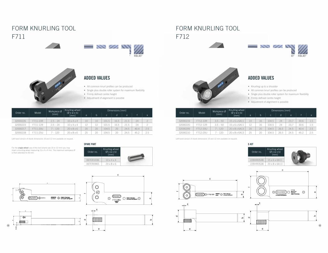
ADDED VALUES
• All common knurl profiles can be produced
• Single plus double roller system for maximum flexibility
• Firmly defined centre height
• Adjustment of alignment is possible
FORM KNURLING TOOLF711
Order no.Knurling wheel
(Ø x w x b)[mm]
06TER1036 10 x 4 x 4
06TER0965 20 x 8 x 6
SPARE PART
Order no. Model Workpiece Ø[mm]
Knurling wheel(Ø x w x b)
[mm]
Dimensions [mm]
a b c d e f x
32000226 F711-10R 2.5 – 24 10 x 4 x 4 10 10 101.5 16.5 21.5 24 2
32000223 F711-12R 2.5 – 24 10 x 4 x 4 12 12 101.5 16.5 21.5 24 2
32000217 F711-20U 7 – 120 20 x 8 x 6 20 20 104.5 20 24.5 40.4 2.5
32000218 F711-25U 7 – 120 20 x 8 x 6 25 20 104.5 20 24.5 45.2 2.5
Left-hand version of shank dimensions 10 and 12 mm available on request.
For the single-wheel use of this tool (shank size 10 or 12 mm) you may insert a knurling wheel measuring 15 x 4 x 4 mm. The maximum workpiece Ø is then extended to 50 mm.
23
RBR30° RBL30° RBR45° RBL45°RAA
RGE45°RGE30°
MaßtabelleBuchstabe Abmaß in mm
a 10 / 12b 16c 104,5d 24e 23,7f 30,6x 1,5
abd
f
e
c
x
MaßtabelleBuchstabe Abmaß in mm
a 20 / 25b 20c 104,5d 26,5e 24,5f 40,4 / 45,2x 2,5
abd
f
e
c
x
MaßtabelleBuchstabe Abmaß in mm
a 10 / 12b 16c 104,5d 24e 23,7f 30,6x 1,5
abd
f
e
c
x
MaßtabelleBuchstabe Abmaß in mm
a 20 / 25b 20c 104,5d 26,5e 24,5f 40,4 / 45,2x 2,5
abd
f
e
c
x
ADDED VALUES
• Knurling up to a shoulder
• All common knurl profiles can be produced
• Single plus double roller system for maximum flexibility
• Firmly defined centre height
• Adjustment of alignment is possible
FORM KNURLING TOOLF712
Order no. Model Workpiece Ø[mm]
Knurling wheel(Ø x w x b)
[mm]
Dimensions [mm]
a b c d e f x
32000219 F712-10R 3.5 – 50 15 x 6 x 6A11 10 16 104.5 24 23,7 30.6 1.5
32000220 F712-12R 3.5 – 50 15 x 6 x 6A11 12 16 104.5 24 23,7 30.6 1.5
32000209 F712-20U 7 – 120 20 x 8 x 6A13 20 20 104.5 26.5 24.5 40.4 2.5
32000210 F712-25U 7 – 120 20 x 8 x 6A13 25 20 104.5 26.5 24.5 45.2 2.5
Left-hand version of shank dimensions 10 and 12 mm available on request.
Order no.Knurling wheel
(Ø x w x b)[mm]
22BHR0548 15 x 6 x 6A11
22BHR0538 20 x 8 x 6A13
E-KIT
24
MaßtabelleBuchstabe Abmaß in mm
a 12b 20c max. 122d 21e max. 47f 26x 1 / 3,5
max. c
ab
fd
max. e
18
17,5
2
x
RBR30° RBL30° RBR45° RBL45°RAA
RGE45°RGE30°
MaßtabelleBuchstabe Abmaß in mm
a 12b 20c max. 122d 21e max. 47f 26x 1 / 3,5
max. c
ab
fd
max. e
18
17,5
2
x
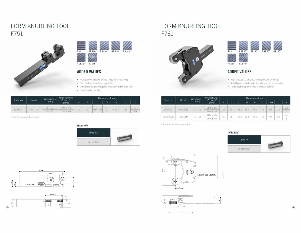
ADDED VALUES
• High process stability due to tangential machining
• Special design for Swiss-type lathes
• Eliminates double workplace allocation in the slide unit
• User-friendly handling
FORM KNURLING TOOLF751
Order no.
06TER0964
SPARE PART
Order no. Model Workpiece Ø[mm]
Knurling wheel(Ø x w x b)
[mm]
Dimensions [mm]
a b c d e f x
32000211 F751-12R5 – 20 10 x 4 x 4
12 20 max. 122 21 max. 47 261
0 – 15 15 x 4 x 4 3.5
Left-hand version available on request.
25
Maßtabelle F761Buchstabe Abmaß in mm
Arbeitsbeitsbereich 0 - 45a 16 / 20 / 25b 16 / 20 / 25c 148,5d 35,5e 78,5f 73fmax 100h 25x 5 / 2,5
abd
c
e
X9
mm
fmax
h
f
RBR30° RBL30° RBR45° RBL45°RAA
RGE45°RGE30°
Maßtabelle F761Buchstabe Abmaß in mm
Arbeitsbeitsbereich 0 - 45a 16 / 20 / 25b 16 / 20 / 25c 148,5d 35,5e 78,5f 73fmax 100h 25x 5 / 2,5
abd
c
e
X9
mm
fmax
h
f
ADDED VALUES
• High process stability due to tangential machining
• Knurl holders can be adjusted via synchronous spindle
• Force neutralisation due to tangential position
FORM KNURLING TOOLF761
Order no.
06TER0965
SPARE PART
Order no. Model Workpiece Ø[mm]
Knurling wheel(Ø x w x b)
[mm]
Dimensions [mm]
a b c d e f f max. h x
32000221 F761-20R 10 – 4520 x 8 x 6
20 20 148.5 35.5 78.5 73 94 252.5
25 x 8 x 6 5
32000225 F761-25R 10 – 4520 x 8 x 6
25 25 148.5 35.5 78.5 73 94 252.5
25 x 8 x 6 5
Left-hand version available on request.
26
d max
n max
j
k
e
Maßtabelle C691 - mit SchaftBuchstabe Abmaß in mm
Arbeitsbeitsbereich 2,6 - 20a 15 / 20 / 25d max 75e 53h 50i 9 / 10 / 15j 20k 54l 16n max 32x 3,5 / 1
l
ai
h
x
RBR30° RBL30° RBR45° RBL45°RAA
RGE45°RGE30°
d max
n max
j
k
e
Maßtabelle C691 - mit SchaftBuchstabe Abmaß in mm
Arbeitsbeitsbereich 2,6 - 20a 15 / 20 / 25d max 75e 53h 50i 9 / 10 / 15j 20k 54l 16n max 32x 3,5 / 1
l
ai
h
x
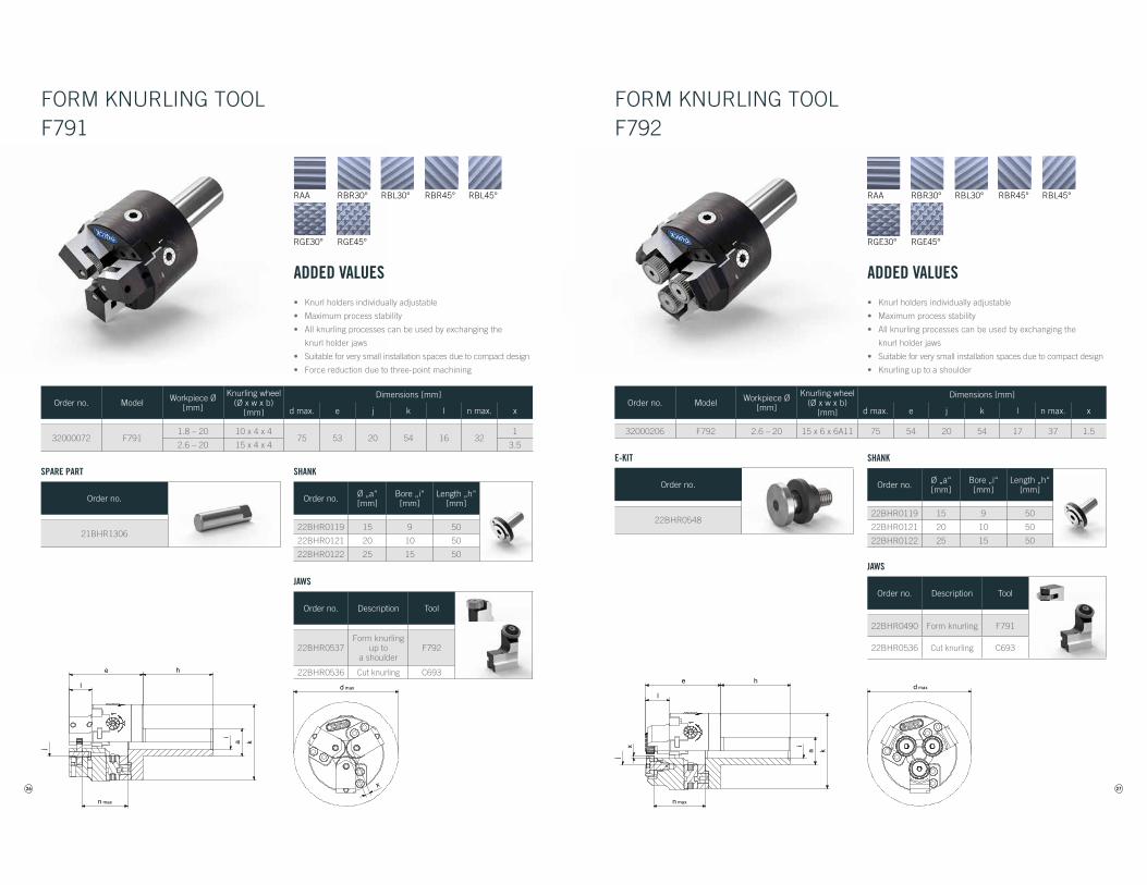
ADDED VALUES
• Knurl holders individually adjustable
• Maximum process stability
• All knurling processes can be used by exchanging the
knurl holder jaws
• Suitable for very small installation spaces due to compact design
• Force reduction due to three-point machining
FORM KNURLING TOOLF791
Order no. Model Workpiece Ø[mm]
Knurling wheel(Ø x w x b)
[mm]
Dimensions [mm]
d max. e j k l n max. x
32000072 F7911.8 – 20 10 x 4 x 4
75 53 20 54 16 321
2.6 – 20 15 x 4 x 4 3.5
Order no. Ø „a“[mm]
Bore „i“[mm]
Length „h“[mm]
22BHR0119 15 9 50
22BHR0121 20 10 50
22BHR0122 25 15 50
SHANK
Order no. Description Tool
22BHR0537Form knurling
up to a shoulder
F792
22BHR0536 Cut knurling C693
JAWS
Order no.
21BHR1306
SPARE PART
27
d max
n max
j
k
e
Maßtabelle C691 - mit SchaftBuchstabe Abmaß in mm
Arbeitsbeitsbereich 2,6 - 20a 15 / 20 / 25d max 75e 54h 50i 9 / 10 / 15j 20k 54l 17n max 37x 1,5
l
ai
h
x
RBR30° RBL30° RBR45° RBL45°RAA
RGE45°RGE30°
d max
n max
j
k
e
Maßtabelle C691 - mit SchaftBuchstabe Abmaß in mm
Arbeitsbeitsbereich 2,6 - 20a 15 / 20 / 25d max 75e 54h 50i 9 / 10 / 15j 20k 54l 17n max 37x 1,5
l
ai
h
x
ADDED VALUES
• Knurl holders individually adjustable
• Maximum process stability
• All knurling processes can be used by exchanging the
knurl holder jaws
• Suitable for very small installation spaces due to compact design
• Knurling up to a shoulder
FORM KNURLING TOOLF792
Order no. Model Workpiece Ø[mm]
Knurling wheel(Ø x w x b)
[mm]
Dimensions [mm]
d max. e j k l n max. x
32000206 F792 2.6 – 20 15 x 6 x 6A11 75 54 20 54 17 37 1.5
Order no. Ø „a“[mm]
Bore „i“[mm]
Length „h“[mm]
22BHR0119 15 9 50
22BHR0121 20 10 50
22BHR0122 25 15 50
SHANK
Order no. Description Tool
22BHR0490 Form knurling F791
22BHR0536 Cut knurling C693
JAWS
Order no.
22BHR0548
E-KIT
28
K N U R L I N G W H E E L S
29
K N U R L I N G W H E E L S
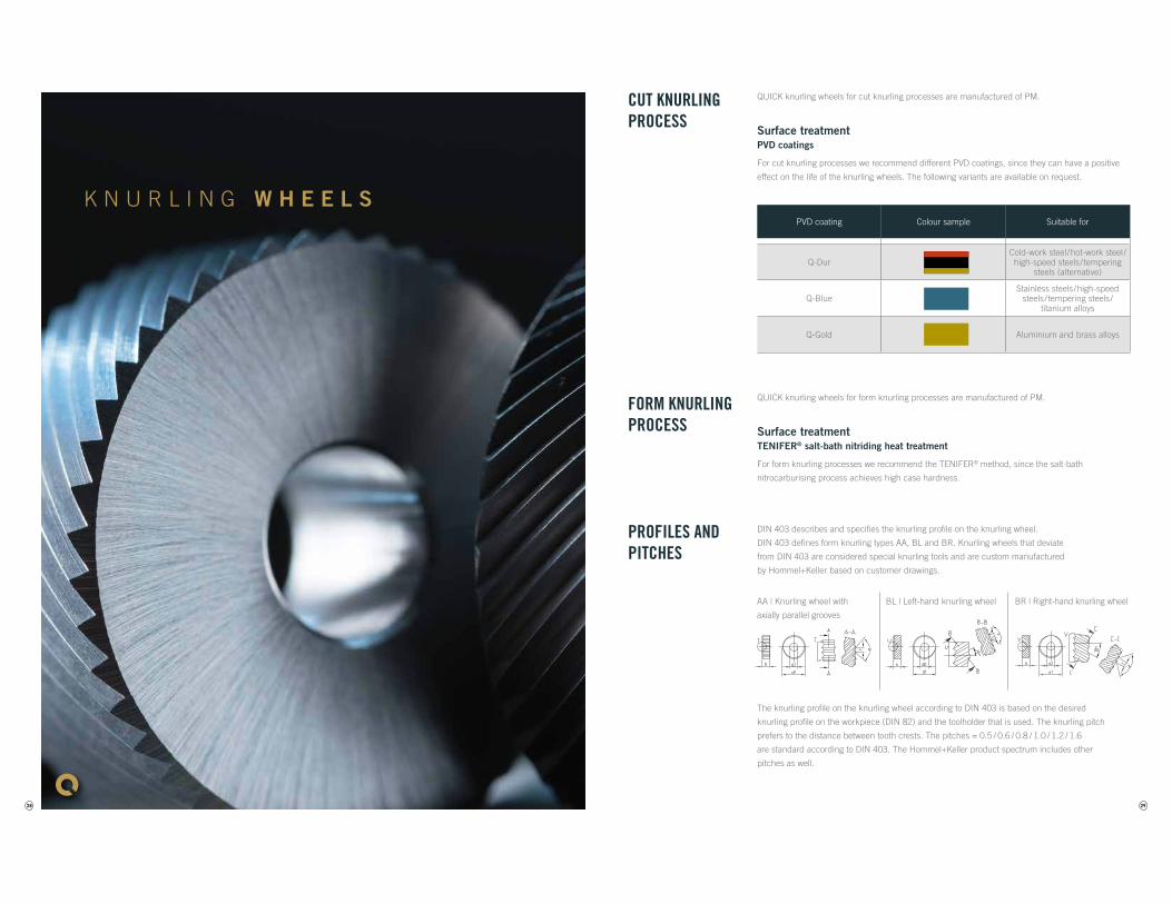
QUICK knurling wheels for cut knurling processes are manufactured of PM.
Surface treatmentPVD coatings
For cut knurling processes we recommend different PVD coatings, since they can have a positive
effect on the life of the knurling wheels. The following variants are available on request.
QUICK knurling wheels for form knurling processes are manufactured of PM.
Surface treatmentTENIFER® salt-bath nitriding heat treatment
For form knurling processes we recommend the TENIFER® method, since the salt-bath
nitrocarburising process achieves high case hardness.
DIN 403 describes and specifies the knurling profile on the knurling wheel.
DIN 403 defines form knurling types AA, BL and BR. Knurling wheels that deviate
from DIN 403 are considered special knurling tools and are custom manufactured
by Hommel+Keller based on customer drawings.
The knurling profile on the knurling wheel according to DIN 403 is based on the desired
knurling profile on the workpiece (DIN 82) and the toolholder that is used. The knurling pitch
prefers to the distance between tooth crests. The pitches = 0.5 / 0.6 / 0.8 / 1.0 / 1.2 / 1.6
are standard according to DIN 403. The Hommel+Keller product spectrum includes other
pitches as well.
PVD coating Colour sample Suitable for
Q-DurCold-work steel /hot-work steel /high-speed steels/ tempering
steels (alternative)
Q-BlueStainless steels/high-speed
steels/ tempering steels/ titanium alloys
Q-Gold Aluminium and brass alloys
CUT KNURLINGPROCESS
FORM KNURLING PROCESS
PROFILES AND PITCHES
BR | Right-hand knurling wheelBL | Left-hand knurling wheelAA | Knurling wheel with
axially parallel grooves
30
AA BL15° BR15° BL30° BR30°
Dimensions [mm]Profile Pitches
[mm]Ø Width Bore
8.9 2.5 4
AA
BL15°
BR15°
BL30°
BR30°
14.5 3 5
AA
BL15°
BR15°
BL30°
BR30°
21.5 5 8
AA
BL15°
BR15°
BL30°
BR30°
32 8 14
AA u
BL15° u
BR15° u
42 12 18
AA u
BL15° u
BR15° u
BL30°
BR30°
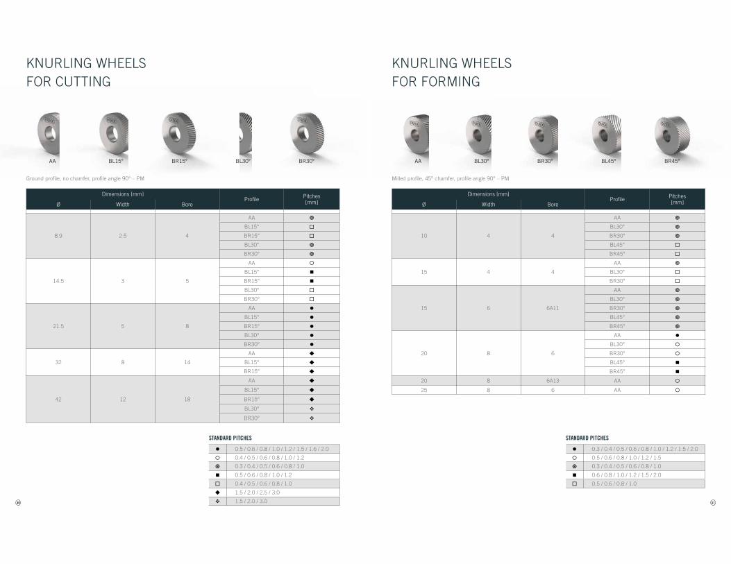
Ground profile, no chamfer, profile angle 90° – PM
KNURLING WHEELS FOR CUTTING
0.5 / 0.6 / 0.8 / 1.0 / 1.2 / 1.5 / 1.6 / 2.0
0.4 / 0.5 / 0.6 / 0.8 / 1.0 / 1.2
0.3 / 0.4 / 0.5 / 0.6 / 0.8 / 1.0
0.5 / 0.6 / 0.8 / 1.0 / 1.2
0.4 / 0.5 / 0.6 / 0.8 / 1.0
u 1.5 / 2.0 / 2.5 / 3.0
1.5 / 2.0 / 3.0
STANDARD PITCHES
31
AA BL30° BR30° BL45° BR45°
Dimensions [mm]Profile Pitches
[mm]Ø Width Bore
10 4 4
AA
BL30°
BR30°
BL45°
BR45°
15 4 4
AA
BL30°
BR30°
15 6 6A11
AA
BL30°
BR30°
BL45°
BR45°
20 8 6
AA
BL30°
BR30°
BL45°
BR45°
20 8 6A13 AA
25 8 6 AA
Milled profile, 45° chamfer, profile angle 90° – PM
KNURLING WHEELS FOR FORMING
0.3 / 0.4 / 0.5 / 0.6 / 0.8 / 1.0 / 1.2 / 1.5 / 2.0
0.5 / 0.6 / 0.8 / 1.0 / 1.2 / 1.5
0.3 / 0.4 / 0.5 / 0.6 / 0.8 / 1.0
0.6 / 0.8 / 1.0 / 1.2 / 1.5 / 2.0
0.5 / 0.6 / 0.8 / 1.0
STANDARD PITCHES
32
T E C H N O L O G Y
33
RBR45° RBL45° RGE45°
RBR30° RBL30°RAA RGE30°
C 6 1 2 - 1 2 M F 7 1 1 - 1 2 R
T E C H N O L O G Y
IMPORTANT INFORMATIONRÄNDELPROFILE BEI HOMMEL+KELLER
Rändelprofile nach DIN82
Zusätzliche Profile
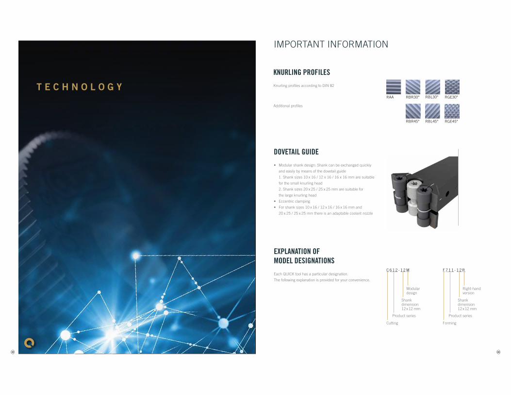
DOVETAIL GUIDE
• Modular shank design: Shank can be exchanged quickly
and easily by means of the dovetail guide
1. Shank sizes 10 x 16 / 12 x 16 / 16 x 16 mm are suitable
for the small knurling head
2. Shank sizes 20 x 25 / 25 x 25 mm are suitable for
the large knurling head
• Eccentric clamping
• For shank sizes 10 x 16 / 12 x 16 / 16 x 16 mm and
20 x 25 / 25 x 25 mm there is an adaptable coolant nozzle
EXPLANATION OF MODEL DESIGNATIONS
Each QUICK tool has a particular designation.
The following explanation is provided for your convenience.
KNURLING PROFILES
Knurling profiles according to DIN 82
Additional profiles
Shank dimension 12 x 12 mm
Modular design
Shank dimension 12 x 12 mm
Right-hand version
Forming
Product series
Cutting
Product series
34
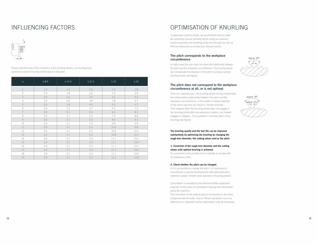
a b 8.9 b 14.5 b 21.5 b 32 b 42
1 1.0 1.3 2.0 1.5 1.8
2 2.5 1.8 2.6 2.5 3.0
3 3.0 2.2 3.0 3.1 4.3
4 3.0 2.6 3.8 3.8 5.7
5 3.0 2.8 4.5 4.5 6.7
6 3.0 3.1 4.7 5.1 7.5
7 3.0 3.1 5.0 6.2 8.1
8 3.0 3.1 5.3 7.6 8.6
9 3.0 3.1 5.3 9.4 9.1
10 3.0 3.1 5.3 9.8 9.5
11 3.0 3.1 5.3 10.4 9.8
12 3.0 3.1 5.3 10.6 10.1
13 3.0 3.1 5.3 10.8 12.2
14 3.0 3.1 5.3 11.1 13.1
15 3.0 3.1 5.3 11.1 13.6
16 3.0 3.1 5.3 11.1 14.1
17 3.0 3.1 5.3 11.1 14.4
18 3.0 3.1 5.3 11.1 14.6
19 3.0 3.1 5.3 11.1 14.8
Please note that due to the inclination of the knurling wheels, cut knurling tools
cannot be used for knurling all the way to a shoulder.
INFLUENCING FACTORS
35
To guarantee optimal results, we recommend that you read
the operating manual carefully before using our products.
Correct assembly and handling of the tool will save you set-up
time and allow you to achieve your desired results.
The pitch corresponds to the workpiece circumferenceIn many cases the user does not notice the relationship between
the pitch and the workpiece circumference. The knurling wheel
can compensate the distortion of the pitch to produce optimal
knurling results (see figure).
The pitch does not correspond to the workpiece circumference at all, or is not optimalThis is an extreme case. The knurling wheel cannot compensate
the unfavourable relationship between the pitch and the
workpiece circumference, or the profile is heavily distorted.
In the worst case this can result in “double knurling”.
This happens when the knurling wheel does not engage in
the knurling profile after one workpiece rotation, but instead
engages in between. This is evident in the finer pitch of the
knurling (see figure).
The knurling quality and the tool life can be improved
substantially by optimising the knurling by changing the
rough-turn diameter, the cutting values and / or the pitch.
1. Correction of the rough-turn diameter and the cutting
values until optimal knurling is achieved.
If a correction is not possible due to inability to comply with
the tolerances, then:
2. Check whether the pitch can be changed.
If it is not possible to change the pitch, it is necessary to
manufacture a special knurling wheel with optimised pitch
(defined number of teeth / outer diameter of knurling wheel).
Consultation is provided by the Hommel+Keller application
engineer on the basis of a workpiece drawing and information
about the machine.
The calculation of the optimal pitch is conducted on the basis
of approximate formulas. Due to influencing factors (such as
differences in materials) further optimisation may be necessary.
OPTIMISATION OF KNURLING
approx. 90º
approx. 90º
approx. 1/2 p
p
36
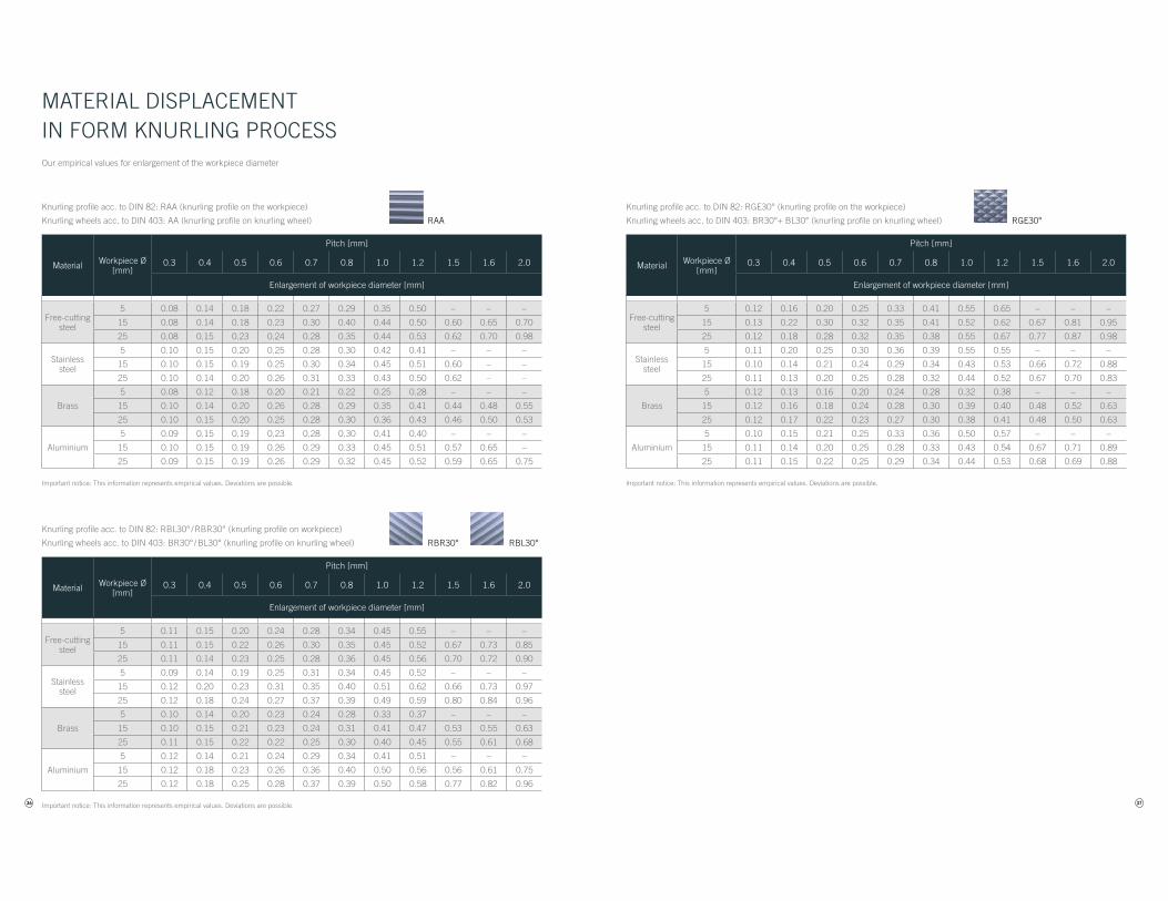
RAA
RBR30° RBL30°
Material Workpiece Ø[mm]
Pitch [mm]
0.3 0.4 0.5 0.6 0.7 0.8 1.0 1.2 1.5 1.6 2.0
Enlargement of workpiece diameter [mm]
Free-cutting steel
5 0.08 0.14 0.18 0.22 0.27 0.29 0.35 0.50 – – –
15 0.08 0.14 0.18 0.23 0.30 0.40 0.44 0.50 0.60 0.65 0.70
25 0.08 0.15 0.23 0.24 0.28 0.35 0.44 0.53 0.62 0.70 0.98
Stainless steel
5 0.10 0.15 0.20 0.25 0.28 0.30 0.42 0.41 – – –
15 0.10 0.15 0.19 0.25 0.30 0.34 0.45 0.51 0.60 – –
25 0.10 0.14 0.20 0.26 0.31 0.33 0.43 0.50 0.62 – –
Brass
5 0.08 0.12 0.18 0.20 0.21 0.22 0.25 0.28 – – –
15 0.10 0.14 0.20 0.26 0.28 0.29 0.35 0.41 0.44 0.48 0.55
25 0.10 0.15 0.20 0.25 0.28 0.30 0.36 0.43 0.46 0.50 0.53
Aluminium
5 0.09 0.15 0.19 0.23 0.28 0.30 0.41 0.40 – – –
15 0.10 0.15 0.19 0.26 0.29 0.33 0.45 0.51 0.57 0.65 –
25 0.09 0.15 0.19 0.26 0.29 0.32 0.45 0.52 0.59 0.65 0.75
Material Workpiece Ø[mm]
Pitch [mm]
0.3 0.4 0.5 0.6 0.7 0.8 1.0 1.2 1.5 1.6 2.0
Enlargement of workpiece diameter [mm]
Free-cutting steel
5 0.11 0.15 0.20 0.24 0.28 0.34 0.45 0.55 – – –
15 0.11 0.15 0.22 0.26 0.30 0.35 0.45 0.52 0.67 0.73 0.85
25 0.11 0.14 0.23 0.25 0.28 0.36 0.45 0.56 0.70 0.72 0.90
Stainless steel
5 0.09 0.14 0.19 0.25 0.31 0.34 0.45 0.52 – – –
15 0.12 0.20 0.23 0.31 0.35 0.40 0.51 0.62 0.66 0.73 0.97
25 0.12 0.18 0.24 0.27 0.37 0.39 0.49 0.59 0.80 0.84 0.96
Brass
5 0.10 0.14 0.20 0.23 0.24 0.28 0.33 0.37 – – –
15 0.10 0.15 0.21 0.23 0.24 0.31 0.41 0.47 0.53 0.55 0.63
25 0.11 0.15 0.22 0.22 0.25 0.30 0.40 0.45 0.55 0.61 0.68
Aluminium
5 0.12 0.14 0.21 0.24 0.29 0.34 0.41 0.51 – – –
15 0.12 0.18 0.23 0.26 0.36 0.40 0.50 0.56 0.56 0.61 0.75
25 0.12 0.18 0.25 0.28 0.37 0.39 0.50 0.58 0.77 0.82 0.96
MATERIAL DISPLACEMENT IN FORM KNURLING PROCESS
Knurling profile acc. to DIN 82: RAA (knurling profile on the workpiece)
Knurling wheels acc. to DIN 403: AA (knurling profile on knurling wheel)
Knurling profile acc. to DIN 82: RBL30° / RBR30° (knurling profile on workpiece)
Knurling wheels acc. to DIN 403: BR30° / BL30° (knurling profile on knurling wheel)
Our empirical values for enlargement of the workpiece diameter
Important notice: This information represents empirical values. Deviations are possible.
Important notice: This information represents empirical values. Deviations are possible. 37
RGE30°
Material Workpiece Ø[mm]
Pitch [mm]
0.3 0.4 0.5 0.6 0.7 0.8 1.0 1.2 1.5 1.6 2.0
Enlargement of workpiece diameter [mm]
Free-cutting steel
5 0.12 0.16 0.20 0.25 0.33 0.41 0.55 0.65 – – –
15 0.13 0.22 0.30 0.32 0.35 0.41 0.52 0.62 0.67 0.81 0.95
25 0.12 0.18 0.28 0.32 0.35 0.38 0.55 0.67 0.77 0.87 0.98
Stainless steel
5 0.11 0.20 0.25 0.30 0.36 0.39 0.55 0.55 – – –
15 0.10 0.14 0.21 0.24 0.29 0.34 0.43 0.53 0.66 0.72 0.88
25 0.11 0.13 0.20 0.25 0.28 0.32 0.44 0.52 0.67 0.70 0.83
Brass
5 0.12 0.13 0.16 0.20 0.24 0.28 0.32 0.38 – – –
15 0.12 0.16 0.18 0.24 0.28 0.30 0.39 0.40 0.48 0.52 0.63
25 0.12 0.17 0.22 0.23 0.27 0.30 0.38 0.41 0.48 0.50 0.63
Aluminium
5 0.10 0.15 0.21 0.25 0.33 0.36 0.50 0.57 – – –
15 0.11 0.14 0.20 0.25 0.28 0.33 0.43 0.54 0.67 0.71 0.89
25 0.11 0.15 0.22 0.25 0.29 0.34 0.44 0.53 0.68 0.69 0.88
Knurling profile acc. to DIN 82: RGE30° (knurling profile on the workpiece)
Knurling wheels acc. to DIN 403: BR30°+ BL30° (knurling profile on knurling wheel)
Important notice: This information represents empirical values. Deviations are possible.
38
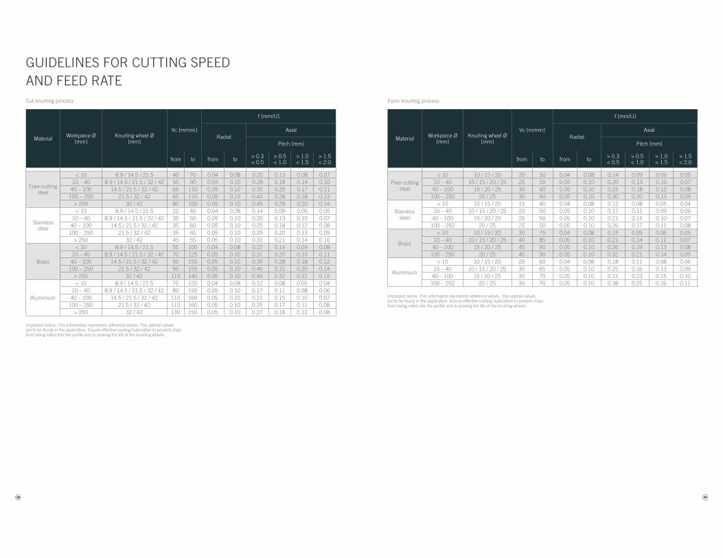
GUIDELINES FOR CUTTING SPEED AND FEED RATECut knurling process
Material Workpiece Ø[mm]
Knurling wheel Ø[mm]
Vc [m/min]
f [mm/U]
RadialAxial
Pitch [mm]
from to from to > 0.3< 0.5
> 0.5< 1.0
> 1.0< 1.5
> 1.5< 2.0
Free-cutting steel
< 10 8.9 / 14.5 / 21.5 40 70 0.04 0.08 0.20 0.13 0.08 0.0710 – 40 8.9 / 14.5 / 21.5 / 32 / 42 50 90 0.05 0.10 0.28 0.18 0.14 0.10
40 – 100 14.5 / 21.5 / 32 / 42 65 110 0.05 0.10 0.35 0.25 0.17 0.11100 – 250 21.5 / 32 / 42 65 110 0.05 0.10 0.42 0.28 0.18 0.13
> 250 32 / 42 80 100 0.05 0.10 0.45 0.29 0.20 0.14
Stainless steel
< 10 8.9 / 14.5 / 21.5 22 40 0.04 0.08 0.14 0.09 0.06 0.0510 – 40 8.9 / 14.5 / 21.5 / 32 / 42 30 50 0.05 0.10 0.20 0.13 0.10 0.07
40 – 100 14.5 / 21.5 / 32 / 42 35 60 0.05 0.10 0.25 0.18 0.12 0.08100 – 250 21.5 / 32 / 42 35 60 0.05 0.10 0.29 0.20 0.13 0.09
> 250 32 / 42 45 55 0.05 0.10 0.31 0.21 0.14 0.10
Brass
< 10 8.9 / 14.5 / 21.5 55 100 0.04 0.08 0.22 0.14 0.09 0.0810 – 40 8.9 / 14.5 / 21.5 / 32 / 42 70 125 0.05 0.10 0.31 0.20 0.15 0.11
40 – 100 14.5 / 21.5 / 32 / 42 90 155 0.05 0.10 0.39 0.28 0.18 0.12100 – 250 21.5 / 32 / 42 90 155 0.05 0.10 0.46 0.31 0.20 0.14
> 250 32 / 42 115 140 0.05 0.10 0.49 0.32 0.22 0.15
Aluminium
< 10 8.9 / 14.5 / 21.5 70 120 0.04 0.08 0.12 0.08 0.05 0.0410 – 40 8.9 / 14.5 / 21.5 / 32 / 42 80 150 0.05 0.10 0.17 0.11 0.08 0.06
40 – 100 14.5 / 21.5 / 32 / 42 110 160 0.05 0.10 0.21 0.15 0.10 0.07100 – 250 21.5 / 32 / 42 110 160 0.05 0.10 0.25 0.17 0.11 0.08
> 250 32 / 42 130 150 0.05 0.10 0.27 0.18 0.12 0.08
Important notice: This information represents reference values. The optimal values are to be found in the application. Ensure effective cooling / lubrication to prevent chips from being rolled into the profile and to prolong the life of the knurling wheels.
39
Important notice: This information represents reference values. The optimal values are to be found in the application. Ensure effective cooling / lubrication to prevent chips from being rolled into the profile and to prolong the life of the knurling wheels.
Form knurling process
Material Workpiece Ø[mm]
Knurling wheel Ø[mm]
Vc [m/min]
f [mm/U]
RadialAxial
Pitch [mm]
from to from to > 0.3< 0.5
> 0.5< 1.0
> 1.0< 1.5
> 1.5< 2.0
Free-cutting steel
< 10 10 / 15 / 20 20 50 0.04 0.08 0.14 0.09 0.06 0.0510 – 40 10 / 15 / 20 / 25 25 55 0.05 0.10 0.20 0.13 0.10 0.07
40 – 100 15 / 20 / 25 30 60 0.05 0.10 0.25 0.18 0.12 0.08100 – 250 20 / 25 30 60 0.05 0.10 0.30 0.20 0.13 0.09
Stainless steel
< 10 10 / 15 / 20 15 40 0.04 0.08 0.12 0.08 0.05 0.0410 – 40 10 / 15 / 20 / 25 20 50 0.05 0.10 0.17 0.11 0.09 0.06
40 – 100 15 / 20 / 25 25 50 0.05 0.10 0.21 0.15 0.10 0.07100 – 250 20 / 25 25 50 0.05 0.10 0.26 0.17 0.11 0.08
Brass
< 10 10 / 15 / 20 30 75 0.04 0.08 0.15 0.09 0.06 0.0510 – 40 10 / 15 / 20 / 25 40 85 0.05 0.10 0.21 0.14 0.11 0.07
40 – 100 15 / 20 / 25 45 90 0.05 0.10 0.26 0.19 0.13 0.08100 – 250 20 / 25 45 90 0.05 0.10 0.32 0.21 0.14 0.09
Aluminium
< 10 10 / 15 / 20 25 60 0.04 0.08 0.18 0.11 0.08 0.0610 – 40 10 / 15 / 20 / 25 30 65 0.05 0.10 0.25 0.16 0.13 0.09
40 – 100 15 / 20 / 25 35 70 0.05 0.10 0.31 0.23 0.15 0.10100 – 250 20 / 25 35 70 0.05 0.10 0.38 0.25 0.16 0.11