Assessment matrix for timber structures
355
Assessment matrix for timber structures : basis for standardized building checks Citation for published version (APA): Abels, M. (2011). Assessment matrix for timber structures : basis for standardized building checks. [Phd Thesis 2 (Research NOT TU/e / Graduation TU/e), Built Environment]. Technische Universiteit Eindhoven. https://doi.org/10.6100/IR712624 DOI: 10.6100/IR712624 Document status and date: Published: 01/01/2011 Document Version: Publisher’s PDF, also known as Version of Record (includes final page, issue and volume numbers) Please check the document version of this publication: • A submitted manuscript is the version of the article upon submission and before peer-review. There can be important differences between the submitted version and the official published version of record. People interested in the research are advised to contact the author for the final version of the publication, or visit the DOI to the publisher's website. • The final author version and the galley proof are versions of the publication after peer review. • The final published version features the final layout of the paper including the volume, issue and page numbers. Link to publication General rights Copyright and moral rights for the publications made accessible in the public portal are retained by the authors and/or other copyright owners and it is a condition of accessing publications that users recognise and abide by the legal requirements associated with these rights. • Users may download and print one copy of any publication from the public portal for the purpose of private study or research. • You may not further distribute the material or use it for any profit-making activity or commercial gain • You may freely distribute the URL identifying the publication in the public portal. If the publication is distributed under the terms of Article 25fa of the Dutch Copyright Act, indicated by the “Taverne” license above, please follow below link for the End User Agreement: www.tue.nl/taverne Take down policy If you believe that this document breaches copyright please contact us at: [email protected] providing details and we will investigate your claim. Download date: 19. Aug. 2022
-
Upload
khangminh22 -
Category
Documents
-
view
1 -
download
0
Transcript of Assessment matrix for timber structures

Assessment matrix for timber structures : basis forstandardized building checksCitation for published version (APA):Abels, M. (2011). Assessment matrix for timber structures : basis for standardized building checks. [Phd Thesis2 (Research NOT TU/e / Graduation TU/e), Built Environment]. Technische Universiteit Eindhoven.https://doi.org/10.6100/IR712624
DOI:10.6100/IR712624
Document status and date:Published: 01/01/2011
Document Version:Publisher’s PDF, also known as Version of Record (includes final page, issue and volume numbers)
Please check the document version of this publication:
• A submitted manuscript is the version of the article upon submission and before peer-review. There can beimportant differences between the submitted version and the official published version of record. Peopleinterested in the research are advised to contact the author for the final version of the publication, or visit theDOI to the publisher's website.• The final author version and the galley proof are versions of the publication after peer review.• The final published version features the final layout of the paper including the volume, issue and pagenumbers.Link to publication
General rightsCopyright and moral rights for the publications made accessible in the public portal are retained by the authors and/or other copyright ownersand it is a condition of accessing publications that users recognise and abide by the legal requirements associated with these rights.
• Users may download and print one copy of any publication from the public portal for the purpose of private study or research. • You may not further distribute the material or use it for any profit-making activity or commercial gain • You may freely distribute the URL identifying the publication in the public portal.
If the publication is distributed under the terms of Article 25fa of the Dutch Copyright Act, indicated by the “Taverne” license above, pleasefollow below link for the End User Agreement:www.tue.nl/taverne
Take down policyIf you believe that this document breaches copyright please contact us at:[email protected] details and we will investigate your claim.
Download date: 19. Aug. 2022

Beurteilungsmatrix für Holzkonstruktionen
Grundlage eines standardisierten Gebäudechecks
I

Published by Bouwstenen Publicatieburo Postbus 513, 5600 MB Eindhoven The Netherlands Telephone: +31(0)40 4442293 Copyright© 2011 by Michael Abels [CIP Gegevens Koninklijke Bibliotheek Den Haag] Beurteilungsmatrix für Holzkonstruktionen Grundlage eines standardisierten Gebäudechecks Die englische Version Assessment Matrix for Timber Structures Basis for Standardized Building Checks ist unter der gleichen ISBN- und Bouwstenen-Nummer erhältlich
Michael Abels Technische Universiteit Eindhoven Faculteit Bouwkunde Proefschrift – Doctorate Thesis – ISBN 978 -90-6814-633-2 NUR code 955 Schlüsselbegriffe (Trefwoorden, Keywords): Beurteilungsmatrix, Gebäudecheck, Nachhaltiges Bauen, Formblatt, Checkliste, Datenbank, Objektbuch, EU-Richtlinie Cover design: Bert Lammers, Tekenstudio, Faculteit Bouwkunde All rights reserved. No part of this publication may be reproduced, stored in a retrieval system, or transmitted in any form or by any means, photocopy, recording or otherwise, without written permission from the author.
II

Assessment Matrix for Timber Structures Basis for Standardized Building Checks
PROEFSCHRIFT ter verkrijging van de graad van doctor aan de Technische Universiteit Eindhoven, op gezag van de rector magnificus, prof.dr.ir. C.J. van Duijn, voor een commissie aangewezen door het College voor Promoties in het openbaar te verdedigen op woensdag 11 mei 2011 om 16.00 uur door Michael Abels geboren te Grevenbroich, Duitsland
III

Dit proefschrift is goedgekeurd door de promotoren: prof.mag.arch.ing.dr.h.c. P. Schmid en prof.dr.ir. A.J.M. Jorissen Copromotor: dr.ir. A.J.M. Leijten
IV

Acknowledgement
This PhD-Thesis would not have been possible without the support of various people
whom I would like to thank at this point.
First of all, I would like to name Dr.-Ing. Hans Löfflad, who in 2004 provided the most
important contact for me to my first promoter, prof. mag. arch. ing. dr. h. c. Peter
Schmid. Peter, in turn, referred me to my second promoter, prof. dr. ir. André
Jorissen. I would now like to thank both of them very kindly since they have
contributed greatly to my dissertation now being complete.
I especially want to thank Peter Schmid for his profound insights and excellent
directions in allowing me to develop my first thoughts into a scientific dissertation. His
method of dealing with the most varied circumstances is exemplary.
Thanks also go to André Jorissen for his perfect knowledge of timber and for
suggesting many interesting contacts, both in the scientific field and in different
timber companies.
Furthermore, I would like to thank the other members of the examination committee
who also supported me and gave me valuable advice during the editing of my thesis.
Here, I would like to first name my Copromoter dr. ir. Ad Leijten of the Eindhoven
University of Technology, who, in addition to his knowledge of timber, provided
valuable support in the translation of the German version into the English version.
I would like to thank Prof. Dr.-Ing. Karl Rautenstrauch of the Bauhaus University
Weimar for his very nice support and confirmation of my ideas during the final stages
of my work. My exchange with Prof. Dipl.-Ing. Wolfgang Winter of the Vienna Uni-
versity of Technology was also very beneficial in terms of rounding out the overall
dissertation.
I received additional kind support from prof. dr. ir. Wim Schaefer of the Eindhoven
University of Technology and prof. dr. ir. Michiel Haas of the Delft University of
Technology.
I would like to thank my former high school teacher, Mr. Klaus Weiler, for the
unlimited use of his home as a very interesting case study. I also want to thank my
mother in her capacity as sexton for providing me with her church key for a further
very interesting case study.

I would also like to thank my colleagues at the office who supported me in whatever
way they could: Sabrina, Ingo, Hannah, Steffan, Andrea and Nele.
Finally, I would like to thank my entire family very much because they had to go
without seeing me quite often in the past few years; here I am reminded of our last
holiday in South Tyrol. I hope to soon have more time for my children, Amélie and
Magnus. I also want to give a big thanks to my wife Helga. She not only provided
continual support but also motivated me again and again in bad times to finish the
PhD-Thesis I had started when there seemed to be no end in sight. Thank you!

Assessment Matrix for Timber Structures Michael Abels
Index of Contents
1
Index of Contents
Chapter
Page
Acknowledgment
0. Introduction - Structure of the PhD-Thesis 0/1
0.1 Basic Problem 0/1
0.2 Research aim 0/1
0.3 Scientific relevancy - state of-the-art of science 0/2
0.4 Research scope 0/4
0.5 Processing method 0/5
0.6 Result as solution and/or answer to the basic problem
description
0/6-7
1. General and Basic Knowledge for the Assessment
of Timber Building Structures
1/1
1.1 Explanation of terms 1/1
1.1.1 Definition of terms 1/2
1.1.2 Wood construction regulations 1/7
1.2 Wood characteristics and different wood
materials (= checklist 1 basics)
1/9
1.2.1 Materials and their selection 1/10
1.2.1.1 Solid wood products 1/11
1.2.1.2 Glued laminated timber = gluam 1/12
1.2.1.3 Timber products 1/15
1.2.1.4 Box beams an hybrid products
(=composite components)
1/19
1.2.2 Mechanical wood characteristics 1/20
1.2.2.1 Young's modulus - Deformation computations 1/21
1.2.2.2 Strength and permissible stress types 1/21
1.2.2.3 Wood age impact on mechanical characteristics 1/22

Assessment Matrix for Timber Structures Michael Abels
Index of Contents
2
Chapter
Page
1.2.3 Physical wood characteristics 1/23
1.2.3.1 Density 1/23
1.2.3.2 Thermal characteristics 1/24
1.3 Wood moisture: Swelling and shrinkage
(= checklist 2 basics)
1/25
1.4 Wood preservation
(= checklist 3 basics)
1/27
1.4.1 Moisture protection: Structural-constructive and
chemical wood preservation
1/27
1.4.2 Protection against insects, fungi and other influences 1/28
1.5 Wood constructions
(= database basics)
1/29
1.5.1 Historical development of wood constructions 1/30
1.5.2 Wooden-beam ceilings and wooden panels
(=basics of database 1)
1/31
1.5.3 Carpenter-made roof constructions
(= basics of database 2)
1/32
1.5.4 Framework, connections and wooden beams
(=basics of database 3)
1/33
1.5.5 Timber frame construction (= panel construction) –
prefabricated houses (= basics of database 3)
1/36
1.5.6 Modern timber engineering constructions:
Board stacking systems and board plywood
construction
1/37
1.5.7 Engineered timber structure
(=basics of database 4)
1/39
1.5.8 Connections and connection techniques
(= basics of database 5)
1/42

Assessment Matrix for Timber Structures Michael Abels
Index of Contents
3
Chapter
Page
1.5.8.1 Carpenter-made connections 1/42
1.5.8.2 Engineered connections 1/43
1.5.8.3 Connections with adhesives 1/44
1.5.9 Special constructions 1/44
1.6 Structural computations
(= database basics)
1/46
1.6.1 Structural safety analysis and usability analysis 1/46
1.6.2 Historical development 1/48
1.6.3 Load bearing (supporting) and non-load bearing
(nonstructural) Components
1/48
1.6.4 Static systems 1/49
1.6.5 Reinforcement (stiffening) systems 1/51
1.7 Building Physics basics
(= database basics)
1/53
1.7.1 Sound insulation 1/53
1.7.2 Moisture protection 1/55
1.7.3 Fire protection 1/55
1.7.4 Heat insulation - Energy-saving measures 1/57
1.8 Intermediate conclusion and outlook into the
following chapters
1/61
2. Development of an Assessment Matrix
(= Main Matrix)
2/1
2.1 Definition of terms - matrix 2/1
2.2 Complexity of Tasks
2/2

Assessment Matrix for Timber Structures Michael Abels
Index of Contents
4
Chapter
Page
2.3 Involvement of Experts 2/8
2.4 Methodology of the construction state analysis 2/10
2.4.1 General information about the design +
content of the “forms”
2/11
2.4.2 Form 1:
Basic evaluation and structural parameters
2/11
2.4.3 Form 2:
construction state analysis
2/15
2.4.4 Form 3: Load-bearing system / structural analysis /
structural elements / connections (building
parameters)
2/27
2.4.5 Form 4: Condition mapping of the “actual state” 2/31
2.4.6 Form 5: Examination methods for different material
parameters [Only approximate “on-site controls”]
2/34
2.4.7 Specifying an Expert Database for specific
inspections (= Appendix to Form 5)
2/37
2.5 General information about the layout and content
of the “Checklists”
2/42
2.5.1 Checklist 1: Determination of Wood-Species 2/43
2.5.2 Checklist 2: cracks and deformations 2/47
2.5.3 Checklist 3: Quick on-site analysis of fungus and
insect infestations
2/49
2.6 Concrete, typical damages to structural elements,
their detection + causes and professional
removal or restoration
2/56
2.6.1 General information about the layout + content of the
“Databases”
2/58

Assessment Matrix for Timber Structures Michael Abels
Index of Contents
5
Chapter
Page
2.6.2 Database 1: Ceiling constructions / supporting
elements / stairs / balconies
2/62
2.6.3 Database 2: Roof constructions (carpenter-made) 2/68
2.6.4 Database 3: Wall constructions / bracing systems /
framework / timber supports
2/78
2.6.5 Database 4: Engineering / widespread timber
constructions
2/83
2.6.6 Database 5: Connecting pieces / junctions 2/88
2.6.7 Form 6: Final inspection protocol 2/91
2.7 Assessment Matrix of Timber Structures
(= complete matrix)
2/105
2.7.1 Application of the matrix: why / how / where / when 2/110
2.7.2 Object book (for documentation) 2/111
2.8 Temporary conclusion and prospects of the
following sections
2/113
3. Example Assessment Matrix applications
(= main matrix)
3/1
3.1 General information about the practical matrix
application
3/1
3.2 Reason for the project selection 3/3
3.3 Case study 1:
Historic church building St. Georg in Bedburg
3/6
3.4 Case study 2:
Listed truss building in Bedburg
3/32

Assessment Matrix for Timber Structures Michael Abels
Index of Contents
6
Chapter
Page
3.5 Case study 3: Sports Hall Kleiststraße in
Mühlheim an der Ruhr
3/60
3.6 Peculiarities of previous applications +
evaluation of previous matrix applications
3/87
3.7 Social applications of the Assessment Matrix 3/91
3.8 Approval of the final acceptance report for
creating a model for introducing and
implementing a standardized building check
3/93
3.9 Preliminary conditions regarding the obligations
governed by building law for cyclical monitoring
depending on the building categories and
different criteria
3/95
3.9.1 Buildings categories (= BC) 3/95
3.9.2 Monitoring forms 3/96
3.9.3 Monitoring cycles (in years) = release periods = RP 3/97
3.9.4 Requirements of the timber expert and testing
process
3/98
3.9.5 Test badges 3/99
3.9.6 Implementation of the standardized building check in
society
3/105
3.10 Preliminary consideration of a bill 3/105
3.11 Intermediate conclusion + outlook of the
following section
3/107
- 108

Assessment Matrix for Timber Structures Michael Abels
Index of Contents
7
Chapter
Page
4. Summary and Outlook 4/1
4.1 Possible matrix programming implementations
for a simple data processing application
4/1
4.2 Continuous research and extension suggestion
into non-timber constructions and transnational
studies
4/2
4.3 Conclusions 4/4
5. Appendix 5/1
5.1 Summary of the PhD-Thesis in different
languages
5/1
5.1.1 German 5/1
5.1.2 Dutch 5/2
5.1.3 English 5/3
5.1.4 Spanish 5/4
5.1.5 French 5/5
5.1.6 Italian 5/6
5.2 List of literature = references 5/7
5.3 Notes of literature 5/9
5.4 Named internet pages 5/15
5.5 Mentioned regulations and standards
5/16

Assessment Matrix for Timber Structures Michael Abels
Index of Contents
8
Chapter
Page
5.6 Notes of literature „Informationsdienst Holz“ 5/18
5.7 References and notes of literature with chapter
specification
5/23
5.8 Composition of all tables, images, pictures, etc.,
of all chapters
5/30
5.9 Curriculum Vitae 5/34 -
35

Assessment Matrix for Timber Structures Michael Abels
Chapter 0 1
0. Introduction - Structure of the PhD-Thesis
In the following first section of this PhD-Thesis the objective of this research is
explained and the scientific approach is briefly described.
0.1 Basic Problem
The self-conception when entering a building, from our own home to a large place of
gathering such as a historical church, is unfortunately upset on a regular basis when
buildings show severe damage and are thus closed for use, or which even collapse.
In most cases this is caused by constructional/structural deficiencies which could
have been detected earlier.
How can this deficiency of our modern society be corrected using its large portfolio of
technical capabilities?
0.2 Research aim
The objective of this thesis is to provide an instrument and to define a procedure to
ensure that in the future people everywhere will be able to enter and utilize buildings,
where they can safely stay, live and work. Furthermore, damage could be detected
earlier and thus be corrected with less effort.
The focus of this thesis is on load-bearing timber structures, which are evaluated
using an assessment matrix developed and presented here, and finally released by a
still to be established inspection authority after possible strengthening or
reconstruction.
The author of this PhD-Thesis intends to close an existing gap in our society by
providing this new assessment matrix. In the future, this can enable timber
appraisers, who so far have worked according to their own concepts, to use a
strategy allowing them to compare their assessments and to conclude with a
common evaluation. Thus, a sustainable process can be established.

Assessment Matrix for Timber Structures Michael Abels
Chapter 0 2
What is the benefit to society if individual timber appraisers find typical damage
patterns and correct them on one project only when this danger is not detected in
thousands of other, similar constructions?
Besides the safety for users (=social relevance), the suggested inspection approach
(=matrix), which applies to all buildings independently of materials used, age and
size, is used to preserve structural cultural assets (= societal relevance) - with
respect to sustainable development as well.
0.3 Scientific relevancy - state of-the-art of science
The tragedy in Bad Reichenhall (Germany), on January 2nd 2006, when the wooden
roof construction of an ice pavilion collapsed and 15 people lost their lives, shocked
the entire nation.
It was quickly determined that structural deficiencies caused the tragedy. This could
have been prevented, if the building had been sufficiently inspected. Active
discussions started to take place not only in Germany, if public buildings should be
inspected on a regular base in the future. During random inspections initiated by the
German TÜV (Technical Supervisory Association) after the tragedy, significant
deficiencies were detected on several hall roof constructions, which emphasized the
need for regular inspections.
Amongst other things this PhD-Thesis takes up the approaches of the study group
Wood Glue Constructions [10] and attempts to establish a unambiguous procedure,
in order to stop multi interpretation, as on the one hand so far no standard
assessment procedure exists for timber structures and on the other hand, all
buildings are basically left alone after their completion.
In the present thesis a sustainable process sequence is developed, how a still to be
established inspection instance checks usability and structural integrity of any
building on a regular base. For this purpose the buildings are divided into building
categories, based on which monitoring effort and cycles will be determined.
Thus, the scientific framework of this work has been established.
Assessment Matrix for Timber Structures Michael Abels
Chapter 0 3
The described course of procedure is based on the assessment matrix, which will be
developed in the 2nd chapter and applied in the 3rd chapter of this work. Among
others, the current status of all common construction types, common inspection
methods, handling of possible damage and material characteristics knowledge was
incorporated into this assessment matrix.
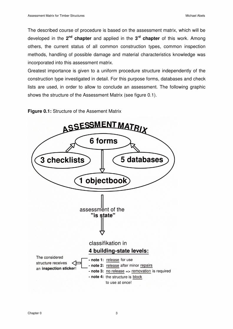
Greatest importance is given to a uniform procedure structure independently of the
construction type investigated in detail. For this purpose forms, databases and check
lists are used, in order to allow to conclude an assessment. The following graphic
shows the structure of the Assessment Matrix (see figure 0.1).
Figure 0.1: Structure of the Assement Matrix

Assessment Matrix for Timber Structures Michael Abels
Chapter 0 4
As scientific basis of the topic areas addressed in this PhD-Thesis, literature
references to other directly related scientific publications are provided at respective
locations or sections. In the 5th chapter of this dissertation, in sections 5.3 to 5.7,
more references web pages, mentioned rules and standards are given. For that a
chapter assignment is made.
At this point a previous dissertation at Technical University Eindhoven, prepared by
Jalil H. Saber Zaimian [27], must be mentioned, who in his "Model for structural
transformation" uses different terminology, which is used in the present thesis as
well.
Furthermore, additional research work, among others by Professor Peter Niemz from
ETH Zürich, will be mentioned at certain locations throughout the course of this PhD-
Thesis, which addresses individual aspects of timber structures important within the
framework of appraisals of existing timber constructions.
0.4 Research scope
In the 1st chapter the author collects information for individual important aspects of
timber constructions from already existing research papers, which in the future could
be useful to the user of the assessment matrix, if he faces a similar problem.
The entire thesis should be understood as a collection of literature references to
many different timber construction divisions, for which timber construction
assessment is of interest, to generate a large network in the future, which will be able
to answer any question of the matrix user. This thesis cannot deliver this very
advanced version. Most likely this version will only exist in several years in a
programmed IT version after multiple applications by multiple users.
A final version will never exist, as the matrix should be continuously updated with the
latest development in timber construction.
Besides expert knowledge in timber construction, long-term experience is necessary
to actually apply the assessment matrix. In the 1st chapter of this PhD-Thesis a
theoretical knowledge base is presented as well as a large amount of literature
references to in-depth information to allow not only timber expert access to this
dissertation. The chapter is mainly for interested parties and participants in and on
construction processes, who merely have basic knowledge. Due to the complexity of

Assessment Matrix for Timber Structures Michael Abels
Chapter 0 5
the discussed topic only such terms can be defined in the 1st chapter, which are
important in the later matrix and its proposed building-law related applications. For
all sub-topics addressed in this chapter, information and relation to later topics should
be provided or established. It is important to mention with respect to chapter 1, that
only well understand and reliable information is briefly presented, corresponding to
the state-of-the-art of technology. Often reference to technical regulation or literature
reference are provided, which will communicate the outlook to the interested party
already having great expert knowledge, to apply the later introduced assessment
matrix in the future by himself.
0.5 Processing method
By means of literature and Internet research, expert discussions and attendance at
expert conferences, congresses and seminars, the topic of timber construction was
and is comprehensibly developed addressing all angles. Furthermore, current
European timber construction provisions and their predecessor standards were
researched. Different tasks in the professional day-to-day work of the author
continuously delivered and deliver concrete points of references with respect to
timber constructions, covering historical construction methods up to modern
engineered timber constructions. The author was able to collect the experiences
mentioned above throughout his professional carrier of 15 years as engineer and
architect.
The matrix exactly described in the previous section of scientific relevancy, has
already been tested over a longer period of time on different buildings within the
scope of engineering appraisals. These concrete projects are the reason for the basic
idea of the matrix and the prerequisite for its step-wise development.
In the 3rd chapter of this PhD-Thesis the matrix is applied to three concrete buildings.
These case studies are used to test and finally validate the matrix.
In order to present the large spectrum of existing timber constructions, three very
different buildings were intentionally selected:

Assessment Matrix for Timber Structures Michael Abels
Chapter 0 6
1. Church building with historical Gothic church tower construction (including bell
frame), dated 1551, and nave from the late baroque period, dated 1783, with
new engineered framework roof-construction, dated 1951.
2. Protected timbered house dated 1653, with framework inner walls, wood-
beamed ceiling and double-layered historical roof truss.
3. Triple gymnasium with modern engineered roof construction with glued-
laminated girders, erected 1979.
In the following a societal application is presented.
For this purpose the assessment matrix is awarded a possible legal framework. The
target should be to define a new EU standard based on this thesis, which regulates
regular building monitoring with respect to usability and structural safety depending
on defined building classes.
An awarded inspection sticker visibly attached to the building, similar to the known
German TÜV stamps, indicates the release for a certain time frame, and could soon
be integral part of all buildings in order to awaken respective awareness within the
population.
0.6 Result as solution and/or answer to the basic problem description
The present dissertation covers a wide field of detailed topics.
The basis is the previously described development of a matrix enabling
comprehensive and objective assessment of the structural condition of all timber
constructions. Before that different terms of this matrix are presented and explained.
When preparing the assessment matrix which should be applied in Europe, it is
necessary to limit to efforts to one country at the beginning. The focus is on
Germany; otherwise the research topic would be too extensive. Subsequent to this
work a transnational study could be performed. The matrix form was consciously
selected as it is very well suited for the discussed topic. In the following several
scientific considerations are presented justifying this assumption. The processing
sequence is defined to ensure that all relevant aspects are handled. For faster and
simpler processing so-called checklists and databases are provided to the users for
frequently occurring problems.

Assessment Matrix for Timber Structures Michael Abels
Chapter 0 7
As the later application of the matrix developed in this dissertation should be based
on a computer program, the programmer can directly access a clear structure, which
highlights relationships and dependences between all sub-aspects.
As already described above, the focus of this work is on timber constructions. The
consideration of massive constructions (made of ferroconcrete and/or brickwork) and
metal constructions (steel and/or aluminum light constructions) would go beyond the
scope of this thesis. However, this dissertation provides a good template, how to
include such constructions into the developed approach in the future. Separate
assessment matrices of these building materials could be developed in future
scientific papers. Besides that, the following considerations apply to all buildings
independently from the material used.
In the 4th chapter of this PhD-Thesis it is discussed, how the topic of this
dissertation can be used in future scientific work even by different University
Faculties, such as from a legal or technical-philosophical point of view.
Summarizing it can be stated
- That there is a need for systematic checks of timber structures.
- That so far no comprehensive assessment matrix exists for timber
constructions taking into account all aspects and considering the social
relevance of user safety and societal relevance of preserving structural cultural
assets.
- That the matrix can be optimized and adapted to technical developments
based on area-wide application and regular user assessments.
- That the approach developed in this work can present the basis of a new EU
standard, according to which all buildings must be subjected to regular
standardized monitoring.
- That based on previous considerations and studies scientific relevance is
given, as the developed sustainable approach should close a gap still existing
within the building laws.

Assessment Matrix for Timber Structures Michael Abels
Chapter 1 1
1. General Information and Basic Knowledge for the Assessment of Timber
Building Structures
As an entry point into this dissertation, different timber structure terms are listed in
this chapter.
In preparation of chapter 2, the focus in chapter 1 is mainly on diverse basic
knowledge. Continuative literature references are provided for the interested reader
and/or later user of the matrix. Thus, to facilitate certain correlations, the later
structure of the matrix is already considered in this chapter.
1.1 Explanation of terms
The technical terms often used in this dissertation are briefly explained in this chapter
1. Besides that, technical basic knowledge is briefly presented to address not only a
professional audience of architects, engineers and wood experts, who intensively
deal with timber constructions and their conservation on a professional base. People
interested in timber constructions, but not having the necessary scientific
background, should have the opportunity to access this thesis and get an
understanding, which aspects are important for the assessment and conservation of
timber constructions. These persons for example include employees of monument
protection services or other institutions, which accompany and document building
monitoring. They usually do not have the in-depth technical knowledge in the timber
area.
References and literature references provided, offer the interested reader the
opportunity to independently deal with individual topics in detail. It would go beyond
the scope of this PhD-Thesis to explain all technical details, such as mechanical and
physical timber characteristics. However, the matrix user must know them.
Only qualified persons can actually apply the assessment matrix at a construction
site and/or to the building object.
In chapters 2, 3 and 4 this will be discussed in more detail. The instructions of
chapters 5.3 to 5.7 are very important.

Assessment Matrix for Timber Structures Michael Abels
Chapter 1 2
1.1.1 Definition of terms
When dealing with timber constructions, which appear in different shapes in
buildings, then experts as well as laymen use terms, which may be differently
understood by different people. In the following, different designations are listed and
briefly explained to ensure that every reader will understand the same content when
using these terms.
Architectural conservation: Older buildings are entitled to architectural
conservation from a building law point of view. This means that the original rights
from the time of construction and/or the building approval from that time are still valid,
although now more strict regulations may apply. Care should be taken in case of
larger remodeling or reconstruction measures. Architectural conservation is often
voided and the current building laws must be applied to the entire construction object
within this building measure.
Monument conservation: The goal of monument conservation is to secure
monuments as cultural heritage for future generations. It is important to any society to
inform about its own history by means of cultural monuments and nature monuments.
A vital image of the architecture and the way of living of previous times is preserved.
In Germany it is common to attach a visible label to the outer facade of landmarked
objects according to the Hague Convention for the protection of cultural assets in
case of armored conflicts (UNESCO 1954 [112]).
Figure 1.1: Monument conversation label of former GDR

Assessment Matrix for Timber Structures Michael Abels
Chapter 1 3
Furthermore, different labels are common in individual German areas. (As an
example the current monument conservation label for North Rhine-Westphalia is
shown in figure 1.2).
Figure 1.2: Current monument conservation label in the German area North Rhine-
Westphalia (NRW).
As already described at the beginning of this thesis, it is a very important task of our
society to preserve structural cultural assets, often called monuments, for future
generations. Here a saying from the Old Testament should be mentioned.
In the sayings of Salomon the following rule is listed as 24.3, which is of crucial
importance for monument conservation:
"By wisdom a house is built,
and through understanding it is established"
(Salomon' sayings; 24.3)
Due to the large number of buildings in our modern society worth preserving, more
attention will be focused in the future on conservation and strengthening (see
definition below) of these constructions.
New timber building constructions will be built in the future as well. The modern
methods of engineered timber constructions described before have almost no limits
with respect to architectural designs.
In Germany monument conservation authorities exist, controlling compliance with
monument conservation laws. Here the monument conservation laws of the German
States North Rhine-Westphalia and Brandenburg are mentioned as examples.

Assessment Matrix for Timber Structures Michael Abels
Chapter 1 4
Old building: This term is often used for buildings, which do not comply with current
building designs due to their condition. In Germany the architecture up to World War
II is often addressed by this. Residential constructions mostly consisted of brickwork
walls, wood-beamed ceilings and box-type windows. The following architectural style
with major use of ferroconcrete components (walls and ceilings) as well as coupled
and insulating glass windows concludes the old building era in Germany. Larger clear
room heights of more than 3 meters are typical for old buildings. Old buildings are
always subjected to architectural conservation mentioned above.
Redevelopment: Redevelopment describes the partial renewal or completion of a
building, which after the redevelopment should regain its function functional again.
Modernizations are often included in redevelopments, in order to improve the living
standard. Prior to a redevelopment it must be coordinated with the responsible
building control authority, if architectural conservation is voided due to the
redevelopment.
Redevelopment goes beyond maintenance and/or repair and/or strengthening, as the
building substance should often be adapted to a new utilization (= change of
utilization).
Maintenance and/or strengthening: Unfortunately, continuous monitoring and/or
maintenance are not performed for many older timber constructions. For this reason,
different deficiencies and even damage can already be detected on younger timber
constructions, which must be repaired in order to save these buildings long-term. The
modern methods of chemical and constructive wood preservation, which are
described later on, already offer good possibilities requiring minor effort to
retroactively protect constructions. However, as a retroactive measure is often
associated with greater effort, these wood preservation measures should always be a
priority when planning new wood constructions.
Wood construction damage has often progressed so far, e.g. due to fungus or insect
infestation, that larger maintenance is necessary in order to secure long-term
conservation and possibly short-term stability of the building.

Assessment Matrix for Timber Structures Michael Abels
Chapter 1 5
This is one of the main subjects of this PhD-Thesis. In the later course of this paper,
typical repair methods (see different databases, sections 2.6.2 ff) are presented for
different wood construction damage.
Change of use: During their useful life, buildings are often reconstructed or
extended. For this reason, occurring stress and loads (especially service loads =
traffic loads), caused by more people traffic in the building, may be impacted.
Changes of utilization from pure residential use to commercial use, e.g. as store
area, are of great importance as well. Besides increased loads on the construction,
possibly structural-physical demands, such as new refrigeration/cooling rooms for
food stores must be observed.
Structural safety: A building is structurally safe, if the chance of collapse is very
small and if its load-bearing construction is designed to transmit all possible external
loads (wind, snow, permanent and service loads + possible dynamic loads, e.g.
caused by earthquakes) during the construction and utilization duration, without any
damage and permissible smaller deformations into the ground. Within the scope of a
structural safety demonstration, the structural engineer determines all possible loads
and performs stress and deformation analyses.
Usability: In the decisive German regulation is stated:
"A building must be designed and realized to ensure that
besides its load carrying capacity it will maintain its
usability and stability throughout its provided service
duration and requiring appropriate maintenance efforts"
Typical requirements for usability are crack width limitations, water tightness and
deformation or vibration restrictions.

Assessment Matrix for Timber Structures Michael Abels
Chapter 1 6
It may occur that the pure structural stress analysis is sufficient; however
deformations reach an unacceptable value. Thus, the following requirements must be
met with respect to the usability of a building:
- Proper function of the entire building.
- Well-being of the persons belonging to the planned building use.
- The traffic safety of all building users must be ensured. For example,
railings must be installed at possible dangerous locations.
If one or several of the points mentioned are not met, then usability is not or not any
more provided.
Sustainability [21]: This term is used several times throughout the thesis. It should
express, that a system is established and/or installed within our society, which
sustains itself and (specifically using the example of this thesis) contributes to the
conservation and protection of the entire building inventory. This system is based on
a process, which is explained in detail in this thesis and which is based on an
assessment matrix.
Different aspects of sustainability are differentiated (see [21]). The present
dissertation addresses ecological sustainability by suggested legally obligatory
maintenance and protection of all buildings in their original design.
Social sustainability is targeted as well. Usable and structurally safe building
substance is the main requirement for a sustainable society worth living. The
assessment matrix is developed for this purpose.
To complete the 3-column model of sustainability (see figure 1.3) economic
sustainability must be discussed now. If this aspect is used in the PhD-thesis, then it
can be stated that regular building checks are more cost-effective (= economic) in the
long run than costly redevelopments caused by damage being detected too late. In
case of severe building damage, it must often be decided whether demolition is the
most cost-effective option.

Assessment Matrix for Timber Structures Michael Abels
Chapter 1 7
Figure 1.3: 3-column sustainability model
1.1.2 Wood construction regulations
Starting with the development of human life in shelters, wood was used. Thus,
experiences in handling this material were communicated from generation to
generation. Today traditional trade rules are often mentioned, which still righteously
have a high value in our today's society. Many old trade rules have spiritual aspects
containing concrete practical results: "If you process wood, do not forget the tree",
indicates for example, that growth direction and thus fiber orientation of the wood
must be considered.
Based on former trade rules and empirical values, the DIN standards (German
Institute for Standardization) were established in Germany at the beginning of the
20th century.
Any well-founded findings in science, technology and experiences up to the
respective publication date are included in these standards. The application of
standards is often referred to as working according to the state-of-the-art of
technology. However, standards often do not contain current regulations and/or
technical developments, as a rather long period of time may pass until an updated
standard is published. However, if these not yet standardized advanced
developments have already proven themselves, then these improvements apply as
"state-of-the-art of technology".

Assessment Matrix for Timber Structures Michael Abels
Chapter 1 8
If a European certification is available (within the European Union) for a construction
product, then this is documented using the CE symbol (see figure 1.4). This is a
freely negotiable process, which today is not automatically applied to all construction
products.
Figure 1.4: CE mark („Conformité Européenne“)
In the meantime standardized dimensioning rules exist in civil engineering throughout
Europe. These European standards were compiled by accredited scientists,
engineers and users - similar to the German DIN standards.
In the German standardization, DIN 1052 was always crucial for the calculation and
execution of wooden constructions. These measurements and constructions are now
regulated in Euro Code 5.
The structural safety analyses executed in the present thesis for the purpose of
technical discussions up to wood construction assessments are based on the
currently valid regulation. This is especially important, as in the future the topic
discussed in this thesis should be applied throughout Europe.
As the assessment matrix presented in this dissertation should in the future be
practically applied to wood constructions in our society, it is necessary to address
current wood construction regulations, which must be obligatorily applied during any
wood construction assessment. The matrix also remains valid after possible law and
regulations changes.
Although the goal of this PhD-Thesis is to apply the matrix across Europe, it is
necessary to limit initial efforts to one country only. The focus is on Germany.
Otherwise the research topic would be too extensive. A transnational study will be
suggested in the further course of this thesis.
The topic of this section clearly indicates that a wood expert must permanently adapt
his knowledge to the current state of knowledge. This not only applies to new
materials and construction methods, but mainly to their proper realization. Structural
safety and usability analyses must always be based on the currently applicable

Assessment Matrix for Timber Structures Michael Abels
Chapter 1 9
regulations, even if an expert never learned them during his vocational training/study.
In order to counter this problem, all experts in the building and construction area are
subjected to advanced education, which is monitored by the respective chambers of
architects and engineers.
1.2 Wood characteristics and different wood materials
(= checklist 1 basics)
In the further course of this thesis, different wood characteristics are often discussed.
It is important to mention that this includes mostly used natural construction timber,
such as pine, spruce, oak, etc. Frequently used glued laminated timber and the
increasing product portfolio of wood composites are covered as well.
In this chapter 1 the basics are established, which are of importance for later
important sections of this thesis.
The core of this PhD-Thesis is the already briefly described assessment matrix,
which will be elaborated and described in detail in chapter 2. Auxiliary tools should be
provided to the matrix user, to facilitate its application. This includes three different
"checklists", which check the construction to be investigated. Checklist 1 should be
helpful in determining the type of wood product (solid wood art, glued laminated
timber or wood composite panels).
In the present section, several points belonging to the characterization of wood and
other wood composites should be addressed. They thus belong to the topic of
checklist 1.

Assessment Matrix for Timber Structures Michael Abels
Chapter 1 10
1.2.1 Materials and their selection
When talking about timber constructions, then all commonly used wood types and
wood materials are combined. These usually are common soft woods: Spruce and
Pine (see section 1.2.1.1). Glued laminated timber (see section 1.2.1.2) belong to
today's common materials. The increasing product portfolio of wood composites (see
section 1.2.1.3) completes today's offering.
Hardwood (mainly oak) is very often used in older constructions. Hardwood provides
better mechanical characteristics than soft wood. For cost reasons however, it is
rarely used today.
As the maximum natural available solid wood dimensions (see section 1.2.1.1) are
not sufficient for larger spans or constructions, they can be extended using joints (see
fig. 1.5). Another option is the use of glued laminated timber (see section 1.2.1.2).
Figure 1.5: Timber purlin joint with cantilever bracket
In the following sections important material alternatives for wood constructions are
investigated in detail.

Assessment Matrix for Timber Structures Michael Abels
Chapter 1 11
1.2.1.1 Solid wood products
Solid wood products are offered at the wood market in the commercial forms
described above. They are installed in design dimensions required according to the
structural design and/or structural-physical requirements.
Untrimmed round timber can often be found in older buildings. They were installed in
almost untreated condition, but assumed the load-carrying function for a very long
time and are still assuming this function.
So-called solid construction timber is increasingly used at the modern wood market. It
differs from normal round wood by the fact that the surfaces are shaped and that they
were dried in the range of 15% +- 3%.
Common wood products used today in constructions are solid wood or glued
laminated timber. Most rectangular timber can be obtained as standard merchandise
in different dimensions.
From a tree trunk are made: bars, boards, shelves, squared timber and beams. What
form originates from which part of the tree trunk profile can be seen in the following
figure (see fig. 1.6).
Figure 1.6: Cut lines in the tree trunk
The strength class is of utmost importance for the wood quality required. As can be
seen in the following table (see fig. 1.7), different classes are applied with respect to
visual and automatic grading.

Assessment Matrix for Timber Structures Michael Abels
Chapter 1 12
Figure 1.7: Strength classes allocation to DIN EN 338 and the assignment of visual
and machine grading automatic sorting classes
softwood
hardwood
C16 C20 C24 C30
D30
C35
D35
C40
D40
C45 C50
D50
D60
visual
sorting
classes
S7 - S10 S13
LS10
(oak)
LS10
(beech)
LS13
(beech)
- - -
old
automatic
sorting
classes
MS7 - MS10 - - MS17 - - -
new
automatic
sorting
classes
C16M - C24M C30M
D30M
C35M D40M - C50M D60M
Different visual sorting characteristics exist. Based on them, timber is assigned to
different strength classes. This includes for example the following criteria: cracks,
discolorations, insect damage, dull edge, warping, etc.
1.2.1.2 Glued laminated timber = gluam
As the length and cross section of natural timber are limited and, for structural
reasons, larger timber dimensions are required for larger spans, glued laminated
timber was developed. Here layers of dried timber are artificially glued to each other.
(See figure 1.8.)
Figure 1.8: Glued laminated timber (=gluam) in rectangular design

Assessment Matrix for Timber Structures Michael Abels
Chapter 1 13
In longitudinal direction the timber is connected via finger jointing (see fig. 1.9).
Finger jointing has been described and investigated in detail in several scientific
papers.
Figure 1.9: Finger jointing in longitudinal beam direction
◄ Finger jointing
Using this approach, theoretically all dimensions are possible. However, the transport
to the usage location, together with the assembly, limits the dimensions of glued
laminated limber.
Manufactured glued laminated timber components are not only produced in
rectangular profiles. The architecture or the selected roof pitches often require an
asymmetrically glued laminated timber design. In those cases single-pitch or ridged
roof girders are used. There are almost no limits regarding the shapes (see e.g. fig.
1.10).
Figure 1.10: Glued laminated timber as ridged roof girder with curved underside in
an indoor riding ring.
Glued laminated timber may only be manufactured by approved specialist
companies. In Germany this timber can be recognized by its monitoring symbol (see
fig. 1.11).

Assessment Matrix for Timber Structures Michael Abels
Chapter 1 14
This ensures that only suitable timber is selected with matching glue connections,
and that all finger joining connection must pass an inspection (see Fig. 1.12). In
general, selected timber manufacturing companies ensure that all specified
requirements are met.
Figure 1.11: German glued laminated timber approval symbol
Figure 1.12: Finger joining inspection
The importance of the glue connections is investigated in detail in several scientific
papers. Thereby several influences (e.g. climatic) on the glue connection are
detected.
The later section 1.5.8.3 provides further information regarding glued connections.
Depending on the usage class of the analyzed building, Euro Code 5 defines
minimum requirements for the corrosion protection of metal components and
connections, which are mostly used in the discussed engineered wood constructions.
Using an investigation device (see fig.: 1.13) the coating layer thickness can be
checked.

Assessment Matrix for Timber Structures Michael Abels
Chapter 1 15
Figure 1.13: Zinc layer thickness using a leptoskop measuring device (=thick layer
scale)
For the glued laminated timber discussed in this section, all requirements for glued
connections apply, which will be described in detail in a later section of this PhD-
Thesis (see 1.5.8.3). In addition, further professional literature references are
provided.
1.2.1.3 Timber products
The increasing range of timber products completes the possible product portfolio of
timber to be used in timber constructions.
Depending on the degree of crushed wood pieces, which are manufactured by
adding bonding agents, the following groups of wood composites are differentiated:
Plywood (see fig. 1.14), chip boards (see fig. 1.6) and wood fiber boards (see fig.
1.18).
The very frequently used flat pressboards (see fig. 1.20) belong to the wood
composites (chip boards).
Plywood consists of wood composite boards, which are glued onto each other in
layers respectively rotated by 90°. The number of layers is often odd.
In case of laminated wood the individual boards are parallel.

Assessment Matrix for Timber Structures Michael Abels
Chapter 1 16
Figure 1.14: Plywood
Figure 1.15: Typical use of spruce plywood sheets as formwork for a wooden-beam
ceiling
Laminated chip composites are manufactured from wood chips, synthetic resin
glue and additives under heat and pressure application.
Figure 1.16: Chipboards (= flat pressboard)
Figure 1.17: Typical use of chipboards as cladding for timber frame constructions

Assessment Matrix for Timber Structures Michael Abels
Chapter 1 17
Wood fiber boards are made from wood, sawing by-products and wood waste
(based on wood fiber containing plants, such as flax or canola). Cohesion is based
on entangled wood fibers as well as bonding forces within wood. It is also possible to
use adhesives as bonding agents.
For wood fiber boards the following types are differentiated:
- Manufacturing using wet processing:
o Insulating wood fiber board
o Medium-hard fiber board / density 350 to 800 kg/m³
o Hard fiber board / density > 800 kg/m³
- Manufacturing using dry processing:
o Medium-density fiber board
o High-density fiber board
Figure 1.18: Wood fiber boards
Figure 1.19: Typical use of wood fiber boards as insulation material for rafter
insulation = insulating wood fiber board

Assessment Matrix for Timber Structures Michael Abels
Chapter 1 18
Figure 1.20: Flat pressboards, e.g. OSB boards (= oriented strand board)
Figure 1.21: Typical use of OSB boards as windproof (= outer) sealing level of a
passive house
The boards can assume different tasks, such as load-bearing cladding of ceiling and
wall elements, heat and/or noise protection linings of walls and ceilings, and many
more.
The large assortment of plasterboards (with and without fiber reinforcements) does
not belong to the wood composites. However, they should be mentioned, as they can
not only be used as ceiling and wall lining, but can also assume structural functions
(only with fiber reinforcement) as cladding. Thus, plasterboards and/or gypsum fiber
boards can be partially compared to wood composite boards.
This area of wood composites clearly shows that new products continuously enter the
market. A wood expert must continuously inform himself about their characteristics to
ensure that all his assessments correspond to the state-of-the-art of technology.

Assessment Matrix for Timber Structures Michael Abels
Chapter 1 19
1.2.1.4 Box beams and hybrid products
(= composite components)
Another form of composite wood elements is the so-called box beams. They
represent a combination of the previously described solid woods and wood
composite boards. If, from a structural point of view, very large girder depths are
required, then composite boxed-in sections can be used as alternative to heavy
glued laminated timber structures. The transitions between the individual boards can
be glued or mechanically mounted.
This design type, which was developed in the seventies of the last century, must be
critically assessed, as cladding glue connections are very important.
Measured cracks must be carefully examined, because they may quickly negatively
impact the load bearing capability.
Figure 1.22: Boxed-in section and rectangular glued laminated girder
Composite wood profiles are often used. Similar to the I profile in steel construction,
the material-saving and structurally effective I girders are very often used in wood
construction.
An I girder functions according to the same principle as a steel girder, however is
made of wood composites. Two belts of glued laminated wood (laminated veneer
lumber) are connected by an OSB longitudinal girder (oriented strand board) via
special bonding, and present a rigid girder. This girder is very lightweight and still
exhibits high load bearing capacity.

Assessment Matrix for Timber Structures Michael Abels
Chapter 1 20
Figure 1.23: I girder
The topic of composite wood profiles is very important for the further development of
this thesis. Older wood constructions must often be structurally strengthened, if e.g.
existing wood profiles are not structurally sufficient due to usage changes and
corresponding load increases.
This strengthening form is addressed several times in chapter 2 in the sections
regarding the different databases (see sections 2.6.2 ff).
1.2.2 Mechanical wood characteristics
In order to understand the problem of different wood damage in the further course of
this dissertation, a short overview about the physical and mechanical wood
characteristics is provided for the inexperienced reader.
Figure 1.24: Wood structure – Cross section through a tree trunk

Assessment Matrix for Timber Structures Michael Abels
Chapter 1 21
The wood fibers of a trunk run in the growth direction and thus vertically.
As can be recognized in the cross section through a tree trunk (see fig. 1.25), the
structure is heterogeneous, as a year ring is added each year. This heterogeneous
structure has a large impact on the mechanical (+ physical) wood characteristics, as
they show significant differences depending on the wood fiber directions (see fig.
1.28) (tangential, radial or longitudinal). It is important for a later wood installation, if
this cross section is subjected to tensile, pressure, torsional or bending load.
1.2.2.1 Young's modulus - Deformation computations
When subjected to a load, wood behaves almost completely elastically up to a certain
load.
For all structural analyses, where the existing stress of a construction is compared to
permissible stress, and existing deformations to permissible deformations, the elastic
parameter of Young's modulus is very important. Young's modulus can greatly vary
for the same wood type and is affected by the moisture content in the wood. With
increasing wood moisture, Young's modulus decreases. It is differentiated between
Young's modulus perpendicular and parallel to the fiber.
In different tables [4] different Young's modules are listed for different timber building
materials.
Young's modulus is decisive for deformation computations of wood constructions,
which are very important in the further course of this thesis.
1.2.2.2 Strength and permissible stress types
Similar to Young's modulus, different permitted stress types exist depending on the
load in the fiber direction (parallel or perpendicular), the age and the wood type.
These must be checked within the scope of structural safety analyses (structural
computations) and are listed in tables already mentioned several times in this thesis.
Usually the following stress types are differentiated:

Assessment Matrix for Timber Structures Michael Abels
Chapter 1 22
- Compression strength (perpendicular or parallel to the fiber)
- Tensile strength (perpendicular or parallel to the fiber, e.g. timber exists in timber framing subjected to tensile load).
- Bending strength (stress during common loads) - Shearing resistance (e.g. for offsets, if a longitudinal force impacts parallel
to the fiber. The sill of the presented offset is subjected to shearing.
- Shear caused by shearing force (shear stress parallel to the fiber also occurs during bending loads)
- Torsion (= distortion around the own axis)
These values are listed in tables [4] for solid woods, glued laminated timber and
wood composites (laminated veneer lumber and flat pressboards).
For all stress analyses, which must be performed by the wood expert according to
the requirements of the inspected wood construction, the permitted wood stress limits
must be met depending in the wood type, age and moisture content.
1.2.2.3 Wood age impact on mechanical characteristics
As this thesis is focused on the assessment of existing wood constructions, for which
an assessment matrix is first developed and later applied within the scope of this
dissertation, the impact of the wood age on different mechanical characteristics is
very interesting.
Diverse scientific investigations of the last 40 years discuss this very important topic
for all existing wood constructions.
Material characteristics, such as the dependency of the compression strength from
gross density, pressure, and bending, shear and impact resistance, are tested for
100 to 500 years old structural wood.
According to the investigations mentioned above, it can be summarized that in the
comparison of old and new fault-free structural wood no systematic difference in
wood structure and strength exists.
For the assessment of older wood constructions, this knowledge should now be
applied to the main topic of this PhD-Thesis.

Assessment Matrix for Timber Structures Michael Abels
Chapter 1 23
For the structural safety analysis of an existing construction the structural engineer
performs stress analyses as described in section 1.1.1. For this purpose, the static
system must be determined first (if not already known). Next, all possible
loads/stresses must be determined, the building is subjected to. The limiting values
are described as allowable stress according to the older regulations, and as
characteristic rated values according to the current European regulations. They
always depend on the existing wood quality. The quality depends on the sorting
characteristics, which were described in previous section 1.2.1.1. For the wood
expert, the standard assignment of older wood in installed condition represents a
main challenge. In installed condition, visual sorting can often only incompletely be
performed.
According to Ehlbeck [113] it is common to assess hardwood according to the
permitted values of previous quality class II. However, the necessary sorting
according to S10 does not belong to the tasks of a structural engineer.
The specified wood requirements (= sorting characteristics) cannot be checked in
installed condition or only with significant efforts, as the wood cannot be visually
inspected from all sides and cannot be removed for inspection purposes for
economic and monument preservation reasons. Modern investigation methods,
which are presented in more detail in section 2.4.7, offer different alternative non-
destructive strength determination options.
In addition, the wood expert’s experience is important to assess, if in the concrete
case smaller wood damage in rather oversized profiles is harmless, and highly
stressed parts must be inspected in more detail and possibly strengthened.
1.2.3 Physical wood characteristics
1.2.3.1 Density
In the further course of this thesis, load determinations for different profiles are often
discussed. Thus, the term of density is of great importance. Wood density is the ratio
of mass and volume. It is different from wood type to wood type. The density for all
materials can be obtained from different tables (see fig. 1.26). As the density of wood
depends on the moisture content, the moisture content must always be provided. In
the following table wood densities in totally dry condition are measured.

Assessment Matrix for Timber Structures Michael Abels
Chapter 1 24
Figure 1.25: Table excerpt: Density of different wood types [4]
European hardwoods: Mean value of Density
(absolutely dry condition) [g/cm³]:
Spruce and Fir 0.43
Pine 0.49
Larch 0.65 Softwoods:
Beech 0.68
Oak 0.65
As described in the previous section 1.2.2.3, the gross density of installed wood is
directly related to the strength of the wood.
Information on how to determine the cross density for wood in installed condition is
provided in section 2.4.7.
1.2.3.2 Thermal characteristics
The importance of thermal protection is continuously increasing. In Germany and/or
Europe this is expressed by regular tightening of the Energy Conservation
Regulations and the EU Directive regarding renewable energies.
Existing thermal bridges as well as moisture penetration within the construction,
cause different wood construction damages. The coefficient of thermal conductivity λ
[W/mK] is decisive for the assessment and the comparison with other building
materials. In order to assess the heat insulation quality of these building materials,
other materials are listed as well for comparison purposes.
Figure 1.26: Table excerpt: Thermal conductivities of different materials [4]
(measured in darr-state)
Material: λλλλvalue [W/mK]:
Spruce / Pine / Fir 0.13
Beech / Oak 0.20
Plywood 0.15
Chipboards 0.13 ÷ 0.17
Insulation, WLG 035 0.035
Concrete 2.10
Steel 60
Aluminum 200

Assessment Matrix for Timber Structures Michael Abels
Chapter 1 25
In the later section 1.7.4 "Thermal protection - energy saving measures", additional
important aspects regarding this structural-physical area will be provided.
1.3 Wood moisture: Swelling and shrinkage (= checklist 2 basics)
In the previous section different basic knowledge required for the assessment matrix
checklist 1 in chapter 2 was presented. Now the topic of checklist 2 should be
prepared. Using his guided checklist, cracks and deformation detected in wood
should be assessed. In this context wood moisture will be presented in more details,
as it is responsible for swelling and shrinkage, and associated cracks and
deformations in wood and wood composites.
Moisture of all wood components and composites has a significant impact on most of
the mechanical and physical characteristics. Wood is a hygroscopic building material.
The wood moisture will always adapt to its environment. The moisture content can be
determined using the standardized procedure, which is described in more detail in
section 2.4.7. Another option is the use of different electronic wood moisture
measuring devices. Hygroscopic moisture with a moisture range below the fiber
saturation point mainly impacts the compression strength.
Wood should always be installed in the condition corresponding to the later moisture
situation.
German DIN 1052 [S5]provides the following values:
- Completely closed buildings with heating: (9 ± 3) %
- Completely closed buildings without heating: (12 ± 3) %
- Covered, open buildings: (15 ± 3) %
- Building exposed to atmospheric conditions on all sides: ≥ 18 %
It should always be verified on site, if these moisture ranges actually exist, as the
previous values are important for wood preservation. Thus, wood preservation may
not be met.
Moisture changes in the wood cause dimensional changes. An increase caused by
increased moisture is called swelling. A dimensional reduction caused by decreased
moisture is called shrinkage.

Assessment Matrix for Timber Structures Michael Abels
Chapter 1 26
Due to the heterogeneous structure described above, wood behaves differently in
different direction during swelling and shrinkage.
The largest dimensional changes occur tangentially. Radial changes amount to
approx. half of tangential changes. Changes in the fiber direction are negligible.
Figure 1.27: Directions in the wood profile
This knowledge is often of enormous importance for damage assessment on wood
constructions.
The following table clarifies these different swelling and shrinkage dimensions in %
per 1% moisture reduction.
Figure 1.28: Wood shrinkage depending on the fiber direction [4]
Main direction
Wood type: Tangential Radial Longitudinal
European
hardwoods
0.24 0.12
(range of wood
moisture 6÷20%)
0.01
Oak / Beech 0.40 0.20 0.01
The drying process often causes smaller to larger cracks in the wood. Checklist 2
contains information on what types of cracks are harmless. It also indicates, starting
from which crack width depth the load bearing capacity is affected. Checklist 2 will be
described in detail in section 2.5.3..

Assessment Matrix for Timber Structures Michael Abels
Chapter 1 27
1.4 Wood preservation (= checklist 3 basics)
In the previous sections basic knowledge regarding the first two checklists was
presented. Now the focus will be on the extensive and thus very important spectrum
of wood preservation. The topic of the third and last checklist described in chapter 2
will be highlighted.
1.4.1 Moisture protection: Structural-constructive and
chemical wood preservation
As mentioned in the previous sections of this thesis, each wood structure must be
protected against excess moisture. Depending on the wood type, short- or long-term
damage may occur caused by fungus infestation, mildew-rottenness (soft rod) or
similar. The fire detection aspect, which is very important in wood construction as
well, will be discussed in chapter 1.7 "Building Physics".
It is differentiated between structural/constructive wood preservation (see e.g. fig.
1.29) and chemical wood preservation. In the later, a wood preservative is inserted
into the wood using the boiler pressure method. This form is much more effective
than dip preservation.
When applying structural-constructive and/or chemical moisture protection measures
to a wood construction, several points should be met.
During any wood construction planning, preventive structural-constructive measures
should be applied.
If structural-constructive measures are not possible or not sufficient, chemical wood
preservation measures should be applied as well. However, focus should be on the
reduction of chemical wood preservatives usage. Furthermore, it must be ensured
that this application is properly performed according to strictest specifications and
monitoring.

Assessment Matrix for Timber Structures Michael Abels
Chapter 1 28
Figure 1.29: Example of constructive wood preservation applied to a column base
1.4.2 Protection against insects, fungi and other influences
The previously mentioned aspects of structural and chemical wood preservation
against moisture are also applied for the protection against fungi and insects, as
"moisture infestation” is the basis of fungus infestation. Chemical wood preservation
prevents insect infestation. In checklist 3 described later in section 2.5.4, wood
preservation against insects and fungi will be discussed in detail. Using this checklist,
it is possible to diagnose a fungus and/or insect infestation of a wood construction on
site.
Figure 1.30: Boiler pressure preservation system
1 Preservation boiler 5 Condenser
2 Measuring vessel 6 Vacuum master
3 Compressor 7 Storage tank
4 Vacuum pump

Assessment Matrix for Timber Structures Michael Abels
Chapter 1 29
In most cases redevelopment is necessary, if a wood construction is already infested
by insects and/or fungi. It always makes sense to visually inspect constructions on a
regular base, as smaller damage can often be repaired with minor effort.
The databases in chapter 2 (see sections 2.6.1 ff) discuss this topic in detail and
show common redevelopment methods for different wood constructions.
1.5 Wood constructions (= database basics)
In the previous sections different basic knowledge regarding the 3 checklists was
communicated, which are very important for the further course of this paper. Now
additional auxiliary resources, the so-called "databases" of the already mentioned
assessment matrix, which will be described in detail in chapter 2, will be discussed.
The exact structure of the total of 5 databases can be found in section 2.6.1.
Generally speaking, these databases discuss different, most common wood
constructions.
In the following sections different basic knowledge will be communicated for these 5
groups:
- Wooden-beam ceilings
- Carpenter-made roof constructions
- Framework plus timber frame construction
- Connections + junction points
- Engineered timber structure
with respect to their historical development and design principles.
Furthermore, literature references will be provided in the different areas, which may
be important during the later assessment of specific wood constructions.
Thus, the current reference to the later databases makes also sense in the reverse
direction to this chapter 1, as different references to respective scientific publications
are already provided.

Assessment Matrix for Timber Structures Michael Abels
Chapter 1 30
1.5.1 Historical development of wood constructions
The most important human effort has always been to secure living quality and
security. Warmth and living comfort have always played an essential role. Since
primitive times wood as regenerating raw material has offered protection and living
space to people. Not only shaped using an ax, but by evolving means of growing
industrialization, this forest material is one of the most important building materials of
today's and future generations.
It is one of our basic needs to make a home. In primitive times without any auxiliary
tools, this was a cave or similar shelter (see fig. 1.31).
Figure 1.31: Reconstruction of an historical wood shelter in the open-air museum
Molfsee in Schleswig-Holstein
Based on inspiration and smartness of our ancestors and by means of simplest tools,
this form of accommodation quickly advanced. Even sustainability was already
considered in the past.
Today, state-of-the-art connection methods leave all options open to realize wood
constructions.
Wood can be used in load-bearing building enclosures and as main building material
in sectional construction. In the area of interior fittings, such as lining, floor coverings,
etc., the use of this material has not limits.

Assessment Matrix for Timber Structures Michael Abels
Chapter 1 31
1.5.2 Wooden-beam ceilings and wooden panels (=basics of database 1)
If floor ceilings are realized as load bearing wood construction, then this is referred to
as wooden-beam ceiling [1]. This wood, first only axed and later sawed, is placed on
supporting walls or other wooden beams. The beams have a distance of approx. 50
cm to 1.00 m to each other.
Figure 1.32: Bottom view of a wooden ceiling (left); Beam joint to an inner wall after
removal of the top formwork (right)
The walls can be framework constructions or masoned (=massive) designs. Above
the load-bearing wooden beams, continuous wooden lagging is applied. In older
buildings these are mostly wooden floor boards, which were used as top layer in
living quarters as well.
Up to approx. 1940, floor ceilings in multi-family houses were realized as wooden-
beam ceilings, in single-family houses even up to approx. 1960. Later on, the
originally light wood constructions were mainly replaced by massive ferroconcrete
constructions.
Wooden-beam ceilings can be found (see fig. 1.33) in modern architecture. In the
meantime and in combination with different expansion measures, they comply with
current structural-physical requirements of fire protection and noise and heat
insulation (see section 1.7). Bottom linings with fire protection panels, compartment
insulation for improved heat protection and floating floor structures for improved
sound insulation are mentioned as examples.
Wood can be found at any current construction side. The percentage is different from
previous decades and/or centuries; however wooden-beam ceilings are still very
popular with architects and builders.

Assessment Matrix for Timber Structures Michael Abels
Chapter 1 32
Figure 1.33: Wooden-beam ceiling in visible implementation
In database 1 "Ceiling constructions / supporting components / stairs / balconies"
described in section 2.6.2, different design variants of wooden-beam ceilings are
presented in detail.
1.5.3 Carpenter-made roof constructions
(= basics of database 2)
As each building is equipped with a steep or flat roof, whose upper ending is mostly
designed as load-bearing wood construction, wood is an essential part.
In database 2 "Roof constructions (carpenter-made)", which is described in more
detail in section 2.6.3, common constructions are described in more detail.
The name "carpenter-made wood constructions" [1] refers to the carpenter
profession, who builds these constructions. In Germany this is still common.
Figure 1.34: Purlin roof construction of a single-family house in Bedburg -
It was built on site from individual timber (= structural members): rafters, purlins, tie-
beams, etc.
In the Netherlands the trend is now to pre-manufacture roof panels in the factory
(panel construction) [1] to ensure short building times on site (see fig. 1.35).

Assessment Matrix for Timber Structures Michael Abels
Chapter 1 33
Figure 1.35: Assembly of a pre-manufactured heat-insulated roof element
1.5.4 Framework, connections and wooden beams (=basics of database 3)
From the ancient world up to the 19th century, framework construction was one of the
dominant construction types, and spread in Central Europe from North of the Alps up
to England.
The timber-framed house has a load-bearing wooden frame, where the
compartments are mostly filled with a wood-clay mixture or brickwork.
Framework constructions are frame constructions. The individual elements and their
designations are shown in the presented system sketch (see fig. 1.37).
Figure 1.36: Assembly of a timber-framed wall

Assessment Matrix for Timber Structures Michael Abels
Chapter 1 34
Figure 1.37: Construction elements of a timber-framed wall, source [2]
Figure 1.38: Timber-framed house in Elsdorf (Rhineland)
Up to the seventies of the last century it was possible to determine the age of
framework constructions simply based on stylistic characteristics. Using
dendrochronology (= scientific method of wood age determination), it has been
possible since the last decades to more accurately determine the age of framework
constructions. The oldest preserved framework constructions in South Germany
originate in the 13th century, in North Germany in the 14th century.
Determining the exact age of a wood construction allows the investigation with
respect to typical design characteristics. This knowledge can also be important for
mechanical wood characteristics (see section 1.2.2.3).
Further development of historic timber-frames houses up to modern prefabricated
houses, is explained in more details in section 1.5.5. Throughout the last century up

Assessment Matrix for Timber Structures Michael Abels
Chapter 1 35
to today, the modern prefabricated houses were developed based on historical
timber-framed buildings. They are manufactured using so-called the timber frame
construction.
The different reinforcement systems, which are explained in more detail in section
1.6.5, were and are mostly designed as timber framework. Thus, for the purpose of
this thesis, they will be combined with classic timber framework.
In database 3 "Wall constructions / reinforcement systems / framework / wooden
columns" described in chapter 2.6.4, different design variants of timber-framed walls
are presented in detail.
When in the past large support spans, e.g. for large roof constructions, had to be
managed, timber truss was proven early on to be a very good structural system. The
junction points of older frameworks were carpenter-made. The variety of roof
constructions presented in more detail in database 2 in section 2.6.3, is often
equipped with a truss as supporting or stiffening element. The majority of these
trusses can also be identified as framework.
Figure 1.39 Oak framework constructions with carpenter-made connections of a roof
construction, dated 1772
Simple wood columns should be mentioned in this section as well. Due to their
similar design principle, when compared to pillars or posts within framework
constructions, they are also added to this section and are also part of the already
mentioned database 3 (see section 2.6.4).

Assessment Matrix for Timber Structures Michael Abels
Chapter 1 36
1.5.5. Timber frame construction (= panel construction) - prefabricated houses
(= basics of database 3)
As the share of prefabricated houses is continuously increasing in Germany, the
design principle used should be explained in more detail (refer to [1] as well).
In order to "just" assembly and/or install prefabricated wall, ceiling and roof elements
at the construction site, they must be manufactured upfront in the factory. The design
principle of framework construction was more or less adapted. As an example, the
wall structure should be briefly explained. It consists of a sill, posts (the distance is
defined according to the structural specifications and/or lagging dimensions) and one
or several bay rails. The structural stability of this wall panel is achieved by installing
continuous wooden lagging. This lagging, which can be installed on the inside and
the outside, is also called cladding and replaces the original rails, straps and struts of
classical framework. In order to achieve good noise and heat insulation, the
compartments are filled with mineral wool. These tasks can be recognized on fig.
1.40.
Figure 1.40: Manufacturing of a prefabricated wall in timber frame design
The dimensions of the finished elements must ensure safe transport by truck to the
construction site, and there handling using a crane (see fig. 1.41).

Assessment Matrix for Timber Structures Michael Abels
Chapter 1 37
Figure 1.41: Installation of a prefabricated wall in timber frame design
Wall, ceiling and roof elements are manufactured as so-called panel elements using
timber frame construction already described.
Figure 1.42: Installation of a prefabricated roof element of a prefabricated house
1.5.6 Modern timber engineering constructions: Board stacking systems and
board plywood construction
Modern timber engineering constructions must be mentioned as well within the
context of this thesis.
Board stacking construction contains massive two-dimensional components (wall and
roof elements) (see fig. 1.43).
Adjacent boards or planks are arranged next to each other and joined using nails or
hardwood dowels.

Assessment Matrix for Timber Structures Michael Abels
Chapter 1 38
Figure 1.43: Inside view of a board stacking ceiling and wooden plank wall
Crossed layer wood or board plywood (see fig. 1.44) is a construction kit similar to
the previously mentioned board stacking constructions, made from massive spruce
fins glued crosswise.
Figure 1.44: Residential house built using the board plywood construction method
These modern timber engineering constructions meet today's building requirements
for several reasons. In the following a selection is provided:
- Building elements can be prefabricated in the factory and must "only" be
installed on site.
- Massive wooden elements can be visibly used.
- Smaller component thicknesses, especially in ceiling systems, are
possible.
- Comfortable surface temperatures provide a comfortable room climate.
For their moisture-adaptive characteristics, these construction systems allow
diffusion-open construction. Peaks in room air humidity can be compensated. No
vapor barrier is necessary on the inside of the room.

Assessment Matrix for Timber Structures Michael Abels
Chapter 1 39
Although this PhD-Thesis is mainly focused on the preservation of existing, mostly
older wood constructions, the short overview of modern timber engineering
constructions should consciously point out the required long-term application of the
assessment matrix for wooden constructions presented in this thesis. Similar to
already existing historic buildings, current modern constructions should be inspected
in the next decades as well. The wood expert must permanently be involved with new
developments in order to know their specifics in the positive as well as negative
sense and to consider them in his future assessments.
1.5.7 Engineered timber structure (= basics of database 4)
Besides the carpenter-made wood constructions previously mentioned, "engineered
wood constructions" are differentiated. Originally the carpenter could simply use his
trade rules, in order to build structurally safe buildings. The technology development
in civil engineering in the last century was mainly focused on incorporating new
mechanical knowledge into structural analyses. By this means exact forces could be
proven in connection points, which could not be executed using common carpenter-
made connections or only with very high material consumption. Further development
of wood-processing machines and the use of the previously described glued
laminated timber allowed increasingly larger wood constructions. Constructions with
a wide span, such as wooden bridges or large roof constructions over halls were and
are executed using timber engineering. Examples of different engineered wood
constructions are presented in the following.
Figure 1.45: Roof construction (= 3-dimensional mullions) over indoor swimming
pool in Eurodisney, Paris (France)

Assessment Matrix for Timber Structures Michael Abels
Chapter 1 40
Figure 1.46: Wooden pedestrian bridge (= truss construction) in Bedburg (Germany)
Figure 1.47: Indoor tennis courts in Bedburg (Germany) with glued-laminated girders
(= three-legged frame) and coupling purlins as supporting (load-bearing) construction
/ outside and inside view
Figure 1.48: Inside view of a lunging hall in Unken (Austria) with supported three-
dimensional wood construction
Figure 1.49: Bottom view of the supporting structure (see figure 1.48) with an
engineered connection

Assessment Matrix for Timber Structures Michael Abels
Chapter 1 41
Wooden framework is used in today's constructions as well. As an example the
saddle roof constructions of different supermarkets can be mentioned. For this
purpose, prefabricated lattice girders are installed. The connection points are
implemented using nail plates (See figures 1.50 and 1.51). They are examples of
engineered wood constructions as well.
Figure 1.50 Lattice girder as nail plate construction in a saddle roof construction (see
also section 1.5.8.2)
Individual nail plate
See also engineered connections in the following section: 1.5.8.2.
Figure 1.51 Lattice girder as nail plate construction in installed condition
In database 4 "Engineered wood construction with a wide span" shown in section
2.6.5, further typical engineered constructions belonging to this section are described
in more detail.

Assessment Matrix for Timber Structures Michael Abels
Chapter 1 42
1.5.8 Connections and connection techniques (= basics of database 5)
Throughout the last centuries the original manual connections (see e.g. fig. 1.52),
which were only based on empirical values and limited tool use, were increasingly
replaced by connections, which require more complex tool use and special material
usage. In these engineered connections (see e.g. fig. 1.54, 1.55, and 1.56) metal
parts made from galvanized steel or non-oxidizing stainless steel are used.
Within the scope of structural stability analyses (structural computations) (see section
1.6) the exact forces in the junction points are determined, which must be absorbed
by the selected connection resources.
Figure 1.52: Traditional manual connections: Framework construction by means of
tenons or notches, source [2]
1.5.8.1 Carpenter-made connections
Original carpenter-made connections are connections, which forgo almost all
additional metal parts, such as offsets in different designs, e.g. face and heel offsets.
Figure 1.53: Headband connection with a face offset within a historical roof
construction

Assessment Matrix for Timber Structures Michael Abels
Chapter 1 43
In database 5 "Connections / junction points" shown in section 2.6.6 common
carpenter-made connections are discussed in more details.
1.5.8.2 Engineered connections
Engineered connections often use so-called sheet metal parts, as well as wood
screws, fitted and pin bolts, special design dowels etc. (see the following figures 1.54,
1.55, and 1.56).
Figure 1.54: Different engineered connections with sheet metal parts
Individual joist hanger
These engineered connections are discussed in more detail in database 5
"Connections/ junction points" in section 2.6.6.
Figure 1.55: Mechanical connection resource: Special dowel design

Assessment Matrix for Timber Structures Michael Abels
Chapter 1 44
Figure 1.56: Mechanical connection resource: Bolts
secondary girder suspended on main girder
jointed connection of a girder
1.5.8.3 Connections with adhesives
Wood connections (joints) also include connections with adhesives, which are mainly
used in manufacturing of the already described glued laminated timber. The
adhesives used must meet certain requirements. The adhesives can for example be
found in the adhesive list of Stuttgart University.
In addition, this testing laboratory maintains a list of companies, which are qualified to
modernize wooden components using adhesive procedures in Germany.
Further information regarding glued connections can be found in section 1.2.1.2.
1.5.9 Special constructions
In section 1.5 different wood constructions were briefly presented regardless of their
dimensions and age. Now constructions should be presented, which do have a long
history as well, but are named special wood construction due to their mostly dynamic
stress.

Assessment Matrix for Timber Structures Michael Abels
Chapter 1 45
One example is bell frames (see figure 1.57), which are implemented as wood
construction in all historical churches as well as in newer religious buildings.
Figure 1.57: Bell frame in St. Georg, Alt-Kaster (Bedburg)
[see Case study 1, section 3.3]
Another example of a special wood construction is windmills (see figure 1.58).
Figure 1.58: Windmill in Bedburg (exterior view and sectional system drawing)
The special constructions presented in this section only represent a very small
selection.
A variety of wood constructions exist, which were built in previous years (decades
and/or centuries), and which are for a multitude on reasons not built anymore or were
only built for a short period of time. In addition, regional structural specifics exist,
which a wood expert may face, when he works for the first time in this region.
Another example of special constructions is the Zollinger architecture for roof
construction.

Assessment Matrix for Timber Structures Michael Abels
Chapter 1 46
Figure 1.59: Roof panel in Zollinger construction, source [2]
In all cases the wood expert must always independently familiarize himself with
constructions unknown to him. In the further course of this thesis, this topic will be
addressed. Suggestions are provided, how wood experts can access the technical
knowledge of other colleagues. For information refer to later sections 3.6 and 4.2.
1.6 Structural computations (= database basics)
The static system is of great importance for any assessment of load-bearing
(supporting) structures. In the databases already mentioned several times, the static
systems and the corresponding structural analyses of all investigated wood
constructions are of fundamental importance. For older buildings without any
planning documentation, the wood expert's experience is required. He must record
the static system via visual inspection of the construction, and verify it using
comparison computations.
The following sequence is used for new buildings. The actual structural analysis
procedure described is generally applicable to all analyses.
1.6.1 Structural safety analysis and usability analysis
Based on the design, the structural engineer prepares the structural safety analysis.
Term definitions can be found in section 1.1.1. This analysis is also called structural
analysis.
First, all internal and external loads affecting the building, are collected. Here it is
differentiated between permanent loads (tare weight of installed materials) and traffic
loads. This includes all varying loads (= not permanent), mainly of persons staying in

Assessment Matrix for Timber Structures Michael Abels
Chapter 1 47
the investigated building. Wind and snow loads are very important as well. They are
determined based in the geographical location and the geometry of the building.
Finally, the importance of earthquake protection is increasing. In other words, the
building must withstand the vibrations of an earthquake.
In Europe standardized loads exist, which are compiled in Euro Code 1/ EN 1991 (=
impacts on supporting structures) [S7]. According to this provision, all outer and inner
loads of a building must be determined. The structural engineer in Europe analyses
earthquake protection according to the requirements of Euro Code 8 / EN 1998. This
analysis is called the dynamic analysis of the building.
Within the scope of a structural analysis, the engineer proceeds as follows. He starts
the building measurements with the top (highest) components. Then, all loads are
determined from top to bottom. At the end, the foundation loads are determined. For
this purpose, previously described densities are often required (see section 1.2.3.1).
Outer loads cause forces on individual building components. These different outer
forces (lateral, normal, bending forces etc.) cause inner stress in the profiles, which
must be withstand. The structural engineer analyses this stress using a stress
analysis. Besides structural safety analyses, usability analyses (refer to section 1.1.1
for term definitions) are very important. This analysis describes the compliance with
maximum deformations. Wood has the best elastic characteristics. However, they
must be referenced to the entire building. For example, a rafter with insufficient height
may be able to safely transfer all occurring outer loads to the components arranged
below. A stress analysis would be approved. However, if the deformation is too
severe, then this may e.g. negatively impact the interior fittings. In this case
plasterboards installed at the underside may show cracks sooner, as their elasticity is
not sufficient.
A degree in civil engineering with specialty "construction engineering" is necessary in
order to be able to perform structural analyses, and to be officially permitted to
perform them in Germany. Architects and construction technicians are usually
capable to perform smaller structural analyses.

Assessment Matrix for Timber Structures Michael Abels
Chapter 1 48
1.6.2 Historical development
While the construction of historical buildings was only based on empirical values,
today all buildings to be constructed are structurally analyzed. Not infrequently
structural engineers must solve the riddle, why constructions, which become visible
within the scope of reconstructions, were structurally safe for decades or even
centuries. Today, the present stress is compared to the maximum design stress in all
stress analyses. Different timber often under designed. However, theses should not
be carelessly exhausted. In addition, most structural analyses are based on idealized
two-dimensional static systems. However, buildings have three-dimensional load
bearing capabilities, which mostly lead to better load bearing capability.
1.6.3 Load bearing (supporting) and non-load bearing (nonstructural)
Components
Within the scope of a structural safety analysis of a new construction, the structural
engineer defines a load bearing system in the analyzed building. In the system
continuous force flow to the foundations must be ensured. If components, such as
e.g. walls, do not contain vertical loads, then they are called non-load bearing
(nonstructural) elements. Care should be taken, if builders would like to
independently remove "obviously" nonstructural components within the scope of a
reconstruction.
Applied to the topic of this thesis, these could for example be wooden construction
parts infested with fungus and/or insects, which are not used for vertical load
propagation (e.g. framework wall parallel to the wooden-beam ceiling stress
direction). Besides vertical loads caused by tare weight, snow and traffic loads, a
multitude of horizontal loads exists. This includes wind loads, impact loads, handrail
loads, etc. Dynamic loads of standing machines or earthquake loads also cause
horizontal loads. These must also be absorbed by the building construction. It may
occur that a nonstructural wall must not absorb any vertical loads; however it must be
used as stiffening element for the dissipation of horizontal loads. The analysis of
sufficient building reinforcement (stiffening) is another task of the structural engineer.

Assessment Matrix for Timber Structures Michael Abels
Chapter 1 49
The wood expert's experience is especially required for the analyses of existing wood
constructions performed in this PhD-Thesis. He must identify load bearing and
nonstructural elements on site.
1.6.4 Static systems
The idealized presentation of the static system of a building as single-field systems
and/or multi-field systems (see fig. 1.60) is the simplest solution. Spanned free rooms
are defined as fields.
Figure 1.60: Multi-field system, here a 2-field system
For the analyzed systems it is investigated, on which supporting components (=
supports) they rest and how many fields they pass. From a structural point of view,
multi-field systems are usually better than single-field systems. The flow effect across
the inner supports is beneficial with respect to stress and deformation in the mostly
unfavorable field center.
A multitude of static systems of roof supports (flat and three-dimensional),
reinforcement (stiffening) systems (roof and wall systems) etc. exist.
For angled rafters (according to the roof pitch) the supporting components, such as
e.g. purlins, are added to the static system. Fig. 1.61 illustrates such a system.

Assessment Matrix for Timber Structures Michael Abels
Chapter 1 50
Figure 1.61: Static system (2-field system) of a continuous rafter, which rests on an
eaves, center and ridge purlin
The next two figures show 2 additional possible roof construction designs. The collar
beam roof (see fig. 1.62) still common today, and truss and strut frames often found
in older roofs (fig. 1.63).
Figure 1.62: Static system of a collar beam roof
Figure 1.63: Static system of purling roof with strut and truss frame
Different static systems can be found in chapter 2, section 2.6.1 ff, databases 1-5 of
this thesis.
The literature references in section 1.6.1 provide different information as well.

Assessment Matrix for Timber Structures Michael Abels
Chapter 1 51
1.6.5 Reinforcement (stiffening) systems
As described above in detail, besides dissipation of vertical loads for all structural
systems, dissipation of horizontal forces applies as well. The systems here are called
reinforcement systems. Each roof construction must safely transfer wind loads to
components arranged below. For this purpose, the roof area should be implemented
as so-called structural panel. Today this is e.g. ensured by the application of wind
bracing tape (see fig. 1.64).
Figure 1.64: Wind bracing tape on a roof construction
Wind bracing tape on the roll
For older roof constructions wooded wind braces were attached (nailed) (see fig.
1.65).
Figure 1.65: Wooden wind brace on bottom side of the rafter
Typical for older wood constructions are headbands (see fig. 1.66) attached to the
column head, which also support the stability of the supporting structures.

Assessment Matrix for Timber Structures Michael Abels
Chapter 1 52
Figure 1.66: Headband on a column
In combination with the column and the horizontal purlin, these headbands have the
same effect as a bending-resistant frame corner, which represents the classic form of
a reinforcement element in steel construction.
By installing continuous wooden lagging, the floor ceiling level is made into a
structural panel, which can dissipate horizontal forces.
The diagonal elements in old framework walls were also used for reinforcement. In
modern timber frame construction, which is briefly described above in section 1.5.5,
the wall is transferred into a structural disk by cladding installation.
All reinforcement systems can also be recorded as static system. For this purpose,
flat (level) framework systems are often used. A stationary (not moving) triangle can
be used as simplest reinforcement system in a static system.
Figure 1.67: Static system of a wall bracing

Assessment Matrix for Timber Structures Michael Abels
Chapter 1 53
1.7 Building Physics basics (= database basics)
Building physics includes the following divisions: moisture, heat, fire and noise
protection.
As the basic knowledge described in the previous sections already contains building
physics aspects for the 3 checklists (material characteristics, cracks and
deformations, wood preservation against fungi and insects) as well as the 5
databases, it must not be repeated. The actual databases in chapter 2 (see sections
2.6.1 ff) address further building physics aspects, as they often cause different
damage patterns in wood constructions.
A missing or insufficient chemical and/or constructive moisture protection, insufficient
heat insulation of wood constructions of the thermal building enclosure, or missing
fire protection of the load-bearing construction of a residential building, mostly cause
damage to the wood construction, which must be repaired and/or strengthened for
old buildings. When planning new buildings these aspects of building physics should
be considered from the beginning.
Next, the building physics divisions are briefly discussed. The goal is to mention the
most important aspects of assessing a wood construction in general, regardless of
dimensions, age and usage.
References included to scientific papers and/or literature references should provide
the possibility of researching an aspect in detail, possibly taking into account the
entire current state-of-the-art of technology.
1.7.1 Sound insulation
Faulty sound insulation rarely leads to construction damage. However, to
retroactively improve impact sound and structure-borne sound for wooden ceiling and
wall constructions is usually very difficult. Especially for new buildings, a sound
insulation analysis must be performed and consequently implemented during the
planning phase. This should silence the preconception that only massive buildings
can achieve good sound insulation.

Assessment Matrix for Timber Structures Michael Abels
Chapter 1 54
As it is difficult to assign older constructions to available reference constructions with
respect to sound assessment, only sound level measurements can provide reliable
values within the object.
In section 2.6 databases are collected, which besides additional assessment criteria,
show common redevelopment measures for detected deficiencies for the different
wood components and/or wood constructions.
The following system sketches (see figures 1.68 and 1.69) show options, how to
improve the sound insulation of a classic wooden-beam ceiling.
Figure 1.68: Common wooden-beam ceiling with clay inserts and parquet floor
(achieves minimum sound insulation in most cases)
When subsequently introduced or lifting loads that are intended to improve the sound
insulation, must necessarily be a static pre-review.
Figure 1.69: Improved structure with insulating wood-fiber boards
(achieves sound insulation of 70 dB)
The wood expert must usually decide, which measures improve sound insulation. For
this decision the impact of adjacent components is important and structural safety
verification must show, which load reserves are available in the analyzed

Assessment Matrix for Timber Structures Michael Abels
Chapter 1 55
construction. This is necessary, as additional ceiling superstructures and/or
suspension significantly increase the tare weight of the roof construction.
1.7.2 Moisture protection
Due to its great importance and the corresponding negative impact of water and/or
moisture on wood constructions, moisture protection was already discussed in detail
in the previous section 1.4.1.
In summary, it can be stated that each construction must be protected against
moisture using building physics means. If this natural protection is not sufficient
and/or not possible, then necessary chemical wood preservation must be applied
according to hazard and usage class (see sections 1.4.1 and 1.4.2).
A planned usage change of a building may cause increasingly necessary chemical
wood preservation. The wood expert must decide on the implementation on a case-
by-case base.
With respect to moisture protection for wood constructions, not only outer influences
of weather and ground moisture must be considered, but also handling of too high air
humidity in kitchens and bathrooms. A water pipe leakage not being detected for a
long time, not infrequently causes significant damage to adjacent wood and wood
composites. Thus, this aspect is not only important when planning new wood
constructions. When assessing older constructions, greatest attention must be paid
to the generation of wet areas in bathrooms as well as water pipe routing.
In sections 2.4.6 and 2.4.7 investigation methods are presented, which can be used
to localize different weak points and already existing damage, which are often
caused by have building physics.
1.7.3 Fire protection
Wood is a flammable material, which must be protected against fire. When protecting
wood against fire, it is of fundamental importance to understand, which requirements
must be met by the load-bearing wood components. For this purpose fire ratings
were defined.

Assessment Matrix for Timber Structures Michael Abels
Chapter 1 56
They indicate how long (in minutes) a construction must remain structurally safe in
case of a fire to enable the rescue of persons by the fire brigade.
F30 (fire retardant)
F60 + F90 (fire resistant)
These requirements are clarified within the scope of structural fire protection.
Depending on the building dimensions and usage, fire ratings are defined.
There are 3 possibilities to protect wood in the case of a fire. It is possible to line
components with fire panels (see fig. 1.73). Depending in the fire rating, cladding
provided by different suppliers may be used, which must demonstrate the respective
permits in form of test certificates.
Figure 1.70: Fire protection cladding of wood profiles in a roof construction
Furthermore, chemical wood preservatives exist, which generate a heat insulating
foam layer in case of a fire (see figure 1.74).
Figure 1.71: Heat-insulating foam layer of chemical fire protection cladding
Foam layer on a wood
profile, generated during
a fire
The third option is to increase the wood dimensions, as the charring zone represents
natural fire protection of the remaining profile. Tables exist for this constructive fire
protection specifying the minimum wood profiles as a function of present stress, fire
rating and fire load (three or four sides).
[The left pillar (with headband) is already protected. The
right is without plater]

Assessment Matrix for Timber Structures Michael Abels
Chapter 1 57
Fire protection is of special importance for the assessment of older and/or already
existing wood constructions, which are the focus of this thesis.
If deficiencies in the other building physics divisions, such as moisture, sound and
heat protections, cause wood damage, the damage must be detected as soon as
possible and successively professionally corrected. In case of fire protection
assessment of wood constructions, the focus is on personal protection in case of a
fire.
For this reason, wood experts should be urged not to compromise in fire protection
questions, when monitoring buildings. With respect to this point, the often mentioned
argument of architectural conservation may not be applied either (see section 1.1.1).
What may have worked for several decades may tomorrow cost a person’s life.
The actual building usage must be considered for the definition of escape
routes/options in the case of a fire within the scope of structural fire protection. The
above mentioned fire ratings must be defined depending on the building dimensions,
height and usage. The quality of installed fire panels or similar must be verified
and/or specified, if this had not been done yet.
If for reasons of monument conservation, wood must remain visible, chemical fire
protection is an alternative.
If above described constructive fire protection is applied, then structural safety
analyses of the investigated constructions must be available or must be performed to
ensure that stress reserves are available. In case of a fire, the remaining profiles
underneath the generated charring zone, must ensure structural safety for a certain
time (= fire rating in minutes).
1.7.4 Heat insulation - Energy-saving measures
The importance of this last building physics area is increasing - especially for the
assessment of existing and/or older wood constructions.
As already described in section 1.2.3.2 "Thermal characteristics", societal awareness
is well developed due to regular tightening of heat insulation and energy saving
provisions in the past years and decades.
For example, the heat insulation provision in 1995 still pursued the realization of so-
called low-energy houses. Future provisions are increasingly focusing on the

Assessment Matrix for Timber Structures Michael Abels
Chapter 1 58
requirement to build zero-energy houses. The current energy saving provision
provides specifications, which must be met in case of redevelopment as well as
partial replacement of outer components of the thermal building enclosure ( = all
outer components bordering against ambient air, the ground or unheated rooms).
In the following, individual aspects are listed, which are important for the energy
assessment of older buildings. A wood expert should always think about these
aspects, while he applies the assessment matrix using all previously mentioned
auxiliary tools: forms, checklists and databases described in detail in chapter 2 of this
thesis.
If the wood expert does not have sufficient knowledge in the area of heat insulation,
then he should involve a respective expert as needed. Databases are available in the
German region of North Rhine Westphalia, providing officially recognized experts for
sound and heat insulation.
The new energy saving provisions combine the original heat insulation provisions and
heating system provisions. Thus, not only structural-constructive characteristics of
the building enclosure, but also building services are important for the energy
assessment of a building. In order to meet these higher requirements, a new
occupational field was created for architects and civil engineers. These experts are
called "energy advisers". Energy advisers are capable to completely assess a
building with respect to energy (including the area of moisture protection). They point
out weak points and list necessary and/or recommended remodeling measures, such
as e.g. additional insulation of outer components. The result of an energy
consultation is an energy pass (certificate) (refer to section 3.9.6). This label will be
addressed at the end of this thesis, as the result of a building investigation, which will
be described in more detail in the further course, should also be documented in the
form of a label (see section 3.9.5).
Each wood expert should be familiar with the basics of building energy assessments.
The quality of the outer enclosure has the highest priority. In energy saving analyses,
the heat transfer coefficients (= U values) are determined for individual outer
components or against unheated rooms or areas adjacent to the ground. This is
necessary for component comparison and in order to maintain the limiting values
defined in the energy saving provision. If observed in the context of the general
analysis procedure, all qualities of the thermal enclosure target a value, which is the

Assessment Matrix for Timber Structures Michael Abels
Chapter 1 59
decisive parameter of energy saving analyses, the so called "specific transmission
heat loss (= H'T value). The 2nd parameter is the annual primary energy requirement
(= Q''p value). For both parameters specified limiting values must be met. Building
service conditions are decisive for the annual primary energy requirement.
Besides the previously mentioned aspects within the scope of building energy
assessments, the points possibly causing damage to wood constructions, are very
important in this building physics area.
During the inspection of the thermal building enclosure described above, greatest
attention must be focused on possible and/or obviously existing heat bridges. These
are the classical locations, where warm inner air condenses on a cold inner wall
(mostly a corner) due to insufficient or missing outer insulation. This moisture causes
short- or long-term mold damage, which may cause significant damage to wood
constructions as already described in section 1.4. When heat bridges are detected,
the wood expert must provide useful improvement measures.
In the case of heat bridges, retrospective insulation measures may be unavoidable.
In case of facades subjected to monument conservation, retrospective insulation
measures may only be installed on the inside. In any case, for any retrospective
insulation measures it must be investigated upfront, if condensation may be
generated within the construction. This water condensation could cause known
damage to wood constructions. Using for example the Glaser approach, this
condensation risk within the construction can be estimated.
The window condition as well as roller shutter casings (if available) should be
inspected during every building inspection. Window quality, including frames and
roller shutter casings, has been significantly improved during the last decades.
However, replacing old windows with new highly insulated designs, which are air-
tight, can also cause problems. Until now, air could be exchanged through leaks in
the old frame. Humid room air may have been able to escape. After a window
replacement this may not be possible anymore and lead to mold in the room corners.
This must be investigated prior to installing new windows.
In this context the term "leak-tightness" is used, whose importance is increasing with
respect to energy assessments. In new buildings the leak tightness required in the
energy saving provision, is more frequently tested using a "blower-door" test to
ensure the controlled air exchange rate.
Wind and air leak-tightness are differentiated for buildings.

Assessment Matrix for Timber Structures Michael Abels
Chapter 1 60
The air-tight layer (on the interior side) in outer components is mainly used to avoid
condensation due to room air convection into the component. The air-tight layer is
also used to prevent heat loss and to ensure comfort (= prevention of draft effects).
For insulated wood constructions a vapor barrier must be installed on the inside,
which should exclusively prevent or reduce water vapor diffusion through the
component.
When investigating air tightness, the transitions from walls to ceilings and/or roof
pitches as well as window connections must be inspected with greatest care. The
airtight implementation of openings (e.g. chimney, pipe penetrations, electrical cables
etc.) must be inspected as well.
Wind tightness describes the layer on the outside of an outer component to prevent
ambient air flow through the heat insulation.
The aspects mentioned last, indicate the complexity of this building physics subject. It
should be highlighted that a building must always be analyzed as a complete entity.
An energy pass / certificate should be issued for serious building assessments (if not
existing already).
If no information is available, then the quality of outer components, especially of
insulation layers, should be inspected on site. This is also important, as not visible
damage to wood constructions can cause enormous remodeling costs, if not detected
early on.
Besides energy losses causing financial damage, the focus should be on the harmful
aspects (dangerous to health), e.g. in the case of mold infestation.
The aspects mentioned in this section should sensitize the reader, who may perform
building inspections himself, which points are of great interest during a building
assessment.
Next, an example is presented experienced by the author within the scope of his
appraisal activities. The green flat roof of a new construction had to be completely
replaced after one year of utilization. The reason was a planning mistake causing the
generation of condensate in the layer structure of the construction. Significant
damage can already be caused after shortest time. This example should emphasize
that care should not only be taken, when inspecting older buildings, and that moisture
impact on wooden constructions is in any case destructing.

Assessment Matrix for Timber Structures Michael Abels
Chapter 1 61
1.8 Intermediate conclusion and outlook into the following chapters
As already described at the beginning of chapter 1, this chapter should merely
provide an introduction into the subject matter of this dissertation. Thus, sections 1.1
to 1.7 are limited to important facts. The goal was to address the contents of the
following chapter 2, which as the core of this thesis, presents the development of the
assessment matrix. Thus, chapter 2 is based on the basic knowledge in chapter 1. In
chapter 2 additional cross-references and/or literature references are provided
enabling in-depth self-study as needed or as desired.
The collection of the different aspects of this first section indicates that wood is very
versatile and that the buildings constructed from early times, up to today's modern
society, must be analyzed with respect to this aspect.
The importance of the subject discussed in this thesis, the assessment of buildings
with a load bearing wood construction, must be highlighted for each sub-aspect.
This was and is the greatest challenge: collect the different aspects of wood
constructions and summarize them in a matrix, in order to analyze the condition of
wood constructions regardless of their dimensions, age, location or consistency, and
to finally assess them.
This challenge is gradually addressed in the next chapter, where an assessment
matrix of valuable timber constructions is compiled.
Everything communicated in chapter 1 is already known and corresponds to the
current state-of-the-art of technology. This chapter does not have any scientific
relevance, as no new findings are presented. These should be delivered in the
following sections of this PhD-Thesis.

Assessment Matrix for Timber Structures Michael Abels
Chapter 2 1
2. Development of an Assessment Matrix (= Main Matrix)
After presenting different aspects of timber structures in the previous chapter, the
current chapter seeks to present and develop step-by-step an assessment
framework with the help of which timber structures can be inspected in the future.
A user manual for the use of the matrix is presented at the end of this 2nd chapter.
2.1 Definition of terms - matrix
A matrix is referred to as a fact that is arranged in the form of a technical table (see
Figure 2.1) or presented graphically, for example, in the form of a structured chart
(see Figure 2.2), or in a combination of the two. This form is most suitable for tackling
or illustrating a previously described technical question. The processing sequence is
predefined with all aspects or subitems to be observed. Thus all important
parameters are examined.
Figure 2.1: Representation of a technical fact in a tabular form,
e.g. properties of various types of wood
Wood-
species
Moist wood
% fiber
saturation
Shrinkage %
axial
Shrinkage %
radial
Shrinkage %
tangential
Dry density
pine 26 – 28 0,2 – 0,4 3,7 – 4,0 7,7 – 8,3 0,49
fir 30 – 34 0,2 – 0,4 3,6 – 3,7 7,9 – 8,5 0,43
oak 22 - 24 0,3 – 0,6 4,6 10,9 0,65

Assessment Matrix for Timber Structures Michael Abels
Chapter 2 2
Figure 2.2: Example of a structured chart of piecework
2.2 Complexity of Tasks
Because a timber structure that can be inspected from countless perspectives is so
complex, it is also important to refer to experts who posses a great deal of
knowledge, for example, in the area of building biology as well as the necessary
equipment, which allows them to conduct more precise investigations and, therefore,
make more decisive declarations about their findings. The timber expert is at the
forefront of an investigation. He oversees the complete assessment procedure and
conducts an evaluation upon completion.
Solving a criminal case is shown here for comparison (see Figure 2.3) because such
acts are already anchored in society’s collective awareness.

Assessment Matrix for Timber Structures Michael Abels
Chapter 2 3
The chief inspector is the director and coordinator of a criminal case that involves for
example, a manhunt. The inspector's analytical procedure at the beginning of a still
highly complex case resembles, in principle, a timber expert's evaluation of a timber
construction, which he will be able to conduct in the future with the aid of the matrix
developed here.
Figure 2.3: The proceedings of an inspector solving a criminal case –
Schematic representation

Assessment Matrix for Timber Structures Michael Abels
Chapter 2 4
The inspector usually involves diverse experts until the case is solved.
If the possible offender is found, he is brought before a judge who convicts him
according to the laws (e.g. the penal code, etc.)if he is guilty. From now on, the
offender has a criminal record and, therefore, registered in order to protect the public
from further criminal acts. This legal process (or proceeding), which is conveyed to
the youngest of children and thus made known early on, achieves long-term impact
that is of great importance for the public good.
These proceedings can also be represented graphically. Figure 2.4 is a graphic that
presents the chronology of the inspector's proceedings.
Figure 2.4: Matrix of an inspector's sustainable proceedings for solving a criminal
case

Assessment Matrix for Timber Structures Michael Abels
Chapter 2 5
During the construction state analysis [2], which is described in detail in Section 2.4,
the timber expert (= appraiser) undertakes, as the leader and coordinator of a timber
structure assessment, the role of inspector in the analogy described above. The open
case is a specific task here, for example, the evaluation of a timber structure's
stability. After the execution of various on-site analyses and the possible inclusion of
experts, which will be explained in greater detail in the following Section 2.3, the
timber expert produces a construction state analysis. Based on this, he establishes
the additional procedures, such as strengthening, restoration, etc., that should be
implemented. All works are conducted on the basis of current timber regulations (e.g.
EN 1995 [S8]) or, as the case may be, the state-of-the-art.
At the end of the state of the construction analysis, the timber expert can classify the
construction under consideration into different “construction state levels.”
At this point the assessment usually ends momentarily. The idea of this PhD-Thesis
is to achieve sustainability in these common construction jobs by pursuing a coherent
process similar to the one described for solving the criminal case. For this purpose, a
concept is developed over the course of the thesis, which is described concretely at
the end of chapter 3. As a result, catastrophes such as the 2006 collapse of the ice
pavilion in Bad-Reichenhall, Germany can be prevented.
If the system presented later in this thesis were to be introduced into European
society, it can be argued that such catastrophes could be made nearly impossible.
In Germany, the laws only obligate the property owner to maintain his property. The
following excerpt from the German Civil Code [S24] serves this purpose.
German Civil Code Article 836: If a human being is killed or the health of a human
being is injured or a thing is damaged by the collapse of a building, then the
possessor of the building is liable to make compensation to the injured person, to the
extent that the collapse is a consequence of inadequate upkeep.
Therefore, most owners are overextended on one hand due to their lack of technical
knowledge and on the other hand, no official control function exists that verifies the
usability of buildings let alone authorizes their use.
The German TÜV (= Technical Inspection Association) can serve as a model. No
vehicle is allowed on public roadways without a TÜV sticker. This model is described
in detail in chapter 3.

Assessment Matrix for Timber Structures Michael Abels
Chapter 2 6
German building laws (e.g. regional building laws) require an official, government-
issued building permit with a final inspection before use. Afterward, all buildings are
left to their “fate”, reminders of the Bad-Reichenhall tragedy.
This complex fact, which is effective in improving the sustainable safety of the user,
is the goal of this PhD-Thesis. For this process an instrument is necessary initially.
The matrix represents this instrument.
To narrow down the scope of this thesis, “only” timber structures are covered and
included in the evaluation matrix. In old buildings these are mostly the supporting
structures (roofs, ceilings, stud walls, etc.). As damages in the recent past have
shown, however, not only older timber structures must be more closely inspected
since devastating damage can occur in newer (engineering) timber structures in a
short amount of time.
As described in the previous section, timber experts use different expertise know-
ledge to conduct a condition analysis depending on the specific task in order to
evaluate the considered timber structure as well as possible or necessary. Various
experts are presented in the following graphic (= Figure 2.5).

Assessment Matrix for Timber Structures Michael Abels
Chapter 2 7
Figure 2.5: Assessment of a timber structure with different (external) experts –
Schematic representation
The timber expert is usually an architect or engineer with verifiable minimum
credentials predominantly in the timber sector. Due to the complexity described
above, these days it is nearly impossible to cover all industries.

Assessment Matrix for Timber Structures Michael Abels
Chapter 2 8
2.3 Involvement of Experts
The timber experts listed in the above graphic (see number 1) can be consulted or
involved if knowledge is lacking or necessary measuring and testing equipment is
unavailable. In Section 2.4.7, the creation of an expert database will begin, which can
be expanded or individually arranged by the respective users (= timber experts) at
any time.
Subsequently, the main areas that the timber expert must cover during the
construction state analysis are named. Additional experts may become involved
according to the specific needs of each respective situation.
The verification of forces and stresses in the supporting cross-sections and fasteners
often requires verification by a structural engineer (= stress analyst).
Often the cause of damage lies in the structural-physical realm. Strengthening or
reconstruction, etc. usually concerns the improvement of the structural-physical
aspects of moisture, sound and fireproofing and heat insulation. For this purpose,
building biologists and chemists can be just as involved in the state of the
construction analysis as timber experts if protecting the timber from fungus and
inspects is required as part of the bigger picture.
As far as the inspection of landmarked structures is concerned, it can be potentially
advantageous to receive technical knowledge from monument curators and
architectural historians. The dendrochronological age determination of wood provides
an exact age determination. This can only be conducted by testing laboratories.
Mechanical stresses, such as for example, acceptable bending stress and shearing
stress can only be investigated in testing laboratories equipped for such a purpose
once one or more wood samples has been taken from the structure under
consideration.
Once in awhile, precise surveying equipment is necessary in order to verify exact
deformations, for example. In this case, external surveyor's offices can be contracted.
In the continuing process, various inspection methods are named in Sections 2.4.6 +
2.4.7, which are usually only carried out by experts who possess the necessary
equipment, such as for example, a device for endoscopically inspecting a wooden-
beam ceiling, among other things.
This was a selection of experts that the timber expert involved in the construction
state analysis where required.

Assessment Matrix for Timber Structures Michael Abels
Chapter 2 9
This procedure can also be represented graphically as shown previously in figure
2.5. Figure 2.6 shows a graphic that illustrates the chronology of a timber expert's
proceedings.
Figure 2.6: Graphic of a timber expert's sustainable procedures for examining a
timber structure.

Assessment Matrix for Timber Structures Michael Abels
Chapter 2 10
2.4 Methodology of the construction state analysis
In the future the total assessment of timber structures should occur with the aid of a
matrix. Top priority is the simplification of work through the specified forms that are
processed consecutively. A further advantage would be the potential improvement
resulting from evaluations that could be conducted within the scope of a QM system
(= quality management system) [17] in the timber expert’s office, which could then
recall the matrix in the future. The goal is to use the matrix in the form of an IT
program (= computer program) in the future. This is discussed in greater detail in
Section 4.1.
The simple structured design of the matrix should simplify the assessment of timber
structures through the predetermined processing sequence,
The matrix consists of a total of 6 forms, which are presented in greater detail in
Section 2.4 et seq. All forms are presented in the object book. This is described in
detail in Section 2.7.2.
Furthermore, there are 3 checklists that simplify the work, which are shown in
Section 2.5.1 et seq.
The selection of forms that are laid out, especially for the assessment of timber
constructions of any kind, is rounded out through 5 databases described in detail in
Section 2.6.1 et seq.
The aim of this matrix for the assessment of timber structures is to achieve the same
conclusion for the same construction among different timber experts. This
standardization would stop assessments from facing criticism of any kind. When the
assessment of the timber structures should be carried out and the associated
consequences will be described in greater detail in chapter 3 of this thesis.

Assessment Matrix for Timber Structures Michael Abels
Chapter 2 11
2.4.1 General information about the design + content of the “forms”
The forms, which are henceforth introduced and described in greater detail, present
the guidelines of the entire assessment matrix. The open points on all forms are
completed in chronological order. The aforementioned checklists and databases,
which will be described in greater detail later on, serve to ensure that the forms are
filled out completely and that a subsequent full summary of the undertaken
assessment is conducted. The last form 6 serves this purpose in that it documents
the final acceptance report (see Section 2.6.7).
All completed, filled out forms are compiled together in the object book (see Section
2.7.2). The purpose of this assessment, which at first seems time-consuming, is
described in detail in chapter 3. If this sustainability strived for in the assessment
process of timber constructions “merely” saves a human life, the costs will have
already been worthwhile.
2.4.2 Form 1: Basic evaluation and structural parameters
All general information regarding the considered timber construction is first compiled
in Section 1 of Form 1. The reason or the motive for inspections is requested in
Section 2. Concepts that will be explained later on in chapter 3 are already included
here (forms of monitoring, building categories, etc.).

Assessment Matrix for Timber Structures Michael Abels
Chapter 2 12
Form 1: date …………….. (enter date) (1/3) The completely filled out Form 1 is to be filed in the object book!
The yes / no / unknown – fields are to be marked.
Additional appendices are to be referenced! 1. General project information:
General: General project information and the reasons for inspection can
be specified in advance.
On-site meetings: All conducted on-site meetings are listed.
Accessibility of the timber construction: The accessibility of the regarded on-site
timber constructions is described here in short.
no.: term: entry:
1.1 building – description
1.1.1 examined structure
1.2 builder / ownership:
name:
adress:
tel.: fax:
e-mail:
1.3 responsible for building-check:
1.4 leading office
(complete adress):
[= timber-expert]
1.4.1 clerk:
1.5 date of check:
1.6 place (street, village):
1.7 geographical location, altitude
(above see level):
unknown
1.8 direction / cadastral extracts
available:
yes
no
1.9 age of the building or of the
structure:
unknown
1.10 date of setting-up: unknown
1.11 design drafters / architect:
unknown

Assessment Matrix for Timber Structures Michael Abels
Chapter 2 13
Form 1: date …………….. (enter date) (2/3) 1.12 exporting company:
unknown
1.13 responsible building-office:
1.14 planned use in the planing:
1.15 Is the building listed? yes
no
unknown
1.15.1 responsible conservation authority:
1.16 Is the building used or unused?
(unused since?)
1.17 classification in a building style:
1.17.1 determined building style or
construction era:

Assessment Matrix for Timber Structures Michael Abels
Chapter 2 14
Form 1: date …………….. (enter date) (3/3)
2. Occasion or reason of the building check:
2.1 first check of the structure after completion yes
no
2.2 commission per building check (= official normed
building check)
yes
no
2.3 monitoring form 1 yes
no
2.4 monitoring form 2 yes
no
2.5 classification of the building in a building category:
BC 1 / BC 2 / BC 3
(see chapter 3.9.1)
2.6 Is a structure defect noted? yes
no
2.7 Is a building-measure planned? (enlargement,
extension, use change, expansion, etc.)
yes
no
2.8 Is a repair planned? (modernization, reconstruction,
renovation, etc.)
yes
no
continuation: see form 2

Assessment Matrix for Timber Structures Michael Abels
Chapter 2 15
2.4.3 Form 2: construction state analysis
Once the (first) general information and the motive for the inspection has been
clarified and listed, then Form 2 serves the purpose of closely inspecting the
constructions. Records shall be closely reviewed and the previous, current and
planned use is established. Subsequently, classification into usage classes
(according to EN 335) is conducted. The age with possible historical classifications
should also be collected within the scope of Form 2.
Later in this thesis these usage classes are used for the classification of any building
in so called “building categories” (see Section 3.9.1).
This beginning to the in-depth inspection within the scope of the construction state
analysis is carried out in the office and represents, with the information from Form 1,
the prerequisite for the on-site meetings to follow. The information from Form 3 (see
Section: 2.4.4) comes partly from the reviewed documents, yet is checked on-site,
finalized, and subsequently documented.

Assessment Matrix for Timber Structures Michael Abels
Chapter 2 16
Form 2: date …………….. (enter date) (1/11) Beginning of an “in-depth inspection” in the office:
Notes/ Comments:
The completely filled out Form 2 is to be filed in the object book!
Copies of the reviewed documents, such as building designs, static calculations, etc.,
are to be made and also filed in the object book.
Additional appendices are to be referenced! 1. Documents for classifying timber constructions:
Notes:
- The documents listed below are to be requested from the builder or authorized
party and accepted by the building authority and land registry (= department of the
appropriate district court) with a corresponding power of attorney (see page 13 on
Form 2).
- The potentially available planning documents are to be compared at the following
on-site meeting with the actual construction state. In doing so, the static span widths,
the verified connections, and the indicated materials are inspected above all.
no.: term: present: checked on site or
performed:
1.1 Building an civil engineering drawings
available
yes / no
if 1.1 negative answered:
1.1.1 allowance necessary yes / no
if 1.1 positive answered:
1.1.2 building-application plans = approval plans
scale = 1:100
yes / no
1.1.2.1 ground plans yes / no yes / no
1.1.2.2 sectional drawings yes / no yes / no
1.1.2.3 building-views yes / no yes / no
1.1.2.4 site map or cadastral extracts yes / no yes / no
1.1.3 execution plans or detailed plans scale =
1:50
yes / no yes / no

Assessment Matrix for Timber Structures Michael Abels
Chapter 2 17
Form 2: date …………….. (enter date) (2/11)
1.1.4 Detail drawings
scale = 1:25 / 1:20 / 1:10, etc.
yes / no yes / no
1.1.5 Joinery drawings of the timber structures yes / no yes / no
1.1.6 Installation plan of the roofing, etc. yes / no yes / no
1.2 Statics available ? yes / no
(if yes,
go to 1.3)
if 1.2 is negative answered:
1.2.1 Is the statical system important?/
The statical system is treated on the form 3.
yes / no
1.2.2 Statical calculation yes / no yes / no
1.2.3 Check the constant load on the building yes / no yes / no
1.2.3.1 Maximum snow-load yes / no yes / no
1.2.3.2 Maximum wind-load yes / no yes / no
1.2.3.3 Structure of the components with the load-
determination of the net weight
yes / no yes / no
1.2.3.3.1 Cover plates yes / no yes / no
1.2.3.3.2 Walls yes / no yes / no
1.2.3.3.3 Roofing yes / no yes / no
1.2.3 Specification of the used materials (=wood-
species)
yes / no
(if yes,
go to 1.3)
yes / no
if 1.2.3 is negative answered:
1.2.3.1 determination of the wood-species see Checklist 1 (2.5.1)
1.2.4 Execution plans of the statical calculation,
e.g roof construction plan, etc.
yes / no yes / no

Assessment Matrix for Timber Structures Michael Abels
Chapter 2 18
Form 2: date …………….. (enter date) (3/11)
1.2.5 test report of the statical calculation of the
auditor-structural engineer
yes / no
1.2.5.1 special structure yes / no
1.2.5.2 license in individual cases yes / no
1.3 physical evidence existing? yes / no
1.3.1 heat protection certification yes / no yes / no
1.3.2 constructive fire-protection certification yes / no yes / no
1.3.3 constructual fire-protection certificate = fire
protection concept
yes / no yes / no
1.3.4 sound-protection certificate yes / no yes / no
1.3.5 information to the moisture-protection yes / no yes / no
1.4 montage-information yes / no
1.5 glue-book of the timber structure company yes / no

Assessment Matrix for Timber Structures Michael Abels
Chapter 2 19
Form 2: date …………….. (enter date) (4/11)
2. Establishing the use of the building:
Notes:
- Use of the building is coordinated with the builder or authorized party, which is to be
inspected in each case at the following on-site meeting!
- Multiple uses are possible in one structure.
- The indicated loads are determined.
- The classification into usage classes is conducted. Different assignments are
possible from room to room or in general depending on the situation within the
building.

Assessment Matrix for Timber Structures Michael Abels
Chapter 2 20
Form 2: date …………….. (enter date) (5/11)
2.1 Use of the building as:
present: Checked on site or performed:
2.1.1 residential building yes / no yes / no
2.1.2 public building yes / no yes / no
2.1.3 commercial used building. Which crowds are possible?
yes / no yes / no
2.1.4 special loads on the structure of building. The
load is be specified in kN.
yes / no
2.1.4.1 point loads from machines, water bed, safe,
watertank, bulk materials, bells, or other
yes / no yes / no
Load in kN=
2.1.4.2 roof construction: solar system/ photovoltaic
system
yes / no yes / no
Load in kN=
2.1.4.3 trafficability of areas by vehicles, or similar yes / no yes / no
Load in kN =
2.1.4.4 existing horizontal-loads by impacting of
vehicles, handrailloads, etc.
yes / no yes / no
Load in kN =
2.1.4.5 existing dynamical loads yes / no yes / no
Load in kN =
2.1.4.6 statement of other loads yes / no yes / no
Load in kN=

Assessment Matrix for Timber Structures Michael Abels
Chapter 2 21
Form 2: date …………….. (enter date) (6/11)
3. Classification of the considered building into usage classes:
Notes:
- The considered timber construction will be subsequently assigned a usage class.
Different assignments are possible from room to room or in general depending on the
situation within the building. The usage classes define the requirements of installed
timber with regard to resistance and durability.
- The specified timber moisture and room humidity as well as the required wood
preservative will be determined within the scope of exact diagnosis techniques or
detection methods (see Form 5).

Assessment Matrix for Timber Structures Michael Abels
Chapter 2 22
Form 2: date …………….. (enter date) (7/11)
3.1 Classification in use-classes
(according to EN 335)
Classification
possible:
Checked on site:
3.1.1 use-class 0:
Inside built wood, completely dry (wood moisture <20%); no wood preservatives required
yes / no yes / no
3.1.2 use-class 1:
Internal components with an average room
humidity ≤70%; requirements to the wood preservatives: insect-preventive
yes / no yes / no
3.1.3 use-class 2:
Internal components with an average room humidity>70%, internal components in wet areas, external components without direct weather stress; requirements to the wood preservatives: insect-preventive, fungus-retardant
yes / no yes / no
3.1.4 use-class 3:
External components with weather stress without permanent ground- an/or water contact internal components in wet rooms, wood exposed to the weather or condensation, but no ground contact; requirements to the wood preservatives: Iv, P, W= insect-preventive, fungus-retardant, weatherproof
yes / no yes / no
3.1.5 use-class 4:
Timber with permanent ground- and/or fresh water contact, even with sheath, there are special conditions for wood on sea water; requirements to the wood preservative, insect preventive, fungus-retardant weatherproof, soft rot retardant (timber used in the ground)
yes / no yes / no

Assessment Matrix for Timber Structures Michael Abels
Chapter 2 23
Form 2: date …………….. (enter date) (8/11) Figure 2.7: use-classes for timber (according to EN 335)
Class Term of use, area of application Woodmoisture Art of risking
0 Living rooms/machine rooms, components in heated rooms
about 10% no
1 Without ground contact, covered (dry) 10-18% 1.1 Controllable construction timber in roof
and basement insects
1.2 Difficult to controll construction timber insects 2 Without ground contact, covered (risk of
humidification) Sometime
>20%
2.1 Wet rooms: bathrooms, indoor swimming pools
Moulds, wood-destroying mushrooms not exclude
2.2 Outdoors under roof, small cross sections, protected facades, roof spans
Blue stain
2.3 Outdoor under roof, medium to large cross sections
Blue stain and moulds
2.4 Unvantilated basements: structure, cover, floors
Rot, insects
3 Without ground contact, not covered often >20% 3.1 Small cross sections (thickness <25mm):
façade unprotected, thin balcony parts Low risk of rot, if water can drain
off, blue stain, weathering 3.2 Medium to large cross sections: windows,
shutters, open balconies pergolas Rot, insects, blue stain, weathering
4 In contact with ground or fresh water: masts, swells, poles, wood in foundation
constantly >20%
Rrot by wooddestroying mushrooms (also soft rot)

Assessment Matrix for Timber Structures Michael Abels
Chapter 2 24
Form 2: date …………….. (enter date) (9/11)
4. Determination of the age of the considered construction with a comparison
of typical historical constructions:
Notes:
- As taken from Section 1.2.2.3, the exact age is not necessary for continued
assessment of the timber construction.
- Below a table is shown for 2 epochs. The table contains: typical structures,
constructions and connections.
- Like all other templates of this matrix, the table can be extended gradually by
the matrix user.

Assessment Matrix for Timber Structures Michael Abels
Chapter 2 25
Form 2: date …………….. (enter date) (10/11)
4.1 History of building classification:
Classific- ation
possible: 4.1.1 Middle Ages/
Romanesque (1020 – 1250) Sample-building
Sample-constructions: roof construction on the outside brickwork (roman influence) -each beam was assigned to a couple of rafter (roof trusses) -no supporting blanket (family and church buildings) -formation along with panicle
-roof pitch ≥ 28°
Sample- connection: -the solid wood structure still betrays the ax blows of the carpenter
yes / no
4.1.2 Middle Ages/ Gothic (1140 - 1470) Sample-building
Sample construction: -wood often already laid on edge -stiffening the rafters with collar beams -related trusses manufacturers: sparring with aim = cross-linking, head bands + head rail = formation along -development of the horizontal roof
Sample-connection: Simple leaf, shear stud, tap, comb, stowing (hardwood nail for deposit insurande)
yes / no
- The following periods may be supplemented.

Assessment Matrix for Timber Structures Michael Abels
Chapter 2 26
Form 2: date …………….. (enter date) (11/11)
Power of Attorney
Regarding: Inspection and copying of building files Construction project designation: …………………………………………… As owner of the property: …………………………………………… I hereby authorize: …………………………………………… to review and prepare photocopies of the construction documents and land register of my property. Name: …………………………………………… Date: …………………………………………… Signature: ……………………………………………
Continuation: see Form 3

Assessment Matrix for Timber Structures Michael Abels
Chapter 2 27
2.4.4 Form 3: Load-bearing system / structural analysis / structural elements /
connections (building parameters)
The completely filled out Form 3 is to be filed in the object book!
Additional appendices are to be referenced! Because all possible damages to timber constructions resulting from cross sectional
weaknesses, for example, due to faulty wood preservation, overstraining or the like,
(can) induce short or long term adverse effects of the bearing structure, they play a
meaningful role in the construction state analysis. It is often difficult to statically
investigate interior, supporting structural elements (e.g. in lower levels) if the
complete system is unknown. In order to investigate present strains in a weak or
cracked timber cross-section, the complete load-bearing system of the considered
timber construction must be measured. The structural engineer (= stress analyst)
always begins at the highest point of the building because the loads function from top
to bottom.

Assessment Matrix for Timber Structures Michael Abels
Chapter 2 28
Form 3: date …………….. (enter date) (1/3)
• General information about static computation: (explanations regarding
stability can be listed here)
• Finished static layouts that are created or available for the considered
construction can be inserted here as alternatives to the prescribed input
structure of Form 3.
1.) Construction of the load-bearing system:
• 1.1 Supporting structural elements for vertical loads
(Dead weight, live/payloads, snow, etc.)
→→→→ 1.1.1 Roof Construction:
Roof crossbars, rafters, purlins, binders, containers, frames, etc.
Sketch(es) (possibly use further sheets or refer to Form 4):
Insert here
→→→→ 1.1.2 Horizontal supporting elements:
Beamed ceilings, beams/coatings, roof bracings (wind braces,
plates, etc.)
Sketch(es) (possibly use further sheets or refer to Form 4):
Insert here
→→→→ 1.1.3 Vertical supporting elements:
Stud walls, posts, columns, wall bracings
Sketch(es) (possibly use further sheets or refer to Form 4):
Insert here

Assessment Matrix for Timber Structures Michael Abels
Chapter 2 29
Form 3: date …………….. (enter date) (2/3)
• 1.2. Supporting structural elements for horizontal loads
(Wind, beam loads, reinforcement loads, LF: earthquakes, impact
loads, dynamic loads (e.g. vibrations from church bells)
→→→→ 1.2.1 In the whole structure:
Framework, latticework structures, bracings (roof and wall
bracings), wind braces
Sketch(es) (possibly use further sheets or refer to Form 4):
Insert here
2.) Identification / determination of all loads:
• 2.1 Outdoor loads:
- Wind
- Snow / rain
- Earthquake zones
- Soil characteristics
• 2.2 Dead weight of the construction (construction and expansion
loads):
- Roof cladding:
- Collar beams framing
- Collar beams over the …floor: (insert flat floor)
- Collar beams over the …floor: (insert flat floor)
- ……………………….
-………………………..
- Wall construction (outside):
- Wall construction (inside):
- Balcony or projections (if present):
- Other loads:

Assessment Matrix for Timber Structures Michael Abels
Chapter 2 30
Form 3: (3/3)
3.) Connections:
Weak points are often the connections within a structure that can no longer
sufficiently bear the existing weight as a result of various circumstances
(cross-sectional weaknesses, gaping joints due to shrinkage and swelling,
corrosion of metal connecting devices, overstraining due to changes of use,
etc.).
For this reason they must also be documented in the form of sketches (photos,
etc.) and the visible cross-sections, connecting devices, and materials
documented. Here the difficulty is often present that internal connecting
devices, such as e.g., studs of specific constructions types cannot be secured
from outside. In this case, the inspecting timber expert must decide on a case-
by-case basis which methods (see Sections 2.4.6 + 2.4.7) to implement for a
more detailed and continued analysis.
Sketch(es) (possibly use further sheets or refer to Form 4):
Insert here
4.) Cross-sectional dimensions of the supporting structural elements:
→ In the sketches of the static system(s) shown above (from top to
bottom), the on-site measured cross-sectional dimensions are recorded.
The wood type is also documented [potentially use checklist 1 (2.5.1)].
Continuation: see Form 4

Assessment Matrix for Timber Structures Michael Abels
Chapter 2 31
2.4.5 Form 4: Condition mapping of the “actual state” (1/3)
The completely filled out Form 4 is to be filed in the object book!
Additional appendices are to be referenced!
Conducting the construction state analysis is initially a matter of determining the
current status and documenting it in a suitable form. In the ideal case, planning
documents would have been reviewed in the previous process, which could be used
for this purpose (see Form 2).
If original documents are not available, measurements are to be made and presented
in a suitable (if possible, to scale) form. Digital photographs also present a good
option these days for documentation. The drawings in Form 3 (see 2.4.4) can also be
used.
Concerning the targeted standardization of form entry described in the previous
sections, a legend is also provided here so that all future timber experts can use the
same symbols, abbreviations, etc. for certain phenomena, such as pests (e.g. house
longhorn beetles, dry rot, etc.) and types of damages (e.g. strong moisture
penetrations, distortion, decay, etc.) to more precisely examine timber constructions
or timber structural elements (e.g. ceiling beams, rafters, purlins, etc.) within the
scope of a construction state analysis for the mapping of conditions described here.
As can be derived from the concept that was just explained, not only the condition of
the timber construction’s supporting elements should be mapped, but also visibly
obvious damages should be identified and additional required areas of inspection
specified. With this, a rough assessment of the construction is conducted within the
scope of mapping, Form 5 (see Section 2.4.6) to follow contains, together with the
expert database (see Section 2.4.7), the possible inspections to be undertaken later
when mapping conditions.

Assessment Matrix for Timber Structures Michael Abels
Chapter 2 32
2.4.5 Form 4: Conditions mapping of the “actual state” (2/3)
Proposed design of a mapping with different information:
Continuation: see Form 5

Assessment Matrix for Timber Structures Michael Abels
Chapter 2 33
2.4.5 Form 4: Conditions mapping of the “actual state” (3/3) Symbols and designations for recording the construction state – suggestion for a
legend (based on [2])

Assessment Matrix for Timber Structures Michael Abels
Chapter 2 34
2.4.6 Form 5: Examination methods for different material parameters (1/3)
[Only approximate “on-site controls”] [7], [18]
The completely filled out Form 5 (including the expert database) is to be filed in the
object book!
Additional appendices are to be referenced! Whether the timber expert personally performs a detailed inspection of the
construction within the scope of a building inspection very much depends on his
experience. A trained eye already sees a lot, yet a timber expert directly examines
the critical areas.
For an approximate “on-site control” of different material parameters, tools are hardly
necessary.
Subsequently, the first established inspections that the timber expert completes at
the first on-site appointment are specified.
- Visual appraisals + photographic documentation:
Required tools: Digital camera, magnifier, hammer, nails, pocketknife, chisel, wood
moisture meter, spiral and core drill, measuring tools (measuring tape, calliper +
crack gauge, water level, wire for depth measurements of cracks)
Procedure: Parameter(s):
- Visible damages that are recorded with
hand drawings or digital photos.
- General building state:
type, place, and extent of damage
- Hammer test (tapping) of suspicious areas. - Positioning of:
cavities and weak spots.
- Test with the pocketknife or chisel. - Timber strength
- Drilling of suspicious areas with a core drill
for core extraction
(see also 2.4.7)
- A wide variety of inspections can be
conducted in the test laboratory with
the core drill.
- Wood moisture meter - Wood moisture
- Measuring or locating big deformations with
a water level.
- Deformations

Assessment Matrix for Timber Structures Michael Abels
Chapter 2 35
2.4.6 Form 5: Examination methods for different material parameters (2/3)
[Only approximate “on-site controls”]
Procedure: Parameter(s):
- Determination of wood type, e.g. with the
help of pictures for comparison (= Checklist
1, see 2.5.1)
- Wood species
- Measuring or locating cracks with a crack
gauge (= Checklist 2, see 2.5.2)
- Cracks
- Locating fungus and/or insect infestations,
e.g. with the help of pictures for comparison
(= Checklist 3, see 2.5.3)
- Fungus and/or insect infestation
- Drilling of suspicious areas with a spiral drill
(mainly abutments)
- Rot + cavities
(= physical condition of the timber)
Were experts from the expert database (see 2.4.7) consulted?
yes / no
If yes, show the result:
…………………………………………………………………………………………………
…………………………………………………………………………………………………
Figure 2.8: Wood moisture meter with electrodes

Assessment Matrix for Timber Structures Michael Abels
Chapter 2 36
2.4.6 Form 5: Examination methods for different material parameters (3/3)
[Only approximate “on-site controls”]
Figure 2.9: Crack gauge
The timber expert determines the next approach based on previous inspections.
He can decide, using the forms (1 to 4) competed thus far, which additional
inspections must be conducted. In addition, external experts are often included
unless he has other additional measuring tools, etc., at his disposal.
Figure 2.10: Core sampling on a roof structure
An expert database is subsequently consulted, where offices, institutes and individual
persons can be found and activated for the various problems that have come to light
within the scope of the initial appraisal. Each user of the assessment matrix
introduced here can, over time, compile his own expert list that satisfies, for example,
his regional, financial, and personal requirements, etc.
Therefore, no business addresses are shown in the expert database.
Continuation: see Expert Database + Form 6

Assessment Matrix for Timber Structures Michael Abels
Chapter 2 37
2.4.7 Specifying an Expert Database for specific inspections (1/3)
(= Appendix to Form 5)
As already explained in the previous section, an expert database should now be
compiled that can be consulted for all (current) potential timber inspections.
Parameter Procedure
According to [114]
Expert =
Business Address
- Hidden, unexposed
structural elements
- X-ray examination
(= electromagnetic /
radiographic measuring
procedures)
(the timber expert enters his
preferred address/es in this
column)
- Timber density - Echo-tomographical
measurement
- Timber age - Dendrochronological
inspection
- Stability
(= mechanical properties)
- Mechanical load test on
core drill
- Fungus and/or insect
infestation
- Chemical and biological
inspections of timber:
- Vitality test
- Proof of penetration
- Timber moisture - Gravimetric method of
measuring moisture in timber

Assessment Matrix for Timber Structures Michael Abels
Chapter 2 38
2.4.7 Specifying an expert database for specific inspections (2/3)
(= Appendix to Form 5)
- E-Module - Ultrasonic method
(= Acoustic measuring
method)
in-situ or in laboratory?
(the timber expert enters his
preferred address/es in this
column)
- Cavities and stability - Drilling resistance
measurement with the help of
resistographs
- Stability and gross density (- Penetration resistance
measurement with a Polidyn
measuring tool 6J)
- Measurement of specimens
- Identifying covered lattice
work structures
- Thermograpy
(= Thermal procedures)
- Fungus infestation - Electromagnetic /
radiographic measuring
procedures
- Hidden, unexposed
structural elements
- Endoscopic inspection
(= optical measuring
procedures)
- Determining wood species - Microscopic
- Infrared-spectroscopy
- Interior cracks + cavities
- Ultrasound-Echo

Assessment Matrix for Timber Structures Michael Abels
Chapter 2 39
2.4.7 Specifying an Expert Database for specific inspections (3/3)
(= Appendix to Form 5)
- Loading capacity (e.g. of
existing wooden beamed
ceilings)
- Load test
(the timber expert enters his
preferred address/es in this
column)
The NDT building compendium of the Federal Institute for Materials Research and
Testing in Berlin, Germany, provides a listing of modern non-destructive inspection
methods on timer, or rather, timber structures. The “German Society for Non-
destructive Testing” offers more information. The expert database can be
continuously updated using these references.
There are numerous scientific tests for the different possible inspection methods for
timber structures addressed in this current section. These can be consulted as
needed, e.g. when preparing and planning certain forms of inspection.

Assessment Matrix for Timber Structures Michael Abels
Chapter 2 40
2.4.7 Specifying an Expert Database for specific inspections
(= Appendix to Form 5)
The following pictures show examples of the same expert examinations:
Figure 2.11: Drilling resistance measurement on a damaged supporting structure
Figure 2.12: Endoscopic examination of a wooden beamed ceiling

Assessment Matrix for Timber Structures Michael Abels
Chapter 2 41
2.4.7 Specifying an Expert Database for specific inspections
(= Appendix to Form 5)
Various possibilities are presented with these specified procedures for conducting a
non-destructive inspection if necessary. This may be required for different reasons
(e.g. monument conservation, etc.).
Figure 2.13: Mobile computer tomography on wooden foundation piles
The still absent Form 6 (= end acceptance protocol) is described in greater detail in
Section 2.6.7, because this serves as the final evaluation of the considered timber
structure.
As previously described, all filled out forms are collected, or rather, compiled in the
object book. This object book is introduced in Section 2.7.2.

Assessment Matrix for Timber Structures Michael Abels
Chapter 2 42
2.5 General information about the layout and content of the “Checklists”
Now that the first 5 forms have been presented, 3 checklists will be developed in the
following sections. As previously described, these should serve to conduct an easier
and, above all, faster assessment of the considered timber structures.
The checklists are broken down as follows:
- Checklist 1: Material Properties (determination of wood species)
- Checklist 2: Cracks + Deformations
- Checklist 3: Fungus + Insects
These three topics are of great importance for the appraisal of almost every timber
construction.
In the previous sections of this thesis:
- 1.2 “Wood characteristics and different wood materials” (= basis for
checklist 1)
- 1.3 “Wood moisture: Swelling and shrinkage“ (= basis for checklist 2)
- 1.4 “Wood preservation” (= basis for checklist 3)
different basic knowledge was provided.
Section 2.4.6 referenced these checklists multiple times. The checklists represent
great relief for the “on-site controls” described in the previous section. With their help,
discovered material can be directly identified, cracks and deformations can be
evaluated, and potential fungus and/or insect infestations of the considered timber
structure can be eradicated.
If inspections do not produce results using the checklists, experts from the expert
database described in Section 2.4.7 can become involved.
The 3 checklists outlined here were also referenced in the conditions mapping of the
“actual state” (see Section: 2.4.5).

Assessment Matrix for Timber Structures Michael Abels
Chapter 2 43
2.5.1 Checklist 1: Determination of Wood-Species (1/4) - With the following questions the determination of the wood-species could be carried out. - Is no clear determination possible, the experts database should be involved (see section 2.4.7). - The pictures below should be compared with the wood samples. They were created based on the process of Dr. Hanno Sachße [20]. - Required equipment: Knife and loupe. question 1: Are pores on the brain surface visible? answer 1: yes → it is a hardwood answer 1: no → it is a softwood
hardwoods: Oak or Beech (On the brain surface tree-ring are visible)
question 2: Are large pores existing on the brain surface in
tree-ring device (=tangential)? answer 2: yes → it is a Oak
(= ring-porous hardwood) Oak – cross section radial
Oak – cross section tangential
Oak – cross section lateral
Oak – cross section – stock of a tree
answer 2: no → it is a Beech
(= dispersed-porous hardwood) Beech – cross section radial
Beech – cross section tangential
Beech – cross section lateral
Beech - cross section – stock of a tree

Assessment Matrix for Timber Structures Michael Abels
Chapter 2 44
2.5.1 Checkliste 1: Determination of Wood-Species (2/4)
softwoods: Fir, Pine, Douglas Fir, Larch and Spruce
question 3: Has the wood resin ducts (they are sometimes filled yellow white)? answer 3: no → it is a Fir Fir – cross section radial
Fir – cross section tangential
Fir – cross section lateral
Fir - cross section – stock of a tree
answer 3: yes → The softwoods: Pine, Douglas Fir,
Larch and Spruce are possible.
question 4: Smells the wood very aromatic? answer 4: yes → The softwoods:
Pine and Douglas Fir are possible.
question 5: Ends the early wood selective on the late wood?
answer 5: yes → it is a Pine Pine – cross section radial
Pine – cross section tangential
Pine – cross section lateral
Pine - cross section – stock of a tree

Assessment Matrix for Timber Structures Michael Abels
Chapter 2 45
2.5.1 Checklist 1: Determination of Wood-Species (3/4)
softwoods: Fir, Pine, Douglas Fir,
Larch and Spruce
answer 5: no → it is a Douglas Fir
Douglas Fir – cross section radial
Douglas Fir – cross section tangential
Douglas Fir - cross section – stock of a tree
answer 4: no → The softwoods:
Larch and Spruce are possible. question 6: Ends the early wood selective on the late wood? answer 6: yes → it is a Larch Larch – cross section radial
Larch – cross section tangential
Larch – cross section lateral
Larch - cross section – stock of a tree

Assessment Matrix for Timber Structures Michael Abels
Chapter 2 46
2.5.1 Checklist 1: Determination of Wood-Species (4/4)
softwoods: Fir, Pine, Douglas Fir,
Larch and Spruce answer 6: no → it is a Spruce Spruce – cross section radial
Spruce – cross section tangential
Spruce – cross section lateral
Spruce - cross section – stock of a tree

Assessment Matrix for Timber Structures Michael Abels
Chapter 2 47
2.5.2 Checklist 2: cracks and deformations (1/2)
(see basic information and references in Section 1.3)
General: To assess influence of cracks in wood different limits (depending on the direction of stress)
have to observed. These are given in the following charts.
References: „Risse im Bauholz“ [103], „Beurteilungskriterien für Rißbildungen“ [12] and „Alte
Holzbauwerke – Beurteilen und Sanieren“ [2]
Local host: Crack widths are measured with crack lessons, crack depths can be seen with a wire
and/or a crack width drawers.
There are various levels of cracks:
- Development prior to installation (biologically related cracks): heart shakes, frost cracks, skin
cracks and ring shake
- Shrinkage cracks: form before and after installation
- Mechanical cracks: tension cracks, shear cracks, splitting cracks (cracks of connections),
shear cracks
Cracks in wood often have negative influence on:
- sustainability
- access to moisture
- access to harmful organisms
- fire resistance
Graphics: Sketch of system with different types of stress on a wooden truss:
To bend (in the middle) and shear (at the support points) and a thrust stressed wooden pillar:

Assessment Matrix for Timber Structures Michael Abels
Chapter 2 48
2.5.2 Checklist 2: cracks and deformations (2/2)
- Permitted (= acceptable) crack depths in timbers
- Maximum crack width ≤ 0,07 x b (b = relevant section width)
- The safe crack length must be evaluated case by case.
- All crack sizes (depth, width, length) are only valid for non-achievement of the permissible stress! - Incision: see system diagram on the facing page: cut: A-A Main stress: bending t = crack depth in the bending direction t = single crack depth and the sum of opposite individual cracks
cut: B-B cutt: C-C Main stress: Shear Main stress: Thrust (horizontal cracks t)
Deformation: The determined local deformation must also be interpreted by the timber experts.
Here experience of the timber expert is needed again. He must judge, if the deformation have attained
a critical level or a negative influence on other components.
He must determine the context in which position stand the actual (= measured on site) to the
calculated deformation and permitted (as the case: L/200 or L/300).
In critical cases it may be necessary, to determine the Young`s modulus. For that different details are
listed in section 2.4.7.

Assessment Matrix for Timber Structures Michael Abels
Chapter 2 49
2.5.3 Checklist 3: Quick on-site analysis of fungus and insect infestations (1/7)
(see the associated basic knowledge + references in Section 1.4) On-site quick analysis using the technique from Björn Dinger, specialist for wood and
wood preservation [IN110].
With the following set of questions and the corresponding pictures for comparison,
the timber expert can implement a quick on-site analysis of the occurrence of fungus
or insect infestations.
1. Which damages exist?
Damage to the considered timber can be evaluated with the help of the
following questions and images in just a few steps.
This determination of damage is not only applicable to the initial orientation. In order
to eliminate defects and attain a professional analysis, experts should be consulted
when needed (see Section: 2.4.7).
Step 1: The determining step
The picture that most closely resembles the instance of damage should be selected.
The 3 categories are broken down as follows:
Broown rot fungus (see chart 1) + White rot fungus (see chart 2)
Furniture beetles (see chart 3) + Longhorn beetles(see chart 4)
Blue strain fungi (see chart 5) + Mold (see chart 6)
If none correspond, direct contact with an expert should be made.

Assessment Matrix for Timber Structures Michael Abels
Chapter 2 50
2.5.3 Checklist 3: Quick on-site analysis of fungus and insect infestations (2/7)
chart 1: Brown rot fungus
Brown rot fungus: True dry rot, brown cellar-sponge (= cellar rot fungus), pore-sponge and bracket fungi
Question 1:
Are destroyed wood (rot, Figure 1) and / or fungus fruiting bodies (Figure 2) visible?
Figure 1:
Figure 2:
Question 2:
Is the wood brown, destroyed in a cube-like chunks or broken? Is any whitish “hyphae” visible on the timber?
Figure 3:
Figure 4:
Answer: The damage described is caused by brown rot fungus. Brown rot fungi occur mainly in buildings. They destroy the wood and result in the loss of strength. The main culprits on wooden constructions are: true dry rot, brown cellar rot fungus, pore sponges and bracket fungi. Because true dry rot means an increased hazard, the fungus type should be determined in case of a brown rot infestation so that the real dry rot can be differentiated from other timber damaging fungi. Figure 5:
Figure 6:
Figure 7:

Assessment Matrix for Timber Structures Michael Abels
Chapter 2 51
2.5.3 Checklist 3: Quick on-site analysis of fungus and insect infestations (3/7)
2: White rot fungus
White rot fungus: House spores (= oak spores)
Question 3:
Does the timber have a light, fibrous appearance? (referred to Figure 8)
Figure 8:
Answer: The damage described is caused by white rot fungus. This fungus destroys wood, whereby the timber becomes whitish, fibrous and soft. This fungus usually needs high wood moisture and is usually found less often in buildings. An exception is the effuse house spore (oak spore). Because the white rot fungus also leads to the loss of stability in timber the attacked areas should be professionally improved.
Figure 9:

Assessment Matrix for Timber Structures Michael Abels
Chapter 2 52
2.5.3 Checklist 3: Quick on-site analysis of fungus and insect infestations (4/7)
Chart 3: Furniture beetles:
Question 4:
Are burrows (Figure 10) and / or holes (Figure 11) visible in the timber?
Figure 10:
Figure 11:
Question 5:
Can small, round holes (referred to Figure 13) and burrows (referred to Figure 12) up to approx. 4 mm in diameter be seen?
Figure 12:
Figure 13:
Figure 14:
Figure 15:
Answer: The damages described are caused mainly by furniture beetles. There are various types of these beetles, which live in dry timber and are relatively small. The common furniture beetle (see Figure 14) is typical and is also called the “woodworm”. This insect lives in dry, constructed timber (e.g. stairs, furniture, cross beams) where it causes great damages. The afflicted timber surfaces exhibit small, round holes. Another common pest is the death watch beetle (see Figure 15). They are mostly found in lattice woodwork. The insect infests timber already damaged by decay.

Assessment Matrix for Timber Structures Michael Abels
Chapter 2 53
2.5.3 Checklist 3: Quick on-site analysis of fungus and insect infestations (5/7)
Chart 4: Longhorn beetles:
Question 6:
Are oval holes or burrows larger (see Figure 16 and Figure 17) than a few millimeters (> 5 mm) visible?
Figure 16:
Figure 17:
Figure 18:
Figure 19:
Answer: The damages described are caused mainly by longhorn beetles. Figure 19 The longhorn beetles (see Figure 18, Figure 19 shows agrub) comprise numerous species, of which only a few have any direct significance for the timber. As fresh wood insects they can be present in the wood when it is constructed or they may also infest timber as dry wood insects. Theold- house borer beetle has special meaning. It lives in dry soft wood where it causes immense damage. These insects are mainly found in the timber of roofs where they ruin the inside of the beams while leaving a thin outside layer of timber. The extent of an infestation is only identifiable after the removing the surface layer.

Assessment Matrix for Timber Structures Michael Abels
Chapter 2 54
2.5.3 Checklist 3: Quick on-site analysis of fungus and insect infestations (6/7)
Chart 5: Blue stain fungi:
Question 7:
Are superficial discoloring (Figure 20) or soft films of fungus (Figure 21) without deeper damages noticeable?
Figure 20:
Figure 21:
Question 8:
Is the afflicted material timber? Do the discoloring reach deeper in the timber and cannot be removed with a damp rag?
Figure 22:
Figure 23:
Answer: The damages described are caused mainly by blue stain fungi. Blue stain fungi populate damp timber. They penetrate the top timber layer and cause dark discoloring. Despite these appearances, however, these fungi bring about no significant reduction in stability. Thus the blue stain fungi play only a secondary roll for timber usage in the building industry. The fungi mainly destroy coatings on timber (e.g. windows, facades). In the long-term, therefore, moisture can penetrate the cracks that have formed in the covering, which leads to damage (decay). Blue stain fungi appear mainly in connection with mold. They can only be clearly distinguished from mold in laboratory test.

Assessment Matrix for Timber Structures Michael Abels
Chapter 2 55
2.5.3 Checklist 3: Quick on-site analysis of fungus and insect infestations (7/7)
Chart 6: Mold:
Question 9:
Are discolorations (referred to Figure 24)/ fungal films (referred to Figure 25) found on the surface of the material? Can they be removed with a wet rag?
Figure 24:
Figure 25:
Answer: The damages described are caused mainly by mold. Mold grows on organic materials (e.g. wood, wallpaper) and on soiled inorganic materials. Mold can arise starting with 70 – 80 % relative humidity (surface humidity), (see “Mold Decontamination Guide” from the Federal Environment Agency, UBA) [308]. Because individual mold varieties can lead to health hazards the infestation should be inspected by a specialist and the causes identified. On wood, mold often occurs alongside blue stain fungi. They can only be clearly distinguished in laboratory tests.

Assessment Matrix for Timber Structures Michael Abels
Chapter 2 56
2.6 Concrete, typical damages to structural elements, their detection +
causes and professional removal or restoration
In the past and present, constructions have been used in a great variety of buildings
that are befitting of the respective period. Today and in the past, the advantage to
this has been that different firms can produce the same quality constructions
because they are common knowledge.
The disadvantage on the other hand is that when constructions prove faulty in
retrospect, typical damages appear that must be rectified. Figure 2.14 shows typical
timber construction damage.
The reasons for such damage can be many. Because timber is an organic material, it
can be attacked and corroded by fungi and insects. The cause in this case is often a
high moisture content within the structure, which can effectively be minimized
through certain constructive and/or chemical protective measures.
In the case of older structures, it was typical that window connections and passages
between horizontal and vertical structural elements, etc., could not be built
adequately leak-proof. Various damages occurred based on the respective condition.
Through the advancement of wood preservation, damages typical of older
constructions have all but been eliminated in newer structures. The older
construction methods, however, also had their positive side effects. Due to small
leaks, which were indeed unintentional yet not technically different to implement,
moist air could be released to the outside. This is often a problem with newer
buildings and unfortunately may lead to typical damages in the future. The buildings
can be and are constantly becoming denser. Windows are made with sealing strips
and the underside moisture barriers of the roof cladding are linked together and
connected to all adjoining structural elements so that the required airtight seal is
fulfilled (see Section: 1.4.7). The impermeability required by the German Energy
Conservation Regulations can be tested with a “blower door test” [36]. If modern
buildings are constructed without an automatic ventilating system it should assumed
that a mold infestation is developing in the classic indoor areas (e.g. thermal bridges
in the upper corners of a room) because the moist air condenses on colder exterior
elements.

Assessment Matrix for Timber Structures Michael Abels
Chapter 2 57
Figure 2.14: Typical vulnerabilities of timber structures. Taken from [6]
roof rafter with a wooden floor joists:
- recording horizontal forces at the base
- missing or ineffective panicle
- deformation at the first
- deformation in the middle rafter
collar beam roof with single roof
standing:
- eaves + collar beam connection
- fracture of the collar beam above the head
rail
simple truss:
- eaves
- connections: strut and seek head
- connection: joist to hang stalk
- corrosion hanging iron
- connection: hinged beam
stud wall:
- swell + column base
- bolt connection + strut
- infill + eaves
truss beam:
- bearing
- guttering on attika formation
- deformation
binder boarch, cold roof with rainproof
and airtight roofing:
- lateral deflection
- tilt
- twist of the boards at high temperatures
- lack of vapor barrier at warm room under
roof trusses

Assessment Matrix for Timber Structures Michael Abels
Chapter 2 58
The problem in the past was that structural inspections could often not be carried out
due to the lack of proper technical equipment.
Today there are many different inspection methods for timber construction that detect
problems in the first phase of damage. The inspections indicated in Sections 2.4.6
(Form 5: Examination methods) and 2.4.7 (Expert database for specific inspections)
offer today, in comparison to the past, excellent opportunities to inspect timber
constructions in various ways.
How these possibilities should be dealt with in the future to avoid the development
and testing of certain inspection methods in research facilities or universities will be
described at length in Chapter 3 to follow.
Now that the identification of potential timber damages and, in part, their causes have
been addressed, this section will describe in detail the professional repair or
decontamination of possible damages.
Today there is a large selection of proven decontamination techniques that have
been under constant development for the past few decades. The classics are
presented in the following databases, for example, various abutment rehabilitations,
etc. The timber expert usually works together with the involved specialty company on
a case-by-case basis to select one of the many rehabilitation methods that use
advanced tool and material inserts.
The question of when exactly the timber expert will schedule the rehabilitation or
corrective maintenance is also very important.
This topic will be discussed in greater detail later in the thesis once the different
databases have been described and the construction status levels have been
assessed, so that an objective assessment can also be made in this case.
2.6.1 General information about the layout + content of the “Databases”
As previously described in this thesis, appraising timber constructions should be
made easier by various tools.
The “databases” presented below should represent an additional simplification along
with the previously described forms and checklists. Five are distinguished here and
are separated into the following types of construction:

Assessment Matrix for Timber Structures Michael Abels
Chapter 2 59
- Database 1: Ceiling constructions / supporting elements / stairs /
balconies
- Database 2: Roof constructions (carpenter-made)
- Database 3: Wall constructions / bracing systems /
framework / wooden supports
- Database 4: Engineering / widespread timber constructions
- Database 5: Connections / junctions
In the sections of the first chapter:
- 1.5 Wood constructions (= basics of all databases)
- 1.5.2 Wooden-beam ceilings + wooden panels
(= basics of database 1)
- 1.5.3 Carpenter-made roof constructions
(= Basis of database 2)
- 1.5.4 Framework, connections, and wooden beams
(= basics of database 3)
- 1.5.5 Timber frame construction (= panel construction) – prefabricated
houses (= basics of database 3)
- 1.5.7 Engineered wood construction
(= basics of database 4)
- 1.5.8 Connections and connection techniques
(= basics of database 5)
- 1.6 Structural computations
(= basics of all databases)
diverse basic knowledge about the databases was provided. It is important to note
that various references have already been provided in the aforementioned sections
of Chapter 1, which concern an array of issues such as scientific examinations
among others, and may be of interest while using the database.
Common timber constructions should be covered by these databases. Typical types
of damage and their professional rehabilitation are presented in all five databases.
All databases are constructed in the same way and are organized into 5 categories
(A to E).
These are explained in brief here:

Assessment Matrix for Timber Structures Michael Abels
Chapter 2 60
Category: Name: Content:
A General - The considered type of construction is briefly
described and explained.
B Damages - The causes of typical damages are
presented and briefly explained.
C Static System - Typical concrete constructions are shown
and the corresponding static system is explained in
order to show the forces to be absorbed.
D Identification - Typical methods of compiling or analyzing
the above-mentioned damages are presented.
E Rehabilitation - Subsequently, modern refurbishment or
restoration methods that remedy the previously
described damages are presented.
The following graphic shows the importance of the databases in the assessment
process of timber structures.
The complete process sequence of the assessment of timber structures is given in
the diagrams 2.6 and 2.63.

Assessment Matrix for Timber Structures Michael Abels
Chapter 2 61
Figure 2.15: Importance of “databases” in the Assessment Process of Timber Structures

Assessment Matrix for Timber Structures Michael Abels
Chapter 2 62
2.6.2 Database 1: Ceiling constructions / supporting elements / stairs /
balconies
(see the associated basic knowledge + references in Section 1.5.2) A (General):
Wooden balconies have traditionally been used and often still are used as a
supporting ceiling joist over the individual floors. Depending on static requirements,
these balconies are used as the living room ceiling, terrace, etc.
Wooden balconies are mostly used as girders for a central support or in general over
openings in supporting walls.
Due to mostly similar constructions, the wooden balconies in database 1 are also
assigned in the same way as wooden stairs, which in almost all cases are an integral
part of a wooden-beam ceiling.
Figure 2.16: Tier of wooden beams over a living space
B (Damages):
The same damages often occur in wooden-beamed ceilings because any exposure
of the timber construction to moisture leads to short or long-term damage. Typical
damages and their causes are shown below:

Assessment Matrix for Timber Structures Michael Abels
Chapter 2 63
Figure 2.17: Typical damage to wooden-beamed ceiling, taken from [2]
Legend to Figure 2.17: 1. Heavy sagging or swinging of the ceiling
2. Insect burrows + fungi decay
3. Rot in wet areas (kitchen, bathroom) due to mildew
4. Abutment walled-in tight on all sides
5a. Defective or unbeveled / stripped cornices
5b. Overly thin fore wall frame with lacking insulation
5c. Wall slat (sill plate) made of softwood, mostly rotten
No.: Type of Damage: Cause:
1 Heavy sagging or possible - Decay due to moisture exposure without
breakage of the beam or sufficient ventilation.
swinging of the ceiling - Too much pressure (e.g. construction
or service loads are too heavy after a change
of use).
2 Insect burrows + fungi - Entry of moisture through the exterior wall.
decay
3 Rot in wet areas (kitchen, - Improper changes: e.g. renovation
bathroom) due to mildew measures (= formation of damp areas)
4 Rotting beam ends - Abutments walled-in on all sides
- Due to inadequate ventilation the timber
moisture cannot escape and causes the
aforementioned damages.
5 Rotting beam ends - Due to damaged exterior walls (e.g.

Assessment Matrix for Timber Structures Michael Abels
Chapter 2 64
unmasked cornices, overly thin fore wall
frames without sufficient insulation, etc.),
moisture permeates the beam ends and
causes the aforementioned damages. The
weather side (= west side) is often the most
vulnerable area of a building.
C (Static System):
(see the associated basic knowledge + references in Section 1.6ff) Only singe field or multiple field systems are distinguished for wooden-beamed
ceilings. The following parameters are important for the static evaluation:
- Static span = Usually the distance from the middle of a supporting wall to
the middle of a supporting wall.
- Dead weight: The beam weight and the total ceiling construction count
here: underside sheathing + top side execution (sheathing, construction
with top layer lining). For older constructions the fill between the beams is
extremely important.
- Working or live load: Which loads affect the topside of the ceiling?
Does it concern living spaces, flat roofs, rooms with large gatherings of
people, etc.?
- The distance between timber beams with all alternate formations (e.g. for
stairway openings, chimneys, etc.) within a tier of wooden beams is
standard for the static calculations of beams and wooden lagging (with
boards, wood panels, etc.) on the underside, and most importantly, on the
top side.
- Takes the tier of wooden beams a important function as a static plate in the
stability of the building?
D (Identification): [7]
In order to identify the various damages described above methods of evaluation are
needed, which have already been described in detail in Sections 2.4.6 + 2.4.7.
These are reviewed as follows:

Assessment Matrix for Timber Structures Michael Abels
Chapter 2 65
- Optical positioning: If the top or bottom casing or coating is removed, the
critical beam ends can be clearly assessed.
Without having to remove the casing, the beams can be precisely
examined with an endoscope (see Figure 2.18).
To this end, small holes (DN = 15mm) must be drilled in the casing for the
endoscope to be able to pass into the partitions of the wooden-beamed
ceiling.
Figure 2.18: Endoscope [7]
- Acoustic positioning: The spaces between beams can only be accounted
for by testing with a hammer. However, a reliable conclusion cannot be
made on this basis.
- Vibration tests: If vibrations occur from jumping on the roof, conclusions
about the condition of the considered wooden ceiling beams can be made.
- Mechanical positioning: This inspection is more accurate with a drill. The
beam ends, for example, can be bored into through the flooring and then
inspected.
E (Restoration): [2], [5], [6]
Now that the most common damage to wooden-beamed ceilings and their supporting
structural elements, etc., have been defined, a selection of present day refurbishment
and restoration methods will now be presented:

Assessment Matrix for Timber Structures Michael Abels
Chapter 2 66
3 Common restoration methods for decaying wooden-beam ends:
Figure 2.19: Lateral joint element with wooden joints
• The connection pieces must be statically proven in each instance.
Figure 2.20: Lateral joint element with steel beams
• The connection pieces must be statically proven in each instance.

Assessment Matrix for Timber Structures Michael Abels
Chapter 2 67
Figure 2.21: Abutment restoration using the BETA technique
• The method of restoration must be implemented according to regulation by a
specialist company.
The timber expert decides on a form of restoration in line with the appraisal and, in
addition, provides more detailed instructions. In order to identify the forces that must
be connected, he must first conduct a proof of stability for the affected wooden-
beams being restored so as to indicate the joint element connection pieces on the
resting beams.
The construction status levels, which will be presented later in the thesis within the
scope of Form 6 “End Acceptance Protocol” (= 2.6.7) do not leave the extremely
important step between points D (= Identification) and E (= Restoration) found in all
databases to the subjective experience of a timber expert in deciding when exactly
and how extensive the restorations will be, but rather they provide a precise
approach in the matter. These objective decisions, which are derived from Section
2.6.7, have the positive side effect that different timber experts come to the same
conclusion when using the assessment matrix.

Assessment Matrix for Timber Structures Michael Abels
Chapter 2 68
2.6.3 Database 2: Roof constructions (carpenter-made)
(see the associated basic knowledge + references in Section 1.5.3)
A (General):
Wood materials have been employed since the beginning of time for the assembly of
roof constructions. The classic forms of construction are subsequently presented:
Figure 2.22: Rafter roof
Figure 2.23: Collar beam roof
Figure 2.24: Single standing truss

Assessment Matrix for Timber Structures Michael Abels
Chapter 2 69
Figure 2.25: Double standing truss
Figure 2.26: Horizontal truss
Figure 2.27: Hanging fixture = truss frame

Assessment Matrix for Timber Structures Michael Abels
Chapter 2 70
B (Damages):
Damages similar to those for the wooden-beamed ceilings described in the previous
section also often occur in different carpenter-made roof constructions.
Short and long-term damage can occur through the penetration of moisture if small
leaks are present in the roof cladding or due to other structural-physical reasons (e.g.
condensation problems in the construction). Different types of damage to roof
constructions and their causes are subsequently presented:
No.: Type of damage: Cause:
1 Tilting - Absent reinforcements or reinforcements no
longer functioning due to damage.
2 Bent or broken - Missing or deficient bracing bonds
compression struts
(often the upper belts
of trussed rafter)
3 Broken truss members - Overstressing
- Timber abnormalities
- Chemically aggressive influences
(= cross-sectional weaknesses)
4 Cracked tension plates - Knottiness
or tension rods - Cross-sectional weaknesses
- Load transfers
- Inadequately measured
5 Damages to binding - Increasing moisture
supports (e.g. due to - Splash water, condensation
decay) - Leaks in roof cladding
- Cracks in preliminary timber
- Fungus infestation
6 Knot distortions - Defective (loose, corroded, inadequately
measured) fasteners
- Bad fit of pressure connections
- Timber shrinkage
7 Distortions - Subsequent reconstruction or extension
(shifting, sagging measurements (e.g. resulting from changes

Assessment Matrix for Timber Structures Michael Abels
Chapter 2 71
of roof beams) of use)
8 Destroyed timber parts - Insect and/or fungus infestation
C (Static System):
(see the associated basic knowledge + references in Section 1.6ff) With the carpenter-made roof constructions considered here the static systems look
different accordingly. The proof usually occurs through idealized biaxial systems. The
following parameters are of importance for the static evaluation:
- Static spans
- Dead weight
- Live load (= snow load)
- Distance between binders, rafters, etc.
Figure 2.28: Gypsum plasterboard covering on a roof extension
The experienced timber expert, who has more than sufficient knowledge about static
systems, diverts the load bearing system from a considered construction for which no
proof of stability exists. The type of support points that the roof construction has is
important here, i.e. if it is directly over an eaves purlin covering the entire surface, or
indirectly over a free spanning middle purlin. Each roof construction must secure the
flow of forces from the roof ridge to the base points so that stability and usage safety
are guaranteed.

Assessment Matrix for Timber Structures Michael Abels
Chapter 2 72
Furthermore, it must be determined for the static system whether the transition points
from various timbers are flexible or rigid. The lengths or distances between supports
and roof pitches can be determined on-site using various measuring tools.
For a better understanding of the aforementioned roof constructions, the biaxial
cross-sectional views and the corresponding static systems are drawn here.
Figure 2.29: Rafter roof (sectional view + static system)
Figure 2.30: Collar beam roof (sectional view + static system)
Figure 2.31: Single standing truss (sectional view + static system)

Assessment Matrix for Timber Structures Michael Abels
Chapter 2 73
Figure 2.32: Double standing truss (sectional view + static system)
Figure 2.33: Horizontal truss (sectional view + static system)
[see case study 2 = Section 3.4]
Figure 2.34: Hanging fixture = truss frame (sectional view + static system)
The biaxial static systems mainly serve the inspection of all vertical (from dead
weight, snow, and proportionate wind loads) and horizontal loads (predominately)
from wind in the x and y directions.
It should not be forgotten to inspect each load bearing system in the third (= spatial) z
direction. This means the building reinforcement. Wind braces or sheathings often
serve this purpose, which convert a roof or ceiling into an effective plate. Ceiling and
wall braces should also be mentioned here. The timber expert conducts the required
proofs.

Assessment Matrix for Timber Structures Michael Abels
Chapter 2 74
D (Identification): [7]
The inspection methods already described in detail in Sections 2.4.6 + 2.4.7 are
necessary for identifying the various damages.
These are subsequently presented again:
- Optical appraisal: At this juncture the experience of the timber expert is
questioned. Many of the damages mentioned above are obvious in
inspections, for example, large deformations. It is still sensible, however, to
use appropriate measuring instruments for detecting distortions.
The endoscopic inspection is also a good opportunity to localize and
assess damages to sloping ceilings closed on the underside (or closed
collar beam positions).
It is always sensible to look at the outside condition of the roof because the
roof covering must be in flawless condition so that no moisture can pass
through.
- Mechanical positioning: Voids in timber can initially be localized with a
hammer test. More precise inspections can be conducted here with a drill
like with wooden-beamed ceilings.
E (Restoration): [2], [5], [6]
The previously described damages to carpenter-made roof constructions mostly
concern timber beams that are rotted in sections (mostly in the areas nearest to the
outside wall) and, therefore, warrant professional replacement.
Various established restoration methods are subsequently outlined.
- 3 Common restoration methods for the partial replacement of decayed
wooden-beam sections in roof bases:

Assessment Matrix for Timber Structures Michael Abels
Chapter 2 75
Figure 2.35: Restoration of a dilapidated rafter base (Version 1):
Lumber add-on with sliding dovetail joint
• The connection pieces must be statically proven in each instance.
Spatial schematic drawing
Vertical Section, taken from [2]

Assessment Matrix for Timber Structures Michael Abels
Chapter 2 76
Figure 2.36: Restoration of a dilapidated rafter base (Version 2):
Replacement of timber
Vertical Section
• The connection pieces must be statically proven in each instance.
Spatial schematic drawing

Assessment Matrix for Timber Structures Michael Abels
Chapter 2 77
Figure 2.37: Restoration of a dilapidated rafter base (Version 3):
Installation of a tension rod
Vertical Section taken from [2]
• The connection pieces must be statically proven in each instance.
The timber expert decides on a form of restoration in line with the appraisal and, in
addition, provides more detailed instructions. In order to identify the forces that must
be connected, he must first conduct a proof of stability for the affected wooden-
beams being restored so as to be able to indicate the connection pieces of the new
timber on the existing intact timber construction.
Spatial schematic drawing

Assessment Matrix for Timber Structures Michael Abels
Chapter 2 78
2.6.4 Database 3: Wall constructions / bracing systems / framework / timber
supports
(see the associated basic knowledge + references in Sections 1.5.4 + 1.5.5)
A (General):
The last structural elements - the wall constructions - are now considered alongside
the previously considered ceiling and roof constructions in order to construct a
complete timber house.
The component drawings of a classic stud wall are presented in the following graphic
(= Figure 2.38):
Figure 2.38: Stud wall – system drawing
1 celling beams 2 timber of floor beam
3 parapet transom 4 transom
5 lintel 6 bands
7 door stand or door post 8 St. Andrew´s cross
9 window stands or window post 10 stands
11 support 12 beams
13 corner stands or corner posts

Assessment Matrix for Timber Structures Michael Abels
Chapter 2 79
The original stud walls were replaced with timber frame structures in modern wood
house constructions (see Figure 2.39).
The bay rail and St. Andrew’s cross of bracing supports are achieved in the timber
frame construction by the inner and/or outer planking.
Figure 2.39: Timber frame construction – system drawing
B (Damages):
The types of damage described in the previous sections regarding wooden-beamed
ceilings and carpenter-made roof constructions also often occurs in stud walls.
All exterior walls are exposed to atmospheric conditions and thus moisture.
Therefore, potential weak spots in transition zones to roofs, floor slabs, or
foundations occur as a result of any potential increasing moisture.
Various types of damages to stud wall constructions and their causes are
subsequently listed:
No.: Type of damage: Causes:
1 Rotten beams - Insufficient insulation of the bottom plate
and posts - Missing or deformed vertical and
horizontal insulators of the base point.

Assessment Matrix for Timber Structures Michael Abels
Chapter 2 80
2 Rotten locking - Frequent moisture ingress on worn
connections windows.
- Mostly inadequate heat protection of outer
stud walls.
- Leaks in the transition points to the roof
3 Slanting outer - Inadequate bending reinforcements of
and inner walls wall parts.
- Displacement due to rotten beams
(see above)
- Stresses are too heavy
4 Damaged infill - Bracings are too weak
5 No longer functional - Shrinkage (= fermentation) of timber due to
junctures high moisture ingress or moisture fluctuations
- Shifts due to inadequate building stabilization
(= bracing)
6 Rotten timber Diffusion resistant (retroactive) color application of
the timber
C (Static System):
(see the associated basic knowledge + references in Section 1.6ff) The timber construction of the stud walls assume the function of load dissipation
inside (= interior walls) as well as outside (= exterior walls) of a building’s vertical and
horizontal loads over the undermost beams and into the groundwork, i.e. foundation
or basement.
The fillings have no static duty function.
The vertical loads (dead weight and live weight of ceilings, walls, and roofs) are fed
from the top timber beams into the posts where they rest flat on the surface of the
beams.
The same statistical information is valid for the timber beams as for the ceiling beams
and supporting structural elements handled in database 1. The posts portray the
point of support. All diagonally attached timber such as middle crossbars, head, and
tail bands, help the bend stabilization of these posts.

Assessment Matrix for Timber Structures Michael Abels
Chapter 2 81
These were also assigned to database 3 because of the comparable system of stud
posts to conventional timber supports,
Due to wind pressure and elements of live loads, the horizontal loads are carried by
the diagonally constructed lumber within the stud walls. Triangles, by way of the St.
Andrew’s cross, braces, head, and foot bands, rise together with the vertical and
horizontal existing lumber cross-sections and can be fed over the horizontal forces
downward into the beams.
As long as the stud wall is not plastered, a timber expert can easily use the static
system.
D (Identification): [7]
Optical method:
As long as the stud walls are not plastered, no special method is needed to observe
the aforementioned damages.
However, in many cases the lumber is plastered over. If a non-destructive
assessment is desired, the timber construction can be inspected using thermographs
(see Figure 2.45).
The following picture shows the hidden timber structure under the plastered surface.
The differing temperatures on-resistances are made visible here.
Figure 2.40: Photo of a plastered building with an infrared camera

Assessment Matrix for Timber Structures Michael Abels
Chapter 2 82
Mechanical positioning: With the latticework structures, as with the wooden ceiling
beams and roof constructions of the previous databases, a mechanical examination
is possible with knocking tests, drilling, etc.
E (Restoration): [2], [5], [6]
If rotten timbers inside of a stud wall are discovered within the scope of an appraisal,
they must be replaced with new timber.
Various methods are subsequently presented. Aesthetic reasons or grounds for
monument conservation often play a role here in choosing elaborate substitution
methods. If no optical standards are provided, a rotten mortise joint of a brace can,
for example, be replaced on a plate or a barrier by sheet metal mounted on the
outside and the renovation is complete.
Various well-established, present day restoration methods are subsequently
presented.
- 2 Common restoration methods for the partial replacement of decaying timber
sections of a stud wall construction:
Figure 2.41: Restoration of a dilapidated mortise joint:
False pivot

Assessment Matrix for Timber Structures Michael Abels
Chapter 2 83
Figure 2.42: Restoration of a dilapidated post base:
New post base with pivot
The timber expert determines a mode of restoration in the context of an appraisal
and specifies more precise data to this end. To determine the connected forces, he
must conduct the proof of stability for the stud wall construction in order to specify the
fasteners of the new timber on the previously intact timber construction.
2.6.5 Database 4: Engineering / widespread timber constructions
(see the associated basic knowledge + references in Section 1.5.7)
A (General):
After considering the older or original timber constructions, the newer engineered
constructions stand in the foreground of this database.
Through further permanent development of the static appraisal possibilities and the
development of glued timber, ever increasing spans can be bridged with timber
material.

Assessment Matrix for Timber Structures Michael Abels
Chapter 2 84
Besides timber bridges, roof constructions over halls (gyms, public buildings,
agricultural buildings, etc.) are especially worthy of mention.
Almost all forms can be fabricated with glued laminated timber.
The connection points in carpenter-made timber constructions essentially are the
criteria for producing standard and utilizable constructions. Timber engineering has
developed a variety of joint connections for this purpose that can withstand much
heavier loads. Beside this increased load bearing capacity in the timber construction,
a self-contained aesthetic is joined with multifaceted design opportunities.
Figure 2.43: Junction with embedded steel plates and steel dowel pins
Dimensions can be artificially fabricated using glued laminated timber, which makes it
possible to bridge large distances between supports.
Stud wall constructions are also fabricated using relatively small timber dimensions
with large distances between supports because large strains can be absorbed using
the proper structural elements and the described juncture techniques for timber
constructions (see also Section 1.5.8.2).
Various german “Informationsdienst Holz” books act of these engineered juncture
possibilities in a very detailed way, and through a multitude of charts, offer the
possibility to examine or newly configure existing connections using information
regarding maximum loadable stress resultants.
These books are listed in section 5.6

Assessment Matrix for Timber Structures Michael Abels
Chapter 2 85
B (Damages):
With engineer-like or widespread timber constructions there are also typical damages
or damage core areas worth inspecting.
As was described in the previous databases, the constructions considered here are
also exposed to weather and thus moisture.
Various types of damages and their causes are subsequently presented:
No.: Type of damage: Causes:
1 Deformed multifaceted - Insufficient buckling safety
frame supports - Unaccounted for eccentric application of load
- Deformations in adjacent fields
2 Slanted frames - Insufficient buckling and wind bracings
3 Destroyed or displaced - Pest infestations
column footing - Insufficient water spray protection
- Unventilated column footings
- Missing chemical timber protection
- Mechanical destructions (possible missing
impact protection)
- Insufficient anchoring against wind suction, that is,
for position stability
4 Fractures from fasteners - Chemically aggressive influences
and wooden rods - Subsequent static influences (e.g.
additional loads, changes in the static system, etc.)
- Settling of building
5 Moisture / corroding - Changes in structural physical influences
damages - Changes in climatic relationships
6 Truss support - Unventilated lumber
- Bearing plates not secured against lifting
- Corroded loose coating
- Additional torque via eccentric support
- Changes in mechanical connections:
e.g.: studs are loose, gaping jointing
with displacements, cracked front timber faces
7 With solid timber purlins - Insufficient tip and slip resistance

Assessment Matrix for Timber Structures Michael Abels
Chapter 2 86
- Insufficient wind suction anchoring
- Missing tight-connection bond of purlin face
8 With joint purlins - Lateral cracks with faulty hinge formation
C (Static Systems):
(see the associated basic knowledge + references in Section 1.6ff) It is assumed that with previous databases the regarded timber constructions were
partly built without proof of stability and it was thus often difficult to provide evidence
for these in hindsight. The constructions regarded here were statically examined in
each case before their assembly.
In the best case this proof of stability is available, which makes an examination much
easier, because the resulting cross sections and connecting specifications can be
examined on-site. If no evidence exists, the systems can be evaluated using modern
static programs (e.g. as a level, or if necessary, spatial framework).
D (Identification):
The classic examination methods mentioned in the previous databases, rather than
various other methods of examination, could be implemented for prevalent glued
laminated timber (= glued timber). At this point only the non-destructive inspection
methods that were presented in the expert databases (see Section 2.4.7) are
referenced.
Those commonly used are listed again below.
Non-destructive inspection methods:
- The inspection of hidden timber components, or rather metallic fasteners, with an
endoscope belongs to the standard examination.
- The moisture measurement with hand tools is conducted using electronic
resistance methods.
- The occurring shrinkage cracks in glued timber are of great importance and must be
precisely (width, depth and location) identified in order to make further predictions.

Assessment Matrix for Timber Structures Michael Abels
Chapter 2 87
The corresponding limit values are taken from Checklist 2 (see Section: 2.5.2)
- The interior timber condition (cavities, firmness) can be monitored with the
help of a drilling resistance measuring procedure. These inspections of
the object can easily be conducted with a resistograph.
More precise information about these evaluation methods can, for example, be
taken from links in the expert databases (see Section 2.4.7).
- A drilling core extraction is essential if the timber expert decides that further
inspections should be conducted in the laboratory (e.g. assessment of existing
waterproofing, analysis of strength, pest infestation, etc.).
These drilling cores are also essential for the appraisal of glue quality on laminated
timber in the laboratory.
Figure 2.44: Core samples (diameter 80mm) from laminated timber beams
- An additional, yet relatively costly possibility for inspection is the integrity check (=
test of flawlessness) using the ultrasonic method developed by Dr. Andreas
Hasenstab [41].
E (Restoration):
Engineering companies specializing in timber construction must professionally
restore any damage to engineer-made timber constructions detected by experts.
The timber expert decides on a form of restoration in line with the appraisal and, in
addition, provides more detailed instructions. The maximum occurring stress

Assessment Matrix for Timber Structures Michael Abels
Chapter 2 88
resultants in the affected areas are also of great importance here. They arise, as
already described either from existing static details or they must be newly calculated
with static programs.
2.6.6 Database 5: Connecting pieces / junctions
This 5th database is not as elaborately examined as the previous 4.
In the other databases various connections were already closely examined, which
initially serves to examine and then to mend.
At this point the timber experts should have the possibility to include his already
closely examined special connecting pieces (carpenter and engineer-made) and
junctions so that he can fall back on these experiences in his future appraisals.
These connecting pieces and junctions can also be listed in multiple databases
because there is a multitude of connections that occur, for example, in engineer-
made roof constructions, stud walls, and wooden beams (e.g. displacements,
attachment of headbands, etc.).
As with all of the described databases, the stress resultants (in direction and
magnitude) for the considered connection must be known. These cannot be
determined by a connecting or junction point. The whole system must therefore be
examined.
Examples of junction restorations from rotting mortise or offset joints are
subsequently shown:

Assessment Matrix for Timber Structures Michael Abels
Chapter 2 89
Figure 2.45: Restoration of a dilapidated sliding dovetail joint
with a piece of sheet metal (= rafter foot connector):
This restoration may represent an alternative to the figures 2.35 ÷ 2.37
Figure 2.46: Restoration of a dilapidated mortise joint
with a piece of sheet metal (= joist hanger):
This restoration may represent an alternative to figure 2.19
The sheet metal part replaced the
rotted away heel displacement.
The later added bar shoe replaced
the rotted away cone.

Assessment Matrix for Timber Structures Michael Abels
Chapter 2 90
Figure 2.47: Restoration of a dilapidated mortise joint
with a piece of sheet metal (= angle joint):
This restoration is an alternative to the figures 2.41 and 2:42
Figure 2.48: Restoration of a dilapidated mortise joint with
jointed cleats
(e.g. with a dilapidated truss support foot):
This restoration is an alternative to the figures 2.41 and 2.42
As will be described further along in the thesis, the entire assessment matrix is
aligned with the fact that an exchange should occur between the operators (see
chapter 3.9). It offers this regularly in all 5 databases. Timber experts can share
information about completed restorations with the entire sphere of users so they can
all profit from the individual knowledge (see 4.1).
The lateral steel angle replaced the
rotted away cone.
The lateral cleats replaced the rotted
away cone.

Assessment Matrix for Timber Structures Michael Abels
Chapter 2 91
2.6.7 Form 6: Final inspection protocol (1/14)
This last Form 6 presents the final inspection protocol of the entire inspection, which
should be conducted with the help of the assessment matrix developed in Chapter 2.
At the end of the evaluation the timber expert is asked to compose a neutral final
opinion using the collected data and characteristics.
He must consider the whole structure and in doing so follow the main objective if the
stability against collapse (= static) and the fitness for use for a specific future time
can be secured. He (= the timber expert) consequently undertakes the responsibility
for these two aspects: stability and suitability for use.
In the context of the following concluding assessment the term "state of construction
level" is used.
This designation was already used in earlier codes from the former GDR (= German
Democratic Republic (see [2] + [16]) and it finds a sensible reuse in the assessment
matrix of this PhD-Thesis.

Assessment Matrix for Timber Structures Michael Abels
Chapter 2 92
2.6.7 Form 6: Final inspection protocol (2/14)
It is important that the timber expert consider the structure permanently and not allow
himself to be guided to a positive impression from the beginning. It makes no sense
to examine individual components when the initial appearance of trivial damages can
lead to bigger damages in a short amount of time. Static supporting and non-
supporting structural elements belong to the whole construction. The following
structural elements should be examined closely:
- Walls:
- Exterior walls
- Interior walls
- Facades
- Moisture barriers
- Floors/ceilings:
- Ceiling construction
- Stairs
- Floor construction
- Roof:
- Roof construction
- Roofing
- Roof drain
With all components, the structural-physical aspects of noise, heat, fire, and moisture
protection should be scrutinized and considered with the complete evaluation.
To this end, the details of Section 1.7 can be helpful.
All of the aforementioned aspects are included in the same assessment table
presented.

Assessment Matrix for Timber Structures Michael Abels
Chapter 2 93
2.6.7 Form 6: Final inspection protocol (3/14)
In the framework of a construction evaluation, various characteristics and already
existing damages are reviewed. In order for different timber experts to come to the
same conclusions in the future, diverse assessment criteria are presented in the
following table.
For all 5 databases it is specified (see chapter 3.9) when (that is, from the
construction status level 3) the timber expert must bring about a refurbishment or
restoration of the considered timber construction so that, at the very least,
construction status level 2 can be reached, which allows for a harmless use of the
building.
This assessment table, which makes up 7 pages with all the annotations, addenda,
and appendices is now presented.
A similar approach to the construction assessment, which doesn't cover the extent of
this thesis, was delivered by the authors Willi Mönck and Klaus Erler (see [6]).

Assessment Matrix for Timber Structures Michael Abels
Chapter 2 94
2.6.7 Form 6: final acceptance-rating table (4/14) Figure 2.49 a: Evaluation criteria of the databases 1-4 (the database 5 is included in
the table) for a determination of a building state level for a timber structure

Assessment Matrix for Timber Structures Michael Abels
Chapter 2 95
2.6.7 Form 6: final acceptance-rating table (5/14) Figure 2.49 b: Evaluation criteria of the databases 1-4 (the database 5 is included in
the table) for a determination of a building state level for a timber structure

Assessment Matrix for Timber Structures Michael Abels
Chapter 2 96
2.6.7 Form 6: final acceptance-rating table (6/14) Figure 2.49 c: Evaluation criteria of the databases 1-4 (the database 5 is included in
the table) for a determination of a building state level for a timber structure

Assessment Matrix for Timber Structures Michael Abels
Chapter 2 97
2.6.7 Form 6: final acceptance-rating table (7/14) Figure 2.49 d: Evaluation criteria of the databases 1-4 (the database 5 is included in
the table) for a determination of a building state level for a timber structure

Assessment Matrix for Timber Structures Michael Abels
Chapter 2 98
2.6.7 Form 6: Final inspection protocol – assessment table (8/14)
Averaged final scores:
Evaluation of all assessment criteria: With the help of the important factors, an
average score of the construction status is calculated.
=> The whole structure is assigned the “Building Stage Level” (= average -overall
score / rounded): ________
The reason for this decision follows in Appendix 1.
The definitions of construction status levels are taken from Addition 1 of Form 6
(see page 10/14 of form 6)
If more serious damage occurs, construction status level 2 cannot be reached!
Notes on the table:
(bracket value) = corresponding increase
1) Increase of the weighting factors with more exact proof or enabled experts.
2) The assessment of structural fire protection is not the purpose of this evaluation.
When necessary, an external fire protection plan can be obtained from a fire
protection expert.
3) To complete the full evaluation some recommendations could be pronounced by
the timber expert. In addition to the requested time the color of the inspection badge
is given (see page 12/14 of form 6)
(X) To be able to approve an appraised construction for further use, at least
construction status level 2 must be reached. In the case of a worse assignment
corresponding repairs and/or strengthening (or others) are to be conducted according
to the precise specifications of the timber expert. See: Form 6 _ Appendix 2
(see page 11/14 of form 6)
(XX) Basic requirements for the static examination:
- Well-defined static system of load transfer
- The supporting system consists exclusively of materials approved by the
building authorities
= see Addition 1 to Form 6 (= Definition of construction status levels)
(see page 9/14 of form 6)
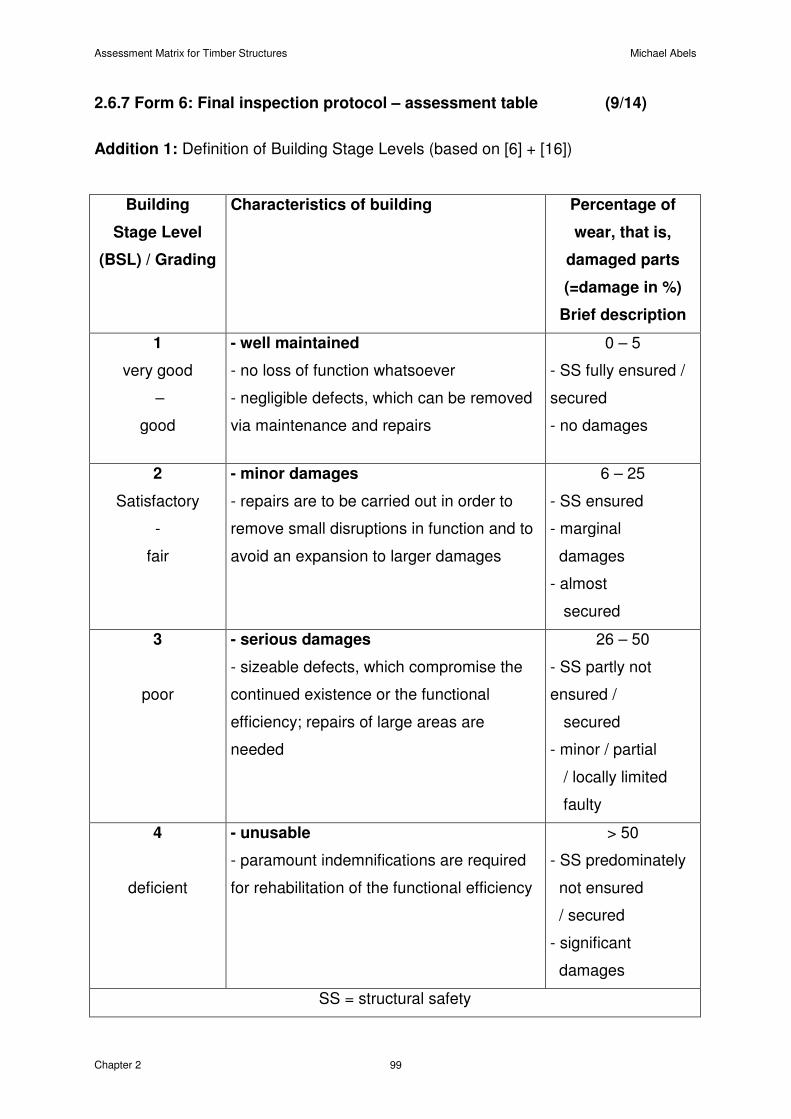
Assessment Matrix for Timber Structures Michael Abels
Chapter 2 99
2.6.7 Form 6: Final inspection protocol – assessment table (9/14)
Addition 1: Definition of Building Stage Levels (based on [6] + [16])
Building
Stage Level
(BSL) / Grading
Characteristics of building Percentage of
wear, that is,
damaged parts
(=damage in %)
Brief description
1
very good
–
good
- well maintained
- no loss of function whatsoever
- negligible defects, which can be removed
via maintenance and repairs
0 – 5
- SS fully ensured /
secured
- no damages
2
Satisfactory
-
fair
- minor damages
- repairs are to be carried out in order to
remove small disruptions in function and to
avoid an expansion to larger damages
6 – 25
- SS ensured
- marginal
damages
- almost
secured
3
poor
- serious damages
- sizeable defects, which compromise the
continued existence or the functional
efficiency; repairs of large areas are
needed
26 – 50
- SS partly not
ensured /
secured
- minor / partial
/ locally limited
faulty
4
deficient
- unusable
- paramount indemnifications are required
for rehabilitation of the functional efficiency
> 50
- SS predominately
not ensured
/ secured
- significant
damages
SS = structural safety

Assessment Matrix for Timber Structures Michael Abels
Chapter 2 100
2.6.7 Form 6: Final inspection protocol – assessment table (10/14)
Appendix 1:
Reason for the assessment = summary
(At this point the final score is explained briefly)
Insert here
the summary
↑
↓

Assessment Matrix for Timber Structures Michael Abels
Chapter 2 101
2.6.7 Form 6: Final inspection protocol – assessment table (11/14)
Appendix 2: (only needed for construction status level 3 and 4)
As a result of the detected defects of the construction regarded here and the
resulting grading, the following repairs and/or retrofitting are necessary: (here the
various databases can be referenced)
Here could
be proposed
recommended
repairs and/or
exercises!
↑
↓

Assessment Matrix for Timber Structures Michael Abels
Chapter 2 102
2.6.7 Form 6: Final inspection protocol – assessment table (12/14)
Appendix 3:
At the end of the assessment the timber expert has the option to provide general
recommendations. The period for acceptance is also defined and described here
shortly. The inspection badge color is specified.
Here could
be proposed
general
recommendation!
↑
↓

Assessment Matrix for Timber Structures Michael Abels
Chapter 2 103
2.6.7 Form 6: Final inspection protocol (13/14)
The assessment table presented earlier, aims to conclusively evaluate the regarded
timber structure. This assessment is subsequently illustrated again.
At the end of the appraisal the timber expert provides a final score for the regarded
structure.
This corresponds to the “Building Stage Levels”: 1 to 4.
A short explanatory note to the score is also included.
It is also important to say that grade averaging cannot be conducted for buildings
where various individual, independent timber constructions were appraised. Almost
the entire construction can be classified as construction status levels 1 and 2,
whereas a relatively small portion is so defective that the building must be restored at
this point for the continued use to be approved.
In Chapter 3 of this thesis, a standardized building check is prompted upon which the
appraisal is based. Based on their building category, the constructions are only
approved for a certain amount of time. These specifications are also presented in
Chapter 3.
Consequences of the Grading:
- If grade 1 (= Building Stage Level 1) is given, the construction can
unobjectionably be approved for use.
- If grade 2 (= Building Stage Level 2) is given as a result of minor damages, the
construction can still be approved for continued use. The timber expert specifies
exactly which repairs are to be conducted to prevent further expansions of damages.
He does not, however, have a regular controlling function if the specified work really
is conducted. The timber expert can, in his discretionary judgment, reduce the
approved time by up to 5 years.
- If grade 3 (= Building Stage Level 3) is given, the construction is initially not
approved for further use. Serious damages are present (usually more than 3).

Assessment Matrix for Timber Structures Michael Abels
Chapter 2 104
2.6.7 Form 6: Final inspection protocol (14/14)
The timber expert specifies exactly what must be done. Only after a successful
approval of the restored or reinforced construction will an approval be given.
- If grade 4 (= Building Stage Level 4) is given, the construction is immediately
blocked for further use. Such sizeable damages are present that the construction is
useless. Multiple and extensive restorations are required. Therefore a previous cost
calculation is needed. A deconstruction (= demolition) may be the most sensible
solution before further damages emanate from the construction. Yet it must be
considered that the owner in this case is required to undertake the demolition costs,
which cannot be insubstantial. It is also important to state that before the demolition
of a landmarked object, the agreement of the appropriate monument protection
service should be obtained.
As gathered from the previous explanations, the timber expert has a very important
assignment to approve the construction for use or to call for the remediation of
defects. Yet he also has the authority to block a building from further use. If danger is
present and thus a person's life is endangered in any way, the construction must
immediately be barricaded!
At the end of the final inspection protocol the timber expert can provide a suggestion,
for example, concerning the maintenance of the regarded building. Furthermore, it is
sensible to summarize all conducted examinations, which are documented in the
forms. The assigned grade can be explained here.

Assessment Matrix for Timber Structures Michael Abels
Chapter 2 105
2.7 Assessment Matrix for Timber Structures (= complete matrix)
In the previous sections a matrix was successively created that should serve as a
guide during the assessment of timber constructions. As mentioned, this 2nd chapter
can serve as a guide for the user of the assessment matrix. Because of the
complexity of this task, which was already discussed in Section 2.2, not all areas can
be completely covered. With each appraisal the most important task belongs to the
timber expert, which is to combine all aspects or characteristics in an objective
manner into a neutral report. The matrix should bring the operator to objectively
evaluate the regarded construction.
Over time, the operators of this matrix can supplement or change the forms,
checklists, and databases according to their own interests so that the benefit (=
assistance) is always increasing. This aspect will be addressed in Chapter 3.
The completed matrix is subsequently first illustrated in a schematic outline (see
Figure 2.63) and later in a detailed schematic extended version (see Figures 2.64 to
2.66).

Assessment Matrix for Timber Structures Michael Abels
Chapter 2 106
Figure 2.50: Assessment Matrix in summary form

Assessment Matrix for Timber Structures Michael Abels
Chapter 2 107
Figure 2.51 a: Assessment Matrix as long – version (1/3)

Assessment Matrix for Timber Structures Michael Abels
Chapter 2 108
Figure 2.51 b: Assessment Matrix as long – version (2/3)

Assessment Matrix for Timber Structures Michael Abels
Chapter 2 109
Figure 2.51 c: Assessment Matrix as long – version (3/3)

Assessment Matrix for Timber Structures Michael Abels
Chapter 2 110
2.7.1 Application of the matrix: why / how / where / when
The developed matrix is suitable for all timber experts. The main goal, which follows
with the implementation of this matrix, is to increase the safety of all users of
buildings with load-carrying timber structures. At the same time, the preservation of
all buildings and thus objects of our cultural assets are secured. Society must be
sensitized to this to begin with if buildings today can be entered without hesitation.
Unfortunately, in the past this regularly led to tragedy when buildings, due to serious
structural damages, were barricaded and even when buildings collapsed burying
many people beneath them (see figure 2.52).
As previously described, our society has the necessary "know-how" and the required
"equipment" for recognizing damages to timber constructions early on.
Figure 2.52: Ice pavilion in Bad-Reichenhall, Germany,
before and after the structural collapse on 01.03.2006

Assessment Matrix for Timber Structures Michael Abels
Chapter 2 111
The question “how can this instance be avoided in our society in future?” is answered
in chapter 3. In doing so, an effective process is developed, which requires the
owners of timber constructions to allow examinations to be conducted on all
buildings.
By whom, how, where, and when these assessments should or must be conducted
will be described in detail in the next chapter.
2.7.2 Object book (for documentation)
The object book presented here contains all of the previously conducted analyses
conducted within the framework of an assessment. As already presented in Section
2.4, all forms are integrated in the object book.
Why this is done is described in Chapter 3 of this PhD-Thesis. In this section the
author develops an effective process in which the structural examination should be
legally required. The control of these evaluations falls in the area of responsibility of
the lower building control authority. The object books can be applied here as
construction documents.
In order for the person responsible to quickly obtain an overview, the cover sheet of
the object book will be configured as follows:

Assessment Matrix for Timber Structures Michael Abels
Chapter 2 112
Object specified:
- Building: (description) Photo of the building:
....................................................................................... (insert here)
- Components / Investigated Structures:
.......................................................................................
- Builder, Owner: (name, address, phone, fax, e-mail)..............................
- Place: (street, postcode, place, district, landing, parcel, land registry number)
..........................................................................................
..........................................................................................
- Responsible Building Office:
..........................................................................................
- File Number: (if any)
..........................................................................................
Building Information by Building Check:
- Timber Expert: (name, address, phone, fax, e-mail)
.........................................................................................................................
place, date:............................................................(signature timber expert)
- Building Category: (underline the right one)
BC 1 / BC 2 / BC 3
- Last Monitoring: ..............................
- Partial acceptance / Professional Company Statement(PCS) no later than:
..........................
- Next Monitoring: ..........................
Contained Forms:
Form: date: index: (= date of revision)
1
2
3
4
5
included experts
6 = final acceptance
- Total “Building Stage Level” (BSL): (+ explanatory report: see back)
- special features or special reports (date):.....................................
- Inspection Badge (red / green / blue) awarded on (date):.............../ valid through:.....................

Assessment Matrix for Timber Structures Michael Abels
Chapter 2 113
2.8 Temporary conclusion and prospects of the following sections
Now that an assessment matrix has been composed in chronological order in this 2nd
chapter, it can be employed in the further course of this thesis. It is important to once
again note that the present condition of the matrix cannot or should not be the final
result. As the past and present have shown, the field of construction is always in a
state of development. In the future this should be permanently incorporated into the
forms, checklists, and databases.
In the following 3rd chapter the matrix is implemented in 3 different case studies.
Finally, the societal relevance of the assessment matrix developed here will be
addressed in the form that this matrix can illustrate the basis of an officially
standardized building check. On the other hand, suggestions are being developed,
such as how the previously described development process (of the matrix) can be
taken into account.

Assessment Matrix for Timber Structures Michael Abels
Chapter 3 1
3. Example Assessment Matrix applications (= main matrix)
Chapter 1 of this PhD-Thesis provided a strong foundation of knowledge followed by
Chapter 2, with the development of the assessment matrix now being applied to
concrete building objects. In doing so, a few explanations will be noted in advance;
the selection of case studies is founded before the 3 matrix applications are
presented. The case studies will then be subsequently evaluated [17]. Once these
practical matrix applications have been established, Chapter 3 will then present a
social application of the matrix and its thoroughly sustainable process.
3.1 General information about the practical matrix application
In Chapter 2 of this thesis, the assessment matrix for appraising timber constructions
was developed. In doing so, multiple complexities were described that result from
wood that has been and still is being used in a variety of building constructions.
Neither the size nor the age of the construction plays a role when applying the matrix.
The design of the matrix allows for controlled processing. This means that the
described forms allow a chronological appraisal of all constructions. It initially
concerns the detection of the "actual condition" of the considered construction. The
databanks contained within the assessment matrix provide typical weak points for the
most common construction types including options for testing as well as possible
restoration methods if required. Otherwise the described checklists can represent a
simplification of work for appraisals because they respond to typical circumstances
like damages, e.g. from cracks, fungus, insects, and/or material properties.
All common inspection methods are prompted in the forms in addition to the "formal"
project properties for construction state analyses right up to condition mapping. In
addition to timber experts with knowledge and equipment who take on the most
important role in the overall process as the user of the assessment matrix, additional
experts (see expert database, section 2.4.7) may be consulted for the assessment of
the considered constructions. The forms provide useful information about this topic
as well.
The last (= 6th) form allows for a regulated appraisal form according to which all
previous inspection aspects are summarized into one assessment.

Assessment Matrix for Timber Structures Michael Abels
Chapter 3 2
The present section is about the testing and presentation of the practical suitability of
the assessment matrix; it demonstrates to the interested reader and potential future
user the advantages that these new appraisal forms offer.
Because the aspiration of this thesis is a future comprehensive application of this
assessment matrix - for example, in the form of an EU guideline that mandates
defined inspection procedures for all buildings - a great deal of value is placed on the
structure of this assessment form. Future benefits will be reaped from this sought
after standardization of appraisals because the form (= structure), which can be
offered as a computer program (see Chapter 4.1 of this thesis) can be constantly
improved and optimized.
Important to note here is that the actual motive for the subsequently presented
inspections was voluntary (for case studies 1 and 3) and conducted in connection
with a planned change of use (= case study 2). The possibility of a legal obligation to
such inspections being implemented will be described in greater detail in the course
of Chapter 3. Likewise, the next section will address the impacts of appraisals, i.e.
how to navigate impaired constructions with regard to building user safety and the
preservation of structural cultural assets.
Its purpose is to grant the assessment matrix legal legitimacy so that this
standardized building check represents a sustainable process in our society. This
closed process is presented in detail at the end of the chapter.
The following graphic (see Figure 3.1) is a schematic outline of the process.

Assessment Matrix for Timber Structures Michael Abels
Chapter 3 3
Figure 3.1: Schematic outline of the Assessment Matrix
3.2 Reason for the project selection
Because the previously described assessment matrix can and should be applied to
all load bearing timber constructions, it is reasonable that the form presented in this
thesis is merely an example and not a final version.
The author of this PhD-Thesis has not only been developing the matrix presented
here for many years, but has also applied it on a permanent basis to a number of

Assessment Matrix for Timber Structures Michael Abels
Chapter 3 4
different timber constructions. Mostly engineering questions arise as the focus of
research, for example, changes of use to existing constructions, e.g. in the case of
structural modifications like additions and alterations or in the case of a variety of
other structural circumstances, e.g., appraisals of wooden bridges, supporting
frameworks, etc.
The purpose of this matrix, which is set to achieve the aforementioned legal
legitimacy, makes it necessary to develop additional forms and other databanks
and/or checklists so that they can be summarized in one logically organized form in
the object book with understandable results.
The completion of this form shall be demonstrated using the following 3 case
studies.
Three intentionally different building types have been selected with extremely
differing characteristics in terms of size, age and load bearing type of timber
construction. Having said that, these intentionally selected buildings represent
typical constructions in our society worth sustainably securing. The safety of users is
the top priority followed by the preservation of structural cultural assets.
An historic church building was selected as the 1st case study. This building has
3 timber constructions that were inspected. The first construction considered in detail
is the historic spire, which had already been reinforced in the past at different
positions. The remaining timber constructions are the historic belfry and the
engineered timber frame construction over the nave, which was completely redone
approximately 50 years ago.
Without a doubt, this case concerned a public building that urgently required
inspections due to its purpose of use, large dimensions, and the partial old age of the
timber constructions, especially since this had never been officially implemented.
More information about the matrix application is provided in Chapter 3.3.
The appraisal of timber construction was conducted after consulting with the church
proprietor, the Archbishopric of Cologne, who showed great interest in having
additional church buildings inspected.
The 2nd case study concerns a medieval half-timbered building also in Bedburg,
which due to its prestigious location and old age is under monument protection. The
building's carpenter-made roof construction was appraised with the help of the

Assessment Matrix for Timber Structures Michael Abels
Chapter 3 5
assessment matrix. Additional load bearing timber constructions within the building
are the wooden-beam ceilings and the half-timbered interior walls.
The actual reason for this inspection was the building owner's planned change of
use, which required inspections of the state of the building. The building is
momentarily exclusively used for private purposes and after the change of use will be
a public cultural center for musical performances.
It was intentionally selected as a case study because the inspection represents a
model building appraisal for which the interests of the responsible monument
protection authority, the Rhenish Office for the Protection of Historic Monuments, are
to be taken into account. Detailed information about the inspections is provided in
Chapter 3.4.
The final 3rd case study was selected in order to demonstrate an additional,
commonly occurring type of timber construction. It concerns a modern sports hall
constructed as a widespread engineered timber construction with glued laminated
beams. This modern timber construction is used publically by the neighboring
gymnasium and different sports clubs in the city of Mülheim an der Ruhr.
The author of this PhD-Thesis was commissioned for the appraisal of the object by
the owner of the building, the city of Muelheim an der Ruhr, in order to comply with
their legal obligation to undertake stability and usability inspections; this will be
described in greater detail in the course of this chapter.
The application and analysis of the assessment matrix contains for the first time an
official character and, in addition to the other case studies, represents a younger
construction type.
These short descriptions of the 3 case studies show the diversity of application
options for the assessment matrix. Larger buildings were intentionally selected, all of
which are classified in building category 3 (see section 3.9.1 of this thesis), the
highest category. The conducted inspections were especially comprehensive due to
this classification. More information can be found in the following chapters. A number
of documents (photos, planning documents, proofs of stability, etc.) have been
organized in Chapter 5 for a better overview. Appraisals of buildings for the two lower
building categories are not necessarily less complex, yet they are generally not as
comprehensive as the 3 case studies presented in Chapter 3.

Assessment Matrix for Timber Structures Michael Abels
Chapter 3 6
3.3 Case study 1
Historic church building St. Georg
in Bedburg – Alt-Kaster
Figure 3.2: Photo – Church tower with aisle
Figure 3.3: Awarded “test badge” after verification (just a suggestion) (see Section
3.9.5)

Assessment Matrix for Timber Structures Michael Abels
Chapter 3 7
Figure 3.4: Measurement drawings – Side and rear view of the church
Figure 3.5: Drawing of the nave (registration by german timber expert)

Assessment Matrix for Timber Structures Michael Abels
Chapter 3 8
Figure 3.6: Spatial representation of the nave
Figure 3.7: Half-timbered walls – Base point detail

Assessment Matrix for Timber Structures Michael Abels
Chapter 3 9
object specified:
building(description): church building St. Georg
-components/
investigated
structures:
nave, church steeple, belltower
-builder, owner:
(name,address,
phone, fax, e-mail):
Erzbistum Köln, Marzellenstr. 32,
50668 Köln, phone: 0221-1642-1700,
e-mail: 1
photo of the building:
- place: (street, postcode, place, district, landing, parcel, land registry number)
Hauptstraße, 50181 Bedburg – Alt-Kaster,
district: cadastral, area: 4, parcel: 48
- responsible building office:
Rhein-Erft-Kreis, Untere Bauaufsicht, Willy-Brandt-Platz 1, 50126 Bergheim
- file number (if any): 100-123-2009
Building information by building check:
- timber expert: (name, address, phone, fax, e-mail)
Michael Abels, Dipl.-Ing., Am Mühlenkreuz 28, 50181 Bedburg,
phone.: 02272-905637, fax.: 02272-905635, [email protected]
-Building Category: (underline the right one)
BC 1 / BC 2 / BC 3
- Last monitoring: 09.10.2009
-partial acceptance / Professional Company Statement (PCS) no later than:
Contained Forms: 09.10.2009
Form: date: index: (= date of revision)
1 09.10.2009 -
2 09.10.2009 -
3 09.10.2009 -
4 09.10.2009 -
5 09.10.2009 -
Included experts - -
6 = final acceptance 09.10.2009 Signature of the timber expert:
………………………………………………
- Total “Building Stage Level”: 1 (nave) / 2 (belltower) / 2 (church steeple)
- spezial features or spezial reports (date):-
- inspection sticker (red/green/blue) awared on (date):09.10.2009 / valid through: 30.09.2019

Assessment Matrix for Timber Structures Michael Abels
Chapter 3 10
Form 1: date 09.10.2009 The completely filled out Form 1 is to be filed in the object book!
The yes / no / unknown – fields are to be marked.
Additional appendices are to be referenced! 1. General project information:
General / preliminary remarks (reason for inspection):
After consulting the owner of the inspected building, the Archdiocese of Cologne, a building check was
performed on a volunteer basis.
An initial inspection of the wooden constructions was conducted on the considered object for which no
planning documents existed. The building has a total of 3 different (more or less independent) timber
constructions: the church tower, the belfry and the nave.
The inspections service to identify whether mechanical and/or biological damages are present in
timber constructions. Furthermore, it must be ensured that the supporting structure stability required
by the building authorities is maintained. For this purpose, the entire building with its mentioned timber
constructions was measured on-site and statically tested in the office.
The inspection results are summarized in the conclusion of the building inspection. A concept detailing
restoration, inspection, and/or renovation measures for the sake of preserving the considered
construction is outlined in the conclusion.
All inspections conducted meet the general state of the art and account for local circumstances. The
evaluation of the timber construction was conducted according to the "assessment matrix for the
conservation of valuable timber constructions" developed by the author.
Site inspections:
Different site inspections were conducted outside and inside of the considered object for the appraisal
of the wooden roof construction.
The on-site inspections took place on:
- 07.30.2009
- 08.14.2009
- 08.20.2009
The timber expert involved in the present appraisal gained a complete picture of the considered object,
in that he inspected it closely inside and out before he examined the wooden roof construction in
greater detail.
Accessibility of the roof construction:
The load bearing timber constructions are uncovered and must be reached using different steps and
ladders.

Assessment Matrix for Timber Structures Michael Abels
Chapter 3 11
Form 1: date 09.10.2009 The completely filled out Form 1 is to be filed in the object book!
The yes / no / unknown – fields are to be marked.
Additional appendices are to be referenced! 1. General project information:
General: General project information and the reasons for inspection can
be specified in advance.
On-site meetings: All conducted on-site meetings are listed.
Accessibility of the timber construction: the accessibility of the regarded on-site
timber constructions is described here in short. no.: term: entry:
1.1 building – description church building St. Georg
1.1.1 examined structure - nave – belltower - churchsteeple
1.2 builder / ownership:
name: Erzbistum Köln
Erzbischöfliches Generalvikariat
Abteilung 730 - Bau
adress: Marzellenstraße 32
50668 Köln
phone: 0221-1642-1700
e-mail: [email protected]
1.3 responsible for building-check:
Pfarrgemeinde St. Georg
Der Kirchenvorstand
phone: 02272-3374
1.4 leading office
(complete adress):
[= timber-expert]
Michael Abels, Dipl.-Ing.
Planung-Statik-Bauphysik
Am Mühlenkreuz 28, 50181 Bedburg
phone: 02272-905637
1.4.1 clerk: Michael Abels
1.5 date of check: 09.10.2009
1.6 place (street, village): Hauptstraße
50181 Bedburg – Alt-Kaster
1.7 geographical location, altitude
(above see level):
51°00`35,98``N ca. 62 ü.N.N.
6°33`29,37``E
unknown
1.8 direction / cadastral extracts
available:
See abstract from geoinformation cadastrial
1.9 age of the building or of the
structure:
historical massive church
building
unknown

Assessment Matrix for Timber Structures Michael Abels
Chapter 3 12
Form 1: date 09.10.2009
1.10 date of setting-up:
See appendix 1, page 3/13
(see historical overview) unknown
1.11 design drafters / architect: - unknown
1.12 exporting company: -
unknown
1.13 responsible building-office: Rhein-Erft-Kreis
Untere Bauaufsicht
Willy-Brandt-Platz 1, 50126 Bergheim
1.14 planned use in the planing: churchbuildung (catholic)
1.15 Is the building listed? yes
no
unknown
1.15.1 responsible conservation authority: Landschaftsverband Rheinland
Amt für Denkmalpflege im Rheinland
Abtei Brauweiler, Ehrenfriedstr. 19,
50259 Pulheim,
Hr. Dr. Kretzschmar
phone: 02234-9854-0
1.16 Is the building used or unused?
(unused since?)
used (church fair + concerts + exhibitions)
1.17 classification in a building style: gothic tower + nave in Late Baroque
1.17.1 determined building style or
construction era:
See abbove

Assessment Matrix for Timber Structures Michael Abels
Chapter 3 13
Appendix 1: date 09.10.2009
History (short historical overview):
- 1365: A chapel in Kaster is mentioned for the first time in connection with a
donation from Duke Wilhelm von Jülich.
- 1542: The old chapel is destroyed.
- 1551: The first parish church is built on the foundation of the old chapel. It is
gothic in style with three naves.
- 1624: After a fire in the city the church is only rebuilt provisionally.
- 1750: The church receives the relics of the holy martyrs Ursula & Mauritius.
- 1783: While preserving the old gothic tower, the church is renovated in the
style of the late Baroque period, with single-nave brick hall and flat mirror
ceiling. The ceiling slab measures: 27.50m x 13.25m.
- 1788: The wooden main altar, four columns, and the altarpiece are built.
- 19th century: The sacristy is added to the tower.
- 20th century: The organ is revived; the organ prospect stems from the 18th
century.
- 1951: The church is restored to its original condition. The timber constructions
over the nave and some of the restorations performed on the church tower
were done in this year.
- 1978: The foundation of the original 14th century church is discovered during
renovations.

Assessment Matrix for Timber Structures Michael Abels
Chapter 3 14
Form 1: date 09.10.2009
2.Occasion or reason of the building check:
2.1 first check of the structure after completion yes
no
2.2 commission per building check (= official normed
building check)
yes
no
2.3 monitoring form 1 yes
no
2.4 monitoring form 2 yes
no
2.5 classification of the building in a building category:
BC 1 / BC 2 / BC 3
(see Section: 3.9.1)
BC3
2.6 Is a structure defect noted? yes
no
2.7 Is a building-measure planned? (enlargement,
extension, use change, expansion, etc.)
yes
no
2.8 Is a repair planned? (modernization, reconstruction,
renovation, etc.)
yes
no
continuation: see form 2

Assessment Matrix for Timber Structures Michael Abels
Chapter 3 15
Form 2: date 09.10.2009
Beginning of an “in-depth inspection” in the office:
Notes/ Comments:
The completely filled out Form 2 is to be filed in the object book!
Copies of the reviewed documents, such as building designs, static calculations, etc.,
are to be made and also filed in the object book.
Additional appendices are to be referenced! 1. Documents for classifying timber constructions:
Notes:
- The documents listed below are to be requested from the builder or authorized party
and accepted by the building authority and land registry (= department of the
appropriate district court) with a corresponding power of attorney (see page 13 on
Form 2).
- The potentially available planning documents are to be compared at the following
on-site meeting with the actual construction state. In doing so, the static span widths,
the verified connections, and the indicated materials are inspected above all.
no.: term: present: checked on site or performed:
1.1 Building and civil engineering drawings
available
yes / no
if 1.1 negative answered:
1.1.1 allowance necessary
(see e.g. figure 3.5)
yes / no
1.1.2 building-application plans = approval plans
scale = 1:100 (see e.g. figure 3.4)
yes / no yes / no
1.1.2.1 ground plans yes / no yes / no
1.1.2.2 sectional drawings yes / no yes / no
1.1.2.3 building-views yes / no yes / no
1.1.2.4 site map or cadastral extracts
(not part of this thesis)
yes / no yes / no
1.1.3 execution plans or detailed plans scale =
1:50
yes / no yes / no

Assessment Matrix for Timber Structures Michael Abels
Chapter 3 16
Form 2: date 09.10.2009
1.1.4 Detail drawings
scale= 1:25 / 1:20 /1:10, etc.
(see e.g. figures 3.6 and 3.7)
yes / no yes / no
1.1.5 Joinery drawings of the timber structures
(see e.g. figures 3.6 and 3.7)
yes / no yes / no
1.1.6 Installation plan of the roofing, etc. yes / no yes / nein
1.2 Statics available? yes / no
If 1.2 is negative answered:
1.2.1 Is the statical system important?/
The statical system is treated on the form 3.
yes / no
1.2.2 Statical calculation yes / no yes / no
1.2.3 Check the constant load on the building yes / no
1.2.3.1 Maximum snow-load yes / no
1.2.3.2 Maximum wind-load yes / no
1.2.3.3 Structure of the components with the load-
determination of the net weight
yes / no
1.2.3.3.1 Cover plates yes / no
1.2.3.3.2 Walls yes / no
1.2.3.3.3 Roofing yes / no
Specification of the used materials (=wood-
types)
Nave: softwood
yes / no yes / no
1.2.3.1 determination of the wood-type see Checklist 1

Assessment Matrix for Timber Structures Michael Abels
Chapter 3 17
Form 2: date 09.10.2009
1.2.4 Execution plans of the statical
calculation, e.g. roof construction plan, etc.
yes / no
1.2.5 test report to the statical calculation from
the auditor-structural engineer
yes / no
1.2.5.1 special structure yes / no
1.2.5.2 license in individual cases yes/ no
1.3 Physical evidence existing? yes / no
1.3.1 energy-saving certification yes / no not necessary
1.3.2 constructive fire-protection certification yes / no not necessary
1.3.3 constructual fire-protection certificate = fire
protection concept
yes / no not necessary
1.3.4 sound-protection certificate yes / no not necessary
1.3.5 information to the moisture-protection yes / no not necessary
1.4 montage-information yes / no not necessary
1.5 glue-book of the timber structure company yes / no glued timber not
used

Assessment Matrix for Timber Structures Michael Abels
Chapter 3 18
Form 2: date 09.10.2009
2.1 Use of the building as: present: Checked on site
or performed:
2.1.1 residential building yes / no
2.1.2 public building yes / no
2.1.3 commercial used building. Which crowds are possible?
yes / no
2.1.4 special loads on the structure of building. The
load is be specified in kN.
yes / no
2.1.4.1 single load from machines, water bed, safe,
watertank, bulk materials, bells, or other
yes / no yes / no
bell weight is still under
investigation
2.1.4.2 roof construction: solar system/ photovoltaic
system
yes / no Load in kN =
2.1.4.3 trafficability with vehicles of areas, or similar yes / no
Load in kN =
2.1.4.4 existing horizontal-loads by impacting of
vehicles, handrailloads, etc.
yes / no Load in kN =
2.1.4.5 existing dynamical loads yes / no bell weights
2.1.4.6 statement of other loads yes / no Load in kN =
Classification possible:
Checked on site:

Assessment Matrix for Timber Structures Michael Abels
Chapter 3 19
Form 2: date 09.10.2009
3.1 classification in use-classes: Classification
possible:
Checked on site:
3.1.1 use-class 0:
Inside built wood, completely dry (wood moisture <20%); no wood preservatives required
yes / no
3.1.2 use-class 1:
Internal components with an average room
humidity ≤70%; requirements to the wood preservatives: insect-preventive
yes / no
3.1.3 use-class 2:
Internal components with an average room humidity>70%, internal components in wet areas, external components without direct weather stress; requirements to the wood preservatives: insect-preventive, fungus-retardant
yes / no
3.1.4 use-class 3:
External components with weather stress without permanent ground- an/or water contact internal components in wet rooms, wood exposed to the weather or condensation, but no ground contact; requirements to the wood preservatives: Iv, P, W= insect-preventive, fungus-retardant, weatherproof
yes / no
3.1.5 use-class 4:
Timber with permanent ground- and/or fresh water contact, even with sheath, there are special conditions for wood on sea water; requirements to the wood preservative, insect preventive, fungus-retardant weatherproof, soft rot retardant (timber used in the ground)
yes / no

Assessment Matrix for Timber Structures Michael Abels
Chapter 3 20
Form 3: date 09.10.2009
1.) Construction the load bearing system:
(see e.g. figure 3.6)
• 1.1 Load bearing components for vertical loads
(dead weight, live/payloads, snow, etc.)
→ 1.1.1 Roof construction:
Roof crossbars, rafters, purlins, binders, containers, frames, etc.
Sketch(es) (possible use of additional sheets or refer to form 4):
(see e.g. figures 3.6 and 3.7)
- A: Engineered latticework structures
over the nave
- B: Spatial timber framing (historic) as church tower
- C: Level timber framing (historic) as belfry
→ 1.1.2 Horizontal supporting elements:
Beamed ceilings, beams/coatings, roof bracings (wind braces,
plates, etc.)
Sketch(es) (possible use of additional sheets or refer to form 4):
(see e.g. figures 3.6 and 3.7)

Assessment Matrix for Timber Structures Michael Abels
Chapter 3 21
Form 3: date 09.10.2009
• 1.2. Supporting structural elements for horizontal loads
(Wind, beam loads, reinforcement loads, LF: earthquakes, impact
loads, dynamic loads (e.g. vibrations from church bells)
- A: Cross bracing of the half-timbered walls through intact wind
braces. Adequate reinforcement in both building directions
(no distortions + cracks)
- B: The 4 body diagonals arranged crosswise through
intermediate levels (i.e. static plates) + each floor are
evidently (no distortions + cracks) adequately reinforced.
- C: Adequately reinforced evidently in both directions through
sufficient forms of reinforcement (mainly braces + St.
Andrew’s crosses)
→ 1.2.1 In the entire building:
Frames, latticework structures, bracings (roof and wall bracings),
wind braces
Sketch(es) (possible use of additional sheets or refer to form 4):
see 1.2 above
2.) Identification / determination of all loads:
• 2.1 Outdoor loads:
- Wind
- Snow/ rain see static calculation
- Earthquake zone (not part of this thesis)
- Soil characteristics
• 2.2 Dead weight of the construction (construction and expansion
loads):
- Roof cladding: see static calculation
- Collar beams framing: (not part of this thesis)
- Collar beams over the …floor: (insert flat floor)
- Collar beams over the …floor: (insert flat floor)
- Wall construction (outside):
- Wall construction (inside):
- Balcony or projections (if present):
- Other loads:

Assessment Matrix for Timber Structures Michael Abels
Chapter 3 22
Form 3: date 09.10.2009
3.) Connections:
Weak points are often the connections within a structure that can no longer
sufficiently bear the existing weight as a result of various circumstances
(cross-sectional weaknesses, gaping joints due to shrinkage and swelling,
corrosion of metal connecting devices, overstraining due to changes of use,
etc.).
For this reason they must also be documented in the form of sketches (photos,
etc.) and the visible cross-sections, connecting devices, and materials
documented. Here the difficulty is often present that internal connecting
devices, such as e.g., studs of specific constructions types cannot be secured
from outside. In this case, the inspecting timber expert must decide on a case-
by-case basis which methods (see Sections 2.4.6 + 2.4.7) to implement for a
more detailed and continued analysis.
Sketch(es) (possibly use further sheets or refer to Form 4):
(see e.g. figures 3.6 and 3.7)
4.) Cross-sectional dimensions of the supporting structural elements:
→ In the sketches of the static system(s) shown above (from top to
bottom), the on-site measured cross-sectional dimensions are recorded.
The wood type is also documented [potentially use checklist 1 (2.5.1)].
(The static calculation is not part of this thesis)
Continuation: see Form 4

Assessment Matrix for Timber Structures Michael Abels
Chapter 3 23
2.4.5 Form 4: Condition mapping of the “actual state” date 09.10.2009
The completely filled out Form 4 is to be filed in the object book!
Additional appendices are to be referenced!
Conducting the construction state analysis is initially a matter of determining the
current status and documenting it in a suitable form. In the ideal case, planning
documents would have been reviewed in the previous process, which could be used
for this purpose (see Form 2).
If original documents are not available, measurements are to be made and presented
in a suitable (if possible, to scale) form. Digital photographs also present a good
option these days for documentation. The drawings in Form 3 (see 2.4.4) can also be
used.
Concerning the targeted standardization of form entry described in the previous
sections, a legend is also provided here so that all future timber experts can use the
same symbols, abbreviations, etc. for certain phenomena, such as pests (e.g. house
longhorn beetles, dry rot, etc.) and types of damages (e.g. strong moisture
penetrations, distortion, decay, etc.) to more precisely examine timber constructions
or timber structural elements (e.g. ceiling beams, rafters, purlins, etc.) within the
scope of a construction state analysis for the mapping of conditions described here.
As can be derived from the concept that was just explained, not only the condition of
the timber construction’s supporting elements should be mapped, but also visibly
obvious damages should be identified and additional required areas of inspection
specified. With this, a rough assessment of the construction is conducted within the
scope of mapping, Form 5 (see Section 2.4.6) to follow contains, together with the
expert database (see Section 2.4.7), the possible inspections to be undertaken later
when mapping conditions.
(see e.g. figures 3.6 and 3.7)

Assessment Matrix for Timber Structures Michael Abels
Chapter 3 24
2.4.6 Form 5: Examination methods for different material parameters
[Only approximate “on-site controls”] [7], [18] date 09.10.2009
The completely filled out Form 5 (including the expert database) is to be filed in the
object book!
Additional appendices are to be referenced! Whether the timber expert personally performs a detailed inspection of the
construction within the scope of a building inspection very much depends on his
experience. A trained eye already sees a lot, yet a timber expert directly examines
the critical areas.
For an approximate “on-site control” of different material parameters, tools are hardly
necessary.
Subsequently, the first established inspections that the timber expert completes at
the first on-site appointment are specified.
- Visual appraisals + photographic documentation:
Required tools: Digital camera, magnifier, hammer, nails, pocketknife, chisel, wood
moisture meter, spiral and core drill, measuring tools (measuring tape, calliper +
crack gauge, water level, wire for depth measurements of cracks)
Procedure: Parameter(s):
- Visible damages that are recorded with
hand drawings or digital photos.
- General building state:
type, place, and extent of damage
- Hammer test (tapping) of suspicious areas. - Positioning of:
cavities and weak spots.
- Test with the pocketknife or chisel. - Timber strength
- Drilling of suspicious areas with a core drill
for core extraction
(see also 2.4.7)
- A wide variety of inspections can be
conducted in the test laboratory with
the core drill (see also 2.4.7)
- Wood moisture meter - Wood moisture
- Measuring or locating big deformations with
a water level.
- Deformations

Assessment Matrix for Timber Structures Michael Abels
Chapter 3 25
2.4.6 Form 5: Examination methods for different material parametersdate 09.10.2009
[Only approximate “on-site controls”]
Procedure: Parameter(s):
- Determination of wood type, e.g. with the
help of pictures for comparison (= Checklist
1, see 2.5.1)
- Wood type
- Measuring or locating cracks with a crack
gauge (= Checklist 2, see 2.5.2)
- Cracks
- Locating fungus and/or insect infestations,
e.g. with the help of pictures for comparison
(= Checklist 3, see 2.5.3)
- Fungus and/or insect infestation
- Drilling of suspicious areas with a spiral drill
(mainly abutments)
- Rot + cavities
(= physical condition of the timber)
Were experts from the expert database (see 2.4.7) consulted?
yes / no
If yes, show the result:
…………………………………………………………………………………………………
…………………………………………………………………………………………………

Assessment Matrix for Timber Structures Michael Abels
Chapter 3 26
2.6.7 Form 6: Final inspection protocol date 09.10.2009
It is important that the timber expert consider the structure permanently and not allow
himself to be guided to a positive impression from the beginning. It makes no sense
to examine individual components when the initial appearance of trivial damages can
lead to bigger damages in a short amount of time. Static supporting and non-
supporting structural elements belong to the whole construction. The following
structural elements should be examined closely:
checked:
- Walls:
- Exterior walls
- Interior walls
- Facades
- Moisture barriers
- Floors/ceilings:
- Ceiling construction
- Stairs
- Floor construction
- Roof:
- Roof construction
- Roofing
- Roof drain
With all components, the structural-physical aspects of noise, heat, fire, and moisture
protection should be scrutinized and considered with the complete evaluation.
To this end, the details of Section 1.7 can be helpful.
All of the aforementioned aspects are included in the same assessment table
presented.

Assessment Matrix for Timber Structures Michael Abels
Chapter 3 27
2.6.7 Form 6: final acceptance-rating table Evaluation criteria of the databases 1-4 (the database 5 is included in the table) for a
determination of a building state level for a timber structure

Assessment Matrix for Timber Structures Michael Abels
Chapter 3 28
2.6.7 Form 6: final acceptance-rating table Evaluation criteria of the databases 1-4 (the database 5 is included in the table) for a
determination of a building state level for a timber structure

Assessment Matrix for Timber Structures Michael Abels
Chapter 3 29
2.6.7 Form 6: Final inspection protocol – assessment table
Averaged final scores:
Evaluation of all assessment criteria: With the help of the important factors, an
average score of the construction status is calculated.
=> The whole construction is assigned the Building Stage Level (= average overall
score / rounded):
(1x4 + 1x2 + 1x1 + 1x2 + 1x2 + 1x1 + 1x1 + 1x1 + 1x1 + 2x1 + 1x1 + 1x1)
= 19 / 18 = 1,06 => rounded = 1
The reason for this decision follows in Appendix 1.
The definitions of construction status levels are taken from Addition 1 of Form 6.
If more serious damage occurs, construction status level 2 cannot be reached!
Notes on the table:
(bracket value) = corresponding increase
1) Increase of the weighting factors with more exact proof or enabled experts.
2) The assessment of structural fire protection is not the purpose of this evaluation.
When necessary, an external fire protection plan can be obtained from a fire
protection expert.
3) To complete the full evaluation some recommendations could be pronounced by
the timber expert. In addition to the requested time the color of the inspection badge
is given
(X) To be able to approve an appraised construction for further use, at least
construction status level 2 must be reached. In the case of a worse assignment
corresponding repairs and/or strengthening (or others) are to be conducted according
to the precise specifications of the timber expert. See: Form 6 _ Appendix 2
(XX) Basic requirements for the static examination:
- Well-defined static system of load transfer
- The supporting consists exclusively of materials approved by the building
authorities
= see Addition 1 to Form 6 (= Definition of construction status levels)

Assessment Matrix for Timber Structures Michael Abels
Chapter 3 30
2.6.7 Form 6: Final inspection protocol – assessment table
Addition 1: Definition of construction status levels
Building Stage
Level (BSL) /
Grading
Characteristics of building Percentage of
wear, that is,
damaged parts
(=damage in %)
Brief description
1
very good
–
good
- well maintained
- no loss of function whatsoever
- negligible defects, which can be removed
via maintenance and repairs
0 – 5
- SS fully ensured /
secured
- no damages
2
Satisfactory
-
fair
- minor damages
- repairs are to be carried out in order to
remove small disruptions in function and to
avoid an expansion to larger damages
6 – 25
- SS ensured
- marginal
damages
- almost
secured
3
poor
- serious damages
- sizeable defects, which compromise the
continued existence or the functional
efficiency; repairs of large areas are
needed
26 – 50
- SS partly not
ensured /
secured
- minor / partial
/ locally limited
faulty
4
deficient
- unusable
- paramount indemnifications are required
for rehabilitation of the functional efficiency
> 50
- SS predominately
not ensured
/ secured
- significant
damages
SS= structural safety

Assessment Matrix for Timber Structures Michael Abels
Chapter 3 31
Form 6: Final acceptance report date 09.10.2009
Appendix 1 = Reason for the assessment
After analyzing all conducted inspections that were adequately documented earlier in the work, the
following results can be formulated for the wooden constructions of the St. George church building:
- The accessible appraisal of the wooden roof construction evaluated at random showed no
peculiarities.
- There are no grave mechanical or biological damages to this roof construction.
- The supporting structure stability required by the building authorities is ensured.
- Constructional and chemical wood preservation appears evidently to be in order.
- At the moment no repair, restoration, or renovation measures are necessary.
- Due to the large span widths of the half-timbered walls over the nave, future structural
modifications, e.g. for photovoltaic systems, new wall coverings, installation of insulation within
the scope of energy efficiency, etc., static tests must be conducted before commencing.
The building is released for use by
the timber expert for the next 10 years
(see figure 3.3)
Appendix 2: Not required
Appendix 3 recommendation:
Regular maintenance in this period is required in any case.
As for the roof constructions under consideration, it is recommended that the roof cladding be regularly
inspected by a roofing business inside and out. We recommend a maintenance/inspection contract
with a local roofing business so that leaks in the roof cladding or damages to roof drainage, etc. can
be recognized early and fixed immediately.
Due to the large dynamic strain of the belfry, we also recommend here regular inspections of the load-
bearing timber construction for distortions, cracks, etc. in addition to mechanical maintenance of the
belfry system. In doing so, the maintenance company commissioned with maintaining the mechanical
systems can be asked to immediately report any damage of the timber construction to the named
timber expert.

Assessment Matrix for Timber Structures Michael Abels
Chapter 3 32
3.4 Case study 2
Listed truss building
in Bedburg – Alt-Kaster
Figure 3.8: Photo – Front view of the building
Figure 3.9: Awarded “test badges” after verification (just a suggestion)
(see Section 3.9.5)
a.) red badge b.) green badge

Assessment Matrix for Timber Structures Michael Abels
Chapter 3 33
Figure 3.10: Photo – Side view of the building
Figure 3.11: Measurement drawing – Front view of the building

Assessment Matrix for Timber Structures Michael Abels
Chapter 3 34
Figure 3.12: Measurement drawing – Side view of the building (left)
Figure 3.13: Measurement drawing – roof construction
(registration by german timber expert)

Assessment Matrix for Timber Structures Michael Abels
Chapter 3 35
Figure 3.14: Photo – Level 1 of the roof construction (line of sight from front to back)
Figure 3.15: Photo – Level 2 of the roof construction

Assessment Matrix for Timber Structures Michael Abels
Chapter 3 36
Figure 3.16: Photo – Transfer from level 2 onto level 3
Figure 3.17: Condition mapping – roof construction (floor plan)
(registration by german timber expert)

Assessment Matrix for Timber Structures Michael Abels
Chapter 3 37
Figure 3.18: Condition mapping – 2nd level (floor plan)
(registration by german timber expert)
Figure 3.19: Condition mapping – Ground level (floor plan)
(registration by german timber expert)

Assessment Matrix for Timber Structures Michael Abels
Chapter 3 38
Figure 3.20: Destroyed beam ends in an area of the roof over the ground floor
destroyed beam ends
of wooden beams
- Destroyed ends of wooden beams in outside wall by worms (= common
furniture beetle) (Location see figure 3.19)
- Renovation with lateral timber lashing for example (see figure 2.19)

Assessment Matrix for Timber Structures Michael Abels
Chapter 3 39
Object specified:
- building: listed truss resdidential building
-components /
investiated
structures:
roof construction, beamed ceilings and
truss interior walls
- builder, owner:
(name, address, phone,
fax, e-mail):
Herr Klaus Weiler, Hauptstraße 10, 50181
Bedburg–Alt-Kaster, phone: 02272 - 1654
Photo of the building:
- place: (street, postcode, place, district, landing, parcel, land registry number)
Hauptstraße 10, 50181 Bedburg – Alt-Kaster, district: cadastral, area: 4, parcel: 85
-responsible building office:
Rhein - Erft - Kreis, Untere Bauaufsicht, Willy - Brandt - Platz 1, 50126 Bergheim
-file number: -
Building information by building check:
-timber expert: (name, address, phone, fax, e-mail)
Michael Abels Dipl.-Ing., Am Mühlenkreuz 28, 50181 Bedburg, phone: 02272-905637, fax: 02272-905635, [email protected]
-building category: (underline the right one)
BC 1 / BC 2 / BC 3 - last monitoring: 12.10.2009
- partial acceptance / Professional Company Statement (PCS) no later than:
- next monitoring: 06.30.2015 06.30.2010
Contained forms:
form: date: index: (= date of revision)
1 12.10.2009 -
2 12.10.2009 -
3 12.10.2009 -
4 12.10.2009 -
5 12.10.2009 -
Including experts - -
6 = final acceptance 12.10.2009 Signature of the timber expert:
………………………………………………
- Total „Building Stage Level“: 3 / after decrease + PCS (latest to 6/2010) 2
- spezial features or spezial reports : first „red“ test badge with support and
suspensive condition, later „green“ test badage.
- Inspection Badge (red) awarded on: 12.10.2009 / valid through: (6/2010) _
6/2015

Assessment Matrix for Timber Structures Michael Abels
Chapter 3 40
Form 1: date 12.10.2009 The completely filled out Form 1 is to be filed in the object book!
The yes / no / unknown – fields must be checked off.
General project information:
General / preliminary remarks (reason for inspection):
The contractor and current resident of the considered real estate, Mr. Klaus Weiler, commissioned the
author of this appraisal on 12.01.2009 with the inspection of the timber construction presented here.
This should serve to evaluate the structural condition because a change of use from a residence to a
public cultural center for musical performances is planned.
An initial inspection of all wooden-beam ceilings over the ground and 2nd level and all half-timbered
inner walls was conducted for the considered object. In doing so, an accessible appraisal of the
wooden supporting structure was conducted. These inspections service to identify whether mechanical
or biological damages are present in timber constructions. Furthermore, it must be ensured that the
supporting structure stability required by the building authorities is maintained.
The inspection results are summarized in the conclusion of this expert opinion. A concept detailing
restoration, inspection and/or renovation measures for the sake of preserving the considered
construction is outlined in the conclusion.
All inspections conducted meet the general state of the art and account for local circumstances. The
evaluation of the timber construction was conducted according to the "assessment matrix for the
conservation of valuable timber constructions" developed by the author.
Site inspections:
Different site inspections were conducted outside and inside of the considered object for the appraisal
of the wooden roof construction.
The on-site inspections took place on:
- 12.01.2009
- 12.03.2009
- 12.07.2009
The timber expert involved in the present appraisal gained a complete picture of the considered object,
in that he inspected it closely inside and out before he examined the wooden roof construction in
greater detail.
Accessibility of the timber structures:
The load-bearing roof construction is not covered and therefore freely visible. The half-timbered walls
are plaster for the most part and not visible in their construction. The wooden-beam ceilings are
covered on the underside (plaster ceiling) as well as the topside (timber floor boards).

Assessment Matrix for Timber Structures Michael Abels
Chapter 3 41
Form 1: date 12.10.2009 The completely filled out Form 1 is to be filed in the object book!
The yes / no / unknown – fields are to be marked.
Additional appendices are to be referenced! 1. General project information:
no.: term: entry:
1.1 building - description Historic listed residence/ two- storey rendered
building/ house on the corner/ 3 axes
1.1.1 examined structure Roof construction + beamed ceilings + truss
interior walls
1.2 builder / ownership:
name: Herr Klaus Weiler
adress: Hauptstraße 10
50181 Bedburg
phone: 02272-1654, e-mail: -
1.3 responsible for building-check: See 1.2
1.4 leading office
(complete adress):
[= timber-expert]
Michael Abels, Dipl.-Ing.
Planung - Statik - Bauphysik
Am Mühlenkreuz 28, 50181 Bedburg
phone: 02272-905637, www.michael-abels.de
1.4.1 clerk: Michael Abels
1.5 date of check: 12.10.2009
1.6 place (street, village): Hauptstraße 10
50181 Bedburg – Alt-Kaster
1.7 geographical location, altitude
(above see level):
51°00`35,98``N ca. 62 ü.N.N.
6°33`29,37``E
unknown
1.8 direction / cadastral extracts
available:
See abstract from geoinformation cadastral
1.9 age of the building or of the
structure:
Historical truss building with
massive external walls +
massive vault cellar
unknown
1.10 date of setting-up:
Date 1653 in wall anchors
on the roadside gable
unknown
1.11 design drafters / architect: - unknown

Assessment Matrix for Timber Structures Michael Abels
Chapter 3 42
Form 1: date 12.10.2009 1.12 exporting company: -
unknown
1.13 responsible building-office: Rhein-Erft-Kreis
Untere Bauaufsicht
Willy-Brandt-Platz 1, 50126 Bergheim
1.14 planned use in the planing: Residentil building
1.15 Is the building listed? yes
no
unknown
1.15.1 responsible conservation authority: Landschaftsverband Rheinland
Amt für Denkmalpflege im Rheinland
Abtei Brauweiler, Ehrenfriedstr. 19,
50259 Pulheim,
Hr. Dr. Kretzschmar
phone: 02234 - 9854 - 0
1.16 Is the building used or unused?
(unused since?)
used as a residential building
1.17 classification in a building style: transition between
- early baroque 1600- 1650 and
- high baroque 1650- 1720
1.17.1 determined building style or
construction era:
See above

Assessment Matrix for Timber Structures Michael Abels
Chapter 3 43
Form 1: date 12.10.2009 2. Occasion or reason of the building check:
2.1 First check of the structure after completion? yes
no
2.2 commission per building check (= official normed
building check)
yes
no
2.3 monitoring form 1 yes
no
2.4 monitoring form 2 yes
no
2.5 classification of the building in a building category:
BC 1 / BC 2 / BC 3
(see Section 3.9.1)
BC3
2.6 Is a structure defect noted? yes
no
2.7 Is a building-measure planned? (enlargement,
extension, use change, expansion, etc.)
yes
no
2.8 Is a repair planned? (modernization, reconstruction,
renovation, etc.)
yes
no
continuation: see form 2

Assessment Matrix for Timber Structures Michael Abels
Chapter 3 44
Form 2: date 12.10.2009 Beginning of an "in-depth inspection" in the office:
Notes/ Comments:
- The completely filled out Form 1 is to be filed in the object book!
Copies of the reviewed documents, such as building designs, static calculations, etc.,
are to be made and also filed in the object book.
1. Closely inspect documents on timber construction:
Notes:
- The documents listed below are to be requested from the builder or authorized party
and accepted by the building authority and land registry with a corresponding power
of attorney.
- The potentially available planning documents are to be compared at the following
site inspection with the actual construction state. In doing so, the static span widths,
the verified connections, and the indicated materials are inspected above all.
no.: term: present: checked on site
or performed:
1.1 Building an civil engineering available yes / no
If 1.1 negative answered:
1.1.1 allowance necessary
(see e.g. figures 3.8, 3.10 and 3.13)
yes / no
If 1.1 positive answered:
1.1.2 building-application plans = approval plans
scale = 1:100
yes / no
1.1.2.1 ground plans
(see e.g. figures 3.11 and 3.12)
yes / no yes / no
1.1.2.2 sectional drawings yes / no yes / no
1.1.2.3 building-views
(see e.g. figures 3.11 and 3.12)
yes / no yes / no
1.1.2.4 site map or cadastral extracts
(not part of this thesis)
yes / no
yes / no
1.1.3 execution plans or detailed plans scale =
1:50
yes / no ja / no

Assessment Matrix for Timber Structures Michael Abels
Chapter 3 45
Form 2: date 09.10.2009
1.1.4 Detail drawings (connections)
scale = 1:25 / 1:20 / 1:10, etc.
(see e.g. figures 3.13, 3.14, 3.15 and 3.16)
yes / no yes / no
1.1.5 Joinery drawings of the timber structures
(see e.g. figure 3.13)
yes / no yes / no
1.1.6 Installation plan of the roofing, etc. yes / no yes / no
1.2 Statics available ? yes / no
If 1.2 is negative answered:
1.2.1 Is the statical system important?/
The statical system is treated on the form 3.
yes / no
1.2.2 Statical calculation yes / no yes / no
1.2.3 Check the constant load on the building yes / no
1.2.3.1 Maximum snow-load
! Attention: There are accumulatons of snow
possible to the right neighbor building!
yes / no
1.2.3.2 Maximum wind-load yes / no
1.2.3.3 Structure of the components with the load-
determination of the net weight
yes / no
1.2.3.3.1 Cover plates yes / no
1.2.3.3.2 Walls yes / no
1.2.3.3.3 Roofing yes / no
1.2.3 Specification of the used materials (=wood-
types)
both softwood and hardwood (oak)
yes / no yes / no
1.2.3.1 determination of the wood-species see Checklist 1 (2.5.1)

Assessment Matrix for Timber Structures Michael Abels
Chapter 3 46
Form 2: date 12.10.2009
1.2.4 Execution plans of the statical calculation,
e.g roof construction plan, etc.
yes / no
1.2.5 test report of the statical calculation of the
auditor-structural engineer
yes / no
1.2.5.1 special structure yes / no
1.2.5.2 license in individual cases yes / no
1.3 physical evidence existing? yes / no
1.3.1 heat protection certification yes / no
1.3.2 constructive fire-protection certification yes / no
1.3.3 constructual fire-protection certificate = fire
protection concept
yes / no
1.3.4 sound-protection certificate yes / no
1.3.5 information to the moisture-protection yes / no
Requirements
and properties of
building physics
are investigsted
1.4 montage-information yes / no
1.5 glue-book of the timber structure company yes / no no use of glued
timber

Assessment Matrix for Timber Structures Michael Abels
Chapter 3 47
Form 2: date 12.10.2009
2.1 Use of the building as:
present: Checked on site or performed:
2.1.1 residential building yes / no
2.1.2 public building After the planned change of use, a public use is planned
yes / no
2.1.3 commercial used building. Which crowds are possible?
yes / no
2.1.4 special loads on the structure of building. The
load is be specified in kN.
yes / no
2.1.4.1 point loads from machines, water bed, safe,
watertank, bulk materials, bells, or other
yes / no yes / no
2.1.4.2 roof construction: solar system/ photovoltaic
system
yes / no Load in kN =
2.1.4.3 trafficability of areas by vehicles, or similar yes / no
Load in kN =
2.1.4.4 existing horizontal-loads by impacting of
vehicles, handrailloads, etc.
yes / no Load in kN =
2.1.4.5 existing dynamical loads yes / no
2.1.4.6 statement of other loads yes / no Load in kN

Assessment Matrix for Timber Structures Michael Abels
Chapter 3 48
Form 2: date 12.10.2009
3.1 Classification in use-classes: Classification
possible:
Checked on site:
3.1.1 use-class 0:
ground und first floor
Inside built wood, completely dry (wood moisture <20%); no wood preservatives required
yes / no
3.1.2 use-class 1:
atticfloor Internal components with an average room
humidity ≤70%; requirements to the wood preservatives: insect-preventive
yes / no
3.1.3 use-class 2:
Internal components with an average room humidity>70%, internal components in wet areas, external components without direct weather stress; requirements to the wood preservatives: insect-preventive, fungus-retardant
yes / no
3.1.4 use-class 3:
External components with weather stress without permanent ground- an/or water contact internal components in wet rooms, wood exposed to the weather or condensation, but no ground contact; requirements to the wood preservatives: Iv, P, W= insect-preventive, fungus-retardant, weatherproof
yes / no
3.1.5 use-class 4:
Timber with permanent ground- and/or fresh water contact, even with sheath, there are special conditions for wood on sea water; requirements to the wood preservative, insect preventive, fungus-retardant weatherproof, soft rot retardant (timber used in the ground)
yes / no

Assessment Matrix for Timber Structures Michael Abels
Chapter 3 49
Form 3: date 12.10.2009
General information about static calculations:
The aim of the appraisal conducted on the wooden constructions of the historical half-timbered home
considered here was above all to assess the adequate stability required by the building authorities as
described above. The actual static system had to be inspected to accomplish this. Because static
calculations were not conducted at the point in time of the building's construction, the present static
systems were identified and assessed in this section of the inspection. In doing so, the dimensions,
timber cross sections, wood qualities, and the constructed connections were inspected on-site and
partially documented (see the attached photographs + system sketches).
The present static systems were inspected using comparative calculations on the basis of all
dimensions and determined loads on-site (dead weight and live loads) [see appendix 5].
1.) Design of the load-bearing system:
(see e.g. figures 3.17, 3.18 and 3.19)
• 1.1 Supporting structural elements for vertical loads:
(Dead weight, live/payloads, snow, etc.)
Wooden-beam ceilings and load-bearing half-timbered walls
→ 1.1.1 Roof construction:
Roof crossbars, rafters, purlins, binders, containers, frames, etc.
Sketch(es) (possible use of additional sheets or refer to form 4):
(see e.g. figure 3.13)
Collar beam roof with double lying and freestanding roof
construction and a tier of collar beams
→ 1.1.2 Horizontal supporting elements:
Beamed ceilings, beams/coatings, roof bracings (wind braces,
plates, etc.)
Sketch(es) (possible use of additional sheets or refer to form 4):
(see e.g. figures 3.13 ÷ 3.19)
Wooden-beam ceilings over the ground and 2nd floors.
Two additional wooden-beam tiers are located within the roof
construction.
A massive vaulted brick ceiling spans over the basement level.

Assessment Matrix for Timber Structures Michael Abels
Chapter 3 50
Form 3: date 12.10.2009
• 1.2. Load-bearing components for the horizontal loads
(Wind, beam loads, reinforcement loads, LF: earthquakes, impact
loads, dynamic loads (e.g. vibrations from church bells)
Living area floors: The wooden-beam ceilings act as static plates over the
ground and 2nd level (the basement ceiling is a massive vaulted ceiling).
The half-timbered walls and massive outer walls can absorb all occurring
horizontal loads from wind earthquakes due to their adequate length and
configuration in both building directions (longitudinal + diagonal).
Top floor: The roof construction has wind braces in the longitudinal direction of
the building in both directions on the underside of the sloping roofs. In the
transverse direction, the struts form the supporting frame corner for the
horizontal load bearing.
→ 1.2.1 In the entire building:
Frames, latticework structures, bracings (roof and wall bracings),
wind braces
Sketch(es) (possible use of additional sheets or refer to form 4):
see 1.2
2.) Identification and determination of all loads:
• 2.1 External loads according to DIN 1055:
- Wind
- Snow see static calculation
- Earthquake zone (not part of this thesis)
• 2.2 Dead weight of the construction (construction and expansion
loads):
- Roof cladding: see static calculation
- Tiers of collar beams: (not part of this thesis)
- Tier of beams over the 2nd floor:
- Tier of beams over the ground floor:
- Wall construction (outside):
- Wall construction (inside):
- Balcony or projections (if present):
- Other loads:

Assessment Matrix for Timber Structures Michael Abels
Chapter 3 51
Form 3: date 12.10.2009
3.) Connections:
Weak points are often the connections within a structure that can no longer
sufficiently bear the existing weight as a result of various circumstances
(cross-sectional weaknesses, gaping joints due to shrinkage and swelling,
corrosion of metal connecting devices, overstraining due to changes of use,
etc.).
For this reason they must also be documented in the form of sketches (photos,
etc.) and the visible cross-sections, connecting devices, and materials
documented. Here the difficulty is often present that internal connecting
devices - such as studs of specific constructions types - cannot be secured
from outside. In this case, the inspecting timber expert must decide on a case-
by-case basis which methods (see sections 2.4.6 + 2.4.7) to implement for a
more detailed and continued analysis.
Sketch(es) (possible use of additional sheets or refer to form 4):
(see e.g. figures 3.13, 3.14, 3.15, 3.16)
The main focus of the conducted inspection documented here was the
support points of the wooden-beam ceilings over the ground and 2nd
floors.
Of further importance are all of the connections of the roof construction
described above. Special precaution must be taken for their inspection
because most of the connecting points are mortised.
4.) Cross-sectional dimensions of the load-bearing components:
→ The load-bearing timber cross sections measured on-site were entered
into the attached condition mapping (= Form 4). Furthermore, all static
systems were identified and documented. The wood types are also
entered.
(see e.g. figures 3.13, 3.17, 3.18, 3.19)
Continuation: see form 4

Assessment Matrix for Timber Structures Michael Abels
Chapter 3 52
2.4.5 Form 4: Condition mapping the "actual condition" date 12.10.2009
The condition mapping conducted using Form 4 is to be filed in the object book!
The complete construction was measured during the aforementioned site inspections
because planning documents for the building were not available.
(see e.g. figures 3.17, 3.18, 3.19)
With the help of the plans, the static proofs could be conducted on one hand and the
correct positions and dimensions of identified defects and damages could be mapped
on the other hand.
With the help of this condition mapping, additional required steps - e.g. in case of
required restoration measures - can be passed on in a simple and clear form.
The following form 5 along with the expert databank provides the possible
inspections that can be integrated into the condition mapping at a later point.

Assessment Matrix for Timber Structures Michael Abels
Chapter 3 53
2.4.6 Form 5: Inspection methods for different date 12.10.2009
material parameters [only approximate "on-site inspections"]
Process: Parameter(s): Implemented:
- Detecting and measuring distortions with a
long spirit level.
- Distortions
- Determining the wood type with pictures for
comparison (= check list 1, see 2.5.1)
- Wood type
- Detecting and measuring cracks using a crack
gauge (= check list 2, see 2.5.2)
- Cracks
- Detecting and inspecting a fungus and/or
insect infestation using pictures for comparison
(= check list 3, see 2.5.3)
- Fungus and/or insect
infestation
- Drilling of suspicious areas with a
spiral drill (mainly abutments).
Otherwise, some areas were not visible;
Abutment support points inspected with an
endoscope.
- Rots + cavities
(= physical state of the wood)
Were experts from the expert database (see 2.4.7) consulted?
yes / no
If yes, show the result:
…………………………………………………………………………………………………
…………………………………………………………………………………………………
…………………………………………………………………………………………………
…………………………………………………………………………………………………

Assessment Matrix for Timber Structures Michael Abels
Chapter 3 54
2.6.7 Form 6: final acceptance-rating table Evaluation criteria of the databases 1-4 (the database 5 is included in the table) for a
determination of a building state level for a timber structure
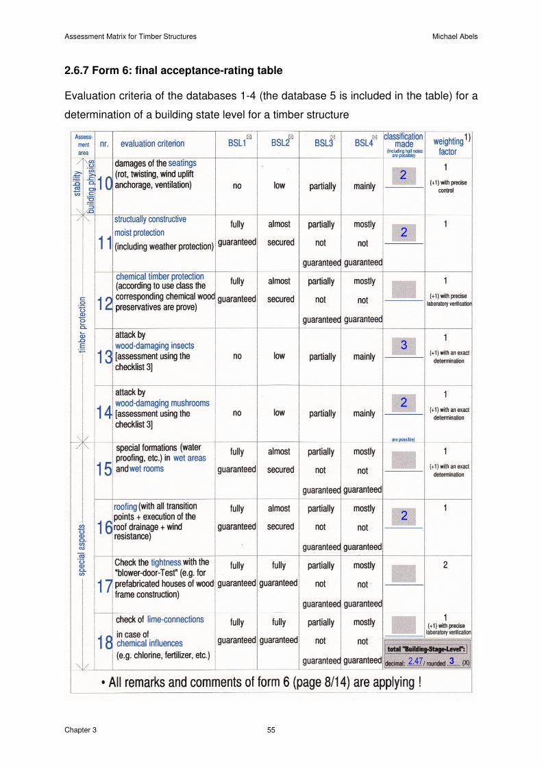
Assessment Matrix for Timber Structures Michael Abels
Chapter 3 55
2.6.7 Form 6: final acceptance-rating table Evaluation criteria of the databases 1-4 (the database 5 is included in the table) for a
determination of a building state level for a timber structure

Assessment Matrix for Timber Structures Michael Abels
Chapter 3 56
2.6.7 Form 6: Final inspection protocol – assessment table
Averaged final scores:
Evaluation of all assessment criteria: With the help of the important factors, an
average score of the construction status is calculated.
� The whole construction is assigned the Building Stage Level (= average -
overall score / rounded): 3
(Genaue Berechnung = 3x5 + 2x2 + 2x1 + 3x2 + 2x2 + 3x1 + 2x1 + 2x1 + 2x1
+ 3x1 + 2x1 + 2x1 = 47 / 19 = 2,47 → rounded = 3)
The reason for this decision follows in Appendix 1.
The definitions of construction status levels are taken from Addition 1 of Form 6.
If more serious damage occurs, construction status level 2 cannot be reached!
Notes on the table:
(bracket value) = corresponding increase
1) Increase of the weighting factors with more exact proof or enabled experts.
2) The assessment of structural fire protection is not the purpose of this evaluation.
When necessary, an external fire protection plan can be obtained from a fire
protection expert.
3) To complete the full evaluation some recommendations could be pronounced by
the timber expert. In addition to the requested time the color of the inspection badge
is given
(X) To be able to approve an appraised construction for further use, at least
construction status level 2 must be reached. In the case of a worse assignment
corresponding repairs and/or strengthening (or others) are to be conducted according
to the precise specifications of the timber expert. See: Form 6 _ Appendix 2
(XX) Basic requirements for the static examination:
- Well-defined static system of load transfer
- The supporting system consists exclusively of materials approved by the
building authorities
= see Addition 1 to Form 6 (= Definition of construction status levels)

Assessment Matrix for Timber Structures Michael Abels
Chapter 3 57
2.6.7 Form 6: Final inspection protocol – assessment table
Addition 1: Definition of construction status levels (based on [6] + [16])
Building Stage
Level (BSL) /
Grading
Characteristics of building Percentage of
wear, that is,
damaged parts
(=damage in %)
Brief description
1
very good
–
good
- well maintained
- no loss of function whatsoever
- negligible defects, which can be removed
via maintenance and repairs
0 – 5
- SS fully ensured /
secured
- no damages
2
Satisfactory
-
fair
- minor damages
- repairs are to be carried out in order to
remove small disruptions in function and to
avoid an expansion to larger damages
6 – 25
- SS ensured
- marginal
damages
- almost
secured
3
poor
- serious damages
- sizeable defects, which compromise the
continued existence or the functional
efficiency; repairs of large areas are
needed
26 – 50
- SS partly not
ensured /
secured
- minor / partial
/ locally limited
faulty
4
deficient
- unusable
- paramount indemnifications are required
for rehabilitation of the functional efficiency
> 50
- SS predominately
not ensured
/ secured
- significant
damages
SS = structural safety

Assessment Matrix for Timber Structures Michael Abels
Chapter 3 58
2.6.7 Form 6: Final acceptance report date 12.10.2009
Appendix 1: Reason for the assessment = conclusion
After analyzing all conducted inspections that were adequately documented earlier in the work, the
following results can be formulated for the wooden roof bearing structure of Mr. Klaus Weiler's half-
timbered home protected as a landmark:
- The accessible appraisal of the wooden roof bearing structure (= roof construction, wooden-
beam ceilings, and half-timbered inner walls) evaluated at random showed different
peculiarities.
- Wooden-beam ceilings:
- Serious biological damages are present in the support points of the outer walls that require
immediate (See Appendix 2) renovation!
- The adequate stability required by the building authorities is not ensured for the wooden-beam
ceilings over the ground level!
- Roof construction:
- The supporting structure stability required by the building authorities is ensured for the roof
bearing structure.
The entire roof construction, however, is in a very poor state. It is susceptible during storms
and under snow that might accumulate next to the neighboring house on the right side. All use
of the top floor is strictly prohibited!
- Constructional and chemical wood preservation appears evidently to be in order.
- Half-timbered inner walls:
- The half-timbered inner walls were also sampled at random. No peculiarities were detected. At
the moment no repair, restoration or renovation measures are necessary.
For all considered timber constructions it can be said:
- The change of use of the construction conceived by the contractor should be seen as
extremely critical, because the wooden constructions (roof construction, wooden-beam
ceilings and half-timbered inner walls) have no load reserves whatsoever. If the property is
converted, however, special proofs of stability will need to be conducted that taken into
account the poor state of the current construction and determine necessary restoration
measures.
Appendix 2: Necessary repairs of the identified deficiencies
During the building inspection ends of wooden beams (above the ground floor) destroyed by beetles
were found. This is documented in the corresponding state mapping (see figure 3.19). Usind the
database 1 (see section 2.62) a repair method has been proposed ( see figure 3.20).

Assessment Matrix for Timber Structures Michael Abels
Chapter 3 59
2.6.7 Form 6: Final acceptance report – evaluation table date 12.10.2009
Appendix 3:
Recommendation:
Regular maintenance in this period is required in any case.
As for the roof constructions under consideration, it is recommended that the roof cladding be regularly
inspected by a roofing business inside and out. We recommend a maintenance/inspection contract
with a local roofing business so that leaks in the roof cladding or damages to roof drainage, etc. can
be recognized early and fixed immediately. These measures are strongly recommended due to unique
shape of the roof (with potential accumulations of snow directly next door at the neighboring house)
and because it shares roof drainage with the neighbor. Additional significant loads may come to bear
on the considered roof cladding for which it is not designed!
Also due to the unique shape of the roof, snow accumulations may occur that are not taken into
account by the static calculation. Only a standard load of 75 kg/m² roof cladding was taken into
account. It is highly recommended that the owner of the house has the roof cladding inspected under
winter weather conditions (heavy snowfall) in order to arrange snow and/or ice removal early on. The
author of this expert opinion is available to answer any queries on the matter as well as develop an
inspection concept for heavy and ongoing snowfall.
General information about the appendices:
All of the measurement drawings, different photographs, system sketches, conducted proofs of
stability, etc. are attached in the appendices.
Approval:
Use of the building (as a residence) can only be released by the appraiser for the next 5 years
(see figure 3.9b).
Due in part to serious damages present in the building, the approval is contingent upon the
restoration of the dilapidated wooden-beam ends within the wooden-beam ceiling over the
ground level within the next 6 months. They must then be removed again. Until then the "red"
test badges (see figure 3.9a) are valid. Only then can the final "green" badges be installed.
The condition precedent for the approval for use of the building is the restoration of the entire
roof construction according to the information in Appendix 7 (supporting structure +
impermeability of the roof cladding + securing the roof drainage) construction and roofing
businesses! Special contractor's statements (= SCS) must be presented afterward!
The renewed approval procedure and SCS template must occur by:
The end of June 2010 at the latest.

Assessment Matrix for Timber Structures Michael Abels
Chapter 3 60
3.5 Case Study 3
Sports Hall Kleiststraße in Mülheim an der Ruhr
Figure 3.21: Photo – outside view
Figure 3.22: Photo – view of roof from below with roof bracing
Figure 3.23: Awarded “test badge” after verification (just a suggestion)
(see Section 3.9.5)

Assessment Matrix for Timber Structures Michael Abels
Chapter 3 61
Figure 3.24: Original drawing – general plan / site plan (expert of the original plan)

Assessment Matrix for Timber Structures Michael Abels
Chapter 3 62
Figure 3.25: State mapping – floor plan drawing

Assessment Matrix for Timber Structures Michael Abels
Chapter 3 63
Figure 3.26: Original structural analysis – steel shoe binder connections
(excerpt of the original plan)
Figure 3.27: Original structural analysis – roof bracing
(excerpt of the original plan)

Assessment Matrix for Timber Structures Michael Abels
Chapter 3 64
Figure 3.28: Inspection of the binder support points using the resistograph
Figure 3.29: Inspection of a crack using a crack gauge
Figure 3.30: Electrical wood moisture test

Assessment Matrix for Timber Structures Michael Abels
Chapter 3 65
Figures 3.31: Output log of a drill resistance measurement using the resistograph
(The protocol shows no abnormalities.)

Assessment Matrix for Timber Structures Michael Abels
Chapter 3 66
object specified:
- building: Sports hall Kleiststraße ( =triple gym)
-components/
investigated
structures:
Engeneering- style wooden roof
construction
-builder, owner:
(name,address,
phone, fax, e-mail):
Stadt Mülheim an der Ruhr, Hans-Böckler-Platz 5,
45468 Mülheim
Immobilienservice der Stadt Mülheim an der Ruhr
phone: 0208-455-2336, e-mail: [email protected]
Photo of the building:
- place: (street, postcode, place, district, landing, parcel, land registry number)
Kleiststraße 50, 45472 Mülheim
- responsible building office:
Stadt Mülheim an der Ruhr (adress, see above)
- file number (if any): 200/10/1975
Building information by building check:
- timber expert: (name, address, phone, fax, e-mail)
Michael Abels, Dipl.-Ing., Am Mühlenkreuz 28, 50181 Bedburg,
phone: 02272-905637, fax: 02272-905635, [email protected]
-building category: (underline the right one)
BC 1 / BC 2 / BC 3
- Last monitoring: the monitoring documented here is 1. -partial acceptance / Professional Company Statement (PCS) no later than :
Contained Forms: 12.01.2019
Form: date: index: (= date of revision)
1 12.29.2009 -
2 12.29.2009 -
3 12.29.2009 -
4 12.29.2009 -
5 12.29.2009 -
Included experts - -
6 = final acceptance 12.29.2009 Signature of the timber expert
………………………………………………
- Total “Building Stage Level”: 1
- spezial features or spezial reports (date): -
- Inspection Badge (blue) awared on (date): 12.01.2009 / valid through:
12.01.2019

Assessment Matrix for Timber Structures Michael Abels
Chapter 3 67
Form 1: date 11.29.2009 The completely filled out Form 1 is to be filed in the object book!
The yes / no / unknown – fields must be checked off.
1. General project information:
General / preliminary remarks (reason for inspection):
The city Mülheim an der Ruhr, represented by ImmobilienService, commissioned the author of this
expert opinion on 11.18.2009 as the result of an offer on 10.26.2009 and a public request for bids on
10.02.2009 for the inspection of the timber construction presented here.
An initial inspection of the wooden roof construction was conducted on the considered object. In doing
so, an accessible appraisal of the wooden supporting structure was conducted. The inspections
service to identify whether mechanical and/or biological damages are present in timber constructions.
Furthermore, it must be ensured that the supporting structure stability required by the building
authorities is maintained.
The inspection results are summarized in the conclusion of this expert opinion. A concept detailing
restoration, inspection, and/or renovation measures for the sake of preserving the considered
construction is outlined in the conclusion.
All inspections conducted, meet the general state of the art and account for local circumstances. The
evaluation of the timber construction was conducted according to the "assessment matrix for the
conservation of valuable timber constructions" developed by the author.
Site inspections:
Different site inspections were conducted outside and inside of the considered object for the appraisal
of the wooden roof construction.
The on-site inspections took place on:
- 10.30.2009
- 11.14.2009
- 11.20.2009
The timber expert involved in the present appraisal gained a complete picture of the considered object,
in that he inspected it closely inside and out before he examined the wooden roof construction in
greater detail.
Accessibility of the roof construction:
The load-bearing roof wood glue binders are uncovered. All positions were able to be appraised first-
hand using a lifting platform.

Assessment Matrix for Timber Structures Michael Abels
Chapter 3 68
Form 1: date 11.29.2009 (1/3) no.: term: entry:
1.1 building – description Sports hall (triple gym)
1.1.1 examined structure Engineering- style wooden roof construction
(glued timber beams)
1.2 builder / ownership:
name: Stadt Mülheim
Immobilienservice der Stadt
Jörn Sprenger
Mülheim an der Ruhr
adresse: Hans - Böckler - Platz 5
45468 Mülheim
phone: 0208-455-6030
e-mail: [email protected]
1.3 responsible for building-check:
Stadt Mülheim
Immobilienservice der Stadt
Mülheim an der Ruhr
(Adresse: siehe oben)
1.4 leading office
(complete adress):
[= timber-expert]
Michael Abels, Dipl.-Ing.
Planung - Statik - Bauphysik
Am Mühlenkreuz 28, 50181 Bedburg
Tel.: 02272-905637, www.michael-abels.de
1.4.1 clerk: Michael Abels
1.5 date of check: 29.01.2010
1.6 place (street, village): Kleiststraße 50
45472 Mülheim an der Ruhr
1.7 geographical location, altitude
(above see level):
51°25`39,82`` N
6°56`18,86`` E
unknown
1.8 direction / cadastral extracts
available:
entrance = yes
NO – site
no
1.9 age of the building or of the
structure:
vintage 1975
35 years
unknown
1.10 date of setting-up: vintage 1975 unknown
1.11 design drafters / architect: Architekturbüro A. Riege
Mülheim an der Ruhr
unknown

Assessment Matrix for Timber Structures Michael Abels
Chapter 3 69
Form 1: date 11.29.2009 (2/3) 1.12 exporting company: Hallenbau J. Brüninghoff
Knufdrees 5, 4284 Helden
unknown
1.13 responsible building-office: Stadt Mülheim
Bauaufsichtsamt
45468 Mülheim
1.14 planned use in the planing: gym (mainly for school sports)
1.15 Is the building listed? yes
no
unknown
1.15.1 responsible conservation authority: -
1.16 Is the building used or unused?
(unused since?)
used
1.17 classification in a building style: -
1.17.1 determined building style or
construction era:
-

Assessment Matrix for Timber Structures Michael Abels
Chapter 3 70
Form 1: date 11.29.2009 (3/3)
2. Occasion or reason of the building check:
2.1 first check of the structure after completion yes
no
2.2 commission per building check (= official normed
building check)
yes
no
2.3 monitoring form 1 yes
no
2.4 monitoring form 2 yes
no
2.5 classification of the building in a building category:
BC 1 / BC 2 / BC 3
(see Section 3.9.1)
BC3
2.6 Is a structure defect noted? yes
no
2.7 Is a building-measure planned? (enlargement,
extension, use change, expansion, etc.)
yes
no
2.8 Is a repair planned? (modernization, reconstruction,
renovation, etc.)
yes
no
continuation: see form 2

Assessment Matrix for Timber Structures Michael Abels
Chapter 3 71
Form 2: date 11.29.2009 Beginning of an "in-depth inspection" in the office:
Notes:
- The completely filled out Form 1 is to be filed in the object book!
Copies of the reviewed documents such as building designs, static calculations, etc.,
are to be made and also filed in the object book.
1. Closely inspect documents on timber construction:
Notes:
- The documents listed below are to be requested from the builder or authorized party
and accepted by the building authority and land registry with a corresponding power
of attorney.
- The potentially available planning documents are to be compared at the following
site inspection with the 75 actual construction state. In doing so, the static span
widths, the verified connections, and the indicated materials are inspected above all.
no.: term: present: checked on site or performed:
1.1 Building an civil engineering drawings
available
(see e.g. figures 3.24, 3.26, 3.27)
yes / no
if 1.1 negative answered:
1.1.1 allowance necessary yes / no
if 1.1 positive answered:
1.1.2 building-application plans = approval plans
scale = 1:100
yes / no -
1.1.2.1 ground plans yes / no yes / no
1.1.2.2 sectional drawings yes / no yes / no
1.1.2.3 building-views yes / no yes / no
1.1.2.4 site map or cadastral extracts yes / no yes / no
1.1.3 execution plans or detailed plans scale =
1:50
yes / no yes / no

Assessment Matrix for Timber Structures Michael Abels
Chapter 3 72
Form 2: date 11.29.2009
1.1.4 Detail drawings (connections)
scale = 1:25 / 1:20 / 1:10, etc.
(see e.g. figures 3.26, 3.27)
yes / no yes / no
1.1.5 Joinery drawings of the timber structures yes / no yes / no
1.1.6 Installation plan of the roofing, etc. yes / no yes / no
1.2 Statics available?
The test report of the chief structural engineer also exists
Not part of this thesis
yes / no
1.2.1 Is the statical system important?/
The statical system is treated on the form 3.
yes / no yes / no
1.2.2 Statical calculation yes / no yes / no
1.2.3 Check the constant load on the building yes / no
1.2.3.1 Maximum snow-load yes / no
1.2.3.2 Maximum wind-load yes / no
1.2.3.3 Structure of the components with the load-
determination of the net weight
yes / no
1.2.3.3.1 Cover plates (not necessary) yes / no
1.2.3.3.2 Walls (not necessary) yes / no
1.2.3.3.3 Roofing yes / no
1.2.3 Specification of the used materials (=wood-
types) roof beams as glued timber
yes / no yes / no
1.2.3.1
determination of the wood-type Not necessary

Assessment Matrix for Timber Structures Michael Abels
Chapter 3 73
Form 2: date 11.29.2009
1.2.4 Execution plans of the statical calculation,
e.g roof construction plan, etc.
yes / no yes / no
1.2.5 test report of the statical calculation of the
auditor-structural engineer
(not part of this thesis)
yes / no
1.2.5.1 special structure yes / no
1.2.5.2 license in individual cases yes / no
1.3 physical evidence existing?
non- existent
yes / no
1.3.1 heat protection certification yes / no
1.3.2 constructive fire-protection certification yes / no
1.3.3 constructual fire-protection certificate = fire
protection concept
yes / no
1.3.4 sound-protection certificate yes / no
1.3.5 information to the moisture-protection yes / no
1.4 montage-information yes / no
1.5 glue-book of the timber structure company yes / no

Assessment Matrix for Timber Structures Michael Abels
Chapter 3 74
Form 2: date 11.29.2009
2.1 Use of the building as:
present: Checked on site or performed:
2.1.1 residential building yes / no
2.1.2 public building yes / no
2.1.3 commercial used building. Which crowds are possible?
yes / no
2.1.4 special loads on the structure of building. The
load is be specified in kN.
yes / no
2.1.4.1 point loads from machines, water bed, safe,
watertank, bulk materials, bells, or other
yes / no yes / no
2.1.4.2 roof construction: solar system/ photovoltaic
system
yes / no Load in kN =
2.1.4.3 trafficability of areas by vehicles, or similar yes / no
Load in kN =
2.1.4.4 existing horizontal-loads by impacting of
vehicles, handrailloads, etc.
yes / no Load in kN =
2.1.4.5 existing dynamical loads yes / no
2.1.4.6 statement of other loads yes / no Load in kN

Assessment Matrix for Timber Structures Michael Abels
Chapter 3 75
Form 2: date 11.29.2009
3.1 Classification in use-classes: Classification
possible:
Checked on site:
3.1.1 use-class 0:
Inside built wood, completely dry (wood moisture <20%); no wood preservatives required
yes / no yes / no
3.1.2 use-class 1:
Internal components with an average room
humidity ≤70%; requirements to the wood preservatives: insect-preventive
yes / no yes / no
3.1.3 use-class 2:
Internal components with an average room humidity >70%, internal components in wet areas, external components without direct weather stress; requirements to the wood preservatives: insect-preventive, fungus-retardant
yes / no yes / no
3.1.4 use-class 3:
External components with weather stress without permanent ground- an/or water contact internal components in wet rooms, wood exposed to the weather or condensation, but no ground contact; requirements to the wood preservatives: Iv, P, W= insect-preventive, fungus-retardant, weatherproof
yes / no yes / no
3.1.5 use-class 4:
Timber with permanent ground- and/or fresh water contact, even with sheath, there are special conditions for wood on sea water; requirements to the wood preservative, insect preventive, fungus-retardant weatherproof, soft rot retardant (timber used in the ground)
yes / no yes / no

Assessment Matrix for Timber Structures Michael Abels
Chapter 3 76
Form 3: date 11.29.2009 (1/3)
General information about static calculations:
The aim of the appraisal conducted on the wooden constructions of the Kleiststraße sports hall
considered here was, most importantly, to assess the adequate stability required by the building
authorities as described above. The actual static system had to be inspected to accomplish this. The
existing static calculation that was tested before the construction of the building, constituted the basic
requirement. This system warranted on-site inspections. In doing so, the dimensions, timber cross
sections, wood qualities, and the constructed connections were inspected and partially documented
(see the attached photographs).
All points of the original static calculation, including all construction plans [see appendix 2], were
comprehensible and sometimes supported with comparative calculations [see appendix 5]. The plans
and calculation information agreed with the local circumstances.
1.) Design of the load-bearing system:
(see e.g. figure 3.25)
• 1.1 Load-bearing components for vertical loads
(dead weight, live/payloads, snow, etc.)
Wood glue binders (1 - field - support)
→ 1.1.1 Roof construction:
Roof crossbars, rafters, purlins, binders, containers, frames, etc.
Sketch(es) (possible use of additional sheets or refer to form 4):
Trapezoidal steel sheets (freely supported from binder to
binder)
(see e.g. figures 3.22)
→ 1.1.2 Horizontal supporting elements:
Beamed ceilings, beams/coatings, roof bracings (wind braces,
plates, etc.)
Sketch(es) (possible use of additional sheets or refer to form 4):
Crossed round bars as roof bracings
(see e.g. figures 3.22, 3.27)

Assessment Matrix for Timber Structures Michael Abels
Chapter 3 77
Form 3: date 11.29.2009 (2/3)
• 1.2. Load-bearing components for the horizontal loads
(Wind, beam loads, reinforcement loads, LF: earthquakes, impact
loads, dynamic loads)
Reinforced concrete columns
→ 1.2.1 In the entire building:
Frames, latticework structures, bracings (roof and wall bracings),
wind braces
Sketch(es) (possible use of additional sheets or refer to form 4):
(see e.g. figure 3.25)
2.) Identification and determination of all loads:
• 2.1 External loads according to Eurocode 1:
- Wind
- Snow see static calculation
- Earthquake zone (not part of this thesis)
• 2.2 Dead weight of the construction (construction and expansion
loads):
- Roof cladding: see static calculation
- Tier of collar beams: (not part of this thesis)
- Tier of beams over the …floor:
- Tier of beams over the …floor:
- Wall construction (outside):
- Wall construction (inside):
- Balcony or projections (if present):
- Other loads:

Assessment Matrix for Timber Structures Michael Abels
Chapter 3 78
Form 3: date 11.29.2009
3.) Connections:
Weak points are often the connections within a structure that can no longer
sufficiently bear the existing weight as a result of various circumstances
(cross-sectional weaknesses, gaping joints due to shrinkage and swelling,
corrosion of metal connecting devices, overstraining due to changes of use,
etc.).
For this reason they must also be documented in the form of sketches (photos,
etc.) and the visible cross-sections, connecting devices, and materials
documented. Here the difficulty is often present that internal connecting
devices - such as studs of specific constructions types - cannot be secured
from outside. In this case, the inspecting timber expert must decide on a case-
by-case basis which methods (see sections 2.4.6 + 2.4.7) to implement for a
more detailed and continued analysis.
Sketch(es) (possible use of additional sheets or refer to form 4):
The main focus of the inspection was on the support points of the
binders. They rest in steel beam shoes, which in turn are
connected to wooden cross members.
(see e.g. figure 3.26)
4.) Cross-sectional dimensions of the load-bearing components:
→ The load-bearing timber cross sections measured on-site that agreed
with the information in the available planning documents were entered
into the attached condition mapping.
All load-bearing wood parts are laminated timber (= laminated wood).
Continuation: see form 4

Assessment Matrix for Timber Structures Michael Abels
Chapter 3 79
Form 4: Condition mapping the "actual condition" date 11.29.2009
The condition mapping conducted using Form 4 is to be filed in the object book!
(see e.g. figure 3.25)
Using the documents available in the archive that are listed above, it was possible to prepare drawings
(floor plan + section) prior to the site inspection that include the wooden roof construction. The
dimensions and cross sections were compared with the conditions on-site.
The floor plan sketch is attached with Appendix 6.
This plan serves to correctly map the positions and dimensions of detected defects and/or damages.
With the help of this condition mapping, additional required steps - e.g. in case of required restoration
measures - can be passed on in a simple and clear form.
Furthermore, this plan contains the requirements for the following static inspection of the timber
construction.
The following form 5 along with the expert databank provides the possible
inspections that can be integrated into the condition mapping at a later point.

Assessment Matrix for Timber Structures Michael Abels
Chapter 3 80
Form 5: Inspection methods for different date 11.29.2009
material parameters [only approximate "on-site inspections"]
Process: Parameter(s): Implemented:
- Detecting and measuring distortions (e.g. with
a long spirit level).
- Distortions
- Determining the wood type using pictures for
comparison
Not necessary for laminated binders
- Wood type
- Detecting and measuring cracks using a crack
gauge (⇒inspection according to check list 2)
No noteworthy cracks were detected
- Cracks
(see e.g. figure 3.29)
- Detecting and inspecting a fungus and/or
insect infestation using pictures for comparison
(⇒ Inspection according to check list 3)
No patterns of damage were detected
- Fungus and/or insect
infestation
- Drilling of suspicious areas with a
spiral drill (mainly abutments).
Inspection of the beamed ceilings was conducted
using a resistograph
(see below)
- Rots + cavities
(= physical state of the wood)
Rinntech drill resistance
measuring apparatus, type:
Resistograph series 4, 4453-P
(see e.g. figures 3.28, 3.31)
Were experts from the expert database consulted?
yes / no }
If yes, with what outcome:
…………………………………………………………………………………………………
All of the beamed ceilings were drilled with the resistograph for the inspection.
The inspection results (which are all positive) are attached.
(see e.g. figure 3.31)
…………………………………………………………………………………………………
…………………………………………………………………………………………………
……………………………………………………………………………………………

Assessment Matrix for Timber Structures Michael Abels
Chapter 3 81
2.6.7 Form 6: final acceptance-rating table Evaluation criteria of the databases 1-4 (the database 5 is included in the table) for a
determination of a building state level for a timber structure

Assessment Matrix for Timber Structures Michael Abels
Chapter 3 82
2.6.7 Form 6: final acceptance-rating table Evaluation criteria of the databases 1-4 (the database 5 is included in the table) for a
determination of a building state level for a timber structure

Assessment Matrix for Timber Structures Michael Abels
Chapter 3 83
2.6.7 Form 6: Final inspection protocol – assessment table
Averaged final scores:
Evaluation of all assessment criteria: With the help of the important factors, an
average score of the construction status is calculated.
=> The whole construction is assigned the Building Stage Level (= average -overall
score / rounded):
(1x4 + 1x2 + 1x1 + 1x2 + 1x2 + 2x1 + 1x1 + 1x1 + 1x1 + 1x1 + 1x1 + 1x1 +
1x1 + 1x1) = 21 / 20 = 1,05 => rounded 1
The reason for this decision follows in Appendix 1.
The definitions of construction status levels are taken from Addition 1 of Form 6.
If more serious damage occurs, construction status level 2 cannot be reached!
Notes on the table:
(bracket value) = corresponding increase
1) Increase of the weighting factors with more exact proof or enabled experts.
2) The assessment of structural fire protection is not the purpose of this evaluation.
When necessary, an external fire protection plan can be obtained from a fire
protection expert.
3) To complete the full evaluation some recommendations could be pronounced by the timber expert. In addition to the requested time the color of the inspection badge is given (X) To be able to approve an appraised construction for further use, at least
construction status level 2 must be reached. In the case of a worse assignment
corresponding repairs and/or strengthening (or others) are to be conducted according
to the precise specifications of the timber expert. See: Form 6 _ Appendix 2
(XX) Basic requirements for the static examination:
- Well-defined static system of load transfer
- The supporting system consists exclusively of materials approved by the
building authorities
= see Addition 1 to Form 6 (= Definition of construction status levels)

Assessment Matrix for Timber Structures Michael Abels
Chapter 3 84
2.6.7 Form 6: Final inspection protocol – assessment table 4/7
Addition 1: Definition of construction status levels (based on [6] + [16])
Building Stage
Level (BSL) /
Grading
Characteristics of building Percentage of
wear, that is,
damaged parts
(=damage in %)
Brief description
1
very good
–
good
- well maintained
- no loss of function whatsoever
- negligible defects, which can be removed
via maintenance and repairs
0 – 5
- SS fully ensured /
secured
- no damages
2
Satisfactory
-
fair
- minor damages
- repairs are to be carried out in order to
remove small disruptions in function and to
avoid an expansion to larger damages
6 – 25
- SS ensured
- marginal
damages
- almost
secured
3
poor
- serious damages
- sizeable defects, which compromise the
continued existence or the functional
efficiency; repairs of large areas are
needed
26 – 50
- SS partly not
ensured /
secured
- minor / partial
/ locally limited
faulty
4
deficient
- unusable
- paramount indemnifications are required
for rehabilitation of the functional efficiency
> 50
- SS predominately
not ensured
/ secured
- significant
damages
SS = structural safety

Assessment Matrix for Timber Structures Michael Abels
Chapter 3 85
Form 6: Final acceptance report date 11.29.2009
Appendix 1: Conclusion = reason for the assessment
After analyzing all conducted inspections that were adequately documented earlier in the work, the
following results can be formulated for the wooden roof bearing structure of the Kleiststraße sports
hall:
- The accessible appraisal of the wooden roof construction evaluated at random showed no
peculiarities.
- There are no grave mechanical or biological damages to this roof construction.
- The supporting structure stability required by the building authorities is ensured [JAZ: there
may be formatting to replicate here].
- Constructional and chemical wood preservation appears evidently to be in order.
- At the moment no repair, restoration, or renovation measures are necessary.
- Due to the extremely large span widths of the binders and the pure wood-to-wood connections
over steel beam shoes, future structural modifications, e.g. for installing photovoltaic systems,
new ceiling coverings, new sport and/or acoustics equipment, insulation within the scope of
energy efficiency, etc., static tests must be conducted before commencing.
The building is released for use
by the timber expert for the next 10 years
(see figure 3.23)
Appendix 2: Not required
Appendix 3: Recommendation:
Regular maintenance in this period is required in any case.
As for the roof constructions under consideration, it is recommended that the roof cladding be regularly
inspected by a roofing business inside and out. We recommend a maintenance/inspection contract
with a local roofing business so that leaks in the roof cladding or damages to roof drainage, etc. can
be recognized early and fixed immediately. This measure is highly recommended due to the unique
shape of the roof (with continuous parapet) and the inner drainage pipes. Due to backed up roof
gullies and the resulting masses of water and/or snow, additional significant loads may affect the
considered roof cladding for which it is not designed!
Also due to the unique shape of the roof, snow accumulations may occur that are not taken into
account by the static calculation. Only a standard load of 75 kg/m² roof cladding was taken into
account. It is highly recommended that city workers inspect the roof cladding under winter weather
conditions (heavy snow fall) in order to arrange snow and/or ice removal from inside the auditorium
early on. The author of this expert opinion is available to answer any queries on the matter as well as
develop an inspection concept for heavy and ongoing snowfall.

Assessment Matrix for Timber Structures Michael Abels
Chapter 3 86
Form 6: Final acceptance report date 11.29.2009
General information about the appendices:
All construction documents available in the Mülheim an der Ruhr city archive were reviewed at the
beginning of the construction state analysis.
The following important documents were found:
- File no.: 42719 / IIa, school complex (sport halla) 1st addendum
- File no.: 42719 / II, expansion of the school - structural analysis
- File no.: 42719 / II, school complex
Contained therein are original architectural plans (floor plans, building views + building section) from
11.30.1975.
Furthermore, they contain the original structural analysis of the hall construction. They were produced
on 08.31.1977 by the engineering firm Karl Kolb and reviewed by structural engineer Dr.-Ing Werner
Schneider on 11.21.1978.
Different copies and photographs (of the plans) of the planning documents are attached in the
appendix.

Assessment Matrix for Timber Structures Michael Abels
Chapter 3 87
3.6 Peculiarities of previous applications + evaluation of previous matrix
applications
Because of the complexity of this task, it should be re-emphasized here that the
maxtrix application can and should be continually optimized with regular evaluations
by users of the matrix. A programmed form of the assessment matrix is indispensable
for this purpose (see section 4.1).
Over the course of last year and in connection with numerous applications of the
considered matrix, the author of this thesis undertook sylistic, formal, and logical
corrections and amendments along with optimizations for specialist areas.
The user of the assessment matrix, the timber expert, plays a lead roll in every
appraisal. It is of fundamental importance that the quality of the expert be controlled
by an official office and that he/she is only granted this title upon proof of adequate
qualifications (proof of professional experience + passing a test). Additional points on
this topic are listed in section 3.9.4. It must be ensured in every case that the
standardized appraisals described in this thesis are not abused, like what has
happened in the past when issuing of energy certifications from internet offices
without any on-site controls whatsoever.
Peculiarities that have stood out during past matrix applications, including these 3
case studies, will be subsequently named in order to formulate general regulations.
Case study 1 showed that a building may consist of multiple and extremely different
timber constructions that are interconnected, such as for example, the church tower
next to the nave, which exercise no static influence on each other.
Rule 1: All constructions (not only the load-bearing constructions) must be identified
and inspected during the appraisal of a building. No weightings are to be applied with
regard to the age, size, or any other aspects of the construction. All load-bearing
constructions must be inspected in regard to building user safety. They can only be
approved for use once all directly adjoining constructions have been sufficiently
inspected.

Assessment Matrix for Timber Structures Michael Abels
Chapter 3 88
All 3 case studies have shown that it is necessary to complete the entire assessment
matrix because only then are all aspects considered.
Rule 2: In order to be able to conduct a final appraisal of a timber construction, it is
necessary to use the entire assessment matrix and fill out all forms.
The peculiarity of the 2nd case study is that, independent of regular appraisals of
timber constructions, the building was supposed to have been adequately inspected
before a planned building project because necessary restoration measures must be
conducted in conjunction with or before the other construction work if possible.
Rule 3: In addition to regular building maintenance, sufficient building appraisals
must be conducted before all planned building measures on the object, such as for
example, remodels and/or additions, changes of use, etc. in order to inspect the
effects and tolerances of the existing load-bearing constructions early on.
A peculiarity of the 3rd case study is that the experienced and trained eye of the
timber expert as well as "on-site inspections" are sometimes not enough for
identifying hidden damages within a construction. It is often indispensable to inspect
the widespread support points of wood glue binders with a resistograph because
internal rots can have fatal consequences in these areas.
Rule 4: In addition to the experience of the wood expert, the use of modern
inspection methods must not be foregone when inspecting complex wood
constructions in order to be able to inspect invisible areas from the outside.
Likewise, all 3 case studies showed that it is indispensable to personally inspect the
object because planning documents (if at all available) often do not show everything.
The unique shape of the sport hall roof (= case study 3) can be named as an
example here, which has roof drainage not shown in the plans. A continuous parapet
presents the high risk that the complete roof surface can flood if the roof gullies
become backed up (the only roof drainage), which would lead to a significant
increase in strain that was not taken into account in the static calculation.

Assessment Matrix for Timber Structures Michael Abels
Chapter 3 89
Rule 5: The timber expert's site inspection is indispensable within the scope of any
timber construction appraisal, independent of how many documents are available for
the object. With his signature, the timber expert confirms that he has personally
inspected the construction.
As previously described, all 3 case studies concern larger buildings classified as (the
later described) building category 3. For logical reasons, points should be adopted
from similar processes that have proven to be effective in practice. Named here, for
example, is the obligatory testing of proofs of stability prescribed by German building
law. In the case of larger buildings (for example residential buildings with more than 3
units or all public buildings), the static calculations must be conducted by officially
certified structural engineers (= state approved expert for testing stability). This
process is governed in Germany by regional building regulations, e.g. Building
Regulations of the Land NRW. The 4 eyes principle should also apply to the
appraisal of timber constructions for building categories 2 and 3.
Rule 6: The finished forms with the final test report and all associated building
documents must be countersigned by an additional timber expert in the case of
building inspections for structures in building classes 2 and 3 (= using the 4 eyes
principle).
An additional peculiarity was noticed during the inspection of the tournament hall
(none of the 3 case studies just reviewed) to which a so-called corrugated web
beam was applied. The author of this thesis conducted extensive research on this
special construction, which was used in the 1950s and 60s and was/is particularly
vulnerable to damage.

Assessment Matrix for Timber Structures Michael Abels
Chapter 3 90
Figure 3.32: Corrugated web beam as rafters of a tournament hall roof
+ system sketch
This showed, however, that due to the versatility of wood, this assessment matrix will
never be finished. The qualified timber expert possesses enough know-how,
however, to fill any gaps in knowledge on his own.
Rule 7: If special constructions are being appraised that are unknown to the timber
expert, they are to conduct literature research and consult external experts where
necessary in order to then be able to develop solid conclusions about the considered
timber construction. The construction is then added to the corresponding databank so
that henceforth matrix users can exchange information.
A peculiarity was exposed in the evaluation of the 2nd case study. Whether a building
is used publicly is of vital importance. In this case study, the planned change of use
from a residence to a public cultural center was the focus of this inspection. The
conceived test badges developed over the course of this chapter must reveal a public
building.

Assessment Matrix for Timber Structures Michael Abels
Chapter 3 91
Otherwise, the significant damages identified within the scope of the inspection must
be indentified and remedied for the user before the building can be approved for
unobjectionable use.
Rule 8: The test badges installed on the inspected building must reveal to the user
whether the building is public and whether significant damages are present in the
building (see section 3.9.5).
The 8 rules above were formulated using the individual evaluations of the matrix
applications used in the case studies. They should be made valid for all participants
in future test procedures (see section 3.7ff).
3.7 Social applications of the Assessment Matrix
The concrete application (previous sections of Chapter 3) of the assessment matrix
described in Chapter 2 has already shown how it can be used for all timber
constructions. There are no minimum requirements whatsoever, e.g. with regard to
the size or age of the considered timber constructions. In the following sections 3.8
and 3.9, however, specifications will be proposed regarding the extent of evaluations
depending on building use. With this a social application of the assessment matrix
will be presented.
The requirements for the group of people who are at all allowed to conduct
evaluations are also described in greater detail in the sections to follow. It is clear
from the previous passages that the timber expert must have many years of concrete
experience (= professional practice) with timber constructions of all types in addition
to more than sufficient scientific and theoretical knowledge gained in Germany within
the scope of academic studies in architecture, wood technology, and/or civil
engineering.
It is also important to note that the evaluation is not restricted to German and Dutch
wood constructions. This thesis concerns primarily German processes only because
of the nationality of the author. As mentioned in section 3.10, it is the goal of this
thesis to expand to all of Europe with this type evaluation. This is pursued without a
second thought because the building techniques are very similar and the materials

Assessment Matrix for Timber Structures Michael Abels
Chapter 3 92
are practically identical. A positive side effect will be the Europe-wide exchange over
newer constructions, connection means, materials, and a much larger group of
people and users will become informed of older defects and damages and will
therefore also be forewarned.
The QM system (= quality management system) described in Chapter 2 within the
scope of developing an assessment matrix (= main matrix) would be much more
useful if it could be expanded to a European group of users.
In addition to the many positive features of the assessment matrix that contribute to
an extensive, prompted, and above all, universal construction state analysis of timber
constructions, the lack of sustainability, which was described in greater detail in
section 2.2, must not go unmentioned here.
Applying the assessment matrix is only momentarily useful to the owner of the
considered construction since legal obligations for regular monitoring are not in place.
The potential resulting hazards are not regulated by the current building law situation.
The owner of a timber construction is in no way obligated to inspections. A model
building check is presented in the following section 3.8, which should result in
sustainability in the entire construction sector for preventing future catastrophes
caused by collapsing timber constructions.

Assessment Matrix for Timber Structures Michael Abels
Chapter 3 93
3.8 Approval of the final acceptance report for creating a model for introducing
and implementing a standardized building check.
An assessment matrix was presented in detail earlier in the thesis at the end of which
a final acceptance report (see section 2.6.7) (= form 6) is attached with the described
evaluation groups and construction state classifications. In addition, an object book
(see section: 2.7.2) was presented.
As already described, it is emphasized that different timber experts can come to the
same results using a sophisticated and universal assessment matrix.
When everything is aimed at this final assessment result, the question of how to deal
with the evaluations and what their consequences are must be addressed. If we
attempt to draw a comparison with vehicle inspections in Germany, the name "TÜV"
(Technical Inspection Association) comes immediately to mind. In this case, it is
understood that only authorized persons or workshops with certain minimum
qualifications are entitled to inspect the vehicles according to prescribed guideliness.
The vehicle is then approved for public roads for a certain period of time if it complies
with defined criteria. Defects are often detected in TÜV inspections, which must then
be completely remedied. Once all defects have been fixed, the TÜV grants the
vehicle a test badge for the license plate for all to see (see Figure 3.33).
Figure 3.33: German TÜV badges (individually and on a license plate)
This process is well known by every vehicle owner in Germany. The same testing
principal is applied in Austria, to give an example of another European land (see
Figure 3.34). The police write tickets for missing or invalid TÜV badges until the TÜV
inspection is conducted. If a vehicle owner who is involved in an accident does not
have valid TÜV badges, his/her liability insurance agency is capable of denying
compensation.
When purchasing a vehicle, the buyer is usually extremely interested in knowing how
long the vehicle has had approval from the TÜV.

Assessment Matrix for Timber Structures Michael Abels
Chapter 3 94
In the case of technical consumer goods, these neutral TÜV inspections are
associated with costs (TÜV fee + usually an inspection beforehand) and are not met
with criticism, however, because they ensure the safety and overall well-being of
societies where residents are in direct contact with public roads. It is clear to every
user that the different TÜV workshops arrive at the same result.
Figure 3.34: TÜV badge in Austria
In connection with the theme of this thesis, the question presses as to why there are
no comparable testing standards for buildings, which after all are technical consumer
goods. No one would take a long journey on a bus with a TÜV badge that has been
expired for a year. On the other hand, people enter buildings of all kinds (size,
condition, age, etc.) and without thinking about the stability and fitness for use. These
unapparent conditions can result in anything from buildings being closed down to
collapse. Subsequent inspections, e.g. of the Bad-Reichenhall ice rink showed that
the catastrophe was caused by construction defects that could have been detected
beforehand within the scope of inspections.
Because the principal necessity of a "Building TÜV is comprehensible as a result of
each of the previous arguments, the concern is now a solution that creates a
conclusive and therefore sustainable process for the construction industry.
The following questions are pressing: "Who" (which inspection personnel, with which
superior inspection institution) monitored or inspected "What" (which building) and
"When" (in which monitoring cycles)?
The "How" (how the inspection is conducted) of a building inspection can be
sufficiently answered for at least wood constructions using the presented assessment
matrix. How comprehensive an appraisal should be is explained in greater detail over
the course of this section.

Assessment Matrix for Timber Structures Michael Abels
Chapter 3 95
This question, which also covers some legal aspects, will be addressed in detail in
the next section (3.9). The conclusive answers to these questions allow the targeted
sustainability of the evaluation process for timber structures described earlier in the
thesis to be achieved.
3.9 Preliminary conditions regarding the obligations governed by building law
for cyclical monitoring depending on the building categories and different
criteria
In this section the question: "What" (= which building) needs to be inspected, will be
answered.
For this purpose, all buildings will be classified into building categories, which is
subsequently described.
3.9.1 Buildings Categories (= BC) (based on [9] and [10])
Inspections are divided among the following building categories:
BC1: Inferior buildings
• Smaller residential houses (with up to 2 housing units = HU)
• Pedestrian bridges with a span of ≤ 10m
• Agricultural buildings (barns, stables, etc.)
• Functional buildings (small garages, sheds, etc.)
BC2: Building with larger crowds of people
(= public building)
+ more complex timber constructions in non-prominent
locations
+ objects protected as landmarks (that would fall under BC1)
• Multiple family houses (with ≥ 3 HU)
• Commercial buildings
• Government buildings (with low public traffic)
• Lodging buildings (guest houses, hotels mit a max. 20 rooms)

Assessment Matrix for Timber Structures Michael Abels
Chapter 3 96
• Windmills
• Lake dwellings (= stilt houses)
• Public buildings with low public traffic (e.g. fire houses, etc.)
BC3: Special timber constructions [all buildings with special
approvals (authorizations in each individual case)]
+ all timber constructions in prominent locations (e.g. small
inner-city timber house), buildings with high risk potential
(e.g. laboratories, etc.)
• Pedestrian bridges with a span > 10m (+ all other bridges)
• Sports facilities (stages + roof constructions), halls + stadiums of all
types
• Public buildings: Educational establishments, museums, churches,
goverment buildings with high public use, halls, etc.
• Towers
• Widespread, engineered timber construction
The completed inspections, which were documented in the abovementioned forms of
the assessment matrix, must be countersigned by another timber expert. Through
this additional examination, which should only be conducted using the written
documents and contain arrangements for an additional site inspection if requested by
a second inspector, the already approved 4 eyes principle (see section 3.6) will be
utilized in the construction processes.
3.9.2 Monitoring forms (based on [9] and [10])
After the building categories were determined, the question: "When" [in which
monitoring cycles should inspections occur?] should be answered.
In doing so, there are 2 monitoring forms
M1= Site inspections of the considered timber construction with a simple
visual inspection by the timber expert.

Assessment Matrix for Timber Structures Michael Abels
Chapter 3 97
M2= In-depth (= extensive) examination by the timber expert using the
assessment matrix.
All monitorings are documented in the object book (see 2.7.2).
The "local building control authority" is responsible for examining the registration of
all required inspections.
3.9.3 Monitoring cycles (in years) = release periods = RP (based on [9] and [10])
In addition to the previously mentioned monitoring forms, the following monitoring
cycles [in years] are also significant:
← monitoring form →
RP MF1 MF2
BC 1 15 -
BC 2 10 20
(MF2 replaces MF1)
BC 3 - 10
← b
uil
din
g c
ate
go
ry →
The RP changes, if:
- the timber construction is completed:
UC 0 → RP +3
- the construction is ≥ 50%
UC 3 oder 4 → RP –3
- the timber expert has reasonable
concerns :
→ RP -1/ -5
BC= building category,
definition: see 3.9.1
MF= monitoring form,
definition: see 3.9.2
It is important to say again, that buildings only be made available for use, if the check (using the Assessment Matrix) results at least Building Stage Level 2 (see section 2.6.7).
⇒⇒⇒⇒ cange/ correction of release periods (= RP)
- If there are reasonable (significant) concerns, the RP can be reduced up tp 5
years

Assessment Matrix for Timber Structures Michael Abels
Chapter 3 98
- Influence of use classes(= UC) (see form 2, section 2.4.3)
o If the timber construction completly concerns to UC 0
⇒ extention of the RP +3
o If the construction concerns to UC 3 + 4 for over 50%
⇒ reducing of the RP -3
If the timber expert is in doubt, the monitoring cycles can be reduced by up to 5 years
and individual (up to 3; with more than 3 repairs an additional M1 must be
implemented after the work.) repairs may be called for in special reports.
- The year of completion (= final inspection) is standard for the first inspection of
new buildings.
- If construction measures that are subject to approval are conducted on timber
constructions in building categories 2 or 3 (e.g. renovations/additions, changes
of use, etc.), a simultaneous M2 examination is implemented.
3.9.4 Requirements of the timber expert and testing process
We still need the answer to the question: "Who" [Which test personnel with which
qualifications and which superior testing institution] conducts the appraisals of the
timber construction?
The following is required of this person:
• Minimum requirements for timber experts:
Course of study: Architecture, timber/civil engineering,
Professional practice: At least 7 years with credentials in the
timber sector.
• Who appoints the timber experts, ensures their suitability, and
requires them to undergo routine advanced training?
The federal chambers of architects and engineers, e.g. in North
Rhine-Westphalia, conduct inspection procedures similar to
those of structural engineers and appoint "state-certified timber
experts" who they manage in corresponding lists.

Assessment Matrix for Timber Structures Michael Abels
Chapter 3 99
• Who calls for M1 and M2 according to the determined monitoring
cycles depending on the building categories 1 through 3?
The local building control authorities ask the owner to have the
monitoring conducted according to legal guidelines and at their
expense.
3.9.5 Test badges
Upon completing an inspection with positive results, the local building control
authority grants the owner a test badge, which is to be mounted on the building in a
highly visible place. The author of this thesis has designed a badge.
Modeled after the EU flag, the 12 stars were positioned in a circular formation. The
internationally oriented test badge label, which is also circular and reads: "Official -
Normed - Building – Check" was attached.
Additionally, the seals include the following general information:
- The country code indicates in which state, province, or territory, etc. the badge
was issued. This can only be carried out by the appropriate local building
control authority according to regional circumstances.
- The building category is also shown so that the classification is recognizable
from outside.
- Furthermore, the expiration date (month and year) of the approval is shown.
The official approval expires 3 months at the latest after the stated date.
Expired test badges must be replaced with a badge indicating the badge has
expired. In the best case, a new badge of approval is pasted over the existing
one that has expired.
Furthermore, the test badges differ in color so that these important criteria can be
recognized immediately:
- Public buildings receive a "blue" test badge after approval
(see Figure 3.35). The design and the color were chosen based on the EU
flag.

Assessment Matrix for Timber Structures Michael Abels
Chapter 3 100
Figure 3.35: Porposal of a "Blue" test badge
legend:
BC3 = building code 3
D = Germany
released until december 2019,
referred to 3.9.3
- Only privately used residential buildings or smaller buildings in categories 1
and 2 receive a "green" test badge (see Figure 3.36).
The green color was modelled after the german construction sign with a
"green point," according to Appendix B, no. 14.3 of the administrative
regulations in the North Rhine-Westphalian building regulations (see Figure
3.37), which is awarded with the approval. To this end "only" smaller
residential buildings that fulfill all requirements of a development plan generally
count.
Figure 3.36: Proposal of a "Green" test badge
legend:
BC = building code
D = Germany
released until september 2019,
referred to 3.9.3

Assessment Matrix for Timber Structures Michael Abels
Chapter 3 101
Figure 3.37: Existing "Green" construction sign in the german region NRW

Assessment Matrix for Timber Structures Michael Abels
Chapter 3 102
- The approval initially occurs with one or more conditions or with a condition
precedent (e.g. submission of a proof by a certain date, or the like). A "red"
test badge is then granted according to Appendix A, no. 14.3 of the
administrative regulations in the North-Rhine Westphalian building regulations
(see Figure 3.38). This is replaced by the "blue" or "green" badge after a new
(successful) final inspection. The "red" test badge represents a maximum 6-
month-long transitional period and shows the building users that there are
serious defects on or in the building that must be repaired. This "alarm signal"
should have been enough motivation for the building owner to have the
damages quickly repaired.
The red color was modeled after the "red construction sign" (see Figure 3.39),
which shows that the considered building was inspected and an additional
inspection (after completion of a new building) was required.
Figure 3.38: Proposal of a "Red" test badge
legend:
BC = building code
D = Germany
released only for 6 month under reserve,
in this example until june 2010

Assessment Matrix for Timber Structures Michael Abels
Chapter 3 103
Figure 3.39: Existing "Red" construction sign in the german region NRW
- If the damages assessed in an inspection are so serious that use can no
longer be authorized, the timber expert calls for an immediate closure. This

Assessment Matrix for Timber Structures Michael Abels
Chapter 3 104
can occur, for example in Germany, in cooperation with the administrative
offices that bar access to buildings until the indicated damages are repaired.
The administrative offices are a section of the local government under the
German administrative structure. They oversee all legal, security, and
organizational matters.
The following graphic (see Figure 3.40) summarizes the now completely described
standardized building check.
Figure 3.40: Summary of the standardized building check as a graphic

Assessment Matrix for Timber Structures Michael Abels
Chapter 3 105
3.9.6 Implementation of the standardized building check in society
For all new legal obligations there are often opposing voices to be heard that
denounce an ever growing bureaucracy in today's society.
Because the in-depth explanations explored above show that the control over the
implementation of structural inspections is subject to the already existing local
building control authorities, the personnel must be supplemented where possible.
The personnel costs would be covered by the fees for the building owner.
Additional counter arguments are insignificant because the described structural legal
obligations mainly serve the safety of all users. One possibility for keeping additional
adminstrative tasks to a minimum might be, for example, that timber experts are all
dedicated to monitoring entire, related regions, similar to the chimney sweeper
system in Germany. Subsequently, the experts would independently take charge of
the examinations of all assigned buildings.
In the recent past it was shown that new legal requirements in construction could be
implemented as quickly as possible, such as the introduction of the energy-saving
certificate according to the current Energy Conservation Regulations [S18], shown for
residential buildings. The energy certificate is an EU guideline (2002/91/EC) [S19] of
the European Parliament and Council for the overall efficiency of buildings.
In today's society laws related to energy conservation or public safety can be
instituted much easier than before.
In the following section (3.10) of this thesis, preliminary considerations for a bill are
described that must be passed in order to create an official obligation to introduce
routine structural monitorings.
3.10 Preliminary consideration of a bill
Even after developing the conclusive assessment matrix described in previous
sections, who can and may conduct these examinations and at what times is still
lacking the lawful legitimacy that would create a legal obligation to fulfill this
sustainable assessment plan.

Assessment Matrix for Timber Structures Michael Abels
Chapter 3 106
With the development of the assessment matrix (= main matrix) in the 2nd chapter of
this PhD-Thesis it was always noted that only the appraisal of timber constructions is
concerned here. Otherwise it would go beyond the scope of this dissertation.
The preliminary considerations mentioned in the last section for the introduction of a
standardized building check and the following suggestions for the introduction of
national laws, or better yet, EU guidelines, apply to buildings. Only a classification
into one of the three various building categories must be specified for universal
validity on all buildings. With the current selection (see section: 3.9ff) timber
constructions stand at the forefront.
A better understanding of the hierarchy of building control authorities in the German
states (e.g. North Rhine-Westphalia = NRW) is subsequently presented. The local
building control authority, which performs various functions, has been mentioned
often.
A hierarchy of building control authorities exists in the German states.
An example is North Rhine-Westphalia (= NRW). The following building control
authorities are concerned:
- Local building control authority: Building authorities for cities,
municipalities, districts, etc.
- Superior building control: District government for the monitoring
of the local building control authority.
- Superior building control: Ministry of the state government
The superior building control is responsible for the enactment of building law and
administration regulations and for the introduction of technical building regulations,
etc.
In NRW this is the Ministry for Building and Transport, Construction and Urban
Development.
The State Ministry for Transport, Building and Urban Development is responsible if
nationwide building laws are enacted.
The German law "For the protection and care of monuments in the state of NRW"
[S22] can serve comparitively or as a template.
There are EU guidelines in addition to national requirements. These were
implemented in national law.
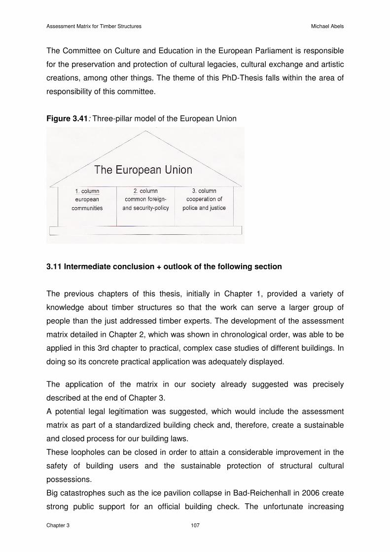
Assessment Matrix for Timber Structures Michael Abels
Chapter 3 107
The Committee on Culture and Education in the European Parliament is responsible
for the preservation and protection of cultural legacies, cultural exchange and artistic
creations, among other things. The theme of this PhD-Thesis falls within the area of
responsibility of this committee.
Figure 3.41: Three-pillar model of the European Union
3.11 Intermediate conclusion + outlook of the following section
The previous chapters of this thesis, initially in Chapter 1, provided a variety of
knowledge about timber structures so that the work can serve a larger group of
people than the just addressed timber experts. The development of the assessment
matrix detailed in Chapter 2, which was shown in chronological order, was able to be
applied in this 3rd chapter to practical, complex case studies of different buildings. In
doing so its concrete practical application was adequately displayed.
The application of the matrix in our society already suggested was precisely
described at the end of Chapter 3.
A potential legal legitimation was suggested, which would include the assessment
matrix as part of a standardized building check and, therefore, create a sustainable
and closed process for our building laws.
These loopholes can be closed in order to attain a considerable improvement in the
safety of building users and the sustainable protection of structural cultural
possessions.
Big catastrophes such as the ice pavilion collapse in Bad-Reichenhall in 2006 create
strong public support for an official building check. The unfortunate increasing

Assessment Matrix for Timber Structures Michael Abels
Chapter 3 108
frequency of natural disaster such as earthquakes or seaquakes (e.g.: Tsunami in
2004), extreme storms [e.g.: Hurricane Kyrill in 2007 or Hurricane Xynthia in 2010] or
the extreme winter (as a result of global climate changes) of the past years, including
more snow than in previous decades, bring about an increased awareness for the
protection of existing buildings in our society.
This aspect was taken up in the current chapter and extensively discussed.
Assessment Matrix for Timber Structures Michael Abels
Chapter 4 1
4. Summary and Outlook
The focus in this concluding section of the PhD-Thesis is on outlooks and future
perspectives regarding the application of the developed assessment matrix. Scientific
and societal benefits of the new assessment matrix should be highlighted.
4.1 Possible matrix programming implementations for a simple data
processing application
It would not be consistent with today’s modern age of electronic data processing, if
the presented forms, checklists and databases were to be manually processed. The
programming implementation of the complete assessment matrix as a computer-
based program would make sense. This form of input would have many advantages.
Besides faster data input, to some extent even on-site using a notebook, data could
be provided to the involved experts (see section 2.4.7) in a simple form, e.g. via
programming interfaces, for further processing.
Furthermore, it would make sense to use already available Internet links in modern
data processing programs for an online platform for timber construction experts. On
such a platform appraisals could for example be stored (on a voluntary basis), if
questions, problems or specifics must be resolved within the expert community. This
platform could also be used to announce regular meetings and symposiums for users
of the assessment matrix.
In comparison, this form of program utilization is already used today by different
program providers.
The described exchange with other users can take place here as well. However,
each program license holder can design his own user interface according to his
requirements. This way he can generate a time advantage by e.g. using individual
sequences from already existing project entries and embedding them in new
sequences.
The goal of different device manufacturers of expert databases (2.4.7) could be to
save their research results in a data format, which could be imported by the still to be
implemented program. An example would be today's exchange between statics and

Assessment Matrix for Timber Structures Michael Abels
Chapter 4 2
CAD (Computer Aided Design) programs. It is of rather large help to the CAD
designer, if he e.g. can import the computation results of a FEM (Finite Element
Method) analysis of a statics program for further processing in his program.
4.2. Continuous research and extension suggestion into non-timber
constructions and transnational studies
A permanent exchange between several wood experts conducting the described
future monitoring activities (see 3.9.2) using the assessment matrix developed and
described in this paper, would be of interest. This exchange, which could be
conducted in the form of a professional quality management system (QM system),
can be the focus of a follow-on research paper based on this dissertation.
Figure 4.1: QM system structure, taken from [17]
The permanent extension or supplementation of checklists and databases could be
of interest and could be the topic of a scientific diploma, bachelor’s or master’s thesis.
Country-specific constructions could be included as well. For example, a database
regarding "timber piers” would be of great interest in the Netherlands.

Assessment Matrix for Timber Structures Michael Abels
Chapter 4 3
In this thesis the assessment matrix is exclusively focused on the German
construction monitoring system (with respect to approval procedures,
building/construction laws and processes etc.). Another suggestion for future
research based on this dissertation would be the preparation of the assessment
matrix for a transnational application.
Qualified work, service and process monitoring is continuously gaining in importance.
These processes could be applied to permanently improve the assessment matrix
developed in this thesis.
In Germany the certification of service providers in different areas, such as architects
and engineering offices, doctors, hospitals etc., by accredited inspection authorities is
increasingly becoming a standard. Purpose of these certifications is to confirm the
existence of a good quality management system. As they are currently still voluntary
qualifications, future user behavior will most likely promote an obligation, as
uncertified institutions will be less frequented.
In the following an inspection certificate is presented confirming the QM qualification.
Figure 4.2: TÜV inspection sticker after passed quality inspection
(TÜV-certified: German Association for Technical Inspection]
From engineering scientific point of view additional research based on this PhD-
Thesis makes sense as well. One obvious option is the extension of the assessment
matrix to non timber constructions. In older buildings almost only brickwork elements
are used in addition to load-bearing timber elements. Similar to the steel and
ferroconcrete constructions in newer buildings, these brickwork elements must be
investigated in more detail within the framework of building monitoring. The contents
in chapter 3 are, as already described, almost generally applicable to all buildings
regardless of the selected material (wood, steel, ferroconcrete and brickwork).

Assessment Matrix for Timber Structures Michael Abels
Chapter 4 4
Thus, as already mentioned several times within this paper, it would be desirable to
extend the assessment matrix in future to the entire building/construction area
regardless of the material used.
Furthermore, it could be investigated if other areas, such as mechanical engineering
or shipbuilding, would benefit from assessment forms already tested in similar areas.
Besides engineering-scientific areas, this thesis also addresses legal topics. One
example would be the discussion of new laws, which should establish building
inspections and require building owners to have their buildings inspected on a regular
basis.
Scientific research with respect to this range of topics could be conducted in the near
future by legal faculties.
In addition, the following question could be discussed in more detail from a
philosophical point of view: "Why do we need a building assessment matrix in our
modern, high-tech societies?" There are already several different philosophical texts
available regarding technology philosophy. For example, the well-known authors
Martin Heidegger and Hans Jonas address in their work basic questions with respect
to technical developments of modern societies. In future philosophical papers, these
viewpoints could critically question the whole purpose of a building inspection using
the here developed matrix.
With that several possible future research topics are listed. They pick up on the topics
of this dissertation and in parts sharpen or promote them.
4.3 Conclusions
As a conclusion of this thesis it can be said that within the scope of this work (in
chapter 2) a matrix was developed, which can be used to assess different load-
bearing timber constructions. Due to the described complexity of the topic, the
currently available assessment matrix cannot cover all possible timber construction
details. The presented case studies show the variety of wood materials used in the
last centuries and that wood will be irreplaceable in the future as well.

Assessment Matrix for Timber Structures Michael Abels
Chapter 4 5
Using the exchange of experiences promoted in chapter 2, the matrix should be
continuously extended. As the common book form is unsuitable, the matrix can only
be implemented as a computer-based program suggested here as well. Based on
continuously ongoing evaluation by the matrix users, the matrix will not only be
optimized, but also continuously adapted to new technical developments.
This thesis is mainly focused on the coherent structure of the assessment matrix,
which brings different terms, such as forms, checklists and databases to life.
In addition to concrete practical applications, the societal benefits of this matrix are
addressed in chapter 3. The author's highest priorities are praxis orientation and
societal benefits. The process sequence described in detail, lends itself to be the
legal basis for an official standardized building inspection. A desirable result could be
a respective EU Directive.
Thus, beside the social relevance of this PhD-Thesis of improving the safety of
building users, the societal relevancy of sustainable preservation of structural cultural
assets is provided as well.
The assessment matrix presented in this dissertation provides an original and
fundamental contribution to the "body of knowledge" of architectural, construction and
engineering science. This thesis closes a sensitive gap of technical-scientific as well
as societal relevancy.
In addition to the positive thoughts and requests in these conclusions, some critical
challenges should be mentioned as well.
Unfortunately, it must be expected that a legal implementation of the developed
building inspection will meet partial resistance. Standard complains about increasing
bureaucracy will most likely be expressed. In the past, after the accident in Bad-
Reichenhall in January 2006, the public was horrified at first. As the first concerns
that technical deficiencies caused the accident, were confirmed in the court
proceedings in November 2008, no renewed requests for building inspections were
expressed. These technical deficiencies could have been detected in advance by
building monitoring.
The author of this dissertation would like to create new awareness by publications in
different print media and the Internet. Furthermore, he hopes that a fast computer
implementation of the assessment matrix will allow the release of a program

Assessment Matrix for Timber Structures Michael Abels
Chapter 4 6
specifically for timber experts as soon as possible. This will further increase the
awareness level.
Beside his commitment to publish the objectives of this thesis within the society and
higher political levels, lobbying is required, pursuing the interest in the legal
implementation of an official building inspection.
For this purpose the definition by Hans Merkle [31] is provided: "The target-oriented
persuasion of decision makers in politics and administration is called lobbying".
Thus, the author of this PhD-Thesis hopes for the support by lobbyists in important
organizations, professional associations, publishers or chambers, in order to promote
a political implementation.
The application of the targeted building inspection to all buildings may be equally
challenging, whereas the assessment matrix in this dissertation only addresses wood
materials - anything else would go beyond the scope of this thesis. Thus, it may be
beneficial to develop in the future, in parallel to possible legal preparations,
assessment matrices for massive building materials: brickwork, concrete and
ferroconcrete constructions, as well as lightweight construction materials: steel etc.
As a legally obligatory building inspection is a global topic of civilized societies, a
worldwide research could have been conducted within the scope of this thesis. Focus
of this research could be the existence of similar procedures on different continents,
which could be used as template for EU member states. For time reasons this was
omitted. Solely the reviewed directive SIA 462 of the Swiss Engineers and Architects
Association picks up on the basics of the topic of this work. However, in order for
Switzerland to benefit from the presented work, a sustainable process and the
necessary assessment matrix must still be developed.
For the practical applicability of this new tool (=assessment matrix) it is necessary to
focus necessary attention on the mostly German standards (and/or if possible
European standards). These standards may have to be modified when applied to
other countries. For this purpose, respective (suggested) follow-on investigations
within the European framework would be useful, necessary and beneficial.
In conclusion, it must be stated that catastrophes like the collapse of the ice pavilion
in Bad-Reichenhall (Germany) can be avoided by the means of the matrix, whose

Assessment Matrix for Timber Structures Michael Abels
Chapter 4 7
application will hopefully be legally required in the near future. Initial spontaneous
thoughts and requests for an official building inspection disappeared from the media
and thus, from public attention.
The public should naturally expect that each building has an inspection sticker (as
proposed in this PhD-Thesis) as the result of a building inspection.
Unfortunately, the society only requests statutory obligatory monitoring forms after
tragedies such as the catastrophe at the Love Parade music event in Duisburg
(Germany, summer 2010). Here, 21 people died after a mass panic. In this case, an
event safety TÜV was requested in the media on the same day.
An official standardized building inspection as suggested in the present thesis, which
is essential for the assessment matrix, would close a large gap in the
building/construction laws.
This PhD-Thesis can provide a significant contribution to our building/construction
culture and thus impact in various social-cultural ways.

Assessment Matrix for Timber Structures Michael Abels
chapter 5 1
5.1 Summary of the PhD-Thesis in different languages:
5.1.1 German summary
Beurteilungsraster für Holzkonstruktionen
Wie kann zukünftig sichergestellt werden, dass Menschen permanent und überall
standsichere und gebrauchstaugliche Gebäude betreten, um sich in diesen sicher
aufhalten, leben und arbeiten zu können?
Damit Katastrophen, wie der Einsturz der Eissporthalle in Bad-Reichenhall
(Deutschland) aus dem Jahr 2006 nie wieder vorkommen, wurde ein Beurteilungs-
raster (auch als Matrix bezeichnet) entwickelt, das zukünftig zur Bewertung von
Bauwerken herangezogen werden soll.
In dem Beurteilungsraster, der in dieser Arbeit schwerpunktmäßig für tragende Holz-
konstruktionen, unabhängig der Größe und des Alters, entwickelt wurde, wurde unter
anderem der aktuelle wissenschaftliche Stand aller üblichen Konstruktionsarten, die
gängigen Untersuchungsmethoden, der Umgang mit eventuellen Schäden und
Kenntnisse über Materialeigenschaften eingearbeitet.
Neben der sozialen Relevanz dient die Beurteilungsmatrix ebenfalls der Erhaltung
von baulichem Kulturgut, auch im Hinblick auf eine nachhaltige Entwicklung, da die
Matrix die Grundlage einer zukünftigen, gesetzlich verpflichtenden Überwachung
jeglicher Gebäude darstellen soll.
Die Matrix wurde bereits über einen längeren Zeitraum an verschiedenen Bauwerken
mit Holzkonstruktionen erprobt. An drei konkreten Gebäuden, die als Fallstudien
dieser Arbeit dienten, konnte das Beurteilungsraster erprobt und abschließend
validiert werden.
Ziel ist es, auf der Basis dieser Arbeit eine neue EU-Richtlinie vorzugeben, die die
regelmäßige Überwachung von Gebäuden in Abhängigkeit von definierten Gebäude-
kategorien im Hinblick auf deren Gebrauchstauglichkeit und Standsicherheit hin
regelt.
Eine abschließend verliehene und am Gebäude für alle sichtbar angebrachte Prüf-
plakette, ähnlich den bekannten deutschen TÜV-Siegeln, zeigt dem Nutzer die
Freigabe für einen bestimmten Zeitraum und könnte bald zur festen Ausstattung aller
Bauwerke gehören, um ein entsprechendes Bewusstsein innerhalb der Bevölkerung
zu wecken.

Assessment Matrix for Timber Structures Michael Abels
chapter 5 2
5.1.2 Dutch summary
Ontwikkeling van een beoordelingsraster voor houtconstructies
Hoe kan in de toekomst worden gegarandeerd dat mensen permanent en overal
stabiele en onverslijtbare gebouwen betreden om er veilig te kunnen vertoeven,
leven en werken?
Opdat catastrofes zoals de instorting van de ijsbaan in Bad-Reichenhall (Duitsland)
in 2006 zich nooit meer zouden kunnen voordoen, werd een beoordelingsraster (ook
wel matrix genoemd) ontwikkeld voor de toekomstige technische beoordeling van
bouwwerken.
Het beoordelingsraster dat in dit werkstuk speciaal werd ontwikkeld voor dragende
houtconstructies, bevat, onafhankelijk van de grootte en leeftijd, onder andere de
huidige wetenschappelijke stand van alle gebruikelijke constructiewijzen, de
gangbare onderzoeksmethodes, de omgang met eventuele schade en kennis over
materiaaleigenschappen.
Naast de maatschappelijke relevantie dient de beoordelingsmatrix ook voor het
behoud van bouwkundig cultuurgoed, ook met het oog op een duurzame
ontwikkeling aangezien de matrix de basis moet vormen voor een toekomstige,
wettelijk verplichte controle van alle gebouwen.
De matrix werd reeds gedurende een langere periode getest op verschillende
bouwwerken met houtconstructies. Voor drie concrete gebouwen, die als casestudy’s
van dit werk dienden, kon het beoordelingsraster worden getest en tot bestluit
worden gevalideerd.
Het doel is om op basis van dit werk een nieuwe EU-richtlijn op te stellen, die de
regelmatige controle van gebouwen op basis van gedefinieerde gebouwcategorieën
met het oog op hun bruikbaarheid en stabiliteit regelt.
Na de test wordt op het gebouw voor iedereen zichtbaar een testplaat aangebracht,
vergelijkbaar met de bekende Duitse TÜV-zegels, waardoor de gebruiker weet dat
het gebouw voor een bepaalde periode is vrijgegeven. Deze plaat zou weldra tot de
vaste uitrusting van alle bouwwerken moeten behoren, om de bevolking hiervan
bewust te maken.

Assessment Matrix for Timber Structures Michael Abels
chapter 5 3
5.1.3 English summary
Assessment Matrix for Timber Structures
How can futurily be secured enabling people to enter stable and utilisable buildings
permanently and everywhere for them to stay, live and work safely?
In order to avoid catastrophies like the collapse of the Bad Reichenhall ice pavillion
(Germany) in 2006, a method of evaluation (= assessment matrix) had been
designed which will be used to assess constructions prospectively.
The matrix developed in this dissertation has its main focus on bearing timber
constructions, independent of size and age.
The actual scientific level of information referring to main methods of contruction,
current examination methods, handling of potential damage and knowledge of
material properties is included in this matrix.
Besides a social relevance the matrix as well serves conservation of structural
cultural assets – in view of a lasting development, too.
It is supposed to be constituted as a foundation of legally obligated monitoring for all
buildings in future.
The matrix has been tested on several buildings with timber construction for a longer
period of time already. Three buildings are case studies of this dissertation and
helped to prove and finally validate the matrix.
Based on the dissertation, it is the aim to create a new EU directive to regulate a
continuous supervision of buildings in dependence on serviceability and stability.
Finally a test badge similar to the german TÜV seals should be attached visibly to
everybody at the building. It displays approval for a certain period of time and could
soon be definite equipment of all buildings to raise awareness within the population.

Assessment Matrix for Timber Structures Michael Abels
chapter 5 4
5.1.4 Spanish summary
Desarrollo de un sistema de evaluación para el mantenimiento
de estructuras de madera valiosas
¿Cómo puede garantizarse a futuro que las personas entren siempre y en todo lugar
en edificios estables y aptos para usar a fin de poder permanecer, vivir y trabajar en
ellos sintiéndose seguras?
Para que no vuelvan a ocurrir catástrofes como el derrumbe del pabellón de
deportes sobre hielo de Bad-Reichenhall (Alemania) en 2006 se desarrolló un
sistema de evaluación (también denominado matriz) al que podrá recurrirse para
calificar construcciones.
En el sistema de evaluación que se desarrolló como tema central de este trabajo
para construcciones portantes de madera independientemente del tamaño y de la
antigüedad, se integraron, por ejemplo, el actual estado científico de todos los tipos
de estructura habituales, los métodos usuales de examen, el manejo de daños
eventuales y conocimientos de las propiedades de los materiales.
Junto con la relevancia social, la matriz de evaluación también sirve para la
conservación del acervo arquitectónico, también en lo que respecta a un desarrollo
sustentable, ya que la matriz representa el fundamento de una vigilancia futura de
todos los edificios y obligatoria por ley.
La matriz ya ha sido probada por un largo período en diversas construcciones con
estructuras de madera. El sistema de evaluación pudo probarse y finalmente
validarse en tres edificios concretos que sirvieron como estudios de casos para este
trabajo.
El objetivo es establecer, sobre la base de este trabajo, una nueva directiva de la UE
que reglamente la vigilancia regular de edificios en función de categorías de edificios
definidas en relación con su aptitud para ser usados y su estabilidad.
Una plaqueta de evaluación que se otorga tras la finalización e instalada de forma
visible para todos, similar a los conocidos sellos alemanes TÜV, que muestra al
usuario la autorización por un período de tiempo determinado y que podría ser parte
prontamente del equipamiento fijo de todas las construcciones para despertar una
conciencia análoga en la población.

Assessment Matrix for Timber Structures Michael Abels
chapter 5 5
5.1.5 French summary
Développement d'une grille d'évaluation pour la préservation
de constructions en bois précieuses
De quelle manière peut-on assurer la stabilité statique et la capacité d'emploi de
bâtiments afin que tout le monde puisse y accéder, rester, vivre et travailler en toute
sécurité ?
Afin de garantir que des catastrophes telles l'effondrement de la patinoire couverte
de Bad-Reichenhall (Allemagne) en 2006 ne se reproduisent plus jamais, une grille
d'évaluation (appelée matrice aussi) a été développée qui pourra être appliquée à
l'évaluation de bâtiments.
Développée pour des constructions en bois portantes avant tout et en dépit de leurs
dimensions et leur âge, la grille d'´évaluation du présent travail comporte entre autres
le savoir scientifique actuel de tous les types de constructions, les méthodes
d'investigation habituelles, la prise en charge de dégâts éventuels et les
connaissances sur les caractéristiques de matériaux.
Outre son importance pour domaine social, la matrice d'évaluation servira également
à la préservation de bâtiments classés patrimoine culturel, compte tenu d'un
développement durable aussi, car la matrice devra constituer la base pour des
contrôles ultérieurs obligatoires et applicables à tous les bâtiments.
La matrice a déjà été testée pour une période prolongée sur de différents bâtiments
avec des constructions de bois. La grille d'évaluation a été testée et validé
définitivement sur trois bâtiments concrets qui servent d'études de cas dans le
présent travail.
Nous visons l'établissement d'une nouvelle directive CE sur la base du présent
travail. Celle-ci devra stipuler le contrôle régulier de bâtiments en fonction de
catégories de bâtiments définies toujours dans l’optique de leur capacité d'emploi et
de leur stabilité statique.
Un label de sécurité contrôlée similaire aux labels du TÜV allemand informera les
usagers sur l'autorisation d'exploitation délivrée pour une période définie. De tels
labels pourront bientôt faire partie intégrante de tous les bâtiments afin de
sensibiliser la population.

Assessment Matrix for Timber Structures Michael Abels
chapter 5 6
5.1.6 Italian summary
Sviluppo di una griglia di valutazione per la conservazione di costruzioni in
legno pregiate
Come si può assicurare in futuro che le persone entrino sempre e dappertutto in
edifici stabili e idonei all’uso per potervi soggiornare, vivere e lavorare?
Affinché non si ripetano catastrofi come quella avvenuta a Bad-Reichenhall
(Germania) nel 2006 dove crollò il tetto del palaghiaccio, è stata sviluppata una
griglia di valutazione (chiamata anche "matrice") che dovrà essere utilizzata in futuro
per valutare gli edifici.
Nella griglia di valutazione, che in questo lavoro è stata sviluppata ponendo
l’attenzione sulle costruzioni portanti in legno, indipendentemente dalle dimensioni e
dall’età, sono stati inseriti, fra le varie cose, lo stato attuale delle conoscenze
scientifiche su tutti i tipi tradizionali di costruzione, i metodi di analisi in uso, la
gestione di eventuali danni e le conoscenze sulle caratteristiche dei materiali.
Oltre ad avere un’importanza a livello sociale, la griglia di valutazione serve alla
conservazione del patrimonio edile anche in vista di uno sviluppo sostenibile, in
quanto la griglia deve rappresentare la base per il controllo futuro, imposto dalla
legge, di tutti gli edifici.
La griglia è già stata collaudata per un periodo di tempo piuttosto lungo per la
valutazione di diversi edifici con costruzioni in legno. La griglia di valutazione è stata
collaudata su tre edifici concreti, che sono stati utilizzati come studi di caso per
questo lavoro, ed infine validata.
L’obiettivo è quello di creare, sulla base di questo lavoro, una nuova Direttiva UE che
regoli il controllo degli edifici sulla base di categorie predefinite di edifici valutandone
l’idoneità all’uso e la stabilità.
Un contrassegno conferito al termine dei controlli eseguiti e fissato sull’edificio in
modo da risultare visibile a tutti (simile al famoso sigillo TÜV tedesco) mostra agli
utenti l’abilitazione per un certo periodo di tempo e potrebbe presto diventare un
elemento fisso di tutti gli edifici al fine di sensibilizzare la popolazione.

Assessment Matrix for Timber Structures Michael Abels
chapter 5 7
5.2 List of literature = references
[1] Schulze, Horst, Holzbau: Wände – Decken – Bauprodukte - Dächer – Konstruktionen – Bauphysik - Holzschutz, 3. Auflage, B.G. Teubner Stuttgart, Leipzig, 2005 [2] Erler, Klaus, Alte Holzbauwerke – Beurteilen und Sanieren, 3.Auflage, Verlag Bauwesen, Berlin, 2004 [3] Böttcher, Detlef, Erhaltung und Umbau Historischer Tragwerke, Ernst & Sohn Verlag, Berlin, 2000 [4] Wendehorst, Reinhard, Bautechnische Zahlentafeln, 33. Auflage, B.G. Teubner, Stuttgart 2009 [5] Lißner, Karin & Rug, Wolfgang, Holzbausanierung, Springer-Verlag, Berlin Heidelberg, 2000 [6] Mönck, Willi & Erler, Klaus, Schäden an Holzkonstruktionen, 4. Auflage, Huss-Medien Verlag Bauwesen, Berlin, 2004 [7] Kraft / Pribbernow, Handbuch der Holzprüfung, Verlag Bau + Technik, Düsseldorf, 2006 [8] Herzog, Natterer, Schweitzer, Volz, Winter, Holzbauatlas, 4. Auflage, Birkhäuser Edition Detail, Basel, Schweiz, 2003 [9] Universität Karlsruhe, Ingenieurholzbau Karlsruher Tage - Tagungsband, Bruderverlag, Karlsruhe, 2007 [10] Studiengemeinschaft Holzheim e.V./ CTT Council of Timber Technology, Leitfaden zu einer ersten Begutachtung von Hallentragwerken aus Holz, Wuppertal, 2006 [11] R. Halasz u. C. Scheer, Holzbau- Taschenbuch, Band 1, 9. Auflage, Verlag Ernst & Sohn, Berlin, 2009
[12] P. Frech, E.h.K. Möhler, Beurteilungskriterien für Rißbildungen, in „Bauen mit Holz“, Bruderverlag, Karlsruhe, 1987 [13] Fischer, H. B.; Rinn, F.: Bestandsplan mit farbiger Zustandskartierung. In: Bauen mit Holz, Bruderverlag, Karlsruhe, 11 (1996) S. 850-856 [14] W. Rug u. A. Seemann, Festigkeit von Altholz, Holztechnologie – Leipzig 29, 1988 [15] Weiß, B., Wagenführ, A., Kruse, K., Beschreibung und Bestimmung von Bauholzpilzen, Verlag Weinbrenner, Leinfelden, 2000

Assessment Matrix for Timber Structures Michael Abels
chapter 5 8
[16] W. Rug, Bauforschungsberichte der Bundesminister für Raumordnung, Bauwesen und Städtebau, Erarbeitung eines Querschnittsberichtes über sanierungsbedürftige Wohnbauten in Mischbauweise in der ehemaligen DDR, IRB- Verlag, Berlin,1992 [17] R. Stockmann, Evaluation und Qualitätsentwickelung – Eine Grundlage für wirkungsorientiertes Qualitätsmanagement, Waxmann Verlag, Münster, 2006 [18] K. Winter und H. Held, In- situ- Prüfverfahren für verbautes Holz, Bau-Zeitung 50, Berlin, 1996 [19] K. Kempe, Holzschädlinge: Holzzerstörende Pilze u. Insekten an Bauholz - Vermeiden – Erkennen – Bekämpfen, 3. Auflage, Fraunhofer IRB- Verlag, Stuttgart, 2003 [20] H. Sachße, Wir bestimmen Holz heimischer Bäume, Neumann Verlag, Radebeul, 1958 [21] F. Ekardt, Das Prinzip Nachhaltigkeit, Generationengerechtigkeit und globale Gerechtigkeit, Beck- Verlag, München 2005 [22] K. Lißner u. W. Rug, Ergänzung bzw. Präzisierung der für die Nachweisführung zur Stand- u. Tragsicherheit sowie Gebrauchstauglichkeit von Holzkonstruktionen in der Altbausubstanz maßgebenden Abschnitte der DIN 1052, Fraunhofer IRB- Verlag, Stuttgart, 2005

Assessment Matrix for Timber Structures Michael Abels
chapter 5 9
5.3 Notes of literature
[23] Jonas, Hans, Das Prinzip Verantwortung: Versuch einer Ethik für die technologische Zivilisation, Suhrkamp, Frankfurt, 1984 [24] Böttcher, Detlef, Stützenfreie Dächer, Ernst & Sohn – Verlag für Architektur & technische Wissenschaften, Berlin 1986 [25] Erler, Klaus, Holz im Außenbereich, Birkhäuser Verlag, Basel, Schweiz, 2002 [26] Umberto Eco, Wie man eine wissenschaftliche Abschlussarbeit schreibt, 12. Auflage, C.F. Müller Verlag, Heidelberg, 2007 [27] Jalil H. Saber Zaimian, Ein Model zur baulichen Transformation, bouwstenen 93, TU Eindhoven, 2005 [28] Niemz, P. und Pichelin F., Einfluss der Holzfeuchte auf die Verklebungsgüte, Holz- Zentralblatt, Zürich, 2009(6): p. 164,166
[29] Reinhard Stockmann, Evaluation und Qualitätsentwickelung – Eine Grundlage für wirkungsorientiertes Qualitätsmanagement, Waxmann Verlag, Münster, 2006 [30] Martin Heidegger, Sein und Zeit, 19. Auflage, Niemeyer, Tübingen, 2006
[31] Hans Merkle, Lobbying - Das Praxishandbuch für Unternehmen, Primus- Verlag, Darmstadt, 2003 [32] Winter Stefan, Starke Leichtgewichte – Zur Tragwerksplanung mit Doppel-T- Trägern aus Holz und Holzwerkstoffen, Die neue quadriga, 2001 [33] Hubel, Achim, Denkmalpflege: Geschichte, Themen, Aufgaben. Eine Einführung, Reclam, Stuttgart, 2006 [34] Peter Klein, Dieter Eckstein, Die Dendrochronologie und ihre Anwendung, In: Spektrum der Wissenschaft, Heidelberg, 1988 [35] Görlacher, R., Die Dendrochronologie von altem Konstrutkionsholz: Bestimmung des Elastizitätsmoduls, In: Bauen mit Holz, Bruderverlag, Karlsruhe, 8/1991 [36] Energieargentur NRW, Luftdichte Gebäudehülle – Qualitätssicherung durch Blower- Door Messung, Wuppertal, 2010 [37] Hauser, Gerd, Stiegel, H., Wärmebrücken- Atlas für den Holzbau, Bauverlag, Wiesbaden, 1992

Assessment Matrix for Timber Structures Michael Abels
chapter 5 10
[38] Hans Joachim Blaß, Volker Krämer, Lastverteilung, Tragwirkung und Verformungsverhalten für nachgiebig miteinander verbundene Brettstapelelemente, Fraunhofer IRB Verlag, 2002 [39] Stefan Winter, Heinrich Kreuzinger, Peter Mestek, Holzbau der Zukunft, Teilprojekt 15, Flächen aus Brettstapeln, Brettsperrholz und Verbundkonstruktionen, Fraunhofer IRB Verlag, 2009 [40] Umweltbundesamt, Leitfaden zur Ursachensuche und Sanierung bei Schimmelpilzwachstum in Innenräumen („Schimmelpilzsanierung - Leitfaden“), Dessau, 2005 [41] Andreas Hasenstab, Integritätsprüfung von Holz mit dem zerstörungsfreien Ultraschallechoverfahren, Dissertation, TU Berlin, Berlin, 2006 [42] Weiner, J.: Steinzeitliche Zimmermannskunst. In: Bauen mit Holz, Bruderverlag Karlsruhe, 4 (1992) S. 340 – 348 [43] Irmschler, H.-J.: Allgemeine bauaufsichtliche Zulassungen im Holzbau, Bauen mit Holz, Bruderverlag, Karlsruhe, 11/1993. [44] Krabbe, E.; Kintrup, H.: Gelenkkonstruktionen bei Durchlaufträgern mit Gelenken. In: HSA, Folge 2, 11/1977 [45] Colling, F.; Ehlbeck, J.: Tragfähigkeit von Kleinzinkenverbindungen im Holzleimbau, Bauen mit Holz, Bruderverlag, Karlsruhe, 7/1992. [46] Hahn, A., et al., Verklebung von Holz mit 1K-PUR-Klebstoffen. Holz-Zentralblatt, 2009(17): p. 421-422. [47] Schrödter, A. and P. Niemz, Untersuchungen zum Versagensverhalten von Klebfugen bei erhöhter Temperatur und Luftfeuchte. Holztechnologie, 2006. 47: p. 24-32. [48] Niemz, P., H. Poblete, and J. Cuevas, Untersuchungen zum Einfluss der Klimabelastung auf die Festigkeit von keilverzinktem Holz. Holzforschung und Holzverwertung, 2001(4): p. 81-82 [49] Niemz, P, A. Hänsel, and U. Wendt, Untersuchungen zum Verformungs- und Bruchverhalten von Holzwerkstoffen, in VIII. Symposium Verformung und Bruch. 1988: Magdeburg, Germany. [50] Möhler, K.; Siebert, W.: Untersuchungen zur Erhöhung der Querzugfestigkeit in gefährdeten Bereichen. In: HSA, Folge 8, 2/1987 [51] Deinhard, M.: Die Tragfähigkeit historischer Holzkonstruktionen. In: Bauen mit Holz, Bruderverlag, Karlsruhe, 1-3 (1963); Dissertation, Bruderverlag, Karlsruhe, 1963

Assessment Matrix for Timber Structures Michael Abels
chapter 5 11
[52] Walthelm, U.: Experimentell ermittelte Festigkeits- und Brucheigenschaften von Holz in alten Bauwerken. In: Bauingenieur, Springer-Verlag, Berlin, 63/6 (1988) S. 273-275 [53] Niemz, P., Qualitätskontrolle mittels holzphysikalischer Eigenschaften. Holz-Zentralblatt, 1992(8): p. 106-108. [54] Mönck, W.: Holzzerstörung bei freitragenden Konstruktionen von Mineraldünger-Lagerhallen. Holztechnologie, Leipzig 16 (1975) 1, S. 22-28 [55] Clausnitzer, K.-D., Historischer Holzschutz, 2. Auflage ÖkobuchVerlag, Staufe, 2000 [56] Göckel, H.: Konstruktiver Holzschutz, Bauen mit Holz ohne Chemie, Beuth Verlag, Werner Verlag, Berlin/ Düsseldorf, 1996 [57] Kothe, E. : Auswirkung von Holzschäden durch Pilze und Insekten auf die Standsicherheit von Holzbauwerken - Eine Bestandsaufnahme. Bautechnik 75/8, S. 552- 558, 1998 [58] Bruhn, S. et al.: Serpula lacrimans; Der Chloridgehalt im Holz als Indikator für das Vorkommen von Echtem Hausschwamm. Bausanierung 10, S. 48- 49, 1996 [59] Mislin, M.: Die Geschichte der Baukonstruktion und Bautechnik. Band 1: Antike bis Renaissance, Band 2: Barock bis Neuzeit, Düsseldorf, 1997 [60] Imhof, M.: Historisches Fachwerk: Zur Architekturgeschichte im 19. Jahrhundert. Bamberg, 1996 [61] Bindung, G.: Das Dachwerk auf Kirchen im deutschen Sprachraum vom Mittelalter bis zum 18. Jahrhundert. München, 1996 [62] Ahnert, R.; Krause, K.-H.: Typische Baukonstruktionen von 1860-1960 zur Beurteilung der vorhandenen Bausubstanz. Bd. 1, 6.Aufl. Berlin: Verlag Bauwesen, 2000 [63] Möhler , K.; Mistler, L.: Ausklinkungen am Endauflager von Biegeträgern. In: HSA, Folge 4, 11/1979. [64] Schulze, H.: Hausdächer in Holzbauart. Konstruktion, Statik, Bauphysik. Werner-Verlag, Düsseldorf, 1987 [65] Großmann, G. U.: Der Fachwerkbau in Deutschland. DuMont Buchverlag, Köln, 1998 [66] Heimeshoff, B.: Bemessung von Holzstützen mit nachgiebigem Fußanschluss. In: HSA, Folge 3, 5/1979. [67] Bernert, K.: Umgebindehäuser. Verlag für Bauwesen, Berlin, 1988

Assessment Matrix for Timber Structures Michael Abels
chapter 5 12
[68] Heimeshoff, B.; Eglinger, W.: Einspannung von Stützen aus Brettschichtholz durch Verguss in Betonfundamente. Bauen mit Holz, Karlsruhe 85 (1983) 9,S. 558-561 [69] Fritzen, K. u. Kollektiv: Holzrahmenbau- Praxis. Planung, Beispiele, Kosten. Bruderverlag Karlsruhe, 1990 [70] Mönck, W.: Bauschäden an Satteldachbinder in Nagelbauweise. Bauzeitg., Berlin 34 (1980) 5, S. 257-260 [71] Kessel, M.; Augustin, R.: Untersuchungen über Tragverhalten von Verbindungen mit Eichenholznägeln. In: Bauen mit Holz, Bruderverlag, Karlsruhe, 92/4 (1990) S. 246-250 [72] Kersken- Bradlay, M.: Bemessung von Verbindungen nach nationalen und internationalen Regeln. Tagungsband der 6. Brandschutz- Tagung. Würzburg, 1993 [73] Gärlacher, R.; Kromer, M.: Tragfähigkeit von Versatzanschlüssen in historischen Holzkonstruktionen. In: bauen mit Holz 93 (1991), S. 164-169. [74] Ehlbeck, K.; Schlager, M.: Hirnholzdübelverbindungen bei Brettschicht und Nadelvollholz. Bmh 6/1992. [75] Ehlbeck, J.; Göhrlacher, R.: Querzuggefährdete Anschlüsse mit Nagelplatten. HSA, Folge 8, 2/1987. [76] Möhler, K.; Herröder, W.: Holzschrauben oder Schraubnägel bei Dübelverbindungen. In: HSA, Folge 5, 4/1980. [77] Dunky, M. and P. Niemz, Holzwerkstoffe und Leime Technologie und Einflussfaktoren. 2002, Berlin: Springer- Verlag, Berlin, 2002 [78] Niemz, P. and K. Allenspach, Untersuchungen zum Einfluss von Temperatur und Holzfeuchte auf das Versagensverhalten von ausgewählten Klebstoffen bei Zugscherbeanspruchung. Bauphysik, 2009. 31(5): p. 296-304. [79] Müller, F. P.: Berechnung und Konstruktion von Glockentürmen. Berlin: Verlag Ernst & Sohn, 1968 [80] Otzen, R.: Die statische Berechnung der Zollbau-Lamellendächer. In: Der Industriebau, VIII/IX (1923) S. 96-103 [81] Groeger, H.: Bauphysik in der Bauwerkserhaltung. In: Tagung Denkmalpflege und Bauwerkserhaltung, Baunatal/ Kassel, 1994 [82] P. Niemz, Holz, Physik des Holzes und der Holzwerkstoffe, DRW- Verlag, Leinfelden, 1993 [83] Schulze, H.: Holz in unbelüfteten Konstruktionen des Wohnungsbaus, Aachener Bausachverständigentage, Bauverlag, Gütersloh, 1993

Assessment Matrix for Timber Structures Michael Abels
chapter 5 13
[84] Künzel, H.; Großinsky, T.: Das unbelüftete Sparrendach – Messergebnisse, Folgerungen für die Praxis. Aachener Bausachverständigentage, Bauverlag, , Gütersloh, 1993 [85] Cziesielski, E.: Belüftete Dächer und Wände – Stand der Technik. Aachener Bausachverstädigentage, Bauverlag, Gütersloh, 1993 [86] Pohlenz, R.: Planen und Bauen im Bestand – Schallschutz bei der Altbausanierung. Deutsches Architekturblatt 10, S. 1298-1300, 1998 [87] Krämer, G.: Holzbalkendecken aufgerüstet – Sanierung bestehender Holzbalkendecken unter Schall- und Brandschutzaspekten. Bauen mit Holz 12, S. 865- 871, 1997 [88] Leimer, H.- P.: Bestimmung der Feuerwiderstandsdauer von Fachwerkwänden. Internationale Zeitschrift für Bauinstandsetzen 4, S. 113- 124, 1998 [89] Kordina, K.; Meyer- Ottens, C.: Holz-Brandschutz-Handbuch. Deutsche Gesellschaft für Holzforschung e.V., Ernst & Sohn Verlag, Berlin, 2009 [90] Jenisch, R.: Tauwasserschäden, Schadenfreies Bauen, Band 16, IRB- Verlag, Stuttgart, 1996 [91] Lamers, R.: Nachträglicher Wärmeschutz im Baubestand. Aachener Bausachverständigentage, Bauverlag, Gütersloh, 1996 [92] Niemz, P., S. Clauss, and Y. Herbers, Zerstörungsfreie Bestimmung des E-Moduls von Fichtenholz, Holztechnologie, 50(4): p. 19-25, Dresden, 2009 [93] Niemz, P. and F. Bächle, Bohrwiderstands- und Schallgeschwindig-keitsmessung. Untersuchungen zur Erkennbarkeit von Fäule in Fichtenholz. Stadt und Grün, p. 52-55, Patzer- Verlag, Berlin, 2002 [94] G. Geburtig, Brandschutz im Bestand: Holz, Fraunhofer IRB- Verlag, Stuttgart, 2009
[95] Niemz, P., Innere Defekte von Bäumen in Holz mit Schall bestimmt. Holz-Zentralblatt, 126(12): p. 169-171, DRW- Verlag, Leinfelden, 2001 [96] Niemz, P., et al., Untersuchungen zur Holzartendifferenzierung mit Hilfe der Infrarot-Spektroskopie. Teil2. Holzforschung und Holzverwertung, 41(2): p. 22-26, Wien, 1989 [97] Rinn, F.: Chancen und Grenzen bei der Untersuchung von Konstruktionshölzern mit der Bohrwiderstandsmethode. In: Bauen mit Holz, Bruderverlag, Karlsruhe, 9 S.2745 – 2748, 1992 [98] Zahorszki, F.: Infrarotthermographie – Bauschäden finden und Energie sparen. In: Bauzeitung, Berlin, 50/4 S. 50-51, 1996

Assessment Matrix for Timber Structures Michael Abels
chapter 5 14
[99] Schwab, E. et al.: Bohrkerne zur Untersuchung der Festigkeit hölzerner Rammpfähle. In: bauen mit Holz, Bruderverlag, Karlsruhe, 1982 [100] Rinn, F., Technische Grundlagen der Impuls – Tomographie, Baumzeitung (8): 29-31, Braunschweig, 2003 [101] Bröker, F.- W.; Kühl, J.: Untersuchungen zu zellulosegefüllten Epoxidharzen zur Sanierung breiter Risse im Bauholz. In: Bauen und Holz 9, Bruderverlag Karlsruhe, 1991 [102] Mann, W.: Verformungen als Schadensursache im Holzbau. Deutsche Bauzeitschrift, S. 1725-1727, Güterloh, 1980 [103] Erler, K.: Risse im Bauholz. In: Mikado, Bad Kissingen, H. 4 2001, S. 36-39 und H. 5 2001 S. 32-36 [104] Blaß, H. J.; Ehlbeck, J.; Kührt, J.: Wiederherstellung der Tragfähigkeit von gerissenen Brettschichtholzträgern. In: bauen mit Holz 94, S. 118-121, 1992 [105] Balkowski, F.D.. Sanierung historischer Bausubstanz. Verlagsgesellschaft Rudolf Müller, Köln, 1981 [106] Schmidt, H.: Erhaltungskonzepte. Methoden u. Maßnahmen zur Sicherung historischer Bauwerke, W. Ernst u. Sohn, Berlin, 1990 [107] Kastner, R. H.: Gebäudesanierung (Analyse, Planung, Durchführung). München: Callwey, 1983 [108] Gerner, M.: Historische Häuser erhalten und Instandsetzen. 2.Aufl., Augustus Verlag, München, 1990 [109] Einbau von Bädern auf Holzbalkendecken. Bauzeitg., Berlin, S. 78-82, 1983 [110] Deinhard, M., Systembedingte Schäden an Dachwerken, eine Darstellung historischer Dachkonstruktionen und ihre Schwachpunkte. Deutsches Zentrum für Handwerk und Denkmalpflege (DZHD), Fulda, 1996 [111] Cramer, J.: Untersuchung von Fachwerkbauten auf thermographischer Basis. Bauen mit Holz, Karlsruhe 82, S. 59, 1980 [112] Fiedler, W., Turner, S., Bibliographie zum Recht des Internationalen Kulturgüterschutzes, Walter de Gruyter, Berlin, 2003 [113] Ehlbeck, J., Holzbau-Kalender 2002, Bruder Verlag, Karlsruhe, 2001 [114] Brünninghoff, H., Kreuzinger, H., u.a., Methodes for the Assessment of Timber Structures, TUM, München

Assessment Matrix for Timber Structures Michael Abels
chapter 5 15
5.4 Named internet pages
[W1] URL: http://www.123recht.net/article.asp?a=33797&ccheck=1 (04.08.2010)
[W2] URL: http://www.erzbistum-koeln.de (10.09.2009) [W3] URL: http://www.denkmalpflege.lvr.de (04.08.2010) [W4] URL: http://www.tuv.com (04.08.2010) [W5] URL: http://www.aknw.de (04.08.2010) [W6] URL: http://www.ikbaunrw.de (04.08.2010) [W7] URL: http://www.europarl.europa.eu (04.08.2010) [W8] URL: http://www.bam.de/microsites/zfp-kompendium/verz/findex_abc.html (04.08.2010) [W9] URL: http://www.DGZfP.de (10.08.2010) [W10] URL: http://www.informationsdienst-holz.de (10.08.2010) [W11] URL: http://www.din.de (10.08.2010) [W12] URL: http://www.mpa.uni-stuttgart.de/organisation/fb_1/abt_12/listen_
und_verzeichnisse/klebstoffliste-II-Stand-27-02-2009.pdf (20.08.2010)
[W13] URL: http://www.ikbaunrw.de/Fachlisten/Fachliste_21-08-2010_suw.pdf
(20.08.2010)
[W14] URL: http://e-collection.ethbib.ethz.ch/eserv/eth:29823/eth-29823-01.pdf
(10.08.2010)

Assessment Matrix for Timber Structures Michael Abels
chapter 5 16
5.5 Mentioned regulations and standards [S1] DIN-EN 309, Spanplatten – Definitionen und Klassifizierung, CEN, 04.2005 [S2] DIN EN 335-1, Dauerhaftigkeit von Holz und Holzprodukten – Definition der Gebrauchsklassen – Teil 1: Allgemeines, CEN, 10.2006 [S3] DIN-EN 338, Bauholz für tragende Zwecke- Festigkeitsklassen, CEN, 02.2010 [S4] DIN-EN 350-2, Dauerhaftigkeit von Holz und Holzprodukten – Natürliche Dauerhaftigkeit von Vollholz, Teil 2: Leitfaden für die natürliche Dauerhaftigkeit und Tränkbarkeit von ausgewählten Holzarten von besonderer Bedeutung in Europa, CEN, 10.1994 [S5] DIN 1052, Entwurf, Berechnung und Bemessung von Holzbauwerken, CEN, 08.2003 [S6] DIN 1055-100, Einwirkungen auf Tragwerke, Teil 100: Grundlagen der Tragwerksplanung, Sicherheitskonzept und Bemessungsregeln, CEN, 01.2007 [S7] DIN-EN 1991-1-1ff Eurocode 1, Einwirkungen und Tragwerke, CEN 10.2002 [S8] DIN-EN 1995, Eurocode 5, Entwurf- Berechnung und Bemessung von Holzbauten, CEN, 04.2010 [S9] DIN EN 1998, Eurocode 8, Auslegung von Bauwerken gegen Erdbeben, 04.2006 [S10] DIN 4074-1ff, Sortierung von Holz nach der Tragfähigkeit, DIN, 06/2009 [S11] DIN EN ISO 9001, Qualitätsmanagementsysteme- Anforderungen, DIN, 2008(12)
[S12] DIN 14081-1ff, Nach Festigkeit sortiertes Bauholz für tragende Zwecke mit rechteckigem Querschnitt, 07/2010 [S13] Normenreihe DIN 68800, Holzschutz - Teil 1: Allgemeines, -Teil 2: Vorbeugende bauliche Maßnahmen im Hochbau, -Teil 3: Vorbeugender Schutz von Holz mit Holzschutzmitteln, - Teil 4: Bekämpfungs- und Sanierungsmaßnahmen gegen Holzzerstörende Pilze und Insekten, CEN, 11.2009 [33] SIA 462, Beurteilung der Tragsicherheit bestehender Bauwerke, Schweizerischer Ingenieur- und Architekten- Verein, Zürich, 1994 [S14] Bellmann, H. u. a. (1992): Holzschutz, Eine ausführliche Erläuterung zur DIN 68 800, T 3. Beuth- Verlag, Berlin

Assessment Matrix for Timber Structures Michael Abels
chapter 5 17
[S15] KOMO attest – met – productcertificaat, Verlengde / Houtkonstrukties, Beta polymeer chemisch restauratiesysteem von Conserduc / Renofors, 01/1994 [S16] Deutsches Institut für Bautechnik, Allgemeine bauaufsichtliche Zulassung für die Bauart zur Sanierung schadhafter Holzbauteile mit dem Beta-Verfahren, Berlin, 2001 [S17] SIA 462, Beurteilung der Tragsicherheit bestehender Bauwerke, Schweizerischer Ingenieur- und Architekten- Verein, Zürich, 1994 [S18] Energieeinsparverordnung - EnEV, Verordnung über energiesparenden Wärmeschutz und energiesparende Anlagetechnik bei Gebäuden, 29.4.2009 [S19] Richtlinie 2002/91/EG des europäischen Parlaments und des Rates vom 16.12.2002 über die Gesamtenergieeffizienz von Gebäuden, 2002 [S20] Bauordnung für das Land Nordrhein- Westfalen = BauO NRW, 06/2000 [S21] Verwaltungsvorschrift zur Landesbauordnung – VV BauO NRW, Runderlass des Ministeriums für Städtebau und Wohnen, Kultur und Sport, 12.10.2000 [S22] Denkmalschutzgesetz Nordrhein- Westfalen (DSchG), 25.11.1997 [S23] Deutsches Strafgesetzbuch (StGB), 2.10.2009 [S24] Deutsches Bürgerliches Gesetzbuch (BGB), 28.9.2009

Assessment Matrix for Timber Structures Michael Abels
chapter 5 18
5.6 Notes of literature „Informationsdienst Holz“ (= IDH)
Literature: IDH chapter
1.) Holzbau - Handbuch
Holzbauzeichnungen 0,2,1
Entwurfsüberlegungen bei Holzbauten 1,1,1
Überdachungen mit großen Spannweiten 1,1,2 1.5.7
Bauen mit Holzwerkstoffen 1,1,3 1.2.1.3
Holzbausysteme 1,1,4
Mehrzweckhallen (08/96) 1,2,1 1.5.7
Mehrzweckhallen (07/01) 1,2,1/1 1.5.7
Sport- und Freizeitbauten 1,2,2 1.5.7
Zukunftsmodell Turn- und Mehrzweckhalle 1,2,3
Mehrgeschossiger Wohnungsbau in Holz 1,3,1 1.5.5
Niedrigenergiehäuser – Bauphysikalische Entwurfsgrundlage 1,3,2 1.7.4
Niedrigenergiehäuser – Planungs- und Ausführungsempfehlungen 1,3,3 1.7.4
Holzrahmenbau 1,3,4 1.5.5
Das Wohnblockhaus 1,3,5 1.5.4
Holzskelettbau 1,3,6 1.5.4
Skelettbaudetails, Teil 1: Gestalten-Bauen 1,3,7
Skelettbaudetails, Teil 2: Bauphysik-Haustechnik-Lebensdauer 1,3,8
Familienhäuser 1,3,9 1.5.5
Das Passivhaus – Energieeffizientes Bauen 1,3,10 1.7.4
Lärmschutzwände 1,6,1 1.7.1
Konstruktion von Anschlüssen im Hallenbau 1,7,2 1.5.8
Planungsgrundlagen; Industrie- und Gewerbebauten 1,8,1 1.5.7
Holzbauten bei chemisch-aggressiver Beanspruchung –
Aggressive Belastung 1,8,2 1.4.2
Industrie- und Gewerbebauten 1,8,3 1.5.7

Assessment Matrix for Timber Structures Michael Abels
chapter 5 19
Planung, Konstruktion, Berechnung (Brücken) 1,9,1 1.5.7
Details für Holzbrücken 1,9,2 1.5.7
QS – Holzplattenbrücken 1,9,4 1.5.7
Außenverkleidung aus Vollholz 1,10,1 1.2.3.2
Holzfassaden für die Gebäuderenovierung 1,10,2
Holz-Glas-Fassaden 1,10,3
Außenbekleidung mit Holzwerkstoffplatten 1,10,4 1.2.1.3
Modernisierung von Altbauten 1,14,1 1.1.1
Nachträglicher Dachgeschossausbau 1,14,3 1.5.3
Brettstapelbauweise 1,17,1 1.5.6
Nagelplatten-Konstruktionen 1,17,4 1.5.8.2
Holz-Glas-Konstruktionen und Holz-Wintergärten 1,18,1
Holz im Außenbereich 1,18,2 1.4
Bemessung nach Eurocode5-1-1 2,1,1 1.1.2 +
1.6
Verbindungsmittel; Verbindungen nach DIN 1052, nach DIN 18800 2,2,1 1.5.8 +
1.5.8.2
Genauere Nachweise – Sonderbauarten 2,2,2 1.5.8
Berechnungsgrundlagen-Schalung, Lattung (Dachbauteile) 2,3,1 1.5.3
Dachbauteile, Hausdächer 2,3,2 1.5.3
Verbände und Abstützungen (Grundlagen, Regelnachweise) 2,12,1 1.6.5
Verbände und Abstützungen (Genauere Nachweise) 2,12,2 1.6.5 +
1.5.4
Aussteifungsverbände von NP – Konstruktionen 2,12,3 1.6.5
Holzhäuser – Werthaltigkeit und Lebensdauer 3,1,2 1.5.5
Nassbereiche in Bädern 3,2,1 1.4.1
Holzbau und die Energiesparverordnung 3,2,2 1.7.4
Innovative Haustechnik im Holzbau 3,2,3
Wärmebrücken 3,2,6 1.7.4

Assessment Matrix for Timber Structures Michael Abels
chapter 5 20
Grundlagen des Schallschutzes 3,3,1 1.7.1
Schalldämmende Holzbalkendecken- und Brettstapeldecken 3,3,3 1.5.6 +
1.7.1
Grundlagen des Brandschutzes 3,4,1 1.7.3
Feuerhemmende Holzbauteile (F30-B) 3,4,2 1.7.3
Brandschutz im Holzbau – gebaute Beispiele 3,4,3 1.7.3
Bauliche Empfehlungen (Holzschutz) 3,5,1 1.4
Baulicher Holzschutz 3,5,2 1.4.1
Konstruktionsvollholz 4,2,1 1.2.1.1
Einheimische Nutzhölzer und ihre Verwendung 4,2,2 1.2.1 +
2.5.1
Konstruktive Vollholzprodukte 4,2,3 1.2.1.1
Konstruktive Vollholzprodukte, Ergänzungsblatt Massivholz 4,2,3/1 1.2.1.1
Konstruktive Holzwerkstoffe 4,4,1 1.2.1.3
Baufurniersperrholz aus Buche 4,4,2 1.2.1.3
Dämmstoffe aus nachwachsenden Rohstoffen 4,5,1 1.2.3.2
+ 1.7.4
Holzfaserdämmstoffe 4,5,2 1.2.3.2
+ 1.7.4
Dielenböden 6,4,1
Parkett 6,4,2
Fenster, Grundlagen, Konstruktionen, Details 6,7,2 1.7.4
Ausschreibung von BS – Holz 7,2,1 1.2.1.2
Bauwerkserhaltung – Erneuerung von Fachwerkbauten 7,3,1 1.5.4 +
2.6.4
2.) Allgemeines Schriften
Holzbau – Die Qualität hat ein Zeichen 1.2.1
Ökobilanzen Holz – Fakten lesen, verstehen und Handeln 1.1.1
Erstellung von Ökobilanzen – Hilfestellung für Unternehmen und

Assessment Matrix for Timber Structures Michael Abels
chapter 5 21
Entscheidungsträger
Wohnungsgesundheit im Holzbau – Raumklima, Bauphysik,
Baustoffe
1.2.1 +
1.2.1 +
1.5
Entsorgung von schutzmittelhaltigen Hölzern und Rohstoffen-
Grundlagen, Praktische Empfehlungen
Holz-Rohstoff der Zukunft- nachhaltig verfügbar und umweltgerecht
Das Holzhaus-Argumente für den Holzbau 1.5
Neuer Wohnwert mit Holz 1 – Modernisierung: Boden, Wand, Decke
und Fassade 2.6
Neuer Wohnwert 2 – Modernisierung: Ausbau, Anbau 2.6
Dachausbau mit Massivholz – Ausbauideen 1.5.3 +
2.6.3
Tipps für den Umgang mit Massivholz – Ausbauanleitungen für
Wand, Decke, Dach, Bad
Profilholz für Wand, Decke und Fassade – Beispiele für
verschiedene Anwendungen
Fenster- Fensterelemente, Grundlagen, Ausführungsbeispiele
Holzfensterprofile, lamelliert, keilgezinkt – Holz,
Fensterkonstruktionen, Anforderungen
Argumente für das Holzfenster
Haustüren für Wohnbauten – Konstruktionen, Beispiele
Sanieren und Aufstocken von Flachdächern – Argumente und
Beispiele mit Nagelplatten-Konstruktionen 1.5.7
Konstruktionen gestalten: Bauen mit Nagelplatten 1.5.7
NP – Konstruktionen vorbildlich – Imagebroschüre der
Nagelplattenbauweise 1.5.7
Innentreppen aus Holz- Treppenformen, Beispiele
BS – Holz – Elemente, Decken, Wand, Dach, Boden 1.2.1.2
BS – Holz Merkblatt – Beschaffenheit, Einsatz, Behandlung 1.2.1.2
Duo- und Triobalken – ein Baustoff für den modernen Holzbau 1.2.1.2

Assessment Matrix for Timber Structures Michael Abels
chapter 5 22
Öffentliche Bauten aus Holz- Niedrigentropie, Holzbaukultur,
Beispiele
Moderne Holzbrücken – Beispiele 1.5.7
Weltausstellung EXPO 2000 – Ausgewählte Holzbauten 1.5.7
Errichtet anlässlich der Weltausstellung EXPO 2000
Aussteifende Holzbalkendecken im Mauerwerksbau –
Berechnungshinweise, Details, Anschlüsse
1.6.5 +
1.5.2
NP – Konstruktionen ohne chemischen Holzschutz –
Vorraussetzungen und Anwendungsbereiche 1.5.7
Nichtbelüftete Dächer mit Brettschalung (Merkblatt) – Bauphysik von
belüfteten und unbelüfteten Dächern 1.7
Dachschalungen aus Vollholz (Merkblatt) – Bauphysik,
Konstruktionen, Ökologie
1.7 +
1.5.3 +
2.6.3
Lärmschutzbauten aus Holz – Dokumentation eines
Modellvorhabens (Studie) 1.7.1
Heimisches Holz im Wasserbau – Holzarten, Gebrauchsdauer,
Holzschutz, Verbindungsmittel, Anwendungsbereiche
1.4.1 +
1.7.2
Landwirtschaftliche Betriebsgebäude in Holz 1.4.2
Bauen verpflichtet – Kommunale Bauvorhaben in Holzbauweise
Bauen mit BS – Holz 1.2.1.2
Argumente für Brettschichtholz 1.2.1.2
Trocknung von Rundholz 1.2.3.1
+ 1.3
Montageempfehlung für Nagelplattenbinder 1.5.7
Dokumentation Nagelplattenkonstruktionen 1.5.7

Assessment Matrix for Timber Structures Michael Abels
chapter 5 23
5.7 References and notes of literature with chapter specification
references /
notes of
Literature /
internet
pages /
regulations
and
standards:
Distinguisted:
references (1 - 22), notes of Literature (23 - 114), named internet pages
(W1 bis W14) and mentioned regulations and standards (S1 - S24)
Acknowledgment
0. Introduction - Structure of the PhD-Thesis [26]
0.1 Basic Problem
0.2 Destination [10],[27],
[28],[W4],
0.3 Scientific relevancy - state of-the-art of science
0.4 Research scope
0.5 Processing method
0.6 Result as solution and/or answer to the basic problem
description
1. General and Basic Knowledge for the Assessment of Timber
Building Structures
[1],[8],[11]
1.1 Explanation of terms
1.1.1 Definition of terms [21],[27],
[S6],
1.1.2 Wood construction regulations [42],[43],
[S5],[S8],
[W11]
1.2 Wood characteristics and different wood
materials (= checklist 1 basics)
[8],[11]
1.2.1 Materials and their selection [43],[44]
1.2.1.1 Solid wood products [S3],[S8],

Assessment Matrix for Timber Structures Michael Abels
chapter 5 24
[S10],[S12]
1.2.1.2 Glued laminated timber = gluam [28],[45],
[46],[47],
[48],[S8]
1.2.1.3 Timber products [49],[77],
[S1]
1.2.1.4 Box beams an hybrid products
(=composite components)
[32],[39],[44]
1.2.2 Mechanical wood characteristics
1.2.2.1 Young's modulus - Deformation computations [4],[35],[92]
1.2.2.2 Strength and permissible stress types [4],[50]
1.2.2.3 Wood age impact on mechanical characteristics [3],[14],
[35],[51],
[52]
1.2.3 Physical wood characteristics [53],[88]
1.2.3.1 Density [4]
1.2.3.2 Thermal characteristics [4],[S18],
[S19]
1.3 Wood moisture: Swelling and shrinkage
(= checklist 2 basics)
[4],[28],
[S13]
1.4 Wood preservation (= checklist 3 basics) [55],[S14]
1.4.1 Moisture protection: Structural-constructive and
chemical wood preservation
[25],[56]
1.4.2 Protection against insects, fungi and other influences [15],[40],
[54],[57],
[58]
1.5 Wood constructions (= database basics)
1.5.1 Historical development of wood constructions [8],[59],[60]
[61],[62]
1.5.2 Wooden-beam ceilings and wooden panels
(=basics of database 1)
[1], [3], [63]
1.5.3 Carpenter-made roof constructions (= basics of database 2) [1], [3],
[12],

Assessment Matrix for Timber Structures Michael Abels
chapter 5 25
[24],[51],
[64],[80]
1.5.4 Framework, connections and wooden beams
(=basics of database 3)
[3],
[34],[65],
[66],[67],
[68]
1.5.5 Timber frame construction (= panel construction) –
prefabricated houses (= basics of database 3)
[1], [3], [69]
1.5.6 Modern timber engineering constructions:
Board stacking systems and board plywood construction
[38],[39],
[64],[65]
1.5.7 Engineered timber structure
(=basics of database 4)
[3], [70]
1.5.8 Connections and connection techniques
(= basics of database 5)
[3], [72]
1.5.8.1 Carpenter-made connections [71],[73]
1.5.8.2 Engineered connections [74],[75],
[76]
1.5.8.3 Connections with adhesives [28],[77],
[78],[W12]
1.5.9 Special constructions [79]
1.6 Structural computations (= database basics)
1.6.1 Structural safety analysis and usability analysis [24],[43],
[79],[80],
[S7]
1.6.2 Historical development
1.6.3 Load bearing (supporting) and non-load bearing
(nonstructural) Components
1.6.4 Static systems
1.6.5 Reinforcement (stiffening) systems [1]
1.7 Building Physics basics (= database basics) [81]
1.7.1 Sound insulation [86],[87]
1.7.2 Moisture protection [25]
1.7.3 Fire protection [87],[88],

Assessment Matrix for Timber Structures Michael Abels
chapter 5 26
[89],[94]
1.7.4 Heat insulation - Energy-saving measures [36],[37],
[83],[84],
[85],[90],
[91],[98],
[W13]
1.8 Intermediate conclusion and outlook into the following
chapters
2. Development of an Assessment Matrix (= Main Matrix)
2.1 Definition of terms - matrix
2.2 Complexity of Tasks [2], [S8],
[S20],[S23]
[S24],[W4]
2.3 Involvement of Experts [33],[34]
[S22]
2.4 Methodology of the construction state analysis [S11]
2.4.1 General information about the design + content of the “forms”
2.4.2 Form 1: Basic evaluation and structural parameters
2.4.3 Form 2: construction state analysis [34],[42],
[59],[60],
[61],[62],
[S2],[S7],
[S8],
2.4.4 Form 3: Load-bearing system / structural analysis /
structural elements / connections (building parameters)
[S7]
2.4.5 Form 4: Condition mapping of the “actual state” [2],[13]
2.4.6 Form 5: Examination methods for different material
parameters [Only approximate “on-site controls”]
[7],[18]
2.4.7 Specifying an Expert Database for specific inspections
(= Appendix to Form 5)
[7],[15],[22]
[34],[41],
[53],[92],
[93],[95],

Assessment Matrix for Timber Structures Michael Abels
chapter 5 27
[96],[97],
[98],[99],
[100],[111],
[W8],[W14]
2.5 General information about the layout and content of the
“Checklists”
2.5.1 Checklist 1: Determination of Wood-Species [20]
2.5.2 Checklist 2: cracks and deformations [12],[102],
[101],[103],
[104]
2.5.3 Checklist 3: Quick on-site analysis of fungus and insect
infestations
[19]
2.6 Concrete, typical damages to structural elements, their
detection + causes and professional removal or restoration
[2],[6],
[36],[37],
[105],[106],
[107],[108]
[S18]
2.6.1 General information about the layout + content of the
“Databases”
[2],[3],[5],
[6]
2.6.2 Database 1: Ceiling constructions / supporting elements /
stairs / balconies
[87],[109],
[S7]
2.6.3 Database 2: Roof constructions (carpenter-made) [110],[S7]
2.6.4 Database 3: Wall constructions / bracing systems /
framework / timber supports
[88],[111]
[S7]
2.6.5 Database 4: Engineering / widespread timber constructions [41],[70],
[W10],[S7],
2.6.6 Database 5: Connecting pieces / junctions
2.6.7 Form 6: Final inspection protocol [6],[16],[22]
2.7 Assessment Matrix of Timber Structures (= complete matrix)
2.7.1 Application of the matrix: why / how / where / when
2.7.2 Object book (for documentation)
2.8 Temporary conclusion and prospects of the following sections

Assessment Matrix for Timber Structures Michael Abels
chapter 5 28
3. Example Assessment Matrix applications
(= main matrix)
[29]
3.1 General information about the practical matrix application
3.2 Reason for the project selection
3.3 Case study 1: Historic church building St. Georg in Bedburg
3.4 Case study 2: Listed truss building in Bedburg
3.5 Case study 3: Sports Hall Kleiststraße in Mühlheim an der
Ruhr
3.6 Peculiarities of previous applications + evaluation of previous
matrix applications
[17],[S18],
3.7 Social applications of the Assessment Matrix [9],[10],
[S11]
3.8 Approval of the final acceptance report for creating a model
for introducing and implementing a standardized building
check
3.9 Preliminary conditions regarding the obligations governed by
building law for cyclical monitoring depending on the building
categories and different criteria
[9],[10]
3.9.1 Buildings categories (= BC)
3.9.2 Monitoring forms
3.9.3 Monitoring cycles (in years) = release periods = RP
3.9.4 Requirements of the timber expert and testing process [S21]
3.9.5 Test badges [S21]
3.9.6 Implementation of the standardized building check in society [S18],[S19]
3.10 Preliminary consideration of a bill
3.11 Intermediate conclusion + outlook of the following section [S22]
4. Summary and Outlook
4.1 Possible matrix programming implementations for a simple
data processing application
4.2 Continuous research and extension suggestion into non-
timber constructions and transnational studies
[23],[29],
[30]

Assessment Matrix for Timber Structures Michael Abels
chapter 5 29
4.3 Conclusions [31],[S17]
[W1]
5. Appendix
5.1 Summary of the PhD-Thesis in different languages
5.1.1 German
5.1.2 Dutch
5.1.3 English
5.1.4 Spanish
5.1.5 French
5.1.6 Italian
5.2 List of literature = references
5.3 Notes of literature
5.4 Named internet pages
5.5 Mentioned regulations and standards
5.6 Notes of literature „Informationsdienst Holz“
5.7 References and notes of literature with chapter specification
5.8 Composition of all tables, images, pictures, etc., of all
chapters
5.9 Curriculum Vitae

Assessment Matrix for Timber Structures Michael Abels
chapter 5 30
5.8 Composition of all tables, images, pictures, etc., of all chapters
Chapter 0: Figure-No.: Picture Description: Page:
Figure 0.1 Structure of the Assessment Matrix 0/3
Chapter 1: Figure-No.: Picture Description: Page:
Figure 1.1 Monument conversation label of former GDR 1/2 Figure 1.2 Current monument conservation label in the German state North Rhine-
Westphalia (NRW) 1/3
Figure 1.3 3-column sustainability model 1/7 Figure 1.4 CE mark („Conformité Européenne“) 1/8 Figure 1.5 Timber purlin joint with cantilever bracket 1/10 Figure 1.6 Cut lines in the tree trunk 1/11 Figure 1.7 Strength classes according to DIN EN 338 [S3] and Euro Code 5 [S8] as well
as assignment of visual and automatic sorting classes 1/12
Figure 1.8 Glued laminated timber (=gluam) in rectangular design 1/12 Figure 1.9 Finger jointing in longitudinal beam direction 1/13 Figure 1.10 Glued laminated timber as ridged roof girder with curved underside in an
indoor riding ring 1/13
Figure 1.11 Glued laminated timber monitoring symbol 1/14 Figure 1.12 Finger joining inspection 1/14 Figure 1.13 Zinc layer thickness using a measuring device 1/15 Figure 1.14 Plywood 1/16 Figure 1.15 Typical use of spruce plywood sheets as formwork for a wooden-beam ceiling 1/16
Figure 1.16 Chipboards (= flat pressboard) 1/16 Figure 1.17 Typical use of chipboards as cladding for timber frame construction 1/16
Figure 1.18 Wood fiber boards 1/17 Figure 1.19 Typical use of wood fiber boards as insulation material for rafter insulation =
insulating wood fiber board 1/17
Figure 1.20 Flat pressboards, e.g. OSB boards (= oriented strand board) 1/18 Figure 1.21 Typical use of OSB boards as windproof (= outer) sealing level of a passive
house 1/18
Figure 1.22 Boxed-in section and rectangular glued laminated girder 1/19 Figure 1.23 I girder 1/20 Figure 1.24 Wood structure – Cross section through a tree trunk 1/20 Figure 1.25 Table excerpt: Density of different wood types 1/24 Figure 1.26 Table excerpt: Thermal conductivities of different materials 1/24 Figure 1.27 Directions in the wood profile 1/26 Figure 1.28 Wood shrinkage depending on the fiber direction 1/26 Figure 1.29 Example of constructive wood preservation applied to a column base 1/28 Figure 1.30 Boiler pressure preservation system 1/28 Figure 1.31 Reconstruction of an historical wood shelter in the open-air museum Molfsee
in Schleswig-Holstein 1/30
Figure 1.32 Bottom view of a wooden ceiling (left); Beam joint to an inner wall after removal of the top formwork (right)
1/31
Figure 1.33 Wooden-beam ceiling in visible implementation 1/32 Figure 1.34 Purlin roof construction of a single-family house in Bedburg 1/32 Figure 1.35 Assembly of a pre-manufactured heat-insulated roof element 1/33 Figure 1.36 Assembly of a timber-framed wall 1/33 Figure 1.37 Construction elements of a timber-framed wall 1/34 Figure 1.38 Timber-framed house in Elsdorf (Rhineland) 1/34 Figure 1.39 Oak framework construction with carpenter-made connections of a roof 1/35

Assessment Matrix for Timber Structures Michael Abels
chapter 5 31
construction, dated 1772 Figure 1.40 Manufacturing of a prefabricated wall in timber frame construction 1/36 Figure 1.41 Installation of a prefabricated wall in timber frame construction 1/37 Figure 1.42 Installation of a prefabricated roof element of a prefabricated house 1/37 Figure 1.43 Inside view of a board stacking ceiling and wooden plank wall 1/38 Figure 1.44 Residential house built using the board plywood construction method 1/38 Figure 1.45 Roof construction (= 3-dimensional mullions) over indoor swimming pool in
Eurodisney, Paris (France) 1/39
Figure 1.46 Wooden pedestrian bridge (= truss construction) in Bedburg (Germany) 1/40 Figure 1.47 Indoor tennis courts in Bedburg (Germany) with glued-laminated girders (=
three-legged frame) and coupling purlins as supporting (load-bearing) construction / outside and inside view
1/40
Figure 1.48 Inside view of the lunging hall with supported three-dimensional wood construction
1/40
Figure 1.49 Bottom view of the supporting structure with engineered connection 1/40 Figure 1.50 Lattice girder as nail plate construction in a saddle roof construction 1/41 Figure 1.51 Lattice girder as nail plate construction in installed condition 1/41 Figure 1.52 Traditional manual connections: Framework construction by means of tenons
or notches 1/42
Figure 1.53 Headband connection with a face offset within a historical roof construction 1/42 Figure 1.54 Different engineered connections with sheet metal parts 1/43 Figure 1.55 Mechanical connection resource: Special dowel design 1/43 Figure 1.56 Mechanical connection resource: Bolts 1/44 Figure 1.57 Bell frame in St. Georg, Alt-Kaster (Bedburg) 1/45 Figure 1.58 Windmill in Bedburg 1/45 Figure 1.59 Roof panel in Zollinger construction 1/46 Figure 1.60 Multi-field system, here a 2-field system 1/49 Figure 1.61 Static system (2-field system of a continuous rafter, which rests on an eaves,
center and ridge purlin 1/50
Figure 1.62 Static system of a collar beam roof 1/50 Figure 1.63 Static system of purling roof with strut and truss frame 1/50 Figure 1.64 Wind bracing tape on a roof construction 1/51 Figure 1.65 Wooden wind brace on bottom side of the rafter 1/51 Figure 1.66 Headband on a column 1/52 Figure 1.67 Static system of a wall bracing 1/52 Figure 1.68 Common wooden-beam ceiling with clay inserts and parquet floor 1/54 Figure 1.69 Improved structure with insulating wood-fiber boards 1/54 Figure 1.70 Fire protection cladding of wood profiles in a roof construction 1/56 Figure 1.71 Heat-insulating foam layer of chemical fire protection cladding 1/56 Chapter 2: Figure-No.: Picture Description: Page:
Figure 2.1 Representation of a technical fact in a tabular form, e.g. properties of various types of wood
2/1
Figure 2.2 Example of a structured chart of piecework 2/2 Figure 2.3 The proceedings of an inspector solving a criminal case – Schematic
representation 2/3
Figure 2.4 Matrix of an inspector's sustainable proceedings for solving a criminal case 2/4 Figure 2.5 Assessment of a timber structure with different (external) experts – Schematic
representation 2/7
Figure 2.6 Graphic of a timber expert's sustainable procedures for examining a timber structure
2/9
Figure 2.7 use-classes for timber 2/23 Figure 2.8 Wood moisture meter with electrodes 2/35 Figure 2.9 Crack gauge 2/36 Figure 2.10 Core sampling on a roof structure 2/36 Figure 2.11 Drilling resistance measurement on a damaged supporting structure 2/40 Figure 2.12 Endoscopic examination of a wooden beamed ceiling 2/40

Assessment Matrix for Timber Structures Michael Abels
chapter 5 32
Figure 2.13 Mobile computer tomography on wooden foundation piles 2/41 Figure 2.14 Typical vulnerabilities of timber structures 2/57 Figure 2.15 Importance of “databases” in the assessment process of timber structures 2/61 Figure 2.16 Tier of wooden beams over a living space 2/62 Figure 2.17 Typical damage to wooden-beamed ceiling 2/63 Figure 2.18 Endoscope 2/65 Figure 2.19 Lateral joint element with wooden joints 2/66 Figure 2.20 Lateral joint element with steel beams 2/66 Figure 2.21 Abutment restoration using the BETA technique 2/67 Figure 2.22 Rafter roof 2/68 Figure 2.23 Collar beam roof 2/68 Figure 2.24 Single standing truss 2/68 Figure 2.25 Double standing truss 2/69 Figure 2.26 Horizontal truss 2/69 Figure 2.27 Hanging fixture = truss frame 2/69 Figure 2.28 Gypsum plasterboard covering on a roof extension 2/71 Figure 2.29 Rafter roof (sectional view + static system) 2/72 Figure 2.30 Collar beam roof (sectional view + static system) 2/72 Figure 2.31 Single standing truss (sectional view + static system) 2/72 Figure 2.32 Double standing truss (sectional view + static system) 2/73 Figure 2.33 Horizontal truss (sectional view + static system) 2/73 Figure 2.34 Hanging fixture = truss frame (sectional view + static system) 2/73 Figure 2.35 Restoration of a dilapidated rafter base (Version 1): Lumber add-on with
sliding dovetail joint 2/75
Figure 2.36 Restoration of a dilapidated rafter base (Version 2): Replacement of timber 2/76 Figure 2.37 Restoration of a dilapidated rafter base (Version 3): Installation of a tension
rod 2/77
Figure 2.38 Stud wall – system drawing 2/78 Figure 2.39 Timber frame construction – system drawing 2/79 Figure 2.40 Photo of a plastered building with an infrared camera 2/81 Figure 2.41 Restoration of a dilapidated mortise joint: False pivot 2/82 Figure 2.42 Restoration of a dilapidated post base: New post base with pivot 2/83 Figure 2.43 Junction with embedded steel plates and steel dowel pins 2/84 Figure 2.44 Core samples (diameter 80mm) from laminated timber beams 2/87 Figure 2.45 Restoration of a dilapidated sliding dovetail joint with a piece of sheet metal
(= rafter foot connector) 2/89
Figure 2.46 Restoration of a dilapidated mortise joint with a piece of sheet metal (= joist hanger)
2/89
Figure 2.47 Restoration of a dilapidated mortise joint with a piece of sheet metal (= angle joint)
2/90
Figure 2.48 Restoration of a dilapidated mortise joint with jointed cleats (e.g. with a dilapidated truss support foot)
2/90
Figure 2.49a Evaluation criteria of the databases 1-4 (the database 5 is included in the table) for a determination of a building state level for a timber structure
2/94
Figure 2.49b Evaluation criteria of the databases 1-4 (the database 5 is included in the table) for a determination of a building state level for a timber structure
2/95
Figure 2.49c Evaluation criteria of the databases 1-4 (the database 5 is included in the table) for a determination of a building state level for a timber structure
2/96
Figure 2.49d Evaluation criteria of the databases 1-4 (the database 5 is included in the table) for a determination of a building state level for a timber structure
2/97
Figure 2.50 Assessment matrix in summary form 2/106 Figure 2.51a Assessment matrix as long – version (1/3) 2/107 Figure 2.51b Assessment matrix as long – version (2/3) 2/108 Figure 2.51c Assessment matrix as long – version (3/3) 2/109 Figure 2.52 Ice pavilion in Bad-Reichenhall, Germany, before and after the structural
collapse on 01.03.2006 2/110

Assessment Matrix for Timber Structures Michael Abels
chapter 5 33
Chapter 3: Figure-No.: Picture Description: Page:
Figure 3.1 Schematic outline of the assessment matrix 3/3 Figure 3.2 Photographs – Church tower with aisle 3/6 Figure 3.3 Awarded “test badge” after verification 3/6 Figure 3.4 Measurement drawings – Side and rear view of the church 3/7 Figure 3.5 Drawing of the nave 3/7 Figure 3.6 Spatial representation of the nave 3/8 Figure 3.7 Half-timbered walls – Base point detail 3/8 Figure 3.8 Photo – Front view of the building 3/32 Figure 3.9 Awarded “test badge” after verification 3/32 Figure 3.10 Photo – Side view of the building 3/33 Figure 3.11 Measurement drawing – Front view of the building 3/33 Figure 3.12 Measurement drawing – Side view of the building (left) 3/34 Figure 3.13 Measurement drawing – roof construction 3/34 Figure 3.14 Photo – Level 1 of the roof construction (line of sight from front to back) 3/35 Figure 3.15 Photo – Level 2 of the roof construction 3/35 Figure 3.16 Photo – Transfer from level 2 onto level 3 3/36 Figure 3.17 Condition mapping – roof construction (floor plan) 3/36 Figure 3.18 Condition mapping – 2nd level (floor plan) 3/37 Figure 3.19 Condition mapping – Ground level (floor plan) 3/37 Figure 3.20 Destroyed beam ends in an area of the roof over the ground floor 3/38 Figure 3.21 Photo – outside view 3/60 Figure 3.22 Photo – view of roof from below with roof bracing 3/60 Figure 3.23 Awarded “test badge” after verification 3/60 Figure 3.24 Original drawing – general plan / site plan 3/61 Figure 3.25 Condition mapping – floor plan drawing 3/62 Figure 3.26 Original structural analysis – steel shoe binder connections 3/63 Figure 3.27 Original structural analysis – roof bracing 3/63 Figure 3.28 Inspection of the binder support points using the resistograph (1) 3/64 Figure 3.29 Inspection of a crack using a crack gauge 3/64 Figure 3.30 Electrical wood moisture test 3/64 Figure 3.31 Output log of a drill resistance measurement using the resistograph 3/65 Figure 3.32 Corrugated web beam as rafters of a tournament hall roof + system sketch 3/90 Figure 3.33 German TÜV badges (individually and on a license plate) 3/93 Figure 3.34 TÜV badge in Austria 3/94 Figure 3.35 Proposal of a "Blue" test badge 3/100 Figure 3.36 Proposal of a "Green" test badge 3/100 Figure 3.37 Existing "Green" construction sign in the german region NRW 3/101 Figure 3.38 Proposal of a "Red" test badge 3/102 Figure 3.39 Existing "Red" construction sign in the german region NRW 3/103 Figure 3.40 Summary of the standardized building check as a graphic 3/104 Figure 3.41 Three-pillar model of the European Union 3/107 Chapter 4: Figure-No.: Picture Description: Page:
Figure 4.1 QM system structure 4/2 Figure 4.2 TÜV inspection sticker after passed quality inspection 4/3

Assessment Matrix for Timber Structures Michael Abels
chapter 5 34
5.9 Curriculum Vitae
Michael Abels was born on September 10, 1971 in Grevenbroich, Germany. He grew
up in Bedburg, Germany and completed his Abitur (high school diploma) at the
Städtischen Gymnasium in 1991.
He completed a graduate degree in civil engineering in Aachen in 1996.
In the first couple years he worked in an engineering office as a structural engineer
and building physicist in the areas of fire, sound and moisture proofing, as well as
heat insulation.
Since 1999 Michael Abels has been a state-approved specialist for soundproofing
and heat insulation and is also authorized to present building documents.
In the same year he began his own architecture and engineering firm in his
hometown of Bedburg. His sphere of activity is wide-ranging. Aside from various
building plans, he also conducts stability checks of any kind in solid, timber, steel and
lightweight constructions.
Michael Abels' architecture and engineering firm perfects structural-physical proofs,
especially as experts in the field of heat insulation and soundproofing, and develops
expert opinions on various problems in civil engineering.
Within the scope of their work they have appraised a number of different timber
constructions, experiences that were necessary to complete this work.
His second course of studies as a technical instructor in the professions of structural
and timber engineering at the Rheinland-Westphalian Technical University (=
Rheinisch-Westfälisch-Technischen-Hochschule/RWTH) in Aachen, which Michael
Abels completed while carrying out his work as an engineer from 2000 to 2004 with
successful first and second state examination. He also expanded his engineering
approach by improving his own craftsmanship with various teachings from
construction workers and master craftsmen.
Through his professional contact and the resulting friendship with Dr. Hans Löfflad,
who received his Ph.D. from the TU Einhoven in 2002, Michael met Prof. Peter
Schmid in 2004, which, in turn, led to contact with Prof. Dr. André Jorissen.

Assessment Matrix for Timber Structures Michael Abels
chapter 5 35
With both of these people, Michael Abels has been able to carry out his dream of
writing a dissertation that unifies his professional knowledge in engineering with his
interest in scientific works and research and the concept of the present work's
subject, which delivers a great and sustainable advancement in smart building
inspections.
Michael Abels has been married to Helga Abels since 1997. They have two children,
Magnus and Amélie, and they currently reside in Bedburg.

BOUWSTENEN is een publikatiereeksvan de Faculteit Bouwkunde,Technische Universiteit Eindhoven.Zij presenteert resultaten vanonderzoek en andere aktiviteiten ophet vakgebied der Bouwkunde,uitgevoerd in het kader van dezeFacu lteit.
BOUWSTENEN zijn telefonisch tebestellen op nummer040 - 2472383
KernredaktieMTOZ

Reeds verschenen in de serieBOUWSTENEN
nr.9nr t Strukturering en verwerking vanElan, a computermodel for building tiidgegevens voor de uitvoering vanenergy design, theory and validation bouwwerkenM.H. de Wit ir W.F. SchaeferH.H. Driessen ir P.A. ErkelensR.M.M. van der Velden
nr t0nr? Stedebouwen devorming van eenKwaliteit, keuzevrijheid en kosten speciale wetenschapEvaluatie van experiment Klarendal, K. DoevendansArnhemdrs J. Smeets nr 11
C. le Nobel, arch. HBO lnformatica en ondersteuningM. Broos, J. Frenken, A. v.d. Sanden van ruimteliike besluitvorming
dr G.G. van der Meulennr3Crooswijk nr t2van 'bijzonder' naar'gewoon' Staal in de woningbouw,drs V. Smit korrosie-bescherming van de beganeir K. Noort grondvloer
ir E.J.F. Delsingnr4Staal in de woningbouw nr 13
ir E.J.F. Delsing Een thermisch model voor deberekening van staalplaatbeton.
nr 5 vloeren onder brandomstandighedenMathematical theory of stressed ir A.F. Hamerlinckskin action in profiled sheeting withvarious edge conditions nr 14ir A.WA.M.J. v.d. Bogaard De wiikgedachte in Nederland
Gemeenschapsstreven in eennr 6 stedebouwkundige contextHoe berekenbaar en betrouwbaar is dr ir K' Doevendansde coäfficiönt k in x. ko en l- ks? dr R. Stolzenburgir K.B. Lubdrs A.J. Bosch nr 15
Diaphragm effect of trapezoidallynt7 profiled steel sheets.Hettypologisch gereedschap Experimental reseanch into theEen verkennende studie omtrent influence of force applicationtypologie en omtrent de aanpak ir A.WA'M'W. v.d. Bogaardtypologisch onderzoekJ.H. Luiten arch. HBO nr 16
Versterken met spuit-ferrccement.nr E Het mechanische gedrag van metlnformatievoorziening en spuit'ferrocement versterktebeheerprocessen gewapende betonbalkenir A. Nauta / drs J. Smeets (red.) ir K.B. LubProf. H. Fassbinder (projectleider) ir M.C.G. van Wanroyir A. Proveniers,drs J.v.d. Moosdijk

''r17 ffi27De tracteten van Het woonmilieu op begrip gebrachtJean Nicolas Louls Durand ,laap Ketelaarir G. van Zeyl
nr 28nr 18 Urban environmcnt in developlngWonen onder een plat dak, countriesDrie opstellen over enkele editors: dr ir Peter A. Erkelensvooronder-stelllngen van de dr George G. van der Meulenstedcbouwdr ir K. Doevendans nr 29
Statcgische plrnnen voor de stadnr 19 Onderzoek en planning in drie stedenSupporting decision maklnE processes Prof. dr H. Fassbinder (red.)A graphicaland interactive analysis of ir H. Rikhof (red.)multiväriate datadrs W. Adams nr i0
Stedebouwkunde rn stadsbestuurnr 20 ir Piet BeekmanSelf-help bulldlng productlvltyA method for improving house nr 3tbullding by low-income groups De arshitectuur van Dienn6applied to K€nyt 1990-2000 Een onderzoek naar de historischeir P. A. Erkelens stad
P,C.M. Maasnr 21De verdeling van woningen: nr 32
een kwestie van onderhandelen Conjoint experiments and retaildrs V.Smit Planning
Harmen Oppewalnt 22Flexibiliteit en kosten in het ontwerp- nr 33proces Een besluitvormingonder- Strukturformen lndonesischersteunend model Bautechnik Entwicklung methodischerir M. prins Grundlagen für eine 'konstruktlve
pattern language' in lndonesiennr 23 Heinz Frick
Spontane nederzettingen begeleidVoorwaarden en criteria in Sri tanka nr 34ir P.H. Thung Styles of architectural designing
Empirical research on working stylesnr 24 and personality dispositionsFundamentals of the design of Anton P.M. van Bakelbamboo structuresO. Arce_Villalobos nr 35
' Conjoint choice models for urbannr 25 tourism planninE and marketingConcepten van de bouwkunde Benedict DellaertProf. dr ir M.F.Th. Bax (red.)dr ir H.M.G.J. Trum (red.) nr 35
Stedelijke Planvorming alsnr 26 co-produktieMeaning of the site Prof. dr H. Fassbinder (red.)Xiaodong Li

nr 37 nr 48Design Research in the Netherlands Concrete behaviour in multiaxialeditors: Prof. dr R.M.Oxman, compressionProf. dr ir. M.F.Th. Bax, Erik van Geellr H.H. Achten
nr 49nr 38 Modelling site selectionCommunication in the Building Frank WitloxlndustryBauke de Vries nr 50
Ecolemma modelnr 39 Ferdinand BeetstraOptimaal dimensioneren van gelasteplaatliggers nr 51
Conjoint approachec to developingnr rO activity-based modelsHuisvesting en overwlnning van Donggen Wangarmoededr.ir. P.H. Thung en dr.ir. P. Beekman nr 52(red.) On the effectiveness of ventilation
Ad Roosnr 4lUrban Habitat: The environment nr 53of tomorrcw Conjoint modeling approaches forGeorge G. van der Meulen, residential group preverencesPeter A. Erkelens Eric Molin
nt 42 nr 54A typology of joints Modelling architectural designJohn C.M. Olie information by features
Jos van Leeuwennr 43Modeling constraints-based choices nr 55for leisure mobility planning A spatial decision support system forMarcus P. Stemerding the planning of retail and service
facilitiesnr 44 Theo ArentzeActivity-based travel demandmodeling nr 56D. Ettema lntegrated lighting system assistant
Ellie de Grootnr 45Wind-induced pressure fluctuations on nr 57building facades Ontwerpend leren, leren ontwerpenChris Geurts dr.ir. J.T. Boekholt
nr46 nr 58Generic Representations Temporal aspecß of theme park choiceHenri Achten bchavoir
Astrid Kempermannr 47Johann Santini Aichel nr 59Dirk De Meyer Ontwerp ven een geihdustrialiseerde
funderlngswijzeFaas Moonen

nr 60 at72Merlin: A decision suppolt system for Moisture transfer properties ofoutdoor lelsure plannlng coated EypsumManon van Middelkoop Emile Goossens
nr 61 nr 77The aura of modernity Plybamboo Wall.panels for HousingJos Bosman Guillermo E. Gonzälez-Belträn
nr 62 nr 74Urban Form and Activity.Travel The Future Slte,ProceedingsPatterns Ger MaasDaniölle Snellen Frans van Gassel
nr 63 nr 75Design Researth in the Netherlands Radon transport in Autoclaved Aerated2000 ConcreteHenri Achten Michel van der Pal
nr 64 nt 76Computer Aided Dimensional The Reliability and Validity of lnteractiveControl ln Eulldlng Construction Virtual Reallty Computer -xperimentsRui Wu Amy Tan
nr 55 nr77Beyond Sustainable Building Measuring Housing preferenceseditors: Peter A. Erkelens Using Virtual Reality And Belief
SanderdeJonge NetworksAugust A.M. van Vliet Maciej A. Orzechowski
co-editor: Ruth J.G. Verhagen nr 7g
nr 66 Computational RepresentationsDas globahecyclingfähige Haus of Words and Asrcciations inHans Löfflad Arthitectural Design
Nicole Segers
m67Cool Schools For Hot Suburbs nr 79
Ren€ J. Dierkx Measuring and PredictingAdaptationin Multidimensional
nr 68 Activity.Travel PatternsA Bamboo Building Design Decision Chang-Hyeon JohSupport ToolFitri Mardiono nr 80
strategic Briefingnr 69 Fayez Al Hassan (nog niet gepubliceerd)Driving rain on building envelopesFabien van Mook nr 81
Well Being in Hospitalsnr 70 Simona Di CiccoHeating Monumental ChurchesHenk Schellen nr 82
Solares Bauennr 71 lmplementierungs- und Umsetzungs-Van Woningverhuurder naar aspekte in der Hochschulausbildung inAanbieder van Woongenot österreichPatrick Dogge Gerhard Schuster

nr 83 nr 93Supporting Strategic Design of Ein Modell zur baulichen Tlansformationworkplace Environments with Jolil H.Sober ZoimionCase-Based RaasonlngShauna Mallory-Hill nr 94
Human tighting Demandsnr &4 Healthy tighting in an OfficeACCEI: a Tool for Supporting Concept EnvironmentGeneration in the Early Design Phase Myriam AriesMaxim lvashkov
nr 95
nr E5 A Spatial Decision Support System forBrick-mortar interaction in masonry the Provision and Monitoring of Urbanunder compression GreenspaceAd Vermeltfoort Claudia Pelizaro
nr g6 nr 95Zelfredzaam Wonen Leren CreörenGuus van Vliet Adri Proveniers
nr 87 nr 97Een ensemble met grootstedelijke Simlandscapeallure Rob de WaardJos Bosman/Hans Schippers
nr 98nr 88 Design Team CommunicationOn the Computation of Ad den OtterWdl-Structurcd GraphicRepresentations in nr 99Archltectural Design Humaan-EcologischHenri Achten Georiönteerde Woningbouw
Juri Czabanowskinr 89De E rolutie van een West-Afrikaanse nr 100Vernaculaire Architectuur HambaseWolf Schijns Martin de Wit
nr 90 nr 101ROMBO tactiek Sound Transmission through PipeChristoph Maria Ravesloot Systems and lnto Building Structures
Susanne Bron - van der Jagtnr 91Externalcoupling between building nr 102
energy simulation and computational Het Bouwkundlg Contrapuntfluid dynamics lan Francls BoelenEry Djunaedy
nr t03nr 92 A Framework for r Multl.AgentDeelgn Researth ln the Plannlng Support SyttemNethirlands 2005 Dick Saarloos
Editors:Henri Achten nr 104
Kees Dorst Braclng Stecl Frrmes with CalclumPieter Jan Stappers Silicate Element WallsBauke de Vries Bright Mweene Ng'andu

nr 105 at 117Naar een nieuwe houtskeletbouw Concrete behaviour in multiaxialF.N.G. De Medts compression
J.P.W. Bongersnr 106Anatomy of Dwelling nr 118Enno Wiersma The lmage of the Urban Landscape(nog niet gepubliceerd) Ana Moya Pellitero
nr 107 nr 119Healing Architecture The Self-Organizing City in VietnamEwa Mosiniak Stephanie Geertman(nog niet gepubl iceerd)
nr 120nr 108 A Multi-Agent PlanningGeborgenheid Support System for Assessingdrs T.E.L. van Pinxteren Externalities of Urban Form Scenarios
Rachel Katoshevski-Cavarinr 109Modelling Strategic Behaviour nr 121
in Anticipation of Congestion Den Schulbau neu denken, fühlen undQiHan wollen
Urs Christian Maurer-Dietrichnr 110Reflecties op het Woondomein nr 122Fred Sanders Peter Eisenman Theories and Practices
Bernhard Kormossnr ltlOn Assessment of wind Comfort nr 123by Sand Erosion User Simulation of Space UtilisationGabor Dezso VincentTabak
nr ll2 nr 124Bench Heating in Monumental Moisture Transport in Cavity Brick WallChurches A.AghaiDionne Limpens-Neilen (nog niet gepubliceerd)
nr 113 nr 125
RE. Architecture ln Search of a Complex System ModelAna pereira Roders Oswald Devisch
nr ll4 nr 125
Toward Applicable Green Architecture tighting in Work Environment dircttUsama rt Firy Effects of tighting Level and spectrum
on Pshychophysiological Variablesnr ll5 Grazyna GorickaKnowledge Repr€sentation Under (nog niet gepubliceerd)
lnherent Uncertainty in a Multi-AgentsFtem for Land Use tlanning nr 127
Liying Ma - Flanking Sound Transmission troughtightweight Framed Double Leaf Walls
nr 116 Stefan Schoenwald
lntegrated Heat Air and MoistureModeling and SimulationJos van Sch'rjndel

nr l2g n] 139Bounded Rationality and Spatial- Nog niet bekendTemporal Pedestrian Shopping Mariette van StralenBehaviour (nog niet gepubliceerd)WeiZhu
nr 139nr 129 Lateral behaviorof steel framesTravel information lmpact on activity with discretely connededtlävel pattern Precäst concrete infill panelsZhongwei Sun Paul Teewen
nr 130 nr ItOCo-simulation for performence lnteEral design m€thod ln the contextprediction of innovative integrated of sustalnable building designmechanical energy systemt in Perica SavanovicbuildingsMarija Tröka nr 141
Household Actlvity-Ilavel Behavior:nr 131 lmplementatiod of Wlthln-HouseholdAllemaal Winnen InteractionsM.J. Bakker RenniAnggraini(nog niet gepubliceerd) (nog niet gepubliceerd)
nr 132 nt 142Architectural Cue Model in Evacuation Design Research in the t{etherlands 2010Simulation for Underground Space Henri AchtenDesign (nog niet gePubliceerd)Chengyu 5un
nr 143nr 133 Modelling life trriectories and transportUncertainty and sensitivity analysis in mode choice using Bayesian Beliefbuilding performance simulation for Networksdeclsion support and design Marloes VerhoevenoptimizationChristina Hopfe nr 1&
Assessing Construction Proiectnr 134 Performance in GhanaFacilitatingdistributedcollaboration WilliamGyadu-Asieduin the AEC/FM sector using SemanticWeb Technologies nr 145
Jacob Beetz Empowering Senlors through Domoticllomes
nr 135 Masi MohammadiCirtumferentially Adhesive Bonded6lass Panes for Bracing Steel Frame pr 1t15
in Fagades An lntegral DesiEn ConceptforEdwin Huveners Ecological Self.Compacting Concrete
Martin Hungernr 136lnfluence oftemperature on concrete nr 147beams strengthened in flexure with Governing Multi'Actor DecisionCFRp Processes in Dutch lndustrial AreaErnst-Lucas Klamer Redevelopment
Erik Blokhuisnr 137Sturen op klantwaardeJos Smeets

nr 148A Multifunctional Design Approach forSustainable ConcreteGötz Hüsken
nr 149
Quality monitoring in infrastruturalDesign-Build projectsRuben Favi6