Assembly guide - Sunroom - Solarium International
29
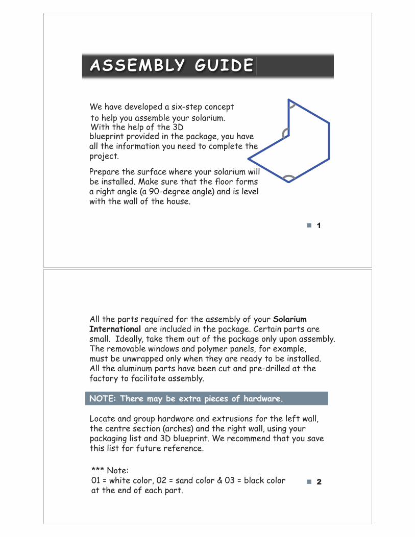
1 We have developed a six-step concept to help you assemble your solarium. With the help of the 3D blueprint provided in the package, you have all the information you need to complete the project. Prepare the surface where your solarium will be installed. Make sure that thoor forms a right angle (a 90-degree angle) and is level with the wall of the house. ASSEMBLY GUIDE 2 All the parts required for the assembly of your Solarium are included in the package. Certain parts are small. Ideally, take them out of the package only upon assembly. The removable windows and polymer panels, for example, must be unwrapped only when they are ready to be installed. All the aluminum parts have been cut and pre-drilled at the factory to facilitate assembly. NOTE: There may be extra pieces of hardware. Locate and group hardware and extrusions for the left wall, the centre section (arches) and the right wall, using your packaging list and 3D blueprint. We recommend that you save this list for future reference. *** Note: 01 = white color, 02 = sand color & 03 = black color at the end of each part.
-
Upload
khangminh22 -
Category
Documents
-
view
1 -
download
0
Transcript of Assembly guide - Sunroom - Solarium International
1
We have developed a six-step concept to help you assemble your solarium. With the help of the 3Dblueprint provided in the package, you have all the information you need to complete the project.
Prepare the surface where your solarium will be installed. Make sure that th!"#oor forms a right angle (a 90-degree angle) and is level with the wall of the house.
ASSEMBLY GUIDE
2
All the parts required for the assembly of your Solarium !"#$%"&#'("&)*are included in the package. Certain parts are small. !Ideally, take them out of the package only upon assembly. The removable windows and polymer panels, for example, must be unwrapped only when they are ready to be installed. All the aluminum parts have been cut and pre-drilled at the factory to facilitate assembly.
NOTE: There may be extra pieces of hardware.
Locate and group hardware and extrusions for the left wall, the centre section (arches) and the right wall, using your packaging list and 3D blueprint. We recommend that you save this list for future reference.
*** Note: 01 = white color, 02 = sand color & 03 = black colorat the end of each part.
3
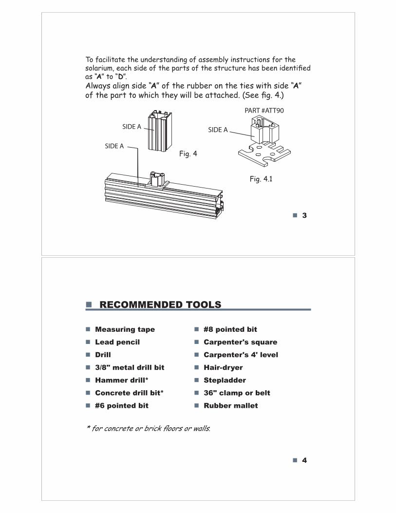
To facilitate the understanding of assembly instructions for the solarium, each side of the parts of the structure has been identified as “A” to “D”.Always align side “A” of the rubber on the ties with side “A” of the part to which they will be attached. (See fig. 4.)
SIDE A
SIDE A
Fig. 4
SIDE A
PART #ATT90
Fig. 4.1
4
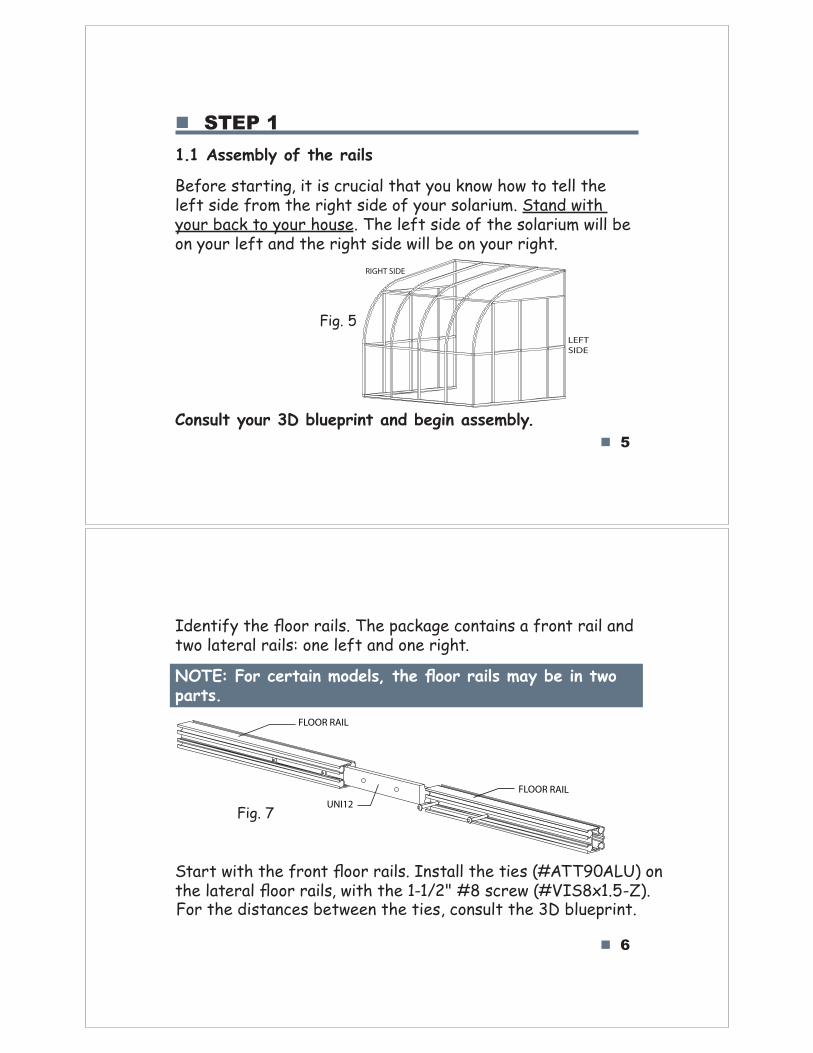
RECOMMENDED TOOLS
Measuring tape
Lead pencil
Drill
3/8" metal drill bit
Hammer drill*
Concrete drill bit*
#6 pointed bit
#8 pointed bit
Carpenter's square
Carpenter's 4' level
Hair-dryer
Stepladder
36" clamp or belt
Rubber mallet
* for concrete or brick floors or walls.
5
STEP 1
1.1 Assembly of the rails
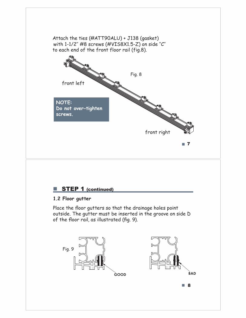
Before starting, it is crucial that you know how to tell the left side from the right side of your solarium. Stand with your back to your house. The left side of the solarium will be on your left and the right side will be on your right.
RIGHT SIDE
LEFT
SIDE
Fig. 5
Consult your 3D blueprint and begin assembly.
6
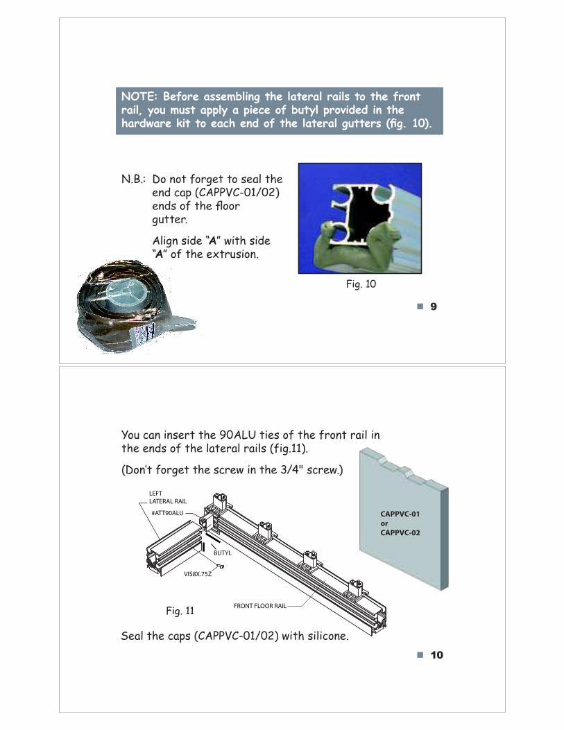
Identify the floor rails. The package contains a front rail and two lateral rails: one left and one right.
NOTE: For certain models, the floor rails may be in two parts.
FLOOR RAIL
UNI12
FLOOR RAIL
Fig. 7
Start with the front floor rails. Install the ties (#ATT90ALU) onthe lateral floor rails, with the 1-1/2" #8 screw (#VIS8x1.5-Z).For the distances between the ties, consult the 3D blueprint.
7
Attach the ties (#ATT90ALU) + J138 (gasket)with 1-1/2‛‛ #8 screws (#VIS8X1.5-Z) on side ‘‛C‛‛to each end of the front floor rail (fig.8).
Fig. 8
NOTE: Do not over-tighten screws.
8
STEP 1 (continued)
1.2 Floor gutter
Place the floor gutters so that the drainage holes point outside. The gutter must be inserted in the groove on side D of the floor rail, as illustrated (fig. 9).
Fig. 9
front left
front right
GOOD BAD
9
NOTE: Before assembling the lateral rails to the front rail, you must apply a piece of butyl provided in the hardware kit to each end of the lateral gutters (!g. 10).
Fig. 10
N.B.: Do not forget to seal the end cap (CAPPVC-01/02) ends of th!"#oor gutter.
Align side “A” with side “A” of the extrusion.
10
You can insert the 90ALU ties of the front rail inthe ends of the lateral rails (fig.11).
(Don$t forget the screw in the 3/4" screw.)
LEFT
LATERAL RAIL
FRONT FLOOR RAIL
#ATT90ALU
Fig. 11
CAPPVC-01
or
CAPPVC-02
Seal the caps (CAPPVC-01/02) with silicone.
VIS8X.75Z
BUTYL
11
STEP 1 (continued)
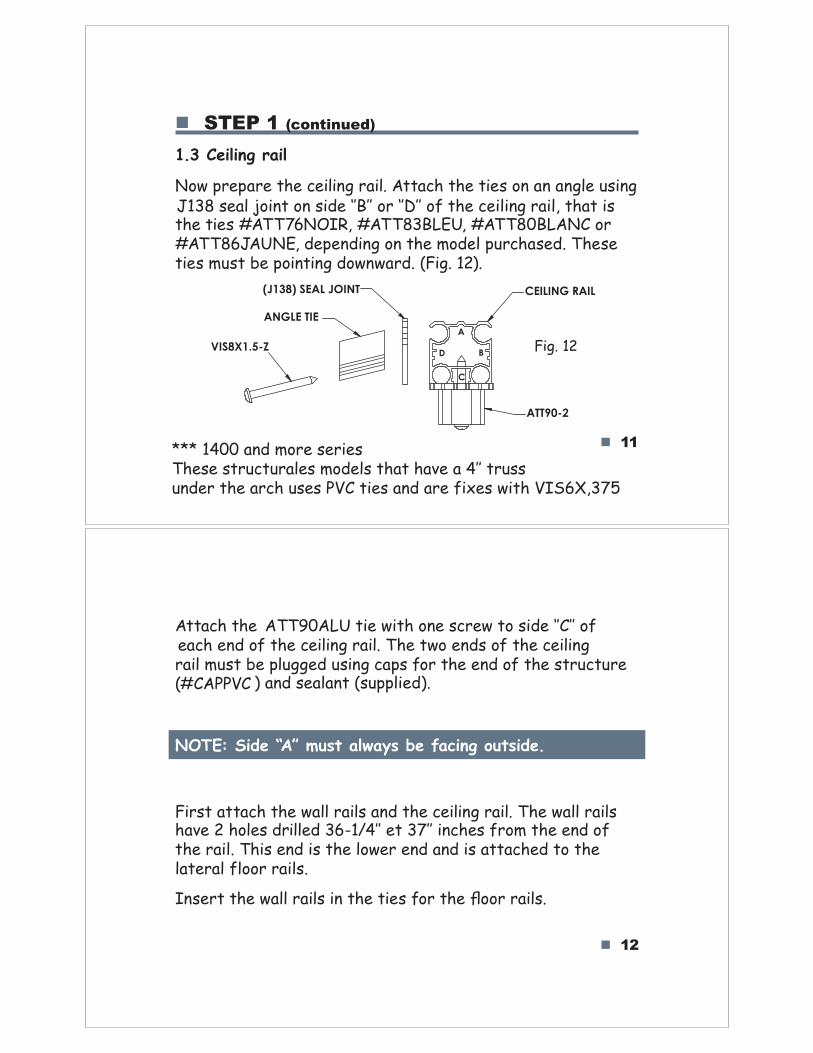
1.3 Ceiling rail
Now prepare the ceiling rail. Attach the ties on an angle using !"#$%&'()%*+,-.%+-%&,/'%01211%+3%01411%+5%.6'%7',),-8%3(,)9%.6(.%,&the ties #ATT76NOIR9%:ATT832LEU9%:ATT802LANC or #ATT86JAUNE9%/epending on the model purchased. These ties must be pointing downward. (Fig. 12).
ANGLE TIE
VIS8X1.5-Z
(J138) SEAL JOINT
ATT90-2
CEILING RAIL
B
C
D
A
Fig. 12
12
Attach the ;<<=>;?@%.,'%A,.6%+-'%&73'A%.+%&,/'%01B11%+5each end o5%.he ceiling rail. The two ends o5%.he ceiling rail must be plugged using cap&%5or the end o5%.he structure (#CAPPVC ) and sealant (supplied).
NOTE: Side “A” must always be facing outside.
First attach the wall rails and the ceiling rail. The wall rails have 2 holes drilled 36-1/C11%'.%#D11%,-76'&%53+E%.6'%'-/%+5the rail. This end is the lower end and is attached to the)(.'3()%5)++3%3(,)&F
Insert the wall rails in the tie&%5or th'%Goor rails.
*** 1400 and more series<6'&'%&.3H7.H3()'&%E+/')&%.6(.%6(I'%(%C11%.3H&&%H-/'3%.6'%(376%H&'&%JKB%.,'&%(-/%(3'%5,L'&%A,.6%KMNOP9#DQ
13
WALLRAIL
LATERALFLOOR RAIL
FLOOR GUTTER
VIS8X.75-Z
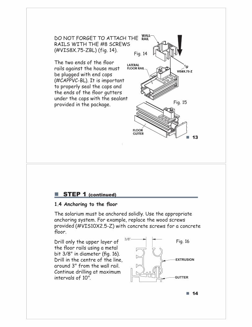
DO NOT FORGET TO ATTACH THE RAILS WITH THE #8 SCREWS (#VIS8X.75-ZBL) (fig. 14).
Fig. 14
The two ends of the floor rails against the house must be plugged with end caps (#CAPPVC-BL). It is important to properly seal the caps and the ends of the floor gutters under the caps with the sealant provided in the package. Fig. 15
14
3/8"
GUTTER
EXTRUSION
STEP 1 (continued)
1.4 Anchoring to the floor
The solarium must be anchored solidly. Use the appropriate anchoring system. For example, replace the wood screws providedfloor.
(#VIS10X2.5-Z) with concrete screws for a concrete
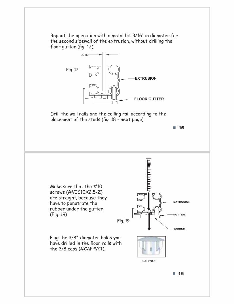
Fig. 16Drill only the upper layer of the floor rails using a metal bit 3/8" in diameter (fig. 16). Drill in the centre of the line, around 3" from the wall rail. Continue drilling at maximum intervals of 10".
FLOORGUTTER
15
Repeat the operation with a metal bit 3/16" in diameter for the second sidewall of the extrusion, without drilling the floor gutter (fig. 17).
Fig. 17
3/16"
FLOOR GUTTER
EXTRUSION
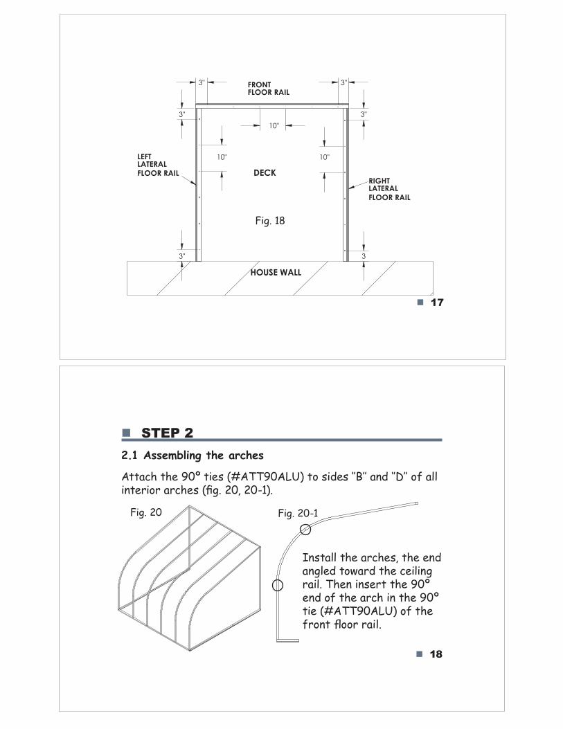
Drill the wall rails and the ceiling rail according to the placement of the studs (fig. 18 - next page).
16
Make sure that the #10 screws (#VIS10X2.5-Z).are straight, because they have to penetrate the rubber under the gutter. (Fig. 19)
Fig. 19
Plug the 3/8"-diameter holes you have drilled in the floor rails with the 3/8 caps (#CAPPVC1).
CAPPVC1
RUBBER
GUTTER
EXTRUSION
18
STEP 2
2.1 Assembling the arches
Attach the 90º tie!"#$%&&'(%)*+",-"!./0!"12322"45/"12622"-7"488i5terior arches (9g. 20, 20-1).
Fig. 20 Fig. 20-1
I5sta88",he arches, the e5d a5g8ed toward the cei8i5g rai8. The5"i5sert the 90º e5d o7",he arch i5",he 90º ti0"#$%&&'(%)*+"-7",:07;-5,"<--;";4.8=
17
3"
10"
3
10"
10"
3"3"
3" 3"
HOUSE WALL
RIGHT
LATERAL
FLOOR RAIL
LEFT
LATERAL
FLOOR RAIL
FRONT
FLOOR RAIL
DECK
Fig. 18
19
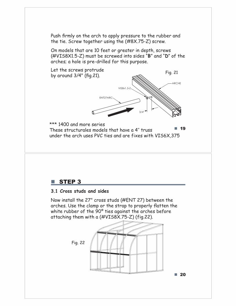
Pus!"#rmly on the arch to apply pressure to the rubber and the tie. Screw together using the (#8X.75-Z) screw.
On models that are 10 feet or greater in depth, screws (#VIS8X1.5-Z) must be screwed into sides “B” and “D” of the arches; a hole is pre-drilled for this purpose.
Fig. 21Let the screws protrude by around 3/4" (#g.21).
20
STEP 3
3.1 Cross studs and sides
Now install the 27" cross studs (#ENT 27) between the arches. Use the clamp or the strap to properl$"%atten the white rubber of the 90º ties against the arches before attaching them with a (#VIS8X.75-Z) (fig.22).
Fig. 22
*** 1400 and more series&!'('"()*+,)+*-.'("/01'.(")!-)"!-2'"-"344")*+(("under the arch uses PVC ties and are fixes with VIS6X,375
3/4"
ARCHE
VIS8x1.5-Z
ENT27ARC
21
Continue with the lateral supports (#MON73).For the position of the door, refer to your 3D blueprint for more details.
NOTE: On models that are 10 feet or greater in depth, attach a coloured angled tie (#ATT76ROUGG, #ATT76ORAND, #ATT83MAUVD or
#ATT83VERTG) with j138 to side!"#""$%&$'()$)*+$,-.()/0$1()/)arches will later receive the roof/233%-'/$4&560$7890
22
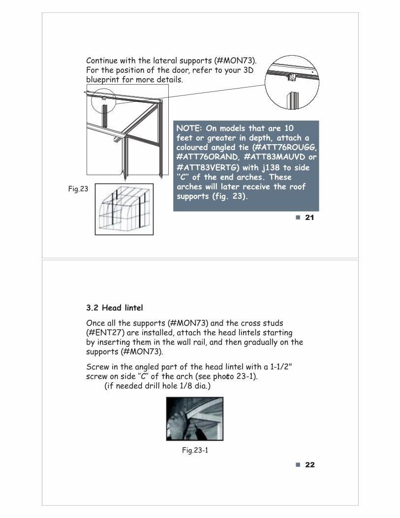
307$:ead lintel
Once all the supports (#MON73) and the cross studs (#ENT27) are installed, attach the head lintels starting by inserting them in the wall rail, and then gradually on the supports (#MON73).
Screw in the angled part of the head lintel with a 1-1/2" scre!"#$"%&'(")*+**"#,"-.("/01."2%(("3.#-#"456789
(if needed drill hole 1/8 dia.)i c
Fig.23-1
Fig.23
23
3.3 #CAPPVC2
Plug all unused 1/8" holes with a drop of sealant and add the caps to the structure (#CAPPVC2) (#SCALB).
CAPPVC2
3.4 Ceiling rail sealant
Apply sealant along the jointing of the ceiling rail and the wall of the house (!g. 24).
Fig. 24
24
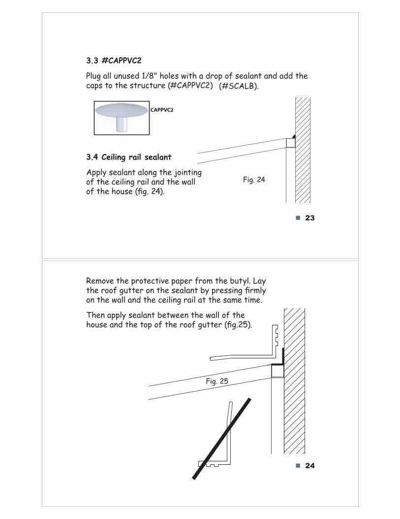
Remove the protective paper from the butyl. Lay the roof gutter on the sealant by pressin"#!rmly on the wall and the ceiling rail at the same time.
Then apply sealant between the wall of the house and the top of the roof gutter (!g.25).
Fig. 25
25
STEP 4
4.1 Installing the removable window
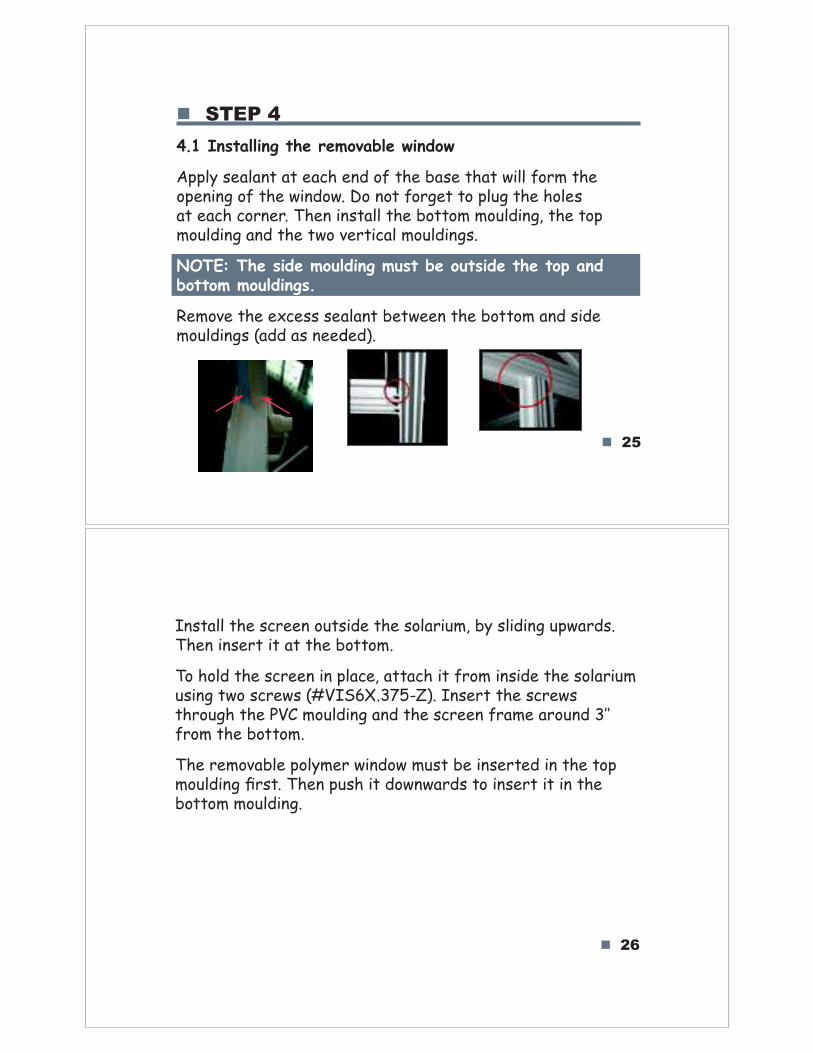
Apply sealant at each end of the base that will form the opening of the window. Do not forget to plug the holes at each corner. Then install the bottom moulding, the top moulding and the two vertical mouldings.
NOTE: The side moulding must be outside the top and bottom mouldings.
Remove the excess sealant between the bottom and side mouldings (add as needed).
26
Install the screen outside the solarium, by sliding upwards. Then insert it at the bottom.
To hold the screen in place, attach it from inside the solarium using two screws (#VIS6X.375-Z). Insert the screws through the PVC moulding and the screen frame aroun!"#$$from the bottom.
The removable polymer window must be inserted in the top mouldin%"&rst. Then push it downwards to insert it in the bottom moulding.
27
STEP 5
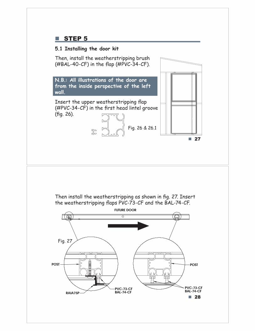
5.1 Installing the door kit
Fig. 26 & 26.1
Then, install the weatherstripping brush (#BAL-40-CF) in the flap (#PVC-34-CF).
N.B.: All illustrations of the door are from the inside perspective of the left wall.
Insert the upper weatherstripping flap (#PVC-34-CF) in the first head lintel groove (fig. 26).
28
Then install the weatherstripping as shown in fig. 27. Insert the weatherstripping flaps PVC-73-CF and the BAL-74-CF.
FUTURE DOOR
POST
PVC-73-CFBAL-74-CFRAIA75P
POST
PVC-73-CFBAL-74-CF
Fig. 27
29
RAI61PHBRAIA75P
N
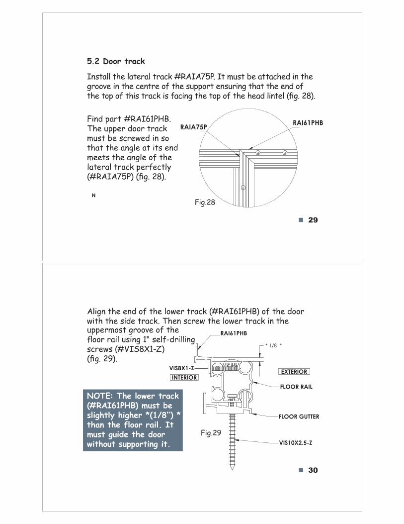
5.2 Door track
Install the lateral track #RAIA75P. It must be attached in the groove in the centre of the support ensuring that the end of the top of this track is facing the top of the head lintel (!g. 28).
Fig.28
Find part #RAI61PHB. The upper door track must be screwed in so that the angle at its end meets the angle of the lateral track perfectly (#RAIA75P) (!g. 28).
30
* 1/8" *
FLOOR RAIL
FLOOR GUTTER
RAI61PHB
VIS10X2.5-Z
EXTERIOR
INTERIOR
VIS8X1-Z
Align the end of the lower track (#RAI61PHB) of the door with the side track. Then screw the lower track in the
Fig.29
NOTE: The lower track (#RAI61PHB) must be !"#$%&"'(%#$%)*(+,-./001(+than the floor rail. Itmust guide the doorwithout supporting it.
uppermost groove of the "oor rail using 1" self-drilling screws (#VIS8X1-Z) (!g. 29).
31
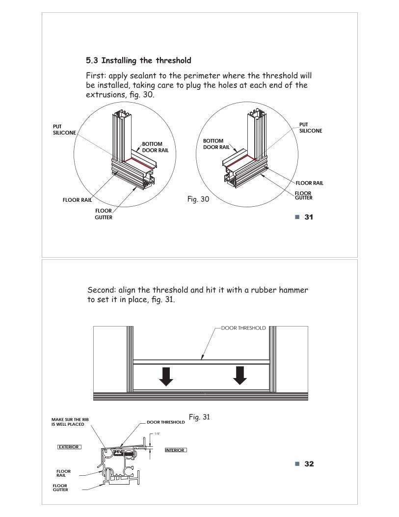
5.3 Installing the threshold
First: apply sealant to the perimeter where the threshold will be installed, taking care to plug the holes at each end of the extrusions, fig. 30.
ig. 30
32
Second: align the threshold and hit it with a rubber hammer to set it in place, fig. 31.
DOOR THRESHOLD
Fig. 31
F
PUTSILICONEPUT
SILICONE
FLOORGUTTER
FLOOR RAIL
BOTTOMDOOR RAIL
FLOOR RAILFLOORGUTTER
BOTTOMDOOR RAIL
1/8"
FLOORRAIL
FLOORGUTTER
EXTERIOR INTERIOR
DOOR THRESHOLDMAKE SUR THE RIBIS WELL PLACED
33
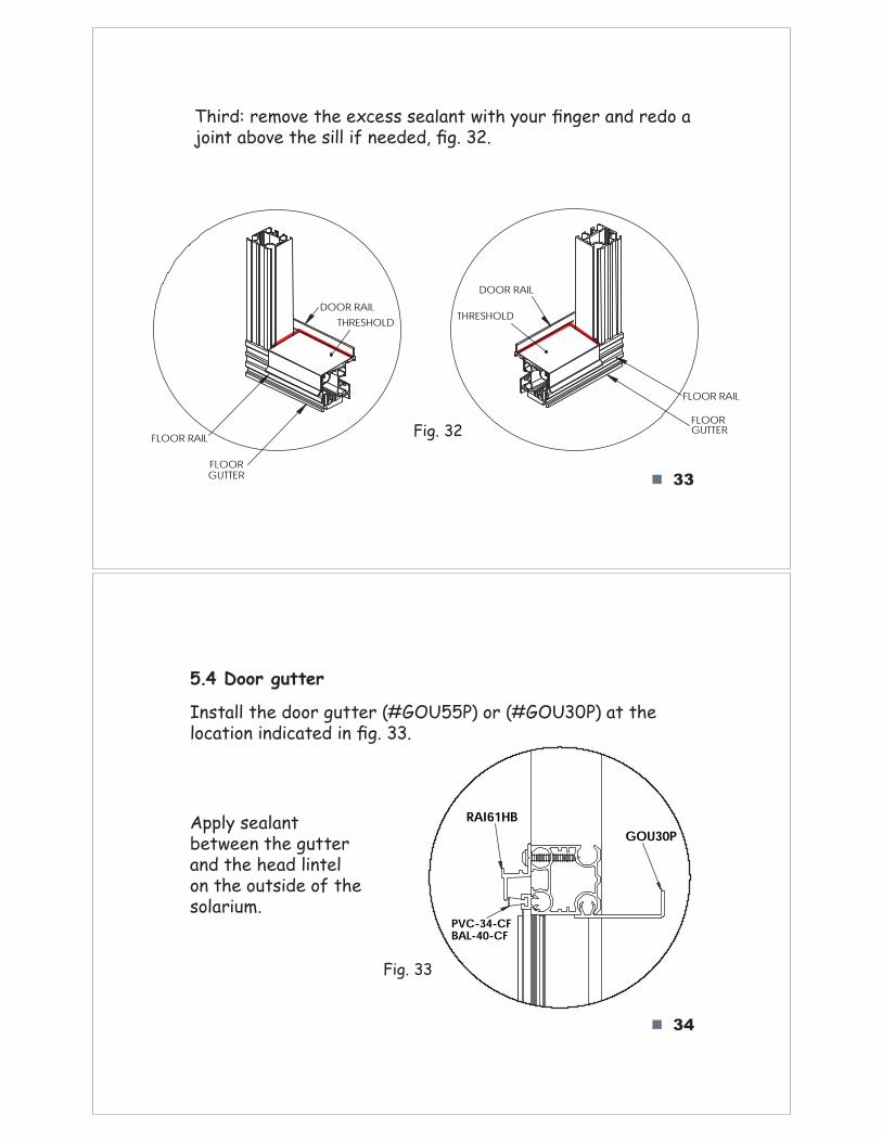
Third: remove the excess sealant with your finger and redo a joint above the sill if needed, fig. 32.
Fig. 32
34
5.4 Door gutter
Install the door gutter (#GOU55P) or (#GOU30P) at the location indicated in fig. 33.
Apply sealant between the gutter and the head lintel on the outside of the solarium.
RAI61HB
PVC-34-CFBAL-40-CF
GOU30P
Fig. 33
FLOORGUTTER
FLOOR RAIL
DOOR RAIL
THRESHOLD
FLOOR RAIL
FLOORGUTTER
DOOR RAILTHRESHOLD
35
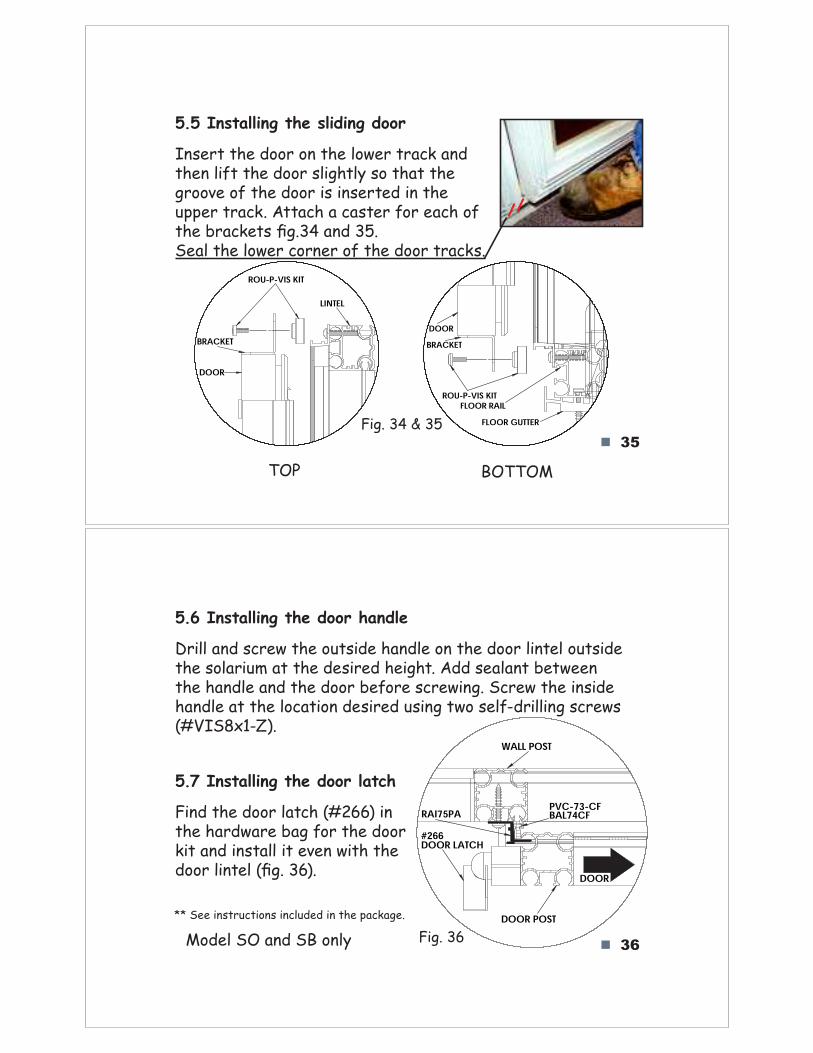
5.5 Installing the sliding door
Insert the door on the lower track and then lift the door slightly so that the groove of the door is inserted in the upper track. Attach a caster for each of the brackets fig.34 and 35. Seal the lower corner of the door tracks.
Fig. 34 & 35
LINTEL
DOOR
ROU-P-VIS KIT
BRACKETDOORBRACKET
ROU-P-VIS KITFLOOR RAIL
FLOOR GUTTER
36
5.6 Installing the door handle
Drill and screw the outside handle on the door lintel outside the solarium at the desired height. Add sealant between the handle and the door before screwing. Screw the inside handle at the location desired using two self-drilling screws (#VIS8x1-Z).
#266DOOR LATCH
DOOR POST
PVC-73-CFBAL74CF
WALL POST
RAI75PA
DOOR
5.7 Installing the door latch
Find the door latch (#266) in the hardware bag for the door kit and install it even with the door lintel (fig. 36).
** See instructions included in the package.
Fig. 36
TOP BOTTOM
Model SO and SB only
37
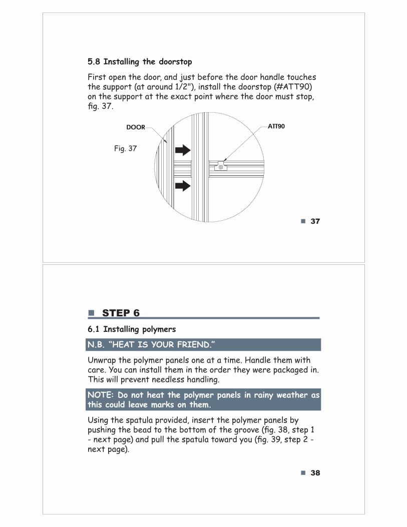
5.8 Installing the doorstop
First open the door, and just before the door handle touches the support (at around 1/2"), install the doorstop (#ATT90) on the support at the exact point where the door must stop, fig. 37.
Fig. 37
DOOR ATT90
38
STEP 6
6.1 Installing polymers
N.B. “HEAT IS YOUR FRIEND.”
Unwrap the polymer panels one at a time. Handle them with care. You can install them in the order they were packaged in. This will prevent needless handling.
NOTE: Do not heat the polymer panels in rainy weather as this could leave marks on them.
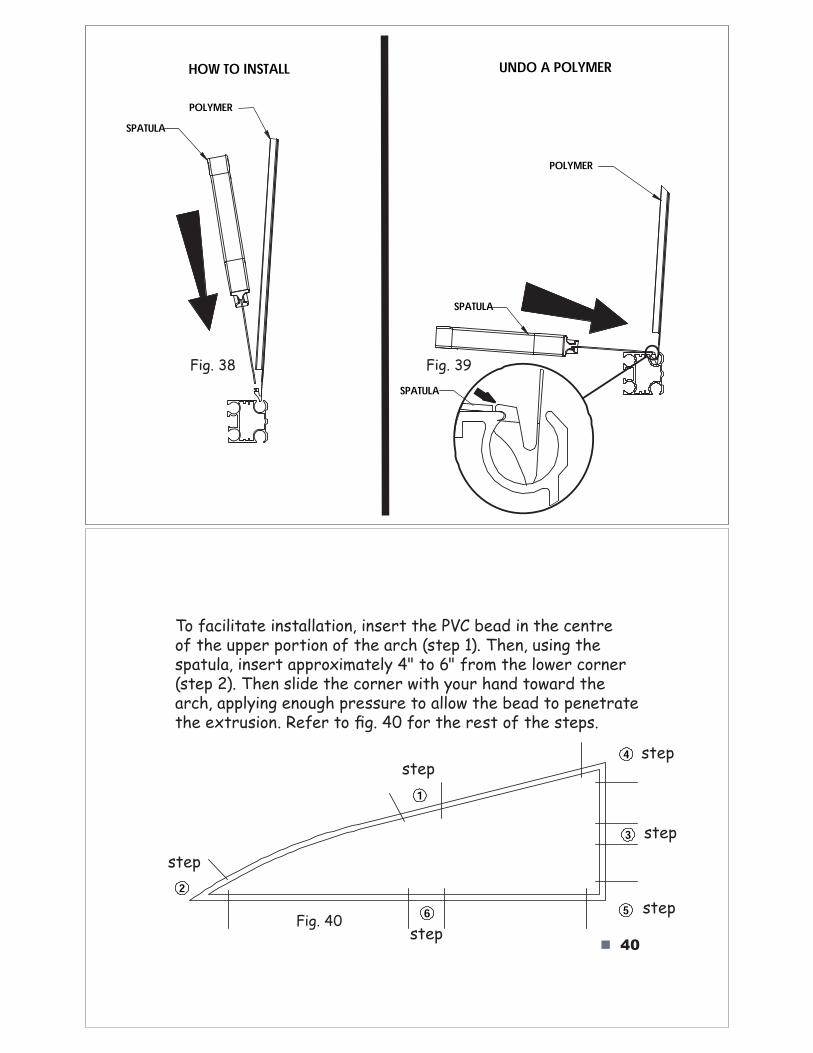
Using the spatula provided, insert the polymer panels by pushing the bead to the bottom of the groove (fig. 38, step 1 - next page) and pull the spatula toward you (fig. 39, step 2 - next page).
40
62
1
3
5
4
To facilitate installation, insert the PVC bead in the centre of the upper portion of the arch (step 1). Then, using the spatula, insert approximately 4" to 6" from the lower corner (step 2). Then slide the corner with your hand toward the arch, applying enough pressure to allow the bead to penetrate the extrusion. Refer to fig. 40 for the rest of the steps.
Fig. 40
step
step
step
step
step
step
Fig. 39Fig. 38
POLYMER
SPATULA
HOW TO INSTALL
SPATULAPOLYMER
UNDO A POLYMER
SPATULA
41
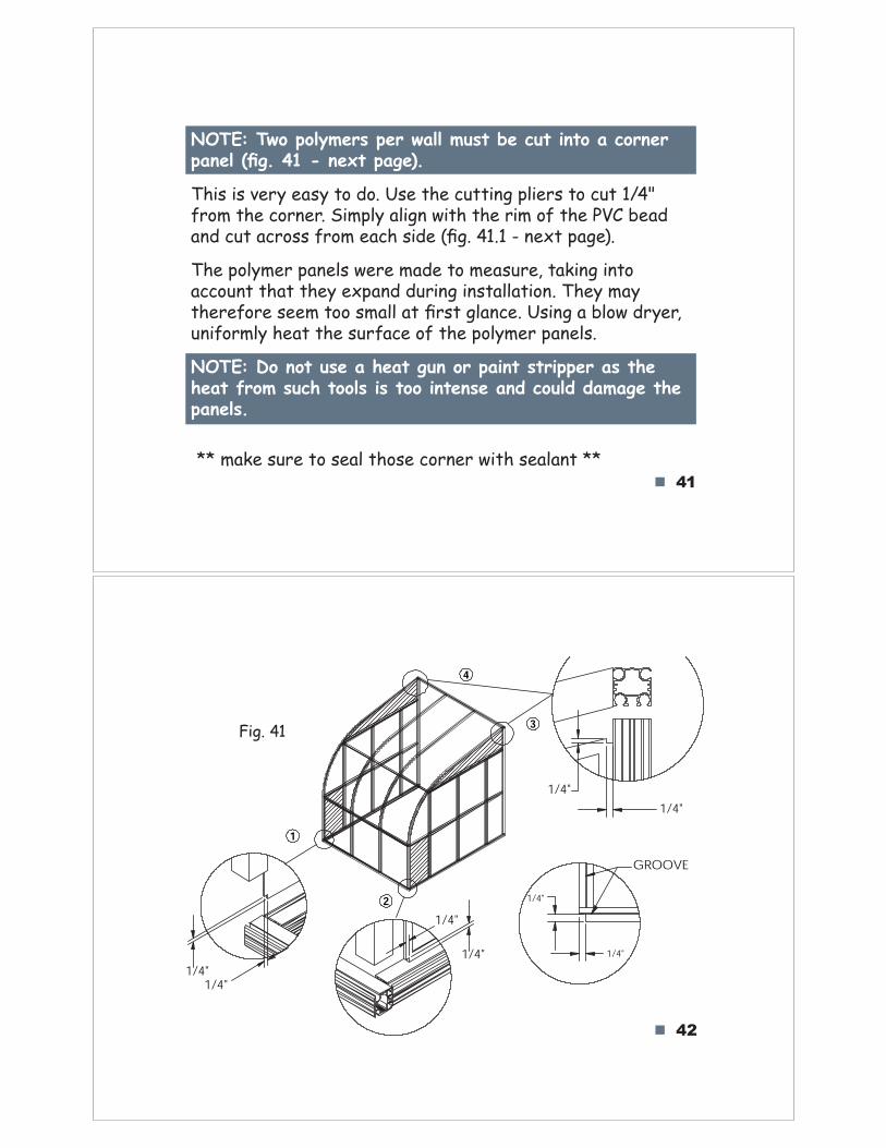
NOTE: Two polymers per wall must be cut into a corner panel (fig. 41 - next page).
This is very easy to do. Use the cutting pliers to cut 1/4" from the corner. Simply align with the rim of the PVC bead and cut across from each side (fig. 41.1 - next page).
The polymer panels were made to measure, taking into account that they expand during installation. They may therefore seem too small at first glance. Using a blow dryer, uniformly heat the surface of the polymer panels.
NOTE: Do not use a heat gun or paint stripper as the heat from such tools is too intense and could damage the panels.
42
1
2
3
4
1/4"1/4"
1/4"
1/4"
1/4"1/4"
1/4"
1/4"
GROOVE
Fig. 41
** make sure to seal those corner with sealant **
43
65 4
2
8
1
7
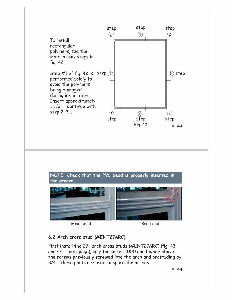
3To install rectangular polymers, see the installations steps in fig. 42.
Fig. 42
Step #1 of fig. 42 is performed solely to avoid the polymers being damaged during installation. Insert approximately 1-1/2"... Continue with step 2, 3...
44
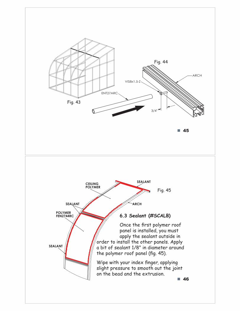
Good bead
NOTE: Check that the PVC bead is properly inserted in the groove.
Bad bead
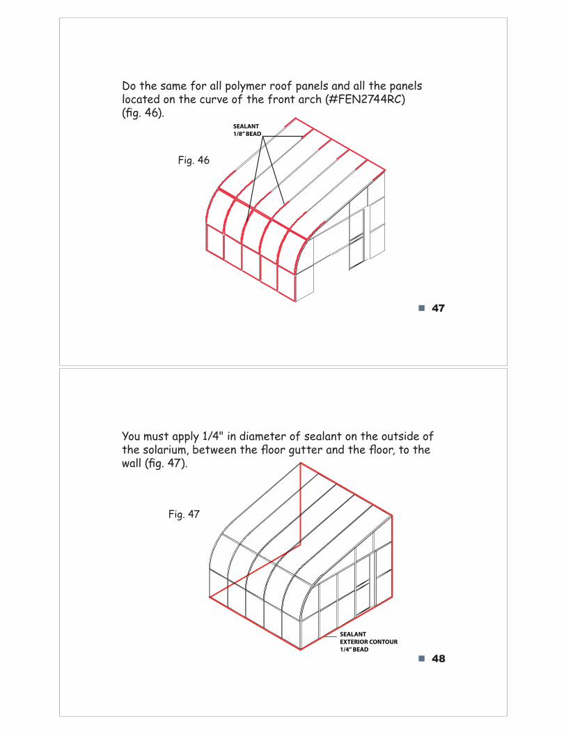
6.2 Arch cross stud (#ENT27ARC)
First install the 27" arch cross studs (#ENT27ARC) (fig. 43 and 44 - next page), only for series 1000 and higher, above the screws previously screwed into the arch and protruding by 3/4". These parts are used to space the arches.
step stepstep
step step
stepstep step
45
Fig. 43
Fig. 44
46
ARCH
CEILING
POLYMER
SEALANT
POLYMER
FEN2744RC
SEALANT
SEALANT
6.3 Sealant (#SCALB)
Once th!"#rst polymer roof panel is installed, you must apply the sealant outside in
Fig. 45
order to install the other panels. Apply a bit of sealant 1/8" in diameter around the polymer roof panel (#g. 45).
Wipe with your inde$"#nger, applying slight pressure to smooth out the joint on the bead and the extrusion.
3/4"
ARCH
VIS8x1.5-Z
ENT27ARC
47
Do the same for all polymer roof panels and all the panels located on the curve of the front arch (#FEN2744RC) (!g. 46).
Fig. 46
SEALANT
1/8” BEAD
48
You must apply 1/4" in diameter of sealant on the outside of the solarium, between th"#$oor gutter and th"#$oor, to the wall (!g. 47).
Fig. 47
SEALANT
EXTERIOR CONTOUR
1/4” BEAD
49!
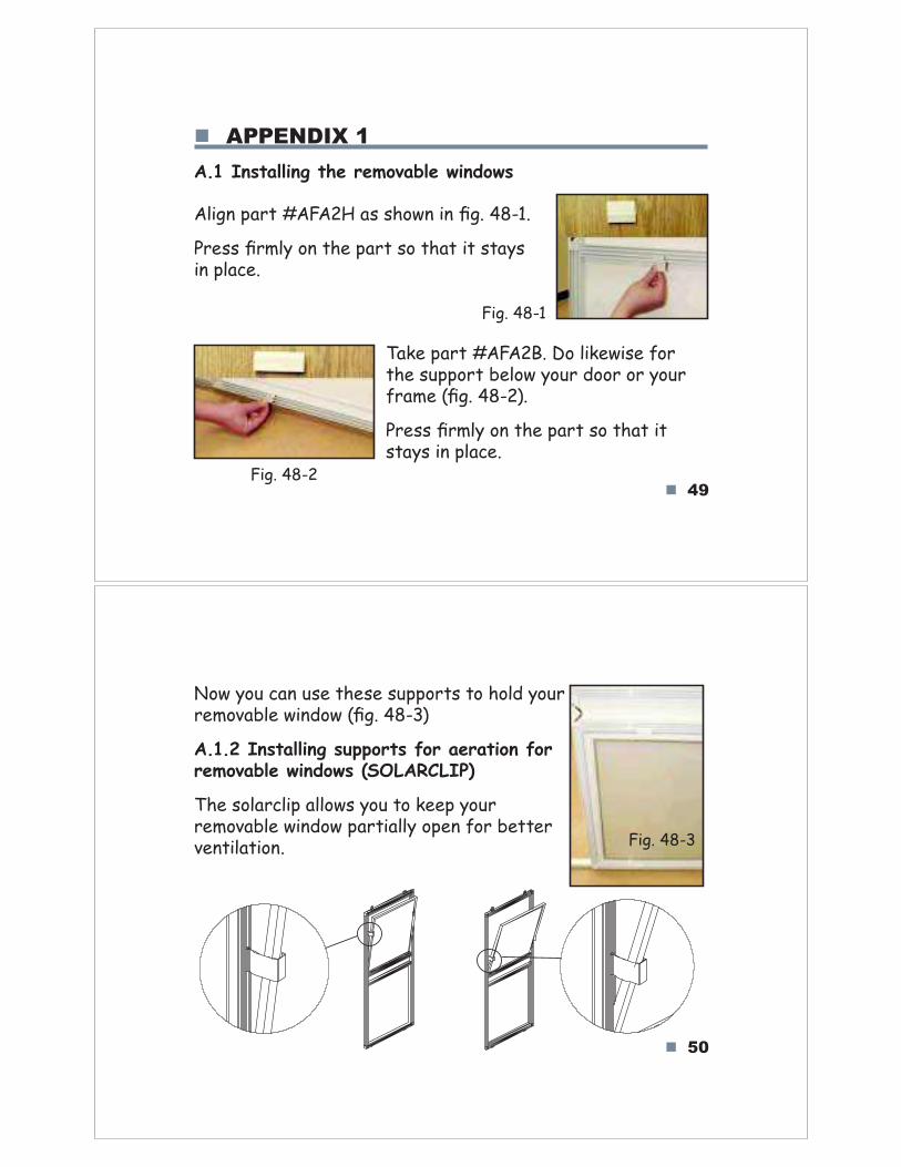
Align part #AFA2H as shown in fig. 48-1.
Press firmly on the part so that it stays in place.
APPENDIX 1
A.1 Installing the removable windows
!
Fig. 48-1
Fig. 48-2
Take part #AFA2B. Do likewise for the support below your door or your frame (fig. 48-2).
Press firmly on the part so that it stays in place.
50!
Now you can use these supports to hold your removable window (fig. 48-3)
A.1.2 Installing supports for aeration for removable windows (SOLARCLIP)
The solarclip allows you to keep your removable window partially open for better ventilation. Fig. 48-3
51
APPENDIX 2
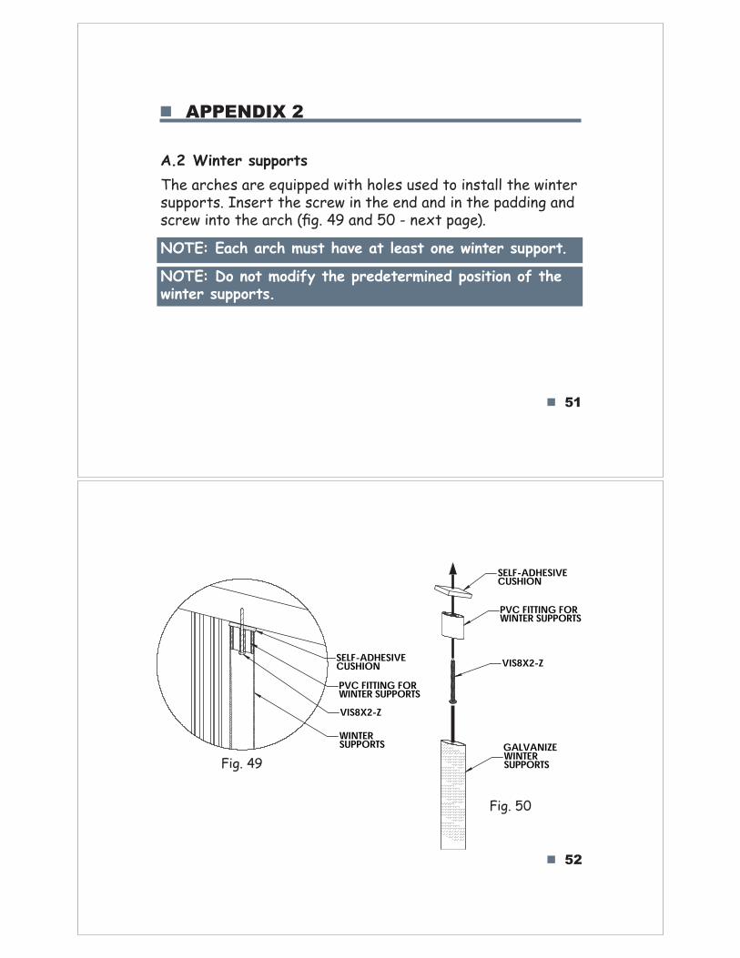
A.2 Winter supports
The arches are equipped with holes used to install the winter supports. Insert the screw in the end and in the padding and screw into the arch (fig. 49 and 50 - next page).
NOTE: Each arch must have at least one winter support.
NOTE: Do not modify the predetermined position of the winter supports.
52
SELF-ADHESIVECUSHIONPVC FITTING FORWINTER SUPPORTSVIS8X2-ZWINTERSUPPORTS
SELF-ADHESIVECUSHION
VIS8X2-Z
WINTERSUPPORTS
PVC FITTING FORWINTER SUPPORTS
Fig. 49
Fig. 50
GALVANIZE
53!
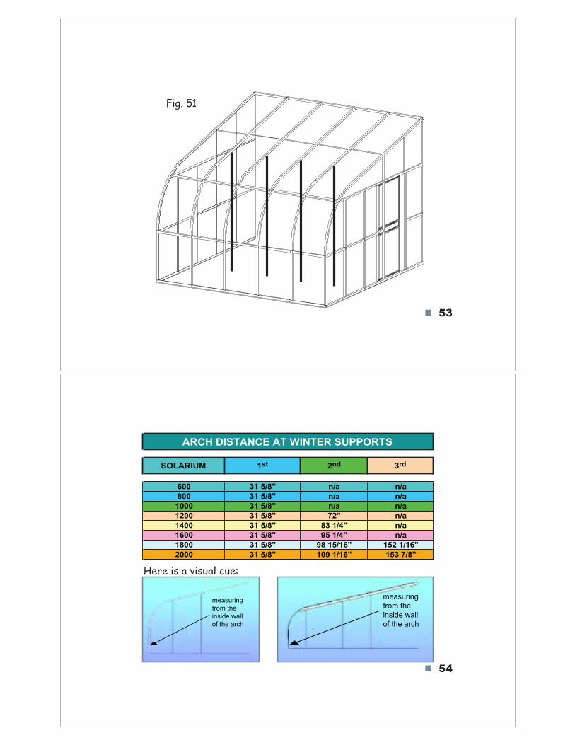
Fig. 51
54!
600 31 5/8" n/a n/a
800 31 5/8" n/a n/a
1000 31 5/8" n/a n/a
1200 31 5/8" 72" n/a
1400 31 5/8" 83 1/4" n/a
1600 31 5/8" 95 1/4" n/a
1800 31 5/8" 98 15/16" 152 1/16"
2000 31 5/8" 109 1/16" 153 7/8"
ARCH DISTANCE AT WINTER SUPPORTS
SOLARIUM 1st 3rd2nd
measuring
from the
inside wall
of the arch
measuring
from the
inside wall
of the arch
Here is a visual cue:

55!
It is important that you properly clean snow off your solarium and carefully unblock the draining holes in the base.
You have now finished installing your Solarium "#$%&#'$()#'*.
Congratulations!
56!
APPENDIX 3
A.3 Maintaining the polymers
To clean your solarium, we recommend using the +)*,-.%/® line of cleaning products.
These products have been tested and developed to maintain the properties of the polymer panels.
!
57!
NOTICE
A.1 The Screen Kit:
A QUESTION OF SECURITY
We strongly discourage you from installing the screen in a lower section if your balcony is over 24" from the ground, to protect occupants against the risk of falling or other injury if ever the screen is split due to impact or some other accident.
!