ASME Boiler and Pressure Vessel Code Evaluation and ...
314
ORNL/TM-2017/66 ASME Boiler and Pressure Vessel Code Evaluation and Equivalence Study for Liquefied Natural Gas Facilities Barry Oland Mark Lower Simon Rose April 2017
-
Upload
khangminh22 -
Category
Documents
-
view
0 -
download
0
Transcript of ASME Boiler and Pressure Vessel Code Evaluation and ...

ORNL/TM-2017/66
ASME Boiler and Pressure Vessel Code Evaluation and Equivalence Study for Liquefied Natural Gas Facilities
Barry Oland Mark Lower Simon Rose
April 2017

This report was prepared as an account of work sponsored by an agency of the United States Government. Neither the United States Government nor any agency thereof, nor any of their employees, makes any warranty, express or implied, or assumes any legal liability or responsibility for the accuracy, completeness, or usefulness of any information, apparatus, product, or process disclosed, or represents that its use would not infringe privately owned rights. Reference herein to any specific commercial product, process, or service by trade name, trademark, manufacturer, or otherwise, does not necessarily constitute or imply its endorsement, recommendation, or favoring by the United States Government or any agency thereof. The views and opinions of authors expressed herein do not necessarily state or reflect those of the United States Government or any agency thereof.

ORNL/TM-2017/66
Energy and Transportation Science Division
ASME Boiler and Pressure Vessel Code Evaluation and Equivalence Study
for Liquefied Natural Gas Facilities
Barry Oland
Mark Lower
Simon Rose
Date Published: April 2017
US Department of Transportation
Pipeline and Hazardous Materials Safety Administration
Pipeline Safety Program
East Building Second Floor
1200 New Jersey Avenue, S.E.
Washington, DC 20590
Pipeline and Hazardous Materials Safety Administration
Agreement Number DTPH56-13-X-000022
under DOE Proposal Number 2117-S865-A1
Prepared by
Oak Ridge National Laboratory
Oak Ridge, TN 37831-6283
managed by
UT-BATTELLE, LLC
for the
US DEPARTMENT OF ENERGY
under contract DE-AC05-00OR22725


iii
CONTENTS
CONTENTS ...........................................................................................................................................iii
LIST OF FIGURES ................................................................................................................................ ix
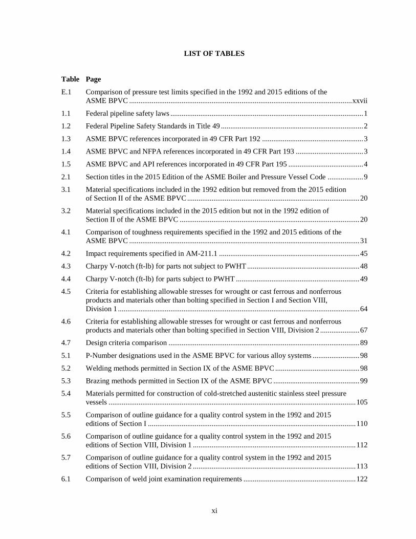
LIST OF TABLES ................................................................................................................................. xi
ACRONYMS AND ABBREVIATIONS ............................................................................................xiii
ACKNOWLEDGMENTS ..................................................................................................................... xv
ABSTRACT ........................................................................................................................................ xvii
EXECUTIVE SUMMARY .................................................................................................................. xix
E.1 MATERIALS .......................................................................................................................... xix E.2 DESIGN ................................................................................................................................... xx
E.2.1 Failure Modes......................................................................................................... xx E.2.2 Strength Theories ................................................................................................ xxiv E.2.3 Principles of Limit Design Theory ...................................................................... xxiv
E.3 FABRICATION AND INSPECTION ................................................................................... xxv E.4 PRESSURE TESTING ......................................................................................................... xxvi E.5 OVERPRESSURE PROTECTION ..................................................................................... xxvii E.6 CONCLUSIONS AND OBSERVATIONS ........................................................................xxviii
E.6.1 Conclusions .......................................................................................................xxviii E.6.2 Observations ........................................................................................................ xxix
1. INTRODUCTION .......................................................................................................................... 1
1.1 RULEMAKING AND REGULATORY REVIEW PROCESS ................................................ 2 1.2 FEDERAL SAFETY STANDARDS FOR LNG FACILITIES IN 49 CFR Part 193 ............... 5
1.2.1 Framework for Safety Equivalency ......................................................................... 5 1.2.2 NFPA and ASME Codes and Standards Incorporated by Reference in 49
CFR Part 193 ............................................................................................................ 6 1.2.3 Equivalency Provision in NFPA 59A ...................................................................... 6
1.3 PURPOSE AND NEED FOR SAFETY EQUIVALENCY EVALUATION ........................... 7 1.3.1 Safety Equivalency Evaluations using Quantitative Comparative Analysis............ 7 1.3.2 Safety Equivalency Evaluations Using Qualitative Comparative Analysis ............. 8
1.4 SAFETY EQUIVALENCY EVALUATION SCOPE AND OBJECTIVES ............................ 8
2. ASME BPVC SCOPE AND REVISION PROCESS ..................................................................... 9
2.1 SECTION I – RULES FOR CONSTRUCTION OF POWER BOILERS .............................. 11 2.2 SECTION VIII, DIVISION 1 – RULES FOR CONSTRUCTION OF PRESSURE
VESSELS ................................................................................................................................. 12 2.3 SECTION VIII, DIVISION 2 – ALTERNATIVE RULES FOR CONSTRUCTION OF
PRESSURE VESSELS ............................................................................................................ 13 2.4 SECTION II – MATERIALS .................................................................................................. 14
2.4.1 Material Specifications – Parts A, B, and C........................................................... 14 2.4.2 Material Properties – Part D ................................................................................... 15
2.5 SECTION V – NONDESTRUCTIVE EXAMINATION........................................................ 15 2.6 SECTION IX – QUALIFICATION STANDARD FOR WELDING, BRAZING, AND
FUSING PROCEDURES; WELDERS; BRAZERS; AND WELDING, BRAZING,
AND FUSING OPERATORS ................................................................................................. 16

iv
2.6.1 Procedure Qualifications ........................................................................................ 16 2.6.2 Performance Qualifications .................................................................................... 17 2.6.3 Welding, Brazing, and Fusing Data ....................................................................... 17
2.7 SECTION XI – RULES FOR INSERVICE INSPECTION OF NUCLEAR POWER
PLANT COMPONENTS ......................................................................................................... 17
3. MATERIALS SPECIFICATIONS AND MATERIAL PROPERTIES ....................................... 19
3.1 MATERIALS PERMITTED FOR DESIGN AND FABRICATION OF BOILERS
AND PRESSURE VESSELS .................................................................................................. 19 3.2 TEMPERATURE-DEPENDENT AND TIME-DEPENDENT PROPERTIES ...................... 24 3.3 TOUGHNESS PROPERTIES ................................................................................................. 24 3.4 FATIGUE PROPERTIES ........................................................................................................ 24 3.5 CORROSION PROPERTIES .................................................................................................. 25
4. DESIGN ........................................................................................................................................ 27
4.1 POTENTIAL FAILURE MODES ........................................................................................... 27 4.1.1 Excessive Elastic Deformation and Elastic Instability........................................... 28 4.1.2 Excessive Plastic Deformation ............................................................................... 30 4.1.3 Brittle Fracture ....................................................................................................... 30 4.1.4 Stress Rupture and Creep Deformation.................................................................. 51 4.1.5 Plastic Instability – Incremental Collapse .............................................................. 52 4.1.6 Fatigue .................................................................................................................... 54 4.1.7 Stress Corrosion and Corrosion Fatigue ................................................................ 57
4.2 DESIGN BASIS ....................................................................................................................... 59 4.2.1 Design Basis Requirements in Section I ................................................................ 59 4.2.2 Design Basis Requirements in Section VIII, Division 1 ........................................ 60 4.2.3 Design Basis Requirements in Section VIII, Division 2 ........................................ 61
4.3 STRESS CATEGORIES .......................................................................................................... 62 4.3.1 Primary Stresses ..................................................................................................... 63 4.3.2 Secondary Stresses ................................................................................................. 63 4.3.3 Peak Stresses .......................................................................................................... 63
4.4 MAXIMUM ALLOWABLE DESIGN STRESSES ................................................................ 63 4.4.1 Basis for Establishing Allowable Stress Values for Section I and Section
VIII, Division 1 ...................................................................................................... 64 4.4.2 Basis for Establishing Allowable Stress Values for Section VIII, Division 2 ....... 66 4.4.3 Alternative Rules for Material Having a Higher Allowable Stress at Low
Temperature ........................................................................................................... 69 4.5 STRENGTH THEORIES......................................................................................................... 70
4.5.1 Maximum Stress Theory ........................................................................................ 70 4.5.2 Maximum Shear Stress Theory Using the Tresca Yield Criterion ........................ 70 4.5.3 Distortion Energy Theory Using the von Mises Yield Criterion ........................... 71
4.6 PRINCIPLES OF LIMIT DESIGN THEORY ........................................................................ 71 4.7 STRESS RANGE FOR REPETITIVELY APPLIED LOADS ............................................... 74 4.8 PLASTIC COLLAPSE ............................................................................................................ 79
4.8.1 Plastic Collapse Requirements in Section I and Section VIII, Division 1 ............. 79 4.8.2 Plastic Collapse Requirements in Section VIII, Division 2 ................................... 79
4.9 DESIGN-BY-RULE ................................................................................................................ 80 4.9.1 Design-by-Rule Requirements in Section I............................................................ 80 4.9.2 Design-by-Rule Requirements in Section VIII, Division 1 ................................... 81 4.9.3 Design-by-Rule Requirements in Section VIII, Division 2 ................................... 83
4.10 DESIGN-BY-ANALYSIS ....................................................................................................... 86

v
4.11 COMPARISON OF KEY DIFFERENCES IN ASME BPVC DESIGN RULES................... 89
5. FABRICATION ............................................................................................................................ 93
5.1 FORMING ............................................................................................................................... 93 5.1.1 Forming Requirements in Section I ....................................................................... 93 5.1.2 Forming Requirements in Section VIII, Division 1 ............................................... 94 5.1.3 Forming Requirements in Section VIII, Division 2 ............................................... 95
5.2 TOLERANCES ........................................................................................................................ 95 5.2.1 Formed Head Tolerances ....................................................................................... 95 5.2.2 Alignment Tolerances ............................................................................................ 96
5.3 WELDING AND BRAZING PROCESSES ............................................................................ 97 5.3.1 Base Metal Groupings ............................................................................................ 97 5.3.2 Welding and Brazing Methods............................................................................... 98 5.3.3 Procedure Qualification Record ............................................................................. 99 5.3.4 Procedure Specification ......................................................................................... 99 5.3.5 Procedure Specification Record ........................................................................... 100 5.3.6 Performance Qualification ................................................................................... 100 5.3.7 Performance Qualification Record ....................................................................... 100 5.3.8 Welding, Brazing, and Fusing Data ..................................................................... 100
5.4 HEAT TREATMENT OF WELDMENTS ............................................................................ 101 5.4.1 Preheating Requirements ..................................................................................... 101 5.4.2 Postweld Heat Treatment Requirements .............................................................. 101
5.5 COLD STRETCHING ........................................................................................................... 104 5.5.1 Summary of Cold Stretching Requirements in Section VIII, Division 1 ............. 104 5.5.2 Cold Stretching Technology ................................................................................ 106
5.6 QUALITY CONTROL .......................................................................................................... 107 5.6.1 Quality Control System Requirements in Section I ............................................. 108 5.6.2 Quality Control System Requirements in Section VIII, Division 1 ..................... 109 5.6.3 Quality Control System Requirements in Section VIII, Division 2 ..................... 112
6. INSPECTION AND EXAMINATION ...................................................................................... 115
6.1 GENERAL INSPECTION AND TEST REQUIREMENTS ................................................. 115 6.2 NONDESTRUCTIVE EXAMINATION (NDE) requirements............................................. 116
6.2.1 General NDE Requirements in Section I ............................................................. 117 6.2.2 General NDE Requirements in Section VIII, Division 1 ..................................... 119 6.2.3 General NDE Requirements in Section VIII, Division 2 ..................................... 122 6.2.4 Acceptance Standards .......................................................................................... 124 6.2.5 Certification Requirements for NDE Personnel ................................................... 134 6.2.6 Summary of Differences in NDE Requirements between the 1992 and 2015
Editions ................................................................................................................ 137 6.3 NDE TECHNOLOGY ........................................................................................................... 141
6.3.1 General NDE Requirements in Section V ............................................................ 142 6.3.2 Radiographic Examination Requirements in Section V....................................... 142 6.3.3 Ultrasonic Examination Requirements in Section V ........................................... 144 6.3.4 Liquid Penetrant Examination Requirements in Section V ................................. 145 6.3.5 Magnetic Particle Examination Requirements in Section V ................................ 145 6.3.6 Visual Examination Requirements in Section V .................................................. 146
7. TESTING .................................................................................................................................... 147
7.1 PRESSURE TESTING .......................................................................................................... 147 7.1.1 Basis for Pressure Testing Limits in Section I of the ASME BPVC ................... 147

vi
7.1.2 Basis for Pressure Testing Limits in Section VIII, Division 1 of the ASME
BPVC ................................................................................................................... 151 7.1.3 Basis for Pressure Testing Limits in Section VIII, Division 2 of the ASME
BPVC ................................................................................................................... 159 7.1.4 Comparison of Pressure Testing Requirement in the ASME BPVC ................... 171
7.2 ALTERNATIVE PRESSURE TESTING.............................................................................. 172 7.3 PROOF TESTING ................................................................................................................. 173
7.3.1 Proof Testing Requirements in Section I of the ASME BPVC ........................... 173 7.3.2 Proof Testing Requirements in Section VII, Division 1 of the ASME BPVC .... 174 7.3.3 Proof Testing Requirements in Section VIII, Division 2 of the ASME
BPVC ................................................................................................................... 175
8. OVERPRESSURE PROTECTION ............................................................................................ 177
8.1 ASME BPVC, SECTION I – OVERPRESSURE PROTECTION REQUIREMENTS
FOR BOILERS ...................................................................................................................... 177 8.1.1 Overpressure Protection by Pressure Relief Device – Section I .......................... 177 8.1.2 Overpressure Protection by System Design – Section I....................................... 179
8.2 ASME BPVC, SECTION VIII, DIVISION 1 – OVERPRESSURE PROTECTION
REQUIREMENTS FOR PRESSURE VESSELS ................................................................. 179 8.2.1 Overpressure Protection by Pressure Relief Device – Section VIII, Division
1 ............................................................................................................................ 179 8.2.2 Overpressure Protection by System Design – Section VIII, Division 1 .............. 186
8.3 ASME BPVC, SECTION VIII, DIVISION 2 – OVERPRESSURE PROTECTION
REQUIREMENTS FOR PRESSURE VESSELS ................................................................. 186 8.3.1 Overpressure Protection by Pressure Relief Device – Section VIII, Division
2 ............................................................................................................................ 189 8.3.2 Overpressure Protection by System Design – Section VIII, Division 2 .............. 189
8.4 BEST PRACTICES FOR THE INSTALLATION AND OPERATION OF PRESSURE
RELIEVING DEVICES......................................................................................................... 189
9. TECHNICAL RATIONALE FOR EQUIVALENT SAFETY ................................................... 193
9.1 SECTION I – 1992 COMPARED TO 2015 .......................................................................... 193 9.2 SECTION VIII, DIVISION 1 – 1992 COMPARED TO 2015 .............................................. 193 9.3 SECTION VIII, DIVISION 2 – 1992 COMPARED TO 2015 .............................................. 194
10. POST-CONSTRUCTION CODES AND STANDARDS .......................................................... 271
10.1 NATIONAL BOARD OF BOILER AND PRESSURE VESSEL INSPECTORS ............... 271 10.1.1 National Board Inspection Code .......................................................................... 271 10.1.2 National Board Registration ................................................................................. 272
10.2 AMERICAN PETROLEUM INSTITUTE ............................................................................ 273 10.3 FITNESS-FOR SERVICE, API 579-1/ASME FFS-1 ........................................................... 273
11. EQUIVALENT SAFETY EVALUATION CONCLUSIONS AND OBSERVATIONS .......... 275
11.1 EQUIVALENT SAFETY EVALUATION CONCLUSIONS .............................................. 275 11.2 OBSERVATIONS AND CONSIDERATIONS FOR FUTURE REGULATION OF
LNG FACILITIES ................................................................................................................. 276 11.2.1 Verification of Overpressure Protection System Installation, Inspection, and
Testing .................................................................................................................. 276 11.2.2 Fitness-for-Service Evaluations ........................................................................... 277 11.2.3 Enhancements to Pneumatic Pressure Testing Requirements .............................. 277

vii
12. REFERENCES............................................................................................................................ 279
APPENDIX A: Historical Perspective: Design Stresses .................................................................. A - 1

viii

ix
LIST OF FIGURES
Figure Page
E.1 Plastic collapse stress limit used as the basis for establishing maximum allowable
design stresses specified in the ASME BPVC. ..................................................................... xxvi
4.1 Elastic perfectly plastic stress-strain relationship used as the basis for limit design
theory........................................................................................................................................ 72 4.2 Plastic collapse stress limit used as the basis for establishing maximum allowable
design stresses specified in the ASME BPVC. ........................................................................ 73 4.3 Comparison of design stress limit specified in the 1992 and 2015 editions of Section I
in the ASME BPVC to plastic collapse stress limit. ................................................................ 75 4.4 Comparison of design stress limit specified in the 1992 and 2015 editions of Section VIII,
Divisions 1 and 2 in the ASME BPVC to plastic collapse stress limit. ................................... 76
4.5 Stress-strain relationship beyond yield for cyclic loading. ...................................................... 77
5.1 Idealized stress-strain relationship for Type 304L stainless steel. ......................................... 107
7.1 Comparison of maximum allowable design stress and hydrostatic pressure testing
limits specified in the 1992 edition of Section I of the ASME BPVC to the plastic
collapse stress limit. ............................................................................................................... 150 7.2 Comparison of maximum allowable design stress and hydrostatic pressure testing
limits specified in the 2015 edition of Section I of the ASME BPVC to the plastic
collapse stress limit. ............................................................................................................... 151 7.3 Comparison of maximum allowable design stress and hydrostatic pressure testing
limits specified in the 1992 edition of Section VIII, Division 1 of the ASME BPVC to
plastic collapse stress limit ..................................................................................................... 155 7.4 Comparison of maximum allowable design stress and hydrostatic pressure testing
limits specified in the 2015 edition of Section VIII, Division 1 of the ASME BPVC to
plastic collapse stress limit ..................................................................................................... 156 7.5 Comparison of maximum allowable design stress and pneumatic pressure testing limits
specified in the 1992 edition of Section VIII, Division 1 of the ASME BPVC to plastic
collapse stress limit. ............................................................................................................... 160 7.6 Comparison of maximum allowable design stress and pneumatic pressure testing limits
specified in the 2015 edition of Section VIII, Division 1 of the ASME BPVC to plastic
collapse stress limit. ............................................................................................................... 161 7.7 Comparison of maximum allowable design stress and hydrostatic pressure testing
limits specified in the 1992 edition of Section VIII, Division 2 of the ASME BPVC to
plastic collapse stress limit. .................................................................................................... 165 7.8 Comparison of maximum allowable design stress and hydrostatic pressure testing
limits specified in the 2015 edition of Section VIII, Division 2 of the ASME BPVC to
plastic collapse stress limit. .................................................................................................... 166 7.9 Comparison of maximum allowable design stress and pneumatic pressure testing limits
specified in the 1992 edition of Section VIII, Division 2 of the ASME BPVC to plastic
collapse stress limit. ............................................................................................................... 170 7.10 Comparison of maximum allowable design stress and pneumatic pressure testing limits
specified in the 2015 edition of Section VIII, Division 2 of the ASME BPVC to plastic
collapse stress limit. ............................................................................................................... 171

x
xi
LIST OF TABLES
Table Page
E.1 Comparison of pressure test limits specified in the 1992 and 2015 editions of the
ASME BPVC ....................................................................................................................... xxvii
1.1 Federal pipeline safety laws ....................................................................................................... 1
1.2 Federal Pipeline Safety Standards in Title 49 ............................................................................ 2
1.3 ASME BPVC references incorporated in 49 CFR Part 192 ...................................................... 3
1.4 ASME BPVC and NFPA references incorporated in 49 CFR Part 193 .................................... 3
1.5 ASME BPVC and API references incorporated in 49 CFR Part 195 ........................................ 4
2.1 Section titles in the 2015 Edition of the ASME Boiler and Pressure Vessel Code ................... 9
3.1 Material specifications included in the 1992 edition but removed from the 2015 edition
of Section II of the ASME BPVC ............................................................................................ 20
3.2 Material specifications included in the 2015 edition but not in the 1992 edition of
Section II of the ASME BPVC ................................................................................................ 20
4.1 Comparison of toughness requirements specified in the 1992 and 2015 editions of the
ASME BPVC ........................................................................................................................... 31
4.2 Impact requirements specified in AM-211.1 ........................................................................... 45
4.3 Charpy V-notch (ft-lb) for parts not subject to PWHT ............................................................ 48
4.4 Charpy V-notch (ft-lb) for parts subject to PWHT .................................................................. 49
4.5 Criteria for establishing allowable stresses for wrought or cast ferrous and nonferrous
products and materials other than bolting specified in Section I and Section VIII,
Division 1 ................................................................................................................................. 64
4.6 Criteria for establishing allowable stresses for wrought or cast ferrous and nonferrous
products and materials other than bolting specified in Section VIII, Division 2 ..................... 67
4.7 Design criteria comparison ...................................................................................................... 89
5.1 P-Number designations used in the ASME BPVC for various alloy systems ......................... 98
5.2 Welding methods permitted in Section IX of the ASME BPVC ............................................. 98
5.3 Brazing methods permitted in Section IX of the ASME BPVC .............................................. 99
5.4 Materials permitted for construction of cold-stretched austenitic stainless steel pressure
vessels .................................................................................................................................... 105
5.5 Comparison of outline guidance for a quality control system in the 1992 and 2015
editions of Section I ............................................................................................................... 110
5.6 Comparison of outline guidance for a quality control system in the 1992 and 2015
editions of Section VIII, Division 1 ....................................................................................... 112
5.7 Comparison of outline guidance for a quality control system in the 1992 and 2015
editions of Section VIII, Division 2 ....................................................................................... 113
6.1 Comparison of weld joint examination requirements ............................................................ 122

xii
6.2 Comparison of volumetric and surface examination acceptance standards ........................... 126
6.3 Differences in surface NDE requirements between the 1992 and 2015 editions of the
ASME BPVC ......................................................................................................................... 137
6.4 NDE methods capable of detecting imperfections in welded construction ........................... 141
7.1 Synopsis of hydrostatic pressure testing requirements for boilers specified in the 1992
and 2015 editions of Section I of the ASME BPVC .............................................................. 148
7.2 Synopsis of hydrostatic pressure testing requirements for pressure vessels specified in
the 1992 and 2015 editions of Section VIII, Division 1 of the ASME BPVC ....................... 152
7.3 Synopsis of pneumatic pressure testing requirements for pressure vessels specified in
the 1992 and 2015 editions of Section VIII, Division 1 of the ASME BPVC ....................... 157
7.4 Synopsis of hydrostatic pressure testing requirements for pressure vessels specified in
the 1992 and 2015 editions of Section VIII, Division 2 of the ASME BPVC ....................... 162
7.5 Synopsis of pneumatic pressure testing requirements for pressure vessels specified in
the 1992 and 2015 editions of Section VIII, Division 2 of the ASME BPVC ....................... 167
7.6 Comparison of pressure test limits specified in the 1992 and 2015 editions of the
ASME BPVC ......................................................................................................................... 172
8.1 Comparison of overpressure protection requirements specified in the 1992 and 2015
editions of Section I of the ASME BPVC .............................................................................. 178
8.2 Comparison of overpressure protection requirements specified in the 1992 and 2015
editions Section VIII, Division 1 of the ASME BPVC .......................................................... 180
8.3 Comparison of overpressure protection requirements specified in the 1992 and 2015
editions Section VIII, Division 2 of the ASME BPVC .......................................................... 187
9.1 Evaluation of equivalent safety – ASME BPVC Section 1, 1992 edition and 2015
edition ..................................................................................................................................... 195
9.2 Evaluation of equivalent safety – ASME BPVC Section VIII, Division 1, 1992 edition
and 2015 edition ..................................................................................................................... 214
9.3 Evaluation of equivalent safety – ASME BPVC Section VIII, Division 2, 1992 edition
and 2015 edition ..................................................................................................................... 241

xiii
ACRONYMS AND ABBREVIATIONS
AHJ Jurisdiction Having Authority
API American Petroleum Institute
ASME American Society for Mechanical Engineers
ASTM American Society for Testing and Materials
AWS American Welding Society
BPQ Brazer or Brazing Operator Performance Qualification
BPS Brazing Procedure Specification
°C Degree Celsius
CEN European Committee for Standardization
CFR Code of Federal Regulations
CR Computed Radiography
DFW Diffusion Welding
DR Digital Radiography
°F Degree Fahrenheit
FFS Fitness-for-service
FPQ Fusing Operator Performance Qualification Record
FPS Fusing Procedure Specification
FSW Friction Stir Welding
ft Feet
ft-lb Foot-pound
g Gram
HAZ Heat Affected Zone
HCF High-Cycle Fatigue
hr Hour
IBR Incorporated by Reference
in. Inch
ksi 1,000 pounds per square inch
lb Pound
LCF Low-cycle Fatigue
LEFM Linear Elastic Fracture Mechanics
LNG Liquefied Natural Gas
LSR Lowest Stress Ratio
MAWP Maximum Allowable Working Pressure
MDMT Minimum Design Metal Temperature
MHz Megahertz
mm Millimeter
MPa Megapascal
MT Magnetic particle examination
NB National Board of Boiler and Pressure Vessel Inspectors
NBIC National Board Inspection Code
NDE Nondestructive Examination
NFPA National Fire Protection Association
OPS Office of Pipeline Safety
PAUT Phased Array Ultrasonic Diffraction
PHMSA Pipeline and Hazardous Materials Safety Administration
psi Pounds per square inch
psig Pounds per square inch, gage
PT Liquid Penetrant Examination

xiv
PQR Procedure Qualification Record
PWHT Postweld Heat Treatment
RT Radiographic Examination
SCC Stress Corrosion Cracking
TOFD Ultrasonic Time of Flight Diffraction
UDS User's Design Specification
UT Ultrasonic Examination
VT Visual Examination
WPQ Welder/Welding Operator Performance Qualification
WPS Welding Procedure Specification

xv
ACKNOWLEDGMENTS
This ASME Boiler and Pressure Vessel Code Evaluation and Equivalence Study for Liquefied
Natural Gas Facilities report was funded by the U.S. Department of Transportation Pipeline and
Hazardous Materials Safety Administration (PHMSA) under PHMSA Agreement Number
DTPH56-13-X-000022 and U.S. Department of Energy Proposal Number 2117-S865-A1.
The authors of this report would like to acknowledge the participation of PHMSA staff involved in
this study, in particular Joe Sieve, Thach Nguyen, Tewabe Asebe, and Julie Halliday. The time spent,
enthusiasm, commitment, and leadership of the PHMSA staff has been most notable and contributed
to the value of this report. In addition, the authors would like to acknowledge the technical review
provided by David Osage and James Sowinski of the Equity Engineering Group Inc.
The Oak Ridge National Laboratory team is grateful for the opportunity to contribute to this
important aspect of the safety of liquefied natural gas facilities.
Most respectfully,
Simon D. Rose, C. Barry Oland, and Mark D. Lower.


xvii
ABSTRACT
The U.S. Department of Transportation’s Pipeline and Hazardous Materials Safety Administration
(PHMSA) is the safety authority responsible for establishing Federal safety standards for natural gas and
hazardous liquid pipelines including Liquefied Natural Gas (LNG) facilities. Safety standards
promulgated by PHMSA for LNG facilities used in the transportation of gas by pipeline are prescribed in
Title 49, Part 193 of the Code of Federal Regulations (CFR). Rather than promulgating pipeline safety
regulations for boilers; pressure vessels; and the production, storage, and handling of LNG, PHMSA
incorporates rules published by the National Fire Protection Association (NFPA) in the 2001 and 2006
editions of NFPA 59A into 49 CFR Part 193. The NFPA 59A standard provides minimum fire protection,
safety, and related requirements for the location, design, construction, security, operation, and
maintenance of LNG plants. The 2001 edition of NFPA 59A, in turn, incorporates by reference (IBR) the
1992 edition of the ASME Boiler and Pressure Vessel Code (ASME BPVC). The ASME Boiler and
Pressure Vessel Code (ASME BPVC) provides rules for the construction of boilers, pressure vessels, and
nuclear components, and includes requirements for materials, design, fabrication, examination,
inspection, and stamping. By incorporating these specific editions of NFPA 59A and the ASME BPVC
into 49 CFR Part 193 through the IBR process these codes and standards have the full force of the law.
Most standards-developing organizations update and revise their codes and standards on a regular
schedule. Therefore, conformance with regulations in 49 CFR Part 193 requires satisfying requirements
that are no longer current and, consequently, not applicable to the design and fabrication of boilers and
pressure vessels for LNG facilities. In order to enforce any edition of a code or standard change including
the IBR edition, PHMSA must first publish a notice of proposed rulemaking in the Federal Register. To
permanently address any potential compliance issue, PHMSA must issue a final rule. However, before
PHMSA can revise or update Federal pipeline safety regulations, the agency must ensure that all proposed
changes result in conditions that are at least as safe as those provided by existing regulations or better.
Information presented in this report is intended for use by PHMSA in determining if rules specified in the
2015 edition of the ASME BPVC provide an equivalent or greater level of safety to corresponding rules
specified in the 1992 edition of the ASME BPVC. The safety baseline for comparison is the 1992 edition
of the ASME BPVC.


xix
EXECUTIVE SUMMARY
Federal safety standards for Liquefied Natural Gas (LNG) facilities used in the transportation of gas by
pipeline are prescribed by the U.S. Department of Transportation’s Pipeline and Hazardous Materials
Safety Administration (PHMSA) in Title 49, Part 193 of the Code of Federal Regulations (CFR). Rather
than promulgating pipeline safety regulations for boilers and pressure vessels for liquefied natural gas
(LNG) facilities, PHMSA incorporates rules published by the National Fire Protection Association
(NFPA) in the 2001 and 2006 editions of NFPA 59A into 49 CFR Part 193. The 2001 edition of
NFPA 59A, in turn, incorporates by reference (IBR) the 1992 edition of the American Society of
Mechanical Engineers (ASME) Boiler and Pressure Vessel Code (BPVC). By incorporating specific
editions of codes and standards into 49 CFR Part 193 through this IBR process, these codes and standards
have the full force of law. However, the 2001 and 2006 editions of NFPA 59A and the 1992 edition of the
ASME BPVC have been replaced by more recent editions. Therefore, conformance with regulations in 49
CFR Part 193 requires satisfying requirements that are no longer current, and consequently, not applicable
to the design and fabrication of boilers and pressure vessels for LNG facilities.
In order to enforce any edition of a code or standard including the IBR edition, PHMSA must first publish
a notice of proposed rulemaking in the Federal Register. To permanently address any potential
compliance issue, PHMSA must make revisions to applicable Federal pipeline safety regulations through
its established rulemaking process. Before PHMSA can revise Federal pipeline safety regulations, it must
first ensure that all proposed rule changes result in conditions that are at least as safe as those provided by
existing regulations. This report presents the required technical documentation needed by PHMSA to
update 49 CFR Part 193 because it provides rationale and justification for concluding that the rules and
requirements specified in Section I, Section VIII, Division 1, and Section VIII, Division 2 in the 2015
edition of the ASME BPVC are equivalent in safety to the corresponding rules and requirements specified
in Section I, Section VIII, Division 1, and Section VIII, Division 2 in the 1992 edition of the ASME
BPVC. Safety equivalency evaluation results presented in this report were determined using a
combination of quantitative and qualitative comparative analyses of rules specified in the 1992 and 2015
editions of the ASME BPVC. The safety baseline for comparison is the 1992 edition of the ASME BPVC.
The equivalency evaluation results presented in this report focus primarily on materials; design including
failure modes, strength theories, and principles of limit design theory; fabrication and inspection
including nondestructive examinations; pressure testing; and overpressure protection.
E.1 MATERIALS
Section II of the ASME BPVC provides specifications and properties for materials permitted for
construction of boilers and pressure vessels. Specifications for materials permitted for design and
fabrication of boilers and pressure vessels are identified in Section II, Part A – Ferrous Material
Specifications, Part B – Nonferrous Material Specifications, Part C – Specifications for Welding Rods,
Electrodes, and Filler Metals. The 2015 edition of Section II includes 62 materials that are not included in
the 1992 edition and excludes nine materials that are included in the 1992 edition. Justification for these
material changes is described in the Preface to the 2015 edition of Section II of the ASME BPVC which
states:
“The ASME Boiler and Pressure Vessel Committee has given careful consideration to
each new and revised specification, and has made such changes as they deemed
necessary to make the specification adaptable for Code usage. In addition, ASME has
furnished ASTM with the basic requirements that should govern many proposed new
specifications. Joint action will continue an effort to make the ASTM, AWS, and ASME specifications identical.”

xx
Criteria for establishing maximum allowable design stresses for materials permitted for construction of
boilers and pressure vessels are specified in Section II, Part D - Properties of the ASME BPVC.
Maximum allowable stresses based on these criteria are tabulated in Section II, Part D as discrete values
for temperatures between -20ºF and 1,650ºF. Maximum allowable design stresses for Section I boilers
and Section VIII, Division 1 pressure vessels increased from the tensile strength divided by 4.0 (ST/4)
permitted in the 1992 edition to the tensile strength divided by 3.5 (ST/3.5) permitted in the 2015 edition
of the ASME BPVC. Maximum allowable design stresses for Section VIII, Division 2 pressure vessels
increased from the tensile strength divided by 3.0 (ST/3) permitted in the 1992 edition to the tensile
strength divided by 2.4 (ST/2.4) permitted in the 2015 edition of the ASME BPVC.
The increases in allowable stresses specified in the 2015 edition of Section II, Part D of the ASME BPVC
compared to the 1992 edition provide equivalent safety for the following reasons.
• In no case can the maximum allowable stress ever exceed two‐thirds of the specified minimum
yield strength at room temperature. This means that the minimum design margin against plastic
collapse in the 1992 and 2015 edition of the ASME BPVC always equals or exceeds 1.5. The
basis for the minimum design margin of 1.5 against plastic collapse is discussed in more detail in
Sect. E.2.3.
• An increase in the maximum allowable design stress for a material with a critical flaw size
requires an increase in fracture toughness to maintain the same margin against brittle fracture.
Therefore, to maintain an equivalent or greater level of safety against brittle fracture resulting
from the increase in allowable stresses permitted in the 2015 edition of the ASME BPVC,
fracture toughness rules in the 2015 edition of Section VIII, Division 1 and Division 2 are more
stringent and comprehensive compared to corresponding rules in the 1992 edition of Section VIII,
Division1 and Division 2 as discussed in Sect. E.2.1.
E.2 DESIGN
The intent of design and fabrication rules specified in the ASME BPVC is to ensure that a boiler or
pressure vessel will provide safe and satisfactory performance during its useful service life. However,
compliance with these rules does not ensure a long service life nor does it guarantee a minimum design
margin of 1.5 against plastic collapse when the loadings and environmental conditions are more severe
that those represented in the design basis. According to rules specified in the ASME BPVC, users are
responsible for establishing the design basis for a boiler or pressure vessel, and the designer is responsible
for ensuring that the specified stress limits are not exceeded under all operating conditions defined by the
user.
E.2.1 Failure Modes
The failure categories for boilers and pressure vessel are organized into four groups: (1) materials,
(2) design, (3) fabrication, and (4) service. The various possible modes of failure which confront boiler
and pressure vessel designers are:
• Excessive elastic deformation including elastic instability – Design and Fabrication
• Excessive plastic deformation (ductile rupture) – Design and Material
• Brittle fracture – Design, Material, and Fabrication
• Stress rupture / creep deformation (inelastic) – Design, Material, and Service
• Plastic instability – incremental collapse – Design and Service

xxi
• High strain – low-cycle fatigue – Design and Service
• Stress corrosion – Service
• Corrosion fatigue – Service
Evaluations of rules provided in the 1992 and 2015 editions of the ASME BPVC for controlling these
failure modes were conducted to determine equivalent safety.
Excessive elastic deformation including elastic instability
Excessive elastic deformation (deflection) and elastic instability (buckling) cannot be controlled by
imposing upper limits on calculated stress alone because these behavioral phenomena are affected by
component geometry, stiffness, and material properties. The designer of a boiler or pressure vessel is
responsible for applying engineering principles to understand and avoid in-service problems or failures
caused by excessive elastic deformation and elastic instability through proper application of design rules
and specified stress limits.
Section I and Section VIII, Division 1 use charts and tables for determining shell thickness of components
under external pressure. Section VIII, Division 2 – 1992 uses charts and tables for determining shell
thickness of components under external pressure. Section VIII, Division 2 – 2015 provides rules for three
alternative types of buckling analysis to evaluate structural stability from compressive stress fields. These
excessive elastic deformation and elastic instability rule changes were evaluated and found to provide
equivalent safety.
Excessive plastic deformation (ductile rupture)
Plastic collapse is the load at which overall structural instability occurs. The collapse load used as the
basis for design rules specified in the 1992 and 2015 editions of the ASME BPVC is the maximum load
limit for a component made of elastic perfectly plastic material. Deformations of these components
increase without bound at the collapse load. The plastic deformation mode of failure (ductile rupture) is
controlled by imposing limits on calculated stress. Primary stress limits and primary plus secondary stress
limits specified in the ASME BPVC are intended to prevent excessive plastic deformation leading to
incremental collapse and to provide a nominal margin on the ductile burst pressure. The designer of a
boiler or pressure vessel is responsible for ensuring that the specified stress limits are not exceeded under
all operating conditions defined by the user.
The maximum allowable membrane stress, Pm, for boilers and pressure vessels constructed in accordance
with rules specified in the 1992 and 2015 editions of Section I and Section VIII, Division 1 of the ASME
BPVC is limited to two-thirds of the yield strength, 2/3 Sy, or less. Rules specified in the 1992 and 2015
editions of Section VIII, Division 1 and Section VIII, Division 2 of the ASME BPVC also ensure that the
primary membrane stress plus the primary bending stress, Pm + Pb, does not exceed Sy. Based on the
principles of limit design theory, these rules provide a minimum design margin against plastic collapse
equal to or greater than 1.5.
In limit design theory, which is discussed in more detail in Sect. E.2.3, materials are assumed to exhibit
an elastic-perfectly plastic stress-strain relationship with no strain hardening. Allowable stresses based on
perfect plasticity and limit design theory are, therefore, considered by ASME to be a floor below which a
boiler or pressure vessel constructed from any sufficiently ductile material will be safe. The actual strain-
hardening properties of materials permitted for construction of boilers and pressure vessels give them an
increased margin above this floor. Therefore, the excessive plastic deformation rules specified in the 2015

xxii
edition of the ASME BPVC were evaluated and found to provide equivalent or greater safety compared to
corresponding excessive plastic deformation rules specified in the 1992 edition of the ASME BPVC.
Brittle fracture
Brittle fracture is a failure mode that can occur without appreciable prior plastic deformation in metals
that are under tensile stress. When local stresses in the area of a flaw reach the yield point, the metal may
tear or form a crack, which can then grow suddenly through the thickness causing a catastrophic failure.
The ability of a metal to resist tearing or cracking is a measure of its fracture toughness. Fracture
toughness is a material property that often varies with temperature. According to linear elastic fracture
mechanics (LEFM) theory, allowable stress in the presence of a given crack size is proportional to the
fracture toughness. Therefore, to maintain an equivalent or greater level of safety against brittle fracture
resulting from the increase in allowable stresses permitted in the 2015 edition of the ASME BPVC,
fracture toughness rules in the 2015 edition of Section VIII, Division 1 and Division 2 are more stringent
and comprehensive compared to corresponding rules in the 1992 edition of Section VIII, Division1 and
Division 2. As discussed in Sect. E.1, the maximum allowable design stresses for Section I boilers and
Section VIII, Division 1 pressure vessels increased from the tensile strength divided by 4.0 (ST/4)
permitted in the 1992 edition to the tensile strength divided by 3.5 (ST/3.5) permitted in the 2015 edition
of the ASME BPVC. Maximum allowable design stresses for Section VIII, Division 2 pressure vessels
increased from the tensile strength divided by 3.0 (ST/3) permitted in the 1992 edition to the tensile
strength divided by 2.4 (ST/2.4) permitted in the 2015 edition of the ASME BPVC.
No fracture toughness requirements are specified in either the 1992 or the 2015 edition of Section I of the
ASME BPVC because boilers operate at elevated temperatures where brittle fracture is a very unlikely
mode of failure. The fracture toughness rules specified in the 2015 edition of the ASME BPVC were
evaluated and found to provide equivalent or greater safety compared to corresponding fracture toughness
rules specified in the 1992 edition of the ASME BPVC because the flaw evaluation and acceptance
criteria are based on LEFM theory with a fracture margin (KIC/KIA) equal to or greater than 1.8.
Stress rupture / creep deformation (inelastic)
Boiler and pressure vessel materials that are in service above a certain temperature undergo continuing
deformation (creep) at a rate that is strongly influenced by both stress and temperature. The temperature
at which creep occurs varies with the alloy composition. In order to prevent excessive deformation and
possible premature rupture it is necessary to limit the allowable stresses by additional criteria on creep-
rate and stress-rupture. In this creep range of temperatures, these criteria may limit the allowable stress to
substantially lower values than those suggested by the usual factors on short time tensile and yield
strengths.
Historically, the official ASME position has been that a design in the creep range has no implied
maximum duration. When setting allowable stress limits, ASME uses the average and minimum
100,000 hr stress rupture strengths of a material and also considers a conservative estimate of 10 -7/hr for
the creep (strain) rate. Therefore, the allowable stresses specified in the 1992 and 2015 editions of
Section II, Part D of the ASME BPVC at temperatures in the range where creep and stress rupture
strength govern are the same.
Plastic instability – incremental collapse
Ratcheting is defined as a progressive incremental inelastic deformation or strain that can occur in a
component subjected to variations of mechanical stress, thermal stress, or both. Ratcheting is produced by
a sustained load acting over the full cross section of a component, in combination with a strain controlled

xxiii
cyclic load or temperature distribution that is alternately applied and removed. Ratcheting results in cyclic
straining of the material that can cause failure by fatigue and at the same time produces cyclic incremental
deformation which may ultimately lead to collapse.
No plastic instability and incremental collapse requirements associated with ratcheting are specified in
either the 1992 or the 2015 edition of Section I or Section VIII, Division 1 of the ASME BPVC. The
elastic analysis method provided in the 2015 edition of Section VIII, Division 2 of the ASME BPVC to
evaluate ratcheting is the same as the method provided in the 1992 edition of Section VIII, Division 2 of
the ASME BPVC. However, the 2015 edition of Section VIII, Division 2 also includes elastic-plastic
stress analysis criteria for protection against ratcheting not included in the 1992 edition. The rules
specified in the 2015 edition of the ASME BPVC for protection against ratcheting were evaluated and
found to provide equivalent or greater safety compared to corresponding rules specified in the 1992
edition of the ASME BPVC for protection against ratcheting.
High strain – low-cycle fatigue
Fatigue is the weakening of a material caused by repeatedly applied loads. It is the progressive and
localized material degradation that occurs when a component is subjected to cyclic loading. If the loads
are above a certain threshold, microscopic cracks will begin to form at stress concentrations such as
square holes or sharp corners. Eventually the crack will reach a critical size, propagate, and cause the
component to fracture. Avoidance of discontinuities that increase local stresses increases the fatigue life
of a component subjected to cyclic loading.
Boilers are generally not subjected to cyclic loading. Consequently, no fatigue requirements are specified
in either the 1992 or the 2015 edition of Section I of the ASME BPVC. Plastic instability and incremental
collapse requirements are also not specified in either the 1992 or the 2015 edition of Section VIII,
Division 1 of the ASME BPVC. Rules specified in the 1992 edition of Section VIII, Division 2 of the
ASME BPVC prevent fatigue failure by limiting peak stresses. The 2015 edition of Section VIII,
Division 2 of the ASME BPVC provides more comprehensive rules for fatigue assessment than the 1992
edition. These fatigue assessment rules cover: (1) elastic stress analysis and equivalent stresses, (2) elastic
plastic stress analysis and equivalent strains, and (3) fatigue assessment of welds.
The fatigue assessment rules specified in the 2015 edition of the ASME BPVC for high-strain, low-cycle
fatigue were evaluated and found to provide equivalent or greater safety compared to corresponding rules
specified in the 1992 edition of the ASME BPVC for high-strain, low-cycle fatigue: (1) because the
increase in allowable stresses permitted in the 2015 edition of the ASME BPVC, which can never exceed
two thirds of the yield strength, 2/3 Sy, as discussed in Sect. E.2, do not affect fatigue life, and because
(2) fatigue rules specified in the 1992 and 2015 editions of the ASME BPVC limit primary plus
secondary stress intensity to two times the yield strength, 2 Sy, which is a level that assures shakedown to
elastic action after a few repetitions of the stress cycle.
Stress corrosion and corrosion fatigue
Corrosion is a surface phenomenon that exhibits the gradual destruction of metals by chemical or
electrochemical reactions with their environment. There are many types of corrosion that can cause
deterioration of boiler and pressure vessel components. Two common types of corrosion that can
adversely affect the integrity of a boiler or pressure vessel include stress corrosion cracking and corrosion
fatigue. Stress corrosion cracking (SCC) is the growth of crack formation in a corrosive environment and
is highly chemically specific in that certain alloys are likely to undergo SCC only when exposed to a
small number of chemical environments. The chemical environment that causes SCC for a given alloy is
often one which is only mildly corrosive to the metal otherwise. The specific environment is of crucial

xxiv
importance, and only very small concentrations of certain highly active chemicals are needed to produce
catastrophic cracking, often leading to devastating and unexpected failure. Metal components with severe
SCC can appear bright and shiny, while being filled with microscopic cracks. These cracks can lead to
unexpected sudden failure of normally ductile metals subjected to a tensile stress. Corrosion fatigue is the
mechanical degradation of a material under the joint action of corrosion and cyclic loading. Since
corrosion-fatigue cracks initiate at a metal’s surface, surface treatments like plating, cladding, nitriding,
and shot peening can improve the materials’ resistance to corrosion fatigue. However, corrosion fatigue
only occurs when the metal is under tensile stress. The rate of fatigue crack growth is enhanced by
corrosion.
The ASME BPVC does not provide rules specifically for prevention of SCC or corrosion fatigue, but
rather assigns users or their designated agents responsibility for assuring that the materials used for
construction of boilers and pressure vessels are suitable for the intended service conditions with respect to
mechanical properties, resistance to corrosion, erosion, oxidation, and other damage mechanisms
anticipated during their service life. Protection against environmental conditions such as corrosion is the
responsibility of the designer when included in the design basis. This protection is normally accomplished
by selecting corrosion resistant materials and adding a corrosion allowance to the required minimum
thickness of a component. The stress corrosion and corrosion fatigue rules specified in the 2015 edition of
the ASME BPVC were evaluated and found to provide equivalent or greater safety compared to
corresponding rules for stress corrosion and corrosion fatigue specified in the 1992 edition of the ASME
BPVC.
E.2.2 Strength Theories
The stress state at any point in a boiler or pressure vessel is completely defined by the magnitudes and
directions of the three principal stresses. When two or three of these stresses are different from zero, the
proximity to yielding must be determined by means of a strength theory. Rules specified in the 1992 and
2015 editions of Section I and Section VIII, Division 1 of the ASME BPVC are based on the maximum
stress theory where the controlling stress is the largest of the three principal stresses. Rules specified in
the 1992 edition of Section VIII, Division 2 for design-by-rule and for design-by-analysis and rules
specified in the 2015 edition of Section VIII, Division 2 of the ASME BPVC for design-by-rule are based
on maximum shear stress theory (also known as the Tresca yield criterion). Rules specified in the 2015
edition of Section VIII, Division 2 of the ASME BPVC for design-by-analysis are based on the distortion
energy theory (also known as the octahedral shear theory and the von Mises criterion). The Tresca
criterion represents a critical value of the maximum shear stress in a material while the von Mises
criterion represents a critical value of the distortional energy stored in a material. The maximum shear
stress theory (Tresca) and the distortion energy theory (von Mises) are both much better than the
maximum stress theory for predicting both yielding and fatigue failure in ductile metals. Therefore, the
rules for design-by-rule and design-by-analysis specified in Section VIII, Division 2 in the 2015 edition
of the ASME BPVC were evaluated and found to provide equivalent or greater safety compared to
corresponding rules for design-by-rule and design-by-analysis specified in Section VIII, Division 2 in the
1992 edition of the ASME BPVC.
E.2.3 Principles of Limit Design Theory
The theory of limit analysis defines a lower bound to the limit load of a component as the solution of a
numerical model in which the material is assumed to exhibit elastic-perfectly plastic behavior at a
specified yield strength, Sy. In a solid bar with a rectangular cross section made from elastic-perfectly
plastic material, limit design theory predicts ‘collapse’ of the bar under either of the following loading
conditions.

xxv
(a) Collapse occurs whenever the bar is subject to an axial tensile stress, Pm, equal to the yield
strength, Sy. When expressed as an equation, collapse occurs when Pm = Sy.
(b) Collapse occurs whenever the bar is subject to a bending stress, Pb, equal to the yield strength, Sy,
times a shape factor equal to 1.5. When expressed as an equation, collapse occurs when
Pb = 1.5Sy.
The following equation was derived by summing moments about the neutral axis of a solid bar with a
rectangular cross section subjected to combined axial and bending stresses.
Pb / Sy = 1.5 [1 – (Pm / Sy)2] for 0 ≤ Pm / Sy ≤ 1.0
This equation, which defines the plastic collapse stress limit envelope shown in Fig. E.1, establishes the
plastic collapse stress limit on which the maximum allowable stresses, hydrostatic and pneumatic test
pressure limits, and overpressure protection requirements in the 1992 and 2015 editions of the ASME
BPVC are based.
Application of the principles of limit design theory is the fundamental reason for concluding that the
corresponding plastic collapse rules, hydrostatic and pneumatic pressure test rules, and overpressure
protection rules in Section I, Section VIII, Division 1 and Section VIII, Division 2 in the 1992 and 2015
editions of the ASME BPVC provide equivalent safety.
E.3 FABRICATION AND INSPECTION
The term “fabrication” is not explicitly defined in the ASME BPVC, but it is generally understood to
mean all activities a manufacturer uses to process and assemble plates, pipes, tubes, and other material
products into a complete boiler or pressure vessel consistent with applicable rules in the ASME BPVC.
Fabrication methods and processes tend to change as construction technology evolves and improves over
time. Changes to forming and processing rules that are not specified in the 1992 edition but are now
specified in the 2015 edition of the ASME BPVC involve the addition of cold stretching, diffusion
welding (DFW), and friction stir welding (FSW) and more stringent rules for forming tolerances. In the
cold-stretching method, which is only permitted in Section VIII, Division 1 in the 2015 edition of the
ASME BPVC, the minimum design margin against plastic collapse is at least 1.5 which is consistent with
the limit design theory principles discussed in Sect. E.2.3.
The ASME BPVC provides requirements for inspection and examination including Nondestructive
Examination (NDE) of boilers and pressure vessels during and after fabrication. Rules specified in the
2015 edition permit use of ultrasonic examination (UT) in lieu of radiographic examination (RT) and use
of digital radiography (DR). Rules specified in the 2015 edition also require additional NDE qualification
for computed radiography (CR), radiography (DR), phased array ultrasonic diffraction (PAUT), and
ultrasonic time of flight diffraction (TOFD). In addition, quality control requirements in the 2015 edition
are more comprehensive than corresponding requirements in the 1992 edition of the ASME BPVC.
Although NDE methods and NDE personnel qualification requirements are more comprehensive in the
2015 edition, flaw acceptance criteria in the 1992 and 2015 editions of the ASME BPVC remain
unchanged.

xxvi
Fig. E.1 Plastic collapse stress limit used as the basis for establishing
maximum allowable design stresses specified in the ASME BPVC.
E.4 PRESSURE TESTING
Pressure testing of boilers and pressure vessels that are constructed in accordance with ASME BPVC
rules must be performed before the Authorized Inspector can authorize application of the Certification
Mark (Code stamp). Pressure tests are performed after fabrication is completed primarily to verify the
leak tight integrity of the boiler or pressure vessel, but also to identify gross deformations or anomalies
that may indicate design errors, material deficiencies, or weld defects. Many members of the ASME Code
committees believe that the primary purpose for pressure testing is to establish that the boiler or pressure
vessel has been properly constructed and that it has a significant design margin above and beyond its
nominal maximum allowable working pressure (MAWP). In this sense, the pressure test is seen to
demonstrate the validity of the design as a pressure container. Any leaks revealed by the pressure test
except for leakage that might occur at temporary test closures must be repaired, and the boiler or pressure
vessel must be retested.
Hydrostatic and pneumatic pressure tests are not intended to verify the pressure-resisting (burst) capacity
of a pressure vessel because the ASME BPVC does not provide methods for determining burst pressure

xxvii
other than by proof testing that involves a burst test. These conclusions are reinforced by the facts that:
(1) the minimum hydrostatic and pneumatic test pressures specified in a particular edition of a
Construction Code are not the same, and (2) the specified minimum hydrostatic and pneumatic test
pressures vary from one Construction Code and edition of the ASME BPVC to another.
Stress limits provided in the 1992 and 2015 editions of Section I and Section VIII, Division 2 of the
ASME BPVC for hydrostatic and pneumatic tests ensure that the boiler or pressure vessel remains below
the plastic collapse stress limit. Stress limits are not provided in either the 1992 or 2015 edition of Section
VIII, Division 1 for hydrostatic and pneumatic tests, but any visible permanent distortion could result in
rejection of the pressure vessel by the Inspector. Table E.1 provides a comparison of minimum test
pressures, maximum general membrane stress limits, and over pressure protection limits specified in the
1992 and 2015 edition of the ASME BPVC for fire exposure.
Table E.1 Comparison of pressure test limits specified in the 1992 and 2015 editions of the ASME BPVC
ASME BPVC Pressure Test Limits
Overpressure
Protection Limit
for Fire Exposure
Section I
Hydrostatic
1992 – minimum hydrostatic test pressure – 1.5 MAWP to 1.59 MAWP
1992 – maximum general membrane stress limit – 0.9 Pm
2015 – minimum hydrostatic test pressure – 1.5 MAWP
2015 – maximum general membrane stress limit – 0.9 Pm
1.20 MAWP
1.20 MAWP
Section I
Pneumatic
1992 – Pneumatic pressure testing is not permitted
2015 – Pneumatic pressure testing is not permitted
Not Applicable
Not Applicable
Section VIII,
Division 1
Hydrostatic
1992 – minimum hydrostatic test pressure – 1.5 MAWP
1992 – If the pressure vessel is subjected to visible permanent distortion,
the Inspector shall reserve the right to reject the vessel.
2015 – minimum hydrostatic test pressure – 1.3 MAWP
2015 – If the pressure vessel is subjected to visible permanent distortion,
the Inspector shall reserve the right to reject the vessel.
1.21 MAWP
1.21 MAWP
Section VIII,
Division 1
Pneumatic
1992 – minimum pneumatic test pressure – 1.25 MAWP
1992 – maximum general membrane stress limit not specified
2015 – minimum pneumatic test pressure – 1.1 MAWP*
2015 – maximum general membrane stress limit not specified
1.21 MAWP
1.21 MAWP
Section VIII,
Division 2
Hydrostatic
1992 – minimum hydrostatic test pressure – 1.25 MAWP
1992 – maximum general membrane stress limit – 0.9 Pm
2015 – minimum hydrostatic test pressure – greater of 1.43 MAWP or
1.25 MAWP (ST/S)
2015 – maximum general membrane stress limit – 0.95 Pm
1.21 MAWP
1.21 MAWP
Section VIII,
Division 2
Pneumatic
1992 – minimum pneumatic test pressure – 1.15 MAWP*
1992 – maximum general membrane stress limit – 0.8 Pm
2015 – minimum pneumatic test pressure – 1.15 MAWP (ST/S)*
2015 – maximum general membrane stress limit – 0.8 Pm
1.21 MAWP
1.21 MAWP
*The minimum pneumatic test pressure is less than the overpressure protection limit for fire exposure. Pressure
vessels that are pneumatically tested to a pressure less than the overpressure protection limit of 1.21 MAWP could
experience a maximum overpressure while in service that is greater than the pneumatic test pressure.
E.5 OVERPRESSURE PROTECTION
Rules specified in the ASME BPVC for design and fabrication of boilers and pressure vessels ensure an
acceptable level of safety against unplanned releases of hazardous materials and stored energy by:
(1) providing a minimum design margin against plastic collapse of at least 1.5 as discussed in Sect. E.2.3,
and (2) requiring overpressure protection under conditions when the pressure exceeds MAWP. These
xxviii
separate, but complementary, criteria provide duplication of critical safety functions necessary for
increased reliability and satisfactory in-service performance.
Overpressure protection is normally provided by pressure relief devices (e.g., safety valves, pressure
relief valves, rupture disks, nonreclosing pressure relief devices, etc.) capable of venting excess pressure
through a designated release path, but can also be provided by a method referred to in the ASME BPVC
as “system design.” According to rules specified in the 2001 edition of NFPA 59A, the capacity of
pressure relief devices for stationary LNG containers must be based on exposure to fire. A tabulation of
overpressure protection limits specified in the 1992 and 2015 editions of Section I for boilers and
Section VIII, Divisions 1 and 2 for pressure vessels that are exposed to fire is presented in Sect. E.4. It is
important to note that the minimum pneumatic test pressure specified in the 2015 edition of Section VIII,
Division 1 and Section VIII, Division 2 of the ASME BPVC is less than the specified overpressure
protection limit of 1.21 MAWP for fire exposure. Subjecting a pressure vessel to a test pressure equal to
or greater than the overpressure protection limit of 1.21 MAWP ensures that the pressure vessel never
experiences a maximum overpressure while in service that is greater than the pneumatic test pressure.
E.6 CONCLUSIONS AND OBSERVATIONS
Rules specified in 49 CFR Part 193 through IBR of the 2001 edition of NFPA 59A require:
1. design and fabrication of boilers and pressure vessels for LNG facilities in accordance with
applicable rules specified in Section I, Section VIII, Division 1, or Section VIII, Division 2 in the
1992 edition of the ASME BPVC;
2. application of a Code stamp on boilers and pressure vessels for LNG facilities; and
3. registration of pressure vessels for LNG facilities with the National Board or other agency that
registers pressure vessels.
E.6.1 Conclusions
Compliance with these rules by owners of new LNG facilities and existing LNG facilities that require
modification is not practical because the ASME BPVC edition used for construction of a boiler or
pressure vessel must be either the edition that is mandatory on the date the boiler or pressure vessel is
contracted for by the manufacturer, or a published edition issued by ASME prior to the contract date,
which is not yet mandatory. Even though construction of a boiler or a pressure vessel to an edition of the
ASME BPVC issued prior to the 2015 edition may be feasible, the Authorized Inspector will not issue
approval to the manufacturer to apply the official Certification Mark (Code Stamp) on the nameplate.
Consequently, compliance with rules specified in the 2001 edition of NFPA 59A is not possible because
boilers and pressure vessels for LNG facilities that are design and fabricated in accordance with
applicable rules in the 1992 edition of the ASME BPVC cannot be Code stamped.
Although rules specified in the 2001 edition of NFPA 59A are mandatory, Sect. 1.2 of the 2001 edition of
NFPA 59A includes an equivalency provision that permits use of systems, methods, or devices of
equivalent or superior quality, strength, fire resistance, effectiveness, durability, and safety over those
prescribed by this standard. Compliance with this equivalency provision requires submission of technical
documentation to the authority having jurisdiction to demonstrate equivalency. This report presents the
required technical documentation needed to demonstrate equivalency because it provides rationale and
justification for concluding that the rules and requirements specified in Section I, Section VIII,
Division 1, and Section VIII, Division 2 in the 2015 edition of the ASME BPVC are equivalent in safety to the corresponding rules and requirements specified in Section I, Section VIII, Division 1, and
Section VIII, Division 2 in the 1992 edition of the ASME BPVC.

xxix
Acceptance of this report by the authority having jurisdiction as the basis for safety equivalency avoids
the potential consequences to owners of new and existing LNG facilities that new and replacement boilers
and pressure vessels for these facilities cannot be Code stamped, and eliminates the need for an owner of
an LNG facility to submit a special permit application to PHMSA in accordance with requirements
specified in §190.341 requesting PHMSA to waive compliance with the particular Federal pipeline safety
regulations in 49 CFR Part 193 that govern construction of boilers and pressure vessels for LNG facilities.
It is also important to note that this report does not provide the technical documentation required to
demonstrate equivalent safety for future editions of Section I, Section VIII, Division 1, and Section VIII,
Division 2 of the ASME BPVC that will be issued by ASME beginning with the 2017 edition.
Consequently, equivalency reports similar to this one will need to be prepared for those editions to
comply with the equivalency provisions in the 2001 edition of NFPA 59A.
E.6.2 Observations
It is important to note that the ASME BPVC does not include rules for installation of overpressure
protection devices on a boiler or pressure vessel before it is placed in service or for evaluating the
structural integrity of boilers and pressure vessels where inspection has revealed degradation and flaws
because these post-construction activities are considered beyond the scope of the ASME BPVC.
The ASME BPVC assigns responsibility for designing and installing pressure relief systems and for
ensuring that the inlet and outlet piping is designed such that the performance and operating
characteristics of the pressure relief system is not adversely affected to the owners and users. Verification
that boilers and pressure vessels for LNG facilities are adequately protected from effects of overpressure
while in service is a risk reduction measure necessary for ensuring compliance with overpressure
protection rules specified in NFPA 59A and the ASME BPVC. Rules for ensuring that pressure-relieving
devices are properly installed before a boiler or pressure vessel is placed in service and periodically
inspected and tested while in service are provided in the National Board Inspection Code (NBIC) and
American Petroleum Institute (API) standard API 510. Compliance with NBIC or API 510 rules for
installation, inspection, and testing of a pressure relief device is not required by rules specified in the
2001 edition of NFPA 59A or 49 CFR Part 193, but a change in 49 CFR Part 193 that requires such
compliance would ensure needed verification of overpressure protection system installation, inspection,
and testing.
Joint API and ASME rules for fitness-for-service (FFS) assessment specified in API 579-1/ASME FFS-1
are currently recognized and referenced by the NBIC and API 510 as suitable means for evaluating the
structural integrity of boilers and pressure vessels where inspection has revealed degradation and flaws in
the equipment. However, compliance with rules for installation, inspection, and testing of pressure-
relieving devices specified in the NBIC or API 510 and for fitness-for-service assessments specified in
API 579-1/ASME FFS-1 are not required by the 2001 edition of NFPA 59A or 49 CFR Part 193.
It is also important to note that rules for pressure relief device capacity in the 2001 edition of NFPA 59A
states that the capacity of pressure relief devices for stationary LNG containers must be based on
exposure to fire. Assurance that pressure vessels for LNG facilities are subjected to a pneumatic test
pressure that equals or exceeds the maximum pressure that the pressure vessel could experience in service
when exposed to fire is not provided by rules specified in either the 1992 or 2015 editions of Section VIII,
Division 1 and Section VIII, Division 2 of the ASME BPVC. An additional regulatory requirement to
subject pressure vessels that are pneumatically tested to a pressure equal to or greater than the required
overpressure protection limit of 1.21 MAWP for pressure vessels exposed to fire would provide a means
for ensuring that the pressure vessel will never experience a maximum overpressure while in service that
is greater than the pneumatic test pressure.

xxx

1
1. INTRODUCTION
Congress established the U.S. Department of Transportation (DOT) through the Department of
Transportation Act (Pub. L 89-670) dated October 15, 1966. Since then, Congress enacted various other
laws authorizing the Secretary of Transportation to prescribe Federal safety standards for natural gas and
hazardous liquid pipelines. Two key statutes provide the framework for the Federal pipeline safety
program. The Natural Gas Pipeline Safety Act of 1968 as amended authorizes DOT to regulate pipeline
transportation of natural (flammable, toxic, or corrosive) gas and other gases as well as the transportation
and storage of liquefied natural gas (LNG); and the Hazardous Liquid Pipeline Safety Act of 1979 as
amended authorizes DOT to regulate pipeline transportation of hazardous liquids (crude oil, petroleum
products, anhydrous ammonia, and carbon dioxide). A list of Federal pipeline safety laws enacted by
Congress is presented in Table 1.1 of this report.
Table 1.1 Federal pipeline safety laws
Short title Public law Date
Natural Gas Pipeline Safety Act of 1968 90-481 August 12, 1968
Natural Gas Pipeline Safety Act Amendments of 1976 94-477 October 11, 1976
Hazardous Liquid Pipeline Safety Act of 1979 96-129 November 30, 1979
An Act to amend the Natural Gas Pipeline Safety Act of 1968
and the Hazardous Liquid Pipeline Safety Act of 1979
99-516 October 22, 1986
Pipeline Safety Reauthorization Act of 1988 100-561 October 31, 1988
An Act to improve navigational safety and to reduce the hazards to navigation resulting from vessel collisions with
pipelines in the marine environment
101-599 November 16, 1990
Pipeline Safety Act of 1992 102-508 October 24, 1992
Accountable Pipeline Safety and Partnership Act of 1996 110-3793 October 12, 1996
Pipeline Safety Improvement Act of 2002 107-355 December 17, 2002
Norman Y. Mineta Research and Special Programs
Improvement Act
108-426 November 30, 2004
Pipeline Inspection, Protection, Enforcement, and Safety Act
of 2006
109-468 December 29, 2006
Pipeline Safety, Regulatory Certainty, and Job Creation Act
of 2011
112-90 January 3, 2012
Protecting Our Infrastructure of Pipelines and Enhancing
Safety Act of 2016
114-183 June 22, 2016
The Pipeline and Hazardous Materials Safety Administration (PHMSA) within DOT is the safety
authority responsible for establishing Federal safety standards for natural gas and hazardous liquid
pipelines including LNG facilities. These standards are organized and published in Title 49, Parts 190 to
199 of the Code of Federal Regulations (49 CFR Parts 190 to 199). Titles for 49 CFR Parts 190 to 199 are
shown in Table 1.2 of this report.
The Office of Pipeline Safety (OPS), within PHMSA has overall regulatory responsibility for natural gas
and hazardous liquid pipelines in the United States for PHMSA regulated pipelines.

2
Table 1.2 Federal Pipeline Safety Standards in Title 49
Part Title
190 Pipeline safety enforcement and regulatory procedures
191 Transportation of natural and other gas by pipeline; annual reports, incident reports, and safety
related condition reports
192 Transportation of natural and other gas by pipeline: minimum Federal safety standards
193 Liquefied natural gas facilities: Federal safety standards
194 Response plans for onshore oil pipelines
195 Transportation of hazardous liquids by pipeline
196 Protection of underground pipelines from excavation activity
198 Regulations for grants to aid State pipeline safety programs
199 Drug and alcohol testing
1.1 RULEMAKING AND REGULATORY REVIEW PROCESS
National consensus codes and standards have been used as the foundation for pipeline safety regulations
beginning with the first Federal pipeline safety rules issued in 1970. The National Technology Transfer
and Advancement Act of 1995 (Pub. L. 104-113) directs Federal agencies to use voluntary consensus
standards in lieu of government-written standards whenever possible. Some or all portions of certain
codes and standards are incorporated by reference (IBR) into pipeline safety regulations. Currently, there
are more than 60 IBR codes and standards in 49 CFR Parts 190 to 199. The length of these codes and
standards often varies from less than 10 to more than 1,000 pages, and most have secondary references. In
addition, many of these codes and standards are copyright protected and not readily accessible except for
inspection in the PHMSA office on New Jersey Avenue, SE or at the National Archives and Records
Administration in Washington, DC as stated in §193.2013(b) or through purchase from the respective
standards-developing organization.
To the extent practicable, PHMSA is authorized and responsible for ensuring that pipeline safety
regulations are consistent with safety requirements specified in IBR consensus codes and standards
because IBR codes and standards have the full force of the law. Rather than promulgating pipeline safety
regulations for boilers; pressure vessels; and the production, storage, and handling of LNG, PHMSA
incorporates applicable rules published by American Society of Mechanical Engineers (ASME)
International, the American Petroleum Institute (API), and the National Fire Protection Association
(NFPA) into 49 CFR Parts 192, 193, and 195 through the IBR process.
Table 1.3 of this report lists the titles and editions of IBR codes and standards for boilers and pressure
vessels published by ASME International that apply to 49 CFR Part 192 as specified in §192.7.
Table 1.4 of this report lists the titles and editions of IBR codes and standards for boilers and pressure
vessels published by ASME International and NFPA that apply to 49 CFR Part 193 as specified in
§193.2013.
Table 1.5 of this report lists the titles and editions of IBR codes and standards for boilers and pressure
vessels published by ASME International and API that apply to 49 CFR Part 195 as specified in §195.3.

3
Table 1.3 ASME BPVC references incorporated in 49 CFR Part 192
49 CFR Paragraph Reference IBR approved for
§192.7(c)(6) ASME Boiler & Pressure Vessel Code, Section I: “Rules for
Construction of Power Boilers 2007,” 2007 edition, July 1,
2007, (ASME BPVC, Section I)
§192.153(b)
§192.7(c)(7) ASME Boiler & Pressure Vessel Code, Section VIII,
Division 1: “Rules for Construction of Pressure Vessels,”
2007 edition, July 1, 2007, (ASME BPVC, Section VIII,
Division 1)
§§192.153(a), (b), (d); and
192.165(b)
§192.7(c)(8) ASME Boiler & Pressure Vessel Code, Section VIII,
Division 2: “Alternate Rules, Rules for Construction of
Pressure Vessels,” 2007 edition, July 1, 2007, (ASME BPVC,
Section VIII, Division 2)
§§192.153(b), (d); and
192.165(b)
§192.7(c)(9) ASME Boiler & Pressure Vessel Code, Section IX:
“Qualification Standards for Welding and Brazing
Procedures, Welders, Brazers, and Welding and Brazing
Operations,” 2007 edition, July 1, 2007, (ASME BPVC,
Section IX)
§§192.225(a); 192.227(a);
and Item II, Appendix B to
Part 192
Table 1.4 ASME BPVC and NFPA references incorporated in 49 CFR Part 193
49 CFR Paragraph Reference IBR approved for
§193.2013(e)(1) ASME Boiler & Pressure Vessel Code, Section VIII,
Division 1: “Rules for Construction of Pressure Vessels,”
2007 edition, July 1, 2007, (ASME BPVC, Section VIII,
Division 1)
§ 193.2321(a) (See Note 1)
§193.2013(g)(1) NFPA–59A (2001), “Standard for the Production, Storage,
and Handling of Liquefied Natural Gas (LNG),”
(NFPA 59A–2001) [NFPA–59A (2001) incorporates by
reference the ASME BPVC, 1992 Edition. See Note 2.]
§§ 193.2019(a), 193.2051,
193.2057, 193.2059
introductory text and (c),
193.2101(a), 193.2301,
193.2303, 193.2401,
193.2521, 193.2639(a), and
193.2801
§193.2013(g)(2) NFPA 59A (2006), “Standard for the Production, Storage,
and Handling of Liquefied Natural Gas (LNG),” 2006
edition, approved August 18, 2005, (NFPA–59A–2006)
[NFPA–59A (2006) incorporates by reference the ASME
BPVC, 2004 Edition. See Note 3.]
§§ 193.2101(b) and
193.2321(b)
Notes:
1. Butt welds in metal shells of storage tanks with internal design pressure above 15 psig must be nondestructively
examined in accordance with rules specified in Section VIII, Division 1 of the ASME BPVC (incorporated by
reference, see §193.2013) except that 100 percent of welds that are both longitudinal (or meridional) and
circumferential (or latitudinal) of hydraulic load bearing shells with curved surfaces that are subject to
cryogenic temperatures must be nondestructively examined in accordance with rules specified in Section VIII,
Division 1 of the ASME BPVC.
2. Chapter 12 of NFPA 59A-2001 lists documents or portions thereof that are referenced within this standard as
mandatory requirements and shall be considered part of the requirements of this standard. This list includes the
1992 edition of the ASME BPVC, including Addenda and applicable Code Interpretation Cases.

4
3. Chapter 2 of NFPA 59A-2006 lists documents or portions thereof that are referenced within this standard as
mandatory requirements and shall be considered part of the requirements of this standard. This list includes the
2004 edition of the ASME BPVC.
Table 1.5 ASME BPVC and API references incorporated in 49 CFR Part 195
49 CFR Paragraph Reference IBR approved for
§195.3(b)(16) API Standard 510, ‘‘Pressure Vessel Inspection Code: In-
Service Inspection, Rating, Repair, and Alteration,’’ 9th
edition, June 2006, (API Std 510)
§195.205(b) and
195.432(c)
§195.3(c)(5) ASME Boiler & Pressure Vessel Code, Section VIII,
Division 1: “Rules for Construction of Pressure Vessels,”
2007 edition, July 1, 2007, (ASME BPVC, Section VIII,
Division 1)
§§195.124 and 195.307(e)
§195.3(c)(6) ASME Boiler & Pressure Vessel Code, Section VIII,
Division 2: “Alternate Rules, Rules for Construction of
Pressure Vessels,” 2007 edition, July 1, 2007, (ASME BPVC,
Section VIII, Division 2)
§195.307(e)
§195.3(c)(7) ASME Boiler & Pressure Vessel Code, Section IX:
“Qualification Standards for Welding and Brazing
Procedures, Welders, Brazers, and Welding and Brazing
Operations,” 2007 edition, July 1, 2007, (ASME BPVC,
Section IX)
§195.222(a)
Most standards-developing organizations update and revise their codes and standards on a regular
schedule. Therefore, conformance with PHMSA regulations may involve satisfying requirements
specified in a code or standard that is either obsolete or no longer applicable. In order to enforce any
edition of a code or standard including the IBR edition, PHMSA must first publish a notice of proposed
rulemaking in the Federal Register.
To permanently address this potential non-compliance issue, PHMSA must make revisions to applicable
Federal pipeline safety regulations in Parts 190 to 199 through the established rulemaking process defined
in 49 CFR Part 190, Subpart D – Procedures for Adoption of Rules.
When the PHMSA regulations do not keep up with the latest IBR editions, a pipeline operator can submit
a special permit application to PHMSA in accordance with requirements specified in §190.341 to request
a waiver from compliance with these parts of the Federal pipeline safety regulations. Special permit
applications must contain the information described in §190.341(c) including the following.
• An explanation of the unique circumstances that the applicant believes make the applicability of
that regulation or standard (or portion thereof) unnecessary or inappropriate for its facility.
• A description of any measures or activities the applicant proposes to undertake as an alternative
to compliance with the relevant regulation, including an explanation of how such measures will
mitigate any safety or environmental risks.
Upon receipt of a special permit application, PHMSA is required to provide notice to the public of its
intent to consider the application and invite comment. In addition, PHMSA may consult with other
Federal agencies before granting or denying an application on matters that PHMSA believes may have
significance for proceedings under their areas of responsibility. Review of a special permit by PHMSA is
estimated at 6 to 12 months and possibly longer, and issuance of a special permit cannot be guaranteed. In

5
many cases, the term of a special permit is five years, which requires the special permits to be renewed
before the five-year period expires. The policy regarding the termination period of a special permit would
require review by PHMSA on a case-by-case basis.
1.2 FEDERAL SAFETY STANDARDS FOR LNG FACILITIES IN 49 CFR PART 193
Federal safety standards for LNG facilities were first promulgated in 1972 under 49 CFR Part 192. As an
interim measure, consensus standard NFPA 59A was incorporated by reference while Federal regulations
for LNG facilities were being drafted. This standard provides minimum fire protection, safety, and related
requirements for the location, design, construction, security, operation, and maintenance of LNG plants.
Since 1979, Federal regulations for LNG facilities are promulgated under 49 CFR Part 193.
Prior to October 2000, 49 CFR Part 193 directly incorporated by reference the 1996 and 1972 editions of
NFPA 59A and Section VIII, Division 1 and Division 2 of the 1995 edition of the ASME Boiler and
Pressure Vessel Code (ASME BPVC). While the 1996 edition of NFPA 59A referenced the 1992 edition
of the ASME BPVC, 49 CFR Part 193 required use of rules for strength testing of all shells and internal
parts of heat exchangers specified in the 1995 edition of the ASME BPVC.
In 2000, a major revision to 49 CFR Part 193 was made, including removal of the subparts on siting,
design, construction, equipment, and fire protection and instead referencing Chapters 1 through 9 in the
1996 edition of NFPA 59A. This revision served to include developments in LNG facility design and
safety that had not been updated in 49 CFR Part 193. The subparts on operation, maintenance, personnel
qualification and training, and security in 49 CFR Part 193 remained and continue to remain substantially
as they have been since 1980.
In March 2004, PHMSA incorporated by reference the 2001 edition of NFPA 59A into 49 CFR Part 193,
superseding the 1996 edition. Both the 1996 and the 2001 editions of NFPA 59A incorporate by reference
the 1992 edition of the ASME BPVC. Then in 2010, PHMSA incorporated by reference the sections on
ultrasonic inspection and seismic design requirements specified in the 2006 edition of NFPA 59A.
Although the LNG industry has made technological advancements in many areas of design, construction,
and operation, and Federal safety standards for LNG facilities have changed over time, the safety
requirements specified in 49 CFR Part 193 need to be revised and updated to take advantage of state-of-
the-art technology and to address the risks associated with today’s LNG facilities.
1.2.1 Framework for Safety Equivalency
Operators of LNG facilities regulated under 49 CFR Part 193 have an additional option for requesting
PHMSA to waive compliance with one or more of the Federal pipeline safety regulations. This option
involves the operator submitting safety equivalency technical documentation to PHMSA for consideration
as the Jurisdiction Having Authority (AHJ) on a case-by-case basis. To receive approval from PHMSA
for “Equivalency,” the LNG facility operator must demonstrate that the proposed systems, methods, or
devices are either equivalent or have superior quality, strength, fire resistance, effectiveness, durability,
and safety over those required in 49 CFR Part 193. Based on results of its equivalency evaluation,
PHMSA may issue a letter to the LNG facility operator stating no objections to the equivalency
framework. This “no objection” letter may include statements intended to clarify actions proposed by the
LNG facility operator for ensuring equivalent safety [1].

6
1.2.2 NFPA and ASME Codes and Standards Incorporated by Reference in 49 CFR Part 193
Design and fabrication requirements in the most current edition of 49 CFR Part 193 for LNG facilities are
based on rules specified in the 2001 and 2006 editions of NFPA 59A. As discussed in Sect. 1.2 of this
report, these NFPA standards provide minimum fire protection, safety, and related requirements for the
location, design, construction, security, operation, and maintenance of LNG plants. They also incorporate
several additional industry standards by reference, including the 1992 and 2004 editions of the ASME
BPVC. The current version of NFPA 59A was published in 2016, but previous versions were published in
2001, 2006, 2009, and 2013. The current version of the ASME BPVC is the 2015 edition which will be
replaced on July 1, 2017 by the 2017 edition.
The ASME BPVC is published by ASME International which is located at three Park Avenue, New
York, NY. It provides rules for the construction of boilers, pressure vessels, and nuclear components, and
includes requirements for materials, design, fabrication, examination, inspection, and stamping. The ASME BPVC contains mandatory requirements, specific prohibitions, and nonmandatory guidance for
construction activities and in-service inspection and testing activities for certain nuclear applications. The
ASME BPVC does not address all aspects of these activities and those aspects that are not specifically
addressed should not be considered prohibited. Items constructed in accordance with all of the applicable
rules of the ASME BPVC are identified with the official Certification Mark described in the governing
section of the ASME BPVC.
1.2.3 Equivalency Provision in NFPA 59A
Although rules specified in the 2001 edition of NFPA 59A are mandatory, Sect. 1.2 of NFPA 59A-2001
includes the following equivalency provision.
1.2 Equivalency. Nothing in this standard is intended to prevent the use of systems,
methods, or devices of equivalent or superior quality, strength, fire resistance,
effectiveness, durability, and safety over those prescribed by this standard. Technical documentation shall be submitted to the authority having jurisdiction to demonstrate
equivalency. The system, method, or device shall be approved for the intended purpose by the authority having jurisdiction.
In addition, NFPA 59A-2001, Paragraph 3.4.2 states the following.
Boilers shall be designed and fabricated in accordance with the ASME Boiler and Pressure Vessel Code, Section I, or CSA Standard B 51, Boiler, Pressure Vessel and
Pressure Piping Code, and pressure vessels shall be designed and fabricated in
accordance with the ASME Boiler and Pressure Vessel Code, Section VIII, Division 1 or Division 2, or CSA Standard B 51, Boiler, Pressure Vessel and Pressure Piping Code
and shall be Code stamped.
Applicable editions of the ASME BPVC are listed in NFPA 59A-2001, Paragraph 12.1.2.4 – ASME
Publications as follows.
ASME Boiler and Pressure Vessel Code, 1992 edition, including Addenda and applicable Code Interpretation Cases.
As discussed in Sect. 1.2.1 of this report, these provisions in NFPA 59A-2001 provide a way for operators
of LNG facilities regulated under 49 CFR Part 193 to request permission from the AHJ to use an edition

7
of the ASME BPVC for design and fabrication of boilers and pressure vessels other than the 1992 edition
of the ASME BPVC.
Equivalency determinations that are acceptable to PHMSA begin with the assumption that:
(a) boilers and pressure vessels for LNG applications that are designed and fabricated in accordance
with rules specified in the 1992 edition of the ASME Code exhibit a minimum level of safety
acceptable to PHMSA, and
(b) all other boilers and pressure vessels for LNG applications must equal or exceed this minimum
level of safety.
1.3 PURPOSE AND NEED FOR SAFETY EQUIVALENCY EVALUATION
Before PHMSA can revise or update Federal pipeline safety regulations using the rule making procedures
defined in 49 CFR Part 190, it must ensure that all proposed changes result in conditions that are at least
as safe as those provided by existing regulations. These safety equivalency determinations are based on
either qualitative or quantitative comparative analysis results in which the safety consequences and
potential benefits of the changes are evaluated and the technical rationale for determining whether the
proposed changes do, or do not, result in equivalent safety are documented.
The purpose for conducting these safety equivalency evaluations and documenting the technical rationale
is to provide PHMSA with information needed to determine if rules specified in a particular edition of the
ASME BPVC provide an equivalent level of safety to the corresponding rules specified in the 1992
edition of the ASME BPVC. This report documents the safety equivalency evaluations results for the
2015 edition of the ASME BPVC and is consistent with the equivalency provisions in Sect. 1.2 of NFPA
59A-2001 as discussed in Sect. 1.2.3 of this report.
1.3.1 Safety Equivalency Evaluations using Quantitative Comparative Analysis
Safety equivalency evaluations based on quantitative comparative analysis results can be relatively
straight forward as illustrated in the following equivalency evaluation of Section VIII, Division 1,
Paragraph UG-101 – Proof Tests to Establish Maximum Allowable Working Pressure in the ASME
BPVC.
Paragraphs UG-101(l)(2), UG-101(m)(2), UG-101(n)(4), and UG-101(o)(5) in the 1992 edition of
Section VIII, Division 1 of ASME BPVC include the term ‘formulas.’ Whereas, corresponding text in
Paragraphs UG-101(l)(2), UG-101(m)(2), UG-101(n)(4), and UG-101(o)(5) in the 2015 edition of
Section VIII, Division 1 of ASME BPVC include the term ‘equations.’ In addition, both editions refer to
identical mathematical relations. Therefore, the text changes from ‘formulas’ to ‘equations’ do not have
an adverse impact on the safety equivalency of pressure vessels and pressure vessel parts designed and
fabricated in accordance with rules specified in the 2015 edition of Section VIII, Division 1 of the ASME
BPVC, compared to pressure vessels and pressure vessel parts designed and fabricated in accordance with
rules specified in the 1992 edition of Section VIII, Division 1 of the ASME BPVC.
However, a word-by-word or sentence-by-sentence comparison of text in the 1992 edition of the ASME
BPVC to the 2015 edition of the ASME BPVC is not always feasible, especially when text in a particular
paragraph in the 2015 edition of the ASME BPVC has been reorganized, deleted, added, or moved
relative to the corresponding text in the 1992 edition of the ASME BPVC. For example, Section VIII,
Division 2 of the ASME BPVC was completely rewritten and reformatted in 2007 making a direct

8
comparison of text in the 1992 edition of the ASME BPVC and the 2015 edition of the ASME BPVC
impossible.
1.3.2 Safety Equivalency Evaluations Using Qualitative Comparative Analysis
Safety equivalency evaluations based on qualitative comparative analysis results often involve an
equivalency evaluation based on technical rationale that involves engineering judgement to ensure that
the safety objective of the proposed changes to the regulation fulfill the intended purpose for the existing
regulation. As an example, consider the differences in hydrostatic pressure testing requirements specified
in the 1992 and 2015 editions of Section VIII, Division 1 of the ASME BPVC where:
• Paragraph UG-100 – Standard Hydro Test in the 1992 edition of Section VIII, Division 1 of the
ASME BPVC states that vessels designed for internal pressure shall be subjected to a hydrostatic
test pressure which at every point in the vessel is at least equal to 1.5 times the maximum
allowable working pressure to be marked on the pressure vessel multiplied by the lowest ratio
(for the materials of which the vessel is constructed) of the stress value S for the test temperature
on the vessel to the stress value S for the design temperature.
• Paragraph UG-99 – Standard Hydro Test in the 2015 edition of Section VIII, Division 1 of the
ASME BPVC states that vessels designed for internal pressure shall be subjected to a hydrostatic
test pressure that at every point in the vessel is at least equal to 1.3 times the maximum allowable
working pressure multiplied by the lowest stress ratio (LSR) for the materials of which the vessel
is constructed.
Evaluating the safety significance of the difference between these hydrostatic test pressure rules requires
an understanding of the underlying maximum allowable design stress limits discussed in Sect. 4.4 of this
report and the plastic collapse stress limits discussed in Sect. 4.5 of this report on which these hydrostatic
test pressure requirements are based.
1.4 SAFETY EQUIVALENCY EVALUATION SCOPE AND OBJECTIVES
This report documents the technical rationale used to determine whether boilers and pressure vessels
designed and fabricated in accordance with rules and requirements specified in the 2015 edition of the
ASME BPVC are as safe as boilers and pressure vessels designed and fabricated in accordance with rules
and requirements specified in the 1992 edition of the ASME BPVC. The basis for the technical rationale
was established by a team of Subject Matter Experts from the Oak Ridge National Laboratory (ORNL)
through reviews of ASME BPVC rules and consideration of information presented in open-source,
publically available reference documents.
The scope of this report is limited to a comparison of rules and requirements specified in the 1992 and
2015 editions of the ASME BPVC because differences among corresponding rules and requirements
specified in the 1992 and 2015 editions of the ASME BPVC could potentially have an adverse effect on
the safety of boilers and pressure vessels for LNG facilities. The safety baseline for comparison is the
1992 edition of the ASME BPVC which PHMSA considers the minimum acceptable level of safety for
boilers and pressure vessels for LNG facilities.

9
2. ASME BPVC SCOPE AND REVISION PROCESS
The ASME BPVC is a national consensus standard that specifies rules and requirements for design and
fabrication of boilers and pressure vessels. The 2015 edition of the ASME BPVC contains more than
14,000 pages that are organized into the various sections listed in Table 2.1 of this report.
Table 2.1 Section titles in the 2015 Edition of the ASME Boiler and Pressure Vessel Code
Section Title
I Rules for Construction of Power Boilers (See Note 1)
II Materials (See Note 2)
III Rules for Construction of Nuclear Facility Components (See Note 1)
IV Rules for Construction of Heating Boilers (See Note 1)
V Nondestructive Examination (See Note 2)
VI Recommended Rules for the Care and Operation of Heating Boilers
VII Recommended Guidelines for the Care of Power Boilers
VIII Rules for Construction of Pressure Vessels (See Note 1)
IX Qualification Standard for Welding, Brazing, and Fusing Procedures; Welders; Brazers; and
Welding, Brazing, and Fusing Operators (See Note 2)
X Fiber-Reinforced Plastic Pressure Vessels (See Note 1)
XI Rules for In-service Inspection of Nuclear Power Plant Components
XII Rules for Construction and Continued Service of Transport Tanks (See Notes 1 and 3)
Notes:
1. Construction Code – provides rules for materials, design, fabrication, examination, inspection, testing,
certification, and pressure relief. Construction Codes refer to Reference Codes.
2. Reference Code – provides standards for materials, welding and brazing procedures and qualifications, and
nondestructive examination that are referenced by the Construction Codes.
3. Rules for Construction and Continued Service of Transport Tanks are not included in the 1992 edition of the
ASME BPVC.
The ASME Boiler and Pressure Vessel Committee’s function is to establish rules of safety relating only
to pressure integrity, which govern the construction of boilers, pressure vessels, transport tanks, and
nuclear components, and the in-service inspection of nuclear components and transport tanks. This
Committee meets regularly to consider revisions to existing rules, new rules as dictated by technological
development, Code Cases, and requests for interpretations. Only the Committee has the authority to provide official Code Interpretations of the ASME BPVC. Actions of the Committee become effective
only after confirmation by ballot of the Committee and approval by ASME. After public review and final
approval by ASME, revisions are published at regular intervals in editions of the ASME BPVC. The
terms Code Case and Code Interpretations are defined as follows in the 2015 edition of Section VIII,
Division 2 of the ASME BPVC.
Code Cases represent alternatives or additions to existing Code rules. Code Cases are
written as a question and reply, and are usually intended to be incorporated into the Code at
a later date. When used, Code Cases prescribe mandatory requirements in the same sense as

10
the text of the Code. However, users are cautioned that not all jurisdictions or owners automatically accept Code Cases. The most common applications for Code Cases are:
• to permit early implementation of an approved Code revision based on an urgent
need
• to permit the use of a new material for Code construction
• to gain experience with new materials or alternative rules prior to incorporation
directly into the Code
Code Interpretations provide clarification of the meaning of existing rules in the Code, and
are also presented in question and reply format. Interpretations do not introduce new requirements. In cases where existing Code text does not fully convey the meaning that was
intended, and revision of the rules is required to support an interpretation, an Intent
Interpretation will be issued and the Code will be revised.
The Committee recognizes that tools and techniques used for design and analysis change as technology
progresses and expects engineers to use good judgment in the application of these tools. The designer is
responsible for complying with ASME BPVC rules and demonstrating compliance with Code equations
when such equations are mandatory. The ASME BPVC neither requires nor prohibits the use of
computers for the design or analysis of components constructed to the requirements of the ASME BPVC.
However, designers and engineers using computer programs for design or analysis are cautioned that they
are responsible for all technical assumptions inherent in the programs they use and the application of
these programs to their design. In addition, the ASME BPVC does not contain rules to cover all details of
design and fabrication. Where complete details are not given, it is intended that the manufacturer, subject
to the acceptance of the Authorized Inspector, provide details of design and fabrication that will be as safe
as otherwise provided by the rules in the ASME BPVC.
After ASME BPVC revisions are approved by ASME, they may be used beginning with the date of
issuance. In most cases, revisions become mandatory 6 months after the date of issuance. The current,
2015 edition, of the ASME BPVC was issued on July 1, 2015. After publication in the 2015 edition,
Errata to the ASME BPVC are posted on the ASME web site to provide corrections to incorrectly
published items, or to correct typographical or grammatical errors. Such Errata must be used on the date
posted. Future editions of the ASME BPVC will be issued every two years beginning July 1, 2017.
The ASME BPVC edition used for construction of a boiler or pressure vessel must be either the edition
that is mandatory on the date the boiler or pressure vessel is contracted for by the manufacturer, or a
published edition issued by ASME prior to the contract date, which is not yet mandatory. Even though
construction of a boiler or a pressure vessel to an edition of the ASME BPVC issued prior to the 2015
edition may be possible, the Authorized Inspector will not issue approval to the manufacturer to apply the
official Certification Mark (Code Stamp) on the nameplate. Therefore, it is not possible to construct a new
boiler or pressure vessel to requirements specified in an edition of the ASME BPVC issued prior to the
2015 edition of the ASME BPVC and have it Code Stamped.
According to the preface in Section II, Part A in the 2015 edition of the ASME BPVC, the ASME BPVC
has been adopted into law by 50 states and many municipalities in the United States and by all of the
Canadian provinces. The specific section and edition of the ASME BPVC incorporated by reference in
49 CFR Part 193 is listed in Table 1.4 of this report.

11
2.1 SECTION I – RULES FOR CONSTRUCTION OF POWER BOILERS
Section I of the ASME BPVC provides requirements for all methods of construction of power, electric,
and miniature boilers; high temperature water boilers, heat recovery steam generators, and certain fired
pressure vessels to be used in stationary service; and power boilers used in locomotive, portable, and
traction service. Design and fabrication rules specified in Section I apply to the boiler proper and to the
boiler external piping. Superheaters, economizers, and other pressure parts connected directly to the boiler
without intervening valves are also considered parts of the boiler proper, and their construction must
conform to Section I rules. Boiler external piping must be considered as that piping which begins where
the boiler proper or isolable superheater or isolable economizer terminates at:
(a) the first circumferential joint for welding end connections; or
(b) the face of the first flange in bolted flanged connections; or
(c) the first threaded joint in that type of connection; and which extends up to and including the valve
or valves required by Section I of the ASME BPVC.
The ASME Code Certification (including Data Forms and stamping the Certification Mark with
appropriate Designator) and inspection by the Authorized Inspector, when required by Section I, is
required for the boiler proper and the boiler external piping. Rules pertaining to use of the following
single Designators are included in the 2015 edition of Section I of the ASME BPVC:
S — power boiler Designator
M — miniature boiler Designator
E — electric boiler Designator
A — boiler assembly Designator
PP — pressure piping Designator
V — boiler pressure relief valve Designator
PRT — fabricated parts Designator
In addition to the applicable Designator, the boiler must also be stamped to show the maximum allowable
working pressure (MAWP) when built and the other information as specified in Paragraph PG-106.4.1 in
the 2015 edition of Section I of the ASME BPVC.
In March 1996, the ASME Materials Subcommittee was asked to respond to a question about the design
life for components constructed in accordance with Section I rules. The following interpretation was
published as Interpretation IID-95-01.
Question: Do the criteria of Appendix I of Section II, Part D, for establishing stress
values in Tables IA and 1B, imply an explicit design life for Section I construction, using
the allowable stresses in Tables 1A and 1B for materials permitted for Section I construction?
Reply: No. There is neither an explicit nor an implicit design life associated with the allowable stresses in Tables IA and IB for Section I construction. The criteria of
Appendix I of Section II, Part D, have been established with the intention that sufficient margin is provided in the allowable stresses to preclude failure during

12
normal operation for any reasonable life of boilers constructed according to Section I rules.
2.2 SECTION VIII, DIVISION 1 – RULES FOR CONSTRUCTION OF PRESSURE
VESSELS
Section VIII, Division 1 of the ASME BPVC provides requirements applicable to the design, fabrication,
inspection, testing, and certification of pressure vessels operating at either internal or external pressures
exceeding 15 psig. Such vessels may be fired or unfired. This pressure may be obtained from an external
source or by the application of heat from a direct or indirect source, or any combination thereof. Specific
requirements apply to several classes of material used in pressure vessel construction and also to
fabrication methods such as welding, forging, and brazing.
Section VIII, Division 1 contains mandatory requirements, specific prohibitions, and nonmandatory
guidance for pressure vessel materials, design, fabrication, examination, inspection, testing, certification,
and pressure relief. The ASME BPVC does not address all aspects of these activities, and those aspects
which are not specifically addressed should not be considered prohibited. Engineering judgment must be
consistent with the philosophy of this Division, and such judgments must never be used to overrule
mandatory requirements or specific prohibitions of this Division. Paragraph UG-1(c)(1) in the 2015
edition of Section VIII, Division 1 of the ASME BPVC states:
The scope of this Division has been established to identify the components and
parameters considered in formulating the rules given in this Division. Laws or regulations issued by municipality, state, provincial, Federal, or other enforcement or
regulatory bodies having jurisdiction at the location of an installation establish the mandatory applicability of the Code rules, in whole or in part, within their jurisdiction.
Those laws or regulations may require the use of this Division of the Code for vessels or
components not considered to be within its Scope. These laws or regulations should be reviewed to determine size or service limitations of the coverage which may be different
or more restrictive than those given here.
The remainder of Paragraph U-1 defines classes of pressure vessels that are not included in the scope of
Section VIII, Division 1 of the ASME BPVC.
Pressure vessels certified in accordance with Section VIII, Division 1 requirements must be stamped with
a Certification Mark with the either the U or UM Designator, as appropriate, and the other required
information as described in Paragraph UG-116 in the 2015 edition of Section VIII, Division 1 of the
ASME BPVC. This information includes the MAWP and the minimum design metal temperature
(MDMT). Endnotes further explain that:
• The MAWP may be assumed to be the same as the design pressure when calculations are not
made to determine the MAWP.
• When a pressure vessel is expected to operate at more than one pressure and temperature
condition, other values of MAWP with the coincident permissible temperature may be added as
required.
• The MDMT marked on the nameplate shall correspond to a coincident pressure equal to the
MAWP. When there are multiple MAWP’s, the largest value shall be used to establish the
MDMT marked on the nameplate. Additional MDMT’s corresponding with other MAWP’s may
also be marked on the nameplate.

13
2.3 SECTION VIII, DIVISION 2 – ALTERNATIVE RULES FOR CONSTRUCTION OF
PRESSURE VESSELS
Section VIII, Division 2 of the ASME BPVC provides materials, design, and nondestructive examination
requirements that are more rigorous than those provided in Section VIII, Division 1; however, higher
design stress intensity values are permitted. The scope of the 2015 edition of Section VIII, Division 2 of
the ASME BPVC is defined in Part 1, Paragraph 1.2. Text in Paragraph 1.2.1.1 states:
In the scope of this division, pressure vessels are containers for the containment of
pressure, either internal or external. This pressure may be obtained from an external
source or by the application of heat from a direct or indirect source as a result of a process, or any combination thereof.
A list of pressure vessels that may be constructed using rules specified in the 2015 edition of Section VIII,
Division 2 of the ASME BPVC is presented in Part 1, Paragraph 1.2.1.2. Text in Paragraph 1.2.1.3 states:
The scope of this Division has been established to identify components and parameters
considered in formulating the rules given in this Division. Laws or regulations issued by municipality, state, provincial, federal, or other enforcement or regulatory bodies having
jurisdiction at the location of an installation establish the mandatory applicability of the
Code rules, in whole or in part, within the jurisdiction. Those laws or regulations may require the use of this Division of the Code for vessels or components not considered to
be within its scope. These laws or regulations should be reviewed to determine size or service limitations of the coverage which may be different or more restrictive than those
given here.
The remainder of Paragraph 1.2 defines:
• additional requirements for high pressure vessels
• geometric scope of this Division
• classifications outside the scope of this Division
• combination units
• field assembly of vessels
• pressure relief devices
Pressure vessels certified in accordance with Section VIII, Division 2 requirements must be stamped with
a Certification Mark with the U2 Designator and the other required information as described in
Article S-1, Paragraph AS-100 in the 1992 edition and Annex 2-F in the 2015 edition of Section VIII, Division 2 of the ASME BPVC.
Article S-1, Paragraph AS-100 requires:
• design pressure at coincident temperature
• minimum permissible temperature
When a pressure vessel is expected to operate at more than one pressure and temperature condition,
other values of coincident pressure and design temperature may be added.

14
Annex 2-F requires:
• MAWP, internal or external, at the coincident maximum design metal temperature. When a vessel
is specified to operate at more than one pressure and temperature condition, such values of
coincident pressure and design temperature shall be added to the required markings. The MAWP
(external) is required only when specified as a design condition.
• MDMT at coincident MAWP in accordance with Part 3.
2.4 SECTION II – MATERIALS
Section II of the ASME BPVC is considered a Reference Code rather than a Construction Code. It defines
rules for materials permitted for construction of boilers and pressure vessels. Section II of the 1992 and
2015 editions of the ASME BPVC is subdivided into Parts A through D as follows.
Part A — Ferrous Material Specifications
Part B — Nonferrous Material Specifications
Part C — Specifications for Welding Rods, Electrodes, and Filler Metals
Part D — Properties
Discussions about the scope, content, and history of Section II follow.
2.4.1 Material Specifications – Parts A, B, and C
The ASME and the American Society for Testing and Materials (ASTM) have cooperated for more than
fifty years in the preparation of material specifications adequate for safety in the field of pressure
equipment for the ferrous and nonferrous materials covered in Section II (Part A — Ferrous and Part B —
Nonferrous) of the ASME BPVC.
In 1969, the American Welding Society (AWS) began publication of specifications for welding rods,
electrodes, and filler metals, hitherto issued by ASTM. The Boiler and Pressure Vessel Committee
recognized this new arrangement and is now working with AWS on these specifications. Section II,
Part C of the ASME BPVC, contains the welding material specifications permitted for construction of
boilers and pressure vessels.
In 1992, the ASME Board of Pressure Technology Codes and Standards endorsed the use of non-ASTM
material for ASME BPVC applications. It is the intent to follow the procedures and practices currently in
use to implement the adoption of non-ASTM materials.
Each material specification included in Section II, Parts A, B, and C of the ASME BPVC that is identical
to it corresponding ASTM or AWS material specification is indicated by the ASME and the originating
organization symbols. Material specifications prepared and copyrighted by ASTM, AWS, and other
originating organizations are reproduced in Section II of the ASME BPVC with the permission of the
respective Society. The ASME Boiler and Pressure Vessel Committee has given careful consideration to
each new and revised material specification, and has made such changes as they deemed necessary to
make the material specification adaptable for ASME BPVC use. In addition, ASME has furnished ASTM
with the basic requirements that should govern many proposed new material specifications. Joint action
with these other Societies will continue over time to make the ASTM, AWS, and ASME material
specifications identical. To assure a clear understanding on the part of the users of Section II, ASME
publishes both the identical material specifications and those amended for ASME BPVC use in Part A, B,

15
or C, as applicable, every 2 years. Additional discussion about materials permitted for design and
fabrication of boilers and pressure vessels is presented in Sect. 3.1 of this report.
2.4.2 Material Properties – Part D
Section II, Part D of the ASME BPVC provides tabulated design stress values, tensile and yield stress
values, and other material properties corresponding to each of the material specifications included in
Section II, Parts A and B of the ASME BPVC. These values are used as input to design calculations
performed in accordance with rules specified in other sections of the ASME BPVC.
Stress tables in Section II, Part D in the 2015 edition of the ASME BPVC cover allowable stresses
(Tables 1A, 1B, 2B, 3,4,5A, and 5B) and design stress intensities (Tables 2A, 2B, and 4). Tables U and
Y-1 provide tensile strength values and yield strength values, respectively, for ferrous and nonferrous
materials. Ultimate strength values provided in Table U-2 apply to special materials used in Section VIII,
Division 3 of the ASME BPVC. Physical properties (thermal conductivity, thermal diffusivity, thermal
expansion, and density), Young’s modulus, and Poisson’s ratio values are tabulated in Section II, Part D
(Tables TE, TCD, TM, and PRD) of the ASME BPVC based on nominal material composition.
Additional discussions about specific material properties are presented in Sects. 3.2 through 3.5 of this
report.
2.5 SECTION V – NONDESTRUCTIVE EXAMINATION
Section V of the ASME BPVC contains requirements and methods for nondestructive examination
(NDE), which are ASME BPVC requirements to the extent they are specifically referenced and required
by other sections or referencing document. These NDE methods are intended to detect surface and
internal imperfections in materials, welds, fabricated parts, and components. The NDE methods permitted
in the 2015 edition of the ASME BPVC include:
• radiographic examination
• ultrasonic examination
• liquid penetrant examination
• magnetic particle examination
• eddy current examination
• visual examination
• leak testing
• acoustic emission examination
Section V of the ASME BPVC also prescribes requirements for:
• equipment
• procedure
• calibration
• examinations and inspections
• evaluation

16
• records and documentation
2.6 SECTION IX – QUALIFICATION STANDARD FOR WELDING, BRAZING, AND
FUSING PROCEDURES; WELDERS; BRAZERS; AND WELDING, BRAZING, AND
FUSING OPERATORS
Section IX in the 2015 edition of the ASME BPVC contains requirements for the qualification of welders,
welding operators, brazers, brazing operators, plastic fusing operators, and the material joining processes
they use during welding, brazing, and fusing operations for the construction of components under the
rules of the ASME BPVC, the ASME B31 Codes for Pressure Piping, and other Codes, standards, and
specifications that reference Section IX of the ASME BPVC. As such, this is an active document subject
to constant review, interpretation, and improvement to recognize new developments and research data.
Qualification standards for plastic fusing are included in the 2015 edition of Section IX of the ASME
BPVC but not in the 1992 edition.
Section IX of the ASME BPVC is a reference document for the qualification of material joining processes
by various Construction Codes such as Section I, III, IV, VIII, XII, etc. These particular Construction
Codes apply to specific types of fabrication and may impose additional requirements or exemptions to
Section IX qualifications. However, qualification in accordance with Section IX of the ASME BPVC is
not a guarantee that procedures and performance qualifications will be acceptable to a particular
Construction Code.
Rules specified in the 2015 edition of Section IX of the ASME BPVC for welding, brazing, and plastic
fusing are subdivided into the following categories.
• Procedure Qualifications
• Performance Qualifications
• Welding, Brazing, and Fusing Data
2.6.1 Procedure Qualifications
Each material joining process that is used in the construction of components under the rules of the ASME
BPVC and referenced in Section IX must be qualified. In general, a Procedure Specification is required
for each joining process. A Procedure Specification lists the essential and nonessential variables as they
apply to that particular process. When an essential variable must be changed beyond the range qualified
and the change is not an editorial revision to correct an error, requalification of the Procedure
Specification is required. If a change is made in a nonessential variable, the procedure need only be
revised or amended to address the nonessential variable change. When toughness testing is required for
Welding Procedure Specification (WPS) qualification by the Construction Code, the supplementary essential variables become additional essential variables, and a change in these variables requires
requalification of the Procedure Specification.
The purpose of the Procedure Specification and the Procedure Qualification Record (PQR) is to ensure
the material joining process proposed for construction is capable of producing joints having the required
mechanical properties for the intended application. Personnel performing the material joining procedure
qualification test must be sufficiently skilled. The purpose of the procedure qualification test is to
establish the mechanical properties of the joint produced by the material joining process and not the skill
of the personnel using the material joining process. In addition, special consideration is given when
toughness testing is required by other sections of the ASME BPVC. However, the toughness
supplementary essential variables do not apply unless referenced by the Construction Code.

17
Section IX of the ASME BPVC does not contain rules for production joining, nor does it contain rules to
cover all factors affecting production material joining properties under all circumstances. Where such
factors are determined by the organization to affect material joining properties, the organization must
address those factors in the Procedure Specification to ensure that the required properties are achieved in
the production material joining process.
2.6.2 Performance Qualifications
Performance qualification for welding is defined as the demonstration of a welder’s or welding operator’s
ability to produce welds meeting prescribed standards. The purpose of Performance Qualification is to
determine the ability of the person using a material joining process to produce a sound joint. In Operator
Performance Qualification, the basic criterion is to determine the ability of the operator to properly
operate the equipment to produce a sound joint. Each material joining process that is included in
Section IX of the ASME BPVC was reviewed with regard to those factors (called variables) which have
an effect upon the material joining operations as applied to procedure or performance criteria.
2.6.3 Welding, Brazing, and Fusing Data
Welding, brazing, and fusing data requirements specified in Section IX in the 2015 edition of the ASME
BPVC include the variables grouped into categories such as joints, base materials and filler materials,
positions, preheat and postweld heat treatment, gas, electrical characteristics, and technique. These
variables tend to be process dependent and only apply as referenced for the applicable process.
2.7 SECTION XI – RULES FOR INSERVICE INSPECTION OF NUCLEAR POWER
PLANT COMPONENTS
In-service inspection requirements specified in Section XI in the 2015 edition of the ASME BPVC are
only applicable to nuclear power plant components. The ASME BPVC does not provide rules for
in-service inspection of boilers and pressure vessels constructed in accordance with rules specified in
Section I, Section VIII, Division 1, or Section VIII, Division 2 of the ASME BPVC. A discussion of
in-service inspection and repair codes and standards applicable to boilers and pressure vessels constructed
in accordance with rules specified in Section I, Section VIII, Division 1, or Section VIII, Division 2 of the
ASME BPVC following construction is presented in Sect. 10 of this report.

18

19
3. MATERIALS SPECIFICATIONS AND MATERIAL PROPERTIES
Section II of the ASME BPVC provides material specifications and material properties for materials
permitted for construction of boilers and pressure vessels. It is subdivided into Parts A, B, C, and D as
discussed in Sect. 2.4 of this report.
3.1 MATERIALS PERMITTED FOR DESIGN AND FABRICATION OF BOILERS AND
PRESSURE VESSELS
Specifications for materials permitted for design and fabrication of boilers and pressure vessels are
identified in Section II, Parts A, B, and C by the capital letter “S” followed by a series of symbols and
alphanumeric characters. Example material specification identifiers follow.
Part A – Ferrous Material Specifications – SA-513, SA-1008/SA-1008M, SA/EN 10028-2
Part B – Nonferrous Material Specifications – SB-210, SB-249/SB-249M, SB/EN 1706, SF-468M
Part C – Specifications for Welding Rods, Electrodes, and Filler Metals – SFA-5.01M/SFA-5.01,
SFA-5.13, SFA-5.36/SFA-5.36M
These identifiers remain in effect throughout the life of the specification even when the specification is
revised, changed, or declared obsolete.
From time to time, it becomes necessary to remove specifications from Section II of the ASME BPVC.
This occurs because the sponsoring society (e.g., ASTM, AWS, European Committee for Standardization
[CEN]) has notified ASME that the specification has either been replaced with another specification, or
that there is no known use and production of a material. Removal of a specification from Section II also
results in concurrent removal of the same specification from Section IX and from all of the ASME Boiler
and Pressure Vessel Construction Codes that reference the material. This action effectively prohibits
further use of the material in ASME boiler and pressure vessel construction.
Since the 1980s, when ASTM and ASME material specifications for steels are updated, they include
limits on the amount of residual elements that may be present in the steel. For example, ASTM and
ASME material specifications published in the 1980s for carbon steel pipe did not provide limits on
residual elements such as chromium, copper, nickel molybdenum and vanadium because they were not
normally expected in carbon steels. However, these residual elements can affect weldability, fracture
toughness, and strength. Material specifications in the 2015 edition of Section II, Part A of the ASME
BPVC for steels now include limits on residual elements.
The Preface to the 2015 edition of Section II of the ASME BPVC provides additional information about
the way existing material specifications are revised and new materials specifications are incorporated into
Section II of the ASME BPVC. It states:
“The ASME Boiler and Pressure Vessel Committee has given careful consideration to each new and revised specification, and has made such changes as they deemed
necessary to make the specification adaptable for Code usage. In addition, ASME has furnished ASTM with the basic requirements that should govern many proposed new
specifications. Joint action will continue an effort to make the ASTM, AWS, and ASME
specifications identical.”

20
Table 3.1 of this report identifies those material specifications that are included in Section II, Parts A, B,
and C in the 1992 edition of the ASME BPVC but are no longer included in the 2015 edition of
Section II.
Table 3.1 Material specifications included in the 1992 edition but removed from the 2015
edition of Section II of the ASME BPVC
Part Specification Title
A SA-199/SA-199M Seamless Cold-Drawn Intermediate Alloy Steel Heat Exchanger and Condenser
Tubes
SA-226/SA-226M Electric-Resistance-Welded Carbon Steel Boiler and Superheater Tubes for
High-Pressure Service
SA-275/SA-275M Magnetic Particle Examination of Steel Forgings
SA-388/SA-388M Ultrasonic Examination of Heavy Steel Forgings
SA-442/SA-442M Pressure Vessel Plates, Carbon Steel, Improved Transition Properties
SA-620/SA-620M Steel Sheet, Carbon, Drawing Quality, Special Killed, Cold-Rolled
SA-695 Steel Bars, Carbon, Hot-Wrought or Cold-Finished, Special Quality, for Fluid-
Power Applications
SA-812/SA-812M Steel Sheet, High-Strength, Low alloy Hot-Rolled, for Welded Layered
Pressure Vessels
B SB-337 Seamless and Welded Titanium and Titanium Alloy Pipe
C SFA-5.27 Copper and Copper Alloy Gas Welding Rods
Table 3.2 of this report identifies those material specifications that are included in the 2015 edition of
Section II, Parts A, B, and C in the ASME BPVC but are not included in the 1992 edition of Section II.
Table 3.2 Material specifications included in the 2015 edition but not in the 1992 edition of
Section II of the ASME BPVC
Part Specification Title
A SA-31 Specification for Steel Rivets and Bars for Rivets, Pressure Vessels
SA-231/SA-231M Specification for Chromium-Vanadium Alloy Steel Spring Wire
SA-232/SA-232M Specification for Chromium-Vanadium Alloy Steel Valve Spring Quality Wire
SA-276 Specification for Stainless Steel Bars and Shapes
SA-311/SA-311M Specification for Cold-Drawn, Stress-Relieved Carbon Steel Bars Subject to
Mechanical Property Requirements
SA-513 Specification for Electric-Resistance-Welded Carbon and Alloy Steel
Mechanical Tubing
SA-568/SA-568M Specification for Steel, Sheet, Carbon, Structural, and High-Strength, Low
alloy, Hot-Rolled and Cold-Rolled, General Requirements for
SA-572/SA-572M Specification for High-Strength Low Alloy Columbium-Vanadium Structural
Steel
SA-656/SA-656M Specification for Hot-Rolled Structural Steel, High-Strength Low Alloy Plate
with Improved Formability

21
Table 3.2 Material specifications included in the 2015 edition but not in the 1992 edition of
Section II of the ASME BPVC
Part Specification Title
SA-749/SA-749M Specification for Steel, Strip, Carbon and High-Strength, Low alloy, Hot-
Rolled, General Requirements for
SA-803/SA-803M Specification for Seamless and Welded Ferritic Stainless Steel Feedwater
Heater Tubes
SA-874/SA-874M Specification for Ferritic Ductile Iron Castings Suitable for Low-Temperature
Service
SA-905 Specification for Steel Wire, Pressure Vessel Winding
SA-941 Specification for Terminology Relating to Steel, Stainless Steel, Related
Alloys, and Ferroalloys
SA-960/SA-960M Specification for Common Requirements for Wrought Steel Piping Fittings
SA-961/SA-961M Specification for Common Requirements for Steel Flanges, Forged Fittings,
Valves, and Parts for Piping Applications
SA-962/SA-962M Specification for Common Requirements for Steel Fasteners or Fastener
Materials, or Both, Intended for Use at any Temperature from Cryogenic to
the Creep Range
SA-965/SA-965M Specification for Steel Forgings, Austenitic, for Pressure and High-
Temperature Parts
SA-985/SA-985M Specification for Steel Investment Castings General Requirements, for
Pressure-Containing Parts
SA-995 Specification for Castings, Austenitic-Ferritic (Duplex) Stainless Steel, for
Pressure-Containing Parts
SA-999/SA-999M Specification for General Requirements for Alloy and Stainless Steel Pipe
SA-1008/SA-1008M Specification for Steel, Sheet, Cold-Rolled, Carbon, Structural, High-Strength
Low alloy and High-Strength Low Alloy With Improved Formability
SA-1010/SA-1010M Specification for Higher-Strength Martensitic Stainless Steel Plate, Sheet, and
Strip
SA-1011/SA-1011M Specification for Steel, Sheet and Strip, Hot-Rolled, Carbon, Structural, High-
Strength Low alloy, High-Strength Low alloy With Improved Formability,
and Ultra-High-Strength
SA-1016/SA-1016M Specification for General Requirements for Ferritic Alloy Steel, Austenitic
Alloy Steel, and Stainless Steel Tubes
SA-1017/SA-1017M Specification for Pressure Vessel Plates, Alloy-Steel, Chromium-Molybdenum-
Tungsten
SA/AS 1548 Specification for Fine Grained, Weldable Steel Plates for Pressure Equipment
SA/CSA-G40.21 Specification for Structural Quality Steels
SA/EN 10025-2 Specification for Hot Rolled Products of Structural Steels
SA/EN 10028-2 Specification for Flat Products Made of Steels for Pressure Purposes
SA/EN 10028-3 Specification for Flat Products Made of Steels For Pressure Purposes
SA/EN 10028-4 Specification for Flat Products Made of Steels For Pressure Purposes

22
Table 3.2 Material specifications included in the 2015 edition but not in the 1992 edition of
Section II of the ASME BPVC
Part Specification Title
SA/EN 10028-7 Specification for Flat Products Made of Steels for Pressure Purposes
SA/EN 10088-2 Specification for Stainless Steels
SA/EN 10216-2 Specification for Seamless Steel Tubes for Pressure Purposes
SA/EN 10217-1 Specification for Welded Steel Tubes for Pressure Purposes
SA/GB 713 Specification for Steel Plates for Boilers and Pressure Vessels
SA/IS 2062 Specification for Steel for General Structural Purposes
SA/JIS G3118 Specification for Carbon Steel Plates for Pressure Vessels for Intermediate and
Moderate Temperature Service
SA/JIS G4303 Specification for Stainless Steel Bars
SA/JIS G5504 Specification for Heavy-Walled Ferritic Spheroidal Graphite Iron Castings for
Low Temperature Service
SA/NF A 36-215 Specification for Weldable Fine Grain Steels for Transportation of Dangerous
Substances
B SB-187/SB-187M Specification for Copper, Bus Bar, Rod, and Shapes and General Purpose Rod,
Bar, and Shapes
SB-653/SB-653M Specification for Seamless and Welded Zirconium and Zirconium Alloy
Welding Fittings
SB-815 Specification for Cobalt-Chromium-Nickel-Molybdenum-Tungsten Alloy
(UNS R31233) Rod
SB-818 Specification for Cobalt-Chromium-Nickel-Molybdenum-Tungsten Alloy
(UNS R31233) Plate, Sheet, and Strip
SB-858 Test Method for Ammonia Vapor Test for Determining Susceptibility to Stress
Corrosion Cracking in Copper Alloys
SB-861 Specification for Titanium and Titanium Alloy Seamless Pipe
SB-862 Specification for Titanium and Titanium Alloy Welded Pipe
SB-906 Specification for General Requirements for Flat-Rolled Nickel and Nickel
Alloys Plate, Sheet, and Strip
SB-928/SB-928M Specification for High Magnesium Aluminum-Alloy Sheet and Plate for
Marine Service and Similar Environments
SB-956 Specification for Welded Copper and Copper-Alloy Condenser and Heat
Exchanger Tubes with Integral Fins
SF-467 Specification for Nonferrous Nuts for General Use
SF-467M Specification for Nonferrous Nuts for General Use [Metric]
SF-468 Specification for Nonferrous Bolts, Hex Cap Screws, and Studs for General
Use
SF-468M Specification for Nonferrous Bolts, Hex Cap Screws, and Studs for General
Use [Metric]
SB/EN 1706 Aluminum and Aluminum Alloys — Castings — Chemical Composition and

23
Table 3.2 Material specifications included in the 2015 edition but not in the 1992 edition of
Section II of the ASME BPVC
Part Specification Title
Mechanical Properties
C SFA-5.02/SFA-5.02M Specification for Filler Metal Standard Sizes, Packaging, and Physical
Attributes
SFA-5.31 Specification for Fluxes for Brazing and Braze Welding
SFA-5.32/SFA-5.32M Specification for Welding Shielding Gases
SFA-5.34/SFA-5.34M Specification for Nickel-Alloy Electrodes for Flux Cored Arc Welding
SFA-5.36/SFA-5.36M Specification for Carbon and Low alloy Steel Flux Cored Electrodes for Flux
Cored Arc Welding and Metal Cored Electrodes for Gas Metal Arc Welding
The remainder of the material specifications included in Parts A, B, and C in the 1992 edition of
Section II of the ASME BPVC are also included in Parts A, B, and C in the 2015 edition of Section II.
However, changes or modifications to these specifications may have occurred between 1992 and 2015. A
comparison of the text and figures in corresponding editions or revisions of these specifications to
evaluate effects of changes on equivalent safety was not performed as part of this study.
Prior to 1990, materials manufactured to older material specifications could be substituted for those
materials under the latest edition of the ASME BPVC. This was seen as a reasonable policy since material
specifications typically change very little and have years of proven satisfactory service history. As many
material specifications changed in the 1980s and with the influx of imported materials, Code Case 2053
was issued in 1989 to allow the use of materials made to older material specifications for new
construction with certain restrictions. Text in Code Case 2053 (2001) states:
“Inquiry: May material in inventory that meets the requirements of a Section II material
specification that was superseded and meets the requirements of the current specification
except for the more restrictive chemical compositional requirements of the current
Section II specification, be used in Code construction?
Reply: It is the opinion of the Committee that material in inventory that meets the
requirements of a Section II material specification that was superseded, and meets the requirements of the current specification except for the more restrictive chemical
composition requirements of the current Section II specification, may be used in Code
construction provided the following requirements are met.
(a) There is no prohibition on the use of the specification that was superseded in the
rules of the Code, providing that specification has been accepted by, and stress values published in the specific Code Section for which it is to be used.
(b) The material shall have been melted when the chemical requirements of an ASME
approved material specification that has been superseded were in effect.”
Code Case 2053 initially applied to Section I, Section IV, Section VIII, Division 1 and Section VIII,
Division 2 of the ASME BPVC. However, Code Case 2053 was removed from Section I in 2001 and
annulled in 2004 for all sections of the ASME BPVC. Consequently, use of materials in inventory that do
not meet the current material specification is not permitted.

24
Section II, Mandatory Appendix II in the 2015 edition of the ASME BPVC provides the basis for use of
acceptable ASME, ASTM, and non-ASTM editions. According to Mandatory Appendix II, which applies
to Section II, Parts A and B, materials that comply with older material specifications may only be used if
the earlier edition has been shown to meet the latest adopted edition.
3.2 TEMPERATURE-DEPENDENT AND TIME-DEPENDENT PROPERTIES
Criteria for establishing maximum allowable design stresses for materials permitted for construction of
boilers and pressure vessels are specified in Section II, Part D – Properties of the ASME BPVC. A
discussion of these criteria is presented in Sect. 4.4 of this report. Maximum allowable stresses based on
these criteria are tabulated in Section II, Part D as discrete values for temperatures in the range of -20ºF to
100ºF and for each 50ºF increment between 150ºF and 1,650ºF. Notes indicate when allowable stress
values for a particular material at temperatures equal to or greater than a specified temperature limit were
obtained from time-dependent properties.
3.3 TOUGHNESS PROPERTIES
The toughness of a material is a measure of its ability to resist tearing or cracking. Material toughness is
commonly measured by the Charpy V-notch impact test method which is a standardized high strain-rate
test used to determine the amount of energy absorbed by a material during fracture. This absorbed energy
is a measure of the material’s notch toughness. Notch toughness values are needed to establish the
temperature between ductile and brittle behavior as discussed in Sect. 4.1.3 of this report. Unlike certain
ferrous materials, nonferrous alloys do not exhibit a ductile-brittle transition because they do not suffer a
loss of impact resistance at low temperatures.
Some, but not all, material specifications included in Section II of the ASME BPVC require Charpy
V-notch impact tests to verify that the material meets a minimum energy absorption value. As a
supplement to prescribed minimum energy absorption values in these material specifications, rules
specified in the ASME BPVC provide additional toughness requirements for avoiding brittle fracture.
As the role of fracture mechanics in avoiding brittle fracture has progressed over time, the importance of
material toughness on boiler and pressure vessel safety is reflected in ASME BPVC changes to material
toughness rules between the 1992 and 2015 editions. These rule changes depend on the application and
the minimum design metal temperature and vary from one section of the ASME BPVC to another. A
comparison of toughness requirements specified in the 1992 and 2015 editions of the ASME BPVC is
presented in Table 4.1 of this report.
3.4 FATIGUE PROPERTIES
Fatigue is progressive degradation of metal that occurs when a component is subjected to cyclic loading.
Preventing fatigue failure requires reducing stresses and limiting the number of loading cycles. As
discussed in Sect. 4.1.6 of this report, the ASME BPVC establishes fatigue margins based on two
considerations: a factor of twenty on the number of cycles and a factor of two on stress. These limits are
determined from fatigue test data obtained from a series of test specimens machined from the same
material. Plots of fatigue test data used to construct design fatigue curves for carbon steels, low alloy
steels, and 18-8 stainless steels are presented in ASME PTB-1-2014 [2]. Discussions about failure caused
by cyclic loading and permitted stress ranges for cyclic loading are presented in Sects. 4.1.6 and 4.7 of
this report.

25
3.5 CORROSION PROPERTIES
Corrosion is the gradual destruction of a material by chemical or electrochemical reaction with the
environment. Common types of corrosion that can occur when the material makes contacts with the
corrosive environment include:
• atmospheric corrosion
• corrosion fatigue
• crevice corrosion
• environmentally assisted cracking
• galvanic corrosion
• hydrogen induced stress cracking
• intergranular corrosion
• pitting corrosion
• stress corrosion cracking
• sulfide stress cracking
• uniform corrosion
Additional information about degradation mechanisms that can adversely affect boiler and pressure vessel
in-service performance is presented in standard API RP 571 [3],
The corrosion rate of metal in a particular environment can be determined by corrosion testing such as the
simple weight loss test. However, other corrosion mechanisms such as stress corrosion cracking must be
studied using more complex testing methods that involve exposure of a stressed material sample in the
environment of interest.
Changes in the chemical composition of a material can significantly increase or decrease its rate of
corrosion in a particular environment. For example, type 304 stainless steels are resistance to corrosion in
demineralized water, whereas carbon steels corrode when exposed to demineralized water. Discussions
about stress corrosion cracking and corrosion fatigue, which are failure modes that can adversely affect
boiler and pressure vessel safety, are presented in Sect. 4.1.7 of this report.

26

27
4. DESIGN
The intent of design and fabrication rules in the ASME BPVC is to ensure that a boiler or pressure vessel
will provide safe and satisfactory performance during its useful service life. However, compliance with
these rules does not ensure a long service life nor does it guarantee a minimum design margin when the
loadings and environmental conditions are more severe than those represented in the design basis. These
statements are supported by text in the Foreword to the 2015 edition of Section I of the ASME BPVC
which states:
“The objective of the rules is to afford reasonably certain protection of life and property, and to provide a margin for deterioration in service to give a reasonably long, safe
period of usefulness.” Responsibility for assuring safe and satisfactory in-service performance of a boiler or pressure vessel rests with both the user and the designer.
Boiler and pressure vessel users including LNG facility operators are responsible for providing the
designer with a complete design basis for the boiler or pressure vessel; assuring that the materials used for
construction are suitable for the intended service conditions; and installing, operating, and maintaining the
boiler or pressure vessel within the design basis. After a boiler or pressure vessel has been designed,
constructed, and stamped in accordance with ASME BPVC rules, it is critically important from a safety
viewpoint for users to ensure that each boiler or pressure vessel is incorporated into a pressure system that
includes overpressure protection capable of limiting pressure under both normal and abnormal operating
scenarios to acceptable levels consistent with the design basis. Users are also responsible for inspecting
and maintaining the overpressure protection system throughout the service life of the boiler or pressure
vessel.
Boiler and pressure vessel designers are responsible for complying with ASME BPVC rules and for
demonstrating compliance with applicable equations when such equations are mandatory. The designer is
also responsible for knowing when and how to apply these equations based an understanding of the
engineering principles and design philosophy used to establish the primary, secondary, and peak stress
limits. Limiting stresses that a boiler or pressure vessel may experience to those specified in the ASME
BPVC is fundamental to satisfactory in-service performance within the design basis.
4.1 POTENTIAL FAILURE MODES
The four failure categories for boilers and pressure vessels are organized into the following groups.
1. Material
2. Design
3. Fabrication
4. Service
The various possible modes of failure which confront a boiler or pressure vessel designer are [2]:
• Excessive elastic deformation including elastic instability – Design and Fabrication
• Excessive plastic deformation (ductile rupture) – Design and Material
• Brittle fracture – Design, Material, and Fabrication
• Stress rupture / creep deformation (inelastic) – Design, Material, and Service

28
• Plastic instability – incremental collapse – Design and Service
• High strain – low-cycle fatigue – Design and Service
• Stress corrosion – Service
• Corrosion fatigue – Service
Safety criterion in the form of a design margin for each of these possible modes of failure must be
established on a case-by-case basis because design details, material properties, loading combinations, and
environmental conditions have a significant effect on the true margin of safety for boilers and pressure
vessels. Brief descriptions of the various factors that owners and designers must consider to protect
against each possible failure mode follow.
4.1.1 Excessive Elastic Deformation and Elastic Instability
Excessive elastic deformation (deflection) and elastic instability (buckling) cannot be controlled by
imposing upper limits on calculated stress alone because these behavioral phenomena are affected by
component geometry, stiffness, and material properties. Excessive elastic deformation can occur when a
component with inadequate stiffness experiences unwanted flexibility or unacceptable deflections.
Buckling is characterized by a sudden sideways failure of a component subjected to high compressive
stress, where the compressive stress at the point of failure is less than the ultimate compressive stress that
the material is capable of withstanding. Forming and alignment tolerances can also contribute to
excessive elastic deformation and elastic instability.
Special stress limits in the ASME BPVC are provided for elastic and inelastic instability, but the designer
of a boiler or pressure vessel is responsible for applying engineering principles to understand and avoid
in-service problems or failures caused by excessive elastic deformation and elastic instability.
4.1.1.1 Excessive Elastic Deformation and Elastic Instability Requirements in Section I
Appendix 3, Subpart 3 in the 1992 and 2015 editions of Section II, Part D of the ASME BPVC provides
charts and tables for determining shell thickness of components under external pressure that are designed
and fabricated in accordance with rules specified in Section I of the ASME BPVC. According to
Appendix 3, Subpart 3, Paragraph 3-100 in the 1992 and 2015 editions of Section II, Part D, of ASME
BPVC:
“These charts were established in order to facilitate a conservative approach in determining external pressure ratings for components covering a wide range of
geometries, materials, and conditions. The methods provide for a uniform basis of
calculation for the referencing Section; the use of the charts eliminates the need for complex calculations by equations and incorporates realistic factors of safety for
components of widely varying length-to-diameter and diameter-to-thickness ratios.”
In addition, Section I, Paragraph PG-29.9 in the 1992 and 2015 editions of the ASME BPVC states:
“Unstayed dished heads with the pressure on the convex side must have a maximum
allowable working pressure equal to 60% of that for heads of the same dimensions with the pressure on the concave side.”

29
4.1.1.2 Excessive Elastic Deformation and Elastic Instability Requirements in Section VIII,
Division 1
Rules specified in the 1992 and 2015 editions of Section VIII, Division 1 of the ASME BPVC for the
design of shells and tubes under external pressure are limited to cylindrical shells, with or without
stiffening rings, tubes, and spherical shells. Three typical forms of cylindrical shells are shown in
Figure UG-28. Charts used in determining minimum required thicknesses of components under external
pressure are given in Subpart 3 of Section II, Part D as discussed in Sect. 4.1.1.1 of this report.
4.1.1.3 Excessive Elastic Deformation and Elastic Instability Requirements in Section VIII,
Division 2
1992 Edition
Rules for avoiding excessive elastic deformation and elastic instability are provided in the 1992 edition of
Section VIII, Division 2 of the ASME BPVC. Article D-3 specifies rules for determining the thickness of
vessels under external pressure. These rules apply to spherical, conical, and cylindrical shells with or
without stiffening rings; formed heads; and tubular products. Charts for use in determining the thickness
of these components are provided in Appendix 2 which incorporates by reference the charts in Subpart 3
of Section II, Part D as discussed in Sect. 4.1.1.1 of this report.
Rules for cylinders under axial compression are specified in Paragraph AD-340 in the 1992 edition of
Section VIII, Division 2 of the ASME BPVC. Implementation of these rules also requires use of
applicable factors in the charts in Subpart 3 in the 1992 edition of Section II, Part D of the ASME BPVC.
2015 Edition
According to rules specified in Part 5, Paragraph 5.4.1.1 in the 2015 edition of Section VIII, Division 2 of
the ASME BPVC states:
“In addition to evaluating protection against plastic collapse as defined in 5.2, a design
factor for protection against collapse from buckling shall be satisfied to avoid buckling of
components with a compressive stress field under applied design loads.” Rules for protection against collapse from buckling including three alternative types of buckling
analyses are provided in Part 5, Paragraph 5.4 in the 2015 edition of Section VIII,
Division 2 of the ASME BPVC. Related discussions about rules for protection against
plastic collapse specified in Part 5, Paragraph 5.2 are presented in Sect. 4.8 of this
report.
Three alternative types of buckling analyses are included in Part 5, Paragraph 5.4 in the 2015 edition of
Section VIII, Division 2 of the ASME BPVC to evaluate structural stability from compressive stress
fields. The design factor to be used in a structural stability assessment is based on the type of buckling
analysis performed. Minimum design factors are provided for use with shell components when the
buckling loads are determined using a numerical solution (i.e. bifurcation buckling analysis or elastic-
plastic collapse analysis). Bifurcation buckling is defined as the point of instability where there is a
branch in the primary load versus displacement path for a structure. Unlike rules specified in Section VIII,
Division 1, these buckling analyses do not reference the external pressure charts provided in the 2015
edition of Section II, Part D, Subpart 3 of the ASME BPVC.

30
4.1.2 Excessive Plastic Deformation
The plastic deformation mode of failure (ductile rupture) is controlled by imposing limits on calculated
stress. Primary stress limits and primary plus secondary stress limits in the ASME BPVC are intended to
prevent excessive plastic deformation leading to incremental collapse and to provide a nominal margin on
the ductile burst pressure. The designer of a boiler or pressure vessel is responsible for ensuring that the
specified stress limits are not exceeded under all operating conditions defined by the user.
Rules for protection against plastic collapse are not specifically provided in Section I or Section VIII,
Division 1 of the ASME BPVC. As discussed in Sect. 4.4 of this report, the maximum allowable stress
for boilers and pressure vessels constructed in accordance with rules specified in Section I, Section VIII,
Division 1, and Section VIII, Division 2 of the ASME BPVC is limited to two-thirds of the yield strength,
2/3 Sy, or less. This limit provides protection against plastic collapse and prevents excessive plastic
deformation by ensuring elastic response for all operating conditions.
Rules for avoiding excessive plastic deformation are provided in Appendix 4, Paragraph 4-130 in the 1992
edition of Section VIII, Division 2 and Part 5, Paragraph 5.2 in the 2015 edition of Section VIII,
Division 2 of the ASME BPVC. Technical discussions about protection against plastic collapse are
presented in Sect. 4.8 of this report.
4.1.3 Brittle Fracture
Brittle fracture is a failure mode that can occur without appreciable prior plastic deformation in metals
that are under tensile stress. When local stresses in the area of a flaw reach the yield point, the metal may
tear or form a crack, which can then grow suddenly through the thickness causing a catastrophic failure.
The ability of a metal to resist tearing or cracking is a measure of its fracture toughness. Fracture
toughness is a material property that often varies with temperature.
Brittle fracture is generally more of a concern for relatively thick metallic components compared to
relatively thin metallic components because there are always flaws or irregularities of various kinds
present that act as stress raisers. Examples of stress raisers include welds with undercuts, grooves, or
ridges. Ligaments between openings, changes in geometry at transitions between materials of different
thickness, and nozzle-to-shell junctions can also act as stress raisers. These stress-raising irregularities,
which are often referred to as notches, can cause a stress concentrations equal to two or more times the
nominal tensile stress.
Fracture mechanics is the field of engineering concerned with the study of the propagation of cracks in
materials. It uses methods of analytical solid mechanics to calculate the driving force on a crack and those
of experimental solid mechanics to characterize the material’s fracture toughness. In fracture mechanics
calculations, the value of the stress intensity factor, KI, is based on the applied stress and dimensions of
the flaw. The calculated KI must be less than the critical fracture toughness parameter, KIc, to avoid brittle
fracture. In linear elastic fracture mechanics (LEFM) theory:
• Fracture toughness, KIc, is a material property that varies with temperature.
• The allowable stress, σ, in the presence of a given crack size, a, is proportional to the fracture
toughness.
• The allowable crack size for a given stress is proportional to the square of the fracture toughness
as stated by the following equation.
𝜎2𝜋𝑎𝑐 ∝ 𝐾𝐼𝑐2

31
• Increasing KIc has a much larger influence on allowable crack size than on allowable stress.
• A stress equal to 0.8 Sy is approximately the upper bound stress limit for LEFM theory
applicability.
Fracture mechanics equivalency studies show that the required stress intensity factor, KI, increases with
an increase in the maximum allowable design stress from ST/4 to ST/3.5 and increases even further when
the maximum allowable design stress increases from ST/3 to ST/2.4 [4]. Rule changes between the 1992
and the 2015 editions of the ASME BPVC that increased maximum allowable design stresses based on
tensile strength, ST, are discussed in Sect. 4.4 of this report.
From an equivalency viewpoint, an increase in the maximum allowable design stress for a material with a
critical flaw size requires an increase in fracture toughness to maintain the same margin against brittle
fracture. An increase in fracture toughness is also required with an increase in the maximum allowable
design stress because surface and volumetric NDE techniques have flaw size detection limits. Increasing
fracture toughness reduces the possibility that critical flaw sizes below the NDE detection limits result in
brittle fracture.
Protection against brittle fracture is provided by material selection, rather than by analysis [2]. Measures
for avoiding failure by brittle fracture involve:
• selecting materials with adequate fracture toughness for the service environment
• conducting surface and volumetric nondestructive examinations to detect defects that exceed
acceptance criteria
• reducing stress concentrations such as notches by eliminating stress raisers
• using forming practices, welding procedures, welding materials, and postweld heat treatment
processes that reduce the possibility of crack development
• operating a boiler or pressure vessel at or above its minimum metal design temperature
• providing a pressure relief system with a relieving capacity capable of preventing a pressure
increase that causes stresses to exceed allowable stress limits
Rules for avoiding brittle fracture focus on fracture toughness and vary from one section and edition of
the ASME BPVC to another. A comparison of these rules is presented in Table 4.1. Discussions of
changes in fracture toughness rules between the 1992 and the 2015 editions of the ASME BPVC follow.
Table 4.1 Comparison of toughness requirements specified in the 1992 and 2015 editions of
the ASME BPVC
Safety-related
Parameter 1992 Edition 2015 Edition
Material
Toughness,
Section I
Section I does not specify rules for material
toughness.
Paragraph PG-99 states: “After a boiler has
been completed, it shall be subjected to
pressure tests using water at not less than
ambient temperature, but in no case less than
70°F.”
Section I does not specify rules for material
toughness.
Paragraph PG-99 states: “After a boiler has
been completed (see PG-104), it shall be
subjected to pressure tests using water at not
less than ambient temperature, but in no case
less than 70°F (20°C).”
Material
Toughness,
Section VIII, Division 1, Paragraph UG-84(a)
General states: “Charpy impact tests in
Section VIII, Division 1, Paragraph UG-84(a)
General states: “Charpy V‐notch impact tests

32
Table 4.1 Comparison of toughness requirements specified in the 1992 and 2015 editions of
the ASME BPVC
Safety-related
Parameter 1992 Edition 2015 Edition
Section VIII,
Division 1
accordance with the provisions of this
Paragraph shall be made on weldments and
all materials for shells, heads, nozzles, and
other pressure vessel parts subject to stress
due to pressure for which impact tests are
required by the rules in Subsection C.”
in accordance with the provisions of this
Paragraph shall be made on weldments and
all materials for shells, heads, nozzles, and
other pressure vessel parts subject to stress
due to pressure for which impact tests are
required by the rules in Subsection C.”
1. Material
Toughness
(carbon and
low alloy
steels)
Section VIII, Division 1,
Paragraph UG-84(c)(4)
• Minimum impact energy limits for
carbon and low alloy steels range from
15 to 26 ft-lb for material with a yield
strength up to 50 ksi and from 20 to 37
ft-lb for materials with yield strengths
between 55 and 65 ksi depending on
thickness (See Figure UG-84.1).
• Minimum lateral expansion limits for
carbon and low alloy steels with tensile
strength equal to or greater than 95 ksi is
0.015 in. irrespective of thickness (See
Paragraph UHT-6(a)(3))
Section VIII, Division 1,
Paragraph UG-84(b)(4)
• Minimum impact energy limits for
carbon and low alloy steels with tensile
strength less than 95 ksi range from 15 to
26 ft-lb for material with a yield strength
up to 50 ksi and from 20 to 37 ft-lb for
materials with yield strengths between 55
and 65 ksi depending on thickness (See
Figure UG-84.1).
• Minimum lateral expansion limits for
carbon and low alloy steels with tensile
strength equal to or greater than 95 ksi
range from 0.015 to 0.025 in. depending
on thickness (See Figure UHT-6.1).
2. Material
Toughness
(high alloy
steels)
Section VIII, Division 1,
Paragraph UG-84(c)(4)
• Minimum lateral expansion for high
alloy steels is 0.015 in. (See Paragraph
UHT-6(a)(3))
• Impact testing may be waived for Types
304, 304L, 316, 316L, and 347 stainless
steel base metals operating at
temperatures of -425°F and higher, and
for all other Table UHA-23 base metals
operating at temperatures of -325°F and
higher. (See Paragraph UHA-51(a))
Paragraph UHA-51(b) specifies rules for
exemptions from impact testing requirements
for the following:
(1) ferritic chromium stainless steels and
austenitic-ferritic duplex steels
(2) and (3) austenitic chromium-nickel
stainless steels
(4) materials in casting forms
(5) materials in the form of deposited weld
metal
(6) heat affected zone
Section VIII, Division 1,
Paragraph UHA-51(a) Required Impact
Testing of Base Metal, Heat‐Affected Zones,
and Weld Metal
• Minimum lateral expansion for high
alloy steels is 0.015 in. at -320°F and
above.
• Minimum lateral expansion for high
alloy steels is 0.021 in. below -320°F.
Paragraph UHA-51further specifies rules for
exemptions from impact testing for the
following:
(d) Exemptions from Impact Testing for
Base Metals and HAZs.
(e) Exemptions from Impact Testing for
Welding Procedure Qualifications.
(f) Required Impact Testing for Austenitic
Stainless Steel Welding Consumables
With MDMTs Colder Than -155°F
(-104°C).
(g) Exemption From Impact Testing
Because of Low Stress.
(h) Vessel (Production) Impact Tests
(i) Vessel (Production) Impact Tests for

33
Table 4.1 Comparison of toughness requirements specified in the 1992 and 2015 editions of
the ASME BPVC
Safety-related
Parameter 1992 Edition 2015 Edition
Autogenous Welds in Austenitic
Stainless Steels.
Paragraph UHA-51(b) Required Impact
Testing for Welding Procedure
Qualifications.
Paragraph UHA-51(c) Required Impact
Testing When Thermal Treatments Are
Performed.
3. Material
Toughness
(nonferrous
alloys
including:
copper,
nickel,
aluminum,
titanium, and
magnesium
alloys)
Section VIII, Division 1, Paragraph NF-65
The nonferrous alloys listed in Table UNF-23
do not exhibit a transition range at low
temperatures as do some ferrous materials
and hence do not suffer a loss of impact
resistance at low temperatures. The static
tensile strength increases as the temperature
decreases, and the ductility as measured by
percent elongation is not adversely affected to
any significant degree. For these reasons, low
temperature impact tests of nonferrous
materials are not required by this Division.
Section VIII, Division 1, Paragraph UNF-65
The materials listed in Tables UNF-23.1
through UNF-23.5, together with deposited
weld metal within the range of composition
for material in that Table, do not undergo a
marked drop in impact resistance at subzero
temperature. Therefore, no additional
requirements are specified for wrought
aluminum alloys when they are used at
temperatures down to -452°F (-269°C); for
copper and copper alloys, nickel and nickel
alloys, and cast aluminum alloys when they
are used at temperatures down to -325°F
(-198°C); and for titanium or zirconium and
their alloys used at temperatures down to
-75°F (-59°C).
4. Material
Toughness
(bolting
materials)
Section VIII, Division 1,
Paragraph UG-84(c)(4)(b)
Minimum lateral expansion limits for carbon
and low alloy steels with tensile strength
equal to or greater than 95 ksi is 0.015 in.
irrespective of thickness (See Paragraph
UHT-6(a)(3))
Paragraph UCS-66(a) states: “Figure UCS-66
shall be listed to establish impact testing
exemptions for steels listed in Part UCS.
Unless exempted by UG-20(f) or UCS 66(b),
impact testing is required for a combination
of minimum design metal temperature (see
UG-20) and thickness (as defined be low)
which is below the curve assigned to the
subject material.” (See Figure UCS-66,
General Note (e) for impact test exemption
temperatures for bolting and Figure UG-84.1
General Note (c) for impact test
requirements.)
Section VIII, Division 1,
Paragraph UG-84(c)(4)(b)
Minimum lateral expansion limits for carbon
and low alloy steels with tensile strength
equal to or greater than 95 ksi range from
0.015 to 0.025 in. depending on thickness
(See Figure UHT-6.1).
Paragraph UCS-66(a) states: “Unless
exempted by the rules of UG-20(f) or other
rules of this Division, Figure UCS-66 shall be
used to establish impact testing exemptions
for steels listed in Part UCS. When Figure
UCS-66 is used, impact testing is required for
a combination of minimum design metal
temperature (see UG-20) and governing
thickness (as defined below) that is below the
curve assigned to the subject material.” (See
Figure UCS-66, General Note (c) for impact
test exemption temperatures for bolting and
nuts and Figure UG-84.1 General Note (c) for
impact test requirements.)
5. Material Section VIII, Division 1 Section VIII, Division 1, Mandatory

34
Table 4.1 Comparison of toughness requirements specified in the 1992 and 2015 editions of
the ASME BPVC
Safety-related
Parameter 1992 Edition 2015 Edition
Toughness
(Cr-Mo
steels)
No requirements specifically for Cr-Mo steels
Appendix 31, Paragraph 3-5
Minimum impact energy for 2.25Cr-1Mo
steel is 40 ft-lb
Material
Toughness,
Section VIII,
Division 2
Section VIII, Division 2,
Paragraph AM-204.1 states that Charpy
V-notch impact tests shall be made for the
following materials, as a function of the
minimum specified yield strength unless
exempted.
Section VIII, Division 2, Part 3 – Material
Requirements, Paragraph 3.11 states that
Charpy V-notch impact tests shall be made
for the following materials, as a function of
the minimum specified yield strength unless
exempted.
1. Material
Toughness
(carbon and
low alloy
steels)
Section VIII, Division 2,
Paragraph AM-211.1 carbon and low alloy
steels
• Minimum impact energy limits for fully
deoxidized carbon and low alloy steels
listed in Table ACS-1 range from 13 to
20 ft-lb depending on tensile strength up
to 95 ksi (See Table AM-211.1).
• Minimum impact energy limits for other
than fully deoxidized carbon and low
alloy steels listed in Table ACS-1 range
from 10 to 13 ft-lb depending on tensile
strength up to 75 ksi (See Table AM-
211.1).
• Minimum lateral expansion for fully
deoxidized and other than fully
deoxidized carbon and low alloy steels
listed in Table ACS-1 is equal to or
greater than 0.015 in. (See Table AM-
211.1).
Section VIII, Division 2, Part 3,
Paragraph 3.11.2 carbon and low alloy steels
• Minimum impact energy limits for
carbon and low alloy steels with tensile
strength less than 95 ksi range from 20 to
61 ft-lb depending on thickness (See
Part 3, Figures 3.3 and 3.4).
• Minimum lateral expansion limits for
carbon and low alloy steels with tensile
strength equal to or greater than 95 ksi
range from 0.012 to 0.032 in. depending
on thickness (See Part 3, Figure 3.6).
2. Material
Toughness
(quenched
and tempered
steels)
Section VIII, Division 2,
Paragraph AM-211.2 quenched and tempered
steels
• Minimum lateral expansion for quenched
and tempered steels listed in Table
AQT-1 is equal to or greater than
0.015 in. (See Table AM-211.2).
• Drop weight tests must be performed for
quenched and tempered steels listed in
Table AQT-1 at metal temperatures
below -20°F as specified in Paragraph
AM-310. Each test specimen must meet
the “no-break” criterion, as defined by
ASTM E 208-69, at the test temperature.
Section VIII, Division 2, Part 3,
Paragraph 3.11.3 quenched and tempered
steels with tensile strength less than 95 ksi
• Minimum impact energy limits for with
tensile strength less than 95 ksi range
from 20 to 61 ft-lb depending on
thickness (See Part 3, Figures 3.3 and
3.4).
• Minimum lateral expansion for quenched
and tempered steels with tensile strength
equal to or greater than 95 ksi range from
0.012 to 0.032 in. depending on thickness
(See Part 3, Figure 3.6).
3. Material Section VIII, Division 2, Paragraph AM- Section VIII, Division 2, Part 3,

35
Table 4.1 Comparison of toughness requirements specified in the 1992 and 2015 editions of
the ASME BPVC
Safety-related
Parameter 1992 Edition 2015 Edition
Toughness
(high alloy
steels)
211.2 high alloy steels
• Minimum lateral expansion for high
alloy steels listed in Table AHA-1 is
equal to or greater than 0.015 in. (See
Table AM-211.2).
• Impact testing is required for Types 304,
304L, and 347 for metal temperatures
below -425°F and all other materials at
metal temperatures below -325°F.
Paragraph 3.11.4 high alloy steels
• Minimum lateral expansion for high
alloy steels is 0.015 in. above -320°F.
• Minimum lateral expansion for high
alloy steels is 0.021 in. below -320°F.
4. Material
Toughness
(nonferrous
alloys)
Section VIII, Division 2, Paragraph
AD-121.2(g) nonferrous alloys
No additional requirements are specified for:
• wrought aluminum alloys when they are
used at temperatures down to -452°F
• copper and nickel alloys when they are
used at temperatures down to -325°F.
Section VIII, Division 2, Part 3,
Paragraph 3.11.5 nonferrous alloys
No additional toughness requirements are
specified for:
• wrought aluminum down to -452°F
• copper, nickel, and cast aluminum down
to -325°F
• titanium down to -75°F
5. Material
Toughness
(bolting
materials)
Section VIII, Division 2, Paragraph AM-214
bolting materials
• Impact tests are not required for bolting
materials listed in Table 3 of Section II,
Part D when used at minimum
permissible temperatures equal to or
above those shown in the Table.
• Bolting materials to be used for lower
temperatures than shown in Table 3 of
Section II, Part D must conform to
SA-320, except that the toughness
criterion must be Charpy V notch with
lateral expansion of 0.015 in. minimum.
Section VIII, Division 2, Part 3,
Paragraph 3.11.6 ferrous bolting materials
• No testing of ferrous bolting materials
listed in Tables 3.4, 3.5, 3.6, and 3.7 is
required when used at a temperature
warmer than the specified temperature
limit.
• Ferrous bolting materials listed in Table
3-A.11 for use with flanges must have a
minimum impact energy equal to
30 ft-lb.
6. Material
Toughness
(Cr-Mo
steels)
Section VIII, Division 2
No requirements specifically for Cr-Mo steels
Section VIII, Division 2, Part 3,
Paragraph 3.4.5 Cr-Mo steels
Minimum impact energy for 2.25Cr-1Mo
steel is 40 ft-lb
4.1.3.1 Toughness Requirements in Section I
Boilers that are designed and fabricated in accordance with rules specified in Section I of the ASME
BPVC operate at elevated temperatures where brittle fracture is a very unlikely mode of failure.
Therefore, no fracture toughness requirements are specified in either the 1992 or the 2015 edition of

36
Section I of the ASME BPVC. However, as a precaution against brittle fracture, hydrostatic pressure
testing rules specified in Paragraph PG-99 in the 1992 and 2015 editions of Section I of the ASME BPVC
state that after a boiler has been completed, it must be subjected to pressure tests using water at not less
than ambient temperature, but in no case less than 70°F.
4.1.3.2 Toughness Requirements in Section VIII, Division 1
1992 Edition
Toughness Requirements for Carbon and Low Alloy Steels
Paragraph UG-84 in the 1992 edition of Section VIII, Division 1 of the ASME BPVC specifies rules for
impact testing. Figure UG-84.1 is a plot of impact energy (Cv ft-lb) versus maximum nominal
thickness (in.) for materials or welds. This plot provides minimum impact energy limits for carbon and
low alloy steels listed in Table UCS-23 having a specified minimum tensile strength of less than 95 ksi.
These limits vary depending on the minimum specified yield strength and the material thickness.
Specific impact energy limit curves for materials or welds with minimum specified yield strengths of 38,
45, 50, 55, and 65 ksi are plotted in Figure UG-84.1 with a general note indicating that interpolations
between yield strengths is permitted. The minimum impact energy for materials or welds with minimum
specified yield strengths equal to or less than 50 ksi and thicknesses between 0.394 and 1-3/8 in. is
15 ft-lb. The minimum impact energy for materials or welds with minimum specified yield strengths
equal to or greater than 55 ksi and thicknesses between 0.394 and 1-1/4 in. is 20 ft-lb. These minimum
impact energy limits increase as the material or weld thickness increases up to 3 in. Minimum impact
energy values for materials or welds with thicknesses equal to or greater than 3 in. vary with yield
strength as follows.
Minimum Impact Energy (ft-lb) Minimum Specified Yield Strength
18 38
23 45
26 50
30 55
36.75 65
Paragraph UG-84(c)(4)(b) in the 1992 edition of Section VIII, Division 1 of the ASME BPVC states:
“The applicable minimum lateral expansion opposite the notch for all specimen sizes for
Table UCS-23 materials, having a specified minimum tensile strength of 95,000 psi or
more, and Table UHA-23 materials shall be as required in UHT-6(a)(3) and
UHT-6(a)(4). All requirements of UHT-6(a)(3) and UHT-6(a)(4) shall apply.”
Requirements specified in UHT-6(a)(3) and UHT-6(a)(4) follow.
UHT-6(a)(3) Each of the three specimens tested shall have a lateral expansion opposite the notch not less than 0.015 in.
UHT-6(a)(4) If the value of lateral expansion for one specimen is below 0.015 in. but not below 0.010 in., a retest of three additional specimens may be made, each of which must
equal or exceed the specified minimum value of 0.015 in. Such a retest shall be permitted

37
only when the average value of the three specimens equals or exceeds 0.015 in. If the required values are not obtained in the retest or if the values in the initial test are below
the minimum required for retest, the material may be reheat treated. After reheat
treatment, a set of three specimens shall be made, each of which must equal or exceed the
specified minimum value of 0.015 in.
Exemptions from mandatory impact testing are specified in Paragraph UG-20(f) as follows.
(f) Impact testing per UG-84 is not mandatory for pressure vessel materials that satisfy
all of the following:
(1) The material shall be limited to P‐No. 1, Gr. No. 1 or 2, and the thickness, as defined in UCS-66(a), shall not exceed that given in (a) or (b) below:
(a) 1/2 in. for materials listed in Curve A of Fig. UCS-66;
(b) 1 in. for materials listed in Curve B, C, or D of Fig. UCS-66.
(2) The completed vessel shall be hydrostatically tested per UG-99(b), (c), or (k).
(3) Design temperature is no warmer than 650°F nor colder than -20°F. Occasional operating temperatures colder than -20°F are acceptable when due to lower
seasonal atmospheric temperature.
(4) The thermal or mechanical shock loadings are not a controlling design
requirement. (See UG-22)
(5) Cyclical loading is not a controlling design requirement. (See UG-22)
Figure UCS-66 in the 1992 edition of Section VIII, Division 1 of the ASME BPVC presents four separate
nonlinear plots (A, B, C, and D) of minimum design metal temperature vs nominal thickness up to 6 in.
Each plot represents exemptions from impact testing for a group of carbon and low alloy steels that
conform to materials specifications included within the scope of the four nonlinear plots as defined in the
general notes. However, as Figure UCS-66 shows, impact testing is required for all carbon and low alloy
steels with a MDMT below -55°F.
Rules for impact tests of ferritic steels with tensile properties enhanced by heat treatment are specified in
Part UHT in the 1992 edition of Section VIII, Division 1 of the ASME BPVC. These rules also apply to
carbon and low alloy steels with a specified minimum tensile strength of 95 ksi or more. According to
rules specified in Paragraph UHT-6, Charpy V-notch impact test specimens must exhibit a lateral
expansion opposite the notch not less than 0.015 in. for any material thickness.
Toughness Requirements for High Alloy Steels
Part UHA in the 1992 edition of Section VIII, Division 1 of the ASME BPVC specifies requirements for
pressure vessels constructed of high alloy steels. Paragraph UHA-11(a) states:
“All materials subject to stress due to pressure shall conform to one of the Specifications
given in Section II, and shall be limited to those listed in Table UHA-23 except as
otherwise provided in (b) and (c) and UG-10 and UG-11.”
Rules for impact tests for pressure vessels constructed of high alloy steels listed in Table UHA-23 are
specified in Paragraph UHA-51 in the 1992 edition of Section VIII, Division 1 of the ASME BPVC.
These rules, which apply to impact testing of base metal, heat‐affected zones, and weld metal, state that

38
impact test requirements prescribed in Paragraph UG-84 apply to the following combinations of materials
and operating temperatures.
(a) Except as modified in (b) below, impact testing may be waived for Types 304, 304L, 316,
316L, and 347 stainless steel base metals operating at temperatures of -425°F and higher,
and for all other Table UHA-23 base metals operating at temperatures of -325°F and higher.
(b) For the following materials operating at a metal temperature below -20°F except when the minimum thickness is the greater of those determined under the most severe condition of
coincident pressure (external or internal) and temperature in accordance with UG-21 for temperatures of (a) -20°F and above, and (b) below -20°F in which case the coincident
pressure (internal if above atmospheric and external if below atmospheric) shall be
multiplied by 2 ½:
(1) ferritic chromium stainless steels and austenitic-ferritic duplex steels;
(2) austenitic chromium-nickel stainless steels with carbon in excess of 0.10%;
(3) austenitic chromium-nickel stainless steels that have a nickel or a chromium content in
excess of the AISI standard analysis range of the specified type number and product
form;
(4) materials in casting form;
(5) material in the form of deposited weld metal with the following exception: Vessel (production) impact tests of welds in accordance with UG-84(i) are not required for
welds joining austenitic chromium-nickel stainless steels at operating temperatures of
-325°F and above where all of the following conditions are satisfied:
(a) the deposited weld metal is of less than 0.10% carbon;
(b) weld metal impact tests of each Welding Procedure Specification, using the specific type base material and electrode or combination of electrode-flux to be used for the
production weld, are made in accordance with UG-84(h) as a part of each procedure
qualification record made in accordance with Section IX and are tested at
temperatures at least as low as the minimum design temperature of the vessel;
(c) the welding processes are limited to gas metal arc, shielded metal arc, gas tungsten arc, and submerged arc. Section IX, QW-250, Supplementary Essential Variables,
shall also apply;
(d) each lot of electrodes used in production welding with the shielded metal-arc welding
(SMAW) process shall require impact tests of the weld metal only in accordance with
UG-84(g) using the Welding Procedure Specification (WPS) to be employed in production welding. Electrodes that meet the requirements of SFA-5.4, AWS
Classification E310-15 or -16 at operating temperatures of -325°F and warmer shall be exempt from the impact tests required in this Paragraph.
(6) the heat affected zone whenever the base metal is required to be impact tested.
(c) For the following materials at all values of operating temperature:
(1) Type 309, 310, 316, 309Cb, 310Cb, or 316Cb material that is postweld heat treated at
temperatures below 1650°F. The tests shall include the weld metal and shall be made at room temperature, or at operating temperature if colder.
(2) austenitic/ferritic duplex steels over 3/8 in. nominal thickness. The test shall include weld
metal and the heat affected zone and shall be made at room temperature or at the minimum design metal temperature if colder.

39
Charpy impact test requirements for materials that require impact testing are specified in
Paragraph UG-84 in the 1992 edition of Section VIII, Division 1 of the ASME BPVC.
Paragraph UG-84(c)(4)(b) states:
“The applicable minimum lateral expansion opposite the notch for all specimen sizes for Table UCS-23 materials, having a specified minimum tensile strength of 95,000 psi or
more, and Table UHA-23 materials shall be as required in UHT-6(a)(3) and UHT-6(a)(4). All requirements of UHT-6(a)(3) and UHT-6(a)(4) shall apply.”
Requirements specified in UHT-6(a)(3) and UHT-6(a)(4) follow.
UHT-6(a)(3): Each of the three specimens tested shall have a lateral expansion opposite the notch not less than 0.015 in.
UHT-6(a)(4): If the value of lateral expansion for one specimen is below 0.015 in. but not
below 0.010 in., a retest of three additional specimens may be made, each of which must
equal or exceed the specified minimum value of 0.015 in. Such a retest shall be permitted
only when the average value of the three specimens equals or exceeds 0.015 in. If the required values are not obtained in the retest or if the values in the initial test are below
the minimum required for retest, the material may be reheat treated. After reheat
treatment, a set of three specimens shall be made, each of which must equal or exceed the specified minimum value of 0.015 in.
Toughness Requirements for Nonferrous Metals
Part UNF in the 1992 edition of Section VIII, Division 1 of the ASME BPVC specifies requirements for
pressure vessels constructed of nonferrous materials. Paragraph UNF-5(a) states:
“All nonferrous materials subject to stress due to pressure shall conform to one of the
Specifications given in Section II and shall be limited to those listed in Table UNF-23 except as otherwise provided in UG-10 and UG-11.”
Rules specified in Paragraph UNF-65 in the 1992 edition of Section VIII, Division 1 of the ASME BPVC
state:
“The materials listed in Table UNF-23, together with deposited weld metal within the
range of composition for material in that Table, do not undergo a marked drop in
impact resistance at subzero temperature. Therefore, no additional requirements are
specified for wrought aluminum alloys when they are used at temperatures down to -452°F; for copper and copper alloys, nickel and nickel alloys, and cast aluminum alloys
when they are used at temperature down to -325°F; and for titanium or zirconium used at temperatures down to -75°F. The materials listed in Table UNF-23 may be used at lower
temperatures than those specified herein and for other weld metal compositions provided
the user satisfies himself by suitable test results such as determinations of tensile elongation and sharp-notch tensile strength (compared to unnotched tensile strength)
that the material has suitable ductility at the design temperature.”

40
2015 Edition
Toughness Requirements for Carbon and Low Alloy Steels
Charpy impact test requirements for materials that require impact testing are specified in
Paragraph UG-84 in the 2015 edition of Section VIII, Division 1 of the ASME BPVC.
Paragraph UG-84(c)(4)(-a) states:
“Except for materials produced and impact tested in accordance with the requirements in
the specifications listed in General Note (c) of Figure UG-84.1, the applicable minimum
energy requirement for all specimen sizes for Table UCS-23 materials having a specified minimum tensile strength less than 95,000 psi (655 MPa) shall be that shown in Figure
UG-84.1, multiplied by the ratio of the actual specimen width along the notch to the
width of a full‐size (10 mm × 10 mm) specimen, except as otherwise provided in (2)(-a)
above.”
Figure UG-84.1 in the 2015 edition of Section VIII, Division 1 of the ASME BPVC is a plot of impact
energy (Cv ft-lb) versus maximum nominal thickness (in.) for materials or welds for carbon and low alloy
steels listed in Table UCS-23 having a specified minimum tensile strength of less than 95 ksi. The plots of
impact energy versus material or weld thickness presented in Figures UG-84.1 in the 1992 and 2015
editions of Section VIII, Division 1 of the ASME BPVC are the same. A corresponding figure based on
metric units is included as Figure UG-84.1M in the 2015 edition of Section VIII, Division 1 of the ASME
BPVC.
Paragraph UG-84(c)(4)(-b) states:
“The applicable minimum lateral expansion opposite the notch for all specimen sizes for
Table UCS-23 materials, having a specified minimum tensile strength of 95,000 psi (655 MPa) or more, shall be as required in UHT-6(a)(3) and UHT-6(a)(4). For UHT
materials, all requirements of UHT-6(a)(3) and UHT-6(a)(4) shall apply.”
Requirements specified in UHT-6(a)(3) and UHT-6(a)(4) follow.
UHT-6(a)(3) Each of the three specimens tested shall have a lateral expansion opposite
the notch not less than the requirements shown in Figure UHT-6.1.
UHT-6(a)(4) If the value of lateral expansion for one specimen is less than that required
in Figure UHT-6.1 but not less than 2/3 of the required value, a retest of three additional
specimens may be made, each of which must be equal to or greater than the required value in Figure UHT-6.1. Such a retest shall be permitted only when the average value of
the three specimens is equal to or greater than the required value in Figure UHT-6.1. If the values required are not obtained in the retest or if the values in the initial test are less
than the values required for retest, the material may be reheat treated. After reheat
treatment, a set of three specimens shall be made, each of which must be equal to or greater than the required value in Figure UHT-6.1.
Figures UHT-6.1 and UHT-6.1M in the 2015 edition of Section VIII, Division 1 of the ASME BPVC are
plots of Charpy V-notch impact test requirements based on customary and metric units, respectively.
These figures present the required lateral expansion as a function of material thickness.
Exemptions from mandatory impact testing are specified in Paragraph UG-20(f) as follows.

41
(f) Impact testing per UG-84 is not mandatory for pressure vessel materials that satisfy all of the following:
(1) The material shall be limited to P‐No. 1, Gr. No. 1 or 2, and the thickness, as
defined in UCS-66(a) [see also Note (1) in Figure UCS-66.2], shall not exceed that
given in (-a) or (-b) below:
(-a) 1/2 in. (13 mm) for materials listed in Curve A of Figure UCS-66;
(-b) 1 in. (25 mm) for materials listed in Curve B, C, or D of Figure UCS-66.
(2) The completed vessel shall be hydrostatically tested per UG-99(b) or UG-99(c) or
27-4. Alternatively, the completed vessel may be pneumatically tested in accordance
with 35-6.
(3) Design temperature is no warmer than 650°F (345°C) nor colder than -20°F (-29°C). Occasional operating temperatures colder than -20°F (-29°C) are
acceptable when due to lower seasonal atmospheric temperature.
(4) The thermal or mechanical shock loadings are not a controlling design
requirement. (See UG-22.)
(5) Cyclical loading is not a controlling design requirement. (See UG-22.)
Figure UCS-66 in the 2015 edition of Section VIII, Division 1 of the ASME BPVC, which is the same as
Figure UCS-66 in the 1992 edition of Section VIII, Division 1 of the ASME BPVC, presents four
separate nonlinear plots (A, B, C, and D) of minimum design metal temperature vs nominal thicknesses
up to 6 in. Each plot represents exemptions from impact testing for a group of carbon and low alloy steels
that conform to materials specifications included within the scope of the four nonlinear plots as defined in
the general notes. Figure UCS-66M presents corresponding plots based on metric units. Tabular values
for Figures UCS-66 and UCS-66M are provided in Table UCS-66 in the 2015 edition of Section VIII,
Division 1 of the ASME BPVC. However, as Figures UCS-66 and UCS-66M show, impact testing is
required for all carbon and low alloy steels with a MDMT below -55°F and 48°C, respectively.
Toughness Requirements for High Alloy Steels
Part UHA in the 2015 edition of Section VIII, Division 1 of the ASME BPVC specifies requirements for
pressure vessels constructed of high alloy steels. Paragraph UHA-11(a) states:
“All materials subject to stress due to pressure shall conform to one of the specifications given in Section II, and shall be limited to those listed in Table UHA-23 except as
otherwise provided in (b) and UG-4.”
Charpy impact test requirements for materials that require impact testing are specified in
Paragraph UG-84 in the 2015 edition of Section VIII, Division 1 of the ASME BPVC.
Paragraph UG-84(c)(4)(-b) states: “For Table UHA-23 materials, all requirements of UHA-51 shall
apply.”
Paragraph UHA-51 states:
“Impact tests, as prescribed in (a), shall be performed on materials listed in Table
UHA-23 for all combinations of materials and MDMTs except as exempted in (d), (e), (f), (g), (h), or (i). Impact testing is required for UNS S17400 materials. Impact tests are not
required where the maximum obtainable Charpy specimen has a width along the notch

42
less than 0.099 in. (2.5 mm). As an alternative method to impact tests, ASTM E1820 JIC tests are allowed when the MDMT is colder than -320°F (-196°C). See Figures JJ-1.2-1
through JJ-1.2-5 for flowchart illustrations of impact testing requirements.
Rules for impact tests of high alloy steels listed in Table UHA-23 are specified in Paragraph UHA-51 in
the 2015 edition of Section VIII, Division 1 of the ASME BPVC. These rules, which apply to impact
testing of base metal, heat‐affected zones, and weld metal, state:
(1) Impact test shall be made from sets of three specimens. A set shall be tested
from the base metal, a set shall be tested from the heat affected zone (HAZ),
and a set shall be tested from the weld metal. Specimens shall be subjected to the same thermal treatments as the part or vessel that the specimens
represent. Test procedures, size, location, and orientation of the specimens shall be the same as required in UG-84.
(2) When the MDMT is -320°F (-196°C) and warmer, impact tests shall be
performed at the MDMT or colder, and the following requirements shall be
met:
(-a) Each of the three specimens tested in each set shall have a lateral expansion opposite the notch not less than 0.015 in. (0.38 mm) for
MDMTs of -320°F (-196°C) and warmer.
(-b) When the MDMT is -320°F (-196°C) and warmer, and the value of
lateral expansion for one specimen of a set is less than 0.015 in.
(0.38 mm) but not less than 0.010 in. (0.25 mm), a retest of three additional specimens may be made, each of which must equal or
exceed 0.015 in. (0.38 mm). Such a retest shall be permitted only when the average value of the three specimens equals or exceeds 0.015 in.
(0.38 mm). If the required values are not obtained in the retest or if the
values in the initial test are less than minimum required for retest, the material may be reheat treated. After reheat treatment, new sets of
specimens shall be made and retested; all specimens must meet the lateral expansion value of 0.015 in. minimum.
(3) When the MDMT is colder than -320°F (-196°C), production welding
processes shall be limited to shielded metal arc welding (SMAW), gas metal
arc welding (GMAW), submerged arc welding (SAW), plasma arc welding
(PAW), and gas tungsten arc welding (GTAW). Each heat, lot, or batch of
filler metal and filler metal/flux combination shall be pre‐use tested as
required by (f)(4)(-a) through (f)(4)(-c). Exemption from pre‐use testing as
allowed by (f)(4)(-d) and (f)(4)(-e) is not applicable. Notch toughness testing shall be performed as specified in (-a) or (-b) below, as appropriate.
(-a) If using Type 316L weld filler metal, or Type 308L filler metal welded with the GTAW or GMAW process
(-1) weld metal deposited from each heat of Type 316L filler metal shall
have a Ferrite Number (FN) not greater than 5, and a weld metal deposited from each heat of Type 308L filler metal shall have a FN
in the range of 4 to 14, as measured by a ferritescope or magna
gauge calibrated in accordance with AWS A4.2, or as determined by
applying the chemical composition from the test weld to
Figure UHA-51-1

43
(-2) impact tests shall be conducted at -320°F (-196°C) on three sets of three specimens: one set from the base metal, one set from the
weld metal, and one set from the HAZ
(-3) each of the three specimens from each test set shall have a lateral
expansion opposite the notch not less than 0.021 in. (0.53 mm)
(-b) When the qualifying conditions of (-a) cannot be met
(-1) weld metal deposited from each heat or lot of austenitic stainless
steel filler metal used in production shall have a FN not greater than
the FN determined for the test weld.
(-2) impact tests shall be conducted at -320°F (-196°C) on a set of three
specimens from the base metal. Each of three specimens shall have a lateral expansion opposite the notch not less than 0.021 in.
(0.53 mm).
(-3) ASTM E1820 JIC tests shall be conducted on two sets of two
specimens, one set from the HAZ, one set from the weld metal, at a
test temperature no warmer than MDMT. The HAZ specimen orientation shall be T-L. A KIC(J) value of not less than 120 ksi √in.
(132 MPa √m) is required for all specimens tested.
(-c) When the required Charpy impact test specimens do not meet the lateral
expansion requirements in (-a)(-3) or (-b)(-2), ASTM E1820 JIC tests
shall be conducted on an additional set of two specimens representing the failed set of impact test specimens at a test temperature no warmer
than MDMT. The specimen orientation for the base metal and HAZ shall be T-L. A KIC(J) value of not less than 120 ksi √in. (132 MPa √m) is
required for all specimens tested.
Flowcharts that illustrate toughness testing requirements and exemptions from toughness testing by the
rules of Paragraph UHA-51(d), (e), (f), (g), (h), and (i) are provided in Nonmandatory Appendix JJ,
Figures JJ-1.2-1 through JJ-1.2-5. These figures cover the following.
• Figure JJ-1.2-1 titled: Austenitic Stainless Steel Base Metal and HAZ Toughness Testing Requirements
• Figure JJ-1.2-2 titled: Welding Procedure Qualification With Toughness Testing Requirements
for Austenitic Stainless Steel
• Figure JJ-1.2-3 titled: Welding Consumable Pre-Use Testing Requirements for Austenitic
Stainless Steel
• Figure JJ-1.2-4 titled: Production Toughness Testing Requirements for Austenitic Stainless Steel
• Figure JJ-1.2-5 titled: Austenitic-Ferritic Duplex, Ferritic Chromium, and Martensitic Stainless
Steel Toughness Testing Requirements
Rules for impact tests of ferritic steels with tensile properties enhanced by heat treatment are specified in
Part UHT in the 2015 edition of Section VIII, Division 1 of the ASME BPVC. These rules also apply to
carbon and low alloy steels with a specified minimum tensile strength of 95 ksi or more. According to
rules specified in Paragraph UHT-6, Charpy V-notch impact test specimens must exhibit a lateral
expansion opposite the notch as specified in Figure UHT-6.1. These permissible lateral expansion values
vary from 0.015 to 0.025 in. for materials that are between 1.25 and 3 in. thick.

44
Toughness Requirements for Cr–Mo Steels
Toughness requirements for Cr–Mo steels with additional requirements for welding and heat treatment
are specified in Paragraph 31-5 in Mandatory Appendix 31 in the 2015 edition of Section VIII, Division 1
of the ASME BPVC. These rules state that the minimum toughness requirements for base metal, weld
metal, and heat affected zone, after exposure to the simulated postweld heat treatment Condition B, must
be an impact energy equal to or greater than 40 ft-lb based on an average for three specimens with a
35 ft-lb minimum limit for one specimen in the set of three specimens for full size Charpy V-notch,
transvers specimens tested at the MDMT. Condition B is defined as follows: “Condition B: Temperature
must be no higher than the actual minimum vessel‐portion temperature, plus 25°F (15°C). Time at
temperature must be no more than 120% of the actual hold time of the vessel‐portion exposed to the
minimum vessel‐portion temperature.”
Toughness Requirements for Nonferrous Materials
Part UNF in the 2015 edition of Section VIII, Division 1 of the ASME BPVC specifies requirements for
pressure vessels constructed of nonferrous materials. Paragraph UNF-5(a) states:
“All nonferrous materials subject to stress due to pressure shall conform to one of the
specifications given in Section II and shall be limited to those listed in Table UNF-23.1 through UNF-23.5 except as otherwise provided in Paragraphs UG-10 and UG-11.”
Rules specified in Paragraph UNF-65 in the 2015 edition of Section VIII, Division 1 of the ASME BPVC
state:
“The materials listed in Tables UNF-23.1 through UNF-23.5, together with deposited weld metal within the range of composition for material in that Table, do not undergo a
marked drop in impact resistance at subzero temperature. Therefore, no additional
requirements are specified for wrought aluminum alloys when they are used at temperatures down to -452°F (-269°C); for copper and copper alloys, nickel and nickel
alloys, and cast aluminum alloys when they are used at temperatures down to -325°F (-198°C); and for titanium or zirconium and their alloys used at temperatures down to
-75°F (-59°C). The materials listed in Tables UNF-23.1 through UNF-23.5 may be used
at lower temperatures than those specified herein and for other weld metal compositions provided the user satisfies himself by suitable test results such as determinations of
tensile elongation and sharp‐notch tensile strength (compared to unnotched tensile
strength) that the material has suitable ductility at the design temperature.”
4.1.3.3 Toughness Requirements in Section VIII, Division 2
1992 Edition
Paragraph AM-204 in the 1992 edition of Section VIII, Division 2 of the ASME BPVC provides general
material toughness requirements for all steel products. According to these rules, Charpy V-notch impact
tests must be performed in accordance with requirements specified in Paragraph AM-204.1 for steel
materials used for shells, heads, nozzles, and other pressure containing parts, as well as for the structural
members essential to structural integrity. Impact test procedures and apparatus must conform to the
applicable paragraphs of SA-370 – Test Methods and Definitions for Mechanical Testing of Steel
Products.

45
Toughness Requirements for Ferrous Materials including Carbon and Alloys Steels, High Alloy Steels, and Quenched and Tempered Steels
Paragraph AM-211 in the 1992 edition of Section VIII, Division 2 of the ASME BPVC provides
acceptance criteria for impact tests of ferrous materials including carbon and alloys steels, high alloy
steels, and quenched and tempered steels. These criteria cover:
• minimum energy requirements for carbon and low alloy steels with specified minimum tensile
strength less than 95 ksi.
• lateral expansion requirements for all other steels
According to Paragraph AM-211.1, the applicable minimum energy requirement for standard specimen
sizes must be that shown in Table AM-211.1. This table presents the minimum Charpy V-notch impact
test requirements for carbon and low alloy steels based on the specified minimum tensile strength and to
what extent the steel is deoxidized. The impact test requirements in Table AM-211.1 for carbon and low
alloy steels are summarized in Table 4.2 of this report.
Table 4.2 Impact requirements specified in Table AM-211.1
Specified minimum
tensile strength
Minimum Charpy
V-notch impact energy
(ft-lb) for
fully deoxidized steels
Minimum Charpy
V-notch impact energy
(ft-lb) for
other than fully
deoxidized steels
65 ksi or less Average for 3 specimens
Minimum for 1 specimen
13
10
10
7
over 65 ksi to 75 ksi,
inclusive
Average for 3 specimens
Minimum for 1 specimen
15
12
13
10
over 75 ksi but not
including 95 ksi
Average for 3 specimens
Minimum for 1 specimen
20
15
-----
-----
95 ksi and over Minimum 3 specimens Lateral expansion value
0.015 in.
According to Paragraph AM-211.2, the applicable minimum lateral expansion opposite the notch must
not be less than 0.015 in for all specimen sizes for materials identified in the following tables.
• Table ACS-1 materials, having a specified minimum tensile strength of 95,000 psi or more
• Table AHA-1 materials
• Table AQT-1 materials
Impact test temperature requirements for ferrous materials listed in Table ACS-1, Table AHA-1, and
Table AQT-1 are specified in Paragraph AM-211.3 in the 1992 edition of Section VIII, Division 2 of the
ASME BPVC. Table ACS-1 lists material specifications including type and grade designations for carbon
and low alloy steels. Table AHA-1 lists material specifications including type and grade designations for
high alloy steels. Table AQT-1 lists material specifications including type and grade designations for
quenched and tempered steels.
46
Lateral expansion impact test temperature requirements for high alloy steels are specified in
Paragraph AM-213 in the 1992 edition of Section VIII, Division 2 of the ASME BPVC. According to
these requirements, impact tests employing the lateral expansion criterion of AM-211.2 must be
performed for the following combinations of materials and temperature conditions.
• For temperatures below -325°F: Types 304, 304L, and 347 at metal temperatures below -425°F
and all other materials at metal temperatures below -325°F must be impact tested.
• For temperatures below -20°F: The following materials at metal temperatures below -20°F must
be impact tested:
(1) chromium stainless steels, P-Nos. 6 and 7
(2) austenitic chromium-nickel stainless steels with carbon content in excess of 0.10%
(3) austenitic chromium-nickel stainless steels that have a chromium or nickel content in excess
of the AISI standard analysis range of the specified type number and product form
(4) high alloy steels in casting form
• For all temperatures: The following materials at all metal temperatures must be impact tested:
Type 309, 310, 316, 309Cb, 310Cb, or 316Cb material that is postweld heat treated at
temperatures below 1650°F. The tests must be conducted on the base metal, heat affected zone
material, and weld metal, and must be made at room temperature or at the vessel’s minimum
permissible temperature (see AD-155), if lower.
Impact testing exemption requirements for carbon and low alloy steels are specified in Paragraph AM-218
in the 1992 edition of Section VIII, Division 2 of the ASME BPVC. Figure AM-218.1 shows impact test
exemption curves for carbon steels.
Toughness Requirements for Ferritic Steels with Tensile Properties Enhanced by Quenching and
Tempering
Paragraph AM-310 in the 1992 edition of Section VIII, Division 2 of the ASME BPVC provides
toughness requirements for quenched and tempered ferritic steels. According to these requirements, all
quenched and tempered ferritic steels listed in Table AF-630.1 must be tested for toughness by Charpy
V-notch impact tests and all materials covered by this rule must have lateral expansion criteria applied to
all impact test specimens. The minimum lateral expansion for materials listed in Table AQT-1 must not
be less than 0.015 in.
For minimum allowable temperatures below -20°F, in addition to Charpy V-notch tests, drop-weight tests
as defined by ASTM E 208 – Conducting Drop-Weight Test to Determine Nil-Ductility Transition
Temperature of Ferritic Steels, must be made on all materials listed in Table AQT-1, with the following
exceptions:
(1) SA-522 for any temperature
(2) SA-353 and SA-553 when the temperature is above -325°F
(3) SA-645 when the temperature is above -280°F
For plates 5/8 in. thick and over, one drop-weight test (two specimens) must be performed for each plate
in the as-heat-treated condition.

47
For forgings and castings of all thicknesses, one drop-weight test (two specimens) must be performed for
each heat in any one heat treatment lot. The sampling procedure in SA-350 – Specification for Carbon
and Low alloy Steel Forgings, Requiring Notch Toughness Testing for Piping Components for forgings or
in SA-352 – Specification for Steel Castings, Ferritic and Martensitic, for Pressure-Containing Parts,
Suitable for Low-Temperature Service for castings must be used. Each of the two test specimens must
meet the “no-break” criterion, as defined by ASTM E 208-69, at the test temperature.
Toughness Requirements for Nonferrous Materials
There are no toughness requirements specified in the 1992 edition of Section VIII, Division 2 of the
ASME BPVC for nonferrous materials listed in Table ANF-1.1 for aluminum alloys, Table ANF-1.2 for
copper and copper alloys, Table ANF-1.3 for nickel and nickel alloys, and Table ANF-1.4 for titanium
and titanium alloys. According to requirements specified in Paragraph AD-121.2(g) in the 1992 edition of
Section VIII, Division 2, no additional requirements are specified for wrought aluminum alloys when they
are used at temperatures as low as -452°F and for copper and nickel alloys when they are used at
temperatures as low as -325°F. However, materials listed in the tables in Subpart I in the 1992 edition of
Section II, Part D of the ASME BPVC may be used at lower temperatures than those specified therein and
for other weld metal compositions provided the user satisfies himself by suitable test results, such as
determinations of tensile elongation and sharp-notch tensile strength (compared to unnotched tensile
strength), that the material has suitable ductility at the design temperature.
Toughness Requirements for Bolting Materials
Paragraph AM-214 in the 1992 edition of Section VIII, Division 2 of the ASME BPVC provides
toughness requirements for bolting materials listed in Table ABM-1. According to these requirements,
impact tests are not required for bolting materials listed in Table 3 in the 1992 edition of Section II,
Part D of the ASME BPVC when used at minimum permissible temperatures equal to or above those
shown in the table. Bolting materials to be used for lower temperatures than those shown in Table 3 must
conform to SA-320, except that the toughness criterion must be Charpy V-notch with lateral expansion of
0.015 in. minimum.
2015 Edition
Part 3 in the 2015 edition of Section VIII, Division 2 of the ASME BPVC specifies rules for material
toughness. According to these rules, Charpy V-notch impact tests must be made for materials used for
shells, heads, nozzles, and other pressure containing parts, as well as for the structural members essential
to structural integrity of the vessel, unless exempted by the rules of Paragraph 3.11. Separate requirements
for the following material groups are provided in Paragraph 3.11.
(a) Toughness requirements for materials listed in Table 3-A.1 (carbon and low alloy steel materials
except bolting materials) are given in Paragraph 3.11.2.
(b) Toughness requirements for materials listed in Table 3-A.2 (quenched and tempered steels with
enhanced tensile properties) are given in Paragraph 3.11.3.
(c) Toughness requirements for materials listed in Table 3-A.3 (high alloy steels except bolting
materials) are given in Paragraph 3.11.4.
(d) Toughness requirements for materials listed in Table 3-A.4 through 3-A.7 (nonferrous alloys) are
given in Paragraph 3.11.5.
(e) Toughness requirements for all bolting materials are given in Paragraph 3.11.6.

48
Toughness Requirements for Carbon and Low Alloy Steel Materials Except Bolting Materials Listed in Table 3-A.1
Part 3, Paragraph 3.11.2 in the 2015 edition of Section VIII, Division 2 of the ASME BPVC specifies
toughness requirements for carbon and low alloy steel listed in Table 3-A.1. According to these
requirements, impact tests must be performed on carbon and low alloy materials listed in Table 3-A.1 for
all combinations of materials and MDMTs except as exempted by Paragraph 3.11.2.3, 3.11.2.4, 3.11.2.5,
or 3.11.2.8. When impact testing is necessary, the following toughness values are required.
(1) If the specified minimum tensile strength is less than 655 MPa (95 ksi), then the required
minimum energy requirement for all specimen sizes must be that shown in Figure 3.3 and
Figure 3.4 for pressure vessel parts not subject to postweld heat treatment (PWHT) and pressure
vessel parts subject to PWHT, respectively, multiplied by the ratio of the actual specimen width
along the notch to the width of a full-size specimen, except as otherwise provided in 3.11.7.2(b).
(2) If the specified minimum tensile strength is greater than or equal to 655 MPa (95 ksi), then the
minimum lateral expansion (see Figure 3.5) opposite the notch for all specimen sizes must not be
less than the values shown in Figure 3.6. The lateral expansion values shown in Figure 3.6 vary
from a minimum of 20 mils (0.020 in) for nominal material thicknesses up to 1.0 in., from 20 mils
to 32 mils (0.032 in.) for materials with thicknesses between 1.0 and 2.0 in., and a minimum of
32 mils for material thicknesses that range from 2.0 to 4.0 in.
Figure 3.3 in the 2015 edition of Section VIII, Division 2 of the ASME BPVC presents Charpy V-notch
impact test requirements for full-size specimens for carbon and low alloy steels as a function of the
minimum specified yield strength for parts not subject to PWHT. Tabulated values plotted in Figure 3.3
are listed in Table 4.3 of this report.
Table 4.3 Charpy V-notch (ft-lb) for parts not subject to PWHT
Thickness Specified Minimum Yield Strength, ksi
30 38 50 65 80
0.25 20 20 20 20 20
0.375 20 20 20 20 23
0.50 20 20 20 20 27
0.625 20 20 20 21 32
0.75 20 20 20 25 37
1 20 20 20 33 46
1.25 20 20 25 39 53
1.5 20 20 30 45 60
Figure 3.4 in the 2015 edition of Section VIII, Division 2 of the ASME BPVC presents Charpy V-notch
impact test requirements for full-size specimens for carbon and low alloy steels as a function of the
minimum specified yield strength for parts subject to PWHT. Tabulated values plotted in Figure 3.4 are
listed in Table 4.4 of this report.
Exemptions from impact testing are based on:

49
Table 4.4 Charpy V-notch (ft-lb) for parts subject to PWHT
Thickness Specified Minimum Yield Strength, ksi
30 38 50 65 80
0.25 20 20 20 20 20
0.375 20 20 20 20 20
0.5 20 20 20 20 20
0.625 20 20 20 20 20
0.75 20 20 20 20 20
1 20 20 20 20 20
1.25 20 20 20 20 25
1.5 20 20 20 20 30
1.75 20 20 20 23 35
2 20 20 20 26 38
2.25 20 20 20 29 41
2.5 20 20 20 32 44
2.75 20 20 21 34 47
3 20 20 23 36 50
3.25 20 20 25 38 52
3.5 20 20 26 40 54
3.75 20 20 27 42 56
4 20 20 28 43 58
4.25 20 20 29 44 59
4.5 20 20 29 45 60
4.75 20 20 30 45 60
5 20 20 30 45 61
5.25 20 20 30 45 61
5.5 20 20 30 45 61
5.75 20 20 30 45 61
6 20 20 30 45 61
6.25 20 20 30 45 61
6.5 20 20 30 45 61
6.75 20 20 30 45 61
7 20 20 30 45 61
• the MDMT, thickness, and material specification are specified in Part 3, Paragraph 3.11.2.3 in the
2015 edition of Section VIII, Division 2 of the ASME BPVC.
• material specification and product form are specified in Part 3, Paragraph 3.11.2.4 in the 2015
Edition of Section VIII, Division 2 of the ASME BPVC.
• design stress values are specified in Part 3, Paragraph 3.11.2.5 in the 2015 edition of Section VIII,
Division 2 of the ASME BPVC.
Part 3, Paragraph 3.11.2.8 in the 2015 edition of Section VIII, Division 2 provides an alternative to impact testing. According to this alternative, the MDMT may be established using a fracture mechanics
approach. The fracture mechanics procedures must be in accordance with API 579-1/ASME FFS –
Fitness-For-Service [5], Part 9, Level 2 or Level 3. Rules for conducting fracture mechanic evaluations
are provided in Part 5, Paragraph 5.11 in the 2015 edition of Section VIII, Division 2 of the ASME
BPVC.

50
Toughness Requirements for Quenched and Tempered Steels with Enhanced Tensile Properties Listed in Table 3-A.2
According to requirements specified in Part 3, Paragraph 3.11.3 in the 2015 edition of Section VIII,
Division 2 of the ASME BPVC, all quenched and tempered steels listed in Table 3-A.2 must be subjected
to Charpy V-notch testing. The minimum lateral expansion must be based on the following requirements.
(1) If the specified minimum tensile strength is less than 655 MPa (95 ksi), then the required
minimum energy requirement must be that shown in Figure 3.3 and Figure 3.4 as applicable.
(Note: These values are tabulated in Table 4.3 and Table 4.4 of this report.)
(2) If the specified minimum tensile strength is greater than or equal to 655 MPa (95 ksi), then the
minimum lateral expansion (see Figure 3.5) opposite the notch for all specimen sizes must not be
less than the values shown in Figure 3.6. (Note: The lateral expansion values shown in Figure 3.6
in the 2015 edition of Section VIII, Division 2 of the ASME BPVC vary from a minimum of
20 mils (0.020 in) for nominal material thicknesses up to 1.0 in., from 20 mils to 32 mils
(0.032 in.) for materials with thicknesses between 1.0 and 2.0 in., and a minimum of 32 mils for
material thicknesses that range from 2.0 to 4.0 in.)
In addition, when the MDMT is colder than -29°C (-20°F), drop-weight tests as defined by ASTM E208 –
Conducting Drop-Weight Test to Determine Nil-Ductility Transition Temperature of Ferritic Steels, must
be made on all materials listed in Table 3-A.2. Exceptions to this rule are specified in Part 3,
Paragraph 3.11.3.3(a) in the 2015 edition of Section VIII, Division 2 of the ASME BPVC. The test
specimens must meet the “no-break” criterion, as defined by ASTM E208, at the test temperature.
Toughness Requirements for High Alloy Steels Except Bolting Materials Listed in Table 3-A.3
According to requirements specified in Part 3, Paragraph 3.11.4 in the 2015 edition of Section VIII,
Division 2 of the ASME BPVC, impact tests must be performed on high alloy materials listed in
Table 3-A.3 for all combinations of materials and MDMTs except as exempted by Paragraph 3.11.4.3 or
3.11.4.5. Impact testing is also required for UNS S17400 materials. Impact tests must be made from sets
of three specimens: one set from the base metal, one set from the weld metal, and one set from the heat
affected zone (HAZ).
When the MDMT is -196°C (-320°F) and warmer, impact tests must be conducted at the MDMT or
colder. The minimum lateral expansion opposite the notch must be no less than 0.015 in. for MDMTs of -
196°C (-320°F) and warmer. When the MDMT is colder than -196°C (-320°F), toughness tests must be
conducted at -196°C (-320°F) on three sets of three specimens: one set from the base metal, one set from
the weld metal, one set from the HAZ. Each of the three specimens from each test set must have a lateral
expansion opposite the notch not less than 0.021 in.
Exemptions from impact testing for base materials and HAZs are stated in Part 3, Paragraph 3.11.4.3, and
exemptions from impact testing for welding procedure qualifications are stated in Part 3,
Paragraph 3.11.4.4 in the 2015 edition of Section VIII, Division 2 of the ASME BPVC.
Toughness Requirements for Nonferrous Alloys Listed in Table 3-A.4 through 3-A.7
According to requirements specified in Part 3, Paragraph 3.11.5 in the 2015 edition of Section VIII,
Division 2 of the ASME BPVC, nonferrous materials listed in Tables 3-A.4 through 3-A.7, together with
deposited weld metal within the range of composition for material in that table, do not undergo a marked
drop in impact resistance at subzero temperature. Therefore, additional requirements are not specified for:

51
(a) Wrought aluminum alloys when they are used at temperature down to -269°C (-452°F);
(b) Copper and copper alloys, nickel and nickel alloys, and cast aluminum alloys when they are used
at temperatures down to -198°C (-325°F); and
(c) Titanium or zirconium and their alloys used at temperatures down to -59°C (-75°F).
Toughness Requirements for Bolting Materials
According to requirements specified in Part 3, Paragraph 3.11.6 in the 2015 edition of Section VIII,
Division 2 of the ASME BPVC, impact tests are not required for bolting materials listed in Tables 3.4,
3.5, 3.6, and 3.7 when used at MDMTs equal to or warmer than those shown in these tables. Bolting
materials to be used for colder temperatures than those shown in Tables 3.4 through 3.7 must conform to
SA-320, except that the toughness criterion must be Charpy V-notch with acceptance criteria in
accordance with requirements for carbon and low alloy steels in Paragraph 3.11.2 or requirements for
high alloy steels in Paragraph 3.11.4, as applicable.
Impact testing is required for ferrous bolting materials listed in Table 3-A.11 for use with flanges
designed in accordance with Part 5 in the 2015 edition of Section VIII, Division 2 of the ASME BPVC.
The average for three Charpy V-notch impact specimens must be at least 30 ft-lb, with the minimum
value for any individual specimen not less than 25 ft-lb.
Toughness Requirements for Cr–Mo Steels
Toughness requirements for Cr–Mo steels are specified in Part 3, Paragraph 3.4.5 in the 2015 edition of
Section VIII, Division 2 of the ASME BPVC. The minimum toughness requirements for base metal, weld
metal, and heat affected zone, after exposure to the simulated postweld heat treatment Condition B, are
shown in Table 3.3 of this report for 2.25Cr-1Mo. According to Table 3.3, impact energy is equal to or
greater than 40 ft-lb based on an average for three specimens with a 35 ft-lb minimum limit for one
specimen in the set of three specimens for full size Charpy V-notch, transvers specimens tested at the
MDMT. Condition B is defined as follows: “Condition B – Temperature shall be no higher than the actual
minimum vessel-portion temperature, plus 14°C (25°F). Time at temperature shall be no more than 120%
of the actual hold time of the vessel portion exposed to the minimum vessel-portion temperature.”
4.1.4 Stress Rupture and Creep Deformation
Boiler and pressure vessel materials that are in service above a certain temperature undergo continuing
deformation (creep) at a rate that is strongly influenced by both stress and temperature. The temperature
at which creep occurs varies with the alloy composition. In order to prevent excessive deformation and
possible premature rupture it is necessary to limit the allowable stresses by additional criteria on creep-
rate and stress-rupture. In this creep range of temperatures, these criteria may limit the allowable stress to
substantially lower values than those suggested by the usual factors on short time tensile and yield
strengths.
Historically, the official ASME position has been that a design in the creep range has no implied
maximum duration. When setting allowable stress limits, ASME uses the average and minimum
100,000 hr stress rupture strengths of a material and also considers a conservative estimate of 10 -7/hr for
the creep (strain) rate.
Additional information about creep rupture properties associated with materials used in ASME BPVC construction is provided in Nonmandatory Appendix A, Paragraph A-200 in the 2015 edition of
Section II, Part D of the ASME BPVC.

52
4.1.4.1 Stress Rupture and Creep Deformation Requirements in Section I and Section VIII,
Division 1
Criteria for establishing allowable stresses at temperatures in the range where creep and stress rupture
strength govern are provided in Section II, Part D of the ASME BPVC as discussed in Sect. 4.4 of this
report. It is important to note that the allowable stresses specified in the 1992 and 2015 editions of
Section II, Part D of the ASME BPVC at temperatures in the range where creep and stress rupture
strength govern are the same. Satisfactory empirical limits for creep-rate and stress-rupture have been
established and are used in the 1992 and 2015 editions of Section I and Section VIII, Division 1 of the
ASME BPVC [2].
4.1.4.2 Stress Rupture and Creep Deformation Requirements in Section VIII, Division 2
Creep behavior complicates the detailed stress analysis because the distribution of stress will vary with
time as well as with the applied loads. The difficulties are particularly noticeable under cyclic loading. It
has not yet been possible to formulate complete design criteria and rules in the creep range. Therefore,
rules specified in the 1992 and 2015 editions of Section VIII, Division 2 of the ASME BPVC are
restricted to temperatures at which creep will not be significant. This is achieved by limiting the tabulated
allowable stress intensities to below the temperature of creep behavior. The ASME Subgroup on Elevated
Temperature is studying this problem [2].
4.1.5 Plastic Instability – Incremental Collapse
Ratcheting is defined as a progressive incremental inelastic deformation or strain that can occur in a
component subjected to variations of mechanical stress, thermal stress, or both. Ratcheting is produced by
a sustained load acting over the full cross section of a component, in combination with a strain controlled
cyclic load or temperature distribution that is alternately applied and removed. Ratcheting results in cyclic
straining of the material, which can cause failure by fatigue and at the same time produces cyclic
incremental deformation, which may ultimately lead to collapse.
4.1.5.1 Plastic Instability and Incremental Collapse in Section I
Boilers that are designed and fabricated in accordance with rule specified in Section I of the ASME
BPVC are generally not subjected to cyclic loading. In addition, rules specified in the 1992 and 2015
editions of Section I of the ASME BPVC do not:
• require calculation of thermal stresses and do not provide allowable values for them
• require the detailed calculation and classification of all stresses and the application of different
stress limits to different classes of stress
• consider the possibility of fatigue failure [2]
Instead, rules in the 1992 and 2015 editions of Section I of the ASME BPVC provide equations for
minimum wall thickness based on the maximum stress theory discussed in Sect. 4.5.1 of this report.
Therefore, no plastic instability and incremental collapse requirements associated with ratcheting are
specified in either the 1992 or the 2015 edition of Section I of the ASME BPVC.
4.1.5.2 Plastic Instability and Incremental Collapse in Section VIII, Division 1
Paragraph U-2(a) in the 1992 and 2015 editions of Section VIII, Division 1 of the ASME BPVC states
that the user or his designated agent must establish the design requirements for pressure vessels, taking
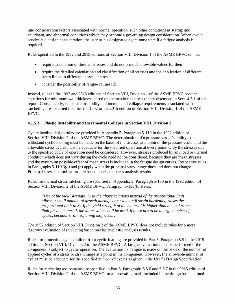
53
into consideration factors associated with normal operation, such other conditions as startup and
shutdown, and abnormal conditions which may become a governing design consideration. When cyclic
service is a design consideration, the user or his designated agent must state if a fatigue analysis is
required.
Rules specified in the 1992 and 2015 editions of Section VIII, Division 1 of the ASME BPVC do not:
• require calculation of thermal stresses and do not provide allowable values for them
• require the detailed calculation and classification of all stresses and the application of different
stress limits to different classes of stress
• consider the possibility of fatigue failure [2]
Instead, rules in the 1992 and 2015 editions of Section VIII, Division 1 of the ASME BPVC provide
equations for minimum wall thickness based on the maximum stress theory discussed in Sect. 4.5.1 of this
report. Consequently, no plastic instability and incremental collapse requirements associated with
ratcheting are specified in either the 1992 or the 2015 edition of Section VIII, Division 1 of the ASME
BPVC.
4.1.5.3 Plastic Instability and Incremental Collapse in Section VIII, Division 2
Cyclic loading design rules are provided in Appendix 5, Paragraph 5-110 in the 1992 edition of
Section VIII, Division 2 of the ASME BPVC. The determination of a pressure vessel’s ability to
withstand cyclic loading must be made on the basis of the stresses at a point of the pressure vessel and the
allowable stress cycles must be adequate for the specified operation at every point. Only the stresses due
to the specified cycle of operation need be considered. However, stresses produced by any load or thermal
condition which does not vary during the cycle need not be considered, because they are mean stresses
and the maximum possible effect of mean stress is included in the fatigue design curves. Respective rules
in Paragraphs 5-110.3(a) and (b) apply when the principal stress range does and does not change.
Principal stress determinations are based on elastic stress analysis results.
Rules for thermal stress ratcheting are specified in Appendix 5, Paragraph 5-130 in the 1992 edition of
Section VIII, Division 2 of the ASME BPVC. Paragraph 5-130(b) states:
“Use of the yield strength, Sy, in the above relations instead of the proportional limit
allows a small amount of growth during each cycle until strain hardening raises the
proportional limit to Sy. If the yield strength of the material is higher than the endurance
limit for the material, the latter value shall be used, if there are to be a large number of cycles, because strain softening may occur.”
The 1992 edition of Section VIII, Division 2 of the ASME BPVC does not include rules for a more
rigorous evaluation of ratcheting based on elastic-plastic analysis results.
Rules for protection against failure from cyclic loading are provided in Part 5, Paragraph 5.5 in the 2015
edition of Section VIII, Division 2 of the ASME BPVC. A fatigue evaluation must be performed if the
component is subject to cyclic operation. The evaluation for fatigue is made on the basis of the number of
applied cycles of a stress or strain range at a point in the component. However, the allowable number of
cycles must be adequate for the specified number of cycles as given in the User’s Design Specification.
Rules for ratcheting assessments are specified in Part 5, Paragraphs 5.5.6 and 5.5.7 in the 2015 edition of
Section VIII, Division 2 of the ASME BPVC for all operating loads included in the design basis defined

54
by the user even if the fatigue screening criteria are satisfied. Protection against ratcheting is satisfied if
one of the following three conditions is met [2].
1. The loading results in only primary stresses without any cyclic secondary stresses.
2. Elastic Stress Analysis Criteria – Protection against ratcheting is demonstrated by satisfying the
rules of Part 5, Paragraph 5.5.6.
3. Elastic-Plastic Stress Analysis Criteria – Protection against ratcheting is demonstrated by
satisfying the rules of Part 5, Paragraph 5.5.7.
The elastic analysis method provided in the 2015 edition of Section VIII, Division 2 of the ASME BPVC
to evaluate ratcheting in accordance with rules specified in Part 5, Paragraph 5.5.6 is the same as the
method provided in the 1992 edition of Section VIII, Division 2 of the ASME BPVC [2].
The elastic-plastic analysis method provided in the 2015 edition of Section VIII, Division 2 of the ASME
BPVC to evaluate ratcheting in accordance with rules specified in Part 5, Paragraph 5.5.7 involves
application, removal, and re-application of the applied loadings. If protection against ratcheting is
satisfied, it may be assumed that progression of the stress-strain hysteresis loop along the strain axis
cannot be sustained with cycles and that the hysteresis loop will stabilize. A separate check for plastic
shakedown to alternating plasticity is not required. Ratcheting is not a concern if the entire component
remains elastic, or an elastic core is maintained with alternating plasticity occurring outside of the core
during cyclic operation. Ratcheting is also not a concern when there is no permanent change to the overall
component dimensions meaning that a progressive incremental inelastic deformation has not occurred [2].
4.1.6 Fatigue
Fatigue is the weakening of a material caused by repeatedly applied loads. It is the progressive and
localized material degradation that occurs when a component is subjected to cyclic loading. If the loads
are above a certain threshold, microscopic cracks will begin to form at stress concentrations such as
square holes or sharp corners. Eventually the crack will reach a critical size, propagate, and cause the
component to fracture. Avoidance of discontinuities that increase local stresses will increase the fatigue
life of a component subjected to cyclic loading.
There are two basic forms of fatigue that can adversely affect a boiler or pressure vessel. High-cycle
fatigue (HCF) is characterized by low amplitude high frequency elastic strains. Low-cycle fatigue (LCF)
is characterized by high amplitude low frequency plastic strains. The primary difference between HCF
and LCF is the fact that the former involves little or no plastic action, whereas failure in a few thousand
cycles can be produced only by strains in excess of the yield strain. In the plastic region, large changes in
strain can be produced by small changes in stress.
The ASME BPVC establishes fatigue margins based on two considerations: (1) a factor of twenty on the
number of cycles, and (2) a factor of two on stress. Studies of fatigue test data show that 10,000 cycles is
the approximate border between LCF and HCF and a factor of twenty on the number of cycles has little
effect at a high number of cycles. Consequently, a factor on stress was introduced as a margin at the
higher number of cycles. A factor of two on stress gives approximately the same margin as a factor of
twenty on cycles [2].
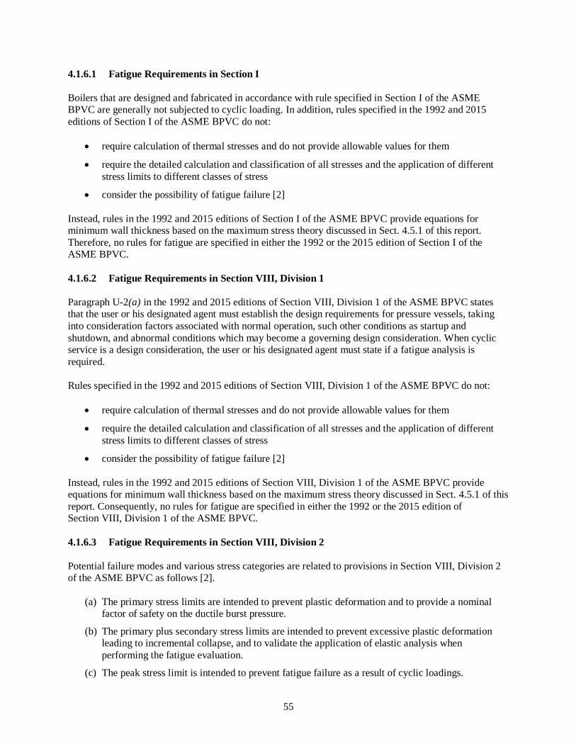
55
4.1.6.1 Fatigue Requirements in Section I
Boilers that are designed and fabricated in accordance with rule specified in Section I of the ASME
BPVC are generally not subjected to cyclic loading. In addition, rules specified in the 1992 and 2015
editions of Section I of the ASME BPVC do not:
• require calculation of thermal stresses and do not provide allowable values for them
• require the detailed calculation and classification of all stresses and the application of different
stress limits to different classes of stress
• consider the possibility of fatigue failure [2]
Instead, rules in the 1992 and 2015 editions of Section I of the ASME BPVC provide equations for
minimum wall thickness based on the maximum stress theory discussed in Sect. 4.5.1 of this report.
Therefore, no rules for fatigue are specified in either the 1992 or the 2015 edition of Section I of the
ASME BPVC.
4.1.6.2 Fatigue Requirements in Section VIII, Division 1
Paragraph U-2(a) in the 1992 and 2015 editions of Section VIII, Division 1 of the ASME BPVC states
that the user or his designated agent must establish the design requirements for pressure vessels, taking
into consideration factors associated with normal operation, such other conditions as startup and
shutdown, and abnormal conditions which may become a governing design consideration. When cyclic
service is a design consideration, the user or his designated agent must state if a fatigue analysis is
required.
Rules specified in the 1992 and 2015 editions of Section VIII, Division 1 of the ASME BPVC do not:
• require calculation of thermal stresses and do not provide allowable values for them
• require the detailed calculation and classification of all stresses and the application of different
stress limits to different classes of stress
• consider the possibility of fatigue failure [2]
Instead, rules in the 1992 and 2015 editions of Section VIII, Division 1 of the ASME BPVC provide
equations for minimum wall thickness based on the maximum stress theory discussed in Sect. 4.5.1 of this
report. Consequently, no rules for fatigue are specified in either the 1992 or the 2015 edition of
Section VIII, Division 1 of the ASME BPVC.
4.1.6.3 Fatigue Requirements in Section VIII, Division 2
Potential failure modes and various stress categories are related to provisions in Section VIII, Division 2
of the ASME BPVC as follows [2].
(a) The primary stress limits are intended to prevent plastic deformation and to provide a nominal
factor of safety on the ductile burst pressure.
(b) The primary plus secondary stress limits are intended to prevent excessive plastic deformation
leading to incremental collapse, and to validate the application of elastic analysis when
performing the fatigue evaluation.
(c) The peak stress limit is intended to prevent fatigue failure as a result of cyclic loadings.

56
(d) Special stress limits are provided for elastic and inelastic instability.
1992 Edition
Rules specified in Article D-1, Paragraph AD-160 in the 1992 edition of Section VIII, Division 2 of the
ASME BPVC establish criteria for determining when a fatigue analysis is required. If a fatigue analysis is
not required, design rules specified in Appendix 4 – Mandatory Design Based on Stress Analysis apply.
When a fatigue analysis is required, design rules specified in Appendix 5 – Mandatory Design Based on
Fatigue Analysis apply. Rules for design for cyclic loading are provided in Appendix 5, Paragraph 5-110
in the 1992 edition of Section VIII, Division 2 of the ASME BPVC. Rules specified in the 1992 edition of
Section VIII, Division 2 of the ASME BPVC prevent fatigue failure by limiting peak stresses. Cyclic
loading design procedures in the 1992 edition of Section VIII, Division 2 of the ASME BPVC that apply
when the principal stress direction does not change are specified in Paragraph 5-110.3(a). Corresponding
procedures that apply when the principal stress direction change are specified in Paragraph 5-110.3(b).
Requirements for preventing thermal stress ratchet growth of a shell subjected to thermal cycling are
provided in Paragraph 5-130 in the 1992 edition of Section VIII, Division 2 of the ASME BPVC. Rules in
Paragraph 5-130(b) further state that:
“Use of the yield strength Sy in the above relations instead of the proportional limit
allows a small amount of growth during each cycle until strain hardening raises the
proportional limit to Sy. If the yield strength of the material is higher than is the endurance limit for the material, the latter value shall be used, if there are to be a large
number of cycles, because strain softening may occur.”
2015 Edition
Rules specified in Part 4 – Design by Rule Requirements, Paragraph 4.1.1.4 in the 2015 edition of
Section VIII, Division 2 of the ASME BPVC state:
“A screening criterion shall be applied to all pressure vessel parts designed in accordance with this Division to determine if a fatigue analysis is required. The fatigue
screening criterion shall be performed in accordance with 5.5.2. If the results of this
screening indicate that a fatigue analysis is required, then the analysis shall be performed in accordance with 5.5.2. If the allowable stress at the design temperature is
governed by time-dependent properties, then a fatigue screening analysis based on
experience with comparable equipment shall be satisfied (see 5.5.2.2).”
Rules for performing a fatigue evaluation are specified in the following Paragraphs in the 2015 edition of
Section VIII, Division 2 of the ASME BPVC.
• Paragraph 5.5.3 – Fatigue Assessment – Elastic Stress Analysis and Equivalent Stresses. In this
method, an effective total equivalent stress amplitude is used to evaluate the fatigue damage for
results obtained from a linear elastic stress analysis.
• Paragraph 5.5.4 – Fatigue Assessment – Elastic Plastic Stress Analysis and Equivalent Strains. In
this method, The effective strain range is used to evaluate the fatigue damage for results obtained
from an elastic-plastic stress analysis.
• Paragraph 5.5.5 – Fatigue Assessment of Welds – Elastic Analysis and Structural Stress. In this
method, an equivalent structural stress range parameter is used to evaluate the fatigue damage for
results obtained from a linear elastic stress analysis. The controlling stress for the fatigue
evaluation is the structural stress that is a function of the membrane and bending stresses normal

57
to the hypothetical crack plane. This method is recommended for evaluation of welded joints that
have not been machined to a smooth profile. Weld joints with controlled smooth profiles may be
evaluated using 5.5.3 or 5.5.4. However, this fatigue method may only be used when approved by
the owner/user.
Rules specified in the 2015 edition of Section VIII, Division 2 of the ASME BPVC for evaluating fatigue
are more comprehensive and provide equivalent or greater safety compared to corresponding rules for
evaluating fatigue specified in the 1992 edition of Section VIII, Division 2 of the ASME BPVC.
4.1.7 Stress Corrosion and Corrosion Fatigue
Corrosion is a surface phenomenon that exhibits the gradual destruction of metals by chemical or
electrochemical reactions with their environment. There are many types of corrosion that can cause
deterioration of boiler and pressure vessel components. Two common types of corrosion that can
adversely affect the integrity of a boiler or pressure vessel include stress corrosion cracking and corrosion
fatigue.
Stress corrosion cracking (SCC) is the growth of crack formation in a corrosive environment and is highly
chemically specific in that certain alloys are likely to undergo SCC only when exposed to a small number
of chemical environments. The chemical environment that causes SCC for a given alloy is often one
which is only mildly corrosive to the metal otherwise. The specific environment is of crucial importance,
and only very small concentrations of certain highly active chemicals are needed to produce catastrophic
cracking, often leading to devastating and unexpected failure. Metal components with severe SCC can
appear bright and shiny, while being filled with microscopic cracks. These cracks can lead to unexpected
sudden failure of normally ductile metals subjected to a tensile stress. Additional information about SCC
associated with materials used in ASME BPVC construction is provided in Nonmandatory Appendix A,
Paragraph A-701 in the 2015 edition of Section II, Part D of the ASME BPVC.
Corrosion fatigue is the mechanical degradation of a material under the joint action of corrosion and
cyclic loading. Since corrosion-fatigue cracks initiate at a metal’s surface, surface treatments like plating,
cladding, nitriding, and shot peening can improve the materials’ resistance to corrosion fatigue. However,
corrosion fatigue only occurs when the metal is under tensile stress. The rate of fatigue crack growth is
enhanced by corrosion. Additional information about corrosion fatigue associated with materials used in
ASME BPVC construction is provided in Nonmandatory Appendix A, Paragraph A-605 in the 2015
edition of Section II, Part D of the ASME BPVC.
Users or their designated agents are responsible for assuring that the materials used for construction of
boilers and pressure vessels are suitable for the intended service conditions with respect to mechanical
properties, resistance to corrosion, erosion, oxidation, and other damage mechanisms anticipated during
service life. Protection against environmental conditions such as corrosion is the responsibility of the
designer when included in the design basis. This protection is normally accomplished by selecting
corrosion resistant materials and adding a corrosion allowance to the required minimum thickness of a
component. The corrosion allowance does not need to be the same for all parts of a boiler or pressure
vessel.
4.1.7.1 Corrosion Requirements in Section I
Concerns for corrosion of certain materials used for boiler construction are identified in Endnote 1 in the
2015 edition of Section I of the ASME BPVC which states:

58
“Austenitic alloys are susceptible to intergranular corrosion and stress corrosion cracking when used in boiler applications in water-wetted service. Factors that affect the
sensitivity to these metallurgical phenomena are applied or residual stress and water
chemistry. Susceptibility to attack is usually enhanced by using the material in a stressed
condition with a concentration of corrosive agents (e.g., chlorides, caustic, or reduced
sulfur species). For successful operation in water environments, residual and applied stresses must be minimized and careful attention must be paid to continuous control of
water chemistry.”
However, the 1992 and 2015 editions of Section I of the ASME BPVC do not include rules that
specifically govern corrosion allowances.
4.1.7.2 Corrosion Requirements in Section VIII, Division 1
Rules for corrosion are specified in Paragraph UG-25 in the 1992 and 2015 editions of Section VIII,
Division 1 of the ASME BPVC. These rules state:
“The user or his designated agent must specify corrosion allowances other than those required by the rules of this Division. Where corrosion allowances are not provided, this
fact shall be indicated on the Data Report.”
In addition,
“Vessels or parts of vessels subject to thinning by corrosion, erosion, or mechanical
abrasion shall have provision made for the desired life of the vessel by a suitable increase in the thickness of the material over that determined by the design formulas, or
by using some other suitable method of protection.”
Nonmandatory suggestions on the selection and treatment of austenitic chromium-nickel and ferritic and
martensitic high chromium steel are provided in Appendix HA in the 1992 edition of Section VIII,
Division 1 of the ASME BPVC. Paragraph UHA-103 states:
“Austenitic chromium-nickel steels that are highly stressed in tension may develop transcrystalline or intercrystalline cracks when exposed to certain corrosive media. The
stresses may be produced by external loads, welding or cold forming operations, or by
uneven cooling. Methods of reducing susceptibility to stress corrosion cracking include
the selection of a composition that will have a stable austenite structure in the operating
range and heat treatment to reduce the magnitude of the residual stresses.”
Similar guidance on the selection and treatment of austenitic chromium–nickel and ferritic and
martensitic high chromium steels is provided in Nonmandatory Appendix HA in the 2015 edition of
Section VIII, Division 1 of the ASME BPVC.
4.1.7.3 Corrosion Requirements in Section VIII, Division 2
Rules specified in Paragraph AD-115 in the 1992 edition of Section VIII, Division 2 of the ASME BPVC
state that:
“Vessels or parts thereof subject to loss of metal by corrosion, erosion, mechanical
abrasion, or other environmental effects must have provisions made for such of the same thickness for all parts of the vessel, if different rates of attack are expected for the various

59
parts. No additional thickness need be provided when previous experience in like service has shown that corrosion does not occur or is of only a superficial nature determined by
the design formulas or stress analysis.”
In comparison, rules specified in Part 4, Paragraph 4.1.4.2 in the 2015 edition of Section VIII, Division 2
of the ASME BPVC state:
“The term corrosion allowance as used in this Division is representative of loss of metal by corrosion, erosion, mechanical abrasion, or other environmental effects and shall be
accounted for in the design of vessels or parts when specified in the User's Design
Specification.”
User’s Design Specification rules specified in Part 2, Paragraph 2.2.2.1 in the 2015 edition of
Section VIII, Division 2 of the ASME BPVC state:
“If corrosion fatigue is anticipated, a factor should be chosen on the basis of experience
or testing, by which the calculated design fatigue cycles (fatigue strength) should be
reduced to compensate for the corrosion.”
A discussion of screening criterion for determining if a fatigue analysis is required is presented in
Sect. 4.1.6.3 of this report.
4.2 DESIGN BASIS
According to rules specified in the ASME BPVC, users are responsible for establishing the design basis
for a boiler or pressure vessel. These rules vary from one section and edition of the ASME BPVC to
another. Requirements in Section I and Section VIII, Division 1 of the ASME BPVC do not explicitly
consider the effects of combined stress or give detailed methods for combining stresses. However,
Section VIII, Division 2 of the ASME BPVC provides specific guidelines for stresses, how they are
combined, and allowable stresses for categories of combined stresses.
4.2.1 Design Basis Requirements in Section I
Mandatory design requirements for boiler components with multiple design conditions are provided in
Paragraph PG-21.4 in the 2015 edition of Section I of the ASME BPVC. This paragraph states that
components with multiple design conditions may be designed considering the coincident pressures and
temperatures if all of the following conditions are met.
1. The component must be designed for the most severe condition of coincident pressure and
temperature expected to be sustained during operation that results in the greatest calculated
thickness for the pressure part and that will not exceed the maximum temperature or the
maximum allowable stress permitted in Section II, Part D for the material.
2. The design requirements of this Section must be met for each design condition (coincident
pressure and temperature).
3. The MAWP selected for the part must be sufficiently in excess of the highest pressure of the
multiple design conditions to permit satisfactory boiler operation without operation of the
overpressure protection device (s). Each design condition (coincident pressure and temperature)
must be reported on the Manufacturer’s Data Report.
In addition, Paragraph PG-22.1 in the 2015 edition of Section I of the ASME BPVC states:

60
“Stresses due to hydrostatic head must be taken into account in determining the minimum thickness required unless noted otherwise. This Section does not fully address additional
loadings other than those from working pressure or static head. Consideration must be
given to such additional loadings.”
This requirement ensures that post-construction loads such as those associated with in-service pressure
tests that may be imposed by PHMSA regulations or by the Authority Having Jurisdiction are included in
the design basis.
Paragraph PG-22.1 in the 1992 edition of Section I of the ASME BPVC also defines requirements for
loadings. However, these requirements are stated differently from those in Paragraph PG-22.1 in the 2015
edition of Section I of the ASME BPVC. Paragraph PG-22.1 in the 1992 edition states:
“Stresses due to hydrostatic head shall be taken into account in determining the
minimum thickness required unless noted otherwise. Additional stresses imposed by
effects other than working pressure or static head which increase the average stress by
more than 10% of the allowable working stress must also be taken into account. These
effects include the weight of the component and its contents, and the method of support.”
This requirement in Paragraph PG-22.1 in the 1992 edition is less conservative than the corresponding
requirement in Paragraph PG-22.1 in the 2015 edition because stresses are not allowed to exceed the
maximum allowable stress permitted in the 2015 edition of Section II, Part D of the ASME BPVC.
4.2.2 Design Basis Requirements in Section VIII, Division 1
Mandatory requirements specified in Paragraph U-2 in the 1992 and 2015 editions of Section VIII,
Division 1 of the ASME BPVC state that the user or his designated agent must establish the design
requirements for pressure vessels, taking into consideration factors associated with normal operation, and
such other conditions as startup and shutdown. The 1992 edition lists four such considerations, whereas
the 2015 edition lists five such conditions. However, these lists do not necessarily identify all conditions
that should be included as design requirements because additional conditions could also affect the design
of a particular pressure vessel.
Nonmandatory guidance to the responsibilities of the user and designated agent is provided in
Nonmandatory Annex NN in the 2015 edition of Section VIII, Division 1 of the ASME BPVC. This
guidance states that a “user” is an entity that defines the design conditions and parameters of the pressure
vessel and communicates these conditions and parameters to the Manufacturer. This guidance also states
that the user is responsible for providing the information pertinent to the design requirements for the
pressure vessel to be constructed. Additional guidance is provided in Nonmandatory Appendix KK for
preparing User’s Design Requirements. This guidance includes User’s Design Requirement Forms for
single and multi-chamber pressure vessels and instructions for completing these forms. The forms include
entries for defining design and operating conditions, materials, nozzle schedules, joint and flange
requirements, and a signature block for certifying that the information in the form is accurate and
represents all details of design as per the user or his designated agent. They are also formatted with space
for entering additional design requirements including post-construction loads such as those associated
with in-service pressure tests that may be imposed by PHMSA in 49 CFR Part 193 or the Authority
Having Jurisdiction. It is important to note that Nonmandatory Appendix KK states that completion of
these forms is neither required nor prohibited for pressure vessels constructed in accordance with ASME
BPVC rules.

61
In comparison, the 1992 edition of Section VIII, Division 1 does not include corresponding guidance to
that provided in Nonmandatory Annex KK or Nonmandatory Annex NN in the 2015 edition of
Section VIII, Division 1 of the ASME BPVC.
4.2.3 Design Basis Requirements in Section VIII, Division 2
Paragraph AD-100 in the 1992 edition of Section VIII, Division 2 of the ASME BPVC states that when
complete rules are not provided for a pressure vessel or pressure vessel part, or when the vessel designer
or user chooses, a complete stress analysis of the pressure vessel or pressure vessel part must be
performed considering all of the loadings specified in the User’s Design Specification (UDS).
Paragraph AG-301 further states that it is the responsibility of the user or an agent acting on his behalf,
who intends that a pressure vessel be designed, constructed, tested, and certified in compliance with these
rules, to provide for such pressure vessel or pressure vessels, a UDS. The only information that must be
provided in the UDS is defined in Paragraphs AG-301(a), AG-301(b), and AG-301(c). This list, which is
much less comprehensive that the list defined in Paragraph 2.2.2 in the 2015 edition of Section VIII,
Division 2 of the ASME BPVC, only includes whether or not:
(a) a fatigue analysis is to be performed,
(b) a corrosion or erosion allowance is to be provided, and
(c) the contained fluid is lethal.
Paragraph AG-301.2 in the 1992 edition of Section VIII, Division 2 of the ASME BPVC states that a
professional engineer, registered in one or more of the states of the United States of America or the
provinces of Canada and experienced in pressure vessel design, must certify to the compliance of the
UDS with the requirements specified in Paragraph AG-301.
Design basis rules for pressure vessels constructed in accordance with requirements specified in the 2015
edition of Section VIII, Division 2 of the ASME BPVC are provided in Part 4, Paragraph 4.1.5. These
rules states that:
• all applicable loads and load case combinations must be considered in the design to determine the
minimum required wall thickness for a pressure vessel part, and
• the loads that must be considered in the design must include, but not be limited to, those shown in
Table 4.1.1 and must be included in the User’s Design Specification (UDS).
According to Part 2, Paragraph 2.2.1 in the 2015 edition of Section VIII, Division 2 of the ASME BPVC,
it is the responsibility of the user or an agent acting on behalf of the user to provide a certified UDS for
each pressure vessel to be constructed in accordance with this Division. The UDS must contain sufficient
detail to provide a complete basis for design and fabrication in accordance with this Division including all applicable loads and conditions acting on the pressure vessel that affect its design as well as other
information listed in Paragraph 2.2.2. It is the user’s responsibility to specify, or cause to be specified, the
effective Code edition and Addenda to be used for construction, which must be the Code edition and
Addenda in effect when the contract for the vessel is signed by the user and the Manufacturer. However,
the Manufacturer is not responsible to include any loadings or conditions in the design that are not
defined in the UDS. A summary of the information required to be specified in the UDS follows [2].
1. Installation site – identify location, Jurisdictional authority, and environmental conditions such as
wind, earthquake and snow loads, and the lowest one-day mean temperature for this location.

62
2. Vessel identification – provide the vessel number or identification, and any special service fluids
where specific properties are needed for design.
3. Vessel configuration and controlling dimensions – provide outline drawings, pressure vessel
orientation, openings, connections, closures including quantity, type and size, the principal
component dimensions, and the support method.
4. Design conditions – specified design pressure [see definition of design pressure in
Paragraph 4.1.5.2.(a)] and design temperature, MDMT, dead loads, live loads and other loads
required to perform load case combinations. Note that the specified design pressure is the design
pressure required at the top of the vessel and its operating position.
5. Operating conditions – operating pressure and temperature, fluid transients and flow and
sufficient properties for determination of steady-state and transient thermal gradients across
vessel sections. Operating conditions are used to satisfy certain acceptance criteria limits when
performing a design by analysis per Part 5.
6. Design fatigue life – When a vessel is designed for cyclic conditions, the number of design cycles
per year and the required vessel design life in years must be stated.
7. Materials of construction – specification of materials of construction, corrosion and/or erosion
allowance.
8. Loads and loads cases – the user must specify all expected loads and load case combinations as
listed in Part 4, Paragraph 4.1.5.3.
9. Overpressure protection – describe the type of overpressure protection system. The system must
meet the requirements of Part 9.
10. Additional requirements – Part 2, Paragraph 2.2.2.2 lists additional requirements that may be
appropriate to be described in the UDS for the intended vessel service such as, additional
requirements for NDE, heat treatments, type of weld joints, and information concerning erection
loadings, etc. These additional design requirements could include post-construction loads such as
those associated with in-service pressure tests that may be imposed by PHMSA in 49 CFR Part
193 or the Authority Having Jurisdiction.
Normative guidance for certifying a UDS is presented in Annex 2-A in the 2015 edition of Section VIII,
Division 2 of the ASME BPVC. According to this guidance, one or more Professional Engineers,
registered in one or more of the states of the United States of America or the provinces of Canada and
experienced in pressure vessel design, must certify that the UDS meets the requirements in Part 2,
Paragraph 2.2.2, and must apply the Professional Engineer seal in accordance with the required
procedures. In addition, the Registered Professional Engineer(s) must prepare a statement to be affixed to
the document attesting to compliance with the applicable requirements of the Code.
4.3 STRESS CATEGORIES
The ASME BPVC prescribes primary, secondary, and peak stress limits for boilers and pressure vessels
to prevent the following modes of failure [2].
1. Bursting and gross distortion from a single application of pressure are prevented by the limits
placed on primary stresses
2. Progressive distortion is prevented by the limits placed on primary-plus-secondary stresses. These
limits assure shake-down to elastic action after a few repetitions of the loading.
3. Fatigue failure is prevented by the limits placed on peak stresses.

63
Stress limit equations specified in the ASME BPVC are primarily a function of yield strength, but they
also provide a design margin against plastic collapse caused by inelastic response as discussed in Sect. 4.8
of this report. These stress limits are used to establish MAWP, to define boundaries for pneumatic and
hydrostatic pressure testing, and as the basis for overpressure protection limits. Boiler and pressure vessel
designers are responsible for understanding when primary, secondary, and peak stresses occur and which
equations must be applied.
4.3.1 Primary Stresses
A primary stress is a stress developed by the imposed loading which is necessary to satisfy the laws of
equilibrium between external and internal forces and moments. Primary stresses are categorized as:
• General primary membrane stresses
• Primary bending stresses
• Local primary membrane stresses
The basic characteristic of a primary stress is that it is not self-limiting. If a primary stress exceeds the
yield strength of the material through the entire thickness, the prevention of failure is entirely dependent
on the strain-hardening properties of the material. Primary stress limits for boilers and pressure vessels are
intended to prevent gross distortion (i.e., plastic deformation) and bursting from a single application of
pressure. The need for subdividing primary stress into membrane and bending categories is that limit
design theory shows that the calculated value of a primary bending stress may be allowed to exceed the
calculated value of a primary membrane stress [2]. A discussion of limit design theory is presented in
Sect. 4.4 of this report.
4.3.2 Secondary Stresses
A secondary stress is a stress developed by the self-constraint of a component. It must satisfy an imposed
strain pattern rather than being in equilibrium with an external load. The basic characteristic of a
secondary stress is that it is self-limiting. Local yielding and minor distortions can satisfy the
discontinuity conditions or thermal expansions which cause secondary stress. Thermal stresses that can
produce distortion of a component are categorized as secondary stresses.
4.3.3 Peak Stresses
A peak stress is the highest stress in the region under consideration. The basic characteristic of a peak
stress is that it causes no significant distortion and is objectionable because it is a possible source of
fatigue failure. Thermal stresses that result from almost complete suppression of the differential
expansion, and thus cause no significant distortion, are categorized as peak stresses.
4.4 MAXIMUM ALLOWABLE DESIGN STRESSES
The ASME BPVC provides rules for establishing allowable design stresses for ferrous and nonferrous
metals and for bolting materials. Different maximum allowable stress limits are prescribed for specific
material types and temperature ranges. Maximum allowable stress limits have evolved over time and vary
from one section and edition of the ASME BPVC to another. The basis used to establish allowable stress
values is explained in the appendices to Section II, Part D of the ASME BPVC.
Alternative rules for establishing allowable design stresses for materials having higher allowable stresses
at low temperature are provided in Part ULT of Section VIII, Division 1 of the ASME BPVC. Similar

64
rules for materials having a higher allowable stresses at low temperature are not provided in Section I or
Section VIII, Division 2 of the ASME BPVC.
4.4.1 Basis for Establishing Allowable Stress Values for Section I and Section VIII, Division 1
Criteria for establishing allowable stresses for use in performing calculations in accordance with rules
specified in Section I and Section VIII, Division 1 of the ASME BPVC are discussed in Mandatory
Appendix 1 of Section II, Part D in the 2015 edition and in Appendix 1 of Section II, Part D in the 1992
edition. These allowable stress values, which are specified in Section II, Part D, Tables 1A and 1 B, are
subdivided into materials below room temperature and materials at room temperature and above. Except
for pressure vessels constructed using materials having a higher allowable stresses at low temperature as
discussed in Sect. 4.4.3 of this report, the maximum allowable stress is the lowest value obtained from the
criteria presented in Table 4.5 of this report. It is important to note that the maximum allowable stress
may equal, but can never exceed, two‐thirds of the specified minimum yield strength (i.e., 2/3 Sy) at room
temperature.
Table 4.5 Criteria for establishing allowable stresses for wrought or cast ferrous and nonferrous
products and materials other than bolting specified in Section I and Section VIII, Division 1
Criteria
(See Notes 1 and 2)
Section II, Part D, Appendix 1,
1992 Edition
Section II, Part D, Mandatory
Appendix 1, 2015 Edition
(a)(1) ST/4.0
1/4 of the specified minimum tensile
strength at room temperature, ST
ST/3.5
the specified minimum tensile strength at
room temperature, ST, divided by 3.5
(a)(2) ST/4.0 or 1.1 ST RT/4.0
either 1/4 of the specified minimum
tensile strength at room temperature, ST,
or 1/4 of the tensile strength at
temperature, 1.1 ST RT
ST/3.5 or 1.1 ST RT/3.5
either the tensile strength at room
temperature, ST, divided by 3.5 or the
tensile strength at temperature, 1.1 ST RT,
divided by 3.5
(a)(3) 2/3 SY
2/3 of the specified minimum yield
strength at room temperature, SY
2/3 SY
2/3 of the specified minimum yield
strength at room temperature, SY
(a)(4) 2/3 SY RY or 0.9 SY RY
either 2/3 of the yield strength at
temperature, SY RY, or 90% of the yield
strength at temperature, SY RY
2/3 SY RY or 0.9 SY RY
either 2/3 of the yield strength at
temperature, SY RY, or 90% of the yield
strength at temperature, SY RY
Criteria
(See Note 3)
Section II, Part D, Appendix 1,
1992 Edition
Section II, Part D, Mandatory
Appendix 1, 2015 Edition
(b)(1) 1.0 SC
100% of the average stress to produce a
creep rate of 0.01%/1,000 hr, SC
1.0 SC
100% of the average stress to produce a
creep rate of 0.01%/1,000 hr, SC
(b)(2) 0.67 SRavg
67% of the average stress to cause rupture
at the end of 100,000 hr, SRavg
Favg × SRavg
100Favg% of the average stress to cause
rupture at the end of 100,000 hr, SRavg
where Favg = 0.67 at 1,500°F and below
(b)(3) 0.8 SRmin
80% of the minimum stress to cause
rupture at the end of 100,000 hr, SRmin
0.8 SRmin
80% of the minimum stress to cause
rupture at the end of 100,000 hr, SRmin

65
where:
RY = ratio of the average temperature dependent trend curve value of tensile strength to the room temperature tensile
strength
RY = ratio of the average temperature dependent trend curve value of yield strength to the room temperature yield
strength
Notes:
1. 1992 Criteria (a)(4): Two sets of allowable stress values are provided in Table 1A for austenitic materials and in
Table 1B for specific nonferrous alloys. The higher alternative stresses are identified by footnote. These stresses
exceed two-thirds but do not exceed 90% of the minimum yield strength at temperature. The higher stress
values should be used only where slightly higher deformation is not in itself objectionable. These higher
stresses are not recommended for design of flanges or other strain sensitive applications.
2. 2015 Criteria (a)(4): Two sets of allowable stress values may be provided for austenitic stainless steels in
Table 1A, and nickel alloys and cobalt alloys in Table 1B, having an SY/ST ratio less than 0.625. The lower
values are not specifically identified by a footnote. These lower values do not exceed two‐thirds of the yield
strength at temperature. The higher alternative allowable stresses are identified by a footnote. These higher
stresses may exceed two‐thirds but do not exceed 90% of the yield strength at temperature. The higher values
should be used only where slightly higher deformation is not in itself objectionable. These higher stresses are
not recommended for the design of flanges or for other strain-sensitive applications.
3. 1992 and 2015 Criteria (b): At temperatures in the range where creep and stress rupture strength govern the
selection of stresses, the maximum allowable stress value for all materials is established by the Committee not
to exceed the lowest of the tabulated values.
The factor of 4.0 and 3.5 with respect to ultimate tensile strength presented in Table 4.1 of this report for
Criterion (a)(1) and (a)(2) is a design margin against bursting [4]. It is also intended to account for
uncertainties in material properties, loading conditions, fabrication and welding, geometric shape, and the
design approach that are difficult to quantify in terms of safety equivalency.
The bursting pressure of cylindrical and spherical shells can be predicted with reasonable accuracy if
consideration is given to the strain hardening properties of the material [4]. However, there are no rules in
the ASME BPVC for calculating burst pressure or for taking strain hardening properties into
consideration. Therefore, it is impossible to quantify the magnitude of the design margin for bursting for a
particular pressure vessel design configuration using ASME BPVC rules.
Paragraph UG-23(c) in the 1992 and 2015 editions of Section VIII, Division 1 of the ASME BPVC states:
“The wall thickness of a vessel computed by these rules shall be determined such that, for
any combination of loadings listed in UG-22 that induce primary stress and are expected
to occur simultaneously during normal operation of the vessel, the induced maximum general primary membrane stress does not exceed the maximum allowable stress value in
tension (see UG-23), except as provided in (d) below. Except where limited by special
rules, such as those for cast iron in flanged joints, the above loads shall not induce a combined maximum primary membrane stress plus primary bending stress across the
thickness that exceeds 1.5 times the maximum allowable stress value in tension (see
UG-23). It is recognized that high localized discontinuity stresses may exist in vessels
designed and fabricated in accordance with these rules. Insofar as practical, design rules
for details have been written to limit such stresses to a safe level consistent with experience.”
These rules ensure that the maximum allowable primary membrane stress, Pm, does not exceed 2/3 Sy and
that the maximum primary membrane stress plus primary bending stress, Pm + Pb, does not exceed Sy.
These maximum allowable stress limits are consistent with the principles of limit design theory discussed
in Sect. 4.6 and the plastic collapse requirements discussed in Sect. 4.8 of this report.

66
Loadings to be considered in pressure vessel design are listed in Paragraph UG-22 in the 1992 and 2015
editions of Section VIII, Division 1 of the ASME BPVC. These lists include the same loadings. However,
Paragraphs UG-22(i) and (j) in the 2015 edition of Section VIII, Division 1 impose additional loadings
that are not included in the 1992 edition of Section VIII, Division 1 of the ASME BPVC. These addition
loadings include: (i) abnormal pressure, such as those cause by deflagration, and (j) test pressure and
coincident static head acting during the hydrostatic test.
For allowable stress values specified in the 1992 edition of Section II, Part D of the ASME BPVC, which
are shown in Table 4.1 of this report, the yield strength controls the design of boilers and pressure vessels
that are designed and fabricated in accordance with rules specified in the 1992 edition of Section I or
Section VIII, Division 1 of the ASME BPVC when the ultimate tensile strength is greater than 2.67 (e.g.
2/3 × 4.0) times the yield strength. In comparison, the yield strength controls the design of boilers and
pressure vessels that are designed and fabricated in accordance with rules specified in the 2015 edition of
Section I or Section VIII, Division 1 of the ASME BPVC when the ultimate tensile strength is greater
than 2.33 (e.g. 2/3 × 3.5) times the yield strength. In general, yield to tensile strength ratios for steels
increase with increasing tensile strength.
Results of experimental burst testing of pressure vessels provides the basis for concluding that for some
pressure vessels, particularly those from steel with a high value of strain hardening coefficient, and which
have been designed under rules specified in the 1992 edition of the ASME BPVC, the true margin against
the bursting mode of failure can be as low as 2.4 [4]. An historic perspective on the evolution of design
stresses in the ASME BPVC is presented in Appendix A of this report.
According to LEFM theory, allowable stress in the presence of a given crack size is proportional to the
fracture toughness of the material. Therefore, to maintain an equivalent or greater level of safety against
brittle fracture resulting from the increase in allowable stresses, fracture toughness rules in the 2015
edition of Section VIII, Division 1 were changed from corresponding rules in the 1992 edition of
Section VIII, Division 1 of the ASME BPVC. For example, the minimum lateral expansion for high alloy
steels below -320°F was increased from 0.015 in. in the 1992 edition to 0.021 in. in the 2015 edition.
Toughness rules in the 1992 and 2015 editions of Section VIII, Division 1 of the ASME BPVC are
discussed and compared in Sect. 4.1.3.2 of this report.
4.4.2 Basis for Establishing Allowable Stress Values for Section VIII, Division 2
Criteria for establishing allowable stresses for use in performing calculations in accordance with rules
specified in Section VIII, Division 2 of the ASME BPVC are discussed in Mandatory Appendix 10 of
Section II, Part D in the 2015 edition and Appendix 2 of Section II, Part D in the 1992 edition. These
allowable stress values, which are specified in Tables 2A and 2 B in the 1992 edition of Section II, Part D
and Tables 5A and 5 B in the 2015 edition of Section II, Part D, are subdivided into materials below room
temperature and materials at room temperature and above. Maximum allowable stresses represent the
lowest value obtained from the criteria presented in Table 4.6 of this report. Unlike Section VIII,
Division 1 of the ASME BPVC, there are no rules in Section VIII, Division 2 of the ASME BPVC
specifically for pressure vessels constructed using materials having a higher allowable stresses at low
temperature.

67
Table 4.6 Criteria for establishing allowable stresses for wrought or cast ferrous and
nonferrous products and materials other than bolting specified in Section VIII, Division 2
Criteria (See Notes 1
and 2)
Section II, Part D, Appendix 2,
1992 Edition
Section II, Part D, Mandatory
Appendix 10, 2015 Edition
(a)(1) ST/3.0
one‐third of the specified minimum
tensile strength at room temperature, ST
ST/2.4
the specified minimum tensile strength at
room temperature, ST, divided by 2.4
(a)(2) 1.1 ST RT/3
one‐third of the tensile strength at
temperature, 1.1 ST RT
SY/1.5
the specified minimum yield strength at
room temperature, SY, divided by 1.5
Criteria (See Notes 1
and 2)
Section II, Part D, Appendix 2,
1992 Edition
Section II, Part D, Mandatory
Appendix 10, 2015 Edition
(a)(3) 2/3 SY
two‐thirds of the specified minimum yield
strength at room temperature, SY
SY RY/1.5
the yield strength at temperature, SY RY,
divided by 1.5
(a)(4) 2/3 SY RY or 0.9 SY RY
either two‐thirds of the yield strength at
temperature, SY RY, or 0.90 times the yield
strength at temperature, SY RY (Note 1)
Min. [SY/1.5, 0.9 SY RY]
lesser of the specified minimum yield
strength at room temperature, SY, divided
by 1.5, or 0.90 times the yield strength at
temperature, SY RY (Note 2)
Criteria (See Note 3) Section II, Part D, Appendix 2,
1992 Edition
Section II, Part D, Mandatory
Appendix 10, 2015 Edition
(b)(1) 1.0 SC
100% of the average stress to produce a
creep rate of 0.01%/1,000 hr, SC
1.0 SC
100% of the average stress to produce a
creep rate of 0.01%/1,000 hr, SC
(b)(2) 0.67 SRavg
100Favg% of the average stress to cause
rupture at the end of 100,000 hr, SRavg
Favg × SRavg
100Favg% of the average stress to cause
rupture at the end of 100,000 hr, SRavg
where Favg = 0.67 at 1,500°F and below
(b)(3) 0.8 SRmin
80% of the minimum stress to cause
rupture at the end of 100,000 hr, SRmin
0.8 SRmin
80% of the minimum stress to cause
rupture at the end of 100,000 hr, SRmin
where:
RY = ratio of the average temperature dependent trend curve value of tensile strength to the room temperature tensile
strength
RY = ratio of the average temperature dependent trend curve value of yield strength to the room temperature yield
strength
Notes:
1. In Table 2B for specific nonferrous alloys and in Table 2A for austenitic materials, the design stress intensity
values may exceed 66.67% and may reach 90% of the yield strength (0.2% offset) at temperature. This may result in a permanent strain of as much as 0.1%. When this amount of deformation is not acceptable, the
designer should reduce the allowable stress to obtain an acceptable amount of deformation. Table Y-2 lists
factors which should be applied to give low levels of permanent strain.
2. For austenitic stainless steels, nickel alloys, and cobalt alloys having an SY/ST ratio less than 0.625, higher stress
values are established at temperatures where the short-time tensile properties govern, to permit use of these
alloys where slightly greater deformation is acceptable. The stress values in this range exceed 66.67%, but do
not exceed 90%, of the yield strength at temperature, but never exceed two-thirds of the specified room

68
temperature minimum yield strength. These higher stress values are not recommended for the flanges of
gasketed joints or other applications where slight amounts of distortion can cause leakage or malfunction. Table
Y-2 lists multiplying factors that, when applied to the yield strength values shown in Table Y-1, will give
allowable stresses that will result in lower levels of permanent strain.
3. Criteria (b): At temperatures in the range where creep and stress rupture strength govern the selection of
stresses, the maximum allowable stress value for all materials is established by the Committee not to exceed the
lowest of the tabulated values.
The factor of 3.0 and 2.4 with respect to ultimate tensile strength presented in Table 4.6 of this report for
Criterion (a)(1) and (a)(2) is a design margin against bursting [4]. It is also intended to account for
uncertainties in material properties, loading conditions, fabrication and welding, geometric shape, and the
design approach that are difficult to quantify in terms of safety equivalency.
The bursting pressure of cylindrical and spherical shells can be predicted with reasonable accuracy if
consideration is given to the strain hardening properties of the material [4]. However, there are no rules in
the ASME BPVC for calculating burst pressure or for taking strain hardening properties into
consideration. Therefore, it is impossible to quantify the magnitude of the design margin for bursting for a
particular pressure vessel design configuration using ASME BPVC rules.
Experimental testing of pressure vessels was conducted at the University of Kansas in 1970s to develop a
better understanding of the bursting mode of failure of pressure vessels designed and fabricated in
accordance with rules specified in Section VIII, Division 2 of the ASME BPVC. The project included
burst tests on pressure vessels fabricated from three materials with different strain hardening exponents
(Type 304 stainless, SA-516 Gr. 70, and SA-517 Gr. F). These test results provide the basis for
concluding that [4]:
“Using the modified Svensson formula and the specified minimum tensile properties, the theoretical margins of safety for the University of Kansas test vessels (without sharp
notches) designed to Section VIII, Division 2 rules, ranged from about 2.8 for the
304 stainless steel vessel (with high strain hardening exponent) to about 3.2 for the high strength, quenched and tempered steel SA-517 (with low strain hardening exponent).”
As discussed in Sect. 4.5.2 of this report, Paragraph AD-140(b) in the 1992 edition of Section VIII,
Division 2 of the ASME BPVC states:
“The average value of the general primary membrane stress intensity across the
thickness of the section under consideration, due to any combination of design pressure and mechanical loadings expected to occur simultaneously, should not exceed the design
stress intensity value kSm.”
In addition, Paragraph AD-140(d) states:
“The primary bending stress due to any combination of design pressure and
mechanical loadings expected to occur simultaneously shall not exceed 1.5kSm.”
In comparison, Part 4, Paragraph 4.1.6.1 in the 2015 editions of Section VIII, Division 2 of the ASME
BPVC states:
“The wall thickness of a vessel computed by the rules of Part 4 for any combination of
loads (see 4.1.5) that induce primary stress (see definition of primary stress in 5.12) and

69
are expected to occur simultaneously during operation shall satisfy the equations shown below.”
Pm ≤ Sy (4.1.1)
Pm + Pb ≤ 1.5 Sy (4.1.2)
These rules ensure that the maximum allowable primary membrane stress, Pm, does not exceed 2/3 Sy and
that the maximum allowable primary membrane stress plus primary bending stress, Pm + Pb, does not
exceed Sy. These maximum allowable stress limits are consistent with the principles of limit design theory
discussed in Sect. 4.6 and the plastic collapse requirements discussed in Sect. 4.8 of this report.
For allowable stresses specified in the 1992 edition of Section II, Part D of the ASME BPVC, which are
shown in Table 4.6 of this report, the yield strength controls the design of pressure vessels that are
designed and fabricated in accordance with rules specified in the 1992 edition of Section VIII, Division 2
of the ASME BPVC when the ultimate tensile strength is greater than 2.0 (e.g. 2/3 × 3.0) times the yield
strength. In comparison, the yield strength controls the design of boilers and pressure vessels that are
designed and fabricated in accordance with rules specified in the 2015 edition of Section VIII, Division 2
of the ASME BPVC when the ultimate tensile strength is greater than 1.6 (e.g. 2/3 × 2.4) times the yield
strength. In general, yield to tensile strength ratios for steels increase with increasing tensile strength.
The following statement about the reduction factor on the specified minimum tensile strength in
Criterion (a)(1) in Table 4.6 of this report is presented in ASME publication PTB-1-2014 [2].
The design margin of 2.4 on the minimum specified room temperature ultimate tensile strength (i.e. the tensile strength at temperature is typically not considered) reflects
European practice and recognizes the successful service experience of vessel constructed
to these requirements. An overview of international pressure vessel codes and design requirements relative to both design margins and operating margins for in-service
equipment is provided in WRC 447 [6]. In general, the trend in Europe was to use a lower design margin with increased examination and inspection requirements when
compared to the ASME B&PV Section VIII Codes.
According to LEFM theory, allowable stress in the presence of a given crack size is proportional to the
fracture toughness. Therefore, to maintain an equivalent or greater level of safety against brittle fracture
resulting from the increase in allowable stresses, fracture toughness rules in the 2015 edition of
Section VIII, Division 2 were significantly changed from corresponding rules in the 1992 edition of
Section VIII, Division 2 of the ASME BPVC. A discussion of these toughness requirement changes is
presented in Sect. 4.1.3.3 of this report.
4.4.3 Alternative Rules for Material Having a Higher Allowable Stress at Low Temperature
Alternative rules for maximum allowable stress values for pressure vessels constructed of materials
having a higher allowable stresses at low temperature are tabulated in Part ULT of the 1992 and 2015
editions of Section VIII, Division 1 of the ASME BPVC. These maximum allowable stress values are
limited to the materials listed in Table ULT-23 at cryogenic temperatures for welded and nonwelded
construction for temperatures between -320°F and 100°F (150°F for 2015 edition). Materials listed in
Table ULT-23 include 5%, 8% and 9% nickel steels; Types 304 and 316 (2015 edition only) stainless
steels; and 5083-0 aluminum alloys.

70
Part ULT also includes rules for use in conjunction with rules covered in specified subsections and parts
of Section VIII, Division 1 of the ASME BPVC. These rules cover general, design, fabrication, inspection
and tests, marking and reports, and pressure relief devices.
4.5 STRENGTH THEORIES
The stress state at any point in a boiler or pressure vessel is completely defined by the magnitudes and
directions of the three principal stresses. When two or three of these stresses are different from zero, the
proximity to yielding must be determined by means of a strength theory. The following strength theories
are often used in engineering applications.
• maximum stress theory
• maximum shear stress theory (also known as the Tresca yield criterion)
• distortion energy theory (also known as the octahedral shear theory and the von Mises criterion)
The specific strength theory used as the basis for design rules specified in the ASME BPVC varies from
one section and edition to another.
The maximum stress theory states that the controlling stress is the largest of the three principal stresses.
The Tresca criterion represents a critical value of the maximum shear stress in a material while the von
Mises criterion represents a critical value of the distortional energy stored in a material. The maximum
shear stress theory (Tresca) and the distortion energy theory (von Mises) are both much better than the
maximum stress theory for predicting both yielding and fatigue failure in ductile metals. It is also
important to note that rules specified in the ASME BPVC based on these yield stress theories are only
applicable to homogenous materials with isotropic material properties.
4.5.1 Maximum Stress Theory
Equations specified in Section I and Section VIII, Division 1 of the ASME BPVC for determining wall
thickness are, by implication, consistent with the maximum stress theory. For thin-walled cylindrical
pressure vessels at locations that are remote from any discontinuities, the hoop stress is twice the axial
stress and the radial stress on the inside is compressive and equal to the internal pressure, p. If the hoop
stress is σ, the principal stresses are:
σ1 = σ
σ2 = σ/2
σ3 = – p
According to the maximum stress theory, the controlling stress is σ, because it is the largest of the three
principal stresses (provided σ1 ˃ σ3).
4.5.2 Maximum Shear Stress Theory Using the Tresca Yield Criterion
Design rules specified in Section VIII, Division 2 in the ASME BPVC prior to the 2007 edition were
consistent with the maximum shear stress theory. This statement is supported by the following text in
Paragraph AD-140(a) in the 1992 edition of Section VIII, Division 2:
“The theory of failure used in this Division is the maximum shear stress theory except in
the case of some specially designed configurations, shapes, or design rules included as
part of this Division.”

71
The maximum shear stress at a point is defined as one-half of the algebraic difference between the largest
and the smallest of the three principal stresses. Thus, if the principal stresses are σ1, σ2, and σ3, and σ1 ˃ σ2
˃ σ3, the maximum shear stress is given by (σ1 – σ3)/2. The maximum shear stress theory of failure states
that yielding in a component occurs when the maximum shear stress reaches a value equal to the
maximum shear stress at the yield point in a uniaxial tensile test. In the uniaxial tensile test, at yield,
σ1 = Sy, σ2 = 0, and σ3 = 0; therefore, the maximum shear stress is Sy/2, and yielding in the component
occurs when
(σ1 – σ3)/2 = Sy/2 {4.1}
The term “stress intensity” is used to define a stress value that is twice the maximum shear stress and is
equal to the largest algebraic difference between any two of the three principal stresses. Therefore, stress
intensity is directly comparable to strength values found from uniaxial tensile tests.
Beginning with the 2007 edition of Section VIII, Division 2 of the ASME BPVC, the specified design-by-
rule equations in Part 4 are based on a limit analysis using the Tresca yield criterion that has a three
dimensional yield or limit surface. This Tresca yield surface is defined by Equation {4.2} in the principal
stress space.
f(σ1, σ2, σ3) = max(|σ1 – σ2|, |σ2 – σ3|, |σ3 – σ1|) = yield strength in uniaxial tension = Sy {4.2}
4.5.3 Distortion Energy Theory Using the von Mises Yield Criterion
Beginning with the 2007 edition of Section VIII, Division 2 of the ASME BPVC, the specified design-by-
analysis equations in Part 5 are based on a limit analysis using the von Mises yield criterion given by
Equation {4.3}.
f(σ1, σ2, σ3) = (1/√2)[(σ1 – σ2)2 + (σ2 – σ3)
2 + (σ3 – σ1)2]0.5 = yield strength in uniaxial tension = Sy {4.3}
Most experiments show that the distortion energy theory (von Mises) is more accurate than the shear
theory (Tresca) because ductile materials behave closer to the von Mises yield criterion. However, the
Tresca yield criterion gives a more conservative estimate on failure compared to the von Mises yield
criterion. Under the same loading conditions, principle stresses determined using the Tresca yield
criterion are approximately 15% more than the principle stresses determined using the von Mises yield
criterion. Even though the maximum difference between the von Mises and Tresca yield criteria is only
about 15%, this difference represents a systemic error (divergence) on the part of the Tresca yield
criterion.
4.6 PRINCIPLES OF LIMIT DESIGN THEORY
The stress intensity limits specified in Section II of the ASME BPVC are based on application of limit
design theory principles [2]. In this theory, materials are assumed to exhibit an elastic-perfectly plastic
stress-strain relationship with no strain hardening as shown in Fig. 4.1 of this report. Allowable stresses
based on perfect plasticity and limit design theory are considered by ASME to be a floor below which a
boiler or pressure vessel constructed from any sufficiently ductile material will be safe. The actual strain-
hardening properties of specific materials will give them an increased margin above this floor.

72
Fig. 4.1 Elastic perfectly plastic stress-strain
relationship used as the basis for limit design
theory.
Limit load analysis is based on the theory of limit analysis that defines a lower bound to the limit load of
a component as the solution of a numerical model with the following properties:
1. The material model is elastic-perfectly plastic at a specified yield strength, Sy.
2. The strain-displacement relations are those of small displacement theory.
3. Equilibrium is satisfied in the undeformed configuration.
In a solid bar with a rectangular cross section made from elastic-perfectly plastic material, limit design
theory predicts ‘collapse’ of the bar under either of the following loading conditions.
(a) Collapse occurs whenever the bar is subject to an axial tensile stress, Pm, equal to the yield
strength, Sy. When expressed as an equation, collapse occurs when Pm = Sy.
(b) Collapse occurs whenever the bar is subject to a bending stress, Pb, equal to the yield strength, Sy,
times a shape factor equal to 1.5. When expressed as an equation, collapse occurs when
Pb = 1.5Sy.
A shape factor of 1.5 corresponds to a beam with a rectangular cross section that is loaded in bending so
that the ratio between the moment associated with a fully plastic cross section and the moment associated
with first yielding of the outer fiber of the beam equals 1.5. Thus, a beam with a rectangular cross section
can resist 50% additional moment before a fully plastic hinge forms compared to a fully elastic beam in
which the bending stress at the outer edge of the beam equals the yield strength, Sy,
When the primary stress in a bar with a rectangular cross section consists of a combination of bending
stress and axial stress, the limit load depends on the ratio between the axial and bending stresses. As
previously discussed for loading condition (b) above, when the average axial tensile stress, Pm, is zero, the
limit load occurs when the bending stress, Pb, equals 1.5Sy. However, as axial stress, Pm, increases, the
limit load decreases because there is less material available to resist bending.
Equation {4.4} shows the relationship between limit load bending stress, Pb, and axial stress, Pm.
Pb / Sy = 1.5 [1 – (Pm / Sy)2] for 0 ≤ Pm / Sy ≤ 1.0 {4.4}

73
This equation defines the plastic collapse stress limit envelope for an axial stress to yield strength ratio,
Pm / Sy, between 0 and 1. It was derived by summing moments about the neutral axis of a solid bar with a
rectangular cross section and an elastic-plastic stress-strain curve subjected to combined axial and
bending stresses.
Fig. 4.2 of this report shows how the plastic collapse stress limit envelope at the outer fiber of an elastic-
perfectly plastic rectangular bar varies as the average axial stress across the bar increases. Note that the
bending stress, Pb, and axial stress Pm, are normalized by the yield strength, Sy, and the ratio of the axial
stress to the yield strength, Pm / Sy, is limited to a range of 0 to 1. Maximum allowable design stresses
specified in the ASME BPVC are well within this plastic collapse stress limit envelope as discussed in
Sect. 4.8 of this report.
Fig. 4.2 Plastic collapse stress limit used as the basis for establishing maximum
allowable design stresses specified in the ASME BPVC.

74
The maximum allowable design stress values published in the 2015 edition of Section II, Part D of the
ASME BPVC are based on the following stress limits as discussed in Sect. 4.4 of this report.
Pm ≤ Sy Stress limit {4.5}
Pm + Pb ≤ 1.5Sy Stress limit {4.6}
Adequate safety against plastic collapse for pressure vessels constructed in accordance with rules
specified in the 2015 edition of Section VIII, Divisions 1 and 2 is achieved by limiting design stresses to
2/3 of these stress limits as stated in Equations {4.7} and {4.8}.
Pm ≤ 0.67Sy Design stress limit {4.7}
Pm + Pb ≤ 1.0Sy Design stress limit {4.8}
In comparison, adequate safety against plastic collapse for boilers constructed in accordance with rules
specified in the 1992 and 2015 editions of Section I is achieved by limiting the design membrane stress,
Pm, to 2/3Sy to be consistent with the maximum stress theory. For boiler components in which bending
produces the maximum stress, the design bending stress, Pb, is similarly limited to 2/3Sy.
Fig. 4.3 of this report shows the relationship between design stress limits and the plastic collapse stress
limit specified in Section I of the ASME BPVC. The difference in stress values represents a design
margin against plastic collapse. Although the difference between design stress limits and the plastic
collapse stress limit is not constant, it is important to note that the design margin equals or exceeds 1.5 for
all stress combinations.
Fig. 4.4 of this report shows the corresponding relationships between the design stress limits expressed by
Equations {4.7} and {4.8} and the plastic collapse stress limit specified in Section VIII, Divisions 1 and 2
of the ASME BPVC. The difference in stress values represents a design margin against plastic collapse.
Although the difference between design stress limits and the plastic collapse stress limit is not constant, it
is important to note that the design margin equals or exceeds 1.5 for all stress combinations.
4.7 STRESS RANGE FOR REPETITIVELY APPLIED LOADS
The ASME BPVC limits localized discontinuity stresses to 3.0 times the maximum allowable stress value
in tension or 2.0 times the minimum specified yield strength, Sy, of the material provided the allowable
stress is not governed by time-dependent properties of the material and the room temperature ratio of the
specified minimum yield strength, Sy, to specified minimum tensile strength, Su, for the material does not
exceed 0.7. This requirement ensures the material has strain-hardening properties sufficient to prevent
material failure if the primary stress exceeds the yield strength of the material through the entire
thickness.
A calculated elastic stress range equal to twice the yield strength, Sy, is significant because it determines
the borderline between loads which, when repetitively applied, allow the component to ‘shakedown’ to
elastic action and loads which produce plastic action each time they are applied. Shakedown of a
component occurs if, after a few cycles of load application, ratcheting ceases. The subsequent structural
response is elastic, or elastic-plastic, and progressive incremental inelastic deformation is absent. Elastic
shakedown is the case in which the subsequent response is elastic. The following definition of shakedown
is provided in Part 5, Paragraph 5.12 in the 2015 edition of Section VIII, Division 2 of the ASME BPVC.

75
Fig. 4.3 Comparison of design stress limit specified in the 1992 and 2015 editions
of Section I in the ASME BPVC to plastic collapse stress limit.
(20) Caused by cyclic loads or cyclic temperature distributions which produce plastic deformations in some regions of the component when the loading or temperature
distribution is applied, but upon removal of the loading or temperature
distribution, only elastic primary and secondary stresses are developed in the
component, except in small areas associated with local stress (strain)
concentrations. These small areas shall exhibit a stable hysteresis loop, with no indication of progressive deformation. Further loading and unloading, or
applications and removals of the temperature distribution shall produce only
elastic primary and secondary stresses.
To illustrate this ‘shakedown’ phenomenon, consider the condition where the outer fiber of a beam which
is strained in tension to a strain value ε1, somewhat beyond the yield strain, εy, as shown in Fig. 4.5(a) of
this report by the path OAB. The calculated elastic stress is S = S1 = Eε1. In this illustration of a secondary

76
stress, it is assumed that the nature of the loading is such as to cycle the strain from zero to ε1 and back to
zero, rather than cycling the stress from zero to S1, and back to zero. When the beam is returned to its
original position, the outer fiber has a residual compressive stress of magnitude S1 – Sy. On any
subsequent loading, this residual compression must be removed before the stress goes into tension and
thus the elastic range has been increased by the quantity S1 – Sy. If S1 = 2 Sy, the elastic range becomes
2Sy, but if S1 ˃ 2Sy, the fiber yields in compression, as shown by EF in Fig. 4.5(b) of this report and all
subsequent cycles produce plastic strain. Therefore, 2 Sy, is the maximum value of calculated secondary
elastic stress which will ‘shake down’ to purely elastic action.
Fig. 4.4 Comparison of design stress limit specified in the 1992 and 2015 editions
of Section VIII, Divisions 1 and 2 in the ASME BPVC to plastic collapse stress limit.
Section I and Section VIII, Division 1 of the ASME BPVC do not consider the possibility of fatigue
failure. Therefore, Section I and Section VIII, Division 1 of the ASME BPVC do not include rules for the
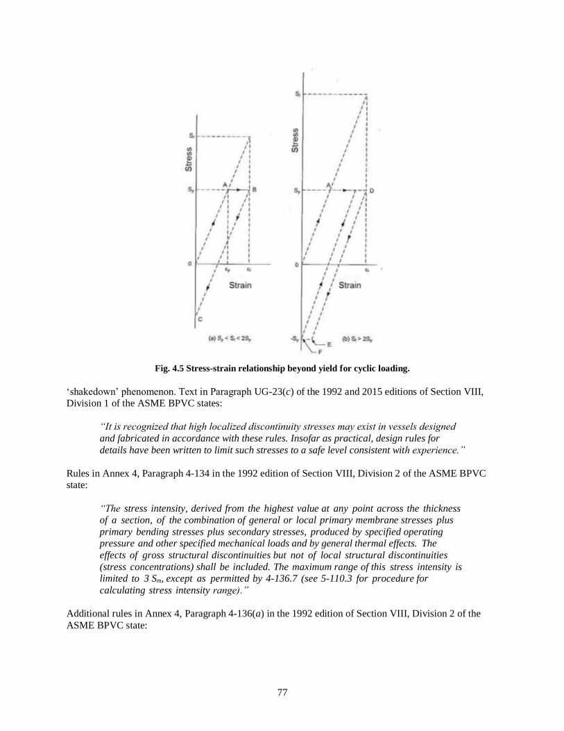
77
Fig. 4.5 Stress-strain relationship beyond yield for cyclic loading.
‘shakedown’ phenomenon. Text in Paragraph UG-23(c) of the 1992 and 2015 editions of Section VIII,
Division 1 of the ASME BPVC states:
“It is recognized that high localized discontinuity stresses may exist in vessels designed
and fabricated in accordance with these rules. Insofar as practical, design rules for
details have been written to limit such stresses to a safe level consistent with experience.”
Rules in Annex 4, Paragraph 4-134 in the 1992 edition of Section VIII, Division 2 of the ASME BPVC
state:
“The stress intensity, derived from the highest value at any point across the thickness of a section, of the combination of general or local primary membrane stresses plus
primary bending stresses plus secondary stresses, produced by specified operating pressure and other specified mechanical loads and by general thermal effects. The
effects of gross structural discontinuities but not of local structural discontinuities
(stress concentrations) shall be included. The maximum range of this stress intensity is limited to 3 Sm, except as permitted by 4-136.7 (see 5-110.3 for procedure for
calculating stress intensity range).”
Additional rules in Annex 4, Paragraph 4-136(a) in the 1992 edition of Section VIII, Division 2 of the
ASME BPVC state:

78
“The limit on primary plus secondary stress intensity of 3 Sm (see 4-134) has been placed at a level which assures shakedown to elastic action after a few repetitions of
the stress cycle except in regions containing significant local structural discontinuities
or local thermal stresses. These last two factors are considered only in the
performance of a fatigue evaluation.”
Paragraph 4-136(b) further states:
“The limits on local membrane stress intensity (see 4-132) and primary membrane plus
primary bending stress intensity of 1.5 Sm (see 4-133) have been placed at a level which
conservatively assures the prevention of collapse as determined by the principles of limit analysis. The following Paragraphs provide guidance in the application of plastic
analysis and some relaxation of the basic stress limits which are allowed if plastic analysis is used.”
Corresponding rules specified in Part 4, Paragraph 4.1.6.3 in the 2015 edition of Section VIII, Division 2
of the ASME BPVC state:
“The allowable primary plus secondary stress at the design temperature shall be
computed as follows:
SPS = max [3S, 2Sy] (4.1.9)
However, SPS shall be limited to 3S if either
(a) the room temperature ratio of the minimum specified yield strength from Annex 3-D to the ultimate tensile strength from Annex 3-D exceeds 0.70; or,
(b) the allowable stress from Annex 3-A is governed by time-dependent properties.”
In addition, Part 5, Paragraph 5.5.7 in the 2015 edition of Section VIII, Division 2 of the ASME BPVC
states:
“To evaluate protection against ratcheting using elastic-plastic analysis, an assessment
is performed by application, removal and reapplication of the applied loadings. If protection against ratcheting is satisfied, it may be assumed that progression of the
stress-strain hysteresis loop along the strain axis cannot be sustained with cycles and
that the hysteresis loop will stabilize. A separate check for plastic shakedown to
alternating plasticity is not required. The following assessment procedure can be used to
evaluate protection against ratcheting using elastic-plastic analysis.”
An important point to note from the foregoing discussion of primary and secondary stresses is that 1.5Sy
is the failure stress for primary bending, whereas for secondary bending 2Sy is merely the threshold
beyond which some plastic action occurs. Therefore, the allowable design stress for primary bending must
be reduced below 1.5Sy, whereas 2Sy is a safe design value for secondary bending because minor plastic
action during overloads is tolerable. The same type of analysis shows that 2Sy is also a safe design value
for secondary membrane tension. As described previously in Sect. 4.3 of this report, local membrane
stress produced by mechanical load has the characteristics of a secondary stress but has been arbitrarily
placed in the primary category. In order to avoid excessive distortion, it has been assigned an allowable
stress level of Sy, which is 50% higher than the allowable general primary membrane stress of 2/3 Sy but
precludes excessive yielding.

79
4.8 PLASTIC COLLAPSE
Plastic collapse is defined as the onset of gross plastic deformations. Plastic collapse corresponds to the
load at which overall structural instability occurs. The collapse load is defined as the maximum load limit
for a component made of elastic perfectly plastic material. The collapse load is derived from an elastic-
plastic analysis considering both the applied loading and deformation characteristics of the component
where the deformations of these components increase without bound at the collapse load.
4.8.1 Plastic Collapse Requirements in Section I and Section VIII, Division 1
Section I and Section VIII, Division 1 of the ASME BPVC do not require a detailed stress analysis to
evaluate protection against plastic collapse but merely set the wall thickness necessary to keep the basic
hoop stress below the tabulated allowable stress. As discussed in Sect. 4.4 of this report, the primary
stress for boilers and pressure vessels constructed in accordance with rules specified in the 1992 and 2015
editions of Section I and Section VIII, Division 1 of the ASME BPVC is limited to two-thirds of the yield
strength, 2/3 Sy, or less. The primary stress is the maximum principle stress which may be either a
membrane stress or a bending stress, whichever is greater. Rules specified in the 1992 and 2015 editions
of Section VIII, Division 1 of the ASME BPVC also ensure that the primary membrane stress plus the
primary bending stress, Pm + Pb, does not exceed Sy. Based on the principles of limit design theory
discussed in Sect. 4.6 of this report, these rules provide a minimum design margin against plastic collapse
equal to or greater than 1.5 for all primary membrane and bending stress combinations.
4.8.2 Plastic Collapse Requirements in Section VIII, Division 2
Basic stress intensity limits for pressure vessels designed and fabricated in accordance with requirements
in the 1992 edition of Section VIII, Division 2 of the ASME BPVC are specified in Paragraph 4-130.
These stress intensity limits are consistent with the design criteria specified in Paragraph AD-140(b) in
the 1992 edition of Section VIII, Division 2 of the ASME BPVC and discussed in Sect. 4.4.2 of this
report. According to text in Paragraphs 4-136(b):
“The limits on local membrane stress intensity and primary membrane plus primary
bending stress intensity of 1.5 Sm have been placed at a level which conservatively
assures the prevention of collapse as determined by the principles of limit analysis.”
1992 Edition
Guidance for application of plastic analysis in the 1992 edition of Section VIII, Division 2 of the ASME
BPVC is presented in Appendix 4, Paragraph 4-136. The guidance covers:
• Plastic Analysis – Paragraphs 4-136.2 and 4-136.5. Plastic analysis is that method which
computes the structural behavior under given loads considering the plasticity characteristics of the
material including strain hardening and the stress redistribution occurring in the structure.
• Limit Analysis – Paragraph 4-136.3. Limit analysis is a special case of plastic analysis in which
the material is assumed to be ideally plastic (non-strain-hardening).
• Experimental Analysis – Paragraphs 4-136.4. Experimental stress analysis is required when the
critical or governing stresses in parts in which theoretical stress analysis is inadequate or for
which design values are unavailable. Rule for experimental stress analysis including collapse load
criterion are specified in Appendix 6.

80
• Shakedown Analysis – Paragraphs 4-136.6. Shakedown of a structure occurs if, after a few cycles
of load application, ratcheting ceases. Subsequent response is elastic.
• Simplified Elastic-Plastic Analysis – Paragraphs 4-136.7. Simplified elastic-plastic analysis is a
method for determining when stress intensity limits on the range of primary plus secondary stress
intensity may be exceeded.
2015 Edition
As discussed in Sect. 4.4.2 of this report, rules specified in Part 4, Paragraph 4.1.6.1 in the 2015 editions
of Section VIII, Division 2 ensure that the maximum allowable primary membrane stress, Pm, does not
exceed 2/3 Sy and that the maximum allowable primary membrane stress plus primary bending stress,
Pm + Pb, does not exceed Sy. These maximum allowable stress limits are consistent with the plastic
collapse stress limits discussed in Sect. 4.6 of this report.
Three alternative analysis methods are provided in Part 5, Paragraph 5.2 in the 2015 edition of
Section VIII, Division 2 of the ASME BPVC for evaluating protection against plastic collapse. Brief
descriptions of these analysis methods follow.
1. Elastic Stress Analysis Method – Stresses are computed using an elastic analysis, classified into
categories, and limited to allowable values that have been conservatively established such that a
plastic collapse will not occur.
2. Limit-Load Method – A calculation is performed to determine a lower bound to the limit load of
a component. The allowable load on the component is established by applying design factors to
the limit load such that the onset of gross plastic deformations (plastic collapse) will not occur.
3. Elastic-Plastic Stress Analysis Method – A collapse load is derived from an elastic-plastic
analysis considering both the applied loading and deformation characteristics of the component.
The allowable load on the component is established by applying design factors to the plastic
collapse load.
For components with complex geometries and loadings, the categorization of stresses requires significant
knowledge and judgment by the analyst. This is especially true for three dimensional stress fields [2].
4.9 DESIGN-BY-RULE
The design approach used in the 2015 edition of Section I, Section VIII, Division 1, and Section VIII,
Division 2, Part 4 of the ASME BPVC is referred to as design-by-rule. This design-by-rule approach is
also used in the 1992 editions of Section I, Section VIII, Division 1, and Section VIII, Division 2,
Part AD. The design-by-rule approach has evolved from theory, experiment, and past successful
experience.
Design-by-rule is not based on a detailed stress analysis. Instead, design-by-rule generally involves
calculation of average membrane stress across the thickness of the walls of the boiler or pressure vessel.
Application of design-by-rule involves determination of loads, selection of a design equation, and the
selection of an appropriate allowable design stress for the material [2].
4.9.1 Design-by-Rule Requirements in Section I
Rules specified in the 1992 and 2015 editions of Section I of the ASME BPVC do not:

81
• require calculation of thermal stresses and do not provide allowable values for them
• require the detailed calculation and classification of all stresses and the application of different
stress limits to different classes of stress
• consider the possibility of fatigue failure [2]
Instead, rules in the 1992 and 2015 editions of Section I of the ASME BPVC provide allowable stress
limits for ensuring that the maximum allowable primary membrane stress, Pm, does not exceed 2/3 Sy and
equations for minimum wall thickness based on the maximum stress theory as discussed in Sects. 4.4.1
and 4.5.1 of this report.
As previously discussed in Sect. 4.5.1 of this report, equations specified in the 1992 and 2015 editions of
Section I of the ASME BPVC for determining wall thickness are, by implication, consistent with the
maximum stress theory. For thin-walled cylindrical pressure vessels at locations that are remote from any
discontinuities, the hoop stress is twice the axial stress and the radial stress on the inside is compressive
and equal to the internal pressure, p.
Rules for openings and compensation are specified in Paragraphs PG-32 through PG-39 in the 1992 and
2015 editions of Section I of the ASME BPVC. These rules are based on the area replacement concept in
which the metal cut out by an opening must be replaced by reinforcement within a prescribed zone around
the opening. A detailed discussion of this concept is presented in WRC Bulletin 335 [7]. The reference
note for Paragraphs PG-32 through PG- 39 in the 1992 and 2015 editions of Section I of the ASME
BPVC states:
“The rules governing openings as given in this Code are based on the stress intensification created by the existence of a hole in an otherwise symmetrical section.
They are based on experience with vessels designed with safety factors of 4 and 5 applied
to the specified minimum tensile strength of the shell material. External loadings such as those due to thermal expansion or to unsupported weight of connecting piping have not
been evaluated. These factors should be given attention in unusual designs or under conditions of cyclic loading.”
4.9.2 Design-by-Rule Requirements in Section VIII, Division 1
Paragraph UG-23(c) in the 2015 edition of Section VIII, Division 1 provides rationale for design-by-rule
requirements stating that:
“It is recognized that high localized discontinuity stresses may exist in vessels designed and fabricated in accordance with these rules. Insofar as practical, design rules for
details have been written to limit such stresses to a safe level, consistent with experience.”
Rules specified in the 1992 and 2015 editions of Section VIII, Division 1 of the ASME BPVC do not:
• require calculation of thermal stresses and do not provide allowable values for them
• require the detailed calculation and classification of all stresses and the application of different
stress limits to different classes of stress
• consider the possibility of fatigue failure [2]

82
Instead, rules in the 1992 and 2015 editions of Section VIII, Division 1 of the ASME BPVC provide
allowable stress limits for ensuring that the maximum allowable primary membrane stress, Pm, does not
exceed 2/3 Sy, the maximum primary membrane stress plus primary bending stress, Pm + Pb, does not
exceed Sy, and equations for minimum wall thickness based on the maximum stress theory as discussed in
Sect. 4.4.1 of this report.
As previously discussed in Sect. 4.5.1 of this report, equations specified in the 1992 and 2015 editions of
Section VIII, Division 1 of the ASME BPVC for determining wall thickness are, by implication,
consistent with the maximum stress theory. For thin-walled cylindrical pressure vessels at locations that
are remote from any discontinuities, the hoop stress is twice the axial stress and the radial stress on the
inside is compressive and equal to the internal pressure.
Rules for openings and compensation are specified in Paragraphs UG-36 through UG-39 in the 1992 and
2015 editions of Section VIII, Division 1 of the ASME BPVC. These rules are based on the area
replacement concept in which the metal cut out by an opening must be replaced by reinforcement within a
prescribed zone around the opening. A detailed discussion of this concept is presented in
WRC Bulletin 335 [7]. The reference note for Paragraphs UG-36 through UG-39 in the 1992 and 2015
editions of Section VIII, Division 1 of the ASME BPVC states:
“The rules governing openings as given in this Code are based on the stress
intensification created by the existence of a hole in an otherwise symmetrical section. They are based on experience with vessels designed with safety factors of 4 and 5 applied
to the specified minimum tensile strength of the shell material. External loadings such as those due to thermal expansion or to unsupported weight of connecting piping have not
been evaluated. These factors should be given attention in unusual designs or under conditions of cyclic loading.”
However, the reference note to Paragraphs UG-36 in the 2015 edition states:
“The rules governing openings as given in this Division are based on the stress intensification created by the existence of a hole in an otherwise symmetrical section.
External loadings such as those due to the thermal expansion or unsupported weight of
connecting piping have not been evaluated. These factors should be given attention in unusual designs or under conditions of cyclic loading.”
Supplementary deign formulas are specified in Mandatory Appendix 1 in the 2015 edition of
Section VIII, Division 1 of the ASME BPVC for:
• Large openings in cylindrical and conical shells
• Rules for reinforcement of cones and conical reducers under external pressure
• Alternative rules for reinforcement of openings under internal pressure
• Alternative method for design of reinforcement for openings in cylindrical and conical shells
under internal pressure

83
4.9.3 Design-by-Rule Requirements in Section VIII, Division 2
1992 Edition
Basic requirements for application of design-by-rule methods specified in the 1992 edition of
Section VIII, Division 2 of the ASME BPVC are described in Part AD. These methods provide specific
design rules for some commonly used pressure vessel shapes under pressure loadings and, within
specified limits, rules or guidance for treatment of other loadings. Simplified rules are also included for
the approximate evaluation of design cyclic service life. However, Part AD does not contain rules to
cover all details of design. Individual articles in Part AD cover the following subjects.
Article D-1 – General
Article D-2 – Shells of Revolution Under Internal Pressure
Article D-3 – Shells of Revolution External Internal Pressure
Article D-4 – Weld Joints
Article D-5 – Opening and Their Reinforcement
Article D-6 – Nozzles and Other Connections
Article D-7 – Flat Heads, Bolted, and Studded Connections
Article D-8 – Quick-Actuating Closures
Article D-9 – Attachments and Supports
Article D-10 – Access and Inspection Openings
Article D-11 – Special Requirements for Layered Vessels
According to Part AD, Paragraph AD-100(b) in the 1992 edition of Section VIII, Division 2 of the ASME
BPVC states:
“When complete rules are not provided for a vessel or vessel part, or when the vessel
designer or user chooses, a complete stress analysis of the vessel or vessel part shall be performed considering all of the loadings specified in the User's Design Specification.
This analysis shall be done in accordance with Appendix 4 for all applicable stress
categories and in accordance with Appendix 5 when fatigue evaluation is required.
Alternatively, an experimental stress analysis can be performed in accordance with
Appendix 6. When either of these procedures is followed, the general principles, design requirements of Articles D-1, D-3, and D-4, and weld detail, fabrication, inspection, and
testing requirements of this Division shall also be met. In addition, the wall thickness of a vessel shall not be less than that computed by the formulas of AD-201 through AD-206.”
As previously discussed Sect. 4.5.2 of this report, rules specified in Part AD, Paragraph AD-140(a) state
that the theory of failure used in this Division is the maximum shear stress theory except in the case of
some specifically designated configurations, shapes, or design rules included as a part of this Division.
Stress intensity is defined as two times the maximum shear stress.
Rules for openings and their reinforcement are specified in Article D-5 in the 1992 edition of
Section VIII, Division 2. Paragraph AD-500 states:

84
“The rules contained in this Article provide for a satisfactory design in the vicinity of openings in the pressure shell, under pressure loading only, on the basis of opening
shape, area replacement and its distribution, provided a fatigue analysis is not required.
These rules do not include design requirements for piping loads that may be imposed on
the nozzle and/or shell portion and that may be added to the pressure loadings. Such
additional loadings should be carefully considered by the design engineer.”
The area replacement concept requires that the metal cut out by an opening be replaced by reinforcement
within a prescribed zone around the opening. A detailed discussion of this concept is presented in
WRC Bulletin 335 [7]. Design requirements for the following types of openings, nozzles, and
reinforcements are specified in Article D-5, Paragraphs AD-500 through AD-570.
• Dimensions and Shape of Openings
• Location of Openings in Welded Joints
• Circular Openings not Requiring Reinforcement
• Required Reinforcement for Openings in Shells and Formed Heads
• Required Reinforcement for Openings in Flat Heads
• Limits of Reinforcement
• Metal Available for Reinforcement
• Alternative Rules for Nozzle Design
• Requirements for Nozzles with Separate Reinforcing Plates
Article D-6 in the 1992 edition of Section VIII, Division 2 establishes rules for attaching nozzles and
other pressure connections by welding. These rules cover the following types of nozzles and connections.
• Requirements for Nozzles and Other Connections
• Nozzle Necks Abutting the Vessel Wall
• Fittings with Internal Threads
• Studded Connections Subject to External Loading
• Threaded Connections
2015 Edition
Basic requirements for application of design-by-rule methods specified in the 2015 edition of
Section VIII, Division 2 of the ASME BPVC are described in Part 4 – Design by Rule Requirements,
Paragraph 4.1. The requirements of Part 4 provide design rules for commonly used pressure vessel shapes
under pressure loading and, within specified limits, rules, or guidance for treatment of other loadings. The
scope of design-by-rule requirements specified in Part 4 have been significantly enhanced compared to
corresponding requirements specified in Part AD in the 1992 edition of Section VIII, Division 2 of the
ASME BPVC. Individual paragraphs in Part 4 in the 2015 edition of Section VIII, Division 2 cover the
following subjects.
4.1 – General Requirements
4.2 – Design Rules for Welded Joints

85
4.3 – Design Rules for Shells Under Internal Pressure
4.4 – Design of Shells Under External Pressure and Allowable Compressive Stresses
4.5 – Design Rules for Openings in Shells and Heads
4.6 – Design Rules for Flat Heads
4.7 – Design Rules for Spherically Dished Bolted Covers
4.8 – Design Rules for Quick-Actuating (Quick Opening) Closures
4.9 – Design Rules for Braced and Stayed Surfaces
4.10 – Design Rules for Ligaments
4.11 – Design Rules for Jacketed Vessels
4.12 – Design Rules for Noncircular Vessels
4.13 – Design Rules for Layered Vessels
4.14 – Evaluation of Vessels Outside of Tolerance
4.15 – Design Rules for Supports and Attachments
4.16 – Design Rules for Flanged Joints
4.17 – Design Rules for Clamped Connections
4.18 – Design Rules for Shell and Tube Heat Exchangers
4.19 – Design Rules for Bellows Expansion Joints
4.20 – Design Rules for Flanged-and-Flued or Flanged-Only Expansion Joints
However, Part 4 does not provide rules to cover all loadings, geometries, and details. When design rules
are not provided for a pressure vessel or pressure vessel part, a stress analysis in accordance with Part 5 –
Design by Analysis Requirements must be performed considering all of the loadings specified in the
User’s Design Specification. The design procedures in Part 4 may be used if the allowable stress at the
design temperature is governed by time-independent or time-dependent properties unless otherwise noted
in a specific design procedure. When the pressure vessel is operating at a temperature where the allowable
stress is governed by time-dependent properties, the effects of joint alignment and weld peaking in shells
and heads must be considered.
As previously discussed in Sect. 4.5.2 of this report, beginning with the 2007 edition of Section VIII,
Division 2 of the ASME BPVC, the specified design-by-rule equations in Part 4 are based on a limit
analysis using the maximum shear stress theory.
Design rules for openings in shells and heads are specified in Part 4, Paragraph 4.5 in the 2015 edition of
Section VIII, Division 2. The rules in Paragraph 4.5 are applicable for the design of nozzles in shells and
heads subjected to internal pressure, external pressure, and external forces and moments from
supplemental loads as defined in Paragraph 4.1. Design procedures for the following types of nozzles and
other design rules for nozzles and opening are specified in Paragraphs 4.5.2 through 4.5.17:
• Dimensions and Shape of Nozzles
• Method of Nozzle Attachment
• Nozzle Neck Minimum Thickness Requirements

86
• Radial Nozzle in a Cylindrical Shell
• Hillside Nozzle in a Cylindrical Shell
• Nozzle in a Cylindrical Shell Oriented at an Angle from the Longitudinal Axis
• Radial Nozzle in a Conical Shell
• Nozzle in a Conical Shell
• Radial Nozzle in a Spherical Shell or Formed Head
• Hillside or Perpendicular Nozzle in a Formed Head
• Circular Nozzles in a Flat Head
• Spacing Requirements for Nozzles
• Strength of Nozzle Attachment Welds
• Local Stresses in Nozzles in Shells and Formed Heads from External Loads
• Inspection Openings
• Reinforcement of Openings Subject to Compressive Stress
The traditional ASME area replacement approach to designing openings in pressure vessels provides safe
designs because yield strength governs the design of openings for most materials. However, the area
replacement approach results in a conservative local primary stress and a bias towards over reinforcement
for certain nozzle geometries. From a safety viewpoint, excessive reinforcement can be detrimental to
fatigue life. To benefit from the increase in allowable stresses permitted in the 2015 edition of Section II
in the ASME BPVC, rules in Part 4, Paragraph 4.5 explicitly limit local primary stresses at the opening.
The objectives of the rules in Part 4, Paragraph 4.5 are to:
1. provide a more accurate design
2. consider a wider range of geometries
3. provide direction for calculation of local primary membrane equivalent stresses and attachment
weld stresses
These rules use a modified pressure area method to determine the magnitude of the discontinuity force
resisted locally. They also explicitly consider thick shells. Openings in flat heads are provided with a
separate set or rules that are based on beam on elastic foundation principles.
Configurations, including dimensions and shape, or loading conditions that do not satisfy the rules of
Paragraph 4.5 may be designed in accordance with Part 5.
4.10 DESIGN-BY-ANALYSIS
Pressure vessels that are designed and fabricated in accordance with rules specified in Section VIII,
Division 2 of the ASME BPVC and that satisfy fatigue screening criteria discussed in Sect. 4.1.5.3 of this
report must comply with design-by-analysis requirements. These requirements are specified in
Appendix 5 in the 1992 edition of Section VIII, Division 2 of the ASME BPVC and in Part 5 in the 2015
edition of Section VIII, Division 2 of the ASME BPVC. The 1992 and 2015 editions of Section I and
Section VIII, Division 1 of the ASME BPVC do not include design-by-analysis requirements.

87
1992 Edition
Rules specified in Appendix 4 – Mandatory Design Based on Stress Analysis in the 1992 edition of
Section VIII, Division 2 of the ASME BPVC provide design requirements for cylindrical and spherical
shells; torispherical, ellipsoidal, and flat heads; and various stress states. Individual articles in Appendix 4
cover the following subjects.
4.1 – No Title
4.2 – Analysis of Cylindrical Shells
4.3 – Analysis of Spherical Shells
4.4 – Design Criteria and Formulas for Torispherical and Ellipsoidal Heads
4.5 – Analysis of Flat Circular Heads
4.6 – Stresses in Openings for Fatigue Evaluation
4.7 – Discontinuity Stresses
4.8 – Thermal Stresses
4.9 – Stresses in Perforated Flat Plates
According to rules specified in Appendix 4, Paragraph 4-100 in the 1992 edition of Section VIII,
Division 2 of the ASME BPVC, when a fatigue evaluation is not required, a pressure vessel or a pressure
vessel part may be designed using the stress analysis methods given in Appendix 4. However, when a
fatigue evaluation is required, Appendix 4 should be used together with Appendix 5 – Mandatory Design
Based on Fatigue Analysis.
Appendix 4, Article 4-4, Paragraph 4-111 – Basis for Determining Stresses states:
“The theory of failure used in the rules of this Appendix for combining stresses is the
maximum shear stress theory. The maximum shear stress theory at a point is equal to
one-half the difference between the algebraically largest and the algebraically smallest of the three principle stresses at that point.”
Additional discussion about the maximum shear stress theory, which is also known as the Tresca yield
criterion, is presented in Sect. 4.5.2 of this report.
Appendix 4, Article 4-6 in the 1992 edition of Section VIII, Division 2 of the ASME BPVC specifies
rules for stresses in openings for fatigue evaluation. Three methods are provided for determining peak
stresses around openings.
Analytical Method: This method uses suitable analytical techniques such as finite element
computer analyses, which provide detailed stress distributions around openings. In
addition to peak stresses due to pressure, the effects of other loadings shall be included.
The total peak stress at any given point shall be determined by combining stresses due to
pressure, thermal, and external loadings in accordance with the rules of Part AD.
Experimental Stress Analysis: This is based on data from experiments (Paragraph 4-620).
Stress Index Method: This uses various formulas based on data obtained from an
extensive series of tests covering a range of variations of applicable dimensional ratios
and configurations (Paragraph 4-610). This method covers only single, isolated openings.

88
Stress indices may also be determined by theoretical or experimental stress analysis. Such
analysis shall be included in the Design Report.
Design-by-analysis rules for pressure vessels that require a fatigue evaluation are specified in Appendix 5
in the 1992 edition of Section VIII, Division 2 of the ASME BPVC. Appendix 5 – Mandatory Design
Based on Fatigue Analysis includes rules for design based on rules specified in the following paragraphs
in Article 5-1.
• Paragraph 5-110 – Design for Cyclic Loading
• Paragraph 5-120 – Fatigue Analysis of Bolts
• Paragraph 5-130 – Thermal Stress Ratcheting in Shell
• Paragraph 5-140 – Progressive Distortion of Nonintegral Connections
Discussions of rules specified in Article 5-1, Paragraphs 5-110 and 5-130 are presented in Sect. 4.1.5.3 of
this report.
The theory of failure used in Appendix 5 is based on the maximum shear stress theory. Additional
discussion about the maximum shear stress theory, which is also known as the Tresca yield criterion, is
presented in Sect. 4.5.2 of this report.
2015 Edition
Design-by-analysis rules are specified in Part 5 in the 2015 edition of Section VIII, Division 2 of the
ASME BPVC. Detailed design procedures utilizing the results from a stress analysis are provided to
evaluate components for plastic collapse, local failure, buckling, and cyclic loading. Supplemental
requirements are provided for the analysis of bolts, perforated plates and layered vessels. Procedures are
also provided for design using the results from an experimental stress analysis, and for fracture mechanics
evaluations.
The design-by-analysis requirements in Part 5 in the 2015 edition of Section VIII, Division 2 of the
ASME BPVC are organized based on protection against the failure modes listed below. The component is
evaluated for each applicable failure mode. If multiple assessment procedures are provided for a failure
mode, only one of these procedures must be satisfied to qualify the design of a component.
• Paragraph 5.2, Protection Against Plastic Collapse – these requirements apply to all components
where the thickness and configuration of the component is established using design-by-analysis
rules.
• Paragraph 5.3, Protection Against Local Failure – these requirements apply to all components
where the thickness and configuration of the component is established using design-by-analysis
rules. It is not necessary to evaluate the local strain limit criterion if the component design is in
accordance with the component wall thickness and weld details of Part 4.
• Paragraph 5.4, Protection Against Collapse from Buckling – these requirements apply to all
components where the thickness and configuration of the component is established using design-
by-analysis rules and the applied loads result in a compressive stress field.
• Paragraph 5.5, Protection Against Failure from Cyclic Loading – these requirements apply to all
components where the thickness and configuration of the component is established using design-
by-analysis rules and the applied loads are cyclic. In addition, these requirements can also be used

89
to qualify a component for cyclic loading where the thickness and size of the component are
established using the design-by-rule requirements of Part 4.
The design-by-analysis procedures in Part 5 may only be used if the allowable stress at the design
temperature is governed by time-independent properties unless otherwise noted in a specific design
procedure. Supplemental requirements for stress classification in nozzle necks, bolts, perforated plates,
and layered vessels are specified in Part 5, Paragraphs 5.6 through 5.9, respectively.
Requirements for experimental stress analysis are specified in Part 5, Paragraphs 5.10. This paragraph
references rules in Annex 5-F for experimental stress and fatigue analysis. Part 5, Paragraphs 5.11
provides requirements for fracture mechanics evaluations performed to determine the MDMT.
Beginning with the 2007 edition of Section VIII, Division 2 of the ASME BPVC, the specified design-by-
analysis equations in Part 5 are based on a limit analysis using the distortion energy theory (also known as
the octahedral shear theory and the von Mises criterion) given by Equation {4.3} in Sect. 4.5.3 of this
report.
4.11 COMPARISON OF KEY DIFFERENCES IN ASME BPVC DESIGN RULES
A comparison of key differences and similarities in design criteria between the 1992 and 2015 editions of
the ASME BPVC is presented in Table 4.7 of this report.
Table 4.7 Design criteria comparison
Design Criteria Comparison
Strength Theory – Section I 1992 – rules are based on the maximum stress theory.
2015 – rules are based on the maximum stress theory
Strength Theory – Section VIII,
Division 1
1992 – rules are based on the maximum stress theory.
2015 – rules are based on the maximum stress theory
Strength Theory – Section VIII,
Division 2, Part 4 – Design by
Rule
1992 – rules are based on the maximum shear stress theory (also known as
the Tresca yield criterion).
2015 – rules are based on the maximum shear stress theory (also known as
the Tresca yield criterion).
Strength Theory – Section VIII,
Division 2, Part 5 – Design by
Analysis
1992 – rules are based on the maximum shear stress theory (also known as
the Tresca yield criterion).
2015 – rules are based on the distortion energy theory (also known as the
octahedral shear theory and the Mises criterion).
Maximum allowable stress –
Section I
1992 – maximum allowable stress limit lesser of St/4.0 or 2/3 Sy
2015 – maximum allowable stress limit lesser of St/3.5 or 2/3 Sy
Maximum allowable stress –
Section VIII, Division 1
1992 – maximum allowable stress limit lesser of St/4.0 or 2/3 Sy
2015 – maximum allowable stress limit lesser of St/3.5 or 2/3 Sy
Maximum allowable stress –
Section VIII, Division 2
1992 – maximum allowable stress limit lesser of St/3.0 or 2/3 Sy
2015 – maximum allowable stress limit lesser of St/2.4 or 2/3 Sy

90
Table 4.7 Design criteria comparison
Design Criteria Comparison
Stress calculation and
classification – Section I
1992 – equations are specified for minimum allowable wall thickness,
therefore, detailed calculation and classification of all stresses and the
application of different stress limits to different classes of stress are not
required.
2015 – equations are specified for minimum allowable wall thickness,
therefore, detailed calculation and classification of all stresses and the
application of different stress limits to different classes of stress are not
required.
Stress calculation and
classification – Section VIII,
Division 1
1992 – equations are specified for minimum allowable wall thickness,
therefore, detailed calculation and classification of all stresses and the
application of different stress limits to different classes of stress are not
required.
2015 – equations are specified for minimum allowable wall thickness,
therefore, detailed calculation and classification of all stresses and the
application of different stress limits to different classes of stress are not
required.
Stress calculation and
classification – Section VIII,
Division 2
1992 –detailed calculation and classification of all stresses and the application
of different stress limits to different classes of stress are required.
2015 –detailed calculation and classification of all stresses and the application
of different stress limits to different classes of stress are required.
Calculation of thermal stress –
Section I
1992 – thermal stress calculations are not required and allowable thermal
stress values are not specified.
2015 – thermal stress calculations are not required and allowable thermal
stress values are not specified.
Calculation of thermal stress –
Section VII, Division 1
1992 – thermal stress calculations are not required and allowable thermal
stress values are not specified.
2015 – thermal stress calculations are not required and allowable thermal
stress values are not specified.
Calculation of thermal stress –
Section VII, Division 2
1992 – thermal stress calculations are required and allowable thermal stress
values are specified.
2015 – thermal stress calculations are required and allowable thermal stress
values are specified.
Excessive elastic deformation
and elastic instability – Section I
1992 – charts and tables are provided for determining shell thickness of
components under external pressure
2015 – charts and tables are provided for determining shell thickness of
components under external pressure
Excessive elastic deformation
and elastic instability –
Section VIII, Division 1
1992 – charts and tables are provided for determining shell thickness of
components under external pressure
2015 – charts and tables are provided for determining shell thickness of
components under external pressure
Excessive elastic deformation
and elastic instability –
Section VIII, Division 2
1992 – charts and tables are provided for determining shell thickness of
components under external pressure
2015 – rules are provided for protection against collapse from buckling
including three alternative types of buckling analyses.

91
Table 4.7 Design criteria comparison
Design Criteria Comparison
Excessive plastic deformation –
Section I
1992 – rules for protection against plastic collapse are not specifically
provided, but the maximum allowable stress is limited to two-thirds of the
yield strength, 2/3 Sy, or less.
2015 – rules for protection against plastic collapse are not specifically
provided, but the maximum allowable stress is limited to two-thirds of the
yield strength, 2/3 Sy, or less.
Excessive plastic deformation –
Section VIII, Division 1
1992 – rules for protection against plastic collapse are not specifically
provided, but the maximum allowable stress is limited to two-thirds of the
yield strength, 2/3 Sy, or less. In addition, rules ensure that the primary
membrane stress plus the primary bending stress, Pm + Pb, does not exceed Sy.
2015 – rules for protection against plastic collapse are not specifically
provided, but the maximum allowable stress is limited to two-thirds of the
yield strength, 2/3 Sy, or less. In addition, rules ensure that the primary
membrane stress plus the primary bending stress, Pm + Pb, does not exceed Sy.
Excessive plastic deformation –
Section VIII, Division 2
1992 – stress intensity limits for avoiding excessive plastic deformation are
provided in Appendix 4, Paragraph 4-130. The limits on local membrane
stress intensity and primary membrane plus primary bending stress intensity
of 1.5 Sm have been placed at a level which conservatively assures the
prevention of collapse as determined by the principles of limit analysis.
2015 – three alternative analysis methods are provided in Part 5,
Paragraph 5.2 for evaluating protection against plastic collapse.
(a) Elastic Stress Analysis Method
(b) Limit-Load Method
(c) Elastic-Plastic Stress Analysis Method
Method (c), which is not included in the 1992 edition, provides a collapse
load derived from an elastic-plastic analysis considering both the applied
loading and deformation characteristics of the component.
Brittle fracture – Section I 1992 – no fracture toughness requirements are specified.
2015 – no fracture toughness requirements are specified.
Brittle fracture – Section VIII,
Division 1
1992 – fracture toughness requirements vary depending on the minimum
specified yield strength, material type, and material thickness.
2015 – fracture toughness requirements vary depending on the minimum
specified yield strength, material type, and material thickness, but these
requirements are more comprehensive and stringent than corresponding rules
specified in the 1992 edition.
Brittle fracture – Section VIII,
Division 2
1992 – fracture toughness requirements include minimum Charpy V-notch
impact test requirements for carbon and low alloy steels based on the
specified minimum tensile strength and to what extent the steel is deoxidized.
Minimum Charpy V-notch impact energy limits range up to 20 ft-lb. The
minimum lateral expansion value is 0.015 in.
2015 – fracture toughness requirements are provided for five specific material
groups. Minimum Charpy V-notch impact energy and lateral expansion
requirements vary over a range from 20 to 61 ft-lb and 0.012 to 0.032 in.
depending on material type, thickness, and yield strength.
Fatigue – Section I 1992 – rules for prevention of fatigue failure are not specified.
2015 – rules for prevention of fatigue failure are not specified.

92
Table 4.7 Design criteria comparison
Design Criteria Comparison
Fatigue – Section VIII,
Division 1
1992 – rules for prevention of fatigue failure are not specified.
2015 – rules for prevention of fatigue failure are not specified.
Fatigue – Section VIII,
Division 2
1992 – rules for prevention of fatigue failure are specified.
2015 – rules for prevention of fatigue failure are specified.
Openings and reinforcements –
Section I
1992 – rules for openings and reinforcements are based on the area
replacement concept in which the metal cut out by an opening must be
replaced by reinforcement within a prescribed zone around the opening.
2015 – rules for openings and reinforcements are based on the area
replacement concept in which the metal cut out by an opening must be
replaced by reinforcement within a prescribed zone around the opening.
Openings and reinforcements –
Section VIII, Division 1
1992 – rules for openings and reinforcements are based on the area
replacement concept in which the metal cut out by an opening must be
replaced by reinforcement within a prescribed zone around the opening.
2015 – rules for openings and reinforcements are based on the area
replacement concept in which the metal cut out by an opening must be
replaced by reinforcement within a prescribed zone around the opening and
include supplementary design formulas for openings and reinforcements.
Openings and reinforcements –
Section VIII, Division 2
1992 – rules for openings and reinforcements are based on the area
replacement approach that is conservative, but excessive reinforcement can be
detrimental to fatigue life.
2015 – rules for openings and reinforcements are specified including
supplementary design formulas for openings and reinforcements. These rules
use a modified pressure area method to determine the magnitude of the
discontinuity force resisted locally.

93
5. FABRICATION
The term “fabrication” is not explicitly defined in the ASME BPVC, but it is generally understood to
mean all activities a manufacturer uses to process and assemble plates, pipes, tubes, and other material
products into a complete boiler or pressure vessel consistent with applicable rules in the ASME BPVC.
Fabrication activities often involve a broad range of manufacturing methods and processes such as
forming, machining, bolting, welding, brazing, and heat treating. These methods and processes tend to
change as construction technology evolves and improves over time.
The ASME BPVC places limitations on certain fabrication activities, specifically those involving welding
and brazing practices related to boiler and pressure vessel construction, to holders of a valid Certificate of
Authorization. Acquiring a Certificate of Authorization requires certification of a manufacturer’s or
assembler’s quality control system for consistency with rules specified in Construction Codes (Section I,
IV, VIII, X, or XII of the ASME BPVC), as applicable.
5.1 FORMING
Changes in construction technology now make it practical to construct pressure vessels from thinner and
thinner materials. Consequently, cold forming is now performed more than in the past. Forming is
generally allowed by any process that does not unduly impair the mechanical properties of the material. It
is left to the manufacturer to use judgement in selecting processes that are appropriate for the material.
However, manufacturing operations that involve forming can cause impaired service performance,
especially in austenitic materials and for components in the creep range. Heat treatment after forming is
sometimes required to restore material properties and minimize the threat of premature failure due to
recrystallization during the time of operation [8].
5.1.1 Forming Requirements in Section I
1992 Edition
Rules for fabrication of boilers are specified in Paragraphs PG-75 through PG-82 in the 1992 edition of
Section I of the ASME BPVC. These rules cover cutting plates and other stock, plate identification,
repairs of defects in materials, tube holes and ends, distortion, tolerances for formed heads, and holes for
stays. Paragraph PG-80 in the 1992 edition of Section I of the ASME BPVC specifies distortion limits for
cylindrical furnace and other cylindrical parts subjected to external pressure. The rule states:
“Cylindrical furnace and other cylindrical parts subjected to external pressure shall be rolled to practically a true circle with a maximum permissible deviation from the true
circle of not more than 1/4 in.”
This rule applies to all cylindrical furnace and other cylindrical parts subjected to external pressure
irrespective of diameter, thickness, or length.
2015 Edition
Rules for fabrication of boilers are specified in Paragraphs PG-75 through PG-82 in the 2015 edition of
Section I of the ASME BPVC. These rules cover cutting plates and other stock, plate identification,
repairs of defects in materials, tube holes and ends, permissible out-of-roundness of cylindrical shells,
tolerances for formed heads, and holes for stays. However, out-of-roundness limits specified in the 2015
edition of Section I of the ASME BPVC are more stringent than corresponding out-of-roundness limits

94
specified in the 1992 edition of Section I of the ASME BPVC because they vary depending on the outside
diameter, thickness, and length of the component.
Paragraph PG-80.2 in the 2015 edition of Section I of the ASME BPVC specifies out-of-roundness limits
for cylindrical components subjected to external pressure greater than 24 in. diameter. These limits, which
are based on the dimensional parameters that vary according to the outside diameter, thickness, and
length, are plotted in Figure PG-80. A separate out-of-roundness limit of 1% on diameter applies to
cylindrical components subjected to external pressure with diameters less than 24 in.
Paragraph PG-19 on cold forming of austenitic materials was added to Section I with the 1999
Addendum. Rules in Paragraph PG-19 in the 2015 edition of Section I of the ASME BPVC state that
cold‐formed areas of pressure‐retaining components manufactured of austenitic alloys must be heat
treated for 20 minutes per inch of thickness or for 10 minutes, whichever is greater, at the applicable
temperatures given in Table PG-19 and conditions specified in Paragraphs PG-19(a) and PG-19(b).
However, these rules only apply when the design temperature equals or exceed 1,000°F.
5.1.2 Forming Requirements in Section VIII, Division 1
1992 Edition
Rules for fabrication of pressure vessels are specified in Paragraphs UG-75 through UG-83 in the 1992
edition of Section VIII, Division 1 of the ASME BPVC. These rules cover cutting plates and other stock;
material identification; repairs of defects in materials; forming shell sections and heads; permissible out-
of-roundness of cylindrical, conical, and spherical shells; tolerances for formed heads, lugs and fitting
attachments, and holes for screw stays.
Paragraph UG-79(a) places limits on cold working of all carbon and low alloy steels when the extreme
fiber elongation from forming exceeds 5%. Equations for determining extreme fiber elongation are
specified in Paragraph UCS-79(d) in the 1992 edition of Section VIII, Division 1 of the ASME BPVC.
Rules for permissible out-of-roundness of cylindrical, conical, and spherical shells are specified in
Paragraph UG-80 in the 1992 edition of Section VIII, Division 1 of the ASME BPVC. Separate rules are
provided for pressure parts subjected to internal and external pressure. Figure UG-80.1 is a plot of
maximum permissible deviation from a circular form for pressure vessels under external pressure. These
permissible deviations vary with outside diameter, thickness, and length.
2015 Edition
Rules for fabrication of pressure vessels are specified in Paragraphs UG-75 through UG-83 in the 2015
edition of Section VIII, Division 1 of the ASME BPVC. These rules cover cutting plates and other stock;
material identification; repairs of defects in materials; forming pressure parts; permissible out-of-
roundness of cylindrical, conical, and spherical shells; tolerances for formed heads, lugs and fitting
attachments, and holes for screw stays.
Rules specified in Paragraph UG-79 in the 2015 edition of Section VIII, Division 1 of the ASME BPVC
for forming shell sections and heads were updated considerably compared to corresponding rules in the
1992 edition of Section VIII, Division 1 of the ASME BPVC. Paragraph UG-79 in the 1992 edition of
Section VIII, Division 1 of the ASME BPVC only specifies rules for forming carbon and low alloy steel
shell sections and heads. Whereas, Paragraph UG-79 in the 2015 edition of Section VIII, Division 1 of the
ASME BPVC provides rules for cold working of carbon and low alloy steels, nonferrous alloys, high
alloy steels, and ferritic steels. Equations for calculating forming strains for cylinders, heads, tubes, and
pipes are specified in Table UG-79-1. When the calculated forming strains exceed the maximum

95
prescribed allowable strains specified in Paragraphs UCS-79(d), UHA-44(a), UNF-79(a), and
UHT-79(a)(1), as applicable, and the design temperatures exceed specified limits, post fabrication heat
treatment is required.
5.1.3 Forming Requirements in Section VIII, Division 2
1992 Edition
General fabrication requirements for pressure vessels are specified in Article F-1 in the 1992 edition of
Section VIII, Division 2 of the ASME BPVC. These requirements cover forming in Paragraph AF-110,
tolerance for shells under internal pressure in Paragraph AF-130.1, and tolerance for shells under internal
pressure in Paragraph AF-130.2. Rules in Paragraph AF-111 state:
“All materials for shell sections and for heads shall be formed to the required shape
by any process that will not unduly impair the mechanical properties of the material.”
Figure AF-130.2 is a plot of maximum permissible deviation from a circular form for pressure vessels
under external pressure. These permissible deviations vary with outside diameter, thickness, and length.
2015 Edition
Rules for forming shell sections and heads are specified in Part 6, Paragraph 6.1.2 in the 2015 edition of
Section VIII, Division 2 of the ASME BPVC. These rule cover forming of carbon and low alloy steels,
high alloy steel parts, nonferrous material parts, lugs and fitting attachments, and spin-holes. Equations
for determining extreme fiber elongation are specified in Table 6.1 in the 2015 edition of Section VIII,
Division 1 of the ASME BPVC. Results of extreme fiber elongation calculations are used to determine if
subsequent heat treatment is required based on post-cold-forming strain limits and heat-treatment
requirements specified in Tables 6.2.A, 6.2.B, and 6.3 in the 2015 edition of Section VIII, Division 2 of
the ASME BPVC. These rules are more stringent than corresponding rules in the 1992 edition of
Section VIII, Division 2 of the ASME BPVC which do not require determination of extreme fiber
elongation.
Rules for permissible out-of-roundness of cylindrical, conical, and spherical shells subject to external
pressure are specified in Part 4, Paragraph 4.4.4.1 in the 2015 edition of Section VIII, Division 2 of the
ASME BPVC. These rules are based on equations for calculating maximum plus or minus deviations
from a true circle.
5.2 TOLERANCES
The ASME BPVC provides minimal requirements for fabrication tolerances. The owner or user is
responsible for including fabrication tolerances in the design basis. Permitted deviations in out-of-
roundness of shells and heads are discussed in Sect. 5.1 of this report. Discussions of formed head and
alignment tolerance requirements follow.
5.2.1 Formed Head Tolerances
Tolerance requirements for formed heads are provided in Section I, Section VIII, Division 1, and
Section VIII, Division 2 of the ASME BPVC.

96
5.2.1.1 Tolerance for Formed Heads in Section I
The same shape deviation requirements for formed heads are specified in Paragraph PG-81 in the 1992
and 2015 editions of Section I of the ASME BPVC. The rule in Paragraph PG-81 in both editions states:
“When heads are made to an approximate ellipsoidal shape, the inner surface of such heads must lie outside and not inside of a true ellipse drawn with the major axis equal to
the inside diameter of the head and one‐half the minor axis equal to the depth of the head. The maximum variation from this true ellipse shall not exceed 0.0125 times the
inside diameter of the head.”
5.2.1.2 Tolerance for Formed Heads in Section VIII, Division 1
The same shape deviation requirements for formed heads are specified in Paragraph UG-81 in the 1992
and 2015 editions of Section VIII, Division 1 of the ASME BPVC. These requirements apply to inner
surfaces of a torispherical, toriconical, hemispherical, and ellipsoidal heads.
5.2.1.3 Tolerance for Formed Heads in Section VIII, Division 2
Shape deviation requirements for formed heads are specified in Paragraph AF-135 in the 1992 edition of
Section VIII, Division 2 of the ASME BPVC. These requirements apply to inner surfaces of torispherical,
toriconical, hemispherical, and ellipsoidal heads. Corresponding requirements are specified in Part 4,
Paragraph 4.3.2.2 in the 2015 edition of Section VIII, Division 2 of the ASME BPVC.
According to rules specified in Part 4, Paragraph 4.3.2.3 in the 2015 edition of Section VIII, Division 2 of
the ASME BPVC, shells that do not meet the tolerance requirements of Paragraph 4.3.2 may be evaluated
using rules for evaluation of vessels outside of tolerance specified in Paragraph 4.1.4. Corresponding
rules for evaluation of pressure vessels outside of tolerance are not provided in the 1992 edition of
Section VIII, Division 2 of the ASME BPVC.
5.2.2 Alignment Tolerances
Alignment tolerances are generally intended to ensure complete weld penetration on the inside surfaces of
adjoining components [4].
Rules for alignment tolerances for edges to be butt welded are specified in Paragraph PW-33 in the 1992
and 2015 editions of Section I of the ASME BPVC. The maximum allowable offsets in welded joints are
specified in Table PW-33 in both editions.
Rules for alignment tolerances for edges to be butt welded are specified in Paragraph UW-33 in the 1992
and 2015 editions of Section VIII, Division 1 of the ASME BPVC. The maximum allowable offsets in
welded joints are specified in Table UW-33 in both editions.
Rules for alignment tolerances for edges to be butt welded are specified in Paragraph AF-142 in the 1992
edition of Section VIII, Division 2 of the ASME BPVC. Table AF-142.1 defines the maximum allowable
offset in welded joints. Corresponding rules for alignment tolerances for edges to be butt welded are
specified in Part 6, Paragraph 6.1.6 in the 2015 edition of Section VIII, Division 2 of the ASME BPVC.
Table 6.4 defines the maximum allowable offsets in welded joints.
Separate longitudinal and circumferential alignment tolerances at edges to be butt welded for quenched
and tempered high strength steels are specified in Paragraph AF-614 in the 1992 edition of Section VIII,
97
Division 2 of the ASME BPVC and in Part 6, Paragraph 6.6.5.4 in the 2015 edition of Section VIII,
Division 2 of the ASME BPVC.
By comparison, the alignment tolerances for edges to be butt welded defined in Table PW-33,
Table UW-33, Table AF-142.1, and Table 6.4 are identical with alignment tolerances for circumferential
joints being somewhat higher than alignment tolerances for longitudinal joint because axial stresses are
half the circumferential stresses.
5.3 WELDING AND BRAZING PROCESSES
Welding was first allowed by the ASME BPVC in 1918, four years after the first edition was published.
When initially introduced, welding was only allowed when stresses were carried by other members and
safety did not depend on the strength of the weld. Section IX of the ASME BPVC, which specifies rules
for welding and brazing, was added to the ASME BPVC in 1941. The rules in Section IX have changed
significantly since 1941 and now include rules for welding, brazing, and fusing procedures; welders;
brazers; and welding, brazing, and fusing operators. The title of the 1992 edition of Section IX of the
ASME BPVC is: Qualification Standard for Welding and Brazing Procedures, Welders, Brazers, and
Welding and Brazing Operators. The title of the 2015 edition of Section IX of the ASME BPVC is:
Qualification Standard for Welding, Brazing, and Fusing Procedures; Welders; Brazers; and Welding,
Brazing, and Fusing Operators. Rules in Section IX apply to boilers and pressure vessels constructed in
accordance with rules specified in Section I, Section VIII, Division 1, and Section VIII, Division 2 of the
ASME BPVC. However, these Construction Codes may impose additional requirements or exceptions to
those specified in Section IX of the ASME BPVC. For example, the 1992 edition of Section I of the
ASME BPVC does not permit brazing.
An important quality aspect of welding and brazing is the need for control of the joining process to
produce sound joints and safe construction. The methodology used by ASME to achieve this objective is
to permit joining only by qualified welders, brazers, and fusing operators authorized through the
performance qualification process using qualified procedures known as procedure specifications. The
principle goal of procedure specification and performance qualification is to assure that the properties of
the joint are at least the equivalent of the base materials being joined.
In general, once a procedure specification is qualified, it remains a qualified procedure indefinitely.
However, the qualification of any new procedure specification must be in accordance with the current
edition of the ASME BPVC. Performance qualification must be demonstrated on a consistent basis
because a person’s qualification expires if the person does not apply the procedure specification within a
six-month period. The opportunity also exists to revoke a person’s qualifications at any time when there is
specific reason to question the person’s ability to make joints that meet the procedure specification. These
conditions have remained in place since before the 1992 edition of the ASME BPVC was published.
5.3.1 Base Metal Groupings
P‐Numbers are assigned to base metals for the purpose of reducing the number of welding and brazing
procedure qualifications required. P‐Numbers are alphanumeric designations: accordingly, each
P-Number must be considered a separate P‐Number (e.g., base metals assigned P‐No. 5A are considered a
separate P-Number from those assigned P‐No. 5B or P‐No. 5C). Table 5.1 of this report shows the
P-Number designations used in the ASME BPVC for various alloy systems.

98
Table 5.1 P-Number designations used in the ASME BPVC for various alloy systems
Base Metal Welding Brazing
Steel and steel alloys P‐No. 1 through P‐No. 15F P‐No. 101 through P‐No. 103
Aluminum and aluminum-base alloys P‐No. 21 through P‐No. 26 P‐No. 104 and P‐No. 105
Copper and copper-base alloys P‐No. 31 through P‐No. 35 P‐No. 107 and P‐No. 108
Nickel and nickel-base alloys P‐No. 41 through P‐No. 49 P‐No. 110 through P‐No. 112
Titanium and titanium-base alloys P‐No. 51 through P‐No. 53 P‐No. 115
Zirconium and zirconium-base alloys P‐No. 61 and P‐No. 62 P‐No. 117
5.3.2 Welding and Brazing Methods
Rules for welding and brazing in the 1992 and 2015 editions of Section IX of the ASME BPVC cover the
welding and brazing methods identified in Table 5.2 and Table 5.3 of this report, respectively.
Table 5.2 Welding methods permitted in Section IX of the ASME BPVC
Welding Method 1992 Edition 2015 Edition
Oxyfuel Gas Welding (OFW) Yes Yes
Shielded Metal‐Arc Welding (SMAW) Yes Yes
Submerged‐Arc Welding (SAW) Yes Yes
Gas Metal‐Arc Welding (GMAW and FCAW) Yes Yes
Gas Tungsten‐Arc Welding (GTAW) Yes Yes
Plasma‐Arc Welding (PAW) Yes Yes
Electroslag Welding (ESW) Yes Yes
Electrogas Welding (EGW) Yes Yes
Electron Beam Welding (EBW) Yes Yes
Stud Welding Yes Yes
Inertia and Continuous Drive Friction Welding Yes Yes
Resistance Welding Yes Yes
Laser Beam Welding (LBW) Yes Yes
Flash Welding Yes Yes
Diffusion Welding (DFW) No Yes
Friction Stir Welding (FSW) No Yes
Rules for welding are specified in Part QW in the 1992 and 2015 editions of Section IX of the ASME
BPVC. Rules for brazing are specified in Part QB in the 1992 and 2015 editions of Section IX of the
ASME BPVC. Rules for plastic fusing are only specified in Part QF in the 2015 edition of Section IX of
the ASME BPVC.

99
Table 5.3 Brazing methods permitted in Section IX of the ASME BPVC
Brazing Method 1992 Edition 2015 Edition
Torch Brazing (TB) Yes Yes
Furnace Brazing (FB) Yes Yes
Induction Brazing (IB) Yes Yes
Resistance Brazing (RB) Yes Yes
Dip Brazing — Salt or Flux Bath (DB) Yes Yes
Dip Brazing — Molten Metal Bath (DB) Yes Yes
5.3.3 Procedure Qualification Record
As discussed in Sect. 2.6.1 of this report, the PQR documents what occurred during the production of a
test coupon by a person using one or more joining processes following an organization’s procedure
specification. As a minimum, the record must document the essential variables for each process used to
produce the test coupon, the ranges of variables qualified, and the results of the required testing and
nondestructive examinations. The organization must certify a PQR by a signature or other means as
described in the organization’s Quality Control System and must make the PQR accessible to the
Authorized Inspector.
Rules that govern PQR are specified in Paragraph QW-200.2 for welding and QB-200.2 for brazing in the
1992 and 2015 editions of Section IX of the ASME BPVC. Rules that govern PQR for plastic fusing are
specified in Paragraph QF-201.5 for in the 2015 edition of Section IX of the ASME BPVC.
5.3.4 Procedure Specification
A procedure specification is a written document that provides direction to the person applying the
material joining process. Details for preparation and qualification of procedure specifications are provided
in the 1992 and 2015 editions of Section IX of the ASME BPVC for welding procedure specifications
(WPS) and brazing procedure specifications (BPS), and in the 2015 editions of Section IX of the ASME
BPVC for fusing procedure specifications (FPS) processes. According to rules specified in Section IX of
the ASME BPVC, a WPS, BPS, or FPS used by an organization having responsibility for operational
control of material joining processes must have been qualified by that organization, or must be a standard
procedure specification acceptable under the rules for the joining process to be used.
Procedure specifications address the conditions (including ranges, if any) under which the material
joining process must be performed. These conditions are referred to as “variables.” When a procedure
specification is prepared by the organization, it must address, as a minimum, the specific essential and
nonessential variables that are applicable to the material joining process to be used in production. When
toughness qualification of the material joining procedure is required, the applicable supplementary
essential variables must also be addressed in the procedure specification.
Rules for welding procedure qualification are specified in Part QW, Article II in the 1992 and 2015
editions of Section IX of the ASME BPVC. Rules for brazing procedure qualification are specified in Part
QB, Article XII in the 1992 and 2015 editions of Section IX of the ASME BPVC. Rules for plastic fusing
procedure qualification are only specified in Part QF, Article XXII in the 2015 edition of Section IX of
the ASME BPVC.

100
5.3.5 Procedure Specification Record
The purpose of qualifying the procedure specification is to demonstrate that the joining process proposed
for construction is capable of producing joints having the required mechanical properties for the intended
application. Qualification of the procedure specification demonstrates the mechanical properties of the
joint made using a joining process, and not the skill of the person using the joining process.
The PQR documents what occurred during the production of a procedure qualification test coupon and the
results of testing that coupon. A procedure specification may be supported by one or more PQRs, and one
PQR may be used to support one or more procedure specifications.
5.3.6 Performance Qualification
The purpose of qualifying the person who will use a joining process is to demonstrate that person’s ability
to produce a sound joint when using a procedure specification.
Rules for welding performance qualification are specified in Part QW, Article III in the 1992 and 2015
editions of Section IX of the ASME BPVC. Rules for brazing performance qualification are specified in
Part QB, Article XIII in the 1992 and 2015 editions of Section IX of the ASME BPVC. Rules for plastic
fusing performance qualification are only specified in Part QF, Article XXIII in the 2015 edition of
Section IX of the ASME BPVC.
5.3.7 Performance Qualification Record
Rules for Welder/Welding Operator Performance Qualification (WPQ) are specified in Paragraph
QW-301.4 in the 1992 and 2015 editions of Section IX of the ASME BPVC. Rules for brazing
performance qualification record are specified in Paragraph QB-301.4 in the 1992 and 2015 editions of
Section IX of the ASME BPVC. Rules for fusing PQRs are only specified in Paragraph QF-301.4 in the
2015 edition of Section IX of the ASME BPVC. Performance qualification records are designed in the
2015 edition of Section IX of the ASME BPVC as follows.
• Welder/Welding Operator Performance Qualification (WPQ)
• Brazer or Brazing Operator Performance Qualification (BPQ)
• Fusing Operator Performance Qualification Record (FPQ)
5.3.8 Welding, Brazing, and Fusing Data
Welding, brazing, and fusing data articles include the variables grouped into categories such as joints,
base materials and filler materials, positions, preheat and postweld heat treatment, gas, electrical
characteristics, and technique. These variables are referenced from other articles as they apply to each
process.
Welding data include essential, supplementary essential or nonessential variables. Brazing data include
essential and nonessential variables. Fusing data include the fusing variables grouped as joints, pipe
material, position, thermal conditions, equipment, and technique.
Rules for welding data are specified in Part QW, Article IV in the 1992 and 2015 editions of Section IX
of the ASME BPVC. Rules for brazing data are specified in Part QB, Article XIV in the 1992 and 2015
editions of Section IX of the ASME BPVC. Rules for fusing data are only specified in Part QF,
Article XXIV in the 2015 edition of Section IX of the ASME BPVC.

101
5.4 HEAT TREATMENT OF WELDMENTS
Heat treatment can affect the strength and toughness of a welded joint, its corrosion resistance, and the
level of residual stress. Therefore, heat treatment requirements, which are categorized as preheating and
postweld heat treatment, are material dependent.
5.4.1 Preheating Requirements
The WPS for the material being welded specifies the minimum preheating requirements in accordance
with the weld procedure qualification requirements of Section IX that apply to boilers and pressure
vessels constructed in accordance with rules specified in Section I, Section VIII, Division 1, and
Section VIII, Division 2 of the ASME BPVC.
Where preheating is not required by the WPS, preheating may be employed during welding to assist in
completion of the welded joint. The need for and temperature of preheat are dependent on a number of
factors, such as the chemical analysis, degree of restraint of the parts being joined, elevated temperature
physical properties, and material thicknesses.
Mandatory rules for preheating are not given in the 1992 edition of Section VIII, Division 1 of the ASME
BPVC except as required in the footnotes that provide for exemptions to postweld heat treatment in
Tables UCS-56 and UHA-32. However, some practices used for preheating are given in Appendix R as a
general guide for the materials listed by PNumbers of Section IX. Similarly, mandatory rules for
preheating are not given in the 2015 edition of Section VIII, Division 1 of the ASME BPVC except as
required in the General Notes that provide for exemptions to postweld heat treatment in Tables UCS-56-1
through UCS-56-11 and Tables UHA-32-1 through UHA-32-7. However, some practices used for
preheating are given in Nonmandatory Appendix R for the materials listed by P-Numbers in Section IX.
Guidelines for preheating are provided in Appendix D in the 1992 edition of Section VIII, Division 2 of
the ASME BPVC for the materials listed by P-Numbers of Section IX. However, the preheating
temperatures listed in Appendix D do not necessarily ensure satisfactory completion of the welded joint,
and requirements for individual materials within the P-Number and Group numbers listing may have
preheating more or less restrictive than this general guide. Similarly, guidelines for preheating are
provided in Table 6.7 in the 2015 edition of Section VIII, Division 2 of the ASME BPVC for the
materials listed by P-Numbers of Section IX. However, the preheating parameters shown in this table do
not necessarily ensure satisfactory completion of the welded joint, and requirements for individual
materials for the P-Number listing may have preheating requirements that are more restrictive.
5.4.2 Postweld Heat Treatment Requirements
Satisfactory qualification of the welding procedure must be performed before applying the detailed
requirements and exemptions for postweld heat treatment specified in Section I, Section VIII, Division 1,
and Section VIII, Division 2 of the ASME BPVC.
5.4.2.1 Postweld Heat Treatment Requirements in Section I
1992 Edition
Rules for postweld heat treatment are specified in Paragraph PW-39 in the 1992 edition of Section I of the
ASME BPVC. Mandatory requirements for postweld heat treatment of pressure parts and attachments for
boilers are specified in Table PW-39. These requirements apply to P-Numbers 1 and 3 materials.

102
2015 Edition
Rules for postweld heat treatment are specified in Paragraph PW-39 in the 2015 edition of Section I of the
ASME BPVC. According to rules specified in Paragraph PW-39.1, all welded pressure parts of power
boilers must be given a postweld heat treatment at a temperature not less than that specified in
Tables PW-39-1 through PW-39-14. These tables apply to P-Numbers 1, 3, 4, 5A, 5B, 15E, 6, 7, 10H, 31,
43, 45, and 51 materials. Table PW-39.1 provides alternative postweld heat treatment requirements for
carbon and low alloy steels. The rules for postweld heat treatment specified in the 2015 edition of Section
I of the ASME BPVC cover more materials than the corresponding rules for postweld heat treatment
specified in the 1992 edition of Section I of the ASME BPVC.
5.4.2.2 Postweld Heat Treatment Requirements in Section VIII, Division 1
1992 Edition
Rules for postweld heat treatment are specified in Paragraph UW-40 in the 1992 edition of Section VIII,
Division 1 of the ASME BPVC. According to rules specified in Paragraph UW-40(b), the temperatures
and rates of heating and cooling to be used in postweld heat treatment of pressure vessels constructed
of materials for which postweld heat treatment may be required are given in Paragraphs UCS-56,
UHT-56, UHA-32, and UNF-56.
According to rules specified in Paragraph UCS-56(a), minimum postweld heat treatment temperature for
carbon and alloy alloys steels are specified in Table UCS-56. This table specifies postweld heat treatment
requirements for P-Numbers 1, 3, 4, 5, 9A, 9B, 10A, 10B, 10C, and 10F materials. Table UCS-56.1
provides alternative postweld heat treatment requirement for carbon and low alloy steels.
According to rules specified in Paragraph UHT-56(b), pressure vessels or pressure vessel parts
constructed of steels listed in Table UHT-23 must be postweld heat treated when required in
Table UHT-56, except that postweld heat treatment shall be required for all thicknesses when joining the
materials with the inertia and continuous drive friction welding processes. Table UHT-56 specifies
postweld heat treatment requirements for P-Numbers 1, 3, 6, 11A, and 11B materials.
According to rules specified in Paragraph UHA-32(a), all welded pressure vessels or pressure vessel parts
must be given a postweld heat treatment at a temperature not less than the applicable value specified in
Table UHA-32 when the nominal thickness, as defined in UW-40(f), including corrosion allowance, of
any welded joint in the pressure vessel or pressure vessel part exceeds the limits in the Notes to
Table UHA-32. This table specifies postweld heat treatment requirements for P-Numbers 6, 7, 8, 10E,
10G, 10H, and 10I materials.
Although postweld heat treatment of nonferrous materials is normally neither necessary nor desirable,
postweld heat treatment requirements for specified nonferrous materials are covered in
Paragraph UNF-56.
2015 Edition
Rules for postweld heat treatment are specified in Paragraph UW-40 in the 2015 edition of Section VIII,
Division 1 of the ASME BPVC. According to rules specified in Paragraph UW-40(a), minimum postweld
heat treatment temperatures for carbon and alloy alloys steels are specified in Table UCS-56-1 through
UCS-56-11. These tables specify postweld heat treatment requirements for P-Numbers 1, 3, 4, 5A, 5B,
5C, 9A, 9B, 10A, 10B, 10F, and 15E materials.

103
Postweld heat treatment requirements for ferritic steels with properties enhanced by heat treatment are
specified in Paragraph UHT-56 in the 2015 edition of Section VIII, Division 1 of the ASME BPVC.
According to rules specified in Paragraph UHT-56(a), minimum postweld heat treatment temperatures are
specified in Table UHT-56. This table specifies postweld heat treatment requirements for P-Numbers 1,
6, 11A, and 11B materials.
Postweld heat treatment requirements for high alloy steels are specified in Paragraph UHA-32 in the
2015 edition of Section VIII, Division 1 of the ASME BPVC. According to rules specified in Paragraph
UHA-32(a), minimum postweld heat treatment temperatures are specified in Table UHA-32-1 through
UHA-32-7. These tables specify postweld heat treatment requirements for P-Numbers 6, 7, 8, 10H, 10I,
10K, and 45 materials.
Although postweld heat treatment of nonferrous materials is normally neither necessary nor desirable,
postweld heat treatment requirements for specified nonferrous materials are covered in
Paragraph UNF-56.
The rules for postweld heat treatment specified in the 2015 edition of Section VIII, Division 1 of the
ASME BPVC cover more materials than the corresponding rules for postweld heat treatment specified in
the 1992 edition of Section VIII, Division 1 of the ASME BPVC.
5.4.2.3 Postweld Heat Treatment Requirements in Section VIII, Division 2
1992 Edition
Rules for postweld heat treatment are specified in Article F-4, Paragraph AF-402 in the 1992 edition of
Section VIII, Division 2 of the ASME BPVC. Except for nonferrous materials and except as otherwise
provided in Table AF-402.1 and Table AF-402.2 for ferrous materials, all welded pressure vessels or
pressure vessel parts must be given a postweld heat treatment at a temperature not less than that
specified in those tables when the nominal thickness, including corrosion allowance, of any welded
joint in the pressure vessel or pressure vessel parts exceeds the limits in those tables. Table AF-402.1
specifies postweld heat treatment requirements for P-Numbers 1, 3, 4, 5A, 5B, 6, 7, 8, 9A, 9B, 10A, 10B,
10F, and 10H materials. Table AF-402.2 provides alternative postweld heat treatment requirement for
carbon and low alloy steels.
2015 Edition
Rules for postweld heat treatment are specified in Part 6, Paragraph 6.4.2 in the 2015 edition of
Section VIII, Division 2 of the ASME BPVC. Minimum postweld heat treatment temperatures are
specified in Tables 6.8 through 6.15 for P-Numbers 1, 3, 4, 5A, 5B, 5C, 15E, 6, 7, 8, 9A, 9B, 10A, 10B,
10C, 10E, 10F, 10G, 10H, 10I, 10K, and 45 materials. Table 6.16 provides alternative postweld heat
treatment requirement for carbon and low alloy steels.
Postweld heat treatment requirements for quenched and tempered high strength steel materials listed in
Table 3-A.4, are covered in Part 6, Paragraph 6.6.6.
Although postweld heat treatment of nonferrous materials is not normally necessary nor desirable,
postweld heat treatment requirements for specified nonferrous materials are covered in Part 6,
Paragraph 6.4.6.

104
The rules for postweld heat treatment specified in the 2015 edition of Section VIII, Division 2 of the
ASME BPVC cover more materials than the corresponding rules for postweld heat treatment specified in
the 1992 edition of Section VIII, Division 2 of the ASME BPVC.
5.5 COLD STRETCHING
Cold stretching is a pressure vessel construction method that involves fabrication of a pressure vessel
from ductile material, and then subjecting the pressure vessel to a hydrostatic pressure that causes the
material to plastically deform (i.e., stretch). Plastic deformation of a ductile material increases its yield
strength and hardness [9], thus reducing the required wall thickness of the pressure vessel. Austenitic
stainless steels are excellent materials for cold stretching applications because they exhibit considerable
work-hardening properties while still maintaining many other desirable qualities. For most austenitic
stainless steels, the strain corresponding to the tensile strength is 30% or more.
Cold stretching in the United States was introduced as Code Case 2596 on January 29, 2008 and was later
incorporated into the 2013 edition of Section VIII Division 1 of the ASME BPVC. The inquiry reply in
Code Case 2596 states:
“It is the opinion of the Committee that cold-stretched austenitic stainless steel vessels
may be designed and fabricated under the rules of Section VIII, Division 1, provided the
following additional requirements are met.”
These additional requirements are codified in Mandatory Appendix 44 in the 2015 edition of Section VIII,
Division 1 of the ASME BPVC.
The cold stretching method as defined in Code Case 2596 and codified in Mandatory Appendix 44 in the
2015 edition of Section VIII, Division 1 of the ASME BPVC involves the following sequential activities.
1. Design the austenitic stainless steel pressure vessel based on a maximum allowable stress, σk, for
the material determined as follows:
σk = (specified yield strength + 29 ksi) / 1.5
2. Construct the pressure vessel in accordance with rules specified in Section VIII, Division 1.
3. Pressurize the completed pressure vessel to a cold-stretching pressure, Pc, between 1.5 and 1.6
times the design pressure, P.
4. Mark the nameplate with “CS” under the Certification Mark.
Subjecting an austenitic stainless steel pressure vessel to an internal pressure between 1.5 P and 1.6 P is
sufficient to cause a permanent change in the diameter of the pressure vessel due to plastic deformation of
the material. The amount of plastic deformation the pressure vessel exhibits is a function of the actual
yield strength of the material and the material’s non-linear stress-strain relationship.
5.5.1 Summary of Cold Stretching Requirements in Section VIII, Division 1
Mandatory Appendix 44 in the 2015 edition of Section VIII, Division 1 of the ASME BPVC specifies
requirements for design, construct, and stamping of cold-stretched austenitic stainless steel pressure
vessels in addition to those provided in Section VIII, Division 1. However, rules in Paragraph 44-4
restrict design and fabrication of cold-stretched pressure vessels to those austenitic stainless steel
materials listed in Table 5.4 of this report.

105
Table 5.4 Materials permitted for construction of cold-stretched austenitic stainless steel
pressure vessels
Material†
Allowable Design
Stress, S, in Tension,
ksi (MPa)‡
Yield Strength,
ksi (MPa), min.
Tensile Strength,
ksi (MPa), min.
Elongation,
%, min.
SA-240, Type 304
Stainless steel
39.3 (270) 30 (205) 75 (515) 40
SA-240, Type 304L
Stainless steel
36.0 (247) 25 (170) 70 (485) 40
SA-240, Type 304N
Stainless steel
42.7 (293) 35 (240) 80 (550) 30
SA-240, Type 316
Stainless steel
39.3 (270) 30 (205) 75 (515) 40
SA-240, Type 316L
Stainless steel
36.0 (247) 25 (170) 70 (485) 40
SA-240, Type 316N
Stainless steel
42.7 (293) 35 (240) 80 (550) 30
SA-240, Type 316LN
Stainless steel
39.3 (270) 30 (205) 75 (515) 40
†SA-240/SA-240M, Specification for Chromium and Chromium-Nickel Stainless Steel Plate, Sheet, and Strip
for Pressure Vessels and for General Applications
‡The allowable design stress equals the sum of the yield strength plus 29 ksi divided by 1.5.
For reference, Table 5.4 also includes allowable design stresses based on rules specified in Mandatory
Appendix 44 and the minimum yield strength, tensile strength, and elongation values specified in
SA-240/SA-240M for these materials.
Design rules specified in Paragraph 44-5 in Mandatory Appendix 44 in the 2015 edition of Section VIII,
Division 1 of the ASME BPVC state that the wall thickness of a cold stretched pressure vessel is
calculated according to the applicable rules of Section VIII, Division 1 before cold stretching using the
applicable allowable design stress value shown in Table 5.4 Materials permitted for construction of cold-
stretched austenitic stainless steel pressure vessels of this report. Other restrictions on the design and
fabrication of cold stretched pressure vessels include:
• vessel wall ≤ 1.2 in.
• design calculations are based on the nominal diameter – no allowance is necessary for the
possible increase in diameter due to cold stretching
• MDMT ≥ -320°F
• maximum design temperature ≤ 120°F
• rules are limited to single diameter cylindrical shells with dished heads or spherical shells – flat
heads are not permitted
• rules are only applicable for internal pressure
• minimum specified ultimate tensile strength (UTS) of weld filler metal must not be less than the
minimum specified UTS for the base metals of the weld joint

106
• radiographic examination must be performed before cold stretching
Rules to assure adequate toughness include:
• impact testing of base materials is not required
• welding procedure qualification must include impact tests of weld metal and heat affected zone at
MDMT in the cold stretched condition at 1.5 time the allowable design stress, S
• welding procedure qualification is exempted from impact testing for MDMT of -55°F and
warmer
Fabrication process rules that cover welding and examination, cold-stretching operation, and cold-
stretching procedure record are provided in Mandatory Appendix 44, Paragraph 44-6 in the 2015 edition
of Section VIII, Division 1 of the ASME BPVC. The Certification Mark on the nameplate of a pressure
vessel that was designed and fabricated in accordance with rules specified in Mandatory Appendix 44
must be marked with “CS” under the Certification Mark to indicate that the pressure vessel was
constructed using cold-stretching methods.
5.5.2 Cold Stretching Technology
Cold stretching is permitted because it takes advantage of the strain hardening characteristics, toughness,
and ductility of austenitic stainless steels. Points A through E in Fig. 5.1 of this report show an idealized
stress-strain curve for Type 304L stainless steel that conforms to applicable minimum yield strength,
tensile strength, and elongation requirements specified in material specification SA-240/SA-240M.
According to rules specified in Paragraph 44-5 in Mandatory Appendix 44 in the 2015 edition of
Section VIII, Division 1 of the ASME BPVC, the allowable design stress for SA-240, Type 304L
stainless steel is 36 ksi (i.e., [(25 + 29) / 1.5]). This value, which exceeds the minimum specified yield
strength indicated by Point B, corresponds to Point F in Fig. 5.1 of this report. The required wall
thickness of a pressure vessel is determined using this allowable design stress, S, and the design
pressure, P.
Following construction, the pressure vessel is subjected to a cold-stretching pressure, Pc, which must be
between 1.5 P and 1.6 P. These limits correspond to Points C and D, respectively, in Fig. 5.1 of this
report. The tensile stress resulting from a cold-stretching pressure equal to 1.5 P is 54 ksi. The tensile
stress resulting from a cold-stretching pressure equal to 1.6 P is 57.6 ksi.
As the pressure is vented following completion of the cold-stretching operation, the tensile stress in the
wall decreases linearly from Point C or D to atmospheric pressure along the path shown by Lines CGH
and DIJ, respectively, in Fig. 5.1 of this report. The slope of these paths is governed by the modulus of
elasticity of the material.
After the pressure vessel is placed in service and subjected to the design pressure, P, the tensile stresses in
the wall exhibit linearly elastic stress-strain behavior as shown by Line GH or IJ in Fig. 5.1 of this report.
The specific path depends on the magnitude of the cold-stretching pressure, Pc. In the cold-stretching
method, the minimum design margin against plastic collapse is at least 1.5 (i.e., ratio of stress at point C,
54 ksi, versus stress at point G, 36 ksi) which is consistent with the limit design theory principles
discussed in Sect. 4.6 of this report.

107
Fig. 5.1 Idealized stress-strain relationship for Type 304L stainless steel.
Adequate fracture toughness of cold-stretched pressure vessels is provided by:
• limiting the wall thickness of cold-stretched pressure vessels to 1.2 in.
• including impact testing in the welding procedure qualification
• limiting construction of cold-stretched pressure vessels to specific SA-240/SA-240M stainless
steels (these stainless steels exhibit lateral expansion greater than 0.015 in. at -320°F.)
• requiring a minimum design metal temperature no colder than -320°F
• limiting the design temperature to 120°F or less
5.6 QUALITY CONTROL
The ASME BPVC requires any Manufacturer or Assembler holding or applying for a Certificate of
Authorization to use the Certification Mark to have, and demonstrate, a quality control system to establish
that all Code requirements, including material, design, fabrication, examination (by the Manufacturer),
inspection of boilers, pressure vessels, and associated parts (by the Authorized Inspector), pressure
testing, and certification will be met. The Authorized Inspector is responsible for verifying that the
Manufacturer has a valid Certificate of Authorization and is working to a quality control system.
0
10
20
30
40
50
60
70
80
0 5 10 15 20 25 30 35 40 45 50
Str
ess,
ksi
Strain, %
Tensile Strength: 70 ksi (485 MPa), min.Elongation: 40%, min.
Yield Strength:25 ksi (170 MPa), min.
Allowable Design Stress:36 ksi (247 MPa)
A
B
E
H
1.5 P: 54 ksi (371 MPa)
1.6 P: 57.6 ksi (395) MPa)
F
CD
J
IG

108
Section I, Section VIII, Division 1, and Section VIII, Division 2 of the ASME BPVC provide guidance
and rules for the scope and content of the quality control system. It is important to note that the quality
control system may contain information of proprietary nature relating to the Manufacturer’s processes.
Therefore, the ASME BPVC does not require any distribution of this information, except for the
Authorized Inspector or an ASME designee.
5.6.1 Quality Control System Requirements in Section I
Quality control system requirements are specified in Paragraph PG-105.4 in the 1992 and 2015 editions
of Section I of the ASME BPVC.
1992 Edition
Paragraph PG-105.4 in the 1992 edition of Section I of the ASME BPVC states:
“The quality control system shall be in accordance with the requirements of
Appendix A-300.”
An outline of features to be included in the written description of the quality control system is provided in
Appendix A-300, Paragraph A-302. Additional quality control system requirements specified in the 1992
edition of Section I of the ASME BPVC follow.
Paragraph PW-1.2.4 states that the Manufacturer’s quality control system must include as a minimum:
1. A requirement for complete and exclusive administrative and technical supervision of all welders
by the Manufacturer.
2. Evidence of the Manufacturer’s authority to assign and remove welders at his discretion without
involvement of any other organization.
3. A requirement for Assignment of Welder identification symbols.
4. Evidence that this program has been accepted by the Manufacturer’s Authorized Inspection
Agency which provides the inspection service.
2015 Edition
Paragraph PG-105.4 in the 2015 edition of Section I of the ASME BPVC states:
“Any Manufacturer or Assembler holding or applying for a Certificate of Authorization shall demonstrate a quality program that meets the requirements of ASME CA-1 and
establishes that all Code requirements including material, design, fabrication,
examination (by the Manufacturer), and inspection for boilers and boiler parts (by the
Authorized Inspector) will be met. The quality control system shall be in accordance with
the requirements of A-301 and A-302.”
Publication ASME CA-1 [10] specifies requirements for accreditation and certification of organizations
supplying products or services that are intended to conform to the requirements of ASME standards listed
in Table 1, where Table 1 in ASME CA-1 identifies Section I of the ASME BPVC. Additional quality
control system requirements specified in the 2015 edition of Section I of the ASME BPVC follow.

109
Paragraph PG-11.5.2 states that the Certificate Holder’s quality control system must provide for the
following activities associated with subcontracting of welding operations, and these provisions must be
acceptable to the Manufacturer’s Authorized Inspection Agency:
(a) the welding processes permitted by this Section that are permitted to be subcontracted
(b) welding operations
(c) Authorized Inspection activities
(d) placement of the Certificate Holder’s marking in accordance with PG-11.4.8
Paragraph PG-11.5.7 states:
“The Certificate Holder and the subcontractor shall describe in the quality control
system the operational control of procedure and personnel qualifications of the subcontracted welding operations.”
Paragraph PG-11.5.9 states:
“The Certificate Holder shall describe in the quality control system the operational control for maintaining traceability of materials received from the subcontractor.”
Paragraph PW-1.2.4 states that the Manufacturer’s quality control system must include as a minimum:
1. A requirement for complete and exclusive administrative and technical supervision of all welders
by the Manufacturer.
2. Evidence of the Manufacturer’s authority to assign and remove welders at his discretion without
involvement of any other organization.
3. A requirement for Assignment of Welder identification symbols.
4. Evidence that this program has been accepted by the Manufacturer’s Authorized Inspection
Agency which provides the inspection service.
Paragraph PB-1.4.4 specifies these same four requirements for the Manufacturer’s quality control system
for brazers.
Paragraph PW-50.1 states:
“Provisions for training, experience, qualification, and certification of NDE personnel
shall be described in the Manufacturer’s quality control system (see PG-105.4).”
Comparison of Outline Guidance for Quality Control Systems in the 1992 and 2015 Editions
Table 5.5 of this report presents a comparison of topics covered in the outline guidance for a quality
control system provided in Appendix A-300 in the 1992 edition and in Nonmandatory Appendix A,
Paragraph A-302 in the 2015 edition of Section I of the ASME BPVC.
5.6.2 Quality Control System Requirements in Section VIII, Division 1
Quality control system requirements are specified in Paragraph UG-117(e) 1992 and 2015 editions of
Section VIII, Division 1 of the ASME BPVC.

110
Table 5.5 Comparison of outline guidance for a quality control system in
the 1992 and 2015 editions of Section I
1992 Edition 2015 Edition
Authority and Responsibility Authority and Responsibility
Organization Organization
Drawing, Design Calculations, and Specification
Control
Drawing, Design Calculations, and Specification
Control
Material Control Material Control
Examination and Inspection Program Examination and Inspection Program
Correction of Nonconformities Correction of Nonconformities
Welding Welding
Nondestruction Examination Nondestruction Examination
Heat Treatment Heat Treatment
Calibration of Measurement and Test Equipment Calibration of Measurement and Test Equipment
Records Retention Records Retention
Sample Forms Sample Forms
Inspection of Boilers and Boiler Parts Inspection of Boilers and Boiler Parts
Inspection of Safety and Safety Relief Valves Inspection of Pressure Relief Valves
Certifications
1992 Edition
Paragraph UG-117(e) in the 1992 edition of Section VIII, Division 1 of the ASME BPVC states:
“The quality control system shall be in accordance with the requirements of
Appendix 10.”
An outline of features to be included in the written description of the quality control system is provided in
Appendix 10, Paragraphs 10-3 through 10-16. Additional quality control system requirements specified in
the 1992 edition of Section VIII, Division 1 of the ASME BPVC follow.
Paragraph UW-51(a)(2) states:
“Provisions for training, experience, qualification, and certification of NDE personnel shall be described in the manufacturer’s Quality Control System.”
Paragraph UW-51(c)(2) states:
“Provisions for training, experience, qualification, and certification of personnel responsible for equipment setup, calibration, operation, and evaluation of examination
data shall be described in the Manufacturer's Quality Control System.”
2015 Edition
Paragraph UG-117(e) in the 2015 edition of Section VIII, Division 1 of the ASME BPVC states:

111
“The quality control system shall be in accordance with the requirements of Mandatory Appendix 10.”
An outline of features to be included in the written description of the quality control system is provided in
Mandatory Appendix 10, Paragraphs 10-3 through 10-17. Additional quality control system requirements
specified in the 2015 edition of Section VIII, Division 1 of the ASME BPVC follow.
Paragraph UG-11(e)(2) states that the Certificate Holder’s quality control system must provide for the
following activities associated with subcontracting of welding operations, and these provisions must be
acceptable to the Manufacturer’s Authorized Inspection Agency:
(a) the welding processes permitted by this Section that are permitted to be subcontracted
(b) welding operations
(c) Authorized Inspection activities
(d) placement of the Certificate Holder’s marking in accordance with UG-11(d)(8)
Paragraph UG-11(e)(7) states:
“The Certificate Holder and the subcontractor shall describe in their Quality Control
Systems the operational control of procedure and personnel qualifications of the
subcontracted welding operations.”
Paragraph UG-11(e)(9) states:
“The Certificate Holder shall describe in their Quality Control Systems the operational control for maintaining traceability of materials received from the subcontractor.”
Paragraph UW-26 states that the Manufacturer’s quality control system must include as a minimum:
1. A requirement for complete and exclusive administrative and technical supervision of all welders
by the Manufacturer.
2. Evidence of the Manufacturer’s authority to assign and remove welders at his discretion without
involvement of any other organization.
3. A requirement for Assignment of Welder identification symbols.
4. Evidence that this program has been accepted by the Manufacturer’s Authorized Inspection
Agency which provides the inspection service.
Paragraph UB-30(d)(4) specifies these same four requirements for the Manufacturer’s quality control
system for brazers.
Paragraph UW-54(a) states:
“Provisions for training, experience, qualification, and certification of NDE personnel shall be described in the Manufacturer’s quality control system.”

112
Comparison of Outline Guidance for Quality Control Systems in the 1992 and 2015 Editions
Table 5.6 of this report presents a comparison of topics covered in the outline guidance for a quality
control system provided in Appendix 10 in the 1992 edition and in Mandatory Appendix 10 in the 2015
edition of Section VIII, Division 1 of the ASME BPVC.
Table 5.6 Comparison of outline guidance for a quality control system
in the 1992 and 2015 editions of Section VIII, Division 1
1992 Edition 2015 Edition
Authority and Responsibility Authority and Responsibility
Organization Organization
Drawing, Design Calculations, and Specification
Control
Drawing, Design Calculations, and Specification
Control
Material Control Material Control
Examination and Inspection Program Examination and Inspection Program
Correction of Nonconformities Correction of Nonconformities
Welding Welding
Nondestruction Examination Nondestruction Examination
Heat Treatment Heat Treatment
Calibration of Measurement and Test Equipment Calibration of Measurement and Test Equipment
Records Retention Records Retention
Sample Forms Sample Forms
Inspection of Vessels and Vessel Parts Inspection of Vessels and Vessel Parts
Inspection of Safety and Safety Relief Valves Inspection of Pressure Relief Valves
Certifications
5.6.3 Quality Control System Requirements in Section VIII, Division 2
Quality control system requirements are specified in Paragraph AS-204 in the 1992 edition and Part 2,
Paragraph 2.3.6 in the 2015 edition of Section VIII, Division 2 of the ASME BPVC.
1992 Edition
Paragraph AS-204 in the 1992 edition of Section VIII, Division 2 of the ASME BPVC states:
“The quality control system shall be in accordance with the requirements of
Appendix 18.”
An outline of features to be included in the written description of the quality control system is provided in
Appendix 18, Paragraphs 18-111 through 18-124. Additional quality control system requirements
specified in the 1992 edition of Section VIII, Division 2 of the ASME BPVC follow.
Paragraph AI-501(c) for radiographic examination and Paragraph 9-310 for ultrasonic examination of
welds state that provisions for training, experience, qualification, and certification of personnel
responsible for equipment setup, calibration, operation, and evaluation of examination data must be
described in the Manufacturer’s quality control system.

113
2015 Edition
Part 2, Paragraph 2.3.6 in the 2015 edition of Section VIII, Division 2 of the ASME BPVC states:
“The Manufacturer shall have and maintain a Quality Control System in accordance
with Annex 2-E.” An outline of features to be included in the written description of the quality control system is provided in
Annex 2-E, Paragraphs 2-E.3 through 2-E.16. Additional quality control system requirements specified in
the 2015 edition of Section VIII, Division 2 of the ASME BPVC follow.
Part 2, Paragraph 2.3.7.1 further states:
“The Quality Control system shall describe the manner in which the Manufacturer (Certificate Holder) controls and accepts the responsibility for the subcontracting of
activities. The Manufacturer shall ensure that all contracted activities meet the
requirements of this Division.”
Part 2, Paragraph 6.2.2.1(c)(4) state that the Manufacturer’s quality control system must include as a
minimum:
(a) A requirement for complete and exclusive administrative and technical supervision of all welders
by the Manufacturer
(b) Evidence of the Manufacturer's authority to assign and remove welders at his discretion without
involvement of any other organization
(c) A requirement for assignment of welder identification symbols
(d) Evidence that this program has been accepted by the Manufacturer's Authorized Inspection
Agency.
Part 2, Paragraph 7.3 states that the quality control system must include provisions for training,
experience, qualification, and certification of NDE personnel.
Comparison of Outline Guidance for Quality Control Systems in the 1992 and 2015 Editions
Table 5.7 of this report presents a comparison of topics covered in the outline guidance for a quality
control system provided in Appendix 18 in the 1992 edition and in Annex 2-E in the 2015 edition of
Section VIII, Division 2 of the ASME BPVC.
Table 5.7 Comparison of outline guidance for a quality control system in the 1992 and
2015 editions of Section VIII, Division 2
1992 Edition 2015 Edition
Authority and Responsibility Authority and Responsibility
Organization Organization
Drawing, Design Calculations, and Specification
Control
Drawing, Design Calculations, and Specification
Control
Material Control Material Control
Examination and Inspection Program Examination and Inspection Program
Correction of Nonconformities Correction of Nonconformities
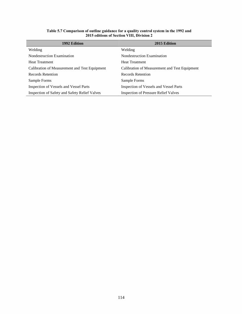
114
Table 5.7 Comparison of outline guidance for a quality control system in the 1992 and
2015 editions of Section VIII, Division 2
1992 Edition 2015 Edition
Welding Welding
Nondestruction Examination Nondestruction Examination
Heat Treatment Heat Treatment
Calibration of Measurement and Test Equipment Calibration of Measurement and Test Equipment
Records Retention Records Retention
Sample Forms Sample Forms
Inspection of Vessels and Vessel Parts Inspection of Vessels and Vessel Parts
Inspection of Safety and Safety Relief Valves Inspection of Pressure Relief Valves

115
6. INSPECTION AND EXAMINATION
The ASME BPVC provides requirements for inspection and examination including nondestructive
examination of boilers and pressure vessels during and after fabrication. The terms inspection,
examination, and nondestructive examination are defined as follows.
Inspection: the observation of any operation performed on materials and/or components to determine
its acceptability in accordance with given criteria.
Examination: the process of determining the condition of an area of interest by nondestructive means
against established acceptance or rejection criteria.
Nondestructive Examination (NDE): the development and application of technical methods to
examine materials and/or components in ways that do not impair future usefulness and
serviceability in order to detect, locate, measure, interpret, and evaluate flaws.
6.1 GENERAL INSPECTION AND TEST REQUIREMENTS
General requirements for inspection and tests are specified in Paragraph PG-90 in Section I,
Paragraph UG-90 in Section VIII, Division 1, and Article I-1, Paragraph AI-100 in Section VIII,
Division 2 in the 1992 edition of the ASME BPVC. Corresponding general requirements for inspection
and tests are specified in Paragraph PG-90 in Section I, Paragraph UG-90 in Section VIII, Division 1, and
Part 7, Paragraph 7.1 in Section VIII, Division 2 in the 2015 edition of the ASME BPVC. These general
requirements define Manufacturer responsibilities and Inspector duties where the terms Manufacturer and
Inspector are defined as follows.
Manufacturer: the organization responsible for construction of a boiler, pressure vessel, vessel
component, or part or the organization responsible for the manufacture of pressure relief devices
in accordance with the rules of the ASME BPVC and who holds an ASME Certificate of
Authorization to apply the Certification Mark to such an item.
Inspector: an Authorized Inspector regularly employed by an ASME accredited Authorized
Inspection Agency or by a company that manufacturers pressure vessels exclusively for its own
use and not for resale that is defined as a User-Manufacturer. This is the only instance in which
an Inspector may be in the employ of the Manufacturer.
Manufacturer responsibilities include, but are not limited to, the following.
• examination of all materials before fabrication to make certain they have the required thickness,
to detect defects, to make certain the materials are permitted by the ASME BPVC, and that
traceability to the material identification has been maintained. (See Sect. 3.1 of this report.)
• documentation of impact tests when such tests are required. (See Sect. 4.1.3 of this report.)
• examination of the shell and head sections to confirm they have been properly formed to the
specified shapes within the permissible tolerances. (See Sects. 5.1 and 5.2 of this report.)
• qualification of the welding and brazing procedures before they are used in fabrication. (See
Sect. 5.3.4 of this report.)
• qualification of welders and welding operators and brazers before using the welders or brazers in
production work. (See Sect. 5.3.6 of this report.)

116
• examination of all parts prior to joining to make certain they have been properly fitted for
welding or brazing and that the surfaces to be joined have been cleaned and the alignment
tolerances are maintained.
• certifying that personnel performing and evaluating NDE are qualified and certified.
• examination of parts as fabrication progresses, for material marking, that defects are not evident,
and that dimensional geometries are maintained.
• provision of controls to assure that all required heat treatments are performed. (See Sect. 5.4 of
this report.)
• provision of records of nondestructive testing examinations. (See Sect. 6.3 of this report.)
• making the required hydrostatic or pneumatic test and having the required inspections performed
during such test. (See Sect. 7.1 of this report.)
• providing for retention of radiographs, ultrasonic test reports, NDE records, Manufacturer’s Data
Reports, and other required documentation.
Inspector duties include, but are not limited to, the following.
• verifying that the Manufacturer has a valid Certificate of Authorization and is working to a
Quality Control System (See Sect. 5.6 of this report.).
• verifying that the applicable design calculations are available.
• verifying that materials used in the construction comply with the requirements.
• verifying that all welding and brazing procedures are qualified.
• verifying that all welders, welding operators, brazers, and brazing operators are qualified.
• verifying that the heat treatments, including PWHT, are performed.
• verifying that material imperfections repaired by welding are acceptably repaired.
• verifying that weld defects are acceptably repaired.
• verifying that required NDE, impact tests, and other tests are performed and that the results are
acceptable
• making a visual inspection to confirm that there are no material or dimensional defects.
• making a visual inspection to confirm that the material identification numbers are properly
transferred.
• performing internal and external inspections and witnessing the hydrostatic or pneumatic test
• verifying that the required marking is provided and that the required nameplate is attached.
• signing the Certificate of Inspection on the Manufacturer’s Data Report.
6.2 NONDESTRUCTIVE EXAMINATION (NDE) REQUIREMENTS
Nondestructive examination is an indispensable inspection method for assuring sound construction by
identifying critical flaws in materials and welds. Section V of the ASME BPVC contains requirements
and methods for NDE, which are Code requirements to the extent they are specifically referenced and

117
required by other ASME BPVC Sections. Descriptions of NDE methods and respective abbreviations
used in Section I, Section VIII, Division 1, and Section VIII, Division 2 of the ASME BPVC follow.
RT — Radiography: a method of detecting imperfections in materials by passing X‐ray or nuclear
radiation through the material and presenting their image on a recording medium.
UT — Ultrasonics: a method for detecting imperfections in materials by passing ultrasonic
vibrations (frequencies normally 1 MHz to 5 MHz) through the material.
MT — Magnetic Particle: a method of detecting cracks and similar imperfections at or near the
surface in iron and the magnetic alloys of steel. It consists of properly magnetizing the material
and applying finely divided magnetic particles that form patterns indicating the imperfections.
PT — Liquid Penetrant: a method of nondestructive examination that provides for the detection
of imperfections open to the surface in ferrous and nonferrous materials that are nonporous.
VT — Visual: a nondestructive examination method used to evaluate an item by observation,
such as, the correct assembly, surface conditions, or cleanliness of materials, parts, and
components used in the fabrication and construction of ASME Code boilers, pressure vessels, and
related hardware.
These NDE methods are categorized as either surface examinations or volumetric examinations. Surface
NDE is a method capable of detecting imperfections located on or just beneath the surface of a
component. Surface examination methods include PT, MT, and VT. Volumetric NDE is a method capable
of detecting imperfections located anywhere within the examined volume. Volumetric examination
methods include RT and UT. Discussions of underlying NDE technologies for these methods are
presented in Sect. 6.3 of this report.
6.2.1 General NDE Requirements in Section I
Rules for circumferential and longitudinal butt welded joints in boilers fabricated by welding that require
volumetric examination are specified in Paragraph PW-11 in the 1992 and 2015 editions of Section I of
the ASME BPVC. These rules state that all circumferential and longitudinal butt welded joints must be
examined throughout their entire length unless specifically exempted by rules that depend on the service
conditions, nominal pipe size, or material thickness. The following statement in Paragraph PW-11 in the
1992 and 2015 editions of Section I of the ASME BPVC establishes the basis for these exemptions.
Experience has demonstrated that welded butt joints not requiring volumetric
examination by these rules have given safe and reliable service even if they contain imperfections that may be disclosed upon further examination. Any examination and
acceptance standards beyond the requirements of this Section are beyond the scope of
this Code and shall be a matter of agreement between the Manufacturer and the User.
Rules specified in Paragraph PW-11 in the 1992 and 2015 editions of Section I of the ASME BPVC
further define which volumetric examination method (RT or UT) or combination of methods (RT and
UT) must be used to examine particular types of circumferential and longitudinal butt welded joints as
discussed in Sects. 6.2.1.1 and 6.2.1.2 of this report.
Rules for visual and liquid penetrant examinations (VT and PT) of bimetallic tubes when the clad strength
is included are specified in Paragraph PW-44 in the 2015 edition of Section I of the ASME BPVC as
discussed in Sect. 6.2.1.3 of this report.

118
6.2.1.1 Radiographic Examination Requirements in Section I
Rules for radiography examination of welds are provided in Paragraph PW-51 in the 1992 and 2015
editions of Section I of the ASME BPVC. These rules state that all welds that require radiographic
examination must be examined by the X-ray or gamma-ray method in accordance with rules specified in
Article 2, Section V of the ASME BPVC. Paragraphs PW-51.3.1 and PW-51.3.2 in both editions define
the conditions under which indications shown on the radiographs of welds and characterized as
imperfections are unacceptable and must be repaired and the repair radiographed. Acceptance standards
for radiographic examinations are compared in Sect. 6.2.4.1 of this report.
Rules specified in Paragraph PW-11 in the 1992 edition of Section I of the ASME BPVC state that all
longitudinal and circumferential buttwelded joints must be radiographically examined throughout their
entire length, except circumferential welds in pressure parts not exceeding NPS 10 or 1.25 in. wall
thickness.
Welded butt joints that require volumetric examination are specified in Table PW-11 in the 2015 edition
of Section I of the ASME BPVC. These volumetric examination requirements vary depending on the
pressure part service conditions but otherwise cover the entire length of all longitudinal buttwelded joints
(all sizes and thicknesses) and circumferential welds in pressure parts that exceed NPS 10 or 1.25 in. wall
thickness.
6.2.1.2 Ultrasonic Examination Requirements in Section I
Rules for ultrasonic examination of welds are provided in Paragraph PW-52 in the 1992 and 2015
editions of Section I of the ASME BPVC. These rules state that techniques and standards for ultrasonic
examination must follow rules specified in Article 5, Section V in the 1992 edition or Article 4,
Mandatory Appendix VII, Section V in the 2015 edition of the ASME BPVC, as applicable. Acceptance
standards for ultrasonic examinations are compared in Sect. 6.2.4.1 of this report.
Rules for when ultrasonic testing must be used are specified in Paragraph PW-11.2 in the 1992 edition of
Section I of the ASME BPVC.
Unless Table PW-11 in the 2015 editions of Section I of the ASME BPVC restricts volumetric
examination to one method, either the radiographic or the ultrasonic method may be used.
6.2.1.3 Visual and Liquid Penetrant Examination Requirements in Section I
Fabrication rules for bimetallic tubes when the clad strength is included are specified in
Paragraph PW-44.8.1 in the 2015 edition of Section I of the ASME BPVC. These rules state:
“Visual examination (VT) shall be performed on 100% of the clad surface in accordance
with Section V, Article 9. Any indication open to the surface shall additionally be
subjected to liquid penetrant examination (PT) in accordance with A-270 and acceptance or rejection based on A-270.4. The portion of bimetallic tubing containing rejectable
defects shall either be removed or the defects repaired in accordance with PW-44.9.”
Visual and liquid penetrant examinations must comply with Article 9 and Article 6, respectively, in the
2015 edition of Section V of the ASME BPVC. Corresponding rules for fabrication of bimetallic tubes
when the clad strength is included are not provided in the 1992 edition of Section I of the ASME BPVC.

119
6.2.2 General NDE Requirements in Section VIII, Division 1
Rules for volumetric examination of joints in pressure vessels fabricated by welding that require
volumetric examination are specified in Paragraph UW-11 in the 1992 and 2015 editions of Section VIII,
Division 1 of the ASME BPVC. These rules apply to pressure vessels made using carbon and low alloy
steels [Paragraph UCS-57], high alloy steels [Paragraph UHA-33], nonferrous materials
[Paragraph UNF-57], pressure vessels constructed of materials having higher allowable stresses at low
temperature [Paragraph ULT-57(a)], and pressure vessels constructed of ferritic steels with tensile
properties enhanced by heat treatment [Paragraph UHT-57(a) and (b)].
6.2.2.1 General Volumetric Examination Requirements
Specific rules for radiographic and ultrasonic examinations of welded joints are provided in the 1992 and
2015 editions of Section VIII, Division 1 of the ASME BPVC for the following types of examinations.
• UW-11(a) – full radiography
• UW-11(b) –spot radiography
• UW-11(c) –no radiography
• UW-11(d) –electrogas welds in ferritic materials
• UW-11(e) –welds made by the electron beam process
• UW-11(f) –welds made by the inertia and continuous drive friction welding process
A summary of the requirements for each type of examination follows.
(a) Butt joints that must be subjected to radiographic examination over their full length are identified
in Paragraph UW-11(a). However, Paragraph UW-11(a)(7) in the 1992 edition and
Paragraph UW-11(a)(8) in the in the 2015 edition states that ultrasonic examination may be
substituted for radiography for the final closure seam of a pressure vessel if the construction of
the pressure vessel does not permit interpretable radiographs in accordance with Code
requirements. Butt joints subjected to full radiography are permitted to have higher joint design
efficiencies compared to butt joints subjected to spot radiography.
(b) According to rule specified in Paragraph UW-11(b), butt joints made in accordance with Type
No. (1) or (2) of Table UW-12 which are not required to be fully radiographed by requirements
specified in Paragraph UW-11(a), may be examined by spot radiography. Type No. (1) butt joints
are attained by double‐welding or by other means that will obtain the same quality of deposited
weld metal on the inside and outside weld surfaces to agree with the requirements of
Paragraph UW-35. Welds using metal backing strips that remain in place are excluded. Type
No. (2) butt joints are single‐welded butt joints with backing strip other than those included under
Type No. (1).
(c) Rules for no radiographic examination of welded joints are specified in Paragraph UW-11(c).
Except as required in Paragraph UW-11(a), no radiographic examination of welded joints is
required when the pressure vessel or pressure vessel part is designed for external pressure only, or
when the joint design complies with requirements specified in Paragraph UW-12(c). Butt joints
subjected to no radiography have lower joint design efficiencies compared to butt joints subjected
to full or spot radiography.

120
(d) Rules in Paragraph UW-11(d) state that electrogas welds in ferritic materials with any single pass
greater than 1 1/2 in. (38 mm) and electroslag welds in ferritic materials must be ultrasonically
examined throughout their entire length in accordance with the requirements of Appendix 12 in
the 1992 edition or Mandatory Appendix 12 in the 2015 edition of Section VIII, Division 1 of the
ASME BPVC, as applicable.
(e) Rules in Paragraph UW-11(e) state that all welds made by the electron beam process must be
ultrasonically examined for their entire length in accordance with the requirements of
Appendix 12 in the 1992 edition or Mandatory Appendix 12 in the 2015 edition of Section VIII,
Division 1 of the ASME BPVC, as applicable. Three exceptions to this requirement are specified
in the 2015 edition but excluded from the 1992 edition of Paragraph UW-11(e).
(f) According to rule specified in Paragraph UW-11(f), when radiography is required for a welded
joint in accordance with Paragraphs UW-11(a) and UW-11(b), and the weld is made by the
inertia and continuous drive friction welding processes, the welded joints must also be
ultrasonically examined for their entire length in accordance with Appendix 12 in the 1992
edition or Mandatory Appendix 12 in the 2015 edition of Section VIII, Division 1 of the ASME
BPVC, as applicable. However, Paragraph UW-11(f) in the 2015 edition of Section VIII,
Division 1 further states that ultrasonic examination may be waived if the following conditions
are met:
(1) The nominal thickness at the welded joint does not exceed 1/4 in. (6 mm).
(2) For ferromagnetic materials, the welds are either examined by the magnetic particle
examination technique in accordance with Mandatory Appendix 6 or examined by the liquid
penetrant examination technique in accordance with Mandatory Appendix 8.
(3) For non-ferromagnetic materials, the welds are examined by the liquid penetrant examination
technique in accordance with Mandatory Appendix 8.
6.2.2.2 General Surface Examination Requirements
Rules for surface examination of welded joints in pressure vessels fabricated by welding that require
liquid penetrant or magnetic particle examination are specified in Paragraph UG-103 in the 1992 and
2015 editions of Section VIII, Division 1 of the ASME BPVC. Where magnetic particle examination is
prescribed in this Division it must be performed in accordance with Appendix 6 in the 1992 edition or
Mandatory Appendix 6 in the 2015 edition, as applicable. These rules apply to pressure vessels
constructed of ferritic steels with tensile properties enhanced by heat treatment [Paragraph UHT-57(d)].
Where liquid penetrant examination is prescribed it must be performed in accordance with Appendix 8 in
the 1992 edition or Mandatory Appendix 8 in the 2015 edition, as applicable. These rules apply to
pressure vessels made using high alloy steels [Paragraph UHA-34], nonferrous materials
[Paragraph UNF-58(a) and (c)], pressure vessels constructed of materials having higher allowable stresses
at low temperature [Paragraph ULT-57(b)], and pressure vessels constructed of ferritic steels with tensile
properties enhanced by heat treatment [Paragraph UHT-57(c) and (e)].
6.2.2.3 Radiographic Examination Requirements in Section VIII, Division 1
Rules for radiographic examination of welded joints are specified in Paragraph UW-51 in the 1992 and
2015 editions of Section VIII, Division 1 of the ASME BPVC. These rules state that all welds that require
radiographic examination must be examined in accordance with rules specified in Article 2, Section V of
the ASME BPVC. Paragraphs UW-51(b)(1) through (b)(4) define the conditions under which indications
shown on the radiographs of welds and characterized as imperfections are unacceptable and must be

121
repaired and the repair radiographed. Acceptance standards for full radiographic examinations are
compared in Sect. 6.2.4.1 of this report.
Rules for spot radiographic examination of buttwelded joints are specified in Paragraph UW-52 in the
1992 and 2015 editions of Section VIII, Division 1 of the ASME BPVC. Paragraph UW-52(c) states that
the minimum length of a spot radiograph is 6 in. (150 mm). Requirements for the extent of spot
radiographic examinations are provided in Paragraph UW-52(b). Acceptance standards for spot
radiographic examinations are compared in Sect. 6.2.4.1 of this report.
6.2.2.4 Ultrasonic Examination Requirements in Section VIII, Division 1
Rules for ultrasonic examination of welded joints are specific in Paragraph UW-53 in the 1992 and 2015
editions of Section VIII, Division 1 of the ASME BPVC. According to these rules, ultrasonic examination
of welded joints when required or permitted by other paragraphs of this Division must be performed and
evaluated to the acceptance standards in accordance with Appendix 12 in the 1992 edition or Mandatory
Appendix 12 in the 2015 edition of Section VIII, Division 1 of the ASME BPVC, as applicable.
Rules specified in Paragraph UW-51(a)(4) in the 2015 edition of Section VIII, Division 1 of the ASME
BPVC state:
“As an alternative to the radiographic examination requirements above, all welds in material 1/4 in. (6 mm) and greater in thickness may be examined using the ultrasonic
(UT) method per the requirements of 7.5.5 of Section VIII, Division 2.”
Paragraph UW-53 in the 2015 edition of Section VIII, Division 1 of the ASME BPVC further states that
ultrasonic examination of welds per UW-51(a)(4) must be performed in accordance with the requirements
of Section VIII, Division 2, Paragraph 7.5.5 and must be evaluated to the acceptance standards specified
in Section VIII, Division 2, Paragraph 7.5.5.
Acceptance standards for ultrasonic examinations and flaw evaluation and acceptance criteria specified in
Section VIII, Division 2, Paragraph 7.5.5 are compared in Sect. 6.2.4.1 of this report.
6.2.2.5 Liquid Penetrant Examination Requirements in Section VIII, Division 1
Rules for liquid penetrant examination are specified in Appendix 8 in the 1992 edition and Mandatory
Appendix 8 in the 2015 edition of Section VIII, Division 1 of the ASME BPVC. These rules describe
methods which must be employed whenever liquid penetrant examination is specified in this Division.
Liquid penetrant examination must be performed in accordance with a written procedure, certified by the
Manufacturer to be in accordance with the requirements of T‐150 of Section V of the ASME BPVC.
Acceptance standards for liquid penetrant examinations are compared in Sect. 6.2.4.2 of this report.
6.2.2.6 Magnetic Particle Examination Requirements in Section VIII, Division 1
Rules for magnetic particle examination are specified in Appendix 6 in the 1992 edition and Mandatory
Appendix 6 in the 2015 edition of Section VIII, Division 1 of the ASME BPVC. These rules describe
methods which must be employed whenever magnetic particle examination is specified in this Division.
Magnetic particle examination must be performed in accordance with a written procedure, certified by the
Manufacturer to be in accordance with the requirements of T‐150 of Section V of the ASME BPVC.
Acceptance standards for magnetic particle examinations are compared in Sect. 6.2.4.2 of this report.

122
6.2.3 General NDE Requirements in Section VIII, Division 2
Examination requirements specified in the 1992 edition of Section VIII, Division 2 of the ASME BPVC
for welded joints are significantly different from corresponding rules in the 2015 edition of Section VIII,
Division 2. A comparison of weld joint examination requirements specified in the 1992 and 2015 editions
is presented in Table 6.1 of this report.
Table 6.1 Comparison of weld joint examination requirements
Joint Category or Type of
Connection
Required Examination – Section VIII, Division 2
1992 Edition† 2015 Edition‼
A RT (complete) RT or UT and MT or PT
B RT (complete) RT or UT and MT or PT
C RT (complete), UT, MT, PT‡ RT or UT and MT or PT
D RT (complete), UT, MT, PT‡ RT or UT and MT or PT
Attachments MT, PT RT or UT and MT or PT
† Ultrasonic examination in accordance with Article 9-3 in the 1992 edition of Section VIII, Division 2 of the
ASME BPVC may be substituted for radiography for the final closure seam of a pressure vessel if the construction
of the vessel does not permit interpretable radiographs in accordance with Code requirements. The absence of
suitable radiographic equipment must not be justification for such substitution. In addition, the written examination
procedure must be available to the Inspector and must be proven by actual demonstration to the satisfaction of the
Inspector to be capable of detecting and locating discontinuities described in this Division.
‡ Visual examination may be substituted for liquid penetrant examination or magnetic particle examination under
conditions specified Table AF-241.1, Note 1 in the 1992 edition of Section VIII, Division 2 of the ASME BPVC.
‼ All finished welds shall be subject to visual examination. Both volumetric and surface examinations are required
to be applied to the extent shown in Table 7.2 in the 2015 edition of Section VIII, Division 2 of the ASME BPVC.
1992 Edition
Required examinations for permitted types of welds are defined in Table AF-241.1 in the 1992 edition of
Section VIII, Division 2 of the ASME BPVC. The required examinations, which are weld joint category
or connection type dependent, vary from one material type to another. Locations for weld joint
Category A (i.e., shell-to-shell), B (i.e., shell-to-head), C (i.e., shell-to-flange), and D (i.e., nozzle-to-
shell) are illustrated in Fig. AD-400.1 in the 1992 edition of Section VIII, Division 2 of the ASME
BPVC.
2015 Edition
Inspection and examination requirements are specified in Part 7 in the 2015 edition of Section VIII,
Division 2 of the ASME BPVC. Rules in Part 7, Paragraph 7.4 for examination of welded joints state:
“All finished welds shall be subject to visual examination in accordance with 7.5.2.
All finished welds shall be subject to nondestructive examination depending on Examination Group
selected in 7.4.2 and the Joint Category and Weld Type as defined in 4.2.
All welding shall be subject to in-process examination by visual examination at the fit-up stage and
during back gouging.”

123
Table 7.2 in the 2015 edition of Section VIII, Division 2 of the ASME BPVC indicates the required NDE,
joint category designation, joint efficiency, and acceptable joint types for each Examination Group. The
extent of examination given in Table 7.2 is a percentage (e.g., 10%, 25%, or 100%, as applicable) of the
total length of the welded joints under consideration.
Rules specified in Part 7, Paragraph 7.4.4 state:
“The selection of the examination method for internal flaws (radiographic or ultrasonic) shall be in accordance with Table 7.3. The basis of the selection is the most suitable
method to the relevant application in relation to the material type and thickness, as well
as any additional NDE requirements specified in the User's Design Specification [see 2.2.2.2(a)].”
According to Table 7.3 requirements, full penetration joints with a thickness less than 1/2 in. must be
examined using radiographic examination, but full penetration joints with a thickness equal to or greater
than 1/2 in. may be examined using either radiographic or ultrasonic examination.
Rules specified in Part 7, Paragraph 7.4.4 further state:
“For nonmagnetic or partially-magnetic materials, or magnetic materials welded with
non-magnetic or partially magnetic filler metals, Liquid Penetrant Examination in accordance with 7.5.7 shall be used. For magnetic steels, Magnetic Particle Examination
or Liquid Penetrant Examination, in accordance with 7.5.6 and 7.5.7 respectively, shall be used as applicable.”
6.2.3.1 Radiographic Examination Requirements in Section VIII, Division 2
Rules for radiographic examination of joints in pressure vessels fabricated by welding in accordance with
requirements specified in the 1992 edition of Section VIII, Division 2 of the ASME BPVC are provided
in Article I-5, Paragraph AI-500. Corresponding rules for radiographic examination of joints in pressure
vessels fabricated by welding in accordance with requirements specified in the 2015 edition of
Section VIII, Division 2 of the ASME BPVC are provided in Part 7, Paragraph 7.5.3. According to these
rules, all welded joints subjected to radiographic examination must be examined in accordance with
requirements specified in Article 2 in the applicable edition of Section V of the ASME BPVC.
6.2.3.2 Ultrasonic Examination Requirements in Section VIII, Division 2
Rules for ultrasonic examination of joints in pressure vessels fabricated by welding in accordance with
requirements specified in the 1992 edition of Section VIII, Division 2 of the ASME BPVC are provided
in Article 9-3, Paragraph 9-300(b). According to these rules, all welded joints subjected to ultrasonic
examination must be examined in accordance with requirements specified in Section V, Article 5 in the
1992 edition of the ASME BPVC.
Corresponding rules for ultrasonic examination of joints in pressure vessels fabricated by welding in
accordance with requirements specified in the 2015 edition of Section VIII, Division 2 of the ASME
BPVC are provided in Part 7, Paragraph 7.5.4. According to these rules, all welded joints subjected to
ultrasonic examination must be examined in accordance with requirements specified in Section V,
Article 4 in the 2015 edition of the ASME BPVC.

124
6.2.3.3 Liquid Penetrant Examination Requirements in Section VIII, Division 2
Rules for liquid penetrant examination of welded joints in pressure vessels fabricated by welding in
accordance with requirements specified in the 1992 edition of Section VIII, Division 2 of the ASME
BPVC are provided in Article 9-2, Paragraph 9-200(b). According to these rules, all welded joints
subjected to liquid penetrant examination must be examined in accordance with requirements specified in
Section V, Article 6 in the 1992 edition of the ASME BPVC.
Corresponding rules for liquid penetrant examination of welded joints in pressure vessels fabricated by
welding in accordance with requirements specified in the 2015 edition of Section VIII, Division 2 of the
ASME BPVC are provided in Part 7, Paragraph 7.5.7. According to these rules, all welded joints
subjected to liquid penetrant examination must be examined in accordance with requirements specified in
Section V, Article 6 in the 2015 edition of the ASME BPVC.
6.2.3.4 Magnetic Particle Examination Requirements in Section VIII, Division 2
Rules for magnetic particle examination of welded joints in pressure vessels fabricated by welding in
accordance with requirements specified in the 1992 edition of Section VIII, Division 2 of the ASME
BPVC are provided in Article 9-2, Paragraph 9-200(b). According to these rules, all welded joints
subjected to magnetic particle examination must be examined in accordance with requirements specified
in Section V, Article 7 in the 1992 edition of the ASME BPVC.
Corresponding rules for magnetic particle examination of welded joints in pressure vessels fabricated by
welding in accordance with requirements specified in the 2015 edition of Section VIII, Division 2 of the
ASME BPVC are provided in Part 7, Paragraph 7.5.6. According to these rules, all welded joints
subjected to magnetic particle examination must be examined in accordance with requirements specified
in Section V, Article 7 in the 2015 edition of the ASME BPVC.
6.2.3.5 Visual Examination Requirements in Section VIII, Division 2
Although Table AF-241.1, Note 1 states that visual examination may be substituted for liquid penetrant
examination or magnetic particle examination, no rules for visual examination of welds are specified in
the 1992 edition of Section VIII, Division 2 of the ASME BPVC.
Rules for visual examination of joints in pressure vessels fabricated by welding in accordance with
requirements specified in the 2015 edition of Section VIII, Division 2 of the ASME BPVC are provided
in Part 7, Paragraph 7.5.2. According to these rules, all welds for pressure retaining parts must be visually
examined.
6.2.4 Acceptance Standards
Specified NDE acceptance criteria in the 2015 editions of Section I, Section VIII, Division 1, and
Section VIII, Division 2 remain essentially the same as the specified NDE acceptance criteria in the
1992 editions of Section I, Section VIII, Division 1, and Section VIII, Division 2 of the ASME BPVC.
However, supplemental requirements have been added and different methodologies have been
incorporated into the 2015 edition of Section VIII, Division 2 of the ASME BPVC to allow pressure
vessel manufacturers more design options.
In addition, attempts were made to harmonize inspection and examination requirements in the
2015 edition of Section VIII, Division 2 with inspection and examination requirements in other ASME
BPVC Sections and some European pressure vessel standards with similar design margins. For instance,

125
rules specified in the 2015 edition of Section VIII, Division 2 of the ASME BPVC provide for partial
radiography and introduce weld joint efficiencies similar to the way Section VIII, Division 1 has used for
many years. However, the partial radiography requirements specified in the 2015 edition of Section VIII,
Division 2 are still more extensive than the spot radiography requirements specified in the 2015 edition of
Section VIII, Division 1 of the ASME BPVC.
6.2.4.1 Volumetric Examination Acceptance Standards
Acceptance standards for volumetric examination are specified in Section I, Section VIII, Division 1, and
Section VIII, Division 2 of the ASME BPVC. These standards identify four types of indications that are
considered rejectable imperfections and must be removed. These types of indications include:
1. any indication characterized as a crack or zone of incomplete fusion or penetration
2. elongated indications greater than a specified length which is a function of the weld thickness
3. a group of aligned indications that have an aggregate length greater than a specified length which
is a function of the weld thickness
4. rounded indications in excess of that specified which is a function of the weld thickness
The flaw evaluation and acceptance criteria specified in Part 7, Paragraph 7.5.5.3 in the 2015 edition of
Section VIII, Division 2 of the ASME BPVC is based on linear elastic fracture mechanics criteria with a
fracture margin (KIC/KIA) equal to or greater than 1.8 [2]. Allowable flaw sizes are specified in the
following tables in the 2015 edition of Section VIII, Division 2 of the ASME BPVC.
• Table 7.8 – Flaw Acceptance Criteria for Welds with a Thickness of 6.4 mm (1/4 in)
• Table 7.9 – Flaw Acceptance Criteria for Welds Between Thicknesses of 6 mm (1/4 in) and less
Than 13 mm (1/2 in)
• Table 7.10 – Flaw Acceptance Criteria for Welds With Thickness Between 25 mm (1 in) and less
Than or Equal to 300 mm (12 in)
• Table 7.11 – Flaw Acceptance Criteria for Welds Between Thickness of 25 mm (1 in) and less
Than or Equal to 300 mm (12 in)
Corresponding flaw evaluation and acceptance criteria are not provided in the 1992 edition of
Section VIII, Division 2 of the ASME BPVC.
Table 6.2 of this report presents a comparison of radiographic examination and ultrasonic examination
acceptance standards specified in the 1992 and 2015 editions of Section I, Section VIII, Division 1, and
Section VIII, Division 2. The comparison shows no difference in radiographic and ultrasonic indications
acceptance standards. However, editorial changes have been made and metric equivalents are included in
the 2015 editions of Section I, Section VIII, Division 1, and Section VIII, Division 2 of the ASME BPVC.
These changes are either not safety significant or result in equivalent safety.

126
Table 6.2 Comparison of volumetric and surface examination acceptance standards
Section I – 1992 Edition – Radiographic
Examination
Section I – 2015 Edition – Radiographic
Examination
PW-51 Radiographic Examination
PW-51.3.1 Any indication characterized as a crack, or
zone of incomplete fusion or penetration.
PW-51.3.2 Any other elongated indication on the
radiograph that has a length greater than:
1/4 in. for t up to 3/4 in.
1/3t for t from 3/4 in. to 2 1/4 in.
3/4 in. for t over 2 1/4 in.
where t is the thickness of the weld.
PW-51.3.3 Any group of aligned indications that have
an aggregate length greater than t in a length of 12t,
except when the distance between the successive
imperfections exceeds 6L where L is the length of the
longest imperfection in the group.
PW-51.3.4 Rounded indications in excess of those
shown in Appendix A-250.
A-250 Acceptance Standards for Radiographically
Determined Rounded Indications in Welds
A-250.3 Acceptance Criteria
A-250.3.2 Relevant Indications (See Table 1 for
Examples). Only those rounded indications which
exceed the following dimensions shall be considered
relevant:
1/10t for t less than 1/8 in.
1/64 in. for t 1/8 in. to 1/4 in., inclusive
1/32 in. for t 1/4 in. to 2 in., inclusive
1/16 in. for t greater than 2 in.
A-250.3.3 Maximum Size of Rounded Indication
(See Table 1 for Examples). The maximum
permissible size of any indication shall be 1/4t, or
5/32 in., whichever is smaller; except that an isolated
indication separated from an adjacent indication by
1 in. or more may be 1/3t, or 1/4 in., whichever is less.
For t greater than 2 in. the maximum permissible size
of an isolated indication shall be increased to 3/8 in.
A-250.3.4 Aligned Rounded Indications. Aligned
rounded indications are acceptable when the
summation of the diameters of the indications is less
than t in a length of 12t (see Figure 1). The length of
groups of aligned rounded indications and the spacing
between the groups shall meet the requirements of
PW-51 Radiographic Examination
PW-51.3.1 Any indication characterized as a crack, or
zone of incomplete fusion or penetration.
PW-51.3.2 Any other elongated indication on the
radiograph that has a length greater than:
(a) 1/4 in. (6 mm) for t up to 3/4 in. (19 mm)
(b) 1/3t for t from 3/4 in. (19 mm) to 2 1/4 in.
(57 mm)
(c) 3/4 in. (19 mm) for t over 2 1/4 in. (57 mm)
where t is the thickness of the weld.
PW-51.3.3 Any group of aligned indications that have
an aggregate length greater than t in a length of 12t,
except when the distance between the successive
imperfections exceeds 6L where L is the length of the
longest imperfection in the group.
PW-51.3.4 Rounded indications in excess of those
shown in A-250.
A-250 Acceptance Standards for Radiographically
Determined Rounded Indications in Welds
A-250.3 Acceptance Criteria
A-250.3.2 Relevant Indications (See Table A-250.3.2
for Examples). Only those rounded indications which
exceed the following dimensions shall be considered
relevant:
(a) 1/10t for t less than 1/8 in. (3 mm)
(b) 1/64 in. (0.4 mm) for t 1/8 in. to 1/4 in. (6 mm),
inclusive
(c) 1/32 in. (0.8 mm) for t 1/4 in. (6 mm) to 2 in.
(50 mm), inclusive
(d) 1/16 in. (1.6 mm) for t greater than 2 in.
(50 mm)
A-250.3.3 Maximum Size of Rounded Indication
(See Table A-250.3.2 for Examples). The maximum
permissible size of any indication shall be 1/4t, or
5/32 in. (4 mm), whichever is smaller; except that an
isolated indication separated from an adjacent
indication by 1 in. (25 mm) or more may be 1/3t, or 1/4
in. (6 mm), whichever is less. For t greater than 2 in.
(50 mm) the maximum permissible size of an isolated
indication shall be increased to 3/8 in. (10 mm).
A-250.3.4 Aligned Rounded Indications. Aligned
rounded indications are acceptable when the
summation of the diameters of the indications is less
than t in a length of 12t (see Figure A-250.3.4-1). The
length of groups of aligned rounded indications and the
spacing between the groups shall meet the

127
Table 6.2 Comparison of volumetric and surface examination acceptance standards
Section I – 1992 Edition – Radiographic
Examination
Section I – 2015 Edition – Radiographic
Examination
Figure 2.
A-250.3.5 Spacing. The distance between adjacent
rounded indications is not a factor in determining
acceptance or rejection, except as required for isolated
indications or groups of aligned indications.
A-250.3.6 Rounded Indication Charts. The rounded
indications characterized as imperfections shall not
exceed that shown in the charts. The charts in
Figures 3.1 through 3.6 illustrate various types of
assorted, randomly dispersed, and clustered rounded
indications for different weld thicknesses greater than
1/8 in. These charts represent the maximum acceptable
concentration limits for rounded indications. The chart
for each thickness range represents full‐scale 6 in.
radiographs, and shall not be enlarged or reduced. The
distributions shown are not necessarily the patterns that
may appear on the radiograph, but are typical of the
concentration and size of indications permitted.
A-250.3.7 Weld Thickness t Less Than 1/8 in. For t
less than 1/8 in. the maximum number of rounded
indications shall not exceed 12 in a 6 in. length of
weld. A proportionally fewer number of indications
shall be permitted in welds less than 6 in. in length.
A-250.3.8 Clustered Indications. The illustrations for
clustered indications show up to four times as many
indications in a local area, as that shown in the
illustrations for random indications. The length of an
acceptable cluster shall not exceed the lesser of 1 in. or
2t. Where more than one cluster is present, the sum of
the lengths of the clusters shall not exceed 1 in. in a
6 in. length of weld.
requirements of Figure A-250.3.4-2.
A-250.3.5 Spacing. The distance between adjacent
rounded indications is not a factor in determining
acceptance or rejection, except as required for isolated
indications or groups of aligned indications.
A-250.3.6 Rounded Indication Charts. The rounded
indications characterized as imperfections shall not
exceed that shown in the charts. The charts in Figures
A-250.3.6-1 through A-250.3.6-6 illustrate various
types of assorted, randomly dispersed, and clustered
rounded indications for different weld thicknesses
greater than 1/8 in. (3 mm). These charts represent the
maximum acceptable concentration limits for rounded
indications. The chart for each thickness range
represents full‐scale 6 in. (150 mm) radiographs, and
shall not be enlarged or reduced. The distributions
shown are not necessarily the patterns that may appear
on the radiograph, but are typical of the concentration
and size of indications permitted.
A-250.3.7 Weld Thickness t Less Than 1/8 in.
(3 mm). For t less than 1/8 in. (3 mm), the maximum
number of rounded indications shall not exceed 12 in a
6 in. (150 mm) length of weld. A proportionally fewer
number of indications shall be permitted in welds less
than 6 in. (150 mm) in length.
A-250.3.8 Clustered Indications. The illustrations for
clustered indications show up to four times as many
indications in a local area, as that shown in the
illustrations for random indications. The length of an
acceptable cluster shall not exceed the lesser of 1 in.
(25 mm) or 2t. Where more than one cluster is present,
the sum of the lengths of the clusters shall not exceed
1 in. (25 mm) in a 6 in. (150 mm) length of weld.
Section I – 1992 Edition – Ultrasonic Examination Section I – 2015 Edition – Ultrasonic Examination
PW-52 Ultrasonic Examination
PW-52.3 Acceptance–Rejection Standards.
Imperfections that cause an indication to exceed the
evaluation levels specified in Section V shall be
investigated to the extent that the ultrasonic
examination personnel can determine their shape,
identity, and location, and evaluate them in terms of
PW-52.3.1 and PW-52.3.2.
PW-52.3.1 Cracks, lack of fusion, or incomplete
penetration are unacceptable regardless of length.
PW-52.3.2 Other imperfections are unacceptable if the
indication exceeds the reference level and their length
exceeds the following:

128
Table 6.2 Comparison of volumetric and surface examination acceptance standards
Section I – 1992 Edition – Radiographic
Examination
Section I – 2015 Edition – Radiographic
Examination
(a) 1/4 in. for t up to 3/4 in.
(b) 1/3t for t from 3/4 in. to 2 1/4 in.
(c) 3/4 in. for t over 2 1/4 in.
where t is the thickness of the weld being examined. If
the weld joins two members having different
thicknesses at the weld, t is the thinner of these two
thicknesses.
(a) 1/4 in. (6 mm) for t up to 3/4 in. (19 mm)
(b) 1/3t for t from 3/4 in. (19 mm) to 2 1/4 in.
(57 mm)
(c) 3/4 in. (19 mm) for t over 2 1/4 in. (57 mm)
where t is the thickness of the weld being examined. If
the weld joins two members having different
thicknesses at the weld, t is the thinner of these two
thicknesses.
Section VIII, Division 1 – 1992 Edition –
Radiographic Examination
Section VIII, Division 1 – 2015 Edition –
Radiographic Examination
UW-51 Full Radiography
(b)(1) any indication characterized as a crack or zone
of incomplete fusion or penetration;
(b)(2) any other elongated indication on the radiograph
which has length greater than:
(-a) 1/4 in. for t up to 3/4 in.
(-b) 1/3t for t from 3/4 in. to 2 1/4 in.
(-c) 3/4 in. for t over 2 1/4 in.
where
t = the thickness of the weld excluding any
allowable reinforcement. For a butt weld joining
two members having different thicknesses at the
weld, t is the thinner of these two thicknesses. If a
full penetration weld includes a fillet weld, the
thickness of the throat of the fillet shall be included
in t.
(b)(3) any group of aligned indications that have an
aggregate length greater than t in a length of 12t,
except when the distance between the successive
imperfections exceeds 6L where L is the length of the
longest imperfection in the group;
(b)(4) rounded indications in excess of that specified
by the acceptance standards given in Appendix 4.
UW-52 Spot Radiography
(c)(1) rounded Welds in which indications are
characterized as cracks or zones of incomplete fusion
or penetration shall be unacceptable.
(c)(2) Welds having indications are characterized as
slag inclusions or cavities shall be unacceptable if the
length of any such indication is greater than 2/3t where
t is the thickness of the weld excluding any allowable
reinforcement. For a butt weld joining two members
having different thicknesses at the weld, t is the thinner
of these two thicknesses. If a full penetration weld
includes a fillet weld, the thickness of the throat of the
UW-51 Full Radiography
(b)(1) any indication characterized as a crack or zone
of incomplete fusion or penetration;
(b)(2) any other elongated indication on the radiograph
which has length greater than:
(-a) 1/4 in. (6 mm) for t up to 3/4 in. (19 mm)
(-b) 1/3t for t from 3/4 in. (19 mm) to 2 1/4 in.
(57 mm)
(-c) 3/4 in. (19 mm) for t over 2 1/4 in. (57 mm)
where
t = the thickness of the weld excluding any
allowable reinforcement. For a butt weld joining
two members having different thicknesses at the
weld, t is the thinner of these two thicknesses. If a
full penetration weld includes a fillet weld, the
thickness of the throat of the fillet shall be included
in t.
(b)(3) any group of aligned indications that have an
aggregate length greater than t in a length of 12t,
except when the distance between the successive
imperfections exceeds 6L where L is the length of the
longest imperfection in the group;
(b)(4) rounded indications in excess of that specified
by the acceptance standards given in Mandatory
Appendix 4.
UW-52 Spot Radiography
(c)(1) Welds in which indications are characterized as
cracks or zones of incomplete fusion or penetration
shall be unacceptable.
(c)(2) Welds having indications characterized as slag
inclusions or cavities are unacceptable when the
indication length exceeds 2/3t, where t is defined as
shown in UW-51(b)(2). For all thicknesses, indications
less than 1/4 in. (6 mm) are acceptable, and indications
greater than 3/4 in. (19 mm) are unacceptable. Multiple
aligned indications meeting these acceptance criteria
are acceptable when the sum of their longest

129
Table 6.2 Comparison of volumetric and surface examination acceptance standards
Section I – 1992 Edition – Radiographic
Examination
Section I – 2015 Edition – Radiographic
Examination
fillet shall be included in t. If several indications within
the above limitations exist in line, the welds shall be
judged acceptable if the sum of the longest dimensions
of all such indications is not more than t in a length of
6t (or proportionately for radiographs shorter than 6t)
and if the longest indications considered are separated
by at least 3L of acceptable weld metal where L is the
length of the longest indication. The maximum length
of acceptable indications shall be 3/4 in. Any such
indications shorter than 1/4 in. shall be acceptable for
any plate thickness.
(c)(3) Rounded indications are not a factor in the
acceptability of welds not required to be fully
radiographed.
dimensions indications does not exceed t within a
length of 6t (or proportionally for radiographs shorter
than 6t), and when the longest length L for each
indication is separated by a distance not less than 3L
from adjacent indications.
(c)(3) Rounded indications are not a factor in the
acceptability of welds not required to be fully
radiographed.
Section VIII, Division 1 – 1992 Edition –
Ultrasonic Examination
Section VIII, Division 1 – 2015 Edition –
Ultrasonic Examination
Appendix 12 Ultrasonic Examination of Welds (UT)
12-3 Acceptance–Rejection Standards
These Standards shall apply unless other standards are
specified for specific applications within this Division.
Imperfections which produce a response greater than
20% of the reference level shall be investigated to the
extent that the operator can determine the shape,
identity, and location of all such imperfections and
evaluate them in terms of the acceptance standards
given in (a) and (b) below.
(a) Indications characterized as cracks, lack of fusion,
or incomplete penetration are unacceptable regardless
of length.
(b) Other imperfections are unacceptable if the
indications exceed the reference level amplitude and
have lengths which exceed:
(1) 1/4 in. for t up to 3/4 in.;
(2) 1/3t for t from 3/4 in. to 2 1/4 in.;
(3) 3/4 in. for t over 2 1/4 in.
where t is the thickness of the weld excluding any
allowable reinforcement. For a butt weld joining two
members having different thicknesses at the weld, t is
the thinner of these two thicknesses. If a full
penetration weld includes a fillet weld, the thickness of
the throat of the fillet shall be included in t.
Mandatory Appendix 12 Ultrasonic Examination of
Welds (UT)
12-3 Acceptance–Rejection Standards
These Standards shall apply unless other standards are
specified for specific applications within this Division.
Imperfections which produce a response greater than
20% of the reference level shall be investigated to the
extent that the operator can determine the shape,
identity, and location of all such imperfections and
evaluate them in terms of the acceptance standards
given in (a) and (b) below.
(a) Indications characterized as cracks, lack of fusion,
or incomplete penetration are unacceptable regardless
of length.
(b) Other imperfections are unacceptable if the
indications exceed the reference level amplitude and
have lengths which exceed:
(1) 1/4 in. (6 mm) for t up to 3/4 in. (19 mm);
(2) 1/3t for t from 3/4 in. to 2 1/4 in. (19 mm to
57 mm);
(3) 3/4 in. (19 mm) for t over 2 1/4 in. (57 mm).
where t is the thickness of the weld excluding any
allowable reinforcement. For a butt weld joining two
members having different thicknesses at the weld, t is
the thinner of these two thicknesses. If a full
penetration weld includes a fillet weld, the thickness of
the throat of the fillet shall be included in t.
Section VIII, Division 2 – 1992 Edition –
Radiographic Examination
Section VIII, Division 2 – 2015 Edition –
Radiographic Examination
Article I-5 Radiographic Examination
AI-500 Technique for Radiographic Examination
Part 7 Inspection and Examination Requirements
Paragraph 7.5.3 Radiographic Examination

130
Table 6.2 Comparison of volumetric and surface examination acceptance standards
Section I – 1992 Edition – Radiographic
Examination
Section I – 2015 Edition – Radiographic
Examination
of Welded Joints
AI-511 Unacceptable Defects and Repair
Requirements
Sections of weld that are shown by radiography to
have any of the following types of defects are
unacceptable unless the defects are removed, the weld
is repaired in accordance with the requirements of
AF-252, and the repaired weld is reexamined in
accordance with the requirements of AF-253:
(a) any type of crack or zone of incomplete fusion
or penetration;
(b) any elongated inclusion, such as slag, which has a
length greater than:
1/4 in. for t up to 3/4 in.
1/3 t for t from 3/4 in. to 2 1/4 in.
3/4 in. for t over 2 1/4 in.
where
t= thickness of the weld excluding any allowable
reinforcement. For a butt weld joining two
members having different thicknesses at the weld,
t is the thinner of these two thicknesses. If a full
penetration weld includes a fillet weld, the
thickness of the throat of the fillet shall be
included in t.
(c) any group of inclusions in line that has an
aggregate length greater than t in a length of 12t,
except when the distance between the successive
imperfections exceeds 6L, where L is the length of
the longest imperfection in the group;
(d) rounded indications in excess of that specified by
the acceptance of the porosity of the standards
given in Appendix 8.
Appendix 8 - Mandatory Rounded Indications
Charts Acceptance Standard for Radiographically
Determined Rounded Indications in Welds
8-110 Terminology
(a) Rounded Indications. Indications with a maximum
length of three times the width or less on the
radiograph are defined as rounded indications. These
indications may be circular, elliptical, conical, or
irregular in shape and may have tails. When
evaluating the size of an indication, the tail shall be
included. The indication may be from any source in
the weld, such as porosity, slag, or tungsten.
(b) Aligned Indications. A sequence of four or more
Paragraph 7.5.3.2 Acceptance Criteria
(a) Linear Indications
(1) Terminology
Thickness t - the thickness of the weld excluding any
allowable reinforcement. For a butt weld joining two
members having different thicknesses at the weld, t is
the thinner of these two thicknesses. If a full
penetration weld includes a fillet weld, the thickness of
the fillet throat shall be included in the calculation of t.
(2) Acceptance/Rejection Criteria
(-a) Any crack or zone of incomplete fusion or lack of
penetration
(-b) Any other linear indication that has a length
greater than:
(-1) 6 mm (1/4 in.) for t less than or equal to 19 mm
(3/4 in.),
(-2) t/3 for t greater than 19 mm (3/4 in.) and less
than or equal to 57 mm (2–1/4 in.),
(-3) 19 mm (3/4 in.) for t greater than 57 mm
(2-1/4 in.).
(-c) Any group of indications in line that has an
aggregate length greater than t in a length of 12t except
when the distance between the successive
imperfections exceeds 6L, where L is the length of the
longest imperfection in the group;
(-d) Internal root weld conditions are acceptable when
the density or image brightness change as indicated in
the radiograph is not abrupt. Linear indications on the
radiograph at either edge of such conditions shall be
evaluated in accordance with the other sections of this
Paragraph.
(b) Rounded Indications
(1) Terminology
(-a) Rounded Indications - indications with a maximum
length of three times the width or less on the
radiograph are defined as rounded indications. These
indications may be circular, elliptical, conical, or
irregular in shape and may have tails. When evaluating
the size of an indication, the tail shall be included.
(-b) Aligned Indications - a sequence of four or more
rounded indications shall be considered to be aligned

131
Table 6.2 Comparison of volumetric and surface examination acceptance standards
Section I – 1992 Edition – Radiographic
Examination
Section I – 2015 Edition – Radiographic
Examination
rounded indications shall be considered to be aligned
when they touch a line parallel to the length of the
weld drawn through the center of the two outer
rounded indications.
(c) Thickness t. t is the thickness of the weld,
excluding any allowable reinforcement. For a butt weld
joining two members having different thicknesses at
the weld, t is the thinner of these two thicknesses. If a
full penetration weld includes a fillet weld, the
thickness of the throat of the fillet shall be included
in t.
8-120 Acceptance Criteria
(a) Image Density. Density within the image of the
indication may vary and is not a criterion for
acceptance or rejection.
(b) Relevant Indications (See Table 8-1 for
Examples). Only those rounded indications which
exceed the following dimensions shall be considered
relevant.
1/10t for t less than 1/8 in.
1/64 in. for t 1/8 in. to 1/4 in., inclusive
1/32 in. for t 1/4 in. to 2 in., inclusive
1/16 in. for t greater than 2 in.
(c) Maximum Size of Rounded Indications (See
Table 8-1 for Examples). The maximum permissible
size of any indication shall be 1/4t or 5/32 in.,
whichever is smaller, except that an isolated
indication separated from an adjacent indication by
1 In. or more may be 1/3t, or 1/4 in., whichever is
less. For t greater that 2 in., the maximum permissible
size of an isolated indication shall be increased to
3/8 in.
(d) Aligned Rounded Indications. Aligned rounded
indications are acceptable when the summation of the
diameters of the indications is less than t in a length of
12t (see Fig. 8-1). The length of groups of aligned
rounded indications and the spacing between the
when they touch a line parallel to the length of the weld
drawn through the center of the two outer rounded
indications.
(-c) Thickness t - the thickness of the weld, excluding
any allowable reinforcement. For a butt weld joining
two members having different thicknesses at the weld, t
is the thinner of these two thicknesses. If a full
penetration weld includes a fillet weld, the thickness of
the fillet throat shall be included in the calculation of t.
(2) Acceptance Criteria
(-a) Rounded Indication Charts - relevant rounded
indications characterized as imperfections shall not
exceed those shown in Figures 7.5 through 7.10, which
illustrate various types of assorted, randomly dispersed
and clustered rounded indications for different weld
thicknesses greater than 3 mm (1/8 in.). The charts for
each thickness range represent full-scale 150 mm (6
in.) radiographs, and shall not be enlarged or reduced.
The distributions shown are not necessarily the patterns
that may appear on the radiograph, but are typical of
the concentration and size of indications permitted.
(-b) Relevant Indications (see Table 7.7 for examples) -
only those rounded indications that exceed the
following dimensions shall be considered relevant and
compared to the acceptance charts for disposition.
(-1) for t less than 3 mm (1/8 in.)
(-2) 0.4 mm (1/64 in.) for t greater than or equal to
3 mm (1/8 in.) and less than or equal to 6 mm
(1/4 in.)
(-3) 0.8 mm (1/32 in.) for t greater than 6 mm
(1/4 in.) and less than or equal to 50 mm (2 in.)
(-4) 1.5 mm (1/16 in.) for t greater than 50 mm
(2 in.)
(-5) Maximum Size of Rounded Indication - the
maximum permissible size of any indication shall
be t/4 or 4 mm (5/32 in.), whichever is smaller;
except that an isolated indication separated from an
adjacent indication by 25 mm (1 in.) or more may
be t/3, or 6 mm (1/4 in.), whichever is less. For t
greater than 50 mm (2 in.) the maximum
permissible size of an isolated indication shall be
increased to 10 mm (3/8 in.).
(-6) Aligned Rounded Indications - aligned rounded
indications are acceptable when the summation of
the diameters of the indications is less than t in a
length of 12t (see Figure 7.3). The length of groups
of aligned rounded indications and the spacing
between the groups shall meet the requirements of

132
Table 6.2 Comparison of volumetric and surface examination acceptance standards
Section I – 1992 Edition – Radiographic
Examination
Section I – 2015 Edition – Radiographic
Examination
groups shall meet the requirements of Fig. 8-2.
(e) Spacing. The distance between adjacent rounded
indications is not a factor in determining acceptance or
rejection, except as required for isolated indications or
groups of aligned indications.
(f) Rounded Indications Charts. The rounded
indications as determined from the radiographic film
shall not exceed that shown in the charts.
The charts in Fig. 8-3 illustrate various types of as
sorted, randomly dispersed and clustered rounded
indications for different weld thicknesses greater than
1 in. These charts represent the maximum acceptable
concentration limits for rounded indications.
The chart for each thickness range represents full
scale 6 in. radiographs, and shall not be enlarged
or reduced. The distributions shown are not
necessarily the patterns that may appear on the
radiograph, but are typical of the concentration and
size of indications permitted.
(g) Weld Thickness t Less Than 1/8 in. For t less
than 1/8 in., in maximum number of rounded
indications shall not exceed 12 in. a 6 in. length of
weld. A proportionally fewer number of indications
shall be permitted in welds less than 6 in. in length.
(h) Clustered Indications. The illustrations for
clustered indications show up to four times as
many indications in a local area as that shown in
the illustrations for random indications. The length of
an acceptable cluster shall not exceed the lesser of
1 in. or 2t. Where more than one cluster is present,
the sum of the lengths of the clusters shall not
exceed 1 in. in a 6 in. length of weld.
Figure 7.4.
(-7) Clustered Indications - the illustrations for
clustered indications show up to four times as many
indications in a local area, as that shown in the
illustrations for random indications. The length of
an acceptable cluster shall not exceed the lesser of
25 mm (1 in.) or 2t. Where more than one cluster is
present, the sum of the lengths of the clusters shall
not exceed 25 mm (1 in.) in a 150 mm (6 in.) length
weld.
(-8) Weld Thickness t less than 3 mm (1/8 in.) - for t
less than 3 mm (1/8 in.) the maximum number of
rounded indications shall not exceed 12 in a
150 mm (6 in.) length of weld. A proportionally
fewer number of indications shall be permitted in
welds less than 150 mm (6 in.) in length.
(-c) Image Density - density or image brightness within
the image of the indication may vary and is not a
criterion for acceptance or rejection.
(-d) Spacing - the distance between adjacent rounded
indications is not a factor in determining acceptance or
rejection, except as required for isolated indications or
groups of aligned indications.
Section VIII, Division 2 – 1992 Edition –
Ultrasonic Examination
Section VIII, Division 2 – 2015 Edition –
Ultrasonic Examination
Appendix 9 – Mandatory Nondestructive
Examination
Article 9-3 Ultrasonic Examination of Welds
9-320 Acceptance/Rejection Standards
These standards shall apply unless other standards
are specified for specific applications within this
Division. All imperfections that produce an amplitude
greater than 20% of the reference level shall be
investigated to the extent that the operator can
determine the shape, identity, and location of all such
imperfections and evaluate them in terms of the
acceptance standards given in (a) and (b) below.
(a) Imperfections that are interpreted to be cracks,
lack of fusion, or incomplete penetration are
Part 7 Inspection and Examination
7.5.4.2 Acceptance Criteria.
These standards shall apply unless other standards are
specified for specific applications within this Division.
All imperfections that produce an amplitude greater
than 20% of the reference level shall be investigated to
the extent that the operator can determine the shape,
identity, and location of all such imperfections and
evaluate them in terms of the acceptance standards
given in (a) and (b) below.
(a) Imperfections that are interpreted to be cracks, lack
of fusion, or incomplete penetration are unacceptable

133
Table 6.2 Comparison of volumetric and surface examination acceptance standards
Section I – 1992 Edition – Radiographic
Examination
Section I – 2015 Edition – Radiographic
Examination
unacceptable regardless of length.
(b) All other linear type imperfections are
unacceptable if the amplitude exceeds the reference
level and the length of the imperfection exceeds the
following:
1/4 in. for t up to 3/4 in.
1/3 t for t from 3/4 in. to 2 1/4 in.
3/4 in. for t over 2 1/4 in.
where t is the thickness of the weld, excluding any
allowable reinforcement. For a butt weld joining two
members having different thicknesses at the weld, t is
the thinner of these two thicknesses. If a full
penetration weld includes a fillet weld, the thickness
of the throat of the fillet shall be included in t.
regardless of length.
(b) All other linear type imperfections are unacceptable
if the amplitude exceeds the reference level and the
length of the imperfection exceeds the following:
(1) 6 mm (1/4 in.) for t less than 19 mm (3/4 in.)
(2) t/3 for t greater than or equal to 19 mm (3/4 in.)
and less than or equal to 57 mm (2-1/4 in.)
(3) 19 mm (3/4 in.) for t greater than 57 mm
(2-1/4 in.)
In the above criteria, t is the thickness of the weld,
excluding any allowable reinforcement (see 6.2.4.1(d)).
For a butt weld joining two members having different
thicknesses at the weld, t is the thinner of these two
thicknesses. If a full penetration weld includes a fillet
weld, the thickness of the throat of the fillet shall be
included in t.
Section VIII, Division 2 – 1992 Edition –
Magnetic Particle Examination
Section VIII, Division 2 – 2015 Edition –
Magnetic Particle Examination
Appendix 9 – Mandatory Nondestructive
Examination
Article 9-1 Magnetic Particle Examination
9-130 Acceptance Standards
These acceptance standards shall apply unless other
more restrictive standards are specified for specific
materials or applications within this Division.
All surfaces to be examined shall be free of:
(a) relevant linear indications;
(b) relevant rounded indications greater than
3/16 in.;
(c) four or more relevant indications in a line
separated by 1/16 in. or less (edge-to-edge)
Part 7 Inspection and Examination
7.5.6.2 Acceptance Criteria.
The following acceptance standards shall apply unless
other more restrictive standards are specified for
specific material or applications within this Division.
Unacceptable indications shall be removed or reduced
to an indication of acceptable size. Whenever an
indication is removed by chipping or grinding and
subsequent repair by welding in not required, the
excavated area shall be blended into the surrounding
surface so as to avoid notches, crevices, or corners.
Where welding is required after removal of indications,
the repair shall be done in accordance with 6.2.7.
(a) All surfaces to be examined shall be free of:
(1) Relevant linear indications
(2) Relevant rounded indications greater than 5 mm
(3/16 in.)
(3) Four or more relevant rounded indications in a
line separated by 1.5 mm (1/16 in.) or less, edge-to-
edge
(b) Crack like indications detected, irrespective of
surface conditions, are unacceptable.
Section VIII, Division 2 – 1992 Edition –
Liquid Penetrant Examination
Section VIII, Division 2 – 2015 Edition –
Liquid Penetrant Examination
Appendix 9 – Mandatory Nondestructive
Examination
Part 7 Inspection and Examination

134
Table 6.2 Comparison of volumetric and surface examination acceptance standards
Section I – 1992 Edition – Radiographic
Examination
Section I – 2015 Edition – Radiographic
Examination
Article 9-2 Liquid Penetrant Examination
9-230 Acceptance Standards
These acceptance standards shall apply unless other
more restrictive standards are specified for specific
materials or applications within this Division.
All surfaces to be examined shall be free of:
(a) relevant linear indications;
(b) relevant rounded indications greater than
3/16 in.;
(c) four or more relevant indications in a line
separated by 1/16 in. or less (edge-to-edge)
7.5.7.2 Acceptance Criteria.
The following acceptance standards shall apply unless
other more restrictive standards are specified for
specific material or applications within this Division.
Unacceptable indications shall be removed or reduced
to an indication of acceptable size. Whenever an
indication is removed by chipping or grinding and
subsequent repair by welding is not required, the
excavated area shall be blended into the surrounding
surface so as to avoid notches, crevices, or corners.
Where welding is required after removal of indications,
the repair shall be done in accordance with 6.2.7.
(a) All surfaces to be examined shall be free of:
(1) Relevant linear indications
(2) Relevant rounded indications greater than 5 mm
(3/16 in.)
(3) Four or more relevant rounded indications in a
line separated by 1.5 mm (1/16 in.) or less, edge-to-
edge
(b) Crack like indications detected, irrespective of
surface conditions, are unacceptable
6.2.4.2 Surface Examination Acceptance Standards
Liquid penetrant (PT) and magnetic particle (MT) inspections are surface examination techniques used to
detect cracks or other discontinuities on material surfaces. The examination methods are typically used in
Section I, Section VIII, Division 1, and Section VIII, Division 2 of the ASME BPVC to provide material
quality factors. The acceptance criteria are either contained within the referenced paragraphs or provided
in referenced appendices.
Table 6.2 of this report presents a comparison of acceptance standards for liquid penetrant and magnetic
particle inspections specified in the 1992 and 2015 editions of Section I, Section VIII, Division 1, and
Section VIII, Division 2. The comparison shows no difference in liquid penetrant and magnetic particle
indications acceptance standards. However, editorial changes have been made and metric equivalents are
included in the 2015 editions of Section I, Section VIII, Division 1, and Section VIII, Division 2 of the
ASME BPVC. These changes are either not safety significant or result in equivalent safety.
6.2.5 Certification Requirements for NDE Personnel
As discussed in Sect. 6.1 of this report, the manufacturer is responsible for certifying that personnel
performing and evaluating radiographic and ultrasonic examinations required by Section I, Section VIII,
Division 1, and Section VII, Division 2 are qualified and certified.
6.2.5.1 Certification Requirements for RT and UT Personnel in the 1992 Edition

135
Rules for qualification of radiographic and ultrasonic NDE personnel are specified in the following
paragraphs in the 1992 edition of the ASME BPVC.
• Section I, Paragraphs PW-51.5 and PW-52.4
• Section VIII, Division 1, Paragraph UW-51(a)(2) and Appendix 12, Paragraph 12-2
• Section VIII, Division 2, Article I-5, Paragraph AI-501(c) and Article 9-3, Paragraph 9-310
According to these rules, each person must be qualified and certified in accordance with their employer’s
written practice. Standard SNT-TC-1A, which is published by the American Society for Nondestructive
Testing, must be used as a guideline for employers to establish their written practice for qualifications and
certification of personnel. Provisions for training, experience, qualification, and certification of NDE
personnel must be described in the manufacturer's Quality Control System. (Note: Earlier editions of
SNT-TC-1A allowed NDE Level III inspectors to be qualified based on experience without having to pass
an examination [2]. However, in 1992, the requirements were tightened to require these inspectors to be
qualified by examination.) Quality Control System requirements are discussed in Sect. 5.6 of this report.
Paragraphs PW-51.5 and PW-52.4 in the 1992 edition of Section I of the ASME BPVC further state:
“When personnel have been certified according to their employer’s written practice based upon an edition of SNT-TC-1A earlier than that referenced in A-361, their
certification shall be valid for performing nondestructive examination required by this
Section until their next scheduled recertification. Any recertification, reexamination, or new examination shall be performed to the employer’s written practice based on the
edition of SNT-TC-1A referenced in A-361.”
6.2.5.2 Certification Requirements for RT and UT Personnel in the 2015 Edition
Rules for qualification of radiographic and ultrasonic NDE personnel are specified in the following
paragraphs in the 2015 edition of the ASME BPVC.
• Section I, Paragraph PW-50
• Section VIII, Division 1, Paragraph UW-54
• Section VIII, Division 2, Part 7, Paragraph 7.3
The rules in each of these paragraphs specify the same requirements as stated in the following text from
Paragraph PW-50 in the 2015 edition of Section I of the ASME BPVC.
The Manufacturer shall be responsible for assuring that nondestructive examination (NDE) personnel have been qualified and certified in accordance with their employer’s
written practice prior to performing or evaluating radiographic or ultrasonic
examinations required by this Section. SNT‐TC‐1A or CP‐189 shall be used as a
guideline for employers to establish their written practice. National or international
Central Certification Programs, such as the ASNT Central Certification Program (ACCP), may be used to fulfill the examination and demonstration requirements of the
employer’s written practice. Provisions for training, experience, qualification, and
certification of NDE personnel shall be described in the Manufacturer’s quality control
system.
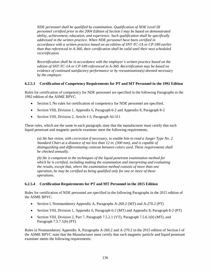
136
NDE personnel shall be qualified by examination. Qualification of NDE Level III personnel certified prior to the 2004 Edition of Section I may be based on demonstrated
ability, achievement, education, and experience. Such qualification shall be specifically
addressed in the written practice. When NDE personnel have been certified in
accordance with a written practice based on an edition of SNT‐TC‐1A or CP‐189 earlier
than that referenced in A-360, their certification shall be valid until their next scheduled recertification.
Recertification shall be in accordance with the employer’s written practice based on the
edition of SNT‐TC‐1A or CP‐189 referenced in A-360. Recertification may be based on
evidence of continued satisfactory performance or by reexamination(s) deemed necessary by the employer.
6.2.5.3 Certification of Competency Requirements for PT and MT Personnel in the 1992 Edition
Rules for certification of competency for NDE personnel are specified in the following Paragraphs in the
1992 edition of the ASME BPVC.
• Section I, No rules for certification of competency for NDE personnel are specified.
• Section VIII, Division 1, Appendix 6, Paragraph 6-2 and Appendix 8, Paragraph 8-2
• Section VIII, Division 2, Article I-3, Paragraph AI-311
These rules, which are the same in each paragraph, state that the manufacturer must certify that each
liquid penetrant and magnetic particle examiner meet the following requirements.
(a) He has vision, with correction if necessary, to enable him to read a Jaeger Type No. 2
Standard Chart at a distance of not less than 12 in. (300 mm), and is capable of
distinguishing and differentiating contrast between colors used. These requirements shall
be checked annually.
(b) He is competent in the techniques of the liquid penetrant examination method for which he is certified, including making the examination and interpreting and evaluating
the results, except that, where the examination method consists of more than one
operation, he may be certified as being qualified only for one or more of these operations.
6.2.5.4 Certification Requirements for PT and MT Personnel in the 2015 Edition
Rules for certification of NDE personnel are specified in the following Paragraphs in the 2015 edition of
the ASME BPVC.
• Section I, Nonmandatory Appendix A, Paragraphs A-260.2 (MT) and A-270.2 (PT)
• Section VIII, Division 1, Appendix 6, Paragraph 6-2 (MT) and Appendix 8, Paragraph 8-2 (PT)
• Section VIII, Division 2, Part 7, Paragraph 7.5.2.1 (VT), Paragraph 7.5.6.1(b) (MT), and
Paragraph 7.5.7.1(b) (PT)
Rules in Nonmandatory Appendix A, Paragraphs A-260.2 and A-270.2 in the 2015 edition of Section I of
the ASME BPVC state that the Manufacturer must certify that each magnetic particle and liquid penetrant
examiner meets the following requirements:

137
(a) The examiner has vision, with correction if necessary, to enable him to read a Jaeger Type No. 2 Standard Chart at a distance of not less than 12 in. (300 mm) and is
capable of distinguishing and differentiating contrast between colors used. These
capabilities shall be checked annually.
(b) The examiner is competent in the techniques of the magnetic particle examination
method for which he is certified, including making the examination and interpreting and evaluating the results, except that where the examination method consists of
more than one operation, he may be certified as being qualified only for one or more of these operations.
The same rules with editorial text changes are specified in Appendix 6, Paragraph 6-2 and in Appendix 8,
Paragraph 8-2 in the 2015 edition of Section VIII, Division 1 of the ASME BPVC. These changes are
either not safety significant or result in equivalent safety.
Requirements for personnel performing visual examination of welds for pressure retaining parts
constructed in accordance with rules specified in the 2015 edition of Section VIII, Division 2 of the
ASME BPVC are provided in Part 7, Paragraph 7.5.2.1. According to these requirements, personnel
performing visual examinations must have vision, with correction if necessary, to read a Jaeger Type
No. 2 Standard Chart at a distance of not less than 300 mm (12 in.), and be capable of distinguishing and
differentiating contrast between colors used. Compliance with this requirement must be demonstrated
annually.
Requirements for personnel performing magnetic particle and liquid penetrant examinations required by
the 2015 edition of Section VIII, Division 2, must be qualified and certified in accordance with rules
specified in Part 7, Paragraph 7.3 in the 2015 edition of Section VIII, Division 2 of the ASME BPVC. A
discussion of the rules specified in Part 7, Paragraph 7.3 is presented in Sect. 6.2.5.2 of this report. In
addition, evaluation of magnetic particle and liquid penetrant examinations must only be performed by
MT or PT Level II or III personnel, as applicable.
Qualification requirements for Level II and Level III personnel are provided in Mandatory Appendix II –
Supplemental Personnel Qualification Requirements for NDE Certification in the 2015 edition of
Section V of the ASME BPVC. (Note: Earlier editions of SNT-TC-1A allowed Level III personnel to be
qualified based on experience without having to pass an examination [2]. These requirements were
tightened in 1992 to require inspectors to be qualified by examination. However, on January 15, 1998
ASME issued an interpretation I-98-06 that grandfathered current Level III personnel. Rule changes in the
2004 edition of the ASME BPVC made examination of new and requalifying (every 5 years) NDE
personnel mandatory.)
6.2.6 Summary of Differences in NDE Requirements between the 1992 and 2015 Editions
A summary of differences in NDE requirements between the 1992 and 2015 editions of the ASME BPVC
is presented in Table 6.3 of this report.
Table 6.3 Differences in surface NDE requirements between the 1992 and 2015 editions of
the ASME BPVC
Paragraph Component or Item Description Differences in NDE
Requirements
Section I
PG-25 Quality Factors for Steel Castings Nonlinear imperfections increased

138
Table 6.3 Differences in surface NDE requirements between the 1992 and 2015 editions of
the ASME BPVC
Paragraph Component or Item Description Differences in NDE
Requirements
from 3/32 in. in 1992 to 3/16 in. in
2015
PG-93 Examination and Repair of Flat Plate in Corner Joints The rules contained in PG-93 did
not exist in 1992
PW-40 Defect Removal for Base Materials, Welds, and Welded
Repairs
These requirements are much more
stringent and prescriptive than 1992
PW-44 Fabrication Rules for Bimetallic Tubes When the Clad
Strength is Included
The rules in PW-44 did not exist in
1992 (See Sect. 6.2.1 of this report)
PW-54 Seal Welding After Hydrotest PT or MT examination was not
required in 1992
Part PFT Requirements for Fire Tube Boilers PT or MT examination was not
required in 1992
Section VIII, Division 1
UG-24 Quality Factors for Castings Castings to be assessed per the
material specification or
Appendix 7, whichever is more
restrictive. See changes to
Appendix 7 below.
UG-93 Inspection of Materials Materials shall meet the
requirements of the material
specification.
UW-11(e) Examination of welds by the Electron Beam Process Electron beam welds must be
ultrasonically examined for their
entire length. Three exceptions to
this requirement are specified in the
2015 edition but excluded from the
1992 edition.
UW-11(f) Examination of welds by the Inertia and Continuous
Drive Friction Welding Processes
2015 edition states that ultrasonic
examination may be waived if the
following conditions are met.
UW-13 Longitudinal Joints in Shells and Heads Using a Butt
Weld with One Plate Offset
No change to the requirements
UW-42 Weld Metal Buildup No change to the requirements
Part UF Requirements for Vessels Fabricated by Forging 2015 Edition has additional
inspection requirements for
qualifying weld procedures and
welder performance for seal
welding of threaded connections
Part UCS Requirements for Vessels Constructed of Carbon and
Low Alloy Steels
2015 Edition has additional
requirements for fillet welds of
“lightly loaded attachments” when
the MDMT is colder than -55°F

139
Table 6.3 Differences in surface NDE requirements between the 1992 and 2015 editions of
the ASME BPVC
Paragraph Component or Item Description Differences in NDE
Requirements
Part UNF Requirements for Pressure Vessels Constructed of
Nonferrous Materials
2015 Edition contains additional
inspection requirements for weld
repairs after final PWHT of UNS
Nos. N08800, N08810, and N08811
alloys
Part UHA Requirements for Pressure Vessels Constructed of High
Alloy Steel
No change to the requirements
Part UCI Requirements for Pressure Vessels Constructed of Cast
Iron
No change to the requirements
Part UHT Requirements for Pressure Vessels Constructed of
Ferritic Steels with Tensile Properties Enhanced by Heat
Treatment
No change to the requirements
Part ULW Requirements for Pressure Vessels Fabricated by
Layered Construction
No change to the requirements
Part ULT Requirements for Pressure Vessels Constructed of
Materials Having Higher Allowable Stresses at Low
Temperature
No change to the requirements
Appendix 2 Flanged Machined from Plate or Bar Stock No change to the requirements
Appendix 5 Flanged-and-Flued or Flanged-Only Expansion Joints The 1992 edition did not contain
rules for flanged expansion joints
Appendix 6 Methods for Magnetic Particle Examination (MT) 2015 edition requires
documentation to be available to
the Inspector
Appendix 7 Examination of Steel Castings No change to the requirements
Appendix 8 Methods for Liquid Penetrant Examination (PT) 2015 edition requires
documentation to be available to
the Inspector
Appendix 20 Hubs Machined from Plate No change to the requirements
Appendix 22 Integrally Forged Vessels No change to the requirements
Appendix 26 Bellows Expansion Joints Appendix 26 did not exist in the
1992 edition
Appendix 42 Diffusion Bonding This method of bonding
microchannel heat exchangers was
not allowed in 1992
Appendix 44 Cold Stretching of Austenitic Stainless Steel Pressure
Vessels
This method of designing and
fabricating vessels was not allowed
in 1992
Section VIII, Division 2
3.3 Examination of Ferrous Forgings 2015 edition contains mandatory
requirements for examination
following final machining of thick

140
Table 6.3 Differences in surface NDE requirements between the 1992 and 2015 editions of
the ASME BPVC
Paragraph Component or Item Description Differences in NDE
Requirements
and complex forgings
3.6 Examination of Nonferrous Forgings 2015 edition contains mandatory
requirements for examination
following final machining of thick
and complex forgings
3.7 Examination of Bolts, Studs and Nuts over 1 inch 1992 edition requires bolts, studs
and nuts over 2 in. to be examined.
2015 edition requires bolts, studs,
and nuts over 1 in. to be examined.
3.8 Examination of Castings No change to the requirements
3.9 Examination of Hubs Machined from Plate Supplemental requirements for
hubs machined from plate did not
exist in the 1992 edition. The 1992
edition did not allow hubs for
tubesheets and flat heads
3.11 Postweld Heat Treatment of Welded Attachments 2015 Edition has additional
requirements for welding of “lightly
loaded attachments” when the
MDMT is colder than -55°F
4.16 Examination of Fabricated Flanges No change to the requirements
6.1 Repair of Defective Materials No change to the requirements
6.1 Examination of Welds of Spin-Holes Not covered in the 1992 edition
6.1.3 Examination of Cut Edges No change to the requirements
6.1.4 Removal of Tack Welds and Temporary Attachments No change to the requirements
6.2.4 Austenitic Chromium-Nickel Alloy Steel Welds No change to the requirements
6.2.4 Weld Metal Buildup No change to the requirements
6.4. Postweld Heat Treatment After Repairs No change to the requirements
6.7.6 Examination After Heat Treatment for Forged Vessels No change to the requirements
6.7.7 Examination of Finished Welds with Carbon Content
Exceeding 0.35%
No change to the requirements
7.4.12 Examination of Expansion Joints No change to the requirements
7.5 Examination Method and Acceptance Criteria The content and requirements in
this Paragraph and the referenced
table is essentially unchanged
7.6 Surface Examination after Hydrotest for Fatigue Service This is a new requirement in later
editions were derived from the
ASME piping codes and
Section VIII Division 3

141
6.3 NDE TECHNOLOGY
Nondestructive evaluation technology involves the use of noninvasive techniques to evaluate the integrity
of a material, component, or structure and to locate and quantify imperfections that could adversely affect
the ability of the item to perform its intended function. Successful implementation of NDE technology
results in no harm to the material, component, or structure.
Requirements specified in Section I, Section VIII, Division 1, and Section VIII, Division 2 of the ASME
BPVC for evaluating the acceptability of a boiler or pressure vessel incorporate applicable NDE
technologies into the following NDE methods.
• Radiographic Examination – RT
• Ultrasonic Examination – UT
• Liquid Penetrant Examination – PT
• Magnetic Particle Examination – MT
• Visual Examination – VT
These NDE methods are capable of detecting imperfections that require evaluation where the term
evaluation means the determination of whether a relevant indication is cause to accept or to reject a
material or component. Table 6.4 of this report identifies common types of imperfections found in welded
construction and the NDE methods that are capable of detecting the imperfections.
Table 6.4 NDE methods capable of detecting imperfections in welded construction
Imperfection† NDE Method
Burn Through VT, RT
Cracks PT, MT, UT
Excessive/Inadequate Reinforcement VT, RT
Inclusions (Slag/Tungsten) RT
Incomplete Fusion UT
Incomplete Penetration PT, MT, RT, UT
Misalignment VT, RT
Overlap PT, MT
Porosity VT, PT, RT
Root Concavity VT, RT
Undercut VT, RT
†An imperfection is a departure of a quality characteristic from its intended condition.
Nondestructive examination requirements specified in Section I, Section VIII, Division 1, and
Section VIII, Division 2 of the ASME BPVC typically incorporate examination and documentation
requirements specified in Section V of the ASME BPVC. However, these Construction Codes may
supplement the requirements specified in Section V with additional requirements that are more restrictive or take exceptions to a particular requirement specified in Section V.

142
Section V in the 1992 and 2015 editions of the ASME BPVC is arranged into Subsection A –
Nondestructive Methods of Examination and Subsection B – Documents Adopted by Section V.
Subsection A is organized into Articles, mandatory appendices, and nonmandatory appendices that
provide requirements for a particular NDE method. It describes the NDE methods to be used if referenced
by a Construction Code or referencing documents. Subsection B lists standards, which are identified by
the SE designation, that cover NDE methods that are accepted as standards. These standards, which are
generally identical to ASTM specifications, are nonmandatory unless specifically referenced in whole or
in part in Subsection A or as indicated in a Construction Code or referencing documents.
6.3.1 General NDE Requirements in Section V
Article 1 – General Requirements in the 1992 and 2015 editions of Section V of the ASME BPVC
specifies general requirements and methods for NDE which are Code requirements to the extent they are
specifically referenced and required by a Construction Code or referencing documents. These NDE
methods are intended to detect surface and internal imperfections in materials, welds, fabricated parts, and
components. Paragraph T-150 in each edition specifies the following rules that apply to all NDE methods.
When required by the referencing Code Section, all nondestructive examinations performed under this Code Section shall be performed following a written procedure. A
procedure demonstration shall be performed to the satisfaction of the Inspector. When
required by the referencing Code Section, a personnel demonstration may be used to verify the ability of the examiner to apply the examination procedure. The examination
procedure shall comply with the applicable requirements of this Section for the particular examination method. Written procedures shall be made available to the Inspector on
request. At least one copy of each procedure shall be readily available to the Nondestructive Examination Personnel for their reference and use.
In addition, both editions state that Nondestructive Examination Personnel must be qualified in
accordance with the requirements of the referencing Construction Code.
Article 1, Paragraph T-120(g) in the 2015 editions of Section V of the ASME BPVC further states that if
the techniques of computed radiography (CR), digital radiography (DR), phased-array ultrasonic
technology (PAUT), or ultrasonic time-of-flight diffraction (TOFD) are to be used, the training,
experience, and examination requirements found in Article 1, Mandatory Appendix II must also be
included in the employer’s written practice for each technique as applicable. The term technique is used
in this context to mean a specific way of utilizing a particular NDE method.
Mandatory Appendix II in the 2015 edition of Section V of the ASME BPVC provides the additional
personnel qualification requirements that are mandated by Article 1, T 120(g), and which are to be
included in the employer’s written practice for NDE personnel certification, when any of the following
techniques are used by the employer: computed radiography (CR), digital radiography (DR), Phased
Array Ultrasonic Technology (PAUT), and ultrasonic Time of Flight Diffraction (TOFD).
6.3.2 Radiographic Examination Requirements in Section V
Radiographic examination is a noninvasive NDE method used to detect imperfections in materials by
passing X‐ray or nuclear radiation through the material and presenting their image on a recording
medium.
Article 2 – Radiographic Examination in the 1992 and 2015 editions of Section V of the ASME BPVC
specifies requirements for radiographic examination of materials including castings and welds. Certain

143
product-specific, technique-specific, and application-specific requirements are also specified in the
following appendices for this Article.
• Appendix I – In-Motion Radiography (provided in 1992 edition)
• Mandatory Appendix I – In-Motion Radiography (provided in 1992 edition)
• Appendix II – Real-Time Radioscopic Examination (provided in 1992 edition)
• Mandatory Appendix II – Real-Time Radioscopic Examination (provided in 2015 edition)
• Appendix III – Digital Image Acquisition, Display, and Storage for Radiography and Radioscopy
(provided in 1992 edition)
• Mandatory Appendix III – Digital Image Acquisition, Display, and Storage for Radiography and
Radioscopy (provided in 2015 edition)
• Mandatory Appendix IV – Interpretation, Evaluation, and Disposition of Radiographic and
Radioscopic Examination Test Results Produced by the Digital Image Acquisition and Display
Process (provided in 2015 edition)
• Mandatory Appendix V – Glossary of Terms for Radiographic Examination (provided in 2015
edition)
• Mandatory Appendix VI – Acquisition, Display, Interpretation, and Storage of Digital Images of
Radiographic Film for Nuclear Applications (provided in 2015 edition)
• Mandatory Appendix VI – Supplement A (provided in 2015 edition)
• Mandatory Appendix VII – Radiographic Examination of Metallic Castings (provided in 2015
edition)
• Mandatory Appendix VIII – Radiography Using Phosphor Imaging Plate (provided in 2015
edition)
• Mandatory Appendix IX – Application of Digital Radiography (provided in 2015 edition)
Paragraph III-210 in Appendix III in the 1992 edition and Mandatory Appendix III in the 2015 edition of
Section V of the ASME BPVC states:
“Digital image acquisition, display, and storage can be applied to radiography and
radioscopy. Once the analog image is converted to digital format, the data can be
displayed, processed, quantified, stored, retrieved, and converted back to the original analog format, for example, film or video presentation.”
These rules in Mandatory Appendix III only apply to digital image acquisition, display, and storage for
radiography and radioscopy and not to digital radiography (DR) techniques as an alternative to film
radiography.
According to rules specified in Paragraph IX-210 and Mandatory Appendix IX in the 2015 edition of
Section V of the ASME BPVC, digital radiography may be performed on materials, including castings
and weldments when the modified provisions to Article 2 as indicated in Mandatory Appendix IX and all
other applicable requirements of Article 2 are satisfied. Mandatory Appendix IX provides requirements
for using digital radiography techniques as an alternative to film radiography. In addition, this Mandatory
Appendix addresses techniques where the image is transmitted directly from the detector as a digital
image rather than using an intermediate process for conversion of an analog image to a digital format, and

144
applications in which the radiation detector and the source of the radiation may or may not be in motion
during exposure.
Use of digital radiography techniques as an alternative to film radiography as specified in Mandatory
Appendix IX in the 2015 edition of Section V of the ASME BPVC provides equivalent or greater safety
compared to use of film radiography and digital image acquisition permitted in the 1992 edition of
Section V of the ASME BPVC.
6.3.3 Ultrasonic Examination Requirements in Section V
Ultrasonic examination is a noninvasive NDE method used to detect imperfections in materials by passing
ultrasonic vibrations (frequencies normally 1 MHz to 5 MHz) through the material.
Article 5 – Ultrasonic Examination Methods for Materials and Fabrication in the 1992 edition and
Article 4 – Ultrasonic Examination Methods for Welds in the 2015 edition of Section V of the ASME
BPVC provide or reference requirements which are to be used in selecting and developing ultrasonic
examination procedures when examination to any part of this Article is a requirement of a referencing
Construction Code. These procedures are to be used for the ultrasonic examination and the dimensioning
of indications for comparison with acceptance standards when required by the referencing Construction
Code. Certain product-specific, technique-specific, and application-specific requirements are also
specified in the following appendices of this Article.
• Appendix I – Screen Height Linearity (provided in 1992 edition)
• Mandatory Appendix I – Screen Height Linearity (provided in 2015 edition)
• Appendix II – Amplitude Control Linearity (provided in 1992 edition)
• Mandatory Appendix II – Amplitude Control Linearity (provided in 2015 edition)
• Mandatory Appendix III – Time of Flight Diffraction (TOFD) Technique (provided in 2015
edition)
• Mandatory Appendix IV – Phased Array Manual Raster Examination Techniques Using Linear
Arrays (provided in 2015 edition)
• Mandatory Appendix V – Phased Array E-Scan and S-Scan Linear Scanning Examination
Techniques (provided in 2015 edition)
• Mandatory Appendix VII – Ultrasonic Examination Requirements for Workmanship Based
Acceptance Criteria (provided in 2015 edition)
• Mandatory Appendix VIII – Ultrasonic Examination Requirements for a Fracture Mechanics
Based Acceptance Criteria (provided in 2015 edition)
• Mandatory Appendix IX – Procedure Qualification Requirements for Flaw Sizing and
Categorization (provided in 2015 edition)
• Mandatory Appendix X – Ultrasonic Examination of High Density Polyethylene (provided in
2015 edition)
Prior to 2005, ultrasonic examination was not permitted except for a final closure weld where
radiographic examination was impractical as discussed in Sect. 6.2.2.1 of this report. Code Case 2235,
which was issued in 1995, allowed ultrasonic examination in lieu of radiographic examination for
Section I, Section VIII, Division 1, and Section VIII, Division 2 for welds greater than 1/2 in. thick. Code

145
Case 2235 has since been incorporated into Section VIII, Division 1 and Section VIII, Division 2 of the
ASME BPVC. As discussed in Sect. 6.2.2.4 of this report, Paragraph UW-51(a)(4) in the 2015 edition of
Section VIII, Division 1 now states the following.
As an alternative to the radiographic examination requirements above, all welds in
material 1/4 in. (6 mm) and greater in thickness may be examined using the ultrasonic (UT) method per the requirements of 7.5.5 of Section VIII, Division 2.
Requirements for the Time of Flight Diffraction (TOFD) examination technique for welds, which are
specified in Article 4, Mandatory Appendix III in the 2015 edition of Section V of the ASME BPVC, are
not included in Article 5 in the 1992 edition of Section V of the ASME BPVC.
6.3.4 Liquid Penetrant Examination Requirements in Section V
Liquid penetrant examination is a noninvasive NDE method used to detect discontinuities which are open
to the surface of nonporous metals and other materials. Typical discontinuities detectable by this method
include cracks, seams, laps, cold shuts, laminations, and porosity. In principle, a liquid penetrant is
applied to the surface to be examined and allowed to enter discontinuities. All excess penetrant is then
removed, the part is dried, and a developer is applied. The developer functions as a blotter to absorb
penetrant that has been trapped in discontinuities, and as a contrasting background to enhance the
visibility of penetrant indications. The dyes in penetrants are either color contrast (visible under white
light) or fluorescent (visible under ultraviolet light).
Article 6 – Liquid Penetrant Examination in the 1992 and 2015 editions of Section V of the ASME BPVC
states that the liquid penetrant examination techniques described in this Article must be used together
with Article 1 when specified by the referencing Construction Code. It also provides details to be
considered in the procedures used for liquid penetrant examinations.
Additional requirements for the control of contaminant content for all liquid penetrant materials used on
nickel base alloys, austenitic stainless steels, and titanium are specified in Article 6, Mandatory
Appendix II in the 2015 edition of Section V of the ASME BPVC. This requirement is not included in the
1992 edition of Section V of the ASME BPVC.
6.3.5 Magnetic Particle Examination Requirements in Section V
Magnetic particle examination is a noninvasive NDE method used to detect cracks and other
discontinuities on the surfaces of ferromagnetic materials. The sensitivity is greatest for surface
discontinuities and diminishes rapidly with increasing depth of discontinuities below the surface. Typical
types of discontinuities that can be detected by this method include cracks, laps, seams, cold shuts, and
laminations. In principle, this method involves magnetizing an area to be examined, and applying
ferromagnetic particles (the examination’s medium) to the surface. Particle patterns form on the surface
where the magnetic field is forced out of the part and over discontinuities to cause a leakage field that
attracts the particles. Particle patterns are usually characteristic of the type of discontinuity that is
detected. Whichever technique is used to produce the magnetic flux in the part, maximum sensitivity
corresponds to linear discontinuities oriented perpendicular to the lines of flux. For optimum effectiveness
in detecting all types of discontinuities, each area is to be examined at least twice, with the lines of flux
during one examination being approximately perpendicular to the lines of flux during the other.
Article 7 – Magnetic Particle Examination in the 1992 and 2015 editions of Section V of the ASME
BPVC states that the magnetic particle examination techniques described in this Article must be used

146
together with Article 1 when specified by the referencing Construction Code. It also provides details to be
considered in the procedures used for magnetic particle examinations.
6.3.6 Visual Examination Requirements in Section V
Visual examination is a noninvasive NDE method used to evaluate an item by observation, such as, the
correct assembly, surface conditions, or cleanliness of materials, parts, and components used in the
fabrication and construction of ASME Code boilers, pressure vessels, and related hardware. Visual
inspection is implied throughout the ASME BPVC and only explicitly stated as a requirement for
examination of specific components. For example, Part 7, Paragraph 7.5.2 in the 2015 edition of
Section VIII, Division 2 of the ASME BPVC states that all welds for pressure retaining parts must be
visually examined. Section I, Section VIII, Division 1, and Section VIII, Division 2 of the ASME BPVC
generally invoke examination procedures contained in Section V.
Article 9 – Visual Examination in the 1992 and 2015 editions of Section V of the ASME BPVC states
that methods and requirements for visual examination in this Article are applicable together with
requirements of Article 1 when specified by a referencing Construction Code. Specific visual examination
procedures required for every type of examination are not included in this Article because there are many
applications where visual examinations are required. Some examples of these applications include
nondestructive examinations, leak testing, in-service examinations, and fabrication procedures.

147
7. TESTING
The function of the ASME Committee responsible for developing and maintaining the ASME BPVC is to
establish rules of safety that relate only to pressure integrity. In support of this function, the ASME BPVC
provides: (1) pressure testing requirements for boilers and pressure vessels, (2) alternative pressure testing
requirements, and (3) proof testing requirements for pressure vessels.
7.1 PRESSURE TESTING
Pressure testing of boilers and pressure vessels that are constructed in accordance with ASME BPVC
rules must be performed before the Authorized Inspector can authorize application of the Certification
Mark (Code stamp). Pressure tests are performed after fabrication is completed primarily to verify the
leak tight integrity of the boiler or pressure vessel, but also to identify gross deformations or anomalies
that may indicate design errors, material deficiencies, or weld defects.
Many members of the ASME Code committees believe that the primary purpose for pressure testing is to
establish that the boiler or pressure vessel has been properly constructed and that it has a significant
design margin above and beyond its nominal MAWP. In this sense, the pressure test is seen to
demonstrate the validity of the design as a pressure container [11]. Another important aspect of the
pressure test is that it serves as a leak test. Any leaks revealed by the pressure test except for leakage that
might occur at temporary test closures must be repaired, and the boiler or pressure vessel must be
retested.
Hydrostatic and pneumatic pressure tests are not intended to verify the pressure-resisting (burst) capacity
of a pressure vessel because the ASME BPVC does not provide methods for determining burst pressure
other than by proof testing that involves a burst test as discussed in Sect. 7.3.2.2 of this report. This
conclusion is reinforced by the facts that: (1) the minimum hydrostatic and pneumatic test pressures
specified in a particular edition of a Construction Code are not the same, and (2) the specified minimum
hydrostatic and pneumatic test pressures vary from one Construction Code and edition of the ASME
BPVC to another.
Hydrostatic and pneumatic pressure tests are also not intended to blunt cracks where crack tip blunting is
the phenomenon of small-scale plastic deformation of an initially sharp crack. Crack tip blunting only
occurs when the actual stress is high enough to produce plastic deformation in the material at the crack
tip. This stress state is directly related to temperature, the actual material yield strength, and the strain
hardening properties of the particular material.
Stress limits are provided in Section I and Section VIII, Division 2 for hydrostatic and pneumatic tests to
ensure that the boiler or pressure vessel remains below the plastic collapse stress limit. Corresponding
stress limits are not provided in Section VIII, Division 1 for hydrostatic and pneumatic tests, but any
visible permanent distortion could result in rejection of the pressure vessel by the Inspector.
7.1.1 Basis for Pressure Testing Limits in Section I of the ASME BPVC
The objective of design rules specified in Section I of the ASME BPVC is to establish the wall thickness
of a boiler so that the maximum hoop stress, Pm, does not exceed two third of the minimum specified
yield strength, Pm ≤ 0.67 Sy. Additional discussion about allowable stress limits specified in Section I of
the ASME BPVC is presented in Sect. 4.4.1 of this report.
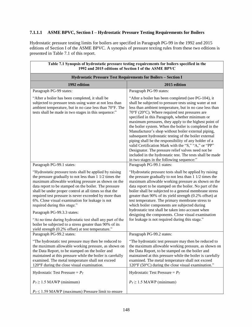
148
7.1.1.1 ASME BPVC, Section I – Hydrostatic Pressure Testing Requirements for Boilers
Hydrostatic pressure testing limits for boilers are specified in Paragraph PG-99 in the 1992 and 2015
editions of Section I of the ASME BPVC. A synopsis of pressure texting rules from these two editions is
presented in Table 7.1 of this report.
Table 7.1 Synopsis of hydrostatic pressure testing requirements for boilers specified in the
1992 and 2015 editions of Section I of the ASME BPVC
Hydrostatic Pressure Test Requirements for Boilers – Section I
1992 edition 2015 edition
Paragraph PG-99 states:
“After a boiler has been completed, it shall be
subjected to pressure tests using water at not less than
ambient temperature, but in no case less than 70°F. The
tests shall be made in two stages in this sequence:”
Paragraph PG-99 states:
“After a boiler has been completed (see PG-104), it
shall be subjected to pressure tests using water at not
less than ambient temperature, but in no case less than
70°F (20°C). Where required test pressures are specified in this Paragraph, whether minimum or
maximum pressures, they apply to the highest point of
the boiler system. When the boiler is completed in the
Manufacturer’s shop without boiler external piping,
subsequent hydrostatic testing of the boiler external
piping shall be the responsibility of any holder of a
valid Certification Mark with the “S,” “A,” or “PP”
Designator. The pressure relief valves need not be
included in the hydrostatic test. The tests shall be made
in two stages in the following sequence:”
Paragraph PG-99.1 states:
“Hydrostatic pressure tests shall be applied by raising
the pressure gradually to not less than 1 1/2 times the
maximum allowable working pressure as shown on the
data report to be stamped on the boiler. The pressure
shall be under proper control at all times so that the
required test pressure is never exceeded by more than
6%. Close visual examination for leakage is not
required during this stage.”
Paragraph PG-99.3.3 states:
“At no time during hydrostatic test shall any part of the
boiler be subjected to a stress greater than 90% of its
yield strength (0.2% offset) at test temperature.”
Paragraph PG-99.1 states:
“Hydrostatic pressure tests shall be applied by raising
the pressure gradually to not less than 1 1/2 times the
maximum allowable working pressure as shown on the
data report to be stamped on the boiler. No part of the
boiler shall be subjected to a general membrane stress
greater than 90% of its yield strength (0.2% offset) at
test temperature. The primary membrane stress to
which boiler components are subjected during
hydrostatic test shall be taken into account when
designing the components. Close visual examination
for leakage is not required during this stage.”
Paragraph PG-99.2 states:
“The hydrostatic test pressure may then be reduced to
the maximum allowable working pressure, as shown on
the Data Report, to be stamped on the boiler and
maintained at this pressure while the boiler is carefully
examined. The metal temperature shall not exceed
120°F during the close visual examination.
Paragraph PG-99.2 states:
“The hydrostatic test pressure may then be reduced to
the maximum allowable working pressure, as shown on
the Data Report, to be stamped on the boiler and
maintained at this pressure while the boiler is carefully
examined. The metal temperature shall not exceed
120°F (50°C) during the close visual examination.”
Hydrostatic Test Pressure = PT
PT ≥ 1.5 MAWP (minimum)
PT ≤ 1.59 MAWP (maximum) Pressure limit to ensure
Hydrostatic Test Pressure = PT
PT ≥ 1.5 MAWP (minimum)

149
Table 7.1 Synopsis of hydrostatic pressure testing requirements for boilers specified in the
1992 and 2015 editions of Section I of the ASME BPVC
Hydrostatic Pressure Test Requirements for Boilers – Section I
1992 edition 2015 edition
that the required test pressure is never exceeded by
more than 6%. (See Paragraph PG-99.1)
However, no part of the boiler may be subjected to a
general membrane stress greater than 90% of its yield
strength (0.2% offset) at the test temperature.
Pm ≤ 0.90 Sy
However, no part of the boiler may be subjected to a
general membrane stress greater than 90% of its yield
strength (0.2% offset) at the test temperature.
Pm ≤ 0.90 Sy
Fig. 7.1 and Fig. 7.2 of this report respectively compare the maximum allowable design stress and
hydrostatic pressure testing limits specified in the 1992 and 2015 editions of Section I of the ASME
BPVC to plastic collapse stress limit discussed in Sect. 4.8.1 of this report. Note that the hydrostatic
pressure testing stress limit in these figures corresponds to a MAWP that is based on a maximum
allowable design stress limit equal to 0.67 Sy.
It is important to note that:
• Hydrostatic test pressure rules specified in Paragraph PG-99.1 in the 1992 edition of Section I of
the ASME BPVC allow the primary membrane stress to exceed the plastic collapse stress limit by
up to 6% when the MAWP is based on an allowable primary membrane stress, Pm, equal to
0.67 Sy. Under these conditions, this hydrostatic pressure test condition violates the principles of
limit design theory discussed in Sect. 4.6 of this report. However, Paragraph PG-99.3.3 states that
no part of the boiler may be subjected to a stress greater than 90% of its yield strength (0.2%
offset) at test temperature. This additional requirement ensures that all parts of the boiler remain
below the plastic collapse stress limit during the hydrostatic test.
• The primary membrane stress limit of 0.90 Sy specified in the 1992 and 2015 editions of Section I
of the ASME BPVC ensures compliance with the principles of limit design theory, but this limit
conflicts with the test pressure rule, PT ≥ 1.5 MAWP (minimum), when the MAWP is based on
an allowable primary membrane stress, Pm, equal to 0.67 Sy. Under these conditions, the primary
membrane stress limit establishes a maximum hydrostatic test pressure equal to 1.35 MAWP (i.e.,
0.9 × 1.5 MAWP). Consequently, the primary membrane design stress must be reduced to a value
less than 0.67 Sy to satisfy the minimum required test pressure of 1.5 MAWP and maintain a
primary membrane stress below the primary membrane stress limit of 0.90 Sy.
• As discussed in Sect. 8.1 of this report, overpressure protection rules specified in Paragraph
PG-67.4.2 in the 1992 and 2015 editions of Section I of the ASME BPVC limit the pressure of an
operating boiler, except for the steam piping between the boiler and the prime mover, to
1.20 MAWP or less. This overpressure protection limit ensures that the primary membrane stress,
Pm, does not exceed 0.80 Sy (i.e., 1.20/1.50). A minimum hydrostatic test pressure equal to the
lesser of 1.5 MAWP or a membrane stress, Pm, no greater than 0.90 Sy ensures that the boiler will
never experience a maximum overpressure while in service that is greater than the hydrostatic test
pressure. (i.e., 0.90 × 1.5 MAWP > 1.20 MAWP)
• Rules in the 1992 and 2015 editions of Section I of the ASME BPVC do not specify a minimum
or maximum hydrostatic test pressure duration. The rules state that a boiler must be maintained at
the MAWP while the boiler is carefully examined.

150
Fig. 7.1 Comparison of maximum allowable design stress and hydrostatic pressure testing limits
specified in the 1992 edition of Section I of the ASME BPVC to the plastic collapse stress limit.
7.1.1.2 ASME BPVC, Section I – Pneumatic Pressure Testing Requirements for Boilers
The 1992 and 2015 editions of Section I of the ASME BPVC do not provide pneumatic pressure test rules
for boilers.

151
Fig. 7.2 Comparison of maximum allowable design stress and hydrostatic pressure testing limits
specified in the 2015 edition of Section I of the ASME BPVC to the plastic collapse stress limit.
7.1.2 Basis for Pressure Testing Limits in Section VIII, Division 1 of the ASME BPVC
The objective of design rules specified in Section VIII, Division 1 of the ASME BPVC is to establish the
wall thickness of a boiler or pressure vessel so that the maximum hoop, Pm, stress does not exceed
two-thirds of the minimum specified yield strength (i.e., Pm ≤ 0.67 Sy). In addition, Paragraph UG-23(c) in
the 1992 and 2015 editions of Section VIII, Division 1 of the ASME BPVC states that a combined
maximum primary membrane stress plus primary bending stress, Pm + Pb, across the thickness cannot

152
exceed 1.5 time the maximum allowable stress in tension (i.e., Pm + Pb ≤ 1.0 Sy). Additional discussion
about allowable stress limits specified in Section VIII, Division 1 of the ASME BPVC is presented in
Sect. 4.4.1 of this report.
7.1.2.1 ASME BPVC, Section VIII, Division 1 – Hydrostatic Pressure Testing Requirements for
Pressure Vessels
Hydrostatic pressure testing limits are specified in Paragraph UG-99 in the 1992 and 2015 editions of
Section VIII, Division 1 of the ASME BPVC. A synopsis of pressure texting rules from these two
editions is presented in Table 7.2 of this report.
Table 7.2 Synopsis of hydrostatic pressure testing requirements for pressure vessels specified
in the 1992 and 2015 editions of Section VIII, Division 1 of the ASME BPVC
Hydrostatic Pressure Test Requirements for Pressure Vessels – Section VIII, Division 1
1992 Edition 2015 Edition
Paragraph UG-99(b) states:
“Except as otherwise permitted in (a) above and (k)
below, vessels designed for internal pressure shall be
subjected to a hydrostatic test pressure which at every
point in the vessel is at least equal to 1 1/2 times the
maximum allowable working pressure to be marked on
the vessel multiplied by the lowest stress ratio (for the
materials of which the vessel is constructed) of the stress
value S for the design temperature (see UG-21). All
loadings that may exist during this test shall be given
consideration.”
Paragraph UG-99(b) states:
“Except as otherwise permitted in (a) above and 27-4,
vessels designed for internal pressure shall be subjected
to a hydrostatic test pressure that at every point in the
vessel is at least equal to 1.3 times the maximum
allowable working pressure multiplied by the lowest
stress ratio (LSR) for the materials of which the vessel is
constructed. The stress ratio for each material is the
stress value S at its test temperature to the stress value S
at its design temperature.”
Paragraph UG-99(c) states:
“A hydrostatic test based on a calculated pressure may
be used by agreement between the user and the
Manufacturer. The hydrostatic test pressure at the top of
the vessel shall be the minimum of the test pressures
calculated by multiplying the basis for calculated test
pressure as defined in 3-2 for each pressure element by
1 1/2 and reducing this value by the hydrostatic head on
that element. When this pressure is used, the Inspector
shall reserve the right to require the Manufacturer or the
designer to furnish the calculations used for determining
the hydrostatic test pressure for any part of the vessel.”
Paragraph UG-99(c) states:
“A hydrostatic test based on a calculated pressure may
be used by agreement between the user and the
Manufacturer. The hydrostatic test pressure at the top of
the vessel shall be the minimum of the test pressures
calculated by multiplying the basis for calculated test
pressure as defined in 3-2 for each pressure element by
1.3 and reducing this value by the hydrostatic head on
that element. When this pressure is used, the Inspector
shall reserve the right to require the Manufacturer or the
designer to furnish the calculations used for determining
the hydrostatic test pressure for any part of the vessel.”
Paragraph UG-99(d) states:
“The requirements of (b) above represent the minimum
standard hydrostatic test pressure required by this
Division. The requirements of (c) above represent a
special test based on calculations. Any intermediate
value of pressure may be used. This Division does not
specify an upper limit for hydrostatic test pressure.
However, if the hydrostatic test pressure is allowed to
exceed, either intentionally or accidentally, the value
determined as prescribed in (c) above to the degree that
the vessel is subjected to visible permanent distortion,
the Inspector shall reserve the right to reject the vessel.”

153
Table 7.2 Synopsis of hydrostatic pressure testing requirements for pressure vessels specified
in the 1992 and 2015 editions of Section VIII, Division 1 of the ASME BPVC
Hydrostatic Pressure Test Requirements for Pressure Vessels – Section VIII, Division 1
1992 Edition 2015 Edition
Paragraph UG-99(f) states:
“Single-wall vessels designed for a vacuum or partial
vacuum only, and chambers of multichamber vessels
designed for a vacuum or partial vacuum only, shall be
subjected to an internal hydrostatic test or when a
hydrostatic test is not practicable, to a pneumatic test in
accordance with the provisions of UG-100. Either type
test shall be made at a pressure not less than 1.5 times
the difference between normal atmospheric pressure and
the minimum design internal absolute pressure.”
Paragraph UG-99(f) states:
“Single‐wall vessels and individual pressure chambers
of combination units designed for vacuum only (MAWP
less than or equal to zero) shall be subjected to either
(1) an internal hydrostatic pressure test in accordance
with UG-99, or a pneumatic pressure test in accordance
with UG-100. The applied test pressure shall be not less
than 1.3 times the specified external design pressure;
or
(2) a vacuum test conducted at the lowest value of
specified absolute internal design pressure. In
conjunction with the vacuum test, a leak test shall be
performed following a written procedure complying
with the applicable technical requirements of Section V,
Article 10 for the leak test method and technique
specified by the user. Leak testing personnel shall be
qualified and certified as required by T-120(e) of
Section V, Article 1.”
Paragraph UG-99(g) states:
“Following the application of the hydrostatic test
pressure an inspection shall be made of all joints and
connections. This inspection shall be made at a pressure
not less than two thirds of the test pressure.”
Paragraph UG-99(g) states:
“Following the application of the hydrostatic test
pressure, an inspection shall be made of all joints and
connections. This inspection shall be made at a pressure
not less than the test pressure divided by 1.3. Except for
leakage that might occur at temporary test closures for
those openings intended for welded connections, leakage
is not allowed at the time of the required visual
inspection. Leakage from temporary seals shall be
directed away so as to avoid masking leaks from other
joints.”
Paragraph UG-99(k)(2) states:
“When painting or coating prior to the hydrostatic test is
permitted, or when internal linings are to be applied, the
pressure-retaining welds shall first be leak tested in
accordance with ASME Section V, Article 10.”
Section V, Article 10 – Leak Testing,
Paragraph VI-1041.3 Test Duration states:
“The test pressure (or vacuum) shall be held for the
duration specified by the referencing Code Section or, if
not specified, it shall be sufficient to establish the
leakage rate of the component system within the
accuracy or confidence limits required by the
referencing Code Section. For very small components or
systems, a test duration in terms of minutes may be
sufficient. For large components or systems, where
temperature and water vapor corrections are necessary, a
Section V, Article 10 – Leak Testing, Paragraph VI 1073
– Test Duration states:
“The test pressure (or vacuum) shall be held for the
duration specified by the referencing Code Section or, if
not specified, it shall be sufficient to establish the
leakage rate of the component system within the
accuracy or confidence limits required by the
referencing Code Section. For very small components or
systems, a test duration in terms of minutes may be
sufficient. For large components or systems, where
temperature and water vapor corrections are necessary, a

154
Table 7.2 Synopsis of hydrostatic pressure testing requirements for pressure vessels specified
in the 1992 and 2015 editions of Section VIII, Division 1 of the ASME BPVC
Hydrostatic Pressure Test Requirements for Pressure Vessels – Section VIII, Division 1
1992 Edition 2015 Edition
test duration in terms of many hours may be required.” test duration in terms of many hours may be required.”
According to rules specified in Paragraph UG-99(b), the hydrostatic test pressure, PT, must be established
based on the following conditions.
• Minimum PT ≥ 1.5 MAWP × LSR for the materials of which the pressure vessel is constructed
based on rules specified in the 1992 edition of Section VIII, Division 1 of the ASME BPVC.
• Minimum PT ≥ 1.3 MAWP × the LSR for the materials of which the pressure vessel is
constructed based on rules specified in the 2015 edition of Section VIII, Division 1 of the ASME
BPVC.
• Maximum PT is not specified in either the 1992 or 2015 edition of Section VIII, Division 1 of the
ASME BPVC. However, if the hydrostatic test pressure is allowed to exceed, either intentionally
or accidentally, the value determined by calculation as prescribed in Paragraph UG-99(c) to the
degree that the vessel is subjected to visible permanent distortion, the Inspector reserves the right
to reject the pressure vessel. According to Mandatory Appendix 3-2 in the 2015 edition of
Section VIII, Division 1 of the ASME BPVC, the basis for the calculated test pressure in
Paragraph UG-99(c) is the highest permissible internal pressure as determined by the design
equations, for each element of the vessel using nominal thicknesses with corrosion allowances
included and using the allowable stress values given in Subpart 1 of Section II, Part D of the
ASME BPVC for the temperature of the test.
It is important to note that:
• Hydrostatic test pressure rules specified in Paragraph UG-99(b) in the 1992 and 2015 editions of
Section VIII, Division 1 of the ASME BPVC allow the primary membrane stress to exceed the
plastic collapse stress limit when MAWP is based on an allowable primary membrane stress, Pm,
equal to 0.67 Sy and the hydrostatic test pressure is greater than 1.5 MAWP. This hydrostatic
pressure test condition violates the principles of limit design theory discussed in Sect. 4.6 of this
report and could result in visible permanent distortion of the pressure vessel sufficient for the
Inspector to reject the vessel.
• As discussed in Sect. 8.2 of this report, overpressure protection rules specified in Paragraph
UG-125(c)(2) in the 1992 and 2015 editions of Section VIII, Division 1 of the ASME BPVC state
that when a pressure vessel can be exposed to fire or other unexpected sources of external heat,
the pressure relief device(s) must be capable of preventing the pressure from rising more than
21% above the MAWP. (i.e., 1.21 MAWP). This overpressure protection limit ensures that the
primary membrane stress, Pm, does not exceed 0.81 Sy (i.e., 1.21/1.50) under fire conditions. A
minimum hydrostatic test pressure equal to 1.3 MAWP ensures that the pressure vessel will never
experience a maximum overpressure while in service that is greater than the hydrostatic test
pressure. (i.e., 1.3 MAWP > 1.21 MAWP)
• Rules in the 1992 and 2015 editions of Section VIII, Division 1 of the ASME BPVC do not
specify a minimum or maximum hydrostatic test pressure duration.

155
Fig. 7.3 and Fig. 7.4 of this report respectively compare the maximum allowable design stress and
hydrostatic pressure testing limits specified in the 1992 and 2015 editions of Section VIII, Division 1 of
the ASME BPVC to plastic collapse stress limit discussed in Sect. 4.8.1 of this report. Note that the
minimum hydrostatic pressure testing limit in these figures corresponds to a MAWP that is based on a
maximum allowable design stress limit equal to 0.67 Sy.
Fig. 7.3 Comparison of maximum allowable design stress and hydrostatic pressure testing limits
specified in the 1992 edition of Section VIII, Division 1 of the ASME BPVC to plastic collapse stress
limit

156
Fig. 7.4 Comparison of maximum allowable design stress and hydrostatic pressure testing limits
specified in the 2015 edition of Section VIII, Division 1 of the ASME BPVC to plastic collapse stress
limit
According to rules specified in Paragraph UG-99(f) in the 2015 edition of Section VIII, Division 1
single-wall pressure vessels designed for vacuum or partial vacuum, may be subjected to a vacuum test
conducted in accordance with Section V, Article 10 requirements as specified by the user. Leak test
methods permitted in Section V, Article 10 include: bubble test, halogen diode detector probe test, helium
mass spectrometer test, pressure chamber test, and ultrasonic leak detector test. Corresponding rules in

157
Paragraph UG-99(f) in the 1992 edition of Section VIII, Division 1 do not permit vacuum testing of
single-wall pressure vessels designed for vacuum or partial vacuum.
7.1.2.2 ASME BPVC, Section VIII, Division 1 – Pneumatic Pressure Testing Requirements for
Pressure Vessels
Pneumatic pressure testing limits are specified in Paragraph UG-100 in the 1992 and 2015 editions of
Section VIII, Division 1 of the ASME BPVC. A synopsis of pneumatic pressure texting rules from these
two editions is presented in Table 7.3 of this report.
Table 7.3 Synopsis of pneumatic pressure testing requirements for pressure vessels specified
in the 1992 and 2015 editions of Section VIII, Division 1 of the ASME BPVC
Pneumatic Pressure Test Requirements for Pressure Vessels – Section VIII, Division 1
1992 Edition 2015 Edition
Paragraph UG-100(a) states that a pneumatic test
prescribed in this Paragraph may be used in lieu of the
standard hydrostatic test prescribed in UG-99 for
vessels:
1. that are so designed and/or supported that they
cannot safely be filled with water;
2. not readily dried, that are to be used in services
where traces of the testing liquid cannot be tolerated
and the parts of which have, where possible, been
previously tested by hydrostatic pressure to the
pressure required in Paragraph UG-99.
Paragraph UG-100(a) states that a pneumatic test may
be used in lieu of the standard hydrostatic test prescribed
in Paragraph UG-99 for vessels:
1. that are so designed and/or supported that they
cannot safely be filled with water;
2. not readily dried, that are to be used in services
where traces of the testing liquid cannot be tolerated
and the parts of which have, where possible, been
previously tested by hydrostatic pressure to the
pressure required in Paragraph UG-99.
Paragraph UG-100(b) state that except for enameled
vessels, for which the pneumatic test pressure shall be
at least equal to, but need not exceed, the maximum
allowable working pressure to be marked on the vessel,
the pneumatic test pressure shall be at least equal to
1.25 times the maximum allowable working pressure
to be stamped on the vessel multiplied by the lowest
ratio (for the materials of which the vessel is
constructed) of the stress value S for the test
temperature of the vessel to the stress value S for the
design temperature (see UG-21). In no case shall the
pneumatic test pressure exceed 1.25 times the calculated
test pressure as defined in 3-2.
The term calculated test pressure is defined in
Appendix 3, Paragraph 3-2 as follows.
calculated test pressure - the requirements for
determining the test pressure based on calculations are
outlined in UG-99(c) for the hydrostatic test and in
UG-100(b) for the pneumatic test. The basis for
calculated test pressure in either of these paragraphs is
the highest permissible internal pressure as determined
by the design formulas, for each element of the vessel
using nominal thicknesses with corrosion allowances
included and using the allowable stress values given in
Subpart 1 of Section II, Part D for the temperature of
the test.
Paragraph UG-100(b) state that except for enameled
vessels, for which the pneumatic test shall be at least
equal to, but not exceed, the maximum allowable
working pressure to be marked on the vessel, the
pneumatic test pressure at every point in the vessel must
be at least equal to 1.1 times the maximum allowable
working pressure multiplied by the lowest stress ratio
(LSR) for the materials of which the vessel is
constructed. The stress ratio for each material is the
stress value S at its test temperature to the stress value S
at its design temperature. However, in no case shall the
pneumatic test pressure exceed 1.1 times the basis for
the calculated test pressure as defined in Mandatory
Appendix 3-2.
Mandatory Appendix 3-2 states that the basis for
calculated test pressure in Paragraph UG-100(b) is the
highest permissible internal pressure as determined by
the design equations, for each element of the vessel
using nominal thicknesses with corrosion allowances
included and using the allowable stress values given in
Subpart 1 of Section II, Part D for the temperature of the
test.

158
Table 7.3 Synopsis of pneumatic pressure testing requirements for pressure vessels specified
in the 1992 and 2015 editions of Section VIII, Division 1 of the ASME BPVC
Pneumatic Pressure Test Requirements for Pressure Vessels – Section VIII, Division 1
1992 Edition 2015 Edition
Paragraph UG-100(c) state that the metal temperature
during pneumatic testing must be maintained at least
30°F above the minimum design metal temperature (see
UG-20) to minimize the risk of brittle fracture.
Paragraph UG-100(c) state that the metal temperature
during pneumatic testing must be maintained at least
30°F (17°C) above the minimum design metal temperature to minimize the risk of brittle fracture.
Paragraph UG-100(d) states that the pressure in the
vessel must be gradually increased to not more than one‐half of the test pressure. Thereafter, the test pressure
must be increased in steps of approximately one‐tenth of
the test pressure until the required test pressure has been
reached. Then the pressure must be reduced to a value
equal to four-fifths of the test pressure and held for
sufficient time to permit inspection of the vessel.
Paragraph UG-100(d) states that the pressure in the
vessel must be gradually increased to not more than one‐half of the test pressure. Thereafter, the test pressure
must be increased in steps of approximately one‐tenth of
the test pressure until the required test pressure has been
reached. Then the pressure must be reduced to a value
equal to the test pressure divided by 1.1 and held for a
sufficient time to permit inspection of the vessel. Any
leaks that are present, except for leakage that might
occur at temporary test closures for those openings
intended for welded connections, must be corrected, and
the vessel must be retested.
Paragraph UG-100(e) includes inspection requirements
for pressure-retaining welds that are painted or otherwise
coated either internally or externally prior to the pressure
test.
According to rules specified in Paragraph UG-100(b), the pneumatic test pressure, PT, must be established
based on the following conditions.
• Minimum PT ≥ 1.25 MAWP × the LSR for the materials of which the pressure vessel is
constructed based on rules specified in the 1992 edition of Section VIII, Division 1 of the ASME
BPVC.
• Minimum PT ≥ 1.1 MAWP × LSR for the materials of which the pressure vessel is constructed
based on rules specified in the 2015 edition of Section VIII, Division 1 of the ASME BPVC.
• Maximum PT is not specified in either the 1992 or 2015 edition of Section VIII, Division 1 of the
ASME BPVC. However, rules specified in the 2015 edition of Section VIII, Division 1 of the
ASME BPVC state that in no case shall the pneumatic test pressure exceed 1.1 times the basis for
the calculated test pressure as defined in Mandatory Appendix 3-2.
It is important to note that:
• Pneumatic test pressure rules specified in Paragraph UG-100(b) in the 1992 edition of
Section VIII, Division 1 of the ASME BPVC allow the primary membrane stress to exceed the
plastic collapse stress limit when MAWP is based on an allowable primary membrane stress, Pm,
equal to 0.67 Sy and the pneumatic test pressure is greater than 1.5 MAWP. This pneumatic
pressure test condition violates the principles of limit design theory discussed in Sect. 4.6 of this
report and could result in visible permanent distortion of the pressure vessel sufficient for the
Inspector to reject the vessel.
• As discussed in Sect. 8.2 of this report, overpressure protection rules specified in Paragraph
UG-125(c)(2) in the 2015 edition of Section VIII, Division 1 of the ASME BPVC state that when

159
a pressure vessel can be exposed to fire or other unexpected sources of external heat, the pressure
relief device(s) must be capable of preventing the pressure from rising more than 21% above the
MAWP. (i.e., 1.21 MAWP). This overpressure protection limit ensures that the primary
membrane stress, Pm, does not exceed 0.81 Sy (i.e., 1.21/1.50). A minimum pneumatic test
pressure equal to 1.1 MAWP does not ensure that the pressure vessel will never experience a
maximum overpressure while in service that is greater than the pneumatic test pressure
(i.e., 1.1 MAWP < 1.21 MAWP).
• Rules in the 1992 and 2015 editions of Section VIII, Division 1 of the ASME BPVC do not
specify a minimum or maximum pneumatic test pressure duration. The rules state that the
pressure must be held for sufficient time to permit inspection of the pressure vessel.
Fig. 7.5 and Fig. 7.6 of this report respectively compare the maximum allowable design stress and
pneumatic pressure testing limits specified in the 1992 and 2015 editions of Section VIII, Division 1 of
the ASME BPVC to plastic collapse stress limit discussed in Sect. 4.8.1 of this report. Note that the
minimum pneumatic pressure testing limit in these figures corresponds to a MAWP that is based on a
maximum allowable design stress limit equal to 0.67 Sy.
7.1.3 Basis for Pressure Testing Limits in Section VIII, Division 2 of the ASME BPVC
The objective of design rules specified in Section VIII, Division 2 of the ASME BPVC is discussed in
Sect. 4.4.2 of this report. Paragraph AD-140(b) in the 1992 edition of Section VIII, Division 2 of the
ASME BPVC states:
“The average value of the general primary membrane stress intensity across the
thickness of the section under consideration, due to any combination of design pressure
and mechanical loadings expected to occur simultaneously, should not exceed the design stress intensity value kSm.”
In addition, Paragraph AD-140(d) states:
“The primary bending stress due to any combination of design pressure and mechanical loadings expected to occur simultaneously shall not exceed 1.5kSm.”
In comparison, Part 4, Paragraph 4.1.6.1 in the 2015 editions of Section VIII, Division 2 of the ASME
BPVC states:
“The wall thickness of a vessel computed by the rules of Part 4 for any combination of
loads (see 4.1.5) that induce primary stress (see definition of primary stress in 5.12) and are expected to occur simultaneously during operation shall satisfy the equations shown
below.”
Pm ≤ Sy (4.1.1)
Pm + Pb ≤ 1.5 Sy (4.1.2)
These rules ensure that the maximum allowable primary membrane stress, Pm, does not exceed 2/3 Sy and
that the maximum allowable primary membrane stress plus primary bending stress, Pm + Pb, does not
exceed Sy. These maximum allowable stress limits are consistent with the principles of limit design theory
discussed in Sect. 4.6 and the plastic collapse requirements discussed in Sect. 4.8 of this report.

160
Fig. 7.5 Comparison of maximum allowable design stress and pneumatic pressure testing limits
specified in the 1992 edition of Section VIII, Division 1 of the ASME BPVC to plastic collapse stress
limit.

161
Fig. 7.6 Comparison of maximum allowable design stress and pneumatic pressure testing limits
specified in the 2015 edition of Section VIII, Division 1 of the ASME BPVC to plastic collapse stress
limit.
7.1.3.1 ASME BPVC, Section VIII, Division 2 – Hydrostatic Pressure Testing Requirements for
Pressure Vessels
Hydrostatic pressure testing limits are specified in Article T-3 in the 1992 edition and in Part 8,
Paragraph 8.2 in the 2015 edition of Section VIII, Division 2 of the ASME BPVC. A synopsis of pressure
texting rules from these two editions is presented in Table 7.4 of this report.

162
Table 7.4 Synopsis of hydrostatic pressure testing requirements for pressure vessels specified
in the 1992 and 2015 editions of Section VIII, Division 2 of the ASME BPVC
Hydrostatic Pressure Test Requirements for Pressure Vessels – Section VIII, Division 2
1992 Edition 2015 Edition
Article T-3 Hydrostatic Tests, Paragraph AT-300
Minimum hydrostatic test pressure, PT, is:
PT = 1.25 MAWP (SmTT/ SmDT)
where:
SmTT/ SmDT is the lowest ratio of the stress intensity value
for the test temperature of the vessel to the stress
intensity value for the design temperature.
Article D-1 – General, Paragraph AD-151.1 states:
“If the test pressure at any point in a vessel, including
static head, exceeds the required test pressure defined in
AT-300, AT-301, and AT-410 by more than 6%, the
upper limit shall be established by the design engineer
using all the loadings that may exist during the test.”
Article D-1 – General, Paragraph AD-151.1 states that
the hydrostatic test pressure of a completed vessel must
not exceed that value which results in the following
equivalent stress limits:
Pm ≤ 0.90 Sy
Pm + Pb ≤ 1.35 Sy
for Pm ≤ 0.67 Sy
Pm + Pb ≤ (2.15 Sy – 1.2 Pm)
for 0.67 Sy < Pm ≤ 0.90 Sy
where
Pm is the general primary membrane stress
Pm + Pb is the general primary membrane plus primary
bending stress
S is the allowable stress
Sy is the yield stress at the test temperature
Part 8 – Pressure Testing Requirements, Paragraph 8.2.1
Minimum hydrostatic test pressure, PT, is greater of:
PT = 1.43 MAWP (8.1)
or
PT = 1.25 MAWP (ST / S) (8.2)
where
S = allowable stress from Annex 3-A evaluated at the
design temperature.
ST = allowable stress from Annex 3-A evaluated at the
test temperature.
ST / S is the lowest ratio for the pressure-boundary
materials, excluding bolting materials, of which the
vessel is constructed.
Part 4, Paragraph 4.1.6.2(a) states that the hydrostatic
test pressure of a completed vessel must not exceed that
value which results in the following equivalent stress
limits:
Pm ≤ 0.95 Sy (4.1.3)
Pm + Pb ≤ 1.43 Sy
for Pm ≤ 0.67 Sy (4.1.4)
Pm + Pb ≤ (2.43 Sy – 1.5 Pm)
for 0.67 Sy < Pm ≤ 0.95 Sy (4.1.5)
where
Pm is the general primary membrane stress
Pm + Pb is the general primary membrane plus primary
bending stress
S is the allowable stress
Sy is the yield stress at the test temperature
Article T-3 Hydrostatic Tests, Paragraph AT-352 – Fluid
Media and Temperature for Hydrostatic Tests states:
“Any liquid, nonhazardous at any temperature, may be
used for the hydrostatic test if below its boiling point.
Combustible liquids having a flash point less than
110°F, such as petroleum distillates, may be used only
for near atmospheric temperature tests. For vessels
constructed of steels whose resistance to brittle fracture
at low temperature has not been enhanced, test
Part 8 – Pressure Testing Requirements, Paragraph 8.2.4
– Test Procedure states:
(a) The metal temperature during a hydrostatic test shall
be maintained at least 17°C (30°F) above the minimum
design metal temperature of the vessel, but need not
exceed 50°C (120°F), to minimize the risk of brittle
fracture.
(b) The test pressure shall not be applied until the vessel

163
Table 7.4 Synopsis of hydrostatic pressure testing requirements for pressure vessels specified
in the 1992 and 2015 editions of Section VIII, Division 2 of the ASME BPVC
Hydrostatic Pressure Test Requirements for Pressure Vessels – Section VIII, Division 2
1992 Edition 2015 Edition
temperatures above 60°F may be useful in minimizing
risk of brittle fracture during hydrostatic testing (see
AD-155). The test pressure shall not be applied until
then vessel and the pressurizing medium are at about the
same temperature. If the test temperature exceeds 120°F,
it is recommended that examination of the vessel
required by AT-355 be delayed until the temperature is
reduced to 120°F.”
and the test fluid are at about the same temperature.
(c) Hydrostatic pressure shall be gradually increased
until the test pressure is reached. The pressure shall then
be reduced to a value not less than the test pressure
divided by 1.43 before examining for leakage in
accordance with 8.2.5.
Article T-3 Hydrostatic Tests, Paragraph AT-355 –
Examination for Leakage After Application of Pressure
states:
“Following the application of the hydrostatic test
pressure, examination for leakage shall be made of all
joints and connections and of all regions of high stress
such as head knuckles, regions around openings, and
thickness transition sections. This examination shall be
made at a pressure equal to the greater of the design
pressure or three-fourths of the test pressure and shall be
witnessed by the Inspector. Any leaks that are present
shall be corrected in accordance with the rules, after
which the vessel shall be retested in accordance with
these requirements.”
Part 8 – Pressure Testing Requirements, Paragraph 8.2.5
– Test Examination and Acceptance Criteria states:
(a) Following the reduction of the test pressure to the
level indicated in 8.2.4(c), a visual examination for
leakage shall be made by the Inspector of all joints and
connections and of all regions of high stress such as
knuckles of formed heads, cone-to-cylinder junctions,
regions around openings, and thickness transitions.
Visual examination of the vessel may be waived
provided all of the following requirements are satisfied:
(1) A suitable gas leak test is applied, 8.4.2.
(2) Substitution of the gas leak test is by agreement
between the Manufacturer and Inspector.
(3) All welded seams that will be hidden by assembly
are given a visual examination for workmanship prior to
assembly.
(b) Any leaks that are present, except for that leakage
that may occur at temporary test closures for those
openings intended for welded connections, shall be
corrected and the vessel shall be retested.
(c) The Inspector shall reserve the right to reject the
vessel if there are any visible signs of permanent
distortion.
Part 7, Paragraph 7.7 – Leak Testing states:
“When specified in the Users' Design Specification, leak
testing shall be carried out in accordance with Article 10
of Section V in addition to hydrostatic test as per 8.2 or
pneumatic test as per 8.3.”
Section V, Article 10 – Leak Testing,
Paragraph VI-1041.3 Test Duration states:
“The test pressure (or vacuum) shall be held for the
duration specified by the referencing Code Section or, if
not specified, it shall be sufficient to establish the
leakage rate of the component system within the
accuracy or confidence limits required by the
referencing Code Section. For very small components or
systems, a test duration in terms of minutes may be
sufficient. For large components or systems, where
temperature and water vapor corrections are necessary, a
test duration in terms of many hours may be required.”
Section V, Article 10 – Leak Testing,
Paragraph VI-1073 – Test Duration states:
“The test pressure (or vacuum) shall be held for the
duration specified by the referencing Code Section or, if
not specified, it shall be sufficient to establish the
leakage rate of the component system within the
accuracy or confidence limits required by the
referencing Code Section. For very small components or
systems, a test duration in terms of minutes may be
sufficient. For large components or systems, where
temperature and water vapor corrections are necessary, a
test duration in terms of many hours may be required.”

164
According to rules specified in Part 8, Paragraph 8.2.1 in the 2015 edition of Section VIII, Division 2 of
the ASME BPVC, the minimum hydrostatic test pressure, PT, must be the greater of the values
determined using the following equations.
PT = 1.43 MAWP (8.1)
or
PT = 1.25 MAWP (ST / S) (8.2)
The upper limits of the test pressure must be determined using the method specified in
Paragraph 4.1.6.2(a). However, any intermediate value of pressure may be used. According to
requirements for hydrostatically tested pressure vessels specified in Paragraph 4.1.6.2(a), when a
hydrostatic test is performed in accordance with Part 8, the hydrostatic test pressure of a completed
pressure vessel must not exceed that value which results in the following equivalent stress limits:
Pm ≤ 0.95 Sy (4.1.3)
Pm + Pb ≤ 1.43 Sy for Pm ≤ 0.67 Sy (4.1.4)
Pm + Pb ≤ (2.43 Sy – 1.5 Pm) for 0.67 Sy < Pm ≤ 0.95 Sy (4.1.5)
It is important to note that:
• These primary stress limits, which are consistent with the limit design theory discussed in
Sect. 4.6 of this report, are intended to prevent plastic deformation and to provide a nominal
design margin on ductile burst pressure. However, the maximum and minimum hydrostatic test
pressures for a pressure vessel that is designed and fabricated in accordance with rules specified
in the 2015 edition of Section VIII, Division 2 of the ASME BPVC are equal when MAWP is
based on an allowable primary membrane stress, Pm, equal to 2/3 Sy (i.e., 0.95 × 1.5 MAWP =
1.43 MAWP). Controlling the hydrostatic test pressure to a pressure of at least 1.43 MAWP but
not more than 1.43 MAWP may be problematic. Consequently, the primary membrane design
stress may need to be reduced to a value less than 0.67 Sy to satisfy the minimum test pressure
requirement, maintain a primary membrane stress below the primary membrane stress limit of
0.95 Sy and provide a margin for hydrostatic test pressure control.
• As discussed in Sect. 8.3 of this report, Part AR, Article R-1, Paragraph AR-140 in the 1992
edition of Section VIII, Division 2 of the ASME BPVC and Part 9 in the 2015 edition of
Section VIII, Division 2 of the ASME BPVC state that when a pressure vessel can be exposed to
fire or other unexpected sources of external heat, the pressure relief device(s) must be capable of
preventing the pressure from rising more than 21% above the MAWP. (i.e., 1.21 MAWP). This
overpressure protection limit ensures that the primary membrane stress, Pm, does not exceed
0.81 Sy (i.e., 1.21/1.50). A minimum hydrostatic test pressure equal to 1.25 MAWP ensures that
the pressure vessel will never experience a maximum overpressure while in service that is greater
than the hydrostatic test pressure. (i.e., 1.25 MAWP > 1.21 MAWP)
Fig. 7.7 and Fig. 7.8 respectively compare the maximum allowable design stress and hydrostatic pressure
testing limits specified in the 1992 and 2015 editions of Section VIII, Division 2 of the ASME BPVC to
plastic collapse stress limit discussed in Sect. 4.8.1 of this report. Note that the hydrostatic pressure
testing stress limit in these figures corresponds to a MAWP that is based on a maximum allowable design
stress limit equal to 0.67 Sy.

165
Fig. 7.7 Comparison of maximum allowable design stress and hydrostatic pressure testing limits
specified in the 1992 edition of Section VIII, Division 2 of the ASME BPVC to plastic collapse stress
limit.

166
Fig. 7.8 Comparison of maximum allowable design stress and hydrostatic pressure testing limits
specified in the 2015 edition of Section VIII, Division 2 of the ASME BPVC to plastic collapse stress
limit.
7.1.3.2 ASME BPVC, Section VIII, Division 2 – Pneumatic Pressure Testing Requirements for
Pressure Vessels
Pneumatic pressure testing limits are specified in Article T-4 in the 1992 edition and in Part 8,
Paragraph 8.3 in the 2015 edition of Section VIII, Division 2 of the ASME BPVC. A synopsis of pressure
texting rules from these two editions is presented in Table 7.5 of this report.

167
Table 7.5 Synopsis of pneumatic pressure testing requirements for pressure vessels specified
in the 1992 and 2015 editions of Section VIII, Division 2 of the ASME BPVC
Pneumatic Pressure Test Requirements for Pressure Vessels – Section VIII, Division 2
1992 Edition 2015 Edition
Article T-4 Pneumatic Tests, Paragraph AT-410
Minimum pneumatic test pressure, PT, is:
PT = 1.15 MAWP (SmTT/ SmDT)
where:
SmTT/ SmDT is the lowest ratio of the stress intensity value
for the test temperature of the vessel to the stress
intensity value for the design temperature.
Part 8 – Pressure Testing Requirements, Paragraph 8.3.1
Minimum pneumatic test pressure, PT, is:
PT = 1.15 MAWP (ST / S) (8.3)
where
S = allowable stress from Annex 3-A evaluated at the
design temperature.
ST = allowable stress from Annex 3-A evaluated at the
test temperature.
ST / S is the lowest ratio for the pressure-boundary
materials, excluding bolting materials, of which the
vessel is constructed.
Article D-1 – General, Paragraph AD-151.2 states that
the limits given in AD-151.1 shall apply to
pneumatically tested vessels except that the calculated
membrane stress intensity shall be limited to 80% of the
yield strength at room temperature.
Pm ≤ 0.80 Sy
Pm + Pb ≤ 1.35 Sy
for Pm ≤ 0.67 Sy
Pm + Pb ≤ (2.15 Sy – 1.2 Pm)
for 0.67 Sy < Pm ≤ 0.80 Sy
where
Pm is the general primary membrane stress
Pm + Pb is the general primary membrane plus primary
bending stress
S is the allowable stress
Sy is the yield stress at the test temperature
Part 4, Paragraph 4.1.6.2(b) states that the pneumatic test
pressure of a completed vessel shall not exceed that
value which results in the following equivalent stress
limits:
Pm ≤ 0.80 Sy (4.1.6)
Pm + Pb ≤ 1.20 Sy
for Pm ≤ 0.67 Sy (4.1.7)
Pm + Pb ≤ (2.22 Sy – 1.5 Pm)
for 0.67 Sy < Pm ≤ 0.95 Sy (4.1.8)
where
Pm is the general primary membrane stress
Pm + Pb is the general primary membrane plus primary
bending stress
S is the allowable stress
Sy is the yield stress at the test temperature
Article T-4, Paragraph AT-422 – Temperature of Vessel
and Testing Medium states:
“For vessels constructed of steels whose resistance to
brittle fracture at low temperature has not been
enhanced, test temperatures above 60°F may be useful in
reducing risk of brittle fracture during pneumatic testing
(see AD 155). The test pressure shall not be applied until
the vessel and the pressuring medium are at about the
same temperature.”
Part 8 – Pressure Testing Requirements, Paragraph 8.3.4
– Test Procedures states:
(a) The metal temperature during a pneumatic test shall
be maintained at least 17°C (30°F) above the minimum
design metal temperature to minimize the risk of brittle
fracture.
(b) The test pressure shall not be applied until the vessel
and the test fluid are at about the same temperature.
(c) Test pressure shall be gradually increased until one-
half of the test pressure is reached after which the test
pressure shall be increased in steps of approximately
one-tenth of the test pressure until the test pressure has
been reached. The pressure shall then be reduced to a

168
Table 7.5 Synopsis of pneumatic pressure testing requirements for pressure vessels specified
in the 1992 and 2015 editions of Section VIII, Division 2 of the ASME BPVC
Pneumatic Pressure Test Requirements for Pressure Vessels – Section VIII, Division 2
1992 Edition 2015 Edition
value not less than the test pressure divided by 1.15
before examining for leakage in accordance with 8.3.5.
Article T-4, Paragraph AT-423 – Rate of Applying Test
Pressure and Examination states:
“The pressure in the vessel shall gradually be in creased
to not more than one-half of the test pressure, after
which the test pressure shall be increased in steps of
approximately one-tenth of the test pressure until the
required test pressure has been reached. The pressure
shall then be reduced to a value equal to the greater of
the design pressure or three-fourths of the test pressure
and held for a sufficient time to permit examination of
the vessel in accordance with AT-355.”
Article T-3 Hydrostatic Tests, Paragraph AT-355 –
Examination for Leakage After Application of Pressure
states:
“Following the application of the hydrostatic test
pressure, examination for leakage shall be made of all
joints and connections and of all regions of high stress
such as head knuckles, regions around openings, and
thickness transition sections. This examination shall be
made at a pressure equal to the greater of the design
pressure or three-fourths of the test pressure and shall be
witnessed by the Inspector. Any leaks that are present
shall be corrected in accordance with the rules, after
which the vessel shall be retested in accordance with
these requirements.”
Part 8 – Pressure Testing Requirements, Paragraph 8.3.5
– Test Examination and Acceptance Criteria states:
(a) Following the reduction of the test pressure to the
level indicated in 8.3.4(c), the reduced pressure shall be
held for sufficient time to allow a visual examination for
leakage. This visual examination shall be made, and the
Inspector shall witness this examination. Visual
examination of the vessel may be waived provided:
(1) a suitable gas leak test is applied, see 8.4.2,
(2) substitution of the gas leak test is by agreement
between the Manufacturer and Inspector,
(3) all welded seams that will be hidden by assembly are
given a visual examination for workmanship prior to
assembly.
(b) Any leaks that are present, except for that leakage
that may occur at temporary test closures for those
openings intended for welded connections, shall be
corrected and the vessel shall be retested.
(c) The Inspector shall reserve the right to reject the
vessel if there are any visible signs of permanent
distortion.
Part 7, Paragraph 7.7 – Leak Testing states:
“When specified in the Users' Design Specification, leak
testing shall be carried out in accordance with Article 10
of Section V in addition to hydrostatic test as per 8.2 or
pneumatic test as per 8.3.”
Section V, Article 10 – Leak Testing,
Paragraph VI-1041.3 Test Duration states:
“The test pressure (or vacuum) shall be held for the
duration specified by the referencing Code Section or, if
not specified, it shall be sufficient to establish the
leakage rate of the component system within the
accuracy or confidence limits required by the
referencing Code Section. For very small components or
systems, a test duration in terms of minutes may be
sufficient. For large components or systems, where
temperature and water vapor corrections are necessary, a
test duration in terms of many hours may be required.”
Section V, Article 10 – Leak Testing,
Paragraph VI-1073 – Test Duration states:
“The test pressure (or vacuum) shall be held for the
duration specified by the referencing Code Section or, if
not specified, it shall be sufficient to establish the
leakage rate of the component system within the
accuracy or confidence limits required by the
referencing Code Section. For very small components or
systems, a test duration in terms of minutes may be
sufficient. For large components or systems, where
temperature and water vapor corrections are necessary, a
test duration in terms of many hours may be required.”

169
According to rules specified in Part 8, Paragraph 8.3.1 in the 2015 edition of Section VIII, Division 2 of
the ASME BPVC, the minimum pneumatic test pressure, PT, must be determined using the following
equation.
PT = 1.15 MAWP (ST / S) (8.3)
The upper limits of the test pressure must be determined using the method specified in
Paragraph 4.1.6.2(b). However, any intermediate value of pressure may be used. According to
requirements for pneumatically tested vessels in Paragraph 4.1.6.2(b), when a pneumatic test is performed
in accordance with Part 8, the pneumatic test pressure of a completed vessel must not exceed that value
which results in the following equivalent stress limits:
Pm ≤ 0.80 Sy (4.1.6)
Pm + Pb ≤ 1.20 Sy for Pm ≤ 0.67 Sy (4.1.7)
Pm + Pb ≤ (2.22 Sy – 1.5 Pm) for 0.67 Sy < Pm ≤ 0.95 Sy (4.1.8)
It is important to note that:
• The pneumatic test pressure envelope defined by equations specified in Article D-1, Paragraph
AD-151.2 in the 1992 edition and Part 4, Paragraph 4.1.6.2(b) in the 2015 edition of Section VIII,
Division 2 of the ASME BPVC is limited to a maximum primary membrane, Pm, stress equal to
0.80 Sy and primary membrane plus primary bending stress, Pm + Pb, limits that are different
(i.e., 1.35 Sy in the 1992 edition and 1.20 Sy in the 2015 edition). However, these primary stress
limits are consistent with the limit design theory discussed in Sect. 4.6 of this report.
• As discussed in Sect. 8.3 of this report, overpressure protection rules specified in Part AR,
Article R-1, Paragraph AR-140 in the 1992 edition of Section VIII, Division 2 of the ASME
BPVC and Part 9 in the 2015 edition of Section VIII, Division 2 of the ASME BPVC state that
when a pressure vessel can be exposed to fire or other unexpected sources of external heat, the
pressure relief device(s) must be capable of preventing the pressure from rising more than 21%
above the MAWP. (i.e., 1.21 MAWP). This overpressure protection limit ensures that the primary
membrane stress, Pm, does not exceed 0.81 Sy (i.e., 1.21/1.50). A minimum pneumatic test
pressure equal to 1.15 MAWP does not ensure that the pressure vessel will never experience a
maximum overpressure while in service that is greater than the pneumatic test pressure.
(i.e., 1.15 MAWP < 1.21 MAWP)
• Rules in the 1992 and 2015 editions of Section VIII, Division 2 of the ASME BPVC do not
specify a minimum or maximum pneumatic test pressure duration. The rules state that many
hours may be required.
Fig. 7.9 and Fig. 7.10 respectively compare the maximum allowable design stress and pneumatic pressure
testing limits specified in the 1992 and 2015 editions of Section VIII, Division 2 of the ASME BPVC to
plastic collapse stress limit discussed in Sect. 4.8.1 of this report. Note that the pneumatic pressure testing
stress limit in these figures corresponds to a MAWP that is based on a maximum allowable design stress
limit equal to 0.67 Sy.

170
Fig. 7.9 Comparison of maximum allowable design stress and pneumatic pressure testing limits
specified in the 1992 edition of Section VIII, Division 2 of the ASME BPVC to plastic collapse stress
limit.

171
Fig. 7.10 Comparison of maximum allowable design stress and pneumatic pressure testing limits
specified in the 2015 edition of Section VIII, Division 2 of the ASME BPVC to plastic collapse stress
limit.
7.1.4 Comparison of Pressure Testing Requirement in the ASME BPVC
Table 7.6 of this report presents a comparison of pressure testing requirement specified in the 1992 and
2015 editions of the ASME BPVC and described in Sects. 7.1.1, 7.1.2, and 7.1.3 of this report.

172
Table 7.6 Comparison of pressure test limits specified in the 1992 and 2015 editions of the
ASME BPVC
ASME BPVC Pressure Test Limits
Section I Hydrostatic
(see Figs. 7.1 and 7.2)
1992 – minimum hydrostatic test pressure – 1.5 MAWP to 1.59 MAWP
1992 – maximum general membrane stress limit – 0.9 Pm*
2015 – minimum hydrostatic test pressure – 1.5 MAWP
2015 – maximum general membrane stress limit – 0.9 Pm†
Section VIII, Division 1
Hydrostatic
(see Figs. 7.3 and 7.4)
1992 – minimum hydrostatic test pressure – 1.5 MAWP
1992 – If the pressure vessel is subjected to visible permanent distortion, the Inspector
shall reserve the right to reject the vessel.
2015 – minimum hydrostatic test pressure – 1.3 MAWP
2015 – If the pressure vessel is subjected to visible permanent distortion, the Inspector
shall reserve the right to reject the vessel.
Section VIII, Division 1
Pneumatic
(see Figs. 7.5 and 7.6)
1992 – minimum pneumatic test pressure – 1.25 MAWP
1992 – maximum general membrane stress limit not specified
2015 – minimum pneumatic test pressure – 1.1 MAWP
2015 – maximum general membrane stress limit not specified
Section VIII, Division 2
Hydrostatic
(see Figs. 7.7 and 7.8)
1992 – minimum hydrostatic test pressure – 1.25 MAWP
1992 – maximum general membrane stress limit – 0.9 Pm
2015 – minimum hydrostatic test pressure – 1.43 MAWP or 1.25 MAWP (ST/S)
2015 – maximum general membrane stress limit – 0.95 Pm
Section VIII, Division 2
Pneumatic
(see Figs. 7.9 and 7.10)
1992 – minimum pneumatic test pressure – 1.15 MAWP
1992 – maximum general membrane stress limit – 0.8 Pm
2015 – minimum pneumatic test pressure – 1.15 MAWP (ST/S)
2015 – maximum general membrane stress limit – 0.8 Pm
*No part of the boiler shall be subjected to a general membrane stress greater than 90% of its yield strength (0.2%
offset) at test temperature.
†No part of the boiler shall be subjected to a general membrane stress greater than 90% of its yield strength (0.2%
offset) at test temperature. The primary membrane stress to which boiler components are subjected during
hydrostatic test shall be taken into account when designing the components.
7.2 ALTERNATIVE PRESSURE TESTING
Alternative pressure testing rules are provided in Part 8 in the 2015 edition of Section VIII, Division 2 of
the ASME BPVC. According to alternative pressure testing requirements specified in Part 8,
Paragraph 8.4 in the 2015 edition of Section VIII, Division 2 of the ASME BPVC, in cases where it is
desirable to pressure test a pressure vessel partially filled with liquid, the requirements of Paragraph 8.3
must be met, except the pneumatic pressure applied above the liquid level must at no point result in a total
pressure that causes the general membrane stress to exceed 80% of the specified minimum yield strength
of the material at test temperature.
Requirements for Leak Tightness Testing are specified in Paragraph 8.4.2 as follows.
a) Leak tightness tests include a variety of methods of sufficient sensitivity to allow for the detection
of leaks in pressure elements, including, but not limited to the use of direct pressure and vacuum
bubble test methods, and various gas detection tests.

173
b) The selection of a leak tightness test to be employed should be based on the suitability of the test
for the particular pressure element being tested.
c) The metal temperature for leak tightness tests must be in accordance with Paragraph 8.3.4.a.
Additionally, the temperature must be maintained within the specified range for the test
equipment being used.
d) Leak tightness tests must be performed in accordance with Article 10 of Section V.
Corresponding alternative pressure testing rules are not provided in the:
• 1992 and 2015 editions of Section I of the ASME BPVC
• 1992 and 2015 editions of Section VIII, Division 1 of the ASME BPVC
• 1992 edition of Section VIII, Division 2 of the ASME BPVC
7.3 PROOF TESTING
Proof testing of pressure vessels is another type of pressure test that can be performed for the purpose of
establishing the MAWP of those elements or component parts for which the thickness cannot be
determined by means of the design rules. Rules for proof testing are provide in the 1992 and 2015
editions of Section I and Section VIII, Division 1 but not in Section VIII, Division 2 of the ASME BPVC.
7.3.1 Proof Testing Requirements in Section I of the ASME BPVC
Paragraph PG-18 in the 1992 and 2015 editions of Section I of the ASME BPVC states that where no
rules are given for calculating the strength of a boiler or any part thereof, the Manufacturer may establish
MAWP by testing a full‐size sample in accordance with one of the three test methods specified in
Paragraph A-22 – Proof Tests to Establish Maximum Allowable Working Pressure in the 1992 and 2015
editions of Section I of the ASME BPVC. Procedures for determining the internal MAWP based on the
following proof test methods are described in Paragraph A-22.6.
• Strain Measurement Test
• Displacement Measurement Test
• Burst Test
According to rules specified in Paragraph A-22.3.2 in the 1992 and 2015 editions of Section I of the
ASME BPVC, in the Strain Measurement Test and the Displacement Measurement Test, the hydrostatic
pressure in the pressure part must be increased gradually until approximately one‐half the anticipated
maximum allowable working pressure is reached. Thereafter, the test pressure must be increased in steps
of approximately one tenth or less of the anticipated maximum allowable working pressure until the
pressure required by the test procedure is reached. The pressure must be held stationary at the end of each
increment for a sufficient time to allow the observations required by the test procedure to be made, and
must be released to zero to permit determination of any permanent strain or displacement after any
pressure increment that indicates an increase in strain or displacement over the previous equal pressure
increment. Equations are provided for using proof test data to compute MAWP.
According to rules specified in Paragraph A-22.6.3 in the 1992 and 2015 editions of Section I of the
ASME BPVC, the Burst Test may be used for pressure parts under internal pressure when constructed of
any material permitted to be used under the rules of Section I. The maximum allowable working pressure
of any component part proof tested by this method must be established by a hydrostatic test to failure by

174
rupture of a full‐size sample of such pressure part. The hydrostatic pressure at which rupture occurs must
be determined. Alternatively, the test may be stopped at any pressure before rupture that will satisfy the
requirements for the desired maximum allowable working pressure. The item so tested must not be used
for Code construction. Equations for cast materials and other than cast materials are provided for using
burst test data to compute MAWP.
It is important to note that the corresponding proof test equations in the 1992 and 2015 editions of
Section I of the ASME BPVC are the same.
7.3.2 Proof Testing Requirements in Section VII, Division 1 of the ASME BPVC
Requirements for proof testing to establish MAWP are provided in Paragraph UG-101 in the 1992 and
2015 editions of Section VIII, Division 1 of the ASME BPVC. Provision is made in these rules for two
types of tests to determine the internal maximum allowable working pressure:
1. tests based on yielding of the part to be tested. These tests are limited to materials with a ratio of
minimum specified yield to minimum specified ultimate strength of 0.625 or less.
2. tests based on bursting of the part.
Requirements for permitted proof test procedures are specified in the following paragraphs in the 1992
and 2015 editions of Section VIII, Division 1 of the ASME BPVC.
• Paragraph UG-101(l) – Brittle-Coating Test Procedure
• Paragraph UG-101(m) – Bursting Test Procedure
• Paragraph UG-101(n) – Strain Measurement Test Procedure
• Paragraph UG-101(o) – Displacement Measurement Test Procedure
• Paragraph UG-101(p) – Procedure for Vessels Having Chambers of Special Shape Subject to
Collapse
Selection of a particular proof test procedure depends on its applicability to the type of loading and to the
material used in construction. A brief description of each proof test procedure follows. It is important to
note that the corresponding proof test equations in the 1992 and 2015 editions of Section VIII, Division 1
of the ASME BPVC are the same.
7.3.2.1 Brittle-Coating Test Procedure
According to Paragraph UG-101(l)(1), the brittle-coating test procedure may be used only for pressure
vessels and pressure vessel parts under internal pressure, constructed of materials having a definitely
determinable yield point. Component parts that require proof testing must be coated with a brittle coating.
The parts being proof tested must be examined between pressure increments for signs of yielding as
evidenced by flaking of the brittle coating, or by the appearance of strain lines. The application of
pressure must be stopped at the first sign of yielding, or if desired, at some lower pressure. The MAWP at
test temperature for parts tested under this Paragraph must be computed by one of the following formulas
specified in UG-101(l)(2).

175
7.3.2.2 Bursting Test Procedure
According to Paragraph UG-101(m)(1), the bursting test procedure may be used for pressure vessels or
pressure vessel parts under internal pressure when constructed of any material permitted to be used under
the rules of Section VIII, Division 1 of the ASME BPVC. The MAWP of any component part proof
tested by this method must be established by a hydrostatic test to failure by rupture of a full-size sample
of such pressure part. The hydrostatic pressure at which rupture occurs must be determined. Alternatively,
the test may be stopped at any pressure before rupture that will satisfy the requirements for the desired
MAWP. The MAWP at test temperature for parts tested under this Paragraph must be computed by one of
the following formulas specified in UG-101(m)(2).
7.3.2.3 Strain Measurement Test Procedure
According to Paragraph UG-101(n)(1), the strain measurement test procedure may be used for pressure
vessels or pressure vessel parts under internal pressure, constructed of any material permitted to be used
under the rules of Section VIII, Division 1 of the ASME BPVC. Strains must be measured in the direction
of the maximum stress at the most highly stressed parts by means of strain gages of any type capable of
indicating incremental strains to 0.00005 in. / in. (0.005%). It is recommended that the gage length be
such that the expected maximum strain within the gage length does not exceed the expected average strain
within the gage length by more than 10%. The strain gages and the method of attachment must be shown
by test to be reliable and the results documented for a range of strain values that is at least 50% higher
than expected, when used with the material surface finish and configuration being considered. The
MAWP at test temperature for parts tested under this Paragraph must be computed by one of the
following formulas specified in Paragraph UG-101(n)(4).
7.3.2.4 Displacement Measurement Test Procedure
According to Paragraph UG-101(o)(1), the displacement measurement test procedure may be used only
for pressure vessels and pressure vessel parts under internal pressure, constructed of materials having a
definitely determinable yield point. Displacement must be measured at the most highly stressed parts by
means of measuring devices of any type capable of measuring to 0.001 in. (0.02 mm). The displacement
may be measured between two diametrically opposed reference points in a symmetrical structure, or
between a reference point and a fixed base point. The MAWP at test temperature for parts tested under
this Paragraph must be computed by one of the following formulas specified in UG-101(o)(5).
7.3.2.5 Procedure for Vessels Having Chambers of Special Shape Subject to Collapse
According to Paragraph UG-101(p)(1), pressure chambers of vessels, portions of which have a shape
other than that of a complete circular cylinder or formed head, and also jackets of cylindrical vessels
which extend over only a portion of the circumference, which are not fully staybolted as required by
UG-28(i), must withstand without excessive deformation a hydrostatic test of not less than three times the
desired maximum allowable working pressure.
7.3.3 Proof Testing Requirements in Section VIII, Division 2 of the ASME BPVC
Rules for proof testing are not provided in the 1992 and 2015 editions of Section VIII, Division 2 of the
ASME BPVC.

176

177
8. OVERPRESSURE PROTECTION
Rules specified in the ASME BPVC for design and fabrication of boilers and pressure vessels ensure an
acceptable level of safety against unplanned releases of hazardous materials and stored energy by:
1. providing a minimum design margin against plastic collapse of at least 1.5 as discussed in
Sect. 4.8 of this report, and
2. requiring overpressure protection for conditions when the pressure exceeds MAWP.
These separate, but complementary, criteria provide duplication of critical safety functions necessary for
increased reliability and satisfactory in-service performance.
Overpressure protection is normally provided by pressure relief devices (e.g., safety valves, pressure
relief valves, rupture disks, nonreclosing pressure relief devices, etc.) capable of venting excess pressure
through a designated release path, but can also be provided by a method referred to in the ASME BPVC
as “system design.” Discussions about overpressure protection by system design are presented in
Sects. 8.2.2 and 8.3.2 of this report. Paragraph 4.7.3.1 in the 2001 edition of NFPA 59A states that the
capacity of pressure relief devices for stationary LNG containers must be based on exposure to fire.
Equations for computing the required pressure relieving capacity for fire exposure are provided in
Paragraph 4.7.3.4 in the 2001 edition of NFPA 59A.
A comparison of overpressure protection rules specified in the 1992 and 2015 editions of Section I for
boilers and Section VIII, Division 1 and Division 2 for pressure vessels exposed to fire and brief
discussions of best practices for the installation and operation of pressure relief devices follow.
8.1 ASME BPVC, SECTION I – OVERPRESSURE PROTECTION REQUIREMENTS FOR
BOILERS
Paragraphs PG-67 through PG-73 in the 1992 and 2015 editions of Section I of the ASME BPVC specify
rules that govern safety valves and safety relief valves including the maximum allowable overpressure
permitted for boilers. A comparison of these rules is presented in Table 8.1 of this report.
8.1.1 Overpressure Protection by Pressure Relief Device – Section I
Overpressure protection rules specified in Paragraph PG-67.4.2 in the 1992 and 2015 editions of Section I
of the ASME BPVC limit the pressure of an operating boiler, except for the steam piping between the
boiler and the prime mover, to 1.20 MAWP or less. This overpressure protection limit ensures that the
primary membrane stress, Pm, does not exceed 0.80 Sy (i.e., 1.20/1.50).
It is also important to note that these rules do not assign responsibility for installation of pressure relief
valves on the boiler prior to placing the boiler in service or for ensuring that the pressure relief valves are
periodically inspected throughout the service life of the boiler. These post-construction activities are
considered beyond the scope of the 1992 and 2015 editions of Section I of the ASME BPVC, but are
crucial for ensuring boiler safety. Part I of the National Board Inspection Code [12] provides requirements
and guidance for ensuring that all types of pressure-retaining items including overpressure protection
devices are installed and function properly before a boiler is placed into service. Additional discussion
about the National Board Inspection Code is presented in Sect. 10.1.1 of this report.

178
Table 8.1 Comparison of overpressure protection requirements specified in the 1992 and
2015 editions of Section I of the ASME BPVC
Overpressure Protection Requirements – Section I
1992 Edition 2015 Edition
Section I, Safety Valves and Safety Relief Valves
Paragraphs PG-67 through PG-73
Paragraph PG-67 – Boiler Safety Valve Requirements
Paragraph PG-67.1 states: “Each boiler shall have at
least one safety valve or safety relief valve and if it has
more than 500 sq ft of bare tube water‐heating surface,
or if an electric boiler has a power input more than
1,100 kW, it shall have two or more safety valves or
safety relief valves.”
Paragraph PG-67.3 states: “One or more safety valves
on the boiler proper shall be set at or below the
maximum allowable working pressure (except as noted
in PG-67.4). If additional valves are used the highest
pressure setting shall not exceed the maximum
allowable working pressure by more than 3%. The
complete range of pressure settings of all the saturated‐steam pressure relief valves on a boiler shall not exceed
10% of the highest pressure to which any valve is set.
Pressure setting of pressure relief valves on high‐temperature water boilers may exceed this 10% range.”
Paragraph PG-67.4.2 states: “Any or all spring-loaded
safety valves may be set above the maximum allowable
working pressure of the parts to which they are
connected, but the set pressures shall be such that when
all of these valves (together with the power‐actuated
pressure-relieving valves) are in operation the pressure
will not rise more than 20% above the maximum
allowable working pressure of any part of the boiler,
except for the steam piping between the boiler and the
prime mover.” (i.e., 1.20 MAWP)
Section I, Overpressure Protection Requirements
Paragraphs PG-67 through PG-73
Paragraph PG-67 – Boiler
Paragraph PG-67.1 states: “Each boiler shall have at
least one pressure relief valve and if it has more than
500 ft2 (47 m2) of bare tube water‐heating surface, or if
an electric boiler has a power input more than 1,100
kW, it shall have two or more pressure relief valves.”
Paragraph PG-67.3 states: “One or more pressure relief
valves on the boiler proper shall be set at or below the
maximum allowable working pressure (except as noted
in PG-67.4). If additional valves are used the highest
pressure setting shall not exceed the maximum
allowable working pressure by more than 3%. The
complete range of pressure settings of all the saturated‐steam pressure relief valves on a boiler shall not exceed
10% of the highest pressure to which any valve is set.
Pressure setting of pressure relief valves on high‐temperature water boilers may exceed this 10% range.”
Paragraph PG-67.4.2 states: “Any or all of the pressure
relief valves may be set above the maximum allowable
working pressure of the parts to which they are
connected, but the set pressures shall be such that when
all of these valves (together with the power‐actuated
pressure-relieving valves) are in operation the pressure
will not rise more than 20% above the maximum
allowable working pressure of any part of the boiler,
except for the steam piping between the boiler and the
prime mover.” (i.e., 1.20 MAWP)
Paragraph PG-72 – Operation
Paragraph PG-72.1 states: “Safety valves shall be
designed and fabricated to operate without chattering,
and to attain full lift at a pressure no greater than 3%
above their set pressure. The minimum blowdown for
spring-loaded safety or safety relief valves shall be 2%
of the set pressure, except that for boilers whose
MAWP is less than 100 psi, the valves may be set to
reseat between 2 and 4 psi below their set pressure.”
Paragraph PG-72.2 specifies the following set point
tolerances plus or minimum for pressure relief valves.
2 psi for pressures up to and including 70 psi
3% for pressures over 70 psi up to and including 300
Paragraph PG-72 – Operation
Paragraph PG-72.1 states: “Pressure relief valves shall
be designed and fabricated to operate without
chattering, with a minimum blowdown of 2 psi (15
kPa) or 2% of the set pressure, whichever is greater,
and to attain full lift at a pressure not greater than 3%
above their set pressure.”
Paragraph PG-72.2 specifies the following set point
tolerances plus or minimum for pressure relief valves.
2 psi for pressures up to and including 70 psi
3% for pressures over 70 psi up to and including 300

179
Table 8.1 Comparison of overpressure protection requirements specified in the 1992 and
2015 editions of Section I of the ASME BPVC
Overpressure Protection Requirements – Section I
1992 Edition 2015 Edition
psi
10 psi for pressures over 300 psi up to and including
1000 psi
1% for pressures over 1000 psi
psi
10 psi for pressures over 300 psi up to and including
1000 psi
1% for pressures over 1000 psi
Paragraph PG-110 – Stamping of Safety Valves
Paragraph PG-110 states that each pressure relief valve
shall be plainly marked with the required data
including the Code “V” symbol.
Paragraph PG-110 – Stamping of Boiler Pressure
Relief Valves
Paragraph PG-110 states that each pressure relief valve
shall be plainly marked with the required data
including a Certification Mark with the “V”
Designator.
Mandatory Appendix VI, Paragraph VI-8 states: “The
Code Edition and Addenda used to govern
overpressure protection shall be the same as those
governing design.”
The comparison of overpressure protection requirements in Table 8.1 of this report shows that the rules
for overpressure protection specified in the 1992 and 2015 editions of Section I of the ASME BPVC are
the same. Therefore, the rules for overpressure protection specified in the 2015 edition of Section I of the
ASME BPVC provide an equivalent level of safety compared to corresponding rules for overpressure
protection specified in the 1992 edition of Section I of the ASME BPVC.
8.1.2 Overpressure Protection by System Design – Section I
Section I of the ASME BPVC does not provide rules for overpressure protection by system design
because Paragraph PG-67.1 states:
“Each boiler shall have at least one safety valve or safety relief valve.”
8.2 ASME BPVC, SECTION VIII, DIVISION 1 – OVERPRESSURE PROTECTION
REQUIREMENTS FOR PRESSURE VESSELS
Paragraphs UG-125 through UG-136 in the 1992 edition and Paragraphs UG-125 through UG-138 in the
2015 edition of Section VIII, Division 1 of the ASME BPVC specify rules that govern overpressure
protection including the maximum allowable overpressure permitted for pressure vessels. A comparison
of these rules is presented in Table 8.2 of this report.
8.2.1 Overpressure Protection by Pressure Relief Device – Section VIII, Division 1
Overpressure protection rules specified in Paragraph UG-125(c)(2) in the 1992 and 2015 editions of
Section VIII, Division 1 of the ASME BPVC state that when a pressure vessel can be exposed to fire or
other unexpected sources of external heat, the pressure relief device(s) must be capable of preventing the
pressure from rising more than 21% above the MAWP (i.e., 1.21 MAWP). This overpressure protection
limit ensures that the primary membrane stress, Pm, does not exceed 0.81 Sy (i.e., 1.21/1.50).

180
Table 8.2 Comparison of overpressure protection requirements specified in the 1992 and
2015 editions Section VIII, Division 1 of the ASME BPVC
Overpressure Protection Requirements – Section VIII, Division 1
1992 Edition 2015 Edition
Section VIII, Division 1, Pressure Relief Devices
Paragraphs UG-125 through UG-136
Paragraph UG-125 – General
Paragraph UG-125(a) states: “All pressure vessels
within the Scope of this Division, irrespective of size
or pressure, shall be provided with protective devices
in accordance with the requirements of U-125 through
UG-136. Unless otherwise defined in this Division,
the definitions relating to pressure relief devices in
Appendix I of ASME/ANSI PTC 25.3 Safety and
Relief Valves shall apply.”
Paragraph UG-125(b) states: “An unfired steam boiler,
as defined in U-l(g), shall be equipped with pressure
relief devices required by Section I insofar as they are
applicable to the service of the particular installation.
Paragraph UG-125(c) states: “All pressure vessels
other than unfired steam boilers shall be protected by a
pressure relieving device that shall prevent the pressure
from rising more than 10% or 3 psi, whichever is
greater, above the MAWP except as permitted in (1)
and (2) below.
(1) When multiple pressure relieving devices are
Section VIII, Division 1, Overpressure Protection
Paragraphs UG-125 through UG-138
Paragraph UG-125 – General
Paragraph UG-125(a) states: “Other than unfired steam
boilers, all pressure vessels within the scope of this
Division, irrespective of size or pressure, shall be
provided with protection in accordance with the
requirements of UG-125 through UG-138, or with
protection by system design in accordance with the
requirements of UG-140, or a combination of the two.
Unfired steam boilers shall be provided with protection
in accordance with the requirements of UG-125
through UG-138.”
Paragraph UG-125(a) further states that the following
shall apply:
[1] It is the user’s or his/her designated agent’s
responsibility to identify all potential
overpressure scenarios and the method of
overpressure protection used to mitigate each
scenario.
[2] It is the responsibility of the user to ensure that
the required overpressure protection system is
properly installed prior to initial operation.
[3] If a pressure relief device(s) is to be installed, it
is the responsibility of the user or his/her
designated agent to size and select the pressure
relief device(s) based on its intended service.
[4] The overpressure protection system need not be
supplied by the vessel Manufacturer.
[5] Unless otherwise defined in this Division, the
definitions relating to pressure relief devices in
Section 2 of ASME PTC 25 shall apply.
Paragraph UG-125(b) states: “An unfired steam boiler
shall be equipped with pressure relief devices required
by Section I insofar as they are applicable to the
service of the particular installation.”
Paragraph UG-125(c) states: Other than unfired steam
boilers, when a pressure relief device is provided, it
shall prevent the pressure from rising more than 10%
or 3 psi (20 kPa), whichever is greater, above the
MAWP except as permitted in (1) and (2) below and
UG-127(d)(3).
Paragraph UG-125(c)(1) states: “When multiple

181
Table 8.2 Comparison of overpressure protection requirements specified in the 1992 and
2015 editions Section VIII, Division 1 of the ASME BPVC
Overpressure Protection Requirements – Section VIII, Division 1
1992 Edition 2015 Edition
provided and set in accordance with UG-l34(a),
they shall prevent the pressure from rising more
than 16% or 4 psi, whichever is greater, above
the maximum allowable working pressure. (i.e.,
1.16 MAWP)
(2) Where an additional hazard can be created by
exposure of a pressure vessel to fire or other
unexpected sources of external heat,
supplemental pressure relieving devices shall be
installed to protect against excessive pressure.
Such supplemental pressure relieving devices
shall be capable of preventing the pressure from
rising more than 21% above the maximum
allowable working pressure. The same pressure
relieving devices may be used to satisfy the
capacity requirements of (c) or (c)(1) above and
this Paragraph pro vided the pressure setting
requirements of UG-134(a) are met.” (i.e., 1.21
MAWP)
Paragraph UG-125(c)(3) states: “Pressure relief
devices, intended primarily for protection against
exposure of a pressure vessel to fire or other
unexpected sources of external heat installed on
vessels having no permanent supply connection and
used for storage at ambient temperatures of
nonrefrigerated liquefied compressed gases, are
excluded from the requirements of (c)(1) and (c)(2)
above, provided:
(a) the relief devices are capable of preventing the
pressure from rising more than 20% above the
maximum allowable working pressure of the
vessels;
(b) the set pressure of these devices shall not
exceed the maximum allowable working
pressure of the vessels;
(c) the vessels have sufficient ullage to avoid a
liquid full condition;
(d) the maximum allowable working pressure of the
vessels on which these devices are installed
is greater than the vapor pressure of the stored
liquefied compressed gas at the maximum
anticipated temperature that the gas will reach
under atmospheric conditions; and
(e) pressure relief valves used to satisfy these
provisions also comply with the requirements
of UG-129(a)(5), UG-131(c)(2), and
UG-134(d)(2).”
pressure relief devices are provided and set in
accordance with UG-134(a), they must prevent the
pressure from rising more than 16% or 4 psi (30 kPa),
whichever is greater, above the MAWP.”
Paragraph UG-125(c)(2) states: “When a pressure
vessel can be exposed to fire or other unexpected
sources of external heat, the pressure relief device(s)
must be capable of preventing the pressure from rising
more than 21% above the MAWP. Supplemental
pressure relief devices must be installed to protect
against this source of excessive pressure if the pressure
relief devices used to satisfy the capacity requirements
of UG-125(c) and UG-125(c)(1) have insufficient
capacity to provide the required protection.” (i.e., 1.21
MAWP)
Requirements in Paragraph UG-125(c)(3) states:
“Pressure relief devices, intended primarily for
protection against exposure of a pressure vessel to fire
or other unexpected sources of external heat installed
on vessels having no permanent supply connection and
used for storage at ambient temperatures of
non-refrigerated liquefied compressed gases, are
excluded from the requirements of UG-125(c)(1) and
UG-125(c)(2), provided:
(-a) the pressure relief devices are capable of
preventing the pressure from rising more than
20% above the MAWP of the vessels;
(-b) the set pressure marked on these devices shall
not exceed the MAWP of the vessels;
(-c) the vessels have sufficient ullage to avoid a
liquid full condition;
(-d) the MAWP of the vessels on which these
pressure relief devices are installed is greater
than the vapor pressure of the stored liquefied
compressed gas at the maximum anticipated
temperature that the gas will reach under
atmospheric conditions; and
(-e) pressure relief valves used to satisfy these
provisions also comply with the certified
capacity requirements of UG-129(a)(5), the
capacity certification test requirements of
UG-131(c)(2), and the requirements of

182
Table 8.2 Comparison of overpressure protection requirements specified in the 1992 and
2015 editions Section VIII, Division 1 of the ASME BPVC
Overpressure Protection Requirements – Section VIII, Division 1
1992 Edition 2015 Edition
UG-134(d)(2) for set pressure tolerance (within
−0%, +10%) of pressure relief valves which
comply with UG-125(c)(3).”
Paragraph UG-126 –Pressure Relief Valves
Paragraph UG-126(d) states: “The set pressure
tolerances, plus or minus, of pressure relief valves shall
not exceed 2 psi for pressures up to and including 70
psi and 3% for pressures above 70 psi.”
Paragraph UG-126 –Pressure Relief Valves
Paragraph UG-126(d) states: “The set pressure
tolerances, plus or minus, of pressure relief valves shall
not exceed 2 psi (15 kPa) for pressures up to and
including 70 psi (500 kPa) and 3% for pressures above
70 psi (500 kPa).”
Paragraph UG-127 – Nonreclosing Pressure Relief
Devices, Paragraph UG-127(a) – Rupture Disk Devices
Paragraph UG-127(a) states: “Every rupture disk shall
have a stamped burst pressure established by rules of
(a)(1)(b) below within a manufacturing design range at
a specified disk temperature and shall be marked with a
lot number. The burst pressure tolerance at the
specified disk temperature shall not exceed ±2 psi for
stamped burst pressure up to and including 40 psi and
±5% for stamped burst pressure above 40 psi.”
Paragraph UG-127 – Nonreclosing Pressure Relief
Devices, Paragraph UG-127(a) – Rupture Disk Devices
Paragraph UG-127(a)(1) states: “Every rupture disk
shall have a marked burst pressure established by rules
of UG-137(d)(3) within a manufacturing design
range47 at a specified disk temperature48 and shall be
marked with a lot49 number. The burst pressure
tolerance at the specified disk temperature shall not
exceed ±2 psi (±15 kPa) for marked burst pressure up
to and including 40 psi (300 kPa) and ±5% for marked
burst pressure above 40 psi (300 kPa).
Paragraph UG-127 – Nonreclosing Pressure Relief
Devices, Paragraph UG-127(b) – Breaking Pin Devices
Paragraph UG-127(b)(3) states that e ach breaking pin
device shall have a rated pressure and temperature at
which the pin will break. The breaking pin shall be
identified to a lot number and shall be guaranteed by
the Manufacturer to break when the rated pressure,
within the following tolerances, is applied to the
device:
±5% for rated pressure between 30 and 150 psi
±10% for rated pressure between 151 and 275 psi
±15% for rated pressure between 276 and 375 psi
Paragraph UG-127(b)(4) states: “The rated pressure of
the breaking pin plus the tolerance in psi shall not
exceed 105% of the maximum allowable working
pressure of the vessel to which it is applied.” (i.e.,
1.05 MAWP)
Paragraph UG-127 – Nonreclosing Pressure Relief
Devices, Paragraph UG-127(b) –Pin Devices
Paragraph UG-127(b)(1) states: “Every pin device shall
have a marked set pressure established by the rules of
UG-138(d)(4) and UG-138(d)(5) at a specified pin
temperature. The set pressure tolerance shall not
exceed ±2 psi (±15 kPa) for marked set pressures up to
and including 40 psi (300 kPa) and ±5% for marked set
pressures above 40 psi (300 kPa).
Paragraph UG-127 – Nonreclosing Pressure Relief
Devices, Paragraph UG-127(c) – Spring Loaded
Nonreclosing Pressure Relief Device
Paragraph UG-127(c)(1) states: “A spring loaded
nonreclosing pressure relief device, pressure actuated
by means which permit the spring loaded portion of
the device to open at the specified set pressure and
Paragraph UG-127 – Nonreclosing Pressure Relief
Devices, Paragraph UG-127(c) – Spring Loaded
Nonreclosing Pressure Relief Device
Paragraph UG-127(c)(1) states: “A spring loaded
nonreclosing pressure relief device, pressure actuated
by means which permit the spring loaded portion of the
device to open at the specified set pressure and remain

183
Table 8.2 Comparison of overpressure protection requirements specified in the 1992 and
2015 editions Section VIII, Division 1 of the ASME BPVC
Overpressure Protection Requirements – Section VIII, Division 1
1992 Edition 2015 Edition
remain open until manually reset, may be used
provided the design of the spring loaded nonreclosing
device is such that if the actuating means fail, the
device will achieve full opening at or below its set
pressure. Such a device may not be used in
combination with any other pressure relief device.
The tolerance on opening point shall not exceed
±5%.”
open until manually reset, may be used provided the
design of the spring loaded nonreclosing device is such
that if the actuating means fail, the device will achieve
full opening at or below its set pressure. Such a device
may not be used in combination with any other
pressure relief device. The tolerance on opening point
shall not exceed ±5%.
Note: The 1992 edition of Section VIII, Division 1
does not specify rules for open flow paths or vents.
Paragraph UG-127 – Nonreclosing Pressure Relief
Devices, Paragraph UG-127(d) – Open Flow Paths or
Vents
Paragraph UG-127(d)(3) states: “The aggregate
capacity of the open flow paths, or vents, shall be
sufficient to prevent overpressure in excess of those
specified in UG-125(c). When the MAWP is 15 psi
(105 kPa) or less, in no case is the pressure allowed to
rise more than 21% above the MAWP.” (i.e., 1.21
MAWP)
Paragraph UG-133 – Determination of Pressure
Relieving Requirements
Paragraph UG-133(a) states: “Except as permitted in
(b) below, the aggregate capacity of the pressure
relieving devices connected to any vessel or system of
vessels for the release of a liquid, air, steam, or other
vapor shall be sufficient to carry off the maximum
quantity that can be generated or supplied to the
attached equipment without permitting a rise in
pressure within the vessel of more than 16% above the
maximum allowable working pressure when the
pressure relieving devices are blowing.”
(i.e., 1.16 MAWP)
Paragraph UG-133(b) states: “Protective devices as
permitted in UG-125(c)(2), as protection against
excessive pressure caused by exposure to fire or other
sources of external heat, shall have a relieving capacity
sufficient to prevent the pressure from rising more than
21% above the maximum allowable working pressure
of the vessel when all pressure relieving devices are
blowing.” (i.e., 1.21 MAWP)
Paragraph UG-133 – Determination of Pressure
Relieving Requirements
Paragraph UG-133(a) states: “Except as permitted in
(b) below, the aggregate capacity of the pressure relief
devices connected to any vessel or system of vessels
for the release of a liquid, air, steam, or other vapor
shall be sufficient to carry off the maximum quantity
that can be generated or supplied to the attached
equipment without permitting a rise in pressure within
the vessel of more than 16% above the MAWP when
the pressure relief devices are blowing.” (i.e.,
1.16 MAWP)
Paragraph UG-133(b states: “Pressure relief devices as
permitted in UG-125(c)(2), as protection against
excessive pressure caused by exposure to fire or other
sources of external heat, shall have a relieving capacity
sufficient to prevent the pressure from rising more than
21% above the maximum allowable working pressure
of the vessel when all pressure relief devices are
blowing.” (i.e., 1.21 MAWP)
Paragraph UG-134 –Pressure Settings of Pressure
Relief Devices
Paragraph UG-134(a) states: “When a single pressure
relieving device is used, it shall be set to operate at a
pressure not exceeding the MAWP of the vessel. When
the required capacity is provided by more than one
pressure relieving device, only one device need be set
Paragraph UG-134 –Pressure Settings and Performance
Requirements
Paragraph UG-134(a) states: “When a single pressure
relief device is used, the set pressure marked on the
device shall not exceed the MAWP of the vessel. When
the required capacity is provided in more than one
pressure relief device, only one pressure relief device

184
Table 8.2 Comparison of overpressure protection requirements specified in the 1992 and
2015 editions Section VIII, Division 1 of the ASME BPVC
Overpressure Protection Requirements – Section VIII, Division 1
1992 Edition 2015 Edition
at or below the MAWP, and the additional devices may
be set to open at higher pressures but in no case at a
pressure higher than 105% of the MAWP, except as
provided in (b) below.” (i.e., 1.05 MAWP)
Paragraph UG-134(b) states: “Protective devices
permitted in UG-125(c)(2) as protection against
excessive pressure caused by exposure to fire or other
sources of external heat shall be set to operate at a
pressure not in excess of 110% of the MAWP of the
vessel. If such a device is used to meet the
requirements of both UG-125(c) and UG-125(c)(2), it
shall be set to operate at not over the MAWP.” (i.e.,
1.10 MAWP)
Paragraph UG-134(d)(1) states: “The set pressure
tolerance for pressure relief valves shall not exceed
±2 psi for pressures up to and including 70 psi and 3%
for pressures above 70 psi, except as covered in (d)(2)
below.”
Paragraph UG-134(d)(2) states: “The set pressure
tolerance of pressure relief valves which comply with
UG-125(c)(3) shall be within -0%, +10%.”
need be set at or below the MAWP, and the additional
pressure relief devices may be set to open at higher
pressures but in no case at a pressure higher than 105%
of the MAWP, except as provided in
Paragraph UG-134(b).“ (i.e., 1.05 MAWP)
Paragraph UG-134(b) states: “For pressure relief
devices permitted in UG-125(c)(2) as protection
against excessive pressure caused by exposure to fire
or other sources of external heat, the device marked set
pressure shall not exceed 110% of the MAWP of the
vessel. If such a pressure relief device is used to meet
the requirements of both UG-125(c) and UG-125(c)(2),
the device marked set pressure shall not be over the
MAWP.” (i.e., 1.10 MAWP)
Paragraph UG-134(d)(1) states: “The set pressure
tolerance for pressure relief valves shall not exceed ±2
psi (15 kPa) for pressures up to and including 70 psi
(500 kPa) and ±3% for pressures above 70 psi (500
kPa), except as covered in (2) below.”
Paragraph UG-134(d)(2) states: “The set pressure
tolerance of pressure relief valves which comply with
UG-125(c)(3) shall be within −0%, +10%.”
Paragraph UG-134(e) states: “The burst pressure
tolerance for rupture disk devices at the specified disk
temperature shall not exceed ±2 psi (15 kPa) of marked
burst pressure up to and including 40 psi (300 kPa) and
±5% of marked burst pressure above 40 psi (300 kPa).”
Paragraph UG-134(f) states: “The set pressure
tolerance for pin devices shall not exceed ±2 psi (15
kPa) of marked set pressure up to and including 40 psi
(300 kPa) and ±5% of marked set pressures above 40
psi (300 kPa) at specified pin temperature.”
Paragraph UG-129 - Marking
Paragraph UG-129 states that each safety, safety relief,
liquid relief, and pilot operated valve NPS 1/2 and
larger shall be plainly marked by the manufacturer or
assembler with the required data including the Code
UV symbol.
Paragraph UG-129 - Marking
Paragraph UG-129 states that each safety, safety relief,
liquid relief, and pilot operated valve NPS 1/2 and
larger shall be plainly marked by the manufacturer or
assembler with the required data including either the
UV or UD Designator.
Note: The 1992 edition of Section VIII, Division 1
does not permit overpressure protection by system
design.
Paragraph UG-140 – Overpressure Protection by
System Design
Paragraph UG-140(a) states that a pressure vessel does
not require a pressure relief device if:

185
Table 8.2 Comparison of overpressure protection requirements specified in the 1992 and
2015 editions Section VIII, Division 1 of the ASME BPVC
Overpressure Protection Requirements – Section VIII, Division 1
1992 Edition 2015 Edition
(a) the pressure is self‐limiting (e.g., the maximum
discharge pressure of a pump or compressor)
and specified conditions are met; or
(b) the pressure is not self‐limiting and specified
conditions are met.
(See Sect. 8.2.2 of this report)
Pressure Relief Devices
Paragraph ULT-125 - General
Paragraph ULT-125 states: “The provisions of UG-125
through UG-136 shall apply to vessels constructed to
this Part; the vessel shall be equipped with a safety
relief valve suitable for low temperature service and
installed to remain at ambient temperature except when
relieving.”
It is also important to note that guidance to the responsibilities of the user and designated agent provided
in Nonmandatory Appendix NN in the 2015 edition of Section VIII, Division 1 of the ASME BPVC
states:
“The user ensures the required overpressure protection system is properly installed and
places the vessel in service.”
This guidance is reinforced by rules specified in Paragraph UG-125(a)(1) and (a)(2) in the 2015 edition of
Section VIII, Division 1 of the ASME BPVC. Similar text is provided as a footnote to
Paragraph UG-125(a) in the 1992 edition of Section VIII, Division 1 of the ASME BPVC which states:
“Safety devices need not be provided by the vessel manufacturer, but overpressure
protection shall be provided prior to placing the vessel in service.”
These post-construction activities are considered beyond the scope of the 1992 and 2015 editions of
Section VIII, Division 1 of the ASME BPVC, but are crucial for ensuring pressure vessel safety. Part I of
the National Board Inspection Code provides requirements and guidance for ensuring that all types of
pressure-retaining items including overpressure protection devices are installed and function properly
before a pressure vessel is placed into service. Additional discussion about the National Board Inspection
Code [12] is presented in Sect. 10.1.1 of this report.
The comparison of overpressure protection requirements in Table 8.2 of this report shows that the rules
for overpressure protection by pressure relief device specified in the 1992 and 2015 editions of
Section VIII, Division 1 of the ASME BPVC are the same. Therefore, the rules for overpressure
protection specified in the 2015 edition of Section VIII, Division 1 of the ASME BPVC provide an
equivalent level of safety compared to the rules for overpressure protection specified in the 1992 edition
of Section VIII, Division 1 of the ASME BPVC.

186
8.2.2 Overpressure Protection by System Design – Section VIII, Division 1
The 1992 edition of Section VIII, Division 1 of the ASME BPVC does not provide rules for overpressure
protection by system design. However, Paragraph UG-125(a) states: “All pressure vessels within the
Scope of this Division, irrespective of size or pressure, shall be provided with protective devices in
accordance with the requirements of U-125 through UG-136.”
According to rules for overpressure protection by system design specified in Paragraph UG-140 in the
2015 edition of Section VIII, Division 1 of the ASME BPVC, a pressure vessel does not require a
pressure relief device if:
(a) the pressure is self‐limiting (e.g., the maximum discharge pressure of a pump or compressor) and
specified conditions are met; or
(b) the pressure is not self‐limiting and specified conditions are met.
The decision to limit the pressure by system design is the responsibility of the user. If the user chooses
overpressure protection by system design, rules state that the user must request that the Manufacturer’s
data report state that overpressure protection is provided by system design per Paragraph UG-140(a) or
UG-140(b). In addition, the user must conduct a detailed analysis to identify and examine all potential
overpressure scenarios. The “Causes of Overpressure” described in ANSI/API Standard 521, Pressure‐Relieving and Depressuring Systems [13], must be considered. Other standards or recommended practices
that are more appropriate to the specific application may also be considered. A multidisciplinary team
experienced in methods such as hazards and operability analysis (HazOp); failure modes, effects, and
criticality analysis (FMECA); “what‐if” analysis; or other equivalent methodology must establish that
there are no sources of pressure that can exceed the MAWP at the coincident temperature. The rules
further state that results of the analysis must be documented and signed by the individual in responsible
charge of the management of the operation of the pressure vessel.
For pressure vessels in which the pressure is self‐limiting the rules state that analysis must show the
maximum coincident pressure and temperature that can result from each of the potential overpressure
scenarios does not exceed the MAWP at that temperature.
For pressure vessels in which the pressure is not self‐limiting, the rules state that there must be no
credible overpressure scenario in which the pressure exceeds 116% of the MAWP times the ratio of the
allowable stress value at the temperature of the overpressure scenario to the allowable stress value at the
design temperature. In addition, the overpressure limit must not exceed the test pressure.
Guidance on overpressure protection by systems design is provided in a document by Karcher [14] and in
WRC Bulletin 498 [15].
8.3 ASME BPVC, SECTION VIII, DIVISION 2 – OVERPRESSURE PROTECTION
REQUIREMENTS FOR PRESSURE VESSELS
Part AR, Article R-1, Paragraph AR-140 in the 1992 edition of Section VIII, Division 2 of the
ASME BPVC and Part 9 in the 2015 edition of Section VIII, Division 2 of the ASME BPVC
specify rules that govern the maximum allowable overpressure permitted for pressure vessels. A
comparison of these rules is presented in Table 8.3 of this report.

187
Table 8.3 Comparison of overpressure protection requirements specified in the 1992 and
2015 editions Section VIII, Division 2 of the ASME BPVC
Overpressure Protection Requirements – Section VIII, Division 2
1992 Edition 2015 Edition
Section VIII, Division 2, Part AR – Pressure Relief
Devices
Article AR-100 – Protection Against Overpressure
Paragraph AR-100 states: “All pressure vessels within
the scope of this Division shall be provided with
protection against overpressure in accordance with the
requirements of AR-130.”
Section VIII, Division 2, Part 9 – Pressure Vessel
Overpressure Protection
Paragraph 9.1.1 – Protection Against Overpressure
Paragraph 9.1.1(a) states: “All pressure vessels within
the scope of this Division, irrespective of size or
pressure, shall be provided with protection against
overpressure in accordance with the requirements of
this Part.”
Paragraph 9.1.1(b) states: “The vessel Manufacturer
need not supply pressure relief devices or other
overpressure protection. It is the responsibility of the
user to ensure that the required pressure relief devices
and/or overpressure protection are properly installed
and in place prior to initial operation.”
Paragraph 9.1.1(f) states: “It is the responsibility of the
user or his/her designated agent to size and select the
pressure relief device(s) or overpressure protection
provisions based on its intended service.”
Paragraph 9.2 states: “Except as permitted by 9.1.2(b),
safety, safety relief, relief and pilot-operated pressure
relief valves shall be as defined in Section VIII,
Division 1, and shall meet all requirements of Section
VIII, Division 1.”
Paragraph AR-130 – Nonreclosing Pressure Relief
Devices
Paragraph AR-131 – Rupture Disk Devices states:
“The burst pressure tolerance at the specified disk
temperature shall not exceed ±2 psi for stamped burst
pressure up to and including 40 psi and ±5% for
stamped burst pressure above 40 psi.”
Paragraph AR-132(a) – Breaking Pin Devices states:
“Breaking pin devices shall not be used as single
devices but only in combination between the safety or
safety relief valve and the vessel.”
Paragraph AR-132(c) – Breaking Pin Devices states:
“Each breaking pin device shall have a rated pressure
and temperature at which the pin will break. The
breaking pin shall be identified by a lot number and
shall be guaranteed by the manufacturer to break when
the rated pressure, within the following tolerances, is
applied to the device.
Paragraph 9.3 – Non-reclosing Pressure Relief Devices
Paragraph 9.3.1 – Rupture Disk Devices states:
“Rupture disk devices and rupture disk holders shall be
as defined in Section VIII, Division 1, and shall meet
all requirements for application, burst pressure,
certification and installation of Section VIII,
Division 1.”
Paragraph 9.3.2.1 – General states: “Breaking pin
devices and breaking pin housings shall be as defined
in Section VIII, Division 1, and shall meet all
requirements for application, break pressure and
certification of flow capacity of Section VIII,
Division 1.”

188
Table 8.3 Comparison of overpressure protection requirements specified in the 1992 and
2015 editions Section VIII, Division 2 of the ASME BPVC
Overpressure Protection Requirements – Section VIII, Division 2
1992 Edition 2015 Edition
±5% for rated pressure between 30 and 150 psi
±10% for rated pressure between 151 and 275 psi
±15% for rated pressure between 276 and 375 psi
Paragraph AR-133(a) – Spring Loaded Nonreclosing
Pressure Relief Devices states: “A spring loaded
nonreclosing pressure relief device, pressure actuated
by means which permit the spring loaded portion of
the device to open at the specified set pressure and
remain open until manually reset, may be used
provided the design of the spring loaded nonreclosing
device is such that if the actuating means fail, the
device will achieve full opening at or below its set
pressure. Such a device may not be used in
combination with any other pressure relief device. The
tolerance on opening point shall not exceed ±5%.
Paragraph 9.3.3 – Spring Loaded Nonreclosing
Pressure Relief Devices states “Spring loaded non-
reclosing pressure relief devices shall be as defined in
Section VIII, Division 1, and shall meet all
requirements for application, set pressure, capacity
certification and tolerance of Section VIII, Division 1.”
Paragraph AR-150 – Permissible Overpressures
Paragraph AR-150(c) – Permissible Overpressure
states: “The permissible overpressure shall be limited
to 21% of the design pressure when the pressure relief
devices are discharging for conditions such as exposure
to fire or other unexpected sources of heat.” (i.e.,
1.21 MAWP)
Paragraph 9.1.3 – Required Relieving Capacity and
Allowable Overpressure
Paragraph 9.1.3(a) states: “Relieving capacity and
allowable overpressure shall be in accordance with the
requirements specified in Section VIII, Division 1.”
(see Paragraph UG-125(c) in the 2015 edition of
Section VIII, Division 1 where the maximum
overpressure limit is 1.21 MAWP)
Paragraph 9.1.3(b) states: “Where overpressure
protection is provided by means other than the use of
pressure relief devices, the requirements of 9.7 shall be
followed and the allowable overpressure
(accumulation) shall not exceed the MAWP.”
Article R-4 – Marking and Stamping
Paragraph AR-401 – Safety, Safety Relief, Liquid
Relief, and Pilot Operated Valves
Paragraph AR-401 states that each safety, safety relief,
liquid relief, and pilot operated valve NPS 1/2 and
larger shall be plainly marked by the manufacturer or
assembler with the required data including the ASME
UV symbol.
Paragraph 9.5 – Marking and Stamping
Paragraph 9.5 states: “Except as permitted by 9.1.2(b),
all pressure relief devices used shall be marked and
stamped in accordance with the requirements of
Section VIII, Division 1.”
Paragraph 9.1.2(b) states: “All pressure relief devices
listed in Section VIII, Division 1 and bearing either the
Certification Mark with the UV or UD Designator are
permissible.”
Note: The 1992 edition of Section VIII, Division 2
does not permit overpressure protection by system
design.
Paragraph 9.7 states: “A pressure vessel may be
provided with overpressure protection by system
design in lieu of a pressure relief device or pressure
relief devices if all provisions of Section VIII,
Division 1, UG-140 are satisfied.”

189
Table 8.3 Comparison of overpressure protection requirements specified in the 1992 and
2015 editions Section VIII, Division 2 of the ASME BPVC
Overpressure Protection Requirements – Section VIII, Division 2
1992 Edition 2015 Edition
Note: Overpressure protection by system design is
discussed in Sect. 8.2.2 of this report.
8.3.1 Overpressure Protection by Pressure Relief Device – Section VIII, Division 2
The comparison of overpressure protection requirements in Table 8.3 of this report shows that the rules
for overpressure protection by pressure relief device specified in the 1992 and 2015 editions of
Section VIII, Division 2 of the ASME BPVC are the same. In particular, the permissible overpressure
must be limited to 21% of the design pressure (i.e., 1.21 MAWP) when the pressure relief devices are
discharging for conditions such as exposure to fire or other unexpected sources of heat. Therefore, the
rules for overpressure protection specified in the 2015 edition of Section VIII, Division 2 of the ASME
BPVC provide an equivalent level of safety compared to the rules for overpressure protection specified in
the 1992 edition of Section VIII, Division 2 of the ASME BPVC.
8.3.2 Overpressure Protection by System Design – Section VIII, Division 2
According to Part 9, Paragraph 9.7 in the 2015 edition of Section VIII, Division 2 of the ASME BPVC, a
pressure vessel may be provided with overpressure protection by system design in lieu of a pressure relief
device or pressure relief devices if all provisions of ASME BPVC, Section VIII, Division 1,
Paragraph UG-140 are satisfied. This requirement incorporates Code Case 2211 into Part 9 by allowing
system design or protective instrumentation to be used in lieu of pressure relief devices.
Guidance on overpressure protection by systems design is provided in a document by Karcher [14] and in
WRC Bulletin 498 [15].
8.4 BEST PRACTICES FOR THE INSTALLATION AND OPERATION OF PRESSURE
RELIEVING DEVICES
The ASME BPVC provides rules for overpressure protection of boilers and pressure vessels based on
installation of pressure relief devices or application of system design. These rules establish overpressure
limits that are proportional to MAWP and provide a margin against plastic collapse that ASME considers
safe. The following statement in the 1992 edition of Section VIII, Division 1 and Division 2 of the ASME
BPVC recognizes the overall importance of overpressure protection to pressure vessel safety.
Safety devices need not be provided by the vessel manufacturer, but overpressure
protection shall be provided prior to placing the vessel in service.
In addition, the noteworthy statement in Mandatory Appendix 43, Paragraph 43-2(d) in the 2015 edition
of Section VIII, Division 1 of ASME BPVC and the identical statement in Annex 2-I, Paragraph 2-I.2(d) in the 2015 edition of Section VIII, Division 2 of ASME BPVC permit use of overpressure protection
requirements from the ASME BPVC edition in effect when the vessel is placed in service.
(d) It is permitted to use overpressure protection requirements from the Edition in effect
when the vessel is placed in service.

190
The ASME BPVC does not assign responsibility for installation or in-service maintenance of pressure
relief devices including periodic inspection and testing of the pressure relief system because these post-
construction activities are considered beyond the scope of the ASME BPVC. Owners and users are
responsible for designing and installing pressure relief systems and for ensuring that the inlet and outlet
piping is designed such that the performance and operating characteristics of the pressure relief system is
not adversely affected [2].
Best practices for the installation and operation of pressure relief devices are discussed in informative
Annex 9-A in the 2015 edition of Section VIII, Division 2 of the ASME BPVC. It addresses relevant
topics such as sizing of pressure relief devices for fire conditions and cautions against allowing pressure
relief devices to discharge into a common header that can be a potential source of overpressure. In
addition, where isolation valves are installed in the pressure relief path, the user is responsible for
determining the overpressure expected to occur in the protected pressure vessel upon inadvertent closure
of the isolation valve. Annex-9A also includes informative guidance for design of pressure relief device
installations.
Owners and users are responsible for establishing and maintaining a management system for ensuring that
a pressure vessel is not operated without overpressure protection. Depending on the postulated
overpressure scenario, Annex 9-A discusses possible mitigation measures, including administrative
controls, mechanical locking elements, valve failure controls, and valve operation controls. Owner and
user responsibilities include, but are not limited to, the following:
(a) Deciding and specifying if the overpressure protection system will allow the use of stop valves(s)
located in the relief path.
(b) Establishing the pressure relief philosophy and the administrative controls requirements.
(c) Establishing the required level of reliability, redundancy, and maintenance of instrumented
interlocks, if used.
(d) Establishing procedures to ensure that the equipment is adequately protected against
overpressure.
(e) Ensuring that authorization to operate identified valves is clear and that personnel are adequately
trained for the task.
(f) Establishing management systems to ensure that administrative controls are effective.
(g) Establishing the analysis procedures and basis to be used in determining the potential levels of
pressure if the stop valve(s) is closed.
(h) Ensuring that the analysis described in (g) is conducted by personnel who are qualified and
experienced with the analysis procedure.
(i) Ensuring that the other system components are acceptable for the potential levels of pressure
established in (g).
(j) Ensuring that the results of the analysis described in (g) are documented and reviewed and
accepted in writing by the individual responsible for the operation of the vessel and valves.
(k) Ensuring that the administrative controls are reviewed and accepted in writing by the individual
responsible for operation of the vessel and valves.
Additional guidance related to sizing, selection, and installation of pressure relieving devices is provided
in API 520 [16] and [17].

191
Part I of the National Board Inspection Code [12] provides requirements and guidance for ensuring that
all types of pressure-retaining items including overpressure protection devices are installed and function
properly before a boiler or pressure vessel is placed into service. Additional discussion about the National
Board Inspection Code is presented in Sect. 10.1.1 of this report.

192

193
9. TECHNICAL RATIONALE FOR EQUIVALENT SAFETY
The purpose of the safety equivalency determinations presented in Sects. 9.1 through 9.3 in this report is
to provide PHMSA with information needed to determine if rules specified in the 2015 edition of the
ASME BPVC provide an equivalent level of safety to the corresponding rules specified in the 1992
edition of the ASME BPVC. A discussion of the analysis methods used to evaluate equivalent safety is
presented in Sect. 1.3 of this report.
Evaluation results for equivalent safety determinations for boilers and pressure vessels that are designed
and fabricated in accordance with rules specified in the 1992 and 2015 editions of the ASME BPVC are
presented in Table 9.1 of this report for Section I, Table 9.2 of this report for Section VIII, Division 1, and
Table 9.3 of this report for Section VIII, Division 2 of the ASME BPVC. The tables also include a
summary of technical rationale used as the basis for the equivalent safety determinations and references to
the particular sections of this report that provide additional information that supports these
determinations.
9.1 SECTION I – 1992 COMPARED TO 2015
Equivalent safety determinations for boilers that are designed and fabricated in accordance with rules
specified in the 1992 and 2015 editions of Section I of the ASME BPVC are presented in Table 9.1 of this
report. The equivalency safety evaluation and rationale presented in Table 9.1 of this report and the text
presented in the referenced sections of this report support the conclusion that the rules and requirements
specified in the 2015 edition of Section I of the ASME BPVC provide equivalent or greater safety
compared to the rules and requirements specified in the 1992 edition of Section I of the ASME BPVC.
This conclusion is further supported by the comparison of design criteria and pressure testing
requirements that are presented in Table 4.7 and Table 7.6 of this report and applicable to the 1992 and
2015 editions of Section I of the ASME BPVC.
The equivalent safety determinations presented in Table 9.1 of this report indicate which supplementary
rules and requirements are specified in the 2015 edition of Section I of the ASME BPVC but not in the
1992 edition of Section I of the ASME BPVC. These supplementary rules and requirements were
evaluated to confirm that they did not violate the fundamental safety assumptions stated or implied in the
1992 edition of Section I of the ASME BPVC. The equivalency safety evaluations for these
supplementary rules and requirements, which are presented in the referenced sections of this report, also
support the conclusion that the supplementary rules and requirements specified in the 2015 edition of
Section I of the ASME BPVC provide equivalent or greater safety compared to the 1992 edition of
Section I of the ASME BPVC.
9.2 SECTION VIII, DIVISION 1 – 1992 COMPARED TO 2015
Equivalent safety determinations for pressure vessels that are designed and fabricated in accordance with
rules specified in the 1992 and 2015 editions of Section VIII, Division 1 of the ASME BPVC are
presented in Table 9.2 of this report. The equivalency safety evaluation and rationale presented in Table
9.2 of this report and the text presented in the referenced sections of this report support the conclusion
that the rules and requirements specified in the 2015 edition of Section VIII, Division 1 of the ASME
BPVC provide equivalent or greater safety compared to the rules and requirements specified in the 1992
edition of Section VIII, Division 1 of the ASME BPVC. This conclusion is further supported by the
comparison of design criteria and pressure testing requirements that are presented in Table 4.7 and Table
7.6 of this report and applicable to the 1992 and 2015 editions of Section VIII, Division 1 of the ASME
BPVC.

194
The equivalent safety determinations presented in Table 9.2 of this report indicate which supplementary
rules and requirements are specified in the 2015 edition of Section VIII, Division 1 of the ASME BPVC
but not in the 1992 edition of Section VIII, Division 1 of the ASME BPVC. These supplementary rules
and requirements were evaluated to confirm that they did not violate the fundamental safety assumptions
stated or implied in the 1992 edition of Section VIII, Division 1 of the ASME BPVC. The equivalency
safety evaluations for these supplementary rules and requirements, which are presented in the referenced
sections of this report, also support the conclusion that the supplementary rules and requirements
specified in the 2015 edition of Section VIII, Division 1 of the ASME BPVC provide equivalent or
greater safety compared to the 1992 edition of Section VIII, Division 1 of the ASME BPVC.
9.3 SECTION VIII, DIVISION 2 – 1992 COMPARED TO 2015
Equivalent safety determinations for pressure vessels that are designed and fabricated in accordance with
rules specified in the 1992 and 2015 editions of Section VIII, Division 2 of the ASME BPVC are
presented in Table 9.3 of this report. The equivalency safety evaluation and rationale presented in Table
9.3 of this report and the text presented in the referenced sections of this report support the conclusion
that the rules and requirements specified in the 2015 edition of Section VIII, Division 2 of the ASME
BPVC provide equivalent or greater safety compared to the rules and requirements specified in the 1992
edition of Section VIII, Division 2 of the ASME BPVC. This conclusion is further supported by the
comparison of design criteria and pressure testing requirements that are presented in Table 4.7 and Table
7.6 of this report and applicable to the 1992 and 2015 editions of Section VIII, Division 2 of the ASME
BPVC.
The equivalent safety determinations presented in Table 9.3 of this report indicate which supplementary
rules and requirements are specified in the 2015 edition of Section VIII, Division 2 of the ASME BPVC
but not in the 1992 edition of Section VIII, Division 2 of the ASME BPVC. These supplementary rules
and requirements were evaluated to confirm that they did not violate the fundamental safety assumptions
stated or implied in the 1992 edition of Section VIII, Division 2 of the ASME BPVC. The equivalency
safety evaluations for these supplementary rules and requirements, which are presented in the referenced
sections of this report, also support the conclusion that the supplementary rules and requirements
specified in the 2015 edition of Section VIII, Division 2 of the ASME BPVC provide equivalent or
greater safety compared to the 1992 edition of Section VIII, Division 2 of the ASME BPVC.

195
Table 9.1 Evaluation of equivalent safety – ASME BPVC Section 1, 1992 edition and 2015 edition
Reference
section of
this report
Rule or
Requirement
Equivalency Safety Evaluation and Rationale for Rules and Requirements Specified in the
1992 and 2015 Editions of Section I of the ASME BPVC
Equivalent Safety
Determination
4.1.1.1 Excessive
Elastic
Deformation
and Elastic
Instability
Excessive elastic deformation (deflection) and elastic instability (buckling) cannot be controlled by
imposing upper limits to the calculated stress alone because these behavioral phenomena are
affected by component geometry and stiffness and material properties. Excessive elastic
deformation can occur when a component with inadequate stiffness experiences unwanted
flexibility or unacceptable deflections. Buckling is characterized by a sudden sideways failure of a
component subjected to high compressive stress, where the compressive stress at the point of
failure is less than the ultimate compressive stress that the material is capable of withstanding. The
designer of a boiler or pressure vessel is responsible for applying engineering principles to
understand and avoid in-service problems or failures caused by excessive elastic deformation and
elastic instability.
Charts and tables for determining shell thickness of components under external pressure that are
designed and fabricated in accordance with rules specified in Section I of the ASME BPVC are
provided in Subpart 3 in the 1992 and 2015 editions of Section II, Part D, of ASME BPVC. The
basis for establishing external pressure charts in Subpart 3 is discussed in Appendix 3. According
to Appendix 3, Paragraph 3-100 in the 1992 and 2015 editions of Section II, Part D, of ASME
BPVC: “These charts were established in order to facilitate a conservative approach in determining
external pressure ratings for components covering a wide range of geometries, materials, and
conditions. The methods provide for a uniform basis of calculation for the referencing Section; the
use of the charts eliminates the need for complex calculations by equations and incorporates
realistic factors of safety for components of widely varying length-to-diameter and diameter-to-
thickness ratios.”
In addition, Section I, Paragraph PG-29.9 in the 1992 and 2015 editions of the ASME BPVC state
that: “Unstayed dished heads with the pressure on the convex side must have a maximum allowable
working pressure equal to 60% of that for heads of the same dimensions with the pressure on the
concave side.”
Excessive elastic
deformation and elastic
instability requirements
in the 2015 edition
provide equivalent
safety compared to
excessive elastic
deformation and elastic
instability requirements
in the 1992 edition.
4.1.2 Excessive
Plastic
Deformation
The plastic deformation mode of failure (ductile rupture) is controlled by imposing limits on
calculated stress. Primary stress limits and primary plus secondary stress limits in the ASME
BPVC are intended to prevent excessive plastic deformation leading to incremental collapse and to
provide a nominal margin on the ductile burst pressure. The designer of a boiler or pressure vessel
is responsible for ensuring that the specified stress limits are not exceeded under the operating
conditions defined by the user.
There are no rules specified in Section I of the ASME BPVC specifically for protection against
plastic collapse. However, as discussed in Sect. 4.4.1 of this report, the maximum allowable
Excessive plastic
deformation
requirements in the
2015 edition provide
equivalent safety
compared to excessive
plastic deformation
requirements in the
1992 edition.

196
Table 9.1 Evaluation of equivalent safety – ASME BPVC Section 1, 1992 edition and 2015 edition
Reference
section of
this report
Rule or
Requirement
Equivalency Safety Evaluation and Rationale for Rules and Requirements Specified in the
1992 and 2015 Editions of Section I of the ASME BPVC
Equivalent Safety
Determination
membrane stress, Pm, for boilers constructed in accordance with rules specified in the 1992 and
2015 editions of Section I of the ASME BPVC is limited to two-thirds of the yield strength, 2/3 Sy,
or less. This limit provides a minimum design margin against plastic collapse equal to or greater
than 1.5, provides protection against plastic collapse and prevents excessive plastic deformation by
ensuring elastic response to all operating conditions. Additional discussion about protection against
plastic collapse is presented in Sect. 4.8 of this report.
4.1.3.1 Brittle
Fracture
The ability of a metal to resist tearing or cracking is a measure of its fracture toughness. In fracture
mechanics calculations, the value of the stress intensity factor, KI, is based on the applied stress and
dimensions of the flaw. To avoid brittle fracture, the calculated KI must be less than the critical
fracture toughness parameter, KIc. From an equivalency viewpoint, an increase in the maximum
allowable design stress for a material with a critical flaw size requires an increase in fracture
toughness to maintain the same margin against brittle fracture. In addition, increasing fracture
toughness reduces the risk that critical flaw sizes below the NDE detection limits do not result in
brittle fracture.
Boilers that are designed and fabricated in accordance with rule specified in Section I of the ASME
BPVC operate at elevated temperatures where brittle fracture is very unlikely mode of failure.
Therefore, no fracture toughness requirements are specified in either the 1992 or the 2015 edition
of Section I of the ASME BPVC.
Requirements in the
2015 edition for
protection against
brittle fracture provide
equivalent safety
compared to
requirements in the
1992 edition for
protection against
brittle fracture.
4.1.4.1 Stress Rupture
and Creep
Deformation
Boiler and pressure vessel materials that are in service above a certain temperature undergo
continuing deformation (creep) at a rate that is strongly influenced by both stress and temperature.
The temperature at which creep occurs varies with the alloy composition. In order to prevent excessive deformation and possible premature rupture it is necessary to limit the allowable stresses
by additional criteria on creep-rate and stress-rupture.
Empirical limits for creep-rate and stress-rupture have been established and are specified in
Section I of the ASME BPVC. Allowable stresses specified in the 1992 and 2015 editions of
Section II, Part D of the ASME BPVC at temperatures in the range where creep and stress rupture
strength govern are the same.
Stress rupture and
creep deformation
requirements in the 2015 edition provide
equivalent safety
compared to stress
rupture and creep
deformation
requirements in the
1992 edition.
4.1.5.1 Plastic
Instability –
Incremental
Collapse
Ratcheting is defined as a progressive incremental inelastic deformation or strain that can occur in a
component subjected to variations of mechanical stress, thermal stress, or both. Ratcheting is
produced by a sustained load acting over the full cross section of a component, in combination with
a strain controlled cyclic load or temperature distribution that is alternately applied and removed.
Ratcheting results in cyclic straining of the material, which can result in failure by fatigue and at
the same time produces cyclic incremental deformation of a component, which may ultimately lead
Plastic instability and
incremental collapse
requirements in the
2015 edition provide
equivalent safety
compared to plastic

197
Table 9.1 Evaluation of equivalent safety – ASME BPVC Section 1, 1992 edition and 2015 edition
Reference
section of
this report
Rule or
Requirement
Equivalency Safety Evaluation and Rationale for Rules and Requirements Specified in the
1992 and 2015 Editions of Section I of the ASME BPVC
Equivalent Safety
Determination
to collapse.
Boilers that are designed and fabricated in accordance with rule specified in Section I of the ASME
BPVC are generally not subjected to cyclic loading. Therefore, no plastic instability and
incremental collapse requirements associated with ratcheting are specified in either the 1992 or the
2015 edition of Section I of the ASME BPVC.
instability and
incremental collapse
requirements in the
1992 edition.
4.1.6.1 Fatigue Fatigue is the weakening of a material caused by repeatedly applied loads. It is the progressive and
localized material degradation that occurs when a component is subjected to cyclic loading. If the
loads are above a certain threshold, microscopic cracks will begin to form at stress concentrations
such as square holes or sharp corners. Eventually the crack will reach a critical size, propagate, and
cause the component to fracture. Avoidance of discontinuities that increase local stresses will
increase the fatigue life of a component subjected to cyclic loading.
Boilers that are designed and fabricated in accordance with rule specified in Section I of the ASME
BPVC are generally not subjected to cyclic loading. In addition, rules specified in the 1992 and
2015 editions of Section I of the ASME BPVC do not:
• require calculation of thermal stresses and do not provide allowable values for them
• require the detailed calculation and classification of all stresses and the application of
different stress limits to different classes of stress
• consider the possibility of fatigue failure [2]
Instead, rules in the 1992 and 2015 editions of Section I of the ASME BPVC provide equations for
minimum wall thickness based on the maximum stress theory discussed in Sect. 4.5.1 of this report.
Therefore, no fatigue requirements are specified in either the 1992 or the 2015 edition of Section I of the ASME BPVC.
Fatigue requirements in
the 2015 edition
provide equivalent
safety compared to
fatigue requirements in
the 1992 edition.
4.1.7.1 Stress
Corrosion and
Corrosion
Fatigue
Two common types of corrosion that can adversely affect the integrity of a boiler or pressure vessel
include stress corrosion cracking and corrosion fatigue. Stress corrosion cracking (SCC) is the
growth of crack formation in a corrosive environment and is highly chemically specific in that
certain alloys are likely to undergo SCC only when exposed to a small number of chemical
environments. Corrosion fatigue is the mechanical degradation of a material under the joint action
of corrosion and cyclic loading. Since corrosion-fatigue cracks initiate at a metal’s surface, surface
treatments like plating, cladding, nitriding, and shot peening can improve the materials’ resistance
to corrosion fatigue. However, corrosion fatigue only occurs when the metal is under tensile stress.
Concerns for corrosion of certain materials used for boiler construction are identified in Endnote 1
in the 2015 edition of Section I of the ASME BPVC which states: “Austenitic alloys are susceptible
Stress corrosion
cracking and corrosion
fatigue requirements in
the 2015 edition
provide equivalent
safety compared to
stress corrosion
cracking and corrosion
fatigue requirements in
the 1992 edition.

198
Table 9.1 Evaluation of equivalent safety – ASME BPVC Section 1, 1992 edition and 2015 edition
Reference
section of
this report
Rule or
Requirement
Equivalency Safety Evaluation and Rationale for Rules and Requirements Specified in the
1992 and 2015 Editions of Section I of the ASME BPVC
Equivalent Safety
Determination
to intergranular corrosion and stress corrosion cracking when used in boiler applications in water-
wetted service. Factors that affect the sensitivity to these metallurgical phenomena are (1) applied
or residual stress and (2) water chemistry. Susceptibility to attack is usually enhanced by using the
material in a stressed condition with a concentration of corrosive agents (e.g., chlorides, caustic, or
reduced sulfur species). For successful operation in water environments, residual and applied
stresses must be minimized and careful attention must be paid to continuous control of water
chemistry.” However, the 1992 and 2015 editions of Section I of the ASME BPVC do not include
rules that specifically govern corrosion allowances.
4.2.1 Design Basis Requirements defined in Paragraph PG-22 – Loadings in the 1992 edition of Section I of the
ASME BPVC are different from those in Paragraph PG-22 – Loadings in the 2015 edition.
Paragraph PG-22.1 in the 1992 edition states: “Additional stresses imposed by effects other than
working pressure or static head which increase the average stress by more than 10% of the
allowable working stress must also be taken into account.” This requirement in Paragraph PG-22.1
in the 1992 edition is less conservative than the corresponding requirement in Paragraph PG-22.1
in the 2015 edition which states: “Stresses due to hydrostatic head shall be taken into account in
determining the minimum thickness required unless noted otherwise. This Section does not fully
address additional loadings other than those from working pressure or static head. Consideration
shall be given to such additional loadings.” This requirement ensures that post-construction loads
such as those associated with in-service pressure tests that may be imposed by PHMSA regulations
or by the Authority Having Jurisdiction are included in the design basis.
Design basis
requirements in the
2015 edition provide
equivalent or greater
safety compared to
design basis
requirements in the
1992 edition.
4.4.1 Allowable
Stress Values
Criteria for establishing allowable stress values for use in performing calculations in accordance
with rules specified in Section I of the ASME BPVC are discussed in Mandatory Appendix 1 of
Section II, Part D in the 2015 edition and in Appendix 1 of Section II, Part D in the 1992 edition.
According to these criteria, the maximum allowable stress in the 1992 edition of Section II, Part D
is either two‐thirds of the room temperature yield strength or the ultimate tensile strength divided
by 4.0, whichever is less. Correspondingly, the maximum allowable stress in the 2015 edition of
Section II, Part D is either two‐thirds of the room temperature yield strength or the ultimate tensile
strength divided by 3.5, whichever is less. For allowable stress values specified in the 1992 edition
of Section II, Part D, the two‐thirds of the yield strength value controls the design when the
ultimate tensile strength of the material is greater than 2.67 (e.g. 2/3 × 4.0) times the yield strength.
Correspondingly, for allowable stress values specified in the 2015 edition of Section II, Part D, the
two‐thirds of the yield strength value controls the design when the ultimate tensile strength of the
material is greater than 2.33 (e.g. 2/3 × 3.5) times the yield strength. In general, yield to tensile
strength ratios for steels increase with increasing tensile strength. It is also important to note that
the maximum allowable stress specified in both the 1992 and 2015 editions of Section II, Part D
Allowable stress rules
in the 2015 edition
provide equivalent
safety compared to
allowable stress rules in
the 1992 edition.

199
Table 9.1 Evaluation of equivalent safety – ASME BPVC Section 1, 1992 edition and 2015 edition
Reference
section of
this report
Rule or
Requirement
Equivalency Safety Evaluation and Rationale for Rules and Requirements Specified in the
1992 and 2015 Editions of Section I of the ASME BPVC
Equivalent Safety
Determination
may equal, but can never exceed, two‐thirds of the specified minimum yield strength at room
temperature, 2/3 Sy. This upper limit proves a minimum design margin of 1.5 against plastic
collapse as discussed in Sect. 4.6 of this report.
4.5.1 Section I
Strength
Theory
Equations specified in the 1992 and 2015 editions of Section I of the ASME BPVC for determining
wall thickness are, by implication, consistent with the maximum stress theory discussed in
Sect. 4.5.1 of this report.
The strength theory
used as the basis for
equations in the 2015
edition is equivalent in
safety to the strength
theory used as the basis
for equations in the
1992 edition.
4.7 Stress Range
for
Repetitively
Applied Loads
Shakedown of a component occurs if, after a few cycles of load application, ratcheting ceases. The
subsequent structural response is elastic, or elastic-plastic, and progressive incremental inelastic
deformation is absent. Elastic shakedown is the case in which the subsequent response is elastic.
Section I of the ASME BPVC does not consider the possibility of fatigue failure. Therefore,
Section I of the ASME BPVC does not include rules for the ‘shakedown’ phenomenon.
An equivalent safety
evaluation of rules in
the 1992 and 2015
editions for repetitively
applied loads is not
possible.
4.8.1 Plastic
Collapse
Stress Limits
Plastic collapse is the load at which overall structural instability occurs. The collapse load is the
maximum load limit for a component made of elastic perfectly plastic material. Deformations of
these components increase without bound at the collapse load.
Adequate safety against plastic collapse for boilers constructed in accordance with rules specified
in the 1992 and 2015 editions of Section I is achieved by limiting design membrane stress, Pm, to
two-thirds of the yield strength to be consistent with the maximum stress theory discussed in
Sect. 4.5.1 of this report.
Rules specified in the 1992 and 2015 editions of Section I of the ASME BPVC do not require a
detailed stress analysis to evaluate protection against plastic collapse but merely set the wall
thickness necessary to keep the basic hoop stress below the tabulated allowable stress. As discussed
in Sect. 4.8.1 of this report, the maximum allowable stress for boilers constructed in accordance
with rules specified in Section I is limited to two-thirds of the yield strength, 2/3 Sy, or less. Based
on the principles of limit design theory discussed in Sect. 4.6 of this report, the minimum design
margin against plastic collapse is at least 1.5.
Allowable stress rules
in the 2015 edition
provide equivalent
safety to allowable
stress rules in the 1992
edition.
4.9.1 Design-by-
Rule
The design approach used in the 1992 and 2015 editions of Section I of the ASME BPVC is
referred to as design-by-rule. This design-by-rule approach is not based on detailed stress analysis.
The design-by-rule
approach in the 2015

200
Table 9.1 Evaluation of equivalent safety – ASME BPVC Section 1, 1992 edition and 2015 edition
Reference
section of
this report
Rule or
Requirement
Equivalency Safety Evaluation and Rationale for Rules and Requirements Specified in the
1992 and 2015 Editions of Section I of the ASME BPVC
Equivalent Safety
Determination
Instead, design-by-rule generally involves calculation of average membrane stress across the
thickness of the walls of the component. As discussed in Sect. 4.5.1 of this report, rules in the 1992
and 2015 editions of Section I are based on the maximum stress theory.
Rules for openings and reinforcements in the 1992 and 2015 editions of Section I of the ASME
BPVC are based on the area replacement concept in which the metal cut out by an opening must be
replaced by reinforcement within a prescribed zone around the opening.
edition provides
equivalent safety to the
design-by-rule
approach in the 1992
edition
4.10 Design-by-
Analysis
The 1992 and 2015 editions of Section I of the ASME BPVC do not include design-by-analysis
requirements.
An equivalent safety
evaluation of design-
by-analysis
requirements in the
1992 and 2015 editions
is not possible.
5.1.1 Forming
Deviations
Rules for fabrication of boilers are specified in Paragraphs PG-75 through PG-82 in the 1992 and
2015 editions of Section I of the ASME BPVC. Paragraph PG-80 in the 1992 edition specifies
distortion limits for cylindrical furnace and other cylindrical parts subjected to external pressure.
The rule states: “Cylindrical furnace and other cylindrical parts subjected to external pressure shall
be rolled to practically a true circle with a maximum permissible deviation from the true circle of
not more than 1/4 in.”
Out-of-roundness limits specified in the 2015 edition of Section I of the ASME BPVC are more
stringent than corresponding out-of-roundness limits specified in the 1992 edition of Section I of the ASME BPVC because they vary depending on the outside diameter, thickness, and length of
the component.
Forming deviations in
the 2015 edition
provide equivalent
safety to forming
deviations in the 1992
edition.
5.2.1.1 Formed Head
Tolerances
The same shape deviation requirements for formed heads are specified in Paragraph PG-81 in the
1992 and 2015 editions of Section I of the ASME BPVC. The rule in Paragraph PG-81 in both
editions states: “When heads are made to an approximate ellipsoidal shape, the inner surface of
such heads must lie outside and not inside of a true ellipse drawn with the major axis equal to the
inside diameter of the head and one‐half the minor axis equal to the depth of the head. The
maximum variation from this true ellipse shall not exceed 0.0125 times the inside diameter of the
head.”
Formed head tolerances
in the 2015 edition
provide equivalent
safety to formed head
tolerances in the 1992
edition.
5.2.2 Alignment
Tolerances
Rules for alignment tolerances for edges to be butt welded are specified in Paragraph PW-33 in the
1992 and 2015 editions of Section I of the ASME BPVC. The maximum allowable offsets in
welded joints are specified in Table PW-33 in both editions.
Alignment tolerances
in the 2015 edition
provide equivalent
safety to alignment

201
Table 9.1 Evaluation of equivalent safety – ASME BPVC Section 1, 1992 edition and 2015 edition
Reference
section of
this report
Rule or
Requirement
Equivalency Safety Evaluation and Rationale for Rules and Requirements Specified in the
1992 and 2015 Editions of Section I of the ASME BPVC
Equivalent Safety
Determination
By comparison, the alignment tolerances for edges to be butt welded defined in Table PW-33 are
identical with alignment tolerances for circumferential joints being somewhat higher than
alignment tolerances for longitudinal joint because axial stresses are half the circumferential
stresses.
tolerances in the 1992
edition.
5.3.1 Base Metal
Groupings P‐Numbers are assigned to base metals for the purpose of reducing the number of welding and
brazing procedure qualifications required. P-Numbers for the same base metal are different for
welding and brazing.
P-Numbers in the 2015
edition provide
equivalent safety to
P-Numbers in the 1992
edition.
5.3.2 Welding and
Brazing
Methods
Rules for welding are specified in Part QW in the 1992 and 2015 editions of Section IX of the
ASME BPVC. Rules for brazing are specified in Part QB in the 1992 and 2015 editions of Section
IX of the ASME BPVC. Rules for plastic fusing are only specified in Part QF in the 2015 edition of
Section IX of the ASME BPVC.
All of the welding and brazing methods permitted in the 1992 edition are also permitted in the 2015
edition. However, Diffusion Welding (DFW) and Friction Stir Welding (FSW) are also permitted
in the 2015 edition.
Welding and brazing
methods in the 2015
edition provide
equivalent safety to
welding and brazing
methods in the 1992
edition.
Fusing method rules
are not specified in the
1992 edition.
5.3.3 Procedure
Qualification
Record
The PQR documents what occurred during the production of a test coupon by a person using one or
more joining processes following an organization’s procedure specification. As a minimum, the
record must document the essential variables for each process used to produce the test coupon, the
ranges of variables qualified, and the results of the required testing and nondestructive
examinations.
Procedure qualification
record rules in the 2015
edition provide
equivalent safety to
procedure qualification
record rules in the 1992
edition.
5.3.4 Procedure
Specification
A procedure specification is a written document that provides direction to the person applying the
material joining process. Rules for welding procedure qualification are specified in Part QW,
Article II in the 1992 and 2015 editions of Section IX of the ASME BPVC. Rules for brazing
procedure qualification are specified in Part QB, Article XII in the 1992 and 2015 editions of
Section IX of the ASME BPVC. Rules for plastic fusing procedure qualification are only specified
in Part QF, Article XXII in the 2015 edition of Section IX of the ASME BPVC.
Procedure specification rules in the 2015 edition provide equivalent safety to procedure
Procedure specification
rules in the 2015
edition provide
equivalent safety to
procedure specification
rules in the 1992
edition.
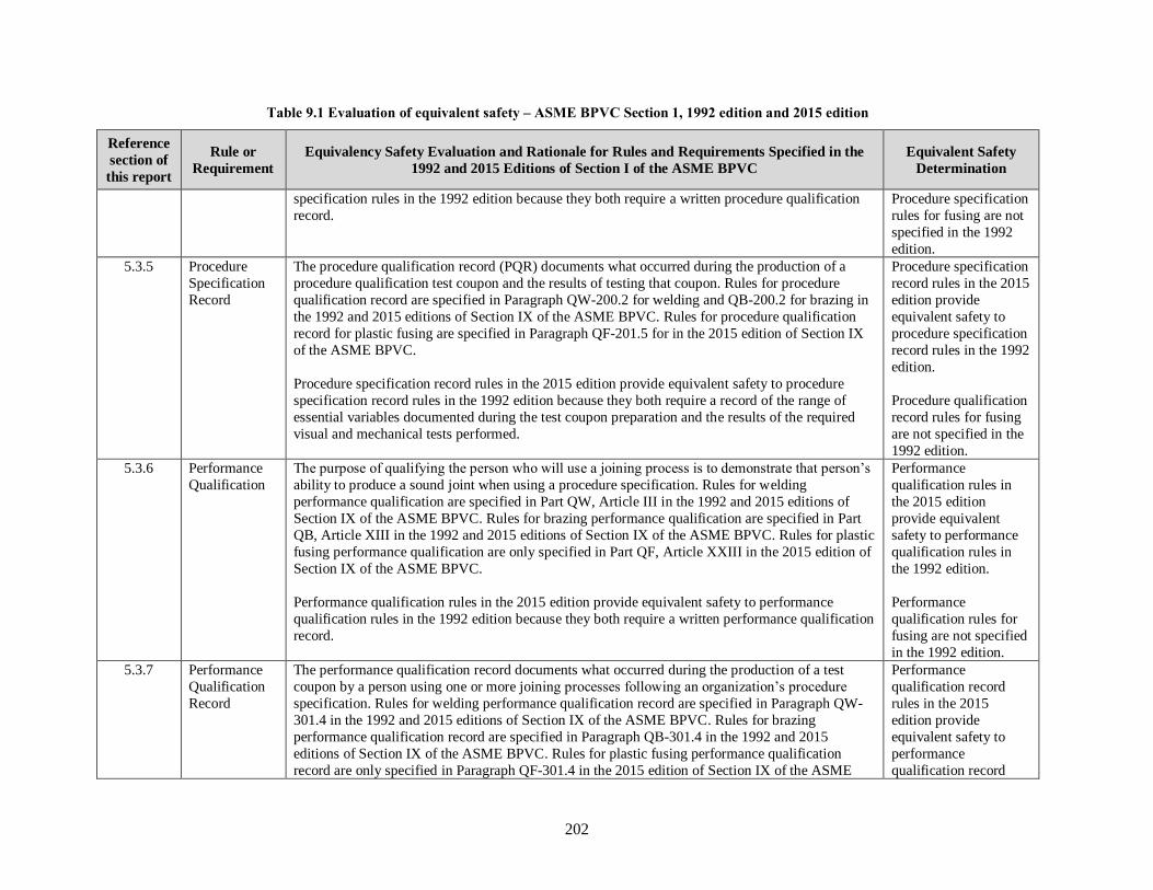
202
Table 9.1 Evaluation of equivalent safety – ASME BPVC Section 1, 1992 edition and 2015 edition
Reference
section of
this report
Rule or
Requirement
Equivalency Safety Evaluation and Rationale for Rules and Requirements Specified in the
1992 and 2015 Editions of Section I of the ASME BPVC
Equivalent Safety
Determination
specification rules in the 1992 edition because they both require a written procedure qualification
record.
Procedure specification
rules for fusing are not
specified in the 1992
edition.
5.3.5 Procedure
Specification
Record
The procedure qualification record (PQR) documents what occurred during the production of a
procedure qualification test coupon and the results of testing that coupon. Rules for procedure
qualification record are specified in Paragraph QW-200.2 for welding and QB-200.2 for brazing in
the 1992 and 2015 editions of Section IX of the ASME BPVC. Rules for procedure qualification
record for plastic fusing are specified in Paragraph QF-201.5 for in the 2015 edition of Section IX
of the ASME BPVC.
Procedure specification record rules in the 2015 edition provide equivalent safety to procedure
specification record rules in the 1992 edition because they both require a record of the range of
essential variables documented during the test coupon preparation and the results of the required
visual and mechanical tests performed.
Procedure specification
record rules in the 2015
edition provide
equivalent safety to
procedure specification
record rules in the 1992
edition.
Procedure qualification
record rules for fusing
are not specified in the
1992 edition.
5.3.6 Performance
Qualification
The purpose of qualifying the person who will use a joining process is to demonstrate that person’s
ability to produce a sound joint when using a procedure specification. Rules for welding
performance qualification are specified in Part QW, Article III in the 1992 and 2015 editions of
Section IX of the ASME BPVC. Rules for brazing performance qualification are specified in Part
QB, Article XIII in the 1992 and 2015 editions of Section IX of the ASME BPVC. Rules for plastic
fusing performance qualification are only specified in Part QF, Article XXIII in the 2015 edition of
Section IX of the ASME BPVC.
Performance qualification rules in the 2015 edition provide equivalent safety to performance
qualification rules in the 1992 edition because they both require a written performance qualification
record.
Performance
qualification rules in
the 2015 edition
provide equivalent
safety to performance
qualification rules in
the 1992 edition.
Performance
qualification rules for
fusing are not specified
in the 1992 edition.
5.3.7 Performance
Qualification
Record
The performance qualification record documents what occurred during the production of a test
coupon by a person using one or more joining processes following an organization’s procedure
specification. Rules for welding performance qualification record are specified in Paragraph QW-
301.4 in the 1992 and 2015 editions of Section IX of the ASME BPVC. Rules for brazing
performance qualification record are specified in Paragraph QB-301.4 in the 1992 and 2015
editions of Section IX of the ASME BPVC. Rules for plastic fusing performance qualification
record are only specified in Paragraph QF-301.4 in the 2015 edition of Section IX of the ASME
Performance
qualification record
rules in the 2015
edition provide
equivalent safety to
performance
qualification record

203
Table 9.1 Evaluation of equivalent safety – ASME BPVC Section 1, 1992 edition and 2015 edition
Reference
section of
this report
Rule or
Requirement
Equivalency Safety Evaluation and Rationale for Rules and Requirements Specified in the
1992 and 2015 Editions of Section I of the ASME BPVC
Equivalent Safety
Determination
BPVC.
Performance qualification record rules in the 2015 edition provide equivalent safety to performance
qualification record rules in the 1992 edition because they both require documentation of what
occurred during the production of a test coupon by a person using one or more joining processes
following an organization’s procedure specification. Performance qualification records are
designed in the 2015 edition of Section IX of the ASME BPVC as follows.
• Welder/Welding Operator Performance Qualification (WPQ)
• Brazer or Brazing Operator Performance Qualification (BPQ)
• Fusing Operator Performance Qualification Record (FPQ)
rules in the 1992
edition.
Performance
qualification record
rules for fusing are not
specified in the 1992
edition.
5.3.8 Welding,
Brazing, and
Fusing Data
Welding, brazing, and fusing data articles include the variables grouped into categories such as
joints, base materials and filler materials, positions, preheat/postweld heat treatment, gas, electrical
characteristics, and technique. They are referenced from other articles as they apply to each
process. Welding data include essential, supplementary essential or nonessential variables. Brazing
data include essential and nonessential variables. Fusing data include the fusing variables grouped
as joints, pipe material, position, thermal conditions, equipment, and technique.
Rules for welding data are specified in Part QW, Article IV in the 1992 and 2015 editions of
Section IX of the ASME BPVC. Rules for brazing data are specified in Part QB, Article XIV in the
1992 and 2015 editions of Section IX of the ASME BPVC. Rules for fusing data are only specified
in Part QF, Article XXIV in the 2015 edition of Section IX of the ASME BPVC.
Welding and brazing rules in the 2015 edition provide equivalent safety to welding and brazing,
data rules in the 1992 edition because they both specify data articles as they apply to each process.
Welding and brazing,
data rules in the 2015
edition provide
equivalent safety to
welding and brazing,
data rules in the 1992
edition.
Fusing data rules are
not specified in the
1992 edition.
5.4.1 Preheating
Requirements
The WPS for the material being welded specifies the minimum preheating requirements in
accordance with the weld procedure qualification requirements of Section IX that apply to
construction of boilers in accordance with rules specified in Section I of the ASME BPVC.
Preheating rules in the
2015 edition provide
equivalent safety to
preheating rules in the
1992 edition.
5.4.2.1 Postweld Heat
Treatment
Requirements
Rules for postweld heat treatment are specified in Paragraph PW-39 in the 1992 and 2015 editions
of Section I of the ASME BPVC. Mandatory requirements for postweld heat treatment of pressure
parts and attachments for boilers are specified in Table PW-39 in the 1992 edition. These
requirements apply to P-No. 1 and 3 materials.
Postweld heat
treatment rules in the
2015 edition provide
equivalent safety to

204
Table 9.1 Evaluation of equivalent safety – ASME BPVC Section 1, 1992 edition and 2015 edition
Reference
section of
this report
Rule or
Requirement
Equivalency Safety Evaluation and Rationale for Rules and Requirements Specified in the
1992 and 2015 Editions of Section I of the ASME BPVC
Equivalent Safety
Determination
According to rules specified in Paragraph PW-39.1 in the 2015 edition, all welded pressure parts of
power boilers must be given a postweld heat treatment at a temperature not less than that specified
in Tables PW-39-1 through PW-39-14. These tables apply to P-No. 1, 3, 4, 5A, 5B, 15E, 6, 7, 10H,
31, 43, 45, and 51 materials. Table PW-39.1 provides alternative postweld heat treatment
requirement for carbon and low alloy steels.
postweld heat treatment
rules in the 1992
edition.
5.5 Cold
Stretching
The 1992 and 2015 editions of Section I of the ASME BPVC do not include cold stretching
requirements.
An equivalent safety
evaluation of cold
stretching requirements
in the 1992 and 2015
editions is not possible.
5.6.1 Quality
Control
System
The ASME BPVC requires any Manufacturer or Assembler holding or applying for a Certificate of
Authorization to use the Certification Mark to have, and demonstrate, a quality control system to
establish that all Code requirements, including material, design, fabrication, examination (by the
Manufacturer), inspection of boilers, pressure vessels, and associated parts (by the Authorized
Inspector), pressure testing, and certification will be met. The Authorized Inspector is responsible
for verifying that the Manufacturer has a valid Certificate of Authorization and is working to a
quality control system.
Section I of the ASME BPVC provides guidance and rules for the scope and content of the quality
control system. It is important to note that the quality control system may contain information of
proprietary nature relating to the Manufacturer’s processes. Therefore, the ASME BPVC does not
require any distribution of this information, except for the Authorized Inspector or an ASME
designee.
Quality control system requirements in the 2015 edition of Section I include the same quality
control system requirements as those in the 1992 edition of Section I of the ASME BPVC.
However, the 2015 edition of Section I specifies additional quality control system requirements that
are not specified in the 1992 edition of Section I of the ASME BPVC.
Quality control system
requirements in the
2015 edition provide
equivalent safety to
quality control system
requirements in the
1992 edition.
6.2.1 General NDE
Requirements
in Section I
Rules for circumferential and longitudinal butt welded joints in boilers fabricated by welding that
require volumetric examination are specified in Paragraph PW-11 in the 1992 and 2015 editions of
Section I of the ASME BPVC. These rules state that all circumferential and longitudinal butt
welded joints must be examined throughout their entire length unless specifically exempted by
rules that depend on the service conditions, nominal pipe size, or material thickness. Rules
specified in Paragraph PW-11 in the 1992 and 2015 editions of Section I of the ASME BPVC
General NDE
requirements in the
2015 edition provide
equivalent safety to
general NDE
requirements in the

205
Table 9.1 Evaluation of equivalent safety – ASME BPVC Section 1, 1992 edition and 2015 edition
Reference
section of
this report
Rule or
Requirement
Equivalency Safety Evaluation and Rationale for Rules and Requirements Specified in the
1992 and 2015 Editions of Section I of the ASME BPVC
Equivalent Safety
Determination
further define which volumetric examination method (RT or UT) or combination of methods (RT
and UT) must be used to examine particular types of circumferential and longitudinal butt welded
joints.
1992 edition.
6.2.1.1 Radiographic
Examination
Requirements
in Section I
Rules for radiography examination of welds are provided in Paragraph PW-51 in the 1992 and
2015 editions of Section I of the ASME BPVC. These rules state that all welds that require
radiographic examination must be examined by the X-ray or gamma-ray method in accordance
with rules specified in Article 2, Section V of the ASME BPVC. Paragraphs PW-51.3.1 and
PW-51.3.2 in both editions define the conditions under which indications shown on the radiographs
of welds and characterized as imperfections are unacceptable and must be repaired and the repair
radiographed.
Radiographic
examination
requirements in the
2015 edition provide
equivalent safety to
radiographic
examination
requirements in the
1992 edition.
6.2.1.2 Ultrasonic
Examination
Requirements
in Section I
Rules for ultrasonic examination of welds are provided in Paragraph PW-52 in the 1992 and 2015
editions of Section I of the ASME BPVC. These rules state that techniques and standards for
ultrasonic examination must follow rules specified in Article 5, Section V in the 1992 edition or
Article 4, Mandatory Appendix VII, Section V in the 2015 edition of the ASME BPVC, as
applicable.
Ultrasonic examination
requirements in the
2015 edition provide
equivalent safety to
ultrasonic examination
requirements in the
1992 edition.
6.2.1.3 Visual and
Liquid
Penetrant
Examination
Requirements
in Section I
Fabrication rules for bimetallic tubes when the clad strength is included are specified in Paragraph
PW-44.8.1 in the 2015 edition of Section I of the ASME BPVC. These rules state: “Visual
examination (VT) shall be performed on 100% of the clad surface in accordance with Section V,
Article 9. Any indication open to the surface shall additionally be subjected to liquid penetrant
examination (PT) in accordance with A-270 and acceptance or rejection based on A-270.4. The
portion of bimetallic tubing containing rejectable defects shall either be removed or the defects
repaired in accordance with PW-44.9.” Visual and liquid penetrant examinations must comply with
Article 9 and Article 6, respectively, in the 2015 edition of Section V of the ASME BPVC.
Corresponding rules for fabrication of bimetallic tubes when the clad strength is included are not
provided in the 1992 edition of Section I of the ASME BPVC.
An equivalent safety
evaluation of visual and
liquid penetrant
examination
requirements in the
1992 and 2015 editions
is not possible.
6.2.4.1 Volumetric
Examination
Acceptance
Standards
Acceptance standards for volumetric examination are specified in Section I, Section VIII,
Division 1, and Section VIII, Division 2 of the ASME BPVC. These standards identify the
following types of indications that are considered rejectable imperfections and must be removed.
1. any indication characterized as a crack or zone of incomplete fusion or penetration
2. elongated indications greater than a specified length which is a function of the weld
Volumetric
examination acceptance
standards in the 2015
edition provide
equivalent safety to
volumetric examination

206
Table 9.1 Evaluation of equivalent safety – ASME BPVC Section 1, 1992 edition and 2015 edition
Reference
section of
this report
Rule or
Requirement
Equivalency Safety Evaluation and Rationale for Rules and Requirements Specified in the
1992 and 2015 Editions of Section I of the ASME BPVC
Equivalent Safety
Determination
thickness
3. a group of aligned indications that have an aggregate length greater than greater than a
specified length which is a function of the weld thickness
4. rounded indications in excess of that specified which is a function of the weld thickness
A comparison of radiographic examination and ultrasonic examination acceptance standards is
shown in Table 6.2 of this report. The comparison shows no difference in radiographic and
ultrasonic indications acceptance standards. However, editorial changes have been made and metric
equivalents are included in the 2015 editions of Section I, Section VIII, Division 1, and Section
VIII, Division 2 of the ASME BPVC. These changes are either not safety significant or result in
equivalent safety.
acceptance standard in
the 1992 edition.
6.2.4.2 Surface
Examination
Acceptance
Standards
Liquid penetrant (PT) and magnetic particle (MT) inspections are surface examination techniques
used to detect cracks or other discontinuities on material surfaces. The examination methods are
typically used in Section I, Section VIII, Division 1, and Section VIII, Division 2 of the ASME
BPVC to provide material quality factors. The acceptance criteria are either contained within the
referenced Paragraphs or provided in referenced appendices.
A comparison of liquid penetrant examination and magnetic particle examination acceptance
standards is presented in Table 6.2 of this report. The comparison shows no difference in liquid
penetrant and magnetic particle indications acceptance standards. However, editorial changes have
been made and metric equivalents are included in the 2015 editions of Section I, Section VIII,
Division 1, and Section VIII, Division 2 of the ASME BPVC. These changes are either not safety
significant or result in equivalent safety.
Surface examination
acceptance standards in
the 2015 edition
provide equivalent
safety to surface
examination acceptance
standard in the 1992
edition.
6.2.5.1 and
6.2.5.2
Certification
Requirement
for RT and UT
Personnel
According to rules specified in the 1992 edition of the ASME BPVC for qualification of
radiographic and ultrasonic NDE personnel, each person must be qualified and certified in
accordance with their employer’s written practice. Standard SNT TC 1A, which is published by the
American Society for Nondestructive Testing, must be used as a guideline for employers to
establish their written practice for qualifications and certification of personnel. Provisions for
training, experience, qualification, and certification of NDE personnel must be described in the
manufacturer's Quality Control System. (Note: Earlier editions of SNT-TC-1A allowed NDE
Level III inspectors to be qualified based on experience without having to pass an examination [2].
However, in 1992, the requirements were tightened to require these inspectors to be qualified by
examination.) Paragraphs PW-51.5 and PW-52.4 in the 1992 edition of Section I of the ASME
BPVC further state: “When personnel have been certified according to their employer’s written
practice based upon an edition of SNT TC 1A earlier than that referenced in A 361, their
certification shall be valid for performing nondestructive examination required by this Section until
Certification
requirement for RT and
UT personnel in the
2015 edition provide
equivalent safety to
certification
requirement for RT and
UT personnel in the
1992 edition.

207
Table 9.1 Evaluation of equivalent safety – ASME BPVC Section 1, 1992 edition and 2015 edition
Reference
section of
this report
Rule or
Requirement
Equivalency Safety Evaluation and Rationale for Rules and Requirements Specified in the
1992 and 2015 Editions of Section I of the ASME BPVC
Equivalent Safety
Determination
their next scheduled recertification. Any recertification, reexamination, or new examination shall
be performed to the employer’s written practice based on the edition of SNT TC 1A referenced in
A 361.”
Rules for qualification of radiographic and ultrasonic NDE personnel are stated in the following
text from Paragraph PW-50 in the 2015 edition of Section I of the ASME BPVC.
The Manufacturer shall be responsible for assuring that nondestructive examination
(NDE) personnel have been qualified and certified in accordance with their
employer’s written practice prior to performing or evaluating radiographic or
ultrasonic examinations required by this Section. SNT‐TC‐1A or CP‐189 shall be used
as a guideline for employers to establish their written practice. National or
international Central Certification Programs, such as the ASNT Central Certification
Program (ACCP), may be used to fulfill the examination and demonstration
requirements of the employer’s written practice. Provisions for training, experience,
qualification, and certification of NDE personnel shall be described in the
Manufacturer’s quality control system.
NDE personnel shall be qualified by examination. Qualification of NDE Level III
personnel certified prior to the 2004 Edition of Section I may be based on
demonstrated ability, achievement, education, and experience. Such qualification shall
be specifically addressed in the written practice. When NDE personnel have been
certified in accordance with a written practice based on an edition of SNT‐TC‐1A or
CP‐189 earlier than that referenced in A-360, their certification shall be valid until
their next scheduled recertification.
Recertification shall be in accordance with the employer’s written practice based on the edition
of SNT‐TC‐1A or CP‐189 referenced in A-360. Recertification may be based on evidence of
continued satisfactory performance or by reexamination(s) deemed necessary by the employer.
6.2.5.3 and
6.2.5.4
Certification
of
Competency
Requirements
for PT and MT
Personnel
Rules for certification of competency for NDE personnel are specified in the 1992 edition of the
ASME BPVC. These rules state that the manufacturer must certify that each liquid penetrant and
magnetic particle examiner meet the following requirements.
(a) He has vision, with correction if necessary, to enable him to read a Jaeger Type
No. 2 Standard Chart at a distance of not less than 12 in. (300 mm), and is capable of
distinguishing and differentiating contrast between colors used. These requirements
shall be checked annually.
Certification of
competency for PT and
MT personnel in the
2015 edition provide
equivalent safety to
certification of
competency for PT and
MT personnel in the

208
Table 9.1 Evaluation of equivalent safety – ASME BPVC Section 1, 1992 edition and 2015 edition
Reference
section of
this report
Rule or
Requirement
Equivalency Safety Evaluation and Rationale for Rules and Requirements Specified in the
1992 and 2015 Editions of Section I of the ASME BPVC
Equivalent Safety
Determination
(b) He is competent in the techniques of the liquid penetrant examination method for
which he is certified, including making the examination and interpreting and
evaluating the results, except that, where the examination method consists of more
than one operation, he may be certified as being qualified only for one or more of
these operations.
Rules for certification of competency for NDE personnel are specified in the 2015 edition of the
ASME BPVC. Rules in Nonmandatory Appendix A, Paragraphs A-260.2 and A-270.2 in the 2015
edition of Section I of the ASME BPVC state that the Manufacturer must certify that each magnetic
particle and liquid penetrant examiner meets the following requirements:
(a) The examiner has vision, with correction if necessary, to enable him to read a
Jaeger Type No. 2 Standard Chart at a distance of not less than 12 in. (300 mm) and is
capable of distinguishing and differentiating contrast between colors used. These
capabilities shall be checked annually.
(b) The examiner is competent in the techniques of the magnetic particle examination
method for which he is certified, including making the examination and interpreting
and evaluating the results, except that where the examination method consists of more
than one operation, he may be certified as being qualified only for one or more of
these operations.
The same rules with editorial text changes are specified in Appendix 6, Paragraph 6-2 and in
Appendix 8, Paragraph 8-2 in the 2015 edition of Section VIII, Division 1 of the ASME BPVC.
These changes are either not safety significant or result in equivalent safety.
1992 edition.
6.3.1 General NDE
Requirements
in Section V
Article 1 in the 1992 and 2015 editions of Section V of the ASME BPVC specifies general
requirements and methods for NDE which are Code requirements to the extent they are specifically
referenced and required by a Construction Code or referencing documents. These NDE methods
are intended to detect surface and internal imperfections in materials, welds, fabricated parts, and
components. Paragraph T-150 in each edition specifies the following rules that apply to all NDE
methods.
When required by the referencing Code Section, all nondestructive examinations
performed under this Code Section shall be performed following a written procedure.
A procedure demonstration shall be performed to the satisfaction of the Inspector.
When required by the referencing Code Section, a personnel demonstration may be
used to verify the ability of the examiner to apply the examination procedure. The
General NDE
requirements in the
2015 edition provide
equivalent safety to
general NDE
requirements in the
1992 edition.

209
Table 9.1 Evaluation of equivalent safety – ASME BPVC Section 1, 1992 edition and 2015 edition
Reference
section of
this report
Rule or
Requirement
Equivalency Safety Evaluation and Rationale for Rules and Requirements Specified in the
1992 and 2015 Editions of Section I of the ASME BPVC
Equivalent Safety
Determination
examination procedure shall comply with the applicable requirements of this Section
for the particular examination method. Written procedures shall be made available to
the Inspector on request. At least one copy of each procedure shall be readily
available to the Nondestructive Examination Personnel for their reference and use.
In addition, both editions state that Nondestructive Examination Personnel must be qualified in
accordance with the requirements of the referencing Construction Code.
Article 1, Paragraph T-120(g) in the 2015 editions of Section V of the ASME BPVC further states
that if the techniques of computed radiography (CR), digital radiography (DR), phased-array
ultrasonic technology (PAUT), or ultrasonic time-of-flight diffraction (TOFD) are to be used, the
training, experience, and examination requirements found in Article 1, Mandatory Appendix II
must also be included in the employer’s written practice for each technique as applicable. The term
technique is used in this context to mean a specific way of utilizing a particular nondestructive
examination (NDE) method.
Mandatory Appendix II in the 2015 edition of Section V of the ASME BPVC provides the
additional personnel qualification requirements that are mandated by Article 1, T 120(g), and which
are to be included in the employer’s written practice for NDE personnel certification, when any of
the following techniques are used by the employer: computed radiography (CR), digital
radiography (DR), Phased Array Ultrasonic Technology (PAUT), and ultrasonic Time of Flight
Diffraction (TOFD).
6.3.2 Radiographic
Examination
Requirements
in Section V
Article 2 in the 1992 and 2015 editions of Section V of the ASME BPVC specifies requirements
for radiographic examination of materials including castings and welds. Certain product-specific,
technique-specific, and application-specific requirements are also specified in the appendices for
this Article. The 1992 and 2015 editions of Section V of the ASME BPVC include three
appendices, but the 2015 edition of Section V of the ASME BPVC includes seven additional
appendices with requirements not included in the 1992 edition.
Paragraph III-210 in Appendix III in the 1992 edition and Mandatory Appendix III in the 2015
edition of Section V of the ASME BPVC states: “Digital image acquisition, display, and storage
can be applied to radiography and radioscopy. Once the analog image is converted to digital
format, the data can be displayed, processed, quantified, stored, retrieved, and converted back to
the original analog format, for example, film or video presentation.” These rules in Appendix III
only apply to digital image acquisition, display, and storage for radiography and radioscopy and not
to digital radiography (DR) techniques as an alternative to film radiography.
Radiographic
examination
requirements in
Section V in the 2015
edition provide
equivalent safety to
radiographic
examination
requirements in
Section V in the 1992
edition.

210
Table 9.1 Evaluation of equivalent safety – ASME BPVC Section 1, 1992 edition and 2015 edition
Reference
section of
this report
Rule or
Requirement
Equivalency Safety Evaluation and Rationale for Rules and Requirements Specified in the
1992 and 2015 Editions of Section I of the ASME BPVC
Equivalent Safety
Determination
According to rules specified in Paragraph IX-210 and Mandatory Appendix IX in the 2015 edition
of Section V of the ASME BPVC, digital radiography may be performed on materials, including
castings and weldments when the modified provisions to Article 2 as indicated in Mandatory
Appendix IX and all other applicable requirements of Article 2 are satisfied. Mandatory
Appendix IX provides requirements for using digital radiography techniques as an alternative to
film radiography. In addition, this Mandatory Appendix addresses techniques where the image is
transmitted directly from the detector as a digital image rather than using an intermediate process
for conversion of an analog image to a digital format, and applications in which the radiation
detector and the source of the radiation may or may not be in motion during exposure.
6.3.3 Ultrasonic
Examination
Requirements
in Section V
Article 5 in the 1992 edition and Article 4 in the 2015 edition of Section V of the ASME BPVC
provide or reference requirements which are to be used in selecting and developing ultrasonic
examination procedures when examination to any part of this Article is a requirement of a
referencing Construction Code. These procedures are to be used for the ultrasonic examination and
the dimensioning of indications for comparison with acceptance standards when required by the
referencing Construction Code. Certain product-specific, technique-specific, and application-
specific requirements are also specified in Article 5 or Article 4, as applicable. The 1992 and 2015
editions of Section V of the ASME BPVC include two appendices, but the 2015 edition of
Section V of the ASME BPVC includes seven additional appendices with requirements not
included in the 1992 edition.
Prior to 2005, ultrasonic examination was not permitted except for a final closure weld where
radiographic examination was impractical as discussed in Sect. 6.2.2.1 of this report. Code Case
2235, which was issued in 1995, allowed ultrasonic examination in lieu of radiographic
examination for Section I, Section VIII, Division 1, and Section VIII, Division 2 for welds greater
than 1/2 in. thick. Code Case 2235 has since been incorporated into Section VIII, Division 1 and
Section VIII, Division 2 of the ASME BPVC. As discussed in Sect. 6.2.2.4 of this report,
Paragraph UW-51(a)(4) in the 2015 edition of Section VIII, Division 1 now states the following.
As an alternative to the radiographic examination requirements above, all welds in
material 1/4 in. (6 mm) and greater in thickness may be examined using the ultrasonic
(UT) method per the requirements of 7.5.5 of Section VIII, Division 2.
Requirements for the Time of Flight Diffraction (TOFD) examination technique for welds, which
are specified in Article 4, Mandatory Appendix III in the 2015 edition of Section V of the ASME
BPVC, are not included in Article 5 in the 1992 edition of Section V of the ASME BPVC.
Ultrasonic examination
requirements in
Section V in the 2015
edition provide
equivalent safety to
ultrasonic examination
requirements in
Section V in the 1992
edition.
6.3.4 Liquid Article 6 in the 1992 and 2015 editions of Section V of the ASME BPVC states that the liquid Liquid penetrant

211
Table 9.1 Evaluation of equivalent safety – ASME BPVC Section 1, 1992 edition and 2015 edition
Reference
section of
this report
Rule or
Requirement
Equivalency Safety Evaluation and Rationale for Rules and Requirements Specified in the
1992 and 2015 Editions of Section I of the ASME BPVC
Equivalent Safety
Determination
Penetrant
Examination
Requirements
in Section V
penetrant examination techniques described in this Article must be used together with Article 1
when specified by the referencing Construction Code. It also provides details to be considered in
the procedures used for liquid penetrant examinations.
Additional requirements for the control of contaminant content for all liquid penetrant materials
used on nickel base alloys, austenitic stainless steels, and titanium are specified in Article 6,
Mandatory Appendix II in the 2015 edition of Section V of the ASME BPVC. This requirement is
not included in the 1992 edition of Section V of the ASME BPVC.
examination
requirements in
Section V in the 2015
edition provide
equivalent safety to
liquid penetrant
examination
requirements in
Section V in the 1992
edition.
6.3.5 Magnetic
Particle
Examination
Requirements
in Section V
Article 7 – Magnetic Particle Examination in the 1992 and 2015 editions of Section V of the
ASME BPVC states that the magnetic particle examination techniques described in this Article
must be used together with Article 1 when specified by the referencing Construction Code. It also
provides details to be considered in the procedures used for magnetic particle examinations.
Magnetic particle
examination
requirements in
Section V in the 2015
edition provide
equivalent safety to
magnetic particle
examination
requirements in
Section V in the 1992
edition.
6.3.6 Visual
Examination
Requirements
in Section V
Article 9 – Visual Examination in the 1992 and 2015 editions of Section V of the ASME BPVC
states that methods and requirements for visual examination in this Article are applicable together
with requirements of Article 1 when specified by a referencing Construction Code. Specific visual
examination procedures required for every type of examination are not included in this Article
because there are many applications where visual examinations are required. Some examples of
these applications include nondestructive examinations, leak testing, in-service examinations, and
fabrication procedures.
Visual examination
requirements in
Section V in the 2015
edition provide
equivalent safety to
visual examination
requirements in
Section V in the 1992
edition.
7.1.1.1 Basis for
Hydrostatic
Pressure
Testing Limits
The objective of design rules specified in Section I of the ASME BPVC is to establish the wall
thickness of a boiler so that the maximum hoop stress, Pm, does not exceed two third of the
minimum specified yield strength, Pm ≤ 0.67 Sy. Hydrostatic pressure testing limits for boilers are
specified in Paragraph PG-99 in the 1992 and 2015 editions of Section I of the ASME BPVC as
follows.
Hydrostatic pressure
testing limits in the
2015 edition provide
equivalent safety to
hydrostatic pressure

212
Table 9.1 Evaluation of equivalent safety – ASME BPVC Section 1, 1992 edition and 2015 edition
Reference
section of
this report
Rule or
Requirement
Equivalency Safety Evaluation and Rationale for Rules and Requirements Specified in the
1992 and 2015 Editions of Section I of the ASME BPVC
Equivalent Safety
Determination
1992 – minimum hydrostatic test pressure – 1.5 MAWP to 1.59 MAWP
1992 – maximum general membrane stress limit – 0.9 Pm
2015 – minimum hydrostatic test pressure – 1.5 MAWP
2015 – maximum general membrane stress limit – 0.9 Pm
Overpressure protection rules specified in Paragraph PG-67.4.2 in the 1992 and 2015 editions of
Section I of the ASME BPVC limit the pressure of an operating boiler, except for the steam piping
between the boiler and the prime mover, to 1.20 MAWP or less. This overpressure protection limit
ensures that the primary membrane stress, Pm, does not exceed 0.80 Sy (i.e., 1.20/1.50). A minimum
hydrostatic test pressure equal to 1.5 MAWP or a membrane stress, Pm, equal to 0.90 Sy ensures
that the boiler will never experience a maximum overpressure while in service that is greater than
the hydrostatic test pressure. (i.e., 0.9 × 1.5 MAWP > 1.20 MAWP)
Rules specified in the 1992 edition of Section I of the ASME BPVC do not specify a minimum or
maximum hydrostatic test pressure duration. The rules state that a boiler must be maintained at the
MAWP while the boiler is carefully examined.
testing limits in the
1992 edition.
7.1.1.2 Basis for
Pneumatic
Pressure
Testing Limits
The 1992 and 2015 editions of Section I of the ASME BPVC do not include pneumatic pressure
testing requirements.
An equivalent safety
evaluation of
pneumatic pressure
testing requirements in
the 1992 and 2015
editions is not possible.
7.2 Alternative
Pressure
Testing
The 1992 and 2015 editions of Section I of the ASME BPVC do not include alternative pressure
testing requirements.
An equivalent safety
evaluation of
alternative pressure
testing requirements in
the 1992 and 2015
editions is not possible.
7.3.1 Proof Testing Paragraph PG-18 in the 1992 and 2015 editions of Section I of the ASME BPVC states that where
no rules are given for calculating the strength of a boiler or any part thereof, the Manufacturer may
establish MAWP by testing a full‐size sample in accordance with one of the following three test
methods.
• Strain Measurement Test
• Displacement Measurement Test
• Burst Test
The proof testing
requirements in the
2015 edition provide
equivalent safety to the
proof testing
requirements in the
1992 edition

213
Table 9.1 Evaluation of equivalent safety – ASME BPVC Section 1, 1992 edition and 2015 edition
Reference
section of
this report
Rule or
Requirement
Equivalency Safety Evaluation and Rationale for Rules and Requirements Specified in the
1992 and 2015 Editions of Section I of the ASME BPVC
Equivalent Safety
Determination
Corresponding proof test equations in the 1992 and 2015 editions of Section I of the ASME BPVC
for computing MAWP using test data are the same.
8.1.1 Overpressure
Protection by
Pressure Relief
Device
Overpressure protection rules specified in Paragraph PG-67.4.2 in the 1992 and 2015 editions of
Section I of the ASME BPVC limit the pressure of an operating boiler, except for the steam piping
between the boiler and the prime mover, to 1.20 MAWP or less. This overpressure protection limit
ensures that the primary membrane stress, Pm, does not exceed 0.80 Sy (i.e., 1.20/1.50).
The rules for overpressure protection specified in the 1992 and 2015 editions of Section I of the
ASME BPVC are the same. Therefore, the rules for overpressure protection specified in the 2015
edition of Section I of the ASME BPVC provide an equivalent level of safety compared to the rules
for overpressure protection specified in the 1992 edition of Section I of the ASME BPVC.
The overpressure
protection requirements
by pressure relief
device in the 2015
edition provide
equivalent safety to the
overpressure protection
requirements by
pressure relief device in
the 1992 edition
8.1.2 Overpressure
Protection by
System Design
Section I of the ASME BPVC does not provide rules for overpressure protection by system design. An equivalent safety
evaluation of
overpressure protection
by system design in the
1992 and 2015 editions
is not possible.

214
Table 9.2 Evaluation of equivalent safety – ASME BPVC Section VIII, Division 1, 1992 edition and 2015 edition
Reference
section of
this report
Rule or
Requirement
Equivalency Safety Evaluation and Rationale for Rules and Requirements Specified in the
1992 and 2015 Editions of Section VIII, Division 1 of the ASME BPVC
Equivalent Safety
Determination
4.1.1.2 Excessive
Elastic
Deformation
and Elastic
Instability
Excessive elastic deformation (deflection) and elastic instability (buckling) cannot be controlled by
imposing upper limits to the calculated stress alone because these behavioral phenomena are
affected by component geometry and stiffness and material properties. Excessive elastic
deformation can occur when a component with inadequate stiffness experiences unwanted
flexibility or unacceptable deflections. Buckling is characterized by a sudden sideways failure of a
component subjected to high compressive stress, where the compressive stress at the point of
failure is less than the ultimate compressive stress that the material is capable of withstanding. The
designer of a boiler or pressure vessel is responsible for applying engineering principles to
understand and avoid in-service problems or failures caused by excessive elastic deformation and
elastic instability.
Rules for the design of shells and tubes under external pressure given in the 1992 and 2015 editions
of Section VIII, Division 1 of the ASME BPVC are limited to cylindrical shells, with or without
stiffening rings, tubes, and spherical shells. Three typical forms of cylindrical shells are shown in
Figure UG-28. Charts used in determining minimum required thicknesses of components under
external pressure are given in Subpart 3 of Section II, Part D as discussed in Sect. 4.1.1.1 of this
report.
Excessive elastic
deformation and elastic
instability requirements
in the 2015 edition
provide equivalent
safety compared to
excessive elastic
deformation and elastic
instability requirements
in the 1992 edition.
4.1.2 Excessive
Plastic
Deformation
The plastic deformation mode of failure (ductile rupture) is controlled by imposing limits on
calculated stress. Primary stress limits and primary plus secondary stress limits in the ASME
BPVC are intended to prevent excessive plastic deformation leading to incremental collapse and to
provide a nominal margin on the ductile burst pressure. The designer of a boiler or pressure vessel
is responsible for ensuring that the specified stress limits are not exceeded under the operating conditions defined by the user.
There are no rules specified in Section VIII, Division 1 of the ASME BPVC specifically for
protection against plastic collapse. However, as discussed in Sect. 4.4.1 of this report, the
maximum allowable membrane stress, Pm, for boilers and pressure vessels constructed in
accordance with rules specified in the 1992 and 2015 editions of Section VIII, Division 1 of the
ASME BPVC is limited to two-thirds of the yield strength, 2/3 Sy, or less. Rules specified in the
1992 and 2015 editions of Section VIII, Division 1 of the ASME BPVC also ensure that the
primary membrane stress plus the primary bending stress, Pm + Pb, does not exceed Sy. Based on
the principles of limit design theory discussed in Sect. 4.6 of this report, these rules provide a
minimum design margin against plastic collapse equal to or greater than 1.5. Additional discussion
about protection against plastic collapse is presented in Sect. 4.8 of this report.
Excessive plastic
deformation
requirements in the
2015 edition provide
equivalent safety compared to excessive
plastic deformation
requirements in the
1992 edition.
4.1.3.2 Brittle The ability of a metal to resist tearing or cracking is a measure of its fracture toughness. In fracture Requirements in the

215
Table 9.2 Evaluation of equivalent safety – ASME BPVC Section VIII, Division 1, 1992 edition and 2015 edition
Reference
section of
this report
Rule or
Requirement
Equivalency Safety Evaluation and Rationale for Rules and Requirements Specified in the
1992 and 2015 Editions of Section VIII, Division 1 of the ASME BPVC
Equivalent Safety
Determination
Fracture mechanics calculations, the value of the stress intensity factor, KI, is based on the applied stress and
dimensions of the flaw. To avoid brittle fracture, the calculated KI must be less than the critical
fracture toughness parameter, KIc. From an equivalency viewpoint, an increase in the maximum
allowable design stress for a material with a critical flaw size requires an increase in fracture
toughness to maintain the same margin against brittle fracture. In addition, increasing fracture
toughness reduces the risk that critical flaw sizes below the NDE detection limits do not result in
brittle fracture.
Impact test requirements are specified in Paragraph UG-84 in the 1992 and 2015 editions of
Section VIII, Division 1 of the ASME BPVC. Minimum impact energy limits for carbon and low
alloy steels listed in Table UCS-23 having a specified minimum tensile strength of less than 95 ksi
are provided in Figure UG-84.1. These limits vary depending on the minimum specified yield
strength and the material thickness. According to these limits:
• The minimum impact energy, Cv, for all carbon and low alloy steels listed in Table UCS-23
with a maximum thickness of 1.375 in. and a minimum specified yield strength equal to
50 ksi or below is 15 ft-lb.
• The minimum impact energy, Cv, for all carbon and low alloy steels listed in Table UCS-23
with a maximum thickness of 1.25 in. and a minimum specified yield strength between to
55 and 65 ksi is 20 ft-lb.
According to rules specified in UG-20 in the 1992 and 2015 editions of Section VIII, Division 1 of
the ASME BPVC, impact testing of carbon and low alloy steels is not required when the design
temperature is no colder than -20ºC.
Rules for impact tests for pressure vessels constructed of ferritic steels with tensile properties
enhanced by heat treatment are specified in Part UHT of the 1992 and 2015 editions of
Section VIII, Division 1 of the ASME BPVC. These rules also apply to carbon and low alloy steels
with a specified minimum tensile strength of 95 ksi or more. According to rules specified in
Paragraph UHT-6 in the 2015 edition of Section VIII, Division 1 of the ASME BPVC,
Charpy V-notch impact test specimens must exhibit a lateral expansion opposite the notch as
specified in Figure UHT-6.1. These permissible lateral expansion values vary from 0.015 to
0.025 in. for materials that are between 1.25 and 3 in. thick. These rules are more comprehensive
and stringent than corresponding rules specified in the 1992 edition of Section VIII, Division 1 of
the ASME BPVC which require a minimum lateral expansion value of 0.015 in. for any material
thickness.
2015 edition for
protection against
brittle fracture provide
equivalent or greater
safety compared to
requirements in the
1992 edition for
protection against
brittle fracture.

216
Table 9.2 Evaluation of equivalent safety – ASME BPVC Section VIII, Division 1, 1992 edition and 2015 edition
Reference
section of
this report
Rule or
Requirement
Equivalency Safety Evaluation and Rationale for Rules and Requirements Specified in the
1992 and 2015 Editions of Section VIII, Division 1 of the ASME BPVC
Equivalent Safety
Determination
Toughness requirements for Cr–Mo steels with additional requirements for welding and heat
treatment are specified in Paragraph 31-5 in Mandatory Appendix 31 in the 2015 edition of
Section VIII, Division 1 of the ASME BPVC. These rules state that the minimum toughness
requirements for base metal, weld metal, and heat affected zone, after exposure to the simulated
postweld heat treatment Condition B, must be an impact energy equal to or greater than 40 ft-lb
based on an average for three specimens with a 35 ft-lb minimum limit for one specimen in the set
of three specimens for full size Charpy V-notch, transvers specimens tested at the MDMT.
Corresponding rules for Cr–Mo steels are not provided in the 1992 edition of Section VIII,
Division 1 of the ASME BPVC.
4.1.4.1 Stress Rupture
and Creep
Deformation
Boiler and pressure vessel materials that are in service above a certain temperature undergo
continuing deformation (creep) at a rate that is strongly influenced by both stress and temperature.
The temperature at which creep occurs varies with the alloy composition. In order to prevent
excessive deformation and possible premature rupture it is necessary to limit the allowable stresses
by additional criteria on creep-rate and stress-rupture.
Empirical limits for creep-rate and stress-rupture have been established and are specified in
Section VIII, Division 1 of the ASME BPVC. Allowable stresses specified in the 1992 and 2015
editions of Section II, Part D of the ASME BPVC at temperatures in the range where creep and
stress rupture strength govern are the same.
Stress rupture and
creep deformation
requirements in the
2015 edition provide
equivalent safety
compared to stress
rupture and creep
deformation
requirements in the
1992 edition.
4.1.5.2 Plastic
Instability –
Incremental
Collapse
Ratcheting is defined as a progressive incremental inelastic deformation or strain that can occur in a
component subjected to variations of mechanical stress, thermal stress, or both. Ratcheting is
produced by a sustained load acting over the full cross section of a component, in combination with
a strain controlled cyclic load or temperature distribution that is alternately applied and removed.
Ratcheting results in cyclic straining of the material, which can result in failure by fatigue and at
the same time produces cyclic incremental deformation of a component, which may ultimately lead
to collapse.
Paragraph U-2(a) in the 1992 and 2015 editions of Section VIII, Division 1 of the ASME BPVC
states that the user or his designated agent must establish the design requirements for pressure
vessels, taking into consideration factors associated with normal operation, such other conditions as
startup and shutdown, and abnormal conditions which may become a governing design
consideration. When cyclic service is a design consideration, the user or his designated agent must
state if a fatigue analysis is required. Rules specified in the 1992 and 2015 editions of Section VIII,
Division 1 of the ASME BPVC do not:
Plastic instability and
incremental collapse
requirements in the
2015 edition provide
equivalent safety
compared to plastic
instability and
incremental collapse
requirements in the
1992 edition.

217
Table 9.2 Evaluation of equivalent safety – ASME BPVC Section VIII, Division 1, 1992 edition and 2015 edition
Reference
section of
this report
Rule or
Requirement
Equivalency Safety Evaluation and Rationale for Rules and Requirements Specified in the
1992 and 2015 Editions of Section VIII, Division 1 of the ASME BPVC
Equivalent Safety
Determination
• require calculation of thermal stresses and do not provide allowable values for them
• require the detailed calculation and classification of all stresses and the application of
different stress limits to different classes of stress
• consider the possibility of fatigue failure [2]
Instead, rules in the 1992 and 2015 editions of Section VIII, Division 1 of the ASME BPVC
provide equations for minimum wall thickness based on the maximum stress theory discussed in
Sect. 4.5.1 of this report. Consequently, no plastic instability and incremental collapse requirements
associated with ratcheting are specified in either the 1992 or the 2015 edition of Section VIII,
Division 1 of the ASME BPVC.
4.1.6.2 Fatigue Fatigue is the weakening of a material caused by repeatedly applied loads. It is the progressive and
localized material degradation that occurs when a component is subjected to cyclic loading. If the
loads are above a certain threshold, microscopic cracks will begin to form at stress concentrations
such as square holes or sharp corners. Eventually the crack will reach a critical size, propagate, and
cause the component to fracture. Avoidance of discontinuities that increase local stresses will
increase the fatigue life of a component subjected to cyclic loading.
Paragraph U-2(a) in the 1992 and 2015 editions of Section VIII, Division 1 of the ASME BPVC
states that the user or his designated agent must establish the design requirements for pressure
vessels, taking into consideration factors associated with normal operation, such other conditions as
startup and shutdown, and abnormal conditions which may become a governing design
consideration. Rules specified in the 1992 and 2015 editions of Section VIII, Division 1 of the
ASME BPVC do not:
• require calculation of thermal stresses and do not provide allowable values for them
• require the detailed calculation and classification of all stresses and the application of
different stress limits to different classes of stress
• consider the possibility of fatigue failure [2]
Instead, rules in the 1992 and 2015 editions of Section VIII, Division 1 of the ASME BPVC
provide equations for minimum wall thickness based on the maximum stress theory discussed in
Sect. 4.5.1 of this report. Consequently, no rules for fatigue are specified in either the 1992 or the
2015 edition of Section VIII, Division 1 of the ASME BPVC.
Fatigue requirements in
the 2015 edition
provide equivalent
safety compared to
fatigue requirements in
the 1992 edition.
4.1.7.2 Stress
Corrosion and
Two common types of corrosion that can adversely affect the integrity of a boiler or pressure vessel
include stress corrosion cracking and corrosion fatigue. Stress corrosion cracking (SCC) is the
Stress corrosion
cracking and corrosion

218
Table 9.2 Evaluation of equivalent safety – ASME BPVC Section VIII, Division 1, 1992 edition and 2015 edition
Reference
section of
this report
Rule or
Requirement
Equivalency Safety Evaluation and Rationale for Rules and Requirements Specified in the
1992 and 2015 Editions of Section VIII, Division 1 of the ASME BPVC
Equivalent Safety
Determination
Corrosion
Fatigue
growth of crack formation in a corrosive environment and is highly chemically specific in that
certain alloys are likely to undergo SCC only when exposed to a small number of chemical
environments. Corrosion fatigue is the mechanical degradation of a material under the joint action
of corrosion and cyclic loading. Since corrosion-fatigue cracks initiate at a metal’s surface, surface
treatments like plating, cladding, nitriding, and shot peening can improve the materials’ resistance
to corrosion fatigue. However, corrosion fatigue only occurs when the metal is under tensile stress.
Rules for corrosion are specified in Paragraph UG-25 in the 1992 and 2015 editions of
Section VIII, Division 1 of the ASME BPVC. These rules state that the user or his designated agent
must specify corrosion allowances other than those required by the rules of this Division. In
addition, vessels or parts of vessels subject to thinning by corrosion, erosion, or mechanical
abrasion shall have provision made for the desired life of the vessel by a suitable increase in the
thickness of the material over that determined by the design formulas, or by using some other
suitable method of protection.
Nonmandatory suggestions on the selection and treatment of austenitic chromium-nickel and
ferritic and martensitic high chromium steel are provided in Appendix HA in the 1992 edition of
Section VIII, Division 1 of the ASME BPVC. Paragraph UHA-103 states: “Austenitic chromium-
nickel steels that are highly stressed in tension may develop transcrystalline or intercrystalline
cracks when exposed to certain corrosive media. The stresses may be produced by external loads,
welding or cold forming operations, or by uneven cooling. Methods of reducing susceptibility to
stress corrosion cracking include the selection of a composition that will have a stable austenite
structure in the operating range and heat treatment to reduce the magnitude of the residual
stresses.”
fatigue requirements in
the 2015 edition
provide equivalent
safety compared to
stress corrosion
cracking and corrosion
fatigue requirements in
the 1992 edition.
4.2.2 Design Basis Mandatory requirements specified in Paragraph U-2 in the 1992 and 2015 editions of Section VIII,
Division 1 of the ASME BPVC state that the user or his designated agent must establish the design
requirements for pressure vessels, taking into consideration factors associated with normal
operation, and such other conditions as startup and shutdown. The 1992 edition lists four such
considerations, whereas the 2015 edition lists five such conditions.
Nonmandatory guidance to the responsibilities of the user and designated agent is provided in
Nonmandatory Annex NN in the 2015 edition of Section VIII, Division 1 of the ASME BPVC.
This guidance states that a “user” is an entity that defines the design conditions and parameters of
the pressure vessel and communicates these conditions and parameters to the Manufacturer.
Additional guidance is provided in Nonmandatory Appendix KK for preparing User’s Design
Requirements. This guidance includes User’s Design Requirement Forms for single and multi-
Design basis
requirements in the
2015 edition provide
equivalent or greater
safety compared to
design basis
requirements in the
1992 edition.

219
Table 9.2 Evaluation of equivalent safety – ASME BPVC Section VIII, Division 1, 1992 edition and 2015 edition
Reference
section of
this report
Rule or
Requirement
Equivalency Safety Evaluation and Rationale for Rules and Requirements Specified in the
1992 and 2015 Editions of Section VIII, Division 1 of the ASME BPVC
Equivalent Safety
Determination
chamber pressure vessels and instructions for completing these forms. The forms include entries for
defining design and operating conditions, materials, nozzle schedules, joint and flange
requirements, and a signature block for certifying that the information in the form is accurate and
represents all details of design as per the user or his designated agent. They are also formatted with
space for entering additional design requirements including post-construction loads such as those
associated with in-service pressure tests that may be imposed by PHMSA in 49 CFR Part 193 or
the Authority Having Jurisdiction. It is important to note that Nonmandatory Appendix KK states
that completion of these forms is neither required nor prohibited for pressure vessels constructed in
accordance with ASME BPVC rules.
In comparison, the 1992 edition of Section VIII, Division 1 does not include corresponding
guidance to that presented in Nonmandatory Annex KK or Nonmandatory Annex NN in the 2015
edition of Section VIII, Division 1 of the ASME BPVC.
4.4.1 and
4.4.3
Allowable
Stress Values
Criteria for establishing allowable stress values for use in performing calculations in accordance
with rules specified in Section VIII, Division 1 of the ASME BPVC are discussed in Mandatory
Appendix 1 of Section II, Part D in the 2015 edition and in Appendix 1 of Section II, Part D in the
1992 edition. According to these criteria, the maximum allowable stress in the 1992 edition of
Section II, Part D is either two‐thirds of the room temperature yield strength or the ultimate tensile
strength divided by 4.0, whichever is less. Correspondingly, the maximum allowable stress in the
2015 edition of Section II, Part D is either two‐thirds of the room temperature yield strength or the
ultimate tensile strength divided by 3.5, whichever is less. For allowable stress values specified in
the 1992 edition of Section II, Part D, the two‐thirds of the yield strength value controls the design
when the ultimate tensile strength of the material is greater than 2.67 (e.g. 2/3 × 4.0) times the yield
strength. Correspondingly, the two‐thirds of the yield strength value controls the design when the
ultimate tensile strength of the material is greater than 2.33 (e.g. 2/3 × 3.5) times the yield strength.
In general, yield to tensile strength ratios for steels increase with increasing tensile strength. It is
also important to note that the maximum allowable stress specified in both the 1992 and 2015
editions of Section II, Part D may equal, but can never exceed, two‐thirds of the specified minimum
yield strength at room temperature, 2/3 Sy.
Alternative rules for maximum allowable stress values for pressure vessels constructed of materials
having a higher allowable stresses at low temperature are tabulated in Part ULT of the 1992 and
2015 editions of Section VIII, Division 1 of the ASME BPVC. These maximum allowable stress
values are limited to the materials listed in Table ULT-23 at cryogenic temperatures for welded and
nonwelded construction for temperatures between -320°F and 100°F (150°F for 2015 edition).
Materials listed in Table ULT-23 include 5%, 8% and 9% nickel steels; Types 304 and 316 (2015
Allowable stress rules
in the 2015 edition
provide equivalent
safety to allowable
stress rules in the 1992
edition.

220
Table 9.2 Evaluation of equivalent safety – ASME BPVC Section VIII, Division 1, 1992 edition and 2015 edition
Reference
section of
this report
Rule or
Requirement
Equivalency Safety Evaluation and Rationale for Rules and Requirements Specified in the
1992 and 2015 Editions of Section VIII, Division 1 of the ASME BPVC
Equivalent Safety
Determination
edition only) stainless steels; and 5083-0 aluminum alloys. Part ULT also includes rules that are to
be used in conjunction with rules covered in specified subsections and parts of Section VIII,
Division 1 of the ASME BPVC. These rules cover general, design, fabrication, inspection and tests,
marking and reports, and pressure relief devices.
Paragraph UG-23(c) in the 1992 and 2015 editions of Section VIII, Division 1 of the ASME BPVC
states: “The wall thickness of a vessel computed by these rules shall be determined such that, for
any combination of loadings listed in UG-22 that induce primary stress and are expected to occur
simultaneously during normal operation of the vessel, the induced maximum general primary
membrane stress does not exceed the maximum allowable stress value in tension (see UG-23),
except as provided in (d) below. Except where limited by special rules, such as those for cast iron
in flanged joints, the above loads shall not induce a combined maximum primary membrane stress
plus primary bending stress across the thickness that exceeds 1.5 times the maximum allowable
stress value in tension (see UG-23). It is recognized that high localized discontinuity stresses may
exist in vessels designed and fabricated in accordance with these rules. Insofar as practical, design
rules for details have been written to limit such stresses to a safe level consistent with experience.”
These rules ensure that the maximum allowable primary membrane stress, Pm, does not exceed
2/3 Sy and that the maximum primary membrane stress plus primary bending stress, Pm + Pb, does
not exceed Sy. This upper limit proves a minimum design margin of 1.5 against plastic collapse as
discussed in Sect. 4.6 of this report.
4.5.1 Strength
Theory
Equations specified in the 1992 and 2015 editions of Section VIII, Division 1 of the ASME BPVC
for determining wall thickness are, by implication, consistent with the maximum stress theory
discussed in Sect. 4.5.1 of this report.
Design membrane
stress limits in the 2015 edition provide
equivalent safety to
design membrane stress
limits in the 1992
edition.
4.7 Stress Range
for
Repetitively
Applied Loads
Shakedown of a component occurs if, after a few cycles of load application, ratcheting ceases. The
subsequent structural response is elastic, or elastic-plastic, and progressive incremental inelastic
deformation is absent. Elastic shakedown is the case in which the subsequent response is elastic.
The ASME BPVC limits localized discontinuity stresses to 3.0 times the maximum allowable stress
value in tension or 2.0 times the minimum specified tensile yield stress, Sy, of the material provided
the allowable stress is not governed by time-dependent properties of the material and the room
temperature ratio of the specified minimum yield strength, Sy, to specified minimum tensile
strength, Su, for the material does not exceed 0.7. This requirement ensures the material has strain-
Rules for stress range
for repetitively applied
loads in the 2015
edition provide
equivalent safety to
rules for stress range
for repetitively applied
loads in the 1992

221
Table 9.2 Evaluation of equivalent safety – ASME BPVC Section VIII, Division 1, 1992 edition and 2015 edition
Reference
section of
this report
Rule or
Requirement
Equivalency Safety Evaluation and Rationale for Rules and Requirements Specified in the
1992 and 2015 Editions of Section VIII, Division 1 of the ASME BPVC
Equivalent Safety
Determination
hardening properties sufficient to prevent material failure if the primary stress exceeds the yield
strength of the material through the entire thickness.
Text in Paragraph UG-23(c) of the 1992 and 2015 editions of Section VIII, Division 1 of the
ASME BPVC state that: “It is recognized that high localized discontinuity stresses may exist in
vessels designed and fabricated in accordance with these rules. Insofar as practical, design rules for
details have been written to limit such stresses to a safe level consistent with experience.”
Therefore, Section VIII, Division 1 of the ASME BPVC does not include rules for the ‘shakedown’
phenomenon.
edition.
4.8.1 Plastic
Collapse
Stress Limits
Plastic collapse is the load at which overall structural instability occurs. The collapse load is the
maximum load limit for a component made of elastic perfectly plastic material. Deformations of
these components increase without bound at the collapse load.
Adequate safety against plastic collapse for pressure vessels constructed in accordance with rules
specified in the 1992 and 2015 editions of Section VIII, Division 1 of the ASME BPVC is achieved
by limiting design membrane stress, Pm, to two-thirds of the yield strength, 2/3 Sy, and by limiting
primary membrane stress plus primary bending stress, Pm + Pb, to the yield strength, Sy. This upper
limit proves a minimum design margin of 1.5 against plastic collapse as discussed in Sect. 4.6 of
this report.
Rules specified in the 1992 and 2015 editions of Section VIII, Division 1 of the ASME BPVC do
not require a detailed stress analysis to evaluate protection against plastic collapse but merely set
the wall thickness necessary to keep the basic hoop stress below the tabulated allowable stress. As
discussed in Sect. 4.4.1 of this report, the maximum allowable stress for boilers constructed in
accordance with rules specified in Section VIII, Division 1 of the ASME BPVC is limited to two-
thirds of the yield strength, 2/3 Sy, or less. Based on the principles of limit design theory discussed
in Sect. 4.6 of this report, the minimum design margin against plastic collapse is at least 1.5.
Allowable stress rules
2015 edition provide
equivalent safety to
allowable stress rules
1992 edition.
4.9.2 Design-by-
Rule
The design approach used in the 1992 and 2015 editions of Section VIII, Division 1 of the ASME
BPVC is referred to as design-by-rule. This design-by-rule approach is not based on detailed stress
analysis. Instead, design-by-rule generally involves calculation of average membrane stress across
the thickness of the walls of the pressure vessel or component. As discussed in Sect. 4.5.1 of this
report, rules in the 1992 and 2015 editions of Section VIII, Division 1 of the ASME BPVC are
based on the maximum stress theory.
Rules for openings and reinforcements in the 1992 and 2015 editions of Section VIII, Division 1 of
the ASME BPVC are based on the area replacement concept in which the metal cut out by an
The design-by-rule
approach in the 2015
editions provides
equivalent safety to the
design-by-rule
approach in the 1992
editions.

222
Table 9.2 Evaluation of equivalent safety – ASME BPVC Section VIII, Division 1, 1992 edition and 2015 edition
Reference
section of
this report
Rule or
Requirement
Equivalency Safety Evaluation and Rationale for Rules and Requirements Specified in the
1992 and 2015 Editions of Section VIII, Division 1 of the ASME BPVC
Equivalent Safety
Determination
opening must be replaced by reinforcement within a prescribed zone around the opening.
Supplementary deign formulas are specified in Mandatory Appendix 1 in the 2015 edition of
Section VIII, Division 1 of the ASME BPVC for certain types of openings.
4.10 Design-by-
Analysis
The 1992 and 2015 editions of Section VIII, Division 1 of the ASME BPVC do not include design-
by-analysis requirements.
An equivalent safety
evaluation of design-
by-analysis
requirements in the
1992 and 2015 editions
is not possible.
5.1.2 Forming
Deviations
Rules for fabrication of pressure vessels are specified in Paragraphs UG-75 through UG 83 in the
1992 and 2015 editions of Section VIII, Division 1 of the ASME BPVC. These rules cover cutting
plates and other stock; material identification; repairs of defects in materials; forming pressure
parts; permissible out-of-roundness of cylindrical, conical, and spherical shells; tolerances for
formed heads, lugs and fitting attachments, and holes for screw stays.
Rules specified in Paragraph UG-79 in the 2015 edition for forming shell sections and heads were
updated considerably compared to corresponding rules in the 1992 edition. Paragraph UG-79 in the
1992 edition only specifies rules for forming carbon and low alloy steel shell sections and heads.
Whereas, Paragraph UG-79 in the 2015 edition provides rules for cold working of carbon and low
alloy steels, nonferrous alloys, high alloy steels, and ferritic steels. Equations for calculating
forming strains for cylinders, head, tube, and pipe are specified in Table UG-79 1. When the
calculated forming strains exceed the maximum prescribed allowable strains specified in
Paragraphs UCS-79(d), UHA-44(a), UNF-79(a), and UHT-79(a)(1) and the design temperatures
exceed specified limits, post fabrication heat treatment is required.
Forming deviations in
the 2015 edition
provide equivalent
safety to forming
deviations in the 1992
edition.
5.2.1.2 Formed Head
Tolerances
The same shape deviation requirements for formed heads are specified in Paragraph UG-81 in the
1992 and 2015 editions of Section VIII, Division 1 of the ASME BPVC. These requirements apply
to inner surfaces of a torispherical, toriconical, hemispherical, and ellipsoidal heads.
Formed head tolerances
in the 2015 edition
provide equivalent
safety to formed head
tolerances in the 1992
edition.
5.2.2 Alignment
Tolerances
Rules for alignment tolerances for edges to be butt welded are specified in Paragraph PW-33 in the
1992 and 2015 editions of Section I of the ASME BPVC. The maximum allowable offsets in
welded joints are specified in Table PW-33 in both editions.
By comparison, the alignment tolerances for edges to be butt welded defined in Table PW-33 are
Alignment tolerances
in the 2015 edition
provide equivalent
safety to alignment
tolerances in the 1992

223
Table 9.2 Evaluation of equivalent safety – ASME BPVC Section VIII, Division 1, 1992 edition and 2015 edition
Reference
section of
this report
Rule or
Requirement
Equivalency Safety Evaluation and Rationale for Rules and Requirements Specified in the
1992 and 2015 Editions of Section VIII, Division 1 of the ASME BPVC
Equivalent Safety
Determination
identical with alignment tolerances for circumferential joints being somewhat higher than
alignment tolerances for longitudinal joint because axial stresses are half the circumferential
stresses.
edition.
5.3.1 Base Metal
Groupings P‐Numbers are assigned to base metals for the purpose of reducing the number of welding and
brazing procedure qualifications required. P-Numbers for the same base metal are different for
welding and brazing.
P-Numbers in the 2015
edition provide
equivalent safety to
P-Numbers in the 1992
edition.
5.3.2 Welding and
Brazing
Methods
Rules for welding are specified in Part QW in the 1992 and 2015 editions of Section IX of the
ASME BPVC. Rules for brazing are specified in Part QB in the 1992 and 2015 editions of Section
IX of the ASME BPVC. Rules for plastic fusing are only specified in Part QF in the 2015 edition of
Section IX of the ASME BPVC.
All of the welding and brazing methods permitted in the 1992 edition are also permitted in the 2015
edition. However, Diffusion Welding (DFW) and Friction Stir Welding (FSW) are also permitted
in the 2015 edition.
Welding and brazing
methods in the 2015
edition provide
equivalent safety to
welding and brazing
methods in the 1992
edition.
Fusing method rules
are not specified in the
1992 edition.
5.3.3 Procedure
Qualification
Record
The PQR documents what occurred during the production of a test coupon by a person using one or
more joining processes following an organization’s procedure specification. As a minimum, the
record must document the essential variables for each process used to produce the test coupon, the
ranges of variables qualified, and the results of the required testing and nondestructive
examinations.
Procedure qualification
record rules in the 2015
edition provide
equivalent safety to
procedure qualification
record rules in the 1992
edition.
5.3.4 Procedure
Specification
A procedure specification is a written document that provides direction to the person applying the
material joining process. Rules for welding procedure qualification are specified in Part QW,
Article II in the 1992 and 2015 editions of Section IX of the ASME BPVC. Rules for brazing
procedure qualification are specified in Part QB, Article XII in the 1992 and 2015 editions of
Section IX of the ASME BPVC. Rules for plastic fusing procedure qualification are only specified
in Part QF, Article XXII in the 2015 edition of Section IX of the ASME BPVC.
Procedure specification rules in the 2015 edition provide equivalent safety to procedure
specification rules in the 1992 edition because they both require a written procedure qualification
Procedure specification
rules in the 2015
edition provide
equivalent safety to
procedure specification
rules in the 1992
edition.
Procedure specification
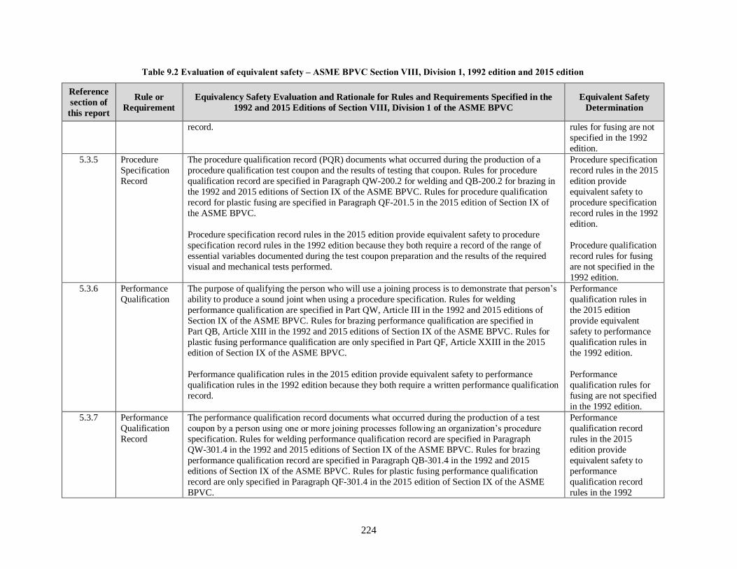
224
Table 9.2 Evaluation of equivalent safety – ASME BPVC Section VIII, Division 1, 1992 edition and 2015 edition
Reference
section of
this report
Rule or
Requirement
Equivalency Safety Evaluation and Rationale for Rules and Requirements Specified in the
1992 and 2015 Editions of Section VIII, Division 1 of the ASME BPVC
Equivalent Safety
Determination
record. rules for fusing are not
specified in the 1992
edition.
5.3.5 Procedure
Specification
Record
The procedure qualification record (PQR) documents what occurred during the production of a
procedure qualification test coupon and the results of testing that coupon. Rules for procedure
qualification record are specified in Paragraph QW-200.2 for welding and QB-200.2 for brazing in
the 1992 and 2015 editions of Section IX of the ASME BPVC. Rules for procedure qualification
record for plastic fusing are specified in Paragraph QF-201.5 in the 2015 edition of Section IX of
the ASME BPVC.
Procedure specification record rules in the 2015 edition provide equivalent safety to procedure
specification record rules in the 1992 edition because they both require a record of the range of
essential variables documented during the test coupon preparation and the results of the required
visual and mechanical tests performed.
Procedure specification
record rules in the 2015
edition provide
equivalent safety to
procedure specification
record rules in the 1992
edition.
Procedure qualification
record rules for fusing
are not specified in the
1992 edition.
5.3.6 Performance
Qualification
The purpose of qualifying the person who will use a joining process is to demonstrate that person’s
ability to produce a sound joint when using a procedure specification. Rules for welding
performance qualification are specified in Part QW, Article III in the 1992 and 2015 editions of
Section IX of the ASME BPVC. Rules for brazing performance qualification are specified in
Part QB, Article XIII in the 1992 and 2015 editions of Section IX of the ASME BPVC. Rules for
plastic fusing performance qualification are only specified in Part QF, Article XXIII in the 2015
edition of Section IX of the ASME BPVC.
Performance qualification rules in the 2015 edition provide equivalent safety to performance
qualification rules in the 1992 edition because they both require a written performance qualification
record.
Performance
qualification rules in
the 2015 edition
provide equivalent
safety to performance
qualification rules in
the 1992 edition.
Performance
qualification rules for
fusing are not specified
in the 1992 edition.
5.3.7 Performance
Qualification
Record
The performance qualification record documents what occurred during the production of a test
coupon by a person using one or more joining processes following an organization’s procedure
specification. Rules for welding performance qualification record are specified in Paragraph
QW-301.4 in the 1992 and 2015 editions of Section IX of the ASME BPVC. Rules for brazing
performance qualification record are specified in Paragraph QB-301.4 in the 1992 and 2015
editions of Section IX of the ASME BPVC. Rules for plastic fusing performance qualification
record are only specified in Paragraph QF-301.4 in the 2015 edition of Section IX of the ASME
BPVC.
Performance
qualification record
rules in the 2015
edition provide
equivalent safety to
performance
qualification record
rules in the 1992

225
Table 9.2 Evaluation of equivalent safety – ASME BPVC Section VIII, Division 1, 1992 edition and 2015 edition
Reference
section of
this report
Rule or
Requirement
Equivalency Safety Evaluation and Rationale for Rules and Requirements Specified in the
1992 and 2015 Editions of Section VIII, Division 1 of the ASME BPVC
Equivalent Safety
Determination
Performance qualification record rules in the 2015 edition provide equivalent safety to performance
qualification record rules in the 1992 edition because they both require documentation of what
occurred during the production of a test coupon by a person using one or more joining processes
following an organization’s procedure specification. Performance qualification records are
designed in the 2015 edition of Section IX of the ASME BPVC as follows.
• Welder/Welding Operator Performance Qualification (WPQ)
• Brazer or Brazing Operator Performance Qualification (BPQ)
• Fusing Operator Performance Qualification Record (FPQ)
edition.
Performance
qualification record
rules for fusing are not
specified in the 1992
edition.
5.3.8 Welding,
Brazing, and
Fusing Data
Welding, brazing, and fusing data articles include the variables grouped into categories such as
joints, base materials and filler materials, positions, preheat/postweld heat treatment, gas, electrical
characteristics, and technique. They are referenced from other articles as they apply to each
process. Welding data include essential, supplementary essential or nonessential variables. Brazing
data include essential and nonessential variables. Fusing data include the fusing variables grouped
as joints, pipe material, position, thermal conditions, equipment, and technique.
Rules for welding data are specified in Part QW, Article IV in the 1992 and 2015 editions of
Section IX of the ASME BPVC. Rules for brazing data are specified in Part QB, Article XIV in the
1992 and 2015 editions of Section IX of the ASME BPVC. Rules for fusing data are only specified
in Part QF, Article XXIV in the 2015 edition of Section IX of the ASME BPVC.
Welding and brazing rules in the 2015 edition provide equivalent safety to welding and brazing,
data rules in the 1992 edition because they both specify data articles as they apply to each process.
Welding and brazing,
data rules in the 2015
edition provide
equivalent safety to
welding and brazing,
data rules in the 1992
edition.
Fusing data rules are
not specified in the
1992 edition.
5.4.1 Preheating Requirements
The WPS for the material being welded specifies the minimum preheating requirements in accordance with the weld procedure qualification requirements of Section IX that apply to pressure
vessels constructed in accordance with rules specified in Section VIII, Division 1 of the ASME
BPVC.
Mandatory rules for preheating are not given in Section VIII, Division 1 of the ASME BPVC
except as required in the footnotes that provide for exemptions to postweld heat treatment in Tables
UCS-56 and UHA-32 in the 1992 edition and Tables UCS-56-1 through UCS 56-11 and Tables
UHA-32-1 through UHA-32-7 in the 2015 edition.
Preheating rules in the 2015 edition provide
equivalent safety to
preheating rules in the
1992 edition.
5.4.2.2 Postweld Heat Rules for postweld heat treatment are specified in Paragraph UW-40 in the 1992 and 2015 editions Postweld heat

226
Table 9.2 Evaluation of equivalent safety – ASME BPVC Section VIII, Division 1, 1992 edition and 2015 edition
Reference
section of
this report
Rule or
Requirement
Equivalency Safety Evaluation and Rationale for Rules and Requirements Specified in the
1992 and 2015 Editions of Section VIII, Division 1 of the ASME BPVC
Equivalent Safety
Determination
Treatment
Requirements
of Section VIII, Division 1 of the ASME BPVC. The temperatures and rates of heating and cooling
to be used in postweld heat treatment of pressure vessels constructed of materials for which
postweld heat treatment may be required are given in Paragraphs UCS-56, UHT-56, UHA-32, and
UNF-56 in the 1992 and 2015 editions. However, postweld heat treatment requirements in the 2015
edition of Section VIII, Division 1 of the ASME BPVC are more comprehensive that
corresponding rules in the 1992 edition of Section VIII, Division 1 of the ASME BPVC.
Postweld heat treatment temperatures for carbon and alloy alloys steels are specified in
Table UCS-56 in the 1992 edition and in Tables UCS-56-1 through UCS-56-11 in the 2015 edition.
Postweld heat treatment temperatures for ferritic steels with properties enhanced by heat treatment
are specified in Table UHT-56 in the 1992 and 2015 editions. Postweld heat treatment temperatures
for high alloy steels are specified in Table UHA-32 in the 1992 edition and in Tables UHA-32-1
through UHA-32-7 in the 2015 edition. Postweld heat treatment temperatures specified in these
tables are applicable to specific P-Number materials.
Although postweld heat treatment of nonferrous materials is not normally necessary nor desirable,
postweld heat treatment requirements for specified nonferrous materials are covered in Paragraph
UNF 56 in the 1992 and 2015 editions.
treatment rules in the
2015 edition provide
equivalent safety to
postweld heat treatment
rules in the 1992
edition.
5.5 Cold
Stretching
The 1992 edition of Section VIII, Division 1 of the ASME BPVC does not include cold stretching
requirements. Cold stretching is a pressure vessel construction method that was incorporated into
the ASME BPVC through approval of Code Case 2596 on January 29, 2008.
Mandatory Appendix 44 in the 2015 edition specifies requirements for design, construct, and
stamping of cold-stretched austenitic stainless steel pressure vessels in addition to those provided in
Section VIII, Division 1. However, rules in Paragraph 44-4 restrict design and fabrication of cold-
stretched pressure vessels to specific types of the austenitic stainless steels that conform to
SA-240/SA-240M material specification requirements.
An equivalent safety
evaluation of cold
stretching requirements
in the 1992 and 2015
editions is not possible.
5.6.2 Quality
Control
System
The ASME BPVC requires any Manufacturer or Assembler holding or applying for a Certificate of
Authorization to use the Certification Mark to have, and demonstrate, a quality control system to
establish that all Code requirements, including material, design, fabrication, examination (by the
Manufacturer), inspection of boilers, pressure vessels, and associated parts (by the Authorized
Inspector), pressure testing, and certification will be met. The Authorized Inspector is responsible
for verifying that the Manufacturer has a valid Certificate of Authorization and is working to a
quality control system.
Quality control system
requirements in the
2015 edition provide
equivalent safety to
quality control system
requirements in the
1992 edition.
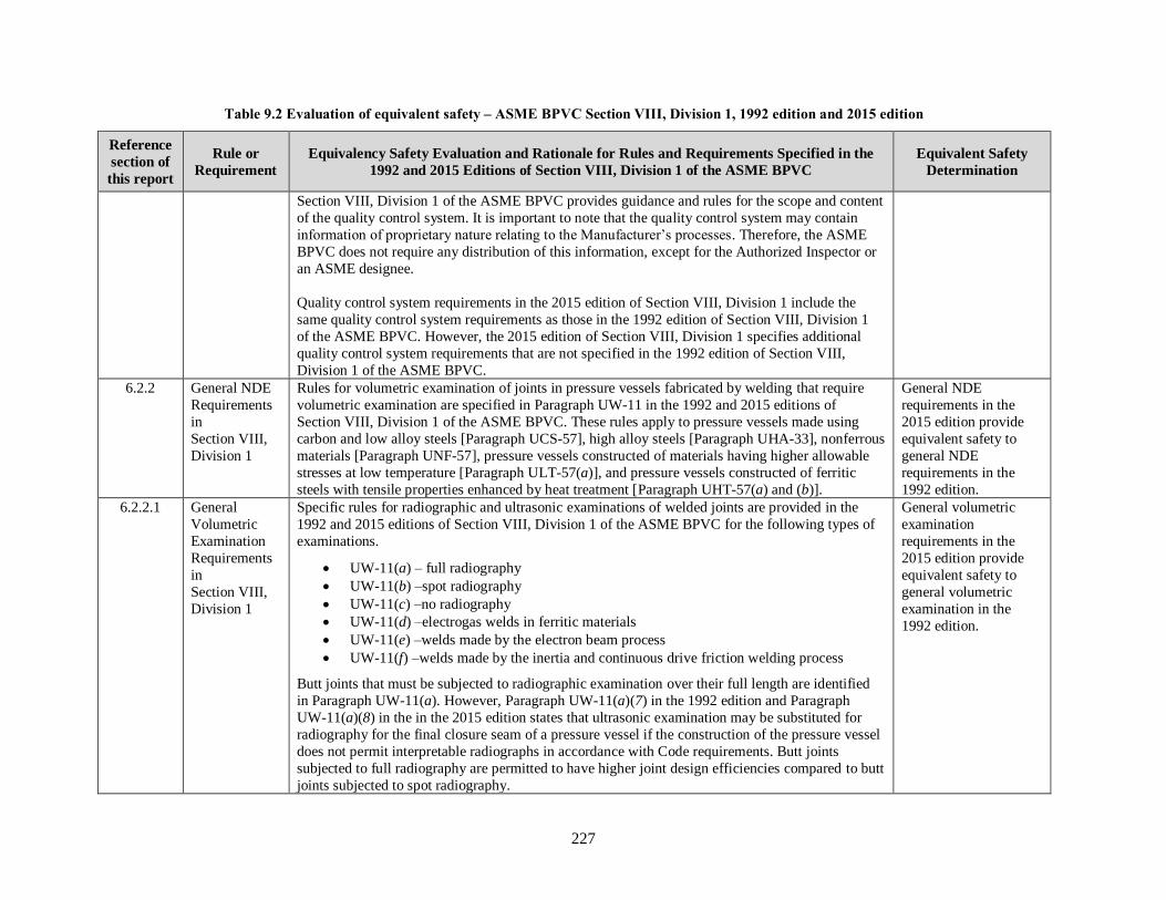
227
Table 9.2 Evaluation of equivalent safety – ASME BPVC Section VIII, Division 1, 1992 edition and 2015 edition
Reference
section of
this report
Rule or
Requirement
Equivalency Safety Evaluation and Rationale for Rules and Requirements Specified in the
1992 and 2015 Editions of Section VIII, Division 1 of the ASME BPVC
Equivalent Safety
Determination
Section VIII, Division 1 of the ASME BPVC provides guidance and rules for the scope and content
of the quality control system. It is important to note that the quality control system may contain
information of proprietary nature relating to the Manufacturer’s processes. Therefore, the ASME
BPVC does not require any distribution of this information, except for the Authorized Inspector or
an ASME designee.
Quality control system requirements in the 2015 edition of Section VIII, Division 1 include the
same quality control system requirements as those in the 1992 edition of Section VIII, Division 1
of the ASME BPVC. However, the 2015 edition of Section VIII, Division 1 specifies additional
quality control system requirements that are not specified in the 1992 edition of Section VIII,
Division 1 of the ASME BPVC.
6.2.2 General NDE
Requirements
in
Section VIII,
Division 1
Rules for volumetric examination of joints in pressure vessels fabricated by welding that require
volumetric examination are specified in Paragraph UW-11 in the 1992 and 2015 editions of
Section VIII, Division 1 of the ASME BPVC. These rules apply to pressure vessels made using
carbon and low alloy steels [Paragraph UCS-57], high alloy steels [Paragraph UHA-33], nonferrous
materials [Paragraph UNF-57], pressure vessels constructed of materials having higher allowable
stresses at low temperature [Paragraph ULT-57(a)], and pressure vessels constructed of ferritic
steels with tensile properties enhanced by heat treatment [Paragraph UHT-57(a) and (b)].
General NDE
requirements in the
2015 edition provide
equivalent safety to
general NDE
requirements in the
1992 edition.
6.2.2.1 General
Volumetric
Examination
Requirements
in
Section VIII,
Division 1
Specific rules for radiographic and ultrasonic examinations of welded joints are provided in the
1992 and 2015 editions of Section VIII, Division 1 of the ASME BPVC for the following types of
examinations.
• UW-11(a) – full radiography
• UW-11(b) –spot radiography
• UW-11(c) –no radiography
• UW-11(d) –electrogas welds in ferritic materials
• UW-11(e) –welds made by the electron beam process
• UW-11(f) –welds made by the inertia and continuous drive friction welding process
Butt joints that must be subjected to radiographic examination over their full length are identified
in Paragraph UW-11(a). However, Paragraph UW-11(a)(7) in the 1992 edition and Paragraph
UW-11(a)(8) in the in the 2015 edition states that ultrasonic examination may be substituted for
radiography for the final closure seam of a pressure vessel if the construction of the pressure vessel
does not permit interpretable radiographs in accordance with Code requirements. Butt joints
subjected to full radiography are permitted to have higher joint design efficiencies compared to butt
joints subjected to spot radiography.
General volumetric
examination
requirements in the
2015 edition provide
equivalent safety to
general volumetric
examination in the
1992 edition.

228
Table 9.2 Evaluation of equivalent safety – ASME BPVC Section VIII, Division 1, 1992 edition and 2015 edition
Reference
section of
this report
Rule or
Requirement
Equivalency Safety Evaluation and Rationale for Rules and Requirements Specified in the
1992 and 2015 Editions of Section VIII, Division 1 of the ASME BPVC
Equivalent Safety
Determination
6.2.2.2 General
Surface
Examination
Requirements
in
Section VIII,
Division 1
Rules for surface examination of welded joints in pressure vessels fabricated by welding that
require liquid penetrant or magnetic particle examination are specified in Paragraph UG-103 in the
1992 and 2015 editions of Section VIII, Division 1 of the ASME BPVC. Where magnetic particle
examination is prescribed in this Division it must be performed in accordance with Appendix 6 in
the 1992 edition or Mandatory Appendix 6 in the 2015 edition, as applicable. These rules apply to
pressure vessels constructed of ferritic steels with tensile properties enhanced by heat treatment
[Paragraph UHT-57(d)]. Where liquid penetrant examination is prescribed it must be performed in
accordance with Appendix 8 in the 1992 edition or Mandatory Appendix 8 in the 2015 edition, as
applicable. These rules apply to pressure vessels made using high alloy steels [Paragraph UHA-34],
nonferrous materials [Paragraph UNF-58(a) and (c)], pressure vessels constructed of materials
having higher allowable stresses at low temperature [Paragraph ULT-57(b)], and pressure vessels
constructed of ferritic steels with tensile properties enhanced by heat treatment
[Paragraph UHT-57(c) and (e)].
General surface
examination
requirements in the
2015 edition provide
equivalent safety to
general surface
examination in the
1992 edition.
6.2.2.3 Radiographic
Examination
Requirements
in
Section VIII,
Division 1
Rules for radiographic examination of welded joints are specified in Paragraph UW-51 in the 1992
and 2015 editions of Section VIII, Division 1 of the ASME BPVC. These rules state that all welds
that require radiographic examination must be examined in accordance with rules specified in
Article 2, Section V of the ASME BPVC. Paragraphs UW-51(b)(1) through (b)(4) define the
conditions under which indications shown on the radiographs of welds and characterized as
imperfections are unacceptable and must be repaired and the repair radiographed.
Rules for spot radiographic examination of butt welded joints are specified in Paragraph UW-52 in
the 1992 and 2015 editions of Section VIII, Division 1 of the ASME BPVC. Paragraph UW-52(c)
states that the minimum length of a spot radiograph is 6 in. (150 mm). Requirements for the extent
of spot radiographic examinations are provided in Paragraph UW-52(b).
Radiographic
examination
requirements in the
2015 edition provide
equivalent safety to
radiographic
examination in the
1992 edition.
6.2.2.4 Ultrasonic
Examination
Requirements
in
Section VIII,
Division 1
Rules for ultrasonic examination of welded joints are specific in Paragraph UW-53 in the 1992 and
2015 editions of Section VIII, Division 1 of the ASME BPVC. According to these rules, ultrasonic
examination of welded joints when required or permitted by other Paragraphs of this Division must
be performed and evaluated to the acceptance standards in accordance with Appendix 12 in the
1992 edition or Mandatory Appendix 12 in the 2015 edition of Section VIII, Division 1 of the
ASME BPVC, as applicable.
Rules specified in Paragraph UW-51(a)(4) in the 2015 edition of Section VIII, Division 1 of the
ASME BPVC state: “As an alternative to the radiographic examination requirements above, all
welds in material 1/4 in. (6 mm) and greater in thickness may be examined using the ultrasonic
(UT) method per the requirements of 7.5.5 of Section VIII, Division 2.” Paragraph UW-53 in the
Ultrasonic examination
requirements in the
2015 edition provide
equivalent safety to
ultrasonic examination
requirements in the
1992 edition.

229
Table 9.2 Evaluation of equivalent safety – ASME BPVC Section VIII, Division 1, 1992 edition and 2015 edition
Reference
section of
this report
Rule or
Requirement
Equivalency Safety Evaluation and Rationale for Rules and Requirements Specified in the
1992 and 2015 Editions of Section VIII, Division 1 of the ASME BPVC
Equivalent Safety
Determination
2015 edition of Section VIII, Division 1 of the ASME BPVC further states that ultrasonic
examination of welds per UW-51(a)(4) must be performed in accordance with the requirements of
Section VIII, Division 2, Paragraph 7.5.5 and must be evaluated to the acceptance standards
specified in Section VIII, Division 2, Paragraph 7.5.5.
6.2.2.5 Liquid
Penetrant
Examination
Requirements
in
Section VIII,
Division 1
Rules for liquid penetrant examination are specified in Appendix 8 in the 1992 edition and
Mandatory Appendix 8 in the 2015 edition of Section VIII, Division 1 of the ASME BPVC. These
rules describe methods which must be employed whenever liquid penetrant examination is
specified in this Division. Liquid penetrant examination must be performed in accordance with a
written procedure, certified by the Manufacturer to be in accordance with the requirements of
T-150 of Section V of the ASME BPVC.
Liquid penetrant
examination
requirements in the
2015 edition provide
equivalent safety to
liquid penetrant
examination
requirements in the
1992 edition.
6.2.2.6 Magnetic
Particle
Examination
Requirements
in
Section VIII,
Division 1
Rules for magnetic particle examination are specified in Appendix 6 in the 1992 edition and
Mandatory Appendix 6 in the 2015 edition of Section VIII, Division 1 of the ASME BPVC. These
rules describe methods which must be employed whenever magnetic particle examination is
specified in this Division. Magnetic particle examination must be performed in accordance with a
written procedure, certified by the Manufacturer to be in accordance with the requirements of
T-150 of Section V of the ASME BPVC.
Magnetic particle
examination
requirements in the
2015 edition provide
equivalent safety to
magnetic particle
examination
requirements in the
1992 edition.
6.2.4.1 Volumetric
Examination
Acceptance
Standards
Acceptance standards for volumetric examination are specified in Section I, Section VIII,
Division 1, and Section VIII, Division 2 of the ASME BPVC. These standards identify the
following types of indications that are considered rejectable imperfections and must be removed.
1. any indication characterized as a crack or zone of incomplete fusion or penetration
2. elongated indications greater than a specified length which is a function of the weld
thickness
3. a group of aligned indications that have an aggregate length greater than greater than a
specified length which is a function of the weld thickness
4. rounded indications in excess of that specified which is a function of the weld thickness
A comparison of radiographic examination and ultrasonic examination acceptance standards is
shown in Table 6.2 of this report. The comparison shows no difference in radiographic and
ultrasonic indications acceptance standards. However, editorial changes have been made and metric
Volumetric
examination acceptance
standards in the 2015
edition provide
equivalent safety to
volumetric examination
acceptance standard in
the 1992 edition.

230
Table 9.2 Evaluation of equivalent safety – ASME BPVC Section VIII, Division 1, 1992 edition and 2015 edition
Reference
section of
this report
Rule or
Requirement
Equivalency Safety Evaluation and Rationale for Rules and Requirements Specified in the
1992 and 2015 Editions of Section VIII, Division 1 of the ASME BPVC
Equivalent Safety
Determination
equivalents are included in the 2015 editions of Section I, Section VIII, Division 1, and Section
VIII, Division 2 of the ASME BPVC. These changes are either not safety significant or result in
equivalent safety.
6.2.4.2 Surface
Examination
Acceptance
Standards
Liquid penetrant (PT) and magnetic particle (MT) inspections are surface examination techniques
used to detect cracks or other discontinuities on material surfaces. The examination methods are
typically used in Section I, Section VIII, Division 1, and Section VIII, Division 2 of the ASME
BPVC to provide material quality factors. The acceptance criteria are either contained within the
referenced Paragraphs or provided in referenced appendices.
A comparison of liquid penetrant examination and magnetic particle examination acceptance
standards is presented in Table 6.2 of this report. The comparison shows no difference in liquid
penetrant and magnetic particle indications acceptance standards. However, editorial changes have
been made and metric equivalents are included in the 2015 editions of Section I, Section VIII,
Division 1, and Section VIII, Division 2 of the ASME BPVC. These changes are either not safety
significant or result in equivalent safety.
Surface examination
acceptance standards in
the 2015 edition
provide equivalent
safety to surface
examination acceptance
standard in the 1992
edition.
6.2.5.1 and
6.2.5.2
Certification
Requirement
for RT and UT
Personnel
According to rules specified in the 1992 edition of the ASME BPVC for qualification of
radiographic and ultrasonic NDE personnel, each person must be qualified and certified in
accordance with their employer’s written practice. Standard SNT TC 1A, which is published by the
American Society for Nondestructive Testing, must be used as a guideline for employers to
establish their written practice for qualifications and certification of personnel. Provisions for
training, experience, qualification, and certification of NDE personnel must be described in the
manufacturer's Quality Control System. (Note: Earlier editions of SNT-TC-1A allowed NDE
Level III inspectors to be qualified based on experience without having to pass an examination [2].
However, in 1992, the requirements were tightened to require these inspectors to be qualified by
examination.)
Rules for qualification of radiographic and ultrasonic NDE personnel are stated in the following
text from Paragraph PW-50 in the 2015 edition of Section I of the ASME BPVC.
The Manufacturer shall be responsible for assuring that nondestructive examination
(NDE) personnel have been qualified and certified in accordance with their
employer’s written practice prior to performing or evaluating radiographic or
ultrasonic examinations required by this Section. SNT‐TC‐1A or CP‐189 shall be used
as a guideline for employers to establish their written practice. National or
international Central Certification Programs, such as the ASNT Central Certification
Program (ACCP), may be used to fulfill the examination and demonstration
Certification
requirement for RT and
UT personnel in the
2015 edition provide
equivalent safety to
certification
requirement for RT and
UT personnel in the
1992 edition.

231
Table 9.2 Evaluation of equivalent safety – ASME BPVC Section VIII, Division 1, 1992 edition and 2015 edition
Reference
section of
this report
Rule or
Requirement
Equivalency Safety Evaluation and Rationale for Rules and Requirements Specified in the
1992 and 2015 Editions of Section VIII, Division 1 of the ASME BPVC
Equivalent Safety
Determination
requirements of the employer’s written practice. Provisions for training, experience,
qualification, and certification of NDE personnel shall be described in the
Manufacturer’s quality control system.
NDE personnel shall be qualified by examination. Qualification of NDE Level III
personnel certified prior to the 2004 Edition of Section I may be based on
demonstrated ability, achievement, education, and experience. Such qualification shall
be specifically addressed in the written practice. When NDE personnel have been
certified in accordance with a written practice based on an edition of SNT‐TC‐1A or
CP‐189 earlier than that referenced in A-360, their certification shall be valid until
their next scheduled recertification.
Recertification shall be in accordance with the employer’s written practice based on the edition
of SNT‐TC‐1A or CP‐189 referenced in A-360. Recertification may be based on evidence of
continued satisfactory performance or by reexamination(s) deemed necessary by the employer.
6.2.5.3 and
6.2.5.4
Certification
of
Competency
Requirements
for PT and MT
Personnel
Rules for certification of competency for NDE personnel are specified in the 1992 edition of the
ASME BPVC. These rules state that the manufacturer must certify that each liquid penetrant and
magnetic particle examiner meet the following requirements.
(a) He has vision, with correction if necessary, to enable him to read a Jaeger Type
No. 2 Standard Chart at a distance of not less than 12 in. (300 mm), and is capable of
distinguishing and differentiating contrast between colors used. These requirements
shall be checked annually.
(b) He is competent in the techniques of the liquid penetrant examination method for
which he is certified, including making the examination and interpreting and
evaluating the results, except that, where the examination method consists of more
than one operation, he may be certified as being qualified only for one or more of
these operations.
Rules for certification of competency for NDE personnel are specified in the 2015 edition of the
ASME BPVC. Rules in Nonmandatory Appendix A, Paragraphs A-260.2 and A-270.2 in the 2015
edition of Section I of the ASME BPVC state that the Manufacturer must certify that each magnetic
particle and liquid penetrant examiner meets the following requirements:
(a) The examiner has vision, with correction if necessary, to enable him to read a
Jaeger Type No. 2 Standard Chart at a distance of not less than 12 in. (300 mm) and is
capable of distinguishing and differentiating contrast between colors used. These
Certification of
competency for PT and
MT personnel in the
2015 edition provide
equivalent safety to
certification of
competency for PT and
MT personnel in the
1992 edition.

232
Table 9.2 Evaluation of equivalent safety – ASME BPVC Section VIII, Division 1, 1992 edition and 2015 edition
Reference
section of
this report
Rule or
Requirement
Equivalency Safety Evaluation and Rationale for Rules and Requirements Specified in the
1992 and 2015 Editions of Section VIII, Division 1 of the ASME BPVC
Equivalent Safety
Determination
capabilities shall be checked annually.
(b) The examiner is competent in the techniques of the magnetic particle examination
method for which he is certified, including making the examination and interpreting
and evaluating the results, except that where the examination method consists of more
than one operation, he may be certified as being qualified only for one or more of
these operations.
The same rules with editorial text changes are specified in Appendix 6, Paragraph 6-2 and in
Appendix 8, Paragraph 8-2 in the 2015 edition of Section VIII, Division 1 of the ASME BPVC.
These changes are either not safety significant or result in equivalent safety.
6.3.1 General NDE
Requirements
in Section V
Article 1 in the 1992 and 2015 editions of Section V of the ASME BPVC specifies general
requirements and methods for NDE which are Code requirements to the extent they are specifically
referenced and required by a Construction Code or referencing documents. These NDE methods
are intended to detect surface and internal imperfections in materials, welds, fabricated parts, and
components. Paragraph T-150 in each edition specifies the following rules that apply to all NDE
methods.
When required by the referencing Code Section, all nondestructive examinations
performed under this Code Section shall be performed following a written procedure.
A procedure demonstration shall be performed to the satisfaction of the Inspector.
When required by the referencing Code Section, a personnel demonstration may be
used to verify the ability of the examiner to apply the examination procedure. The
examination procedure shall comply with the applicable requirements of this Section
for the particular examination method. Written procedures shall be made available to
the Inspector on request. At least one copy of each procedure shall be readily
available to the Nondestructive Examination Personnel for their reference and use.
In addition, both editions state that Nondestructive Examination Personnel must be qualified in
accordance with the requirements of the referencing Construction Code.
Article 1, Paragraph T-120(g) in the 2015 editions of Section V of the ASME BPVC further states
that if the techniques of computed radiography (CR), digital radiography (DR), phased-array
ultrasonic technology (PAUT), or ultrasonic time-of-flight diffraction (TOFD) are to be used, the
training, experience, and examination requirements found in Article 1, Mandatory Appendix II
must also be included in the employer’s written practice for each technique as applicable. The term
technique is used in this context to mean a specific way of utilizing a particular nondestructive
General NDE
requirements in the
2015 edition provide
equivalent safety to
general NDE
requirements in the
1992 edition.
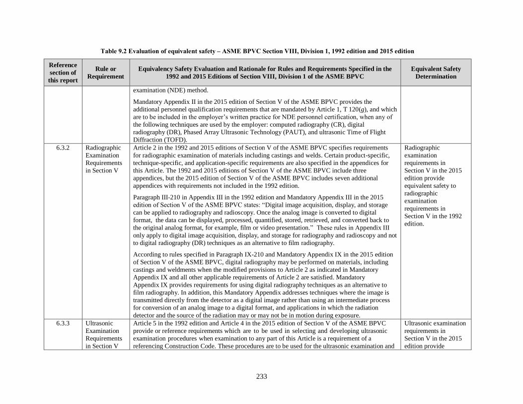
233
Table 9.2 Evaluation of equivalent safety – ASME BPVC Section VIII, Division 1, 1992 edition and 2015 edition
Reference
section of
this report
Rule or
Requirement
Equivalency Safety Evaluation and Rationale for Rules and Requirements Specified in the
1992 and 2015 Editions of Section VIII, Division 1 of the ASME BPVC
Equivalent Safety
Determination
examination (NDE) method.
Mandatory Appendix II in the 2015 edition of Section V of the ASME BPVC provides the
additional personnel qualification requirements that are mandated by Article 1, T 120(g), and which
are to be included in the employer’s written practice for NDE personnel certification, when any of
the following techniques are used by the employer: computed radiography (CR), digital
radiography (DR), Phased Array Ultrasonic Technology (PAUT), and ultrasonic Time of Flight
Diffraction (TOFD).
6.3.2 Radiographic
Examination
Requirements
in Section V
Article 2 in the 1992 and 2015 editions of Section V of the ASME BPVC specifies requirements
for radiographic examination of materials including castings and welds. Certain product-specific,
technique-specific, and application-specific requirements are also specified in the appendices for
this Article. The 1992 and 2015 editions of Section V of the ASME BPVC include three
appendices, but the 2015 edition of Section V of the ASME BPVC includes seven additional
appendices with requirements not included in the 1992 edition.
Paragraph III-210 in Appendix III in the 1992 edition and Mandatory Appendix III in the 2015
edition of Section V of the ASME BPVC states: “Digital image acquisition, display, and storage
can be applied to radiography and radioscopy. Once the analog image is converted to digital
format, the data can be displayed, processed, quantified, stored, retrieved, and converted back to
the original analog format, for example, film or video presentation.” These rules in Appendix III
only apply to digital image acquisition, display, and storage for radiography and radioscopy and not
to digital radiography (DR) techniques as an alternative to film radiography.
According to rules specified in Paragraph IX-210 and Mandatory Appendix IX in the 2015 edition
of Section V of the ASME BPVC, digital radiography may be performed on materials, including
castings and weldments when the modified provisions to Article 2 as indicated in Mandatory
Appendix IX and all other applicable requirements of Article 2 are satisfied. Mandatory
Appendix IX provides requirements for using digital radiography techniques as an alternative to
film radiography. In addition, this Mandatory Appendix addresses techniques where the image is
transmitted directly from the detector as a digital image rather than using an intermediate process
for conversion of an analog image to a digital format, and applications in which the radiation
detector and the source of the radiation may or may not be in motion during exposure.
Radiographic
examination
requirements in
Section V in the 2015
edition provide
equivalent safety to
radiographic
examination
requirements in
Section V in the 1992
edition.
6.3.3 Ultrasonic
Examination
Requirements
in Section V
Article 5 in the 1992 edition and Article 4 in the 2015 edition of Section V of the ASME BPVC
provide or reference requirements which are to be used in selecting and developing ultrasonic
examination procedures when examination to any part of this Article is a requirement of a
referencing Construction Code. These procedures are to be used for the ultrasonic examination and
Ultrasonic examination
requirements in
Section V in the 2015
edition provide

234
Table 9.2 Evaluation of equivalent safety – ASME BPVC Section VIII, Division 1, 1992 edition and 2015 edition
Reference
section of
this report
Rule or
Requirement
Equivalency Safety Evaluation and Rationale for Rules and Requirements Specified in the
1992 and 2015 Editions of Section VIII, Division 1 of the ASME BPVC
Equivalent Safety
Determination
the dimensioning of indications for comparison with acceptance standards when required by the
referencing Construction Code. Certain product-specific, technique-specific, and application-
specific requirements are also specified in Article 5 or Article 4, as applicable. The 1992 and 2015
editions of Section V of the ASME BPVC include two appendices, but the 2015 edition of
Section V of the ASME BPVC includes seven additional appendices with requirements not
included in the 1992 edition.
Prior to 2005, ultrasonic examination was not permitted except for a final closure weld where
radiographic examination was impractical as discussed in Sect. 6.2.2.1 of this report. Code Case
2235, which was issued in 1995, allowed ultrasonic examination in lieu of radiographic
examination for Section I, Section VIII, Division 1, and Section VIII, Division 2 for welds greater
than 1/2 in. thick. Code Case 2235 has since been incorporated into Section VIII, Division 1 and
Section VIII, Division 2 of the ASME BPVC. As discussed in Sect. 6.2.2.4 of this report,
Paragraph UW-51(a)(4) in the 2015 edition of Section VIII, Division 1 now states the following.
As an alternative to the radiographic examination requirements above, all welds in
material 1/4 in. (6 mm) and greater in thickness may be examined using the ultrasonic
(UT) method per the requirements of 7.5.5 of Section VIII, Division 2.
Requirements for the Time of Flight Diffraction (TOFD) examination technique for welds, which
are specified in Article 4, Mandatory Appendix III in the 2015 edition of Section V of the ASME
BPVC, are not included in Article 5 in the 1992 edition of Section V of the ASME BPVC.
equivalent safety to
ultrasonic examination
requirements in
Section V in the 1992
edition.
6.3.4 Liquid
Penetrant
Examination
Requirements
in Section V
Article 6 in the 1992 and 2015 editions of Section V of the ASME BPVC states that the liquid
penetrant examination techniques described in this Article must be used together with Article 1
when specified by the referencing Construction Code. It also provides details to be considered in
the procedures used for liquid penetrant examinations.
Additional requirements for the control of contaminant content for all liquid penetrant materials
used on nickel base alloys, austenitic stainless steels, and titanium are specified in Article 6,
Mandatory Appendix II in the 2015 edition of Section V of the ASME BPVC. This requirement is
not included in the 1992 edition of Section V of the ASME BPVC.
Liquid penetrant
examination
requirements in
Section V in the 2015
edition provide
equivalent safety to
liquid penetrant
examination
requirements in
Section V in the 1992
edition.
6.3.5 Magnetic
Particle
Examination
Article 7 – Magnetic Particle Examination in the 1992 and 2015 editions of Section V of the
ASME BPVC states that the magnetic particle examination techniques described in this Article
must be used together with Article 1 when specified by the referencing Construction Code. It also
Magnetic particle
examination
requirements in

235
Table 9.2 Evaluation of equivalent safety – ASME BPVC Section VIII, Division 1, 1992 edition and 2015 edition
Reference
section of
this report
Rule or
Requirement
Equivalency Safety Evaluation and Rationale for Rules and Requirements Specified in the
1992 and 2015 Editions of Section VIII, Division 1 of the ASME BPVC
Equivalent Safety
Determination
Requirements
in Section V
provides details to be considered in the procedures used for magnetic particle examinations. Section V in the 2015
edition provide
equivalent safety to
magnetic particle
examination
requirements in
Section V in the 1992
edition.
6.3.6 Visual
Examination
Requirements
in Section V
Article 9 – Visual Examination in the 1992 and 2015 editions of Section V of the ASME BPVC
states that methods and requirements for visual examination in this Article are applicable together
with requirements of Article 1 when specified by a referencing Construction Code. Specific visual
examination procedures required for every type of examination are not included in this Article
because there are many applications where visual examinations are required. Some examples of
these applications include nondestructive examinations, leak testing, in-service examinations, and
fabrication procedures.
Visual examination
requirements in
Section V in the 2015
edition provide
equivalent safety to
visual examination
requirements in
Section V in the 1992
edition.
7.1.2.1 Basis for
Hydrostatic
Pressure
Testing Limits
The objective of design rules specified in Section VIII, Division 1 of the ASME BPVC is to
establish the wall thickness of a pressure vessel so that the maximum allowable primary membrane
stress, Pm, does not exceed 2/3 Sy and the maximum primary membrane stress plus primary bending
stress, Pm + Pb, does not exceed Sy. Hydrostatic pressure testing limits for pressure vessels are
specified in Paragraph UG-99 in the 1992 and 2015 editions of Section VIII, Division 1 of the
ASME BPVC. A summary of these limits follows.
1992 – minimum hydrostatic test pressure – 1.5 MAWP
1992 – If the pressure vessel is subjected to visible permanent distortion, the Inspector shall reserve
the right to reject the vessel.
2015 – minimum hydrostatic test pressure – 1.3 MAWP
2015 – If the pressure vessel is subjected to visible permanent distortion, the Inspector shall reserve
the right to reject the vessel.
It is important to note that hydrostatic test pressure rules specified in Paragraph UG-99(b) in the
1992 and 2015 editions of Section VIII, Division 1 of the ASME BPVC allow the primary
membrane stress to exceed the plastic collapse stress limit when MAWP is based on an allowable
primary membrane stress, Pm, equal to 0.67 Sy and the hydrostatic test pressure is greater than
1.5 MAWP. This hydrostatic pressure test condition violates the principles of limit design theory.
Hydrostatic pressure
testing limits in the
2015 edition provide
equivalent safety to
hydrostatic pressure
testing limits in the
1992 edition.

236
Table 9.2 Evaluation of equivalent safety – ASME BPVC Section VIII, Division 1, 1992 edition and 2015 edition
Reference
section of
this report
Rule or
Requirement
Equivalency Safety Evaluation and Rationale for Rules and Requirements Specified in the
1992 and 2015 Editions of Section VIII, Division 1 of the ASME BPVC
Equivalent Safety
Determination
Pressure vessels that are designed and fabricated in accordance with rules specified in the 2015
edition of Section VIII, Division 1 of the ASME BPVC and subjected to a hydrostatic test pressure
equal to 1.3 MAWP are equivalent in safety to pressure vessels that are designed and fabricated in
accordance with rules specified in the 1992 edition of Section VIII, Division 1 of the ASME BPVC
and subjected to a hydrostatic test pressure equal to 1.5 MAWP because:
a. The primary membrane stresses that correspond to 1.3 MAWP and 1.5 MAWP remain at
or below the plastic collapse stress limit for both pressure vessels, and ASME considers
pressure vessels with primary membrane stresses below the plastic collapse stress limit to
be safe.
b. Subjecting a pressure vessel to a pressure test that produces primary membrane stresses
below the plastic collapse stress limit reduces the risk that the pressure vessel will exhibit
visible permanent distortion that could result in rejection of the pressure vessel by the
Inspector.
c. A pressure test (either hydrostatic or pneumatic) is conducted so the Authorized Inspector
can authorize application of the Certification Mark (Code stamp) based on verification of
leak tight integrity and confirm that the pressure vessel does not exhibit gross
deformations or anomalies that may indicate design errors, material deficiencies, or weld
defects.
d. A pressure test is performed after fabrication is completed primarily to verify the leak
tight integrity of the pressure vessel, but also to identify gross deformations or anomalies
that may indicate design errors, material deficiencies, or weld defects. Pressure test limits
are established to maintain primary membrane and bending stresses within the elastic
range so the pressure vessel does not permanently deform. Pressure tests are not intended
to verify the pressure-resisting (burst) capacity of a pressure vessel.
e. As discussed in Sect. 8.1 of this report, overpressure protection rules specified in
Paragraph UG-125(c)(2) in the 1992 and 2015 editions of Section VIII, Division 1 of the
ASME BPVC state that when a pressure vessel can be exposed to fire or other unexpected
sources of external heat, the pressure relief device(s) must be capable of preventing the
pressure from rising more than 21% above the MAWP. (i.e., 1.21 MAWP). This
overpressure protection limit ensures that the primary membrane stress, Pm, does not
exceed 0.81 Sy (i.e., 1.21/1.50). A minimum hydrostatic test pressure equal to 1.3 MAWP
ensures that the pressure vessel will never experience a maximum overpressure while in

237
Table 9.2 Evaluation of equivalent safety – ASME BPVC Section VIII, Division 1, 1992 edition and 2015 edition
Reference
section of
this report
Rule or
Requirement
Equivalency Safety Evaluation and Rationale for Rules and Requirements Specified in the
1992 and 2015 Editions of Section VIII, Division 1 of the ASME BPVC
Equivalent Safety
Determination
service that is greater than the hydrostatic test pressure. (i.e., 1.3 MAWP > 1.21 MAWP)
According to rules specified in Paragraph UG 99(f) in the 2015 edition of Section VIII, Division 1,
single wall pressure vessels designed for vacuum or partial vacuum may be subjected to a vacuum
test conducted in accordance with Section V, Article 10 requirements as specified by the user. Leak
test methods permitted in Section V, Article 10 include: bubble test, halogen diode detector probe
test, helium mass spectrometer test, pressure chamber test, and ultrasonic leak detector test.
Corresponding rules in Paragraph UG 99(f) in the 1992 edition of Section VIII, Division 1 do not
permit vacuum testing of single-wall pressure vessels designed for vacuum or partial vacuum.
7.1.2.2 Basis for
Pneumatic
Pressure
Testing Limits
The objective of design rules specified in Section VIII, Division 1 of the ASME BPVC is to
establish the wall thickness of a pressure vessel so that the maximum allowable primary membrane
stress, Pm, does not exceed 2/3 Sy and the maximum primary membrane stress plus primary bending
stress, Pm + Pb, does not exceed Sy. Pneumatic pressure testing limits for pressure vessels are
specified in Paragraph UG-100 in the 1992 and 2015 editions of Section VIII, Division 1 of the
ASME BPVC. A summary of these limits follows.
1992 – minimum pneumatic test pressure – 1.25 MAWP
1992 – maximum general membrane stress limit not specified
2015 – minimum pneumatic test pressure – 1.1 MAWP
2015 – maximum general membrane stress limit not specified, but the pneumatic test pressure
cannot exceed 1.1 times the basis for the calculated test pressure
It is important to note that:
• Pneumatic test pressure rules specified in Paragraph UG-100(b) in the 1992 edition of
Section VIII, Division 1 of the ASME BPVC allow the primary membrane stress to exceed the
plastic collapse stress limit when MAWP is based on an allowable primary membrane stress,
Pm, equal to 0.67 Sy and the pneumatic test pressure is greater than 1.5 MAWP. This
pneumatic pressure test condition violates the principles of limit design theory discussed in
Sect. 4.6 of this report. The maximum pneumatic test pressure limit specified in the 2015
edition of Section VIII, Division 1 of the ASME BPVC ensure that the pneumatic pressure test
condition do not violate the principles of limit design theory discussed in Sect. 4.6 of this
report.
• As discussed in Sect. 8.2 of this report, overpressure protection rules specified in Paragraph
UG-125(c)(2) in the 2015 edition of Section VIII, Division 1 of the ASME BPVC state that
when a pressure vessel can be exposed to fire or other unexpected sources of external heat, the
Pneumatic pressure
testing limits in the
2015 edition provide
equivalent safety to
pneumatic pressure
testing limits in the
1992 edition.

238
Table 9.2 Evaluation of equivalent safety – ASME BPVC Section VIII, Division 1, 1992 edition and 2015 edition
Reference
section of
this report
Rule or
Requirement
Equivalency Safety Evaluation and Rationale for Rules and Requirements Specified in the
1992 and 2015 Editions of Section VIII, Division 1 of the ASME BPVC
Equivalent Safety
Determination
pressure relief device(s) must be capable of preventing the pressure from rising more than 21%
above the MAWP. (i.e., 1.21 MAWP). This overpressure protection limit ensures that the
primary membrane stress, Pm, does not exceed 0.81 Sy (i.e., 1.21/1.50). A minimum pneumatic
test pressure equal to 1.1 MAWP does not ensure that the pressure vessel will never
experience a maximum overpressure while in service that is greater than the pneumatic test
pressure. (i.e., 1.1 MAWP < 1.21 MAWP)
• Rules specified in the 1992 and 2015 editions of Section VIII, Division 1 of the ASME BPVC
do not specify a minimum or maximum pneumatic test pressure duration. The rules state that
the pressure must be held for sufficient time to permit inspection of the pressure vessel.
Pressure vessels that are designed and fabricated in accordance with rules specified in the 2015
edition of Section VIII, Division 1 of the ASME BPVC and subjected to a pneumatic test pressure
equal to 1.1 MAWP are equivalent in safety to pressure vessels that are designed and fabricated in
accordance with rules specified in the 1992 edition of Section VIII, Division 1 of the ASME BPVC
and subjected to a pneumatic test pressure equal to 1.25 MAWP because:
a. The primary membrane stresses that correspond to 1.25 MAWP and 1.1 MAWP remain at
or below the plastic collapse stress limit for both pressure vessels, and ASME considers
pressure vessels with primary membrane stresses below the plastic collapse stress limit to
be safe.
b. Subjecting a pressure vessel to a pressure test that produces primary membrane stresses
below the plastic collapse stress limit reduces the risk that the pressure vessel will exhibit
visible permanent distortion that could result in rejection of the pressure vessel by the
Inspector.
c. A pressure test (either hydrostatic or pneumatic) is conducted so the Authorized Inspector
can authorize application of the Certification Mark (Code stamp) based on verification of
leak tight integrity and confirm that the pressure vessel does not exhibit gross
deformations or anomalies that may indicate design errors, material deficiencies, or weld
defects.
d. A pressure test is performed after fabrication is completed primarily to verify the leak
tight integrity of the pressure vessel, but also to identify gross deformations or anomalies
that may indicate design errors, material deficiencies, or weld defects. Pressure test limits
are established to maintain primary membrane and bending stresses within the elastic
range so the pressure vessel does not permanently deform. Pressure tests are not intended

239
Table 9.2 Evaluation of equivalent safety – ASME BPVC Section VIII, Division 1, 1992 edition and 2015 edition
Reference
section of
this report
Rule or
Requirement
Equivalency Safety Evaluation and Rationale for Rules and Requirements Specified in the
1992 and 2015 Editions of Section VIII, Division 1 of the ASME BPVC
Equivalent Safety
Determination
to verify the pressure-resisting (burst) capacity of a pressure vessel.
7.2 Alternative
Pressure
Testing
The 1992 and 2015 editions of Section VIII, Division 1 of the ASME BPVC do not include
alternative pressure testing requirements.
An equivalent safety
evaluation of
alternative pressure
testing requirements in
the 1992 and 2015
editions is not possible.
7.3.1 Proof Testing Requirements for proof testing to establish MAWP are provided in Paragraph UG-101 in the 1992
and 2015 editions of Section VIII, Division 1 of the ASME BPVC. Provision is made in these rules
for two types of tests to determine the internal maximum allowable working pressure:
1. tests based on yielding of the part to be tested. These tests are limited to materials with a
ratio of minimum specified yield to minimum specified ultimate strength of 0.625 or less.
2. tests based on bursting of the part.
Requirements for permitted proof test procedures are specified in the following Paragraphs in the
1992 and 2015 editions of Section VIII, Division 1 of the ASME BPVC.
• Paragraph UG-101(l) – Brittle-Coating Test Procedure
• Paragraph UG-101(m) – Bursting Test Procedure
• Paragraph UG-101(n) – Strain Measurement Test Procedure
• Paragraph UG-101(o) – Displacement Measurement Test Procedure
• Paragraph UG-101(p) – Procedure for Vessels Having Chambers of Special Shape Subject
to Collapse
Selection of a particular proof test procedure depends on its applicability to the type of loading and
to the material used in construction. It is important to note that the corresponding proof test
equations in the 1992 and 2015 editions of Section VIII, Division 1 of the ASME BPVC for
computing MAWP using test data are the same.
The proof testing
requirements in the
2015 edition provide
equivalent safety to the
proof testing
requirements in the
1992 edition
8.2.1 Overpressure
Protection by
Pressure Relief
Device
Overpressure protection rules specified in Paragraph UG-125(c)(2) in the 1992 and 2015 editions
of Section VIII, Division 1 of the ASME BPVC state that when a pressure vessel can be exposed to
fire or other unexpected sources of external heat, the pressure relief device(s) must be capable of
preventing the pressure from rising more than 21% above the MAWP. (i.e., 1.21 MAWP) This
overpressure protection limit ensures that the primary membrane stress, Pm, does not exceed 0.81 Sy
(i.e., 1.21/1.50).
The overpressure
protection requirements
by pressure relief
device in the 2015
edition provide
equivalent safety to the
overpressure protection

240
Table 9.2 Evaluation of equivalent safety – ASME BPVC Section VIII, Division 1, 1992 edition and 2015 edition
Reference
section of
this report
Rule or
Requirement
Equivalency Safety Evaluation and Rationale for Rules and Requirements Specified in the
1992 and 2015 Editions of Section VIII, Division 1 of the ASME BPVC
Equivalent Safety
Determination
The rules for overpressure protection by pressure relief device specified in the 1992 and 2015
editions of Section VIII, Division 1 of the ASME BPVC are the same. Therefore, the rules for
overpressure protection specified in the 2015 edition of Section VIII, Division 1 of the ASME
BPVC provide an equivalent level of safety compared to the rules for overpressure protection
specified in the 1992 edition of Section VIII, Division 1 of the ASME BPVC.
requirements by
pressure relief device in
the 1992 edition
8.2.2 Overpressure
Protection by
System Design
The 1992 edition of Section VIII, Division 1 of the ASME BPVC does not provide rules for
overpressure protection by system design. However, Paragraph UG-125(a) states: “All pressure
vessels within the Scope of this Division, irrespective of size or pressure, shall be provided with
protective devices in accordance with the requirements of U-125 through UG-136.”
Rules specified in Paragraph UG-140 in the 2015 edition of Section VIII, Division 1 of the ASME
BPVC state that a pressure vessel does not require a pressure relief device if:
(a) the pressure is self‐limiting (e.g., the maximum discharge pressure of a pump or
compressor) and specified conditions are met; or
(b) the pressure is not self‐limiting and specified conditions are met.
For pressure vessels in which the pressure is not self‐limiting there must be no credible
overpressure scenario in which the pressure exceeds 116% of the MAWP times the ratio of the
allowable stress value at the temperature of the overpressure scenario to the allowable stress value
at the design temperature. In addition, the overpressure limit must not exceed the test pressure.
An equivalent safety
evaluation of
overpressure protection
by system design in the
1992 and 2015 editions
is not possible.

241
Table 9.3 Evaluation of equivalent safety – ASME BPVC Section VIII, Division 2, 1992 edition and 2015 edition
Reference
section of
this report
Rule or
Requirement
Equivalency Safety Evaluation and Rationale for Rules and Requirements Specified in the
1992 and 2015 Editions of Section VIII, Division 2 of the ASME BPVC
Equivalent Safety
Determination
4.1.1.3 Excessive
Elastic
Deformation
and Elastic
Instability
Excessive elastic deformation (deflection) and elastic instability (buckling) cannot be controlled by
imposing upper limits to the calculated stress alone because these behavioral phenomena are
affected by component geometry and stiffness and material properties. Excessive elastic
deformation can occur when a component with inadequate stiffness experiences unwanted
flexibility or unacceptable deflections. Buckling is characterized by a sudden sideways failure of a
component subjected to high compressive stress, where the compressive stress at the point of
failure is less than the ultimate compressive stress that the material is capable of withstanding. The
designer of a boiler or pressure vessel is responsible for applying engineering principles to
understand and avoid in-service problems or failures caused by excessive elastic deformation and
elastic instability.
Rules for determining the thickness of vessels under external pressure are specified in Article D-3
in the 1992 edition of Section VIII, Division 2 of the ASME BPVC. These rules apply to spherical,
conical, and cylindrical shells with or without stiffening rings; to formed heads; and to tubular
products. Charts for use in determining the thickness of these components are provided in
Appendix 2 which incorporates the charts in Subpart 3 of Section II, Part D as discussed in
Sect. 4.1.1.1 of this report by reference. Rules for cylinders under axial compression are specified
in Paragraph AD 340 in the 1992 edition of Section VIII, Division 2 of the ASME BPVC.
Implementation of these rules also requires use of applicable factors in the charts in Subpart 3 of
Section II, Part D.
Three alternative types of buckling analyses are included in Part 5, Paragraph 5.4 in the 2015
edition of Section VIII, Division 2 of the ASME BPVC to evaluate structural stability from compressive stress fields. The design factor to be used in a structural stability assessment is based
on the type of buckling analysis performed. These buckling analyses do not reference the external
pressure charts provided in the 2015 edition of Section II, Part D, Subpart 3.
Excessive elastic
deformation and elastic
instability requirements
in the 2015 edition
provide equivalent or
greater safety compared
to excessive elastic
deformation and elastic
instability requirements
in the 1992 edition.
4.1.2 Excessive
Plastic
Deformation
The plastic deformation mode of failure (ductile rupture) is controlled by imposing limits on
calculated stress. Primary stress limits and primary plus secondary stress limits in the ASME
BPVC are intended to prevent excessive plastic deformation leading to incremental collapse and to
provide a nominal margin on the ductile burst pressure. The designer of a boiler or pressure vessel
is responsible for ensuring that the specified stress limits are not exceeded under the operating
conditions defined by the user.
Rules for avoiding excessive plastic deformation are provided in Appendix 4 in the 1992 edition of
Section VIII, Division 2 and Part 5, Paragraph 5.2 in the 2015 edition of Section VIII, Division 2.
As discussed in Sect. 4.4.2 of this report, the maximum allowable membrane stress, Pm, for
Excessive plastic
deformation
requirements in the
2015 edition provide
equivalent safety
compared to excessive
plastic deformation
requirements in the
1992 edition.

242
Table 9.3 Evaluation of equivalent safety – ASME BPVC Section VIII, Division 2, 1992 edition and 2015 edition
Reference
section of
this report
Rule or
Requirement
Equivalency Safety Evaluation and Rationale for Rules and Requirements Specified in the
1992 and 2015 Editions of Section VIII, Division 2 of the ASME BPVC
Equivalent Safety
Determination
pressure vessels constructed in accordance with rules specified in the 1992 and 2015 editions of
Section VIII, Division 1 of the ASME BPVC is limited to two-thirds of the yield strength, 2/3 Sy, or
less. Rules specified in the 1992 and 2015 editions of Section VIII, Division 2 of the ASME BPVC
also ensure that the primary membrane stress plus the primary bending stress, Pm + Pb, does not
exceed Sy. Based on the principles of limit design theory discussed in Sect. 4.6 of this report, these
rules provide a minimum design margin against plastic collapse equal to or greater than 1.5.
Additional discussion about protection against plastic collapse is presented in Sect. 4.8 of this
report.
4.1.3.3 Brittle
Fracture
The ability of a metal to resist tearing or cracking is a measure of its fracture toughness. In fracture
mechanics calculations, the value of the stress intensity factor, KI, is based on the applied stress and
dimensions of the flaw. To avoid brittle fracture, the calculated KI must be less than the critical
fracture toughness parameter, KIc. From an equivalency viewpoint, an increase in the maximum
allowable design stress for a material with a critical flaw size requires an increase in fracture
toughness to maintain the same margin against brittle fracture. In addition, increasing fracture
toughness reduces the risk that critical flaw sizes below the NDE detection limits do not result in
brittle fracture.
General material toughness requirements for all steel products are provided in Paragraph AM-204
in the 1992 edition of Section VIII, Division 2. According to these rules, Charpy V-notch impact
tests in accordance with requirements specified in Paragraph AM-204.1 must be made for steel
materials used for shells, heads, nozzles, and other pressure containing parts, as well as for the
structural members essential to structural integrity. Impact test procedures and apparatus must
conform to the applicable Paragraphs of SA-370. According to Paragraph AM-211.1, the
applicable minimum energy requirement for standard specimen sizes must be that shown in Table
AM-211.1. This table presents the minimum Charpy V-notch impact test requirements for carbon
and low alloy steels based on the specified minimum tensile strength and to what extent the steel is
deoxidized. The minimum specified Charpy V-notch impact energy limits listed in the table range
up to 20 ft-lb. The minimum specified lateral expansion value listed in the table is 0.015 in.
Material toughness requirements in the 2015 edition of Section VIII, Division 2 are provided in
Part 3. According to these rules, Charpy V-notch impact tests must be made for materials used for
shells, heads, nozzles, and other pressure containing parts, as well as for the structural members
essential to structural integrity of the vessel, unless exempted by the rules of Paragraph 3.11.
Separate requirements for five specific material groups are provided in Paragraph 3.11. Minimum
Charpy V-notch impact energy and lateral expansion requirements vary over a range from 20 to
61 ft-lb and 0.012 to 0.032 in. depending on material type, thickness, and yield strength.
Requirements in the
2015 edition for
protection against
brittle fracture provide
equivalent or greater
safety compared to
requirements in the
1992 edition for
protection against
brittle fracture.

243
Table 9.3 Evaluation of equivalent safety – ASME BPVC Section VIII, Division 2, 1992 edition and 2015 edition
Reference
section of
this report
Rule or
Requirement
Equivalency Safety Evaluation and Rationale for Rules and Requirements Specified in the
1992 and 2015 Editions of Section VIII, Division 2 of the ASME BPVC
Equivalent Safety
Determination
Material toughness requirements in the 2015 edition of Section VIII, Division 2 are significantly
more stringent and comprehensive than corresponding material toughness requirements in the 1992
edition of Section VIII, Division 2.
4.1.4.2 Stress Rupture
and Creep
Deformation
Boiler and pressure vessel materials that are in service above a certain temperature undergo
continuing deformation (creep) at a rate that is strongly influenced by both stress and temperature.
The temperature at which creep occurs varies with the alloy composition. In order to prevent
excessive deformation and possible premature rupture it is necessary to limit the allowable stresses
by additional criteria on creep-rate and stress-rupture.
Rules specified in the 1992 edition of Section VIII, Division 2 of the ASME BPVC are restricted to
temperatures at which creep will not be significant. This is achieved by limiting the tabulated
allowable stress intensities to below the temperature of creep behavior.
Criteria for establishing allowable stresses at temperatures in the range where creep and stress
rupture strength govern are provided in Section II, Part D of the ASME BPVC as discussed in
Sect. 4.4 of this report. The allowable stresses specified in the 1992 and 2015 editions of Section II,
Part D of the ASME BPVC at temperatures in the range where creep and stress rupture strength
govern are the same.
Stress rupture and creep
deformation
requirements in the
2015 edition provide
equivalent safety
compared to stress
rupture and creep
deformation
requirements in the
1992 edition.
4.1.5.3 Plastic
Instability –
Incremental
Collapse
Ratcheting is defined as a progressive incremental inelastic deformation or strain that can occur in a
component subjected to variations of mechanical stress, thermal stress, or both. Ratcheting is
produced by a sustained load acting over the full cross section of a component, in combination with
a strain controlled cyclic load or temperature distribution that is alternately applied and removed.
Ratcheting results in cyclic straining of the material, which can result in failure by fatigue and at
the same time produces cyclic incremental deformation of a component, which may ultimately lead
to collapse.
Rules for thermal stress ratcheting are specified in Appendix 5, Paragraph 5-130 in the 1992 edition
of Section VIII, Division 2 of the ASME BPVC. Paragraph 5-130(b) states: “Use of the yield
strength Sy in the above relations instead of the proportional limit allows a small amount of growth
during each cycle until strain hardening raises the proportional limit to Sy. If the yield strength of
the material is higher than is the endurance limit for the material, the latter value shall be used, if
there are to be a large number of cycles, because strain softening may occur.” The 1992 edition of
Section VIII, Division 2 of the ASME BPVC does not include rules for a more rigorous evaluation
of ratcheting based on elastic-plastic analysis results.
Rules for protection against ratcheting are specified in Part 5, Paragraph 5.5 in the 2015 edition of
Plastic instability and
incremental collapse
requirements in the
2015 edition provide
equivalent safety
compared to plastic
instability and
incremental collapse
requirements in the
1992 edition.

244
Table 9.3 Evaluation of equivalent safety – ASME BPVC Section VIII, Division 2, 1992 edition and 2015 edition
Reference
section of
this report
Rule or
Requirement
Equivalency Safety Evaluation and Rationale for Rules and Requirements Specified in the
1992 and 2015 Editions of Section VIII, Division 2 of the ASME BPVC
Equivalent Safety
Determination
Section VIII, Division 2 of the ASME BPVC for all operating loads included in the design basis
defined by the user even if the fatigue screening criteria are satisfied. Protection against ratcheting
is satisfied if one of the following three conditions is met [2].
1. The loading results in only primary stresses without any cyclic secondary stresses.
2. Elastic Stress Analysis Criteria – Protection against ratcheting is demonstrated by
satisfying the rules of Part 5, Paragraph 5.5.6.
3. Elastic-Plastic Stress Analysis Criteria – Protection against ratcheting is demonstrated by
satisfying the rules of Part 5, Paragraph 5.5.7.
The elastic analysis method provided in the 2015 edition of Section VIII, Division 2 of the ASME
BPVC to evaluate ratcheting in accordance with rules specified in Part 5, Paragraph 5.5.6 is the
same as the method provided in the 1992 edition of Section VIII, Division 2 of the ASME
BPVC [2].
4.1.6.3 Fatigue Fatigue is the weakening of a material caused by repeatedly applied loads. It is the progressive and
localized material degradation that occurs when a component is subjected to cyclic loading. If the
loads are above a certain threshold, microscopic cracks will begin to form at stress concentrations
such as square holes or sharp corners. Eventually the crack will reach a critical size, propagate, and
cause the component to fracture. Avoidance of discontinuities that increase local stresses will
increase the fatigue life of a component subjected to cyclic loading.
Rules specified in Article D-1, Paragraph AD-160 in the 1992 edition of Section VIII, Division 2 of
the ASME BPVC establish criteria for determining when a fatigue analysis is required. When a
fatigue analysis is required, design rules specified in Appendix 5 – Mandatory Design Based on
Fatigue Analysis apply. Rules specified in the 1992 edition of Section VIII, Division 2 of the
ASME BPVC prevent fatigue failure by limiting peak stresses. Cyclic loading design procedures in
the 1992 edition of Section VIII, Division 2 of the ASME BPVC that apply when the principal
stress direction does not change are specified in Paragraph 5-110.3(a). Corresponding procedures
that apply when the principal stress direction change are specified in Paragraph 5-110.3(b).”
Rules specified in Part 4 – Design by Rule Requirements, Paragraph 4.1.1.4 in the 2015 edition of
Section VIII, Division 2 of the ASME BPVC state that: “A screening criterion shall be applied to
all pressure vessel parts designed in accordance with this Division to determine if a fatigue analysis
is required. The fatigue screening criterion shall be performed in accordance with 5.5.2. If the
results of this screening indicate that a fatigue analysis is required, then the analysis shall be
performed in accordance with 5.5.2. If the allowable stress at the design temperature is governed by
time-dependent properties, then a fatigue screening analysis based on experience with comparable
Fatigue requirements in
the 2015 edition
provide equivalent or
greater safety compared
to fatigue requirements
in the 1992 edition.

245
Table 9.3 Evaluation of equivalent safety – ASME BPVC Section VIII, Division 2, 1992 edition and 2015 edition
Reference
section of
this report
Rule or
Requirement
Equivalency Safety Evaluation and Rationale for Rules and Requirements Specified in the
1992 and 2015 Editions of Section VIII, Division 2 of the ASME BPVC
Equivalent Safety
Determination
equipment shall be satisfied (see 5.5.2.2).” Rules for performing a fatigue evaluation are specified
in the following Paragraphs in the 2015 edition of Section VIII, Division 2 of the ASME BPVC.
• Paragraph 5.5.3 – Fatigue Assessment – Elastic Stress Analysis and Equivalent Stresses.
• Paragraph 5.5.4 – Fatigue Assessment – Elastic Plastic Stress Analysis and Equivalent
Strains.
• Paragraph 5.5.5 – Fatigue Assessment of Welds – Elastic Analysis and Structural Stress.
Rules specified in the 2015 edition of Section VIII, Division 2 of the ASME BPVC for evaluating
fatigue are more comprehensive and provide equivalent or greater safety compared to
corresponding rules for evaluating fatigue specified in the 1992 edition of Section VIII, Division 2
of the ASME BPVC.
4.1.7.3 Stress
Corrosion and
Corrosion
Fatigue
Two common types of corrosion that can adversely affect the integrity of a boiler or pressure vessel
include stress corrosion cracking and corrosion fatigue. Stress corrosion cracking (SCC) is the
growth of crack formation in a corrosive environment and is highly chemically specific in that
certain alloys are likely to undergo SCC only when exposed to a small number of chemical
environments. Corrosion fatigue is the mechanical degradation of a material under the joint action
of corrosion and cyclic loading. Since corrosion-fatigue cracks initiate at a metal’s surface, surface
treatments like plating, cladding, nitriding, and shot peening can improve the materials’ resistance
to corrosion fatigue. However, corrosion fatigue only occurs when the metal is under tensile stress.
Rules specified in Paragraph AD-115 in the 1992 edition of Section VIII, Division 2 of the ASME
BPVC state that: “Vessels or parts thereof subject to loss of metal by corrosion, erosion,
mechanical abrasion, or other environmental effects must have provisions made for such of the
same thickness for all parts of the vessel, if different rates of attack are expected for the various
parts. No additional thickness need be provided when previous experience in like service has
shown that corrosion does not occur or is of only a superficial nature determined by the design
formulas or stress analysis.”
In comparison, rules specified in Part 4, Paragraph 4.1.4.2 in the 2015 edition of Section VIII,
Division 2 of the ASME BPVC state that: ‘The term corrosion allowance as used in this Division is
representative of loss of metal by corrosion, erosion, mechanical abrasion, or other environmental
effects and shall be accounted for in the design of vessels or parts when specified in the User's
Design Specification.”
Stress corrosion
cracking and corrosion
fatigue requirements in
the 2015 edition
provide equivalent or
greater safety compared
to stress corrosion
cracking and corrosion
fatigue requirements in
the 1992 edition.
4.2.3 Design Basis Paragraph AD-100 in the 1992 edition of Section VIII, Division 2 of the ASME BPVC states that
when complete rules are not provided for a pressure vessel or pressure vessel part, or when the
vessel designer or user chooses, a complete stress analysis of the pressure vessel or pressure vessel
Design basis
requirements in the
2015 edition provide

246
Table 9.3 Evaluation of equivalent safety – ASME BPVC Section VIII, Division 2, 1992 edition and 2015 edition
Reference
section of
this report
Rule or
Requirement
Equivalency Safety Evaluation and Rationale for Rules and Requirements Specified in the
1992 and 2015 Editions of Section VIII, Division 2 of the ASME BPVC
Equivalent Safety
Determination
part must be performed considering all of the loadings specified in the UDS. The only information
that must be provided in the UDS is defined in Paragraph AG-301(a), AG-301(b), and AG-301(c).
This list, which is much less comprehensive that the list defined in Paragraph 2.2.2 in the 2015
edition of Section VIII, Division 2 of the ASME BPVC. Paragraph AG-301.2 in the 1992 edition of
Section VIII, Division 2 of the ASME BPVC states that a professional engineer, registered in one
or more of the states of the United States of America or the provinces of Canada and experienced in
pressure vessel design, must certify to the compliance of the UDS with the requirements specified
in Paragraph AG-301.
Design basis rules for pressure vessels constructed in accordance with requirements specified in the
2015 edition of Section VIII, Division 2 of the ASME BPVC are provided in Paragraph 4.1.5.
These rules state that:
• all applicable loads and load case combinations must be considered in the design to
determine the minimum required wall thickness for a pressure vessel part, and
• the loads that must be considered in the design must include, but not be limited to, those
shown in Table 4.1.1 and must be included in the User’s Design Specification (UDS).
Normative guidance for certifying a UDS is presented in Annex 2-A. According to this guidance,
one or more Professional Engineers, registered in one or more of the states of the United States of
America or the provinces of Canada and experienced in pressure vessel design, must certify that the
UDS meets the requirements in Paragraph 2.2.2, and must apply the Professional Engineer seal in
accordance with the required procedures. In addition, the Registered Professional Engineer(s) must
prepare a statement to be affixed to the document attesting to compliance with the applicable
requirements of the Code.
equivalent or greater
safety compared to
design basis
requirements in the
1992 edition.
4.4.2 Allowable
Stress Values
Criteria for establishing allowable stresses for use in performing calculations in accordance with
rules specified in Section VIII, Division 2 of the ASME BPVC are discussed in Mandatory
Appendix 10 of Section II, Part D in the 2015 edition and in Appendix 2 of Section II, Part D in the
1992 edition. These allowable stress values, which are provided in Tables 2A and 2 B in the 1992
edition of Section II, Part D and Tables 5A and 5 B in the 2015 edition of Section II, Part D, are
subdivided into materials below room temperature and materials at room temperature and above.
According to these criteria, the maximum allowable stress in the 1992 and 2015 editions of
Section II, Part D is two‐thirds of the room temperature yield strength, 2/3 Sy.
Unlike Section VIII, Division 1 of the ASME BPVC, there are no rules in Section VIII, Division 2
of the ASME BPVC specifically for pressure vessels constructed using materials having a higher allowable stresses at low temperature.
Allowable stress rules
in the 2015 edition
provide equivalent
safety to allowable
stress rules in the 1992
edition.

247
Table 9.3 Evaluation of equivalent safety – ASME BPVC Section VIII, Division 2, 1992 edition and 2015 edition
Reference
section of
this report
Rule or
Requirement
Equivalency Safety Evaluation and Rationale for Rules and Requirements Specified in the
1992 and 2015 Editions of Section VIII, Division 2 of the ASME BPVC
Equivalent Safety
Determination
For allowable stresses specified in the 1992 edition of Section II, Part D of the ASME BPVC, the
yield strength controls the design of pressure vessels that are designed and fabricated in accordance
with rules specified in the 1992 edition of Section VIII, Division 2 of the ASME BPVC when the
ultimate tensile strength is greater than 2.0 (e.g. 2/3 × 3.0) times the yield strength. In comparison,
the yield strength controls the design of boilers and pressure vessels that are designed and
fabricated in accordance with rules specified in the 2015 edition of Section VIII, Division 2 of the
ASME BPVC when the ultimate tensile strength is greater than 1.6 (e.g. 2/3 × 2.4) times the yield
strength. In general, yield to tensile strength ratios for steels increase with increasing tensile
strength.
Paragraph AD-140(b) in the 1992 edition of Section VIII, Division 2 of the ASME BPVC states:
“The average value of the general primary membrane stress intensity across the thickness of the
section under consideration, due to any combination of design pressure and mechanical loadings
expected to occur simultaneously, should not exceed the design stress intensity value kSm.” In
addition, Paragraph AD-140(d) states: “The primary bending stress due to any combination of
design pressure and mechanical loadings expected to occur simultaneously shall not exceed
1.5kSm.”
In comparison, Part 4, Paragraph 4.1.6.1 in the 2015 editions of Section VIII, Division 2 states:
“The wall thickness of a vessel computed by the rules of Part 4 for any combination of loads (see
4.1.5) that induce primary stress (see definition of primary stress in 5.12) and are expected to
occur simultaneously during operation shall satisfy the equations shown below.”
Pm ≤ Sy (4.1.1)
Pm + Pb ≤ 1.5 Sy (4.1.2)
These rules ensure that the maximum allowable primary membrane stress, Pm, does not exceed
2/3 Sy and that the maximum allowable primary membrane stress plus primary bending stress,
Pm + Pb, does not exceed Sy. These maximum allowable stress limits are consistent with the plastic
collapse stress limits discussed in Sect. 4.6 of this report.
According to LEFM theory, allowable stress in the presence of a given crack size is directly
proportional to the fracture toughness. Therefore, to maintain an equivalent or greater level of
safety against brittle fracture resulting from the increase in allowable stresses, fracture toughness
rules in the 2015 edition of Section VIII, Division 2 were significantly changed from corresponding

248
Table 9.3 Evaluation of equivalent safety – ASME BPVC Section VIII, Division 2, 1992 edition and 2015 edition
Reference
section of
this report
Rule or
Requirement
Equivalency Safety Evaluation and Rationale for Rules and Requirements Specified in the
1992 and 2015 Editions of Section VIII, Division 2 of the ASME BPVC
Equivalent Safety
Determination
rules in the 1992 edition of Section VIII, Division 2. A discussion of these toughness rule changes
is presented in Sect. 4.1.3.3 of this report.
4.5.2 Section VIII,
Division 2
Design-by-
Rule Strength
Theory
Design-by-rule requirements specified in Appendix 4 in the 1992 edition of Section VIII,
Division 2 and in Part 4 in the 2015 edition of Section VIII, Division 2 of the ASME BPVC are
based on the maximum shear stress theory, which is also known as the Tresca yield criterion,
discussed in Sect. 4.5.2 of this report.
Design-by-rule
requirements in the
2015 edition provide
equivalent safety to
design-by-rule
requirements in the
1992 edition.
4.5.3 Section VIII,
Division 2
Design-by-
Analysis
Strength
Theory
Design-by-analysis rules specified in Appendix 5 in the 1992 edition of Section VIII, Division 2
are based on the maximum shear stress theory, which is also known as the Tresca yield criterion,
discussed in Sect. 4.5.2 of this report.
Design-by-analysis requirements specified in Part 5 in the 2015 edition of Section VIII, Division 2
of the ASME BPVC are based on the distortion energy theory using the von Mises yield criterion
discussed in Sect. 4.5.3 of this report.
Most experiments show that the distortion energy theory (von Mises) is more accurate than the
shear theory (Tresca) because ductile materials behave closer to the von Mises yield criterion.
However, the Tresca yield criterion gives a more conservative estimate on failure compared to the
von Mises yield criterion. Under the same loading conditions, principle stresses determined using
the Tresca yield criterion are approximately 15% more than the principle stresses determined using
the von Mises yield criterion. Even though the maximum difference between the von Mises and
Tresca yield criteria is only about 15%, this difference represents a systemic error (divergence) on
the part of the Tresca yield criterion.
Design-by-analysis
requirements in the
2015 edition provide
equivalent or greater
safety compared to
design-by-analysis
requirements in the
1992 edition.
4.7 Stress Range
for
Repetitively
Applied Loads
Shakedown of a component occurs if, after a few cycles of load application, ratcheting ceases. The
subsequent structural response is elastic, or elastic-plastic, and progressive incremental inelastic
deformation is absent. Elastic shakedown is the case in which the subsequent response is elastic.
The ASME BPVC limits localized discontinuity stresses to 3.0 times the maximum allowable stress
value in tension or 2.0 times the minimum specified tensile yield stress, Sy, of the material provided
the allowable stress is not governed by time-dependent properties of the material and the room
temperature ratio of the specified minimum yield strength, Sy, to specified minimum tensile
strength, Su, for the material does not exceed 0.7. This requirement ensures the material has strain-
hardening properties sufficient to prevent material failure if the primary stress exceeds the yield
strength of the material through the entire thickness.
Rules for stress range
for repetitively applied
loads in the 2015
edition provide
equivalent safety to
rules for stress range for
repetitively applied
loads in the 1992
edition.

249
Table 9.3 Evaluation of equivalent safety – ASME BPVC Section VIII, Division 2, 1992 edition and 2015 edition
Reference
section of
this report
Rule or
Requirement
Equivalency Safety Evaluation and Rationale for Rules and Requirements Specified in the
1992 and 2015 Editions of Section VIII, Division 2 of the ASME BPVC
Equivalent Safety
Determination
Rules specified in Annex 4, Paragraphs 4-134 and 4-136 in the 1992 edition of Section VIII,
Division 2 and in Part 4, Paragraph 4.1.6.3 in the 2015 edition of Section VIII, Division 2 of the
ASME BPVC similarly state that: The allowable primary plus secondary stress at the design
temperature shall be computed as follows:
SPS = max [3S, 2Sy]
However, SPS shall be limited to 3S if either
(a) the room temperature ratio of the minimum specified yield strength from Annex 3-D to
the ultimate tensile strength from Annex 3-D exceeds 0.70; or,
(b) the allowable stress from Annex 3-A is governed by time-dependent properties.
4.8.2 Plastic
Collapse
Stress Limits
Plastic collapse is the load at which overall structural instability occurs. The collapse load is the
maximum load limit for a component made of elastic perfectly plastic material. Deformations of
these components increase without bound at the collapse load.
Basic stress intensity limits for pressure vessels designed and fabricated in accordance with
requirements in the 1992 edition of Section VIII, Division 2 of the ASME BPVC are specified in
Paragraph 4-130. These stress intensity limits are consistent with the design criteria specified in
Paragraph AD 140(b) in the 1992 edition of Section VIII, Division 2 of the ASME BPVC and
discussed in Sect. 4.4.2 of this report. According to text in Paragraphs 4-136(b): “The limits on
local membrane stress intensity and primary membrane plus primary bending stress intensity of
1.5 Sm have been placed at a level which conservatively assures the prevention of collapse as
determined by the principles of limit analysis.”
Guidance for application of plastic analysis in the 1992 edition of Section VIII, Division 2 of the ASME BPVC is presented in Appendix 4, Paragraph 4-136. The guidance covers:
• Plastic Analysis – Paragraphs 4-136.2 and 4-136.5. Plastic analysis is that method which
computes the structural behavior under given loads considering the plasticity characteristics
of the material including strain hardening and the stress redistribution occurring in the
structure.
• Limit Analysis – Paragraph 4-136.3. Limit analysis is a special case of plastic analysis in
which the material is assumed to be ideally plastic (non-strain-hardening).
• Experimental Analysis – Paragraphs 4-136.4. Experimental stress analysis is required when
the critical or governing stresses in parts in which theoretical stress analysis is inadequate
or for which design values are unavailable. Rule for experimental stress analysis including
Plastic collapse stress
limit rules in the 2015
edition provide
equivalent safety to
plastic collapse stress
limit rules in the 1992
edition

250
Table 9.3 Evaluation of equivalent safety – ASME BPVC Section VIII, Division 2, 1992 edition and 2015 edition
Reference
section of
this report
Rule or
Requirement
Equivalency Safety Evaluation and Rationale for Rules and Requirements Specified in the
1992 and 2015 Editions of Section VIII, Division 2 of the ASME BPVC
Equivalent Safety
Determination
collapse load criterion are specified in Appendix 6.
• Shakedown Analysis – Paragraphs 4-136.6. Shakedown of a structure occurs if, after a few
cycles of load application, ratcheting ceases. Subsequent response is elastic.
• Simplified Elastic-Plastic Analysis – Paragraphs 4-136.7. Simplified elastic-plastic analysis
is a method for determining when stress intensity limits on the range of primary plus
secondary stress intensity may be exceeded.
As discussed in Sect. 4.4.2 of this report, rules specified in Part 4, Paragraph 4.1.6.1 in the 2015
editions of Section VIII, Division 2 ensure that the maximum allowable primary membrane stress,
Pm, does not exceed 2/3 Sy and that the maximum allowable primary membrane stress plus primary
bending stress, Pm + Pb, does not exceed Sy. These maximum allowable stress limits are consistent
with the plastic collapse stress limits discussed in Sect. 4.6 of this report.
The following alternative analysis methods are provided in Part 5, Paragraph 5.2 in the 2015
edition of Section VIII, Division 2 of the ASME BPVC for evaluating protection against plastic
collapse.
1. Elastic Stress Analysis Method – Stresses are computed using an elastic analysis, classified
into categories, and limited to allowable values that have been conservatively established
such that a plastic collapse will not occur.
2. Limit-Load Method – A calculation is performed to determine a lower bound to the limit
load of a component. The allowable load on the component is established by applying
design factors to the limit load such that the onset of gross plastic deformations (plastic
collapse) will not occur.
3. Elastic-Plastic Stress Analysis Method – A collapse load is derived from an elastic-plastic
analysis considering both the applied loading and deformation characteristics of the
component. The allowable load on the component is established by applying design factors
to the plastic collapse load.
4.9.3 Design-by-
Rule
The design approach used in the 1992 and 2015 editions of Section VIII, Division 2 of the ASME
BPVC is referred to as design-by-rule. This design-by-rule approach is not based on detailed stress
analysis.
Basic requirements for application of design-by-rule methods specified in the 1992 edition of
Section VIII, Division 2 of the ASME BPVC are described in Part AD. Part AD provide specific
design rules for some commonly used pressure vessel shapes under pressure loadings and, within
specified limits, rules or guidance for treatment of other loadings. Simplified rules are also included
for the approximate evaluation of design cyclic service life. However, Part AD does not contain
Design-by-rule
requirements in the
2015 edition provide
equivalent or greater
safety compared to
design-by-rule
requirements in the
1992 edition.

251
Table 9.3 Evaluation of equivalent safety – ASME BPVC Section VIII, Division 2, 1992 edition and 2015 edition
Reference
section of
this report
Rule or
Requirement
Equivalency Safety Evaluation and Rationale for Rules and Requirements Specified in the
1992 and 2015 Editions of Section VIII, Division 2 of the ASME BPVC
Equivalent Safety
Determination
rules to cover all details of design. Individual articles in Part AD cover the following subjects.
Part AD, Paragraph AD-100(b) states: “When complete rules are not provided for a vessel or vessel
part, or when the vessel designer or user chooses, a complete stress analysis of the vessel or vessel
part shall be performed considering all of the loadings specified in the User's Design Specification.
This analysis shall be done in accordance with Appendix 4 for all applicable stress categories and
in accordance with Appendix 5 when fatigue evaluation is required. Alternatively, an experimental
stress analysis can be performed in accordance with Appendix 6. When either of these procedures
is followed, the general principles, design requirements of Articles D-1, D-3, and D-4, and weld
detail, fabrication, inspection, and testing requirements of this Division shall also be met. In
addition, the wall thickness of a vessel shall not be less than that computed by the formulas of
AD-201 through AD-206.” Rules specified in Part AD, Paragraph AD-140(a) further state that the
theory of failure used in this Division is the maximum shear stress theory except in the case of
some specifically designated configurations, shapes, or design rules included as a part of this
Division.
Basic requirements for application of design-by-rule methods specified in the 2015 edition of
Section VIII, Division 2 of the ASME BPVC are described in Part 4 – Design by Rule
Requirements, Paragraph 4.1. The requirements of Part 4 provide design rules for commonly used
pressure vessel shapes under pressure loading and, within specified limits, rules, or guidance for
treatment of other loadings. The scope of design-by-rule requirements specified in Part 4 have been
significantly enhanced compared to corresponding requirements specified in Appendix 4 in the
1992 edition of Section VIII, Division 2 of the ASME BPVC. Beginning with the 2007 edition of
Section VIII, Division 2 of the ASME BPVC, the specified design-by-rule equations in Part 4 are
based on a limit analysis using the maximum shear stress theory.
Rules for openings and reinforcements specified in the 1992 edition of Section VIII, Division 2 are
based on the area replacement approach that is conservative, but excessive reinforcement can be
detrimental to fatigue life. Rules for openings and reinforcements specified in the 2015 edition of
Section VIII, Division 2 include supplementary design formulas for openings and reinforcements.
These rules use a modified pressure area method to determine the magnitude of the discontinuity
force resisted locally. Supplemental requirements for stress classification in nozzle necks are
specified in Part 5, Paragraphs 5.6.
4.10 Design-by-
Analysis
Pressure vessels that are designed and fabricated in accordance with rules specified in Section VIII,
Division 2 of the ASME BPVC and that satisfy fatigue screening criteria must comply with design-
by-analysis requirements. These requirements are specified in Appendix 5 in the 1992 edition of
Design-by-analysis
rules in the 2015
edition provide

252
Table 9.3 Evaluation of equivalent safety – ASME BPVC Section VIII, Division 2, 1992 edition and 2015 edition
Reference
section of
this report
Rule or
Requirement
Equivalency Safety Evaluation and Rationale for Rules and Requirements Specified in the
1992 and 2015 Editions of Section VIII, Division 2 of the ASME BPVC
Equivalent Safety
Determination
Section VIII, Division 2 of the ASME BPVC and in Part 5 in the 2015 edition of Section VIII,
Division 2 of the ASME BPVC.
Design-by-analysis rules specified in Appendix 5 – Mandatory Design Based on Fatigue Analysis
in the 1992 edition of Section VIII, Division 2 of the ASME BPVC are based on the maximum
shear stress theory, which is also known as the Tresca yield criterion. The cyclic loading design
procedures specified in Appendix 5, Paragraph 5-110.3 apply to the determination of primary plus
secondary stress intensity range and peak stress intensity range.
Design-by-analysis rules specified in Part 5 in the 2015 edition of Section VIII, Division 2 of the
ASME BPVC are based on a limit analysis using the distortion energy theory (also known as the
octahedral shear theory and the von Mises criterion) discussed in Sect. 4.5.3 of this report. Detailed
design procedures utilizing the results from a stress analysis are provided in Part 5 to evaluate
components for plastic collapse, local failure, buckling, and cyclic loading. Supplemental
requirements are provided for the analysis of bolts, perforated plates and layered vessels.
Procedures are also provided for design using the results from an experimental stress analysis and
for fracture mechanics evaluations.
The design-by-analysis requirements in Part 5 in the 2015 edition of Section VIII, Division 2 of the
ASME BPVC are organized based on protection against the failure modes listed below. The
component is evaluated for each applicable failure mode. If multiple assessment procedures are
provided for a failure mode, only one of these procedures must be satisfied to qualify the design of
a component.
• Protection Against Plastic Collapse – these requirements apply to all components where the thickness and configuration of the component is established using design-by-analysis rules.
• Protection Against Local Failure – these requirements apply to all components where the
thickness and configuration of the component is established using design-by-analysis rules.
It is not necessary to evaluate the local strain limit criterion if the component design is in
accordance with the component wall thickness and weld details of Part 4.
• Protection Against Collapse from Buckling – these requirements apply to all components
where the thickness and configuration of the component is established using design-by-
analysis rules and the applied loads result in a compressive stress field.
• Protection Against Failure from Cyclic Loading – these requirements apply to all
components where the thickness and configuration of the component is established using
design-by-analysis rules and the applied loads are cyclic. In addition, these requirements
can also be used to qualify a component for cyclic loading where the thickness and size of
equivalent or greater
safety compared to
design-by-analysis rules
in the 1992 edition.

253
Table 9.3 Evaluation of equivalent safety – ASME BPVC Section VIII, Division 2, 1992 edition and 2015 edition
Reference
section of
this report
Rule or
Requirement
Equivalency Safety Evaluation and Rationale for Rules and Requirements Specified in the
1992 and 2015 Editions of Section VIII, Division 2 of the ASME BPVC
Equivalent Safety
Determination
the component are established using the design-by-rule requirements of Part 4.
5.1.3 Forming
Deviations
General fabrication requirements for pressure vessels are specified in Article F-1 in the 1992
edition of Section VIII, Division 2 of the ASME BPVC. Rules in Paragraph AF 111 state: “All
materials for shell sections and for heads shall be formed to the required shape by any process that
will not unduly impair the mechanical properties of the material.” Figure AF 130.2 is a plot of
maximum permissible deviation from a circular form for pressure vessels under external pressure.
These permissible deviations vary with outside diameter, thickness, and length.
Rules for forming shell sections and heads are specified in Part 6, Paragraph 6.1.2 in the 2015
edition of Section VIII, Division 2 of the ASME BPVC. These rule cover forming of carbon and
low alloy steels, high alloy steel parts, nonferrous material parts, lugs and fitting attachments, and
spin-holes. Equations for determining extreme fiber elongation are specified in Table 6.1 of this
report. Results of extreme fiber elongation calculations are used to determine if subsequent heat
treatment is required based on post-cold-forming strain limits and heat-treatment requirements
specified in Tables 6.2.A, 6.2.B, and 6.3. These rules are more stringent than corresponding rules in
the 1992 edition of Section VIII, Division 2 which do not require determination of extreme fiber
elongation.
Rules for permissible out-of-roundness of cylindrical, conical, and spherical shells subject to
external pressure are specified in Part 4, Paragraph 4.4.4.1 in the 2015 edition of Section VIII,
Division 2 of the ASME BPVC. These rules are based on equations for calculating maximum plus
or minus deviations from a true circle.
Forming deviations in
the 2015 edition
provide equivalent
safety to forming
deviations in the 1992
edition.
5.2.1.3 Formed Head
Tolerances
Shape deviation requirements for formed heads are specified in Paragraph AF 135 in the 1992
edition of Section VIII, Division 2 of the ASME BPVC. These requirements apply to inner surfaces
of a torispherical, toriconical, hemispherical, and ellipsoidal heads. Corresponding requirements are
specified in Part 4, Paragraph 4.3.2.2 in the 2015 edition of Section VIII, Division 2 of the ASME
BPVC. According to rules specified in Part 4, Paragraph 4.3.2.3, shells that do not meet the
tolerance requirements of Paragraph 4.3.2 may be evaluated using rules for evaluation of vessels
outside of tolerance specified in Paragraph 4.1.4. Corresponding rules for evaluation of pressure
vessels outside of tolerance are not provided in the 1992 edition of Section VIII, Division 2 of the
ASME BPVC.
Formed head tolerances
in the 2015 edition
provide equivalent
safety to formed head
tolerances in the 1992
edition.
5.2.2 Alignment
Tolerances
Rules for alignment tolerances for edges to be butt welded are specified in Paragraph AF-142 in the
1992 edition of Section VIII, Division 2 of the ASME BPVC. Table AF-142.1 defines the
maximum allowable offset in welded joints. Corresponding rules for alignment tolerances for edges
to be butt welded are specified in Part 6, Paragraph 6.1.6 in the 2015 edition of Section VIII,
Alignment tolerances in
the 2015 edition
provide equivalent
safety to alignment

254
Table 9.3 Evaluation of equivalent safety – ASME BPVC Section VIII, Division 2, 1992 edition and 2015 edition
Reference
section of
this report
Rule or
Requirement
Equivalency Safety Evaluation and Rationale for Rules and Requirements Specified in the
1992 and 2015 Editions of Section VIII, Division 2 of the ASME BPVC
Equivalent Safety
Determination
Division 2 of the ASME BPVC. Table 6.4 defines the maximum allowable offsets in welded joints.
Separate longitudinal and circumferential alignment tolerances at edges to be butt welded for
quenched and tempered high strength steels are specified in Paragraph AF-614 in the 1992 edition
and in Part 6, Paragraph 6.6.5.4 in the 2015 edition. These alignment tolerances are the same in
both editions.
By comparison, the alignment tolerances for edges to be butt welded defined in Table PW-33,
Table UW-33, Table AF-142.1, and Table 6.4 are identical with alignment tolerances for
circumferential joints being somewhat higher than alignment tolerances for longitudinal joint
because axial stresses are half the circumferential stresses.
tolerances in the 1992
edition.
5.3.1 Base Metal
Groupings P‐Numbers are assigned to base metals for the purpose of reducing the number of welding and
brazing procedure qualifications required. P-Numbers for the same base metal are different for
welding and brazing.
P-Numbers in the 2015
edition provide
equivalent safety to
P-Numbers in the 1992
edition.
5.3.2 Welding and
Brazing
Methods
Rules for welding are specified in Part QW in the 1992 and 2015 editions of Section IX of the
ASME BPVC. Rules for brazing are specified in Part QB in the 1992 and 2015 editions of Section
IX of the ASME BPVC. Rules for plastic fusing are only specified in Part QF in the 2015 edition of
Section IX of the ASME BPVC.
All of the welding and brazing methods permitted in the 1992 edition are also permitted in the 2015
edition. However, Diffusion Welding (DFW) and Friction Stir Welding (FSW) are also permitted
in the 2015 edition.
Welding and brazing
methods in the 2015
edition provide
equivalent safety to
welding and brazing
methods in the 1992
edition.
Fusing method rules are
not specified in the
1992 edition.
5.3.3 Procedure
Qualification
Record
The PQR documents what occurred during the production of a test coupon by a person using one or
more joining processes following an organization’s procedure specification. As a minimum, the
record must document the essential variables for each process used to produce the test coupon, the
ranges of variables qualified, and the results of the required testing and nondestructive
examinations.
Procedure qualification
record rules in the 2015
edition provide
equivalent safety to
procedure qualification
record rules in the 1992
edition.
5.3.4 Procedure A procedure specification is a written document that provides direction to the person applying the Procedure specification

255
Table 9.3 Evaluation of equivalent safety – ASME BPVC Section VIII, Division 2, 1992 edition and 2015 edition
Reference
section of
this report
Rule or
Requirement
Equivalency Safety Evaluation and Rationale for Rules and Requirements Specified in the
1992 and 2015 Editions of Section VIII, Division 2 of the ASME BPVC
Equivalent Safety
Determination
Specification material joining process. Rules for welding procedure qualification are specified in Part QW,
Article II in the 1992 and 2015 editions of Section IX of the ASME BPVC. Rules for brazing
procedure qualification are specified in Part QB, Article XII in the 1992 and 2015 editions of
Section IX of the ASME BPVC. Rules for plastic fusing procedure qualification are only specified
in Part QF, Article XXII in the 2015 edition of Section IX of the ASME BPVC.
Procedure specification rules in the 2015 edition provide equivalent safety to procedure
specification rules in the 1992 edition because they both require a written procedure qualification
record.
rules in the 2015
edition provide
equivalent safety to
procedure specification
rules in the 1992
edition.
Procedure specification
rules for fusing are not
specified in the 1992
edition.
5.3.5 Procedure
Specification
Record
The procedure qualification record (PQR) documents what occurred during the production of a
procedure qualification test coupon and the results of testing that coupon. Rules for procedure
qualification record are specified in Paragraph QW-200.2 for welding and QB-200.2 for brazing in
the 1992 and 2015 editions of Section IX of the ASME BPVC. Rules for procedure qualification
record for plastic fusing are specified in Paragraph QF-201.5 for in the 2015 edition of Section IX
of the ASME BPVC.
Procedure specification record rules in the 2015 edition provide equivalent safety to procedure
specification record rules in the 1992 edition because they both require a record of the range of
essential variables documented during the test coupon preparation and the results of the required
visual and mechanical tests performed.
Procedure specification
record rules in the 2015
edition provide
equivalent safety to
procedure specification
record rules in the 1992
edition.
Procedure qualification
record rules for fusing
are not specified in the
1992 edition.
5.3.6 Performance
Qualification
The purpose of qualifying the person who will use a joining process is to demonstrate that person’s
ability to produce a sound joint when using a procedure specification. Rules for welding
performance qualification are specified in Part QW, Article III in the 1992 and 2015 editions of
Section IX of the ASME BPVC. Rules for brazing performance qualification are specified in Part
QB, Article XIII in the 1992 and 2015 editions of Section IX of the ASME BPVC. Rules for plastic
fusing performance qualification are only specified in Part QF, Article XXIII in the 2015 edition of
Section IX of the ASME BPVC.
Performance qualification rules in the 2015 edition provide equivalent safety to performance
qualification rules in the 1992 edition because they both require a written performance qualification
record.
Performance
qualification rules in
the 2015 edition
provide equivalent
safety to performance
qualification rules in
the 1992 edition.
Performance
qualification rules for
fusing are not specified
in the 1992 edition.

256
Table 9.3 Evaluation of equivalent safety – ASME BPVC Section VIII, Division 2, 1992 edition and 2015 edition
Reference
section of
this report
Rule or
Requirement
Equivalency Safety Evaluation and Rationale for Rules and Requirements Specified in the
1992 and 2015 Editions of Section VIII, Division 2 of the ASME BPVC
Equivalent Safety
Determination
5.3.7 Performance
Qualification
Record
The performance qualification record documents what occurred during the production of a test
coupon by a person using one or more joining processes following an organization’s procedure
specification. Rules for welding performance qualification record are specified in Paragraph QW-
301.4 in the 1992 and 2015 editions of Section IX of the ASME BPVC. Rules for brazing
performance qualification record are specified in Paragraph QB-301.4 in the 1992 and 2015
editions of Section IX of the ASME BPVC. Rules for plastic fusing performance qualification
record are only specified in Paragraph QF-301.4 in the 2015 edition of Section IX of the ASME
BPVC.
Performance qualification record rules in the 2015 edition provide equivalent safety to performance
qualification record rules in the 1992 edition because they both require documentation of what
occurred during the production of a test coupon by a person using one or more joining processes
following an organization’s procedure specification. Performance qualification records are
designed in the 2015 edition of Section IX of the ASME BPVC as follows.
• Welder/Welding Operator Performance Qualification (WPQ)
• Brazer or Brazing Operator Performance Qualification (BPQ)
• Fusing Operator Performance Qualification Record (FPQ)
Performance
qualification record
rules in the 2015
edition provide
equivalent safety to
performance
qualification record
rules in the 1992
edition.
Performance
qualification record
rules for fusing are not
specified in the 1992
edition.
5.3.8 Welding,
Brazing, and
Fusing Data
Welding, brazing, and fusing data articles include the variables grouped into categories such as
joints, base materials and filler materials, positions, preheat/postweld heat treatment, gas, electrical
characteristics, and technique. They are referenced from other articles as they apply to each
process. Welding data include essential, supplementary essential or nonessential variables. Brazing
data include essential and nonessential variables. Fusing data include the fusing variables grouped
as joints, pipe material, position, thermal conditions, equipment, and technique.
Rules for welding data are specified in Part QW, Article IV in the 1992 and 2015 editions of
Section IX of the ASME BPVC. Rules for brazing data are specified in Part QB, Article XIV in the
1992 and 2015 editions of Section IX of the ASME BPVC. Rules for fusing data are only specified
in Part QF, Article XXIV in the 2015 edition of Section IX of the ASME BPVC.
Welding and brazing rules in the 2015 edition provide equivalent safety to welding and brazing,
data rules in the 1992 edition because they both specify data articles as they apply to each process.
Welding and brazing,
data rules in the 2015
edition provide
equivalent safety to
welding and brazing,
data rules in the 1992
edition.
Fusing data rules are
not specified in the
1992 edition.
5.4.1 Preheating
Requirements
The procedure specification for the material being welded specifies the minimum preheating
requirements of the welding procedure qualification requirements of Section IX. Guidelines for
Preheating rules in the
2015 edition provide

257
Table 9.3 Evaluation of equivalent safety – ASME BPVC Section VIII, Division 2, 1992 edition and 2015 edition
Reference
section of
this report
Rule or
Requirement
Equivalency Safety Evaluation and Rationale for Rules and Requirements Specified in the
1992 and 2015 Editions of Section VIII, Division 2 of the ASME BPVC
Equivalent Safety
Determination
preheating are provided in Appendix D in the 1992 edition of Section VIII, Division 2 of the
ASME BPVC for the materials listed by P-Numbers. Similarly, guidelines for preheating are
provided in Table 6.7 in the 2015 edition of Section VIII, Division 2 of the ASME BPVC for the
materials listed by P-Numbers.
equivalent safety to
preheating rules in the
1992 edition.
5.4.2.3 Postweld Heat
Treatment
Requirements
Rules for postweld heat treatment are specified in Article F-4, Paragraph AF-402 in the 1992
edition of Section VIII, Division 2 of the ASME BPVC. Table AF-402.1 specified postweld heat
treatment requirements for steels and steel alloys. Table AF-402.2 provides alternative postweld
heat treatment requirement for carbon and low alloy steels.
Rules for postweld heat treatment are specified in Part 6, Paragraph 6.4.2 in the 2015 edition of
Section VIII, Division 2 of the ASME BPVC. Minimum postweld heat treatment temperatures for
steels and steel alloys are specified in Tables 6.8 through 6.15. Table 6.16 provides alternative
postweld heat treatment requirement for carbon and low alloy steels. Postweld heat treatment
requirements for quenched and tempered high strength steel materials listed in Table 3-A.4, are
covered in Paragraph 6.6.6.
Although postweld heat treatment of nonferrous materials is not normally necessary nor desirable,
postweld heat treatment requirements for specified nonferrous materials are covered in
Paragraph 6.4.6.
Postweld heat treatment
rules in the 2015
edition provide
equivalent safety to
postweld heat treatment
rules in the 1992
edition.
5.5 Cold
Stretching
The 1992 and 2015 editions of Section VIII, Division 2 of the ASME BPVC do not include cold
stretching requirements.
An equivalent safety
evaluation of cold
stretching requirements
in the 1992 and 2015
editions is not possible.
5.6.3 Quality
Control
System
The ASME BPVC requires any Manufacturer or Assembler holding or applying for a Certificate of
Authorization to use the Certification Mark to have, and demonstrate, a quality control system to
establish that all Code requirements, including material, design, fabrication, examination (by the
Manufacturer), inspection of boilers, pressure vessels, and associated parts (by the Authorized
Inspector), pressure testing, and certification will be met. The Authorized Inspector is responsible
for verifying that the Manufacturer has a valid Certificate of Authorization and is working to a
quality control system.
Section VIII, Division 2 of the ASME BPVC provides guidance and rules for the scope and content
of the quality control system. It is important to note that the quality control system may contain
information of proprietary nature relating to the Manufacturer’s processes. Therefore, the ASME
Quality control system
requirements in the
2015 edition provide
equivalent safety to
quality control system
requirements in the
1992 edition.

258
Table 9.3 Evaluation of equivalent safety – ASME BPVC Section VIII, Division 2, 1992 edition and 2015 edition
Reference
section of
this report
Rule or
Requirement
Equivalency Safety Evaluation and Rationale for Rules and Requirements Specified in the
1992 and 2015 Editions of Section VIII, Division 2 of the ASME BPVC
Equivalent Safety
Determination
BPVC does not require any distribution of this information, except for the Authorized Inspector or
an ASME designee.
Quality control system requirements in the 2015 edition of Section VIII, Division 2 include the
same quality control system requirements as those in the 1992 edition of Section VIII, Division 2
of the ASME BPVC. However, the 2015 edition of Section VIII, Division 2 specifies additional
quality control system requirements that are not specified in the 1992 edition of Section VIII,
Division 2 of the ASME BPVC.
6.2.3 General NDE
Requirements
in
Section VIII,
Division 2
Examination requirements specified in the 1992 edition of Section VIII, Division 2 of the ASME
BPVC for welded joints are significantly different from corresponding rules in the 2015 edition of
Section VIII, Division 2. A comparison of weld joint examination requirements specified in the
1992 and 2015 editions is presented in Table 6.1 of this report.
General NDE
requirements in the
2015 edition provide
equivalent safety to
general NDE
requirements in the
1992 edition.
6.2.3.1 Radiographic
Examination
Requirements
in
Section VIII,
Division 2
Rules for radiographic examination of joints in pressure vessels fabricated by welding in
accordance with requirements specified in the 1992 edition of Section VIII, Division 2 of the
ASME BPVC are provided in Article I-5, Paragraph AI-500. Corresponding rules for radiographic
examination of joints in pressure vessels fabricated by welding in accordance with requirements
specified in the 2015 edition of Section VIII, Division 2 of the ASME BPVC are provided in
Part 7, Paragraph 7.5.3. According to these rules, all welded joints subjected to radiographic
examination must be examined in accordance with requirements specified in the applicable edition
of Section V, Article 2 of the ASME BPVC.
Radiographic
examination
requirements in the
2015 edition provide
equivalent safety to
radiographic
examination
requirements in the
1992 edition.
6.2.3.2 Ultrasonic
Examination
Requirements
in
Section VIII,
Division 2
Rules for ultrasonic examination of joints in pressure vessels fabricated by welding in accordance
with requirements specified in the 1992 edition of Section VIII, Division 2 of the ASME BPVC are
provided in Article 9-3, Paragraph 9-300(b). According to these rules, all welded joints subjected to
ultrasonic examination must be examined in accordance with requirements specified in Section V,
Article 5 in the 1992 edition of the ASME BPVC.
Corresponding rules for ultrasonic examination of joints in pressure vessels fabricated by welding
in accordance with requirements specified in the 2015 edition of Section VIII, Division 2 of the
ASME BPVC are provided in Part 7, Paragraph 7.5.4. According to these rules, all welded joints
subjected to ultrasonic examination must be examined in accordance with requirements specified in
Section V, Article 4 in the 2015 edition of the ASME BPVC.
Ultrasonic examination
requirements in the
2015 edition provide
equivalent safety to
ultrasonic examination
requirements in the
1992 edition.

259
Table 9.3 Evaluation of equivalent safety – ASME BPVC Section VIII, Division 2, 1992 edition and 2015 edition
Reference
section of
this report
Rule or
Requirement
Equivalency Safety Evaluation and Rationale for Rules and Requirements Specified in the
1992 and 2015 Editions of Section VIII, Division 2 of the ASME BPVC
Equivalent Safety
Determination
6.2.3.3 Liquid
Penetrant
Examination
Requirements
in
Section VIII,
Division 2
Rules for liquid penetrant examination of welded joints in pressure vessels fabricated by welding in
accordance with requirements specified in the 1992 edition of Section VIII, Division 2 of the
ASME BPVC are provided in Article 9-2, Paragraph 9-200(b). According to these rules, all welded
joints subjected to liquid penetrant examination must be examined in accordance with requirements
specified in Section V, Article 6 in the 1992 edition of the ASME BPVC.
Corresponding rules for liquid penetrant examination of welded joints in pressure vessels fabricated
by welding in accordance with requirements specified in the 2015 edition of Section VIII,
Division 2 of the ASME BPVC are provided in Part 7, Paragraph 7.5.7. According to these rules,
all welded joints subjected to liquid penetrant examination must be examined in accordance with
requirements specified in Section V, Article 6 in the 2015 edition of the ASME BPVC.
Liquid penetrant
examination
requirements in the
2015 edition provide
equivalent safety to
liquid penetrant
examination
requirements in the
1992 edition.
6.2.3.4 Magnetic
Particle
Examination
Requirements
in
Section VIII,
Division 2
Rules for magnetic particle examination of welded joints in pressure vessels fabricated by welding
in accordance with requirements specified in the 1992 edition of Section VIII, Division 2 of the
ASME BPVC are provided in Article 9-2, Paragraph 9-200(b). According to these rules, all welded
joints subjected to magnetic particle examination must be examined in accordance with
requirements specified in Section V, Article 7 in the 1992 edition of the ASME BPVC.
Corresponding rules for magnetic particle examination of welded joints in pressure vessels
fabricated by welding in accordance with requirements specified in the 2015 edition of
Section VIII, Division 2 of the ASME BPVC are provided in Part 7, Paragraph 7.5.6. According to
these rules, all welded joints subjected to magnetic particle examination must be examined in
accordance with requirements specified in Section V, Article 7 in the 2015 edition of the ASME
BPVC.
Magnetic particle
examination
requirements in the
2015 edition provide
equivalent safety to
magnetic particle
examination
requirements in the
1992 edition.
6.2.3.5 Visual
Examination
Requirements
in
Section VIII,
Division 2
Although Table AF-241.1, Note 1 states that visual examination may be substituted for liquid
penetrant examination or magnetic particle examination, no rules for visual examination of welds
are specified in the 1992 edition of Section VIII, Division 2 of the ASME BPVC.
Rules for visual examination of joints in pressure vessels fabricated by welding in accordance with
requirements specified in the 2015 edition of Section VIII, Division 2 of the ASME BPVC are
provided in Part 7, Paragraph 7.5.2. According to these rules, all welds for pressure retaining parts
must be visually examined.
Visual examination
requirements in the
2015 edition provide
equivalent safety to
visual examination
requirements in the
1992 edition.
6.2.4.1 Volumetric
Examination
Acceptance
Standards
Acceptance standards for volumetric examination are specified in Section I, Section VIII,
Division 1, and Section VIII, Division 2 of the ASME BPVC. These standards identify the
following types of indications that are considered rejectable imperfections and must be removed.
1. any indication characterized as a crack or zone of incomplete fusion or penetration
2. elongated indications greater than a specified length which is a function of the weld
Volumetric
examination acceptance
standards in the 2015
edition provide
equivalent safety to

260
Table 9.3 Evaluation of equivalent safety – ASME BPVC Section VIII, Division 2, 1992 edition and 2015 edition
Reference
section of
this report
Rule or
Requirement
Equivalency Safety Evaluation and Rationale for Rules and Requirements Specified in the
1992 and 2015 Editions of Section VIII, Division 2 of the ASME BPVC
Equivalent Safety
Determination
thickness
3. a group of aligned indications that have an aggregate length greater than greater than a
specified length which is a function of the weld thickness
4. rounded indications in excess of that specified which is a function of the weld thickness
The flaw evaluation and acceptance criteria specified in Part 7, Paragraph 7.5.5.3 in the 2015
edition of Section VIII, Division 2 of the ASME BPVC is based on linear elastic fracture
mechanics criteria with a fracture margin (KIC/KIA) equal to or greater than 1.8 [2]. Allowable flaw
sizes are specified in the following tables in the 2015 edition of Section VIII, Division 2 of the
ASME BPVC.
A comparison of radiographic examination and ultrasonic examination acceptance standards is
shown in Table 6.2 of this report. The comparison shows no difference in radiographic and
ultrasonic indications acceptance standards. However, editorial changes have been made and metric
equivalents are included in the 2015 editions of Section I, Section VIII, Division 1, and
Section VIII, Division 2 of the ASME BPVC. These changes are either not safety significant or
result in equivalent safety.
volumetric examination
acceptance standard in
the 1992 edition.
6.2.4.2 Surface
Examination
Acceptance
Standards
Liquid penetrant (PT) and magnetic particle (MT) inspections are surface examination techniques
used to detect cracks or other discontinuities on material surfaces. The examination methods are
typically used in Section I, Section VIII, Division 1, and Section VIII, Division 2 of the ASME
BPVC to provide material quality factors. The acceptance criteria are either contained within the
referenced Paragraphs or provided in referenced appendices.
A comparison of liquid penetrant examination and magnetic particle examination acceptance
standards is presented in Table 6.2 of this report. The comparison shows no difference in liquid
penetrant and magnetic particle indications acceptance standards. However, editorial changes have
been made and metric equivalents are included in the 2015 editions of Section I, Section VIII,
Division 1, and Section VIII, Division 2 of the ASME BPVC. These changes are either not safety
significant or result in equivalent safety.
Surface examination
acceptance standards in
the 2015 edition
provide equivalent
safety to surface
examination acceptance
standard in the 1992
edition.
6.2.5.1 and
6.2.5.2
Certification
Requirement
for RT and UT
Personnel
According to rules specified in the 1992 edition of the ASME BPVC for qualification of
radiographic and ultrasonic NDE personnel, each person must be qualified and certified in
accordance with their employer’s written practice. Standard SNT TC 1A, which is published by the
American Society for Nondestructive Testing, must be used as a guideline for employers to
establish their written practice for qualifications and certification of personnel. Provisions for
training, experience, qualification, and certification of NDE personnel must be described in the
manufacturer's Quality Control System. (Note: Earlier editions of SNT-TC-1A allowed NDE
Certification
requirement for RT and
UT personnel in the
2015 edition provide
equivalent safety to
certification
requirement for RT and

261
Table 9.3 Evaluation of equivalent safety – ASME BPVC Section VIII, Division 2, 1992 edition and 2015 edition
Reference
section of
this report
Rule or
Requirement
Equivalency Safety Evaluation and Rationale for Rules and Requirements Specified in the
1992 and 2015 Editions of Section VIII, Division 2 of the ASME BPVC
Equivalent Safety
Determination
Level III inspectors to be qualified based on experience without having to pass an examination [2].
However, in 1992, the requirements were tightened to require these inspectors to be qualified by
examination.)
Rules for qualification of radiographic and ultrasonic NDE personnel are stated in the following
text from Paragraph PW-50 in the 2015 edition of Section I of the ASME BPVC.
The Manufacturer shall be responsible for assuring that nondestructive examination
(NDE) personnel have been qualified and certified in accordance with their
employer’s written practice prior to performing or evaluating radiographic or
ultrasonic examinations required by this Section. SNT‐TC‐1A or CP‐189 shall be used
as a guideline for employers to establish their written practice. National or
international Central Certification Programs, such as the ASNT Central Certification
Program (ACCP), may be used to fulfill the examination and demonstration
requirements of the employer’s written practice. Provisions for training, experience,
qualification, and certification of NDE personnel shall be described in the
Manufacturer’s quality control system.
NDE personnel shall be qualified by examination. Qualification of NDE Level III
personnel certified prior to the 2004 Edition of Section I may be based on
demonstrated ability, achievement, education, and experience. Such qualification shall
be specifically addressed in the written practice. When NDE personnel have been
certified in accordance with a written practice based on an edition of SNT‐TC‐1A or
CP‐189 earlier than that referenced in A-360, their certification shall be valid until
their next scheduled recertification.
Recertification shall be in accordance with the employer’s written practice based on
the edition of SNT‐TC‐1A or CP‐189 referenced in A-360. Recertification may be
based on evidence of continued satisfactory performance or by reexamination(s)
deemed necessary by the employer.
UT personnel in the
1992 edition.
6.2.5.3 and
6.2.5.4
Certification
of
Competency
Requirements
for PT and MT
Personnel
Rules for certification of competency for NDE personnel are specified in the 1992 edition of the
ASME BPVC. These rules state that the manufacturer must certify that each liquid penetrant and
magnetic particle examiner meet the following requirements.
(a) He has vision, with correction if necessary, to enable him to read a Jaeger Type
No. 2 Standard Chart at a distance of not less than 12 in. (300 mm), and is capable of
distinguishing and differentiating contrast between colors used. These requirements
Certification of
competency for PT and
MT personnel in the
2015 edition provide
equivalent safety to
certification of
competency for PT and

262
Table 9.3 Evaluation of equivalent safety – ASME BPVC Section VIII, Division 2, 1992 edition and 2015 edition
Reference
section of
this report
Rule or
Requirement
Equivalency Safety Evaluation and Rationale for Rules and Requirements Specified in the
1992 and 2015 Editions of Section VIII, Division 2 of the ASME BPVC
Equivalent Safety
Determination
shall be checked annually.
(b) He is competent in the techniques of the liquid penetrant examination method for
which he is certified, including making the examination and interpreting and
evaluating the results, except that, where the examination method consists of more
than one operation, he may be certified as being qualified only for one or more of
these operations.
Rules for personnel performing visual examination of welds for pressure retaining parts are
specified in Section VIII, Division 2, Part 7, Paragraph 7.5.2.1 in the 2015 edition of Section VIII,
Division 2 of the ASME BPVC. According to these requirements, personnel performing visual
examinations must have vision, with correction if necessary, to read a Jaeger Type No. 2 Standard
Chart at a distance of not less than 300 mm (12 in.), and be capable of distinguishing and
differentiating contrast between colors used. Compliance with this requirement must be
demonstrated annually.
Rules for personnel performing magnetic particle and liquid penetrant examinations required by the
2015 edition of Section VIII, Division 2, must be qualified and certified in accordance with rules
specified in Part 7, Paragraph 7.3 in the 2015 edition of Section VIII, Division 2 of the ASME
BPVC. A discussion of the rules specified in Part 7, Paragraph 7.3 is presented in Sect. 6.2.5.2 of
this report. In addition, evaluation of magnetic particle and liquid penetrant examinations must only
be performed by MT or PT Level II or III personnel, as applicable.
Qualification requirements for Level II and Level III personnel are provided in Mandatory
Appendix II – Supplemental Personnel Qualification Requirements for NDE Certification. (Note:
Earlier editions of SNT-TC-1A allowed Level III personnel to be qualified based on experience
without having to pass an examination [2]. These requirements were tightened in 1992 to require
inspectors to be qualified by examination. However, on January 15, 1998 ASME issued an
interpretation I-98-06 that grandfathered current Level III personnel. Rule changes in the 2004
edition of the ASME BPVC made examination of new and requalifying (every 5 years) NDE
personnel mandatory.)
MT personnel in the
1992 edition.
6.3.1 General NDE
Requirements
in Section V
Article 1 in the 1992 and 2015 editions of Section V of the ASME BPVC specifies general
requirements and methods for NDE which are Code requirements to the extent they are specifically
referenced and required by a Construction Code or referencing documents. These NDE methods
are intended to detect surface and internal imperfections in materials, welds, fabricated parts, and
components. Paragraph T-150 in each edition specifies the following rules that apply to all NDE
methods.
General NDE
requirements in the
2015 edition provide
equivalent safety to
general NDE
requirements in the

263
Table 9.3 Evaluation of equivalent safety – ASME BPVC Section VIII, Division 2, 1992 edition and 2015 edition
Reference
section of
this report
Rule or
Requirement
Equivalency Safety Evaluation and Rationale for Rules and Requirements Specified in the
1992 and 2015 Editions of Section VIII, Division 2 of the ASME BPVC
Equivalent Safety
Determination
When required by the referencing Code Section, all nondestructive examinations
performed under this Code Section shall be performed following a written procedure.
A procedure demonstration shall be performed to the satisfaction of the Inspector.
When required by the referencing Code Section, a personnel demonstration may be
used to verify the ability of the examiner to apply the examination procedure. The
examination procedure shall comply with the applicable requirements of this Section
for the particular examination method. Written procedures shall be made available to
the Inspector on request. At least one copy of each procedure shall be readily
available to the Nondestructive Examination Personnel for their reference and use.
In addition, both editions state that Nondestructive Examination Personnel must be qualified in
accordance with the requirements of the referencing Construction Code.
Article 1, Paragraph T-120(g) in the 2015 editions of Section V of the ASME BPVC further states
that if the techniques of computed radiography (CR), digital radiography (DR), phased-array
ultrasonic technology (PAUT), or ultrasonic time-of-flight diffraction (TOFD) are to be used, the
training, experience, and examination requirements found in Article 1, Mandatory Appendix II
must also be included in the employer’s written practice for each technique as applicable. The term
technique is used in this context to mean a specific way of utilizing a particular nondestructive
examination (NDE) method.
Mandatory Appendix II in the 2015 edition of Section V of the ASME BPVC provides the
additional personnel qualification requirements that are mandated by Article 1, T 120(g), and which
are to be included in the employer’s written practice for NDE personnel certification, when any of
the following techniques are used by the employer: computed radiography (CR), digital
radiography (DR), Phased Array Ultrasonic Technology (PAUT), and ultrasonic Time of Flight
Diffraction (TOFD).
1992 edition.
6.3.2 Radiographic
Examination
Requirements
in Section V
Article 2 in the 1992 and 2015 editions of Section V of the ASME BPVC specifies requirements
for radiographic examination of materials including castings and welds. Certain product-specific,
technique-specific, and application-specific requirements are also specified in the appendices for
this Article. The 1992 and 2015 editions of Section V of the ASME BPVC include three
appendices, but the 2015 edition of Section V of the ASME BPVC includes seven additional
appendices with requirements not included in the 1992 edition.
Paragraph III-210 in Appendix III in the 1992 edition and Mandatory Appendix III in the 2015
edition of Section V of the ASME BPVC states: “Digital image acquisition, display, and storage
Radiographic
examination
requirements in
Section V in the 2015
edition provide
equivalent safety to
radiographic
examination
requirements in

264
Table 9.3 Evaluation of equivalent safety – ASME BPVC Section VIII, Division 2, 1992 edition and 2015 edition
Reference
section of
this report
Rule or
Requirement
Equivalency Safety Evaluation and Rationale for Rules and Requirements Specified in the
1992 and 2015 Editions of Section VIII, Division 2 of the ASME BPVC
Equivalent Safety
Determination
can be applied to radiography and radioscopy. Once the analog image is converted to digital
format, the data can be displayed, processed, quantified, stored, retrieved, and converted back to
the original analog format, for example, film or video presentation.” These rules in Appendix III
only apply to digital image acquisition, display, and storage for radiography and radioscopy and not
to digital radiography (DR) techniques as an alternative to film radiography.
According to rules specified in Paragraph IX-210 and Mandatory Appendix IX in the 2015 edition
of Section V of the ASME BPVC, digital radiography may be performed on materials, including
castings and weldments when the modified provisions to Article 2 as indicated in Mandatory
Appendix IX and all other applicable requirements of Article 2 are satisfied. Mandatory Appendix
IX provides requirements for using digital radiography techniques as an alternative to film
radiography. In addition, this Mandatory Appendix addresses techniques where the image is
transmitted directly from the detector as a digital image rather than using an intermediate process
for conversion of an analog image to a digital format, and applications in which the radiation
detector and the source of the radiation may or may not be in motion during exposure.
Section V in the 1992
edition.
6.3.3 Ultrasonic
Examination
Requirements
in Section V
Article 5 in the 1992 edition and Article 4 in the 2015 edition of Section V of the ASME BPVC
provide or reference requirements which are to be used in selecting and developing ultrasonic
examination procedures when examination to any part of this Article is a requirement of a
referencing Construction Code. These procedures are to be used for the ultrasonic examination and
the dimensioning of indications for comparison with acceptance standards when required by the
referencing Construction Code. Certain product-specific, technique-specific, and application-
specific requirements are also specified in Article 5 or Article 4, as applicable. The 1992 and 2015
editions of Section V of the ASME BPVC include two appendices, but the 2015 edition of
Section V of the ASME BPVC includes seven additional appendices with requirements not
included in the 1992 edition.
Prior to 2005, ultrasonic examination was not permitted except for a final closure weld where
radiographic examination was impractical as discussed in Sect. 6.2.2.1 of this report. Code Case
2235, which was issued in 1995, allowed ultrasonic examination in lieu of radiographic
examination for Section I, Section VIII, Division 1, and Section VIII, Division 2 for welds greater
than 1/2 in. thick. Code Case 2235 has since been incorporated into Section VIII, Division 1 and
Section VIII, Division 2 of the ASME BPVC. As discussed in Sect. 6.2.2.4 of this report,
Paragraph UW-51(a)(4) in the 2015 edition of Section VIII, Division 1 now states the following.
As an alternative to the radiographic examination requirements above, all welds in
material 1/4 in. (6 mm) and greater in thickness may be examined using the ultrasonic
(UT) method per the requirements of 7.5.5 of Section VIII, Division 2.
Ultrasonic examination
requirements in
Section V in the 2015
edition provide
equivalent safety to
ultrasonic examination
requirements in
Section V in the 1992
edition.

265
Table 9.3 Evaluation of equivalent safety – ASME BPVC Section VIII, Division 2, 1992 edition and 2015 edition
Reference
section of
this report
Rule or
Requirement
Equivalency Safety Evaluation and Rationale for Rules and Requirements Specified in the
1992 and 2015 Editions of Section VIII, Division 2 of the ASME BPVC
Equivalent Safety
Determination
Requirements for the Time of Flight Diffraction (TOFD) examination technique for welds, which
are specified in Article 4, Mandatory Appendix III in the 2015 edition of Section V of the ASME
BPVC, are not included in Article 5 in the 1992 edition of Section V of the ASME BPVC.
6.3.4 Liquid
Penetrant
Examination
Requirements
in Section V
Article 6 in the 1992 and 2015 editions of Section V of the ASME BPVC states that the liquid
penetrant examination techniques described in this Article must be used together with Article 1
when specified by the referencing Construction Code. It also provides details to be considered in
the procedures used for liquid penetrant examinations.
Additional requirements for the control of contaminant content for all liquid penetrant materials
used on nickel base alloys, austenitic stainless steels, and titanium are specified in Article 6,
Mandatory Appendix II in the 2015 edition of Section V of the ASME BPVC. This requirement is
not included in the 1992 edition of Section V of the ASME BPVC.
Liquid penetrant
examination
requirements in
Section V in the 2015
edition provide
equivalent safety to
liquid penetrant
examination
requirements in
Section V in the 1992
edition.
6.3.5 Magnetic
Particle
Examination
Requirements
in Section V
Article 7 – Magnetic Particle Examination in the 1992 and 2015 editions of Section V of the
ASME BPVC states that the magnetic particle examination techniques described in this Article
must be used together with Article 1 when specified by the referencing Construction Code. It also
provides details to be considered in the procedures used for magnetic particle examinations.
Magnetic particle
examination
requirements in
Section V in the 2015
edition provide
equivalent safety to
magnetic particle
examination
requirements in
Section V in the 1992
edition.
6.3.6 Visual
Examination
Requirements
in Section V
Article 9 – Visual Examination in the 1992 and 2015 editions of Section V of the ASME BPVC
states that methods and requirements for visual examination in this Article are applicable together
with requirements of Article 1 when specified by a referencing Construction Code. Specific visual
examination procedures required for every type of examination are not included in this Article
because there are many applications where visual examinations are required. Some examples of
these applications include nondestructive examinations, leak testing, in-service examinations, and
fabrication procedures.
Visual examination
requirements in
Section V in the 2015
edition provide
equivalent safety to
visual examination
requirements in
Section V in the 1992
edition.

266
Table 9.3 Evaluation of equivalent safety – ASME BPVC Section VIII, Division 2, 1992 edition and 2015 edition
Reference
section of
this report
Rule or
Requirement
Equivalency Safety Evaluation and Rationale for Rules and Requirements Specified in the
1992 and 2015 Editions of Section VIII, Division 2 of the ASME BPVC
Equivalent Safety
Determination
7.1.3.1 Basis for
Hydrostatic
Pressure
Testing Limits
The objective of design rules specified in Section VIII, Division 2 of the ASME BPVC is to
establish the wall thickness of a pressure vessel so that the maximum allowable primary membrane
stress, Pm, does not exceed 2/3 Sy and the maximum primary membrane stress plus primary bending
stress, Pm + Pb, does not exceed Sy. Hydrostatic pressure testing limits are specified in Article T-3
in the 1992 edition and in Part 8, Paragraph 8.2 in the 2015 edition of Section VIII, Division 2 of
the ASME BPVC. A summary of these limits follows.
1992 – minimum hydrostatic test pressure – 1.25 MAWP
1992 – maximum general membrane stress limit – 0.9 Pm
2015 – minimum hydrostatic test pressure – 1.43 MAWP or 1.25 MAWP (ST/S)
2015 – maximum general membrane stress limit – 0.95 Pm
Pressure vessels that are designed and fabricated in accordance with rules specified in the 2015
edition of Section VIII, Division 2 of the ASME BPVC and subjected to a hydrostatic test pressure
equal to 1.43 MAWP are equivalent in safety to pressure vessels that are designed and fabricated in
accordance with rules specified in the 1992 edition of Section VIII, Division 2 of the ASME BPVC
and subjected to a hydrostatic test pressure equal to 1.25 MAWP because:
a. The primary membrane stresses remain at or below the plastic collapse stress limit for
both pressure vessels, and ASME considers pressure vessels with primary membrane
stresses below the plastic collapse stress limit to be safe.
b. Subjecting a pressure vessel to a pressure test that produces primary membrane stresses
below the plastic collapse stress limit reduces the risk that the pressure vessel will exhibit
visible permanent distortion that could result in rejection of the pressure vessel by the
Inspector.
c. A pressure test (either hydrostatic or pneumatic) is conducted so the Authorized
Inspector can authorize application of the Certification Mark (Code stamp) based on
verification of leak tight integrity and confirm that the pressure vessel does not exhibit
gross deformations or anomalies that may indicate design errors, material deficiencies, or
weld defects.
d. A pressure test is performed after fabrication is completed primarily to verify the leak
tight integrity of the pressure vessel, but also to identify gross deformations or anomalies
that may indicate design errors, material deficiencies, or weld defects. Pressure test
limits are established to maintain primary membrane and bending stresses within the
elastic range so the pressure vessel does not permanently deform. Pressure tests are not
intended to verify the pressure-resisting (burst) capacity of a pressure vessel.
Hydrostatic pressure
testing limits in the
2015 edition provide
equivalent safety to
hydrostatic pressure
testing limits in the
1992 edition.
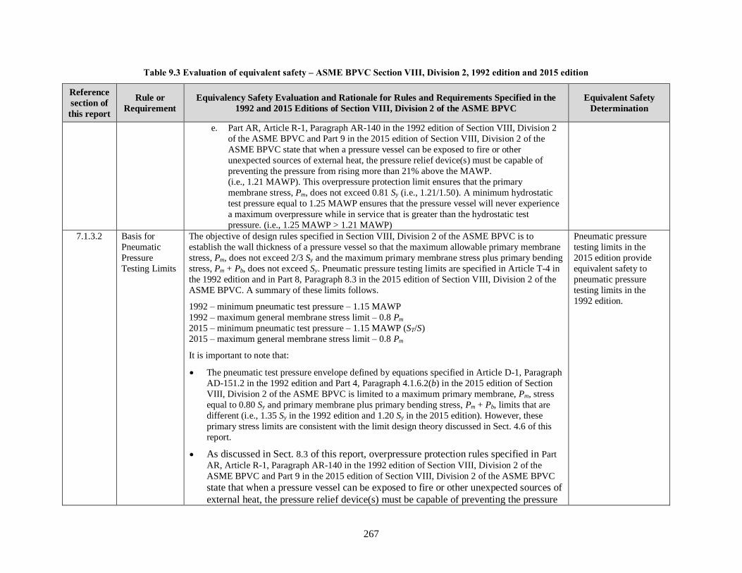
267
Table 9.3 Evaluation of equivalent safety – ASME BPVC Section VIII, Division 2, 1992 edition and 2015 edition
Reference
section of
this report
Rule or
Requirement
Equivalency Safety Evaluation and Rationale for Rules and Requirements Specified in the
1992 and 2015 Editions of Section VIII, Division 2 of the ASME BPVC
Equivalent Safety
Determination
e. Part AR, Article R-1, Paragraph AR-140 in the 1992 edition of Section VIII, Division 2
of the ASME BPVC and Part 9 in the 2015 edition of Section VIII, Division 2 of the
ASME BPVC state that when a pressure vessel can be exposed to fire or other
unexpected sources of external heat, the pressure relief device(s) must be capable of
preventing the pressure from rising more than 21% above the MAWP.
(i.e., 1.21 MAWP). This overpressure protection limit ensures that the primary
membrane stress, Pm, does not exceed 0.81 Sy (i.e., 1.21/1.50). A minimum hydrostatic
test pressure equal to 1.25 MAWP ensures that the pressure vessel will never experience
a maximum overpressure while in service that is greater than the hydrostatic test
pressure. (i.e., 1.25 MAWP > 1.21 MAWP)
7.1.3.2 Basis for
Pneumatic
Pressure
Testing Limits
The objective of design rules specified in Section VIII, Division 2 of the ASME BPVC is to
establish the wall thickness of a pressure vessel so that the maximum allowable primary membrane
stress, Pm, does not exceed 2/3 Sy and the maximum primary membrane stress plus primary bending
stress, Pm + Pb, does not exceed Sy. Pneumatic pressure testing limits are specified in Article T-4 in
the 1992 edition and in Part 8, Paragraph 8.3 in the 2015 edition of Section VIII, Division 2 of the
ASME BPVC. A summary of these limits follows.
1992 – minimum pneumatic test pressure – 1.15 MAWP
1992 – maximum general membrane stress limit – 0.8 Pm
2015 – minimum pneumatic test pressure – 1.15 MAWP (ST/S)
2015 – maximum general membrane stress limit – 0.8 Pm
It is important to note that:
• The pneumatic test pressure envelope defined by equations specified in Article D-1, Paragraph
AD-151.2 in the 1992 edition and Part 4, Paragraph 4.1.6.2(b) in the 2015 edition of Section
VIII, Division 2 of the ASME BPVC is limited to a maximum primary membrane, Pm, stress
equal to 0.80 Sy and primary membrane plus primary bending stress, Pm + Pb, limits that are
different (i.e., 1.35 Sy in the 1992 edition and 1.20 Sy in the 2015 edition). However, these
primary stress limits are consistent with the limit design theory discussed in Sect. 4.6 of this
report.
• As discussed in Sect. 8.3 of this report, overpressure protection rules specified in Part
AR, Article R-1, Paragraph AR-140 in the 1992 edition of Section VIII, Division 2 of the
ASME BPVC and Part 9 in the 2015 edition of Section VIII, Division 2 of the ASME BPVC
state that when a pressure vessel can be exposed to fire or other unexpected sources of
external heat, the pressure relief device(s) must be capable of preventing the pressure
Pneumatic pressure
testing limits in the
2015 edition provide
equivalent safety to
pneumatic pressure
testing limits in the
1992 edition.

268
Table 9.3 Evaluation of equivalent safety – ASME BPVC Section VIII, Division 2, 1992 edition and 2015 edition
Reference
section of
this report
Rule or
Requirement
Equivalency Safety Evaluation and Rationale for Rules and Requirements Specified in the
1992 and 2015 Editions of Section VIII, Division 2 of the ASME BPVC
Equivalent Safety
Determination
from rising more than 21% above the MAWP. (i.e., 1.21 MAWP). This overpressure
protection limit ensures that the primary membrane stress, Pm, does not exceed 0.81 Sy
(i.e., 1.21/1.50). A minimum pneumatic test pressure equal to 1.15 MAWP does not
ensure that the pressure vessel will never experience a maximum overpressure while in
service that is greater than the pneumatic test pressure. (i.e., 1.15 MAWP <
1.21 MAWP)
• Rules specified in the 1992 and 2015 editions of Section VIII, Division 2 of the ASME BPVC
do not specify a minimum or maximum pneumatic test pressure duration. The rules state that
many hours may be required.
Pressure vessels that are designed and fabricated in accordance with rules specified in the 2015
edition of Section VIII, Division 2 of the ASME BPVC and subjected to a pneumatic test pressure
equal to 1.15 MAWP are equivalent in safety to pressure vessels that are designed and fabricated in
accordance with rules specified in the 1992 edition of Section VIII, Division 2 of the ASME BPVC
and subjected to a pneumatic test pressure equal to 1.15 MAWP because:
a. The primary membrane stresses remain at or below the plastic collapse stress limit for
both pressure vessels, and ASME considers pressure vessels with primary membrane
stresses below the plastic collapse stress limit to be safe.
b. Subjecting a pressure vessel to a pressure test that produces primary membrane stresses
below the plastic collapse stress limit reduces the risk that the pressure vessel will exhibit
visible permanent distortion that could result in rejection of the pressure vessel by the
Inspector.
c. A pressure test (either hydrostatic or pneumatic) is conducted so the Authorized Inspector
can authorize application of the Certification Mark (Code stamp) based on verification of
leak tight integrity and confirm that the pressure vessel does not exhibit gross
deformations or anomalies that may indicate design errors, material deficiencies, or weld
defects.
d. A pressure test is performed after fabrication is completed primarily to verify the leak
tight integrity of the pressure vessel, but also to identify gross deformations or anomalies
that may indicate design errors, material deficiencies, or weld defects. Pressure test limits
are established to maintain primary membrane and bending stresses within the elastic
range so the pressure vessel does not permanently deform. Pressure tests are not intended
to verify the pressure-resisting (burst) capacity of a pressure vessel.
7.2 Alternative According to alternative pressure testing requirements specified in Part 8, Paragraph 8.4 in the An equivalent safety

269
Table 9.3 Evaluation of equivalent safety – ASME BPVC Section VIII, Division 2, 1992 edition and 2015 edition
Reference
section of
this report
Rule or
Requirement
Equivalency Safety Evaluation and Rationale for Rules and Requirements Specified in the
1992 and 2015 Editions of Section VIII, Division 2 of the ASME BPVC
Equivalent Safety
Determination
Pressure
Testing
2015 edition of Section VIII, Division 2 of the ASME BPVC, in cases where it is desirable to
pressure test a pressure vessel partially filled with liquid, the requirements of Paragraph 8.3 must
be met, except the pneumatic pressure applied above the liquid level must at no point result in a
total pressure that causes the general membrane stress to exceed 80% of the specified minimum
yield strength of the material at test temperature. Requirements for Leak Tightness Testing are
specified in Paragraph 8.4.2 as follows.
a) Leak tightness tests include a variety of methods of sufficient sensitivity to allow for the
detection of leaks in pressure elements, including, but not limited to the use of direct
pressure and vacuum bubble test methods, and various gas detection tests.
b) The selection of a leak tightness test to be employed should be based on the suitability of
the test for the particular pressure element being tested.
c) The metal temperature for leak tightness tests must be in accordance with
Paragraph 8.3.4.a. Additionally, the temperature must be maintained within the specified
range for the test equipment being used.
d) Leak tightness tests must be performed in accordance with Article 10 of Section V.
The 1992 editions of Section VIII, Division 2 of the ASME BPVC do not include alternative
pressure testing requirements.
evaluation of alternative
pressure testing
requirements in the
1992 and 2015 editions
is not possible.
7.3.3 Proof Testing Rules for proof testing are not provided in the 1992 and 2015 editions of Section VIII, Division 2
of the ASME BPVC.
An equivalent safety
evaluation of proof
testing requirements in
the 1992 and 2015
editions is not possible.
8.3.1 Overpressure
Protection by
Pressure Relief
Device
The rules for overpressure protection by pressure relief device specified in the 1992 and 2015
editions of Section VIII, Division 2 of the ASME BPVC are the same. In particular, the permissible
overpressure shall be limited to 21% of the design pressure (i.e., 1.21 MAWP) when the pressure
relief devices are discharging for conditions such as exposure to fire or other unexpected sources of
heat. Therefore, the rules for overpressure protection specified in the 2015 edition of Section VIII,
Division 2 of the ASME BPVC provide an equivalent level of safety compared to the rules for
overpressure protection specified in the 1992 edition of Section VIII, Division 2 of the ASME
BPVC.
The overpressure
protection requirements
by pressure relief
device in the 2015
edition provide
equivalent safety to the
overpressure protection
requirements by
pressure relief device in
the 1992 edition
8.3.2 Overpressure
Protection by
The 1992 edition of Section VIII, Division 2 does not permit overpressure protection by system
design.
An equivalent safety
evaluation of

270
Table 9.3 Evaluation of equivalent safety – ASME BPVC Section VIII, Division 2, 1992 edition and 2015 edition
Reference
section of
this report
Rule or
Requirement
Equivalency Safety Evaluation and Rationale for Rules and Requirements Specified in the
1992 and 2015 Editions of Section VIII, Division 2 of the ASME BPVC
Equivalent Safety
Determination
System Design Rules specified in Part 9, Paragraph 9.7 in the 2015 edition of Section VIII, Division 2 of the
ASME BPVC state that a pressure vessel may be provided with overpressure protection by system
design in lieu of a pressure relief device or pressure relief devices if all provisions of ASME
BPVC, Section VIII, Division 1, Paragraph UG-140 are satisfied.
overpressure protection
by system design in the
1992 and 2015 editions
is not possible.

271
10. POST-CONSTRUCTION CODES AND STANDARDS
Rules for design and fabrication of boilers and pressure vessels specified in the ASME BPVC do not
apply after the Manufacturer (ASME Certificate of Authorization Holder) applies the Certification Mark
(Code Stamp). Therefore, installation, inspection, maintenance, operation, repair, alterations, and
replacement activities performed after a boiler or pressure vessel is placed in service are beyond the scope
of the ASME BPVC. Codes and standards that establish rules for these activities are published by the:
• National Board of Boiler and Pressure Vessel Inspectors
• American Petroleum Institute
• American Society of Mechanical Engineers
10.1 NATIONAL BOARD OF BOILER AND PRESSURE VESSEL INSPECTORS
The National Board of Boiler and Pressure Vessel Inspectors was created in 1919 to promote greater
safety to life and property through uniformity in the construction, installation, repair, maintenance, and
inspection of pressure equipment. The National Board (NB) membership oversees adherence to laws,
rules, and regulations relating to boilers and pressure vessels. Its members are the chief boiler inspectors
representing most states and all provinces of North America, as well as many major cities in the United
States. The National Board’s functions include:
• Promoting safety and educating the public and government officials on the need for
manufacturing, maintenance, and repair standards.
• Offering comprehensive training programs in the form of continuing education for both
inspectors and pressure equipment professionals.
• Enabling a qualified inspection process by commissioning inspectors through a comprehensive
examination administered by the National Board.
• Setting worldwide industry standards for pressure relief devices and other appurtenances through
operation of an international pressure relief testing laboratory.
• Providing a repository of Manufacturers’ Data Reports through a registration process.
• Accrediting qualified repair and alteration companies, in-service Authorized Inspection Agencies,
and owner-user inspection organizations.
• Investigating pressure equipment accidents and issues involving code compliance.
• Developing installation, inspection, repair, and alteration standards (National Board Inspection
Code).
10.1.1 National Board Inspection Code
The National Board Inspection Code (NBIC) is an American National Standard (NB-23) [12] that has
been adopted by most states and cities, all Canadian provinces, and Federal regulatory agencies including
the DOT. It is the only standard recognized worldwide for in-service inspection repairs and alterations of
boilers and pressure vessels.
The NBIC was first published in 1946 as a guide for chief inspectors. It has become an internationally
recognized standard, adopted by most U.S. and Canadian jurisdictions. The NBIC provides standards for

272
the installation, inspection, and repair and/or alteration of boilers, pressure vessels, and pressure relief
devices. The NBIC is organized into three parts to coincide with specific post-construction activities
involving pressure-retaining items.
Part 1, Installation – Part 1 provides requirements and guidance to ensure all types of
pressure-retaining items are installed and function properly. Installation includes meeting
specific safety criteria for construction, materials, design, supports, safety devices,
operation, testing, and maintenance.
Part 2, Inspection – Part 2 provides information and guidance needed to perform and
document inspections for all types of pressure-retaining items. This Part includes
information on personnel safety, non-destructive examination, tests, failure mechanisms,
types of pressure equipment, fitness for service, risk-based assessments, and
performance-based standards.
Part 3, Repairs and Alterations – Part 3 provides information and guidance to perform,
verify, and document acceptable repairs or alterations to pressure-retaining items
regardless of code of construction. Alternative methods for examination, testing, heat
treatment, etc., are provided when the original code of construction requirements cannot
be met. Specific acceptable and proven repair methods are also provided.
It is important to note that:
• Part 1 of the NBIC provides a method for ensuring that pressure relief devices for boilers and
pressure vessels required by the applicable ASME BPVC section for overpressure protection are
installed prior to placing the boiler and pressure vessel in service.
• Part 2 of the NBIC provides a method for ensuring that pressure relief devices for boilers and
pressure vessels required by the applicable ASME BPVC section for overpressure protection are
periodically inspected and tested while the boiler or pressure vessel is in service. Part 2 of the
NBIC also provides a method for ensuring that boilers and pressure vessels are fit for service after
inspection reveals that the boiler or pressure vessel has experienced damage or degradation while
in service.
• Part 3 of the NBIC provides a method for ensuring that boilers and pressure vessels comply with
applicable ASME BPVC rules following repairs or alterations.
The NBIC is developed and maintained by a consensus committee (the NBIC Main Committee) and
updated every other year. The updates are presented on the National Board’s website for public review in
August of the year prior to the edition date. The NBIC is published as a new edition in July of odd
numbered years (2015, 2017, etc.).
10.1.2 National Board Registration
The National Board also registers pressure vessels that are constructed in accordance with the ASME
BPVC. Registration of an item with the National Board involves the manufacturer submitting an original
manufacturer’s data report to the National Board for permanent retention. Registration is more than
record retention; it represents the culmination of a three-step process, including the design and fabrication
of an item in accordance with the ASME BPVC, the inspection by a National Board commissioned
inspector, and the final documentation certifying compliance with the ASME BPVC.

273
Compliance with 49 CFR Part 193 requires registration of pressure vessels for LNG facilities that are
designed and fabricated in accordance with rules specified in Section VIII of the ASME BPVC through
the IBR process. Requirements for registration of pressure vessels for LNG facilities that are designed and
fabricated in accordance with rules specified in Section VIII of the ASME BPVC are specified in
Paragraph 10.3.4 in the 2001 edition of NFPA 59A.
10.2 AMERICAN PETROLEUM INSTITUTE
The API has adopted API 510 – Pressure Vessel Inspection Code: In-service Inspection, Rating, Repair,
and Alteration [18]. This standard covers in-service inspection, repair, alteration, and rerating activities
for pressure vessels and the pressure-relieving devices protecting these pressure vessels. It applies to all
hydrocarbon and chemical process vessels that have been placed in service unless specifically excluded
per 1.2.2; but it could also be applied to process vessels in other industries at owner/user discretion. This
includes pressure vessels constructed in accordance with an applicable Construction Code (e.g. ASME
BPVC).
Paragraph 1.1.1 in API 510 states:
“ASME BPVC and other recognized Construction Codes are written for new
construction; however, most of the technical requirements for design, welding, NDE, and
materials can be applied to the inspection, rerating, repair, and alteration of in-service pressure vessels. If for some reason an item that has been placed in service cannot follow
the Construction Code because of its new construction orientation, the requirements for design, material, fabrication, and inspection shall conform to API 510 rather than to the
Construction Code. If in-service vessels are covered by requirements in the Construction Code and API 510 or if there is a conflict between the two codes, the requirements of
API 510 shall take precedence.”
As an example of the intent of API 510, the phrase “applicable requirements of the Construction Code”
has been used in API 510 instead of the phrase “in accordance with the Construction Code.”
Paragraph 6.2.1.1 in API 510 further states that inspection activities during pressure vessel installation
must include verification that the pressure-relieving devices satisfy design requirements (correct device
and correct set pressure) and are properly installed.
Generally, API standards are reviewed and revised, reaffirmed, or withdrawn at least every five years. A
one-time extension of up to two years may be added to this review cycle. In May 2014, API published the
tenth edition of API 510. The ninth edition of API 510 has been adopted by PHMSA in 49 CFR Part 195
through the IBR process discussed in Sect. 1.1 of this report.
10.3 FITNESS-FOR SERVICE, API 579-1/ASME FFS-1
Rules for design, fabrication, inspection and testing of new boilers, pressure vessels, piping systems, and
storage tanks are provided in Construction Codes and standards published by API and ASME. These
codes and standards typically do not provide rules for evaluating equipment that degrades while in-service
and deficiencies caused by degradation or from original fabrication defects that are found during
subsequent post-construction inspections. Ensuring that boilers and pressure vessels remain fit for service
requires periodic inspections and fitness-for-service (FFS) assessments of pressure-retaining items that do
not conform to rules specified in the original code of construction. The NBIC (NB-23) and the API
pressure vessel inspection code (API 510) discussed in Sects. 10.1.1 and 10.2 of this report provide rules
for post-construction inspection of boilers and pressure vessels. Rules for assessing FFS are provided in
API 579-1/ASME FFS-1 published jointly by API and ASME.

274
Fitness-for-service (FFS) standard API 579-1/ASME FFS-1 [5] provides procedures for FFS assessments
and rerating of equipment designed and fabricated to the following codes:
• ASME BPVC, Section I
• ASME BPVC, Section VIII, Division 1
• ASME BPVC, Section VIII, Division 2
These FFS assessments are quantitative engineering evaluations that are performed to demonstrate the
structural integrity of an in-service component that may contain a flaw or damage, or that may be
operating under a specific condition that might cause a failure. This standard provides guidance for
conducting FFS assessments using methodologies specifically prepared for pressurized equipment. The
guidelines provided in this standard can be used to make run-repair-replace decisions to help determine if
components in pressurized equipment containing flaws that have been identified by inspection can
continue to operate safely for some period of time. These FFS assessments are currently recognized and
referenced by the NB-23 [12] and API 510 [18] as suitable means for evaluating the structural integrity of
boilers and pressure vessels where inspection has revealed degradation and flaws in the equipment.

275
11. EQUIVALENT SAFETY EVALUATION CONCLUSIONS AND OBSERVATIONS
Rules specified in 49 CFR Part 193 through IBR of the 2001 edition of NFPA 59A require:
1. design and fabrication of boilers and pressure vessels for LNG facilities in accordance with
applicable rules specified in Section I, Section VIII, Division 1, or Section VIII, Division 2 in the
1992 edition of the ASME BPVC (see NFPA 59A-2001, Paragraphs 3.4.2 and 12.1.2.4);
2. application of a Code stamp on boilers and pressure vessels for LNG facilities (see NFPA
59A-2001, Paragraph 3.4.2); and
3. registration of pressure vessels for LNG facilities with the National Board or other agency that
registers pressure vessels (see NFPA 59A-2001, Paragraphs 4.2.2.2 and 10.3.4).
Compliance with these rules by owners of new LNG facilities and existing LNG facilities that require
modification is not practical because the ASME BPVC edition used for construction of a boiler or
pressure vessel must be either the edition that is mandatory on the date the boiler or pressure vessel is
contracted for by the manufacturer, or a published edition issued by ASME prior to the contract date,
which is not yet mandatory. Even though construction of a boiler or a pressure vessel to an edition of the
ASME BPVC issued prior to the 2015 edition may be feasible, the Authorized Inspector will not issue
approval to the manufacturer to apply the official Certification Mark (Code Stamp) on the nameplate.
Consequently, compliance with rules specified in the 2001 edition of NFPA 59A to design and construct
boilers and pressure vessels for LNG facilities in accordance with applicable rules in the 1992 edition of
the ASME BPVC is not possible.
11.1 EQUIVALENT SAFETY EVALUATION CONCLUSIONS
Although rules specified in the 2001 edition of NFPA 59A are mandatory, Sect. 1.2 of the 2001 edition of
NFPA 59A includes an equivalency provision that permits use of systems, methods, or devices of
equivalent or superior quality, strength, fire resistance, effectiveness, durability, and safety over those
prescribed by this standard. Compliance with this equivalency provision requires submission of technical
documentation to the AHJ to demonstrate equivalency.
This report presents the required technical documentation needed to demonstrate equivalency because it
provides rationale and justification for concluding that the rules and requirements specified in Section I,
Section VIII, Division 1, and Section VIII, Division 2 in the 2015 edition of the ASME BPVC are
equivalent in safety to the corresponding rules and requirements specified in Section I, Section VIII,
Division 1, and Section VIII, Division 2 in the 1992 edition of the ASME BPVC.
Acceptance of this report by the AHJ as the basis for safety equivalency in a manner consistent with the
equivalency provisions in NFPA 59A-2001 avoids the potential consequences to owners of new LNG
facilities and existing LNG facilities that boilers and pressure vessels for these facilities cannot be Code
stamped. It also eliminates the need for an owner of an LNG facility to submit a special permit
application to PHMSA in accordance with requirements specified in §190.341 requesting PHMSA to
waive compliance with the particular Federal pipeline safety regulations in 49 CFR Part 193 that govern
construction of boilers and pressure vessels for LNG facilities.
It is also important to note that this report does not provide the technical documentation required to
demonstrate equivalent safety for future editions of Section I, Section VIII, Division 1, and Section VIII, Division 2 of the ASME BPVC that will be issued by ASME beginning with the 2017 edition.

276
Consequently, equivalency reports similar to this one will need to be prepared for future editions of the
ASME BPVC to comply with the equivalency provisions in the 2001 edition of NFPA 59A.
11.2 OBSERVATIONS AND CONSIDERATIONS FOR FUTURE REGULATION OF LNG
FACILITIES
Avoiding the need for similar equivalency reports for future editions of the ASME BPVC could be
possible by modifying regulations in 49 CFR Part 193. Possible modifications to regulations in 49 CFR
Part 193 could include requiring boilers and pressure vessels for LNG facilities with MAWPs greater than
15 psig to have an ASME Certification Mark (Code stamp) applicable to the construction rules in effect at
the time the boiler or pressure vessel is constructed. Precedent for this type of requirement is provided in
PHMSA’s Hazardous Materials Regulations under 49 CFR 180.413(a)(1) as follows.
Except as otherwise provided in this section, each repair, modification, stretching, or
rebarrelling of a specification cargo tank must be performed by a repair facility holding
a valid National Board Certificate of Authorization for use of the National Board “R”
stamp and must be made in accordance with the edition of the National Board Inspection
Code in effect at the time the work is performed.
Additional observations and considerations for future modifications to regulations in 49 CFR Part 193 to
further enhance the safety of boilers and pressure vessels in LNG facilities follow.
11.2.1 Verification of Overpressure Protection System Installation, Inspection, and Testing
Verification that boilers and pressure vessels for LNG facilities are adequately protected from effects of
overpressure while in service is currently not required by 49 CFR Part 193. Rules for ensuring that
pressure relief devices are properly installed before a boiler or pressure vessel is placed in service and
periodically inspected and tested while in service are provided in the NB-23 as discussed in Sect. 10.1.1
and in API 510 as discussed in Sect. 10.2 of this report. Compliance with NB-23 or API 510 rules for
installation, inspection, and testing of a pressure relief device is not required by rules specified in the
2001 edition of NFPA 59A or 49 CFR Part 193, but a change in 49 CFR Part 193 that requires such
compliance would ensure needed verification of overpressure protection system installation, inspection,
and testing. Background information to support and justify the need for verification of overpressure
protection system installation, inspection, and testing follows.
Adequate overpressure protection for boilers and pressure vessels in LNG facilities is a risk reduction
measure that is mandated by rules in NFPA 59A and the ASME BPVC. Rules for pressure relief device
capacity are provided in Paragraph 4.7.3.1 in the 2001 edition of NFPA 59A which states that the capacity
of pressure relief devices for stationary LNG containers must be based on exposure to fire. Equations for
computing the required pressure relieving capacity for fire exposure are provided in Paragraph 4.7.3.4.
Complementary rules in the ASME BPVC that govern this design basis condition mandate an
overpressure protection limit equal to 1.20 MAWP for boilers constructed in accordance with Section I
requirements and an overpressure protection limit equal to 1.21 MAWP for pressure vessels exposure to
fire constructed in accordance with Section VIII, Division 1 and Section VIII, Division 2 requirements.
Although pressure relief devices are critical to boiler and pressure vessel safety, the ASME BPVC does
not include rules for installation of these devices on a boiler or pressure vessel before it is placed in
service because these post-construction activities are considered beyond the scope of the ASME BPVC.
The ASME BPVC assigns owners and users responsibility for designing and installing pressure relief
systems and for ensuring that the inlet and outlet piping is designed such that the performance and
operating characteristics of the pressure relief system is not adversely affected.

277
11.2.2 Fitness-for-Service Evaluations
Rules for FFS assessment are specified in API 579-1/ASME FFS-1 as discussed in Sect. 10.3 of this
report. This joint API and ASME standard is currently recognized and referenced by the NBIC and
API 510 as suitable means for evaluating the structural integrity of boilers and pressure vessels where
inspection has revealed degradation and flaws in the equipment. However, compliance with rules for FFS
assessments specified in API 579-1/ASME FFS-1 are not required by the 2001 edition of NFPA 59A or
49 CFR Part 193. A change in 49 CFR Part 193 that requires compliance with rules for FFS assessments
specified in API 579-1/ASME FFS-1 would provide a means for ensuring an acceptable level of safety for
boilers and pressure vessels in LNG facilities while in service.
11.2.3 Enhancements to Pneumatic Pressure Testing Requirements
Assurance that pressure vessels for LNG facilities are subjected to a pneumatic test pressure that equals or
exceeds the maximum pressure that the pressure vessel could experience in service when exposed to fire
is not provided by rules specified in either the 1992 or 2015 editions of Section VIII, Division 1 and
Section VIII, Division 2 of the ASME BPVC. An additional regulatory requirement to subject pressure
vessels that are pneumatically tested to a pressure equal to or greater than the overpressure protection
limit of 1.21 MAWP would provide a means for ensuring that the pressure vessel will never experience a
maximum overpressure while in service that is greater than the pneumatic test pressure. Background
information to support and justify the need for enhancing pneumatic pressure testing requirements
specified in Section VIII, Division 1 and Section VIII, Division 2 specifically for LNG facility
applications follows.
Section VIII, Division 1 – Pneumatic Pressure Test
As discussed in Sect. 7.1.2.1 of this report, subjecting a pressure vessel to a pneumatic test pressure that
equals or exceeds 1.1 MAWP times the LSR for the materials of which the pressure vessel is constructed
ensures compliance with pneumatic pressure test requirements specified in Paragraph UG-100 in the 2015
editions of Section VIII, Division 1 of the ASME BPVC, but does not ensure that the pressure vessel will
never experience a maximum overpressure while in service due to fire exposure that is greater than the
pneumatic test pressure (i.e., 1.1 MAWP < 1.21 MAWP). Ensuring that a pressure vessel is subjected to a
test pressure that equals or exceeds the maximum overpressure that the pressure vessel will ever
experience in service due to fire exposure could be considered a risk reduction measure for the fire
exposure hazard.
An additional regulatory requirement to subject pressure vessels in LNG facilities that are constructed in
accordance with requirements specified in the 2015 editions of Section VIII, Division 1 of the ASME
BPVC and subjected to a pneumatic pressure test to a test pressure equal to or greater than 1.21 MAWP:
1. ensures compliance with rules for pneumatic pressure testing specified in Paragraph UG-100 in
the 2015 editions of Section VIII, Division 1 of the ASME BPVC; and
2. ensures that the pressure vessel will never experience a maximum overpressure while in service
due to fire exposure that is greater than the pneumatic test pressure (i.e., 1.21 MAWP >
1.1 MAWP).
Compliance with rules specified in Paragraph UG-100 in the 2015 editions of Section VIII, Division 1 of
the ASME BPVC is necessary for the Authorized Inspector to approve application of the official
Certification Mark (Code Stamp) on the nameplate by the manufacturer.

278
Section VIII, Division 2 – Pneumatic Pressure Test
As discussed in Sect. 7.1.3.2 of this report, subjecting a pressure vessel to a pneumatic test pressure that
equals or exceeds 1.15 MAWP (ST / S) ensures compliance with pressure test requirements specified in
Part 8, Paragraph 8.3.1 in the 2015 editions of Section VIII, Division 2 of the ASME BPVC, but does not
ensure that the pressure vessel will never experience a maximum overpressure while in service due to fire
exposure that is greater than the pneumatic test pressure (i.e., 1.15 MAWP (ST / S) < 1.21 MAWP).
Ensuring that a pressure vessel is subjected to a test pressure that equals or exceeds the maximum
overpressure that the pressure vessel will ever experience in service due to fire exposure could be
considered a risk reduction measure for the fire exposure hazard.
An additional regulatory requirement to subject pressure vessels in LNG facilities that are constructed in
accordance with requirements specified in the 2015 editions of Section VIII, Division 2 of the ASME
BPVC and subjected to a pneumatic pressure test to a test pressure equal to or greater than 1.21 MAWP:
1. ensures compliance with rule specified in Part 8, Paragraph 8.3.1 in the 2015 editions of
Section VIII, Division 2 of the ASME BPVC;
2. ensures that the pressure vessel will never experience maximum overpressure while in service
due to fire exposure that is greater than the pneumatic test pressure (i.e., 1.21 MAWP > 1.15
MAWP (ST / S)); but
3. does not ensure compliance with the stress limits specified in Paragraph 4.1.6.2(b) because the
primary membrane stress, Pm, exceeds the 0.80 Sy pneumatic pressure test stress limit for pressure
vessels manufactured using materials with a maximum allowable design stress equal to 0.67 Sy
(i.e., 1.21 × 0.67 Sy = 0.81 Sy).
Compliance with rules specified in Part 8, Paragraph 8.3.1 in the 2015 editions of Section VIII, Division 2
of the ASME BPVC is necessary for the Authorized Inspector to approve application of the official
Certification Mark (Code Stamp) on the nameplate by the manufacturer.
Ensuring that the primary membrane stress, Pm, for a pressure vessel that is constructed in accordance
with rules specified in the 2015 edition of Section VIII, Division 2 of the ASME BPVC and subjected to a
pneumatic test pressure equal to or greater than 1.21 MAWP does not exceed the 0.80 Sy stress limit
requires limiting the maximum allowable design stress to 0.65 Sy for pressure vessels constructed using
those materials with a maximum allowable design stress between 0.65 Sy and 0.67 Sy (i.e., 1.21 × 0.80 ×
0.67 Sy = 0.65 Sy). It is important to note that a primary membrane stress limit equal to 0.65 Sy represents
only a 3% reduction in the maximum permitted primary membrane stress (i.e., (0.67 Sy / 0.65 Sy) – 100
= 3%).
As an alternative regulatory requirement, the overpressure protection limit for fire exposure specified in
the 2015 editions of Section VIII, Division 2 of the ASME BPVC in could be reduced from 1.21 MAWP
to 1.20 MAWP. This reduction in the overpressure protection limit would ensure that all pressure vessels
constructed in accordance with rules specified in the 2015 edition of Section VIII, Division 2 of the
ASME BPVC and subjected to a pneumatic pressure test do not exceed the primary membrane stress, Pm,
limit of 0.80 Sy during the pneumatic pressure test (i.e., 1.20 × 0.67 Sy = 0.80 Sy).

279
12. REFERENCES
[1] US Department of Transportation, Pipeline and Hazardous Material Safety Administration letter
from Alan K. Mayberry to Mr. Norman G. Holmes, President, Elba Liquefaction Company, LLC,
RE: April 30, 2015 Equivalency Letter for Elba Liquefaction Project.
[2] Osage, D.A. and Sowinski, J.C., ASME Section VIII – Division 2 Criteria and Commentary, ASME
PTB-1-2014, American Society of Mechanical Engineers, New York, NY, 2014.
[3] American Petroleum Institute (API), 2011, Damage Mechanisms Affecting Fixed Equipment in the
Refining Industry, API RP 571, Second Edition, American Petroleum Institute, Washington, DC.
[4] Upitis, E. and Mokhtarian, K., Evaluation of Design Margins for Section VIII, Div. 1 and 2 of the ASME Boiler and Pressure Vessel Code, WRC Bulletin 435, Welding Research Council,
September 1998.
[5] API 579-1/ASME FFS-1, Fitness-for-Service, American Petroleum Institute and American Society
of Mechanical Engineers, American Petroleum Institute, Washington, DC, June, 2016.
[6] Upitis, E. and Mokhtarian, K., Evaluation of Operating Margins for In-Service Pressure Equipment, WRC Bulletin 447, Welding Research Council, December 1999.
[7] Rodabaugh, E. C., A Review of Area Replacement Rules for Pipe Connections in Pressure Vessels and Piping, WRC Bulletin 335, The Welding Research Council, Inc., New York, N.Y., August
1988.
[8] MacKay, J.R. and Pillow, J.T., Power Boilers – A Guide to Section I of the ASME Boiler and Pressure Vessel Code – Second Edition, ASME Pres, New York, 2011.
[9] Jinyang Zheng, Abin Guo, Cunjian Miao, Ping Xu, Jian Yang, Jianjun Ye, Li Ma, Linlin Wu,
Guoyi Yang, Cold Stretching of Cryogenic Pressure Vessels From Austenitic Stainless Steels,
ASME Pressure Vessels and Piping Conference, Baltimore, Maryland, PVP2011-57331, 2011.
[10] ASME CA-1-2014, Conformity Assessment Requirements, American Society of Mechanical
Engineers, New York, January 30, 2015.
[11] Bernstein, M.D. and Yoder, L. W., Power Boilers – A Guide to Section I of the ASME Boiler and Pressure Vessel Code, ASME Press, New York, 1998.
[12] NB-23, National Board Inspection Code, 2015 Edition, National Board of Boiler and Pressure
Vessel Inspectors, Columbus, Ohio, 2015.
[13] API Standard 521, Pressure-relieving and Depressuring Systems, Sixth Edition, American
Petroleum Institute, Washington, D.C, January 2014.
[14] Karcher, G. G., Nazario, F.N., Feigel, R.E., Overpressure Protection for Pressure Vessels by
System Design and ASME Code Case 2211, ASME Pressure Vessel and Piping Conference,
Orlando, Florida, PVP-Vol. 353, 1997.
[15] Sims, J.R., Yeich, W.G., Guidance on the Application of Code Case 2211 – Overpressure
Protection by Systems Design, WRC Bulletin 498, The Welding Research Council, Inc., New York,
N.Y., January 2005.
[16] API Standard 520, Sizing, Selection, and Installation of Pressure-Relieving Devices; Part I-Sizing
and Selection, Ninth Edition, American Petroleum Institute, Washington, D.C, July 2014.
[17] API Standard 520, Sizing, Selection, and Installation of Pressure-Relieving Devices;
Part II-Installation, Sixth Edition, American Petroleum Institute, Washington, D.C, March 2015.

280
[18] API 510, Pressure Vessel Inspection Code: In-service Inspection, Rating, Repair, and Alteration,
Tenth Edition, American Petroleum Institute, Washington, DC, May 2014.

A - 1
APPENDIX A:
Historical Perspective: Design Stresses
The following text is published in a book by Martin D. Bernstein and Lloyd W. Yoder titled: Power
Boilers – A Guide to Section I of the ASME Boiler and Pressure Vessel Code [11]. It presents a historical
perspective on the evolution of design stresses used in the ASME BPVC through 1998.
The so-called safety factors, or design margins, now used in establishing allowable stresses with respect to the various failure modes, such as yielding or creep rupture, have
evolved over the life of the Code. Before World War II the factor used on tensile strength
was 5. It was changed to 4 in order to save steel during the war. Starting in the late 1970s, the factor on yield strength was changed from 5/8 to 2/3, a change that was
carried out over quits a long period. The factor on the 100,000-hour creep rupture strength was formerly 0.6. Around 1970, this was changed to the current factor of 0.67.
These reductions in design margins, or safety factors, were adopted over time as
improvements in technology permitted. These improvements included the development of
newer and more reliable methods of analysis, design, and nondestructive examination.
The imposition of quality control systems in 1973 and a record of long satisfactory experience also helped justify reducing some of the design conservatism.
One of the design factors the ASME uses in setting allowable stress not used by most other countries is the factor of approximately 4 on ultimate tensile strength. It happens
that this design factor is a significant one, because it controls the allowable stress for many ferritic (carbon and low alloy) steels below the creep range. This has put users of
the ASME Code at a disadvantage in world markets where competing designs are able to utilize higher allowable stresses based just on yield strength. This situation has caused
the Code committees to reconsider the usefulness and necessity of using tensile strength
as one of the criteria for setting allowable stress. In 1996 the Pressure Vessel Research Council (PVRC), a research group closely associated with the Code committees, was
asked to study whether the design factor on tensile strength could safely be reduced. The PVRC prepared a report reviewing all the technological improvements in boiler and
pressure vessel construction that have occurred since the early 1940s, which was when
the design factor on tensile strength was last reduced, from 5 to 4. On the basis of that report's favorable recommendation, Subcommittee VIII has decided, as an initial step, to
change the factor on tensile strength from about 4 to about 3.5 for pressure vessels
constructed under the provisions of Section VIII, Division 1.
Subcommittee I decided to make the same change for Section I and in 1997 established a task group to investigate the potential effects of such a change and how best to implement
it. That task group concluded that Section I could safely join Section VIII in increasing its allowable stresses. The actual mechanics of setting and publishing new allowable
stresses took Subcommittee II some time, because it was quite a task. In order to expedite
the process while Subcommittee II completed its work, new stresses for a limited group of materials were introduced by means of Code cases, one for Section I and two for
Section VIII, since Code cases can be issued far more quickly than Code Addenda. The Section I case is Case 2284, Alternative Maximum Allowable Stresses for Section I
Construction Based on a Factor of 3.5 on Tensile Strength. The three cases were
approved for use in mid-1998, and their higher stress values are expected to be
incorporated into Section II, Part D in the near future, perhaps in the 1999 Addenda.
One problem with the new cases is that some jurisdictions were reluctant to accept them,

A - 2
or had no ready mechanism which would permit their prompt adoption. Thus widespread use of the higher stresses may have to await their incorporation into Section II, Part D.
In the future, it is possible that the design factor on tensile strength may be reduced
further or eliminated altogether, depending on the results of these first steps. Note that
the change in design factor applied to tensile strength from 1/4 to 1/3.5 is a 14% change. However few allowable stresses will change that much, because the higher allowable
stress will probably be determined and controlled by the factor applied to yield strength, rather than tensile strength. Also note that the higher stresses will be applicable below
the creep range only.
The above-described methods of setting maximum allowable (design) stress values have
been used by the Code committees since the mid-1950s. During that time, new data have been obtained and analyzed to revise design stresses as appropriate, based both on new
laboratory tests and reported experience from equipment in service. There have been
times when the analysis of new data has resulted in a significant lowering of the
allowable stresses at elevated temperature. In all but a few instances, however, the fine
safety record of equipment built to the ASME Code has demonstrated the validity of the material data evaluation, design criteria, and design methods used.