
ASA(ALT) Common Operating Environment Implementation ...
255
ASA(ALT) Common Operating Environment Implementation Plan Core November 2011 v3.0 Draft Distribution Statement A Approved for public release; distribution unlimited
-
Upload
khangminh22 -
Category
Documents
-
view
1 -
download
0
Transcript of ASA(ALT) Common Operating Environment Implementation ...

ASA(ALT)
Common Operating Environment
Implementation Plan
Core
November 2011
v3.0 Draft
Distribution Statement A
Approved for public release; distribution unlimited

v3.0 Draft Page ii
REPORT DOCUMENTATION PAGE Form Approved
OMB No. 0704-0188 Public reporting burden for this collection of information is estimated to average 1 hour per response, including the time for reviewing instructions, searching existing data sources, gathering and maintaining the data needed, and completing and reviewing this collection of information. Send comments regarding this burden estimate or any other aspect of this collection of information, including suggestions for reducing this burden to Department of Defense, Washington Headquarters Services, Directorate for Information Operations and Reports (0704-0188), 1215 Jefferson Davis Highway, Suite 1204, Arlington, VA 22202-4302. Respondents should be aware that notwithstanding any other provision of law, no person shall be subject to any penalty for failing to comply with a collection of information if it does not display a currently valid OMB control number. PLEASE DO NOT RETURN YOUR FORM TO THE ABOVE ADDRESS.
1. REPORT DATE (DD-MM-YYYY)
11-Nov
2. REPORT TYPE
Technical
3. DATES COVERED (From - To)
Oct 2010 – Nov 2011 4. TITLE AND SUBTITLE
ASA(ALT) Common Operating Environment (COE) Implementation Plan, Core
5a. CONTRACT NUMBER
5b. GRANT NUMBER
5c. PROGRAM ELEMENT NUMBER
6. AUTHOR(S)
Farah-Stapleton, Monica; Minor, Phillip; Thorsen, Christine; Perna, Timothy;
Hunter; Aaron;
5d. PROJECT NUMBER
Jones, Elizabeth; Albert, Cecelia; Rosemergy, Steve; Gregg, Samuel; Poole,
David; Feinerman, Laura; Caddell, Jeffery; Newsome, Thomas; Burdeshaw,
Margaret
5e. TASK NUMBER
5f. WORK UNIT NUMBER
7. PERFORMING ORGANIZATION NAME(S) AND ADDRESS(ES)
ASA(ALT) Office of the Chief Systems Engineer, AND ADDRESS(ES)
8. PERFORMING ORGANIZATION REPORT NUMBER
RDECOM CERDEC, MITRE, Software Engineering Institute
9. SPONSORING / MONITORING AGENCY NAME(S) AND ADDRESS(ES) 10. SPONSOR/MONITOR’S ACRONYM(S)
ASA(ALT)
11. SPONSOR/MONITOR’S REPORT
NUMBER(S)
12. DISTRIBUTION / AVAILABILITY STATEMENT
Distribution Statement A: Approved for public release; distribution is unlimited.
13. SUPPLEMENTARY NOTES
14. ABSTRACT
Over the past 8 months ASA (ALT) in conjunction with PEOs, PMs, CERDEC, MITRE, and Carnegie Melon‟s Software Engineering Institute have developed the COE implementation plan that provides detailed guidance on how Army programs should transition to the COE. The ASA(ALT) COE Implementation activity will provide direction to Government and industry partners in order to standardize end-user environments and software development kits, establish streamlined enterprise software processes that rely on common pre-certified reusable software components and develop deployment strategies that give users direct access to new capability.
15. SUBJECT TERMS Common Operating Environment, COE, Computing Environment, Software, Architecture, Infrastructure, Governance. 16. SECURITY CLASSIFICATION OF:
17. LIMITATION OF ABSTRACT
18. NUMBER OF PAGES
19a. NAME OF RESPONSIBLE PERSON
a. REPORT
b. ABSTRACT
c. THIS PAGE
19b. TELEPHONE NUMBER (include area
code
Standard Form 298 (Rev. 8-98) Prescribed by ANSI Std. Z39.18

v3.0 Draft Page iii
This Page Intentionally Left Blank

v3.0 Draft Page iv
Executive Summary
On 28 December 2009, the Vice Chief of Staff of the Army (VCSA) directed Chief Information
Office (CIO)/G-6 to develop "as is" and "end state" network architectures to set the vision for
the evolution of network procurements and enhancements. The Common Operating
Environment (COE) Architecture Appendix C to Guidance for "End State" Army Enterprise
Network Architecture, dated 1 Oct 2010, was written in response to that direction.
Properly executed, implementation of the COE Architecture Appendix C will enable the Army
to develop, test, certify and deploy software capabilities rapidly without introduction of
harmful or unexpected behavior.
Therefore, the Assistant Secretary of the Army Acquisition, Logistics and Technology,
ASA(ALT) has developed the ASA(ALT) COE Implementation Plan, which includes the next
level of technical and programmatic specificity, in order to be positioned for execution. The
COE Implementation Plan is comprised of the Core document (which includes the Overview,
Governance and the Technical Reference Model) and the Appendices document (which
includes the Computing Environment Execution Plans and key operations). The
Implementation Plan addresses the implementation strategy, time lines, effective dates and
key milestones in order to move Army systems to the COE, and inform Program Objective
Memorandum (POM) 14-18 investment decisions. It highlights critical enablers to COE
success including the establishment of a software Ecosystem and enterprise business
strategies that are necessary for the Army to leverage industry best practices and rapidly
develop secure and interoperable applications that satisfy operational requirements. The Plan
also notes that we are not starting from scratch, but are leveraging a rich body of Army and
Department of Defense (DoD) work and systems that are already on the path to implementing
the COE. COE Implementation and the activities supporting it are expected to stimulate
innovation while enabling enhancements to the user experience.
The CIO/G-6 and ASA(ALT) Army Acquisition Executive (AAE) are committed to setting the
conditions for the Army to produce high-quality applications rapidly, while reducing the
complexities embedded in the design, development, testing and deployment cycle. CIO/G6
Appendix C and the ASA(ALT) COE Implementation Plan will provide direction to Government
and industry partners in order to standardize end-user environments and software
development kits, establish streamlined enterprise software processes that rely on common
pre-certified reusable software components and develop deployment strategies that give users
direct access to new capability. Both Appendix C and the COE Implementation Plan are
considered to be living instruments and will continue to evolve in a coordinated manner in
order to keep up with the rapid changes in technology.

v3.0 Draft Page v
This Page Intentionally Left Blank

v3.0 Draft Page vi
VERSION HISTORY
Version # Implemented
By
Revision
Date
Approved
By
Approval
Date
Reason
2.0 ASA(ALT) SoSE 30 JUN 2011 Mr. Edwards Next Release
2.1 ASA(ALT) SoSE 25 July 2011 Mr. Edwards Updated:
- Geospatial
- RT/SC/E CE
2.2 ASA(ALT) OCSE 4 Oct 2011 Mr. Edwards Next Release
3.0 ASA(ALT) OCSE 4 Nov 2011 Mr. Edwards Updated:
- Governance
- Introduction

v3.0 Draft Page vii
This Page Intentionally Left Blank

v3.0 Draft Page viii
Table of Contents
1 INTRODUCTION ................................................................................................................................................. 1-1
1.1 BACKGROUND .............................................................................................................................................................1-1
1.2 PROBLEM STATEMENT AND AGENTS FOR CHANGE ..............................................................................................................1-2
1.3 COE OBJECTIVES .........................................................................................................................................................1-3
1.3.1 COE Goals ............................................................................................................................................................1-4
1.3.2 Principles, Tenets, and Value Proposition ...........................................................................................................1-6
1.3.3 COE Challenges .................................................................................................................................................1-10
1.4 COE SCOPE: VISION TO EXECUTION ..............................................................................................................................1-10
1.4.1 Vision (CIO/G6 Guidance)..................................................................................................................................1-10
1.4.2 Implementation Approach ................................................................................................................................1-11
1.4.3 Implementation Strategy ..................................................................................................................................1-13
1.4.4 Charters and Execution Plans ............................................................................................................................1-22
1.4.5 Critical Enablers ................................................................................................................................................1-23
1.4.6 EcoSystem .........................................................................................................................................................1-41
1.5 EVOLVING THE BUSINESS MODEL ..................................................................................................................................1-42
2 GOVERNANCE .......................................................................................................................................................... 2-1
2.1 OVERVIEW ..................................................................................................................................................................2-1
2.1.1 Purpose ...............................................................................................................................................................2-1
2.1.2 Organizational Overview ....................................................................................................................................2-1
2.1.3 Process Overview ................................................................................................................................................2-3
2.1.4 The COE Proposal ................................................................................................................................................2-3
2.2 ORGANIZATIONAL STRUCTURE ........................................................................................................................................2-4
2.2.1 Computing Environment Working Groups ..........................................................................................................2-4
2.2.2 Technical Advisory Board ....................................................................................................................................2-7
2.2.3 SoS GOSC ...........................................................................................................................................................2-11
2.2.4 Senior Leader Forums ........................................................................................................................................2-12
2.3 PROCESS ...................................................................................................................................................................2-13
2.3.1 Baseline Cycle ....................................................................................................................................................2-13
2.3.2 Immediate Action Cycle.....................................................................................................................................2-14
2.3.3 COEP Approval Process .....................................................................................................................................2-14
2.3.4 Waiver Process ..................................................................................................................................................2-16
2.3.5 Process Examples ..............................................................................................................................................2-17
2.4 ARTIFACTS ................................................................................................................................................................2-19
2.4.1 Charters .............................................................................................................................................................2-19
2.4.2 COE Proposals ...................................................................................................................................................2-19
2.4.3 As-is Baselines ...................................................................................................................................................2-20

v3.0 Draft Page ix
2.4.4 Technology Roadmaps ......................................................................................................................................2-20
2.4.5 Acquisition Strategies........................................................................................................................................2-21
2.4.6 COE Baseline .....................................................................................................................................................2-21
2.4.7 COE Implementation Plan .................................................................................................................................2-21
2.4.8 CEWG Execution Plan ........................................................................................................................................2-21
3 REFERENCE ARCHITECTURE FRAMEWORK ................................................................................................................ 3-1
3.1 OVERVIEW ..................................................................................................................................................................3-1
3.2 COE TECHNICAL REFERENCE MODEL ...............................................................................................................................3-3
3.3 COE TRM REQUIREMENTS AND CONSTRAINTS ..................................................................................................................3-9
3.3.1 COE Information Assurance Requirements .........................................................................................................3-9
3.3.2 LandWarNet Network Operations Requirements ...............................................................................................3-9
3.3.3 Army Geospatial Enterprise Requirements .......................................................................................................3-10
3.3.4 COE Data Architecture Requirements ...............................................................................................................3-11
3.3.5 COE Proposals ...................................................................................................................................................3-13
3.4 RELATING THE COE TRM TO DISA JC2 .........................................................................................................................3-14
3.5 TRM IN APPLICATION .................................................................................................................................................3-15
4 COST/INVESTMENT STRATEGY ................................................................................................................................. 4-1
4.1 INITIAL INVESTMENTS ....................................................................................................................................................4-3
4.2 COST METHODOLOGY ...................................................................................................................................................4-4
4.2.1 As-Is State ...........................................................................................................................................................4-4
4.2.2 To-Be State ..........................................................................................................................................................4-4
4.3 COST DRIVERS .............................................................................................................................................................4-5
4.4 SCOPE OF ESTIMATES ....................................................................................................................................................4-5
4.4.1 Lifecycle Cost .......................................................................................................................................................4-5
4.4.2 “Enterprising” of Services ....................................................................................................................................4-5
4.4.3 Total Cost of Ownership ......................................................................................................................................4-5
4.5 COST ESTIMATION PROCESS ...........................................................................................................................................4-6
4.5.1 Overview .............................................................................................................................................................4-7
4.5.2 COE Definition for Each Estimate ........................................................................................................................4-7
4.5.3 Preparation .........................................................................................................................................................4-7
4.5.4 Ground Rules .......................................................................................................................................................4-8
4.5.5 Assumptions ........................................................................................................................................................4-8
4.5.6 Data Collection & Analysis ..................................................................................................................................4-8
4.5.7 CES/WBS .............................................................................................................................................................4-9
4.5.8 Sensitivity Analysis ..............................................................................................................................................4-9
4.5.9 Cost-Risk Assessment ........................................................................................................................................4-10
4.5.10 Cost Process Summary ..................................................................................................................................4-10
4.6 OVERALL COE COST ESTIMATE .....................................................................................................................................4-12
4.7 CHALLENGES IN REALIZABLE SAVINGS / AVOIDANCE ..........................................................................................................4-12
4.8 LESSONS LEARNED FROM PREVIOUS INITIATIVES ...............................................................................................................4-12
4.9 COST ESTIMATE TEMPLATES .........................................................................................................................................4-12

v3.0 Draft Page x
5 USER REQUIREMENTS .............................................................................................................................................. 5-1
5.1 ORIGIN OF COE REQUIREMENTS .....................................................................................................................................5-1
5.2 CURRENT REQUIREMENTS TRACEABILITY ...........................................................................................................................5-2
5.3 A NEW APPROACH TO DELIVERING INFORMATION CAPABILITIES ............................................................................................5-5
5.4 USER REQUIREMENTS RELATION TO TECHNICAL REQUIREMENTS ..........................................................................................5-6
5.4.1 COE Users ............................................................................................................................................................5-6
5.4.2 Source of COE Related Requirements..................................................................................................................5-8
5.4.3 User Requirements and the Acquisition Process .................................................................................................5-9
5.5 ASSESSMENT AND ALIGNMENT OF TECHNICAL REQUIREMENTS AND IMPLEMENTATIONS ............................................................5-9
5.5.1 Collapse and Reconciliation of Standards .........................................................................................................5-11
5.5.2 Convergence of Mission Command Capability Requirements ...........................................................................5-11
5.6 SUMMARY ................................................................................................................................................................5-12
6 IMPLEMENTATION, INTEGRATION, VERIFICATION, AND TEST .................................................................................. 6-1
6.1 OVERVIEW ..................................................................................................................................................................6-1
6.2 SECTION ORGANIZATION ...............................................................................................................................................6-3
6.2.1 COE Implementation, Integration, and Verification Process Review ..................................................................6-3
6.2.2 Location ...............................................................................................................................................................6-5
6.2.3 Tools ....................................................................................................................................................................6-6
6.3 COEP IMPLEMENTATION ...............................................................................................................................................6-7
6.3.1 COEP Implementation Process ............................................................................................................................6-8
6.3.2 COEP Implementation Participants ...................................................................................................................6-10
6.3.3 COEP Implementation Artifacts ........................................................................................................................6-11
6.4 COEP INTEGRATION ...................................................................................................................................................6-14
6.4.1 COEP Integration Process ..................................................................................................................................6-15
6.4.2 COEP Integration Participants ...........................................................................................................................6-17
6.4.3 COEP Integration Artifacts ................................................................................................................................6-18
6.5 COEP VERIFICATION ...................................................................................................................................................6-20
6.5.1 COEP Verification Process .................................................................................................................................6-21
6.5.2 COEP Verification Participants ..........................................................................................................................6-22
6.5.3 COEP Verification Artifacts ................................................................................................................................6-22
6.6 COE INFRASTRUCTURE IMPLEMENTATION, INTEGRATION, AND VERIFICATION ........................................................................6-24
6.7 CROSS CE INTEGRATION AND VERIFICATION ....................................................................................................................6-25
6.8 COE IMPLEMENTATION, INTEGRATION, AND VERIFICATION EXAMPLES .................................................................................6-25
6.9 SUMMARY ................................................................................................................................................................6-26
7 LEGAL/POLICY .......................................................................................................................................................... 7-1
7.1 ISSUES ........................................................................................................................................................................7-1
7.2 LEGAL GUIDANCE .........................................................................................................................................................7-1
7.2.1 Restrictions on Acquisition & Competition ..........................................................................................................7-1
7.2.2 Data Rights & Rights in Non-Commercial Software ............................................................................................7-2
7.2.3 Commercial Licenses – Terms & Conditions ........................................................................................................7-4
8 WAY AHEAD / ROADMAP ......................................................................................................................................... 8-1

v3.0 Draft Page xi
8.1 OVERALL WAY AHEAD ..................................................................................................................................................8-1
9 APPENDIX A: ACRONYMS ............................................................................................................................. 9-1
10 APPENDIX B: TERMS OF REFERENCE .................................................................................................................. 10-1
11 APPENDIX C: REFERENCES ................................................................................................................................. 11-1
Table of Figures
Figure 1-1. COE Snapshot ................................................................................................. 1-5
Figure 1-2. COE Building Blocks and Key Activities ........................................................... 1-6
Figure 1-3. CIO G/6 - Mission Environments Mapped to Computing Environments ........ 1-11
Figure 1-4. Common Operating Environment .................................................................. 1-12
Figure 1-5. COE Interrelationships and Dependencies ..................................................... 1-14
Figure 1-6. Roles and Responsibilities.............................................................................. 1-16
Figure 1-7. COE Evolution Stages .................................................................................... 1-19
Figure 1-8. COE Phased Approach .................................................................................. 1-19
Figure 1-9. Army Enterprise ............................................................................................ 1-20
Figure 1-10. Conceptual Target End State ....................................................................... 1-21
Figure 1-11. COE EcoSystem ........................................................................................... 1-42
Figure 2-1. Governance Organization Chart ....................................................................... 2-2
Figure 2-2. CEWG Structure and Roles .............................................................................. 2-4
Figure 2-3. TAB Council Structure and Roles .................................................................... 2-8
Figure 3-1. Reference Architecture Purpose ....................................................................... 3-1
Figure 3-2. Candidate Models for the COE Reference Architecture ...................................... 3-3
Figure 3-3. COE Technical Reference Model ........................................................................ 3-4
Figure 3-4. CE Component Mapping to the TRM ................................................................ 3-8
Figure 3-5. COE Data Architecture End State Overview ................................................... 3-11
Figure 3-6. Candidate TAB sponsored COE Proposals ..................................................... 3-13
Figure 3-7. DISA JC2 Architecture ................................................................................... 3-14
Figure 3-8. DISA JC2 relationship to the COE TRM ......................................................... 3-15
Figure 3-9. Notional System Architecture ......................................................................... 3-16
Figure 3-10. COE Methodology for Software Abstraction .................................................. 3-17
Figure 4-1. Cost Process Overview ..................................................................................... 4-7
Figure 4-2. COE Capability Cost Template ....................................................................... 4-14
Figure 4-3. CE Capability Summary Cost Template ......................................................... 4-15
Figure 4-4. COE EcoSystem Cost Template ...................................................................... 4-16
Figure 5-1. TRADOC Specified User Requirements ............................................................. 5-1
Figure 5-2. Operational Environment ................................................................................. 5-2

v3.0 Draft Page xii
Figure 5-3. Army Concept Documentation Relationships. TRADOC ARCIC "Levels of
Integration" Brief, Nov 2010 ................................................................................................ 5-3
Figure 5-4. Requirements Integration Process. TRADOC ARCIC "Levels of Integration" Brief,
Nov 2010 ............................................................................................................................ 5-4
Figure 5-5. JCIDS and the Defense Acquisition Management System. TRADOC Reg 71-20,
dtd 6 Oct 2009 .................................................................................................................... 5-5
Figure 5-6. COE Users and Areas of Operation .................................................................. 5-8
Figure 5-7. Survey/Analysis of Standards, Requirements, Capabilities and Materiel
Solutions .......................................................................................................................... 5-10
Figure 5-8. COE Convergence – Problem Space ................................................................ 5-11
Figure 6-1. Implementation Process ................................................................................. 6-10
Figure 6-2: Integration Process ........................................................................................ 6-15
Figure 6-3. COE SoS Verification ..................................................................................... 6-21
Figure 8-1. COE Top-level Roadmap .................................................................................. 8-2
Figure 8-2. COE Near-term Activity .................................................................................... 8-3
Table of Tables
Table 1-1. COE Tenets and Value Proposition .................................................................... 1-9
Table 1-2. COE Critical Enablers Timeline ....................................................................... 1-24
Table 4-1. AIS CES/WBS ................................................................................................. 4-11
Table 6-1. Suggested Interface Implementation Artifacts .................................................. 6-11
Table 6-2. Suggested Interface Integration Artifacts ......................................................... 6-18
Table 6-3. Suggested Verification Artifacts ....................................................................... 6-23
Table 10-1 Terms of Reference ........................................................................................ 10-62
v3.0 Draft Page xiii
This Page Intentionally Left Blank

v3.0 Draft Page 1-1
1 Introduction “In a net-centric world, no deployed IT systems are islands unto themselves --
they exist as part of a shared IT environment. They are usually interconnected to
several others through a network, sometimes a global network that provides
global interconnection. More and more, these IT systems are being constructed of
common elements.”1
Defense Science Board, March 2009
1.1 Background The current state of the Army is one of multiple Command, Control, Communications,
Computers, Coalition, Intelligence, Surveillance and Reconnaissance (C5ISR) and Generating
Force systems that have duplicative and redundant infrastructures. These infrastructures
are frequently architecturally disparate and/or implemented and resourced inconsistently
across the enterprise. As a result, many of our Programs of Record (PoRs) are built
inefficiently and are not readily capable to support continuous mission evolution and rapid
technology insertion. This state is, in part, a consequence of the establishment and
management of PoRs without sufficient reference to overarching enterprise architecture. The
stovepipe approach to system development has created development, certification and
fielding processes that are time-consuming, inflexible and bureaucratic, and not conducive to
meet rapidly changing demands from the Warfighter. Modernization strategies and tactical
execution are not adequately synchronized across Army organizations, PoRs, and Quick
Reaction Capabilities (QRCs). Organizational structures and investment strategies are not
aligned for enterprise product management and development (i.e., common components,
centralized execution). Multiple disparate and fragmented architectures are key contributors
to operational inefficiencies. All of these are influenced by our current approach and
required acquisition processes for capability development, which has been exacerbated by a
lack of integrated requirements, lack of enterprise architectures, lack of synchronized
system of systems engineering, lack of a unified strategy, lack of an integrated
cost/investment strategy, and inconsistent/lack of governance. It is this set of conditions
that influenced the Vice Chief of Staff of the Army (VCSA) to pose the following questions:
1. “Do the … investment decisions we are making today make sense as we move towards
the objective?
2. What are the current costs across all applicable programs/Program Executive Offices
(PEOs)?
3. What are the second and third order effects of migration to an Army Enterprise COE?
4. Do we have the right technical description / standards and requirements documents in
place to achieve the COE?”
1 Defense Science Board, Task Force on Department of Defense Policies and Procedures for the Acquisition of Information
Technology, March 2009.

v3.0 Draft Page 1-2
1.2 Problem Statement and Agents for Change In the March 2009 report Task Force on Department of Defense Policies and Procedures for the
Acquisition of Information Technology the Defense Science Board (DSB) recognizes that:
„„The conventional DOD acquisition process is too long and too cumbersome for
the needs of the many systems that require continuous changes and
upgrades…acquisition of information technology represents a case that must be
addressed with a process that focuses on the unique characteristics IT
represents.‖1
Similarly, in the Common Operating Environment Architecture Appendix C to Guidance for „End
State‟ Army Enterprise Network Architecture (herein referred to as the Chief Information
Officer (CIO)/G6 Appendix C), the CIO/G6 emphasizes that:
“The current Army approach to information technology implementation and
management is cumbersome and inadequate to keep up with the pace of
change”2
Based on the DSB report, Section 804 of the Fiscal Year (FY) 10 National Defense
Authorization Act directed the Department of Defense (DoD) to develop and implement a new
acquisition process for information technology which resulted in a report to Congress titled A
New Approach for Delivering Information Technology Capabilities in the Department of Defense,
herein referred to as the ―804 Report‖. In describing this new approach the 804 Report
recommends that
―…common IT infrastructures using non-proprietary interfaces will be emphasized
to permit qualified and security-certified standard IT infrastructure services for
on-demand use. This will enable DoD information capability projects to take
advantage of the benefits of agile development methods and rapidly field
capabilities that use state-of-the-practice commercial products, while
simultaneously lowering risk.
Additionally, common IT infrastructures will allow the Department to emulate
commercial IT business models, in which an established infrastructure
encourages multiple smaller firms to develop modular applications that can be
rapidly deployed. This model is proven to benefit both the infrastructure provider
and the application developer, and offers the potential for tremendous
efficiencies (e.g., dramatically reduced time to field new capabilities, increased
competition, innovation, reduced application development costs, and an
established capability pipeline for future development).‖3
The DSB characterizes an IT shared infrastructure as:
2 U.S. Army CIO/G6, Common Operating Environment Architecture Appendix C to Guidance for ‘End State’ Army Enterprise
Network Architecture, 1 October 2010. 3 Office of the Secretary of Defense, A New Approach for Delivering Information Capabilities in the Department of Defense –
Report to Congress, November 2010.

v3.0 Draft Page 1-3
―IT that provides a shared infrastructure is acting as a “utility” to various
national security systems and operational processes. These utilities are at the
processing, networking, and middleware levels….Middleware utilities are
services that support higher level applications (e.g., directory services, security
services, storage services, message services)….The intent of these services is to
provide shared, trustworthy, ubiquitous, high performance, low-cost IT
capabilities that allow both national security and operational process systems to
fulfill their goals.”1
Paralleling the DoD activities described above, on 28 December 2009, the VCSA directed
CIO/G-6 to develop ―as is‖ and ―end state‖4 network architectures to set the vision for the
evolution of network procurements and enhancements. The Army Deputy Chief of Staff,
G-3/5/7, in his EXORD dated 24 May 2010, identified the current Army situation as one
that “…has two Battle Command and Network Modernization Strategies which are
unsupportable.‖5 The Deputy Chief of Staff goes on to instruct the resolution of this problem
“...resulting in the merge of these two strategies based on an Army Enterprise Common
Operating Environment(s) (COEs) and standards.‖5 Thus, setting forth the mission ―To develop
a plan to achieve a COE…‖4 which will “…greatly increase interoperability and operational
relevancy, and decrease time for development, certification and overall cost.‖5 He directed the
CIO/G6 to “Continue development of the Enterprise COE construct and standards.”5 The COE
Architecture Appendix C to Guidance for “End State” Army Enterprise Network Architecture,
dated 1 Oct 2010, was written by the CIO/G6 in response to that direction. Properly
executed, implementation of the CIO/G6 Appendix C will enable the Army to develop, test,
certify and deploy software capabilities more quickly. Therefore, the Assistant Secretary of
the Army Acquisition, Logistics and Technology (ASA(ALT)) developed the ASA(ALT) COE
Implementation Plan, which includes the next level of technical and programmatic specificity,
in order to be positioned for execution. The COE Implementation Plan identifies the
implementation strategy, roles and responsibilities, time lines, effective dates and key
milestones in order to move Army systems to the COE, and inform Program Objective
Memorandum (POM)14-18 investment decisions.
1.3 COE Objectives “The Common Operating Environment is an approved set of computing
technologies and standards that enable secure and interoperable
applications to be rapidly developed and executed across a variety of
Computing Environments.―4
Deputy Chief of Staff, G-3/5/7, 24 May 2010
4 The term “end state”, as it relates to the COE and network architectures, is not intended to indicate an end to COE or
network architecture evolutions, it is refers to the visibility of future technology advancements, as such the “end state” date will move into the future as the COE evolves and those advancements are detailed in subsequent versions of this document. 5 Deputy Chief of Staff, G-3/5/7, EXECUTION Order: Army Enterprise Common Operating Environment (COE) Convergence
Plan, 24 May 2010.

v3.0 Draft Page 1-4
1.3.1 COE Goals
The CIO/G-6 and ASA(ALT) are committed to enabling the Army to produce high-quality
applications rapidly while reducing the complexities embedded in the architecture, design,
development, testing, and deployment cycle without sacrificing prioritization of the
Warfighter needs and requirements. CIO/G6 Appendix C and the ASA(ALT) COE
Implementation Plan will provide contractual guidance to Government and industry partners
in order to:
Standardize end-user environments
Standardize software development kits
Establish streamlined enterprise software processes that rely on common pre-certified
reusable software components
Develop deployment strategies that give users direct access to new capability
The COE path forward is expected to lead the Army to:
Operationally-adaptive Computing Environments (described in paragraph 1.4.2)
Common, Shareable Standards-compliant Infrastructures, Frameworks, Services and
Applications
Consistent and Repeatable Business Processes and Rules
Efficient and Common Cost Methodologies (described in chapter 4)
Integrated Investment Strategies (described in chapter 4)
Reference Architectures (described in chapter 3)
Integrated Test Processes and Environments (described in chapter 6)
Integrated Governance Structures (described in chapter 2)
Adapted Policies where necessary
User-to-Technical requirements traceability and de-confliction for applications
leveraging the COE (described in chapter 5)
Discuss linking traceability from MCEC, COE goals, SoS directives and system
requirements.
Figure 1-1 depicts the realization of the COE goals. It highlights that standards-compliant
frameworks, developed on shareable foundations and infrastructures could be instantiated
on multiple platforms across multiple mission environments could seamlessly interoperate
via shared services and standard data exchanges. Combined, they will contribute to
improve technical and programmatic efficiencies without sacrificing capability and
effectiveness.
Under the guidance of ASA(ALT), the COE Implementation Plan will continue to mature over
time. ASA(ALT) PEOs will lead the development of the COE Computing Environments, as
described in the CE Execution Plans (see Appendices D-I). The PEOs will define the
foundational architecture, design, and implementation for these environments to include the
selection of standardized hardware and software. They will also develop a software
ecosystem (described in section 1.4.6) with components tailored to each computing

v3.0 Draft Page 1-5
environment that will allow the Army to leverage industry best practices and rapidly develop
secure and interoperable applications that satisfy operational requirements.
The PEOs will work together to configure each computing environment so that they
successfully interoperate with each other and create the synergistic combination that will
enable and embody the COE. Included in the plan is a timeline that will show a phased
transition from the current PoR to the COE, as well as a description of the supporting
technical, programmatic, and organizational considerations required to enable that
transition.
Figure 1-1. COE Snapshot
Figure 1-2 provides a top-level summary of the building blocks and key actions that
comprise COE Implementation, from Current State to target End State.
v3.0 Draft Page 1-6
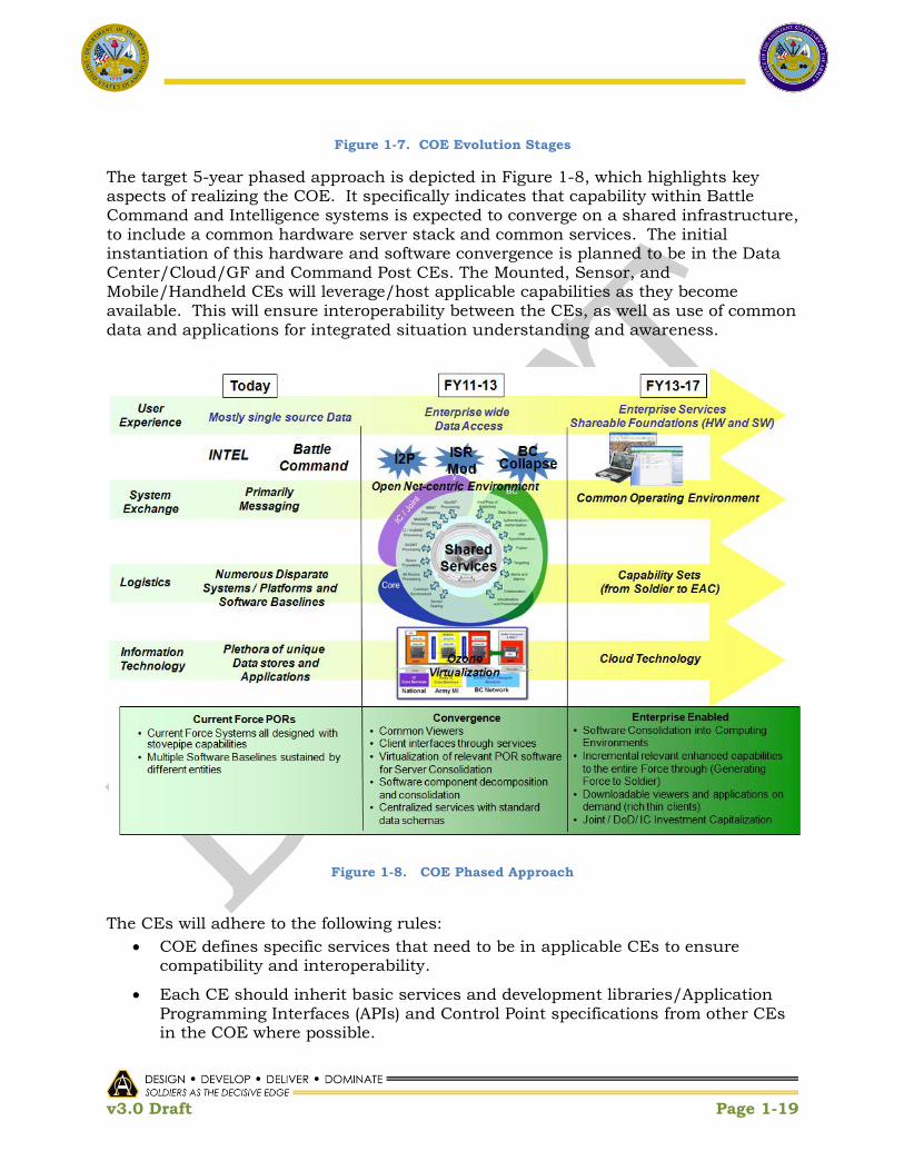
Figure 1-2. COE Building Blocks and Key Activities
1.3.2 Principles, Tenets, and Value Proposition
This plan is based on several developmental principles that will inform design decisions and
drive the collective direction of the developmental community as the COE emerges. These
include:
The COE must be standards-based. This implies that applications will adhere to
standard naming conventions, reside in common libraries, and be deployed using
standard release-management processes.
The COE must be scalable across the enterprise. Applications will be developed in
one environment and extended to others. Servers will be present where needed and
server instantiations will be limited to the minimum required. Enterprise services
and applications will be implemented throughout the COE.
Software solutions within the COE shall be adopted, in the following order of priority:
1) from open source software that has been developed IAW open standards, 2) from COTS products that has been developed IAW open standards, 3) from COTS products that has been developed IAW proprietary standards or
technologies, 4) from existing GOTS products that has been developed IAW open standards and
for which the government has unlimited data rights,

v3.0 Draft Page 1-7
5) from existing GOTS products that has been developed IAW open standards and for which the government has unlimited use rights, and
6) from existing GOTS products that has been developed IAW proprietary standards or technologies.
Developers should only resort to development of new government funded software
when none of the other options described above will meet a set of specific
requirements. In the event that new GOTS software must be developed, the
government shall retain unlimited data rights for any and all resulting artifacts from
the development effort, to include the source code.
The COE must be compliant with overarching DoD directives. This compliance will
enhance interoperability with our joint, multi-national and interagency partners.
The COE will require that software applications are abstracted from the hardware and
software infrastructure supporting them, for improved portability, adhering to the
rules established by the COE as they evolve.
The COE will implement a Service-based Architecture approach. It will establish
common frameworks and shared infrastructures across computing environments,
thereby enabling standardized applications and frameworks to readily integrate
technology-advanced services and applications. It will allow for applications to be
developed by users in response to emerging requirements from mission execution. In
addition, it will serve as a reference architecture that will aid the S&T community and
industry in developing applications that are relevant and readily usable within the
COE.
The COE must remain relevant. ASA(ALT), in concert with key partners such as
Research, Development and Engineering Command (RDECOM), Software Engineering
Centers / Directorates (SECs/SEDs), Defense Advanced Research Projects Agency
(DARPA) and CIO/G6 will continually assess emerging commercial technologies and
standards as candidates for COE implementation. Similarly, current technical
solutions will be assessed for obsolescence and relevance, and be maintained or
eliminated as appropriate.
The COE will be enabled by appropriate security solutions that minimize the most
dangerous and worst case cyber threat. Any known vulnerabilities will be identified
so the commander can understand and manage risk and can categorize these risks
and develop defensive options based on the operational impact of those known
vulnerabilities.
The COE will enable unity of effort across all deployment phases. It will establish a
set of synchronized and integrated processes for Governance, Integration and Test to
simplify Certification, Accreditation, Training, and Fielding.
Finally, COE successful implementation will depend on the time-phased introduction
of certain critical enablers (see Table 1-2). These enablers include, for example,

v3.0 Draft Page 1-8
enterprise collaboration capabilities, cloud computing, and enterprise mediation
services, all within a rich web application framework.
These principles are supported by key tenets that will guide the implementation of the COE.
Table 1-1 summarizes the key tenets and value proposition associated with each.
The primary COE Value Proposition is that if implemented across Army systems it will greatly increase interoperability, agility, security, safety and operational relevancy and effectiveness; and decrease time for development and delivery to the field, certification, and overall costs. Specifically, it will enable:
Increased Capability Agility
Reduced Life Cycle Costs through standardized applications and Unity of Effort
Flexible Infrastructure to Evolve to Rapidly Emerging Standards
Enhanced Cyber Protection

v3.0 Draft Page 1-9
Table 1-1. COE Tenets and Value Proposition
Tenets Value Proposition
Move from Hardware-centric to
software-centric development
• Focus on the applications and
services
• Utilize ―off the shelf‖ as first
option
• Abstract software from
hardware
• Standardized hardware profiles – reduced training,
deployment and sustainment costs
• Operational Flexibility via Capability Set packaging
• Reduced test and integration time
• Minimized Footprint
• Increased commonality through standards-based products
and development of enterprise services and applications
Implement Service-based
Architecture Approach
• Standardized Applications – reduced training, deployment
and sustainment costs
• Readily integrated technology-advanced services and
applications
• Applications can be developed by users in response to
emerging requirements from mission execution
• Expand the development / industry base
Execute Phased Implementation • User (Warfighter) operational experience leveraged near-
term
• More timely insertion of technology advancements enhance
operational effectiveness and adaptability
• Annual life cycle cost metrics and controls
Establish Common Frameworks
and Shared Infrastructures across
Computing Environments
• Reusable software components, Design/Build once, Use
multiple times – Scalable capability across the enterprise
• Reduced integration time and life cycle costs
• Reduced Time to Field
• Interoperability by design – Army, DoD, National, Joint,
Interagency, Intergovernmental, and Multi-national
• Reuse of architecture and implementation through
standards-based development
• Lowered ―barrier to entry‖ for developing applications
• End-to-end work/data flow throughout the enterprise
• Well-defined control points to accelerate testing and
technology insertion
Execute Unity of Effort across all
deployment phases
Synchronized, integrated processes
• Governance
• Integration and Test
• Certification
• Accreditation
• Training
• Fielding

v3.0 Draft Page 1-10
1.3.3 COE Challenges
Given the scale, magnitude, and complexity associated with COE Implementation across the enterprise, the following challenges have been identified:
Hundreds of programs will be affected across the Army
Upfront transition costs are expected to be high but will decrease over time due to anticipated efficiency gains through development, integration, test, certification, training, fielding, and sustainment
Transition of Army programs will begin immediately; funding consistency is required to ensure full COE compliance of Army programs affected by COE with five (5) years
Ongoing sustainment for systems pending transition to COE is required
Requirements, acquisition, materiel release, fielding and funding processes are not currently aligned to respond to this challenge
Current testing methodologies will not facilitate the desired pace of technological change
Alignment has potential for disruption to schedule, cost, and performance to Army acquisition programs
Transition resourcing requirements are significant despite a constrained fiscal environment
Organizational resistance to change
1.4 COE Scope: Vision to Execution
1.4.1 Vision (CIO/G6 Guidance)
In CIO/G6 Appendix C, the CIO/G6 has set the vision for Army with respect to COE. ―The
Common Operating Environment is an approved set of standards that enable secure and
interoperable applications to be rapidly developed and executed across a variety of Computing
Environments.‖2 It states that ―Each computing environment will have a minimum standard
configuration that will support the Army‟s ability to produce and deploy high quality
applications quickly while reducing the complexities of configuration, support, and training
associated with the computing environment.….The mission environments in which Soldiers
operate are differentiated by varying network bandwidth requirements (latency, high bit-error
rate), SWaP (size, weight and power), environmental factors and location permanence. Each
mission environment is supported by a limited number of standardized computing
environments that provide needed capability and integration with other computing
environments.‖2 Figure1-3 illustrates the mission environments mapped to computing
environments identified in CIO/G6 Appendix C. “Implementation of the COE will reduce the
time it takes to deliver relevant applications to the warfighters who need them, and lower the
costs of doing so.”

v3.0 Draft Page 1-11
Figure 1-3. CIO G/6 - Mission Environments Mapped to Computing Environments
1.4.2 Implementation Approach
As identified in CIO/G6 Appendix C, given the diversity of systems within the Army
enterprise, a single technical solution for the COE is not achievable, thus the problem space
has been architecturally categorized into computing environments (CEs)67, which when
combined, form the COE. For the purposes of implementation, and in order to address the
entire Army enterprise, the CIO/G6 Appendix C terms for CEs have been extended, as
depicted in Figure 1-4.
The following definitions serve as an implementation baseline and are expected to continue to be refined over the course of implementation and execution of the CE Execution Plans (see Appendices D-I):
Data Center/Cloud/GF CE: Provides a service-based infrastructure for hosting and accessing enterprise-wide software applications, services, and data. Consists of common services and standard applications for use by a large number of users over wide area networks. This CE also includes the Army‟s Enterprise Resource Planning (ERP) systems.
6 While the COE as a whole has specified goals, principles and tenets it is understood that not all the CE‘s will
uniformly be able to achieve all of these measures, however, this does not excuse CE‘s from complying to the
fullest extent possible where applicable and feasible, The diligence of the CE‘s to endeavor to conform to these
measures of the COE will assure that the COE achieves its‘ value proposition.
7 Programs of Record (PoRs) and systems should naturally fall into one or more of the CE‘s. In the event that it is
not clear which CE(s) a PoR or system should be participant in and contribute to that PoR or system should
address their concern with the Technical Advisory Board (TAB) (see section 2.0 Governance).

v3.0 Draft Page 1-12
Command Post CE: Provides client and server software and hardware, as well as common services (e.g.. network management, collaboration, synchronization, planning, analysis) to implement mission command capabilities.
Mounted CE: Provides operating and run-time systems, native and common applications and services, (e.g. awareness, execution functions, integration of local sensors) software development kits (SDK), and standards and technologies to implement mission command.
Mobile/Handheld CE: Provides operating and run-time systems, native and common applications and services, software development kits (SDK), and standards and technologies for hand held and wearable devices.
Sensor CE: Provides a common interoperability layer, implementing standards and technology for data services, NetOps, and security for specialized, human-controlled or unattended sensors. The Sensor CE does not specify specific hardware and software for the sensors.
Real-Time/Safety Critical/Embedded CE: Defines a common operating environment for systems operating in either a real-time, safety critical or embedded environment while ensuring that opportunities for commonality and interoperability with other CEs are maintained to fullest extent possible.
Figure 1-4. Common Operating Environment
Additionally, it should be pointed out that all CEs must ensure that they continually
coordinate with emerging initiatives and architectures, such as the Real-Time/Safety
Critical/Embedded CE's acceptance of the Future Airborne Capability Environment(FACE)
and Vehicular Integration for C4ISR/Electronic Warfare Interoperability(VICTORY) that will
allow for faster and more effective integration as well as better information sharing among
sub-systems.

v3.0 Draft Page 1-13
1.4.3 Implementation Strategy
As noted in paragraph 1.4.1, the COE is an approved set of standards that enable secure and
interoperable applications to be rapidly developed and executed across a variety of
Computing Environments. The COE Implementation Plan and associated activities comprise
the COE Initiative, which includes the interrelationships and dependencies illustrated in
Figure 1-5.

v3.0 Draft Page 1-14
Figure 1-5. COE Interrelationships and Dependencies

v3.0 Draft Page 1-15
The Army as a business must execute information technology acquisition in a more efficient
yet less costly manner, consistent with DoD IT Acquisition reform initiatives. In order to
achieve COE objectives, changes to current processes and policies may be necessary. Any
changes are expected to streamline execution and costs and will not be additive in nature.
This execution must include the establishment of a software Ecosystem and enterprise
business strategies that will allow the Army to leverage industry best practices and rapidly
develop secure and interoperable applications that satisfy operational requirements. The
COE initiative is expected to stimulate innovation while enabling enhancements to the user
experience. Most importantly, the COE initiative is not starting from scratch, but are
leveraging a rich body of work and systems that are already on a path consistent with COE
implementation.
Roles and responsibilities, as shown in Figure 1-6, have been identified and lead
organizations have been designated for implementation of CEs and other key efforts. The
PEO that have been selected to lead the CEs have significant experience in the development
and deployment of information technologies within the CE problem spaces. They have
established frameworks and made progress towards open standards that set the conditions
for transition to a common infrastructure and implementation of common services and
applications. In addition, they have amassed a large library of ―lessons learned‖ from which
the COE can only benefit.
Implementation is anticipated to include rehosting and/or refactoring of existing capability
over time as well as the development of new capability as necessary to realize emerging
requirements based on mission evolution.
In conjunction with PEO CE Execution, ASA(ALT) will be responsible for execution of the
Governance, Orchestration, and Verification and Validation (V&V) functions. Governance is
described in detail in Section 2.

v3.0 Draft Page 1-16
Figure 1-6. Roles and Responsibilities

v3.0 Draft Page 1-17
Orchestration is the identification, coordination and management of complex system
of systems, this orchestration will be coordinated by, among other methods, System of
System Directives from ASA(ALT). The orchestration activities for the COE include but
are not limited to:
Integrated Capability Portfolio Alignment
COE/CE Architecture and Design Baseline Development
Funding requirements and (re)prioritization Review and Recommendations
Requirements Traceability / Alignment
Capability Set Alignment
COE/CE Synchronization with key partners including G2, G3/5/7, CIO/G6, G8,TRADOC
− Continuous Stakeholder Engagement
− Effort Alignment (e.g. NSWG, NIE/NIR, Integrated WSRs)
Control Point / Interface Definition and Agreements
Systems Engineering Rock Drills
Instantiation and Conduct of EcoSystem Processes
Governance
Investment Strategy Development
Integrated Test Environment
CE Working Group Charters and Synchronization
S&T Community Alignment and Capability Prioritization
Programmatic Synchronization
The verification activity will ensure that the implementation of the COE adheres to the
guidance and tenets of the COE (i.e. are we doing it right across the life cycle). The
Validation activity will ensure that the COE is having the expected outcome of meeting
the tenets of COE Implementation (i.e. given it is right, are we achieving technical and
programmatic efficiencies, reducing time to deliver to the field, providing capability
agility). Activities include, but are not limited to:
COE/CE Architecture and Design Baseline Validation
COE Reference Architecture Compliance − Technical Reference Model
− Performance Reference Model
− Data Reference Model
COE Maturity Model Compliance
Metrics Collection and Analysis
Modeling and Simulation Analyses
COE Critical Enabler Implementation
Technical Reviews / Forums across the engineering life cycle − Entrance and Exit Criteria − Engineering Artifacts Validation
v3.0 Draft Page 1-18
Integration and Test Events − Use Cases − End-to-end operational ―threads‖
S&T Capability / Product Assessments
Risk Assessment / Mitigation
Cross-cutting Trades and Technical Analyses
Accreditation and Certification Process Refinement
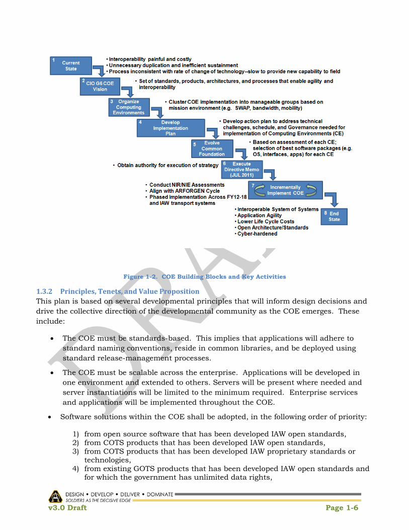
To transition existing capability from individual systems to CEs, a four (4) step strategy, depicted in Figure 1-7, has been defined:
1. Categorize PoRs into CEs that share design and operational constraints.
2. Within each CE, identify commonalities that support the selection of foundational architectures (standards, technologies, software, and hardware) for each CE and configure CEs to interoperate with other applicable CEs to form the COE.
3. Identify and develop commonalities which cross CE boundaries to form unified capabilities across the COE.
4. Continue to expand commonality in both the CEs and the COE through future designs and enhancements.
v3.0 Draft Page 1-19
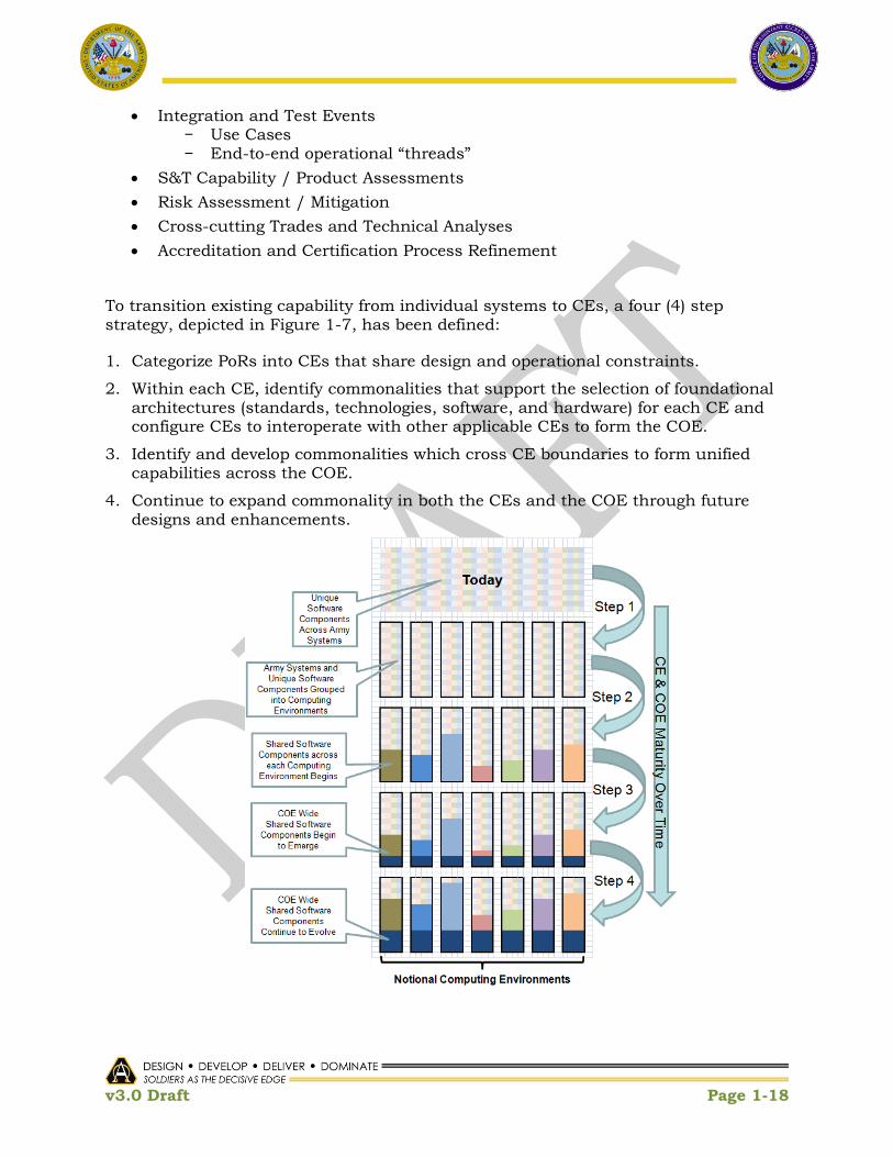
Figure 1-7. COE Evolution Stages
The target 5-year phased approach is depicted in Figure 1-8, which highlights key aspects of realizing the COE. It specifically indicates that capability within Battle Command and Intelligence systems is expected to converge on a shared infrastructure, to include a common hardware server stack and common services. The initial instantiation of this hardware and software convergence is planned to be in the Data Center/Cloud/GF and Command Post CEs. The Mounted, Sensor, and Mobile/Handheld CEs will leverage/host applicable capabilities as they become available. This will ensure interoperability between the CEs, as well as use of common data and applications for integrated situation understanding and awareness.
Figure 1-8. COE Phased Approach
The CEs will adhere to the following rules:
COE defines specific services that need to be in applicable CEs to ensure compatibility and interoperability.
Each CE should inherit basic services and development libraries/Application Programming Interfaces (APIs) and Control Point specifications from other CEs in the COE where possible.

v3.0 Draft Page 1-20
CEs implement their own applications as required by operating constraints and requirements (e.g., power, form-factor, bandwidth).
The applications in each CE will be built consistent with the framework defined by the COE.
In implementing the COE and associated CEs, the architecture, infrastructure, and frameworks developed must address the entire Army enterprise, as depicted in Figure 1-9.
Figure 1-9. Army Enterprise
This implementation includes Phase 0-5 operations, work flow, and data flow across five security enclaves (NIPRnet, SIPRnet, JWICS, NSAnet, Coalition) and seven echelons (APCs/Fixed Sites, Corps, Division, Brigade, Battalion, Company, and Soldier). It captures the capability spectrum in which the Army operates, from the collection of data from a sensor to its transport, processing, and decision-making, ultimately resulting in action taken by the Commander. In order for this overarching work flow and data flow to be implemented, adherence to standards and compliance with the COE Reference Architecture is essential.
The target end state, conceptually depicted in Figure 1-10, is a set of nodes that are
configurable and instantiated based on mission, using cloud-based computing
technologies and a cloud-based infrastructure. These nodes are defined as follows:
Core / Global nodes – specific services and capabilities (Data as a Service; Software as a Service and Infrastructure as a Service) are initiated; provide Mission Tailorability to Edge Nodes and User Nodes.

v3.0 Draft Page 1-21
Regional / Deployable Core Nodes – a subset of Core / Global Node that is dedicated to a specific set of users, typically within the Joint community, where data and services are originated and requested from Edge and User nodes; provide the Mission Tailorability to Edge Nodes and User Nodes.
Edge Nodes – systems where data and services originate and are requested from User Nodes; provide content and services to User Nodes and may obtain non-resident capabilities to other Edge Nodes and / or Core Nodes; can provide services if disconnected from Core / Global Nodes; Mission Tailorable; will support Mission Command on multiple data networks; exist within the Core / Global Nodes
User Nodes – provide users and / or equipment network access, data, and requested services; can still operate when disconnected from the network but are limited to onboard storage and the last data received; are Mission
Tailorable.
Figure 1-10. Conceptual Target End State
This end-state is aligned with TRADOC Pamphlet 524-5-600, CONOPS LandWarNet 2015, which states: ―Facilitate information-enabled joint warfighting and supporting operations from the operational base to the edge of tactical formations, down to the individual Soldier providing linkages between sensors, shooters, and leaders; seamless

v3.0 Draft Page 1-22
and secure interoperability; network services; and, end-to-end connectivity throughout the enterprise. ‗One Army battle command system‘ as part of ‗one network‗ [that] facilitates a consistent alignment of joint capabilities across all layers of the network (platforms and sensors, applications, services, transport, and standards)‖.
Once the end state is achieved, it is expected that the following objectives, at a minimum, will be realized:
• Common User Interface (i.e. consistent look and feel, reduced training for users and developers)
• Richer Collaboration Environment
• Device-independent user experience with secure common framework
• Ready access to all mission-required applications (e.g., Software Marketplace)
• Agile Equipping Strategy
• Flexible Infrastructure that provides:
− Near Seamless access and distribution of data
− Rapid collection and synchronization of user data from Garrison to the tactical edge
− Augmentation of mission through Home Station operations
− Multi-tiered, self-healing, self-managing, self-maintaining network
− Enterprise-wide capability deployment configuration(s) sized to mission need
1.4.4 Charters and Execution Plans
The lead for each Computing Environment is a PEO that was assigned by the ASA(ALT) Military Deputy (MILDEP) in MAR 2011. Each CE has an associated Working Group, Charter, and Execution Plan. The charters are developed by the CE Working Group (CEWG) Lead and approved by ASA(ALT). Each charter describes the internal roles and responsibilities, operating procedures, meeting schedules, and products/artifacts to be delivered by the CEWG.
The CEWG Lead is also responsible for developing, evolving, and maintaining the CE Execution Plan. The Execution Plan will evolve over time adjusting as technical goals mature, new/emerging SoS directives are defined, and advancements in computing technologies become available. Each of the CE Execution Plans, at a minimum, will address:
Bounded Requirements Scope
Assumptions, Constraints, and Limitations
Programmatic and Technical Dependencies (external and internal) and
Synchronization Points between systems and other CE‘s.
Current State
Desired End State
Critical Enablers
Strawman Architecture

v3.0 Draft Page 1-23
Preliminary Design Considerations
Control Points
Software EcoSystem with components tailored to each computing environment
Cross-CE Interdependencies
CE Technical Reference Model
Risk Profile (cost, schedule and performance) - Assessment and Mitigation
Cost profile
Schedule
CE Execution Plans are contained in Appendices D-I.
1.4.5 Critical Enablers
There is a set of critical enablers, e.g. technologies, activities, organizational considerations, that must be addressed in order to achieve the desired COE end state. The implementation plans for these critical enablers are found in the CE Execution Plan appendices. Computing Environment capability will be realized over time through critical enablers, which are summarized in Table 1-2.
Foundations identified as ―To Be Provided‖ are currently under review and awaiting confirmation by ASA(ALT) leadership. The timeline shows to when the capability will be developed and available for fielding. It is assumed that the capability will be included in the Army Capability Set (CS) following the year it becomes available. For example, a capability available for fielding in FY11-12 is projected to be included in CS 13-14.

v3.0 Draft Page 1-24
Table 1-2. COE Critical Enablers Timeline
Enabler CE FY11-12 FY13-14 FY15-16 FY17-18 Foundation
Governance
(Process described in Section 2)
All COE technical roadmap
Proposals for CE critical enablers
Proposals for current systems that will be part
of the COE
Interface Control Points for CEs – intra- and inter-
CE exchanges
Governance Forums
Updates COE
technical roadmap
Change Proposals
Proposals for current systems that will be
part of the COE
Update Interface Control Points for CEs
– intra- and inter-CE exchanges
Governance Forums
Updates COE
technical roadmap
Additional
Proposals
Proposals for current systems that
will be part of the COE
Update Interface Control Points for
CEs – intra- and
inter-CE exchanges
Governance Forums
Updates COE
technical roadmap
Additional
Proposals for current systems
that will be part
of the COE
Update Interface
Control Points
for CEs – intra-
and inter-CE
exchanges
Governance
Forums
Establish CEWG
membership and leads
Establish
Governance Process and Forums
Establish SoSE Team
Enterprise Collaboration Data Center/
Cloud
Mounted
Development and test of standalone XMPP proxy
technical solution(s)
Whiteboarding
Video Tele-
Conferencing
Mounted Platforms
will be able to transparently join TOC
based collaboration
sessions and Group chat sessions
Mounted platforms have stand-alone
whiteboarding capabilities on the
terrestrial networks
Users have an ability to share
white-boarding data with the
TOCS
To Be Provided
Cloud Computing Data Center/
Cloud
Enterprise Cloud
Locations Chosen
Cloud Locations
Operational Service/ Application Migration
Begins
Service/Application
migration Reaches Critical Mass
Army enterprise IDAM
infrastructure and
enterprise services.

v3.0 Draft Page 1-25
Enabler CE FY11-12 FY13-14 FY15-16 FY17-18 Foundation
Data Center Consolidation Data Center/
Cloud
ADCCP consolidates 50 data centers into DECCs
IC closes X data centers
Med Command closes X data centers
ADCCP consolidates 90 more data centers
into DECCs
IC closes X data centers
Med Command closes X data centers
ADCCP consolidates 40
more data centers
into DECCs by end of FY15
About 70 Category 2 Army data
centers remain
IC closes X data centers by end of
FY15
Med Command
closes X data
centers by end of FY15
Army ERPs consolidated into 2
data centers
(ALTESS and Huntsville)
ADCCP Phase 2 addresses
consolidation of
Category 2 data centers
To Be Provided
DOD/PKI Data Center/
Cloud
ARMY/DoD Resolve
token issuance gaps for
tactical Networks/ JWICS/NSAnet/Coalition
networks
Implementation on
Tactical
NIPRNet/SIPRNet
Implementation on
JWICS
NSAnet
/Coalition
Implementation
To Be Provided
Software as a
Service (SaaS)
Widget
Framework
Data Center
/Cloud
Initial Web
infrastructure\Widget-to-
Widget
Interoperability/Initial Web SDK, style and
developer’s guides
(Ozone)/Initial User Capability Provided
Improved Web SDK
(Ozone replacement -
HTML5
enhancements)/Available on
NIPR/JWICS/Coalitio
n /Provide infrastructure that
supports sustained
scalability to larger user base, common
authentication
Capability to
support All major
Command Post
capabilities enabled via web
infrastructure
Command Post
Development

v3.0 Draft Page 1-26
Enabler CE FY11-12 FY13-14 FY15-16 FY17-18 Foundation
Standard
Shareable
Geospatial
Foundation
Data Center/
Cloud
Geospatial data and information services
available
Enhanced Geospatial data and
information
available
Geospatial data and information
updates from
tactical edge Geospatially
enabled analytics
available to tactical edge
Army Geospatial
Enterprise Architecture
/Army Geospatial Data
Model/Geospatial
Metadata
Schema/Geospatial
Services/Geospatial
Application
Server/Geospatial Data
Warehouse
Software as a
Service (SaaS)
Common
Software
Data Center/
Cloud
Develop SaaS categories and inventory
Determine SaaS candidates
Establish SaaS
governance board
Finalize SaaS license inventory
Award SaaS enterprise agreements
Monitor SaaS usage and terminate
under-utilized
software
Recompete enterprise
agreements
To Be Provided
Platform as a
Service (PaaS)
Virtualization Data Center/
Cloud
Common Hypervisor layer and Management
Tools Chosen
Initiate PaaS Standards
Body
Conduct app/system study
with PaaS industry
analysis
Develop PaaS
Architecture
VM Live Migration Implemented to
support Workload and Performance
Award PaaS Contract
Establish PaaS
capability at ALTESS
and potentially other
data centers
Some apps begin conversion to PaaS
Workload Balance implemented/Perfor
mance Based SLAs standard
All Army data centers have PaaS
capability
All apps converted
to common PaaS
platform during refresh
Non-Enterprise Cloud Locations
Shut Down, Non Virtualized
applications
require waiver and POA&M
Recompete PaaS
Contract
To Be Provided

v3.0 Draft Page 1-27
Enabler CE FY11-12 FY13-14 FY15-16 FY17-18 Foundation
Virtualization Command
Post
Design technical architecture for Battalion-
level command posts
based on deployment of virtual servers on a
common hardware
platform
Design technical
architecture for WIN-T increment 2 for
implementation of
virtualization
technologies and physical
hosting of services on
WIN-T increment 2 vehicles (TCNs, SNEs,
and POPs)
Design virtualized technical deployment
architecture for
deployment of command post server architecture
Design technical architecture and
implementation for
deployment of integrated
Mission Command
services
Design and test technical architecture for
deployment of virtualized infrastructure
Command Post CE Common Virtualized
Infrastructure
Test common hardware
infrastructure to
support tactical IPN services not migrated
to an enterprise data
center
Tests hosted virtual
server repository at APCs for on-demand
deployment
Field common
hardware
infrastructure to
support tactical services not migrated
to an enterprise data
center
Test and Fields
virtualized services
Server
Standardization
Command
Post
Existing Servers Leveraged
Legacy Server Replacement with
Standardized
Hardware Begins
Virtualizations exceeds 50%
Server Utilization rate exceeds 80%
Existing Servers
Infrastructure as
a Service (IaaS)
Enterprise-Wide
Identity
Management
Data Center/
Cloud
Initial Implementation with Directory and
Authentication Services and DoD PKI
Continued Implementation
Implementation Complete
To Be Provided

v3.0 Draft Page 1-28
Enabler CE FY11-12 FY13-14 FY15-16 FY17-18 Foundation
Directory and
Authentication
Services
Data Center/
Cloud
Army CIOs (G6/G2) develop and establish
policies and guidance for
AD implementation for all security domains in
coordination with DISA
and DIA
Enterprise Wide Implementation
begins
Enterprise Services available for
Command Posts
Implementation complete
To Be Provided
Enterprise
Mediation
Service
Data Center/
Cloud
Data Models to be supported Identified and
used to define Mediation
requirements/Mediation Engines
selected/Available
Enterprise Services provided by DOD layer
identified
Implementation of Mediation services
/redirection/re-hosting
begins
Implementation of Mediation services
/redirection/re-
hosting continues
Implementation of Mediation
services
/redirection/re-hosting complete
To Be Provided
Infrastructure as
a Service (Iaas)
Common
Infrastructure
Data Center/
Cloud
Initiate IaaS standards body
Develop IaaS detailed
RFI
Develop IaaS architecture
ALTESS pilots initial IaaS capability for Army
Acquisition
Data centers begin to
consolidate to DECCs
Award IaaS contract
Establish additional
IaaS locations
Integrate with DISA DECC services
Demonstrate cloud surging capability
Commence utility-based billing
Negotiate service agreements and
standards with DISA
Establish final IaaS locations
Migrate applications
out of Legacy enclave
Shut down Legacy enclave
Re-compete IaaS
contract
To Be Provided
Data as a Service
(DaaS)
Data
Description
Framework
Command
Post
Structured Storage Service with DDF-based
data model/ Cloud Base
and Lucerne Indexes implemented for
structured data on
SIPRnet
DDF Expanded to support Unstructured
Data/JWICS Support
Added
Global Graph Implementation
DCGS-A SIPR Cloud
Multi-Level
Security
Database
Data Center/
Cloud;
Command
Post
Enterprise Cross Domain Services leveraged where
applicable
Policy Restrictions Identified
Modifications Recommended
1st Operational Instance
Instantiated at all Army Data
Centers
Defense Cross Domain
Analytic
Capability(DCAC)

v3.0 Draft Page 1-29
Enabler CE FY11-12 FY13-14 FY15-16 FY17-18 Foundation
Identity and Access Management
(IDAM)
All DMDC issued Common Access Cards (CAC)
cards in concert with DoD
PKI on NIPRNet
User Name/Password and
Role Based Access Control systems are
prevalent in this time
frame.
DoD is expanding its
capability to SIPRNet
identity management with
the inclusion of a new
SIPR tokens.
Joint Enterprise Directory Service (JEDS) can be
used as the authoritative source of attributes about
users.
Access control policies can be adjusted to restrict
access to data by only “authorized” users.
Data owners are in a
position to begin labeling their data to enable more
granular access control.
Management of identities will continue
to leverage the DoD
enterprise identity management services,
the DoD PKI on
NIPRNet and on the SIPRNet.
Expanded use of JEDs for authoritative source
of user attributes.
Enable Attribute Based
Access Control
(ABAC)
Mature Directory infrastructure
Army Tactical PKI Validation
Architecture standing up.
To Be Provided
Software Marketplace All Pilot for Mobile Apps Instantiate Software Marketplace (Data
Center, SIPR, NIPR)
Provide support for mobile apps, web
apps, desktop Apps
Instantiate app loaders
(like iTunes) on CP CE, Mounted CE &
Mobile CE
Instantiate Software Marketplace
(JWICS, Coalition)
Instantiate Enterprise App store
to tactical edge (CP CE)
To Be Provided
Application Rationalization and
Migration
Data Center/
Cloud
Application inventory
complete
Application
rationalization completed
Master Service Level
Agreement (SLA) reached with DISA
SEC develops first
version of enterprise servers
Some Army systems
retired
Some Army systems
migrated to DECCs
More than 50% of
applications within Army FY11
baseline inventory
retired
Most Army
applications that have not been
retired have been
migrated to a DECC
To Be Provided

v3.0 Draft Page 1-30
Enabler CE FY11-12 FY13-14 FY15-16 FY17-18 Foundation
Backside Infrastructure Data
Center/
Cloud
Identify DC locations Initiate surveys of each
location to determine availability of fiber
Develop and release RFP for fiber lease or purchase and support maintenance
Develop and release RFP for DWDM requirements
SSEB conducted to select vendor of each
Install fiber as required
Establish all
connections to DC’s
Install DWDM
systems at all DC’s
Configure DWDM
equipment
Establish all active
connections for DWDM mesh
Fully operational
Transition to O&M
To Be Provided
Modular Data Centers Data Center/
Cloud
Organization established SSEB conducted to
select vendor
Standardized architecture developed
POR integration
CONOPS created
Participation in test events
Transition to signal
unit ownership for
training, and integration into their
operations
Pilot deployments
Large scale
deployment
Special purpose MDCs developed
To Be Provided

v3.0 Draft Page 1-31
Enabler CE FY11-12 FY13-14 FY15-16 FY17-18 Foundation
Rich Web Application Framework Data Center/
Cloud
Command
Post
Design and deploy initial Ozone Web Framework
Design DIL solution
Design web strategic web architecture (Enterprise)
for CE
HTML5 and emerging
technologies prototyping
Further integration and
development of widgets and functional areas
Implement and deploy
DIL solution
Incorporate HTML5
standards into Ozone and Synapse frameworks
Implement and deploy HTML5, CSS3 and other
successful technologies
Implement and deploy white boarding/deep
collaboration
Implement and deploy strategic web architecture
(Enterprise) for CE
PM design for edge
consumption, support and provisioning for platforms
and handhelds
Enable offline application support, storage and web
caching for widgets
Delivers integrated Web Infrastructure (Handheld,
Platform, Tactical and Enterprise) Implement
and deploy for edge users
including Commander’s Vehicles
Incorporate HTML5 Web Storage and Web
SQL Database for
initialization
Investigate “Google
Caffeine”-like analytics for CP
Tactical Data Mining
Virtualization
All major Command Post capabilities
enabled via web
infrastructure
To Be Provided

v3.0 Draft Page 1-32
Enabler CE FY11-12 FY13-14 FY15-16 FY17-18 Foundation
Hardware Independence Command
Post
Initial Hardware infrastructure established
for server virtualization
o Server HW o Storage HW
o Identical Virtualization
SW o Initial Virtual Machine
Catalogue
Servers available as virtual software images
Initial Virtual
Infrastructure for other
capability developers to
build on
Select Enterprise Services
rehosted (Collaboration, Security)
NIPR/Coalition
One CP server/storage environment available
for fielding by one PM
o Other capability developers able to
develop software
servers only. (Separation of server
hardware and
software complete)
Other Capability
Developers able to
field virtual servers
(software only) vice
physical servers
Client virtualization
environment
Improved Hardware infrastructure for
Virtualization
Common Services
provided locally to be leveraged (not rebuilt)
by capability
developers o Select Enterprise
Services
incorporated into Common Services
(Collaboration,
Security, Data Sharing)
JWICS
One CP client computer hardware
solution available
for fielding by one PM
o Other capability
developers able to develop software
clients only.
(Separation of server hardware
and software
complete)
To Be Provided

v3.0 Draft Page 1-33
Enabler CE FY11-12 FY13-14 FY15-16 FY17-18 Foundation
Tactical Edge Mini Cloud Command
Post
Initial Infrastructure as a Service available (Data
Base via HDFS,
Cloudbase)
Initial rehosting of Cloud
services
Initial unified ingest
available
Analyze Data Center cloud capabilities to make
those capabilities available to Edge Mini
Cloud users
Design common architecture for SIPRNet
the Edge Mini Cloud project implementation
Implement virtualization and web
(thin) client services
Align with Edge (v3.1)
Edge Mini Cloud
infrastructure to support services not
migrated to an
enterprise data center.
Data Center SIPRCloud
Implementation
leveraged by Edge Mini Cloud
DCGS-A Cloud

v3.0 Draft Page 1-34
Enabler CE FY11-12 FY13-14 FY15-16 FY17-18 Foundation
Platform-based Services Mounted Detailed architecture and laboratory architecture
and performance
evaluations
Trade studies (SOSCOE and emerging COTS
technologies)
Trade studies for IA and
identity management,
QOS, Comms awareness,
Network management,
when operating in
disconnected or different bandwidth constrained
environments for NLT
FY15-16 implementation
Capability developers are able to build and
host web services on
the mounted platforms and store services in
the Army Software
Marketplace based on emerging mission
requirements
Download high fidelity data pre-mission
Update high fidelity
data on the local host,
send low fidelity (e.g.,
VMF) during the mission
Synchronize high fidelity data post-
mission
Capability developers are able
to build and host
web services on the mounted platforms
using the widget
framework and the Army Software
Marketplace based
on emerging mission (Dependent
on Cloud and CP)
Download high fidelity data pre-
mission,
Update high fidelity
data on the local
terrestrial network
Send low fidelity
(e.g., VMF) during the mission if high
bandwidth
communications doesn’t exist
Synchronize high fidelity data post-
mission or directly
over higher band communications
networks when the
network is available
Direct connectivity and
information/
service interchange via
Web client with
the TOCs:
(Dependent on
CP CE)
-- Direct
connectivity when
bandwidth available
-- Continued use of
proxies when
bandwidth
unavailable
Technology
refresh of service capability based
on COTS innovations
To Be Provided
Mobile Network Mobile/HH Complete trade study on Fixed and Mobile
wireless network capability for tactical and
garrison environments
Identity interfaces for garrison and tactical
network (NEC, WIN-T,
JTRS, TPE, etc) and
smart phone device
supportability
Phased migration to wireless network that
is scalable to support small teams to large
FOBS with capability
to tunnel NIPR, SIPR, CX-I networks.
Migration to mobile expeditionary
wireless network that is frequency
agile and provides
OTM wireless network capabilities
to enable smart
phones running C2
and SA application
capabilities.
Extended services through
Satellite, Networked
Radios, UAS,
Aerostat, Vehicle Systems, etc
Support across
spectrum of
comms transport
mechanisms
To Be Provided
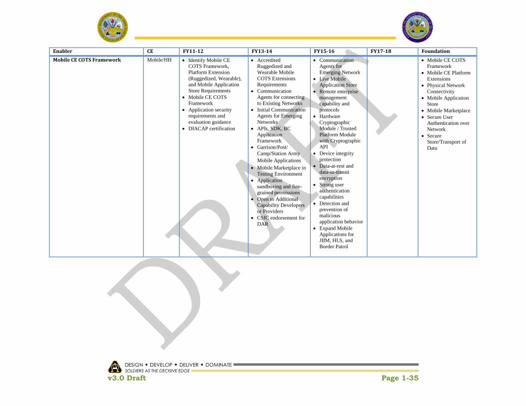
v3.0 Draft Page 1-35
Enabler CE FY11-12 FY13-14 FY15-16 FY17-18 Foundation
Mobile CE COTS Framework Mobile/HH Identify Mobile CE COTS Framework,
Platform Extension
(Ruggedized, Wearable), and Mobile Application
Store Requirements
Mobile CE COTS Framework
Application security requirements and
evaluation guidance
DIACAP certification
Accredited Ruggedized and
Wearable Mobile
COTS Extensions Requirements
Communication Agents for connecting
to Existing Networks
Initial Communication Agents for Emerging
Networks
APIs, SDK, BC
Application
Framework
Garrison/Post/
Camp/Station Army
Mobile Applications
Mobile Marketplace in
Testing Environment
Application
sandboxing and fine-grained permissions
Open to Additional Capability Developers
or Providers
CSfC endorsement for
DAR
Communication Agents for
Emerging Network
Live Mobile Application Store
Remote enterprise management
capability and
protocols
Hardware
Cryptographic Module / Trusted
Platform Module
with Cryptographic API
Device integrity protection
Data-at-rest and
data-in-transit encryption
Strong user authentication
capabilities
Detection and prevention of
malicious
application behavior
Expand Mobile
Applications for JIIM, HLS, and
Border Patrol
Mobile CE COTS Framework
Mobile CE Platform
Extensions
Physical Network
Connectivity
Mobile Application
Store
Mobile Marketplace
Secure User Authentication over
Network
Secure Store/Transport of
Data

v3.0 Draft Page 1-36
Enabler CE FY11-12 FY13-14 FY15-16 FY17-18 Foundation
Sensor Interoperability Plug-in and
Service Framework
Sensor Initial Foundation for Plug-In
Cross domain
selection of existing Base Defense Sensors
mapping validation
Sensor Common Data
Model derived for all
Sensor Domains (16)
Service Framework
Software Development Kit
(SDK)
Certification Tool
Architectural
Foundation
High Bandwidth Sensor Interoperability
Standards identified,
selected and DISR-approved
Service Framework implemented
SDK Available for HB
SI Plug-in Development
SI HB Certification Tool complete
HB Service Framework, SDK and
Certification Tool
available for new sensor acquisition
requirements (i.e. Net-
Ready KPP)
Service Framework
incorporated into CP
and DC/Cloud CEs
Enterprise App Store
On-line (SDK, Cert, Plug-ins, etc.) for
download
HB Validation via Data Center and
Command Post
Low Bandwidth (LB)
Framework; SDK; and Certification Tool
Architectural
Foundation
Update HB Standards, Service
Framework, SDK
and Cert Tool, as necessary
Low Bandwidth (LB) Sensor
Interoperability (SI)
Standards Selected and DISR Approved
LB Framework
Implemented
SDK Available for
LB SI Plug-in Development
SI LB Certification Tool complete
LB Service
Framework, SDK and Certification
Tool available for
new sensor acquisition
requirements (i.e.
Net Ready KPP)
LB Service
Framework incorporated into
Mounted and
Mobile Hh CEs
Enterprise App
Store On-line (SDK, Cert, Plug-ins, etc.)
for download
Sensor CE LB Validation via
Mounted/Mobile Hh Construct
Update Standards,
Service
Framework, SDK and Cert Tool, as
necessary
Incorporate Model and
Simulation into Sensor CE
“Virtual Sensor
Model”
Incorporate
Decision Support
Tools (i.e. Optimum Sensor
Placement tools,
Optimum Sensor Mode Selections,
etc.)
OGC SWE
DoD CBRN Data
Model
ICD 101
IAMD
SensorWeb
BETSS-C
JFPASS
URIM
SPIES
Real-time Interoperability
Framework
RT/SC/E Initial assessment of
FACE 1.1 for Army
Aviation C2 Systems
V1/V2 Standards
Development
Guidance Document
development
Mapping of FACE to
known Army Aviation
C2 Systems
Field FACE-
compliant IDM-OSM
FACE Architecture
for new IDM OSA
Begin Migration
of Aviation to
FACE compliance
Aviation Fleet migration to
FACE
Under consideration:
FACE for Aviation

v3.0 Draft Page 1-37
Enabler CE FY11-12 FY13-14 FY15-16 FY17-18 Foundation
Initial assessment of VICTORY for Army
Ground Mobile Platforms
Architecture Development
Standards Development
MRAP Memo
Prototype Domain Specific Reference
Architecture
Prototype Standard Specification
o Data Bus o Application
o IA
Design Guidelines
Prototype Shareable
APIs
VICTORY Architecture
Mapping
VICTORY into modernization and
upgrade programs for Ground Mobile
platforms
Under consideration:
VICTORY for Ground
Mobile
Networked Munitions Common Message
Definition
Ordnance Standard Framework outline
SDK
Certification Tool
Physical interface / adapter
Networked Munitions Interface
Standard for all new
Networked Munitions Systems.
[Allows new munitions
to be controlled from
any appropriately
safety certified
platform]
Document revisions as
necessary
Spider Anti Personnel
Landmine Alternative
Scorpion Intelligent
Munitions System
Guided Tube Artillery
Munitions Inductive Fuze Setter Common Message
/ Data Definition
SDK
Certification Tool
Physical interface /
adapter
[Allows new system
development to be
compliant with the
standard]
Guided Tube
Artillery Munitions Inductive Fuze
Setter Interface Standard for all new
guided tube artillery
munitions fuze setters
[Allows new inductive
fuze setters to interface
with any external CE]
Document
revisions as necessary
Enhanced Portable
Inductive Artillery
Fuze Setter
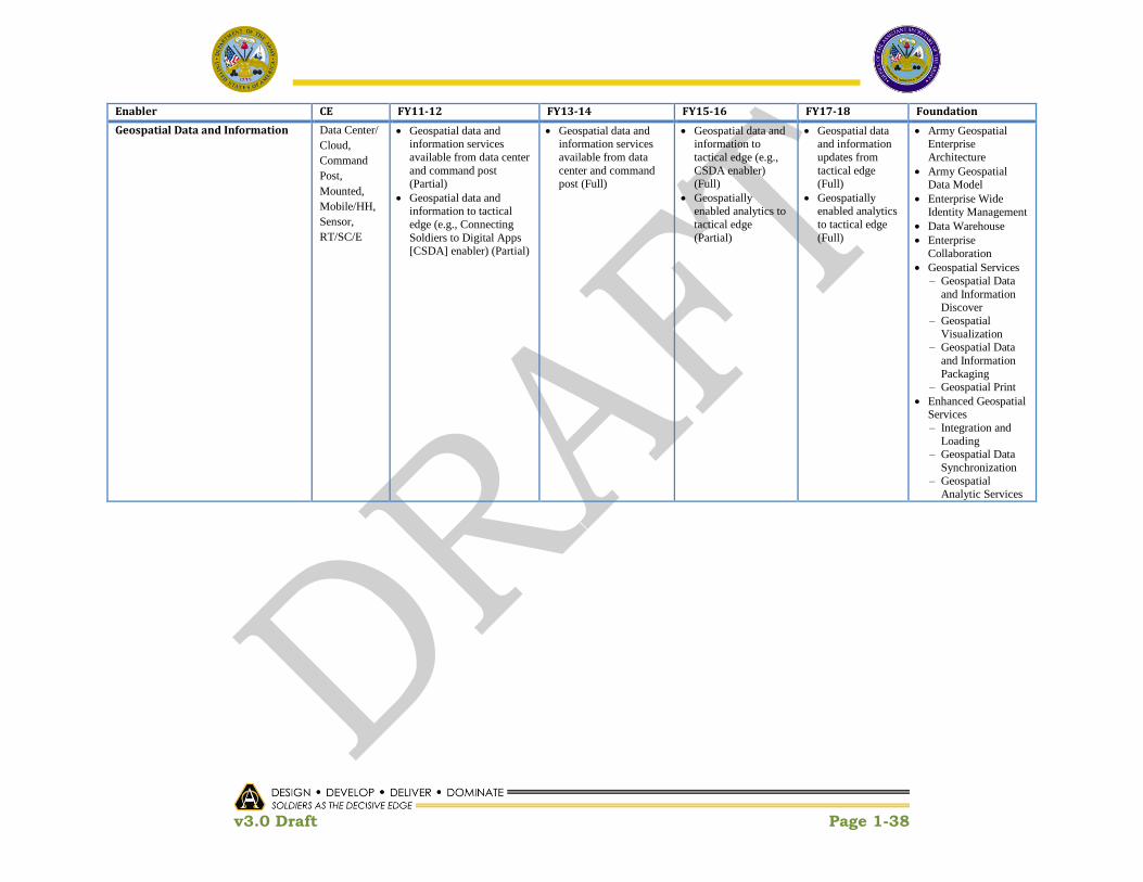
v3.0 Draft Page 1-38
Enabler CE FY11-12 FY13-14 FY15-16 FY17-18 Foundation
Geospatial Data and Information Data Center/
Cloud,
Command
Post,
Mounted,
Mobile/HH,
Sensor,
RT/SC/E
Geospatial data and information services
available from data center
and command post (Partial)
Geospatial data and information to tactical
edge (e.g., Connecting
Soldiers to Digital Apps [CSDA] enabler) (Partial)
Geospatial data and information services
available from data
center and command post (Full)
Geospatial data and information to
tactical edge (e.g.,
CSDA enabler) (Full)
Geospatially enabled analytics to
tactical edge
(Partial)
Geospatial data and information
updates from
tactical edge (Full)
Geospatially enabled analytics
to tactical edge
(Full)
Army Geospatial Enterprise
Architecture
Army Geospatial Data Model
Enterprise Wide Identity Management
Data Warehouse
Enterprise
Collaboration
Geospatial Services
– Geospatial Data
and Information Discover
– Geospatial
Visualization
– Geospatial Data
and Information
Packaging
– Geospatial Print
Enhanced Geospatial Services
– Integration and
Loading – Geospatial Data
Synchronization
– Geospatial Analytic Services

v3.0 Draft Page 1-39
Enabler CE FY11-12 FY13-14 FY15-16 FY17-18 Foundation
Integrated Test Environment All All CS 13/14 CIS infrastructure bought,
customized and / or built
and unit tested
All heavy applications
integrated with CIS and tested to CS 13/14 COE
standards
CS 13/14 COE and Heavy Applications Fully
Integrated to ICPs as per
staged integration plan
CS 13/14 COE and Heavy
Applications Verified
CS 13/14 Validated /
Certified and Ready for Fielding as per
ARFORGEN
CS13/14 Light Applications added as
required
All CS 15/16 CIS infrastructure bought,
customized and / or built and unit tested
All heavy applications
integrated with CIS and tested to CS 15/16
COE standards
CS 15/16 COE and
Heavy Applications
Fully Integrated to ICPs as per staged
integration plan
CS 15/16 COE and Heavy Applications
Verified
CS 15/16 Validated /
Certified and Ready
for Fielding as per ARFORGEN
CS15/16 Light Applications added
as required
All CS 17/18 CIS infrastructure
bought, customized and / or built and
unit tested
All heavy applications
integrated with CIS
and tested to CS
17/18 COE
standards
CS 17/18 COE and Heavy Applications
Fully Integrated to ICPs as per staged
integration plan
CS 17/18 COE and Heavy Applications
Verified
CS 17/18 Validated
/ Certified and
Ready for Fielding as per ARFORGEN
CS 17/18 Light Applications
added as required
All CS 19/20 CIS infrastructure
bought, customized and /
or built and unit
tested
All heavy
applications
integrated with
CIS and tested to
CS 19/20 COE
standards
CS 19/20 COE
and Heavy Applications
Fully Integrated
to ICPs as per staged integration
plan
CS 19/20 COE and Heavy
Applications Verified
CS 19/20 Validated /
Certified and
Ready for Fielding as per
ARFORGEN
To Be Provided
Stand Up ASA(ALT) Office of Chief
SW Architect
All Develop Job Description
Conduct Search and Select Candidate
To Be Provided
Tailored Acquisition Model for COE All Approved acquisition strategy tailoring out
inefficient DoD 5000.2
elements.
To Be Provided
Strategy for In-Sourcing design
authority and data rights.
All Timeline for migration to
“end state” architecture
Data rights strategy
To Be Provided
PM Incentive Plan All Define benefits to PMs for COE compliance
To Be Provided

v3.0 Draft Page 1-40
Enabler CE FY11-12 FY13-14 FY15-16 FY17-18 Foundation
Contracting Handbook All Guidebook providing assistance to PMs on the
type of contracting
mechanisms and clauses to use for COE
acquisition.
Guidance on in-sourcing COE work to Army labs.
To Be Provided

v3.0 Draft Page 1-41
1.4.6 EcoSystem
One of the most challenging aspects of the COE Implementation initiative is
understanding the scope of a software ecosystem. While there is no one globally
accepted definition, with few exceptions, the common theme is the blurring of
boundaries of systems and organizations which serve to enable interconnected
communication and execution of critical capabilities. David Messerschmitt and
Clemens Szyperski have defined a software ecosystem as:
“A set of businesses functioning as a unit and interacting with a shared
market for software and services, together with relationships among
them. These relationships are frequently underpinned by a common
technological platform and operate through the exchange of information,
resources, and artifacts.”8
This description is considered to be the de-facto basis for software ecosystem
definitions. A follow-on definition, developed by Jan Bosch states:
“A software ecosystem consists of the set of software solutions that
enable, support and automate the activities and transactions by the actors
in the associated social or business ecosystem and the organizations that
provide these solutions.”9
While this definition is consistent with Messerschmitt definition, it also highlights the
end-user. This definition implies and assumes that the activities of the users (actors)
are part of the ecosystem. Despite having come from leading software ecosystems
authorities Messerschmitt and Bosch, Neither of these definitions is sufficient to
describe an Army software ecosystem, however each can serve as an informative
source and input. For the purposes of this Implementation Plan a Software
EcoSystem includes, but is not limited to:
Governance
Integrated Test/Certification
– Infrastructure (e.g. Equipment and Networks)
– Configuration Management
– Test Harnesses
– Modeling and Simulation
– Test Tools
Reference Architecture
8 David G. Messerschmitt and Clemens Szyperski (2003). Software Ecosystem: Understanding
an Indispensable Technology and Industry. Cambridge, MA, USA: MIT Press 9 Bosch, Jan (2009). From Software Product Lines to Software Ecosystems. Accepted for SPLC 2009
(13th International Software Product Line Conference), August 2009

v3.0 Draft Page 1-42
Accreditation Process
Certification Process
User Help Desk
Developer‘s Help Desk
Tool Suites
– Software Development Kit (SDK)
– Productivity Tools
Software Marketplace (App Store)
The technical, operational, legal, and economic businesses that function holistically by interacting through shared services, information exchanges, resources, and artifacts are illustrated in Figure 1-11.
Figure 1-11. COE EcoSystem
1.5 Evolving the Business Model
As discussed in ―A New Approach for Delivering Information Capabilities in the Department of Defense‖ report to Congress, November 2010, OSD, FY2010 NDAA, Section 804, directs that the Secretary of Defense shall develop and implement a new acquisition process for information technology systems. The acquisition process developed and implemented pursuant to this subsection shall, to the extent determined by the Secretary:

v3.0 Draft Page 1-43
1) Be based on the recommendations in Chapter 6 of the March 2009 report of the DSB task force on DoD Policies and Procedures for the Acquisition of IT
2) Be designed to include: a) Early and continual involvement of the user b) Multiple, rapidly executed increments or releases of capability c) Early, successive prototyping to support an evolutionary approach d) A modular, open systems approach
The ASA(ALT) COE Implementation Plan activities are only a subset of the broader set of activities that must be implemented by key partners across the Army and DoD In order to comply with and practically execute IT Acquisition reform. Key topics identified in the OSD Report to Congress are mapped to the ASA(ALT) COE Implementation Plan activities as follows:
Management and Governance
− Integrated Master Schedule
− Orchestration and V&V
− Portfolio Alignment
Funding Activities − Collaboration with G8, ODASA-CE, ABO, and internal ASA(ALT) partners to
align appropriate funding with the COE CEs
− Focused investment in game-changing / critical enabling technologies to enable the vision of the COE
− Alignment of R&D and S&T investments to support COE gaps
In addition, the CIO/G-6 and ASA(ALT) AAE are committed to enabling the Army to
produce high-quality applications rapidly while reducing the complexities embedded in
the design, development, testing and deployment cycle. CIO/G6 Appendix C and the
ASA(ALT) COE Implementation Plan will provide direction to Government and industry
partners in order to standardize on recommended end-user environments frameworks
and software development kits, establish streamlined enterprise software processes
that rely on common pre-certified reusable software components, and develop
deployment strategies that give users direct access to new capability. Both Appendix
C and the COE Implementation Plan are considered to be living instruments and will
continue to evolve in a coordinated manner in order to keep up with the rapid changes
in technology. Specific follow-on activities include:
Engaging industry to develop an incentive and financial model for applications and CE foundational software development
Executing acquisition program alignment that is consistent with the COE implementation strategies
Aligning SoS Engineering and Integration activities within ASA(ALT) to ensure the successful implementation of the COE

v3.0 Draft Page 1-44
Empowering the Chief Software Architects across all PEOs to continue to shape the COE implementation
Assessing mission command systems across all PEOs, expanding on initial TRADOC MCEC and Generating Force requirements crosswalk
Re-engaging TRADOC and G3/5/7 in order to deconflict, align, and prioritize all Mission Command requirements and provide to ASA(ALT) to enable efficiencies and remove duplication while not losing capability
Identifying testing and IA certification strategies to support development of rapid application development and developing a testing and IA certification strategy, while leveraging/modifying existing infrastructure in order to streamline current processes and shorten the delivery time to the Warfighter.

v3.0 Draft Page 1-45
This Page Intentionally Left Blank

v3.0 Draft Page 2-1
2 Governance
2.1 Overview
2.1.1 Purpose
COE governance describes an ASA(ALT) led, community process for the development of
SoS directives that address synchronization, interoperability, and interfaces between
systems, especially PoRs. During this process, the COE community develops and
staffs SoS directive recommendations using COE Proposals (described below). These
proposals are assessed in turn by the COE governing bodies and finally submitted to
the AAE (or DAE as appropriate) for approval as formal SoS directives.
This section describes the COE governance model in terms of three key elements:
organizational structure, process, and artifacts. It starts with a summary of each
element and then builds on this summary by examining each in detail. Section 2.2
describes the organizational structure, section 2.3 describes the process (including
many examples), and section 2.4 lists governance related artifacts.
2.1.2 Organizational Overview
The COE governance structure, as shown in Figure 2-1, starts with a foundational set
of organizations called Computing Environment Working Groups (CEWGs). The
membership of these groups is drawn primarily from Program Executive Offices
(PEOs). Given the expertise found in the PEOs and their subordinate Program
Management Offices (PMOs), they are the primary source of COE Proposals (COEPs)10.
COEPs document issues the COE will manage or resolve such as new technology,
interoperability, acquisition efficiencies, and requirements relief.
Above the CEWG, the COE has established a Council of Colonels level advisory body
called the Technical Advisory Board (TAB) Council. The TAB Council acts as the
primary advisory body to the SoS GOSC. It focuses on proposals that affect multiple
CEs, those with a strong JIIM component, and COE wide implementation of Army
directives. It establishes the overall roadmap of the COE, identifies and resolves
technical issues, recommends acquisition strategies, and develops uniform standards
and architectures across all CEs. The COE Chief Engineer chairs the TAB.
A team of System-of-Systems (SoS) Engineers directly supports the COE Chief
Engineer in executing TAB activities. Members of this team support the TAB Council
directly and are also assigned to the CEWGs. The engineers assigned to the CEWGs
actively participate in their assigned CEs and have the responsibility to ensure that
10 A COE Proposal is the artifact used to document and process issues through the governance
process. It is a flexible multi-purpose artifact, analogous to the Internet Request For Comment (RFC). They are introduced in section 2.1.4 and discussed frequently in the rest of section 2.

v3.0 Draft Page 2-2
CE activities stay aligned with COE objectives. SoS Engineers work closely with the
CEWGs and the TAB Council to ensure that COEPs under consideration meet COE
objectives. SoS Engineers are responsible for communicating with other SoS Engineers
to ensure synchronization across governing bodies.
Figure 2-1. Governance Organization Chart
The SoS GOSC reviews all CEWG and TAB recommended COEPs and staffs them
across the Army and OSD. This includes close coordination with other GOSCs such as
the LandWarNet Battle Command Steering Group (LWN BCSG), the Army IT GOSC,
and others as needed. The LandWarNet/Battle Command Steering Committee Senior
Leader Forum (SLF) provides the COE strategic direction in areas such as Capability
Sets and fielding plans. The Chief Management Officer (CMO) SLF has authority over
defense business systems.
v3.0 Draft Page 2-3
The SoS GOSC provides a recommendation to the AAE or DAE. The AAE or DAE
reviews the SoS GOSC recommendations and accompanying analyses and then issues
formal SoS directive memorandums based on those recommendations.
2.1.3 Process Overview
As part of the community process, CEWGs generate COEPs, assess them internally
based on the guidelines in Section 2.1.1.4, and then make a determination whether or
not to recommend them to move forward to the TAB Council. The TAB Council, with
its cross-CE perspective, can also generate proposals. TAB Council proposals address
issues common to multiple CEs or based on directives coming from Army leadership.
Proposals are created in response to a variety of different operational and acquisition
challenges. The nature of the challenge determines whether a solution is needed
immediately or can wait for the appropriate Capability Set aligned, baseline cycle. The
governance process supports both modes. A proposal can be marked for immediate
execution, or for deliberate consideration as part of a baseline. The ability to respond
immediately gives COE governance agility; the baseline process gives it stability and
alignment with ARFORGEN.
2.1.4 The COE Proposal
The COE Proposal is the central artifact of the governance process. COEPs document
SoS directive recommendations to be implemented as part the COE. The SoS directive
indicates a specific action to be taken, a specific relief request, or a specific technical
solution. Each recommendation ultimately supports one of the COE value propositions
and provides a tangible benefit such reduced cost or enhanced operational capability.
COEPs can be submitted by any member of the COE community but must be
sponsored by a member of a CEWG or the TAB Council. Those who formally submit a
COEP and manage its progress through the governance process are called its
proponents.
COEPs can address a large range of issues. They can recommend efficiencies at any
phase of the acquisition process, such as requests for relief. They can propose new
technical standards, new technologies, standard commercial software, or a new-start
development effort. COEPs can also be used for administrative changes within the
COE itself.
Once formally submitted, COEPs move through the process for eventual approval or
rejection by the AAE/DAE. Proposals that direct technical solutions, such as standard
interfaces, data formats, and protocols, will typically become part of the configuration
managed COE baseline.

v3.0 Draft Page 2-4
2.2 Organizational Structure
2.2.1 Computing Environment Working Groups
In order to group PEOs by related concerns and expertise, ASA(ALT) divided them by
CE. CEs share common constraints such as size, weight, bandwidth, and power. IT
systems designed for a command post, for example, can assume sufficient power, few
space constraints, good bandwidth, and so on. In contrast, systems designed for
mounted environments have very limited space and power and usually very low
bandwidth. In each CEWG, PEOs work together to create common solutions.
The CEWGs are led by a chair at the GS-15/O-6 Colonel level.
2.2.1.1 Membership
As depicted in Figure 2-2, the membership of the CEWGs is drawn from PEOs,
including their subordinate Program Managers (PMs) and ASA(ALT). The PEO
representatives are the group‘s principals. The Lead PEO chairs the group. PM
representatives participate as stakeholders. PEOs are expected to represent the
equities of their PMs during deliberations and COEP reviews. The chair provides or
coordinates System Engineering (SE) staff to support the working group. ASA(ALT)
provides a SoS engineering team for each group in order to ensure synchronization
across CEs.
Figure 2-2. CEWG Structure and Roles
CEWG member PEOs and PMs will be able to leverage resources provided by
CERDEC/RDECOM, which serves as Technical Advisor to the TAB Council chair.
These resources are available to help CEWG members research and investigate COE
technical issues and will be coordinated through the TAB Council chair.

v3.0 Draft Page 2-5
Certain organizations are crucial advisors to the COE and the CEWGs. Key advisors
include organizations such as TRADOC, Army Staff, DoD CIO, DISA, NSA, and many
others depending on the circumstances.
2.2.1.2 Purpose
As centers of expertise and experience, the CEWGs help drive the development and
evolution of the COE. They do this in three key ways by: 1) identifying opportunities
for efficiencies in the acquisition process, 2) introducing new technologies, and 3)
recommending technical artifacts for common configuration management.
Opportunities for efficiencies in the acquisition process can be found in any phase of
the lifecycle, from requirements definition through implementation to deployment. As
the CEWGs identify these opportunities, they document them as COEPs and submit
them through the governance process. As new commercial or military technologies
emerge, CEWGs can likewise introduce them via COEPs. For items that require
standardization across CEs, CEWGs can recommend that they be placed under COE
CM.
2.2.1.3 Products
The CEWGs are responsible for creating several artifacts. When the CEWG begins to
operate, the chair is responsible for writing a charter that describes its internal roles
and responsibilities, operating procedures, meeting schedules, and other details. The
chair briefs this charter to the SoS GOSC and updates it as necessary.
The chair is also responsible for the CEWG‘s initial Execution Plan. This plan
documents a strategic vision for the CE, the critical enablers required to achieve that
vision, a preliminary cost estimate, and an outline of the COEPs needed to begin
implementing it.
The chair is also responsible for documenting and maintaining the CE as-is baseline.
This baseline acts like a map of the CE, providing an essential tool for locating
technical gaps and opportunities. The chair will ensure that baseline data is up-to-
date and readily available to all members of the COE community.
The COEP is the central artifact of the CEWG‘s daily business. Principals (including
the chair), stakeholder PMs, and the SoS engineering team can formally submit
COEPs. Alternately, the chair can assign a principal as a proponent. Competing
COEPs may be submitted.
It is critical that the CEWGs leverage the expertise and understanding of the PMs,
subject matter experts, warfighters, industry, and a variety of other sources to identify
the issues they will document as COEPs. The approval process for COEPs is described
in section 3.3.

v3.0 Draft Page 2-6
2.2.1.4 Operating Process
The internal functioning of the CEWG, as documented in its charter, is the
responsibility of the chair. However, COE governance requires that CEWGs
recommend COEPs via a process of consensus. Consensus means that, at a proposal
review meeting where a quorum11 is present, 75% of the quorum recommend a
technical COEP or 50% of the quorum recommend an administrative COEP. The chair
and proponent will attempt to obtain agreement from all voting members throughout
the COEP summary and detailed proposal development. The chair will document all
voting results and justifications.
Detailed COEPs that have been formally recommended by the CEWG are forwarded to
the TAB Council for consideration and analysis. The TAB Council must recommend
them before they can proceed to the SoS GOSC. If the TAB Council does not
recommend a CEWG originated proposal it will be returned to its proponent along with
the reason for the rejection.
2.2.1.5 Roles and Responsibilities
CEWG Chair:
Establish a strategy for migrating the CE towards the COE end-state in
alignment with the priorities set by the Chief Systems Engineer‘s roadmap.
Propose, review, and formally assess COEPs on a regular basis.
Brief assessment results and findings to the TAB Council.
Arbitrate disputes within the group, ensure that all principals can express their
perspectives, and oversee achieving consensus.
Write and maintain the group‘s charter.
Hold design reviews to monitor design and implementation plans when required
by the nature of the COEP.
Monitor and assess compliance of stakeholder PMs with SoS Directives and
adjust plans to accommodate any shortfalls or delays.
Lead COEP concept and design reviews; lead the development of appropriate
COEP artifacts; monitor COEP implementation; orchestrate, lead and record
results of COEP integration and verification activities, and re-plan if necessary.
CEWG Principals:
Ensure their Programs are interoperability with the CEs.
Represent the equities of their organizations, including the interests of their
subordinate PMs.
Task PMs to participate in CEWG and provide support as needed.
Submit COEPs for their preferred implementation of roadmap priorities.
11 For COE governance purposes a quorum means a simple majority of voting members. The
voting members are the chair, principals, and SoS Engineers.

v3.0 Draft Page 2-7
Raise a formal objection against any COEPs with which their organization does
not agree.
Comply with, and ensure PM compliance with, all relevant SoS Directives.
SoS Engineering Team:
Ensure synchronization of the CEWG with overall COE priorities and direction.
Provide independent technical oversight of the working group.
Propose COEPs, especially in the case where compromise proposals are needed.
Raise a formal objection against any COEPs deemed not in the best interest of
the COE, or in conflict with the COE roadmap.
System Engineers:
Develop technical products such as architectures, interface control documents,
data schemas, and others as recommended by the chair.
Provide hardware, software, and interface engineering analyses.
Provide COE related special reports, as recommended by the chair.
Maintain CE system baseline documentation.
Maintain hardware and operating system version compatibility lists.
Stakeholders:
Comply with all relevant approved COEPs.
Ensure that all PM issues are recorded in the Program of Record (POR) impact
section of the COEP.
Submit COEPs.
Participate in all proposal reviews, design reviews, and integration events as
directed by the CEWG chair.
Advisors:
Submit COEPs in support of their organization‘s direction.
Respond to Requests for Information (RFIs) addressed to their organization by
the TAB Council.
Provide information briefings to the group as requested by the chair.
2.2.2 Technical Advisory Board
The COE makes possible a new degree of technical synchronization across PEOs. To
guide that synchronization and to provide a unified technical vision, the governance
process names a body (see Figure 2-3) empowered to set the COE‘s technical direction.
The TAB Council provides this function.
The TAB Council is led by a chair at the GS-15/Colonel level.

v3.0 Draft Page 2-8
Figure 2-3. TAB Council Structure and Roles
2.2.2.1 Membership
ASA(ALT) names a COE Chief Engineer who will chair the TAB Council. It also
provides a SoS engineer12 team and secretariat team.
PEOs provide the TAB Council principals and supporting systems engineering staff.
Each PEO nominates senior technical staff (for example, their Chief Systems Engineer
or equivalent) to represent them in the TAB Council as principals. CEWG chairs are
invited as stakeholders.
Certain organizations are crucial advisors to the COE. As the key technical venue for
the COE, the TAB Council serves as a focal point for external, technically oriented
organizations to engage with the acquisition community. Organizations such as Army
Staff, the Army research laboratories, TRADOC, the Army Geospatial Center (AGC), the
Defense Information Systems Agency (DISA), the Marine Corps technical
organizations, NSA, and others are valuable advisors to the TAB Council. External
organizations are invited to participate in TAB Council meetings on a regular basis.
2.2.2.2 Purpose
The TAB Council reviews all COEPs recommended by the CEWGs or developed
internally, and establishes the technical direction of the COE. It develops transition
roadmaps to migrate the Army from its current architecture to a COE, proposes
solutions for common cross-CE challenges, and identifies and addresses shortfalls in
JIIM interoperability. As the engineering court of last resort, it settles technical
12 The SoS engineering team includes both the engineers that support the CEWGs and those
that support the TAB directly.

v3.0 Draft Page 2-9
disputes within and between CEWGs. And, it provides a forum in which external
technical organizations can engage with the COE.
2.2.2.3 Products
The TAB Council is responsible for several products. The COE Chief Engineer is
required to develop a charter that describes its internal roles, membership details, and
operating procedures. The TAB sponsors COEPs, especially in those areas not covered
by the CEWGs, such as Army-wide directives, cross-CE integration, and JIIM
interoperability. TAB Council COEPs are also the primary vehicle for capturing ideas
arising from the larger community, such as recommendations from deployed
commanders, external organizations, industry, and others.
The COE Chief Engineer sets the technical priorities of the COE via published
roadmaps. These roadmaps describe a transition plan for moving the Army from its
current state to a COE. Roadmap priorities are created with the input of the SoS
engineer, CEWG chairs, and key advisory members. Each roadmap informs the next
baseline, and will be updated at the end of every governance cycle based on current
threat, state of the COE, and state of technology. The SoS GOSC reviews each
roadmap.
2.2.2.4 Operating Process
The TAB will conduct a technical assessment of the CEWG recommended proposals
and request changes as necessary to align it with the appropriate COE baseline
roadmap. The TAB Council Chair will also, with the support of the group members,
select one out of a set of competing proposals to go forward. The TAB Council provides
the results of its technical analysis and COEP recommendation to the SoS GOSC for
consideration.
Like CEWG members, TAB Council members can also develop COEPs. TAB Council
generated proposals address gaps identified in the COE roadmaps or based on Army
and DoD directives. They focus on cross-CE issues, JIIM interoperability, and Army
directives. All TAB Council members can submit COEPs. CEWG chairs are a key
stakeholder for TAB generated proposals.
COEPs submitted to the TAB Council must be internally reviewed and recommended
before going forward to the SoS GOSC. The COE Chief Engineer schedules a formal
review session in which the principals, SoS engineer, advisors, and stakeholders are
invited to discuss the proposal, after which the TAB principals formally recommend or
reject it. The TAB follows the same consensus process as the CEWGs.
Since the COE is intended to encourage innovation, it will accept unsolicited COEPs.
An unsolicited COEP, to borrow a term from the publishing industry, is one written by
someone outside of the COE structure, i.e., not from ASA(ALT), one of the member
PEOs, or key advisory organizations such as the Army staff. For each unsolicited
COEP received, the COE Chief Engineer will determine whether it merits a formal

v3.0 Draft Page 2-10
review. If it does, the COE Chief Engineer will assign a proponent and treat it like
other COEPs. If the proposal is denied, the COE Chief Engineer will provide the
rationale.
2.2.2.5 Roles and Responsibilities
COE Chief Engineer:
Coordinate regular reviews of COEPs with member PEOs.
Assign proponent for unsolicited COEPs.
Write and maintain the group‘s charter.
Participate in COEP reviews.
Coordinate with advisors, and invite subject matter experts as needed.
Develop a roadmap (per COE baseline) that establishes sufficiently detailed
planning objectives to support the work of the CEWGs and incrementally
migrate the Army towards a COE.
Manage the SoS engineer and secretariat performing the systems engineering
and architecture of COEPs and design rules that are broad in scope and span
boundaries across multiple CEs.
Ensure that there is an effective and efficient knowledge management and CM
system to support the development, review, and execution of COE proposals.
Provide technical support and guidance to the CEWG leads.
Propose solutions that help align the COE initiative with other Army business
processes and advocate for those solutions within the SoS GOSC.
Establish an effective strategic communication policy for the COE initiative.
SoS Engineering Team:
Develop cross-functional, cross-CE COEPs that enable COE wide integration,
and JIIM interoperability.
Support development of the technical roadmaps.
TAB Council Principals:
Support the development of COEP resourcing strategies.
Represent the interests and perspectives of their organizations, including the
interests of their subordinate organizations.
Submit COEPs.
Raise a formal objection against any COEPs with which their organization does
not agree.
Task PEO and PEO staff to support TAB Council system engineering efforts as
determined by the COE Chief Engineer.
Advisors:
Submit COEPs in support of their organization‘s direction.

v3.0 Draft Page 2-11
Respond to Requests for Information (RFIs) addressed to their organization by
the TAB Council.
Provide information briefings to the group as requested by the COE Chief
Engineer.
Technical Advisor:
Advise the COE Chief Engineer on technical issues.
Provide a resource that CEWGs can leverage to investigate technical issues.
Submit COEPs at the TAB Council or CEWG level.
Conduct research in support of COE activities as directed by the COE Chief
Engineer.
Participate in system engineering working groups.
Participate in all proposal reviews, design reviews, and integration events as
directed by the COE Chief Engineer.
TAB Secretariat:
Develop and manage a COE CM process.
Administer the CM support tools.
Coordinate, set up, and facilitate meetings, to include audio/visual require-
ments.
Manage the meeting agenda.
Capture meeting minutes, and action items.
Publish meeting minutes, action items, plans, and all other artifacts on the
group portal.
Record the results of formal COEP reviews, including approvals and objections.
Coordinate Information and Communications Technologies (ICT) support to
include collaboration tools such as web portals, email, and calendaring.
Stakeholders:
Participate in meetings as directed by their organization or voluntarily.
Propose agenda items to the COE Chief Engineer.
Provide information briefings to the group as requested by the COE Chief
Engineer.
2.2.3 SoS GOSC
The SoS GOSC plays a central role in COE governance. It provides the final COEP
recommendations to the AAE/DAE. With the advice of the TAB Council, it
recommends the proposals to be included in a COE baseline and reviews the COE
roadmap. It reviews resource strategies and works with the senior Army acquisition
forums to gain approval for relief requests.

v3.0 Draft Page 2-12
2.2.3.1 Membership
The SoS GOSC is chaired by ASA(ALT) and its principal members are the PEOs. The
COE Chief Engineer and the CEWG chairs participate as stakeholders. DA Staff
proponents, TRADOC, and the ASA(ALT) DASAs are invited as key advisors.
The SoS GOSC is led by a chair at the one- or two-star general officer level.
2.2.3.2 Purpose
The primary purpose of the SoS GOSC is to staff COEPs across the Army so that when
they are submitted to the AAE/DAE for approval, Army stakeholders have been
informed and key impacts have been taken into account.
The SoS GOSC reviews all recommended COEPs, investigates issue resolutions, and
staffs the issues across the Army and OSD. The SoS GOSC recommends these issue
resolutions as well as a collection of COEPs for a COE baseline adjustment to the
AAE/DAE.
2.2.3.3 Operating Process
The SoS GOSC holds formal meetings to review COEPs and COE baseline
adjustments. The SoS GOSC will consult with the necessary groups for suggested
resolution in cases where it recommends the proposal but the proposal has an APB
impact.
The SoS GOSC addresses relief requests by coordinating with key leaders in other
organizations, and elevating issues to senior leader forums in cases where the issue
has a major Army or DoD impact. The SoS GOSC is responsible for risk mitigation for
Nunn McCurdy breach risks that the CEWG and TAB identified during proposal
development. The SoS GOSC will submit their mitigation to the AAE/DAE for final
risk assessment.
The SoS GOSC reviews the recommended COE baseline with the proposals that will be
part of that baseline. The SoS GOSC follows the same consensus process as the
CEWG for recommending COEPs.
The SoS GOSC will recommend the batch of COEPs that make up the adjusted COE
baseline as well as APB issues resolution to the AAE/DAE for approval or rejection.
The TAB Council Secretariat maintains CM of the resulting baseline.
The SoS GOSC is the approval body for COE-related issues. COEPs, for example, that
recommend changes to the Implementation Plan, to COE structures, or to COE
processes are approved by the SoS GOSC and do not have to be elevated to the AAE.
2.2.4 Senior Leader Forums
Senior Leader Forums designate a set of bodies rather than a specific one. They
include Army GOSCs, such as the LandWarNet / Battle Command Steering

v3.0 Draft Page 2-13
Committee, the IT GOSC, the CMO, the BTS Steering Committee, and the Capability
Set Management Board. They also include the COE authorities the AAE and DAE.
The LandWarNet GOSC shall advise about capability set content, priorities for COE
development, fielding authorization and priorities, and future concepts that may affect
COE (i.e., policies and directives).
The AAE and DAE are the official approval bodies for COEPs. Once the CEWG, TAB
Council and SoS GOSC recommend COEPs, the AAE or DAE review the COEP,
approve or reject them, and issue SoS directives based on them.
2.3 Process The COE governance process is divided into two main phases: planning and execution.
These phases are aligned with standard acquisition processes. During the planning
phase, the COE community has the opportunity to submit COEPs that will guide PMs
during their normal analysis and design phases. As Programs implement these
COEPs, governance moves into an execution phase where the governing bodies
orchestrate, validate, and verify compliance with the COE baseline.
The COEP approval process is central to the planning phase. It has two variations,
each of which is designed to balance competing requirements. The COE must handle
issues in a way that is deliberative and predictable so that implementing Programs
have the time needed to properly plan for them. For this reason, the main COEP
process follows a two-year, Capability Set aligned baseline cycle. Most of the COEPs
will target a specific baseline and follow this track. However, as a decade of war in
several theaters has clearly demonstrated, the COE must also be capable of
responding rapidly to emerging operational needs, new commercial technologies, and
to challenges in the formal acquisition process. To meet the need for agility,
governance also supports an immediate action cycle in which COEPs are executed as
soon as they are approved. The appropriate cycle depends entirely on the nature of the
COEP and is determined by the proponent.
Managing the orchestration of the COEPs requires several detailed sub-processes and
artifacts. The roles, responsibilities, and artifacts of the COE during this phase are
described in Section 6 of the Implementation Plan.
2.3.1 Baseline Cycle
The COE baseline follows a two-year cycle, synchronized with Capability Sets. This
aligns the COE with ARFORGEN and WSR. Each baseline is named after the
Capability Set year designation, starting with 13/14, and iterating every two years.
The COE baseline process starts with the technology roadmap developed by the COE
Chief Engineer. The COE community (i.e., CEWG chairs, SoS engineer, PEO
principals, etc.) then submits COEPs that implement that guidance. The roadmap,
therefore, is the what and the COEPs are the how.

v3.0 Draft Page 2-14
The TAB Council assigns proposals to baselines as they progress through the COEP
approval process. These recommended proposals are submitted to the SoS GOSC as
batched COEPs by baseline. The SoS GOSC reviews and recommends a batch of
COEPs in the form of a COE baseline adjustment to the AAE/DAE for approval. The
material developers begin execution based on the schedule required to complete the
proposal functionality for the assigned baseline.
ASA(ALT) OCSE has primary orchestration and monitoring responsibility during the
execution. The execution phase applies to SoS directives, and focuses on V&V
activities. Section 6 describes each of these activities in terms of the process,
participants, and artifacts.
2.3.2 Immediate Action Cycle
The immediate action cycle follows the same process as the baseline cycle except that
once a COEP is approved, material developers begin execution immediately. Immediate
action COEPs will be reviewed through the same governance process as baseline
COEPs. The COE Chief Engineer will decide if an immediate action COEP should also
be assigned to a baseline.
2.3.3 COEP Approval Process
The COEP approval process enables the CEWG and TAB Council to submit proposed
Army COE changes. These COEPs are reviewed and recommended by the SoS GOSC
to the AAE/DAE for approval.
The high-level COEP approval process steps are listed below (see Figure 2-4) for a
process model view). The detailed governance process models are available upon
request.
1. Identify an operational gap or opportunity for acquisition efficiency.
2. Develop a summary COEP (see section 3.4.1) using the COE standard template
to describe the proposed solution. Because of the significant work involved in
creating a COEP, proponents start the process by completing a COEP summary.
Initially submitting a summary allows them to get preliminary feedback before
investing significant resources in the proposal.

v3.0 Draft Page 2-15
Figure 2-4. COE Approval Process
S L F
S o S G O S C
T A B
C E W G
M e m b e r fo r m a lly s u b m its C O E P
C h a ir S c h e d u le s R
e v ie wR e c o m m e n d ?
N o
T e c h n ic a l R e v ie w
D e v e lo p A c q u is it io n
S tr a te g y
M e m b e r fo r m a lly s u b m its C O E P
B e g inE x e c u tio n
R e v ie w
R e c o m m e n d ?
N o C O E P R e je c te d
R e c o m m e n d e d C O E P
W ith in A A E
A u th o r ity ?
A A E R e v ie w sY e s
A p p r o v e ?
N o C O E P R e je c te d
Y e s
D A E R e v ie w s
N o
A p p r o v e ?
N oC O E P
R e je c te d
Y e s
A p p r o v e dC O E P
C O E P R e je c te d
R e c o m m e n d ?
N o
Y e s
C O E P R e je c te d
A s s ig n to B a s e lin e
Y e s
A p p r o v e dC O E PR e c o m m e n d e d
B a tc h e d C O E P s
Y e s

v3.0 Draft Page 2-16
3. Chairs, principals, SoS engineers, and stakeholders of the CEWGs and TAB
Council can submit COEPs directly to their groups for informal review. Other
parties must submit unsolicited proposals to the COE Chief Engineer.
4. If the informal, preliminary review is favorable, proponents complete the
detailed version of the COEP. If necessary, a CEWG chair or the TAB Council
chair will assign a principal as the proponent.
5. For COEPs originating in a CEWG, a quorum of principals will review the COEP
and have their recommendations or objections formally noted. If recommended,
the COEP is forwarded to the TAB Council for a technical review,
recommendation, acquisition strategy and baseline assignment process. If
recommended by the TAB, then the COEP is submitted to the SoS GOSC for
review. The SoS GOS will submit the group recommendations to the AAE/DAE
for approval.
6. COEPs originating in the TAB Council are first reviewed internally. The TAB
Council chair holds a formal review with all members and decides whether or
not to recommend the COEP to the SoS GOSC.
7. The SoS GOSC holds formal reviews of recommended COEPs originating in a
CEWG and TAB Council. The SoS GOSC will coordinate communications and
issue resolutions for proposals with a risk of APB impact or other policy issues.
Once any issues or questions have recommended resolution, the SoS GOSC
submits its recommendations to the AAE/DAE. If the SoS GOSC rejects a
proposal, it will provide the proponent with the rationale.
8. The AAE or DAE will provide the official approval for the COEP SoS directives.
The COEPs approved by the AAE/DAE will continue onto execution.
9. During the execution phase, it may be discovered that COEPs require
modification. Proposed modifications are briefed to the TAB Council and SoS
GOSC for review and the AAE/DAE for approval. If the modifications to a COEP
are approved the COEP will be modified and updated in the COE CM system.
2.3.4 Waiver Process
Under certain circumstances, PMs may request COE compliance or deviation waivers.
PMs can submit them in two ways. A PM can request a waiver or partial deviation from
COE technical direction as part of the impact statement they complete for a COEP. For
example, a PM may fully concur with the proposed technical direction but may be
unable to comply in a timely manner, or to comply fully due to programmatic
considerations.
A second of type waiver occurs when unforeseen compliance problems arise during the
execution phase. A PM may have originally planned to comply with the technical
direction described in a COEP but subsequently find that engineering or other
v3.0 Draft Page 2-17
challenges prevent them from doing so. If a PM determines they cannot meet the level
of compliance promised in the original COEP, then they must submit a waiver request.
Waivers are submitted as COEPs to the TAB Council and SoS GOSC for review and
approval for COE specific items at non-acquisition levels. The AAE/DAE must
approve all acquisition level waivers and any proposal waivers affecting more than
COE issues and activity.
2.3.5 Process Examples
The multiple permutations and conditions of the COEP process can make it appear
more complex than it really is. A few, entirely notional, but representative examples
will illustrate how the approval process operates.
1. Technical Standard for COE Baseline: The Chief Engineer‘s roadmap lists the
Blue Force Situational Awareness (BFSA) architecture as an area in need of COE
standardization and rationalization due redundant systems, incompatible protocols,
and mismatched data formats. In support of this roadmap, the Command Post CEWG
submits a proposal for a shared XML format blue position data format. The CEWG
approves the COEP; however, it is determined that it impacts all other CEs, so it must
be elevated to the TAB Council. The SoS engineering team does a technical analysis,
and coordinates with the impacted CEs and JIIM community. This results in a few
minor changes to the COEP to accommodate the needs of these CEs.
This updated COEP is forwarded to the SoS GOSC for resourcing and approval. It is
determined that the proposals falls within the SoS GOSC‘s authority to approve and
the SoS GOSC approves it. It then goes into the queue for the next baseline decision.
When reviewing candidate COEPs for the baseline, the SoS GOSC accepts this
proposal. Relevant PMs must now execute it. This COEP must go through the
integration process described in section 6.
2. Technical Standard Approved by CEWG: The Command Post CEWG, in an
attempt to simplify the systems administration burden on deployed units, decides to
standardize on Windows as the operating system for workstations in their CE. The
proponent for this idea completes the COEP summary, receives a favorable preliminary
review and then completes the detailed COEP. Once the detailed COEP is written it is
determined that the impact is only within the Command Post CE13. This COEP does
meet the conditions for CEWG level approval and is approved.
It is then briefed to the TAB Council and superior bodies, and none objects. Since it
was submitted during the baseline collection window and was intended to be part of
13 Selecting a workstation OS may very well not be limited to a single CE but is assumed so for the
sake of this example.

v3.0 Draft Page 2-18
the COE baseline, this COEP goes into the baseline queue for eventual adjudication by
the SoS GOSC.
3. Request for Regulatory Relief: A new family of low-cost, commercial computing
devices has emerged that the members of the Mounted CEWG believes would greatly
benefit its platforms. In order to select one of these, however, certain military
ruggedization requirements (for example, MIL-STD-810 and MIL-STD-461) would have
to be waived. Since the group concurs on this need, a proponent documents the relief
request as a detailed COEP. This proposal follows the same governance process as a
technology oriented proposal.
4. Proposal as Memorandum of Agreement (MOA): COEPs typically document
specific recommendations but it may often be the case that the most suitable technical
solution is not known. In this case a CEWG needs to invest resources in analysis to
find the right solution. This requires dedicated resources from various PEOs, and
hence a Memorandum of Agreement COEP outlining the scope of that support.
If, for example, a CEWG has identified the need for a common data interchange format
in one of their domains, and there are many possible candidates, selecting the best
candidate will require analysis, and this analysis will take time and resources.
The CEWG chair (or other principal) therefore completes a detailed COEP capturing
those elements relevant to a plan. This COEP would document plan elements such as
goal, benefit, and schedule, but modify the impact statements to show specific
resources needed from each PEO or PM to support the plan. The COEP would flow
through the approval process as an immediate action proposal, and if it is approved
(including a resourcing strategy by the SoS GOSC) the CEWG can begin executing.
Once the CEWG team has completed the analysis, they would submit a second COEP
to make the newly identified standard a part of the COE baseline.
5. Advisor Engagement: CIO/G6 is a critical advisor to the COE on a range of
technical matters. The COE governance process provides a new way for CIO/G6 to
engage with the acquisition community. This new form of engagement allows for a
rigorous debate and exchange of ideas among stakeholders that will benefit the
community by producing stronger recommendations.
For example, if CIO/G6 has developed a set of data standard recommendations, they
might consider documenting them as COEPs and submitting them to the TAB Council
for discussion. At the review of the COEP, all the stakeholders (those PEOs potentially
affected by it) have an opportunity to offer their perspectives and raise their concerns.
From this discussion, a better proposal will emerge. Additionally, using the COE
governance process as a vehicle for Army standards means that the COE will play a
role in verifying PM compliance during the execution phase.

v3.0 Draft Page 2-19
The result, therefore, of this engagement is better technical proposals, and increased
compliance. Advisors are, therefore, strongly encouraged to use the COE as a means
for more direct engagement with the acquisition community.
2.4 Artifacts The essential elements of COE governance are captured in several artifacts. The TAB
Council secretariat handles the CM of these documents and publishing them in a
manner accessible to the entire COE community. The versions they maintain are
always the official versions. The groups who develop these documents must also main-
tain informal working versions as part of their process. Other artifacts, as required by
sub-process, particularly during the execution phase, are listed in other sections of
the Implementation Plan (e.g., 6.3.3).
2.4.1 Charters
The CEWGs, TAB Council, and SoS GOSC complete charters. These describe internal
roles and responsibilities, operating procedures, meeting schedules, and any other
information the chair believes necessary. They are signed and approved by the chair of
the SoS GOSC. Once complete and approved the TAB Council will place them under
CM. Charters may be revised at any time by the chair of the body. The SoS GOSC
must approve all changes. The SoS GOSC determines the format of the charters.
2.4.2 COE Proposals
COEPs document the variety of issues community members want the COE governance
to manage or intercede in. COEPs originate in either a CEWG or in the TAB Council.
The open and transparent nature of the COE means that any interested party can
submit a COEP.
The wide range of possible issues means that the COEP template must be flexible. A
request by a PM for relief from an operational requirement will not contain the same
kind of information as a request to use a new XML data schema. Proponents are
expected to use their judgment on this and attempt to complete as much of the
standard template as possible. Relief requests include standard elements such as
rationale, benefits, risks, etc. but not the amount of detail needed for a technical
standard or new custom software development effort. The proposal should identify
functionality targeted for a specific NIE or other milestones to identify schedule
restrictions. Proposals should identify risks to include possible Nunn McCurdy
breaches as well as the necessary risk mitigation strategy. The specific content of the
COE templates will be determined based on the type of proposal being developed. The
COE template generally captures information to include the following:
Proposal scope and SoS directive
Roles and responsibilities
Benefits and operational impacts
Technical description (textual and graphical)

v3.0 Draft Page 2-20
Issues, constraints, assumptions, and dependencies
Relief and Assistance
Integration and test strategy
Cost
Schedule
Risk Management
Training
Deployment
Sustainment
Because assembling some of this information may require considerable effort on the
part of the proponent and PMs, governance allows for a two-phase process to give
proponents a chance to get preliminary community feedback before expending that
effort. COEPs can start in a summary slide form which communicates the basic
concept for the proposal. Proponents can describe their recommendation and provide
the group with preliminary estimates of impact, cost, test plans, and schedule. If
group reaction is favorable, then the proponent must complete a detail proposal. The
detailed proposal describes the comprehensive concept and specific execution plan for
the proposal functionality. This detailed version will be the one formally reviewed.
Software interface COEPs are especially important for interoperability compliance.
They define interfaces between CEs, and selected interfaces within a CE. The process
for implementing, integrating, and verifying them is defined in Section 6.
Even once approved, COEPs can still be modified. For example, if integration testing
showed serious issues with the proposal, change requests can be submitted through
the governance process (as COEPs.)
The COE Chief Engineer determines the format of the two COEP templates (summary
and detailed).
2.4.3 As-is Baselines
Each CEWG chair must identify and maintain an as-is baseline for the systems (PORs,
key non-PORs, and COTS) and interfaces in the CE. The format of this data is the
responsibility of the Chief Engineer. The TAB Council will keep this under CM.
2.4.4 Technology Roadmaps
The COE Chief Engineer is responsible for the COE roadmaps. Roadmaps provide a
phased transition plan for migrating from the current stove-piped architecture to a
COE. They are developed sufficiently in advance of the Capability Set to give the COE
community time to respond with COEPs. COEPs are the mechanism by which COE
member organizations implement the priorities established in the roadmap. The
roadmaps are put under COE CM after the SoS GOSC reviews them.

v3.0 Draft Page 2-21
2.4.5 Acquisition Strategies
The TAB Council will develop acquisition strategy recommendations and COAs in
support of COEPs. These are attached to the COEP and reviewed and validated by the
SoS GOSC.
2.4.6 COE Baseline
COE baselines align with Capability Sets. They consist of a set of approved COEPs.
Compliance with a COE baseline means compliance with the relevant COEPs in that
baseline. The TAB Council has the responsibility for selecting which COEP will be part
of which baseline. The SoS GOSC reviews the baseline selections and the AAE/DAE
issue the approval for COEPs in the baseline.
Naming the target baseline (for those proposals that are intended for a baseline) is part
of the approval process. The TAB Council manages the collection of COEPs that form a
baseline. The baselines are named after the Capability Set they support; e.g., COE
15/16 baseline.
2.4.7 COE Implementation Plan
The COE Implementation Plan, of which this governance section is a part, captures
the goals of the COE and how it intends to execute its mission. Even though the plan
is not expected to change drastically over time, allowance is made to update it as the
COE matures and lessons are learned. ASA(ALT) is responsible for updating the plan
as needed. Updates must be vetted with the governance process and approved by the
SoS GOSC. The plan will also be placed under COE CM.
2.4.8 CEWG Execution Plan
Each CEWG develops an initial plan that documents a strategic vision for their CE,
the critical enablers required to achieve that vision, a preliminary cost estimate, and
an outline of the actions needed to begin implementing it based on the information
contained in this strategic vision and will be refined as the CE design solidifies. The
COE Chief Engineer specifies the format. Execution Plans are controlled artifacts and
hence placed under COE CM.
v3.0 Draft Page 2-22
This Page Intentionally Left Blank

v3.0 Draft Page 3-1
3 Reference Architecture Framework
3.1 Overview A Reference Architecture provides an authoritative source of information about a specific subject area that guides and constrains the instantiations of multiple architectures and solutions. 14‖ Reference Architectures are typically represented in multiple models or views each of which is designed to address questions of importance to the subject area. The COE Reference Architecture is an ASA(ALT) organizational asset that serves as a tool for providing common information, guidance, and direction to guide and constrain
architectures, technical solutions, and instantiations by:
Providing common language for the various stakeholders
Defining consistent implementation of technology
Encouraging use of common standards, specifications, and patterns15
The relationship between the COE Reference Architecture and Computing Environment architectures is depicted in Figure 3-1.
Figure 3-1. Reference Architecture Purpose
14 Reference Architecture Description, Office of the Assistant Secretary of Defense Networks
and Information Integration (OASD/NII), June 2010. http://cio-nii.defense.gov/sites/diea/products/Ref_Archi_Description_Final_v1_18Jun10.pdf 15 Architectural patterns are a well documented practice. Design patterns us implementation designs that are well understood and leverage knowledge and experience to produce proven solutions to recurring design problems. Design Patterns: Elements of Reusable Object-Oriented Software; Gamma, Helm, Johnson, and Vlissides; 1995
CE Reference Architecture
Guides and constrains development of
Program/Application ArchitecturesUser
Requirements
COE Reference Architecture
Guides and constrains development of
Developer Requirements

v3.0 Draft Page 3-2
As shown in Figure 3-1, the COE Reference Architecture guides and constrains development of CE Reference Architectures. The COE Reference Architecture provides guidance that ensures the CEs come together in a cohesive form to achieve interoperability and collaboration across CEs and achieve other COE tenets. Each CE also has a Reference Architecture (see Appendices D, E, F, G, H and I) that can be mapped to the COE Reference Architecture, but may take another form to reflect the desired alignment between each CE, any commercial analogs, and the needs of the CE stakeholders. For example, the Data Center/ Cloud CE has defined Reference Models for three distinct enclaves: Cloud, ERP, and Legacy (see Figure 12-2) aligned with the NIST Cloud Reference Model (Figure 12-3). These Reference Models are also mapped to the COE Reference Model in Figure 12-4. Similarly, a program providing a fire control capability will respond to the Reference Model defined by the Real-Time/Safety-Critical/Embedded CE described in Appendix F.
Each CE Reference Architecture then guides and constrains the architectures of the PMs/application developers who are stakeholders in the CE. As described in Section 5 and also shown in Figure 3.1, the primary customers of the COE are the PMs and application developers who are responding user needs for functional capabilities. As customers, PMs and application developers will define COE and CE requirements that will be used to help evolve the COE. This section presents the preliminary definition of the COE Technical Reference Model (TRM) as the first instantiation of the COE Reference Architecture. As the COE matures, additional models will be needed in order to respond to questions of interest to COE stakeholders. As these needs are identified, existing models will be reviewed for inclusion and/or reference. For example, the Federal Enterprise Architecture,16 shown in Figure 3-2, identifies models that may be used to express the relationship of the COE to the Army Enterprise. DoD Architecture Framework (DODAF) 2.017 identifies a set of data and views that may be used to relate the COE to systems that use it. Commercial entities such as the Open Group18 have identified models that may be used to show the relationship between the COE and the commercial capabilities.
16 Federal Enterprise Architecture: Consolidated Reference Architecture Document, Chief Information Officers Council, v2.3, October 2001 http://www.whitehouse.gov/sites/default/files/omb/assets/fea_docs/FEA_CRM_v23_Final_Oct_2007_Revised.pdf 17 DoDAF 2.02, DoD Deputy Chief Information Officer, August 2010 http://cio-nii.defense.gov/sites/dodaf20/ 18 The Open Group Architecture Forum (TOGAF), http://www.opengroup.org/architecture/

v3.0 Draft Page 3-3
Figure 3-2. Candidate Models for the COE Reference Architecture
The COE TRM described in Section 3.2, is defined for use in describing the relevant technical characteristics of each CE so as to enable interoperability within the context of the COE. Section 3.3 describes some of the requirements and constraints on the COE, and Section 3.4 shows how the TRM relates to other models, such as the DISA JC2 Architecture Framework.
3.2 COE Technical Reference Model The primary purpose and use of the COE TRM is to define common rules, standards, and services which apply to all computing environments within the COE to ensure they are compatible and interoperable. The TRM is also used by each CE to categorize the standards and technologies that support and enable the use of services and applications that provide user capabilities within the CE to facilitate communication and analysis across the CEs.
In the context of the COE TRM, the following tenets have been identified:
Enable enterprise solutions for MCEC
Align with commercial standards, protocols, services, and applications to maximize the use of open source and COTS/GOTS Software
Define application program interfaces (APIs) and Interface Control Agreements (ICAs) for inter-and intra- CE exchanges
REF
EREN
CE
AR
CH
ITEC
TUR
EActivities and Measures
System Functions and Data
Technology and Standards
Performance Reference Model (PRM)
Business Reference Model (BRM)Data Reference Model (DRM)
Technical Reference Model (TRM)
Alignment Sources:Activity Model
Technical Standards ProfileSystems Functionality Description
Program 1 Architecture Program 2 Architecture Program n Architecture
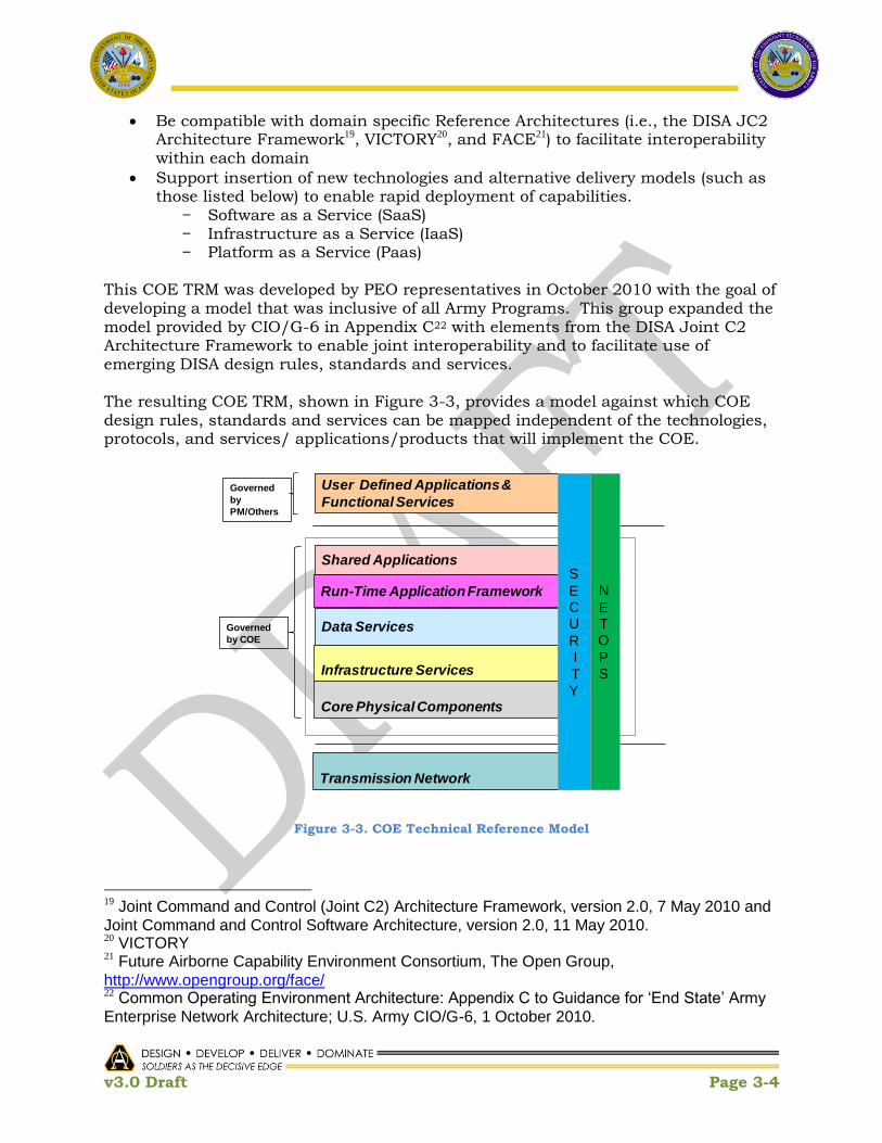
v3.0 Draft Page 3-4
Be compatible with domain specific Reference Architectures (i.e., the DISA JC2 Architecture Framework19, VICTORY20, and FACE21) to facilitate interoperability within each domain
Support insertion of new technologies and alternative delivery models (such as those listed below) to enable rapid deployment of capabilities.
− Software as a Service (SaaS) − Infrastructure as a Service (IaaS) − Platform as a Service (Paas)
This COE TRM was developed by PEO representatives in October 2010 with the goal of developing a model that was inclusive of all Army Programs. This group expanded the model provided by CIO/G-6 in Appendix C22 with elements from the DISA Joint C2 Architecture Framework to enable joint interoperability and to facilitate use of emerging DISA design rules, standards and services. The resulting COE TRM, shown in Figure 3-3, provides a model against which COE design rules, standards and services can be mapped independent of the technologies, protocols, and services/ applications/products that will implement the COE.
Figure 3-3. COE Technical Reference Model
19 Joint Command and Control (Joint C2) Architecture Framework, version 2.0, 7 May 2010 and
Joint Command and Control Software Architecture, version 2.0, 11 May 2010. 20 VICTORY 21 Future Airborne Capability Environment Consortium, The Open Group,
http://www.opengroup.org/face/ 22 Common Operating Environment Architecture: Appendix C to Guidance for „End State‟ Army
Enterprise Network Architecture; U.S. Army CIO/G-6, 1 October 2010.
Governed
by
PM/Others
Governed
by COE
Core Physical Components
Transmission Network
Data Services
User Defined Applications &
Functional Services
Shared Applications
Run-Time Application Framework
Infrastructure Services
N
ETO
PS
S
ECU
RI
TY

v3.0 Draft Page 3-5
Figure 3-3 identifies the scope of the COE by delineating by both heavy black lines and
a brown box the functional elements that are governed by the COE. The TRM shows
the relative hierarchy among the COE and the COE‘s use by User Defined Applications
and Functional Services, and the COE‘s underlying dependency on the Transmission
Network for any given instantiation. As shown in the TRM, User Defined Applications
and Functional Services and Transmission Network are not governed by the COE.
User Defined Applications: Applications that deliver operational or business
capability to an end user. These applications use the suite of services exposed
by one or more of the functional elements governed by the COE. Some
applications will be hosted by COE Standard Applications such as a Web
Browser, while others, such as thick clients, will be hosted by the Run-Time
Application Framework .
Examples of user applications include user-facing mission command
applications and business applications such as word processing or Enterprise
Resource Planning (ERP). Note: Some User-Defined Applications may be reused
in support of multiple capabilities. In this case, this application will become
Shared Applications and subject to COE governance.
Functional Services: The Functional Services are often called Business Logic
Services. These services contain most of the domain specific rules and
business logic of the system where most complex algorithms are implemented.
Functional Services are governed by a Program Manager or other authority
outside of the COE. Functional services typically support applications and not
end users directly.
Commercial examples of Functional Services include Google‘s search and map
engines and Amazon‘s web services. In the Army, Functional Services will
support Mission Command and ERP applications.
Transmission Network: The communications infrastructure comprised of
network systems, such as local area networks (LAN), wide area networks (WAN),
Internet, intranet, and other data communications systems. The users of the
COE depend on this infrastructure for secure communications both within a CE
and among CEs.
The vertical boxes, Security and NETOPS, represent policies that are established by
standing IPTs and executed through design rules, standards, and services within each
of the horizontal elements of the COE. As shown in the figure, they also define polices
that extend beyond the boundaries of the COE.
Security: Measures that protect and defend information and information
systems by insuring their availability, integrity, authentication, confidentiality,

v3.0 Draft Page 3-6
and non repudiation. These measures include providing for restoration of
information systems by incorporating protection, detection, and reaction
capabilities. See Appendix J for Security requirements associated with
Information Assurance.
NETOPS: Measures that enable the flow of data between end user systems
within and across computing environments. NETOPS provides the standards to
which CEs and applications must adhere to be certified for operation on the
network. See Appendix K for more information.
The horizontal boxes in the COE TRM depict TRM elements, not layers: the TRM
neither implies nor inhibits inter-relationships among the entities. (i.e., applications
will potentially interact directly with each element). The elements Governed by the
COE are defined to be:
Shared Applications: A set of user or user application facing capabilities that
are broadly used across the COE or the CE.
For example, a situational map application may be specified for use with the
COE. Commercial examples of shared applications include Google Earth client,
Adobe Connect, and Microsoft Outlook.
Run-time Application Framework: The software infrastructure necessary to
host, compose, and execute software applications and services and the
developer guidance and tools for creating applications and services to run
within the COE.
For example, the iOS and Android OS provide run-time application frameworks
that have enabled the development of numerous mobile applications. Another
example is the Commercial Joint Mapping Toolkit which has enabled the
development of numerous geospatial visualization and analysis applications.
Data Services: Data services provide a set of services to find, expose,
distribute, and access data. Such services normally have a database behind
them, and they offer the ability to search the data, update it, add new data, and
delete data. It is important that a data service encapsulates the data. That is,
users of the service should not need to know the table structure of the database
behind the service to interact with the service.
Data Services Include geospatial web services that serve standard and and
sharable geospatial foundation content (i.e. map background and imagery.
Infrastructure Services: The Infrastructure Services consist of software that
supports the architecture and facilitates interoperability between the services.
In addition, the Infrastructure Services include such services as: User Support

v3.0 Draft Page 3-7
(training and service desk support), Redirection, Orchestration, and a Workflow
Engine. Some infrastructure services will be available to users and applications
locally when disconnected.
Core Physical Components: The minimum hardware and software necessary
to execute CE components (to include operating systems, operating system
libraries, device drivers, hypervisors (virtualization infrastructure)).
The CIO/G-6 Appendix C and each of the CE Execution Plans contain a mapping of
standards and components to the TRM. Figure 3-4 shows a consolidated view of a mix
of the capabilities, functionalities, services, standards, technologies, and materiel
solutions across all of the CEs as of this writing. Details can be found in Appendices D
through I.
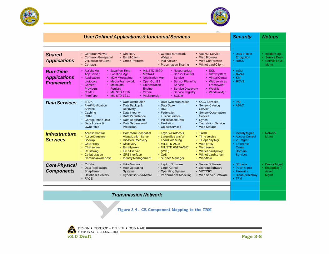
v3.0 Draft Page 3-8
Figure 3-4. CE Component Mapping to the TRM
User Defined Applications & functional Services Security Netops
Shared
Applications
• Common Viewer• Common Geospatial
Visualization Client
• Contacts
• Directory• Email Client• Office Products
• Ozone Framework Widgets
• PDF Viewer
• Presentation Sharing
• VoIP UI Service• Web Browser• Web Conference
• Whiteboard Client
• Data at Rest Encryption
• HBSS
• Incident Mgt• Service Desk• Service Level
Mgmt
Run-Time
Applications Framework
• Activity Mgr• App Server• Application
protocols• Content
Providers• CJMTK• FreeType
• Java Run Time• Location Mgr• M2M Messaging
• Media Framework• MetaData
Registry• MIL STD 1316• MIL STD 1911
• MIL STD 882D• MISRA-C• Notification Mgr
• OpenGL | ES• Orchestration
Engine• Ozone• Package Mgr
• Resource Mgr• Sensor Control
Service
• Sensor Planning Service
• Service Discovery• Service Registry• SQLite
• SGL• View System• Virtual Center
• Web services Framework
• WebKit• Window Mgr
• AGM• IAVAs• KMI
• RCVS
Data Services • 3PDK• Alert/Notification
Service
• Caching• CDM
• Configuration Data• Data Access &
Ownership
• Data Distribution• Data Backup &
Recovery
• Data Integrity• Data Persistence
• Data Replication• Data Separation &
Protection
• Data Synchronization• Data Store• DDS
• Federation• Fusion Service
• Initialization Data• Mediation• Object services
• OGC Services• Sensor Catalog
Service
• Sensor Observation Service
• Synch• Translation Service• Web Storage
• PKI• ABAC
Infrastructure
Services
• Access Control• Active Directory• Backup
• Chat proxy• Chat server
• Clustering• Collaboration• Comms Awareness
• Common Geospatial Visualization Server
• Disaster Recovery
• Discovery• Email proxy
• Email server• GPS Interface• Identity Management
• Layer 4 Protocols• Large file transfer• Load Balancing
• MIL STD 2525• MIL STD 6017/A/B/C
(VMS)• QoS• Surface Manager
• TADIL• Time service• Telephony Mgr
• Web proxy• Web server
• Whiteboard proxy• Whiteboard server• Workflow
• Identity Mgmt• Access Control• Vul Mgmt
• Enterprise Cross
Domain Services
• Network Mgmt
Core Physical
Components
• Condor• Data Replication –
SnapMirror
• Database Servers• FACE
• HA – Vmotion• Host Operating
Systems
• Hypervisor – VMWare
• Laptop Software• Linux Kernel• Operating System
• Performance Modeling
• Server Software• Storage Software• VICTORY
• Web Server Software
• SELinux• Patch Mgmt• Firewalls
• Disable/Destroy• TPM
• Device Mgmt• Enterprise IT
Asset
Mgmt
Transmission Network

v3.0 Draft Page 3-9
3.3 COE TRM Requirements and Constraints
Requirements are imposed on each CE through appendices J, K, L, and N of this
Implementation Plan (IA, NetOps, Geospatial, and COE Data Architecture
respectively). These appendices are summarized below. In addition, TAB-sponsored
COEPs (described in Section 2) will define requirements and constraints across CEs to
enable interoperability and collaboration.
3.3.1 COE Information Assurance Requirements
Mission success relies on timely availability of trustworthy information and
information services. Appendix J provides a high level IA framework for the COE; a
framework that spans the elements of the COE component model. Specific IA
guidance associated with the critical enablers defined for each CE is provided within
each CE appendix as well.
The IA framework herein supports the ongoing need for IA controls and processes as
well as supporting enterprise IA services such as identity and access management,
and enterprise automated security management (e.g. vulnerability management, policy
management). The definition of services identified in the IA framework follows the
model. However, to address the increased presence and constant attack of threat
actors, Mission Assurance techniques and engineering practices such as identification
of critical assets, applying a threat-based approach to the design of these assets, and
addressing resiliency that will provide the ability to fight through cyber attacks will be
enablers towards this end and need to be embedded in Army systems engineering
processes.
The COE IA framework is comprised of overarching enterprise security services,
computing (host/server based) services, application security services and network
security services. The focus of Appendix K is on the enterprise, computing,
application, data, and cryptographic security services. The definition of services
identified in the IA framework follows the TRM.
3.3.2 LandWarNet Network Operations Requirements
As described in Appendix K, the ASA(ALT) SoSE NetOps Integrated Product Team (IPT)
provides direct support to the COE to drive common solutions in the areas of System
Architecture, Data Services and Software Services. NetOps enables the flow of data
between end-user systems within and across Computing CE, supporting the COE
tenet to ―Establish Common Frameworks and Shared Infrastructures across
Computing Environments‖. NetOps provides the standards to which CE applications
must adhere to be certified for operation on the network. In particular, NetOps
bridges the CEs and Network Transport within and across echelons. NetOps and
Information Assurance (IA) will be coordinated to provide full-spectrum capabilities to
the network and user applications. Standardization of NetOps tools, processes and
v3.0 Draft Page 3-10
procedures will reduce network vulnerabilities and improve network availability,
enabling the COE.
In turn, the standardization of CEs simplifies NetOps tasks and can increase
Operational productivity of Network Operators and simplify training requirements.
Common architectures for data dissemination, data storage, collaboration, task
automation, policy, etc. streamline integration of NetOps capabilities and enable an
effective Common Operational Picture (COP). Standardized hardware profiles will
reduce the NetOps training requirements and increase the productivity of Network
Operators through consolidation. Integrated processes for Governance, Integration and
Test, Certification, Accreditation, Training, and Fielding will reduce long term costs for
the Army.
NetOps will develop and promulgate standards for network applications and provide
approved sets of tools and services at each echelon for each CE. In cases where a CE
requires specific extensions or novel tools/services, that CE will be required to
coordinate with the NetOps IPT before procuring or building those capabilities.
3.3.3 Army Geospatial Enterprise Requirements
Appendix L of this Implementation Plan provides guidance on how to achieve Army
Geospatial Enterprise (AGE)23 compliance for Army systems that use Geospatial
Information and Services (GI&S). Implementation of the AGE, as part of the COE
strategy, will provide an integrated Standard and Sharable Geospatial Foundation
(SSGF) across and between all CEs, from which data from all Warfighting Functions
(WFF) can be displayed within a COP. The use of common suites of geospatial software
that operate on standards, protocols, specifications, and common engineering
principles will support GI&S management, and geospatial analysis, visualization,
exploitation, and dissemination across the COE.
The AGE provides a comprehensive framework for systematically exploiting and
sharing GI&S to enable Army full spectrum operations. Specifically, integrated
technologies and processes within Battle Command systems allow geospatial
information to be efficiently collected, generated, managed, analyzed, visualized, and
disseminated from peer to peer, echelon to echelon, Army to Joint, Army to Coalition,
Army to Intelligence Community, and Operating to Generating Force. The AGE directly
supports the following four MCECs 24:
Share and display relevant information
Standard and sharable geospatial foundation (SSGF)
Enable multi-form collaboration
23 For more information on the AGE, see the Army Geospatial Enterprise Concept of Operations (CONOPS) for Battle Command, dated 07 June 2010. 24 Mission Command Essential Capabilities Whitepaper, version 1.95, dated 29 October 2010.

v3.0 Draft Page 3-11
Joint, Interagency, Intergovernmental, and Multinational (JIIM) interoperability
3.3.4 COE Data Architecture Requirements
Figure 3-5 depicts the COE Data Architecture End State: Data Enriched
Applications providing for an increased ability to access, interact with, and use
Diverse Data Stores via a layer of Standard Data Services, informed, as needed, by
Information Exchange Specifications (IESs) within or among Communities of
Interest (COIs) to enable better understanding and interoperability of shared
information. The resulting enterprise data sharing environment will lead to more
efficient and effective CEs that, together with the COE, are less costly to develop and
design.
Figure 3-5. COE Data Architecture End State Overview
Diverse Data Stores are developed along functional lines by COIs in accordance with
the DoD and Army net-centric data strategy guidance documents25. The data stores (or
distributed collection of data stores) supporting a functional area or a COI will contain
whatever data is needed to support that functional area or COI. The name ―Diverse
Data Stores‖ captures the COE end-point objective: to enable all data, in all its
diversity (whether it be structured or unstructured) to be stored, processed, and
retrieved in an efficient manner, appropriately for the users‘ needs. Data Center CEs
at fixed locations and Command Post CEs may use cloud technologies as a way (but
not the only way) to provide Data as a Service (DaaS). Data will be made available
without regard to its actual location: stored in fixed central locations or dispersed
geographically on mobile platforms.
25
DoD CIO Memo, 9May2003, and CIO/G-6, Version 1.5, dated 4 June 2007

v3.0 Draft Page 3-12
Information Exchange Specifications (IES) are documents that specify the types,
structure, and format of data that is exchanged between collaborating agents, such as
COIs. IESs will be used to enhance interoperability and understanding; reduce the
level of mediation required to support data exchange and understanding among
systems within a functional area or COI and between COIs; and make data access
more dynamic, adaptable, and responsive to change. These IESs – common within a
COI or among COIs – will govern the manner in which data is presented and/or
provided to users. An IES includes the message structure for an information exchange
that is further enriched by the use of structures and vocabularies that have been
coordinated within or across COIs. Amongst the Army CEs, a common set of IESs will
be defined.
Consistent with the precepts of a Service Oriented Architecture (SOA), a set of
Standard Data Services will be used to interact with data. This approach will: resolve
the N2 issue of interactions, decouple applications from data, allow applications to
discover previously unknown data, and promote the use of data in new and otherwise
unanticipated ways. These services will be provided as a common set of standardized
and standards-based services within the boundaries of a family of systems or system
of systems and/or within the boundaries of a Service Cloud (along with a Data Cloud).
These standard services will make data accessible via agreed to IESs.
Data-Enriched Applications are those which are able to discover and interact with
data previously inaccessible and to interact with data in new and novel ways. Data-
enriched applications include any software component or service that uses data
(generates, analyzes, etc.), e.g., distinct applications that make up a larger system
(e.g., Global Command and Control System-Army), small mobile applications, widgets,
etc.
Separating data from applications, simplifying access to a broader range of better
defined data using information exchange specifications, and establishing a common
(reduced) set of service interfaces to that data will reap a number of benefits,
including:
Enhanced Interoperability
Flexible, agile, and adaptable exploitation of data
Less software redundancy (build a service once and use many times in many
ways)
Cost-effective utilization of IT resources
Opportunities for new, more powerful applications for the warfighter, such as
integrated mission area ―dashboards‖ and mashups.
Further details on the Desired End State for the COE Data Architecture and the
particulars on how this End State will be achieved are provided in Appendix N.

v3.0 Draft Page 3-13
3.3.5 COE Proposals
As the COE and the COE CEs evolve, additional design rules, standards and services
will be proposed as TAB sponsored COE proposals (see Section 2 of this document)
that will apply to all CEs. These design rules, standards and services will come from
multiple sources:
Commercial: Each CE will rely, to the greatest extent practical, on commercial
practices, standards and products.
DoD: To support interoperability and collaboration across the department, DoD
practices, standards and products (e.g., NCES) will be used.
COE: To support interoperability and collaboration across CEs, a set of Army
enterprise unique design rules, standards and services may need to be defined
and applied as appropriate to each CE.
CE: To support interoperability and collaboration and to gain efficiencies within
each CE, design rules, standards and services will be specified.
There are a number of design rules, standards and services that need to be common
across the COE to enable interoperability. Figure 3-6 shows a representative list of
COE proposals that are being developed for TAB consideration.
Figure 3-6. Candidate TAB sponsored COE Proposals
Standard Applications • Messaging• Collaboration/Chat
Run-Time Application Framework
• Adapt to Network Availability• Mission Time for Embedded Training
Data Services • Data Mediation
Infrastructure Services • Identity Management• Directory services• CDS• NetOps initialization• Registry• Discovery• Monitor Network Availability
Core Physical Components

v3.0 Draft Page 3-14
3.4 Relating the COE TRM to DISA JC2
As stated in the OASD/NII Reference Architecture Description26, Reference
Architectures may be defined at many levels of detail and abstraction and for many
different purposes. Reference Architectures may also be complementary in guiding
architectures and solutions. Such is the case between the COE TRM, which
emphasizes use of common standards, tools, and infrastructure to enable
interoperation, collaboration, and flexibility across all communities in the Army
enterprise, and the DISA JC2 Software Architecture, which emphasizes encapsulation
of common functionality for the C2 community of interest using thin-client
applications on the GIG.
The COE TRM and the DISA JC2 Software Architecture serve different purposes.
There are, therefore, significant differences between the models. As shown in Figure
3-7, the DISA JC2 Software Architecture uses the domain neutral enterprise services
shown in brown and explicitly defines Functional Services which contain most of the
C2 rules and business/mission logic which COE TRM defines to be outside of the COE
and governed by PMs and others.
Figure 3-7. DISA JC2 Architecture
At the same time, there are many deliberate similarities between the models since
DISA JC2 definitions were used to define COE TRM elements:
• DISA JC2 Data Services are aligned with COE TRM Data Services.
• DISA JC2 Presentation Services are a subset of the COE TRM Run-time
Applications Framework.
26 Reference Architecture Description, Office of the Assistant Secretary of Defense Networks and
Information Integration (OASD/NII), June 2010. http://cio-nii.defense.gov/sites/diea/products/Ref_Archi_Description_Final_v1_18Jun10.pdf
Presentation Services
Functional Services
Data Services
C2
Infr
astr
uctu
re
Se
rvic
es

v3.0 Draft Page 3-15
• There are provisions within the COE TRM to include selected DISA JC2
Functional Services as COE Standard Applications.
By design, the COE TRM and the DISA JC2 Software Architecture are complimentary
but not interchangeable. Where appropriate, a program‘s architecture should be
compliant with both models. As shown in Figure 3-8 below, the DISA JC2 Software
Architecture provides domain specific infrastructure that supports the C2 community
of interest while the COE TRM provides domain neutral infrastructure designed to
support all Army communities of interest.
Figure 3-8. DISA JC2 relationship to the COE TRM
Given the diversity of the Army enterprise, there will be other community of interest
defined frameworks that will need to be compatible to the Army COE. This will
continue to be a consideration in COE evolution.
3.5 TRM In Application
Figure 3-9 reflects a notional system represented in the COE TRM framework . As
previously mentioned the TRM has 2 main groupings:
(1) The User Defined Applications and Functional Services. This group represents
the traditional applications that perform an Army business or operational
function for the user / warfighter (e.g., clearing fires). This group will be
developed by a PM or other organization (e.g., DARPA, SEC, warfighter-
developer) and managed by the developer in collaboration with the TCM and/or
user representative.
Domain neutral infrastructure
Domain specific infrastructure
Core Physical Components
Transmission Network
Data Services
User Defined Applications &Functional Services
Shared Applications
Run-Time Application Framework
Infrastructure Services
NETOPS
SECURITY

v3.0 Draft Page 3-16
(2) Core Infrastructure Components. This group represents the components
common to most systems (e.g., operating systems and data services). This
group is the primary focus of the COE.
Figure 3-9. Notional System Architecture
Figure 3-10, using the TRM notation, provides a high level representation of the
methodology we will follow to achieve the COE goals and objectives. The CE leads will
architect and design the core infrastructure components that will be used by all PORs
within the CE to reduce duplication, cost and time required to develop, test, and
certify new functionality. The user defined applications and functional services will be
integrated onto this common foundation, in some cases from multiple sources,
providing capability in a much more efficient manner and enhancing the user
experience.
Governed by the COE
Governed by PM/TCM
User Defined
Applications Functional Services
Operating System
Productivity Tools
Network/Transport
Shared Applications
Data Services Run Time Environment
HW HWHWHWHWHWHWHW
Infrastructure Services
User Defined
Applications Functional Services
User Defined
Applications Functional Services
User Defined
Applications Functional Services
User Defined
Applications Functional Services
User Defined
Applications Functional Services
User Defined
Applications Functional Services
User Defined
Applications Functional Services
Examples
DDS/PASSC/JMTK
CPOFCHAT
LinuxMicrosoft OSSmartPhone
Java Dev KitWIN32 SDK

v3.0 Draft Page 3-17
Figure 3-10. COE Methodology for Software Abstraction
User
Defined Applications Functional Services
Operating System
Productivity Tools
Network/Transport
Shared Applications
Data Services Run Time Environment
HW HWHWHWHWHWHWHW
Infrastructure Services
User
Defined Applications Functional Services
User
Defined Applications Functional Services
User
Defined Applications Functional Services
User
Defined Applications Functional Services
User
Defined Applications Functional Services
User
Defined Applications Functional Services
User
Defined Applications Functional Services
User
Defined Applications Functional Services
Operating System
Productivity Tools
Network/Transport
Shared Applications
Data Services Run Time Environment
HW HWHWHWHWHWHWHW
Infrastructure Services
User
Defined Applications Functional Services
User
Defined Applications Functional Services
User
Defined Applications Functional Services
User
Defined Applications Functional Services
User
Defined Applications Functional Services
User
Defined Applications Functional Services
User
Defined Applications Functional Services
Steps: • Assess Current State• Map to COE Ref Arch
• Design core Infrastructure Components
• Select/Migrate/ Develop Required Apps
• Integrate• Certify• Test
• Field
Expected Outcome:• Single foundation• Common user experience
• Single warfighter interface• Reduced number of PORs• Faster integration of new
services• Reduced costs for new
capabilities• Simplified Training

v3.0 Draft Page 3-18
This Page Intentionally Left Blank

v3.0 Draft Page 4-1
4 Cost/Investment Strategy The current Army approach is that the COE will not be a POR, but rather each
participating organization/POR will capture COE costs within their own funding
line(s). Different PEOs will be addressing different areas (and will be developing
different products) of the COE. In this context, in order to sufficiently address costs
and investments required across the COE life cycle, the following strategy is being
applied.
Examine the total economic impact and expected ROI to the Enterprise
Start with three broad Investment Areas
− Individual PM Implementation Costs across the life-cycle, to include
RDT&E, OPA, and O&S (OMA)
− Software EcoSystem Investments
− Framework Investments
Consider challenges in realizable savings
− Distributed ownership of service components
− Cost elements funded from several accounts
− Total cost of ownership vs. budgeted costs
− Buy-in
− Labor that is multi-tasked
Adhere to efficiency requirements as described in Dr. Ashton Carter‘s
Memorandum for Acquisition Professionals on Better Buying Power: Guidance
for Obtaining Greater Efficiency and Productivity in Defense Spending, dated
September 2010.
To further delineate costs and ensure that PEO/PM POM inputs are consistent and synchronized, i.e., duplicative costs have been removed, cost estimates for each investment area will be broken down as follows:
Individual PM Implementation Costs for key PMs that are initially affected
− Computing Environment Capability and Implementation Costs
− Development / Modification and Validation of specific capability for each CE,
to include retrofit, defect resolution, and /or rework necessary to migrate
capability to achieve COE compliance
− Development / Modification and Validation of ―enterprise‖ capability, such
as services
− Definition, design, development, implementation and validation of Control
Point Agreements
− S&T Technology Insertion/Integration
Software EcoSystem Investments
− Governance

v3.0 Draft Page 4-2
− Integrated Test Environment
− Infrastructure Costs – Equipment and Networks
− Configuration Management
− Test Harnesses
− Modeling and Simulation
− Reference Architecture
− Accreditation Process, to include process implementation and SME support
− Certification Process, to include process implementation and SME support
− User Help Desk
− Developer‘s Help Desk
− Development and Integration environment for each CE
− Certification Environment for each CE
− Software Development Kits
− Extend Army Golden Master Process and Products
− Systems Engineering
Technical Reviews End-to-end Use Case Development COE Orchestration and V&V of Governance
− Acquisition Reform / JCIDS Alignment
Framework Investments
− Marketplace / App Store / Widget Framework
− Thin-Client Framework
− Thick-Client Framework
− Data Framework
− Security Framework
− Application Framework
− Analysis Framework
− Geospatial Framework
− Visualization / Common Map Framework
− Common UI Framework
Life Cycle Investments
− Engineering/Equipping
− Training
− Fielding
− Sustainment
− Organizing
− Manning

v3.0 Draft Page 4-3
For POM preparations, COE CE leads are responsible for costs associated with COE
for the programs in their CE. In addition, existing funding exhibits will be reviewed for
alignment with the COE capability, timelines, and projected cost to ensure consistency
within the aggregate budget process. Standard wording for key exhibits (e.g., R-1, R-
2, P-40, P-5) will be established and applied where necessary with appropriate cross-
references between exhibits to ensure traceability.
4.1 Initial Investments Initial investments will be directed in the following areas:
Command Post CE will converge Ops and Intel capability on a single platform,
starting with DCGS-A as the foundation, to include hardware and software
Mounted CE will converge on a common foundation, starting with JBC-P;
unique platform requirements such as I/O an SWaP will be taken into
consideration to ensure major alterations to platforms are not required
Data Center/Cloud CE will establish the common cloud infrastructure,
consumable by all CEs
Mobile/Handheld CE will provide a common infrastructure in which all Army
handheld devices can operate through leveraging COTS technology and
providing secure and interoperable capabilities that can be rapidly deployed,
starting with leveraging the JBC-P Mobile Handheld capability, to include
hardware and software
Real-Time /Safety Critical / Embedded CE will leverage FACE and VICTORY
Architectures as well as the IBCS foundation for real-time battle command
systems
Sensor CE will provide a common interoperability layer and necessary
interfaces for data exchanges and services, and will not specific hardware and
software for the core functions of the sensor or sensor system devices
Ecosystem will be established for each of the CEs to enable third party
development and certification environment
These investments are based on the following tenets:
Converge to a defined End-State with key incremental shifts
– Develop adaptable architecture, infrastructure, and frameworks
– Keep the data closest to the source
– Connect the applications to the data
– Set and enforce the standards
– Accommodate agile Technology Insertion
– Implement tailored employment across echelons; Not all units and environments are equal so each CE will need to be able to be configured based on resource availability of where it is deployed and what the intended mission is at that location

v3.0 Draft Page 4-4
– Deploy minimal capability set per unit type
– Converge to common platforms while reducing footprint
– Synchronize fielding
– Define Capability Set / Solution Set Evolution – annual builds with projected key capability increases
Define Test Requirements and Establish Facilities
Optimize Validation, Certification, and Accreditation Timelines
4.2 Cost Methodology The following sections discuss the inputs needed and outputs generated for cost and
investment analysis, the cost drivers, the scope of the cost estimates, the cost
estimation process for each estimate, consolidation of the overall COE estimate, and
challenges and lessons learned from prior initiatives.
4.2.1 As-Is State
Cost estimation of the As-Is state requires the following:
Existing architecture
WBS-based cost model
Actual data points (historical data27), to include existing plans and associated
cost exhibits that, if sufficient, can provide a baseline from which to start
Traceability to funding sources for IT services
4.2.2 To-Be State
Cost analysis of the To-Be state requires the following:
Requirements
CONOPS
Architecture
Identification of alternatives, including make vs. buy
Cost Estimate
− Primary approach: Analogous services and engineering build-up with
parametric cross-check
− Historical data for cost estimates
− Migration costs
Analysis of Alternatives
Cost Benefit Analysis
IT Efficiencies Targets
Life Cycle Planning
27 Historical investments / sunk costs that have been incurred may give insight into where there is richness in existing
capability and would help defend why an organization is suitable for providing a solution going forward (e.g., implication of a richness in talent, existing infrastructure, etc,).

v3.0 Draft Page 4-5
The To-Be cost estimate for each CE will evolve and mature over time as the CE
architectures and designs mature and trade studies are performed to support key
implementation decisions such as make versus buy.
4.3 Cost Drivers The major cost drivers of COE elements are:
Service level / capabilities
− Internal service
− Enterprise service – can be Managed Service, Software as a Service
(SaaS), Data as a Service (DaaS), Platform as a Service (PaaS), or
Infrastructure as a Service (IaaS)
Testing, V&V across the life cycle
Certification & Accreditation
Training / Re-training
Sustainment/Maintenance/Evolution
− Interoperability
− IAVM
− NetOps
− Problem Report Resolution
− P3I/Modernization
Conversion of legacy system baselines, where determined necessary, to be COE
compliant
4.4 Scope of Estimates
4.4.1 Lifecycle Cost
Normally, a cost estimate contains all costs from the start through implementation,
operation, and disposal for a program or project. Collectively, these costs are the
lifecycle cost (LCC).
RDT&E
Procurement
O&S phases
4.4.2 “Enterprising” of Services
The cost estimate of enterprising of services will include estimates for migrating an
internal service to an Enterprise Service and the costs of conformance by other
Applications.
4.4.3 Total Cost of Ownership
Total cost of ownership (by Army) estimates for Status Quo (As-Is) and To-Be state
should be developed. Initially, total costs with a certain level of fidelity may not be

v3.0 Draft Page 4-6
sufficiently quantified total number of users and specific COTS licensing fees may not
be readily determined until key design trades are performed. Often overlooked
incremental costs include:
Change management
Preliminary Testing (Feasible Evidence)
Yearly licenses
Pilots
Implementation
System Support Costs
Sustainment/Maintenance/Evolution Costs
− Interoperability
− IAVM
− NetOps
− Problem Report Resolution
− P3I/Modernization
Startup Costs – scaling capabilities to the enterprise
GOTS
Unanticipated costs (e.g., obsolescence of materials, components, and
standards; performance factors)
4.5 Cost Estimation Process The proposed cost estimation process conforms to the Army directive to perform Cost-Benefit Analysis for all Army Enterprise Decision Making, dated 30 December 2009. It also provides a consistent methodology and thus enables validation by DASA-CE. The context of this process is:
National Defense Authorization Act (NDAA) of FY2010, Section 804
Implementation of New Acquisition Process For Information Technology
Systems
The modified JCIDS process for IT or ―IT Box‖
Note: IT embedded in weapon systems will continue to be developed, acquired, and
managed as part of that weapon platform and not separately acquired under the new
IT acquisition process called for by Section 804. Upgrades to embedded IT software in
weapon systems may be considered for applicability to the new IT acquisition process
when hardware changes are not required.
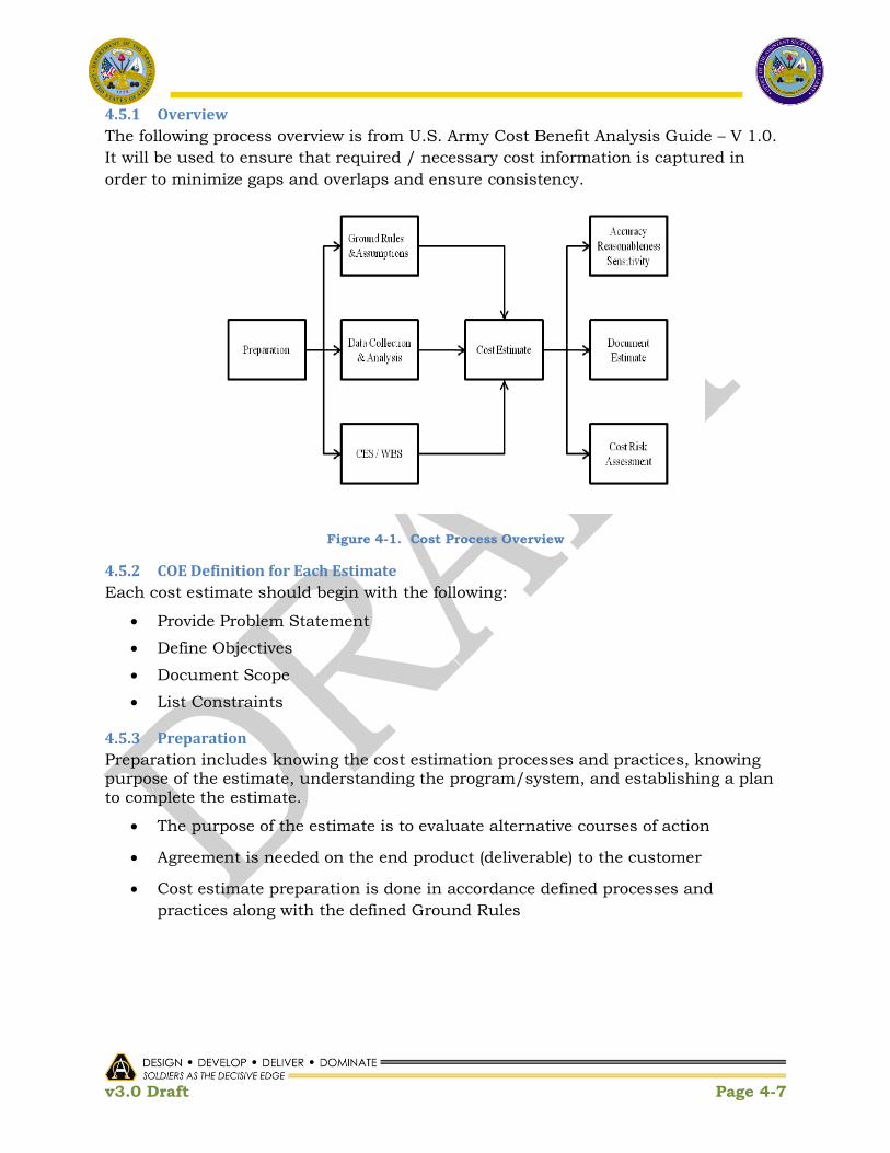
v3.0 Draft Page 4-7
4.5.1 Overview
The following process overview is from U.S. Army Cost Benefit Analysis Guide – V 1.0.
It will be used to ensure that required / necessary cost information is captured in
order to minimize gaps and overlaps and ensure consistency.
Figure 4-1. Cost Process Overview
4.5.2 COE Definition for Each Estimate
Each cost estimate should begin with the following:
Provide Problem Statement
Define Objectives
Document Scope
List Constraints
4.5.3 Preparation
Preparation includes knowing the cost estimation processes and practices, knowing purpose of the estimate, understanding the program/system, and establishing a plan to complete the estimate.
The purpose of the estimate is to evaluate alternative courses of action
Agreement is needed on the end product (deliverable) to the customer
Cost estimate preparation is done in accordance defined processes and
practices along with the defined Ground Rules

v3.0 Draft Page 4-8
4.5.4 Ground Rules
Ground rules describe the basis from which the estimate is made. Listed below are typical examples:
Scope of the estimate
Use of constant / current dollars or inflated (Then-year) dollars
Procurement/fielding schedules
Quantity of development units or prototype units
Fee structure
Development and production, O&S start and stop dates
Specific items or costs excluded from the cost estimate
Government Furnished Equipment (GFE)
Sunk costs
4.5.5 Assumptions
Assumptions are suppositions that describe unknown variables that will affect an estimate. Listed below are typical examples:
Commonality among components and other systems
Technology assumptions
Software assumptions
Test, Validation and Certification
Maintenance / Evolution concept
Training strategy
Support concept
Acquisition strategy
Sparing concept
Long lead items/procurement lead time
Hardware refresh cycle
4.5.6 Data Collection & Analysis
This step includes the process of identifying, collecting, and analyzing data.
Identify the types of data needed (e.g., cost, programmatic, schedule, technical)
Collect cost data and program documentation
Determine the sample size of data to be collected for each cost element
Determine which estimating methods, tools, and models will be used with
which data sets
Verify, validate and adjust (normalize) the data

v3.0 Draft Page 4-9
4.5.7 CES/WBS
A work breakdown structure (WBS) defines in detail the work necessary to accomplish
initiative/proposal objectives. A well-developed cost element structure (CES) helps
ensure that no costs are missed and that there is no double counting, and achieves
the following:
Reflects the requirements and what must be accomplished
Provides a basis for identifying resources and tasks for developing a cost
estimate.
Ensures the cost of each element of the WBS is estimated
Reflects cost elements at the lowest level of a cost estimate, and the cost
estimate total is the sum of all the cost elements
CES/WBSs are required for each CE; however, they are not required for each COEP.
The COEP must identify the CES/WBS elements affected with the associated costs.
As the COEP matures, the cost detail is expected to have greater depth to support the
desired decision.
4.5.7.1 Standard WBS for Information Systems
The CES / WBS for Automated Information Systems (AIS) is depicted in Table 4-1. It
is the OSD CAPE and DASA-CE standard for IT and Software Systems. It is
anticipated that this CES/WBS will be tailored appropriately to comply with contract
mandates as well as for non-AIS systems (i.e., weapons systems) in accordance with
MIL-HDBK-881A guidelines. It is understand that the WBS for existing systems may
either differ from or not conform to the standard CES / WBS depicted in Table 4-1.
For these instances, it is anticipated that those structures will be normalized and
mapped to the standard structure to ensure consistency across costs so that each cost
element consists of the same factors and it is clear where and how costs are captured
for comparative purposes.
4.5.8 Sensitivity Analysis
Sensitivity analysis is a tool for assessing the extent to which costs are sensitive to changes to specific assumptions.
For performing what-if analysis
Determining how sensitive the point estimate is to changes in the cost driver
Developing ranges of potential costs

v3.0 Draft Page 4-10
4.5.9 Cost-Risk Assessment
Uncertainty is associated with cost estimates, since they predict future program costs.
An uncertainty analysis should be performed to capture the cumulative effect of
risks
Technical risk
Schedule risk
Requirements creep
Cost estimating uncertainty
An uncertainty analysis estimates the probability associated with achieving the point
cost estimate. This analysis will be achieved by asking for triangular inputs, rather
than for a point estimate. This analysis will help identify the degree of uncertainty
and mitigate adverse recommendations.
4.5.10 Cost Process Summary
Document ground rules & assumptions
Use the AIS CES / WBS
Perform sensitivity and cost-risk analysis
Analyze cost-risk uncertainly
Adjust the estimate to a 50% confidence level
In addition, keep a management reserve which is roughly equal to the cost
difference between 50% and 80% confidence levels – per the Weapon System
Acquisition Reform Act28 of 2009
Note – this is today‟s best practice and a driver for shift to a COE / Enterprise Service
based capability.
28 (d) DISCLOSURE OF CONFIDENCE LEVELS FOR BASELINE ESTIMATES OF MAJOR DEFENSE
ACQUISITION PROGRAMS – The Director of Cost Assessment and Program Evaluation, and the Secretary of the military department concerned or the head of the Defense Agency concerned (as applicable), shall each – „„…(1) disclose in accordance with paragraph (2) the confidence level used in establishing a cost estimate for a major defense acquisition program or major automated information system program, the rationale for selecting such confidence level, and, if such confidence level is less than 80 percent, the justification for selecting a confidence level of less than 80 percent…”

v3.0 Draft Page 4-11
Table 4-1. AIS CES/WBS
1.0 Investment 2.0 System Operations & Support
1.1 Program Management 2.1 Program Management
1.1.1 Personnel 2.1.1 Personnel
1.1.2 TDY 2.1.2 TDY
1.1.3 Other Government Support 2.1.3 Other Government Support
1.1.4 Other 2.1.4 Other
1.2 Concept Exploration 2.2 Annual Operations Investment
1.2.1 Engineering Analysis & Specs 2.2.1 Annual System Maint Investment
1.2.2 Concept Exploration Hardware 2.2.2 Replenishment Spares
1.2.3 Concept Exploration Software 2.2.3 Replenishment Supplies & Consumables
1.2.4 Concept Exploration Data 2.3 Hardware Maintenance
1.2.5 Exploration Documentation 2.3.1 Organic HW Maint
1.2.6 Concept Exploration Testing 2.3.2 Contract Maint Support
1.2.7 Facilities 2.3.3 Other HW Maint
1.2.8 Other (Log Spt, Env, etc.) 2.4 Software Maintenance
1.3 System Development 2.4.1 COTS
1.3.1 System Design & Specification 2.4.2 Application Mission (Non-COTS)
1.3.2 Dev, Prototype & Test Site Investment 2.4.3 Comm Software (Non-COTS)
1.3.3 Software Development 2.4.4 Data Center Software
1.3.4 System Documentation 2.4.5 Other Software (Config Mgmt)
1.3.5 Data Development & Transition 2.5 Mega Center Ops & Maint Spt
1.3.6 Database Standards/Dictionary 2.6 Data Maintenance
1.3.7 Training Development 2.6.1 Mission Application Data
1.3.8 Test and Evaluate 2.6.2 Standard Admin Data
1.3.9 Development Logistics Support 2.7 Unit/Site Operations
1.3.10 Facilities 2.7.1 System Operations Personnel
1.3.11 Environmental 2.7.2 Utility Reqts
1.3.12 Other Development 2.7.3 Fuel & POL
1.4 System Procurement 2.7.4 Facilities Lease & Maint
1.4.1 Deployment Hardware (AD Domain Controllers) 2.7.5 Communications
1.4.2 System Deployment Software (Identity Mgmt) 2.7.6 Base Operating Support
1.4.3 Initial Document Reqmts 2.7.7 Recurring Training
1.4.4 Logistics Support Equipment 2.7.8 Miscellaneous Support (DIACAP C&A)
1.4.5 Initial Spares 2.8 Env & Hazmat Store & Hand
1.4.6 Warranties 2.9 Contract Leasing
1.5 Outsource / Central / Mega Center Investment
1.5.1 Capital Investment 3.0 Alt Phase Out (SQ Profile)
1.5.2 Software Development 3.1 System Management
1.5.3 System User Investment 3.1.1 Personnel
1.6 System Initiation, Implementation & Fielding 3.1.2 TDY
1.6.1 Initial Training 3.1.3 Other Government Support (AD PM)
1.6.2 System Integration, Site Test/Acceptance 3.2 Phaseout Investment
1.6.3 Common Support Equipment 3.2.1 Hardware
1.6.4 Site Activation & Facilities Prep (Migration Support) 3.2.2 Software
1.6.5 Initial Supplies 3.2.3 Env & Hazmat Store & Hand
1.6.6 Engineering Changes 3.3 SQ Phase out Ops & Support
1.6.7 Initial Logistics Support 3.3.1 HW Maint
1.6.8 Office Furniture 3.3.2 SW Maint
1.6.9 Data Upload (EDS Identity Mgmt) 3.3.3 Unit/Site Operations
1.6.10 Base/Installation Comm (Out of BW Mgmt) 3.3.4 Mega Ctr Operating & Maint Spt
1.6.11 Other 3.3.5 Phase Out Contracts
1.7 Upgrade/P31
1.7.1 Upgrade Development
1.7.2 Life Cycle Upgrades Procure
1.7.3 Central Mega Center Upgrades
1.8 Disposal/Reuse
1.8.1 Capital Recoupment
1.8.2 Retirement
1.8.3 Environment/Hazardous Disposal

v3.0 Draft Page 4-12
4.6 Overall COE Cost Estimate After all the cost estimates have been collected, they need to be analyzed as a whole, to eliminate gaps and overlaps.
Identify duplicate services and cost components
Rationalize duplications
Calculate overall cost estimates
Analyze future cost savings / avoidance
Add in target cost analysis points and metrics
Establish a peer review process (and authority) for approving costs and
establish prioritization of COE initiatives
4.7 Challenges in Realizable Savings / Avoidance Some of the challenges in achieving estimated cost savings / avoidance are listed
below.
Distributed ownership of service components
Cost elements funded from several accounts
Total cost of ownership vs. budgeted costs
Buy-in
Labor that is multi-tasked
4.8 Lessons Learned from Previous Initiatives Lessons learned from previous initiatives are listed below, to ensure success.
Required inputs have to be available
Process needs to be followed
Early socialization and buy-in needed
Governance should be in place
4.9 Cost Estimate Templates The following cost estimate templates (Figures 4-2 to 4-4) will be used to capture all
COE costs. They will be aligned with the Army G-8 POM/WSR process. To complete
the templates:
Estimate costs for FY12 through FY18, but also include FY11 investments in
progress
Estimate cost by capability – use the Capability template and WBS format to
identify cost details
Estimate cost to support the EcoSystem – use the template provided
Aggregate capability cost estimates by CE – use the template provided
Provide costs in terms of PEGs as is done for POM/WSR process – templates to
be provided
Submit requested templates as well as backup spreadsheets where applicable

v3.0 Draft Page 4-13
Ensure that the following questions are answered for each system
1. What capabilities are already planned that align with the COE
Implementation Plan?
a. Which are already included / funded in a base program? State
whether the capability as planned is sufficient or if additional funding
is necessary to meet COE implementation?
b. Which are new development?
2. What is the cost estimate in total?
a. Include life cycle costs and cost types – design, validation, training,
fielding/sustainment ; RDT&E, OPA, O&S
b. Provide capability description, rationale/justification, dependencies
and impact statements
c. Identify contributing organizations
3. What is the variance from the current base plan?
4. What additional funding is required to meet the COE Implementation Plan?
If additional funding is required, is this to achieve COE compliance or is it
for additional development?
5. What is being leveraged from base, initiatives, QRCs, S&T efforts, agencies
(DoD, Joint, IC, …), etc.
6. What is the traceability to existing funding documents: PM/WSR, P&R
Form, Initiative, S&T efforts
7. What assistance is needed with respect to policy and process requirements?

v3.0 Draft Page 4-14
Figure 4-2. COE Capability Cost Template
Category Funding TypeExecution
Organization(s)
Budget/POM/P&R
Form/Initiative/S&T
References
FY11 FY12 FY13 FY14 FY15 FY16 FY17 FY18FY11-12
TotalFY13-18 Ttotal
RDT&E - -
OPA - -
O&S - -
Hardware Total 0 0 0 0 0 0 0 0 0 0
RDT&E - -
OPA - -
O&S - -
Software Total 0 0 0 0 0 0 0 0 0 0
Base Total 0 0 0 0 0 0 0 0 0 0
RDT&E - -
OPA - -
O&S - -
Hardware Total 0 0 0 0 0 0 0 0 0 0
RDT&E - -
OPA - -
O&S - -
Software Total 0 0 0 0 0 0 0 0 0 0
Additional Total 0 0 0 0 0 0 0 0 0 0
RDT&E - -
OPA - -
O&S - -
Hardware Total 0 0 0 0 0 0 0 0 0 0
RDT&E - -
OPA - -
O&S - -
Software Total 0 0 0 0 0 0 0 0 0 0
Reduced Total 0 0 0 0 0 0 0 0 0 0
RDT&E - -
OPA - -
O&S - -
Hardware Total 0 0 0 0 0 0 0 0 0 0
RDT&E - -
OPA - -
O&S - -
Software Total 0 0 0 0 0 0 0 0 0 0
RDT&E
OPA
O&S
All 0 0 0 0 0 0 0 0 0 0
RDT&E - -
OPA - -
O&S - -
Hardware Total 0 0 0 0 0 0 0 0 0 0
RDT&E - -
OPA - -
O&S - -
Software Total 0 0 0 0 0 0 0 0 0 0
RDT&E
OPA
O&S
All 0 0 0 0 0 0 0 0 0 0
Assistance Needed:
Capability Description:
Rationale / Justification:
Dependencies:
ESTIMATE $K
Hardware
Software
Hardware
Software
Original Base Program Plan
(from Current Year Budget
and POM Submission)
Additional Funding
Requirement beyond Base for
COE Implementation
Hardware
Software
Value Proposition:/Efficiency Gains:
Total
Total Overall Cost
Reduced Funding
Requirement from Base due
to COE Implementation
Hardware
Software
[Capability Name]
e.g., Widget Framework
Development for COE Data
Center CE
Impact if not Fully Funded:
Total Cost Variance
Hardware
Software
Total

v3.0 Draft Page 4-15
Figure 4-3. CE Capability Summary Cost Template
Category Funding TypeExecution
Organization(s)
Budget/POM/P&R
Form/Initiative/S&T
References
FY11 FY12 FY13 FY14 FY15 FY16 FY17 FY18FY11-12
TotalFY13-18 Ttotal
RDT&E - - - - - - - - - -
OPA - - - - - - - - - -
O&S - - - - - - - - - -
Hardware Total 0 0 0 0 0 0 0 0 0 0
RDT&E - - - - - - - - - -
OPA - - - - - - - - - -
O&S - - - - - - - - - -
Software Total 0 0 0 0 0 0 0 0 0 0
Capability 1 Cost 0 0 0 0 0 0 0 0 0 0
RDT&E - - - - - - - - - -
OPA - - - - - - - - - -
O&S - - - - - - - - - -
Hardware Total 0 0 0 0 0 0 0 0 0 0
RDT&E - - - - - - - - - -
OPA - - - - - - - - - -
O&S - - - - - - - - - -
Software Total 0 0 0 0 0 0 0 0 0 0
Capability 2 Cost 0 0 0 0 0 0 0 0 0 0
RDT&E - - - - - - - - - -
OPA - - - - - - - - - -
O&S - - - - - - - - - -
Hardware Total 0 0 0 0 0 0 0 0 0 0
RDT&E - - - - - - - - - -
OPA - - - - - - - - - -
O&S - - - - - - - - - -
Software Total 0 0 0 0 0 0 0 0 0 0
Capability 3 Cost 0 0 0 0 0 0 0 0 0 0
RDT&E - - - - - - - - - -
OPA - - - - - - - - - -
O&S - - - - - - - - - -
Hardware Total 0 0 0 0 0 0 0 0 0 0
RDT&E - - - - - - - - - -
OPA - - - - - - - - - -
O&S - - - - - - - - - -
Software Total 0 0 0 0 0 0 0 0 0 0
Capability N Cost 0 0 0 0 0 0 0 0 0 0
RDT&E 0 0 0 0 0 0 0 0 0 0
OPA - -
O&S - -
Hardware Total 0 0 0 0 0 0 0 0 0 0
RDT&E - -
OPA - -
O&S - -
Software Total 0 0 0 0 0 0 0 0 0 0
RDT&E 0 0 0 0 0 0 0 0 0 0
OPA 0 0 0 0 0 0 0 0 0 0
O&S - - - - - - - - - -
All 0 0 0 0 0 0 0 0 0 0
Total CE Cost
Total
Hardware
Software
Hardware
Software
[CE Name]
.
.
.
[CapabilityN Name]
ESTIMATE $K
Hardware
Software
[Capability3 Name]
.
.
.
.
Hardware
Software
[Capability1 Name]
[Capability2 Name]
Hardware
Software

v3.0 Draft Page 4-16
Figure 4-4. COE EcoSystem Cost Template

v3.0 Draft Page 4-17
This Page Intentionally Left Blank

v3.0 Draft Page 5-1
5 User Requirements
5.1 Origin of COE Requirements
COE requirements are largely technical and, thus, are derived from warfighter requirements. As Figure 5-1 illustrates, the TRADOC specified warfighter requirements drive the need for ―user facing‖ Application and Functional Service capabilities that will reside on top of the COE.
Figure 5-1. TRADOC Specified User Requirements
Warfighter requirements are explicitly expressed within the standard TRADOC processes and are not considered part of the COE- with the following class of exceptions: TRADOC specified warfighter requirements that are common across PoRs are candidates for inclusion into the Standard Application layer of the COE (e.g., Chat,
White Board, etc.). The COE Governance process described in Section 2 will serve as the venue for identifying and coordinating introduction of these ―common‖ applications.
The remaining elements of the COE are those that address requirements that are derived as supporting the TRADOC specified warfighter requirements. These generally relate to technical infrastructure.

v3.0 Draft Page 5-2
Today, the technical requirements of a Common Operating Environment are tacitly implied in the JCIDS documentation for some Programs of Record, including ICDs, CDDs, and CPDs. For example, the Net-Enabled Mission Command (NeMC) ICD details the Mission Command Essential Capabilities (MCEC) which "represents the core capabilities necessary for the Army to execute mission command while operating throughout the full spectrum of operations." Further, the NeMC IDC recommends a "synchronized development of the MCEC through a System of Systems (SoS)‖ Engineering process [that] will ensure consistency in implementation and deliver an integrated capability across all layers of the network. In cases where programs are in post Milestone C state, alignment of user and technical requirements will be challenging and require statutory relief and guidance.
5.2 Current Requirements Traceability
The user community, via TRADOC PAM 525-3-0, has highlighted the need to develop and apply C5ISR technologies for a diverse set of environments and missions. Figure 5-2 captures the operational environment and associated spectrum of conflict, areas of conflict, and principles as defined by the user.
Figure 5-2. Operational Environment
Fundamental to the Army‘s ability to design, plan, execute, and deliver Materiel solutions as part of the DOTMLPF (Doctrine Organization Training Materiel Leadership

v3.0 Draft Page 5-3
Personnel Facilities) solution spectrum is the establishment of clear linkages between Capabilities and Systems. The clear identification of systems to capability gap relationships will aid in tracking where remaining gaps are and determining where potential materiel overlaps exist. Additionally it will support better informed decisions regarding integration of new concepts, rapid programs, and new and evolving programs of record (PoR), as well as allocation or re-allocation of functions across systems to achieve the desired effect while achieving the greatest efficiency. The Office of the Secretary of Defense (OSD) and the Joint Chiefs of Staff (JCS) have published clear strategic guidance documents and established processes (see Figure 5-3). Those documents link the Joint Concepts to Joint and Service specific missions. In order to relate and decompose these with Army Capabilities the Training and Doctrine Command (TRADOC), the Army Capabilities Integration Center (ARCIC) establishes the guiding Army concepts, and executes the Capabilities Based Assessment (CBA) process.
Campaign of Learning Support to Concept Development
23
Campaign of LearningInsights relevant to
Key Ideas & significant
shifts in approach
Insights relevant to Key
Ideas and Missions
Experiments
WargamesStudies
S&T
Evaluations Insights/findings/
recommendations/ ISS*
. . .AWFCs
Insights relevant
to Required
Capabilities
Revised Concepts Framework
Army
Operating
Concept
Sustainment
Fires
Maneuver
Protection
Intelligence
Mission Command
Army
Functional
Concepts
Mission
Command
Strategic
Guidance
QDR
NMS
GEF
Emerging Trends
in the OE
Space
Human Dimension
Mission Command
Special
Concepts
Training
Rolling Assessment
*ISS – Interim Solution Strategy
Figure 5-3. Army Concept Documentation Relationships. TRADOC ARCIC "Levels of Integration" Brief, Nov 2010
As part of the CBA process a series of analyses (Functional Area Analysis (FAA), Functional Needs Analysis (FNA), and Functional Solutions Analysis (FSA)) are developed, along with an associated campaign of learning, in order to produce a prioritized list of potential non-materiel and/or materiel approaches that solve, or at least mitigate, capability gaps. The FNA establishes a set of prioritized gaps by Center of Excellence (CoE), and the ARCIC merges these into a single prioritized gap list that scopes the FSA process toward the ―unacceptable risk‖ gaps. The product of the FSAs,

v3.0 Draft Page 5-4
plus the other analyses and requirements documents are provided as input to the Weapons Systems Reviews (WSRs) and drive the development of an Initial Capabilities Document (ICD) (the first step in documenting Materiel solution requirements). This process is captured in Figure 5-4. The ICD documents the requirements to resolve a specific capability gap or a set of capability gaps for a given timeframe as identified in the CBA.
C-B
AC
-BA
C-B
AC
-BA
C-B
A CB
A
Example of How Products Are Integrated
WFF FNA Gaps Prioritized
Gaps based on Operational Risk
FSA
1-n PrioritizedCapability Gaps
One Gap List
Consolidated Ordered
Solutions List
Prioritized RIODOTMLPF Solutions for
Unacceptable Gaps
Level 3
Level 2
Aaaaaaa
BbbbbbbCccccccc
Ddddddd
EeeeeeeeFffffff
Gggggg
HhhhhhhIiiiiii
Jjjjjjj
AaaaaaaBbbbbbb
Cccccccc
DddddddEeeeeeee
Fffffff
GgggggHhhhhhh
Iiiiiii
JjjjjjjAaaaaaa
Bbbbbbb
CcccccccDdddddd
Eeeeeeee
Fffffff
Gggggg
HhhhhhhIiiiiii
Jjjjjjj
Unacceptable Risk
Acceptable Risk
Aaaaaaa
BbbbbbbCccccccc
Ddddddd
EeeeeeeeFffffff
Gggggg
HhhhhhhIiiiiii
Jjjjjjj
AaaaaaaBbbbbbb
Cccccccc
DddddddEeeeeeee
Fffffff
GgggggHhhhhhh
Iiiiiii
JjjjjjjAaaaaaa
Bbbbbbb
CcccccccDdddddd
Eeeeeeee
Fffffff
Gggggg
HhhhhhhIiiiiii
Jjjjjjj
Aaaaaaa
BbbbbbbCccccccc
Ddddddd
EeeeeeeeFffffff
Gggggg
HhhhhhhIiiiiii
Jjjjjjj
AaaaaaaBbbbbbb
Cccccccc
DddddddEeeeeeee
Fffffff
GgggggHhhhhhh
Iiiiiii
JjjjjjjAaaaaaa
Bbbbbbb
CcccccccDdddddd
Eeeeeeee
Fffffff
Gggggg
HhhhhhhIiiiiii
Jjjjjjj
Aaaaaaa
BbbbbbbCccccccc
Ddddddd
EeeeeeeeFffffff
Gggggg
HhhhhhhIiiiiii
Jjjjjjj
AaaaaaaBbbbbbb
Cccccccc
DddddddEeeeeeee
Fffffff
GgggggHhhhhhh
Iiiiiii
JjjjjjjAaaaaaa
Bbbbbbb
CcccccccDdddddd
Eeeeeeee
Fffffff
Gggggg
HhhhhhhIiiiiii
Jjjjjjj
Aaaaaaa
BbbbbbbCccccccc
Ddddddd
EeeeeeeeFffffff
Gggggg
HhhhhhhIiiiiii
Jjjjjjj
AaaaaaaBbbbbbb
Cccccccc
DddddddEeeeeeee
Fffffff
GgggggHhhhhhh
Iiiiiii
JjjjjjjAaaaaaa
Bbbbbbb
CcccccccDdddddd
Eeeeeeee
Fffffff
Gggggg
HhhhhhhIiiiiii
Jjjjjjj
Aaaaaaa
BbbbbbbCccccccc
Ddddddd
EeeeeeeeFffffff
Gggggg
HhhhhhhIiiiiii
Jjjjjjj
AaaaaaaBbbbbbb
Cccccccc
DddddddEeeeeeee
Fffffff
GgggggHhhhhhh
Iiiiiii
JjjjjjjAaaaaaa
Bbbbbbb
CcccccccDdddddd
Eeeeeeee
Fffffff
Gggggg
HhhhhhhIiiiiii
Jjjjjjj
Aaaaaaa
BbbbbbbCccccccc
Ddddddd
EeeeeeeeFffffff
Gggggg
HhhhhhhIiiiiii
Jjjjjjj
AaaaaaaBbbbbbb
Cccccccc
DddddddEeeeeeee
Fffffff
GgggggHhhhhhh
Iiiiiii
JjjjjjjAaaaaaa
Bbbbbbb
CcccccccDdddddd
Eeeeeeee
Fffffff
Gggggg
HhhhhhhIiiiiii
Jjjjjjj
Unacceptable Risk
Acceptable Risk
Gap list
scoped for
Solutions
Analysis
ICDs
WFF Changes / Deletions to
Existing Requirements
Documents
WFFBlueprints
Comparison of Risks
Across WFF
TAA
WSR2-Star
Reviews
Comparison of
Benefits, Risks
& Costs
Campaign of Learning
Experiments
WargamesStudies
S&T
Evaluations Insights/findings/
recommendations
. . .
Focused, short
term learning
event(s)
Focused, short
turn learning
event(s)
Figure 5-4. Requirements Integration Process. TRADOC ARCIC "Levels of Integration" Brief, Nov 2010
This documented relationship between ICDs and other key requirements documents (CDDs and CPDs) associated with materiel requirements can be traced to the particular systems that are developed to address the requirement(s).

v3.0 Draft Page 5-5
Figure 5-5. JCIDS and the Defense Acquisition Management System. TRADOC Reg 71-20, dtd 6 Oct 2009
5.3 A New Approach to Delivering Information Capabilities
In July of 2010, the Office of the Secretary of Defense issued a report to Congress, A New Approach for Delivering Information Capabilities in the Department of Defense, on Dec. 9, 2010, in response to Section 804 of the NDDA of FY2010, which stated that a new acquisition process is required.. The report acknowledges the acquisition challenges as they exist today including those in the requirements space as described above in section 5.1. The report recommends a ―Common IT Infrastructure‖, and a more responsive construct for managing User requirements.
The processes and principles, outlined in the report will serve as a guide for management of the user requirements that will be translated into the technical requirements of the COE. In particular, the following mandates will be applied to the User Requirements process:
“Requirements generation and management
The new IT acquisition process will need to acknowledge the uncertainty
associated with the dynamic IT environment and incorporate the flexibility to
responsively manage changing needs. The proposed new approach for
acquiring IT delivers capability in smaller project increments; the result will
be ―80 percent solutions‖ and deferral of capabilities that can‘t be met within
time-boxed constraints, especially for COTS acquisition solutions. To permit
these flexibilities, the requirements generation and management process will
v3.0 Draft Page 5-6
be adjusted.[It is noted that certain real-time and safety critical systems
cannot be subject to 80% solutions.]
Initial requirements would be defined at the mission level in broad
measurable terms that are not expected to change during the life of the
project or program. This broad definition would include basic IT system
functions, operating security levels, data standards, and architecture. These
broad requirements should be defined quickly and approved by executive level
requirements owners.
Short Suspense Projects
IT will be acquired as small time-boxed projects delivering capability in an
iterative fashion using mature technologies, while managed in capability
aligned portfolios to identify and eliminate redundancy.
Rationalized Requirements Principle
User involvement is critical to the ultimate success of any IT implementation
and user needs must be met. However this principle recognizes that users and
requirements owners must embrace established standards and open modular
platforms vice customized solutions to ensure interoperability and seamless
integration.
Portfolio Responsible Authority
ASA (ALT) oversees the warfighting systems portfolio…Further alignment is
required within each portfolio to leverage economies of scale, identify and
eliminate duplicative capability, clearly define discrete capabilities with well-
defined performance metrics, and develop and enforce information standards
and architectures resulting in greater information sharing across
organizational boundaries."
5.4 User Requirements Relation to Technical Requirements
5.4.1 COE Users
The COE will provide utility to four (4) distinct user communities: the Warfighter, the Generating Force, the PoR Developer, and the Warfighter Developer (a Future Role):
Warfighter
A Warfighter is the prototypical end-user of the COE. The COE provides direct access to Standard Applications to the Warfighter. For example, the Warfighter may use a federated search facility that in turn would invoke any number of services from the COE Data Services layer; or the Warfighter may use a Chat client that would subsequently leverage a Chat Server from the COE Infrastructure Services layer.
Generating Force

v3.0 Draft Page 5-7
The COE will also support the operations of the users within the Generating Force. Although the applications supported here will often be those associated an office environment, the COE security, management, and uniformity attributes will be key enablers to the Generating Force.
Material Developer There are two types of Material Developer; first, is a developer who will utilize the services provided by the COE to build User Applications that fulfill user facing requirements. Second, the COE developer will leverage existing infrastructure COE services to create more complex services that will be included as part of the COE. It is important to note that the community of future material developers is broader than the traditional role of PoRs today and includes a smaller and more agile collection of contributors.
Warfighter Developer [Future Role] It is envisioned that in The Warfighter will also be able to develop applications, build application workflows, and perhaps develop new COE capabilities. This role will require a significant change in the current CONOPS and is still being considered.
The notional relation of each user to the COE is illustrated in Figure 5-6.

v3.0 Draft Page 5-8
Figure 5-6. COE Users and Areas of Operation
5.4.2 Source of COE Related Requirements
COE requirements can be classified into the following two groups:
Specified: Warfighter Requirements Warfighter (End-user) requirements (or capabilities) are specified in TRADOC documentation in operational terms. Many of these directly apply to capabilities provided by the COE infrastructure. For example, the Net-Enabled Mission Command ICD identifies Collaboration as a capability required across systems. Thus, collaboration must be supported by the COE.
Derived: Technical Requirements Derived COE technical requirements that are necessary to implement explicit requirements but are not specifically listed as a requirement. These are the technical requirements that serve to establish the infrastructure that embodies what will become the COE. For example, the (technical) requirements for Identity Management, Directory Services and Public Key Infrastructure (PKI) capabilities are derived from the Warfighter specified capability requirements for services such as chat, e-mail, and collaboration.

v3.0 Draft Page 5-9
5.4.3 User Requirements and the Acquisition Process
COE objectives are fundamentally focused on increased interoperability and operational relevance of the C5ISR tools that are provided to the Warfighter while realizing a reduction of development, test, certification, and deployment timelines, complexities, and cost. A reformed approach to acquisition and a new role for addressing Warfighter requirements will be required in order to realize these objectives.
Each of the COE User Communities will use the COE within one or more of the CE‘s described in the appendices of this document. Further, applications for scores of PoRs will be aligned with the COE within these CEs. Consequently, management of the COE User and Technical Requirements across PoR portfolios and these CE‘s will be critical to achieving the potential interoperability, economies of scale, and functionality improvements promised by the deployment of a COE. The COE Execution Plan, Appendix A, addresses the management of COE requirements that span the CE‘s program portfolios‘.
Success will require embracing the acquisition activities proposed ―…in the new process for delivering IT capability…‖ to the Warfighter which ―… will differ significantly from the traditional weapon system development acquisition process and will be separately defined…‖29by a refined DoD policy. As part of this new policy, the
Report to Congress titled A New Approach for Delivering Information Capabilities in the
Department of Defense, Dated Dec 2010, cites that Continuous Warfighter and IT User Engagement will be required30. Specifically, the new process for delivering the COE will emphasize continuous user engagement that fulfills discrete and defined roles. Chartered agreements between CE proponents and among PoR portfolio managers will formalize rules of engagement.
5.5 Assessment and Alignment of Technical Requirements and
Implementations
Although different systems may provide similar Mission Command capabilities, there are many instances where materiel solutions, and implementations are unnecessarily different. To realize the convergence necessary to achieve a COE across programs of record, ASA(ALT), in cooperation with CIO/G6, TRADOC TCMs, and Program of Record Program Managers, will survey and assess the current and planned technical requirements, standards and implementations across all systems. In cases where alignment is required within a CE, the respective CEWGs will conduct the assessment
29 (c)Acquisition, A New Approach for Delivering Information Capabilities in the Department of Defense, a report to Congress, 9
DEC 2010, Office of the Secretary of Defense, Pursuant to Section 804 of the, National Defense Authorization Act for Fiscal Year
2010, pg7
30 Continuous Warfighter and IT User Engagement, A New Approach for Delivering Information Capabilities in the
Department of Defense, a report to Congress, 9 DEC 2010, Office of the Secretary of Defense, Pursuant to Section 804 of the,
National Defense Authorization Act for Fiscal Year 2010, pg 9

v3.0 Draft Page 5-10
and alignment of technical requirements. Inter-CE assessment and alignment will be conducted under the direction of the COE Chief Engineer.
A candidate standards, requirements, capabilities and materiel solutions mapping process is illustrated in Figure 5-7:
Figure 5-7. Survey/Analysis of Standards, Requirements, Capabilities and Materiel Solutions
The survey and assessment will focus on informing leadership with regard to achieving the following objectives:
Normalizing Capability Requirements: Revise PoR requirements to promote common solutions.
Collapse Standards: Eliminate conflicting, and ambiguous standards. Adjudication of Standards will be addressed by the COE Governance process described in Section 2. This will occur in a phased and coordinated process that will attempt to minimize programmatic impact.
Convergence of Materiel Solutions: Align materiel solutions to eliminate redundancies.
Figure 5-8 illustrates the relationships between the normalization of requirements,
collapsing of standards, and resulting convergence of materiel solutions along with the
respective cognizant organizations.

v3.0 Draft Page 5-11
Figure 5-8. COE Convergence – Problem Space
Implementation of the COE will require that tools be employed support the process of managing allocation of the requirements and capabilities across the boundaries of CE‘s. These processes and tools are discussed in further detail in the CE appendices.
The sections below provide a brief overview of the survey scope and objectives products required to establish a roadmap for a COE across future CS.
5.5.1 Collapse and Reconciliation of Standards
An assessment of CIO-G6 Standards and PoR plans to implement these standards, by CS, will identify a minimal set of maintainable and efficient standards for the evolution of the COE.
5.5.2 Convergence of Mission Command Capability Requirements
A partial survey of Mission Command Essential Capability Requirements addressed, by system, has been conducted to identify capabilities addressed by multiple systems.

v3.0 Draft Page 5-12
This survey will be completed and the results of this survey will: 1) Solidify definition of common components, and, 2) identify the source (PoR) documentation that must be aligned to promote convergence.
5.6 Summary
The results of these surveys and analysis will reveal opportunities to synchronize user operational requirements, derived technical requirements, and related architectural standards, in a disciplined process that can be traced back to authoritative requirements documentation and authoritative operational functions (AUTLS, UJTLS, MCEC, other) and Materiel Solutions to establish a roadmap for the evolution of the COE. These activities constitute a challenging undertaking and must be phased and synchronized in order to achieve success.

v3.0 Draft Page 5-13
This Page Intentionally Left Blank

v3.0 Draft Page 6-1
6 Implementation, Integration, Verification, and Test
6.1 Overview
The COE phases (planning and execution) were identified earlier in this document. Section 2
focused on the Governance process as COE Proposals (COEPs) are nominated, requirements
defined, analyzed, reviewed at appropriate levels, and subsequently a subset are approved.
For ease of discussion in this section the term COEP is used, as opposed to approved COEP.
The reader should note that this section of the document only applies to COEPs that have
been approved for baseline or for immediate action. Further, this section focuses on the set of
activities that occur after a COEP is approved: Implementation, Integration, and Verification.
For each of these activities this section describes the processes, participants, and artifacts.
Application changes that are independent of the COE and approved COEPs, that is,
application changes that do not depend on any other application or the COE infrastructure,
are executed entirely under the guidance of the application Program Manager.
Members from ASA(ALT) System of Systems Engineering (SoSE) and System of Systems
Integration (SoSI) will comprise the SoS engineering team. The CEWG Chair and SoS
engineering team have primary orchestration and monitoring roles throughout the planning
and execution phase (Implementation, Integration, Verification, and Test) of the COE. The
application PM in concert with the Army CIO/G6 maintain responsibility for Certification,
Validation, the process of assessing the application and its ability to deliver the desired
operational capability, remain the responsibility of the User community. The PM maintains
responsibility for transitioning the application to the field. The ASA(ALT) team and the
CIO/G6, as well as other organizations, are working closely to align current activities
whenever and wherever possible.
This section does not yet address Test and Certification nor the processes associated with
the Marketplace (App Store) software transformation initiatives, or introduction of solutions
supporting the introduction of new standards. ASA(ALT) in concert with CIO/G6 will evolve
these processes over the next year, to include:
Identification of the overall concept and model for software updates from a Software
Marketplace
Types of applications that would be appropriate/not appropriate for distribution via a
software update from a Software Marketplace
Information Assurance and system configuration considerations
Testing/qualification required to ensure an application developed in the field is ready
for release through the Software Marketplace process.

v3.0 Draft Page 6-2
All applications must meet Information Assurance procedures and certification. PORs are
required to obtain a Certificate of Networthiness (CoN) as part of the certification package.
CEs (e.g. Data Center) will need a CoN for their systems-of-systems (for example, a data
center will need a CON that includes both hardware and software). If a CE has an
architecture that is replicated, a ―blanket‖ CoN may be appropriate. Other CEs (i.e., Mobile/
Handheld) will need a CON for each device type (e.g. iOS, Droid, Windows) and field
configurations (e.g., OS, firmware, etc.) should be baselined, and include applications that
originate from the Enterprise or Tactical market server. Specific Information Assurance
procedures for the COE are addressed in an appendix of this document and by each CE in
the respective document appendix.
This section is closely tied to earlier sections in this document; a few relationships are
identified here for clarity.
Governance. As described earlier in this document, Governance allows decisions to be made at the lowest levels, whenever possible, and for visibility at all levels. The Governance process continues throughout the execution phase in that the details are worked at the lowest levels (CEWG, PMs, SoS engineer, and CEWG Chair). Anomalies that have cross CE impact or cannot be resolved at the CE level are raised to higher levels (COE Chief Engineer, TAB, SoS GOSC) for resolution. The COE Chief Engineer monitors all COE activities and seeks to identify and mitigate risks across the COE.
Architecture. COE Proposals are reviewed for consistency with the As-Is COE architecture. Changes to the architecture are through evolutionary steps spanning one or more COE baseline versions. The COE Architecture is recorded through COE artifacts prepared throughout a COEPs execution. These are collected by the CEWG Chair to represent the architecture of a single CE. The COE Architecture is a culmination of the COE infrastructure and the CE Architectures.
Cost. The cost associated with the execution phase is discussed in the Cost section. Each COEP contains a Synchronization Matrix, and an Integration and Verification Strategy. Costs associated with these activities should be considered when assessing the cost of a COEP.
User Requirements. COE evolution occurs through the Governance process. Users can input their desires through various mechanisms to ensure the COE evolves to deliver capabilities to the warfighter.
System Acquisition. Although System Acquisition is not discussed in this document directly, there are many sources of System Acquisition information available. Each COE component represents an Acquisition. Participation in a CE and the COE ensures that the component being acquired can interoperate with existing applications and infrastructure. This approach brings integrated capability to the warfighter by design rather than by accident or afterthought. Additional costs to an individual application
should be programmed to permit integration and verification with other applications within a CE and possibly across CEs. These latter costs are discussed in the Cost section.
It is anticipated that this section will benefit from community experience and input. This
section will become more robust as this phase is executed and lessons learned are applied
and codified. Readers are encouraged to provide constructive comments.

v3.0 Draft Page 6-3
6.2 Section Organization This section describes the processes, participants and artifacts for Implementation,
Integration, and Verification in sections 6.3, 6.4, and 6.5, respectively. Section 6.6 discusses
these processes as applied to the COE infrastructure. Section 6.7 outlines the cross CE
integration and verification process. Additional detail is anticipated. Section 6.8 looks at two
examples and how the Implementation, Integration, and Verification activities would be
applied in those specific cases. This section, Section 6.2, provides high-level definitions for
the terms Implementation, Integration, and Verification, and discusses several closely related
topics.
6.2.1 COE Implementation, Integration, and Verification Process Review
Given that the COE is a large complex system of systems (SoS) composed of many
capabilities, applications, platforms, standards, operating systems, and players, an
exhaustive discussion of the Implementation, Integration, and Verification of all approved
COEPs is impossible as the process will vary based on the COEP content. Sections 6.3, 6.4,
and 6.5 will focus on an interface COEP between two applications within a single CE to
outline baseline version activities. A COEP involving an application and the infrastructure
follows a similar pattern and includes the application and the infrastructure PMs and
developers. Infrastructure evolution is discussed in section 6.6 and also follows a similar
pattern. A cross CE interface COEP will follow the same process, but involve players from
multiple CEs. The CIO/G6 refers to interfaces between two or more CEs as Control Points.
Control Points enable Mission Environments to exchange operational data. The CIO/G6 plays
a role in the execution of these COEPs. COEPs designated Immediate Action (discussed
below) follow a subset of the baseline activities and are therefore covered generally if not
specifically.
For clarity, each of the terms Implementation, Integration, and Verification, are described
below.
Implementation occurs after a COEP has been approved. The COEP identifies the
applications impacted by the COEP, the strategy for Integration and Verification, and
the Synchronization Matrix which provides the timetable for these activities.
Implementation includes the development of the detailed COEP design and, if
applicable, interface specifications and infrastructure development. It also includes
modifications to individual applications or infrastructure to implement the COEP.
Integration is the process of bringing infrastructure and an application or multiple
applications that participate in an interface COEP together to ensure they are working
together as designed. As required changes are made to the infrastructure, the
applications and/or the interface specification to achieve this result. Integration
begins with a small number of participants. Subsequent integration events grow
incrementally to ensure the design for the capability is robust and that unintended
and unexpected consequences are identified and addressed early.

v3.0 Draft Page 6-4
Verification occurs as the implementation and integration activities conclude and the
applications, infrastructure, and interfaces are stabilized. Verification examines the
COEP implementation and assesses how well it reflects the approved COEP, as well as
how well the collection of implemented COEPs perform within the SoS.
Implementation begins with an approved COEP. COEPs (collectively) represent the many
different aspects of the COE that are evolving including migration to a standard, adoption of
a commercial product, customization of a commercial product, adoption of an operating
system. An approved and funded COEP for an interface is called an interface COEP. An
interface COEP develops a new interface or modifies an existing interface between
applications. The interface may be between applications in a single CE or an interface
between CEs. Interfaces within a CE may or may not be managed through Governance as
determined by the CE and/or the SoS GOSC. All interfaces between CEs are interface COEPs
and are managed through the Governance process.
The COEP contains many details that will direct activities required in the execution phase. In
addition to describing the proposal in terms of the As-Is and To-Be architectures, the COEP
contains the impacted applications (PORs, NPORs, JIIM PORs, COTS), Synchronization
Matrix, and the Integration and Verification strategy.
The following items are offered as general guidance before discussing the Implementation,
Integration, and Verification activities in more detail.
6.2.1.1 Immediate Action
All changes to the COE are submitted through the COEP process. The COEP Synchronization
Matrix indicates if a proposal is intended for Immediate Action, that is, intended to be fielded
with the baseline currently in the field.
Once approved, implementation for an Immediate Action COEP is monitored by the CEWG
Chair. The Integration and Verification activities for an Immediate Action COEP will be
determined by the COEP itself (and reviewed through the Governance process) and be an
abbreviated version of the baseline process. The COEP for the baseline version will be
executed in accordance with the baseline version Implementation, Integration, and
Verification timelines.
6.2.1.2 Baseline Process
The Baseline Implementation, Integration, and Verification Processes are described in Section
6.3, 6.4, and 6.5 for an interface COEP. The process will be tailored to reflect the content of
the specific COEP.
6.2.1.3 Backwards Compatibility
As new versions of software, operating systems, message protocols and other standards are
developed and nominated as COEPs it is imperative that the question of backwards
compatibility be discussed. Can the COE baseline operate with multiple versions of the
indicated item in place? What capability will not be delivered or handicapped by this

v3.0 Draft Page 6-5
inconsistency? What is the plan to bring all COE components forward to the desired version?
These are questions that must be discussed and agreed to as part of the Governance process
prior to the COEP moving forward.
6.2.1.4 Special Cases
Although impossible to generate a complete list of Special Cases, it is recognized that there
will be special cases. Initially Special Cases will be recognized for safety/critical and
embedded systems. The activities discussed in this section do not imply that the activities
required by Real-Time, Safety Critical, and Embedded systems are lessened. Each CE,
including the Real-Time, Safety Critical and Embedded CE, is encouraged to identify if there
are any CE-specific special cases. It is the intent of the COE TAB and the SoS GOSC that the
list of Special Cases be minimal.
6.2.1.5 Operational Tests
The Integration and Verification Strategy identifies if the approved COEP is a candidate to
participate in any operational tests, for example, the Network Integration Rehearsal /
Network Integration Evaluation (NIR/NIE). These events, organized by ASA(ALT) SOSI, ATEC,
and BMC, provide an opportunity to integrate and verify the COEP in an environment that is
close to the expected operational environment. Since the COE SoSE includes ASA(ALT) SOSI,
there is a direct avenue for coordinating participation in these events as the COEP moves
through Implementation, Integration, and Verification.
As work with the NIR and NIE events progresses in parallel with the development of the COE,
these events provide an opportunity to verify these interfaces in an operational environment.
The COE planning and execution processes provide a means to design interoperability into
applications. Operational test events, such as the NIR/NIE, provide a means to verify the
interfaces in an operational context and will be used to augment or replace COE events when
appropriate.
6.2.1.6 Control Points
The Army CIO/G6 defines a Control Point as the collection of interfaces between one
Computing Environment Configuration and another. A Computing Environment
Configuration is the instantiation of a collection of components that make up an operational
configuration of a Computing Environment.
The CIO/G6 approach to Control Point certification will use one or more test harnesses. This
certification will occur after Implementation, Integration, and Verification. However, test
harnesses will be made available as early in the Implementation, Integration, and Verification
process as possible.
6.2.2 Location
Implementation activities will occur at the location designated by the application PM.
v3.0 Draft Page 6-6
Integration and Verification activities may occur at a variety of locations with the specific
locations being determined by the PMs of the impacted applications and the CEWG Chair.
Integration locations may include the development facility for one or more applications, the
facilities at Aberdeen, or other locations. Verification activity that includes executing
software, for example of an evolving interface, should occur at a location different from any
developer home location to ensure that the software is truly portable.
A location has not been identified at this time.
6.2.3 Tools
Each COEP will state if a tool, such as a test harness, is required as part of the COEP. The
COEP will describe the tool, its development, and its use and availability to impacted
applications.
Several types of tools may aid COEP development:
Test harness(es): this type of tool will replicate key components of the COE. A test harness will enable an application under development to interact with the harness prior to an integration event and thereby assess the robustness of the application‘s software and ability to deliver specific capability. Ideally the test harness will be configurable so that it can replicate (for testing purposes) different applications and different interfaces with those applications. Ideally, the test harness will be configurable to represent applications within a CE and applications in multiple CEs if necessary.
Compliance verifier: this type of tool will verify adherence to a standard. Data (for example, messages) submitted to the tool must adhere to the standard. Similarly, applications that should be able to receive data that meets the standard will receive data from the tool to verify the ability to receive standard compliant data. This type of tool will also help verify that the application under test will not crash when unexpected or non-compliant data is received.
Not all tools will be software-based. Tools such as checklists will be developed by each CE to ensure that a minimal level of compliance to CE and COE standards and policies are maintained.
Additional software-based, checklist or other hard copy format, or emulation tools may be developed.
The Implementation, Integration, and Verification descriptions that follow are each in three
parts: process, participants, and artifacts. The process description outlines the baseline
process for an approved interface COE proposal. The participants description identifies the
primary roles and responsibilities of the CEWG Chair and CEWG members, as well as the
SoS engineer, during each activity. It is anticipated that the CEWG chair will be able to draw
on Systems Engineering support from the PEOs represented by, and included in, the CE. The
artifact section identifies the products that are prepared by the CEWG Chair (supported by
the PEO Systems Engineers), the SoS engineer, and the COEP participants, with visibility
extended to anyone in the COE community.
v3.0 Draft Page 6-7
For simplicity the next section discusses an interface COEP, between two applications within
a single CE. The artifacts described for an interface COEP are intended as examples. The
specific artifacts required by each COEP should be tailored to reflect the COEP. The artifacts
required may be larger or smaller than the list presented for the interface COEP. Artifacts
developed for an application that participates in a COEP may be useful when developing SoS
artifacts.
There are several large categories of COEPs which will complete the baseline process. They
include: Application-to-COE Infrastructure COEPs, CE and COE Interface COEPs, and
Infrastructure COEPs (infrastructure is discussed later in this section). This section will
focus on the baseline process for CE interface COEPs (interfaces within a CE). The COE
interface COEP baseline process, for interfaces that span two or more CEs, is similar to the
process discussed in this section, but involve applications from multiple CEs.
A COEP may represent a large change that will take more than one baseline version to
implement. The Synchronization Matrix for a change that will span multiple baselines should
clearly propose a technically-feasible, phased implementation. A phased implementation
executes the Implement, Integrate, and Verify process for each cycle, over several successive
baseline versions.
The interface COEP example used in the next sections occurs in a single CE. The CEWG
Chair leads the activities and relies on the CEWG members, especially those representing
impacted applications, to attend CEWG meetings where the interface COEP is discussed,
provide input, and review the COEP artifacts developed. The SoS engineer attends CEWG
meetings and becomes familiar with the intricacies of the CE. The SoS engineer offers
guidance, input, and technical support to the CEWG Chair throughout these activities. This
participation and close working relationship with the CE, CEWG, and CEWG Chair enables
the SoS engineer to identify cross CE issues and advocate on behalf of the CE when cross CE
solutions are needed.
6.3 COEP Implementation The planning phase concludes with approved and funded COEPs. Implementation activities
begin with a Concept and Design Review within the CE. Concept and Design Review artifacts
are made available to the COE community. Concept and Design Reviews are held for cross
CE COEPs and representatives of impacted applications and other interested parties are
encouraged to participate. The Concept Review ensures that the proposal description and
capability identified in the COEP is understood in both operational and technical terms.
Several options may be investigated and considered for the delivery of the proposed capability
by the COEP proponent, the CEWG or the impacted CEWGs, the CEWG Chair (s), and the
SoS engineer representative(s). The Concept Review ensures a clear understanding of the
proposed capability, avenues for delivery, and ensures that cross CE visibility is obtained.
The Design Review identifies the impacted applications, assesses the specific technical
development required, the costs of development (skills, resources, time for implementation,
v3.0 Draft Page 6-8
integration, and verification), and further refines the Synchronization Matrix (contained in
the COEP). Additionally the matrix identifies COEP dependencies. The COEP integration and
verification strategy is discussed and modified as part of the Design Review. Note that costs
for individual applications are assessed privately by the SoS GOSC, CEWG Chair, and COE
Chief Engineer. The Design Review, like the Concept Review, is conducted in an open CE or
COE Community forum depending on the breadth of the COEP – CE or cross CE.
The SoS engineer assembles the Master Synchronization Matrix which includes the
Synchronization matrix for each COEP considered for the next baseline. As it is likely that
not all COEPs can be accomplished or funded in a single baseline cycle, the Master
Synchronization Matrix allows prioritization decisions and trades to be made by the SoS
GOSC and discussed with the owning PMs. All decisions are recorded in the Master
Synchronization Matrix.
The Master Synchronization Matrix is maintained by the SoS engineer and is accessible to all
COE members. Cost data is kept separately and made available to those involved in the
prioritization of COEPs for the baseline version. The matrix is used by all participants to
track progress throughout the execution phase.
COEP design discussion continues with the allocation of actions to one or more specific
applications to implement; this design phase identifies the applications to support the
proposed capability as well as begins to define the interface between applications. These
discussions are held at CEWG meetings, led by the CEWG Chair and attended by
stakeholder representatives (PMs and application developer representatives), and the SoS
engineer. For efficiency, these sessions should be attended by those closest to the code and
the schedules. These sessions will occur throughout the execution phase and may occur
face-to-face, or by telecon. The complexity of the change will determine the frequency (weekly,
bi-weekly) and mode (telecon, email, web posting, face-to-face, or other means) of these
discussions. Actions and design details will be recorded by the SoS engineer and made
available for all to review and provide clarifying comments.
After the Design Review there may be several meetings to discuss and further refine the
design and task assignments for a COEP. The SoS engineer reflects all task assignment
updates in the Master Synchronization Matrix. Design changes are reflected in the design
documentation. As mentioned in the Governance section, decisions about baseline content
(which COEPs are planned for the baseline and which are not) are made at the lowest level
possible and reviewed at higher levels for visibility and to provide COE System of System
consistency.
6.3.1 COEP Implementation Process
At the conclusion of the Governance review, application developers begin implementation. As
development continues, the CEWG Chair works closely with the developers to monitor
progress and keep the lines of communication open between the developers of all impacted
applications. Figure 6-1 depicts the key aspects of the Implementation Process. Discussions

v3.0 Draft Page 6-9
include review of the draft interface control document for the new or evolving interface,
patterns of data exchange, data formats, data initialization and consistency requirements,
and identification of any policies (at the CE or COE level) that need to be stated to make the
interface a success. These items appeared in the detailed COEP template as Assumptions,
Constraints, Limitations, and Dependencies. As the design is implemented these items
become clearer and are recorded by the CEWG Chair with review and input from all
developers.
COEP implementation may be quick, or it may occur throughout the Implementation activity
and most of the Integration activity. Anomalies discovered during implementation and
integration are prioritized by the CEWG Chair and the impacted PMs, and addressed by the
developers. During Verification, implementation is limited to critical fixes only as determined
by the CEWG Chair, the SoS engineer, and the COEP proponent acting as the end-user
representative.
During Implementation, Developers, CEWG Chair, and the SoS engineer may have additional
contact especially if an unanticipated challenge arises. These may take many forms, and the
sooner they are known, the sooner a strategy can be employed to address. This might include
re-designing an interface, shifting an interface capability between applications, simplifying
the initial capability targeted for the version, or any number of other alternatives. Whenever
possible, these challenges are assessed for impact on the CE and COE, and resolved at the
lowest, technically feasible level.

v3.0 Draft Page 6-10
Figure 6-1. Implementation Process
6.3.2 COEP Implementation Participants
COEP Proponent – as the submitter of the COEP, the proponent works with the developers, the CEWG Chair, and the SoS engineer to ensure that what is being implemented reflects the capability described in the COEP.
Impacted Application Representatives (PM and developers) – for each application identified in the COEP, the PM closely monitors the activities of the developers to ensure that the development on this COEP, and other COEPs in which this application participates, as well as development internal to the application and independent of the COE is proceeding according to the application and COEP synchronization schedules. The developer is responsible for making changes to the application and keeping the PM, the CEWG Chair and the SoS engineer informed on progress, and reviewing COEP implementation artifacts. The PM and the developers are expected to attend meetings when this COEP is discussed and provide accurate status, and proactively participate in discussion as
appropriate. The application developer is responsible for implementing and unit testing the application in a stand-alone mode to the extent possible.
CEWG Chair – continually monitors implementation progress of each participating application. The CEWG Chair, with input from the developers, drafts implementation artifacts for review by the developers. Should a problem be identified, for example in a COEP design, the CEWG Chair and the SoS engineer will work with the developers to

v3.0 Draft Page 6-11
identify a solution. If a solution is not obtained, the CEWG Chair and the SoS engineer will discuss the problem with the COE Chief Engineer.
SoS engineer – monitors the implementation progress of the CE as a SoS. Whereas the CEWG Chair focuses on the individual COEPs progress, the SoS engineer focuses on the CE as a SoS, and as a component of the larger COE SoS. The SoS engineer keeps the CEWG Chair informed of the larger COE SoS activities and assesses how those activities impact or support the CE. The SoS engineer advocates for SoS solutions that are consistent with the CE activities.
COE Chief Engineer – monitors status across all the COEPs and CEs to obtain a COE status. The COE Chief Engineer may assist on issues internal to a CE or across CEs.
TAB, SoS GOSC – roles as described in the Governance section.
6.3.3 COEP Implementation Artifacts
The artifacts presented in Table 6-1 are suggested for all interface COEPs. The table
identifies the primary or lead responsible for preparing the artifact, the artifact title, and a
description of the artifact. COEPs which do not address CE or COE interfaces will have
artifacts appropriate to the specific COEP. This list of artifacts, for the interface COEP
example, will be prepared by the CEWG Chair and the SoS engineer, with input and review
provided by impacted application PMs and their respective developers. PEO Systems
Engineers will work with the CEWG Chair providing a technical resource that the CEWG
Chair can rely on during the COE planning and execution phases and in particular to
prepare the artifacts described below.
Table 6-1. Suggested Interface Implementation Artifacts
Primary Artifact Description
SoS engineer Master
Synchronization
Matrix (MSM)
The MSM contains the planned enhancements
and bug fixes for the version in development. The
Master Synchronization Matrix includes the
schedule which continues to evolve and flex to
meet challenges. Generally, dates to the right are
fixed and schedule slippage may necessitate a
reduction in scope.
CEWG Chair COE Architectures Diagrams showing the COE components, security
levels, and interface protocols are revised to
reflect current development plans.

v3.0 Draft Page 6-12
Primary Artifact Description
CEWG Chair Interface Control
Documents
Interface Control Documents for interface COEPs
are developed. These mirror the functional
vignettes (described below).
CEWG Chair COEP Data
Exchange Model,
COE Data Exchange
Model
As each new interface is designed and allocated
to participating applications, the data exchange
model is assessed for changes (generally
additions) needed to deliver requested capability.
Changes to the data model are considered,
reviewed by all participants in the COE, with a
goal of minimal impact to all participants and the
infrastructure while delivering new capability.
The data exchange model for a specific interface
COEP is merged with the data exchange model
from the previous baseline and all COEPs
identified for the baseline in execution.
CEWG Chair COEP Vignettes Vignettes are developed for each COEP or for
groups of COEPs and refined by the participating
application PMs and developers. Vignettes take
on greater detail as desired functionality is
understood, ultimately providing Integration and
Verification plans. Vignettes portray the
participating applications, data exchange
patterns, expected data and formats, frequency of
exchange, and starting, ending, steady-state, and
boundary conditions. Implementation,
Integration, and Verification plans are
coordinated with the developers and incorporated
into the MSM ensuring that all developers of an
interface are proceeding appropriately.
SoS engineer Vignette Status
Reports
Vignette status tracking allows problematic
COEPs to be identified and addressed. Status is
considered periodically (weekly).

v3.0 Draft Page 6-13
Primary Artifact Description
CEWG Chair CE Performance
Objectives
CEWG Chair characterizes the performance
parameters in which the COEP is intended to
operate. This includes steady state, high
intensity, and low intensity for the interface
specifically, as well as the environment that may
be competing with the interface for resources.
CEWG Chair CE Performance
Tests
The CEWG Chair drafts performance tests based
on the performance objectives identified by the
CEWG Chair and with inputs and review from
participant developers. Tests demonstrate
performance during execution of the CE and are
designed to identify performance bottlenecks in
the SOS.
CEWG Chair
working with the
G6 Information
Assurance
representative
COE Information
Assurance
Architecture
The COE Information Assurance plan is based on
current Army Information Assurance regulations
(see Information Assurance Appendix and
appropriate CE Appendices). The plan
incorporates the most recent direction and is
updated throughout the COE baseline version
development cycle. Each COE application must
address Information Assurance requirements
individually, and the COE SOS addresses
Information Assurance requirements as a SOS.

v3.0 Draft Page 6-14
Primary Artifact Description
CEWG Chair Tech Notes Throughout the Implementation activity, the
CEWG Chair and SoS engineer interface with the
application developers, the infrastructure
developers, and the COEP proponents to identify
potential problem areas. Should an issue be
identified, the CEWG Chair confer with the
developer, the PMs, and the proponent. The
CEWG Chair strives to learn and document the
technical facts and, working with the SoS
engineer, recommends a technically feasible
alternative to address the issue. The Tech Note is
reviewed by those involved in the issue and a
path forward is determined. If the issue cannot
be resolved at the CE level, it is raised to a higher
level for resolution.
6.4 COEP Integration The focus during Implementation is to ensure that all interface COEP application developers
have clearly identified tasks and timelines. During Implementation the CEWG Chair and SoS
engineer work with the impacted applications of a COEP to ensure all is moving forward and
that any design issues are identified early, discussed, and resolved.
During Integration, the CEWG Chair works with participants to further refine the
synchronization matrix and identify opportunities to integrate the ‗inch steps‘ of a new or
evolving interface. If available, initial integration will use a test harness and take place at a
developer‘s facility. Ideally all applications impacted by the interface COEP will have access to
the same test harness so that the harness represents a ‗gold standard‘ for the desired
interface.
As depicted in Figure 6-2, integration takes place by starting small (an integration event with
two applications), and builds to an integration event that includes all applications impacted
by the interface COEP. As the interface matures, integration should include an event that
stresses the interface in ways that are as stressful, or more, than the expected fielded
environment.

v3.0 Draft Page 6-15
Figure 6-2: Integration Process
Early integration events may be scheduled at a developer‘s lab or may be distributed between
two or more locations. Larger integration events may occur at an integration facility such as
Aberdeen. A specific COE integration facility has not been identified at this time. The use of
distributed integration events may add a realistic element to the integration (and represent
the distributed fielded environment), however, during the early integration events it is
preferable to have all developers, the CEWG Chair, and the SoS engineer in a single location
to facilitate troubleshooting and debugging.
6.4.1 COEP Integration Process
Interface COEP integration activities focus on the robustness of the interface design and the
implementation that has occurred by each application. Integration enables participants to
see whether the design which made sense in theory delivers the desired interface capability
when the software is executing.
The vignettes developed during Implementation to document the interface and better
understand its starting, steady-state, ending, and boundary conditions are used to test the
interface during integration. Identification of which vignettes to execute and participants at
the integration event is part of the integration event planning. Prior to each integration event,
the CEWG Chair, SoS engineer, and the participants review the objectives for each event, the
applications scheduled to be at the event, the environment needed to host the event, and the

v3.0 Draft Page 6-16
tools needed to record the event. The CEWG Chair leads these discussions with the
participants and works with the integration event host to ensure the environment can be
prepared as needed.
From a CE perspective, an integration event may include multiple COEPs, including interface
COEPs, and will also include Information Assurance integration activities.
The vignettes developed during Implementation are used to test the interface during
integration events. The vignettes in essence become test plans. In addition, tools used to aid
development of interfaces are often useful during integration events. To the extent possible
interface integration tools are shared across all impacted applications and made available
during implementation so that each developer can test with the tools prior to attending an
integration event.
The COEP proponent along with the impacted application representatives, CEWG Chair, and
the SoS engineer identify the expected performance requirements of the interface COEP.
Once the interface is developed and initial tests indicate that the interface design is
appropriate, the interface is tested under anticipated loads and assessed. The design and
application implementations is hardened to ensure robust performance is attained under
stressful conditions.
Throughout the integration activities, the CEWG Chair continually reviews and updates the
interface COEP documentation. Inputs to the documents and review of these documents are
part of the interface COEP proponent and interface COEP participant responsibilities. The
SoS engineer also records progress of the integration in the Master Synchronization Matrix.
The interface COEP documentation will become part of the CE and COE architecture
documentation. This documentation serves many purposes including allowing potential new
participants to understand the design and participate in the interface at a later time (through
a new COEP).
As COEP implementation continues, progress is discussed at the CEWG meetings and the CE
Chair monitors progress by all participants. As an integration event approaches, the
objectives for the event are reviewed at the CEWG meeting. The CE Chair clearly identifies
the objectives and outlines the expectations of each participant. These expectations are
refined and clarified through readiness reviews. The purpose of the readiness review is to
clarify what each participant is bringing to the event: hardware, software, functionality, and
technical staff. These reviews allow disconnects to surface, be discussed, and addressed. In
addition, these reviews allow the integration facility owner to collect information required to
prepare the facility for the event, as well as identify any requests of the facility that will not
be met. Readiness Reviews may be conducted privately with the CE Lead and a component
PM (and developer), or may be conducted as a large group. Readiness reviews should be
conducted in advance of the event and as the application implementations near readiness for
the event.

v3.0 Draft Page 6-17
Throughout the integration activities, the aim is to assess the interface and the
implementation of the interface by each impacted application. Developers are active
participants in these events and on site to modify software, assist in the troubleshooting and
debugging, and surface anomalies identified at the event.
As mentioned earlier, anomalies discovered during integration are prioritized by the CEWG
Chair and the participating PMs. Application software anomalies are addressed by the
developers. Interface design anomalies are addressed by the team led by the CEWG Chair
and includes impacted application representatives.
The CEWG Chair monitors the status of the integration and the SoS engineer updates the
Master Synchronization Matrix as required. If progress falls short of the plan, elements or
groups of applications may require additional integration events. If this strategy does not
address the shortfall, the functionality delivered by an interface COEP may be reduced for
the baseline being integrated. An interface COEP may be spread over multiple baseline
versions if it is determined it cannot be completely implemented in the current cycle.
6.4.2 COEP Integration Participants
COEP Proponent – as the interface COEP is integrated, the COEP proponent works with the developers, the CEWG Chair, and the SoS engineer to ensure that what is being integrated reflects the capability described in the COEP.
Impacted Application Representatives (PM and developers) – the PM for each application identified in the COEP, closely monitors the integration activities for this COEP, and other COEPs in which this application participates. The application developer supports the integration activities at the integration location, and is responsible for keeping the PM and the CEWG Chair informed on progress, and reviewing COEP integration artifacts. The PM and the developers are expected to attend meetings when this COEP is discussed and provide accurate status, and proactively participate in discussions as appropriate.
CEWG Chair – orchestrates integration events and activities, records status, updates interface COEP integration artifacts, and leads discussions to resolve problems that arise before, during, and after integration events. Should a problem be identified, for example in a COEP design, the CEWG Chair and the SoS engineer will work with the developers to identify a solution. If a solution is not obtained, the CEWG Chair or SoS engineer will discuss the problem with the COE Chief Engineer.
SoS engineer – monitors the integration progress of the CE as a component of the larger COE SoS. The SoS engineer keeps the CEWG Chair informed of the COE SoS integration activities and assesses how those activities impact or support the CE activities.
COE Chief Engineer – monitors status across all the COEPs and CEs to obtain a COE status. The COE Chief Engineer may assist on issues internal to a CE or across CEs.
TAB, SoS GOSC – roles as described in the Governance section.

v3.0 Draft Page 6-18
6.4.3 COEP Integration Artifacts
The artifacts presented in Table 6-2 are suggested for all interface COEPs. The table identifies
the primary or lead responsible for preparing the artifact, the artifact title, and a description
of the artifact. COEPs which do not address CE or COE interfaces will have artifacts
appropriate to the specific COEP. This list of artifacts, for the interface COEP example, will be
prepared by the CEWG Chair, with input and review provided by impacted application PMs
and their respective developers, and the SoS engineer. The CEWG will rely on PEO Systems
Engineers for SoS engineering assistance during the COE planning and execution phases
and in particular to prepare the artifacts described in Table 6-2.
Table 6-2. Suggested Interface Integration Artifacts
Primary Artifact Description
SoS engineer Master
Synchronization
Matrix (MSM)
The MSM contains the planned enhancements and
bug fixes for the baseline version in integration.
The Master Synchronization Matrix includes the
schedule which continues to evolve and flex to
meet challenges. Generally, dates to the right are
fixed and schedule slippage may necessitate a
reduction in scope.
CEWG Chair Integration
Objectives
For each Integration Event: the CEWG Chair
publishes a list of objectives for the event, the data
exchange model to be used, and the infrastructure
(including information assurance plan if available)
to be used at the event.
CEWG Chair Integration and Test
Plans
For each Integration Event, the CEWG Chair
publishes Integration and Test plans to meet the
objectives. The Integration and Test plans are
based on the artifacts developed during
implementation such as the vignettes, data
exchange model, and patterns of interactions.
These artifacts are tailored to assess the current
state of integration given the implementation
accomplished so far.

v3.0 Draft Page 6-19
Primary Artifact Description
CEWG Chair Integration
Readiness Reviews
(IRR)
The CEWG Chair conducts an Integration Event
Readiness Review with each participant developer
attending the integration event. The review
includes the plans for each COEP and interface
COEP scheduled to be integrated at the event, the
status of that application‘s contribution, the
hardware and software required by that
application, and the ability of the application to
execute in the integration event environment. The
Integration Readiness Review provides an
opportunity for the application developer to assure
the CEWG Chair of their readiness and/or alert
the CEWG Chair of any issues or concerns with
the development of their component.
CEWG Chair Integration
Readiness Review
Checklist
The Checklist is based on the Integration Event
Plan and includes objectives for the integration
event; the integration environment including
hardware, software, and staffing expectations,
information assurance testing and anticipated
modifications, the application‘s ability to run with
current infrastructure, and CE or interface COEP
inputs (data exchange model, databases, etc.).
CEWG Chair Integration Event
HW, SW,
Information
Assurance
requirements for
lab
Prior to each event, the architecture of the event is
drafted and updated as the IRRs are conducted.
This artifact describes the hardware allocated to
each application, the additional software products
required by the application (e.g., MS SQL), the
Information Assurance lockdown version, and any
specific set up requirements by each application.
CEWG Chair Integration Event
architectures
Ideally, each integration event will support the
integration of multiple COEPs, and integration will
occur in parallel. The architecture to support the
integration event is drafted and reviewed during
the Integration Readiness Reviews.

v3.0 Draft Page 6-20
Primary Artifact Description
CEWG Chair Integration Event
Results
The CEWG Chair assesses the results obtained at
the Integration Event and determines the impact
to subsequent events, or if the cycle is concluding,
identifies which requirements will not be met by
the Verification event, and therefore will not be
part of the released version. These results are
input to the Master Synchronization Matrix.
CEWG Chair CPRs COE Problem Reports are generated during the
implementation, integration, and verification
portion of the baseline development cycle.
SoS engineer Vignette Status
Reports
Status of vignettes identifies if all desired
functionality for an interface COEP has been
designed, implemented, integrated, and tested as
scheduled. Vignette status tracking allows lagging
COEPs to be reviewed and addressed. Status
during an Integration Event is considered daily.
CEWG Chair
working with the
G6 Information
Assurance
representative
Information
Assurance Status
The Information Assurance plan for each
integration event is announced prior to the event,
steps are taken to align with the plan during the
event, and the resulting status is reported at the
end of the event.
6.5 COEP Verification Verification looks at the results from COEP implementation and integration, and at the CE
and the COE as a System of Systems. As such the specific changes are verified individually
and in the context of the whole.
Throughout the integration phase, COEP designs, interface specifications, infrastructure and
application software modifications in support of a COEP are subject to modification and
refinement to successfully meet the intent of the COEP. At the end of the cycle, some COEPs
will be completely and successfully implemented as per the final design, some may be
partially implemented and possibly require workarounds, and others may have been dropped
from the baseline cycle. Verification is the process of formally establishing the final state of
the COEP implementation at the conclusion of the baseline cycle. Verification additionally
ensures that COEP implementation has not compromised any of the functionality that was

v3.0 Draft Page 6-21
available prior to the start of the baseline development cycle and that COE SoS performance
is improved or maintained, and not diminished.
Operational test events may provide an integration or validation venue. The Integration and
Verification Strategy may identify inclusion in an operational test environment as one
objective of the strategy. Alternatively, the opportunity to participate in an operational event
may arise during the Implementation, Integration, and Versification process. The CEWG
Chair, SoS engineer, and the COEP participants will decide whether the COEP is ready (the
interface is sufficiently robust) to attend the event. Similarly, the CEWG Chair, SoS engineer,
and COEP participants will determine if the operational event augments COE SoS verification
activities or replaces them. Validation, as noted earlier occurs after the COE execution
activities. However, ASA(ALT) supports events that lead to greater interoperability, and looks
to leverage events where COE SoS applications can and do participate. Whether these events
will augment or replace COE integration or verification events will be determined by the
CEWG Chair and the SoS engineer on a case by case basis.
6.5.1 COEP Verification Process
As described above, Verification examines the individual COEPs and ensures they have been
implemented and integrated successfully and reflect the approved COEPs that initiated the
changes. Additionally and just as importantly, verification ensures that the COE SoS
continues to execute as designed and that the COEPs do not cause any adverse or
unexpected effects. Verification is depicted in Figure 6-3.
Figure 6-3. COE SoS Verification

v3.0 Draft Page 6-22
The implementation of the individual COEPs is examined and compared to the final designs.
Shortfalls and workarounds are documented. The COE SoS is examined under load to gain
insight into how the SoS will perform in the field. When possible, the Verification location will
include distributed sites and representation of each CE‘s platforms and anticipated load.
Several artifacts will be prepared at the conclusion of the verification event including:
A description of new capability available with the COE SoS baseline, and known limitations and ‗workarounds‘.
Updated COE SOS architecture
Updated Master Synchronization Matrix to include the status of each COEP and COE Problem Report (CPR).
Documents prepared as part of the Information Assurance process for this baseline.
These will be made available to the COE community and provided to those organizations
which execute the next set of activities in the execution phase: Certification, Validation, and
Transition to the Field.
6.5.2 COEP Verification Participants
COEP Proponent – the proponent ensures that test cases are developed, and available for review by the representatives of the applications impacted by the interface COEP, the CEWG Chair, and the SoS engineer. The proponent incorporates the test case feedback provided.
Impacted Application Representatives (PM and developers) – the PM for each application identified in the interface COEP monitors the outcome of the verification event. The developer is available to offer guidance and trouble-shooting, develop software patches if required, and review updates to the documentation.
CEWG Chair – orchestrates the verification event, assists with trouble-shooting and problem evaluation, and prepares the artifacts described below.
SoS engineer – monitors the verification progress of the CE as a component of the larger COE SoS. The SoS engineer keeps the CEWG Chair informed of the COE SoS verification activities and assesses how those activities impact or support the CE activities.
COE Chief Engineer – monitors status across all the COEPs and CEs to obtain a COE status.
TAB, SoS GOSC – roles as described in the Governance section.
6.5.3 COEP Verification Artifacts
The artifacts presented in Table 6-3 are guidelines for verification of interface COEPs and the
COE SoS. The table identifies the primary or lead responsible for preparing the artifact, the
artifact title, and a description of the artifact. This list of artifacts, for the interface COEP
example, will be prepared by the CEWG Chair and the SoS engineer, with input and review

v3.0 Draft Page 6-23
provided by impacted application PMs and their respective developers. The CEWG Chair will
work closely with the PEO Systems Engineers to prepare the artifacts for which the CEWG
Chair has lead responsibility as described below.
Table 6-3. Suggested Verification Artifacts
Primary Artifacts Description
CEWG Chair "What's New"
Briefing
Briefing describes the functionality enhancements
integrated and tested at the CE level for this COE SOS
baseline.
CEWG Chair,
SoS engineer
Limitations
and
Constraints
Documents known problem areas and provides suggested
workarounds to accomplish missing or broken
functionality.
Interface
COEP
Proponent
Test
Readiness
and Test Case
Review
COE SOS Test cases are prepared for verification. These are
prepared at any time during the development cycle and
should reflect the operational and technical functionality
developed to meet the new COEPs. Test Cases are reviewed
by the CEWG Chair, the SoS engineer and representatives
of the participating applications to ensure that the test
represents the new capability, and does not include
capabilities that are not available.
CEWG Chair Scenario
Description
Description of the scenario and military context that will be
used to verify the COE SoS. This includes geographic area,
terrain database standard, scenario stress points, data
common to multiple applications, database tools and
sources used to prepare the database, database tools used
to check for database consistency, and more.
SoS engineer COE SOS
Assessments
and Metrics
Reports
Assessment by CE: number of COEPs addressed, %
developed, % integrated, % of capability verified.
CEWG Chair SOS
Architecture(s
)
The final architecture of the SOS is documented.
SoS engineer
working with
the G6
Information
SoS
Information
Assurance
Tests and
Reports from the execution of Information Assurance tests
of the SOS and of the component application. Report
includes results from each application‘s vulnerability scans,
security deficiencies, waivers, etc.

v3.0 Draft Page 6-24
Primary Artifacts Description
Assurance
representativ
e
Results
CEWG Chair,
SoS engineer
CPRs COE Problem Reports are generated during the verification
event when anomalies are discovered.
6.6 COE Infrastructure Implementation, Integration, and Verification COE Infrastructure includes software that is purchased, purchased and customized, or
custom developed to instantiate services provided by the COE as middleware. Changes to the
infrastructure follow the same Governance process as other changes to the COE.
If approved, the Infrastructure COEP will go through implementation, integration, and
verification as would any other change. The artifacts described above will be prepared by the
CEWG Chair if the infrastructure change is specific to a CE, or the SoS engineer if the
change will impact more than one CE. The artifacts will be reviewed by the infrastructure
developer, and be accessible to the community to review and provide comments.
As applications rely on the infrastructure and its services, changes to the infrastructure will
either be made early in the development cycle so that the changes are available for all
applications that use the infrastructure to execute during their implementation and
integration activities, or the release of the infrastructure change will be delayed until the next
cycle so that the change can be made available early. This planning and scheduling will be
included in the COEP Synchronization Matrix and the Integration and Verification Strategy.
An infrastructure COEP will also identify how the proposed change impacts existing test
harnesses and tools and the plan to address.
With all CE and COE changes it is important that all stakeholders have access to the change
design and associated documentation. This is especially important for infrastructure
changes. Any application that relies on the infrastructure will have the means to learn of,
inspect, and comment on the proposed infrastructure changes. Additionally, infrastructure
changes will be reflected in the test harnesses which will be available after thorough
integration and verification of the infrastructure change has been completed.
The infrastructure available within a CE or across the COE has been identified, reviewed,
and verified. As such, applications can be built to take advantage of the infrastructure
services without incurring the cost of designing and building an infrastructure on top of
designing applications which deliver new capability.

v3.0 Draft Page 6-25
6.7 Cross CE Integration and Verification Cross COE integration and verification will occur when a COEP impacts more than one CE.
The Chief Systems Engineer will convene a team drawn from SoSE, SoSI, PEO Systems
Engineers, and application PMs and developers, and the CEWG Chair. The team will examine
the proposal and its impact to the COE community. This team will play a role throughout the
COEP implementation, integration, and verification as they will actively participate in the
concept and design required to meet the COE requirements (for example, they will look at
scale and performance). The team will work application developers to draft integration
vignettes, and identify performance objectives, and performance, operational, and functional
test cases.
Implementation will occur locally (at each participating application‘s development site).
Depending on the COEP, early integration events may occur within a CE, later integration
events will occur across two or more CEs. Integration within a CE will be led by the CE Chair
and be augmented by the SoSE Rep for that CE or another member of the SoS engineering
team.
Cross CE integration events will be coordinated by the SoSE and the SoSI. Representatives of
each impacted application will participate in cross CE integration and verification
coordination meetings, or can choose to rely on the CE Chair to convey information.
Application PMs will participate (directly) in the Readiness Reviews.
As with the CE events, the CE Chair will reflect progress in the Master Synchronization
Matrix. For cross CE events, the lead SoSE/SoSI for the event will update the Master
Synchronization Matrix and monitor progress for successes and shortfalls. The SoSE/SoSI
for the event will prepare Technical Notes if necessary.
The location of the cross CE integration and verification events has not been identified yet.
Additional definition for cross CE integration and verification is being defined.
6.8 COE Implementation, Integration, and Verification Examples This section looks at two examples; the second one was discussed in the Governance section,
to explore how COEPs will be treated during the Implementation, Integration, and
Verification activities of the execution phase.
1. Technical Standard for COE Baseline: A standard for chat (XMPP) is proposed and
approved by one CE, but was raised to the TAB as the protocol affected two other CEs. The
TAB recommended that XMPP be the COE standard for chat, and the SoS GOSC approved.
At the start of the Implementation activities, the chat protocol will be discussed in a Concept
Review and subsequently in a Design Review. Impact to the applications that use chat will be
surfaced. Additionally any tailoring of the protocol will be discussed.
The Master Synchronization Matrix will be updated to identify all applications that use chat
and are therefore moving to this standard. Applications in each of the CEs will implement

v3.0 Draft Page 6-26
changes to adopt the new chat standard. Applications moving to the new standard would be
expected to report their status during Implementation to the CEWG Chairs and the SoS
engineer, and to report shortfalls with the standard encountered. As this COEP impacts more
than one CE, the SoS engineer will coordinate and prepare the draft implementation and
integration artifacts with input from each CE that has applications that are moving to this
standard.
The CEWG Chair, SoS engineer, the proponent, and representatives from the different
applications will draft vignettes to cover the range of instances where the chat protocol is
used. These vignettes will be used during implementation, integration, and verification to
demonstrate that the standard supports all the COE chat requirements. These vignettes will
also be used as technical tests during Verification. As this standard is adopted it is important
to verify that all chat activity that occurred before the standard was adopted can occur using
the new standard. The CEWG Chair will update the CE architecture documentation and the
SoS engineer will update the COE architecture documentation to reflect the adoption of this
standard.
2. Commercial Software for Immediate Action: Recall that a COEP was submitted for the
use of a commercial virtualization product. This COEP was initiated in a single CE and was
elevated to the TAB and the SoS GOSC since more than one CE employs virtualization. As
this COEP reflects the adoption of a commercial product, the implementation activities can
occur as soon as the PM can acquire and implement the product. As the virtualization is
local to a data center, implementation can occur in different data centers independently. The
CEWG Chair updates the CE architecture documentation and the SoS engineer updates the
COE Architecture documentation to identify the use of this product for this purpose.
6.9 Summary The COE planning and execution activities support agile acquisition. The COE activities
recognize the ecosystem within which acquisition occurs and provide a basis from which to
codify the standards, hardware, operating systems, and supporting systems enabling the
development of specific systems that augment warfighter capabilities and make the
warfighter more effective and efficient. The COE allows the developer to focus on the critical
capabilities for the warfighter while leveraging (rather than re-inventing) the common aspects
of the warfighter environment.
The Implementation, Integration, and Verification Processes are activities that occur in the
execution phase of the COE. These activities enable the delivery of new and enhanced
capabilities to the warfighter through collaboration and Governance activities that began with
the COE planning phase. At each point, decisions are made at the lowest possible level so
that agility and responsiveness is maintained. In the case of a high priority, rapid insertion
requirement, the COE is designed to respond through the Immediate Action process.
Through knowledge sharing mechanisms, new capabilities, designs, and schedules are made
available to all, and are therefore easily accessible across the community.

v3.0 Draft Page 6-27

v3.0 Draft Page 6-28
This Page Intentionally Left Blank

v3.0 Draft Page 7-1
7 Legal/Policy
ASA(AL&T) requested that the Office of General Counsel (OGC) identify key topics that must be revisited as the COE implementation Plan is executed. The following is provided as the first view of what will need to be updated regularly as the COE is implemented across the Army enterprise.
7.1 Issues
Three critical legal issues associated with this effort are: (I) Impacts on Acquisition Competition for Army IT Software; (II) Impacts on Technical Data Rights Assessment by Program Managers; and (III) Acceptability of the Terms and Conditions of Commercial Software Licenses.
7.2 Legal Guidance
The following areas are to be addressed:
I Restrictions on Acquisition & Competition II Data Rights & Rights in Non-Commercial Software III Commercial Licenses – Terms & Conditions
7.2.1 Restrictions on Acquisition & Competition
The establishment of a COE comprised of approved computing technologies and standards across a variety of CEs will necessarily impact the procurement process of numerous IT components and software in many areas across the Army.
The default rule in DoD Acquisitions is a statutory requirement for full and open competition – unless some statutory exception applies. ―Full and open competition‖ refers to a contract action in which all responsible sources are permitted to compete. Congressional Intent behind this requirement is to promote economy, efficiency, and effectiveness in the procurement of supplies and services by requiring agencies to conduct acquisitions on the basis of full and open competition to the maximum extent practicable.
Mandating common software or hardware standards will adversely impact the ability of any company with different standards or configurations to compete for billions of dollars in Agency IT procurements.
Standardization vs. Procurement:
There is a split in the Court of Federal Claims on whether IT standardization decisions are within the acquisition process or outside of it. In the majority of cases standardization is seen as included within the procurement process, and the court requires compliance with the acquisition rules. In the few cases where standardization is seen as outside the procurement decision, courts focus on whether the standardization decision was grounded on a open transparent process, based on a detailed and systematic technical evaluation of the agency‘s operational needs, the functional performance of the IT products, interoperability, security criteria and testing for compliance to standards. In any event, the establishment of a COE must at the minimum encompass a detailed and systematic technical evaluation of the

v3.0 Draft Page 7-2
agency‘s operational needs, the functional performance of the IT products, interoperability, security criteria and appropriate testing.
The establishment of IT standards for the COE must be firmly grounded on a rational basis. Agency decisions that are arbitrary or capricious, an abuse of discretion, or otherwise contrary to law are at high risk to a successful legal challenge in the courts or before the GAO. Any standards set by the agency must be logically tied to agency requirements and needs. One can reasonably expect that COE standards are likely to relate to such agency requirements as the following: Security/Information Assurance Protections; Software/Hardware Stability; Software/Hardware Compatibility; Software/Hardware Interoperability; Software Licensing Terms and Conditions; Integration Life Cycle Costs; Adaptability/Agility to Emerging Standards; and other relevant operational considerations.
Consequently, the evaluation of each separate computing environment, [as well as a holistic evaluation of all the computing environments operating together], should include a detailed
technical evaluation of the agency‘s operational needs as noted above, the functional performance of the IT products, testing for compliance to standards, and any other relevant operational requirements to properly inform and shape the standardization decisions for the COE.
7.2.2 Data Rights & Rights in Non-Commercial Software
A second issue relates to the requirement to assess the agency‘s need for data rights in acquired or developed software. Agency personnel developing or acquiring IT equipment or computer software must be mindful of what data rights will be obtained by the agency by virtue of the development or procurement effort. Establishing standards for a COE will likely impact the requirement for Program Managers for major weapon systems to conduct long term technical data needs assessments as required by statute.
There is a distinction between Technical Data Rights in Non-Commercial Items, and Data Rights in Non-Commercial Software. This is seen in the differences in the applicable contract clauses: DFARS 52-227-7013 and 7014.
Required Assessment for Technical Data: Under 10 U.S.C. § 2320(e), Program Managers for major weapon systems and subsystems of major weapon systems must assess the long-term technical data needs of such systems and subsystems and establish corresponding acquisition strategies that provide for technical data rights needed to sustain such systems and subsystems over their life cycle. Assessments and corresponding acquisition strategies with respect to a weapon system or subsystem shall among other requirements address the merits of including a priced contract option for the future delivery of technical data that were not acquired upon initial contract award.
DoD Regulation and Policy memorandum requires PEOs, DRPMs, and PMs of ACAT I and II level programs to prepare and submit a Technical Data Rights Strategy (TDRS) as part of
their acquisition strategy. DA policy encourages ACAT III level programs to comply with this requirement. This requirement is reflected in the OSD Technology Development Strategy requirements announced in April 2011.
Data Rights in Non-Commercial Software: The concept of Data Rights relates to the ability to modify, reproduce, perform, display, release, or disclose recorded information. Having the appropriate level of Data rights are relevant to the agency‘s ability to use, modify, or distribute computer software within the COE. In a FAR contract, the Government is entitled
v3.0 Draft Page 7-3
to acquire certain rights by statute and implementing regulations. Those rights fall into the categories below and contain a unique bundle of intellectual property rights found only in Federal contracts:
Unlimited Rights. All uses for all purposes, Government and commercial.
Government Purpose Rights. All uses, but only for Government purposes.
Limited/Restricted Rights. Internal Government use for Government purpose with very little else authorized.
Special License Rights. As specified by the negotiated contract terms. Often used to alter the default rights under the clauses or agree to an apportionment of rights which does not fit neatly into the default categories. The negotiations must give the Government not less than Limited Rights or Restricted Rights.
Under 10 U.S.C. 2320(a)(2)(A) the USG is normally entitled to Unlimited Rights in data developed exclusively with Federal funds. U.S. courts have ruled that under appropriate circumstances these rights transfer to the Government even where the proper data rights clauses have erroneously been omitted from the contract. In addition, the Government is entitled to Unlimited Rights in most computer software documentation since it is technical data that usually falls under 10 U.S.C. 2320(a)(2)(C)(iii) ―necessary for operation, maintenance, installation, or training (other than detailed manufacturing or process data)‖.
When development is ―exclusively funded by the contractor‖ the USG normally acquires only Limited Rights or Restricted Rights, and ―mixed funding‖ situations normally result in Government Purpose Rights.
Considerations In Commercial Software: DFARS states the Government policy that Commercial
computer software or commercial computer software documentation shall be acquired
under the licenses customarily provided to the public unless such licenses are inconsistent
with Federal procurement law or do not otherwise satisfy user needs. See the text of the
DFARS clauses provided at the end of this section.
Section 2320(b)(1) of Title 10 U.S.C. establishes a presumption that commercial items are developed at private expense whether or not a contractor submits a justification in response to a challenge notice. Therefore, Program Manager‘s generally do not challenge a contractor's assertion that a commercial item, component, or process was developed at private expense unless the Government can demonstrate that it contributed to development of the item, component or process. However, Program Managers should be alert to the possibility that extensive modification of commercial software for the Government could put it outside the scope of the definitions of commercial software in FAR 2.101 or DFARS 252.227-7014(a) and thus bring the software under the noncommercial software clause 252.227-7014.
Consequently, the establishment of the COE may potentially impact the agency‘s data rights in software or software documentation or its ability to obtain the necessary data rights at a reasonable cost. In a general sense, the establishment of computing standards and common computing environments should include consideration and allowance for obtaining technical data rights. Negotiation of special or commercial licenses should not casually surrender the
v3.0 Draft Page 7-4
Government‘s Unlimited or Government Purpose Rights as this may limit competition in our contracting options in the future.
Point: The development of a COE for the Army should account for the statutory requirement for Program Managers for major weapon systems and subsystems of major weapon systems to assess the long-term technical data needs of such systems and subsystems and establish corresponding acquisition strategies that provide for technical data rights, and rights in any non-commercial software needed to sustain such systems and subsystems over their life cycle.
7.2.3 Commercial Licenses – Terms & Conditions
The third issue relates to unacceptable terms and conditions found in commercial software licenses. In the commercial sector, when one acquires commercial software, one generally acquires a license to use the software – and does not acquire ownership of the software or the
underlying code. A commercial software license is a binding agreement allowing for the agency or US Government (USG) to have certain rights in the intellectual property (IP) of the software. There is a FAR policy encouraging the acceptance of standard terms found in commercial licenses to the extent possible. However, the USG‘s status as a sovereign makes many standard commercial terms and conditions unacceptable for agreement by the USG.
There are many standard commercial license provisions which are simply inappropriate or illegal when one party is the sovereign.
FAR contract versus Stand-alone license. When the license terms are worked into the structure of a FAR contract, many issues are automatically resolved. The rights in the data will be IAW defined terms or at least highlighted as ―Special License‖ or ―commercial license‖ rights. An acquisition attorney and a Contracting Officer can review the agreement for conformance with the USG unique contracting requirements. An IP attorney should be brought in whenever the license agreements (within the FAR contract) seem unusual.
When a stand-alone commercial license is used, there are no tried and tested formats that assure that the USG unique contracting issues are properly addressed. The official executing the stand-alone license must have specifically delegated authority and might not be a Contracting Officer. Therefore, that individual executing the contract should consider requesting a review by an IP attorney and by an acquisition attorney.
In a FAR contract these issues are generally addressed by current regulations/policies. Special attention should be given to these areas when using a non-FAR contract.
Authority to bind the USG. Only those officials empowered by the Constitution and certain statutes have inherent or implied authority to act for or bind the USG. All other federal employees are limited agents who can act or bind the USG only IAW specific delegated authority. A Contracting Officer has such authority within the limits of her/his warrant. With very rare exceptions only a Contracting Officer can enter into a contract (of any type, FAR or
non-FAR) which binds the USG.
Because of this limitation of authority, no one other than a Contracting Officer should sign any document purporting to bind or commit the USG without consulting legal counsel. This includes licenses for commercial products and agreements not to disclose certain information provided by non-Government sources.

v3.0 Draft Page 7-5
Point: Agency personnel developing a COE for the Army should be aware of the issues associated with the Agency‘s inability to agree to some terms and conditions in Commercial Software Licenses. A list of prohibited licensing provisions is provided below:
Indemnification. "Open-ended" indemnification provisions are illegal and may not be signed by any Contracting Officer. The statutory prohibition is 31 U.S.C. 1341, and the statutory (and regulatory/FAR) exceptions (10 U.S.C. 2354 and P.L. 85-804) do not apply in most situations.
Choice of law. Federal Contracts, whether FAR contracts or non-FAR contracts, are governed by Federal law rather than state law.
Binding Arbitration. Arbitration as an alternate dispute resolution method is allowed by law and regulations. However, binding arbitration is restricted by 5 U.S.C. 575(c) and may not be agreed to until authorization and procedures have been issued by the agency after coordination with the US Attorney General. Pending such issuances, binding arbitration cannot be made a part of any contract of any type.
Merger Clauses. Language which indicates that a stand-alone agreement (e.g., a commercial license) is the complete and final agreement of the parties is incorrect and must not be used. There are statutory requirements imposed upon every contract, not just FAR contracts. When a FAR contract is used, it becomes the final and complete agreement. When a non-FAR contract is used, it must acknowledge these statutory requirements or, as a minimum, not exclude them.
Disputes. The extent to which the Contract Disputes Act applies to FAR contracts is well established. The extent to which this and other statutes regarding claims and disputes might apply to non-FAR contracts has yet to be fully researched by this author. However, 28 U.S.C. 1345 (Tucker Act), 28 U.S.C. 1345 (granting Federal District Court jurisdiction if the USG is a plaintiff), 28 U.S.C. 1331 (Federal Question Statute), and 28 U.S.C. 1332 (Diversity Statute), as well as the possible applicability of the Contract Disputes Act, would appear at first reading to place all likely non-FAR contract disputes/claims under Federal law and in Federal courts
Sovereign Authority/Immunity. When the USG contracts, it does so as a sovereign, not as a private party. Except where the USG has waived its immunity from being sued, the USG cannot be held liable for its sovereign acts. Two large general exceptions are the Federal Tort Claim Acts and the Contract Disputes Act (and Tucker Act) for contracts noted above. There are some specific authorities that allow the USG to act or take property and then require the USG to pay just compensation. While 28 U.S.C. 1498 has waived immunity for certain unauthorized uses by (or for) the Government of patents and copyrights, this statutory waiver covers only direct infringements. No waiver is given for induced or contributory infringements.
Three sections on data rights for commercial software as they appear in the Defense FAR Supplement (DFARS) are included below:
--- DFARS Part: --- 227.7202 Commercial computer software and commercial computer software documentation. 227.7202-1 Policy. (a) Commercial computer software or commercial computer software documentation shall be acquired under the licenses customarily provided to the public unless such licenses are inconsistent with Federal procurement law or do not otherwise satisfy user needs.

v3.0 Draft Page 7-6
(b) Commercial computer software and commercial computer software documentation shall be obtained competitively, to the maximum extent practicable, using firm-fixed-price contracts or firm-fixed-priced orders under available pricing schedules. c) Offerors and contractors shall not be required to— (1) Furnish technical information related to commercial computer software or commercial computer software documentation that is not customarily provided to the public except for information documenting the specific modifications made at Government expense to such software or documentation to meet the requirements of a Government solicitation; or (2) Relinquish to, or otherwise provide, the Government rights to use, modify, reproduce, release, perform, display, or disclose commercial computer software or commercial computer software documentation except for a transfer of rights mutually agreed upon. 227.7202-3 Rights in commercial computer software or commercial computer software documentation.
(a) The Government shall have only the rights specified in the license under which the commercial computer software or commercial computer software documentation was obtained. (b) If the Government has a need for rights not conveyed under the license customarily provided to the public, the Government must negotiate with the contractor to determine if there are acceptable terms for transferring such rights. The specific rights granted to the Government shall be enumerated in the contract license agreement or an addendum thereto. 227.7103 Noncommercial items or processes. 227.7103-2 Acquisition of technical data.
(a) Contracting officers shall work closely with data managers and requirements personnel to assure that data requirements included in solicitations are consistent with the policy expressed in 227.7103-1. (b)(1) Data managers or other requirements personnel are responsible for identifying the Government's minimum needs for technical data. Data needs must be established giving consideration to the contractor's economic interests in data pertaining to items, components, or processes that have been developed at private expense; the Government's costs to acquire, maintain, store, retrieve, and protect the data; re-procurement needs; repair, maintenance and overhaul philosophies; spare and repair part considerations; and whether procurement of the items, components, or processes can be accomplished on a form, fit, or function basis. …
7.3 Policy
Implementation of COE will require the future modification of policy references to identify COE as an integral part of the acquisition process. Affected policy documents include Joint Capabilities Integration Development System (JCIDS), AR 70-1, AR 25 Series, CJCSI 6212 and DoD Acquisition Strategy.

v3.0 Draft Page 7-7
This Page Intentionally Left Blank

v3.0 Draft Page 8-1
8 Way Ahead / Roadmap
8.1 Overall Way Ahead The release of version 3.0 of the COE Implementation Plan represents significant changes to the v1.0 release of the document in FEB 2011, resulting from the adjudication of over 2000 comments from across the Army and OSD communities. Comment adjudication has resulted in critical content updates across the core document, specifically with respect to Governance, Reference Architecture, and Integration/Test/Validation. In addition, other areas, such as Cost/Investment, Data Strategy, IA/Security, and Standards Baseline/Evolution have key dependencies with other Army and Joint organizations, and are still maturing.
Figure 8-1 provides a top-level schedule of key events for FY11 through FY18 associated with
executing the processes and plans documented herein. These include:
COE Implementation Plan and CE Execution Plan maturation and refinement
CE Milestones for fielding of capability based on implementation of defined critical enablers
Key technical and program reviews, conducted annually with the community to ensure alignment with COE objectives, user capability priorities, and fielding priorities. Technical Reviews will to include System Requirements Reviews (SRRs), Preliminary Design Reviews (PDRs) and Critical Design Reviews (CDRs). Program reviews will include POM deliberations and Weapon System Reviews (WSRs).
Key Governance-based forums to ensure technical and programmatic decisions are adequately substantiated and within the CE baselines and aligned with overall Army program baselines and budgets
Key SoS level technical and operational test events
Near term key activities aligned with the top level schedule are depicted in Figure 8-2. These should be viewed as the first steps in a comprehensive, phased, transformation activity that will span FY12-18.

v3.0 Draft Page 8-2
Figure 8-1. COE Top-level Roadmap

v3.0 Draft Page 8-3
Figure 8-2. COE Near-term Activity

v3.0 Draft Page 8-4
Details will be formalized as a result of continues process development and synchronization across the community, the CE Execution Plans, and Ecosystem development. The CE Execution Plans are captured in Appendices D-I, associated with this document. Appendices also include for key capability areas such as IA/Security, NetOps, Geospatial, and Data.
Specific areas of focus over the next 12 months include:
Roles and Responsibilities Refinement to include overarching organization and potential realignment/restructure
Governance Process Authorities Profile and Linkage with External Boards, Acquisition Community, etc.
Strategic and Tactical Relationships / Stakeholder Alignment and COE Implementation Dependencies
COE Linkage to the JCID process with respect to:
− Legal Authority − Responsibility Authority and Accountability − Documentation Requirements − Army position such that waiver process in minimized
Implementation of JIIM requirements and policies across all COE activities
Test and Certification Plan, i.e., test requirements, integrated test approaches (i.e., AIC, NIE,..), overall schedule alignment across all communities
Measures and Metrics to support Value Proposition and implementation efficiencies
Quality Attributes with scoring tools that can be useful to facilitate comprehensive, disciplined, engineering trade analysis
CE Architecture Baseline Development and Maturation
CE Design Baseline Development and Maturation
COE Baseline, to include CE Maturation, Cross-CE Dependencies, Proposals, Infrastructure Boundaries, Transport Dependencies and Boundaries, Hardware Dependencies and Boundaries
CE Execution Plan Dependency linkages with IA/Security and NETOPS plans, Data Strategy, and Geospatial
Terminology Consistency Review and Terms of Reference Maturation
Charter Finalization, Synchronization and Stakeholder Alignment
Control Point Definition and Validation
Data Strategy Maturation
Software Blocking Transformation
Technical Reference Model Evolution and Maturation

v3.0 Draft Page 8-5
Cost Profile Definition and overall COE Cost Estimate for CE Execution Plans, EcoSystem Development, and overall acquisition life cycle (i.e., systems engineering, requirements refinement, development, test, certification, accreditation, training, deployment, and sustainment)
Integrated Master Schedule
COE Business Case Analysis
Army-wide Resourcing Strategy
Requirements Traceability across CEs
Organization Structure Review with respect to COE Implementation
Financial Structure review w with respect to COE Implementation
In order to adequately execute and mature the COE Implementation Plan and CE Execution Plans, the following dependencies must be addressed as part of the way forward:
Cross-PEO Responsibility and Synchronization
Joint Community Requirements Synchronization
Test Community Engagement and Synchronization
Acquisition Community Requirements and Synchronization
COE-related Strategic and Tactical Communications across from ASA(ALT) Leadership w with respect to priorities and directives
The COE implementation strategy is expected to reflect incremental progression,
through the establishment of key, realizable decision points that will be identified as
outputs of the CE Execution Plans. These decision points will be influenced by
availability of information and products from existing IPTs and initiatives within
ASA(ALT), ARSTAFF, TRADOC, ATEC, RDECOM, Office of General Counsel, and
ODASA-CE.

v3.0 Draft Page 8-6
This Page Intentionally Left Blank

v3.0 Draft Page 9-1
9 Appendix A: Acronyms
AAE Army Acquisition Executive
AAO Army Acquisition Objective
ABCS Army Battle Command Systems
ABO Army Budget Office
ACAT Acquisition Category
ACOIC Army Cyber Operations and Integration Center
ADCCP Army Data Center Consolidation Program
ADS Authoritative Data Source
AFSRB Army Fuze Safety Review Board
AGC Army Geospatial Center
AGDM Army Geospatial Data Model
AGE Army Geospatial Enterprise
AGEA Army Geospatial Enterprise Architecture
AGM Army Golden Master
AGO Army Geospatial-Intelligence Office
AIC Army Interoperability Testing & Certification
AIMD Architecture Integration & Management Directorate
AIS Automated Information Systems
ALO Authorized Level of Organization
AMC Army Materiel Command
AO Area of Operations
APT Advanced Persistent Threat
API Application Programming Interface
AR Army Regulation

v3.0 Draft Page 9-2
ARCIC Army Capabilities Integration Center
ARCYBER Army Cyber
ARFORGEN Army Force Generation
ARNG Army National Guard
ARSTAFF Army Staff
ARSTRAT Army Strategic Command
ASA(ALT) Assistant Secretary of the Army for Acquisition, Logistics and Technology
ASARC Army System Acquisition Review Council
ASCC Army Service Component Command
ASEF Army Systems Engineering Forum
ATEC Army Test and Evaluation Command
ATO Army Technology Objective
AUTLS Army Universal Task Lists
BC Battle Command
BCCS Battle Command Common Services
BCSA Battle Command Situation Awareness
BCT Brigade Combat Team
BCTC Battle Command Training Center
BFT Blue Force Tracking
BOI Bases of Issue
BRM Business Reference Model
C2 Command and Control
C2D Command and Control Directorate
C3T Command, Control and Communications – Tactical
C4ISR Command, Control, Communications, Computers, Intelligence,
Surveillance and Reconnaissance

v3.0 Draft Page 9-3
C5ISR Command, Control, Communications, Computers, Coalition, Intelligence,
Surveillance and Reconnaissance
CAPE Center for the Army Profession and Ethic
CARD Cost Analysis Requirements Document
CBA Capabilities Based Assessment / Cost Benefit Analysis
CCB Configuration Control Board
CDD Capabilities Development Document
CDR Critical Design Review
CDS Cross Domain Solution
CE Computing Environment
CECOM Communications and Electronics Command
CERDEC Communications-Electronics Research, Development and Engineering
Center
CES Cost Element Structure
CEWG Computing Environment Working Group
CHRIS Common Human Resource Information Standards
CIO Chief Information Officer
CIS Cryptographic Interoperability Strategy / COE Infrastructure Software
CIT Cyclic Integration and Test
CM Configuration Management
CMP Configuration Management Plan
COCOM Combatant Command
COE Common Operating Environment
COEP COE Proposal
COIN Counter Insurgency
COI Community of Interest

v3.0 Draft Page 9-4
CONOPS Concept of Operations
COP Common Operational Picture
CORS Cross-Origin Resource Sharing
COTS Commercial Off-The-Shelf
CP Command Post
CPCE Command Post Computing Environment
CPD Capabilities Production Document
CPOF Command Post of the Future
CRM Consolidated Reference Model
CRUD Create, Read, Update and Delete
CS Capability Set
CSS Combat Service Support / Cascading Style Sheets
CSDA Connect the Soldier to Digital Applications
CSDM Common Sensor Data Model
CTA Common Table of Allowances
CTC Combat Training Center
CTSF Central Technical Support Facility
CX-I CENTRIX-International Security Assistance Force
DaaS Data as a Service
DAE Defense Acquisition Executive
DAR Data At Rest
DARPA Defense Advanced Research Projects Agency
DASA-CE Deputy Assistant Secretary of the Army – Cost and Economics
DASC Department of the Army Systems Coordinators
DC Data Center

v3.0 Draft Page 9-5
DCGS-A Distributed Common Ground System- Army
DCS Deputy Chief of Staff
DDF Data Description Framework
DDMS DoD Discovery Metadata Specification
DFARS Defense FAR Supplement
DFCF Data Flow Configuration File
DHCP Dynamic Host Configuration Protocol
DIL Digital Integration Laboratory
DISA Defense Information Systems Agency
DMS Data Management Strategy
DNS Domain Name Service
DPEO Deputy Program Executive Office
DoD Department of Defense
DoDI DoD Instruction
DoDAF DoD Architecture Framework
DOTMLPF Doctrine Organization Training Materiel Leadership Personnel Facilities
DREN Defense Research and Engineering Network
DRM Data Reference Model
DRPM Direct Reporting Program Manager
DS Data Services
DSARC Defense Systems Acquisition Review Council
DSB Defense Science Board
DSC DCGS SIPRnet Cloud
DSCP Differentiated Services Code Point
DTED Digital Terrain Elevation Data

v3.0 Draft Page 9-6
DTCS Developmental Test Command Safety
EAC Echelon Above Corp
EADS Enterprise Authoritative Data Source
ECIB Enhanced Controlled Image Base
ECRG Enhanced Compressed Raster Graphic
EDI Efficient Data Interchange
EIS Enterprise Information Systems / Enterprise Infrastructure Services
EPLRS Enhanced Position Location and Reporting System
ERB Engineering Review Board
ERP Enterprise Resource Planning
ESM Enterprise Security Management
ESS Enterprise Security Services
EW Electronic Warfare
EXORD Executive Order
FAA Functional Area Analysis
FACE Future Airborne Capability Environment
FAR Federal Acquisition Regulation
FBCB2 Force XXI Battle Command Brigade and Below
FCS Future Combat Systems
FEA Federal Enterprise Architecture
FM Field Manual
FNA Functional Needs Analysis
FOB Forward Operating Base
FORSCOM Forces Command
FORSNET Force Net

v3.0 Draft Page 9-7
FSA Functional Solutions Analysis
FSE Field Support Engineer
FSO Full Spectrum Operations
FSR Field Service Representatives
FY Fiscal Year
GAO Government Accountability Office
GASD Geospatial Acquisition Support Directorate
GCM GIG Content Management
GCS Ground Combat Systems
GEM GIG Enterprise Management
GEOINT Geospatial-Intelligence
GeoPDF Geospatial Portable Document Format
GeoTIFF Geographic Tagged Image File Format
GF Geospatial Foundation
GFE Government Furnished Equipment
GFEA Generating Force Enterprise Activity
GGB Geospatial-Enterprise Governance Board
GI Geospatial Information
GI&S Geospatial Information and Services
GIG Global Information Grid
GIO Geospatial Information Officer
GMAD Generate, Manage, Analyze, and Disseminate
GML Geography Markup Language
GMR Ground Mobile Radio
GNA GIG Network Assurance

v3.0 Draft Page 9-8
GNE Global Network Enterprise
GOSC General Officer Steering Committee
GOTS Government Off-The-Shelf
GPC Geospatial Planning Cell
GSTF Geospatial Standing Task Force
GVI Geographic Volunteer Information
HBBS Host / Server Based Security
HBSS Host Based Security System
HDFS Hadoop Distributed File System
HH Hand Held
HQDA Headquarters Department of the Army
HRTe High Resolution Terrain Elevation
HLS Homeland Security
HTML5 Hypertext Mark-up Language 5
HTTPS Hypertext Transport Protocol Secure
HW Hardware
IA Information Assurance
IAW In Accordance with
IaaS Information as a Service / Infrastructure as a Service
IAVM Information Assurance Vulnerability Management
IC Intelligence Community
ICA Interface Computing Agreement
ICD Initial Capabilities Document
ICP Interface Control Point
ICT Information and Communications Technologies

v3.0 Draft Page 9-9
IDAM Identity and Access Management
IDE Integrated Development Environment
IDM Identity Management
IES Information Exchange Specifications
IEW&S Intelligence, Electronic Warfare and Sensors
IGnet Inspector General Net
ILS Integrated Logistics Support
INSCOM Intelligence and Security Command
IP Intellectual Property
IPN Installation Processing Node
IPT Integrated Product Team
IRAD Independent Research and Development
ISM Information Security Marking
ISR Intelligence, Surveillance and Reconnaissance
IT Information Technology
ITD Insider Thread Detection
ITE Integrated Test Environment
ITIL Information Technology Infrastructure Library
IWG Interface Working Group
JAG Judge Advocate General
JBC-P Joint Battle Command-Platform
JC2 Joint Command and Control
JCIDS Joint Capabilities Integration Development System
JCS Joint Chiefs of Staff
JCTD Joint Capabilities Technology Demonstration

v3.0 Draft Page 9-10
JIIM Joint, Interagency, Intergovernmental, and Multinational
JP Joint Publication
JPEG Joint Photographic Experts Group
JTRS Joint Tactical Radio System
JUONS Joint Urgent Operational Needs
JWICS Joint Worldwide Intelligence Communications System
LAN Local Area Network
LCC Lifecycle Cost
LDM Logical Data Model
LIN Line Item Number
LOI Level of Interoperability
LWN/BC LandWarNet / Battle Command
KMI Key Management Infrastructure
KML Keyhole Markup Language
MC Mission Command
MCEC Mission Command Essential Capabilities
MDMP Military Decision Making Process
MDR Metadata Registry
MEDCOM Medical Command
MEDNET Medical Network
METOC Meteorological and Oceanographic
METT-TC Mission, Enemy, Terrain and weather, Troops and support available—
Time available, Civilians
MFWS Multifunction Workstation
MILDEP Military Deputy
MISP Motion Imagery Standards Profile

v3.0 Draft Page 9-11
MM Maturity Model
MOS Military Occupational Specialties
MPEG Moving Picture Experts Group
MS Milestone
MSF Missile and Space Framework
MSIS Munitions Systems Interoperability Standard
N&S Networks and Services
NAS NSG Application Schema
NCGIS National Center for Geospatial Intelligence Standards
NCES Net-Centric Enterprise Services
NDAA National Defense Authorization Act
NeMC Network-enabled Mission Command
NET Net Equipment Training
NETCOM Network Enterprise Technology Command
NetOps Network Operations
NFDD National System for Geospatial Intelligence (NSG) Feature Data
Dictionary
NGA National Geospatial Intelligence-Agency
NIEM National Information Exchange Model
NIPRNet Non-Classified Internet Protocol Router Network
NIST National Institute of Standards and Technology
NITF National Imagery Transfer Format
NOC Network Operations Center
NOSC Network Operations and Security Center
NPOR Non-Program of Record
NSA National Security Agency
v3.0 Draft Page 9-12
NSG National System for Geospatial Intelligence
NSWG National Security Working Group
ODASA-CE Office of the Deputy Assistant Secretary of the Army for Cost and
Economics
OGC Open Geospatial Consortium
OMA Operations and Maintenance, Army
OMB Office of Management and Budget
ONS Operational Needs Statement
OPA Other Procurement, Army
OPORD Operation Order
OS Operating System
O&S Operation and Support
OSD Office of the Secretary of Defense
OSI Open Systems Interconnection
OTM On the Move
OV Operational View
P3I Pre-Planned Product Improvement
PaaS Platform as a Service
PAB Programmatic Advisory Board
PDF Portable Document Format
PDR Preliminary Design Review
PEO Program Executive Office
PEO-I Program Executive Office – Integration
PFED Pocket-Sized Forward Entry Device
PKI Public Key Infrastructure
PM Program Manager

v3.0 Draft Page 9-13
PMO Program Management Office
PNG Portable Network Graphics
POM Program Objective Memorandum
POR Program of Record
PRC Portable Radio used for two way Communications
PRM Performance Reference Model
QoS Quality of Service
QRC Quick Reaction Capability
RDECOM Research, Development, and Engineering Command
RDT&E Research Development Test & Evaluation
REST Representational State Transfer
RFI Request for Information
RICE-FW Reports, Interfaces, Conversions, and Enhancements – Forms and
Workflow
RIT Rapid Integration and Test
RPF Raster Product Format
RTIF Real Time Interoperability Framework
ROI Return on Investment
RT Real Time
RTOS Real-Time Operating System
SA Situational Awareness
SaaS Software as a Service
SATCOM Satellite Command
SCADA Supervisory Control and Data Acquisition
SCRUD Search, Create, Read, Update and Delete
SDK Software Developers Kit

v3.0 Draft Page 9-14
SDN SOF Deployable Node
SE System Engineering
SEC Software Engineering Center
SED Software Engineering Directorate
SEI Software Engineering Institute
SEP System Engineering Plan
SGMM Smart Grid Maturity Model
SIGACT Significant Activity
SIGCoE Signal Center of Excellence
SIPRNet Secret Internet Protocol Router Network
SKL Simple Key Loader
SLD Styled Layer Descriptor
SLF Senior Leaders Forum
SLT Senior Leadership Team
SMDC Space and Missile Defense Command
SME Subject Matter Expert
SNMP Simple Network Management Protocol
SOA Service Oriented Architecture
SOAP Simple Object Access Protocol
SOFTACS Special Operations Forces Tactical Assured Connectivity System
SOP Standard Operating Procedures
SoS System of Systems
SOSCOE System of Systems Common Operating Environment
SoSE System of Systems Engineering
SQL Structured Query Language

v3.0 Draft Page 9-15
SRR Systems Requirements Review
SRS Software Requirements Specification
SSGF Standard and Sharable Geospatial Foundation
S&T Science and Technology
S&TCD Space & Terrestrial Communications Directorate
STRAP System Training Plans
SV System View
SW Software
SWaP-C Size Weight and Power – Cooling
SWB Software Blocking
SWEAT Severe Weather Threat
TAB Technical Advisory Board
TBD To Be Determined
TCM-G Training and Doctrine Command (TRADOC) Capability Manager –
Geospatial
TCN Tactical Component Network
TEMP Test and Evaluation Master Plan
TIN Triangulated Irregular Networks
TOC Tactical Operations Center
TOGAF The Open Group Architecture Forum
TPM Trusted Platform Module
TRADOC Training and Doctrine Command
TRL Technology Readiness Level
TRM Technical Reference Model
TTP Techniques, Tools, Procedures
TV Technical View

v3.0 Draft Page 9-16
UAS Unmanned Aircraft System
UCORE Universal Core
UJTLS Universal Join Task Lists
ULS Ultra Large Scale
URL Universal Resource Location
USAIG United States Army Inspector General
USARC United States Army Reserve Command
USASOC United States Army Special Operations Command
USCYBERCOM United States Cyber Command
USG United States Government
USMC United States Marine Corps
VCSA Vice Chief of Staff of the Army
VGI Volunteer Geographic Information
VICTORY Vehicular Integration for C4ISR/EW Interoperability
VM Virtual Machine
VPF Vector Product Format
VSAT Very Small Aperture Terminal
V&V Verification and Validation
UAV Unmanned Aerial Vehicle
W3C World Wide Web Consortium
WAN Wide Area Network
WBS Work Breakdown Structure
WFS Web Feature Service
WFF Warfighting Function
WiFi Wireless Fidelity

v3.0 Draft Page 9-17
WiMAX Worldwide Interoperability for Microwave Access
WIN-T Warfighter‘s Information Network – Tactical
WLAN Wireless Local Area Network
WMC Web Map Context
WMS Web Map Service
WMTS Web Map Tiling Service
WSDL Web Services Definition Language
WSOC Wideband SATCOM Operations Center
WSR Weapon Systems Review
WSS Workstation Suite
XML eXtensible Markup Language
XMPP Extensible Messaging and Presence Protocol

v3.0 Draft Page 9-18
This Page Intentionally Left Blank

v3.0 Draft Page 10-1
10 Appendix B: Terms of Reference Term IP
Reference
Source Definition
Abstraction [ANSDIT]
[ULS
2006]
(1) A view of an object that focuses on the information relevant to a particular purpose and ignores the remainder of the information.
(2) A process of eliminating, hiding or ignoring characteristics or aspects of a concept untreated to a given purpose.
Accreditation 1-7, 1-8 [ANSDIT] In computer security, the
authorization and
approval, granted by a
designated authority to a
data processing system,
computer network,
organization, or individual,
to process sensitive
information or data.
Acquisition program baseline (APB) 2-2 [DAU
Glossary]
Baseline that reflects the
threshold and objective
values for the minimum
number of cost, schedule,
and performance attributes
that describe the program
over its life cycle. Cost
values reflect the life cycle
cost estimate (LCCE);
scheduled dates include key
activities such as milestones
and the Initial Operational
Capability (IOC); and
performance attributes
reflect the operational
performance required for the
fielded system. Key

v3.0 Draft Page 10-2
Performance Parameters
(KPPs) from the Capability
Development Document
(CDD) and Capability
Production Document (CPD)
are copied verbatim into the
APB. The Key System
Attributes (KSAs) from the
CDD and CPD that support
the Sustainment KPP are
also reflected in the APB.
Other significant
performance parameters
may be added by the
Milestone Decision Authority
(MDA).
Acquisition directive 2-22 Acquisition Decision
Memorandum (ADM). A
memorandum signed by the
Milestone Decision Authority
(MDA) that documents
decisions made as the result
of a Milestone Decision
Review (MDR) or other
decision or program review.
Agile / Agility 1-6, 2-3 [MWD
2011]
Able to move quickly and
easily
Agile development methods 1-2 [ULS
2006]
A style of software
development characterized
by its release schedule,
attitude toward change, and
patterns of communication.
The product is developed in
iterations, usually one to
four weeks long. At the end
of each iteration, the
product has additional, fully
implemented value and is
ready to be deployed. The
design horizon usually
extends only to the end of
the current iteration; little

v3.0 Draft Page 10-3
code is written in
anticipation of further
needs. The project is seen
by the programmers as a
stream of unanticipated
requirements. Written
natural-language
communication is
considered a usually
inefficient compromise.
Face-to-face communication
is higher bandwidth (but
transient). Executable
documentation—code and
tests—is permanent, less
ambiguous, and self-
checking. Agile projects
prefer a combination of the
latter two over the first.
Application Iii, 1-4, 1-
8
[JP 1.02
2010]
[ANSDIT]
[ISO/IEC
2010]
(1) The system or problem to which a computer is applied. Reference is often made to an application as being either of the computational type (arithmetic computations predominate) or of the data processing type (data handling operations predominate).
(2) Application Software. Software or a program that is specific to the solution of a category of application problems. For example, a spreadsheet program. Synonymous with application program.
(3) Application Software. 1. Software designed to help users perform particular tasks or handle particular types of problems, as distinct

v3.0 Draft Page 10-4
from software that controls the computer itself. 2. Software or a program that is specific to the solution of an application problem. 3. Software designed to fulfill specific needs of a user
Application Developer 1-2 [ISO/IEC
2010]
Developer. 1. Organization
that performs development
tasks (including
requirements analysis,
design, testing through
acceptance) during a life
cycle process. 2. Person who
applies a methodology for
some specific job, usually an
endeavor. NOTE May include
new development,
modification, reuse,
reengineering, maintenance,
or any other activity that
results in software products,
and includes the testing,
quality assurance,
configuration management,
and other activities applied
to these products.
Developers apply
methodologies via
enactment.
Application Programming Interfaces
(APIs)
1-17 [DAG –
2011]
(ANSDIT]
(1) Provide for Web Services-based access to system processes and data
(2) A set of subprograms that application
programs may use to request and carry out lower-level services performed by an operating system.
Application Rationalization and
Migration
1-28 The business process of analysis of application requirements leading to the

v3.0 Draft Page 10-5
reduction of redundancies, migration to less expensive physical assets, and consolidation of resources
Architecture [DAU
Glossary]
The structure of
components, their
interrelationships, and the
principal guidelines
governing their design and
evolution over time.
Army Force Generation
(ARFORGEN)
1-6, 2-3 The Army rotational readiness model, which allows for a steady,
predictable flow of ready forces to meet requirements across the spectrum of conflict
Artifact 2-3, 2-22 [ISO/IEC
2010]
Work Product. (1) An artifact
associated with the
execution of a process (2)
the product that is created
by information systems
work, here the result of a
software development effort
(3) a tangible item produced
during the process of
developing or modifying
software. Example: the
project plan, supporting
process requirements,
design documentation,
source code, test plans,
meeting minutes, schedules,
budgets, and problem
reports Note: There are four
generic product categories,
as follows: services (e.g.,
operation); software (e.g.,
computer program,
documents, information,
contents); hardware (e.g.,
computer, device); processed
materials. Some subset of

v3.0 Draft Page 10-6
the work products will be
baselined and some will
form the set of project
deliverables.
CE as-is baseline 2-5, 2-32 See Baseline.
Backside Infrastructure 1-28 [ANSDIT] Backbone. In a computer
network, a subnetwork that
connects end nodes or other
subnetworks and that is
characterized by high-speed
data communications.
Synonymous with backbone
network.
Baseline 2-24 [ISO/IEC
2010]
[DAU
Glossary]
(1) (1) specification or product that has been formally reviewed and agreed upon, that thereafter serves as the basis for further development, and that can be changed only through formal change control procedures (2) formally approved version of a configuration item, regardless of media, formally designated and fixed at a specific time during the configuration item's life cycle (3) agreement or result designated and fixed at a given time, from which changes require justification and approval (4) document or a set of such documents formally designated and fixed at a specific time during the life cycle of a configuration item (5) work product that has been placed under formal configuration management (6) snapshot of the state of a

v3.0 Draft Page 10-7
service or individual configuration items at a point in time (7) description of a system and its components (configuration items) at a particular period including any approved updates (8) an approved plan (for a project), plus or minus approved changes. It is compared to actual performance to determine if performance
is within acceptable variance thresholds. Generally refers to the current baseline, but may refer to the original or some other baseline. Usually used with a modifier (e.g., cost performance baseline, schedule baseline, performance measurement baseline, technical baseline). Note: A baseline should be changed only through formal configuration management procedures. Some baselines may be project deliverables while others provide the basis for further work. Baselines, plus approved changes from those baselines, constitute the current configuration identification.
(2) Defined quantity or quality used as starting point for subsequent efforts and progress measurement that can be a technical, cost, or schedule baseline.
Basic Services 1-17 See Services.

v3.0 Draft Page 10-8
C5ISR Systems 1-1
Capability Set ?,1-21, 2-
3, 2-15
A suite of systems and equipment designed to meet the services projected requirements over a two year period. Instead of developing a capability and buying upfront enough to cover the entire force, the Army will procure only what is needed by units in the train-ready and deployment pools. Every two years or so, the Army will integrate the next capability set, which will reflect any changes or advances in technology realized since the last set was fielded.
Centralized Execution 1-1
Certification 1-7, 1-8,
2-16
[AR 70-1
2011]
[ANSDIT]
[ISO/IEC
2010]
[ULS
2006]
(1) A process that determines that an individual meets all educational, training and experience standards established for a given acquisition career field or position or for membership in the AAC.
(2) In computer systems, a technical evaluation, made as part of and in support of the accreditation process that establishes the extent to which a particular design and implementation of a computer system or of a network meet a prescribed set of requirements.
(3) 1. A written guarantee that a system or component complies with its specified requirements and is acceptable for

v3.0 Draft Page 10-9
operational use 2. A formal demonstration that a system or component complies with its specified requirements and is acceptable for operational use 3. The process of confirming that a system or component complies with its specified requirements and is acceptable for operational use.
(4) Declaration via a formal
certificate from an accredited body attesting that a particular assurance regarding software, hardware, or a system is true.
Charter 2-5, 2-22 A document granting specified authorities to a specific named group for a
particular purpose
Cloud Computing 1-7, 1-22 [NIST
2009]
A model for enabling
convenient, on-demand
network access to a shared
pool of configurable
computing resources (e.g.,
networks, servers, storage,
applications, and services)
that can be rapidly
provisioned and released
with minimal management
effort or service provider
interaction.
Collaboration Environment 1-20 [DAG –
2011]
[DAU
Glossary]
(1) A Systems of Systems type where the
component systems interact more or less voluntarily to fulfill agreed upon central purposes
(2) A tailorable framework of computer platforms, software tools,

v3.0 Draft Page 10-10
information bases, and communication means for the advanced exchange of information and simulations, usually between government-authorized users and industry teams, for the purpose of knowledge sharing, examination, deliberation, decision making, task management, plan preparation (such as Test
and Evaluation Master Plans (TEMPs)), and the conduct of design reviews in which many databases must be assembled to execute the business processes of acquisition.
Commercial Item [AR 70-1
2011]
A commercial item is any
item, other than real
property, that is of a type
customarily used for
nongovernmental purposes
and that has been sold,
leased, or licensed to the
general public; or has been
offered for sale, lease, or
license to the general public;
or any item evolved through
advances in technology or
performance and that is not
yet available in the
commercial marketplace,
but will be available in the
commercial marketplace in
time to satisfy the delivery
requirements under a
government solicitation. This
definition also includes
services in support of a
commercial item, of a type
offered and sold

v3.0 Draft Page 10-11
competitively in substantial
quantities in the commercial
marketplace based on
established catalog or
market prices for specific
tasks performed under
standard commercial terms
and conditions. This does
not include services that are
sold based on hourly rates
without an established
catalog or market price for a
specified service performed.
(See the DAU‘s Glossary of
Defense Acquisition
Acronyms and Terms. See
also FAR Part 2.101.)
Commercial-off –the-shelf 1-6 [ISO/IED
2010]
1. Software defined by a
market-driven need,
commercially available, and
whose fitness for use has
been demonstrated by a
broad spectrum of
commercial users. 2.
Software product available
for purchase and use
without the need to conduct
development activities. 3. An
item that a supplier offers to
several acquirers for general
use.
Command Post [MWD-
2011]
[JP 1.02
2010]
(1) A post at which the commander of a unit in the field receives orders and exercises command
(2) Command Center: A facility from which a commander and his or her representatives direct operations and control forces. It is organized to gather, process, analyze, display, and disseminate planning and operational

v3.0 Draft Page 10-12
data and perform other related tasks.
Command Post CE 1-10 COE IP 1-
10
Provides client and server
software and hardware, as
well as common services
(i.e., network management,
collaboration,
synchronization, planning,
analysis) to implement
mission command
capabilities.
Common Applications 1-13 See Application.
Common elements 1-1 See Element.
Common Framework 1-8 See Framework.
Common Infrastructure 1-13, 1-26 See Infrastructure.
Common Operating Environment
(COE)
iii [JP 1.02
2010]
[G3/5/7
2010]
(1) Automation services that support the development of the common reusable software modules that enable interoperability across multiple combat support applications. This includes segmentation of common software modules from existing applications, integration of commercial products, development of a common architecture, and development of common tools for application developers.
(2) An approved set of computing technologies and standards that enable secure and interoperable applications to be rapidly developed and executed across a variety of Computing Environments.
Common Software 1-24 See Software.
Common Software Components iii, 1-1, 1-
41
See Component.
Common Services 1-10, 1-13 See Service.
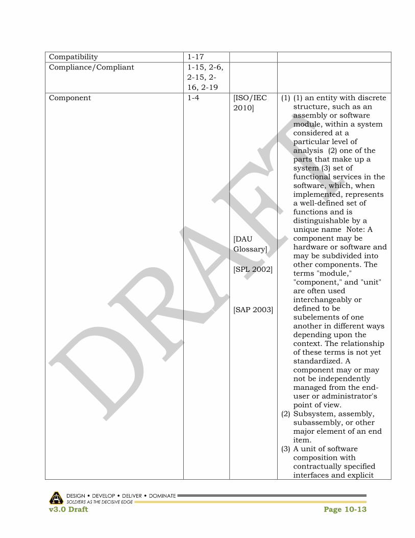
v3.0 Draft Page 10-13
Compatibility 1-17
Compliance/Compliant 1-15, 2-6,
2-15, 2-
16, 2-19
Component 1-4 [ISO/IEC
2010]
[DAU
Glossary]
[SPL 2002]
[SAP 2003]
(1) (1) an entity with discrete structure, such as an assembly or software module, within a system considered at a particular level of analysis (2) one of the parts that make up a system (3) set of functional services in the software, which, when implemented, represents a well-defined set of functions and is distinguishable by a unique name Note: A component may be hardware or software and may be subdivided into other components. The terms "module," "component," and "unit" are often used interchangeably or defined to be subelements of one another in different ways depending upon the context. The relationship of these terms is not yet standardized. A component may or may not be independently managed from the end-user or administrator's point of view.
(2) Subsystem, assembly, subassembly, or other major element of an end item.
(3) A unit of software composition with contractually specified interfaces and explicit

v3.0 Draft Page 10-14
context dependencies only. A software component can be deployed independently and is subject to composition by third parties.
(4) The principal computational element and data store that execute in a system. See also module.
Computing Environment 1-4, 1-7 [CIO/G6
2010]
A minimum standard
configuration that will
support the Army‘s ability to
produce and deploy high
quality applications quickly
while reducing the
complexities of
configuration, support, and
training.
Computing Environment Working
Group (CEWG)
Configuration Management 2-11 [ISO/IEC
2010]
(1) a discipline applying
technical and administrative
direction and surveillance
to: identify and document
the functional and physical
characteristics of a
configuration item, control
changes to those
characteristics, record and
report change processing
and implementation status,
and verify compliance with
specified requirements (2)
technical and organizational
activities comprising
configuration identification,
control, status accounting,
and auditing. See Also:
baseline, change
management, configuration
identification, configuration

v3.0 Draft Page 10-15
control, configuration status
accounting, configuration
audit.
Connector [SAP 2003] A runtime mechanism for
transferring control and data
around a system.
Control Points 1-8, 1-17
Core/Global Nodes 1-19 COE IP 1-
19
Specific services and
capabilities (Data as a
Service, Software as a
Service and Infrastructure
as a Service) are initiated;
provide mission tailorability
to Edge Nodes and User
Nodes.
Critical Enablers 1-7, 1-15,
1-21, 2-5
COE IP 1-
21
Technologies, activities,
organizational
considerations, that must be
addressed in order to
achieve the desired COE end
state.
Data as a Service 1-19
Data Center
Data Center/Cloud/GF CE 1-10 COE IP 1-
10
Provides a service-based
infrastructure for hosting
and accessing enterprise-
wide software applications,
services, and data. Consists
of common services and
standard applications for
use by a large number of
users over wide-area
networks. This also
includes the Army‘s
Enterprise Resource
Planning (ERP) systems.
Data Description Framework 1-26 [ANSDIT] (1) Data Description. A formalized description of a data element and of the data structures in which its name and its words occur.
(2) Data Structure. A

v3.0 Draft Page 10-16
physical or logical relationship among units of data.
Data Mediation
Data Model [ANSDIT]
[ISO/IEC
2010]
(1) A description of the organization of data in a manner that reflects the information structure of an application or an enterprise.
(2) 1. a graphical and textual representation of analysis that identifies
the data needed by an organization to achieve its mission, functions, goals, objectives, and strategies and to manage and rate the organization.. 2. a model about data by which an interpretation of the data can be obtained In the modeling tool industry. NOTE A data model is one that may be encoded and manipulated by a computer. A data model identifies the entities, domains (attributes), and relationships (associations) with other data and provides the conceptual view of the data and the relationships among data. [key style]
Data Reference Model 1-15
Decentralized 2-16 [ULS
2006]
Decentralized System. A
distributed system with no
central authority for any of
its aspects.
Deployment Cycle iii [ISO/IEC
2010]
Deployment. (1) phase of a
project in which a system is
put into operation and
cutover issues are resolved.

v3.0 Draft Page 10-17
Deployment Phases 1-7 [DAG –
2011]
One part of the Production
and Deployment Phase that
commences at Milestone C.
Design Cycle iii [ISO/IEC
2010]
Design. (1) The process of
defining the architecture,
components, interfaces, and
other characteristics of a
system or component. (2)
The result of the process in
(1). (3) The process of
defining the software
architecture, components,
modules, interfaces, and
data for a software system to
satisfy specified
requirements. (4) The
process of conceiving,
inventing, or contriving a
scheme for turning a
computer program
specification into an
operational program. (5)
Activity that links
requirements analysis to
coding and debugging. (6)
Stage of documentation
development that is
concerned with determining
what documentation will be
provided in a product and
what the nature of the
documentation will be.
Development Cycle iii [ANSDIT]
[ISO/IEC
2010]
(1) System Development. A process that usually includes requirements analysis, system design,
implementation, documentation, and quality assurance.
(2) Software Development Cycle1. the period of time that begins with the decision to develop a software product and

v3.0 Draft Page 10-18
ends when the software is delivered
Development Libraries 1-15 [ANSDIT]
[ISO/IEC
2010]
(1) Software Library. In programming, a controlled collection of software and related documentation designed to aid in software development, use, or maintenance.
(2) Software Development Library. 1. a software library containing computer readable and human readable information relevant to a software development effort. Syn: project library, program support library cf. master library, production library, software repository, system library.
Direct Access(to new capabilities) 1-41 [ANSDIT] The capability to obtain
data from a storage device,
or to enter data into a
storage device, in a
sequence independent of
their relative position, by
means of addresses that
indicate the physical
location of the data.
Domain [AR 70-1
2011]
[ANSDIT]
(1) For purposes of the AEA, a group of systems—or system of systems—of a similar nature or focused on satisfying similar objectives. Domains are primarily used within the
DISR. There are four domains: command, control, communications, and intelligence; weapon systems; modeling and simulation; and sustainment.
(2) (1) A specific field of

v3.0 Draft Page 10-19
[ISO/IEC
2010]
knowledge or expertise. (2) The set of permissible data values from which actual values are taken for a particular attribute or specific data element. Synonymous with attribute domain. (3) In a relational database, all of the permissible tuples for a given relation. (4) In distributed data
processing, that part of a computer network in which the resources or addressing are under common control. The domain scheme may be geographical or organizational. (5) In computer security, all of the objects that a subject can access.
(3) 1. a distinct scope, within which common characteristics are exhibited, common rules observed, and over which a distribution transparency is preserved.. 2. a problem space.
Ecosystem 1-39 See software ecosystem
Edge Nodes 1-19 COE IP 1-
19
Systems where data and
services originate, and are
requested from User Nodes;
provide content and services
to User Nodes and may
obtain non-resident
capabilities to other Edge
Nodes and or Core Nodes;
can provide services if
disconnected from
Core/Global Nodes; Mission

v3.0 Draft Page 10-20
Tailorable; will support
Mission Command on
multiple data networks;
exist within the Core/Global
Nodes.
Element [DAU
Glossary]
[SAP 2003]
(1) A complete, integrated set of subsystems capable of accomplishing an operational role or function, such as navigation. It is the Configuration Item (CI) delivered by a single contractor.
(2) The architectural building block (component, connector, or module) that is native to a style.
Embedded 1-11 [ANSDIT] Embedded System. A
computational system that
is a part of a larger system
whose primary purpose is
not computational; for
example, a computer in a
satellite or process control
system.
End User [ANSDIT] The person who benefits,
directly or indirectly, from
the capabilities of a
computer system and uses
these capabilities to
perform a task.
End-User Environments Iii, 1-4, 1-
41
[ANSDIT] Environment. (1) A
collection of hardware
resources and software
resources that supports
one or more phases of
software development or
use of software. (2) The
state of a computer and its
operating system during the
execution of a program.
Enterprise 1-1 [ISO/IEC The organization that

v3.0 Draft Page 10-21
2010] performs specified tasks.
Note: An organization may
be involved in several
enterprises and an
enterprise may involve one
or more organizations.
Enterprise Applications 1-6, 1-8
Enterprise Architecture 1-1 [DAG –
2011]
[AR 70-1
2011]
[SAP 2003]
(1) Describes the "current architecture" and "target architecture," and provides a strategy that will enable an agency to transition from its
current state to its target environment. The Office of Management and Budget defines enterprise architecture as the explicit description and documentation of the current and desired relationships among business and management processes and IT.
(2) Army Enterprise Architecture (AEA). The AEA is a disciplined, structured, comprehensive, and integrated methodology and framework that encompasses all Army information requirements, technical standards, and systems descriptions, regardless of the information system‘s use. The AEA transforms operational
visions and associated requirement capabilities of the warfighters into a blueprint for an integrated and interoperable set of information systems that

v3.0 Draft Page 10-22
implement horizontal information technology insertion, cutting across the functional ―stovepipes‖ and Service boundaries. Among other uses, this architectural blueprint is the basis for an information technology investment strategy that ensures a consistent and effective design and evolution of the Army‘s information
systems. The AEA is the combined total of all of the Army‘s operational technical, and system architectures.
(3) A means for describing business structures and processes that connect business structures
Enterprise Business Strategies iii, 1-13
Enterprise Collaboration
Capabilities
?, 1-22
Enterprise Mediation Services 1-7, 1-26
Enterprise Services 1-6, 1-8 See Services.
Enterprise software processes iii
Execution Phase 2-19 [ISO/IEC
2010]
Implementation Phase. 1
period of time in the
software life cycle during
which a software product is
created from design
documentation and
debugged .
Family of Systems [AR 70-1
2011]
(1) A set or arrangement of independent systems that can be arranged or interconnected in various ways to provide different capabilities. The mix of systems can be tailored to provide desired capabilities, dependent on the situation. An

v3.0 Draft Page 10-23
[DAU
Glossary]
example of a family of systems is a brigade combat team that includes combat and combat support systems. Although these systems can independently provide militarily useful capabilities, in collaboration they can more fully satisfy a more complex and challenging capability: to detect, localize, track, and
engage the enemy. (2) A set of systems that
provides similar capabilities through different approaches to achieve similar or complementary effects. For example, the warfighter may need the capability to track moving targets. The FoS that provides this capability could include manned or unmanned aerial vehicles (UAVs) with appropriate sensors, a space-based platform, or a special operations capability. Each can provide the ability to track moving targets, but with differing characteristics of persistence, accuracy, timeliness, etc.
Federated
Foundation 1-4
Framework 1-4, 1-7,
1-13, 1-
17, 1-18
[ISO/IEC
2010]
(1) a reusable design (models
and/or code) that can be
refined (specialized) and
extended to provide some
portion of the overall
functionality of many

v3.0 Draft Page 10-24
applications (2) a partially
completed software
subsystem that can be
extended by appropriately
instantiating some specific
plug-ins.
Functional Requirement [AR 10-1
2011]
Administrative
requirements, reports, and
plans that do not directly
prescribe the operational
performance of a system but
are used to support a
program. These fall into two
general categories: those
that are generated by statute
(the FAR,
with supplements) and DOD
directives and those that are
generated by Army
regulation, handbooks,
pamphlets, or local policy.
The second category, those
generated by DA and below,
may be exempted. The term
does not include the
operational requirements
established by the CAPDEV.
Generating Force systems 1-1
Geospatial Data and Information 1-36 [JP 1.02
2010]
Information that identifies
the geographic location and
characteristics of natural or
constructed features and
boundaries on the Earth,
including: statistical data
and information derived
from, among other things,
remote sensing, mapping,
and surveying technologies;
and mapping, charting,
geodetic data and related
products. (JP 2-03)
Geospatial Foundation 1-24

v3.0 Draft Page 10-25
Geospatial Information and
Services (GI&S)
?? [JP 1.02
2010]
The collection, information
extraction, storage,
dissemination, and
exploitation of geodetic,
geomagnetic, imagery (both
commercial and national
source), gravimetric,
aeronautical, topographic,
hydrographic, littoral,
cultural, and toponymic
data accurately referenced to
a precise location on the
Earth‘s surface. Geospatial
services include tools that
enable users to access and
manipulate data, and also
include instruction, training,
laboratory support, and
guidance for the use of
geospatial data.
Global interconnection 1-1
Global networks 1-1
Governance iii, 1-1, 1-
7, 1-8, 1-
13
[JP 1.02
2010]
[ISO/IEC
2010]
(1) The state‘s ability to serve the citizens through the rules, processes, and behavior by which interests are articulated, resources are managed, and power is exercised in a society, including the representative participatory decision-making processes typically guaranteed under inclusive, constitutional authority. (JP 3-24)
(2) Corporate Governance. 1. system by which organizations are directed and controlled.
Hardware [ANSDIT] Any physical component
capable of data processing;
for example, computers,

v3.0 Draft Page 10-26
peripheral equipment.
Contrast with software.
Hardware Abstraction Layer (HAL) [ANSDIT] A set of subprograms that
translates various vendors'
hardware characteristics to
a common set of
specifications to optimize
the portability of an
operating system.
Hardware-centric Development 1-8
Hardware Independence 1-30
Key Enablers iii See Critical Enabler
Implementation 2-16 [AMSDIT]
[ISO/IEC
2010]
(1) Of a system, the system development phase at the end of which the hardware, software, and procedures of the system considered become operational.
(2) 1. The process of translating a design into hardware components, software components, or both. 2. The result of the process in (1). 3. A definition that provides the information needed to create an object and allow the object to participate in providing an appropriate set of services. 4. The installation and customization of packaged software. 5. Construction. 6. The system development phase at the end of which the hardware,
software and procedures of the system considered become operational. 7. A process of instantiation whose validity can be subject to test. 8. Phase of development during which user

v3.0 Draft Page 10-27
documentation is created according to the design, tested, and revised.
Industry Best Practices iii, 1-13
Information Technology (IT) 1-2 [AR 70-1
2011]
[ANSDIT]
(1) Any equipment or interconnected system or subsystem of equipment that is used in the automatic acquisition, storage, manipulation, management, movement, control, display, switching, interchange, transmission, or
reception of data or information by the executive agency.
(2) The art and applied sciences that deal with data and information. Examples are capture, representation, processing, security, transfer, interchange, presentation, management, organization, storage, and retrieval of data and information.
Infrastructure 1-1, 1-7,
1-18
[AR 70-1
2011]
The shared computers,
ancillary equipment,
software, firmware, and
similar procedures, services,
people, business processes,
facilities (to include building
infrastructure elements),
and related resources used
in the acquisition, storage,
manipulation, protection,
management, movement,
control, display, switching,
interchange, transmission,
or reception of data or
information in any format,
including audio, video,
imagery, or data, whether

v3.0 Draft Page 10-28
supporting Information
Technology or National
Security Systems as defined
in the Clinger-Cohen Act of
1996.
Infrastructure as a Service 1-19, 1-25 [NIST
2009]
The capability provided to
the consumer is to provision
processing, storage,
networks, and other
fundamental computing
resources where the
consumer is able to deploy
and run arbitrary software,
which can include operating
systems and applications.
The consumer does not
manage or control the
underlying cloud
infrastructure but has
control over operating
systems, storage, deployed
applications, and possibly
limited control of select
networking components
(e.g., host firewalls).
Infrastructure provider 1-2
Interface control document 2-7 [ISO/IEC
2010]
Interface Control. 1. In
configuration management,
the administrative and
technical procedures and
documentation necessary to
identify functional and
physical characteristics
between and within
configuration items provided
by different developers, and
to resolve problems
concerning the specified
interfaces 2. in configuration
management, the process of
identifying all functional and
physical characteristics

v3.0 Draft Page 10-29
relevant to the interfacing of
two or more configuration
items provided by one or
more organizations and
ensuring that proposed
changes to these
characteristics are evaluated
and approved prior to
implementation
Integrated Architecture [AR 70-1
1022]
An architecture consisting of
multiple views or
perspectives (operational
view, systems view, and
technical standards view
that facilitates integration
and promotes
interoperability across
capabilities and among
related integrated
architectures.
Integrated Test Environment 1-37 [ANSDIT] Integration Test. The
progressive linking and
testing of programs or
modules in order to ensure
their proper functioning in
the complete system.
Integration 2-16 [ISO/IEC
2010]
1. the process of combining
software components,
hardware components, or
both into an overall system.
Interoperate 1-4
Interoperable applications iii, 1-11,
1-13
Interoperability 1-17 [JP 1.02
2010]
[JP 1.02
2010]
(1) The ability to operate in synergy in the execution of assigned tasks. (JP 3-0)
(2) The condition achieved among communications-electronics systems or items of communications-electronics equipment

v3.0 Draft Page 10-30
[AR 70-1
2011]
[ANSDIT]
when information or services can be exchanged directly and satisfactorily between them and/or their users. The degree of interoperability should be defined when referring to specific cases. (JP 6-0)
(3) The ability of Army systems, units, or forces to provide data, information, materiel, and services to and
accept the same from other systems, units, or forces and to use data, information, materiel, and services so exchanged to enable them to operate effectively together.
(4) The capability to communicate, execute programs, or transfer data among various functional units under
specified conditions.
Interoperability Certification [AR 70-1
2011]
Army Interoperability
Certification. Confirmation
that the candidate system
has undergone appropriate
testing and that the
applicable standards and
requirements for
compatibility,
interoperability, and
integration have been met.
Interoperability layer 1-11
IT system 1-1
IT environment 1-1
IT infrastructure 1-1
IT shared infrastructure 1-3 [DSB
2009]
IT that provides a shared
infrastructure that is acting
as a ―utility‖ to various
national security systems

v3.0 Draft Page 10-31
and operational processes.
These utilities are at the
processing, networking and
middleware levels.
Joint, Interagency,
Intergovernmental, and
Multinational (JIIM)
2-1
JIIM Component 2-1
Layer [ANSDIT]
[SAP 2003]
(1) (1) In distributed data processing, a group of capabilities, functions, and protocols considered as a whole,
that belongs to a given level in a hierarchical arrangement, of such as features of a given network architecture, and that extends across various data processing systems. (2) In a hierarchically organized artificial neural network, a group of artificial neurons whose outputs may
connect to neurons in a group toward the output of the network but not to neurons in a group back toward the input of the network. Artificial neurons of the same layer may have connections among them.
(2) A collection of code that forms a virtual machine and that interacts with
other layers only according to predefined roles under the relation "allowed to use"
Mashups Wikipedia A Web page or application
that uses and combines
data, presentation or
functionality from two or

v3.0 Draft Page 10-32
more sources to create new
services. The term implies
easy, fast integration,
frequently using open APIs
and data sources to produce
enriched results that were
not necessarily the original
reason for producing the raw
source data.
Middleware Wikipedia
ObjectWeb
[ULS
2006]
(1) Software that provides a link between separate software applications. Middleware is sometimes called plumbing because it connects two applications and passes data between them. Middleware allows data contained in one database to be accessed through another. This definition would fit enterprise application integration and data integration software.
(2) The software layer that lies between the operating system and applications on each side of a distributed computing system in a network."
(3) A set of layers and components that provides reusable common services and network programming mechanisms. Middleware resides on
top of an operating system and its protocol stacks but below the structure and functionality of any particular application.
Middleware utilities 1-3 [DSB
2009]
Middleware utilities are
services that support higher

v3.0 Draft Page 10-33
level applications (e.g.
directory services, security
services, storage services,
message services)…The
intent of these services is to
provide shared, trustworthy,
ubiquitous, high
performance, low-cost IT
capabilities that allow both
national security and
operational process systems
to fulfill their goals.
Mission Command 1-10 [JP 1.02
2010]
The conduct of military
operations through
decentralized execution
based upon mission-type
orders.
Mission Environment 1-4, 1-6 [CIO/G6
2010]
Environments in which
Soldiers operate
differentiated by varying
network bandwidth
requirements (latency, high
bit-error rate) , SWAP (size,
weight, and power) ,
environmental factors and
location permanence.
Mission Tailorable 1-19
Mobile/Handheld CE 1-11 COE IP 1-
11
Provides operating and run-
time system native and
common applications and
services, software
development kits (SDK), and
standards and technologies,
for hand held and wearable
devices.
Mobile CE COTS Framework 1-32
Mobile Network 1-32
Mode [ANSDIT] A method, condition,
manner, or way of doing,
acting, operating, or
functioning.
Modular Applications 1-2 See Modular and

v3.0 Draft Page 10-34
Applications.
Modular Approach 1-41 [ANSDIT] Modular Programming. A
software development
technique in which
software is developed as a
collection of modules.
Modular Data Centers
Module [ANSDIT]
[ISO/IEC
2010]
[DAU
Glossary]
[SAP 2003]
(1) (1) A part of a program developed to be discrete or identifiable with respect to actions such as compilation, binding, or execution,
and that may interact with other programs or parts of programs. The concept referred to by the term "module" may vary according to the different programming languages. Synonymous with program unit. (2) In an information resource dictionary system, a set of capabilities that may be
required or optional. (2) 1. a program unit that is
discrete and identifiable with respect to compiling, combining with other units, and loading. 2. a logically separable part of a program. 3. a set of source code files under version control that can be manipulated together as one. 4. a collection of
both data and the routines that act on it NOTE The terms 'module', 'component,' and 'unit' are often used interchangeably or defined to be subelements of one
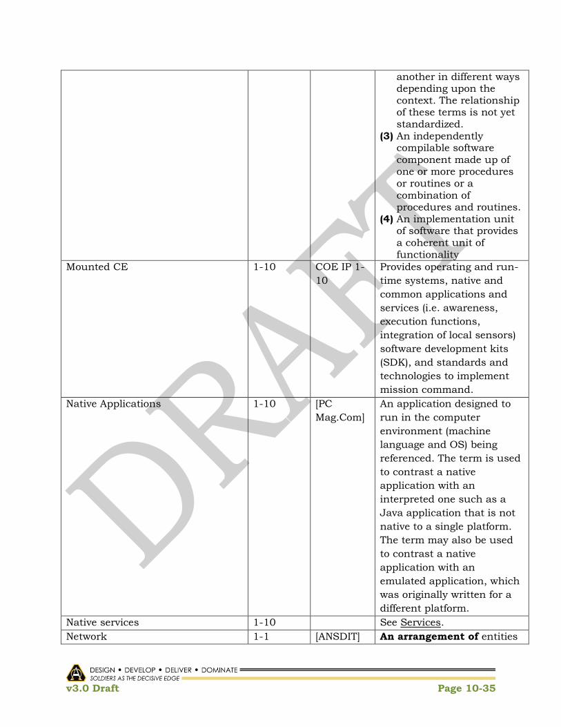
v3.0 Draft Page 10-35
another in different ways depending upon the context. The relationship of these terms is not yet standardized.
(3) An independently compilable software component made up of one or more procedures or routines or a combination of procedures and routines.
(4) An implementation unit of software that provides
a coherent unit of functionality
Mounted CE 1-10 COE IP 1-
10
Provides operating and run-
time systems, native and
common applications and
services (i.e. awareness,
execution functions,
integration of local sensors)
software development kits
(SDK), and standards and
technologies to implement
mission command.
Native Applications 1-10 [PC
Mag.Com]
An application designed to
run in the computer
environment (machine
language and OS) being
referenced. The term is used
to contrast a native
application with an
interpreted one such as a
Java application that is not
native to a single platform.
The term may also be used
to contrast a native
application with an
emulated application, which
was originally written for a
different platform.
Native services 1-10 See Services.
Network 1-1 [ANSDIT] An arrangement of entities

v3.0 Draft Page 10-36
and their
interconnections. In
network topology or in an
abstract arrangement, the
interconnected entities
are points on a scheme,
and the interconnections
are lines on the scheme. In
a computer network, the
interconnected entities
are computers or data
communication equipment,
and the interconnections
are data links.
Network Architecture Iii [ANSDIT] The logical structure and
the operating principles of
a computer network. The
operating principles of a
network include those of
services, functions, and
protocols.
NIR/NIE Assessments 1-6
Non-Program of Record
Non-proprietary interfaces 1-2
Off-the Shelf Item [JP 1.02
2010]
[ISO/IEC
2010]
[DAU
Glossary]
(1) An item that has been developed and produced to military or commercial standards and specifications, is readily available for delivery from an industrial source, and may be procured without change to satisfy a military requirement.
(2) Already developed and available.
(3) Procurement of existing systems or equipment without a research, development, test, and evaluation (RDT&E) program or with minor development necessary to make system suitable for

v3.0 Draft Page 10-37
DoD needs. May be commercial system/equipment or one already in DoD inventory.
On-demand use 1-2
Open Standards 1-13 [Wikipedia] An open standard is a
standard that is publicly
available and has various
rights to use associated with
it, and may also have
various properties of how it
was designed (e.g. open
process). There is no single
definition and
interpretations vary with
usage.
Open System [ANSDIT]
[DAU
Glossary]
(1) A system containing publicly defined interfaces and protocols to facilitate interoperability with other systems, perhaps of different design or manufacture. Contrast
with closed system. (2) A system that
implements specifications maintained by an open, public consensus process for interfaces, services, and support formats, to enable properly engineered components to be utilized across a wide range of systems with minimal change, to interoperate with other components on local and remote systems, and to interact with users in a manner that facilitates portability.
Open Systems Approach 1-41 [DAU
Glossary]
Open Systems Acquisition of Weapons Systems. An integrated technical and

v3.0 Draft Page 10-38
business strategy that defines key interfaces for a system (or a piece of equipment under development) in accordance with those adopted by formal consensus bodies (recognized industry standards‘ bodies) as specifications and standards, or commonly accepted (de facto) standards (both company proprietary and non-
proprietary) if they facilitate utilization of multiple suppliers.
Operating Environment [ISO/IEC
2010]
The set of software operating
concurrently on a specified
computer system.
Orchestration 1-13 COE IP 1-
15
[ULS
2006]
(1) The identification, coordination and management of complex system of system activities for COE.
(2) The activities needed to make the elements of a system work together in sufficient harmony to ensure continuous satisfaction of a set of specified objectives.
Pattern [ULS
2006]
A description of a particular
recurring design problem
that arises in specific design
contexts along with a well-
proven solution for that
problem. In some cases, the
solution is specified by
describing its constituent
participants, their
responsibilities and
relationships, and the ways
in which they collaborate..
Performance Reference Model
(PRM)
1-15 [Wikipedia] The PRM is a standardized
framework to measure the

v3.0 Draft Page 10-39
performance of major IT
investments and their
contribution to program
performance. The PRM has
three main purposes:
Phase 0-5 Operations 1-18
Platform 1-4 [ULS
2006]
The combination of
hardware and software that
provides a virtual machine
that executes software and
applications. Software
platforms include operating
systems, libraries, and
frameworks.
Platform as a Service [NIST
2009]
The capability provided to
the consumer is to deploy
onto the cloud infrastructure
consumer-created or
acquired applications
created using programming
languages and tools
supported by the provider.
The consumer does not
manage or control the
underlying cloud
infrastructure including
network, servers, operating
systems, or storage, but has
control over the deployed
applications and possibly
application hosting
environment configurations.
Platform-based Services 1-32 [Wikipedia] An integration oriented
design approach
emphasizing systematic
reuse, for developing
complex products based
upon platforms and
compatible hardware and
software virtual component,
intended to reduce
development risks, costs and
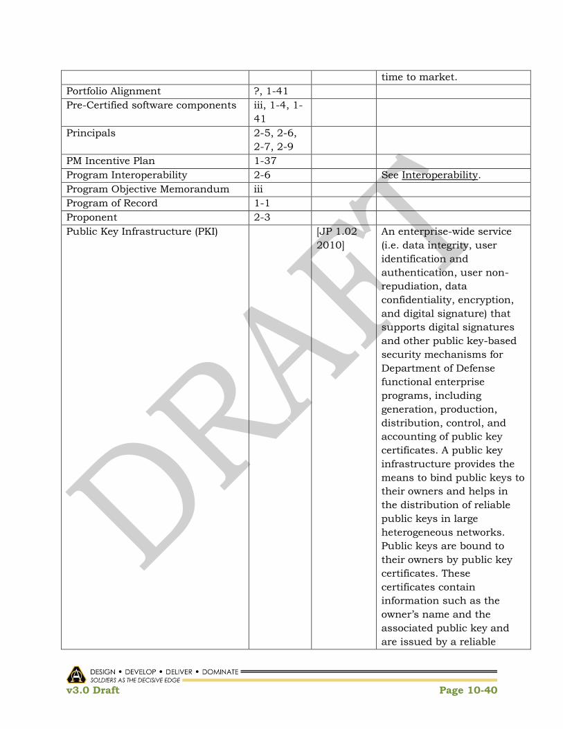
v3.0 Draft Page 10-40
time to market.
Portfolio Alignment ?, 1-41
Pre-Certified software components iii, 1-4, 1-
41
Principals 2-5, 2-6,
2-7, 2-9
PM Incentive Plan 1-37
Program Interoperability 2-6 See Interoperability.
Program Objective Memorandum iii
Program of Record 1-1
Proponent 2-3
Public Key Infrastructure (PKI) [JP 1.02
2010]
An enterprise-wide service
(i.e. data integrity, user
identification and
authentication, user non-
repudiation, data
confidentiality, encryption,
and digital signature) that
supports digital signatures
and other public key-based
security mechanisms for
Department of Defense
functional enterprise
programs, including
generation, production,
distribution, control, and
accounting of public key
certificates. A public key
infrastructure provides the
means to bind public keys to
their owners and helps in
the distribution of reliable
public keys in large
heterogeneous networks.
Public keys are bound to
their owners by public key
certificates. These
certificates contain
information such as the
owner‘s name and the
associated public key and
are issued by a reliable

v3.0 Draft Page 10-41
certification authority.
Quick Reaction Capabilities 1-1
Real-time 1-11 [ANSDIT] Pertaining to the
processing of data by a
computer in connection
with another process
outside the computer
according to time
requirements imposed by
the outside process. "Real-
time" is also used to
describe systems operating
in conversational mode and
processes that can be
influenced by human
intervention while they
are in progress.
Real-Time/Safety-
Critical/Embedded CE
1-11 COE IP 1-
11
Defines a common operating
environment for systems
operating in either a real-
time, safety critical or
embedded environment
while ensuring that
opportunities for
commonality and
interoperability with other
CEs are maintained to the
fullest extent possible.
Real-time Interoperability
Framework
1-35
Reference Architecture 1-4 [SAP 2003] A reference model that is
mapped onto software
elements (that cooperatively
implement the functionality
defined in the reference
model)and the data that
flows between them.
Reference Model [SAP 2003] A division of functionality
into elements together with
the data flow between those
elements.
Refactoring (of existing capability) 1-13 [Wikipedia] Code refactoring is

v3.0 Draft Page 10-42
"disciplined technique for
restructuring an existing
body of code, altering its
internal structure without
changing its external
behavior" ,undertaken in
order to improve some of the
nonfunctional attributes of
the software. Typically, this
is done by applying series of
"refactorings", each of which
is a (usually) tiny change in
a computer program's
source code that does not
modify its functional
requirements. Advantages
include improved code
readability and reduced
complexity to improve the
maintainability of the source
code, as well as a more
expressive internal
architecture or object model
to improve extensibility.
Regional/Deployable Core Nodes 1-19 COE IP 1-
19
A subset of Core/Global
Node that is dedicated to a
specific set of users,
typically within the Joint
community, where data and
services are originated and
requested from Edge and
User Nodes; provide the
mission tailorability to Edge
Nodes and User Nodes.
Rehosting (of existing capability) 1-13 [ANSDIT] Rehost. The conversion of
data and software to enable
it to operate on a
significantly different type
of host computer.
Reusability of Software Modules [AR 70-1
2011]
The extent to which a
program unit that is discrete
and identifiable with respect

v3.0 Draft Page 10-43
to compiling, combining with
other units, and loading and
which can be used as source
code in multiple applications
(for example, a message
parsing module or
mathematical equation
module).
Reusable Software Asset [AR 70-1
2011]
[ISO/IEC
2010]
(1) A software element, including requirements, designs, objects, code, and test data capable of being used by a software
development effort other than the one for which it was originally developed. A synonym for reusable software component.
(2) Reusable Software Product. 1. a software product developed for one use but having other uses, or one developed specifically to be usable on multiple projects or in multiple roles on one project.
Reusable software components Iii, 1-4, 1-
41
See Reusable Software
Asset.
Reuse [AR 70-1
2011]
[ISO/IEC
2010]
(1) The application of reusable software assets, with or without adaptation to more than one software system. Reuse may occur within a software system, across similar software systems, or in widely different software systems.
(2) 1. The use of an asset in the solution of different problems. 2. building a software system at least partly from existing pieces to perform a new application
Rich Client [Wikipedia] A fat client (also called

v3.0 Draft Page 10-44
heavy, rich, or thick client)
is a computer (client) in
client–server architecture or
networks that typically
provides rich functionality
independent of the central
server. Originally known as
just a 'client' or 'thick client',
the name is contrasted to
thin client, which describes
a computer heavily
dependent on a server's
applications.
Rich web application framework 1-7, 1-29 [Wikipedia] A web application framework
is a software framework that
is designed to support the
development of dynamic
websites, web applications
and web services. The
framework aims to alleviate
the overhead associated with
common activities performed
in Web development. For
example, many frameworks
provide libraries for
database access, templating
frameworks and session
management, and they often
promote code reuse.
Roadmap 2-7, 2-15 [Wikipedia] A technology roadmap is a
plan that matches short-
term and long-term goals
with specific technology
solutions to help meet those
goals. It is a plan that
applies to a new product or
process, or to an emerging
technology. Developing a
roadmap has three major
uses. It helps reach a
consensus about a set of
needs and the technologies

v3.0 Draft Page 10-45
required to satisfy those
needs; it provides a
mechanism to help forecast
technology developments
and it provides a framework
to help plan and coordinate
technology developments.
Rock Drill (SE) 1-15
Safety-Critical 1-11 [ISO/IEC
2010]
Software that falls into one
or more of the following
categories: a) software whose
inadvertent response to
stimuli, failure to respond
when required, response
out-of-sequence, or response
in combination with other
responses can result in an
accident b) software that is
intended to mitigate the
result of an accident c)
software that is intended to
recover from the result of an
accident.
Secure applications 1-11,1-13 [Wikipedia] Application security
encompasses measures
taken throughout the
application's life-cycle to
prevent exceptions in the
security policy of an
application or the underlying
system (vulnerabilities)
through flaws in the design,
development, deployment,
upgrade, or maintenance of
the application.
Security-certified standard IT
infrastructure services
1-2
Semantics [ANSDIT] The relationships of
symbols or groups of
symbols to their meanings,
independent of the
manner of their

v3.0 Draft Page 10-46
interpretation and use.
Contrast with syntax,
pragmatics.
Sensor CE 1-11 COE IP 1-
11
Provides a common
interoperability layer,
implementing standards and
technology for data services,
NetOps, and security for
specialized, human-
controlled or unattended
sensors. The Sensor CE
does not specify specific
hardware and software for
the sensors.
Sensor Interoperability Plug-in 1-34
Sensor Service Framework 1-34
Service 1-2,1-8 [SEI
2010]
Services are reusable
components that represent
business or operational
tasks, such as customer
lookup, credit card
validation, weather lookup,
or line-of-sight calculation.
Reusable is a key element of
this definition because it is
what enables the creation of
new business and
operational processes based
on these services. Services
expose their capabilities via
well-defined, standard
service interfaces. In a
service-oriented
environment, service
interface definitions are
available in some form of
service registry.
Service Consumers [SEI 2010] Service consumers are the
clients for the functionality
provided by the services.
Examples of service
consumers are end-user

v3.0 Draft Page 10-47
applications, internal
systems, external systems,
and composite services.
Consumers
programmatically bind to
services (i.e., there is a piece
of code running on the
consumer side that invokes
a piece of code running on
the provider side that
corresponds to the service
interface).
Service-based Architecture
Approach/Infrastructure/capability
1-7, 1-8,
1-10, 4-9
[SEI 2010]
Service-based is used to
describe an architecture,
approach, infrastructure or
capability that arranges
services to meet a need.
This term is contrasted with
Service-Oriented in that a
Service Oriented
Architecture is often
assumed to imply a
particular arrangement of
services and the use of web
services
An SOA infrastructure is the
set of technologies that bind
service consumers to
services through an agreed-
upon communication model,
such as one based on Web
Services, message-oriented
middleware (MOM),
publish/subscribe, or
Common Object Request
Broker Architecture
(CORBA). In addition, SOA
infrastructures typically host
infrastructure services that
can be used by service
providers and service
consumers to perform

v3.0 Draft Page 10-48
common tasks or satisfy
quality attribute
requirements of the
environment. Typical
infrastructure services
include security, discovery,
and data transformation.
Shared Services 1-4 See Service.
Software [AR 70-1
2011]
[ANSDIT]
[ISO/IEC
2010]
(1) A set of computer programs, procedures, data, and associated documentation concerned with the
operation of a data processing system (for example, compiler, library routines, manuals, circuit diagrams); usually contrasted with hardware.
(2) All or part of the programs, procedures, rules, and associated documentation of a data processing system or an
information processing system. Software is an intellectual creation that is independent of the medium on which it is recorded. Contrast with hardware.
(3) 1. All or part of the programs, procedures, rules, and associated documentation of an information processing system. 2. computer
programs, procedures, and possibly associated documentation and data pertaining to the operation of a computer system. 3. Program or set of programs used to run a computer.

v3.0 Draft Page 10-49
Software Architecture [SAP 2003] The software architecture
of a program or computing
system is the structure or
structures of the system,
which comprise software
elements, the externally
visible properties of those
elements, and the
relationships among them.
"Externally visible"
properties are those
assumptions other
elements can make of an
element, such as its
provided services,
performance
characteristics, fault
handling, shared resource
usage, and so on
Software as a Service 1-19, 1-23 [NIST
2009]
The capability provided to
the consumer is to use the
provider‘s applications
running on a cloud
infrastructure. The
applications are accessible
from various client devices
through a thin client
interface such as a web
browser (e.g., web-based
email). The consumer does
not manage or control the
underlying cloud
infrastructure including
network, servers, operating
systems, storage, or even
individual application
capabilities, with the
possible exception of limited
user-specific application
configuration settings.
Software Capabilities
Software Component iii, 1-1, 1- See Component.

v3.0 Draft Page 10-50
41
Software Development Kits iii, 1-4, 1-
41
[Wikipedia] A software development kit
(SDK or "devkit") is typically
a set of development tools
that allows for the creation
of applications for a certain
software package, software
framework, hardware
platform, computer system,
video game console,
operating system, or similar
platform.
Software Ecosystem iii, 1-4, 1-
13, 1-21
[MIT 2003]
[Intuit
2009]
[CSE
2010]
(1) A set of businesses functioning as a unit and interacting with a shared market for software and services, together with relationships among them. These relationships are frequently underpinned by a common technological platform and operate through the exchange of information, resources, and artifacts.
(2) A software ecosystem consists of the set of software solutions that enable, support and automate the activities and transactions by the actors in the associated social or business ecosystem and the organizations that provide these solutions.
(3) A software ecosystem consists of a software platform, a set of internal and external developers and a community of domain experts in services to a community of users that compose relevant solution elements to satisfy their

v3.0 Draft Page 10-51
needs.
Software Infrastructure 1-6
Software-centric Development 1-8
Software Marketplace 1-20, 1-27
Software Module See Module.
Specification [ANSDIT] A detailed formulation, in
document form, that
provides a definitive
description of a system for
the purpose of developing
or validating the system.
Stakeholder [ISO/IEC
2010]
1. Individual or organization
having a right, share, claim,
or interest in a system or in
its possession of
characteristics that meet
their needs and
expectations. 2. Individual,
group or organization that
can affect, be affected by, or
perceive itself to be affected
by, a risk. 3. Individual,
group, or organization who
may affect, be affected by, or
perceive itself to be affected
by a decision or activity. 4.
Person or organization (e.g.,
customer, sponsor,
performing organization, or
the public) that is actively
involved in the project, or
whose interests may be
positively or negatively
affected by execution or
completion of the project. A
stakeholder may also exert
influence over the project
and its deliverables.
EXAMPLE end users, end
user organizations,
supporters, developers,
producers, trainers,
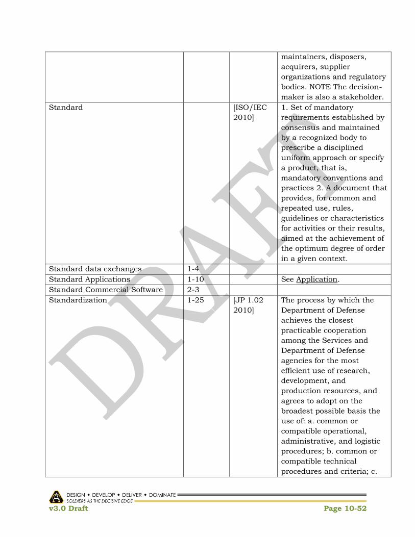
v3.0 Draft Page 10-52
maintainers, disposers,
acquirers, supplier
organizations and regulatory
bodies. NOTE The decision-
maker is also a stakeholder.
Standard [ISO/IEC
2010]
1. Set of mandatory
requirements established by
consensus and maintained
by a recognized body to
prescribe a disciplined
uniform approach or specify
a product, that is,
mandatory conventions and
practices 2. A document that
provides, for common and
repeated use, rules,
guidelines or characteristics
for activities or their results,
aimed at the achievement of
the optimum degree of order
in a given context.
Standard data exchanges 1-4
Standard Applications 1-10 See Application.
Standard Commercial Software 2-3
Standardization 1-25 [JP 1.02
2010]
The process by which the
Department of Defense
achieves the closest
practicable cooperation
among the Services and
Department of Defense
agencies for the most
efficient use of research,
development, and
production resources, and
agrees to adopt on the
broadest possible basis the
use of: a. common or
compatible operational,
administrative, and logistic
procedures; b. common or
compatible technical
procedures and criteria; c.

v3.0 Draft Page 10-53
common, compatible, or
interchangeable supplies,
components, weapons, or
equipment; and d. common
or compatible tactical
doctrine with corresponding
organizational compatibility.
Standardized Applications 1-7, 1-8 See Application.
Standardized Frameworks 1-7 See Framework.
Standards-based 1-6 COE IP, 1-
6
Applications will adhere to
standard naming
conventions, reside in
common libraries, and be
deployed using standard
release-management
processes.
Standards-based products 1-8
Standards-Compliant 1-4 [Wikipedia] Standards-compliant is a
term often used in
describing websites and user
agents' (often web browsers)
relative compliance with web
standards proposed by the
World Wide Web Consortium
(W3C); also used for
emphasizing that one
doesn't use proprietary
methods or features of those
browsers to ensure
interoperability.
Synergistic Combination 1-5
Syntax [ANSDIT]
[ISO/IEC
2010]
(1) The relationships among symbols or groups of symbols, independent of their meanings or the
manner of their interpretation and use; for example, the rules governing the structure of a language. Contrast with semantics.
(2) 1. Words, phrases, expressions, and other

v3.0 Draft Page 10-54
allowable constructs 2. The structural components or features of a language and rules that define the ways in which the language constructs may be assembled together to form sentences. 3. A definition of the format of information in a CDIF transfer.
System [JP 1/02
2010]
[ANSDIT]
(1) A functionally, physically, and/or behaviorally related group of regularly interacting or interdependent elements; that group of elements forming a unified whole. (JP 3-0)
(2) A set of elements and relations among them considered as a whole and for which there is a recognized purpose and capability. Such elements may be both material objects and modes of thinking as well as the results thereof (e.g., forms of organization, mathematical methods, and programming languages).
System Integrity [ANSDIT] 1) In data processing, the
state that exists when
there is complete
assurance that, under all
conditions, a data
processing system is based
on the logical correctness
of the hardware and
software that implement
the protection
mechanisms, and data

v3.0 Draft Page 10-55
integrity. (2) In security,
the quality of a data
processing system fulfilling
its operational purpose
while both preventing
unauthorized users from
making modifications to or
use of resources and
preventing authorized
users from making
improper modifications to
or improper use of
resources.
System of Systems [AR 70-1
2011]
[ISO/IEC
2010]
[DAU
Glossary]
(1) A set or arrangement of interdependent systems that are related or connected to provide a given capability. The loss of any part of the system will degrade the performance or capabilities of the whole. An example of an SoS could be interdependent information systems. While individual systems within the SoS may be developed to satisfy the peculiar needs of a given user group, the information they share is so important that the loss of a single system may deprive other systems of the data needed to achieve even minimal capabilities.
(2) A large system that delivers unique
capabilities, formed by integrating independently useful systems
(3) A set or arrangement that results when independent and useful systems are integrated into a larger system that

v3.0 Draft Page 10-56
delivers unique capabilities.
System of systems Engineering
(SoS)
1-1 [Wikipedia] System-of-Systems
Engineering (SoSE) is a set
of developing processes,
tools, and methods for
designing, re-designing and
deploying solutions to
System-of-Systems
challenges.
System of Systems Synchronization [AR 70-1
2011]
The coordination,
harmonization and
integration effort that starts
early in the EMD phase of a
program and continues
throughout its life cycle. The
objective is the appropriate
consideration of the
interoperability and
interdependency of the
constituent legacy, current,
and future systems so that
capabilities which are
greater than the sum of
individual systems are
provided to the war fighter.
Systems Architecture [AR 70-1
2011]
A technical architecture is
the minimal set of rules
governing the arrangement,
interaction, and
interdependence of the parts
or elements which ensure
that a conformant system
satisfies a specified set of
requirements. The technical
architecture identifies the
services, interfaces,
standards, and their
relationships. It provides the
technical guidelines for
implementation of systems
upon which engineering

v3.0 Draft Page 10-57
specifications are based,
common building blocks are
built, and product lines are
developed.
Tactical Edge Mini Cloud 1-31 See Edge Node.
Tailored Acquisition Model for COE 1-37 COE IP 1-
37
Approved acquisition
strategy tailoring out
inefficient DoD 500.2
elements
Target baseline 2-24
Technical advisory body 2-1
Technical Advisory Board (TAB) 2-1
Technical Advisory Board Council 2-1, 2-3,
2-10
Technical Architecture [JP 1.02
2010]
[AR 70-1
2011]
(1) A minimal set of rules governing the arrangement, interaction, and interdependence of the parts or elements whose purpose is to ensure that a conformant system satisfies a specified set of requirements.
(2) A technical architecture is the minimal set of rules governing the arrangement, interaction, and interdependence of the parts or elements which ensure that a conformant system satisfies a specified set of requirements. The
technical architecture identifies the services, interfaces, standards, and their relationships. It provides the technical guidelines for implementation of systems upon which

v3.0 Draft Page 10-58
engineering specifications are based, common building blocks are built, and product lines are developed.
Technical Reference Model iii See Reference Model.
Technology Roadmap 2-22 See Roadmap.
Testing Cycle iii [ANSDIT] System Test Time. The time
during which a functional
unit is tested for proper
operation. Because a
functional unit may
consist of a computer and
its operating system,
system test time in some
cases includes the time for
testing programs belonging
to the operating system.
Thick Client [Wikipedia] A fat client (also called
heavy, rich, or thick client)
is a computer (client) in
client–server architecture or
networks that typically
provides rich functionality
independent of the central
server. Originally known as
just a 'client' or 'thick client',
the name is contrasted to
thin client, which describes
a computer heavily
dependent on a server's
applications.
Thin Client A thin client (sometimes also
called a lean or slim client)
is a computer or a computer
program which depends
heavily on some other
computer (its server) to fulfill
its traditional computational
roles. This stands in
contrast to the traditional fat
client, a computer designed
to take on these roles by

v3.0 Draft Page 10-59
itself.
Type 2/3
Uniform Standard 2-1
Unity of effort 1-7 [JP1.02
2010]
Coordination and
cooperation toward common
objectives, even if the
participants are not
necessarily part of the same
command or organization -
the product of successful
unified action.
User Nodes 1-19 COEP 1-
19
Provide users and/or
equipment network access,
data, and requested
services; can still operate
when disconnected from the
network but are limited to
onboard storage and the last
data received; are Mission
Tailorable.
Utility 1-2 [DAU
Glossary]
The state or quality of being
useful militarily or
operationally. Designed for
or possessing a number of
useful or practical purposes
rather than a single,
specialized one.
Validation 1-13, 2-15 COE IP 1-
15
[JP 1.02
2010]
(1) Activity to ensure that
the COE is having the
expected outcome of meeting
the tenets of COE
implementation (i.e. given it
is right, are we achieving
technical and programmatic
efficiencies, reducing time to
deliver to the field, providing
capability agility).
(2) 1. A process associated
with the collection and
production of intelligence
that confirms that an
intelligence collection or

v3.0 Draft Page 10-60
production requirement is
sufficiently important to
justify the dedication of
intelligence resources, does
not duplicate an existing
requirement, and has not
been previously satisfied. 2.
A part of target development
that ensures all vetted
targets meet the objectives
and criteria outlined in the
commander‘s guidance and
ensures compliance with the
law of armed conflict and
rules of engagement. 3. In
computer modeling and
simulation, the process of
determining the degree to
which a model or simulation
is an accurate
representation of the real
world from the perspective of
the intended uses of the
model or simulation. 4.
Execution procedure used
by combatant command
components, supporting
combatant commanders,
and providing organizations
to confirm to the supported
commander and United
States Transportation
Command that all the
information records in a
time-phased force and
deployment data not only
are error free for automation
purposes, but also
accurately reflect the current
status, attributes, and
availability of units and
requirements. See also

v3.0 Draft Page 10-61
timephased
force and deployment data;
verification.
Verification 1-13, 2-15 COE IP 1-
15
[JP 1.02
2010]
(1) Activity to ensure the
implementation of the COE
adheres to the guidance and
tenets of the COE (are we
doing it right across the life
cycle).
(2) 1. In arms control, any
action, including inspection,
detection, and identification,
taken to ascertain
compliance with agreed
measures. 2. In computer
modeling and simulation,
the process of determining
that a model or simulation
implementation accurately
represents the developer‘s
conceptual description and
specifications. See also
configuration management;
validation.
Virtualization 1-24 [Wikipedia] Virtualization, in computing,
is the creation of a virtual
(rather than actual) version
of something, such as a
hardware platform,
operating system, a storage
device or network resources.
Virtual Machine [ANSDIT] A data processing system
that appears to the user as
having characteristics
different from those of the
underlying machine or its
real-world operation.
Widget Framework 1-23 [Wikipedia] A software widget is a
generic type of software
application comprising
portable code intended for
one or more different

v3.0 Draft Page 10-62
software platforms. The term
often implies that either the
application, user interface,
or both, are light, meaning
relatively simple and easy to
use, as exemplified by a
desk accessory or applet, as
opposed to a more complete
software package such as a
spreadsheet or word
processor.
Table 10-1 Terms of Reference

v3.0 Draft Page 10-63
This Page Intentionally Left Blank
v3.0 Draft Page 11-1
11 Appendix C: References
1. Defense Science Board, Task Force on Department of Defense Policies and
Procedures for the Acquisition of Information Technology, March 2009.
2. U.S. Army CIO/G6, Common Operating Environment Architecture Appendix C
to Guidance for „End State‟ Army Enterprise Network Architecture, 1 October
2010.
3. Office of the Secretary of Defense, A New Approach for Delivering Information
Capabilities in the Department of Defense – Report to Congress, November
2010.
4. Deputy Chief of Staff, G-3/5/7, EXECUTION Order: Army Enterprise Common
Operating Environment (COE) Convergence Plan, 24 May 2010
5. Common Operating Environment Architecture, 01 OCT 2010 by CIO/G6.
6. Footnote
7. Footnote
8. Defense Acquisition Guide (DAG)
9. Architecture Description, Office of the Assistant Secretary of Defense
Networks and Information Integration (OASD/NII), June 2010. http://cio-
nii.defense.gov/sites/diea/products/Ref_Archi_Description_Final_v1_18Jun1
0.pdf
10. Federal Enterprise Architecture: Consolidated Reference Architecture
Document, Chief Information Officers Council, v2.3, October 2001
11. DoDAF 2.02, DoD Deputy Chief Information Officer, August 2010 http://cio-
nii.defense.gov/sites/dodaf20/
12. The Open Group Architecture Forum (TOGAF),
http://www.opengroup.org/architecture/
13. Common Operating Environment Architecture: Appendix C to Guidance for
‗End State‘ Army Enterprise Network Architecture; U.S. Army CIO/G-6, 1
October 2010.
14. A list of DoD services can be found at: https://www.intelink.gov/wiki/Net-
Centric_Enterprise_Services_Catalog
15. Data Services Layer – Army Service Interface Specification can be found at:
https://www.intelink.gov/inteldocs/view.php?fDocumentId=342142
16. Report to Congress: A New Approach for Delivering Information Capabilities
in the Department of Defense, Office of the Secretary of Defense, 9 DEC 2010.

v3.0 Draft Page 11-2
17. A New Approach for Delivering Information Capabilities in the Department of
Defense Report to Congress, 9 DEC 2010, Office of the Secretary of Defense,
Pursuant to Section 804 of the, National Defense Authorization Act for Fiscal
Year 2010, pg7
18. A New Approach for Delivering Information Capabilities in the Department of
Defense Report to Congress, 9 DEC 2010, Office of the Secretary of Defense,
Pursuant to Section 804 of the, National Defense Authorization Act for Fiscal
Year 2010, pg 9
19. STANAG 4586 NAVY (Edition 2)
20. Footnote
21. Footnote
22. Footnote
23. Footnote
24. Footnote
25. Footnote
26. Footnote
27. Footnote
28. Footnote
29. Footnote
30. Footnote
31. Footnote
32. STANAG 4586 NAVY (Edition 2)
33. STANAG 4586 NAVY (Edition 2)
34. NetOps IPT Draft Charter(v2).docx
35. 20100922 NetOps IPT brief.pptx
36. Integrated Army Cyber Operations Phase I: Theater Joint Tactical NetOps –
Army (TJTN-A) 4 October 2010.docx
37. https://www.kc.army.mil/wiki/IPT_Working_Draft_on_external_NetOps_initia
tives#CIO.2FG6_Initiatives
38. Army Geospatial Enterprise Concept of Operations (CONOPS) for Battle
Command, dated 07 June 2010
39. Army Geospatial Enterprise Policy, dated 08 June 2010.

v3.0 Draft Page 11-3
40. TRADOC Geospatial Functional Solutions Analysis (FSA), dated 02 August
2007.
41. Footnote
42. Geospatial-Enterprise Governance Board Charter, dated 14 April 2009.
43. Army Geospatial Information Officer Charter, dated 07 June 2008
44. Mission Command Essential Capabilities Whitepaper, version 1.95, dated 29
October 2010.
45. Army Geospatial Enterprise Policy, dated 08 June 2010.
46. Army Geospatial Enterprise Configuration Control Board Charter, dated 15
December 2010.
47. Army Geospatial Summit, SoSE-COE Implementation, dated 30 November
2010.
48. OMB Circular No. A-119 can be found at:
http://standards.gov/standards_gov/a119.cfm#1
49. Army Directive 2009-03, Army Data Management, dated 30 October 2009.
50. Concept of Operations for the U.S. Army Authoritative Data Source Registry,
Version 2.3, dated 23 September 2010.
51. Footnote
52. AGE System Implementation Plan
53. Annex 4 of the AGE Policy, dated 08 June 2010.
54. AR 70-1, Army Acquisition Policy, dated 31 December 2003.
55. Smart Grid Maturity Model: Model Definition; A Framework for smart grid
transformation; CMU/SEI-2010-TR-009, September 2010.
56. DoD CIO Memo, 9May2003, and CIO/G-6, Version 1.5, dated 4 June 2007
57. Footnote
58. Common Operating Environment Architecture, Appendix C to Guidance for “End
State” Army Enterprise Network Architecture, US Army CIO/G-6, 1 October
2010
59. Footnote
60. Footnote
61. SEI‘s report Ultra-Large-Scale Systems: The Software Challenge of the Future,
published June 2006 and available for download from
http://www.sei.cmu.edu/uls/

v3.0 Draft Page 11-4
Others:
1. National Geospatial-Intelligence Agency National System for Geospatial
Intelligence (NSG) NSG Foundation GEOINT Data Strategy, Draft, January 2011
2. Army G-4 Draft Document, Logistics Data Transformation Concept of
Operations, dated 3May2011
3. DoD Enterprise Transition Plan, 2011
(http://dcmo.defense.gov/etp/FY2011/shared/docs/FY2011%20ETP.pdf)
4. OFFICE OF BUSINESS TRANSFORMATION, Army Business Systems
Information Technology Strategy, 14 Feb 2011
(http://www.armyobt.army.mil/downloads/2011_army_business_transformatio
n_plan.pdf)
5. Army Geospatial Data Model (AGDM):
https://cac.agc.army.mil/Programs/GASD/Data/
6. AGE Architecture (AGEA):
https://cac.agc.army.mil/externalpages/gasd/AGEA/default.htm
7. AGE System Requirements:
https://cac.agc.army.mil/Programs/GASD/Requirements/
8. AGE Test and Certification:
https://cac.agc.army.mil/Programs/GASD/Architecture/
9. Geospatial Authoritative Data Sources (ADS):
10. Enterprise Authoritative Data Source (EADS) Registry:
https://metadata.dod.mil/eads/homepage.htm
11. EADS CONOPS:
https://metadata.dod.mil/eads/downloads/manuals/EADS_CONOPS.pdf
12. EADS User‘s Manual:
https://metadata.dod.mil/eads/downloads/manuals/EADS_User_Manual.pdf

v3.0 Draft Page 11-5
This Page Intentionally Left Blank