ARIS Compact Web Guiding System
41
ARIS Compact Web Guiding System Product Manual
-
Upload
khangminh22 -
Category
Documents
-
view
0 -
download
0
Transcript of ARIS Compact Web Guiding System
ARIS Compact Web Guiding System
Product Manual

Copyright Information
All of the information herein is the exclusive proprietary property of Roll-2-Roll Technologies LLC, and is disclosed with the understanding that it will be retained in con�dence and will neither be duplicated nor copied in whole or in part nor be used for any purpose other than for which it is disclosed. Information in this document is believed to be reliable and accurate. However no responsibility is assumed as a result of its use nor for any inaccuracies, infringement of patent or other rights of third parties resulting from its use. The information in this document is subject to change without any notice.
Content subject to change without notice ARIS Compact Web Guiding System Product Manual | Page 1 Copyright © 2017 Roll-2-Roll Technologies LLC https://ww.r2r-tech.com +1-888-290-3215

CONTENTS
INTRODUCTION 4
Working Principle 4
Web Position Sensor 4
Controller 4
Guide Mechanism 5
Key Features 5
Product Description 5
General Speci�cations 6
SAFETY INSTRUCTIONS 7
Instructions for Use 7
Proper Use 7
Improper Use 7
Pinch Points 7
Static Discharges and Grounding 8
INSTALLATION 9
Unpacking 9
Web Guiding System Dimensions 9
Mounting Hole Pattern 10
Mounting 11
Sensor Installation 11
Power Input 13
Prewiring 13
Switchcraft DC Connector 13
Industrial DIN Rail Power Supply 13
Grounding 13
Industrial Ethernet Interface 13
OPERATION AND OPERATOR INTERFACE 15
Main Operator Interface Screen 15
Automatic/Manual Operation 15
Servo-Centering Operation 16
Jog-left/Jog-right Operation 17
Guide Point Adjustment 18
Fine Guide Point Adjustment 18
Gross Guide Point Adjustment 19
Web Position Indicators 20
Web Detected Indicator 21
Sensor Position Indicator 21
Content subject to change without notice ARIS Compact Web Guiding System Product Manual | Page 2 Copyright © 2017 Roll-2-Roll Technologies LLC https://ww.r2r-tech.com +1-888-290-3215
Find Sensor Button 21
Communication Indicator 22
Advanced Settings 22
Motor Speed 22
Minimum Contrast 22
Edge/Contrast Web Position Sensing 23
Web Width 24
Analog Output 24
Digital Output 24
Remote Control and Monitoring 27
Output registers 27
Sensor status and fault registers 27
Sensor position output register 28
Quality factor registers 29
Web guide status and fault registers 29
Guide point percentage 31
Diagnostic index 31
Motor speed percentage 31
Sensor input registers 31
Sensor command register 32
Web guide command register 32
Guide point offset register 34
Motor speed register 34
COMMISSIONING 35
General Maintenance 35
TROUBLESHOOTING 36
APPLICABLE MODELS 37
Sensor 37
Control Unit 37
Web Guide Mechanism 37
TECHNICAL SUPPORT AND SERVICE 38
Contact information 38
Return shipping instructions 38
REVISION HISTORY 39
Document Revision 39
Hardware Revision 39
Firmware Revision 39
Content subject to change without notice ARIS Compact Web Guiding System Product Manual | Page 3 Copyright © 2017 Roll-2-Roll Technologies LLC https://ww.r2r-tech.com +1-888-290-3215
INTRODUCTION This product manual provides information about installation, use and maintenance of ARIS Compact Web Guiding System (WGS). The web guiding system is designed for use in indoor industrial and laboratory equipment that process materials in web form as they move through a converting or raw material manufacturing process. The web guiding system is a fully automatic mechatronic system used to accurately align/steer web materials within roll-to-roll machines. The web guide is used at critical locations where accurate alignment of web is necessary. Typical locations include at the unwind section, before process sections, such as before printing, coating, laminating, slitting, and rewind section. Accurate web guiding will improve productivity by enabling high speed transport and manufacturing.
Working Principle
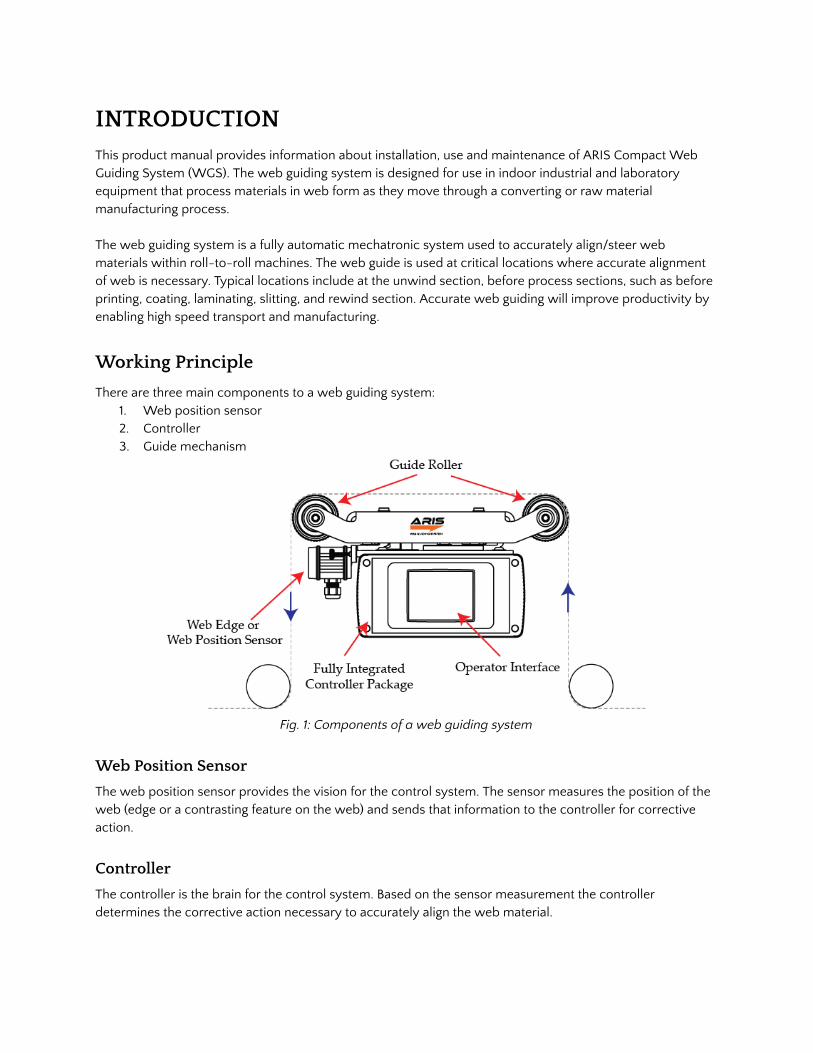
There are three main components to a web guiding system: 1. Web position sensor 2. Controller 3. Guide mechanism
Fig. 1: Components of a web guiding system
Web Position Sensor
The web position sensor provides the vision for the control system. The sensor measures the position of the web (edge or a contrasting feature on the web) and sends that information to the controller for corrective action.
Controller
The controller is the brain for the control system. Based on the sensor measurement the controller determines the corrective action necessary to accurately align the web material.
Content subject to change without notice ARIS Compact Web Guiding System Product Manual | Page 4 Copyright © 2017 Roll-2-Roll Technologies LLC https://ww.r2r-tech.com +1-888-290-3215

Guide Mechanism
The web guide mechanism is the muscle for the control system. The guide mechanism actuated by a motor physically steers the web to the required position based on the command from the controller.
Key Features
● Simplicity: The simplest web guide to install, operate and maintain. ● No setup or re-calibration: The intelligent control system adapts automatically to physical
characteristics of the web material and web transport conditions to provide best performance without the need for re-tuning.
● Plug-and-play system: The sophisticated technologies within the system make the web guide simple to operate. There is no need to (1) select the type of sensor, (2) change controller gains, (3) change sensitivity or (4) perform any calibration. Everything is done automatically. Just connect the power and sensor to start guiding the web.
● Compact design for easy integration: The unique modular compact, aesthetic, and functional design makes it easy to install within tight spaces.
Product Description
The sensor, controller and the guide mechanism are tightly integrated to provide a compact design. The physical design includes a pivoting top roller platform, direct drive linear hybrid stepper motor actuator, an enclosure with integrated controller, operator interface and mounting options. An exploded view of the web guide is shown in Fig. 2.
Fig. 2: Exploded view of the ARIS Compact Web Guiding System
Content subject to change without notice ARIS Compact Web Guiding System Product Manual | Page 5 Copyright © 2017 Roll-2-Roll Technologies LLC https://ww.r2r-tech.com +1-888-290-3215

Grooved rollers, mounted on the pivoting top roller platform, enable better traction between the web and the guide. High performance self cleaning plastic bearings are used for all the rolling and sliding contact surfaces on the roller platform. The roller platform is directly connected to a linear hybrid stepper motor. With its brushless design, the stepper motor offers precision positioning at high speed with minimum motor wear. Two different thrust and speed options are available with the hybrid stepper motor actuator. The extruded enclosure assembly not only support the linear rails that guide the roller platform but also encloses the motor, controller electronics and the operator interface. One side of the enclosure can be equipped with the touch screen operator interface while the other end contains the connector interface for the web guiding system. The bottom of the enclosure provides mounting holes with M6 threaded nuts to mount the web guiding system onto the machine frame. The sensor head houses the LED light source, the optics and the camera sensor. The sensor head is connected to the web guiding system through a shielded cable secured by a cable gland. The sensor head assembly is mounted onto an off-shelf aluminum rail ( igus drylin N low pro�le linear rails with using NW-22-17-40 carriage) on web guide and is secured by M3 thumb screws.
Fig. 3: Sensor head assembly WARNING: Opening and disassembling the extruded enclosure assembly or the sensor assembly without Roll-2-Roll Technologies’ supervision will void warranty of the equipment. In case of any malfunction please contact support.
General Speci�cations
Roller Width 250, 300, 375, 425, 500, 550 mm Sensor Type Fiber optic
Motor Type Linear hybrid stepper Sensor Range 16 mm, 48 mm and 221 mm
Correction Rate Up to 135 mm/sec Sensor Resolution 0.0635 mm or 0.125 mm
Nominal Actuating Travel
± 27mm Sensor Accuracy >99.2%
Control Frequency 50 - 200 Hz Power 24 VDC
Maximum Tension 225 N Error Frequency 8 Hz max
Content subject to change without notice ARIS Compact Web Guiding System Product Manual | Page 6 Copyright © 2017 Roll-2-Roll Technologies LLC https://ww.r2r-tech.com +1-888-290-3215
SAFETY INSTRUCTIONS
The ARIS Compact Web Guiding System is an electromechanical device that operates on low voltage (24 V DC). However, it does present a few safety requirements that must be followed in order to assure safe operation of the system.
Instructions for Use The ARIS Compact Web Guiding System must be properly transported, stored before being installed professionally. The guide should not be installed or commissioned for operation if any visible damage is observed. Only persons who have the necessary quali�cations should work on the installation, commissioning, operation, and maintenance of the web guide. Notes:
● Please read the product manual and properly follow its instructions ● Please read and follow the warning labels on the device ● Be aware of all national, state, and local requirements for accident prevention and environmental
protection.
Proper Use The ARIS Compact Web Guiding System is intended for indoor uses only. The web guide is designed for use in industrial and lab equipment that process materials in web form as they move through a converting or raw material manufacturing process.
Improper Use ● The sensor uses high powered LED light source (visible or invisible) that may be harmful to human
eye. Staring directly at the light source may harm vision and should be avoided. ● Outdoor use is considered improper. ● Any use outside the general speci�cations shall be considered improper use and voids any warranty
of the equipment. ● Any replacement parts or modi�cation necessaries should be made by Roll-2-Roll Technologies LLC.
Pinch Points ● The gap between the top roller platform and the enclosure assembly is a region with pinch points.
The force of the actuator motor can cause damage to body parts due to crushing if these are caught in a pinch point.
● The gap between the rollers and the roller support plates must be considered a pinch point. The guide rollers are not powered and are only driven by the friction of the web on the rollers as the web travels over the rollers. However, while the material is threaded and transported over the guide rollers this creates pinch points between the web and the roller. Under no circumstance should the roller or the web be touched while the web is transported.
● Any installation, maintenance, or inspection work on or around the web guide must be performed when the power to the web guide is turned off or unplugged. It is recommended that caution should be exercised when handling the web guide under power to avoid having body parts caught in the pinch points.
Content subject to change without notice ARIS Compact Web Guiding System Product Manual | Page 7 Copyright © 2017 Roll-2-Roll Technologies LLC https://ww.r2r-tech.com +1-888-290-3215

● Please follow standard Lockout/Tagout procedure while performing any function near the web guide.
● The complete guide assembly has an estimated weight between 22 lbs and 35 lbs depending on the model number. Care should be taken when handling the guide during shipping, transportation, or installation to avoid crushing of body parts or of other equipment from impact due to mishandling of the guide and to avoid personal injury. The web guide system should be securely and properly assembled before placing it in operation. Internal safety rules should be observed during the assembly process.
● ARIS Compact Web Guiding System is an automatic control device that may stop and start at any time without notice, especially when controlled remotely. Hence standard safeguards must be in place to prevent any kind of injury.
Static Discharges and Grounding ● Web, especially plastic webs, when transported over rollers can create signi�cant static voltage
potential. This potential needs to safely discharged by proper grounding. ● The electronic elements of the web guiding system are sensitive to static discharges. Make sure that
the web guiding system, the power supply, and the machine on which the web guide operates is properly grounded to avoid shock and the effect of static discharge.
● A grounding connector on the web guide may be used to safely ground the electronics within the web guiding system.
Content subject to change without notice ARIS Compact Web Guiding System Product Manual | Page 8 Copyright © 2017 Roll-2-Roll Technologies LLC https://ww.r2r-tech.com +1-888-290-3215
INSTALLATION
Unpacking
The ARIS Compact Web Guiding System will arrive packaged in a cardboard enclosure specially designed for the web guide. Although the packaging is designed to protect the product from shock due to transportation, care should be taken in handling the box with the guide to avoid damaging the device.
● When opening the container, make sure you open the box in the upright position. The upright position can be veri�ed by the printing on the outside of the box.
● The sensor unit is shipped uninstalled from the guide unit and will be packaged within the protective cardboard enclosures. Remove the protective cardboard enclosures carefully to avoid dropping the sensor assembly.
● Unpack the optional pre-wired power adapter, if the optional package is shipped.
Web Guiding System Dimensions
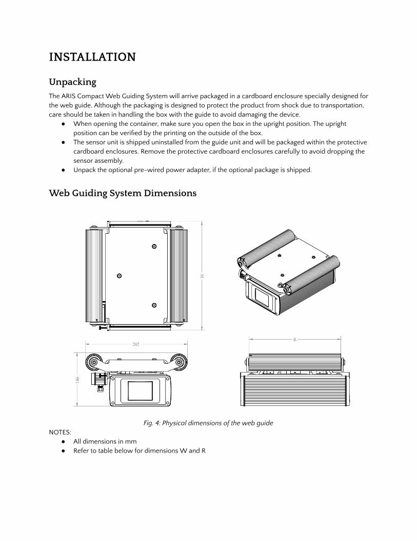
Fig. 4: Physical dimensions of the web guide NOTES:
● All dimensions in mm ● Refer to table below for dimensions W and R
Content subject to change without notice ARIS Compact Web Guiding System Product Manual | Page 9 Copyright © 2017 Roll-2-Roll Technologies LLC https://ww.r2r-tech.com +1-888-290-3215

Roller Face inch [mm] R
Guide Span inch [mm]
Roller Diameter inch [mm]
Width inch [mm] W
Max correction inch [mm]
Max correction speed in/sec [mm/sec]
10 [254]
11.10 [282] 2 [50]
11.85 [301]
�± 1.06 [27] 5.315 - 6.889 [135-175]
12 [304.8] 11.85 [301]
15 [381] 16.85 [428]
17 [431.8] 16.85 [428]
20 [508] 21.85 [555]
22 [558.8] 21.85 [555]
Mounting Hole Pattern
The mounting hole pattern, which is the same for all the different sizes, is shown below.
Fig. 5: Mounting hole pattern Notes:
● The mounting holes are symmetric along the width of the web guide and non-symmetric along the length of the web guide. Hence when the guide is installed installed the mounting holes will not be in the middle of the guide span.
Content subject to change without notice ARIS Compact Web Guiding System Product Manual | Page 10 Copyright © 2017 Roll-2-Roll Technologies LLC https://ww.r2r-tech.com +1-888-290-3215

Mounting
Once the unit is outside of the packaging you may proceed to install the unit. ● The unit comes with four M6 threaded mounting holes located on the bottom of the enclosure. ● Four M6 bolts and spacers are provided with the web guiding system which can be used to mount
the web guide on the machine frame. ● Do not drill additional holes to the bottom of the control unit! ● You may be required to prepare an installation plate to install the unit to your production machine.
Make sure the guide is centered along the width of the web material. Note that the mounting holes are not centered with respect to the two guide rollers.
● The guide has a downstream side and an upstream side. The downstream side will always have the sensor mounting rail underneath the downstream roller, irrespective of the operator interface installation (see Fig. 6 below).
● Make sure to install the guide with proper orientation by following the web direction marking on the roller platform assembly. The sensor must always be on the downstream side of material �ow.
● Secure the guide to the machine by bolting the guide with the M6 bolts that are provided with the guide.
● Tighten each bolt with an allen wrench by hand until each bolt is locked securely. Do not over tighten the bolts.
Fig. 6: Two con�gurations for the operator interface installation. The default con�guration is shown on the left where the web goes from left (upstream side) to right (downstream side).
Sensor Installation
Next the sensor assembly can be installed. ● The sensor assembly is composed of the sensor head, sensor connecting cable, and two sensor
slide carriages with M3 thumb screws. All these elements are factory shipped assembled as a ready to install unit.
● Each sensor slide carriage will have a locking thumbscrew. Unscrew both thumbscrews to allow the carriage to slide into the sensor rail that is mounted under the roller assembly on the downstream side of the web guide.
● The sensor face has a �lter lid (infrared or visible �lter lid). Make sure the �lter lid faces the web material when the sensor assembly is slid into the guide rail.
Content subject to change without notice ARIS Compact Web Guiding System Product Manual | Page 11 Copyright © 2017 Roll-2-Roll Technologies LLC https://ww.r2r-tech.com +1-888-290-3215

● Once the sensor has been installed in the sensor rail, install the plastic end caps on the ends of the rail. The snap-on plastic end caps are typically provided with the web guide.
● If two sensors are used, follow the same procedure to install two sensors. ● After the sensor installation connect the sensor connector (12-pin male) at the end of the sensor
cable to the sensor port on the connector interface on the other side of the enclosure assembly (see Fig. 7). Note that the connector interface may be different for different models.
● A completed sensor installation looks similar to the one shown in Fig. 8.
Fig. 7: Connector interface on the rear side of the web guiding system.
Fig. 8: Typical sensor installation on the sensor rail with end caps installed.
WARNING: Even though the sensor working distance is less than 25 mm, the sensor operation may be affected by any object in the �eld of view of the sensor which is at a distance of 150 mm. Make sure that no object is present within this safe �eld of view range to ensure proper operation of the sensor. WARNING: The infrared light source is invisible to the naked eye. Please do not stare directly into the sensor at any time. This can potential damage eyesight and may cause blindness. WARNING: The white light source is visible to the naked eye. Please do not stare directly into the sensor at any time. This can potential damage eyesight. WARNING: The ultraviolet light source may be visible or invisible to the naked eye. Please do not stare directly into the sensor at any time. This can potential damage eyesight and may cause blindness. Avoid any skin exposure with the ultraviolet light source. The exposure may be potentially harmful.
Content subject to change without notice ARIS Compact Web Guiding System Product Manual | Page 12 Copyright © 2017 Roll-2-Roll Technologies LLC https://ww.r2r-tech.com +1-888-290-3215

Power Input The ARIS Web Guiding operates under 24 VDC (± 5%) power with a maximum current of 4 Amps. There are two power port options available: (1) pre-wired or (2) power jack connector based on the order.
Prewiring
In the pre-wired option, the unit may come with a 2.5 meter long power cable (through a gland nut) for the customer to connect to an appropriately grounded 24 VDC power source. There are three conductors in the power cable. The red colored conductor is the 24V power, the black colored conductor is the DC return or electronic circuit ground.
Switchcraft DC Connector
Sealed Switchcraft L712AS power jack port option is available on the SCU. A mating Switchcraft 761KS12 plug connector or a pre-assembled Switchcraft CARA761KS07984 or a pre-assembled Switchcraft CA761KS07984 can be used to supply power. For the plug connector the 24 VDC power should be supplied to the tip/center pin and electronic ground on the sleeve pin. For the cable assembly the 24 VDC should be connected to the red cable and the electronic ground connected to the black cable.
Industrial DIN Rail Power Supply
Industrial DIN rail mountable power supply such as Mean Well SDR-75-24 can be used to supply the 24VDC power. This is an available purchase option.
Grounding
For safety and for normal operation, the ARIS Compact Web Guiding System, the equipment to which the web guide is installed must be properly grounded. A grounding screw is available on the rear connector interface for connecting the grounding cable. WARNING: Even though the mounting holes provide grounding of the ARIS Compact Web Guiding System, please use all possible options to safely earth the web guide. Improper grounding may result in static buildup that can potentially result in malfunction of the web guiding system.
Industrial Ethernet Interface
An optional industrial ethernet connection to the web guiding system is available on certain models. A 4-pin D-coded M12 socket connect is provided for ethernet connection. Standard network cables such as Phoenix Contact NBC-MSD/ 1,0-93E/R4AC SCO - 1407360 or VS-MSD-IP20-93E/5,0 - 1403500 can be used to connect the ARIS SCU to an ethernet network using RJ45 plug.
Content subject to change without notice ARIS Compact Web Guiding System Product Manual | Page 13 Copyright © 2017 Roll-2-Roll Technologies LLC https://ww.r2r-tech.com +1-888-290-3215

4- Pin Industrial Ethernet Connector.
A set of input and output registers are available to monitor and control the ARIS SCU.
Content subject to change without notice ARIS Compact Web Guiding System Product Manual | Page 14 Copyright © 2017 Roll-2-Roll Technologies LLC https://ww.r2r-tech.com +1-888-290-3215
OPERATION AND OPERATOR INTERFACE
Main Operator Interface Screen
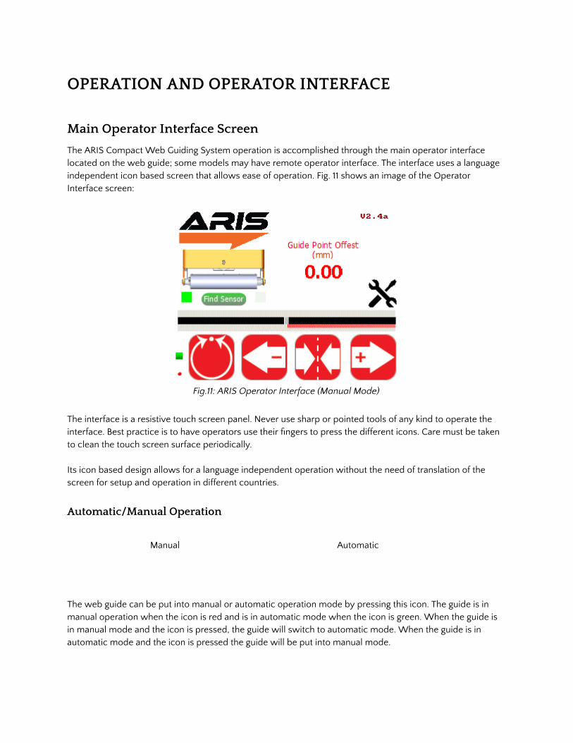
The ARIS Compact Web Guiding System operation is accomplished through the main operator interface located on the web guide; some models may have remote operator interface. The interface uses a language independent icon based screen that allows ease of operation. Fig. 11 shows an image of the Operator Interface screen:
Fig.11: ARIS Operator Interface (Manual Mode)
The interface is a resistive touch screen panel. Never use sharp or pointed tools of any kind to operate the interface. Best practice is to have operators use their �ngers to press the different icons. Care must be taken to clean the touch screen surface periodically.
Its icon based design allows for a language independent operation without the need of translation of the screen for setup and operation in different countries.
Automatic/Manual Operation
Manual Automatic
The web guide can be put into manual or automatic operation mode by pressing this icon. The guide is in manual operation when the icon is red and is in automatic mode when the icon is green. When the guide is in manual mode and the icon is pressed, the guide will switch to automatic mode. When the guide is in automatic mode and the icon is pressed the guide will be put into manual mode.
Content subject to change without notice ARIS Compact Web Guiding System Product Manual | Page 15 Copyright © 2017 Roll-2-Roll Technologies LLC https://ww.r2r-tech.com +1-888-290-3215

● The guide should be placed in manual operation during initial setup of the guide, or during routine maintenance of the production line.
● The guide must be placed in automatic operation when the production line is in production mode.
WARNING: Changing from one mode to another can result in change in the web guide position causing process upsets. Caution must be exercised when changing the operating mode and should be done by those who completely understand the consequence of this change. WARNING: No personnel should be manually handling the web guide or the material around the web guide when the guide is in automatic operation. Failure to follow this warning could result in crushing of body parts at pinch points around and within the web guiding system.
WARNING: Care must be taken that only one person is working on the guide when it is in manual operation. Failure to follow this warning could result in crushing of body parts at pinch points around and within the web guiding system.
A few icons on the operator interface are enabled or disabled as the web guide is switched between manual and automatic mode based on the available options in each mode. Fig. 12 shows the operator interface while the web guiding system is in automatic mode. The advanced setup and sensing mode icons are disabled.
Fig. 12: ARIS Operator Interface (Automatic Mode)
Servo-Centering Operation
Servo-centering off Servo-centering on
The servo-centering operation automatically centers the guide roller assembly of the guide.
● During normal operation the icon will be in red.
Content subject to change without notice ARIS Compact Web Guiding System Product Manual | Page 16 Copyright © 2017 Roll-2-Roll Technologies LLC https://ww.r2r-tech.com +1-888-290-3215

● Upon pressing the icon, the icon turns green and the guide automatically moves the rollers to a factory preset center position. Once centered the icon returns to red indicating that it has �nished the procedure and that servo-centering is off.
The servo center feature allows the guide to be centered quickly to facilitate threading of the web during changeover.
WARNING: Servo centering operation result in change in the web guide position causing process upset. Caution must be exercised when performing this function and should be done by those who completely understand the consequence of this change. WARNING: Servo centering can be performed only when the web guiding system is in manual mode. Pressing the servo center icon during automatic operation will perform a different function.
WARNING: This is an automatic procedure of the web guiding system. No personnel should be performing manual work on or around the guide during the servo-centering procedure. Failure to follow this warning could result in crushing of body parts at pinch points around and within the web guiding system.
Jog-left/Jog-right Operation
Jog-left off Jog-right off
Jog-left on Jog-right on
The Jog-left/Jog-right icons allow the operator to manually move the guide roller assembly to the left or to the right as needed. These operations can be performed only when the web guide is in manual operating mode.
● The Jog-left/Jog-right operation icon indicates the operation is off when the icon is red. ● When the operator turns the Jog-left or Jog-right ON by pressing the icon, the guide will start
moving to the left or right position. The respective icon will turn green during the Jog operation and will turn back to red when the operation is stopped.
The Jog operation can be stopped at any time by pressing the respective icon any time during the jog. If the guide reaches the extreme position, the jog operation will stop automatically. This operation can only be performed when the guide is in manual setting. The left position of the guide is de�ned as the left side of the guide if the operator is viewing the guide from the downstream position (facing the sensor). Similarly, the right position of the guide is de�ned as the right side of the guide if the operator is viewing the guide from the downstream position.
Content subject to change without notice ARIS Compact Web Guiding System Product Manual | Page 17 Copyright © 2017 Roll-2-Roll Technologies LLC https://ww.r2r-tech.com +1-888-290-3215

WARNING: Jog-Left and Jog-Right operations result in change in the web guide position causing process upset. Caution must be exercised when performing these function and should be done by those who completely understand the consequence of this change. WARNING: Jog-Left and Jog-Right operation can be performed only when the web guiding system is in manual mode. Pressing the icons during automatic operation will perform a different function. WARNING: This is a manual procedure of the web guiding system. No personnel should be performing work on or around the guide during the jog procedure. Failure to follow this warning could result in crushing of body parts at pinch points around and within the web guiding system.
Guide Point Adjustment
The guide point of the web guiding system (reference or the desired location of the web with respect to the sensor) is set to 50% of the sensing window of the sensor when shipped from the factory. In this setting the web will be guided to a position exactly in the middle of the sensing window. The guide point can be adjusted to a different location within of the sensor range. This setting is absolute irrespective of the sensor position. The current guide point setting is indicated by the guide point indicator as shown in Fig. 13.
Fig. 13: Guide Point Indicator
The visual guide point indicator is a track bar that provides an easy and quick visual indication of the web edge position with respect to the current guide point. Under normal conditions, the web position should align with the guide point while the web guide is in automatic control mode. A numerical guide point indicator displays the numerical value of the guide point offset on the screen. The guide point can be adjusted in two ways: �ne guide point adjustment for small incremental adjustments and gross guide point adjustment for large step change to the guide point.
Fine Guide Point Adjustment
The �ne adjustments to the guide point can only be made when the web guide is in automatic mode. These adjustments enable small incremental changes to the guide through the operator interface to enable operators to move the desired guiding position of the web. The �ne adjustment to the guide point can be
Content subject to change without notice ARIS Compact Web Guiding System Product Manual | Page 18 Copyright © 2017 Roll-2-Roll Technologies LLC https://ww.r2r-tech.com +1-888-290-3215
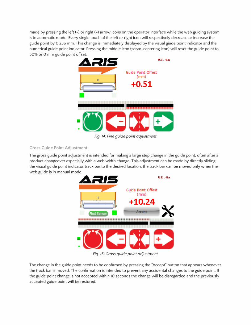
made by pressing the left (-) or right (+) arrow icons on the operator interface while the web guiding system is in automatic mode. Every single touch of the left or right icon will respectively decrease or increase the guide point by 0.256 mm. This change is immediately displayed by the visual guide point indicator and the numerical guide point indicator. Pressing the middle icon (servo-centering icon) will reset the guide point to 50% or 0 mm guide point offset.
Fig. 14: Fine guide point adjustment
Gross Guide Point Adjustment
The gross guide point adjustment is intended for making a large step change in the guide point, often after a product changeover especially with a web width change. This adjustment can be made by directly sliding the visual guide point indicator track bar to the desired location; the track bar can be moved only when the web guide is in manual mode.
Fig. 15: Gross guide point adjustment The change in the guide point needs to be con�rmed by pressing the “Accept” button that appears whenever the track bar is moved. The con�rmation is intended to prevent any accidental changes to the guide point. If the guide point change is not accepted within 10 seconds the change will be disregarded and the previously accepted guide point will be restored.
Content subject to change without notice ARIS Compact Web Guiding System Product Manual | Page 19 Copyright © 2017 Roll-2-Roll Technologies LLC https://ww.r2r-tech.com +1-888-290-3215

NOTE: The pressing of the Left (-) or Right (+) during �ne guide point adjustment will momentarily change the icon to green as shown in Fig. 14. With the release of the button the icon changes the color back to red. WARNING: The guide point adjustment operation result in change in the web guide position causing process upset. Caution must be exercised when performing this function and should be done by those who completely understand the consequence of this change. WARNING: Fine guide point adjustment can be performed only when the web guiding system is in automatic mode. Pressing the Left (-) or Right (+) icons during manual operation will perform the jog operations. WARNING: Guide point adjustment should be made only if it is necessary and should be carried out by personnel with good knowledge about the consequences of the change. The performance of the guiding system may deteriorate if the guide point is too far away from the desired 50% setting. Some of the changes might have no effect if the web guide is in an extreme position.
Web Position Indicators
Horizontal bar graph indicators (see Fig. 16) are available on the operator interface to indicate the position of the web as seen by the sensor. Both the edge position as well as the contrast position are indicated. Depending on the position and orientation of the sensor the bar graphs may increase:
● from left to right for a sensor located on the right side of the web edge ● from right to left for a sensor that is located on the left side of the web edge.
The top web position indicator displays the right edge/contrast position of the web and the bottom web position indicator indicates the left edge/contrast position of the web. When two sensors (one left and one right) are connected or if a wide sensor is connected the edge position indicator may indicate both the left and the right edge of the web.
Fig. 16: ARIS WGS Operator Interface
Content subject to change without notice ARIS Compact Web Guiding System Product Manual | Page 20 Copyright © 2017 Roll-2-Roll Technologies LLC https://ww.r2r-tech.com +1-888-290-3215

Web Detected Indicator
A small square indicator on the bottom left part of the screen (see Fig. 14) indicates the presence and absence of the web as seen by the sensor.
● Whenever the sensor sees a web or a web edge, the indicator turns green. ● When the web is outside the sensing window the green indication goes off.
This web detect indicator can be used for troubleshooting purposes. If this indicator turns off intermittently while a web is in front of the sensor it may indicate that the sensor is �nding it dif�cult to accurately sense the web. This indicates a low contrast condition for the sensor. Such a condition may occur for optical grade clear webs with low scattering in the infrared spectrum.
Sensor Position Indicator
The position of the sensor is indicated by two square indicators on the display (see Fig. 14) that are located downstream of the web guide picture.
● The indicator turns green to display the position and orientation of the sensor with respect to the guide and the web edge.
● If no sensor is attached to the web guiding system then both the indicators will turn gray. ● If two sensors (one right and one left) are attached to the web guiding system or if a wide sensor
with center guiding option is used, both indicators will turn green. ● It is important to ensure that the sensor position indicator accurately indicates the actual position of
the sensor with respect to the guide. ● The operator can �nd the correct position of the sensor by pressing the �nd sensor button that
automatically detects the position of the sensor.
Find Sensor Button
The Find Sensor Button (see Fig. 16) can be used to automatically detect the position and orientation of the sensor with respect to the web guide and the web edge. Once the button is pressed the button will change state (as shown in Fig. 17) until the web edge is found.
● This button should be used whenever the sensor position is changed or when the edge orientation is changed.
● When the edge orientation changes, the bar graph will also change orientation.
● Find sensor button is activated only when the web guiding system is in manual mode.
Fig. 17: Find sensor operation
Content subject to change without notice ARIS Compact Web Guiding System Product Manual | Page 21 Copyright © 2017 Roll-2-Roll Technologies LLC https://ww.r2r-tech.com +1-888-290-3215
Communication Indicator
A round indicator at the left bottom of the operator interface (see Fig. 14) indicates the communication between the electronic controller board and the operator interface.
● This indicator is used for troubleshooting purpose. ● During normal operation this indicator will switch between red and green at a frequency of ~2 Hz.
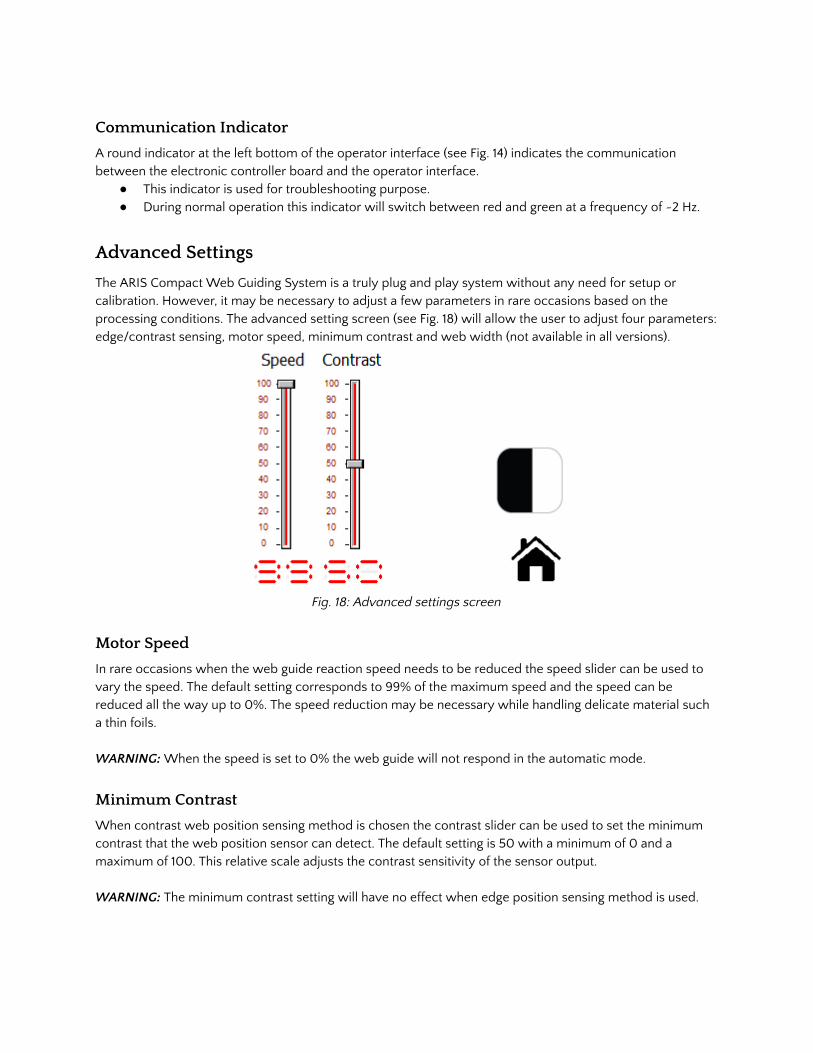
Advanced Settings
The ARIS Compact Web Guiding System is a truly plug and play system without any need for setup or calibration. However, it may be necessary to adjust a few parameters in rare occasions based on the processing conditions. The advanced setting screen (see Fig. 18) will allow the user to adjust four parameters: edge/contrast sensing, motor speed, minimum contrast and web width (not available in all versions).
Fig. 18: Advanced settings screen
Motor Speed
In rare occasions when the web guide reaction speed needs to be reduced the speed slider can be used to vary the speed. The default setting corresponds to 99% of the maximum speed and the speed can be reduced all the way up to 0%. The speed reduction may be necessary while handling delicate material such a thin foils. WARNING: When the speed is set to 0% the web guide will not respond in the automatic mode.
Minimum Contrast
When contrast web position sensing method is chosen the contrast slider can be used to set the minimum contrast that the web position sensor can detect. The default setting is 50 with a minimum of 0 and a maximum of 100. This relative scale adjusts the contrast sensitivity of the sensor output. WARNING: The minimum contrast setting will have no effect when edge position sensing method is used.
Content subject to change without notice ARIS Compact Web Guiding System Product Manual | Page 22 Copyright © 2017 Roll-2-Roll Technologies LLC https://ww.r2r-tech.com +1-888-290-3215

WARNING: A very low contrast setting will make the sensor to be extremely sensitive to minute contrast difference.
Edge/Contrast Web Position Sensing
Edge sensing Contrast sensing
Depending on the type of sensor (infrared or white light or ultraviolet) the ARIS Compact Web Guiding System can operator in either edge sensing mode or contrast sensing mode. The default con�guration is edge sensing with infrared light source.
In edge sensing mode the sensor will look for the web edge scanning from the outside to the inside of the sensor. For a left sensor the scan goes from left to right, while for a right sensor the scan goes from right to left (see Fig. 19).
Fig. 19: Left sensor orientation (left) and right sensor orientation (right)
Contrast sensing mode is intended to be used only with white light sensor. This sensing mode can be used to detect a line or a contrast in the web. In contrast sensing mode the position, of the �rst contrast change in the web, as the sensor scans from inside to outside is detected. An additional setting to optimize the sensor performance (contrast adjustment) is available for advanced users through the advanced setting screen.
WARNING: Do not use contrast sensing method with an infrared sensor unless there is a speci�c need that has been already identi�ed and tested. WARNING: The Edge/Contrast sensing icon is visible, and can be used, only when the web guiding system is in manual mode. WARNING: Both edge and contrast sensing method may work with white light. Additionally optical clear material may be dif�cult to sense with a white light option.
Content subject to change without notice ARIS Compact Web Guiding System Product Manual | Page 23 Copyright © 2017 Roll-2-Roll Technologies LLC https://ww.r2r-tech.com +1-888-290-3215

Fig. 20: Advanced Settings Screen (with width output options)
Web Width
Web width changes can be monitored in real-time for quality control purposes using the ARIS Compact Web Guiding System. The web width selection slider (only available in certain models) can be used to set the type of width output from the web guiding system. The output is an analog voltage based on the choice of width measurement or width monitoring. This setting is valid only when two sensors, one left and one right, or a wide sensor is used.
Analog Output
When the width output is set to be analog, the ARIS Compact Web Guiding System sends an analog output ranging between 0 to 10 Volts based on the percentage of the sensor(s) covered by the web. For example, with a wide sensor if the web covers 60% of the sensor window 6 Volts is output. If two sensors are used, one left and one right, then the output will be the total percentage of the two sensors covered by the web on either side.
Digital Output
The digital output option can be used for event based web monitoring. When this option is selected additional settings are available to the user as shown in Fig. 21. WARNING: This option is not available on all the web guiding systems.
Content subject to change without notice ARIS Compact Web Guiding System Product Manual | Page 24 Copyright © 2017 Roll-2-Roll Technologies LLC https://ww.r2r-tech.com +1-888-290-3215

Fig. 21: Digital width output settings. A lower (-ve limit) and an upper (+ve limit) web width tolerance can be set to trigger outputs based on web width. By default the lower and upper limits are set to zero. The resolution of the tolerances is in millimeters. By using the up and down buttons the lower limit and the upper limit can be changed. Any change in the limits must be accepted by pressing the “Accept Limits” button that becomes visible when the limits are changed (see Fig. 22). The nominal web width is recorded at the instant when the “Accept Limits” button is pressed. As soon as the “Accept Limits” button is pressed the button disappears indicating the limit acceptance as shown in Fig. 23.
Fig. 22: Accept Limits button is visible after a limit change. When the web width increases above the positive limit a positive high signal (+10V) is sent out by the ARIS Compact Web Guiding System. Similarly when the web width decreases below the negative limit a negative low signal (-10V) is sent out. When the web width is within the positive and negative width limits 0V is output.
Content subject to change without notice ARIS Compact Web Guiding System Product Manual | Page 25 Copyright © 2017 Roll-2-Roll Technologies LLC https://ww.r2r-tech.com +1-888-290-3215

Fig. 23: User interface after the pressing Accept Limits button. WARNING: If only one edge sensor is present then the output from the web guiding system, irrespective of the web width setting, will be an analog voltage between 0 to 10 Volts proportional to the web position (the percentage of the sensor covered by the web). WARNING: Whenever a different web material with different nominal width is used the nominal width and the limits must be reset.
Content subject to change without notice ARIS Compact Web Guiding System Product Manual | Page 26 Copyright © 2017 Roll-2-Roll Technologies LLC https://ww.r2r-tech.com +1-888-290-3215
Remote Control and Monitoring
A set of input and output registers are available to monitor and control the web guiding system remotely.
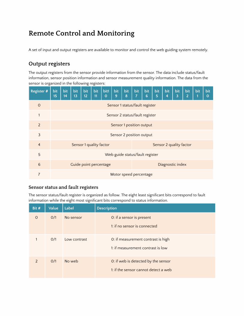
Output registers
The output registers from the sensor provide information from the sensor. The data include status/fault information, sensor position information and sensor measurement quality information. The data from the sensor is organized in the following registers:
Register # bit 15
bit 14
bit 13
bit 12
bit 11
bit10
bit 9
bit8
bit7
bit6
bit5
bit4
bit3
bit2
bit 1
bit0
0 Sensor 1 status/fault register
1 Sensor 2 status/fault register
2 Sensor 1 position output
3 Sensor 2 position output
4 Sensor 1 quality factor Sensor 2 quality factor
5 Web guide status/fault register
6 Guide point percentage Diagnostic index
7 Motor speed percentage
Sensor status and fault registers
The sensor status/fault register is organized as follow. The eight least signi�cant bits correspond to fault information while the eight most signi�cant bits correspond to status information.
Bit # Value Label Description
0 0/1 No sensor 0: if a sensor is present
1: if no sensor is connected
1 0/1 Low contrast 0: if measurement contrast is high
1: if measurement contrast is low
2 0/1 No web 0: if web is detected by the sensor
1: if the sensor cannot detect a web
Content subject to change without notice ARIS Compact Web Guiding System Product Manual | Page 27 Copyright © 2017 Roll-2-Roll Technologies LLC https://ww.r2r-tech.com +1-888-290-3215
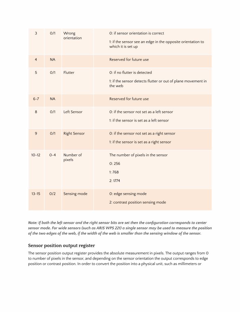
3 0/1 Wrong orientation
0: if sensor orientation is correct
1: if the sensor see an edge in the opposite orientation to which it is set up
4 NA Reserved for future use
5 0/1 Flutter 0: if no �utter is detected
1: if the sensor detects �utter or out of plane movement in the web
6-7 NA Reserved for future use
8 0/1 Left Sensor 0: if the sensor not set as a left sensor
1: if the sensor is set as a left sensor
9 0/1 Right Sensor 0: if the sensor not set as a right sensor
1: if the sensor is set as a right sensor
10-12 0-4 Number of pixels
The number of pixels in the sensor
0: 256
1: 768
2: 1774
13-15 0/2 Sensing mode 0: edge sensing mode
2: contrast position sensing mode
Note: If both the left sensor and the right sensor bits are set then the con�guration corresponds to center sensor mode. For wide sensors (such as ARIS WPS 221) a single sensor may be used to measure the position of the two edges of the web, if the width of the web is smaller than the sensing window of the sensor.
Sensor position output register
The sensor position output register provides the absolute measurement in pixels. The output ranges from 0 to number of pixels in the sensor, and depending on the sensor orientation the output corresponds to edge position or contrast position. In order to convert the position into a physical unit, such as millimeters or
Content subject to change without notice ARIS Compact Web Guiding System Product Manual | Page 28 Copyright © 2017 Roll-2-Roll Technologies LLC https://ww.r2r-tech.com +1-888-290-3215
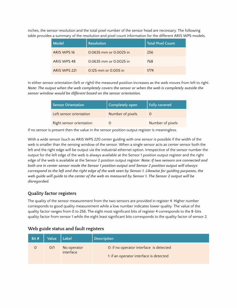
inches, the sensor resolution and the total pixel number of the sensor head are necessary. The following table provides a summary of the resolution and pixel count information for the different ARIS WPS models.
Model Resolution Total Pixel Count
ARIS WPS 16 0.0635 mm or 0.0025 in 256
ARIS WPS 48 0.0635 mm or 0.0025 in 768
ARIS WPS 221 0.125 mm or 0.005 in 1774
In either sensor orientation (left or right) the measured position increases as the web moves from left to right. Note: The output when the web completely covers the sensor or when the web is completely outside the sensor window would be different based on the sensor orientation.
Sensor Orientation Completely open Fully covered
Left sensor orientation Number of pixels 0
Right sensor orientation 0 Number of pixels
If no sensor is present then the value in the sensor position output register is meaningless.
With a wide sensor (such as ARIS WPS 221) center guiding with one sensor is possible if the width of the web is smaller than the sensing window of the sensor. When a single sensor acts as center sensor both the left and the right edge will be output via the industrial ethernet option. Irrespective of the sensor number the output for the left edge of the web is always available at the Sensor 1 position output register and the right edge of the web is available at the Sensor 2 position output register. Note: If two sensors are connected and both are in center sensor mode the Sensor 1 position output and Sensor 2 position output will always correspond to the left and the right edge of the web seen by Sensor 1. Likewise for guiding purposes, the web guide will guide to the center of the web as measured by Sensor 1. The Sensor 2 output will be disregarded.
Quality factor registers
The quality of the sensor measurement from the two sensors are provided in register 4. Higher number corresponds to good quality measurement while a low number indicates lower quality. The value of the quality factor ranges from 0 to 256. The eight most signi�cant bits of register 4 corresponds to the 8-bits quality factor from sensor 1 while the eight least signi�cant bits corresponds to the quality factor of sensor 2.
Web guide status and fault registers
Bit # Value Label Description
0 0/1 No operator interface
0: if no operator interface is detected
1: if an operator interface is detected
Content subject to change without notice ARIS Compact Web Guiding System Product Manual | Page 29 Copyright © 2017 Roll-2-Roll Technologies LLC https://ww.r2r-tech.com +1-888-290-3215
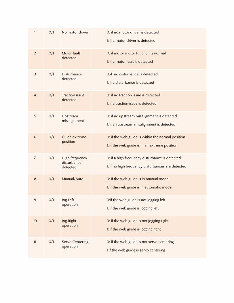
1 0/1 No motor driver 0: if no motor driver is detected
1: if a motor driver is detected
2 0/1 Motor fault detected
0: if motor motor function is normal
1: if a motor fault is detected
3 0/1 Disturbance detected
0:if no disturbance is detected
1: if a disturbance is detected
4 0/1 Traction issue detected
0: if no traction issue is detected
1: if a traction issue is detected
5 0/1 Upstream misalignment
0: if no upstream misalignment is detected
1: if an upstream misalignment is detected
6 0/1 Guide extreme position
0: if the web guide is within the normal position
1: if the web guide is in an extreme position
7 0/1 High frequency disturbance detected
0: if a high frequency disturbance is detected
1: if no high frequency disturbances are detected
8 0/1 Manual/Auto 0: if the web guide is in manual mode
1: if the web guide is in automatic mode
9 0/1 Jog Left operation
0:if the web guide is not jogging left
1: if the web guide is jogging left
10 0/1 Jog Right operation
0: if the web guide is not jogging right
1: if the web guide is jogging right
11 0/1 Servo Centering operation
0: if the web guide is not servo centering
1 if the web guide is servo centering
Content subject to change without notice ARIS Compact Web Guiding System Product Manual | Page 30 Copyright © 2017 Roll-2-Roll Technologies LLC https://ww.r2r-tech.com +1-888-290-3215

12 0/1 Good guiding performance
0: if the guiding performance is not good
1: if the guiding performance is good
13-15 NA Reserved for future use
Guide point percentage
The guide point for the web guide is provided in this register. The value of the guide point range between 0 and 100, representing the guide point as a percentage of the sensor range. A value of 50 indicates that the guide point is at the middle of the sensing window while a value of 25 means the guide point is at the 25% of the sensor window (left of the middle) while a value of 75 means the guide point is at 75% of the sensor window (right of the middle). The eight most signi�cant bits of register 5 provide the guide point percentage output.
Diagnostic index
The diagnostic index output is only available with web guiding that include the KOIOS diagnostic index. The value ranges between 0 and 100. For more details please refer to the KOIOS diagnostics product manual. The eight least signi�cant bits of register 5 provide the diagnostic index output.
Motor speed percentage
The motor positioning speed as a percentage of maximum speed is output in register 7. The value ranges between 0 and 100.
Sensor input registers
Sensor input registers are control registers that are used to control/con�gure the parameters of each sensor. One 16-bit command register for each sensor is available for an external device to set the sensor parameters. The input registers are mapped as shown below:
Register # bit 15
bit 14
bit 13
bit 12
bit 11
bit10
bit 9
bit8
bit7
bit6
bit5
bit4
bit3
bit2
bit 1
bit0
0 Sensor 1 command register
1 Sensor 2 command register
2 Guide command register
3 Guide point offset register
4 Motor speed percentage register
Content subject to change without notice ARIS Compact Web Guiding System Product Manual | Page 31 Copyright © 2017 Roll-2-Roll Technologies LLC https://ww.r2r-tech.com +1-888-290-3215

Sensor command register
Bit # Value Label Description
0-1 0/2 Sensor orientation 0: set sensor orientation to be right sensor 2: set sensor orientation to be left sensor Note: Changing this value will take effect only if bit 5 is set to 1. The auto switch mode needs to be disabled to take control of the sensor orientation through this register.
2-3 0/1 Reserved for future use
4 0/1 Sensing mode 0: set the sensing mode to be edge mode 1: set the sensing mode to be contrast mode
5 0/1 Disable auto switch off
0: Automatic switch is enabled 1: Automatic switch is disabled Note: This bit needs to be set in order to force the sensor orientation externally. If this bit is cleared to zero the sensor will maintain the previous orientation until the sensor automatically detects the sensor orientation when (1) �nd sensor is enabled or (2) when a new sensor is plugged into the sensor port.
6 0/1 Find sensor 0: Disable �nd sensor operation 1: Enable �nd sensor operation by resetting the orientation and allowing the sensor to detect the web orientation. Note: This bit is momentary when set to one. Every time the �nd sensor operation needs to be enabled the bit needs to be cleared to zero before setting it to one.
7 0/1 Disable analog output
0: Enables the analog output for the sensor 1: Disables the analog output for the sensor
8-15 0-255 Minimum contrast Minimum contrast: Minimum contrast required to accept an edge in contrast mode Default value is 50.
Web guide command register
Bit # Value Label Description
0-7 NA Reserved for future use
8 0/1 Remote control 0: if cleared to zero, the local operator interface have control over the web guide 1: if set to one, the remote ethernet controller has control over the web guide. The interface icons to control the web guide on the local operator interface will be disabled. Information for monitoring purposes will be displayed on the screen.
Content subject to change without notice ARIS Compact Web Guiding System Product Manual | Page 32 Copyright © 2017 Roll-2-Roll Technologies LLC https://ww.r2r-tech.com +1-888-290-3215
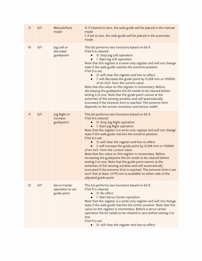
9 0/1 Manual/Auto mode
0: if cleared to zero, the web guide will be placed in the manual mode 1: if set to one, the web guide will be placed in the automatic mode
10 0/1 Jog Left or decrease guidepoint
This bit performs two functions based on bit 9. If bit 9 is cleared:
● 0: Stop Jog Left operation ● 1: Start Jog Left operation
Note that this register is a write only register and will not change state if the web guide reaches the extreme position. If bit 9 is set:
● 0: will clear the register and has no effect ● 1: will decrease the guide point by 0.254 mm or 1/100th
of an inch from the current value. Note that this value on this register is momentary. Before decreasing the guidepoint the bit needs to be cleared before setting it to one. Note that the guide point cannot at the extremes of the sensing window and will automatically truncated if the extreme limit is reached. The extreme limit depends on the sensor resolution and sensor width.
11 0/1 Jog Right or increase guidepoint
This bit performs two functions based on bit 9. If bit 9 is cleared:
● 0: Stop Jog Right operation ● 1: Start Jog Right operation
Note that this register is a write only register and will not change state if the web guide reaches the extreme position. If bit 9 is set:
● 0: will clear the register and has no effect ● 1: will increase the guide point by 0.254 mm or 1/100th
of an inch from the current value. Note that this value on this register is momentary. Before increasing the guidepoint the bit needs to be cleared before setting it to one. Note that the guide point cannot at the extremes of the sensing window and will automatically truncated if the extreme limit is reached. The extreme limit is set such that at least ±3.175 mm is available on either side of the adjusted guide point.
12 0/1 Servo Center operation or set guide point
This bit performs two functions based on bit 9. If bit 9 is cleared:
● 0: No effect ● 1: Start Servo Center operation
Note that this register is a write only register and will not change state if the web guide reaches the center position. Note that this value on this register is momentary. Before a servo center operation the bit needs to be cleared to zero before setting it to one. If bit 9 is set:
● 0: will clear the register and has no effect
Content subject to change without notice ARIS Compact Web Guiding System Product Manual | Page 33 Copyright © 2017 Roll-2-Roll Technologies LLC https://ww.r2r-tech.com +1-888-290-3215
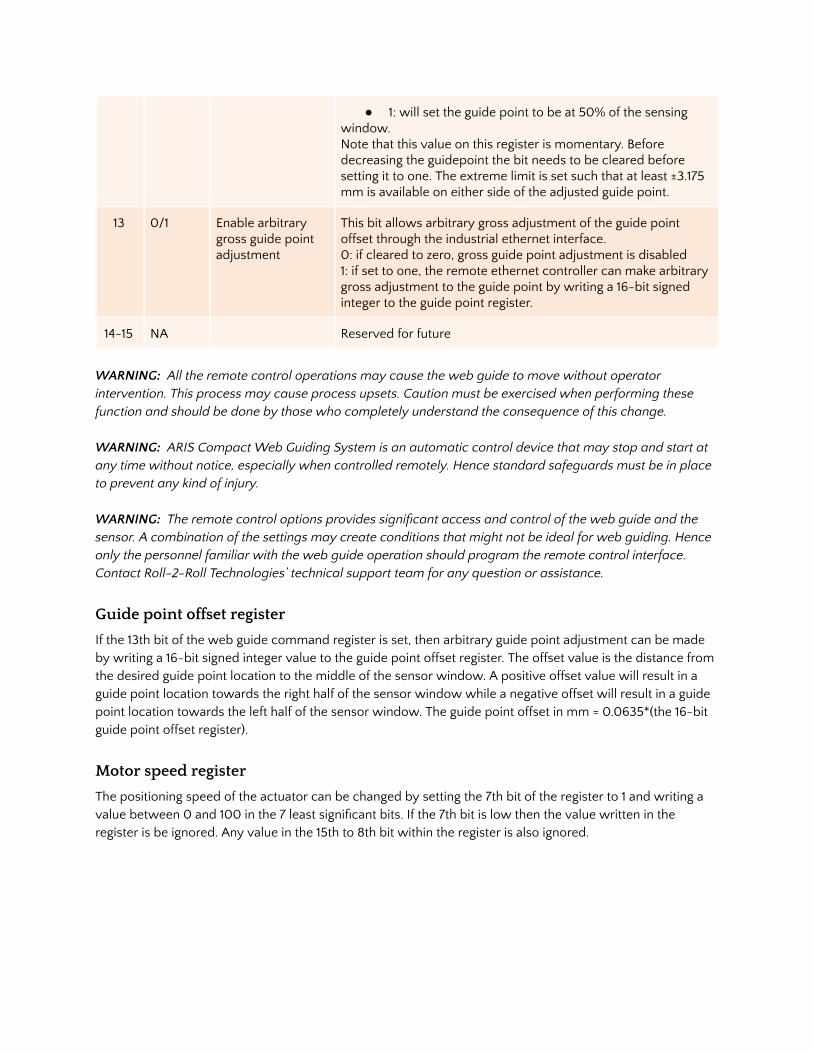
● 1: will set the guide point to be at 50% of the sensing window. Note that this value on this register is momentary. Before decreasing the guidepoint the bit needs to be cleared before setting it to one. The extreme limit is set such that at least ±3.175 mm is available on either side of the adjusted guide point.
13 0/1 Enable arbitrary gross guide point adjustment
This bit allows arbitrary gross adjustment of the guide point offset through the industrial ethernet interface. 0: if cleared to zero, gross guide point adjustment is disabled 1: if set to one, the remote ethernet controller can make arbitrary gross adjustment to the guide point by writing a 16-bit signed integer to the guide point register.
14-15 NA Reserved for future
WARNING: All the remote control operations may cause the web guide to move without operator intervention. This process may cause process upsets. Caution must be exercised when performing these function and should be done by those who completely understand the consequence of this change. WARNING: ARIS Compact Web Guiding System is an automatic control device that may stop and start at any time without notice, especially when controlled remotely. Hence standard safeguards must be in place to prevent any kind of injury. WARNING: The remote control options provides signi�cant access and control of the web guide and the sensor. A combination of the settings may create conditions that might not be ideal for web guiding. Hence only the personnel familiar with the web guide operation should program the remote control interface. Contact Roll-2-Roll Technologies’ technical support team for any question or assistance.
Guide point offset register
If the 13th bit of the web guide command register is set, then arbitrary guide point adjustment can be made by writing a 16-bit signed integer value to the guide point offset register. The offset value is the distance from the desired guide point location to the middle of the sensor window. A positive offset value will result in a guide point location towards the right half of the sensor window while a negative offset will result in a guide point location towards the left half of the sensor window. The guide point offset in mm = 0.0635*(the 16-bit guide point offset register).
Motor speed register
The positioning speed of the actuator can be changed by setting the 7th bit of the register to 1 and writing a value between 0 and 100 in the 7 least signi�cant bits. If the 7th bit is low then the value written in the register is be ignored. Any value in the 15th to 8th bit within the register is also ignored.
Content subject to change without notice ARIS Compact Web Guiding System Product Manual | Page 34 Copyright © 2017 Roll-2-Roll Technologies LLC https://ww.r2r-tech.com +1-888-290-3215

COMMISSIONING
The ARIS Compact Web Guiding System is a real plug-and-play system. A properly installed web guide requires correct threading of the web over the guide rollers and initial positioning of the sensor based on the desired position of the web to provide optimum performance. Once the material is threaded over the guide rollers and the sensor has been properly positioned, all the operator has to do is to press the automatic operation icon on the operator interface. The following section describes the steps and conditions required for automatic operation of the ARIS Compact Web Guiding System.
1. Power ON the system 2. Automatic/Manual operation set to “Manual” (Automatic/Manual icon pressed to red) 3. Jog the guide to left extreme and then to right extreme to correct for any transportation related guide
roller assembly movements. 4. Press the Servo-Center button to center the guide rollers. 5. Thread the material over the rollers. The material wrapped over the rollers must be at a 90 degree
angle both at the entry and exit of the guide rollers. 6. Verify that the material is aligned in the desired position with respect to the upstream and
downstream position of the web. Place web under normal operation tension. 7. Adjust sensor position on the desired edge of the web. Then manually position the sensor so that the
edge of the web is at the middle of the sensing window. This can be done by observing the web edge position indicator on the display. When the bar is in the middle position then the web edge is in the middle of the sensing window.
8. If the sensor position indicator and the actual position of the sensor are different then press the “Find Sensor” button on the operator interface so that the guiding system automatically �nd the correct orientation of the edge sensor. In order for this function to work the web edge needs to be in the middle of the sensing window.
9. Tighten the sensor thumbscrews to secure the sensor position on the sensor rail. 10. Press the Automatic/Manual operation icon to “Automatic” (Automatic/Manual icon pressed to
green). 11. The guide will automatically adjust the position of the web material to guide it to the correct
position.
General Maintenance
The ARIS Compact Web Guiding System is virtually maintenance free. However, the sensor lid should be cleaned to remove any dust particles that might accumulate on the surface.
● You may use any lens cleaning solutions available in the market. ● Do not use use petroleum based products as these can damage the sensor cover and affect its
performance. This cleaning can be done as part of a weekly maintenance schedule or as required by usage or environmental conditions.
Content subject to change without notice ARIS Compact Web Guiding System Product Manual | Page 35 Copyright © 2017 Roll-2-Roll Technologies LLC https://ww.r2r-tech.com +1-888-290-3215
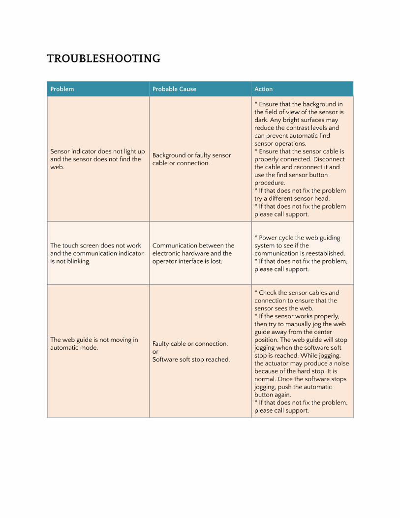
TROUBLESHOOTING
Problem Probable Cause Action
Sensor indicator does not light up and the sensor does not �nd the web.
Background or faulty sensor cable or connection.
* Ensure that the background in the �eld of view of the sensor is dark. Any bright surfaces may reduce the contrast levels and can prevent automatic �nd sensor operations. * Ensure that the sensor cable is properly connected. Disconnect the cable and reconnect it and use the �nd sensor button procedure. * If that does not �x the problem try a different sensor head. * If that does not �x the problem please call support.
The touch screen does not work and the communication indicator is not blinking.
Communication between the electronic hardware and the operator interface is lost.
* Power cycle the web guiding system to see if the communication is reestablished. * If that does not �x the problem, please call support.
The web guide is not moving in automatic mode.
Faulty cable or connection. or Software soft stop reached.
* Check the sensor cables and connection to ensure that the sensor sees the web. * If the sensor works properly, then try to manually jog the web guide away from the center position. The web guide will stop jogging when the software soft stop is reached. While jogging, the actuator may produce a noise because of the hard stop. It is normal. Once the software stops jogging, push the automatic button again. * If that does not �x the problem, please call support.
Content subject to change without notice ARIS Compact Web Guiding System Product Manual | Page 36 Copyright © 2017 Roll-2-Roll Technologies LLC https://ww.r2r-tech.com +1-888-290-3215

APPLICABLE MODELS
Sensor
Model Number Description Part Number
ARIS WPS 16-IR Light source: Infrared; Width: 16 mm 3-000011
ARIS WPS 48-IR Light source: Infrared; Width: 48 mm 3-000012
ARIS WPS 48-WL Light source: White light; Width: 48 mm 3-000022
ARIS WPS 48-UV Light source: Ultraviolet; Width: 48 mm 3-000032
ARIS WPS 221-IR Light source: Infrared; Width: 16 mm 3-000014
Control Unit
Model Number Description Part Number
ARIS SCU MD Basic controller + integrated touch screen display 4-000121
ARIS SCU MC(E) Basic controller + industrial ethernet (Ethernet/IP) 4-000112
ARIS SCU MC(P) Basic controller + industrial ethernet (PROFINET) 4-001112
ARIS SCU MC(E)D Basic controller +Ethernet/IP + integrated touchscreen display 4-000111
ARIS SCU MC(P)D Basic controller +PROFINET + integrated touchscreen display 4-001111
Web Guide Mechanism
Model Number Description Part Number
ARIS WMS G250-50-NC Web guide mechanism: 50 mm diameter, 250 mm wide roller 5-011111
ARIS WMS G300-50-NC Web guide mechanism: 50 mm diameter, 300 mm wide roller 5-011112
ARIS WMS G375-50-NC Web guide mechanism: 50 mm diameter, 375 mm wide roller 5-011113
ARIS WMS G425-50-NC Web guide mechanism: 50 mm diameter, 425 mm wide roller 5-011114
ARIS WMS G500-50-NC Web guide mechanism: 50 mm diameter, 500 mm wide roller 5-011115
ARIS WMS G550-50-NC Web guide mechanism: 50 mm diameter, 550 mm wide roller 5-011116
Content subject to change without notice ARIS Compact Web Guiding System Product Manual | Page 37 Copyright © 2017 Roll-2-Roll Technologies LLC https://ww.r2r-tech.com +1-888-290-3215

TECHNICAL SUPPORT AND SERVICE
Contact information
Roll-2-Roll Technologies LLC is dedicated to providing exceptional service and support to its customers. Please feel free to contact us for any technical support, installation support and service requirements. Roll-2-Roll Technologies LLC 1110 S Innovation Way Dr Stillwater, OK 74074 Website: https://www.r2r-tech.com Technical Support Phone: +1 (888) 290-3215 - ext 3 General Support Phone: +1 (888) 290-3125 - ext 1 Technical Support Email: [email protected] General Support Email: [email protected]
Return shipping instructions
Please contact us to obtain a return merchandise authorization (RMA) number before returning the product to us. If returning the product, please follow the instructions on the RMA form for quick and ef�cient service.
Content subject to change without notice ARIS Compact Web Guiding System Product Manual | Page 38 Copyright © 2017 Roll-2-Roll Technologies LLC https://ww.r2r-tech.com +1-888-290-3215

REVISION HISTORY
Document Revision
Version Date Changes
1.0 Sep 2015 Initial Release Version
1.1 Feb 2016 Comprehensive revision and new sections added: safety instructions, mounting dimensions, troubleshooting, speci�cations.
2.0 Jun 2016 Updated documentation for SCU V4 Rev D hardware, �rmware and OI.
2.2 Dec 2016 Updated documentation for �rmware updates and usability changes
2.4 Jun 2017 Updated documentation for �rmware updates and operator interface changes
Hardware Revision
Version Date Description
SCU V2 Dec 2014 Initial version with 12 VDC input
SCU V3 Jun 2015 Expanded version with 24 VDC input
SCU V4 Rev B Oct 2015 Two sensor option, WDT, RTCC
SCU V4 Rev C Mar 2016 Analog Output
SCU V4 Rev D July 2016 Industrial ethernet option
Firmware Revision
Version Date Description
1.0 Jan 2015 Initial version, single sensor
1.1 Aug 2015 Firmware update for SCU V3, automatic sensor state detection
1.2 Nov 2015 Firmware update for SCU V4 Rev B. Modi�ed sensor algorithm to increase precision and accuracy.
1.3 Dec 2015 Two sensor option with automatic pixel detection
1.4 Mar 2016 Background suppression algorithm
1.5 Apr 2016 Analog output
2.1a Aug 2016 Firmware update for SUC V4 Rev D
Content subject to change without notice ARIS Compact Web Guiding System Product Manual | Page 39 Copyright © 2017 Roll-2-Roll Technologies LLC https://ww.r2r-tech.com +1-888-290-3215

2.2b Dec 2016 Ethernet/IP implicit messaging, edge detection algorithm updates
2.4a Jun 2017 Changes to guide point adjustment
Roll-2-Roll Technologies LLC 1110 S Innovation Way Dr
Stillwater, OK 74074 www.r2r-tech.com [email protected] +1-(888)-290-3215
Content subject to change without notice ARIS Compact Web Guiding System Product Manual | Page 40 Copyright © 2017 Roll-2-Roll Technologies LLC https://ww.r2r-tech.com +1-888-290-3215