Guiding rational reservoir flood operation using penalty-type genetic algorithm
Upload
khangminh22Category
view
3download
0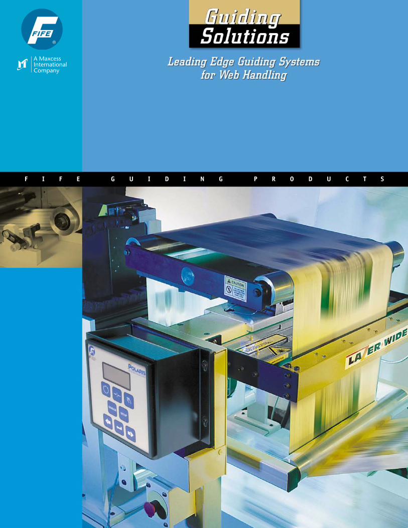
F I F E G U I D I N G P R O D U C T S
T A B L E O F C O N T E N T S
Introduction. . . . . . . . . . . . . . . . . . . . . . . . . . . . . . . . . . . . 2-3
Guiding Controls . . . . . . . . . . . . . . . . . . . . . . . . . . . . . . . . 4-5
Sensors . . . . . . . . . . . . . . . . . . . . . . . . . . . . . . . . . . . . . . . . 6-7
Positioners. . . . . . . . . . . . . . . . . . . . . . . . . . . . . . . . . . . . . . . 8
Actuators . . . . . . . . . . . . . . . . . . . . . . . . . . . . . . . . . . . . . . . . 9
Unwind/Rewind Guides. . . . . . . . . . . . . . . . . . . . . . . . . . . . 10
Intermediate Guides – Displacement-Type . . . . . . . . . . . . 11
Intermediate Guides – Steering-Type. . . . . . . . . . . . . . . . 12
Product Selection Chart . . . . . . . . . . . . . . . . . . . . . . . . . . . 13
1
Guiding components and systems for every application.
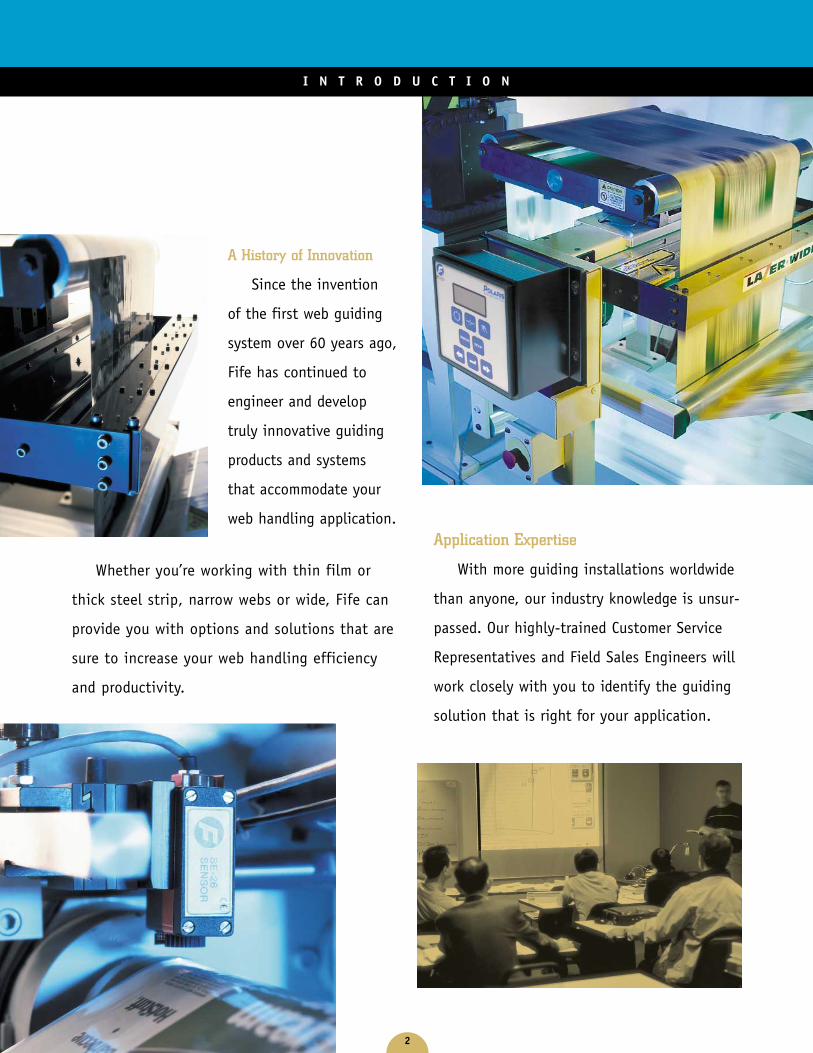
A History of Innovation
Since the invention
of the first web guiding
system over 60 years ago,
Fife has continued to
engineer and develop
truly innovative guiding
products and systems
that accommodate your
web handling application.
Whether you’re working with thin film or
thick steel strip, narrow webs or wide, Fife can
provide you with options and solutions that are
sure to increase your web handling efficiency
and productivity.
2
I N T R O D U C T I O N
Application Expertise
With more guiding installations worldwide
than anyone, our industry knowledge is unsur-
passed. Our highly-trained Customer Service
Representatives and Field Sales Engineers will
work closely with you to identify the guiding
solution that is right for your application.
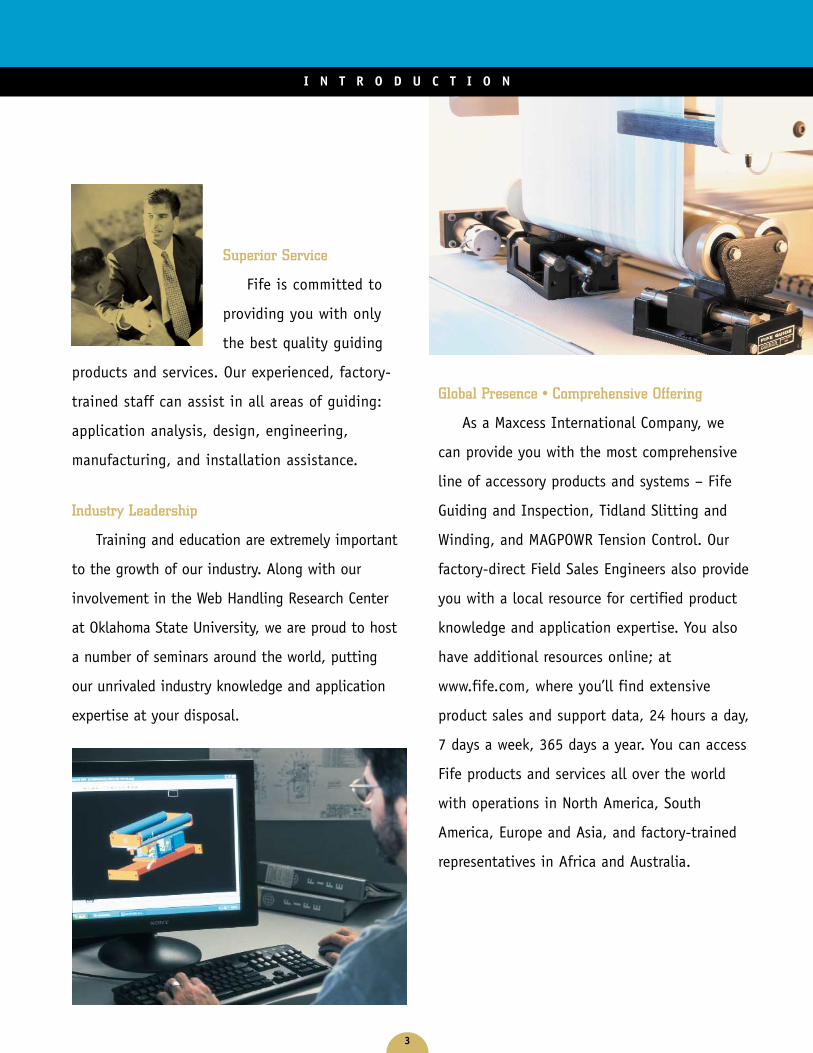
Superior Service
Fife is committed to
providing you with only
the best quality guiding
products and services. Our experienced, factory-
trained staff can assist in all areas of guiding:
application analysis, design, engineering,
manufacturing, and installation assistance.
Industry Leadership
Training and education are extremely important
to the growth of our industry. Along with our
involvement in the Web Handling Research Center
at Oklahoma State University, we are proud to host
a number of seminars around the world, putting
our unrivaled industry knowledge and application
expertise at your disposal.
3
I N T R O D U C T I O N
Global Presence • Comprehensive Offering
As a Maxcess International Company, we
can provide you with the most comprehensive
line of accessory products and systems – Fife
Guiding and Inspection, Tidland Slitting and
Winding, and MAGPOWR Tension Control. Our
factory-direct Field Sales Engineers also provide
you with a local resource for certified product
knowledge and application expertise. You also
have additional resources online; at
www.fife.com, where you’ll find extensive
product sales and support data, 24 hours a day,
7 days a week, 365 days a year. You can access
Fife products and services all over the world
with operations in North America, South
America, Europe and Asia, and factory-trained
representatives in Africa and Australia.
4
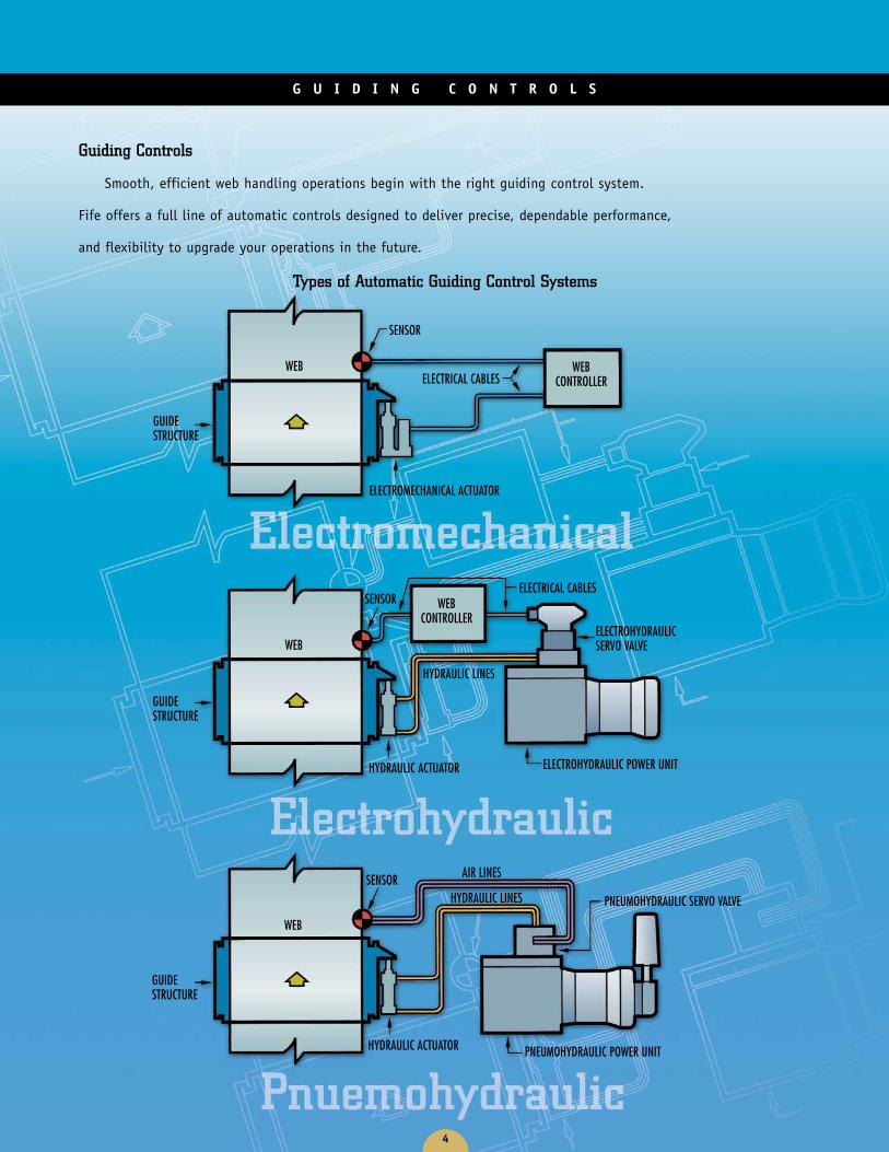
Guiding Controls
Smooth, efficient web handling operations begin with the right guiding control system.
Fife offers a full line of automatic controls designed to deliver precise, dependable performance,
and flexibility to upgrade your operations in the future.
G U I D I N G C O N T R O L S
Types of Automatic Guiding Control Systems
GUIDESTRUCTURE
GUIDESTRUCTURE
GUIDESTRUCTURE
SENSOR
HYDRAULIC ACTUATOR PNEUMOHYDRAULIC POWER UNIT
PNEUMOHYDRAULIC SERVO VALVE
AIR LINES
HYDRAULIC LINES
WEB
SENSOR
HYDRAULIC ACTUATOR ELECTROHYDRAULIC POWER UNIT
ELECTROHYDRAULICSERVO VALVE
ELECTRICAL CABLES
HYDRAULIC LINES
WEB
WEBCONTROLLER
SENSOR
ELECTROMECHANICAL ACTUATOR
ELECTRICAL CABLESWEB WEB
CONTROLLER
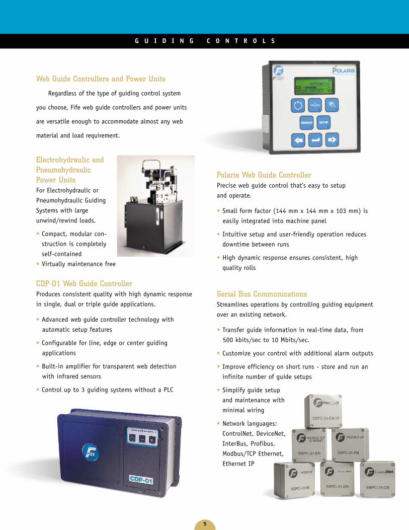
Web Guide Controllers and Power Units
Regardless of the type of guiding control system
you choose, Fife web guide controllers and power units
are versatile enough to accommodate almost any web
material and load requirement.
Electrohydraulic andPneumohydraulicPower UnitsFor Electrohydraulic or
Pneumohydraulic Guiding
Systems with large
unwind/rewind loads.
• Compact, modular con-
struction is completely
self-contained
• Virtually maintenance free
CDP-01 Web Guide ControllerProduces consistent quality with high dynamic response
in single, dual or triple guide applications.
• Advanced web guide controller technology with
automatic setup features
• Configurable for line, edge or center guiding
applications
• Built-in amplifier for transparent web detection
with infrared sensors
• Control up to 3 guiding systems without a PLC
Polaris Web Guide ControllerPrecise web guide control that’s easy to setup
and operate.
• Small form factor (144 mm x 144 mm x 103 mm) is
easily integrated into machine panel
• Intuitive setup and user-friendly operation reduces
downtime between runs
• High dynamic response ensures consistent, high
quality rolls
Serial Bus CommunicationsStreamlines operations by controlling guiding equipment
over an existing network.
• Transfer guide information in real-time data, from
500 kbits/sec to 10 Mbits/sec.
• Customize your control with additional alarm outputs
• Improve efficiency on short runs - store and run an
infinite number of guide setups
• Simplify guide setup
and maintenance with
minimal wiring
• Network languages:
ControlNet, DeviceNet,
InterBus, Profibus,
Modbus/TCP Ethernet,
Ethernet IP
5
G U I D I N G C O N T R O L S
6
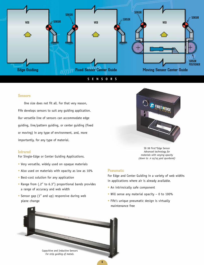
PneumaticFor Edge and Center Guiding in a variety of web widths
in applications where air is already available.
• An intrinsically safe component
• Will sense any material opacity – 0 to 100%
• Fife’s unique pneumatic design is virtually
maintenance free
Edge Guiding
SENSORWEB
Fixed Sensor Center Guide Moving Sensor Center Guide
SENSOR
WEB
SENSOR
SENSOR
SENSORPOSITIONER
WEB
S E N S O R S
SENSOR
SE-38 First*Edge SensorAdvanced technology for
materials with varying opacity(down to .4 oz/sq yard spunbond)
Sensors
One size does not fit all. For that very reason,
Fife develops sensors to suit any guiding application.
Our versatile line of sensors can accommodate edge
guiding, line/pattern guiding, or center guiding (fixed
or moving) in any type of environment, and, more
importantly, for any type of material.
InfraredFor Single-Edge or Center Guiding Applications.
• Very versatile, widely used on opaque materials
• Also used on materials with opacity as low as 10%
• Best-cost solution for any application
• Range from (.2” to 6.3”) proportional bands provides
a range of accuracy and web width
• Sensor gap (1” and up) responsive during web
plane change
Capacitive and Inductive SensorsFor strip guiding of metals.

7
S E N S O R S
UltrasonicFor Single-Edge or Center Guiding Applications.UL, cUL and CE certified.
• Closed-face design helps with immunity towards
dust and contaminants
• Ambient shop noises have no effect of Fife’s
unique ultrasonic technology
• UL and CE approved
• Band width
Intrinsically SafeSingle or Center Edge
Guiding in hazardous
environments.
• Fully certified to Class
I, Division 1, Groups
C and D hazardous
environments
• UL, cUL and CENELEC
certified for use
throughout Europe
and North America
• See our certification at www.ul.com
Visible Light and LaserSingle edge or center guiding and web width
measurement.
• The most intense, incandescent light bulbs are used to
ensure high contrast for maximum guiding accuracy
• Laser based technology provides flexibility for web
width measurement and changes
• Ideal for opaque materials
Special Application Sensors
• Fiber optic sensors
• Capacitance center guide sensor
• Inductive sensors
• Camera sensors
Line or Pattern Guiding
SENSOR
WEB
DAC-004 Diode Array CameraAn extremely flexible sensor able to see virtually any material.
Use the selection chart on page 13 to find thesensors that are the best fit for your application.
SE-31-IS Intrinsically Safe SensorExtremely accurate for applications withvarying web widths. Analog or digitalweb width measurement available withFife Serial Bus Communications.
SE-34 Lazer*Wide Sensor
8
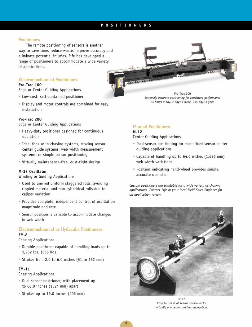
PositionersThe remote positioning of sensors is another
way to save time, reduce waste, improve accuracy andeliminate potential injuries. Fife has developed arange of positioners to accommodate a wide varietyof applications.
Electromechanical Positioners:Pro-Trac 100Edge or Center Guiding Applications
• Low-cost, self-contained positioner
• Display and motor controls are combined for easyinstallation
Pro-Trac 200Edge or Center Guiding Applications
• Heavy-duty positioner designed for continuousoperation
• Ideal for use in chasing systems, moving sensorcenter guide systems, web width measurementsystems, or simple sensor positioning
• Virtually maintenance-free, dust-tight design
M-23 OscillatorWinding or Guiding Applications
• Used to unwind uniform staggered rolls, avoidingrippled material and non-cylindrical rolls due tocaliper variation
• Provides complete, independent control of oscillationmagnitude and rate
• Sensor position is variable to accommodate changesin web width
Electromechanical or Hydraulic Positioners:EM-8Chasing Applications
• Durable positioner capable of handling loads up to1,252 lbs. (568 Kg)
• Strokes from 2.0 to 6.0 inches (51 to 152 mm)
EM-11Chasing Applications
• Dual sensor positioner, with placement upto 60.0 inches (1524 mm) apart
• Strokes up to 16.0 inches (406 mm)
Manual Positioners:M-12Center Guiding Applications
• Dual sensor positioning for most fixed-sensor centerguiding applications
• Capable of handling up to 64.0 inches (1,626 mm)web width variations
• Position indicating hand-wheel provides simple,accurate operation
P O S I T I O N E R S
Pro-Trac 200Extremely accurate positioning for consistent performance
24 hours a day, 7 days a week, 365 days a year.
M-12Easy to use dual sensor positioner for
virtually any center guiding application.
Custom positioners are available for a wide variety of chasingapplications. Contact Fife or your local Field Sales Engineer foran application review.
9
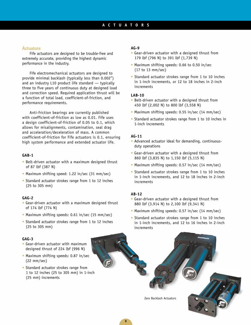
ActuatorsFife actuators are designed to be trouble-free and
extremely accurate, providing the highest dynamicperformance in the industry.
Fife electromechanical actuators are designed toprovide minimal backlash (typically less than 0.002”)and an industry L10 product life standard — typicallythree to five years of continuous duty at designed loadand correction speed. Required application thrust will bea function of total load, coefficient-of-friction, andperformance requirements.
Anti-friction bearings are currently publishedwith coefficient-of-friction as low as 0.01. Fife usesa design coefficient-of-friction of 0.05 to 0.1, whichallows for misalignments, contamination, seal dragand acceleration/deceleration of mass. A commoncoefficient-of-friction for Fife actuators is 0.1, ensuringhigh system performance and extended actuator life.
GAB-1
• Belt-driven actuator with a maximum designed thrustof 87 lbf (387 N)
• Maximum shifting speed: 1.22 in/sec (31 mm/sec)
• Standard actuator strokes range from 1 to 12 inches(25 to 305 mm)
GAG-2 • Gear-driven actuator with a maximum designed thrust
of 174 lbf (774 N)
• Maximum shifting speeds: 0.61 in/sec (15 mm/sec)
• Standard actuator strokes range from 1 to 12 inches(25 to 305 mm)
GAG-3 • Gear-driven actuator with maximum
designed thrust of 224 lbf (996 N)
• Maximum shifting speeds: 0.87 in/sec(22 mm/sec)
• Standard actuator strokes range from1 to 12 inches (25 to 305 mm) in 1-inch(25 mm) increments
AG-9 • Gear-driven actuator with a designed thrust from
179 lbf (796 N) to 391 lbf (1,739 N)
• Maximum shifting speeds: 0.66 to 0.50 in/sec(17 to 13 mm/sec)
• Standard actuator strokes range from 1 to 10 inchesin 1-inch increments, or 12 to 18 inches in 2-inchincrements
LAB-10 • Belt-driven actuator with a designed thrust from
450 lbf (2,002 N) to 800 lbf (3,558 N)
• Maximum shifting speeds: 0.55 in/sec (14 mm/sec)
• Standard actuator strokes range from 1 to 10 inches in1-inch increments
AG-11• Advanced actuator ideal for demanding, continuous-
duty operations
• Gear-driven actuator with a designed thrust from860 lbf (3,835 N) to 1,150 lbf (5,115 N)
• Maximum shifting speeds: 0.57 in/sec (14 mm/sec)
• Standard actuator strokes range from 1 to 10 inchesin 1-inch increments, and 12 to 18 inches in 2-inchincrements
AB-12 • Gear-driven actuator with a designed thrust from
880 lbf (3,914 N) to 2,100 lbf (9,341 N)
• Maximum shifting speeds: 0.57 in/sec (14 mm/sec)
• Standard actuator strokes range from 1 to 10 inchesin 1-inch increments, and 12 to 16 inches in 2-inchincrements
A C T U A T O R S
Zero Backlash Actuators
10
U N W I N D / R E W I N D G U I D E S
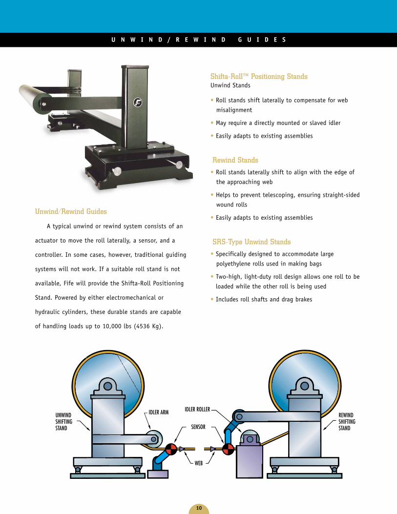
SENSOR
WEB
REWINDSHIFTINGSTAND
UNWINDSHIFTINGSTAND
IDLER ARM IDLER ROLLER
Unwind/Rewind Guides
A typical unwind or rewind system consists of an
actuator to move the roll laterally, a sensor, and a
controller. In some cases, however, traditional guiding
systems will not work. If a suitable roll stand is not
available, Fife will provide the Shifta-Roll Positioning
Stand. Powered by either electromechanical or
hydraulic cylinders, these durable stands are capable
of handling loads up to 10,000 lbs (4536 Kg).
Shifta-Roll™ Positioning StandsUnwind Stands
• Roll stands shift laterally to compensate for web
misalignment
• May require a directly mounted or slaved idler
• Easily adapts to existing assemblies
Rewind Stands
• Roll stands laterally shift to align with the edge of
the approaching web
• Helps to prevent telescoping, ensuring straight-sided
wound rolls
• Easily adapts to existing assemblies
SRS-Type Unwind Stands
• Specifically designed to accommodate large
polyethylene rolls used in making bags
• Two-high, light-duty roll design allows one roll to be
loaded while the other roll is being used
• Includes roll shafts and drag brakes
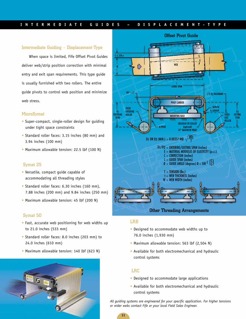
Intermediate Guiding – Displacement-Type
When space is limited, Fife Offset Pivot Guides
deliver web/strip position correction with minimal
entry and exit span requirements. This type guide
is usually furnished with two rollers. The entire
guide pivots to control web position and minimize
web stress.
MicroSymat
• Super-compact, single-roller design for guiding
under tight space constraints
• Standard roller faces: 3.15 inches (80 mm) and
3.94 inches (100 mm)
• Maximum allowable tension: 22.5 lbf (100 N)
Symat 25
• Versatile, compact guide capable of
accommodating all threading styles
• Standard roller faces: 6.30 inches (160 mm),
7.88 inches (200 mm) and 9.84 inches (250 mm)
• Maximum allowable tension: 45 lbf (200 N)
Symat 50
• Fast, accurate web positioning for web widths up
to 21.0 inches (533 mm)
• Standard roller faces: 8.0 inches (203 mm) to
24.0 inches (610 mm)
• Maximum allowable tension: 140 lbf (623 N)
LRB
• Designed to accommodate web widths up to
76.0 inches (1,930 mm)
• Maximum allowable tension: 563 lbf (2,504 N)
• Available for both electromechanical and hydraulic
control systems
LRC
• Designed to accommodate large applications
• Available for both electromechanical and hydraulic
control systems
11
I N T E R M E D I A T E G U I D E S – D I S P L A C E M E N T - T Y P E
Offset Pivot Guide
WEB
LGUIDE SPAN
ø
PIVOT CARRIER
MOUNTING BASE
DEADBAR OR ROLLER(optional)
10° MAXIMUM WRAPPIVOT
SENSOR
FIXEDEXITROLLER
D2EXITING
SPAN
FIXEDENTERINGROLLER
D1ENTERING
SPAN
90° + 5° 1/2 D2 MAXIMUM
W
C=L SIN ø
D1 OR D2 (MIN.) = 0.00357 WØ
D1/D2 = ENTERING/EXITING SPAN (inches)E = MATERIAL MODULUS OF ELASTICITY (p.s.i.)C = CORRECTION (inches)L = GUIDE SPAN (inches)Ø = GUIDE ANGLE (degrees) Ø = SIN-1 ( )T = TENSION (lbs.)t = WEB THICKNESS (inches)
W = WEB WIDTH (inches)
C–L
WEt–––T
Other Threading Arrangements
LC SENSOR
LC
All guiding systems are engineered for your specific application. For higher tensionsor wider webs contact Fife or your local Field Sales Engineer.

12
Intermediate Guides – Steering Type
Fife’s innovative Steering Guides deliver precise web
position by utilizing a long entering span. These versatile
guiding assemblies provide immediate lateral correction
for transient errors, while at the same time compensating
for the web’s steady state errors.
Kamberoller™ Steering Guide
• Standard roll face lengths range from 15 to 120 inches
(381 to 3,048 mm)
• Available for both electromechanical and hydraulic
control systems
• Single, double or tri-roller arrangements
available
Kantiroller™ Steering Guide
• Versatile guide ideal for applications such as envelope
machines and label presses
• Accommodates web widths from less than 8.0 to
14.0 inches (203 to 356 mm)
• Single, double or tri-roller arrangements available
• Available for both electromechanical and hydraulic
control systems
I N T E R M E D I A T E G U I D E S – S T E E R I N G - T Y P E
1. C = 9T ( )2tE
W–3
LENTERING SPAN
L2EXITING SPAN
(Approximately L2)
1/2 L2 MAXIMUM
SENSOR
Typical Straight-Through Threading (S-Wrap)
FIGURE 2
FIGURE 1 ACTUATORMAY BE MOUNTEDON EITHER BASE(Inboard or Outboard)
RACEWAY ANGLE5° TO 25°BOTH RACEWAYSMUST BE SET ATSAME ANGLE
RACEWAY BASEMOUNTING BOLT
GUIDING ROLLER
5° TO 25°(See Note on Other Raceway)
RACEWAYBASE
SERVO-CENTERTRANSDUCERMAY BE MOUNTEDON EITHER BASE
CENTER OF ROTATIONOF GUIDE ROLL(Instant Center)
FIXEDENTERINGIDLER
CENTERLINEOF MACHINE ANDGUIDE ASSEMBLY
NOTE:ALTERNATE ENTERINGWEB PATH, PLANEOF ENTERING WEBSPAN MAY VARY FROMDIAGRAM AS SHOWN.ANGLE ∞ MAY BE ASGREAT AS ±30°
LENTERING SPAN
L1 (2/3 TO 3/4 L)±∞
PRE-ENTRY SPAN
MOUNTING BRACKET
DEADBAR ORROLLER (Optional)10° MAXIMUM WRAP
D2 EXITING SPAN
SENSOR
1/2 D2 MAXIMUM
ALTERNATIVETHREADMANAGEMENT
KAMBEROLLER® GUIDE
L–W
C = ± GUIDE CORRECTION (inches)E = MATERIAL MODULUS OF ELASTICITY (p.s.i.)L = LENGTH OF ENTRY SPAN (inches)T = TENSION (lbs.)t = MATERIAL THICKNESS (inches)W = MATERIAL WIDTH (inches)
2. L = CtE–––T
Kamberoller Entry Span Formulas
WEB
LC
KamberollerTM Steering Guide
13
P R O D U C T S E L E C T I O N C H A R T
Pape
r
Colo
red
Film
Foil
Felt
Opaq
ue &
Tran
spar
ent
Film
Line
Guid
e
Irreg
ular
Edg
e
Cloth
Win
dow
Scre
en
Gauz
e
Spun
bond
Tire
Cord
Roof
ing
Tuft
Scrim
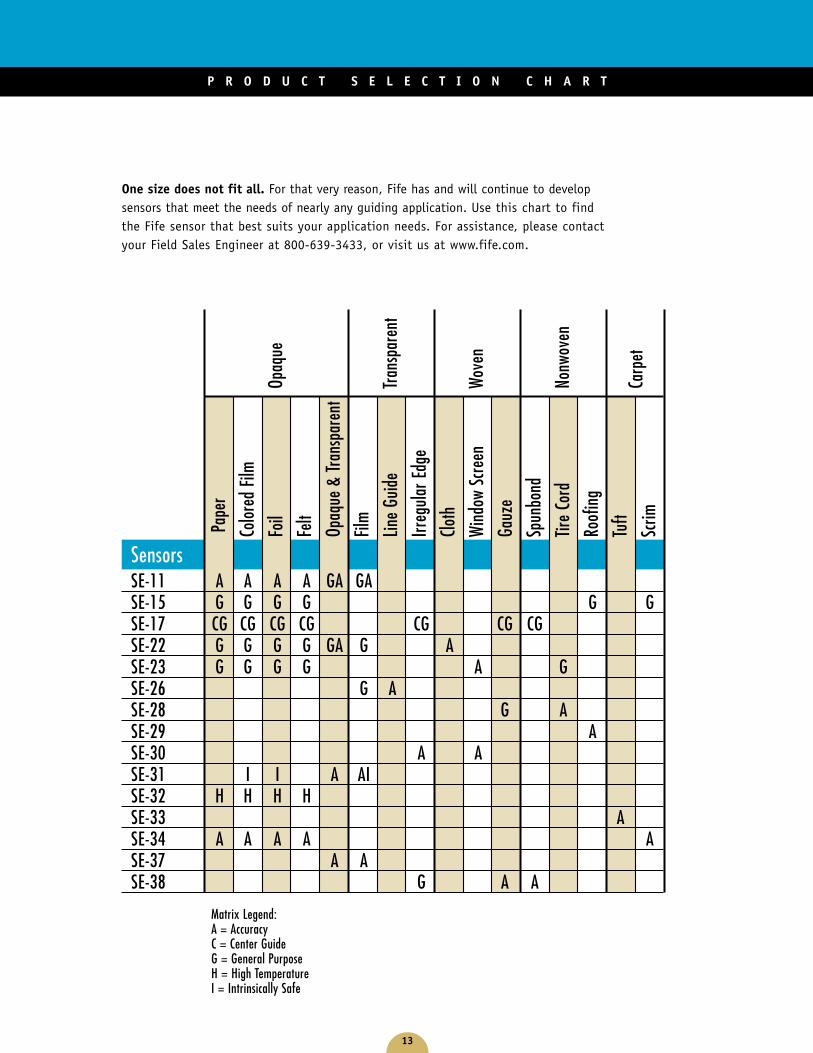
One size does not fit all. For that very reason, Fife has and will continue to developsensors that meet the needs of nearly any guiding application. Use this chart to findthe Fife sensor that best suits your application needs. For assistance, please contactyour Field Sales Engineer at 800-639-3433, or visit us at www.fife.com.
SensorsSE-11 A A A A GA GASE-15 G G G G G GSE-17 CG CG CG CG CG CG CGSE-22 G G G G GA G ASE-23 G G G G A GSE-26 G ASE-28 G ASE-29 ASE-30 A ASE-31 I I A AISE-32 H H H HSE-33 ASE-34 A A A A ASE-37 A ASE-38 G A A
Opaq
ue
Tran
spar
ent
Wov
en
Nonw
oven
Carp
et
Matrix Legend: A = AccuracyC = Center GuideG = General PurposeH = High TemperatureI = Intrinsically Safe
©2003 Maxcess International Guiding Product Line 10/03
GUIDING · INSPECTION
1.800.639.3433(405) 755.1600
TENSION CONTROL
1.800.MAGPOWR(636) 343.5550
SLITTING · WINDING
1.800.426.1000(360) 834.2345
®
MAXCESS INTERNATIONAL COMPANIES
EUROPE (49) 6195.7002.0ASIA (65) 834.1998
Fife CorporationPost Office Box 26508
Oklahoma City, OK 73126, USA
1-800-639-3433
Phone: +1 405-755-1600
Fax: +1 405-755-8425
Web: www.fife.com
Copyright © 2022 FDOKUMEN