Arduino Tips, Tricks, and Techniques - Energia Zero
34
1/34 Arduino Tips, Tricks, and Techniques learn.adafruit.com/arduino-tips-tricks-and-techniques Arduino UNO FAQ Like There's so many Arduino's out there, it may get a little confusing. We wanted to clarify for people some of the changes in the latest version.
-
Upload
khangminh22 -
Category
Documents
-
view
0 -
download
0
Transcript of Arduino Tips, Tricks, and Techniques - Energia Zero
1/34
Arduino Tips, Tricks, and Techniqueslearn.adafruit.com/arduino-tips-tricks-and-techniques
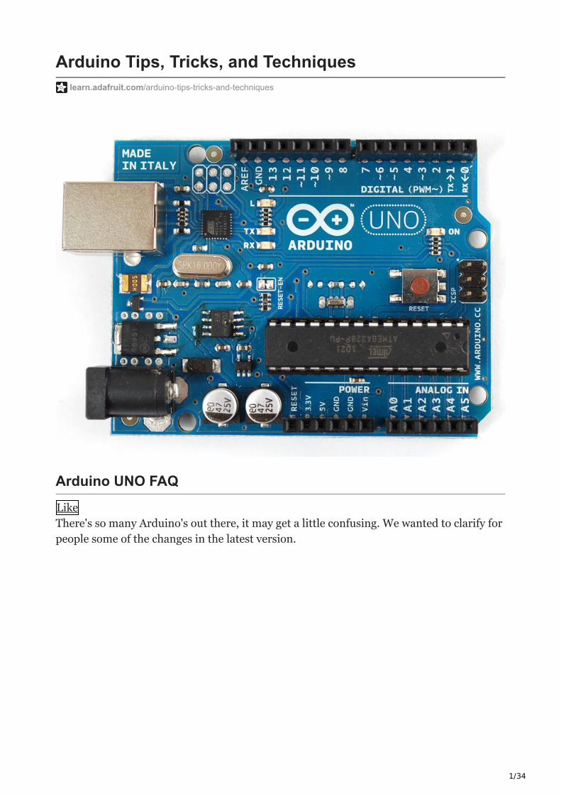
Arduino UNO FAQ
Like
There's so many Arduino's out there, it may get a little confusing. We wanted to clarify for
people some of the changes in the latest version.
2/34
NB
this is just our opinion and interpretation of some of the decisions made by Arduino. We
aren't associated with Arduino, and don't speak for them! If you have to get an Official
Response to your Arduino question please contact them directly. Thx!
NB2 Still in progress, we're collecting common questions to answer. If you have more
questions, please post them in our forums.
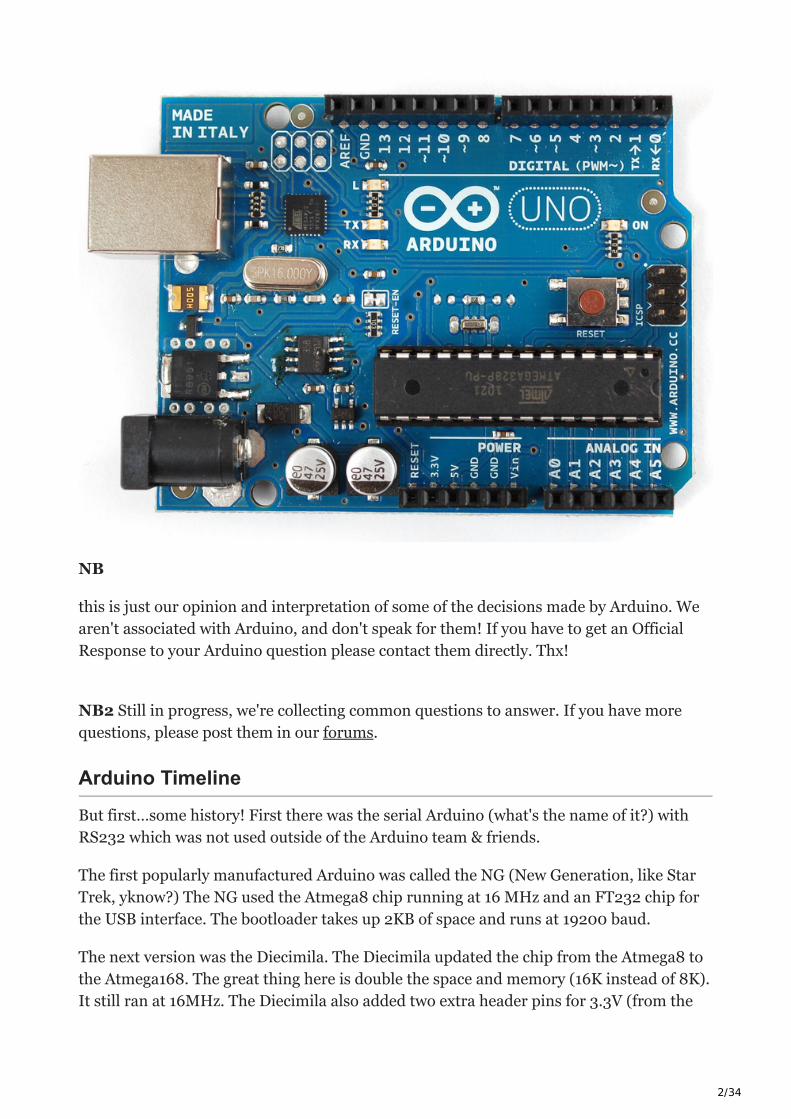
Arduino Timeline
But first…some history! First there was the serial Arduino (what's the name of it?) with
RS232 which was not used outside of the Arduino team & friends.
The first popularly manufactured Arduino was called the NG (New Generation, like Star
Trek, yknow?) The NG used the Atmega8 chip running at 16 MHz and an FT232 chip for
the USB interface. The bootloader takes up 2KB of space and runs at 19200 baud.
The next version was the Diecimila. The Diecimila updated the chip from the Atmega8 to
the Atmega168. The great thing here is double the space and memory (16K instead of 8K).
It still ran at 16MHz. The Diecimila also added two extra header pins for 3.3V (from the
3/34
FTDI chip) and the reset pin which can be handy when a shield is covering up the Reset
button. The bootloader takes up 2KB of space and runs at 19200 baud. Auto-resetting was
also added which makes life awesomer for everyone.
In 2009, the Duemilanove was released. This one also upgraded the chip again, to the
Atmega328. Yet another doubling of space and memory! Another upgrade is now the
power is automagically switched between USB and DC-jack which removed the previous
jumper. This makes it easier and faster to move from programming to standalone and got
rid of some confusion. The bootloader takes up 2KB of space and runs at 57600 baud.
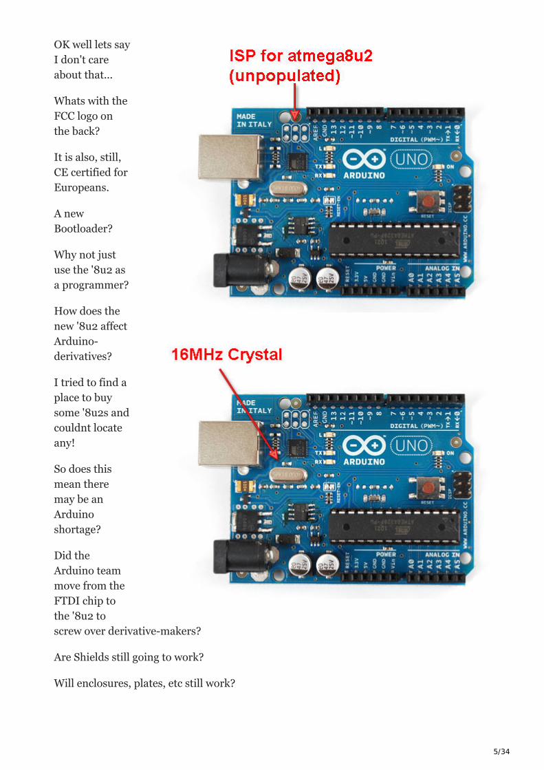
In 2010, we have the Uno! The Uno still uses the 328P chip and the power switcher. It has
a smaller bootloader called OptiBoot (more space for users' projects) that runs at 115K. So
even though the chip is the same, you get another 1.5K of extra flash space that was
previously used by the bootloader. The FTDI chip has also been replaced with a
atmega8u2 which allows for different kinds of USB interfaces. Finally, there's an extra
3.3V regulator (LP2985) for a better 3.3V supply. whew!
New USB Chip
So! All of the older Arduinos (NG, Diecimila and Duemilanove) have used an FTDI chip
(the FT232RL) to convert the TTL serial from the Arduino chip (Atmel ATmega). This
allows for printable debugging, connecting to software like PureData/Max, Processing,
Python, etc. etc. It also allows updating the firmware via the serial bootloader.
The good news about the FT232RL has royalty-free drivers and pretty much just works.
The bad news is that it can -only- act as a USB/Serial port. It can't act like a keyboard,
mouse, disk drive, MIDI device, etc.
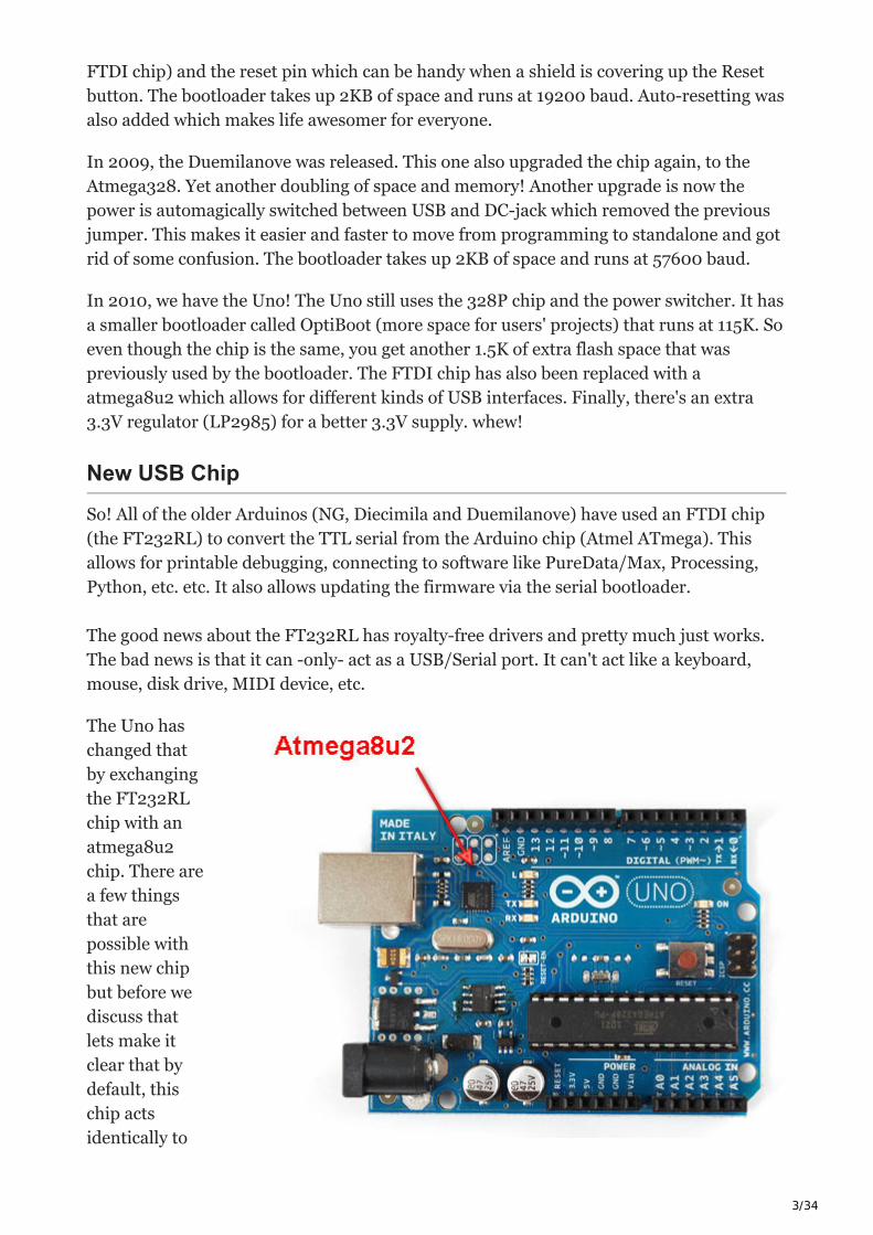
The Uno has
changed that
by exchanging
the FT232RL
chip with an
atmega8u2
chip. There are
a few things
that are
possible with
this new chip
but before we
discuss that
lets make it
clear that by
default, this
chip acts
identically to
4/34
the FTDI chip that it replaces. It's just a USB-serial port!
One improvement in updating the chip is that, previously, Mac users needed to install
FTDI drivers. The 8u2 imitates a 'generic' CDC serial device. So now, Mac users do not
have to install a driver. Windows users still need to install the .INF file but luckily there
are no drivers. This means there will be fewer problems with new versions of windows.
There is no way to have a serial USB device that doesn't require an INF file in windows,
sadly :(
The big thing that is nice about the 8u2 is that advanced users can turn it into a different
kind of USB device. For example it can act like a keyboard or mouse. Or a disk driver. Or a
MIDI interface, etc. Right now there are no examples of how to do this, but we hope to
post some shortly.
And, finally, going with the 8u2 reduced the price of the board which made up for some of
the other extras.
Why not just go with a atmega32u4?
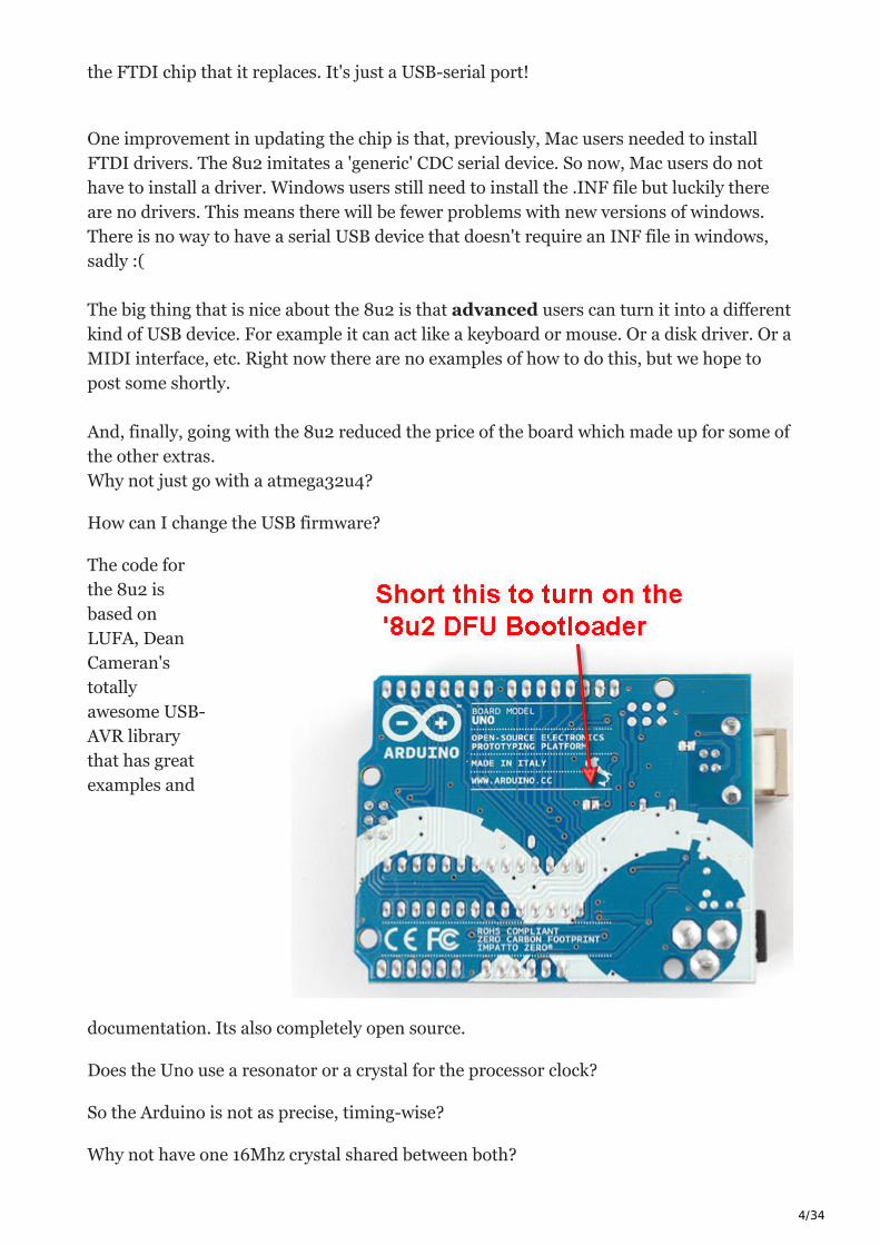
How can I change the USB firmware?
The code for
the 8u2 is
based on
LUFA, Dean
Cameran's
totally
awesome USB-
AVR library
that has great
examples and
documentation. Its also completely open source.
Does the Uno use a resonator or a crystal for the processor clock?
So the Arduino is not as precise, timing-wise?
Why not have one 16Mhz crystal shared between both?
5/34
OK well lets say
I don't care
about that...
Whats with the
FCC logo on
the back?
It is also, still,
CE certified for
Europeans.
A new
Bootloader?
Why not just
use the '8u2 as
a programmer?
How does the
new '8u2 affect
Arduino-
derivatives?
I tried to find a
place to buy
some '8u2s and
couldnt locate
any!
So does this
mean there
may be an
Arduino
shortage?
Did the
Arduino team
move from the
FTDI chip to
the '8u2 to
screw over derivative-makers?
Are Shields still going to work?
Will enclosures, plates, etc still work?

6/34
More 3.3v power!
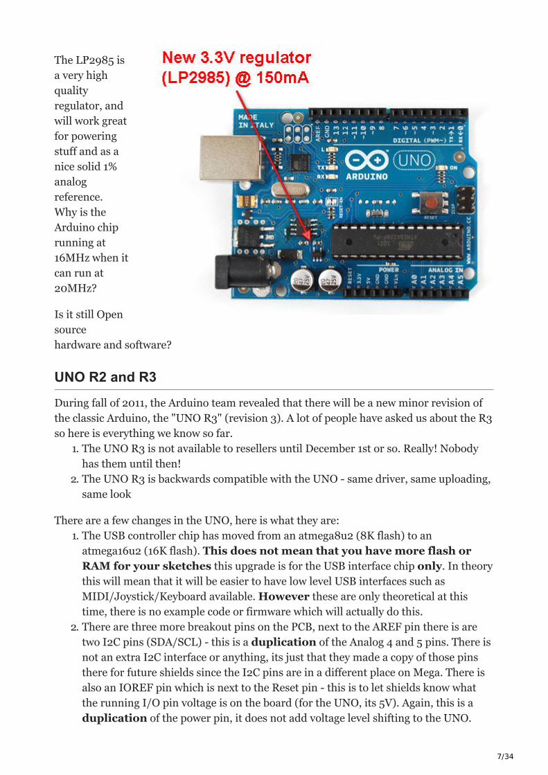
One sad thing about older boards is that they had a 3.3v power supply but it was really
just whatever the FTDI chip's internal 3.3v regulator could give. You -could- get 50mA out
of it, maybe. But high power stuff like XBees, SD cards, some fast ADC or DACs could
easily drag down the FTDI chip and reset the USB connection. The Uno solves this
problem by adding a new 3.3V regulator the LP2985 which can easily provide 150mA.
7/34
The LP2985 is
a very high
quality
regulator, and
will work great
for powering
stuff and as a
nice solid 1%
analog
reference.
Why is the
Arduino chip
running at
16MHz when it
can run at
20MHz?
Is it still Open
source
hardware and software?
UNO R2 and R3
During fall of 2011, the Arduino team revealed that there will be a new minor revision of
the classic Arduino, the "UNO R3" (revision 3). A lot of people have asked us about the R3
so here is everything we know so far.
1. The UNO R3 is not available to resellers until December 1st or so. Really! Nobody
has them until then!
2. The UNO R3 is backwards compatible with the UNO - same driver, same uploading,
same look
There are a few changes in the UNO, here is what they are:
1. The USB controller chip has moved from an atmega8u2 (8K flash) to an
atmega16u2 (16K flash). This does not mean that you have more flash or
RAM for your sketches this upgrade is for the USB interface chip only. In theory
this will mean that it will be easier to have low level USB interfaces such as
MIDI/Joystick/Keyboard available. However these are only theoretical at this
time, there is no example code or firmware which will actually do this.
2. There are three more breakout pins on the PCB, next to the AREF pin there is are
two I2C pins (SDA/SCL) - this is a duplication of the Analog 4 and 5 pins. There is
not an extra I2C interface or anything, its just that they made a copy of those pins
there for future shields since the I2C pins are in a different place on Mega. There is
also an IOREF pin which is next to the Reset pin - this is to let shields know what
the running I/O pin voltage is on the board (for the UNO, its 5V). Again, this is a
duplication of the power pin, it does not add voltage level shifting to the UNO.
8/34
3. The RESET button has moved to be next to the USB connector, this makes it easier
to press when a shield is on top.
Here is what didn't change in the UNO:
1. Processor size and speed - its the same ATMega328P running at 16MHz that we've
had since the Duemilanove. Your code will not run faster or better on the R3
2. Same number of pins - no extra pins are added EVEN THOUGH THERE ARE
MORE BREAKOUTS (see above!)
3. Board size and shape - same size as before
4. Shield compatibility - Every shield that works and plugs into the UNO R1/R2 should
be able to work fine with the R3
5. Driver - the driver is the same
6. Upload speed - same upload speed and technique
If you want to get up an Arduino R3 now, visit the adafruit store and pick up a board or
pack!
Arduino Libraries
Like
Need Help Installing a Library?
Check out our super-detailed tutorial for all operating systems here:
http://learn.adafruit.com/adafruit-all-about-arduino-libraries-install-use
What is a library?
Libraries are great places, and not yet illegal in the United States! If you ever need to learn
how to do something, like say fix a motorcycle, you can go to your local library and take
out a book. Sure you could buy the book but the library is nice because as a resource you
can get the book whenever you need it, keeping your house uncluttered.
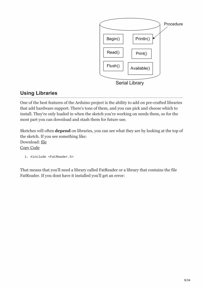
Software Libraries are very similar. We already studied what a procedure is, in lesson 3: a
procedure is a list of things to do. A library is a big collection of procedures, where all the
procedures are related! If you, say, want to control a motor, you may want to find a Motor
Control Library: a collection of procedures that have already been written for you that you
can use without having to do the dirty work of learning the nuances of motors.
For example, this is the Serial Library, which allows the Arduino to send data back to the
computer:
9/34
Using Libraries
One of the best features of the Arduino project is the ability to add on pre-crafted libraries
that add hardware support. There's tons of them, and you can pick and choose which to
install. They're only loaded in when the sketch you're working on needs them, so for the
most part you can download and stash them for future use.
Sketches will often depend on libraries, you can see what they are by looking at the top of
the sketch. If you see something like:
Download: file
Copy Code
1. #include <FatReader.h>
That means that you'll need a library called FatReader or a library that contains the file
FatReader. If you dont have it installed you'll get an error:

10/34
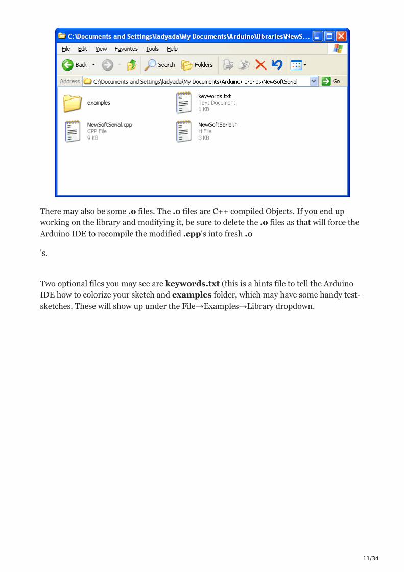
What's in a library?
A library is a folder with some files in it, the files will end in .cpp (C++ code file)
and .h (C++ header file).
11/34
There may also be some .o files. The .o files are C++ compiled Objects. If you end up
working on the library and modifying it, be sure to delete the .o files as that will force the
Arduino IDE to recompile the modified .cpp's into fresh .o
's.
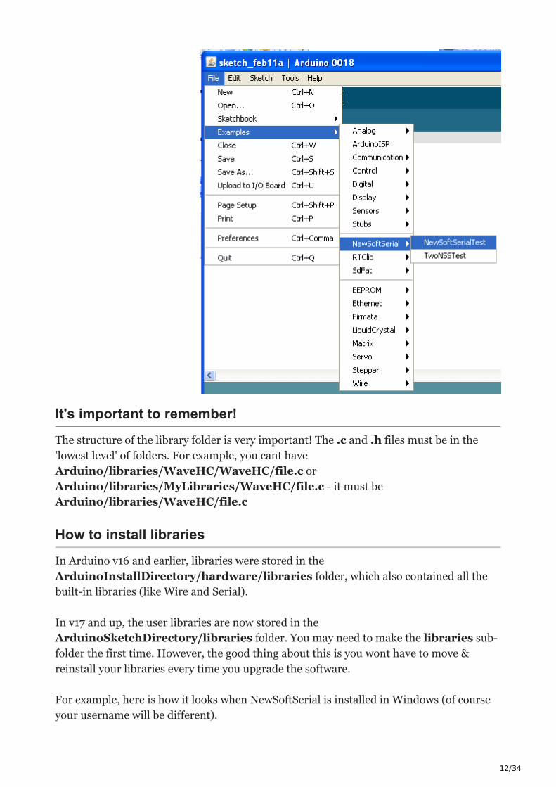
Two optional files you may see are keywords.txt (this is a hints file to tell the Arduino
IDE how to colorize your sketch and examples folder, which may have some handy test-
sketches. These will show up under the File→Examples→Library dropdown.
12/34
It's important to remember!
The structure of the library folder is very important! The .c and .h files must be in the
'lowest level' of folders. For example, you cant have
Arduino/libraries/WaveHC/WaveHC/file.c or
Arduino/libraries/MyLibraries/WaveHC/file.c - it must be
Arduino/libraries/WaveHC/file.c
How to install libraries
In Arduino v16 and earlier, libraries were stored in the
ArduinoInstallDirectory/hardware/libraries folder, which also contained all the
built-in libraries (like Wire and Serial).
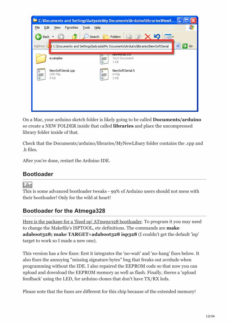
In v17 and up, the user libraries are now stored in the
ArduinoSketchDirectory/libraries folder. You may need to make the libraries sub-
folder the first time. However, the good thing about this is you wont have to move &
reinstall your libraries every time you upgrade the software.
For example, here is how it looks when NewSoftSerial is installed in Windows (of course
your username will be different).
13/34
On a Mac, your arduino sketch folder is likely going to be called Documents/arduino
so create a NEW FOLDER inside that called libraries and place the uncompressed
library folder inside of that.
Check that the Documents/arduino/libraries/MyNewLibary folder contains the .cpp and
.h files.
After you're done, restart the Arduino IDE.
Bootloader
Like
This is some advanced bootloader tweaks - 99% of Arduino users should not mess with
their bootloader! Only for the wild at heart!
Bootloader for the Atmega328
Here is the package for a 'fixed up' ATmega328 bootloader. To program it you may need
to change the Makefile's ISPTOOL, etc definitions. The commands are make
adaboot328; make TARGET=adaboot328 isp328 (I couldn't get the default 'isp'
target to work so I made a new one).
This version has a few fixes: first it integrates the 'no-wait' and 'no-hang' fixes below. It
also fixes the annoying "missing signature bytes" bug that freaks out avrdude when
programming without the IDE. I also repaired the EEPROM code so that now you can
upload and download the EEPROM memory as well as flash. Finally, theres a 'upload
feedback' using the LED, for arduino clones that don't have TX/RX leds.
Please note that the fuses are different for this chip because of the extended memory!
14/34
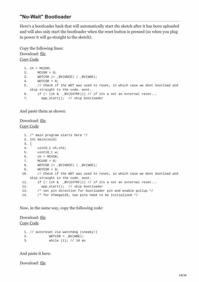
"No-Wait" Bootloader
Here's a bootloader hack that will automatically start the sketch after it has been uploaded
and will also only start the bootloader when the reset button is pressed (so when you plug
in power it will go straight to the sketch).
Copy the following lines:
Download: file
Copy Code
1. ch = MCUSR;2. MCUSR = 0;3. WDTCSR |= _BV(WDCE) | _BV(WDE);4. WDTCSR = 0;5. // Check if the WDT was used to reset, in which case we dont bootload and
skip straight to the code. woot.6. if (! (ch & _BV(EXTRF))) // if its a not an external reset...7. app_start(); // skip bootloader
And paste them as shown:
Download: file
Copy Code
1. /* main program starts here */2. int main(void)3. {4. uint8_t ch,ch2;5. uint16_t w;6. ch = MCUSR;7. MCUSR = 0;8. WDTCSR |= _BV(WDCE) | _BV(WDE);9. WDTCSR = 0;
10. // Check if the WDT was used to reset, in which case we dont bootload and skip straight to the code. woot.
11. if (! (ch & _BV(EXTRF))) // if its a not an external reset...12. app_start(); // skip bootloader13. /* set pin direction for bootloader pin and enable pullup */14. /* for ATmega128, two pins need to be initialized */
Now, in the same way, copy the following code:
Download: file
Copy Code
1. // autoreset via watchdog (sneaky!)2. WDTCSR = _BV(WDE);3. while (1); // 16 ms
And paste it here:
Download: file
15/34
Copy Code
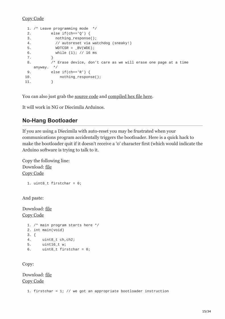
1. /* Leave programming mode */2. else if(ch=='Q') {3. nothing_response();4. // autoreset via watchdog (sneaky!)5. WDTCSR = _BV(WDE);6. while (1); // 16 ms7. }8. /* Erase device, don't care as we will erase one page at a time
anyway. */9. else if(ch=='R') {
10. nothing_response();11. }
You can also just grab the source code and compiled hex file here.
It will work in NG or Diecimila Arduinos.
No-Hang Bootloader
If you are using a Diecimila with auto-reset you may be frustrated when your
communications program accidentally triggers the bootloader. Here is a quick hack to
make the bootloader quit if it doesn't receive a '0' character first (which would indicate the
Arduino software is trying to talk to it.
Copy the following line:
Download: file
Copy Code
1. uint8_t firstchar = 0;
And paste:
Download: file
Copy Code
1. /* main program starts here */2. int main(void)3. {4. uint8_t ch,ch2;5. uint16_t w;6. uint8_t firstchar = 0;
Copy:
Download: file
Copy Code
1. firstchar = 1; // we got an appropriate bootloader instruction
16/34
Paste:
Download: file
Copy Code
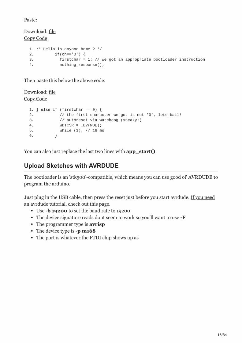
1. /* Hello is anyone home ? */ 2. if(ch=='0') {3. firstchar = 1; // we got an appropriate bootloader instruction4. nothing_response();
Then paste this below the above code:
Download: file
Copy Code
1. } else if (firstchar == 0) {2. // the first character we got is not '0', lets bail!3. // autoreset via watchdog (sneaky!)4. WDTCSR = _BV(WDE);5. while (1); // 16 ms6. }
You can also just replace the last two lines with app_start()
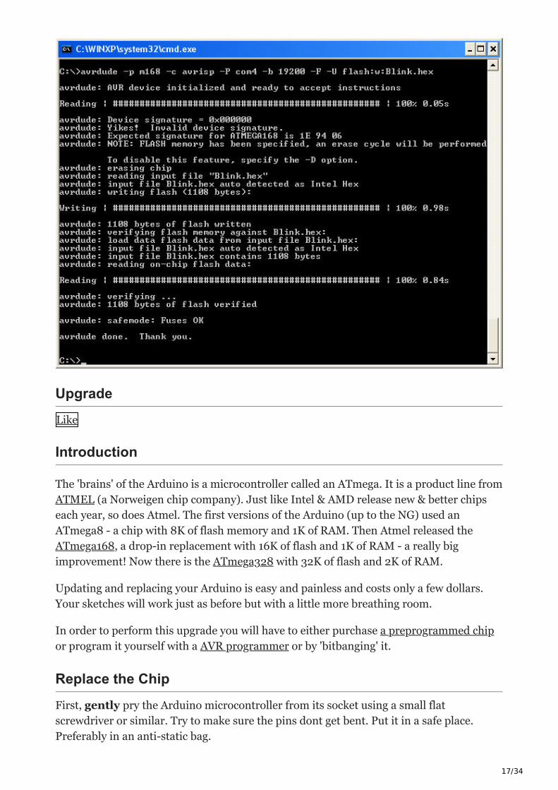
Upload Sketches with AVRDUDE
The bootloader is an 'stk500'-compatible, which means you can use good ol' AVRDUDE to
program the arduino.
Just plug in the USB cable, then press the reset just before you start avrdude. If you need
an avrdude tutorial, check out this page.
Use -b 19200 to set the baud rate to 19200
The device signature reads dont seem to work so you'll want to use -F
The programmer type is avrisp
The device type is -p m168
The port is whatever the FTDI chip shows up as
17/34
Upgrade
Like
Introduction
The 'brains' of the Arduino is a microcontroller called an ATmega. It is a product line from
ATMEL (a Norweigen chip company). Just like Intel & AMD release new & better chips
each year, so does Atmel. The first versions of the Arduino (up to the NG) used an
ATmega8 - a chip with 8K of flash memory and 1K of RAM. Then Atmel released the
ATmega168, a drop-in replacement with 16K of flash and 1K of RAM - a really big
improvement! Now there is the ATmega328 with 32K of flash and 2K of RAM.
Updating and replacing your Arduino is easy and painless and costs only a few dollars.
Your sketches will work just as before but with a little more breathing room.
In order to perform this upgrade you will have to either purchase a preprogrammed chip
or program it yourself with a AVR programmer or by 'bitbanging' it.
Replace the Chip
First, gently pry the Arduino microcontroller from its socket using a small flat
screwdriver or similar. Try to make sure the pins dont get bent. Put it in a safe place.
Preferably in an anti-static bag.

18/34
Next, prepare the new chip. The pins of ICs are a little skewed when they come from the
factory, so they need to be bent in just a tiny bit, to be parallel. Grip the chip from the
ends and use a table.

19/34
Finally, replace the old chip, lining up all the pins and making sure that the notch in the
chip matches the notch in the socket!
Download an Arduino IDE with ATmega328 compatibility
Version 13 and up of the Arduino software supports the 328!
If you purchased a chip from Adafruit that shipped before Feb 5, 2009 the chip will have
the baudrate set at 19200 (same as the older Arduinos). After Feb 5 the upgrade chips
were changed to 57600 baud rate (3 times faster!) in order to be compatible with new
Arduinos. If you have a 19200 baud rate chip you will have difficulty uploading. Simply
quit the Arduino application and edit the file in the hardware folder named boards.txt
and change the line from:
Download: file
Copy Code
1. atmega328.upload.speed=57600
to:
Download: file
Copy Code
1. atmega328.upload.speed=19200
20/34
If you're having problems please try BOTH just in case!
3.3V Conversion
Like
Introduction
All official Arduinos run on 5 volts, which for a long time was the 'standard' voltage for
hobbyist electronics and microcontrollers. But now the coolest new sensors, displays and
chips are 3.3V and are not 5V compatible. For example, XBee radios, and SD cards and
acellerometers all run on 3.3V logic and power. If you tried to connect to them with 5V
you could damage the internals of the accessory.
We use chips like the CD4050 to do level conversion but if you are using a lot of 3.3V
devices, maybe you're just better off upgrading the entire Arduino to run from 3.3V!
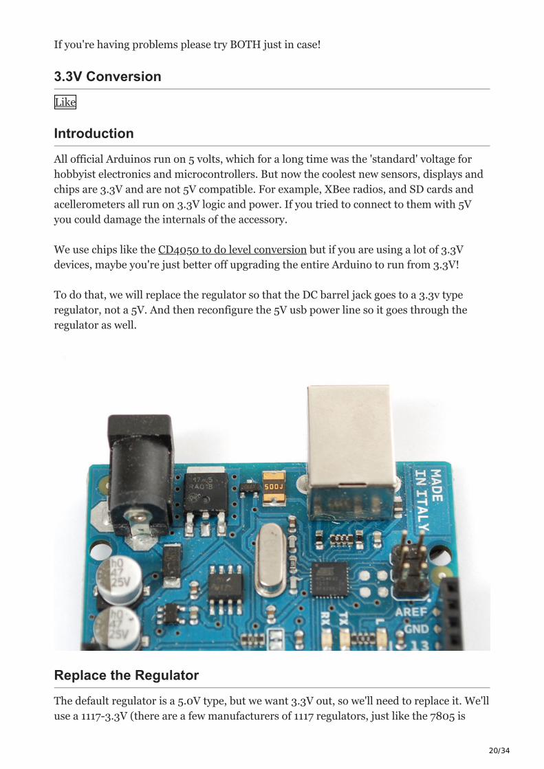
To do that, we will replace the regulator so that the DC barrel jack goes to a 3.3v type
regulator, not a 5V. And then reconfigure the 5V usb power line so it goes through the
regulator as well.
Replace the Regulator
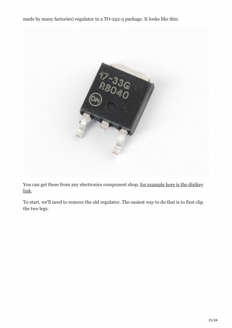
The default regulator is a 5.0V type, but we want 3.3V out, so we'll need to replace it. We'll
use a 1117-3.3V (there are a few manufacturers of 1117 regulators, just like the 7805 is
21/34
made by many factories) regulator in a TO-252-3 package. It looks like this:
You can get these from any electronics component shop, for example here is the digikey
link.
To start, we'll need to remove the old regulator. The easiest way to do that is to first clip
the two legs.
22/34
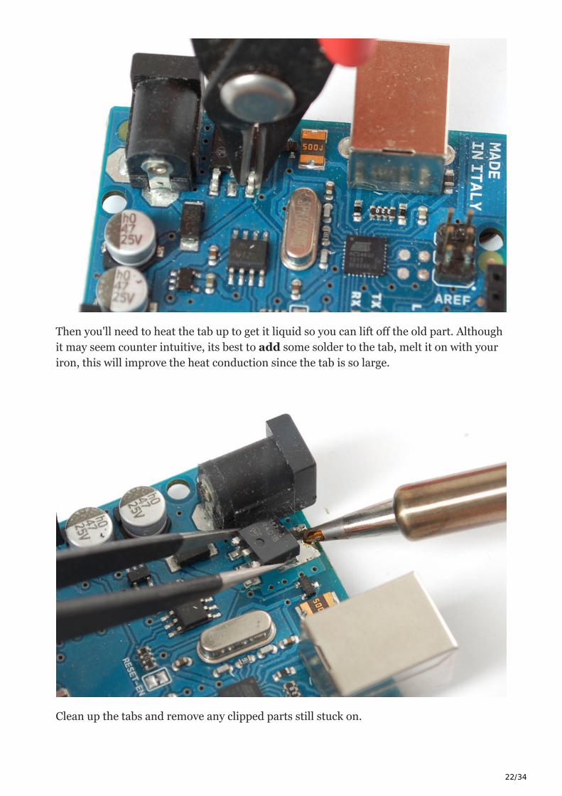
Then you'll need to heat the tab up to get it liquid so you can lift off the old part. Although
it may seem counter intuitive, its best to add some solder to the tab, melt it on with your
iron, this will improve the heat conduction since the tab is so large.
Clean up the tabs and remove any clipped parts still stuck on.
23/34
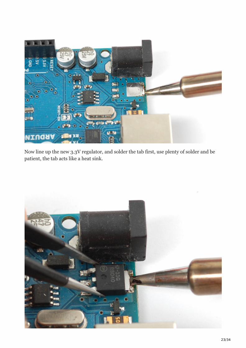
Now line up the new 3.3V regulator, and solder the tab first, use plenty of solder and be
patient, the tab acts like a heat sink.
24/34
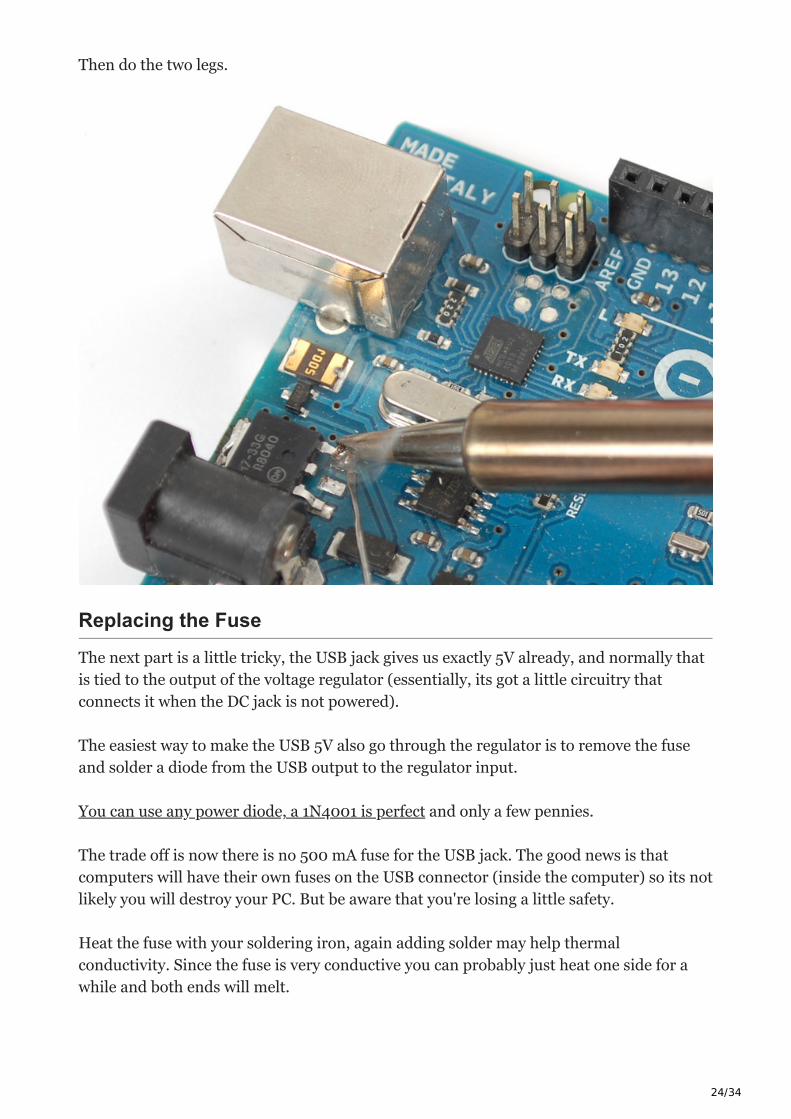
Then do the two legs.
Replacing the Fuse
The next part is a little tricky, the USB jack gives us exactly 5V already, and normally that
is tied to the output of the voltage regulator (essentially, its got a little circuitry that
connects it when the DC jack is not powered).
The easiest way to make the USB 5V also go through the regulator is to remove the fuse
and solder a diode from the USB output to the regulator input.
You can use any power diode, a 1N4001 is perfect and only a few pennies.
The trade off is now there is no 500 mA fuse for the USB jack. The good news is that
computers will have their own fuses on the USB connector (inside the computer) so its not
likely you will destroy your PC. But be aware that you're losing a little safety.
Heat the fuse with your soldering iron, again adding solder may help thermal
conductivity. Since the fuse is very conductive you can probably just heat one side for a
while and both ends will melt.

25/34
Clip the diode short and bend the leads over. Solder the side without a stripe (anode) to
the old fuse pad, nearest the board edge. Solder the striped end (cathode) to the right
hand leg of the regulator.
The Arduino will still automatically select whichever power plug is giving you more
power.

26/34
That's it! You are now 3.3V powered. This is a little lower than the power/frequency
specification for the AVR chips since they ought to have about 3.6V to run 16Mhz but
its probably not going to be an issue since AVRs can be overclocked a little.
Arduino Hacks
Like
Bumpers
Having the conductive traces touch your table is not so great, you can protect your
Arduino by adding bumpers to the bottom.
You can buy these from McMaster
Carr part no. 95495K66 (in large
quantities) or Adafruit
Free up some RAM
27/34
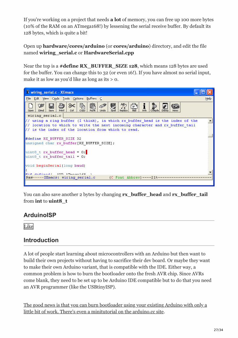
If you're working on a project that needs a lot of memory, you can free up 100 more bytes
(10% of the RAM on an ATmega168!) by lessening the serial receive buffer. By default its
128 bytes, which is quite a bit!
Open up hardware/cores/arduino (or cores/arduino) directory, and edit the file
named wiring_serial.c or HardwareSerial.cpp
Near the top is a #define RX_BUFFER_SIZE 128, which means 128 bytes are used
for the buffer. You can change this to 32 (or even 16!). If you have almost no serial input,
make it as low as you'd like as long as its > 0.
You can also save another 2 bytes by changing rx_buffer_head and rx_buffer_tail
from int to uint8_t
ArduinoISP
Like
Introduction
A lot of people start learning about microcontrollers with an Arduino but then want to
build their own projects without having to sacrifice their dev board. Or maybe they want
to make their own Arduino variant, that is compatible with the IDE. Either way, a
common problem is how to burn the bootloader onto the fresh AVR chip. Since AVRs
come blank, they need to be set up to be Arduino IDE compatible but to do that you need
an AVR programmer (like the USBtinyISP).
The good news is that you can burn bootloader using your existing Arduino with only a
little bit of work. There's even a minitutorial on the arduino.cc site.
28/34
This tutorial is an extention of that tutorial. First we'll show how you can make a
permanent bootloader-burner by soldering a 28-pin ZIF socket to a proto shield and use
the PWM output line of the Arduino to generate a clock. This will let you 'rescue' many
chips that have been set to the wrong type of oscillator, or change ones that are set from
external oscillator (most Arduino bootloaders) to internal (such as the lilypad).
Parts
You will need…If you bought the kit from Adafruit, you'll have an extra few items such as
a Piezo beeper, LEDs, buttons, etc. that you can use for the Standalone version of this
project, just ignore them for now!
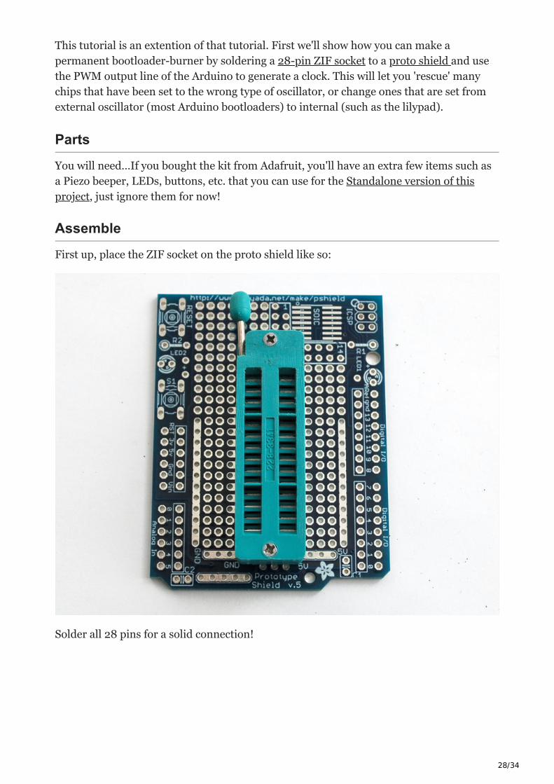
Assemble
First up, place the ZIF socket on the proto shield like so:
Solder all 28 pins for a solid connection!
29/34
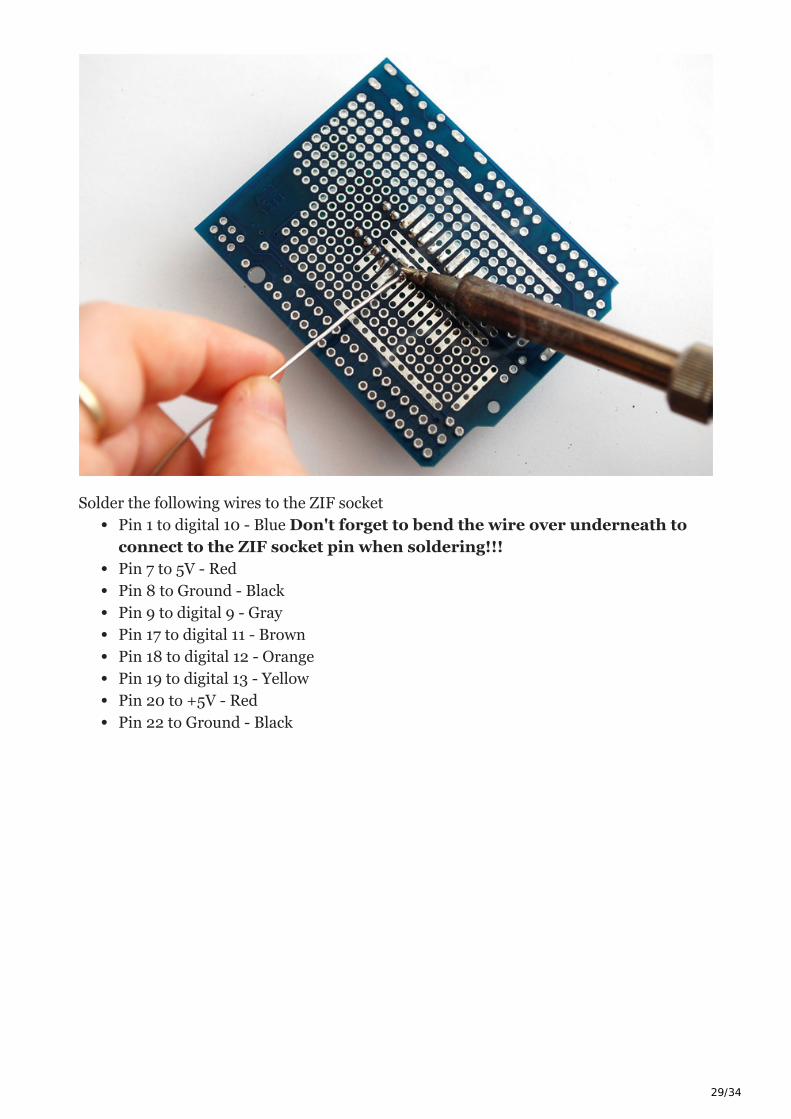
Solder the following wires to the ZIF socket
Pin 1 to digital 10 - Blue Don't forget to bend the wire over underneath to
connect to the ZIF socket pin when soldering!!!
Pin 7 to 5V - Red
Pin 8 to Ground - Black
Pin 9 to digital 9 - Gray
Pin 17 to digital 11 - Brown
Pin 18 to digital 12 - Orange
Pin 19 to digital 13 - Yellow
Pin 20 to +5V - Red
Pin 22 to Ground - Black
30/34
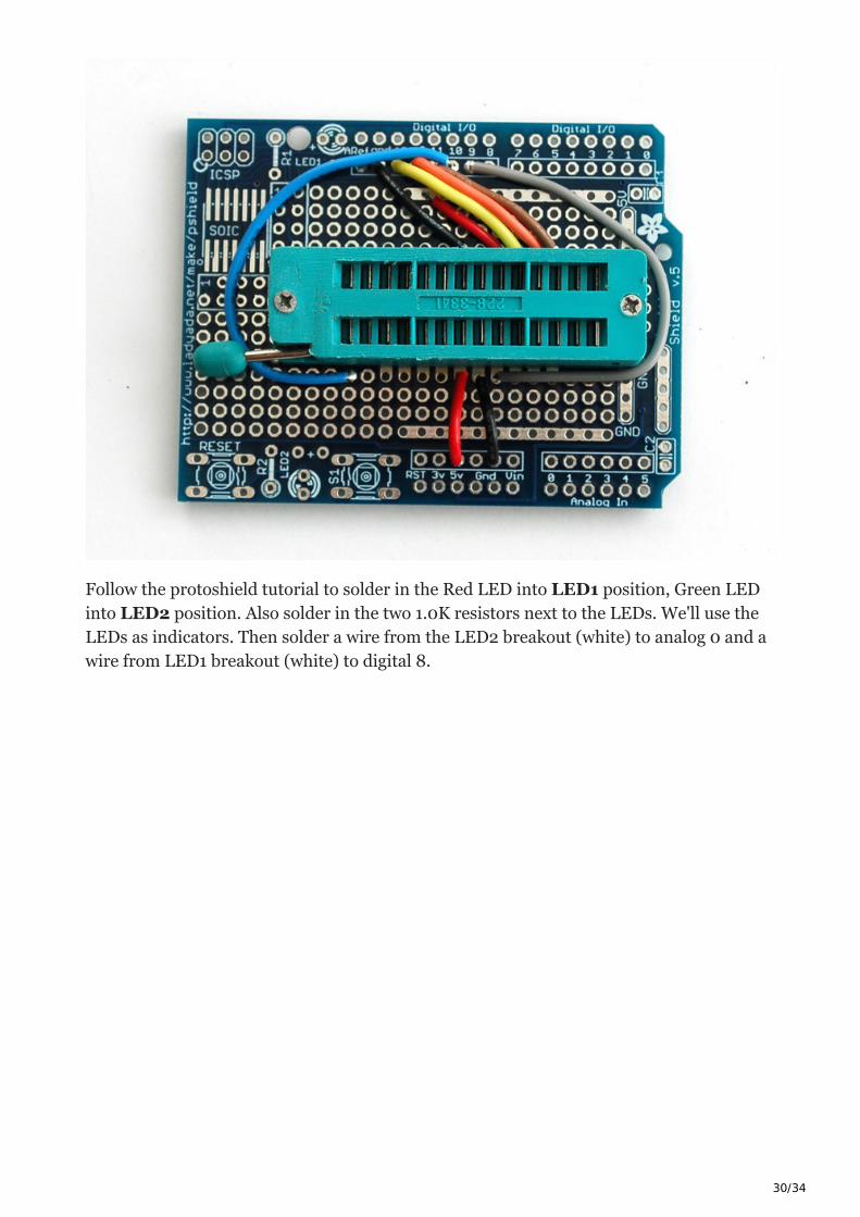
Follow the protoshield tutorial to solder in the Red LED into LED1 position, Green LED
into LED2 position. Also solder in the two 1.0K resistors next to the LEDs. We'll use the
LEDs as indicators. Then solder a wire from the LED2 breakout (white) to analog 0 and a
wire from LED1 breakout (white) to digital 8.
31/34
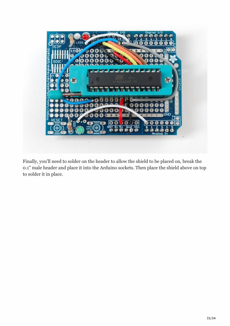
Finally, you'll need to solder on the header to allow the shield to be placed on, break the
0.1" male header and place it into the Arduino sockets. Then place the shield above on top
to solder it in place.

32/34
Load the Code
Time to load the sketch! Grab the code from our Github repository and paste it into a new
sketch. Then upload it to the Arduino.
We have a report that this procedure does not work with Arduino 1.5.2. Use the latest
mainstream Arduino release instead!
Plug the shield on top, lift the latch, pop in the chip and then lower the latch. Make sure
the chip orientation is like so (so with the lever on the left side you can read the text):
33/34
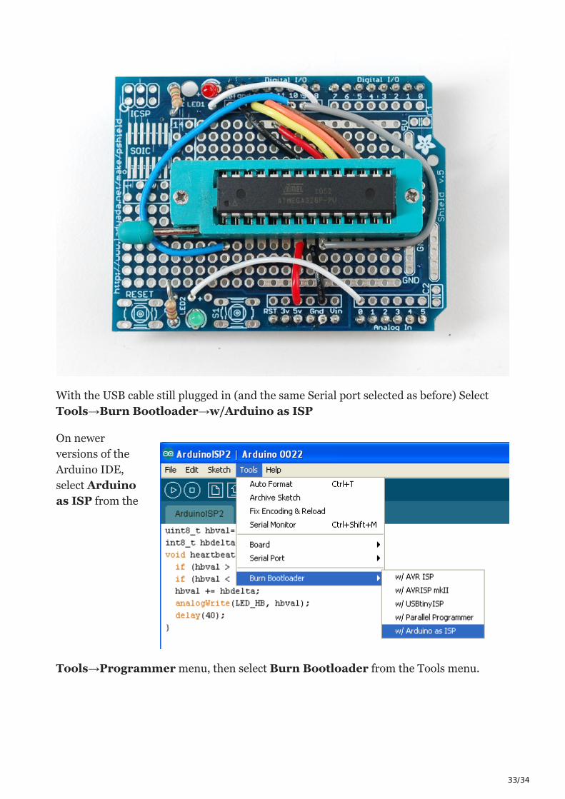
With the USB cable still plugged in (and the same Serial port selected as before) Select
Tools→Burn Bootloader→w/Arduino as ISP
On newer
versions of the
Arduino IDE,
select Arduino
as ISP from the
Tools→Programmer menu, then select Burn Bootloader from the Tools menu.
34/34
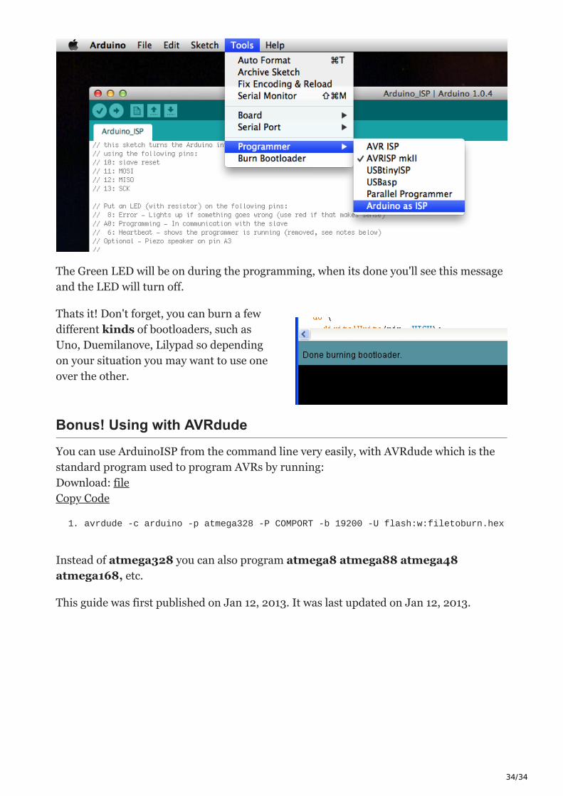
The Green LED will be on during the programming, when its done you'll see this message
and the LED will turn off.
Thats it! Don't forget, you can burn a few
different kinds of bootloaders, such as
Uno, Duemilanove, Lilypad so depending
on your situation you may want to use one
over the other.
Bonus! Using with AVRdude
You can use ArduinoISP from the command line very easily, with AVRdude which is the
standard program used to program AVRs by running:
Download: file
Copy Code
1. avrdude -c arduino -p atmega328 -P COMPORT -b 19200 -U flash:w:filetoburn.hex
Instead of atmega328 you can also program atmega8 atmega88 atmega48
atmega168, etc.
This guide was first published on Jan 12, 2013. It was last updated on Jan 12, 2013.