Arduino for Greenhouse, Garden or Growbox - Instructables.com
17
http://www.instructables.com/id/Arduino-for-Greenhouse-Garden-or-Growbox/ Food Living Outside Play Technology Workshop Arduino for Greenhouse, Garden or Growbox by diy_bloke on May 11, 2012 Table of Contents Arduino for Greenhouse, Garden or Growbox . . . . . . . . . . . . . . . . . . . . . . . . . . . . . . . . . . . . . . . . . . . . . . . . . . . . . . . . . . . . . . . . . . . . . . . . . . . . . . . . . . . . . . . . . 1 Intro: Arduino for Greenhouse, Garden or Growbox . . . . . . . . . . . . . . . . . . . . . . . . . . . . . . . . . . . . . . . . . . . . . . . . . . . . . . . . . . . . . . . . . . . . . . . . . . . . . . . . . 2 Step 1: Arduino for Garden, Greenhouse or Growbox: inputs and outputs . . . . . . . . . . . . . . . . . . . . . . . . . . . . . . . . . . . . . . . . . . . . . . . . . . . . . . . . . . . . . . . . 3 Step 2: Arduino for Greenhouse, Garden or Growbox: PSU . . . . . . . . . . . . . . . . . . . . . . . . . . . . . . . . . . . . . . . . . . . . . . . . . . . . . . . . . . . . . . . . . . . . . . . . . . . 4 Step 3: Arduino for Garden, Greenhouse or Growbox: Humiditity and temperature . . . . . . . . . . . . . . . . . . . . . . . . . . . . . . . . . . . . . . . . . . . . . . . . . . . . . . . . . . 4 Step 4: Arduino for Greenhouse, Garden or Growbox: LDR . . . . . . . . . . . . . . . . . . . . . . . . . . . . . . . . . . . . . . . . . . . . . . . . . . . . . . . . . . . . . . . . . . . . . . . . . . . 5 Step 5: Arduino for Garden, Greenhouse or Growbox: Soil humidity . . . . . . . . . . . . . . . . . . . . . . . . . . . . . . . . . . . . . . . . . . . . . . . . . . . . . . . . . . . . . . . . . . . . . 6 Step 6: Arduino for Greenhouse, Garden or Growbox: the level/float switch . . . . . . . . . . . . . . . . . . . . . . . . . . . . . . . . . . . . . . . . . . . . . . . . . . . . . . . . . . . . . . . 7 Step 7: Arduino for Greenhouse, Garden or Growbox: an alternative level switch . . . . . . . . . . . . . . . . . . . . . . . . . . . . . . . . . . . . . . . . . . . . . . . . . . . . . . . . . . . 8 Step 8: Arduino for Greenhouse, Garden or Growbox: an alternative float switch . . . . . . . . . . . . . . . . . . . . . . . . . . . . . . . . . . . . . . . . . . . . . . . . . . . . . . . . . . . 9 Step 9: Arduino for Garden, Greenhouse or Growbox: Buzzer . . . . . . . . . . . . . . . . . . . . . . . . . . . . . . . . . . . . . . . . . . . . . . . . . . . . . . . . . . . . . . . . . . . . . . . . . 9 Step 10: Arduino for Greenhouse, Garden or Growbox: Solid State Relay . . . . . . . . . . . . . . . . . . . . . . . . . . . . . . . . . . . . . . . . . . . . . . . . . . . . . . . . . . . . . . . . 10 Step 11: Arduino for Greenhouse, Garden or Growbox: The LCD . . . . . . . . . . . . . . . . . . . . . . . . . . . . . . . . . . . . . . . . . . . . . . . . . . . . . . . . . . . . . . . . . . . . . . . 10 Step 12: Arduino for Greenhouse, Garden or Growbox: Construction . . . . . . . . . . . . . . . . . . . . . . . . . . . . . . . . . . . . . . . . . . . . . . . . . . . . . . . . . . . . . . . . . . . . 11 Step 13: The Software . . . . . . . . . . . . . . . . . . . . . . . . . . . . . . . . . . . . . . . . . . . . . . . . . . . . . . . . . . . . . . . . . . . . . . . . . . . . . . . . . . . . . . . . . . . . . . . . . . . . . . . 12 Step 14: The Software: code . . . . . . . . . . . . . . . . . . . . . . . . . . . . . . . . . . . . . . . . . . . . . . . . . . . . . . . . . . . . . . . . . . . . . . . . . . . . . . . . . . . . . . . . . . . . . . . . . . 13 Step 15: The Software: special characters . . . . . . . . . . . . . . . . . . . . . . . . . . . . . . . . . . . . . . . . . . . . . . . . . . . . . . . . . . . . . . . . . . . . . . . . . . . . . . . . . . . . . . . . 16 Step 16: Arduino for Greenhouse, Garden or Growbox: possible expansions . . . . . . . . . . . . . . . . . . . . . . . . . . . . . . . . . . . . . . . . . . . . . . . . . . . . . . . . . . . . . . 17 Related Instructables . . . . . . . . . . . . . . . . . . . . . . . . . . . . . . . . . . . . . . . . . . . . . . . . . . . . . . . . . . . . . . . . . . . . . . . . . . . . . . . . . . . . . . . . . . . . . . . . . . . . . . . . 17 Advertisements . . . . . . . . . . . . . . . . . . . . . . . . . . . . . . . . . . . . . . . . . . . . . . . . . . . . . . . . . . . . . . . . . . . . . . . . . . . . . . . . . . . . . . . . . . . . . . . . . . . . . . . . . . . . . . . 17 Comments . . . . . . . . . . . . . . . . . . . . . . . . . . . . . . . . . . . . . . . . . . . . . . . . . . . . . . . . . . . . . . . . . . . . . . . . . . . . . . . . . . . . . . . . . . . . . . . . . . . . . . . . . . . . . . . . 17
-
Upload
khangminh22 -
Category
Documents
-
view
1 -
download
0
Transcript of Arduino for Greenhouse, Garden or Growbox - Instructables.com
http://www.instructables.com/id/Arduino-for-Greenhouse-Garden-or-Growbox/
Food Living Outside Play Technology Workshop
Arduino for Greenhouse, Garden or Growboxby diy_bloke on May 11, 2012
Table of Contents
Arduino for Greenhouse, Garden or Growbox . . . . . . . . . . . . . . . . . . . . . . . . . . . . . . . . . . . . . . . . . . . . . . . . . . . . . . . . . . . . . . . . . . . . . . . . . . . . . . . . . . . . . . . . . 1
Intro: Arduino for Greenhouse, Garden or Growbox . . . . . . . . . . . . . . . . . . . . . . . . . . . . . . . . . . . . . . . . . . . . . . . . . . . . . . . . . . . . . . . . . . . . . . . . . . . . . . . . . 2
Step 1: Arduino for Garden, Greenhouse or Growbox: inputs and outputs . . . . . . . . . . . . . . . . . . . . . . . . . . . . . . . . . . . . . . . . . . . . . . . . . . . . . . . . . . . . . . . . 3
Step 2: Arduino for Greenhouse, Garden or Growbox: PSU . . . . . . . . . . . . . . . . . . . . . . . . . . . . . . . . . . . . . . . . . . . . . . . . . . . . . . . . . . . . . . . . . . . . . . . . . . . 4
Step 3: Arduino for Garden, Greenhouse or Growbox: Humiditity and temperature . . . . . . . . . . . . . . . . . . . . . . . . . . . . . . . . . . . . . . . . . . . . . . . . . . . . . . . . . . 4
Step 4: Arduino for Greenhouse, Garden or Growbox: LDR . . . . . . . . . . . . . . . . . . . . . . . . . . . . . . . . . . . . . . . . . . . . . . . . . . . . . . . . . . . . . . . . . . . . . . . . . . . 5
Step 5: Arduino for Garden, Greenhouse or Growbox: Soil humidity . . . . . . . . . . . . . . . . . . . . . . . . . . . . . . . . . . . . . . . . . . . . . . . . . . . . . . . . . . . . . . . . . . . . . 6
Step 6: Arduino for Greenhouse, Garden or Growbox: the level/float switch . . . . . . . . . . . . . . . . . . . . . . . . . . . . . . . . . . . . . . . . . . . . . . . . . . . . . . . . . . . . . . . 7
Step 7: Arduino for Greenhouse, Garden or Growbox: an alternative level switch . . . . . . . . . . . . . . . . . . . . . . . . . . . . . . . . . . . . . . . . . . . . . . . . . . . . . . . . . . . 8
Step 8: Arduino for Greenhouse, Garden or Growbox: an alternative float switch . . . . . . . . . . . . . . . . . . . . . . . . . . . . . . . . . . . . . . . . . . . . . . . . . . . . . . . . . . . 9
Step 9: Arduino for Garden, Greenhouse or Growbox: Buzzer . . . . . . . . . . . . . . . . . . . . . . . . . . . . . . . . . . . . . . . . . . . . . . . . . . . . . . . . . . . . . . . . . . . . . . . . . 9
Step 10: Arduino for Greenhouse, Garden or Growbox: Solid State Relay . . . . . . . . . . . . . . . . . . . . . . . . . . . . . . . . . . . . . . . . . . . . . . . . . . . . . . . . . . . . . . . . 10
Step 11: Arduino for Greenhouse, Garden or Growbox: The LCD . . . . . . . . . . . . . . . . . . . . . . . . . . . . . . . . . . . . . . . . . . . . . . . . . . . . . . . . . . . . . . . . . . . . . . . 10
Step 12: Arduino for Greenhouse, Garden or Growbox: Construction . . . . . . . . . . . . . . . . . . . . . . . . . . . . . . . . . . . . . . . . . . . . . . . . . . . . . . . . . . . . . . . . . . . . 11
Step 13: The Software . . . . . . . . . . . . . . . . . . . . . . . . . . . . . . . . . . . . . . . . . . . . . . . . . . . . . . . . . . . . . . . . . . . . . . . . . . . . . . . . . . . . . . . . . . . . . . . . . . . . . . . 12
Step 14: The Software: code . . . . . . . . . . . . . . . . . . . . . . . . . . . . . . . . . . . . . . . . . . . . . . . . . . . . . . . . . . . . . . . . . . . . . . . . . . . . . . . . . . . . . . . . . . . . . . . . . . 13
Step 15: The Software: special characters . . . . . . . . . . . . . . . . . . . . . . . . . . . . . . . . . . . . . . . . . . . . . . . . . . . . . . . . . . . . . . . . . . . . . . . . . . . . . . . . . . . . . . . . 16
Step 16: Arduino for Greenhouse, Garden or Growbox: possible expansions . . . . . . . . . . . . . . . . . . . . . . . . . . . . . . . . . . . . . . . . . . . . . . . . . . . . . . . . . . . . . . 17
Related Instructables . . . . . . . . . . . . . . . . . . . . . . . . . . . . . . . . . . . . . . . . . . . . . . . . . . . . . . . . . . . . . . . . . . . . . . . . . . . . . . . . . . . . . . . . . . . . . . . . . . . . . . . . 17
Advertisements . . . . . . . . . . . . . . . . . . . . . . . . . . . . . . . . . . . . . . . . . . . . . . . . . . . . . . . . . . . . . . . . . . . . . . . . . . . . . . . . . . . . . . . . . . . . . . . . . . . . . . . . . . . . . . . 17
Comments . . . . . . . . . . . . . . . . . . . . . . . . . . . . . . . . . . . . . . . . . . . . . . . . . . . . . . . . . . . . . . . . . . . . . . . . . . . . . . . . . . . . . . . . . . . . . . . . . . . . . . . . . . . . . . . . 17

http://www.instructables.com/id/Arduino-for-Greenhouse-Garden-or-Growbox/
Author:diy_blokeI am a physician by trade. After a career in the pharmeceutical world I decided to take it a bit slower and do things I like. Other than my hobbies that involvesgrassroots medicine in S.E.&P Asia. I have built low income cow dung bio-reactors, solar lamps and family fish ponds as well as houses out of every kind ofthinkable material. Instructables is an endless source of inspiration for my projects.
Intro: Arduino for Greenhouse, Garden or GrowboxI have been using Attiny chips for irrigation tasks in my garden, but having plans to build a greenhouse, an Arduino seemed to be the way to go as it has more ports. Iknow, there are many 'Garduino' type projects already, including ones that twitter the state of your plants, but I just wanted something more basic, so, what does an analretentive Asperger do in such a case: build something myself.
No use of course to spend 23-25 euro's for an Arduino Uno and then still have to add a shield for peripherals: seemed a bit overdone and as I have built various'arduino's' alreday, I decided to just get the chip, a crystal, and 2 capacitors + some more stuff and build the entire thing on an Archer experiment board that I bought 20years ago but has been idle all that time (radioshack partno 276-168). The Archer experiment board has islands with 3 holes and 2 seperate tracks (Vcc and Gnd)snaking in between. Of course it can also be done on regular strip board, perfboard or one can make a PCB for it.
In the end I decided I needed to have the following functions
measure temperature1.measure humidity of the air2.measure humidity of the soil3.measure water level in a container4.measure light, basically to determine if it is light or day5.switch a fan6.switch a pump7.switch a heater8.switch a lamp9.
List of materialsProcessorAtmega 328 here to burn bootloader yourself or buy one preprogrammed1x 28 pins IC foot narrow (or 2x 14 pins ic foot)16MHz Crystal2x 22 nF1x 10 k1x 100nF1x PCB momentary make switchperfboard This is what I used because I had that laying around idle for years alreadyNOTE:an attractive alternative is a cheap arduino clone such as the Pro mini or Pro Micro that can be had for a few dollars at e.g. Dealextreme.com
Display16x2LCD CG046-3007 A00, but any other will do.1602 I2C module
PSU1x 7805, isolated1x 1N40012x 100uF (16 V en 25 Volt)1x 1 k resistor1x LED1x psu connector
Peripherals1x LDR1x DHT11 moisture sensor (e.g. from dealextreme)1x make push button1x Switch1x buzzer (I use the CMB-06, a triggerable buzzer) ($2.99) but use any other buzzer you have or are comfortable with e.g. this one1x NPN transistor (e.g.BC547)1x 330 Ohm2x 10k
Solidstate relays4x330 Ohm4xLED4x8pin dil foot4x39MF22 SSR 4x2pin screw connector (mains voltage)1x 5pin female printheader1x 5pin male header 90degrees angleALTERNATIVELY: buy a ready made 4 channel mechanical relay for just about the same price as loose parts for the SSR, such as this one, or an even cheaper one.
bits and boltsa couple of different colour wires, some print headers, four 3mm bolts and nuts, some 2.5 mm bolts and nuts, 4 spacerssolder tin, solder iron
casingI use two casings:one for the processor and most of the peripherals (I use a plastic box that contained screws: 9x12x4.5 cm)one for the SSR's (I used a Tic-Tac peppermint dispenser The bigger one for 100 mints: 8.5x2x5 cm)
http://www.instructables.com/id/Arduino-for-Greenhouse-Garden-or-Growbox/
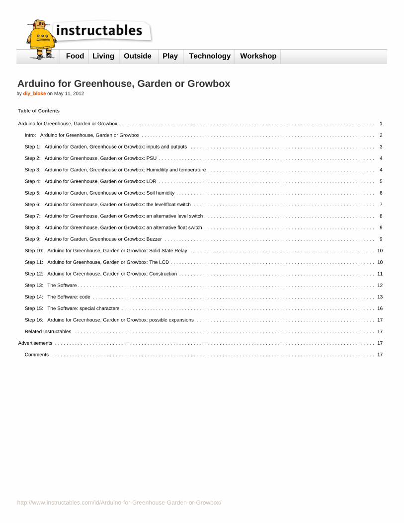
Step 1: Arduino for Garden, Greenhouse or Growbox: inputs and outputsBefore I describe the construction I will discuss the individual items:
ProcessorAn Atmel 328 with an Arduino bootloader is used. That makes for easy adaptation and uploading of the program. It will be a "bare bones" setup with no USB entrance,but simply with the TTL Rx and Tx signals on a header.
PSUSimply a 7805 circuit fed from a wallwart. No 3.3 Volts will be necessary
Humidity and temperature sensorA DHT11 sensor will provide that. It is a 3 pin sensor of which the data can easily be read by the Arduino. There is a library available.
SwitchSimply read as an input to set various functions in the software
LightAn LDR read by an analogue port. It basically is there to determine if it is day or night. This allows for extra light when the days are too short or to perform certainfunctions different at day or might(such as different day and night temperature, no irrigation at night etc)
Soil Moisture sensorThis sensor, read by an analogue port will give information about the humidity of the soil and signal the processor it is time to irrigate. There is an entire science on DIYsoil moisture sensors. I will just be using the classic '2 nails' approach. The software and hardware will allow for the current through the sensor to be switched off, thusdelaying corrosion.
Level sensorThis sensor checks if the water reservoir is still full. A simple float switch will suffice
Buzzerused to give signals, e.g. if the water reservoir is empty. I use an old CMB-06 that has a trigger, meaning it can be triggered with a small current while it can get its maincurrent directly from the power supply lines.
Solid state relaysI use 4 solid state relays to switch a fan, a pump, a heater and the lights. The solid state relays are separated from the processor print out of safety precautions.
http://www.instructables.com/id/Arduino-for-Greenhouse-Garden-or-Growbox/
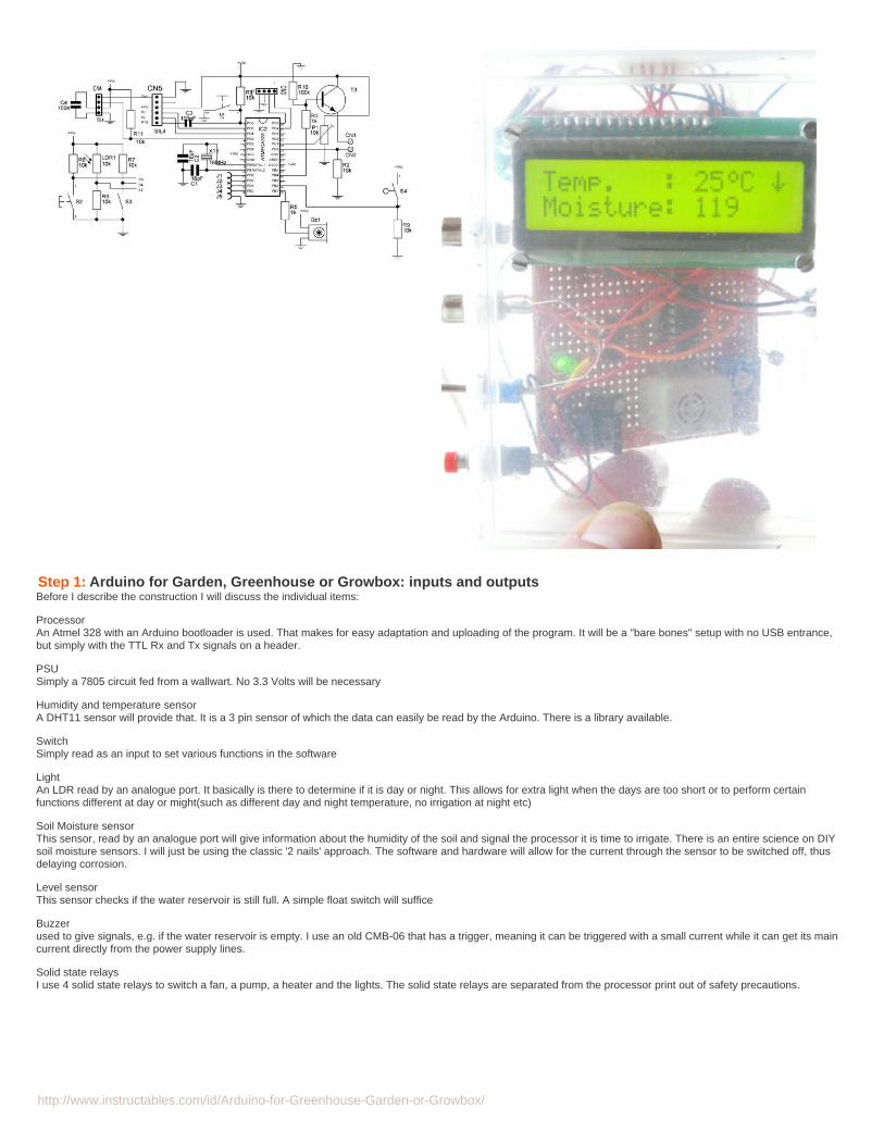
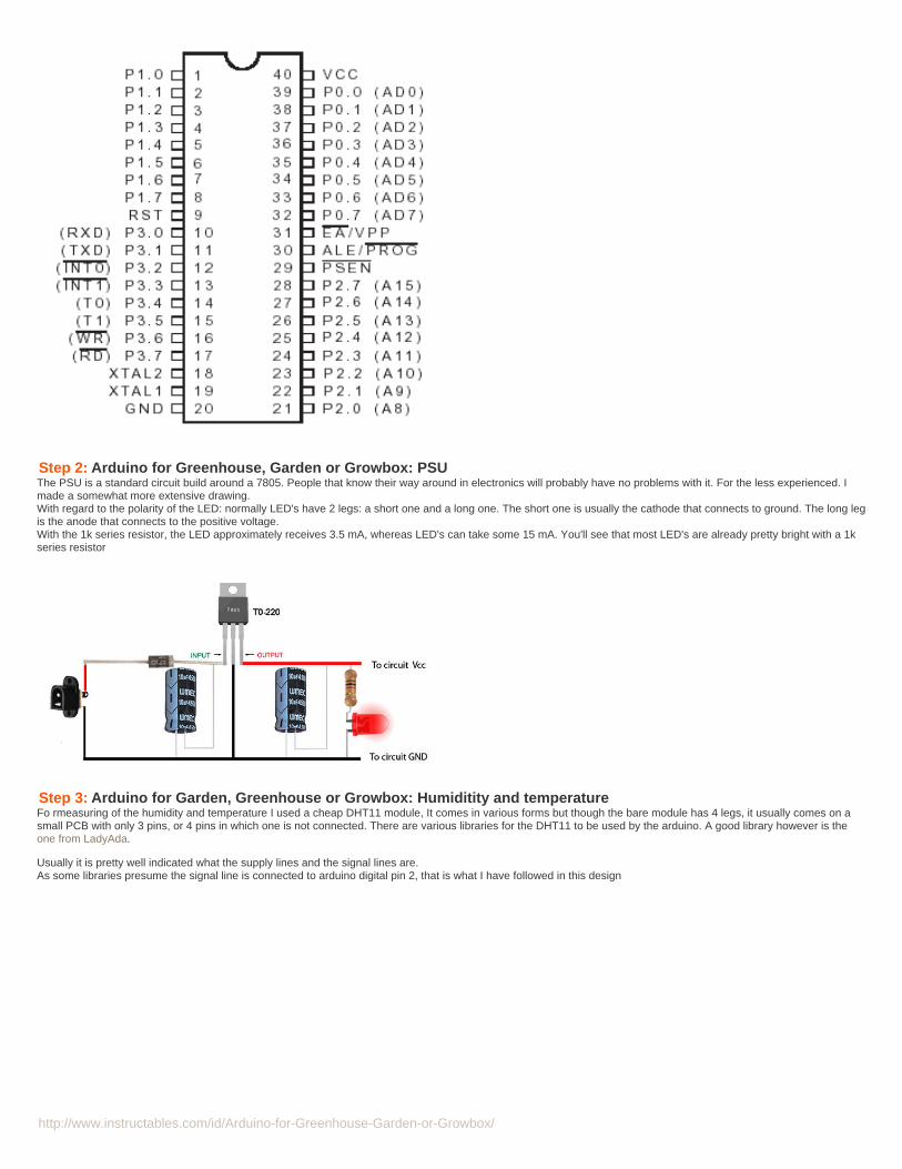
Step 2: Arduino for Greenhouse, Garden or Growbox: PSUThe PSU is a standard circuit build around a 7805. People that know their way around in electronics will probably have no problems with it. For the less experienced. Imade a somewhat more extensive drawing.With regard to the polarity of the LED: normally LED's have 2 legs: a short one and a long one. The short one is usually the cathode that connects to ground. The long legis the anode that connects to the positive voltage.With the 1k series resistor, the LED approximately receives 3.5 mA, whereas LED's can take some 15 mA. You'll see that most LED's are already pretty bright with a 1kseries resistor
Step 3: Arduino for Garden, Greenhouse or Growbox: Humiditity and temperatureFo rmeasuring of the humidity and temperature I used a cheap DHT11 module, It comes in various forms but though the bare module has 4 legs, it usually comes on asmall PCB with only 3 pins, or 4 pins in which one is not connected. There are various libraries for the DHT11 to be used by the arduino. A good library however is theone from LadyAda.
Usually it is pretty well indicated what the supply lines and the signal lines are.As some libraries presume the signal line is connected to arduino digital pin 2, that is what I have followed in this design

http://www.instructables.com/id/Arduino-for-Greenhouse-Garden-or-Growbox/
Step 4: Arduino for Greenhouse, Garden or Growbox: LDRI use an LDR to determine the light level. The LDR forms a voltage divider together with a 15 k resistor. When it gets dark, the resistance of the LDR goes up and thus thevoltage over the 15 k resistor goes down. When it is light, the resistance of the LDR is low and therefore the voltage over the 15 k resistor is high.
LDR's generally have a vary wide range. The one I have is around 300 k in the dark and 300 ohm in daylight. As I only am interested in making a crude light, twilight,night reading, I determined the resistance of the LDR in what I called twilight. That was 15 k. Therefore, chosing a 15 k resistor in the voltage divider gives the broadestrange.
I inserted the LDR in a clear casing (a pill bottle) and connected it via a thin wire to the arduino Vcc and analog pin 1 (that is pin 21 on an Atmega 328). The 15 k resistoris on the circuit board.
A good way to determine the value for the pull down resistor is the Axel Benz formula.As we are only interested in a night and day difference, the pull up resistor is not that critical

http://www.instructables.com/id/Arduino-for-Greenhouse-Garden-or-Growbox/
Step 5: Arduino for Garden, Greenhouse or Growbox: Soil humiditySoil humidity is generally measured by reading the resistance between two pins in the soil. Generally, two types of sensors are used: two nails or pins stuck in the earthor 2 rods encased in gypsum, put in the soil.
Both methods have their pro's and cons. The (galvanized) nails may be put in the soil at various distances, influencing the resistance, however, they are simple andcheap and react quick to changes in the humidity. The gypsum method makes sure the rods have a fixed distance, but the reaction to changes in humidity are slower.
Both types are subject to corrosion in the soil, a process that is sped up by the electrolysis because of the current send through the sensor, however, the gypsumencased rods are less prone to corrosion because they are not directly exposed to the soil.
Though bare rods probably will have to be replaced every year because of corrosion, the gypsum sensor will also need to be replaced because of dissolving of thegypsum.
The corrosion of the rods can be delayed by limiting the electrolysis by only sending a current through the rods when measuring.
That is what I have chosen for in this design: The transistor is opened by a high level from a digital pin. The emmitter is then pulled high (about 4.7 Volts). This voltage isthen fed to the sensor (the two pins in the soil) and the voltage over the 10 k resistor is then read by an analogue pin. The transistor is basically any type of cheap NPNsignal transistor such as a BC107 or a BC547. I used a VN147 a 30 year old 'universal NPN' transistor, for no other reason that I had that laying around and I kinda likethe triangle shape it has
The sensor and the resistor in fact form a regular voltage divider in which the voltage over R2 gives an indication of the resistance of the sensor and thus the humidity ofthe soil.
Resistanceof the soil does not only vary with humidity but also with the type of soil. Generally, my soil in moist conditions renders a resistance of around 10 k between thesensor pins, but even if the pins would be shorted, the maximum current will be about 0.5 mA. It is therefore possible to leave out the resistor and feed the sensor directlyfrom a digital pin (capable of delivering 40 mA), but I just feel happier having some protection of the arduino pins.
The 5V1 zenerdiode between the analogue pin and the earth is to protect the chip against high voltages that may build up if a long line to the probe is used. It is optional.
The software has a routine that will read the voltage over the 10k resistor 5 times and then calculate an average
http://www.instructables.com/id/Arduino-for-Greenhouse-Garden-or-Growbox/
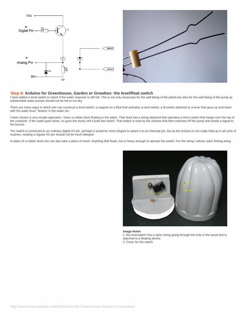
Step 6: Arduino for Greenhouse, Garden or Growbox: the level/float switchI have added a level switch to check if the water reservoir is still full. This is not only necessary for the well being of the plants but also for the well being of the pump assubmersible water-pumps should not be left to run dry.
There are many ways in which one can construct a level switch: a magnet on a float that activates a reed switch, a tlt switch attached to a lever that goes up and downwith the water level, 'feelers' in the water etc.
I have chosen a very simple approach. I have a rubber-duck floating in the water. That duck has a string attached that operates a micro switch that hangs over the top ofthe container. If the water goes down, so goes the ducky intil it pulls the switch. That switch is read by the Arduino that then switches off the pump and sends a signal tothe buzzer.
The switch is connected to an ordinary digital I/O pin. perhaps it would be more elegant to attach it to an interrupt pin, but as the Arduino is not really held up in all sorts ofroutines, reading a regular I/O pin should not be much delayed.
In place of a rubber duck one can also take a piece of wood. Anything that floats, but is heavy enough to operate the switch. For the string I advise nylon fishing string
Image Notes1. the leverswitch has a nylon string going through the hole in the wood and isattached to a floating device2. Cover for the switch

http://www.instructables.com/id/Arduino-for-Greenhouse-Garden-or-Growbox/
Step 7: Arduino for Greenhouse, Garden or Growbox: an alternative level switchIf you do not like a mechanical switch to signal the water-reservoir to be full, thee is a simple electronic solution:Hang two electrodes at the level of the water that you want to signal at. They may come up higher but not lower. Instead of two loose electrodes one could also use apiece of PCB with two tracks etched on it.
Feed those two electrodes to the circuit as depicted here.As long as the water is in contact with the electrodes, the transistor will receive a base current and open up. The collector will be pulled low and the arduino pin can detectthat.When the water-level falls below the electrodes, the transistor will not receive a base current anymore and close. The collector will therefore be high.
Mind you the Atmega 328 I/O pins have an internal pull up resistor and therefore a pull up transistor is not necessary in this circuit. To be sure though a 15k or 22k pull upresistor can be added between the collector and the +5 Volt line.
If you are short on I/O pins you could save a pin by using T1 not just to signal a low level to the processor, but also to directly steer the buzzer, or even to operate a Relayto switch off the pump, saving another I/O pin. But then again, most of the functions could probably be build with discrete components and the Atmega 328 has enoughI/Opins for this project

http://www.instructables.com/id/Arduino-for-Greenhouse-Garden-or-Growbox/
Step 8: Arduino for Greenhouse, Garden or Growbox: an alternative float switchDetermining whether the tank is empty is also possible with a reed switch as the figure shows: When the level drops to a specific amount, the magnet on the plunger willclose the switch and that will be signalling the Arduino that the pump should not be operated any more.
The disadvantage of this circuit is that eventually the reed switch will magnetize and go to a permanent closed position.Replacing the relatively cheap reed switch ofcourse will remedy that.
Step 9: Arduino for Garden, Greenhouse or Growbox: BuzzerI added a buzzer for signalling functions (mainly to signal that the water reservoir would be empty). I have used the CMB-06 buzzer from Star. My main consideration wasthat I had that buzzer laying around for years already. It is a very handy buzzer though because it is triggerable. The advantage of that is that I do not need an arduino pinto deliver the entire current needed for the audio signal, just some current for the trigger. Therefore I do not have to add a transistor to drive the Buzzer.
The + and - are conveniently connected to the power supply and the 'C' (=control) pin is connected via a 1k resistor to an arduino pin (in fact pin 9, that has PWM)
The maximum average (!) current through the buzzer is stated as 23 mA, which could be delivered by an Arduino pin, but the data sheet requires a current source ofabout 70 mA for peaks. That is above what an arduino can safely deliver. Feeding it directly from the power line and only the trigger current being delivered from anarduino pin solves that problem.

http://www.instructables.com/id/Arduino-for-Greenhouse-Garden-or-Growbox/
Step 10: Arduino for Greenhouse, Garden or Growbox: Solid State RelayThe 4 channel solid state relay is used to switch things like grow lights, a water pump a fan and a heater if necessary. It is almost a separate (albeit simple) project.The circuit needs to be build 4 times and I have a print design available.The circuit uses a 39MF22 solid state relay that simply needs a series resistor to limit the current. An LED shows whether the relay is active.Because it is connected to 220 Volts, I have constructed it on a separate PCB and it is in a different case.The 4 channels are controlled by digital pins 5,6,7 and 8 (Those are physicals pins 11-14 on the Atmega 328)Inductive loads like the fan and the pump, may need a snubber network (100 Ohm resistor and 100nF capacitor in series over the connection). As these inductive loadsare only low power I have left them out and have not experienced any problems.This part is fully described in an other instructable..
WarningThis device connects to a mains voltage. That can kill you. If you are not acquainted with working with high voltage circuits then do not build this
Step 11: Arduino for Greenhouse, Garden or Growbox: The LCDConsidering there are only so much I/O pins on the Atmega 328, I decided to add an LCD through an I2C interface
The library to use is the new LCD-library from Malpertida
The pin-out of the i2C interface is such that it will nicely fit most LCD's.It is possible to build your own I2C interface but i would advise against it. The one at Dealextreme is so cheap that building it yourself would be more expensive. Just thechip alone would probably already be more than the ca. 1.80 Euro, the entire ready built part costs at dealextreme.
I had considered to use Nokia 5110 display, but that needed some 4 or 5 data-pins. Surely I could use I2C either for that display or for the in and outputs, but by then Iwas already too far ahead to rewire everything for I2C for outputs and using I2C for the Nokia LCD is something I hadn’t figured out yet, but it is possible. The availablelibrary uses SPI -which is the fastest mode of communication- but as it is hard coded you would need to do some rewriting. therefore I opted for the regular LCD.Using a 5110 display over I2C may seriously slow down the screen build up to maybe a second. You will find some initial reading here

http://www.instructables.com/id/Arduino-for-Greenhouse-Garden-or-Growbox/
Step 12: Arduino for Greenhouse, Garden or Growbox: ConstructionIt is hard to give a description of the construction as a 'this is how you do it' as the way i constructed it depended on the material I had on hand: a slightly opaque plasticbox as a container and a piece of Archer PCB that after laying around for 10 years i finally wanted to put to some good use.
Therefore I can only give some general guidance.I started with building the power supply followed by the Atmel 328 processor. The latter somewhat in the middle of the PCB so there would be space on both sides forvarious components.
It is a good idea to check the workings of every part after you finish it, That way you avoid building the entire circuit and have no clue why it isn’t working (if worse comesto worst). So after i was done with the power supply, I checked it for 5 Volts. Then after I built the processor, I inserted a 328 chip that i had preprogrammed with a testprogram, Added the interface for the relay/ssr and that worked . Wired up the FTDI tested it etc.
In the mean time I had prepared the the LCD by soldering the I2C piggyback to it and tested that on an Arduino UNO so I knew it worked. Then I put it in the box as well.
Initially I had thought to make the connection to the ssri/relay by running a cable through the box, but i decided I wanted a connector. As this needed to be a 5 prongconnector and I already had made a female sil connector on the relay, i just opted for making a male sil connector on the box, using a lot of hot glue.
Don't make the mistake I made by mounting the DHT11 sensor on top of the casing.... especially if the LCD backlight is on, the temperature in and around the casing canrise, easily leading to a 2-5 degrees difference
http://www.instructables.com/id/Arduino-for-Greenhouse-Garden-or-Growbox/
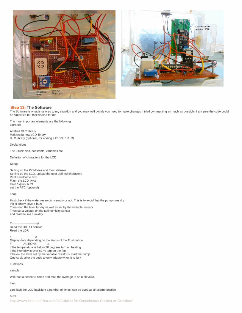
Step 13: The SoftwareThe Software is what is tailored to my situation and you may well decide you need to make changes. I tried commenting as much as possible. I am sure the code couldbe simplified but this worked for me.
The most important elements are the following:Libraries
Adafruit DHT libraryMalpertida new LCD libraryRTC library (optional, for adding a DS1307 RTC)
Declarations
The usual: pins, constants, variables etc
Definition of characters for the LCD
Setup
Setting up the PinModes and their statusesSetting up the LCD, upload the user defined charactersPrint a welcome textFlash the LCD twiceGive a quick buzzset the RTC (optional)
Loop
First check if the water reservoir is empty or not. This is to avoid that the pump runs dryIf it is empty, give a buzzThen read the level for dry vs wet as set by the variable resistorThen set a voltage on the soil humidity sensorand read he soil humidity
//--------------------------//Read the DHT11 sensorRead the LDR
//------------------------//Display data depending on the status of the Pushbutton//------------ACTIONS-----------//if the temperature is below 20 degrees turn on heatingif the Humidity is over 60 % turn on the fanIf below the level set by the variable resistor-> start the pumpOne could alter the code to only irrigate when it is light
Functions
sample
Will read a sensor 5 times and map the average to an 8 bit value
flash
can flash the LCD backlight a number of times. can be used as an alarm function
buzz

http://www.instructables.com/id/Arduino-for-Greenhouse-Garden-or-Growbox/
can sound the buzzer for a number of times
Step 14: The Software: code
/* measure soil moisture, if less than the set value switch pumpmeasure temperature, if less than set value, switch on heatingmeasure humidity, if higher than set value, switch on fan<a href="http://www.quickgrow.com/gardening_articles/fans_air_movement.html"> http://www.quickgrow.com/gardening_articles/fans_...</a>LCD commands:lcd.setBacklight(LED_OFF);lcd.noBacklight();lcd.clear();lcd.home();
*//*-----( Import needed libraries )-----*/#include <Wire.h>#include <LiquidCrystal_I2C.h> //Malpertida#include "RTClib.h" //Adafruit//DHT11 settings#include <dht.h>dht DHT;/*-----( Declare objects )-----*/// set the LCD address to 0x27 for a 20 chars 4 line display// Set the pins on the I2C chip used for LCD connections:// addr, en,rw,rs,d4,d5,d6,d7,bl,blpolLiquidCrystal_I2C lcd(0x27, 2, 1, 0, 4, 5, 6, 7, 3, POSITIVE); // Set the LCD I2C address/*-----(Declare RTC objects )------*/RTC_DS1307 RTC; //declare onject
/*-----( Declare pins )------*/byte moisturePin=0; //read soil mositurebyte levelPin= 1; //analogue Pin1 set level for irrigationbyte humidPin=2; //Physical pin4 Humidity sensorbyte lightPin=5; //Switches on lightbyte fanPin=6; //Switches fanbyte pumpPin =7; //Switches pumpbyte hotPin= 8; // Switches heaterbyte buzPin=9; // Switches buzzerbyte emptyPin=3; //digital Pin3 guards waterlevelbyte spikePin=12; //Digital Pin12 Extra for intermittent switching of spikebyte LDRPin=3;// analog pin for LDRbyte PushButton=4; // PushButtonbyte SwitchButton=3;// Make Switchbyte push=0;byte sButton=0;#define DHT11_PIN humidPin/* Variable setting */unsigned int moist=0; //will contain the soil moisture levelunsigned int irrigate=0; //sets level for irrigation in case no potmeterbyte level=0;int c;// contains the temperature reading// these constants won't change:const int sensorMin = 40; // LDR minimum, discovered through experimentconst int sensorMax = 1012; // LDR maximum, discovered through experimentbyte light; // value for LDR reading// Create a set of new characters
const uint8_t charBitmap[][8] = {
{ 0xc, 0x12, 0x12, 0xc, 0, 0, 0, 0 } ,
{ 0x6, 0x9, 0x9, 0x6, 0, 0, 0, 0 } ,
{ 0x0, 0x6, 0x9, 0x9, 0x6, 0, 0, 0x0 } ,
{ 0x0, 0xc, 0x12, 0x12, 0xc, 0, 0, 0x0 } ,
{ 0x0, 0x0, 0xc, 0x12, 0x12, 0xc, 0, 0x0 } ,
{ 0x0, 0x0, 0x6, 0x9, 0x9, 0x6, 0, 0x0 } ,
{ 0x0, 0x0, 0x0, 0x6, 0x9, 0x9, 0x6, 0x0 } ,
{ 0x4,0x4,0x4, 0x4, 0x15, 0xE,0x4,0x0 }};/// -------- end creation--------------//The following function, "setup", must always be presentvoid setup(){ Serial.begin(115200);
http://www.instructables.com/id/Arduino-for-Greenhouse-Garden-or-Growbox/
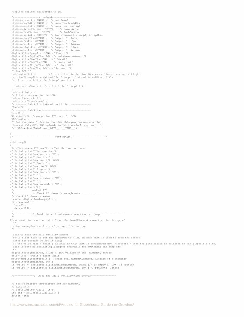
//upload defined characters to LCD
//---------------end upload---------------- pinMode(levelPin,INPUT); // set level pinMode(humidPin,INPUT); // measures humidity pinMode(emptyPin,INPUT); // measures reservoir pinMode(SwitchButton, INPUT); // make Switch pinMode(PushButton, INPUT); // PushButton pinMode(spikePin,OUTPUT); // for alternative supply to spikes pinMode(pumpPin,OUTPUT); // Output for Relay pinMode(fanPin, OUTPUT); // Output for fan pinMode(hotPin, OUTPUT); // Output for heater pinMode(lightPin, OUTPUT);// Output for light pinMode(buzPin, OUTPUT); // Output for buzzer digitalWrite(pumpPin, LOW);// Pump off digitalWrite(spikePin, LOW);// moisture sensor off digitalWrite(fanPin,LOW); // fan Off digitalWrite(hotPin,LOW); // heater off digitalWrite(lightPin, LOW); // light Off digitalWrite(buzPin, LOW); // buzzer off /* Now LCD */ lcd.begin(16,2); // initialize the lcd for 20 chars 4 lines, turn on backlight int charBitmapSize = (sizeof(charBitmap ) / sizeof (charBitmap[0])); for ( int i = 0; i < charBitmapSize; i++ ) { lcd.createChar ( i, (uint8_t *)charBitmap[i] ); } lcd.backlight(); // Print a message to the LCD. lcd.setCursor(0, 0); lcd.print("Greenhouse"); // ------- Quick 2 blinks of backlight ------------- flash(2); // ------- Quick buzz-------------------------------- buzz(1); Wire.begin(); //needed for RTC, not for LCD RTC.begin(); /* Set the date / time to the time this program was compiled. Comment this OUT, AND upload, to let the clock just run. */ // RTC.adjust(DateTime(__DATE__, __TIME__));
}/*----------------------------(end setup )---------------------*/
void loop(){ DateTime now = RTC.now(); //Get the current data// Serial.print("The year is ");// Serial.print(now.year(), DEC);// Serial.print(" Month = ");// Serial.print(now.month(), DEC);// Serial.print(" Day = ");// Serial.print(now.day(), DEC);// Serial.print(" Time = ");// Serial.print(now.hour(), DEC);// Serial.print(':');// Serial.print(now.minute(), DEC);// Serial.print(':');// Serial.print(now.second(), DEC);// Serial.println(); //------------end of RTC // ---------- 1. Check if there is enough water ------------- // check if there is water level= digitalRead(emptyPin); if (level==0) { buzz(3); delay(500); } //------------2. Read the soil moisture content/switch pump---------------- /*First read the level set with P1 on the levelPin and store that in 'irrigate' */ irrigate=sample(levelPin); //average of 5 readings /*
Then we read the soil humidity sensor. We'll first have to set the spikePin to HIGH, in case that is used to feed the sensor. After the reading we set it back) If the value read ('moist') is smaller than what is considered dry ('irrigate') then the pump should be switched on for a specific time. This is done by indicating a higher treshhold for switching the pump off */ digitalWrite(spikePin, HIGH);// put voltage on the humidity sensor delay(100); //wait a short while moist=sample(moisturePin); //read soil humiditySensor, average of 5 readings digitalWrite(spikePin, LOW); if (moist <= irrigate) digitalWrite(pumpPin, level);// if empty a 'LOW' is written if (moist >= irrigate+5) digitalWrite(pumpPin, LOW); // prevents Jitter
//-------------3. Read the DHT11 humidity/temp sensor-----------------
// now we measure temperature and air humidity // READ DATA // Serial.print("DHT11, \t"); int chk = DHT.read11(DHT11_PIN); switch (chk) {

http://www.instructables.com/id/Arduino-for-Greenhouse-Garden-or-Growbox/
case DHTLIB_OK: // Serial.print("OK,\t"); break; case DHTLIB_ERROR_CHECKSUM: Serial.print("Checksum error,\t"); break; case DHTLIB_ERROR_TIMEOUT: Serial.print("Time out error,\t"); break; default: Serial.print("Unknown error,\t"); break; }
//-------------4. Read LDR ---------------------------------------- light=Map(LDRPin);
/* ------------------Actions -------------------*/
//-------------5. DISPLAY DATA ------------------------------------ /* Display data on LCD */ push=digitalRead(PushButton); if (push==1) // pushbutton not pressed { lcd.clear(); lcd.setCursor(0, 0); //set cursor on first line (line 0) lcd.print("Temp. : "); lcd.print((float)DHT.temperature, 0); lcd.print (char(1)); // prints degree sign lcd.print("C"); lcd.print(" "); lcd.print (char(7)); lcd.setCursor(0,1); //set cursor on 2nd line lcd.print("Humidity: "); lcd.print((float)DHT.humidity, 0); lcd.print("%"); lcd.print(" "); delay(1000); // wait for one second and then print the soilmoisture lcd.setCursor(0,1); lcd.print ("Irr. Level: "); lcd.print(irrigate); lcd.setCursor(0,0); lcd.print("Moisture: "); lcd.print(moist); lcd.print(" ");
} if (push==0) // pushbutton pressed { lcd.clear(); lcd.setCursor(0,0); lcd.print("licht: "); lcd.print(light); lcd.print(" "); lcd.setCursor(0,1); lcd.print("licht niv.: "); lcd.print(analogRead(LDRPin)); //buzz(1); }
// ---------------5. Action on temperature ------ //if ((DHT.temperature,0) =<20) c=(DHT.temperature); if (c<=20) //Serial.println(c); {// switch on heating digitalWrite(hotPin,HIGH); } else { digitalWrite(hotPin,LOW); } //--------------6. Action on Humidity ----------- if (DHT.humidity >=50) { // zet ventilator aan digitalWrite(fanPin, HIGH); } else { digitalWrite(fanPin,HIGH); }
delay(1000);
//end dht //end loop}//------- End of Main program-----------////-------- Start of functions------------int sample(int z)/* This function will read the Pin 'z' 5 times and take an average.Afterwards it will be mapped to 8 bits by dividing by 4Could ofcourse immediately divided by 20 but this way it is easier to follow the program*/

http://www.instructables.com/id/Arduino-for-Greenhouse-Garden-or-Growbox/
{ byte i; int sval = 0; for (i = 0; i < 5; i++){ sval = sval + analogRead(z);// sensor on analog pin 'z' } //sval = sval / 5; // average //sval = sval / 4; // scale to 8 bits (0 - 255) sval=sval / 20; return sval;}//------------- Flash the backlight a number of times--------void flash(byte y){ byte j; for (j=0; j<y;j++) { lcd.backlight(); delay(250); lcd.noBacklight(); delay(250); } lcd.backlight(); // finish with backlight on return;}// This function will sound the buzzer "u" timesvoid buzz(byte u){ byte k; for (k=0; k<u;k++) { digitalWrite(buzPin, HIGH); delay(250); digitalWrite(buzPin, LOW); delay(250); } return;}// This function will blink an LED a number of times for a specific durationvoid ledblink(int times, int lengthms, int pinnum){ for (int x=0; x<times;x++){ digitalWrite(pinnum, HIGH); delay (lengthms); digitalWrite(pinnum, LOW); delay(lengthms); }}// This function maps the LDR reading into nrs 0-3int Map(byte sens) { // read the sensor: int sensorReading = analogRead(sens); // map the sensor range to a range of four options: int range = map(sensorReading, sensorMin, sensorMax, 0, 3); // do something different depending on the // range value: switch (range) { case 0: // // Serial.println("dark"); lcd.backlight(); break; case 1: // // Serial.println("dim"); lcd.backlight(); break; case 2: // // Serial.println("medium"); lcd.noBacklight(); break; case 3: // // Serial.println("bright"); lcd.noBacklight(); break; } return range;}
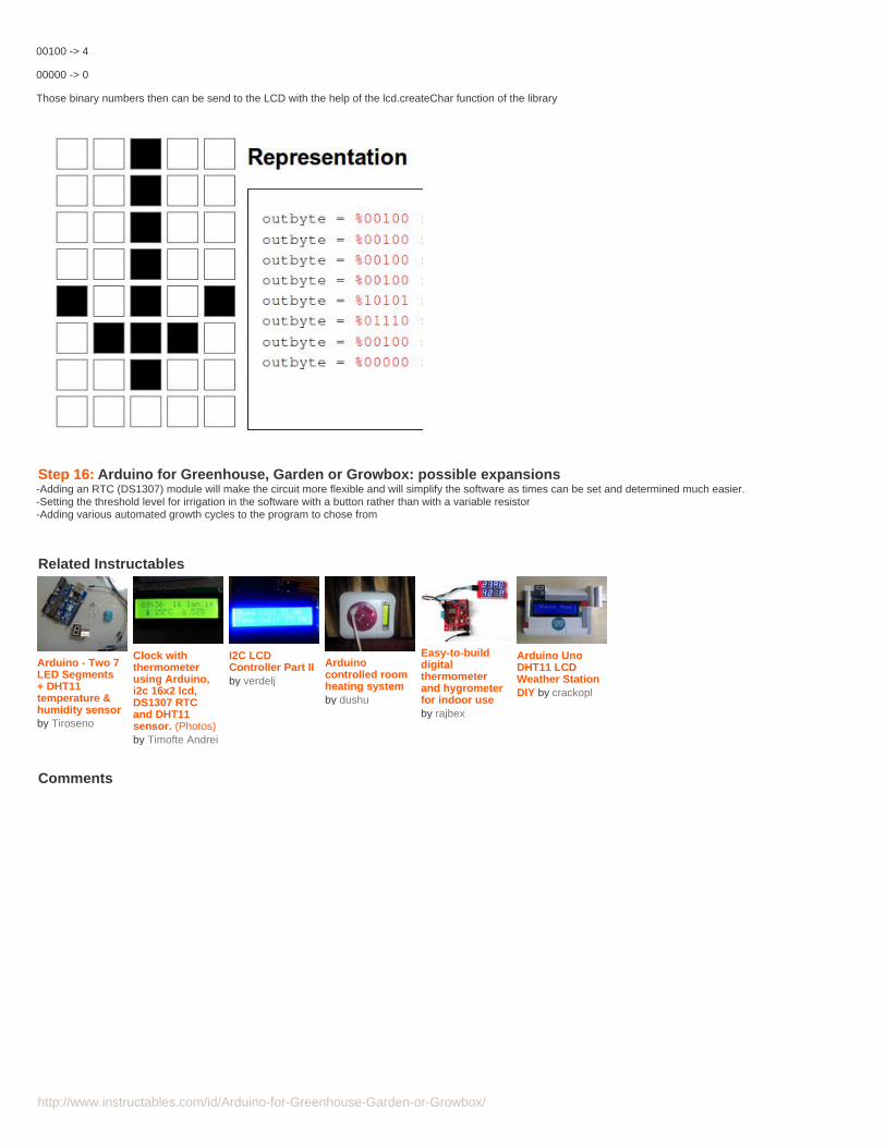
Step 15: The Software: special charactersAs I wanted a proper 'degree' character to use for Celsius, I was inluck as the LCD allows for definition of 8 user characters. Decided to make an arrow as well as visual indication of an empty tank. With regard to the definition ofcharacters for the LCD, that is simple to do with Malpartida's library On page http://custom-character.appspot.com/ you will find a 5x8 template that you can use to designyour own characters. For the Arrow I designed, the pattern was as follows (white segment is '0', black segment is '1'). With the help of a binary - hex converter, one canthen find the hex equivalent of the binary number
00100 -> 4
00100 -> 4
00100 -> 4
00100 -> 4
10101 -> 15
01110 -> E
http://www.instructables.com/id/Arduino-for-Greenhouse-Garden-or-Growbox/
00100 -> 4
00000 -> 0
Those binary numbers then can be send to the LCD with the help of the lcd.createChar function of the library
Step 16: Arduino for Greenhouse, Garden or Growbox: possible expansions-Adding an RTC (DS1307) module will make the circuit more flexible and will simplify the software as times can be set and determined much easier.-Setting the threshold level for irrigation in the software with a button rather than with a variable resistor-Adding various automated growth cycles to the program to chose from
Related Instructables
Arduino - Two 7LED Segments+ DHT11temperature &humidity sensorby Tiroseno
Clock withthermometerusing Arduino,i2c 16x2 lcd,DS1307 RTCand DHT11sensor. (Photos)by Timofte Andrei
I2C LCDController Part IIby verdelj
Arduinocontrolled roomheating systemby dushu
Easy-to-builddigitalthermometerand hygrometerfor indoor useby rajbex
Arduino UnoDHT11 LCDWeather StationDIY by crackopl
Advertisements
Comments