Approved Equipment List (AEL) Section 00500 - Mobiliza
281
Approved Equipment List (AEL) Section 00500 - Submittals Section 00510 - Operation and Maintenance Data Section 01000 - Mobilization Section 01005 - Demolition Section 01100 - Site Preparation Section 01140 - Dewatering Section 01230 - Excavation and Backfill Section 01240 - Trench Excavation Safety Section 01350 - Hydrotesting and Disinfection Section 01410 - Testing Laboratory Services Section 01500 - Concrete for Structures Section 01510 - Concrete Admixtures Section 01600 - Concrete Encasement, Cradles, Caps and Seals Section 01700 - Site Restoration Section 01720 - Gravel or Chip Seal Driveway Section 02300 - Directional Drilling Section 02400 - Valves and Appurtenances Section 02440 - Combination Air Release Valve Section 02500 - Abandonment of Water Infrastructure Section 02640 - Fire Hydrant Assembly Section 02650 - PVC For Water Mains Section 02660 - Ductile Iron Pipe Section 02665 - HDPE Pipe Section 02670 - Ductile Iron Fittings Section 02675 - Pipe Encasement Section 02680 - Joint Restraints and Thrust Blocking Section 02700 - Water Main Tie-Ins Section 02710 - Water Services Section 03000 - Bypass Pumping Section 03100 - Sanitary Sewer Main Section 03120 - Sewer Services Laterals Section 03200 - Sanitary Sewer Manholes Section 03210 - Frames, Grates, Rings, and Covers Section 03220 - Bulkheads Section 03400 - Sanitary Sewer Main TV Inspection Section 03410 - Sanitary Sewer Testing 5/10/2022 3:52 PM TECHNICAL SPECIFICATIONS
-
Upload
khangminh22 -
Category
Documents
-
view
2 -
download
0
Transcript of Approved Equipment List (AEL) Section 00500 - Mobiliza

Approved Equipment List (AEL)Section 00500 - SubmittalsSection 00510 - Operation and Maintenance DataSection 01000 - MobilizationSection 01005 - DemolitionSection 01100 - Site PreparationSection 01140 - DewateringSection 01230 - Excavation and BackfillSection 01240 - Trench Excavation SafetySection 01350 - Hydrotesting and DisinfectionSection 01410 - Testing Laboratory ServicesSection 01500 - Concrete for StructuresSection 01510 - Concrete AdmixturesSection 01600 - Concrete Encasement, Cradles, Caps and SealsSection 01700 - Site RestorationSection 01720 - Gravel or Chip Seal DrivewaySection 02300 - Directional DrillingSection 02400 - Valves and AppurtenancesSection 02440 - Combination Air Release ValveSection 02500 - Abandonment of Water InfrastructureSection 02640 - Fire Hydrant AssemblySection 02650 - PVC For Water MainsSection 02660 - Ductile Iron PipeSection 02665 - HDPE PipeSection 02670 - Ductile Iron FittingsSection 02675 - Pipe EncasementSection 02680 - Joint Restraints and Thrust BlockingSection 02700 - Water Main Tie-InsSection 02710 - Water ServicesSection 03000 - Bypass PumpingSection 03100 - Sanitary Sewer MainSection 03120 - Sewer Services LateralsSection 03200 - Sanitary Sewer ManholesSection 03210 - Frames, Grates, Rings, and CoversSection 03220 - BulkheadsSection 03400 - Sanitary Sewer Main TV InspectionSection 03410 - Sanitary Sewer Testing
5/10/2022 3:52 PM
TECHNICAL SPECIFICATIONS

Section 03500 - WW Design CriteriaSection 03600 - WWTPSection 04000 - Electrical Design CriteriaADOPTED TxDOT SPECIFICATIONSTxDOT Item 00164 - Seeding for Erosion ControlTxDOT Item 00169 - Soil Retention BlanketsTxDOT Item 00340 - Dense-Graded Hot-Mix Asphalt (Small Quantity)TxDOT Item 00506 - Sediment Control Specs
5/10/2022 3:52 PM

Last Updated: 11/02/2021
Crystal Clear SUD
Approved Equipment List (AEL)
Below is a list of Crystal Clear SUD (CCSUD) approved brands for use in the Distribution and Collection
system.
Brands
Air Relief Valves: Empire, Valmatic, Apco, Mueller Company.
Corporation Stops: Ford
Curb Stops: Ford
Fire Hydrants: American, Mueller Company, EJ.
Gate Valves: Mueller Company, American, EJ.
Pipe Type: High Density Polyethylene, C900 Series.
Restraining Joints: EBAA Iron Inc. – Megalug
Saddles: Smith Blair, Ford, Mueller
Tapping Sleeves: Smith Blair, Ford, Mueller, JCM Industries
Tapping Valves: American, Mueller
Meters: Kamstrup
Meter Boxes: DFW Plastics, NDS Meter Boxes.
VFD: Yaskawa
Vertical Turbine Pump: HydroFlo
Motors: TECO or US Motor
Any equipment to be installed in the CCSUD Distribution or Collection systems must come from
the list above. Any equipment installed that is not listed above must be approved by the CCSUD
inspector or a CCSUD Manager or the installation is subject to a failed inspection until the correct
brand can be installed. If you have any questions about these procedures please contact the CCSUD
Inspector.

SUBMITTALS 00500 - 1 REV. 02/2022
SECTION 00500
SUBMITTALS
PART 1 - GENERAL
1.1 SCOPE
A. This Section includes administrative and procedural requirements for submittals required for performance of the Work, including the following:
1. Contractor’s construction schedule.
2. Submittal schedule.
3. Shop drawings.
4. Product data.
5. Quality assurance and quality control submittals, including calculations, mix designs and substantiating test results.
B. Each item provided shall be provided and submitted in PDF format only.
C. Submittals shall meet requirements within this Section. Submittals that don’t allow for thorough review will result in rejection at the Contractor’s responsibility.
PART 2 – EXECUTION
2.1 SUBMITTAL PROCEDURES
A. Coordination
1. Coordinate preparation and processing of submittals with performance of construction activities. Transmit each submittal sufficiently in advance of performance of related construction activities to avoid the need to delay installation because of the time required to process submittals. Allow sufficient time for submittal review, including times for resubmittals.
2. Coordinate each submittal with fabrication, purchasing, testing, delivery, other submittals, and related activities that require sequential activity.
3. Coordinate transmittal of different types of submittals for related elements of the Work so processing will not be delayed by the need to review submittals or resubmittals concurrently. The Engineer reserves the right to withhold action on a submittal requiring coordination with other submittals until all related submittals are receives.
B. Processing
1. Allow fourteen (14) calendar days for initial review. Allow additional time if the Engineer must delay processing to permit coordination with subsequent submittals.
2. If an intermediate submittal is necessary, process the same as the initial submittal.

SUBMITTALS 00500 - 2 REV. 02/2022
3. Allow fourteen (14) calendar days for processing each resubmittal.
4. No extension of Contract Time will be authorized because of failure to transmit submittals to the Engineer sufficiently in advance of the Work to permit processing.
5. The Contractor is to review shop drawings, product data and samples prior to submission to determine and verify the following.
a. Field measurements
b. Field construction criteria
c. Conformance with the Specifications
6. Each shop drawing, working drawing sample and catalog data submitted by the Contractor shall have the following Certification Statement affixed to it, signed by the Contractor:
a. “By this submittal, I hereby represent that I have determined and verified all field measurements, field construction criteria, materials, dimensions, catalog numbers and similar data and I have checked and coordinated each item with other applicable approved shop drawings and all Contract Document requirements.”
b. All Submittals without the Certification Statement will not be reviewed and will be returned to the Contractor for proper submission.
7. No portion of the Work requiring a shop drawing, sample or catalog data is to be started nor any materials be fabricated or installed prior to the approval or qualified approval of such item. Fabrication performed, materials purchased, or on-site construction accomplished which does not conform to the approved shop drawings and data to be at Contractor’s risk. The Owner shall not be liable for any expense or delay due to corrections or remedies to accomplish conformity.
8. Notify the Engineer in writing, at the time of submittal, of any deviations in the submittal(s) from the requirements as specified within the Contract Documents.
9. The review and approval of submittals by the Engineer does not relieve the Contractor from his responsibility about the fulfillment of the terms of the Contract. All risks of error and omission in submittals prepared by Contractor are assumed by the Contractor and the Engineer shall have no responsibility, therefore.
C. Submittal Preparation: Place a permanent label or title block on each submittal for identification. Indicate the name of the entity that prepared each submittal on the label or title block.
1. Provide a space on the label or beside the title block on Shop Drawings to record the Contractor’s review and approval markings and the action taken.
2. Include the following applicable information on the label for processing and recording action taken.
a. Project name.

SUBMITTALS 00500 - 3 REV. 02/2022
b. Date.
c. Name and address of the Contractor.
d. Name and address of the supplier.
e. Name of the manufacturer.
f. Number and title of appropriate Specification Section.
g. Drawing number and detail references, as appropriate.
D. Submittal Transmittal: Package each submittal appropriately for transmittal and handling. Transmit each submittal from the Contractor to the Engineer using a transmittal form. The Engineer will not accept submittals received from sources other than Contractor.
1. Number transmittals in sequence for each Series of the Specifications thus: SD-xxxx. The number after the dash indicates the Section of the Specification. For example, the first item submitted related to Section 01230 – Excavation and Backfill would be labeled SD-01230. Identify resubmittals with numbering identification such as SD-xxxx-1, SD-xxxx-2, etc. For example, the first resubmittal submitted for Section 01230 – Excavation and Backfill would be labeled SD-01230-1.
2. On the transmittal, record relevant information and requests for data. On the form, or separate sheet, record deviations from Contract Document requirements, including variations and limitations. Include Contractor's certification that information complies with the Drawing’s requirements.
2.2 CONSTRACTOR’S PROGRESS SCHEDULE
A. Submit the Progress Schedule in accordance with the Contract Documents under the General Conditions.
2.3 SCHEDULE OF VALUES
A. Submit the Schedule of Values in accordance with the Contract Documents under the General Conditions.
2.4 SUBMITTAL SCHEDULE
A. Concurrently with the development of the Contractor’s Progress Schedule, prepare a complete schedule of submittals. Submit the initial Submittal Schedule along with the Progress Schedule, at, or prior to, the Pre-construction Conference. Provide copies to Engineer, Owner, subcontractors, and other parties required to comply with submittal dates indicated.
1. Submit the Submittal Schedule in accordance with the Contract Documents under the General Conditions.
2. Coordinate Submittal Schedule with the list of subcontractors, Schedule of Values, and the list of products as well as the Contractor’s Progress Schedule.
B. Schedule Updating: Revise the schedule after each meeting or activity where revisions have been recognized or made. Issue the updated schedule

SUBMITTALS 00500 - 4 REV. 02/2022
concurrently with the report of each meeting, or as requested by the Engineer.
2.5 SHOP DRAWINGSA. Submit newly prepared information drawn accurately to scale. Highlight, circle,
or otherwise indicate deviations from the Specifications. Do not reproduce Contract Documents or copy standard information as the basis of Shop Drawings. Standard information prepared without specific reference to the Drawings is not a Shop Drawing.
B. Shop Drawings include fabrication and installation Drawings, setting diagrams, schedules, patterns, templates, and similar drawings. Include the following information:
1. Dimensions;
2. Identifications of products and materials include by sheet and detail number;
3. Compliance with specified standards;
4. Notation of coordination requirements; and
5. Notation of dimensions established by field measurement.
6. Sheet size: Except for templates, patterns, and similar full-size Drawings, submit Shop Drawings on sheets 8-1/2 inches by 11 inches.
7. Do not use Shop Drawings without an appropriate stamp indicating action taken.
2.6 PRODUCT DATAA. Collect product data into a single submittal for each element of construction or
system. Product data includes printed information, such as manufacturer’s
installation instructions, catalog cuts, standard color charts, roughing-in diagrams and templates, standard wiring diagrams, applicable certifications, and performance curves.
1. Mark each copy to show applicable choices and options. Where printed product data includes information on several products that are not required, mark copies to indicate the applicable information. Include the following information:
a. Manufacturer’s printed recommendations;
b. Compliance with trade association standards;
c. Compliance with recognized testing agency standards;
d. Application of testing agency labels and seals;
e. Notation of dimensions verified by field measurement; and
f. Notation of coordination requirements.
2. Do not submit product data until compliance with requirements of the Contract Documents has been confirmed.
2.7 QUALITY ASSURANCE AND QUALITY CONTROL SUBMITTALSA. Submit quality assurance and quality control submittals, including design data,

SUBMITTALS 00500 - 5 REV. 02/2022
certifications, manufacturer's instructions, manufacturer's field reports, materials test results, field testing and inspection reports, and other quality-control submittals as required under other Sections of the Specifications.
B. Certifications: Where other Sections of the Specifications require certification that a product, material, or installation complies with specified requirements, submit a
certification from the manufacturer or responsible Engineer certifying compliance with specified requirements.
1. Mark Signature: Certification shall be signed by an officer of the corporation or other individual authorized to sign documents on behalf of the company.
C. Calculations: When required in the Specifications, calculations shall be prepared and stamped by a Professional Engineer registered in the State of Texas.
D. Concrete, Controlled Low Strength Material, Asphalt Stabilized Base and Hot Mix Asphaltic Concrete Mix Designs and Substantiating Test Data. Requirements for submittal of mix designs and substantiating test data are specified in the applicable Technical Specification Section. Each separate batch plant supplying ASB, HMAC and/or concrete shall submit mix designs to the Engineer for review.
2.8 ENGINEER’S ACTION A. Except for submittals, for the record, or for information where action and return is
not required, the Engineer will review each submittal, mark to indicate action taken, and return within the time frame specified in Paragraph 2.1.B of this Section.
B. Action Stamp: The Engineer will provide its Submittal Review template and mark the stamp appropriately to indicate the action taken, as follows:
1. Engineer’s Review
a. Approved
b. Approved as Noted
c. Rejected
2. Required Response
a. Confirm
b. Revise
c. Resubmit
C. Unsolicited Submittals: The Engineer will return unsolicited submittals to the sender without action.
END OF SECTION

OPERATION AND MAINTENANCE DATA 00510-1 REV. 05/2021
SECTION 00510
OPERATION AND MAINTENANCE DATA
PART 1 – GENERAL
1.1 SCOPE
A. Provide operation and maintenance data in the form of instructional manuals for use by the OWNER'S personnel for:
1. All equipment and systems as specified in the respective specifications for that equipment. May include but are not limited to:
a. Pumps
b. Motors
c. Valves (Gate, Air Release, Check, Butterfly, etc.)
d. Flowmeters
e. Electrical Interface Items (SCADA, Telemetry, etc.)
f. Electrical Switches, Relays, Transmitters, Displays, Cabinets
B. Definition: Operation and Maintenance Data
1. The term "operation and maintenance data" includes all product related information and documents which are required for preparation of the plant operation and maintenance manual. It also includes all data which must accompany said manual as directed by current regulations of any participating government agency.
2. Operation and Maintenance Data shall include, but may not be limited to:
a. Name, address and phone number of manufacturers, manufacturer's local service representative, and Subcontractor or installer.
b. Recommended spare parts lists and local sources of supply for parts.
c. Copy of warranty bond and service contract as applicable as well as contact info for warranty claims.
� For every piece of equipment that has its own warranty
� For warranty on workmanship of the entire project as agreed to by the Contractor in contract documents.
d. Complete, detailed written operating instructions for each product or piece of equipment including equipment function; operating characteristics; limiting conditions; operating instructions for startup, normal, and emergency conditions; regulation and control; and shutdown.
e. Complete, detailed written preventive maintenance instructions as defined below.

OPERATION AND MAINTENANCE DATA 00510-2 REV. 05/2021
f. Written explanations of all safety considerations relating to operation and maintenance procedures.
g. Copy of all approved Shop Drawings.
C. Definition: Preventive Maintenance Instructions:
1. The term "preventive maintenance instructions" includes all information and instructions required to keep a product or piece of equipment properly lubricated, adjusted and maintained so that the item functions economically throughout its full design life. This shall include, but are not limited to the following:
a. A written explanation with illustrations for each preventive maintenance task.
b. Recommended schedule for execution of preventive maintenance
c. Trouble shooting instructions.
d. List of required maintenance tools and equipment.
D. Submittals:
1. General: Submit operations and maintenance data to the ENGINEER within 90 days after approval of Shop Drawings.
a. Submit a full Operations and Maintenance Manual at project close to include all pieces as described in this specification combined into one complete document.
2. Number of Copies: 2 physical copy (compiled into one or more binders as specified below) and 2 USB sticks
3. Format Requirements:
a. Use 8½-inch by 11-inch paper of high rag content and quality. Larger drawings or illustrations are acceptable if neatly folded to the specified size in a manner which will permit easy unfolding without removal from the binder. Provide reinforced punched binder tab or provide fly-leaf for each product.
b. All text must be legible typewritten, machine printed originals or high quality copies of same.
c. Each page shall have a binding margin of approximately 1½ inches and be punched for placement in a three ring loose leaf or triple post binder. Provide binders. Identify and organize each binder with the following:
� Title "OPERATING AND MAINTENANCE INSTRUCTIONS".
� Title of Project.
� Identity of equipment or structure as applicable.
� Identity of general subject matter covered.
� Expected Organization
� Table of Contents

OPERATION AND MAINTENANCE DATA 00510-3 REV. 05/2021
� Contacts for Contractor and each piece of equipment as well as contact information for warranty claims (if different)
� Operation / Installation / Shop Drawings / Preventive Maintenance Data per piece of equipment
d. Use dividers and indexed tabs between major categories of information such as operating instructions, preventive maintenance instructions, or other. When necessary, place each major category in a separate binder.
e. Provide a table of contents for each binder if more than one is required.
f. Identify products by their functional names in the table of contents and at least once in each chapter or Section. Thereafter, abbreviations and acronyms may be used if their meaning is explained in a table in the back of each binder. Use of model or catalog numbers or letters for identification is not acceptable.
g. CONTRACTOR shall furnish required O&M Manuals with complete information and accuracy in order to achieve required approval within two submittals or be subject to back charge fees from the OWNER.
PART 2 – PRODUCTS
Not Used.
PART 3 – EXECUTION
Not Used.
PART 4 – MEASUREMENT AND PAYMENT
4.1 MEASUREMENT: Unless shown on the construction plans or called out within the technical specifications as a pay item, operation and maintenance data preparation activities described herein are for informational purposes only. No separate measurement of operation and maintenance data preparation activities will be made by the Contractor for this Work.
4.2 PAYMENT: Unless specified as a pay item, operation and maintenance data preparation
activities performed and materials furnished in accordance with this Specification Section
will not be paid for directly but are considered to be subsidiary to the pertinent items
associated with construction activities. No separate payment will be made to the
Contractor for this Work.
END OF SECTION

MOBILIZATION 01000-1 REV. 02/2020
SECTION 01000
MOBILIZATION
PART 1 - GENERAL
1.1 SCOPE
A. The Contractor shall mobilize all materials, labor, equipment, and incidentals in preparation for beginning, with subsequent cleanup, of Work performed under the Contract.
B. Work includes, but is not necessarily limited to: mobilization of personnel, equipment, supplies, and incidentals to the project site; establishment of the Contractor’s onsite facilities, safety precautions, scaffolding and/or lifting methods; any other facilities necessary for work on the project; construction submittals; fees for bonds and insurance; obtaining all required permits; coordination with the Owner for the scheduling of all construction activities; disposal and hauling of cleared, grubbed material, debris, surplus excavated material including all existing pipe and appurtenances to be abandoned (where specified in the Drawings), tree protection, coordinating with other utilities for locating buried cables and other utilities during construction, repairing and replacing fences, cleaning and, any other items required for beginning work, but not included explicitly in other bid items.
PART 2 – PRODUCTS
Not Used.
PART 3 - EXECUTION
Not Used.
PART 4 – MEASUREMENT AND PAYMENT
4.1 MEASUREMENT: The lump sum price for Mobilization shall not exceed ten percent (10%) of the subtotal of all other base bid items, excluding this item.
4.2 PAYMENT: Partial payments directed towards the “Lump Sum” bid for Mobilization will be structured as follows:
Payment for this item will be payable will be limited to 75% of the contract lump sum price in the first partial payment; and, the balance payable after cleanup and demobilization.
END OF SECTION

DEMOLITION 01005-1 REV. 03/2022
SECTION 01005
DEMOLITION
PART 1 - GENERAL
1.1 SCOPE
A. The Contractor shall provide all labor, materials, equipment, and incidentals as shown, specified, and required for demolitions, removal, and disposal of Work.
B. Included, but not limited to: demolition and removal of existing materials, equipment, or demolition work necessary to install the new Work as shown and specified and to connect same with existing work in an approved manner. Demolition includes structural concrete, foundations, walls, doors, windows, structural steel, metals, roofs, masonry, attachments, appurtenances, piping, electrical and mechanical equipment, paving, curbs, walks, fencing, and similar existing facilities.
C. Demolitions and removals which may be specified under other Sections
shall conform to requirements of this Section.
1.2 RELATED SECTIONS
A. Section 01100, Site Preparation
1.3 SUBMITTALS
A. Schedule: Submit for approval proposed methods, equipment, and
operating sequences. Include coordination for shut-off, capping, temporary
services, continuation of utility services, and other applicable items to ensure
no interruption of Owner’s operations.
1.4 JOB CONDITIONS
A. Protection:
1. Perform all demolition and removal Work to prevent damage or injury to structures, occupants thereof and adjacent features which might result from falling debris or other causes, and so as not to interfere with the use, and free and safe passage to and from adjacent structures.
2. Closing or obstructing of roadways, sidewalks, and passageways adjacent to the Work by the placement or storage of materials will not be permitted, and all operations shall be conducted with a minimum interference to traffic on these ways.
3. Erect and maintain barriers, lights, sidewalk sheds, and other necessary protective devices.

DEMOLITION 01005-2 REV. 03/2022
4. Repair damage to facilities to remain, or to any property belonging to the Owner or occupants of the facilities.
5. Protect all reference points, benchmarks and monuments from dislocation or damage. Replace or repair immediately any points damaged, destroyed, or dislocated. Protect and maintain all conduits, drains, inlets, sewers, pipes, and wires that are to remain on the property.
B. Scheduling:
1. Carry out operations to avoid interference with Owner’s operations and work in the existing facilities.
C. Existing Conditions
1. Do not work or store materials or equipment on public or adjacent property.
2. Do not allow material and debris to accumulate on the site.
D. Damage:
1. Contractor shall be responsible for repair of any damage to streets, curbs or other property not specifically called for as an item to be demolished.
E. Notification:
1. At least 48 hours prior to commencement of a demolition or removal, notify Engineer in writing of proposed schedule therefor. Owner will inspect the existing equipment and mark for identification those items which are to remain the property of the Owner. Do not start removals without the permission of the Engineer and Owner.
F. Explosives:
1. No explosives will be used for demolition.
PART 2 - PRODUCTS (NOT USED)
PART 3 – EXECUTION
3.1 GENERAL
A. All materials and equipment removed from existing work shall become the property of Contractor, except for those which Owner has identified and marked for his use, in accordance with the Summary of Work. All materials and equipment marked by the Owner to remain his shall be carefully removed by the Contractor, so as not to be damaged, and shall be cleaned and stored on or adjacent to the site in a protected place specified by the Engineer or loaded onto trucks provided by the Owner.
B. Contractor shall dispose of all demolition materials, equipment, debris, and all other items not marked by the Owner to remain as his, off the site and in conformance with all existing applicable laws and regulations.

DEMOLITION 01005-3 REV. 03/2022
C. Surfaces of walls, floors, ceilings, or other areas which are exposed by any of the removals specified herein, and which will remain as architecturally finished surfaces shall be repaired and re-finished by the Contractor with the same or matching materials as the existing adjacent surface or as may be otherwise approved by the Engineer.
D. Pollution Controls: Use water sprinkling, temporary enclosures, and other suitable methods to limit the amount of dust and dirt rising and scattering in the air to the lowest practical level. Comply with governing regulations pertaining to environmental protection.
1. Do not use water when it may create hazardous or objectionable conditions such as ice, flooding, and pollution.
2. Clean adjacent structures, facilities, and improvements of dust, dirt, and debris caused by demolition operations. Return adjacent areas to conditions existing prior to the start of the Work.
E. Building Demolition:
1. Unless otherwise approved by Engineer, proceed with demolition from the top of the structure to the ground. Complete demolition work above each floor or tier before disturbing supporting members of lower levels.
2. Demolish concrete and masonry in small sections.
3. Remove structural framing members and lower to ground by means of hoists, derricks, or other suitable methods.
4. Break up and remove foundations and slabs-on-grade, unless otherwise shown to remain.
5. Locate equipment used for demolition work, and remove demolished
materials, to not impose excessive loads on supporting walls, floors
or framing to remain after demolition.
3.2 STRUCTURAL REMOVAL
A. Remove structures to the lines and grades shown unless otherwise directed by the Engineer. Where no limits are shown, the limits shall be 4 inches outside the item to be installed. The removal of masonry beyond these limits shall be at the Contractor’s expense and these excess removals shall be reconstructed to the satisfaction of the Engineer with no additional compensation to the Contractor.
B. All concrete, brick, tile, concrete block, roofing materials, reinforcement, structural or miscellaneous metals, plaster, wire mesh and other items contained in or upon the structure shall be removed and taken from the site, unless otherwise approved by the Engineer. Demolished items shall not be used in backfill adjacent to structures or in pipeline trenches.
C. After removal of parts or all of masonry walls, slabs and like work which tie into new Work or existing work, the point of junction shall be neatly repaired to leave only finished edges and surface exposed.
D. The jambs, sills and heads of any new windows, passageways, doors, or

DEMOLITION 01005-4 REV. 03/2022
other openings cut into new Work or existing work, shall be dressed with new masonry, concrete or metal to provide a smooth, finished appearance.
E. Where new anchoring materials including bolts, nuts, hangers, welds and reinforcing steel, are required to attach new Work to the existing work they shall be included under this Section, except where specified elsewhere.
F. Demolished reinforced concrete shall be disposed in an approved and licensed location by the Contractor. Contractor shall provide demolition, transport, and landfill disposal fees as part of the Work. Alternately, the Contractor may pulverize concrete to remove reinforcing steel and dispose of concrete debris and reinforcing steel in an approved off-site location.
3.3 MECHANICAL REMOVALS
A. Mechanical removals shall consist of dismantling and removing of existing piping, pumps, motors, equipment, and other appurtenances as specified, shown, or required for the completion of the Work. It shall include cutting, capping, and plugging as required, except that the cutting of existing piping for the purpose of making connections thereto.
B. Existing process, water, chemical, gas, fuel oil and other piping not required for the new Work shall be removed where shown or where it will interfere with new Work. Piping not indicated to be removed or which does not interfere with new Work shall be removed to the nearest solid support, capped, and left in place. Chemical fuel lines and tanks shall be purged and made safe prior to removal or capping. Where piping that is to be removed passes through existing walls, it shall be cut off and properly capped on each side of the wall.
C. When underground piping is to be altered or removed, the remaining piping shall be properly capped. Abandoned underground piping may be left in place unless it interferes with new Work or is shown or specified to be removed. Removed pipe trenches shall be restored to grade with ordinary compaction methods.
D. Waste and vent piping shall be removed to points shown. Pipe shall be plugged with cleanouts and plugs. Where vent stacks pass through an existing roof that is to remain, they shall be removed and the hole in the roof properly patched and made watertight.
E. Any changes to potable water piping and other plumbing and heating system work shall be made in conformance with all applicable codes and under the same requirements as other underground piping. All portions of the potable water system that have been altered or opened shall be pressure tested and disinfected in accordance with Section 01350 of these Specifications and local codes. Other plumbing piping and heating piping shall be pressure tested only.
3.4 ELECTRICAL REMOVALS
A. Electrical removals shall consist of the removal of existing transformers, distribution switchboards, control panels, motors, conduits and wires, poles and overhead wiring, panelboards, lighting fixtures, and miscellaneous

DEMOLITION 01005-5 REV. 03/2022
electrical equipment all as shown, specified, or required to perform the Work.
B. All existing electrical equipment and fixtures to be removed shall be removed with such care as may be required to prevent unnecessary damage, to keep existing systems in operation and to keep the integrity of the grounding systems.
C. Distribution switchboards shall be removed or modified as shown. Switchboards to be removed shall be disconnected and dismantled, and all components shall be disposed of off the site. Circuit breakers and other control equipment on modified switchboards that will no longer be used shall be removed unless otherwise shown or specified. All new openings cut into the modified switchboard panels shall be cut square and dressed smooth to the dimensions required for the installation of the new equipment.
D. Motors shall be disconnected and removed where shown or specified. Motors not designated by the Owner to be salvaged shall be removed from the site. Motors or other electrical gear designated for reuse shall be stored in enclosed, heated storage.
E. Conduits and wires shall be abandoned or removed where shown. All wires in abandoned conduits shall be removed, salvaged, and stored. Abandoned conduits concealed in floor or ceiling slabs, or in walls, shall be cut flush with the slab or wall at the point of entrance. The conduits shall be suitably plugged, and the area repaired in a flush, smooth, approved manner. Exposed conduits and their supports shall be disassembled and removed from the site. Repair all areas of work to prevent rust spots on exposed surfaces.
F. Were shown or otherwise required, wiring in underground duct banks shall be removed. All such wiring shall be salvaged and stored as specified. Contractor shall verify the function of all wiring before disconnecting and removing it. Ducts which are not to be reused shall be plugged where they enter buildings and made watertight.
G. Where shown, direct-burial cable shall be removed.
H. Poles and overhead wiring shall be removed as shown and specified. Existing substation and poles owned by the power company will be removed by the power company. Poles not owned by the power company shall be completely removed from the site by the Contractor. Contractor shall perform this work after the new service has been completed and energized, and in accordance with the approved schedule. Contractor also shall make all the necessary arrangements with the power company for the removal of their transformers and metering equipment after the new electrical system has been installed and energized.
I. Panelboards where shown shall be removed and disposed of off the site. Where shown or specified, they shall be replaced with new panelboards at the same or adjacent locations. All cutting and patching necessary for the removal and replacement of panelboards shall be performed.
J. Lighting fixtures shall be removed or relocated as shown. Fixtures not relocated shall be removed from the site. Relocated fixtures shall be

DEMOLITION 01005-6 REV. 03/2022
carefully removed from their present location and rehung where shown.
K. Wall switches, receptacles, starters, and other miscellaneous electrical equipment shall be removed and disposed of off the site as required. Care shall be taken in removing all equipment to minimize damage to architectural and structural members. Any damage incurred shall be repaired.
3.5 ALTERATIONS AND CLOSURES
A. Alterations shall conform with all applicable Specifications, the Drawings, and the directions and approvals of the Engineer.
B. Where alterations require cutting or drilling into existing floors, walls, and roofs, the holes shall be repaired in an approved manner. The Contractor shall repair such openings with the same or matching materials as the existing floor, wall, or roof or as otherwise approved by the Engineer. All repairs shall be smoothly finished unless otherwise approved by the Engineer.
C. Openings in existing concrete slabs, ceilings, masonry walls, floors and partitions shall be closed and sealed as shown or otherwise directed by the Engineer and Owner. New Work shall be keyed into the existing Work in an acceptable manner.
D. New reinforcing steel shall be welded to the existing reinforcing. Welding shall conform to AWS D12.1, Reinforcing Steel Welding Code. In general, use the same or matching materials as the existing adjacent surface. The finished closure shall be a smooth, tight, sealed, permanent closure acceptable to the Engineer.
3.6 CLEANUP
A. Contractor shall remove from the site all debris resulting from the demolition operations as it accumulates. Upon completion of the Work, all materials, equipment, waste, and debris of every sort shall be removed, and premises shall be left, clean, neat, and orderly, and graded to plan.
B. Demolished reinforced concrete shall be disposed at an approved and licensed disposal site at Contractor’s expense. Alternately, the Contractor may pulverize concrete to remove reinforcing steel and dispose of concrete debris and reinforcing steel at an approved off-site location.
PART 4 – MEASUREMENT AND PAYMENT
4.1 MEASUREMENT: Unless shown on the Drawings or called out within the Specifications as a pay item, demolition activities described herein are for informational purposes only. No separate measurement of demolition activities will be made by the Contractor for this Work.
4.2 PAYMENT: Unless specified as a pay item, demolition activities performed, and materials furnished in accordance with this Section will not be paid for directly but are subsidiary to the pertinent items associated with construction activities. No separate payment will be made to the Contractor for this Work.

DEMOLITION 01005-7 REV. 03/2022
END OF SECTION

SITE PREPARATION 01100 - 1 REV. 02/2020
SECTION 01100
SITE PREPARATION
PART 1 - GENERAL
1.1 SCOPE
A. The Work included in this Section shall consist of preparing the designated easements and/or right-of-way as necessary for construction operations.
PART 2 - PRODUCTS
Not Used.
PART 3 - EXECUTION
3.1 CLEARING
A. The surface of the ground, for the area to be cleared and grubbed, shall be completely cleared of all timber, brush, stumps, roots, grass, weeds, rubbish, topsoil and vegetation removal, and all other objectionable obstructions resting on, or protruding through, the surface of the ground.
B. Trees and shrubs designated for preservation shall be carefully trimmed as directed and shall be protected from scarring, barking, or other injuries during construction. Exposed ends of pruned limbs shall be treated with an approved pruning material. Tree protection shall be installed as necessary per the Drawings.
C. Clearing operations shall be conducted so that the Contractor shall not damage the existing structures and installations, or those structures under construction. Clearing shall be conducted in a manner that provides for the safety of employees and others.
D. Clearing away structures shall consist of removing remains of houses or other structures not completely removed previously (by the Contractor or others), foundations, floor slabs, concrete, brick, lumber, plaster, cisterns, septic tanks, basements, abandoned utility pipes or conduits, equipment or other foundations, fences, retaining walls, outhouses, shacks and all other debris, as well as buried concrete slabs, curbs, gutters, driveways and sidewalks.
3.2 GRUBBING
A. Grubbing shall consist of the complete removal of all stumps, roots larger than 1-1/2 inches in diameter, matted roots, brush, timber, logs and any other organic or metallic debris not suitable for foundation purposes, resting on, under or protruding through the surface of the ground to a depth of 18 inches below the subgrade.
B. All depressions excavated below the original ground surface for, or by the removal of, such objects, shall be refilled with suitable materials and compacted to a density conforming to the surrounding ground surface.

SITE PREPARATION 01100 - 2 REV. 02/2020
PART 4 – JOB CONDITIONS
4.1 STRIPPING
A. In areas so designated, topsoil shall be stockpiled. Stockpiled topsoil shall be protected until it is placed as specified.
B. Any topsoil remaining after all Work is in place shall be removed and disposed of by the Contractor in accordance with local, state and federal regulations.
4.2 DISPOSAL OF CLEARED AND GRUBBED MATERIAL
A. Dispose of all material and debris from the clearing and grubbing operation by hauling such material and debris away to an approved facility.
B. Disposal by burning or burial will not be permitted.
C. The cost of disposal (including hauling) of cleared, grubbed material, debris, surplus material shall be considered a subsidiary obligation of the Contractor.
4.3 FENCES
A. Unless shown otherwise in the Contract Documents, all fences along the proposed route and Right-Of-Way which are damaged or removed temporarily by the Contractor shall be replaced by the Contractor to an equal or better condition.
4.4 HOLES
A. Holes remaining after removal of structures, objectionable materials, etc., shall be backfilled and the entire area shall be bladed to prevent ponding of water and to provide adequate drainage of storm water.
4.5 HAZARDOUS MATERIAL
A. If the Contractor encounters hazardous substances, industrial waste, or other environmental pollutants, underground storage tanks, or conditions conductive to environmental damage, the Contractor shall immediately stop Work in the area affected and report the condition to the Owner in writing.
B. The Contractor shall not be responsible for, or be required to conduct, any investigation, site monitoring, containment, cleanup, removal, restoration or other remedial work of any kind or nature under any applicable state or federal law, regulation, ordinance, or any judicial order.
PART 5 – MEASUREMENT AND PAYMENT
5.1 No direct measurement or payment will be made for the work to be done or the equipment to be furnished under this item but shall be considered subsidiary to the particular items of work for which unit prices are required in the proposal.
END OF SECTION

DEWATERING 01140-1 REV. 01/2019
SECTION 01140
DEWATERING
PART 1 - GENERAL
1.1 SCOPE
A. The Work included in this Section consists of furnishing all equipment, fuel, materials, and labor necessary for dewatering, along with the necessary control and disposal of groundwater, on a continual basis during construction.
1.2 DESCRIPTION OF REQUIREMENTS
A. Dewatering shall include the lowering of the groundwater table to relieve any hydrostatic head that could cause a decrease in the stability of the excavated subgrade. Remove and dispose of water and provide siltation settling basins for all discharges from dewatering systems.
B. Dewatering also shall include the intercepting of seepage which could otherwise emerge from the slope or sides of excavations which could cause a decrease in the stability of the excavated subgrade or the slopes or sides of the excavations.
C. The Contractor shall assume full responsibility and expense for the adequacy of the dewatering system with no additional contract time or cost allowance for performance.
1.3 REFERENCE STANDARDS
A. The drilling, operation, and abandonment of all dewatering wells used in the dewatering system shall comply with regulations of the Texas Commission on Environmental Quality (TCEQ), and the Texas Water Well Drillers Association.
1.4 SUBMITTALS
A. Submit construction plans of dewatering well point system, settling basins and discharge facilities for review by the Owner/Engineer prior to dewatering system installation.
PART 2 – PRODUCTS
2.1 EQUIPMENT AND MATERIALS
A. Selection of equipment and materials is at the option of Contractor as necessary to achieve desired results for dewatering.
B. Eductors, well points, or deep wells, where used, shall be furnished, installed and operated by an experienced Subcontractor who is engaged regularly in ground water control system design, installation and operation.
C. All equipment must be in good repair and operating order.
D. Sufficient standby equipment and materials shall be kept available to ensure continuous operation, where required.

DEWATERING 01140-2 REV. 01/2019
PART 3 - EXECUTION
3.1 DEWATERING
A. The dewatering system shall be capable of providing an excavated subgrade that is relieved of any hydrostatic pressure that could cause a decrease in the stability of the excavated subgrade, and which will provide the necessary groundwater control for the proper performance required to complete the Work described within the Project Specifications.
B. As part of his request for review of a dewatering system, the Contractor shall demonstrate the adequacy of the proposed system and well point filter sand by means of a test installation at the jobsite. Discharge water shall be clear, with no visible soil particles contained within a one-quart sample.
C. Dewatering shall at all times be conducted in such a manner as to preserve the natural undisturbed bearing capacity of the subgrade soils at proposed bottom of excavation.
D. The Contractor shall provide for the disposal of the water removed from the excavation in such a manner as to not cause injury to the public health, private or public property, or to any portion of the work completed or in progress, to the surface of the streets, or cause any impediment to the reasonable use of the site by other contractors.
E. The dewatering system shall not cause damage to newly constructed or existing buildings, utilities, and other work due to the loss of support from incompletely drained soils or from removal of soil particles resulting from the dewatering system operation.
F. If the dewatering system utilized by the Contractor causes or threatens to cause damage to new or existing facilities, the dewatering system shall be modified to prohibit such damage at no additional cost to the Owner.
G. Dispose of subsurface water collected in the manner which conforms to all applicable local and state ordinances, statutes and laws.
H. Maintain continual and complete effectiveness of the dewatering system operation to provide a firm, stable, and excavated subgrade at all times as required for proper performance of Work.
I. Provide dewatering necessary to maintain the groundwater table below the level of backfill as it is being placed.
J. Provide dewatering necessary to maintain the groundwater table below the level of backfill as requested by the Owner. The Contractor’s proposed method of dewatering shall include a minimum of two operating groundwater observation wells or piezometers at each proposed structure and one observation well at each manhole to be used to determine the water level during construction of the structures. Locations of the observation wells shall be at structures and along pipelines as approved by the Owner prior to their installation. The observation wells shall be extended to 6 inches above finished grade, topped with screw-on caps, protected by a 4-inch thick, 24-inch x 24-inch square concrete base, and left in place at the completion of the project.
K. The Contractor shall maintain log readings of the dewatering system documented at least daily. The Contractor shall submit these readings to the Inspector for

DEWATERING 01140-3 REV. 01/2019
review, if requested.
PART 4 – JOB CONDITONS
4.1 EROSION CONTROL
A. Provide adequate protection from erosion that may be caused by any of the dewatering operations utilized during the course of the construction. Any damage, disruption or interference to newly constructed work or existing properties, buildings, structures, utilities and/or other work resulting directly or indirectly from dewatering operations conducted under this Contract shall be remedied by the Contractor, at no additional cost to the Owner.
4.2 TREATMENT OF DEWATERING OPERATIONS DISCHARGES
A. Provide such additional treatment devices as may be required to meet the provisions of the Contract. This may include the construction of sumps and/or settling basins, stone rip-rap, silt fences or other requirements. The treatment devices shall be removed afterwards and/or filled in with acceptable backfill material and restored to original conditions once they are no longer needed, at no additional cost to the Owner.
4.3 NOISE CONTROL
A. When dewatering operations continue between the hours of 6 PM and 8 AM, the Contractor shall control the noise to meet local standards.
PART 5 – MEASUREMENT AND PAYMENT
5.1 MEASUREMENT: Dewatering operations are considered to be subsidiary to Section 01230 – Excavation and Backfill, and no separate measurement will be made by the Contractor for this Work.
5.2 PAYMENT: Dewatering operations are considered to be subsidiary to Section 01230-Excavation and Backfill, and no separate payment will be made to the Contractor for this Work.
END OF SECTION

EXCAVATION AND BACKFILL 01230-1 REV. 02/2022
SECTION 01230
EXCAVATION AND BACKFILL
PART 1 - GENERAL
1.1 SCOPE
A. The Work included in this Section shall consist of furnishing all labor, materials, equipment, and incidentals necessary to perform all excavation (unclassified), backfill, fill, grading and slope protection required for completing the structural and/or utility piping work and/or other work shown within the Drawings and specified herein.
B. The item shall include, but not necessarily be limited to: manholes, vaults, duct conduit, pipe, and roadways and paving; all backfilling, fill and required borrow; grading; dewatering, sheeting, shoring, bracing, water handling, and all other work incidental and specified herein.
C. Trench excavation shall be in accordance with the Typical Trench Backfill Standard Detail as shown within the Drawings.
D. Where references are made to other standards and codes, unless specific date references are indicated, the latest edition of said standard or code shall govern.
1.2 QUALITY ASSURANCE
A. Required Tests:
1. The Owner will engage the services of a qualified testing laboratory to make tests and determine acceptability of the fill or materials as listed below.
2. Required tests:
a. Select Fill Samples: Gradation, ASTM D422.
b. Compacted Select Fill: Compaction, ASTM D1556, ASTM D1557, and ASTM D2922.
B. Permits and Regulations:
1. Obtain all necessary permits for work in roads, rights-of-ways, railroads, etc.
2. Obtain permits as required by local, state and federal agencies for discharging water from excavations.
3. Perform excavation work in compliance with applicable requirements of governing authorities having jurisdiction.
1.3 RELATED SECTIONS
A. Section 01140, Dewatering
B. Section 01240, Trench Excavation Safety
C. Section 01410, Testing Laboratory Services
D. Section 02650, PVC Pipe for Water Main

EXCAVATION AND BACKFILL 01230-2 REV. 02/2022
E. Section 02660, Ductile Iron Pipe
F. Section 02680, Ductile Iron Fittings
G. Section 03100, Sanitary Sewer Mains
H. Section 03200, Sanitary Sewer Manholes
1.4 REFERENCE STANDARDS
A. Comply with the applicable provisions and recommendations of the following except as otherwise shown or specified; latest revision thereof shall apply.
1. ASTM A36 - Specification for Structural Steel.
2. ASTM A328 - Specification for Steel Sheet Piling.
3. ASTM D422 - Method for Particle-Size Analysis of Soils.
4. ASTM D1556 - Test Method for Density and Unit Weight of Soil in Place by the Sand-Cone Method.
5. ASTM D1557 - Test Method for Laboratory Compaction Characteristics of Soil Using Modified Effort (56,000 ft 16/cu ft) (2,700 KN-m/cu m).
6. ASTM D2922 - Test Methods for Density of Soil and Soil-Aggregate in Place by Nuclear Methods (Shallow Depth).
7. AISC Specifications for the Design, Fabrication, and Erection of Structural Steel for Buildings.
8. Occupational Safety and Health Administration (OSHA) Standards, Title 29,
Code of Federal Regulations, Part 1926, Section .650 (Subpart P-
Excavations).
1.5 SUBMITTALS
A. Drawings shall be prepared by a licensed Texas Professional Engineer recognized as an expert in the specialty excavation and backfill activities involved. Drawings shall be submitted to the Engineer for review and record purposes only. Calculations shall not be submitted for review, unless requested by the Engineer. Drawing submittals will not be checked and will not imply approval by Engineer of the work involved. The Contractor shall be solely responsible for designing, installing, operating and maintaining whatever system is necessary to satisfactorily accom-plish all necessary sheeting, shoring, bracing, protection, cofferdams, underpinning and dewatering.
B. Test Reports - Borrow, Backfill, and Grading:
1. Owner’s testing laboratory will submit copies of the following reports directly to Engineer, with a copy to the Contractor:
a. Tests on borrow material.
b. Tests on footing subgrade.
c. Field density tests.

EXCAVATION AND BACKFILL 01230-3 REV. 02/2022
d. Optimum moisture - maximum density curve for each soil type used for backfill.
e. Tests of actual unconfined compressive strength or bearing tests of each strata.
C. The Contractor shall submit samples of all select fill, gravel and base materials as required.
1. Deliver samples to Owner.
D. Compaction equipment and proposed methods.
E. Erosion and sedimentation control plan.
1.6 TRENCH EXCAVATION SAFETY
A. Trench Excavation Safety shall conform to requirements contained within Section 01240 of these Specifications.
1.7 SITE PREPARATION
A. Site preparation shall be completed in accordance with Section 01100 of these Specifications.
1.8 DEWATERING
A. Dewatering shall be conducted in accordance with Section 01140 of these Specifications.
1.9 JOB CONDITIONS AND SAFETY
A. The Contractor shall examine the site and review the available test borings or undertake his own soil borings prior to submitting his bid, taking into consideration all conditions that may affect the work.
B. The Owner will not assume responsibility for variations of sub-soil quality or conditions at locations other than places shown at the time the subsurface investigation was made. Boring log data and soil samples may be available for examination by the Contractor upon request.
C. Existing Structures: The Drawings may show certain surface and underground structures adjacent to the Work. This information has been obtained from existing records. It is not guaranteed to be correct or complete and is shown for the convenience of the Contractor. Contractor shall explore ahead of the required excavation to determine the exact location of all structures. They shall be supported and protected from damage by Contractor. If they are broken or damaged during construction, they shall be restored immediately by Contractor at the Contractor’s expense.
D. Existing Utilities: Locate existing underground utilities in the areas of work. If utilities are to remain in place, provide adequate means of protection during earthwork operations.

EXCAVATION AND BACKFILL 01230-4 REV. 02/2022
1. Should uncharted, or incorrectly charted, piping or other utilities be encountered during excavation, consult the Owner of such piping or utility immediately for directions on how to proceed with construction activities.
2. Cooperate with the Owner and utility companies in keeping respective services and facilities in operation. Repair damaged utilities to satisfaction of the Owner.
3. Demolish and completely remove from site all existing underground utilities indicated within the Contract Documents to be removed.
E. Protection of Persons and Property: Barricade open excavations occurring as part of this Work and post with warning lights. Operate warning lights as recommended by authorities having jurisdiction.
1. Protect structures, utilities, sidewalks, pavements, and other facilities from damage caused by settlement, lateral movement, undermining, washout and other hazards created by earthwork operations.
F. Use of Explosives:
1. The use of explosives at the job site will not be permitted.
G. Dust Control:
1. Conduct all operations and maintain areas of activity, including sweeping and
sprinkling of roadways adjacent to the work area, to minimize creation and
dispersion of dust. Calcium chloride may be used to control serious or
prolonged dust problems, subject to approval of Engineer.
1.10 CODES, ORDINANCES, AND STATUTES
A. The Contractor shall be familiarized and comply with all applicable codes, ordinances, statutes, and bear sole responsibility for any penalties imposed for noncompliance.
1.11 SHORING, SHEETING, BRACING, AND SLOPING
A. The Contractor shall provide shoring, sheeting, bracing, or sloping as required to protect excavations. All shoring, sheeting, bracing, and sloping will be installed and maintained in accordance with OSHA standards and other applicable laws.
B. For trench sheeting for pipes, no sheeting is to be withdrawn if driven below mid-diameter of any pipe, and no wood sheeting shall be cut off at a level lower than one (1) foot above the top of any pipe unless otherwise instructed by the Owner. If during the progress of the Work the Owner decides that additional wood sheeting should be left in place, he may instruct the Contractor in writing. If steel sheeting is used for trench sheeting, removal shall be as specified above, unless written approval is given for an alternate method of removal.
C. All sheeting and bracing not left in place shall be carefully removed in such a manner as not to endanger the construction or other structures, utilities, existing piping, or property. Unless otherwise approved or indicated in the Drawings, all sheeting and bracing shall be removed after completion of the substructure, care being taken not to disturb or otherwise injure the finished masonry. All voids left or caused by withdrawal of sheeting shall be immediately refilled with sand by ramming with tools

EXCAVATION AND BACKFILL 01230-5 REV. 02/2022
especially adapted to that purpose, by watering or otherwise as may be required.
D. Owner has the right to instruct the Contractor with regard to sheeting and bracing to be left in place shall not be construed as creating any obligation on his part to issue such instructions, and his failure to exercise his right to do so shall not relieve the Contractor from liability for damages to persons or property occurring from or on the work occasioned by negligence or otherwise, growing out of a failure on the part of the Contractor to leave in place sufficient sheeting and bracing to prevent any caving or moving of the ground.
E. The Contractor shall construct cofferdams and sheeting outside the neat lines of the foundation unless indicated otherwise to the extent he deems it desirable for his method of operation. Sheeting shall be plumb and securely braced and tied in position. Sheeting, bracing, and cofferdams shall be adequate to withstand all pressures to which the structure will be subjected. Pumping, bracing, and other work within the cofferdam shall be done in a manner to avoid disturbing any construction of the masonry enclosed. Any movement or bulging which may occur shall be corrected by the Contractor at his own expense so as to provide the necessary clearances and dimensions.
1.12 EROSION AND POLLUTION CONTROLS
A. The Contractor shall provide silt barriers, hay bales or other approved devices to prevent erosion or siltation of waterways and drainage courses, in accordance with the Drawing details.
PART 2 – PRODUCTS
2.1 SOIL MATERIALS
A. General:
1. Materials for use as base, fill and backfill shall be as described below.
a. Satisfactory soil materials are defined as those complying with American Association of State Highway and Transportation Officials (AASHTO) M-145, soil classification Groups A-1, A-2-4, A-2-5 and A-3.
b. Unsatisfactory soil materials are those defined in AASHTO M-145 soil classification Groups A-2-6, A-2-7, A-4, A-5, A-6, and A-7 along with peat and other highly organic soils.
B. Structural Fill:
1. Structural fill material shall be well graded soil material consisting of coarse aggregate to medium to fine grain sized sand, free of organic, deleterious and/or compressible material. Rock in excess of 3-1/2 inches in diameter shall not be used in the fill material. Structural fill shall not contain hardpan, stones, rocks, cobbles or other similar materials.
C. Select Common Fill:
1. Select common fill material shall be satisfactory soil material containing no more than 15 percent by weight finer than No. 200 mesh sieve. It shall be free from organic matter, muck, marl, and rock exceeding 3-1/2 inches in

EXCAVATION AND BACKFILL 01230-6 REV. 02/2022
diameter. Select common fill shall not contain broken concrete, masonry, rubble or other similar materials.
2. Material falling within the above referenced specification, encountered during the excavation, may be stored in segregated stockpiles for reuse. All material which, in the opinion of the Owner, is not suitable for reuse shall be spoiled as specified herein for disposal of unsuitable materials.
D. Backfill:
1. Sanitary Sewer Backfill
a. Bedding Material
i. The bedding material shall extend up the sides of the main sufficient to embed the lower quadrant of the main.
ii. The bedding material shall be composed of well-graded, crushed stone, or gravel conforming to the requirements of Table 1 unless modified by the Engineer in writing.
2. Water Main Backfill
a. Bedding Material
i. The bedding and initial backfill materials for ductile iron pipe (DI), Polyvinyl Chloride Pipe (PVC), High Density Polyethylene Pipe (HDPE) Pipe, and Wrapped Steel (WS) Pipe in all nominal diameters shall be composed of well graded crushed stone or gravel conforming to the requirements of Table 2 unless notified by the Engineer in writing.
E. Secondary and General Backfill:
Table 1
Sanitary Sewer Backfill Materials
Sieve Size Tolerance (%)
1-1/2" 0
1" 0-5
½” 40-75
#4 90-100
#8 95-100
Table 2
Potable Water Backfill Materials
Sieve Size Avg. Retained (%) Tolerance (%)
1/2" 0 0
3/8" 0 0-5
#4 30 20-45
#8 90 90-100
#16 95 95-100
#30 98 98-100

EXCAVATION AND BACKFILL 01230-7 REV. 02/2022
1. Provide approved soil materials for backfill and fill, free of clay, rock, or gravel larger than 2 inches in any dimension, debris, waste, frozen materials, vegetable and other organic matter and other deleterious materials. Previously excavated materials meeting these requirements may be used for backfill.
F. Backfill under Existing or Future Pavement Structures
1. No heavy equipment will be used for soil backfilling operations until sufficient cover has been placed and compacted over all pipes and other existing utilities that may be damaged by such equipment. Testing of the completed backfill in streets and under and around structures shall meet the specified density requirements. Initial testing shall not be at Contractor's expense and shall conform to the General Conditions.
2. When soil backfill is to be placed under existing or future pavement structures and within 2 feet of any structures, the backfill shall be compacted to the required density using any method, type and size of equipment, which will give the required compaction without damaging adjacent pipe or bedding. The depth of layers, prior to compaction, shall depend upon the type of sprinkling and compacting equipment used and the test results thereby obtained. Prior to and in conjunction with the compaction operation, each layer shall be brought to the moisture content necessary to obtain the required density and shall be kept level to insure uniform compaction over the entire layer. Testing for density shall be in accordance with Test Method Tex-114-E and Test Method Tex-115-E.
3. Each layer of soil backfill must provide the density as required herein. Swelling soils (soils with plasticity index of 20 or more) shall be sprinkled as required to provide not less than optimum moisture nor more than 2 percent over optimum moisture content and compacted to the extent necessary to provide not less than 95 percent nor more than 102 percent of the density as determined in accordance with Test Method Tex-114-E. Non-swelling soils (soils with plasticity index less than 20) shall be sprinkled as required and compacted to the extent necessary to provide not less than 95 percent of the density as determined in accordance with Test Method Tex-114-E.
4. After each layer of soil backfill is complete, tests may be made by the Owner’s designated representative. If the material fails to meet the density indicated, the course shall be reworked as necessary to obtain the indicated compaction and the compaction method shall be altered on subsequent Work to obtain indicated density.
5. At any time, the Owner’s designated representative may order proof rolling to test the uniformity of compaction of the backfill layers. All irregularities, depressions, weak or soft spots that develop shall be corrected immediately by the Contractor.
6. Should the soil backfill, due to any reason, lose the required stability, density or finish before the pavement structure is placed, it shall be recompacted and refinished at the sole expense of the Contractor. Excessive loss of moisture in the subgrade shall be prevented by sprinkling, sealing or covering with a subsequent backfill layer or granular material. Excessive loss of moisture shall be construed to exist when the subgrade soil moisture content is more than 4

EXCAVATION AND BACKFILL 01230-8 REV. 02/2022
percent below the optimum of compaction ratio density. Backfill shall be placed from the top of the bedding material to the existing grade, base course, subgrade or as otherwise indicated. The remainder of the street backfill shall be Flexible Base, Concrete or Hot Mix Asphalt Concrete as indicated or to be replaced in kind to the surface removed to perform the Work.
G. Topsoil
1. Topsoil shall be reasonably free from subsoil, stumps, roots, brush, stones (2 inches or more in diameter), clay lumps, or similar objects.
2. The topsoil and or soil mixture, unless otherwise specified or approved, shall have a PH range of approximately 5.5 to 8.0.
3. The organic compound of topsoil shall be not less than 1%.
2.2 WATER
A. Water used in compaction shall be clean and free from oil and grease. It shall not contain any organic matter or any other deleterious substances.
2.3 COMPACTION EQUIPMENT
A. Compaction equipment shall be of suitable type and adequate to obtain the densities specified and shall provide satisfactory breakdown of materials to form a dense fill. Compaction equipment shall be operated in accordance with the Manufacturer's instructions and recommendations.
B. Equipment shall be maintained in such condition that it will deliver the manufacturer's rated compaction effort. If inadequate densities are obtained, larger and/or different types of additional equipment shall be provided by the Contractor. Hand-operated equipment shall be capable of achieving the specified densities.
2.4 MOISTURE CONTROL EQUIPMENT
A. Equipment for applying water shall be of a type and quality adequate for the work, shall not leak, and shall be equipped with a distributor bar or other approved device to assure uniform application. Equipment for mixing and drying out material shall consist of blades, discs, or other approved equipment.
PART 3 – EXECUTION
3.1 GENERAL
A. Material shall be furnished, as required, from off site sources and hauled to the site.
B. The Contractor shall take all the necessary precautions to maintain the work area in a safe and workable condition.
C. The Contractor shall protect his work at all times by flagging, marking, lighting and barricading. It shall also be the Contractor’s responsibility to preserve and protect all above and underground structures, pipelines, conduits, cables, drains or utilities which are existing at the time he encounters them. Failure of the Contract Documents to show the existence of these obstructions shall not relieve the

EXCAVATION AND BACKFILL 01230-9 REV. 02/2022
Contractor from this responsibility. The cost of repair of any damage which occurs to these obstructions during or as a result of construction shall be borne by the Contractor without additional cost to the Owner.
3.2 INSPECTION
A. Provide the Resident Inspector with sufficient notice and with the means to examine the areas and conditions under which excavating, filling, and grading are to be performed. The Resident Inspector will notify the Owner and the Engineer if conditions are found that may be detrimental to the proper and timely completion of the Work. Do not proceed with the Work until unsatisfactory conditions have been corrected in an acceptable manner.
3.3 EXCAVATION
A. Excavation of all trenches required for the installation of pipes and electrical ducts shall be made to the depths indicated in the Contract Documents. Excavate in such manner and to such widths as will give suitable room for laying the pipe or installing the ducts within the trenches, for bracing and supporting, and for pumping and drainage facilities. The trench width at the top of the pipe shall not exceed the allowable value as determined by the depth of cut and indicated in the Contract Documents.
B. Rock shall be removed to a minimum 4-6 inches clearance around the bottom and sides of all the pipe or ducts being laid as shown in the Contract Documents.
C. The bottom of the excavations shall be firm, dry and acceptable to the Owner. Excavate unsatisfactory soil material from the bottom of the trench to a depth determined by the Owner/Engineer and replace with rock or shell bedding.
D. Where pipe or ducts are to be laid in bedding or encased in concrete, the trench may be excavated by machinery to, or just below, the designated subgrade provided that the material remaining in the bottom of the trench is no more than slightly disturbed.
E. Where the pipes or ducts are to be laid directly on the trench bottom, the lower part of the trenches shall not be excavated to the trench bottom by machinery. The last of the material being excavated shall be done manually in such a manner that will give a flat bottom true to grade so that pipe or duct can be evenly and uniformly supported along its entire length on un- disturbed material or bedding rock. Bell holes shall be made as required manually so that there is no bearing surface on the bells and pipes are supported along the barrel only.
F. The Contractor shall abide by the following schedule of criteria concerning interferences with other utilities. In no case shall there be less than 0.33 feet (4 inches) between any two pipelines or between pipelines and structures.
G. Concrete encasement shall be provided in accordance with the Concrete Encasement standard detail drawing shown within the Drawings.
3.4 BACKFILLING
A. Backfilling over pipes shall begin as soon as practicable after the pipe has been laid,

EXCAVATION AND BACKFILL 01230-10 REV. 02/2022
jointed, and inspected and the trench filled with suitable bedding material.
B. Backfilling over ducts shall begin not less than three days after placing concrete encasement.
C. All backfilling shall be prosecuted expeditiously and as detailed in the Contract Documents.
D. Select granular bedding material shall meet the required measurements.
E. The remainder of the trench shall be filled with compacted backfill, free from stones having a diameter greater than 2 inches and thoroughly compacted with a tamper as fast as placed.
F. The filling shall be carried up evenly on both sides with at least one person tamping for each person shoveling material into the trench.
G. The remainder of the trench above the compacted backfill, as just described above, shall be filled and thoroughly compacted with topsoil with mechanical equipment. The topsoil shall be mound over the original ground surface to permit passage of vehicles to allow for future settling. There shall be 4 inches of topsoil on the trench supplied from the stockpiled topsoil.
H. In locations where pipes pass through building walls, the Contractor shall take the following precautions to consolidate the refill up to an elevation of at least 1 foot above the bottom of the pipes:
1. Place structural fill in such areas for a distance of not less than 3 feet either side of the center line of the pipe in level layers not exceeding 6 inches in depth.
2. Wet each layer to the extent requested and thoroughly compact each layer with a power tamper.
3.5 GRADING
A. Grading shall be performed at such places as are indicated in the Contract Documents, to the lines, grades, and elevations shown or as approved by the Owner/Engineer and shall be made in such a manner that the requirements for formation of embankments can be followed. All unacceptable material encountered, of whatever nature within the limits indicated, shall be removed and disposed of as requested. During the process of excavation, the grade shall be maintained in such condition that it will be well drained at all times. Temporary drains and drainage ditches shall be installed to intercept or divert surface water which may affect the prosecution or condition of the work.
B. If at the time of excavation, it is not possible to place any material in its proper section of the permanent structure, it shall be stockpiled in approved areas for later use. No extra payments will be considered for the stockpiling or double handling of excavated material.
C. The right is reserved by the Owner to make minute adjustments or revisions in lines or grades if found necessary as the work progresses, due to discrepancies in the Contract Documents or in order to obtain a satisfactory construction outcome.
D. Stones or rock fragments larger than 1-1/2 inches in their greatest dimensions will not be permitted within the top 12 inches of the subgrade line of all dikes, fills or

EXCAVATION AND BACKFILL 01230-11 REV. 02/2022
embankments.
E. All fill slopes shall be uniformly dressed to the grade, cross-section and alignment shown in the Contract Documents, or as approved in writing by the Owner.
F. In cuts, all loose or protruding rocks on the back slopes shall be jarred loose or otherwise removed to line or finished grade of slope. All cut and fill slopes shall be uniformly dressed to the grade, cross-section and alignment shown in the Contract Documents or as approved in writing by the Owner.
G. No grading is to be done in areas where there are existing pipelines that may be uncovered or damaged until such lines which must be maintained are relocated, or where lines are to be abandoned, all required valves are closed and drains plugged at manholes.
I. The Contractor shall replace all pavement that is cut or otherwise damaged during the progress of the work as specified elsewhere herein.
3.6 FIELD QUALITY CONTROL
A. Quality Control Testing During Construction: Owner’s testing service may inspect and approve subgrades and fill layers before construction work is performed thereon. Tests of subgrades and fill layers may be taken as follows:
1. Footing Subgrade: For each strata of soil on which footings will be placed, at least one test will be made to verify required design bearing capacities. Subsequent verification and approval of each footing subgrade may be based on a visual comparison of each subgrade with related tested strata, when acceptable to Engineer.
2. Tank and Building Slab Subgrade: At least one field density test of subgrade will be made for every 2,000 square feet of tank subgrade or building slab, but in no case less than 3 tests will be made per tank or building structure. In each compacted fill layer, one field density test will be made for every 2,000 square feet of overlaying building slab or tank subgrade, but in no case less than 3 tests will be made.
B. If testing service reports or field inspections show subgrade or fills are below specified
density, the Contractor shall provide additional compaction at no additional expense
to the Owner.
PART 4 – MEASUREMENT AND PAYMENT
4.1 MEASUREMENT: Unless shown on the Drawings or within these Specifications as a pay item, the structural and/or utility excavation and backfill quantities shown or described are for informational purposes only. No separate measurement of excavation and backfill quantities will be made by the Contractor for this Work.
4.2 PAYMENT: Unless specified as a pay item, structural and/or utility excavation and backfill performed and materials furnished in accordance with this Specification Section will not be paid for directly, but is considered to be subsidiary to the pertinent items associated with construction activities. No separate payment will be made to the Contractor for this Work.
END OF SECTION

TRENCH EXCAVATION SAFETY 01240-1 REV. 12/2020
SECTION 01240
TRENCH EXCAVATION SAFETY
PART 1 - GENERAL
1.1 SCOPE
A. The Work included in this Section consists of furnishing all materials, equipment, and labor necessary to perform construction of all trench excavation protection systems to be utilized within the project as shown in the Drawings and specified within.
1.2 RELATED SECTIONS
A. Section 02650, PVC Pipe for Water MainsB. Section 02660, Ductile Iron PipeC. Section 02665, HDPE PipeD. Section 02675, Pipe EncasementE. Section 02680, Ductile Iron FittingsF. Section 02690, Tapping Sleeves and Valves
1.3 REFERENCE STANDARDS
A. Latest provision of Part 1926, Subpart P- Excavations, Trenching, and Shoring of the Occupational Safety and Health Administration (OSHA) Standards and Interpretations, or the most applicable approved equal provision.
1.4 SUBMITTALS
A. Excavation Plan: Prior to start of excavation operations, submit a written plan to Engineer for review to demonstrate Contractor’s compliance with OSHA Standard 29 CFR Part 1926.650 and Section 01240 of these Specifications. At a minimum, excavation plan shall include:
1. Name of competent person to be placed in charge of excavation and trenching operations.
2. Excavation method(s) or trench protective system(s) to be used.
3. Copies of “manufacturer’s data” or other tabulated data if protective
systems(s) are designed on the basis of such data.
PART 2 - PRODUCTS
Not Used.
PART 3 – EXECUTION
3.1 Trench excavation safety protection shall be accomplished as required by the latest provision of OSHA Standards, or the most applicable approved equal provision.

TRENCH EXCAVATION SAFETY 01240-2 REV. 12/2020
3.2 SHORING, SHEETING, BRACING, AND SLOPING
A. The Contractor shall provide shoring, sheeting, bracing, or sloping as required to protect excavations. All shoring, sheeting, bracing, and sloping will be installed and maintained in accordance with OSHA standards and other applicable laws.
B. For trench sheeting for pipes, no sheeting is to be withdrawn if driven below mid-diameter of any pipe, and no wood sheeting shall be cut off at a level lower than one (1) foot above the top of any pipe unless otherwise instructed by the Owner. If during the progress of the Work the Owner decides that additional wood sheeting should be left in place, he may instruct the Contractor in writing. If steel sheeting is used for trench sheeting, removal shall be as specified above, unless written approval is given for an alternate method of removal.
C. All sheeting and bracing not left in place shall be carefully removed in such a manner as not to endanger the construction or other structures, utilities, existing piping, or property. Unless otherwise approved or indicated in the Drawings, all sheeting and bracing shall be removed after completion of the substructure, care being taken not to disturb or otherwise injure the finished masonry. All voids left or caused by withdrawal of sheeting shall be immediately refilled with sand by ramming with tools especially adapted to that purpose, by watering or otherwise as may be required.
D. Owner has the right to instruct the Contractor with regard to sheeting and bracing to be left in place shall not be construed as creating any obligation on his part to issue such instructions, and his failure to exercise his right to do so shall not relieve the Contractor from liability for damages to persons or property occurring from or on the work occasioned by negligence or otherwise, growing out of a failure on the part of the Contractor to leave in place sufficient sheeting and bracing to prevent any caving or moving of the ground.
E. The Contractor shall construct cofferdams and sheeting outside the neat lines of the foundation unless indicated otherwise to the extent he deems it desirable for his method of operation. Sheeting shall be plumb and securely braced and tied in position. Sheeting, bracing, and cofferdams shall be adequate to withstand all pressures to which the structure will be subjected. Pumping, bracing, and other work within the cofferdam shall be done in a manner to avoid disturbing any construction of the masonry enclosed. Any movement or bulging which may occur shall be corrected by the Contractor at his own expense so as to provide the necessary clearances and dimensions.
PART 4 – MEASUREMENT AND PAYMENT
4.1 MEASUREMENT: Trench Excavation Safety labor and materials are considered to be subsidiary to other pay items. No separate payment will be made to the Contractor for this Work.
4.2 PAYMENT: Trench Excavation Safety labor and materials are considered to be subsidiary to other pay items. No separate payment will be made to the Contractor for this Work.
END OF SECTION

HYDROTESTING ANDDISINFECTION 01350-1 REV. 12/2020
SECTION 01350
HYDROTESTING AND DISINFECTION
PART 1 – GENERAL
1.1 SCOPE
A. The Contractor shall furnish all labor, materials, equipment, appurtenances, and services required to clean, flush, disinfect, and hydrostatically test all interior surfaces of water main pipelines in accordance with these Specifications.
B. All structures containing water, including treatment units not subject to disinfection, shall be cleaned in accordance with Paragraph 3.3 of this Specification Section.
C. Water for initial hydrostatic testing and disinfecting will be furnished by the Owner.
D. Contractor shall provide all temporary piping, hoses, valves, appurtenances, pumps, and services as required.
E. Where references are made to other standards or codes, unless specific date references are indicated, the latest edition of said standard or code shall govern.
1.2 RELATED SECTIONS
A. Section 02400, Valves and Appurtenances
B. Section 02440, Combination Air Valve
C. Section 02640, Fire Hydrant Assembly
D. Section 02650, PVC Pipe for Water Mains
E. Section 02660, Ductile Iron Pipe
F. Section 02665, HDPE Pipe
G. Section 02670, Ductile Iron Fittings
H. Section 02690, Tapping Sleeves and Valves
I. Section 02700, Water Main Tie-Ins
1.3 REFERENCE STANDARDS
A. Comply with the following applicable provisions and recommendations; the revision in effect at time of the bid opening shall apply.
1. AWWA C600 - Installation of Ductile Iron Mains and Their Appurtenances
2. AWWA C605 - Underground Installation of Polyvinyl Chloride (PVC) and Molecularly Oriented Polyvinyl Chloride (PVCO) Pressure Pipe and Fittings

HYDROTESTING ANDDISINFECTION 01350-2 REV. 12/2020
3. AWWA C604 - Installation of Buried Steel Water Pipe- 4 In. and Larger
4. AWWA C651 - Disinfecting Water Mains
5. AWWA C652 - Disinfection of Water Storage Facilities
6. AWWA C653 - Disinfection of Water Treatment Plants
1.4 SUBMITTALS
A. Submit for approval the following:
1. Hydrostatic testing and disinfection procedures, methods, coordination, and schedules.
2. Related impacts on coordination with Owner’s operations and Work Sequence.
PART 2 – PRODUCTS
2.1 DISINFECTANT
A. Before disinfection for use with potable water, the water main pipeline shall be filled to eliminate air pockets and flushed to remove particulates. The flushing velocity in the main shall not be less than 2.50 feet/second unless the Owner determines that conditions do not permit the required flow rate.
B. The Contractor shall disinfect all installed water mains in accordance with the requirements of AWWA C651.
C. Liquid chlorine, sodium hypochlorite or calcium hypochlorite shall be used in accordance with AWWA C652 and AWWA C653.
D. Liquid chlorine shall be used only where gas-flow chlorinators and injectors are installed for treatment applications. Portable or makeshift gas chlorination equipment is not acceptable.
E. Disinfectant chemicals and materials shall be furnished by the Contractor.F. All disinfection of water mains and piping shall be done under general
supervision of the Inspector.
PART 3 - EXECUTION
3.1 FLUSHING
A. Immediately upon completion of water main installation or repair Work, the Contractor shall flush all mains affected by the scope of the Work.
B. This flushing shall consist of completely filling sections of main between valves and then displacing such initial volumes of water by introducing clear water from existing facilities into and through the main to the point of discharge from the main being flushed.
C. The flow-through shall continue until it is determined all dust, debris, or foreign matter that may have entered during pipe laying operations has been flushed out.

HYDROTESTING ANDDISINFECTION 01350-3 REV. 12/2020
D. All new water mains shall then be left under system pressure for testing.
E. To avoid damage to pavement and inconvenience to the public, fire hoses shall be used to direct flushing water from the main into suitable drainage channels or sewers.
F. The Contractor shall coordinate with the Inspector prior to beginning flushing activities.
3.2 CLEANING
A. All scaffolding, planks, tools, rags, dirt, debris, and any other material not part of the structural or operating facilities shall be removed prior to chlorination.
B. The surfaces of the walls, floors, and operating facilities shall then be thoroughly cleaned by sweeping, a high-pressure water hose, scrubbing, or another equally effective method.
C. All water, dirt, or foreign material accumulated in this operation shall be removed from the water storage facility.
3.3 CHLORINATION PROCEDURE
A. Facilities requiring disinfection shall be chlorinated by one of the following methods described in AWWA C652:
1. Method 1: Chlorination of treatment facilities such that at the end of the appropriate retention period the water will have a free chlorine residual of not less than 10 mg/l.
2. Method 2: Applying a solution of 200 mg/l available chlorine to the surfaces of all treatment facilities that will come in contact with water.
3. Method 3: Chlorination of treatment facilities with water having a free chlorine residual of 2 mg/l after 24 hours.
B. Contractor shall:
1. Provide all temporary taps, plugs, valves (including any necessary temporary valves to isolate new piping or structures from existing system), drains, pumps, piping, and connections required to clean, flush, disinfect, and remove the disinfectant.
2. Provide all temporary pumps, piping, and facilities, as required, to drain all flushing water to the work area runoff control area in accordance with the Contractor’s Storm Water Pollution Prevention Plan (SWPPP).
3. Perform disinfection of each facility immediately before the facility is placed in operation and ensure that the facility is not contaminated after being acceptably disinfected.
3.4 BACTERIOLOGICAL SAMPLING AND TESTING
A. After the chlorination procedure is completed and before each facility is

HYDROTESTING ANDDISINFECTION 01350-4 REV. 12/2020
placed in service, water from the completed facility shall be sampled and tested by Owner for coliform organisms and odor.
B. Samples for bacteriological tests will be taken by the Owner. These samples shall indicate microbiologically-satisfactory water before the facilities will be accepted.
C. If initial test results indicate contamination is present, the Contractor shall repeat the cleaning and disinfection procedure until the test results indicate microbiologically-satisfactory water.
D. The initial cleaning and disinfection procedures shall be performed at the Contractor’s expense. The initial sampling and testing shall be at the Owner’s expense. However, all expenses associated with subsequent cleaning, disinfection, sampling, and testing required due to positive bacteriological tests resulting from the Contractor’s error or negligence shall be paid for by the Contractor. No extra payment or extension of Contract Times will be given to the Contractor for the time elapsed to achieve acceptable disinfection of the pipe.
E. Bacteriological tests will be completed in accordance with AWWA C652.
1. If a test is negative (satisfactory bacteriological sample), the facility may be placed in service.
2. If a test is positive, Owner will perform an additional set of tests to confirm the results of the initial tests.
3. If a repeat test for coliform organisms indicates positive results, the Contractor shall repeat the cleaning and disinfection procedure for the facility until satisfactory results are obtained.
3.5 HYDROSTATIC TESTING FOR PIPES
A. After the water pipeline has been laid and after inspection by the Owner, all newly laid main shall be subjected to a hydrostatic pressure test in accordance with AWWA C600/C605. The Contractor shall perform a hydrostatic pre-test to provide reasonable assurance of acceptance prior to performance of the witnessed test. Upon accomplishing a successful pre-test, the Contractor shall contact the Owner/ Engineer at least 48 hours prior to the test. The Owner or the Inspector shall be present during all hydrostatic pipeline tests.
B. Testing shall not be performed before three (3) days after all portions of water mains installation work has been completed.
C. Proper measures shall be taken to ensure that no cross connections are made during testing activities.
D. Test Pressure: The hydrostatic test pressure shall be 1.5 times the anticipated maximum sustained working pressure of the line or 150 psi, whichever is higher. However, in no case shall the test pressure exceed the rated working pressure for any joint, thrust restraint, valve, fitting, or other connected appurtenance of the test section.
E. Slowly fill the pipe with water and allow it to stand for 24 hours. Expel all air from the main. Apply and maintain the specified test pressure by continuous

HYDROTESTING ANDDISINFECTION 01350-5 REV. 12/2020
pumping if necessary, for the entire test period. The test pressure shall be calculated for the point of lowest elevation, or as specified by the Owner. The pump suction shall be in a barrel or similar device or metered so that the amount of water required to maintain the test pressure may be measured accurately.
F. Each pressure test duration shall be a minimum of two (2) hours, and allowable leakage shall be determined according to the following formula, unless otherwise directed by the Owner:
1. Leakage shall be defined as the quantity of makeup water required to hold the specified test pressure for the duration of the test period. No pipe installation will be accepted if the leakage is greater than the number of gallons per hour as determined by the following formula:
L = SD√𝑃148,000
L = quantity of makeup water, in gallons per hour. S = length of pipe section being tested, in feet. D = nominal pipe diameter, in inches. P = average hydrostatic test pressure, in psi (gauge).
G. Test service connection pipe by either testing in conjunction with the main at the test pressure required for the main, or by testing at the normal hydrostatic main pressure after the main has been completely installed and tested. Inspect visually for leaks and repair any leaks before backfilling. Duration of the test shall be at 15 minutes.
H. Upon completion and disinfection, the water mains shall be tested to determine water tightness according to AWWA C605 or most recent revision.
I. The hydrostatic pressure test must be successful. If the test is unsuccessful the contractor, at his expense, must rectify any problems and repeat the testing protocol.
3.6 HYDROSTATIC TESTING FOR TAPPING SLEEVES
A. Tapping tees shall be tested per manufacturer’s recommendation. Inspect sleeve for leaks, and remedy leaks prior to tapping operation. The test pressure shall be maintained for a minimum of 10 minutes without any perceivable decline in pressure.
PART 4 – MEASUREMENT AND PAYMENT
4.1 MEASUREMENT: Unless shown on the Drawings or called out within the
Specifications as a pay item, the hydrostatic testing and disinfection quantities
shown or described are for informational purposes only. No separate measurement
of hydrostatic testing and disinfection quantities will be made by the Contractor for
this Work.
4.2 PAYMENT: Unless specified as a pay item, hydrostatic testing and disinfection
performed and materials furnished in accordance with this Section will not be paid
for directly but will be subsidiary to the pertinent items associated with construction

HYDROTESTING ANDDISINFECTION 01350-6 REV. 12/2020
activities. No separate payment will be made to the Contractor for this Work.
END OF SECTION

TESTING LABORATORY SERVICES 01410-1 REV. 01/2019
SECTION 01410
TESTING LABORATORY SERVICES
PART 1 – GENERAL
1.1 SCOPE
A. The Work included in this Section consists of furnishing all labor, materials, equipment, and incidentals required for testing laboratory services as specified herein.
1.2 DESCRIPTION OF REQUIREMENTS
A. The Owner will employ and pay for the services of an Independent Testing Laboratory to perform specified services and testing.
B. Employment of the laboratory shall in no way relieve the Contractor's obligations to perform the Work of the Contract.
1.3 QUALIFICATION OF LABORATORY
A. Authorized to operate in the State of Texas.
1.4 RELATED SECTIONS
A. Section 01230, Excavation and Backfill
1.5 REFERANCE STANDARDS
A. Laboratory of National Institute of Standards and Technology (NIST).
1.6 SUBMITTALS
A. Submit a copy of report of inspection of facilities made by Materials Reference Laboratory of National Institute of Standards and Technology (NIST) during the most recent tour of inspection, with memorandum of remedies of any deficiencies reported by the inspection.
PART 2 – TESTING EQUIPMENT
2.1 GENERAL
A. Calibrated at reasonable intervals by devices of accuracy traceable to either:
1. NIST
2. Accepted values of natural physical constants.
PART 3 - EXECUTION

TESTING LABORATORY SERVICES 01410-2 REV. 01/2019
3.1 LABORATORY DUTIES
A. Cooperate with Engineer and Contractor to provide qualified personnel after due notice.
B. Perform specified inspections, sampling and testing of materials and methods of construction.
C. Comply with specified standards.D. Promptly notify Engineer/Owner and Contractor of observed irregularities or
deficiencies of work products.E. Promptly submit written report of each test and inspection; one copy each to
Engineer, Owner and Contractor. Each report shall include:
1. Date issued.
2. Project title and number.
3. Testing laboratory name, address and telephone number.
4. Name and signature of laboratory inspector.
5. Date and time of sampling or inspection.
6. Record of temperature and weather conditions.
7. Date of test.
8. Identification of product and specification section.
9. Location of sample or test in the Project.
10. Type of inspection or test.
11. Results of tests and compliance with Contract Documents.
12. Interpretation of test results, when requested by Engineer.
13. Employment of personnel making test samples.
14. Perform additional tests as required by Engineer or the Owner.
3.2 LIMITATIONS OF AUTHORITY OF TESTING LABORATORY
A. Laboratory is not authorized to:
1. Release, revoke, alter or expand requirements of the Contract Documents.
2. Approve or accept any portion of the Work.
3. Perform any duties of the Contractor.
3.3 CONTRACTOR'S RESPONSIBILITIES
A. Cooperate with laboratory personnel, provide access to Work, and to Manufacturer's operations.
B. Secure and deliver to the laboratory adequate quantities of representational samples of materials proposed to be used and which require testing.
C. Furnish copies of Products test reports as required.

TESTING LABORATORY SERVICES 01410-3 REV. 01/2019
D. Furnish incidental labor and facilities.
E. Provide access to Work to be tested.
F. Obtain and handle samples at the Project site or at the source of the product to be tested.
G. Facilitate inspections and tests.
H. Provide a suitable storage box at the site for storage and curing of test samples.
I. Notify laboratory sufficiently in advance of operations to allow for laboratory assignment of personnel and scheduling of tests.
J. When tests or inspections cannot be performed after such notice, reimburse Owner for laboratory personnel and travel expenses incurred due to Contractor's negligence.
K. Make arrangements with laboratory and pay for additional samples and tests required for Contractor's convenience, including concrete design mixes.
L. Pay for the services of the Independent Testing Laboratory to perform additional inspections, sampling, and testing required when initial tests indicate that work does not comply with the Contract Documents.
PART 4 – MEASUREMENT AND PAYMENT
4.1 Measurement and payment shall be the sole responsibility of the Owner. No separate measurement shall be done by, or payment made to, the Contractor for this Work.
END OF SECTION

CONCRETE FOR STRUCTURES 01500 - 1 REV. 03/2022
SECTION 01500CONCRETE FOR STRUCTURES
PART 1 - GENERAL
1.1 SCOPE
A. The Work included in this Section shall consist of furnishing all material, storage, handling, proportioning, and mixing of materials for Portland cement concrete construction of buildings, bridges, culverts, slabs, prestressed concrete, and incidental appurtenances.
B. The Work in this section shall also include the furnishing and placing of reinforcing steel, deformed smooth, of the size and quantity specified in the Drawings.
C. Where references are made to other standards and codes, unless specific date references are indicated, the latest edition of said standards or code shall govern.
1.2 REFERENCE STANDARDS
A. American Society for Testing and Materials (ASTM) International
B. Texas Department of Transportation (TxDOT)
C. American Association of State Highway and Transportation Officials (AASHTO)
1.3 SUBMITTALS
A. The Contractor shall submit the manufacturer’s product data, instructions, recommendations, shop drawings, and certifications. All submittals shall be in accordance with the Engineer’s requirements and submittals shall be approved prior to delivery.
1. Submit proposed mix design and test data for each type and strength of concrete in the Work.
2. Submit manufacturer’s mill certificates for reinforcing steel. Provide specimens for testing when required by Engineer.
PART 2 – PRODUCTS
2.1 CONCRETE MATERIALS
A. Concrete shall be composed of Portland cement or Portland cement and fly ash, water, aggregates (fine and coarse), and admixtures proportioned and mixed as hereinafter provided to achieve specified results.
1. Cementitious Materials: Portland cement shall conform to ASTM C 150, Type I (General Purpose), Type II (General Purpose with Moderate Sulfate Resistance) and Type III (High Early Strength). Type I shall be used when none is specified. Type I and Type III shall not be used when Type II is specified. Type III may be used in lieu of Type I when the anticipated air temperature for the succeeding 12 hours will not exceed 60oF. All cement shall be of the same type and from the same source for a monolithic placement.

CONCRETE FOR STRUCTURES 01500 - 2 REV. 03/2022
2. Mixing Water: Water for use in concrete and for curing shall be potable water free of oils, acids, organic matter, or other deleterious substances and shall not contain more than 1,000 parts per million of chlorides as Cl or sulfates as SO4.Contractor may request approval of water from other sources. Contractor shall arrange for samples to be taken from the source and tested at his expense. Water quality tests shall conform to AASHTO Method T 26 except where such methods are in conflict with provisions of this specification.
3. Coarse Aggregate
a. Coarse aggregate shall consist of durable particles of crushed or uncrushed gravel, crushed blast furnace slag, crushed stone or combinations thereof; free from frozen material or injurious amounts of salt, alkali, vegetable matter or other objectionable material either free or as an adherent coating. It shall not contain more than 0.25 percent by weight of clay lumps, nor more than 1.0 percent by weight of shale nor more than 5 percent by weight of laminated and/or friable particles when tested in accordance with TxDOT Test Method TEX-413-A. It shall have a wear of not more than 40 percent when tested in accordance with TxDOT Test Method TEX-410-A.
b. Unless otherwise indicated, coarse aggregate shall be subjected to 5 cycles of the soundness test conforming to TxDOT Test Method TEX-411-A. The loss shall not be greater than 12 percent when sodium sulfate is used or 18 percent when magnesium sulfate is used.
c. Coarse aggregate shall be washed. The Loss by Decantation (TxDOT Test Method TEX- 406-A), plus allowable weight of clay lumps, shall not exceed 1 percent or value indicated on the plans or in the project manual, whichever is less. If material finer than the # 200 sieve is definitely established to be dust of fracture of aggregates made primarily from crushing of stone, essentially free from clay or shale as established by TxDOT Test Method TEX-406-A, the percent may be increased to 1.5.The coarse aggregate factor may not be more than 0.82; however, when voids in the coarse aggregate exceed 48 percent of the total rodded volume, the coarse aggregate factor shall not exceed 0.85. The coarse aggregate factor may not be less than 0.68 except for a Class I machine extruded mix that shall not have a coarse aggregate factor not lower than 0.61.
d. When exposed aggregate surfaces are required, the coarse aggregate shall consist of particles with at least 40 percent crushed faces. Uncrushed gravel, polished aggregates and clear resilient coatings are not acceptable for exposed aggregate pedestrian surfaces (i.e., sidewalks, driveways, medians, islands, etc.). Grade 5 aggregates shall be used for exposed aggregate finishes.
e. When tested by approved methods, the coarse aggregate including combinations of aggregates when used, shall conform to the grading requirements shown in Table 1.

CONCRETE FOR STRUCTURES 01500 - 3 REV. 03/2022
Table 1: Coarse Aggregate Gradation Chart (TEX 401-A, Percent Retained)
Grade Nom. Size 2-1/2" 2" 1 1/2" 1" 3/4" 1/2" 3/8" No. 4 No. 8
1 2 1/2" 0 0-20 15-50 60-80 95-100
2 1 1/2" 0 0-5 30-65 70-90 95-100
3 1" 0 0-5 10-40 40-75 95-100
4 1” 0 0-5 40-75 90-100 95-100
5 3/4” 0 0-10 45-80 90-100 95-100
f. Fine aggregate shall consist of clean, hard, durable, and uncoated particles of natural or manufactured sand or a combination thereof, with or without a mineral filler. It shall be free from frozen material or injurious amounts of salt, alkali, vegetable matter or other objectionable material and it shall not contain more than 0.5 percent by weight of clay lumps. When subjected to color test for organic impurities per TxDOT Test Method TEX-408-A, it shall not show a color darker than standard.
g. Acid insoluble residue of fine aggregate used in slab concrete subject to direct traffic shall not be less than 28 percent by weight when tested conforming to TxDOT Test Method TEX-612-J.
h. When tested by approved methods, the fine aggregate, including combinations of aggregates, when used, shall conform to the grading requirements shown in Table 2.
Table 2: Fine Aggregate Gradation Chart (TEX 401-A, Percent Retained)
3/8" No. 4 No. 8 No. 16 No. 30 No. 50 No. 100 No. 200
0 0-5 0-20 15-50 35-75 65-90 90-100 97-100
i. Where sand equivalence is greater than 85, retainage on No. 50 sieve may be 65 to 94 percent. Where manufactured sand is used in lieu of natural sand, the percent retained on No. 200 sieve shall be 94 to 100. Sand equivalent per TxDOT Test.
j. Method TEX-203-F shall not be less than 80 nor less than otherwise indicated, whichever is greater. The fineness modulus will be determined by adding the percentages by weight retained on sieve Nos. 4, 8, 16, 30, 50 and 100 and dividing the sum of the six sieves by 100. For Class A and C concrete, the fineness modulus shall be between 2.30 and 3.10. For Class H concrete, the fineness modulus shall be between 2.40 and 2.90.
k. Mineral filler shall consist of stone dust, clean crushed sand, approved fly ash or other approved inert material.
l. Mortar (Grout) for repair of concrete shall consist of 1 part cement, 2 parts finely graded sand and enough water to make the mixture plastic. When required to prevent color difference, white cement

CONCRETE FOR STRUCTURES 01500 - 4 REV. 03/2022
shall be added to produce color required. When required by the Engineer, an approved latex adhesive shall be added to the mortar.
m. All admixtures shall comply with the requirements of Specification Section 01510 within these Specifications. Calcium chloride-based admixtures shall not be approved.
2.2 STORAGE OF CEMENT AND FLY ASH
A. Cement and fly ash shall be stored in separate and well ventilated, weatherproof buildings or approved bins which will protect the material from dampness or absorption of moisture. Storage facilities shall be easily accessible, and each shipment of packaged cement shall be kept separated to provide for identification and inspection. Engineer may permit small quantities of sacked cement to be stored in the open for a maximum of 48 hours on a raised platform and under waterproof covering.
2.3 STORAGE OF AGGREGATES
A. Aggregates shall be stockpiled in sizes to facilitate blending. If the aggregate is not stockpiled on a hard, non-contaminant base, the bottom 6-inch layer of the stockpile shall not be used without recleaning the aggregate. Where space is limited, stockpiles shall be separated by walls or other appropriate barriers. Aggregate shall be stockpiled and protected from the weather a minimum of 24 hours prior to use to minimize free moisture content. When stockpiles are too large to protect from the weather, accurate and continuous means acceptable to the Engineer shall be provided to monitor aggregate temperature and moisture. Aggregates shall be stockpiled and handled such that segregation and contamination are minimized.
2.4 MEASUREMENT OF MATERIALS
A. Water shall be accurately metered. Fine and coarse aggregates, mineral filler, bulk cement and fly ash shall be weighed separately. Allowances shall be made in the water volume and aggregate weights during batching for moisture content of aggregates and admixtures. Volumetric and weight measuring devices shall be acceptable to Engineer. Batch weighing of sacked cement is not required; however, bags, individually and entire shipments, may not vary by more than 3 percent from the specified weight of 94 pounds per bag. The average bag weight of a shipment shall be determined by weighing 50 bags taken at random.
2.5 MIX DESIGN
A. Contractor shall furnish a mix design acceptable to the Engineer for class of concrete specified. The mix shall be designed by a qualified commercial laboratory and signed/sealed by a Texas-registered Professional Engineer to conform with requirements contained herein, to ACI 211.1 or TxDOT Bulletin C-11 (and supplements thereto). Contractor shall perform, at his own expense, the work required to substantiate the design, including testing of strength specimens. Complete concrete design data shall be submitted to the Engineer for approval. The mix design will be valid for a period of one (1) year provided that there are no changes to the component materials.

CONCRETE FOR STRUCTURES 01500 - 5 REV. 03/2022
B. At the end of one (1) year, a previously approved mix may be resubmitted for approval if it can be shown that no substantial change in the component materials has occurred. The resubmittal analysis must be reviewed, signed and sealed by a Texas-registered Professional Engineer. This resubmittal will include a reanalysis of specific gravity, absorption, fineness modulus, sand equivalent, soundness, wear and unit weights of the aggregates. Provided that the fineness modulus did not deviate by more than 0.20 or that the reproportioned total mixing water, aggregate and cement (or cement plus fly ash) are within 1, 2, and 3 percent, respectively, of pre-approved quantities, a one-year extension on the approval of the mix may be granted by the Engineer. Updated cement, fly ash, and admixture certifications shall accompany the resubmittal.
C. Approved admixtures conforming to Specification Section 01510 within these Specifications may be used with all classes of concrete at the option of the Contractor provided that specific requirements of the governing concrete structure specification are met. Water reducing and retarding agents shall be required for hot weather, large mass, and continuous slab placements. Air entraining agents may be used in all mixes but must be used in the classes indicated on Table 4. Unless approved by the Engineer, mix designs shall not exceed air contents for extreme exposure conditions as recommended by ACI 211.1 for the various aggregate grades.
2.6 CONSISTENCY AND QUALITY OF CONCRETE
A. Consistency and quality of concrete should allow efficient placement and completion of finishing operations before initial set. Retempering shall not be allowed. When field conditions are such that additional moisture is needed for final concrete surface finishing operation, required water shall be applied to surface by fog spray only and shall be held to a minimum. Concrete shall be workable, cohesive, possess satisfactory finishing qualities and of stiffest consistency that can be placed and vibrated into a homogeneous mass within slump requirements specified in Table 3. Excessive bleeding shall be avoided and in no case will it be permissible to expedite finishing and drying by sprinkling the surface with cement powder. No concrete will be permitted with a slump in excess of the maximums shown unless water-reducing admixtures have been previously approved. Slump values shall conform to TxDOT Test Method TEX-415-A.
Table 3: Slump Requirements
Slump, inches
Type of Construction Maximum
Minimum
Cased Drilled Shafts 4 3
Reinforced Foundation Caissons and Footings 3 1
Reinforced Footings and Substructure Walls 3 1
Uncased Drilled Shafts 6 5
Thin-walled Sections (9 inches or less) 5 4
Prestressed Concrete Members 5 4
Precast Drainage Structures 6 4
Wall Sections over 9 inches 4 3
Reinforced Building Slabs, Beams, Columns and Walls 4 1
Bridge Decks 4 2

CONCRETE FOR STRUCTURES 01500 - 6 REV. 03/2022
Pavements, Fixed-form 3 1
Pavements, Slip-form 1-1/2 1/2
Sidewalks, Driveways and Slabs on Ground 4 2
Curb & Gutter, Hand-vibrated 3 1
Curb & Gutter, Hand-tamped or spaded 4 2
Curb & Gutter, Slip-form/extrusion machine 2 1/2
Heavy Mass Construction 2 1
High Strength Concrete 4 3
Riprap and Other Miscellaneous Concrete 6 1
Under Water or Seal Concrete 6 5
B. During progress of the work, Engineer or Owner’s testing laboratory shall cast test cylinders and/or beams as a check on compressive and/or flexural strength of concrete actually placed. Engineer or Utility’s testing laboratory may also perform slump tests, entrained air tests and temperature checks to ensure compliance with specifications.
C. Proportioning of all material components shall be checked prior to discharging. Excluding mortar material for pre-coating of the mixer drum [403.8(2)] and adjustment for moisture content of admixtures and aggregates, material components shall fall within the range of + 1% for water, + 2% for aggregates, + 3% for cement, -2% for fly ash and within manufacturer recommended dosage rates for admixtures except that air entrainment shall be + 1-1/2 points of the mix design requirements.
D. Unless otherwise specified, concrete mix temperature shall not exceed 90° F except in mixes with high range water reducers where a maximum mix temperature of 100° F will be allowed. Cooling an otherwise acceptable mix by addition of water or ice will not be allowed.
E. Test beams or cylinders will be required for small placements such as manholes, inlets, culverts, wing walls, etc. Engineer may vary the number of tests to a minimum of 1 for each 25 cubic yards placed over a several day period.
F. Test beams or cylinders shall be required for each monolithic placement of bridge decks or superstructures, top slabs of direct traffic culverts, cased drilled shafts, structural beams and as otherwise directed by Engineer for design strength or early form removal.
G. Test beams or cylinders made for early form removal or use of structure will be at Contractor's expense, except when required by Engineer.
H. A strength test shall be defined as the average of breaking strength of 2 cylinders or 2 beams as applicable. Specimens will be tested conforming to TxDOT Test Method TEX- 418-A or TEX-420-A. If required strength or consistency of class of concrete being produced cannot be secured with minimum cementitious material specified or without exceeding maximum water/cementitious material ratio, Contractor will be required to furnish different aggregates, use a water reducing agent, an air entraining agent or increase cementitious material content in order to provide concrete meeting these specifications. Test specimens shall be cured using the same methods and under the same conditions as the concrete represented. Design strength beams and cylinders shall be cured conforming to TxDOT Bulletin C-11 (and supplements thereto).

CONCRETE FOR STRUCTURES 01500 - 7 REV. 03/2022
I. When control of concrete quality is by 28-day compressive tests, job control will be by 7- day flexural tests. If the required 7-day strength is not secured with the quantity of cement specified in Table 4, changes in the mix design shall be made and resubmitted for approval.
Notes:
1. Grade 1 coarse aggregate may be used in massive foundations only (except case drilled shafts) with 4 inch minimum clear spacing between reinforcing steel.
2. When Type II cement is used in Class C or S concrete, the 7-day beam break requirement will be 550 psi; with Class A, 460 psi., minimum.
3. *The design water-cement ratio shall be appropriately adjusted for mixes with fly ash per ACI 211.1 or TxDOT C-11 (and supplements thereto), as applicable.
4. **Maximum air design contents for the five grades of coarse aggregate, unless otherwise approved by Engineer, are: 4.5% for Grade 1, 5.5% for Grade 2, and 6.0% for Grades 3, 4, and 5.
2.7 MIXING AND MIXING EQUIPMENT
A. All equipment, tools and machinery used for hauling materials and performing any part of the work shall be maintained in such condition to insure completion of the work without excessive delays. Mixing shall be done in a mixer of approved type and size that will produce uniform distribution of material throughout the mass and shall be capable of producing concrete meeting requirements of ASTM C 94, Ready-mixed Concrete, and these specifications. Mixing equipment shall be capable of producing sufficient concrete to provide required quantities. Entire contents of the drum shall be discharged before any materials are placed therein for a succeeding batch. Improperly mixed concrete shall not be placed in a structure. The mixer may be batched by either volumetric or weight sensing equipment and shall be equipped with a suitable timing device that will lock the discharging mechanism and signal when specified time of mixing has elapsed.
1. Proportioning and Mixing Equipment
a. For all miscellaneous concrete placements, a mobile, continuous, volumetric mixer or a volumetric or weight batch mixer of the rotating paddle type may be used.
b. When approved by Engineer in writing or when specified for use, these mixers may be used for other types of concrete construction,
Table 4: Classes of Concrete
Class Sk CementPer CY
Minimum 28 Day
(psi)
Minimum Beam 7 Day (psi)
*Maximum W/C Ratio
Coarse Agg.
Number
** Air Ent.
A 5.0 3000 500 6.5 1,2,3,4,5 Yes
B 4.0 2000 300 8.0 2,3,4,5 No
C 6.0 3600 600 6.0 1,2,3,4,5 Yes
D 4.5 2500 425 7.5 2,3,4 No
H 6.0 As indicated As Indicated 5.5 3,4 Yes
I 5.5 3500 575 6.2 2,3,4,5 Yes
J 2.0 800 N/A N/A 2,3,4,5 No
S 6.0 3600 600 5.0 2,3,4,5 Yes

CONCRETE FOR STRUCTURES 01500 - 8 REV. 03/2022
including structural concrete, if the number of mixers furnished will supply the amount of concrete required for the operation in question.
c. These mixers shall be designed to receive all the concrete ingredients, including admixtures, required by the mix design in a continuous uniform rate and mix them to the required consistency before discharging. Mixers shall have adequate water supply and metering devices.
d. For continuous volumetric mixers, the materials delivered during a revolution of the driving mechanism or in a selected interval, will be considered a batch and the proportion of each ingredient will be calculated in the same manner as for a batch type plant.
e. Mixing time shall conform to recommendations of manufacturer of mixer unless otherwise directed by Engineer.
2. Ready-mixed Concrete: Use of ready-mixed concrete will be permitted provided the batching plant and mixer trucks meet quality requirements specified herein. When ready-mixed concrete is used, additional mortar (1 sack cement, 3 parts sand and sufficient water) shall be added to each batch to coat the mixer drum. Ready-mixed concrete, batching plant and mixer truck operation shall include the following:
a. A ticket system will be used that includes a copy for the Inspector. Ticket will have machine stamped time/date of concrete batch, weight of cement, fly ash, sand and aggregates, exact nomenclature and written quantities of admixtures and water. Any item missing or incomplete on ticket may be cause for rejection of concrete.
b. Sufficient trucks will be available to support continuous placements. Contractor will satisfy Engineer that adequate standby trucks are available to support monolithic placement requirements.
c. A portion of mixing water required by the mix design to produce the specified slump may be withheld and added at the job site, but only with permission of Engineer and under the Inspector's observation. When water is added under these conditions, it will be thoroughly mixed before any slump or strength samples are taken. Additional cement shall not be added at the job site to otherwise unacceptable mixes.
d. A metal plate(s) shall be attached in a prominent place on each truck mixer plainly showing the various uses for which it was designed. The data shall include the drum's speed of rotation for mixing and for agitating and the capacity for complete mixing and/or agitating only. A copy of the manufacturer's design, showing dimensions of blades, shall be available for inspection at the plant at all times. Accumulations of hardened concrete shall be removed to the satisfaction of the Engineer or Owner.
e. The loading of the transit mixers shall not exceed capacity as shown on the manufacturer's plate attached to the mixer or 63 percent of the drum volume, whichever is the lesser volume. The loading of transit mixers to the extent of causing spill-out enroute to delivery will not be acceptable. Consistent spillage will be cause for disqualification of a supplier.

CONCRETE FOR STRUCTURES 01500 - 9 REV. 03/2022
f. Excess concrete remaining in the drum after delivery and wash water after delivery shall not be dumped on the project site unless approval of the dump location is first secured from the Engineer or Owner.
3. Hand-mixed Concrete
a. Hand mixing of concrete may be permitted for small placements or in case of an emergency and then only on authorization of the Engineer. Hand-mixed batches shall not exceed a 4 cubic foot batch in volume. Material volume ratios shall not be leaner than 1 part cement, 2 parts large aggregate, 1 part fine aggregate and enough water to produce a consistent mix with a slump not to exceed 4 inches. Admixtures shall not be used unless specifically approved by the Engineer.
2.8 REINFORCED STEEL
A. Bars
1. Bar reinforcement shall be deformed and shall conform to ASTM A 615, A 616, Grades 40, 60 or 75 and shall be open-hearth, basic oxygen or electric furnace new billet steel, unless otherwise indicated. Large diameter new billet steel (Nos. 14 and 18), Grade 75, will be permitted for straight bars only.
2. Where bending of bar sizes No. 14 or No. 18 of Grades 40 or 60 is required, bend testing shall be performed on representative specimens as described for smaller bars in the applicable ASTM specification. The required bend shall be 90 degrees at a minimum temperature of 60 F around a pin having a diameter of 10 times the nominal diameter of the bar and shall be free of cracking.
3. Spiral reinforcement shall be either smooth or deformed bars or wire of the minimum diameter indicated. Bars for spiral reinforcement shall comply with ASTM A 675, A 615 or A 617. Wire shall comply with ASTM A 82. The minimum yield strength for spiral reinforcement shall be 40,000 psi.
4. In cases where the provisions of this item are in conflict with the provisions of the ASTM Designation to which reference is made, the provisions of this item shall govern.
5. Report of chemical analysis showing the percentages of carbon, manganese, phosphorus and sulphur will be required for all reinforcing steel when it is to be welded, except for drill shafts. No tack welding will be allowed. All welding shall conform to the requirements of AWS D-1-72.
6. Smooth bars, larger than No. 4, may be steel conforming to the above or may be furnished in any steel that meets the physical requirements of ASTM A 36.
7. Smooth, round bars shall be designated by size number through No.4. Smooth bars above No. 4 shall be designated by diameter in inches.
8. The nominal size and area and the theoretical weight (lbs.) of reinforcing steel bars covered by these specifications are as follows:

CONCRETE FOR STRUCTURES 01500 - 10 REV. 03/2022
B. Placing
1. Reinforcement shall be placed as near as possible in the position indicated. Unless otherwise indicated, dimensions shown for reinforcement are to the centers of the bars. In the plane of the steel parallel to the nearest surface of concrete, bars shall not vary from plan placement by more than 1/12 of the spacing between bars. In the plane of the steel perpendicular to the nearest surface of concrete, bars shall not vary from plan placement by more than 1/4 inch. Cover of concrete to the nearest surface of steel shall be as follows:
Table 5: Reinforced Steel Bars
Bar Size Number
Nominal Diameter (inches)
Nominal Area (Square Inches)
Weight/Linear Foot
2 0.250 0.05 0.167
3 0.375 00.11 0.376
4 0.500 0.20 0.668
5 0.625 0.31 1.043
6 0.750 0.44 1.502
7 0.875 0.875 2.044
8 1.000 0.79 2.670
9 1.128 1.00 3.400
10 1.270 1.27 4.303
11 1.410 1.56 5.313
14 1.693 2.25 7.65
18 2.257 4.00 13.60

CONCRETE FOR STRUCTURES 01500 - 11 REV. 03/2022
PART 3 - MEASUREMENT AND PAYMENT
3.1 MEASUREMENT
A. The quantities of concrete of the various classifications which constitute the completed and accepted structure or structures in place will be measured by the cubic yard, each, square foot, square yard or linear foot as indicated in the Drawings. Measurement will be as follows:
1. General
a. Measurement based on dimensions shall be for the completed structure as measured in place. However, field-measured dimensions shall not exceed those indicated on the plans or as may have been directed by the Engineer in writing.
b. No deductions shall be made for chamfers less than 2 inches in depth, embedded portions of structural steel, reinforcing steel, nuts, bolts, conduits less than 5 inches in diameter, pre/post tensioning tendons, keys, water stops, weep holes and expansion joints 2 inches or less in width.
c. No measurement shall be made for concrete keys between adjoining beams or prestressed concrete planks.
d. No measurement shall be made for fill concrete between the ends or adjoining prestressed concrete planks/box beams at bent caps or between the ends of prestressed concrete planks/box beams and abutment end walls.
e. No measurement shall be made for inlet and junction box invert
Table 6: Reinforced Steel Minimum Cover
DescriptionMinimum Cover
(inches)
(a) Concrete cast against and permanently exposed to earth
3
(b) Concrete exposed to earth or weather
Bar No. 6 through 18 bars 2
(c) Concrete not exposed to weather or in contact with ground:
Slabs, walls, joists:
Bar No. 14 and 18 1 1/2 1-1/2
Bar No. 11 and smaller 1 1

CONCRETE FOR STRUCTURES 01500 - 12 REV. 03/2022
concrete.
f. No measurement shall be made for any additional concrete required above the normal slab thickness for camber or crown.
g. No measurement shall be made for reinforced steel unless it is included as a separate bid item in the contract documents.
3.2 PAYMENT: Payment will be made for the Work completed per the bid item unit as described above. The unit bid price shall include labor, equipment, materials, time and incidentals necessary to complete the Work.
END OF SECTION

CONCRETE ADMIXTURES 01510 - 1 REV. 03/2022
SECTION 01510
CONCRETE ADMIXTURES
PART 1 - GENERAL
1.1 SCOPE
A. The Work in this Section consists of materials requirements of admixtures for Portland cement concrete.
B. Where references are made to other standards and codes, unless specific date references are indicated, the latest edition of said standard or code shall govern.
1.2 RELATED SECTIONS
A. Section 01500, Concrete for Structures
1.3 REFERENCE STANDARDS
A. American Society for Testing and Materials (ASTM) International
B. Texas Department of Transportation (TxDOT)
1.4 SUBMITTALS
A. All admixture submittals must be approved by the Engineer. No admixture shall
be chloride-based or have chloride(s) added in the manufacturing process.
Admixtures must be pretested by the TxDOT Materials and Tests Engineer and
be included in the State’s current approved admixture list. All admixtures must
retain an approved status through the duration of a mix design’s one-year
approval period.
PART 2 - PRODUCTS
2.1 Air Entraining Admixture: An “Air Entraining Admixture” is defined as a material which, when added to a concrete mixture in the proper quantity, will entrain uniformly dispersed microscopic air bubbles in the concrete mix. The admixture shall meet the requirements of ASTM Designation: C 260 modified as follows:
A. The cement used in any series of test shall be either the cement proposed for the specific work or a "reference" Type I cement from one mill.
B. The air entraining admixture used in the reference concrete shall be Neutralized Vinsol Resin.
2.2 Water-Reducing Admixture: A “Water-reducing Admixture” is defined as a material which, when added to a concrete mixture in the correct quantity, will reduce the quantity of mixing water required to produce concrete of a given consistency and required strength. This admixture shall conform to ASTM C 494, Type A.
2.3 Accelerating Admixture: An “Accelerating Admixture” is defined as an admixture that accelerates the setting time and the early strength development of concrete. This

CONCRETE ADMIXTURES 01510 - 2 REV. 03/2022
admixture shall conform to ASTM C 494, Type C. The accelerating admixture will contain no chlorides.
2.4 Water-reducing, Retarding Admixture: A "Water-reducing, Retarding Admixture" is defined as a material which, when added to a concrete mixture in the correct quantity, will reduce the quantity of mixing water required to produce concrete of a given consistency and retard the initial set of the concrete. This admixture shall conform to ASTM C 494, Type D.
2.5 High-range Water Reducing Admixtures: A "High-range Water Reducing Admixture", referred to as a superplasticizer, is defined as a synthetic polymer material which, when added to a low slump concrete mixture increases the slump without adversely affecting segregation, impermeability, or durability of the mix. This admixture shall conform to ASTM C 494, Type F or G.
2.6 Fly Ash: Fly ash used in Portland cement concrete as a substitute for Portland cement or as a mineral filler shall comply with TXDOT Materials Specification D-9-8900 and be listed on TXDOT's current list of approved fly ash sources. Fly ash obtained from a source using a process fueled by hazardous waste (30 Texas Administrative Code, Section 335.1) shall be prohibited. This applies to any other specification concerning the use of fly ash. Contractor shall maintain a record of source for each batch. Supplier shall certify that no hazardous waste is used in the fuel mix or raw materials.
2.7 Certification and Product Information
A. The Contractor shall submit the name of the admixture proposed and manufacturer’s certification that the selected admixtures meet the requirements of this item and of ASTM C 260 and C 494 as applicable. Admixtures for a mix design shall be of the same brand. If more than one admixture is proposed in the concrete mix, a statement of compatibility of components shall accompany certification. Manufacturer’s product literature shall specify when in the batching/mixing operation the admixture must be added.
B. The Engineer may request additional information such as infrared spectrophotometry scan, solids content, pH value, etc., for further consideration. Any unreported changes in formulation discovered by any of the tests prescribed herein may be cause to permanently bar the manufacturer from furnishing admixtures for Owner's work.
2.8 Construction Use of Admixtures
A. All mixtures used shall be liquid except high-range water reducers, which may be a powder. Liquid admixtures shall be agitated as needed to prevent separation or sedimentation of solids; however, air agitation of Neutralized Vinsol Resin will not be allowed.
B. No admixture shall be dispensed on dry aggregates. Admixtures shall be dispensed at the batching site separately, but at the same time as the mixing water. Only high range water reducers may be introduced into the mix at the job site.
C. When other admixtures are used with fly ash, the amount of the other admixture to be used shall be based on the amount of Portland cement only and not the amount of Portland cement and fly ash.

CONCRETE ADMIXTURES 01510 - 3 REV. 03/2022
D. When high-range water reducers are to be added at the job site, transit mixers shall be used. Admixture manufacturer literature shall indicate recommended mixing methods and time for the specific equipment and mix design used. The transit mix equipment shall not be loaded in excess of 63 percent of its rated capacity to ensure proper mixing of the admixture at the site. If during discharging of concrete a change in slump in excess of 30% is noted, the remaining concrete shall be rejected unless prior approval was given by the Engineer to retemper a load with a second charge of admixture. Retempering with water shall not be allowed.
E. Accelerating admixtures will not be permitted in combination with Type II cement.
F. All mixes with air entrainment shall have a minimum relative durability factor of 80 in accordance with ASTM C 260. Dosage of air entrainment admixtures may be adjusted by the Contractor to stay within the specified tolerances for air entrainment requirements within Section 1500 of these Specifications.
PART 3 – MEASUREMENT AN PAYMENT
4.1 MEASUREMENT: Unless shown on the Drawings or called out within the Specifications as a pay item, admixtures quantities shown or described are for informational purposes only. No separate measurement for admixture quantities will be made by the Contractor for this Work.
4.2 PAYMENT: Unless specified as a pay item, admixtures furnished in accordance with this Section will not be paid for directly but will be subsidiary to the pertinent items associated with construction activities. No separate payment will be made to the Contractor for this Work.
END OF SECTION

CONCRETE ENCASEMENT, CRADLES, CAPS, AND SEALS 01600 - 1 REV. 02/2022
SECTION 01600
CONCRETE ENCASEMENT, CRADLES, CAPS AND SEALS
PART 1 – G E N E R A L
1.1 SCOPEA. The Work in this Section consists of furnishing all labor, materials, equipment,
and incidentals for placing of concrete encasements, cradles, caps, and seals on either existing or proposed water and sewer mains, as shown in the Drawings.
B. Where references are made to other standards or codes, unless specific date references are indicated, the latest edition of said standard or code shall govern.
1.2 RELATED SECTIONS
A. Section 01500, Concrete for Structures
1.3 REFERENCE STANDARDS
A. Texas Commission of Environmental Quality (TCEQ)
1. Chapter 217 – Design for Domestic Wastewater Systems
B. American Society for Testing and Materials (ASTM) International
1. ASTM C 138 - Standard Test Method for Unit Weight, Yield and Air
Content (Gravimetric) of Concrete.
2. ASTM C 144 - Standard Specification for Aggregate for Masonry Mortar.
3. ASTM C 150 - Standard Specification for Portland Cement.
4. ASTM C 494 - Standard Specification for Chemical Admixture for Concrete.
5. ASTM C 618 - Standard Specification for Coal Fly Ash and Raw or Calcinated Natural Pozzolan for use as Mineral Admixture in Portland Cement Concrete.
6. ASTM C 869 - Standard Specification for Foaming Agents Used in Making Preformed Foam for Cellular Concrete.
7. ASTM C 937 - Standard Specification for Grout Fluidifier for Pre-placed
Aggregate Concrete.
8. ASTM C 942 - Standard Test Method for Compressive Strength of Grout
for Pre-placed Aggregate Concrete into Laboratory.
9. ASTM C 1017 - Standard Specification for Chemical Admixture for Use in Producing Flowing Concrete.
PART 2 – P R O D U C T S
2.1 MATERIALS

CONCRETE ENCASEMENT, CRADLES, CAPS, AND SEALS 01600 - 2 REV. 02/2022
A. Concrete Class D shall confirm to all requirements of Section 01500 of these Project Specifications.
PART 3 – CONSTRUCTION
3.1 When trench foundation is excessively wet or unstable or installation of water or wastewater main will result in less than 36 inches of cover, Contractor shall notify Engineer. The Engineer may require Contractor to install a concrete seal, cradle, cap, encasement, or other appropriate action.
3.2 Concrete Encasement: Concrete encasement shall be installed when shown in the Drawings. The trench shall be excavated and fine graded to a depth conforming to the Concrete Encasement Detail as shown in the Drawings.
A. The water main or sewer main shall be supported by precast concrete blocks of the same strength as the concrete for encasement and securely tied down to prevent floatation.
B. Encasement shall be placed to a depth and width conforming to the details and sections shown in the Drawings.
3.3 Concrete Cradles: Concrete cradles shall be installed when shown in the Drawings. The trench shall be prepared and the main supported. Straps and tie downs shall be a minimum of No. 4 diameter rebar.
3.4 Concrete Caps: Concrete caps shall be installed when shown in the Drawings.
PART 4 – MEASUREMENT AND PAYMENT
4.1 MEASUREMENT: The quantity measured for payment shall be per linear foot of concrete encasement, cradles, caps, and seals installed as accepted by the Owner for the size of the pipe specified.
4.2 PAYMENT: Payment shall be full compensation for the labor, materials, and installation of concrete encasement, cradles, caps, and seals. This item shall include, but not necessarily be limited to: carrier pipe, concrete encasement, cradle, caps, seals, tracer wire, marker tape, excavation and backfill, compaction, bracing, sheeting, and shoring; grout; compaction; hydrotesting and disinfection; and all other incidental work for the concrete encasement, cradles, caps, and seals, complete in place.
END OF SECTION

SITE RESTORATION 01700-1 REV. 01/2019
SECTION 01700
SITE RESTORATION
PART 1 – GENERAL
1.1 SCOPE
A. The Work included in this Section consists of furnishing all labor, materials, and equipment for preparing and spreading topsoil, fertilizer, seeding, and mulch as shown in the Drawings and specified herein.
B. The Work included in this Section shall also include site restoration of soils to original grade along pipeline installations.
C. Where references are made to other standards or codes, unless specified date
references are indicated, the latest edition of said standard or code shall govern.
1.2 RELATED SECTIONS
A. Section 01100, Site Preparation
1.3 REFERENCE STANDARDS
A. Comply with the applicable provisions and recommendations, except where otherwise shown or specified.
1. Association of Official Analytical Chemists, Official Methods of Analysis.
2. ASTM D2487 – Standard Practice for Classification of Soils for Engineering Purposes (Unified Soil Classification System)
3. FSO-F-241D, Fertilizer, Mixed, Commercial.
1.4 SUBMITTALS
A. The Contractor shall submit certification from supplier that each type of seed conforms to this Section’s requirements and the requirements of the Texas Seed Law.
B. The Contractor shall submit certification stating that the fertilizer complies with this
Section’s requirements and the requirements of the Texas Fertilizer Law.
1.5 PRODUCT DELIVERY STORAGE, AND HANDLING
A. Materials shall be delivered in proper containers and protect materials from deterioration during delivery.
B. Store and cover material to prevent deterioration. Remove packaged materials
which have become damaged or show deterioration from the site.
PART 2 – MATERIALS
2.1 TOPSOIL

SITE RESTORATION 01700-2 REV. 01/2019
A. Topsoil shall be reasonably free from subsoil, stumps, roots, brush, stones (2 inches or more in diameter), clay lumps or similar objects.
B. The topsoil and or soil mixture, unless otherwise specified or approved, shall have a pH range of approximately 5.5 to 8.0.
C. The organic content of topsoil shall be not less than 1%.
2.2 GRASS SEED
A. Grass seed shall conform to the U.S. Department of Agriculture rules and regulations of the Federal Seed Act and the Texas Seed Law.
B. Seed shall be certified 90 percent pure and furnish 80 percent germination and meet the following requirements:
1. Rye: Fresh, clean, Italian rye grass seed (lollium multi-florum), mixed in labeled proportions. As tested, minimum percentages of impurities and germination must be labeled. Deliver in original unopened containers.
2. Bermuda: Extra-fancy, treated, lawn type common Bermuda (Cynodon dactylon). Deliver in original, unopened container showing weight, analysis, name of vendor, and germination test results.
3. Wet, moldy, or otherwise damaged seed will not be accepted.
4. Seed requirements, application rates and planting dates are:
Type Application Rate(pounds/acre)
Planting Date
Hulled Common Bermuda Grass 98/88Unhulled Common Bermuda
Grass 98/88
40/40 Jan 1 to Mar
31
Hulled Common Bermuda
Grass 98/88
40 Apr 1 to Sep
30
Hulled Common Bermuda
98/88
Unhulled Common Bermuda
Grass 98/88
Annual Rye Grass (Gulf)
40/40/30 Oct 1 to Dec
31
2.4 FERTILIZER
A. Fertilizer shall be dry and free flowing, inorganic, water soluble commercial fertilizer, which is uniform is composition. Caked, damaged, or otherwise unsuitable fertilizer

SITE RESTORATION 01700-3 REV. 01/2019
will not be accepted.
B. Fertilizer shall be standard commercial fertilizers containing 12%, nitrogen, 8%
phosphoric acid, and 8% potassium.
C. The fertilizers shall meet the specified requirements of the applicable State and
Federal laws. They shall be furnished in standard containers with name, weight,
and guaranteed analysis of contents clearly marked thereon.
2.5 MULCH
A. Mulch shall be virgin wood cellulose fibers from whole wood chips having a minimum of 20 percent fibers 0.42 inches (10.7mm) in length and 0.01 inches (0.27 mm) in diameter.
B. Mulch shall be dyed green for coverage verification purposes. Straw mulch or hydromulch may be used in lieu of wood mulch if accepted by the Engineer.
C. The Contractor shall demonstrate comparable performance of straw mulch or
hydromulch to wood mulch for acceptance.
PART 3 - EXECUTION
3.1 PREPARATION OF AREA
A. Before applying fertilizer, areas to be seeded shall be rolled or otherwise cleared of
stones larger than 2 inches in any diameter, sticks and other debris which might
interfere with sowing of seed, growth of grass or subsequent maintenance of grass
covered areas.
3.2 PLACING TOPSOIL
A. Topsoil shall be spread evenly on the prepared area to a uniform depth of 4-inches, after compaction.
B. Spreading shall not be done when the ground or topsoil is excessively wet or otherwise in a condition detrimental to the Work.
C. Spreading shall be carried on so that sodding operations can proceed with a minimum of soil preparation or tilling. After spreading, any large stiff clods and hard lumps shall be broken with a pulverizer or by other effective means and all
stones or rocks (2-inches or more in diameter), roots litter, or any foreign material shall be raked up and disposed of by the Contractor.
D. The topsoil surface shall conform to the required lines, grades and cross sections.
Any topsoil or other dirt falling upon pavements as a result of hauling or handling
of topsoil shall be promptly removed.
3.3 DISPOSAL OF WASTE MATERIALS
A. The Contractor shall legally dispose of all waste materials, (i.e. roots, stumps,
brush, stones, clay lumps, etc.) generated during the processing of the on-site
topsoil.

SITE RESTORATION 01700-4 REV. 01/2019
PART 4 – MEASUREMENT AND PAYMENT
4.1 MEASUREMENT: The quantity measured for payment shall be per square yard of topsoil at 4-inch minimum depth completed with seed, fertilizer, mulch, and watering as agreed upon by the Owner and the Contractor.
4.2 PAYMENT: Payment shall be made for all labor, materials, and equipment necessary for preparing and spreading topsoil, fertilizer, seeding, and mulch in square yard at 4-inch minimum depth as specified in the Drawings and specified herein. This shall include, but not necessarily be limited to: spreading topsoil, seeding, mulching, fertilizing, watering, and any other work incidental and included within this Section.
END OF SECTION

REMOVE AND REPLACE EXISTINGGRAVEL/CHIP SEAL DRIVEWAY 01720-1 REV. 08/2019
SECTION 01720
REMOVE AND REPLACE EXISTING GRAVEL/CHIP SEAL DRIVEWAY
PART 1 – GENERAL
1.1 SCOPE
A. The Work included in this Section consists of furnishing all labor, materials, and equipment for the reconstruction of existing gravel and chip seal driveways.
B. Where references are made to other standards or codes, unless specified date
references are indicated, the latest edition of said standard or code shall govern.
1.2 SUBMITTALS
A. The Contractor shall submit certification stating that type of Asphaltic Cement and
Aggregates conform to this Section’s requirements.
PART 2 – MATERIALS
2.1 ASPHALTIC CEMENT
A. TxDOT Item 300, “Asphalts, Oils, and Emulsions”
2.2 AGGRETATES
A. TxDOT Item 302, “Aggregates for Surface Treatments.”
PART 3 - EXECUTION
3.1 REMOVAL OF EXISTING DRIVEWAY
A. If an existing driveway is to be removed and replaced, remove the existing driveway
pavement to the depths and limits shown on the plans or identified by the Engineer
using the methods described herein. Asphaltic concrete driveway pavements shall
be cut with a concrete saw or other equipment approved by the Engineer. Existing
gravel driveways shall be removed with appropriate excavation equipment as
shown on the plans or approved by the Engineer. If necessary, remove adjacent
soil and vegetation to prevent contamination of the driveway area, and place it in a
windrow or stockpile. Do not damage adjacent pavement structure during removal
and reconstruction operations.
3.2 PREPARING SUBGRADE
A. Compaction. Use approved equipment to compact the subgrade layer. The plans
or the Engineer may require specific equipment. Compact until there is no evidence
of further consolidation. Maintain a level layer to ensure uniform compaction. If the
required stability or finish is lost for any reason, recompact and refinish the
subgrade at no additional expense to the Owner. Backfill shall be placed in a

REMOVE AND REPLACE EXISTINGGRAVEL/CHIP SEAL DRIVEWAY 01720-2 REV. 08/2019
maximum of 8” thickness compacted to match existing density.
3.3 SURFACING
A. Gravel Driveway. A gravel driveway is defined as a driveway consisting entirely of flexible base material without an asphaltic concrete, Portland cement concrete, or surface treatment layer. The surface of the compacted base shall be smooth and in conformity with typical sections and to the established lines and grades.
B. Chip Seal Driveway. A chip seal driveway is a driveway with a surface treatment layer.
1. Weather
a) Standard Temperature Limitations. Apply surface treatment when air temperature is above 50ºF and rising. Do not apply surface treatment when air temperature is 60ºF and falling. In all cases, do not apply surface treatment when surface temperature is below 60ºF.
b) Polymer-Modified Asphalt Cement Temperature Limitations. When using materials described in TxDOT Item 300, Section 2.B, “Polymer Modified Asphalt Cement,” apply surface treatment when air temperature is above 70ºF and rising. Do not apply surface treatment when air temperature is 80ºF and falling. In all cases, do not apply surface treatment when surface temperature is below 70ºF.
c) Asphalt Material Designed for Winter Use. When winter asphalt application is allowed, the Engineer will approve the air and surface temperature for asphalt material application. Apply surface treatment at air and surface temperatures as directed.
2. Surface Preparation. Remove dirt, dust, or other harmful material before sealing.
3. Asphalt Placement. Select an application temperature, as approved, in accordance with TxDOT Item 300, “Asphalts, Oils, and Emulsions.” Uniformly apply the asphalt material at the rate of 0.2 Gallons per Square Yard, within 15ºF of the approved temperature, and not above the maximum allowable temperature.
4. Aggregate Placement. As soon as possible, apply aggregate uniformly at the rate directed without causing the rock to roll over.
5. Rolling. Start rolling operation on each shot as soon as aggregate is applied. Use sufficient rollers to cover the entire mat width in 1 pass, i.e., 1 direction. Unless otherwise shown on the plans, make a minimum of 5 passes.
6. Brooming. After rolling, sweep as soon as aggregate has sufficiently bonded to remove excess.
3.4 DISPOSAL OF WASTE MATERIALS
A. The Contractor shall legally dispose of all waste materials, generated during the
processing of the on-site topsoil.
PART 4 – MEASUREMENT AND PAYMENT

REMOVE AND REPLACE EXISTINGGRAVEL/CHIP SEAL DRIVEWAY 01720-3 REV. 08/2019
4.1 MEASUREMENT: The quantity measured for payment shall be per square yard of removal and replacement of existing gravel or chip seal driveway as agreed upon by the Owner and the Contractor.
4.2 PAYMENT: Payment shall be made for all labor, materials, and equipment necessary for “Remove/Replace Existing Gravel/Chip Seal Driveway” in the unit price bid of square yard at 2-inch minimum depth as specified in the Drawings and specified herein. This shall include, but not necessarily be limited to: removal of existing driveway, preparing the subgrade, for furnishing and placing all materials, manipulations, labor, tools, equipment, and any other work incidental and included within this Section.
END OF SECTION

DIRECTIONAL DRILLING 02300-1 REV. 12/2020
SECTION 02300
DIRECTIONAL DRILLING
PART 1 - GENERAL
1.1 SCOPE
A. This item shall govern the furnishing and installation of product piping (and casing where applicable) by the method of directional boring, sometimes referred to as horizontal directional drilling (HDD).
B. The Contractor shall provide all necessary tools, materials, and equipment to successfully complete the installation of directionally drilled piping as specified herein and shown on the drawings. The Contractor shall be responsible for the final constructed product and for furnishing the qualified labor and supervision necessary for this method of construction.
C. The Contractor shall furnish all items necessary to perform the horizontal directional drilling operation and construct the pipe to the lines and grade shown on the drawings.
1.1 REFERENCE STANDARDS
A. American Association of State Highway and Transportation Officials (AASHTO).
B. Occupational Safety and Health Administration (OSHA).
1.2 SUBMITTALS
A. The Engineer and Owner will base the review of submitted details and data on the requirements of the completed work, safety of the work in regard to the public, potential for damage to public or private utilities and other existing structures and facilities, and the potential for unnecessary delay in the execution of the work. Such review shall not be construed to relieve the Contractor in any way of his responsibilities under the contract. Contractor shall not commence work on any items requiring Contractor’s construction drawings or other submittals until the drawings and submittals are reviewed and accepted by the Engineer and Owner.
1. The Contractor shall submit for review complete construction drawings and/or complete written description identifying details of the proposed method of construction, a drill plan, and the sequence of operations to be performed during construction as required by the method of HDD excavation approved. The drawings and descriptions shall be sufficiently detailed to demonstrate to the Owner and Engineer whether the proposed materials and procedures will meet the requirements of this specification. Contractor shall submit arrangement drawings and technical specifications of the machine and trailing equipment (including any modifications), three-year experience record with this type of machine, and a copy of the manufacturer’s operations manual for the machine.
2. Contractor’s construction drawings shall be submitted on the following items.
a. Complete details of the equipment to be utilized as well as the methods and procedures to be used, including but not limited to primary lining installation, timing of installation in relation to the

DIRECTIONAL DRILLING 02300-2 REV. 12/2020
excavation plan and sequence, bulkheads, etc.
b. Fluid pumping techniques including equipment, pumping procedures, pressure grout types, mixtures, and plug systems.
c. Method of controlling line and grade of excavation.
d. Details of cuttings & drilling fluid removal including equipment type, number, and disposal location. The composition of all drilling fluids proposed shall be submitted for approval. No fluid will be approved or utilized that does not comply with permit requirements and all applicable national, state, and local environmental regulations.
e. Proposed contingency plans for critical phases and areas of directional drilling.
B. Quality Control Methods. At least two (2) weeks prior to the start of directional drilling, Contractor shall submit a description of his quality control methods he proposes to use in his operations to the Engineer and Owner for review and approval. The submittal shall describe:
1. Procedures for controlling and checking line and grade.
2. Field forms for establishing and checking line and grade.
C. Safety. Procedures including, but not limited to, monitoring for gases encountered shall be submitted.
D. Hazardous chemical list as well as all MSDS and technical data sheets.
1.3 DESIGN CRITERIA
A. Compatibility of Methods.
1.4 The methods of excavation, lining, and groundwater control shall be compatible job conditions:
A. Environmental Protection
1. Take all necessary measures to eliminate the discharge of water, drilling mud, and cuttings to nearby waterways during the HDD work. If applicable, provide equipment and procedures to maximize the recirculation or reuse of drilling mud to minimize waste.
B. Safety Requirements
1. Perform work in a manner to maximize safety and reduce exposure of personnel and equipment to hazardous and potentially hazardous conditions, in accordance with applicable safety standards.
2. Whenever there is an emergency or stoppage of work which is likely to endanger the excavation or adjacent structures, operate a full work force for 24 hours a day, including weekends and holidays, without intermission until the emergency or hazardous conditions no longer jeopardize the stability and safety of the work.
C. Air Quality
Conduct directional drilling operations by methods and with equipment which will positively control dust, fumes, vapors, gases, or other atmospheric

DIRECTIONAL DRILLING 02300-3 REV. 12/2020
impurities in accordance with applicable safety requirements.
1.5 PERMITS
Obtain any and all other permits required for prosecution of the work.
PART 2 – PRODUCTS
2.1 GENERAL
A. The product pipe must comply with all applicable ASTM standards depending on the purpose and material of the product pipe. Join the pipe sections so that the joining pipe sections are installable using HDD. Ensure that the joined product pipes have adequate strength and flexibility to withstand the installation stresses, overburden pressures, and operating pressures without compromising the structural stability of the pipe wall. Ensure that the product pipe meets the bend radius required for the proposed installation.
B. The following material standards are the minimum in place standards for the product pipe:
Material Standards for HDD Installation
Material Type Non-Pressure Pressure
Polyethylene (PE) ASTM D 2447 ASTM 2513 ASTM D 2447
High Density
Polyethylene (HDPE)
ASTM D 2447
ASTM D 3350
ASTM F 714
ASTM D 2447 ASTM D 3350
ASTM F 714 ASTM 2513
Polyvinyl-Chloride
(PVC)
ASTM F 789 ASTM D1785 ASTM D2241
Steel ASTM A129 Grade
B
AWWA C200 API 2B
C. Detection Wire: Electronic detection material for non-conductive piping products. Select tracer wire design for HDD to conductively locate underground utility lines according to ASTM D-1248. Use either a continuous green sheathed solid conductor copper wire line (minimum #12 AWG for external placement) or a coated conductive tape. Select a minimum 12-gauge copper clad steel wire that is able to withstand the installation tension along the entire length of the line.
PART 3 - EXECUTION
3.1 GENERAL
A. The Contractor shall be responsible for his means and methods of directional drilling construction and shall ensure the safety of the work, the Contractor’s employees, the public, and the adjacent property, whether public or private.
B. Contractor should anticipate that portions of the drilled excavation could be below the groundwater table and/or under waterways.
C. Comply with all local, state, and federal laws as well as rules and regulations at all times to prevent pollution of the air, ground, and water.

DIRECTIONAL DRILLING 02300-4 REV. 12/2020
3.2 EQUIPMENT
A. The directional drilling equipment shall consist of a directional drilling rig of sufficient capacity to perform the bore and pullback of the pipe, a drilling fluid mixing and delivery system of sufficient capacity to successfully complete the installation, a guidance system to accurately guide boring operations, and trained and competent personnel to operate the system. All equipment shall be in good, safe operating condition with sufficient supplies, materials, and spare parts on hand to maintain the system in good working order for the duration of this project.
B. Diesel, electrical, or air-powered equipment will be acceptable and is subject to applicable federal and state regulations.
C. Any method or equipment that the Contractor can demonstrate will produce the specified results will be considered.
D. Contractor shall employ equipment that will be capable of handling the various anticipated ground conditions. In addition, the equipment shall:
1. Be capable of minimizing loss of ground ahead of and around the machine and providing satisfactory support of the excavated face at all times.
2. Provide a system to indicate whether the amount of earth material removed is equivalent to that displaced by the advance of the machine such that the advance rate may be controlled accordingly.
E. Provide adequate secondary containment for any and all portable storage tanks.
D. Drilling must be accomplished with fluid-assisted mechanical cutting. Design/select drilling fluid to transport the spoils, maintain temperature of bits and transmitter, clean cutting from drill bit, reduce friction and pullback on drill rod and product pipe, stabilize the borehole, and reduce migration of drilling fluids in soil. Drilling fluids shall be a mixture of potable water and bentonite (or other stabilizing agent polymers and additives). It is mandatory that minimum pressures and flow rates be used during drilling operation as to avoid fracturing the sub-grade material around and above the bore.
E. The mobile drilling system must be capable of being launched from the surface at an inclined angle and drilling a sufficient diameter pilot hole. The pilot hole will then be enlarged with reamers as required to achieve the completed directional drill bore hole diameter.
3.3 DIRECTIONAL DRILLING DATA
A. Daily logs of construction events and observations shall be submitted on at least the following:
1. Location and elevation of significant soil strata boundaries and brief soil descriptions.
2. Jacking pressures and torsional forces, if applicable.
B. The path of the pilot hole shall be monitored during drilling by taking downhole survey readings at intervals not to exceed 35 feet. These readings shall be used to calculate the horizontal and vertical coordinates of the downhole probe as it progresses along the pilot hole. Calculations shall be performed according to API Bulletin D20. Recorded data and calculations from downhole surveys shall include, but not be

DIRECTIONAL DRILLING 02300-5 REV. 12/2020
limited to the following items:
1. Course length. The distance between two downhole surveys as measured along the drilled path.
2. Measured distance. The total distance of a downhole survey from the entry points as measured along the drilled path; also the summation of the course lengths.
3. Inclination. The angle at which the downhole probe is projecting from the vertical axis at a particular downhole survey point; vertically downward corresponds to zero degrees.
4. Azimuth. The angle at which the downhole probe is projecting in the horizontal plane at a particular downhole survey point; magnetic north corresponds to zero degrees.
5. Station. The horizontal position of a downhole survey measured from an established horizontal control system.
6. Elevation. The vertical position of a downhole survey measured from an established vertical control system.
7. Right. The distance of a downhole survey from the design path reference line; positive values indicate right of the reference line while negative values indicate left of the reference line.
3.4 CONTROL OF THE DRILL LINE AND GRADE
A. Construction Control
1. The Contractor shall establish and be fully responsible for the accuracy of his own control for the construction of the entire project, including structures, drill line, and grade.
2. The Contractor’s control points shall be established sufficiently far from the drilling operation not to be affected by construction operations.
3. The Contractor shall maintain daily records of alignment and grade and shall submit three copies of these records to the Owner and Engineer. However, the Contractor remains fully responsible for the accuracy of his work and the correction of it, as required.
4. The Contractor shall check his control for the bore alignment against an above ground undisturbed reference at least once for each rod length of bore constructed or more often as needed or directed by the Owner and Engineer. Contractor shall furnish a "Directional Bore Log" for each bore completed.
3.5 DISPOSAL OF EXCESS MATERIAL
A. Where such effort is necessary, cost for groundwater control during the course of the drilling work shall be included in the unit contract price for the work.
B. Dewatering required during the course of the project to lower water table, to remove standing water, surface drainage seepage, or to protect ongoing work against rising waters or floods shall be considered incidental to the work being performed.
C. Contractor shall remove all puddled bentonite (drillers mud) and dispose of off- site

DIRECTIONAL DRILLING 02300-6 REV. 12/2020
in a legal manner, at no additional cost to the Owner.
PART 4 – MEASUREMENT AND PAYMENT
4.1 MEASUREMENT: The quantity measured for payment shall be per linear foot for each diameter and type of HDD pipe installed and as accepted by the Owner.
4.2 PAYMENT: Payment shall be full compensation for all labor, materials, testing, and
equipment necessary for drilling and installing various diameter and type of HDD pipe per linear foot. Includes removal of excavated materials and spoils, removal and disposal of drilling fluids, backfilling, and complete restoration of the site according to the unit prices submitted in the bid. No payment will be made for failed bore paths, injection of flowable fill, products taken out of service or incomplete installations due to fault of the Contractor.
A. No payment will be made for the HDD work until the daily construction logs and records of alignment have been delivered to and reviewed by the Engineer.
END OF SECTION

VALVES AND APPURTENANCES 02400-1 REV. 07/2021
SECTION 02400
VALVES AND APPURTENANCES
PART 1 - GENERAL
1.1 SCOPE
A. The Work included in this Section consists of furnishing all labor, materials,
equipment and incidentals required to install complete and ready for operation and
testing all valves and appurtenances as shown within the Construction Drawings
and as specified herein.
B. The Work includes, but not necessarily limited to, all types of valves required for
buried, exposed, submerged, and other types of piping, except where otherwise
specifically included in other Sections.
C. Where references are made to other standards and codes, unless specific date
references are indicated, the latest edition of said standard or code shall govern.
1.2 DESCRIPTIONS OF REQUIREMENTS
A. The Contractor shall furnish and install the gate valves in accordance with the Typical Iron Valve Box Standard Detail as per the Drawings.
B. The Contractor shall furnish and install flush valves in accordance with the Flush Valve details as per the Drawings
C. The Contractor shall install valve markers in accordance with the Marker Standard
Detail drawing as per the Drawings.
1.3 QUALITY ASSURANCE
A. Qualifications
1. Manufacturer shall have a minimum of five (5) years of experience in the production of substantially similar equipment and shall show evidence of satisfactory service in at least five (5) installations.
2. All units of the same type shall be the product of one Manufacturer.
3. The equipment shall be designed, constructed and installed in accordance with the best practices and methods and shall comply with these Specifications as applicable.
1.4 RELATED SECTIONS
A. Section 01230, Excavation and Backfill
B. Section 01350, Hydrotesting and Disinfection
C. Section 02660, Ductile-Iron Pipe

VALVES AND APPURTENANCES 02400-2 REV. 07/2021
1.5 REFERENCE STANDARDS
A. Comply with the following applicable provisions and recommendations, except as otherwise shown or specified where reference is made to one of the below referenced standards, the revision in effect at the time of bid opening shall apply.
1. ASTM A48 - Specification for Gray Iron Castings
2. ASTM A126 - Specification for Gray Iron Castings for Valves, Flanges and Pipe Fittings
3. ASTM A307 - Standard Specification for Carbon Steel Bolts and Studs, and Threaded Rod 60,000 psi Tensile Strength
4. ASTM A436 - Specification for Austenitic Gray Iron Castings
5. ASTM A536 - Specification for Ductile Iron Castings
6. AWWA C500 – Metal-Seated Gate Valves for Water Supply Service
7. AWWA C504 – Rubber-Seated Butterfly Valves
8. AWWA C507 – Ball Valves, 6-inch through 48-inch
9. AWWA C508 – Swing-Check Valves for Waterwork Service, 2-inch through 24-inch NPS
10. AWWA C509 - Resilient-Seated Gate Valves for Water Supply Service
11. AWWA C518 - Double-Disc Swing- Check Valves for Waterworks Service, 2-inch through 48-inch NPS
12. AWWA C520 - Knife Gate Valves, Sizes 2 In. Through 96 In.
13. AWWA C540 – Power Actuating Devices for Valves and Sluice Gates
14. AWWA C541 – Hydraulic and Pneumatic Cylinder and Vane-Type Actuators for Valves and Slide Gates
15. AWWA C542 – Electric Motor Actuators for Valves and Slide Gates
16. AWWA C550 - Protective Interior Coatings for Valves and Hydrants
17. MSS-SP-67 – Butterfly Valves
18. MSS-SP-70 - Gray Iron Gate Valves, Flanged and Threaded Ends
19. MSS-SP-82 - Valve Pressure Testing Methods
20. MSS-SP-98 - Protective Coatings for Interior of Valves and Hydrants
21. Valves shall be NSF-61 certified.
22. AGMA Standards
23. NEMA, National Electrical Manufacturer’s Association.
1.6 SUBMITTALS
A. Shop Drawings
1. Manufacturer's literature, illustrations, paint certifications, specifications, detailed drawings, data and descriptive literature on all valves and

VALVES AND APPURTENANCES 02400-3 REV. 07/2021
appurtenances.
2. Proposed deviations from the Contract Documents.
3. Engineering data including dimensions, materials, sizes and weights.
4. Fabrication, assembly, installation and wiring diagrams.
5. Additional submittal data, where noted, with individual pieces of equipment.
B. Test Reports
1. Provide certified hydrostatic test data, per Manufacturer’s standard procedure or MSS-SP-61 for valve.
2. Hydrostatic tests shall be performed, when required by the valve specifications included herein.
C. Certificates
1. For each valve specified to be manufactured, tested and/or installed in accordance with AWWA and other standards, submit an affidavit of compliance with the appropriate standards, including certified results of required tests and certification of proper installation.
D. Operating and Maintenance Data
1. Operating and maintenance instructions shall be furnished to the Owner. The instructions shall be prepared specifically for the project installation and shall include all required cuts, drawings, equipment lists, descriptions, and other information required to instruct operating and maintenance personnel that may be unfamiliar with such equipment.
2. Provide copies of all shop drawings, test reports, maintenance data and schedules, description of operation; and, spare parts information.
1.7 PRODUCT DELIVERY, STORAGE AND HANDLING
A. Packing and Shipping
1. Care shall be taken in loading, transporting and unloading to prevent damage to the valves, appurtenances, or coatings. Equipment shall not be dropped. All valves and appurtenances shall be examined before installation and no piece shall be installed which is found to be defective. Any damage to the coatings shall be repaired by the Contractor as acceptable to the Owner.
2. Prior to shipping, the ends of all valves shall be acceptably covered to prevent entry of foreign material. Covers shall remain in place until just before installation and connecting piping is completed.
B. Storage and Protection
1. Special care shall be taken to prevent plastic and similar brittle items from being directly exposed to the sun, or exposed to extremes in temperature, to prevent deformation. See the individual valve specifications and manufacturer's information for further requirements.

VALVES AND APPURTENANCES 02400-4 REV. 07/2021
C. Delivery
1. Deliver material to the site to ensure uninterrupted progress of the Work.
a. Deliver anchor bolts and anchorage devices, which are to be embedded in cast-in-place concrete, in ample time to not delay Work.
1.8 MAINTENANCE
A. Special tools and the manufacturer’s standard spare parts if required for normal operation and maintenance, shall be supplied with the equipment in accordance with the Contract Documents and where notes, as specified herein.
B. Provide all special tools required for normal maintenance. Tools shall be packaged in a steel case, clearly and indelibly marked on the exterior to indicate equipment for which tools are intended.
C. Provide to the Owner a list of all spare and replacement parts with individual prices and locations where they are available.
PART 2 - PRODUCTS
2.1 MATERIALS
A. Valves shall have manufacturer’s name and working pressure cast in raised letters on valve body.
B. Manual valve operators shall turn clockwise to close, unless otherwise specified.
C. Unless otherwise specified, all flanged valves shall have ends conforming to ANSI B16.1, Class 150 (Class 200 for valves 12 inches or smaller).
D. Buried valves shall be provided with adjustable two-piece valve boxes and provided with extension stems, operating nuts and covers unless otherwise shown or specified. Extension stems shall terminate 12-inches below furnished grade.
E. All bolts, nuts, and studs on or required to connect buried or submerged valves shall be Type 316 stainless steel.
F. All bolts and studs embedded in concrete and studs required for wall pipe shall be of Type 316 stainless steel.
G. All other bolts, nuts, and studs shall, unless otherwise approved, conform to ASTM A 307, Grade B; or ASTM A 354.
H. Bolts shall have hexagon heads and nuts.
I. Gasket material and installation shall conform to manufacturer’s recommendations.
J. Identification: Identify each valve 4 inches and larger with a stainless steel nameplate stamped with the approved designation. Nameplate shall be permanently fastened to valve body at the factory. Stenciled designations are acceptable for buried valves.
K. The Contractor shall be responsible to coordinate compatible materials of construction for all wettable parts of all valves for each process application.

VALVES AND APPURTENANCES 02400-5 REV. 07/2021
L. The use of a manufacturer's name and/or model or catalog number is for the purpose of establishing the standard of quality and general configuration desired.
M. Valves shall be of the size shown on the Drawings or as noted; and equipment of the same type shall be identical and from one Manufacturer.
N. Each valve box shall be fitted with a plastic valve ID tag (Blue Emedco
3 ½” x 2 ¾”). Tags shall be securely fastened to valves.
O. Valves and appurtenances shall be marked per AWWA Standards with the Owner name (CCSUD), valve size, flow directional arrows, year of manufacture, working pressure for which they are designed and standard referenced, cast in raised letters or indelibly marked upon some appropriate part of the body.
P. Joints, size and material - unless otherwise noted or required by the Owner:
1. Except where noted, all joints referred to herein shall be of the same type, nominal diameter, material, and with a minimum rating equal to the pipe or fittings they are connected to.
2. Valves and appurtenances shall be of the same nominal diameter as the pipe or fittings they are connected to.
3. All valves exposed to view (above-grade), or in vaults (below-grade).
a. 3-inches and smaller - threaded ends
b. 4-inches and larger - flanged ends
Q. Provide all special adaptors as required to ensure compatibility between valves, appurtenances, and adjacent pipe.
R. Valves located outdoors but not within a building; within maximum 2-ft above liquid; in vaults; or where otherwise noted shall be especially designed for submerged service where water may completely submerge the valve. All other units shall be as a minimum weather tight.
S. Rising stem valves shall be sealed with adjustable and replaceable packing; valve design must permit packing replacement under operating system pressures with only moderate leakage.
T. Non-rising stem valves shall use a double O-ring stem seal, except that packing shall be used where geared operators are required.
U. Except as otherwise specified, valves shall be rated for the following working water pressures:
Valve Size Pressure (psi)
3-inches to 12-inches 200
14-inches to 20-inches 150
24-inches and greater 150

VALVES AND APPURTENANCES 02400-6 REV. 07/2021
2.2 GATE VALVES
A. Valves shall be iron body, bronze mounted, non-rising stem and in conformance with AWWA C500.
B. Unless otherwise shown or specified, exposed valves shall have flanged ends conforming to ANSI B16.1, Class 150. Buried valves shall be provided with mechanical joint adapters.
C. Exposed manually operated gate valves shall be equipped with hand wheels. Gate valves located more than five feet above the operating floor shall be provided with chain wheels, sprockets, and aluminum chain. The chain shall extend to three feet above the operating floor.
D. Buried gate valves shall be furnished with valve boxes, nut operated extension stems and tee wrenches as required.
E. Shop painting:
1. Interior metal surfaces of cast iron valves shall be cleaned with a near white blast (SSPC-SP10) and shall be shop painted with two coats of an NSF 61 approved epoxy coating applied in accordance with the manufacturer’s recommendations.
2. Exterior surfaces of the valves shall be shop painted as specified hereinafter under Paragraph 2.10 of this Section.
F. Product and Manufacturer: Provide gate valves of one of the following, as listed in the Approved Equipment List (AEL):
1. Mueller Water Products, Inc.
2. American Cast Iron Pipe Company.
3. EJ Group, Inc.
4. Or Approved Equivalent.
G. Exposed gate valves 16-inches and greater in size shall have valve by-pass.
H. All bonnet and packing gland bolts and nuts shall be zinc-coated or made corrosion resistant by some other approved equivalent.
I. Exposed gate valves 16-inches and greater indicated for horizontal stem Installation shall be furnished with rollers, tracks and scrapers and enclosed bevel gear grease case.
J. Unless otherwise indicated, gate valves 12-inches and smaller shall be capable of installation in the vertical or horizontal position, sealing in both directions at the rated pressure.
K. Resilient wedge valves shall be coated, interior and exterior, with fusion bonded epoxy per AWWA C550.
L. Valve Requirements
1. Resilient Wedge
a. Tongue and grooved guides for wedges.
2. Resilient Seated

VALVES AND APPURTENANCES 02400-7 REV. 07/2021
a. Internal and external epoxy coating of valve body, including bonnet, per AWWA C550.
b. No recesses in valve body.
2.3 KNIFE GATE VALVES
A. Valves shall be ductile iron construction, steel gate. Shall be designed, manufactured, and tested in accordance with AWWA C520.
B. Unless otherwise shown or specified, valves shall have flanged ends conforming to ANSI B16.5, Class 150.
C. Exposed manually operated knife gate valves shall be equipped with hand wheels. Gate valves located more than five feet above the operating floor shall be provided with chain wheels, sprockets, and aluminum chain. The chain shall extend to three feet above the operating floor
D. Shop painting:
1. Interior metal surfaces of cast iron valves shall be cleaned with a near white blast (SSPC-SP10) and shall be shop painted with two coats of an NSF 61 approved epoxy coating applied in accordance with the manufacturer’s recommendations.
2. Exterior surfaces of the valves shall be shop painted as specified hereinafter under Paragraph 2.10 of this Section.
E. Product and Manufacturer: Provide knife gate valves of one of the following, as listed in the Approved Equipment List (AEL):
1. Wey Valve
2. Emerson
3. Dezurik
4. Or approved equivalent.
2.4 CHECK VALVES - LIQUID SERVICE
A. General:
1. Check valves shall absolutely prevent the return of water back through the valve when the upstream pressure decreases below the downstream pressure. The valve shall be tight seating.
B. Double Disc Type
1. Valves shall be designed, manufactured, and tested in accordance with ANSI/AWWA C518.
2. Shall be provided with ANSI B16.1 Class 125 flanges for installation
3. Shop Painting:
a. Exterior surfaces of the valve shall be shop painted as specified hereinafter under Paragraph 2.10 of this Section.
4. Product and Manufacturer: provide double disc type check valves of one of the following:

VALVES AND APPURTENANCES 02400-8 REV. 07/2021
a. Valmatic 8800
b. Or Approved Equivalent.
C. Slanting Disc Type – Pump Discharge (Vertically Oriented)
1. The check valve shall be designed to operate in full open position with a velocity range of 3 to 10 feet per second.
2. Disc position indicator shall be provided.
3. 125 lb. class.
4. Shop Painting:
a. Interior metal surfaces of the valve, except finished or bearing surfaces, shall be cleaned with a near white blast (SSPC-SP10) and shall be shop painted with two coats of an NSF 61 approved epoxy coating applied in accordance with the manufacturer’s recommendations.
b. Exterior surfaces of the valve shall be shop painted as specified hereinafter under Paragraph 2.10 of this Section.
5. Product and Manufacturer: Provide tilting disc, slow opening and controlled closing check valves of one of the following:
a. APCO Series 800 T (APCO Willamette Valve & Primer Corp.).
b. Or Approved Equivalent.
2.5 BUTTERFLY VALVES – WATER SERVICE
A. Valves shall be short body, except where otherwise shown or required to obtain required clearances for valve operator or disc. Valves shall conform to AWWA C504.
B. Valves shall be of the 125 psi pressure class.
C. Flanged ends, where required, shall conform to ANSI B16.1, Class 125.
D. Valve seats shall be mounted in cast-iron valve body, made of rubber suitable for water service.
E. Shafts, retaining rings and internal hardware shall be of stainless steel.
F. Shafts seals of non-buried valves shall have a stuffing box and pull down packing gland. Packing shall be replaceable without removing the valve operator. Buried valves shall be furnished with self-adjusting “V” type packing.
G. Provide a stainless steel seating edge on all discs.
H. Product and Manufacturer. Provide butterfly valves (Circular) of one of the following:
1. Mueller Water Products, Inc.
2. DeZurick/APCO/Hilton.
3. Or Approved Equivalent.
I. Valve Operator – Manual:
1. Valves shall be equipped with an enclosed worm gear drive and nut, hand

VALVES AND APPURTENANCES 02400-9 REV. 07/2021
wheel or chain wheel operator.
2. Enclosed worm gear operators shall have a gear ratio designed not to exceed 80 pounds pull to meet the required operator torque.
3. Gears shall be permanently lubricated and totally enclosed.
4. Operators shall be designed to hold the valve disc in any intermediate position without creeping or fluttering.
5. Adjustable stops shall be provided to prevent over-travel in either position, to withstand a pull of 200 pounds.
6. Stops shall be enclosed within the operator housing and be capable of absorbing the full operator torque with minimum safety factor of five (5).
7. Operators shall be equipped with a direct coupled indicator.
8. Valves regardless of size, if installed with the operating wheel more than five feet above the operating floor, shall be provided with a chain wheel, sprocket, and aluminum chain. The chain shall extend to three feet above the operating floor.
9. Valve operator shall be designed to fully close or fully open the valve in a maximum of 30 turns. Valves shall open counter-clockwise and shall have a position indicator.
10. Shop Painting:
a. Interior metal surfaces of the valve, except finished or bearing surfaces, shall be cleaned with a near white blast (SSPC-SP10) and shall be shop painted with two coats of an NSF 61 approved epoxy coating applied in accordance with the manufacturer’s recommendations.
b. Exterior surfaces of the valve shall be shop painted as specified hereinafter under Paragraph 2.10 of this Section.
11. Product and Manufacturer: Provide manual operators of one of the following:
a. Flowserve Corporation.
b. Or Approved Equivalent.
2.6 RUBBER SEAT BALL VALVES
A. Valves shall have a cast iron body suitable for 150 psi pressure. Body shall have stainless steel conical seating surfaces to provide abrasion-free, corrosion free surfaces for mating with the resilient seat on the rotor.
B. Ends shall be flanged, conforming to ANSI B16.1, Class 125.
C. Shaft seal shall be of bronze, provided with “O” ring seals.
D. Shaft bearings shall be of bronze, permanently lubricated, sealed with “O” ring seals.
E. Seats shall be of rubber suitable for water service, secured to the rotor by means of ductile Ni-Resist adjusting segments.

VALVES AND APPURTENANCES 02400-10 REV. 07/2021
F. Rotor shall be of cast iron, secured to stub shafts with stainless steel taper pins.
G. Stub shafts shall be of stainless steel.
H. Provide adjustable thrust bearings for alignment of the rotor in the body. I. Manufacturer: Provide rubber seat valves of one of the following:
1. Mueller Water Products, Inc.
2. Or Approved Equivalent.
2.7 PINCH CHECK VALVES
A. Pinch Check Valves shall be all rubber, and of the flow operated check type with a slip-on end connection.
B. Valve shall be one-piece rubber construction with fabric reinforcement.
C. Valve shall have protective EDPM exterior wrapping for UV protection.
D. Provide stainless steel attachment straps and hardware as needed to securely attach valve to pipe.
E. Manufacturer: Provide rubber pinch check valve of one of the following:
1. Tideflex Technologies.
2. Or Approved Equivalent.
2.8 PINCH VALVES
A. Pipe Automatic Pinch Valves shall be cast iron construction.
B. connections shall be ANSI Class 125/150 flanged.
C. Sleeves shall be made of EDPM.
D. Provide stainless steel bolts and hardware as needed to securely attach the valve to the pipe.
E. Provide manufacturers standard protective exterior coating for outdoor service.
F. Manufacturer: Provide manual pinch valve of one of the following:
1. Red Valve Company, Inc.
2. Or Approved Equivalent.
2.9 SPECIALS
A. Corporation Stops:
1. Where shown or necessary to complete the Work, corporation stops shall be furnished with bronze stem, washer, nut, body, and key.
2. Product Manufacturer: Provide Corporation Stops of one of the following:
a. Ford Meter Corporation Stops: Box Company, Inc.
b. Or Approved Equivalent.
B. Hose Bibbs:
1. House bibbs shall consist of a boiler drain type valve and vacuum breaker.

VALVES AND APPURTENANCES 02400-11 REV. 07/2021
2. Valve shall be ¾-inch size or 1-inch size as shown on Drawings, bronze bodied, with aluminum hand wheel and renewable composition disc, suitable for 125 psi working pressure.
3. Valve shall have one male copper joint end and one male hose thread end.
4. Product and Manufacturer: Provide House Bibbs of one of the following:
a. NIBCO.
b. Jenkins.
c. Or Approved Equivalent.
2.10 VALVE APPURTENANCES
A. Operators:
1. General: The operators shall be sized based on the maximum expected torque as per valve manufacturer’s recommendations and in no case shall the force required to open or close the valve (i.e., rim pull) exceed 40 pounds. The responsibility for proper operation shall reside with the valve supplier.
2. Manual Operators: Manual operators shall be in compliance with AWWA C504 and shall be of the worm gear type and feature a housing that encloses all gearing and can either be buried or is of weatherproof construction for exposed locations. The operator housing shall be constructed of cast iron and shall be permanently grease packed. All housing O-rings, gaskets, and other features shall be designed to ensure permanent water tightness and maintenance free operation. The axis of the worm gear shaft shall remain fixed during operation and stop-limiting devices shall be provided to limit operator travel. Valves scheduled for above ground service shall be equipped with a hand wheel. Buried valves shall be equipped with a 2-inch square AWWA operating nut. Suitable manufacturers include Limitorque, E-I-M, DeZurick, or approved equivalent.
3. Chain Operators:
a. All valves more than 5 feet-0 inches above operating floor level shall be equipped with chain operator and sprocket wheel bolted directly to the valve operating wheel
b. Aluminum chain shall be provided. Equip all operators with a ½-inch hook bolt located to keep chain out of walking areas.
B. Extension Stems, Stem Guides, Wrenches and Keys:
1. Extension stem shall be at least as large as valve stem it operates.
2. Provide intermediate stem guide for extensions more than 7 feet long.
3. Stem brackets and guides shall be made of cast iron and have fully adjustable bronzed bushed guide block. Fasten brackets to walls with approved expansion bolts.
4. Operating nuts about 2 inches square shall be included with each

VALVES AND APPURTENANCES 02400-12 REV. 07/2021
extension stem and located in floor box or grating recess, as required.
5. Provide operating key or wrench of suitable length and size for each valve that is not readily accessible for direct operation.
C. Valve Boxes: Provide each buried valve with a valve box as follows:
1. Made of heavy pattern cast-iron, 2-piece adjustable telescoping type.
2. Lower section shall enclose operating nut and stuffing box and rest on bonnet.
3. Inside diameter shall be at least 4 ½ inches.
4. Provide extension stem and operating nut
5. Cover shall be heavy duty cast iron with direction to open arrow cast in.
6. Provide valve box of adequate size for operation and maintenance of buried air release valves where shown.
7. Square covers shall be provided for all recycled water main valve boxes. Round covers shall be provided for all potable water main valve boxes and labeled “WATER”.
2.11 SURFACE PREPARATION AND PAINTING
A. Notwithstanding any of these Specifications, all coatings, and lubricants in contact with potable water shall be certified as accepted for use with that fluid.
B. If Manufacturer’s requirements are not to provide finished coating on any interior surfaces, then the Manufacturer shall so state and no interior finish coating will be required, if acceptable to the Owner.
C. Clean and prime coat all ferrous metal surfaces of each valve in the shop.
D. Coat all machined, polished and non-ferrous surfaces including gears, bearing surfaces and similar unpainted surfaces with a corrosion prevention compound which shall be maintained during storage and until equipment begins operation.
PART 3 – EXECUTION
3.1 INSTALLATION
A. All valves and appurtenances shall be installed per the Manufacturer's instructions in the locations shown, true to alignment and rigidly supported. Any damage to the valves and appurtenances shall be repaired to the satisfaction of the Owner before they are installed.
B. Install all brackets, extension rods, guides, the various types of operators and appurtenances as shown on the Drawings, or otherwise required. Before setting these items, the Contractor shall check all Drawings and figures which have a direct bearing on their location. The Contractor shall be responsible for the proper location of valves and appurtenances during the construction of the Work.
C. All components shall be carefully inspected for defects in construction and materials. All debris and foreign material shall be cleaned out of openings, etc. All valve flange covers shall remain in place until connected piping is in place. All operating mechanisms shall be operated to check their proper functioning and all

VALVES AND APPURTENANCES 02400-13 REV. 07/2021
nuts and bolts checked for tightness. Valves and other equipment which do not operate easily, or are otherwise defective, shall be repaired or replaced at no additional cost to the Owner.
D. All items (including valve interiors) shall be cleaned prior to installation, testing, disinfection and final acceptance.
E. Unless otherwise noted, joints for valves and appurtenances shall be made up utilizing the same procedures as specified under the applicable type connecting pipe joint and all valves and other items shall be installed in the proper position as recommended by the Manufacturer. Contractor shall be responsible for verifying manufacturer’s torquing requirements for all valves.
F. Install all valves so that operating wheels or wrenches may be conveniently turned from operating floor but without interfering with access, and as approved by the Engineer.
G. Unless otherwise approved, install all valves plumb and level. Install valves free from distortion and strain caused by misaligned piping, equipment or other causes.
H. Set valve boxed plumb and centered with the bodies directly over the valves. Carefully tamp earth fill around each valve box to a distance of 4 feet on all sides of the box, or to the undisturbed trench face, if less than 4 feet.
3.2 INSTALLATION OF MANUAL OPERATIONAL DEVICES
A. Unless otherwise noted, all operational devices shall be installed with the units at the factory, as shown on the Drawings or as acceptable to the Owner, to allow accessibility to operate and maintain the item and to prevent interference with other piping, valves and appurtenances.
B. For manually operated valves 3-inches in diameter and smaller, valve operators and indicators shall be rotated to display toward normal operation locations.
C. Floor boxes, valve boxes, and extension stems shall be installed vertically centered over the operating nut, with couplings as required and the elevation of the box top shall be adjusted to conform with the elevation of the finished floor surface or grade at the completion of the Contract. Boxes and stem guides shall be adequately supported during concrete pouring to maintain vertical alignment.
3.3 INSPECTION, TESTING AND CORRECTION OF DEFICIENCIES
A. Take care not to over pressure valves or appurtenances during pipe testing. If any unit proves to be defective, it shall be replaced or repaired to the satisfaction of the Owner.
B. Functional Test: All items shall be inspected for proper alignment, operation, proper connection and satisfactory performance. All units shall be operated continuously while connected to the attached piping for at least 8 hours, without vibration, jamming, leakage, or overheating and perform the specified function.
C. The various pipelines in which the valves and appurtenances are to be installed are specified to be field tested. During these tests, any defective valve or appurtenance shall be adjusted, removed and replaced, or otherwise made acceptable to the Owner.

VALVES AND APPURTENANCES 02400-14 REV. 07/2021
D. Various regulating valves, strainers, or other appurtenances shall be tested to demonstrate their conformance with the specified operational capabilities and any deficiencies shall be corrected or the device replaced or otherwise made acceptable to the Owner.
E. Gate valves: Perform shop tests in accordance with AWWA C500, except no leakage shall occur with design pressure held for one minute.
F. Conduct functional field test of each valve in presence of Engineer to demonstrate that each part and all components together function correctly.
3.4 HYDROTESTING AND DISINFECTION
A. Hydrotesting and disinfection shall be in accordance with Section 01350 of these Project Specifications.
B. All valve bodies shall be hydrostatically tested to at least twice the rated working water pressure. In addition, valves shall be seat-tested, bi-directional at the rated working pressure, with seat leakage not to exceed one fluid ounce per inch of valve diameter per hour. Provide certificates of hydrostatic testing results to Engineer.
PART 4 – MEASUREMENT AND PAYMENT
4.1 MEASUREMENT: The quantity that is measured, “per each,” for payment shall be the actual number of valves of each class, type, and size (including actuators, valve boxes, and marker posts/signs) that are furnished and installed by the Contractor for acceptance by the Owner.
4.2 PAYMENT: Payment shall include all labor, materials, testing, and equipment necessary for furnishing and installing complete functioning valves and valve boxes of various sizes as per the Drawings and as specified herein. This item shall also include, but not be limited to: all types and sizes of valves; valve stem; valve box and cover; valve box extensions; concrete collar around valve box; base material below the valve per the Drawings; valve marker, project staking; sheeting; gearing; painting; coating; nut operator extension; excavation and backfill; trenching; restraining utility poles; hydrotesting and disinfection; all items related to trench excavation safety; and all other work incidental to the installation of functional gate valve and box with marker sign complete in place and in reliable service.
END OF SECTION

COMBINATION AIR RELEASE VALVE 02440-1 REV. 09/2020
SECTION 02440
COMBINATION AIR RELEASE VALVE
PART 1 - GENERAL
1.1 SCOPE
A. The Work included in this Section consists of furnishing all labor, materials, testing, equipment, and incidentals required to install a complete combination air release valve assembly.
B. The Contractor shall furnish and install combination air valve assemblies in accordance with the Air Release Valve Standard Detail as shown within the Drawings.
C. Where references are made to other standards and codes, unless specific date references are indicated, the latest edition of said standard or code shall govern.
1.2 QUALITY ASSURANCE
A. Qualifications
1. The equipment shall be designed, constructed, and installed in accordance with the best practices and methods and shall comply with these Specifications as applicable.
2. Provide the services of a qualified and factory-trained service representative of the Manufacturer to provide operational and maintenance instructions.
1.3 RELATED SECTIONS
A. Section 01230, Excavation and Backfill
B. Section 01350, Hydrotesting and Disinfection
1.4 REFERENCE STANDARDS
A. Comply with the following applicable provisions and recommendations, except as otherwise shown or specified where reference is made to one of the below listed standards, the revision in effect at the time of bid opening shall apply.
1. ASTM A48 Class 35 – Gray Iron Castings
2. ASTM A126 Class B – Gray Iron Castings for Valves, Flanges, and Pipe Fittings
3. ANSI/NSF Standard 60 – Drinking Water Treatment Chemicals
4. ANSI/NSF Standard 61 – Drinking Water System Components

COMBINATION AIR RELEASE VALVE 02440-2 REV. 09/2020
1.5 SUBMITTALS
A. Shop Drawings
1. Manufacturer's literature, illustrations, paint certifications, specifications, detailed drawings, data and descriptive literature on combination air valves.
2. Engineering data including dimensions, materials, size, and weight.
3. Additional submittal data, where noted with individual pieces of equipment.
B. Certificates
1. The Manufacturer shall provide certification that products furnished under this specification are manufactured in an ISO 9001 certified facility or documentation from an accredited facility that ISO 9001 certification is in process.
C. Operating and Maintenance Data
1. Operating and maintenance instructions shall be furnished to the Owner. The instructions shall be prepared specifically for this installation and shall include all required cuts, drawings, equipment lists, descriptions and other information required to instruct operating and maintenance personnel unfamiliar with such equipment.
2. Copies of all shop drawings, test reports, maintenance data and schedules, description of operation and spare parts information shall be provided to the Owner.
1.6 PRODUCT DELIVERY, STORAGE AND HANDLING
A. Packing and Shipping
1. Care shall be taken in loading, transporting, and unloading to prevent injury to the valves, appurtenances, or coatings. Equipment shall not be dropped. Each combination air valve and assembly components shall be examined before installation and no piece shall be installed which is found to be defective. Any damage to the coatings shall be repaired as acceptable to the Owner.
2. Prior to shipping, the ends of all valves shall be acceptably covered to prevent entry of foreign material. Covers shall remain in place until after installation and connecting piping is completed.
B. Storage and Protection
1. Special care shall be taken to prevent plastic and similar brittle items from being directly exposed to the sun, or exposed to extremes in temperature, to prevent deformation. See the individual piping specifications and Manufacturer's information for further requirements.
1.7 MAINTENANCE

COMBINATION AIR RELEASE VALVE 02440-3 REV. 09/2020
A. Special tools and the Manufacturer’s standard spare parts, if required for normal operation and maintenance, shall be supplied with the equipment in accordance with the Contract Documents and where noted, as specified herein.
B. Provide all special tools required for normal maintenance. Tools shall be packaged in a steel case, clearly and indelibly marked on the exterior to indicate equipment for which tools are intended.
C. Provide to the Owner a list of all spare and replacement parts with individual prices and location where they are available.
PART 2 – PRODUCTS
2.1 COMBINATION AIR VALVE ASSEMBLY
A. The valve assembly shall be furnished and installed as per the Combination Air Valve standard detail shown within the Construction Drawings.
B. The use of a Manufacturer's name and/or model or catalog number is for the purpose of establishing the standard of quality and general configuration desired.
C. Valves shall be of the size shown on the construction Drawings or as noted; equipment of the same type shall conform to the Approved Equipment List and the models specified in these Specifications.
D. The combination air valve assembly shall be from the list below, also shown in the Approved Equipment List (AEL), or an approved equivalent.
Manufacturer 1” NPT x 5/64” 2” NPTx3/32”Empire Controls 945 (1” NPT) 945
Val-Matic 201C 202C
Apco 143C 145C
E. The combination air release shall be designed to vent accumulated air automatically. The outlet orifice shall be sized properly to facilitate valve operation at pressures of up to 150 psi. The air release valve shall be simple-lever, compound-lever, ball and orifice, or rolling seal depending upon volume requirements and the design of the valve.
F. The combination air release valve shall be designed with the inlet and outlet of equal cross-sectional area where applicable. The valve shall be capable of automatically allowing large quantities of air to be exhausted during the filling cycle and also capable of automatically allowing air to re-enter the system to prevent a negative pressure at water column separation or during the draining cycle. The float shall be guided to minimize premature closure by air and to provide proper alignment for normal closure by floating on the water surface.
G. Combination air release valves shall provide for both automatic air release under system pressure and to allow air movement during filling or draining operations or water column separation. The combination air valve may be housed in a single casting. The housing shall be designed to incorporate conventional or kinetic flow principles to properly vent the air without premature closure. Flanged sized (4 inch and larger) may be furnished in a dual housing. When dual casings are used a bronze manual isolation valve shall be installed if indicated by the manufacturer.

COMBINATION AIR RELEASE VALVE 02440-4 REV. 09/2020
This will allow the air release valve to be serviced when the system is under pressure. Field service of the valve may also be performed by closing the isolation valve between the air valve and the pipe connection.
2.2 SURFACE PREPARATION AND PAINTING
A. Notwithstanding any of these Specifications, all coatings and lubricants in contact with potable water shall be certified as acceptable for use with that fluid.
B. If the manufacturer's requirement is not to require finished coating on any interior surfaces, then Manufacturer shall so state and no interior finish coating will be required, if acceptable to the Owner.
C. Clean and prime coat all ferrous metal surfaces of each valve in the shop.
D. Coat all machined, polished and non-ferrous surfaces including gears, bearing surfaces and similar unpainted surfaces with a corrosion prevention compound which shall be maintained during storage and until equipment begins operation.
PART 3 – EXECUTION
3.1 INSTALLATION - GENERAL
A. Combination air release valve and vault assembly shall be installed per the Manufacturer's instructions in the locations shown, true to alignment and rigidly supported. Any damage to the items listed above shall be repaired to the satisfaction of the Owner before they are installed.
B. Before setting these items, the Contractor shall check all Drawings and figures which have a direct bearing on their location. The Contractor shall be responsible for the proper location of valves and appurtenances during the construction of the work.
C. All materials shall be carefully inspected for defects in construction and materials. All debris and foreign material shall be cleaned out of openings, etc.
D. All items (including valve interiors) shall be cleaned prior to installation, testing, disinfection, and final acceptance.
E. The galvanized iron pipe on the combination air valve is to be installed next to a fence or property and/or R.O.W. line. A 3” 6-foot-tall aluminum post shall be installed to stabilize the galvanized pipe.
3.2 INSTALLATION OF MANUAL OPERATIONAL DEVICES
A. Unless otherwise noted, all operational devices shall be installed with the units at the factory, as shown on the construction drawings or as acceptable to the Owner, to allow accessibility to operate and maintain the item and to prevent interference with other piping, valves and appurtenances.

COMBINATION AIR RELEASE VALVE 02440-5 REV. 09/2020
3.3 INSPECTION, TESTING AND CORRECTION OF DEFICIENCIES
A. Take care not to over pressure valves or appurtenances during pipe testing. If any unit proves to be defective, it shall be replaced or repaired to the satisfaction of the Owner.
3.4 AIR RELEASE VALVE MARKER
A. The Contractor shall furnish and install a combination air release valve marker for each air release valve installed in accordance with the Air Release Valve Standard Detail.
3.5 HYDROTESTING AND DISINFECTION
A. Hydrotesting and disinfection shall be in accordance with Section 01350 of these Specifications.
PART 4 – MEASUREMENT AND PAYMENT
4.1 MEASUREMENT: The quantity measured for payment shall be for each installed complete and functioning combination air valve and assembly of various sizes with valve marker as accepted by the Owner.
4.2 PAYMENT: Payment shall be compensation all labor, materials, testing, and equipment necessary for furnishing and installing a complete and functioning combination air valve assembly of various sizes as per the construction drawings and as specified herein. This item shall also include, but not necessarily be limited to: all sizes of combination air valves and assemblies; combination air valve marker; approved tapping saddle; corporation stop; copper tubing; brass ball valve with lever; brass nipple threaded; box; vault box lid; galvanized iron pipe and fittings; security enclosure; accessories and appurtenances; painting; excavation and backfill;; trenching; selected embedment material; anti-corrosion embedment when specified; hydrotesting and disinfection and all other work incidental to the installation of combination air valve assembly complete and in reliable service.
END OF SECTION

ABANDONMENT OF WATER INFRASTRUCTURE 02500-1 REV. 03/2020
SECTION 02500
ABANDONMENT OF WATER INFRASTRUCTURE
PART 1 – GENERAL
1.1 SCOPE
A. The Work included within this Section consists of furnishing all material,
equipment, and labor while performing all operations necessary for abandoning
water mains, valves, water service lines and/or fire hydrants as shown within the
Drawings and specified herein.
1.2 RELATED SECTIONS
A. Section 01230, Excavation and Backfill
B. Section 02650, PVC Pipe for Water Mains
C. Section 02660, Ductile Iron Pipe
D. Section 02665, HDPE Pipe
E. Section 02670, Ductile Iron Fittings
PART 2 – PRODUCTS
A. A cement-based grout shall be used to fill the void of the existing water main. The grouting material must have strength of at least 100 psi and shall have flow characteristics appropriate for filling the water main. The grout mix design and method of installation shall by approved by the Engineer prior to beginning operation.
B. Plugs and Clamps: Applicable for type of pipe to be plugged
PART 3 – EXECUTION
3.1 WATER MAIN ABANDONMENT
A. The Contractor shall accomplish all cutting, capping, plugging, and blocking necessary to isolate existing mains retained in service from abandoned mains.
B. Do not begin to cut, plug, and abandonment operations until replacement water main has been constructed and tested, all service connections have been installed, and replacement main is approved for use.
C. For water mains that are 8” in diameter and larger, the open ends of abandoned mains and all other openings or holes in such mains occasioned by cutting or removal of outlets shall be blocked off by pressure forcing cement grout into and around the openings in sufficient quantity to provide a permanent substantially watertight seal.
D. All pipe ends of abandoned water mains (both smaller diameter and larger diameter grouted filled pipe) shall be plugged. Pipes less than 24 inches in

ABANDONMENT OF WATER INFRASTRUCTURE 02500-2 REV. 03/2020
diameter shall be plugged with a manufactured plug suitable for the particular type of pipe. The plug provided must be watertight and adequate to seal the pipe from groundwater.
E. When specified or shown within the contract documents, Contractor shall remove the main and all related appurtenances that are to be replaced or will no longer be in service. All effort to accomplish this requirement will be considered subsidiary to the work required, and no direct payment will be made.
F. In no instance shall water mains be abandoned by valve closure.
3.2 WATER VALVE ABANDONMENT
A. Valves to be abandoned in place shall have the rising stem, ductile iron shaft casing and cap removed and backfilled and buried. The valve covers shall be salvaged and returned to the Owner.
3.3 WATER SERVICE LINE ABANDONMENT
A. All water service lines that are being abandoned and not transferred to a new distribution line shall be disconnected at the corporation stop at the main and all other valves and appurtenances, including the water meter and backflow device, removed.
B. Unless otherwise specified, the old service line shall be abandoned after the existing meter has been reset in the existing or new meter box.
C. The Contractor shall accomplish all cutting, capping, and plugging necessary to isolate new service lines transferred to new and existing mains from those abandoned. The corporation stop for an abandoned service line tapped on a ferrous main shall be removed, and the tap at the main shall be plugged with an appropriately sized brass plug. For a non-ferrous main the corporation stop shall not be removed from the main. Instead, the corporation stop shall be closed, and the flared nut shall be removed from the corporation stop. After the appropriately sized copper disc is inserted inside the flared nut, replace the flared nut on the corporation stop. The Contractor shall salvage copper service line tubing, brass fittings, and other materials as directed by the Inspector and return them to Owner.
3.4 FIRE HYDRANTS
A. Fire hydrant branches shall be abandoned by cutting and capping the fire hydrant cast iron tee at the service main and the service restored to its original condition.
B. The contractor shall salvage the existing fire hydrants and other materials as designated in the field by the Inspector and shall deliver this material to 2370 FM 1979, San Marcos, TX 78666.
PART 4 – MEASUREMENT AND PAYMENT
4.1 MEASUREMENT: Unless shown on the construction plans or called out within the technical specifications as a pay item, abandonment activities described herein are for informational purposes only. No separate measurement of abandonment activities will

ABANDONMENT OF WATER INFRASTRUCTURE 02500-3 REV. 03/2020
be made by the Contractor for this Work.
4.2 PAYMENT: The abandonment of existing water infrastructure will be considered
subsidiary to the work required. No separate payment will be made to the Contractor for
this Work.
END OF SECTION

FIRE HYDRANT ASSEMBLY 02640 - 1 REV. 05/2021
SECTION 02640
FIRE HYDRANT ASSEMBLY
PART 1 - GENERAL
1.1 SCOPE
A. The Work included in this Section consists of furnishing all material, equipment, labor, and performing all operations necessary for the supply of fire hydrants, ductile iron pipe, valves, nozzles, markers and accessories as shown within the Construction Drawings and specified herein.
B. Where references are made to other standards and codes, unless specific date references are indicated, the latest edition of said standard or code shall govern.
1.2 DESCRIPTION OF REQUIREMENTS
A. The Contractor shall furnish and install fire hydrants in accordance with the Fire Hydrant Assembly drawing as shown within the Drawings.
1.3 QUALITY ASSURANCE
A. Install fire hydrants to meet current requirements of Owner.
B. Provide manufacturer's certificate for those products that meet or exceed minimum requirements as specified herein.
1.4 RELATED SECTIONS
A. Section 01230, Excavation and Backfill.
B. Section 01350, Hydrotesting and Disinfection
C. Section 02400, Valves and Appurtenances
D. Section 02680, Joint Restraints and Thrust Blocking
1.5 REFERENCED STANDARDS
A. AWWA C502 – Dry-Barrel Fire Hydrants.
B. AWWA C550 – Protective Interior Coatings for Valves and Hydrants.
C. Fire hydrants shall be NSF-61 certified.
1.6 SUBMITTALS
A. Submit Manufacturer’s certificates of conformance to the requirements of these Technical Specifications.
B. Shop Drawings: Submit Manufacturer's drawings and data sheets for material to be supplied under this section. Indicate sizes and types of fire hydrants to be installed.
1.7 PRODUCT DELIVERY, STORAGE AND HANDLING

FIRE HYDRANT ASSEMBLY 02640 - 2 REV. 05/2021
A. During loading, transportation and unloading, exercise care to prevent damage to materials.
B. Handling: Fire hydrants should be unloaded carefully. The hydrant should be carefully lowered from the truck to the ground, not dropped. Only hoists and slings with adequate load capacity to handle the weight of the hydrant shall be used.
C. Storage: Hydrants should be stored in the fully closed position to prevent entry of foreign material that could cause damage to the seating surfaces. Whenever practical, hydrants should be stored indoors. If outside storage is required, means shall be provided to protect the operating mechanism from contamination or weathering. In outside storage, parts and flanges shall be protected from the weather and foreign materials.
PART 2 – PRODUCTS
2.1 STANDARD CRYSTAL-CLEAR SUD FIRE HYDRANTS
A. Fire hydrants shall conform to the requirements of the latest revision of AWWA C502 "Dry- Barrel Fire Hydrants” or latest revision thereof. Hydrant barrel shall have safety breakage feature above the ground line. All hydrants shall have 6-inch mechanical joint shoe connections, two (2) 2 ½-inch hose nozzles and one (1) 4 ½-inch pumper nozzle with caps fitted with cap chains. Connection threads shall conform to National Standard Specifications as adopted by the National Board of Fire Underwriters.
Operating nut shall be a 1 ½-inch pentagon, measure from flat to point, and shall open left (counterclockwise). Main valve shall have 5 ¼ -inch fill opening and be of the compression type, opening against water pressure so that valve remains closed should the barrel be broken off.
B. Operating stem shall be equipped with anti-friction thrust bearing to reduce operating torque and assure easy opening. Stops shall be provided to limit stem travel. Stem threads shall be enclosed in a permanently sealed lubricant reservoir with O-ring seals.
C. Fire hydrants shall be designated for 150 psi working pressure and shop tested to 300 psi pressure with main valve both opened and closed. Under test, the valve shall not leak, the automatic drain shall function, and there shall be no leakage into the bonnet.
D. Fire hydrant shall be the following:
1. Mueller Super Centurion 250 (Model A 423).
2. American Darling (Model B-84-B).
3. Approved equivalent.
2.2 FIRE HYDRANTS (INSTALLED WITHIN NEW BRAUNFELS AND SAN MARCOS JURISDICTIONAL AREAS)
A. Lower barrel shall be rigid to assure above ground break at traffic feature. Bury length of hydrant shall be four (4) feet minimum, five (5) feet maximum (hydrant lead pipe may be elbowed up from main using restrained joints;

FIRE HYDRANT ASSEMBLY 02640 - 3 REV. 05/2021
flanged joints in lead pipes are not allowed). Flange type connections between hydrant shoe, barrel sections and bonnet shall have minimum of 6 corrosion resistant bolts.
1. New Braunfels fire hydrant barrel shall have an inside diameter of not less than 7 inches. Hydrant shall have non-rising stem.
B. Hydrant Main Valves (for New Braunfels fire hydrants only) shall be 5 ¼ I.D. Valve stem design shall meet requirements of AWWA C502, with Operating Nut turning clockwise to close. Operating Nut shall be pentagonal, 1 ½ -inch point to flat at base, and 1 7/16 inches at top and 1-inch minimum height. Seat ring shall be bronze (bronze to bronze threading) and shall be removable with light weight stem wrench. Valve mechanisms shall be flushed with each operation of valve; there shall be a minimum of two (2) drain ports.
C. Outlet Nozzles shall be located approximately 18 inches above ground. Each hydrant shall have two (2) 2 ½ inch (63.5 mm) nozzles 180 degree apart with National (American) Standard Fire Hose Coupling Screw Thread NFPA 1963 Nozzles shall be threaded or cam-locked, O-ring sealed and shall have type 302 or 304 stainless steel locking device. Nozzle caps (without chains) and cap gaskets shall be furnished on the hydrant. The cap nut shall have the same configuration as the operating.
1. New Braunfels fire hydrants shall have one (1) 4-inch pumper nozzle with City of New Braunfels standard 4-480.
2. San Marcos fire hydrants shall have one (1) 4-inch pumper nozzle with City of Austin standard thread-six (6) threads per inch “Higbee” cut, 4.8590 inch O.D., 4.6425 inch root diameter.
D. Hydrant shall have double O-ring seals in a bronze stem sheath housing to assure separation of lubricant from water and shall have a weather cap or seal, or both, as approved by the Owner, to provide complete weather protection.
E. All below ground bolts shall be corrosion resistant. The hydrant valve shall be Neoprene, 90 durometer minimum. The seat ring, drain ring, operating nut and nozzles shall be bronze, AWWA C-502 current, containing not over 16 percent zinc. Break-away stem coupling shall be of ferrous material; its retaining pins, bolts, nuts, etc. of type 302 or 304 stainless steel.
F. Fire hydrants shall be designated for 200 psi working pressure and shop tested to 400 psi pressure with main valve both opened and closed. Under test, the valve shall not leak, the automatic drain shall function, and there shall be no leakage into the bonnet.
G. Fire hydrant shall be the following for San Marcos jurisdictional areas:
1. Mueller Super Centurion 250 Model A 423.
2. American Darling (Model B-84-B-5).
3. Approved equivalent.
H. Fire hydrant shall be the following for New Braunfels jurisdictional areas:
1. Mueller Super Centurion 250 Model A 423
2. American Darling (Model B-84-B).

FIRE HYDRANT ASSEMBLY 02640 - 4 REV. 05/2021
3. Approved equivalent.
PART 3 - EXECUTION
3.1 INSTALLATION
A. The Contractor shall field stake proposed hydrant installation locations for Owner and/or Engineer confirmation and field relocation, if necessary. The Contractor shall provide a minimum of seven (7) calendar days for the Owner and/or Engineer to review/approve the field stake locations and field relocations.
B. Fire hydrant shall be set plumb with not less than two and one-half (2.50) cubic feet of crushed stone.
C. The Contractor shall place a blue-colored reflective marker at a location in the adjacent roadway in accordance with the Marker Details Standard drawing.
D. Before installing any valve, care shall be taken to see that all foreign material is removed from the interior of the body and the valve is opened and closed to see that all parts are in proper working condition. Valves shall be closed prior to installation. Valves shall be set on gravel or ¾-inch stone with a minimum of one (1) square foot bearing area and four (4) inches thick to support the weight of the valve. Valves shall be set plumb with valve boxes placed directly over the operators. The top section of the valve box shall be set to allow equal movement above and below finished grade. After being correctly positioned, fill shall be carefully tamped around the valve box for a distance of four (4) feet on all sides of the box. In unpaved areas, a 24 inches x 24 inches x 9 inches thick reinforced concrete pad shall be poured around the top of the box as shown in the Typical Iron Valve Box Standard detail drawing as shown within per the Construction Drawings. The box shall be adjusted flush with the finished grade. All fire hydrant valves shall be harnessed or restrained as shown.
E. Fire hydrants shall be set so that the bury line is flush with the surface of the proposed ground as recommended by the Manufacturer and shall be connected to the mains with main line tees, ductile iron pipe, gate valve and box, fittings, marker, all being part of the assembly. Hydrants shall be set on gravel or ¾-inch stone pad with a minimum of one (1) square foot bearing area and four (4) inches thick to support the weight of the hydrant. The fire hydrant valve shall be restrained back to the tee. After connections are made, the hydrants shall be set at such elevations that the connecting pipe and the distributing mains shall have the same depth of cover. All backfill around hydrants shall be thoroughly compacted to the surface of the ground. Hydrants shall be turned such that the hose nozzles are parallel with, or at a right angle to the curb with the pumper nozzle facing the curb or street, unless directed otherwise by the Engineer.
3.2 PAINT
A. The interior of the hydrant shoe shall be coated with fusion-bonded epoxy having a normal dry film thickness of 8 mils, conforming to ANSI/AWWA C550 and NSF 61.
B. After the fire hydrant has been installed, the exterior of the fire hydrants shall be painted with suitable primer and finished with oil-based aluminum paint. Paint

FIRE HYDRANT ASSEMBLY 02640 - 5 REV. 05/2021
shall be applied to all exposed metal surfaces above the hydrant base flange.
3.3 TESTING AND INSPECTION
A. All Fire Hydrant tests and inspections shall conform to ANSI/AWWA C502 Section 5.1 “Production Testing”, ANSI/AWWA C502 Section 5.2 “Prototype Testing”, and ANSI/AWWA C502 Section 5.3 “Inspection and Rejection” or latest edition thereof.
3.4 FIRE HYDRANT REPLACEMENT
A. The Contractor shall make every effort to maintain water service to existing fire hydrants throughout the construction period, unless otherwise approved by the Engineer.
PART 4 – MEASUREMENT AN PAYMENT
4.1 MEASUREMENT: Standard fire hydrants with 6-inch valve and box with marker sign will be measured by the unit of each as a fire hydrant assembly.
4.2 PAYMENT: Payment shall be full compensation for all labor, materials, testing, and equipment necessary for furnishing and installing complete new standard fire hydrant with 6-inch valve and box with marker sign as shown within the Drawings and as specified herein. This item shall include, but not necessarily be limited to excavation and backfill, selected material, anti-corrosion embedment when specified, nipples, ductile iron pipe, and fittings inclusive of the tee from the main line pipe, polyethylene wrap, concrete pad, painting, valve marker, hydrotesting and disinfection, inspection and all other work incidental to furnishing and installing a fire hydrant assembly.
END OF SECTION

PVC PIPE FOR WATER MAIN 02650 - 1 REV. 02/2022
SECTION 02650
POLYVINYL CHLORIDE (PVC) PIPE FOR WATER MAINS
PART 1 - G E N E R A L
1.1 SCOPE
A. The Work included in this Section consists of furnishing all material, equipment, testing, and labor while performing all operations necessary for the installation of Polyvinyl Chloride (PVC) pipe that is compliant with all AWWA C900 and C905 standards as shown within the Drawings and as specified herein.
B. Where references are made to other standards or codes, unless specific date references are indicated, the latest edition of said standard or code shall govern.
1.2 QUALITY ASSURANCE
A. Manufacturer shall have a minimum of five (5) years of experience producing PVC pipe and shall show evidence of at least five (5) installations that are currently in satisfactory operation.
B. PVC pipe shall be the product of one manufacturer.
1.3 RELATED SECTIONS
A. Section 01230, Excavation and Backfill
B. Section 01240, Trench Excavation Safety
C. Section 01350, Hydrotesting and Disinfection
D. Section 02670, Ductile Iron Fittings
E. Section 02680, Joint Restraints and Thrust Blocking
1.4 REFERENCE STANDARDS
A. Comply with the current Texas Commission on Environmental Quality (TCEQ) rules and the American Water Works Association (AWWA) standards for materials relating to water distribution systems.
1.5 SUBMITTALS
A. Shop Drawings
1. Submit Manufacturer’s drawings and data sheets for material to be supplied
under this Section. Indicate sizes and types to be installed.
2. Submit Manufacturer’s certificate of conformance with referenced standards.
3. Submit Manufacturer’s specifications for the tracer wire. Indicate size and
print legend to be installed.
4. Submit Manufacturer’s specifications for the detectable marker tape. Indicate
size and color code to be installed.

PVC PIPE FOR WATER MAIN 02650 - 2 REV. 02/2022
1.6 PRODUCT DELIVERY, STORAGE, AND HANDLING
A. Pipe shall be unloaded and inspected in accordance with the Manufacturer's instructions.
B. Pipe stored on the site shall be contained within the protective unit packages provided by the Manufacturer. If packages need to be opened, the pipe shall be stored on a flat surface and not in direct contact with the ground. Do not stack packages higher than four (4) vertical feet. Keep inside of pipe free from dirt and debris. Care shall be exercised to avoid compression damage to or deformation of the pipe.
C. All pipe segments that are stored shall be covered to provide protection from the sunlight.
D. Handle all material carefully at all times. Any pipe having a crack or which has received a severe blow shall be marked as rejected and immediately removed from the jobsite.
PART 2 - P R O D U C T S
2.1 PVC PIPE
A. PVC pressure pipe shall conform to the requirements of AWWA C900 with outside diameter equal to that of cast iron pipe, or to the requirements of AWWA C905 with outside diameter equal to that of cast iron or steel pipe.
B. All PVC pressure pipe shall be a rated DR 18 and blue in color unless otherwise noted on the plans.
C. PVC pipe shall be furnished in standard laying lengths of 20 feet (plus or minus one inch) unless stated otherwise.
D. PVC pipe marking shall include the following:
1. Manufacturer’s name or trademark.
2. Standard to which it conforms.
3. Pipe dimeter size.
4. Material design code.
5. Pressure rating.
6. Standard Dimension Ratio (SDR) number or schedule number.
7. Laboratory seal or mark attesting to suitability for potable water use.
8. Manufacture date (date of installation shall not exceed one year from this date).
2.2 SLICK BORE INSTALLATION METHOD
A. PVC pipe shall be Certa-Lok C900/RJIB (DR 18) for all pipe diameter sizes.
2.3 PIPE JOINT RESTRAINTS AND THRUST BLOCKING
A. Pipe joint restraints and thrust blocking shall conform to all requirements within Section 02680 of these Specifications.

PVC PIPE FOR WATER MAIN 02650 - 3 REV. 02/2022
2.4 DUCTILE IRON FITTINGS
A. All buried fittings shall be ductile iron with mechanical joints and shall conform to all requirements within Section 02670 of these Project Specifications.
2.5 PIPE JOINT LUBRICANT
A. The joint lubricant shall have been tested and approved for potable water service. No lubricant shall be used that will harbor bacteria or damage the gaskets.
2.6 PIPE TRACER WIRE
A. Tracer wire shall be installed for future use in locating pipe. Tracer wire shall be No. 12 AWG copper-clad steel, extra high-strength with minimum 1,150-lb break load and 30 mil HDPE insulation.
B. Tracer wire shall be taped or zip-tied to the main pipeline in a minimum of 60-inch increments.
C. Tracer wire shall be placed on all new PVC pipe whether it is installed by open trench, slick bore or jack and bore method.
D. A conductivity test shall be made on all wire installed. Tests and visual inspection shall be made at each valve box, meter box and listening port as applicable. Conductivity may be tested by using as electrical conductivity meter by attaching underground locating equipment and tracing the signal to each valve box and meter box. No acceptance or payment will be made on any section or reach of pipe installed that does not have a conductive electrical locator wire installed in accordance with the Drawings.
2.7 MARKER TAPE
A. Marker tape shall be installed as an additional pipe identification device when pipe is installed by open trench method only.
B. During the backfilling process, all water mains, service lines and system appurtenances shall have a continuous warning tape placed immediately above them and throughout their length at a depth of eighteen (18) inches above the utility line surface. The tape shall be six (6) inches wide. Tape material shall be formulated from 100 percent virgin polyolefin resins. Resins shall be pigmental for chemical stability and resistance to sulfide staining (color fastness). Tape shall be constructed by the mechanical (non-adhesive) lamination of two piles of three layers blown film in such a manner as to produce a bi-axially oriented structure. The tape shall be able to provide a 700 percent elongation prior to rupture as per ASTM-D882.
C. The warning tape shall be manufactured with a permanent American Public Works Administration (APWA) blue color pigment and at a maximum of every thirty (30) inches along its length, be imprinted with a continuous warning message as follows: “CAUTION: POTABLE WATER LINE BURIED BELOW.”
2.8 WATER MAIN CROSSING MARKER
A. The Contractor shall install the water main crossing marker in accordance with the Marker Standard Detail drawing as shown within the Drawings.

PVC PIPE FOR WATER MAIN 02650 - 4 REV. 02/2022
B. The water main crossing marker shall be placed on Right-of-Way or fence line at all road crossings.
C. The water main crossing marker detail shall be used for water main detecting services.
PART 3 - E X E C U T I O N
3.1 PIPE UNLOADING AT THE SITE
A. Inspect each shipment of pipe and make provision for a timely replacement of any damaged material. Unload by hand or use canvas slings to avoid scratching the pipe. Do not slide or drag PVC pipe over an abrasive surface. Pipe with deep scratches shall be replaced with new pipe and removed from the site immediately.
B. Stack pipe packages no higher than four (4) vertical feet and provide support for the pipe barrel to prevent bending of the pipe. Pipe stockpiled for more than thirty (30) days shall be covered to protect it from the sun's rays. Provide for air circulation through the stockpile.
C. Store rubber gasket rings in a cool, dark place out of the direct rays of the sun.
3.2 DISTRIBUTING PIPE ALONG THE TRENCH
A. Distribute pipe by hand. Do not drop or drag pipe. Distribute sufficient pipe for one day's work, and place with bell end in the direction of pipe laying. Prevent dirt and contaminants from entering the pipe.
3.3 ASSEMBLING THE PIPE
A. Closely follow the Manufacturer's recommended procedure for cleaning, setting the gasket ring, lubricating the spigots end of pipe, and assembling.
3.4 PIPE PLACING IN TRENCH
A. Pipe that is assembled prior to placing in the trench shall be carefully fed by hand (or with the use of approved equipment) on the pipe bed. Provide pockets in the pipe bed material to accommodate bell ends and eliminate a concentration of load at these points.
3.5 PREVENTING TRENCH WATER FROM ENTERING PIPE
A. When pipe laying is not in progress, close the open ends of pipe with a watertight plug and allow no water or other objectionable materials to enter the pipe.
3.6 WATER MAIN INSTALLATION
A. The Contractor shall start his work at a tie-in point or as designated by the Engineer/Owner. Pipe shall be laid with bell ends facing in the direction of the pipe laying, unless otherwise authorized or directed by the Owner. All valves and fire hydrants and valves must be installed as soon as the pipe laying reaches their designated location.
B. All pipes shall be installed to the required lines and grades with fittings, valves, and hydrants placed at the required locations. The pipe shall be laid by inserting the

PVC PIPE FOR WATER MAIN 02650 - 5 REV. 02/2022
spigot end into the bell flush with the intersection line or as recommended by the Manufacturer. At no time shall the bell end be allowed to go past the “insertion line”. A gap between the end of the spigot, and the adjoining pipe is necessary to allow for expansion and contraction.
C. New water main crossing any other utility shall have a minimum of 30 inches of cover over the top of the pipe, unless otherwise modified by the Engineer. Excavation around other utilities shall be done at least 12 inches all around. Any damage to other utilities shall be reported to their governing entity. In both of these cases of existing utility damage, the Contractor shall promptly notify the Inspector.
D. Water main crossings of other utility lines shall be made in accordance with all applicable TCEQ rules and regulations.
3.7 HYDROTESTING AND DISINFECTION
A. Hydrotesting and disinfection of PVC pipe shall be completed in accordance with Section 01350 of these Specifications.
3.8 TRENCH EXCAVATION SAFETY
A. Trench excavation safety shall be provided by the Contractor in accordance with Section 01240 of these Specifications.
PART 4 – MEASUREMENT AND PAYMENT
4.1 MEASUREMENT: The quantity measured for payment shall be per linear foot for each size diameter and type of PVC pipe installed by open cut method regardless of trench depth as accepted by the Owner.
4.2 PAYMENT: Payment shall be full compensation for all labor, materials, testing, and equipment necessary for furnishing and installing the PVC pipe per linear foot of the various diameter size and types by the open cut method regardless of trench depth as per the Drawings and as specified within. This item shall also include, but not necessarily be limited to all types and sizes of PVC pipe; tracer wire; marker tape; water main crossing marker; selected embedment; compaction; hydrotesting and disinfection; project staking; excavation and backfill; all items related to trench excavation safety; and all other work incidental to the installation of the PVC pipe complete in place and in reliable service.
END OF SECTION

DUCTILE IRON PIPE 02660-1 REV. 12/2020
SECTION 02660
DUCTILE IRON PIPE
PART 1 - GENERAL
1.1 SCOPE
A. The Work included in this Section consists of furnishing all material, equipment, labor, testing and performing all operations necessary for the supply of all ductile iron piping within the limits of work, as shown on the Drawings and specified herein.
B. Where references are made to other standards or codes unless specific date references are indicated, the latest edition of said standard or code shall govern.
1.2 QUALITY ASSURANCE
A. Manufacturer’s Qualifications
1. Manufacturer shall have a minimum of five years of experience producing ductile iron pipe and fittings and shall show evidence of at least five installations in satisfactory operation.
2. Ductile iron pipe and fittings shall be the product of one manufacturer.
B. Material Qualifications
1. All pipe, fittings and other materials supplied under this contract shall be subject to inspection while still on the delivery truck. It is the sole responsibility of the vendor and supplier to make prior contact with the Owner and provide a minimum of 48-hours prior notice of delivery.
2. Materials found to be defective, not in strict compliance with the quality standards of samples supplied, or of these specifications shall be immediately returned to the vendor at no expense of the Owner. If defects are discovered at a later time, the vendor shall be required to remove said items and shall bare all costs for so doing together with any replacement costs. Rejection of items may subject the vendor to liquidated and/or actual damages as specified elsewhere herein.
1.3 RELATED SECTIONS
A. Section 01230, Excavation and Backfill
B. Section 01240, Trench Excavation Safety
C. Section 01350, Hydrotesting and Disinfection
D. Section 02670, Ductile Iron Fittings
E. Section 02680, Joint Restraints and Thrust Blocking
1.4 REFERENCE STANDARDS

DUCTILE IRON PIPE 02660-2 REV. 12/2020
A. Reference Standards: Comply with applicable provisions and recommendations of the following, except as otherwise shown or specified:
1. AWWA C104, Cement-Mortar Lining for Ductile-Iron Pipe and Fittings for Water.
2. AWWA C105, Polyethylene Encasement for Ductile-Iron Piping for Water and Other Liquids.
3. AWWA C110, Ductile-Iron and Gray-Iron Fittings, 3 inches through 48 inches, for Water and Other Liquids.
4. AWWA C111, Rubber-Gasket Joints for Ductile-Iron Pressure Pipe and
Fittings.
5. AWWA C115, Flanged Ductile-Iron Pipe with Threaded Flanges.
6. ANSI B16.1, Cast Iron Pipe Flanges and Flanged Fittings.
7. ANSI B18.2.1, Square and Hex Bolts and Screws Inch Series, Including Hex Cap Screws and Lag Screws.
8. ANSI B18.2.2, Square and Hex Nuts.
9. ASTM A 307, Specification for Carbon Steel Bolts and Studs, 60,000 psi
Tensile Strength.
10. ASTM A 354, Specification for Quenched and Tempered Alloy Steel Bolts, Studs and Other Externally Threaded Fasteners.
1.5 SUBMITTALS
A. Submit Manufacturer’s certificate of conformance with Standards.
B. Submit Manufacturer’s drawings and data sheets for material to be supplied under this section. Indicate sizes and types to be installed.
C. Submit Manufacturer’s specifications for marker tape.
1.6 DELIVERY, STORAGE AND HANDLING
A. During shipping, delivery and installation of pipe and accessories, handle in a manner as to ensure a sound, undamaged condition.
B. Exercise particular care not to injure pipe coatings.
PART 2 – PRODUCTS
2 .1 DUCTILE IRON PIPE
A. Ductile iron pipe shall conform to ANSI/AWWA Standard C151/A21.51 or latest revision thereof.
B. Ductile iron pipe for water applications shall be in full compliance with ANSI/NSF 61. Manufacturers shall maintain their NSF certification for the duration of the Contract and any extensions thereof.

DUCTILE IRON PIPE 02660-3 REV. 12/2020
C. All pipes thickness and outside diameter of pipe for water usage shall conform to Table 1 (Standard dimensions of push-on-joint and mechanical-joint ductile-iron pipe) and Table 2 (Dimensions for special thickness classes of push-on-joint ductile-iron pipe and mechanical-joint ductile-iron pipe) from ANSI/AWWA Standard C151/A21.51 for the following sizes. (The pressure class specified is the minimum permitted):
Pipe Diameter Size Pressure Class (psi)
3-inches through 12-inches 350
14-inches through 20-inches 250
24-inch 200
30-inches through 64-inches 150
D. For restrained joint pipe, the thickness of the pipe barrel remaining after grooves are cut, if required in the design of restrained end joints, shall not be less than the nominal wall thickness of equal sized non-restrained joint pipe as shown above.
E. Each piece of pipe shall be marked as required in Section 4.7 of AWWA C151-Letters and numerals on pipe sizes 12-inch and smaller shall be not less than 3/8-inch.
F. The single gasket push-on pipe shall be shipped in standard 20-foot lengths, but not both. The restrained single-gasket push-on joint pipe shall be shipped in standard 20-foot lengths as specified above or fabricated lengths as noted in each order. At least two lengths of each size of single gasket push-on pipe furnished under each order shall be tested with circumferential gauges to ensure that the pipe may be cut at any point along its length and have an outside diameter which will be within the Manufacturer's standard design dimensions and tolerances for plain pipe. These lengths shall be identified with an easily distinguished, painted marking, longitudinally along the full length of the pipe.
2.2 DUCTILE IRON FITTINGS
A. Ductile iron fittings shall be in accordance with Section 02670 of these Specifications.
2.3 LININGS AND COATINGS
A. Asphaltic Coating
1. All pipe and fittings shall be outside coated with an asphaltic material applied by means of the airless spray method. The exterior coating shall meet AWWA Specifications for this type of coating, shall be smooth without pinholes, thin, bare, or overly thick areas. Smoothness shall be such that when hand rubbed, no “sandpaper” feeling will be experienced and such that the spigot area will readily slide through the gasket without pulling, tearing, rolling, or otherwise disturbing the sealing capabilities of the gasket. Spigot ends shall be beveled prior to

DUCTILE IRON PIPE 02660-4 REV. 12/2020
painting and to an extent that will permit ready insertion of the spigot through the gasket area.
B. Interior Cement-Mortar Lining
1. Pipe and fittings for potable water use shall be cement-lined and seal-coated in accordance with ANSI/AWWA Standard C104/A21.4-95, "Cement-Mortar Lining for Ductile-Iron Pipe and Fittings for Water."
C. Exterior Painting
1. All exterior, above grade ductile iron piping, valves, and fittings, excluding stainless steel hardware, shall be prepared for painting by:
a. Cleaning all surfaces as per NAPF 500-03-01 Solvent Cleaning to remove all oil, grease, factory-applied tars and/or bitumastic
coatings and all other soluble contaminants.
b. Preparing ductile iron pipe as per NAPF 500-03-04 Abrasive Blast Cleaning for Ductile Iron Pipe providing a minimum 1.5 mil
angular anchor profile.
c. Preparing ductile iron valves and fittings as per NAPF 500-03-05 Abrasive Blast Cleaning for Cast Ductile Iron Fittings.
2. Following surface preparation, the following coating system shall be applied:
a. First Coat: Tnemec Series 27WB Typoxy applied at 6.0 to 8.0 dry mils.
b. Second Coat: Tnemec Series 27WB Typoxy applied at 6.0 to 8.0 dry mils.
c. Third Coat: Tnemec Series 740 UVX applied at 3.0 to 5.0 dry mils.
d. Total minimum dry film thickness shall be 13.0 mils.
e. The Coatings colors shall be selected by the Owner using a color chart supplied by the Contractor with shop drawing submittals.
2.4 PIPE MARKER TAPE
A. Marker tape shall be used as a buried pipe identification service.
B. During the backfilling process, all Ductile Iron water mains, service lines and system appurtenances shall have a continuous warning tape placed immediately above them and throughout their length at a depth of eighteen (18) inches above the utility line surface. The tape shall be six (6) inches wide. Tape material shall be formulated from 100 percent virgin polyolefin resins. Resins shall be pigmential for chemical stability and resistance to sulfide staining (color fastness). Tape shall be constructed by the mechanical (non-adhesive) lamination of two plies of three layers blown film in such a manner as to produce a bi-axially oriented structure. The tape shall be able to provide a 700 percent elongation prior to rupture as per ASTM-D882.
C. The warning tape shall be manufactured with a permanent American Public Works Administration (APWA) blue color pigment at a maximum of every thirty

DUCTILE IRON PIPE 02660-5 REV. 12/2020
(30) inches along its length, be imprinted with a continuous warning message as follows: “CAUTION: POTABLE WATER LINE BURIED BELOW.” At tees, tape ends, etc., the warning tape shall be tied together (spliced) with a knot to create a continuous warning tape throughout the length of the pipeline and associated branch lines, appurtenances, etc.
2.5 WATER MAIN CROSSING MARKER
A. The Contractor shall install the water main crossing marker in accordance with the Marker standard detail drawing as shown within the Drawings.
B. The water main crossing marker shall be placed on the Right of Way or fence line at all road crossings.
C. The water main crossing marker detail shall be used for water main detecting services.
PART 3 - EXECUTION
3.1 General
A. The Contractor shall provide all barricades and/or flashing warning lights necessary to warn of the construction throughout the Project.
B. Pipe and fittings shall at all times be handled with great care to avoid damage. In loading and unloading, they shall be lifted with cranes or hoists or slid or rolled on skidways in such manner as to avoid shock. Under no circumstances shall this material be dropped or allowed to roll or slide against obstructions.
C. All work shall be performed by skilled workmen experienced in similar installations.
D. All pipes shall be adequately supported by clamps, brackets, straps, concrete supports, rollers, or other devices as shown and/or specified. Supports or hangers shall be spaced so that maximum deflection between supports or hangers shall not exceed 0.05 inches for pipe filled with liquid, but shall not be further than 6 feet apart, whichever is closer, unless otherwise shown.
E. All pipe supports shall be secured to structures by approved inserts or expansion shields and bolts.
F. All pipe shall be thoroughly cleaned internally before being installed. All pipes, except oxygen service, air and gas, shall be flushed with water and swabbed to assure removal of all foreign matter before installation. Air and gas piping shall be tapped with a hammer to loosen scale or other foreign matter that might be within the pipe, then thoroughly blown with a high-pressure air hose. Air shall be from the Contractor's air compressor.
G. Whenever possible, the pipe will be installed with minimum 48-inches of cover, however, due to the numerous utilities in the area, this burial depth could change substantially.
H. At all horizontal or vertical pipe deviations, the Contractor shall install both restrained pipe and thrust blocks. Joints may only be opened to adjust alignment by half of the AWWA or Manufacturer's recommended opening (which is smaller).

DUCTILE IRON PIPE 02660-6 REV. 12/2020
3.2 INSTALLATION OF PIPE, FITTINGS AND VALVES
A. All bends, tees, and plugs, unless otherwise specified, shall be backed with concrete thrust blocks to undisturbed ground. Provision shall be made to prevent concrete from adhering to plugs or bolts.
B. Bolts, nuts, and rubber gaskets for use in flanged and mechanical joints shall be stored under cover. Gaskets shall not be exposed to heat, light or any petroleum products, shall be kept clean and shall not be handled with greasy or dirty hands.
C. Before making up flanged joints in cast iron pipe and fittings, the back of each flange under the bolt heads, and the face of each flange shall have all lumps, blisters and excess bituminous coating removed and shall be wire brushed and wiped clean and dry.
D. Before laying the ductile iron pipe, all lumps, blisters and excess coal-tar coating shall be removed from the bell and spigot ends of each pipe and the outside of the spigot and the inside of the bell wire brushed and wiped clean and dry. The entire gasket groove area shall be free of bumps or any foreign matter which might displace the gasket.
E. The cleaned spigot and gasket shall not be allowed to touch the trench walls or trench bottom at any time. Vegetable soap lubricant shall be applied in accordance with the pipe Manufacturer's recommendations, to aid in making the joint. The workmen shall exercise caution to prevent damage to the gasket or the adherence of grease or particles of sand or dirt. Deflections shall be made only after the joint has been assembled.
F. Cutting of ductile iron pipe for inserting valves, fittings, etc., shall be done by the Contractor with a mechanical pipe saw in a neat and workmanlike manner without damage to the pipe, the lining, or the coating.
G. Unless otherwise directed, ductile iron pipe shall be laid with the bell ends facing in the direction of laying; and for lines on an appreciable slope, the bells shall, at the discretion of the Engineer, face upgrade.
H. Push-on and mechanical joints in ductile iron pipe and fittings shall be made in accordance with the Manufacturer's standards except as otherwise specified herein. Joints between push-on and mechanical joint pipe and/or fittings shall be made in accordance with AWWA Standard Specifications, "Installation of Ductile-Iron Mains and Their Appurtenances,” C600-10, except that deflection at joints shall not exceed one-half of the Manufacturer's recommended allowable deflection, or one-half of the allowable deflection specified in AWWA C600-10, whichever is the lesser amount.
I. Flanged joints shall be used only were indicated on the Drawings. Before making up flanged joints in the pipeline, the back of each flange under the bolt heads and the face of each flange shall have all lumps, blisters and excess bituminous coating removed and shall be wire brushed and wiped clean and dry. Flange faces shall be kept clean and dry when making up the joint, and the workmen shall exercise caution to prevent damage to the gasket or the adherence of grease or particles of sand or dirt. Bolts and nuts shall be tightened by opposites in order to keep flange faces square with each other, and to ensure that bolt stresses are evenly distributed.
J. Bolts and nuts in flanged and mechanical joints shall be tightened in accordance

DUCTILE IRON PIPE 02660-7 REV. 12/2020
with the recommendations of the pipe Manufacturer for a leak-free joint. The workmen shall exercise caution to prevent overstress. Torque wrenches shall be used until, in the opinion of the Engineer, the workmen have become accustomed to the proper amount of pressure to apply on standard wrenches.
3.3 PIPE PROTECTION
A. Paint all uninsulated metal (ductile iron or steel) piping underground with two coats of asphaltic paint.
B. Wrap soil pipe that touches metal or is exposed to masonry with a layer of 6 mils polyethylene.
C. Spirally wrap all pipelines embedded in concrete with two layers of 30 lb. felt.
D. Coat all exposed threads on galvanized steel pipe after assembly with two coats of zinc chromate.
E. Cleaning and Testing: All the piping installed under this project shall be tested as follows and as directed by the Engineer.
1. All potable water piping shall be disinfected per AWWA standards.
2. No leakage shall be permitted for flanged or any other type of above ground piping.
F. Installation of Aboveground and Exposed Piping
1. Aboveground and exposed pipe fittings, valves and accessories shall be installed as shown or indicated on the drawings.
2. Piping shall be cut accurately to measurements established at the job site and shall be worked into place without springing or forcing, properly clearing all equipment access areas and openings. Changes in sizes shall be made with appropriate reducing fittings rather than bushings. Pipe connections shall be made in accordance with the details shown and Manufacturer's recommendations.
3. Open ends of pipelines shall be properly capped or plugged during installation to keep dirt and other foreign material out of the system. Pipe supports and hangers shall be provided where indicated and as required to insure adequate support of the piping.
4. Welded connections shall be made in conformity with the requirements of AWWA Standard C206 and shall be done only by qualified welders. The Engineer may, at his option, require certificates that welders employed on the work are qualified in conformity with the requirements of this standard and/or sample welds to verify the qualifications of the welders. Before testing, field welded joints shall be coated with the same material as used for coating its pipe in accordance with the requirements of AWWA.
5. Flanged joints shall be made up by installing the gasket between the flanges. The threads of the bolts and the faces of the gaskets shall be coated with a suitable lubricant immediately before installation.
6. Use of perforated band iron (plumber's strap), wire or chain as pipe hangers will not be acceptable. Supports for pipe less than 1-1/2 inches nominal size shall not be more than 9-feet on centers and pipe 2-inches

DUCTILE IRON PIPE 02660-8 REV. 12/2020
nominal size and larger shall be supported at not more than 10-feet on centers, unless otherwise indicated. Supports for PVC pipe shall be spaced one-half the distance specified above unless otherwise indicated. Any noticeable sagging shall be corrected by the addition of extra supports at the Contractor’s expense.
3.4 EXCAVATION AND BACKFILL
A. Excavation and backfill on all potable water lines and where otherwise noted, shall be in accordance with Section 01230 of these Specifications.
3.5 TRENCH SURFACE RESTORATION
A. The surface of the backfilled trench shall be restored to match the previous conditions. This shall include final grading, placement of topsoil and seeding, placement of sod, or other prepared or unprepared surfaces. Existing above grade items shall be replaced in-kind, including but not limited to fencing, concrete/asphalt surfaces, curbing, vegetation (shrubs, plantings, trees, etc.) mailboxes, signage, etc.
3.6 FIELD QUALITY CONTROL
A. All water mains shall be flushed to remove all sand, debris, rock, and other foreign matter.
B. Dispose of the flushing water without causing a nuisance or property damage.
C. Pressure and Leakage Testing: All pumps, piping and gauges shall be furnished, installed, and operated by the Contractor and all such equipment and devices and their installation shall be approved by the Engineer.
D. Pump shall be of a non-pulsating type suitable for this application and gauge accuracy certification may be required at the Engineer’s discretion. All pressure and leakage testing shall be done in the presence of a representative of the Owner as a condition precedent to the approval and acceptance of the system.
3.7 HYDROTESTING AND DISINFECTION
A. Hydro testing and disinfection shall be in accordance with Section 01350 of these Specifications.
3.8 TRENCH EXCAVATION SAFETY
A. Trench and excavation safety shall be in accordance with Section 01240 of these Specifications.
PART 4 – MEASUREMENT AND PAYMENT
4.1 MEASUREMENT: The quantity measured for payment shall be per linear foot for each size diameter of ductile iron pipe installed regardless of trench depth and as accepted by the Owner.

DUCTILE IRON PIPE 02660-9 REV. 12/2020
4.2 PAYMENT: Payment shall be full compensation for all labor, materials, testing, and equipment necessary for furnishing and installing the ductile iron pipe per linear foot of the various diameter sizes using the open cut method regardless of trench depth as per the Drawings and as specified within. This item shall also include, but not necessarily be limited to: all types and sizes of ductile iron pipe; marker tape; water main crossing marker; compaction; polyethylene sleeves and wraps; hydro testing and disinfection; project staking; excavation and backfill; dewatering; trenching; all items related to trench safety excavation; and all other work incidental to the installation of the ductile iron pipe complete and in place and in reliable service.
END OF SECTION

HDPE PIPE 02665 - 1 REV. 05/2021
SECTION 02665HIGH DENSITY POLYETHYLENE (HDPE) PIPE
PART 1 – GENERAL
1.1 SCOPE
A. The Work included in this Section consists of all material, equipment, testing, labor and performing all operations necessary for the installation of High-Density Polyethylene (HDPE) pipe as shown in the Drawings and specified herein.
B. Where references are made to other standards or codes, unless specific date references are indicated, the latest edition of said standard or code shall govern.
1.2 QUALITY ASSURANCE
A. Manufacturer shall have a minimum of 5 years of experience producing HDPE pipe and shall show evidence of at least 5 installations in satisfactory operation.
B. HDPE pipe shall be the product of one Manufacturer.
1.3 RELATED SECTIONS
A. Section 01230, Excavation and Backfill
B. Section 01240, Trench Excavation Safety
C. Section 01350, Hydrotesting and Disinfection
D. Section 02670, Ductile Iron Fittings
E. Section 0280, Joint Restraints and Thrust Blocking
1.4 REFERENCE STANDARDS
A. AWWA C651-14 – Disinfection Water Mains
B. AWWA C901 – Polyethylene (PE) Pressure Pipe and Tubing, 3/4 In. (19 mm) Through 3 In. (76 mm), for Water Services.
C. AWWA C906 – Polyethylene (PE) Pressure Pipe and Fittings, 4 In. Through 65 In. (100 mm Through 1,650 mm) for Waterworks.
D. ASTM D2239 – Standard Specification for Polyethylene (PE) Plastic Pipe (SIDR-PR) Based on Controlled Inside Diameter.
E. ASTM D2737 – Standard Specification for Polyethylene (PE) Plastic Tubing.
F. ASTM D3035 – Standard Specification for Polyethylene (DR-PR) Based on Controlled Outside Diameter.
G. ASTM D3350 – Standard Specification for Polyethylene Plastics Pipe and Fittings Materials.
H. ASTM F714 – Standard Specification for Polyethylene (DR-PR) Based on Outside Diameter.
1.5 SUBMITTALS

HDPE PIPE 02665 - 2 REV. 05/2021
A. Submit Manufacturer’s certificate of conformance.
B. Contractor shall submit Manufacturer’s drawings and data sheets for materials to be supplied under this Section. Indicate sizes and types to be installed.
1.6 PRODUCT DELIVERY, STORAGE AND HANDLING
A. Pipe shall be unloaded and inspected in accordance with the Manufacturer's instructions.
B. Pipe and fittings stored on the site shall be stored in the protective unit packages provided by the Manufacturer. If packages need to be opened, the pipe shall be stored on a flat surface and not in direct contact with the ground. Do not stack higher than four (4) feet. Keep inside of pipe and fittings free from dirt and debris. Care shall be exercised to avoid compression damage or deformation to the pipe.
C. All pipe, fittings, and adaptors that are stored shall be covered to provide protection from the sunlight.
D. Handle all material carefully at all times. Any pipe or fitting having gouges or cracks, or which has received a severe blow shall be marked rejected and immediately be removed from the work.
PART 2 - PRODUCTS
2.1 HIGH-DENSITY POLYETHYLENE (HDPE) PIPE
A. Materials
1. Pipe shall be a high density, extra high molecular weight polyethylene manufactured from first-quality high density polyethylene resin containing no additives, fillers, or extenders. The HDPE pipe shall have an ASTM D3350 cell classification of PE 345434C and shall meet or exceed the properties listed in table below.
2. The HDPE pipe shall be SDR-11 DriscoPlex 4000 (blue stripe) for 4-inch or larger water mains or approved alternate and shall bear the seal of approval of the National Sanitation Foundation (NSF).
3. The HDPE pipe shall be SDR-11 DriscoPlex 4100 (blue stripe) for 3-inch or smaller water mains or approved alternate and shall bear the seal of approval of the National Sanitation Foundation (NSF).
Property Specification Unit Nominal Value
Material DesignationPPI/ASTM PE 4710
Material ASTM D-1248 III C 5 P34
Cell Classification ASTM D-3350 445574C
Density ASTM D-1505 gm/cm3 0.960
Melt Index ASTM D-1238 gm/10 min. 0.08
Flex Modulus ASTM D-790 Psi 120,000
Tensile Strength ASTM D-638 Psi 3,500

HDPE PIPE 02665 - 3 REV. 05/2021
Compressive
Strength
ASTM D-695 Psi 1,600
Tensile Strength @
Yield (Type VI Spec.)
ASTM D-638
(2”/min.)
Psi 3,500
Elongation @ Yield ASTM D-638 %, minimum 8
Tensile Strength @
Break (Type VI
ASTM D-638 Psi 5,000
Elongation @ Break ASTM D-638 %, minimum 800175,000Modulus of Elasticity ASTM D-638 Psi
B. The inside and the outside surface of each length of pipe shall be free from nicks, scratches, and other surface defects and blemishes. The pipe shall be homogeneous throughout, free of any bubbles, voids, or inclusions.
C. The jointing areas of the barrel of each length of pipe shall be free from dents and gouges.
2.2 PIPE ADAPTORS
A. HDPE to PVC - Mechanical Compression Coupling with restraint – HDPE shall be
restrained by electrofusion flex restraints; PVC pipe restrained using a tapered gripping ring. Stiffener inserts in the pipe bore are required for both HDPE and PVC pipes.
2.3 PIPE TRACER WIRE
A. Tracer wire shall be installed for future use in locating pipe. Tracer wire shall be No. 12 AWG copper-clad steel, extra high-strength with minimum 1,150-lb break load and 30 mil HDPE insulation.
B. Tracer wire shall be taped or zip-tied to the main pipeline in a minimum of 60-inch increments.
C. Tracer wire shall be placed on all new HDPE pipe whether it is installed by open trench, slick bore or jack and bore method.
D. A conductivity test shall be made on all wire installed. Tests and visual inspection shall be made at each valve box, meter box and listening port as applicable. Conductivity may be tested by using as electrical conductivity meter by attaching underground locating equipment and tracing the signal to each valve box and meter box. No acceptance or payment will be made on any section or reach of pipe installed that does not have a conductive electrical locator wire installed in accordance with the Drawings.
2.4 MARKER TAPE
A. Marker tape shall be installed as an additional pipe identification device when pipe is installed by open trench method only.
B. During the backfilling process, all water mains, service lines and system appurtenances shall have a continuous warning tape placed immediately above them and throughout their length at a depth of eighteen (18) inches above the utility line surface. The tape shall be six (6) inches wide. Tape material shall be formulated

HDPE PIPE 02665 - 4 REV. 05/2021
from 100 percent virgin polyolefin resins. Resins shall be pigmental for chemical stability and resistance to sulfide staining (color fastness). Tape shall be constructed by the mechanical (non-adhesive) lamination of two piles of three layers blown film in such a manner as to produce a bi-axially oriented structure. The tape shall be able to provide a 700 percent elongation prior to rupture as per ASTM-D882.
C. The warning tape shall be manufactured with a permanent American Public Works Administration (APWA) blue color pigment and at a maximum of every thirty (30) inches along its length, be imprinted with a continuous warning message as follows: “CAUTION: POTABLE WATER LINE BURIED BELOW.”
2.5 WATER MAIN CROSSING MARKER
A. The Contractor shall install the water main crossing marker in accordance with the Marker Standard Detail drawing as shown within the Drawings.
B. The water main crossing marker shall be placed on Right-of-Way or fence line at all road crossings.
C. The water main crossing marker detail shall be used for water main detecting services.
PART 3 - EXECUTION
3.1 PIPE UNLOADING AT THE SITE
A. Inspect each shipment of pipe and fittings and make provision for a timely replacement of any damaged material. Unload by hand or use canvas slings to avoid scratching the pipe. Do not slide or drag HDPE pipe over an abrasive surface. Pipe with deep scratches shall be replaced with new pipe and removed from the site.
B. Pipe stockpiled for more than thirty (30) days shall be covered to protect it from the sun's rays. Provide for air circulation through the stockpile.
3.2 ASSEMBLING THE PIPE
A. Closely follow the Manufacturer's recommended procedure for cleaning, installing,
and assembling the pipe.
3.3 MAKING HEAT FUSED JOINTS
A. Follow Manufacturer's recommended procedure and use only the recommended tools for prepping piping for heat fusion. All joints shall be made in strict conformance to ASTM F2620 - Standard Practice for Heat Fusion Jointing of Polyethylene Pipe and Fittings and ASTM D3261 – Standard Specification for Butt Heat Fusion Polyethylene Plastic Fittings for Polyethylene Plastic Pipe and Tubing.
3.4 PREVENTING TRENCH WATER FROM ENTERING PIPE
A. When pipe laying is not in progress, close the open ends of pipe with a watertight plug and allow no water or other objectionable materials to enter the pipe.
3.5 HYDROTESTING AND DISINFECTION

HDPE PIPE 02665 - 5 REV. 05/2021
A. Hydrotesting and disinfection of HDPE pipe shall be completed in accordance with Section 01350 of these Specifications.
3.6 TRENCH EXCAVATION AND SAFETY
A. Trench excavation safety shall be provided by the Contractor in accordance with Section 01240 of these Specifications.
PART 4 – MEASUREMENT AND PAYMENT
4.1 MEASUREMENT: The quantity measured for payment shall be per linear foot for each size diameter of HDPE installed regardless of trench depth and as accepted by the Owner.
4.2 PAYMENT: Payment shall be full compensation for all labor, materials, testing, and equipment necessary for furnishing and installing the HDPE per linear foot of the various diameter sizes using the open cut method regardless of trench depth as per the Drawings and as specified within, unless otherwise paid for by another pay item. This item shall also include, but not necessarily be limited to: all types and sizes of HDPE; tracer wire; marker tape; adaptors; water main crossing markers; hydro testing and disinfection; project staking; excavation and backfill; dewatering; trenching; selected embedment; compaction; all items related to trench excavation safety; and all other work incidental to the installation of the HDPE pipe complete and in place and in reliable service.
END OF SECTION

DUCTILE IRON FITTINGS 02670-1 REV. 02/2022
SECTION 02670
DUCTILE IRON FITTINGS
PART 1 - GENERAL
1.1 SCOPE
A. The Work included in this Section consists of furnishing all labor, materials, equipment and incidentals for performing operations necessary to furnish and install ductile iron fittings designed and manufactured to be used with ductile iron-pipe for potable water and wastewater as shown on the Drawings and as specified herein.
B. Where references are made to other standards and codes, unless specific date references are indicated, the latest edition of stated standard or code shall govern.
1.2 QUALITY ASSURANCE
A. The Owner/Engineer may inspect materials for conformance to the Drawings and Specifications herein.
1.3 RELATED SECTIONS
A. Section 02680, Joint Restraint and Thrust Blocking
B. Section 01350, Hydrotesting and Disinfection
1.4 REFERENCE STANDARDS
A. AWWA C110 – Ductile-Iron and Gray-Iron Fittings.
B. AWWA C116 – Protective Fusion-Bonded Epoxy Coatings for the Interior and Exterior Surfaces of Ductile-Iron and Gray-Iron Fittings.
C. AWWA C153 – Ductile-Iron Compact Fittings.
D. ASTM F1674 – Standard Test Method for Joint Restraint Products for Use with PVC Pipe.
E. ASTM D4976 – Standard Specification for Polyethylene Plastics Molding and Extrusion Materials.
F. ASTM A536 – Standard Specification for Ductile Iron Castings.
1.5 SUBMITTALS A. Shop Drawings
1. Submit Manufacturer’s certificate of conformance with referenced standards.
2. Submit Manufacturer’s drawings and data sheets for materials to be supplied under this Section. Indicate dimensions, materials, size, and weight.

DUCTILE IRON FITTINGS 02670-2 REV. 02/2022
1.6 PRODUCT DELIVERY, STORAGE AND HANDLING
A. Deliver materials to the site to ensure uninterrupted progress of the Work.
B. Handle all fittings and accessories carefully with approved handling devices. Do not drop or roll material off trucks.
C. Unload fittings and accessories to or as close to the place where they are to be installed as is practical to avoid unnecessary handling. Keep pipe interiors completely free from dirt and foreign matter.
PART 2 - PRODUCTS
2.1 DUCTILE-IRON FITTINGS
A. Fittings shall be push-on, flanged, or mechanical joint as indicated on the Drawings.
B. Full body fittings shall conform with AWWA C110 for 3 inch through 48 inch for Water and other Liquids.
C. Compact fittings shall conform with AWWA C153.
D. Fittings shall be manufactured conforming to the requirements of ASTM A536.
E. Fittings designated for raw water or wastewater service shall be fusion bonded epoxy coated inside and outside meeting all the requirements of AWWA C116.
F. Fittings, including the joints and restraint systems, shall have a minimum pressure rating of 350 psi for 3-inch through 24-inch in diameter fittings. Minimum pressure ratings of 250 psi for all fittings of size greater than 24-inches in diameter. Testing shall be done in accordance with the procedures found in ASTM F1674.
G. The exterior of all fittings designated for finished or potable water service shall be provided with a petroleum asphaltic coating in accordance with the latest revision of AWWA C110 and AWWA C153 standards. The interior of all fittings designated for finished or potable water service shall be cement mortar lined in accordance with the latest revision of AWWA C104.
H. Fittings for 2-inch size shall be of manufacturers’ standard design in accordance with applicable design standards of AWWA C110 and AWWA C153.
PART 3 - EXECUTION
3.1 DUCTILE IRON FITTINGS
A. Joint restraints and thrust blocking for ductile iron fittings shall be provided in accordance with Section 02680 of these Project Specifications.
B. Anti-corrosion protection consisting of polyethylene sleeve and asphaltic material for ferrous surfaces shall be applied to exterior surfaces of all fittings installed.
C. Approved adapters shall be used when necessary to provide a transition between pipes and/or fittings of different diameters.

DUCTILE IRON FITTINGS 02670-3 REV. 02/2022
PART 4 - MEASUREMENT AND PAYMENT
4.1 MEASUREMENT: The quantity determined for payment shall be as measured by the total fittings weight in tons for the various sizes of fittings installed and as specified in the Drawings.
4.2 PAYMENT: Payment shall be full compensation for all labor, materials, testing, and equipment necessary for furnishing and installing various sizes of fittings made at the unit price bid for each ton of fittings to the nearest one-hundredth of a ton of fitting weight installed. Subsidiary items at no separate cost shall include, but not necessarily be limited to the following: weights of glands, bolts, nuts, washers, gaskets (all types). These are considered subsidiary to the installation of fittings and no separate payment will be made for anti-corrosion protection; select anti-corrosion embedment material; joint restraints and thrust blocking; hydrotesting and disinfection, and all other work incidental to the installation various sizes of fittings in place and in reliable service.
END OF SECTION

PIPE ENCASEMENT 02675 - 1 REV. 02/2022
SECTION 02675
PIPE ENCASEMENT
PART 1 - GENERAL
1.1 SCOPE
A. The Work included in this Section consists of furnishing all material, equipment, labor, and performing all operations necessary to install casing pipe and carrier pipe by the method of jack and bore or open trench, as shown on the Construction Drawings and specified herein.
B. Casing pipe for carrier pipe shall be provided and installed in accordance with the Casing Standard Detail drawing as shown within the Drawings.
C. Where references are made to other standards or codes, unless specific date references are indicated, the latest edition of said standard or code shall govern.
1.2 RELATED SECTIONS
A. Section 01140, Dewatering
B. Section 01220, Exploratory Excavation
C. Section 01230, Excavation and Backfill
D. Section 02650, PVC Pipe for Water Mains
E. Section 02680, Joint Restraints and Thrust Blocking
1.3 REFERENCED STANDARDS
A. AWWA C206 – Field Welding of Steel Water Pipe
B. AWWA C210 – Liquid-Epoxy Coating Systems for the Interior and Exterior of Steel Water Pipelines
C. AWWA C900 – Polyvinyl Chloride (PVC) Pressure Pipe and Fabricated Fittings, 4-In. Through 60-In. (100 mm Through 1,500 mm)
D. ASTM A36 – Standard Specification for Carbon Structural Steel
E. ASTM A135 - Standard Specification for Electric-Resistance-Welded Steel Pipe
F. ASTM A139 – Standard Specification for Electric-Fusion (Arc)-Welded Steel Pipe (NPS 4 and Over)
1.4 SUBMITTALS
A. Shop Drawings
1. Submit Manufacturer’s certificate of conformance with referenced standards.
2. Submit Manufacturer’s drawings and product data sheets for the materials to be supplied under this Section. Indicate sizes and types to be installed.

PIPE ENCASEMENT 02675 - 2 REV. 02/2022
3. Submit Manufacturer’s specifications for tracer wire and marker tape.
PART 2 – MATERIALS
2 .1 CARRIER PIPE
A. Polyvinyl Chloride (PVC) carrier pipe shall be Certa-Lok C900/RJ (DR 18) for all pipe diameter sizes.
B. High-Density Polyethylene (HDPE) carrier pipe as specified on the Construction Drawings for all pipe diameter sizes.
2.2 STEEL CASING
A. Steel casing shall be new or used pipe in good condition, and acceptable to the Owner and to the governing roadway authority.
B. Casing pipe shall extend a minimum of 10 linear feet, past the edge of pavement along TxDOT roadways, and a minimum of 5 linear feet, past the edge of pavement along all other roadways, unless otherwise directed by the Engineer or regulatory authority.
C. Steel casing pipe shall be standard weight or heavier conforming to ASTM A36, ASTM A135, ASTM A139, or other acceptable standard specification.
D. Pipe joints shall be welded together in accordance with AWWA C206.
2.3 PVC CASING
A. PVC casing shall be new or used pipe in good condition, and acceptable to the Owner and governing authority.
B. The diameter of the PVC casing shall be per Casing Standard Detail under steel casing minimum nominal size (in) in correspondence to the pipe nominal size (in) specified or otherwise noted in the Construction Drawings.
2.4 CASING SPACERS
A. Casing spacers are required for all carrier pipe lines 4-inch and larger in diameter.
B. Casing spacers shall be placed within 2 feet of the ends of casing pipe. Subsequent spacers shall be placed a maximum of 10 feet apart within the casing, with at least 3 spacers per joint of pipe.
C. Casing spacers shall be made from T-304 stainless steel of a minimum 14-gauge thickness.
D. Casing spacers shall have a synthetic rubber or PVC liner to insulate the carrier pipeline from the spacer.
E. Casing spacers shall have 1.5-inch-wide glass reinforced plastic or UHMW polymer runners to insulate the spacer from the casing pipe interior.
2.5 PIPE TRACER WIRE AND MARKER TAPE

PIPE ENCASEMENT 02675 - 3 REV. 02/2022
A. Tracer wire shall be installed for future use in locating pipe. Tracer wire shall be No.12 AWG copper-clad steel, extra high-strength with minimum 1,150-lb break load and 30 mil HDPE insulation.
B. Tracer wire shall be taped or zip-tied to the main pipeline in a minimum of 60-inch increments.
C. Tracer wire shall be installed by open trench, slick bore, and jack and bore method.
D. Marker tape shall be installed as an additional buried pipe identification device when pipe is installed by open trench method only.
E. During the backfilling process, all water mains, service lines and system appurtenances shall have a continuous warning tape placed immediately above them and throughout their length at a depth of eighteen (18) inches above the utility line surface. The tape shall be six (6) inches wide. Tape material shall be formulated from 100 percent virgin polyolefin resins. Resins shall be pigmental for chemical stability and resistance to sulfide staining (color fastness). Tape shall be constructed by the mechanical (non-adhesive) lamination of two piles of three layers blown film in such a manner as to produce a bi-axially oriented structure. The tape shall be able to provide a 700 percent elongation prior to rupture as per ASTM-D882.
F. The warning tape shall be manufactured with a permanent American Public Works Administration (APWA) green color pigment and at a max of every thirty (30) inches along its length, be imprinted with the applicable continuous warning message as follows:
1. CAUTION: BURIED FORCE MAIN BELOW
2. CAUTION: BURIED FORCE MAIN BELOW
3. CAUTION: SANITARY SEWER LINE BELOW
4. CAUTION: BURIED STORM SEWER MAIN LINE BELOW
5. CAUTION: STORM DRAIN LINE BELOW
2.6 WATER MAIN CROSSING MARKER
A. The Contractor shall install the water main crossing marker in accordance with the Marker Standard Detail drawing as shown within the Construction Drawings.
B. The water main crossing marker shall be placed on Right-of-Way or fence line at all roads and gas pipeline crossings.
C. The water main crossing marker detail shall be used for water main detecting services.
2.7 HYDROTESTING AND DISINFECTION
A. Hydrotesting and disinfection of carrier pipe shall be completed in accordance with Section 01350 of these Specifications.
PART 3 – CONSTRUCTION

PIPE ENCASEMENT 02675 - 4 REV. 02/2022
3.1 JACKING
A. Suitable bore pits or trenches shall be excavated on each side of the roadway for the purpose of jacking operations, and for placing end joints of the pipe.
B. Bore and receiving pits shall be sheeted, shored, and braced according to OSHA minimum requirements. All excavations shall be adequately dewatered.
C. Jacking work should in no way interfere with the operation of streets, highways, railroads, and other facilities. Jacking operations shall not damage or weaken such facilities.
D. The pipe to be jacked shall be set on guides to support the section of the pipe being jacked, and to direct it in the proper line and grade.
E. Generally, the pipe shall be jacked from the downstream end towards the upstream end.
F. Any pipe that cannot be repaired to its original condition or is damaged in jacking operations shall be removed and replaced at the Contractor’s expense.
G. Jacking pits shall be backfilled and compacted immediately upon completion of jacking operations.
3.2 EXCAVATION AND BACKFILL
A. Excavation and backfill shall be completed in accordance with Section 01230 of the Specifications.
B. Boring operations may include creating of a pilot hole which shall be bored for the entire length of roadway crossing. This shall be used as a guide for the larger hole to be bored. Water or drilling fluid may be used to lubricate cuttings.
PART 4 – MEASUREMENT AND PAYMENT
4.1 MEASUREMENT: The quantity measured for payment shall be per linear foot of casing pipe and carrier pipe installed with jack and bore or open trench method as accepted by Owner. Jack and bore method shall be measured from face to face of jacking pits.
4.2 PAYMENT: Payment shall be full compensation for all labor, materials, tools, and equipment necessary for jacking and boring operations, and furnishing pipe casing and carrier pipe as per the Construction Drawings and as specified within. This item shall include, but not necessarily limited to: jack and bore (if method used); carrier pipe; casing pipe; casing spacers; liners; end seals; pipe tracer wire; marker tape; water main crossing marker; excavation and backfilling; bracing, sheeting, and shoring; grout; compaction; hydrotesting and disinfection; and all other incidental work for furnishing and installing pipe casing and carrier pipe in reliable service.
END OF SECTION

JOINT RESTRAINTS & THRUST BLOCKING 02680-1 REV. 01/2019
SECTION 02680JOINT RESTRAINTS AND THRUST BLOCKING
PART 1 - GENERAL
1.1 SCOPE
A. The Work included in this Section consists of furnishing all labor, materials, equipment and incidentals for thrust blocking installation and adjustment, as shown on the Drawings and as specified herein.
B. Water pipe joint restraints system components shall be installed as shown on the Drawings and as specified herein.
C. Where references are made to other standards and codes, unless specific date references are indicated, the latest edition of stated standard or code shall govern.
1.2 DESCRIPTIONS OF REQUIREMENTS
A. The Contractor shall furnish and install thrust blocking and anchorage in accordance with the Thrust Block Anchoring standard detail shown within the Drawings.
B. Underwriter Laboratories (U.L.) and Factory Mutual (F.M.) certifications are required on all restraint systems.
C. Unless otherwise noted, restraint systems to be used on Polyvinyl Chloride (PVC) pipes (AWWA C900 and C905) shall meet or exceed the ASTM Standard F1674, “Standard Test Methods for Joint Restraint Products for Use with PVC Pipe,” or the latest revision thereof. Restraint system used on ductile iron pipe shall meet or exceed AWWA Standard C111.
D. Each restraint system shall be packaged individually and include installation instructions.
1.3 QUALITY ASSURANCE
A. The Owner/Engineer may inspect materials of conformance to the Drawings specifications herein.
1.4 RELATED SECTIONS
A. Section 02670, Ductile Iron Fittings
1.5 REFERENCE STANDARDS
A. AWWA C105 – Polyethylene Encasement for Ductile-Iron Pipe Systems.
B. AWWA C110 – Ductile-Iron and Gray-Iron Fittings.
C. AWWA C111 – Rubber-Gasket Joints for Ductile – Iron Pressure Pipe and Fittings.

JOINT RESTRAINTS & THRUST BLOCKING 02680-2 REV. 01/2019
D. AWWA C116 – Protective Fusion-Bonded Epoxy Coatings for the Interior and Exterior Surfaces of Ductile-Iron and Gray-Iron Fittings.
E. ASTM A536 – Standard Specification for Ductile Iron Castings.
F. ASTM F1674 – Standard Test Method for Joint Restraint Products for Use with PVC Pipe.
1.6 SUBMITTALS
A. Shop Drawings
1. Pipe joint restraint system.
2. Polyethylene wrapping.
3. Poly tape.
1.7 PRODUCT DELIVERY, STORAGE, AND HANDLING
A. Joint restraints, gaskets, glands, bolts, nuts, and accessories shall be shipped in suitable protective containers.
B. Handle all joint restraints and accessories carefully with approved handling devices. Do not drop or roll material off trucks.
C. Unload joint restraints and accessories to or as close to the place where they are to be installed as is practical to avoid unnecessary handling. Keep all items completely free from dirt and foreign matter.
PART 2 - PRODUCTS
2.1 PIPE JOINT RESTRAINT SYSTEM AND THRUST BLOCKING
A. Suitable thrust blocking and anchorage or joint restraints shall be provided at all the following water main locations: plugs, caps, tees, crosses, valves, bends, reducers, dead ends, and as specified in the Drawings.
B. All mechanical (joint) restraints shall be bidirectional.
C. Restraining joint types shall be as manufactured by EBAA Iron Sales, Inc. as listed on the Approved Equipment List (AEL).
D. Restraint rings for PVC pipe bells (AWWA C900 and C905) shall be made of ductile iron components. All ductile iron shall conform to ASTM A536. A split ring shall be used behind the bell and a serrated restraint ring shall be used to grip the pipe. A sufficient number of bolts shall be used to connect the bell ring and the pipe ring. The combination shall have a minimum working pressure rating of 150 psi.
E. Pipe four (4) inches in diameter or larger shall have an integral bell formed with a race designated to accept the gasket in accordance with AWWA C900 and C905. The spigot end shall have a bevel and a stop mark on the outside diameter to indicate insertion depth. Provisions shall be made for expansion and contraction at each joint. All surfaces of the joint upon or against which the gasket may bear shall be smooth, free of cracks, fractures, or imperfections that could adversely affect the performance of the joint.

JOINT RESTRAINTS & THRUST BLOCKING 02680-3 REV. 01/2019
F. The gasket shall be molded to a circular form and to the proper cross section and shall consist of a vulcanized high grade elastomeric compound conforming to ASTM F4777.
1. Quality Control Test Requirements
a. The Manufacturer shall take adequate measures in the production of PVC and couplings to assure product compliance with the requirements of AWWA C900 and C905.
b. All of the tests specified in AWWA C900 and C905 shall be performed at the intervals indicated therein.
G. Underground mechanical joint or push-on joint applications may not be used above grade or as substitute for flanged joints. Any above grade applications will require submission of shop drawings of the piping system where they are utilized, reasoning for use, and approval from both the Owner and Engineer.
H. Push-on Type Joints (Single Gasket and Single Gasket with Gasket Restraint)
1. Push-on joints shall conform to AWWA C111, except that the gaskets for pipe and fittings shall be neoprene where so specified.
2. The required number of gaskets for each push-on joint pipe plus one extra for every 50 joints or fraction thereof, shall be furnished with each order. The gaskets shall be shipped in suitable protective containers.
2.2 POLYETHYLENE WRAPPING
A. Polyethylene wrapping shall conform to the material requirements of the latest revisions of AWWA C105 and ASTM D4976.
B. The following physical properties shall be met
1. Wrapping film shall be a nominal thickness of 8 mils.
2. Tensile strength shall meet or exceed 3600 psi in accordance with ASTM D882.
3. Minimum elongation shall not be less than 800% of the test strip minimum test per the latest ASTM D882 test.
4. Minimum dielectric strength shall be 800V/mil thickness minimum in accordance with ASTM D149.
5. Minimum impact resistance shall be 600 grams in accordance with ASTM D1709 Method B.
6. Minimum propagation tear resistance shall be 2550 gf machine and transverse direction in accordance with ASTM D1922.
C. POLY TAPE
1. Poly tape shall consist of an elastomeric film backing of either polyethylene or plasticize polyvinyl chloride, coated on one side with a homogenous pressure-sensitive adhesive. Tape shall conform to Federal Specifications L-T-1512a and AWWAA C209.

JOINT RESTRAINTS & THRUST BLOCKING 02680-4 REV. 01/2019
PART 3 - EXECUTION
3.1 RESTRAINER FOR PVC PIPE (C900 and C905) AND DUCTILE IRON PUSH-ON TYPE CONNECTIONS
A. Mechanical pipe joint restraints shall include strapping logs, tie rods, retainer glands, joint harnesses, split clamping rings, threaded flanges and other mechanical restraints as approved by the Owner.
B. All mechanical restraint systems shall be capable of preventing movement of the pipe and withstanding the thrust in pounds for various line sized as follows:
C. Bolts and nuts used to attach the split retainer ring shall comply with ANSI B 18.2/18.2.2, SAW Grade 5. Restraining rods and bolts shall be of low alloy corrosion resistant high strength steel conforming to AWWA C111.
D. Pipe restraints shall be utilized to prevent movement for push-on ductile iron or PVC (compression type) bell and spigot pipe connections or where a flexible coupling has been used to join two sections of plain-end pipe ductile iron or PVC pipe. The restrainer may be adapted to connect a plain end ductile iron or PVC pipe to a ductile iron mechanical joint (MJ) bell fitting. The restrainer must not be directionally sensitive.
E. The pipe shall be restrained by a split retainer band. The band shall be cast iron or ductile iron, meeting or exceeding ASTM A536, Grade 65. The inside face or contact surface of the band shall be of sufficient width to incorporate cast or machined non-directionally sensitive serration to grip the outside circumference of the pipe. The serration shall provide full (360 degrees) contact and maintain pipe roundness and avoid any localized points of stress. The split band casting shall be designed to “bottom-out” before clamping bolt forces (110 ft-lb minimum torque) can over-stress the pipe but will not provide full non-directionally sensitive restraint at the rated pressures.
3.2 NON-METALLIC RESTRAINED JOINT PIPE AND COUPLINGS FOR PVC PIPE CONNECTIONS
A. Gaskets for restrained coupling connections shall join two sections of factory grooved PVC (C900 and C905) pipe.
Nominal Pipe Diameter (inches)
(Inches)
Thrust
(lbs. force)
2 7503 1,500
4 2,700
6 6,000
8 10,400
10 16,800
12 24,000

JOINT RESTRAINTS & THRUST BLOCKING 02680-5 REV. 01/2019
B. The coupling shall incorporate twin elastomeric sealing gaskets meeting the requirements of ASTM F-477 in all applications, meeting or exceeding the performance requirements of AWWA C900 and C905, latest revisions.
C. The inside face or contact surface of the coupling connection shall be of sufficient width to incorporate a factory machined non-directionally sensitive groove in both pipe and coupling the grip the outside circumference of the pipe. The couplings shall provide full (360 degrees) contact and maintain pipe roundness and avoid and localized points of stress. The coupling shall be designed with an internal stop to align the precision-machined grooves in the coupling and pipe prior to installation of a non-metallic thermoplastic restraint spleen and will provide full non-directionally sensitive restraint at the rated pressures.
D. The non-metallic restrained joint pipe and couplings for PVC (C900 and C905) restraint system shall consist of a pipe and couplings system produced by the same Manufacturer meeting the performance qualifications of U.L. and F.M. required on all restraint systems.
3.3 FITTING RESTRAINT FOR DUCTILE IRON PIPE (ONLY)
A. Radial bolt type restrainer systems shall be limited to ductile iron pipe in conjunction with Mechanical Joint (MJ) bell end pipe of fittings. The system shall utilize a standard MJ gasket with a ductile iron replacement gland conforming to Standard MJ bolt circle criteria.
B. The wedge screws shall be compressed to the outside wall of the pipe using a shoulder bolt and twist-off nuts to insure proper actuating of the restraining system.
C. Standard MJ fitting tee-bolts and nuts shall be high strength steel conforming to AWWA C111 and AWWA C153.
D. Standard MJ gasket shall be virgin SBR meeting ASTM D-2000 3 BA 715 or 3 BA 515.
3.4 POLYETHYLENE WRAPPING AND TAPE
A. Polyethylene wrap shall be installed at ductile iron pipe joints as a sleeve 2 feet longer than the pipe joint. The sleeve shall cover the full length of the pipe joint, lap over 1 foot on each end of the adjoining pipe joint, lap over 1 foot on each end of the adjoining pipe joints and be secured with the minimum of two circumferential turns of poly tape.
B. Completely wrap ductile iron fittings and valves with a minimum of 1-foot overlap on each end and appropriately taped using poly tape. No duct tape shall be used.
C. Polyethylene wrap shall be installed on joints and restraint system components for corrosion protection.
PART 4 - MEASUREMENT AND PAYMENT

JOINT RESTRAINTS & THRUST BLOCKING 02680-6 REV. 01/2019
4.1 MEASUREMENT: Joint restraints and thrust blocking are considered subsidiary to Section 02670, and no separate measurement will be made by the Contractor for this Work.
4.2 PAYMENT: Joint restraints and thrust blocking are considered subsidiary to Section 02670, and no separate payment will be made to the Contractor for this Work.
END OF SECTION

WATER MAIN TIE-INS 02700-1 REV. 07/2021
SECTION 02700
WATER MAIN TIE-INS
PART 1 – GENERAL
1.1 SCOPE
A. The Work included within this Section consists of furnishing all material,
equipment, and labor while performing all operations necessary for water main
tie-ins as shown within the Drawings and specified herein.
1.2 RELATED SECTIONS
A. Section 01140, Dewatering
B. Section 01230, Excavation and Backfill
C. Section 01350, Hydrotesting and Disinfection
D. Section 02400, Valves and Appurtenances
E. Section 02650, PVC Pipe for Water Mains
F. Section 02660, Ductile Iron Pipe
G. Section 02665, HDPE Pipe
H. Section 02670, Ductile Iron Fittings
I. Section 02690, Tapping Sleeves and Valves
PART 2 – PRODUCTS
Not Used.
PART 3 – EXECUTION
3.1 WATER MAIN TIE-INS
A. The Contractor shall make a water main tie-in from the new water main to the existing water main as shown within the Drawings or as directed by the Engineer.
B. The Contractor shall be responsible for all shutdowns and isolation of the existing water mains, and this includes the following:
1. Customer notification of service shutdown.
2. Dewatering the excavation.
3. Cutting the pipe for connections.
4. Any other requirements as recommended by the Inspector or Engineer in order to safely and accurately complete this effort.
C. All water main tie-ins shall be completed during normal work hours from 8 A.M.- 5 P.M., unless the Contractor is otherwise directed by the Owner or the Engineer.

WATER MAIN TIE-INS 02700-2 REV. 07/2021
D. During construction, the planned shutdown and tie-in work shall be coordinated through and approved by the Inspector or Engineer with a minimum of two weeks prior notice of such activity and accomplished at a time where it will be the least inconvenient for the customers.
E. No additional compensation will be provided to the Contractor for tie-ins that must be accomplished after normal working hours.
PART 4 – MEASUREMENT AND PAYMENT
4.1 MEASUREMENT: The quantity that is measured, “per each,” for payment shall be the
actual number of water main connection of each class, type, and size that are furnished
and installed by the Contractor for acceptance by the Owner.
4.2 PAYMENT: Payment shall be full compensation for all labor, equipment, and materials
required for completing the water main connections of varying size as indicated within the
Construction Drawings and described within the Technical Specifications. This item shall
also include all items related to trench excavation and safety; and all other work incidental
to the water main connections complete in place and in reliable service.
END OF SECTION

WATER SERVICES 02710 - 1 REV. 03/2019
SECTION 02710
WATER SERVICES
PART 1 – GENERAL
1.1 SCOPE
A. The Work included in this Section consists of furnishing all material, equipment, labor, and performing all operations that consist of water service supply lines adjustment and installation as shown within the Construction Drawings and specified herein.
B. Water services shall be installed in accordance with the Service Standard Detail drawing as shown within the Construction Drawings.
C. Where references are made to other standards or codes, unless date references are indicated, the latest edition of said standard or code shall govern.
1.2 SUBMITTALS
A. Not Included.
1.3 RELATED SECTIONS
A. Texas Department of Transportation (TxDOT) Item 00340, Dense-Graded Hot-Mix Asphalt (Small Quantity)
B. Section 01230, Excavation and Backfill
PART 2 – PRODUCTS
2.1 SERVICE SADDLES
A. Service Saddle shall have an epoxy coated body with double stainless-steel straps and nuts with a pressure rating of not less than that of the pipe to which it is to be connected.
B. Saddle shall have a rubber gasket cemented to the body, with compatible threading between the saddle and corporation stop.
C. Saddle shall conform to AWWA C800 standards. The service saddle shall provide full support around the circumference of the outside diameter pipe size, providing a bearing area of sufficient width to ensure that the pipe will not distort when the saddle is tightened.
D. Single strap saddles are not acceptable for use of this application.
E. Approved Manufacturer, also shown within the Approved Equipment List (AEL), are listed below:
1. Smith - Blair.
2. The Ford Meter Box Company, Inc.
3. Mueller Water Products, Inc.

WATER SERVICES 02710 - 2 REV. 03/2019
4. Or Approved Equivalent.
2.2 CORPORATION STOPS
A. Corporation stops shall be 1-inch or 2-inch brass, equipped with connections compatible with the polyethylene (or copper) tubing and threaded in accordance with Specifications in AWWA C901.
B. The outlet shall be composed of a compression joint.
C. The corporation stop shall be pressure rated at 150 psi.
D. Approved corporation stop shall be ¾-inch (I.P. x Comp) Ford #F-1100-3G-NL, or approved equivalent.
2.3 METER (CURB) STOPS
A. A curb stop shall be installed at the end of every customer service pipe at the customer's property line.
B. Meter (curb) stop brand shall be Ford as the approved Manufacturer, or approved equivalent.
C. Meter (curb) stops shall be angle style, ball type, with full port, tee handle, meter nut and lock wing without drain.
D. Pipe connections shall be suitable for the type of service pipe used.
E. All parts shall be brass with female iron pipe size connections or compression-pattern and shall be designed for a hydrostatic test pressure not less than 150 psi.
F. Curb stops shall be sized to match the meter size and conform to AWWA C800 and AWWA C901.
2.4 POLYETHYLENE (OR COPPER) TUBING
A. Polyethylene tubing shall be provided in compliance with AWWA C901. Copper tubing shall be provided in compliance with ASTM B88.
B. All polyethylene and copper tubing shall be rated at 200 psi working pressure.
2.5 WATER METERS
A. Water meters shall be provided by the Owner.
2.6 METER BOXES
A. Meter boxes shall be as manufactured by DFW Plastics, Model No. DFW1300.12.1C or DFW 1600X.12.1C, or approved equivalent.
2.7 METER BOX LIDS
A. Meter box lids shall be Model No. DFW1200.1C.LID or DFW1500.1C.LID, or approved equivalent.

WATER SERVICES 02710 - 3 REV. 03/2019
B. The word “WATER” shall be cast into the cover or the lid.
PART 3 – EXECUTION
3.1 WATER SERVICE LINE INSTALLATION
A. A service supply line located between the water main, and the inlet side of the water meter is designated as a “water service line.” A service supply line located between the outlet side of the water meter to the point of connection within the limits of the customer’s lot or property is designated as the “customer’s yard piping.”
B. Existing meter and meter box relocation shall be included in the service line installation.
C. The Contractor shall trench and backfill in accordance with the Typical Trench Backfill Standard Detail drawing as shown within the Construction Drawings.
D. Saw cutting, excavation, backfill, and replacement of pavement shall be completed in accordance with the following Project Specifications, whichever are applicable:
1. TxDOT Item 0340, Dense-Graded Hot-Mix Asphalt (Small Quantity)
2. Section 01230, Excavation and Backfill
3.2 BORING SERVICE LINES
A. Bored casing inside diameter shall be 4-inches for 2-inch service lines in accordance with the Service Connection Standard Detail drawings as shown within the Construction Drawings.
B. Steel casing must be used for lateral encased crossings at all TxDOT roadways.
C. HDPE casing may be used for County or residential roadways if approved by Owner/Engineer.
3.3 TAPPING PVC WATER MAINS
A. Single meter service shall include PVC adaptor coupling with corporation stop.
3.4 SINGLE SERVICE LINE- SINGLE AND DUAL METERS
A. Single service lines with single and dual meters shall conform to the Service Connection Standard Detail drawings as shown within the Construction Drawings.
3.5 TAPPING ASBESTOS CEMENT WATER MAINS (AC PIPE)
A. Service line tapping of AC pipe shall be completed during the period immediately before or after hydrostatic pressure testing operations so that subsequent flushing will maximize the elimination of contaminants associated with the tapping process.
B. Direct tapping into the pipe wall without use of a service saddle will not be

WATER SERVICES 02710 - 4 REV. 03/2019
allowed.
C. Service saddles must be used when tapping AC pipe.
D. Drill tools shall be used for services less than 2-inches in size.
E. Shell type drills shall be used for all services 2-inches and greater in size.
3.6 RECONNECTING SHORT AND LONG SERVICE LINES
A. New water main(s) to which services are to be reconnected on the same side of the street as the old main, are defined as “short reconnects.” Existing services on the opposite side of the street of the new main shall be defined as “long reconnects.”
B. Both old and new water mains at existing service line connections shall be exposed.
C. The old water main shall be exposed for the purpose of gaining access to the existing service corporation stop and the new main for the purpose of installing the new corporation stop.
D. The new main shall be exposed for the purpose of being drilled and tapped with an approved tapping machine, a new corporation stop installed under pressure, and the trench extended laterally to expose a sufficient length of the existing service line to provide slack to bend it into position for tying to the new corporation stop.
E. After suitable notification to the customer, the Contractor shall “kill” the existing service by closing the corporation stop, removing the existing flare nut, inserting inside the existing flared nut an appropriately sized copper disc and replacing the existing flared nut on the corporation stop if the main is non-ferrous, or plugging the existing service line at the main if the main is ferrous.
3.7 RELOCATING SHORT AND LONG SERVICES
A. Service relocates are defined as services that are relocated from an alley or street to a side yard or front of street.
B. New water main(s) to which services are to be relocated and are on the same side yard of the street as the customer’s new meter box location, are designated as “short relocates.”
C. New water main(s) to which services are to be relocated and are on the opposite side of the street from the customer’s new meter box location, are designated as “long relocates.”
3.8 NEW SHORT AND LONG SERVICES
A. If a new water main is required to be extended to provide water service for new customers, the service lines laid to be connected to the new water main shall be designated as “new services.”
B. Newly laid water main(s) to which new services are on the same side of the street as the customer’s new meter box location, are designated as “new short services.”

WATER SERVICES 02710 - 5 REV. 03/2019
C. Newly laid water main(s) to which new services are on the opposite side of the street from the customer’s new meter box location, are designated as “new long services.”
D. New services shall be installed in accordance with the Service Connection Standard Detail drawing as within the Construction Drawings.
3.9 ABANDONMENT OF SERVICE LINES
A. The Contractor shall accomplish all cutting, capping, and plugging necessary to isolate new service lines transferred to new and existing mains from those that are to be abandoned.
B. The corporation stop for an abandoned service line tapped on a ferrous main shall be removed, and the tap at the main shall be plugged with an appropriately sized brass plug.
C. For a non-ferrous main, the corporation stop shall not be removed from the main. Instead, the corporation stop shall be closed, and the flared nut shall be removed from the corporation stop. After the appropriately sized copper disc is inserted inside the flared nut, replace the flared nut on the corporation stop.
PART 4 – MEASUREMENT AND PAYMENT
4.1 MEASUREMENT:
A. Reconnect short service will be measured by the unit of the various types and sizes of each service line reconnected.
B. Reconnect long service will be measured by the unit of the various types and sizes of each service line reconnected.
C. Relocate short service will be measured by the unit of the various types and sizes of each service line relocated.
D. Relocate long service will be measured by the unit of the various types and sizes of each service line relocated.
E. New short service will be measured by the unit of the various types and sizes of each new service line installed.
F. New long service will be measured by the unit of the various types and sizes of each new service line installed.
4.2 PAYMENT:
A. Payments shall be full compensation for all labor, materials, testing, and equipment necessary for reconnecting short and long services made at the price bid unit for each service line of the various sizes reconnected as shown within the Construction Drawings and as specified herein. This item shall also include, but not necessarily be limited to: excavation and backfilling; dewatering; cutting pavement and surface structures of whatever type encountered and replacement with whatever type specified, polyethylene or copper, corporation stop, and service saddle for short or long service line reconnections.

WATER SERVICES 02710 - 6 REV. 03/2019
B. Payments shall be full compensation for all labor, materials, testing, and equipment necessary for relocating short and long services made at the price bid unit for each service line of the various sizes relocated as shown within the Construction Drawings and as specified herein. This item shall also include, but not necessarily be limited to: excavation and backfilling; dewatering; cutting pavement and surface structures of whatever type encountered and replacement with whatever type specified, and polyethylene or copper tubing, meter box and lid (if meter box and lid need to be replaced) for short or long service line relocations.
C. Payments shall be full compensation for all labor, materials, testing, and equipment necessary for new short and long services made at the price bid unit for each service line of the various sizes installed as shown within the Construction Drawings and as specified herein. This item shall also include, but not necessarily be limited to: excavation and backfilling; dewatering; cutting pavement and surface structures of whatever type encountered and replacement with whatever type specified; casing; polyethylene or copper tubing, service saddle, corporation stop, meter box and lid, and ball valve for new short or long service line installations.
END OF SECTION

BYPASS PUMPING 03000 - 1 REV. 02/2022
SECTION 03000
BYPASS PUMPING
PART 1 – GENERAL
1.1 SCOPE
A. The Work covered by this Section consists of furnishing all labor, supervision, tools, equipment, appliances, and materials to perform all operations in segment(s). The purpose of bypass pumping is to prevent sewage overflows and always provide reliable sewer service to the users of the sanitary sewer. The Contractor shall maintain sewage flow in the construction area to prevent back-up and/or overflow into upstream pipe segments and laterals, adjacent ditches, storm sewers, and waterways.
B. Bypass pumping is the installation and operation of bulkheads, plugs, hoses, piping, temporary manholes and sumps, and pumps to maintain wastewater flow and prevent backup and overflow. Bypass pumping provides continuous sewer service to the users of the sanitary sewer system while maintenance or construction operations are in progress by diverting flow, when necessary, around the construction location and pumping it to a downstream manhole.
1.2 SUBMITTALS
A. Submittals shall comply with the requirements in the Contract Documents.
B. The Contractor shall submit a written plan for implementation and sequencing of bypass pumping for review and approval of the Engineer prior to installation of the bypass system. The plan shall include details such as:
1. Project information including the project name, location, and permit number (from plan cover sheet).
2. Contact information for Contractor or submitting entity that includes the company name, contact person (24 hours/day), phone number(s), and fax number.
3. Calculations of static lift, friction loses, and flow velocity, (pump curves showing pump operating range shall be submitted).
4. Proposed pump capacity
5. Proposed size and type of hoses
6. Location of downstream discharge
7. Show any special features were pipes or hoses cross roadways, drainage features, temporary trenches, support bridges, etc.
8. Show temporary manholes, sumps, and connections required for bypass pumping.
9. Staging areas for pumps including a schematic showing the arrangement and layout of the pumping and bypassing facilities at various stages in the work.

BYPASS PUMPING 03000 - 2 REV. 02/2022
10. Sewer plugging method and types of plugs.
11. Length, size, material, location, and method of installation of suction piping, temporary manholes, or temporary sumps (if required).
12. Length, size, material, location, method of installation and location of discharge piping.
13. Pump manufacturer, model, sizes, capacity, and number of each size to be on site and power requirements.
14. Standby power generator size, location (if required).
15. Downstream discharge plan, including method of covering manhole opening and securing manhole from the public.
16. Method of protecting discharge manholes or structures from erosion and damage.
17. Thrust and restraint block sizes and locations.
18. Any temporary pipe supports, and anchoring required.
19. Alarm/alerting plan and contact information.
20. Schedule for installation of and maintenance of bypass pumping lines.
PART 2 - P R O D U C T S
2.1 EQUIPMENT AND MATERIALS
A. The pump and bypass pumping lines shall be of adequate capacity and size to handle the peak wet weather flow conditions. All piping, joints, and accessories shall be designed to withstand at least twice the max system pressure, or a minimum of 50 psi, whichever is greater.
B. Internal and/or external bypass pumping operations shall use 100% leak-proofpipe approved for wastewater use with restrained joints.
C. Pumps shall be fully automatic and solids handling, self-priming or submersible pumps in good working order with a working pressure gauge on the discharge. Self-priming pumps shall not require the use of foot-valves or vacuum pumps in the priming system. All pumps used must be constructed to allow dry running for long periods of time to accommodate the cyclical nature of effluent flows. The Contractor shall provide the necessary start/stop controls for each pump. A backup pump of the same capacity as the primary pump shall be always maintained on site to be used if the primary pump fails.
D. No wastewater shall be allowed to drain or stand in earthen sump pits.
E. Pumping between the hours 9:00 p.m. to 8:00 a.m. shall use sound attenuated pumps as the primary pumps. The back-up pump does not have to be sound attenuated and may be used as the primary pump between the hours of 8:00 a.m. and 8:00 p.m. Sound attenuated pumps shall reduce noise generated by
the equipment to a maximum of 70 dBA when measured 30 feet from the pump.
F. The Contractor shall be required to demonstrate that the pumping system is in

BYPASS PUMPING 03000 - 3 REV. 02/2022
good working order and is sufficiently sized to successfully handle flows by performing a test run for a period of 24 hours prior to beginning the Work.
G. Any wastewater back-ups and/or overflows as the result of inadequate equipment are the responsibility of the Contractor.
H. The Contractor shall be required to have all materials, equipment, and labor necessary to complete the repair or replacement on the job site prior to isolating the wastewater manhole and beginning bypass pumping operations.
PART 3 - EXECUTION
3.1 CONSTRUCTION METHODS
A. Maintain sewage flow to prevent backup or overflow onto streets, yards and unpaved areas or into buildings, adjacent ditches, storm sewers, and waterways.
The Contractor shall take all necessary steps to prevent flooding of public or private property. Maintaining flow inside the existing pipe during rehabilitation operations is preferred.
B. It is the sole responsibility of the Contractor to locate and identify all existing sewer lines and services and to provide any and all labor, material, equipment, techniques, and methods to bypass pump as necessary for his construction methods and to monitor the effectiveness of this installed system and its effect on adjacent facilities.
C. The Contractor is responsible for implementing an alert system that will call or signal the Contractor and Owner of pump failure or sewage overflow for the entire duration of bypass pumping operations (both working/daytime and off work/nighttime hours).
D. Temporary plugs used for bypass pumping shall be reinforced with secondary plugs if the primary plug is compromised. Plugs shall be redundantly tethered to ensure that they are not lost in the wastewater collector system. Deviations from these requirements will be reviewed by the Engineer. Plugs shall be properly maintained and fully operational during all bypass pumping activities. Contractor is responsible for retrieving any bypass pumping equipment, including temporary plugs that enter the wastewater system.
E. Contractor shall complete the Work as quickly as possible and satisfactorily pass all tests, inspections, and repair all deficiencies prior to discontinuing bypass pumping operations and returning flow to the sewer manhole or line segment.
F. The Contractor will monitor levels to ensure the system does not surcharge above allowable levels.
G. During bypass pumping, do not allow sewage to be leaked, dumped, or spilled in or onto any area outside of the existing sanitary sewer system.
H. In the event of accidental spill or overflow, immediately stop the discharge and take action to clean up and disinfect the spill. Promptly notify the Owner so that required reporting can be made to the Texas Commission on Environmental Quality (TCEQ) and the Environmental Protection Agency (EPA) by the Owner. In the event of accidental spill or overflow, the Contractor is responsible for any damages that may have occurred to public or private property including cleaning, disinfection, and other corrections to the satisfaction of the Engineer at no cost to the Owner.

BYPASS PUMPING 03000 - 4 REV. 02/2022
I. Contractor shall not intentionally damage, alter, or remove portions of the existing sewer system structures for the purpose of installing a bypass pumping system without specific approval from the Engineer or Inspector. If a structure is damaged, it shall be reconstructed or replaced to the satisfaction of the Engineer at no additional cost to the Owner.
J. The Contractor shall be responsible for any and all damage that results directly or indirectly from the interference of storm water runoff to bypassing equipment, piping, and/or appurtenances.
K. When bypass pumping operations are complete, piping shall be drained into the sanitary sewer prior to disassembly, and all pumps and lines shall be flushed with clean water until all discharge is clear.
3.2 TRAFFIC CONSIDERATIONS
A. The Contractor shall locate bypass pump(s) and discharge lines in a manner that does not cause unnecessary or excessive interference with the use of streets, private driveways, and alleys. Traffic control shall be performed under the approval and/or specifications of the respective City, County or State directives.
B. Ingress and egress to adjacent properties shall be always maintained. Contractor shall provide ramps, steel plates or other methods over temporary surface piping to facilitate access to adjacent properties.
3.3 SCHEDULING
A. The Contractor shall report any bypass pumping activities not included in the submitted plan to the Engineer prior to proceeding with these activities.
B. The Contractor shall cease bypass pumping operations when directed by the Engineer.
PART 4 – MEASUREMENT AND PAYMENT
4.1 MEASUREMENT:
A. Unless shown on the Drawings or called out within these Specifications as a pay item, no separate payment will be made for the installation, operation, and maintenance of bypass pumping system for any lateral service work or mains less than or equal to 6-inches.
B. When included as a contract pay item, measurement for bypass pumping shall be on per calendar day basis. Bypass pumping set-up and operation for 8-inch and larger sanitary sewer main will be a contract pay item. The Contractor will not be paid for bypass pumping when pumps are not in operation.
4.2 PAYMENT:
A. The Work performed and materials are furnished as described by this item and measured under the “Measurement” subsection, will be paid at the unit price bid, when included as a contract pay item. Unit prices shall be full compensation for

BYPASS PUMPING 03000 - 5 REV. 02/2022
furnishing all labor, equipment, time, materials, and incidentals necessary to complete the Work.
END OF SECTION

SANITARY SEWER MAIN 03100 - 1 REV. 03/2022
SECTION 03100
SANITARY SEWER MAIN
PART 1 - GENERAL
1.1 SCOPE
A. The Work included in this Section consists of furnishing all material, equipment, labor and performing all operations necessary for the installation, adjustment or replacement of sanitary sewer mains, and stubs of the size and type specified in the Drawings and all applicable Work such as excavating, bedding, jointing, backfilling materials, testing and all other accessories within the limits of Work, as shown on the Drawings and specified herein.
B. Where references are made to other standards or codes unless specific date references are indicated the latest edition of said standard or code shall govern.
1.2 RELATED SECTIONS
A. Section 01230, Excavation and Backfill
B. Section 01240, Trench Excavation Safety
C. Section 01500, Concrete for Structures
D. Section 01600, Concrete Encasement, Cradles, Caps and Seals
E. Section 02670, Ductile Iron Fittings
F. Section 02680, Joint Restraints and Thrust Blocking
G. Section 03120, Sanitary Service Laterals
H. Section 03220, Bulkheads
I. Section 03400, Sanitary Sewer Main TV Inspection
J. Section 03410, Sanitary Sewer Testing
K. Section 04815, Concrete Encasement
1.3 REFERENCE STANDARDS
A. Texas Commission of Environmental Quality (TCEQ)
1. Chapter 217 – Design for Domestic Wastewater Systems
2. Chapter 213 – Edwards Aquifer
B. Comply with the current American Water Works Association (AWWA) standards for materials relating to water distribution systems.
1.4 SUBMITTALS
A. Shop Drawings

SANITARY SEWER MAIN 03100 - 2 REV. 03/2022
1. Submit Manufacturer’s product data, instructions, recommendations, and
certificate of conformance with referenced standards. Indicate sizes and types to be installed.
2. Submit proposed methods, equipment, material, and sequence of operation for sewer construction.
3. Submit Manufacturer’s specifications for the tracer wire. Indicate size and print legend to be installed.
4. Submit Manufacturer’s specifications for the detectable marker tape. Indicate size and color code to be installed.
1.5 PRODUCT DELIVERY, STORAGE, AND HANDLING
A. Pipe shall be unloaded and inspected in accordance with the manufacturer's instructions. Inspect each shipment of pipe and fittings and make provision for a timely replacement of any damaged material.
B. Pipe stored on the site shall be stored in the protective unit packages provided by the manufacturer. If packages need to be opened, the pipe shall be stored on a flat surface and not in direct contact with the ground. Do not stack higher than four (4) feet. Keep inside of pipe and fittings free from dirt and debris. Care shall be exercised to avoid compression damage or deformation to the pipe.
C. All pipe that are stored shall be covered to provide protection from the sunlight. Provide for air circulation through the stockpile.
D. Always handle all material carefully. Unload by hand or use canvas slings to avoid scratching the pipe. Do not slide or drag PVC pipe over an abrasive surface. Pipe with deep scratches shall be replaced with new pipe and removed from the site. Any pipe or fitting having a crack, or which has received a severe blow shall be marked rejected and immediately be removed from the work.
PART 2 – PRODUCTS
2.1 POLYVINYLCHLORIDE (PVC) SEWER MAIN (NONPRESSURE)
A. Materials
1. All PVC pressure sewer main shall be SDR 26 (ASTM D 3034) with a pressure rating of 115 psi minimum for mains sizes less than 15-inches in diameter or 72 psi minimum for larger mains unless stated otherwise on the Drawings.
2. All sanitary sewer PVC pipe shall be green. White pipe is prohibited.
B. Pipe Markings
1. PVC sewer main permanent markings shall include the following at intervals of not more than five (5) feet:
a. Manufacturer’s name or trademark
b. Nominal pipe size
c. PVC cell classification per ASTM D 1734

SANITARY SEWER MAIN 03100 - 3 REV. 03/2022
i. For pipe sizes 6-inch to 15-inch in diameter: ASTM D 3034, type PSM, SDR 26 PVC Sewer Pipe
ii. For pipe sizes 18-inch and larger: ASTM F 679, T-1 wall PVC Sewer Pipe.
C. Standards
1. Any PVC sewer mains having a deflection of the inside diameter greater than 5% after 30 days of installation will not be accepted.
2. All PVC sewer mains shall pass the low-pressure test, as described in 30 TAC § 217.57.
3. At waterline crossings and where water and sewer mains are parallel and separation distance cannot be achieved as per TAC § 217.53, use higher pressure rated pipe SDR 26 (ASTM D2241-09) with a pressure rating of 150 psi. This shall include all lateral piping as well.
2.2 PRESSURE PIPE/FORCE MAINS
A. Materials
1. Size and Pressure Ratings
a. Pressure or force mains shall be constructed of PVC class 200 (SDR 26) for pipes less than 12-inch diameter.
b. Pressure or force mains shall be constructed of ductile iron pipe Pressure Class 250 minimum for pipes greater than 12-inch diameter.
2.3 PIPE JOINT RESTRAINTS AND THRUST BLOCKING
A. Pipe joint restraints and thrust blocking shall conform to all requirements with all requirements of Section 02680 of these Specifications.
2.4 DUCTILE IRON FITTINGS
A. All buried fittings shall be ductile iron with mechanical joints and shall conform to all requirements within Section 02670 of these Specifications.
2.5 PIPE TRACER WIRE
A. Tracer wire shall be installed on all non-ductile iron sewer main. Tracer wire shall be No. 12 AWG copper-clad steel, extra high-strength with minimum 1,150-lb break load and 30 mil HDPE insulation.
B. Tracer wire shall be taped or zip-tied to the main pipeline in a minimum of 60-inch increments.
C. A conductivity test shall be made on all wire installed. Tests and visual inspection shall be made at each valve box, meter box and listening port as applicable. Conductivity may be tested by using as electrical conductivity meter by attaching underground locating equipment and tracing the signal to each valve box and meter box. No acceptance or payment will be made on any section or reach of

SANITARY SEWER MAIN 03100 - 4 REV. 03/2022
pipe installed that does not have a conductive electrical locator wire installed in accordance with the Drawings.
2.2 MARKER TAPE
A. Marker tape shall be installed as an additional pipe identification device when pipe is installed by open trench method only.
B. During the backfilling process, all sanitary sewer mains and force mains, sewer service laterals and system appurtenances shall have a continuous warning tape placed immediately above them and throughout their length at a depth of eighteen (18) inches above the utility line surface. The tape shall be six (6) inches wide. Tape material shall be formulated from 100 percent virgin polyolefin resins. Resins shall be pigmental for chemical stability and resistance to sulfide staining (color fastness). Tape shall be constructed by the mechanical (non-adhesive) lamination of two piles of three layers blown film in such a manner as to produce a bi-axially oriented structure. The tape shall be able to provide a 700 percent elongation prior to rupture as per ASTM-D882.
C. The warning tape shall be manufactured with a permanent American Public Works Administration (APWA) green color pigment and at a max of every thirty (30) inches along its length, be imprinted with the applicable continuous warning message as follows:
1. CAUTION: BURIED FORCE MAIN BELOW
2. CAUTION: SANITARY SEWER LINE BELOW
3. CAUTION: BURIED STORM SEWER MAIN LINE BELOW
4. CAUTION: STORM DRAIN LINE BELOW
2.6 PROHIBITED PIPE
A. The following pipe shall NOT be used:
1. Concrete pipe
2. Asbestos-cement (AC) pipe
3. Fiberglass reinforced sewer pipe (non-pressure type)
4. Concrete steel cylinder pipe
PART 3 – EXECUTION
3.1 SEWER MAIN INSTALLATION
A. The Contractor shall commence installation of the pipe at the downstream end of the sanitary sewer main. Pipe installation shall proceed upgrade (in an upstream direction) with the bell pointing in the upstream direction of flow.
B. No pipe shall be laid within 10 feet of any point where excavation is in progress.
C. Pipe shall be lowered into the trench without disturbing the prepared foundation or the trench sides.
D. The drilling of lifting holes in the field will not be permitted.

SANITARY SEWER MAIN 03100 - 5 REV. 03/2022
E. Pipe shall be installed by means of a concentric pressure being applied to the pipe with a mechanical pipe puller. Pulling or pushing a joint of pipe in pace using a crane, bulldozer or backhoe will not be permitted. Pipe shall be pulled in a straight line with all parts of the pipe online and grade at all times. No side movement of the pipe will be permitted during or after the pulling operation.
F. Should coupled joints of pipe be out of line or off grade, they shall be removed one joint at a time in the presence of the Inspector and brought to the proper line and grade. The lifting or moving of several joints of coupled pipe at one time to close a partially open joint or fine grade under laid joints of pipe will not be permitted.
G. No horizontal or vertical curves shall be permitted in conformance with appropriate regulatory agency requirements.
H. Before leaving the work unattended, the upper ends of all pipelines shall be securely closed with a tight-fitting plug or closure. The interior of laid pipe shall be kept free from dirt, silt, gravel, or foreign material at all times.
I. All pipes in place must be approved by the Inspector before backfilling.
J. When replacing an existing system in place, the Contractor shall maintain screens to prevent the entrance of construction debris into the sewer system.
K. Where not otherwise indicated, all sewer main shall be laid to the following minimum depths:
1. Sewer main installed in natural ground in easements or other undeveloped areas, which are not within existing or planned streets, roads, or other traffic areas shall be laid at least 36 inches of cover for wastewater service.
2. Sewer main installed in existing streets, roads, or other traffic areas shall be laid with at least 60 inches of cover.
3. Sewer main installed in such proposed streets shall be laid with at least 42 inches of cover below the actual subgrade.
3.2 PIPE SEPARATION
A. Where gravity and force main sewers are constructed in the vicinity of water mains, the requirements of the 30 TAC § 217.53 shall be met.
1. Collection system pipes must be installed in trenches separate from water supply trenches.
2. Wherever possible, a collection system pipe must be located below a water supply pipe. A sewer collection system pipe that parallels must have a vertical separation of at least (2) two feet between outside diameters of pipe or at least four (4) feet of horizontal separation.
3. Wherever possible, collection system pipes and manholes should be located at least (9) nine feet from all water supply pipes.
4. If a collection system pipe cannot be located below a water supply pipe; or, a collection system pipe or manhole cannot be located at least (9) nine feet from all water supply pipes, refer to Figure 30 TAC §217.53(d)(3) for design criteria and protection requirements.

SANITARY SEWER MAIN 03100 - 6 REV. 03/2022
5. A sewer collection system pipe that crosses a public water supply pipe or parallels a water supply pipe within (9) nine feet shall be constructed per the following:
a. DR 18 (150 PSI) per AWWA C900 for PVC pipe smaller than 12-inch diameter
b. DR 25 (165 PSI) per AWWA C905 for PVC pipe larger than 12-inch diameter
3.3 TEMPORARY PIPE PLUGS, CAPS, BULKHEADS AND TREANCH CAPS
A. Temporary plugs, caps, or plywood bulkheads shall be installed to close all openings of the pipe and fittings when pipe construction is not in progress.
B. All temporary end plugs or caps shall conform to all requirements within Section 03220 of these Specifications.
C. Trench caps shall be reinforced Class D concrete as indicated.
3.4 CONCRETE ENCASEMENT, CRADLES, CAPS, AND SEALS
A. When trench foundation is excessively wet or unstable or installation of water or wastewater pipe will result in less than 36 inches of cover, Contractor shall notify Engineer and Owner. The Engineer and Owner may require the Contractor to install a concrete seal, cradle, cap, encasement, or other appropriate action.
B. All concrete cap, etc., shall be continuous and begin and end within 6 inches of pipe joints. Concrete caps, cradles, and encasement shall conform to Section 01600 of these Specifications. The pipe shall be well secured to prevent shifting or flotation while the concrete is being placed.
PART 4 – MEASUREMENT AND PAYMENT
4.1 MEASUREMENT: The quantity measured for payment shall be per linear foot for each size diameter, types, and classes of main. Parallel lines will be measured individually. Where a main ties into an existing system, the length of the new main will be measured from the visible end of the existing system at the completed joint. Unless otherwise indicated, the length of sanitary sewer mains will be measured along mainhorizontal centerline stationing through manholes, junctions, and other appurtenances.
4.2 PAYMENT: Payment shall be full compensation for all labor, materials, testing, and equipment necessary for furnishing, installing, adjustment or replacement of sanitary sewer mains, and stubs, of the size and type specified by the open cut method regardless of trench depth as per the Drawings and specified within. This item shall also include, but not necessarily be limited to all types and sizes of main; tracer wire; marker tape; bulkheads; elected embedment; compaction; sanitary sewer testing; excavation and backfill; trench excavation safety; and vertical stacks on deep sewer main services.
END OF SECTION

SEWER SERVICE LATERALS 03120 - 1 REV. 03/2022
SECTION 03120
SEWER SERVICE LATERALS
PART 1 – GENERAL
1.1 SCOPE
A. The Work included in this Section consists of furnishing all labor, supervision, tools, equipment, materials, and requirements for sewer service laterals to the sanitary sewer mains.
B. Where references are made to other standards or codes, unless specific date references are indicated, the latest edition of said standard code shall govern.
1.2 DESCRIPTION OF REQUIREMENTS
A. The Contractor shall furnish and install single service laterals in accordance with DTL #302 standard detail shown within the Drawings.
1.3 RELATED SECTIONS
A. Section 01230, Excavation and Backfill
B. Section 01240, Trench Excavation Safety
C. Section 01500, Concrete for Structures
D. Section 02670, Ductile Iron Fittings
E. Section 03100, Sanitary Sewer Mains
F. Section 03200, Sanitary Sewer Manholes
G. Section 03410, Sanitary Sewer Testing
1.4 REFERENCED STANDARDS
A. American Society for Testing and Materials (ASTM) International
1.5 SUBMITTALS
A. Submit materials required to establish compliance with these Specifications. Submittals shall include the following:
1. Certified drawings showing all important details of construction and dimensions.
2. Descriptive literature, bulletins and/or catalogs of the equipment.
3. The total weight of each item.
4. Additional submittal data, where noted with individual pieces of equipment.
PART 2 – PRODUCTS

SEWER SERVICE LATERALS 03120 - 2 REV. 03/2022
2.1 SERVICE CONNECTIONS
A. Service connections shall be installed at the locations designated by the Owner and in conformity to the same ditching and bedding detail as used on the main sewer line construction.
B. The maximum diameter of service connections to main sewer lines shall be a 4-inch.
C. Service lines larger than 4-inch shall be connected to manholes.
2.2 FITTINGS
A. Wyes shall be 8-inch, 10-inch, 12-inch, etc., by 4 inches of the same material as the main line pipe and shall have the same type gasketed connections.
B. Bends shall be standard 4-inch, 11.25° (1/8) pipe bends. Bends and joints shall be as specified for service pipe.
C. Service pipe installed as part of main sewer line construction shall be standard 4-inch service pipe. Polyvinyl Chloride (PVC) service pipe shall be 4-inch SDR 35 pipe which complies with the same requirements as the main sewer, conforming to ASTM D3034, F-794 or F-949 with gasketed joints and all required markings consistent with main line material.
D. Service pipe installed by a plumber in conjunction with a main line tap, existing stub out or manhole shall be either 4-inch ductile iron, SCH 40 PVC, or PVC pipe consistent with the existing stub out pipe (see section 2.2.C above).
PART 3 – EXECUTION
3.1 INSTALLATION OF SERVICE LINES ON NEW SEWER CONSTRUCTION:
A. Service connections shall be properly installed at the required locations. All wyes, bends, sanitary sewer main and other appurtenances shall be provided as required for each connection. All joints shall be installed to provide watertight connections.
B. Catalog cuts and related data for all material shall be submitted to the Owner and the Engineer for review.
C. Wye joints shall be installed as directed, with the branch turned to the proper direction, or as shown on the plans. Wyes shall be firmly supported by methods and materials used for bedding of main line pipe. Branch of wyes shall be installed at an angle 45° to the springline unless grade requirements dictate otherwise
D. Bends for service lines shall be placed in the wyes per the Drawings, or where necessary for proper alignment.
E. When installed during sewer line construction, service pipe shall be installed to the proper line and grade from the sewer line to the property line at a grade of not less than 1/4" per foot. Backfilling and bedding procedures shall be as for sewer mains. Watertight plugs shall be placed in the end of service line stubs. Plugs shall be as recommended by the pipe manufacturer and shall be installed in accordance with the Manufacturer's recommendation. Suitable markers shall be installed at the ends of service line stubs for above ground location. A suitable marker shall include a

SEWER SERVICE LATERALS 03120 - 3 REV. 03/2022
section of pipe of the same material as service line extended one to two feet above ground surface.
1. Service line stub locations at the property line shall be recorded by the Contractor and furnished to the Engineer to be included on the as-built Drawings.
2. Service line locations shall be referenced to the station location of the main at the point the service line intersects the sewer main. In the event a service line is not installed at a 90° angle to the sewer main, the station of the service line at the property line shall be referenced to the main line station. The information shall also include the perpendicular distance from the center of the sewer main to the end of the service line and the depth of the sewer line.
3. The service line location data referenced in item 2 above shall be included on the as-built Drawings.
3.2 SERVICE CONNECTIONS TO EXISTING LINES:
A. Materials:
1. Minimum pipe size for new connections to either existing sewer main lines or manholes shall be 4 inches.
2. All sanitary sewer PVC pipe shall be green. White pipe is prohibited.
3. Taps into existing sewer main lines shall use a gasketed fitting in conjunction with a "Predco Fastfit" sewer tap saddle or ROMAC CB Sewer Saddle or approved equal. Saddles shall be mounted on pipe according to Manufacturer's recommendations.
4. Taps directly into manholes shall be made by coring the manhole wall and installing the proper size manhole boot.
B. Installation:
1. Taps will not be made prior to applicable fees being paid and a sewer connection permit being obtained from the Owner.
2. The main line will be tapped only when no service line stub is available. In the event the service line stub cannot be located by the Owner personnel, the plumber/ contractor will be allowed to tap the line. Service line shall be installed at an angle of 45° to the springline unless grade requirements dictate otherwise.
3. Ties to Existing Service Line Stubs:
a. Connection shall be made with the proper watertight connector
suitable for the application.
b. Connection shall remain visible until inspection by the Owner and/or Engineer.
c. Backfill shall be carefully placed and tamped around the connection as to prevent any settlement or movement.
4. Taps to Sewer Main Lines:

SEWER SERVICE LATERALS 03120 - 4 REV. 03/2022
a. Tap saddles shall be installed in accordance with Manufacturer's recommendations.
b. Holes for saddles shall be 4.5 inches in diameter and shall be made by mechanical hole cutters or by keyhole saw or saber saw only. “Hammer Taps” are not approved. Holes shall be laid out with a template at an angle of 45° to the vertical (unless grade requirements dictate otherwise) and shall be deburred and carefully beveled to provide a smooth hole shaped to conform to the fitting. Care shall be taken to prevent any foreign material from entering the cut-in pipe opening. Any material or debris that does enter the line shall be removed.
c. Where applicable, saddle and pipe mating surfaces shall be wiped clean and dry. Epoxy cement shall be used in cementing in accordance with the cement manufacturer's recommendations and ASTM D2855.
d. Service line shall be connected to the Predco tap saddle or Romac CD saddle by means of a fixture specified by the tap saddle Manufacturer.
e. Tap inspections shall be conducted after hole is cut, but before connection is made up.
f. If integrity of sewer main is breached during tap installation:
i. Where the installation of the tap causes visible cracks or splits in the clay sewer line, the sewer main line will be encased in concrete for the full length of the cracked pipe.
ii. Where the installation of the tap causes visible cracks or splits in the PVC sewer line, the cracked sewer line shall be cut out and replaced with a section of the appropriate size SDR-35 PVC using gasketed, PVC, bell x bell or bell x spigot couplings or approved equal watertight coupling suitable for the application. The EFT shall determine the length of damaged sewer main to be replaced to remove all damaged material. The EFT, at their discretion, may approve “Fernco” or similar rubber, strapped, couplings in making PVC or DIP main-sewer pipe connections.
iii. Any sewer line damaged during the installation of a tap, shall be repaired at no cost to the Owner.
g. In the event water is entering into the ditch, the contractor/plumber shall pump the ditch as dry as necessary to make the complete connection visible at the time of inspection.
h. Backfill shall be carefully placed and tamped around the connection so as to prevent any settlement or movement. Where a cracked pipe is encased in concrete, backfilling shall not commence until the encasement has hardened.
5. Taps to Manholes:
a. Service line must enter manhole at angle no less than 90° to the

SEWER SERVICE LATERALS 03120 - 5 REV. 03/2022
direction of flow.
b. For manholes less than 12 feet in depth:
i. Plumber/contractor shall core drill the manhole wall directly above manhole table to a diameter specified by the manhole boot manufacturer. If the slope of table is less than 2 1/2" per foot, the invert of service line shall enter manhole 6" above table, and a suitable service invert formed on the table.
ii. Pipe connections shall be made by a flexible synthetic rubber boot mechanically clamped to the manhole and to the pipe to provide a watertight seal and designed to accommodate pipe movement up to 2 inches radically or 22 degrees angularly in any direction. The synthetic rubber boot shall have a minimum wall thickness of 3/8 inch. The synthetic rubber material shall conform to ASTM C-923. Bands, clamps and other metal accessories shall be of Series 304 stainless steel. Approved manhole boots shall be Kor-N-Seal as Manufactured by NPC or PSX Direct Drive as manufactured by Press-Seal or equal.
iii. The void area inside the manhole boot shall be filled with non-shrink grout such as "Preco Plug" or approved equivalent, and walls shall be troweled smooth.
iv. A curved trough shall be formed on/in manhole table to direct flow into the main invert. If the service enters below the table, then table must be removed and a new trough formed.
v. Tap inspections shall be held before backfilling commences. Work must be visible and dewatered during inspection.
vi. Backfill shall be carefully placed and tamped around the connection so as to prevent any settlement or movement and shall commence only after non-shrink grout has sufficiently hardened.
c. For manholes greater than 13.5 feet in depth, an inside drop may be installed. Inside drops on existing (4-foot inside diameter) manholes are allowed for 6” services; however, it is critical that the drop be constructed so as minimize the intrusion into the manhole. Also, no restriction of the normal use of the manhole steps is allowed.
i. Plumber/contractor shall core drill the manhole wall a minimum of four feet below ground surface. If four feet cannot be obtained, notify the Owner and Engineer before proceeding.
ii. A manhole boot shall be installed as given in paragraph 5.b above.
iii. Service pipe shall be inserted through the manhole wall.
iv. A tee shall be placed on pipe with run horizontal for clean out, and a PVC plug, with a section removed, inserted in the run of the tee. The half-plug will create a dam prevent high

SEWER SERVICE LATERALS 03120 - 6 REV. 03/2022
flows from overrunning the drop but will permit the entry of rodding tools for cleaning.
v. The drop pipe shall extend to the manhole table and a 45° bend shall be installed on the end. The 45° bend shall be rotated toward the direction of water flow in the invert.
vi. Inside piping shall be secured to the manhole wall by means a stainless-steel strap spaced every 4 vertical feet and securely anchored to manhole wall. The space between the entering pipe and the manhole opening shall be sealed with a non-shrink grout.
vii. A curved trough shall be formed on/in manhole table to direct flow into main invert. The trough shall extend beyond the opening of the 45° bend to its curvature or change in direction.
viii. The void area inside the manhole boot shall be filled with non-shrink grout such as "Preco Plug" or approved equivalent, and the walls shall be troweled smooth.
ix. Tap inspection shall be held before backfilling commences. Work must be visible and dewatered.
x. Backfill shall be carefully placed and tamped around the connection so as to prevent any settlement or movement only after non-shrink grout has sufficiently hardened.
xi. The Owner reserves the right to deny the installation of an inside drop for any reason. If an inside drop is planned, the plumber should contact the Engineer to confirm approval prior to proceeding with the work.
C. Inspection of Taps to Existing Sewer Main Lines:
1. Plumber shall contact the Owner approximately eight hours before tap inspection will be needed. Tap to main lines shall remain unconnected and dewatered until the tap has been approved by the Owner and/or Engineer.
2. In the event a road or street must be cut in order to make the connection, the plumber will obtain any and all permits to conduct work in public right of way; and have it at the job site at the time of the inspection.
3. Service lines over 100 feet in length shall be tested for infiltration and exfiltration per Section 03410 of these Specifications.
4. If tap fails inspection, the connection will be corrected at no expense to the Owner. Another inspection is required after correction and tap shall remain uncovered and dewatered until tap passes inspection.
6. Failed Inspections:
a. Any tap which fails inspection shall be corrected within 5 working days, after the date on which the first inspection was performed.
b. The Owner and Engineer shall be notified of any tap which is not
corrected and successfully re-inspected within this time frame.

SEWER SERVICE LATERALS 03120 - 7 REV. 03/2022
PART 4 – MEASUREMENT AND PAYMENT
4.1 MEASUREMENT: Sewer service laterals shall be measured by each unit installed at the various diameter sizes and type of material.
4.2 PAYMENT: Payment shall be full compensation for all labor, materials, testing, and equipment necessary for furnishing and installing sewer service laterals by the unit of various diameter sizes by open cut method regardless of trench depth as per the Drawings. This item shall include, but not necessarily be limited to all materials including pipe; pipe fittings (to include wyes, tees, bends, and other appurtenances); gaskets; bypass pumping; excavation and backfill; trench excavation safety; surface restoration; testing; cutting pavement; concrete support and all other work incidental to the installation of sewer service laterals.
END OF SECTION

SANITATY SEWER MANHOLES 03200 - 1 REV. 03/2022
SECTION 03200
SANITARY SEWER MANHOLES
PART 1 – G E N E R A L
1.1 SCOPE
A. The Work included in this Section consist of furnishing all material, equipment, labor and performing all operations necessary for the installation, adjustment or replacement of sanitary sewer manholes including protective coating, excavation, installation, backfilling and surface restoration.
B. Where references are made to other standards or codes unless specific date references are indicated the latest edition of said standard or code shall govern.
1.2 RELATED SECTIONS
A. Section 01230, Excavation and Backfill
B. Section 01500, Concrete for Structures
C. Section 03100, Sanitary Sewer Main
D. Section 03210, Frames, Grates, Rings, and Covers
E. Section 03220, Bulkheads
F. Section 03400, Sewer TV Inspection
1.3 REFERENCE STANDARDS
A. Texas Commission on Environmental Quality (TCEQ)
1. Chapter 213 – Edwards Aquifer
2. Chapter 217 – Design Criteria for Domestic Wastewater Systems
B. American Society for Testing Materials (AASHTO)
1. M306: Standard Specification for Drainage, Sewer, Utility, and Related Castings
C. American Society of Engineers (ASME)
1. ASME B 16.1 – Cast Iron Pipe Flanges and Flanged Fittings
D. American Society for Testing and Materials (ASTM)
1. A 307 - Standard Specification for Carbon Steel Bolts and Studs, 60,000 psi Tensile
2. A 536: Standard Specification for Ductile Iron Castings
3. A 615 - Standard Specification for Deformed and Plain Billet-Steel Bars for Concrete Reinforcement
4. C 443 - Standard Specification for Joints for Circular Concrete Sewer and Culvert Pipe, Using Rubber Gaskets

SANITATY SEWER MANHOLES 03200 - 2 REV. 03/2022
5. C 478 - Standard Specification for Precast Reinforced Concrete Manhole Sections
6. C 890 - Standard Practice for Minimum Structural Design Loading for Monolithic or Sectional Precast Concrete Water and Wastewater Structures
7. C 913 – Standard Specifications for Precast Concrete Water and Wastewater Structures
8. C 923 – Standard Specification for Resilient Connectors Between Reinforced Concrete Manhole Structures, Pipes and Laterals
9. C 990 – Standard Specification for Joints for Concrete Pipe, Manholes, and Precast Box Sections Using Preformed Flexible Joint Sealants
10. D 638 - Test Method for Tensile Properties of Plastics
11. D 648 - Standard Test Method for Deflection Temperature of Plastics under Flexural Load in the Edgewise Position.
12. D 698 - Standard Test Method for Laboratory Compaction Characteristics of Soil Using Standard Effort (12,400 ft-lb/ft.)
13. D 790 - Flexural Properties of Unreinforced and Reinforced Plastics and Electrical Insulating Materials
14. D 1238 - Standard Test Method for Melt Flow Rates of Thermoplastics by Extrusion Plastometer
15. D 1505 - Standard Test Method for Density of Plastics by the Density-Gradient Technique
16. D 1693 - Standard Test Method for Environmental Stress-Cracking of Ethylene Plastics
17. D 2665 - Standard Specification for Poly (Vinyl Chloride) (PVC) Plastic Drain, Waste and Vent Pipe and Fittings
18. D 4787 - Standard Practice for Continuity Verification of Liquid or Sheet Linings Applied to Concrete Substrates
19. D 7234 - Standard Test Method for Pull-Off Adhesion Strength of Coatings on Concrete Using Portable Pull-Off Adhesion Testers
E. National Association of Corrosion Engineers (NACE)
1. SPO 188 - Discontinuity (Holiday) Testing of New Protective Coatings on Conductive Substrates
1.4 SUBMITTALS
The submittal requirements of this specification item include:
A. Type, size, and manufacturer of manhole (diameter of water or wastewater manhole), structure (precast, cast in place, standard, Tee, etc.), and materials and equipment to be furnished (concrete, seals, rings, covers, etc.)
B. Aggregate types, gradations, and physical characteristics for the Portland cement concrete mix.

SANITATY SEWER MANHOLES 03200 - 3 REV. 03/2022
C. Proposed proportioning of materials for the mortar mix.
D. Proposed product for coating the interior surface of new and/or existing wastewater manholes.
E. Submit the following procedures.
1. Acceptance testing procedure
2. Associated test equipment and materials type structures
3. Adjustment technique
F. Submit test record reports to include as a minimum of the following items:
1. Name of manhole Manufacturer
2. Interior surface coating type and application method for wastewater manholes
3. Protective coating test reports
4. Model and Manufacturer of vacuum tester
5. Test method used.
6. Date tested and re-tested
7. Passed or fail. If failed, describe what was done to correct the problem.
8. Location and station of manhole
9. Precast and cast-in place bottom
10. Description of repairs made to joints, if any.
1.5 PRODUCT DELIVERY, STORAGE AND HANDLING
A. All items shall be unloaded and inspected in accordance with the Manufacturer's instructions. Inspect each manhole segment and make provision for a timely replacement of any damaged material.
PART 2 – P R O D U C T S
2.1 MATERIALS
A. Concrete and cement stabilizing sand
1. All concrete shall be provided in accordance with Section 01500, Concrete for Structures of these Specifications.
2. The cast in place concrete shall be Class A. The precast concrete manhole base section, riser section, and appurtenances shall conform to the applicable requirements of ASTM C 478.
3. Concrete for backfill of over-excavated areas shall be Class A or Class J as indicated in the Drawings.
4. Cement stabilized sand for bedding or backfilling, when indicated or required on the Drawings, shall contain two bags of Portland Cement per

SANITATY SEWER MANHOLES 03200 - 4 REV. 03/2022
cubic yard.
5. The sand shall meet the requirements for fine aggregate in accordance with Section 01500 of these Project Specifications.
B. Mortar
1. The mortar shall be composed of one part Portland cement, one part masonry cement (or 1/4 part hydrated lime), and sand equal to 2-1/2 to 3 times the sum of the volumes of the cements and lime used. The sand shall meet the requirements for "Fine Aggregate" within Section 01500 of these Specifications.
C. Reinforcement Steel
1. The reinforcement steel shall be provided in accordance with Section 01500 of these Project Specifications. Secondary, non-structural steel in cast-in-place wastewater manholes may be replaced by collated fibrillated polypropylene fibers, if approved by the Engineer and Owner.
D. Pre-Cast Concrete Manhole Components
1. All constructed manholes shall be watertight and equipped with pre-tested and approved rings and covers. New manholes shall conform to the applicable requirements of ASTM C 478.
2. Precast Base Sections, Riser Sections, and Cones
a. The width of the invert shall be specifically sized for the connecting sewer mains. Inverts shall be “U” shaped with a minimum depth of three fourths of the largest main diameter. Where sewer mains enter the manhole up to 24 inches above the flowline of the outlet, the invert shall be filleted to prevent splashing and solid deposition. A drop sewer main shall be provided for a sewer entering a manhole at more than 24 inches above the flowline of the outlet.
b. Joints for concrete base sections, riser sections, and cones shall conform to the requirements of ASTM C 443. Precast bases for 78 inches inside diameter manholes shall have performed inverts. Inserts acceptable to the Engineer shall be embedded in the concrete wall of the manhole sections to facilitate handling; however, through-wall holes for lifting shall not be permitted. Any voids between the sewer main and boot shall be filled with a product recommended by the manhole Manufacturer to prevent solids collection.
3. Precast junction boxes
a. Precast junction boxes shall be allowed only where indicated on the Drawings or acceptable to the Engineer. Joints for wastewater junction boxes shall conform to the requirements of ASTM C 443.
b. Precast bases and precast junction boxes shall have flexible, resilient and noncorrosive boot connectors or ring waterstops acceptable to the Engineer conforming to the requirements of ASTM C 923 on all wastewater pipe connections.

SANITATY SEWER MANHOLES 03200 - 5 REV. 03/2022
4. Precast grade rings
a. Rings shall be reinforced Class A or I concrete.
b. Precast grade rings at 24 ½ inches inside diameter
i. The adjustment ring shall be used only for adjusting manholes with 24-inch lids. Inside to outside diameter dimension of the ring shall be 6 inches with a thickness of 3 inches to 6 inches.
c. Precast grade rings at 35 inches inside diameter
i. The adjustment ring shall be used for all new manhole construction with 32-inch lids. Inside to outside diameter dimension of the ring shall be 6 inches with a thickness of 4 inches to 6 inches.
E. New Manhole Construction and Minor Manhole Adjustment:
1. New manhole construction and minor manhole adjustments shall be performed in accordance with the Typical New Manhole Construction and Minor Manhole Adjustment Detail (DTL#322) as per the Drawings and shall consist of adding precast reinforced concrete rings to adjust the manhole to final grade.
2. For new manhole construction, the maximum vertical allowable ring adjustment, including the depth of the ring casting, shall be limited to 18 inches.
3. For adjustments of existing manholes that fall within the limits of overlay and street reconstruction projects, the maximum vertical allowable, including the depth of the ring casting, shall be limited to two feet.
4. All other existing manholes shall have a maximum allowable ring adjustment, including the depth of the ring casting, of one foot.
5. Any adjustment that will exceed these requirements shall be accomplished in accordance with the Typical Major Manhole Adjustment Detail (DTL #321) and as described below in subsection (H). All manholes not located in paved areas shall have bolted covers.
F. Interior Surface Coating for Wastewater Manholes: The interior surface of new manholes should be property prepared prior to product application in accordance with NACE No.6/SSPC-SP13. Interior surfaces shall be coated with one of the following products:
1. Carboline Plasite 4500 Series – 125 mils
2. Raven 405 – 125 mils
3. SprayWall – 125 mills
G. Manhole Rings and Covers: Rings and covers shall be provided in accordance with Section 03210 of these Project Specifications.
H. Bulkheads: Bulkheads shall be provided in accordance with Section 03220 of these Project Specifications.
I. Waterproofing joint materials O-rings and wedge seals for the joints of all

SANITATY SEWER MANHOLES 03200 - 6 REV. 03/2022
wastewater manholes shall conform with ASTM C 443. The connections between reinforced concrete wastewater manhole structures and sewer mains shall meet the requirements for ASTM C 923.
PART 3 - E X E C U T I O N
3.1 INSTALLATION
A. Manholes shall be constructed of materials and workmanship as prescribed by these Project Specifications, at such places shown in the contract documents or as designated by the Engineer, and in conformity with the typical Details. The Inspector will inspect all sewer mains before it is placed in the trench and will reject any sections found to be damaged or defective to a degree that would affect the structural integrity of the sewer main. Rejected sewer main shall be immediately removed from the site and replaced with new acceptable sewer main.
B. Contractor shall insure that all existing or proposed manholes or structures shall always remain visible and accessible. No manhole or structure covers shall be covered by pavement, equipment, or other obstructions other than removable, temporary lid provided for safety. Inspector shall cause Work to be suspended until this requirement is met without any valid claims of costs or schedule delays.
C. All manholes shall have a minimum inside diameter of 48 inches. Manhole base section or junction box dimension shall be appropriately increased to accommodate all converging sewer main. A minimum horizontal clearance of 12 inches shall be maintained between adjacent sewer mains. Sewer main ends within the base section or junction box walls shall not be relied upon to support overlying manhole dead and live load weights. All wastewater branch connections to new or existing mains shall be made at manholes with the influent main crown installed at the elevation of the effluent main crown. Where lines enter the manhole up to 24 inches above the flowline of the outlet, the invert shall be sloped upward to receive the flow, thus preventing splashing or solids deposition. Where the spring line of an influent main is 24 inches or more above the spring line of the effluent main, a drop manhole shall be used. Construction of extensions to existing systems shall require placement of bulkheads at locations indicated or directed by the Engineer or Owner. Unless otherwise indicated on the Drawings; wastewater manholes shall have concentric cones, except on manholes over large mains where an eccentric cone shall be situated to provide access to an invert ledge. Eccentric cones may be used where conflicts with other utilities dictate. Flat-slab tops may be used where clearance problems exist.
D. Manholes shall be founded at the established elevations on uniformly stable subgrade. Unstable subgrade shall be over-excavated a minimum of 12 inches and replaced with a material acceptable to the Engineer and/or Owner. Precast base units shall be founded and leveled on a 6-inch coarse aggregate bedding. A sewer main section with a prefabricated tee manhole and half the length of the adjoining sewer main sections on each side shall be founded on a minimum of 6-inch unreinforced Class A concrete. The cast-in-place concrete cradle shall be placed against undisturbed trench walls up to the sewer main’s spring line.
E. All adjustments shall be completed prior to the placement of the final surface.

SANITATY SEWER MANHOLES 03200 - 7 REV. 03/2022
F. Manhole components to be reused shall be carefully removed and the contact areas shall be cleaned of all mortar, concrete, grease and sealing compounds. Any items broken in the process of removal and cleaning shall be replaced in kind by the Contractor at its expense.
G. If the adjustment involves lowering the top of a manhole, a sufficient depth of precast concrete rings or brick courses shall be removed to permit reconstruction. The mortar shall be cleaned from the top surface remaining in place and from all brick or concrete rings to be reused and the manhole rebuilt to the required elevation. The manhole ring and cover shall then be installed with the top surface conforming to the proposed grade.
H. If the adjustment involves raising the elevation of the top of the manhole in accordance with section 2.1.G, the top of brick or concrete ring shall be cleaned and built up vertically to the new elevation, using new or salvaged concrete rings and the ring and cover installed with the top surface conforming to the proposed grade.
I. Cast-in-place foundations shall have a minimum depth of 12 inches at the invert flowline. The widths of all manhole inverts shall be specifically sized for the connecting sewer mains. Inverts shall be “U” shaped with a minimum depth of three fourths of the largest sewer main diameter. The lowermost riser section may be set in the Portland cement concrete, while still green, after which the foundation shall be cured a minimum of 24 hours prior to proceeding with construction of the manhole up to 12 feet in depth. The foundation shall be cured an additional 24 hours prior to continuing construction above the 12-foot level. Manhole depth shall be measured from the invert flowline to the finish surface elevation.
J. Wastewater manholes having cast in place foundations may be constructed over existing sewer mains, except polyvinyl chloride (PVC), and the top half of the sewer main removed to facilitate invert construction. The manhole bottom shall rise from the spring line elevation of the sewer main, approximately one inch for each 12 inches of run (1:12,8%). Wastewater manholes with lines larger than 18 inches shall require precast bases; manholes constructed over in-service mains, however, may be built on cast-in-place foundations if the flow cannot be interrupted. Precast and cast-in-place wastewater junction boxes shall be allowed only were indicated on the Drawings.
K. Sewer mains, except reinforced concrete mains, set in cast-in-place foundations, shall require a water stop seal or gasket around the outside perimeter of the main. It shall be approximately centered under the manhole section wall.
L. Cast-in-place wastewater manholes, junction boxes and flat-slab transitions shall be reinforced, Class A concrete in accordance with Section 01500, Concrete for Structures, of these Project Specifications. Forms will be required for all cast-in-place walls above the foundation. Where the surrounding material can be trimmed to a smooth vertical face, outside forms may be omitted.
M. Backfilling for manholes shall conform to the density requirements of Section 01230, Excavation and Backfill. Manhole construction in roadways may be staged to facilitate base construction. Manholes constructed to interim elevations shall be covered with steel plates of sufficient thickness to support vehicular traffic. Steel plates on wastewater manholes shall be set in mortar to minimize inflow. Manholes shall be completed to finish elevation prior to placement of the roadway's finish

SANITATY SEWER MANHOLES 03200 - 8 REV. 03/2022
surface. The excavation for completion of manhole construction shall be backfilled with cement stabilized sand with 2 sacks of cement per cubic yard up to the bottom of Portland Cement pavement slabs or to within 2 inches of finish elevation of asphaltic concrete pavements. The cement stabilized sand shall be a minimum of 12 inches thick.
N. After rings and covers are set to grade, the inside and outside of the concrete rings shall be wiped with mortar so placed as to form a durable water-tight joint smooth and even with the manhole cone section. No grouting shall be performed when the atmospheric temperature is at or below 40°F (5°C), and when necessary, because of a sudden drop in temperature, joints shall be protected against freezing for at least 24 hours.
O. When applying manhole protective coating, surface is to be prepped per NACE No.6/SSPC-SP13 with 125 mils of approved protective coating per the Manufacturer’s instructions.
P. Joints on sewer pipes shall not be cast or constructed within the wall sections of manholes.
Q. Voids between exterior pipe walls and manhole walls at all pipe connections in manholes shall be filled with a non-shrink grout, concrete or mortar, as approved by the Engineer or as shown in the contract documents and inspected prior to backfilling.
R. Where connections to existing manholes are required, the adjacent pipe bedding shall be prepared to proper grade, the existing manhole neatly cut and the new pipe inserted so that the end is projecting 2 inches from the inside wall. The invert shall then be reshaped to properly channel new flows. Debris of any kind shall be kept out of new or existing manholes or mains.
S. Manhole Ring Encasement: All manhole rings shall be encased with 4,000 psi reinforced concrete as shown in the contract documents or as approved by the Engineer. Concrete manhole ring encasement shall extend 6 inches below the top of the cone and have a minimum width when measured at the manhole ring of 1 foot. The surface of the encasement shall be flush with the top of the manhole ring. Where manholes are constructed in existing streets and where directed by the Engineer or shown in the contract documents, the exterior exposed surfaces of the ring, mortar; throat rings and manhole surface shall be coated with a ⅛ inch minimum thickness of mastic or plastic prior to placement of concrete.
3.2 TESTING FOR WASTEWATER MANHOLES
Manholes shall be tested separately and independently of sanitary sewer mains. All new manholes must pass a leakage test. The contractor shall test each manhole (after assembly and backfilling) for leakage, separate and independent of all other sanitary sewer mains, by means of either a hydrostatic test, vacuum test, or other methods approved by the Engineer. The Contractor is hereby instructed to conduct either of the two identified tests in the following manner:
A. Vacuum Method: A vacuum test shall be performed by the Contractor prior to backfilling those manholes that fall within the right-of-way that require detouring of vehicular traffic. A second vacuum test will not be required after backfilling and compaction is complete unless there is evidence that the manhole has been

SANITATY SEWER MANHOLES 03200 - 9 REV. 03/2022
damaged or disturbed subsequent to the initial vacuum test.
For manhole installations which do not require detouring of vehicular traffic, the vacuum method is recommended and may be used by the Contractor prior to backfilling the manhole to ensure proper installation so that defects may be located and repaired; however, a vacuum test shall be performed after backfilling, and compaction are complete. Testing after backfilling and compaction are complete will be the basis for acceptance of the manhole.
1. Equipment:
a. The manhole vacuum tester shall be a device approved for use by the Engineer and/or Owner.
b. Pipe sealing plugs shall have a load resisting capacity equal to or greater than that required for the size of the connected pipe to be sealed.
2. Procedures for new installed 4’-0” diameter manholes
a. Manhole section interiors shall be carefully inspected; units found to have through-wall lift holes, or any penetration of the interior surface by inserts provided to facilitate handling, will not be accepted. Coating shall be applied after the testing unless coating is applied before installation or unless it is applied at the factory. All lift holes and exterior joints shall be plugged with an acceptable non-shrink grout. No grout shall be placed in horizontal joints.
b. After cleaning the interior surfaces of the manhole, the Contractor shall place and inflate pneumatic plugs in all the connecting pipes to isolate the manhole; sealing pressure within the plugs shall be as recommended by the plug manufacturer. Plugs and the ends of pipes connected by flexible boots-shall be blocked to prevent their movement during the vacuum test.
c. The vacuum test head shall be placed on the top of the cone section or, inside of the top of the manhole cone section, and the compression seal band inflated to the pressure recommended by its manufacturer. The vacuum pump shall be connected to the outlet port with the valve open. When a vacuum of 10 inches of mercury (-5 psig) has been attained, the valve shall be closed and the time noted. Tampering with the test equipment will not be allowed.
d. The manhole shall have passed the test if the vacuum does not drop below 9 inches of mercury (-4.5 psig) within three (3) minutes of the time the valve was closed. The actual vacuum shall be recorded at the end of the three (3) minutes during which the valve was closed.
e. When the standard vacuum test cannot be performed because of design or material constraints (examples: T-Type manholes, T-Lock Liners, or other reasons acceptable to the Engineer or designated representative), testing of individual joints shall be performed as directed by the Engineer or designated representative.

SANITATY SEWER MANHOLES 03200 - 10 REV. 03/2022
B. Exfiltration Method: At the discretion of the Engineer and/or the Owner, the Contractor may substitute the Exfiltration Method of testing for the Vacuum test described in Subsection 3.2.A above. This method may only be used when ground water is not present. If ground water is present a Vacuum Test shall be used unless otherwise directed by the Engineer and/or the Owner. All backfilling and compaction shall be completed prior to the commencement of testing. The procedures for this test shall include the following:
1. Manhole section interiors shall be carefully inspected; units found to have through wall lift holes, or any penetration of the interior surface by inserts provided to facilitate handling, will not be accepted. Coating shall be applied after the testing unless coating is applied before field assembly, or at the factory. All lift holes and exterior joints shall be plugged with an acceptable non-shrink grout. No grout shall be placed in horizontal joints
2. After cleaning the interior surface of the manhole, the Contractor shall place and inflate pneumatic plugs in all of the connecting pipes to isolate the manhole; sealing pressure within the plugs shall be as recommended by the plug Manufacturer.
3. Concrete manholes shall be filled with water or otherwise thoroughly wetted for a period of 24 hours prior to testing.
4. At the start of the test, the manhole shall be filled to the top with water. The test time shall be 1 hour (60 minutes). The Construction Inspector must be present for observation during the entire time of the test. Permissible loss of water in the 1-hour test time is 0.025 gallons per diameter foot, per foot of manhole depth. For a 4-foot diameter manhole, this quantity converts to a maximum permissible drop in the water level (from the top of the manhole cone) of 0.05 inches per foot of manhole depth or 0.5 inches for a 10-foot-deep manhole.
C. Failure to Pass and Records: If the manhole fails to pass the initial test method as described in (A) Vacuum Method and, if allowed, (B) Exfiltration Method, or if visible groundwater leakage into the manhole is observed, the Contractor shall locate the leak, if necessary, by disassembly of the manhole. The Contractor shall check the gaskets and replace them if necessary. The Contractor may re-lubricate the joints and re-assemble the manhole, or the Contractor may install an acceptable exterior joint sealing product on all joints and then retest the manhole. If any manhole fails the vacuum and/or exfiltration test twice, the Contractor shall consider replacing that manhole. If the Contractor chooses to attempt to repair that manhole, the manhole must be retested until it passes. In no case shall cold applied preformed plastic gaskets be used for repair. Records of all manhole testing shall be made available to the Engineer and/or the Owner at the close of each working day, or as otherwise directed. Any damaged or visually defective products, or any products out of acceptable tolerance shall be removed from the site.
D. Protective Coating Testing:
1. Spark (Holiday)Test – After the coating product(s) have cured in accordance with manufacturer recommendations, all surfaces shall be inspected for holidays per NACE RPO188-99 or ASTM D4787 standards. All detected holidays shall be marked and repaired according to the

SANITATY SEWER MANHOLES 03200 - 11 REV. 03/2022
coating product(s) Manufacturer’s recommendations.
a. Test voltage shall be a minimum of 100 volts per mil of coating system thickness.
b. Detection of a known or induced holiday in the coating product shall be confirmed to ensure proper operation of the test unit.
c. All areas repaired shall be retested following cure of the repair material(s).
2. Adhesion Test - Adhesion of the coating system to the substrate shall be confirmed in a minimum of 5% of the manholes coated (no fewer than 1 manhole). After the coating product(s) have cured in accordance with manufacturer recommendations, testing shall be conducted in accordance with ASTM D7234 standard. Owner’s representative shall select the manholes and areas to be tested.
E. Inspection: The Engineer or designated representative shall make a visual inspection of each manhole after it has passed the testing requirements and is in its final condition. The inspection shall determine the completeness of the manhole; any defects shall be corrected to the satisfaction of Engineer or Owner.
PART 4 – MEASUREMENT AND PAYMENT
4.1 MEASUREMENT:
A. Sanitary sewer manholes will be measured by the unit of each completed junction box and manhole from zero feet to eight (8) feet in depth.
B. Sanitary sewer manholes and junction boxes deeper than eight (8) feet shall be measured by the number of vertical feet in excess to eight (8) feet.
4.2 PAYMENT:
A. Payment shall be full compensation for all labor, materials, equipment, materials, necessary for furnishing and installing completed new junction boxes and manholes as shown in the Drawings and as specified herein. This item shall include, but not necessarily be limited to excavation and backfill, surface restoration, coating, cones, bases, rings and covers, manhole ring, manhole rubber joint seal, mortar, saws cutting of surfaces, testing, inspection, and all other work incidentals to furnishing and installing a completed junction box and manhole.
B. Payment for that portion of a Standard pre-cast manhole with pre-cast base, drop manhole with pre-cast base, special manhole, centered tee manhole, or tangent tee manhole in excess of eight (8) feet in depth will be made at the unit price of extra depth manholes paid for at the unit price bid per vertical foot of the indicated type and size complete in place.
END OF SECTION

FRAMES, GRATES, RINGS, AND COVERS 03210-1 REV. 01/2022
SECTION 03210
FRAMES, GRATES, RINGS, AND COVERS
PART 1 - G E N E R A L
1.1 SCOPE
A. This item shall govern furnishing and installation of frames, grates, rings and covers for inlets, manholes and other structures indicated on the Drawings.
1.2 RELATED SECTIONS
A. Section 01500, Concrete for Structures
1.3 REFERENCE STANDARDS
A. Current Texas Commission on Environmental Quality (TCEQ) rules and American Water Works Association (AWWA) standards relating to manholes and sewer collection systems.
1.4 SUBMITTALS
A. Shop Drawings
1. Submit Manufacturer’s drawings for material to be supplied under this Section. Indicate model number, description, model number, painting requirements, and characteristics of frames, grates, rings, covers, height adjustment insert, and nuts and bolts to be installed.
PART 2 – PRODUCTS
2.1 MATERIALS
A. Welded Steel
1. Welded steel grates and frames shall conform to the number, size, dimensions, and details indicated on the Drawings and shall be welded into an assembly in accordance with those details. Steel shall conform to the requirements of American Society for Testing and Materials (ASTM) A36/A36M.
B. Castings
1. Castings, whether Carbon-Steel, Gray Cast Iron or Ductile Iron shall conform to the shape and dimensions indicated on the Drawings and shall be clean substantial castings, free from sand or blowholes or other defects. Surfaces of the castings shall be free from burnt on sand and shall be reasonably smooth. Runners, risers, fins, and other cast on pieces shall be removed from the castings and such areas ground smooth. Bearing surfaces between manhole rings and covers or grates

FRAMES, GRATES, RINGS, AND COVERS 03210-2 REV. 01/2022
and frames shall be cast or machined with such precision that uniform bearing shall be provided throughout the perimeter area of contact. Pairs of machined castings shall be matchmarked to facilitate subsequent identification at installation except for water and wastewater manhole and valve castings. These manhole and valve castings shall be fabricated with such draft, tolerances, bolt hole spacing, etc., that all rings and covers of a particular type or class are interchangeable and matchmarking will not be required.
2. Steel castings shall conform to ASTM A27/A27M. Grade 70-36 (480-250) shall be furnished unless otherwise specified on the Drawings.
3. Cast iron castings shall conform to ASTM A48.
4. Ductile Iron castings shall conform to ASTM A 536. Grade 60-40-18 (415-275-125) shall be used unless otherwise indicated on the Drawings.
C. Manhole Cover Riser Rings
1. Height-adjustment inserts for wastewater manhole rings, which are used for raising standard manhole covers, shall per the Details.
D. Nuts and Bolts
1. Nuts and bolts shall be hex head 5/8” x 2.5” #11 National Coarse Thread, Type 316 stainless steel. For bolted manhole covers, a thin film of an approved "Anti-freeze" compound, approved by the Engineer or designated representative, shall be applied to all bolts.
E. Mortar
1. Unless otherwise specified or approved by the Engineer or designated representative, the mortar for bedding castings shall consist of one (1) part Portland cement and three (3) parts sand and sufficient water to provide the desired consistency. The gradation of the fine aggregate shall meet the requirements for Grade No. 1 per the requirements of Section 01500, Concrete for Structures.
PART 3 – CONSTRUCTION METHODS
3.1 Frames, grates, rings and covers shall be constructed of the specified materials in accordance with the Drawings and Details.
3.2 All welding shall conform to the requirements of the ANSI/AWS Structural Welding Code D1.1. Welded frames, grates, rings and covers shall be given 1 coat of a commercial grade red lead oil paint and 2 coats of commercial grade aluminum paint. All coats shall be a minimum of 1.5 mils, dry.
PART 4 – MEASUREMENT AND PAYMENT
4.1 MEASUREMENT: Unless shown on the construction plans or called out within the Specifications as a pay item, frames, grates, rings and covers will not be measured. The quantities shown for these items or described are for informational purposes only.
4.2 PAYMENT: Unless specified as a pay item, frames, grates, rings and covers will not be paid for separately. Payment for furnishing all materials, tools, equipment, labor and

FRAMES, GRATES, RINGS, AND COVERS 03210-3 REV. 01/2022
incidentals to complete the Work will be included in the Bid Items which constitute the complete structures.
END OF SECTION

BULKHEADS 03220 - 1 REV. 02/2022
SECTION 03220
BULKHEADS
PART 1 - G E N E R A L
1.1 SCOPE
A. The Work in this Section consists of furnishing all labor, materials, equipment, and incidentals for installing plywood or end caps as a temporary utility plug as. This Work will be placed in conjunction with installation of a sewer main where a continuation of the system will be performed later as shown in the Drawings.
1.2 RELATED SECTIONS
A. Section 01230, Excavation and Backfill
B. Section 01500, Concrete for Structures
C. Section 03100, Sanitary Sewer Main
1.3 SUBMITTALS
A. Provide Manufacturer’s shop drawings and indicate material type (wood, plastic, rubber, etc.) f or the bulkheads.
B. Provide the bulkhead’s application such as pipe characteristics and locations.
1.4 PRODUCT DELIVERY, STORAGE AND HANDLING
PART 2 – P R O D U C T S
2.1 MATERIALS
A. Plywood shall be construction grade, ¾ inch thick and need not be new or treated.
B. End caps may be plastic, vitrified clay pipe, rubber, or concrete.
PART 3 – CONSTRUCTION METHODS
3.1 After installation of the utility requiring temporary bulkheading, an end cap or a section of plywood, having dimensions at least 6 inches more than the outside sewer main diameter shall be attached to the exposed bell or spigot and backfilled immediately after installation. Care shall be exercised to prevent the backfill material from entering the sewer main.
3.2 Bulkheads used with staged construction shall be sound, reasonably free of knots and warps and have a 3-inch nominal thickness.
PART 4 – MEASUREMENT AND PAYMENT

BULKHEADS 03220 - 2 REV. 02/2022
4.1 MEASUREMENT: Bulkheads will not to be measured separately but shall be considered subsidiary to the sanitary sewer main or sewer manholes.
4.2 PAYMENT: The labor, materials, and installation of bulkheads are not to be paid separately but shall be considered subsidiary to the sanitary sewer main or sewer manholes for which payment is made.
END OF SECTION

SANITARY SEWER MAIN 03400 - 1 REV. 03/2022TELEVISION INSPECTION
SECTION 03400
SANITARY SEWER MAIN TELEVISION INSPECTION
PART 1 – GENERAL
1.1 SCOPE
A. The Work covered by this Section consists of furnishing all labor, supervision, tools, equipment, materials, permits, and incidentals to televise, inspect, video, still photograph and document recording of sewer mains and manholes utilizing a color closed-circuit television (CCTV) inspection unit to evaluate the condition of the sewer infrastructure. All televised and recorded information shall be written to DVD video in a format specified by the Owner.
B. Televising may be observed by the Inspector, Engineer or Contractor as the camera is run through the system. All abnormalities, such as, but not limited to, misaligned joints, cracked/defected pipe, rolled gaskets, encrustations, mineral deposits, debris, shall be documented as part of the CCTV inspection.
C. Removal of all debris, solids, sand, grease, grit, rock, etc. from sewer mains, manholes, or structures to facilitate television inspection shall be included as part of this Work.
1.2 RELATED SECTIONS
A. Section 03100, Sanitary Sewer Main
B. Section 03120, Sewer Service Laterals
C. Section 03200, Sanitary Sewer Manholes
D. Section 03410, Sanitary Sewer Testing
1.3 REFERENCE STANDARDS
A. Texas Commission of Environmental Quality (TCEQ)
1. Chapter 213 Edwards Aquifer Recharge Zone
2. Chapter 217 Design Criteria for Domestic Wastewater Systems
1.4 SUBMITTALS
A. The Contractor shall provide a DVD and log of the televised system for review and approval by the Owner, Engineer and/or Inspector. DVDs must be in a format readable with standard viewing software such as Windows Media Player. If the Contractor provides a DVD of such poor quality that it cannot be properly evaluated, the Contractor shall re-televise as necessary at no additional cost to the Owner.
1. PACP Report and Top View Report for each section of pipe using NASSCO’s PACP Standards unless otherwise instructed by the Engineer or Owner.

SANITARY SEWER MAIN 03400 - 2 REV. 03/2022TELEVISION INSPECTION
2. Separate line for each deficiency and location.
3. Corresponding video and location of each section of pipe and deficiencies on digital video.
B. The television unit shall also have the capability of displaying in color, on DVD, pipe inspection observations such as pipe defects, sags, points of intrusion, offset joints, service connection locations and any other relevant physical attributes. Each DVD shall be permanently labeled with the following:
1. Project name;
2. Date of television inspection;
3. Station to station location and size of sanitary sewer main;
4. Street and easement location;
5. Name of Contractor;
6. Date video submitted;
7. Video number;
8. Inspector’s name.
C. The Contractor shall provide a line diagram area drawing and written log of findings for each DVD submitted. The drawing and written log shall include a description and location of the pipe segment televised, flow and camera direction, position of service connections, description and location of failures, overall pipe condition and weather conditions at the time of the CCTV inspection.
PART 2 - P R O D U C T S
2.1 QUALITY ASSURANCE
A. Equipment used shall be in good working order and provide continuous operation during TV/video inspection.
B. CD / DVD disks shall be of good visual quality capable of slow
motion and pausing without significant reduction of visual quality.
C. Contractor must be NASSCO/PACP certified and certification
number submitted to Owner and Engineer prior to commencement of Work.
D. Video image shall be calibrated using a Marconi Resolution Chart No. 1 or equivalent.
2.1 EQUIPMENT AND MATERIALS
A. Television Camera
1. The television inspection equipment shall have an accurate footage counter which displays on the monitor the exact distance of the camera from the center of the starting manhole.

SANITARY SEWER MAIN 03400 - 3 REV. 03/2022TELEVISION INSPECTION
2. Camera used shall be 360-degree COLOR RVC camera.
3. Camera shall be operative in 100% relative humidity and be specifically designed for the environment.
4. Camera shall have an integral lighting system capable of producing clearly focused, well-defined images of the entire periphery of the pipe.
5. The quality of video picture and definition provided shall be to the satisfaction of the Owner and Engineer and, if unsatisfactory, equipment shall be removed and replaced with satisfactory equipment.
6. The camera height shall be centered in the sewer main being televised.
7. The speed of the cameral shall not exceed 40 feet per minute.
B. Video Recording Equipment
1. Furnish video equipment to provide a visual and audio recording of all areas in the pipe. Video recording system at the site shall be capable of
rewind, play back, slow motion and stop motion.
2. The video shall be recorded on a CD, DVD, or equal portable storage device whose format is compatible with Windows XP Pro. Also, an audio channel for clearly recording the camera locations and operator observations (cracks, leaks, service connections, etc.).
3. The system shall continuously indicate distance, in feet, from manhole to manhole and the manhole-to-manhole run numbers on the video recording.
C. Power Supply
1. Power supply shall be continuous. If night operations occur, supply all labor, power and lighting equipment for operations, traffic safety, permits, etc.
PART 3 - EXECUTION
3.1 GENERAL
A. New Mains: Recommended Cleaning
1. All mains and manholes should be clean of debris prior to televising. The sanitary sewer main shall be flushed within 72 hours of televising and recording. This will assure the main is clean of debris as well as identify any potential sags within the main.
2. All sanitary sewer gravity lines shall be televiewed at the Contractor’s expense; and a video recording of the subject mains provided prior to preliminary acceptance and at the 1-year warranty inspection by the Owner. Televiewing may only occur after the stabilized subgrade has been installed and satisfactory density tests have been submitted to the Engineer. The Owner’s authorized representative must be present during the televiewing, unless otherwise approved by the Owner. The sewer video inspection shall include rotating the camera lens to inspect the interior of each sewer lateral.

SANITARY SEWER MAIN 03400 - 4 REV. 03/2022TELEVISION INSPECTION
3. Demonstrate the ability of the televised and video equipment (camera/light/video/audio/photograph system) to the satisfaction of the Owner and Engineer. Distance meter shall be furnished on the digital video recording. Meter shall be checked using distances between manholes.
3.2 TELEVISING INSPECTION
A. Inspection shall be done one manhole section at a time.
B. Locate video vehicle on upstream side of manhole. Recording shall begin during the lowering of the camera into the manhole opening. Video in the downstream direction such that camera movement is with the flow. Camera lens shall be positioned looking along the axis of the sewer. The camera axis should be within ±10% of the vertical sewer centerline of the pipe. For oval shaped pipes, the camera shall be positioned vertically above the invert at a height ⅔ of the vertical dimension of the pipe.
C. Insert the camera in the upstream manhole after flow restrictions required have been accomplished. Flow into the system being inspected shall be stopped, except for service laterals into the system being inspected. Move camera through the pipelines at a moderate speed not exceeding 30 feet per minute. Excessive use of the pan and tilt features should be avoided. Stop camera at locations where one or more of the following conditions is observed:
1. Infiltration/inflow sources.
2. Service Laterals.
3. Structural defects including broken pipe; collapsed or collapsing pipe, cracks, deterioration, punctures, etc.
4. Abnormal joint conditions such as misalignments, open joints, and joints not sealed.
5. Unusual conditions such as root intrusion, protruding pipes, inline pipe size changes, mineral deposits, grease, and obstructions.
D. Stop camera long enough for a thorough visual inspection of the conditions. All such conditions as specified above, along with the corresponding the Pipeline Assessment and Certification Program (PACP) code for each condition, shall be audio recorded on video and the inspection log sheet. Move the camera and rotate to obtain optimum view of the conditions. Each condition should be framed as to provide a full perspective. If requested by an Owner’s representative, view problem areas in the opposite direction by pulling the TV camera from the opposite direction at no additional cost to the Owner.
E. While the camera is stopped at each service connection, rotate the camera to be able to view the service connection for a length of time that enables a good visual inspection of the service connection for damage and infiltration. Be responsible for measurements such as service lateral locations, if used for subsequent rehabilitation work.
F. When, during the inspection operation, the television camera will not pass through the entire manhole-to-manhole section, set up equipment so that the

SANITARY SEWER MAIN 03400 - 5 REV. 03/2022TELEVISION INSPECTION
inspection can be performed from the opposite manhole at no additional cost to the Owner. All reasonable effort should be given to video the entire segment including the removal of obstructions, reversals, location and exposure of buried manholes, use of more versatile equipment, etc.
G. Any defects or anomalies detected on new construction that does not meet the Owner’s requirements shall be corrected by the Contractor prior to the Owner and Engineer’s acceptance. Once corrected, the portion(s) shall be videoed, again, to assure the modification(s) was made correctly.
3.3 CONSTRUCTION METHODS
A. The Contractor is required to have all material, equipment, and labor force on site prior to isolating the sewer manhole segment and beginning the inspection operations.
B. Clean sewer lines and manholes as needed to allow free travel of the camera.
C. Television inspection shall be done one section (between two manholes) at a time.
D. The internal pipe flow shall be bypassed if the line is in service, and the flow exceeds 25% of the internal pipe diameter. Flow can be reduced to allowable levels by performing bypass pumping, after a bypass plan has been submitted and approved.
E. The Contractor shall not be allowed to float the camera. If the camera is unable to move down the sewer pipe due to an inspection, the Contractor shall contact the Owner, Engineer and/or Inspector and clean the system as necessary to continue the inspection. If, the obstruction is due to a collapsed main or pipe deflection, televising shall be suspended, and payment shall be made based on the actual linear feet of main televised. The blockage shall be corrected by the Contractor at his expense, and the remaining televising of the sewer line shall continue. No additional payment shall be made for additional setups required due to obstructions encountered during televising.
F. In the event of accidental spill or overflow, immediately stop the discharge and take action to clean up and disinfect the spill. Promptly notify the Owner so that required reporting can be made to the Texas Commission on Environmental Quality (TCEQ) and the Environmental Protection Agency (EPA) by the Owner. In the event of accidental spill or overflow, the Contractor is responsible for any damages that may have occurred to public or private property including cleaning, disinfection, and other corrections to the satisfaction of the Engineer at no cost to the Owner.
G. The Contractor shall be responsible for any and all damage of the sanitary sewer mains that results directly from the television inspections, at the Contractor’s expense.
3.4 MAINTENANCE OF TRAFFIC
A. Be responsible for all maintenance of traffic around work site. Contractor shall maintain traffic in accordance with all federal, state and local regulations. At no additional cost to the Owner, submit a Maintenance of Traffic Plan, for review and approval by the Engineer as necessary, prior to commencing Work. Obtain all necessary permits prior to commencing Work, at no additional cost to the Owner.

SANITARY SEWER MAIN 03400 - 6 REV. 03/2022TELEVISION INSPECTION
B. Maintenance of traffic shall also include construction and maintenance of any necessary detour facilities, furnishings, installing and maintaining of traffic control and safety devices during construction, control of dust, and any other special requirements for safe and expeditious movement of traffic around or through the work site.
C. Be responsible for coordination with all affected agencies when roadways will be closed, or traffic will be detoured. No detours or roadway closings shall be permitted unless specifically received approval from the Owner.
PART 4 – MEASUREMENT AND PAYMENT
4.1 MEASUREMENT: The quantity that is measured per linear feet for payment shall be
done for post television inspection on the basis of unit price bid per linear foot of
sanitary sewer main based on the diameter sizes described within the payment
subsection. This Work shall include full compensation for all labor, materials,
equipment, tools, logging, bypass pumping, settlement testing, cleaning, hauling
materials, tools, debris disposal, inspection, and incidentals necessary to complete
the Work.
4.2 PAYMENT: Payment shall be full compensation for all labor, materials, equipment tools, logging, cleaning by bypass pumping, and incidentals necessary to complete the Work based on the unit bid price per linear foot on the following pipe diameters:
8-inch through 15-inch
18-inch through 24-inch
27-inch and larger
A. No additional compensation shall be provided for all needed repairs, re-cleaning, or re-televising effort.
B. There will be no separate pay item for this Work for bypass pumping associated with this Work.
C. There will no separate pay item for ramps, steel plates, or other methods be employed by the Contractor to facilitate traffic over surface piping.
END OF SECTION

SANITARY SEWER TESTING 03410-1 REV. 02/2022
SECTION 03410SANITARY SEWER TESTING
PART 1 – GENERAL
1.1 SCOPE
A. The Contractor shall furnish all labor, materials, equipment, appurtenances, and services to conduct the air, infiltration, exfiltration, and pipe deflection tests in accordance with these Specifications.
B. Where references are made to other standards or codes, unless specific date references are indicated, the latest edition of said standard or code shall govern.
1.2 REFERENCE STANDARDS
A. Texas Commission of Environmental Quality (TCEQ)
1. Chapter 217 – Design for Domestic Wastewater Systems
B. American Society for Testing and Materials (ASTM) International
1. ASTM C 828 – Standard Test Method for Low Pressure Air Test of Vitrified Clay Pipelines.
2. ASTM C 924 – Standard Practice for Testing Concrete Pipe Sewer Lines by Low-Pressure Air Test Method.
3. ASTM D 3034 – Standard Specification for Type PSM Polyethylene (Vinyl Chloride) (PVC) Sewer Pipe and Fittings.
4. ASTM F 794 – Specification for Poly (Vinyl Chloride) (PVC) Profile Gravity Sewer Pipe and Fittings Based on Controlled Inside Diameter.
5. ASTM F 1417 – Standard Test Method for Installation Acceptance of Plastic Gravity Sewer Lines Using Low Pressure Air.
6. ASTM C 1244 Standard Test Method for Concrete Sewer Manholes by the Negative Air Pressure (Vacuum) Test Prior to Backfill.
1.3 RELATED SECTIONS
A. Section 03100, Sanitary Sewer Main
B. Section 03200, Sanitary Sewer Manholes
C. Section 03400, Sanitary Sewer Main TV Inspection
1.4 SUBMITTALS
A. The contractor shall submit the Manufacturer’s product data instructions, recommendations, shop drawings, and certifications.
B. Submit test plan before testing and in adequate timing to obtain approval by Engineer.

SANITARY SEWER TESTING 03410-2 REV. 02/2022
C. Include testing procedures, methods, equipment, and tentative schedule.
D. Obtain advance written approval for deviations from Drawings and Specifications.
E. Submit test reports for each test on each segment of sanitary sewer.
PART 2 – EXECUTION
Testing of Installed Pipe: The Contractor shall perform a low-pressure air test or an infiltration/exfiltration test, and for pipe installed by open cut method, a settlement test before installed Work shall be considered accepted. If a gravity collection main is composed of flexible pipe, a deflection test will be required. Flexible pipe is defined as pipe that will deflect at least 2% without structural distress. Contractor shall insure that all testing is performed in the presence of the Inspector, with copies of all written test results available to the Engineer and Inspector. The pipe shall be inspected with closed circuit television (CCTV) camera. The Contractor shall be solely responsible for making proper repairs to these elements which do not pass these test requirements.
2.1 EXFILTRATION TEST
A. Water for the Work shall be metered and furnished by the Contractor.
B. The main shall be filled with water for its complete length or by sections as determined by the Engineer. If tested for its complete length, the maximum head at any point shall not exceed 25 feet unless otherwise indicated. If tested in sections, the manholes in the test section shall be filled with water. After the main has been filled and allowed to stand for 24 hours, the amount of exfiltration shall be calculated. Any amount more than 200 gallons per inch of inside pipe diameter per mile per day shall be cause for rejection.
C. Portions of mains located within the Edwards Aquifer Recharge Zone or within any recharge area or recharge feature within the Edwards Aquifer Transition Zone, the minimum head during testing shall not be less than 2 feet and the leakage rate shall not exceed 50 gallons per inch of inside pipe diameter per mile per day. This rate shall apply for the entire portion of the main extending up to the first manhole located outside the recharge zone, recharge area, or recharge features indicated on Drawings and shall also be applicable for any recharge areas or recharge features which may be identified during construction.
D. Construction within the 25-year flood plain, the exfiltration rate shall not exceed 10 gallons per inch diameter per mile of main per 24 hours at the same minimum test head.
2.2 INFILTRATION TEST
A. When the main placed in easements is completed, the upper portion of the trench backfill shall be removed to a depth of not less than 18 inches below the finished surface and width equal to the original trench width. The trench shall then be flooded with water until it is completely saturated, and water stands in the ditch a minimum of 12 inches deep. In cases of steep terrain, earthen dikes shall be used to assure that water will stand over the trench. After it is apparent that the trench is completely saturated, the main shall then

SANITARY SEWER TESTING 03410-3 REV. 02/2022
be inspected with CCTV for infiltration. Any section of the main or any service stub that indicates infiltration above the maximum quantity specified shall be cause for rejection.
B. This procedure shall not be used for mains installed in areas where the Plasticity Index (P.I.) of the surrounding material is 20 or higher or where the backfill material has a P.I. of 20 or more.
C. Portions of mains located within the Edwards Aquifer Recharge Zone or within any recharge area or recharge feature within the Edwards Aquifer Transition Zone, the total infiltration as determined by water test, must be at a rate not greater than 50 gallons per inch of pipe diameter per mile of pipe per 24 hours at a minimum test head of two feet. This rate shall apply for the entire portion of the line extending up to the first manhole located outside the recharge zone, recharge area, or recharge features indicated on Drawings and shall also be applicable for any recharge areas or recharge features which may be identified during construction. Construction within the 25-year flood plain, the infiltration rate shall not exceed 10 gallons per inch diameter per mile of pipe per 24 hours at the same minimum test head.
D. If the quantity of infiltration exceeds the maximum quantity specified, remedial action must be undertaken to reduce the infiltration to an amount within the limits specified.
2.3 SETTLEMENT TEST
A. During the infiltration test or after the exfiltration test, the main will be TV inspected for possible settlement. When air testing has been used, water shall be flushed into the pipe to permit meaningful observations. Prior to flushing, the manholes and pipes should be cleared of all debris. Any pipe settlement which causes excessive ponding of water in the pipe shall be cause for rejection. Excessive ponding shall be defined as a golf ball (1-5/8” diameter) submerged at any point along the line.
2.4 LOW PRESSURE AIR TEST OF PLASTIC GRAVITY SEWER MAINS
A. General
1. Wastewater mains, at the discretion of the Engineer, shall be air tested between manholes. Backfilling to grade shall be completed before the test and all laterals and stubs shall be capped or plugged by the Contractor so as not to allow air losses, which could cause an erroneous, test result. Manholes shall be plugged so they are isolated from the pipe and cannot be included in the test.
2. All plugs used to close the sewer for the air test shall be capable of resisting the internal pressures and must be securely braced. Place all air testing equipment above ground and allow no one to enter a manhole or trench where a plugged sewer is under pressure. Release all pressure before the plugs are removed. The testing equipment used must include a pressure relief device designed to relieve pressure in the sewer under test at 10 psi or less and must allow continuous monitoring of the test pressures in order to avoid excessive pressure. Use care to avoid the flooding of the air inlet by infiltrated

SANITARY SEWER TESTING 03410-4 REV. 02/2022
ground water. (Inject the air at the upper plug if possible.) Use only qualified personnel to conduct the test.
B. Ground Water
1. Presence of ground water will affect the test results; test holes shall be dug to the pipe zone at intervals of not more than 100 feet and the average height of ground water above the pipe (if any) shall be determined before starting the test.
C. Test Procedure
1. The Engineer may, at any time, require a calibration check of the instrumentation used. Use a pressure gauge having minimum divisions of 0.10 psi and an accuracy of 0.0625 psi (one ounce per square inch.) All air used shall pass through a single control panel. Clean the sewer to be tested and remove all debris where indicated. Wet the sewer prior to testing. The average back pressure of any groundwater shall be determined (0.433 psi) for each foot of average water depth (if any) above the sewer.
2. Add air slowly to the section of sewer being tested until the internal air pressure is raised to 4.0 psig greater than the average back pressure of any ground water that may submerge the main. After the internal test pressure is reached, allow at least 2 minutes for the air temperature to stabilize, adding only the amount of air required to maintain pressure. After the temperature stabilization period, disconnect the air supply. Determine and record the time in seconds that is required for the internal air pressure to drop from 3.5 psig to 2.5 psig greater than the average backpressure of any ground water that may submerge the main. Compare the time recorded with the specification time for the size and length of pipe as given in the following table:

SANITARY SEWER TESTING 03410-5 REV. 02/2022
NOTES: 1. Specification times are as given in UNI-B-6 RECOMMENDED
PRACTICE FOR LOW-PRESSURE TESTING OF INSTALLED PIPE -- by Uni-Bell PVC Pipe Association, 2655 Villa Creek Dr.,Ste. 155, Dallas Texas 75234.
3. Any drop in pressure, from 3.5 psig to 2.5 psig (adjusted for groundwater level), in a time less than that required by the above table shall be cause for rejection. When the line tested includes more than one size pipe, the minimum time shall be that given for the largest size pipe included.
4. Test procedure for sewer main located in the Edwards Aquifer Recharge Zone or identified recharge areas or recharge features within the Edwards Aquifer Transition Zone:
i. Low-pressure air tests must conform to the procedure described in ASTM C-924 or other equivalent procedures. For safety reasons, air testing of main sections will be limited to main sizes of 36 inches inside diameter or less. Mains that are 36 inches or larger inside diameter may be air tested at each joint. The minimum time allowable for the pressure to drop from 3.5 pounds per square inch to 2.5 pounds per square inch gauge during a joint test, regardless of main size, shall be twenty (20) seconds.
ii. Sections of main less than 36-inch inside diameter, the
minimum time allowable for the pressure to drop from 3.5
pounds per square inch gauge to 2.5 pounds per square inch
gauge must be computed by the following equation:
T = 0.0850 (D)(K)/(Q)
T = time for pressure to drop 1.0 pounds per square inch gauge in seconds;
K = 0.000419(D)(L), but not less than 1.0
D = nominal inside diameter in inches;
L = length of line of same pipe size in feet; and
Q = rate of loss, assume 0.0015 cubic feet per minute per
square foot (ft3/min/ft sq) of internal surface area.
iii. Any drop in pressure, from 3.5 psig to 2.5 psig, in a time less than that required by the above formula shall be cause for rejection. When the line tested includes more than one size of pipe, the minimum time shall be that calculated for the largest size pipe included.
iv. Manholes must be tested separately and independently. All manholes must be hydrostatically tested with a maximum loss allowance of 0.025 gallon per foot diameter per foot of head per hour.

SANITARY SEWER TESTING 03410-6 REV. 02/2022
v. When mains are air tested, manholes are to be tested separately by exfiltration or vacuum method in accordance with Section 3200 of these Specifications.
D. Deflection Test
i. Deflection tests shall be performed by the Contractor on all flexible and semi-rigid wastewater pipes based on the 30 TAC § 217 standards.
ii. The deflection test must be accurate to within +/- 0.2% deflection. The test shall be conducted after the final backfill has been in place at least 30 days. No pipe shall exceed a deflection of five percent. If a pipe should fail to pass the deflection test, a second test shall be conducted to rectify the errors and after the failed area’s final backfill has been in place an additional 30 days. The tests shall be performed without mechanical pulling devices. Upon completion of construction, the Engineer shall certify to the Inspector that the entire installation has passed the deflection test. This certification may be in conjunction with the notice of completion required in 30 TAC § 217.14. This certification shall be provided for the Owner to consider the requirements of the approval have been met.
iii. Mandrel:
Testing for in-place deflection shall be with a pipe mandrel or rigid ball sized at 95% of the inside diameter of the pipe.
A second test of flexible and semi-rigid wastewater mains 18-inch size and larger, also with a main mandrel or ball sized at 95% of the inside diameter of the pipe, shall be conducted by the Contractor 30 days prior to expiration of his warranty on the Work.
All mandrel dimensions shall be per appropriate standard. Statistical or other “tolerance packages” shall not be considered in mandrel sizing.
The rigid mandrel shall be constructed of a metal or a rigid plastic material that can withstand 200 psi without being deformed. The mandrel shall have nine or more “runners” or “legs” as long as the total number is an odd number.
The barrel section of the mandrel shall have at least 75% of the inside diameter of the pipe.
A proving ring shall be provided and used for each size mandrel in sue.
Contractor shall submit his proposed main mandrels or testing balls to the Engineer or Inspector for concurrence prior to testing the main.

SANITARY SEWER TESTING 03410-7 REV. 02/2022
Test(s) must be performed without mechanical pulling devices and must be witnessed by the Engineer or Inspector.
Any deficiencies noted shall be corrected by the Contractor and the test(s) shall be redone.
iv. Test Reports: Submit reports from tests in accordance with
relevant standards.
PART 3 – MEASUREMENT AND PAYMENT
3.1 MEASUREMENT: Unless shown on the Drawings or called out within the Specifications as a pay item, the air, infiltration, exfiltration, and deflection testing quantities shown or described are for information purposes only. No separate measurement for these testing procedures will be made by the Contractor for this Work.
3.2 PAYMENT: Unless specified as a pay item, the air, infiltration, exfiltration, and deflection settlement testing will not be paid for directly but will be subsidiary to the pertinent items associated with construction activities. No separate payment will be made to the Contractor for this Work.
END OF SECTION

WASTEWATER DESIGN CRITERIA 03500 - 1 REV. 04/2022
SECTION 03500
WASTEWATER DESIGN CRITERIA
PART 1 - GENERAL
The following information is intended to assist engineers and the general public in the design and construction of wastewater facilities. Information herein is to provide minimum Crystal Clear Special Utility District (CCSUD) requirements only. Sound engineering judgment shall be utilized to determine if these minimum requirements are suitable for each engineering design.
1.1 CONSTRUCTION PLAN INFORMATION AND SUBMITTAL REQUIREMENTS
A. One (1) complete set of Civil Construction plans shall be submitted to CCSUD for verification of conformance to the CCSUD Standards and Specifications.
B. Plans submitted to CCSUD must show approved easements and/or permits on highway and/or railroad crossings.
C. All wastewater plans will include the following items:
1. Engineer’s dated signature and seal of a Professional Engineer licensed in the State of Texas on each plan sheet.
2. Engineering firm name and registered number (format F-xxxxx) on each plan sheet.
3. Date of plans and revisions.
4. North arrow and scale must be shown. The standard horizontal scale for plan and profile sheets shall be 1” = 50’, 40’ or 20’ for the plan view. The vertical scale shall be 1” = 5’, 4’ or 2’. The same scale shall be used on all plan and profile sheets. For sheets other than plan and profile, horizontal scales of 1" = 50', 40' or 20' may be used as appropriate.
5. A general location map.
6. Standard CCSUD Wastewater construction notes.
7. Volume and page number of recorded easement(s).
8. Size, pipe material and location of main with respect to the easements and rights-of-way.
9. Property lines and dimensions, legal description, lot and block numbers, rights-of-way dimensions, and curb and sidewalk locations and street names.
10. Location, size, and material of all existing water and wastewater mains, lines, and services. The direction of flow in the wastewater mains shall be indicated.
11. Location, size, and description of other utilities where they may conflict with water or wastewater mains or other service lines.
12. Curve data for roads, property lines, and water and wastewater lines.
13. Curves are not permitted on wastewater mains unless given written approval by the CCSUD Engineer.
14. Final plat recording or land status report.
D. Final plan approval may require additional authorizations.
1. Texas Department of Transportation permit

WASTEWATER DESIGN CRITERIA 03500 - 2 REV. 04/2022
2. Railroad permit
3. Gas Company permit
4. Easement acquisition (Volume and Page listed on plans)
5. City approval
6. County approval
7. Texas Commission on Environmental Quality approval
1.2 WASTEWATER SYSTEM PLANS
A. All plan view drawings shall include all applicable items listed in the General Requirements mentioned above plus the following items.
1. Station numbers at all proposed connections to existing or proposed wastewater mains.
2. The location, alignment, and structural features of the wastewater main, including manholes and concrete retards, if applicable.
3. Station numbers for beginning points, ending points, manholes, clean- outs and other appurtenances.
4. Details of all required appurtenances.5. Location of all existing and proposed wastewater services, mains, and manholes.6. One hundred year flood plain limits.7. Retaining walls, including geogrid, straps, tie-backs and all other components.8. Culverts, bridges, and other drainage structures.
B. A profile view shall be provided for all wastewater mains and shall include all applicable items listed in the general requirements above plus the following items:
1. The existing ground profile and proposed street finish grade or subgrade or finished grade if not under pavement.
2. Station numbers and elevations of all utility crossings.
3. Identify the pipe size, percent grade, and pipe material to be used including ASTM and/or AWWA designation. If an alternate material is to be allowed, both should be listed (example “DI or PVC”).
4. Station numbers and elevations for starting points, ending points, manholes, wastewater service lines, clean-outs, and at intermediate points every 100 feet.
5. Elevations shall be indicated on the profile showing the finish floor elevations of all existing structures. If the structure has an active septic tank or other disposal system, the flow line elevation of the plumbing where it exits from the structure is to be indicated. If a lot or tract is vacant, side shots may be required from the middle of each lot to ensure gravity service is possible from the lot to the main.
6. Design flows, minimum and maximum, and flow velocities at minimum and maximum dry weather flows.
7. Retaining walls, including geogrid, straps, tie-backs and all other components.
8. Culverts, bridges, and other drainage structures.

WASTEWATER DESIGN CRITERIA 03500 - 3 REV. 04/2022
(NOTE: Plan Approval shall expire one year from the date of current approval. If construction has not begun on the facility within one year of the approval date, plans must be resubmitted for approval and must include all criteria in effect at the time resubmitted.)
1.3 LIFT STATION REVIEW, APPROVAL AND ACCEPTANCE
A. Engineering Report, Plans and Specifications Review and Approval
(NOTE: Plan Approval shall expire one year from the date of approval. If construction has not begun on the facility within one year of the approval date, plans must be resubmitted for approval and must include all criteria in effect at the time resubmitted.)
1. Prior to design two (2) copies of a detailed engineering report shall be submitted to CCSUD for review and approval of the lift station and all related line work. The engineering report shall include the following:
a) Justification for the proposed lift station. The report must clearly show that gravity lines are not available and are not economically feasible and that the number of lift stations has been minimized. This justification must include a cost benefit analysis of gravity versus lift station project including 30 years of operation and maintenance of the proposed system.
b) A master development plan for the service area of the proposed lift station shall be prepared. This plan shall include a map showing the location of the lift station, the service area, the boundaries of the drainage basin it is in and the location of the nearest existing wastewater interceptor within or outside of that basin.
c) Engineering calculations and data described in Sections 2.2.A and 2.2.H shall be contained in the engineering report.
d) The Engineering Report shall be approved by CCSUD prior to beginning preparation of the plans and specifications.
2. Prior to construction two (2) complete sets of the Civil Construction plans and specifications shall be submitted to the CCSUD for review and approval. These plans and specifications shall be prepared, sealed, signed, and dated by a Professional Engineer licensed to practice in Texas and shall be in compliance with the approved Engineering Report. The plans and specifications for the lift station shall also include all related line work and a comprehensive site plan including any required access road(s) and easement(s).
3. All plans and specifications for lift stations to be served by CCSUD , submitted for review and approval, must demonstrate compliance with current CCSUD Design Criteria and Standard Specifications. Approval of the lift station plans and specifications does not imply CCSUD will accept the lift station for operation and maintenance (Refer to Section 3.3).a) Within the CCSUD Service Area the following type of Lift Stations may be
submitted for review and approval:
1) Submersible pump facilities with mechanical redundancy for duplex, triplex, and quadplex operations.
B. Submittal and Shop Drawing Review
Once the engineering report, plans and specifications have been approved, submittals and shop drawings shall be provided to CCSUD per Specification Section 00500 - Submittals. These submittals shall contain complete detailed information and drawings for all lift station equipment and components.

WASTEWATER DESIGN CRITERIA 03500 - 4 REV. 04/2022
C. CCSUD Operation and Maintenance Acceptance
CCSUD may accept a lift station with a firm pumping capacity greater than 120 gpm for operation and maintenance provided the following conditions are met:
1. CCSUD has inspected the lift station and determined that it is constructed in conformance to CCSUD’s requirements. Any lift station not conforming to CCSUD standards shall be upgraded to CCSUD standards before CCSUD will accept the lift stations for operation and maintenance.
2. The owner or his representative has provided all information requested in Sections 3.1 and 3.2 above, two (2) complete hardcopy sets and one (1) electronic copy of all Operations and Maintenance Manuals for all equipment installed and has received CCSUD’s approval.
3. The owner has granted CCSUD a wastewater easement for the lift station and access road. A copy of the recorded easement plat, legal description and any other legal documents granting the easement shall be delivered to CCSUD. The easement shall extend to at least five (5) feet outside the lift station fence and shall include access road with turn-around areas that extend back to paved public rights-of-way. This easement shall be separate and in addition to any necessary pipeline easement.
4. If the lift station is to become a permanent installation, transfer of ownership and title to the land may be required by CCSUD prior to acceptance of the station for operation and maintenance.
5. A letter of assignment has been written to CCSUD from the owner transferring title of the lift station and related equipment to CCSUD. This letter shall be delivered to CCSUD before acceptance of the lift station for operation and maintenance. The original owner may regain title to a temporary lift station that was designed and constructed entirely at his expense and for which no refund was made by CCSUD. After written notification by CCSUD that the lift station has been abandoned, the original owner has one (1) month to notify CCSUD in writing of his intent to regain title to the temporary lift station site.
6. One (1) complete set of Record Drawings shall be provided to CCSUD in paper and digital format prior to acceptance of the lift station for operation and maintenance.
PART 2 - DESIGN REQUIREMENTS FOR WASTEWATER SYSTEMS
2.1 INTRODUCTION
These guidelines are intended to establish the minimum basic design requirements for wastewater systems served by CCSUD, but do not address major facilities such as wastewater treatment plants. Generally, these systems will be operated and maintained by CCSUD.
All project manuals shall include the appropriate CCSUD Standard Specifications. All projects are required to be built in accordance with these CCSUD Standard Specifications, which may include other requirements not addressed here. All variations are subject to the approval of CCSUD. Additional requirements for specific projects may be established where the conditions of service to the tract and related system operation and maintenance needs warrant.

WASTEWATER DESIGN CRITERIA 03500 - 5 REV. 04/2022
The following information is provided to assist engineers and the general public in the design and construction of water and wastewater facilities within the CCSUD service area. All plans for such facilities shall be prepared by or under the supervision of a Professional Engineer, licensed in the State of Texas. It will be the responsibility of the engineer to ensure that the plans are in compliance with the latest versions of all applicable federal, state, and local ordinances, rules, and regulations.
These include, but are not limited to, the following:
A. Design Criteria for Sewage Systems – Texas Commission on Environmental Quality (TCEQ)
B. CCSUD Standard Specifications and DetailsC. CCSUD Wastewater Design CriteriaD. CCSUD Electrical Design Criteria
2.2 WASTEWATER SYSTEMS
A. Determination of Wastewater Flow
1. Residential single-family units shall be assumed to produce an average wastewater flow of 225 gallons/day. When designing lift stations, assume 325 gallons/day.
2. Industrial wastewater flows will be evaluated on a case-by-case basis.
3. Inflow/Infiltration.
In sizing wastewater lines, external contributions are accounted for by including 750 gallons per acre per day served for inflow and infiltration. For wastewater lines in the Edwards Aquifer Zone refer to the Texas Commission on Environmental Quality requirements. Strict attention shall be given to minimizing inflow and infiltration.
4. Peak Dry Weather Flow.
The peak dry weather flow is derived from the formula:
where:
F = average dry-weather flow in gpm
5. Peak Wet Weather Flow.
The peak wet weather flow is obtained by adding inflow and infiltration to the peak dry weather flow. In designing for an existing facility, flow measurement shall be used in lieu of calculations for the pre-existing developed area.
6. Minimum Flow.
Qpd =[18+(0.0206 × F) 0.5]
[4+ (0.0206 × F) 0.5]× F
225(gal/LUE/day) × (# LUE)F =
1440

WASTEWATER DESIGN CRITERIA 03500 - 6 REV. 04/2022
The minimum flow is derived from the formula:
B. Determination of Pipe Size
1. Minimum Size.
The minimum diameter of all gravity wastewater mains shall be eight(8) inches. For service line sizes, refer to the CCSUD Standard Details.
2. Design Requirements.
For wastewater mains, fifteen (15) inches in diameter or smaller, use the larger size as determined below:
a. The main shall be designed such that the Peak Dry Weather Flow shall not exceed 65% of the capacity of the pipe flowing full.
b. The main shall be designed such that the Peak Wet Weather Flow shall not exceed 85% of the capacity of the pipe flowing full.
For wastewater mains, eighteen (18) inches in diameter or larger, the main shall be designed such that the Peak Wet Weather Flow shall not exceed 80% of the capacity of the pipe flowing full.
3. Design Velocities.
The minimum design velocity calculated using the Peak Dry Weather Flow shall not be less than two (2) feet per second (fps). The maximum design velocity calculated using the Peak Wet Weather Flow should not exceed ten (10) fps. Velocities in excess of 10 fps may be considered under special conditions where no other options are available. In such cases, proper consideration shall be given to pipe material, abrasive characteristics of the wastewater flows, turbulence and displacement by erosion or shock.
4. Minimum Slope.
Minimum allowable slope for mains shall conform with the Texas Commission on Environmental Quality standards. (see table below)
Sizes of Pipe In Inches I.D.
Minimum Slope In Percent
Maximum Slope In Percent
6 0.50 12.35
8 0.34 8.40
10 0.25 6.23
12 0.20 4.88
15 0.15 3.62
18 0.12 2.83
21 0.10 2.30
24 0.08 1.93
27 0.07 1.65
30 0.06 1.43
33 0.055 1.26
36 0.045 1.12
39 0.04 1.01
>39 Calculate Calculate
C. Design Considerations
Qmin = 0.2 × (0.0144 × F) 0.198 × F

WASTEWATER DESIGN CRITERIA 03500 - 7 REV. 04/2022
1. Materials and Standards.
All materials and appurtenances shall conform to the CCSUD Approved Equipment List.
2. Protecting Public Water Supply.
No physical connection shall be made between a drinking water supply and a wastewater pipe or any appurtenance thereof. An air gap of a minimum of two inlet pipe diameters between the potable water supply and the overflow level connected to the wastewater pipe shall be provided.
3. Location.
The location of the wastewater main shall be in conformance with the CCSUD Standard Details (location shall be center of street). Alternative assignments must be approved by CCSUD.
4. Separation Distance.
The separation between wastewater mains and other utilities shall be in accordance with the Rules adopted by the Texas Commission on Environmental Quality.
5. Steep grades.
Where the pipe grade exceeds 12 percent and the construction is outside of any pavement, concrete retards conforming to the CCSUD standards will be required at intervals of no more than 25 feet (preferably at joint locations).
6. Depth of Cover.
The minimum depth of cover over the upper-most projection of the main shall be 36 inches. Add concrete cap or encasement if cover is less than 36 inches; the maximum depth shall be as approved by CCSUD for the specific material, application, and conditions.
7. Turbulence.
Wastewater lines shall be designed to minimize turbulence to prevent release of sulfide gases and subsequent corrosion.
D. Manholes
All manhole ring and covers shall have ring covers locked into place by a one (1) foot wide concrete collar per Standard Detail Drawing No. 329. All manholes shall be constructed so that the top of the ring is two inches (2”) above surrounding ground except when located in paved area. In paved areas, the manhole ring shall be flush with pavement.
1. Location.
Manholes shall be located and spaced to facilitate inspection and maintenance of the wastewater main. Manholes shall be placed at the following locations:
a. Intersections of mains.
b. Horizontal alignment changes.
c. Vertical grade changes.
d. Change of pipe size.
e. Change of pipe material.
f. The point of discharge of a force main into a gravity wastewater main.
g. Intersection of service lines to main lines 24 inches and larger.
h. A manhole is required at the point of connection of a building service line to the public wastewater service stub for multi-family projects exceeding fifteen (15) dwelling units and for commercial developments with use of a

WASTEWATER DESIGN CRITERIA 03500 - 8 REV. 04/2022
2” domestic meter or larger.
2. Spacing.
Manhole spacing for lines smaller than 24 inches should not exceed 500 ft.; for larger mains, spacing may be increased, subject to approval by CCSUD in writing.
3. Covers.
All manholes not located in paved areas, or those residing in drainage ways shall have bolted, watertight covers. Where watertight manhole covers are used, every third manhole will be vented and equipped with manhole rain infiltration inserts.
4. Corrosion Prevention.
Manholes shall be constructed of or lined with a corrosion resistant material. Where new construction ties into an existing manhole, the existing manholes must be lined, coated, or replaced with a corrosion resistant material.
5. All lines into manholes, including drop connections, shall match crown- to-crown where feasible. Any deviation must be approved in advance by CCSUD in writing.
6. Drop manholes will have a maximum of 8’ of drop and are not allowed where main size exceeds 15”. The minimum distance before requiring a drop pipe is 2’ of drop.
7. Manholes shall have the following minimum sizing:
a) 48” for mains up to 18” in diameterb) 60” for 24” mainsc) 72” for 30” and 36” mainsd) 84” diameter for mains 48” and larger.e) Box manholes are acceptable for mains larger than 30”
E. Ventilation
Ventilation shall be provided as required by TCEQ Rules and Regulations.
F. Inverted Siphons
When justified and approved by CCSUD in writing, siphons shall have a minimum of two barrels. The minimum pipe size shall be eight (8) inches with a minimum flow velocity of 3.0 fps at peak dry weather flow. The minimum dry weather flow shall be used to size the smallest barrel. Three- barrel siphons shall be designed to carry the capacity of the incoming gravity wastewater mains(s) with one barrel out of service.
An additional corrosion resistant pipe shall be designed to allow for the free flow of air between the inlet and outlet siphon boxes. The diameter of this air jumper shall not be smaller than one-half the diameter of the upstream wastewater pipe. Air jumper pipe design shall provide for removal of condensate water that will collect in the pipe.
Siphon inlet and outlet structures shall be manufactured with approved corrosion resistant material and shall provide for siphon cleaning and maintenance requirements.
G. Service Lines
1. Wastewater service lines, between the main and property line, shall have an

WASTEWATER DESIGN CRITERIA 03500 - 9 REV. 04/2022
inside diameter not less than six (6) inches. The minimum grade allowed for service lines is two (2) percent. In all new systems, grade breaks exceeding allowable joint deflection must be made with approved fittings and shall not exceed a cumulative total of 45 degrees. No service connections shall be made to mains larger than 15” in diameter.
2. Usually, wastewater services are placed at the center of a lot. Services to lots will terminate at the property line with a cleanout or will extend four (4) feet past the underground electric conduit if electric is installed in the front easement. Services should have a minimum of thirty-six (36) inches of cover. Cleanout shall be installed at the property line. All sewer cleanouts that lead to CCSUD mains shall be installed with a protective utility shroud and pivoting marker pole during time of construction.
3. Service to lots having a water/wastewater easement will terminate within the easement. For details, see the CCSUD Standard Details.
H. Lift Stations (Excluding low pressure systems)
Lift stations are discouraged and will be allowed only where conventional gravity service is not feasible (Lift Station installation cost plus 30 years O&M expense is less than installation cost for gravity system). This subsection details the specific design criteria for wastewater lift stations. Additional requirements for individual lift stations may be imposed by CCSUD as conditions warrant.
In addition to these criteria, all lift stations must meet the Texas Commission on Environmental Quality Chapter 217 rules and the CCSUD Design Criteria and Standard Specifications.
1. Flow Development
Calculation of wastewater flow shall be done in accordance with Section2.2.A. The following calculations shall be included.
a. Maximum Wet Weather Flow (Design Flow)
This flow is used to determine the lift station design capacity. All lift stations shall be designed to handle the maximum wet weather flow for its service area.
Equation:
(Population of service area × 100 gallons per capita per day (gpcd) × maximum flow peaking factor) + (750 gallons per day) × (number of acres).
b. Maximum Dry Weather Flow
This flow is used to determine pipe size in the collection system. Equation:
(Population of service area) × (100 gpcd) × (maximum flow peaking factor)
c. Average Dry Weather Flow
This is the flow developed without the maximum flow peaking factor. This flow is used to determine the average detention time in the wet well.
Equation
(Population of service area) × (100 gpcd)

WASTEWATER DESIGN CRITERIA 03500 - 10 REV. 04/2022
d. Minimum Dry Weather Flow
This is used to determine the maximum detention time in the wet well.
Equation
(Population of service area) × (100 gpcd) × (minimum flow peaking factor)
e. A minimum of two (2) pumps shall be required for all lift stations. The capacity of the pumps shall be such that the maximum wet weather flow can be handled with the largest pump out of service.
2. Wet Well Design
a. Wet wells shall be round, precast concrete. Fiberglass wet wells will not be accepted.
b. Wet wells shall have epoxy spray-in coatings.c. All guide rails, brackets, anchors, and supports shall be 316SS.d. Full length 316SS lifting chains shall be provided for each pump.
e. The bottom of the wet well shall have a minimum slope to the intake of two (2) vertical to one (1) horizontal. There shall be no projections in the wet well, which would allow deposition of solids.
f. The wet well volume shall be sized to provide adequate storage volume at peak design flows and a pump cycle time of sufficient duration to prevent pump short cycling and consequential motor damage. Pump cycle time, defined as the sum of “pump off” time plus “pump on” time, shall be as follows:
Motor H.P. Minimum Cycle Time in Minutes (tc)
2 to 50 10
51 to 75 15
76 to 250 30251 to 1500 45
Volume between “pump on” and “pump off” elevation (of the pump cycle) shall be determined by the following criteria:
where q = pump capacity in gpm
g. All “pump on” levels shall have a minimum separation of one (1) foot between levels. All “pump off” levels shall be at least six (6) inches above the top of the pump casing. For more than two (2) pumps, the “pump off” levels shall be staged with a minimum separation of one (1) foot between levels.
h. An example of a two (2) pump staging sequence follows:
1) High level alarm
2) Lag pump on
3) Lead pump on
4) Lag pump off
V = (tc/4) × q

WASTEWATER DESIGN CRITERIA 03500 - 11 REV. 04/2022
5) Lead pump off
6) Low level alarm
The high level alarm shall be at least one foot above the last
(highest) “pump on” level in the wet well and also at least one (1) foot below the flowline of the lowest influent line into the wet well.
3. Wet Well Detention Time
a. Calculate the detention time (Td) in the wet well for the maximum wet weather flow, maximum dry weather flow and average dry weather flow using the following equation:
Td = tf + te
Where:
tf = (v) (i) = time to fill the wet well in minutes
te = (v) (q - i) = time to empty the wet well in minutes
V = volume of wet well between “pump on” and “pump off” elevations in gallons
q = Pump capacity in gpm
i = flow into the station corresponding to the maximum wet weather flow, maximum dry weather flow or average dry weather flow in gpm.
b. Maximum detention time shall be calculated with i = minimum dry weather flow.
c. Odor control shall be provided for the wet well if the total detention time in the wet well and force main system exceeds 180 minutes.
4. Static Head
The static head shall be calculated for “pump on” and “pump off” elevations in the wet well.
5. Net Positive Suction Head
The net positive suction head (NPSH) required by the pump selected shall be compared with the NPSH available in the system at the eye of the impeller. The engineer shall consult the pump manufacturer for the NPSH required values for that pump and compare them with calculated values for the NPSH available. The NPSH available should be greater than the NPSH required for selected pump. The following equation may be used for calculating the NPSH available:
Where: PB = barometric pressure in feet absolute,
Hs = minimum static suction head in feet,
Pv = vapor pressure of liquid in feet absolute,
Hfs = friction loss in suction in feet.
For lift stations in CCSUD’s service area a barometric pressure of 33.4 feet may be used and a vapor pressure of one and four-tenths (1.4) feet may be used. These values are based on the following assumptions: an altitude of 500 feet above sea level, a water temperature of 85ºF and a specific gravity
NPSHA = PB + Hs - Pv - Hfs

WASTEWATER DESIGN CRITERIA 03500 - 12 REV. 04/2022
of water of 0.996 at 85ºF.
6. Suction Piping Design
a. All suction piping shall be flanged ductile iron and have a minimum diameter of four (4) inches. Each pump shall have a separate suction pipe.
b. Suction piping shall have a velocity of three (3) to five (5) fps.
c. All suction pipes inside the wet well shall be equipped with a flare
type, down-turned intake. The distance between the bottom of the flare and the floor of the wet well shall be between D/3 and D/2 where D is the diameter of the flare inlet.
7. Discharge Pipinga. CCSUD prefers above-grade over concrete slab. Will accept below grade
vault if necessary due to location within a subdivision.b. Valve pad piping shall be epoxy lined flanged ductile iron.
c. Provide an emergency bypass pumping port at lift station valve pad with check valve, plug valve, and aluminum female camlock with plug. Size to match pump discharge flange.
8. Force Main Design
a. All force mains shall be ductile iron with non-corrosive lining, PVC class 160 or an approved HDPE with a minimum diameter of four(4) inches. Force main pipe within the station shall be flanged. Flexible fittings shall be provided at the exit wall.
b. Force mains shall be sized so that the flow velocity is between three (3.0) and six (6.0) feet per second at ultimate development. During initial development phases, flow velocities may be as low as two and one-half (2.5) feet per second.
c. The maximum time required to flush the force main shall be calculated based on average dry weather flow. Flush time shall be calculated for average dry weather flow using the following equations:
Tflush = (tf + te) × (Force Main Length)
(tc/2) × (Vfm) × (60 sec/min)
Where:
te = Time to empty wet well in minutes
tf = Time to fill wet well in minutes
Vfm = Flow velocity in the force main in feet per secondtc = Pump cycle time in minutes

WASTEWATER DESIGN CRITERIA 03500 - 13 REV. 04/2022
i = average dry weather flow in gpm
*See Section 2.2.H.3.a, "Wet Well Detention Time", for an explanation of V and q.
d. Odor and corrosion control shall be provided for the force main if the force main detention time exceeds 30 minutes if dual force mains are not feasible.
e. Location and size of all air release valves shall be evaluated for odor or nuisance potential to adjacent property by the design engineer.
The use of air release valves shall be restricted to installations where there are not possible alternatives.
f. Sulfide Generation Potential.
Lift station/force main systems shall be evaluated for their sulfide generation potential and their ability to achieve scouring velocities during average dry weather flow periods. If the evaluation indicates that sulfide concentration of greater than 2 ppm and solids deposition are likely, the design shall:
1) define a workable sulfide control technique that will minimize sulfide formation in the force main,
2) include “pig” launching stations and recovery points to allow
cleaning of the force main, and
3) protect the gravity main and manholes downstream of the force main from corrosion. The length of pipe to be protected shall be determined on a case-by-case basis.
g. Thrust restraint when required shall be shown on the plan view.
9. Head Loss Curves
a. Data points for the system capacity curve shall be provided in tabular form and graphed with pump head capacity curve on the same graph. Two system capacity curves shall be plotted using the Hazen Williams coefficient values of C = 100 and C= 140.
b. Pump output in gpm at maximum and minimum head shall be clearly shown on the system curve for each pump and combination of pumps.
c. For stations with two (2) or more pumps operating in parallel, multiple, and single operation points shall be plotted on the system curve.
d. Pumps with the highest efficiencies at all operating points shall be used.
e. If pumps are equipped with smaller impellers during start up to handle lower than design flows, impellers sized to handle the design flow shall also be provided.
10. Buoyancy Calculations
The lift station design shall include a complete analysis of buoyant forces on the entire lift station structure.
11. Water Hammer
*te =
*tf =
V
q - i
V
i

WASTEWATER DESIGN CRITERIA 03500 - 14 REV. 04/2022
a =12
{(w/g) × [(1/k) + (d/(E × t))]}0.5
a. Calculations for water hammer showing maximum pressures, which would occur upon total power failure while pumping, shall be provided using the following equations.
where:
p = water hammer pressure (psi)
a = pressure wave velocity (ft/s)
w = specific weight of water (62.4 lb./ft3)
g = acceleration of gravity (32.2 ft/s2)
k = bulk modulus of water (300,000 psi)
d = inside diameter of pipe (in)
E = Young's modulus of pipe (psi)
t = pipe wall thickness (in)
v = flow velocity in pipe (ft/s)L = length of force main (ft)
Surge control measures shall be provided when pressures, including those due to water hammer, exceed the pressure rating of
the pipe.
12. Suction Specific Speed
Suction specific speed of the pumps shall be calculated using the following formula:
where: SSS = suction specific speed (rpm)
Q = flow at the best efficiency point, gallons per minute (gpm)
H= net positive suction head required at maximum impeller speed (feet)
R= speed of pump and motor in rpm
Suction specific speed should be below 9,000 rpm to ensure that the pump will not cavitate because of internal recirculation.
13. Energy Calculations
Energy costs shall be calculated using the following equations:
a. Calculate the water horsepower required.
where:
p =a × v
+ operating pressure of pipe (psi)2.31 × g
SSS = R (Q) 0.5 / (H) 0.75
(Q)(h)(8.34 lb/gal)P =
33,000 ft-lb min/hp

WASTEWATER DESIGN CRITERIA 03500 - 15 REV. 04/2022
PBhp =
pump efficiency*
P = water horsepower (hp)
Q = flow, gallons per minute (gpm)
h = head, feet (ft)
b. Calculate the brake horsepower required.
where: Bhp = brake horsepower (hp)
P = water horsepower (hp)
* Use the most efficient pumps for the application.
c. Calculate the electrical horsepower required
where: Ehp = electrical horsepower (hp)
Bhp = brake horsepower (hp)
Use the most efficient motors for the application
d. Calculate the power required in kilowatts.
e. Calculate daily power consumption in kilowatt-hours.
where: E = total power consumption, kilowatt hours (kWh) per day
EkWn = power required, kilowatts for pumps 1,2,...,n tn
= estimated pump run time in hours per dayfor pumps 1,2,...,n
f. Calculate the estimated cost for power consumption over the life of the station.
C = (E)($0.06/kWh)(T)
where:
C = cost of power over the life of the station (dollars)
E = power consumption (kilowatt-hour per day – kWh/day)
T = time the station is expected to be in service (days)
g. Stress and thrust calculations for internal station piping and bends shall be provided for stations with flows over 1000 gpm.
14. Specific Station Requirements
a. Pumps shall be ABS, Flygt, or KSB; substitutions are not allowed. Grinder pumps are not allowed. Each pump shall be equipped with a mix/flush valve or equivalent mixing device. Provide full length 316SS lifting chains and chain grip eye. Pumps shall have minimum 4” diameter suction and discharge openings. Provide non-clogging impellers. Lift station design
EkW = (Ehp)(0.746 Kw/hp)
Ehp =Bhp
motor efficiency
E = [(EKW1)(t1 ) +(EkW2)(t2 )+(EkW3)(t3 )...]

WASTEWATER DESIGN CRITERIA 03500 - 16 REV. 04/2022
and pump selection shall incorporate the future ability to increase impeller one size without changing pump bases, motors, electrical, or controls. Pumping systems shall be selected based on maximum wire-to-water efficiency. Field draw down testing is required to demonstrate the specified flow rate for each pump.
b. Guide rails with intermediate brackets, hoists, and hatches are required for stand-alone mixers. Materials of construction, components, and accessories shall be the same as for pumps.
c. All guide rails, brackets, anchors, and supports shall be 316SS.
d. All motors shall be Premium Efficiency with minimum 1.15 service factor. All motors driven by variable frequency drives shall be inverter-duty rated.
e. All equipment shall be designed to automatically reset after power outages.
f. All equipment shall have elapsed time meters.
g. Every lift station shall be equipped with an equipment lifting device. All components shall be corrosion resistant.
h. Wet wells and manholes shall be precast concrete. The interior of the structures shall be lined with SewperCoat, Refratta HAC 100, or approved equal calcium aluminate material. Proposed substitutes must be equal in composition and manufacturer warranty. Product must be installed by a manufacturer certified applicator. Prepare surface by sand blasting. Provide smooth trowel finish. Apply spray curing compound. Minimum thickness for manholes shall be ½”. Minimum thickness for wet wells shall be 1”.
i. The first riser and floor of the wet well shall be pre-cast integrally. Where this is not feasible, Adeka P-201 waterstop shall be used to seal the walls to a cast-in-place floor slab. Provide rubber O-ring gaskets at all riser joints.
j. All exposed vertical and horizontal concrete edges shall be formed with ¾” chamfer strips.
k. All equipment, piping, and valves shall be labeled for identification purposes (e.g. pipe labels, color coding, banding, flow arrows, equipment numbers, valve tags, etc.).
l. Provide color coded tracing wire (copper clad steel, 12 gauge, 30 mil HDPE jacket) for all buried piping.
m. Valve boxes, equipment, exposed piping and valves, and appurtenances shall be painted. Provide colors in accordance with TCEQ rules. Do not paint stainless steel, hot dip galvanized, brass, or aluminum items.
n. Lift station wet well and valve pad piping shall be epoxy lined flanged ductile iron. Wet well piping shall be coated with minimum two (2) coats of coal tar epoxy. Paint for valve pad piping and valves shall be white color high-build epoxy with topcoat of polyurethane in Grey Pantone #431-U color. Do not paint stainless steel, hot dip galvanized, brass, or aluminum items. Install in accordance with manufacturer recommendations.
o. Gate valves are not allowed for wastewater use. Isolation valves shall be round port plug valves with horizontal shaft closing downward by Crispin,

WASTEWATER DESIGN CRITERIA 03500 - 17 REV. 04/2022
GA, Milliken, or Pratt. Plug valves, and check valves shall have 316SS external bolts, nuts, fasteners, and hardware. Valve assembly shall be installed above ground on concrete slab/pad.
p. Flange coupling adapters shall be Smith Blair Model 911. Flange adapters are not allowed within hydraulic structures.
q. Provide an emergency bypass pumping port at lift station valve pad with check valve, plug valve, and aluminum female camlock with plug. Size to match pump discharge flange.
r. All influent lines penetrating the wet well walls shall be shown in both plan view and sections. Seal wall penetrations with PSX direct drive boots, or GBRA approved equal, and non-shrink grout.
s. Wet wells shall have 4” minimum cast-in-place 316SS gooseneck vents with welded waterstop rings on pipe at penetrations. Provide flanged 316SS screens located 24” above top of roof slab.
t. Wet well hatch assemblies shall be aluminum with frames, safety grates, and covers rated for 300 PSF live load. Entrance hatches larger than 40 inches in diameter shall be spring loaded. Covers shall be equipped with padlock staples. Hardware, fasteners, and hinges shall be 316SS. Hatch assemblies shall be EJ Safe Hatch, or GBRA approved equal. Provide 2ea hatch keys.
u. All fasteners shall be Type 316 stainless steel (e.g. hardware, screws, anchor bolts, rods, bolts, nuts, etc. for piping, valves, pumps, motors, equipment, etc.) including those for factory assembly of components. All bolts and nuts shall be heavy hex. Anchor bolts installed within hydraulic structures shall be epoxy type. Field apply nickel anti-seize compound to threads prior to assembly. Stainless steel items shall not be painted.
v. All exposed piping 4” and smaller conveying liquids shall be heat traced, insulated, and covered with an aluminum insulation jacket cover. Pipes with continuous flow are exempt from this requirement.
w. Pipe bells shall be installed in upstream direction.
x. Air release valves shall be A.R.I. Model D-025. ARV vent piping to be Schedule 80 PVC with 316 stainless steel anchors and strut supports. Install a PVC ball valve below air release valve. Install union in vent piping adjacent to ARV.
y. PVC ball valves shall be Sch 80 true union type by GF, Hayward, Nibco, or Spears.
z. PVC male adapters are not allowed.
aa. Pressure gauge assemblies shall include the following items:
1) Stainless steel full port isolation ball valve.
2) Pressure diaphragm seal and plain end bibb sampling valve, both stainless steel.
3) 4” Pressure gauge, complying with ASME B40.1, Grade 1A, with 1% full scale accuracy, stainless case and stainless steel wetted parts, glycerin filled.
4) Gauges shall read in both ftH2O and PSI. Select range for normal working pressure to be mid-range.

WASTEWATER DESIGN CRITERIA 03500 - 18 REV. 04/2022
5) The entire assembly shall be Type 316 stainless steel.
bb. Provide 1” Woodford Y1 non-freeze yard hydrant with 50ft heavy duty rubber hose, brass adjustable spray nozzle, and McMaster-Carr 53325K33 hose rack. Provide Watts 009 RPZ backflow preventer with brass pipe/fittings/valves, insulated and heated aluminum enclosure,
cc. Any potable water supply below the overflow elevation of the wet well shall be protected by an air gap.
dd. All lift stations must be evaluated for backup power requirements.
ee. Flow monitoring will be provided for all lift stations.
ff. SCADA monitoring and control unit will be required for all lift stations. Refer to CCSUD Electrical Design Criteria.
gg. Hydraulic structures must pass leakage testing prior to application of any coatings or linings. Fill with clean water to overflow level. Allow minimum 24-hour saturation period. Test duration is 1-hour. No allowable leakage. Test each basin or chamber separately. Any areas of visible moisture shall be repaired and retested.
hh. All testing shall be performed by the contractor and witnessed by CCSUD.
ii. Contractor shall perform operational demonstration testing (see attached procedure). Contractor shall startup, test, and verify all equipment is operational prior to scheduling GBRA to witness demonstration testing. Operator training shall be conducted on a separate day after demonstration testing. Contractor shall coordinate schedule with CCSUD at least two (2) weeks in advance.
jj. The contractor shall maintain service to existing wastewater systems at all times during construction. Any work involving power outages, bypass pumping, pump and haul, or any other interruption of flow must be performed between 8:00am and 5:00pm excluding weekends and holidays. All necessary temporary power, bypass pumping, pump and haul, temporary plugs, etc., shall be furnished and performed by the contractor. Coordinate and schedule any such activities with CCSUD at least two (2) weeks in advance.
kk. Explosives and blasting are not allowed.
15. Exceptions
Exceptions to these design criteria must be requested in writing. Written approval from CCSUD or a designee must be obtained before any exceptions will be allowed.
PART 3 CONSTRUCTION INSPECTION, ACCEPTANCE AND WARRANTY
3.1 CONSTRUCTION INSPECTION PROCEDURE
To have a CCSUD inspector assigned to a project, the following items must be submitted to the CCSUD. The appropriate contact person will be able to answer any questions regarding the following information:

WASTEWATER DESIGN CRITERIA 03500 - 19 REV. 04/2022
A. Two (2) sets of signed plans are required. Also required are two (2) copies of signed contracts (lump sum contracts should include water and wastewater quantities on a developer’s or consulting engineer’s letterhead), two (2) sets of cut sheets with one (1) copy of field notes and two (2) copies of any permits listed on the front of the plans.
B. One (1) copy of the bid tabulation (if the project is bid out) will be required with the above listed items for all service extensions submitted for construction. All of these required items must be submitted at the same time. For reviews occurring during the construction phase, two (2) copies of the revised plans are required.
C. To set up a Pre-Construction Meeting, contact the CCSUD.D. One (1) copy of the approved plans and contracts must be submitted to the CCSUD
at least three (3) working days before the Pre-Construction Meeting.E. The contractor shall call the One Call System for information on existing buried
utilities.
3.2 CCSUD ACCEPTANCE
To obtain final CCSUD acceptance of a project, one (1) paper and digital copy of Record Drawings showing all field changes, along with the Engineer of Record must submit the CCSUD provided Closeout Submittal Form. Refer to CAD Deliverables in the Appendix for acceptable drawing formats. Also, a signed and sealed engineer’s cost estimate for water and sewer improvements. The estimate needs to include line items for the following assets: sewer mains (length and size), sewer force mains (length and size), sewer services (number and size), sewer manholes (number), and sewer structures (number). Any outstanding fees, based on final cost figures, must be paid prior to final acceptance.
If landscaping and vegetation items are outstanding, a conditional acceptance letter may be issued. This allows for the release of letter of credit requirement for the majority of the wastewater related work that has been satisfactorily completed. When all work is completed and all necessary information is provided, a final acceptance letter will be issued.
If the project includes a lift station, the lift station will be considered separately for operation and maintenance acceptance. (Refer to Section 3.3)
3.3 CONSTRUCTION WARRANTY
The correction of any damages or adjustments required to the facilities resulting from the final development of a project will remain the responsibility of the owner and/or developer. A two-year warranty on all sewer facilities shall begin upon the date of the acceptance letter.
END OF SECTION

WASTEWATER TREATMENT PLANT 03600 - 1 REV. 04/2022
SECTION 03600
WASTEWATER TREATMENT PLANT (WWTP)
PART 1 - GENERAL
1.1 SCOPE
A. This specification pertains to the design, fabrication, installation, and
commissioning of a modular, prefabricated, coated-steel, field-erected
decentralized modular wastewater treatment plant including all necessary tankage
and equipment capable of conveying and treating domestic wastewater by means
of the membrane bioreactor (MBR) activated sludge process operating in the
Modified Ludzack-Ettinger mode. The Modular MBR System is a fully integrated
system with all onboard and external tankage, pumps, blowers, controls, and
accessories consisting of the following systems in general:
1. Influent Lift Station
2. Headworks
3. Flow Equalization System
4. MBR Process System including:
a) Process Tank Assemblies with Interconnecting Piping and Valves
b) Internally fed Rotary Drum Screen (2-mm, perforated plate)
c) Membrane Modules and Appurtenant Hardware
d) Process and MBR Scour Blowers and Controls
e) Feed Forward Pumps and Controls
f) RAS/Rescreen/WAS Pumps and Controls
g) Permeate Pumps and Controls
h) Process Chemical Dosing Systems
1) Alkalinity Adjustment
2) Chemical Oxidant/Coagulant
3) Supplemental Carbon Feed
4) Chlorine Disinfection [if required]
i) UV Disinfection Equipment and Controls
j) Clean in Place System
k) Fully Integrated, PLC-based system controls and process instrumentation
l) Factory-certified technician start-up, training, and testing
5. Sludge Holding System
6. Post Aeration System
7. Non-Potable Water System

WASTEWATER TREATMENT PLANT 03600 - 2 REV. 04/2022
8. Equipment Building
9. Spare Parts
B. Section Excludes:
1. Site civil and structural support systems
2. Fencing
3. Landscaping
4. Odor control
5. Potable water supply
6. Effluent pump stations
C. Modular MBR System Supplier shall furnish all tankage, equipment, controls, and appurtenances to complete and make ready for operation a modular, MBR-based wastewater treatment system as described herein and as shown on the Drawings. The supplier is solely responsible for the design, fabrication, assembly, delivery and startup of the system in accordance with the design criteria established in this specification.
1.2 RELATED WORK
The following sections define the work to accomplish interfaces to ensure the successful integration of the Modular MBR System into the balance of the project.
A. Section 01100 – Site Preparation
B. Section 01140 – Dewatering
C. Section 01230 – Excavation and Backfill
D. Section 01500 – Concrete for Structures
E. Section 02400 – Valves and Appurtenances
F. Section 03100 – Sanitary Sewer Main
G. Section 03200 – Sanitary Sewer Manholes
H. Section 03500 – Wastewater Design Criteria
I. Section 09900 - Painting
J. TxDOT Item 00550 – Chain Link Fence
K. Treatment Plant Equipment as specified in Division 11
1.3 REFERENCES:
A. Applicable Standards:
1. American Iron and Steel Institute (AISI).
a) AISI 4130 – Heat Treated Alloy Steel
b) AISI 4140 – Heated Treated Hexagon Steel
2. AMERICAN SOCIETY OF MECHANICAL ENGINEERS (ASME)
a) ASME B1.20.1 (2018) Pipe Threads, General Purpose (Inch)

WASTEWATER TREATMENT PLANT 03600 - 3 REV. 04/2022
b) ASME B1.20.2M (2006; R 2011) Pipe Threads, 60 Deg. General Purpose (Metric)
1) ASME B16.1 (2020) Gray Iron Pipe Flanges and Flanged Fittings Classes 25, 125, and 250
2) ASME B16.3 (2016) Malleable Iron Threaded Fittings, Classes 150 and 300
3) ASME B16.4 (2016) Standard for Gray Iron Threaded Fittings; Classes 125 and 250
4) ASME B16.5 (2017) Pipe Flanges and Flanged Fittings NPS 1/2 Through NPS 24 Metric/Inch Standard
3. American Society for Testing and Materials (ASTM):
a) A29/A29M – Steel Bars, Carbon and Alloy, Hot-Wrought and Cold-Finished.
b) A36 – Structural Steel Specifications.
c) A48 – Gray Iron Castings.
d) A53, Grade B – Pipe Specifications
e) A325 – High Strength Fastener Specifications
f) A370 – Mechanical Testing of Steel Products.
g) A536 – Cast Iron Specifications
h) 303 – Stainless Steel Material Specifications
i) 304 – Stainless Steel Material Specifications
j) 316 – Stainless Steel Material Specifications
4. American Gear Manufacturers Association (AGMA).
5. American Welding Society (AWS).
a) AWS D1.1/D1.1M (2020) Structural Welding Code - Steel
b) Welding in Building Construction Specifications.
6. American Society of Mechanical Engineers (ASME).
a) ASME B1.20.1 (2013; R 2018) Pipe Threads, General Purpose (Inch)
b) ASME B1.20.2M (2006; R 2011) Pipe Threads, 60 Deg. General Purpose (Metric)
c) ASME B16.1 (2020) Gray Iron Pipe Flanges and Flanged Fittings Classes 25, 125, and 250
d) ASME B16.3 (2016) Malleable Iron Threaded Fittings, Classes 150 and 300
e) ASME B16.4 (2016) Standard for Gray Iron Threaded Fittings; Classes 125 and 250
f) ASME B16.5 (2017) Pipe Flanges and Flanged Fittings
g) NPS 1/2 Through NPS 24 Metric/Inch Standard Pressure Vessel Specifications.
7. American Water Works Association (AWWA).

WASTEWATER TREATMENT PLANT 03600 - 4 REV. 04/2022
a) AWWA C110/A21.10 (2012) - Ductile-Iron and Gray-Iron Fittings for Water
b) AWWA C111/A21.11 (2017) - Rubber-Gasket Joints for Ductile-Iron Pressure Pipe and Fittings
c) AWWA C115/A21.15 (2020) - Flanged Ductile-Iron Pipe With Ductile-Iron or Gray-Iron Threaded Flanges
d) AWWA C151/A21.51 (2017) - Ductile-Iron Pipe, Centrifugally Cast
e) AWWA C200 (2012) - Steel Water Pipe - 6 In. (150 mm) and Larger
f) AWWA C206 (2017) - Field Welding of Steel Water Pipe
g) AWWA C207 (2018) - Standard for Steel Pipe Flanges for Waterworks Service, Sizes 4 in. through 144 in. (100 mm through 3600 mm)
h) AWWA C504 (2015) - Standard for Rubber-Seated Butterfly Valves
i) AWWA C508 (2014) - Standard for Swing-Check Valves for Waterworks, 2-inch through 24-inch
j) AWWA C540 (2002) - Power Actuating Devices for Valves and Sluice Gates.
k) AWWA C900 (2016) - Polyvinyl Chloride (PVC) Pressure Pipe, and Fabricated Fittings, 4 In. Through 60 In. (100 mm Through 1,500 mm)
l) AWWA C550 (2017) - Protective Epoxy Interior Coatings for Valves and Hydrants.
8. Anti-Friction Bearing Manufacturers Association (AFBMA).
a) Bearing Life Specifications.
9. Federal Communications Commission (FCC).
10. Institute of Electrical and Electronic Engineers (IEEE).
11. The Instrumentation, Systems and Automation Society (ISA)
12. ISO Standard 9001
13. Insulated Cable Engineers Association (ICEA)
14. Manufacturers Standardization Society of the Valve and Fittings Industry (MSS)
a) MSS SP-58 (2018) Pipe Hangers and Supports - Materials, Design and Manufacture, Selection, Application, and Installation
b) MSS SP-70 (2011) Gray Iron Gate Valves, Flanged and Threaded Ends
c) MSS SP-78 (2011) Cast Iron Plug Valves, Flanged and Threaded Ends
d) MSS SP-80 (2019) Bronze Gate, Globe, Angle and Check Valves
15. National Electrical Manufacturers Association (NEMA):
a) NEMA ICS 1 (2000; R 2015) - Standard for Industrial Control and Systems: General Requirements
b) NEMA ICS6 - Enclosures for Industrial Controls and Systems.
c) NEMA MG 1 (2018) - Motors and Generators
d) NEMA 250 - Enclosures for Electrical Equipment (1000 Volts Maximum).

WASTEWATER TREATMENT PLANT 03600 - 5 REV. 04/2022
16. National Fire Protection Association (NFPA):
a) NFPA 70 - National Electrical Code.
b) NFPA 820 - Standard for Fire Protection in Wastewater Treatment and Collection Facilities
17. Pipe Fabrication Institute (PFI)
18. Standards of the Hydraulic Institute.
19. Underwriters Laboratory (UL):
a) 508 – Electric Industrial Control Equipment.
1.4 QUALITY CONTROL
A. Modular MBR System Manufacturer (Integrator): Company in continuous operation at the same fabrication facility for more than 10 years specializing in manufacturing products specified in this Section with five years' documented treatment system fabrication experience.
B. Modular MBR System Designer: Professional engineer experienced in design of MBR wastewater treatment systems with not less than 10 operating MBR system references.
C. Modular MBR Control System Integrator: Professional electrical or controls engineer experienced in design of MBR wastewater treatment systems with not less than 10 operating MBR system references.
D. Installer: Company specializing in erecting and placing in operation MBR wastewater treatment systems with not less than five years' documented, continuous experience and not less than 10 operating MBR systems with references.
1.5 COORDINATION REQUIREMENTS
This section identifies the requirements of the various parties for the furnishing, installing, testing, training, startup, and warranty support for the Modular MBR System.
A. Modular MBR System Supplier shall provide engineering, design, labor, tools, rigging, materials, and incidentals required for the installation and commissioning of the Modular MBR System.
B. Contractor shall prepare the plant site to receive the Modular MBR System; including, but not limited to, site civil preparation, yard piping and conduit runs to the System points of connection, foundations, paving, grading, site access control and security during construction and all temporary utilities including water, power, and sanitary facilities.
C. Engineer is responsible for coordinating the Work of this section with the work and services of others involved in the project. All questions which may arise as to the interpretation of any or all Plans and Specifications and all questions as to the acceptable fulfillment of the Contract on the part of the Contractor and Suppliers shall be resolved by the Engineer.
1.6 SUBMITTALS
A. Process and Instrumentation Diagrams (P&IDs) showing all equipment and instrumentation included with the Modular MBR System.
B. The output of a biological process simulation (BioWin®) model supporting the stated treatment capacity of the Modular MBR System.

WASTEWATER TREATMENT PLANT 03600 - 6 REV. 04/2022
C. System installation drawings, detailing system dimensions, materials, weights, locations of lifting lugs/points, and anchor bolt locations.
D. System mechanical layout drawings, detailing the number of membrane units, air and permeate piping distribution, piping supports, instrumentation and valves, and all other components comprising the Modular MBR System. Drawings shall include plan, elevation, and sectional views sufficient for installation, configuration, and operation of the Modular MBR System.
E. Cut sheets for all components clearly identifying manufacturer, models, ranges, materials of construction, and installation details.
F. Installation and Operations Manual (IOM)
1. One hard copy of the IOM shall be provided along with an electronic copy in PDF format. Include all manuals, drawings, and related documentation necessary for the assembly, installation, and operation of the Modular MBR System.
2. Mechanical and Process Control System Commissioning procedures.
G. Modular MBR System Supplier Qualifications
1. Modular MBR System Supplier must demonstrate a minimum of five (5) years active experience in the design and manufacture of membrane bioreactor packaged treatment systems for the treatment of municipal wastewater, and upon request, furnish supporting evidence.
2. The Membrane Module Supplier must demonstrate a minimum two (2) year history of successful MBR installations in North America acceptable to the Engineer and the Owner.
H. Warranties and Guarantees
1. Warranties and guarantees shall commence at Substantial Completion of the system or 6 months from delivery of the packaged plant to site, whichever occurs sooner.
2. Mechanical Warranty: All mechanical equipment shall be guaranteed for one (1) year, parts, and workmanship.
3. Membrane Warranty: The Modular MBR System Supplier warrants that the membrane modules to be used for treatment of wastewater will be suitable to achieve the effluent water quality in terms of flow and TSS as indicated herein for a period of not less than 60 months after date of Substantial Completion. The first 12 months of the Modular MBR System Supplier Membrane Module Warranty Period shall be a full replacement warranty, with the balance of the Warranty Period covered under a prorated warranty. Warranty shall include cost of membrane repair or replacement, at the Modular MBR System Supplier's discretion. Any membrane modules replaced under warranty shall assume the remaining warranty of the membrane modules.
a) Limitation of Membrane Module Warranty: The Owner recognizes that the occurrence of any of the following may void the membrane warranty.
1) Physical damage or faulty installation of the membrane modules by others.
2) Unauthorized alteration by others of components not manufactured by the Modular MBR System Supplier.

WASTEWATER TREATMENT PLANT 03600 - 7 REV. 04/2022
3) Catastrophic exposure to chemicals not normally associated with wastewater treatment because of accidents, vandalism, or other acts that are totally outside the bounds of routine and normal wastewater treatment plant operations.
4) Use of water treatment chemicals, chemical cleaning solutions, or cleaning procedures other than chemicals, solutions and procedures approved by the Modular MBR System Supplier, other than those prescribed in the Procurement Documents.
5) Exposure of the membranes to wastewater treatment or treatment chemicals at concentrations, levels, or contact times unacceptable to the Modular MBR System Supplier. The Modular MBR System Supplier is responsible to provide the Owner a listing of the known wastewater treatment and cleaning chemicals and concentrations and time of exposure that could result in a loss of membrane integrity or cause irreversible fouling. Operation or cleaning of the membrane outside the stated limits shall void the remaining portion of the membrane warranty. Such conditions include:
i) Inappropriate operation of the biological system that results in exposure of the membrane modules to mixed liquor suspended solids concentrations more than design values, for more than 24 hours greater than three times per year or a cumulative total of 72 hours.
ii) Catastrophic exposure to chemicals not normally associated with water or wastewater treatment because of accidents, vandalism, or other acts outside the bounds of routine and normal treatment plant operation.
iii) Exposure to fats, oils, and grease at concentrations greater than 500 mg/l.
iv) Use of chemicals or cleaning procedures other than those recommended and approved by the Modular MBR System Supplier.
v) Exposure of the membranes to treatment or cleaning chemicals at concentrations above levels or contact time or temperatures acceptable to the MBR Supplier.
6) Improper operation or maintenance of equipment, as defined by the O&M Manual.
7) If the Owner fails to perform its obligations under the warranty or any other agreement between the Owner and the Modular MBR System Supplier
8) Owner fails to pay any charges otherwise due the Modular MBR System Supplier.
9) Changes in the Modular MBR System Supplier’s established operational and maintenance guidelines cannot be applied retroactively to invalidate the membrane module warranty.
4. Process Guarantee: The Plant shall include a performance (or process) warranty for a period of one (1) year following successful completion of commissioning, that guarantees that the effluent from the wastewater treatment plant will be equal to or less than the effluent limits specified herein when the plant is operated properly by

WASTEWATER TREATMENT PLANT 03600 - 8 REV. 04/2022
a trained, State licensed or certified operator holding a license or certification appropriate to the rate.
1.7 DEFINITIONS
A. For the purposes of this specification terms have meanings indicated below which are applicable to both the singular and plural thereof:
1. AADF: Average annual daily flow is the net daily flow lasting approximately 7 – 9 months.
2. Average Flux Rate (GFD): The permeate produced (in gallons per day) divided by the outside surface area of the membrane (in square feet), calculated over a period of 60 minutes or more.
3. Clean-in-Place (CIP): Any instance in which a Membrane Train is taken offline and subjected to cleaning chemicals for a period of approximately 30 minutes. The CIP procedure may be manual, automated, or semi-automated and uses one or more cleaning chemicals to reverse the effects of Membrane Fouling. This process may also be termed Recovery Clean.
4. Design Flow: The word “Design Flow” is interchangeable with the word “Net Flow”.
5. Instantaneous Flux Rate (GFD): The permeate produced (in gallons per day) divided by the outside surface area of the membrane (in square feet), calculated based on flow rate at a given instant in time.
6. Instantaneous Flow Rate: Equals the Permeate flow rate produced during the service cycle in gallons per day. Service cycle is defined as the period of continuous permeation between the membrane relaxation and backpulse where the Manufacturer’s equipment uses relaxation and/or backpulse as a permeability maintenance method.
7. Maintenance Clean: Any instance in which a Membrane Train is taken offline and subjected to cleaning chemicals for a period of approximately 30 minutes to 2 hours with the goal of removing foulants from the membrane surface to lower the TMP.
8. MBR system (OR, membrane bioreactor system): All equipment, materials, and appurtenances required for a complete functioning system, meeting all performance requirements as specified herein.
9. Membrane Module (Cassette): The smallest assembled unit of the membrane system that is designed to be removed from a membrane system and replaced as a complete unit.
10. Membrane Train: A stand-alone set of Membrane Modules operated as one unit.
11. MLSS: Mixed liquor suspended solids.
12. MMDF: Maximum month daily flow is the net daily flow lasting approximately 3 – 5 months.
13. PPF: Peak period net daily flow (occurs for a maximum of 15 consecutive days, twice per year typically during Holidays).
14. PHF: Peak hourly net flow lasting approximately 4 -10 hours.
15. Performance Test: A performance run which demonstrates the system meets the performance requirements specified.

WASTEWATER TREATMENT PLANT 03600 - 9 REV. 04/2022
16. Permeate: Water produced by the membrane filtration process
17. RAS: Return activated sludge.
18. WAS: Waste activated sludge FOG: Fats, oils, and greases.
19. Beneficial Use: The Modular MBR System is functioning and treating wastewater to the benefit of the Owner.
20. Contractor: The company responsible for preparing the plant site to receive the Modular MBR System, including, but not limited to, site preparation, foundations, paving, grading, off system equipment, yard piping and conduit runs to the System points of connection/interfaces, site access control and security and temporary utilities including water and power.
21. Online Monitoring: Web-based online monitoring tool for monitoring and optimizing membrane performance through data analysis.
22. Engineer: The company responsible for integrating the Modular MBR System into the balance of the plant and for verifying that the system complies with all governing codes and Agency-issued discharge or water reuse permit requirements.
23. Equipment Platform: A dedicated, integral skid, built into the System, where equipment, piping, and controls are attached. the Modular MBR System includes an Upper Platform and a Lower Platform.
24. Onboard/Offboard: All components physically mounted to the Process Tank Assembly whether at the factory or in the field, are “onboard”. All other components, located in the field, are “offboard.”
25. Clean-In-Place (CIP): A CIP is generally synonymous with Maintenance Cleaning but can also refer to a Recovery Cleaning. A Maintenance Cleaning is performed in-situ and in mixed liquor or activated sludge. The procedure is conducted by charging cleaning chemicals to membranes in the reverse direction of permeate flow with a soak time lasting more than 2hr – 6hr. A Recovery Cleaning is performed in-situ and in water or dilute chemical. The procedure is conducted by charging cleaning chemicals to membranes in either direction with a typical soak time of 8hrs.
26. Modular MBR System: a pre-assembled, transportable, integrated biological treatment process that uses submerged membranes for the purposes of solids, liquid separation. An MBR System is an integrated assembly of treatment equipment, tankage, and controls capable of providing full biological treatment of wastewater.
27. MBR System Supplier: the company responsible for providing all system design, integration, manufacturing, delivery, and installation of the Modular MBR System and for providing warranty support.
28. Zone: area within a process that is designed, programmed, and operated to perform a specific function.
29. Membrane Unit (MU): A Membrane Unit is an assembly generally consisting of a Membrane Module and a Diffuser Module.
30. Owner: The owner shall act as the buyer, typically through a General Contractor as Agent, who will also act as the end-user responsible for the operations of the facility.
31. Production Capacity: The net permeate flow rate over a given period of continuous operation accounting for CIP procedures and relaxation.

WASTEWATER TREATMENT PLANT 03600 - 10 REV. 04/2022
32. MLSS: Mixed liquor suspended solids concentration generally reported in units of in mg/l.
33. Permeability: Equals the instantaneous flux rate divided by the transmembrane pressure (TMP). The units of permeability are gfd/psi.
34. Relaxation: A temporary suspension of membrane filtration with continued air scouring for the purpose maintaining treatment capacity or reducing CIP requirements.
35. Transmembrane Pressure (TMP): The effective pressure differential across the membrane during normal operation.
36. HRT/SRT. Hydraulic Retention Time (HRT) is the total time, the wastewater is in contact with the activated sludge in all the various process zones including the membrane zones before it is pumped out. Solids Retention Time (SRT) is the total time, the incoming solids and solids generated in the process basins (referred as activated sludge) stay in the various process zones including the membrane zones before wasting occurs.
PART 2 - PRODUCTS
2.1 ACCEPTABLE MODULAR MBR SYSTEM SUPPLIERS
BluBoxMBR, LLC
4001 North Valley DriveLongmont, CO 80504(720) 221-4366
2.2 INFLUENT LIFT STATION
A. The Modular MBR System Supplier shall furnish all tankage, equipment, controls, and appurtenances to complete and make ready for operation an onsite Influent Lift Station as described herein and as shown on the Drawings. The Supplier is solely responsible for the design, fabrication, assembly, delivery, field-erection, and startup of the system in accordance with the design criteria established in this specification.
B. Influent Lift Station shall include a suitable wet well for the soil conditions and anchoring requirements, redundant pumps configured for duplex, triplex, or quadplex operations and sized in accordance with the Engineer’s flow requirements as per the plans and specifications.
C. All lift stations shall conform to CCSUD’s Wastewater Design Criteria, Electrical Design Criteria and standard specifications and details.
D. All pumping systems shall include the necessary access and hardware for safe and secure access and removal of equipment by utility personnel.
E. All equipment and controls supplied shall meet the operating conditions required for pumping raw sewage materials conveyed from force and gravity conveyance systems.
F. All equipment and controls supplied shall be fully integrated with the Modular MBR Process Control Systems for proper operation and monitoring.
G. Local disconnects for all mechanical equipment shall be provided for proper servicing.

WASTEWATER TREATMENT PLANT 03600 - 11 REV. 04/2022
2.3 HEADWORKS
A. The Modular MBR System Supplier shall furnish all structural access platforms, equipment, controls, and appurtenances to complete and make ready for operation an onsite Headworks as described herein and as shown on the Drawings. The Supplier is solely responsible for the design, fabrication, assembly, delivery, field-erection, and startup of the system in accordance with the design criteria established in this specification.
B. The Headworks equipment will be required to meet the membrane warranty of the supplied membrane technology and shall have the following performance parameters:
1. Headworks shall be sized to accommodate the peak flows from the Influent Lift Station with the appropriate redundancy requirements.
2. Fine Screen shall have a maximum perforation opening of 2 mm or as required to meet membrane warranty of the membrane technology supplied.
3. 90% Screen Capture Efficiencies.
4. Maintain Coarse Suspended Solids (CSS) in the membrane basins at a maximum of 200 mg/L or less as recommended by the membrane technology.
5. Maintain no higher than the maximum level of Grit, as defined as recommended by the membrane technology.
6. All screens shall include a screenings washer and compactor.
7. The Headworks shall include all necessary platforms, stairways, walkways, and handrails for proper access and operation in accordance with the plans and specifications.
C. All headworks screenings conveyance systems shall be supplied with the ability to install odor control measures if required.
D. Local disconnects for all mechanical equipment shall be provided for proper servicing.
2.4 FLOW EQUALIZATION (EQ) SYSTEM
A. The Modular MBR System Supplier shall provide a minimum of one (1) field-erected Flow EQ tank supplied as shown on the plans.
B. Minimum Flow EQ volume shall be determined based on Engineer’s design.
C. The Flow EQ System shall include the required aeration system, influent pumping systems, level transmitter, high level switch, and carbon vent.
D. The Flow EQ Tank shall include the minimum flanges/connections for all required liquid and air connections as well as the required manway or access hatch.
E. The Flow EQ Tank shall be equipped with an air distribution system to provide 30 scfm per 1,000 cf of basin volume. The coarse bubble diffusers shall be located as shown on the drawings.
F. Local disconnects for all mechanical equipment shall be provided for proper servicing.
2.5 MBR PROCESS ASSEMBLIES
A. The Modular MBR System Supplier shall furnish a complete MBR Process with prefabricated assemblies including all required tankage, equipment, controls, and

WASTEWATER TREATMENT PLANT 03600 - 12 REV. 04/2022
appurtenances to complete and make ready for operation an MBR Process as described herein and as shown on the Drawings. The Supplier is solely responsible for the design, fabrication, assembly, delivery, field erection, and startup of the system in accordance with the design criteria established in this specification.
B. MBR Process Design and Performance Criteria
1. Hydraulic Capacity
MBR systems are typically designed with screened equalization tankage prior to the MBR System. The Modular MBR System shall be designed to hydraulically treat flows noted below.
Table 2.5.1: Hydraulic Design Criteria
Parameter Value Unit Net Flux Value Duration1 Units
Design Flow MGD gfd days/yr
Peak Day Flow
MGD gfd days/yr
Peak Hour Flow
MGD gfd hrs/day
1Duration figures used to project CIP requirements but do not limit capacity. Durations may not be consecutive.
2. Influent Loading & Effluent Targets
The MBR System shall be capable of treating raw wastewater at listed flows to the specified effluent criteria noted below.
Table 2.5.2: Process Design Criteria
Parameter Influent Conc. Influent Loading Effluent Targets
BOD5 mg/l lbs/day mg/l
TSS mg/l lbs/day mg/l
TKN mg/l lbs/day mg/l
NH3-N mg/l lbs/day mg/l
TP mg/l lbs/day mg/l
TN mg/l lbs/day mg/l
Turbidity NTU NTU NTU
Alkalinity mg/l lbs/day mg/l
3. Process design and operating assumptions explicitly include the following:
a) Higher levels of any parameter impact treatment capacity and maintenance requirements.
b) Influent FOG shall not exceed 50 mg/l.
c) No substances shall be placed in the system in quantities which are not biodegradable or toxic to the biological system.

WASTEWATER TREATMENT PLANT 03600 - 13 REV. 04/2022
4. Modular MBR System Dimensions & Weights
a) Weights:
1) The shipping weight of the Modular MBR System should be assumed to be 50,000 lb.
2) The operating weight is assumed to be 250,000 lb full of water.
b) Dimensions:
1) The bottom footprint dimensions of the System shall be no more than 45'-0” x 8'-6"
2) The maximum shipping height of the System shall be no more than 12'
3) The installed tallest field-erected point shall be the CIP vent; approximately 17’-8". The tallest point for the Fine Screen is 17'-1".
4) The hook height for Membrane Module removal shall be approximately 9'-10".
C. MBR Process General Arrangement
1. The MBR Process shall be sized and configured for the design influent and effluent criteria in accordance with local and state regulations. The MBR Process is comprised of a minimum of one (1) Process Tank Assembly, Supplemental Tank Assemblies (as needed), a fully integrated Electrical & Controls System that provided operator interface with the entire Modular MBR System, and up to eleven discrete Subsystems or process Zones.
2. Each MBR Process Tank Assembly includes one Tank that shall be divided into 4 separate process Zones. Equipment platforms, an upper and lower, are structurally integrated into one end of the Tank Assembly. The Tank and Platforms are structurally supported by common beams for the purposes of handling, transporting, and mounting.
3. Each MBR Supplemental Tank Assembly includes one Tank that shall be divided into 3 separate process Zones. Equipment platforms, an upper and lower, are structurally integrated into one end of the Tank Assembly. The Tank and Platforms are structurally supported by common beams for the purposes of handling, transporting, and mounting.
4. The MBR Process shall be configured with one Anoxic Zone, one Pre-Aeration Zone, and two Membrane (MBR) Zones. Each zone shall be separated by a welded baffle that shall be hydraulically rated. Every zone can be fully drained if needed. A field-mounted fine screen (FS) shall be located on top of the Anoxic Zone.
5. Influent wastewater shall be pumped into the FS and flows through a drum screen into the Anoxic Zone where it shall be mixed into the biological process. Mixed liquor shall be pumped from the Anoxic Zone into the Pre-Aeration Zone where it then flows by gravity into one of 2 MBR Zones (operated in parallel) and back to a varying level Anoxic Zone.
6. Submerged membrane modules filter treated water out of the process. A small side stream of mixed liquor shall be intermittently pumped to the FS for removal of accumulated hair and fiber.
7. Redundancy for every major piece of process equipment including pumps and blowers shall be provided.

WASTEWATER TREATMENT PLANT 03600 - 14 REV. 04/2022
8. Each piece of equipment shall be provided with shut off valves or mechanisms so that it may be isolated or by-passed, while the Modular MBR System continues to operate.
D. MBR Process Structural
1. Tank Materials
a) Plates, Angles, and Channel Shapes:
1) Carbon steel plates, angles and shapes shall conform to the requirements of ASTM A-36 with a minimum yield strength of 36,000 psi.
2) Floor and wall plates shall be ¼” thickness.
3) Aluminum plates, angles and shapes shall be 6061 alloy with a T6 temper.
b) Carbon Steel Pipe: Carbon steel pipe shall conform to the requirements of ASTM A-53, type S, Grade B and ASME B16.10, schedule 40.
c) Stainless Steel Pipe: Stainless steel pipe shall conform to the requirements of ASTM A-312, TP304 and ASME B36.19, schedule 10 or 40, as specified in tank drawing nozzle schedule.
d) Unistrut: Unistrut structural members shall be P1000, 1 5/8”, stainless steel.
2. Tank Fabrication
a) Tank welding shall conform to the requirement of ANSI/AWWA D-100-05: Welded Carbon Steel Tanks for Water Storage.
b) Tank welding shall conform to the requirement of ANSI/AWWA D-100-05: Welded Stainless-Steel Tanks for Water Storage.
c) All welds shall be continuous seal welds.
d) Tank construction shall conform to applicable sections of AISC, 13th Edition of the Steel Construction Manual.
3. Finishes, Carbon Steel Tanks
a) All internal and external carbon steel surfaces shall be painted.
b) All stainless-steel surfaces and piping shall be painted.
4. Internal Paint:
a) Preparation: Prepare internal tank surfaces to a near white metal blast of 3 mil profile per SSPC-SP10, free of all visible oil, grease, dirt, dust, mill scale, rust, paint, oxides, corrosion products, and other foreign matter.
b) Application: Apply interior paint in one coat to a 10-14 mils DFT thickness. Deposit by stripe coat on inside and outside corners followed by an immediate full coat application. Material should be brushed into cavities behind pipe penetration flanges as part of the stripe coat process. Observe all coating manufacture’s requirements for application (pot life and recoat times).
c) Paint shall be Carboline Phenoline Liner 341.
5. External Paint
a) Preparation: Prepare internal tank surfaces and equipment platforms to a near white metal blast of 3 mil profile per SSPC-SP10, free of all visible oil, grease, dirt, dust, mill scale, rust, paint, oxides, corrosion products, and other foreign

WASTEWATER TREATMENT PLANT 03600 - 15 REV. 04/2022
matter.
b) Application: Apply exterior epoxy primer paint at 4-6 mils DFT in one coat. The underside of the tank shall be treated as the exposed sides. Apply top coat of polyurethane paint @ 2-3 mils thickness. Observe all coating manufacture’s requirements for application (pot life and recoat times).
1) Primer Paint shall be Carboline Carboguard 893; Gray (0700).
2) Top coat shall be polyurethane Carboline Carbothane 134HS.
c) Finish Color (Top Coat).
1) “Brilliant Blue” RAL 5007 (Carboline Color Code 9109) shall be used on all vertically corrugated surfaces ONLY.
2) “Telegrey 4” RAL 7047 (Carboline Color Code 2792) on all non-corrugated and horizontally corrugated surfaces.
B. MBR Process Subsystems
1. Internally Fed Rotary Drum Screen
a) The Modular MBR System is designed to receive primary-screened wastewater (2-mm perforated plate, typical). The System shall be equipped with a fine screen proven in polymeric membrane bioreactor service conforming to the design criteria specified below. Each Internally Fed Rotating Drum Screen unit shall consist of a fully enclosed Perforated Plate Rotating Drum Screen basket, internal flight solids conveyance, integral high-flow bypass, high-pressure spray bar, local control panel interlocked with main plant PLC, backwash water booster pump.
b) Fully automatic, internally fed, perforated plate media, cylindrical drum screen designed to receive pumped flow from primary screened municipal wastewater.
c) Cylindrical drum screen constructed of perforated plate media from type 304L stainless steel with perforations around the entire basket.
d) Conveying/dewatering flights shall form an internal spiral along the entire length of the drum screen cylinder from type 304L stainless steel.
e) Cleaning brush and spray bar on the outside of the screen drum cylinder to prevent small solids from passing through the screen.
f) Overflow pipe with sensor to detect overflow condition.
g) The unit shall be fully enclosed and incorporate a hinged hood for complete access to the perforated drum, spray bar and brush; all from type 304L stainless steel.
h) Provide one (1) NEMA 7 safety microswitch mounted to discharge access door.
i) All fabricated parts of the screen will be 304 stainless steel
j) System Configuration and Design Criteria
Number of units
Average flow, per screen, [gpm]

WASTEWATER TREATMENT PLANT 03600 - 16 REV. 04/2022
Hydraulic capacity, per screen, [gpm]
Basket openings, [mm] 2.0
Nominal basket diameter, inches
Wash system flow rate, gpm (maximum) 20
Wash system pressure, psig (min) 70
Main control panel enclosure type NEMA 4X Stainless Steel
Hazardous area classification for the screen Non-Hazardous
k) Manufacturer:
l) SAVI (FKA Enviro-Care): Flo-RotoDrum Internally Fed Rotating Drum Screen, Model RTV, or equivalent.
2. Membrane Clean In Place (CIP)
a) Provide a fully functional, fully automated membrane clean-in-place (CIP)system to maintain production capacity and meet performance requirements specified herein. The allowable frequency of listed cleaning methods shall be as follows:
1) Backpulse or Backwash shall not exceed 8 per hour.
2) Maintenance Clean or CIP frequency shall not exceed 1 in 2 weeks.
3) Recovery Clean frequency shall not exceed 4/yr.
b) CIP System controls shall be integrated into the PLC and SCADA within the MBR system Panel.
c) System shall be fully automated and not require any operator intervention other than refilling clean-in-place chemical tanks.
d) CIP System shall include:
1) Mix tank(s).
2) Chemical injection pump(s).
3) Isolation valves.
4) Check valves.
5) Flow Meter(s).
6) Automated diversion valve(s).
e) Manufacturer: MBR System Supplier Selection
3. Pumps.
a) All on-board pumps irrespective of the service shall be of like type, make and model.
b) Each pump shall be progressing cavity.
c) Unless otherwise noted as off-board, pumps shall be factory installed, pre- plumbed and pre-wired.

WASTEWATER TREATMENT PLANT 03600 - 17 REV. 04/2022
d) Each pump shall have isolation valves and gauges on the inlet and outlet.
e) Pump controls will be integrated into the PLC and SCADA within the MBR system Panel.
f) Motor controls and HOA will be integrated into the MBR System Panel.
g) Each pump shall have a remote disconnect.
h) Pump motor shall be inverter-duty rated and operated via Variable Frequency Drives.
i) Major pump components shall be cast iron for casings and NBR
j) Manufacturer: Seepex, or equivalent.
4. WAS System
a) Provide a fully functional Sludge Wasting System.
b) WAS controls shall be integrated into the PLC and SCADA within the MBR system Panel.
c) System shall be fully automated and not require any operator intervention.
d) Sludge shall be removed from membrane tanks.
e) Offboard solids handling will be by others.
f) System shall include:
1) WAS Pump
2) Automated Diversion valves(s)
3) Isolation valves.
4) Gauges
5) Check valves.
g) Manufacturer: MBR System Supplier Selection
5. Re-screen System
a) Provide a fully functional Re-screen System.
b) Re-screen System controls shall be integrated into the PLC and SCADA within the MBR system Panel.
c) Re-screen at minimum 15% of the total system tank volume daily.
d) Re-screen shall be taken from each membrane tank.
e) System shall be fully automated and not require any operator intervention.
f) System shall include:
1) Re-screen Pump
2) Automated Diversion valves(s)
3) Isolation valves.
4) Gauges
5) Check valves.

WASTEWATER TREATMENT PLANT 03600 - 18 REV. 04/2022
g) Manufacturer: MBR System Supplier Selection
6. Blowers.
a) Blowers provide air scour to the membranes and oxygen into the biological process.
b) Blower shall be either positive displacement or regenerative type.
c) Unless otherwise noted as off-board, blowers shall be factory installed, pre- plumbed and pre-wired.
d) Blower controls shall be integrated into the PLC and SCADA within the MBR system Panel.
e) Blower motor shall be inverter-duty rated and operated via Variable Frequency Drives.
f) Motor controls and HOA will be integrated into the MBR System Panel.
g) Each blower shall have a remote disconnect.
h) Blowers shall accommodate a minimum surge or 1.5 psig under normal operating conditions.
i) Blowers shall be provided complete with inlet and exhaust silencers with filters, pressure relief valves, check valves, motors, pressure gauges, and mounting equipment. Fittings shall be stainless steel.
j) Sound level shall be ≤77 dba @ 5’.
k) Manufacturer: FPZ, Aerzen, or equivalent.
7. Analytics
a) Analytics will provide system measurements used for operational control and adjustments.
b) Unless otherwise noted as off-board, instruments shall be factory installed, pre- plumbed and pre-wired.
c) Instruments will be integrated into the PLC and SCADA within the MBR system Panel.
d) Transmembrane Pressure Measurement (TMP)
1) Permeate Pressure transmitter shall be used for calculating the TMP of the membrane units.
2) The TMP pressure transmitter shall produce a 4-20mA signal for PLC input.
3) Manufacturer: Endress + Hauser, or equivalent.
e) Flow Meter(s).
1) The flow meter shall be used to measure the instantaneous flow of treated effluent.
2) The flow meter shall produce a 4-20mA signal for PLC input.
3) Manufacturer: Endress & Hauser, or equivalent.
f) Turbidity Meter(s).

WASTEWATER TREATMENT PLANT 03600 - 19 REV. 04/2022
1) The turbidity meter shall be provided for membrane integrity and effluent quality monitoring.
2) Manufacturer: HACH, or equivalent.
g) Controller(s).
1) Multi-channel controller that operates multiple sensors.
2) Manufacturer: HACH, or equivalent.
h) Dissolved Oxygen (DO).
1) DO measurement shall be sampled continuously. This provides for automatic operational adjustments for DO control in the process zones.
2) Manufacturer: HACH, or equivalent
i) Level Transmitter.
1) Ultrasonic.
2) Manufacturer: Blue Ribbon or equivalent
j) Level Switch.
1) Mechanical.
2) Manufacturer: Conery or equivalent
k) Total Suspended Solids (TSS)
1) TSS measurement shall be sampled continuously in the MBR zone. This provides for operational adjustments to control the MLSS level in the MBR zone.
2) Manufacturer: HACH, or equivalent.
8. Process Chemical Dosing Systems
a) System Design
1) Process Chemical Dosing subsystem shall include two (2) identical peristaltic metering pumps designed to add adequate carbon and alkalinity for biological treatment, if needed, as well as to add coagulant for total phosphorus removal and chlorine for disinfection residual,if required.
2) Refer to chemical feed Process and Instrumentation Diagram in the project plans
b) System Components:
1) Mix tank(s).
2) Chemical injection pump(s).
i) Controlled by operator -selected feed rate in the integrated MBR control panel
ii) Capable of feeding up to 2.2-gph
3) Isolation valves.
4) Check valves.
5) Flow Meter(s).

WASTEWATER TREATMENT PLANT 03600 - 20 REV. 04/2022
6) Automated diversion valve(s).
9. Ultraviolet (UV) Disinfection System
a) Each Process Tank Assembly shall include an UV Disinfection System consisting of four inline UV units.
b) The four UV units operate in parallel with two (2) duty units and two (2) standby units for redundancy.
c) Each UV unit is rated for up to 40 gpm given a transmissivity of at least 50%.
d) Each unit includes a self-cleaning, stainless-steel wiper to prevent quartz fouling.
e) An alarm shall be generated when it is time for a lamp to be replaced. Isolation valves are installed for each unit.
f) An electrically actuated valve is installed downstream of the UV lamps to prevent gravity permeate flow during intermittent mode. An air relief valve is located at the piping highpoint.
10. Platforms and Walkways
a) Fine Screen Platform
1) Provide an aluminum walkway over the Anoxic Zone for access to the Fine Screen.
2) Structural Design Basis: Design platform structural members for worst case loading condition including all mechanical and piping loads as well as the loads noted below.
i) Uniform load of 100 lbf/sq. ft. or concentrated line load of 1000 lbf, or point load of 300-psf, whichever produces the greater stress.
ii) Limit maximum deflection to L/240 or 1/4 inch, whichever is less
iii) Platform walking surface shall include texturing to achieve a non-slip surface equivalent to a static coefficient of friction of not less than 0.6 when measured by ANSI /NSFI B101.3.
3) Provide aluminum handrails compliant with OSHA .1910.29 - Fall protection systems.
b) Upper Mechanical Platform
1) Provide an aluminum or painted steel platform over the Lower Mechanical Platform integral to the MBR Structure generally as indicated in the project plans.
2) Structural Design Basis: Design platform structural members for worst case loading condition including all mechanical and piping loads as well as the loads noted below.
i) Uniform load of 100 lbf/sq. ft. or concentrated line load of 1000 lbf, or point load of 300-psf, whichever produces the greater stress.
ii) Limit maximum deflection to L/240 or 1/4 inch, whichever is less.

WASTEWATER TREATMENT PLANT 03600 - 21 REV. 04/2022
iii) Platform walking surface shall include texturing to achieve a non-slip surface equivalent to a static coefficient of friction of not less than 0.6 when measured by ANSI /NSFI B101.3.
3) Provide aluminum handrails compliant with OSHA .1910.29 - Fall protection systems.
c) Lower Mechanical Platform
1) Provide an aluminum or painted steel platform under the Upper Mechanical Platform integral to the MBR Structure generally as indicated in the project plans.
2) Structural Design Basis: Design platform structural members for worst case loading condition including all mechanical and piping loads as well as the loads noted below.
i) Uniform load of 100 lbf/sq. ft. or concentrated line load of 1000 lbf, or point load of 300-psf, whichever produces the greater stress.
ii) Limit maximum deflection to L/240 or 1/4 inch, whichever is less.
iii) Platform walking surface shall include texturing to achieve a non-slip surface equivalent to a static coefficient of friction of not less than 0.6 when measured by ANSI /NSFI B101.3.
11. Stairs
a) Provide aluminum stairs for access to the Upper Mechanical Platform and the Fine Screen platforms that are compliant with OSHA .1926.1052 – Stairways.
12. Support Utilities (Automated CIP Optional)
a) Electrical
The Modular MBR System requires 480/3PH/60HZ power and 250 Amp minimum service (provided by others). Two electrical panels are located on the Bottom Platform. All electrical loads including convenience outlets, instruments, motors, automated valves are pre-wired. Only one field connection is required.
b) Plant Water
The minimum continuous demand is 16 gpm at 70 psig. There are three demands for plant water onboard the Modular MBR System, fine screen wash water, membrane Maintenance Cleaning, and module rinsing. The demands are defined further below.
Plant Water Demand
Type Potential
Demand
Min.
Flow
(gpm)
Design
Flow
(gpm)
Max.
Flow
(gpm)
Min./Max.
Pressure
Notes
Wash Water
Continuous 16 16 16 70/80 6hr per day
Module CIP
Periodic 0 35/85 Does not require PW.

WASTEWATER TREATMENT PLANT 03600 - 22 REV. 04/2022
Module Rinse
Periodic 0 >35psig Not routine maintenance.
13. Controls
a) General Requirements
1) Provide an integrated Modular MBR Control System in a freestanding Control Panel (CP)mounted on the Lower Platform.
2) Control Panel shall include the PLC, HMI, hand switches for valves, motor controls, VFD, starters.
3) Panel shall be factory installed and wired to all components onboard (mounted to the Process Tank Assembly).
4) Panel shall be UL508A listed.
5) Provide and install all electrical and controls conduits, wires, and appurtenances necessary to power all components of the MBR System.
6) General Contractor shall provide electrical power and conduit to the Panel and between the CP and any electrical items installed separately (offboard) from the Modular MBR System.
b) Motor/PLC Control Panel (CP-1)
1) Provide a NEMA 4 rated, steel enclosure, factory installed Control Panel floor-mounted to the Lower Platform. Wire CP to all other components of the Modular MBR System. All input and output (I/O) devices shall be wired to terminal blocks inside the CP.:
2) Uninterrupted Power Supply (UPS): 120VAC power for PLC components and the HMI.
3) Heater and thermostat for climate control.
4) Surge protective device for main power.
5) Control power transformer: 15KVA, 480VAC, 1 phase 60Hz primary, 120X240VAC secondary
6) 24 VDC power supply.
7) Allen Bradley CompactLogix PLC programmed to control equipment included with the Modular MBR System as described by the System Designer’s approved P&IDs and Control Narrative. Additional, off-board, equipment can be controlled on a project specific basis.
8) 16 port ethernet switch.
9) 10” color touch screen operator interface.
10) VPN interface for remote access to PLC and HMI and data collection.
11) Web-based alarm dialer.
12) Pilot devices as required.
13) Intrinsic safety barriers as required.

WASTEWATER TREATMENT PLANT 03600 - 23 REV. 04/2022
14) SCADA System shall be an Allen Bradley Panelview Plus 7 with a 10.5” display that is factory mounted in the CP.
i) SCADA System shall include a graphical interface, trending capability, remote monitoring, remote alarming, and remote plant control.
ii) Remote capabilities shall include HMI monitoring and control, as well as the necessary telemetry to provide proper communication with CCSUD’s existing SCADA platform as specified in CCSUD’s Electrical Design Criteria.
15) Provide door mounted interface modules for manual control of each variable frequency drive (VFD).
16) Provide Hand-Off-Auto (HOA) switches for all full voltage starters.
17) VFDs and FVNR starters as required.
18) VFDs will include motor protector breakers and line reactors.
19) Full voltage starters will include motor protector breakers and starter contactors.
20) All motors include selector switches for manual motor operation.
21) All VFDs include panel mounted HIM modules for manual speed control and trouble shooting.
c) Local Disconnects
1) Provide local disconnects for every piece of rotating equipment on the Modular MBR System.
2) Disconnects shall be NEMA 4, Polycarbonate or Aluminum; UL-listed as manufactured by Altec.
d) Outlets & Lighting
1) Provide (2) 115-v outlets near the main pumping units powered by a transformer in MCP-1.
2) Plant lighting shall be provided in accordance with local utility requirements.
2.6 SLUDGE HOLDING SYSTEM
A. The Modular MBR System Supplier shall provide a minimum of one (1) field-erected Sludge Holding System supplied as shown on the plans.
B. Minimum Sludge Holding Tank operating volume shall be determined based on Engineer’s loading criteria and the estimated sludge production. The Sludge Holding Tank shall provide a minimum of 15 days of sludge storage capacity.
C. The Sludge Holding System shall include the required aeration system, level transmitter, high level switch, and carbon vent.
D. The Sludge Holding Tank shall include the minimum flanges/connections for all required liquid and air connections as well as the required manway or access hatch
E. The Sludge Holding Tank shall include a 3” Cam-Lok fitting for sludge draw down by pump and haul operations.

WASTEWATER TREATMENT PLANT 03600 - 24 REV. 04/2022
F. The Post Aeration Tank shall be equipped with an air distribution system to provide 30 scfm per 1,000 cf of basin volume. The coarse bubble diffusers shall be located as shown on the drawings.
2.7 POST AERATION SYSTEM
A. The Modular MBR System Supplier shall provide a minimum of one (1) field-erected Post Aeration System supplied as shown on the plans.
B. Minimum Post Aeration Tank operating volume shall be determined based on required for minimum chlorine contact time of 20 minutes at peak flow.
C. The Post Aeration System shall include the required aeration system, level transmitter, high level switch, low level switch.
D. The Post Aeration Tank shall include the minimum flanges/connections for all required liquid and air connections as well as the required manway or access hatch
E. The Post Aeration Tank shall include a fitting for the Non-Potable Water Supply System, if required.
A. The Post Aeration Tank shall be equipped with an air distribution system to provide 20 scfm per 1,000 cf of basin volume. The fine bubble diffusers shall be located as shown on the drawings.
2.8 NON-POTABLE WATER SYSTEM
B. The Modular MBR System Supplier shall provide a Non-Potable Water System, if required, as shown on the plans.
C. The Modular MBR System Supplier shall supply and install a non-potable water pump system to provide water for the wastewater treatment system. The non-potable water pump system shall have sufficient capacity to provide water for operations throughout the plant.
D. The system shall consist of a minimum of two (2) pumps with controls, a bladder tank, and associated pipe, hose bibs, and hose racks.
2.9 EQUIPMENT BUILDING
A. The Modular MBR System Supplier shall provide an insulated prefabricated building with field-erected power distribution panel, HVAC, and lighting shall be supplied in accordance with local, state, and federal code.
B. The prefabricated building shall include a field-erected bathroom and sink facilities for the duty operator as well as an eyewash station with integrated shower for operator safety.
C. The prefabricated building shall be sized to adequately house the Non-Potable Water System, if required, and store Spare Parts and other materials required by the Utility including but not limited to maintenance tools, mechanical equipment, chemicals, chemical containment, computer equipment and peripherals, telemetry systems, and plant electrical panels as needed.

WASTEWATER TREATMENT PLANT 03600 - 25 REV. 04/2022
2.10 SPARE PARTS
A. The Modular MBR System Supplier shall furnish one complete set of manufacturer’s recommended spare parts for each piece of equipment included with the Modular MBR System, including, but not limited to:
1. Pumps beyond hardwired spare(s)
a) Provide one shelf spare pump for each model supplied.
b) Provide lot of conventional spare and replacement parts for each model supplied.
2. Blowers beyond hardwired spare(s)
a) Provide one complete blower for each model supplied.
b) Provide lot of conventional spare and replacement parts for each model supplied.
3. Mixers
a) Provide one shelf spare mixer for each model supplied
4. Ultraviolet Disinfection System
a) Provide one full set of spare UV bulbs
B. Furnish a list of spare parts recommended by the MBR System Supplier for the Future Expansion Capacity phase. Adequate spare parts must be provided such that plant operators can replace or repair any malfunctioning equipment that causes a train or treatment unit failure such that the failed train or treatment unit can be restarted within three days.
PART 3 - EXECUTION
3.1 GENERAL
C. All work shall be performed by skilled craftsmen qualified to perform the required work in a manner comparable with the best standards of practice.
D. The Contractor shall provide a supervisor at the work site during all construction operations. The supervisor shall have the authority to sign change orders, coordinate work and make decisions pertaining to the fulfillment of the contract.
E. The Contractor and all workmen employed by him shall conduct all operations in a clean and sanitary manner and in conformance with all aspects of the contract documents.
3.2 COORDINATION
A. The Modular MBR System Supplier shall coordinate the delivery, acceptance, and field erection of all supplied equipment for a complete functioning system.
B. The Modular MBR System Supplier shall provide all required lifting lugs on prefabricated assemblies as well as required fasteners and fittings to simplify handling.
C. The Modular MBR System Supplier shall coordinate the setting of all prefabricated assemblies and ensure they are level and in the correct position.
D. The Modular MBR System Supplier shall install all prefabricated assemblies in the field.

WASTEWATER TREATMENT PLANT 03600 - 26 REV. 04/2022
3.3 START-UP
A. The Modular MBR System Supplier shall provide services of the manufacturer’s representative as needed to ensure proper installation of equipment and to provide start-up supervision.
3.4 TRAINING
A. Manufacturer shall furnish the services of a factory trained service representative for one trip including two days of operator training. Contractor shall coordinate training to ensure equipment is operational and ready for training and Owner staff is available. Manufacturer shall submit written training agenda to Owner for approval at least seven days prior to training. Manufacturer shall provide written materials describing operation procedure, required maintenance frequency, and installation of spare parts.
B. General Contractor shall include all of Supplier’s travel, expense, and coordination costs in bid. Training may be same day as start up.
C. The Contractor shall provide services of the manufacturer’s representative to provide training for the operation of the plant and O&M instruction.
3.5 COMMISSIONING PLAN
A. The Modular MBR System Supplier shall provide a detailed, stepwise delivery and commissioning plan for the Engineer’s review. The goals of the commissioning plan are to thoroughly inspect the Modular MBR System in a methodical fashion and to provide thorough site-specific training.
B. The setup and or configuration of every component shall be documented on forms complying with the requirements of the Commissioning Plan.
C. Remote monitoring capabilities and report generation shall be verified and accepted by the Owner. Operator feedback and overall readiness shall be documented using Supplier’s standard acceptance forms.
D. Minimum Content of the Commissioning Plan:
5. Startup Team
6. PLC/Programming Factory Acceptance Test
7. Mechanical Inspection & System Wet Test (New Unit)
8. Training Session 1
9. System Startup
10. Startup Instructions
b) Site Inspection and System Checkout (no water)
c) System Wet Test (with clean water)
d) SCADA Connectivity & Report Generation Test
e) System Seeding and Beneficial Use
1) Seed the process with the required volume (#,### gallons) of fresh, biologically active sludge at 3,000 mg/l TSS or equivalent. The sludge target VSS is 70% or higher.

WASTEWATER TREATMENT PLANT 03600 - 27 REV. 04/2022
2) Demonstrate chemical dosing accuracy and control. Confirm operator understanding of chemical dosing requirements and preparedness.
3) The Modular MBR System shall operate 3 days without a significant interruption in service. Confirm that the Modular MBR System is free from pump or valve cavitation, water hammer, overheating, overloading, vibration, or other operating problems.
4) Perform Membrane Clean in Place (CIP).
5) Place the Modular MBR System in beneficial use, treating wastewater per Operator direction.
f) Training Session 2
g) 30-Day Process Validation Test
h) Post-Commissioning Checkout & Startup Closeout
END OF SECTION

ELECTRICAL DESIGN CRITERIA 00400-1 REV. 3/2022
SECTION 04000
CCSUD ELECTRICAL DESIGN CRITERIA
PART 1 - GENERAL REQUIREMENTS
A. The contractor shall maintain service to existing systems at all times during
construction. Any work involving power outages, bypass pumping, or any other
interruption of flow must be performed between 8:00am and 5:00pm excluding
weekends and holidays. All necessary temporary power, bypass pumping,
temporary plugs, etc., shall be furnished and performed by the contractor.
Coordinate and schedule any such activities with CCSUD at least two (2) weeks in
advance.
PART 2 - ELECTRICAL
A. General
1. If enclosures, panels, instrumentation, and controls are not located within a building, electrical equipment shall be mounted on a rack with a shade roof (detail provided upon request). Electrical rack with roof shelter for electrical and control equipment orientation of shelter shall be such that panels face east or north.
2. Electrical work shall be installed in accordance with CCSUD standard details (see attachments).
3. Electrical equipment buildings shall be located between distances of 50’ minimum to 150’ maximum, from pump motor locations.
4. Engineer to provide complete design drawings and specifications. Drawing package to include site plan, load, calculations, one-line diagrams, schematics, panel layouts, grounding design, etc. Include types, sizes, quantities, and routing of all raceways and conductors. Each duct bank section shall be detailed. Provide interior and exterior layout details, schematics, and in-line diagrams for all control panels and MCCs.
5. All equipment shall be designed to automatically reset after power outages.
6. Main electrical service shall be provided with a Transient Voltage Surge Suppressor (TVSS)/Surge Protection Device (SPD) including overcurrent protection on each leg. Schneider/Square-D(SQ-D) surge protection devices (SPD) shall be provided and located at service entrances.
7. Electrical service shall be 480V 3-phase. Phase converters are not allowed. Requests for smaller electrical service shall be reviewed and considered for approval on a case-by-case basis.
8. Electrical service disconnects shall be enclosed circuit breakers.
9. Provide general use receptacles for temporary loads, power tools, etc. The receptacles shall be located in the electrical room, at the electrical rack, and within 10’ from each pump.
10.Electrical panels shall have tinned copper bus and bolt-on type circuit breakers.

ELECTRICAL DESIGN CRITERIA 00400-2 REV. 3/2022
11.All surface mounted device boxes shall be FD type sand cast aluminum with 316SS cover screws.
12.All receptacles shall be duplex 120V 20A GFCI-WR. Outdoor locations shall have aluminum while in-use covers.
13.Schneider/SQ-D Mini-Power Centers (MPZ) shall be used at locations where requires for 240/208/120V
14.Schneider/SQ-D electrical panels and appurtenances shall be used throughout locations unless other manufacturers have been approved by CCSUD.
15.Provide type written panel circuit directories in all electrical panels. An as-built laminated one-line diagram shall be located in each electrical room.
16.Use aluminum hardware, struts, and straps. If anchors are necessary, 316SS anchors shall be used. All exterior mounted electrical enclosures and devices shall be mounted on struts.
17.All electrical enclosures shall have black heavy duty plastic labels with white 3/8” block lettering or engraved aluminum labels. Labels shall be attached with aluminum rivets on NEMA 1 panels or for indoor installations only. All instruments shall have round shaped black plastic tags with white 1/4” block lettering or engraved aluminum tags, attached with 316SS cable. Label circuit numbers on all device covers with white adhesive tape type labels with black machine printed 3/16” block lettering. All tags shall be consistent throughout locations. Identification for electrical systems shall be as follows:
a) Panelboards: identify panel name, ampere rating, voltage, phase, power source and circuit number, and main overcurrent protective device. Provide a typed circuit directory to identify loads served.
b) Transformers: identify kVA rating, voltage, and phase for both primary and secondary, power source and circuit number, and loads served.
c) Enclosed switches, circuit breakers, and motor controllers: identify voltage, phase, power source and circuit number, and loads served.
d) Label each junction/pull box cover plate with the circuit number of the circuits it contains. Label each exiting conduit at the point where it exits the junction box with the circuit number it contains. If the raceway system is in an exposed area label the inside of the junction/pull box cover plate only.
18.Provide ability to operate facility with one pump removed for maintenance, by utilizing a Hand-Off-Auto (HOA) switch and control that alternates remaining pumps in service with no parallel switching. This allows for proper lockout procedures to be followed when performing maintenance.
19.Non-fused disconnect switches, NEMA 4X 316SS type, shall be used at pump locations in lieu of emergency stop switches.
20.Power studies sealed by a professional engineer shall be performed by Schneider/SQ-D or by designated contractors as approved by CCSUD.
a) Perform analysis of electrical power distribution system using software and data from actual installed equipment and components. Hand calculations are not permitted.
b) Protective device coordination studies: analyze all known alternate power source scenarios and determine suitable margins between time-current

ELECTRICAL DESIGN CRITERIA 00400-3 REV. 3/2022
curves to achieve full selective coordination while providing adequate protection for personnel, equipment, and conductors.
c) Arc flash and shock risk assessment: perform incident energy and arc flash boundary calculations using alternate scenarios to determine the worst-case scenarios to determine the worst-case scenario. Apply arc flash warning labels compliant with ANSI Z535.4 to all equipment components.
d) Provide reports to the Engineer of record and the Owner for all analysis/studies performed.
21.Contractor shall perform operational demonstration testing. Contractor shall startup, test, and verify all equipment is operational prior to scheduling CCSUD to witness demonstration testing. Operator training shall be conducted on a separate day after demonstration testing has been completed. Contractor shall coordinate scheduling with CCSUD at least two (2) weeks in advance.
B. Motor Starters
1. All motors must be driven by variable frequency drives and shall be inverter-duty rated.
2. All full voltage starters shall be NEMA sized, minimum size of 1. Half sized starters and IEC starters are not allowed. These starters shall be provided with solid state overload relays.
3. Yaskawa (Square D) are the allowable manufacturers for Variable Frequency Drives (VFD). The Toshiba VF model VFD, Toshiba H7 VFD, or the Schneider Altivar Process VFD shall be provided for all motors unless determined otherwise by CCSUD. All VFDs shall be supplied with harmonic filters. Manufacturer substitutions are allowed only with written approval from CCSUD.
4. If motors have across the line starters, Siemens or Eaton contractors shall be used.
C. Lighting
1. Provide manually controlled, dark sky compliant, LED site lighting in each process area: 15,000 lumens and 4,000K. Provide intermediate hinged aluminum poles in bronze color; anchors and hardware shall be stainless steel. Provide photocells and receptacles at all light poles. Receptacles shall be located on the light pole base and shall be circuited separately from the light circuitry. Switches shall be located on electrical rack or in electrical room. Where applicable, Cooper # GALN-SA2D-740-U-XX-BZ pole light fixtures shall be used on Valmont Structures light pole base.
2. Interior light fixtures throughout sites shall be vapor tight LED fixtures: 4000 lumens and 4000K.
3. Exterior light fixtures installed on equipment buildings shall be weatherproof LED full cutoff wall pack with photocells and motion sensors. Provided lights shall be wall/surface mount above doors, 4000K and 24W minimum. Cooper # IST-SA1X-740-U-XX-BZ wall pack light fixtures shall be used where applicable.

ELECTRICAL DESIGN CRITERIA 00400-4 REV. 3/2022
D. Conduit
1. All exposed/above ground conduit shall be rigid aluminum (¾” minimum) only.
Stub-ups from underground to 6” above grade including the 90-degree bends
shall be PVC coated aluminum conduit or shall be aluminum conduit wrapped in
corrosion tape. No steel galvanized rigid, EMT, or IMC conduit shall be used.
2. Underground conduit shall be Sch 40 PVC (1” minimum) and shall be installed with detectable red tape and backfilled with sand.
3. For flexible conduit, use Type LFNC flexible seal tight conduit for ¾” minimum to 2” sizes (½”LFNC flex will be allowed for instruments with ½” threaded hub entries, all other flex shall be ¾” or larger). Use aluminum core liquid tight flexible metal conduit for sizes 2 ½” and larger. Maximum length of flex conduit shall be 24”. All connectors shall be aluminum. No smurf tube shall be used.
4. Conduit fittings, not including couplings and connectors, shall be Form 7 sand cast aluminum with aluminum covers and 316SS screws. Snap-on covers are not permitted. Couplings and connectors shall be aluminum.
5. Use aluminum Myers hubs, grounding type, with insulated throats for all exterior enclosure entries or wet locations.
6. Use UNY and UNF aluminum unions. Galvanized unions are not permitted.
7. Use aluminum seal-off fittings where required by NEC, seal with 3M-2123 re-enterable sealing compound.
8. Use Noalox or other comparable anti-oxidizing agent on all conduit threads.
9. Field bending of conduit shall be accomplished using the appropriate tools. Flame bending is not allowed.
E. Grounding
1. Engineer to design site grounding system to include fencing, electrical rack,
generator, RTU, antenna, etc. Resistance to ground for site grounding shall be
5 Ohms or less. Testing report shall be provided at project close out.
2. A separate grounding conductor is required for every raceway, including
electrical and I&C. Minimum size is 10 AWG.
3. A grounding grid shall be used throughout sites in accordance with NEC 250.4.
4. All motor tails shall be grounded by grounding rings. All motor tails shall be
grounded to grid for lightning protection.
5. Megger test load and line conductors of all power circuits and submit test reports.
F. Conductors
1. All MCC control wiring shall be UL-508 compliant, flexible 41 strand tinned
copper, size 14 AWG minimum, 600V insulation, Type MTW for MCCs.
2. All other conductors shall be stranded copper XHHW-2.
3. Phase colored insulation is required for all conductors.
4. A separate neutral conductor is required for every 120VAC or 277VAC circuit.
5. Coordinate sizes of components to accommodate voltage drop. Coordinate
direct buried cable with other trades to mitigate conflicts. Coordinate with

ELECTRICAL DESIGN CRITERIA 00400-5 REV. 3/2022
equipment installed by other trades to provide suitable terminations for
equipment installed by others.
6. Color code conductors using integrally colored insulation. Use the following
conventions (listed in phase A, B, C, Neutral order). Maintain consistent color
coding throughout the project:
a) 480Y/277 V, 3-Phase: brown, purple, yellow, gray.
b) 208Y/120 V, 3-Phase: black, red, blue, white.
c) 240/120 V, 3-Phase High Leg Delta: black, orange, blue, white.
d) 120/240 V, 1-Phase: black, red, white.
e) Grounding in all systems shall be green.
7. Label wiring with yellow heat shrink type markers with black machine printing.
Cloth wire wrap shall be permitted in the field.
PART 3 - INSTRUMENTATION AND CONTROLS
A. General
1. Provide Power Quality Meter (PQM) in its own separate enclosure on load side
of service or on load side of main disconnect. A PQM shall be used at locations
with 400A services or larger.
2. All equipment shall be designed to automatically reset after power outages.
3. All panels shall be tested in accordance with NFPA 70.
4. Provide LED strip lighting with door switch inside control panels of the enclosure size is greater than or equal to 30” wide and greater than or equal to 12” deep.
5. Pump controllers shall be provided by the pump manufacturer. Provide an OIT touch screen for local system monitoring and adjustment of setpoints. Mount the OIT on the exterior door of the pump control panel with a hinged UV protective cover, if exterior, by Shade Aide or CCSUD approved equal. Furnish a spare pump controller, backup programming CD, and one spare I/O module of each type.
6. All PLCs shall be of the same communication type; each with 10% minimum spare I/O, all mapped to the top end. This applies to the entire site and all equipment.
7. At a minimum, the following points shall be monitored in the control room(s):
a) Pump run status for each pump.
b) Pump auto status for each pump.
c) Common fault for each pump (seal fail, over temp, fail to start, motor overload).
d) Generator runs.
e) Generator fault.
f) Generator low fuel alarm.
g) Power fail.
h) ATS position.
i) High float.
j) Low float.

ELECTRICAL DESIGN CRITERIA 00400-6 REV. 3/2022
k) System in backup.
l) PQM ampacities.
m) Daily pump run time hour meters (display on control room screens, reset daily at noon).
n) Intrusion alarms (pump control panel and RTU).
o) Submersible transmitter level.
p) Communications fail.
8. RTU backup power supply shall be a 24V battery system with trickle charger. The battery system shall have sufficient capacity to power the RTU for a minimum duration of four (4) hours.
9. All control panels shall not be penetrated through the top of panels.
10.All enclosures shall be NEMA 4X 316SS with external mounting lugs and lockable 3-point latch system. Mount all enclosures on aluminum struts.
11.All control panel wiring shall be flexible 41 strand tinned copper, size 14 AWG minimum, 600V insulation, Type SIS for control panels, and color coded as follows:
a) AC controls Red
b) DC controls Blue
c) DC (+) power Red
d) DC (-) power Black
e) AC hot Black
f) AC neutral White
12.All 4-20mA signal wire shall be 18 AWG twisted shielded.
13.The contractor shall maintain service to existing wastewater systems at all times during construction. Any work involving power outages, bypass pumping, pump and haul, or any other interruption of flow must be performed between 8:00am and 5:00pm excluding weekends and holidays. All necessary temporary power, bypass pumping, pump and haul, temporary plugs, etc., shall be furnished ad performed by the contractor. Coordinate and schedule any such activities with CCSUD at least two (2) weeks in advance.
PART 4 - SCADA
A. General
1. All sites shall have a SCADA system, appropriate for the applicable service area
with the ability to connect to CCSUD’s existing SCADA platform.
2. Panels shall be provided by Neltronics (Stan Nelke).
3. Coordinate with CCSUD and Neltronics Staff to determine service area, site specific requirements, and appropriate radio. SCADA system shall be designed and installed in accordance with CCSUD standards. All SCADA points inside the pump control panel shall be landed on terminal strips mounted on the backplane.
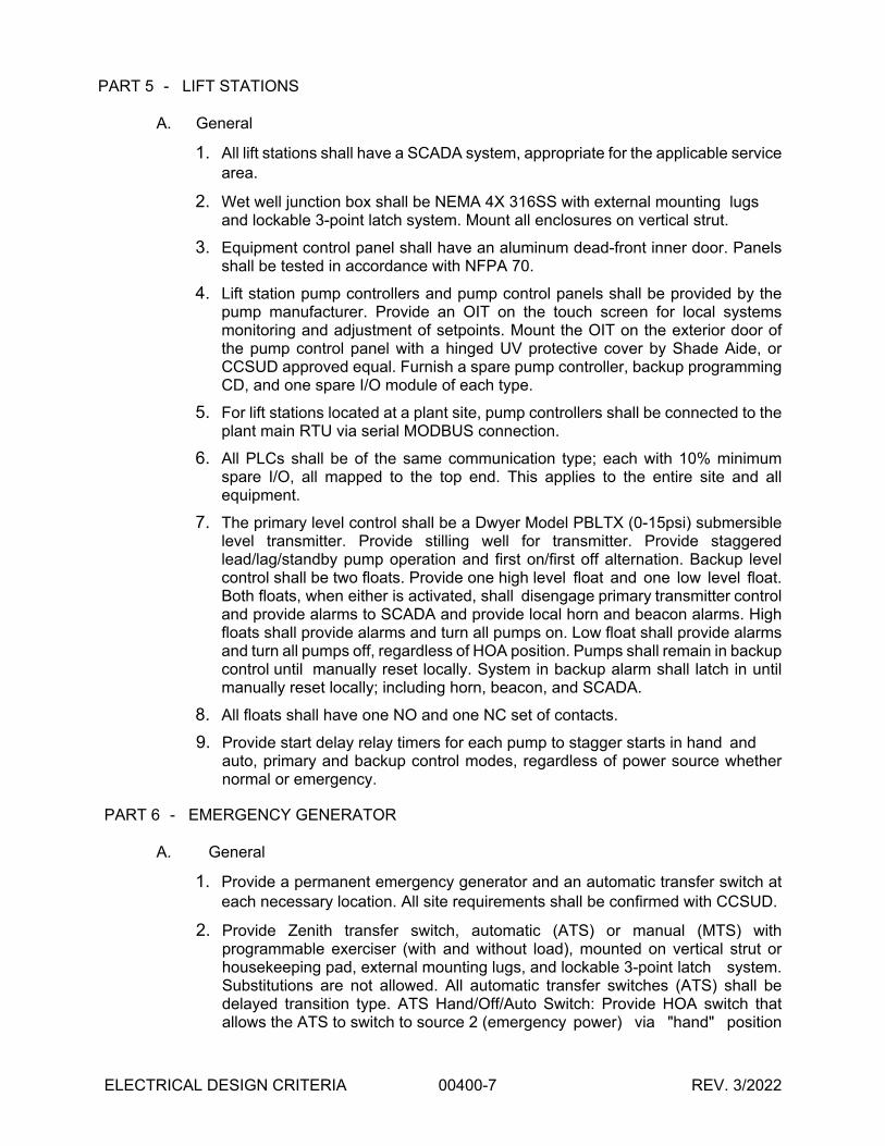
ELECTRICAL DESIGN CRITERIA 00400-7 REV. 3/2022
PART 5 - LIFT STATIONS
A. General
1. All lift stations shall have a SCADA system, appropriate for the applicable service
area.
2. Wet well junction box shall be NEMA 4X 316SS with external mounting lugs and lockable 3-point latch system. Mount all enclosures on vertical strut.
3. Equipment control panel shall have an aluminum dead-front inner door. Panels shall be tested in accordance with NFPA 70.
4. Lift station pump controllers and pump control panels shall be provided by the pump manufacturer. Provide an OIT on the touch screen for local systems monitoring and adjustment of setpoints. Mount the OIT on the exterior door of the pump control panel with a hinged UV protective cover by Shade Aide, or CCSUD approved equal. Furnish a spare pump controller, backup programming CD, and one spare I/O module of each type.
5. For lift stations located at a plant site, pump controllers shall be connected to the plant main RTU via serial MODBUS connection.
6. All PLCs shall be of the same communication type; each with 10% minimum spare I/O, all mapped to the top end. This applies to the entire site and all equipment.
7. The primary level control shall be a Dwyer Model PBLTX (0-15psi) submersible level transmitter. Provide stilling well for transmitter. Provide staggered lead/lag/standby pump operation and first on/first off alternation. Backup level control shall be two floats. Provide one high level float and one low level float. Both floats, when either is activated, shall disengage primary transmitter control and provide alarms to SCADA and provide local horn and beacon alarms. High floats shall provide alarms and turn all pumps on. Low float shall provide alarms and turn all pumps off, regardless of HOA position. Pumps shall remain in backup control until manually reset locally. System in backup alarm shall latch in until manually reset locally; including horn, beacon, and SCADA.
8. All floats shall have one NO and one NC set of contacts.
9. Provide start delay relay timers for each pump to stagger starts in hand and auto, primary and backup control modes, regardless of power source whether normal or emergency.
PART 6 - EMERGENCY GENERATOR
A. General
1. Provide a permanent emergency generator and an automatic transfer switch at
each necessary location. All site requirements shall be confirmed with CCSUD.
2. Provide Zenith transfer switch, automatic (ATS) or manual (MTS) with programmable exerciser (with and without load), mounted on vertical strut or housekeeping pad, external mounting lugs, and lockable 3-point latch system. Substitutions are not allowed. All automatic transfer switches (ATS) shall be delayed transition type. ATS Hand/Off/Auto Switch: Provide HOA switch that allows the ATS to switch to source 2 (emergency power) via "hand" position

ELECTRICAL DESIGN CRITERIA 00400-8 REV. 3/2022
and operate facility under generator power. The switch shall remain in “hand” until the user manually selects a different position. The intent of the HOA is to allow the user to test the generator under facility load or manually engage the generator if desired, without having to operate the normal power circuit breaker feeding the ATS.
3. Generator shall be manufactured by Cummins. Manufacturer substitutions are allowed only with written approval from CCSUD. Size generator to operate the facility at 100% capacity with 20% maximum voltage drop and 10% frequency dip for any motor starting conditions. Max loading 90% of rated capacity.
4. Provide diesel powered generator. Fuel capacity shall be 24 hours minimum at 100% generator load rating. Maximum storage for fuel calculations shall be 90% of tank capacity.
5. Level of sound shall be 60 to 80 d(B)A maximum measured at full load at 7 meters with provided steel sound attenuation enclosure.
6. Generator shall have a battery charger and dry contacts for all alarms. Generator and ATS alarms shall be monitored via Modbus to SCADA.
7. Generators shall be equipped with a low fuel alarm.
8. Generator shall be mounted on a cast-in-place reinforced concrete pad with perimeter beam. Concrete pad shall allow for a 3-foot working clearance (minimum) around entire generator.
9. Perform onsite load bank testing in accordance with NFPA 110:
a) Perform cold start block test at 100% load.
b) Perform 4-hour load bank testing, 2-hours of which shall be at 100% load.
c) Perform 1.5-hours facility/plant load testing.
d) Refill fuel tank to 90% capacity upon completion of testing.
10.All testing shall be performed by the contractor and witnessed by CCSUD. Test equipment must be calibrated annually.
11.Contractor shall perform operational demonstration testing. Contractor shall startup, test, and verify all equipment is operational prior to scheduling CCSUD to witness demonstration testing. Operator training shall be conducted on a separate day after demonstration testing. Contractor shall coordinate schedule with CCSUD at least two (2) weeks in advance. Demonstration testing shall include HOA and generator testing from supply 1 to supply 2 for a minimum duration of 30 minutes and then back to supply 1.
PART 7 - SUBMITTALS
A. Construction submittals shall be provided for CCSUD/Engineer review prior to
purchase of materials.
B. Provide electronic backup copies of programming for PLCs, pump controllers, HMI and other controls.
C. Provide two (2) hard copies and one (1) electronic copy of the O&M Manual.
END OF SECTION

164
1
Item 164 Seeding for Erosion Control 1. DESCRIPTION
Provide and install temporary or permanent seeding for erosion control as shown on the plans or as directed.
2. MATERIALS
2.1. Seed. Provide seed from the previous season’s crop meeting the requirements of the Texas Seed Law, including the testing and labeling for pure live seed (PLS = Purity × Germination). Furnish seed of the designated species, in labeled unopened bags or containers to the Engineer before planting. Use within 12 mo. from the date of the analysis. When Buffalograss is specified, use seed that is treated with KNO3 (potassium nitrate) to overcome dormancy.
Use Tables 1–4 to determine the appropriate seed mix and rates as specified on the plans. If a plant species is not available by the producers, the other plant species in the recommended seed mixture will be increased proportionally by the PLS/acre of the missing plant species.
Table 1 Permanent Rural Seed Mix
District and Planting Dates Clay Soils Species and Rates (lb. PLS/acre)
Sandy Soils Species and Rates (lb. PLS/acre)
1 (Paris) Feb. 1–May 15
Green Sprangletop Sideoats Grama (Haskell) Bermudagrass Little Bluestem (Native) Illinois Bundleflower
0.3 3.2 1.8 1.7 1.0
Green Sprangletop Bermudagrass Bahiagrass (Pensacola) Sand Lovegrass Weeping Lovegrass (Ermelo) Partridge Pea
0.3 1.5 6.0 0.6 0.8 1.0
2 (Ft. Worth) Feb. 1–May 15
Green Sprangletop (Van Horn) Sideoats Grama (Haskell) Texas Grama (Atascosa) Hairy Grama (Chaparral) Shortspike Windmillgrass (Welder) Little Bluestem (OK Select) Purple Prairie Clover (Cuero) Engelmann Daisy (Eldorado) Illinois Bundleflower Awnless Bushsunflower (Plateau)
1.0 1.0 1.0 0.4 0.2 0.8 0.6 0.75 1.3 0.2
Green Sprangletop (Van Horn) Hooded Windmillgrass (Mariah) Shortspike Windmillgrass (Welder) Hairy Grama (Chaparral) Slender Grama (Dilley) Sand Lovegrass (Mason) Sand Dropseed (Borden County) Partridge Pea (Comanche) Little Bluestem (OK Select) Englemann Daisy (Eldorado) Purple Prairie Clover
1.0 0.2 0.2 0.4 1.0 0.2 0.2 0.6 0.8 0.75 0.3
3 (Wichita Falls) Feb. 1–May 15
Green Sprangletop (Van Horn) Sideoats Grama (Haskell) Texas Grama (Atascosa) Hairy Grama (Chaparral) Shortspike Windmillgrass (Welder) Little Bluestem (OK Select) Blue Grama (Hachita) Western Wheatgrass (Barton) Galleta Grass (Viva) Engelmann Daisy (Eldorado) Awnless Bushsunflower (Plateau)
0.6 1.0 1.0 0.4 0.2 0.8 0.4 1.2 0.6 0.75 0.2
Green Sprangletop (Van Horn) Hooded Windmillgrass (Mariah) Shortspike Windmillgrass (Welder) Hairy Grama (Chaparral) Sand Lovegrass (Mason) Sand Dropseed (Borden County) Partridge Pea (Comanche) Little Bluestem (OK Select) Englemann Daisy (Eldorado) Purple Prairie Clover (Cuero)
1.0 0.2 0.2 0.4 0.2 0.2 0.6 0.8 0.75 0.3
4 (Amarillo) Feb. 15–May 15
Green Sprangletop Sideoats Grama (Haskell) Blue Grama (Hachita) Buffalograss (Texoka) Illinois Bundleflower
0.3 3.6 1.2 1.6 1.0
Green Sprangletop Weeping Lovegrass (Ermelo) Blue Grama (Hachita) Sand Dropseed (Borden Co.) Sand Bluestem Purple Prairie Clover
0.3 0.8 1.0 0.3 1.8 0.5

164
2
District and Planting Dates Clay Soils Species and Rates (lb. PLS/acre)
Sandy Soils Species and Rates (lb. PLS/acre)
5 (Lubbock) Feb. 15–May 15
Green Sprangletop Sideoats Grama (El Reno) Blue Grama (Hachita) Buffalograss (Texoka) Illinois Bundleflower
0.3 3.6 1.2 1.6 1.0
Green Sprangletop Weeping Lovegrass (Ermelo) Blue Grama (Hachita) Sand Dropseed (Borden Co.) Sand Bluestem Purple Prairie Clover
0.3 0.8 1.0 0.3 1.8 0.5
6 (Odessa) Feb. 1–May 15
Green Sprangletop (Van Horn) Sideoats Grama (South Texas) Blue Grama (Hachita) Galleta Grass (Viva) Shortspike Windmillgrass (Welder) Pink Pappusgrass (Maverick) Alkali Sacaton (Saltalk) Plains Bristlegrass (Catarina Blend) False Rhodes Grass (Kinney) Whiplash Pappusgrass (Webb) Arizona Cottontop (La Salle)
1.0 1.0 0.4 0.6 0.2 0.6 0.2 0.2 0.1 0.6 0.2
Green Sprangletop (Van Horn) Hooded Windmillgrass (Mariah) Blue Grama (Hachita) Hairy Grama (Chaparral) Sand Lovegrass (Mason) Sand Dropseed (Borden County) Indian Ricegrass (Rim Rock) Sand Bluestem (Cottle County) Little Bluestem (Pastura) Purple Prairie Clover (Cuero)
1.0 0.2 0.4 0.4 0.2 0.2 1.6 1.2 0.8 0.3
7 (San Angelo) Feb. 1–May 1
Green Sprangletop (Van Horn) Sideoats Grama (Haskell) Texas Grama (Atascosa) Hairy Grama (Chaparral) Shortspike Windmillgrass (Welder) Little Bluestem (OK Select) Blue Grama (Hachita) Western Wheatgrass (Barton) Galleta Grass (Viva) Engelmann Daisy (Eldorado) Illinois Bundleflower (Sabine)
1.0 1.0 1.0 0.4 0.2 0.4 0.4 1.2 0.6 0.75 1.0
Green Sprangletop (Van Horn) Hooded Windmillgrass (Mariah) Shortspike Windmillgrass (Welder) Hairy Grama (Chaparral) Sand Lovegrass (Mason) Sand Dropseed (Borden County) Sand Bluestem (Cottle County) Partridge Pea (Comanche) Little Bluestem (OK Select) Englemann Daisy (Eldorado) Purple Prairie Clover (Cuero)
1.0 0.2 0.2 0.4 0.2 0.2 1.2 0.6 0.8 0.75 0.3
8 (Abilene) Feb. 1–May 15
Green Sprangletop (Van Horn) Sideoats Grama (Haskell) Texas Grama (Atascosa) Hairy Grama (Chaparral) Shortspike Windmillgrass (Welder) Little Bluestem (OK Select) Blue Grama (Hachita) Western Wheatgrass (Barton) Galleta Grass (Viva) Engelmann Daisy (Eldorado) Illinois Bundleflower (Sabine)
1.0 1.0 1.0 0.4 0.2 0.4 0.4 1.2 0.6 0.75 1.0
Green Sprangletop (Van Horn) Hooded Windmillgrass (Mariah) Shortspike Windmillgrass (Welder) Hairy Grama (Chaparral) Sand Lovegrass (Mason) Sand Dropseed (Borden County) Sand Bluestem (Cottle County) Partridge Pea (Comanche) Little Bluestem (OK Select) Englemann Daisy (Eldorado) Purple Prairie Clover (Cuero)
1.0 0.2 0.2 0.4 0.2 0.2 1.2 0.6 0.8 0.75 0.3
9 (Waco) Feb. 1–May 15
Green Sprangletop (Van Horn) Sideoats Grama (Haskell) Texas Grama (Atascosa) Hairy Grama (Chaparral) Shortspike Windmillgrass (Welder) Little Bluestem (OK Select) Purple Prairie Clover (Cuero) Engelmann Daisy (Eldorado) Illinois Bundleflower Awnless Bushsunflower (Plateau)
1.0 1.0 1.0 0.4 0.2 0.8 0.6 0.75 1.3 0.2
Green Sprangletop (Van Horn) Hooded Windmillgrass (Mariah) Shortspike Windmillgrass (Welder) Hairy Grama (Chaparral) Slender Grama (Dilley) Sand Lovegrass (Mason) Sand Dropseed (Borden County) Partridge Pea (Comanche) Little Bluestem (OK Select) Englemann Daisy (Eldorado) Purple Prairie Clover
1.0 0.2 0.2 0.4 1.0 0.2 0.2 0.6 0.8 0.75 0.3
10 (Tyler) Feb. 1–May 15
Green Sprangletop Bermudagrass Bahiagrass (Pensacola) Sideoats Grama (Haskell) Illinois Bundleflower
0.3 1.8 9.0 2.7 1.0
Green Sprangletop Bermudagrass Bahiagrass (Pensacola) Weeping Lovegrass (Ermelo) Sand Lovegrass Lance-Leaf Coreopsis
0.3 1.8 9.0 0.5 0.5 1.0
11 (Lufkin) Feb. 1–May 15
Green Sprangletop Bermudagrass Bahiagrass (Pensacola) Sideoats Grama (Haskell) Illinois Bundleflower
0.3 1.8 9.0 2.7 1.0
Green Sprangletop Bermudagrass Bahiagrass (Pensacola) Sand Lovegrass Lance-Leaf Coreopsis
0.3 2.1 9.0 0.5 1.0
Table 1 (continued) Permanent Rural Seed Mix

164
3
District and Planting Dates Clay Soils Species and Rates (lb. PLS/acre)
Sandy Soils Species and Rates (lb. PLS/acre)
12 (Houston) Jan. 15–May 15
Green Sprangletop Bermudagrass Sideoats Grama (Haskell) Little Bluestem (Native) Illinois Bundleflower
0.3 2.1 3.2 1.4 1.0
Green Sprangletop Bermudagrass Bahiagrass (Pensacola) Weeping Lovegrass (Ermelo) Lance-Leaf Coreopsis
0.3 2.4 10.5 1.0 1.0
13 (Yoakum) Jan. 15–May 15
Green Sprangletop (Van Horn) Sideoats Grama (South Texas) Texas Grama (Atascosa) Slender Grama (Dilley) Shortspike Windmillgrass (Welder) Halls Panicum (Oso) Plains Bristlegrass (Catarina Blend) Canada Wildrye (Lavaca) Illinois Bundleflower (Sabine) Purple Prairie Clover (Cuero)
1.0 1.0 1.5 1.0 0.3 0.2 0.2 2.0 1.3 0.6
Green Sprangletop (Van Horn) Hooded Windmillgrass (Mariah) Slender Grama (Dilley) Hairy Grama (Chaparral) Shortspike Windmillgrass (Welder) Purple Prairie Clover (Cuero) Partridge Pea (Comanche) Englemann Daisy (Eldorado)
1.0 0.4 1.0 0.8 0.2 0.6 0.6 1.0
14 (Austin) Feb. 1–May 15
Green Sprangletop (Van Horn) Sideoats Grama (South Texas) Texas Grama (Atascosa) Hairy Grama (Chaparral) Shortspike Windmillgrass (Welder) Little Bluestem (OK Select) Purple Prairie Clover (Cuero) Engelmann Daisy (Eldorado) Illinois Bundleflower (Sabine) Awnless Bushsunflower (Plateau)
1.0 1.0 1.0 0.4 0.2 0.8 0.6 0.75 1.3 0.2
Green Sprangletop (Van Horn) Hooded Windmillgrass (Mariah) Shortspike Windmillgrass (Welder) Hairy Grama (Chaparral) Slender Grama (Dilley) Sand Lovegrass (Mason) Sand Dropseed (Borden County) Partridge Pea (Comanche) Little Bluestem (OK Select) Englemann Daisy (Eldorado) Purple Prairie Clover
1.0 0.2 0.2 0.4 1.0 0.2 0.2 0.6 0.8 0.75 0.3
15 (San Antonio) Feb. 1–May 1
Green Sprangletop (Van Horn) Sideoats Grama (South Texas) Texas Grama (Atascosa) Slender Grama (Dilley) Shortspike Windmillgrass (Welder) Pink Pappusgrass (Maverick) Halls Panicum (Oso) Plains Bristlegrass (Catarina Blend) False Rhodes Grass (Kinney) Hooded Windmillgrass (Mariah) Arizona Cottontop (La Salle)
1.0 1.0 1.0 1.0 0.2 0.6 0.2 0.2 0.1 0.2 0.2
Green Sprangletop (Van Horn) Slender Grama (Dilley) Hairy Grama (Chaparral) Shortspike Windmillgrass (Welder) Pink Pappusgrass (Maverick) Plains Bristlegrass (Catarina Blend) Hooded Windmillgrass (Mariah) Multi-flowered False Rhoades Grass (Hidalgo) Arizona Cottontop (La Salle)
1.0 2.0 0.6 0.4 0.6 0.2 0.3 0.1 0.2
16 (Corpus Christi) Jan. 1–May 1
Green Sprangletop (Van Horn) Sideoats Grama (South Texas) Texas Grama (Atascosa) Slender Grama (Dilley) Shortspike Windmillgrass (Welder) Pink Pappusgrass (Maverick) Halls Panicum (Oso) Plains Bristlegrass (Catarina Blend) False Rhodes Grass (Kinney) Hooded Windmillgrass (Mariah) Arizona Cottontop (La Salle)
1.0 1.0 1.0 1.0 0.2 0.6 0.2 0.2 0.1 0.2 0.2
Green Sprangletop (Van Horn) Slender Grama (Dilley) Hairy Grama (Chaparral) Shortspike Windmillgrass (Welder) Pink Pappusgrass (Maverick) Plains Bristlegrass (Catarina Blend) Hooded Windmillgrass (Mariah) Multi-flowered False Rhodes Grass (Hidalgo) Arizona Cottontop (La Salle)
1.0 2.0 0.6 0.4 0.6 0.2 0.3 0.1 0.2
17 (Bryan) Feb. 1–May 15
Green Sprangletop Bermudagrass Sideoats Grama (Haskell) Little Bluestem (Native) Illinois Bundleflower
0.3 1.5 3.6 1.7 1.0
Green Sprangletop Bermudagrass Bahiagrass (Pensacola) Weeping Lovegrass (Ermelo) Sand Lovegrass Lance-Leaf Coreopsis
0.3 1.5 7.5 0.6 0.6 1.0
Table 1 (continued) Permanent Rural Seed Mix

164
4
District and Planting Dates Clay Soils Species and Rates (lb. PLS/acre)
Sandy Soils Species and Rates (lb. PLS/acre)
18 (Dallas) Feb. 1–May 15
Green Sprangletop (Van Horn) Sideoats Grama (Haskell) Texas Grama (Atascosa) Hairy Grama (Chaparral) Shortspike Windmillgrass (Welder) Little Bluestem (OK Select) Purple Prairie Clover (Cuero) Engelmann Daisy (Eldorado) Illinois Bundleflower Awnless Bushsunflower (Plateau)
1.0 1.0 1.0 0.4 0.2 0.8 0.6 0.75 1.3 0.2
Green Sprangletop (Van Horn) Hooded Windmillgrass (Mariah) Shortspike Windmillgrass (Welder) Hairy Grama (Chaparral) Slender Grama (Dilley) Sand Lovegrass (Mason) Sand Dropseed (Borden County) Partridge Pea (Comanche) Little Bluestem (OK Select) Englemann Daisy (Eldorado) Purple Prairie Clover
1.0 0.2 0.2 0.4 1.0 0.2 0.2 0.6 0.8 0.75 0.3
19 (Atlanta) Feb. 1–May 15
Green Sprangletop Bermudagrass Sideoats Grama (Haskell) Illinois Bundleflower
0.3 2.4 4.5 1.0
Green Sprangletop Bermudagrass Bahiagrass (Pensacola) Sand Lovegrass Lance-Leaf Coreopsis
0.3 2.1 7.5 0.6 1.0
20 (Beaumont) Jan. 15–May 15
Green Sprangletop Bermudagrass Sideoats Grama (Haskell) Illinois Bundleflower
0.3 2.7 4.1 1.0
Green Sprangletop Bermudagrass Bahiagrass (Pensacola) Sand Lovegrass Lance-Leaf Coreopsis
0.3 2.1 7.5 0.6 1.0
21 (Pharr) Jan. 15–May 15
Green Sprangletop (Van Horn) Sideoats Grama (South Texas) Texas Grama (Atascosa) Slender Grama (Dilley) Shortspike Windmillgrass (Welder) Pink Pappusgrass (Maverick) Halls Panicum (Oso) Plains Bristlegrass (Catarina Blend) False Rhodes Grass (Kinney) Hooded Windmillgrass (Mariah) Arizona Cottontop (La Salle)
1.0 1.0 1.0 1.0 0.2 0.6 0.2 0.2 0.1 0.2 0.2
Green Sprangletop (Van Horn) Slender Grama (Dilley) Hairy Grama (Chaparral) Shortspike Windmillgrass (Welder) Pink Pappusgrass (Maverick) Plains Bristlegrass (Catarina Blend) Hooded Windmillgrass (Mariah) Multi-flowered False Rhoades Grass (Hidalgo) Arizona Cottontop (La Salle)
1.0 2.0 0.6 0.4 0.6 0.2 0.3 0.1 0.2
22 (Laredo) Jan. 15–May 1
Green Sprangletop (Van Horn) Sideoats Grama (South Texas) Texas Grama (Atascosa) Slender Grama (Dilley) Shortspike Windmillgrass (Welder) Pink Pappusgrass (Maverick) Halls Panicum (Oso) Plains Bristlegrass (Catarina Blend) False Rhodes Grass (Kinney) Hooded Windmillgrass (Mariah) Arizona Cottontop (La Salle)
1.0 1.0 1.0 1.0 0.2 0.6 0.2 0.2 0.1 0.2 0.2
Green Sprangletop (Van Horn) Slender Grama (Dilley) Hairy Grama (Chaparral) Shortspike Windmillgrass (Welder) Pink Pappusgrass (Maverick) Plains Bristlegrass (Catarina Blend) Hooded Windmillgrass (Mariah) Multi-flowered False Rhoades Grass (Hidalgo) Arizona Cottontop (La Salle)
1.0 2.0 0.6 0.4 0.6 0.2 0.3 0.1 0.2
23 (Brownwood) Feb. 1–May 15
Green Sprangletop (Van Horn) Sideoats Grama (Haskell) Texas Grama (Atascosa) Hairy Grama (Chaparral) Shortspike Windmillgrass (Welder) Little Bluestem (OK Select) Blue Grama (Hachita) Western Wheatgrass (Barton) Galleta Grass (Viva) Engelmann Daisy (Eldorado) Awnless Bushsunflower (Plateau)
0.6 1.0 1.0 0.4 0.2 0.8 0.4 1.2 0.6 0.75 0.2
Green Sprangletop (Van Horn) Hooded Windmillgrass (Mariah) Shortspike Windmillgrass (Welder) Hairy Grama (Chaparral) Sand Lovegrass (Mason) Sand Dropseed (Borden County) Partridge Pea (Comanche) Little Bluestem (OK Select) Englemann Daisy (Eldorado) Purple Prairie Clover (Cuero)
1.0 0.2 0.2 0.4 0.2 0.2 0.6 0.8 0.75 0.3
Table 1 (continued) Permanent Rural Seed Mix

164
5
District and Planting Dates Clay Soils Species and Rates (lb. PLS/acre)
Sandy Soils Species and Rates (lb. PLS/acre)
24 (El Paso) Feb. 1–May 15
Green Sprangletop (Van Horn) Sideoats Grama (South Texas) Blue Grama (Hachita) Galleta Grass (Viva) Shortspike Windmillgrass (Welder) Pink Pappusgrass (Maverick) Alkali Sacaton (Saltalk) Plains Bristlegrass (Catarina Blend) False Rhodes Grass (Kinney) Whiplash Pappusgrass (Webb) Arizona Cottontop (La Salle)
1.0 1.0 0.4 0.6 0.2 0.6 0.2 0.2 0.1 0.6 0.2
Green Sprangletop (Van Horn) Hooded Windmillgrass (Mariah) Blue Grama (Hachita) Hairy Grama (Chaparral) Sand Lovegrass (Mason) Sand Dropseed (Borden County) Indian Ricegrass (Rim Rock) Sand Bluestem (Cottle County) Little Bluestem (Pastura) Purple Prairie Clover (Cuero)
1.0 0.2 0.4 0.4 0.2 0.2 1.6 1.2 0.8 0.3
25 (Childress) Feb. 1–May 15
Green Sprangletop Sideoats Grama (El Reno) Blue Grama (Hachita) Western Wheatgrass Galleta Illinois Bundleflower
0.3 2.7 0.9 2.1 1.6 1.0
Green Sprangletop Weeping Lovegrass (Ermelo) Sand Dropseed (Borden Co.) Sand Lovegrass Purple Prairie Clover
0.3 1.2 0.5 0.8 0.5
Table 2
Permanent Urban Seed Mix District and Planting Dates Clay Soils
Species and Rates (lb. PLS/acre) Sandy Soils
Species and Rates (lb. PLS/acre) 1 (Paris) Feb. 1–May 15
Green Sprangletop Bermudagrass Sideoats Grama (Haskell)
0.3 2.4 4.5
Green Sprangletop Bermudagrass
0.3 5.4
2 (Ft. Worth) Feb. 1–May 15
Green Sprangletop Sideoats Grama (El Reno) Bermudagrass Buffalograss (Texoka)
0.3 3.6 2.4 1.6
Green Sprangletop Sideoats Grama (El Reno) Bermudagrass Sand Dropseed (Borden Co.)
0.3 3.6 2.1 0.3
3 (Wichita Falls) Feb. 1–May 15
Green Sprangletop Sideoats Grama (El Reno) Bermudagrass Buffalograss (Texoka)
0.3 4.5 1.8 1.6
Green Sprangletop Sideoats Grama (El Reno) Bermudagrass Sand Dropseed (Borden Co.)
0.3 3.6 1.8 0.4
4 (Amarillo) Feb. 15–May 15
Green Sprangletop Sideoats Grama (El Reno) Blue Grama (Hachita) Buffalograss (Texoka)
0.3 3.6 1.2 1.6
Green Sprangletop Sideoats Grama (El Reno) Blue Grama (Hachita) Sand Dropseed (Borden Co.) Buffalograss (Texoka)
0.3 2.7 0.9 0.4 1.6
5 (Lubbock) Feb. 15–May 15
Green Sprangletop Sideoats Grama (El Reno) Blue Grama (Hachita) Buffalograss (Texoka)
0.3 3.6 1.2 1.6
Green Sprangletop Sideoats Grama (El Reno) Blue Grama (Hachita) Sand Dropseed (Borden Co.) Buffalograss (Texoka)
0.3 2.7 0.9 0.4 1.6
6 (Odessa) Feb. 1–May 15
Green Sprangletop Sideoats Grama (Haskell) Blue Grama (Hachita) Buffalograss (Texoka)
0.3 3.6 1.2 1.6
Green Sprangletop Sideoats Grama (Haskell) Sand Dropseed (Borden Co.) Blue Grama (Hachita) Buffalograss (Texoka)
0.3 2.7 0.4 0.9 1.6
7 (San Angelo) Feb. 1–May 1
Green Sprangletop Sideoats Grama (Haskell) Buffalograss (Texoka)
0.3 7.2 1.6
Green Sprangletop Sideoats Grama (Haskell) Sand Dropseed (Borden Co.) Blue Grama (Hachita) Buffalograss (Texoka)
0.3 3.2 0.3 0.9 1.6
8 (Abilene) Feb. 1–May 15
Green Sprangletop Sideoats Grama (Haskell) Blue Grama (Hachita) Buffalograss (Texoka)
0.3 3.6 1.2 1.6
Green Sprangletop Sand Dropseed (Borden Co.) Sideoats Grama (Haskell) Blue Grama (Hachita) Buffalograss (Texoka)
0.3 0.3 3.6 0.8 1.6
9 (Waco) Feb. 1–May 15
Green Sprangletop Bermudagrass Buffalograss (Texoka) Sideoats Grama (Haskell)
0.3 1.8 1.6 4.5
Green Sprangletop Buffalograss (Texoka) Bermudagrass Sand Dropseed (Borden Co.)
0.3 1.6 3.6 0.4
Table 1 (continued) Permanent Rural Seed Mix
Table 2 (continued) Permanent Urban Seed Mix

164
6
District and Planting Dates Clay Soils Species and Rates (lb. PLS/acre)
Sandy Soils Species and Rates (lb. PLS/acre)
10 (Tyler) Feb. 1–May 15
Green Sprangletop Bermudagrass Sideoats Grama (Haskell)
0.3 2.4 4.5
Green Sprangletop Bermudagrass
0.3 5.4
11 (Lufkin) Feb. 1–May 15
Green Sprangletop Bermudagrass Sideoats Grama (Haskell)
0.3 2.4 4.5
Green Sprangletop Bermudagrass
0.3 5.4
12 (Houston) Jan. 15–May 15
Green Sprangletop Sideoats Grama (Haskell) Bermudagrass
0.3 4.5 2.4
Green Sprangletop Bermudagrass
0.3 5.4
13 (Yoakum) Jan. 15–May 15
Green Sprangletop Sideoats Grama (South Texas) Bermudagrass
0.3 4.5 2.4
Green Sprangletop Bermudagrass
0.3 5.4
14 (Austin) Feb. 1–May 15
Green Sprangletop Bermudagrass Sideoats Grama (South Texas) Buffalograss (Texoka)
0.3 2.4 3.6 1.6
Green Sprangletop Bermudagrass Buffalograss (Texoka)
0.3 4.8 1.6
15 (San Antonio) Feb. 1–May 1
Green Sprangletop Sideoats Grama (South Texas) Bermudagrass Buffalograss (Texoka)
0.3 3.6 2.4 1.6
Green Sprangletop Bermudagrass Buffalograss (Texoka)
0.3 4.8 1.6
16 (Corpus Christi) Jan. 1–May 1
Green Sprangletop Sideoats Grama (South Texas) Bermudagrass Buffalograss (Texoka)
0.3 3.6 2.4 1.6
Green Sprangletop Bermudagrass Buffalograss (Texoka)
0.3 4.8 1.6
17 (Bryan) Feb. 1–May 15
Green Sprangletop Bermudagrass Sideoats Grama (Haskell)
0.3 2.4 4.5
Green Sprangletop Bermudagrass
0.3 5.4
18 (Dallas) Feb. 1–May 15
Green Sprangletop Sideoats Grama (El Reno) Buffalograss (Texoka) Bermudagrass
0.3 3.6 1.6 2.4
Green Sprangletop Buffalograss (Texoka) Bermudagrass Sand Dropseed (Borden Co.)
0.3 1.6 3.6 0.4
19 (Atlanta) Feb. 1–May 15
Green Sprangletop Bermudagrass Sideoats Grama (Haskell)
0.3 2.4 4.5
Green Sprangletop Bermudagrass
0.3 5.4
20 (Beaumont) Jan. 15–May 15
Green Sprangletop Bermudagrass Sideoats Grama (Haskell)
0.3 2.4 4.5
Green Sprangletop Bermudagrass
0.3 5.4
21 (Pharr) Jan. 15–May 15
Green Sprangletop Sideoats Grama (South Texas) Buffalograss (Texoka) Bermudagrass
0.3 3.6 1.6 2.4
Green Sprangletop Buffalograss (Texoka) Bermudagrass Sand Dropseed (Borden Co.)
0.3 1.6 3.6 0.4
22 (Laredo) Jan. 15–May 1
Green Sprangletop Sideoats Grama (South Texas) Buffalograss (Texoka) Bermudagrass
0.3 4.5 1.6 1.8
Green Sprangletop Buffalograss (Texoka) Bermudagrass Sand Dropseed
0.3 1.6 3.6 0.4
23 (Brownwood) Feb. 1–May 15
Green Sprangletop Sideoats Grama (Haskell) Bermudagrass Blue Grama (Hachita)
0.3 3.6 1.2 0.9
Green Sprangletop Buffalograss (Texoka) Bermudagrass Sand Dropseed (Borden Co.)
0.3 1.6 3.6 0.4
24 (El Paso) Feb. 1–May 15
Green Sprangletop Sideoats Grama (South Texas) Blue Grama (Hachita) Buffalograss (Texoka)
0.3 3.6 1.2 1.6
Green Sprangletop Buffalograss (Texoka) Sand Dropseed (Borden Co.) Blue Grama (Hachita)
0.3 1.6 0.4 1.8
25 (Childress) Feb. 1–May 15
Green Sprangletop Sideoats Grama (El Reno) Blue Grama (Hachita) Buffalograss (Texoka)
0.3 3.6 1.2 1.6
Green Sprangletop Sand Dropseed (Borden Co.) Buffalograss (Texoka) Bermudagrass
0.3 0.4 1.6 1.8

164
7
Table 3 Temporary Cool Season Seeding
Districts Dates Seed Mix and Rates (lb. PLS/acre)
Paris (1), Amarillo (4), Lubbock (5), Dallas (18) September 1–November 30 Tall Fescue Western Wheatgrass Wheat (Red, Winter)
4.5 5.6 34
Odessa (6), San Angelo (7), El Paso (24) September 1–November 30 Western Wheatgrass Wheat (Red, Winter)
8.4 50
Waco (9), Tyler (10), Lufkin (11), Austin (14), San Antonio (15), Bryan (17), Atlanta (19)
September 1–November 30 Tall Fescue Oats Wheat
4.5 24 34
Houston (12), Yoakum (13), Corpus Christi (16), Beaumont (20), Pharr (21), Laredo (22)
September 1–November 30 Oats 72
Ft. Worth (2), Wichita Falls (3), Abilene (8), Brownwood (23), Childress (25)
September 1–November 30 Tall Fescue Western Wheatgrass Cereal Rye
4.5 5.6 34
Table 4
Temporary Warm Season Seeding Districts Dates Seed Mix and Rates
(lb. PLS/acre) All May 1–August 31 Foxtail Millet 34
2.2. Fertilizer. Use fertilizer in conformance with Article 166.2., “Materials.”
2.3. Vegetative Watering. Use water that is clean and free of industrial wastes and other substances harmful to the growth of vegetation.
2.4. Mulch.
2.4.1. Straw or Hay Mulch. Use straw or hay mulch in conformance with Section 162.2.5., “Mulch.”
2.4.2. Cellulose Fiber Mulch. Use only cellulose fiber mulches that are on the Approved Products List, Erosion Control Approved Products. (http://www.txdot.gov/business/resources/erosion-control.html) Submit one full set of manufacturer’s literature for the selected material. Keep mulch dry until applied. Do not use molded or rotted material.
2.5. Tacking Methods. Use a tacking agent applied in accordance with the manufacturer’s recommendations or a crimping method on all straw or hay mulch operations. Use tacking agents as approved or as specified on the plans.
3. CONSTRUCTION
Cultivate the area to a depth of 4 in. before placing the seed unless otherwise directed. Use approved equipment to vertically track the seedbed as shown on the plans or as directed. Cultivate the seedbed to a depth of 4 in. or mow the area before placement of the permanent seed when performing permanent seeding after an established temporary seeding. Plant the seed specified and mulch, if required, after the area has been completed to lines and grades as shown on the plans.
3.1. Broadcast Seeding. Distribute the seed or seed mixture uniformly over the areas shown on the plans using hand or mechanical distribution or hydro-seeding on top of the soil unless otherwise directed. Apply the mixture to the area to be seeded within 30 min. of placement of components in the equipment when seed and water are to be distributed as a slurry during hydro-seeding. Roll the planted area with a light roller or other suitable equipment. Roll sloped areas along the contour of the slopes.
3.2. Straw or Hay Mulch Seeding. Plant seed according to Section 164.3.1., “Broadcast Seeding.” Apply straw or hay mulch uniformly over the seeded area immediately after planting the seed or seed mixture. Apply

164
8
straw mulch at 2 to 2.5 tons per acre. Apply hay mulch at 1.5 to 2 tons per acre. Use a tacking method over the mulched area.
3.3. Cellulose Fiber Mulch Seeding. Plant seed in accordance with Section 164.3.1., “Broadcast Seeding.” Apply cellulose fiber mulch uniformly over the seeded area immediately after planting the seed or seed mixture at the following rates. Sandy soils with slopes of 3:1 or less—2,500 lb. per acre. Sandy soils with slopes greater than 3:1—3,000 lb. per acre. Clay soils with slopes of 3:1 or less—2,000 lb. per acre. Clay soils with slopes greater than 3:1—2,300 lb. per acre.
Cellulose fiber mulch rates are based on dry weight of mulch per acre. Mix cellulose fiber mulch and water to make a slurry and apply uniformly over the seeded area using suitable equipment.
3.4. Drill Seeding. Plant seed or seed mixture uniformly over the area shown on the plans at a depth of 1/4 to 1/3 in. using a pasture or rangeland type drill unless otherwise directed. Plant seed along the contour of the slopes.
3.5. Straw or Hay Mulching. Apply straw or hay mulch uniformly over the area as shown on the plans. Apply straw mulch at 2 to 2.5 tons per acre. Apply hay mulch at 1.5 to 2 tons per acre. Use a tacking method over the mulched area.
Apply fertilizer in conformance with Article 166.3., “Construction.” Seed and fertilizer may be distributed simultaneously during “Broadcast Seeding” operations, provided each component is applied at the specified rate. Apply half of the required fertilizer during the temporary seeding operation and the other half during the permanent seeding operation when temporary and permanent seeding are both specified for the same area.
Water the seeded areas at the rates and frequencies as shown on the plans or as directed.
4. MEASUREMENT
This Item will be measured by the square yard or by the acre.
5. PAYMENT
The work performed and the materials furnished in accordance with this Item and measured as provided under “Measurement” will be paid for at the unit price bid for “Broadcast Seeding (Perm)” of the rural or urban seed mixture and sandy or clay soil specified, “Broadcast Seeding (Temp)” of warm or cool season specified, “Straw or Hay Mulch Seeding (Perm)” of the rural or urban seed mixture and sandy or clay soil specified, “Straw or Hay Mulch Seeding (Temp)” of warm or cool season specified, “Cellulose Fiber Mulch Seeding (Perm)” of the rural or urban seed mixture and sandy or clay soil specified, “Cellulose Fiber Mulch Seeding (Temp)” of warm or cool season specified, “Drill Seeding (Perm)” of the rural or urban seed mixture and sandy or clay soil specified, “Drill Seeding (Temp)” of warm or cool season specified, and “Straw or Hay Mulching.” This price is full compensation for furnishing materials, including water for hydro-seeding and hydro-mulching operations, mowing, labor, equipment, tools, supplies, and incidentals. Fertilizer will not be paid for directly but will be subsidiary to this Item. Water for irrigating the seeded area, when specified, will be paid for under Item 168, “Vegetative Watering.”

169
1
Item 169
Soil Retention Blankets
1. DESCRIPTION
Provide and install soil retention blankets (SRB) as shown on the plans or as directed.
2. MATERIALS
Provide only SRB that meet the requirements of DMS-6370, “Soil Retention Blankets,” and are on the Approved Products List, Erosion Control Approved Products. (http://www.txdot.gov/business/resources/erosion-control.html) Use material of the following class and type as shown on the plans and provide a copy of the manufacturer’s label for the selected product.
2.1. Class 1: Slope Protection.
2.1.1. Type A. Slopes 3:1 or flatter—clay soils,
2.1.2. Type B. Slopes 3:1 or flatter—sandy soils,
2.1.3. Type C. Slopes steeper than 3:1—clay soils, and
2.1.4. Type D. Slopes steeper than 3:1—sandy soils.
2.2. Class 2: Flexible Channel Liners.
2.2.1. Type E. Biodegradable materials with shear stress less than 2.0 psf,
2.2.2. Type F. Biodegradable materials with shear stress less than 4.0 psf,
2.2.3. Type G. Nonbiodegradable materials with shear stress less than 6.0 psf, and
2.2.4. Type H. Nonbiodegradable materials with shear stress less than 8.0 lb. psf.
3. CONSTRUCTION
Provide a copy of the manufacturer's installation instructions to the Engineer before placement of the material. Place the SRB within 24 hr. after the seeding or sodding operation, or when directed. Install and anchor the SRB in strict accordance with the recommendations contained within the manufacturer's published literature. Installation includes the repair of ruts, reseeding or resodding, and the removal of rocks, clods, and other foreign materials which may prevent contact of the blanket with the soil.
4. MEASUREMENT
This Item will be measured by the square yard of surface area covered.
5. PAYMENT
The work performed and materials furnished in accordance with this Item and measured as provided under “Measurement” will be paid for at the unit price bid for “Soil Retention Blankets” of the class and type specified. This price is full compensation for equipment, materials, labor, tools, and incidentals.

340
214
Item 340 Dense-Graded Hot-Mix Asphalt (Small Quantity) 1. DESCRIPTION
Construct a hot-mix asphalt (HMA) pavement layer composed of a compacted, dense-graded mixture of aggregate and asphalt binder mixed hot in a mixing plant. This specification is intended for small quantity (SQ) HMA projects, typically under 5,000 tons total production.
2. MATERIALS
Furnish uncontaminated materials of uniform quality that meet the requirements of the plans and specifications.
Notify the Engineer of all material sources and before changing any material source or formulation. The Engineer will verify that the specification requirements are met when the Contractor makes a source or formulation change, and may require a new laboratory mixture design, trial batch, or both. The Engineer may sample and test project materials at any time during the project to verify specification compliance in accordance with Item 6, “Control of Materials.”
2.1. Aggregate. Furnish aggregates from sources that conform to the requirements shown in Table 1 and as specified in this Section. Aggregate requirements in this Section, including those shown in Table 1, may be modified or eliminated when shown on the plans. Additional aggregate requirements may be specified when shown on the plans. Provide aggregate stockpiles that meet the definitions in this Section for coarse, intermediate, or fine aggregate. Aggregate from reclaimed asphalt pavement (RAP) is not required to meet Table 1 requirements unless otherwise shown on the plans. Supply aggregates that meet the definitions in Tex-100-E for crushed gravel or crushed stone. The Engineer will designate the plant or the quarry as the sampling location. Provide samples from materials produced for the project. The Engineer will establish the Surface Aggregate Classification (SAC) and perform Los Angeles abrasion, magnesium sulfate soundness, and Micro-Deval tests. Perform all other aggregate quality tests listed in Table 1. Document all test results on the mixture design report. The Engineer may perform tests on independent or split samples to verify Contractor test results. Stockpile aggregates for each source and type separately. Determine aggregate gradations for mixture design and production testing based on the washed sieve analysis given in Tex-200-F, Part II.
2.1.1. Coarse Aggregate. Coarse aggregate stockpiles must have no more than 20% material passing the No. 8 sieve. Aggregates from sources listed in the Department’s Bituminous Rated Source Quality Catalog (BRSQC) are preapproved for use. Use only the rated values for hot-mix listed in the BRSQC. Rated values for surface treatment (ST) do not apply to coarse aggregate sources used in hot-mix asphalt.
For sources not listed on the Department’s BRSQC: build an individual stockpile for each material; request the Department test the stockpile for specification compliance; and once approved, do not add material to the stockpile unless otherwise approved.
Provide aggregate from non-listed sources only when tested by the Engineer and approved before use. Allow 30 calendar days for the Engineer to sample, test, and report results for non-listed sources.
Provide coarse aggregate with at least the minimum SAC shown on the plans. SAC requirements only apply to aggregates used on the surface of travel lanes. SAC requirements apply to aggregates used on surfaces other than travel lanes when shown on the plans. The SAC for sources on the Department’s Aggregate Quality Monitoring Program (AQMP) (Tex-499-A) is listed in the BRSQC.
cmartinez
Text Box
Crystal Clear Special Utility District (CCSUD) Adopted, as amended 10/09/2018 TxDOT Item 00340 and all associated reference specifications

340
215
2.1.1.1. Blending Class A and Class B Aggregates. Class B aggregate meeting all other requirements in Table 1 may be blended with a Class A aggregate to meet requirements for Class A materials. Ensure that at least 50% by weight, or volume if required, of the material retained on the No. 4 sieve comes from the Class A aggregate source when blending Class A and B aggregates to meet a Class A requirement. Blend by volume if the bulk specific gravities of the Class A and B aggregates differ by more than 0.300. Coarse aggregate from RAP and Recycled Asphalt Shingles (RAS) will be considered as Class B aggregate for blending purposes.
The Engineer may perform tests at any time during production, when the Contractor blends Class A and B aggregates to meet a Class A requirement, to ensure that at least 50% by weight, or volume if required, of the material retained on the No. 4 sieve comes from the Class A aggregate source. The Engineer will use the Department’s mix design template, when electing to verify conformance, to calculate the percent of Class A aggregate retained on the No. 4 sieve by inputting the bin percentages shown from readouts in the control room at the time of production and stockpile gradations measured at the time of production. The Engineer may determine the gradations based on either washed or dry sieve analysis from samples obtained from individual aggregate cold feed bins or aggregate stockpiles. The Engineer may perform spot checks using the gradations supplied by the Contractor on the mixture design report as an input for the template; however, a failing spot check will require confirmation with a stockpile gradation determined by the Engineer.
2.1.2. Intermediate Aggregate. Aggregates not meeting the definition of coarse or fine aggregate will be defined as intermediate aggregate. Supply intermediate aggregates, when used that are free from organic impurities.
The Engineer may test the intermediate aggregate in accordance with Tex-408-A to verify the material is free from organic impurities. Supply intermediate aggregate from coarse aggregate sources, when used that meet the requirements shown in Table 1 unless otherwise approved.
Test the stockpile if 10% or more of the stockpile is retained on the No. 4 sieve, and verify that it meets the requirements in Table 1 for crushed face count (Tex-460-A) and flat and elongated particles (Tex-280-F).
2.1.3. Fine Aggregate. Fine aggregates consist of manufactured sands, screenings, and field sands. Fine aggregate stockpiles must meet the gradation requirements in Table 2. Supply fine aggregates that are free from organic impurities. The Engineer may test the fine aggregate in accordance with Tex-408-A to verify the material is free from organic impurities. No more than 15% of the total aggregate may be field sand or other uncrushed fine aggregate. Use fine aggregate, with the exception of field sand, from coarse aggregate sources that meet the requirements shown in Table 1 unless otherwise approved.
Test the stockpile if 10% or more of the stockpile is retained on the No. 4 sieve, and verify that it meets the requirements in Table 1 for crushed face count (Tex-460-A) and flat and elongated particles (Tex-280-F).

340
216
Table 1 Aggregate Quality Requirements
Property Test Method Requirement Coarse Aggregate
SAC Tex-499-A (AQMP) As shown on the plans Deleterious material, %, Max Tex-217-F, Part I 1.5 Decantation, %, Max Tex-217-F, Part II 1.5 Micro-Deval abrasion, % Tex-461-A Note1 Los Angeles abrasion, %, Max Tex-410-A 40 Magnesium sulfate soundness, 5 cycles, %, Max Tex-411-A 30 Crushed face count,2 %, Min Tex-460-A, Part I 85 Flat and elongated particles @ 5:1, %, Max Tex-280-F 10
Fine Aggregate Linear shrinkage, %, Max Tex-107-E 3
Combined Aggregate3
Sand equivalent, %, Min Tex-203-F 45 1. Not used for acceptance purposes. Optional test used by the Engineer as an indicator of the need for
further investigation. 2. Only applies to crushed gravel. 3. Aggregates, without mineral filler, RAP, RAS, or additives, combined as used in the job-mix formula (JMF).
Table 2 Gradation Requirements for Fine Aggregate
Sieve Size % Passing by Weight or Volume 3/8″ 100 #8 70–100
#200 0–30
2.2. Mineral Filler. Mineral filler consists of finely divided mineral matter such as agricultural lime, crusher fines, hydrated lime, or fly ash. Mineral filler is allowed unless otherwise shown on the plans. Use no more than 2% hydrated lime or fly ash unless otherwise shown on the plans. Use no more than 1% hydrated lime if a substitute binder is used unless otherwise shown on the plans or allowed. Test all mineral fillers except hydrated lime and fly ash in accordance with Tex-107-E to ensure specification compliance. The plans may require or disallow specific mineral fillers. Provide mineral filler, when used, that:
is sufficiently dry, free-flowing, and free from clumps and foreign matter as determined by the Engineer; does not exceed 3% linear shrinkage when tested in accordance with Tex-107-E; and meets the gradation requirements in Table 3.
Table 3 Gradation Requirements for Mineral Filler
Sieve Size % Passing by Weight or Volume #8 100
#200 55–100
2.3. Baghouse Fines. Fines collected by the baghouse or other dust-collecting equipment may be reintroduced into the mixing drum.
2.4. Asphalt Binder. Furnish the type and grade of performance-graded (PG) asphalt specified on the plans.
2.5. Tack Coat. Furnish CSS-1H, SS-1H, or a PG binder with a minimum high-temperature grade of PG 58 for tack coat binder in accordance with Item 300, “Asphalts, Oils, and Emulsions.” Specialized or preferred tack coat materials may be allowed or required when shown on the plans. Do not dilute emulsified asphalts at the terminal, in the field, or at any other location before use.
The Engineer will obtain at least one sample of the tack coat binder per project in accordance with Tex-500-C, Part III, and test it to verify compliance with Item 300, “Asphalts, Oils, and Emulsions.” The Engineer will obtain the sample from the asphalt distributor immediately before use.
2.6. Additives. Use the type and rate of additive specified when shown on the plans. Additives that facilitate mixing, compaction, or improve the quality of the mixture are allowed when approved. Provide the Engineer

340
217
with documentation, such as the bill of lading, showing the quantity of additives used in the project unless otherwise directed.
2.6.1. Lime and Liquid Antistripping Agent. When lime or a liquid antistripping agent is used, add in accordance with Item 301, “Asphalt Antistripping Agents.” Do not add lime directly into the mixing drum of any plant where lime is removed through the exhaust stream unless the plant has a baghouse or dust collection system that reintroduces the lime into the drum.
2.6.2. Warm Mix Asphalt (WMA). Warm Mix Asphalt (WMA) is defined as HMA that is produced within a target temperature discharge range of 215°F and 275°F using approved WMA additives or processes from the Department’s MPL.
WMA is allowed for use on all projects and is required when shown on the plans. When WMA is required, the maximum placement or target discharge temperature for WMA will be set at a value below 275°F.
Department-approved WMA additives or processes may be used to facilitate mixing and compaction of HMA produced at target discharge temperatures above 275°F; however, such mixtures will not be defined as WMA.
2.7. Recycled Materials. Use of RAP and RAS is permitted unless otherwise shown on the plans. Do not exceed the maximum allowable percentages of RAP and RAS shown in Table 4. The allowable percentages shown in Table 4 may be decreased or increased when shown on the plans. Determine asphalt binder content and gradation of the RAP and RAS stockpiles for mixture design purposes in accordance with Tex-236-F. The Engineer may verify the asphalt binder content of the stockpiles at any time during production. Perform other tests on RAP and RAS when shown on the plans. Asphalt binder from RAP and RAS is designated as recycled asphalt binder. Calculate and ensure that the ratio of the recycled asphalt binder to total binder does not exceed the percentages shown in Table 5 during mixture design and HMA production when RAP or RAS is used. Use a separate cold feed bin for each stockpile of RAP and RAS during HMA production.
Surface, intermediate, and base mixes referenced in Tables 4 and 5 are defined as follows: Surface. The final HMA lift placed at or near the top of the pavement structure; Intermediate. Mixtures placed below an HMA surface mix and less than or equal to 8.0 in. from the
riding surface; and Base. Mixtures placed greater than 8.0 in. from the riding surface.
2.7.1. RAP. RAP is salvaged, milled, pulverized, broken, or crushed asphalt pavement. Crush or break RAP so that 100% of the particles pass the 2 in. sieve. Fractionated RAP is defined as 2 or more RAP stockpiles, divided into coarse and fine fractions.
Use of Contractor-owned RAP, including HMA plant waste, is permitted unless otherwise shown on the plans. Department-owned RAP stockpiles are available for the Contractor’s use when the stockpile locations are shown on the plans. If Department-owned RAP is available for the Contractor’s use, the Contractor may use Contractor-owned fractionated RAP and replace it with an equal quantity of Department-owned RAP. This allowance does not apply to a Contractor using unfractionated RAP. Department-owned RAP generated through required work on the Contract is available for the Contractor’s use when shown on the plans. Perform any necessary tests to ensure Contractor- or Department-owned RAP is appropriate for use. The Department will not perform any tests or assume any liability for the quality of the Department-owned RAP unless otherwise shown on the plans. The Contractor will retain ownership of RAP generated on the project when shown on the plans.
The coarse RAP stockpile will contain only material retained by processing over a 3/8-in. or 1/2-in. screen unless otherwise approved. The fine RAP stockpile will contain only material passing the 3/8-in. or 1/2-in. screen unless otherwise approved. The Engineer may allow the Contractor to use an alternate to the 3/8-in. or 1/2-in. screen to fractionate the RAP. The maximum percentages of fractionated RAP may be comprised of coarse or fine fractionated RAP or the combination of both coarse and fine fractionated RAP.

340
218
Do not use Department- or Contractor-owned RAP contaminated with dirt or other objectionable materials. Do not use Department- or Contractor-owned RAP if the decantation value exceeds 5% and the plasticity index is greater than 8. Test the stockpiled RAP for decantation in accordance with Tex-406-A, Part I. Determine the plasticity index in accordance with Tex-106-E if the decantation value exceeds 5%. The decantation and plasticity index requirements do not apply to RAP samples with asphalt removed by extraction or ignition.
Do not intermingle Contractor-owned RAP stockpiles with Department-owned RAP stockpiles. Remove unused Contractor-owned RAP material from the project site upon completion of the project. Return unused Department-owned RAP to the designated stockpile location.
Table 4 Maximum Allowable Amounts of RAP1
Maximum Allowable Fractionated RAP2 (%)
Maximum Allowable Unfractionated RAP3 (%)
Surface Intermediate Base Surface Intermediate Base 20.0 30.0 40.0 10.0 10.0 10.0
1. Must also meet the recycled binder to total binder ratio shown in Table 5. 2. Up to 5% RAS may be used separately or as a replacement for fractionated RAP. 3. Unfractionated RAP may not be combined with fractionated RAP or RAS.
2.7.2. RAS. Use of post-manufactured RAS or post-consumer RAS (tear-offs) is permitted unless otherwise shown on the plans. Up to 5% RAS may be used separately or as a replacement for fractionated RAP in accordance with Table 4 and Table 5. RAS is defined as processed asphalt shingle material from manufacturing of asphalt roofing shingles or from re-roofing residential structures. Post-manufactured RAS is processed manufacturer’s shingle scrap by-product. Post-consumer RAS is processed shingle scrap removed from residential structures. Comply with all regulatory requirements stipulated for RAS by the TCEQ. RAS may be used separately or in conjunction with RAP.
Process the RAS by ambient grinding or granulating such that 100% of the particles pass the 3/8 in. sieve when tested in accordance with Tex-200-F, Part I. Perform a sieve analysis on processed RAS material before extraction (or ignition) of the asphalt binder.
Add sand meeting the requirements of Table 1 and Table 2 or fine RAP to RAS stockpiles if needed to keep the processed material workable. Any stockpile that contains RAS will be considered a RAS stockpile and be limited to no more than 5.0% of the HMA mixture in accordance with Table 4.
Certify compliance of the RAS with DMS-11000, “Evaluating and Using Nonhazardous Recyclable Materials Guidelines.” Treat RAS as an established nonhazardous recyclable material if it has not come into contact with any hazardous materials. Use RAS from shingle sources on the Department’s MPL. Remove substantially all materials before use that are not part of the shingle, such as wood, paper, metal, plastic, and felt paper. Determine the deleterious content of RAS material for mixture design purposes in accordance with Tex-217-F, Part III. Do not use RAS if deleterious materials are more than 0.5% of the stockpiled RAS unless otherwise approved. Submit a sample for approval before submitting the mixture design. The Department will perform the testing for deleterious material of RAS to determine specification compliance.
2.8. Substitute Binders. Unless otherwise shown on the plans, the Contractor may use a substitute PG binder listed in Table 5 instead of the PG binder originally specified, if the substitute PG binder and mixture made with the substitute PG binder meet the following:
the substitute binder meets the specification requirements for the substitute binder grade in accordance with Section 300.2.10., “Performance-Graded Binders;” and
the mixture has less than 10.0 mm of rutting on the Hamburg Wheel test (Tex-242-F) after the number of passes required for the originally specified binder. Use of substitute PG binders may only be allowed at the discretion of the Engineer if the Hamburg Wheel test results are between 10.0 mm and 12.5 mm.

340
219
Table 5 Allowable Substitute PG Binders and Maximum Recycled Binder Ratios
Originally Specified PG Binder
Allowable Substitute PG
Binder
Maximum Ratio of Recycled Binder1 to Total Binder (%)
Surface Intermediate Base HMA
76-222 70-22 or 64-22 20.0 20.0 20.0 70-28 or 64-28 30.0 35.0 40.0
70-222 64-22 20.0 20.0 20.0 64-28 or 58-28 30.0 35.0 40.0
64-222 58-28 30.0 35.0 40.0
76-282 70-28 or 64-28 20.0 20.0 20.0 64-34 30.0 35.0 40.0
70-282 64-28 or 58-28 20.0 20.0 20.0 64-34 or 58-34 30.0 35.0 40.0
64-282 58-28 20.0 20.0 20.0 58-34 30.0 35.0 40.0
WMA3 76-222 70-22 or 64-22 30.0 35.0 40.0
70-222 64-22 or 58-28 30.0 35.0 40.0
64-224 58-28 30.0 35.0 40.0
76-282 70-28 or 64-28 30.0 35.0 40.0
70-282 64-28 or 58-28 30.0 35.0 40.0
64-284 58-28 30.0 35.0 40.0 1. Combined recycled binder from RAP and RAS. 2. Use no more than 20.0% recycled binder when using this originally specified PG binder. 3. WMA as defined in Section 340.2.6.2., “Warm Mix Asphalt (WMA).” 4. When used with WMA, this originally specified PG binder is allowed for use at the
maximum recycled binder ratios shown in this table.
3. EQUIPMENT
Provide required or necessary equipment in accordance with Item 320, “Equipment for Asphalt Concrete Pavement.”
4. CONSTRUCTION
Produce, haul, place, and compact the specified paving mixture. In addition to tests required by the specification, Contractors may perform other QC tests as deemed necessary. At any time during the project, the Engineer may perform production and placement tests as deemed necessary in accordance with Item 5, “Control of the Work.” Schedule and participate in a pre-paving meeting with the Engineer on or before the first day of paving unless otherwise directed.
4.1. Certification. Personnel certified by the Department-approved hot-mix asphalt certification program must conduct all mixture designs, sampling, and testing in accordance with Table 6. Supply the Engineer with a list of certified personnel and copies of their current certificates before beginning production and when personnel changes are made. Provide a mixture design developed and signed by a Level 2 certified specialist.

340
220
Table 6 Test Methods, Test Responsibility, and Minimum Certification Levels
Test Description Test Method Contractor Engineer Level1 1. Aggregate and Recycled Material Testing
Sampling Tex-221-F 1A Dry sieve Tex-200-F, Part I 1A Washed sieve Tex-200-F, Part II 1A Deleterious material Tex-217-F, Parts I & III 1A Decantation Tex-217-F, Part II 1A Los Angeles abrasion Tex-410-A TxDOT Magnesium sulfate soundness Tex-411-A TxDOT Micro-Deval abrasion Tex-461-A 2 Crushed face count Tex-460-A 2 Flat and elongated particles Tex-280-F 2 Linear shrinkage Tex-107-E 2 Sand equivalent Tex-203-F 2 Organic impurities Tex-408-A 2
2. Asphalt Binder & Tack Coat Sampling Asphalt binder sampling Tex-500-C, Part II 1A/1B Tack coat sampling Tex-500-C, Part III 1A/1B
3. Mix Design & Verification Design and JMF changes Tex-204-F 2 Mixing Tex-205-F 2 Molding (TGC) Tex-206-F 1A Molding (SGC) Tex-241-F 1A Laboratory-molded density Tex-207-F 1A VMA2 (calculation only) Tex-204-F 2 Rice gravity Tex-227-F 1A Ignition oven correction factors3 Tex-236-F 2 Indirect tensile strength Tex-226-F 2 Hamburg Wheel test Tex-242-F 2 Boil test Tex-530-C 1A
4. Production Testing Mixture sampling Tex-222-F 1A Molding (TGC) Tex-206-F 1A Molding (SGC) Tex-241-F 1A Laboratory-molded density Tex-207-F 1A VMA2 (calculation only) Tex-204-F 1A Rice gravity Tex-227-F 1A Gradation & asphalt binder content3 Tex-236-F 1A Moisture content Tex-212-F 1A Hamburg Wheel test Tex-242-F 2 Boil test Tex-530-C 1A
5. Placement Testing Trimming roadway cores Tex-207-F 1A/1B In-place air voids Tex-207-F 1A/1B Establish rolling pattern Tex-207-F 1B Ride quality measurement Tex-1001-S Note4 1. Level 1A, 1B, and 2 are certification levels provided by the Hot Mix Asphalt Center certification program. 2. Voids in mineral aggregates. 3. Refer to Section 340.4.8.3., “Production Testing,” for exceptions to using an ignition oven. 4. Profiler and operator are required to be certified at the Texas A&M Transportation Institute facility when Surface
Test Type B is specified.
4.2. Reporting, Testing, and Responsibilities. Use Department-provided templates to record and calculate all test data pertaining to the mixture design. The Engineer will use Department templates for any production and placement testing. Obtain the current version of the templates at http://www.txdot.gov/inside-txdot/forms-publications/consultants-contractors/forms/site-manager.html or from the Engineer.

340
221
The maximum allowable time for the Engineer to exchange test data with the Contractor is as given in Table 7 unless otherwise approved. The Engineer will immediately report to the Contractor any test result that requires suspension of production or placement or that fails to meet the specification requirements.
Subsequent mix placed after test results are available to the Contractor, which require suspension of operations, may be considered unauthorized work. Unauthorized work will be accepted or rejected at the discretion of the Engineer in accordance with Article 5.3., “Conformity with Plans, Specifications, and Special Provisions.”
Table 7 Reporting Schedule
Description Reported By Reported To To Be Reported Within Production Testing
Gradation
Engineer Contractor 1 working day of completion of the test
Asphalt binder content Laboratory-molded density VMA (calculation) Hamburg Wheel test Moisture content Boil test Binder tests
Placement Testing
In-place air voids Engineer Contractor 1 working day of completion of the test1
1. 2 days are allowed if cores cannot be dried to constant weight within 1 day.
4.3. Mixture Design.
4.3.1. Design Requirements. The Contractor may design the mixture using a Texas Gyratory Compactor (TGC) or a Superpave Gyratory Compactor (SGC) unless otherwise shown on the plans. Use the dense-graded design procedure provided in Tex-204-F. Design the mixture to meet the requirements listed in Tables 1, 2, 3, 4, 5, 8, 9, and 10.
4.3.1.1. Target Laboratory-Molded Density When The TGC Is Used. Design the mixture at a 96.5% target laboratory-molded density. Increase the target laboratory-molded density to 97.0% or 97.5% at the Contractor’s discretion or when shown on the plans or specification.
4.3.1.2. Design Number of Gyrations (Ndesign) When The SGC Is Used. Design the mixture at 50 gyrations (Ndesign). Use a target laboratory-molded density of 96.0% to design the mixture; however, adjustments can be made to the Ndesign value as noted in Table 9. The Ndesign level may be reduced to no less than 35 gyrations at the Contractor’s discretion.
Use an approved laboratory from the Department’s MPL to perform the Hamburg Wheel test in accordance with Tex-242-F, and provide results with the mixture design, or provide the laboratory mixture and request that the Department perform the Hamburg Wheel test. The Engineer will be allowed 10 working days to provide the Contractor with Hamburg Wheel test results on the laboratory mixture design.
The Engineer will provide the mixture design when shown on the plans. The Contractor may submit a new mixture design at any time during the project. The Engineer will verify and approve all mixture designs (JMF1) before the Contractor can begin production.
Provide the Engineer with a mixture design report using the Department-provided template. Include the following items in the report:
the combined aggregate gradation, source, specific gravity, and percent of each material used; asphalt binder content and aggregate gradation of RAP and RAS stockpiles; the target laboratory-molded density (or Ndesign level when using the SGC); results of all applicable tests;

340
222
the mixing and molding temperatures; the signature of the Level 2 person or persons that performed the design; the date the mixture design was performed; and a unique identification number for the mixture design.
Table 8 Master Gradation Limits (% Passing by Weight or Volume) and VMA Requirements
Sieve Size
A Coarse Base
B Fine Base
C Coarse Surface
D Fine
Surface
F Fine
Mixture 2″ 100.01 – – – –
1-1/2″ 98.0–100.0 100.01 – – – 1″ 78.0–94.0 98.0–100.0 100.01 – –
3/4″ 64.0–85.0 84.0–98.0 95.0–100.0 100.01 – 1/2″ 50.0–70.0 – – 98.0–100.0 100.01 3/8″ – 60.0–80.0 70.0–85.0 85.0–100.0 98.0–100.0 #4 30.0–50.0 40.0–60.0 43.0–63.0 50.0–70.0 70.0–90.0 #8 22.0–36.0 29.0–43.0 32.0–44.0 35.0–46.0 38.0–48.0
#30 8.0–23.0 13.0–28.0 14.0–28.0 15.0–29.0 12.0–27.0 #50 3.0–19.0 6.0–20.0 7.0–21.0 7.0–20.0 6.0–19.0 #200 2.0–7.0 2.0–7.0 2.0–7.0 2.0–7.0 2.0–7.0
Design VMA, % Minimum – 12.0 13.0 14.0 15.0 16.0
Production (Plant-Produced) VMA, % Minimum – 11.5 12.5 13.5 14.5 15.5
1. Defined as maximum sieve size. No tolerance allowed.
Table 9 Laboratory Mixture Design Properties
Mixture Property Test Method Requirement Target laboratory-molded density, % (TGC) Tex-207-F 96.51 Design gyrations (Ndesign for SGC) Tex-241-F 502 Indirect tensile strength (dry), psi Tex-226-F 85–2003 Boil test4 Tex-530-C – 1. Increase to 97.0% or 97.5% at the Contractor’s discretion or when shown on the plans or
specification. 2. Adjust within a range of 35–100 gyrations when shown on the plans or specification or when
mutually agreed between the Engineer and Contractor. 3. The Engineer may allow the IDT strength to exceed 200 psi if the corresponding Hamburg
Wheel rut depth is greater than 3.0 mm and less than 12.5 mm. 4. Used to establish baseline for comparison to production results. May be waived when
approved.
Table 10 Hamburg Wheel Test Requirements
High-Temperature Binder Grade Test Method Minimum # of Passes
@ 12.5 mm1 Rut Depth, Tested @ 50°C
PG 64 or lower Tex-242-F
10,0002 PG 70 15,0003
PG 76 or higher 20,000 1. When the rut depth at the required minimum number of passes is less than 3 mm, the
Engineer may require the Contractor to increase the target laboratory-molded density (TGC) by 0.5% to no more than 97.5% or lower the Ndesign level (SGC) to no less than 35 gyrations.
2. May be decreased to no less than 5,000 passes when shown on the plans. 3. May be decreased to no less than 10,000 passes when shown on the plans.
4.3.2. Job-Mix Formula Approval. The job-mix formula (JMF) is the combined aggregate gradation, target laboratory-molded density (or Ndesign level), and target asphalt percentage used to establish target values for hot-mix production. JMF1 is the original laboratory mixture design used to produce the trial batch. When

340
223
WMA is used, JMF1 may be designed and submitted to the Engineer without including the WMA additive. When WMA is used, document the additive or process used and recommended rate on the JMF1 submittal. Furnish a mix design report (JMF1) with representative samples of all component materials and request approval to produce the trial batch. Provide approximately 10,000 g of the design mixture and request that the Department perform the Hamburg Wheel test if opting to have the Department perform the test. The Engineer will verify JMF1 based on plant-produced mixture from the trial batch unless otherwise determined. The Engineer may accept an existing mixture design previously used on a Department project and may waive the trial batch to verify JMF1. Provide split samples of the mixtures and blank samples used to determine the ignition oven correction factors. The Engineer will determine the aggregate and asphalt correction factors from the ignition oven used for production testing in accordance with Tex-236-F.
The Engineer will use a TGC calibrated in accordance with Tex-914-K in molding production samples. Provide an SGC at the Engineer’s field laboratory for use in molding production samples if the SGC is used to design the mix.
The Engineer may perform Tex-530-C and retain the tested sample for comparison purposes during production. The Engineer may waive the requirement for the boil test.
4.3.3. JMF Adjustments. If JMF adjustments are necessary to achieve the specified requirements, the adjusted JMF must:
be provided to the Engineer in writing before the start of a new lot; be numbered in sequence to the previous JMF; meet the mixture requirements in Table 4 and Table 5; meet the master gradation limits shown in Table 8; and be within the operational tolerances of the current JMF listed in Table 11.
The Engineer may adjust the asphalt binder content to maintain desirable laboratory density near the optimum value while achieving other mix requirements.
Table 11 Operational Tolerances
Description Test Method Allowable Difference Between Trial Batch and JMF1 Target
Allowable Difference from Current JMF Target
Individual % retained for #8 sieve and larger Tex-200-F
or Tex-236-F
Must be within master grading limits
in Table 8
±5.01,2
Individual % retained for sieves smaller than #8 and larger than #200 ±3.01,2
% passing the #200 sieve ±2.01,2 Asphalt binder content, % Tex-236-F ±0.5 ±0.32 Laboratory-molded density, % Tex-207-F ±1.0 ±1.0 VMA, %, min Tex-204-F Note3 Note3 1. When within these tolerances, mixture production gradations may fall outside the master grading limits; however,
the % passing the #200 will be considered out of tolerance when outside the master grading limits. 2. Only applies to mixture produced for Lot 1 and higher. 3. Mixture is required to meet Table 8 requirements.
4.4. Production Operations. Perform a new trial batch when the plant or plant location is changed. Take corrective action and receive approval to proceed after any production suspension for noncompliance to the specification. Submit a new mix design and perform a new trial batch when the asphalt binder content of:
any RAP stockpile used in the mix is more than 0.5% higher than the value shown on the mixture design report; or
RAS stockpile used in the mix is more than 2.0% higher than the value shown on the mixture design report.
4.4.1. Storage and Heating of Materials. Do not heat the asphalt binder above the temperatures specified in Item 300, “Asphalts, Oils, and Emulsions,” or outside the manufacturer’s recommended values. Provide the Engineer with daily records of asphalt binder and hot-mix asphalt discharge temperatures (in legible and

340
224
discernible increments) in accordance with Item 320, “Equipment for Asphalt Concrete Pavement,” unless otherwise directed. Do not store mixture for a period long enough to affect the quality of the mixture, nor in any case longer than 12 hr. unless otherwise approved.
4.4.2. Mixing and Discharge of Materials. Notify the Engineer of the target discharge temperature and produce the mixture within 25°F of the target. Monitor the temperature of the material in the truck before shipping to ensure that it does not exceed 350°F (or 275°F for WMA) and is not lower than 215°F. The Department will not pay for or allow placement of any mixture produced above 350°F.
Produce WMA within the target discharge temperature range of 215°F and 275°F when WMA is required. Take corrective action any time the discharge temperature of the WMA exceeds the target discharge range. The Engineer may suspend production operations if the Contractor’s corrective action is not successful at controlling the production temperature within the target discharge range. Note that when WMA is produced, it may be necessary to adjust burners to ensure complete combustion such that no burner fuel residue remains in the mixture.
Control the mixing time and temperature so that substantially all moisture is removed from the mixture before discharging from the plant. The Engineer may determine the moisture content by oven-drying in accordance with Tex-212-F, Part II, and verify that the mixture contains no more than 0.2% of moisture by weight. The Engineer will obtain the sample immediately after discharging the mixture into the truck, and will perform the test promptly.
4.5. Hauling Operations. Clean all truck beds before use to ensure that mixture is not contaminated. Use a release agent shown on the Department’s MPL to coat the inside bed of the truck when necessary.
Use equipment for hauling as defined in Section 340.4.6.3.2., “Hauling Equipment.” Use other hauling equipment only when allowed.
4.6. Placement Operations. Collect haul tickets from each load of mixture delivered to the project and provide the Department’s copy to the Engineer approximately every hour, or as directed. Use a hand-held thermal camera or infrared thermometer to measure and record the internal temperature of the mixture as discharged from the truck or Material Transfer Device (MTD) before or as the mix enters the paver and an approximate station number or GPS coordinates on each ticket unless otherwise directed. Calculate the daily yield and cumulative yield for the specified lift and provide to the Engineer at the end of paving operations for each day unless otherwise directed. The Engineer may suspend production if the Contractor fails to produce and provide haul tickets and yield calculations by the end of paving operations for each day.
Prepare the surface by removing raised pavement markers and objectionable material such as moisture, dirt, sand, leaves, and other loose impediments from the surface before placing mixture. Remove vegetation from pavement edges. Place the mixture to meet the typical section requirements and produce a smooth, finished surface with a uniform appearance and texture. Offset longitudinal joints of successive courses of hot-mix by at least 6 in. Place mixture so that longitudinal joints on the surface course coincide with lane lines, or as directed. Ensure that all finished surfaces will drain properly.
Place the mixture at the rate or thickness shown on the plans. The Engineer will use the guidelines in Table 12 to determine the compacted lift thickness of each layer when multiple lifts are required. The thickness determined is based on the rate of 110 lb./sq. yd. for each inch of pavement unless otherwise shown on the plans.

340
225
Table 12 Compacted Lift Thickness and Required Core Height
Mixture Type Compacted Lift Thickness Guidelines Minimum Untrimmed Core
Height (in.) Eligible for Testing Minimum (in.) Maximum (in.)
A 3.00 6.00 2.00 B 2.50 5.00 1.75 C 2.00 4.00 1.50 D 1.50 3.00 1.25 F 1.25 2.50 1.25
4.6.1. Weather Conditions. Place mixture when the roadway surface temperature is at or above 60°F unless otherwise approved. Measure the roadway surface temperature with a hand-held thermal camera or infrared thermometer. The Engineer may allow mixture placement to begin before the roadway surface reaches the required temperature if conditions are such that the roadway surface will reach the required temperature within 2 hr. of beginning placement operations. Place mixtures only when weather conditions and moisture conditions of the roadway surface are suitable as determined by the Engineer. The Engineer may restrict the Contractor from paving if the ambient temperature is likely to drop below 32°F within 12 hr. of paving.
4.6.2. Tack Coat. Clean the surface before placing the tack coat. The Engineer will set the rate between 0.04 and 0.10 gal. of residual asphalt per square yard of surface area. Apply a uniform tack coat at the specified rate unless otherwise directed. Apply the tack coat in a uniform manner to avoid streaks and other irregular patterns. Apply a thin, uniform tack coat to all contact surfaces of curbs, structures, and all joints. Allow adequate time for emulsion to break completely before placing any material. Prevent splattering of tack coat when placed adjacent to curb, gutter, and structures. Roll the tack coat with a pneumatic-tire roller to remove streaks and other irregular patterns when directed.
4.6.3. Lay-Down Operations.
4.6.3.1. Windrow Operations. Operate windrow pickup equipment so that when hot-mix is placed in windrows substantially all the mixture deposited on the roadbed is picked up and loaded into the paver.
4.6.3.2. Hauling Equipment. Use belly dumps, live bottom, or end dump trucks to haul and transfer mixture; however, with exception of paving miscellaneous areas, end dump trucks are only allowed when used in conjunction with an MTD with remixing capability unless otherwise allowed.
4.6.3.3. Screed Heaters. Turn off screed heaters, to prevent overheating of the mat, if the paver stops for more than 5 min.
4.7. Compaction. Compact the pavement uniformly to contain between 3.8% and 8.5% in-place air voids.
Furnish the type, size, and number of rollers required for compaction as approved. Use a pneumatic-tire roller to seal the surface unless excessive pickup of fines occurs. Use additional rollers as required to remove any roller marks. Use only water or an approved release agent on rollers, tamps, and other compaction equipment unless otherwise directed.
Use the control strip method shown in Tex-207-F, Part IV, on the first day of production to establish the rolling pattern that will produce the desired in-place air voids unless otherwise directed.
Use tamps to thoroughly compact the edges of the pavement along curbs, headers, and similar structures and in locations that will not allow thorough compaction with rollers. The Engineer may require rolling with a trench roller on widened areas, in trenches, and in other limited areas.
Complete all compaction operations before the pavement temperature drops below 160°F unless otherwise allowed. The Engineer may allow compaction with a light finish roller operated in static mode for pavement temperatures below 160°F.

340
226
Allow the compacted pavement to cool to 160°F or lower before opening to traffic unless otherwise directed. Sprinkle the finished mat with water or limewater, when directed, to expedite opening the roadway to traffic.
4.8. Production Acceptance.
4.8.1. Production Lot. Each day of production is defined as a production lot. Lots will be sequentially numbered and correspond to each new day of production. Note that lots are not subdivided into sublots for this specification.
4.8.2. Production Sampling.
4.8.2.1. Mixture Sampling. The Engineer may obtain mixture samples in accordance with Tex-222-F at any time during production.
4.8.2.2. Asphalt Binder Sampling. The Engineer may obtain or require the Contractor to obtain 1 qt. samples of the asphalt binder at any time during production from a port located immediately upstream from the mixing drum or pug mill in accordance with Tex-500-C, Part II. The Engineer may test any of the asphalt binder samples to verify compliance with Item 300, “Asphalts, Oils, and Emulsions.”
4.8.3. Production Testing. The Engineer will test at the frequency listed in the Department’s Guide Schedule of Sampling and Testing and this specification. The Engineer may suspend production if production tests do not meet specifications or are not within operational tolerances listed in Table 11. Take immediate corrective action if the Engineer’s laboratory-molded density on any sample is less than 95.0% or greater than 98.0%, to bring the mixture within these tolerances. The Engineer may suspend operations if the Contractor’s corrective actions do not produce acceptable results. The Engineer will allow production to resume when the proposed corrective action is likely to yield acceptable results.
The Engineer may use alternate methods for determining the asphalt binder content and aggregate gradation if the aggregate mineralogy is such that Tex-236-F does not yield reliable results. Use the applicable test procedure if an alternate test method is selected.
Table 13 Production and Placement Testing
Description Test Method Individual % retained for #8 sieve and larger Tex-200-F
or Tex-236-F
Individual % retained for sieves smaller than #8 and larger than #200 % passing the #200 sieve Laboratory-molded density
Tex-207-F Laboratory-molded bulk specific gravity In-Place air voids VMA Tex-204-F Moisture content Tex-212-F, Part II Theoretical maximum specific (Rice) gravity Tex-227-F Asphalt binder content Tex-236-F Hamburg Wheel test Tex-242-F Recycled Asphalt Shingles (RAS)1 Tex-217-F, Part III Asphalt binder sampling and testing Tex-500-C Tack coat sampling and testing Tex-500-C, Part III Boil test Tex-530-C 1. Testing performed by the Construction Division or designated laboratory.
4.8.3.1. Voids in Mineral Aggregates (VMA). The Engineer may determine the VMA for any production lot. Take immediate corrective action if the VMA value for any lot is less than the minimum VMA requirement for production listed in Table 8. Suspend production and shipment of the mixture if the Engineer’s VMA result is more than 0.5% below the minimum VMA requirement for production listed in Table 8. In addition to suspending production, the Engineer may require removal and replacement or may allow the lot to be left in place without payment.

340
227
4.8.3.2. Hamburg Wheel Test. The Engineer may perform a Hamburg Wheel test at any time during production, including when the boil test indicates a change in quality from the materials submitted for JMF1. In addition to testing production samples, the Engineer may obtain cores and perform Hamburg Wheel tests on any areas of the roadway where rutting is observed. Suspend production until further Hamburg Wheel tests meet the specified values when the production or core samples fail the Hamburg Wheel test criteria in Table 10. Core samples, if taken, will be obtained from the center of the finished mat or other areas excluding the vehicle wheel paths. The Engineer may require up to the entire lot of any mixture failing the Hamburg Wheel test to be removed and replaced at the Contractor’s expense.
If the Department’s or Department-approved laboratory’s Hamburg Wheel test results in a “remove and replace” condition, the Contractor may request that the Department confirm the results by re-testing the failing material. The Construction Division will perform the Hamburg Wheel tests and determine the final disposition of the material in question based on the Department’s test results.
4.8.4. Individual Loads of Hot-Mix. The Engineer can reject individual truckloads of hot-mix. When a load of hot-mix is rejected for reasons other than temperature, contamination, or excessive uncoated particles, the Contractor may request that the rejected load be tested. Make this request within 4 hr. of rejection. The Engineer will sample and test the mixture. If test results are within the operational tolerances shown in Table 11, payment will be made for the load. If test results are not within operational tolerances, no payment will be made for the load.
4.9. Placement Acceptance.
4.9.1. Placement Lot. A placement lot is defined as the area placed during a production lot (one day’s production). Placement lot numbers will correspond with production lot numbers.
4.9.2. Miscellaneous Areas. Miscellaneous areas include areas that typically involve significant handwork or discontinuous paving operations, such as temporary detours, driveways, mailbox turnouts, crossovers, gores, spot level-up areas, and other similar areas. Miscellaneous areas also include level-ups and thin overlays when the layer thickness specified on the plans is less than the minimum untrimmed core height eligible for testing shown in Table 12. The specified layer thickness is based on the rate of 110 lb./sq. yd. for each inch of pavement unless another rate is shown on the plans. Compact miscellaneous areas in accordance with Section 340.4.7., “Compaction.” Miscellaneous areas are not subject to in-place air void determination except for temporary detours when shown on the plans.
4.9.3. Placement Sampling. Provide the equipment and means to obtain and trim roadway cores on site. On site is defined as in close proximity to where the cores are taken. Obtain the cores within one working day of the time the placement lot is completed unless otherwise approved. Obtain two 6-in. diameter cores side-by-side at each location selected by the Engineer for in-place air void determination unless otherwise shown on the plans. For Type D and Type F mixtures, 4-in. diameter cores are allowed. Mark the cores for identification, measure and record the untrimmed core height, and provide the information to the Engineer. The Engineer will witness the coring operation and measurement of the core thickness.
Visually inspect each core and verify that the current paving layer is bonded to the underlying layer. Take corrective action if an adequate bond does not exist between the current and underlying layer to ensure that an adequate bond will be achieved during subsequent placement operations.
Trim the cores immediately after obtaining the cores from the roadway in accordance with Tex-207-F if the core heights meet the minimum untrimmed value listed in Table 12. Trim the cores on site in the presence of the Engineer. Use a permanent marker or paint pen to record the date and lot number on each core as well as the designation as Core A or B. The Engineer may require additional information to be marked on the core and may choose to sign or initial the core. The Engineer will take custody of the cores immediately after they are trimmed and will retain custody of the cores until the Department’s testing is completed. Before turning the trimmed cores over to the Engineer, the Contractor may wrap the trimmed cores or secure them in a manner that will reduce the risk of possible damage occurring during transport by the Engineer. After testing, the Engineer will return the cores to the Contractor.

340
228
The Engineer may have the cores transported back to the Department’s laboratory at the HMA plant via the Contractor’s haul truck or other designated vehicle. In such cases where the cores will be out of the Engineer’s possession during transport, the Engineer will use Department-provided security bags and the Roadway Core Custody protocol located at http://www.txdot.gov/business/specifications.htm to provide a secure means and process that protects the integrity of the cores during transport.
Instead of the Contractor trimming the cores on site immediately after coring, the Engineer and the Contractor may mutually agree to have the trimming operations performed at an alternate location such as a field laboratory or other similar location. In such cases, the Engineer will take possession of the cores immediately after they are obtained from the roadway and will retain custody of the cores until testing is completed. Either the Department or Contractor representative may perform trimming of the cores. The Engineer will witness all trimming operations in cases where the Contractor representative performs the trimming operation.
Dry the core holes and tack the sides and bottom immediately after obtaining the cores. Fill the hole with the same type of mixture and properly compact the mixture. Repair core holes with other methods when approved.
4.9.4. Placement Testing. The Engineer may measure in-place air voids at any time during the project to verify specification compliance.
4.9.4.1. In-Place Air Voids. The Engineer will measure in-place air voids in accordance with Tex-207-F and Tex-227-F. Cores not meeting the height requirements in Table 12 will not be tested. Before drying to a constant weight, cores may be pre-dried using a Corelok or similar vacuum device to remove excess moisture. The Engineer will use the corresponding theoretical maximum specific gravity to determine the air void content of each core. The Engineer will use the average air void content of the 2 cores to determine the in-place air voids at the selected location.
The Engineer will use the vacuum method to seal the core if required by Tex-207-F. The Engineer will use the test results from the unsealed core if the sealed core yields a higher specific gravity than the unsealed core. After determining the in-place air void content, the Engineer will return the cores and provide test results to the Contractor.
Take immediate corrective action when the in-place air voids exceed the range of 3.8% and 8.5% to bring the operation within these tolerances. The Engineer may suspend operations or require removal and replacement if the in-place air voids are less than 2.7% or greater than 9.9%. The Engineer will allow paving to resume when the proposed corrective action is likely to yield between 3.8% and 8.5% in-place air voids. Areas defined in Section 340.9.2., “Miscellaneous Areas,” are not subject to in-place air void determination.
4.9.5. Irregularities. Identify and correct irregularities including segregation, rutting, raveling, flushing, fat spots, mat slippage, irregular color, irregular texture, roller marks, tears, gouges, streaks, uncoated aggregate particles, or broken aggregate particles. The Engineer may also identify irregularities, and in such cases, the Engineer will promptly notify the Contractor. If the Engineer determines that the irregularity will adversely affect pavement performance, the Engineer may require the Contractor to remove and replace (at the Contractor’s expense) areas of the pavement that contain irregularities and areas where the mixture does not bond to the existing pavement. If irregularities are detected, the Engineer may require the Contractor to immediately suspend operations or may allow the Contractor to continue operations for no more than one day while the Contractor is taking appropriate corrective action.
4.9.6. Ride Quality. Use Surface Test Type A to evaluate ride quality in accordance with Item 585, “Ride Quality for Pavement Surfaces,” unless otherwise shown on the plans.
5. MEASUREMENT
Hot mix will be measured by the ton of composite hot-mix, which includes asphalt, aggregate, and additives. Measure the weight on scales in accordance with Item 520, “Weighing and Measuring Equipment.”
cmartinez
Text Box
Hot mix will be measured by the square yard of specified total thickness (inches) of composite hot mix,
cparker
Line
cparker
Line
cparker
Line
cparker
Line

340
229
6. PAYMENT
The work performed and materials furnished in accordance with this Item and measured as provided under Article 340.5., “Measurement,” will be paid for at the unit bid price for “Dense Graded Hot-Mix Asphalt (SQ)” of the mixture type, SAC, and binder specified. These prices are full compensation for surface preparation, materials including tack coat, placement, equipment, labor, tools, and incidentals.
Trial batches will not be paid for unless they are included in pavement work approved by the Department.
Payment adjustment for ride quality, if applicable, will be determined in accordance with Item 585, “Ride Quality for Pavement Surfaces.”
cmartinez
Line
cmartinez
Text Box
CCSUD.
cparker
Line
cparker
Line

506
1
Item 506
Temporary Erosion, Sedimentation, and Environmental Controls
1. DESCRIPTION
Install, maintain, and remove erosion, sedimentation, and environmental control measures to prevent or reduce the discharge of pollutants in accordance with the Storm Water Pollution Prevention Plan (SWP3) on the plans and the Texas Pollutant Discharge Elimination System (TPDES) General Permit TXR150000. Control measures are defined as Best Management Practices used to prevent or reduce the discharge of pollutants. Control measures include, but are not limited to, rock filter dams, temporary pipe slope drains, temporary paved flumes, construction exits, earthwork for erosion control, pipe, construction perimeter fence, sandbags, temporary sediment control fence, biodegradable erosion control logs, vertical tracking, temporary or permanent seeding, and other measures. Erosion and sediment control devices must be selected from the Erosion Control Approved Products or Sediment Control Approved Products lists. Perform work in a manner to prevent degradation of receiving waters, facilitate project construction, and comply with applicable federal, state, and local regulations. Ensure the installation and maintenance of control measures is performed in accordance with the manufacturer’s or designer’s specifications.
Provide the Contractor Certification of Compliance before performing SWP3 or soil disturbing activities. By signing the Contractor Certification of Compliance, the Contractor certifies they have read and understand the requirements applicable to this project pertaining to the SWP3, the plans, and the TPDES General Permit TXR150000. The Contractor is responsible for any penalties associated with non-performance of installation or maintenance activities required for compliance. Ensure the most current version of the certificate is executed for this project.
2. MATERIALS
Furnish materials in accordance with the following:
Item 161, “Compost,”
Item 432, “Riprap,” and
Item 556, “Pipe Underdrains.”
2.1. Rock Filter Dams.
2.1.1. Aggregate. Furnish aggregate with approved hardness, durability, cleanliness, and resistance to crumbling, flaking, and eroding. Provide the following:
Types 1, 2, and 4 Rock Filter Dams. Use 3 to 6 in. aggregate.
Type 3 Rock Filter Dams. Use 4 to 8 in. aggregate.
2.1.2. Wire. Provide minimum 20 gauge galvanized wire for the steel wire mesh and tie wires for Types 2 and 3 rock filter dams. Type 4 dams require:
a double-twisted, hexagonal weave with a nominal mesh opening of 2-1/2 × 3-1/4 in.;
minimum 0.0866 in. steel wire for netting;
minimum 0.1063 in. steel wire for selvages and corners; and
minimum 0.0866 in. for binding or tie wire.
2.1.3. Sandbag Material. Furnish sandbags meeting Section 506.2.8., “Sandbags,” except that any gradation of aggregate may be used to fill the sandbags.

506
2
2.2. Temporary Pipe Slope Drains. Provide corrugated metal pipe, polyvinyl chloride (PVC) pipe, flexible tubing, watertight connection bands, grommet materials, prefabricated fittings, and flared entrance sections that conform to the plans. Recycled and other materials meeting these requirements are allowed if approved.
Furnish concrete in accordance with Item 432, “Riprap.”
2.3. Temporary Paved Flumes. Furnish asphalt concrete, hydraulic cement concrete, or other comparable non-erodible material that conforms to the plans. Provide rock or rubble with a minimum diameter of 6 in. and a maximum volume of 1/2 cu. ft. for the construction of energy dissipaters.
2.4. Construction Exits. Provide materials that meet the details shown on the plans and this Section.
2.4.1. Rock Construction Exit. Provide crushed aggregate for long- and short-term construction exits. Furnish aggregates that are clean, hard, durable, and free from adherent coatings such as salt, alkali, dirt, clay, loam, shale, soft or flaky materials, and organic and injurious matter. Use 4- to 8-in. aggregate for Type 1. Use 2- to 4-in. aggregate for Type 3.
2.4.2. Timber Construction Exit. Furnish No. 2 quality or better railroad ties and timbers for long-term construction exits, free of large and loose knots and treated to control rot. Fasten timbers with nuts and bolts or lag bolts, of at least 1/2 in. diameter, unless otherwise shown on the plans or allowed. Provide plywood or pressed wafer board at least 1/2 in. thick for short-term exits.
2.4.3. Foundation Course. Provide a foundation course consisting of flexible base, bituminous concrete, hydraulic cement concrete, or other materials as shown on the plans or directed.
2.5. Embankment for Erosion Control. Provide rock, loam, clay, topsoil, or other earth materials that will form a stable embankment to meet the intended use.
2.6. Pipe. Provide pipe outlet material in accordance with Item 556, “Pipe Underdrains,” and details shown on the plans.
2.7. Construction Perimeter Fence.
2.7.1. Posts. Provide essentially straight wood or steel posts that are at least 60 in. long. Furnish soft wood posts with a minimum diameter of 3 in., or use nominal 2 × 4 in. boards. Furnish hardwood posts with a minimum cross-section of 1-1/2 × 1-1/5 in. Furnish T- or L-shaped steel posts with a minimum weight of 1.25 lb. per foot.
2.7.2. Fence. Provide orange construction fencing as approved.
2.7.3. Fence Wire. Provide 14 gauge or larger galvanized smooth or twisted wire. Provide 16 gauge or larger tie wire.
2.7.4. Flagging. Provide brightly-colored flagging that is fade-resistant and at least 3/4 in. wide to provide maximum visibility both day and night.
2.7.5. Staples. Provide staples with a crown at least 1/2 in. wide and legs at least 1/2 in. long.
2.7.6. Used Materials. Previously used materials meeting the applicable requirements may be used if approved.
2.8. Sandbags. Provide sandbag material of polypropylene, polyethylene, or polyamide woven fabric with a minimum unit weight of 4 oz. per square yard, a Mullen burst-strength exceeding 300 psi, and an ultraviolet stability exceeding 70%.
Use natural coarse sand or manufactured sand meeting the gradation given in Table 1 to fill sandbags. Filled sandbags must be 24 to 30 in. long, 16 to 18 in. wide, and 6 to 8 in. thick.

506
3
Table 1 Sand Gradation
Sieve Size Retained (% by Weight)
#4 Maximum 3%
#100 Minimum 80%
#200 Minimum 95%
Aggregate may be used instead of sand for situations where sandbags are not adjacent to traffic. The aggregate size must not exceed 3/8 in.
2.9. Temporary Sediment Control Fence. Provide a net-reinforced fence using woven geo-textile fabric. Logos visible to the traveling public will not be allowed.
2.9.1. Fabric. Provide fabric materials in accordance with DMS-6230, “Temporary Sediment Control Fence Fabric.”
2.9.2. Posts. Provide essentially straight wood or steel posts with a minimum length of 48 in., unless otherwise shown on the plans. Furnish soft wood posts at least 3 in. in diameter, or use nominal 2 × 4 in. boards. Furnish hardwood posts with a minimum cross-section of 1-1/2 × 1-1/2 in. Furnish T- or L-shaped steel posts with a minimum weight of 1.25 lb. per foot.
2.9.3. Net Reinforcement. Provide net reinforcement of at least 12.5 gauge (SWG) galvanized welded wire mesh, with a maximum opening size of 2 × 4 in., at least 24 in. wide, unless otherwise shown on the plans.
2.9.4. Staples. Provide staples with a crown at least 3/4 in. wide and legs 1/2 in. long.
2.9.5. Used Materials. Use recycled material meeting the applicable requirements if approved.
2.10. Biodegradable Erosion Control Logs.
2.10.1. Core Material. Furnish core material that is biodegradable or recyclable. Use compost, mulch, aspen excelsior wood fibers, chipped site vegetation, agricultural rice or wheat straw, coconut fiber, 100% recyclable fibers, or any other acceptable material unless specifically called out on the plans. Permit no more than 5% of the material to escape from the containment mesh. Furnish compost meeting the requirements of Item 161, “Compost.”
2.10.2. Containment Mesh. Furnish containment mesh that is 100% biodegradable, photodegradable, or recyclable such as burlap, twine, UV photodegradable plastic, polyester, or any other acceptable material.
Furnish biodegradable or photodegradable containment mesh when log will remain in place as part of a vegetative system.
Furnish recyclable containment mesh for temporary installations.
2.10.3. Size. Furnish biodegradable erosion control logs with diameters shown on the plans or as directed. Stuff containment mesh densely so logs do not deform.
3. QUALIFICATIONS, TRAINING, AND EMPLOYEE REQUIREMENTS
3.1. Contractor Responsible Person Environmental (CRPE) Qualifications and Responsibilities. Provide and designate in writing at the preconstruction conference a CRPE and alternate CRPE who have overall responsibility for the storm water management program. The CRPE will implement storm water and erosion control practices; will oversee and observe storm water control measure monitoring and management; will monitor the project site daily and produce daily monitoring reports as long as there are BMPs in place or soil disturbing activities are evident to ensure compliance with the SWP3 and TPDES General Permit TXR150000. During time suspensions when work is not occurring or on contract non-work days, daily inspections are not required unless a rain event has occurred. The CRPE will provide recommendations on how to improve the effectiveness of control measures. Attend the Department’s preconstruction conference

506
4
for the project. Ensure training is completed as identified in Section 506.3.3., “Training,” by all applicable personnel before employees work on the project. Document and submit a list, signed by the CRPE, of all applicable Contractor and subcontractor employees who have completed the training. Include the employee’s name, the training course name, and date the employee completed the training. Provide the most current list at the preconstruction conference or before SWP3 or soil disturbing activities. Update the list as needed and provide the updated list when updated.
3.2. Contractor Superintendent Qualifications and Responsibilities. Provide a superintendent that is competent, has experience with and knowledge of storm water management, and is knowledgeable of the requirements and the conditions of the TPDES General Permit TXR150000. The superintendent will manage and oversee the day to day operations and activities at the project site; work with the CRPE to provide effective storm water management at the project site; represent and act on behalf of the Contractor; and attend the Department’s preconstruction conference for the project.
3.3. Training. All Contractor and subcontractor employees involved in soil disturbing activities, small or large structures, storm water control measures, and seeding activities must complete training as prescribed by the Department.
4. CONSTRUCTION
4.1. Contractor Responsibilities. Implement the SWP3 for the project site in accordance with the plans and specifications, TPDES General Permit TXR150000, and as directed. Coordinate storm water management with all other work on the project. Develop and implement an SWP3 for project-specific material supply plants within and outside of the Department’s right of way in accordance with the specific or general storm water permit requirements. Prevent water pollution from storm water associated with construction activity from entering any surface water or private property on or adjacent to the project site.
4.2. Implementation. The CRPE, or alternate CRPE, must be accessible by phone and able to respond to project-related storm water management or other environmental emergencies 24 hr. per day.
4.2.1. Commencement. Implement the SWP3 as shown and as directed. Contractor-proposed recommendations for changes will be allowed as approved. Conform to the established guidelines in the TPDES General Permit TXR150000 to make changes. Do not implement changes until approval has been received and changes have been incorporated into the plans. Minor adjustments to meet field conditions are allowed and will be recorded in the SWP3.
4.2.2. Phasing. Implement control measures before the commencement of activities that result in soil disturbance. Phase and minimize the soil disturbance to the areas shown on the plans. Coordinate temporary control measures with permanent control measures and all other work activities on the project to assure economical, effective, safe, and continuous water pollution prevention. Provide control measures that are appropriate to the construction means, methods, and sequencing allowed by the Contract. Exercise precaution throughout the life of the project to prevent pollution of ground waters and surface waters. Schedule and perform clearing and grubbing operations so that stabilization measures will follow immediately thereafter if project conditions permit. Bring all grading sections to final grade as soon as possible and implement temporary and permanent control measures at the earliest time possible. Implement temporary control measures when required by the TPDES General Permit TXR150000 or otherwise necessitated by project conditions.
Do not prolong final grading and shaping. Preserve vegetation where possible throughout the project, and minimize clearing, grubbing, and excavation within stream banks, bed, and approach sections.
4.3. General.
4.3.1. Temporary Alterations or Control Measure Removal. Altering or removal of control measures is allowed when control measures are restored within the same working day.

506
5
4.3.2. Stabilization. Initiate stabilization for disturbed areas no more than 14 days after the construction activities in that portion of the site have temporarily or permanently ceased. Establish a uniform vegetative cover or use another stabilization practice in accordance with the TPDES General Permit TXR150000.
4.3.3. Finished Work. Remove and dispose of all temporary control measures upon acceptance of vegetative cover or other stabilization practice unless otherwise directed. Complete soil disturbing activities and establish a uniform perennial vegetative cover. A project will not be considered for acceptance until a vegetative cover of 70% density of existing adjacent undisturbed areas is obtained or equivalent permanent stabilization is obtained in accordance with the TPDES General Permit TXR150000. An exception will be allowed in arid areas as defined in the TPDES General Permit TXR150000.
4.3.4. Restricted Activities and Required Precautions. Do not discharge onto the ground or surface waters any pollutants such as chemicals, raw sewage, fuels, lubricants, coolants, hydraulic fluids, bitumens, or any other petroleum product. Operate and maintain equipment on-site to prevent actual or potential water pollution. Manage, control, and dispose of litter on-site such that no adverse impacts to water quality occur. Prevent dust from creating a potential or actual unsafe condition, public nuisance, or condition endangering the value, utility, or appearance of any property. Wash out concrete trucks only as described in the TPDES General Permit TXR150000. Use appropriate controls to minimize the offsite transport of suspended sediments and other pollutants if it is necessary to pump or channel standing water (i.e., dewatering). Prevent discharges that would contribute to a violation of Edwards Aquifer Rules, water quality standards, the impairment of a listed water body, or other state or federal law.
4.4. Installation, Maintenance, and Removal Work. Perform work in accordance with the SWP3, according to manufacturers’ guidelines, and in accordance with the TPDES General Permit TXR150000. Install and maintain the integrity of temporary erosion and sedimentation control devices to accumulate silt and debris until soil disturbing activities are completed and permanent erosion control features are in place or the disturbed area has been adequately stabilized as approved.
The Department will inspect and document the condition of the control measures at the frequency shown on the plans and will provide the Construction SWP3 Field Inspection and Maintenance Reports to the Contractor. Make corrections as soon as possible before the next anticipated rain event or within 7 calendar days after being able to enter the worksite for each control measure. The only acceptable reason for not accomplishing the corrections with the time frame specified is when site conditions are “Too Wet to Work.” Take immediate action if a correction is deemed critical as directed. When corrections are not made within the established time frame, all work will cease on the project and time charges will continue while the control measures are brought into compliance. Commence work once the Engineer reviews and documents the project is in compliance. Commencing work does not release the Contractor of the liability for noncompliance of the SWP3, plans, or TPDES General Permit TXR150000.
The Engineer may limit the disturbed area if the Contractor cannot control soil erosion and sedimentation resulting from the Contractor’s operations. Implement additional controls as directed.
Remove devices upon approval or as directed. Finish-grade and dress the area upon removal. Stabilize disturbed areas in accordance with the permit, and as shown on the plans or directed. Materials removed are considered consumed by the project. Retain ownership of stockpiled material and remove it from the project when new installations or replacements are no longer required.
4.4.1. Rock Filter Dams for Erosion Control. Remove trees, brush, stumps, and other objectionable material that may interfere with the construction of rock filter dams. Place sandbags as a foundation when required or at the Contractor’s option.
Place the aggregate to the lines, height, and slopes specified, without undue voids for Types 1, 2, 3, and 5. Place the aggregate on the mesh and then fold the mesh at the upstream side over the aggregate and secure it to itself on the downstream side with wire ties, or hog rings for Types 2 and 3, or as directed. Place rock filter dams perpendicular to the flow of the stream or channel unless otherwise directed. Construct filter dams according to the following criteria unless otherwise shown on the plans:

506
6
4.4.1.1. Type 1 (Non-Reinforced).
Height. At least 18 in. measured vertically from existing ground to top of filter dam.
Top Width. At least 2 ft.
Slopes. No steeper than 2:1.
4.4.1.2. Type 2 (Reinforced).
Height. At least 18 in. measured vertically from existing ground to top of filter dam.
Top Width. At least 2 ft.
Slopes. No steeper than 2:1.
4.4.1.3. Type 3 (Reinforced).
Height. At least 36 in. measured vertically from existing ground to top of filter dam.
Top Width. At least 2 ft.
Slopes. No steeper than 2:1.
4.4.1.4. Type 4 (Sack Gabions). Unfold sack gabions and smooth out kinks and bends. Connect the sides by lacing in a single loop–double loop pattern on 4- to 5-in. spacing for vertical filling. Pull the end lacing rod at one end until tight, wrap around the end, and twist 4 times. Fill with stone at the filling end, pull the rod tight, cut the wire with approximately 6 in. remaining, and twist wires 4 times.
Place the sack flat in a filling trough, fill with stone, connect sides, and secure ends as described above for horizontal filling.
Lift and place without damaging the gabion. Shape sack gabions to existing contours.
4.4.1.5. Type 5. Provide rock filter dams as shown on the plans.
4.4.2. Temporary Pipe Slope Drains. Install pipe with a slope as shown on the plans or as directed. Construct embankment for the drainage system in 8-in. lifts to the required elevations. Hand-tamp the soil around and under the entrance section to the top of the embankment as shown on the plans or as directed. Form the top of the embankment or earth dike over the pipe slope drain at least 1 ft. higher than the top of the inlet pipe at all points. Secure the pipe with hold-downs or hold-down grommets spaced a maximum of 10 ft. on center. Construct the energy dissipaters or sediment traps as shown on the plans or as directed. Construct the sediment trap using concrete or rubble riprap in accordance with Item 432, “Riprap,” when designated on the plans.
4.4.3. Temporary Paved Flumes. Construct paved flumes as shown on the plans or as directed. Provide excavation and embankment (including compaction of the subgrade) of material to the dimensions shown on the plans unless otherwise indicated. Install a rock or rubble riprap energy dissipater, constructed from the materials specified above, to a minimum depth of 9 in. at the flume outlet to the limits shown on the plans or as directed.
4.4.4. Construction Exits. Prevent traffic from crossing or exiting the construction site or moving directly onto a public roadway, alley, sidewalk, parking area, or other right of way areas other than at the location of construction exits when tracking conditions exist. Construct exits for either long- or short-term use.
4.4.4.1. Long-Term. Place the exit over a foundation course as required. Grade the foundation course or compacted subgrade to direct runoff from the construction exits to a sediment trap as shown on the plans or as directed. Construct exits with a width of at least 14 ft. for one-way and 20 ft. for two-way traffic for the full width of the exit, or as directed.
4.4.4.1.1. Type 1. Construct to a depth of at least 8 in. using crushed aggregate as shown on the plans or as directed.
4.4.4.1.2. Type 2. Construct using railroad ties and timbers as shown on the plans or as directed.

506
7
4.4.4.2. Short-Term.
4.4.4.2.1. Type 3. Construct using crushed aggregate, plywood, or wafer board. This type of exit may be used for daily operations where long-term exits are not practical.
4.4.4.2.2. Type 4. Construct as shown on the plans or as directed.
4.4.5. Earthwork for Erosion Control. Perform excavation and embankment operations to minimize erosion and to remove collected sediments from other erosion control devices.
4.4.5.1. Excavation and Embankment for Erosion Control Features. Place earth dikes, swales, or combinations of both along the low crown of daily lift placement, or as directed, to prevent runoff spillover. Place swales and dikes at other locations as shown on the plans or as directed to prevent runoff spillover or to divert runoff. Construct cuts with the low end blocked with undisturbed earth to prevent erosion of hillsides. Construct sediment traps at drainage structures in conjunction with other erosion control measures as shown on the plans or as directed.
Create a sediment basin, where required, providing 3,600 cu. ft. of storage per acre drained, or equivalent control measures for drainage locations that serve an area with 10 or more disturbed acres at one time, not including offsite areas.
4.4.5.2. Excavation of Sediment and Debris. Remove sediment and debris when accumulation affects the performance of the devices, after a rain, and when directed.
4.4.6. Construction Perimeter Fence. Construct, align, and locate fencing as shown on the plans or as directed.
4.4.6.1. Installation of Posts. Embed posts 18 in. deep or adequately anchor in rock, with a spacing of 8 to 10 ft.
4.4.6.2. Wire Attachment. Attach the top wire to the posts at least 3 ft. from the ground. Attach the lower wire midway between the ground and the top wire.
4.4.6.3. Flag Attachment. Attach flagging to both wire strands midway between each post. Use flagging at least 18 in. long. Tie flagging to the wire using a square knot.
4.4.7. Sandbags for Erosion Control. Construct a berm or dam of sandbags that will intercept sediment-laden storm water runoff from disturbed areas, create a retention pond, detain sediment, and release water in sheet flow. Fill each bag with sand so that at least the top 6 in. of the bag is unfilled to allow for proper tying of the open end. Place the sandbags with their tied ends in the same direction. Offset subsequent rows of sandbags 1/2 the length of the preceding row. Place a single layer of sandbags downstream as a secondary debris trap. Place additional sandbags as necessary or as directed for supplementary support to berms or dams of sandbags or earth.
4.4.8. Temporary Sediment-Control Fence. Provide temporary sediment-control fence near the downstream perimeter of a disturbed area to intercept sediment from sheet flow. Incorporate the fence into erosion-control measures used to control sediment in areas of higher flow. Install the fence as shown on the plans, as specified in this Section, or as directed.
4.4.8.1. Installation of Posts. Embed posts at least 18 in. deep, or adequately anchor, if in rock, with a spacing of 6 to 8 ft. and install on a slight angle toward the runoff source.
4.4.8.2. Fabric Anchoring. Dig trenches along the uphill side of the fence to anchor 6 to 8 in. of fabric. Provide a minimum trench cross-section of 6 × 6 in. Place the fabric against the side of the trench and align approximately 2 in. of fabric along the bottom in the upstream direction. Backfill the trench, then hand-tamp.
4.4.8.3. Fabric and Net Reinforcement Attachment. Attach the reinforcement to wooden posts with staples, or to steel posts with T-clips, in at least 4 places equally spaced unless otherwise shown on the plans. Sewn

506
8
vertical pockets may be used to attach reinforcement to end posts. Fasten the fabric to the top strand of reinforcement by hog rings or cord every 15 in. or less.
4.4.8.4. Fabric and Net Splices. Locate splices at a fence post with a minimum lap of 6 in. attached in at least 6 places equally spaced unless otherwise shown on the plans. Do not locate splices in concentrated flow areas.
Requirements for installation of used temporary sediment-control fence include the following:
fabric with minimal or no visible signs of biodegradation (weak fibers),
fabric without excessive patching (more than 1 patch every 15 to 20 ft.),
posts without bends, and
backing without holes.
4.4.9. Biodegradable Erosion Control Logs. Install biodegradable erosion control logs near the downstream perimeter of a disturbed area to intercept sediment from sheet flow. Incorporate the biodegradable erosion control logs into the erosion measures used to control sediment in areas of higher flow. Install, align, and locate the biodegradable erosion control logs as specified below, as shown on the plans, or as directed.
Secure biodegradable erosion control logs in a method adequate to prevent displacement as a result of normal rain events, prevent damage to the logs, and as approved, such that flow is not allowed under the logs. Temporarily removing and replacing biodegradable erosion logs as to facilitate daily work is allowed at the Contractor’s expense.
4.4.10. Vertical Tracking. Perform vertical tracking on slopes to temporarily stabilize soil. Provide equipment with a track undercarriage capable of producing a linear soil impression measuring a minimum of 12 in. long × 2 to 4 in. wide × 1/2 to 2 in. deep. Do not exceed 12 in. between track impressions. Install continuous linear track impressions where the 12 in. length impressions are perpendicular to the slope. Vertical tracking is required on projects where soil disturbing activities have occurred unless otherwise approved.
4.5. Monitoring and Documentation. Monitor the control measures on a daily basis as long as there are BMPs in place and/or soil disturbing activities are evident to ensure compliance with the SWP3 and TPDES General Permit TXR150000. During time suspensions when work is not occurring or contract non-work days, daily inspections are not required unless a rain event has occurred. Monitoring will consist of, but is not limited to, observing, inspecting, and documenting site locations with control measures and discharge points to provide maintenance and inspection of controls as described in the SWP3. Keep written records of daily monitoring. Document in the daily monitoring report the control measure condition, the date of inspection, required corrective actions, responsible person for making the corrections, and the date corrective actions were completed. Maintain records of all monitoring reports at the project site or at an approved place. Provide copies within 7 days. Together, the CRPE and an Engineer’s representative will complete the Construction Stage Gate Checklist on a periodic basis as directed.
5. MEASUREMENT
5.1. Rock Filter Dams. Installation or removal of rock filter dams will be measured by the foot or by the cubic yard. The measured volume will include sandbags, when used.
5.1.1. Linear Measurement. When rock filter dams are measured by the foot, measurement will be along the centerline of the top of the dam.
5.1.2. Volume Measurement. When rock filter dams are measured by the cubic yard, measurement will be based on the volume of rock computed by the method of average end areas.
5.1.2.1. Installation. Measurement will be made in final position.
5.1.2.2. Removal. Measurement will be made at the point of removal.

506
9
5.2. Temporary Pipe Slope Drains. Temporary pipe slope drains will be measured by the foot.
5.3. Temporary Paved Flumes. Temporary paved flumes will be measured by the square yard of surface area. The measured area will include the energy dissipater at the flume outlet.
5.4. Construction Exits. Construction exits will be measured by the square yard of surface area.
5.5. Earthwork for Erosion and Sediment Control.
5.5.1. Equipment and Labor Measurement. Equipment and labor used will be measured by the actual number of hours the equipment is operated and the labor is engaged in the work.
5.5.2. Volume Measurement.
5.5.2.1. In Place.
5.5.2.1.1. Excavation. Excavation will be measured by the cubic yard in its original position and the volume computed by the method of average end areas.
5.5.2.1.2. Embankment. Embankment will be measured by the cubic yard in its final position by the method of average end areas. The volume of embankment will be determined between:
the original ground surfaces or the surface upon that the embankment is to be constructed for the
feature and
the lines, grades and slopes of the accepted embankment for the feature.
5.5.2.2. In Vehicles. Excavation and embankment quantities will be combined and paid for under “Earthwork (Erosion and Sediment Control, In Vehicle).” Excavation will be measured by the cubic yard in vehicles at the point of removal. Embankment will be measured by the cubic yard in vehicles measured at the point of delivery. Shrinkage or swelling factors will not be considered in determining the calculated quantities.
5.6. Construction Perimeter Fence. Construction perimeter fence will be measured by the foot.
5.7. Sandbags for Erosion Control. Sandbags will be measured as each sandbag or by the foot along the top of sandbag berms or dams.
5.8. Temporary Sediment-Control Fence. Installation or removal of temporary sediment-control fence will be measured by the foot.
5.9. Biodegradable Erosion Control Logs. Installation or removal of biodegradable erosion control logs will be measured by the foot along the centerline of the top of the control logs.
5.10. Vertical Tracking. Vertical tracking will not be measured or paid for directly but is considered subsidiary to this Item.
6. PAYMENT
The following will not be paid for directly but are subsidiary to pertinent Items:
erosion-control measures for Contractor project-specific locations (PSLs) inside and outside the right of
way (such as construction and haul roads, field offices, equipment and supply areas, plants, and
material sources);
removal of litter, unless a separate pay item is shown on the plans;
repair to devices and features damaged by Contractor operations;
added measures and maintenance needed due to negligence, carelessness, lack of maintenance, and
failure to install permanent controls;

506
10
removal and reinstallation of devices and features needed for the convenience of the Contractor;
finish grading and dressing upon removal of the device; and
minor adjustments including but not limited to plumbing posts, reattaching fabric, minor grading to
maintain slopes on an erosion embankment feature, or moving small numbers of sandbags.
Stabilization of disturbed areas will be paid for under pertinent Items except vertical tacking which is subsidiary.
Furnishing and installing pipe for outfalls associated with sediment traps and ponds will not be paid for directly but is subsidiary to the excavation and embankment under this Item.
6.1. Rock Filter Dams. The work performed and materials furnished in accordance with this Item and measured as provided under “Measurement” will be paid for at the unit price bid as follows:
6.1.1. Installation. Installation will be paid for as “Rock Filter Dams (Install)” of the type specified. This price is full compensation for furnishing and operating equipment, finish backfill and grading, lacing, proper disposal, labor, materials, tools, and incidentals.
6.1.2. Removal. Removal will be paid for as “Rock Filter Dams (Remove).” This price is full compensation for furnishing and operating equipment, proper disposal, labor, materials, tools, and incidentals.
When the Engineer directs that the rock filter dam installation or portions thereof be replaced, payment will be made at the unit price bid for “Rock Filter Dams (Remove)” and for “Rock Filter Dams (Install)” of the type specified. This price is full compensation for furnishing and operating equipment, finish backfill and grading, lacing, proper disposal, labor, materials, tools, and incidentals.
6.2. Temporary Pipe Slope Drains. The work performed and materials furnished in accordance with this Item and measured as provided under “Measurement” will be paid for at the unit price bid for “Temporary Pipe Slope Drains” of the size specified. This price is full compensation for furnishing materials, removal and disposal, furnishing and operating equipment, labor, tools, and incidentals.
Removal of temporary pipe slope drains will not be paid for directly but is subsidiary to the installation Item. When the Engineer directs that the pipe slope drain installation or portions thereof be replaced, payment will be made at the unit price bid for “Temporary Pipe Slope Drains” of the size specified, which is full compensation for the removal and reinstallation of the pipe drain.
Earthwork required for the pipe slope drain installation, including construction of the sediment trap, will be measured and paid for under “Earthwork for Erosion and Sediment Control.”
Riprap concrete or stone, when used as an energy dissipater or as a stabilized sediment trap, will be measured and paid for in accordance with Item 432, “Riprap.”
6.3. Temporary Paved Flumes. The work performed and materials furnished in accordance with this Item and measured as provided under “Measurement” will be paid for at the unit price bid for “Temporary Paved Flume (Install)” or “Temporary Paved Flume (Remove).” This price is full compensation for furnishing and placing materials, removal and disposal, equipment, labor, tools, and incidentals.
When the Engineer directs that the paved flume installation or portions thereof be replaced, payment will be made at the unit prices bid for “Temporary Paved Flume (Remove)” and “Temporary Paved Flume (Install).” These prices are full compensation for the removal and replacement of the paved flume and for equipment, labor, tools, and incidentals.
Earthwork required for the paved flume installation, including construction of a sediment trap, will be measured and paid for under “Earthwork for Erosion and Sediment Control.”

506
11
6.4. Construction Exits. Contractor-required construction exits from off right of way locations or on-right of way PSLs will not be paid for directly but are subsidiary to pertinent Items.
The work performed and materials furnished in accordance with this Item and measured as provided under “Measurement” for construction exits needed on right of way access to work areas required by the Department will be paid for at the unit price bid for “Construction Exits (Install)” of the type specified or “Construction Exits (Remove).” This price is full compensation for furnishing and placing materials, excavating, removal and disposal, cleaning vehicles, labor, tools, and incidentals.
When the Engineer directs that a construction exit or portion thereof be removed and replaced, payment will be made at the unit prices bid for “Construction Exit (Remove)” and “Construction Exit (Install)” of the type specified. These prices are full compensation for the removal and replacement of the construction exit and for equipment, labor, tools, and incidentals.
Construction of sediment traps used in conjunction with the construction exit will be measured and paid for under “Earthwork for Erosion and Sediment Control.”
6.5. Earthwork for Erosion and Sediment Control.
6.5.1. Initial Earthwork for Erosion and Sediment Control. The work performed and materials furnished in accordance with this Item and measured as provided under “Measurement” will be paid for at the unit price bid for “Excavation (Erosion and Sediment Control, In Place),” “Embankment (Erosion and Sediment Control, In Place),” “Excavation (Erosion and Sediment Control, In Vehicle),” “Embankment (Erosion and Sediment Control, (In Vehicle),” or “Earthwork (Erosion and Sediment Control, In Vehicle).”
This price is full compensation for excavation and embankment including hauling, disposal of material not used elsewhere on the project; embankments including furnishing material from approved sources and construction of erosion-control features; and equipment, labor, tools, and incidentals.
Sprinkling and rolling required by this Item will not be paid for directly but will be subsidiary to this Item.
6.5.2. Maintenance Earthwork for Erosion and Sediment Control for Cleaning and Restoring Control Measures. The work performed and materials furnished in accordance with this Item and measured as provided under “Measurement” will be paid under a Contractor Force Account Item from invoice provided to the Engineer.
This price is full compensation for excavation, embankment, and re-grading including removal of accumulated sediment in various erosion control installations as directed, hauling, and disposal of material not used elsewhere on the project; excavation for construction of erosion-control features; embankments including furnishing material from approved sources and construction of erosion-control features; and equipment, labor, tools, and incidentals.
Earthwork needed to remove and obliterate erosion-control features will not be paid for directly but is subsidiary to pertinent Items unless otherwise shown on the plans.
Sprinkling and rolling required by this Item will not be paid for directly but will be subsidiary to this Item.
6.6. Construction Perimeter Fence. The work performed and materials furnished in accordance with this Item and measured as provided under “Measurement” will be paid for at the unit price bid for “Construction Perimeter Fence.” This price is full compensation for furnishing and placing the fence; digging, fence posts, wire, and flagging; removal and disposal; and materials, equipment, labor, tools, and incidentals.
Removal of construction perimeter fence will be not be paid for directly but is subsidiary to the installation Item. When the Engineer directs that the perimeter fence installation or portions thereof be removed and replaced, payment will be made at the unit price bid for “Construction Perimeter Fence,” which is full compensation for the removal and reinstallation of the construction perimeter fence.

506
12
6.7. Sandbags for Erosion Control. Sandbags will be paid for at the unit price bid for “Sandbags for Erosion Control” (of the height specified when measurement is by the foot). This price is full compensation for materials, placing sandbags, removal and disposal, equipment, labor, tools, and incidentals.
Removal of sandbags will not be paid for directly but is subsidiary to the installation Item. When the Engineer directs that the sandbag installation or portions thereof be replaced, payment will be made at the unit price bid for “Sandbags for Erosion Control,” which is full compensation for the reinstallation of the sandbags.
6.8. Temporary Sediment-Control Fence. The work performed and materials furnished in accordance with this Item and measured as provided under “Measurement” will be paid for at the unit price bid as follows:
6.8.1. Installation. Installation will be paid for as “Temporary Sediment-Control Fence (Install).” This price is full compensation for furnishing and operating equipment finish backfill and grading, lacing, proper disposal, labor, materials, tools, and incidentals.
6.8.2. Removal. Removal will be paid for as “Temporary Sediment-Control Fence (Remove).” This price is full compensation for furnishing and operating equipment, proper disposal, labor, materials, tools, and incidentals.
6.9. Biodegradable Erosion Control Logs. The work performed and materials furnished in accordance with this Item and measured as provided under “Measurement” will be paid for at the unit price bid as follows:
6.9.1. Installation. Installation will be paid for as “Biodegradable Erosion Control Logs (Install)” of the size specified. This price is full compensation for furnishing and operating equipment finish backfill and grading, staking, proper disposal, labor, materials, tools, and incidentals.
6.9.2. Removal. Removal will be paid for as “Biodegradable Erosion Control Logs (Remove).” This price is full compensation for furnishing and operating equipment, proper disposal, labor, materials, tools, and incidentals.
6.10. Vertical Tracking. Vertical tracking will not be measured or paid for directly but is considered subsidiary to this Item.